AD-A-A97 705 DAYTON UNI -V ON RESEARCH INST F/S 5/9 USER*S GUIDE FOR CDMBIMAN PROGRAMS (COMPUTERIZED BIOMECHANICAL -- ETCIU3 JAN Al P BAPU. S EVANS. P KIKTA, M KORNA F33615-78-C-0507 UNCLASSIFIED UDR-TR-8044 AFAMRL-TR-A0-91 NL IME I4lll.fff

Welcome message from author
This document is posted to help you gain knowledge. Please leave a comment to let me know what you think about it! Share it to your friends and learn new things together.
Transcript
AD-A-A97 705 DAYTON UNI -V ON RESEARCH INST F/S 5/9USER*S GUIDE FOR CDMBIMAN PROGRAMS (COMPUTERIZED BIOMECHANICAL -- ETCIU3JAN Al P BAPU. S EVANS. P KIKTA, M KORNA F33615-78-C-0507
UNCLASSIFIED UDR-TR-8044 AFAMRL-TR-A0-91 NL
IME I4lll.ffffff
SUPERSEDES AMRL-TR-78-31, AD A-057 968
AD 0o97 05
USER'S GUIDE FOR COMBIMAN PROGRAMS(Computerized Blomeochanical MAN-Model)Version 4P. BAPUS EVANSF KIXTAM. KORNA
UNIVERSITY OF DA YTON RESEARCH INSTITUTE C300 COLLEGE PARK A VENUEDAYTON, OHIO 45469
J. McDANIELAIR FORCE AEROSPACE MEDICAL RESEARCH LABORA TOR Y
JANUARY 1981
Approved for public release; distribution unlimited.
r AIR FORCE AEROSPACE MEDICAL RESEARCH LABORATORYAEROSPACE MEDICAL DIVISION
LaAIR FORCE SYSTEMS COMMANDWRIGHT-PATrERSON AIR FORCE BASE, OHIO 45433
81 4 13 221
NOTEDB
When US Government drawings, spectfications, or other data are used for my purpos other than a defltsly relatedGovernment procurement operation, th Government thereby incure no responsibility nor any obligation bstsoever.and the fact that the Government may bae formulated, furided, or In any way mnqpled the said drawings. specift-nations, or other data, is not to be regarded by implication or oiherwise, as In any mamer licensing Ow boider ormy other person or corporation, or conveying any rights or permission to maufcture, use, or sell any patentedinveticm that may In any way be related thereto.
Please do not request copies of this report from Air Force Aerospace Medical Research Laboratory. Additionalcopies may be purchased from.
National Technical Information Service5285 Port Royal RoadSprlngfteld, Virginia 22161
Federal Government agencies and their contractors registered with Defense Documentation Center should directrequests for copies of this report to:
Defense Documentation CenterCameron StationAlexandria, Virginia, 22314
TECHNICAL REVIEW AND APPROVAL
AFAJRL-TR-80-91
This report has been reviewed by the Office of Public Affairs (PA) and is releasable to the National Technical
hnormation Service (NTIS). At NTIS, it will be available to the general public, including foreign nations.
This technical report has been reviewed end is apparoved ee. publicattou.
FOR THE COMMANDiER
Hum 911ngbaelag DivisionAir Force Aerospace Medical Reiesroh Laboratory
AIR POf1tcg/2,.,s AII 1l41 - to
SECURITY 9CI kSIFICATION OF THIS PAGE (When De nter,,ed)__,._, I: )RPOR DOUMENA.TON AGEREAD INSTRUCTIONS.J'()REPRT OCUMNTAION AGEBEFORE COMPLETING FORM
f JAFAMrLTR-8,0'-9l1 kv1D-1c 7
/USER'S LUIDE FOR U IROGRAMS Technical interim reper(-.Mputerized BIomechanical MAN-Model), , NM
.[UDR-TR-80-44'.CONTRACT OR GRANT NUMSER(e)
I_.bapu , M. Krna4 ",\ / ) )-
S /vans, j.. cDaniel- /' F33615-78-C-05071P ./ Kikta, __ __,_ _ _ __"
Lc-IE"FORMING ORQGAIZATION NAME AND ADDRESS 10. PROGRAM ELEMENT, PROJECT, TASKAREA a WORK UNIT NUMBERS
University of Dayton Research Institute
300 College Park Avenue 62202F.,-7184108 24Dayton, Ohio 45469 _ _ _ _ _ _ _ .. __
I1. CONTROLLING OFFICE NAME AND ADDRESS 12. R.PQRT DATS
Air Force Aerospace Medical Research Lab., I i ) Jan u-f981Aerospace Medical Division, AFSC ,3. NUMBER OF PAGESWright-Patterson Air Force Base, Ohio 4543] 293
14. MONITORING AGENCY NAME & ADRESS(II different trots Controlling Office) IS. SECURITY CLASS. (of thie report)
Unclassified
IS.. DECLASSIFICATION, DOWNGRADINGSCHEDULE
16. DISTRIBUTION STATEMENT (of thl Report)
Approved for public release; distribution unlimited ""
17. DISTRIBUTION STATEMENT (of the abstract entred In Block 20. It different lto.. Report)
IS. SUPPLEMENTARY NOTES
*Workload and Ergonomics BranchHuman Engineering DivisionAir Force Aerospace Medical Research Laboratory
IS. KEY WORDS (Continue an re erse ede If neceseaer and Identify by block number)
Computer Model Evaluation Anthropometric ModelMan Model Program Functions PlotUser's Guide COMBIMAN Biomechanical ModelCrew Station Three Dimensional Computer Simulation
20. ABSTRACT (Continwe an reot sde If necesey end identify by block number)
-'This User's Guide describes the operational procedures for us-ing the AFMfH%4COMBIMAN (COMputerized Blomechanical MAN-Model) pro-
s. The Guide is based on the programs as of 29 February 1980.PThe Guide includes an introduction to the man-model and the conven-tions used to develop and analyze crew stations. It also deals witthe operation of the programs which make up the COMBIMAN system.These programs include the interactive graphics proqram CBM04, and; .
DO I " t" 1473 EDITION OF I NOV 65 IS OBSOLETE
SECURITY CLASSIFICATION Of THIS PAGE (When Ocm. Entsed)
. , ,' .
. .. . .... . , i I l l . . ..
UNCLASSIFIED
SECURITY CLASSIFICATION OP THIS PAGE(W eU Dat. Entered)
Block 20. (Continued)
and the three key file creation/modification programs CBMAM, CBMCM,and CBMVM, which maintains the Data Bases of anthropometric surveys,crew station configurations, and visibility contour definitions re-spectively. It also contains a complete description of the use ofCBMOFF, the off-line plot program.
The guide to the operation of the four main programs includesdescriptions of the processing available with each program, defini-tions and examples of all input and output data formats used, pro-cedures to follow to load the programs and specify processing foreach, and explanations of all diagnostic messages generated by theprograms.
(O
(t~T% ASSTICATtIfl OF • A, C IGfW1erl t).f F,,re,.,
SUMMARY
This User's Guide describes the operational procedures for
using the AFAMRL COMBIMAN (COMputerized BIomechanical MAN-model)
programs. The Guide is based on the programs as of 29 February
1980. The Guide includes an introduction to the man-model and
the conventions used to develop and analyze crew stations. It
also deals with the operation of the programs which make up the
COMBIMAN system. These programs include the interactive graphics
program CBM04, and the three key file creation/modification pro-
grams CBMAM, CBMCM, and CBMVM, which maintains the Data Bases of
anthropometric surveys, crew station configurations, and visibility
contour definitions respectively. It also contains a complete
description of the use of CBMOFF, the off-line plot program.
The guide to the operation of the four main programs in-
cludes descriptions of the processing available with each program,
definitions and examples of all input and output data formats
used, procedures to follow to load the programs and specify pro-
cessing for each, and explanations of all diagnostic messages
generated by the programs.
Accession For
NTIS GRA&IDTIC TARUnannoun-cd ElJustiflcation_
By.
Distribution/Availabiiity Codes
Dist Special
PREFACE
This work was performed under USAF Contract F33615-78-C-0507
entitled Biomechanics of Cockpit Evaluation. The government work
unit number for this contract is 71840824. The contractmonitor
and technical advisor is Dr. Joe W. McDaniel of the Workload and
Ergonomics Branch of the Air-F'orce Aerospace Medical Research
Laboratory. The development of the programs to which this User's
Guide refers was performed by the University of Dayton Research
Institute (UDRI). The UDRI Technical Report number for this Guide
is UDR-TR-80-44.
The purpose of this report is to provide a detailed guide to
the use of the key computer programs of the AFAMRL COMBIMAN pro-
gram. It is not intended to document the theoretical approach
taken in developing any of the computer programs. The manipulation
of the model and crew station is straightforward and the informa-
tion contained in Section 2 will enable a noncomputer person to
run the interactive graphics program CBM04. Because of the techni-
cal nature of the plot program described in Section 3, and the
database maintenance programs described in Sections 4, 5, and 6,
some computer skills would be required of the person assigned to
interpreting and using these programs. Since all the programs
are considered relevant to the COMBIMAN effort, they are all in-
cluded in this guide for completeness. The description of the
man-model and crew station in the introduction is presented as
general background material needed to efficiently use the programs.
The link-system described in the introduction is based on research
originally performed by W. T. Dempster of the University of Michi-
gan. Dr. K. W. Kennedy of AFAMRL/HEG contributed to the definition
of the Anthropometric Data Base and provided significant improve-
ments to the Dempster man-model link system.
2
The authors would like to acknowledge the assistance andthe technical support provided by Mr. Charles Clauser of theWorkload and Ergonomics Branch of the AFAMRL. In Addition, theauthors would like to thank Ms. Charlene Thompson of UDRI for herpatience while typing this User's Guide.
3
TABLE OF CONTENTS
Section Page
1 INTRODUCTION 14
1.1 MAN-MODEL GENERATION 151.2 CREW STATION DESIGN 151.3 EVALUATION TECHNIQUES 191.4 THE COMBIMAN PROGRAMS 22
2 THE COMBIMAN INTERACTIVE GRAPHICS PROGRAMVERSION 4, - CBM04 26
2.1 INTRODUCTION 262.1.1 Functions Available 282.1.2 Requirements 30
2.2 AVAILABLE PROCESSING 322.2.1 CHANGE VIEW Function (PFKO) 352.2.2 IDENTIFY OBJECT Function (PFK1) 392.2.3 OMIT OBJECT Function (PFK2) 412.2.4 INCLUDE OBJECT Function (PFK3) 442.2.5 RETRIEVE ANTHROPOMETRY Function
(PFK4) 452.2.6 RETRIEVE CREW STATION Function
(PFK5) 482.2.7 VISIBILITY PLOT Function (PFK6) 512.2.8 OFF-LINE PLOT COMBIMAN Function
(PFK7) 552.2.9 ON-LINE PLOT COMBIMAN Function
(PFK8) 572.2.10 PRINT DATA Function (PFK9) 582.2.11 PERFORM REACH ANALYSIS Function
(PFK11) 60
2.2.11.1 Positioning the CrossSymbol "+" 60
2.2.11.2 Post Reach Processing 692.2.12 INPUT 12 ANTHROPOMETRIC DIMENSIONS
Function (PFK12) 742.2.13 INPUT TWO INDEPENDENT VARIABLES
Function (PFK13) 792.2.14 DISPLAY TABLE Function (PFK14) 862.2.15 DESIGN PANEL Function (PFK16) 912.2.16 DELETE PANEL Function (PFK18) 932.2.17 CHANGE PERSPECTIVE Function
(PFK22) 942.2.18 RESET SLUMPED POSTURE Function
(PFK23) 962.2.19 RESET ERECT POSTURE Function (PFK24) 982.2.20 RESET PROGRAMMED POSTURE Function
(PFK25) 1002.2.21 INCREMENT ROLL, PITCH AND YAW ANGLE
Function (PFK26) 102
4
TABLE OF CONTENTS (Continued)
Section Page
2.2.22 SEAT ADJUST Function (PFK27) 1032.2.23 STATE SWITCH Function (PFK29) 1052.2.24 RESTART PROGRAM Function (PFK30) 1102.2.25 END PROGRAM Function (PFK31) il
2.3 EXECUTING THE JOB 1132.3.1 Loading the Program CBM04 1132.3.2 Error Procedures 1152.3.3 Ending the Program 117
2.4 PROGRAM MESSAGES-INFORMATION AND ERRORTYPE 119
3 OFF-LINE PLOT PROGRAM (CBMOFF) 126
3.1 PROCESSING AVAILABLE 1263.2 PROGRAM MESSAGES INCLUDING ERROR CORRECTION 134
4 COMBIMAN ANTHROPOMETRIC DATA BASE MAINTENANCEPROGRAM (CBMAM) 135
4.1 PROCESSING PERFORMED 1354.2 RESTRICTIONS AND LIMITATIONS 1374.3 HOW TO USE PROGRAM CBMAM 137
4.3.1 Identifying Input Data 1384.3.2 Specifying the Processing Desired 145
4.3.2.1 ADD ANTHROPOMETRIC MEMBERFunction 145
4.3.2.2 TYPE 0 MEMBERS 1474.3.2.3 TYPE 1 MEMBERS 1534.3.2.4 CHECK ANTROPOMETRIC MEMBER
Function 1574.3.2.5 DELETE ANTHROPOMETRIC MEM-
BER Function 1574.3.2.6 COMPRESS ANTHROPOMETRIC
DATA BASE Function 1574.3.2.7 DUMP ANTHROPOMETRIC MEMBER
Function 1584.3.2.8 END PROGRAM Function 1584.3.2.9 INITIALIZE ANTHROPOMETRIC
DATA BASE Function 1584.3.2.10 PUNCH ANTHROPOMETRIC MEMBER
Function 1584.3.2.11 PRINT ANTI]ROPOMETRIC MEMBER
Function 1604..3 Submittinq a Processinq Request 1604.3.4 Interprctinq the Output Data 161
4., PROGRAM MESSAGES INCLUDING ERROR C(ORR.CT]ON 171
TABLE OF CONTENTS (Continued)
Section Page
5 CREW STATION DATA BASE MAINTENANCE PROGRAM(CBMCM) 180
5.1 PROCESSING PERFORMED 1805.2 RESTRICTIONS AND LIMITATIONS 1825.3 HOW TO USE PROGRAM CBMCM 182
5.3.1 Specifying the Input Data 1825.3.2 Specifying Processing Desired 185
5.3.2.1 ADD CREW STATION MEMBERFunction 191
5.3.2.2 CHECK CREW STATION MEMBERFunction 193
5.3.2.3 DELETE CREW STATION MEMBERFunction 193
5.3.2.4 COMPRESS CREW STATION DATABASE Function 194
5.3.2.5 DUMP CREW STATION MEMBERFunction 194
5.3.2.6 END PROGRAM Function 1945.3.2.7 INITIALIZE CREW STATION
DATA BASE Function 1945.3.2.8 PUNCH CREW STATION MEMBER
Function 1955.3.2.9 PRINT CREW STATION MEMBER
Function 1955.3.3 Submitting a Processing Request 1955.3.4 Interpreting the Output 197
5.4 PROGRAM MESSAGES - INCLUDING ERRORCORRECTION 205
6 VISIBILITY DATA BASE MAINTENANCE PROGRAM (CBMVN) 212
6.1 PROCESSING PERFORMED 2126.2 RESTRICTIONS AND LIMITATIONS 2146.3 HOW TO USE CBMVM 214
6.3.1 Input Data 2146.3.2 Specifying Processing Desired 216
6.3.2.1 ADD VISIBILITY MEMBERFunction 216
6.3.2.2 CHECK VISIBILITY MEMBERFunction 217
6.3.2.3 DELETE VISIBILITY MEMBERFunction 217
6.3.2.4 COMPRESS VISIBILITY DATABASE Function 220
6.3.2.5 DUMP VISIBILITY MEMBERFunction 220
6
TABLE OF CONTENTS (Continued)
Section Page
6.3.2.6 PRINT VISIBILITY MEMBERFunction 221
6.3.2.7 INITIALIZE VISIBILITYMEMBER Function 221
6.3.2.8 END PROGRAM Function 2216.3.3 Submitting a Processing Request 2216.3.4 InterpreLing the Output 221
6.4 PROGRAM MESSAGES - INCLUDING ERRORCORRECTION 228
REFERENCES 234
APPENDIX A: COMBIMAN DISTRIBUTION TAPE DOCUMENTATION 236
APPENDIX B-i: LINKAGE EDITOR MAPS FOR CBM04 240
APPENDIX B-2: LINKAGE EDITOR MAP OF CBMAM 245
APPENDIX B-3: LINKAGE EDITOR MAP OF CBMCM 247
APPENDIX B-4: LINKAGE EDITOR MAP OF CBMVM 249
APPENDIX C-i: COMBIMAN SOURCE CBMCP2 LISTING 251
APPENDIX C-2: COMBIMAN SOURCE CBMCP3 LISTING 255
APPENDIX C-3: COMBIMAN SOURCE CBMCP4 LISTING 257
APPENDIX C-4: CBMOFF LISTING 260
APPENDIX D: JCL AND DATA REQUIRED TO CREATE 67 USAFAND 70 ARMY SURVEY MEMBERS AND R67 USAFAND R70 ARMY REGRESSION MEMBERS OF THECOMBIMAN ANTHROPOMETRIC DATA BASE 267
APPENDIX E: JCL AND DATA REQUIRED TO CREATE THECOMBIMAN CREW STATION DATA BASE MEMBERA7E-01 282
APPENDIX F: THE JCL AND DATA REQUIRED TO CREATE THECOMBIMAN VISIBILITY DATA BASE MEMBERA7E-01 286
7
LIST OF FIGURES
Figure Paqe
1 COMBIMAN Link System - Side View. 16
2 A COMBIMAN Link System with Enfleshment Ellipses. 17
3 Enfleshed COMBIMAN with Tanqent Lines. p3
4 COMBIMAN CRT Display with Man-Model and SimplifiedCrew Station Rotated OFF-AXIS. 20
5 Data Flow in the COMBIMAN Program. 23
6 Format of IBM 2250-3 Display Unit. 27
7 CRT Unit ;ith Function Keys, Alphanumeric Keyboardand Light Pen. 29
8 Functions Available to COMBIMAN User. 31
9 Program Function Keyboard (PFK) Overlay for ProgramCMB04. 33
10 Function Sequence for Generating the Man-Model. 34
lla Top View (X-Y Plane) of the Man-Model and a CrewStation. 36
llb Side View (X-Z Plane) of the Man-Model and a CrewStation. 37
llc Front View (Y-Z Plane) of the Man-Model and a CrewStation. 38
12 The Identify Object Function Performed on theHUDSCRN (Heads Up Display) for the A7E-01 CrewStation. 40
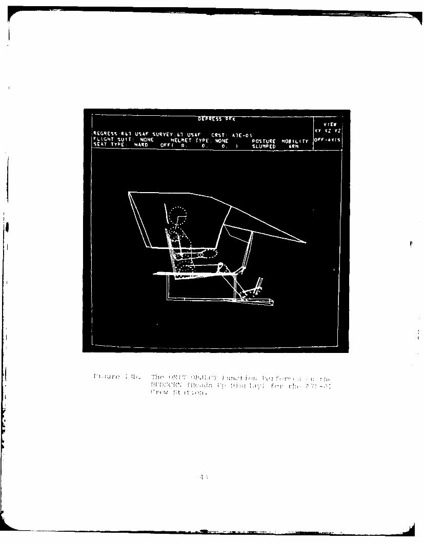
13a The OMIT OBJECT Function Performed on the HUDSCRN(Heads Up Display) for the A7E-01 Crew Station. 42
13b The OMIT OBJECT Function Performed on the HUDSCRN(Heads Up Display) for the A7E-01 Crew Station. 43
14 Table of Available Regression Member Names - OneMust Be Selected. 46
15 Table of Survey Member Name - One Must Be Selected. 47
16a Table of Available Crew Station Membernames. 49
16b Table of Available Crew Station Member NameDisplayed When the Total Number of Panels Exceeds250. 50
17 Visibility Plot. 52
18 Canopy Outline Coordinates in Aircraft System. 54
19 The Message and a Response for the COMBIMAN PlotFunction. 56
I.- - . . .. . . .. . . . . .. . . . . . . . . . ¢ " " - . . . . " : '" - . . . .. .. . . . . l l i I I . . . - ' " c i " l ] I l i i ll 2 "' -' *8-
LIST OF FIGURES (Continued)
Figure Page
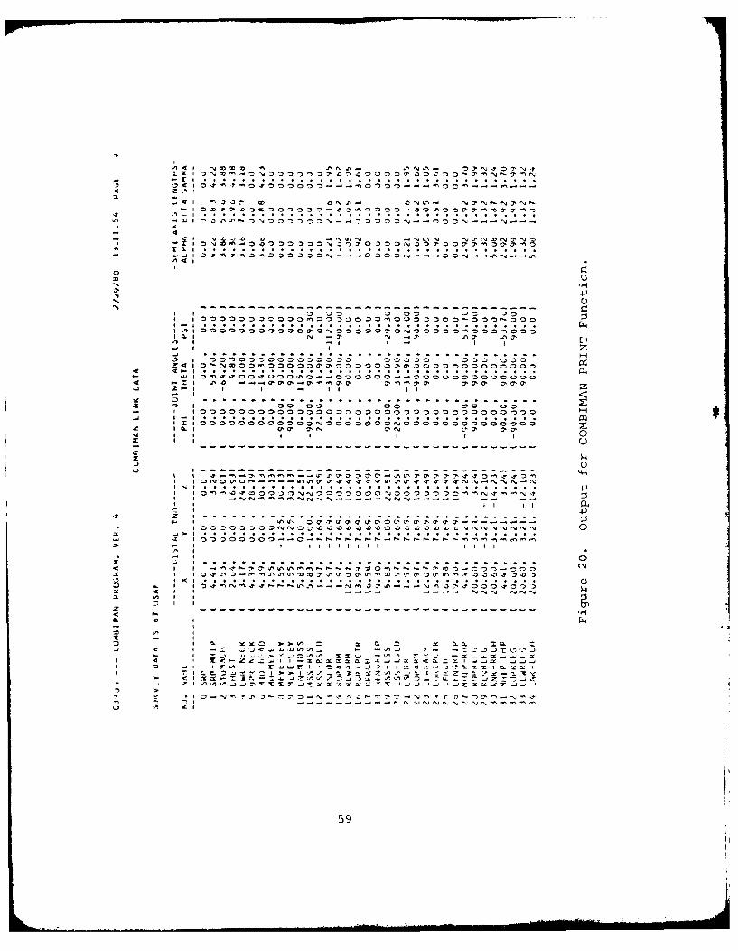
20 Output for COMBIMAN PRINT Function. 59
21a PERFORM REACH ANALYSIS Function. 61
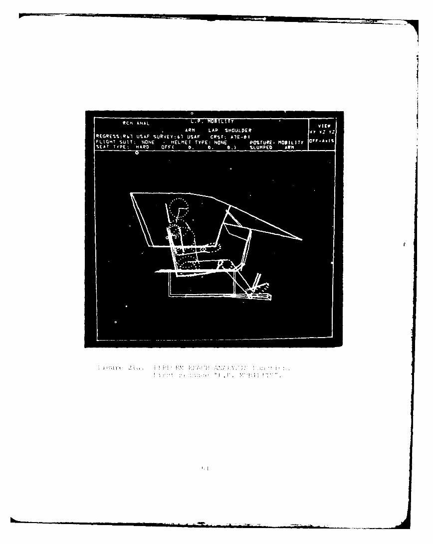
21b PERFORM REACH ANALYSIS Function Light PenReach Type. 62
21c PERFORM REACH ANALYSIS Function Light PenExtent of Reach. 63
22 Positioning Cross Symbol "+" Initially the CrossSymbol is Displayed at the SRP as Shown by theArrow. 64
23a Side View (X-Z Plane) - the "+" Symbol Locates theReach Point. 66
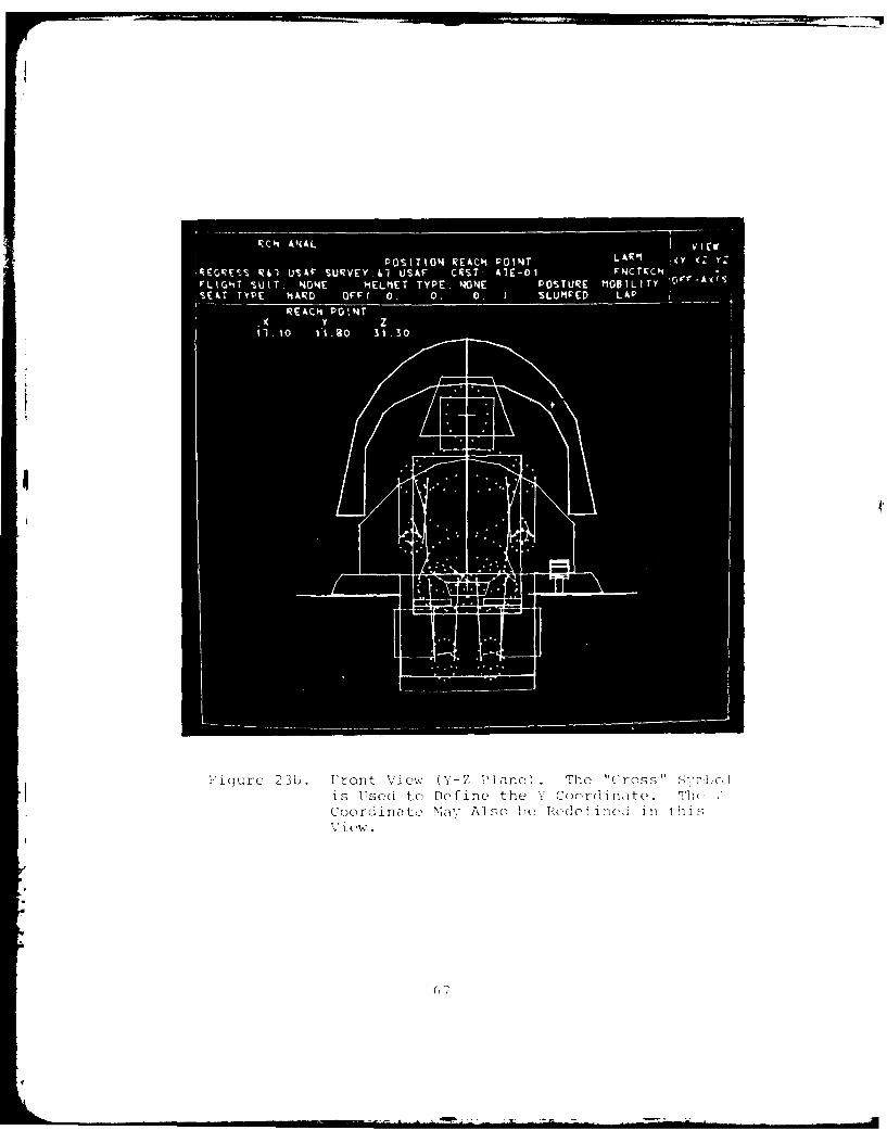
23b Front View (Y-Z Plane). 67
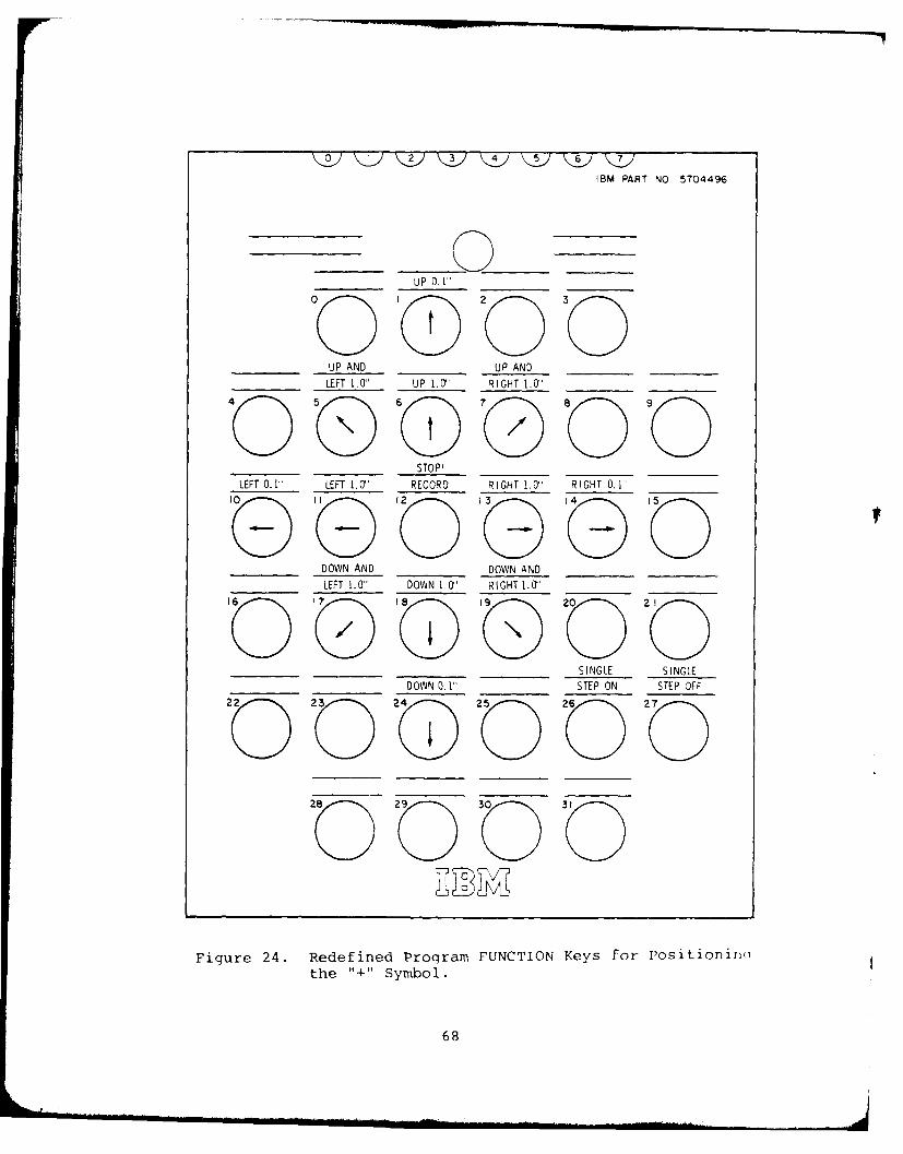
24 Redefined Program FUNCTION Keys for Positioningthe "+" Symbol. 68
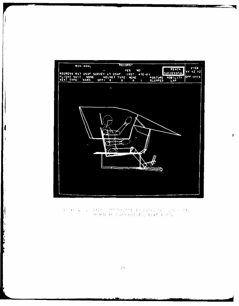
25a REACH SUCCESSFUL is Displayed after the Reach isSuccessfully Performed. 70
25b MISS DISTANCE is Displayed after the Man-ModelCould Not Reach the Point. 71
26 PERFORM REACH Function Printout Obtained When UserResponds "YES" to Message "RECORD? L.P. YES or NO". 72
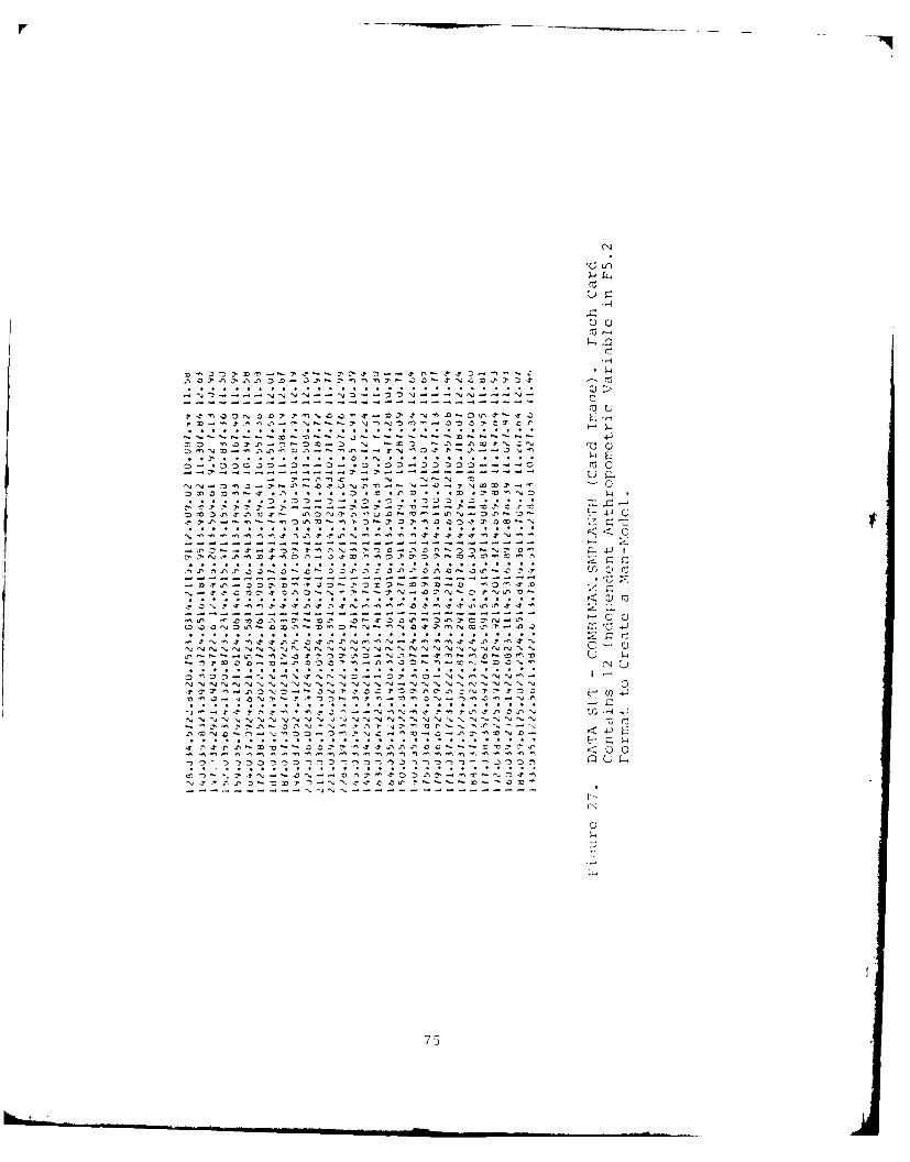
27 DATA SET - COMBIMAN.SMPLANTH (Card Image). 75
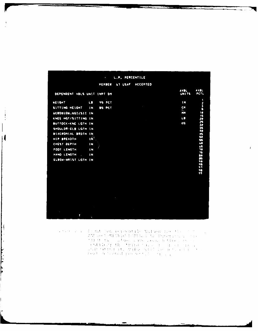
28 Light Pen Percentile Values for the INPUT 12ANTHROPOMETRIC DIMENSIONS Functions. 76
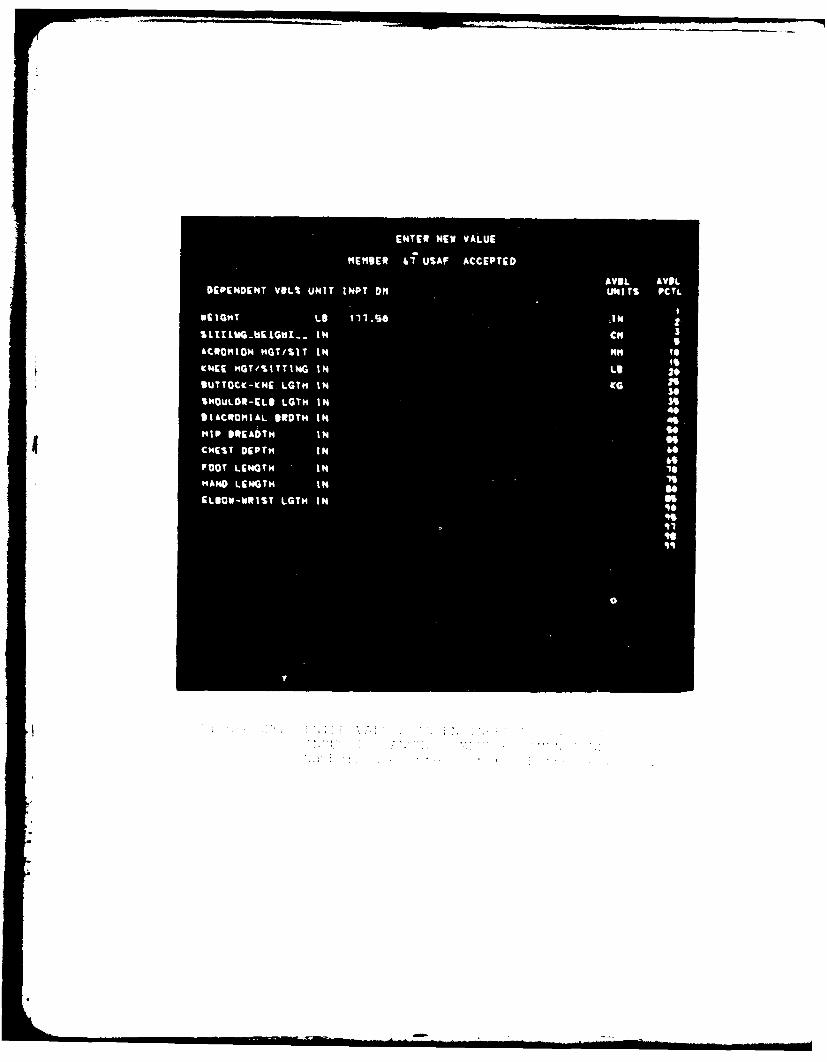
29 ENTER VALUES IN ENGINEERING UNITS for the INPUT12 ANTHROPOMETRIC DIMENSIONS Function. 77
30a INPUT TWO INDEPENDENT VARIABLE Function Light-PenFirst Independent Variable. 80
30b INPUT TWO INDEPENDENT VARIABLE Function Light-PenSecond Independent Variable. 81
30c INPUT TWO INDEPENDENT VARIABLE Function Light-PenPercentile for the Second Independent VariableWithin Range. 83
31a DISPLAY TABLE Displays Links, Their Lengths andEuler Angles. 87
31b DISPLAY TABLE Change THETA Value of MH-MEYE from90* to 1100. 88
32 Example of Euler Angle Changes for Elbow Joints. 90
9
LIST OF FIGURES (Continued)
Figure Page
33 Printed Output of the Newly Designed PanelNEWPNL is Within the Box. 92
34 PFK's for Change Perspective Function. 95
35 RESET SLUMPED Posture Function. 97
36 RESET ERECT POSTURE Function. 99
37 An Example of the Reset Programmed PostureFunctions. 101
38 SEAT ADJUST Function Enter X Coordinate Offsetin Inches. 104
39a Surface Dimension and Internal Link LengthsCalculated by CBM04. 107
39b Printed Output of the Two Selected IndependentVariable Values Calculated by CBM04. 108
40 Transformation Equation Developed for PositioningStomach Link (Set State Switch 72 ON) 109
41 JOB CONTROL CARDS to Execute CBM04. 114
42 Options Displayed on Depressing ALT CODE and CANCELKeys Together. 118
43a The Format of the NAMELIST CNTRL. 128
43b The Format of the Data Card for Unwanted Plots. 128
43c COMBIMAN OFF-LINE Plot. 130
43d Plot Banner for the Plot Shown in Figure 43c. 131
43e Card Input for Figure 43c. 132
43f Card Input for Figure 43g. 132
43g Altered COMBIMAN OFF-LINE Plot. 133
44 Data Flow for Program CBMAM. 136
45 Sample Data Obtained from Summary Statistics of1967 Survey of the Air Force Rated Officers. 142
46 Program CBMAM Control Card Format. 146
47a Example of +ADD Control Card for Type 0 Member. 148
47b Example of +ADD Control Card for Type 1 Member. 148
48a Program CBMAM Regression Member Variable Defini-tion Card. 149
10
LIST OF FIGURES (Continued)
Figure Page
48b Program CBMAM Regression Member Simple RegressionCoefficient Definition Card. 149
48c Program CBMAN Regression Member Multiple RegressionCoefficient Definition Card. 149
49 Example of Regression, or Type 0, Member. 152
50a Program CBMAM Survey Member Percentile DefinitionCard. 154
50b Program CBMAM Survey Member Dimension DefinitionCards. 154
51 Example of Survey, or Type 1, Member. 155
52 Job Control Cards to Execute CBMAM. 159
53 FT02 DD Card to Allocate Space for COMBIMAN.ANTHDTAand Execute CBMVM. 159
54 A Sample Output of the +CMP Function. 162
55 A Sample Output of the +PRT Function. 164
56 A Sample Output of the +DMP Function. 165
57 Output Format Used for Type 0 Regression Data. 167
58a A Sample Output of the +ADD Function for Type 1Member. 169
58b A Sample Output of the +ADD Function for Type 1Member. 170
59 A Sample Output of the +ADD Function for Type 0Member. 172
60 Data Flow for Program CBMCM. 181
61 Sample Crew Station - DESK. 183
62 An Example of a Typical Aircraft Coordinate Systemand its Related COMBIMAN Coordinate System. 184
63 Example of Valid and Invalid Panels. 186
64a X, Y and Z Coordinates of Panels of DESK. 187
64b X, Y and Z Coordinates of Panels of DESK. 188
65 Convention for Determining the Location of aControl in a Panel Relative to Its Verrices. 189
66 Program CBMCM Control Card Format. 190
67a Program CBMCM ADD Member Card Format for Panels. 190
11
LIST OF FIGURES (Continued)
Figure Page
67b Program CBMCM ADD Member Card Format for Panels(Continued). 190
67c Program CBMCM ADD Member Card Format for Controls. 190
68 Sample Data for $ADD Member Function. 192
69 Job Control Cards tu Execute Program CBMCM. 196
70 FT01 DD Card to Allocate Space on Disk and Execute
Program CBMCM. 196
71 A Sample Output of the $CMP Function. 198
72 A Sample Output of the $PRT (No Membername)Function. 200
73 A Sample Output of the $DMP Function. 201
74 A Sample Output the $ADD Function. 204
75 Example of Program CBMWM $PRT (Membername)Function Output Format. 206
76 Data Flow for Program CBMVM. 213
77 X, Y and Z Coordinates of A7E-01 Boundaries. 215
78 Program CBMVM Control Card Format. 218
79a Program CBMVM Member Card Format for Panels. 218
79b Program CBMVM Member Card Format for Coordinatesof Panels. 218
80 Sample Data for &ADD Member Function. 219
81a Job Control Cards to Execute CBMVM. 222
81b FT09 DD Card to Allocate Space for COMBIMAN.VISDATAand Execute Program CBMVM. 222
82 A Sample Output of &CMP Function. 224
83 A Sample Output of &PRT Function. 224
84 A Sample Output of &DMP Function. 226
85 A Sample Output of CBMVM &ADD Function. 227
86 A Sample Output of CBMVM &PRT Function. 229
12
LIST OF TABLES
Table Page
1 PROGRAM MESSAGES AND USER RESPONSES FOR PFK13WHEN VALUES WILL BE INPUT AS PERCENTILES 84
2 PROGRAM MESSAGES AND USER RESPONSES FOR PFK13WHEN VALUES WILL BE INPUT AS ABSOLUTE DIMENSIONS 85
3 LINK SYSTEM DEFINITION 89
4 PROGRAM CBM04 USER ACTIVATED STATE SWITCHES 106
5 LIST OF DEPENDENT VARIABLES NEEDED TO GENERATECOMBIMAN LINK SYSTEM 139
6 LIST OF DEPENDENT VARIABLE PREDICTORS 139
7 LIST OF ANTHROPOMETRIC DIMENSIONS AVAILABLE INTHE ANTHROPOMETRIC DATA BASE 141
8 MATRIX OF CORRELATION COEFFICIENTS BETWEEN MASSAND LENGTH RELATED VARIABLES (CHURCHILL, ET AL,SEPTEMBER 1976) 143
9 DEPENDENT AND INDEPENDENT VARIABLES (CHURCHILL,
ET AL, SEPTEMBER 1976) 144
13
SECTION 1
INTRODUCTION
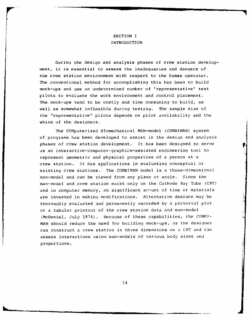
During the design and analysis phases of crew station develop-
ment, it is essential to assess the inadequacies and dangers of
the crew station environment with respect to the human operator.
The conventional method for accomplishing this has been to build
mock-ups and use an undetermined number of "representative" test
pilots to evaluate the work environment and control placement.
The mock-ups tend to be costly and time consuming to build, as
well as somewhat inflexible during testing. The sample size of
the "representative" pilots depends on pilot availability and the
whims of the designers.
The COMputerized BIomechanical MAN-model (COMBIMAN) system
of programs has been developed to assist in the design and analysis
phases of crew station development. It has been designed to serve
as an interactive-computer-graphics-assisted engineering tool to
represent geometric and physical properties of a person at a
crew station. It has applications in evaluating conceptual or
existing crew stations. The COMBIMAN model is a three-dimensional
man-model and can be viewed from any plane or angle. Since the
man-model and crew station exist only on the Cathode Ray Tube (CRT)
and in computer memory, no significant ar-ount of time or materials
are invested in making modifications. Alternative designs may be
thoroughly evaluated and permanently recorded by a pictorial plot
or a tabular printout of the crew station data and man-model
(McDaniel, July 1974). Because of these capabilities, the COMBI-
MAN should reduce the need for building mock-ups, as the designer
can construct a crew station in three dimensions on a CRT and can
assess interactions using man-models of various body sizes and
proportions.
14
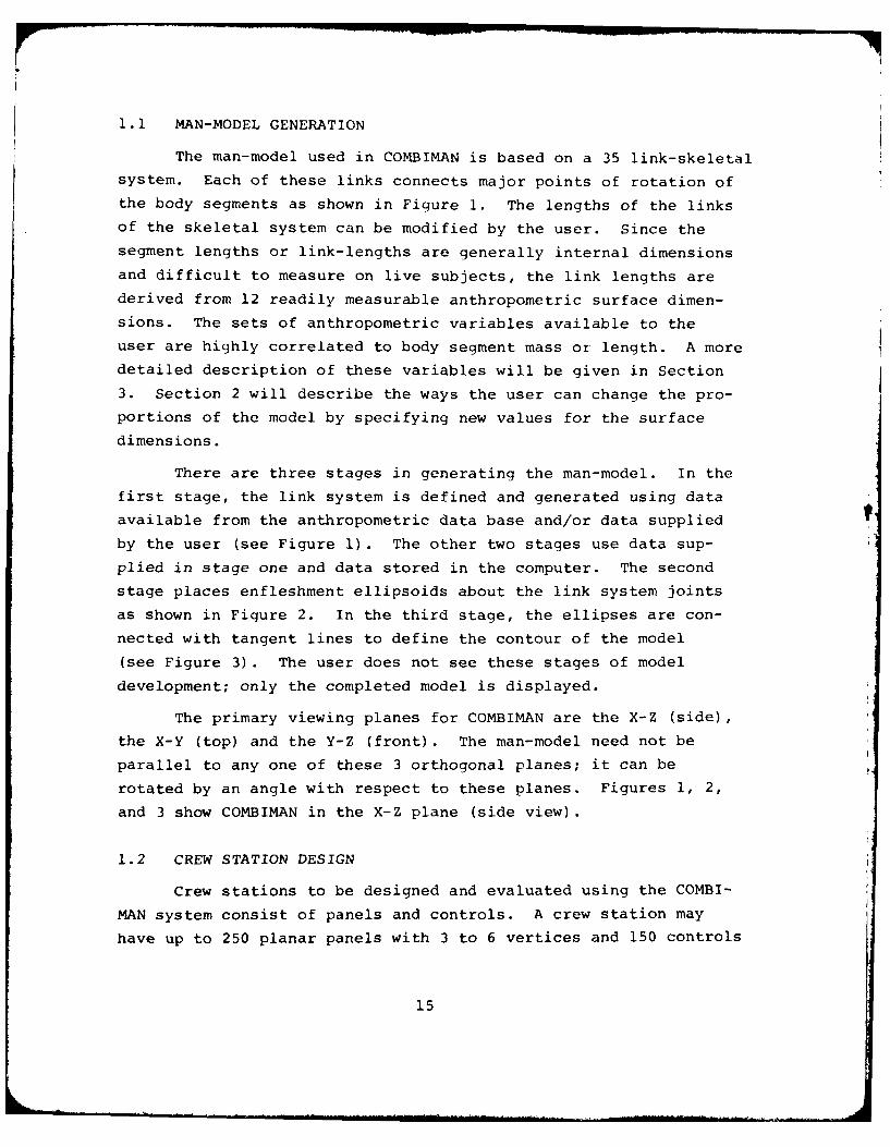
1.1 MAN-MODEL GENERATION
The man-model used in COMBIMAN is based on a 35 link-skeletal
system. Each of these links connects major points of rotation ofthe body segments as shown in Figure 1. The lengths of the links
of the skeletal system can be modified by the user. Since the
segment lengths or link-lengths are generally internal dimensions
and difficult to measure on live subjects, the link lengths are
derived from 12 readily measurable anthropometric surface dimen-
sions. The sets of anthropometric variables available to the
user are highly correlated to body segment mass or length. A more
detailed description of these variables will be given in Section
3. Section 2 will describe the ways the user can change the pro-portions of the model by specifying new values for the surface
dimensions.
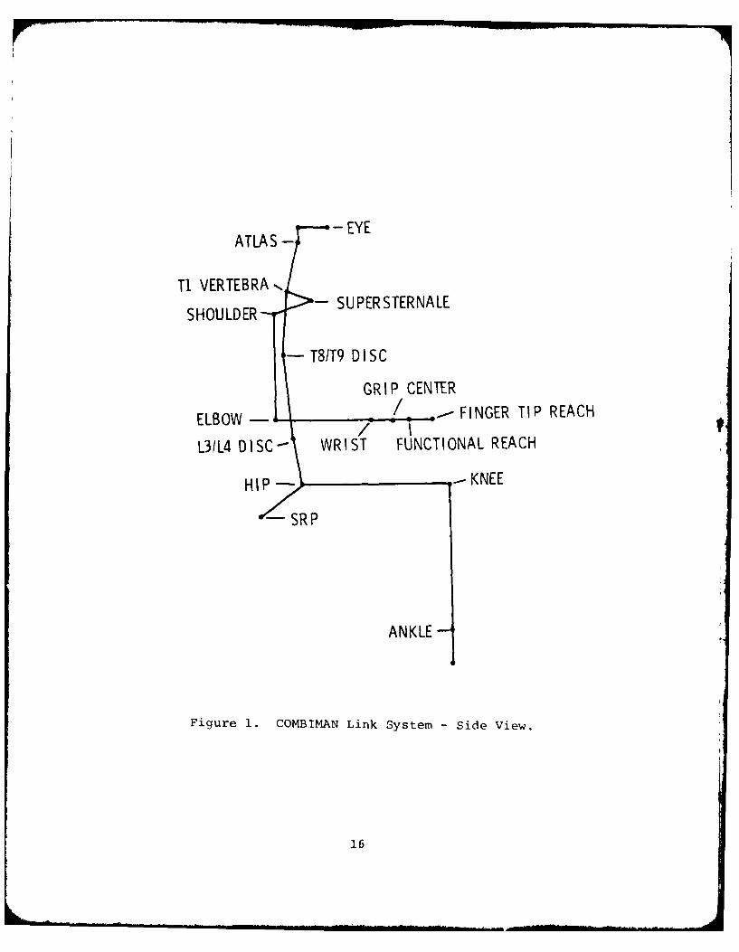
There are three stages in generating the man-model. In thefirst stage, the link system is defined and generated using data
available from the anthropometric data base and/or data supplied
by the user (see Figure 1). The other two stages use data sup-
plied in stage one and data stored in the computer. The second
stage places enfleshment ellipsoids about the link system joints
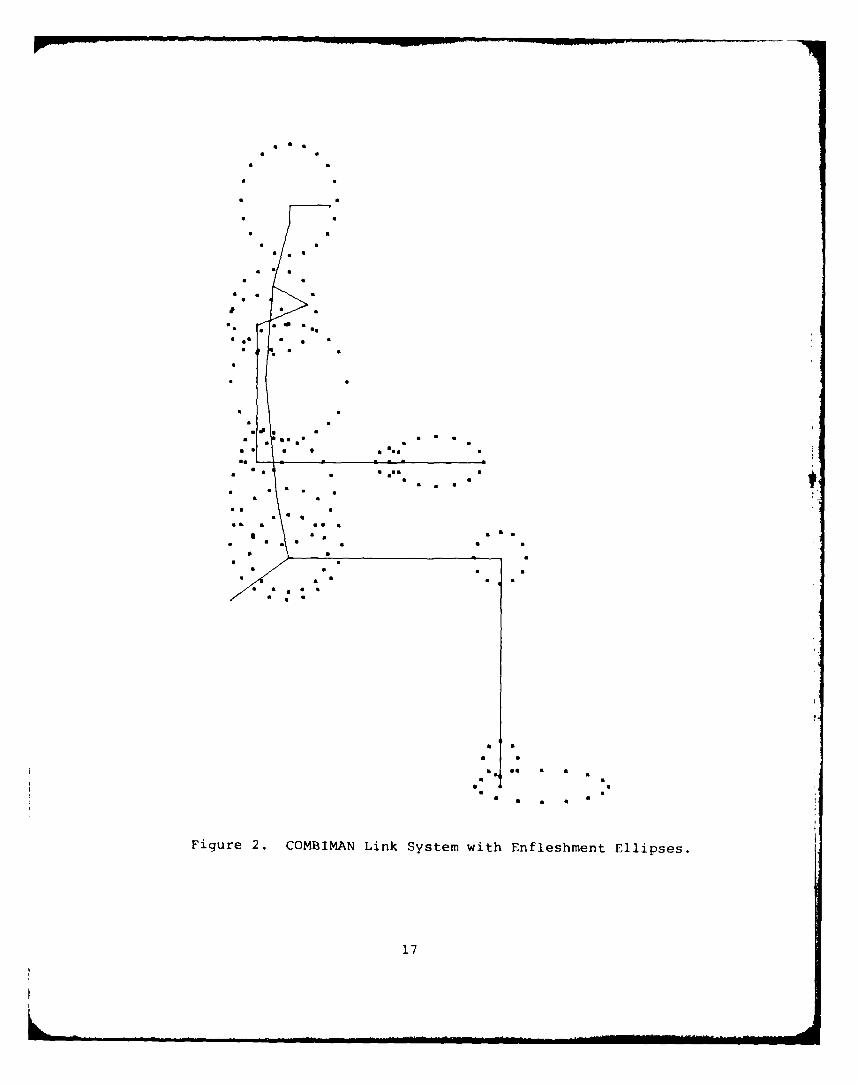
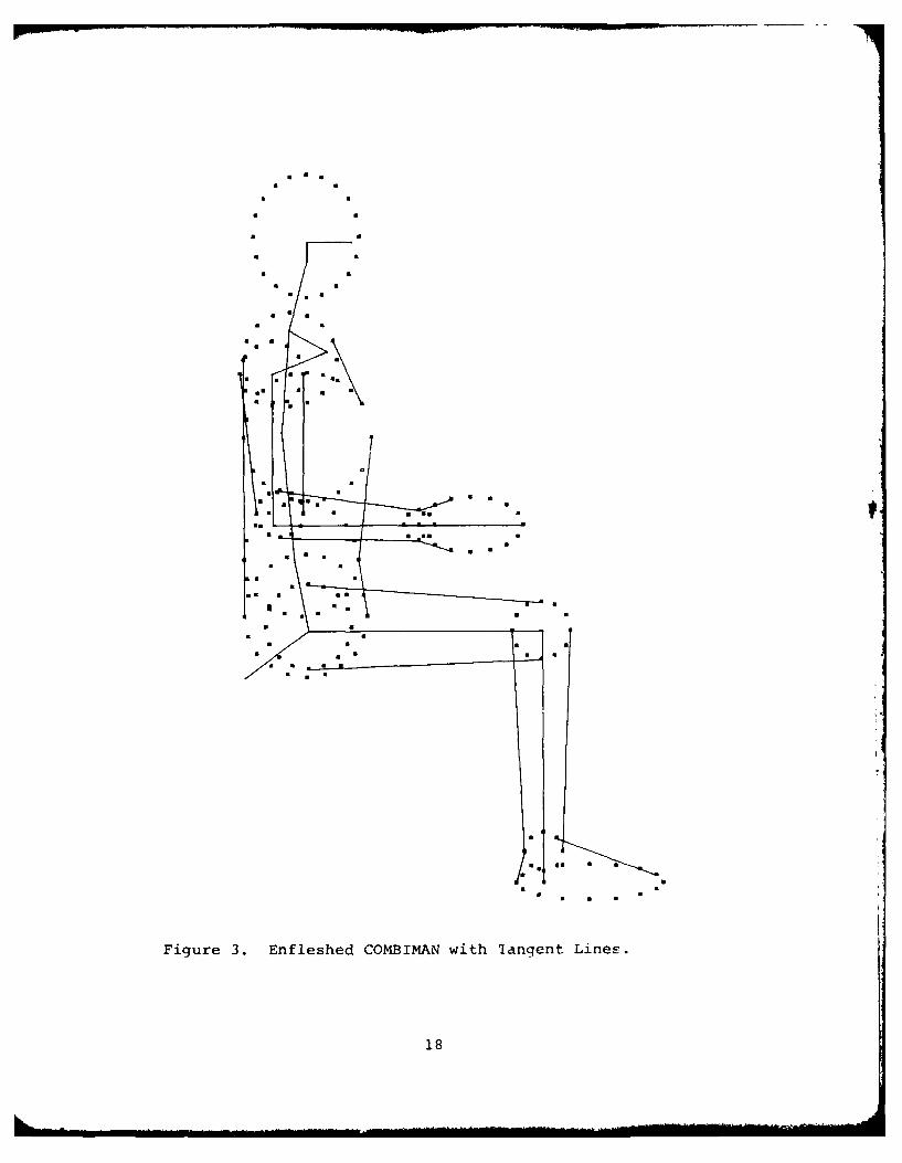
as shown in Figure 2. In the third stage, the ellipses are con-
nected with tangent lines to define the contour of the model
(see Figure 3). The user does not see these stages of model
development; only the completed model is displayed.
The primary viewing planes for COMBIMAN are the X-Z (side),
the X-Y (top) and the Y-Z (front). The man-model need not be
parallel to any one of these 3 orthogonal planes; it can be
rotated by an angle with respect to these planes. Figures 1, 2,
and 3 show COMBIMAN in the X-Z plane (side view).
1.2 CREW STATION DESIGN
Crew stations to be designed and evaluated using the COMBI-
MAN system consist of panels and controls. A crew station may
have up to 250 planar panels with 3 to 6 vertices and 150 controls
15
EYEATLAS -
Ti VERTEBRA SPRTENLSHOULDER-SUESENE
-T8/T9 D ISC
GRIP CENTER
ELBOW FINGER TIP REACH
1-314 DISC- WRIST FUNCTIONAL REACH
HIP KNEE
ANKLE-
Figure 1. COMBIMAN Link System -Side View.
16
a S
roll a
Ci *
S *l iCl
•* S C 4 5 III
* C
a a • a
Fiur 2. CM A N ikSstmwt nfehet liss
... .. .. . . .. . .. ,,i. ....a.....,.. . ...
a S
* S
* S
S * S
* S
* S ScSm S * S
* S
S
S SS S S
Figure 3. Enfleshed COMBIMAN with 'langent Lines.
18
which may or may not be located on the defined panels. Although
the crew stations used in COMBIMAN are usually aircraft crew
stations, it is possible to construct and display any workspace
requiring interaction by a seated operator. This would include
automobile instrument panels, industrial configurations, and
control panels for other types of vehicles.
Two methods are used to generate and display crew stations.
The designer can either use an existing or conceptual configura-
tion, or can construct a new one on the Cathode Ray Tube (CRT)
using the available interactive graphic options. In the first
method, panels and controls for existing or conceptual configura-
tions, are coded onto computer cards, or magnetic tape, or direct
access disk, and are entered into the Crew Station Data Base.
These data are accessible to the user through the interactive
graphics program. In the second method, the user can desiqn crew
stations at the CRT, using alphanumeric keyboard and the proqram
function keys, followinq the basic series of steps similar to
those used on a draw..ing board.
A crew station entered into the program exists in three
dimensions and the man-model can interact with it. Since the
CRT has only two dimensions, the 3-D man-model and crew station
are projected onto the screen in the orientation the user selects.
The display can then be rotated within the display area to suit
the designers' needs. An example of the display with a rotated
and magnified model and crew station are shown in Figure 4.
1.3 EVALUATION TECHNIQUES
A number of evaluation techniques have been implemented into
the COMBIMAN system. Primarily, they are designed to allow the
user to vary the proportions of the man-model to suit a particular
situation or problem, and to position the model within the crew
station to assess human performance and to aid in placement of
controls and panels.
19
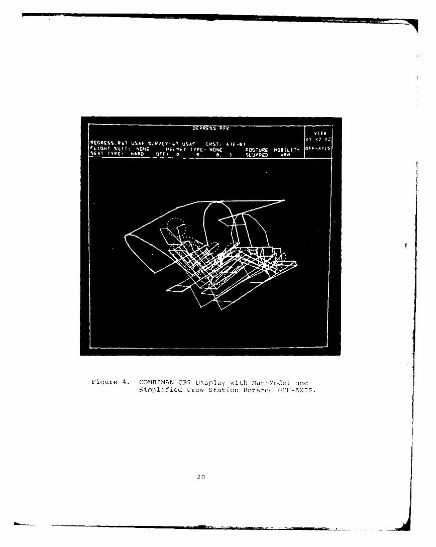
Figure 4. COMBIMAN CRT Display with Man-Model andSimplified Crew Station Rotated OFF-AXIS.
20
In order to display the man-model on the CRT, COMBIMAN uses
information from on-line disk files and from user supplied data
on anthropometric surface dimensions. The ability to make use of
user supplied anthropometric data permits the construction of man-
models of variable proportions suitable to the particular needs of
the user. To define the man-model, CBM04 (COMBIMAN program
Version 4) requires values for the twelve anthropometric variables
to generate the 35 internal link lengths. The user can either
supply values for all 12 variables or supply values for one mass
related and one length related variable and let the program com-
pute the other 10 variables using multiple regression equations.
The user supplied data may be (a) direct measures obtained from
specific subjects; or (b) percentile values chosen from the COMBI-
PAN Anthropometric Data Base. The latter option is generally the
most useful, as it limits the range of values for user supplied
dimensions and eliminates unrealistic combinations of dimensions.
The man-model can be positioned in a crew station by direct-
ly entering sets of rotational angles used to position the links
of the model, or with the PERFORM REACH ANALYSIS function (see
Paragraph 2.2.11) by specifying a point on the display. The later
method applies to reach involving the arms and incorporates auto-
matic restrictions to mobility. The user may also initialize the
man-model in the standard anthropometric seated measuring posture
(ERECT POSTURE), the SLUMPED POSTURE, which is an erect posture
positioned in a 130 seat back angle and 60 seat pan angle, or a
third posture (PRGM'D POSTURE) defined by the user.
Other information available to the user includes hard copy
plots of the display, printed output showing the three dimensional
real world coordinates of the man-model and of the panels of the
crew station, and visibility plots, which give the user information
on the visual field of the crew station based on the eye position
of the model.
21
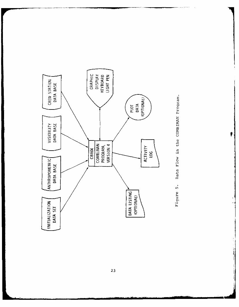
1.4 THE COMBIMAN PROGRAMS
The COMBIMAN system is divided into five programs, the main
program being the interactive graphics program CBM04, which allows
the user to generate a variable size man-model and then assesses
interaction with new or existing crew stations. Before the user
can define the proportions of the man-model, or call up crew
stations and visibility contours for evaluation, the files which
store the anthropometric, crew station, and visibility member
data must be created. This is done using three specialized file
creation/modification programs, each dealing with a particular
type of data set: anthropometric, crew station, or visibility
member. Similar sets of commands are used by each program to
initialize the file, add data, delete data, write existing data
groups to the printer, or to punch data groups to cards. The data
flow of the COMBIMAN program is shown in Figure 5. Figure 5 also
shows a fourth file, the initialization data set, which is used
in constructing the man-model and cannot be modified by the user.
The following sections will explain the operation of four
of the key programs of the COMBIMAN system, including the inter-
active graphics program CBM04, and three of the file manipulation
programs which maintain the data files used as input to CBM04.
The manipulation of the man-model and crew station using the in-
teractive graphics program CBM04 is straightforward. Sections 1
and 2 of this guide will provide a designer not skilled in com-
puter programming with sufficient information to use the inter-
active program CBM04. The technical nature of the data and pro-
grams described in Sections 3, 4, 5, and 6 requires some computer
skills to interpret and use these Data Base maintenance programs.
Section 2 describes the use of the function keys which may
be activated by the user in program CBM04 to manipulate the man-
model and to design and to evaluate crew stations. This section
includes examples of the optional as well as the standard output
formats supplied by the program, and lists the possible error or
information messages generated by the proqram.
22
<LCL
00
C))
41-)
CIS-
E C00
-i
4)
Q)
<0
23
Section 3 describes the COMBIMAN off-line plotting program,
CBMOFF. This program uses data generated by CBM04 to produce
plots of variable size, color, and content from three-dimensional
coordinate data. Input formats, plotting options, and program
out :ut are explained in this section.
The program which creates and maintains the data base of
Anthropometric surveys, CBMAM, is documented in Section 4. The
types of data which maj be stored, the sources for such data, the
input data formats, sample output formats, and message formats
are discussed. The uses of, and formats for, the commands or
functions which manipulate the file are also described.
The program which creates and maintains the data base of
geometric descriptions of crew station configurations, CBMCM, is
documented in Section 5. The program which creates and maintains
the data base of geometric descriptions of crew stations for visi-
bility plots, CBMVM, is documented in Section 6. Data sources
and input, output, and message formats are described for both
programs. These sections also contain examples of Job Control
cards to run the programs.
DERS I
>2'N~'n2 Q'~M*J~TMJ\V P'f.<
COPTRZD8OMCAIA A
SECTION 2
THE COMBIMAN INTERACTIVE GRAPHICS PROGRAMVERSION 4, - CBM04
At the heart of the COMBIMAN system is the fourth version
of the COMBIMAN interactive graphics program CBM04. The program
uses an IBM 2250-3 Display Unit for the design and analysis of
crew stations. The user at the display device controls the
course of execution of program CBM04 using a Program Function
Keyboard. Functions of the program may be executed by depressing
lighted Program Function Keys (PFK). This section describes the
functions available to the COMBIMAN user, shows the output that
the functions may generate, and traces through suggested execu-
tion sequences for generating the man-model, and retrieving a
crew station.
2.1 INTRODUCTION
The graphics program CBM04 enables the designer to bring
together the information on anthropometry and crew stations
stored on disk (see Sections 4 and 5) and combine them with the
interactive qualities of the Cathode Ray Tube (CRT). Doing this,
one can evaluate real-life conditions, or establish design criteria
for new situations in a fraction of the time it would take using
conventional methods.
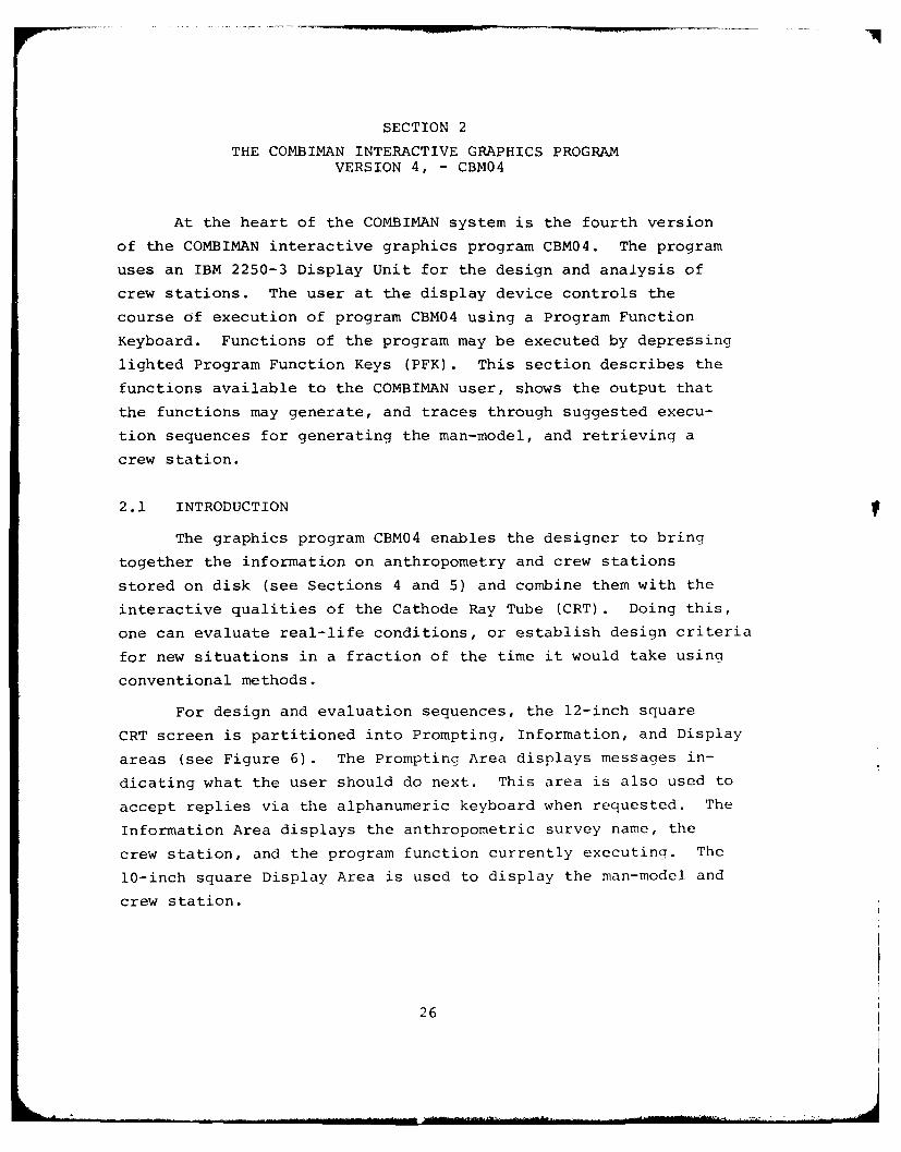
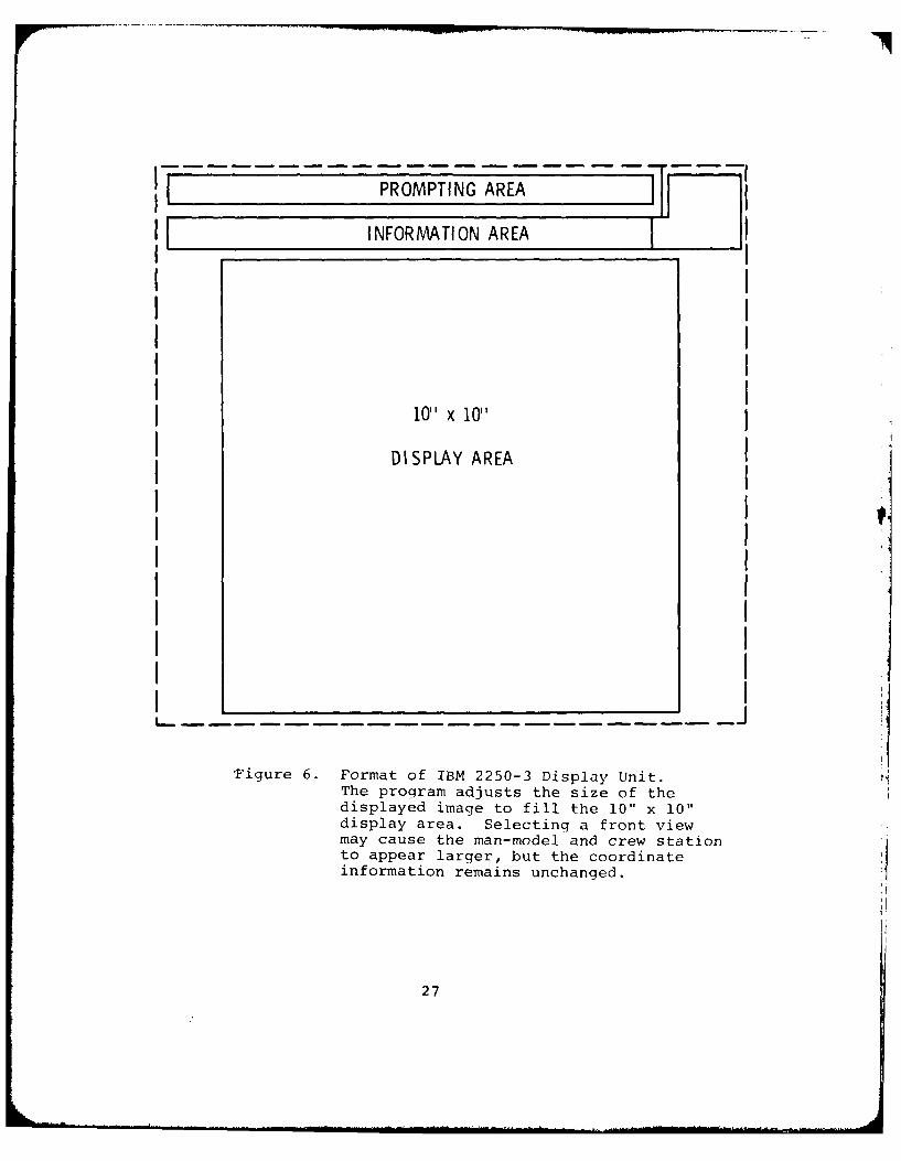
For design and evaluation sequences, the 12-inch square
CRT screen is partitioned into Prompting, Information, and Display
areas (see Figure 6). The Prompting Area displays messages in-
dicating what the user should do next. This area is also used to
accept replies via the alphanumeric keyboard when requested. The
Information Area displays the anthropometric survey name, the
crew station, and the program function currently executing. The
10-inch square Display Area is used to display the man-model and
crew station.
26
----- PROMPTING AREA
I INFORMATION AREA
10I xI0
ds le img lol l thI0 0dipa DaSPL. AReAetn arntvema cas h a-oe n rwsa ito apea larerbut he oordnatinomto reanIncagd
I I7
Replies to prompting messages are given through the Alpha-
numeric Keyboard (ANKB), the Light Pen, or the Programmable Func-
tion Keys (PFK). Replies given through the ANKB are displayed in
the Prompting Area below the prompting message and are processed
by the program after simultaneously depressing the ALT CODING key1
and the "5" key. Replies that require using the light pen are
given by depressing the light pen barrel aimed at the desired
response displayed on the screen.
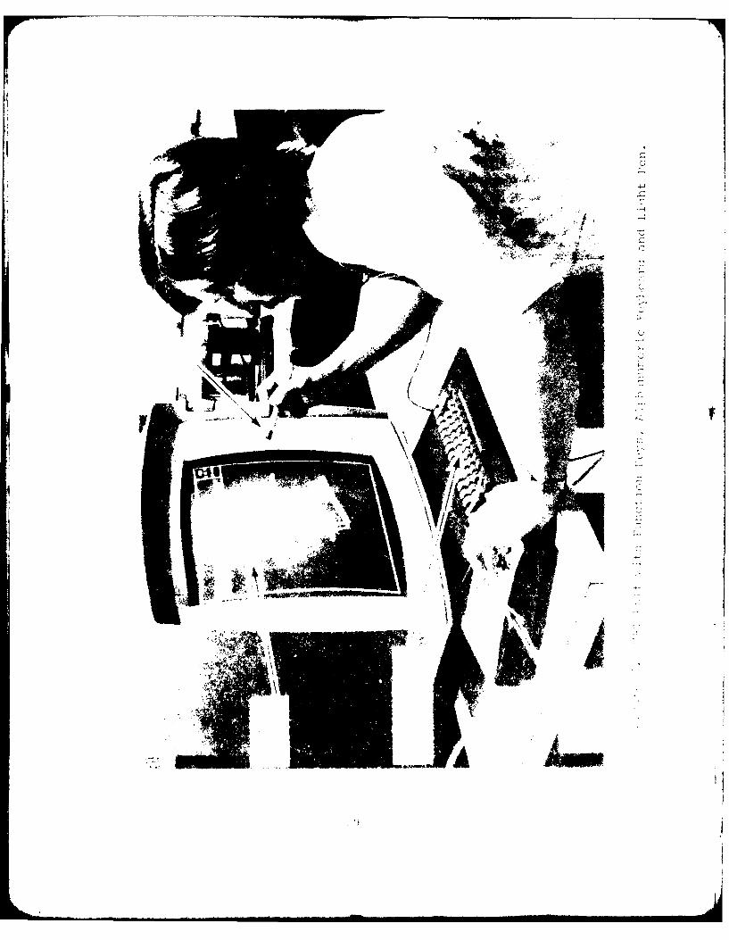
Figure 7 shows the IBM 2250-3 CRT in use. The user's left
hand is on the Program Function Keyboard, and his right hand is
using the light pen to identify a point on the screen. The Alpha-
numeric Keyboard is shown below the CRT.
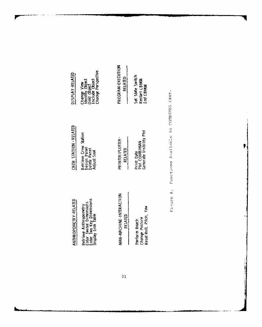
2.1.1 Functions Available
The functions which are available to the user fall
into six basic categories, as shown in Figure 8. The first cate-
gory, the Anthropometry Related functions, enables the user to
retrieve data for a particular anthropometric survey from the
Anthropometric Data Base, specify values for the surface dimen-
sions of the man-model, and manipulate the geometry of the model
to achieve the desired man-model configuration. The Crew Station-
Related functions let the user retrieve existing three-dimensional
crew station configurations from the Crew Station Data Base and
then add to and modify the retrieved configuration. These func-
tions also allow the user to start from the beginning of a design
sequence and create a new crew station configuration. The Display-
Related functions allow the user to rotate and to magnify the
contents of the display area. They also enable the user to
identify objects within the Display Area, or modify the contents
by omitting or by including objects. The user can evaluate
In subsequent use in the text the simultaneous depression of the"ALT-CODING" and "5" keys will be referred to as the ALT-CODE/5sequence. IBM refers to this sequence as EOB (End of Block).(IBM System Reference Library, Program Numbers 360S-LM-537.)
28
V-
the interaction of man-model with crew station through the Man-
Machine Interaction Related functions. These functions provide
the user with a reach analysis routine and change posture functions.
The Printer/Plotter Related functions supply the user with hard-
copy output of the configuration of either the man-model or the
crew station. The program generates plot output as soon as a
plot function is activated, but the printed output occurs only at
the end of the run. The final category, the Program Execution
Related functions, permits the user to restart the program, or to
end it. It also enables the user to set State Switches which
either suppress or activate additional processing or printing.
A standard feature of the program is a listing of all actions
taken by the user. This is a sequence of messages printed at the
termination of the program CBMO4.
2.1.2 Requirements
At the Wright-Patterson Air Force Base AFAMRL HESS
facility, the program CBM04 runs on an IBM 370/155 Operating System
Computer using a 2250-3 graphics display terminal with light pen,
alphanumeric keyboard, and program function keyboard, and an on-
line Gould 4800 plotter. The program requires 550K bytes computer
memory and a minimum of 20K bytes graphics buffer control area.
The Initialization, Anthropometric, Crew Station and Visibility
Data Bases reside on a disk drive in a direct access format. The
space requirement for each data base depends on the number of
members and their complexities. IBM System/360 Operating System
Graphic Subroutine Package (GSP) for FORTRAN IV is used to create
displays on the CRT. Gould 4800/5000 IBM System/360/370 Plot
package is used for on-line plotting.
Other requirements for specific functions will be
described in the appropriate paragraphs which follow.
30
LALJ
~x
LL1 CX -
c U-m r- 2c"
U I-
C)C
C. w)o<
w z
a) a
31
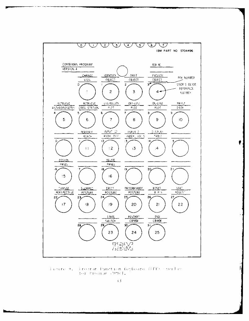
2.2 AVAILABLE PROCESSING
Functions of Proqram CBM04 are requested by means of the
Program Function Keyboard (PFK). This keyboard consists of 32
keys, numbered 0 to 31, whose functions are assioned by procram
CBM04. When a function is enabled, the appropriate button on the
PFK will be liqhted. The primary functions for Proqram CPM04
are shown on the PFE Overlay Mask in Fiqure 9. The circles in
Ficurc 9 represent the PFk keys. Their numbers are shown abovte
and te the left of each circle. The numbers within the carcle -
represent the subsections where the functions are described.
For example, PFKO contains a "1" within the circle and is d'.crihe'
in Parajqraph 2.2.1. A function is requested by ai sin(;]c, mon~eptary
depression of the correspondinq JIFK.
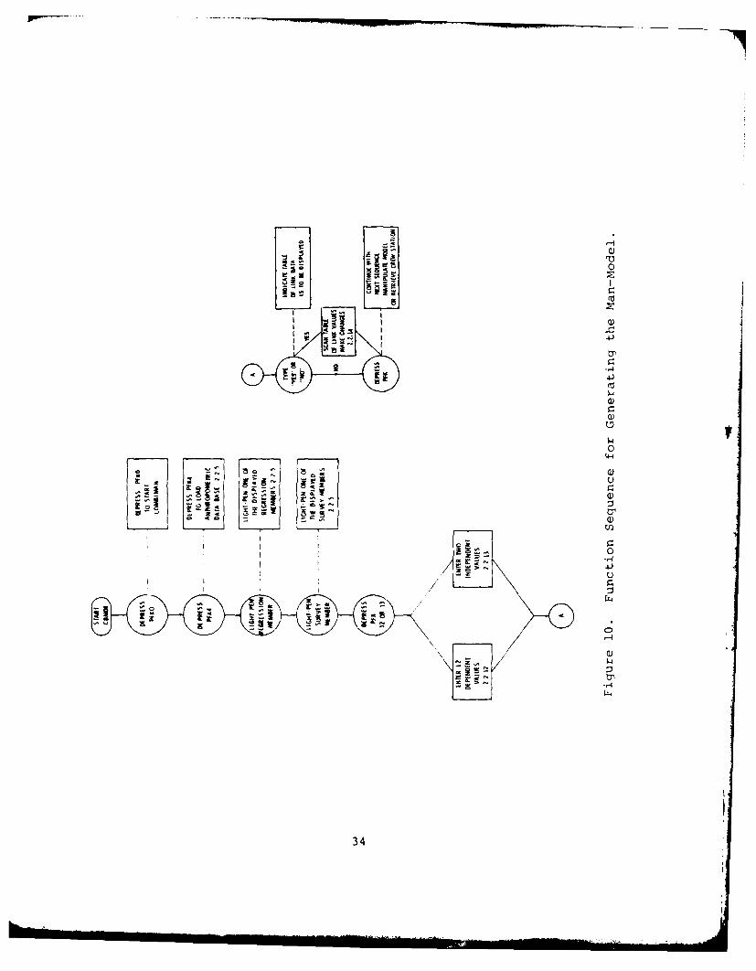
once the proqram is loaded (for instructions on loadin:,
see Fara<rapi1 2.3.1) the promptinq area of the screen will dis, lay
the lmeSSaqje "DEPRESS' FFK4". The first secu(nce of steps the uer
follows should utilize the Anthropometrv Related f anctions to
qjenerate the man-model. The mandatory. sequence is shown in Fic'ure
iC. The nuniber in each block refers to the paranraph which de-
scribes the function.
After the man-model is generated and displayed on the CRT,
the user may choose to manipulate the man-model usino] the Display-
RClated functions, or may retrieve or develop a crew station usinc
the Crew Station Related functions. When usinn the Crew Station
Related functions, the RETRIEVE CREW STATION Function (I'aracx aih
2.2.6) should be selected before deletino panels. The Prooram
I xecution Related functions (see Fiqure 8) are always enabled and
may be depressed at any time durin(q the execution of CLIM04.
The followinq paraqraphs describe the processin<i performTed
by each function as numbered in Fiqure 9.
12
0, IO 2 4 5 6 7
IBM PART NO 5704496
COMBIMIAN PROGRAM FEB 80
VE SO 4 C A G IDENTIFY O OMIT INCLUDE K NUMBERv 1Ev. OBJECT OBJECT OBJ E CT
0 I 2 3USER'S GUIDE
1 2 REFER EN CE2 3 4 NU!0BF;;
-R TRIEV REVE E IIIIY O -LK ON- L INE PPI NTA \THR OP(WETR~ CREV, STATION PLOT PLOT PLOT DAT4
4( 5D 6D 7D 11 (
_________ ERFORY' INPUT 12 INPUT 2 DISDLA\ _____
__________ REACH ANTH DIV' INDEP. VB. S TABLE ______
0o IID 102 3)E C)
DESIGN.__OANEL _______ PANEL ______ __ _____ ______
6E 17 D 9) 20 20
^HANGE SUMEERC RGMMD RSTEADEPSOECTIVE POSTURE POSTURE -POSTURE R - ADJLUW
2 23 D4 25 26 D2
________ STATE RESTART END
_______ SV I TCH CBM04 CBM04
D 23 4 2
4--40
0)
IEI
IrU
14
3-
0
0lJ
--
34)
pp __
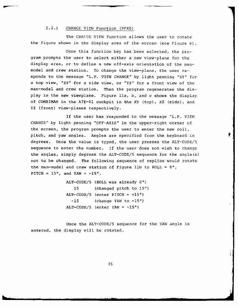
2.2.1 CHANGE VIEW Function (PFKO)
The CHANGE VIEW function allows the user to rotate
the figure shown in the display area of the screen (see Figure 6).
Once this function key has been selected, the pro-
gram prompts the user to select either a new view-plane for the
display area, or to define a new off-axis orientation of the man-
model and crew station. To change the view-plane, the user re-
sponds to the message "L.P. VIEW CHANGE" by light penning "XY" for
a top view, "XZ" for a side view, or "YZ" for a front view of the
man-model and crew station. Then the program regenerates the dis-
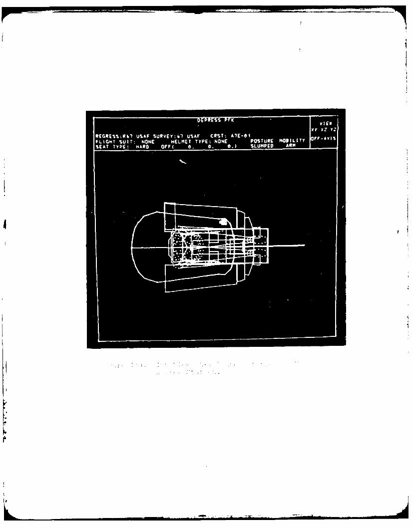
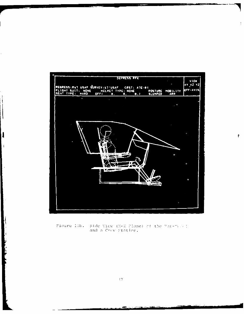
play in the new viewplane. Figure lla, b, and c shows the display
of COMBIMAN in the A7E-01 cockpit in the XY (top), XZ (side), and
YZ (front) view-planes respectively.
If the user has responded to the message "L.P. VIEW
CHANGE" by light penning "OFF-AXIS" in the upper-right corner of
the screen, the program prompts the user to enter the new roll,
pitch, and yaw angles. Angles are specified from the keyboard in
degrees. Once the value is typed, the user presses the ALT-CODE/5
sequence to enter the number. If the user does not wish to change
the angles, simply depress the ALT-CODE/5 sequence for the angle(s)
not to be changed. The following sequence of replies would rotate
the man-model and crew station of Figure llb to ROLL = 00,
PITCH = 150, and YAW = -15'.
ALT-CODE/5 (ROLL was already 0)
15 (changed pitch to 150)
ALT-CODE/5 (enter PITCH = +150)
-15 (change YAW to -15*)
ALT-CODE/5 (enter YAW = -15*)
Once the ALT-CODE/5 sequence for the YAW angle is
entered, the display will be rotated.
35
DERS 8 *S
UVIE
kyxzY
p.R W9- SF UVY#IUAF CS:AE0
FLIGHT ~ ~ ~ SUIT NOE HLE YE OE PSUEMDLT -- lI
'1,IA
RERS :4 SFS~ E UA C S: *S * 6:
lIi" urt I I,- 1-Io t tic - Idl )i Vci nh :~->cin:w t, Ic ~I t I(~
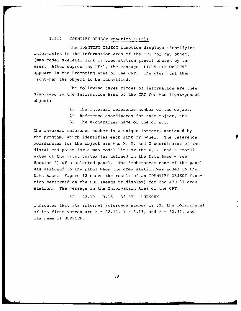
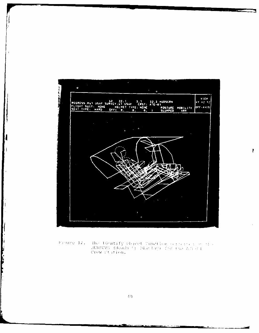
2.2.2 IDENTIFY OBJECT Function (PFKI)
The IDENTIFY OBJECT function displays identifying
information in the Information Area of the CRT for any object
(man-model skeletal link or crew station panel) chosen by the
user. After depressing PFK1, the message "LIGHT-PEN OBJECT"
appears in the Prompting Area of the CRT. The user must then
light-pen the object to be identified.
The following three pieces of information are then
displayed in the Information Area of the CRT for the light-penned
object:
1) The internal reference number of the object,
2) Reference coordinates for that object, and
3) The 8-character name of the object.
The internal reference number is a unique integer, assigned by
the program, which identifies each link or panel. The reference
coordinates for the object are the X, Y, and Z coordinates of the
distal end point for a man-model link or the X, Y, and Z coordi-
nates of the first vertex (as defined in the Data Base - see
Section 5) of a selected panel. The 8-character name of the panel
was assigned to the panel when the crew station was added to the
Data Base. Figure 12 shows the result of an IDENTIFY OBJECT func-
tion performed on the HUD (heads up display) for the A7E-Ol crew
station. The message in the Information Area of the CRT,
62 22.10 3.15 32.37 HUDSCRN
indicates that its internal reference number is 62, the coordinates
of its first vertex are X 22.10, Y -~3.15, and Z =32.37, and
its name is HUDSCRN.
39
VIE
Ib 2 . 23MDCNX zY
('t4 It ,It t
CA(
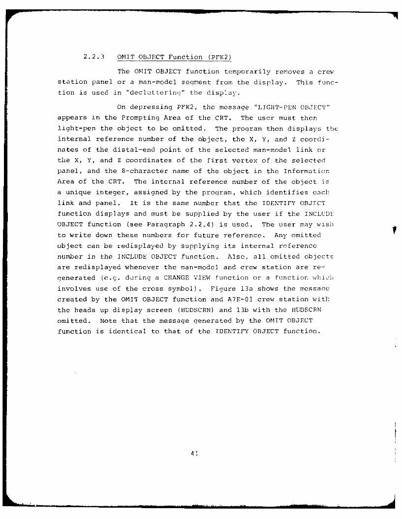
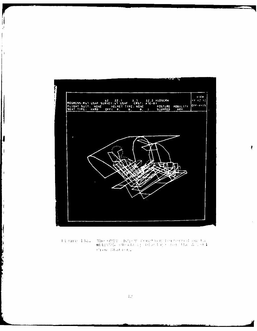
2.2.3 OMIT OBJECT Function (PFK2)
The OMIT OBJECT function temporarily removes a crew
station panel or a man-model segment from the display. This func-
tion is used in "decluttering" the display.
On depressing PFK2, the message "LIGHT-PEN OBJECT"
appears in the Prompting Area of the CRT. The user must then
light-pen the object to be omitted. The program then displays the
internal reference number of the object, the X, Y, and Z coordi-
nates of the distal-end point of the selected man-model link or
the X, Y, and Z coordinates of the first vertex of the selected
panel, and the 8-character name of the object in the Information
Area of the CRT. The internal reference number of the object is
a unique integer, assigned by the program, which identifies each
link and panel. It is the same number that the IDENTIFY OBJECT
function displays and must be supplied by the user if the INCLUDE
OBJECT function (see Paragraph 2.2.4) is used. The user may wish
to write down these numbers for future reference. Any omitted
object can be redisplayed by supplying its internal reference
number in the INCLUDE OBJECT function. Also, all omitted objects
are redisplayed whenever the man-model and crew station are re-
generated (e.c. during a CHANGE VIEW function or a function which
involves use of the cross symbol). Figure 13a shows the messaqe
created by the OMIT OBJECT function and A7E-01 crew station with
the heads up display screen (HUDSCRN) and 13b with the HUDSCRN
omitted. Note that the message generated by the OMIT OBJECT
function is identical to that of the IDENTIFY OBJECT function.
41
0 22. 3.1 2.3 MDSCR
REGREWR41 USAF SVikUSFCT:AE0
t-1 I
HI~ tI
4.
IIE
iuREGES Q13b USAF SUVY4 USAF C T AI-1 XY xz i t
FLIGHT~~~~~~~~~ %UT OE HLMTTP 4NE PSUEMlI(yOUAi
2.2.4 INCLUDE OBJECT Function (PFK3)
The INCLUDE OBJECT function redisplays an object
that was removed from the screen by the OMIT OBJECT function.
After depressing PFK3, the message "ENTER OBJECT NUMBER" appears
in the Prompting Area of the CRT. The number is entered through
the ANKB followed by the ALT-CODE/5 sequence. The only valid
entries for this function are internal reference numbers of man-
model skeletal links or crew station panels which have previously
been deleted by the OMIT OBJECT function. The program will keep
prompting for a valid internal key number until the user supplies
one or enters the ALT-CODE/5 sequence to ignore the function and
return to the main program. There are no other messages associated
with this function. Depressing PFK3 and entering key number 62
(HUDSCRN reference number) for the INCLUDE OBJECT function for
Figure 13b would cause the heads up display screen to reappear in
its original position in the crew station. The man-model and
crew station display will once again look like that of Figure 12 a.
44
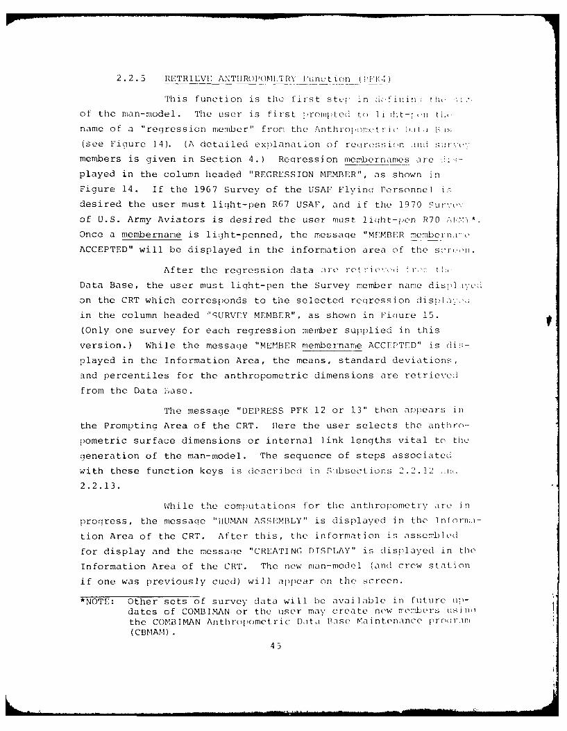
2.2.5 RETRIEVE ANTIIROMITRY Function ('F 4:PM
This function is the first ste:, in iinin : th ,; 1
of the man-model. The user is first prompted to Ii ih t-, 'n til,
name of a "regression member" from the Anthropomet ri, i)uit.i i i.;
(see Figure 14). (A detailed explanation of reiiression .ind swrlvo
members is given in Section 4.) Regression membernames are <i<;-
played in the column headed "REGRESSION MEMBER", as shown in
Figure 14. If the 1967 Survey of the USAF Flyina Personnel iF
desired the user must light-pen R67 USAF, and if the 1970 Surve,v
of U.S. Army Aviators is desired the user must light-pen R70 A,}.
Once a membername is light-penned, the message "MEMBER memberni : 0
ACCEPTED" will be displayed in the information area of the s.roon.
After the regression data a-tre retl-ievce r'- tilt
Data Base, the user must liqht-pen the Survey member name displa.,;d
on the CRT which corresponds to the selected regression display,,,:
in the column headed "'URVEY MEMBER", as shown in Ficiure 15.
(Only one survey for each regression member supplied in this
version.) While the message "MEMBER membername ACCEPTED" is dis-
played in the Information Area, the means, standard deviations,
and percentiles for the anthropometric dimensions are retrieved
from the Data base.
The message "DEPRESS PFK 12 or 13" then ar~pears in
the Prompting Area of the CRT. Here the user selects the anthro-
pometric surface dimensions or internal link lengths vital to the
generation of the man-model. The sequence of steps associated
with these function keys is described in Suibsections 2.2.12 ,i.
2.2.13.
While the computations for tile anthropometry are in
progress, the message "HUMAN ASSEMBLY" is displayed in the 1nfonla-
tion Area of the CRT. After this, the information is assembled
for display and the message "CREATING DISPLAY" is displayed in the
Information Area of the CRT. The new man-model (and crew station
if one was previously cued) will appear on the screen.
*NOTE: Other sets of survey data will be available in future tip-
dates of COMBIMAN or the user may create new rembers usinthe COMBIMAN Anthropometric ),ata Base Maintenance pro(rIPI(CBMAM )
45
R1t UStAF
(Inc
L.P SURVEYNAME
MEBR W UAFACPE
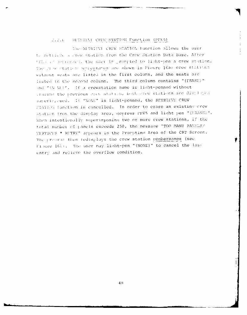
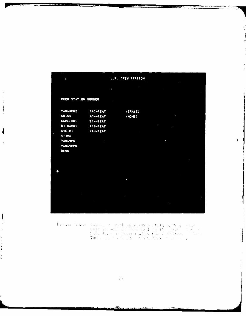
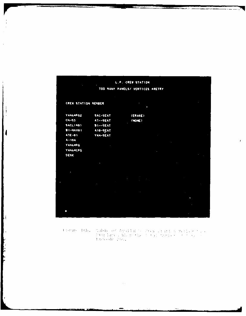
' . Id T l'I' 'ili. CBI'W STIATION Function (iPY 5)
T I I. tPI 'VI CRIW STATION functi on .1l]ows the user
t. I tt 1 "' . r ' ; " t it ion t- r i, the Crew Itition Data Base. After
t. user is ,rOted to liaht-pen a crew station.
1 ' t It 1, en Ie npes i rt- shnown i n "i ou re 16a ; crew sta1ti, ios
;itn-uet .etts ar listed in the first column, and the seats are
iisitd in the second column. The third column contains "(FRASI'"
n ' " Ni) ". If a crewstation name is liaht-penned without
,2 1 2:3 1 t!e :re\ious -I st t -, st ih, V-tl -. e%' stati,- ns are' Cis"'], 1 ,,1
3 J ta t'1os1'd. If "-NONI " is lioht-penned , the RETRIEVE CREW
IA'i , :wfction is cancelled. In order to erase an existins crew
t,iti ,n 4 ron. thei di s} lay area, depress PFK5 and liqht pen "(AIP:xSE)
Xhen intentionally superimposinq two or more crew stations, if the
total numlber of panels exceeds 250, the messaqe "TOO MANY PANE.LS/
V[RTICIS * RPETRY" appears in the i'ror-'ptinu Area of the CRT Screen.
The T ro,:r in thicn redisilays the crew station membernames (see
I'i :urc 104 . The user may liolht-pen "(NONE)" to cancel the las
,ntrY," ind relieve the overflow condition.
48
S -
L.P. CREW STATION
TOO N&MY PAMELSi VERTICES *RETRY
CREW STATION "C"BER
Y4%44PG2 SAC-SEAT (ERASE)
Al--SEAT (NONE)
S&CL(40) 9 1 -- SIE hT
4to-SEAT
41E -0 1
YA"44PG
VA"44tpG
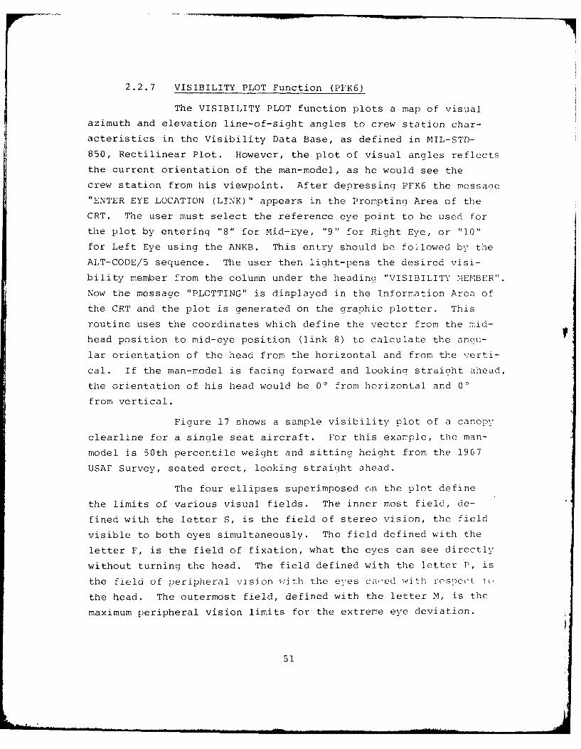
2.2.7 VISIBILITY PLOT Function (PFK6)
The VISIBILITY PLOT function plots a map of visual
azimuth and elevation line-of-sight angles to crew station char-
acteristics in the Visibility Data Base, as defined in MIL-STD-
850, Rectilinear Plot. However, the plot of visual angles reflects
the current orientation of the man-model, as he would see the
crew station from his viewpoint. After depressing PFK6 the messane
"ENTER EYE LOCATION (LINK)" appears in the Prompting Area of the
CRT. The user must select the reference eye point to be used for
the plot by entering "8" for Mid-Eye, "9" for Right Eye, or "10"
for Left Eye using the ANKB. This entry should be followed by the
ALT-CODE/5 sequence. The user then light-pens the desired visi-
bility member from the column under the heading "VISIBILITY MEMBER".
Now the message "PLOTTING" is displayed in the Information Area of
the CRT and the plot is generated on the graphic plotter. This
routine uses the coordinates which define the vector from the mid-
head position to mid-eye position (link 8) to calculate the ancu-
lar orientation of the head from the horizontal and from the verti-
cal. If the man-model is facing forward and looking straight ahead,
the orientation of his head would be 00 from horizontal and 0'
from vertical.
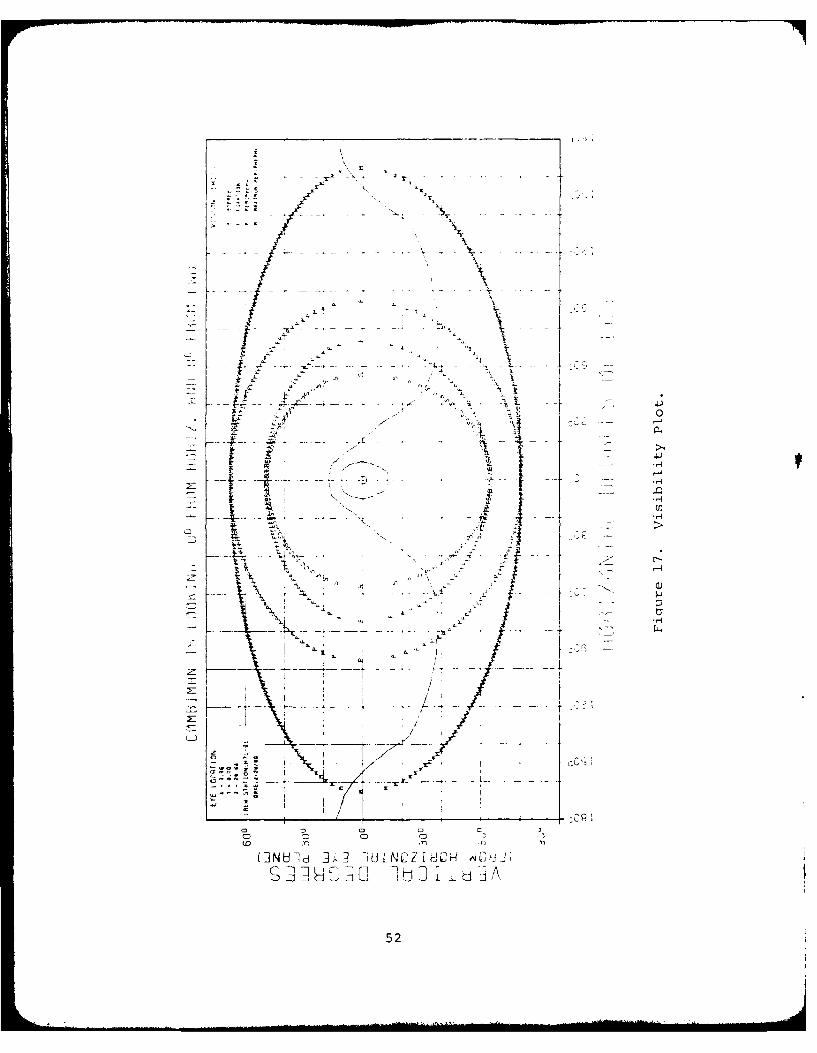
Figure 17 shows a sample visibility plot of a canopy
clearline for a single seat aircraft. For this example, the man-
model is 50th percentile weight and sitting height from the 1967
USAF Survey, seated erect, looking straight ahead.
The four ellipses superimposed on the plot define
the limits of various visual fields. The inner most field, de-
fined with the letter S, is the field of stereo vision, the field
visible to both eyes simultaneously. The field defined with the
letter F, is the field of fixation, what the eyes can see directly
without turning the head. The field defined with the letter F, is
the field of peripheral vision with the eyes ca'-ed with respect to
the head. The outermost field, defined with the letter M, is the
maximum peripheral vision limits for the extreme eye deviation.
51
rr
IL
:1 4.
-4L4
ftLi>.
2I H , 1 -i Lz NCZIH H AV
52 :
=mo
The symbol is the aim point of the head (and eyes if the eyes
are caged forward with respect to the head). The vision Limits
are generated with respect to the angle of sight from the Mid-F:ye
point (link 8 end point).
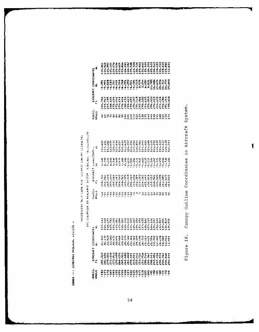
In addition to generating a hard copy plot, the
routine also calculates and prints a cross-reference listing of
the three dimensional coordinates of the objects plotted in five
degree azimuth increments from -180' from horizontal line of sic;ht
to +1800 for each panel and/or contour in the visibility member.
This listing is a handy reference to the crew station drawings.
The coordinates are given in the original user-supplied system
of coordinates rather than the NSRP system of coordinates used
elsewhere (see Parag raph 5.3.2.1). The listino also ;ives tho
coordinates of the eye location of the man-model. Figure L3 shows
a part of the coordinate data for the plot in Figure 17.
53
0
og U
- iii'.t 11 1111 lNNN
-- 4- { i l i l l l.
4g
S.,l l i l l l l l l l l
45
4.
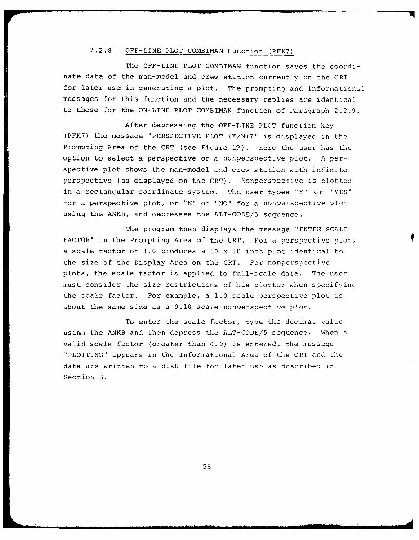
2.2.8 OFF-LINE PLOT COMBIMAN Function (PFK7)
The OFF-LINE PLOT COMBIMAN function saves the coordi-
nate data of the man-model and crew station currently on the CRT
for later use in generating a plot. The prompting and informational
messages for this function and the necessary replies are identical
to those for the ON-LINE PLOT COMBIMAN function of Paragraph 2.2.9.
After depressing the OFF-LINE PLOT function key
(PFK7) the message "PERSPECTIVE PLOT (Y/N)?" is displayed in the
Prompting Area of the CRT (see Figure 19). Here the user has the
option to select a perspective or a nonperspective plot. A per-
spective plot shows the man-model and crew station with infinite
perspective (as displayed on the CRT). Nonperspective is plotted
in a rectangular coordinate system. The user types "Y" or "YES"
for a perspective plot, or "N" or "NO" for a nonnerspective plot
using the ANKB, and depresses the ALT-CODE/5 sequence.
The program then displays the message "ENTER SCALE
FACTOR" in the Prompting Area of the CRT. For a perspective plot,
a scale factor of 1.0 produces a 10 x 10 inch plot identical to
the size of the Display Area on the CRT. For nonpersoective
plots, the scale factor is applied to full-scale data. The user
must consider the size restrictions of his plotter when specifying
the scale factor. For example, a 1.0 scale perspective plot is
about the same size as a 0.10 scale nonoerspective plot.
To enter the scale factor, type the decimal value
using the ANKB and then depress the ALT-CODE/5 sequence. When a
valid scale factor (greater than 0.0) is entered, the message
"PLOTTING" appears in the Informational Area of the CRT and the
data are written to a disk file for later use as described in
Section 3.
55
I iqu re 19. 'ho Messac and a ReT nsc fri ti (> X!1'10t FUTIet i Cn.
2.2.9 ON-LINE PLOT COMBIMAN Function (PFK8)
The ON-LINE PLOT COMBIMAN function generates on-line
plots of the man-model and crew station configuration currently
shown in the Display Area of the screen. After depressing the ON-
LINE PLOT function key (PFK8), the user has the option of select-
ing a perspective or a nonperspective plot (see Paracraph 2.2.8)
The program displays the message "PERSEPCTIVE PLOT (Y/N)?" in the
Prompting Area of the CRT. The user must respond "Y" or "YES" for
a perspective plot, or "N" or "NO" for a nonperspective plot,
from the ANKB.
The program then displays the message "ENTER SCALE
FACTOR" in the Prompting Area of the CRT (see Paragraph 2.2.8).
To enter the scale factor, type the decimal value using the ANKB
and then depress the ALT-CODE/5 sequence. When a valid scale
factor (greater than 0.0) is entered the proaram displays the
message "PLOTTING" in the Informational Area of the CRT, and the
plotter generates the image. Note that the scale factor is applied
to the display image size for perspective plots, but to the full
scale coordinates for nonperspective plots.
57
2.2.10 PRINT DATA Function (PFK9)
The PRINT DATA function prints man-model and crew
station data. The man-model data consists of, for each link the
x, y, and z coordinates of the distal end of each link, the trans-
formation angles for each link, and the enfleshment semi-axes
lengths at the distal end of the link.
Data, for the crew station currently being displayed,
consits of the name, type, and x, y, and z coordinates for each
vertex of each panel. The coordinates of each control of the
displayed crew station together with its name and name of the panel
it is located on, if any, are also printed. An example of the
output generated by the PRINT DATA function is shown in Figure 20.
58
- .~t .d' .. ~ . 7 .
* 4-)
....... .. ....
i
-. 4
I I 00 0 0 0 i 0
-I I I - II~~~~ 0 0 00 0 000 00 0 v0 0
, 4 .
0 Z 1 I - IIII I I !
- W
S: 00 00059
3f - -00 0- -0O 00-00-00-000- 000
2:j
I In
I Z
ZD I - - -A 4~
-, z 59
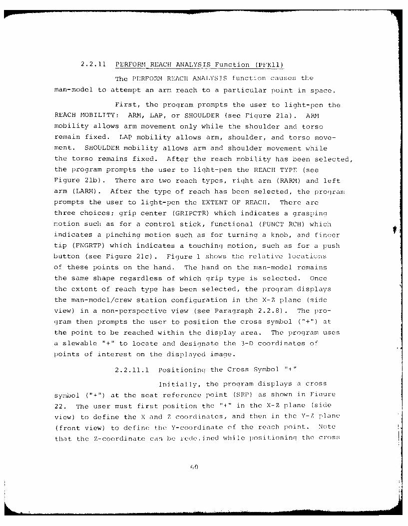
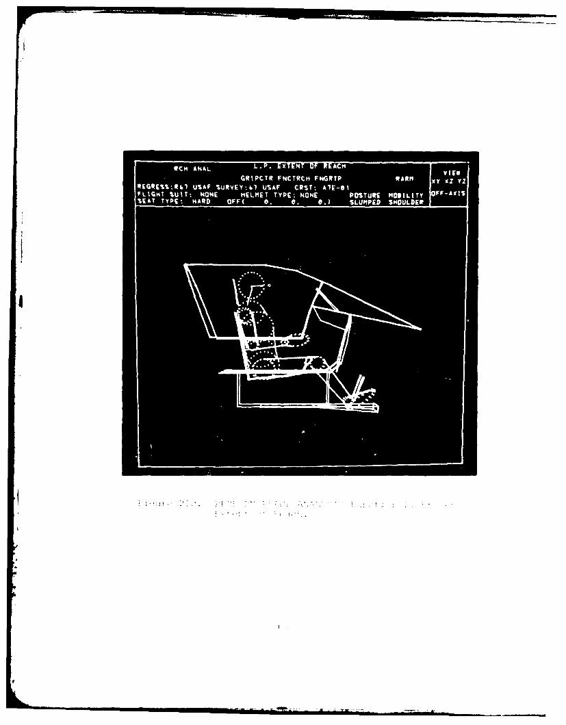
2.2.11 PERFORM REACH ANALYSIS Function (PFKll)
The PERFORM REACH ANALYSIS function causes the
man-model to attempt an arm reach to a particular point in space.
First, the program prompts the user to light-pen the
REACH MOBILITY: ARM, LAP, or SHOULDER (see Figure 21a). ARM
mobility allows arm movement only while the shoulder and torso
remain fixed. LAP mobility allows arm, shoulder, and torso move-
ment. SHOULDER mobility allows arm and shoulder movement while
the torso remains fixed. After the reach mobility has been selected,
the program prompts the user to light-pen the REACH TYPE (see
Figure 21b). There are two reach types, right arm (RARM) and left
arm (LARM) . After the type of reach has been selected, the proqram
prompts the user to light-pen the EXTENT OF REACH. There are
three choices; grip center (GRIPCTR) which indicates a graspina
motion such as for a control stick, functional (FUNCT RCH) which
indicates a pinching motion such as for turning a knob, and finqer
tip (FNGRTP) which indicates a touching motion, such as for a push
button (see Figure 21c) . Figure 1 shows tie relative locations
of these points on the hand. The hand on the man-model remains
the same shape regardless of which grip type is selected. Once
the extent of reach type has been selected, the program displays
the man-model/crew station configuration in the X-Z plane (side
view) in a non-perspective view (see Paragraph 2.2.8). The pro-
gram then prompts the user to position the cross symbol ("+") at
the point to be reached within the display area. The program uses
a slewable "+" to locate and designate the 3-D coordinates of
points of interest on the displayed imaqe.
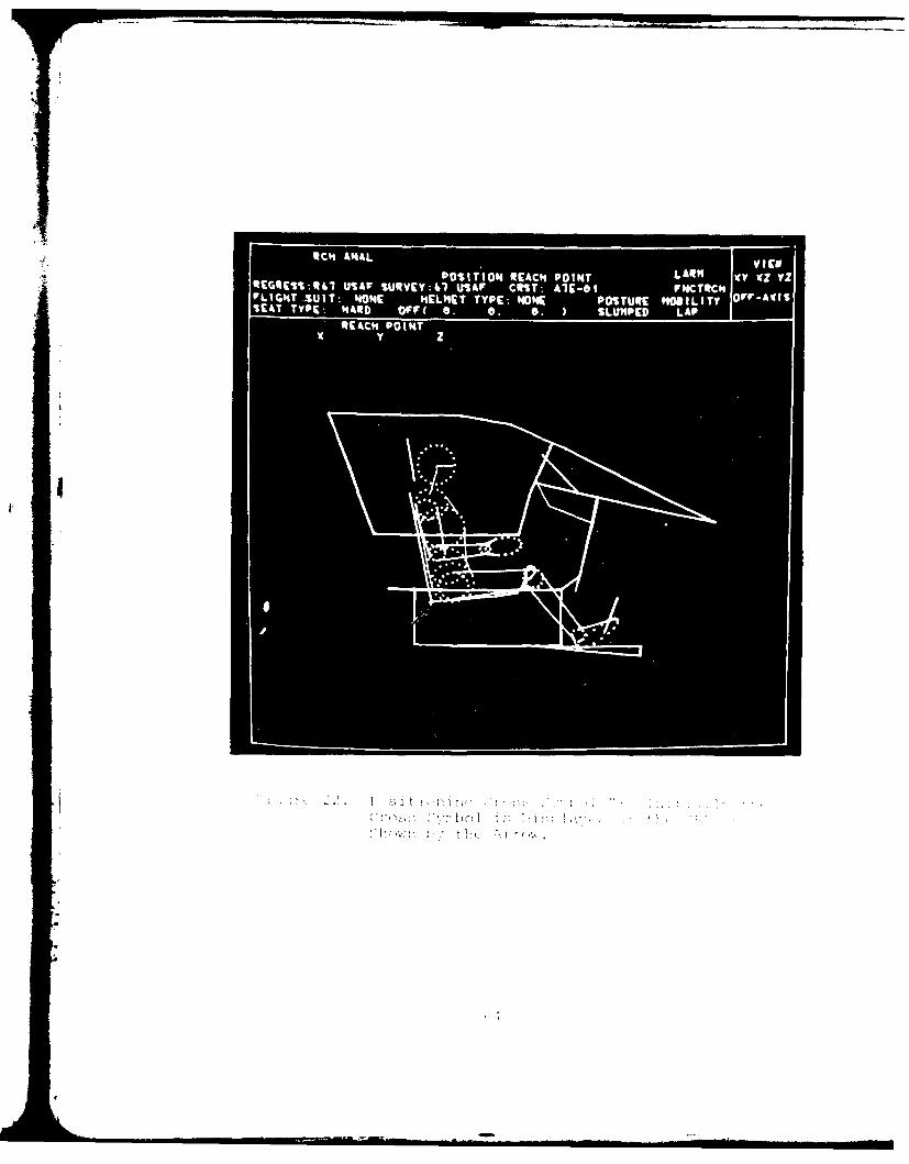
2.2.11.1 Positioning the Cross Symbol "+"
Initially, the program displays a cross
symbol ("+") at the seat reference point (SRP) as shown in Fioure
22. The user must first position the "+" in the X-Z plane (side
view) to define the X and Z coordinates, and then in the Y-Z plane
(front view) to define the Y-coordinate of the reach point. Note
that the Z-coordinate can be yede, ined while positioning the cross
60
Vito
AR LA SHULE If -y
1S S EY4 USA IRT, Al-
FL G T S I : N N E M T T P : N N O T R O I I Y O F Af%[&TTYP t HND FF( 0. 0 0. SLMPED SMOLDE
Ii ~ 21. I I
RC NLETETO EC
GRPT NTC NRPRR
Wt ANAV U ~i L ii I-- 1 (JPOI 10 RA"P I LAO
USFSIE:1UA OT I-1FCRH
!*IN SUT- 40M it "TTP:NN PSUC "DL
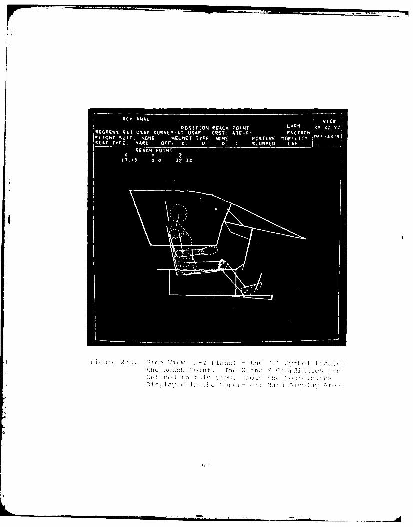
in the Y-Z plane. Figure 23a and 23b show the man-model in the
X-Z and Y-Z planes respectively with the "+" at a point to be
reached on the instrument panel. Positioninq the "+" is achieved
using the Proqram Function Keyboard as described in the followin!
paragraph.
The PFKs are temporarily redefined as
shown in Figure 24. Their direction and magnitude of movement
are indicated inside the circles representing the PFKs in the
figure. By selecting the proper PFK, the "4" can be moved up,
down, left, right, or combinations of these, at two different
speeds. For example, depressing PFK7 causes the "+" to move up
and right in one inch increments at a rate of approximately 25
steps per second.
Once in motion, the direction and/or
magnitude of movement of the cross can be changed simply by de-
pressing another directional PFK. The motion may be stopped by
depressing the STOP/RECORD key (PFKi2) once, or depressing the
SINGLE STEP ON key (PFK26). After depressing the STOP key, motion
can be continued by selecting any other key. As soon as the cross
is near the desired point, depress the SINGLE STEP ON key (PFK26).
This stops automatic motion of the cross, allows the cross to be
moved in single steps of 0.1 or 1.0 inch each time a directional
key is depressed. In this way, the cross may be positioned pre-
cisely by (1) monitoring the position of the cross relative to
the displayed image, or (2) monitoring the X, Y, Z Coordinate Read-
out (see Figure 23a) which appears in the upper-left part of the
Display Area when this function is in progress. This latter method
is to be used when the coordinates of the point are known. Note
that these coordinates are in the Seat Reference Point coordinate
system. Also note that this is different from the NSRP (&eutral
Seat Reference Point) when the SEAT ADJUST function is used to
displace the seat.
To locate and enter a 3-D coordinate set
proceed as follows:
65
r i,:ure 23>. Side View /X- Ii n ) -th ' W:1c,] ,CC:,itQ..the Reach P int. I nrdi ptes. aYhe fined in tnis View . ,Noto tUSA C so1-0 i atesDii awe in thE HlEr-METft TYPE:'NN DPOSTUR]M. Ar,
SEATTYPE HAD OF( 0 0. . SUMPE(LA
.31
RC N LP S T O EA H P I TLA MW
yh 7
KU K,,. KU 'U KU,. KU Kt U KU .IBM PART NO 5704496
0U 0 2T3
D NUP AND D NUP AND
LEFT 1.0" UP 1.0' RIGHT 1.0"
4 5 6INGL 9 1NL___________ ___________ STOP' ______ ______ ______
LEFT 0. 1" LE FT 1. 0" RECORD RIGHT 1.0- RIGHT 0.1' - ____
________ DOWN AND _ _____ DOWN AND ______ ______
__________ LEFT 1.0" DOWVN1.0" RIGHT 1.0" ______ ______
'6 I?(D 1 20 21
____________~~~~~~ I______ __ ____ _______ SNGLE S ING LEDOWN 0.1" STEP ON STEP OFF
2223 ?CD 25 ) 26 27
28 29
30D 30
Figure 24. Redefined Program FUNCTION Keys for Positionin"the "+" Symbol.
68
" When the "+" is to be used to locate a point, the display
automatically transitions to a side view (XZ plane)." Move the cross to the desired location in the side view
by the method described above.
* Depress the STOP/RECORD key (PFKI2) twice in succession
to enter the X coordinate.
" The display automatically transitions to a front view
(YZ plane).
" Use the left or right direction keys to position the
cross in the Y direction.
NOTE: If the cross is moved up or down, the Z coordinate
is redefined.
" Depress the STOP/RECORD key (PFKI2) twice in succession
to enter the Y and Z coordinates.
* The display automatically transitions to the orientation
in use at the time the PERFORM REACH function was acti-
vated.
Now the PFKs are reset to their original
definition and the man-model begins to reach toward the specified
point in three to six discrete steps. When the reach is success-
ful, "REACH SUCCESSFUL" is displayed in the Informational Area of
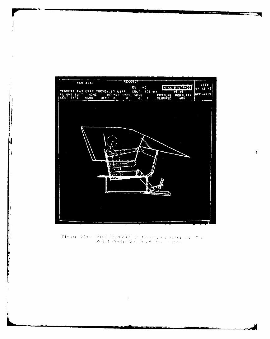
the display (see Figure 25a). If the man-model could not reach
the point, the message "MISS DISTANCE" and the miss distance value
in inches are displayed in the Information Area of the CRT display
(see Figure 25b).
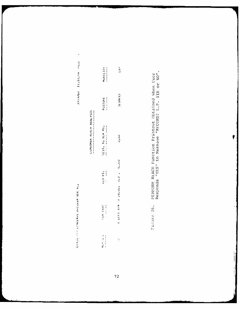
2.2.11.2 Post Reach Processing
Following the reach, the user must light-
pen the response "YES" or "NO" to the promptinq message "RECORD?"
(see Figures 25a or 25b) . If the user's response is "YES", a
summary of the reach analysis as shown in Figure 26 will be printed
out. If the user's response is "NO" there will be no printed out-
put.
69
I I ANALI IVirg
0 E OsIx zY
REGRSS:kl UAF Ij~vy 4 USA CRT AE-0
FLIGNT~~~~~~~~~~ SUT.4M E7TTP NNE PSUEMBLT frA
v IIEl
RCGR JSib. USAF SUVC:4 USAFK KRT AI20 ss~
. I V I ' > t P . ,
* 0
-P0
0
4 -3
0 0
-4'4
4'
2L1
=1 72
The message "CONTINUE REACH?" is then
displayed in the Prompting Area of the CRT screen. If the user
wishes to continue the reach analysis with the same arm or have
a two arm reach, he must light-pen "YES". In this case the pro-
gram will restart the reach routine and will prompt the user to
light-pen the reach type (see Paragraph 2.2.11). If the user
desires a two arm reach, he must light-pen "LARM" if the first
choice was "RARM" and vice versa. When a two arm reach is exe-
cuted, the first reach determines the position of the shoulder
and trunk. The reach by the remaining arm is an "arm only" type
of reach, without shoulder or trunk movement. If the user light-
pens "NO" the program progresses to display the next message
"RESET POSTURE?". If the user light-pens "YES" the program resets
the man-model to the posture before the reach attempt. If the
user light-pens "NO" the man-model remains in the reaching posture.
At this point the reach routine returns control to the main progra.
73
2.2.12 INPUT 12 ANTHROPOMETRIC DIMENSIONS Function (PFK12)
This is one of two methods of defining the body-
size of the man-model. The other is described in Paragraph 2.2.13.
The INPUT 12 ANTHROPOMETRIC DIMENSInNS function allows the user
to supply values, either as percentiles or as absolute dimensions,
for each of the dependent anthropometric variables necessary to
construct the link system of the man-model. This function can be
selected by depressing PFKI2.
After PFK12 is depressed, the message "CARD INPUT?
(Y/N)" is displayed in the Prompting Area. The user may type in
the response "YES" or "Y" to read the 12 anthropometric dimensions
from input cards in the format shown in Figure 27. If the response
is "NO" or "N" followed by the ALT CODE/5 sequence, or simply
the ALT CODE/5 sequence, the message "WILL VALUES BE IN PERCENTILES?"
will be displayed in the Prompting Area of the CRT.
The user must type in "YES" or "Y" as a positive or
"NO" or "N" as a negative response to this prompting message.
If the response is "YES" or "Y", the user should respond to the
prompt "L.P. PERCENTILE" by light-penning the appropriate percent-
iles for each dependent variable as they ar:e automatically under-
lined. The first two variables have been thus defined in Fiqure
28.
If the response is "NO" or "N" (the values will not
be percentiles, but engineering units) the values for the 12 units
must be keyed in as the 12 variable names are sequentially under-
lined. The procedure is as follows:
9 The first variable name will be underlined, and the
message "ENTER NEW VALUE" appears in the prompting areai
(see Figure 29).
e The user types in the numeric quantity. This is follo':ved
by ALT-CODE/5 sequence to enter the value.
74
. ,...
•• •
(0j
. .. 4' '.. fl " .. . . . . ... 4... ... .. --
. . . . . . .. . . . . . . . . . c.N' n -Df *4 3 T -a 41 *f'N
-4-
• • . • • • • • • , , , . • • • • • . . . El
75
II I II II III II z . . . r...
71
L.P- PERCENTILE
MEMIER 41 USAF ACCEPTED AvIL A VOL
DEPENDE14T VBLS UNIT INPT DM UNITS PCTL
WEIGHT LO 'VS PtT IN 23%ITTING, "EIGHT IN SS PtT s
IN 14
KNEE MGT/%ITTING IN 20
OUTtOCK-KNE LGT" IN KG n30
S"OULDR-ELD LGTM IN ss
BlAtROMIAL 9RDTM IN :so
HIP OREADTH t-4 ssCHEST DEPTH IN i.0
6sFOOT LENGTH IN '10
isHAND LENGTH IN as
ssELDOW-WRIT LGTH IN
is
ENTER MEN VA LUE
MEMBER 4T USAF ACCEPTED AVIL AWDL
DEPENDENT VIL% UNIT INPT D" UNITS PICTL
WEIGHT L9 I'll.se IN
%lTllMG-bfiLGbl-- IN C" 3
AtQO"I0N HOT/SIT IN
KNEE MOTISITTIkG IN Ll 20249UTTGCI(-KNE.LGTH IN CG
%MOULD*-ELD LGTH IN
SIACOOMIAL BROTH IN
HIP BREADTH IN ofCHEST DEPT" IN
64FOOT LENGTH IN isHAND LENGTH IN is
ELDON-W*IT LOTH IN
0
* Next the user must identify the units of measure for the
quantity entered in the previous step.
NOTE: Since these units are declared for each number
entered, the numbers need not be in the same
units, that is, inches, centimeters, and milli-
meters; and pounds and kilograms. These units
may be mixed as desired. After the quantity is
entered, the prompt "L.P. NEW UNIT, IF DESIRF"
appears. The user selects the appropriate unit
of measure with the light pen. Alternatively,
since pounds and inches are the default units of
measure, the user may select these by using the
ALT-CODE/5 sequence rather than the light pen.
9 These steps are repeated until all 12 variables are de-
fined.
NOTE: While values may be entered in any units of mea-
sure, they are converted to pounds or inches for
processing, display, and printouts.
The last message while using this function is "TABLE
OF LINK DATA (Y/N)." To scan the table of link data, which in-
cludes link names, lengths and transformation anqles, and to make
changes, the user should type "YES" or "Y" and then depress the
ALT-CODE/5 sequence. If not, the user depresses the ALT-CODE/5
sequence. Instructions on changing the contents of the table will
be (liven in Paragraph 2.2.14.
7 8
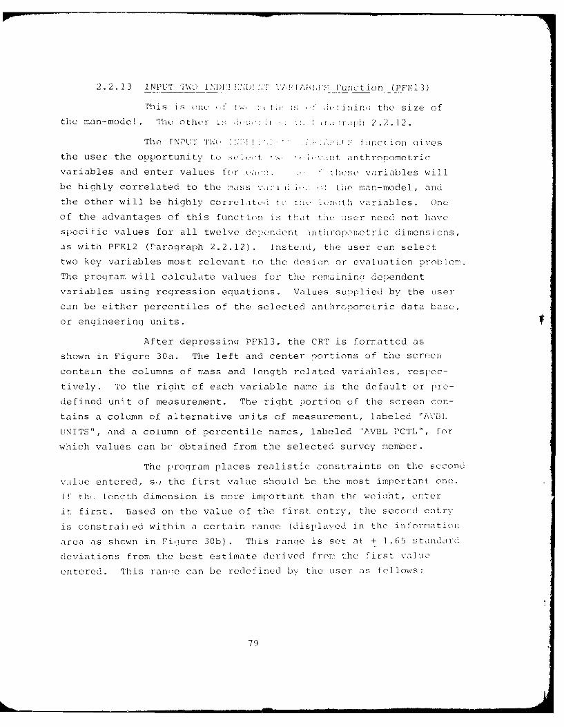
2.2.13 INPUT TWO 01:1 11t)! /T ,,AU Junction (PFK13)
This is one, t:, '1 _.inin(: the size of
the man-model. The other i, ,,'r , :. ,1 th 2.2.12.
The INPUT TW ,I I function oives
the user the opportunity to s1l:-t ' nt inthropometric
variables and enter values for ,<. t he se variables will
be highly correlated to the mass v ' the -man-model, and
the other will be highly correlatc., t t!i _, o n:th variables. One
of the advantages of this functi(,n is that tm user need not have
specific values for all twelve depeindent nthropometric dimensions,
as with PFK12 (Paragraph 2.2.12). Insteald, the user can select
two key variables most relevant to the desio:n or evaluation problem.
The program will calculate values for the remaininq dependent
variables using regression equations. Values supplied by the user
can be either percentiles of the selected anthropometric data base,
or engineering units.
After depressing PFKI3, the CRT is formatted as
shown in Figure 30a. The left and center portions of the screen
contain the columns of mass and length related variables, respec-
tively. To the right of each variable name is the default or pro-
defined unit of measurement. The right portion of the screen con-
tains a column of alternative units of measurement, labeled "AVBIL
UNITS", and a column of percentile names, labeled 'AVBL PCTL", for
which values can be obtained from the selected survey member.
The program places realistic constraints on the second
value entered, s,; the first value should be the most important one.
if th,: len(-th dimension is more important than the weioht, enter
it first. Based on the value of the first entry, the second entry
is constraiied within a certain rane (displayed in the information
area as shown in Fiiure 30b). This ranqe is set at + 1.65 standard
deviations from the best estimate derived from the first value
entered. This ranoe can be redefined by the user as follows:
79
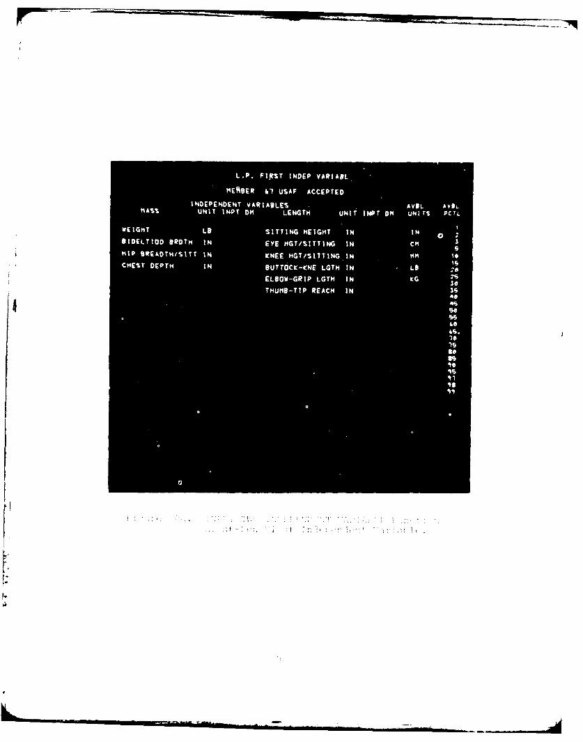
L. .FI% N E A IR I
HEADER 41UA ACPE
INEPNDN VAIBE IL b.
" A %UIrM T D L N T N T I P D N T C TWEGTL ITNGHIH NI
BIETO RT NEY G/.TN NC"1 IEDMST NKNEMTSTIGI i
a -- ~ ~mis
L.P. VIL IN OTHER COLUMN
MEMBER 41 USAF ACCEPTED
INDEPENDENT VARIABLES AVIL AVIL"A%% UNIT INPT OM LENGTH UNIT INPT DM UNITS PCTL
---------- LD IS PCT SITTING HEIGHT IN IN
SIDELTIOD BROTH IN EYE MGT/SITTING IN C"
HIP IREADTH/SITT IN KNEE MGT/SITTING IN M"
CHEST DEPTH IN BUTTDCC-KNE LGTH IN Lt
ELBOW-GRIP LGTH IN KG 2%s*
THUMB-TIP REACH IN so
soss
60
'70
Is
ss%*Is41
0
10 1
C c (,Ili
The first prompting message is "ENTER NEW Z-SCORE."I
This Z-score value is used in the equation which calculates the
range of permissible values for the second independent variable
selected. If the default value of 1.65 is retained, the permissible
range will include approximately 90% of all possible values for
the variable. Increasing the Z-score will increase the range;
decreasing it will decrease the range. The value the user types
in must fall between -3.0 and +3.0. If the default value of 1.65
is suitable, the user may respond by depressing the ALT-CODE/5
sequence. Otherwise, type the new value and enter it by the
ALT-CODE/5 sequence.
The next message is "WILL VALUES BE IN PERCENTILES?"
If the user's response is "YES" or "Y" or just the ALT-CODE/5
sequence, values will be input by light-penning a percentile from
the column "AVBL PCTL" (see Figure 30c). If the response is "NO"
or "N", values for the selected variables will be entered in Engi-
neering units using the alphanumeric keyboard. For values to be
input as percentiles, Table 1 shows the sequence of displayed
messages and user responses to be followed. If the values are
supplied through the alphanumeric keyboard, the user should use
Table 2 as a guide to the sequence of system messages and user
responses. Once the independent values are supplied, the program
calculates the surface dimensions required to construct the link
system of the man-model. These dimensions are calculated usinq
multiple regression equations from the selected regression member
with the user supplied dimensions.
The last message while using this function is "TABLE
OF LINK DATA (Y/N)." To scan the table of link data, which in-
cludes link names, lengths and transformation angles, and to make
changes, the user should type "YES" or "Y" and then depress the
ALT-CODL/5 sequence. If not, the user depresses the ALT-CODE1 /5
se(luenc,'. Instructions on changing the contents of the talil wil1
bu (iven in Paragraph 2.2.14.
Z-score represents the extent to which an individual value fallsabove or below the mean of a set of data.
82
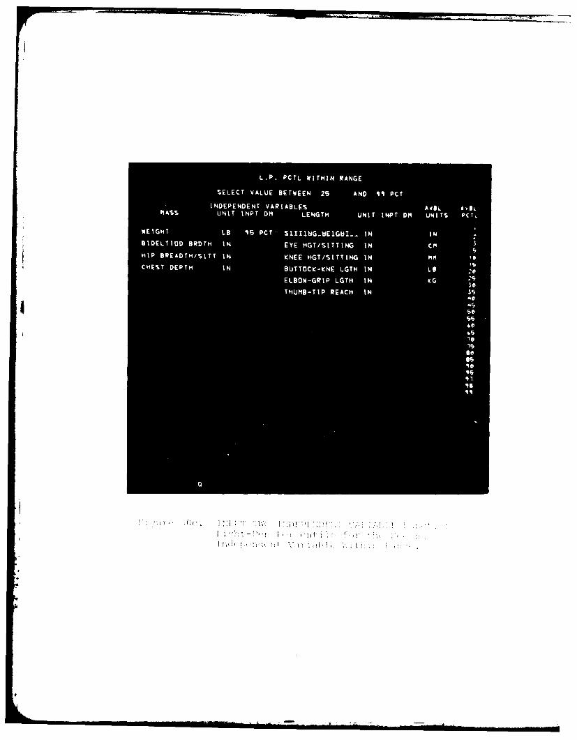
L. .P t IT I A G
SEEC VAU BEWE 2 N 1 C
INEEDN AIBE VLAI
MAS UNI INP DM LEGT UNT1- H UIS PT
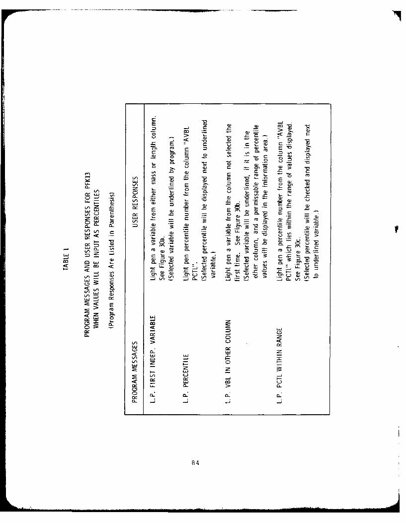
Cm
C o COa)
00 - CE) *
-L V =Q- 0 0 0n w
0) >m CL)a - m
E~ L CV) 0) C:~ E 0 )
o- Ln - to m -)~ L. 1E
m, m w- co cs W)~~~~~~L 0) L = - ) - C C E
u W : 7
~ = - 0 LELz m -c t)CL) m Lf, CU m L
_A _) CL VL< L nE - ~ a~0
0u
LU LW ~ L 0>
-) <) _ Z)E~
0 LU L-
-) C , C 0
<~ m
LCL
L/~84
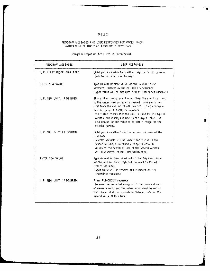
TABLE 2
PROGRAM MESSAGES AND USER RESPONSES FOR PFK13 WHENVALUES WILL BE INPUT AS ABSOLUTE DIMENSIONS
(Program Responses Are Listed in Parenthesis)
PROGRAM MESSAGES USER RESPONSES
L.P. FIRST INDEP. VARIABLE Light pen a variable from either mass or length column.(Selected variable is underlined)
ENTER NEW VALUE Type in real number value via the alphanumerickeyboard, followed by the ALT-CODE!5 sequence.ITyped value will be displayed next to underlined variable.
L.P. NEW UNIT, IF DESIRED If a unit of measurement other than the one listed nextto the underlined variable is desired, light pen a newunit from the column "AVBL UNITS". If no cnange isdesired, press ALT-CODE 5 sequence.The system checks that the unit is valid for the type ofvariable and displays it next to the input value. Italso checks for the value to be within range for theselected survey.
L.P. VBL IN OTHER COLUMN Light pen a variable from the column not selected thefirst time.(Selected variable will be underlined if it is in the
proper column: a permissible range of absolutevalues in the preferred unit of the second variablewill be displayed in the information area.)
ENTER NEW VALUE Type in real number value within the displayed range.via the alphanumeric keyboard, followed by the ALT-
CODE15 sequence.(Typed value will be verified and displayed next tounderlined variable.)
L.P. NEW UNIT, IF DESIRED Press ALT-CODE/5 sequence.iBecause the permitted range is in the preferred unitof measurement, and the value input must be withinthat range, it is not possible to change units for thesecond value at this time.)
85
2.2.14 DISPLAY TABLE Function (PFKI4)
The DISPLAY TABLE function gives the user the oppor-
tunity to inspect the table of link dimensions and angles and make
changes to any or all of the values, if necessary. Since the table
displays internal link lengths, the anthropometry of the man-model
should be defined prior to using this function. Fiqure 31a shows
an example of a Display Table.
The user can modify the values in the Display Table
by light-penning the value to be changed, typing a new value, and
depressing ALT-CODE/5 (see Figure 31b). When all changes are made
the user depresses ALT-CODE/5 again. The transformation angles
in this display can be modified to place the man-model in any
desired position (see Paragraph 2.2.20).
Other than the choices of slumped or erect posture,
and the reposturing in the reach analysis, using the LINK TABLE
to change the joint angles is the user's most important method to
change the body position of the man-model. To properly use this
table refer to Table 3 for all link definitions.
As described in Section 1, the link system is a
series of vectors added together. Each link vector has a local
coordinate system with its origin at the distal end. The orienta-
tion of the next distal link is defined in this local coordinate
system. The Phi, Theta, and Psi correspond to Euler anqles as
shown in Figure 32. Since these local coordinate systems are
usually not aligned with the base system, no rule can be qiven for
selecting a particular direction of movement. The user should
try angular changes one-by-one to verify desired results.
86
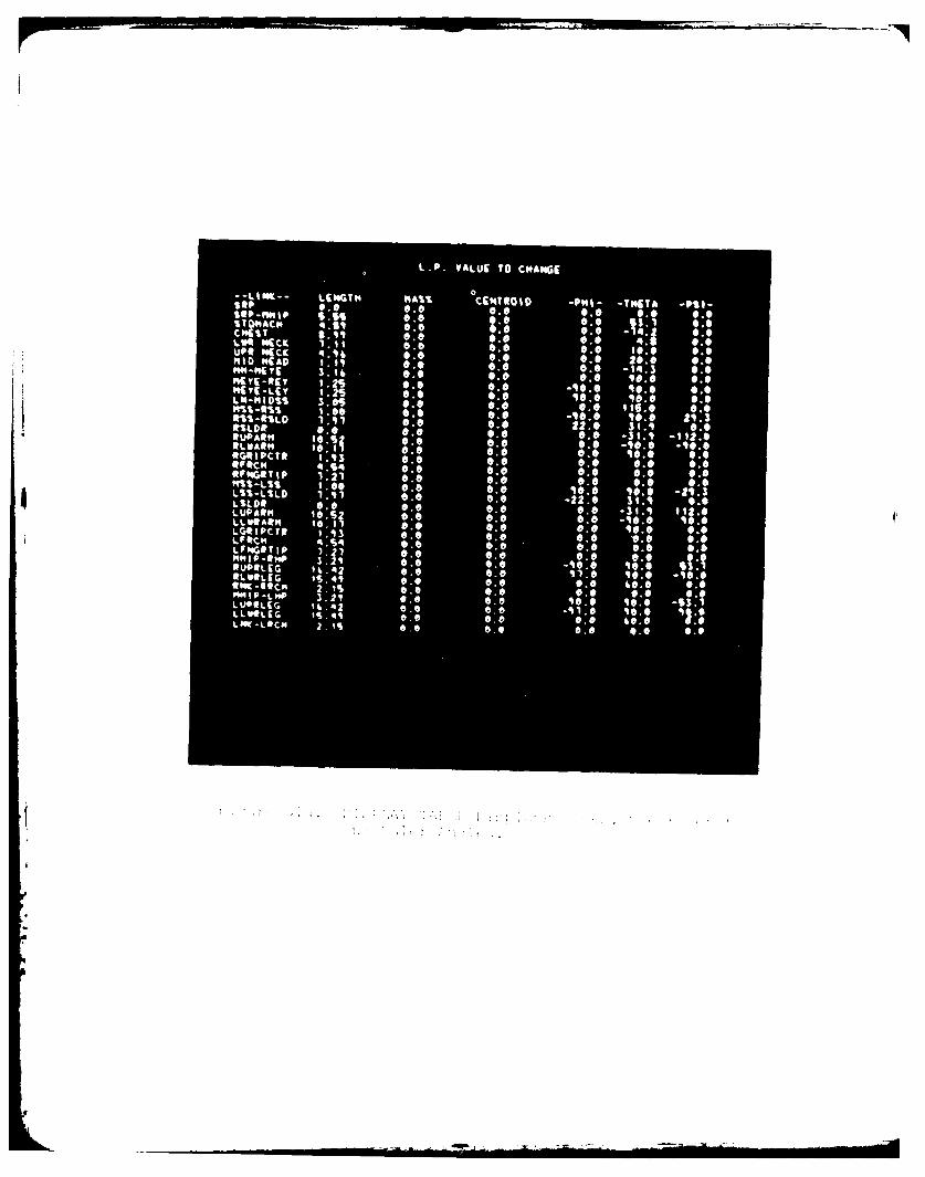
L.P. VALUE TO C"ANGE
0 CIN"Olp-TI49TA -0%1-
0.0 0.010O.NHIP 0.0 -11 1 0.0%TO"Acm 0:0 0.0 4CNCT 0.0 0.0 1 0 : 0
Lv* OKC-K 0.0 0.0up* $Ica 4.416 IN :.090.0 0.0 28HIO AD 1.11t 0.0 0.6 0.6 -14""-"EYE S. 16, : so0.0 0.0 0.0"EYE-REY 0.0 0.0 -110.0"Eyt-LEY 0.0 0.0 110.0LN-MiDS1 0.0 8.0 0.01.00 0.0 0.0ots -110.6%-WSLD 1.111 0.0 0.0 22.0 31.9 0.0MON 0.0 0.0 0.0 0 -3 t.,t*UPA*" I* Si
0.0 0.0
QL 1 0:1 0.0 -10.0 -10.0*GQWAI:C"T* l.i3 Wo 0.0alrec" 6.0 0.0 0.0 0 Ceof TIP 4:S4 0.0 0.0 :-0 0.6WIN 1 21 0.0 0.0 0.0 0.6"%%-L% 1.00 0.0 0.0 190.0 1*.* - 1.3L%%-LSLD 1.111 0.0 0.0 -22.* SIA 0ALSLOR 0.0 0.0LUPAQ" 0.0 Ito, : eq 148-46LLW*Altlq
0.0 0.0LGOIPCTO q0.6 ::G$:is 0:0 0.0 6.0 V.0 *.44.S4 0.6 0.0 0.0 0.0 0.0LFNGRTIP 1 0.0 0.03: 121 -4:: w 00:RUPOLEG 14.42 0.0 0.0
41 6.0 11.0 '10.0 -90.00.0 0.0
I p- L "P 0.0 0.0 0.0 0.03, 2v 10.0 _S1.1LLW* 6,0 6.6L G 0.0 0.0 60.0 .0Low -LfC14 6.0 S.0
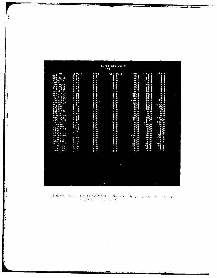
F
ENTER H(W VALUEIf*-
I-L I %a L FWGT M HAS% CIMTROID -PHI- -THETA -PSI-
%to $.# 0.0 0.0 0.0 0.00.0 7
S 10446c" 4. 1 1 4.0C-CIT 1.02 0.6 0.0.Wq 'Act. 1.14 0.6 0.0 10.8 0.0
'JpQ foict 4 . -to 0.6 0.0 0.0 20.0 #.*MID "(to 0. 14 1 0.6 0.0 0.0 -14.3 0.0"ft-mcli S.11 0.6 0.8 6.0 26-0-- 6.4mi't-0j, I is 0.0 0.0 110.0 o.$"Cl- Av , . IS 0.0 0.0 is.* 0.0
I DIL S .01 G.* 8.0 0.0 ITS"S 1.60 0.0 0'a -10.0 4 0:: 21 3M. D I . 2.q 0.0 0.0 22.0 3l.i Co
N't, DO 0.0 8.0 0.0 0.0 -31.1 -f?2.00 -v a 11 -4 10 . 4 4 6.0 6.6 0.6 -40.0 - is . 0#,#ARM to.11 6. v 6.0 0.0 is. 0 0.0or's I VC T I I . 1#2 0.0 6. 0 0.0 0.0 0.0 -7Or K . 4.sl 0.0 0.0 0.0 0.0 0.0
.23 6.8 6.0 0.0 a a 0.0
0.0 0.8 is. 0 io:o -21.3i's D $.1 0.0 0.6 -22.0 31.1 0.0%, :4p 0.9 0.0 6.6 8.0 -31 It 112.0
19.44 0.6 0.0 6.0 -is:$ Ito.0leil 0.0 6.6 0.6 116.0 6.0
-. 0 ' pe: '1 1,12 0.0 6.6 0.0 6 0 Cs4'. S 1 0.6 0.6 0:8 0.0
0 1,21 0.6 0.0 0 0 0.06-0-0 0.6 -140.6 116:0 93.1of - -40.0'j, 46.8
lp 09 - j 14 it 0.0 0.8 40.0 0.0114 0.8 8.0 0.0 0.*
J.:t a, f We _S3.1_41'a 40.6 We0.6 ie.o 8.0
2 e'a
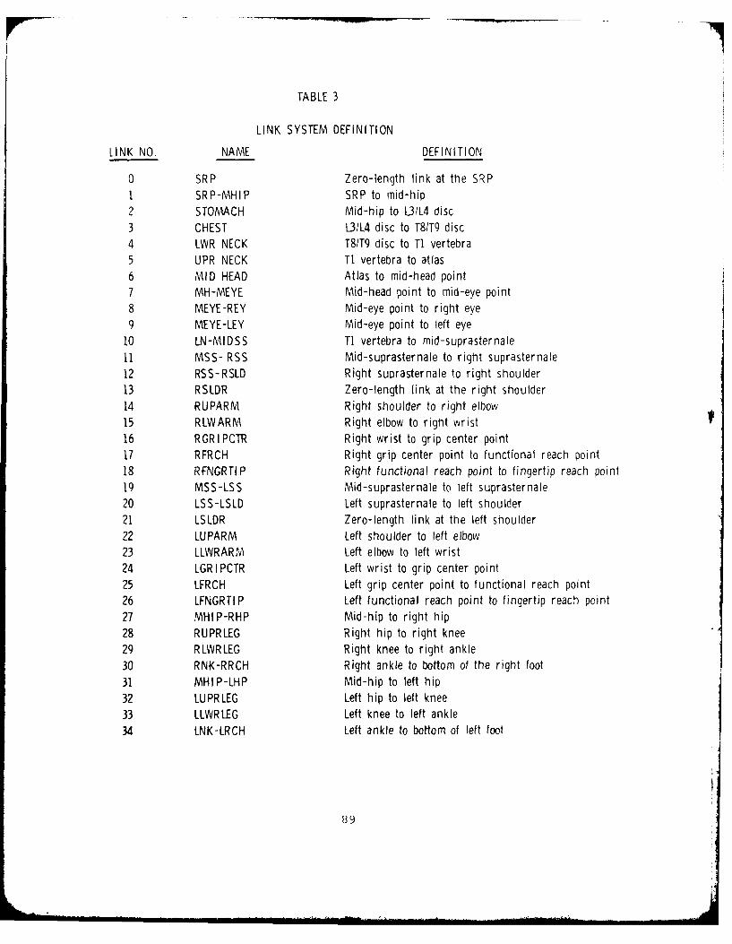
TABLE 3
LINK SYSTEM DEFINITION
LINK NO. NAME DEFINITION
0 SRP Zero-length link at the SRPI SRP-MHIP SRP to mid-hip2 STOMACH Mid-hip to 1L31L4 disc3 CHEST L31L4 disc to T81T9 disc4 LWR NECK T8/T9 disc to T1 vertebra5 UPR NECK T1 vertebra to atlas6 MID HEAD Atlas to mid-head point7 MH-MEYE Mid-head point to mid-eye point8 MEYE-REY Mid-eye point to right eye9 MEYE-LEY Mid-eye point to left eye
10 LN-MIDSS TI vertebra to mid-suprasternale11 MSS- RSS Mid-suprasternale to right suprasternale12 RSS-RSLD Right suprasternale to right shoulder13 RSLDR Zero-length link at the right shoulder14 RUPARM Right shoulder to right elbow15 RLWARM Right elbow to right wrist16 RGRIPCTR Right wrist to grip center point17 RFRCH Right grip center point to functional reach point18 RFNGRTIP Right functional reach point to fingertip reach point19 MSS-LSS Mid-suprasternale to left suprasternale20 LSS-LSLD Left suprasternale to left shoulder21 LSLDR Zero-length link at the left shoulder22 LUPARM Left shoulder to left elbow23 LLWRARM Left elbow to left wrist24 LGRIPCTR Left wrist to grip center point25 LFRCH Left grip center point to functional reach point26 LFNGRTIP Left functional reach point to fingertip reach point27 MHIP-RHP Mid-hip to right hip28 RUPRLEG Right hip to right knee29 RLWRLEG Right knee to right ankle30 RNK-RRCH Right ankle to bottom of the right foot31 MHIP-LHP Mid-hip to left hip32 LUPRLEG Left hip to left knee33 LLWRLEG Left knee to left ankle34 LNK-LRCH Left ankle to bottom of left foot
89
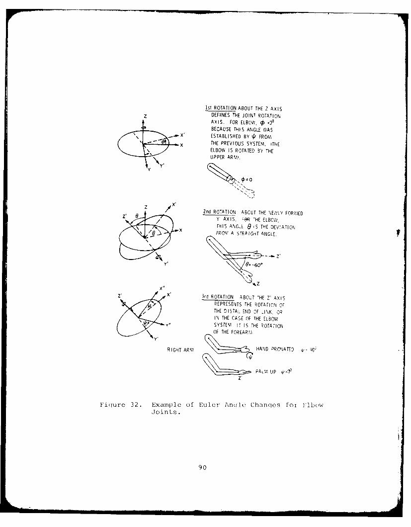
Ist ROTATION ABOUT THE Z AXIS
z DEFINES THE JOINT ROTATIONAXIS. FOR ELBOW, .00BECAUSE THIS ANGLE WAS
X ESTABLISHED BY 4/ FROM
X THE PREVIOUS SYSTEM. (THEELBOW IS ROTATED BY THEUPPER ARM,.
Y 0=0
2nd ROTATION ABOUT THE NEWLY FORMED
/ Y7 AXIS. F@R THE ELBOW,
THIS ANGLE e IS THE DEVIATIONFROM A STRAIGHT ANGLE.
z. X, 3rd ROTATION ABOUT THE Z' AXISREPRESENTS THE ROTATION OFTHE DISTAL END OF LINK ORIN THE CASE OF THE ELBOW
Y" SYSTEM, IT IS THE ROTATIONOF THE FOREARM.
RIGHT ARM HAND PRONATED p, 0o,Q
PALM UP p'0lZ'
Figure 32. Example of Euler Anqcle Chanqes for ILbowJoints.
90
2.2.15 DESIGN PANEL Function (PFKI6)
The DESIGN PANEL function allows the user to add a
panel to an existing crew station, or design a new crew station
by assemblina a series of new panels.
In response to prompting message "ENTER PANEL NAME"
the user must type a panel name of up to eight characters and
enter it by ALT CODE/5 sequence. To the prompting messaae "ENTER
PANEL TYPE" the user should enter a type number "I" for cieneral
crew station, "2" for seat panel, and "3" for rudder or brake pedal
through the ANKB followed by ALT-CODE/5 sequence. Finally as a
response to the message "NO. OF VERTICES" the user must supply
the number of vertices (maximum of six vertices) for the panel
being defined. Then with the cross symbol "+" and the lighted
PFKs (see Figure 22), the user defines the vertices of the panel,
one at a time, in the X-Z plane and then in the Y-Z plane usina
the method described in Paragraph 2.2.11.1*.
As mentioned in Paragraph 2.2.11, PFK12 is used to
stop the "+" while in motion. When depressed twice consecutively,
it implies the final location of the defined vertex. When sub-
sequent vertices are entered, they are automatically connected
by lines.
The panel thus defined can be treated like any other
panel. It will not, however, be automatically added to the per-
manent Crew Station Data Base.
The newly designed panel name and coordinates will
appear on the printout as shown in Figure 33.
The panel will be erased when the "ERASE" option
of the RETRIEVE CREW STATION function is selected again.
VThe program assiqns the lowest unused seuTuence numbr as the"internal reference number" for this new panel.
91
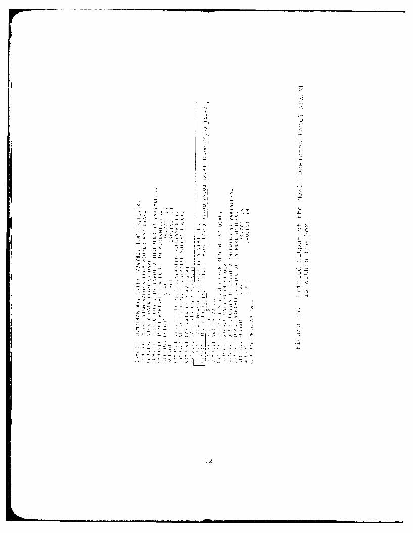
=~ c)
- ,2 , )
2)
4" 2
N©
*,. *--- .,.- - - -
-s< >- -- I < ,-
'-22
IhA
AD-AI97 705 DAYTON UNIV ON RESEARCH INST F/6 5/8USER'S GUIDE FOR COMBIMAN PROGRAMS (COMPUTERIZED BIOMECHANICAL -ETC(U)
, JAN 81 P RAPU. S EVANS. P KZKTA, M KORNA F33615-78-C 8507
r UNCLASSIFIED UDRTR-80-44 AFAMRL-TR-80-91 NL
IEIIEEEEIIEIEIIEIhEEIIEE
EIIIEEEEEIIIE
2.2.16 DELETE PANEL Function (PFKI8)
The DELETE PANEL function allows the user to removea crew station panel from the display. It does not remove the
panel from the Crew Station Data Base. Once deleted, the panel
cannot be recalled using the INCLUDE OBJECT function. It must
be either recreated by the DESIGN PANEL function, or the entire
crew station recalled again using the RETRIEVE CREW STATION func-
tion in Paragraph 2.2.6, which resets the crew station to its
original configuration.
To delete a panel, the name of the panel must be
entered through the alphanumeric keyboard as response to prompting
message "ENTER PANEL NAME". If the specified panel does not
exist, the program repeats the prompt until the user specifies
an existing panel, or signals ALT-CODE/5. If no name is specifiedby signaling only ALT-CODE/5, the function request is ignored andno deletion occurs. The panel name can be found with the IDENTIFY
OBJECT function described in Paragraph 2.2.2.
The DELETE PANEL function is different from the
OMIT OBJECT function because this function deletes the panel from
the display and cannot be redisplayed by the INCLUDE OBJECT function.
93
2.2.17 CHANGE PERSPECTIVE Function (PFK22)
The CHANGE PERSPECTIVE function allows the user to
change the point of view and/or the effective viewing distance to
the displayed man-model and the crew station. This function is
useful in enhancing the perspective and therefore the three di-
mensional character of the displayed image.
To activate the CHANGE PERSPECTIVE function, first
depress PFK22. The program displays the message "VIEW ADJUST"
and temporarily redefines PFKs 1, 2, 3, 4, 5, 6, and 9 (see Figure
34). If the user depresses PFK9, the message "L.P. NEW CENTER
POINT" is displayed. The user may respond by light-penning any
desired point in the display. Now the program displays the man-
model and the crew station as if looking along the point light-
penned. The display is initialized as if the viewing distance is
30 feet away from the screen. This distance may be increased in
increments of 10 feet by repeatedly depressing PFK1, or decreased
(closer to the screen) in increments of 10 feet by depressing
PFK3. This distance increment may be redefined by selecting PFK4,
for a 1 foot increment; PFK5, for a 10 feet increment; or PFK6,
for a 100 feet increment. However, the upper and lower limits
for the effective viewing distance are 10 feet and 1,000 feet
respectively.
Depressing PFK9 allows the user to select anotherview point. i
PFK2 terminates the CHANGE VIEW function and returns
to the main program, resetting all PFKs to the original definition.
Example: To view the display with respect to the
left eye of the man-model, first depress PFK22. Then the PFKs 1,
2, 3, 4, 5, 6 and 9 light up and the message "VIEW ADJUST" is
displayed along with the man-model and crew station. Depress
PFK9 and respond to the prompting message on the screen "L.P. NEW
CENTER POINT" by light-penning the left eye of the man-model.
The new display will be along a line with the same horizontal
and vertical coordinates as the left eye of the man-model.
94
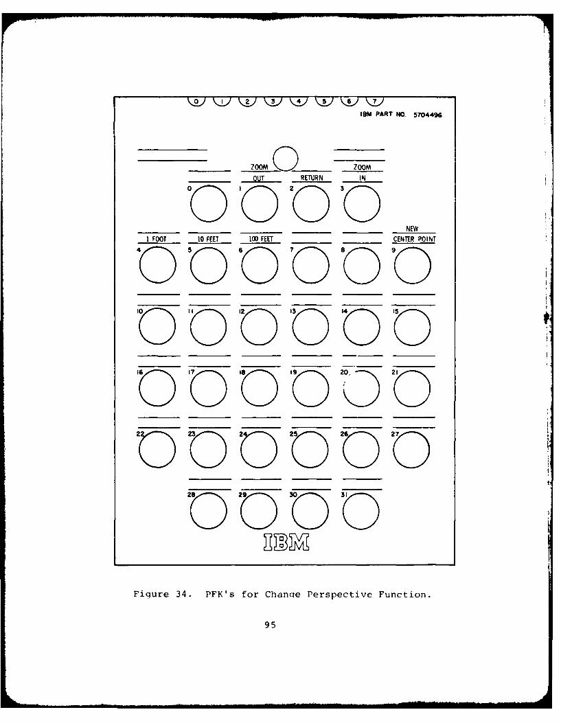
IBM PART NO. 5704496
ZOOM 0 ZOOM
OUT RETURN _ N
NEW1 FOOT 10 FEET 100 FEET CENTER POINT'0 50 60 0 80 90'0 '0 '0 '0'0
Fiqure 34. PFK's for Chanqe Perspective Function.
95
2.2.18 RESET SLUMPED POSTURE Function (PFK23)
The RESET SLUMPED POSTURE function resets the trans-
formation angles of the man-model so that it assumes a slumped
posture, as shown in Figure 35. The "slumped posture" is a
posture for sitting erect in a seat with a 130 back angle and a
60 seat pan angle. If other postures are desired, the skeletal-
link angles may be changed by the method specified in Paragraph
2.2.14, the DISPLAY TABLE function and the RESET PROGRAMMED
POSTURE function as described in 2.2.20. This function is commonly
used to get back to a starting posture after a reach analysis or
a modification of joint angles as described in 2.2.14.
96
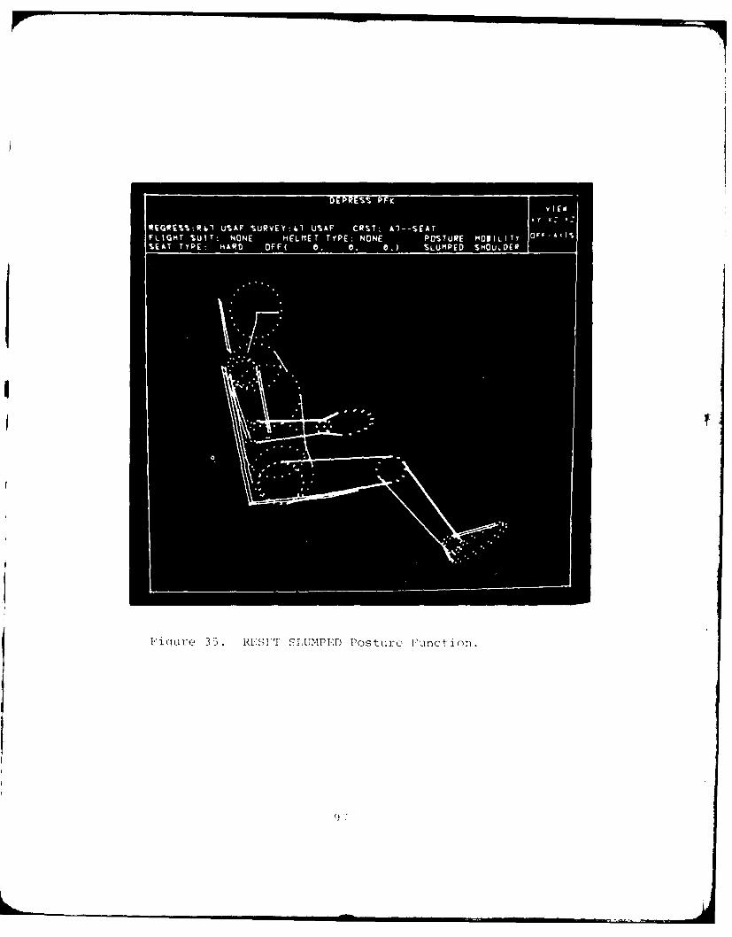
Eioure 35. RESET SLUMPED Posture Function.
2.2.19 RESET ERECT POSTURE Function (PFK24)
The RESET ERECT POSTURE function resets the trans-
formation angles of the man-model so that it assumes the standard
erect posture as shown in Figure 36.
98
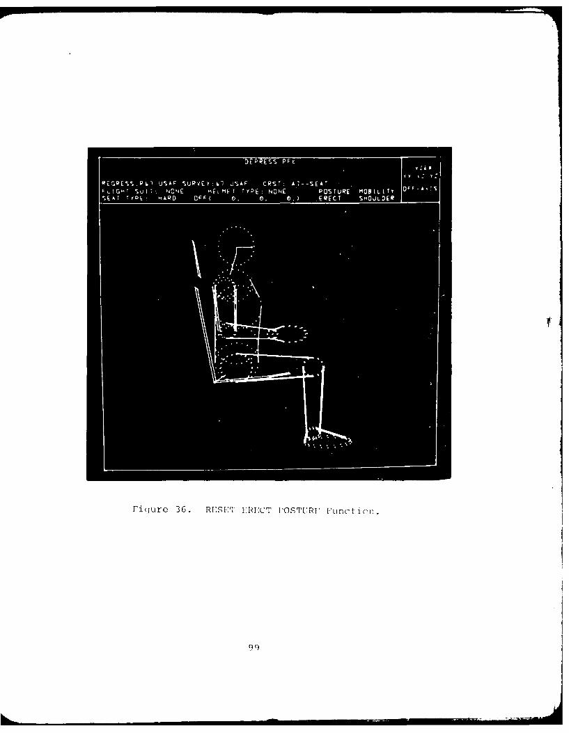
Fiqure36. RLS1:ERESS POSF EFucin
9v I
2.2.20 RESET PROGRAMMED POSTURE Function (PFK25)
The RESET PROGRAMMED POSTURE function resets the
transformation anqies of the man-model so that it assumes the
"Programmed Posture". The "Programmed Posture" is any posture
the user desires, which can be achieved by modifying the trans-
formation angles using the DISPLAY TABLE function (see Paragraph
2.2.14). After all changes are made, the new posture of the man-
model can be redisplayed at anytime by depressing PFK25 (see
Figure 37).
When the program is initialized, the angles for the
ERECT POSTURE are automatically entered into this PROGRAMMED
POSTURE storage area, so initially pressing the PFK25 merely re-
calls the ERECT POSTURE. However, anytime the user changes any
one or more angles in the link system Display Table, these changed
angles are automatically entered into the PROGRAMMED POSTURE
storage area. This function may be thought of as a "redisplay"
of the last change to the Display Table (See Paragraph 2.2.14).
The angle changes by this function are not stored
permanently, and must be redefined every time the user starts
or restarts the program.
This function may be used to define a working posture
to the user's own specification. Normally, a pilot sits with
upper-back and head well forward, causing the eye position to be
lowered. Since one posture will not serve all applications, this
function allows the user to define and recall any posture.
100
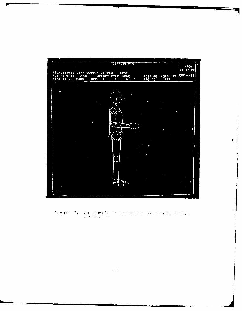
1'GN i UT NON HELME TYPiNWPSUE MU IYOrASW~~~~~~~ TYE AR r( . 6 0 Q;I R
2.2.21 INCREMENT ROLL, PITCH AND YAW ANGLE Function (PFK26)
The "INCREMENT ROLL, PITCH AND YAW ANGLE" function
allows the user to enter a set of roll, pitch and yaw anqle incre-
ments by which the man-model and crew station are rotated; and a
maximum number of iterations desired before the display resets to
roll, pitch and yaw angle values of 0.0 degrees. It is similar
to a series of "CHANGE VIEW" function (PFKO, described in Para-
graph 2.2.1) calls.
This feature allows the user to rapidly rotate the
model through a series of discrete steps without taking the time
to enter new roll, pitch, and yaw angles using the CHANGE VIEW
function. In the default case built into the program, the display
assumes a side view with the first selection of PFK26 and on each
depression of PFK26 the displayed image rotates -15' in pitch
(nose up) and +15' in yaw (left) for six discrete steps, endina
with a top view of the displayed crew station. The next depression
of PFK26 resets the display to the original side view. The user
may pause after any step to make a plot, or select other functions.
The preprogrammed example uses six discrete rotation-
al increments of 00, -150, +150 for the roll, pitch and yaw anqles.
The user may redefine the number of increments or the roll, pitch,
and yaw increments in the following manner.
First set State Switch 10 "ON" (see Paragraph 2.2.23).
Then depress PFK26 and respond to message "ENTER ROLL ANGLE" by
typing the ROLL increment angle in degrees, and enterinq it by
ALT-CODE/5 sequence. Respond to subsequent messages to enter
PITCH and YAW angles the same way. The messaqe "ENTER MAX. NO.
ITERATIONS" then appears in the Promptinq Area of the CRT. The
user must then type the number of steps the program should take
to reset the man-model from the Alphanumeric Keyboard followed
by ALT-COD:/5 sequence.
102
2.2.22 SEAT ADJUST Function (PFK27)
The SEAT ADJUST function allows the user to off-set
the man-model and his seat, if any, with respect to the displayed
crew station. This function cannot be activated unless a crew
station is displayed on the CRT screen. A seat may or may not be
present at the user's option. The default values for this func-
tion are X=O, Y=O, and Z=O. After depressing PFK27, the user is
prompted to enter the X coordinate or offset. The value in inches
is typed using the ANKB and is entered by the ALT-CODE/5 sequence
(see Figure 38). If the default value (0 inches) is to be re-
tained, enter the ALT-CODE/5 sequence. The program then prompts
the user to enter the Y and Z-coordinates in that order. The
user should enter them the same way the X-coordinate is entered.
Since the seat may be "adjusted" in three dimensions, this provides
a method for placing the man-model (and seat) in different stations
in a multi-operator crew station.
103

I~ 'V;
2.2.23 STATE SWITCH Function (PFK29)
The STATE SWITCH function allows the user to specify
the state in which to run the program CBM04. Table 3 shows the
various switches available and the meanings of their states.
When this function is selected by depressing PFK29,
the message "ENTER SWITCH NUMBER" is displayed. The user may type
the switch number followed by the ALT-CODE/5 sequence. Then the
message "ENTER ON OR OFF" is displayed. The user must type "ON"
or "OFF" followed by the ALT-CODE/5 sequence to invoke the state
detailed in Table 4.
105
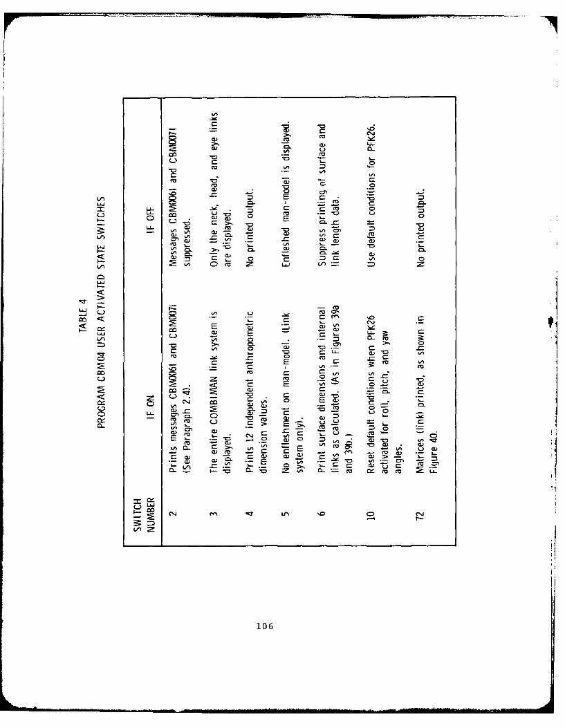
-o C . A'
C0a
LI' C0 =3 C
d.)~~ 001 (
LA C 0 CL0.
Li - - AA
la 00
-o >, s. 3:~
-E
Cu C- C'm - V 0) Q
0.) C* > E-,m~ a) 7E -o m
-A CL E- L 0.w
Cu L) C> 2S
CL'). C.~LA' 4 -2 CL m w
m ) u C C~
106
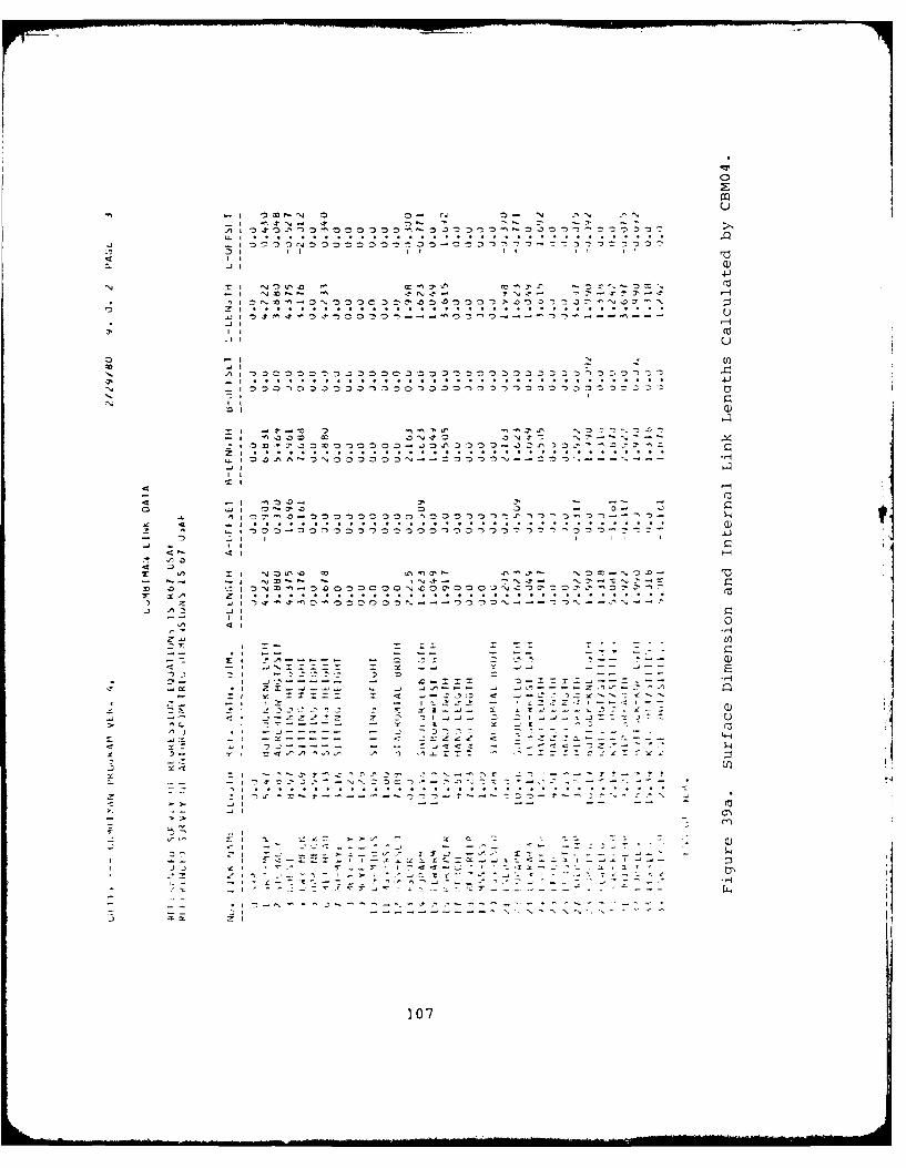
0
g '; ' : '. .. .... ". . " .. .. ....... ... . . .
- :D' 0 'o a 0
- 4 ---
Q
u... . . . ... . .. . .. .
! y I
.-+--"I-_I I "I-I :
-Z-
--.. N - +- "N+++"" - ..
z .7
107
4.1 0 0 0 0 0 0 ~ 0~l
II!C~)0 -I -~ U
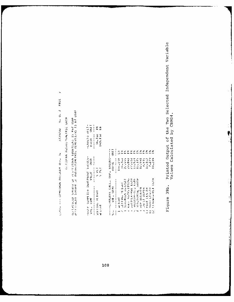
'-4.0
a0
4
0)
0 C
0 )
4 J4- fa
<.0
< I w-'0 L
4J )
> >
-108
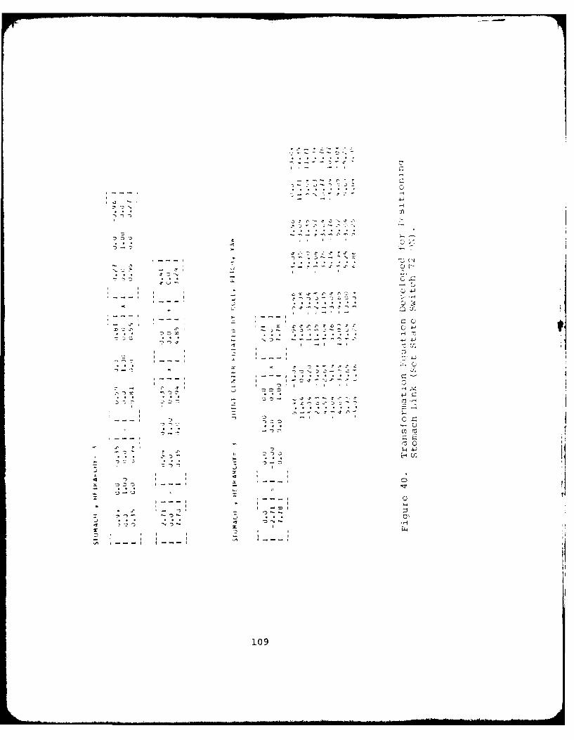
--- 4 - N0 -,I - 4-
~ ,.J-~
* j~..2' ~-,.x -. C'!
or-* . . ~ -
Q 4~ JI -
4---, *2~L
0!-'- .
- N ~ 4-,-.-'
-~ 4 -~ -~ -'J. I4 - , 4
- r 4 2 I
- 4---4 .4 0
- -. a. - 4 4-.4 ~
4~J ~* . . . . - c~- ~za.~-~"-.*
I -
* I -, -4 4 4
'4-'L)
1' ~'~ Ks~Y4x 4-- . . . 4,.; 44.4- s-.-, 4. t
C)* 4 4 I
r * -4 '~ .~I , -~I C)4 .'~-
4 ~I -~ I
I 4 - I I- 4 4 I I 4,'~A 11 11 *1
109
2.2.24 RESTART PROGRAM Function (PFK30)
The RESTART PROGRAM function allows the user to
start program CBM04 over again as though the program is executed
from the start. When this function is evoked, all temporary files
are erased and all State Switches and Anthropometric dimensions
must be redefined.
110
2.2.25 END PROGRAM Function (PFK31)
The END PROGRAM function displays the COMBIMAN
Banner and terminates the program CBM04.
111
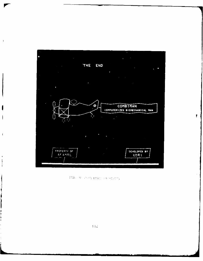
A MIIJDR
V'
2.3 EXECUTING THE JOB
This sequence is intended to assist the user in loading the
program CBM04, specifying processing, handling error procedures,
obtaining output, and ending the program. It will not describe
data formats and program functions as these are described in
detail in Paragraph 2.2 of this section.
2.3.1 Loading the Program CBM04
The Job Control Cards to load the program CBM04 are
shown in Figure 41. The program begins execution by displaying
the COMBIMAN banner. Depressing PFKO lights up enabled PFKs and
displays the message "DEPRESS PFK4". Now the user can begin pro-
cessing the man-model by depressing PFK4 to select anthropometry.
Explanation of the processing performed by enabled or lighted
function keys are explained in Paragraph 2.2.
All input data are kept on data bases created and
maintained by the programs CBMAM, CBMCM, and CBMVM (see Sections
4, 5, and 6). The user may select data from these data bases or
may modify them to suit the situation. All interactions with the
program are done through the Program Function Keyboard (PFK) , the
Alphanumeric Keyboard (ANKB), and the Light Pen (LP).
113
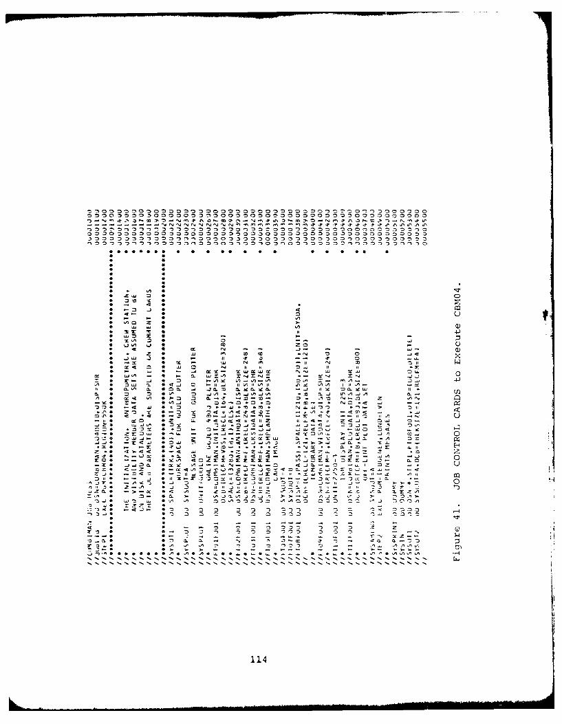
IN, N N N N N n -Q N In 1: -1 ' t ~- 'r 'r +t + *t. : .f f1
J, 0 -, D~ -0 0 3 ,- ' 03 - ~3303 ,03- ~333 ,~333333-
**** *** * 4 44 * * * * * 4*
OA 4c
'A 4-In *1L 1
a. A
w Le) c) 4 4
In m c 3
4 I- - 43D z4n "n Z 4
4 4 n
4~ ~ mT~ 4I
4 440 ~ 4 - -
4 XA ~ELI
4 ~3A 4 114
2.3.2 Error Procedures
The program CBM04 performs some preliminary error
checking on the user supplied data. The majority of checking is
for data values which are outside the limits built into the pro-
gram or the wrong type (i.e. alpha or numeric). For example,
State Switch numbers must be between 1 and 72, the maximum number
of panels for any crew station configuration to be displayed can-
not exceed 250, and all man-model dimensions entered must be
positive values. When the user light-pens or types in values which
are out of range, the program prompts the user to retry the entry.
Numerical values can be typed with or without a decimal point, at
the user's option.
Example 1. Enter State Switch number "3".
This can be done in any one of the following ways.
(a) Type "3" and depress ALT-CODE/5.
(b) Type "3." and depress ALT-CODE/5.
(c) Type "3.0" and depress ALT-CODE/5.
If the program expects a whole number, decimal values
are rounded off to the nearest Integer. Example 3.4
and 2.7 are rounded off to 3.
If the program expects two decimal places, the input
number is rounded off accordingly.
Example 2. Change a value in the link table from
10.50 to 11.32.
Light-pen 10.50, then Type "11.32" and depress
ALT-CODE/5.
Typing "11.319" or 11.3215" and depressing ALT-CODE/5
has the same effect as entering 11.32.
115
If a Program Function Key is depressed the corre-
sponding function as described in Paragrahh 2.2 is enabled. How-
ever, if a key is pressed erroneously, the followinq procedure
may be followed.
For Program Function Keys 0, 1, 2, 3, 6, 7, 8, 11,
14, 16, 18, and 29 depress ALT-CODE/5 to cancel the selection of
that function.
With Program Function Keys 4, 9, 12, 13, 23, 24, 25,
27, 30, and 31, the function must be executed.
For Program Function Key 5, light-pen "(NONE)" in
the display to cancel execution of the RETRIEVE CREW STATION
function.
For Program Function Key 22, depress the temporarily
defined PFK2 to return to the graphics routine.
For Program Function Key 26, depress PFKO and light-
pen the appropriate "VIEW".
116
2. 3. 3 Ending the Proqram
There are three ways to end program CPMOA0. The
r)riiarv method for terminatinc the prouiram is throu,:h C,VM04,
us ino the END PROGRA\M function key (PPK31) . Another - method to
terminate execution of the nrorrm is to uise the CAXC7L ko':' ,.
the IBM 2250 Alphanumeric Keyboard. When CANCEL key and Al. "'V
key are depressed together, the three options shown in i,:u&1
are displayed.
Liciht-penning the "TERMINATE" option terminat's
the program without producing a memory dump of 2r1ra 1 CBM(4.
The "DUMP" option terminates the procram and produces a Full
storage dump. The "RESUME" resumes the execution of rocra
CBM04 as though the CANCEL key had not been ased.
The third o tion is to cancel the vrc::ram fro: the
computer operator's console.
117
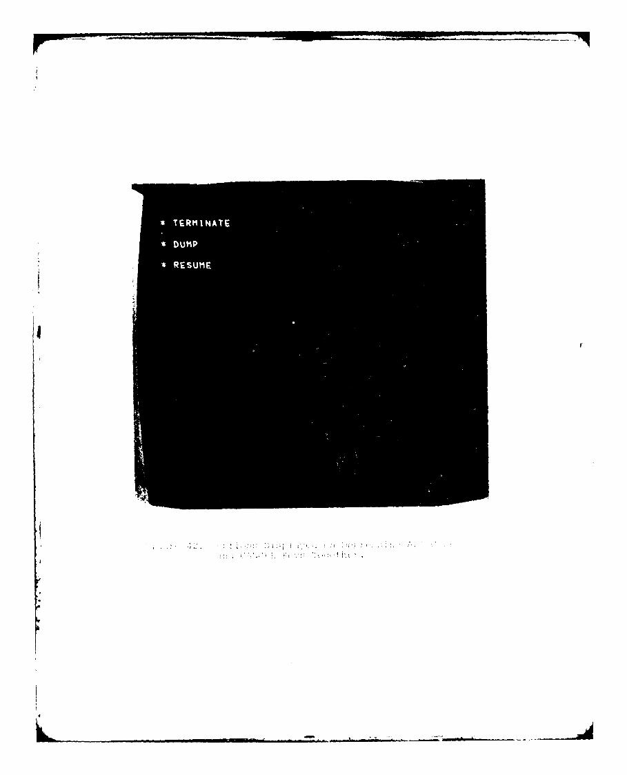
TEMNT
2.4 PROGRAM MESSAGES-INFORMATION AND ERROR TYPE
The program CBM04 prints out both information and action
oriented messages. The message format is as follows:
CBM~nni Message Text
where:
CBM - identifies the message as coming from the COMBI-MAN system,
0 - identifies the message as coming from program
CBM04,
nn - is the message number,
i - is the action code (I=information, A=action tobe performed), and
Message
Text - is the message text.
The messages are as follows:
I
119
......9 ..
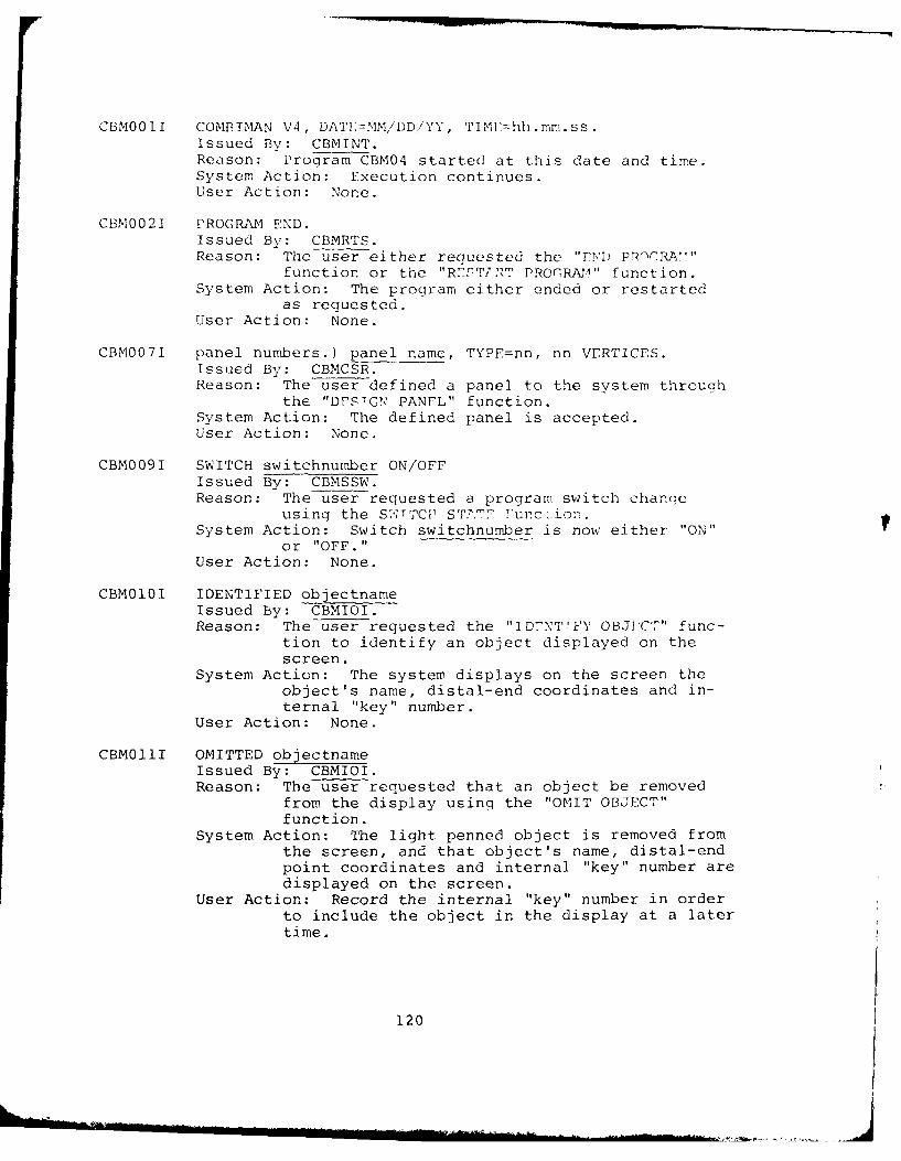
CBM0011 COMBIMAN V4, DAT}:=MM/DD/YY, TIMF<hh.mm.ss.Issued BV: CBMINT.Reason: Program CBM04 started at this date and time.System Action: Execution continues.User Action: None.
CBM002] PROGRAM END.Issued By: CBMRTS.Reason: The user either requested the "E,1) PRTCRA7"
function or the "R72T7,RT PROlRAm," function.System Action: The program either ended or restarted
as requested.User Action: None.
CBM0071 panel numbers.) panel name, TYPE=nn, nn VERTICES.Issued By: CBMCSR.Reason: The user defined a panel to the system through
the "DESIGN PANEL" function.System Action: The defined panel is accepted.User Action: None.
CBM009I SWITCH switchnumber ON/OFFIssued By: CBMSSW.Reason: The user requested a program switch changc
using the S'JT'TCP ST.E 2unc1ion.System Action: Switch switchnumber is now either "ON"
or "OFF."User Action: None.
CBM010I IDENTIFIED objectnameIssued By: CBMIOI.Reason: The user requested the "ID-NTrFY OBJECT" func-
tion to identify an object displayed on thescreen.
System Action: The system displays on the screen theobject's name, distal-end coordinates and in-ternal "key" number.
User Action: None.
CBM011I OMITTED objectnameIssued By: CBMIOI.Reason: The user requested that an object be removed
from the display usinq the "OMIT OBJECT"function.
System Action: The light penned object is removed fromthe screen, and that object's name, distal-endpoint coordinates and internal "key" number aredisplayed on the screen.
User Action: Record the internal "key" number in orderto include the object in the display at a latertime.
120
... ... .... ,J......
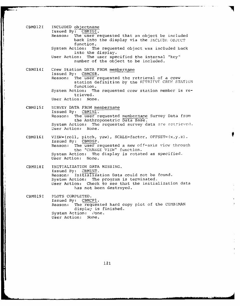
CBM012I INCLUDED objectname
Issued By: CBMIOI.Reason: The user requested that an object be included
back into the display via the INCLUDI OBJECTfunction.
System Action: The requested object was included back
into the display.User Action: The user specified the internal "key"
number of the object to be included.
CBM014I Crew Station DATA FROM membernameIssued By: CBMCSR.Reason: The user requested the retrieval of a crew
station definition by the RETRIEVE CREW STATION
function.System Action: The requested crew station member is re-
trieved.User Action: None.
CBM015I SURVEY DATA FROM membernameIssued By: CBMINI.Reason: The user requested membername Survey Data from
the Anthropometric Data Base.System Action: The requested survey data are retrieved.User Action: None.
CBM016I VIEW=(roll, pitch, yaw), SCALE=factor, OFFSET=(x,y,z).Issued By: CBMDSP.Reason: The user requested a new off-axis view throuqh
the "CHANGE VIEW" function.System Action: The display is rotated as specified.User Action: None.
CBM018I INITIALIZATION DATA MISSING.Issued By: CBMINT.Reason: IniEtil ation Data could not be found.
System Action: The program is terminated.User Action: Check to see that the initialization data
has not been destroyed.
CBM019I PLOTS COMPLETED.Issued By: CBMCP1.Reason: The requested hard copy plot of the COMBIMAN
display is finished.System Action: T1one.
User Action: None.
121
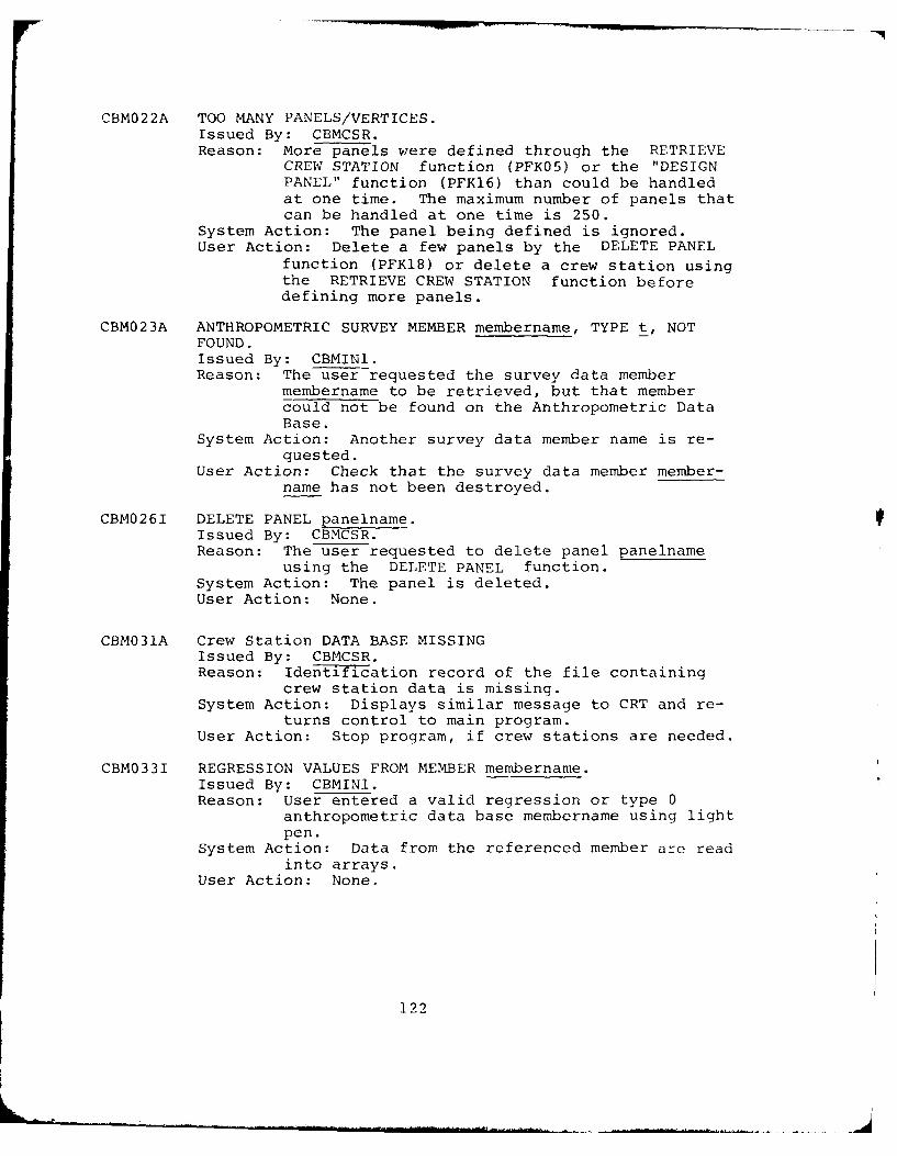
CBM022A TOO MANY PANELS/VERTICES.Issued By: CBMCSR.Reason: More panels were defined through the RETRIEVE
CREW STATION function (PFK05) or the "DESIGNPANEL" function (PFKl6) than could be handledat one time. The maximum number of panels thatcan be handled at one time is 250.
System Action: The panel being defined is ignored.User Action: Delete a few panels by the DELETE PANEL
function (PFKl8) or delete a crew station usingthe RETRIEVE CREW STATION function beforedefining more panels.
CBM023A ANTHROPOMETRIC SURVEY MEMBER membername, TYPE t, NOTFOUND.Issued By: CBMIN1.Reason: The user requested the survey data member
membername to be retrieved, but that membercould not be found on the Anthropometric DataBase.
System Action: Another survey data member name is re-quested.
User Action: Check that the survey data member member-name has not been destroyed.
CBM026I DELETE PANEL panelname.Issued By: CBMCSR.Reason: The user requested to delete panel panelname
using the DELETE PANEL function.System Action: The panel is deleted.User Action: None.
CBM031A Crew Station DATA BASE MISSINGIssued By: CBMCSR.Reason: Identification record of the file containing
crew station data is missing.System Action: Displays similar message to CRT and re-
turns control to main program.User Action: Stop program, if crew stations are needed.
CBM033I REGRESSION VALUES FROM MEMBER membername.Issued By: CBMIN1.Reason: User entered a valid regression or type 0
anthropometric data base membername using lightpen.
System Action: Data from the referenced member are readinto arrays.
User Action: None.
122
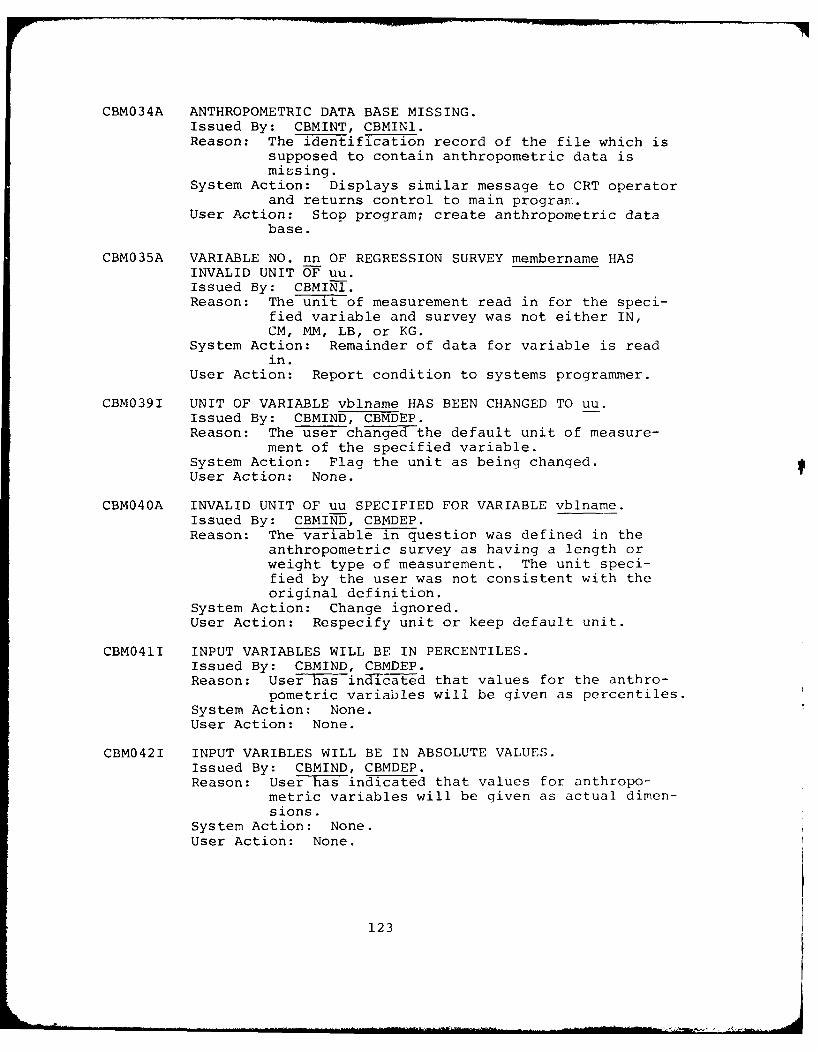
CBM034A ANTHROPOMETRIC DATA BASE MISSING.Issued By: CBMINT, CBMINl.Reason: The identification record of the file which is
supposed to contain anthropometric data ismissing.
System Action: Displays similar message to CRT operatorand returns control to main program.
User Action: Stop program; create anthropometric database.
CBM035A VARIABLE NO. nn OF REGRESSION SURVEY membername HASINVALID UNIT OF uu.Issued By: CBMINI.Reason: The unit of measurement read in for the speci-
fied variable and survey was not either IN,CM, MM, LB, or KG.
System Action: Remainder of data for variable is readin.
User Action: Report condition to systems programmer.
CBM039I UNIT OF VARIABLE vblname HAS BEEN CHANGED TO uu.Issued By: CBMIND, CBMDEP.Reason: The user changed the default unit of measure-
ment of the specified variable.System Action: Flag the unit as being changed.User Action: None.
CBM040A INVALID UNIT OF uu SPECIFIED FOR VARIABLE vblname.Issued By: CBMIND, CBMDEP.Reason: The vatable in question was defined in the
anthropometric survey as having a length orweight type of measurement. The unit speci-fied by the user was not consistent with theoriginal definition.
System Action: Change ignored.User Action: Respecify unit or keep default unit.
CBM041I INPUT VARIABLES WILL BE IN PERCENTILES.Issued By: CBMIND, CBMDEP.Reason: User has ina-c-ted that values for the anthro-
pometric variables will be given as percentiles.System Action: None.User Action: None.
CBM042I INPUT VARIBLES WILL BE IN ABSOLUTE VALUES.Issued By: CBMIND, CBMDEP.Reason: User has indicated that values for anthropo-
metric variables will be given as actual dimen-sions.
System Action: None.User Action: None.
123
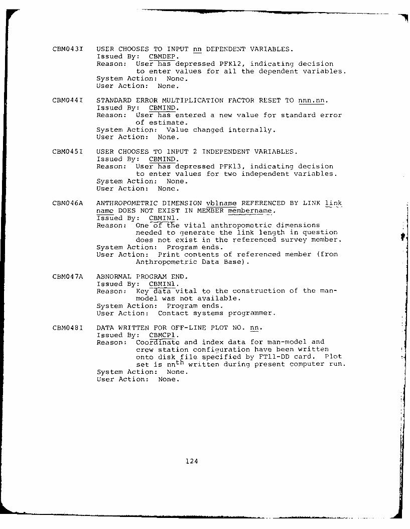
CBM043I USER CHOOSES TO INPUT nn DEPENDENT VARIABLES.Issued By: CBMDEP.Reason: User has depressed PFKI2, indicating decision
to enter values for all the dependent variables.System Action: None.
User Action: None.
CBM044I STANDARD ERROR MULTIPLICATION FACTOR RESET TO nnn.nn.Issued By: CBMIND.Reason: User has entered a new value for standard error
of estimate.System Action: Value changed internally.User Action: None.
CBM045I USER CHOOSES TO INPUT 2 INDEPENDENT VARIABLES.Issued By: CBMIND.Reason: User has depressed PFKl3, indicating decision
to enter values for two independent variables.System Action: None.User Action: None.
CBM046A ANTHROPOMETRIC DIMENSION vblname REFERENCED BY LINK link
name DOES NOT EXIST IN MEMBER membername.Issued By: CBMINI.Reason: One of the vital anthropometric dimensions
needed to generate the link length in questiondoes not exist in the referenced survey member.
System Action: Program ends.User Action: Print contents of referenced member (from
Anthropometric Data Base).
CBM047A ABNORMAL PROGRAM END.Issued By: CBMINI.Reason: Key data vital to the construction of the man-
model was not available.System Action: Program ends.User Action: Contact systems programmer.
CBM048I DATA WRITTEN FOR OFF-LINE PLOT NO. nn.Issued By: CBMCP1.Reason: Coord-iiite and index data for man-model and
crew station configuration have been written
onto disk file specified by FT11-DD card. Plot
set is nnth written during present computer run.
System Action: None.User Action: None.
124
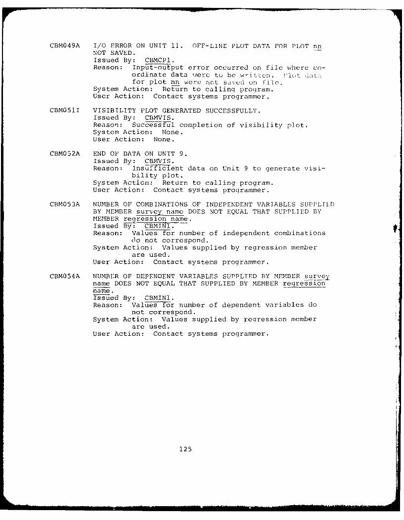
CBM049A I/O ERROR ON UNIT 11. OFF-LINE PLOT DATA FOR PLOT nnNOT SAVED.Issued By: CBMCP1.Reason: Input-output error occurred on file where co-
ordinate data were to be written. I'lot dJatafor plot nn were not saived on file.
System Action: Return to calling program.User Action: Contact systems programmer.
CBM051I VISIBILITY PLOT GENERATED SUCCESSFULLY.Issued By: CBMVIS.Reason: Successful completion of visibility plot.System Action: None.User Action: None.
CBM052A END OF DATA ON UNIT 9.Issued By: CBMVIS.Reason: Insufficient data on Unit 9 to generate visi-
bility plot.System Action: Return to calling program.User Action: Contact systems programmer.
CBM053A NUMBER OF COMBINATIONS OF INDEPENDENT VARIABLES SUPPLIEDBY MEMBER survey name DOES NOT EQUAL THAT SUPPLIED BYMEMBER regression name.Issued By: CBMIN1.Reason: Values for number of independent combinations
Oo not correspond.System Action: Values supplied by regression member
are used.User Action: Contact systems programmer.
CBM054A NUMBER OF DEPENDENT VARIABLES SUPPLIED BY MEMBER surveyname DOES NOT EQUAL THAT SUPPLIED BY MEMBER regressionname.Issued By: CBMINI.Reason: Values for number of dependent variables do
not correspond.System Action: Values supplied by regression member
are used.User Action: Contact systems programmer.
125
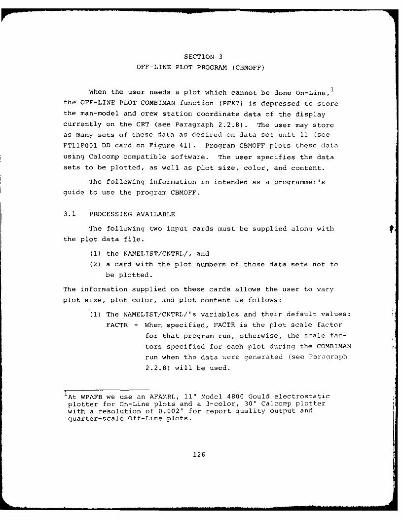
SECTION 3
OFF-LINE PLOT PROGRAM (CBMOFF)
When the user needs a plot which cannot be done On-Line,
the OFF-LINE PLOT COMBIMAN function (PFK7) is depressed to store
the man-model and crew station coordinate data of the display
currently on the CRT (see Paragraph 2.2.8). The user may store
as many sets of these data as desired on data set unit 11 (see
FT11FOl DD card on Figure 41). Program CBMOFF plots these data
using Calcomp compatible software. The user specifies the data
sets to be plotted, as well as plot size, color, and content.
The following information in intended as a programmer's
guide to use the program CBMOFF.
3.1 PROCESSING AVAILABLE
The following two input cards must be supplied along with
the plot data file.
(1) the NAMELIST/CNTRL/, and
(2) a card with the plot numbers of those data sets not to
be plotted.
The information supplied on these cards allows the user to vary
plot size, plot color, and plot content as follows:
(1) The NAMELIST/CNTRL/'s variables and their default values:
FACTR - When specified, FACTR is the plot scale factor
for that program run, otherwise, the scale fac-
tors specified for each plot during the COMBIMAN
run when the data ;ere cenerated (see Pararaph
2.2.8) will be used.
iAt WPAFB we use an AFAMRL, 11" Model 4800 Gould electrostatic
plotter for On-Line plots and a 3-color, 30" Calcomp plotterwith a resolution of 0.002" for report quality output andquarter-scale Off-Line plots.
126
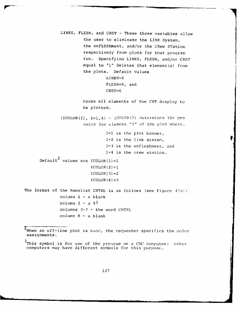
LINKS, FLESH, and CRST - These three variables allow
the user to eliminate the LINK System,
the enFLESHment, and/or the CRew STation
respectively from plots for that program
run. Specifying LINKS, FLESH, and/or CRST
equal to "1" deletes that element(s) from
the plots. Default values
LINKS=O
FLESH=O, and
CRST=O
cause all elements of the CRT display to
be plotted.
(ICOLOR(I), I=1,4) - ICOLOR(I) determines the pen
color for element "I" of the plot where,
I=l is the plot banner,
I=2 is the link system,
1=3 is the enfleshment, and
1=4 is the crew station.
Default 2 values are ICOLOR(l)=I
ICOLOR(2) =1
ICOLOR(3) =2
ICOLOR(4) =3
The format of the Namelist CNTRL is as follows (see Figure 43a):
column 1 - a blank
column 2 - a $3
columns 3-7 - the word CNTRL
column 8 - a blank
2 When an off-line plot is made, the requester specifies the colorassignments.
3This symbol is for use of the program on a CDC computer: othercomputers may have different symbols for this purpose.
127
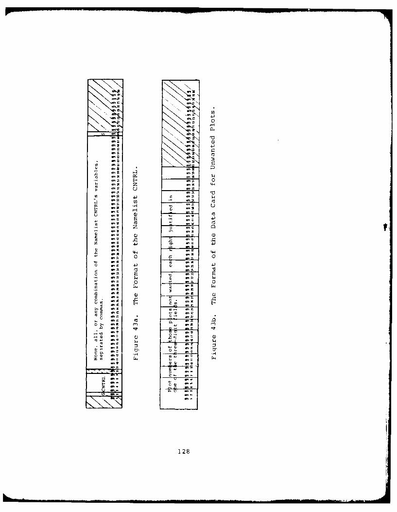
C4-
k 01 0
N.,,
aa
It: It~ 4-4> ' ,.
a'; 4
'- a': ~ 0'3 4-)
aCa
%) a'C 4~ , -4
z 4-
C: a: A,;
- ~~ 0, r 'r. a.4
. 0 .C a 0 :'C a
C .: CL (0 rd ~ V .
z , W 44.
a,:l 0 -
O'C E-'128
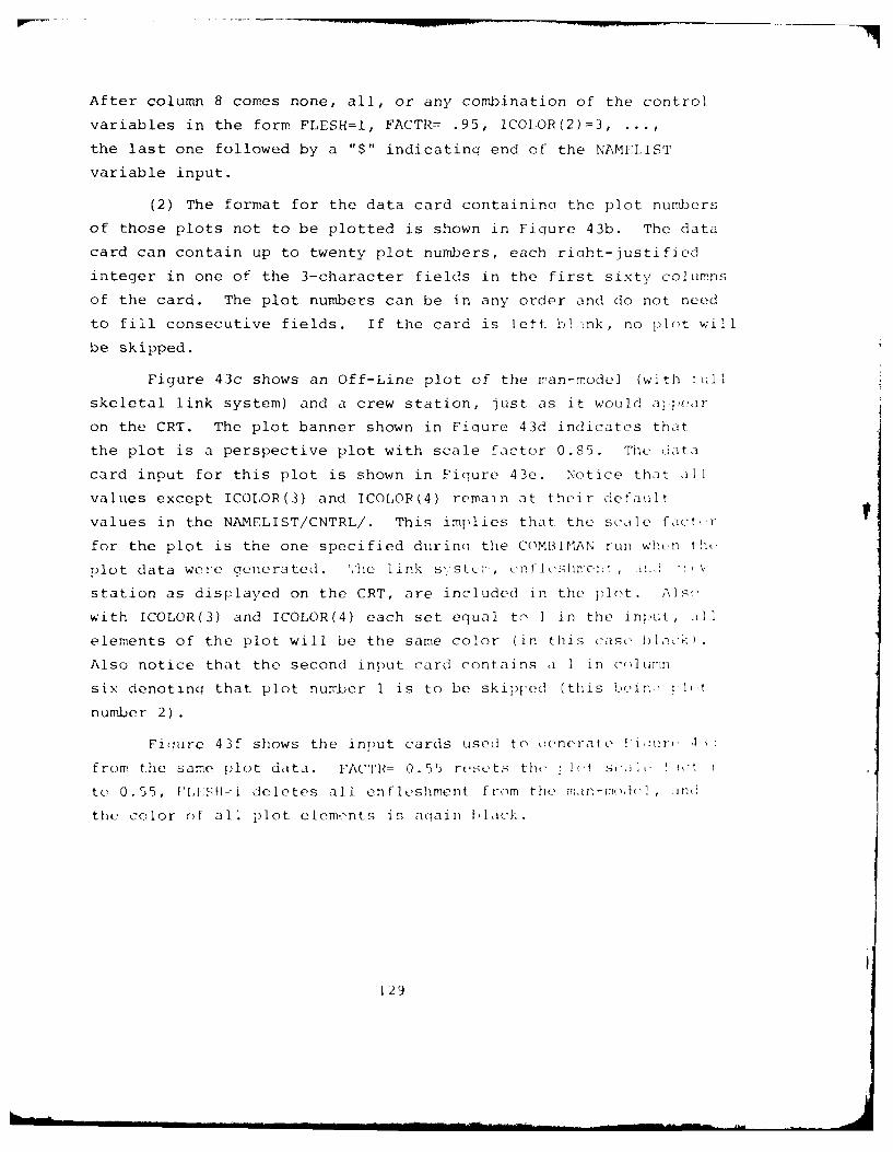
After column 8 comes none, all, or any combination of the control
variables in the form FLESH=I, FACTR= .95, ICOIOR(2)=3,
the last one followed by a "$" indicating end of the NAMELIST
variable input.
(2) The format for the data card containina the plot numbers
of those plots not to be plotted is shown in Figure 43b. The data
card can contain up to twenty plot numbers, each richt-justified
integer in one of the 3-character fields in the first sixty columns
of the card. The plot numbers can be in any order and do not need
to fill consecutive fields. If the card is left b ink, no plot will
be skipped.
Figure 43c shows an Off-Line plot of the man-model (with full
skeletal link system) and a crew station, just as it would apear
on the CRT. The plot banner shown in Figure 43d indicates that
the plot is a perspective plot with scale factor 0.85. The data
card input for this plot is shown in Figure 43e. Notice that all
values except ICOLOR(3) and ICOLOR(4) remain at their default
values in the NAMELIST/CNTRL/. This implies that the scale factr Vfor the plot is the one specified durincu the COMBIMAN run when tnht
plot data were generated. ,.he link s1s , enf1],slhmen , 1!'! ":' V
station as displayed on the CRT, are included in the )lt. Als
with ICOLOR(3) and ICOLOR(4) each set equal to I in the input, AIl
elements of the plot will be the same color (in this case black).
Also notice that the second input card contains a 1 in eel]ur-n
six denoting that plot number 1 is to be skipped (this -ein : l Ieit
number 2).
Fiqure 43f shows the input cards used to eTenerate i:r' 4 :
from the same plot data. FACTR= 0.55 resets the i hIt sc,)!,L J t 1
to 0.55, FAI:SKf-I deletes all enfleshment from the man-mode, ,nd
the color of all plot elements is aqain Llack
129
f40
C)
.1
44)
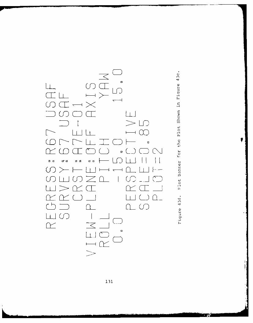
LLL -
OID CD C
0
4
0 1 Cr a aa aa L D hIJH H L
W>QQI I0 c01--I(J)I p
G QLLI LLLD L..
CL IiILicED
131
rAu
114a
o r 4-4
as.as
- -C.7
(13 ra3
- a.
a 0) 132
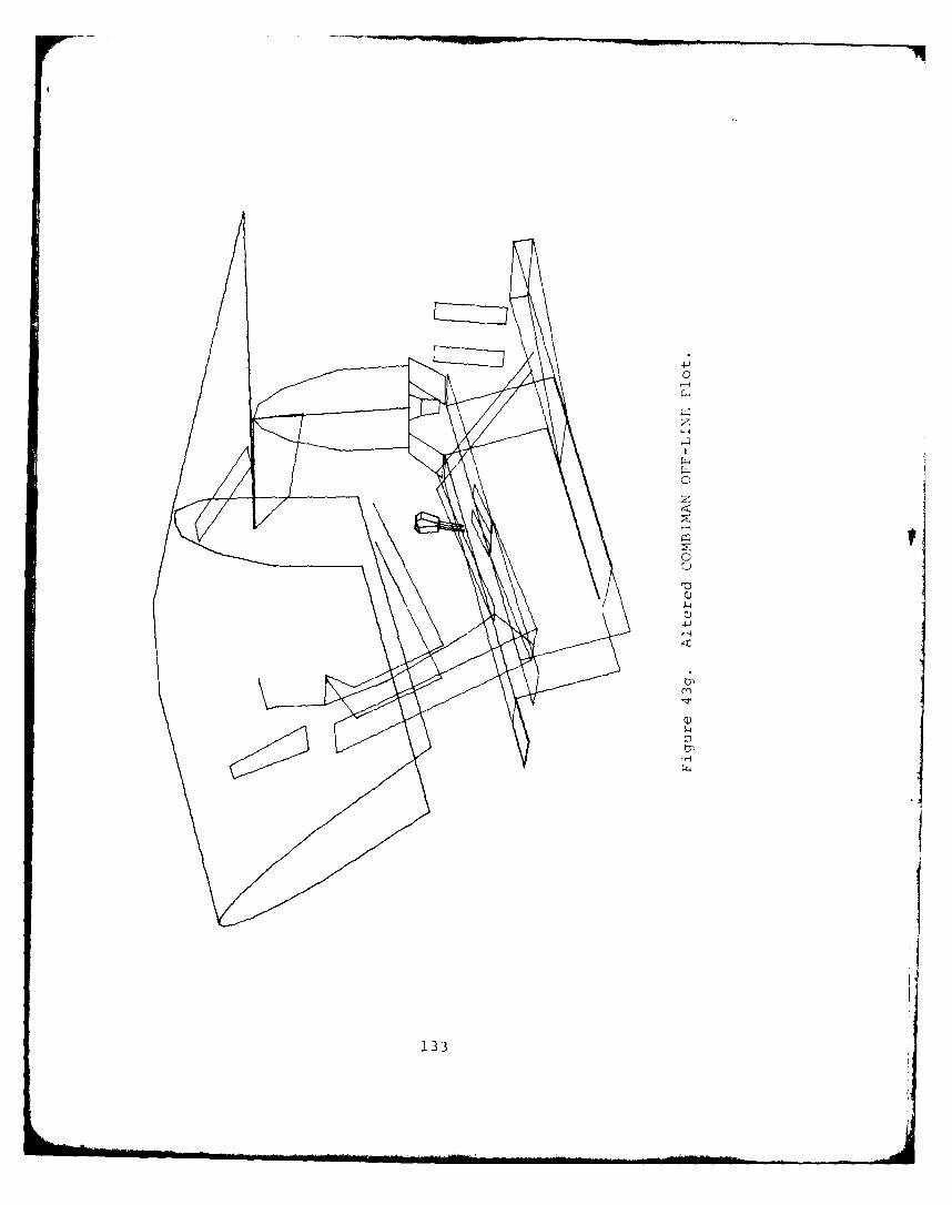
-1
c-i
:1.33
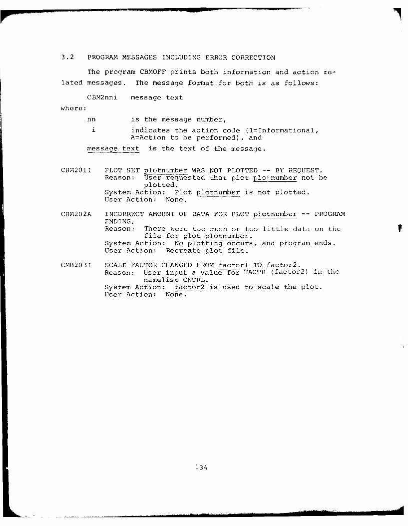
3.2 PROGRAM MESSAGES INCLUDING ERROR CORRECTION
The program CBMOFF prints both information and action re-
lated messages. The message format for both is as follows:
CBM2nni message text
where:
nn is the message number,
i indicates the action code (I=Informational,
A=Action to be performed), and
message text is the text of the message.
CBM201I PLOT SET plotnumber WAS NOT PLOTTED -- BY REQUEST.Reason: User requested that plot plotnumber not be
plotted.System Action: Plot plotnumber is not plotted.User Action: None.
CBM202A INCORRECT AMOUNT OF DATA FOR PLOT plotnumber -- PROGRAMENDING.Reason: There were too much or too little data on the
file for plot plotnumber.System Action: No plotting occurs, and program ends.User Action: Recreate plot file.
CMB203I SCALE FACTOR CHANGED FROM factorl TO factor2.Reason: User input a value for FACTR (factor2) in the
namelist CNTRL.System Action: factor2 is used to scale the plot.User Action: None.
134
SECTION 4
COMBIMAN ANTHROPOMETRIC DATA BASE MAINTENANCEPROGRAM (CBMAM)
As the COMBIMAN has become more sophisticated, the user is
often asked to supply more anthropometric data to generate the
man-model. To simplify this task for the user a Data Base is
constructed to store key data items. This Data Base resides
on a direct-access disk, and contains anthropometric survey
and regression data relevant to generating the man-model.
Information on the Data Base is organized into groups of
related records called members. Members may be either regression
data, or anthropometric survey data. Data for survey members are
generally subsets of existing anthropometric surveys in the
AFAMRL Anthropometric Data Bank. To add a new anthropometric
survey to the Data Base, the key information needed includes the
mean and standard deviation for each anthropometric variable and
a set of correlation coefficients for all the relevant variables
of the survey.
4.1 PROCESSING PERFORMED
The program CBMAM (COMBIMAN Anthropometric Data Base Main-
tenance Program) allows the user to create and maintain the Anthro-
pometric Data Base. The user may supply the input data on 80
character computer card or in card image format on magnetic tape.
The program CBMAM reads and processes the data according to the
user's selection of control commands. These commands allow the
user to add members to the Data Base, delete members from the
Data Base, print or punch existing members, list the directory
of the Data Base, or compress the data on the file to combined
unused space. The data flow of the program is shown in Figure 44.
135
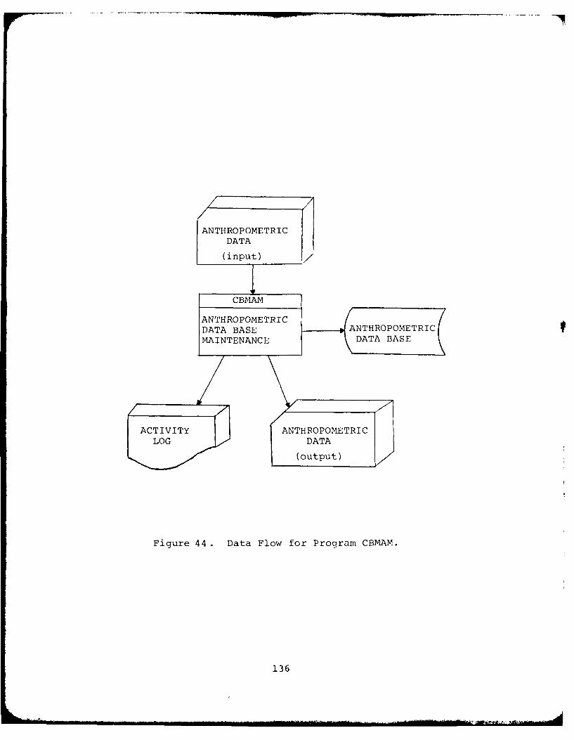
ANTHROPOMETRICDATA
(input)
DT BAE ANTHROPOMETRIC
ACTIVITYANTHROPOMETRICLOG DATA
(output)
Figure 44. Data Flow for Program CBMAM.
136

The Data Base is made up of two types of related data. One
type consists of regression data which is used by the interactive
graphics program CBM04 when predicting anthropometric surface
dimensions needed to generate the link system of the man-model.
The second type consists of survey data which define the means,
standard deviations, and percentiles for each variable for a
particular survey. Each group of data, whether dealinq with
regression or survey information, is called an anthropometric mem-
ber, and is referenced by the member's name and type classification.
4.2 RESTRICTIONS AND LIMITATIONS
The Anthropometric Data Base may contain a maximum of 20
members consisting of regression and survey types. The number
of records for each member need not be the same but the sum of
the record counts for all the members cannot exceed 1979. In-
formation on the number of members on the Data Base and their
size may be obtained by using the "+PRT" control card. This is
explained in greater detail in Paragraph 4.3.2.9.
Additional limitations on the number of variables and re-
lated data are explained in Paragraph 4.3.2. Members to be added
should have unique member names. If the new member name matches
any name in the directory, the member will not be added.
4.3 HOW TO USE PROGRAM CBMAM
The surveys used in COMBIMAN are subsets of the 1967 Survey
of the USAF Flying Personnel (Churchill, et al, 1976) and the
1970 Survey of U.S. Army Aviators (Churchill, et al, 1971). As
new surveys become available, or subsets of existing surveys in
he AFAMRL Data Bank become needed, the program CBMAM is used to
add these new members. In most cases, each new survey type mem-
ber has a corresponding regression type member which contains
multiple and single regression equation coefficients to predict
additional anthropometric variables from those which the user
137
specifies. In a few cases, one regression type member may be re-
ferenced by several survey type members. These are special cases,
however, and this practice should not be used regularly without
first consulting with personnel in the Workload and Ergonomics
Branch of the Air Force Aerospace Medical Research Lab. Wright-
Patterson Air Force Base, Ohio to verify the statistical accuracy
of the regression data of the anthropometric survey in question.
All examples illustrating the use of CBMAM will be based on
the 1967 USAF Flying Personnel survey and its regression type
counterpart.
4.3.1 Identifying Input Data
The nucleus of the anthropometric variables con-
sidered for input as part of any anthropometric member should be
the 12 variables required to generate the 35 internal link lengths
of the man-model skeletal system. These variables and their 16
character abbreviations, where applicable, are listed in Table 5.
Few users of COMBIMAN will have specific values in mind to input
for each of the 12 variables. To accommodate this, additional
anthropometric variables can be selected which are found to be
good predictors of either body segment mass or body segment length,
and have moderately high correlations with the 12 required vari-
ables. The variables chosen to predict mass and length for the
1967 Survey are shown in the appropriate columns of Table 6.
Those variables in Table 6 which are both predictors and required
dimensions are marked with an asterisk.
Alternately, the user may select one mass related
and one length related variables from Table 6 and supply the
values. The values for the 12 variables in Table 5 are com-
puted using the regression equations from the Anthropometric Data
Base.
Once the complete set of variables is estab-
lished, it is necessary to obtain means, standard deviations,
percentiles, and correlation coefficients for each variable of
138
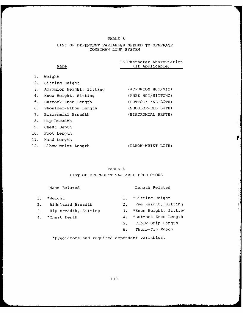
TABLE 5
LIST OF DEPENDENT VARIABLES NEEDED TO GENERATECOMBIMAN LINK SYSTEM
16 Character AbbreviationName (If Applicable)
1. Weight
2. Sitting Height
3. Acromion Height, Sitting (ACROMION HGT/SIT)
4. Knee Height, Sitting (KNEE HGT/SITTING)
5. Buttock-Knee Length (BUTTOCK-KNE LGTH)
6. Shoulder-Elbow Length (SHOULDR-ELB LGTH)
7. Biacromial Breadth (BIACROMIAL BRDTH)
8. Hip Breadth
9. Chest Depth
10. Foot Length
11. Hand Length
12. Elbow-Wrist Length (ELBOW-WRIST LGTH)
TABLE 6
LIST OF DEPENDENT VARIABLE PREDICTORS
Mass Related Length Related
1. *Weight 1. *Sitting Height
2. Bideltoid Breadth 2. Eye Height, Sitting
3. Hip Breadth, Sitting 3. *Knee Height, Sitting
4. *Chest Depth 4. *Buttock-Knee Length
5. Elbow-Grip Length
6. Thumb-Tip Reach
*Predictors and required dependent variables.
139
the particular survey from the AFAMRL Anthropometric Data Bank.
The set of variables used for the 1967 Survey is shown in Table
7. A sample of the data obtained for Weight is shown in Figure
45.
The coefficients used in the regression equations
are based on means, standard deviations and correlation coeffi-
cients for each variable, and on the equations which were de-
veloped in WADD-TR-60-31, pages 69-70 (Zeigen, et al, 1960).
Tables 8 and 9 show the correlation coefficients matrices used
in calculating the regression coefficients. The means, standard
deviations, and correlation coefficients for 1967 USAF survey
are available in AMRL-TR-77-2 (Churchill, et al, 1978).
The total number of multiple regression equations
(NR) needed for a particular survey is calculated usinq the
following equation:
NR = (NM x NL) x ND (1)
where NM is the number of variables related to body seqment mass,
NL is the number of variables related to body segment length,
and ND is the number of dependent varibles. For 1967 Survey,
each of the 24 combinations of mass-length-related dimensions
has its own set of 12 multiple regression equations to compute
the surface dimensions required to generate the man-model. In
addition to multiple regression coefficients, simple re(iression
coefficients and associated standard error of estimates are
available for each of the 24 combinations. The standard units
of measurement for all variables and coefficients !ised in COMBIMAN
are pounds and inches, but there are provisions to channc these
metric units.
140
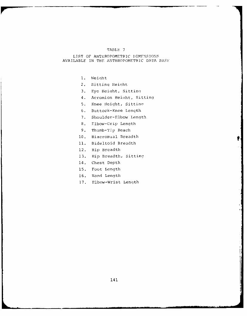
TABLE 7
LIST OF ANTHROPOMETRIC DIMENSIONSAVAILABLE IN THE ANTHROPOMETRIC DATA BASE
1. Weight
2. Sitting Heiaht
3. Eye Height, Sitting
4. Acromion Height, Sitting
5. Knee Height, Sittinq
6. Buttock-Knee Length
7. Shoulder-Elbow Length
8. Elbow-Grip Length
9. Thumb-Tip Reach
10. Biacromial Breadth
11. Bideltoid Breadth
12. Hip Breadth
13. Hip Breadth, Sitting
14. Chest Depth
15. Foot Length
16. Hand Length
17. Elbow-Wrist Length
141
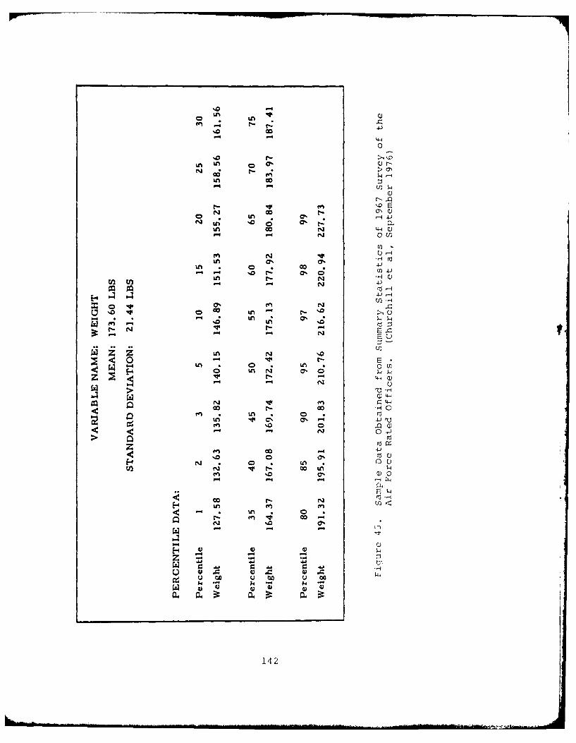
-')
'n r-~.
- 4-40-
%0 >, "-
(1)
N Go O
W;l r- Nr
N -N
0. co '.
en N U) -
o LL N 0
N n
C'4-4
- 4 -P
N O * 0, *1 (0V '. C)
E- %n -n
t!0
4))
k - ' -L- -L'-- -1 - -
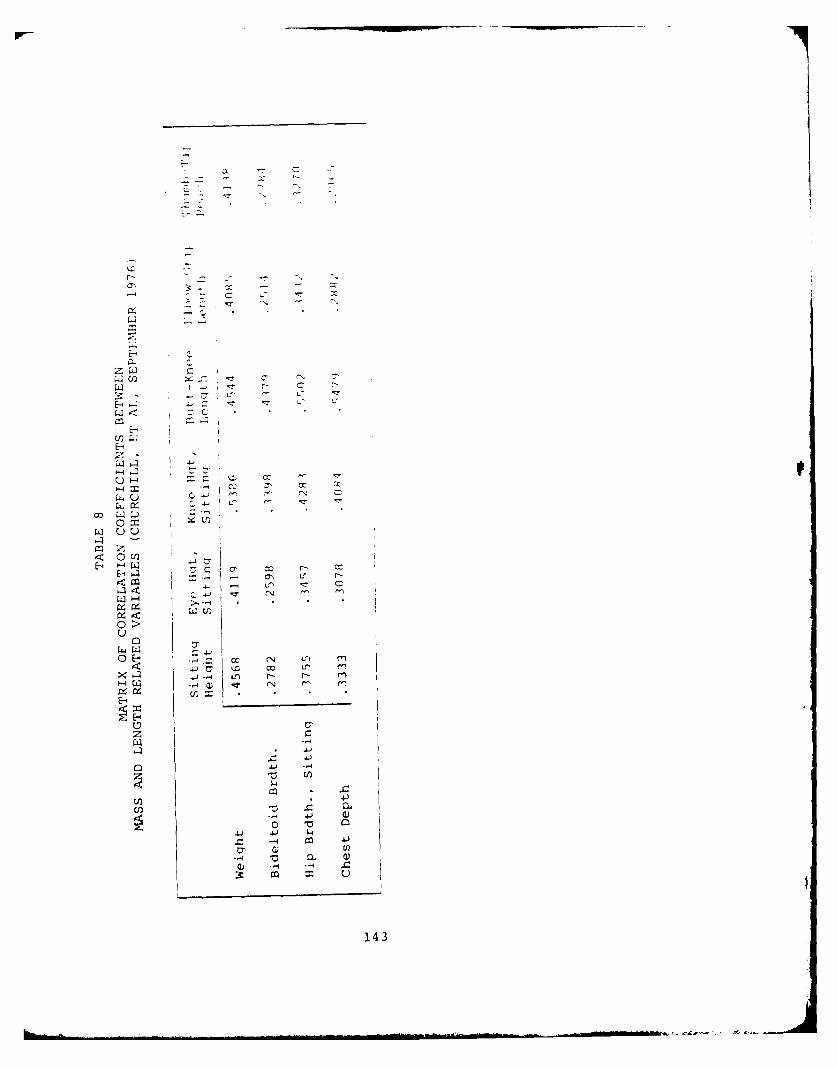
E-4
<N
L:.
Sz(D QU
E 4 -4W
CU-1
C)~
z
4-) -4
0 ~--I)
143
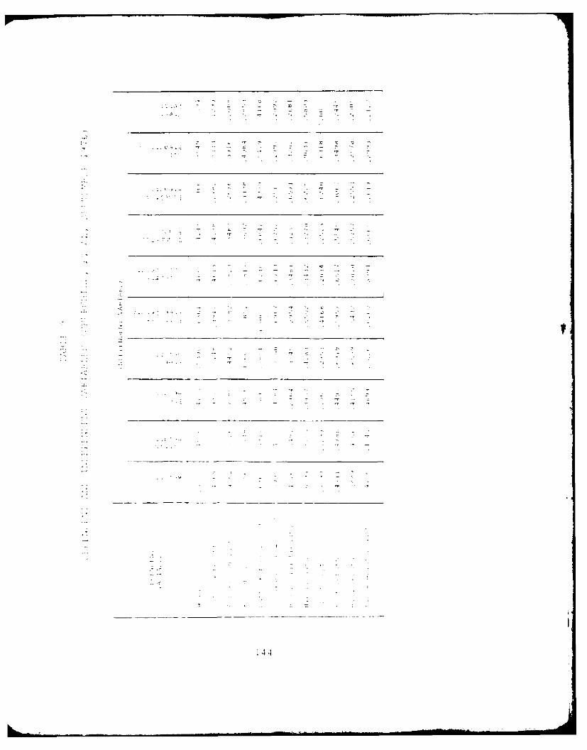
1 44
4.3.2 Specifying the Processing Desired
The Anthropometric Data Base Maintenance program,
CBMAM, allows the user to create and maintain the Anthropometric
Data Base. The Data Base contains regression data which are used
by the interactive graphics program CBM04 to predict anthro-
pometric surface dimensions needed to generate the link system of
the man-model. It also contains survey data which define the
means, standard deviations, and percentiles for every defined
variable for a particular anthropometric survey. Each group of
data, whether dealing with regression or survey information, is
called an anthropometric member, and is referenced by the member'F
name and type classification.
The program CBMAM allows the user to maintain the
Data Base by the addition, deletion, listing, etc., of the member
types through input cards as shown in Figure 46.
These control cards may be placed in any order in
the input stream of the program, with one exception. If the Data
Base is to be initialized for the first time, the +INT control
card must be the first card. In each of the followin; subsections,
the control card forrat of the function is listed first. This is
followed by the text which explains each keyword. Additional data
formats, if any, are then described for each function.
4.3.2.1 ADD ANTHROPOMETRIC MEMBER Function
+ADD membername type nvbl ncmb ndep npctregrname (followed by member defiition)
The ADD ANTI:ROPOMETRIC MEMBER function,
as defined by the +ADD control card and the member definition
cards which follow, adds to the Anthropometric Data Base specific
data under the name membername. The membername is an alphanumeric
character string, no lonqer than 16 characters. The type field
distinquishes between the two types of members. A type value of
"0" signals that the nierrler which follows (')ntains reorossion in-
formation, while a type value of "I" si nifies thit the member con-
tains survey dimensional data. The typoe- value, as well as all
14 53
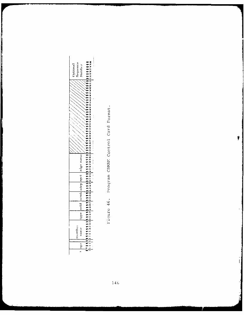
- \\ "- ,:
C -
- o
Q' , a,
" a,=
N "-
r 6N '-'i
~1!
other integer values supplied on the control card, must be riht-
justified within its field. The nvbl field defines the total
number of variables described in member membername. The maximum
number is 45. The ncmb field indicates the maximum number of
combinations of independent mass and length variables. The maxi-
mum number is 50. The number of anthropometric variables needed
to determine the internal link lengths is supplied in field ndep.
The maximum number is 30. Fields, npct and regrname are used onl>
when the type field value is 1. Npct contains the number of per-
centile values which will be supplied for everv one of the nvbl
variables. The maximum value for npct is 30. The regrname field
references the type 0 membername which contains the appropriate
regression information.
4.3.2.2 TYPE 0 MEMBERS
An example of an +ADD control card for a
type 0 member in the 1967 Survey is outlined in Figure 47a. The
membername is R67 USAF, and contains a total of 17 variables,
with 24 combinations of independent variables, and 12 dependent
variables. An example of an +ADD control card for a type 1
member is outlined in Figure 47b. The number of percentiles for
each variable of member 67 USAF is 25, and the referenced re-
gression type member is R67 USAF. Note that the values for nvbl,
ncmb, and ndep are identical to the type 0 member R67 USAF, shown
in Figure 47a.
Figure 48 shows the record fo:-mats used
for type 0 members in the data base. The format in Pigure 48a
defines anthropometric variables used in this regression member.
Columns 1-2 contain a sequence number for the variable, right-
justified in the field. Columns 4-19 contain the 16-character
name of the anthropometric variable. Columns 21-22 contain a two-
character abbreviation for the default unit of measurement of the
variable. Approved abbreviations are IN, CM, MM, LB, and KG per-
taining to inches, centimeters, millimeters, pounds, and kilograms,
respectively. A "1" punched in column 26, 30, or 34, indicates
147
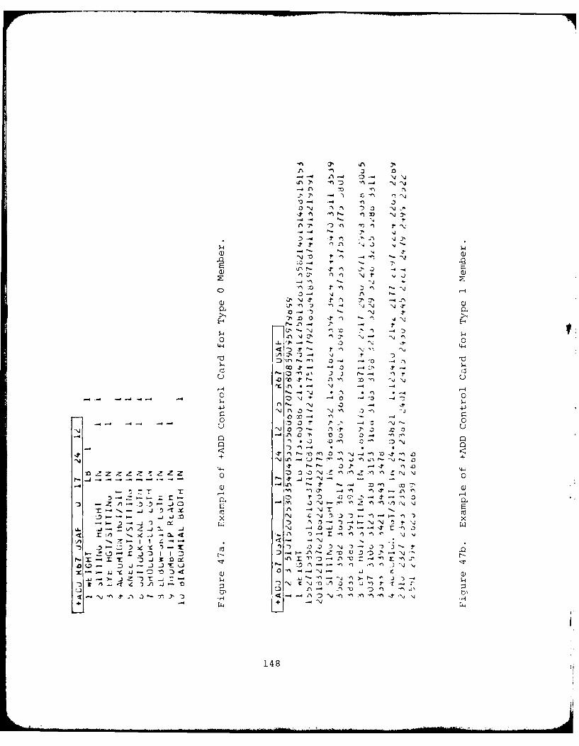
3-4 -4
4-4-
0) - 4 - 4 -4
NO -4 ~4) IX -n )
-4 0~ 0- Nt 0
4JN NNnN 4
4D~~- ' C
0 -:o 0f
on o 7 * n-
44J 0 P- r- J, - t, -'.-- -Z
7 T os) I P - n f)a-4-D7 P-4 - ' - 'D
-4 -r 77 'S ~
44-
~~z z ~ z z z z 0-1480
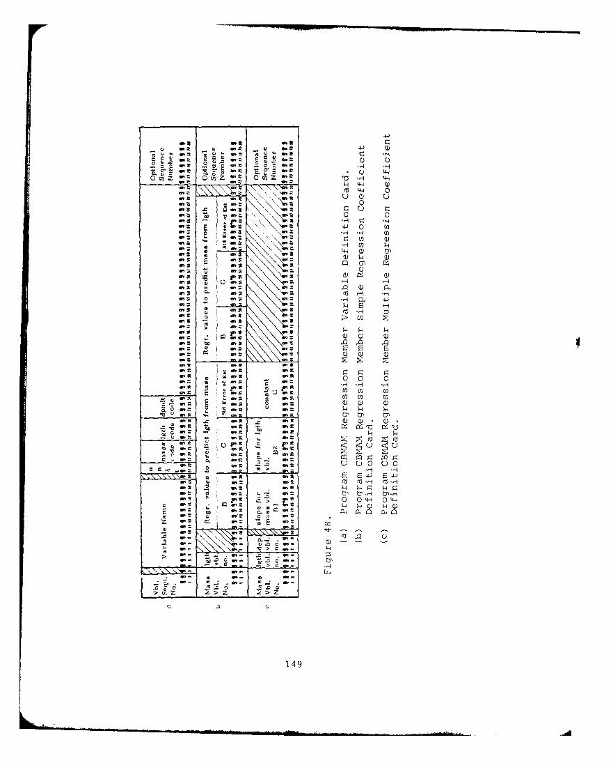
41
t e 41 Q)U
r ar tot r Z w
:cl 01Z 01 - t C) = Qo z L Z :t a tn z rA 4-4
4 4-4 Q)M 4-4 0Nen
x 4n a
E 4-) 0 (n
0 -4 -H (j)Q)4
444
on S
1w,u r-A
on P
on 4
(z H> U)
4 4 4
4n a m
w It 0 0 0-r-I H r-iCl)EEn W Win tC) C) a)
C m 4n 2 4 4 4U- m
Q it
4ro 2: ro0, st u in r 0
to St m 4nm A C, nE
2 u L) 0 u 0r .2 i :: :. rl r-l
4n R on It F 4-) 4Jin e in t -1 (z -H
2 . W. 2 -4 4 r- 4 5":re L W% t U-) 13) -H U).H> 0 0 4-1 C) 4-4
in 4to 0. la4
ft
7 E 00zT
> -4
> --; -3
IBon qD
mt. z > z
u
149
a mass related independent variable, a length related independent
variable or a dependent variable necessary to generate the link
lengths respectively. A variable can either be independent or
dependent, as in the case of sitting height, but cannot pertain to
both mass and length. If all three fields are blank, the data
card is flagged as containing an error. As each variable definition
card is read in, the program checks the use of the variable and
records its status.
The first outlined area of Figure 49 is
an example of a Variable Definition Card. A "1" is punched in
columns 30 and 34 to indicate that the Sitting Height is both
an independent variable related to body segment length and a
dependent variable.
Two types of record formats are used for
each combination of mass and length related independent variables
as shown in Figures 48b and 48~c. In Figure 4g1b, the variable
numbers, punched in columns 1-3 and 4-6 are obtained in columns
1-2 of the variable definition cards (Figure 49a). Columns 11-40
contain simple regression information necessary to predict the
length related variable from the mass related variable. This
information includes the slope and constant in the regression
formula:
Y = bX + c (2)
where:
b is the slope and
c is the intercept.
It also contains the standard error of estimate associated with
the equation. Columns 41-70 contain similar data to predict mass
from the length variable.
The reqression data used in the followinq
examples are unpublished data provided by the USAF. This report
contains the slope, intercept, and standard error in metric units.
150
The coefficients are multiplied by appropriate factors to convert
them to the English units specified on the Variable Definition
Card. The regression equation to predict sitting height in inches
from weight in pounds would be:
Estimated Sitting Height = 0.02669 x Actual Weight + 32.05275(Variable #2) Variable #1)
(1)The standard error would be 1.11161.
The equation to predict weight in pounds from sitting height in
inches is:
Estimated Weight = 7.84538 x Actual Sitting Height - 114.20831
(2)The standard error would be 19.05910.
In Figure 49 (2), the "l" in column 3 identifies Weight as the
mass related variable, and the "2" in column 6 identifies Sitting
Height as the length related variable. The regression coefficients
for equations (1) and (2) are punched in the remainder of the card.
T!he second record format is shown in Figure
48c and defines the multiple regression information necessary to
predict each dependent variable from the particular combination
of mass and length related variables. Columns 1-3 define the in-
dependent mass variable number; columns 4-6 define the independent
variable number; and columns 7-9 define the dependent variable
number. Each integer value must be right-justified. Columns 11-
20 define the slope associated with the mass variable value (b I ;
columns 21-30 define the slope for the length variable value (b 2);
and columns 31-40 define the constant of the equation (c) . The
equation form is:
Y b1X1 +b 2X2 + c (3)
where:
xis the value of mass related variable;
151
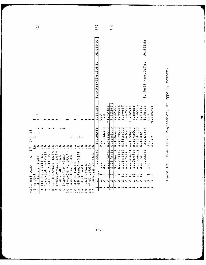
0%
-4 -4
.Q0
(Q0
4 0 0
J- 4 4 30
0 1 r0
-44 4 0 07 -
0 40-0N. 0
n0'4~~~ z0 O3z~~ z0
M C - --- 1) ~))~ U
-' ) -4
.4. *t _j. 0~ 4 .3-J- I 1 0 4N ' na,
' - - - -- - -1:~~~ '1 Wa 41 le~ A44 Nj0a
-J)
+ - -o - rrz-4o o o )~~-,)
-. Jt~)~-~. .4 ~ ** * *0 *152*
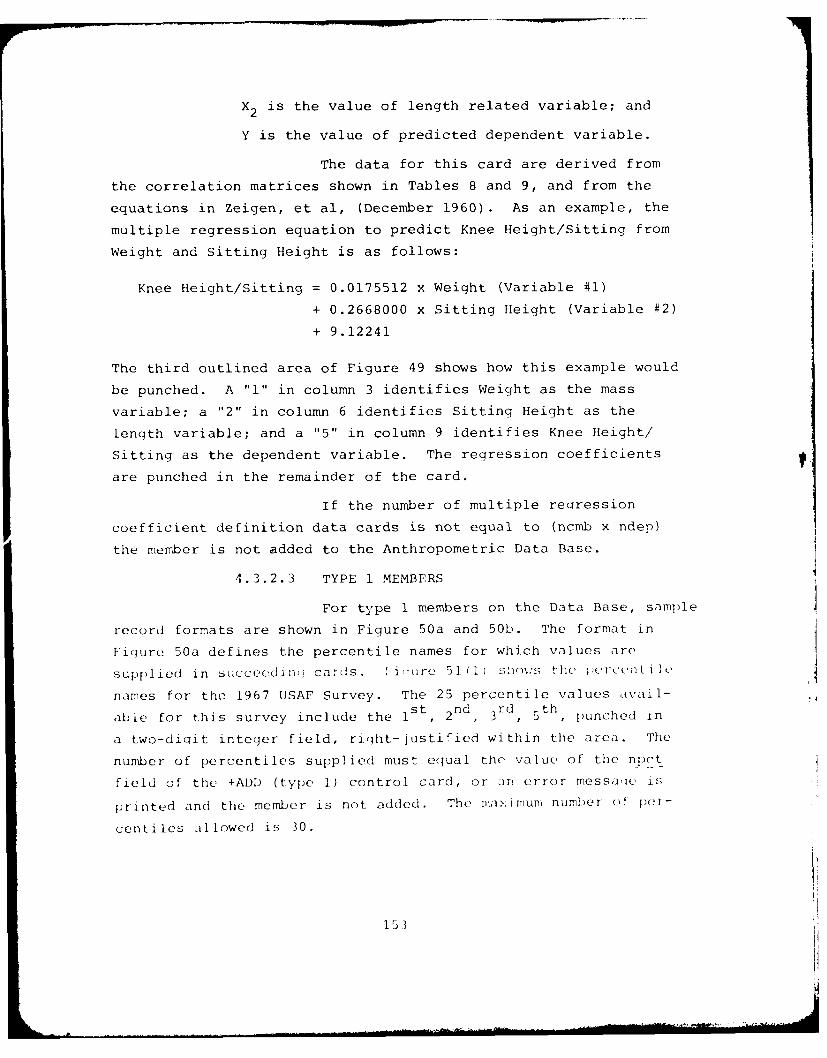
X2 is the value of length related variable; and
Y is the value of predicted dependent variable.
The data for this card are derived from
the correlation matrices shown in Tables 8 and 9, and from the
equations in Zeigen, et al, (December 1960). As an example, the
multiple regression equation to predict Knee Height/Sitting from
Weight and Sitting Height is as follows:
Knee Height/Sitting = 0.0175512 x Weight (Variable #1)
+ 0.2668000 x Sitting Height (Variable #2)
+ 9.12241
The third outlined area of Figure 49 shows how this example would
be punched. A "I" in column 3 identifies Weight as the mass
variable; a "2" in column 6 identifies Sitting Height as the
length variable; and a "5" in column 9 identifies Knee Height/
Sitting as the dependent variable. The regression coefficients
are punched in the remainder of the card.
If the number of multiple regression
coefficient definition data cards is not equal to (ncmb x ndep)
the member is not added to the Anthropometric Data Base.
4.3.2.3 TYPE 1 MEMBERS
For type 1 members on the Data Base, sample
record formats are shown in Figure 50a and 50b. The format in
Fiqure 50a defines the percentile names for which values are
supplied in succeedini cards. i'i"ure 51 (1) s:plos the percent l
names for the 1967 USAF Survey. The 25 percentile values avail-s t nd rd( th
able for this survey include the I , 2 , 3 , 5 , punched in
a two-digit integer field, right-justified within the area. The
number of percentiles supplied must equal the value of the npct
field of the +ADD (type 1) control card, or an error messa,c, is
printed and the member is not added. The mwiximum number of )er-
centiles allowed is 30.
153
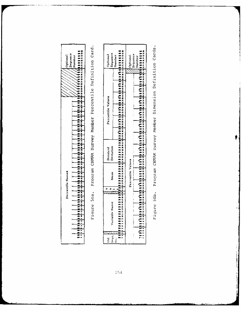
-g~o - -
-~ o % 6.t ~ . -
En "::.:TZ-- 41.,
2 ; n4-4.
-st 4-4'
N 2 -a 4n-3 a
: J.
: ~ !0::a4n g-2W
6. ) t~ -: n-- ~ ~ I t ;.: C6. T c. I.
-~ a) - -:6.26. M . *.
-: 2 6
:f : .;6.
3 J 44~ p:-- a
C) 6. 6. M
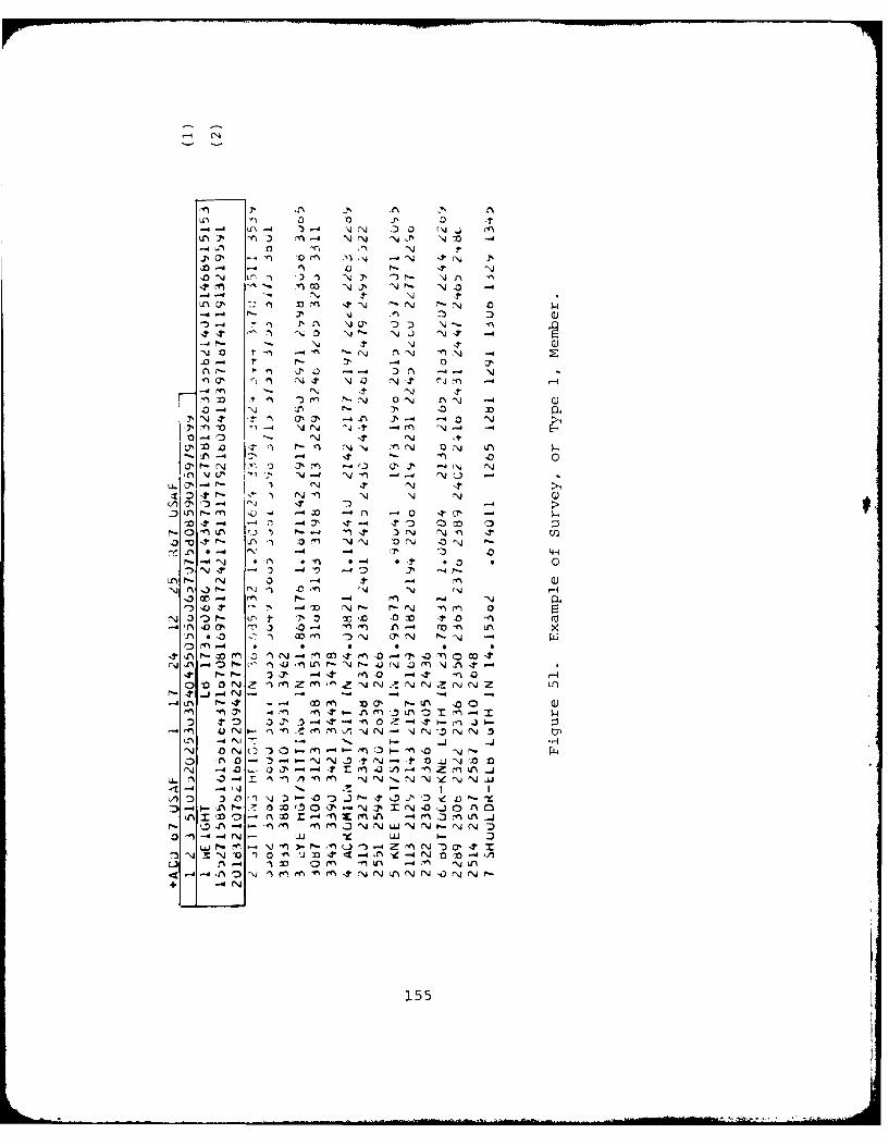
(-4 jN
.o -4 It- N J ~ 0 ' ,
m ~ coi 4-d NN -,jJP% Nji a
-dN NJ t-L 4 CP nj 3 N0N.)
D44. el' PN n ~ N. ~ -
-4-Nj -t 4.t0NO n' ., --4 ~ "N )N N -4.0-- . 0 cj'
.04 -- 4- Ln- -. 4N
N N, 0% Nl >
0-N Nn 4-Y' .
O-4 r - N O4 JN .1-
-LA-41 r'4. - 0
N- -? N (1 n(U-\.N .I oN"- N 0 N 0N~A~'0' N 4 4--
3LA !' LA- iv a ' NN 0N
* L 'D N* f- M F-0
'N- -4 In in' -40 P n -a
L - N0rf 0 -4) COr ) -4 P 0 n) C
a j .0"i zm N C N N \jN z L_j 4 - - - - - -
-4 ""N N! 1- 11% 'ir) 0
A 03 '3 li N DOtN '0 14N
4.LA 0 - 1~ ',j~~ -4 -t '1 0 J'' '- I0 C
-* p 1- 0 M 1. 4 ~ -4-.
- -D -N m- .
La -ON - LIf ? wN NJ (n - Li N
A -4) rf- FfN '0z ' - N l N~ N N 0 jo+
N- ~ C'i~J~u.JN155 N
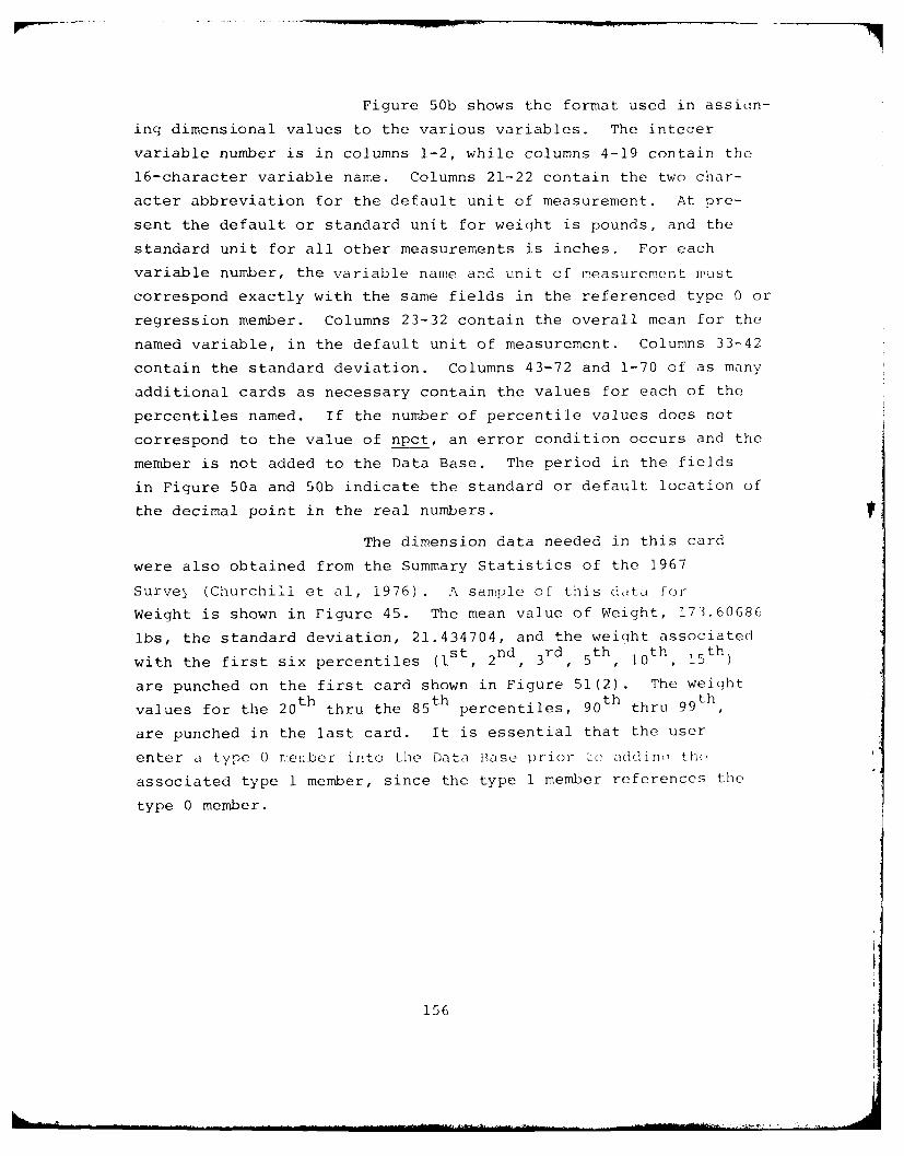
Figure 50b shows the format used in assign-
ing dimensional values to the various variables. The inteqer
variable number is in columns 1-2, while columns 4-19 contain the
16-character variable name. Columns 21-22 contain the two char-
acter abbreviation for the default unit of measurement. At pre-
sent the default or standard unit for weight is pounds, and the
standard unit for all other measurements is inches. For each
variable number, the variable name and unit of measurement must
correspond exactly with the same fields in the referenced type 0 or
regression member. Columns 23-32 contain the overall mean for the
named variable, in the default unit of measurement. Columns 33-42
contain the standard deviation. Columns 43-72 and 1-70 of as many
additional cards as necessary contain the values for each of the
percentiles named. If the number of percentile values does not
correspond to the value of npct, an error condition occurs and the
member is not added to the Data Base. The period in the fields
in Figure 50a and 50b indicate the standard or default location of
the decimal point in the real numbers.
The dimension data needed in this card
were also obtained from the Summary Statistics of the 1967
Surve (Churchill et al, 1976). A sample of this data for
Weight is shown in Figure 45. The mean value of Weight, 173.60686
lbs, the standard deviation, 21.434704, and the weight associatedst nd rd th th th
with the first six percentiles (1, 2 , 3 r, 5 , 10 , 15
are punched on the first card shown in Figure 51(2). The weightth th th th
values for the 20 thru the 85 percentiles, 90 thru 99
are punched in the last card. It is essential that the user
enter a type 0 r.eiber into the Data Base prior Lu addinm th(
associated type 1 member, since the type 1 member references the
type 0 member.
156
4.3.2.4 CHECK ANTHROPOPIETRIC MEMBER Function
+CHK membername type nvbl ncmb ncep npctre__ name
The CHECK ANTHROPOMFTRIC MEMBI'R function
operates in the same fashion as the ADD ANTHROPOMETRIC MEMBE:R
function does, except the member is not added. The member is onI;
checked for errors.
4.3.2.5 DELETE ANTHROPOMETRIC MEMBER Function
+DEL membername type
The DELETE ANTHROPOMETRIC MEMBER function
removes the specified member from the data base, but does not make
the space the member occupied available for reuse. The +CMP func-
tion must be used to accomplish this.
4.3.2.6 COMPRESS ANTHROPOMETRIC DATA BASE Function
+CMP
The COMPRESS ANTHROPOMETRIC DATA BASE func-
tion makes space available for storing anthropometric members by
compressing used space together and therefore maximizing the amount
of continuous unused space. The intermediate blocks of unused
space are created by the DELETE ANTHROPOMETRIC MEMBER function.
The greater the activity of the Anthropometric Data Base (i.e.,
+ADD's and +DEL's), the more often it becomes necessary to use
this +CMP function. If the message "CBM310A INSUFFICIENT SPACE
REMAINING TO ADD MEMBER membername" appears whep \otu tr"' to adco a
member, it becomes necessary to use the +CMP function. If the
+ADD function gives the CBM310A message immediately followinq the
+CMP function, the Data Base is full and no new members can be
added until an existing member is deleted, or more space is added.
157
+DMI' memberA1'A t'' (,
+ DMI
The [ .- Avih< 'I . I W ' II
I i'ts tII c , t ent I tile ,itlthl , 2C k.. !'- Vr " '.: Il"
t Vitu S! ' C1 t I i riots thL -e)ri I ett, "I t ;1 '7 tt I-I 1xlIt'l !hast2
14t :t' t:ci nw is :i' 1 n 1. t it c It ,'* U. I)ris + I'w kti 'n is
wak [' :: 1 1" Lx :;:at: I a oer>; t r!, ., t n t.
4 . 3 .2 .8 iND i[&,IA. !rit iyli
+END
The I ND i'RO(RAM function control card
terminates execution of the proqram CBMAM and returns control to
the operatinq system.
4.3.2.9 IZFIIAA Z" ANTtfRC()1I TIpC DATAfv wAFunct ion
+INT
The iN iT ALIZI AXTIIIOP ).,TRIC DATA ,
function will reset the Data Base to its oriqinal unused state.
Any members that were on the Data Base before the function was
invoked will be purqed, and all the space --ill 1( ,iIdi]
new members. The primary purpose of this function is to establish
a Data Base.
4.3.2.10 PUNCH ANTEROPOY I TNIC MtMBI' Vjnetit,
+PCII membername type
The PU'C! ANTIIRO tO(MI'I IC MIR funet iji.
will punch a copy of the specified member in the same format the
ADD ANTItR,)OMITRIC MI.LItI , function retuir es :ui the stek ci:ik-
type. The member is punched onto computer cards. Specifyin: a
member name that does not exist causes a printout of the meLber
names that are on the IDaita Past,. This function does not roe
the member from the Bat , Bas.
VAt
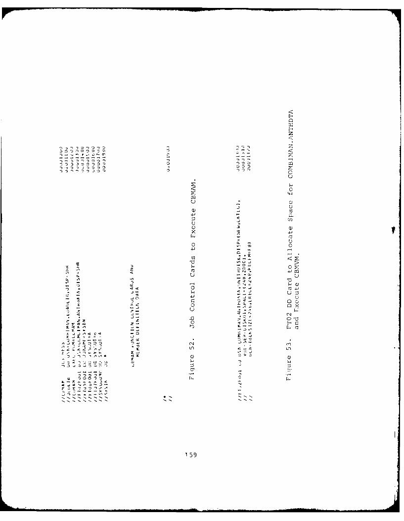
C)
0 0
0- -0
4-)
u .N.
.4 Z
X~ .1 4JL
La -:- .0
-22 2
159-
4 . 3.2 . 11 PRINT ANT1IROPMI 2 P1FTRlC Ml *IJEIR f'ctln
+PRT membername type
+PRT
The PRINT ANTHROPOME'lRIC MEMBER function
will print the contents of the specified membier, memb-ername, of
type, type, in a format similar to that used in the ADD ANTHROPO-
METRIC MEMBER function. Specifyinc no name, or a name that is not
in the Data Base causes a printout of the member names in the Data
Base, the number of records the member occupy in the Data Base, thc
type, and any additional data as supplied on the +ADD control car(-
when the members were added to the Data Base.
4.3.3 Submittinq a Processing Request
In submitting a processing request for the procrar-
CBMAM, the user must use a predetermined set of Job Control LancLac e
Cards (JCL) which calls the procram CBMA.M and defines the files
used (such as the Data Base itself). Located within this deck of
JCL cards are the prooram function control cards and arc relat':o
member definition cards. The set of JC1 used at hESS facility
is shown in Figure 52. Use of the card which becins //FT02F0Ol as
shown in Figure 52 assumes that the space on disk for the Data Pas<
has already been allocated. If for some reason this condition is
not met, the //FT02FOOl DD card in Fioure 52 should be replaced
by the card sequence shown in Figure 53. The JCL deck should be
run with this replacement series only once - enough to allocate
the space for the file on disk, and to catalogue the file in the
system library. Thereafter the simplified "//FT02FO0l DD" card
shown in Figure 52 should be used.
If the file h~as lust bon created, or if the use'r
w,ants to reinitialize the Fi](,, the 47'T control Function . ,a
be used before an'i other control card fun(ctj(I .
The last control card read into the ' rei,,, shou](;I
be the +END control c:iru.
] E; 0
4.3.4 Interpreting the Output Data
The program CBMAM generates output to the card
punch, to the disk file, or to the printer depending on the con-
trol card function specified. The formats for the printed out-
put will be discussed in this section. Punched records use the
same format as the input data records discussed in Paragraph 4.3.2.
Five basic types of formats are used by CBMNIM when
writinci data on the printer. Each of these format types, their
use, and an example of each will be presented in the following
paragraphs. Each of the types begin with the same heading, list-
ing the proc:ram nare, CBMAM, the date and time of the program
execution, and a page number.
The first type of output is generated by the INI-TIALIZE, PUNCH, COMPRESS, DELETE, and END functions. The output
informs the user of the start and end of processing associated
with the function specified. For the COMPRESS function, addi-
tional messages are supplied indicating that a particular member
was or was not moved in the process of compressing unused records.
An example of this format for the COMPRESS function is shown in
Figure 54.
The second type of output is generated by the PRINT
or PUNCH functions when the +PRT or +PCH control cards are sup-
plied with a blank membername field. This causes a listinq of the
index of the Data Base. The location and type of each member is
contained on the index as one record. This information is print-
ed in the following format:
nn.) membername, EXTENT = (nl, n2), TYPE = tt,
nv \AR]ABLES , nc COMB OF INDEP, nd DEPENDENT,
np PERCENTILES, r-membername REFFRENCE D SURVEY.
whcre:
nr is the record number of this identification recordwithin the directory.
nI is the location < tln I a w t iI1 1e2; t -1 :1
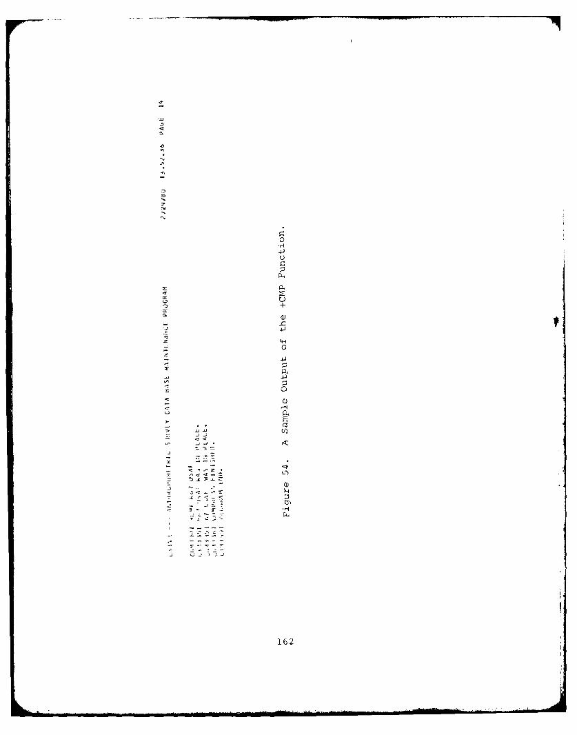
44
0
4-)
4Q
Ur
7+
0.162
n2 is the location of the last record of data which
defines this member.
tt is the type code (0 or 1).
nv is the total number of anthropometric variablesdefined.
nc is the number of combinations of independent vari-ables.
nd is the number of dependent variables.
np is the number of percentiles (np = 0 if tt = 0).
r-membername is the name of the referenced regressionmember (r-membername is blank if tt = 0).
This information was originally supplied to the
Data Base on the +ADD control card. An example of the usage of
the PRINT function is shown in Figure 55.
The third type of output is generated by the DUMP
function. This function is used primarily by systems programmers
to locate causes of I/O (Input/Output) errors on the Data Base.
For the member specified on the +DMP Control Card, a message
giving directory or index information is printed, using the
output format previously described for the +PRT control card.
Each record associated with the member is then printed in the
following format:
RECORD nnn + = + (record in EBCDIC) + = +
+ = + (record in hexadecimal) + = +
+ = + (remainder of record in hexadecimal) + = +
where nnn is the location of the record in the Data Base.
The record in EBCDIC is printed using a 25A4 format. The record
in hexadecimal is printed using a l0Z8 format. An example of the
DUMP function is shown in Figure 56.
The fourth output format is used by the CHECK, ADD,
and PRINT functions when a type 0, or regression member is speci-
fied. After reading the control card and checking it for errors,
the information contained on the control card is reformatted and
written out to the printer.
163
..n ..2
Z Z
-J z z
A. +
Zng-
-)-,--0
44 + 4
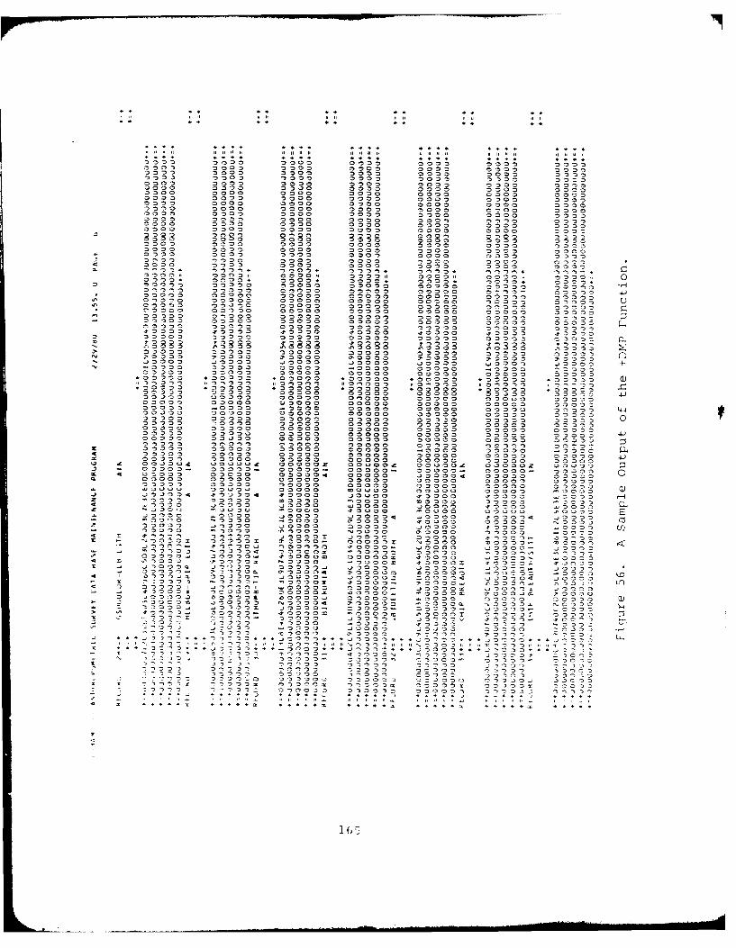
*~.. ... .... 6 .04 44 4" 44 v4 CD 44 44 44 m 44
0 n. 0 . . n 0** 0. 4 'o ." .) .o :.0000 04000 0000~ 0000o 000)= 0000 00000000 0.000 0000 0000 0000 0oo00 0000O0000 0 00o0 05 0 30 0 00 0 0 0 00 0 D00o0I0=0:0 0000 0000 00,00 0000 0000 0000a000o0 0000 000C) 'n0 0 '0 00 0000 30 0-40 0 0on0) 0 0--,00 000 000 0.3600 00400)0000 0000o 0000 000 000 00 In0o0000 0 00 0 00,00 0000O 00,00 000 000000 0000o0000 D00 0000 0000 0000 C
o0n 000 0000 000 00,0 00 0000 00 00 0000 00n00 0 o00 o00n000 0 00 00000 0000. n00 0 0 0C3000D 000 00 o 0 0 00 00o, 00
0~~~~~~~: o0~ nU3 0 3 3 0 3 0 30
0000 ~ -. 0o0 000 000 000 000 0000 0 00000 0000 000 000 o0
n. 0o0D0 00 000 0 0 00 000 0 'n n0 04 00 000o0 o00 0 0000 0n 0o 000o. 0 . 0 0 . 0 00 0 0 0 0 0 00000044~~~, 0n04 00 0 00 , 00 04 00 04 0000 0000 'nn C5 00 0 00000 0 000 00 0 0 0 0 n0000 n0 'n 0 0 0 0 m0 0 0 0 0 oo o 0 00 0 0 0 0~ Hm, " n I00, 00000 0 0 0 000 000000, or0 0 o00n 00n 00 o* 000M,0 o0o00)0 00000 0 00 0 0 0 0 0 0 004'0 0o o =0000o 00000 00 0 noo o o 0 0 .40 00000, 0000 0 3o0 00 0300" 0 0 0) 0 00 0oo 0 ~o 0 "o no0000= 0 00 0 0000 00 0 o 3 o0 -00 o000 00 o0D
-'~~~' 0000 00,0 00 0 00 0 0 00 0 o0n 00-~~~~~~ 00 0 o0 0 00 0 0 0 00 0 000 0 0 n nn0000 0 000 000 0 00 000 00000 0000-33 :
-o 0 0 o 0o00 00 00 0 0000 0000n 00n00o
2' 00 0 0 00 000 0 000' 0 000 0000 -oo0 D 000 (=4 ao o , O 000 D 000D 20 o0 2'00 * .,00n0 3 n C 0 00 030000 -. 00 0000 .. 0 0 0 0
M,00 00 0 0 0 00 00000 00000 000;.0000 .0000 o0000 o0000 .0000 *30ol0 .00
00 0 z00000 00000o 00 0 00=0 0 Z 0 0 005'S 400040 00 0 00 00 00 00 00 0 000.0 000D-00000- 00000 420000 00000 00000 00003 000o0 0 Iooloo 0010 .oooo 0 0:)00 00000 0 I 110' " : o00000 4-4000100 000100 00000 00000 00000l 00000: 000ID0 0000. 0000.)0 0000 0 In00 00 0 0000 00000 0000.. 00 0 00 00000 0000 00000 =Moo.)
00 0 Imo0 I.000 00 00 0 o0 0 o0 0 00000In00:0 00 0 0000D n ,0 00 0 00 0 00 0 0000 00 00o0D0 0a00 00 00000 00003,0 00000 c 00000000o'0 o000 0000 00 0 Cln)0003=1 0 0 0lo0 0 . 013 '.l) o 0000 0000 n 30 0 00 00000 Inn000 0 0000 4n00' 0 n00o000 0 00 00 0 0 00 0 (30 C000 n,000 D0 00000 440 o 3004 004C 0000~ 000004 00000 3n3 0 on0 S S00034, :- 0000 ~ oo ~ 0 0000 00000 -00n0 1 0000 0 0 0000 0
300Q0.00 00000-0 0 00U00 - o o0 000 0 00000 00000Oooz 0000 000 00000. 00000 00000 00000o 0000000000 00000 00000 00000 0000 00000O 00000O0 .40424o 0 04000 0 a0 00 0 0'D00 0 0000 0o0 00 0 n0o44o4 4400004 o 40 0 400D0 0 .40D0 0 000 3-) n00.0 :o 00 n n n
o ' 0000 'o 0000 40000 '.70000 01004 30 n0oz4.00 00 0 o400 4400 000 2 000 440000n
-~ ~ 0 0 0 0 0 0 I00 0 a00 0 000 0 0 In o 'o 0 0 0 00 00 00000 4000 0 ID0 00 .*O0:30 o 0000=0- no00 0 .0 '0000 000'a 0000 1 000.-., o4o0000 . 000 00 00 aoo. 4400 4 00- -40 0 0
4' 00000.4~ 00000 ' 00004o 00 013 .t)OooO 4 0 0' . .* 44 4400 0k 4000 000 044 4400 0 40000 I 4 0 . 0000
4 4 0004a 00 0- 44000M 44000402 000004z 4 00oC 44000
44 ~~~ 40 0 00 0 0 00 00 0 0 0=-. ' 00 1 'n00 4 c400o0 000 0 0001 )000044 000 0 0 00 000 00 o)
o4 000 ,3 M 000 . 00- 00 00 'n0 0 440001 1 .4' -00 - 0 0 0 0 0 0 1 1 n 1. D :2 0 0 0 0 0 '.o 0 0 04 0 0 0/ 4 0 0 - 4 -
0o 00 f0 0 -000 ~0 oo30 0000. 44'000 0000 0000 M D O
-''0 'nj 00 D 10 000 Z40000:- -o oz 2000:O 0 DZw40m *o ") U4 000o 0 0, U 4 000 . * a4 0 0 . *, = ?0'.
'D 1 0 00 00000 -3 0 -T on o0
00005 0 00 00 000 0 00 n n000
J 5 4 *4'~~Z o44 4 4 o4,44 4 .4 3 o443 . . . . . .n.4 . . . .on [
n -5 n 'D o
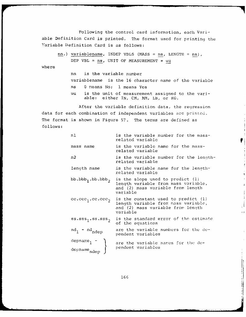
Following the control card information, each Vari-
able Definition Card is printed. The format used for printing the
Variable Definition Card is as follows:
nn.) variablename, INDEP VBLS (MASS = ns, LENGTH = ns),
DEP VBL = ns, UNIT OF MEASUREMENT = uu
where
nn is the variable number
variablename is the 16 character name of the variable
ns 0 means No; 1 means Yes
uu is the unit of measurement assigned to the vari-able: either IN, CM, MM, LB, or KG.
After the variable definition data, the regression
data for each combination of independent variables are printed.
The format is shown in Figure 57. The terms are defined as
follows:
nl is the variable number for the mass-related variable
mass name is the variable name for the mass-related variable
n2 is the variable number for the length-related variable
length name is the variable name for the length-related variable
bb.bbblpbb.bbb 2 is the slope used to predict (1)length variable from mass variable,and (2) mass variable from lengthvariable
cc.ccclcc.ccc2 is the constant used to predict (1)length variable from mass variable,and (2) mass variable from lenqthvariable
ss.ssslss.sss 2 is the standard error of the estimateof the equations
nd - nd are the variable numbers for the de-1 dndep pendent variables
depnamel - ] are the variable names for the de-
depname nde p pendent variables
166
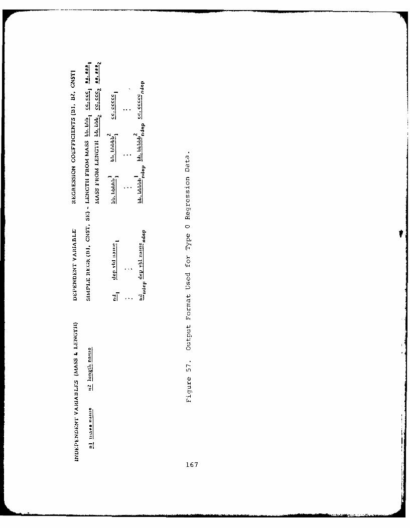
zC
- 4-) U
z 0~~
La
z
LaE-4
0
UU
- -! 14 0)
0. 0
41
z 42)
0
Z)L-4
4~1 4
*16
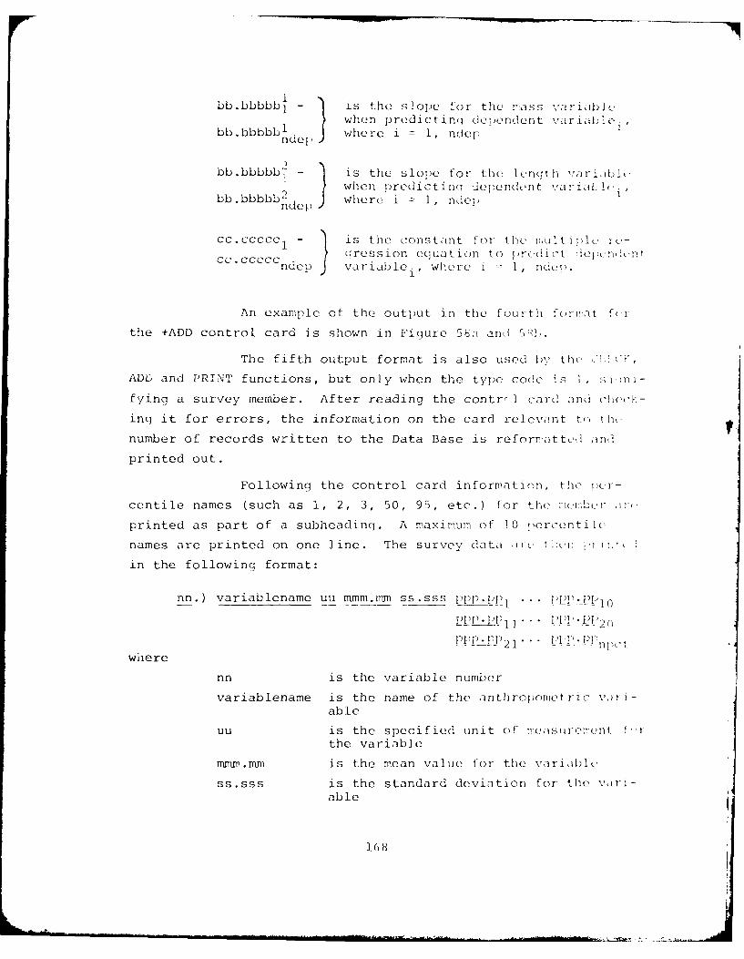
bb.bbbbbl is the slop~e for the mass -iariablIe-when predictinq dependent variable,bb.bbbbbl where i = 1, ndern do
bb.bbbbb'7 - is the slope for the length vrai
bb.bbbbb 2 3where i =II ndepndep ) hnpeit n eedn
cc. ccccc - is the constaint for the raulti pie re-
cc.CCC cccc ? ression equation to pr( 1i t ~pidnndep )variable , where i -- 1, nldcep.
An example of the output in the fourth for!-at f(r
the +ADD control card is shown in Figure 5ba- ani i.
The fifth output format is also used by' the(V H
ADD and PRINT functions, but only when the type code is 1, s i
fying a survey member. After reading the contrr I card aind choc-
inq it for errors, the information on the card relevaint to) the,
number of records written to the Data Base is reforrmatted andi
printed out.
Following the control card information, the ier--
centile names (such as 1, 2, 3, 50, 95, etc.) for themeera
printed as part of a subheadingl. A maximum of 10 percentile
names are printed on one line. The survey datai 11c tl:(uni Cii-
in the following format:
nn.) variablename uu nunm.rnm ss.sss ppp.PP1 . .. 1)Pp1 --1 p-)1
PP!1P1 PH'2 n f
2P 1 111 pcwhere
nn is the variable number
variablename is the name of the anthropnmetric %) rj -
able
u u is the specified! unit Of nea'tSurerient 1-ithe variable
minn .M.M is the mean value for the variable(.
ss.sss is the standard deviation for the vari-able
168
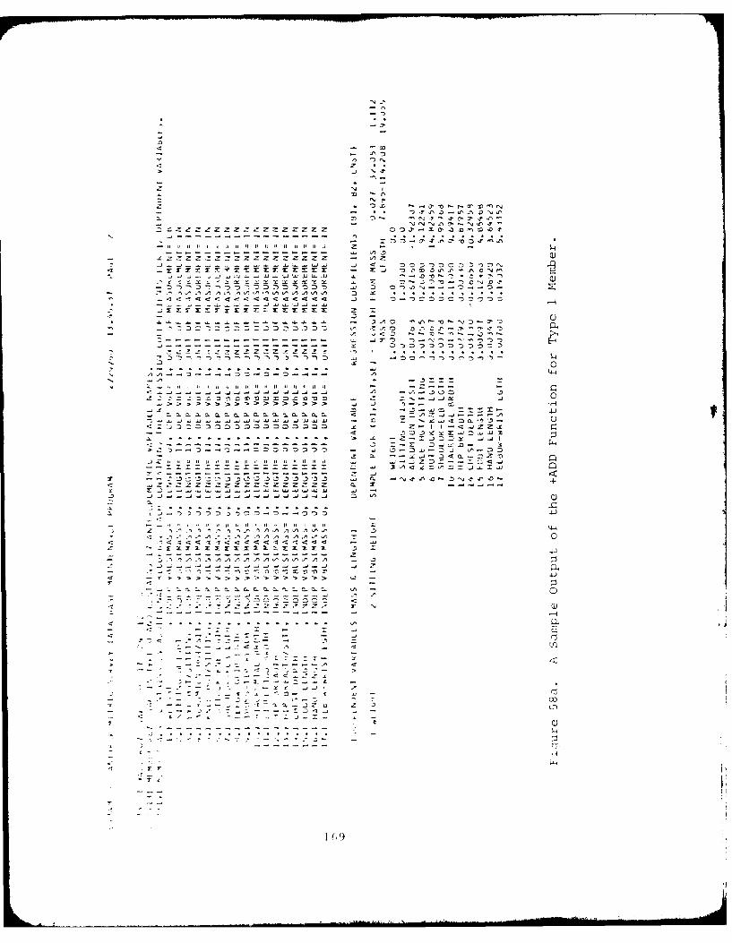
N j
-0
n~ -D o lv
4 4 *-
N I
ZDf
< <'
-~ - - -Z - - - - - - Z- - fI
. . .. . . .. . .0 .0 . 0. .0N. .
. . . .. A . . . . . . . . .
7>
7C .
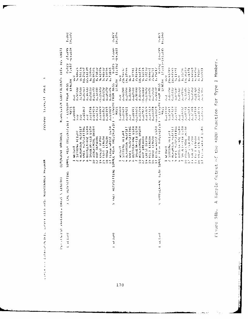
-~
- ~:~-
A 3.0z.J ? 2-.
-~ -~- I
N
NIt' ~2' ~~~--~''A- * 2<P ~'-~--..)r2-
~4 Afl~C'42N3N.?A~- .e ~ ~'~-r'-
2'~21~~ ~ 321~- 2 ~-r >9 . .
- ~21A2121N.021~0'A.a~ 221~?213N21~.~N =21~21'~~fl.:I>~Z - -- - - N- -~ - -.. ' A.2 A~3- AZ AZ AZ
- ..) <.1.. 21212 212ZC~~21.t4.... 21221212121212121 21~-4... 21210:. 21 21210 ~.*4 - ~.J 2121~21..I~-.I9-A~--s~j 212* 21-21--r--- Z.1 3213.NAN21P
2: ~3-t21~21AN~-.T 2 1 ~ 21~-~21~21-r2 -o'-:.~---~--~.........................................................................
3 21~N~N21~-.212 21~~921~It'21-N?~2121 2121212121212121211.. 2121.212121210212121... 021021-.-W 210021:
II 0
Z 2: 2- A .421 21 ~ ~21N212100...4221~ 2'.-.~-J .- j~21 - "N2121)~J2:21-- ~ ~-~ 212121212102121212121 21213212121212121212121 2121212121.212)2121 2o
21 5 . .
- x -
211 A A
N.1 A-~3~3fl ~A -- '.31321 .3>9 ->9
z =N-.~J~J~~ .. JZ 2:%--....~ ... ~ ~ --4 ' ' .- , ' c21 - ~ 22:22.-. -~-.4421 2:Z2:~ - -~4 >9 .~AZJ.-~-- 21 N~4210.3~3-..21 21 ~4215.3.2 ~--- +
21.-I I-4..IZZ~- Z1 I-4...IZZ.0 '33~~s:*2:21.~~~Z IZ-.2J212~ 4~IX Z21~-~~l~ ~ 0
~.1 3-Z.4.21J A-21J~ .5~Z~~21j A.Z -Z 21 -- 21~-214a.JZZ~~ -- -3
2 ~-A~
2 1' ~ - 4~)
.1..JZ21.--214.4 -- J221--2421 -J ZA4~A21~~ .KA4~21A21 ... ~A<
Z -J -~ -~ c-~ ~. ~'J4A4'21N-tt'40. N~A~-21 tS2-2. ~~A-0N*
.0 0. 2: 2: -
3 LI A A A3
.33. -- Z 4i
21 3- ~J A
-~ - - C.0 - A 21
Z 3 A '.. 021 N
- - - .3 o21 ..J .3 2:
21-~2:
A I- 21
2: -~ P
.0
-i 121
.0 0)
- .2 21
- C I C
170
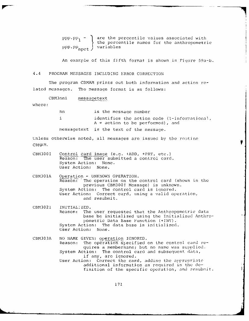
- are the percentile values associated with
1 the percentile names for the anthropometric
PPP PPnpc9t variables
An example of this fifth format is shown in Figure 59a-b.
4.4 PROGRAM MESSAGES INCLUDING ERROR CORRECTION
The program CBMAM prints out both information and action re-
lated messages. The message format is as follows:
CBM3nni messagetext
where:
nn is the message number
i identifies the action code (I-informational,A = action to be performed), and
messagetext is the text of the message.
Unless otherwise noted, all messages are issued by the routine
CBMAM.
CBM300I Control card image (e.g. +ADD, +PRT, etc.)Reason: The user submitted a control card.System Action: None.User Action: None.
CBM301A Operation - UNKNOWN OPERATION.Reason: The operation on the control card (shown in the
previous CBM300I Message) is unknown.System Action: The control card is ignored.User Action: Correct card, using a valid operation,
and resubmit.
CBM302I INITIAL]ZED.Reason: The user requested that the Anthropometric data
base be initialized using the Initialized Anthro-pometric Data Base Function (+INT).
System Action: The data base is initialized.User Action: None.
CBM303A NO NAME GIVEN; operation IGNORED.Reason: The operation specified on the control card re-
quires a membername; but no name was supplied.System Action: The control card and subsequent data,
if any, are ignored.User Action: Correct the card, adding the appropriate
additional information as required in the de-finition of the specific operation, and resubmit.
171
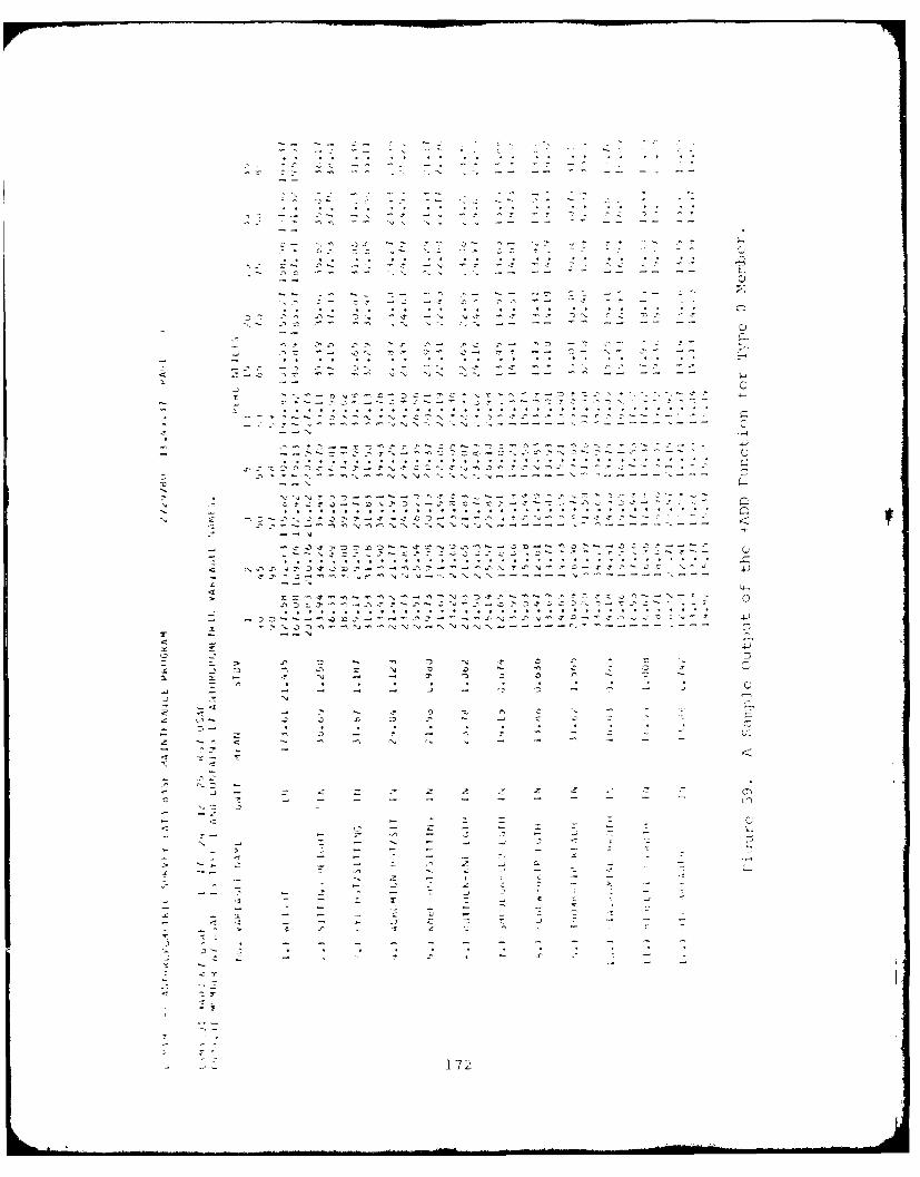
• ° • ° • • • o .° ° • ° -. • °
"f° ° ° o ° • • • _ • .- -
-- D-.- C
• • ° °*o .°
u ' - - ~ ~ - -
- ,'. • • • • • • • • • • • • • . • , , •
2 - . C.
. . ... . . . . ... ...
2"- ~ -- C3 :
--- --_ -
* S
..... .. -- -2 -.- 72~~
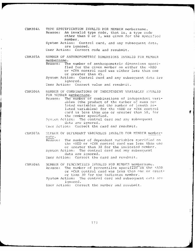
CBM304A TYPE SPECIFICATION INVALID FOR MEMBER membername.Reason: An invalid type code, that is, a type code
other than 0 or 1, was given for the specifiedmember.
System Action: Control card, and any subsequent data,are ignored.
User Action: Correct code and resubmit.
CBM305A NUMBER OF ANTHROPOMETRIC DIMENSIONS INVALID FOR MEMBERmembername.Reason: The number of anthropometric dimensions speci-
fied for the given member on either the +ADDor +CHK control card was either less than oneor greater than 45.
System Action: Control card and any subsequent data areignored.
User Action: Correct value and resubmit.
CBM306A NUMBER OF COMBINATIONS OF INDEPENDENT VARIABLES INVALIDFOR MFEMBER membername.Reason: The number of combinations of independent vari-
ables (the product of the number of mass re-lated variables and the number of length re-lated variables) for the +ADD or +C11K controlcard is less than one or Qreater than 50, forthe member specified.
Svs-e. Action: The control card and any subsequentdata are ignored.
User Action: Correct the card and resubmit.
CBM307A xuUMB3R OF DEPENDENT VARIABLES INVALID FOR MEMBER member-name.Reason: The number of dependent variables specified on
the +ADD or +CHK control card was less than oneor greater than 30 for the indicated member.
System Action: The control card and any subsequentdata are ignored.
User Action: Correct the card and resubmit.
CBM308A NUMBER OF PERCENTILES INVALID FOR MEMBER membername.Reason: The number of percentiles specified on the +ADD
or +C1IK control card was less than one or creat-er than 30 for the indicatea member.
System Action: The control card and subsequent data areignored.
User Action: Correct the number and resubmit.
173
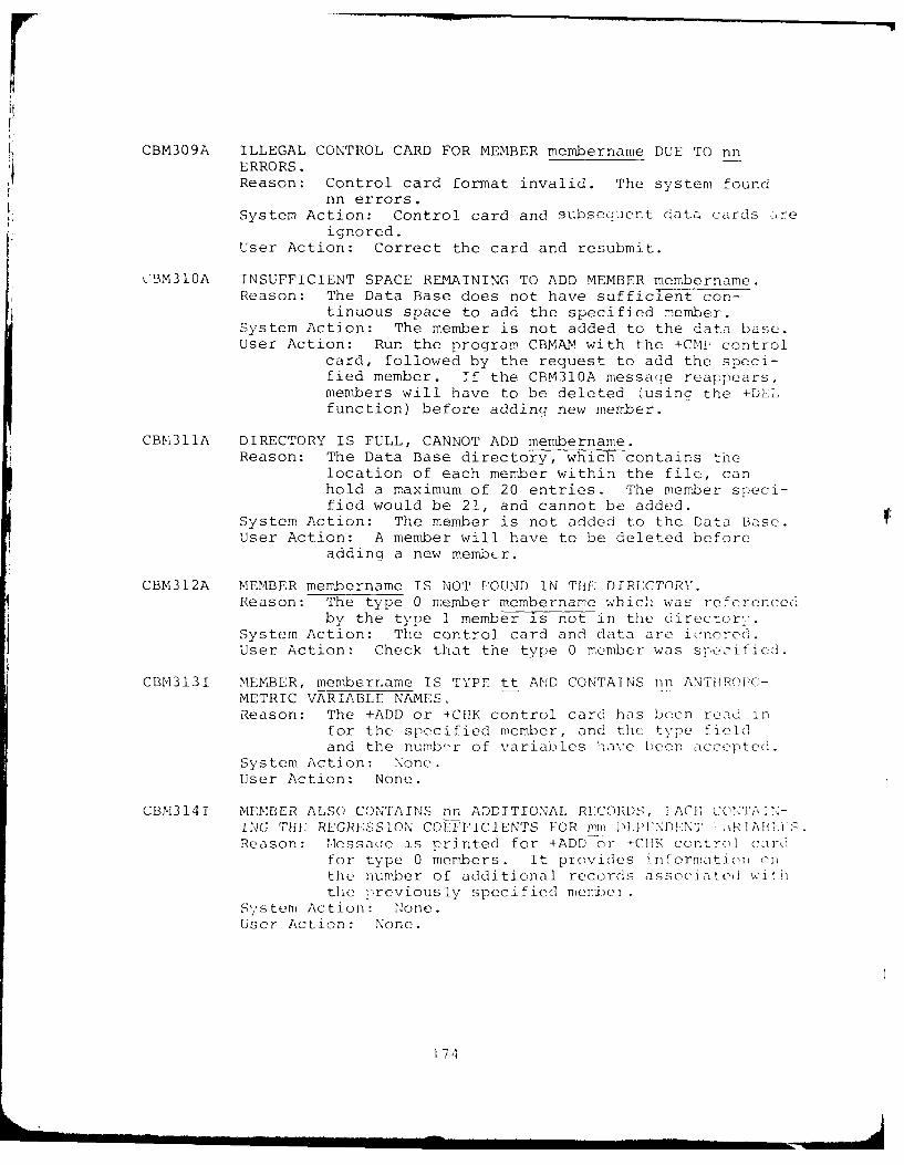
CBM309A ILLEGAL CONTROL CARD FOR MEMBER membername DUE TO nnERRORS.Reason: Control card format invalid. The system found
nn errors.System Action: Control card and gubseouent data cards are
ignored.User Action: Correct the card and resubmit.
CBM310A INSUFFICIENT SPACE REMAINING TO ADD MEMBER membername.Reason: The Data Base does not have sufficient con-
tinuous space to add the specified member.System Action: The member is not added to the data base.User Action: Run the program CBMAM with the +CNIP control
card, followed by the request to add the speci-fied member. If the CBM310A message reappears,members will have to be deleted (using the +DELfunction) before adding new member.
CBM311A DIRECTORY IS FULL, CANNOT ADD membername.Reason: The Data Base directory, which contains the
location of each member within the file, canhold a maximum of 20 entries. The member speci-fied would be 21, and cannot be added.
System Action: The member is not added to the Data Base.User Action: A member will have to be deleted before
adding a new member.
CBM312A MEMBER membername IS NOT FOUND IN THE DIRECTORY.Reason: The type 0 member membername which was referenced
by the type 1 member is not in the director,:'.System Action: The control card and data are icnored.User Action: Check that the type 0 member was specified.
CBM313I MEMBER, memberr.ame IS TYPE tt AND CONTAINS nn ANTPR(PO-METRIC VARIABLE NAMES,Reason: The +ADD or +C1HK control card has been read in
for the specified member, and the type fieldand the numb -r of variables h-ave been accepted.
System Action: None.User Action: None.
CBM314I MEMBER ALSO CONTAINS nn ADDITIONAL RECORDS, FACE COX]A]>-ING THE REGRESSION COEFFICIENTS FOR mm PIPNDENT ,ERAIi.Reason: Nlessacie is printed for +ADD or +CIIK control card
for type 0 members. It provides information onthe number of additional records associate(i withthe previously specified meml)el
System Action: None.User Action: None.
174
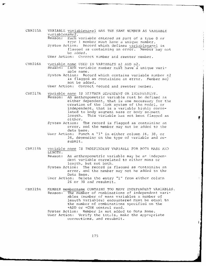
CBM315A VARIABLE variablenamel HAS THE SAME NUMBER AS VARIABLEvariablename2.Reason: Each variable entered as part of a type 0 or
type 1 member must have a unique number.System Action: Record which defines variablenamel is
flagged as containing an error. Member may notbe added.
User Action: Correct number and reenter member.
CBM316A variable name USED IN VARIABLES n1 AND n2.Reason: Lach variable number must have a unique vari-
able name.System Action: Record which contains variable number n2
is flagged as containing an error. Member maynot be added.
User Action: Correct record and reenter member.
CBM317A variable name IS NEITHER DEPENDENT OR INDEPENDENT.Reason: An anthropometric variable must be defined as
either dependent, that is one necessary for thecreation of the link system of the model, orindependent, that is a variable highly corre-lated to body segment mass or body seamentlength. This variable has not been flagaced aseither.
System Action: The record is flagged as containinq anerror, and the member may not be added to thedata base.
User Action: Punch a "l" in either column 16, 30, or34, depending on the type of variable and re-submit.
CBM318A variable name IS INDEPENDENT VARIABLE FOR BOTH MASS ANDLENGTH.Reason: An anthropometric variable may be ar indepen-
dent variable correlated to either mass orlength, but not both.
System Action: The record is flagged as containinq anerror, and the member may not be added to theData Base.
User Action: Delete the entry "l" from either column26 or 30 and resubmit.
CBM319A MEMBER membername CONTAINS TOO MANY INDEPENDENT VARIABLES.Reason: The number of combinations of independent vari-
ables (number of mass variables x number oflength variables) encountered must be equal tothe number of combinations specified on the+ADD or +CHK control card.
System Action: Member is not added to Data Base.User Action: Verify the totZuls, make the appropriate
corrections, and resubmit.
175
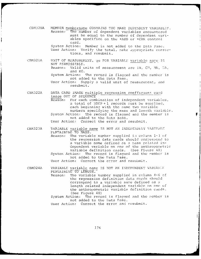
CBM320A MEMBER membername CONTAINS TOO MANY DEPENDENT VARIABLES.Reason: The number of dependent variables encountered
must be equal to the number of dependent vari-ables specified on the +ADD or +CIIK controlcard.
System Action: Member is not added to the Data Base.User Action: Verify the total, make appropriate correc-
tions, and resubmit.
CBM321A UNIT OF MEASUREMENT, uu FOR VARIABLE variable name ISNOT PERMISSIBLE.Reason: Valid units of measurement are IN, CM, MM, LB,
and KG.System Action: The record is flagged and the member is
not added to the Data Base.User Action: Supply a valid unit of measurement, and
resubmit.
CBM322A DATA CARD IMAGE multiple regression coefficient cardimage OUT OF SEQUENCEReason: For each combination of independent variables,
a total of NDEP + 1 records must be supplied,each beginning with the same two variablenumbers specifying the mass and length variable.
System Action: The record is flagged and the member isnot added to the Data Base.
User Action: Correct the error and resubmit.
CBM323A VARIABLE variable name IS NOT AN INDEPENDENT VARIABLYPERTAINING TO MASS.Reason: The variable number supplied in column 1-3 of
the regression data cards should correspond toa variable name defined as a mass related in-dependent variable on one of the anthropometricvariable definition cards. (See Figure 40)
System Action: The record is flagged and the member isnot added to the Data Base.
User Action: Correct the error and resubmit.
CBM324A VARIABLE variable name IS NOT AN INDEPENDENT VARIABLEPERTAINING TO LENGTH.Reason: The variable number supplied in column 4-6 of
the regression definition data cards shouldcorrespond to a variable name defined as alength related independent variable on one ofthe anthropometric variable definition cards.(See Figure 40)
System Action: The record is flagged and the member isnot added to the Data Base.
User Action: Correct the error and resubmit.
176
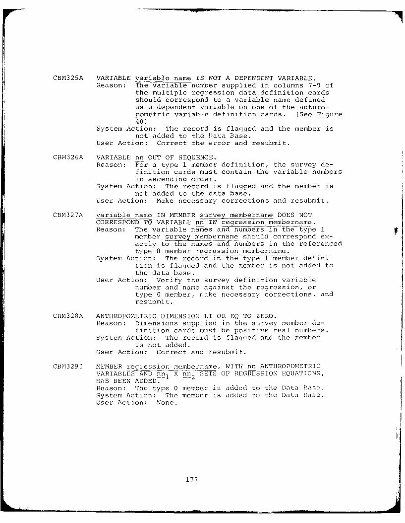
CBM325A VARIABLE variable name IS NOT A DEPENDENT VARIABLE.
Reason: The variable number supplied in columns 7-9 ofthe multiple regression data definition cardsshould correspond to a variable name definedas a dependent variable on one of the anthro-
pometric variable definition cards. (See Figure40)
System Action: The record is flagged and the member isnot added to the Data Base.
User Action: Correct the error and resubmit.
CBM326A VARIABLE nn OUT OF SEQUENCE.Reason: For a type 1 member definition, the survey de-
finition cards must contain the variable numbersin ascending order.
System Action: The record is flagged and the member isnot added to the data base.
User Action: Make necessary corrections and resubmit.
CBM327A variable name IN MEMBER survey membername DOES NOTCORRESPOND TO VARIABLE nn IN regression membername.Reason: The variable na-mes and numbers in the type 1
member survey membername should correspond ex-actly to the names and numbers in the referencedtype 0 member regression membername.
System Action: The record in the type 1 member defini-tion is flagged and the member is not added tothe data base.
User Action: Verify the survey definition variablenumber and name against the regression, ortype 0 member, rake necessary corrections, andresubmit.
CBM328A ANTHROPOMETRIC DIMENSION LT OR EQ TO ZERO.Reason: Dimensions supplied in the survey member de-
finition cards must be positive real numbers.System Action: The record is flagged and the member
is not added.User Action: Correct and resubmit.
CBM3291 MEMBER regression membername, WITH nn ANTIIROPOMETRICVARIABLES AND nn1 X nn 2 SETS OF REGRESSION EQUATIONS,HAS BEEN ADDED.Reason: The type 0 member is added to the Data Base.System Action: The member is added to the Data Base.User Action: None.
177
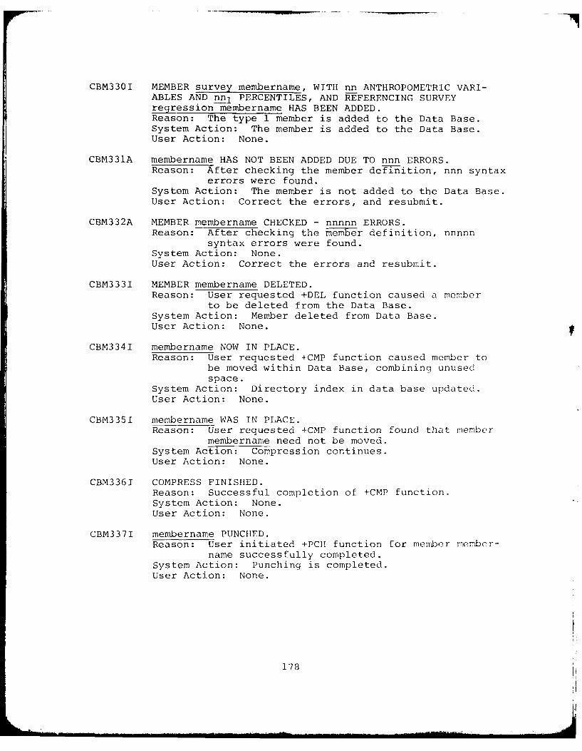
CBM330I MEMBER survey membername, WITH nn ANTHROPOMETRIC VARI-ABLES AND nn I PERCENTILES, AND REFERENCING SURVEYregression membername HAS BEEN ADDED.Reason: The type 1 member is added to the Data Base.System Action: The member is added to the Data Base.User Action: None.
CBM331A membername HAS NOT BEEN ADDED DUE TO nnn ERRORS.Reason: After checking the member definition, nnn syntax
errors were found.System Action: The member is not added to the Data Base.User Action: Correct the errors, and resubmit.
CBM332A MEMBER membername CHECKED - nnnnn ERRORS.Reason: After checking the member definition, nnnnn
syntax errors were found.System Action: None.User Action: Correct the errors and resubmit.
CBM3331 MEMBER membername DELETED.Reason: User requested +DEL function caused a member
to be deleted from the Data Base.System Action: Member deleted from Data Base.User Action: None.
CBM3341 membername NOW IN PLACE.Reason: User requested +CMP function caused member to
be moved within Data Base, combining unusedspace.
System Action: Directory index in data base updated.User Action: None.
CBM335I membername WAS IN PLACE.Reason: User requested +CMP function found that member
membername need not be moved.System Action: Compression continues.User Action: None.
CBM3361 COMPRESS FINISHED.Reason: Successful completion of +CMP function.System Action: None.User Action: None.
CBM337I membername PUNCHED.Reason: User initiated +PCH function for member member-
name successfully completed.System Action: Punching is completed.User Action: None.
178
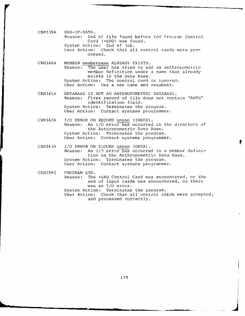
CBM339A END-OF-DATA.Reason: End of file found before End Program Control
Card (+END) was found.System Action: End of job.User Action: Check that all control cards were pro-
cessed.
CBM340A MEMBER membername ALREADY EXISTS.Reason: The user has tried to add an anthropometric
member definition under a name that alreadyexists in the Data Base.
System Action: The control card is ignored.User Action: Use a new name and resubmit.
CBM341A DATABASE IS NOT AN ANTHROPOMETRIC DATABASE.Reason: First record of file does not contain "ANTH"
identification field.
System Action: Terminates the program.User Action: Contact systems programmer.
CBM342A I/O ERROR ON RECORD nnnnn (INDEX).Reason: An I/O error has occurred in the directory of
the Anthropometric Data Base.
System Action: Terminates the program.User Action: Contact systems programmer.
CBM343A I/O ERROR ON RLCORD nnnnn (DATA).Reason: An I/O error has occurred in a member defini-
tion on the Anthropometric Data Base.
System Action: Terminates the program.User Action: Contact systems programmer.
CBM3991 PROGRAM END.Reason: The +END Control Card was encountered, or the
end of input cards was encountered, or therewas an I/O error.
System Action: Terminates the program.User Action: Check that all control cards were accepted,
and processed correctly.
179
_ __... .Iil . . .. .J = . . ..
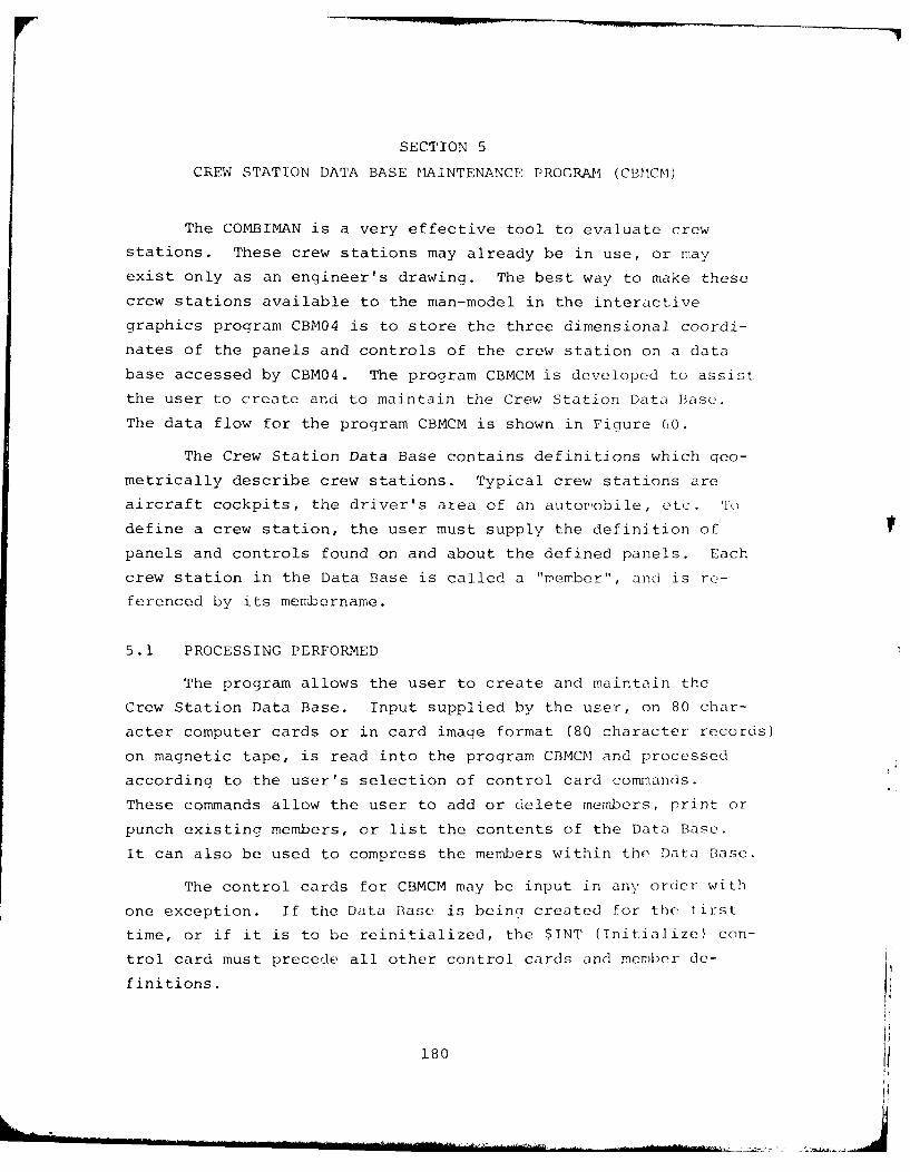
SECTION 5
CREW STATION DATA BASE MAINTENANCE PROGRAM1 (CBMCM)
The COMBIMAN is a very effective tool to evaluate crew
stations. These crew stations may already be in use, or may
exist only as an engineer's drawing. The best way to make these
crew stations available to the man-model in the interactive
graphics program CBM04 is to store the three dimensional coordi-
nates of the panels and controls of the crew station on a data
base accessed by CBM04. The program CBMCM is developed to assist
the user to create and to maintain the Crew Station Data Base.
The data flow for the program CBMCM is shown in Figure 60.
The Crew Station Data Base contains definitions which geo-
metrically describe crew stations. Typical crew stations are
aircraft cockpits, the driver's area of an automobile, etc. To
define a crew station, the user must supply the definition of
panels and controls found on and about the defined panels. Each
crew station in the Data Base is called a "member", and is re-
ferenced by its membername.
5.1 PROCESSING PERFORMED
The program allows the user to create and maintain the
Crew Station Data Base. Input supplied by the user, on 80 char-
acter computer cards or in card image format (80 character records)
on magnetic tape, is read into the program CBMCM and processed
according to the user's selection of control card commands.
These commands allow the user to add or delete members, print or
punch existing members, or list the contents of the Data Base.
It can also be used to compress the members within the Data Base.
The control cards for CBMCM may be input in any order with
one exception. If the Data Base is being created for the first
time, or if it is to be reinitialized, the $INT (Initialize) con-
trol card must precede all other control cards and member de-
finitions.
180
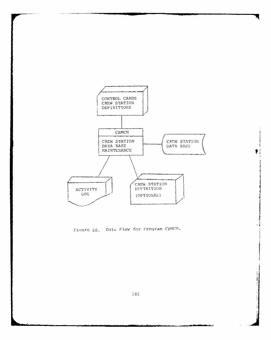
CONTROL CARDS (CREW STATION
DEFINITIONS j/
ACTVIT STATIO NSTATON
LOGRE SOTONAL)
Figiure 60. Data Flow for Program CBPIC1.
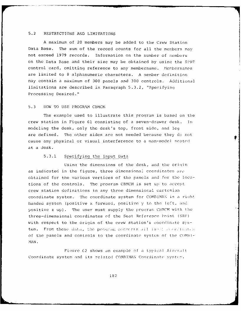
5.2 RESTRICTIONS AND LIMITATIONS
A maximum of 20 members may be added to the Crew Station
Data Base. The sum of the record counts for all the members may
not exceed 1979 records. Information on the number of members
on the Data Base and their size may be obtained by usinq the $PRT
control card, omitting reference to any membername. Plembernames
are limited to 8 alphanumeric characters. A member definition
may contain a maximum of 300 panels and 300 controls. Additional
limitations are described in Paragraph 5.3.2, "Specifying
Processing Desired."
5.3 HOW TO USE PROGR Iv CBMCM
The example used to illustrate this program is based on the
crew station in Figure 61 consisting of a seven-drawer desk. In
modeling the desk, only the desk's top, front side, and leg
are defined. The other sides are not needed because they do not
cause any physical or visual interference to a man-model seated
at a desk.
5.3.1 Specifying the Input Data
Using the dimensions of the desk, and the oriqin
as indicated in the figure, three dimensional coordinates are
obtained for the various vertices of the panels and for the loca-
tions of the controls. The prooram CBMCM is set up to accept
crew station definitions in any three dimensional cartesian
coordinate system. The coordinate system for COMBIMAN is a riclht
handed system (positive x forward, positive y to the left, and
positive z up). The user must supply the proqram CBMCM with the
three-dimensional coordinates of the Seat Reference loint (SHI')
with respect to the origin of the crew station's coordinate sys-
tem. From these d t-i, thie proqrdiri c EnvCr-tS I 1 itI' 7 C( (V I' ittf, :,
of the panels and controls to the coordinate system of the CoMPIl-
MAN.
Fiqure 62 shows an example of a typical Aircra ft
Coordinate system and its related COMBIMAN Coordinate syste,m.
182
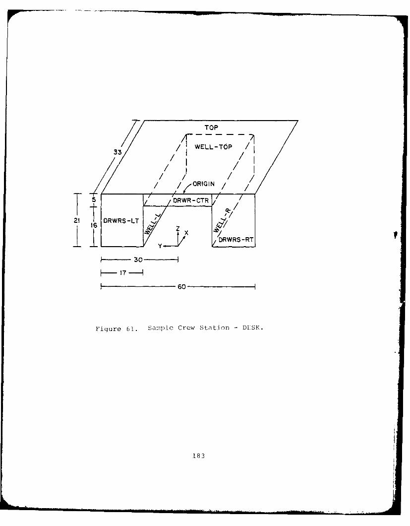
35 WELL -TOP /
i /ORIGINi /
T DRWR- CTR
t02! DRWRS-LT ~/
16 II .~ 'RWRS-RT
I-30 -
60
Figure 61. Sample Crew Station - DESK.
183
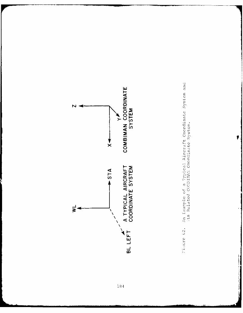
C)z
owLL
0 r~0
00
<l LL. Lu
0: (0
C) tC)
F0
LL.'.
184
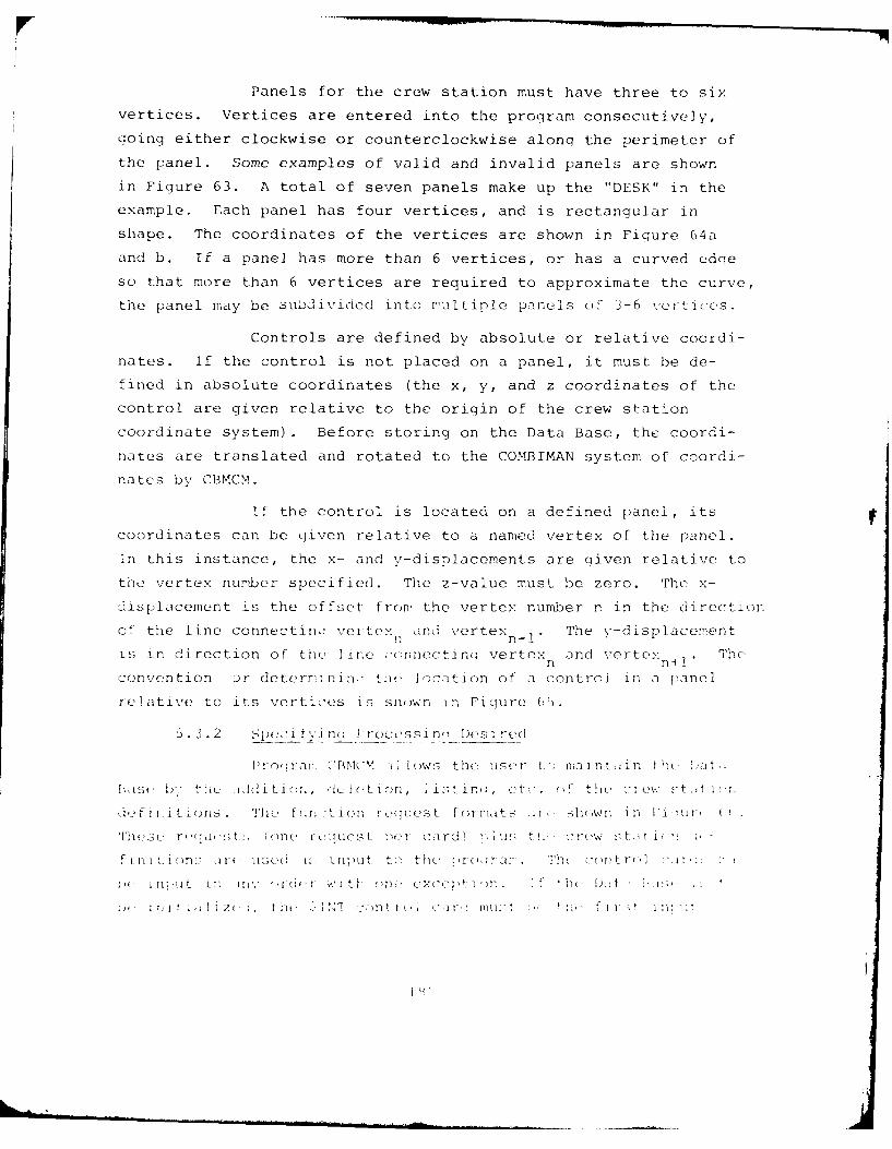
Panels for the crew station must have three to six
vertices. Vertices are entered into the proqram consecutively,
going either clockwise or counterclockwise alonq the perimeter of
the panel. Some examples of valid and invalid panels are shown
in Figure 63. A total of seven panels make up the "DESK" in the
example. Each panel has four vertices, and is rectangular in
shape. The coordinates of the vertices are shown in Figure 64a
and b. If a panel has more than 6 vertices, or has a curved edqe
so that more than 6 vertices are required to approximate the curve,
the panel may be subdivided into rultiple panels of 3-6 vertices.
Controls are defined by absolute or relative coordi-
nates. If the control is not placed on a panel, it must be de-
fined in absolute coordinates (the x, y, and z coordinates of the
control are given relative to the origin of the crew station
coordinate system). Before storing on the Data Base, the coordi-
nates are translated and rotated to the COMBIMAN system of coordi-
nates by CBMCM.
If the control is located on a defined panel, its
coordinates can be given relative to a named vertex of the panel.
In this instance, the x- and v-displacements are aiven relative to
the vertex nUmrber specified. The z-value must be zero. The x-
displacement is the offset from the vertex number n in the direction
of the line connectin: vertex and vertex The v-displacement
is in direction of the, line ,()nnectino vertex and vertex Thv,
convention Dr detern ning: ti(, location of a control in a panel
relative to its vertices is shown in Fiqure 05.
5. 3.2 Spe f T il.' rus si n(_ Dens :rd
Pr o s BrIYMC Lows the user L I tain t tYi a",t
[K,,st U, th' t .iditi<n It, i t on, ]ist n c <t . t! tho 2 rewo , )t, t
d,, fi :i ti rls. Thu f!irlLion reoguest formats .1t shovwn in 1i ,: , I
Tht~sc' r. usts. o n< r tL u t iop card) ,ius t! ,. -w .t t 1 : -
ions ar I S((i i ll)Ut tst tho 1W r(; : , T.h] ('e f r , ,
Z( , t lit 1 f '1 t ,)n t I ( .,1- Il. I I. t
I ' P
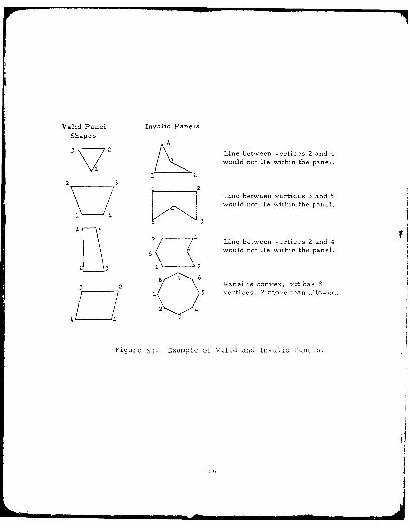
Valid Panel Invalid Panels
Shapes4
3 2 Line between vertices 2 and 4
would not lie within the panel.
2.2
2 31 2
Line between vertices 3 and 5would not lie within the panel.
2. 43
5 Line between vertices 2 and 4
6 would not lie within the panel.
2 3 1 2
3 2 8 ' ~ Panel is convex, but has S2.5 vertices, 2 more than allowed.
2 4
4C
Figure 63. Example of Valid and Invalid Panels.
I TOP
POINT X y z1 0.0 30.0 00
21 32 33.0 30.0 0.0________3 33.0 -30.0 0.0
41 4 0.0 -30.0 0.0
2DRWRS - LT
POINT X Y z1 0.0 30.0 0.0
2 0.0 13.0 0.03 0.0 13.0 -21.04 0.0 30.0 -21.0
3ORWRS -RT
POINT X Y Z1 0.0 -30.0 0.02 0.0 -13.0 0.0
I3~3 0.0 -13.0 -21.0r3 ] 4 0.0 -30.0 -21.0
4DRWRS- CT
POINT X Y z1 0.0 1 3.0 0.0
2 0.0 13.0 -5.01 4 3 0.0 -13.0 -5.0
4 0.0 -13.0 0.02 3
Figjure (Aii. X, Y and Z Coordinates of Panels of DESK.
187
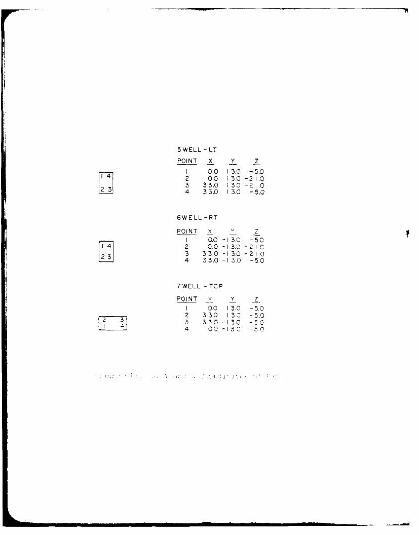
5 WELL - LT
POINT X Y Z
1 0.0 I 3.0 -5.02 0.0 1 3.0 -2 1.03 33.0 13.0 -21t.04 33.0 13.0 -5.0
6WELL -RT
POINT X y1 0.0 -1 3-C - 5.0
142 0.0 -13.0 -21.03 3 3 3.0 -13.0 -21.0
274 33.0 - 13.0 -5.0
7WELL -TOP
POINT X Y z1 0.0 13.0 -5.0
2 330 13.0 -5.03 330 -130 - 04 00 -130 -50
, AD-AO97 705 DAYTON UNIV OH RESEARCH INST F/S 5/8
USER S GUIDE FOR COMBIMAN PROGRAMS (CBIOMECHANICAL - TC(U)
'LAN IE P BAPU, S EVANS, P KIKTA. M KORNA F336 1 5"T-C-O5OT
UNCLASSIFIED UDR-TR-80-44 AFAMRL-TR-80-91 NL
3.4IEIIIIEEEEEE
IIIIIIIIIIIhIIEEEEIIEIIIIEEEIEIIEIIIIEEEEIEEEEIIIIIIEEEIEEIIIIIIEI-IEEmmhEmhEEEEIa
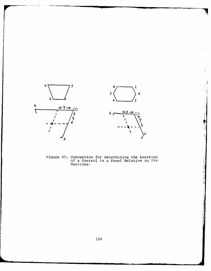
46
5 2
4 3276
2
Figure 65. Convention for Determining the Locationof a Control in a Panel Relative to ItsVertices.
189
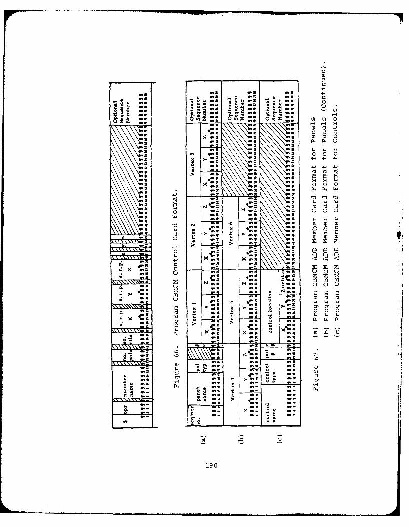
40 a
00
-ad . 1. a
.3. 0 z V 0 0U)z 2 m 0 t z
z3-c) () 4tI.: ci rci
ua 4-J3
dm a P44 144 U4
in - 0 0 0
> u's a'
fX4 44 W'314
0 1NU m 3u U u
.3 0 wo d" 2 -
>0 - - >. at *_ 4"-
4nma
U'4-) x m x In
0 .n a
of =S c .N m
ow -2 0 n9
0 In '3 0 404 0
$4n a0 -' - -
On 2l-.n - 2f
w ~ . I..
0 ml do
oft -, r~ r' 3 4.0 I
*01 m3 c- N :
190-'
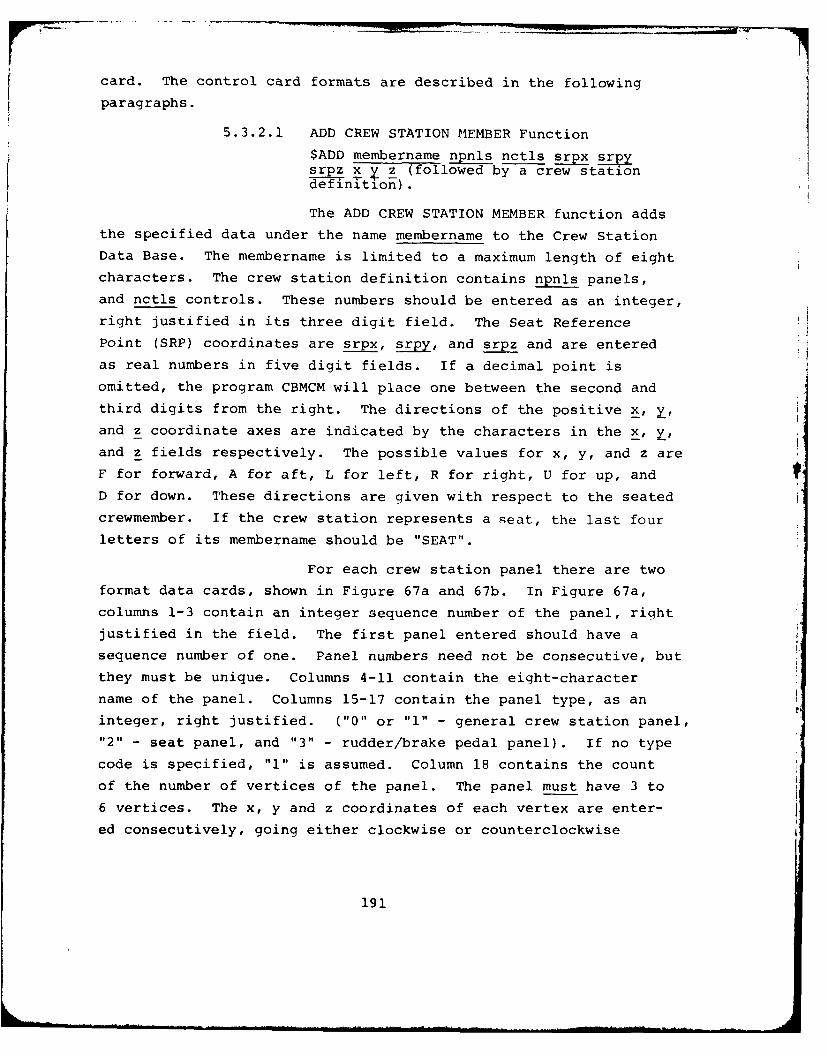
card. The control card formats are described in the following
paragraphs.
5.3.2.1 ADD CREW STATION MEMBER Function
$ADD membername npnls nctls srpx srpsrpz x y z (followed by a crew stationdefinition).
The ADD CREW STATION MEMBER function adds
the specified data under the name membername to the Crew Station
Data Base. The membername is limited to a maximum length of eight
characters. The crew station definition contains npnls panels,
and nctls controls. These numbers should be entered as an integer,
right justified in its three digit field. The Seat Reference
Point (SRP) coordinates are srpx, srpy, and srpz and are entered
as real numbers in five digit fields. If a decimal point is
omitted, the program CBMCM will place one between the second and
third digits from the right. The directions of the positive x, Y,
and z coordinate axes are indicated by the characters in the x, y,
and z fields respectively. The possible values for x, y, and z are
F for forward, A for aft, L for left, R for right, U for up, andD for down. These directions are given with respect to the seated
crewmember. If the crew station represents a seat, the last four
letters of its membername should be "SEAT".
For each crew station panel there are two
format data cards, shown in Figure 67a and 67b. In Figure 67a,
columns 1-3 contain an integer sequence number of the panel, right
justified in the field. The first panel entered should have a
sequence number of one. Panel numbers need not be consecutive, but
they must be unique. Columns 4-11 contain the eight-character
name of the panel. Columns 15-17 contain the panel type, as an
integer, right justified. ("0" or "l" - general crew station panel,"2" - seat panel, and "3" - rudder/brake pedal panel). If no type
code is specified, "1" is assumed. Column 18 contains the count
of the number of vertices of the panel. The panel must have 3 to
6 vertices. The x, y and z coordinates of each vertex are enter-
ed consecutively, going either clockwise or counterclockwise
191
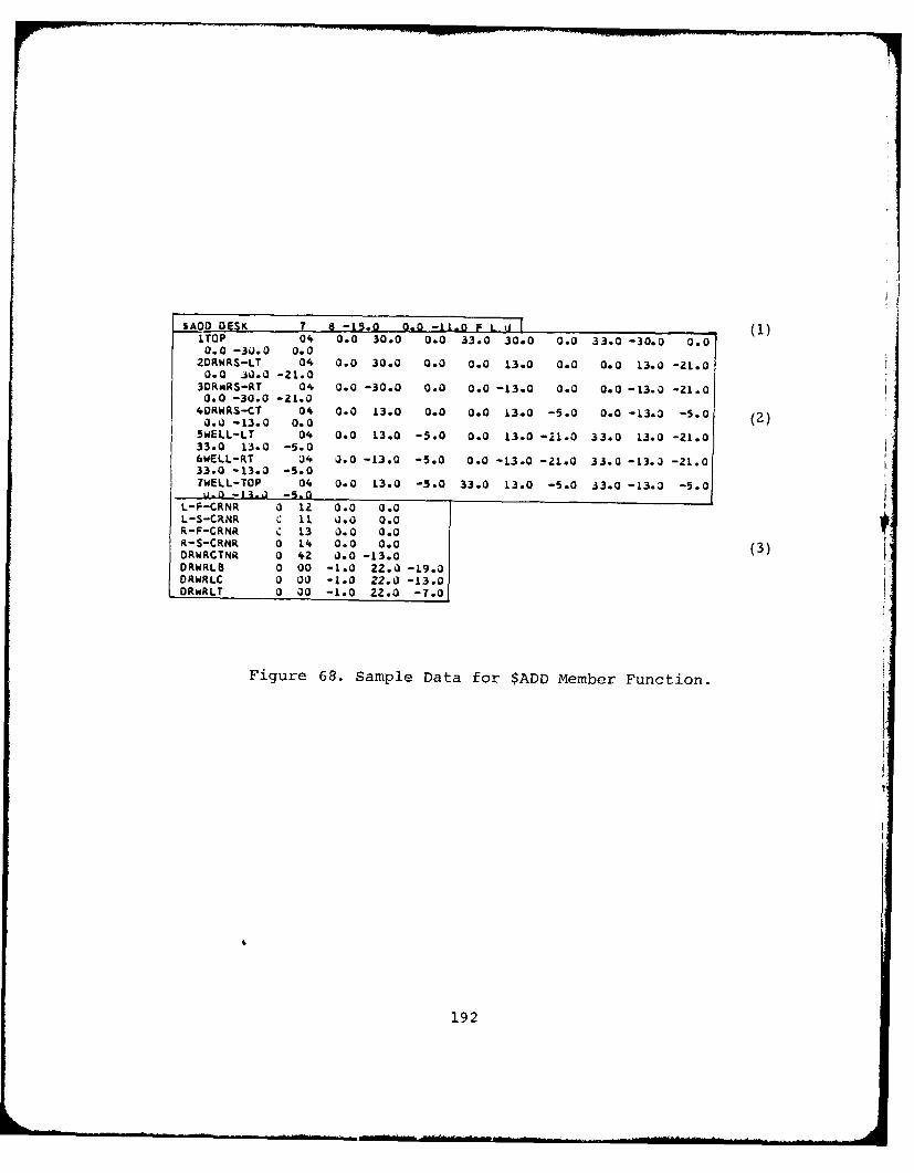
(1)
- O$AD DESK 0 - 0.0 0 .0 . 0 3 L 0 3. -10RTOP 04 0.0 30.0 0.0 33.0 30.0 0.0 33.0 -30.0 0.0
0.0 -30.0 0.02.RWRS-LT 04 0.0 30.0 0.0 0.0 13.0 0.0 0.0 13.0 -21.00.0 30.0 -21.0
30RwRS-RT 04 0.0 -30.0 0.0 0.0 -L3.0 0.0 0.0 -13.0 -21.00.0 -30.0 -ZL.0
40RWRS-CT 04 0.0 13.0 0.0 0.0 13.0 -5.0 0.0 -13.3 -S.0L . -L3.0 0.0 2 00..SWELL-LT 0 0.0 3.0 -5.0 0.0 L3.0 -1o0 33.0 L3.0 -21.033.0 L3.0 -510 . 00(6WELL-RT U4 0.0 -13.0 -5.0 0.0 -13.0 -21.0 33.0 -13.3 -21.0
33.0 - 0.3 4 -5.0 . 0WELL-TOP 0 01.0 22.0 -. 00 -5.0 3.0 -13.3 -5.0u 1 4-- a . -5.0 - 1
L-F-CRNR 0 12 0.0 0.0 |L-S-CRNR C 11 0.0 0.0r%-F'CRNR C 13 0.0 0.0
-S-CRNR 0 L4 0.0 00 (3)DRWIRCTNR 0 42 J.0 -13.0
DRWRLC 0 00 -1.0 Z2.0 -13.0ORWRLT 0 00 -1.0 22.0 -7.0|
Figure 68. Sample Data for $ADD Member Function.
192
around the perimeter of the panel. All the panel definitions are
listed together.
Each control is defined on a card using
the format in Figure 67c. The control name is listed in columns
1-8. If the control is to be defined relative to a vertex, pnl#
references a panel defined previously. The entry is an integer
value, right justified in the field. The vertex to which the
control is relative to is specified in the one-digit field v#.
If a value is entered for pnl#, the field v# must be non-zero.
The coordinates of the control are real numbers. If the location
is relative to a defined panel, the z-field is blank. if the loca-
tion is absolute, all three values (x, y, and z) must be supplied.
If no decimal point is supplied, the program places one between
the second and third right-most digits.
An example of the input definition for the
member "DESK" is shown in Figure 68. The first outlined area is
the $ADD control card. The second outlihed area shows the panel
definition cards followed by the control definition cards.
Should an error be detected by the program
in the input data for a member, the member is not added.
5.3.2.2 CHECK CREW STATION MEMBER Function
$CHK membername npns nctls srpx srpysrpz x yz (followed by a workspacedefinition).
The CHECK CREW STATION MEMBER function
operates in the same way the ADD CREW STATION MEMBER function does,
EXCEPT that the member is not added. This function checks new
member input data for proper format and content.
5.3.2.3 DELETE CREW STATION MEMBER Function
$DEL membername
The DELETE CREW STATION MEMBER function
removes the specified crew station member from the Data Base, but
does NOT make the space the member occupied available for reuse.
In order to make the space available the COMPRESS CREW STATION
DATA BASE function must be used.
193
5.3.2,4 COMPRESS CREW STATION DATA BASE Function
$CMP
The COMPRESS CREW STATION DATA BASE func-
tion compresses used space together maximizing the amount of con-
tinuous unused space. The intermediate blocks of unused space are
created by the DELETE CREW STATION MEMBER function. When the message
"CBMI27A NO SPACE, CANNOT ADD membername" appear, it is necessary
to use this function. If the compress function, followed by the
$ADD function gives the CBM127A message, the Data Base is full.
5.3.2.5 DUMP CREW STATION MEMBER Function
$DMP membername$DMP
The DUMP CREW STATION MEMBER function prints
the contents of the crew station member membername, or the complete
Crew Station Data Base if no member name is given on the control
card. The format of the display, per second is:
RECORD nn +=+ (record in EBCDIC) +=+
+=+ (record in hexadecimal) +=+
+=+ (rest of record in hexadecimal) +=+
The +=+ characters act as delimeters of the
displayed data. This function is used primarily by system pro-
grammers to test the file.
5.3.2.6 END PROGRAM Function
$END
The END PROGRAM function terminates execu-
tion of the program CBMCM.
5.3.2.7 INITIALIZE CREW STATION DATA BASE Function
$INT
The INITIALIZE CREW STATION DATA BASE func-
tion resets the Data Base to an original unused state. The primary
purpose of this function is to establish a Crew Station Data Base.
194
5.3.2.8 PUNCH CREW STATION MEMBER Function
$PCH membername
The PUNCH CREW STATTON MEMBFR function
punches a copy of the specified member in a format that the ADD
CREW STATION MEMBER function requires. Specifyinq a nerbername
that does not exist causes a printout of all the membernames on
the Data Base. This function does not remove any member from the
Data Base.
5.3.2.9 PRINT CREW STATION MEMBFR Function
$PRT membername$PRT
The PRINT CRI'W STATTON MEMBER function
prints the contents of the specified member, membername in a format
similar to that of the ADD CREW STATION MEMBER function. Speci-
fying no name, or a nonexistinqi nare causes a printout of the
index containing member names and their record numbers, on the
Data Base, and their origin and orientation.
5.3.3 Submitting a Processing Request
The sequence of JOB CONTROL LANGUAGE (JCL) caros
needed to execute the program CBMCM are shown in Figure 69. All
function control cards and member definition cards follow the
"//SYSIN DD*" card. The "//FT01F001" card included in this se-
quence assumes that the space for the Data Base has already been
allocated on disk. If this condition is not met, the "//FT01F001"
card specified in Figure 69 should be replaced by the sequence
of cards shown in Figure 70. The first function control card in
this case should be the $INT card, which initializes the Data
Base. This sequence to allocate space for the Data Base and to
initialize it should be executed only once. Thereafter, the
simplified "//FT01F001" card shown in Figure 69 should be used
for all file manipulations.
The last function control card read into the pro-
gram should be the "$END" card.
195
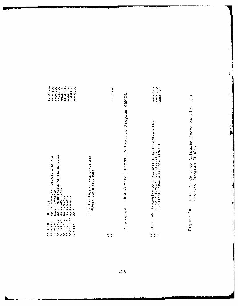
10 C,
04)
A44
CL)04 0 I(-a Z 34-
A .0 $4 - x
6m Co
fs m
-~ - 4196
- 4I0
5.3.4 Interpreting the Output
The program CBMCM generates output to the card punch,
disk file, or printer, depending on the specified control card
function. The formats for the printed output will be discussed in
this section. Punched records have the same format as the input
data records discussed in Paragraph 5.3.2. The physical format of
the records on the Data Base is not described here.
Five basic formats are used by CBMCM for printed out-
put. These format types, their use, and their examples are pre-
sented in this subsection. All types begin with the same heading
"CBMCM", the data and time of the program execution, and a page
number.
The first type of output is generated oy the INI-
TIALIZE, PUNCH, COMPRESS, DELETE, and END functions. The output
indicates the start and end of processing associated with the
specified function. For the COMPRESS function, additional messages
are supplied, indicating that a particular member was, or was not,
moved in the process of combining unused space. An example of
this format, for the COMPRESS function, is shown in Figure 71.
The second type of output is generated by the PRINT
or PUNCH functions when the $PRT or $PCH control card is supplied
with blank membername field. This causes a listing of the index
of the Data Base in the following format:
nn.) membername, EXTENT = (nl, n2), np PANELS, nc CONTROLS,
ORIGIN = (xx, yy, zz), ORIENT = (a, b, c)
where:
nn is the number of the member identification recordwithin the directory
membername is the name of the member identified
nl is the location of the first record which definesthis member
n2 is the location of the last record which definesthis member
197
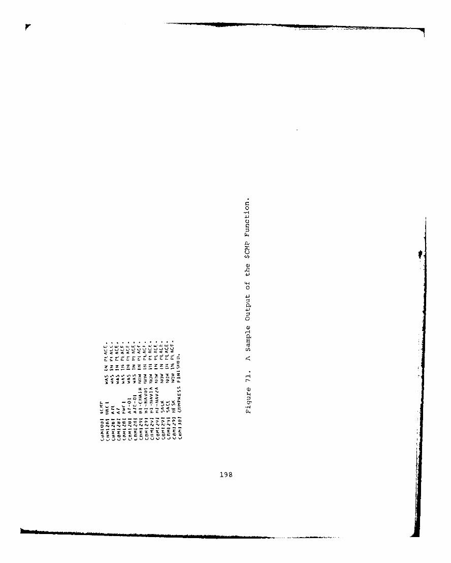
.4-4
04~J
41)
0
01)
t. -4) ~ U U~.. ~JJU) W, UU
U) Z) a
u 53 u .'
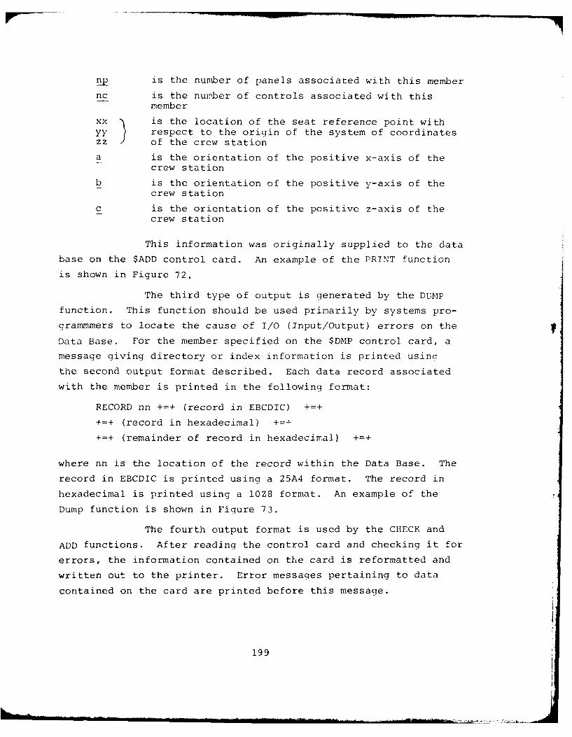
np is the number of panels associated with this member
nc is the number of controls associated with thismember
xx is the location of the seat reference point withyy respect to the origin of the system of coordinates
zz ) of the crew station
a is the orientation of the positive x-axis of thecrew station
b is the orientation of the positive v-axis of thecrew station
c is the orientation of the positive z-axis of thecrew station
This information was originally supplied to the data
base on the $ADD control card. An example of the PRINT function
is shown in Figure 72.
The third type of output is generated by the DUMP
function. This function should be used primarily by systems pro-
grammmers to locate the cause of I/O (Input/Output) errors on the
Data Base. For the member specified on the $DMP control card, a
message giving directory or index information is printed usinq
the second output format described. Each data record associated
with the member is printed in the following format:
RECORD nn +=+ (record in EBCDIC) +=+
+=+ (record in hexadecimal) 4+
+=+ (remainder of record in hexadecimal) +=+
where nn is the location of the record within the Data Base. The
record in EBCDIC is printed using a 25A4 format. The record in
hexadecimal is printed using a 10Z8 format. An example of the
Dump function is shown in Figure 73.
The fourth output format is used by the CHECK and
ADD functions. After reading the control card and checking it for
errors, the information contained on the card is reformatted and
written out to the printer. Error messaqes pertaining to data
contained on the card are printed before this message.
199
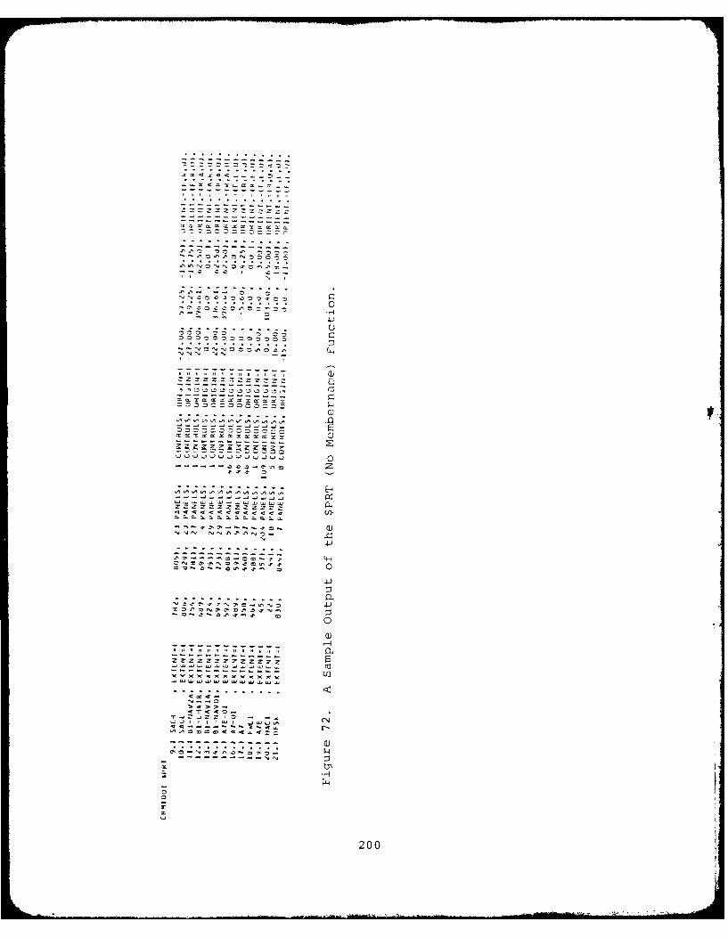
- C -
CZCZZZ CZr14
a--.j
- 4240
0
20
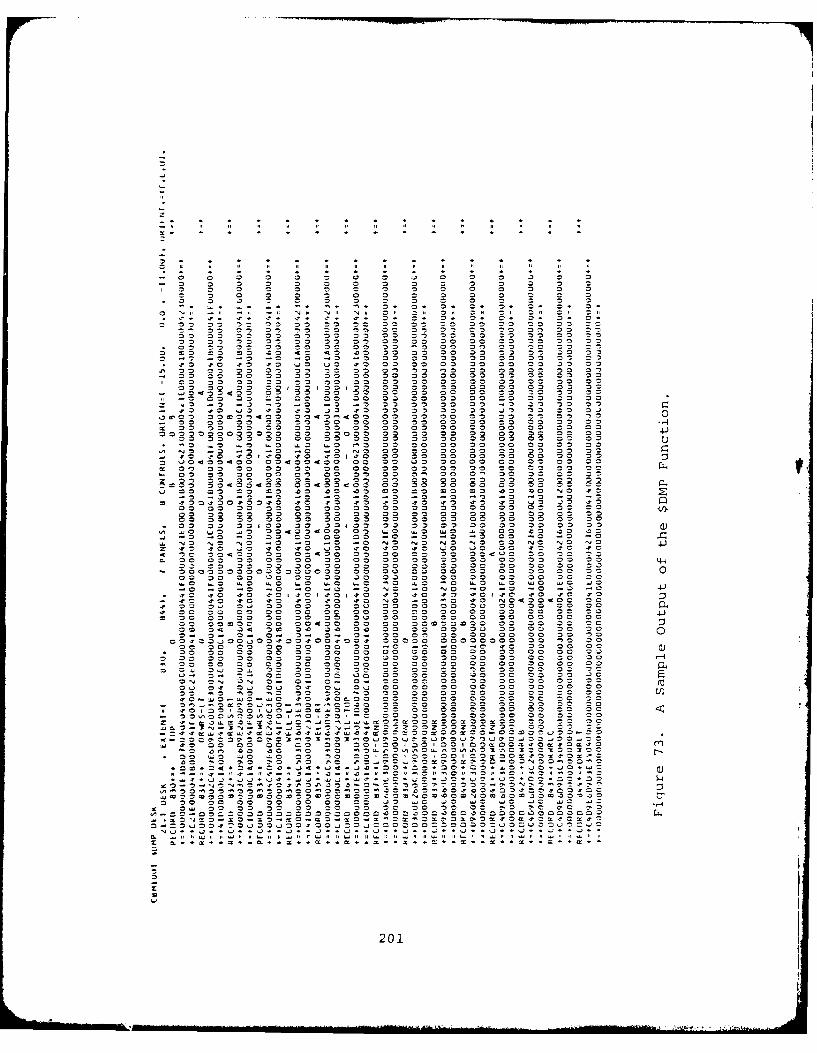
- 0 3 3 3 3 o 3 3 0 3
c c 3 33 Q n D C n 0 0 =- 3 0 -3 n = 3 0 c S c S 5 3 5 0 3
* 3 3 3 3 0 0 3 c c0 n c 3. . 3. c a * ,. 13 0 c* =* 3. 03
z n0 3 D c3 m I3 0 33 00 33 0 30 30 33 33 z z
33 n 33 3D 3, oz3-1 03 o0 3 00, 33 3 3 c3
wo -3 0 3 0 30 33 33 33 n0 30 3 3= 33 0= 32-,c -3-. o n 33 - 0 33 03 C,0 3 3
3 ± 0 0 00 00 n3 0c 33 33 30 33 33 33 33 3:
c 07 c7 .73 07 03 03 .3 3m 33 3 3 33 3 3.9 ~ 0 33 3C 33 33 o n3 3 3~ 3 3 3 33 0 3
- 3 o 33 0 33 3 30 33 33 33 n 0 0 3 33 33 33 339 OI o 00<3300300 33 33 Om 33 33 33 33 33 V0 3
c3 M, 33 3c9c3c 33930 33 33 0 0 00 03 3c 33C-~~~0 .94 9 3 3 3 3 3 3 0 33 C3 3 33
.9~~ c 03 , 23 30 3 3 3 33 3 3 3 3 3sO .53 3 80.0 o3 ..3 3 .3 33 30 33 go -3 3 3 33 37
no 33 03 00 33 0 30 33 30 00 30 33 33 33 3
33 33 3 -3 0 c' 3 0n00 ... = .0 , .c 3 c3 c3 33 300 3 0 3 3 3
'9~~~ ~~ cO -3 -3 -. . 0 on 03 3 3 0 03 3 0 3-~ ~ .3 .0 .3.0 .0 .3 3 3 30 30 00 33 00 30co 003340 0 3430 4*30. 0 3 3 0 000 03 33 33 0
00 33 0 0 " 00 0 c 3 03 3 0 0 :33 c 30
_. 0 03 c 03 .03 10 0 -0 w0 03 .0 00 'D 73
No -c -3 -3 zo -3-3-3 3-3 c0- 13-3-n c7 33.37 no n7 c3 n3 07 .3 a7 07 c 0m= c0 c u z0 30 o30 03 33 33 n3 330 33 03 33 33 03 00 33 .03n
33~~~ 33 3 3 0 3 3 3 3 0 3 343-43 33 3c 33- 0 0 0 00 =33.) 0 03 3c 33 33 0
Oo.~0 on ooo 334334000 0c 0 S~ . w 0 0 = 0 0 .03 =3 Q .=S
20 .7 0 03 0 .70 no on 0 O70 .70 00a 00 30 0 7 00 0 =04 0 00 3 - 40 33 0 33o 3 3 0 33 3000 0 0 30 03 0 N 33 33303 03 3 3
33 33 33 33 30 33~c 33 30 33 3 0 33 3 0
03 Q 30 33 33 33 3 33 3 0N0 33 30 w0 0cc . c 0 0 - 90 c 990 c .0 o0 ~0 0 D c c 9. 0 c00 = 03 03
w o -e Q o -0 o 0 3 0 3 NO v 1 0 NO 0c -. 3 = o3 cc c co c7 .70 .7m o c 9c o 9o7o < 0 7 .70 .73 c797 a7 m7 = .73c n
- o7 .70 37 o7 .70 57 57 NO -0 5. S7 50 0 00.7 !3 30 3f 33 0 z 30 30 33 a3 0n 3 00 3c 3 o30Dc
.7 3 3 3 3 0 0 0 0 2 ,0 2 0 03 33 30 30 33.4.o 3c 03 30 30 30 3o 3c 00 30 3o00 0 0 0
* 5 %0 E3 3 30 33 30 00 00 o0 o33 0 3 3o 33 33 33 "o c0 a0 30 c3 3o 30 33 3o0 3 3~cm 33 c0 c0 c0 33 00 o0 30 303003 3
o o~ ,~ c~ C, '6 33 30) 33 53 3 0 30 3, 00l 33 a= 0 33 0 33 o 0 0 ,3 c3 c
cO ON 7. 3o 0Y-0 0 -0 30 3 3 3 30 3 03 33c no 0 cc0 30 33 3 00 c3 30 w0 o 03 o
c7 . 0 9 9 9 o7 c7 03 no 00 00 00 00 30 c0 33C .. I
- ~ ~ ~ ~ ~ ~ ~ Z -33~3'093~9 33 :33: 33 3 3 3 3 3
m ~ c3 o0 03 c c c 30 ,0 3 30 3 9 0 0 1 0 . = - z73
*~~~~~~~~~ 00 .9. ... .9. .0 .0 03 3 93 9 0 0O 0O . .
00 * ~9 ~3 4~3 7.0 .72013 3 0 O ~ 30 N 3 . 3
Panel definition card, after being read and checked
for errors is printed. The format used for printing the panel
definition cards is as follows:
nn.) pnl nm, TYPE=tt, nv VERTICES -- INPUT COORD ABSOLUTE COORD -
(xx yYI' zz) (axl' aYl' az
(x-Xnv' Ynv' ZZnv) (a-Xnv' aynv aZnv)
where:
nn is the panel number
pnl nm is the panel name
tt is the panel type
nv is the number of vertices used to define thepanel
i' are the x, y, and z coordinates for the lthxxiyyi,zzi vertex of the panel, in the crew station system
of coordinates, where i = 1, nv.
are the x, y, and z coordinates of the i th
axi,ayi,az i vertex of the panel, converted to the COMBIMANsystem of coordinates, where i = 1, nv.
After the panel definition data, the control data
are printed, using the following format:
cntl nm tt pnl ref. v.# (xx,yy,zz) TO (ax,ay,az) & (rx,ry)
where:
cntl nm is the 8 character name of the control
tt is the 2 digit control type
pnl ref is the panel where the control is located(if applicable)
v.# is the reference vertex number for that control(if applicable)
are the three dimensional coordinates (relative orYYJ absolute) which define the location of the controlz
2z
202
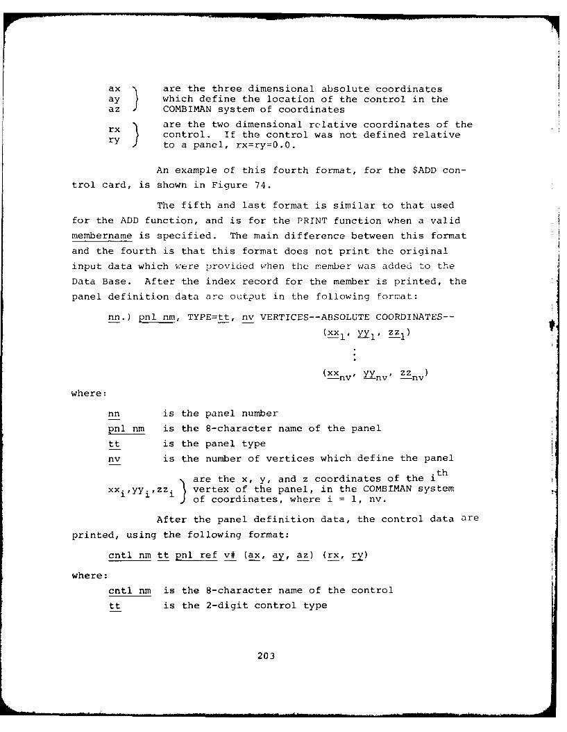
ax are the three dimensional absolute coordinatesay which define the location of the control in theaz COMBIMAN system of coordinates
rare the two dimensional relative coordinates of therx control. If the control was not defined relativery to a panel, rx=ry=0.0.
An example of this fourth format, for the $ADD con-
trol card, is shown in Figure 74.
The fifth and last format is similar to that used
for the ADD function, and is for the PRINT function when a valid
membername is specified. The main difference between this format
and the fourth is that this format does not print the original
input data which were provided when the member was added to the
Data Base. After the index record for the member is printed, the
panel definition data are output in the following format:
nn.) pnl nm, TYPE=tt, nv VERTICES--ABSOLUTE COORDINATES--
(xXl' YI'
(xx -- nv yy nv, zznv
where:
nn is the panel number
pnl nm is the 8-character name of the panel
tt is the panel type
nv is the number of vertices which define the panel
are the x, y, and z coordinates of the i th
xxifyyirzz i vertex of the panel, in the COMBIMAN systemof coordinates, where i = 1, nv.
After the panel definition data, the control data are
printed, using the following format:
cntl nm tt pnl ref v# (ax, ay, az) (rx, ry)
where:
cntl nm is the 8-character name of the control
tt is the 2-digit control type
203
0
90
1,
-r 04
-4 ~r0000o000 C)
- ooeo~,o,
~r -
09999000Sr - .
4,00094,99000904,00904,90904,09094,9000 r 09009909909099a.9099990..a9099009a.90994
- II~ - Ir - II -
a.O 9 9 0 9~ 0)4009(40 00900009 00009 00~0900900.)0O~" .0
0 * 0....~ 99000009 4..)099~J0"0U0"..0.4 '''r~'~ ~.4''~'- 99009090
= W r~-M C .I rat ..Jr I 1W I I.~ .r Ira. ) Zr ~N.7
900009090999099990999000999009000990r9000
09009090..a90099099...r990 9..r00993
0r9900 009*4,4%4%4,4%4%4%ttr4,t4%P 4,4%A4%4%4,4%~t4,4%4%C.At4%0 09,09990 .4J
4 4 4 4 4 r09000~a'~aNI I r r I WI~~ N'IJN 0
I ~---r---- I .----9'
4, 4, 4, 4, 4, 4, 4, 00009009 0)a. 44 a. at a. a. at 9109909009
r) .4 4,.9- - - - - - - Srnfl- - - - - - - CI - s35 5 x
tat ILl U U .14 I~J ad H I fl~S S S S S
-r Ci).7 .7 -~ -, .7 '7 .7
- . . . . 0rN'7N~nO 0 9 0 0 0 0
Z n N I rr Ir Ir ,r r -WIt W 44 .14 U 41 .1. a. I
5. 5. 5. 5. 5. 5. Zr
- - - - - - 5. r N5.5.0.5.3
* . - . FrOOOOS- - - -I==~0 0)-4 5 .1 - -
-J - .IJr900099994, 4, 4, r r r 0. rS x ~I ad .4
4,5. 3 3 3 a. a. ..4 rtatC S a. a. a.9,- 0 9 3 3 3 r 55555
a.rZZZZZ
N - .7 4% .0 - -r r r r r 1555N 21 ~ 4, ~ 4,3335
- I r r r r5 .41441559090
5.
99
ZS
204
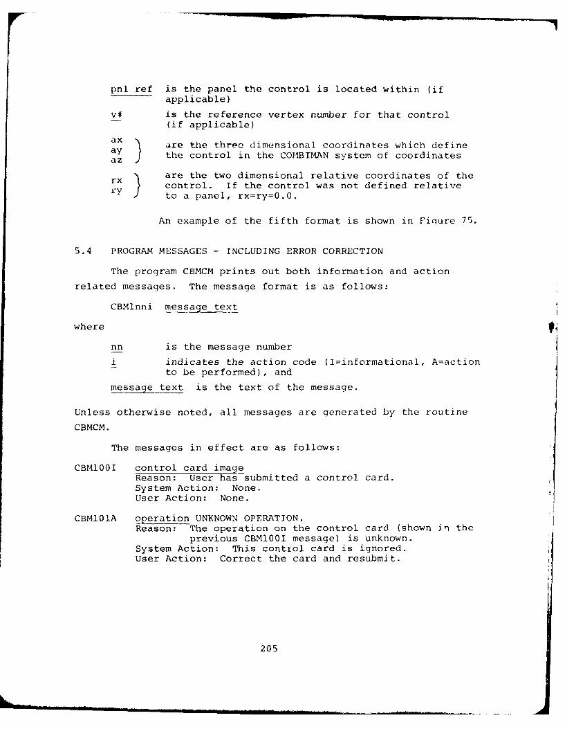
pnl ref is the panel the control is located within (ifapplicable)
V# is the reference vertex number for that control(if applicable)
ax are the three dimensional coordinates which defineay the control in the CO,1BIMAN system of coordinatesaz
rx are the two dimensional relative coordinates of thery control. If the control was not defined relative
to a panel, rx=ry=0.0.
An example of the fifth format is shown in Fiaure 75.
5.4 PROGRAM MESSAGES - INCLUDING ERROR CORRECTION
The program CBMCM prints out both information and action
related messages. The message format is as follows:
CBMlnni message text
where
nn is the message number
i indicates the action code (I=informational, A=actionto be performed), and
message text is the text of the message.
Unless otherwise noted, all messages are generated by the routine
CBMCM.
The messages in effect are as follows:
CBM100I control card imageReason: User has submitted a control card.System Action: None.User Action: None.
CBMI01A operation UNKNOWN OPERATION.Reason: The operation on the control card (shown in the
previous CBM100I message) is unknown.System Action: This control card is ignored.User Action: Correct the card and resubmit.
205
04
. .~ .. .~ 2 .0 .
-5 5
3- 3
.~~ ~ .2 .* .. . ... . . . . .
-Z --Zs
x It x4l I~ -' II t14~~~
- ~22.2222222 ~2 222 2062 22 2 22
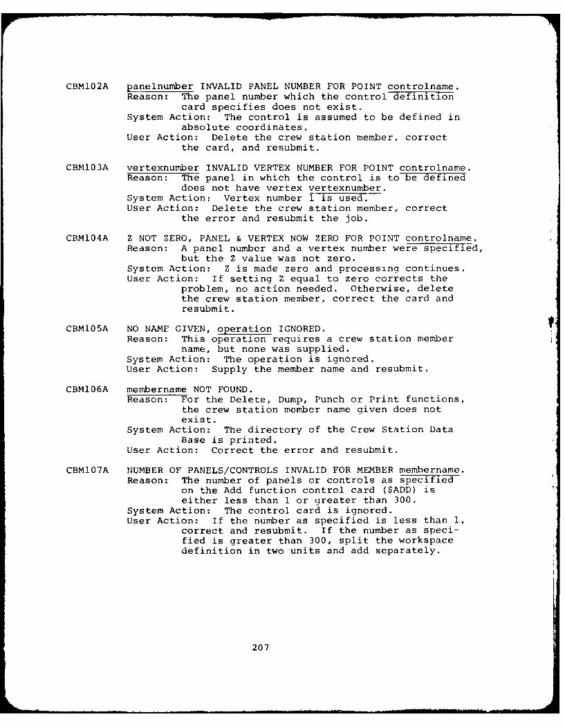
CBMl02A panelnumber INVALID PANEL NUMBER FOR POINT controlname.Reason: The panel number which the control definition
card specifies does not exist.System Action: The control is assumed to be defined in
absolute coordinates.User Action: Delete the crew station member, correct
the card, and resubmit.
CBM103A vertexnumber INVALID VERTEX NUMBER FOR POINT controlname.Reason: The panel in which the control is to be defined
does not have vertex vertexnumber.
System Action: Vertex number i is used.User Action: Delete the crew station member, correct
the error and resubmit the job.
CBM104A Z NOT ZERO, PANEL & VERTEX NOW ZERO FOR POINT controlname.Reason: A panel number and a vertex number were specified,
but the Z value was not zero.System Action: Z is made zero and processing continues.User Action: If setting Z equal to zero corrects the
problem, no action needed. Otherwise, deletethe crew station member, correct the card andresubmit.
CBM105A NO NAME GIVEN, operation IGNORED.Reason: This operation requires a crew station member
name, but none was supplied.
System Action: The operation is ignored.User Action: Supply the member name and resubmit.
CBM106A membername NOT FOUND.Reason: For the Delete, Dump, Punch or Print functions,
the crew station member name given does notexist.
System Action: The directory of the Crew Station DataBase is printed.
User Action: Correct the error and resubmit.
CBM107A NUMBER OF PANELS/CONTROLS INVALID FOR MEMBER membername.Reason: The number of panels or controls as specified
on the Add function control card ($ADD) iseither less than 1 or greater than 300.
System Action: The control card is ignored.User Action: If the number as specified is less than 1,
correct and resubmit. If the number as speci-fied is greater than 300, split the workspacedefinition in two units and add separately.
207
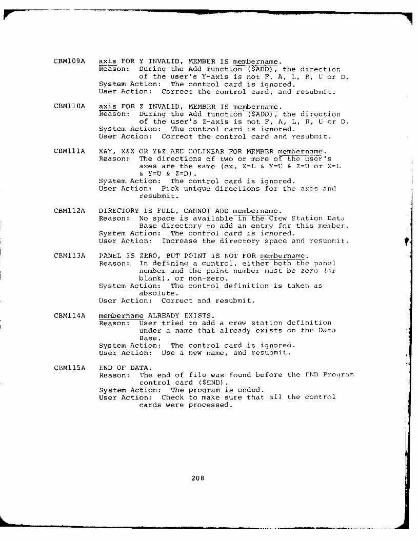
CBM109A axis FOR Y INVALID, MEMBER IS membername.Reason: During the Add function ($ADD), the direction
of the user's Y-axis is not F, A, L, R, U or D.System Action: The control card is ignored.User Action: Correct the control card, and resubmit.
CBMI1OA axis FOR Z INVALID, MEMBER IS membername.Reason: During the Add function ($ADD), the direction
of the user's Z-axis is not F, A, L, R, U or D.System Action: The control card is ignored.User Action: Correct the control card and resubmit.
CBM11A X&Y, X&Z OR Y&Z ARE COLINEAR FOR MEMBER membername.Reason: The directions of two or more of the user's
axes are the same (ex. X=L & Y=U & Z=U or X=L
& Y=U & Z=D).System Action: The control card is ignored.User Action: Pick unique directions for the axes and
resubmit.
CBM112A DIRECTORY IS FULL, CANNOT ADD membername.Reason: No space is available-in the Crew Station Data
Base directory to add an entry for this member.System Action: The control card is iqnored.User Action: Increase the directory space and resubmit.
CBM113A PANEL IS ZERO, BUT POINT IS NOT FOR membername.Reason: In defining a control, either both the panel
number and the point number must be zero (orblank), or non-zero.
System Action: The control definition is taken asabsolute.
User Action: Correct and resubmit.
CBM114A membername ALREADY EXISTS.Reason: User tried to add a crew station definition
under a name that already exists on the DataBase.
System Action: The control card is ignored.User Action: Use a new name, and resubmit.
CBM115A END OF DATA.Reason: The end of file was found before the END Proqram
control card ($END).System Action: The program is ended.User Action: Check to make sure that all the control
cards were processed.
208
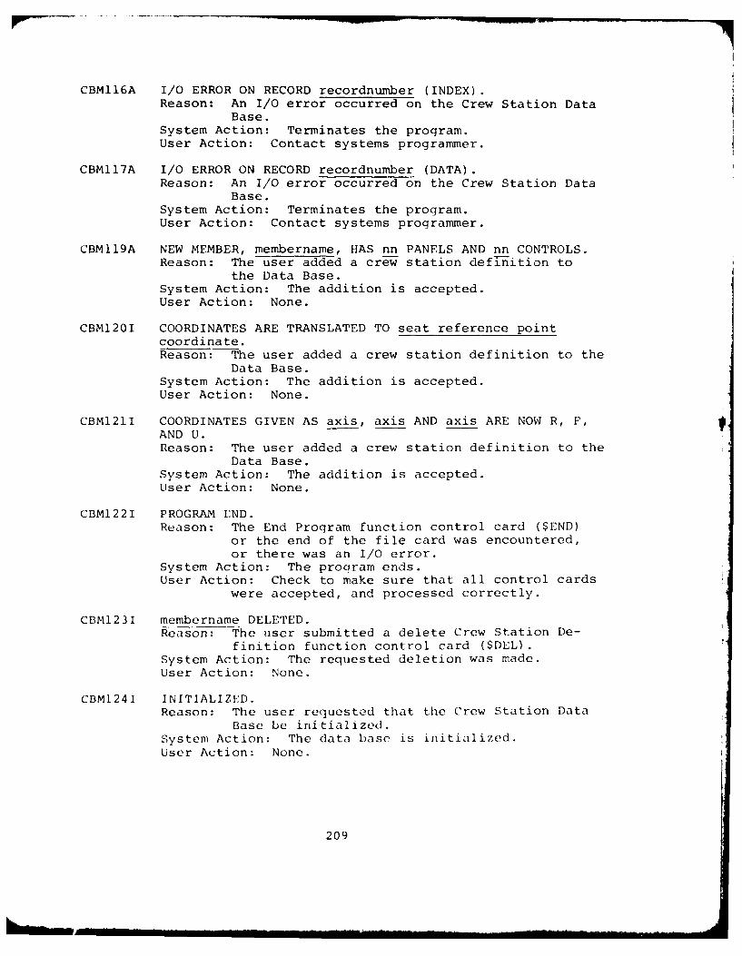
CBM1l6A I/O ERROR ON RECORD recordnumber (INDEX).Reason: An I/O error occurred on the Crew Station Data
Base.System Action: Terminates the program.User Action: Contact systems programmer.
CBM117A I/O ERROR ON RECORD recordnumber (DATA).Reason: An I/O error occurred on the Crew Station Data
Base.System Action: Terminates the program.User Action: Contact systems programmer.
CBMI19A NEW MEMBER, membername, HAS nn PANELS AND nn CONTROLS.Reason: The user added a crew station definition to
the Data Base.System Action: The addition is accepted.User Action: None.
CBM120I COORDINATES ARE TRANSLATED TO seat reference pointcoordinate.Reason: The user added a crew station definition to the
Data Base.System Action: The addition is accepted.User Action: None.
CBM121I COORDINATES GIVEN AS axis, axis AND axis ARE NOW R, F,AND U.Reason: The user added a crew station definition to the
Data Base.System Action: The addition is accepted.User Action: None.
CBM1221 PROGRAM END.Reason: The End Program function control card ($END)
or the end of the file card was encountered,or there was an I/O error.
System Action: The program ends.User Action: Check to make sure that all control cards
were accepted, and processed correctly.
CBM123I membername DELETED.Reason: The user submitted a delete Crew Station De-
finition function control card ($DEL).System Action: The requested deletion was made.User Action: None.
CBM1241 INITIALIZED.Reason: The user requestod that the Crew Station Data
Base be initialized.System Action: The data base is initialized.User Action: None.
209
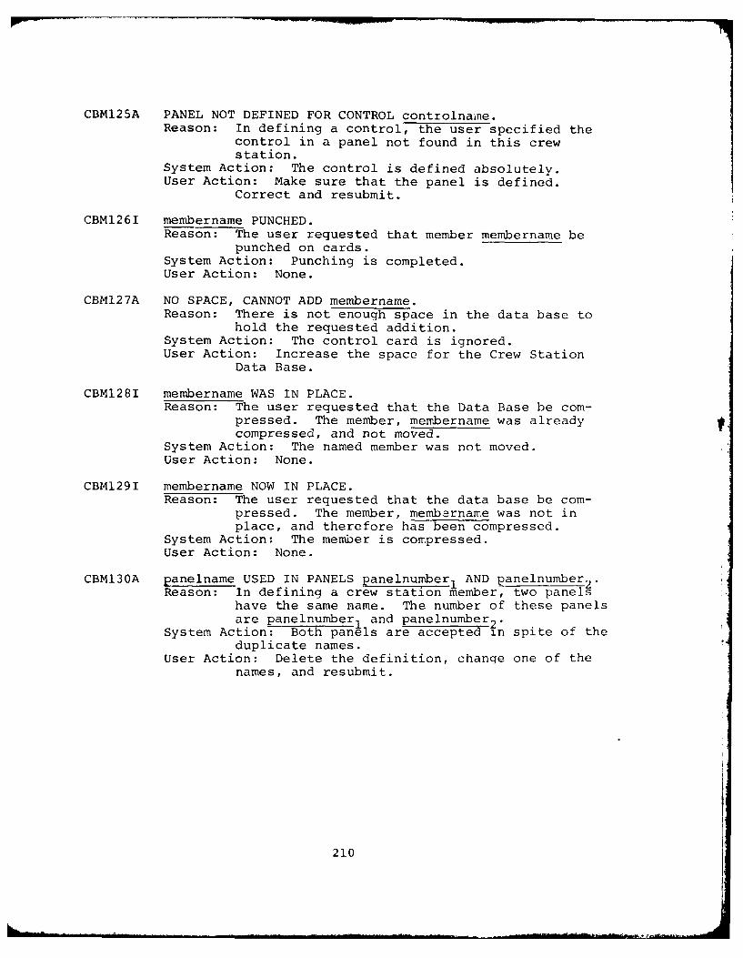
CBM125A PANEL NOT DEFINED FOR CONTROL controlnamne.Reason: In defining a control, the user specified the
control in a panel not found in this crew
station.System Action: The control is defined absolutely.User Action: Make sure that the panel is defined.
Correct and resubmit.
CBM126I membername PUNCHED.Reason: The user requested that member membername be
punched on cards.System Action: Punching is completed.User Action: None.
CBMI27A NO SPACE, CANNOT ADD membername.Reason: There is not enough space in the data base to
hold the requested addition.System Action: The control card is ignored.User Action: Increase the space for the Crew Station
Data Base.
CBM128I membername WAS IN PLACE.Reason: The user requested that the Data Base be com-
pressed. The member, membername was alreadycompressed, and not moved.
System Action: The named member was not moved.User Action: None.
CBM129I membername NOW IN PLACE.Reason: The user requested that the data base be com-
pressed. The member, membarname was not inplace, and therefore has been compressed.
System Action: The member is compressed.User Action: None.
CBM130A panelname USED IN PANELS panelnumber, AND panelnumber2 .Reason: In defining a crew station member, two panels
have the same name. The number of these panelsare panelnumber1 and panelnumber 2.
System Action: Both panels are accepted in spite of theduplicate names.
User Action: Delete the definition, change one of thenames, and resubmit.
210
CBM131A panelname HAS SAME PANEL NUMBER AS panelnumber.Reason: In adding a crew station definition, two panels
have the same panel number.System Action: Both panels are accepted. Note that
references to the second will cause a referenceto the first.
User Action: Delete the crew station definition, correctthe error, and resubmit.
CBMl32A controlname IS A DUPLICATE NAME.Reason: In adding a crew station definition, two con-
trols have the same name.
System Action: Only the first control can be referenced.User Action: Delete the definition, change one of the
names to make it unique, and resubmit.
211
SECTION 6
VISIBILITY DATA BASE MAINTENANCE PROGRAM (CBMVM)
One of the important functions provided by the interactive
program CBM04 is the VISIBILITY PLOT function. This function
evaluates the visual man-model crew station interaction. It uses
the eye location of the current man-model and the three dimensional
coordinates of selected crew stations, stored on the Visibility
Data Base, to generate on-line plots of the man-model's Visibility
Data Base on disk and to make visibility crew station members avail-
able to the user. Note that the Visibility Data Base may contain
the same geometric panels as the Crew Station Data Base, a subset
of the crew station data base, or an entirely different set of
panels and contours. A data flow of the program CBMVM is shown
in Figure 76.
6.1 PROCESSING PERFORMED
The program CBMVM allows the user to create and maintain the
Visibility Data Base. Input data are supplied on £0-character cot"-
puter cards or card images on magnetic tape and are 9 rocesscd
according to the user's selection of control commands. These
commands allow the user to add or delete members, print information
about existing members, or list contents of the Data Base. It can
also be used to compress the members within the Data Base to main-
tain continuous blocks of available disk space.
The control cards may be input in any order with one excep-
tion. If the Data Base is created for the first time or is re-
initialized, the $INT (initialize) control card must precede all
other control cards and member definitions.
212
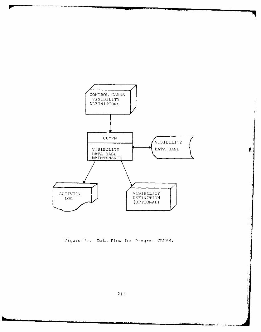
CONTROL CARDSVISIBILITY
DEFINITIONS
M A I N T EDN CF I N I T
(OPTIONAL)
Figure 70. Data Flow for Program CIVM1.
213
6.2 RESTRICTIONS AND LIMITATIONS
A maximum of 20 members of crew stations may be added to the
Visibility Data Base. Each member may contain up to 15 panels or
contours. The panels and contours may consist of two to 100 ver-
tices. The large number of vertices per panel allows a greater
accuracy of approximating curved edges than is possible with the
Crew Station Data Base. These vertices must be input in consecu-
tive order, as described in Paragraph 6.3.1.
The total number of available records on the Visibility Data
Base for member coordinate information is 1479.
Other limitations will be described in Paragraph 6.3.2,
"Specifying Processing Desired".
6.3 HOW TO USE CBMVM
The example used to illustrate this program is based on the
A7E-01 crew station shown with the seated man-model in Figiure 4.
The panels and edges of the A7E-01 crew station were combined to
produce a visibility member consisting of three panels: the upper
and lower window panels and the cockpit canopy panels. These
panels are shown in Fiqure 77, along with the three-dimensional
coordinates used to define points along the panel boundaries.
6.3.1 Input Data
Input to CBMVM is similar to that of CBMCM, except
that adjacent panels and edges can be combined into panels for
input to CBMVM.
The program CBMCM is set up to accept any three
dimensional cartesian coordinate system. The user must also
supply the program with the three-dimensional coordinates of the
Seat Reference Point (SRP) with respect to the origin of crew
station coordinate system.
214
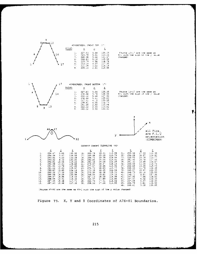
9
4INDSC7EEN, FRONT 7CR '0 '
?CINT:
227.63 5.3 125.-5 Fonts - ire :he same is4 14 2. 22379 5.51 123.24 3-1 sitn tne 42;l or toe / 'anJe\3. 220.)8 5.46 121.S 7 :oanged)4. 213.93 5.13 - 20.59'. 215.79 4.36 118.76
17 .. 212. 4 4.27 117.352.1.39 j.s. ....[6
4. 209.-4 2.31 .13.34
17 4INDSCREEN. FRONT 3OTTOM 17,
POINT: x v z
4. 227.63 5.34 125.35 Points 10-17 are one same as4 2. 230.20 5."S 126.65 3-1 witn one sign ;f one v vale
3. 222.22 5.68 127.34 onangedi4. 234.44 5.41 129.035. 237.31 4.-0 130.596. 239.41 4.05 121.3
241.39 2.32 122.36i 0 3. 242.12 2.33 123.41
99 242.12 2.30 133.41
/
46 47/ / all Figs.0 = are F,L,U
orientationL 92 (COMBIMAN)
COCKPIT CANOPY CLEARL2NE '92)
294.47 3.00 135.50 16. 286.78 19.41 i16.98 31. 255.59 17.33 114.302. 294.24 2.47 134.60 17 235.96 13.30 116.76 32. 254.69 16.97 114.60
3. 293.61 6.22 133.26 18. 284.71 19.30 116.54 23. 252.92 15.78 115.'-4. 293.22 8.32 132.01 19. 292.31 19.14 126.41 34. 251.32 14.0 117.405. 292.61 10.54 130.24 20. 291.34 19.08 116.29 35. 251.32 13.39 1S.576. 292.09 12.43 128.60 21. 279.87 18.9' 116.16 36. 250.59 13.35 1:9.-c7. 291.52 13.78 127.00 22. 277.67 18.36 115.94 37. 250.69 13.35 119.703. 291.14 15.33 125.57 23. 275.72 13.65 115.77 38. 249.55 11.73 122.339. 290.67 15.89 124.15 24. 273.35 13.49 115.55 39. 249.07 10.97 124.20
10. 290.32 17.30 122.38 25. 270.30 18.38 115.32 40. 248.'3 10.16 125.501i. 289.59 13.35 120.36 26. 268.34 13.2 115.16 41. 248.1 3.1 12-.3012. 289.07 18.36 119.44 27 267. 13 19.00 114.99 42. 247.32 - 34 123.5013. 288.55 19.51 118.32 28. 234.37 17.89 114.86 43.24743 6.32 120.2014. 287.95 19.46 117.71 29. 260.73 1-.31 114.42 44. 247.38 4.97 132.335. 287.43 19.46 117.32 30. 258.53 17.24 114.95 45. 246.79 2.81 124.50
46. 246.61 3.20 135.00
(Points 47-92 are the same is 45-1 wich the sign of tne y value =hanged)
Figure 77. X, Y and Z Coordinates of A7E-01 Boundaries.
215
Directions of the x, y, and z axes are A for aft,
F for forward, L for left, R for right, U for up, and D for down.
CBMVM converts the given coordinates to the COMBIMAN coordinate
system (x=F, y=L, z=U, and SRP=(0,0,0)). (See Figure 77.)
Panels for crew stations may have a maximum of 100
vertices. These vertices must be input consecutively, going
either clockwise or counterclockwise along the perimeter of the
panel as explained in Paragraph 6.3.2.1.
6.3.2 Specifying Processing Desired
Program CBMVM allows the user the same functions
as program CBMCM excluding the function to punch the member (PCH).
The function request formats are punched one request per card and
are shown in Figure 78. The &INT card is used to initialize the
Data Base; the other control cards can be used anytime and in any
order. The format and necessary parameters of the control cards
are explained in the following paragraphs.
6.3.2.1 ADD VISIBILITY MEMBER Function
&ADD membername type nbnds srpx srpy srpzx y z xx yy zz (followed by visibilitymember def-n!tion).
The ADD VISIBILITY MEMBER function adds
the specified data under the member name membername to the Visi-
bility Data Base. The membername is limited to a maximum lenqth
of eight characters. Type is a two-digit right justified integer
that can be either 0 or 1. If type=0, the program checks the
panel vertices for clockwise or counterclockwise entries. Typezl
avoids this test. Nbnds is a right justified three-digit integer,
that specifies the number of panels associated with a membername.
The SRP coordinates are srpx, srpy, and srpz and are entered as
real numbers of 6 digits or less. A decimal point, omitted, is
inserted by the program in-between the second and the third digits
from the right. X, Y, and Z indicate the directions of the posi-
tive x, y, and z coordinates respectively, (A, F, L, R, U or D).
xx, yy, zz are two letter abbreviations for the axis labels and
216
directions of the input coordinate system when the operator is
seated in the crew station. Examples of these values are FS (fuse-
lae station-aft), WL (waterline-up), or BL (buttline-riqht).
Each panel is defined by a card containing
its sequence number (seq.#), panelname, and number of coordinates
(# coord) within the panel, and number of vertices, one to a card.
Figure 79 shows the format for these input cards.
Seq.# and # coord are 3-digit right
justified integers; the panelname can be up to 28 characters long.
The three-dimensional coordinates are input as 6-digit, real
numbers, one set to a card. A decimal point, if omitted, is in-
serted between the second and the third digits from the right.
An example of the ADD VISIBILITY MEMBER
function is shown in Figure 80. The first outlined area con-
tains the &ADD control card. The associated panels consists of
a panel name card (area 2) followed by the specified number of
three-dimensional coordinate data cards shown in the third out-
lined area.
If the program detects an error in the
input data the member will not be added to the Data Base.
6.3.2.2 CHECK VISIBILITY MEMBER Function
&CHK membername type nbnds srpx srpy srpx y z xx yy zz (followed by visibilityworkspace def-nition).
The CHECK VISIBILITY MEMBER function
operates in the same way the ADD VISIBILITY MEMBER function does
except that the member is not added, but is only checked for
errors.
6.3.2.3 DELETE VISIBILITY MEMBER Function
&DEL membername
The DELETE VISIBILITY MEMBFR function
removes a given membername from the Data 'lase. In order to make
the space occupied by the deleted member available, C(OMPRI'SS
VISIBILITY MEMBER function must be used.
217
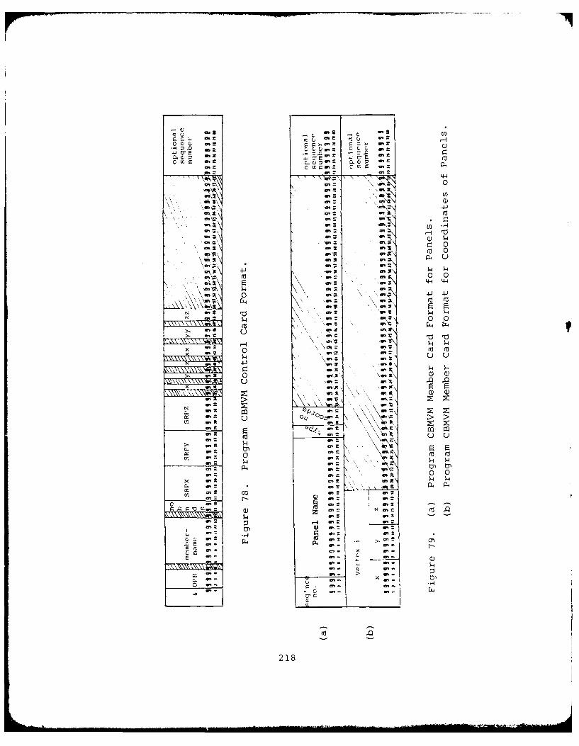
a4-4
fa.~m 0 0
4-4 4-4
\4 0.. 0
0 m)
4n~ r
tor m. 0'44
N~~~~ aZa:a': a'
C.)4 P-4~
.C E)
E~ z*
E' ~a'S , ~ a'A .
D4. a.
21
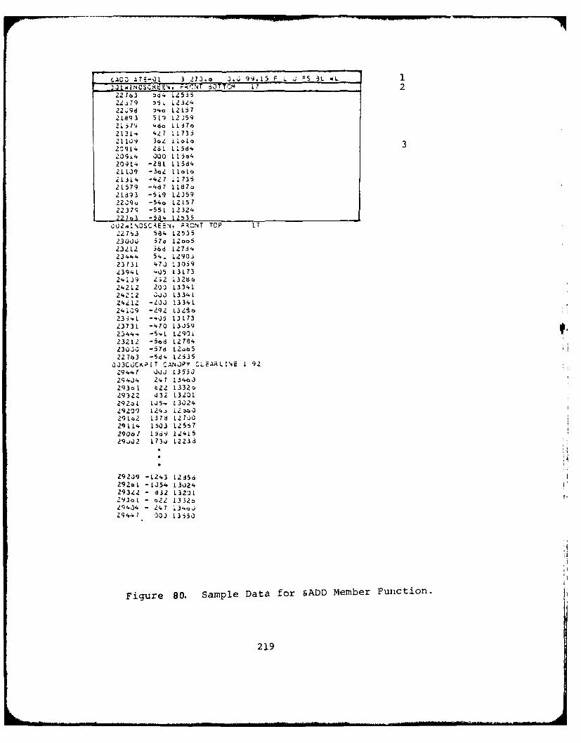
F.ACZ) .17=.0 3 2?3.o J., 99.15 F i FSt 3L)J1NICSC~.r~ 222163 :'d i25352 79 '5i L 123242298 D.o 121i721893 519 125921 57 N ,-do 1137o
2131* .27 11735211'/ 36Z llalo 32C9L4 261 L15d420CP14 00 115*42091'4 -2L 115d421LJ9 -3o2 11oLo21JL4 -42? 17352L579 -4d7 1187:21693 -59 12)592239o -54o 1215722379 -55L 12324227o3 -Ja4 12535
O2JAINCSCENJ, ;RCNT TOP 17227 3 584 125352300J 57a 12oo 523212 568 127342344. 541 1290.23731 473 L305943941 .05 L373241)9 Z32 1326624212 213 13341242"12 ;3J L334L24, 12 -3O.J 13341241G9 -292 L3 ?8o23"4vL -0,O5 13L?3
23731 -470 L335923444. -541 1290i23212 -5od L2784230J0 -578 123o522763 -544 12535
033C Ci ,[T CANOPY CL-ARLINE 1 9229 4 7 'JJ L3553294J4 247 1346J293ol t22 L332o29322 d32 1320L2923L LJ5-, 1302429209 124.) L2 3029lo2 1376 127JO29114 1503 125572901 1ia9 1241529'J.)2 1733 12233
29209 -L243 L215d2920L -1354 1302429322 - 832 L323L293oL - o22 L3325
2) 434 - 247 134,J
29441 33 13, 350
Figure 80. Sample Data for &ADD Member Function.
219
6.3.2.4 COMPRESS VISIBILITY DATA BASE Function
&CMP
The COMPRESS VISIBILITY DATA BASE func-
tion compresses used space and maximizes the continuous unused
space for the Visibility Data Base.
If the message "CBM527A NO SPACE, CANNOT
ADD membername" is encountered during an &ADD operation, it is
necessary to compress first and then attempt to add again. If
the message reappears, the Data Base is full.
6.3.2.5 DUMP VISIBILITY MEMBER Function
&DMP membername or&DMP
The DUMP VISIBILITY MEMBER function
prints the entire contents of the visibility member membername
or the complete Visibility Data Base if no name is specified. The
format of the output is as follows:
RECORD nn
+=+ first half of record in EBCDIC +=+
+=+ second half of record in EBCPIC +=+
+=+ complete +=+
+=+ record +=+
+=+ in +:+
+=+ Hexadecimal +=+
where:
nn - is the number of record on the data base and
+=+ - is delimeter for the data.
The use of this function is primarily
as a debugqing aid for Input/Output errors.
220
6.3.2.6 PRINT VISIBILITY MEMBER Function
&PRT membername or&PRTR
The PRINT VISIBILITY MEMBER function prints
the specified membernime in a format similar to the ADD VISIBILITY
MEMBER function. Specifying no name or a nonexistent name causes
a printout of the list of members and their extents on the Data
Base, as well as their origin and orientation.
6.3.2.7 INITIALIZE VISIBILITY MEMBER Function
&INT
The INITIALIZE VISIBILITY MEMBER function
is used primarily to establish a Data Base, although it may be
used to return the data base to its original unused state.
6.3.2.8 END PROGRAM Function
&END
The END PROGRAM function ter_mixnit-e- R&Cu-
tion of the program CBMVM.
6.3.3 Submitting a Processing Request
The sequence of Job Control Language (JCL) cards
needed to execute the program CBMVM are shown in Figure 81a.
Initialization of the Data Base for the first time requires
allocation of space on disk for the Data Base and is accomplish-
ed by the "//FT09F0jI1 DD" cards shown in Figure 81b and the $INT
control card initializes the Data Base. The "//FT09F001" card
in Figure 81a is used for all subsequent processing requests.
Always end a run with the &END control card.
6.3.4 Interpreting the Output
Output generated by the program CBMVM, which con-
trols page formatting and identifies each page with the source
program (CBMVM) name, date, and time of program execution, and
paqe number, falls into five format types.
221
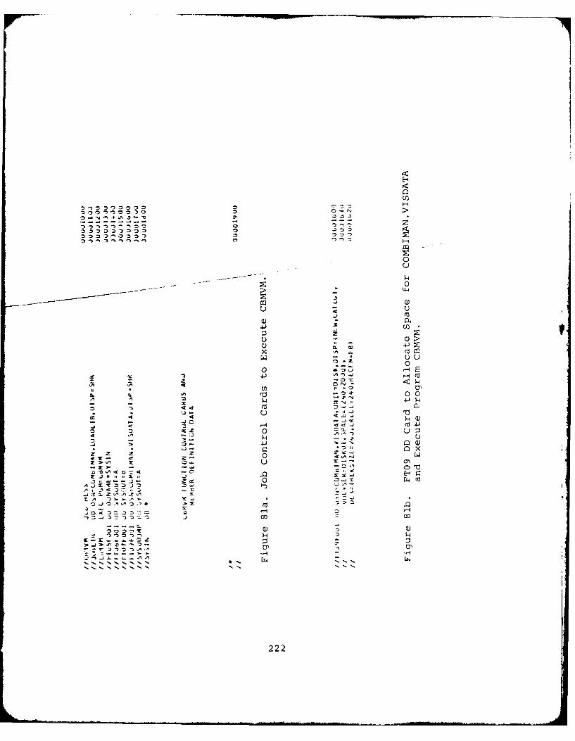
,n
00
4-4
0
4-))
U
3 4-)
~ - 0--
4 Cl4I
,0.. 00-0- x0 -N
U " . '4 . -J ,--
-* "- ...)1 - ..
4 44
4 -1
n 0
< , 0-- 'A-x _jD jXt E4r
a. z zz* f
cr- -- 4 --- U0 -. ,'
-400 00
222t
1-40)
-, "-4
* ~ . ~ ~i. . .. . .. - ". .. ... ... . .... ' '"", - ... ...... .. "' -- • r, , .... ' - '... .•... +. __ . ... ,_--"Hl
The first type of output is generated by the &INT,
&CMP, &DEL and &END functions. The output for these functions
indicates the start and end of processing associated with the
specified function. The COMPRESS function, however, generates
additional messages indicating that a certain member was, or was
not, moved in the process of combining unused space. An example
of this format, for the COMPRESS function, is shown in Figure 82.
The second type of output is generated by the PRINT
function with a blank membername field. This causes a listing of
the entire directory for the Data Base in the following format:
nn.) membername, EXTENT (nl, n2), nb PANELS,
ORIGIN = (x,y,z), ORIENT = (a,b,c),
AXES HEADINGS = (xx, yy, zz)
where:
nn identifies the record number of the memberwithin the directory
membername is the 8 character name of the member at recordnn
nl is the location of first record of membername
n2 is the location of last record of membername
nb is the number of panels associated with themember
x is the location of the SRP in the originalYJ coordinate systemza "b are the original orientation of the positivec Jx, y, and z axes, respectivelyc
xx are the original axes headings for the positiveYJ x, y and z axes, respectively.zz
This information was originally supplied to the
Data Base by the &ADD control card. An example of the output of
the &PRT function is shown in Figure 83.
223
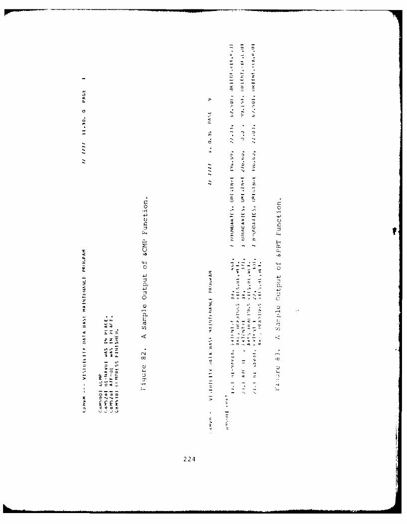
z z
.44
0x 00
4J 4-
z~ Q4 C-
CLC
z z
0-- -AA ~ ~ I
4 Jz .
4
>
a 0 ?.. -~224
The third type of output is generated by the DUNiP
function. For the member specified on the &DMP control card, the
directory information in the second format is printed first. It
is followed by records of the member printed in the format shown
in Paragraph 6.3.2.5. The record in EBCDIC is printed in a 30A4
format and for the hexadecimal output, 15Z8 format is used.
The DUMP function is used primarily as a debugging
aid for Input/Output errors. An example of the DUMP function
output is shown in Figure 84.
The fourth output format is used by the CHECK and
ADD functions. The first item printed out is a reformatting of
the information on the control card. Then, each panel definition
along with its input and absolute coordinates is printed. The
format is:
nn.) bndnm,nv VERTICES - INPUT COORD--ABSOLUTE COORD--
(xill YlI' z1 1 ) to (x2 1 ' Y2 1 ' z21 )
I? l 0!i iU 0!
(lnv'Ylnv Zlnv ) to (X2 2nv, 2nv )
where:
nn is the panel sequence number
bndnm is the boundary name (8 characters or less)
nv is the number of vertices for the panel
coordinate of ith vertex of the panel in theXli'Yli'zi oriqinal system of coordinates (i=l,n-t1-
coordinates of the ith vertex of the panel,x2 i'y2i'z2i converted to the COMPIMAN coordinate s\stem
(i=l ,nv)
An exampltc of the output (ienerated b-, the &AI)D func-
ti'.n is,; shown in Fiui re c,').
'IJt:< t ifth int! last format is used hI, the ']
i .[. in t li.s rikUtpit the ori,:inal l', utats ,re nct
irt~ P. T ie I, ru -u.' ir, r t 1s prilted first 1.> ful , L,
t~~~~~~ ;Il t [, i ., i I t 1,)tl , 1, . :
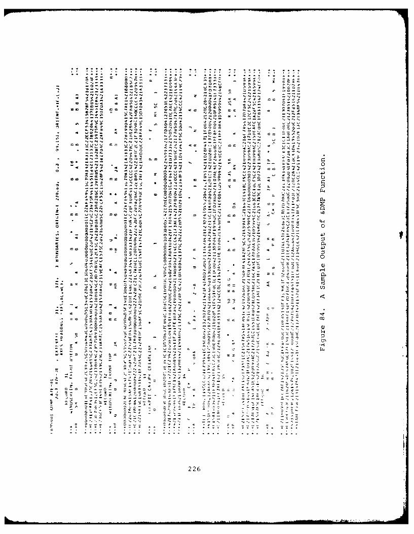
. . -. . . . .. . .
ZZ z 177- ZCZ 0L
a~ IO~ .. ' a..
MWI
0 w I00 4m 4000 '00
- C . w 4 C . J4'. 4 42 4J~t4 N O 'O' ~ t '.n0 0 0 C~.4 4' '44~4.) .JOO ' 04~cc
* C C N44. O 0.., ~ 0 0 4 0 0 14. ~ 'O 4.0o- 0 6 0 I .. & 0 I' .,N N O 4 CtJ c N2~~~~~~~~ z~.?4 2'O' I N - - -
z~N NNN 'no
0 4'0 0 0 ~ C '0 4 N 4'0 - 0 00 .4 0 0
ZL 4 N . 0 'f .L
*~~' C~. co0< tJ.004 4 '0 00 L .0 c~s'4 m t5 4 ~ ' 3
O2O -
L-2'~ I 01M4'MC 04-
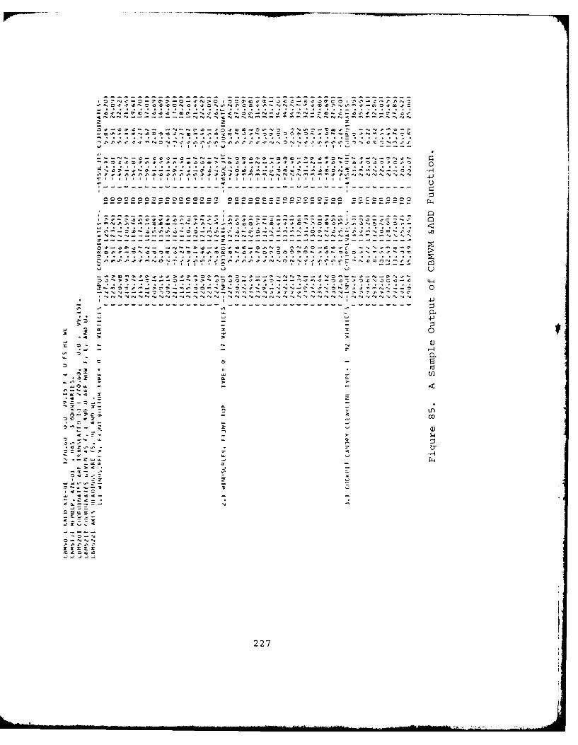
z zt
--- -, --- - - -- -- --- - --- -- -- ---0% ~ 4 - --- --- --4' t
.C 3.~ .2 .l'2 O .' ' .C 2 N i . N...S
CC~~*4'.74'.74'4'eCC2!O.7' ZI.-%777- *0"Z24'03C7Ct0 ~~4J- - - - - - - - - - - - - - - - - - - - - - - - - - - --.- - - - - - - - - - - - - - - -'9 '' .7 A N N N N N N 4
Ill, lil I i I! t I tI 1.11 ill III IQ4- 2 1
C000 0000 000 00 O CCCC CCC CCCC Q4
2-2-
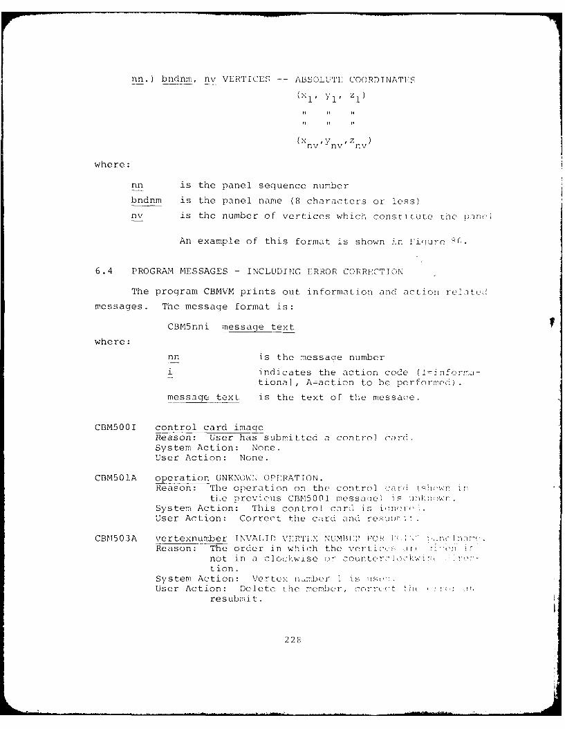
nn.) bndnm, nv VERTICES -- ABSOLUTE COORDINATES
(xnv, ynv, znv)
where:
nn is the panel sequence number
bndnm is the panel name (8 characters or less)
nv is the number of vertices which constitute the pincl
An example of this format is shown i.n Fi-ure I(.
6.4 PROGRAM MESSAGES - INCLUDING ERROR CORRECTION
The program CBMVM prints out information and action related
messages. The message format is:
CBM5nni message text
where:
nn is the messaqe number
i indicates the action code (I=infcrr-a-tional, Aaction to be performed).
message text is the text of the messaqe.
CBM500I control card imaqeReason: User has submitted a control card.System Action: None.User Action: None.
CBM501A operation UNKNOW:X OPERATION.Reason: The operation on the control car 2 shown in
th~e previous CBN500I messa(ie) is d .System Action: This control card is i(nUser Action: Correct the card and resu .
CBM503A vertexnumber INVALID VERTI;: NUMBI " , FOP 1 lv' rn, !Reason: The order in which the vertic. , {n
not in a clockwise ()r counter<to r, ,tion.
System Action: Vertex number 1 is ,so'User Action: Delete the membe, corrct t
resubmit.
228
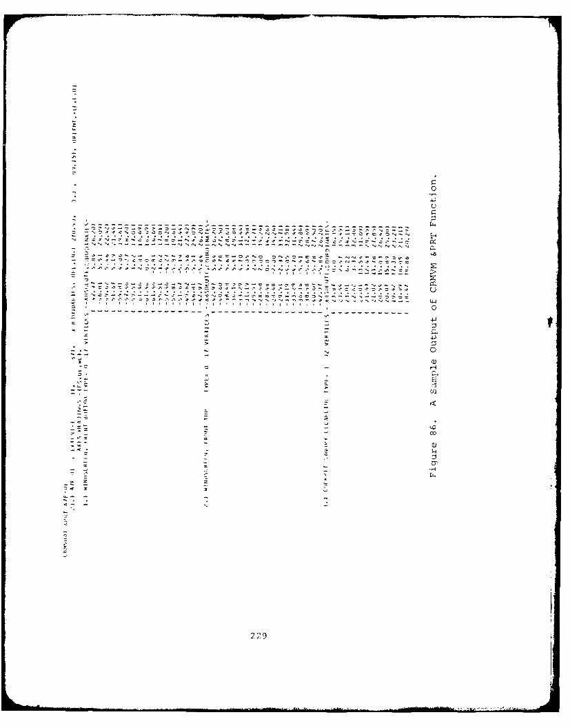
0
C)
-- ..- . - - -.-- - - ------ -- -- -- -- - -- -- -- -- -- ---.z c0
2. 9
'C..
229 1 IIII ,* It.N C ~ N~ tC ,-Z- N O. ~ Ifl ~ % --* SJt4, fl r~flfl4 4,4 *< * ~ I N ~ u -,I. .C v 4 N J N N N ... 4.
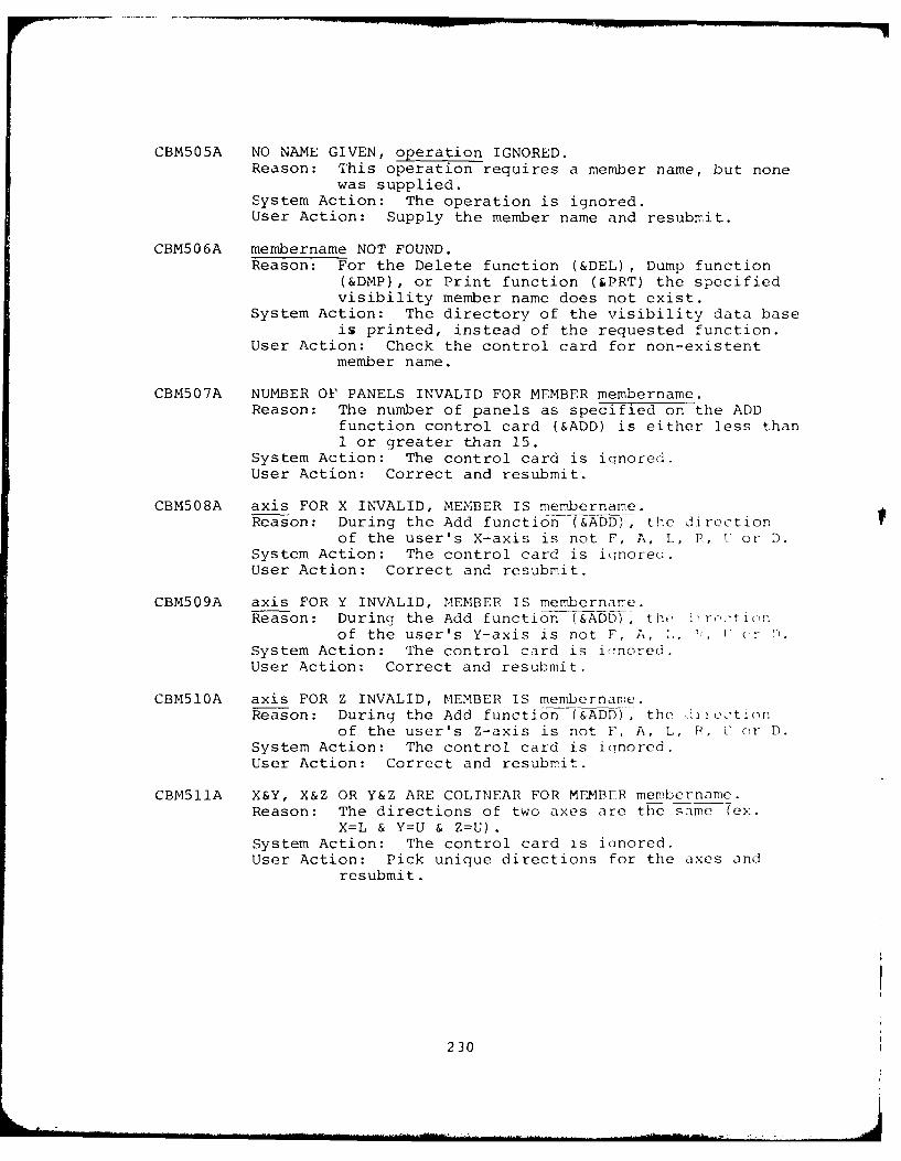
CBM505A NO NAME GIVEN, operation IGNORED.Reason: This operation requires a member name, but none
was supplied.System Action: The operation is ignored.User Action: Supply the member name and resubmit.
CBM506A membername NOT FOUND.Reason: For the Delete function (&DEL) , Dump function
(&DMP), or Print function (&PRT) the specifiedvisibility member name does not exist.
System Action: The directory of the visibility data baseis printed, instead of the requested function.
User Action: Check the control card for non-existentmember name.
CBM507A NUMBER OF PANELS INVALID FOR MEMBER membername.Reason: The number of panels as specified on the ADD
function control card (&ADD) is either less than1 or greater than 15.
System Action: The control card is iqnored.User Action: Correct and resubmit.
CBM508A axis FOR X INVALID, MEMBER IS membername.Reason: During the Add function (&ADD), the direction
of the user's X-axis is not F, A, L, P, U or D.System Action: The control card is iqnoreG.User Action: Correct and resubmit.
CBM509A axis FOR Y INVALID, MEMBER IS membernare.Reason: During the Add function (&ADD), th,, 11 r,.-tion
of the user's Y-axis is not F, A, 1, ' , V (,i '.System Action: The control card is iqinored.User Action: Correct and resubmit.
CBM510A axis FOR Z INVALID, MEMBER IS membername.Reason: During the Add function (&ADD), the airection
of the user's Z-axis is not F, A, L, P, U or D.System Action: The control card is ianored.User Action: Correct and resubmit.
CBM511A X&Y, X&Z OR Y&Z ARE COLINEAR FOR MEMBER membername.Reason: The directions of two axes are the same (ex.
X=L & Y=U & Z=U).System Action: The control card is ianored.User Action: Pick unique directions for the axes and
resubmit.
230
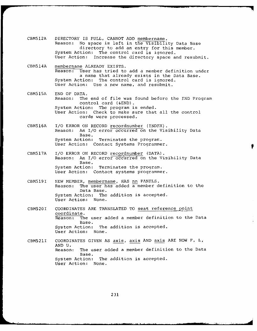
CBM512A DIRECTORY IS FULL, CANNOT ADD membername.Reason: No space is left in the Visibility Data Base
directory to add an entry for this member.System Action: The control card is ignored.User Action: Increase the directory space and resubmit.
CBM514A membername ALREADY EXISTS.Reason: User has tried to add a member definition under
a name that already exists in the Data Base.System Action: The control card is ignored.User Action: Use a new name, and resubmit.
CBM515A END OF DATA.Reason: The end of file was found before the END Program
control card (&END).System Action: The program is ended.User Action: Check to make sure that all the control
cards were processed.
CBM516A I/O ERROR ON RECORD recordnumber (INDEX).Reason: An I/O error occurred on the Visibility Data
Base.System Action: Terminates the program.User Action: Contact Systems Programmer.
CBM517A I/O ERROR ON RECORD recordnumber (DATA).Reason: An I/O error occurred on the Visibility Data
Base.System Action: Terminates the program.User Action: Contact systems programmer.
CBM519I NEW MEMBER, membername, HAS nn PANELS.Reason: The user has added a member definition to the
Data Base.System Action: The addition is accepted.User Action: None.
CBM520I COORDINATES ARE TRANSLATED TO seat reference pointcoordinate.Reason: The user added a member definition to the Data
Base.System Action: The addition is accepted.User Action: None.
CBM521I COORDINATES GIVEN AS axis, axis AND axis ARE NOW F, L,AND U.Reason: The user added a member definition to the Data
Base.System Action: The addition is accepted.User Action: None.
23 1
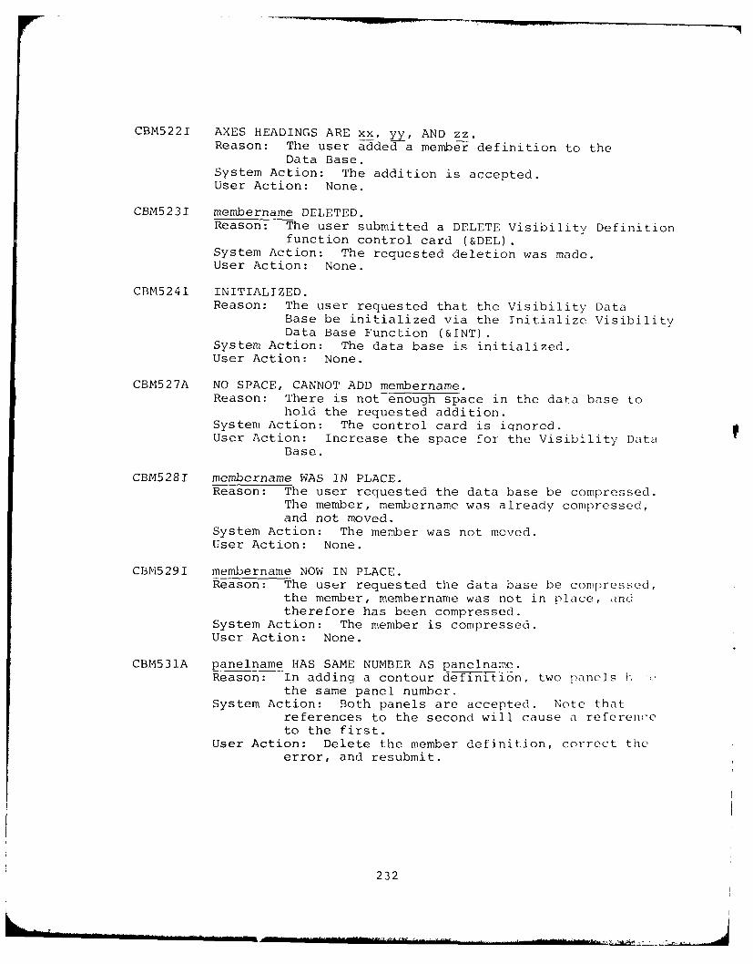
CBM5221 AXES HEADINGS ARE xx, yy, AND zz.Reason: The user added a membier definition to the
Data Base.System Action: The addition is accepted.User Action: None.
CBM5231 membername DELETED.Reason: The user submitted a DELETE Visibility Definition
function control card (&DEL)System Action: The requested deletion was made.User Action: None.
CBM5241 INITIALIZED.Reason: The user requested that the Visibility Data
Base be initialized via the Initialize VisibilityData Base Function (&INT).
System Action: The data base is initialized.User Action: None.
CBM527A NO SPACE, CANNOT ADD membername.Reason: There is not enough space in the data base to
hold the requested addition.System Action: The control card is ignored.User Action: Increase the space for the Visibility Data
Base.
CBM5281 membername WAS IN PLACE.Reason: The user requested the data base be compressed.
The member, membername was already compressed,and not moved.
System Action: The member was not moved.User Action: None.
CBM5291 membername NOW IN PLACE.Reason: The user requested the data base be compressed,
the member, membername was not in place, andtherefore has been compressed.
System Action: The member is compressed.User Action: None.
CBM531A panelname HAS SAME NUMBER AS panelname.Reason: In adding a contour definition, two panels h
the same panel number.System Action: Both panels are accepted. Note that
references to the second will cause a referenceto the first.
User Action: Delete the member definition, correct theerror, and resubmit.
232
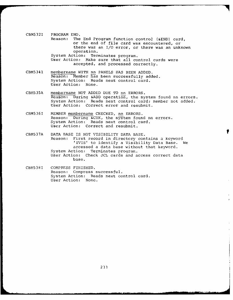
CBM5321 PROGRAM END.Reason: The End Program function control (&END) card,
or the end of file card was encountered, orthere was an I/O error, or there was an unknownoperation.
System Action: Terminates program.User Action: Make sure that all control cards were
accepted, and processed correctly.
CBM5341 membername WITH nn PANELS HAS BEEN ADDED.Reason: Member has been successfully added.System Action: Reads next control card.User Action: None.
CBM535A membername NOT ADDED DUE TO nn ERRORS.Reason: During &ADD operation, the system found nn errors.System Action: Reads next control card; member not added.User Action: Correct error and resubmit.
CBM5361 MEMBER membername CHECKED, nn ERRORS.Reason: During &CHK, the system found nn errors.System Action: Reads next control card.User Action: Correct and resubmit.
CBM537A DATA BASE IS NOT VISIBILITY DATA BASE.Reason: First record in directory contains a keyword
'IVIS' to identify a Visibility Data Base. Weaccessed a data base without that keyword.
System Action: Terminates program.User Action: Check JCL cards and access correct data
base.
CBM538I COMPRESS FINISHED.Reason: Compress successful.System Action: Reads next control card.User Action: None.
233
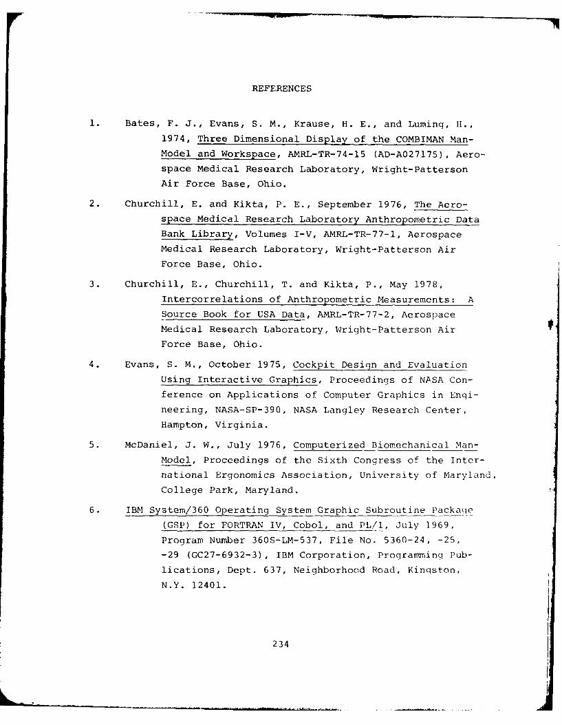
REFERENCES
1. Bates, F. J., Evans, S. M., Krause, H. E., and Luming, H.,
1974, Three Dimensional Display of the COMBIMAN Man-
Model and Workspace, AMRL-TR-74-15 (AD-A027175), Aero-
space Medical Research Laboratory, Wright-Patterson
Air Force Base, Ohio.
2. Churchill, E. and Kikta, P. E., September 1976, The Aero-
space Medical Research Laboratory Anthropometric Data
Bank Library, Volumes I-V, AMRL-TR-77-1, Aerospace
Medical Research Laboratory, Wright-Patterson Air
Force Base, Ohio.
3. Churchill, E., Churchill, T. and Kikta, P., May 1978,
Intercorrelations of Anthropometric Measurements: A
Source Book for USA Data, AMRL-TR-77-2, Aerospace
Medical Research Laboratory, Wright-Patterson Air
Force Base, Ohio.
4. Evans, S. M., October 1975, Cockpit Design and Evaluation
Using Interactive Graphics, Proceedings of NASA Con-
ference on Applications of Computer Graphics in Engi-
neering, NASA-SP-390, NASA Langley Research Center,
Hampton, Virginia.
5. McDaniel, J. W., July 1976, Computerized Biomechanical Man-
Model, Proceedings of the Sixth Congress of the Inter-
national Ergonomics Association, University of Maryland,
College Park, Maryland.
6. IBM System/360 Operating System Graphic Subroutine Packaqe
(GSP) for FORTRAN IV, Cobol, and PL/I, July 1969,
Program Number 360S-LM-537, File No. 5360-24, -25,
-29 (GC27-6932-3), IBM Corporation, Programminq Pub-
lications, Dept. 637, Neighborhood Road, Kinqston,
N.Y. 12401.
234
7. Zeigen, R. S., et al., December 1960, A Head Circumference
Sizing System for Helmet Design: Including Three-
Dimensional Presentation of Anthropometric Data, WADD-
TR-60-631 (AD 251939), Wright-Patterson Air Force Base,
Ohio.
8. Evans, S. M., May 1978, Updated User's Guide for the COMBI-
MAN Programs, AMRL-TR-78-31, Aerospace Medical Research
Laboratory, Wright-Patterson Air Force Base, Ohio.
9. Churchill, Edmund, et al., December 1971, Anthropometry of
U.S. Army Aviators - 1970, TR-72-52-CE, United States
Army Natick Laboratories, Natick, Massachusetts.
235
APPENDIX A
COMBINAN DISTRIBUTION TAPE DOCUMENTATION
236
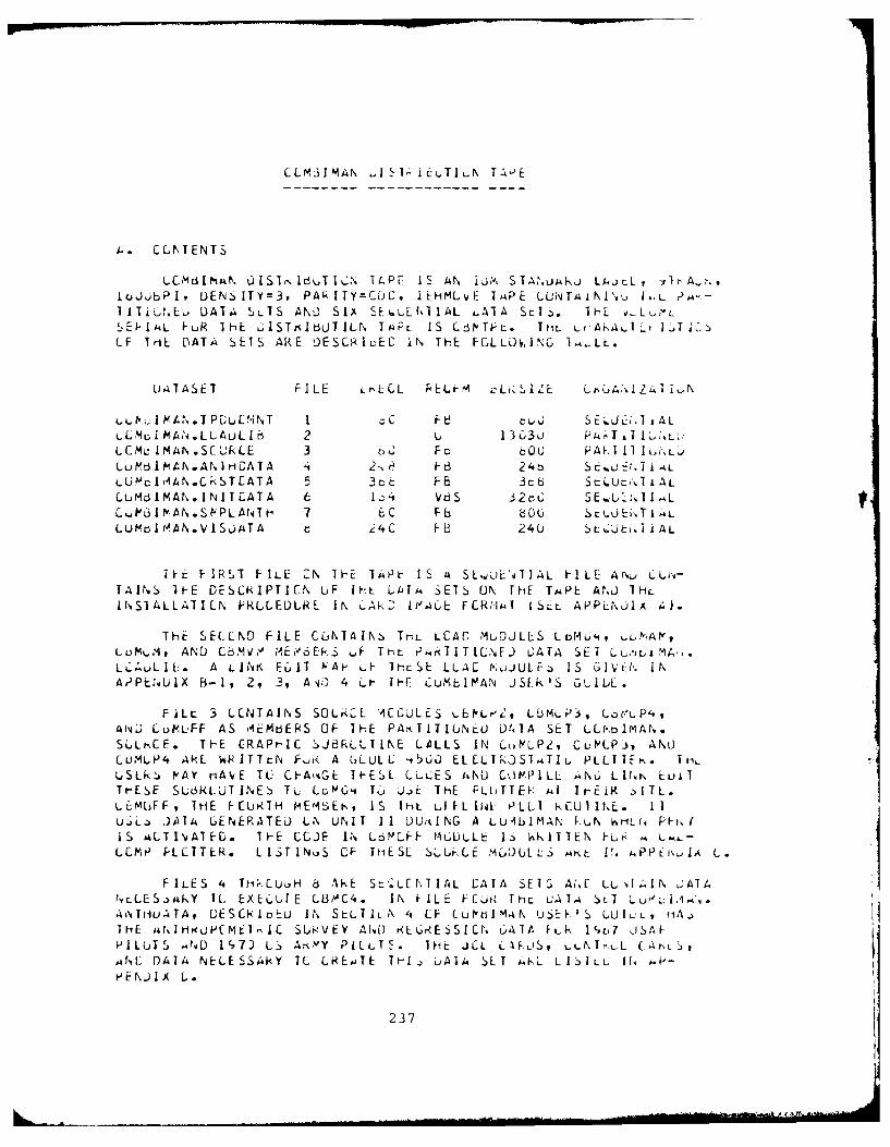
C LM31 MAN - I 1 1 uT I N TA E
i.. CLNTENTS
LCM I MAN t) IS Ir. I UT I LN T14PF IS AN 13M. S IAMAdJ LAJtLL, t jIr ,,1ujjbP I, DENS ITY=3, PAk I TY=CjC, I HMLvE I APE LONTA i NlI,,u .CI i i-.L DATA SVIS AND) SIX SE6rL\1I AL LAIA St.). ]HE s ,LW,-L',E IAL VuR IHE L1ISTs IbJTILN TA.PL IS CrVTh- E. ThL Lt'.h4k,,l -f I 'Ti.>(-F TriL DATA4 SETS ARE DESCR IuEC lN THE FGLL~v,lN IM..LL .
Li"TASET F1L E L r L CL PEL-.M ILi S IZEcLL% ~Z4 T1-.N
LC I MAN.PTPul'iN T 1 :I F~ d S E'J C 1.T ALL L Mu I Mk..L L ALLIb 2 L 13 C3uLGML: I MAN.SC IULE 3 FbcO0 P~d.1 11 16i',L.iLuM61A.ANIH-CATA 's 2 e F 6 24b SC.A)E- - iALL Uf4IA A N .C kS TEA T A 5 3 c F 6 3cb SrLUEI<iALLuMd IMAN.I1NI1T CATA 6 1,;,4 v 3 2 C SE.., UJ.T I .L
LP3I PAN.St'PLAtsTH 7 ECE oo SELJEN.T I LLU~ol AN.V I SOjTA z4 C F b 240 S L J t i% AL
i~t F-IRST FILE CN IH-E 1AiP I S As SEL.0'iLJAL FilLE A1 . CLij-TAINS 1H-E DESLRIPTICN LiF IFE LAIu SETS ON ThE TAPE ANLJ TIHllN.SltLLA11LN PfRLLEDLRE IN k'Atk2 If4.A6 FCRft1MT ISLL. APPL.C.LIA 4).
THE SECLN9 FILE CONTAINZ TrL LCAC MLDJLLS Lo4t LMNAP,LdtILM94 AND CbMid.,' MIE06EkS LF Tt-L PMTITILNE.) OATA SET LL.ItLIMA-.L L ; 6L I. A LINK EUIIT VAP, &F 7HcSE LLAC MoJULF~j IS GIvCI. INAdPES',UIX Bs-1, 2, 3, A 0 4 Lt- 1I-F CuMbIPAN JSE.k'S GUIUL.
FiLL 3 LLNTAINS SOLrkCL A~CCULES Lb~.LMLPi, Cot-*,PisisNj LuV.LFF AS AIEMgjEIS OF THE PAmTITIjNtL0 041A SET L0-r01MAN.SLLh-CE. Th-E CRAPr-IC $)JBRLLTINE LALLS IN CutoPP, CuL)Pi, ) ANt)CU.-1LP'4 Ak WRITTtN fhui< A GLULE 4s'5jO ELELI;kOST.ATIL PLLITE4.. ThmUSLk~j PA rAVE TL- CF-AtiGE It-ESL LLLES AND COMPILL AN6 LINN~- LUllTHESE SLUkLLUT1.NFS, TL LcAG's Tu W)E THE PLUTT~k Al JI-CiK -)ITL.LizMcFF , THE I-CURIH MEr4SEI , IS Iht LI FL14 P[[eLLT kCU1 INE. I]ujL. . JAIA GENERATED LN UNIT 11 D)Uid NG A LUIbIMAN kuN hti- fq Ph, 1IS ALTIvjAIF0. T hE CLJF IN LbPJLI-h MGULLt: IS %RITTEN -L,r A LAL-
cCPMP PLLTTER. LIST IN.S CF TtiESL SLU,(E tM0)ULLS mh~t 1. kPPtl\,,A L.
LES. 4L EXECUTE CAkECS. INFIL FCU TATA ;, LuIzIN ~ IATFILES~AK 4C TliEC,U-E L1M4 IN~ f NIL FCAtThL LSEI&A SETAN A
4iNTHuATAq GESCkIoEu IN SELTILN 4s CF LUlPdIMig USE 'S LUIL'L, f1A3IHE isNI uOPCME1 1C SUi8VtfY AN~D r<LGR-ESSICt, 647tA FLk 1'c'7 JSAI-PILUTS .ND 1',7J L.- Am."Y PLLTS. 1Hzt JCL CIF L)Sv LLNTrt-L CAtLS,A4NC 041A NkEESii<Y IC LAEjiTE TthIj uAlA SLI AKL L IZI L CI f. .p E NJ Ix L,.
237
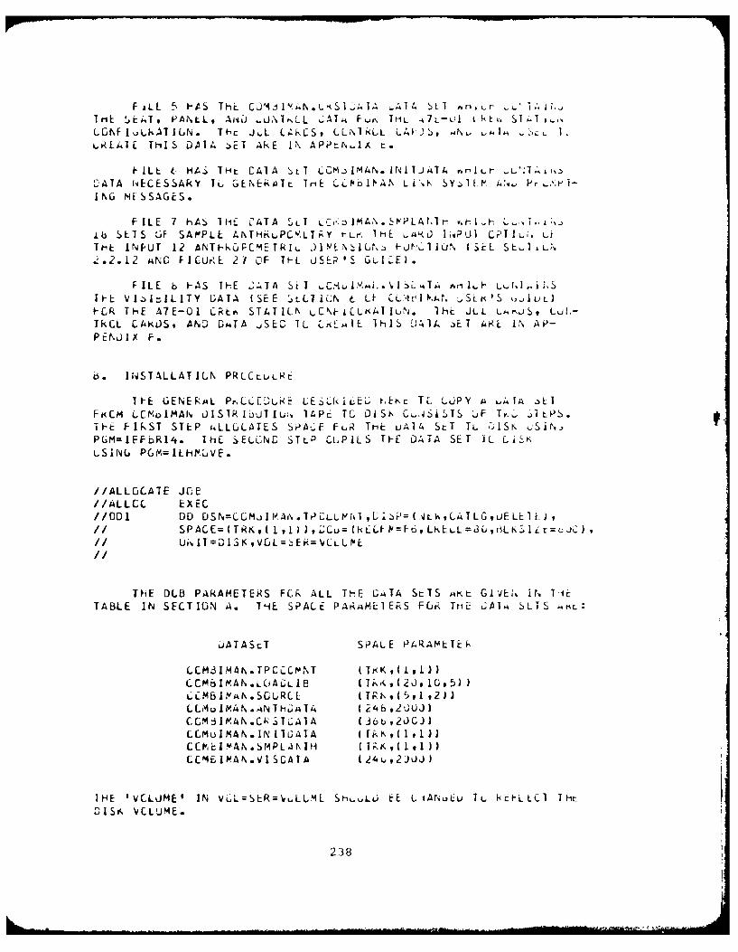
F &LL 5 -A S Thc. Ca4 I V 4N.. K S1.II-A A1 4 bL I A h - r- ~LA.TriE S.EiT, PAl\LL, AISO .J-\T,,LL L;ATM KU\, ItML 4 7L-Ll t 6. S I T iLGFI A.AAT I GN. T h-~ J L L~k[S , CN~hLL LAVI2), .MN . LAJ M6 -ILLLRL-41I THI S DAIA -)ET Ak~E 1% AP~tt' JA t.
I Lt 6 1-t. THt CAI A Sri CCM..,MArN. NL TJATA nrlIlk.r - 'TA IA NiE CE S S A kY 1L6 G E N E kaTLi rE: U'LIP' PA N L i ,. S Y,: IE.4.fvL Pw ~r '1
ING MESSAGES.
FILE 7 hAS liiL CTASLI .;IA.tTA~r '1-ib SLTS LJ SAP'PLL ANTH~.,PC% LT;Y rLr. IHE -W~<J) lvPU1 CPTIu;. Lf
Ti'L INPUT 12 ANT-kuFCMETRI,- 31YLN IL~a FJN.AIUN- (SEL SE AiLt".. 2.12 ANLD FICUr~L 27 OF 71-L uSER IS Gu LE).
F ILE b FApS TIE 2ATTA Si I CM.tL.wI S LTA4AT i h Lt, IJ S
It-1: V1IILITY DATA ( SEE LLTICN 6 U- C-I.d.Sci'S oJIUL)t-LR TH-E V7E-O1 CR~v. ST4T ILr\ kCNt-CLf4T IUN . ihi JLL Lsm Lu!k-TkCL CAKOS, AND D#ATA jS:C TL LrkLMIE IhIS D41A jET 4RE 1% AP-PEN~JIX F.
63. INSTALLATILN PRLCLULRC
It-E GENERA4L PrLC:EDURE LESLk.jcE.; tli"c II, LUPY A LiAA 3LIFi<CM LC?~DIMAN' JISIRIiUTlu. 14PE TG DlSt\ C',ASi-'IS .jF Ty,~ jitPs.1IE FIf\ST STEP cALLGJLATES SiPA--E FuiR THE uAI4 StT TL UIS\ .;Sltvg,PGMIEFOR14. ]HE : ELGNC STLP CLPILS TFE DATA SET IL Li$.KuSIN6 PGYMILhl.VE.
//ALLGCATE JO;E//ALLCC EXEC//D1 DD DSNLMJ)Ir A\.TPALuLt[I,(.)PLL,LALG,LELL),
1/ Ui.IT=O1SK~,VGLz E1k=VLL I'vE
THE DLB PAkAlOETER~S FCk ALL THE G;"T4 StTS A~t GlvE:.. it. Ti:rTABLE IN SECT ION A. THE SPALE PARAML-lERS F(JUR Triil LCAlM SLI S MIK.:
b.ATAStT SiPALE PA'RAML:TEAk
LCMdIMAN.TPCCCM,%T ( K,(1)CCMtsItF-AN.LL)ALJLI8 (Tk,u,(2J91U95flLCM63II'N.SGURLE (Tgr\,U5,i ,2)LL~uhf1.AN.ANTh-;ATA (i4o92JUJ)(CCM:3IPAN .Ck~jV..;AlA (36bu,2jcj)LCMuIMAN.IN [lUaTA ( Ii%.is (1,1 iiLCMC1AN.SMPLINTH ( I K,(L))CCM4EIAAN.VISCATA ( 24u,2)JJ)
IHE 'VCLLIME' IN VGL-'SER= uLUML ShLUi EE LiA.uL, u TL 1-LLCI Th
D15Sf \VCLUME.
238
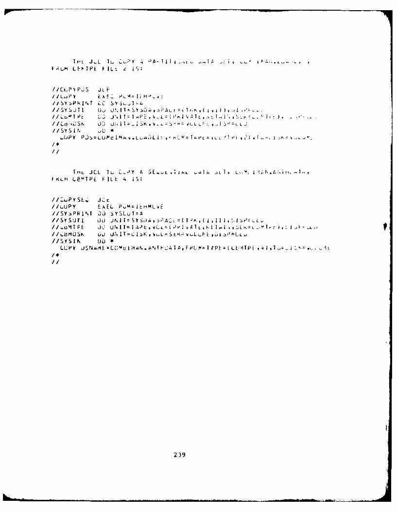
F k Lm L I PE FIL t
//CLPI PJS JL F
//SY >PkINT ?SC A~
//SSUT I D j U' I Ij,- S Y 3PLL,2 iI i
/SY sI N ~L *
hiL JCL 1L. C,1Y A 3E -L 1"L 1Af L I, Lk, A"' .A hfFRLM LBMNTPE FILE 1~ jS
//L.UPY E)AEL PumzltriMLvE//SY-)PkNT DJL) S YS Lu I= A
//6oIMTFE 3 0 U N IT I A r E VL L z d~Lk, Z L.Ir ,I Iu'
s Y SI N t)L *
239
APP-N PI X '3-1
LINKGI DIT()k >tAPS- FOR CB3M04
24 0
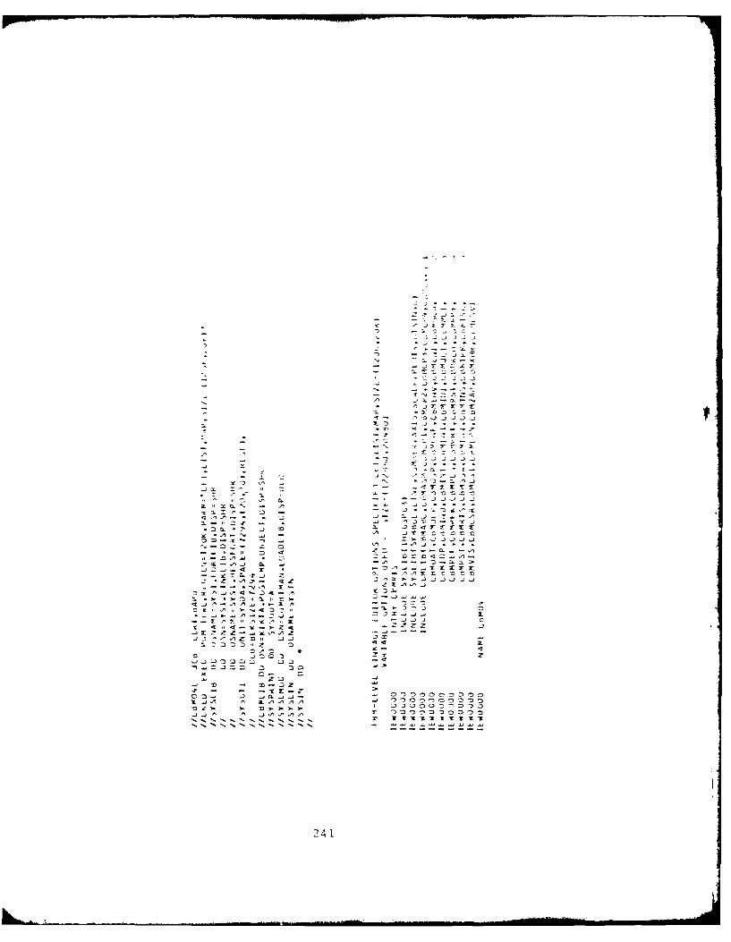
9 , --. ..'
z a 2
na r
24143L "D --3 - 3o o oo -
- ~ ~ ~ 2 1 - .
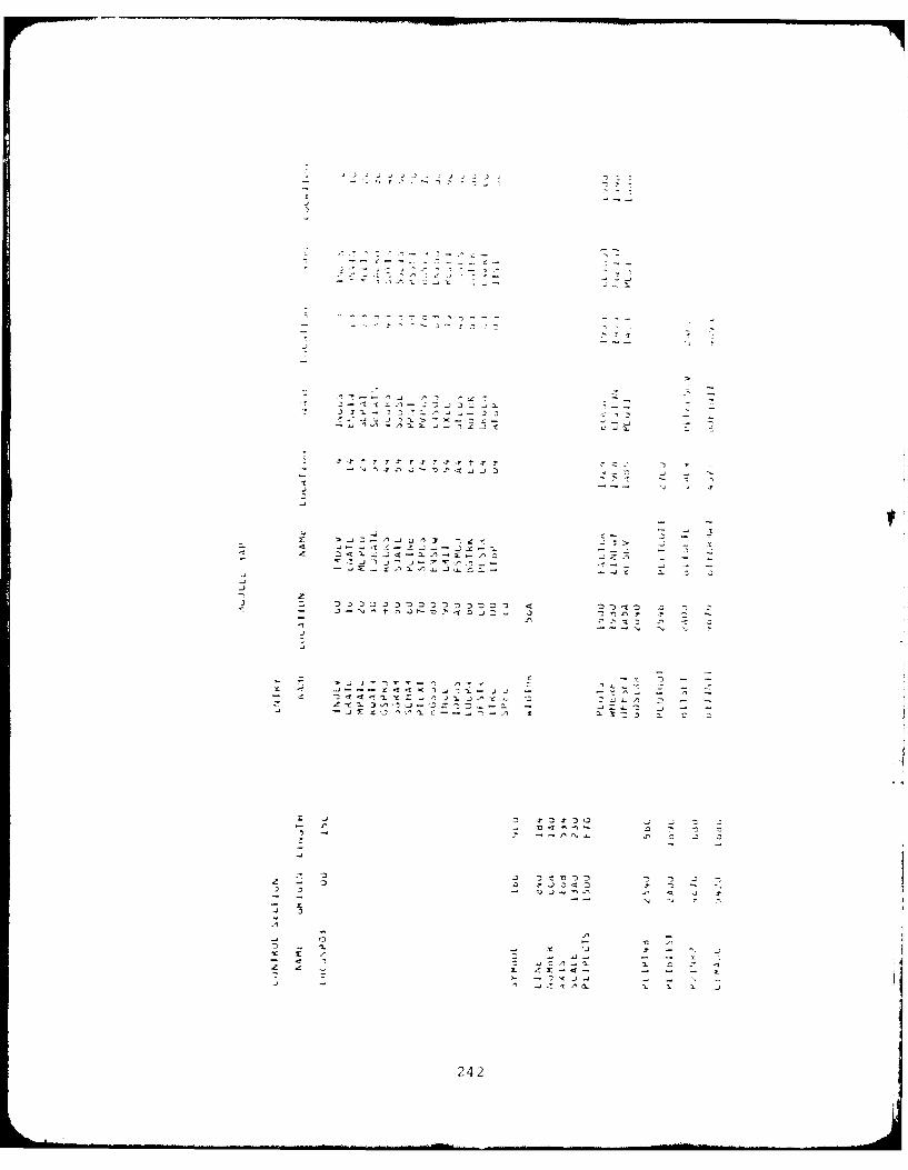
- - .? '.- lp--, -.
,I
24
-- f, 1
-- - . .. ... . . .. .. i .. . . .I l l l l -
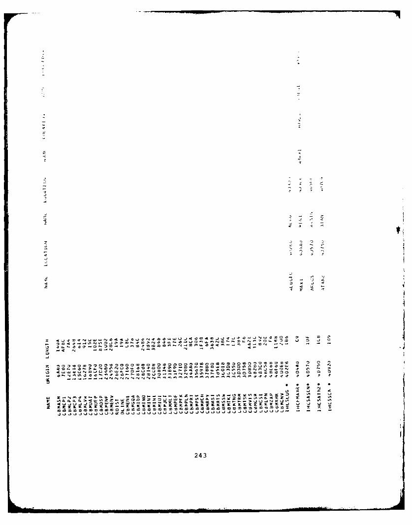
f2 N
U) x
'-43
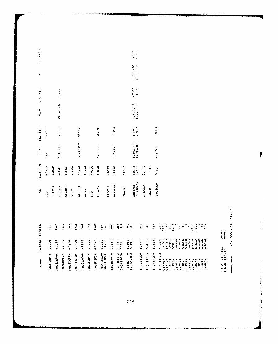
-).
< L6
i 7r I - 7 7:
CL j 0a ac
to =-. 00u m! 7 -4 A Of
0 go j zp 00 1- . i fN Q2! ! "2 ! "' . U - - I~ -N N -
U- w3 67 .7 0) 7f m7 v7 = A A A
ix -r rU n- N 11 ,J 0.
x ZD %, t) . L -2 >. A A '2 A -cc 0C '2 U. cc x 0 0 -a D~ ex 2 3
U. n M. C X2 'n a -i e.
244
APPENDIX B-2
LINKAGE EDITOR MAP OF CBMAM
245
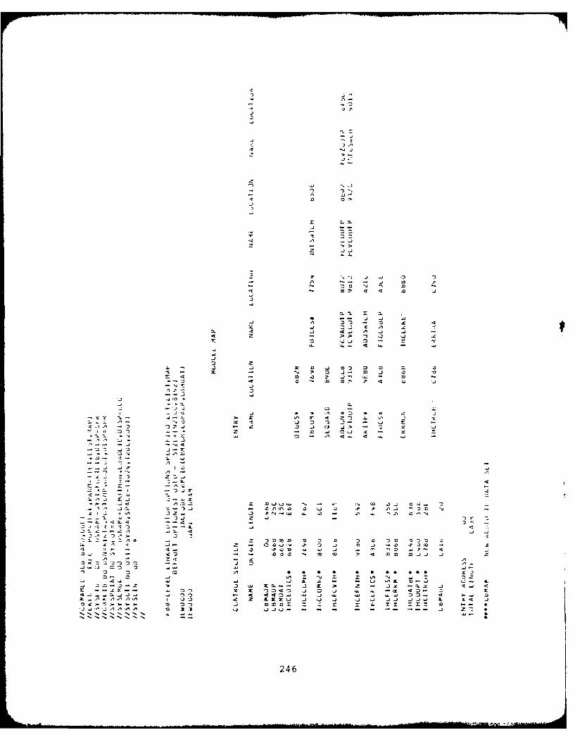
D -
33
- -Z
II
m3 --
N4 N0x
it-
24
. . .....
APPENDIX B-3
LINKAGE EDITOR MAP FOR CBMCM
247
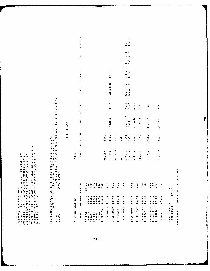
a--3
CLD
-4 It-24 a 3
a- L- C
03 z- -3-
A CL zz x
0 QS
- .
OD x -A
-~0248
APPENDIX B-4
LINKAGE EDITOR MAP OF CBMVM
249
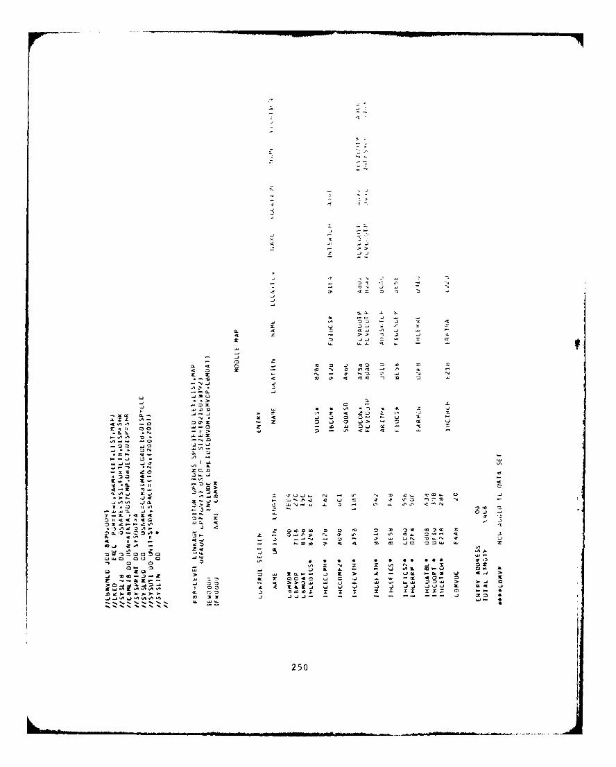
0 D.
z -
303
of 3
4c -7 >tt 3 )
13 : :)) 3
j~ I0 O
'm C3
EDw 3 0 0 a
26 .3 =t - It .0j -W I >~~~ I43 m- .4 1:4 2J . r
0 A 0 'Aa '3x J
-~ * 250
APPENDIX C-I
COMBIMAN SOURCE
CBMCP2 LISTING
251
SUBIAuLriNE CjM4e(X,Y)
CL CB~lCP2 - LUIS MAN-MuULL AND Ce4EA TAiIN C,% .,LL, PLLIrI~
CL LALLEJ BY IC. u~MCPI - MAIN UUMblMiN PLOT {LcIi'th J)....I.L dMP - tiEAUING 4LUIT KuIui EL 3"
cCALLS -C )LCT - CAL,,CN.P PUJT IeI ( GK". L 1 4
L SYMouL - G4JULJ CHA44AL tR PLJT RT ~L
L OUTPur TO-c. JN I 9 - PLuTTLK DATA ,..p-.
L PARAMETERS - -j.-. j ..C A - A4 KAY OF X VALUES Tu OL ,'LjTTjz '..,.c
C Y - AmRAY uF Y '4ALUL> lu 6-' P.Lullc...j,:.
C COMIMU N //CiMbAY IIMAN-MCThcL AYZ .,T. J'j~,, 35C PUJtLftzJ ENFLESIAME.'T tLLI?'l-; .,.F,. PuINTS -i--
L INtJLA A,I,&AY IU ictF Nt $,:LAT IGNS-uP iL I ..zN uI'i(S A(,, .,
C LINKS,.L I NL;E AkkAV Tu AY Z' S 1 L LCLAr I 1AI4 ,,,T I .4! : P rI;,I. I,.
INTEGER XYZrK,L~uMMON / L 8MdAY/ A Y Z Lr1.IUCJ ) XYAm IJ,.6 k.~,l S 4,
1 MAXTAN42,'tJl
c LuMMUN // CiMXf1 // MAN-MCLL 41L).1, .,L X Y J~AL MAN-4uI)EL J I NI ANt. E LL I P'SL ,i cA I r-i .4t 4!.kuL ...N
c mLKK.PAct PANLC XYZ d)AT4.
L (:Y 1, .'AY Z AR4RAY - ICENT!FY I .. -A..- "2. I I,[T: t....,
L 'lAx NuMuLIk LF XYZIS, RqO SP4tt-Ay.T 1 NK.. I-1 2 I
C PCINTS ALLu~t.J.C ',UMbLM .fr. LINK\S, K[Y' , Y, .K, L .I .- yu .. ,.*.., ,.
L AYL' 4 . LLINTi'CLS . ANO i~~,c e.EYT~u oXKKEEPIN,, AR(RAY.
1 N TLE E .x Y ..Kt.L I Y P, I ', L , LP, u,
-'A A Y Z, AA .."4A)( YiAA..IL . It '.,., -1 -. , A4 I iv..I A
Ni LYT .I% I j , , i ,i L ' A4( , , 1
, A.
C PLuT MA,1-1'4LLdtL L INKS A NU ArIAJi,%C
J= A13S(K tYTAu( 5.[HI ER CJ)= ICALL PLuT (AC Li,Y(l ,I .3 1
L
00 50 Iz.e.NL..KS
J=1A3S.KLYTh~b5,ICC -'j --K=KEYTAdC 1,1) -
H1ERIJ)=I
C DCSPL4Y CNLY HEAU AND NEC LIN,S3 iF L2CCO ,FF)
* Gd TG 2J
CC LCCAT E C~UCKDINATc OF PE v 1,j S olL INT T- ChA iN
CALL PLLT(ACLC *Y IL 1,3)10 M=2
CC CHECK IF MIT Uk INCLLJCE STAIUS
I F C KEY TAB(C5, IC T.,.AND.*KEY T A i , I .L 1 .3CALL PLU II A II ), Y I I) AI
2'. J=LAES(KlEYTAtdhU,HCl
IF (J.t'..1J GU TO 50CC PLCT ENFL::SHEU $M
4t-UE.
C3J KP=KEYTAE( i,1 J+'ACNIKS-1
LI=PKEYT.toI).C J-2
35 DC 45 LZ=rUP,Ll
4D~ CONCCNJE .C-C
IF(MINTANI I, I I t...-J GO TL DJ*L I=MINT AN I, IC +NL NK~L2=MINI AN( e.ICC. L:4KCALL PL uT(A Cl JC, Y CL .3LALL .LJI (XlL2),Y CLC,2)
L2=MAATANC2,&1C*,,LN K
,.ALL lPLuIAkL ICYC i I5.
LALL P'LuTCACL4)vY(L .C,2C,UJ LCNtCNUt
L P'LuI oLH&: TACCI " A,,ELSC
IF I %LK..izQ.NKEYI "LljHWC
')G 3J I= I.,% LK= F YT J I , i ) +iA YZ +,.L4KSLALL PL .,TCr)V,,J
IF (KEY I~ (') I. ).LT I
253
K-K+ r- I ii, I LJ
o0 L A' L LLIXIi y J1'
8j COPNTLNuE
END
254
APPENDIX C-2
COMB IMAN SOURCE
CBMCP3 LISTING
255
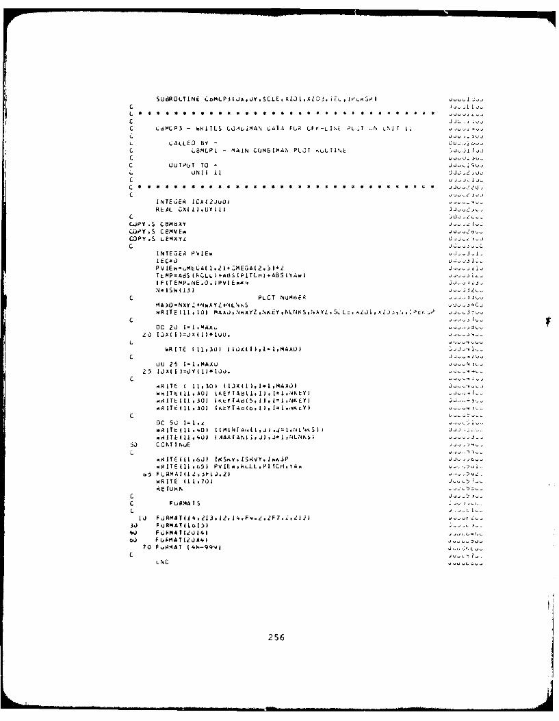
SUd3ROLTINE CMLP3(JA,0YSCLE,XZL.),AL0i, iEs, ,I I-.'.,
C J Ji, I QC LiML P3 Wk NI ILS LL)ALiMAN L ATIA FGR LF f--L I t tLi L I II a i
L LALLED By-C COMLP1 MAIN LCM61MN PLOT NuLL1INE ,JL1,
C UUTPuT TO - ju- I Jk.UNIT I I1 JJ,; .2 ,jh
C )JU 2 2u
INTEGER I CX I2JU01REAL OX(I),UY (I)
CUJP Is CBMBXY j 1CLOPY ,S C 2fV EsU-COPY,S LeMXYZ U'- ~
INTEGER PYIEwI ECsO- 0>PV LEvquLt CA( 1. 2) *OEGA(2.3 5+ZT*AP=AdSCk(LL)sAdS(PLTCI)+ABS(YAwIIFIT E P. NE .0.(P vIE044j, I-
CPLCT Nu~oEk "J~j.'4A)IU-NXY *NWAYZ*NLNtS Vj )4CojRITE (11 ,.10) MAAJ,NXYZ,-%EY hLNKS,NAYL SL., ji,)A~jA,1IPEP., ij3
C -- lu)
DO 20 iI.MAA,;20 lOX( I )=JX(US100O.
0(0 25 1= I MAAU
mR(TE 1 11.305 (IJX(I(,I=,MAXD)w R IlT t iI I .30) (EYIAbIi i I)J, 1-1,NKEY) U~~-
.s.UTLI LL .301 (IKLT1o(5, I I, Lz 14KiEYJ j.
c U-DC 50 I=1I. i
AITH(I1 4U) I AAX IAN I i ) ,J1,LNS):j L CIT I NuE
A R I TE ( 11 L5) PVIEm~kLLL *P1 TCH,YA. ,-o5 F PLRM A I(L 2 , -10J. 2)
WRITE (1 19701)-57RE TUkN
CFUIR.'ATS , -' '
I J F URMA T( 4, 213 ,12, 14 , F-. e ,2F 7.c212)
40 FiPMATI201416%) FUAMATIZ,)A4) :V
70 Fu8MAT ( 4,h-99'11 Jtc
LC C
256
APPENDIX C-3
COMB IMAN SOURCE
CBMCP4 LISTING
257
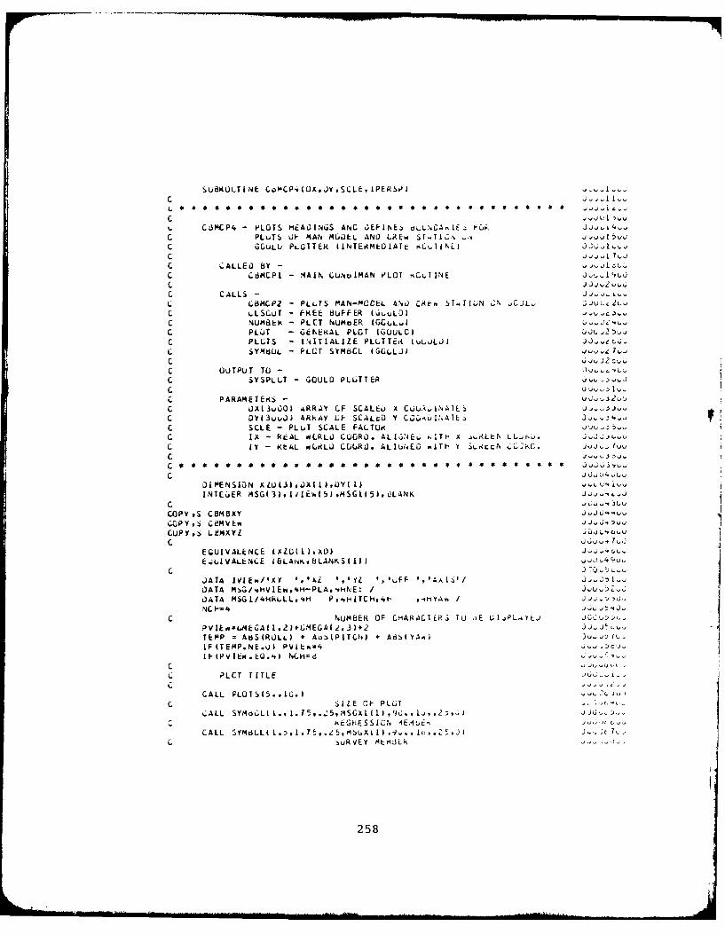
SUBIULTLNE C.oMCP.(OX,JYSCLE, IPER)ol
C
C -..JU I5vt, CdMCP4 P )LOTS HEADINGS ANC GEFINE4 OLL>.OA IE~ f;Cjk I.&C PLuTS UP- MAN MGOEL AND LAEw Td~..C GGULU PLOTTER (INTErAMEOIATE RL IINL) 2C1~C j - %J,
C CALLED BY -C C 6MCPI - 4A IN LU.Nu IMAN PLOT kCLt IIN EJ I't
C CALLS - j IL. C$14C*2 - PLL4.7 MAN-MOCEL A-NO C~4.. ST..TIUN Z;% CJ JJ , LLC4 ~ ,SCLT - FREE BUFFER (Gi.ULD)C NUMB~ER PLtT NUMbER (GCUL.4y lc PIUjT - GENERAL PLOT (GUULC) )t2tjC PLLTS - INITIALIZE VLLTTE*R (%uL-iLJ) jj-dc.JL SYMdUL - P'LCT SYMbCL (GGOLJ J L)Lz7
C OUTPUT TO 4
C SYSPLLT - GOULD PLOTTERCC PARAMETERS-C D)X(3uOD) ARRAY LF SCALEU A CUUi,LNAILS UwC DY13viu~ ARkAY CF SCALt:D Y C0Cul.%AIEa j-4
C SCLE - PLuT SCALE FALTORC IX -RcAL PILRLO CUORD). ALI[,)4EL; .. ITH X j;RLL,% LLLC IY - KbAL ioLRLU COURD. ALIu~tE0 l~Th~ Y LKLN j -C J
C J~u4v,
D1IAE NSION xZu (3) JX I I IY I I -,~u, i..uINTE..,R MSG3),IdlEh(5)M4SGII5hdLANI(
C 'i v., uu
COPY',S ComoAy j V
CUPY,,, Lk!MXYZ 'o() ,LC-
EQUIVALENCE (XZL I hX0) ,. JA-IuE.JUIVAa.ENCE iBLAivisbLANKS( I)J
DATA MSG/'.tiVIE*w,4H-PLA,4H%'E: /
DATA MSI/4HkuLL,.I- P,4HITCHv41- 4HY-iA"./
NCC ~, NMBER OF CHARAC1EP.S !U jE UliPL..ILUPVIE.-,LMEGAII#2)*LEGAI2,3)*2 -
TEMP = AkJS(RDLL) + AuS(PITCHJ + A6S(YAA.)IF(TEMP.NE.Uj) PVIE%=4 J-1: mc').I F(PV lEw.* Q.',) NCH=d
C ~jyj t.L
L PLCT TITLEc
CALL PLOTS(5.,IO.)C SIZE OF PLGT
CALL SYoL .I15 5MGllc kEGkESSICN 4Et6
CALL 7-C SuRVEY Mt4:43Lk
258
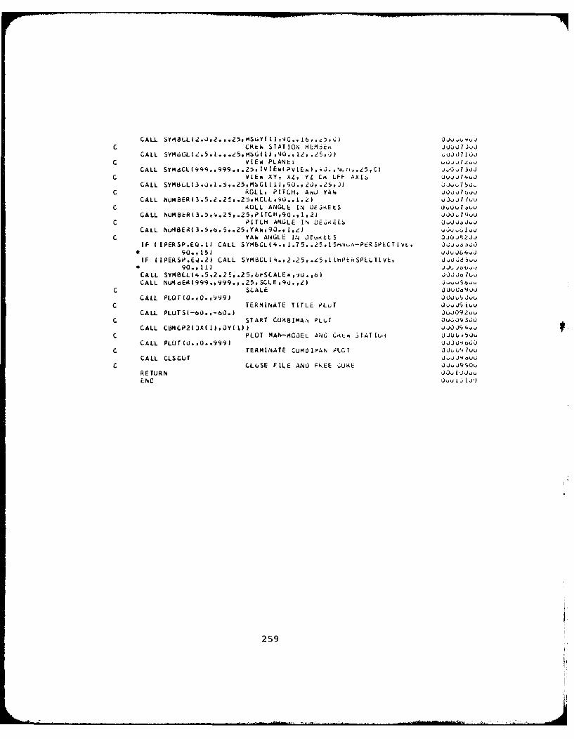
C CRtlm STATIC,% M1E~oE JUw)Q7.)JJCALL SYdL,.,..e.MGLU,2.5J jQJk71uj
C VIEWi PLANt. ujji~jl,
L VIE" XYi XL, YL CrK LFF AXIS, U~oj74vJ
CALL SYM13LL(3.Uti.5,.25,MsGiI 1bco.2Q, .25,jl jjU75U..C ROLL. PITCH, Ai4) YA6 hili
CALL NuaR35,.5.2tCL U.,, u.j1 Iluu
C ROLL ANGLL IN JEL..EtS uuluCALL NUMBI:R(3.,'.25..25,PILCH,9O., 1,2) iuru
C PITCH ANGLE IN Dt,;,EES UUowCALL NuP4BER( 3.5,o. 5,.25,YA.,90.,Ie U1, 6 u
C YAW ANiGLE IN OE6,LLS 0juji2ijIF ( IPERSP.EQ.11 CALL SYtMbLL(4.,1.75,.2,,15ri.4'v-P-.SPECTLVL, QOJ,*90.,15) u~ji4QJ
IF I IPERSII.E.).2) CALL SYtBOL(4.,2.Z5,.,e5,llhPU:KSPLLIIVL, jo5ugo9.,11) )J..J joo
CALL SYMBLI',.5,2.Zt,.25,6l-SCALE=,1O.,6) Jjou
CALL NUM dER(999.t 999.,p .25,9SLEv90. , 2 1)v~C SCALE )JuuoohjCj
CALL PLOT1.0.vV99) JuuhAjvuLc TERMINATE TITLE PLUT J-U'iA
CALL PLUTS(-6U.,-60.) JJ9uC START CU;481MA'di PLuT uX3J
CALL C13M CP21 OX ( 1), Y 1)) j OJlC PLOT MAN-,4COEL ANC CKL 3 IAIui NU*
CALL PLOT(U.#O.9999) J40
C TERM4INATE CUM61MAN i'LGI Ojuu~lliCALL CLSQUT vliu
C CLUSE FILE ANL) t4EE c;UXE JdJJ99ouRETURN JJLju
259
APPENDIX C-4
CBMOFF LISTING
260
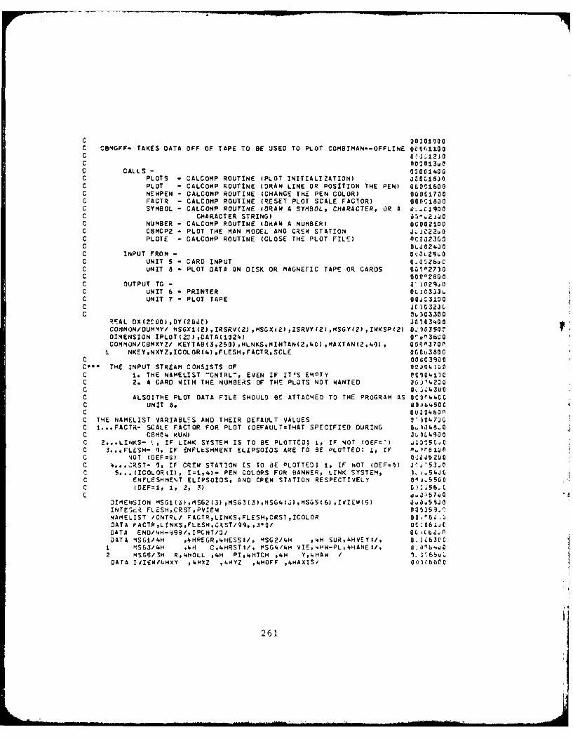
C O)0t'00C CBMGFF- TAKES DATA OFF OF TAPE TO BE USED TO PLOT COMBIMAN--OFFLINE 0061100C 0 1 2JOC nO-';13utC CALLS - 93001400C PLOTS - CALCOMP ROUTINE (PLOT INITIALIZATION) OZOGl5JnC PLOT - CALCOMP ROUTINE (DRAW LINE OR POSITION THE PEN) GOfl1600C NEWPEN - CALCOMP ROUTINE (CHANGE THE PEN COLOR) O0OG1730C FACTR - CALCOMP ROUTINE (RESET PLOT SCALE FACTOR) OOnCl8j0C SYMBOL - CALCOMP ROUTINE (DRAW A SYMBOL, CHARACTER, OR A 0. L 19D0C CHARACTER STRING) 0 i'JiOC NUMBER - CALCOMP ROUTINE (DRAW A NUMBER) 00002100C CBMCP2 - PLOT THE MAN MODEL AND CREW STATION J JC22uOC PLOTE - CALCOMP ROUTINE (CLOSE THE PLOT FILE) nCO323GOC 06J024JOC INPUT FROM - JaL25OC UNIT 5 - CARD INPUT 0 0 526u 0C UNIT 8 - PLOT DATA ON DISK OR MAGNETIC TAPE OR CARDS UDIP2730C 00092800C OUTPUT TO - 0"J029j0C UNIT 6 - PRINTER 0DJ03 3LC UNIT 7 - PLOT TAPE OOjC3DO0C Jr]0323CC 4303300
RlAL DX(2CUO),DY(20C) J0303400COMMON/OUMMY/ MSGXI(2),IRSRV(2),MSGX(Z),ISRVY(2),MSGY(2),IWKSP(2) 0-.)O350tDIIENSION IPLOT(23),CATA(i52') 'u'v36COCOMMON/CBMXYZ/ KEYTAB(3,250),NLNKSMINTAN(2,40),MAXTAN(2,40), 0!ifn370P
± NKEYNXYZICOLOR(4),FLESHFACTRSCLE 0G0u3800C OOaC39ooC'* THE INPUT STREAM CONSISTS OF aoJ0' jC i. THE NAYELIST "CNTRL-p EVEN IF IT'S EMPTY eC104100C 2. A CARD WITH THE NUMBERS OF THS PLOTS NOT WANTED OGJ'42COC O 00.3UOC ALSO;THE PLOT DATA FILE SHOULD BE ATTACHED TO THE PROGRAM AS OC3'r44GC UNIT 8o 0.i 50CC OUJ0O60nC THE NAMELIST VARIABLES AND THEIR DEFAULT VALUES 0')O47JGC 1...FACTR- SCALE FACTOR FOR PLOT (DEFAULT=THAT SPECIFIED DURING 0..1,18.0OC CBMCL RUN) J3.L'900C 2...LINKS- r, IF LINK SYSTEM IS TO BE PLOTTED; ip IF NOT (OEF=-) .con5c'oC 3...FLESH- q1 IF ENFLtSHMENT ELIPSOIOS ARE TO BE PLOTTED: 1, IF nA~r5j1oC -40T (OEF=U) 0C005230C ...°CRST- 9, IF CREW STATION IS TO 8E PLOTTEO; t, IF NOT (DEF=I) 3j%'53A0C 5... (ICOLOR(I), I 1=4)- PEN COLORS FOR BANNER, LINK SYSTEM, IL.54JLC ENFLESHMENT ELIPSOIDS, AND CREW STATION RESPECTIVELY 0niJ550C (OEF=I, 1, 2, 3) 0',"56.Ltc uJ.57uO
DIMENSION MSGI(3),MSG2(3),MSG3(3),MSG4(3),MSGS(6),IVIEW(5) jj0..sJOINTEScR FLESHCRSTPVIEW 001359NAMELIST /CNTRL/ FACTRLINKSFLESHCRSTICOLOR 00,"6.,uDATA FACTPLINKSFLESH,C.RST/9. ,3-0/ OC 061JtDATA ENO/4H-9g/,IPCNT/O/ 0o tbi!fDATA MSGI/4H 4IHREGR14HESSI/, MSG2/4H 4.H SURLHVEY:/, 0. I630C
i MSG3/4H 4H CLHRSTI/, MSG4/4H VIEsHW-PL,'HANE:/, J.Jnb.*2 MSG5/3H R,4HOLL #4H PI,4HTCH 4WH YIHAW / 1., 6DATA IVIEW14HXY 4'HXZ ,4HYZ ,4HOFF ,4HAXIS/ 00],I6600
261
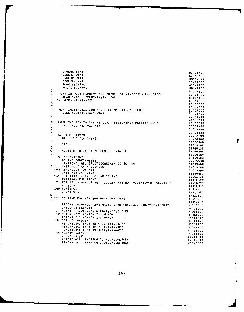
ICOLOR(x) =1 ~ ~7rICOLOR(C2)=i ULI'268C00rCOLOR(3)=Z 00016900ICOLOR(4)=3 n,'C7J;0READ CB,CNTRL) uJ1,llOOWRITZ(6,CNTRL) 00307200
cOf if,? J 73; aC READ IN PLOT NUMBERS FCR THOSE NOT WANTED(IN ANY ORDER) 0021n74~00
REAO(5,8C) (IPLOT(I) ,I=1,20) D'%.75080 FORMAT(2s ±X,12), CiO I'76uC
C OCJC7700C acat 780C PLOT INITIALIZATION FOR OFFLINE CALCOMP PLOT 0 3079U0
CALL PLOTS(DATA,±:'2,7) onjC8ioC 00 i fl 1C JO~U8200C MOVE THE PEN TO THE -Y LIMIT SWITCH(PEN PLOTTER ONLY) ooj:83;0
CALL PLQT(3. ,-2.,-S) O182C 30)C85l0C 310 86J 3C SET TH= MARGIN 00 J)'790
CALL PLOT(i.,1l.,-3) CC J)6600oC 01) 189J 0
I PC=, oo00cg9.dpC 00 149120C*4 ROUTINE To C.HECK IF PLOT IS WANTED lajmg2oo
5 IPCNT=IPCNT+1 3C1,9L.00DO 14.5 ICHECK=1,21 j,93IFUIOCNT .NE, IOLOT(ICHECK)) GO To 14.5 09)1096 I0
C SKIP PLOT DATA SUBFILE nc9014 IEAO(o,90) DATAOJ n51 0983')
IF(EOF(8)137,1'.1 030099U~3141 IF(DATAll *NE. END) GO TO 14.0 ucC Aj.0
WRITE(6,iF]) IPCNT o ilcirtPiSj FORMATCIX,9HPLOT SET IZ2,28H WAS NOT PLOTTED--BY REQUEST) 00j102'10
GO To c; ooI314.5 CONTINUE 3J )1CL' u
rpc=Ipc+i 03I1L50C 00 1U630C** ROUTINE FOR READING DATA OFF TAPE a: 1c ?ijC G' 31usac
READ(8, 10) MAXD,NIXYZ NKEY oNLNKSPNXYZpSCLE, XD, YD ,N, IPERSP J'9uIF(EOF(8))130,12
11 FO.IMAT( I',213,l2,L4F.2, 2F?.2,212) D^4111~i)
1REAO(8,30) (DX(I),Izi,MAXD) 003112J0
33 FORMATCI6F5.2) CL 311 4UREAOD8,35) (KEYTAB(i,I) ,r11NKEY) 91111500READ(8,35) (KEYTA8(2,l) ,11,NKEY) 04 'liciREADC8,35) (KEYTA9(3,I) ,I:1,NKEY) 00 3117lo,
75 FORMAT(1I5) 11131180000 53 I01,2 anill.jo1READ18,,.) (MlNTAN(I,J) ,J1,pNLNKS) 0-12.IZARFAD(8,'.) (MAXTAN(1,J) ,JzlNLNKS) o',1io0
262
41J FORMAT(ZlI4) 00.122U059 CONTINUE Coj123uC
REAO(8,60) IPSRV(2j,IRSRV(2),ISRVY(1),ISRVY(2),IWKSPcI),xWKSP(2) 011124Uj60 FORMATCZOA4) 99 )12503
READ(8,65) PVIEWROLLpPITCH,YAW QJ012b. 065 FORMAT(I2,3FI0,2) GjI127'V'
READ(8,90) ENOFLE J^ 31282 190 FC-tIAT(A.) a iI z30 11
IF(ENOFLE *EQ. END) GO TO 151 j.jj13jopWRZTEt6,110) N 5i. '1312"
ii' FORMAT UX,33HINCORRECT AMOUNT OF DATA FOR PLOT,12, 02'1320C-17H --PPOGRAM ENI3ING) On)13301STOP -340
C "011135'OC** PLOTTING ROUTINE u J11 ')C GO )13?.*
151. CONTINUE 0"3 13800C G 31 39i cC SPECIFY COLOR FOR THE BANNER OJ4U
CALL NEWPEN(ICOLOR(2j))314'C J 1 '.2JiCC PLOT THE BANNER 3flJ143 fPC 05 J144'. oC REGRESSION MEMBER OJ4,
CALL SYMBOLC1.,1.25,.35,MSGIUI),*.I.) 0011'46(19CALL SYMBOL(999.,999.,.35,MSG1(),90.,l~)11470-ALL SYMBOL(999.,g399,,.35,MSG1(3)90.'.) U;314890CALL SYMBOL(999.,c399.,.35,IRSRV(I),9.,.) uJ4CALL SYMBOLI,999. ,gg9. ,. 35,IRSRV(2) 9L. ,4) I15U
C or15,C SURVEY MEMBER 0 f!11~520
CALL SYM9OL (1.5,1.25,.35,MSG2(l),9.,) O'.,.1531CCALL SYM9OL 1999.,999.,.35,MSG2(2),90.,.) OI5CALL SYMBOL(399.,9999.,.315,MSGZ(3),90.,4) 03155 CCALL SYMBOL (999.,999.,.35,ISRVY(1) ,9. ,') 1121561 3CALL SYMBOL (999.,999.,.35,ISRVY(2),9.,'.) 00G1S72z
C 0'15 OC CREW STATION MEMBER 9.'%5,30C
CALL SYMBOL (2.,1.25,.35vMS&3(1),90.,4) :~~aCALL SY4a0L (999.p999.,.3%,MSG32),90.,.) ~6~CALL SYMBOL (999.,99Q.,.35,MSG3(3),9.,.) 00"1620LCALL SYMBOL C999.,999.,.35,IWK<SP(l),9'.,4) 0%116310CALL SYMBOL (999.,999.,.35,IWKSP(2),9O.,4) Qo6
C 6j6C VIEW PLANES 01ID6Th
CALL SYMBOL(2.5t,25.35MSG.(),0.,) 311167wOCALL SYMbOL ('999.,9c,9.,.35,mSGd.(2),9L.,4) U0316300CALL SYMBOL (999
0,993.,.35mSG4(3)q9a.,q4) "I6
C U011±7 21 0C VIEW XY, XZ, YZ, OR OFF AXIS J.J171
CALL SYMBOL(99B.,999.,.35,IVIrW(PVIEW,0.,4) G0172 OIF(PVIEW.c20.'dCALL SYMBOL(90q. ,399.,.35,IWIEW(5) ,91. ,') Oij)173O0
C u J 1 ± 7
263
C ROLL, PITCH, AND YAW J~wl?5 3CALL SYMBOL(3.L,I.25,.35,MSG5(1),90.,3) Of3176j'00 155 1=2,6 0-'3177.0C
155 CALL SYMB0L(999.,9.,.35,MSG5(I),90.,4) Ot1jl?8voC 0CG)190C ROLL ANGLE IN DEGREES jia4
YINC=t. Z~8~iF(A3SROLL).GE.iC.) YINCx.:175 oriliS2.01IF(A3S(ROLL).GE.Ii3.)YINC .35 033187G!IFCROLL.LT.~.YINC=YINC+. 175 018'... cCALL NUMS3ER(3.5,2.12ZYINC,.35,ROLL,9O.li ,1)150
C 0011860CC PITCH ANGLE IN DEGREES 3J3167'!
YINC=. 00CO318830IF ( A3SPIT0M).GE.::j.) YINC=. ±75 0ca189CCIFCA3S(PITCH).GE.IOC.)YINC=.35 rJ93IF(PITCH.LT.3.)YINC*YINC+.175 ~0019030CALL NUMBERC3,5,4. 75-YINC,.35,PITCH,9 . ,1) 3011920C
C a c31911 1C YAW ANGLE IN DEGREES 0C3193J9
YI NC =". O0' 119530IF(A3S(YAW.GE.3.) YINC=.175 00119600
IF(YAW.LT.J.)YINC=YINC-.175 0:11980CCALL NUMN R(3.5,7.55-YINC,.35,YAW,90. ,i) on'l19fln
C BC 12.j. 0C PERSPECTIVE OR NON-PERSPECTIVE U61ZCIol
IF(IPERSP.EQ.1)CALL SYMB0L(4.,2.65,.35,±5HN0N-PERSPECTIVE,94 .,15) 3102C2,0IF(IPERSP.EQ.2)CALL SYMBOL(4..,3.35,.35,.±HPER(SPECTIVE,9,.,,11) d'fl2030C
C Vw3204. 0C SCALE 3Z 2050 1
IF(FACTR.NE.99.) SCLE=FACTR I)" 12L JCCALL SYMBOL(%*.5,3.35,.35,GNSCALE=,90.,6) 02)2w760CZALL NUMBER(999. ,999.,.35,SCLE-,90,,2) 1I 2 8u C
C aj2 3 2~1I
C PLOT NUMBER 01 721i,-jtPLT =N J 3211.joCALL SYMBOL(S.r ,3. 7,.35,SNPLOT=,9r.,5) 0,321203CALL NUMBERC999. .939.,. 35,PLT,9,* ,-j) j2t3j3
C 0.j)21432C-7I 1 'C RESET ORIGIN (,' 216.a
C CALL PLOT(7. ,3. ,-3) ni1
CC GO TO MAN-4OOtL AND CRFW STATION PLOT ROUTINE
CALL CB4CP2(OX(1) ,3Y(l) )C
CALL FACTOR(±.L)CALL PLOT( 12. ,C. ,-3) '02.GO rTJ 5 0. '2251O
C 3 122t~joC PLOTE CLOSES OUT THIE PLOT u.;.2713
IZ1 CALL ;ILOTE(AA) "'229C 0-2q.
STOP1 1-31
ENOI212j
264
c r 2321JZC CBMCP2 - CALCOMP PLOT OF COMBIMAN SECONO SUBROUTINE--AOJUSTED ufl'233,0C FOR PLOTTING OFFLINE. OL. S23.0)CC 3 : J23 50C CALLED BY - OC'236tjOC CBHOFr - CALCOMP (R) PLOT OF COMBIMAN MAIN S/R 111237.C 00.238OUC CALLS - 1 239J')C PLOT - CALCOMP ROUTINE (DRAW LINE OR POSITION THE PEN) OU,124-10tjC SYMBOL - CALCOMP ROUTINE(ORAW A SYMBOL, CHARACTER, OR WJ2'.IOOC CHARACTER STRING) 331221C NEWPEN -CALCOMP ROUTINE (CHANGE THE PEN COLOR) OV124'33CC 0O12'.4C 'C INPUT FROM u 459
C (NONE) JCJ24.6JGC 00124.703C OUTPUT TO - 00124.S3JPC UNIT 7 - PLOTTER DATA 3 *J2'.970C 0;32546 0C PARAM IERS - 30'251.0C X - ARRAY OF X VALUES TO BE PLOTTED Or 3?520C Y - ARRAY OF Y VALUES TO BE PLOTTED OOJ253n0C IL25446C Gul25530
SUBROUTINE CBMCP2(X,r) 00O12561r'REAL X(I),Y(1.) C.325710COMMON/CBMXYZ/ KEYTAe(3,251),NLNK(S,MINTAN(2'40) , Ofl' 25BU0
1 MAXTAN(2,'.),NKEY,NXYZ,ICJLOR(4),IFLCSM,FACTR,SCLE 0.1325900INTEGER HIER(Z0) ,FLESH 3C ,26 0"'
C C,1 26119'C PLOT PAN-MOOEL AND CREW STATION 0T1 Z62i CC j00263ZGC CALCULATE PLOTTING FACTOR " 264,C
SCALE=FACT RJSCLE U-;265..0IF(FACTR.EQ.99.) SCALE~l. 0:13.266ioCALL FACTOR(SCALE) 60267:3O
C O0P62C PLOT THE LINK SYSTEM it 126930
C 0t3 27 :JrJ=IA3SH(EYTAB(2,i) ) J ,271.r.HIER (J)i 0 . 27210CALL PLOT(X(1),Yfl),7) JU1273J300 51 I=2,NLNKS 3.o 327'.10
C 0 127513O
C SPECIFY COLOR FOR LINK SYSTEM cr_? 76:"CALL NEWPEN(ICOLOR(ZJ) 331277,J
J=IABS(Kt:YIA8(2,I)) .)73'K=K(EYTASi( ,l) J2 C
HI7E9 U) : ) )8.JC LOCATE CJOROINATE ()F PREVIOUS POINT IN THE :HAIN j2 "
L=HIER IJ-i ) J..e 3ouCALi. PLOT(X(L),YIL),3 1 3o2811l
2 0, 5
C CHECK( IF OMIT OR INCLUCE STATUS 126)IF (KEYTAO(2,I).LT.L.ANO.KEYTAB(3,I).LT.C) M=3 j.J287,CCALL PLOT(X(I)PY(I) ,M) 014dC ^J=IABS(KEYTAB(3,I)) OC1 28330IF (J.EQ.1) GO TO SP 1 O'j2934
C 0 nI29100C PLOT ENFLESHED MAN-MOOEL 3!1?92jC
IF(FLESH.EQ.1) GO TO 50 00,12931031 KP=KEYTAB(i,I).NLNKS-1 Or'294vG
C OC' 2Q5. CC SPtCIFY COLOR FOR ENFLESHMANT OU-32962CC ,29O
CALL NEWPEN(ICOLOR(3)) 001Z9890L±i'(P.IEYTA8 (3,2)-2 C11299)
35 00 4.5 L2=KP,Ll Of136uOCALL SYM9OL(X(L2)-.JL.,y(LZ),.i759jH.,i.3,Z,.175,O) 0023c1.)o
47 CONTINUE 01.302JPIF (MINTANUI,I).EQ.C) GO TO 50 0033u3,jCL1=.41NTAN (1,I) +NL NIS '.. oL2=MINTAN (2,1) 4NLNKS 0.1'3L SOCCALL PLOT(X(LI),Y(LI),3) 00'-3061GfCALL PLOT(X(L2),Y(LZ),2) 0 13367 CLl=MIAXTAN (1,I)+NLNKS C: jc340L2=MAXTAN (2,1) *NLNKS Oj30CALL PLOTCX (Li) ,Y(Li) ,3) ac J31 i3oCALL PLOT (X(L2)PY(L2),2) 0, 311C6
52 CONTINUE U. 31 2 CC01 13C PLOT CREW STATION PANELS 3' 3141.JC DO~i3.5,JC
IF (NLNKS.EQ.NKEY) RETURN 0' 3316' CII=NLNKS+i Bf 131720
C 3: 318~joC SPECIFY COLOR FOR CREW STATION 0. 231 9CC f'1 1 2 JOU
CALL NEWPEN(ICOLOR(4)) -3211C00 83 I=II,NKEY OC1I3221.0
K=KEYTAB( 1, )+NJ(YZ.NLN'(S 0'032330CALL PLOT(X(K),Y(K),3) 0'I32uM=2 ,j20IF (KEYTAB(2,I).LT.P.ANO.i(EYTAS(3,I).LT.'-) 4=3 0'332bw3J=IA9S(KEYTA893,I)) 1.-3327.CL=K(+i G - 332 Bi
K=K+J0 3j32 3n900 60 J=L,K 1.:73~u
63 CALL PLOT(X(J),Y(J),M) J.;331Jrej CONTINUE 0 1332jrf
RET U-N O0.)333jnEND '"1334JOD
266
APPENDIX D
JCL AND DATA REQUIRED TO CREATE67 USAF AND 70 ARMY SURVEY MEMBERS AND
R67 USAF AND R70 ARMY REGRESSION MEMBERS
OF THE COMBIMAN ANTHROPOMETRIC DATA BASE
267
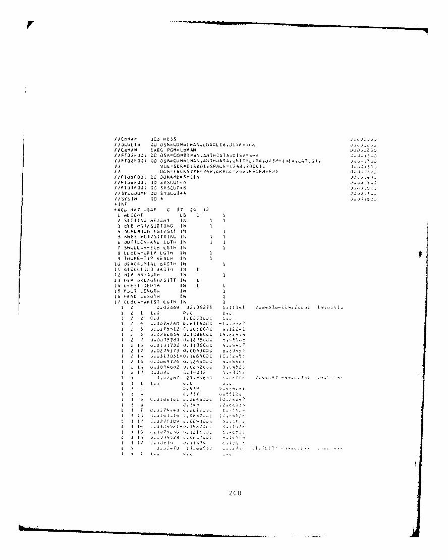
IIJCbLh5 CLI USN=LMmI PN.LACL d,J I S =SO//CoiAM ExEC PGM-LtbMAM .U12&//F1021-001 GO LOSNCOMB!I PA. AN I hAT A, tS~zS-,< 1~.~ -
II VUL=SEk=DISKOhSPAL=(2,8,20CC),I Lb=(bLKS LZE=Z4dtLkELL= 4d kCFM=F2 I Ji -) Z,
//FTO,.FOO I CL L)0hAAkSY SIN jo I.
IilFQI'OI.) UO SYSCUT-A J ji""
I(SV4 0UMP J0 S YSi~vI= Jjwj1 1//SYS IN 00* J~ l J+ IN I+AC,; R7 JSAF C 17 24 12
1 ok 10-T LB ISt STI N, ,E1.. i IN 1 1
3 LY E ICI/S1T ING IN I4. AC~fICifAidS IN5 ,ANEE HUTI~SITTING IN I.6 11Ur1LCN-.NL LLITH- IN I I1 SH.LLLrm-ELO LGll' IN I6 LLQCh-u j L~ll' IN 19 fthiur-TIP REA~LH IN I
IJ diACkLMIAL oROTH IN11 dEULHTIb0 oKOlI- 1N 11 Z il p6 3L A olr, I N13 h-[P dRkAGTh/SITT IN I14 CIIIST OEPIH IN1 115 F.,LT LENUT- IN II~ C -ANC LtNGIH I N II I EL L Rk-sIS T LtI I N I
I J.Ui669 3 Z.0)52 7 1.11 I,, 1 ,D3-Li1.J I '1. ,1u1 2 L.0 D.Cc1 1 .0.) 1 .C JcO;JU L -
124 -Jl~otO U.671603C -1,L~125 ).ul 75) 2
C.2L1tecZC .2i1e b J.02l8c654 0.1C~thO... 14t4-
1 2 1 0.ou7 787 0.1875C0.,1 2 16 C.
0 1'!
7 3 2 0. 1105C.C c,.,17
1 2 12 J.02 79173 O.C0430)kC b.31),n,I Z 14. J.u3k3U3I-0.166t5C3C C551 2 1~ J .0uct124 u. l24bCL:.C 4.z 4oC
I 1 ) 0.) 4,32 J.L,. 3 L'.t2 -1 17 ;.0J,) I . 14032 . !"4
I s J . .C J.3
I I 0.80 47 1 2,13 t J.?41i I J~u~td 7 j0.-G2I I
1 1 .jL 034 Li 1 4t,1 3 1 0., 2 P 8 0J . L ~ i C C(. ,t
, 3 ; , 1 151. t.' c~1 ~ ~ ) 7 12 1.21 t..~ :1-
I ? . .~ ' .11'.74 (L .dI
268
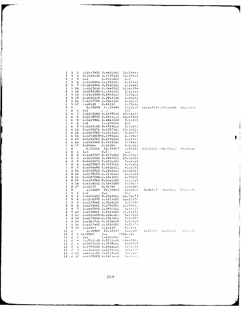
1 5 J 0.1-,7402 ).462C;OOC 2 3 5 .A'.31 5 '. J.182 126 0.2',5;c0Cc 14 . -1;',.1 5 5 .0 I. COCGOO C C .c1 5 6 6 I ( 05100C t 721 5 7 -C.000O1969 0.518CCL, e.811,4C1 5 10 Z0.0125630 (;.14420C;C IC.tc774I :) 12 0.u282283-U.CC81J20 S.1c1L61 5 14 0.33Ji890-0.i34~00C 7.j72jCI 5 15 J.3030315 0.2947JCC 3.tctiI lo Ca 0.J0L;77S5 U .2 U c1,;J0 2 .c t 2D1 5 17 -.00029 0.45137 1.lS5ileI b Q0. C315 8 1c.29694 C . 2c , 12.dI
217-.
31..) .a3 I u.: -'z
I o I 1.0 C.' 0."1 a 2 'I.02U3268 0.1 G5C0C [email protected] 0 4 U.0238937 0.C511jZ ld.46754t1 6 5 0.1029961 0.6863000 5.113DI1 0 6 0.0 1.C0co C cc O C.01 b 7 -J.3023189 0.4719U;6C 3.2-:25C-
1 a 12 U.02b)7283 0 . ,4 12 JO 8 . 2 c 3
1 6 14 J.J2S3819-0.C79,5G00 b. 45oi1 o 15 0.0033780 0 -2 19 2C C 41I a0 Ja 0.J001f)94 5 0 .15 10 0 0 3 . 7,;1,1 6 17 0.OOUa'. 0.32354 4.CC,51
1a 0.01212 11. 75517 2. , :14 L 1 i. 7 J2 CJ-[t7 1IV .'Jo Ic1 1 1.0 0.C l
8 2 0.0187717 0- L4 7OC 24.4512018 lt J.J267835 0.38970CO 15.22c9.
I d 5 0.01201.72 1.C400000 3. .S31 8 6 J.0227087 0.72S7G0C 47 2 G2I J 7 U.J046650 C.65C6000 -5..i2.-. 2
d I 10 U.0132520 O.23o2C00 I C . 02 71d 12 0.J0278150 6. CI 7b000 8 .,1 318 I. 0.0287244-0. I523006 6.78t9t18 15 0.Uu53740 0. lUoCjk , .. ," I,
d Ib 0.-00J18 110 0.334.2000 2 . ta2;18 17 0.00147 0.7b746 0.418'.,
1 9 0.03029 26.35823 1.42t12 5.tlac7
1 '- 1 1.0 . 0~ 3.2c1 9 2 C.02CC327 0 .216 3C00 2t.3. 7 31 9 4 0.0216575 ;. 127-3JJC lo.2t27C1 9 5 0.,)137441 ;.3609,;OC t.1%2c1 9 a 0.u231181 0.279CC0c 12.s4s,u.1 9 7 0.00'.5591l 0.26500CG1 91 0U .J1368110C.C8G5000 11.114i3c
1 '3 12 0.0261o93-C.CO'icjoCC I.1I340-1 9 14. 0.027S646-U.C362G0o 5 . 951 9 15 0.J0b37U1 0. 129b00C j 3-5 21 'i la G.0027'.02 U. 1032.OGC 3U'-1 9 It i.00407 0.2223e 4.,1D
11 2 J.34.567 3C. 12037 1.-004 C.Z 711 2 1 Ia.95a1E 0.0 -14a.2&31 1 2 2 J.u I.COCLOOC 0.1 1 2 * .J561,02JO0 .72102 -3.;L LI1 I L, ).2Q71L;J0 0.3578,o02 '4.%1-1 1 2 o ;.3755t)GO 0.248b00C 7 .52i
1 1 2 1 U. uC0 -o J.22G~.C .I I u C1 1 2 1 20SJ ~~.C 00 C. I -j C I .. i
2691
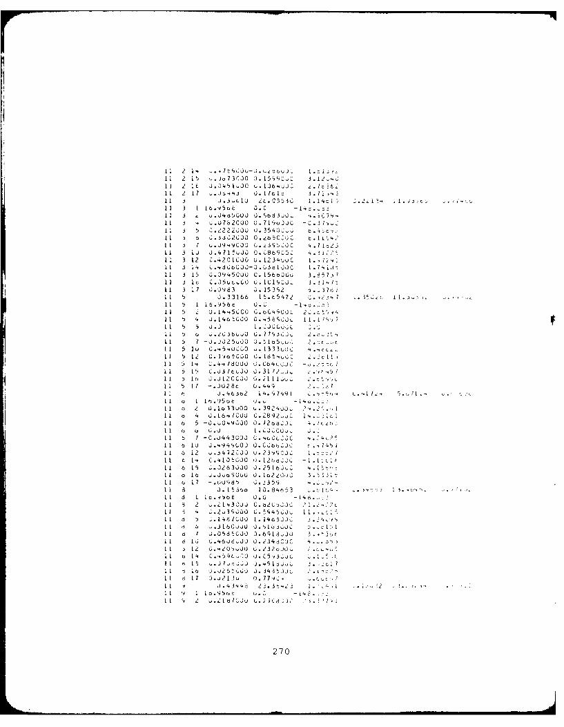
1 1 2 1. .7 d JJ-J.L, a oJC .i1 1 2 15 .Jo73rJ3Q J. 15YCC 3 .1 2.'.C11 2 It J .G'51 JC U.1IJ6'.UUC 4.tt11 2 17 : t 1 3. 7ld 3. 11,43.
1 1 3 1 1 e)., 5o t Q. C 11 1 3 4 3 .J4dSGU3J J. b8 3..J L .C 7"It 3 -. .U7b2CUO U).719')33C-.3.C11 3 5 X222J U3. 35423.61I 1 5 ;.-ijc2co0. O.b5C3jc t ~. 1 11,4It 3 7 u.J9.4C3C u.23S533C 4.fi1323It 3 liJ .'.71%33J O.C36';CQO L'.3 251 1 3 12 C .42 01 GJO u .1234UUC i. ,7 z"11 1 3 14 C .-,d tGcOJ-3. (Ac IJC [ .7 , Ics11 3 15 O.J945030 C. 156bJi~j 3.3573i7I1 I j1c C.J5Ut..C0 U . IC I', O3L 3 .3ijI I11 3 1 7 J.39683 u .15 3;2 5. 71 1 5 J .33166 1 5. b 54 72 0 ., ' 2 .5~s11 5 1 16.,)56t U.01 1 5 2 J. 14,5C;CO C. OC';O03L 23.tS, 11,I1 I t 4 J . 14.6 6 0.. 5tS~ I.L1',,)711 5 5 3..) i2C.-,Ii I r, -.236.... G. 77',j333 2.r,11 7 -J.JO25u.,30 .5lo5,u.. 2.:c.,.1 1 5 1i U .454u),O ,. 13 3 3 j '.cc, ,1 1 5 1,2 C.3'i6 C30 G. 1654u,C i 2. c I
1 1 5 15 C.J3 1L 3 JO .3 17u~ 2 , '4 1 16 Ia .Jk2CC3~j C.;1116." iI I I1 -. 302at 0. 449 ..
I~ J J. 4 6 2 14.919 c, 74q. I.. 9,1 ~ '1 1 9a.5a ( CeP.LC~
11 11(0 2 O.1a33030 u.3924uJx 2 [11 0 4 0 16'.lcou G.2892.,JL 1'.. 1..111 6 5 -J. A3'.9GQ03. 127.aCJh , 2.1 1 (3 0 G.J 1 LJCIGO uC iL1 6 7 -C.J443U33 C.4ACC1 1 6 1 U J .,. 9 4 '(.J 0. C,;b bL C t745 11 1 6 i 2 ;.-1.472CJJ u . 23,i , 3C I - 1 iI1I t 1 , C . -#.1J t(J0 J .1
2 6 23 C -1.I 1 At
I 1 6 15 .J263JJO0. 3.5 1 b J.,2 .1 ::11L a Ia b .JuoaCu3 0. 102,Oj C 3 31I1 I 1 7 -. 339jdb 6. 2351)11 I3 a J. I5.36o 10.84653 .1 . .j: 15-T11 3 d i c. -ysa6 .G -[4 21 1 83 2 6 .2 #3 COJ C .b2 C ,23C .2 2I I ;. .2,393600 C. 594533s. 1 1 . -
I I . 1I8 /C3JOI.. l533C 24 -'IL 6 6 ~.316C3.uU 0.5Ia6i6.0C[1 Ia I ;.J5d5CJO (O.6
9I.3uJO 3 .3,,1 1 73 16. C..460..3 cuJ0. i343OC '1 1 0 12 6..4,-0 u. 2320LOG iI1 14. C . t ,, J. C5 -, uC L11 ' 15 -J.73c,.;J3 J.'5Ii3- c1 1 1 la J..2bP u . 3435 0 21 1 d 1 7 3.,2 13 0 7. 779 C, -. 1c 711 0.4.34.-1 2-;.3t-23 I1. 6I .~ .
I I~ 11a.95C) ,. C -1I I 2 .31IdlC33 L.2) C3JJ l 1
270
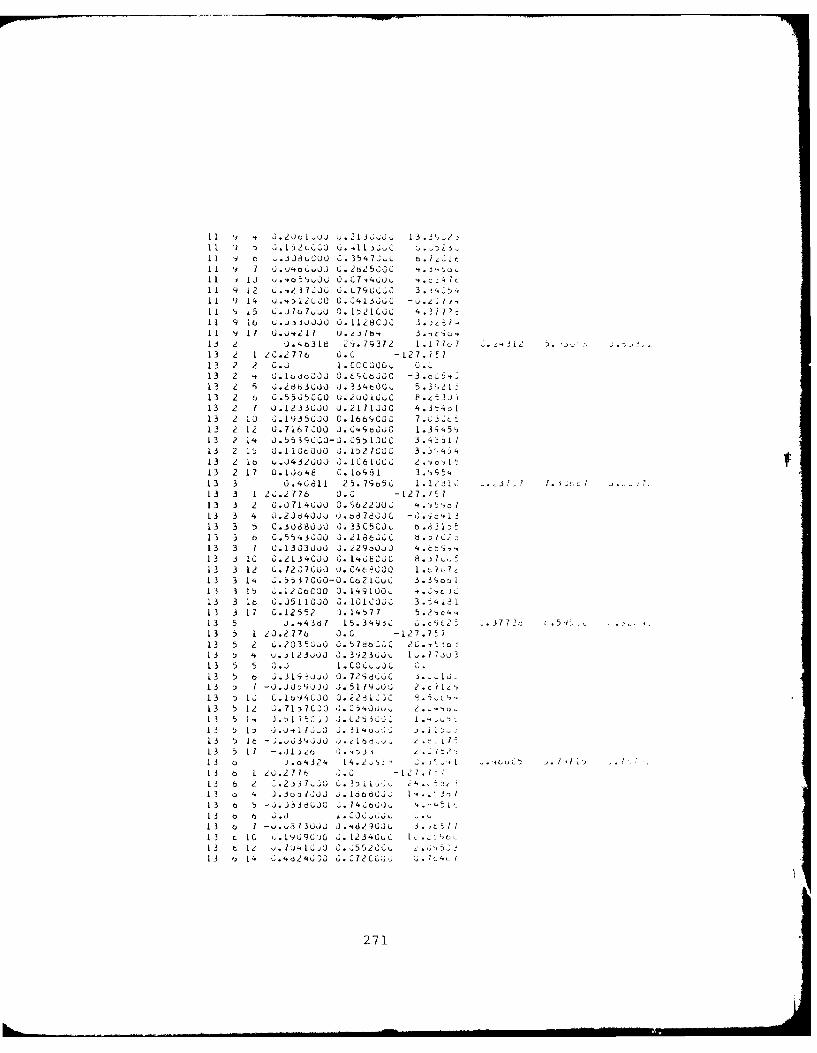
11 I o, 3 JuCU 0 . 3 5 1, 7,;, t I t[[ 13 3.oS'2,,C0 3.Ci. 3 . b.2:
11 9 14 0..7 0. L70.GC 3.i YCII 9 1'. .,12u,0 0133u&C -ozT-
1 1 15 C. J? .,- 0. 12CuLG 4 . ! 7)
II 9 16 U.ujJj333 O.1128CJC 3. 81,11 9 1 7 U. j,2 17 u. 2-7 b,, 3. , c 1;, ,13 e 0 . b318 2%.79372 1 . 71o7 -. 2 . : , 2
13 2 1 2C.2776 3.0 -127. A713 2 2 G.J I.CCCOO, 0.
13 2 G .1(1uoJ0 O.LCtOOC -3
.cc13 2 5 3.2883 30 u. 334t3G,, 5.3 21
13 2 t 0.555CC00 u.2u 01uC 8 .3jt
13 2 7 U.1233u30 0.2171300 4.3-.461
13 2 13 3.1935JO 0.166 9CDC 7.-30
12 2 12 0.7167,00 J.C'.ScOjC 1.3S45,
13 2 14 .55390CO-o. C5) ICLC 3.43511
13 2 15 C. I10oOb0 J. 1527COC 3.3 ,413 2 1 6 .432000 J.1C6 100 o .,c'It13 2 17 O.lio4 o 8.1o481 3. S 5,,
13 3 0.4G811 25.7S 5C i. 12 1d L J.,5 c13 3 1 2 .2776 0.0 -127.17
13 3 2 C.0714 0 O . 622U00 4',t c, 713 3 4 G.2Jd40Jo , .o8780JC -0.-c c 1
13 3 5 C.i880jO 3.33C5CJ 6.d1D13 3 o 0.55,,3 O J. 21866,C b. D L
13 3 1 3.1303u3 J. i2930u3 4. ,
13 3 10 G.213C0C0 G. I't8C C 8 .j 7 .
13 3 12 L.72,7033 0. J 40)0 1.o ,?,7413 3 1. ;.5:3?Co0-O. Co2 1 OuC 3.3 o311 3 3 15 0 .12CtC00 0. 14'1 0 ,.',. ).13 3 I 0.3511030 3. 0131C3 3.-4i31
L3 3 17 0.12552 3. 14577 5.2ic413 5 J. 14381 15.3 4 9 3 u.t 25 ,.3770 L.59. .13 , 1 20.2 776 3.0 -27.77
13 5 2 6.2035,O 0.57d60C0 , 26.1,tjo13 5 ' u.3123u0 J. 39233J3 [, .L 7iu13 5 5 3.3 I.C 0 L J .
13 5 o .j93uj O. 728 66C J. LJ13 3 1 -J.J359.J .51 19GJ 2 c 1i
,
13 t) 13 .lo 4CO0 3.2281.]0 ,
13 5 12 6.71-7C20 3. ,' ,)3 2u , 213 5 1, ).,)1750.3 J. L25 -j, i. ,
13 5 13 J. , 1 7 O 3. 3 1.i13 5 17 - . , .13 51[ -.J1 ,, o 3.-,aj j 2
13 o J.o4324 14.2,',l - ] .1 .f/(,-, L..I
13 o 1 2 .2716 6, . - 12 7 113 6 z 0.2137 10 u. 0.)i1, 413 6 4
3U. :) 333 j Ibod3J 1. 1/
13 o 5 -3.J338uo3 ; 0. )4 to: ) , 4 it13 o 6 3.3 i. C .13 6 1 -v.u3 3U,)J J . ?.29 ,)u 3 ;t II13 t 1 , 0.I0J3C J. L23'3uC L .,o13 t 12 .iU41 0. o.5520uc
13 o 1. 4,j.2'I 3 ..- 0 , 720L00. ..;Jt
271
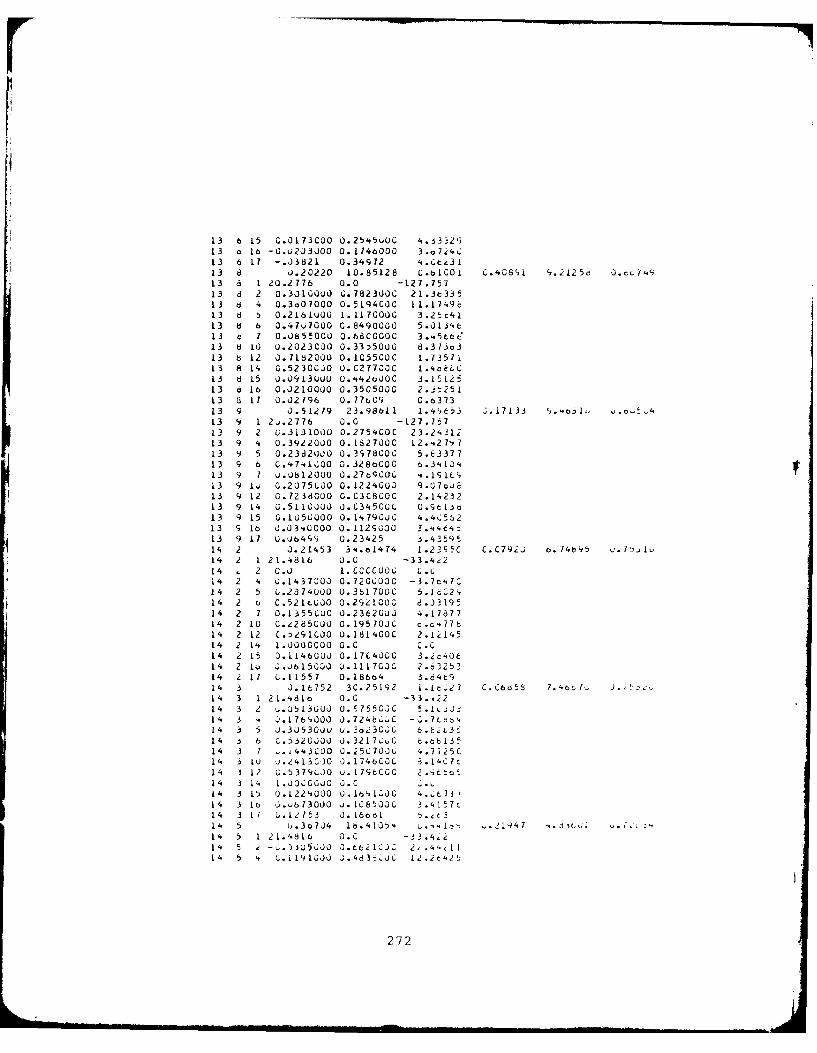
13 6 15 0.0173C00 0.25'.S0UC 4.J3'Z2913 a Lo -0.U20)3JO0 0.1746000 3.c7.e413 6 17 -. J3821 0.34972 '..Ctz3l13 13 0.20220 10.85128 C.tbICO I C.40891 '.12 5(5d *3c,7 4913 8 1 20.2776 0.0 -127 .75713 8 2 0.30100Ou G.7823000 21.3t33513 8 4 0.3o01000 O.5194COC 11.1749c13 6 5 0.216LU00 1. 11 70000 3 .2 ' 4 113 8 b 0.417000O C.8490000 5.1IJ4613 d 7 0.0855000 0.6800000 3..,5t6&'13 8 10 0.2023C00 0.33250U0 8.373o313 8 12 J.1182000 0.105500C 1.7357113 8 14 0.52300J0 O.C27700C 1.41k6
13 8 15 0.3913u00 0...420J00 3.1512513 6 L6 0.J210000 0.3505000 2. -25113 8 17 0.027196 U. 77tC9 C.637313 9 J. 51U79 23. 98bi 1 1.41,33 .17 133 o .13 9 1 2J.2776 0.0 -L27.7t?13 9 2 G.3L3l1i)0 0.275400C 23.2,.3113 9 4 0.3922030 0.1827000 12...271913 9 5 0 .23d2030 0.3S7800C 5 .E3 3 713 9 6 C.474.1600 0. 328(3C00 6 .3 1, 0'.13 9 7 J .08 12000 0.27bqO000 i. 191L13 9 lo 0.2075CO00 01224G00 9.O7CUE13 9 12 0.7238000 0.0308000 2.1423213 9 14 0.5110000 0.C345000 0.St13c13 9 15 0.1050000 0. 1479030 4 .4C 56213 S 16 0.0340000 0.1129330 3.t4.t4813 9 17 0.064SS 0.23425 3.43591,14 2 3.21453 34.eL4T4 1.23953 C.C79za o.74b9514 2 1 21.4816 0.0 -33.4e214 c2 0.3) 1.0000003t C . 614 2 4 U.1431000 0.7203000 -3.7t'.7C14 2 5 G.2074330 0.381700C 5.1602',14 2 oC.521tuD0 0.29Z1000 d.J319514 2 7 0.1-355C00 0.2362000 4.1787714 2 10 C.,L2850
3 0 0. 1957030 c o~~77 b
14 2 12 C .>29 103O0 0.18 1400C 2 .1 14,514 2 14 1.3000000O 0.0 C.014 2 15 0.1146003 0.17C0'.00 3.i640614 2 lo J.J615000 3.1117030 2.6325314 2 11 (.11557 0.18664 3.d4t'i14 3 J.16752 3C.25192 L.1c327 C.C6d~s 7.4ot,7.- .K.14 3 1 2 1.4.810 0.0 -33 .4221 4 3 Z u. J5 1 3 G0 0. S755030 5.13J3314 3 4i 3.1L769,000 J .724b.. C - 0. I ta 64
14 3 5 3.3353033 u. 3823033G 6.LiL3514 3 6 C.5320030 O.3217-C 8.bb13'14 3 7 -. i443CO0 G.;5370J3 4.7i25C14 3 10 3.21413030O 3.1746003 3.14C1614 3 12 3.5319330U 0.1196000 2.46LCt14 3 14 1.00c0030 0.C .14 3 L5 0.1224000 0 .16', 1.00 4 . t7 3714 3 lo 3.o6 1300 0 u. 166503C 3 .4 1 5 7t14 3 li G.12753 0.16661 5.t14 5 u.3t7J4 lb.4105'. -2191, .. j47 cl 5f14 5 1 2 1.4816 0.0 3.i14 5 , - u .3353 ) 06,JO-62 133 2, 444c1114 5 4 0;.1191033 0.483i8033 12I.jt42'
272
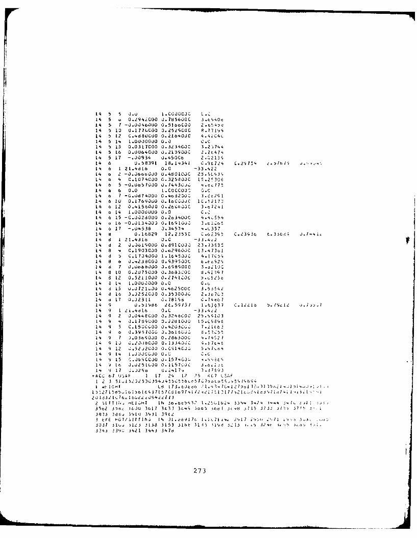
14 5 5 0.v 1.COOCCOC L.014 5 o0.2942000 0.785600C 3.t 940c1'4 5 7 -J.0046OU0 0.5IboC00
2.?34:)c
14 5 10 0.l77COO 0.252SC0C P.77 94i14 5 12 C.4d8f)CU0 0.216400C 4.4.e04C14 5 1'. 1.0000000 0.0 0.014 5 15 0.0311000 0.3234GOC 3.2,74414 5 16 0.0064000 0.213900C 2.7647414 5 17 -.00934 J.45006 2. 213G14 6 0.58391 18.14'341 C.9t124 C.29754~14 6 1 21.4616 0.0 -33.,.z214 b 2 -J.J6ta6000 0.48CL000 25.SC93,14 b 4 0.1074CJO 0.3258000 15.2'30614 6 5 -O.Uo57000 0.74430jG ".tc7714 o 6 0.0 1.Coccooc O.c14 6 7 -0.0d74000 0.463200C 3et
2 9 1
14 6 10 0.1769000 0. 16CCL0C 1C.5217314 6 12 0.4156000 0.2950600C 3.c724s114 o14 1.0000000 0.0 G.c14 6 15 -C.0,328000 0.263400C 4.4iC5'14 o 16 -0.0134000 0.16S1000 3.c.0-6514 6 17 -. 04538 0.34534 t.C35714 8 0.16829 12.2353C C..62395 0.239,3t t.3366; 0.7 4,14 d 1 21.4316 0.0 -33 .4,214 d 2 J.0o1S000 0.8910000 23.73E3514 8 *. 0.1903000 0.o296JJ0 13.473o114 8 5 C.1704000 1.1645000 4..I7C,14 8 0 0.'.238000 0.G39500C 6.tcG2c,14 46 7 L).0b68000 J.698900C 3.aii10C14 8 L0 0.2075000 0.3683000 8.1;259j714 8 12 0.5211000 0.274100C ).C525c14 8 14. 1.0000000 0.0 O.u14 6 15 u0,721LU0 0:462500C 3 535'.214 d 16 3.0252000 0.3530000 2.3c
3
14 B 17 0.02311 0).781sd 0.74t:6714 9 0.51986 2t.59757 1.61t133 C.12216 5.7;,12 j.7 D,14 9 1 21.4olb 0.0 -33.422L4 9 2 J.0448000 0.3246C00 25.sy,0314 9 4 J.1739000 0.2281000 15.CSE89614 9 5 C.15GC(;00 0.4203000; 7.i166314 9 6 0.3957000, 0.3616000) 8.52 5514 9 7 3.03a9000O 0.286300C 4..74,2714 9 10j J.2J.)bCO 0.1334000 ';.&764614 9 12 ;.52u2C,000.0914000 5.,,7,o414 9 1'. 1.0030000 0.0 0.014 9 15 0.0690000 0.157400 .99L14 V91t 3.0251000 0.1157000 3.~j14 9 17 J.J296 0.2417;, 3.37 3
4.A00 67 U' AF 1 17 24 12 235 RC7L SAF1 2 3 5~535U5J50~L50~L3 99I tIGH r LB 17 3 .6Jc c6 2 1.. 3. C I?:)1 o33 35cI .j1)il IA,
2 Si IT TLN E ,LH IN 36 bcri 3 23 1 2'(,1624. 33N'.t 3.2. 4 3444 3 .'1. ) I
35o2 35bi iLJU 3t11 3t633 3t49, 3o6'5 itc,1 3t9d 3715 3733 37-5 371T31133 3B6. 310 31,31 39C23 EYE HGT/SirTIN IN 3L.c6qi7L 1.~1~2',17 jIDU. ' lj 3.5,3037 1 ju, S123 3138 3153 3166 3133 31c,, 3,: 13 i.9 324c 3eo,5 i'.z,, J-.,13240 239u. J421 34.43 31,76
273
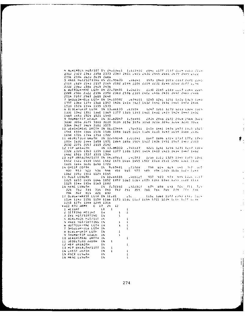
4 Ak~kC ILN rHtT/SIT IN 24.G36z1 1.12341L; eq 177 !1;7 ~.2L231J 2321 2343 2358 2373 23t 24C1 .41 2430 24,,5 2461 2' 19 2-Y, c,_z2t51 259. 2620 2o39 2C65 KNEE HGI/SITIING IN 21.95673 ;80.1 147i 19Y8 2015 203I 2611 .,2113 212o 21[,3 2157 21649 2182 z194 220t 2219 2231 2-4, 22LU 2, 7 z"u2322 236 2386 24J5 24366 dUT01? -KNE LGrH IN 23.78431 1.Ct23, 2138 2165 e18 ,:,.C7 ,",., zol,2289 230o 2322 2336 2350 2363 2376 2389 24Cd u416 2431 24'.1 2.o: >146(2514 2551 2587 2o10 2t:487 SHO-ULLK-ELL LGTH IN 14.15382 .t741l 1265 128l 12,1 1.33o 13'4 1.,1357 13bo 137 13o8 1397 140o 1.1', 1423 1432 1',.,1 1451l 1'i-l 1,1i I4oL1503 1526 1544 1555 15738 ELBLo,-URIP LGTH IN 13.8d133 .(3554 1247 1261 1270 izt 1i ,. i3L,1331 13'.,2 1351 1380 1369 1371 13d5 1393 1461 I'.&G i'.1, 1421y i..J i..52
1469 1443 1509 1521 15409 THUMb-TIP KEALM IN 31.62047 1.5649E 2824 2846 2612 298d 247b4 3u013030 305t 3(19 3100 3120 3139 315b 317o 31,8 321 324 .U' 3i2' 33,13364 3427 3469 3502 3555
10 OIALkGMIAL bRCTH IN 16.C3454 .7o4311 1'.1 1441 145t 1475 I5 L5251541 1554 156 1576 1586 1596 L65 ol4 1-24 1u33 1,43 L(,54 Iuoo 18.o1698 1726 1744 1758 1782
11 oIJkLTIlU 6kL;H IN 18°.90,46 I. C41 lo 7 1696 171'. 1131 177i 179"181' 130 1o4e 1658 1371 d 4 16S6 190 1922 1936 [451 13t,7 , o) 2jCu52C32 2071 2097 2115 2142
12 FIP OREA3TH IN 13.Ei8310 .741t.37 1221 1,e41 1254 1271 I',l 131'.1328 1334 1350 1359 1368 1377 138t 1345 1,.C4 1",13 1423 14-~', 1. ',? 1-,o/14t2 151: 1537 1555 15k4
13 HiP dREA.OTH/SITT IN 14.67822 .',0583 1i56 t10 1325 13.,b 1.>75 13,,t1412 142o 1439 1451 14C2 1473 1414 1495 15C6 151o 15i 154: i.)ui 1 IL,It05 1844 1870 1o90 1723
14 CH[ST CEPTH IN 9.65481 .75788 798 81'. 8e5 J'Jl 2tL o5900 913 428 436 946 956 965 975 485 994 1005 LUo 1 2,
, 1,4j
10c2 1090 1110 1124 114915 FuOT LENGTH IN 10.64335 .468125 957 913 91 -) 4 1.-,c l.A 71025 1033 1039 1046 1052 1057 1003 i,6; L075 1 o 10ioO 1o','j LiJJ ii11125 114. 115o 1165 1180
16 hANC LENGTH IN 7.52310 .j2
23
C7 671 698 b43 70J 111 71,125 73i 735 739 743 741 751 155 160 764 189 774 1., izo
794 801 815 821 83017 EL8U..-,RIST LG rIH IN 11.81 . 15, lObd lUll ljuN IlI. 1i'
114 114.j 1151 1159 116b 1173 118 I io1 7 1194 121 1204 1, 1 )o,1253 127. 1288 1299 1316
+4AC R70 ARMY C 17 24 121 mE IGiT LB 1 12 SI TTING HEldhT 1.4 13 EYE HGT/SIrTING IN t4 ACRL'ION t ,GI/SIT IN 1
5 ,NtE HGT/SITTING IN I I
o dUTTC(K-KNE LGTH IN 1 17 SHLLLU(-LLd LGTm IN 18 ELOL -Gk IP LTH IN I9 THUM8-TIP (EACH IN I
10 di ACM IAL dROTH IN I11 dIOELT,I0 3,(DTH IN I12 HIP dREA01H IN 1
13 HIP tktAUTti/SITT IT 1
14 LHEST dEPTH IN 1 115 FOCI LEN.Im IN 116 HANI LtNuTH IN I
274
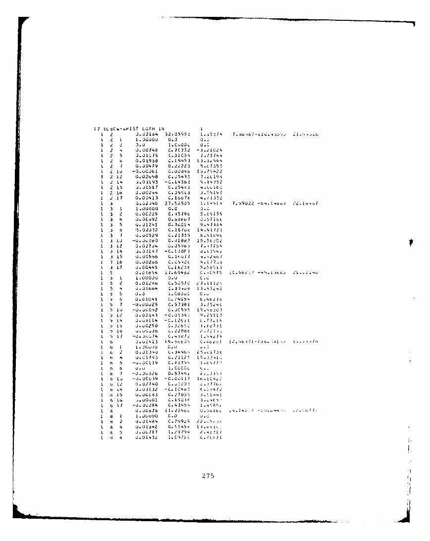
II E:L zC%-.iIST LGTH IN1 2 J. U2164 32.05S51 1.15--14 7 do'61- L I .. , .:1.'.4taI1 z1 1.00000 0.0 0.0
1 z 3.U 1.CWCOL 0.0I Z 4 J.00748 C.7C752 -3.21C241 2 5 3.01175 C.31C5S 7.1314..1 z o 0.01988 C.19453 13.3,4412 7 0.00479 0.22223 5.0J353
1 2 lu -O.uOOS6L G.U(;d9d tj1.?4221 2 12 O.02ca98 C.J5435 1.2L194;I Z14 0.03193 -C.1436e s.1'4?52L Z 15 0J. ()5 L7 C. 1548 1 4.".u1601 2 Lo 00j2't'. C.09'18L 3 . CS1,1 2 17 0.00413 C.1667t' 4.113521 3 0. -02J40 23.52505 1.'1'..i'. 7.!)9U22 -6'..1.ooD 2 2 . IQ-j1 3 1 1.00000U 0.0 0.1i1 3 2 O.OC229 C.'35?9C 5.(';15S1 3 4 0). OX,92 0.66o f ., 7 lot1 3 5 6.J1241 0.3kL01'. 9.'.33341 3 6 0.02U32 C.1IS 7c; 14.14 112 11 3 7 0.00529 C.21355 6.1lt961. 3 10 -0.OOcdo G.0186? 15.5t2021 3 12 0 .027U4 G. J550 ) I. .. 12~1 3 14 J. 03147 -C. 130? 7 8. 1TI1-1 15 0 .0 G5 6 G .14,67 4 .',1,l1 3 16 0 . )0 06 C. C1,'#2 c 4.1 17 o1 3 17 0.00445 0.16213t 5.5E6131 5 O.J lo54 11.61;46i C. C,.75 jC. 56z 7 -41-.5u 1 Cj2 21I i I 1.U0000 0.0 .1 5 2 0.0124o G. 5(57C 2 3.11 121 5 14 J.Ul6o4 0.33,ut 1
3.41t4c
L 5 5 0).31 i.COJU C 0 .I l 6 U0. 01041 G. .1405',. .11236L 5 ? -o.00o25 C.53381 3.252'.C1 5 10 -0.k0cG32 C.UC55'z 1..tC1 ,12 U.02643 -0.013cy: 4.2b1131 5 14 J.03114 -C. 12(;11 t .717.5I 1 J.0C250 C.32o50' .Iac731I I oa j.0C~
3 6 L.2 2 8 8t e 2.7 21"'.1 17 -0 . j 14 C. '.4e6I7;2 1.9,z4.41 b 1.j43 IS. 5cto9 2C. ce~ 12. "t;" i- I5r. jOL L i. 'I I
o I L .00010 0.0t'a 2 0.3J13 40 C .3'96' 23.1 7 3b 4 u . G1713 3 0u. 2112' 15 . 1
16 5 -u - ci119 C. F175. 1 . t 7116 ba o. j 1.C GCCL 1I. .16 7 -03. J332 0. 534h 2. -3 il) '
1 6 10 -J.OCu 39 -C .CL;11 7 lo. IC4i1 o Le 0.02740 C . 520 3 '.. 1 77(1 b L4. 0.03132 -C. I(4o t t. . 4,
I o 15 u.uU183 (;.27856 3.1'.
1 6 11 -u . J 2 84 C. 43 S ) , 1 ..6M'8 "I a 0 .J0d16 11Il14$c U. jolo, '.. 19 .:,
I a I I1. 0000 0.0 0 ."I ti 2 u . 14 a', C .7C'9 z ; 2 .~'
d 4 0.018'.2 0.5145C 1.'V1 J .31.117 1.29794 2.,.1
13 J .001,#52 1 . C'1I1 L C . 1L 3 1
275
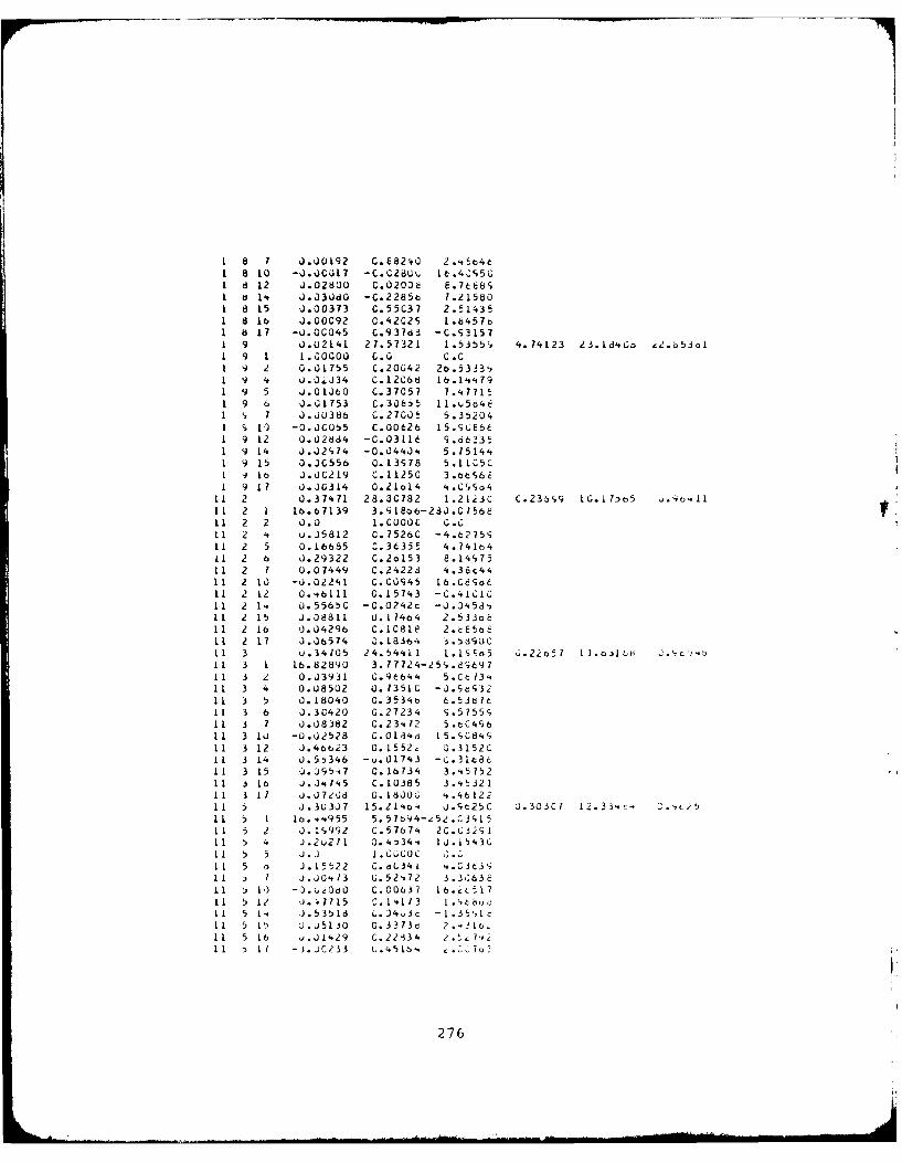
8 1 .U0192 G.E8240 25.6et1 8 10 -J.oCjL7 -. 028O0 16.4095G1 a 12 0.02'00 C.02006 e,/tbsI d 14 J.03dO -C.2285b 1.215801 8 15 0.00373 C.55C37 2.514351 8 16 J.00C92 C.2C2S 1.6457o1 8 17 -0.0G045 C.937d3 -C.S31571 9 0.0214I 27.57321 1.5355c 4.74123 23.1d*Go 22.o53oi1 9 1 1.00000 C.0 0.01 9 2 0.01755 C.20042 2o.5333,1 9 4 J .04J34 C.120tC6 6.1'q791 9 5 J.O160 C.37057 7.477151 9 6 0.01753 C.30655 ll.u5d461 7 1 0.00386 C.27CO5 5.352041 S 1) -0.00055 C.00626 15.S4E661 9 12 0.02d64 -C.03116 9.662351 9 14 0.02914 -0.04404 5.151441 9 15 O.J0556 0.13S78 5.11C5CI - 1 1 0.00219 C.11250 3.eS6 a1 9 17 0.JG314 O.ZloI4 4.CSd4i1 2 0.37471 28.3C782 1.2123C C.23bS9 1G.1L7)o5 ,.' 1111 2 1 16.67139 3.918o6-23J.0156E11 2 2 0.0 1.C00OC 0.k11 2 4 u.35812 C.75260 -4.6275SI1 2 5 0.16b85 C.3(35t 4.741411 2 6 J.29322 C.2o153 8.14 7511 2 7 0.07449 C.24228 4.36c4411 2 10 -0.02241 C.C0045 16.c8dLd11 2 12 0.46111 0.15743 -C.41CC11 2 1. 0.5565C -0.0242c -0.045d'11 2 15 J.08811 0.17464 2.533o&11 2 16 0.04296 C.10818 2.E5bE11 2 17 0.06574 .18364 159dl11 3 u.34705 24.54411 1.I s 5 6.22o51 11.0jIt, .b ' C',
11 3 1 16.82890 3.77724-259.8969711 3 2 0.03931 G.96644 5.Cc 13,11 3 4 0.08502 0.13510 -J.ScS3211 3 5 o.L804O 0.35348 6.53d76It 3 6 J.30420 0.27234 S.5755;11 3 7 0.08382 0.23.?2 5.cC49611 3 lu -0.02528 C.0164d 15.4084911 3 12 0.46623 0.1552, Z.3152C11 3 14 0.55346 -u.Ol
743
-C.31c8cI1 3 15 U.095i7 0. 16734 3..575211 3 16 J.04745 C.10385 3.4532111 3 1? 7 .07208 0. 1800 4.46122it 5 J.303J7 15.2'64 j.9e25C 0.303C? 12.334 O.,t2511 5 1 16.44955 5.57b94-zS5.GJSL511 5 2 0.19992 C.57674 20.032;111 5 4 J.2U2?1 0.43344 1J.1543011 5 5 1.) 1.(OoO.OC11 5 o J.15522 C.oL34L *.G03',11 ) I i.JOO.3 G.52,72 3.3063E11 5 1') - .OdO .0063? 0I16.zLL 1 5 12 ..15 . I 3 .. 1 1t b"c11 5 14 J .53518 L.)4,36 -1.3
5 c
11 5 , l .u5130 C.3313v 2 . e,11 5 16 u.JL42
9 C.22134 2. t 7 ,2
276
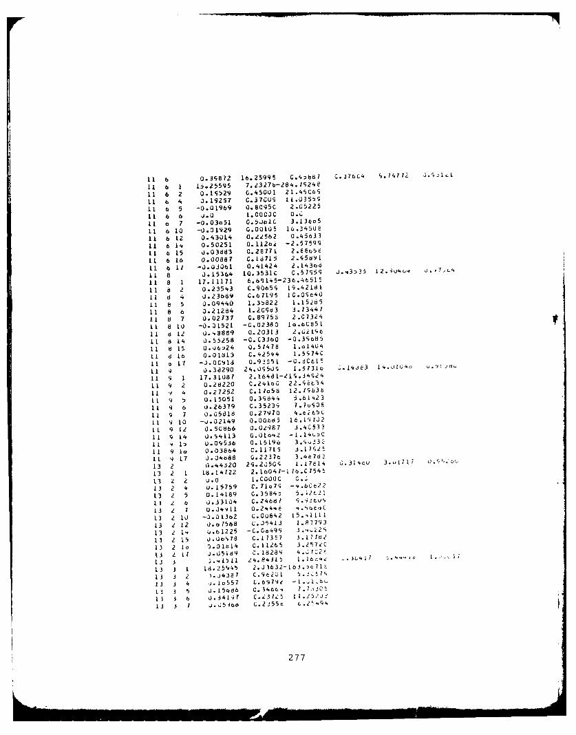
11 6 0.39872 16.25995 C.',687 C.J76C4 S.14772 3. 3 -
It 6 1 L5.25595 7.2327b-284.7S24e
11 6 2 0.15529 G.4500 21.4cC6S
11 6 4 0.19257 C.T37CUS 1.03559
11 b 5 -0.01969 O.8095C 2.05225
11 6 6 0.0 I.0Coc O..it 6 7 -0.03o51 0.50oiC 3.136o5
11 6 10 -0.01929 0.00105 1(.3450E
11 6 12 0.430L4 0.22562 0.45633
11 6 14 0.50251 0.112b -2.57599
11 6 15 0.03883 0.28771 2.6et5e
i 6 16 0.00887 0. 1715 2.C75d9I
1 6 11 -0.0306l 0.414.24 2.143bo
i 8 0.15364 10.3531C G.57S5S 1.s3535 12.4U, j. 7,"4
11 8 1 17.11171 6.69145-236.4t515
il a 2 0.23543 C.9 0 6 5 19.4218111 d 4 J.23669 C.67195 IC.O9C40
11 8 5 0.09440 1.35822 1.15j85
11 8 6 0.212a4 1.2G93 3.13447
It 8 7 0.02737 C.89758 2.C7324
11 8 1O -0.01521 -G.02380 lo.6C851
11 6 12 0.48889 0.20313 2.Ci196
1, 6 14 0.55258 -0.C3360 -0.3.b85
I1 8 15 0.0j624 0.51418 1.o140 4
1i d l 0.018L3 C.42544 1.5S74C
I I 11 -J.00c91 0.93551 - 0.6 d 615
11 9 0.38290 24.0950 1.5131c .14d3 1 4.J104 0.j
11 9 1 17.31087 2.16481-21S.34S24
11 9 2 0.28220 C.2410C 22.9Et34
II o 4 0.27252 C.17o5d 12.1963b
11 9 0.15051 0.3c844 5.61 23
I 9 6 0.26379 C.3523 7.7oe01
11 9 7 0.05818 0.27970 4.625C
11 9 10 -u.02I49
O.o0d5 16.19132?
L1 9 L2 0.50866 0.02987 3.4C533
11 9 14 U.54113 0.01.,42 -1.14UDC
11 v 1) 0.09536 0.15196 3.9'33
11 9 Io 0.038b4 C.11715 i.1l925
11 9 17 0.04b88 0.2237t 3.4b763
13 2 0.44320 29.25G 1.17E/ 6.314tu 3..L717 o
13 2 1 18.14722 2.1b047-17c.C7545
13 2 2 u.0 l.COOOC C.3
13 2 4 u.15759 C. 71og -4.6C22
13 2 5 0.14189 C.3584; 5.;2t21
13 l 6 1.33104 C.246d7 9.4 it ]
13 2 7 u. 4911 0.244,4e ."O C
13 2 10 -0.01362 C.0U642 15.4111 1
13 2 12 o.e1568 C.J5413 1.83793
13 2 1'4 C.6 1225 -C. Go499 3 .,.,229
13 2 15 0.06978 C.17357 3.177b2
13 2 lo J.D1b14 0.11265 3.257,C
13 Z Il J.05169 0.18289 4 .372 3
13 3 )...LII e4.84)315 1.16 :4e LI
13 3 1 18.25'45 2.Jl632-163.;c7lt
13 3 2 ).J4387 C.962u1 5.]C/lS
13 3 4 ).1u557 L.69792 -I..1Cbu13 3 5 1.I5odb C.346' 7.7" t
I1 3 6 '). 3'1~i C.23U15 I11.25-'J-'13 3 1 J.,;54b C.2355c L.2'4
94
277
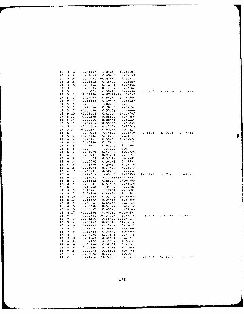
LJ 3 10 -Q.G1738 C.01604, 15.70CUI13 3 12 J. o7o0d5 G05498 i .,;5, 9o313 3 14t O.oU032 -C.07t45 2.E119S513 3 1 5 J.30~12 C. 1652 -1 .I'i.>513 3 16 U.U2346 G. 1;7-46
3.0
74L
13 3 17 0. 058a9 0. 17842 4 .1 7SCt13 5 J. 3C075 1z. 394t78 C.9i5736 J. 33755 7 .b3 53 013 5 1 17. 72776 4.57839i-18d .u'iC3 713 5 2 U.27994 C.54284 20.3CI54C13 5 4 U.35664 C.394,9 S.8oC2513 5 5 0.0 1.0000C C.u.13 6 0.2U.554 C.178107 -. 31,C5e13 5 7 -0. J0254 C. 53202 i. jbiu,13 5 10 -0. 01103 G. 0C37, 10.69i5U i13 5 12 0.6b288 U.05583 2.5U35513 5 14 0.57169 O.OCS61 0.16';13 5 15 U04514 0.33769 .NC6313 5 16 -O.00213 C.23339 2.72C6313 5 17 -0.00297 C. 45194 2.C0i21 3 6 U. 44045 1 7. 146U7 L . 2 7 09 04L2.j 3 c3.o j.,,j013 6 1 16.85-300 5.11235-200.63t3313 6 2 0.2b761 C.3',86d 22.30926Zc13 b 4 0.35284 0.27800 11.5E12213 b 5 -0.06611 C.8329i 2.1135~t13 o 6 0.0 1.0000o G.013 6 7 -U.07475 C.52722 3.Co72513 61LO -0.0(.IS,0 -0.00201 It.1",15713 6 1? 0 .b,7 7 U. 07o9/1 2 .01i 513 6 14 U.55590 C.04241 0.193J113 b615 U. 0L135 C.2()43 7 3 .199c,7 e13 6 16 -0.01993 0.19978 3.1217 313 t. 17 -U.05591 G.42880 2.CSS4c1 3 8 0 .145 19 11. 65S96C U .551. C.4t 14 d. 17"r- L13 d 1 18.27690 5./C191-17.03'5213 8 2 U.31602 C.8t.2241'.(013 d 4 0.38881 0.5c9555 9y. 141 Z5
13 b 5 0.16,4b0 1.35102 1.'iS3Ut13 E 6 J.26941 1.17809 4.1168113 b 7 0.02724 C.64;69& 2.1674113 d 10 -U.00C587 -C.02772 lb.4b3o513 8 12 J.6b522 0.J9958 2.31i5E13 8 14 0.5E3ob -C.Cb254 1.o113'.12 d 15 0.06336 C.5739,' 1.dc97213 8 16 O.OG552 C.43018 1. 18',,13 d817 -J.JL24b C. 932t)5 -0 .,030C13 9 U.32706 26.31334 1.5817t .. 1.ztc 1.c :
13 9 1 18..,1iiS 2.11400-Iod.7131J'13 Z 2 .36160 L.2311b 2 5.1At613 4 J. 42405 C. 1560 4 12 . 1"t7113 5 J .1(IIL0 0. 314 1 '13 ,6 *). 327o5 C. 3449J 8. . "'1 ,13 7 U.6Otb24 '. 2 7 9 1 4 ..7 - iI13 9~ 10 -u..i11u3 J.JC531 16:. 11)11 3 '9 12 J .61,17J 0.30(3J2 3.2tcC0113 9 14 J. 5oli44 C.7J1 71 ".5, d1 3 9 15 0).09689 0.1523J3 '. 2,,O(1 3 t o 0.02i123 U. 11672 3 1 t H t1 3 917 0..3602G C.Z22'.4 3 1A'14 J .21v16 3 3. 1245 t 1 4', - j~~,h j.
278
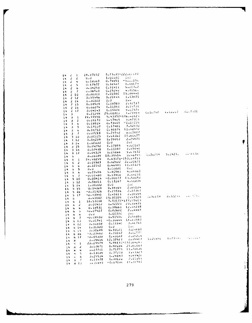
L 4 Z 1 q 93 7692 5. 7 3,J 5-22 2kUc L 1
14 Z 2 u.0 1 .660j
14 2 4 w. 1d0J3 0. 7',691 -* ;1~L
14 z 5 (117672 0.3d4u7 t),47
14 2 6 J.34296, C.31411 '.O~,
14 2 1 ob09Z3 0.2 524.C
L14 2 10) J (; L C 03c3C 1 5 .d4 4
14 2 12 05 5 11clo 0.2 0 t I4 j.13 t7 1
L4 2 14 1.00000 0.0 6.1.
14 21L5 0.08939 C.18585 2. 33
14 2 16 0 .iJ 7 4 o. 11 59 1 -j. I "5 1
14 2 17 1 .U'.14 3 C .Iy4 7 c 4.. i2 2T7
1" 3 0.21L298 2S.C316' I .:179 5 1.. i
14 3 1 19.91556 5.43352-13t.,t2'
14 3 2 0.0 1170 G., 74uSi_ ~.4 7 3
14 3 4 J.18819 G.73405 -1.1 Z.3i
14 3 5 u.18107 C.37481 7.52t3
14 3 b ).34t712 C. 3031c, j10.tu32
14 3 1 o.0 7218 0. 245'i2 . .13to 7
14 3 10 1 ..)C12 5 c. uL2o 2 1 t . L7~
L4 3 12 o.5(3259 0.20012 2.2S;471
14 3 1-* 1. kC UJJ C.0 L
14 3 15 0.09250 C.17899 ..CCldt
14 3 16 0.J2430 C.11197 3_15t4L
14 3 17 ().04329 U. I i Lt ~.L 117 2
14 5 1 19 . 42t)9 6.o3l76-L50.c4731
14 i 2 j.,)5563 0.62602 22202
14 # j. .22 192 0.4o49 1 1 1. ..S12'
14 5 5 1 .1 1. C60c G .J
14 t) 6 U.20654 C.8098.i 4.d','id3
14 5 7 -0 . I e0 0. 1341 t 3 . 4 i3 1
14 5 10 0.00414 -C.CC1I7 13. -309
14 512 0.56011 0.11281 4.',18J4
1 , 5 L14 1.00000 0C.0 .1
14 5 15 0).04Uo9 0 .34-tt69 2 dtIJ4
14 5 16 -0).01126 c.2353c 2.71361
14 5 17 -u. o354 1 C.-.581 1 2.JIt4',4
14 j o..1182 1 s. hC CO1, o.,328 6 3u 1 1 .3''
1'. b 1 13 .031 8 7. 53172- 11 1. 5tb1
14 6 2 0.0C41J G.5,223 23.3d4lC
14 b 4 0.16531 Q.38461 12.. i238
14 6 5 -o.j7927 0.82600 2-w4445
14 o 6 0).0i 1.000 0. k
% f31 -u.08l13U 0.51S3C 2.9o31
14 60 0 .UC741 -0.306"" 1L.i.532
14 6 k2 8 16 C . 2 3 3 o 3 .4t 74
14 b 14. 1 .J.000 0.0
14 6 16 -0).J34bO C.20C42 3~?
14 6 11 -00i-33 i C. 4 -i.d 8 j .'A 21v
14 6 0.09406 12 .32i21 3 0 .. '.o'lL 1
14 3i V) 2 '5 19 S96q1jJ.-1I~.6.,4
14 m 2 J.12671 0.98dt 21.rttul
14 o 4 J.2771 3.1177" 11.2r~jt
14 1 '5 j. 13jj4 1. 372)jI 1 . .iJ 2 -"i
14 ;~ 6 0.29 504 4.',4) .'*'2c
14 d I) j1L9 -C.1.3LiL 1t.jc5!'l
279
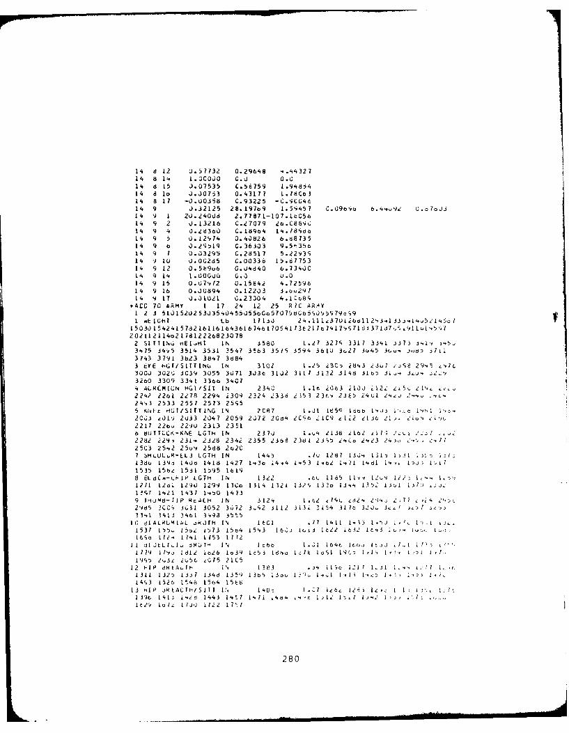
14 8 12 0.57732 0.29648 ,.i'i32714 a 1, L.GCOO c.0 0.C14 d 15 J. 07535 C.56759 1.9'484L4 8 lo 0.0753 0.43177 1.18C6314 8 17 -0.00358 C.93225 -C.9C04614 9 J.32125 28.197o9 1.5i457 C.09oio b. "',O 92 0.o7o J14 9 1 20.24008 2.77871-L07.1tC5614 9 2 j. 13216 C-27079 eo.C8b9i14 9 4 0.4d300 C.189b4 1'..18ido14 9 5 0.12,14 0.40826 6.d8735L4 9 ( 0.29519 C.36303 9.5-35614 9 1 0.03295 C.28517 5.22V3S14 9 10 0.0G285 C.00336 15.6775314 9 12 0. 5 b9o6 0.4840 6.3 4) C14 9 14 1.00000 0.0 U.014 9 15 0.07912 0.15842 41.7259614 9 16 0.0U894 0.12203 3.cL297L4 9 17 0.01021 C.23304 4.lCo8
*ACG 70 ARMY 1 17 24 12 25 RIC ,R,'AY1 2 3 51015202530354045jJ55bGo57075b;b590959796;9I wE IGlT Lb 17 13 24 .1 14,.T Li 0 1 24,. 33.)4 1 5 , 50 7
15030154241578216116164361646170541136217t1c17971d371i7,1, 1LcdL5I2021121 14o2 l7d122268230782 SITTLN.; mEI..t" IN 3580 1.27 327c 3317 33,1 3373 341' J5.3'.75 34v5 3514 3531 3547 3563 351S 3594 361u 3o27 3o45 36o. J dD ,711
3743 3791 3b23 3847 38843 EYE .,GI/SITTINu IN 310G 1.25 2SC 2843 23ul ,'j8 29.5 ,',It.300J 302.; 3C39 3055 3071 303t 3102 3117 3132 3148 3Lo! 31o. 3,.,, ;2L3260 3309 3341 330o 34C74 ALRLMIUN HGI /SIT IN 2340 1.1. 2063 ikOO 212,! ,i5C e i .,2242 2261 2Z78 2294 2309 2324 233d 2353 23,', 235 24U1 2".,j 2-,24i3 2533 2557 2573 25S55 Kte HGT/SITT LG IN 2C87 1.J 185C 1bt~b L', ', , 1',o*.2CJ3 z~l') 2u33 2047 2059 2072 20d4 2CCb ZC9 £122 2136 21. iiu, ZI'12211 22bu 2290 2313 23516 dUTTLC.-KNE LGTH IN 2371 1.,4 2138 i162 i7" i 2..) 22: 72282 229-1 2314 2328 2342 2355 2368 238l 2395 ,4Co 2.23 241o Z-., ' ,.. 12503 2542 25u4 2588 2a20
7 SHLUL .N-LL3 LGTH IN 1445 Iu 1287 13.'* 131 1)31 "'f ;138o 39 140o 1418 1427 1.3a ,4i44 .53 1-02 14i 1.d1 1'.,L 1: 1iL1
1535 15be 1531 1595 16198 ELdCa-LMIP LGTH I IN 1322 .6U 11 5 Ili-, 1'li le2: 1,U -. 1,D1,1271 1261 1290 1299 L3Co 1314 1321 132S 133o 13'. , 132 oi 137 1 .:I1,7 1'.21 1437 14.P0 14139 1HOft3-TIP RrALH IN 3124 1.t2 7,L. 4,2'. 213'.i. 1,77 .'i4 2 '3.2965 2CC, 3631 3052 3;72 3 92 3112 3132 3154 31 7o 32.L J0 .,I33',1 3413 3461 398 3555
10 di ALAUMIAL iNJTli IN 16C1 .17 1411 1-.. 1.'): j 1. I.'.1537 1P 5. l5o2 1573 1504 1513 16O; 1Go3 1622 1632 Lc-3 . 1 -316S( 1f 2-, 114.1 1153 1772
I 1 I JELI.1 bRo OTH 1'1 I:bo I .,I 164t lco o ItjJ 1 t I'.1 719 1
19j Idi2 1o2o 1o39 c53 ldt I :It loSI 19C; 1 11, 1'- ., , 1 ,
Li9o 2,43z 2t56 4015 2lC512 -IP d A..,I- IN 1383 , il c 121 1 1U1 3 .'1 . '1 i ,.
1311 1325 Ljj 1346 1359 13b' Iiou 13 , -.21 1,11I-. I 1, t 1i1493 L52b L5 4 1564 15
E6
13 HIP JR tA TCTi/SII I I a-- 1.21 IZ64 126, 1 le, . , -IJWt., 1413 I2'd 1443 14 5 ' ,4o' 7-i 14b4 t: 2 ' , I I .....
It221 to Ie 1730 1122 171i
280
14 CHEST OEP~TH IN i47 .81, 1b1 71c 781 ,3 ,3, 5dh d8 65 39t3 91 923 934 946 S7 it; 981 oli3 10,7 lbi 1-i',
lco2 109b 1116 1136 Ill4
15 FULA LENGTH IN 1C43 .5 927 vl '5u t2 95IOCL L009 1017 1023 1030 1 J36 104 3 IC't9 LC'5 1. t2 lJob, LU, U juo 7 u,I S 1126 113d 1146 1158
16 I-ANC LENGTH IN 75( .34 tl7 6D t'l oc9 7L. 72.,727 733 738 743 7.t7 751 755 7b C 764 lco 773 17c 16, 1 ' , I8J0 814 824 832 645
17 ELBC,-,RLS" LuTH IN 1139 .57 1,;10 1023 l..3 IJ64c lJ(o lool1092 11i2 1110 Il L12o 1133 14C 11,7 1 1154 1161 l 17 ILo I1tc 1,,u1210 1233 1248 1261 1282
//,
281
APENDIX E
JCL AND DATA REQUIRED TO CREATE THECOMBIMAN CREW STATION DATA BASE MEMBER A7E-01
2I
282
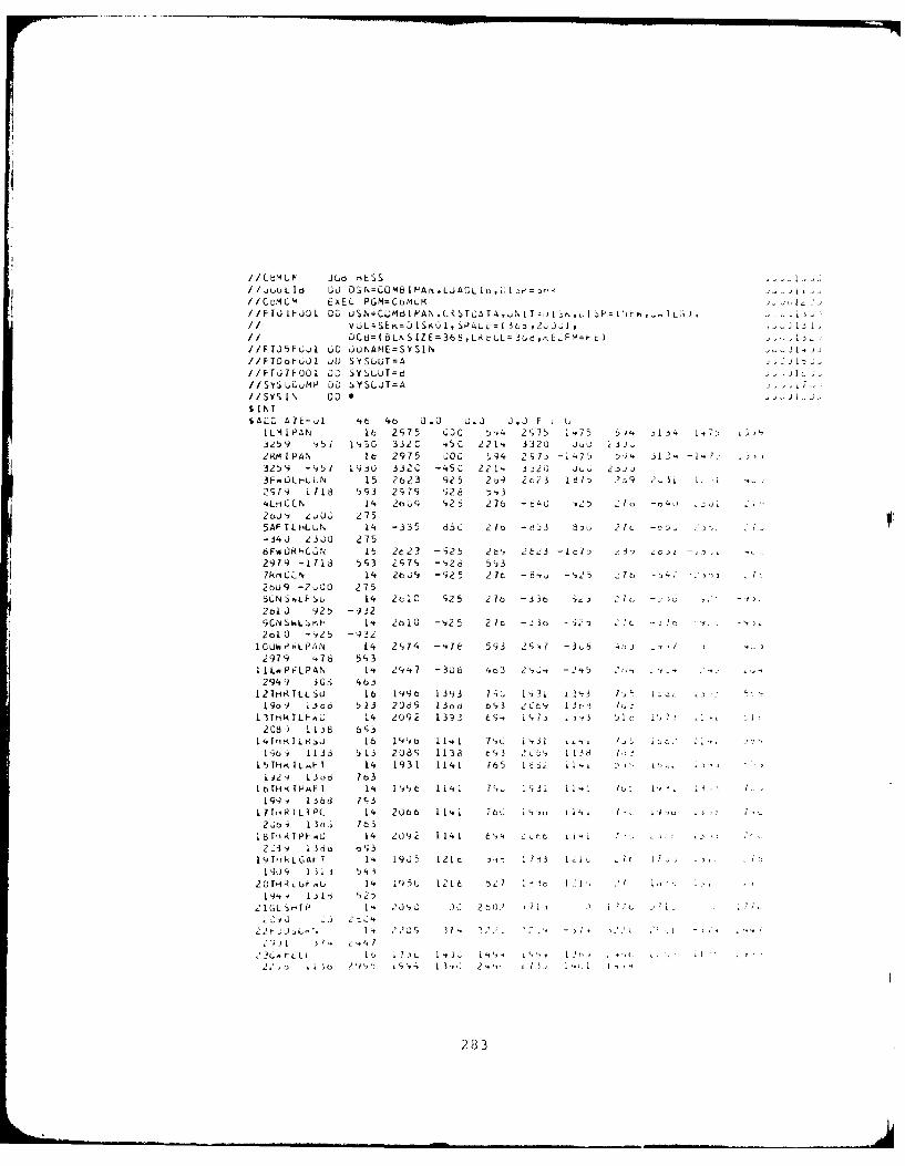
//CBML JLO rHESS
//.uuLj I L DSC0=LMB A. L AL[; II CMF Li XEL PGM=CtPM/ F TO FJO. I ] OC;LSN=CUb I P/AN WC kTG, AT A,-N iTz, I Nu I P=( u L ) ha.
// V6L=SE,=OSL) IKUI, SP4L t( 6j ,216 ) , J J:II OCd=( tLF, S IZ E=366,Lk tLL = 2,d , E FM =F L//FTJ5FOu. uC JUNAME=SYSIN N//FToF OL 31) SYSLUT=A jJVJ,
//FJ7' OI J0 SYSLUT=d . ;
//SYSULujMP J0 SYSLT =A//SYSIN $1 ),SI NI
SALO A7E-L t6 4o 0.0 G.3 3.3 F L 61L, I PAN 16 2c, 75 GOC 5,4 2975 1 75 5v, 1" , i-7; 3)43 59 15i li3O 332C -5C 221', 3320 Jvu -j,2.M1P AN Ib 2975 JOG 594 27& -V.75 9 31. -1,7; 7 t,1
32,)9 -957 19i30 332C -45C 221, 3 32i uu3 2-J 33F,.OLt-LUN 15 2623 925 2o
9 2c23 1 1 2 9 2 .i i:)
2919 11 6 593 2979 t)26 534L."L C N 14 2t39 q ,25 276 -40 ,24 2 (o -c4, Z; /
2oJ 2 03 2755AFTLHLUN 14 -335 65C 21o -tD3 338 2 -L.; D-o34J 23o0 2756F*LRHCjN 15 2e23 -925 2 ', 2623 -1W 7: e I -. ,
2979 -1713 5,3 297,
-,26 5,3
7kLN14 206 1 - 2 5 2 It -64 -S2 5 7o t, 4 -, 7
2bu9 -20 O 2758LN ,LFSu 1't 2t1C 125 2to -j6 i.; Z , -3t, -, ' I
2ol 925 -9329CN SL:,e.h 14 2t)10 -,,25 21to - J3 o -'2 C., - J - )
2oL0 -,25 -932
10 PLPA N 14 Z974 -",7E 593 2S47 -3,3 6 ,, .. ,2979 .76 593
1 [LmP LPAN 14 294 7 -308 4o3 2s, -245 25',
2949 3 ' 4.6312IHRTLLSU lo 6 99t1 39 7l g G 1-; ' - 1 1 3 5 sa ) .:1:-19o
9 1.,d 513 206
9 13o06 b,3 2Cb4 I 13o,1 1.;5
I3THR LF,.L 14 2092 1393 6-.2 i97. 1 ,lc Ic, 7; .3 1(
2C8 ) 1I 8 6q31 Tt TkRTLk.j 16 19a li.1 1 71", i-,I ii.. t'J; ioc2 V,
I. -t,4 i 136 513 208s 113d t93 1 C - 13.a CISTHFIL.F 1 14 1931 1141 765 1dL 11.l , u, L,';
1)2 130d 7t316bTH I< PAFT I 1i I I:' i 4l 1 7 Lu 1 31 1i. 1b -v IL*' I,,
199 , 138 79;317ITHRTIL T PL 14 2U66 114 7'. b 70 19, 1i~ 1-, l 'u , ,
2 Jo -y 13ni 163
18 Ti k IPl-J 14 209i W 1 69 t4 Lt t j, r-i~.23iv 1366 o93
19TrkLGA T 1. 19J5 12 L c 1, 1 1,3 1 .1. It 1 ..
1909 13i 3 543
20fH1RL , V U 14 19535 121',6 5 1 7 lb I "I I '.19 .i [i I l 525
2 1GL srmT P 1. 2 J , 3G a 2,6 . 1, i 7 . 7 i.
5L .Z , C 233LI , I L L Lo i7 l 1 ,j i 4 - " ,, h , , * ,, . .- i ,-
283
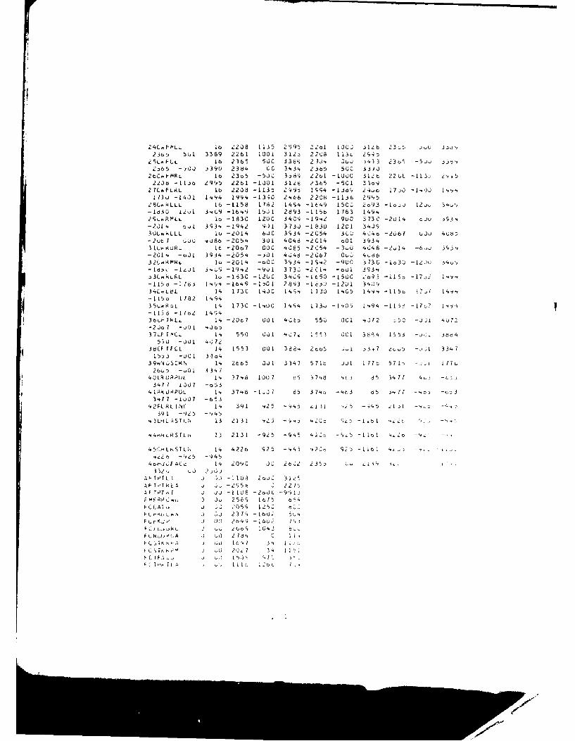
24C,.FMLL Ia 2208 11J5 2995 22bI 100L )IZb 23 )Ou 3.)
23o: 5ul 3389 2261 100i 3123 2208 113, 299:25L^FCL 16 2365 56C 338S 23J' 3uj .433 23o
5 -5. j36
2,65 -30J .390 2384 0C 3,5, 23 o 50C j3)0
2 L. 9-MR L Io 23.5 -50C 3369 22ol -10)C 312 b 22 Ct -113> 5.22J8 -11a Z9'5 2261 -IO01 312e 23t5 -501 33o9
27CoFLRL 16 2208 -113t 2i 11S4 -iJo 24,o 17;0 -1 ' ) 1 .. '1130 -1401 1.'94 199' -13;0 2'Ub. 2208 -1136 2995
28C, kLLL 16 -158 1782 14S4 -1649 150L 2o9
3 -Io, 12j, 34.9,-Iogo i.7l 3 L.C9 -16,#9 15J1 2893 -115b 1783 149.
2',...RMLL io -183C 120C 3 40C -19. 9t0 373C -2U14. GJu -93.-231' o1 393. -19,2 ; 9i 3730 -1830 1201 34J330L.-LL l0 -2014 6JC 3934 -2054 3LO 4.to -2u6 u0j 4U8-2ub 1 OCO -,088 -205'. 301 4048 -2C14 oOl 393431oL. URL It -2Oo7 GOC 40E5 -2C54 -3 U .048 -2 1' -6- 393".-201' -aOL 3934 -205'. -301 4J48 -2C67 CuO 4,ob321,4RMXL lo -201'. -oCC 393'. -1 S42 -9uo 3730 -Io3U -12,3C 34,'
- 16-, - I..O1 3 4 L -19.2 -901 3730 -i C '. -oul 3934,3L. kL.L 1o -183C -12GC 3';9 -1650 -15CG 69 3 -11 5 -172 1 '.',-115d -1 18 L'.', -1b'9 -1501 2893 -1630 -1201 319,340.,t61 1'. 173C I '.JC 14 -'- 11730 1 4G5 I14v'. -1156 1?' 14-.'-115a 1182 141435'RLL 11 173C -1,OC 149'. 173u -1405 1494 -1136 -17,7 1-'.-L158 -176Z 14943b.iI'.LL 14 -2067 001 4,;,E 55C OCi 4,)72 :50 -Uj1 '7 Z-2jo? -uOl 4J06,37 LF I fCL 1', 550 00l 4,;7 1 15? GCI 3894 1553 - J7i -do
530 -00L 4,07238CFFCL 14 1553 001 388,. 2oS - 3.? e,0
5 -. 01 334.7
1553 -0L01 33d31'. SCRN I , 2665 J01 3347 571t >i I 77t 571, -1 ' ll
40LR URPL't 1 37468 1001 L5 37',8 t-L> 35 3471 4,-, -c.33417 1307 -o53
4 lRo. O8POL 14. 3748 -1>07 85 37'40 -4C3 85) , 7 o11 - .D,,34ri -10u01 -653
42FL. LI INE 14 j91 92 5 - , ) 131 it - "4, 5 4I -' 1c
39 1 -92 5 -4995'.3LHL SSTL N 13 213 1 ,2j - v ", c SL D -Ii o1 2,c c, .
4, H L k S T L 1, 13 213 1 -92 5 - 9 5 2 C C -S 5 -1 101 ,2o t) ..
45CHL'STL;, 14 422 25 -1,4 9 , *2Co 92D - 1161 - - .-22. -9-5 -94 5
4or-,JJF AC c 14 209C 1c 2b 2 235, ' ,19
3 32u j 230 1AFTITLI ,3 -1108 2otJ 31AFT T A .kE -295t , 2 It-1 FT PT, J JJ -1108 -2adC -99-F f F R8 ,,p 3 J 2569 1t1 t5f-C AT 2059 125Z t .
F C , KO L, ,N 3 03 2379 -13 0 1 bFC- Kj. I 0 a49 -166Z 1
3 L> t , k6 1043F L Ai,P i;'A 0 7) t1o, C I I.,
"C ',IK ,' J 2.G 16.1 3. 1 1C.T~.' r& K 2()Z7 3'. 1F1 /-., -, 2, 15.7 T1. FI .
iI
7 AD-A097 705 DAYTON UNIV OH RESEARCH INST F/G 5/8USER-S GUIDE FOR COMBIMAN PROGRAMS (COMPUTERIZED BIOMECHANICAL -- ETC(U)JAN 81 P GAPU. S EVANS. P KIKTA. M KORNA F33615-78-C-0507
UNCLASSIFIED UDR-TR-80-44 AFAMRL-TR-80-91 NL
74,400000FN
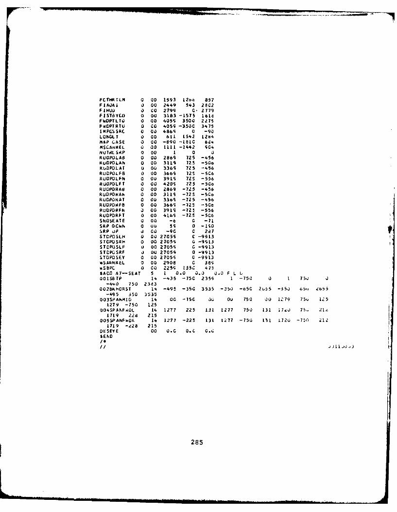
FCTHRTLM 0 00 1593 L26 857FZAUAI 0 00 2449 543 2eC2FIHUW 0 CO 2799 0. 2779FlST8YCO 0 O 3183 -1575 1618FWDPTLT 0 00 405S 3500 2275F CPT RTU 0 CO 4059 -3500 3475IMPGSSRC 0 00 486S 0 -90LUNGLT 0 00 61L L54, LZb4MAP CASE 0 00 -690 -1810 6i'.MSCA.,4REL s 00 1111 -1442 904NUTAL SAP 0 00 1 0 aRUOPOLAB 0 00 2869 725 -456RuOPOLAN 0 00 3119 725 -50oRUDPDLAT u 00 336S 725 -456RUCPDLFB 0 00 3669 "72 -5C6RUOPOLFN 0 OU 3919 725 -556RUOPOLFT 0 00 4209 725 -5CoRUOPORA8 0 00 2869 -725 -456RuOPOtAN 0 00 3119 -725 -5CoRUOPORAT 0 O 336S -725 -456RUDPODFB 0 00 366S -725 -SeRUDPDRFN J 00 3919 -725 -556RUOPDRFI 0 00 4169 -725 -506SNOSEATE 0 00 -t 0 -71SRP OCkN 0 u0 59 0 -ISOSRP UP 3 Go -90 C 287STCPOSLH 0 O0 27059 C -9913STCPOSRPI 0 00 27055 G -9513STCPUSLF 0 00 27055 C -9913STCPGSRF 0 00 27059 0 -9913STOPOSEY 0 00 27055 0 -9913WSARMREL 0 00 2908 0 381;wS8PC 0 CO 2259 135C 475SACO Al-SEAT 5 1 0.0 0. 0.0 F L LOOI.S8TP 14 -435 -75C 2355 1 -750 0 1 75, 0
-440 750 2363OO28KHORST 14 -495 -350 3535 -350 -650 2 5 -350 65, b 5
-495 350 3535O03SPANMID 14 00 -750 J; Ou 750 00 1Z79 75u 1; 5
1279 -750 125004SPANF.OOL 14 1277 225 131 1277 750 131 174J 75 , 2le
111g 22d 215005SPANFwDf 14 1277 -225 131 1277 -750 131 1720 -750 212
1719 -e28 215DESEYE 00 O.0 O.c G.cSEND
J I j
285
APPENDIX F
THE JCL AND DATA REQUIRED TO CREATE THECOMBIMvAN VISIBILITY DATA BASE MEMBER A7E-O1
286
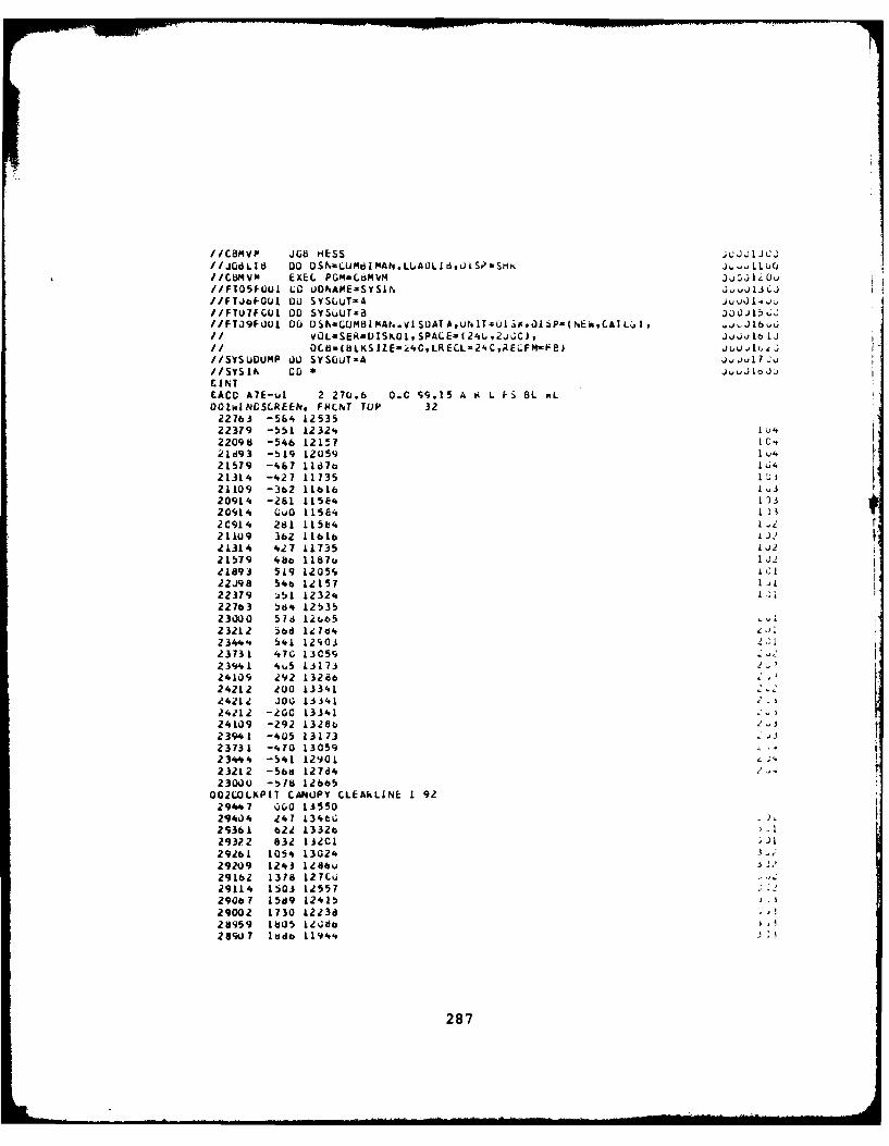
IICB1VP JOB HESS ;cJ 1 .J j//J~dLI8 00 DSN-CU1tiMAN.L.A0Ld,UiSP-SHK lll/CbY4vm EXEC PGM-CMVM 4jI j//F105I0U1 LO iU0NAPOE-SYS IN ;.,)J13 LJ//FTJa*0(J1 0U SYSLuT-A wo v//FTU7FCOI 00 SYsu~ S~UT 8:)j 15. j//FT09FO001 00 DSaLMB IMAN.V ISUAT A. ut T-uI i. lP( NE0 CA Lj It Ol~
1/VOL.SER-0ISKI0,SPALE=I24,2hCi, Jj vIt) IjII C8=(8LKSIZE=2'.C,LRECL-24C,ARE .FM-FEI iu ( .
//SVSUUMP UU SYSUT-A Jjju17 S'//SysIN DOS~ J1~J
EACD A7E-w.I 2 270.6 0.C S9.15 A K L FS 13L P.LOO1iNCSI.REEN, FIRCNT TOP 3222763 -56'. 1253522379 -55L L232%. I U'22098 -546 12157 10-t
21579 -467 11dbo 1I,421314. -427 11735 1
20914 -261 1158'. 13
20% 14 QuO 11584'.)ZC914 281 115b4 .21109 362 oL6L L J221314. 4v27 11735 221579 48b 118o J21L894 519 1205fs i;I22J98 54be 12157 1,L22379 i5i 1232. 122763 tod'o 12!)352 300 0 51d 12CI65232L2 5bl d 171842 34.' 6* 41 12903 2123731 470 13C59 -
23941 4wS 1317324109 002 1326624212 200 13341.24212 J0 1 3341 C-
24212 -200 1334124109 -292 1328b
23941 -405 13173 "23731 -4.70 1305923444 -541 1290123212 -56d 127d423000 -5f8 12665
OO2LOLKP[T CANUPY CLEAkLINE 1 9229447 %)00 135502940'. 247 134tG29361 622 L332o -29322 832 1320129261 1054 1302429209 1243 128bu29162 1378 127Cu32911'. L503 125?29067 15S9 12415)29002 1730 1223d28959 1805 12 J13289U 7 lddo 11944.
287
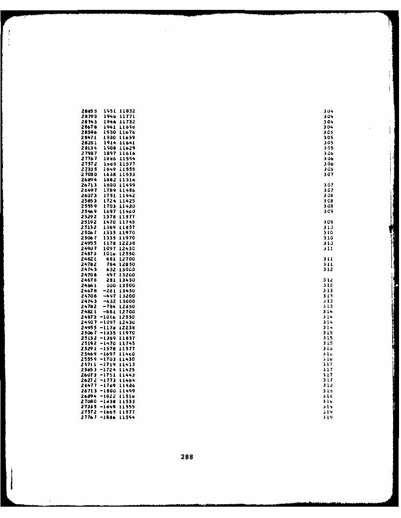
28855 1951 11832 30428795 1946 11771 30428743 1946 11732 30428678 L941 L16Sd 30428596 1930 11676 3C528471 1930 11659 30528281 1914 11641 30528134 1908 11629 30527987 1897 11616 30627767 1886 11594 30627572 1abS 11577 30627335 18,49 11555 Jcb27080 1838 11533 30726894 1882 tLSIo26713 1800 11499 30726497 1789 11486 30726073 1751 11442 3.1825853 1724 11425 3C825559 1703 11430 30825469 1697 11460 3C925292 1578 1157725192 1470 11745 3C925132 1389 11857 31325067 1335 L1970 31025067 1335 11970 31024955 1178 12238 31324907 1097 1243C i1124873 101o 125502482L 88L LZT 0 31124782 784 12850 31124743 632 130GO 31224708 497 132G024678 281 13450 31224661 000 13500 31224678 -281 13450 31324708 -497 13200 31324743 -632 13000 31324782 -784 12850 31324821 -881 12700 31424873 -1016 12550 31424907 -1097 12430 31424955 -L7d 12238 31425067 -1335 11970 31525132 -1389 11857 31525192 -1470 11745 31525291-1578 11577 3 Lb25469 -1697 L14CO 31c25559 -1703 11430 1b25711 -1719 11413 31725853 -1724 11425 31726073 -1751 11443 31726272 -1773 11464 31726477 -17d9 11486 31326713 -1800 114S9 31626894 -1822 5isio 3Id
27080 -1438 11533 3 lb273359 -1849 11555 .,27572 -1665 11577 ; 1927761 -1886 11594 3 J
288
I
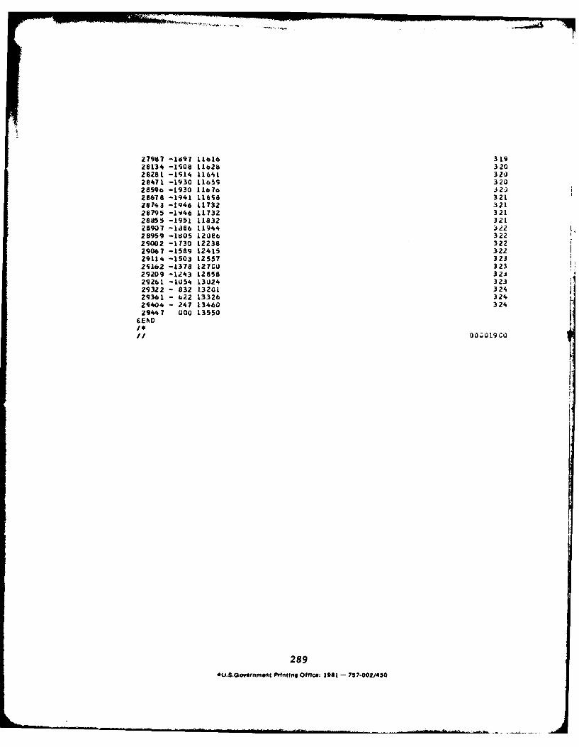
* -. . .. -
27987 -1697 IL16 31928134 -1908 1162b 32028281 -1914 11641 32028471 -1930 11659 32028596 -L930 L1676 j2,828678 -1941 11658 32128743 -1946 L1732 32128795 -1946 11732 32128855 -1951 11832 32128907 -ld86 11944 3228959 -l6O5 12U86 32229002 -1730 12238 32229067 -1589 12415 32229114 -1503 12557 32325162 -L378 127G0 323
29209 -1243 12858 32329261 -10S4 13024 32329322 - 832 13201 32429361 - 622 13326 324
29404 - 247 13460 32429447 000 13550
CEADI.I/ 00.019 CO
289*u.S.Government Pvntng Office: 1981 - 757o002/450

II
Related Documents