MURI: Closed-loop Control of Vortex Formation In Separated Flows With Application to Micro Air Vehicles Final Report AFOSR Grant FA9SS0-0S-1-0369 Tim Colomus (PI] and Morteza Charib California Institute ofTechnology Clarence W. Rowley Princeton University Cilead Tadmor Northeastern University David R. Williams Illinois Institute ofTechnology Content« I Eirturoe aaaauaary 4 Saaaaatloe, MMq. • 5 Control •fsortetthrddinc in a a Taree-diaaeo.ior.at aaneriral .. • ». 7 «HI Tniri studies M low Reynold« «ombrr I r»Mk«lto« rrwItMit from Ih.. »ward » /iiin lity« MNM Pasadena. CA October 25.2010 I Executive summary TfcM tti at MMned with developing theory algorithm», and application« of model-baaed, clcned ia^fla»toMn>l«<ml*toen*i^rolMiaii^lli«^erBiaawvxlBck* Th« riTeo» arc cMnd —it O» ««Tit»aaTltai la ewrgralad «loscd-loop flaw and flight oontrol for »uS.li/.ijcm ind regulation n( «nparalad rWw»ocsjaitag on tutmtsnpvd «ad mxro «it vcroclcs d iAViMAV. Incrcaauf lift mocialed with controlled flow» will laid Is dramatic improvcmcnti in manruvctabililv. gta.1 ICMSUJXC. and wider Right «nputa controlled captive tr»»cctnry «ynem h». been .mplc K ruich. roll, «nd phasgi. innmt.yi of th« wwtg m tnpnap» lo die nnHriiiy fin—n nant flow r 1 faA fhiif—irm IIIIUIJ wah gutting fnxjBfju flow wa» iiffiTig»m ucat force itmniimiMii in rcanorue to pulse like dtslarbMXc« from leading-edge actuators «tCTt»>rdtoor4amlir*wmodtlaoflh*»s7araa«d he aotd a» Altar kernel to predict the retpone of Ihe »nig lo mote complex actuator omul »pails A «oic. of caonvTkn of incrcaaang eornpkxirv were <toa>gard lo rupracis bit Muctuatioru m puffing condition. The mow robust controller» were «Me to suppre« lift fluctuation» associated with • broadband spectra of freeswearn veiocuy, up to a Imui of about a (acsor of about 10 tune, .lower than the <ur.ru*. vonca ütcdding freasscoav ofthe natural .cparaied Dow Tb« bandwidth Imnution» were found lo he aasocajted with, for thi» control architecture. At limmrawi aaauciatcd with dtc time for the actuate« produced liarliiig rrlga «ami rwept dowaaucorn along the winy Circumventing this limitation in future will require M directty. and utilise information from, the vortex formation process, a topic which »a» iiiualigltit directly uamg raamriiial .imulauon» and model baud control, aa iltanannl below A «me of cuiropolational flcad dsnamic. (CrTM. reduced-orifcr modeling (ROM), and cowrol design too*» »rare ab» ihr» loped in order to study adsamed concept» for model baaed cootrol of aerodynamic MMI IM «Iciinihin« pn»Mil* !•* « t»»t QOan^MnMe'aaB aWIMMHOI **'wi. a»lva.*ivcu gaWJfMgj anavä*ajBB for nodal reduction and control design an dared» aalcgratcd to provtde a cJoaod-loop flow control toolkit with general appbcahdrtv to feedback control m external How» I he cumplc« nhyaica «nociawd with small- aaale. «sssnry Omra-itanrnaiaatl wing afcapc. and separated lautcacb flows ha>r been mapped and itudioi in companion capenment» in a novel oil tunnel facility that provide« «talc of the an. frai time and holographic How weoonntuei» to corueifarncni aod \-alniau trie compuutuMui moOcli Major brcaalhrt»ug1w are reported m the inalhcmaticc and algorithm» lot tcducing complc» CTD model» to low degrce-of tractor» «am. turtaMe for «pedacatjao is practKiJL realtime controller» b the fluid r1)'«ii if« L u—MUHX UM pitMiiaiiMWl mrtatiiiiiii far rtagutad-order modeling t» Proper Orthogonal Decom : gal gavgaflMWJ Ol aim* iclual.or producr high lift limit m lev where the tyncfcrooGOuon of vonca arieddmg lead» u> puching the vortao ciincr to the «jcnon »urfacc. mulling in higher lift. The« limit cycle» arc ma robutt to dunnbancc.. how cvtr. and frndharrk control baaed on real-time trackiQg of the phaac of the lift llueruatinm. a »ucccntulK implerncrded in order to »ubilune uVctc high lift limit cycle» In addition optimal control theory i» uaed to find«etnatnr wai<eform» thai mavirmre the penod-aiatogtd lift and theac watrform» are then uaad together with the phaac lock loop feedback control to achieve optimal lift timit-cvcle behavior Three-diniCTO ioo«i muUttcaw woe prrfomxd for natural and aettatwd flowtow low -aaprct ratio flat ntalea with irrtanajnlar. cemKirtular. ai»d oelu-wing planform» at a var.cr, of angle, of attack For very low aspect ratio platev ihc up\ortic«»h»vc > tlaNlumg iraltxac« o« the »orte» »heiicWif Open-loop actuation n able to attenuate and in •omc cans, completely »uppre» vorte» ihaddtng Finally. cUiwd loop control i» applied m the mm: rkrwaraiitaa«! tonulatxien unng an cJCbuiaini «onVirif, approach, which •• abh M find optimal roruunacte« of n (POOi, m a of modr» that are optimal in the ten»* that thry capture lite mrM crasg> m Ü»c g~ivcn clau aet In practice. however. POD model» lend to be fragile. Th.» frag.lity ,. uridcratoud by the control theory ccanmun.r». a balatittnl truncation and optimal llanazl norm reduction offer more to e and theoretical bound» on error» However, three technique! have previously been far too compulacton^ly apemrve to perform oa a full CTD model Thi» repot« on dcvclnpaacm of approaimaie hatanrail truncatioa, called balanced POD, thai i» compucuiiKijIly tractable for targe ayatem». aod produce» modcU aaavait iQrotical to thoae from cjcact balaocrd truncation The tc*hn«|ue n extended to unstable and periodic lystra» in order to UM them to model vortex shedding eat two aod three-dimensional w tngs A luaaaachy of two and nVit diwii I modd probajaai aw paaed and »olvcd in order reduced »»öor rnoortütg and tlamreucal control of vortex dk.-ddj.vg at low Reynold» number In particular. ""•*** —" ...-..-,- i. ... ,. -rr--...... .- . -|'-'] fir ---fi lililiig

Welcome message from author
This document is posted to help you gain knowledge. Please leave a comment to let me know what you think about it! Share it to your friends and learn new things together.
Transcript
MURI: Closed-loop Control of Vortex Formation In Separated Flows With Application to Micro Air Vehicles
Final Report
AFOSR Grant FA9SS0-0S-1-0369
Tim Colomus (PI] and Morteza Charib California Institute ofTechnology
Clarence W. Rowley Princeton University
Cilead Tadmor Northeastern University
David R. Williams Illinois Institute ofTechnology
Content«
I Eirturoe aaaauaary
4 Saaaaatloe, MMq. •
5 Control •fsortetthrddinc in a
a Taree-diaaeo.ior.at aaneriral .. • ». 7 «HI Tniri studies M low Reynold« «ombrr
I r»Mk«lto« rrwItMit from Ih.. »ward
» /iiin lity«
MNM
Pasadena. CA October 25.2010
I Executive summary
TfcM tti at MMned with developing theory algorithm», and application« of model-baaed, clcned ia^fla»toMn>l«<ml*toen*i^rolMiaii^lli«^erBiaawvxlBck* Th« riTeo» arc cMnd —it O» ««Tit»aaTltai la ewrgralad «loscd-loop flaw and flight oontrol for »uS.li/.ijcm ind regulation n( «nparalad rWw»ocsjaitag on tutmtsnpvd «ad mxro «it vcroclcs d iAViMAV. Incrcaauf lift mocialed with controlled flow» will laid Is dramatic improvcmcnti in manruvctabililv. gta.1 ICMSUJXC. and ■ wider Right
«nputa controlled captive tr»»cctnry «ynem h». been .mplc K ruich. roll, «nd phasgi. innmt.yi of th« wwtg m tnpnap» lo die nnHriiiy fin—n nant flow
r 1 faA fhiif—irm ■IIIIUIJ wah gutting fnxjBfju flow wa» iiffiTig»m ucat force itmniimiMii in rcanorue to pulse like dtslarbMXc« from leading-edge actuators
«tCTt»>rdtoor4amlir*wmodtlaoflh*»s7araa«d he aotd a» ■ Altar kernel to predict the retpone of Ihe »nig lo mote complex actuator omul »pails A «oic. of caonvTkn of incrcaaang eornpkxirv were <toa>gard lo rupracis bit Muctuatioru m puffing condition. The mow robust controller» were «Me to suppre« lift fluctuation» associated with • broadband spectra of freeswearn veiocuy, up to a Imui of about a (acsor of about 10 tune, .lower than the <ur.ru*. vonca ütcdding freasscoav ofthe natural .cparaied Dow Tb« bandwidth Imnution» were found lo he aasocajted with, for thi» control architecture. At limmrawi aaauciatcd with dtc time for the actuate« produced liarliiig rrlga «ami
rwept dowaaucorn along the winy Circumventing this limitation in future will require M directty. and utilise information from, the vortex formation process, a topic which »a»
iiiualigltit directly uamg raamriiial .imulauon» and model baud control, aa iltanannl below A «me of cuiropolational flcad dsnamic. (CrTM. reduced-orifcr modeling (ROM), and cowrol design
too*» »rare ab» ihr» ■ loped in order to study adsamed concept» for model baaed cootrol of aerodynamic MMI IM «Iciinihin« pn»Mil* !•* « t»»t QOan^MnMe'aaB aWIMMHOI **'wi. a»lva.*ivcu gaWJfMgj anavä*ajBB for nodal reduction and control design an dared» aalcgratcd to provtde a cJoaod-loop flow control toolkit with general appbcahdrtv to feedback control m external How» I he cumplc« nhyaica «nociawd with small- aaale. «sssnry Omra-itanrnaiaatl wing afcapc. and separated lautcacb flows ha>r been mapped and itudioi in companion capenment» in a novel oil tunnel facility that provide« «talc of the an. frai time and holographic How weoonntuei» to corueifarncni aod \-alniau trie compuutuMui moOcli
Major brcaalhrt»ug1w are reported m the inalhcmaticc and algorithm» lot tcducing complc» CTD model» to low degrce-of tractor» «am. turtaMe for «pedacatjao is practKiJL realtime controller» b the fluid r1)'«ii if« L u—MUHX UM pitMiiaiiMWl mrtatiiiiiii far rtagutad-order modeling t» Proper Orthogonal Decom
: gal gavgaflMWJ Ol aim* iclual.or ■ producr high lift limit m lev where the tyncfcrooGOuon of vonca arieddmg lead» u> puching the vortao ciincr to the «jcnon »urfacc. mulling in higher lift. The« limit cycle» arc ma robutt to dunnbancc.. how cvtr. and frndharrk control baaed on real-time trackiQg of the phaac of the lift llueruatinm. a »ucccntulK implerncrded in order to »ubilune uVctc high lift limit cycle» In addition optimal control theory i» uaed to find«etnatnr wai<eform» thai mavirmre the penod-aiatogtd lift and theac watrform» are then uaad together with the phaac lock loop feedback control to achieve optimal lift timit-cvcle behavior Three-diniCTO ioo«i ■muUttcaw woe prrfomxd for natural and aettatwd flowtow low -aaprct ratio flat ntalea with irrtanajnlar. cemKirtular. ai»d oelu-wing planform» at a var.cr, of angle, of attack For very low aspect ratio platev ihc up\ortic«»h»vc > tlaNlumg iraltxac« o« the »orte» »heiicWif Open-loop actuation n able to attenuate and in •omc cans, completely »uppre» vorte» ihaddtng Finally. cUiwd loop control i» applied m the mm: rkrwaraiitaa«! tonulatxien unng an cJCbuiaini «onVirif, approach, which •• abh M find optimal roruunacte« of
n (POOi, m a of modr» that are optimal in the ten»* that thry capture lite mrM crasg> m Ü»c g~ivcn clau aet In practice. however. POD model» lend to be fragile. Th.» frag.lity ,. uridcratoud by the control theory ccanmun.r».
a balatittnl truncation and optimal llanazl norm reduction offer more to e and theoretical bound» on error» However, three technique! have previously been far too
compulacton^ly apemrve to perform oa a full CTD model Thi» repot« on dcvclnpaacm of approaimaie hatanrail truncatioa, called balanced POD, thai i» compucuiiKijIly tractable for targe ayatem». aod produce» modcU aaavait iQrotical to thoae from cjcact balaocrd truncation The tc*hn«|ue n extended to unstable and periodic lystra» in order to UM them to model vortex shedding eat two aod three-dimensional w tngs
A luaaaachy of two and nVit diwii I modd probajaai aw paaed and »olvcd in order reduced »»öor rnoortütg and tlamreucal control of vortex dk.-ddj.vg at low Reynold» number In particular. ""•*** —" ...-..-,- i. ... ,. -rr--...... .-■ . -|'-'] fir ---fi lililiig
2 Introdnction
la Ihn tatton. we t«-v>cw the recent literature on natural and actuated h»i over two. «ml ttoce-dimcriviorial lUl plakX and ssrfou». aad eifert armed« open- »ad «lo^Wo^«o«Wiof»^wtiao fo» Uftenh»occinent drag reduction. and olhet objective» We include in the di«tu»«icm •umcof out own mulls (bat «e amplified
atlas report
11 W* 6m ccwidcr fkm tW end fare«» »s»»iciai*d wtth a flat plate ot aafod «I an angle of attack, to an otherwHc ismform. steady, »urain of «peed I-. under the actMin ol cununuou». but unsteady, forcing firotn an actuator The chord length a c. and. unlcat utherwu« mmmmfd the plantbrtn u rrrtangiilsr «nth breadth :/> and an aspect ratio AR ■ M/r The rctesant Reynold« numberis Re - -* We fu>t discuss the natural («nfcireed) tlow. and. at the next nxt«». actuated (farced) flow v
At the angle of attack, a. is increased diffctcnt region.« of «cparatcd flow appeal a» a function uf the airfoil ihapc and Reynold» noxnbet For Ununat airfoil», onset of tcparatkoa would typically occur neat the trailing edge, and progress u)MUuant Hau usjtitvsul Kot flat plaici and other thn< the «harp kadaag edge precaoter Kaiarabon and a «^«*i.in bubble (with t>p»^ly turbiu^ reaiuchrneni oa the suction aartacc) may precede the fully-itallcd condition. Wc are concerned here with completely «rpatated nulled) flow over the entire cucoun aorfacc. when the airfod benavn aa a bUdThody with vertex »heddmg. oaeiluaory force», and the formation of a Karmen vortex ctrcet in (he wake The frequency of sssrtex ahedtuag. at leant for the high AR caae. follow» a Strouhal acauag (Fage * foharoen 19:7) wtth
■na/V * 0.15 to 0.2. where ctino ii the protected area in the direction of the «ream, and the Saouhal number ■» nearly ccsatuat at high Re
Aa a diwuaand mure fulls in section 5 I .1. for a ritictlv 21) flat plate, the onset of vortex ihcdding iKcurv much a» it doc» foeabluff body, a» a I Icerf bifurcation atcnucat value of Re o< a Ahuia A Rowley 120 KW) found a,.,,, - 13* at Re - 100 and Chen et al COW) found an Rc^, = »> at a fixed a « JO* For Re > Recn,. the saw variation in »bedding frequency with Re u observed a» that on a circular cylinder (Roshko 1955) lUacd on the «imilsittv with the How over a circular cvlindei (eg [UrUev A Ilcndenon 19961 a could be expected that at a higher Re the 2D vonea »heddmg WCMW uralergp a njrther b^ In .t() flow (even lie an infinite plate), but these imtabditses are on!» reeeatlv beginning In be »ludied (Rcsdrstxst? A Theeeut» 201 i i For km eapecl ratio, 3D Rat plates at km Re. varan .neddmg «till occur», nut dau ■» very limited Taira A Cokmius (20096) .nvcxtigated lew AR flat plate» foe Re » »00 and 500 over a range of a and for rectangular. dUpncal. «cm. -circular, and cMU «haped pianforrm The Unart of vortex ihedduig i» delayed to higher Re and a at the aspect ratio a decresaed. due to a «tarxlumg infliaxnrr of the up vustjccx A» AR at inratascd beyond about 3. the uuiial btfxecaavan to vorara ihaddlng ootaodc» wi(h the value foi «Iricl!» 21> flow
A« in Muff bwucs. vortex shedding pcrwab at high a when Re r» increavni , William« Stubcr A Chanb 1990) Nomuully 20 airfoilv and m particular, the symmetric NACA «eric», have been studied ihe most Huang et »1 (2001) memured the freooency of vortex «bedding in the wake of a NACA 0012 over a wide range of pent Mall value» of uupto Re »0(10*) At »uiltcicntlv large Re. the thin them lavei hounding Ihe «paratioo displays a Kelv» llelnvholu inatabdrry (with St aiviu! an order uf rnari«n*te fogher than vwtci »heddtag). and ultimately become» turbulent (Brendel A Mueller 19*,) The dominant »hear layer instabil- ity frctjuency shows a power law ifctwraVwcr on Reynold, nuanber. / - Re*, «amilar to ctrcular cylinder. Yanuo-rcb ct al (2009) like the circular cylinder «tvanued .irf.nl flow» typwally »bow a broad band of frecruencicv centered around the norniaal »heddutg value at the wake, aaweoually due to the tnteraction of
the diltcting timeacak» and the effect» of increa»mgly oranplirairrl and turbulent wake» i Yartnevych ct al 290*). The »maation i» marc complicatod at value» of a near the ortart of full» »cparMod flow, where !<s - thar ttaoraae. in Re can land to nanachamnl of the »ep»ca»ed region pnot w the txauang edge Finally, we **t<i>*foin,xMc.mi*ni>c*,i0,lt.flo»*t***Ul<*.\ (2tXr-JlfourKltlultheraruraU^rl<««be4itaig
lea wa» ceajplad to *ha a-etnhrani oirillnim
2U SleJMh-»U«cactaatedfl<m»
Following (he pioneering work of Prandit (1904). claaate »cpararion ouotrol laeaailfinai (Lachaxann 1961) «ich a» »lady blowing and •ucuon attempt, to ccanrur a boundary layer thereby^^ delaying or preventing veporauon Lately, urtxteath' blowing, /ero-farl^naas actiiaten (^rvtaaaxue jet»), rmtfininnftiti flap». rHitrma
sady actuawo have been shown to achieve umilar net fotmance but wtth far lower crgy fluxe» than tteadv blrmtng e» «JCUOO (tireenblatt A wSgnanato 200fj«.
Seucrt et al 200*) For airfotl» and flap», bfl and lift-tewkag rat» can be «Utantiallv incraaaad. bat the underlying mecharuum anociatcd with litt <t»hanc«mriu at drag reduetwo are »nil detasted. The dnminaai idea, dtanaxsed in detail by r,rreohum A Wygnandu (2000ol. ■» that cxciutMn of vtartacal Mructure» in Ihe tenanted shear lay« leads to erihanccd critrairaric« aavl the attendant nictic« »x«1acc.elirTia3atmt ct rwa^omg the extent e/lhe »crwnitcd region, and leading to a Itrr»-averaged flow field cloaer to the ideal potent»»! flow Krnreirimeni ltkel> pUv» a rale regaidk.» of whether vortical «uctu-o» are
d aa part c^ a Kdvtn-Htdaaxaltt äwtfM or trpatrainn bubble, hut, as dacmscd in the previou» »ecuon. the rrcerueocics at which these occur are diitinci F.vpecially for low frequenue» and high angles of attack, though, lifl enhanccme al»o been exDlaincd in Icrm» of vortex lifl(e.g Wuetal (I Wtt». *hrough cceaaearaliori e/wwticalstw cUner to the curtace of the plate
For a ■pccificd penothe actastoc. atrloil geometry and angle »f attaca, any nundinwii il perfot tnetrtc ') a ai most be a function of the Reynold» number, the actuator waveform and noodimcr f intatnsn rasjsining as IVeeaxncy and amplriiidr For the frrxxscacy. the aaoatcsxraaMncaoKc
•■a - %&■ *°«- y. h. of unccooa. and A a
and •sthe
1 For boththetequanuuev the chord length i. »ometimc» replaced by the length of ihe (natural. n bubble when the tVm ■» not fuU» »eparatrJ Mean and fluctuating value» of c. aa low
at about 10 ' can be effect.vr iGreenbun A VVyrnaruki 200tV/i Crresxthtstt A V^gnao»li <2<M0.) Utowed that c, ccälsasrs rtats cir.ia.nrri with vrveral different actaatces.
but. m general, if n dilhcull to to coraparr data tram different ataoastut» and wtneform», or with character- izing Ike actuator iiiifoiaaaatr at ssraaa of s vtrfocaty (or nan »lux i that can depend «a the ptianrang for the actuator and vvtsstbar the pcrfcernance is rneastsrsd wtth or wrilbowt flow Most studies observe a Iowa rhjashnld and ttaper i—aiiuii baasl of saatasatsa \im <*&* <t>c rw*t of fm**«*x>*i oomivl *m am h. achieved, to the controls community tU» »Ittwwn M the i/avir iiwa» arid u of a control .yxtern. Reynold» number effect» (e.g Sofort et al 20041 have al»o been «uebed Here the most pressing issue is whether «oroe rescrts of lift erilusvcemcnt or drag redueiK» could be expUincxl by ,he nxxhanivot of tripping the bc»at«dary layer to delay or r««eni vcparaiton II i» clear, bowevx». that there rcrruum ta effect of forcing at Re lower than 'hove for which mriearig can Uad to a njrbulew boundary layer, aa well a» at high Re when the buiiiha) layer was ttirbulent even in the absence or tripping (Seifert et at
• •ua»r»w>ar.««t»*waidw«Mk>l..
2004). The effect of actuation frequency on performance has al»o been widely »tudied. and gauu (tilt enhance
meat, drag reducöon. and other goal») have been realised across a wide range of frecjucnuex Here we employ (he tens low frequency" when the actuation frequency •• below and up to the vortex »bedding ftsquencv (,dasstasse4 above), and high frequcocv " to refer to evcnthing »tgntficaotly shove it. aad in par- ticular lo excitation of ibear-layer inttabilttio A» divcussed by Ratu et al. (2008) (hacafta referred lo av RMC). s third dwtmct taneseafe exuu when (he («veanl *km forna a doted recsrcuiation rwbbic on the to foil surface. While these three distinct nmetcale» «hear layer, wake (vortex shedding), and (in some case») Mnstatann rtubbk-can he »lentr/sad by sxaramaxg velocit\ ipeclta iiasusarad al ddlcrent IrxsOons i RMC i the tack of such data make» tt difficult In make definitive »taterncnt» about the» value» in past exrxmment» For exvarnple. for a .uioulcnt «TWSIMKI. C.reenblatt A Wypian»k. (2<»0ul repcet ancsptimal valueof/• - I tot a deflected (km (with (he flap length aa the length teak), where 'optimal- refer» to that frequcnev at «Inch a minimal actuation amplitude was required for reatiachmeni (in the mean), aad racy staKUtt BUS
limescale with ihcat layer mstah.i tie» «hooding timevcalc discu»»cd m the last section. Si ssOHJas ^*^>. wlicrco, i« the flap deflection «ngle »t UHxUude that a lvpscal vxa- tcx shedding frecgiency would have /' > I when o, > »*. one cm\ infer thai wake and/or vcturauun bubble uutabditie» may equally have played a tole Setter! ct al 11996a) used osoUakxry bhrnxag al the lead mg edge of a NACA00I5 asrfotl at k*»ss 10*. and found lift erihancemcni and drag reduction over range
- h a hroad maxnnum around f . a75. which, for the range of I«" < a < ir ei«ttidered give» 0 : -. St -; 0.24
For lower Reynold» nutraber». Ilstaoeiat (I994i acou»ticalhi forced th» flow near the IcaUsag edge of s fully »cparatcd SAC A 65 VOIS airfoil and ubserved a strung crihaoceerieni of vortex sbcddmg. and the mean lifl. but «w/i when cxeitaiiori was close to the natural vurtcx shsiUng ficcajcary. The ccata-ajiaiortal study of RMC showed that foraNACA 441« al Re -40,000 and a- 18*. actuation with f ~- 6 wa. increasingly uveffcciivc. m iheu case, f - 12 wa» identified a. the truumulli »mr^ifled fie^uericv m the »^xu^taxg iheai late» Thtac icsulu are corroboniicil by the experimental finding» of Cicrpka et al i.20titt> who suhjaitad a NACA 001 $ in = 20-1 and an inclined flat rttase (a = IV) »ubiccted to an cvecinvmagticuc aoeaastaa near the leading edge For the plate, with 0 5 < /" < 3. the flow we» reaiuchcd (the kit imhsncxrrnent was best at f - 0 7 (St - 0.24). whereas /' .- 6 had little effect on the »c{>arat>en For thru racltncd flat platte, they cmploytsl a wavelet algorithm lo detect large-scale vorticc» in time .revolved P1V data, which revealed an interesting cualcxcixace of »mallei vuruccs ptotfoccd near the actuator aaa» one large coherent vortex adveetirtg down the plate per cycle of actuation, in the case of f - I (St - 0.23 k and to fwo coherent >»ni»pwcycJcofas3iial»f»wheo/- «0.5. both ot which imply vortex »heddeng at St = 0 23 A unliLal uuttAgMatton (wtth a ilicleetric tssrncr dtsclatrge actuator) i»a» rttatted bv Crrsverihlatt el al (200«) (flat pUtri
ctal (?ÄatitNACA(X>l}, For the flat pUte at a « 20-. 0 J < r < 0« provided the beat lift wlstrraaa/ • 3 »a» tncfTccti»«. and imoke vivualisatinn at/' » 0 4 »bowed a strong vortex
ig dtrwmtrcasn akxag the chord, f - I 5 waw opurnsl for a NAC A 0015 al a = 16* Recent studie» have also documented the effect of the »rrv-y»*r»i on perfbrrnancc It appear» that periodic
but puhahU actuatHW ot rrvadulascd high nxeiucocy ttraascadal emulation tan ptoxhice pertca-nance eoual or greater to stnusnida! actuation at the same frapjency (Amrtay A Glexer 2002a. Woo at al 20M. Cicrpka etal 2«X». rHrenbtan et al 2tT0«. foe A C\»loniu» 2010) Indeed, rt appear» that pub« with a» low . duty cycle as 5% can be effective. (GreenWait ct si 200R) In out work presented below I section 5 2 4|. we have employed an adrocot-based spntuach at a km Resnolds ruanhcr DNS to find the actuator ssgnal (a body fore* m this case) that gave the highest lift. Indeed, the optimal signal was a nearly periodic rwUitile forcing at a freoxicncy dote to that of she vertrat shedding
All of the above stvsases have IcKxwed o« 2D geora^nea. but our n shown that leading-edge actuation offer »rroilai perfeamanc« Sraariita,
vol.
-a)p]
I lowov-r w note that rclalrve!» few •tudics have rcpMlcd urutcadv flow metrics atmctatrd wtth fluc- tuating force» at function of the actuation frexjocnc) At pointed out by Amrtay A Gltva i2002o), enhance mem of vxalex vheddua: by forcing near its natural frequcnev also increases the fluctuating lift and drag compared to the baseline. Asm faxet being potentially detrimental in application, wich unsteady effects are essential to understand if cfoscd-foop control approaches are to be successful Thu is divtutxod in greater tsctssl to the next «ocacct.
13 Uadiae-edee »ortex
When a flat plat* at high angle of attack r» unpulnvelv started, the ssjcatrataag »xsrtax dseet al the Icsvdsng and trailing edges roll up into a coherent leading and trailing edge vortices (I FV.TT V) The TFV (start up
tastdly shed ,nto the wake, while the LEV curmnue» to grow for about a diorit length of travel, where the lifl and drag reach their maximal values (without regard tu the additional added mats force during the accelcraiion) Once the LEV begins u« shed the liA decrease» to a minimum that occurs after 4-5 chord lengths of travel, which appears lo be only weakly dependent on the Reynold« number or acceleration rate (Chen ct at 2010i Thi» tancscalc is nxsaitarnt wrrh the so-called umvrrtal time-vcale of vortex forrnauon that is observed in a variety faf flow» (e g tktbirt 2009) Rcaauonal forces on flapping wing», on (he other hand, appear to prolong («tabiliac) the LEV stracrure (Lenimk A Dacktnaon 2009) For a translatang wing. Ilka ihe initial LFV t« «hcd. alternating TFV and LFV of dimtnithmg amplitude are shed until periodic or qua* periodic vortex »hcdding is attained Tbc-extra'lift fiwce of the initial LEV ha» bom measured to he a« much a. »0% above the steady-state (iime-avcragcdl value (Dictaton A Goe 1991ST) The LEV. and as avaciatcd lift LiKivmem are ..ntilar to the dynamic stall vswtca that i» produced and shed during rapid pitch up to high angles of attack (e.g Carr !9gXa)
2.4 transient rrtpoase tn actuation
As tliitiimiil above, understanding the uansicnt response to miuatum. tcrminatioa. or other changes to actuation parameters is s-tsential to the drns^snant of eln«ed4r»op flow andAsr flight c-orgrot Strategie» Rclatisrly fex» expeixrncntal and comriutaiic«ud «tudicx luvx addrexved thi» .»rue Amiuy * Glcrer (Amitav A Glexer 2002a. 20061 ecarnmed the rv-spoatc of a »yrr»»c-tric NACA airfotl at Re = 3 . 10* and a « I7J* lo a burst of togh-frtx)ucncy sywhetic jet actuation Trxe response of the actuator consists uf several eiecUotvsuclion phases of the actuatot I/' > 10) with rapidly dimnushing amplitude The phaaravcragc circulation flux in (he wake was ix»rt»sdcr»r»e despite the low actuation amplitude c„ i 10 '. and coosisicd of an atrtial negative ccastntntioa to the csreulation. folWmed by a large pcmirvr vurte» being «hcd into the wake, and additional oscillation» or dimirtudung amplitude The total duratioo of the transient reapotuc was long amparcd to the actuauoo. lasting »everal hundred actuation cycles, or aboat 10 cortvactrvc Iraac units (/• « fjc = |0> The response to step changes in actuation has also been «tudtcd (Amitay A Gleaer 2tXT2«. Darato A Wyswarasfo 20t>to.6) awl d^ •cparatcd and controlled flow states Similat to Ihe burst of actuation, the forced icattachment firu result» kj a negative vwrsex tcdlemad by the atacslcvng of b>»ac, p flow ova a deflected flap, and showxvl thai the revporoe scales weU with cooveetive uroc. at s miratrtum when the acuMttjon amplitude »a «xstTncacath large the cararolled state ts reached after about /' . 20 At kas« rtey^isniat raarrth^
pa«flManapHN mm p*m* ,» g*tf**«qpi«JhMJI adap.»..*»jpan|
noi«oi|tid> «o| ^om A"«M « u| naawqmoip jo aauaoju aqi utl (aaqai »aaiuaajjod waatdo ptaot w japj» i ayuwoa i>r«r»^a*»a»)«»»o»» *trp» pgamionrfiHI
ocr» tm» nuai-mm pwmmJ*, a.q*i.%au. «• torpi»aq» «3»JOA .«*,* iptm jo tai*n taqlrq JOJ
^WllulJU««>»«uw■cuI»^».,;^,p^n;•np«n«wuo^«^UIJml^»^»^^u3«IWl?-u<«|tpp•U] «aoqcnuD« (ouxanu laojrp u> YJOI » ay a aout» jfeo-.Tu.pwi KM«*», u, apn aaa« po* pauSnop a«a»
uaj>o»*» »aeqpaaj p*««n»u»<K) *«t» M~> P« »wp«»I *P «* ««wnt>» Aq powoj •*»«* jo •ar>nq»rqn»i»^*y.,.»rf~.u*m,j»4».>ujH.jr»in^^ ,
aknp taaoo» JOJ ftapou» acqaat*»
»n ;.i i; ^..H^V ^.~-J*U. \ n^QMMtippQ ♦«i.tfoqii^) *>1 ;,j ^n*nt:pftn .» '.j-rm onhm^iai JJu'itio
amp oojqcaii nip JOJ aAtiaojp ajotu qantn am po« \JO*WJ» pu» utB*rn» jo n»^ aqi aiijocjoau.
fiaptM «««Mai *u l»»W«l< «au<M «a qam> «iiqjo *pouod qti» inuanAa put TwiianXt aiqt» -a» o» pqma |» tadiqMjp M.« Juiapooj apw poanpxi Kg ajrtpoaajd annjiaaU» v (*• ««»$1 f
»uojmtafopomjapj»p*tnp*j JOJ «tap «atAOjd<n ptn t^tqd «op »t^ atcAiXMti i»« nifn wog qr.w aurmtn» \|»i»r*fp an atp mumnV» Umiu&u») *>p jo 0|pJ»»l» H/mmm
wmmmmami Mnoqn pu» paruMut| luautaidui. oi p»oo|»A»p «M »^»oiinjj noun»» V poqwo» BI jajonqnu atp o> [nniigi »:«aarnij» at »jTauunilu» »pronaNtu jo ODM- am pMJcq»» .aoo»*?« tna
•ipiioiTf y Jaqtuno »PtouA»,j »vuanotu m «"] w to« po> «.land i«u oraj >:v«h»- VK>I puna« t.vw.y j.>
o»jp>»»t»Aap»t>.rjott»i»mai^<J»P«^ -j
aa»jjn> umim J141 toon xauo* panjaua»* mtna» m jo oxnyuuta J.p qv.» lauaiaota» niiunify Kajnpn aqi <p>* pjuumi aq <a
pomjj m bojinxpri aqi tn pxoujw uninrialrtn» >iu<nm>Toy UM ,|u tnpitqwaq «tnunin aqj iDxnm
-X luunp jfea »»(pwi «0 w Mtwutu /i npnnnrn« atn ipu« pinuiim «MtÄqd *p pomupwi <n
pu« -»lapoui ap JOJ nrp apiMud m tnnap m pacpnn «« poach IU»AIIVXUJ pa* -aprmiuui« nwrpanp
*p^<pi*fen«»««P«*>«l»m'«n»»«aLUuivBMtti«ii>i4i. XB«»»pu»| «amui» yn» »m«.|*ii UH wan»*» oi «Mm» «o pionnwimp Xi»»i*«»f» I»«I »onnnouo jo mmmwu» pnat« nSmp
oi pa« «a« pw ini—|jj| UI>IJJIH«HII IIOHU tuoa tutm pwn«|i>o JO« wxmnm m «moduu
UK *• jo »W»«" *»P*»'P«>"I»>I »»»y **va* -iimmmm naifl Spnm o»»»n«o<H po» U'l >»«»»l -o» at lap» m uoi(Mmi a« in pmummoaap aw« (vouoo HfUg P*» «M»U liooMPMWO U Uott»$l |
tn*mmtftiaaXM mm mi y ummim pun » aoq JpiAiMil JM nonaaniioi VUU JU; UIJU». cu^uMop «XUI
-aafg«> aip a psoOT <v«^* SDippoui pw \>»n^^
•si»» «q -««»Pi»»« i»ua»i»D
»1 -SSO'
•ina»»)i»(l»a po» wwiroiw nttui «up ^y>W*mmntmMpm,M9^*Mmw*rnwvun<l*<m*>uimmtti'm*»»<mp*Q*
ISVM a>m>K*** m»uo mmm^mmmmi^mtjßmißmmimM minj^m *jmm i
paw*»»W««f»»TB»»P>mi««u^
■iMjiJfyMp^w^piioiiiiiitJtt/wo^j^tpou^ 1»C>na04PM*m •*/>•>» <i«iW!^ 1^1 oi |nim> «cMitiimio/m np pw
»»«owqimo« w»o«t- »aqj, «op »m w n^ny—. iwnf» —jg iiii)ii«w»|»i ;miim «DHirujnp
ipw) «fiHjjo Mpowd «lanMm w n»«» «• "«i|«<d U P» •«»./» ««1, Jwpn» joj p*jn,.Mjp »»s m, jjnpx»«! 00. pssuwwo »p "v.» WOIASHI 0| -qaptitj)
aOJ »«>puo*ai«n o»p tmqai pu» nut»« urn H^ » >^ n>T°u »>T^ <nodC r« wan
-.•»» pa* uonot jo t«oi)j JUI W>I«JW1K> «J> ^pntwujariX« QOJ P»»«»«8 («0«) <»l«>«m «OCM P»»»»»«) aonnKMfanwa pnofetpiQ oia,4 pnmwf*^uUi)»*^wwwxmap*>amimjomf&nm»mm-
dm <n uo «rooj aaq cuojj» jno u*i«op iai»xo JOJ a|qmm ipipoui tcuufnap JOJ oobnmaw xwaurxis
dopuap pa Katppou. an»«!) j« in ^ p »™ MQ *****<>,» »*lo*i «v )o *m* 3* r> *>0
oauro tpyatiija np t» tpo» ijtjojrj*» uacf. na>*«j atmb«o,UK>pa» •n|»»wiin >o.a»a ■III»J»W«/1 i*a*i>
;o .prjout u»o -ajuntui JOJ tJTOK ■ --J VK^mi 0*V" CKM ■» »*«*l »W«*» T|»>»» >*•* iwunuXp «|t uo poji» nawocutii u» >*«v oi iiwti icnq MMJ njnntj (limnmt ••u»*too»J •pttU «on oi -ÄO.0JH nou • ui iun»»j iinunaup %||I|IM*W» np IPWU ip«,« potpna » XtM|)
[■ w «aanoil (ÜOd'• uotinoduioua |cuo*oipiO J**>M UD
Pauooj nw. «on «up u. »*i« «nmojrf nof/jj 'UiHj*iunco»jo* nuonnsojip-JJUn japjiiw c Vin p»ipl^ii tt jjpooj pwMwn**WHppi(
'J4i|»pt>«plii| mji ip«u.Av ui uoipniuu |>pom jo nijoj ram am O) i»o»w u n -»aojauJ in pgpunjJtJuii ao, <jmi anp ua|puiui» |«n) |iponi aanpoal en upjo u| auut ntu u> uiu at r>»nnnrlr» Igmiommömo» aa» ng
an .«tbiuu naip inq 'HotK) P«»w.n »<»M *»'« ^ P»» U00O I» •» «°>t*»«l '1IC0Ü 1» »» *»1<»»B ««>» jauonpjo »uocirtmuM o, portcU» «a* a»! tatnjauo» nuitpio p»«cf «apoiu -IVIIII JOJ -aftaap fwo
JOJ poan aq **» amp •afdraoud »i po» ^contnnba «a^^S »"«N *Ht *«o»B( »■ awirwrin taimm» nji iJii»rjjuiapt«tg««>ja»>aaJjoj ijtioattopa»«*»oo» a«>oaajna»pfen^toJjnmn-tnrjoj>t»nn)aiaiai»Aa«p
jopno« poji man tj»*pmma*n*m*m uatpiaaaw aoei, panqa «uiiaVup a»j nawpaai a»a»|nfl«aaafl
«ppoui japjo-pjMipa>j p|
... layyatjWl »WioiMajMHs^
pu» Xanqi ui n**t n vaoq mam m po» 'f uonaa» ui paquaep «naatuatha taooni pu'w (fm am in uotnuiini lap iimnanp oi uaaq »*• <pj»j>jau ina»aud a«p in riao»* «narui y *=t«oi pu» uomcoa»
nt, nn« pantaon* «ootnvuiii qtpxuparu imp ajM«) Xjo*JBpnooa aq oi <j«|ii it %iqi po» T» ool oi | ;O
jap» aip so XMaabag arc» cpv » wq«V». «op AVH a»i »»»» Mtiaovuieo t inaq* t» on .oamnn aast » »auaaaj pu* *i*a» ami Mnaanno» atp Xq paoaAot t» aujijta pana»otrt aip III o»»i»ni3* m a»u*o»ai ur| a«p
t eaartaa» oi paaaauaoup «i ty »ajCTWpt»» awauado «i «aauaip tq put uonnua» o| «aorjaruaiiy mm, jo avooosaj nujaqui atp po* unruat uonnw jo avoodatj aiunuXp aip pu* j9|t<u|ao> aip 3 I Mnjaaiiqw nrnaontl * K.J «uumumtq ipriiMpta»| «e ataqi ramnpom Aimuado m uihnqs i«»j viiuaoijp« joj
laouni put« « m i*5*»
U* jo aonota afanjd iptui Mp taUUOB <i ia;|onu<o a-uvJopr a^Kwiiau punaa c pxn (fOOtl I* » "»«niN 3»
na, ■ «aeyn qt jo ttnrniinia pnuiaaai tt| iaoanfaaaj »oiiarni» aaautodo oi fenjaa« ramaanu pan» o»n
■ pwai, vajj»a|oqpaMOVP»«i*wi>ooroauo»^wpM
■JOB» jo octa» »ruq l>npiit^-i»^^ .jonmia» ia(-p*»tnd IOJ ffurniat (ajmvutTl pu» uommn» pjtr^mrp »«awh ji>j (OOUOJ fcta^io. ijmuiujo
Boimi apuip— awlia a»<f>»ma pnti«iiaa|ill*i (loop f iai»*po|j uiwiipiioj Jun»jaA» aqi oi tajonp aa»
JOJ pu» »raxl> maiiijip ,. norj aip q-nnnat trtnimjoijoir» 0) pot»» $|0r) VJVN » ■» »ai«*«»* «
jatxnu oiaaaiaip » m aJWlto» aqi paiaiip» oi (jij paai>»auj aip pann (otOfl »waj»U».T 3» wjjut'i n*ajnt\
•pa—g ■lliMiaaia»' atoui jo aoqauiij » r* aotnuuirjt»: a/nuiioo ot v oot|ior|dUMn
i° l*°l nou
V ,...g »tp U-K(A\ »)ht|oA loianja» aqt .IUIJOMOJ uatp pa»
lmDJM aai»faill ■ «pa. unnaada» woMrw jo nail« atp «mootap (q tuaojd iuit»»^nu»atw»aani<v
aqi»l.r»aot.AHpa|.n|ihi>-0|0Zl •«.'.' '^W '»»«»U ,P»»»>a CitW *"«> P»»™»»» f"
pajwa] wsj «p a» paan, p»j#H iiajjinj taaarvaaanBl • tptw uoojuntn IUJ«UJ«I r»ij<u»jro {unt> I» *» OftiM uoiitualo pmattioa ** «at*anu> U'l aq'um aoitpc pu* ajao itand atp jo uo-und » ctvo <p»> oar aoruMOl «aunt paBMi XaaaW po* |totjn u* to tTttiqaiuI jiixta luunp «■»iej»ii> luaotuiiui IMUP oi (apotu
iprpi ^unuXp » o, *j»q po, atmujJ paw. fooci n P ||*W-aioa»»» »J 1"*00C f»?"»««« » «»»»»a » «i »Milpoqaarn pin roniKiat uaowMN »Vn|*»"» V>* pcqitaoara «tutanXq aip •» qaru >ataj»j|»ip unutaj
ajaqj qjVaap >»»iniuw at^Hoda amj toaiajjip <(»aiannpiiqj to« « ntp Xtu» » w tntjammd ninmnlii
jyqri«/.« **ui *oi> iininipu.» JbuimadO ui olhntp m>|> <p M;»IJI JO; Ayw P«* «t*°ii,
*>a Watutn atp it| ««01 aaaqtM a>
Xat«0)| •t-a) «»[«»Jin«. i»i.uo pu» '({One «waljow 5/ lur)«<<] »-») uiniNnwui uiiiiiaqujoj '(wot f K>
P^TWK wi»a*»aBj<a>»«oaopBjfcjpjoi«arpoqjtriMooJ^^
np ui pa>»Jijuuuiap "aaq i»q [«am« «atj latrat-peanra Ijjjvt ntp jo uad «a paaoeujp v»« atp «aojj
ap»JV UnK^aa«»/o»l3|,«»9t t» »» ^ajMaB * »M»au«aa»tp «aaq aA«) >^<*jj»aa; jo wjattaq p»>»j>»*»i
a« jt> ajaarm motvaai j» «tuof»» a pea '«nu| taaVi taaq raq »apot» «Hiavn anxuid mm u «ttai Jaatt» JO »urppoq» vnjo> onjioipw pantaim» »ajaajjiuii ytaauAp pm(| staotqu»
aaajpjoiaiaaijjnMatptaptjaawtaoao^ r^-
-4MK3 IWIIMII» aq |ou t»m taaujant topuoa nuoiitUMlK» awu« nuuttu ui AU»«»*o»a lq*u Apr»tai at
uwumpid m*y JMOJaaa at n no* aNpotu ajots ptaaaa» aqj .antppaat xauut atatjtujrp a
•noqariBB *mm pa» -m« «U Traaqpat« paia^io»»» ttit» rjoiian»^ aa» «aatp ^ootapooo tajttp ipaaai npan nq uati >■! femimai jo i|i(i»5ii m woia»«on doo^oaa» mmjt
.1 « -ai*D**» JOJ uonama» ooo) wauo m jminajjaui MM OI »uty atp jo .icai»u.Vp atp »ao» m m taot
-a»aat ponauiainaoj MUM (m m uaip >au^ ^JJMIOO»WI oooauana< aoaoj (uaiaa
prntf»»APMuajjJi|Jj1W»i»jnW
tit>nfmrit»n »U«J»I atp am »«ta*or^ A*« uopaa** putoao «og *>at»mja9nd taaj»iq oi omnan» tq maokw. »ti«pj»J pu» w»v ||.u panoqum
aanpoai oi Io»ppatr« IOUOA awiojtpoX» Mwaaasi wj apaamap uaq« -po* *<vov •»« i» ipm^atjaipi ■' •otfirtap jo «umi»A3Jin uartX» /vjv.vat *P ""Pq**
1 a» ronooa oot»pa«op atp «laaqiocUq atp anund a*
tpnatoi cup uj >« po» HV <*i<a>q » ■*Ä
«< paxtj qu« P*Aatqo» aq at raajnttajaou* >)j «*i pa» JJV ««i qit« pai»j^»p» viipuaq aaqBia oi n On pu* a*pa *np»»| atp nau IMPIIM J<H«(.O»«O|» JO »\rpatqo »aj.
«JVS « M >V| paaWjw »^ ptf»» p^
U'l«««iJI (o»WI «ail»K » «a*»l »tOOr I* I» T"»H> r "»t t M»»«a«n uaa <a»*iiJ tag « *•>*).***» HV •wq ina* • JOJ laacattjaao m «aasaaaaa «tp «oj oi n,j\ <H mtamaw .x «o( i» a^dttaw HVJ IVJBMJI
«uiairuaai noqiui pauniqo aq on Mirt»» pnonu* pin paao» ||»i» pocaataap «nip •nmumipomm uq-qaXt jo ^»>J pin »ry ipoq u.\ «t^iui.-. a« uarnojq o, pa«, aq u*n |<ua»» „ou J| .<U1«B» »owaanop DO» paadt
iutwiua umtUTOoi »aiwajau. \-ov aamotxati aqi niairi Apu*a. «y qfej •**>»*»» «taaoto !*»!>■ utpliq pu* pud. iqSHi utmuruiui jaujbq <>J\' jo auaAin atp qii.H o|»n trntf paoapui) vauanoja J»U«q u.rioo oi »v u»rq atn Mt»3«Ui «s*wjp to.» rtwj ,<jqt»» aoj ptumotu «J|«3M«uo W) aip oi (»itfJU. tj*p
in pu» ■itioiniiuiii viant ^runjauoa qip<«pinq taanaqwio oi art?) piiostai touirra tnp ««.■WJJTO »oaax» ofcojq, itiaou »ma *tu» paxtj « paqddi aq /Cpajtaal wan» ttnr»a»Jtpaai aqtm» M»»»nm*.>t»f i
. i»^ÄJj)a»ojn
*n« atp •* <|ajnum ataat aqi oo jauoo tap untaanp ttjaqj u> tafhnqs aoajp MOq» itpjig-juiipajd aajrip
»taA/taiacuiiaawiJooapiApaoilv-qf.;! - uj pawrtulaj »» ».nopa». vauo» jo oon»»>itiapau anajaat}in.«iiri paw. .iuimnau«uj p«hjpu» n»t>-r
totyn)oo.acnio.rnugt| Toummn »'XWIP^ 'H «-I».VI f— Kd 1 aoq»J*ia»«op uaj>«)aq urdtaan ft>r/Tita»B • oi ep«| \ji|vuoi- Jimlil»t| m pamju« ■•) nonmu |«uoii • «pru.fl^ajndtounpoa.va iAj.i xaunt A) auipi»««: »uig ;r\» u» I(*U.»JI «num. »a u»dw»ii M<«oaai
atp M poaatai « A3! aip j.. i»v -qtto». paoqa oi aad» lau») ocm isad»» »o; aqt «i anp *jfwao4«uauiq> a.utr. 4q pataag» Xttltnnt aiota voq ia>jj jaquami
trjtooXat) «o| atp oi anp Xpjnl >. Xii|<q*n aqj. (yoy) xoarjc jo tadka itaiq tjaurajvu a tin 1*H •*•>!" atp A3
-! »fqat» » jo atoj aqi OKUJ utaii tua-tg-o»} j.. ooiadajd Bthtno »00$ t«p|«»»t»a oonuia m pm
,i»o» pautpjo» oaqan os uointHun pu» tn|kn4r> «otarpavij»t,>aiiii| »»aq». «A» I tpaua no» »AVTt JOJ c^noftfetaq loliniliui am oaaBj. pittooo pjo^.x«!» ptn 'tsuaittya a.\ajTnduaJ pu» viqriM T»>U
»trtirua acq forpfqau. aaoatitt.jjad Avn
,..i,«oa paa ajaruiji.jjad t/jfaj) JO, ^i.oiqauaq i^SoioTt St
>wjaaj «aajjjauaa»! ao»9 |W mq •< ooriaaf ai imap w panruirp an a*aqjL uowftpr taf araq>a> a> iaf.taaa»W afea-aaaaai, ajM atnr»
paw» JJJ atp a poja» japxataitna atp in paawotwoaoaoq a^ ^| « ^| - a^ JOJ toaawijado J^nas
AM »* « "»Tl (WOOZ) !»a«u*v« » »na»^ t^aaaqt^^aairnnrwawj«. i»i iiilia»a»a»»jro»>»o»ijt>»iif»>ii «afapaaija
1 J
I
IK m km
I! WH
! pmllS
imm
uffli fa]
JJiii
If1
2 I
I
fi fillip 111 Sil'iH
I lift P
i |]I |
ri'iHH
«
ifl«!
l|iri|l 2
s 9
fl *
o "■
iiiiil Hi*
'ft i ti «
si*
1! I
J:
ii
fiSifJljirl« ijiftf
'«lilUiiü
fi. tsjt
jrfii*HiA
, i|«
i|:ajil*
IJ i\
il? *
Ijliiflal'Ilj
5 jlliiJiflllJ
li ** 's
*
Mi
H
it lilt1 K
it«! iijli il»w
j iiJiti! Whi
I* J It liiill
I I I i i i f |II|S i?f*!J
8
ftp i! P
l 1 ' • c 9"* t
ill
* t S l * e ■ IS
»3 8
"Mil! ij"ife «Uli
¥! to
bs. s*ll'I M
i* II .1
i i .5
: 4
I?ll1sli *llJJJ|™
Hi«
i
Ä'liffS
iKii
(1 with tieady blowing but tun not been completely, which can be Th« it con.is.rni wtih the (tow «»ualiMtioo Inpi at the
» uf the rtxtrcuialioo »ppei .trcamlinc patterns, which wr believe ■» the result of a »trong tpanwisc component of flaw in the rccucaUtian region
Tto nuimuin vetoes of ncgaii.c RcynnMt cues» (»VI woe found new the ditidinr
ssttsstsVusst over the separated flow region, and indicate a tramfcr of energy from the mean flow into the tuibulenl flow In the actuated caae (figure 3 3 2b) the Reynold» »ire*» shows a strong
I*JM near the leading edge. possibly awsriated with the strong favorable prreture region Comparing figure. 3 3 2c and 1 3 Id « ur thai the
n actuation accelerate« the formation of the negative Reynold» Mm» region, resulting in a « of the fccirculanon region
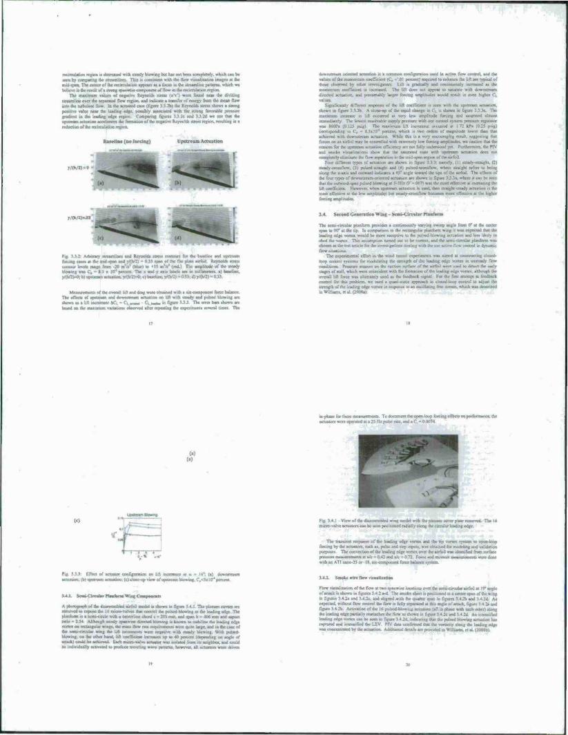
Baseline (no forcing) Upstream Actuation
y/Cb/U-»
,.(b/2,..JJ
•ft.iirary iircumlincv and Reynold« «tree» forcing caae« at the and «pan 4; contour IcvrU range Inuii -30 m'V (blue) to '15 Rl blowing wa» C. - I J » 10 * percent. Tbe » and y a> y/(b/2v-0: b) upstream arrasssmt. ynV2 >-o. «.) baseline.
I the «tcady ssltanetces at h
II y'fh/2) - 0 33
of ttat overall lift and drag «row obtained with a at«-eotapotvow taitx bajancc The effects of upatraatn tad toasts» cam actuation 00 lift with .tcady and puhod blowing are «Sown a. a lift increment AC. - T, .«« r. ^ - ,n r.riw 3 3 3 The cm» ban «howu are
baaed on the maximum variation« observed aftct repealing the expertancntt Kvcnl time». Tht
ihininsjinni uritattd »wualton u a tianwna configuration u«cd in acsne flow ccmtroL and the valuta of the momentum coc1 - mat) required to enhance the lift art typical of thoat Utxtstrvtd by other invctugauirt Lift u rraUually tad tontiratoutly «nfteased aa the momentum coefTicieM it increased The lift doe» not appear 10 uturate with downsucatti directed actuation, and preaumably largo forcing anylirudet would result m even higher Ct
valuta Significant;, different response of the lift coefficient H >cen with tht upiucam actuation
tacrwn 10 figure 3_> 3b A dote-up of lac rapid change in CL it shown in figure 3 J 3c The ncrcasc in lift occurrcc ,i..iude forcing and «aluratcd alnvo«i
The lowest resolvable supply pressure «nth oar control ivtteir. pressure regulator «rat laOPa (0 125 pug) The maximum hit incrcnieoi cccuned at I ~. corresponding to C„ - K 3il0"' percent, «rasch ■» two ordtn of magnitude tower tltta taat aUactrtai with downstream actuation While this it a very encouraging retuti. «uggcstmg that forces on an airfoil may be controlled with catremcly low forcing amplitudes we caution that the reasons lor the upstream affixation efficiency ate not fully understood yet. Furthermore, the PI V and smoke visualization« show that the taturaicd «late with upstream actuation docs not risfnpktcly eliminate the (tow separation m the nud-tpan region uf (fat
Four dilTercnt types of actuation art tbown in figure .(cady-straight, (21 «teady-ctotaflow. (3) pulted straight and (4) pulsed sTotsfto», where tiraight refm to bang aloof the x-as.it and outward ind tratet a 45" angle toward the taps of the airfoil. The effects of the four types of down.Mic-.im oriented actuat.on are thown in figure 3.3.3a. wnere it can be seen 'hat the osjtward-tpen pulted blowinf- * as the most effective at increasing the lift coclTicirni However, whan upstream actuation it used, then ttratght-tlcady actuation it the moat effective at the low amplitudes bot vicactv-cross/low tinnuan more eflfett 11e al tht higher forcing amplitude.
3.4. Second Gewcralion Win«; - Sent. Circular Planform
The vemi-circular putnlorm provida a contmuoutly varying «weep angle fron 0* at the center tpan to nor at the up la conasarrsno to the rrrtangtilar ptatvfoan wing 11 was exptxtod that lac leading edge vortex would be more receptive to the pulsed-blowing actuation and lea •best the vortex That assumption turned out 10 be correct, and tbe «em. circular pUctform was chose« at the test article for tbe imestigatiom dealing with the use active flow control in dynamic flow situation.
The experuisental effort to the wind tunnel rxpenment« was aimed at cutnuucting doted loop cotvuol systems let modulating the strength of the leading edge vortex m unttcady flow laanilälilMaa Pressure tensor, en the tuction «urfacc of the airfoil woe used to detect the carry Mages of «all. which were coincident with tile formation uf the leading edge vortex, although the
locte was uiumately used aa the feedback signal For the fins attempt at feedback control tor tut utubltiii. we used a quasi-static approach 10 closed-loop control to adjust Itu- ttrength of the leading edge vortex in response m an tssullaxtng Ira ctrcarn. which was descrtbed m Wiiliamv et al. (200JUI
mpcutscforiht^sernciisuiTmeni« To document the open-loop forcing ctTectt on iisifoitnartai, tat acruaton were operated at a 25 Mr pulse rate, and a (" - 0 0074
(a)
(c)
V» ••
Fig 3.41 View of the dnattx-mMcd wusg model with the plenum cover plate removed The I« micro-valve actuators can be seen positioned radially along tat circular leading edge
The transient response of the leading edge vortex and the trp tunes tystcm to open loop forcing by the acluatort. tuch at. pulse and step input», «rat obtained for modeling and validation purposes The convection of the leading edge vonex over the airfoil «ras idenuned from turiacc tttuaat iiiiaiMimniHi at x/c - 0.42 and xA - 0.73 Force and moment nstssntrctncntt were done with an ATI nano-25 or IX. MX component force balance tystcm
I fine, of actuator configuration on lift ■ 1.tbjursunxam actuation. (Otiose up view of u.
34 1
ent-u - aba»a»j.C.c$» 10- percent
•ytsjj
. . a of use ditassembled atrf.ul model it shown m figure 3.4 1 The plenum coven arc removed to expose the 16 micro-valves that control the pulsed-blowing 10 the leading edge The ptanaortn 11 a «ctni-ctrc Ic «nth a ccntcr'.atc chord e - 201 nun, and tpan b - 406 mm and aspect ratio - 254 Although oeady tpanwuc directed blowing is known to statxlrzc the leading edge vonex ran nxtangulai wings, the mas» flow rate requirement 1 were quite large, and in the caae of the »enti circular wtag tar lift incrtsnent» woe negauve with «txssdy blowing With pulsed hUavtng. oa the other hand, lift coelTicami increase« up to 40 percent tdepeading on angle of attack» could be achieved Each nucrc-valve actuator was milated from its neighbor, and could be individually activated to produce traveling wave paiiem», however, all actuator« were driven
air foil at ! 4* angle or tpan of the wing
3.4.2 Sntokr win ftow vuaakiation
Flow viaualuauon of the flow at two tpanwiw locatioru ma the «cmi-CMS of attack 1« thown in figures 3.4 2 a-d The smoke «beet it poxttaxaod at a in figure» 3 < 2a and 3.4.2c. and aligned with the quarti-t us and 1 4 Jit A» expected, without flow control the flow it fully teparatcd at this angle of attack, ftgorr rigure 3 4 2b- Act.vat.on of the 16 ptUtcd-btowmg actuawr» (all in phase «nth each other 1 alone the leading edge rsarttally reattacbet the flow at shown in figure 3 4 2c and 3 4 2d. An -niiftl leacUng edge vonex can be teen in figure 3 4.2d. mostatiag that the pulsed blowing actuation ha. captured and intensified the LEV FTV data confirmed that the Voracity along the leading edge
Mtrm+trnVam^nUVKm
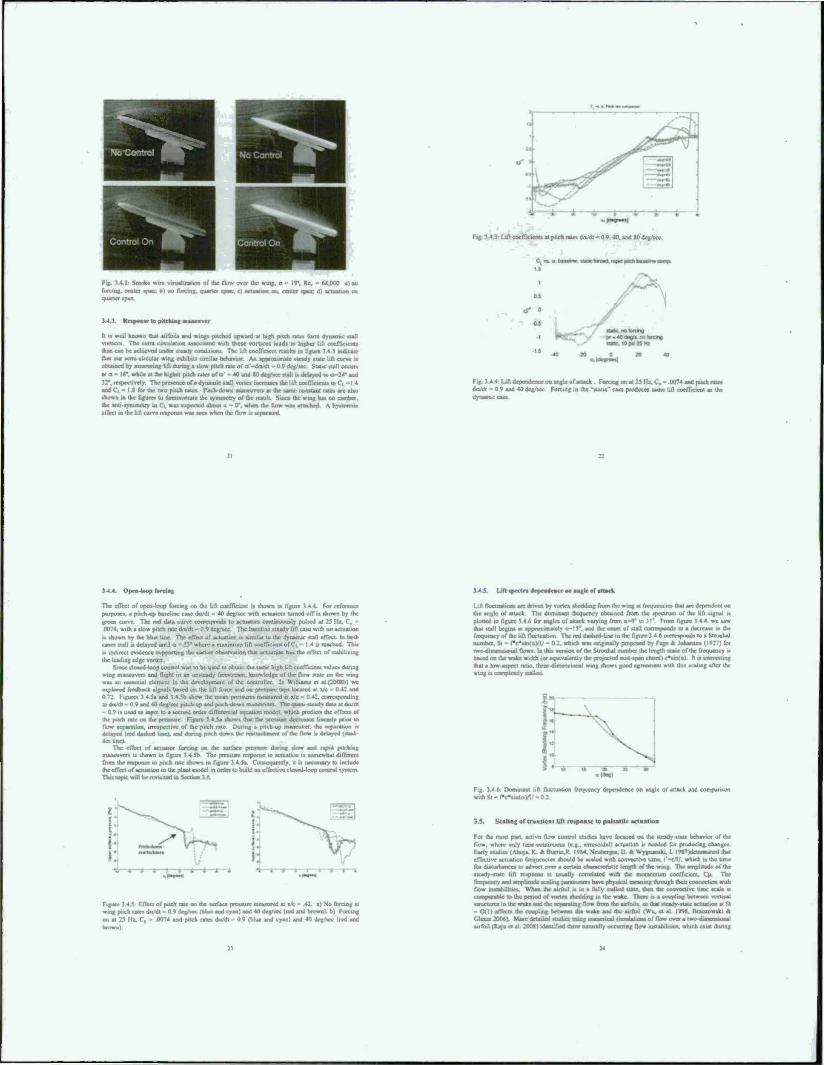
p>. No Control f
1 M_ r
T.f. i 4 2. Staat» t oualiralion of ihr flow over Ihc win«, «i - 19", He. - (.X.OOO a) no
o faüf. quarter «pan. c) actuation on. center torn, d) actuation oa
UJ. RnpNH to piichwg UMW
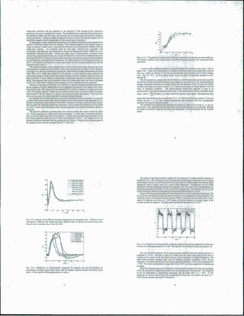
li i» well known that airfoil» and «Hop pitched upward ti high pitch ma form dynamic %ull vortices The cxtn circulation IIWCHIBI with these vortices leads to higher lift coefficient» than can be achieved under steady condmoru The lift cocfTiciem remit* in figure Ml) indicate that uur «enu-circulat wing exhibit» umilar behavior As aprarutimaic «lady «talc lift carve i» obtained by mca.ur.ne lift dunng a slow pitch rate of a -dnt/dt - 0.9 dog/tec Slat«: «tall occur»
at o - 16*. while «4 the higher pitch rate* of u' - 40 and «Ode**« «all it delayed tou-24- and
32*. respectively The presence of a dynamic «tall vonca increase» the lift coefficients and C, - I 8 for the two poch rates. Pitch down maneuver» at the same constant rates arc also shown in the figures to demonstrate the symmetry of the result Since the wog has no camber, ihr soti rymmeir) in C\ «a» expected about « - (T. «hen the (low <m attached. A hysteresis effect in the lift curve respurue sras seen »hen the Ho» is separated
Fig MA Lift coefficient» at pitch rate. da/dt - 0 v. 40. and SO deg/sc*
Fig 5 i 4 Lifl depeodoner on angle ofattack Forcing on at 25 IU C. - 0074 and pitch rates ikx/dt - 0 o and 40 deg/sec Forcing in the "static" case produces same lift coelTicieni as the
MA Open loop
The cfTcil of open loop forcing on the lifl coefficient it shown in figure 3.4.t. For utuaouu purposes, a pitch up baseline case du/dt - 40 deg/sec with actuators turned off it shown by the green curse The red data curve corresponds to actuators continuously pulsed at 23 0074, with a slow pitch rate un/dt - 0 0 deg/.scc. The batch nc steady lift case with no actuation
hi ahosnt by the blue line. The effect or actuation is iirmLar lo the dynamic «tall effect In bosh case« (tall ts delayed until a - B* where a maximum lift coefficient of d - 14» ararhrd. This
is indirect cvsdeocc supporting the earlier obsercation that actuation has the effect of lasshilieirsf. ihc leading edge vortex
Since timed-loop control vraa to be used to obtain the tame high lift cocffiocat values during wing maneuvers and flight in an unsteady fni.ificam. knowledge of the flow state oa dar wutg was an csaeotiat ciemeni in the development of the 000 oral ct al.(200X1» we ssstptored feedback signalt based on the lifl force and on pressure taps located at a/c - 0.42 and 0 72 Figures | 4 Sa and 3 4 5b show the mean pressure* measured at »7c - 0 42. corresponding todrt/dt-0 9arvd40det7»e«pMch-smandpricb^ssnmaivrusrr. The qua^ttcady daUatdoMt - 0.9 it uses! as input to a second order diRcrcu II which predicts the effeots of the puch rate on the pressure Figure M 5a «hows that the pressure decnattot linearly prior lo flow separation, irrespective ol ihc pitch rale During a pitch up maneuver, the separation it delayed (red dashed line), and during pitch down use iniiiiiliaiii» of the flow » delayed (daah- dutlmcl.
The effect of* acUiMor forcing on the surface prrtsure during slow and rapid pitching maneuvers is shown in figure 3 4 5b The pressure response u actuation is somewhat diffisjar» from the response to patch rate shown in figure V4 5a Consequcruly. it it necessary to include the effect of actuation in the plant model in order to build an effective closed-loop corurol tysacas. TTus loose will be revuned in Section *• *>
Figure t 4 1 F.fTcct of rnich rate on the surface pressure measured al v. 42 j) Nu forcing at wing pitch rates du/dt - 0 9 deg/sec (Mae and cyan) and 40 deg/sec (rod and brown) b) Forcing on at 25 II*. C. - 0074 and pitch rates du/dt - 09 iblue and cyan) and 40 deg/sec (red and
Itsfal 1 ifl tpectra dependence oa angle of attack
Lift nuctuatinns are driven by vortex shedding from the wing ai frequence» thai arc dependent on the angle of attack The dominant frequency obtained from the tpeclrum of the lift signal ts plotted in figure V4 6 for angles of amack varysng from o-°" to 31' From figure 14 4 stu» that <ull begins at approsiaiatnty a-15*. and the eatset of stall correspond« so a ikcrcaac in the frequency of the lift flucluatum The red daahcd-ltnc in the figure 3 4.6 currespood» to a Slrouhal number. St - f t'suXaVU • 02. svhtch «a» originally proposast by Fage A Jnrranien (1927) tor •wo-dimrmitiral flow. In tht» vervon of the Stroohal rrumber the lerigth scaleof the frtsuuency is based on the wake width (or eqwvaUndy She aanjccaad asid «pan dtord) c*s«(o) ft ts interesting thai a low aspect ratio, threc-turncmiorial wing «how« good agreement with this scaling after the wing i» co»Ttpletciy stalled
Fig M 6 Dominant lift fluctuauon frequency dependence on angle of a srithSl-f»cNi»>t:ayi'-02
3.5. Scaling of transient lift response tu pulsatile actuation
For the moat part, active flow control studies hate focused on the steady state hnhasiur of the flow, where only time continuous (eg., sinusoidal) actuation i» needed for producing change« My «ludies (Ahuja. K & Burnnjt. 1984. Ncubergcr. D * Wygriaosfa. I. 19T*Me4cr>»uncd that etYccuve actuation frequencies «hould be scaled with tonvecuve time. i--c/U. which a (he trme for disturbances to adveel over a certain ckaractcnstic lerigth of the wsag The amplitude of the steady-state Ufl response is usually correlated with the momcnium coefTicient. Cu The
gpatasrtetmhavephysa^rnearungaVou^t flow mstabiliucs Whan the airfoil i. in a fully stalled stale then the coovecuvc time scale is ■rat»■lit to (he period of varies «hooding in the wake. There it a coupling between vnrucal structures in the wake and the srparattag flow from the atrfoüs. as that steatty-statc actuation at St - (XI) affects the coupling between the wake and the airfoil (Wu. et al I99S. Dtauioweki at Clc«r200M More detailed Bastle» camg nsajeacavl iwaaaitinni of flow over a tsasvitawfiatnjril airfoil (Raju et al 200«) idenlified three naturally occurring flow instabilities, which cstst dunng
steady-statt rtmdiltmt» and are important to the dynamics of the actuator to-flow interaction rneehanitin that anal be modelet! for control The mubiuua art connected «nth ifce «hear layer, ihe separation bubble aad (be wake, and each hat its own len|<h scale and specific frequcnev scaling parameter» Adding uintcady aerodynamic effect» oo tup of this already complei mm of leatahflttata ii-ga.an i Hat aw» ataartsaches a» flow ccattrol may be rsrcciaary
In attempting to better undenund (he problem, wr studied (he response of (he «panted flow n to tadivafcai pulses (Vom (he actuator The transient behavior of the forces acting on
a In reap our to pulse-type or step-input disturbances can be significantly different from (he MOM An extensive »tody of .irpinput' transient How associated with
It and aoparatum wa» conducted by Darabi and Wygnaaaki (2004a. 2004b) on a two- dimcnuocial deflected Rat plate Utrog step input» from a mm aw maai, vmceeoil dnveo actuator they showed that (he (out time it takes for the flow u> reattach on a deflected flat plate wa» long 0(20-50 P) HI cam« of convecTjve Om« unit», and was to a tare..- on the frequency and amplitude of excitation. For fixed valuer i : -nettr* CM
and I- •. the (ranawni lift response to a ucp input »caled with the dynamic prmurc (Cj and die convoctivc omc-acak (T I
The tt» tic separated flow on 2D an:. sctuaboa input was urvcetigaMd by Amitay and Glcccr (2002. 2O0e>| They aocuenenred Jie effect of flow trartstcrits
je the onset and terminatton of actuation. Glcato and co-workers tBrwwowrk. ft Clam 2006. We«, et at 2001) air» studied the lift response to ahort duration put*» produced by combustion actuators. They »howed that energetic pulses from the actuaton with time scales aa •hart at 0(003 t'i were eflcclive in producing a asssntentary .«crease in circulation around (he
ndieturbcd «ate wai long, on (be order ofCXSIOt) The ctln.: of different pulic sequence» on the orculation war also explored
Here and m (be paper by William» ct al (JOOva) we u»c »ruvt duration puUanle disturbance» for the purpoae of ryatan identification oo (he «tranced flow around a low aspect ratio, three istntsjiliuis-t »in« The output from the rcparated flow -tyuern" response to a »irujjc pulse pvet a sort of -impulse response- model that can. within certain limits, be used to predict the large - scale ftatnui of the Ufl raaporsse to various time varying actuator input signal» The model can altob«iH«d*»r>artofacomrolslsvtiihm!o«mu;»ieactuatorrc»pon«e
By I forty lug (he Ufl force transient to pulse-like disturbances from Ihe actuator, it is possible aj I'hujti v.pu' Wtoa* IT-..-.;C. guj ;.f.,s;u» kaj|gJ»l • '"•■ anl HfM BJMJ t» <v >S< .cpamc^ Best addition to obtaining scaling relation, for the ft v.» .npui and ..mplc model.
.• ,.:<;• to eafga. tyr
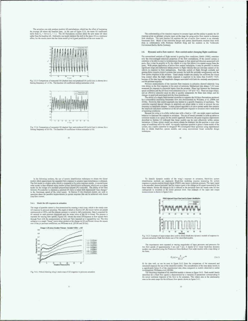
examined The peak lid coefficient
3.5 I for the response lo a s flow speeds wai polar tint « (be actuator pre».' pressure coefficient correlate (hcacruaior jet en
I esgasjasj assaaBsi I freestrearn speed. .
a above the unforced »loady .late value •% shown in figure sc from the actuator A wide range of actuator pressures, ee shown A nearly linear increase with the square root of be seen until saturation occurs The square root of the
it velocity Using hot wire roesrsuranents of
*'.•
Figure J i I The peak in (he transient lilt coelTictcnt deperaknee on actuator [irraaari csufTiciaoi The actuator iitpptied only a «ingle pulse with different amply prelaw» l. flow speeds and valve
A variety of bft coefficient figure 3J.i Each curve corresponds to a diftetent free time. Mm. which are chosen so (hat the oon dimensional pabe duration time is kept
the coovortive bme scale i"-tU/c .n speed and actuator pulse duration
Mm'- Mm U/c -0 S Al (Vow apeedt below 4 m/s (he peak lift inclement saturates aa Cn*' awian 50.
The lift response to a single pulse can be treated as a filtar kernel, and can be used lo predict the lift lime history for arbitrary actuator input signals, at least up to St - 0.2. Even though the detailed tauiacoon» between the actuator input aad the response of the lift force arc alrnoti certainly nun-linear, the results in figure 3 5 1 indicate some degree of linear behavior over the range of operating cundmons The uhaar, at maatl stngte-pulse response is used aa an approximation of an impulse response kernel. K|j>. in the convolution to obtain a predicted output
signal tt<*)-Cj*ri/)»r(*-». where utk) islhe arbitrary inrart signal The asagattudc input
signal ulk'l is arbitrarily given an amplitude of I 0 To find the calibration corn rant, C. the total impulse of the '■ . 3 . 5- and 10-pobc npcruncau trat compared with the corrcspooiliog ptrdictcd total impulse usm, the model
The peedtcted and mraaured lift tracjtseata are shown in figure JJJ for the J-. 5 and 10 puke cane» The agreement between the model and the measurement, are lansiacsory. ahhrsagh (he mode) over-predicts traasicnl overshoot and urtderthoot in the
nUAV
MSII..0»!
"I 1—2—a—s—a—x
Fig ).5J. Cottttjartson of expcrmverually wiinaid lift reapome and she rift predicted by assrvofring a 10-potse square wave signal with (he impulse iiapnni kernel Fieeatrcaaa speed was U - $ m/s. and M S kPa supply pressure to verve».
The ability of the kernel model to predict (he lift lopoose to a steady, periodic actual«» i. torsssttrrtil next The actuation comists of amplitude modulating a continuoui tram of «quart pulses (again with oo- and off time. ofO.OlTt). equivalent w a 2*11* square wave earner signal superposed with a square wave at a much lenaer fnsasency. Cornparaons of the model predictions with tbc experiments arc show» in figures J 5 4. 3 5 5. and 3 5 6. conesponding so an amplitude modulation at 04H*. 14 11/. and 5 0 I!.- re.p.x:i .civ The baseline lift that occur» without forcing it shown in each figure as (he fl I mill' da.h dot EM ■
Figure 33 4 costtpares the predicted lift ro measured lift at 0 4 lit modulation frequency The phase berwaea ihe actuation signal and the lift response JI tire (unctsmcnusl forcing frrquency was measured using a qua) ipn.lnl dcnsiry fonctton. Wuh a 25» period the How baa nearly a qaao stcady hft behavior, and only it' 2« »" phase shift otttts hetween the control signal to the actuate» and the lift response The phase shift predicted by the model is o - 2» 2*
Fig i 5 4 Comparison of meavured l.ft soefTxieni (dashed line) and (he predscted lift («olid Ime) t. .euiwn fee a forcing frequency of 0 4 11/ The baseline lift coefficient without actuat.i
The low -pass filler crsaraeser of the system becomes apparent when the forcing frequency at increased so I 4 He. The data m figure 3 5 5 show thai the sqtu- h valve is rounded at the comers of the lift signal, because of the attetsuatson of higher frequencies The phase delay tec sen irsttatsji input aad lift isstpuun become, significant at (hi frequency. The phase shift between the actuator input and (he lift at 14 Itz is now increased so * -7«g* The linear model predicts a phase shift of» - CT. to it doe» a good job of rrpTlsVuing
When tbc forcing frequency is increased to 5 11/ a» shown so figure 3 5.6. then the amplitude or the lift fluctuation is significantly reduced by the filtering effect of the kernel The amplitude of the lift flisctuatioro is sigraficanily artenuated. and the phase shift at • - Iff Al this frequency the model imder-predicts the fluctuating lift force, and over predicts the phase (• - 243*7 between acroetor input and lift ftucttattsaa
I of >"*J » "»voip »paad« «ou aaajayip am JOJ »daui at*» aip max» <MCT|W« Jf «Ml» UW.au w^x UMPJUJ» am m »op aoi JO smodoi jaacnjiioe prnja» atp oi *iipuod»»uoa awwd fo wnir» « Aq pjovataaarip « paotk *oy P**ö ■ «3 P*JH"»P»
<^a»jo»ajra vrt««^««»~^"«»»P«»P»OW«»P«n«^«»«»*»«öaBi*»«»qx tqottt) V »-«»1WÄ ^*w»»«!
«Ma» a» W»»ri **** * M«"*""» <m* m* P*ammm4** *m JO tg jsuwq ^pjaaflii*» .
pa» pamaaa, aai f> ooiunsiaoa aqt tonjj ;o t ami« m uaa» aq ta»a « ||a» »i»» am iij
•a»*«« jo A»]ap aunt .<|..« .tapota japan tut j Tampa*»-JOArj-oonamai. np «mo poynoopi «w «japoui jnan^fi u»t-ipq<t »on irj»<m»5 v */■ t v<* v» f <n»a>»>i»<*i jo jaood» »op o*u JOJ ■»—»it pa» Htanojd HVPJJ je aaytiiailrui XuUt»* w papate aw« wiiiinl» i aaj.
ippouipwjwu»pi»|ij«9oo.»om«<n v»a umnmja» ajmvud jo tppom jraamXp «oq T*lo. aoiqo <n paw «irp maWinrfoi jo apjojara, :r? { *J
unnmia» JUIHUKI m atuoduj yt| jo dvm * •.tautft»««*)paw in «tj
• a» a» at x «
fuimuiiiTp » « * a
f\AAAAJWlAA/ü WO» O
I«! JBAMM. 9ip I« II indiiw pur indui aqi jo «ton*** »no ')M»t 1 )^1i;n».^p«Jo^BWJ»i«Ajpsip«p«it>»PoUii>>'»»»»M^»Vm*o,1 ijurt«,«») »ip .<q pom«»« pro*» u»t ut sfoanp atp « tan«« iiuhmi .up pin .Ai~ujd panup. patuoaoj aqi «i ptptaifa*» wu,-!■ I IIIIIHII w w*» «an <SglM) pat»« ^««»«t «uop—t-apwri« 3w*oi untub am «Dunama unnboj »ut|apooi ioqo(a»ia paAouauja aj» «poipaui i»m»jijim»pi oaariX» «oq-ap»iq IIIIIWIJI a anmtaf i.aui» «p j* «njpna atojao/p Ajoaopt ox
(JOtOZ po»qoioc) T» p«BriiitÄ »1 -waoujaoaamrujd ^aqt»10« uwntx alp MRUi tuaiaijjaoa yi| ui a9unp aqi «r DatiOfd oaq» *Ajn3 „J»mn|_ apian t ot «a»d*||oa ■"»«U« X»t«oji»oifaj « •> paiidai y<mL pot v»i * IWWWUl «p «w. ..«<, utnnnp »nu» ipswd» »oy r» aiuoilwj i;i|uraia ap Mouf | 9 £ a»* j quad« «K>u «UIXJTA >OJ pipuii« w wjooid OM^ ~ponoj t* yf| **j jo anprA osaoi aip poo apnjtuvoot MMMd oa»a IC <puoooi (j^j jq paonb» M ncQ wwacm »,pn 01 pou»A n ajmatd amooid *QpmtitK1* tpMiimmoo pHptdaa o»|te-<w«i aqi VK * »»»3 «Jp«fl» jo »I»»» »aj. -oop»»»»» amnajd 01 »»OMhaj yt| »on» Xptat« aui« ipnj* dru» >»» r «atmmta <n paoinuaiap »J«j 11 (onon» a(o^»»ad jo aft» *«j.
«mi.n.~ oi nomhaj ijn aip |ap«K 1 o »
|Otiuna «OQ doo| patop iptM p»ADapc ao ao mp aiaodui taatmU 01 »ioamaA.ucuii *|C|mod agi rang« appoadn 01 pon *j> «poo» pan)«ani atji A ••»"ia»S
ul |aooni pot* aip jo oaadt uiranvxui aip ui
_oJhm{a dai«. pasnuiopaci t^tm jotiyi t' aa»j i;t; amtam t arrtutrax 01 oiuioorx?-1j ■pauuoj paai aip jo Ä\i|»9« a»li «H^ouo? (w |ti»aiui |»umiK>da*d pirpuin» r jo u«i«ap atp K>; |Opoui BMtd v to %XM tptnA\ 't-jiiliiuipai ootucMjrniapi tuan'* «^im» «xByn poonioo UM|i Of |aood npJO «Moi pooaa« V vtpwaj svwxKu atjnd a«(i 01 (vxmhixo n uniq« opm oidln) > n ppoui tuy aqj. toonioa « taoaoamtnp »to awwna« 01 anMdm »o«j pjntiroa« ay awmiwudd» qant» ipua
noon o«i inmio 01 lanbtooMi uotirninoapi ma»«! ja ><n «n tuoioat »moojinj aip i\
uflitap aqojnwo «WH pmowmooo tuna pu> .«wo OOOAJ no/^Miq tnoap 01 rap ■* Jjwp, tinrtpmiuj »M iooa«np ao, »goa»» pyw 1
«p jo (OpoKi Jona) ■ UMIS n uottwnb ntrtioduii X|wnbo ny ^J«A aq 11 [JIM «OWMOOOO jo atau pap» AM n uonionb OBI pa) -paimaqo as iXun DOOI|« o»a ppo« uooXi MSUI) y wo«>ilHiii| uictt» utqit* SfMWfp pan» aq or> oapow irau<| nop ponanan fC «««»S »f >»■""> nwop«»!*»» aroodoj Mind ari i»Aa«on npaoado* pupm aqi JOJ ootido 0« n «ppont »awtumi « «Ha«i dMpx>I in mw«»o pu»»n jo a» aoj. -ootwina» o» aoaodtto atjj miiinwji 1 «PMOOP«
joootpjoQ laaoo iianui aoo '^o^ « D paxij a ipiA ai»i» panni Xj]nj a in «t «UIM o*fi aiuojooj UK«!!?'.'"
1 lafjaolikl PJ
porq apt» » a^a uotwnia« in a»uodv»j matatjjaoa VJI) atpjo ornnRiuojui arrutl pin apni<|dun jqi «naiooa 1*9 ppnu atotU« « aoi 01 tt «aatudda puaoai aaouj v «So»q5 apnuidunr to öoanoajj Xiar joj tanoaaa 01 npa> 01 <app awitd pn* apnjiidm» ut tatoaop ininmi paiinbai MQUHM
apj. ^ooanrawjOAMaoiaaajaijiaoAaoipttparn («OIK V »«On I» » •ivMWft <<J pa*u>toouiap «a» «oU uiaaapaoj) fun«|n>u> Xippimmm a <« pamootd aaoqaiaawu aawj \p] »aj aianddn» 01 UIJOJIBIIO pjamjoj-aaoj apiam«joj(s|tqaaoj.
taacoaiiwtp W[) aip mw pjwijowa apcntjduia m laturp MJ pu» U»iap aoni aapaj »j anniadmi» Xppinb 01 »iq» aq amoa aanom«» SAoaajp or pa» iX»iap aJj»| an ataqj. 10 - » * JK - * »S «1 paoisatn» aaa» asaoj «n aip pa» i»i»»ao»o poodi
BBBkiaaaafj oaj oaaMiaQ ft*] aanjj -joaantaa-ooj UKUJ atodo« |»pio«niii» 01 anodaoi JOJ pajnmau MM f £» 1 «A|ip aura paa^pjolJOH uonanoa jo torao aip 01 airaoduu «*og am m t^aaap amn •uot Hinnnw paoom oonrapaoi aaaadka
lO.uowiCTMHlu,,»*»!,«»^™»«!^ 0i0tJO<J»o»»'; »"'«') pi « (aon P!|0») UT P*e<P»ad po» (aai) paq»»p) UT pajrowooi jo ooauijduaoj |
I •«« « ■a >.„ ,.< tmiisaij
aj|iuaaX|iuaui <paa»pan ooi otoq ip<* paiaiao«»» «aSooqa ajmjridiii» po» «»»1 aura ooj jo auwaaq
(OtK lV>»«-a| «ats Jajurj aq «1 paoadsa n snadnt ajama» pjtnj apt aap/a lonaoa doo) patota JOJ «uataijji» wu Xnarwp aj» <|»poui <p»w"»iiö »Ojenp» aip 01 anjudui uimi* mo\i aqi po» «attaanXpoo» /Cpmanon aoj ipoq JOJ aaaoaa» pap tuaftXs pupjoa «aamhaj UM><J aDusnl po» Apaottvn uXnonp njfiu jo puona aoin |»»u •«ooipoataun «ou oi avoodioj 01 a|aiaaA aq» jo aupaoo auuvpm aan unp aapopu iq*0 ». w»MMa.a»io aaoajapoa po» ai^a« w»av™«n aanraai ot a|qjnad oq Äma n «anhiuq». fiuiuoa «o[j BAIV» JO uonrx-dd» laoojd q»i*A ""W"
1
aap oaaq xXaaoa axarea 01 n UMaji aaip At* » si apopM aqi <\j 01 ajqanod aq X»ai p oaap Taai» ipi* parntaM*» uonaanp pu» paoih «oy 01 saaVrnta tnuauctunnii at lamj 01 apa» aq ot )«<aipaooi •> asBjUt pMpjB» •»> Jt HJMiyaupuii «way auj jo •atuodoad icaanm pafaiaA» aoro aq> Xpjo «•»!»»»» XltöO KMOH "»uompooa »ot; toiwnS in tooooo tstiu jo «nXnnj» mootioaAOoa aqj.
vuoijipuna jq3nj SuiSuaqa japan |oj«aol »ou - |Oj|aoa »oy avOJa aiaaaavfl Tf
Xmtauao o>t»g -utiaaa laatnaaAtan
.M #""■ ^**IJ1 "•"'B^*^ ö'<iT'aTjTj|^iäp»jJ VT** *^J«**^^^^~ ™ aa**aif»a|f
qoap. oaarU. paa uSwp janonuoa aqt .0 ipnM «oy ojnjioajj Apaanon a» at prjaoa mag **oaa jo an jap «jopiaa »( aoqa«5 oaa aaj, wwnaatJ j«tg aitaaoXp a* puiuoa »otj »Ana» tutcn JOJ affaaj aap IM natal aoi»nta» Aaupqia oa OM4 aaooaraj \p\ aip otpaad ot Xtn»a» aqj pur indat jopana» tn »oaodVu aaa«»a»j« a« jo Swpeapktapim IPJ.
f0 « uwianoa anoqa» waoijpoa U.; aona«»iq aqj. n, r | jo Xaoanaoij Jutaaaj • JOJ oaooi ti (autt ptpx) un pauapaJd po» (aim poipaap) U'l paanaaa«jo umuadiao^ $ { t S.j
UH aaaw »a« a« jo anapaaaal poa.*»M<« lapw
nOTi|o.>u.»»vnij»aujamwuim*«i>»*a^BTO^»tiaaoo<|U»OT>io V".*"l—'q*»«-P<■■■" anjiA ui oaa« JMO am »fioo» *»np«» «Jaooamanij ui| «U I 1 ""«J «V!M» joaoupoa «II aaaca aaa VrC •«*» J» a»»» aaj o| nm aui|a«»q am *uaq» U)I aaWaaa aqj towoaoai jo joajja atp «aq qatu» -woiriqinuad tji| SAniaod aanpoad <|oo uaa omt»nja» aqj.
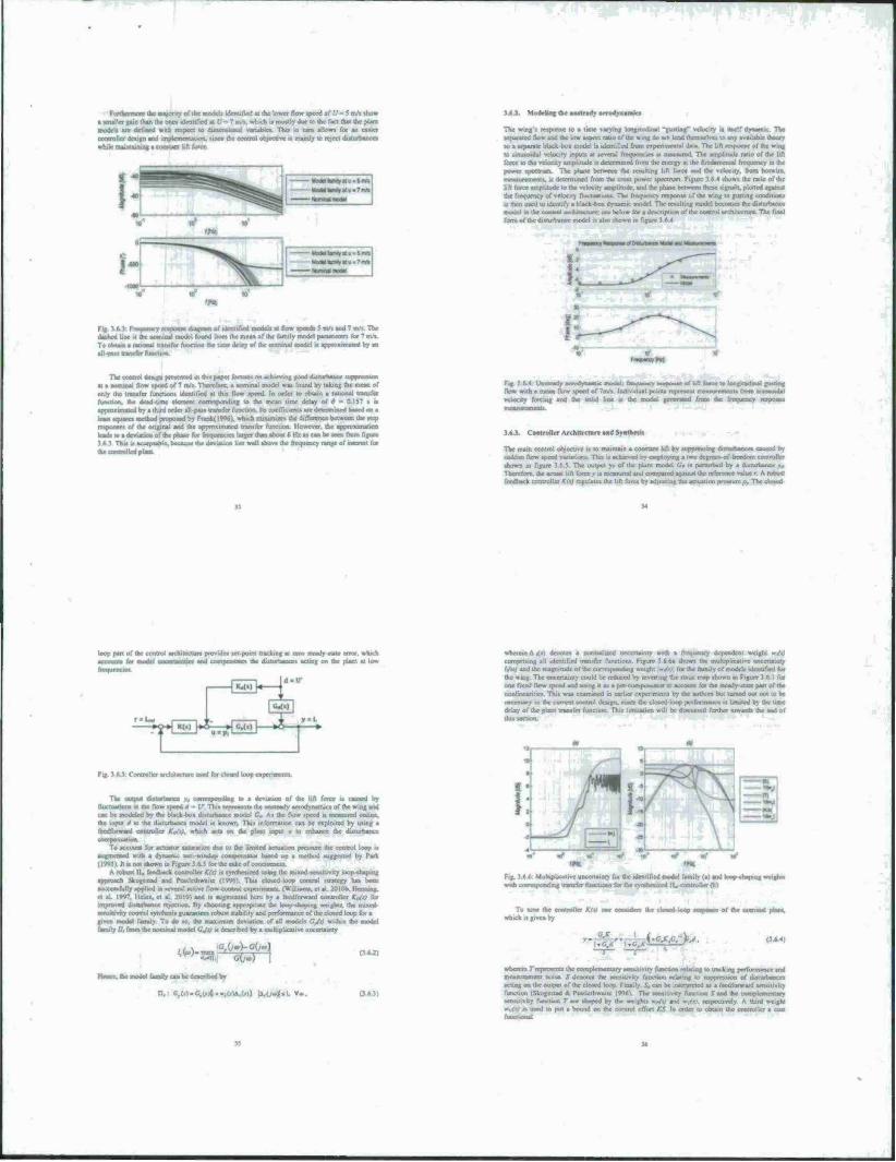
Fu/ihrrmotc the majority of the modelt identified at (he lower flow «peed of (/ - $ nv« »ho» • »mailer nuii than the one« identified «6-7 nvx, which a mostly due to the fact that the plant models are defined with mpect to da»w>j|nn»l variable» Tin n turn allow« for an caxict cootrallar design and implctncmation. •incc die control objective u mamty to reject diststrtajoce»
Klin force
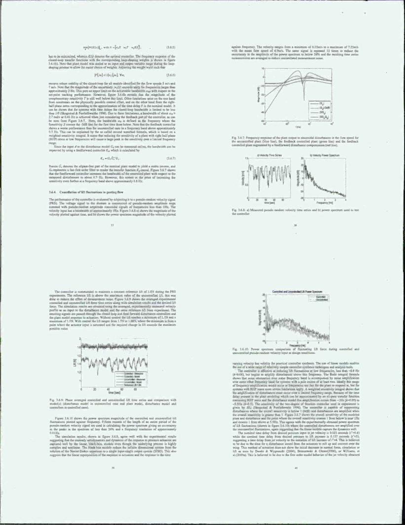
Ike unttrad» aerodynamics
The wing » response 10 a tune varying longitudinal "gmnng' txlpciiy •> iixlf dynamic The If awl flow and die low aspect ratio of the wing do tut lend ihcn.w.-'..r • to any available thron «o a separate black-boi model t> identified from experimental data The lift n^ponsr of ihe « mr to fwäoidil velocity input» at several frrcfucnc.e» u mcasured The amplitude rah. force lo the velocity amplitude i> determined from the energy ai the fundamental frequency in the power «ptxtruni The phase between the resulting lift force and the velocity, from hornrnt ■Deasurcmmu. M detcrmincil from the cross power »pectrum Figure ' M «him» the mm of the lift force amplitude to the velocity amplirode. and the phase berween theac signals, plotted again*: the flwpauny of velocity fluctuations TW frequency response of the wmg lo gutting cotuhtwa i* then used to identify a Black-be* dynamic model The resulting model become» the dtlMToawa model m thr control anchilev n of the lotrtmi architecture The final form of the disturbance model i» al«o shown in figure 1 ft 4
daahed line it the TO(
diagram ur «krtiiftcd models at flow speech I m/s aod 7 m/s The round from the mean of the family model parameter! for 7 m/t
thr time delay of the nominal model i. aprm>xnrtsied by an
The cannot «eaiga »iniiarei in asra asspor aacu.es on achieving good disturbance tupumaton at a nominal flow speed of 7 nv» Therefore, a imminil model waa found by taking the meat of only the iranafcr It» this flow «peed In order to obtain a rational transfer function, thr dead time clement corresponding lo the mean time delay of f> - ' approximate»! by a third order all-pa»» tranafcr function It» coefficients arc determined baaed on a leant squares method proposed by Frank!! W61, which mirumi/c the difTercnce between the Hep response* of the ongitial and the approximated tramfer function However, the approximation lead« to • deviation of the phase for ftaaistnrari larger than about 6 Hz aa can be accn from figure
. i acceptable, becau« the deviation lies well abu»* the ficcpiency tange of mlcrest for ihe controlled phot
Fig •• ft 4 Untteady acrodyre flow with a mean flow »peed of 7nv» Individual poiou vdooty forcing and the »olid line u the model
af tin foroe to haagtadaaal gajatmg
i*X Controller Arehitrrtnre and Syathe»*»
Tbc main control objective » lo maintain a constant Ufl by <upptcsting ditturbancea cauaed by Midden flow »peed »itiMinna Th» u achieved by employing a two degree»-of-freedom controller tbown in figure WJ The »mtput >, of the plant model Or •< perturbed by a disturbance » Therefore, the actual lifl force r n measured and compared again« the lafaonce value r K robust feedback controllci K<\) regulate» the lift force by adjusting the actuauon pressure». The cloaed
loop part of the conuol architecture provide« »rt point tracking at MM ateady-ataar error, which ■ aod rnmpmmlii the ditturbance« acting on the plant at low
wherein A <•) denote« a normalurd uncenaint» wilh a frcciucncy dependent w. all identified transfer function« Figure J ft ha shows the mulupücaiivc uncertainty
M*>) and the magnitude of the currcvptindrag »< . the wmg The uncertainty could be reduced hy inverting the runic map «how-, one fixed flow «peed and rang rt aa a per compemawr lo aceovai for 'he steady-state part of the nonlineanuc«. This «vaa examined in earlier expenmentx by the author« but turned out not to be necoaary in the current contro! deugn. «tnce the clotcd-loop performance it limned by the time delay of the plant tramfer function TJi di«vu««cd further toward» the end of mis section.
Fig J 6 J Controller archnaourc oaad for closed loop expenmena
of the lift force n caused by . t» aerodynamic» of (he wing and
t A« the flow «peed at mtwoircd online. Ike input J U) the diuurbance model i» known Thi» informauvn can be exploited by uaing a feedforward conaoiicr Kofi), whicb act» on the plant input u to enhance the i
The output duiurtxence aa correapooding t> a riix-tuauotu in the flow «peed 4 - V- Thi« reprawrou
n be modcW by *c black boa dnlurhance model
to account for actualor «aturauon due to the limited actuation procure the control loop n aufnvcnted with a dynamic aati-windup comppnsaio» baaed on a method tuggeilcrl by Park (IW5) It it not »hown in Figure 3ft y for ihe »akc of conciaenaaa.
A robuM H. feedback controller KfU i« »ynihcvued uaing the mixed «cnxinvtty loop-vhaping approach Aogcatad and Poatlcthwaitc 11996) Thu cloved loop control «traaegy baa been «uccnafttlty applied in «cveral active flow control exprnmenii. (WdluHru, et al. 2010h. Henning, et al |v<J 101 and i« augmented here hy a feedforward controller Kof» for MltUHWCd disturbance rejection By chooamg appropnsic (be Inilp ihawng weight«, the mixed- •ensuivtty conuol tynthciii guarantee» robust ttabilny and performance of the closed loop for a given model family To do »o. the maximum deviation of all n- - tat model family tl, from the nominal model GJt) i« described by a multiplicative uncertainty
faaaalycanbedescnbrdby
n, C,trl-C.t.«J..,(iV&1Ul) H,ük4«uv*.
MulupUcativc uncertainty lor the identified model family (a) and loop «haptng weight» with corresponding transfer function» for the eynlhcauxd IL coottvlier (bl
To one Oat controller Kfti oae consider, «he chiied luap napaiai of the nominal plant, which i» given by
.cjl^'- (364,
wherera T represent» the complemcn'.-i - o relating to tracking performance and measurement noise S denotes the «rtsiuvity function relating to roppremon of disturbance» acting on the output of the closed loop Fatally. & can be interpreted as a feedforward function (Skngertad * PoMlethwaitc "»ft» The semmvity function S and the c»»mplcmentar> •eisaitrvliy fonction T arc shaped by the weig'. .-.»pcct.vely A third weight
-^ed to put a bound un the control effort KS In «»der ii> obtain the controller a coat
mintKUi^.muhX.lwJ - (3.6J)
has in be minimized, wherein Kit) denotes the optimal «Mlroller The frt>qiicncy ic.ponse of the iU>sed loop transfer tiinction» with <hc corrr*p»*t*dmg tooiwlaping sssaght» is shown i* figure
M«M thai plan model was scaled to an input and output variable range dunog the loop »haping process to allow for easier cho.ee of weight» Adjusting the wctgbl »jff} such thai
|T</.)..l/Kv~lV-. (16 6)
half.plane aero* corrcaporidsng k
a »lability of the elated-loop rot all modcll identified (or the fin» «needs 5 rtv» and 7 mh. No» that the magnitude of the uncertainty m/xi exceed* unity for frequencies larger than
y 2 Hz. Thi» putt an upper limii on the achievabk bandwidth t„ wish respect to the I pcrtbrmancc However, figure 3 6 6b revests that the magnitude of the
vit> T t» «till »!•': oihct iirmtations anse on the one hand t on the physically ponibte conttol effort, and on the other hand from the nght
g to the approximation of the umc delay » in the nominal model. It can be «bown that (or «yuan» with tune delay« the closed loop bandwidth « limned to be leu than IS (Skogestad <% »ostlethwa.ibc |v«AJ Due to rhetc limitations, a bandwidth of about «(* M ran/« or 0 « IU ■« achieved when just considering the feedback part of the control!«, a» can be «ecu from Figure 11 ~ lieu- the bandwidth u, i« defined a» lbs frequency where the Scnuuvit) 5 cross«-» the IdB uoc lor the fin« time from below Note that the feedback cssntrtsucr «how« a wortc performance than the uncontrolled case in a frequency band above approximately 0 7 IU. This can be explained by the to called ssscood watcrbed formula, wbtch •« baaed on a weighted «ensitivity integral It Mate* that reducing the xcmiuvuy of a plant with right half plane < RJIP) im» at low frequencies will cause a large peek m the »ensiuviry over a limited frequency range.
Since the uiput J to the dttturbancc model Cj can be Bitaaarid online, the bandwidth can be •roproved by uung a feedforward controller Kj. which ti cilciiUrcd by
- Herein 0\ denote, the allpa« free part of the norm nal pla« model to yield » «taWe imci»*. and Cfiapamat. a fax firs order filter to render the transfer function K,, causal Figure 1.6 7 «how« that the feedforward controller increate* the baadwHkh or the controlled ptao with retpect «o the racaaurcd d««turbaoce» IO about 0 7 IU However, du* come« at the pnee of incrcaxmg the «eruitivity even further at a frequency band above approximately OX IU.
The performance of the controller u evaluated by artharclaeg it to a ptcudo-random velocity «tgnal (PRS) The votuge «ignal tu the ah«««» r* i-oest true ted of pseudo-random araplitude net» »urtianad with pacado-random amplitude sinusoidal «ignal» of frequencies lest than 1IU The velocity input ha. * bandwidth of anprnximairly IIU Figure 3 6 H a) .how« the magnitude of the
lad against time, and b) shows the power «pectrum magnitude of the velocity plotted
again« frequency The velocity range* from a minimum of 6.25m/s to a maximum of 7_25rtvs with the mean flow speed of 6 Oov. The same «ignal a try ward IS tunes to reduce the uncertainry in the anvplitut* of the power «pectrum to below 2*H and the resulting tune seric* i nani ii awavrraaed w wauiir «aajuaiiilaiad it mat none.
0 j^^tijE;^^ I
■an —9tv | — »AH
•tr- ite.
«xfxncy mpamt at 4m flim 0*9+mmmmxdai the imconuolled plant (blue line), the feedback controlled «onaaaUed ptaia- lag—jaltal by a foedibrward disssehance
9«gaa%1lsavtMi
dntuittancet ia the flow speed (or (green line) and the feedback
(red line)
i> maintain a conatant reference Uli of UN during the PRS i The reference lift is above the maximum value of the uncontrolled lilt, thi« MM
done to reduce the effect of measurement oouc Figure 3.6 9 «how» the averaged expenmenial controlled and uncontrolled lift force time ten« along wuh «imulauun result* and the desired lift force. The «until at «on result» arc obtained using the averaged, cxpcnrocnially measured velocity profile a» an input U> the dtansrbance model and the tame reference lift from experiment. The resulting signals arc pasted through the closed loop and feed forward disturbance corttrollen and the plant model response to actuation. Without control the lifl reach« a minimum of I .IN and a mtsimum of I 5N With control the lift ranee from 1 7N to I «IN. where the m Jumum is from a point where the actuator input is saturated and the required chaugc in lift rxceeda the a
Wrtf\fjW^
Phase averaged controlled and unconuiilied lift time *cr*i mod«*«) (dssaartMBcc model ta sneontrolled case and plant mode).
Figure 3 6 10 shows the power spectrum inagninide of the controlled and uncontrolled lift fluctuations plotted against frequency Fifteen record* of the length of an enure period of the ptead« raadustl vetoed? «ignal arc used in calculating the power spectrum giving an uncertainty in the peaks «n the «pectrum or less than 26% and a frequency resolution of OOIIU
The ««nutation result*, shown in figure 1.6.9. agree well with the < «Igjerling that the unsteady aerodynamics and dynamic« of the response io prc»ure actuation are captured well by the linear, black-box. modelt even though the underlying process is highly complex and nonlinear The Mack-box models reduce the infinite dimensional system from the solution of the Navrcr-Skwx. estimations to a single snout single output system (SISOi This also suggest» that the Uncar rapcrpositinn of the response to actuation and the response to the time
■ssMMMMM*
Fig 16.10 Power spectrum i.unqaniiun of fluctuating lift force during controlled and uncorttrolled ptcudo raadbm velocity input at design conditions
varying velocity ha* validity for practical controller ivnthru« The use of linear model» enable* the use of a wide ranee of relatively simple controller tynthesi« technique« and analyti« tool»
The controller r* effective at reducing lift fluctuation» at low frequencies, lot» than -0* IU •nit begins to amplify disturbance, above this frequency The Bode mtegral formula
«how. thai oouc attenuation over some frequency band is accompanied by none amplification over some other frequency band for systems with a pole excess of at lcsvst two Ideally due range of frequency amplification would occur at frequencies too fast for the plant to respond at. but for »> stems with HI IP /en» more severe limitation* apply. A weighted sensitivity integral shows that the amplification or disturbance» mast occur over a limited rrequency range. Became of the tone deUy present in the plant modeling which can be appro.imaie.l by an all pas« tranter function rnataming WIT aero* and the dt»turtssnce mode! this amplification occurs from - IIU l«-n l»! tt> -5.SIU (Jr-0 5). The sensitrvity of the two-degree of freedom controller used ia uixiaiuii «s given by SSB fSkogestad * rVstlethwait« It96) The controller is capable of supprcssung disttirbanccs «heie the overall sensitivity is below I (OdB) and disturbances are amplified when the ovarall ssasssnvity is greater than I Figure 1.6.7 shows the overall sensitivity of the modeled plant and disturbance and the point where the overall «cn.iuvity crosses I from below is near IIU and Cflssaet I from abu»n at S.SIU Tbsa agree» with the «penmentally obtained power spectrum or lift fluctuation« (shown in figure 1.6 10) where the controlled disturbance» are amplified over use tinrssiMiifrr«! flucruauon«. again «nggraTing that the linear model« capture the dynarr...
The rtonunal umc delay rrom deured pressure input so jet veloctiy is 0.023 seconds (/'aO.SI while the nominal usne delay from desired pressure to lift increase .. 0.1)7 seconds <7'=5). suggesting a time delay from jet velocity to the initiation or lift increase of r'^4 Thu is believed to be due to the umc tor a disturbance rssocd from the actuators to roll up and coovca over the wing. This method of actuation doc* not »how the initial decrease in normal force, circulation or lift as «ten n, Darab. ft Wsgnaniki (2004), Brarxat»an*i tt Gte»er(200ftl. or W.Iuams, et al(2O09a) Thi.ubdse»^ to l»r duet«, the first ord*»m
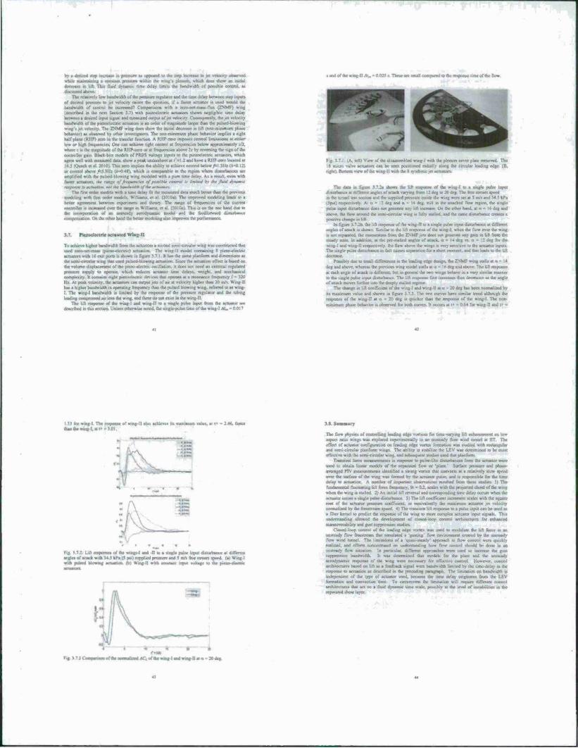
by a desired step IIICJ—«i is prcsworc at oeprsscd to the »icp tanaw in jet velocity observed wfclk rntuniaiaing a constant pressure within Ac wing's plenum, which doc* »how an uxiual decrease m lift. This fluid dynamic nmc delay limit» the beiYdwidir. of possible control, a» discussed above.
The relaiisrly Um bandwidth of lac pressure regulator and the tune delay between step input» of deitrcd pwaaywi lo ret velocity eanc* die question, if a fatter actuator is used would the bandwidth of control be increased' i om pari sons with a «er» net ma» • flux (ZNMF) wutg (described in the not Section 1 7) with piezoelectric actuator* shows nejrlijublc time delay Its» In» a drured input ugnal and rtjeasurrd output of jot velocity (oraeouently. the jet velocity rnsndwrfm of the pitroclcetnc actuator» a) an order of magnitude larger dian die puHed-bbmin«
velocity The ZNMF wing doaa »how the initial decrease m lift (non-manmum phase behavior) aa ubaarved by other investigators The mm minimum phase behavior implies a right half plane (RHP) ten, in the transfer function A RHP-arru imrxHC umtrol limitation» at mher lew or high frrouarscic«. On* can achieve tight controi it frequencies below approximately irX where .- .»the magnitude of the RHP-jcrn or at ffrjquencica above 2i by reverting the »ign of the controller gain Black-box modelt of PUBS voltage inputs lo the piezoelectric actuators, which agree well with oieaaured data, «how a peak undenhotx at <-\l and have a RHP «ru located at InSlOuachetal 2010) Thi» »ero implre» the ahilit) to achieve control beu or conirnl above hi Hü i.-0 4«, which i» comparable to the region where diuurbance» arc amplified with the pulsed blowing wing modeled with a pure time delay. A» a result, even with tatter actuator», thf nmf of frtmtencha of poalhte control u /mirt hy at« fluid dynamic rttpomm k> »ammo», mm the kmm mm of Ihr metuaten
That first order aillltrll with a um* delay fit the measured dau much better than the previous modeling with firsi order m.-. il (2010a) The improved modeling lead» to a belter agreement between experiment and theory Tlie range of frecjucncic» of the current cxmlroIU» u «created over the range in William*, el at (2010a) Thi. i« on the one hand due to the iwrMporatioa of an umicwly acrodynamK model and the fcodlurward duturbancc etianpaeiaation On ihc other hand the betier modeling also improve« the performance
■ and of the wing II .*_ - 0 025 » These arc tnull compucd to the response time of the flow
3.7. \\,n- II
To achieve higher bandwidth from the actuator» a second * used rero-nct-eaau (pteav-etectnc) actuation acSMturt with 16 exit ports is shown in figure the »rmi circular wing that used pubcd-blowi the volume displacement of the pievu «lectne
n: ..in.u. ii wing was constructed that II model containing I picxo electric
e tame iilanfiwi and dimenttoo» as bsH the actuation effect is based on does not need sn external regulated
pressure supply to operate, which reduce» actuator time delays, weight, and mechanical ccariptnity h contaust eight waotseaccsne devices thai operate at a iirratasotx frequency f - 320 IU Al peak velocity. u* actiaitor» can outrsui ,ct» ol au at velocity higher than 20 m.» W.ng II has a higher band» idth in operating fmrueney than the pulsed blowing wing, referred lo as wing- I The wtng-l bandwidth is Untiled by the response of the pressure regulator and the tubing India» c.»sauresisd air into the wmg, and three do not exist ia the wmg-ll
The lift response of the wuxg-l and wing-II to a single puksr uspU from the actuator are described tn thi» wxtioo- Unlessotherwise noted, the single-pulse Urne of the wmg-I At» - OOP
Fig 3 7.1 (A. left! View of the disassembled wing-l with the plenum cover | 1& micro valve actuator» can be seen petitioned radially aloof the circula right) Bostirm sirw of the wmg-ll with the I synthetic ,ei actuatort-
The data m figure 3.72a shows the lift response of the wrog-1 to a nagle pulse inptn mstiafeancc at different angle» of at lack varying from 12 deg to 20 dcg The free stream speed in the tunnel *e»! section and the supplied pressure inside the wing were set at i my» and U «. kPa ! Jpsil respectively At a - 12 deg and ci - I« dcg. Hill in the attached flow region, the »ingle pulse input duturbats« doe» not generate any tin increase On the other hand, at •■ - 16 dog and
above, the flow around the semi -circular wing is fully nailed, and the tame dMCurbaccc creates a .. se in lift
In figure 3.7 2b. the lift response of the win»-II to a »ingle pulte input dttnrrbanv* at different angle» of attack is shown. Similar to the lift response of the wing-l. when the flow over the wing ia not separated, the ntoaterjtom from the ZNMF jets decs not gcoersse any gam ro lift from the ttcady state In askdition. at the pre stalled angles of attack. <i - i * dcg v» .■ • : 2 deg tor the wing I and wing II respectively, the flow above the wing» u very tontiuve u. the senator input« The single pulse disturbance m fad causes separation for a short moment, and thai Iced» to the lift
PoaasMy doc to small ililTcrriKr» m the leading edge design, the ZNMF wmg «alls I dcg and above, whereas the previous wmg model stall« at a - Indcg and above The lift response at each angle of attack i» different, but in general the two wings behave la a very similar mannci to the single poise input diflurbance The lift letpsatw fin increase» then ciecreaaes at axe angle of snack moves further into the deeply staWed regime
The change m lift coefficient of the wing I a: ilrg ha» been mirrnajiaad by
urn value and shown in figure 3 7.3 The two curves have .rniiuu trend although the acanoaat of the wmg I! at o - 20 dcg n qoKka than the mpunii of the wing-l. The nm
mrnimum phaac behavior is observed for bush curves. It occurs at I» - 064 for wsog-11 and f -
SJ&Sß The response of wmg-ll alto achieve» its maximum vahtc, at t< - 2 46. faster
•».-..
Fig. ) 72. Lift rerstnrari of the wings-l and II to a »ingle pulse input disturbance at different angles of attack with 34. J kPa ($ psi) »implied pressure and 5 m/i free »ucam speed (a) Wing I with pulacd blowing acroaxson. (b) Wmg II wuh iiiimul input rc4tage to the ffnao alectric
3AS«asaiary
The Oow physjcs of controlling landing edge voniccs for time varying lift enhancement on low aspect ratio wing» was txyssaud cxpenmcmaliy in an unsteady flow wind tunnel at ITT The effect of actuator rrmfigiawiiiin on leading edge vortex formation wat tudied with recraogular and »rm. circular ptanform wmg« The ability to ttabtlijc the LEV wast destvtmnod to be Boat effective with the scrm circular wing, and aubieCjUCnl attrases used thai ptanform
Transient force mciMuierutnli ia itanuttatl ID pursr-Iike ihitarrjar»,*! from the acnastor were used to obtain linear rtvorlrlt of the separated flow or •plant' Surface pressure and nhwat- ircragcd PIV measurement» .dentined a strong viates that convect» at a relatively ilow speed over the surface of the wing was farmed by the actuator pulse, and is ixrspeasible tor the time delay lo actuation A number of important otHervatsoni resulted from these studies I) The Ismshanrraal fluctuatinK lift lurcc rmsruency. St - 02. scales with the proiected chord of the *,n, when the wing is stalled. 2) An initial lift m.-rvsi and csx^espooding lime delay occurs when the actuator issue» a »ingle pulse diuurhance 3i The lift corlTKient itvcTrmcn1 stale» with the souan- root of the acrnaior prcsaurc corfTocni. or couivaleistly the maiinsssm artiassor jet valucity ■sormaliaed by the frrettressm speed *) The transient lift response Us a pulse input can be used a» a filter kernel to pnsdict the rrsportsc of the wmg to more complex actuator input signal» Thi» .»rtctaaxandrng allowed the uevelopmeni of dosed Uvop conlrul architectures for enhanced
«ssasssfcJsWgTafcilit»/ aaTal gaM npjaXasSOT alPxsäsW. Closed loop control of the leading edge vonrx waa used to rnodulatc the lift fere* ax an
unsteady flow Ireestrcam that simulated a »rusting flow envuonment created by the irrttteady flow wind runnel The limitations of a uuasi »teauy' approach tu flow coarrol wen radized. and eflcata csjeseentrased on usvaerstanding how flow csmtrol should be done in an unsteady flow situation la rasracuUr. different auuioaclict were used to mcrcate the gust tupprcssion bandwidth- It was determined thai model» for the plant and the unsteady aerodynamic response of the wing were necessary for effective control However, control atschiiccturc« based on lift aa a feedback signal were battdwuith limited by the time-delay in the response to actuation as described tn the pncedrag paragraph The limitation on baodwichh rt indepetsdent of the type of actuator used, because the nmc delay originates from the LEV formation and con circumvent the limitation will require difTciv ■
s that act on a fluid dynamic tssrur static, possibly at «he level of irastabslities in the d shear layer
4 Simulation, modeling, and control tool»
A new (iKmuUuoo of Ihr u mi boM**) i taw algebraically identical u> the ua i.tionni step method u presented for incompressible flow ova bodies with prescribed nirface
motion Like previous methods a boundary force u applied at die immersed «urbcc to satisfy Ute o» slip constrain! Thi» cm» constraint can be added to the incomprcwiWc Navicr-Stokes equations by introducing rcgulartxaiion and interpolation opemtorc. The current method fpvt» prominence to the role of the boundary force acting aa a Lagrange multiplier to satisfy the no-slip condition. This role s analogous- to the effect of pressure on the momemum equation to ulufy the ckvcipcoce free constraint The currnu immersed bound an method icmovts «lip and non-dnsaynm not ctswnnnent» of the sxjuuiy field through a protection. The boundary force it determined implicitly without any ooomihitivc rclatMsnt allowing the present formulation to use laigct CFL numbers compared to some pail method» Sstmsetry and r-nitist-definitenesa of the iv stem an |»«sused such that the —rf gratbcnl method can be used to sols e for the flow Acid. Exam- ple! «ho» that the current fbrmulabon achieve« second-order temporal accuracy and better thaa first-ordci spaual accuracy in /.; norms foi one and two-dimension«: teat problems Result» from tvao-dimnniisnal umulalKMU of flows over «tauonarv and moving cylinders are m good agreement »nth those from previous experimental and numerical studies.
4 1.1 rlaikcr m. ml
immersed boundary method« (IBM») have gained popularity for thcu ability to handle moving or deforming boose» vsith complex surface gromctrs (Pcatan 2i*)2. Mitud A. Uccartno 20O5V I'eskm (19771 fin«tea» duccd the method by deaenhmg the floss field with an Eulcrun ducrcttrauon and representing the immersed surface with a set of Lagnmgian points The Eulcnan gnd is not required to conform to the body geome try aa the no-alrp boundary condition u enf.mted at the Lagsstngvan potnu by adding appropriate boundary force» The lutundary farce» dust exist a» singular function» along the surface m the continuous rouaiMsm are dcacribod by discrete delta function» that smear (regulanre) the forcing effect over the naghbuttng Fulcrum ceUa.
Pcskin oruunalls used the IHM to simulate blood flow tmtdc a bean with flexible »nivsr». where the forcing function was» tssmpsised by Kookc's law (Pcvkm 1972) This technique sva> later extended to rigid budm by taking the tpnng constant be a large value (Beyer «V Lc Vcquc 1992. Lai * Pcxkin 2000) Goldstein ct at. (1993) applied the concept of feedback control to compute the force on the rigid immersed surface The difference between the velocity «otuiioo and the boundary velocity is u*cd to a proportions! integral controller For the afiitemcntioned tcvhmquci to model flow oxer rigid bodies. the choice of gam I stiffness I remains ml hoc and large gain results in stiff equations Our intention is to remnvr all tumng parameters and formulate the IBM in a general framework for rigid bodies (aa well e bodies with prescribed surface
In oar fortrsulatuin. we treat the bormdary fbrces in a tnastner anaksgou« to the diseretoaed peesstnc Fur the incompressible Navter-Stokes ctsuatsons. pressure may be viewed a> a Lagrange multiplier required to satisfy the divergence free constraint Similarly, boundary forces can be regarded as Lagrange multiplier» dial unify the no-slip constraint (Glowiitski ci al |99g) By introducing regoianxatkon and nttsaptslauon operator» and grouping the pressure and force unknowns loecther. the dtstreiiaed incompressible Navicr Stokes equations can in fact be formulated with a structure algebraically identical ui the traditional fractional
. Although previous research has implemented immersed boundary techniques with the tradi-
tional fractional step algorithm, the enure IBM itself has not been regarded as a fractional step (projection) merlscslaiixspoitedhere. We followthe algebrax approach ofPerot Perot (I99J). where the fractional step method n written as a block LI desCTisposition.
In the ncxi section, we review the traditional fractional step method as it isthc fundarncnul bau« for our IBM. In Section 3, we introduce the immersed boundary- projection method Thi« formulation i< ecttsxesssred to previous methods in Section 4; namely the original IBM (Pcslua 1972), the direct forcing method (Mood YoxtsuT 1997). the immersed interface method (UM) (Lee ft LeVeque 200)1. and the distributed L multiplier (Dt.M) method (Clowinski et a! 190«) In Section S. numerical examples arc considered to ai the temporal and spatial accuracy of the current method Flows over stationary and moving cylinders are umtilatcd and results are compared to previous experimental and rtssntarical studies Section 6 nnftaiiiii the current formulation
CU The fractional Step Method
a^JjiftsiTirttwi ■.■„•!■
jf— V.--VO-J-VV v.-o.
(41.1)
where a. />, and Rt are the suitably non-dimcnsionaluxd velocity vector, pressure, and the Reynolds num bet. rcxpectrvds Following references (Cborin 196*. Temam 1969. Ktm & Mom 19«). Perot 199], Clung et ai 2002). the equations are discreunid with a itagastml niiali fimte sxilumc formulation using the im- plicit Crank Nicnlson (CN) integration lor the viscous terms and the explicit second-order Adams Bash forth (AB2) scheme for the eonvecuve terms This produces an algebraic «yxiem of equations.
\D 0 1K')-W-fe)- 14 1.3)
artss-re^'asidaareltwiiixcrci^ The discrete selocrtv can h« reeox- atedbyrr*'1 oX '«/••'. where Ä is a diagona; matns that traco^cavr» the cUscrcte ss^ocity inio übe ssrtocitv flux Suh^minces C and 0 CAsnespssitd to the discrete gradient and ikwgcoc« e^scrator». rexpectively The operator resulting from the implicit velocity term is A = ^,tf - +f.. where St is the (diagonal) mass ma. tn.x and L it the discrete (vector) 1 aplanan We construct the I apiarian to be symmetric, hence making A symmetric a« well. The nght-hand »de of Eq (4.!.)) consisu of the explicit terms from the iiimftaii oottatjoo. r*. ad aabomofeneuxs. terms frtim the boundary ccsndiUio. or, andocj. Detail» on the diacrcu» UonorEot (4 1 l)and(4 I 21 can be found in Perot (1993) and Cliangctal. (2002) It is interesting to note that 0" =» - D' for the tUtggercd grid formulation
The traditional fractional step method by Otorm (I9M) and Tenaan (1969) «an uuroouced to sol« ■ m an elncsenl manner by uatng an apnroxunation for A'' In the present analysis, wsr «dopt the
obsasrvHion made by Perot (1993) that the fractional step method can be rx^ranjed as an LU laKtrnpoxition ofF.q.(4
\ c GTI*G\ JrI7I(T)-ö>(5)-(-*T,w>)
where (T is the .V th itrdcr Tayksr a
,-t^*.^vi^l-^i(A#-,I)*^,- -~
-I,F^V '/-)"v' Thela»! icrm in Eq (4 i 41 u the leaxung order error resulting frcm the truncatsoo m r»v Let us note that «V a II ami and can he mads pouuvsMicfinttc with ispprtspnat» cnosce» of i/ and V (Perot 1993). la the current situation, there also exist» a second order temporal (hvcrctuauon error from the AB2 and CN methods A» discussed in Perot (1993). the fractional step error can bo absorbed by the discrete pressure if Uf ' and C are cxsmmutatise (tor example, in the case of periodic ilomaia.). other»« there remain» aa V-th order error.
Equation (4 14) is more commonly wnttrn m three «teps:
/,g--r'-nc,, (Solve for ,«crme«liace velocity) (4 1.6)
C'rT'c«. »</,•.he., , Solve the Pottaon equation I
/*' « q - affcft) (Pntjeeboo «tepj (4 1 «)
Su»ce both A and C'fC «re ssinmctric pcanlixreHaefiiuie maJrtees. the coniugate gradient nsetbod can he rtsihand to «xsKe the above atunscntiam and lisisssso eqatsliceia io an elTicienl natsaner la geraeral. tor nwv «ymmetnc marsccs. various other Krytov' tolvcr» can be employed
Here it>r discrete pressure i> dsWioted by « without any superscript for. .-gard prewure aa a I *ffTf)t* multiplier (Chang ct a! 2002) There has been extensive discussion on the exact tune level of the Jinitaa prrma-i variable for wioux treanrsents oTprcsssure in fractional step method» (MrikwercU 4 Lee 1900. Brown et al 2001) For the present method. ♦ i» a (iixt-orclei accuraa ipproximatKin of ptcssini
I .irdcr accuracs of * does not aflect the temporal accuracy of the velocity s-sriablcircrui 1001). »c use a as »simple representation ut the prevsurr \«nable Ifasecciodsirder accurate
I Brown et al (2001) should be referred to for ftanhtr modtflcalanin. :o the Iracutsnal step
Altbuugb a detailed stability analysis is not offered m this paper, we demonstrate that the present method described in the next »eciion can »tahls solve fot the How fieU lot CrT. number» up to 1. a« »hiiwn in SecUisn 5 We rncmion that trac^aonal Stan methods for ir»v«a^aas>t»». flow «an aaflci raawratal msUhdirv if Ar is decreased arbitranlv ««ermond at t>iartapeile 199» The time step i» lunird by a lower bound of A/>eAr"' ifcs»ualc«Ti»eoofmierpo!j*!onMeinedr«v^^ ccsnatani and I is the intuipiilKiiai order of setooty. here / ■ 2) Whtle lomadiu aw oJcasad m Gcrermond «t (}u«rsapeilc (199«) aad Codma (2001). we have not imbxed than here unce a much larger cV i» usually «elected baaed on the CTL constraint
We «He in passing that the form of Eq (4 IJ) is known as the Karush-Kuhn-Tucker (KKT) »ystem dial appears in cenvtramed optimi/ation problems (Noccdal * Wright 1999) Thu system minimises a term similar to the kinetic energy.
min -lr*,,)'ilf- ■'-«•M'(r«-«V,)j »sjbject to »V-'-O+sV..
R k i»ttassss]»»sa) dw Lagrange mulupucr» ui muimut the «vstcm enenry and sarisfy the k
(4 19)
4.IJ Immrrtrd Boundars Projection Method
The Discrrturd NavierSioke. equaUo« with boundary Issree Since the ctisoxsuaod > eqi»arions. Eq (4 13). at« observed to be a KKT »ystem with pressure acting as a «et of Upbors to satisfy the cootusvsiry coostramt. one can imagine appending additional algeb increaang the ntambcr of Lagrange muhiplierx Hence we iiKorporaic the no «lip cxsnsuaint from d into the tractional step fiatiavwuik.
The IBM mtrndtaxs a «el of Lagranpan pouas. {,. that tepresent ate surface. «3«. of aa a oksject. Jt. ssvihm a csanovrtautsnal daaunn. 9. »hose reoinctry need not conform to da: utsdcrtying ^ gnd Al the Lagrangtan points, appropriate »urtace forces, U. arc applied to enforce the no-slip o along o)j» Figure 4 1 1 illustralcs the «etup of the spatial ilisanuauon. Since the location of the Lagrangian boundary potnet docs not oecessarily coincide with the undctiyiag qsanal discrrtiralion. ttss> ou>SP»tu«s «re isran»s>t osW tta paatn another one that conveys information in the opposite direction
1—r-1 -4- r4™ ■—•—1
i A i A.
r-4— 1-4—] r-f-]
-4- 1-4— —t—< •—♦— —♦- —f- —f- •—4— -4-
Figure 4 11: Staggered grid diacrctiaalton of a "»■. dtmcmiiinal ccimpuuiiorul domain V and immersed boundary formula:«» for • body i deputed by a .haded object. The huruooial and vertical arrows (—. [)
limw », anal >i velocities lorannm, rtrtpccuvrN Pressure p, w petitioned at the cone» of
■■■ J ..jiiare. (■) »here boundary
Wc coeaidet the conlimiou» versaue, of the lianwpwiaihk Navm-Swhe* equation» and explain how the
IBM can be dutmued into a KKT tyxtem and wived »ah a (ncuonal urp/p.u,cction algorithm. The in
comprceilhtr NavreStohc» cquatwn» with a boundary farce, f. and the »«lip ccwdmoo can be ci
• the oootmuou. analog of the IBM
■(41«.'» - J 4MW* -OM »*((M)).
(4 I 10)
(4.1.111
(U,/) I *•?. The boundary Mt, paramctnaed by .. i» allowed to move at a velocity i with the !>.!*. delta function 6 are uaod to allow the «change of illfitnatfi
■ mFcf» (4 1 10) and 14
Thad^cretuauooofiVarKnTryuemnawta»
n • here HI cormpomb loth* la« term in £q. (4 I 10) with/- \J,.f,\' Similar to the ducras pressure. e do not place a aapenoipt fortune level on / locmpcuuirx its role a» a Lagrangc multiplier The no »lip
nfbrced uamg the coiMnunt. E «•*• ' - i£"' Here A. G. and D are the unplK.ii ix. the ducrete gradient operator, and the discrete drsrj-gcrtcc operator, reapec-
trvely. and f*. he,. and Ac, are the explicit termt in the momentum oquMinn. the boundary condition vector
ara-'car» (4 1 IS)
resulting own the Laptncum cmetratot. and staff htm ahn jr rtsMilam vector atiiarsarrtl from the drvcrgraice
operator, respectively Note that thete iub-raatnce> and vector»{A.C. D.r'.bc,. arid iVr?) are tdcettacat to
thote thai appear in the traditional fractional step method. F.
The TWO addiuonal «t. matnee H and £ art mcroducad to rcguUn/e («mar) the angular booodar»
fore« over a few «11« and interpolate sx-lncrtv valor, defined OS «tat rtaggcred grid onto the 1 «ajLinaajaaji pomts. rexpcctrvcl. hexe «its mainccx » fwjptlanzaum <«) and MrrptJai«,»
art The operator. M and f are «awrt»ct«l from tW rcgalarurd
of ditcrctc dclu function, available, wc chooac to utc the one by «xuax-d for uar on «aggercc- end. (»her» evovJodd de-coopim,
where .v n the cell width of the .taggered gnd in the r-dtret-taon Thtt doocte dell* lurtctuxi ix «tpportcd mm "Cii. three cells, which u an ads oat tin for toroputatamal crBctencv wV have not found »uuafloant
difference* in the results for the cumM fortwlation with altetnatrvx- diacmc drlu fonctioru Reference.
Pexkin (2002). Beyer ft Levcxjuc (1992) may be exmnthed for a vanrry of tktta funcunt.
A» obaervad by Peskui Pexkin (1972) and Beyer and LcVequc Beyer * IxVcxtur (1492). ditcrctc ddta iuncxioo» can be used both f.» n-gvilarvxaiion and .nterpoUtion The intcrpoUUir, operator can be drnved
from ititnuiiing the ota-ajolntinii of a and 6.
«t)mj.{*)S(% &m (4 1 IS)
t» - AcA^S«.
for the rtve-dna J cane, where a, u the
and «i i. the diauac bnundary velocity at the 4-tb I agnurgian pant ((t.r») F«r B cate an extra faauc of A»/(.-. £) u needed Lcmng a denote UV factor preceding the xurranatmtv the ■ilxtyolatio« opirmii for Be, (4 I 16) can be wnttcaaa:
ttl »oa'lxi -«,«/
w ihai the no-tup conduioo a maticnu-d by
ZTrnZMmmlmmml
where £sr!A ' to allow lb. u»c of the flux .^"' ^ Äa*'^ frrm. the (nK^mal «ep fi^ulatk». The h*
i. uctd to repreacot the orupnaj operator and it rcii>nxxl once a trtmfontuxe« (e g X ') i. applwd
MO MMajdjH Injai operator la a dtxcrotc varaion of the oc«vc4tjäc« op«»or in FU) (4 1 I0)ihat
11 ayingim pomtx j,. to the ntdgx^cctog itaggtnn gnd pomtx. », Uefuung//
(4 1 19)
u,, manner tumlat to E. «e obtain
«ci«p,MW4t>-r,)rf'n»-.M
where P i. the nomericaJ intcgnuion factor prooieiKinai u> a» Note that a diagonal rnatru *if M mebtded for
cnnatoficy with the ftsctmnal xtep formulation It should be observed that £ and » arc symmetric up lo a (OOffBot if tfce rtmoml ttMCtxec. * ' and Ware ab»mi
>at»o.lottaachicwx7tTax»t^lwiw«a ' andAfm
Fq (4 I Mi V^a^aorbltooff»etm»x«Uit4(iiMxte fotctag fanenon / that aetutVt
rV/.-f'/ (4.IJD)
The original boundary fuixe can be retrieved by / - -mv(o"/r*)££r/ In the cave of uxing a uniform C'aitcaun gnd ».'.liAi- Ai. die iclauon »miplilici lo / ■ -faff-
The docrcte dclu function of Eo, (4.! 14) ctirretrtry recpare. the uxc of a uniform gnd in the w i o/*\af»o»UI>*a»torpniperi>a.^ 1999) Smce the range and doraam...'
E and H are only limited lo the neighborhood of «\*T. nonuniform dixcrctuuuon can ttitl be applied away from the body Alihough it ■« not purxued hetr. d would be .mcrcting to gtmcrate ducrete delta function,
that arc »uitabk for a non uniform .patuu dixcrewaoon aroiind the imrner^od body
hat «vmmetry between £ and H u not ricccxaavy for divcrctiiaiioo. but it allow» ua to aolve the
overall »item in an efficient rnannei There are unexplored po»»ihilitie. uxing ihlTetcnt dtacretc delta func- atralanTatiiMi operator. Beyer A UVoqnc (1992) ccncidcr euch oxtet w a
lamrrxed bawadary method via orojeelaxxi No. thai we have formulated the .ub-matrice. C and D xttehaWO. (JT and oxjroduced a uaoxfonned force. / the ovxmdl ry«cm of ecpiaöonv Fuj, (4 1 I J).
itim-ms 4 A» prevuiualy dikcu.vcd. both the ducrete prctaure and bottmlary forcing function» arc Lagrange rnul-
tiplierx and. algexiratcalry »peaking, it n no lortger necctxary to make a di.tinction between the two. Tbu» nrgancrmg the xxmmatnce. and vector, u. (q (4 I 21) « the followmg uwmori:
r--.*e,. ■ Cf»)- Q*\G.E':. A (•).
Kci it i:ilcMhexm4m/iedtoaKKTtx'ttem
to«©. wtuch a now m a form Kkotiod to E4 (4 1 1i. providing motramon 10 apply the fractional atep
in »olving the overall tyxtcm a» in Seonon 2 Performing an IV decompocioon of Ec, (4 1 2^).
A. in the onginalfractuevtl.tcp method. There >.«n V i), order vplitiing error. Note that It» eirtw cannot be abvorbed by the Ugrange nruhipl»er. A. becmiac/^/ » ami <J do not enrnmute (even for periodic cVmunraV Hcrxxx a durtt^atVr etpantm
Thuv the immcrxed buuricmry prowciion method corvuat. of the tame time «op» a» Eat. (4.!«-».! J) bui with X repUcing # and <J rcpUang C:
•*«" - '1. (Solve for ratrrmadiaa. xxttooty)
S.Ovc the modtfWd fernen
c*y)
The mam difference» between ihc prevent and the traditional fractional step mffooda are in the rVattaon
eouation and the ttrojeaum ttep Here, the prctaure and bomtoary force are determined .mpliciily fnmi the modifKd Pottaon ecaattion The protection ttep remox-ct the rion^xxreence-ftet and tup t iilfiiw—11 of the vciocrt> from the mltrrrnedtaic vefocm field m one ttep The nuencncnl cocartrauii of no-altp com onlv
at die Lagranguu point», hence making the dimension» of H and /considerably «nailer than 11, and # Thu» it 1» encoujaajne that there 1. n» >i|irufkaivi mcreate m »re of (/B^Q in the modified IVi.twi
eejuaiioc ttom GTB*G m the claaxtcil tractminl »Ttep rncthod
. «ill »orve tot 14 . :,h the oon|irsate gradieni method as both left-head Bde
ei>enUorx are »»-mmetnt and potttixcMatdttute Socac care mutt be taken lo make (ftf'Q poMixsr-dcimite and weU-cond.i.,.ivr<l Fim. axm the iraditional fractional »lep method, one of die datcrete premtre valuo
nagst be pmned lo a certain value to remove the zero e.gemaiuc : Second, no ttptalatg Ugrangian pome,
are allowed to avoid v?r*V(2 from bccuming tingular. Mao. to achieve a rcat»inable condriioo rairnber and to prevent penetration of ttrcamline. catjscd by a lack of Ijtgranaia p^
l^grangian poovo. Ar. U »et appivxirnatcN to ihc ( artruan gnd apac.rui
la the ca>c of moving imnxerted bodies, the location o! the Lageangtan poum mtstt be ijpdaaed ai each
tirtw and »o rmni £. ie.
elcomxmof lUHiKll
f for H Thevr opcratarx can be pre-ctstrsastad at each tame atep by knowing the I the t-agrrtngian point, a priori The current technique it not limited 10 nmd hodxt and a
eaox-mg bodie. !l »c are provided with ihc locanon of rf #* at time loci n- : For cUrforrmng bodies, the t idfl of the body rma» be neamonc to ntatfy the aiuiaaijataafhilir. eotam-aint Thennren. ftjtxjaalaiiuii h^M 0M oVttatiy of dM body ae^
4.M Ceaaoaruaa with athrr •maaervrd bwaadary mrrhodt
Let ux compare our current formulation with a few other IBM», in particular the original IBM (Petkm 1972), ■be direct forcing approach (Mohd Youxul 1997. Fadlun ci al 200(>i. ihc UM (Lee A LeVeoue 2003k and the OLM nictnod (Clciwintlo et al 199») to clanfy the fimdamenial difference-» Smcc we only ■ IBM. that are moat similar to the current formulation, Pexkin 1.2002) and MiRal at Uccanno (2005) »hould
be cemsuhed for additional IBM» The tame notation inUiKluccd earlier b uxed in this section Bcx-ausc the coeapariton erf fiindameiiuU mecharutm. for tati.fying the nu-.lip condition along the imrrtcrxed boondary it
of interest here, « tuiuuia methods for simulating both ngid and elastic bodies. Some detail» sich a* (he
time integration frhssmTS. (be updating algorithm» for the Laajraogian points, and the constitutive relation«
for the boundaryTore« are c»miiied fceeianty of ditcuxsiess The mscreic ipatial operaton and the temporal
maaaam of the diicretc pre taute «triable may Dot be identical to our version but remain conceptual!) similar.
The ssnpaal isamrrsrd bswadery method (IBM) I he original HIM . Peskin 197}) u a nsoekJattatm to
the tiaditional fractional step method, Kqs (4 16-4 1 *). ID simulate Din» over a flexible body An expia.it
boundary force term Hf" computed with llookc's law fa added to the light-hand »iclc of the momentum
Af-S-ho-Hf.
ürfG* = CV -»cj, (4.I.J0)
f-'-f'-»*«« (4.131)
At every time step, the location of the Lagnngum point» on the elastic surface u updated Although it u not considered here, a source/sink can be added u. the pressure Potsson equation to apply a correction to the continuity equation (Kim et a
Let «a mscua how the original IBM may conceptually be related to our method Hook* . la» on be written a« ( - a-(4* - {), where s fa ihc spring constant and {' u the cspubbrium position for ihr boundary
surface If we arc to differentiate ami discrctirc thii relation, we obtain:
/•-' r <(*; '-£«-').
using the implicit Fulei umc uucretLeaüon. Adding the boundary force to the n observe lhat ihc overall system tun the form:
(4 I 32)
equation, we
C -, D I it
bJ XT-') ' W'-iW (4-1JJ)
For ngid body sunulatiom, <>l« chosen to reduce the effect from the t J.)) cub-maim (Beyer A
LcVcquc IW2. Lai& Peskin 2000) In the limit of r —~, we recover our current formulation. F.q. (4.1 13).
The above formulation. F.q (4 1 J 3). hu a itructurc identical to the artificial cornprcssibiluv method (Chonn
I*S7) that approximate!« satisfies Ike conunuit» equation with iif -37 e » 0. where a u an artificial
■peed of aound Thu artificial parameter is typically »et to a large value similaih to the spring constant, r. mFq (4 I 111 ln%icoounk«.Li«luw. a feedback conuvllei(r= u(4,/)) with large
gaimla-, av I and «: > t)hasalio been uaed to compute the boundary force (Goldstein et al IW). which
muht in an identical vtructure lo Eq (4 I J3)
However, targe gam» uaed in auch coustuutivc relation» add «üffno.« lo the governing system, thuv prohibiting the use of high CFL number». For instance. C FL number« used in Lai A Peskin (2000) and Gc4dste»n et al (l»93lare r>i. 10 ')tor7(10 ') for sxriuilations of flow over a ngid circular cylinder It n possible as uae higher CFt number« by lowermg the gain* al the expense of relaxing Ihc no «lip condition
b contrast, the cunrnt protection method solves for the boundary force implicitly wuh no osraJHUtivc relations and behave» similarly lo the liaditional fractional «tep method in term» of temporal «lability Hence
a be performed with CFL numbs» a» high a» I. which is reported later in Section 5 In
5.«
previous methods, it i» not clear ho» the gains or the magnitude of the forcing function relate to how well
the nc-slm condition is satisfied On the other hand, our method satisfies the oootimats equation and the
arty lo machsne prcccuoa or. if desired, to a
The direct forcing method The direct forcing method (Mohd-Yousuf I <N7) approximates the boundary brae for rtgsd bodies with an mtermcdiatc velocity field « The force fa not actually computed bat in- (ileannrilril directly into the momentum equation by substituting the regularurd no-slm condition Bear the
tmnsrrsrd botavkn Conceptual!« «peaking, the momentum cquatson. I q <4 I 25), is modified to yield
(*V /7f)^--i/r•£e• = (ilV-W^:)(r« + Bc,)-iry»r;•,. (4 134)
Crar*C# - CV
t-'-♦'-*-'a« (4IM)
Here HE tntcrpolstca and then reguläreres a vector, »hash acts as a filtenag operator lo extract the vefocit«, held near iSt A diagonal mass matrix l*.. placed for »esJing »ssch that W _/Y£ » o new «i.af Factors
of l/A/ arc inserted in Eq (4 1.34) to keep the order with respect lo At consutcnl (note that A » t>{ I /A»)) .!»>»c equation becomes £«' » trj"' near the immersed boundary and reduces to Atf -
| «nay from the body The difference between the paodtfkd mwissisturn «Tjaatsnn. Eq. (4 I 34). and
the momentum equation from the traditional fractional step method. F.q (4 1 A), can be expressed as the botmdary force for theduect forcing method
»V -£>tf--£(/'-*r,) (4,137)
Note that this method enforces the no slip condition on «' but not on e"''. A protection step is applied later to project the intermediate velocity. q\ onto the »oicnoidal solution «pace In order to satisfy the no- slm condition exactly, iteration» over the entire fractional step als>srithm ia required for each tame level
AMsotsghslmme*-' •» reported to be small (Fadlun et al 2O00). the Btaamitude c^ tSr cmsr carasot be estimated m a deduct ive manner
interface aaetfsod (UM) Next, we consider rxprcsxnting the MM (tee 4t UVtssue 2003) rsiwibraDcs in an alaebntsc form In the I1M. the boundary force is occoirspoaed into langrnnal
coniptsxia-s (/, and /.. reapecuvely) A regularised tangential cwnponent of the force, W/J, in Ihr momentum equation a» an explicit term and the explscii normal boundary force u «npic
the prcsanre Poxsaon eeaaatioa in terms of a pn mm msnp ceeAtson acmaa the asaerfoee The
methodcanbeeesenbeda«:
/•a-r-.oc,-
(?*•<* -<?,'-!*,*tT'a^Dtff). (4IJ«)
f-f-i*iG4-bU:)). (4 140)
where 6 = K/Ttlgj)) i» a corrective term to calculate the pressure gradient (Ce> - «) taking the ;ump con- dition. 'j>\, into csKiMocrstion. Since the normal custspuiavtii of the boundary force u irnpicmcntcd directly into the pmaurc Pouaoo equation rather than in the momentum equatioo. a sharp velocity solution in the
vicinity of ihc interface can be achieved resulting in second-order spatial tomrrgciicc for some tesi prob lern* However, the consiruciion of the correction term b requires explicit knowledge of the boundary force, and is not easily rnade implicit as desired m our forntulahon
54
Wt note in passing that Unmck * Fesd 12005) recendy developed a high order ItM that employ» one
sided finite differences to obtain lump conditions for higher-order derivative* Theu results along with othci numerical and cxpcrunenUl studies Im flau ovnf a stationär« cvlmdei are compared lo our results m Section
The distributed I agrannr mnltiplirr (DIM I method The most similar method to our formulation is the D1.M method bs filnvsintki el al \Vf>*1. »ho uaed m a vanational nrincmU (fimt* clement. frarncVMirk Tlscarworkucsoaety related to ours a* they iniruducc I »graatgr aaiifoplstrt (ce. body force) on the lananrtard
ngid body in satisfy the no-slip condition, cssenlially through projection The main difference between our formulation and the IH.M niethod 1st» in how the projection i» applied to the «XI.K
Conceptually speaking, we consider the DLM method an a different operator splitting applied to Eq (4 1 I?) Thcsr overall lystcm u solved with the Marchuk Yanenku fractional «tcp scheme .'Varsenko 1471. Marchuk 19751 thai decomposes the u«erall operation» into three operators related to: (i) the discrgcncc-frec condi- tion and pressure, (o) the coovcctivc and diffusive operators, and (m) the no-slip condition and boundary force Because the projection operator« that remove the non-divergence-free and no-slip cooditson« arc ap pbad sepauale!« al dillcien) ssub-time lesxb. these two cxtsatrasnU cannot he scmultaocousl» satisfied by the
velocity field In our formulation, there is only one projection step thai simultancatialy irmoves both the cson-divergence
free and »tip caeeesoneril fiom the «elocits (n.Ul \Me also note that our formulation achtesea se<casd-c)rde>
accuracy m tame by da^otmg a suitable apprasuinatwn for A '
summary on the companson» In the first three approaches, the presence of an immersed object ■■ treated
as a corrective term to account for the no-slip condition. The fundamental difference between the aforemen tioned incthod» and our formulation is the implicit treattnent of both the pressure and boundary force at a
single set of Laamaaac mumpiiers in the modified Poissoe equation Once the pressure and the force are
determined, the continuity equation and the no-»lip condition ore satisfied through a projection at the same
time level m out formulation. The DLM method is found to be the most similar method but differs in how
the projections arc applied Our overall IBM u s ic»<xl a» a prpjectioo meüstsd to allo» funhn »^crsdiBBtion
and numerical invcstigatioo from an algebraic point of view
4.1.5 ValislatkM «id Ver
Ufa nueneocally iimatiaagi the temporal and spatial tonvergencc of the current method a one- and two-
dimensional model prohiems. namely the Sinke» problem and flow inside two concentric cylinder», respec- tively Also, flow oxer • circular cylinder is considered to «alidate the current method m sloadv-state and
nan»eni flow Al last, a movmg bods example of an enpultners startsd circular cylinder ts cueandcaxd Since the prevent method is a combination of the immersed bcaaadary and the fractional itcp methods,
we expect ccatvcrgcncc analyses from both methods to earn over to the current formulation The temporal accuracy of the immersed boundary projection method should follow the analysis from the fractional step sigorithm a» shown m Kq U 1 24) tn all of the prxsbtctns below, accxasd-cexfcr finite volume .hscretiotion lexccpt for H and £) n applied For the problem* of flow ova a es linder, a noo-umform gnd u emploved making the scheme formally first-order accurate I lowcsxt. we sttppresa the first-order spatial crroi bv using * very smooth gnd stretching, effectively keeping the overall error to second-order. In the vicinity of the bndv. the spatial grid i» kept uniform with it* finest raaaslagson and »-,, » &v^ aa A/. Unkeas slated otheiwise V « 3 ts chosen for appruximating A '
Figure 4.1 2: Setup for the one-dimensional Stokes' problem
I Stokes' problem Wc first saseas the sccuracv of the current method using a one- rlllisnissmaal Stokes' problem where an infinitely lung flat plate is tmpulsrwly set tnio motion with «HI ■ I m an aatstllv qusxaccsst sxacous tltud with »• = I i F irunr 4 ! f) The initial corsdition for me sanularion i» art to the exact solution to the Stoke, jsroblem after a fmtxr tame oft, - 0 I rssn ciaca«^ M orslse m avoid the cemponsl disconiimnry due u« the impulsive start from interfering with the oaivergeia* »tudy. Simulations arc performed in a periodic computational domain in both r- and i--directHm« with uniform grid discretiB- ti.su The lop and bonom bouralanes are placed far enough to avoid pcriodscity from interfering with the
vcjoci:« profile near the ttanslai.ng plate .Spatial and tcmnoral enmsagence is anal»-7cd m term of lhe/_and
L; norm» of the horizontal velocity error, e, a» i^y,) - «,. over the domain fj ^[0,\] (in non-dimensional
Figurc4 I -Va)ass»5«ie»llsrtemporal/_erit»t .for vs«os^
The error waa computed by cxaupanug (he solution to a temporall« refined lafuxaut solution « Axed gnd
resolution to isolate the spatial discreti/jttiun ernst. We calcxdate the error at t - 0.11 with Ay - 10 5
The three cixrvcrgence curve» on the plot result from the use of dif&rerii orders of expansion .V for »v (or
A 'l Vote that the splitun» error Irore Fq (4 I 24) ts larger m rnagnitude Aan tl« uridertyieq; »cxxsnd-esMer
error resulting fmm the time tmegralson scheme» Hence thi« splitting error dirccdy influersces lb* at
accuracy for the range of At considered A» discussed in Perot (l°93), the splitting error cannot be absorbed by 4 because l..\f ' and Q arc not ccsmrnuutivc even for a periodic domain
Next we perform simulation« with a very fine tune «tep {At = 10 *1 and cianparc the results to the exact solution ai / = 0.101 for varying Ar The velocity profile in the »icum« of the ptalc n influenced b\ the rrajulanloslKsn of Ihc Dirac delta luncium Thi» alters the vcl.iits derivaiivc a: ihc immersed boundary
cauimg the first-order accuracy of" the /_ norm is »»»own in Figure 4 1 5(b) Fortunately. Ihs» smearing effect -i ■ i~ly _>t—. p—.—w^.»/ A- pi.i-_a ft_ .,—«.rfy—g aDcond-ocdcr convergence o achieved in
the/.; sense
Flo» inside twe coaKrnlrst cyliadrrs l^m a ry.o-uimensi.snal test problrni we simulate Mo» between two concentnc hollow cylinder« wob radii r| - 1/3 and rj » I aa well a* the «ow «made the smaller cvlinoci as shown in Figure 4.1.5 The outer cylinder is head stationary while the toner cylinder is rotated with angular velocity Q.
U-- •<■('.) --pa?)-
figure 4.1.3- £ma> normt from the aeenlimensional Stoke» problem (at Temporal t_ oann «ran with m of otpmuon. V f« A '. .V - I 0.^-1 "and/V-O A (hl The/_ 2 a«U,: □
■n aal domain of tu«; -1.05.1 OT x ■ovwUhe-Urih yn.itaXfhudt^-0 We take a periodic co»,.,
U *•'■>' uniform spatial resolution and compute ihc a/imuihal velocity error. *, as ««#<>,) - a#^ ■■ (.including flow müde ihc inoet cylinder) reporting ine L. «d L; normt
We toady the impart of the »phiting cm» from Fq (4 1 241 on ihc temporal novergence by compering oar laabt lo a reference solution obtained with ■ very hoc brne Hep. dt m 5 X 10 * and spatial resolution.
1 The spatial resolution .» kept constant and viscosity it set to V - 1. Figure 4 ; 5«) «rKmi that ÜV urtta oTciparttion V for .4 ' again influence» lbe bchanioi oi camcrgcoic in s lihum «nni!ai K> ihc aae-dimm«o<ul tarn. Aj it can be MM from the N - J case the «ccond-arde* tune integraiion error ■tun ip affect the total error «I the smallest shown tune step Based on both the one- and r*o-dun«n»onal lest problem*, we recommend the use of thud order aanuxi \ for practical proNca» There abo o. an ad»»a*aa*mchoo»ingV-JforecJi>c»»r»gpcwti»^^ choice of A/(Perot 1««)..
Neat we corwdrr the •paiul accuracy of our method at «icady «ate by comparing our rexuiu to the exact soiution The viicoufy u reduced to v » 0 ft in order to aae a fmc Ai while satisfying v.v to keep *" poertne-defirme figure 4 I S<h) «hows the rale of decay fot lh< »palvat error» lo be I and ahoui I 5 m the /_ and the /.; sense Although the fir«t -order comergcncc it expected from the uae of discrete dclu fUBcuooa. lunhct «veatigaoon ■« rcrnnrad u explain why »ecood-order accuracy ban the underlying «natus! dcacrciizaooe catmot be achieved in an /.; mcaaure
TWts»asssltti.ss»jc-vof»heM»eaai it alao studied by comparing the current «otuiion to the exact totu lion at needy «ale Becsuac the preuuie baaed on the current »theme only solve» up to a constant («at « pin the preaturc u. remove ihc en ogenvalw i. »r compere die «»luücatt by matdung ihe pre»aurr a« r « 0 for all caae» and coanpute the error norm» along the x-aaia from 0 lo r, The uifuuiv and £» error nun» are pkaaad agauiu the gnd si» in Figure 4 I 5<c) for the tame problem contidcrcd in aaacaamg ihr aparul accuracy of velocity At expected the spatial accuracy follow» the um trend at the velocity thown m Figure 4 1 St» Due to the presence of ihc discrete Delta funcuon aloiig the «nmerstxi b*»undary. iV preaaare IITtkiliai a iffmid Umrimg the apaual accuracy to outers of one and about I 5 for the mliniiv and U norm», reapectrvely
Ftpa>c 4 I 4: Saojn te dw probtHD oftwe COOO^^
v4 15 Error norm» from the problem of two concentric »ytindcrx i »I Temporal /_ norm error» with differem order, of eaparuuoo. .V. r.» .4 ': V - I: 0- N « 2: C. and AT■ }: A. (b) The U. Q •»" l- D »patial velocity error norm» (c) The l~ Q end £♦. 0 spatial prruurr error nurma.
Flaw wrer aftattoaary cyHad«r V*ceavaider flow ot-er auiculai cvtuvki aaanotbci urrt problem hecau«: »he diracoawn. ot the rccuculauon /one and the fotcc on the cylinder at vanoua Reynotui number» are readily available from prrviou« experimental and mimencal atudm For the numerical «adast. we In» ieec»lufjt»»thciBMorLa.APi^m(:ax>ia™^^ data are availabic Our tvw>dimeoaional iiamilat>ona arc performed by introducing a cylinder nf diameter J » I m a large computational domain / with mitvalh uniform Oow, »-■_-!. Reynold» number» of *r ■ «wat/v - 20. 40, and 100 are cboten for vajidtrng the current method al atiady awn and penodae »one« ahidding condiuun» (v it the kitamiatK vtacoutyl
The cnrnpuiatuiraal domain .. ilncrrtim! nonumformty in both i and r-direciuxta, while ihc grid true tng u kept unilom: I %.•_,. > .n ihr »icmitv nl ihc cylinder Table 4 1 J lummari/r» the iwwlm uaed in the ahiadliian where a, and a, arc the manber of ceilt in the r and r dircciiocu and a« w the aumbir of lagranguui puinU on the lurlacc ol the cylinder with A» <a Aa.. - A»W Compu tauona an performed wilh difTercni ajgaj of S ui cnturc thai the boundary condition» along iV do not tralumce OUT aoluuon Left (nflow) and lateral boundary coothtioro along «r 9 are »et lo unitorm flow of l».r) - (M_.0) and are placed lar away from the cylinder. At the outlet, the convective boundary condition
..liu/iJ« -0)i» appliod ui allow vonicity to exit the domain freely Var.uu» tpaual and temporal reaoluuom are choaen to enaure that reliable toluiiim» arc obtained We record dar maximum CTI n
Table I Parameter» for tpaiial and icmporal ducrciimion uaed m (he »imubtion» The n mimbert are renonetl from Kr = 40(*| and Kr - JOO^lcaae»
iCfl». » aw.A//At».) in Table 4 13 from caaca of Mt - 40 and *e - 200 Nfeae ihai the cxarott method y»elikaalaitkwil»aiwevcnw,!hC-FU..Og|
», ' n. Ai— A ca». «a
Caae A ISO» 150 -?0 W* -VJ.J0 004 0 005 0.22* 7g
CaacB JOOxJOO 0.02 0005 0.4«» uh CaaeC 300.300 00133 0.012$ 0«lt M CaaeD MOaJOO -10.10 00)J3 ooi;5 0.7St 94
For companion, wv compute the force on the body applied by the flow at term» of A* drag and lift coefficient» C„ F.'ipwLdmdC, F.jip«.,!. reapcetttTty. who. piriir - I The force on the cytmitot Mfcllliailll III |ljt»
m m (Si) * -//«MrH,M •)** .AcA.
uting the rcgtileruaciua operawir and the boundary forcang rutxtam Sommatwri over I a implied to take place xparetr!» for each direction of the force vector
Fan», »insulation» arc performed far Kt • 20 and 40 to validate the »icady-ttaie clatracautuica The rxtavJUag wake dimenaaana and drag ooeiTacienl» are compared to »aluct mpmled in the liberaturc The »ire of the wake i» eharacteruxd by '. o. 6. and # (apraTJCnaacK non-xaaaxaaiaavlwed bt the duunrlcr) dafiawd in Figurc4 : 5 following ire noution wacd in Couunceau * Uouard I'-I-TJI The parameter». /.«. and b reprcaent the lengtl, of the ■cein.uUiion /one. ui»tam.c from the cylinder to ihc cenier of the wake voriex. and the gap between ihe center» of the wake voniccv retpecüvely. The aeparation angle i» denoted by 9 mcaaured from the run The »«eady «täte vtxuoiy contour» and »treamlioe» from Caae B are ahown m Figure 4.1.5 for Ä#« 20 and 40 The flow profile» am m close agreement with those reported m the literature The wake propcrtie» from Cue. A and B are compared against pre»«mi >-»DctimcttuJ and numerical tssdata in TaMc 4 ] 3 and arc also found to be ir. accord
Neta. we coaauier flow o»er a cylinder at a Reynolds number of 200 to rereuduue perwdic vortex »bed- dmg A ahort time after ximulationa are mituilad fmm uniform flow, a ncnurhainm in a form of an asxTnmct- rtc body force it added lo tnggcr the ahedding inatabtlity Numerical rraahi replicale the penodae thcxsding of varocca to farm the Karmin t/orba »treei at thotm in the wrtioty contour of Figure 4 15 The resulting lift and drag coeAcieisa and the Sttouhal nuirvhrr. Si m f.J,'u. where /, i» Ihr .bedding frequency, arc compared to previous studio in Table 4 I 5 Rcsulu obtained from Caaca B. C. and D are found to be to good agreement with prevsou«
ftetxilufrtrroCatcntotnrtiJcd to l aje»Har»d('suggest that Ihr placement of the outll«.w boundary i. not too cnbcaL At a pau of positive and negative vxattce» convtx.1 downttream. their effeu on the cylinder become less mtporuuii uncc then fat-field induced velocity would appear to cancel On the other hand, we have oescrved ptxvnoonced irrtCTference from the lateral ooundarv <x»nditii>na when the height of ihr
Flow around a aaovlag cylinder As out Ian tog» problem, we atmtaak flow around a ctrtuiai et linder m impultivT tratulation to validate the present method for am mg bodies The aäaaslatteo u performed
Table 2 Company» of cipcnmcnul «mi numerical »tutto of ucady aw wake dimension* and drag coe flaricnt ttam flow mn a cylinder for ».- = 20 and 40 F.xpcnmcnul »tudio arc Inacd with (*)
/ J W fc/rf « Co
Hr 20 ( .niunirau * Bouard (1977«)* Tnttoo(lv59>»
0.9.3 oii 046 45 0
109 iitcDcnmvJFMTt! 094 105 Linmek ft Fatcl (2005) o'»l 0.36 04.1 415 :i* Prevent (Caw M 0J9 0 43 44 |" 107
Pmrai (fate Bl 0.*» 0.37 0 43 433 106
Rr 40 Coutanccau ft Bouard (1977a)* Tmtoo(IWr
:u 076 059 53 8
1-59 DerauACaaB((l970) 53* 1.52 Limit* 4 Fa>cl (2005) 2-2» 0.72 0.60 51 «S 154 Present (Cat« A) 2.J3 0.75 nw) 54 1 155 PrtaentfCaveB) :3o 0.75 0 60 53.7 154
T»hlc 3 Cornpartaon of **routäruatoiado^(bcx3Utfdniri\Äto1km<t<m\\1kiAm 6—«ayr- II. .1. .,;,.- ai Hi :<X' bxpenmem» XUJICV u.- Bed *<■ •
P Ai c Kr W Ikrtovetal (1995) 0 193 ! !9±0042 t(IM
LiuftKawaciu(l99g) 0.192 131 ±0 049 ±0 69
Ui ft Peskin (2000) 0.190 R<Mako(1954)* 019 - Linnick & ' I 0.197 1 34 rO 044 +0 69
Proem (Caac B) 0.196 1 35 ±0.048 ±0.68 Prevent (Cnac O 0.195 l_34±0047 ±0 6«
Present (Cue D) 0.197 iMinn« ±0 69
Figure 4 I 7 truest» coaaour» (top) for «beady «ale flow over a cylinder, where contour level» aie act fiom < ,,. ; ,n incrcancnu of 0.4, and ccareaiwciding atreamlme» (bottom) For left and right plot», Kt = 20 and
40, reapecuvdy
r»gure4 16 Defautionof the character««, dtmcaawaaoflhc wake uructurc
ft Bouard (19776) and arc found K» be m nmalaul «a» ii «down by the uverlapt
I igixc 4 t 8 .Snapshot of the voructtv («eld u rth contour level» Iran -3 to 3 m aanouwina of 0 4 for Kr i 200.
by moving the Lagrangian body point» at each law »top At ibeae point» stuft thru position» ui tune, the icgulanntion and interpolation operatoni arc updated according to F.q (4 I 2») Wc initially position the cylinder «tith unit diameter i«f .= 11 af the origin and impuhivelv »et n ,nu. moi.on to the left with a constant velocity of*, . -! Remit» arc pracMcd for Reynolds number, of »>- »a^/v-40 and 200
Tbc computational domain ■/ i» taken to he -uodary condition applied alone d'J Non-uniform grid » uaed with uniform grid m the near field having a tcolutwn of •a.» = 0 02 mulling in a grid «a of 425 ■ 250 A comtam time ttcp of A/ - A»«,/? it chosen «ich thai the maximum CFL number* are limited to 0.98 and 0.11. respectively foi Kr - 40 and 200 duruvf the annuha-ina from a anu-djnttntional tune off = 'n».//rf - 0 to 3.5 Quiescent flow u uacd loi (be initial
We preaem snapshots of the How field at non-dimcniional tune of r ° I. IS. and 3.5 in Fiy. Left aad right figure» tUtaattaae (be vorucilt field for *> = 40 and 200 tespeetivelv The (luv. field» are in ■tgreonent with tboae in Coutanccau ft Bouard (1977*) and KounwutvtkxH i Leonard (1995) for «,-, 40 For Kt -m 300, toe flow exhibit» a generation of monger vortex pair in (ha wake of the c\tinier In the (wo caaev Hat »nkalkais are resolved well even neat the Umndaiy and the difference in (be cfTeo of vucoi» diffimon i> nicely «aptutcd
Theta^v«me*Bm«fe«dicrwoeaae»am«Iitoc«imp^ |4 I 42) during the »unulaiion and ar. plotted in Figure 4 1.5 Computational rctufu bated on rmta mcthivd» from rCiwinoutaakcn ft Leonard (1995) and Cotto el at (2001) along with the analyacal «enea toiution (Bar Lev ft Yang 1975) valid for early lime arc »upcrpoved m the current mult». The current «cheme rocaU the ungular behavior of the drag at the ttan up lime (rt I / v'T; I experienced by the cylinder due to the impulttvc motion (Bar-Lev ft Yang 1975) Our drag coeffkienu are about 4 (o 5% larger than thoac from (he vortex method Addition»: Minulatiom were performed with »mallet gnd »pacing» and larger computational domain» However, there were no noticable change» »a our autution» to account for the difference.
VW alto tneaaun the length ol the ttttacalaum amc. pnrv-koualv defined a» IIJ m Figure 4 I 5. in the frame of reference of the cylindct (a «n.t-j (•» validation ovci tune In Figure 4 I 5. theac length» an
d with the reported curve» linm a numerical «tudy of Collins ft Dcnm» (1973) and experimental
Tbrre-dlaarnuMal rxamptn To demonttrate thai the IBPM can be impiementod in ihre« hrieth^^deaenbe reautta for lbt«-din»rtuuooal flow ovw a tow-a»r»w»^a«»D flM plate» at artgk of attack A« an
Ic. a rectaivgular flat plate of atpect ntio 4Ä« 1 at an angle of attack of o» JO it a d m a uniform flow field at I » 0 The Reynold« number it act to Kt » 100 and the o
domain a taken i.. - n«rmali*dbvihecbord» wrthagridtueof 125 , 55 * at» (vtrcamwtte. vertical, and tpanwiae direction», raapectively). I lere, gnd uretthing et applied to icgtun» away from the plate, while keeping uniform reaoluuon in the dote proumity of the immencd body. The time «tep and the mmiroum grid tue are an to 0.01 aad 0.04. it«ptcu»tl». to iunit the maximum Couram ivurnber to 0 5 during the y—tr1""—
In Figure 4 1.12. the tpanwite «vajweity evintourv at the m.dvpan are compared to digital particle im age Miliwimmjl (DflV) aiiaanaianiai acotured {torn a companion experiment performed in an oil tow lank. Simulation reauk» and the !>P!V data arc round lo be ia agreernent along «mil force uneraji on the plate validating the thrtw^imenwonal iromerxed boundary protection method The eorreapemitaj threc^limcroional wake »tructure» are prevented in F .eure 4 : 1 J to illuttraJ* the (ormatmn of lodmg-odge. trailing edge, and up vorttc« The oxxaurflcc hoe are ganmwit far «tut g^aahie («econd invanata of the vxdoctty gradicat leiuor) to »how flow .egiom wnth tignific« routtoo» Streaenlate» arc alao depicted u» Ouanaat oat tap eeTbrtt. laatuJr. a «rong nailing-edge vortex it formed ccarvecting dowiuocacn while i V leading edge and up vorixce» «ay ttaMy aetacliect to tl»e puac (r - I ^) Later at «eadyatatc (/ » 13k the diffused leading-edge vortical »tructure i» »till «tably attached to the plate In the caac of trace^avrrwonai flow, the tucoua dttTuaaon of vorttsttr a the aparmw duccuon and the ttp-effeet atabtlua« the wake »true - turc at thi» low Kt Rexult» with vanc»at aapw ratio. aaa>t of »^ in further detail in Tatra el al (2007)
4.2 Fax4. eaulttdoeaaia atfortthaa
b order to atxctaralr our IB method, wc further awpkiiniiM a nulltpacr (ditcrete »ucamfunctxai) mcthoo thai allowx the dtvanjtaw-ttec conatratnt to be autontaueallv aauanad to machine rmatdofT By cmplonnc a fast HOC namform lechnicfjc. the Lmear naea to determine Ac force« can be aolved cfficientli with doTcioritentrv.teeimaa.a« An»uhi-d«»^ condition» (hat are compaUhk with the favt ane transform aad account for the cxtcmrvc potentuu flow induced by the body aa well a» vortttaty that advecu'diffvuca to large dittance from the body The mulu
» are validated b> ootnpartng to the exact »c>lvjt»nm f« the potential tic« .»»duced by ataijonary and pt'ipaaaiing O»oen vortice» and by an .mpuUively carted circular cytiratk« Speedup» of more thaa aa ordcr-of 4rugnitudc are aüiiocd wimtbc new nvttiiod
In the next »cction, impktrnant a taattapacc (drtcretc oreamfvjocuon) method (Hall 1985. Chang et al 2002) thai allow» the divargatto» fnw man a. ail to ha «tmanatar i|)v aausfted to rtxanhtnr roundivff We dww that if the gnd it kep. uniform throughoui «pace (with equal «pacing in all dinrtka»), the Pooaon Baa «tyaatinti tor the force, can be cflkatntlv tohvjd erther directlv tor tlatmary boebe* or laerativclv for
h the use of a taat m tramform. While ututartn gnd tpacatg » in fact requncd
'Tar (.l-Wwr like a >JVt|,,4iMaV -'.taf' W:lf« aiillilll a».t«.lla»nü« o of Va. t»»vreu»T<« iHaai at al l«Wl Coaipara« u> dtr »emniv anna. aoaUVr f>v»l»r.
MrfatakOaa«
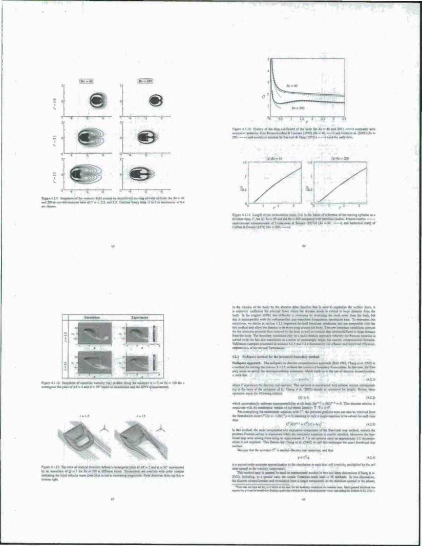
E=S
2 o i
•:'—5—»•
a o
- oj
m \
(ure 4 I V Snapshot« of the vorucitv field »round »n i d 200 at naMfcMMMaal im«ft' ■ 1.15. and V5
areuta» «had« fa. *r - 40 | RSJ n^,™n»t.of0 4
run*« 4.1 10- llialory of the drag coefhemt of the hodv for AV » 40 and 200 ( 1 compared with
numeric«) «olauoro from Koumoutukm A Leonard (IW) (AV - 40, ) and Cuna ct al (2001) (AV - 200. |mdanalytu:«l«tirt«i.Sy8ai.L«4.YaB,()'>'5)( »«alsd for carry nac
,.)AV- 40
Figure 4.1.11: Length of the recirculauoo «me. 1/4 in the frame of reference of the moving funetion tune. f. for (a) *r - 40 and <b) «r - 200 omiparrAi with ptou>u» «ludic« Pre*coJ rrnaaw
acrxruneatal raoavurcrncnu of Coutanceau ft Bouard (I°T7B) (Ac ■ 40. ); and Collins ft Derm» (1*73) (Ar = 200, >
«a
Ivol
» '.i » i
Hi Figure 4.1.12 Soapahou of >panwr>e »ortiuty (ov) profile» along the midapan u = 0) •« Ac» 100 for a wrfayilai Bar plate of ^» - 2and a - XT baaod on «armmnon» and «be DWV aiuastauiiiun
r-IJ t-IJ
Furore 4.1.1): Top vie» of vortical «truciurc behind a rectangular plaic of AR = 2 and a m }0* represented
by an laoaurfac* of Q « I for AV - 100 at di(Tercru time« Streamlines are overlaid with color contour g tor tool velocity aorm from blue to red in increasing magnitude Flow direction from top left to
■ the vicinity of the body by the dt«crete ddu function that n wed w regularize the surface force, H
u relatively inefficient for external flow« «here the domain need« to cxwnd u> Urse distance from the
horn In the original »PM. Ihn diftkuHA is overcome by toetUtuta the mesh M) from the body but
Ibn u tunmipaimtr wnh the ttuUsivjcc/faai «rar tranUorm lormulatum introduced bare To pvcrcume th» restrwuon. we derive » accuon 4 22 improved far-field boundary condihoro that are compatihk with the fast method and allow the domain (o be more »nuj .room! die body The new boundary cood».oos account for lb* «JOaasav* poiaouat flow raduccd by the bod» M u«II a» \ortu.ttv that advccn/dtfruic« to latex dratane*
from the body The boundary condiuom rely on a mum domain approach »hereby the Pomun «Juanen u wived (with the fast one transform) on a vcrio of increasingly large«, but coarser, currasutataonal dotnairn.
Validatior examples presented m section» 4 2 ? and 4 24 demonstrate the «flWsecy and inanrovad efficKncy lopeciivcly. of the revised formulation
f. I «...thpacrmrthod forth, immersed boaadarx
Nulkrsacr approach TbcmiHipore ««Wrvr imm/W*<-rk«i approarh (Hall IM5. lining rl al 2002) i»
• method for solving th* nuon (4 121) without the immersed boundary farmulauon b thi» caac. the flow only need« 10 satisfy the mcrjrnprcwiUUiy conatmini. which lead* u» to the use of discrete stream lunctMX-.
f-Ca.
where C represents the dracrcie curl operator. Tnt* operator a corurrtartcd with column vector« correapond-
a»g to the baar* of the noUnpace of D Chan« ct al (2002) «bould be consulted for detail« llcncc. ihc*c Operator« enjoy Ac following relation
«Two, wbjch automabcally aafoif iiioiiaiimit 1 ly at all tune; O»*"' *■. DCS'' - 0 Tha ducretc rdauoo ■■ i iiiiakraaji with Ha? coiw^taraai vamoc of the vtoor identity: v* VKIJ1
Pn>rmiltiplying the irwrnentum eouaium with Cr. the preasure gradamt term can abo be renxned from the fclaiiliili i amccC*Gp = - [DC)rp m 0. rcaulting in only a «ingle couatxm to be «otved f«x each utnc
C/^Cr-'-c'i.; In this method, the moat tompuutMirtally expensive component of the fractioraal Man trartbod. aamely the pmaure Potaaon «orver. i> ruminated wtulc the canumut» euuataan l« exactly aMuflad Morrm«sr the liac- tional «tap error aming from mine an appto»inuur .1 ' t» not proem »inte an .prwmju: LU decompo- xuan ■• not mniHcd Tbia feature led ("hang et al 12002) to call th» tecauacaje the amct/kwcmmal tup
We note that the operator Cr « arwthcr ducretc truri oricrwiori. and thai
T-C«,
ra a «ccond urde» accurate appro«unation to the cui^Jajjor, in each dual cell (vorticity muhipUcd by the cell area normal to the vnrticity comptwimt)
Thu, method may in genrraJ be uaod on uraitnjcturr^ n»rw^ .E iw,, ar»I üirce dmcmuw KTucu; ct al 2(102 i including, aa a special caac, the »imple ( artewan mesb uaed in IB method«. In two d.meiuioro the ducretc «trtnmfuaction and circulatioa have a «rrurle lawi^naiia (in the direction normal a» the planet.
■»»^..«Wk-IWhl.a^.^^w^-h
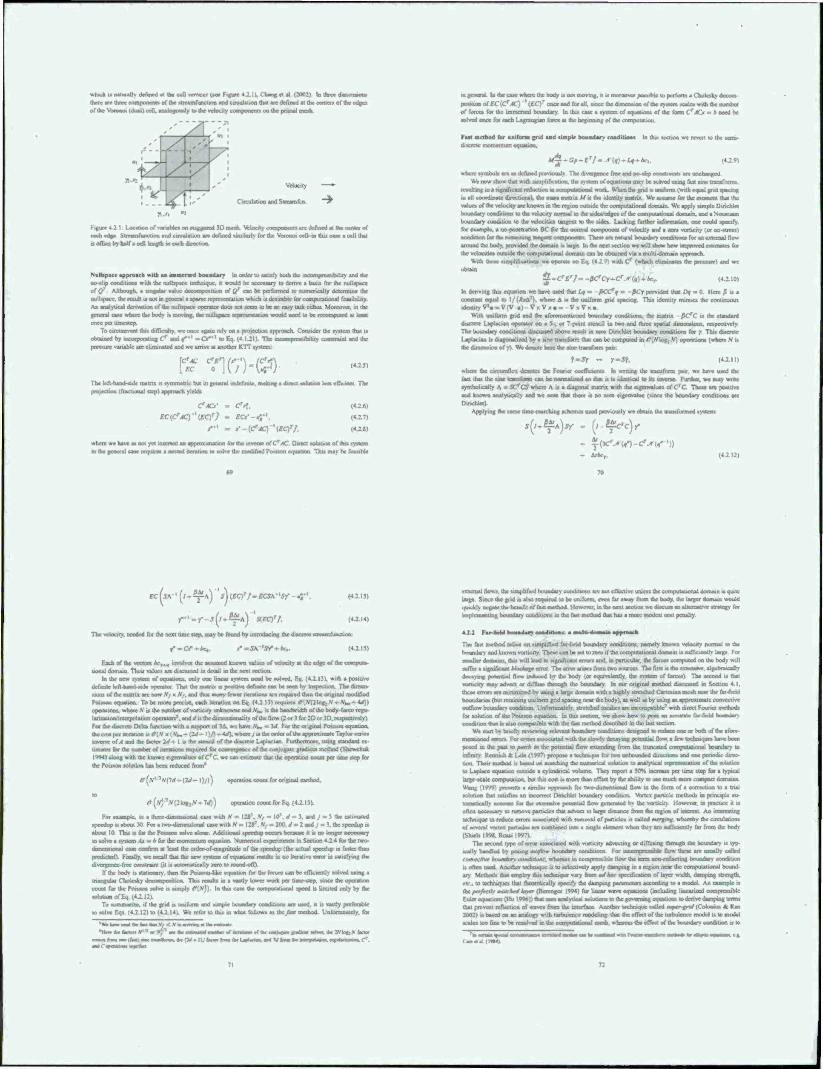
which i« natural!» defined at Ihe cell *rrtkr* (see Figure 4.2.11. Clssng « «1 (3002) In three fimtnmam there arc three curapoaenb of the »trcamf uric lion and circulation that ire defined at the center» of the edges of the Voruooi (dual > ceil, analogously k> the vclouiy ecaiajKncnct ao the primal mesa.
Velocity ►
Circulation and Slrcamfcn ~~W
i-.uu.c42 I Location of »ariahlc. >c laagered >L> rnenh %fcl««% componentt »re defined at the center of each edge Sireamfummon and circulation are defined onuterlv for the Voronm cell-tn th» caae a eel! thai •i ottoa by half a ceil length m each direction
botmdary In urder to satisfy both the • ncompres»ibiliry and Ike technique, it would be necessary to derive a baau for the nulUpacc • »'ip <
off/ Although, a singular value deccanpoaition of {/ can IK raafcarned i« mirnerically determine the null»pacc. the rcsuil t» not in general a sparse rcprr«enUiion whic« u. dninble lor compuuiiunal feaiibdity A» analytical derivation of the nulhpac* operate« doca not icem to be an easy Uak cither Momrver. in the general case where the body i» awia|. the oulaxoara ll|«aai «atiim would need to be rocooirjutcd at let oriceptvtintcstcp
To ciroamrnt Inn difficulty, we once again rely on a protection approach Consider the <vHcrn that n ooutned by incorpxaaung Cr and f ' -Or**1 to fin (4 Uli The itiLunaawatlbniry imniini and the ptewuic variable are eliminated and we arrive at another KTT »vvtcm
[5? n (';•)■(?) Tha lefl-hand-wde malm i» tsmmctnc hut in general indefinite, nsabr* a dtrx»a >T4OIICE km efficiar* The protection (fractional ttcp) approach yield»
(424)
(4 2111
where we have at not yet warned an approximafion far the mverar olC'AC Daeo «oliruon of thu ayttan m the aasacral eaat require» ■ nested iteration u> solvx- the modified Potsson equation Thu mav be feanbk
tfACx' - Crf.
EC[CrAC) VC)7 - «•*-«fM,
I. la the case where the body u not nwvtng. it ig moreover pos» rble to perform a Cbolcsky decom nof£C(Cr.*f) \EC)T auctmdt**, txnee (iteitxmtatai.ni of u^ ayaam Kato vrirh ttic »aaber
of force, for the immcned boundary In thu caat a >y»tcm of equation» of the form (f Ad - » need be aslvcd once far each Ugrangun fort* at the bcgxnmiig of tto cortirwtaaon
Faat mrtbod for uniforms (rid and iimplr boundar» condition» In thia «ecuoa we revert to the senu- discrete momentum equaboo.
*f£-G/^£r/« -♦•(f)-tf- Ac,. wberc »vmbuu aie a» defined previous!» The divernmoe free and ao-ilrp conatramt» are tav hattgrxl
VW now »how that with amplification, the Rasn of oqtattiot» nun be latved uuna Cut tine tramfnrrn». resulting m a ttgajfir ant reductwo ■ conitiiialiiiail work. When the (nd i» uruform twith equal grid »pacing in all coordinate direction.), the tnas» matrix Af » the identity matin Wc a»»umc for the moment that the vetoes of the velocity arc known in the icgum oinsidc the cornrjutauortal dotriain W bounaary condition» to the vdocity normal to the udcVeda^ ofthe coeAputjMaal domaut. and a Ncuoiarm boundary condition to the vdocirica tangent to the tide» Lacking further mfonnauon. one could »pacify, lor example, a no pcnctraiion BC for the normal component of velocity and a aero vorocity (or oo-atrcu) (vnrtfatson for (he tirnaiwntlaeaaaa« i laitpwtanli The« are natiaal boundar». cunditum» for an external dew around (be body, provided the domain i» large In the mat »ccuon we will »how how miptuvad eatnnaac» fat the vctocitve» outside the ecanputanonal itorriain can be obtained vu a multi-domain a|
With «haae .impWicaiioo. wc operate on Eq (4 : •>• with Cr (which dim „MJH;
£-CrErf--fiCfCr-Cr.*(i)-bcr (4.2.10)
In deriving Out equation wc have used that /a» - ßCXff m fiCy provided dnt Of - 0 Here fi n a comtant equal to 1/ (üW). where A i. the uniform grid »pacing Thu identity mimic* the tontmuoui ieaiatityV^-Va- . v . v .. v . - . „
With uniform grid and the aforementioned boundary condition«, the matrix ße'C n the itandard ducrete 1 apiarian operator on a S-. or 7 point ttencil in two and throe apatial dimeniion». ropcctivelv The boundary coodiuons diaexnaed above remll at aero OinchLet bountaary ooodiueru for / Thi» diacrctc Lantacum » dugonalued by a «ne tramform in« can be compelled m/?(Vlog,A/| oe«raiiom (»rlicrc v ,, 4» oanowioa of yy W« deacce here the .tec tranefooa paar.
fmsr - r'Sf. HA") where rial fli—flot denote* (be Foarier coefficient» In wntayg the tranaform pan. w« haxx used the fact thai the xmc tramfonn can be nernultaad to that a a idonhcal to itt ajveoc. Further, wc may write rymbolically A - SC'CS where A u a diagonal matrix with the eigenvalue» of C'C The« arc poaiüvc and known analyiaally and wc note that there a no aero eigenvalue (since Ihe boundary condition» are Dxndvkt).
Applying (he tame Urne marching tchctnc» uaed prevwutly wc ohiatn the iranxformed «yatettt.
s^)sr . (f-^Vc),
- aVivry. {*X\D
EC(SS"(I^^Y'A\ 'S\(£Q'/-ECSA 'Sf a;-' (42 13)
y'-y-J^-fi^A) XEQ'/. (**M)
The velocity, needed for the next umc ttcp. may be found by minvducing thcditcrctc oreamfuncuon.
a*-(i- »"-SA 'Sy ■ (42 15)
Each of the vector» /*>,„ involve» the «»umctl known value» of vetooty at the edge of the coanput»- iiiMul domain tlunr value» arc ditcuMcd in detail in the next »cclion
In the new tyttetn of equation», only one linear lyxtcm need be wived. F.q. (4 2 111. *:th a pouuve definite left handI mta oporator That the matrix is poxtavc definite can be teen by inspection The dunen- uom or the maim arc now ,V, x N/, and thu» IBO«V fev»cr iterations are required than the original modified Pataten equation. To be more precise, each iteration on Fq (4.2 1.1) requires r>(.V(2log: .V - .V*» - 4rf)) upentuonx. where AT is the number of vomcity unknown» and A4, i» the bandwidth of the body-force rcgu Isn/siiorv iiitcrpuUtion opeiauir»'. and rf i» die Jimcnvi-inalili of Ihe flow (2 or ) for 20 or ID.respectivelvl For the discrete Delta function with a lupport of 3A. we have \», n gat For the original Poitsoo equation, the cost per iteration u c»(.V ■ 4. f). where j u ihe order of the approximate Taylor am inverse of A and the factor 2</- I i» the «tcncil of the di<ciric Laplacian F urthcmiorc. using »undard a- tunate» for Hat aaattbet of ncrauon» required for emergence of the conjugate gradtent method (Shcwchuk 19441 aton, „.ii, toe known eigenvalues of CrC. we can estimate that the oprralavn count per tame step for the Pottson solntKin hat bean reduced from
ff[N'"-NOd~{2J~\\i)) orjeratioa count for original incthod.
!»l
"(v)5S(2^.^-710) opcr>Jton count for Fq (42 IM
For example, in a three diincnsiona! case with .V = 124'. V, = 10". d =« }. and J - J the estimated specstop ■» about» For a rwoniirnensiorial c*^ 200. J = 2 and ; -- ... the »peedup is about 10 Tin. at for (be Potatoa solve alone. Attikuaal tpecdap occur» because it a no longer IIUL uiaaiy to solve a tyssern Ax H k for the momentum equation. Numerical experiment» in Section 4 2 4 for the two dimensional eaat confirm at least the oidcr-ol magnitude of (he speedup ((he actual speedup i» faster than predictcdl Finally we recall that the new »»stem of equation» result» m no iterative error in tauxfying the divergence Tree corutramt (it u automatically aero to round off)
If the hoch t» stationery, then tha Pcqaantvitke equation for (be forces can be efficieniiv soKvjd using a tisangsilat Catsataky ikiitBtqitairiija. Thia reautt» at a vaatly lower work pet base-step, «nee the operation count for the Pmtaon solve i. simply r?(.V,') In thu case the compuational speed a limited only by (be •Dhittaa of Eq 14.2 12).
To auiiratnae. if the grid is lawfurm and «unple Uiundxry conditinro arc used, it u vastly preferable to solve Eq» (42 121 u> (4 2 Ml Wc refer to thi» in what follow» as ihc/an method Unfnmmalrly. for
'«Ar Saw a»d it« r«.i Uui V, < N m «n| M Ikx ei •Wax, ts» asttxr« »■■»«, HJ"1 as» tW rsaamal ■
tmr»sMitMl«iin»ilaw,ar(>ii U/h
external flow», the »tmplificd boundary condition» arc not effectrve unlett the etxwgtilational domain it quite large. Since the grid i» also required to be uniform, even far assay from the body, the larger domain would outcklv negate «he benefit or fast method However, mtbc next seoUoo w« ducussan ailernalrvr ttatttgy for kaiplutwjntliig boundary condition» in ihe fa»t method that hat a mote modest cost penally.
4X2 Far»la*a svsaradary eaadlriaair a —slai «a—k. apprxtawh
Tba faat method mliea on »implified tar-field bcsaxlar« coodniorn namely known vciacsty rwrrnal in the botndtt^ andlotownvxsrticrry Tbeaec^ For taaaUer dornam». thu will »tad to »»^nmcaoi error» and, in particular, (be force» ccartpitsed on (be body will «ulTcr a significant Woeaog» error The error arise» from two sources The 6rat n the aaautatve. aqpliiaualry decaymg potential Mow induced by the body (or equrvalenlly. the »v«tcm of forces) The arcood u thai vxxrucicy may advect or diffuse through the boundary m out original nsetbod discussed in Section 4 I, these error» are mnurra/exi bousing a large ikmx»mvvi4 boundane* (but retaining uniform grid »pacing near the body), at well a» by uxing an approximate convective outflow boundarv eondrhfei Urvfortunateh. stretched cneahc« are incompauhk' with direct Fourier nsrthuds for »olurjon of the Pouuon tvquaben In thu section, we »how how to pose an accurate far-field hiiitndar)- condition that i» alvo compatible with ihe faat method described in the last section.
W« start bv bneftv rrwewmg relevant houndary e«»ndTt»ona designed In rcafcapt one or both of (be afore- mentioned errors For error» associated with tha »lowiv decavmg potential Sow. a few Wrrtniiaars hove been poved m (be past to past* m the potential (low extending from the truncated compigannnal boundary to infinity Renns-h i l.ele (1W7, propose » tectauqua for two laxrwvasdcd dirceliom and o« r»mcKW diroc- non. Their rncthud u bated on marching ihe nuincrical wlutioo to analytical retarsewaiion of the »olution to Latdace equation outside a i>lindncal volume They repon a $0% increase per lime »tep for a typical large-scale ccanputatioo. but thii cost i» more than offset by 0V ability to u« miich mitre loa^rsso dorr»^ Wang (199V) present» a similar approach for two-dirncmiorial flow in the form of a correction to a trial •olution that «atufic» an mc«Tect Dtnchlet boundarv condition Wsrtex particle method» in principle au- tnaaaaafli account for (be extensive |iininta»l flow an" * by lbs vorocity However, ea practice it t» often rsecemary to remove particle» thai advect to large distance from the region of astereat. An aifiatln mitaityu' to reduce errors aivociatcd with removal of particle» u called mrrymx- whereby the cuculatioru of aevanl vtrtex particle, are tornbatind into a atngk eittnent w Sen they arc wdficseritl v for from (be body (Stneb 199«. Rossi 1997)
The «ccisnd type of error »asooaied with vomuty advecung or diRusing through da boundary it typ. icaiiy handled by ootmg o-eVw rssuwatn corabuora For maauytssihle (tow these are usual!» called . oavrr//w hnundon eomtUom. whereat in comprcHibU: How the term ncewtilaseMlt btxooitory condition uoitniawd Aooeber lectxoiquc i% to »cleci.wly apply damping in a region riear the cornpuiaiiorial bouml ary Ma*ctk dt« tst>»»*try te rtr, to technique» that thtsanxically »peafy the dtvtnptng patanwtsn according to a aaodel An example ■• (kepttfiatr moKMlaytr (»erengcr 1994) for linear wave equation» (including linearised oxmprorsibtc Eulcr cx»uatiom (Hu 1996)) that uses attdytst^ talubessa lo the go» ■n »to denve dnmpingu that prevent iellcction of wave» from the interface Another tactoisqoc called naarrgrtrf (Coloaaus * Ran 20021 is baaed oo an analogy with turbulence modeling that the effect of the turbulence model u to model t»ata»t»oitoelBtoi»a»»atvt»s»»^
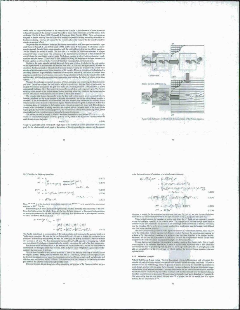
model ecaaee wo karge to be reaorvcd in die compuiaiionai domain A full di»cu»«ion of ihcae icchniquc»
i> beyond the Map* «f du» paper, wc lefat die icadet 10 Mcae recent reference* (or further denart (Sam * Graehe IW. J.n A Bra» 1W. Qfthiilrii * Starovcrov 3000. Colonnni 2004). Tbcac icchnique» arc designed to remove vorueity from (he dumam et «noothlv a» pouibte ihcrcby preventing undnuablc rc
Bettton» cetneeriag Mow do on» aeeeaant fee the vntocsty unfc.ua d bv voruerty Ihn hm» already eyjaed the
dommo (• non-local clTcti) W» pini.nl koc an efternetivc »cfcaiiai» that «hare» mate features vndi these previoua method», espe-
cially (how of lUoMch * Lclc (l*>7i. Shiel. <l Wg.1. and Coloniua * Ran (2002) ll » baud on a muh. domain aaproad. du» abo «kam tarnt operation. w«h the mulugnd metbod for tolvmg elliptic ccaietium
W, On* deaenhe dm metood m wo* The banc idea i» to «trawler die domain a> embedded m a large, domain bui with < comn me»h The circulation on die inner i «malier. ßoert meab i« then mtrrpolated or
ccwxaW onto die otaxr l largo, coaraert mcvh Tbc Potoon equation » wived (with «TO boundary condi
uon«) on the outer domain. Thit solution i< then inicrpoiaicd along the boundary of (he umer mesh and the Ponui tisanuaa u «ulvtd *itfa the 'cveractacT boundari' »alue .pccificd on the umer meah.
Similar to the vonax merging method diacuaacd at»» .illation In the outer portion
of the buyer domain at retained from the prcviotat ume level In thn «ay. wc approximately account for circuation do» ha» advened or diffuved out of the inner domain Clearly, the solution on the coancr mcth
»alarger truncation tm» (or the evohjbim of dm »ortiorv However, inversion of the I apian «a tta
i High frequency luiiyonnm of the solution induced by circulation in the outer mean
decay more rapidlv than 1.» frecsjcticx ccattpooeni» Bern« inlcrccted m the fkm m the VKUUIY of the body
(and »waleiwcdncerd the »olwaien .n iltr outer region only rrtammg (he velocity it ittluco on the irincr
Wt anpt> tma leehttiqiic nRaro^
and lev«! We chocae to keep the total number of grad j»..ni. in each direction fixed un each mcth. wa
magnify the domain and ctsuxen ihr grid by a factor of 2 * each grid level The procedure a abttwn ■rhrraal».. Ihr vxxrutulv at raeasatcd» eoaraified on each projtreaarve grid. The Poiason
equation it Ham «olvad on the large« domain, in turn providing a boundary condition tor the neat «mailer
ill mam The preccae a data repeated until wc return to thr anginal dumam The velocity field decaya algebraically in the ler-nekl oral we thus wtpeot «rrora aaeociated with the
e gecanetiKalry m (he star of the large« domain i> I In the vvoral caac of a mo-dsmcnawnal flow with non-zero tola! circulation, the velocity decay.
wuh the tmrenc of (he dntancc to the vwtical region Analytical exumetc» given <n Appendia B »how thai we obtain a factor of 4 reduction in the boundary error with each progrctwvcrv larger grid Thn. of court«,
u what would be obtained by »imply extending the original grid to a dietaocc equal to the extent of the bag«« grid, but dut to (he coarsening operation, the coat maaeaaet linearly with incrcaaing extent, rather
ihaii quadnuicalty (in two dimrnnont) or cubtcally (in ihrec ifcmenaweiai Tha method can than be written aa MMWX Wa defitw the tlneoaw of each grid aa y '
«here*- I refer, to the original t smallest> gr-d and » = \, refen to UK iatgeat < mr Wc then define ihe
(•SA'Jf, <o-i«>
where * la M arbiträr) input vector (with length equal to the number of discrete circulation value» on the graft/a the «rfuoon (wuh length casual to the maedm of d««»ele «reaanftinctK» «h^l. ar-i ihcoc<rat«
JA <5 wraith, «lowing operation.;
t" - ft
rf ff« anh»ra«»W»\l-»«l.
IM. . tv a« - JA 'Jf»-ift [**•«•«»(#»•'>)'
•
»•AV*,-I. ,1. I m äTTst-r"'
lien: /*>>■" „ . fine-Uv-eoarae mlerptilatK» operator and f
nntnetedtorfy-' 'byar.
hi iiiilm« iig P. tf wtmld be dtauabk to preaervc (to machine roundolT) certain i
«Ujon ilaahtajüiili an that (he velocity decay rate lax from die body n correct Ir.ihcprt
(O.IT)
(«ill)
|tlM| tOJO)
(4.2 in
wi«td»awenu1..»anm«/»oi«ala««i to W torva^ at each liiaii llag
r- - y"'--4-(/-^A) J
(4i2J)
* I* IJII, I .,. i [gaVH 4 * '' ' Iy
Note that in «olvrtaj for tfaa atraantfunction at the next HHK . »axe the cotraifled c
lauon f«!d. and »trrarnfonctton» to uac ..n UK Mfihi-tiarxl- lie nexl tune «tep
When vomctty croaaea the bcajndnry of a given grvd levd. the ?" field» a
E::^!l (4.2.221
The O.pnra alencal land» to a (ion of the total calculation and t» »ccood-order aoaaraie baaed an a favlor-aenea «xparuma We note thai (he cveltKicnt» in l-.j (4 2 12) aura to 4 uncc the circulation is thr (dtaWI cell M the voriK.iiy anduplMd by the area, and ix««irVu»g the grvl by a factor of 2 rcaulu «. a factor «f 4 incrcaac In oall area. The threedimen.ional venuon ol Eo, (4.2 22) conxato of averaging Eq. (4.2.22) o»xv two adtacam (i,y) puma of data normal to the »xalKily coenpocaxau for eatii of dat tlan« ccaBpiavrnt»
For the coane-to-lmc mterpolatiori at Ihe boundary of the ncxt-nncr nveih. wc uae Ihe value from the «tarter mcth for thoac gnd peint» that ouiocide. and a mad-point linear iitterpeaation (again cccond ordet accurate) (or thove point» in between
We note that circulation It only »tncity preserved if there la no vorucity advecung or difTutuig out of
the ornpnal doouun Dumag .xetKaiv tranafer front fine to coerac mcth. circulation i» only prcaerved to (he level ol dttcrctualion error, «tnce the diacretLOtHm error u different on each meah and advectton and ihffutiun met are therefore tbghtry dtfJcrrnt Tcatx below cxanftrm that change» m catculauoo aa »tructure.
peaa between (he differeni domain» are atirtropnatery »mall
UtUiamg ate mdl) damain decchptton of the circulation and tohmon of the rVnaaon eouauon. we now
acroct the interface», expecially at (he coarxev leveit The propagMwn of a ««tea ihrough n exataaned in the next tcctton and u n potxiMe to ace aome dighl internal reiVction» of the local * nc« the boundary I kmricr '.he eiron remain confined la a email region near Ihe rmauaary and diOwtcd over tatnc by (he phyvrcal vtacouty
The multi-domain U'chmuuc come» with a tignnVam mcrcaae m »omrnitatioaal expenac Sanae we nuw •olve thr inaaymenarr vtarucny eucaiwn each FIMX«, ectuatMin V, ume». the orietaiion coum ane» up by
a factor of A/, Nocrthrte»*. it enable» ut to utiUae the Uti algonthm devenbed m the prv» inu» tection Motecnxu. we find (hat the muhj-domxri n »uflttMstth accurate that ocoxtputatmoal domam can he mack mug around the body. Ran time» for parucslar example» are ditcttaaed below
WE note (hat m marry «maabot». it ta dcairabic to apccifv a unrrMin fkn» ehota a body That t. «imnk
to aiiimpliab m the nultqtacc lormulaiinc. a» there n no circulation aaaoctated with it One need only add the uniform tl. M) In orntopU one could add am rv>t«irtual How in thn way. at kraal pnnxded it «aUxf.c» the dimw Pouaon equation wxth xero ngbt-handniMk
ataex The twx»-drnwtv»wrial vela
mhutum of vorucity (Oteen vonex) u computed » in boundary ceatdiuveiv Tkia teat incd to validate the methodology «nee n it ptwyihle io denvc analytically the expected UT4wrvemeni
multi -domain toluiioo wuh incrcaauig A', (or thi. caw A» dnctnaed above, the large« domam uaca no f rietitzauonmo eneaa boundary eeaadabon» An analytical »oluuon for the velocity field with theae
condition« may be cmatructed by the mrthod of image» «uch thai the expected error tor ihe boundary condition» can be evaluated The procedure i. itxarghtfurward and is deenbod in
The reaults «how that the error »hould decreoae aa 4»» la general, and for the aptctal caac of a
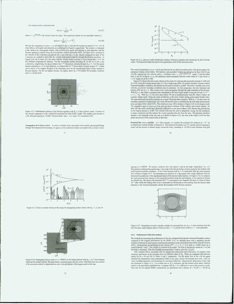
The vortauty aana1 a mmhit* »Hh
»vhcrer.-. v I-' - v- » the distance from the origin The auilyiiial uilulwn (or the uunuiKtl wlocity n
«•(».»> ■*<"**. <4xai
Wc «art ihc »^imputation at time f = la and choose T and «,, weh that Ihc maximum .peed ■• I. at r - Ä In »h»i follow«, all length« ml velocities wc numulmd by * and V. respectively The voruciry is t ttgtasid M Ihc ■■litu of a rectangular domain with uniform (and equal I end »pacing m both direction» and Ihc Poraon aquation » solved uaint the mult, -domain method discussed above. In Figure 4.2.J. contour» of the velocity in the (.direction are plotted for a cane wnh .V, . 5, Ills velocity computed on each of the 5 domains an overlaid lo show thai the velocity field rensams «mouth through ihn domain IHMMI» In Figure 4.2.4, the L, error of u (the enli liefet) is plotted a» V, in varied ftum I to 5. for two AflcaaM twpmnuunal disarm« For the rectangular domain extending to * 4 and i S in the J and y dircoiotu, teapcctively. the decay folio», the 4 v. theoretical eHimaie through S, » 5 Foe the issue« doenam extemttng to I 5 .n each direction, we observe the I ft "• decay down to error, «round 10 'which can ha «hows to he roughly the level of the truncation em» (or the «condorder (inite»olumc method at data grid dentuty. For Ihr non-squarc domain, we resrumr about St - 1 to reduce the boundary condition
Figure4 2 4 L,c equation with increasing S, for the OK»
Figure 4 2V Multidnnuun solution of (he Poisson cquauun with Nt » 5 for an Oacen vortex Contour» of the velocity component in the • direction are plotted for each of Ihc 5 grid» The smallest gnd extend» to t 5AV with pid »pasting &« 0.03A (ontoui level» nun- 0 2. mai= 0 2. inacmcni-0(i:
von«. The hut IAWUI black line »he»» the apravvmate level of the truocaoon error
The vorte« a initialised at 1i, v) = (0,0) and advoctod by an otherwise uniform flow with apead equal to Ihr ail an am velocity of the vortex The voracity and aranurhal velocity arc mil given by Fa» (4 2 2?> and
■-»pectively. but »nh the radiuv r redefined with r » »/it -U'f- -r> Again. I" and the Initial Urn«. *jnae>aolh>lat/s%. the maximum «peed atajnrrarril with the vortcn aloac i« (■' and occur» at rmR. Again wc set AY » J00
Figure 4.2 5 »how» the crrot m die velocity at the origin for a domain thai nominally extend» to =Srtwtth i - 0.05 Since the velocity decay» lice l./r. it ha» a loag range effect To achieve 1«» than I % error without corrected boundary conditions, the domain would need to extend to ± IO0Ä The error is iniually aero (even with the iincmorhirt uuaudaiy condition»! due lo lynnnrtry Aa tame prospexse*. the error tncrcaae» and teaches 23% for ,V,o I Thu occur» as the vortex propagate» through the right boundary of the domain With\, > I. the vortex i» progmsrvcry transfrrred to the neat largest mesh at mtervaU of tinv | a - I, rVr With N, ■= 5. the error atays below 1% up to nondimetaiooal one 80. when ii leave, the coancst. largest mean. Then are small osculation* in the crrot evident daring gnd-to-erid transfer times The arstwiatnd total circulation changes by at moat S*4> during these trans fan With V, = 10. error from the boundary condition is uralrtcctahic up to time 100 and the error II controlled by ihc 2nd order discrctmtion error and stay» below about 0.2H. The sonatina at tune 100 is shown m Figure 4J2.6 on the largest mesh The magnified region u »noun as in an inset and shows contours of the vorticity and normal velocity R» tune 100. the vortex would have phy»»cally diffuved u> a nee »ur of ah»Ml 1.6». whereat Ihc grid spacing on the largest domain is IJ.gR' The velocity field neat the core ts oompktclv wrong, but the circulatioo is ncarty ocajserved and this induce» the correct potential flow be from the cote The physical tamalkntl domain is also depicted on the plot and. aa is shown in Figure 4 2 5 the ems» at the origin is stilt leas «an about ore percent of the correct »aloe at that time
of aa Oseee vartei lo order l. sMiputalKxial boundary, wc agau
» uh vorucay advwaran/diffuunr use Ihc analytical sohiüoo aasocuied with an Oveen vvmcx
PoicatUI flow over a oliadrr As a final example anuispuasr»rry»sa»Tadcylin»toc»fdiiapseaorP The point» and the domain is defined snugl» around the bod»
the potential flow induced at ( =0' by $71 equally spaced Lagrangian
to -rfl SSD m each direction «nth grid
»pacing A - 0 0055/3 We initiale a uniform flow with speed U and let the body "maienali/c" at / - 0 The totution i« obtained by performing I time-step of die Navicr-Sioke» soiutioo usmg the fast method with mulh-domain boundary conditions A flow (Veld obtained with ,V, = 4 „ prevented with the exact potential flow sobsuon m Figure 4 2 ? TTst atreamiine» aic lound lo »>e in agreement »nh • »light differciwc near the Iramarard boundary due to Ihc regulatvaed nature of the ducrete dein function In Figure 42 J., wv compare the «säet uaillllial flow solution la tha numcrscal aoluuoo along the top hououar» of the imanmoat domain for different «L We »ibserie the esumaicd cT(4 "•) convogcncc (see Appendix RI down K> a level of about 10 ! after which the leading «der error is dommatcd by dx ouncation error arising from the discrete delta function« at (he anoienod b»»undary and the iliwretii^ic« of the Totsaon espaauon
Figure 4_2_S: Error in isormal velocity at the ongm for priicaa^iing Oseen vortex with V, « I. 5. and 10
Figure 4.27 Saisamlane» around a circular oander fa, risrnt.ll flow for /V, » 4 a firo two mncr mulli domain» »houn Prevent result I 1 and (he exact totution ( -
4-2.4 Perawaaaae« af th« fast aseahod
Figure 4 2 6: rHoetsgaung Osecn vonea at r « :oo«,'f on the largest domam with S, * 10 Coax contour» represent the normal velocity The «wet »how« a zoomed icpoo near the vonc» The black line» are contour» of the csreaiataan which is resresonted on only a lew grid points of the Urge»! mesh at (hi» time
Wc conclude by measuring the pciformance of tha last nulispaccmulu domain unmersed boundary method ceeupated to (ha onfinal performance b» the 1BPM First, we stmuUlc flow» over a s»auonary circular eylmder of dusaaew O and ceanpa« to t»rc^ 20071. Cotnputatiom arc perf«»med on the dorn ..th A = 0 02O where N, u varied ovwaioen I and 5 The eyltnder at centered at the ongm The flo« a impulsively »urted at i - 0. and the body uaoaaonary Tla» Ae Chok^y decomp»»«^ « used lo «orve F^ (4224,
After traruaent cflecu aaaoctatad with the impulsively «tailed flow have died awa\. ue examine wake snucuass and face» on dar cylinder, (torn tor dvlaocnt value, of \ These arc ceattparcd «nth prooou» result« for *# - 40 and 200 m Tahhts 4 and J. respective:» For the «lead» flow at *# - 40 wc reason CassracarosM d>me«»wNS of te I up ml »liiiiastiaj fmanaiiij mil flu ling fill nut ifiaaj i infTmiiHi CWraratriala ilsmratna» of faaiaaW are illustrated in Figure 4 j 5. It is CTuJcot that as N, is sacreaaad. the laat methiid gives near!» identical reviln to the previously puMiahnd data It appears that V, « 4 is auttäcaent lo reower the prevtous results >4o»e that fat the original IBPM. cssrriputati.ins ar» pesformrd over a c^smain of -MM) » -JO.Mi by
N
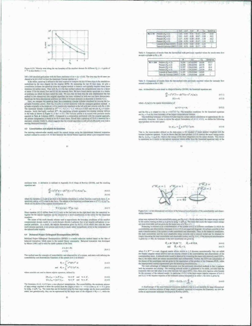
f.'rf o'rf hid 0 Speed-up I Re = 40 Present .\ I) I6<> 0M> 0 55 53-« ! °: 25.»
Pmeu'.v :oi 0*7 051 HO1 1*.5 Piweot<rVf-4) 2.17 0 70 14 : Prcacoi (.V, ■ 5) 2-20 0 70 0 54 SJ 5 i » II J Um«* * Faaei (2O05) ::x HT: o.« 536 154 Tun « Coloniu» (2007) 2 JO 0.73 0 60 S3 7 15* I
Table 4. CompMitwi of ICJUII» fron the fa»t inn ho«) with prcs-i«tvlv reported «line« far »leads -state flow «mad a cylinder* Kr m 40.
Fuji» 4.2-g- VMooly «or along the up boundary of «he «nalkeat domain far different % ( ). A guide of
300 i KB «retched grid potnb with tfac fine« rcaolution of Ai = Ai « 0 02 The lime Hip for «11 CMC« «re caowa to be A/ •> 001 to limit (be maaimum Count« number to 1
«a fa« table*, «pecdup u defined n Ihc Um reouirad to c«inT<M the U»i K> umt itcp. in ihc »imul«t>on« normalterd by ihr tune cUr»ed far the original IBPM By me-unmj tke la* 50 time ocpv «r give a u—«rxiHT oiimMr far tplrcd-up «tact far original method t» «Mwuive «ad lypically »quire« many more iicmiom for earlier unn Thw «Kb V, •• 4 the fa« method reduce« the compuutronal ume by s factor of «oout 15 for ÜV .leads floss and (>"■ for the urulcads. llov. We hasr. losjnd «unilat «pced-up. in • saneti of problcmi on which we have le*ed the code. Wc note DIM «re h«ve tbtat far only iiir(4en»ril«cr1 the fan method .i. ran» duncn»ofu (the original algonihm ha» been val«d«eed in both two and three dunen»«»») Speed up« for thrre-duncnuutwl probtem« are likely u> be more dratnauc at A«cua*ed m Section <21.
New. wc compare Ox «peed op hum far a tiwMlatinj cucular cylinder «umtlated by rttovtng the U- gntagun boundary pouxa Sow Eq I* ±2*> u aulvcd iterativcly with the enjugatr gradient method A cylinder .«riginally at Ihc ungut at / » 0 a impuumdy uamJ«cd to the left «nth un.t velocity with Kr - 200 The «inermoM domain ia .elected m§ A - 0 02O «nd we tue Nt
domain* Inndt thi» high!« «Wined V . the translating Qltntkt jeneraie» two ccajnua njumnf vorucn •a the wake aa aSoam m Furui '• The ss»ti,its nrolilc i. m acc.nd with prrs»u» remit» reported in Tatra * Cotomu» 12007) Compared to a computation performed with the original approach, the preaera compulation it bund to be 4} 4 tonet tatter Recall thai ■ «peed up of 53 0 a obaerved for a
v cylinder tT.btc 5). watch «uggctt. that Ihc ..««mil algorithm u «till tolvcd cirmcntly even «nh •
Srd"» Re Z0Q l',r ..-.,• '. I 0.201%
Prvtcni ! 0 200 I 40=0 052 ±0.70 «4.7 PnacM(\«4) 0 197 I »ft _0 04* i.0 70 6S4 Prctcni (Nt = 5) IflUW Ml 530 Linruck A Faact (2005) >M +0*0 Tajra & CutotuiM (2007) | 0.196 1 ^ • (-;• : • '■■ 1
(4 3 1)
x V>; y.i the «paoaldc
J-C£7--^Ccr-- «ro-o,
icnuackaaar
and the flus «» related u> y by i^C'^Ci'r The r«undar> condiuoa fo. the lina «re lie, = 0 on the outer boundary of the lanjctt cMnputaiumat domain
TWiw>4^a^ie«araayiec/«a<4h»4.4«lapr^^
ga] gf.
la order to derive die adjoin! formulation of (4 > I 4 12) v.« define the following inn» pinihri on the «nac-rpacc:
«mat,«., and ad>aiiM
For dcrtvmg ««luced order modcte «aveful far control deaign war« the app
i «ic^cy«**«*. (4 ] 4)
■ lOaorl outlined «n «ccUaa 4 4. wc flm Imeanac the Newer Stoke» «aiattotw afaoul • pre<omputed »teaih That If, the moer-piwluti denrwd on the «taic-«pacc it the itandard I? inner product weighted with the ttwcrarlapiarian operator It can be »bown tbat the umer-product (4 3.4| oaducc« the lawal roergj oorm *• u, (y.y).< - ioratr, »bach u the cnetgv of the fhad mtcgratod o\x» du entire domam Thw cbotce u cottvenieni a« H result, ia the athoat ajuatiom which differ 6«m oat Lmarued twuarioa« only m ihc
. outlined in Appcndi« B of Ahuui A Rowley (2010A). and the
J .<*£'* . -ßCct; - (CcMi()a)r«.. UM,
«rfaM aV «anavlat (. { aa« «y a» a«« M the d^ •pecuvcly. «ad a. «C< u dual lo ibe flux < The atbou« of the linearired mmlipeat term it ;CTC, ' »hicti can be thown to be a •patial diiuctxatioo of
(4J.7) ♦.««.J-
Since eouation (4 )_5) difren from (4.3.1) only ui die laai term or, ihc r.gtvr hand «.de. the raifrtencal av * far the atboant euuatioRs can be obtained by a «mail modification to the «ol\rr for the lincan/cd
rl.l^baUo^u^r<«T™UHmefrheenntn>0«caUiyandobaerv-
Thc nature of the muhi -domxu. acherne uaed u» approtutnale the boundary conditions of the small«! ooanpotatiixiji dumain nnult« in a null, domain diacrcac Ljolactan that u not exactly «cif-adjoiot to nu- aarncal pnxitwn A« a icmlr. the atbaua formuUiioo given by (4 3 5 4 In) which al*o unn the aame multi-duinain approach, u not pnxi>e and remit« in «mall rather uuigndiiant. erroo m fat rr—gli—«inn of
4.4 Batoactd frojxr Otbogtiaal Occompot.t.on (BPOD)
a (BPOD) a a nodd r baltaannd trtmcation. which aroae in the control theory community Batancarl truncaoor by Ndoore (1«J|| and n valid for «aAir cyMem «^the forts
<.-#a »■-a.
Thii mrthod uaei the conoapU of controllah«lu« and oh«enalvilrt\'o» a «yatem and »tarto i twnttoflability and otMrvaMlty Ctamiam of the cy«em (4.4 I) «a I.
«id »..p'rcf**, a wan ««trnalu «• uaed to daoote «xhomt opeiatoc« defined hv
Figure 4 4 I A rwoC «hiutyC
minor aacs repreaeni the kau io«unJ:«We »u«ev.« Fig 4 4 I c Hi thr .«her hand, the oi by the qndrtn «tarting at «ate r. u given by li{:, - «J»'.«« The «tale» lhai ctciic ihc large»! output energy are mo« obtcrvablc and arc given by the tmuor aus of r*>U ■ I
atiaWai rag H refcrrcd to aa a U«afai««lk>n of the lywcm |4 4.11 to dilTercm coordinate, .n which the controllability «nd obacrv«hilit\ (irammna 1.4 4 2, 4 4 3) are equal «nd diagonal It n ehaeyi pouiblc to find nach a oamfiarnation if the «ytacm a both cocarotlable and ob«cr\«btc Thu». ia the balanced cxediruvte«. the mewt corurolUble and the most obccrvablc «atea coincide and a reduced model can be obtained by «imply trunc«mg the !ca*t conlroliabic ami .«b«T%aWc r»«Jo. a F.i 11 : Ifthth a given by a - «W. the Craniam in the new ciKwdinaic« are given by
#,-♦'»•,(♦')• »;-4>-r,4>. and #,=#.-!,
(4 4 M
(Ca.v). = •
Va«» «nd V««*-. *y€* and *i«S.r
(4A»
(4.4.4) (4 4 5)
The C.ramiao. (442, 4.43) have a mc« phyweal iulii«i«aijo« Forcootrollabiury. the - • • - ■ anon of «put energy reouired to drive the «y«icm Iroen the origin « tune I - — to a «ate «a « / - 0 la grv. hyM* »*••»', 't The Mate, that can be reached utmg the lca%i input energy arc the mo« conDoOab
r. they cam be itpreaftned by the mayor «an ol the elln^o.J ^»U - 1. whale d
where I e R" "* i. a real, diagonal main, whoac entnc» o\ > 0 din max mxwioucaliy-. they arc called fat llankei «ingular value. (llSVa) and ate daactly nrlatcd to the cootrollabiliiy and ob»crv».- coiTTtponding «täte« A rcduccd-orda model a. obtained by trijacaong the «ate» with »datively .mall IISV«. that it. the oate. which are almost unconuolltble and unobaeoabk. Further, the HSV. are miVpcndcat of the choKcol the uwrdinaUM «nd arc pven by Ihc eigenvalues of the pniduo »I the tiiarnuin , •< ■■ the («pnnspnately acakd) eigettvecior» give the balancing tramfiirtttainn.
The main advatttage of balanced truncauon over the picvioueh/ aVracribed method, i» mat ,1 canuatta both the actuation and «nung The remitting reduced mode! i« tuarameed to be «able, prw «led that the iruncation doe. not uke place« an «»der between iw«, equal I ISV» Al«., there cam ngvnsu. cm» bound» f« the accuracy of the reduced model In pattKuUt. if <7w) ■» the inew «aipul lirtwutu ittyuu
|t7(i)-CrV(r)|_<: V a. (4 44)
A rhiamajnrtaw of thr enact balanced mina»« tnethod i. th« a i. not tractable for U ryweru a. it «nvcOvn aolotaon of large mai/is (]Tmir iiiiitaain—« in i iiaynli Ttir TTiiiia—. we now de •cribe an approximate ««fanique developed by Rowley (2005V
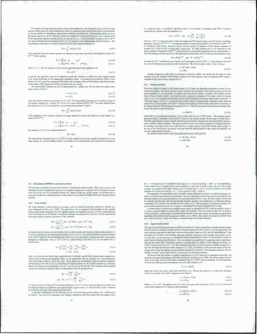
For system» of Urge dimension such at those ciscouutcrcd here; the Gramiant (4V4J, 4 4.3) we huge
nuince» which cannot be easily computed or stored. A computationally tractable procedure- vat introduced
by Rowley (2005) for obtaining an appnuunatc halamng tramfiirmauini The procedure relies on an ap-
proximate expression of the Gramian» witsch wa> umoduccd by Moore (19(1) and can be armed at by
g that the impulse response of (4 4 I) u given by »(f) •* cxp(4i)rJ. where column» of »(f) € R"' ithempomcof(4.4.l)u>an impulse to the cxirrrsrwciding clement of input * The
y Gramian (4 4 2) can be written in term» of thu impulse response at
r,-jT (»<,),•(,))**.
•raporm an satnpkd at equal tune mservah- 6V atsd ttadeed « a irtstnx *v
are computed using a coat-affWttrtf algorithm umtlar to the method of nsignhnti using POO h «wolves
ITdatfi f** (after sealing l
JT-v^iv •:
- •/*,*** <~8 r^B).
»rlsmf.-l. l)^.uV«»e^»(4 4 0,^bc1r^«OTia^brt^^acban««m,
ir,*
(4.4 10)
(4 4 11)
(4 4.12)
la general, the tnarnhuo need not be sampled at equal tune intenalt, to which case each «Mpahot need»
to be acaled differcmly by the appropriate quadrature factor Aa pointed out by Rowley (2005). if (be daraaet (4 4 10) u wad far cae^ula^ KIO ina*^
in thai regard, POD capture» the effect of actuation but not sensing The oraartrajoüity Grajanan «an ah» be apprnxTrnalad in a stnalat way Wc firm jclmr the sdsoiru ttatr-
a - r.-, (44.1J)
(4 4 14)
whore die ad/oant rnatnee» arc given by (4 4.4.4.4.5). The observability Cranium can be written m term of the impulse response jr» . tratsfyTOC- of (4 4 IH where ci4urniuof»^») € R-'« are-ataorjtamed from
«of (44 l3)loanirrrpulaetottKCorte»poodinge>erneni o( input i
•r. = jf"(Jt,. i (4.4.15)
again »amplcd at equal tune intervals S and »tacked in a If the «apthoit of the impulse rcvpoose saama 2 <«"•».
Z«v*(at «:«*.) (4.4.1«)
-v/4(^''C- ST- a*»a-F) (4.4.17)
rteMM«>>lU(4 4J5lcMbcappmumatedby
W.^17: (4.4 1«)
Tbc approximate Gramian« (4 4 12. 4 4 !«> are huge dirneaaioaal and not actually computed due to the B (or modes) of the traro formal wo that balar
rx •«*«* *>ft £)(?)• (4.4 19)
where Ii | R' " 11 • diagonal matrix ol the moil tumiflcanl H.SVi gicatct than a cut-oft which u a modeling pataanelct.wh.WI diagonal matrix ofxmaller and/eru HSV« Sotcthat Z'X6 R~'~
la a relatively small rnatru. where m, and m. arc (he number of snapshot» or the impulse responses or
n-steasw (4 4 !) and '4 4 IV, to each rapsfl. rcqsxuselv For Boat »«stem, that we arc aaamniil m, the tyTiscalniirnbcr of snapshots is (VM0-' 'l.thusrcwihing « a r»a«maWe corjvpuutxsnal cent, «vl t>p»cally r <
100. The ssatfarg tulstTlttvj and row» of the balancing trareformauon and it» inverve are men obtained using:
♦-jrK.t,"' and <r-a (4420)
ofOndT where 4>. * € V ", and the twe sets of modes ate bi-«jrir»ogoriai. that .s.<r4>-/. The arc called the balancing and adjoint modea respectively The reduced-order model.«then written as
(44 211 ■:>
Another cooipanvin with POO was obtained by Rowley (2005). the model« are the lame as those
rahfaitttd using the standard POD'GalcTkin method if the inner product used m computing POD mode» i»
waghied by the cvbsvctvivbiliiy Ceatnaui
4 4.1 Owtsssst prajteHaa
Wrwtbemitsibetttftssarsyito^
become intractable. The reason far thi» ■ that it involve» one «umilation of the adjoint >y»iem (4 4.11) for each vompooent of v. the dimcnwon of which is the vame as the number of output» Ttu« number i» often
tatst) m Buida «yrtemi where a good model needs to capture the response of the entire »vsiem to s gjven input (C » n To iwercome (rot problem. Rowley (20051 proposed a technique called rwtawf nny*rf»nn. in
which the output v of (4.4 I) i» projected onto a small number of energetically important modes obtained
using POO. Let the columns of 6 € V" cisnsist of the leading at POD modes of the datasct cons the oauptKJ obtained from an impulse response of (44.1) Then, for the purpose of obtaining a reduced order
model, the output it approximated by
i it». (4 4.2:
where <98" r» an catisngrsnal pussm ituii of the output onto the first at POD nsodes The resulting output
protected system is optimally close (in the / r-<cn«ci to the original «yttem. for an output of freed rank m With this approximation, only a» adjoini Simulation« are required to appnitiniate the «vsservab.tit« f Iramian.
refer to Rowley (:005) for detail» Thcnumber ofWDrnodc»» for output priijectjon is a clcsign paramcier
far mstanct one rrugbl choose thi« so that the first at modes capture at leas «0% of the output energy In Ihc rest of this disvMtat,.«! the models rrsulting from this approwmatwo of the oulput are referred to as asasoalr MO>SS-pnjKlfdwmlrU
em is then given by
a -«P\4«» -*•»«. 14 4:41
4.5 retention» of 8POD to unstable tystem»
The twluiiquc described m the previous section is valid only for stable «yxtem» This u easy to sec. as the
tcrjmiquc involves ctsWrsarisyg the response to an impulsive input from an actual« (or. far the adjoOTt system. than the ataisor). and for an unstable system, this response Wow» up In du« section, we describe how so •mend the method for unstable systems Further details may be found in Ahuja (2009) and Arm,* & Rowley
PfeNt,
We hricfiv dnenhe a model reducu* rswedure using the balaraosd truncauon rnethod far vsnstabk as» terns des^ksped by Zhou et al H*W) The eigenvalues of .1 are assumed to be anywhere on the complex plane, except on the unaginary axis For unstable tystcms. the uvtegral» as (4 42, 4 4 » arc imbrsvasdarl and hence the (iramtarr« are ill-dcfinrd A modificMl technique was proposed by Zhou et al (1'rW) baaed on the foüossmg Irequcns« -domain defirutiom of the Cnssniana
(45!)
(4J.2I
Kl im l-aist-Ml itricoreTn.ilcan be shown that for ttabte tyttems. the lrsxsuency-dorrtaindt^tiniliorn(4 5 I.
4 J 2) are equnslent to (be tmsc-domain definittom (4 4 1, 4 4 1| The model-reduction procedure of Zhou
« at (1999) began by ftru transforming the system (4 4 I) to coordinates in «Inch the stable and unstable
trytssswes are deeosspled That is. let T <i --'be a transfonrsauoo sod. that if » = Ti. the tystem (4 4 11 asajasjfjgasj :,.
4-s©-(. *)•♦©• I45J)
(454)
Marc. .4. and -4. are such (hat all tbor agerrralues are in Use rigta-arsd lefl rt»if ctsmrsla pla^
while i. and i, are the corresponding states In the applications that wc consider, i. is low-dimensional with (H !0> states, while i. it «till very large Next, denote the controilamliry and observability Gramian« tomstsunding to the set !.4,,B..C,) describing the «table dynamics by W; and Wl respectively Similarly.
denote dse Graanatst corresponding to the set (-A..B..C.) by IT" and »7 The Gramian« of the original system (4.4.1) are then related to those cs>rrcsp.snding to ihe two tubsyttcm« by
(4 5 5)
(4 5 6)
A tvster» ts said to be balaawcd rf na Grarmana deftnad by (4 5 5.4 5 6) arc equal and diagonal, in which case
the diagonal mines are called the synerstidW Hankel singular satussi. A reehs^-ordet model is obtained (rytrursa«^lhe.tauawu*.»ivallsv«>etalu^irS\s
a of ihe Gramian» (4 5 5. 4 5 6) was also given by Zhou ct al (1999) and is
air = - to a state i* air =0and back uithc.Hirinal I ■* — lsgrvxxi by [■■;,, - i^rT. 'to F
if the system (4 4 11 i> »lartcd with an initial condition s, and with no control input, the sum of the output energies (a) exoted on the «able sstbspaee of A in forward tune r » (0,~). and (b) cscited on the unstable •urstptsseofii in the time interval r - < -,0>, is given by tyi*m o»^
The pttvpcrlsrt of balanced truncaiton far ttabte systems described in section 4.4 extend to unstable tys tetris » well; the nsdiscssd rystasa u ytarsss^^ balanced model ts not truncated between rsvo equal getsertlired HSVt Also, the error bound (4 4.8) hold»
for uttttable tystcms. bot with the time-domain impulse response IV i; rcplated by us treqisrrscy domain cisuracrpart C[>l (which is the transfer lum I his a because, for unstable systems. UM,
grows without bound, however, the —nrm a «cl 1 -defined if the trarufcr function C(l) a «tatst A disadvantage of reducing an unstable system based on gencrali/ed HSV« is thai an unstable mode, if
a is almost iMCOUroilabtc or lasobvervablc. rmghi get truncated Thus the reduced model wdl not capture
all the instabilities, which might be undesirable for control In the next section, wc develop an apptvnltmate algonrhre which diffcrs from the approach of Zhou et al (1999) m thit respect; the proposed method treats the unstable dynamics exactly and obtains a reduced model of the stable dynamic»
4.5: «.porot.at.tr rarrhod
■Itc atiraiosuitatc balaiKing rsroccdtm doe» not extend to ursttabie tystcmt srnce the impulse ropueise. of (4.4.1) and (4.4 15) are iincwndcd We
could cotisideT applying the algorJhm to the two tub »ystero givs» in (4 5 i ^ b«a the »amfc^
decouples (4 4 11 itself it not available However, when the dimension of the unstable tub system it small. «tr show thai it a not nesxstary to compute the entire aamfisniiattnn T and it it »till poassMc to obtain an approximate balancing transformation. Here, we present an algorithm for computing iudi a trantforma
taon and alto show that it essentially results in a method thai it a variant of Ihe tes-hruque of Zhou et al (IV99) presented in section 4 5 I The idea behind the akjonthm u to fust prt»jwa tlw original is...
onto the ttill higfc-dimenaional ttabte tutsspace of A Then, one obta.ru a icdueed-order model of the pro
jeaed system utirtg ü^ tnapshc< bated pnKedure de«^ ILfimhW CllsaMfMCr QM bC stOtstcd TBUlly 0O IffTtTlatlt Of tt» to*«» dlflKT1»K>ftva.liry
We»turrsethiitheisumberofururablee.gcri^ using the ccmnutaiiona: packarc AKPAtTC devrlca^ by Ichotscq et *l. (I90«) Wc further assume thai the base» for she nghi and the left urtstabic cigtrnpacr» ♦.,*. •" R"'»- can be ccsmputed Fot the ilgniMssm,
we need the following rsrorcctlon operator onto the stable lubspacc of A.
?.-/ «vr„ (4 5 7)
«4ra«c 4». and 1». base bw of (4 4 I)
such that sp;»»»,, _ /^ We use the isparalor ?, to obtain the dynamics c»frfaa follow*
(45J)
«a follows TV stan ol the rrrmrmum input energies required to drive the system from the origin at time
«.-r\4x,-P.aV y, - C?jt,
srherc a. » P^ tj t*The axhoint of (4 J a\ 4 59) i. the tame at the dynamics of (4 4 11. 4 4 14)
to dse stabk sssssapacc of A' asatsg ?;.and opvenby
»,» BT.t,. (4511.
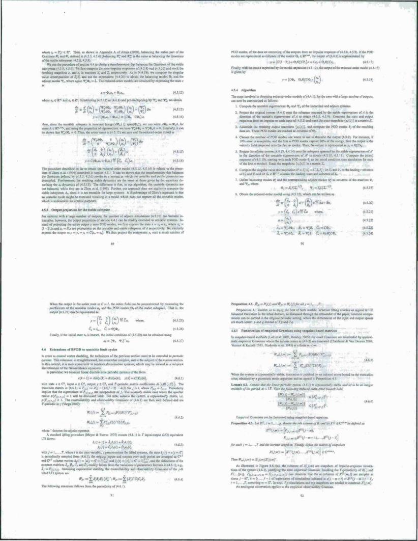
where .-.«?;.-► f TH«. « Awn m AppeBdu A or Ahu^nSW). b^ncm« *< tfJbk pw of ibe
Grama» *, a»d r. deTmed in N ,* ■/; sod Ir?)» die ume a» balancing the C.mmian»
We use ihr procedure of «ccium HID obtain * trarwronrurjon (ha balances the Cnnun of ike «table suh»v»v Srst oomnuic the «uu.impulse ncaputMn of (.4 $ X) «nd (4 5 It', and »tack the
faulting snapshot, i. and .-, a rratneo .T, and /, reopecuvciy A. in («4 19». we compote the unguUi
value decotnp»Hjori of T,X, and uw the expression» (4 4.20) to obtain the balancing mode. O. and ihr
adi^uu mooes *., where again •*;♦, m I. The reduced order model, are obtained by espressing the «Ute ■
of(4J.«.4jVVIf*«rOO ■ appraaonated by
?.) - sv«;c?.]« - a, - e,©;cx by the modal esrssmuin (4 5 12). ihc output ..f the reduced-order model (45.15)
(4.5 18) r.[c*. e.e;c«,)(^)
»•.«fed, (4.5 12)
when «. e R-» and -. 6 R' Substituting (4.5 12) in (4 4.1) and pre-muHipryin» by «f; and V„ »c obtain
(45 IJ)
<4JU)
it (ranjre^O.) £ «pan;«.)!, we can write A*. • 4>»A for
■. and an« the properties or eigenvectors, we rarve ^.<d>. = *;«>J\ - 0. Socially. * can be shown that Y^O. - 0 Thus, the en» ...- «to and rhe reduced-orde» model u
s-r-r ^)ft)-o* »-a«s-.-*s-.)*(£ C.)-
The pscccdnr* deaenbed so bjr to obtain the reduced ordo model (4 5 15. 4 5 16) it related to the proce dm oTZhm Mai (1499) descried MI MCljon 4 5.1 1. urn be »hown Out ihc iramformatwo thai balance, the GranuaM defined by (4 5 5, 4 5 6) renilU m a «item in which the rnuuMc and .tahlc ihnamic. are decoupled rorthermorc. the remain« «table dyrianuc. are the same aa those given by the eouauora de acnht«tr«A-dytunuc.of(4jl5> TV difference LI that, m out algonthm. the unstable dynairuo arc
not balanced, while they are m Zhou et al (1999) Further, our approach does not eaplicitly compute the
«able tubajtttai A,, «nee i a not rncubte lor Urge ryMcrns A ditsdvantags of Zhou « approach a out
an unstable mode might be truncated resulting in a model which docs not capture aO the unstable modes.
which it undesirable for control p
4JJ Output protection for thr ttablr «ubipaer
For «ywcm» with a large number of outputs, the number of adromt umulatwtu (4S 10) can become m-
tractable; however, the output projection of section 4 4 1 can be readily attended to mutable ryitcnu In
stead of protecting Oat entire output v onso POO modes. aa first express the state x • ■ II - ?,)*andj. =?a *x riroKCtiora on ihe uniablc snd «able <ut»»ri«cc» oM respectively We similarly
«»»•«> We then project the comouiieni i'. onto a small numbci of
TlKS»^inwri«rfmc*>ta«uVm»Jced«derir»del.or(4 4:) fortheo
can now be tummarued as follows
1 Compute oat taaaall lajjcwurniii ♦> and T. of the tiocaracd and atbosat iryaarai
2 Project the ongmal >ystem |4 4.1) onto the Mbspace ipanned by the »table iigenvoctoni of A a the direction of the unstable eigenvectors of A u. obtato (4 5t 4 5 9) Compute the state and outrun
reanoe*ofi«immiri»r»l»* on caching
I Assemble the resulting ottfjMr snapshot. {..<<,))• and enmputr the POO moot« •, of the ranking
dau»et These POO modes are stacked as columns of O,
4 Choose the numbci i.f POD mode» one want» to use to describe the uutrHiM4S')i For inktance. if
IO^c«rwi.ecxerMt^andthefuv!»PODmotfcs^
velocity field projected onto the first <n modes Thus, the output It represented a» v, - O.'O,
5 ProjeetuVadtornirys«era(4 4 15.4 4 l4)ootottKt»*.parrspae^ llaJaitwVr
in the direction of the unstable eigenvector» of A' to obtain (4.5.10. 4.5 1 li Compute the (state)
response of (4 5 10) sarong «nth each POD mode 0, as the initial conditKio (one urmitawo for each of the first m mode.) Stack the »n»r safe*.
6 Compute the »mgular »aluc dcconuxniucwi H > XX - tW;. let { . and V. be the leading i
7 Drfinc balancing modes ♦; and the correapondiiw. adioini mode» v' a» columns of the matrices ♦. and T,. where
» model »sung (4.5.! Si wbsch can be wrtnen at
y-(ci. C,)u~Co where,
A, - Y,A*„ S.-1*;*. c. ^e.e;c*.
IUL9H
Whan the output a the entire state or C" - /. the entire field can be rrconstrucisd by ususaatsug the coeSwienti of the unstable mode» a. and ihc POD modes 8. of the «able rubspace That i». the
output (43 21) can ban
C,m^, C.-O;Q>.
(4.5 25)
(4526)
Finally, if the insul state Jo w known, the initial condition of (4 5 20) can be obtained using
«.-Or. -.)•„
. nsioot of stTOD to uastabk tttsttt eydes
b order to conniU vortm sheddirig. the techn«r» a>Mtt«S. Taätasass»ast>a n lathhi catnttTi.lt a ntoaconvanaq» in et>M ■iimnajimn of tht >4t«>»er-Stokea acjttttiiini
m particular, we unsidcr linear tfc »crate-time periodic »y»tern» ol ihc form
e(«-l)-i<(*)sa)-*t»W*); K*)-0(*W»). with state i € C. input a | C. otrtput y i. C and r-penodic matrix coeiTicseoU .«().»[ ),C( ) The naaailiiiii asatru m (4 6 li i. F.,„ - A[j - \)A\, -1\ A{i) tor / > /. wl..■, -rmdK.ty
impbo that the eigenvalue» of K,,iA are aHkpeadtnt of / The mmnOv nsstVr case where the apectral I a I will be discussed Ufa For now. assume Ihr system n apanrmiatlv uabU, ,x
be comroUaMm and eaarvsnMw Gnasuam of (4 6 11 «re then well defined and are r tamochc ir, ; ('Varan 2000):
»iÜ):-£'V..>»V>*l<
«MrJr-irT^CIO-qOr-^..
il pi>J ptx«.cdw,i Pfgjnj A lhaaj HUH ,, (K),
(«A3) ■
iramcicn/r» tbc liDrd iwrmi. the uale i \i =i(j~lT)
.. he original «pun and outputs over each period arc arranged at C*'
and C*'column vectors A.<i ,'. and the dcfiniuoni of the
criaatani man ices A,, 8,. L, and bt readily tbflaw Irom the variation« ofparamctcn formula m (4.6 I). e g.
hml\M» Aiwaning «up lifted LTI «yttem arc
wnh>-l. r.whcrefi.th
.. penodrcally »ampM from
>l stabilrty. the controllability and coservebility Gnrtuam of the / th
(•A4)
The following follows horn the periodic iry of (4 f> 1)
»I
Pr.p.rm.a 4.1. »>-r,(>)«««/l%-r.C0>r«»>-
Proposition 4 I enables us ui enjoy the best of both worlds Where« lifting enable» an appeal to LTI balanced rrtmcatton to the lifted dticraun. aa discussed through the trmsmder or the paper. Ciramtan conrpu- tatsom can be earned in the original period« tettsng. where the dimeaajora of liar «put cad output spaces sre much lower p and e instead of Tp and Tq
4.6.1 Factoriraooo of rmptneal Granlant «wag saapsho« bated ■
bdjdletal 2t«T2. Rowley 2005) the e>^ Creamta» are sunstittiwd by a. X rmptneal Crnmaem where the infinite ttrm m t.4 6 2) are trtmca>ad (ChaisUao. *
\Vrn»^a\ri*iiathl9»5.Shokoohietal Ivgli at . finite -
(4 6 5)
Mm* i.Kit.i.c^i UO) .table .ru.
cm», obtained by a geometric »encs af>rutncnt and an appeal to Praposdiun 4 I
LiajatiAA 4«sawr «to the fbwur penooV ivsiewi '•/ « /; i. nm»*M*lh tuM, ami I« m tv *m rnrngtr
mMpkt/tktpmnodmmlT /am tkrJolhwmt imbfdmrm «nt bom* Md.
" ^0--)fl 4|«4 .:.
g-iOll
Empvnca) t>»3>rana can be factorceed usmg aratpsbo« based enatnees
fninMMU Or #"./»!. .a abaeartar ^nhmmeft. a*tU>V »C~~*täfmim
■ jm).
atawf"^ ■■ tj
,hr«K*J- I rass^taraoriaasJrsrgPiai. F~al>v Jtfim **mt+nof m
r"ü;«»)]<C—'.
TlmmVmU,m)-Xlj.m)X
As illuitratcd in Figure 4 6)(a». the c ' •sons of the vystem (4 6 1), justifying the K
.. one obaerv«. (hat the - o
,r;.,iw am* ■ ,,muU
g<hcrr*r«wwf», «m I
tunes j - 4T. a - 0, . .1 I of irajectsms» of inflations «nrtiaatd a eQ m-r ) = »""(; -.
/■ 1, .f. Hnmaag a« tT In total, r» «mulatxxi« and mp aiap.li.it« «re r»rrded :o i.m»w.
An analogous observation applies to the erjspmeal ob«-r«flsl»ilit> GramLsn
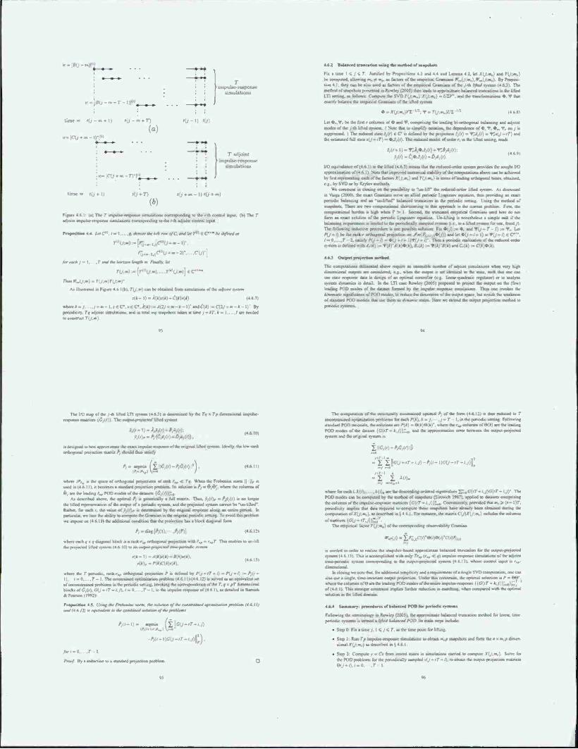
kB- ßU - att},*}
/ ttnpulsr> response
:ßu-""-r-i)f>
tünt« fO-m + J) fO-m + r)
(a) »ü-«J '0>
time» fO + l) '0+71
7" « i impultr-r«potuie
»imuUtiowi
W Kj + m- .
Hie r impulse respon« srnzuuKiocu corresponding to the i-ih conuol input (b) The r ■ conaponding to the »-th adrotnt control input
• 4.4. Ut O". I - I.... ,f. dm*** bV W* rem o/r. «f /w r<" « C— nc */Wd m
CUT
frr*m*j= I. JWitrWtwM* AT**»?.. *Vr
rcr.».) M [r<"{/.-) r^i/-.«)] €C—.
As iilMased a Figure 4.6. Kbk r(/,sr) cm be obtained ta isrmilaiam» of the afoMMsi
.1>~ I) « ^(*W*) - C(k)*k) (4.6.7)
where»-,. ./-•-!.. --*-!)' sodeW^CU/-«-*-!)' »y pcnodKtty. 7> adjoint »miulation». ami in total m« »riapshou taken et time / - *7. * «* |„ . / are needed
4.6.2 Babutcrd trasuaÜM ■via« the method of snapshot»
Fu a time I < / < T Justified by Prapiutio» 4 ) and * 4 and Lemma 4 2. let XiJ.m,) and r(/:sa.) be computed. allowing m. + i».. a« beton of the emptneal Grartuam *Jy;m.),Wm\j.m.\. By Prepoei uur, * :. ihey• can he also used a» factor* of the etnpmcal Gfamiatu of *e/-th//*«/«y.tetn (4AJ). Tbf method of snapshot» presented tn Rowtey (2005) then lead» to appranmacc balanced tnjocatioeu in the lifted LT1 XIIIAC a> blloan: Compute the SVD Ylj.m.) X j.m,) . ITSJT. and the WwfasasUu»» ♦. f thai exarnV balance me erruxrical C.ramiam of the uned system
*-X{j-jm.\rZ V7."f-r(. I <4.*J,
Let •...I», be the fin« • column» of * and *. eomprmn» the loading bi-orthofonal balancing and adjoint modes of the /th lifted ryotm ( Note that u. simplify notation, the dependence of*, «P. *,. T. on , u wpprennl ) The reduced state i,<0 6 C i» define.) by the piotectmn i,(f) - Y;i,U) - T>tJ -'«") and the cstirnaied full uatcr!,~;n- *.i.in The reduce»! mood of order r. m the lifted Httang. read*
PA') -' : (46«)
V0 cqonalencc or<4.6.1) to the lifted (4 6.M means that the reducod-order system provide« the «ought VO approximation of(4 6 I) Note :ha< unproved numerical »lability of the aimnutatioiu above can be achieved by first repreaenimtt each of the factor* X{J;m,\ and ru«J mtr3m.oflead^orthc-j)ruJ r««cs.oe«airwl e.g.. by SVO or by K/ytov methods.
mmecti m closing on the pmsibiliiy to -un-lift" the reduced-order lifted «ysieati As fliruieid to Varga (20001. the exact Granuan» solve an allied periodic l.vapuaov erarsiinn. thus providing an exact periodic balancing and an "un-lilicd" balanced truncation in the periodic setting. Using the method of auslas*, h. There are tare crampuataarail shortcoming to dm approach at the current problem First, the coaasuratinoal burden ts high when T > I Second, the truncated empmcal Gramiam used here do not form an exact solution of the periodic Lyaouoov equation Unlifung u nonetheless a nmplc task if ihr halawraig levfiaeruuil n limited to the penodKally saanpied n-atem <i t . to a lifted system for or», fixed y) The foUowiog inductive procedure k ooc pouiMc soluuon Fix *>(_,) .- ♦, and V{j - T I):- T^ Lot P\] - 0 be the rank-r orthofonal projection on Sm{F,,., ,■&.))) and let *(y -/- I) - flj - ') 6 C". i-O.. ,r 2.*atttfyr\/ ~*" • periodic realiraiwo of ihe reduced order nstem a defined v . andCU«) :- C[*W*)
4AJ OaejMM proiretioa method
The computations delineated above require an untenable number of adjoint simulations when very higb * cucwdcred. eg. »hen the output u set identical to the stale, each that one can
c data in design of an optimal controller (eg linear -auadratic tejrulatot j or to analyze .ystcro dynamics tn detail In the LT1 case Rowley (2003) proposed to project the output on the (few) Iradmg POO mode* of (he dataset fanned by the impulse nesponac tmuilationv Thus one invokes the kmrmalk significance nf POO modes, to reduce the dimension of the output space, but avoid* the innalfmna of standard POD model» thai iwe *em a> J.**««-Hates I lerr we extend the output pmjectwo racmod to
The I/O map of the /-th bltect LTI systtan (4 ., .rams« «aatnee. (<?,(/)}. The .aaja» preyeeresf Ufted syHcn
by the r« x T» dun unal unpulsc-
-l)=i,i,(«)*4*/*/(0; .»,{#)--r*,(t"^(f) -/»>(/)).
■« designed to best appro* irnatc ihr exact impulse rs^ponsc of use original li crtfarjfonal projectjon mamx /* should dais tabafy
A- < !*.< Av|
fi:<J;('»-Ac
(4 MO)
Ideally, ihe km .ank
(46 11)
where a-. „ the space of orthogonal prraeciions of rank /., < T* When the Ftobemu* aurm l| II, t» used in (4.«,. 11). it becomes a standard projection problem It» volution ufl, = 0,0;. where ihe column* .if Ö.aretheleadmg/^roDrmMfc.oftScdatascald,!»))^,
As described above, the optimal P, at jancncally a Full mams. Thus..»,((), - ??,[<I u no looser Ihe lifted renrcarntatioo of the output of a periodic system, and the projected system cannot be "un-liftod~ Rather, for each i. the value of >,i'jr is determined by the original lesponae along an enure period. In particular, we lose the ability to compute the Gramian in the original period«, ictung To avoid this problem M impose on (4 A. IM the additional condition that the projection hau a block diagonal form
4-«-*J!4(». *AT)\
epron h e x f diagonal block gj a rank -,., arttwgonal proyectioa with f., m r^T Thu enables to un lift sod Ufted system (4 6.10) to a
x(*- I) -i»(*)r<*>-*(*W»): ^*i,-»ti-y •
(46 It)
where the T penodsc. rank r.r .«thoguoal proyeetioa P u defined by P{j -lT-„ . PI./»», •-/,(»- I). .-0 r- I The oonttrainod optimiraUrao problem (4 f. I! i -(4 h i: in «Ived a* an equrvalc« »ct of unconttrainod problem» in the periodic telling, invoking itie correspondence of Ihe T, y « pT dmicnM.inal block» of<J,(<).C(J-rr-i.A'-0 T-l,iotheuTir«ilaeiespe«r«oF(4 6n.a.detaiVc*lml^ ftllMlMt) Propwiiooa AS Ura«; the Fmheaäa morm. AW a omlUf. 12) it ee«rvaxVs» tu (Ar .c—AowW aacarwri e/mr araklaair
■ . i V'-«
/»,«> iKrtj-ir-ijjp.
>v/-o,.. ,r i Pmof By a reduction to a standard projection problem.
m/m>Um>(4 6ll)
The emputauon of the structurally constrained optimal A of the form 14 r. IZ) ii thus reduced to T mwemliainrd optimization problem» for each /*!«). t *= / .j~T I. m the periodic setting Following uaodardPOnratwoak. the »iluiion» arc P<*) = «3(A>rX*f. where 0Vr.,cohimm or 6(*l are the leading POD mode, of the dataset {CUT~ t.j))^. and the apssrmaeasuon error between the output piajirt.1
i C;,-.)-AC
- I l\Gu-r->.D-rV<-\W~tT~$.J)f
- I t AW. -
when tor each i.A(/), A(/),«tetl»deace«uiv.^»ifcixde.ga»^ • • - (/ /T - , ...)• The POO mode* can be computed by the method of «upshot» (Suwich I98T). applied to delate«* enrnpnsing thccttlunrnsofthcinipulse-respimae matrices {C{tT~ IJ))'^, Conveniently, provided that«., periodicity implies mat datt required lu cornpute these sraawbn«* have already been obtained during the computation otXlj.m,). as described in ,4 6 1 For instance, the mam« Cjß ofmamco(c;C/-'.'
The empmcal factor Yij-.n.) of die correaporicuTrg observabtliry C
i* needed in order to realize the »napshot based approximate balanced truncation for the output-projected system (4.6 13) This i» iceumpliahid *»ith only tag. (r„ < «) impulse response sa—nl—nine of the adjoi« trejc-yienomc rystem raamraBcatamg m the cniqwt-pnrjected sysscen (4 r. 13). whose control input is r„-
L. for add :. .'.mc .miii.ri' .Mip.
mß^mt^m aajjMiaa I rvir. i.'u>.
«tofa*uvg>eSVDc. t. the optimal selccuon i» P - OO-.
where the column* ore are the leading POD modes or the entire impulse re»poo»c (|tV(»r - 4 y 11;.,,)^; ' Of (46 1) Tht» «ronger ccostnunt impl« further rrrfw:t»on ^ m«chu*g «Ivm co«^»ared w^ rhe optima', solution in the lifted dornen.
4.4.4 S«-raar>: fH^rd«rr»o(b»*Mc^n)I)farp*r**4k«s«ra«
Following the terminology in Rowley (2005). the appnuimaic balanced troncauon method for linear, iime- rmed a lifted holamced POD Its main *tcps tt
• Step 0 Fn a time ;. I t. / < T. a* the tine point tor lifting.
■Mg itoc*«ain*v»*»*arjthc«andfarmtaeaxavadmien • Step I Run Tp anpulsc-ec»] uonal A-(y.«,) aa described «(4M
m Step 2 Coaspute r « Cs fass stored states in lanutatron* earned to cernpure X{j,m the POD problem* for the perHKUcally sampled *ij-iT-1), to obtain the output projection nuance* eo-').<-o. ,T I
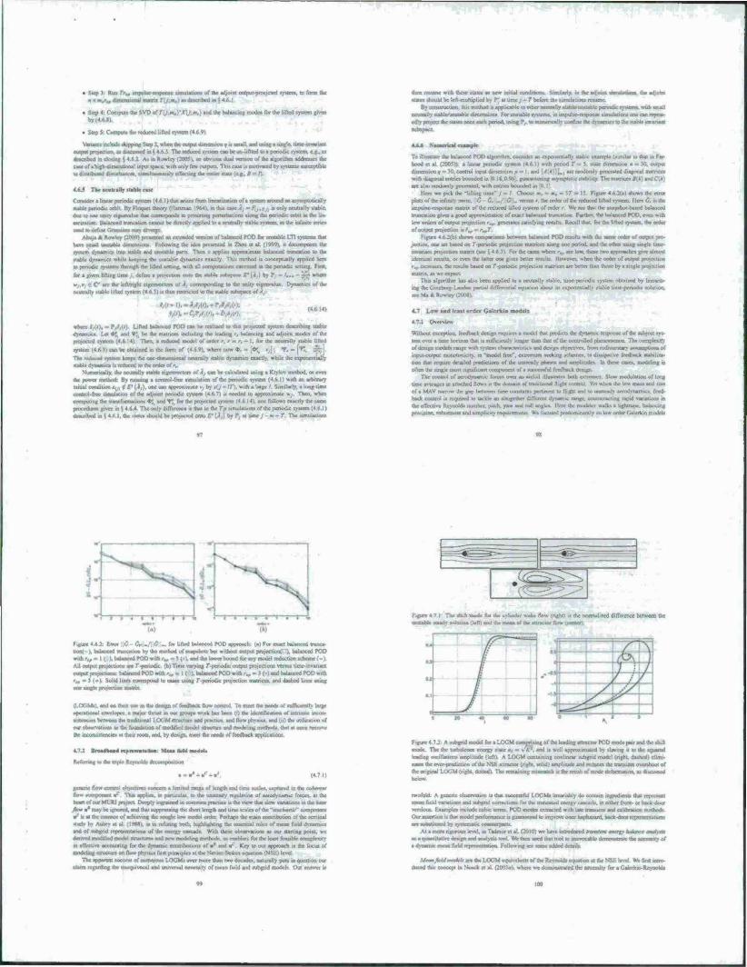
. .... I «ljo.ru «mtput-proejcied lyrtcm. to 6» the
• Step 4; Comp««dw$VDofr(y;i<«.)-jrU;«.)»^t^^l««"*'™«^f««^l''led*y*'em«l«in
by (4.4.1)
. StepS C<*iput« the «**«! hfW.yvrm (-»(.■;,
Vanam» «clod* «tupping Step J. when the output dimenuon « u «mall, and using » «iajlc. Moe-mmu« output projection, atdiscussed un 4 M The reduce«! «y.iern can be un Iifticd Ui epcnodic system, cg^ns .»csenbed in closing l, 4 * : A. m Rowley (300$V « obv«B «foal venion uf the ^coe.lbm iddmse» the a« of« hif h-dimetuiiicul input trjecc, wuh only Tew output! Thi» MM H modvued by »yaicrm »merptible v • .i -«.•.-: : .-.■■I.^KO nmultanrouilv rfTcctine the rain »v»tr (c r ir !<
4»_* T>e«e«tr.lly »table case
Consider a linear penodic ryxtcm (4 ft 11 that ««1« from linearization of* »wirm around an etyttiptoucaliy fUbte pcrvodtc ofb-t By Floauct theory «Hartman 1964), in th» atck, . FU.T, uonly neutnlly Uablc. do* to Mr unity «(emhi* that correspond» to pc»u»ting penurhabom along the penodic orbit m the lot cart/attar, Balanced truncation cannot be Jirtxll« applied In • neutrally «UN« «yatem, a» the infinite «en*» mat to define Gnaw« nn diverge
Ahuja A Rowley (1000) presented an extended version of balanced POD for ratable IT! tyxteras that have Mtiall urrstable dmvrmtnr» Following the idea pmentcd in Zhou ct a! (1949), it eieeompose» the system dyrtenuo inuj »sable aid lanraebl* para Then it appbea appnnimatc balanced tnmolion to the taabW dynanuo while keeping the mutable- dynamic* exactly. This method u conceptually applied here to penodK •> stem» throviah the lifted tctting. «nth all computation» executed in the penodic «sun«, Fml
.. lifting lime j. defmc a promotion onto the itabk Mhapacc E' (Ä,) by ?,
' - are the IcjVnght eigenvector. .,; I conTTponding to the unity eigenvalue Dynamic» «4* the neutrally «table lifted tyttem (4 ft 31 u thu» renncted to the »table sub.■•.
(4 6 141 MrM; D/i/W,
tttfy Li'W bahweed POD on be realized to <ha projected rystcm d dynamic» Let *: «ml <•» he the malhcta including the leading r, balancing and adjoml modes of the pratccrcd »yvem (4*14) Then, a icdusad model of order t. r « t. - I. for the neutrally »table lifted ryxtcm (463) can be obtained in the form of (4 ft 9), where now *, = [•» v,j. •/, ■» f* Th* ndocad tyuem keep, the one dimensional neutrally »labte dynamic« exactly, while the exponentiall) «able dynamic» it reduced to dMt order ofr.
Numerically, the neutrally »table eigemrcuir» ol .4, can be calculated uuna a Krylov method, or even the power method: By tunning a citrrcrol lire timolaoon of the periodic ryxtcm (4.6 I) with an arbrtrary initial condition .,,. «•' f"'(■!,)■ one can approximate v, by «fj ^ IT), with a Urge / Similarly, a loraj-Mnc liitlld On umulation of die adjotnl penodic xyuem (4 6.7) i* needed to appronnuae », Then, when compuun»; the trarwformaiioru V,t and fj .for the projected «ywrm (4.6 14), unc folio»» exactly the aarne
i*i jiven in i 4 6.4 The only dilTcrcoce n that in the Tp vmulatiora of the periodic »yxcm (4 ft 11 i m S 4 ft I. the .-MO ahould be projected onto E' (.?,) by ?. al time , m - T The »imuUuorn
■ran Räume with theae itate» a» new initial condition. Sflnuarty. m the adjoaat taaham the adyeo* itawa ahould be left-multiplied by fj «lime j~T before the iimulauoox tewmc
By corittrucuoo. dm method u- applicabte to other rawtraUy itabltynnaaabh- penodai tynataaa. wtrh araafl neutrally nablo-uncublr dimcmioro FIK urutahle »»xtemt. m impulvr-re-tpon»e timulatioru ixie can repeal <d«y a«qp]r» dar ala«*» C4»K c«»* n
4.6.6 Namencal rxaaapl*
To illnattate the balanced POD alfanthm. coondcr an exponentially «table example (»urular to that hood et al (2005)): a linear periodic «yratn. . 4 ft I» »,th perKvd T - 5. «ale dirnerauon m - 30. dunerujoo9 » 30.control input cbmention p - I. and {A\k'i)\.t are randomly «encrated diaforud with cUa«>^ c^ine, b.n,ndol m 0 Ift.OOf.' euaraniecir« «ymptotu: »abil.iy TV rnatnee. *!l) andO*; are alao randomly generated, with entnex boundeo
Here we prck the -liftint time" j - I Choote m. =a,«iT» IS Fipac 4 6.2(a) »how» the cm* plots ol the mfiwt\ norm. ' .-«ui r. the order of the tedvxed lifted «yxtcm Here l), i» the irrtpiirae-fcxjxHi.e roatra of the reduced lifted xyxum uf order r W* ace that the wtapxhoi baaed balanced truncation grvea a food apprmrrnatinn of exact balanced tnjncaiio« Further the balanced POD. even with low order» of »«put projection r^. (enerate» iatafyinjt reaulH Recall that. For the lifted xysters, the order uf output projcctioe la /„ = r.,r
F .eure 4 62(b) »how» ca*np*rnrjn between balanced POD tcxulu with the >aoic order of output pro- jection, one irt band on r-penodic projection mxtnccx alonjt one period, and the other using a invariant projecttoo matrix (»** -. 4 ft •>! For the caxc» where ',, arc low. Ihevc two approaches » identical rexultx, or even the latter on* give» bener ic>ult> IK<wwrr. «hen the order of ocnprn p raa mcreaatx. dtereauM baaed on T periodic projection matneet air better than thewe by a «ingle projection r-.jir « .* »c .-«[<--'
Thu algonthm hat alto been applied to a neutrally xtabie. nme-penodic tyxtom obtained by Iineanx- mg eat Ginxborg Landau partial differentia! etpiation about it» exponenualry «table time-penodic totatun. tec Ma * Rowley (2t"«8)
4.7 Low and Icaat order Galcriia
4.7.« Overview
Widwut exception, (cexfback dextgn requrre» a model that predict» the dynamic rcxponae of the lea ever a time rnxxruct thai tt rae&ieeiK lonper than that of the oontrollad pberaaxtearaB. The of dexign model» range with »yoem i haaxxtuniiir» and design objecuvex, from nahamaaiy
StSm input-output rminotorucity. in "nnodel free", exuemimi veekmr »chemex. M dimpative feedback «tibilnc*- iion that require dctailai prcdicuom of the uittieady |ihm and ainptitudei In these caxet, modeling t» often lb* angle rnort ngm/icant caeananenl of a «ucxctaful feedback deatg»
The control of acjodyturmic lorcet over an airlo.l illutrratc« both cxlrcmct Slow modulation of long time averages m arracbed ftowt » the dumain of traditional flight control Yet when the low max» and so* of a FV4AV narrow the gap between tune coiuiant» pertinent to lligtu and to uratcad» acrodvnarmci, feed- back count! .» required IO tackle an altogether differera dynamic range uxmieracung rapid variation* w the effective Rcvnold» number, pitch, yaw and roll angle» Here the modeJcr walks a tightrope, balancing preci«o*trobu»tne«ai>dwmpl.crtyr«
n
Figure 4.6 2 hmn ,<> <), ., C .. U* lined halanccd POD approach (a) Fc» exact balanced tninca uon( .. bataoccd ouncau«. by the method uf auapar««x b« withe« ootrrut pnvjectu^ ). b»danccd POD with r,f m l ( i. balanced POO wuh <■„, « 3 ( i, and the lower bound for any model reduction scheme (-) All output projection» an T-periodic (b) Time varying T periodic output projcclions vern» tune-invariant output projector« balanced POD with r.r = l( ), balanced POD with r„ - 3 (1 and balanced POD wmt rt m J (* I Solid line» correspond to cases uatng T pniodic projcctHm matnecx. and dashed lines uxtng
flLXXHttaV and on theat tra« m th» iHetga of (llOirk Dow control 1 o meet th« needi of »ulficreoth large pantina»! emxlupe». a mayo» threat in our ,troup» work bei hecn , 11 the iihiaflharton of axtnnrac mcoo-
limti.lil herweon the tradiUorta! IXXiM«ttucture and pracucc. and flow phvxiu. and (u) the tmluation of «wr obamatjoo. a» the fnaadation ol rnodilicd rnmfcl «ructiax «nd rrwklm^ meUscxU. dial al < the incontittencie« al thttr roots, and. by design, meet the wort» of feedback application»
4.7J. aWdhrsad rapreawmtsras: Moaa I
Riaxserag »a ax» theaa r^ytstrati. itjcrxa-jniirinn
■ -■*-. (4.7.1)
e»3ret*flm»c«ri*rolohrat*rv« Itew innitnaaat a0 Th» applies, in particular to the unsteady regulation of aerodynamic forces, at the hear» o» our MUR1 project Deeply »ngrained in common practice u the view dua »low vanationt in the rsosr flow a* may be ijrnurcd. and thai »upprexnng ihc «hon leiigih and time »cale» ol the "rtocaotnc" compoocni «r* tt at the rannir of achicvotg the sought low roodot order Perhap» the main contribution of the »ctmoal «tud» ft» Aubrv et al (IM*), re m refutimj bath, rughliahurtc the eaaentaal roles of mean fidd ihTiarmc. and of «ubgrul repreaentattona of the energy cascade With these oeHcrvatiiim as our ttanmg point, we d*rned rnoditatd mc^l »tnrxiia« arid rttw rrso* ■n cffrclive atxrMMiivr for the dynamic coninhuiion. of tr* and a1' Key to our approach la the focus of roodcimg «naeture on flaw phyxtcs frrs» pnnciple» at the Savsrr Sinkt» ccxiattnn (NSt) tcvd
The rasaasxax HJOCCS» of nunverou. LOOM« over more than two decade*, riaturally pors in qucaion our clarm regardine the unequivocal and unnersal necesstry of mean field and iuhR»d model» t)ui answer is
Fojur« 4 7 1 The ataft mod* foe th* cvlmdr: waka flow i nghti u the ttnrmauzed difference bttmaaji the taaatabte »lead« txthatKN» (left) and the mean of the etiractor flow itenter)
Flgurc4 7; A »ubgnd model for a LOOM cc»mpn«ing o( :hc leading Jiunttor POD mode pair and the »Sin mode The the turbuience energy state os at U'1, and is well approximated by «laving u to the iquared leading oxcillauoiu amplitude (left) A LOCM containing nonlnxtsxr aubgnd model (nght. dashed) dimi .täte, the over prediction of the NSF. aitractor (nght_ wltd) amplitude and rcduco the tramotw o«xT»hoot of the anginal LOCM (ngK dotted) The remainmg mitmatch i» the rcxul! of mode deformation, a» d.»cu»»cd below
twofold. A generic obtervauoo i» that successful LOCMa invariably do contain ingrodrenu that itptuaetii mean fieid vsnauons and airbgrtd c«rtec.i*>r» for the rruncaicd energy cascade, a» rather from- or hack-dom vcniioojL Fxample» include cubic terms. POO moon extracted with late rnasstcnt and calibration methods Our asaeruoo a that model rsrsforrnuMX is guaraaxt«ad to imrwove on« «re aaaaltsiaxd by rystemat-c totrraerpartx
Al a more ngorou» level. inTadmor et al (2010) we luve introduced imrafnu energy hoime* mmliatt a.aci^iariutatnedesqriartdaoalys.ttool We then uaed that toe»! to irrevocable derr»r»strat« the iteeesiuy of avhitamicrneanrirMrr^sretmttation Followmg «re some added detailt
>4Vrm>r»Vr««xdrtr arc dtc LOCM ««ytnir^ We first rntm- duced rtu. concept in Noack ct al. (MOitr). where we C«»iaxmrara4«»i Jw aaxeasiy
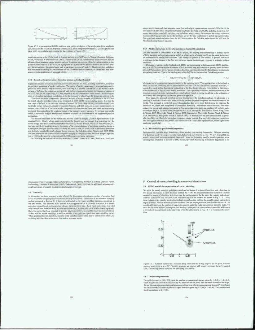
•Ulf i hvhnd irarocwork. UM integrate» mean tietd und suhgrid representations into the LOCM. In all. the new rnmcwxfc it» u dam altogether new «xnpoocnt« a» lb* realm of LOOM*, including mean held iA./f modo that tesolsx mean field »ariation» and mrtmltm tmff tola, that represent OK cntjrgy contem of suppressed flow components, but for the Tint ume. an not the time coefficients of »patial. expansion mode» Fan principle» model den»*«« fco« the SSE thus combine the Clerk» projection of the NSE and the NSE-baaed energy balance equation.
Figure 4 7.3: A paramefnaed LOCM enable« a near per) (left. solid) and the oscillation frequency Kernet, solid) v (dot*, both). successfully ampcru-ating lor the rssidualt
f the accclctauon force amplitude nth the local Galcrkin projection»
rnoddamnponentalthe LOCM loci A detauWaoaly^i» at the NSE loe^ .nTadmor. Gottrale^ Uhriu««. Nssstcs, Monrymk. ft W Siankicwicx 12007). Tadmor ei al (20101, covered both model nructure and the aforementioned transient energy balance analyxis Eatendmg the concept of the Reynold» equation to fre- quency filtered sessions of (he NSC, M highlighted and quantified the essential role« of the bilateral «to play between duunct frequency band» and. in particular between ■' and ■' These analytical tool* have alto been wed in deriving an ideal structure for the Galcrkin Reynold, equation, itt italcts) and thor inter MJiogi vk.ih the traditional. m( centered LOCM.
-i ~ - Hmadband representation: Statistical cla\ure and »ubgrid rnodrh
Significant d>-narmc prediction mramatch between LOGM» and the NSri. including in.tah.htit» motrvaied the growing prevalence of model calihrumm- The tuning of model parameter» by empirical dau and. in particalar. tuned imodali ctUy vuamltrr. trace to Aubry el al (l°88l Calibration ha» the aesthetic short- corning of forfeiting the conftdrnoe awxuted with the fust principle» foundation the Cialerkm protection of the NSE. I'crhar» not uirprtungly. it u also plagued by all HO common » "f tuned model» Addressing this issue u yet another najjajfii aiiaT contnbutMm to the dcseloprnent of effective model design and analysis tools
Tht» thrust had three components Structural analyttts of energy transfer mechanisms at the NSE and the tideal inTinite) Galcrkin sv.tcm levels (Noack el al 2007. 200X1 was our starting point tl reveal» the root cause of failure» to the artictuml mismatch between the linear eddy viscosity dissipation icrmtsi. and the thadic energy exchanges, created by quadrauc Galerfcin and NSE terms, in an exact tepieseniauun. In essence the calsteatuo of the linear modd coroponetii tads because the Linear term terrm are structurally precluded from mimicking the nonlinear nature of the truncated energy cascade. At tow and least model orders, a successful subgnd remedy must rndwor to match the nonlincanfy of the suppressed physical mechanism
The second component of this thrust heed the call to revisit nibgnd Galcrkin representations at the structural level Clear!)-, a leaf order mode! should be focused only an lumped, slow quantities, if . the stored energy. That focus inevitably reawaken the statistical closure monster, where it i» least aajlooi in a least complexity modriing cunsext. Cognizant of the pre«na>Ml rasne* of turtsuleoce modcUng. dating lo Kolitsogorov. Oranger. Balchtvor aad tOarchrtan. we chose to start. eV name, ssith an as ninutic fratnework and derived a rciriarkably simple closure theory, expressly for Galcrkin models (Noack ct al. 2007. 2008). The new (rssmevvork has been validated in system, rangmg in complex its from low order Burgers cessation. to a a 1500 modes spectral compression of the <D horruigene.su» shear turbulence
In a ihirdsicp we revolted the issue of brrasdhssrid LOGMs (Tatnor el al 2/»». Noack et al 2010\ ere
4.7.4 Mode deformation, modal interpolation and manifold rmbrdding
The ssav obsccusT of flow control in the MUR1 ptoicet. the shaping and mcJiestratinsj of pctsodsc cycle» or LEV sheouine and regrowth over an airfoil at a high angle of attack f AoA. can be stated in terms of the defarnsatjos of leading flm» structures This example si gstnenc to flow ctxstrol. m general as sstll a* in reference to the changes m the flow as il traserses natural transient» and responds to unsteady ambient
Motrvaied by earlier result» (Gerhard es at 200.x... we dcirasastrascd in Lehmann et al 12005). Lochten burg et al. (2006) both the severe deleterious effects on closed loop pcrtsrmance of ignoring mode defbrrna uon. and the feasibility of very laaglc aaaadst». baaed on a nssramctruxxl mode; that uxducs a aaswiiaar) inierpolaied mode set. Thai i«, the starting point of the LOGM is a parametrized Galcrkin cxpsvjsion.
. where At *E m u an exogenous paianiefrtauori of the operating potnt This approach can be formsrlased as term» of efficient embedding of the approximated floss state in a loss dimensional nonlinear manifold, as opposed to much higher dimensional embedding sn the host luicat subspacc It is similar ir. this respect so the ltamessiqi. of approximate mertial manifolds The tigmftcara ihfTetcncc. and the irasos-ation sn the |*iijpissfd approach, tx in the tranutjisn from a single global model, in inerual manifolds, to the utilization of local bases, which the generic differential psotnetne approach
Once again, this approach stretches previous boundaries of the Galcrkin paradigm tu advantage is in enabling lo maintain a least model order, affecting inthcr the predict»* pow«r rstt model This approach is contrasted, c g . with approaches that cover mode deformations by enlarging the expansion set, bence both complexity and numerical scnsitivtrv Hcochmark studied included flow scro ration osx» natural and actuated oanxients in flow separation over staue and pitching 2D airfoils, and a counterpart range in 20 »sake flow» t Momnski ct al 2006. Mor/vnski Stankiessic/ Noack. King. Thiele at Tadmor 2007. MsaTttrsk», Noack * Tadmor 2007. Stankrewicz. Monyrsdu. Rosxak. Nxxxsck & Tadmor 200)1. Stankiewi«. Mtsrryiriki. Noack t Tadmor 200«) In these article» sve have demonstrated, in pan« ular. the ability to effectively iiuerpolaie orsssttaion modes between few, explicitly cunyputcd rrpaniiorn The new approach enables near perfect state issssdasson with a least urdcr is^tresteraation, where higher order traditional model» fail
4.7.5 HarssassssscaUs .»«she mod*, cxpaa.soa»
Design snodeb typscally target few distinct, albeit possibly time varying frequencies Effective rrissddtng will therefore employ (texrurmes-specific state», hence frequencs specific modes We base lormulated and tested a conceptual and cosopsmmoaal frarnevsotk, hased oa fksyiaia.) specific modal exrsssxxton, a» an advaattsssnos» shsnauve to the use at FOO rrsodcx for svhaca the mixing of mulnpic trequencic» in the
ds^satrua ixvolvs^ by a sjaspe rnosfo i> comrr^ Luclssetsbu» Lehmar» * Ivtorry^ simple derivation of a nearly gswdesoc mode inierpnlatiisn scheme
4JI Summary
to tlsa »sxlaaci. w« I»»»« presxml»^ flows, smuhlc (or designing controller» for closed-loop flou conuol The version of the immersed bourjdarv roatkod presented to Section 41 a fast, and well-suited to the vortex .bedding problem» cssnsidered in the next section The Balanced POD method, a close appn.ximatKxi to balanced truncation, it a model reduction method hased on lincai i/ation »bout a particular rlosv state In its most basic form, it u valid only for coxiaooox l»ssearucd about a stable cqu.libnum (eg . a stable »oiution of Navier-Stoke» equations) Here, the rriethod has been sotteoded to unstable equilibn» (auch a» an unstable steady solution . Stohev with no vortex shstdding). as well as penocuc orbitt (nach a» a particular vortex-shedding cycle» When oonliaeantie» are important, rrwimal-order Galcrkin model, allow one to include these effect», by modeling both the «ll'ect on Use mean flos» and on truncated modes
5 Control of vortex shedding in numerical simulations
U BPOD models for suppression of vortex shedding
We apply the model isxhtcuoa technique» developed m Section 4 so the unilorrn flow past a flat plate in two spatial diniemions. at a low Reynold» ttumbcr. Re =• 100 We obtain reduced order models of a system ■ Ltuas»albyrn»s»»Mofak»caliiedbods f.stce naar the trading edge of tht flat plate ih» «ssrtitirs and »etocits cootour» of the flow field otstainad on an irixmiisrrc input u» the actuator are shown tn Fig 5 11 Ustng these reduced <srder ttvodels. »e doelop teedback ci»nu^ •ngksofaitacs. WV firsi assume full-statc Icedback hut use osirrx« r»re^t»on dess^r^ m s»Mt»on 4 4 1 I.. considerably decrease the number of output» in order to make the model computation tractable Later, we relax the full-Male fecdb»»»*a»«»mption. and deseiop a rrsc« praaicai obscrvcr-bi a few seloctty maasxtremenu in the near-wake of the flat plate I shown m Fig 5 1 I) to n
sensors
.;rt;iat;..::
•1-'i 4& 6 o!5 i
Future 5 1 1 Aauatu. rrsodeled « a localized body force near the trading angle of attack fixed at ot « IS" Vortiaiy crmtourt are plotted, with tine» The »esuory-sensor iocatsucis arc marked by solid circles
edge of the flat plate, with the •n by dashed
The gnd «izc used is 250 > 250. with the smallest ccmrMtatinoal domain given by tshere length, arc non-ilaainiiiiial 1 bv the chord of the flat piaat. with it» center located at the otigm We use 5 dtsrrtaantt in the multiple grid scheme, rs^lting in an eiTectr« compulauoMl dornam then» of live ts»»anc«t4o»sMto;»»»»» The iirrsestcp used tH 1 ajanatolfaa. to »nrftQI,
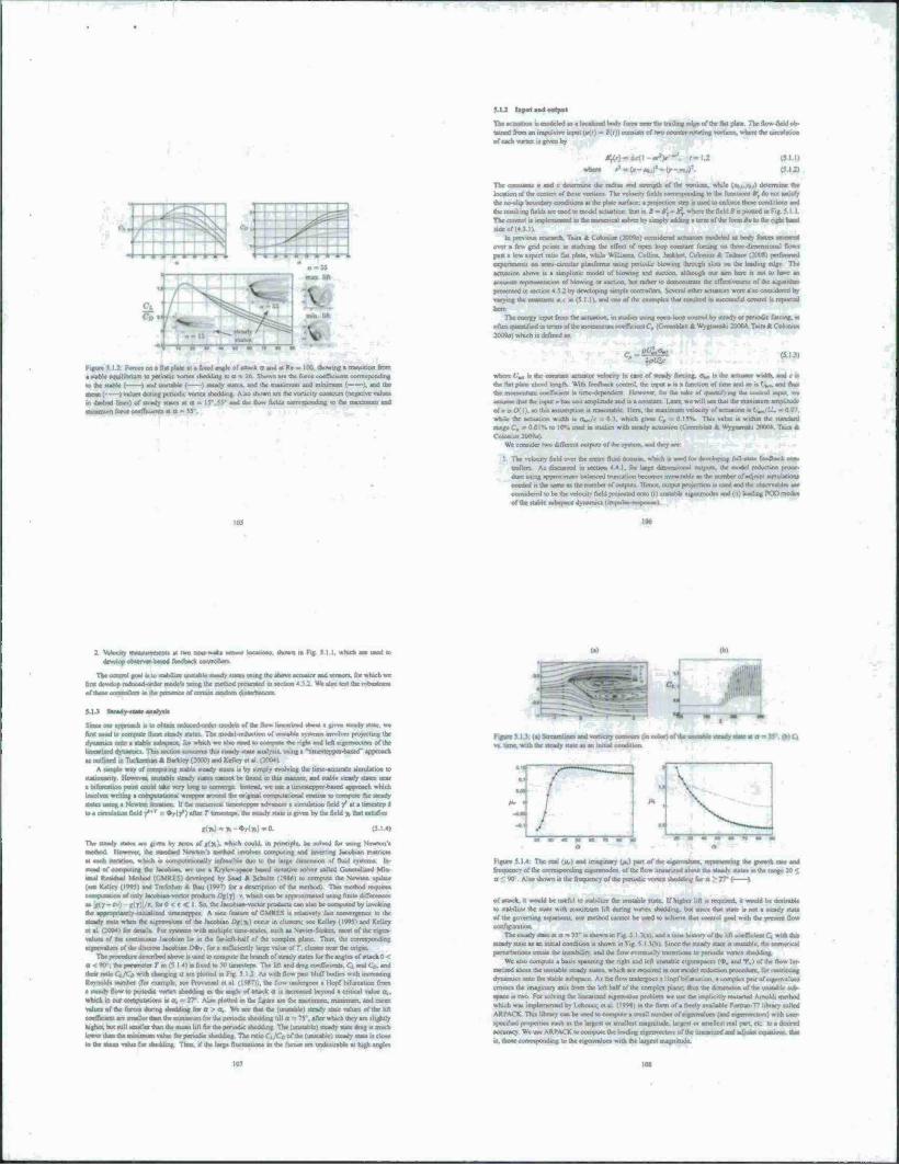
5.1.2 lapet sad oerpei
The «ctualion i« modeled u • localized bod» lore« oca. Ihe Irnln; edge of the lUl pUu I he llow-fieMob- tuned from an impuLive input (»<>) - 4(r)) corai» of two a ofeach wjrte» is |Mt by
(im
Tbc «wunu a and c deseraanc the who* .ad strength of the «oruon. while I«...».) dncmuoe .he loceuonoftiweenixrsofthesevoiissea The vekesty Odd» corresponding to the funcuom », do noi satisfy Ike no-slip boiirakry oondiboa* at (be plate ubec; a pfc^cction step u uted lo cofonx ihcw conditioo» and Ihc tesullinc. fields are used to model actuation, that n. B ■• B\- B% «here lor (kid Ä is plotted in h Trie control .• mtCHrmcnted m the ouojencal solver bv umpKadding a lam of the f>»m #a to ihr righi hand udeof(-i
In pimoua research. Tain * C olomii. (3Q09e) oocsndcred actuator» modeled as body forte» ameared mvt a re« grid potato in «lahme Ihr effect of open loop constant forcing on ihree-dimenuonal flows past a tow aspect rat» flat plate, while William». Collms. Jankbot. COIOMUS A Tsdmo. (SOOt) performed expenmenu on trmi cutulai pbasionoa using periodic blown« through «Jots on ibe leading edge The actuation above u a tunpusuc model of blowing and suction, although our aim hoc » no« 10 have an
presented in section *42 by developing sunple oonnollcrs Several other actuators were also considered by varying the constants «,r in (5.1 1X and one of the exampks Oat coulied ■ aucctaaful ctmDl ■> rcpiaied here
The energv urput from the actuation, m «radio using open loop control bv iti»dy or periodic forcing, i. often qaaotukd ta terms of the momentum ee,(!k&C0iGnm*ka*WypmmkiW>l>l,.Tm»*C<*xum 200*» which is defined a,
regte« J : 2 -i.e. .«i s flat pU». si . fi.ed «nek of attack a and at Re - 100. thowmg a transition from a stabk equilibnum to period« von« »ricddiiig si a ~ :r, Shown are iht force coefftcsaKs coirespoodu») to Hat atabk < ) and unstabk ( ) steady «atcv and iht m«..mue- and minimum ( X, and the •Mail'- > «Uje» during periodic vortex sbeddu« Also shown arc die votticity contours (negative values in dashed unea) of steady «atcs at a - I5\5V and the flow fields correipondo« to the mavanom and minimum force coefficients at ■
***&• where 0„ .. the constant actuator vefoe.ty in cast of steady forest«, o«, is ihc actuator widsh. and c c, ihr flat paste chord length With feedhaek control, the input a is a function of lime and so is V*,. and dais the ntmimmaii «wnVatnt a lime-dependent However, for the aake of quantifying the euanio] mput. tn assume Dial thr lopu) a has unit amplitude and is a constant Later, we will sec that the maximum amplitude
I assumption .. reasonable Her«, the maximum velocity of actual... wtule the actuation width a '"■ This value u within the standard
!C C„ - 0.0IS to 10% used m ttudict with steady actuation (vkecnhlaa A Wygnanski 2000». Tain * »200M
Wc consider two dillcicm output* of ihc system, and they «re:
I The velocity field over the entire fluid domain which i. used for <k\etopin»i full-state feedback, coo tmlkrs As discussed in section 44 I. for larrc duncnwonal outputs, the model reduction proce dure using spprosimate balanced truncation becomes intractable at the number of adjoint asvstjiaTioro neeekdnthrsaiiKasAeinimbeir^iiutpuu Hence, «iipm prcsectjon » used and ihe c*servabte» an considerrd to be the vdocstv field proieetcd onto (0 unstabk eigrnmodr» and (u> loading POO mode» of the stable «t»|ssie dynamics (impulse-tespowc)
B isnatwaar sensor locations, shown m Fig 5 11. wbtdi are used to
The iiaaaul foal is w stabtust lassteblc stoadv iiaics using the above actuator and sensors, for which wc first develop nsdueed-order models using the method [resented in secuon 4 ? : Wt ahv test the robaaaana aflhin .iiuajutlnii saaW pail mic of cenamratidcendtsnaissncea
Sax» «a approach a to ohtam nrducad-ordci model, of (he flow luscarterd about a prim steady stale, we first nord to compute these steadv state» The model-mduction of unstabk syatean HJVT.1V« projecting the dynamics onto a stabk tajbtpaca. fee wtach wc also need »compute dsc ngru and left e.genvecton of the Imearuasd dyiiamics Thl» section concerns this steady state analysis, using a "unie«c|jpa-ba»ed" approach as oullmed ,n Tuckermao * Bartdey (»00) and Kelky «t »I. (2004)
A ssmpk way of curnpuung stabk steady stales is by »imply evolving the time accurate simulation to •tauoaarity. Howevac, »natahlc steady stales cannot be found m thu manner, and stabk steady states near a kftaxaaun pasta amid take vcty lone; to converge Instead, we use a timeatepper-hased approach which involves writing a computation«! wrapper around the original computational routine to compute the steady states itsmg a Newton isertuion U the nuttcncal tmaattppw advances a emulation field y» at a fimii—■'■ » ta• eMlauenfkldy»*r • *r(/)«ftet TUxm^.umMnhMMtovgntatotiKteUl *******
«(»)-»-OH»)-a The uesdy atates are given by ren» ol■«(«,.,. which could, in principle, be solved fur using Newton'. astaaod However, the aandard Sew ton i method involve, aanpuung and mvcrung kcubsan mattvecs at each awnatjoa. which is cotnputauonalh infeanbk due to the large dmtcnsioo of fluid systems. In- stead of coarputing oat Jacebtan, we use a Krytov-space baaed .tcrativc sotver called Cctaaattard Mm •mal Rewdual Method i.CMRF.S) developed by Saad * SchulU (I9M) to compute Ihe Newton update (see Kelky (19*)) and Tretcihen at Bau (1997) for a desarptu» of the method) This method resaeres neauaaiiuii of only Jacobean »eciot product» DtiT) ». wtuchcan be apptt»ntsalod using finite dinerencci
I < C < I So. the Jacobian-voctor product« can also be computed by invoking the «eatliutlWly-nsaialirnrl unxttept«. A nice feature uf CMKES u rciatrvely faat coavergctice to the steady state when the c.eetwaluea of .he Jacobean {*(]») occur in clusters, see Kelky (19951 and Ke!le> etal (M04) for dcank For system, with muUipk tune-acase». inch as Nat wStote». inort of the e.gen valiaa of the corumuou» Jacobean IM in the far-kA4talf of the compla plane Thus, the cotTtapondjOf cigcnvslucs of the discrete Jacobean OdJy. for a satncientlv Urge .-»lue of T, cluster near the origin
The procecturc dnenbed above i» used u. com pule the branch at steady dates lur the angles of anac« 0 < he psswmetcr T in (5 I 4J i« lived to Vi umesteps The lift and drag cocnVacttts. Ct and Co. and
■hear ratio Ci.fCo wuh chancing a an plotted «Fi« )K Al with flow past Muff bodies with uy rearing Rcvnolds number (for cxampk. see Proven«! et «I (19*71). the flow unueegoc* • Hopf Nfurtauoo from a steadv flow to penodsc vorur. sbeddma as the «ngk of attack a et mcraaaed beyond a critical value a. which in oar own«in«ice» is ts, - 17' Also ploued ,n ihe hguit arc the rnaximum. minimum, and mean values of the force« during sheddaag for t» > a. We see that the (umtabkl steady etate vislues of (he left caaatkaast art anslkr than the asmawum for th« rxnwlsc shedding till a - 75'. «fler wriech th« « »ligJMly hi|M.butsttll«nalkrthaniheme««l.ftf.*ther<r.«l.cer»^Wint The lc«.uble) acady stase drag is much lower than dst aiiai at inn trahje for penothc shedding ThcrattoC, ICn of the (unstabk) ucadystale «close to «he mean value for shedtbne. Thus, if the large fluctuations in the forces arc undesirable at high angks
Figure 5 14: The real IJL. ) and imaginary (u.) part of the eigen.-ahicv maiinaa». the growth rate and frequency of Ihe CCTTajpocaune; niaatailliIn«, of the flow Unaarend about the stsedv «tale» m thr i. a ' 90 Also shown Ik the frequency of the periodic verm shedding far a > 2V ( 1
of attack. H would be useful to tfab.li» the emstablr state If higher lift i. required, it would be desirable to «ab.li/r the (tale win nraaaitaaa lift during varies shedding, bat vmce that state is not a steady state of the grn.nias«, equattoni. our method cannot be uaed to achtes« that control goal with dsc present flow unwfly Balten
The escady state at a - W ts shown m F« i I >(«,. and a lane lastoo of d« Ufl «eiocselBQ Wt» das steady stale as an uuiial condition e. shown m Fig 5.13(h) Since the tteady state a unstable, the atanatital pernahattena exeate (he inaasbibri. and the flow «staue!)» tjafautsna« to penodsc vones. iheddinc.
We also compute a basis »panning the right and left unstable eigtnvpaces (♦. and 1»k) of the flow Im- earued about the unstabk steady states, which are required at our model ratortsan procedure, far restricting dynamics ante the stabk aubapace As Ihc flow untkryocs • Hopf bifurcation, a uotnpkx pan uf eigenvalue, crimes the imaginary «xu from the let. Ml'of the complcs plarw.-Jnn :1K cVrrien.»m of tlx-unstable .ue- ■pacc at two For solving (he linratiarrl eigenvalue problem wc use the unpuotly restarted Amoldi method which wa. implemented by Lchovicc| ei al il998i mthc form ol * freely svaiUNe Fortran-n library called ARPACK This library car be tased to eeatpute a small number of eigenvalue» (and e.rcnvecu»r») with user specified propcnies such as Ihe largest or «malle.t magmlude largest or »malk.t real part, etc to a desired accuracy We use ARPACK tocom|»utc dw le^r« eigcmccu«. of the Uvjmxed a^ «diesM equarjee» dsat is. those ctawspoudtng in the eigenvalue-, with ihe largest magnitude
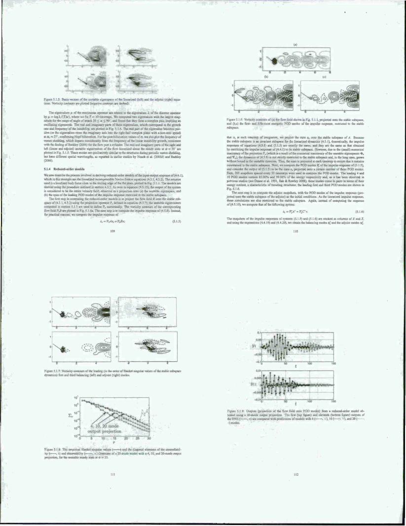
Figure 5 I 5 Basts vectors of «he unable won« Vorticily contours arc plotted (negative
«SajMiajaats of tke Unearusd (left I and the adjoint ingfat) equa xl>
The ofcnvaluCT u o( the oaetiwoui operator arc related to the eigenvalues A of the dtvcreic opera!« byu = logX/iT&i). where w fix T . mputed twoeigenvalue» wuh the large* mag- nitude (or the range of angle of attack 20 < a < 90 . and found that they form a complex pur. implying an oscillating eigenmode The real and imaginary parts of theve eigenvalues, which correspond to the growth rat« and frequency of the uutabtlity. are plotted in Fig 5 I * The real pan of *c eigenvalue become» pos- itiv« (or the eigenvalue« cross the imaginary axis into the right -half complex plane w.th a nonrcro tewed) atr^^rr.corfmningHopfrMfureation rot tr* post-bifurcation vnlucsol a, we »Isuplot ihc frequency of vortex shsddtng. which dep-ru cooudenbly from the fternjency of the linear «viability growth, consistent with the finding of lUrsJev (2006| for the How pa» a cvlmdci The real and imaginarv pana of the right and left (linear and adaosot) unstable tiyamsxtu» of the flow Inaoannd aboul the alrady itate at a - 35 are plotted ui Fig. S 15 These modes arc qualitatively similar to the structures during periodic vortex shedding. but have different spatial watx-lengths. aa reported in earlier «udin by Noack ct at (2003M and Barkley (2006)
5.1 4 Brdurrd-order aaedrk
We now describe the proceu involved in deriving reduced-order modcU of the input -output response of (4 .4 I). which in this example are the linearuxid incompressible Navier-Stokcs equations (4.3 1.4 3 2). Theacruaior used o a localtnrd body force cloae to the ttailmg edge of the Bat piatc. plotted nFis 5 1 i i he model« air derived using the procedure outlined in section 4 5.2. As teen inequation (4) 15». the output of the system :< eaaaaaaaaaaj H "c ihc mine «Saaatta) fici<i ataWtNd »* a ;*•>«■. :».r. MM m the unstable c.^n.psc on.) (b) the «pan of the leading TOO mode» of the impulse response restricted to the ««able subspecc
The lint «tap m computing the reduced-order models is to project the flint field B onto the stable tub- space of (4 3.1,4.3 21 using the projection operator ?, defined m equation (4 5.7). the unstable cqtemecsor» computed an seohon 5 1.3 are used to dehne ?, numerically The vorticity contours of the corresponding
.s are plotted in Fig 5.1 6a The neat step a to compute the lanpuiae r«»ar*oaaeof(4JJV 1 for practical reasons, we compute the impulse response of
Figures 16 >*rtan«y contours of (a) the flovt field thosvn m Fig 5 I I. projected onto tr« «table « and the) the first and fifth-m^t energetic POO mooes of the rapulse response laaUiuaad to the «able
that is, at each timesiep of imegrauon. we project the stale i, onto the «table suhsrsscc of A Because the stable tubspacc it an invariant tubapecc for the linearized dynamics (4 3 11, theoretically, the impulse nagumra of equation* (451) and (5.1 5) arc exactly ihc same, and they arc the tame a» dsat obtained by restricting the impulse response uf (4 4 \) to its stable tubspacc. However, due to the (tmalli nuanoncal inaccuracy of the projection ?, (which a a result of the numerical inaccuracy of the unstable eigcnapacea ♦. and •*■„). the dynamics of (45.11 is not strictly restricted to the stable tubspacc and. in the long lernt, grows w>tbout bound in the unstable Corcction Thus, the state is projeoed a: each'imc«ei> ui ensvoe thai it remains ■.unstrained to the stable «ubspacc Next, we compute the POD modes •; of the invpulse response of (5 ! .5). and consider the output of ($ I 5) to be the «ale a, projected onlu a certain number of these POD modes. Here, 200 snapshots spaced every SO umestrp» were used to compute the POD modes The leading 4 and 10 POD modes contain «5 00% and 99.06% of the energy respccuvely and. aa it has been observed in prrvso» studies <«cc Dearie et al !99I. flak * Rowley 200*1. these modes come in parr, m term, of that energy content a characteristic of traveling strueturet the leading first and third POD modes an shown m Flg. SI A.
The MU t^ is u cssmpuw the adjorra m ^eJcvwUVsusWesubsp^oflheadjoinOwihcmilialcoriditKiri« A., the l.ttrarved impulse response, (bear sifnuusuons arc also restricted to the stable subspacc Agatn, iaaat«ad of uiaaauiaaa, tax iinjeaat
•I. we compute that of the following ryxtern
r. - r.A- -sPJfTv. (5 161
a.-?.^,-P.oV. of the impulse respisntcsol systems (5 1.5) and (5 I 6| arc slacked as columns of X and Z.
the cxgeeaaaoo» (4 4 19) and (4 4 20). we obtain the baW.ng r*sa« #J ard tr* adjosi« eacato »<
110
NtoO« - • . . "",
Figure 5.1 7; Voruory cotuours of the leading (m the order of Haokel dynamics) fun and third balancing .left) and adjoint I right) mode«
singular values of the stable stabspacc
I •> Output« iproicctson of the Sow field onto POO modes) bom a reduced order model ob- a 20-mndc output projeution The first (lop figure) and eleventh (bottom figure) output« of -..jaeecorrasaredss^rstcdiciicttofrrsDdeliss-^ i snd20(
Figure 5 11 The empincal I lattice! singular values ( ) and ihc diagonal c4crnorjtt of rhe c ■ty ( . i I and observability ( . * ) Grarmans of a 2S-mode model with a 4. 10. and 2tVr«od« output pniectiun. for the unstable steady state at a * 35
.pacing .W no. «gjitficanllv change the »rrtgular «hm Iron the SVI) ccnpu.UK™ ,4 4 19) \Mc €
end the output» to be a prujecuor. onto 4. in and 20 POO mode* (corresponding to 4. 10 and 20 mode
mrtfM prujmtliMi. m mwnrtirefl in «ccuoo 4 4.1) Uttog these modo, wc use the cxprcsuor» in cqua-
uon (4 5 20.4.5 25) to obtain the mat. • ■„• ihc fcducod-otdet model of ihc «table »uhspacc
if mmim 1»» »sjrüeity contour» of Ac balancing and Ac adjou* «node», lot • 10-modc output projeäod
tyste«. «re plotted in Fig 5 I .7. The adjoint mode, provide * diiecuon for projecting the linearucd equa
ham «MO Ihc «ihttnüi aaaacd by ihc balancing modes. Since these modes «re quite different from the
POD and the balancing modes, the resulting modeli are also quite diITere<U finan lhu«e obtained using the
standard POO<iatcrkin technique where» an orthogonal projecoon is used. Since the models obtained m
irtg balatsted nxtnt»»^ an kar^ Rowley (2008). ihc batter prilotmance could be aniitwtcd to a better choice of projection using the adjoin. modes
Since ihe reduced order modelt or the stable-aubspate dynamics are approximately balanced, the con trnaahiliiy and ooservaUliiy Gramtam of the a.-dynamic i of (4 5 20' arc appro» .mate !y equal «nd diagonal
Funher. thctr diagonal values arc apnuximatrty the tame as ihc llankxl wngular values ff. obtained by the 1°) Theibagimal value« of the Gramiatu and the »ingular value» fur difTcrctn ouipui protection»
arcptoaadinFig 3 I K (or » W) uatc redis.«d-u«der model Wjh .».reavm« .»der of output projection. Ihr
ItSVt converge to the case wtth lull «ate output, and the number ol converged HSVs 1* roughly equal to ihcorrjceofoutpv»ricojeclio«i.a» •• obacrvrd by llak « Rowley :200a) We »ee that ihe diagonal ercmem»
of hoth the Cismian» «re vrrv cU.^c a) the HSV» lor the first 2b mode» For mgher mooVs. Ihc diagonal
rltsnraii of me obseevacnlirv Gcamian» are inaceirratr. wtuch is due to a amall iiasccutacy of the adjoin,
.ormuiai.on mentioned in section 4 t For controller design, we use models of order' 20. for which thrsc (rramssm ate ssdhcicfltlv accurate
Fatally, to teat the accuracy of the reduced-ordnr rraatttts. we compare the impulse luanuuai.» of tys- 'em li I M (thai 1». re.lnctad 10 da* »table tubspace) with that of the model U < 201. restricting o, m 0. In
pnrtKulat. wc compare the output« of the two systems, wtuch an the projection onto the POD modes, a representative case in F.g. 5.1 0 «how» ihe result» of 4. 10 and 20 mode model« of a tyticm approximated ataaa a JO-asoO« output renjmtiim (the raatpusa arc r.«ioct»ne atsto the leasing 10 POO mode»! The lirsi output, whtch it a projection onto the first POD mode 11 well captured hs «11 the model» until 1 aj 60, while
use ZO-moic model performs well (or all ..me Alto shown .. ihc etcvctiit, output, which u well raptured
only by the 20 mode model
lta»njla1aT('Xf«)t»aitnt»ia;te tttsa** ta (4 ) W) tm m 0»c kn-ba« of te
>,«; - ^(•'t>-.'*.)ae.
Figure 5.1.10; Schematic of the implementation of full -stale feedback control in the nonlinear »tmutattuns The entire vclocsts' .» färat rawsecssd onto the unstabk eiacmsxtoo «ad the stable tsjrafSMc POO modes .0 csxnpute the rerhKcd-ordcr «ate u The nate .» .hen mult.pl«! In ihe gain AT. «nmpotrd tasaed on the redoca»l.ord«rnooV..r»»neLQR.i«orx«n*
Figure S.I II Comparison of ihe output» i., and »u of a 12-mora; rcducas^ordcr mode:
projection of data from the linearized simulation < . a) The control gain is obtained using LQR. a .runs! condition 1« thai obtained hs an impulsive mpv« to the »ystcrn Cootn>l 1» aimed 00 at.' = r-
Q and * an positive wi oft.« I 7)
Ights computed as follows We choose Q such that the first torn renergy. trua .v wcus« 0 - C"c\ wilhCdstfned in <4 5 21. The«
Figure 5 I 12 Ufl lllailiiH Ct vs. tame r. tor 6t0 «at* faedbac* corwul. with control turned on at diffrrm. times in the baa* uncontrolled »imulation The bate case with no control ( ) hat the tmssahtc •ready »tale at rar in.ua! cuod.uon. and u.m...on» U. periodic »«te» shedding The control » letted for
different mu»al conditions, ctxrrepondtng 10 / * 170,1*0,210 of ihr) base case, «ml »tabilux» the »teasty Maaiasaftl»«
u chosen to be a multiple of the identity c/. and ryp«ally t u chosen to be a large aumbcr ■ I04 '. to avrad Muaati. «by ae«rcur>.c oootToUcrs The control atiiat na'iaataa» steps m* »Lrtched ra Fag. 5 1 IÜ, first
1 ungute Ihe reduced-order ■talc o. using the caprcsjion (4 5 27). then ihe control input u given by u » Ka
H»at>. »t« dtsnsrc an r^« X batv^ rn
using (a 10*. and include the same in the ung.nal lincarund and nonlinear »imutanon» The otitput 11 iepm*aaaatd.iiii«|«4Hrs9oVoua^a»»r»w.ijoo. The dilTcrence berwocn the linear and norvUncw utntrlifjrjtsi
.»thai, m iha latter, the .leads, »late field u. it subtneted from the »täte .. before rm-ectmg onto the modes
Fig 1 I II compares the mode» pnsdtcUom w.th the provection of data from the simulation» of ihe
uncaruc. 1 . onuol input The initial condition used is the flow field obtained from an rrarattsrve mrsa to the «ctta.ua Both (h* »tatea «how« at the 6fure csrasaaUy decay to jxro. whtch
impl.e» that the pcnurbaiM«. decay to nro. thus «tab.li/.ng ihe umtable steady »täte. More importantly, the
model prcdact» the outputs accurately for the uasc hesnitoo slsown >n the plots
We now use the same coatroilcr 1.1 the full nonlinear «mulattom and tru the performance .if (he model
for various perturbation» of iha steady state A plot ..f the I.ft coefficcni C, vs. time I. with the control
turned oa at different tines or Che bate simulation. 1» shown in Fig $ ) 12 The initial condition tor the ban case (no control) is the umtabic .ready ttatc, eventually, small numerical error» excite the unstable modes and the flow transition. 10 pcrsodsc vortex aheoumg In separate ssmuiatiom. control 1» turned on
at limes I m 170,110,210 cc««»pcajdrtttt to the base case. A» the tigtn shows. Ihe control is cflecttve and 0 ahlt to atabtlue the »toad» state m each case even when the flow evjuoru strang vortex ibedding. Wc remark thai the latter two of these perturbatHK» arc large nxKigh 10 be out.ide tfu: range of valKbty oflhe
taaaaaiassi lyiltar», bM ttteCO state. Wc also cotrmare the output of the icduccd-orde» model with the output» of the nonlinear «.mulanon. Oat plots an »huwn in Fig S 111 The model, perform well for the initial tranocnt». but for longer litncs
at . . 1 h
<M It» au «c no
Figure 5.1. IJ: Outputs ofa system with full-state feedback control Trie control gain 1» obiairwd using LQR. and the initial condition ts thai lorrcspondiny 10 / ■ ISO of the utworiUullcd case plotted in Fig 5 I 12 Comparison of the output» v., and v., ofa 12-mooe (2 utsstaatc and 10 statue nsodal reduced <vder asnoef I , . ) with ihe projection of data from ihc hill nonlinear simulation I .0).
fail to capture the actual dynarmes. This n not surprising as these perturbation, are outside the range of »sdtdtty of the Smear model» For control purposes, it appears to be »offioen. to capture the initial Imsanii
lapproarmalcfy one period), during wl . . suppressed to a great extent We remark thai one could possibly compote nonlinear model» by projecting the full nonlirtrar ctajattnrrt onto ihe rwtarsfiTrg
modes, or enhance the model tubspace by adding POD mode» of vortex »bedding and the »hi fl modes a» proposed by Nottck 0 at f 20051 to arxouot for the nonlinear terms
F .really, we note that the reduced-order rnodei (4 < 20) ocv-oupkr» if* .iv^umiio on tfx »tac^ atsd unataWe
»tjtsspacrs, and also, the dynamics on the uttstabte subspacx can be computed <»Aly u..ng ihe imttabk
bases O. and T. Tteat, we could denvc a COOBPI gam Kj U'"\ baasd only onus« iwo~dtmrniioa«l
unstable pan ..f the model, »och thai the eicoRj .. • m ihc lefl luufcomplcx plane That is,
w« can c4»tam a starMliasng «>nro^ Wc ha»«• performed
».mulation» to lest such a controller and found that it also it capable of suppressing the periodic vertex .hcdduig and thut result» in a large basm of attract*» lot the »tab.lia«J »teady »late. The eh.».c of wcgbl
rrvauicest>andÄ.ntheLORcoal(5 I 71 need» tobe dilTerrot to obtamacompars^cPerformance However, as shr>sra rs the next sectson, it is eaasntial to model the stable wraqsace dynamo» to design a practical
uiamtln baaed oa aa observer that luwaBativa'ti the entire flow field using a few ranter uwauxatMstiaa
$.14 Otrserver-bated feedback coatrol
The full state feedback control of section 5 1.5 is not directly useful 10 practice, ssntsr it is not possible to masusart the entire flow field Here, we vemidcT a more practical approach of mi awing eatraan flow quant .tie» ai a »mall number uf sensor locationa We assume that we can measure Ihc velocities at the
tensors »isown m Fig 5 I 1. m the rant-wake of the plate We remark that, even though these »enaur» may not be realizable in at»licj«ioris, they serve as a good testing ground foe our model».
5.1.7 Reduced-order nodeh
The method described m detail m secüoo 5 I 4 to »hum model»...' • »vrtcm wuh the full-star« outpvi r. fosi
used to obtain modeK ofa system with the output represented by the two senior measurement» Par that
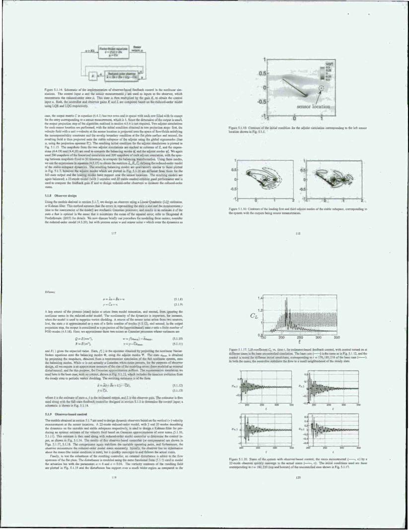
Figure 5 II* Schematic ofihc unpicmauauon of observer-based feedback control in die nonlinear sim- ulations The cuotrol uipul vudihc sensor measurement» y are used aa input» in the observer, which innwnm the reducecl-oraer state A This irate u then multiplied by the gain K. k> obtain the control input a. Both, (he controller and observer gain» K and L arc computed baaed un the reduced-order model uauaf IQR and LOG respectively
case, the output mstni C n eqssasn (4 4 1) luat two rows and u sparse with each row tilled with Oi except (or die entry corresponding to a icruor mc«urcmcnt, which it I. Since the dimension of the output it unall. dut output penjection «cp of the algorithm ouilincd in «ecoon 4 5 * u not required Two adjoint »unulatiocu for each •sneer location are performed, with the initial condition obtained HI two projection «tent fir«, the velocity field with a unit vvefcxary at the acmor location u projected onto the space of flow-fields aatisfyine the »Musyirinhunv cortdramt and the no-slip rjousdary condrnun at the llat pUlc mrfacc and arcond the resulting field is then projected onto the «table Mibapacc of the adjoint using the global cigenmode» (that is, using the project«, operator ?; I The lsailing iruual condition Car the adjotM »irouUtme» u plotted ui Fig 5 I.IS The axapehoti from the two sd/oust «mulauaea arc »lacked a» columns or Z, and the rxprrs «ion« (4 4 10) tai (4 4 ;oi are wed u> compute the balancing modei ♦.• and the adiotru nxJe» »t We again used 200 nvapahmi of lac unearned nmulatior. and 200 maprhnn of each adjoint tjnulalina with the spec inn between anirpahati find lo 50 umealepe, to compute the balancing tratufotmeuoc. Using these mod«. w«uacdktcr^smuiro ince^afiM(4.$.IS) toobcau Ik of (he »table subspacc dynami« The reujiung balancing mode» arc qualitatively »imilat to theme plotted at Fig; 3 1 7. however (he adjoint modes which are plotted in Fig SI 16 arc dilterent from tho»e ft« the full-tfaie ourput and the leading modes have support near the sensor location* The resulting model» arc again balanced: a 22 mode model (with 2 unstable and 20 uablc mode») exhibits good performance and u said to ceenpuat the fb Briber If gam it and to design reduced-order observer» to a
5.1.8 Observer design
i:»ing the model» derived in vcciion 5.1.7. we design an observer using a Linear Quadratic (LQ) cvunuuor. or Kaiman filter Thu method assumes that the errors in representing the state a and and the measurement v (dtaciothrtnattijradaisfthernocMlare «ate « mat is opiunal in the sense Cast it mmimoees the mean of the vquarcd error, refer u> Skogcslad A Pc^oethwertc (2005) for details W» now daman briefly mat procedure tor roodeling ihe« (»ntaes. consider
lei <4 S 20). bet «nth process noue » and sensor none v which enter the dynamic at
Figure 5.115 Contour» of the initial cnndilion for the jd:oini simulation corresponding to Ike left • locaucsi shown BiK^
Figure 5 1 16 Contours of (he leadmgfir« and third adrant n the system with the outputs being sensor mesa a munis
I i>: f.c gajsj .„*>spj».c ..irrrs ponding IB
.-io-*.- r-&*«
(5 IX)
(519)
A key «ourcc of the process (stale) noue ■ antes from model tninfion, and second, tram ignoring the nonlinear term» in the reduced-order model The nonlmeaniy of the dynamics i» imports«, for irararaT, »hen (lie model i» used to luppreji» wrtes »bedding. A »ourcc of the sensor noue arises from two «ounce«, fir«, da slate x a apraxisimsied as i sum of a fmile number of mode» (4 5 12). and seeoad. m the output projection «cp, the output u considered as a projection of the (arjproximalcd) state 1 onto a finite number of POD rnode. (4 J Igy Here, we a.
*-£!«■),
* -/»«-.) -iw »•/-Or«».
(5.1.10)
and f () gives dar expected value Here. f{ ' .»the opecatur obtained by projecting the nonlinear Navier Stokes oqianSoa« onto dar balancing modes «. using the adjoint modes T The state -„_,, a obtained by projecting (he »naptbuts. obtained from a representative snraibMion of the toll nonlinear system, onto the balancing modes. While a ■» not actually a Ganrsran what noise process, tor the purposes of observer design, all we irquirc L» an approximate measure ofihc sux ofihc modeling errors iheic modeled as external ditfurhences). end for thu purpose, the Gaussian aporoximaiion wffkes. The rcTsesentalisx leiadeliiei w« used here i» the base case, with m> control, shown m Fig S.MJ, which includes the transient evolution from dar steady »rate lo periodic vortex shedding. The resulting estimator is of the form
i-Zi. (5.I.I2)
(5I Ml
where ä u the estimate of »Uic a. .' is the estimated ivutput arid f. i» t>rf c*siener gaiti The csiinval« tt then uaed aleaig with *e rell-*t»a* leee^
eUshosvnuiFig 5 I.I4
5.1.» Observer-based control
Tl«rnodrisolvta»nedmtcciumS.I.7areuiedu measurements at the sensor locations A 22 mode reduced -order model, with 2 and 20 modes describing the dyiaamcs on (he unstable end stable aabspaees respcemv-t». t» seed to demgn a Kalmar, fiber for pro- ducing an optrmal estimate ... !iiscd on Gaussian gpprosimaliott» ulenni lam» (.5 I 10, 5.1 it). Thu estimate H then used aloug with i«diiced-<srder model cortt^le» to cWterminc dve ciiotrol in- put, a» »hown in Fig 5 I 14. The roull» of this observer-based controllo (or compensatiKi are »hown m Ftp 5 I 17, 5.1 IS. The comprruatnr again «tacsbres the "^»-*J- opueliiig point, and furtherroorr, the observer rrconsiructs (be leduccd order model »talcs accuraicly Initially, the observer has no information sbout the Stute» ((he initial condition i» zero I. but it quickly comcrrc« to and follows the actual states
Fmally. IO lest the robustness of the resulting controller an external dittorbancc a added to the flow upstream of the flat pUlc The dinurfssoce l» modeled using the same lunctional form (5 ) II used to model the actuation but with the pMaavMrr» a « 4 and c ■ 0.05 The »arbcirv coalours of the icsuhing field are plotted in Fig 5 I I« and the dtstuifeaocc has »oppori over a much wider region a» compared to the
CL
°'fto 200 250 300 350 250 2
FOTSRS I 17 Uft-cc<fficient C", vx tune /. lot estimastK-beaed feedback control. w<* coriUc4 turned on at different time» in the base uneomrollcd simulation The base case ( )■» the same a» m Fig. 5 1 12. and (he conuol is tested tor dtflana* initial conditions, eeareajsnadirsg to r - 170.180,210 of (he base case I ) In both ihe cases, the eontroll«, stabsluea the flow vo . »rruül neqdlTKrhc^ rf ÜVr »>ra^ »tase
r. t J
»o a» *M »
aaT ! n I ■ j«.«.
^
■•4 !
Figure 5.1 IR Stales of the »ystcm with obicrvcr-based control, (he nates rccoriKrucied ( , *.) by a 22-mode observer quickly tsjaasuj», to the actual «ate» ( . e) The uuual coadmon» used are those corresponding lo / = 180,210 (top and bottom! of the uncontrolled case shown in Fig |
II*
' 11
' 11 V I h- ■r
!
to lock etc forcsng with the phase tfc.fi associated with the highest pcrvad averaged lift li u »town dM
«he Osxtajeejagar retails m « stable phase locked limit cycle for * trader range of forcing II ■eat
MO ISO 400
* Figure S I I« Euinstutr-baacd feedback control, in ihr pmeoce uf an external ditfurbanct modeled ea-
me (S I I) Plot (b) showt tfc* wrucrtv coouxn of the Jitiiiihancc i he irroltin-. lit! ooeffWst-ots a» «town
« pfo. tat. born w,th the control timed «ITl i end on ( 1. «* the initial eoMttm boo« a vefcx-
.iv field from ihc »wva »beOding reg u» Tbc controller UmNluo the ftoa evea Ithe puiiari a/thane
tuaurbancet. The control «{Ml a. tvfcieh remains (X I), i» «hown m plot tel
actuabun The duorbaoc« amplitude i» modeled at a nodoto v>«iable «amplri from a utiiforoi Ajtribuooo
in the range I,!.' The litWocflicienta. at the presence of thudrnwhantc. for the fW» »i:h «jmtol turned
off and on. arc diotva in Fig 5 I 10 Wuh the control oft the lift «ay» to the neighborhood of it» value
dura« aorta shedding When the compensator u turned on, the ihrddint it wpprcued and the steady atMe
in «(lam tUbluLcU. However Ihc dutuibancc «auacs the lift to fluctuate around the steady »talc value When
the dutatxarac a (inalh turned off. the hfl again converges to the stradv »talc value
U SyiKstreauatstroofvoms^edditTtf^
l>pcn-and cloaod-loop nrwbroaiauc« of na^ex «htd^ angle of atiack w now coiuidered In order •„, .tody ihc control of two banc ccroxitucnt» of umteady pod ■ull flow (i c kaduv-otae and traibnf-cdae vortices) and develop a phyncally motivated feedback atraJefy we tcaader a raw iharsaai-a.1 flow a. ■ '-nigh irnrudocing camber a. uunc Eppkr auto. I ahape would improve uncontrolled performance, the flat plate ensure» the apaaiun at the leads-*, edge a
the puet-tiall regime and allow» ut k> avoid additionaj complKanona due to the vanaion of the tcpnraiion point or curvarurc effects of a different airfoil fcnmcuy A Rcynoldt number of VXi ws» »clccicd lo be high enough to ensure forming and ahaddmg of Urge onhrir.ii tuuetum of opposite tignt from the leading
and trading cages. F ven thuugh di.t model a highly idralunt we hope to develop a physical!» rnoirvaicd doaad-loop control of global imtabdiry of wanes «nodding without any computational burden
A» m ihc BK)D ttudy. unsteady actuation » modeled at a body force near the leading or trailing edge and it directed either upuicam or liowmtream For moderate anglet of attack, sinutoulal forcing »i the natural dajgtBng frequency rctam» in phaac locking, with t periodic variation of lifl at the tame frequency.
tcadatg lo aagher uastanh lift than the natural vSeoJina llowrttr tl aaffictcntlv high angle' a iiiahaituini of the forcing r>uo,nan>) « alto esctted and the average lift over the forcing period vane» from cycle to cycle a a ccrnplcx tttanne» It it obterved that the period» with the highest averaged lift are aaaociatrd with parucular phaac difference» between the forcing and the lift, but that th» highrtt lili
g cycle is not ejsvnyx «tably maintained with open-loop forcing We deaign a feedback algonthni
(be open-loop control, and that .t it able to stabilere othcrwtae unataMe high-lift Umit cycles that cannot he obtained with open loop cootrol For «ample ai an angle of attack of 40' . ihc frrdback controller can
incieaacthemxrageJniaBBrtiidcofforvxontheplaiem VA and inc^ate toe att«a^ lift ooelTic tent from IJ3 to 2.43
hi that tecbon. open-loop control with penodas putting a the natural thedrhng fll gna i a Bra aaraalr-
gated for vtruu» actuator eonftguraliont over a rang« of a m certain cases, pnmanly for lower angles of attack, open-loop forcing result» in a phase-locked limn
mit with lift varying »t the frcvjucnct. .if actuation The nvvmentum coefliocm.
<-m (5211
is the ratio between the rnomenturo injected by the forcing and that of the frccuicam The values of C„
reporwd are bated <m the avrrage jet velocity. U,. fixed at l) ). anJ tht wuhhof the acnatoi. A« o o 02 Thtt
iniiMpnarntnafaetdC, ofCVOI twaHof the catoconjtdetrd here For each actuation Wtcaiion. two catet
of btowag angles arc cttattdenod. one directed dOtntatDaaja and (he odter dtrected upttream.
For auffictrntlt high a, tubharmooit frcqucncie» m* eaalcd and a more complex limit cycle behavior
it obtained. The penod-avcraged lifl over one cycle of actuator forcing vaj i vele, and
M ia obterved tfaa higher off it attoctttcd with a parucular phase shift between the forcing and the lift
We show that feedback of the lift ugnal can be used lo pru« lock tra: foreirig to the pariicula pliatvc tktft
e highest penod-averaged lift. Stmilar phatc-locJung feedback control hat baa) aad a
«udy pfha« a 1 (XI0t| and b, Tahnor 12004,
c ; t ■
For the tnmakong flat plau a Ut - M0. Meads artKr.^ flow o. .tlwmed for n < 10 At o * 10 . the
flow it artserved to be tcpanwd but remains steady Th» flow unJcrgK» a Hoof b»furvattun between aajjn or atiack of IT and IS" after which vane* theudmg occur- w.ih natural theddmg rret)ucncy. tu,, which vartn from \ 65 a a « IS to 1 J9 a a - SO' Using the vertical prt^acuon of the aarfotl tothc fiiiiiiliaan. w» rasl that a«, can be tcalcd. for a - XT. to a Stroohal manbei of S . /.« -n- a ,,'U. a 0 2. where /. - a,/U«; This agree* wrth the wake Sirouhal manbes for vones tltedding behind rwoHfcatnatraal braffbralarti.llo.hkr. IMI. rtcarman 1967 (mffm 1V7«) The taateadv tbtddmg cvcle ceeatsta ofvon.ee»
of oppoate cign» altcraaely shed from the leading and trailing edges, creating peruHbc tttcillMiona in the lift and drag At a it increaaed. larger vortex structure» an formed, inducing a larger amplitude of otciflauoo in rhe force Ckcncd on ÜV piae Fora > M) . the woran structure ca the auction tide of the pate aoeatrved u> be created from if» leading edge and can be victacd a a tntisarnt LEV. or. equitalently. a dvaatmat tuil vorte« (DSV) datt occur» during a raptd pitch up Maiimum Uft u foand when da LEV a brought (kam to the tucuoo side of the plate a it grow» |aj strength The lift dotToases a» die new »ones structure of the
oppoate sign it formed a the Bailing edge. Th» iratling-edgc vortea (TFV1 puthc» up the LEV «mm. on
ihestKWastdeof thcplalc. and finalh halt» it» growth causing it lo pmch-off and shed into the wake
5.2-2 Opett-Vaap control
In order lo tnvcaugalc the effect of open-loop corarol uting periodic pulling
Mowing on these watet shedding eyeaa. we first etsrtstder
with diffoeni bfowing anglet a the leading and trailing edge of
theplate The nond.menu.aal at velocity is at m V, -V,- r«ni«t/). where 6, - 0.5 and C^ - 0 5 Since this study n focused on maxumong lift from »hrdihng of the oheront vortcs uructurc» rather than
the »uppreaawn of shedding or aeparation, aa it imtiaUy choteo to be Ihc natural shedding frequency for each <r »I which the unsteady shaddatg of tfaa large coherent varies, »trucrurc »ill bluer» be arrtpUfssti the aaaa (CTIuaaa a) 200). Amiiay gt Gteaer 2002A). In the next two taroona we examine leading and trailing
Figure 5 2 I show» ihr lift coefficient with actuation at the leading edge d
.k.wn.ir«an (left) and ijparaetn (right ■ In each figure, the uncontrolled flow (baseline) u ottaiatd m grev with its atajagji at Jawed grey tad it» natimurn and minimum buunding the si
n of the lift tignal whose overall average . • teataro a the cartes a berarcca For
case« where the lift it not phase locked to the forcing signal, variation m the penodawrsvged CA (mragsd over each actuakm perindi is also plotted wilh error ba
Blowing dowianaani provides extra momentum a the leading-edge in addition to thai of the frecxtreem
Tha armjtiifsrs da usuaeady tbcxjding of vortex aosjeturn. rctuitusg m larger magntudet of the bft fttKtua- twe» I he lorccd fl.m ethtbttt bjghet maximum lifl hit alto lower m.rumum lift. below trial of the haseiine
flow At « result. Mowing downs» cam doe* not ngmficanlly benefit da overall average lift
I litwevtr. when the actuation is directed upstream, the retullmg ampliucabon of the unsteady «heading
ha»sn»orep«iiiverfrc«toniheatrerageliri Fur a < 25' the flow locks onto the fort mg 2 - 3 penodt after rta acualion it «uuatcvl However a rugher a the fto«. failt t<. lock onto the forcing frequence atiddtspuvi
a more ceattpUaaad lianst cyck. ttäh aiasiaraaaacs of the forcing tnxnancy aha excited An example is shewn in figure 5 2 2. m a - 50* where each svhharmomc limit cycle coruivtt ofsevcrai period» »nth a different penod-avetaged lift. Figure 13J alto tlxnv» the lilt at s (unction nl ihc jei velocity, and show«that the acruauon prudiKc» the higbcct lift when (/, a in phase with thcC, mi« mum i , when V: --maximum) I tawtve-, the aucrrrcjrog pertod beeoancs slightly out of phaac and the lift tkcroasea. lachpcnod within the
c limit cycle i» obstu.ud to be saonaed with a partscoiat prase shift. ♦. between ihr forcing d the lift, ywlding a patnuUi poiod atciagcq lift The atxsaioo period associated with the highest
T lift.. plotted in a thicker line. Al each a thrtc .» a panicvilar ♦. rculting m the highctt average lift over an actuation period. If the leedhack allows us to acoroingl» adjust the frtxpicncy of actuation lo phase lock the flow a thees ♦. then we could repeatedly produce the highest average Uft period This feedback axtttaawtllberevttesridkaot
■«sight be counter intuitive that unstress» actuation a uV Uadmg eda^ acb»ew and pstibrm« beite» than Oownst-eam actuation I !i>wever, experiments a Reynolds number of the order of
i) Rullan et al (2U06) ocmonvtiaied tha unsteady blowing upttream. parallel lo the chard a the iBHiayj aggr of • sa»srp-edgecl ctteula arc airfoil a ttanou» a beyond end! leads to averaged pressure ■sWi.it.iMii that rtadsed a rugher hfl than tha of the baseline flow I net achsned 1.1! merest« a. bsgh a»
K>Hw-mrntteoentxsm warnen ^ and the actuation pulsamg a the theddmg frequency of the airfoil
Tralhag edge iraiiHii In figure 5 2 3. da lift pafeeiraact of the open-ktop actuation at «a natural
«beddasg fin laaat- a «a trahng edge a isw-attaaad m a ttnaatt ttstxaer «a a» ftgart S2\ Bfotvog
ili-ii-aman exerts a nega.vc effect on the average lift, yielding a Iowa rm-iimum lift than tha of ihr
Mih a .OTular maxunum lift
However, when the forcing a directed upstream, tha lorccd flow lii.plnvi a «ignifKant lift cnhtnccmenl
The farcang excites the vertex »hedeWcycleotm f™ « ttelcwtfte llopf Kfiircawin For a < IV the flow
10 20 30 40 50 10 20 30 40 50
Ftgure 5-il Leading edge actuation maximum and mimrnum lift fDl and us average over time (o) for
dotsrnsxttstti (left) and uptsream (ngbt) actuatsun Avenge of the baaehne case u plortetl in dashed grey
and »haded region .. b>ur»drd by .:» mas «mum and minra^an Acnalsm is appi^ a the utural »f>rddmg titssxastcy. art •■ as. For tvases where the flow a not phase locked lo the forat« s^oal. vtmaurm m nertod- «veraged lift over each actuation penod it plotted with error ba to .ndicatc the range of value» over a iubharmonic l.n.o
Figure 5.2.2. Lift a« a function of üme (»landjet vetociry (bl w.th
(XX lapttream) a the tiarunl thexhtiag frequencv (a* « ra») for a - 50" upaxrtam actxatioa a the Icaslsng edge
• •-tlawline - average -•- TF. dmnama - averagr
10 20 30 40 SO
---nateline. average
-•-LE. upstream - ms». mm
10 20 JO 40 JO a a
Figure 5 2 3 Trading-edge actuation: >a Figure 5 2! f« a descriptor«.
Y,«t«:it> i1«iuui«iihfiiiKofna.nwm:,fi fur 1»»«IIK .Am) and upstream actuauim I duck»
•I the trailing edge at the natural »bedding frequency (tor - at). Dashed and »olid linn represent counter
clockwise and clockwise vorlicity.
lock» onto die forcing attn 2 - 1 penod» However, for a > 20'. the v
Tfcif » urmlar to «he obattMaOoo with ia-«tream Mewing at the leading edge, but the«
it crated at a lower a for the tnulmg-coge actuation than that for the leading-edge actuation
Each period within the subbarrnonic limit cycle it again observed to be associated with a particular #.
mulling in a particular penod-avcraged lift We denote ihe 4 anociaied with the highest penod averaged
lift at each a at Km Pamcularly at a • V) . 40 and 50 . Km. »a. observed to be approximately -0.25.
-0 0*. and 00 radian*, respectively For trading-edge actuation, the period averaged lift at high a ... in
man« OK*, greater than the maximum lift occamno. m the baseline flow This ruggeau a greater potential
for the Uxiling-cdoc feedback actuation in sustain the flow with the highest period-averaged lift Conse-
quently, w« wtiuld obtain a pbjue-locked flow that ha» an average lilt at high as the nautium lift «4the haaebnc flow lor even higher >
In general hlowmg upstream at both the leads« ami trading c*a)«s create ugmrkas« cahaikicaenl m the
average lift However. Wowing iipvtream at the trailing edge prmndo a largn «crew w lift than that of tkc
leading-edgr actuation These findings are ..milar to obsennlions made by Huang ct al I.20Ü4) who inves.
tigaied the effect of blowing and suction control at various location» on the upper surface of a NACA0012
: ncy considered steady blowing and lucuon at R* = 5 » 10' and a = IK and demoostniod that
blowing at the leading edge directed dow aitream exerts a negative effect, decreasing lift and increasing drag
at the tame time, but sucuoa increase-, lift by creating a larger and lower pressure nat on the airfoil » upper
surface They also observed that the actuation near the trnitmg-edge on the upper surface, 0.*r from the
leading edge, improves lift and drag characteriatics by manipulating die circulation of the THY
In order to understand the lift-enhancing mechanism of upstream actuation at the trailing edge we
compare the vorucuy contours at the time of maximum lift for the cases of baseline ami upstream actuation at the trailing edge for 40' in figure 5 2 4 Acluaäcet feeds extra csreulauon to the TEV which induces a
stronger downwash oeai the trailing edge As a result, the sortcx structure on the suction side u pulled down
closer to the plate and the hackrlow near the trailing edge i» reduced l"artituUrry at a - 40*. this delays
the interference of the newly farming TF.V with the LEV residing on the suction Mdc It also lengthen» the
duration over which the vortex «ructurt it formed from the leading edge. These result» ah» agree with the
nasarvariraa that the period associated with the highest lift w rthsn a »ubharrnonac cycle in figure .»ibl has a
Ungar period than that of the baseline flow 1 hi» might mhcaic that there etiau a forcing frequency below
«V»l which the Do» becomes pha»e locked to the forcing at a high« lift than Out ol the baseline Dow
Thus, we next investigate the possibility of the existence of shedding cycles that air phase lacked to the
open loop forcing signal Figure 5 2 5 >him» the lift response in the »ranaUim m open loop forcing frequency
for 20* < a < SO", abov« whnrh uparnam actuation at a» - as» faab to ptsv» lc«k Ü« flow
Over a range of frequency below ««,. the flow u phase locked to the actuation with it* average ltft near
the maximum penod-as-eraged lift of the flow actuated al <ur m 64. A» we go deeper into »tall by increasing
tt. the dornam of attraction for the phase-locked limit cycle decreases, and finally at a « 50*. actuation failed to phase lock the flow .net the range «if forcmg frequencies considered ,
Figure 516 shows the corresponding phase shift. 0. over this range of a* that achieves a phase kicked
flow for a «= 30". Recall that the subhaimuruc cycle lexciicd with upstream blowing at ov>) consists of
several actuation periods with a distinct » associated wilh a particular periodavcraged Uft Also, its highest
period averaged lift i» associated with ♦ ■-■ Km, 025, A» w, is decreased below ui.. the flow phase lock»
onto one of those periods observed in the subharmonic limit cycle at a -30 A» a*, is decreased further, ihe
flow a phase locsxd onto different period» with different *. cUw to »tw wi* high« average lift Finally,
at OJ./CU. aj 0 87. the actuation i» abW to lock the flow at the hot period achieved with forcing at «V Tms
tndicaic» that each phase-locked limit cycle of the vortex sheddmg could be characterized by it» frequency
and the phase (bill, yielding a particular maximum, minimum, and iillap Uft
21. . ..
• ' *
-VBf kautcyck J
S....J..;
Figure 5.2.5. Trailing -edge actuation maximum and minimum lift {Z1. average lift (o), and penod-avcraged
Uft (error bar) over a range of open-loop forcing frequency, a» Maxunum and minimum lift of baseline (- -
Figure 5 2 n: Trailing edge actuation phase shift of the forcing signal. V,. relative u» the lift signal. Q, for
r*W-loeked flows, two a range of open-kwp forcing freiassaev. a» (fl « JO")
0- «,-.
o|
Figure 5 2 7 Feedback control configuration
If Ihe feedback allows us to adjust the frequency of the actuation accordingly to keep the phase shift
between the forcing signal and the lift constant if« example at « = g»«). we dtould be able to reproduce
Ihe high lift shedding cycle» over a wide range of or Thu» in order to achieve the desired phase-locked
shedding cycle, we feedback lift into the controller, whose detail» are desenbed m the next section
S-2J Closed-loop coatroi
Open-loop period« forcmg can lead to limit cycles with a high average lift, but with a decreasing domain of anracuno as a increases Our goal with closed-loop control .» to obtain forced limit cycles with thr maximum avenge Uft. THa mvotves %taMy astmraimng limit cycles that are not «able wnthout feedback
Smoe the ti mati il flows with the high«« avoagt lift seem to be cbatavtatnul by a distinct phase shaft of the forcing relative to the lift at each a. we feedback Ct m an attempt to phaac lock the flow at these htgh-hft (talcs. Direct feedback ofQ with appropriate gain would nnlv allow u» to force Ihe firm to he nvphasc with (.', However, uncc the (lotcrvcd best phase shift» between Q and I.: arc negative, shifting direct feedback •Bjaal laqiarea us to know the frequent» of the forced flow a arteri Instead, we assume thai the lift ugnai being fed back .» apptoximairiy ».nu»..«ial In such cases lift a
Q.{l) - aa^rcosf.aa/-'*).
■ o,-o,cm(<»»./)-r),»in(<iv)
Assuming oast 4, and 9 are »lowly varying m time. « o, and n, to be the Fourier rr
•to - j[tuf)m*/)«. :- r
(5A2)
•ode ova
(SiJ)
I5J.5)
Ttowt feedback a phase-shift^ vcroon of ptaa»ajtn.<^
^(0-«w-A-^a,(r)ce*<av-«t)--»t(')«n(«»./-*)).
at
(5 2M
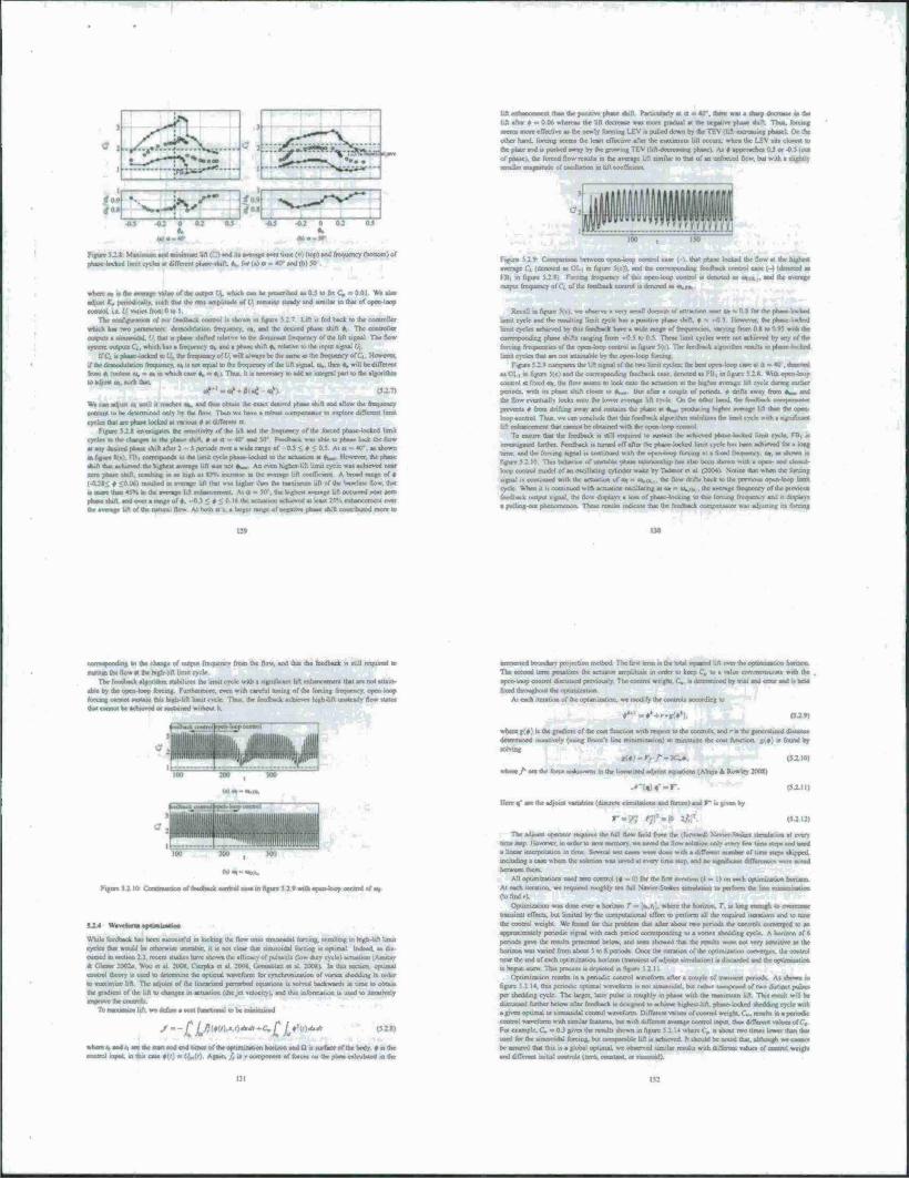
Figstre 5 2.1 Muiman ml minimum l.fi (_ I «id m average over time <o) (top» and Irtsqucncy (bottom) of
pill IprtmT l.m.i cycle* .1 different (share shift, fc. fof (.) a - 40* and <b) 50
s»istrea,..rhca»OTgcvalucs>fu*c«pu«(V,. wluch CM b. pcocr.hed « 0.J lo fa C; = 0 01 Write.
adjust K, pcs-sodtcally. »ueb that the rat» amplitude of C, ranimi »icady and «mil* IO that of O]
control, i e. 6: varie» from 0 to 1 The «oeAJpmtua of our feedback tootrol ■» «ho»»* in I . fed hick io Ibe c
which ha» two ijannialm demodotauon fitqutney. o». and the denied phase tttift * The OMBoOer
output» a iiiaiwwkl. C thai i» pfaaae shifted rclatn« to the iWmaifl fit gurnet of the lift signal The flow
iflWI output* C(. which ha» a frequency m» and a phaae shift «. relative »the input «ignal U,
. phaae locked «u C',. *e frequency oft', will always be thr s,e^ a» th* frequency of (.', However,
if the dettsodulaiioo frequency, a» ■» not equal to the frequency of the lift ugnal. to., then *,, will be different from a, (unla» a*. - m » whichcaae «V - «s,i Tata, it ■* accnatry to aod an «B*»^ pan to tW abjonth» »adjkjtt« N*(M
«,»"-«,'-fli./
We can adjust <u until it reaches «V and thu» obtain the exact desired phase thin and allow the frequency
coolant u> he dcUfTnutcd only bv the flow Then we have a robutl compenwau« Io explore different limit
cycle» that are pha*c locked at «WMU t at different a Fifure 5 2 K investigates the sensitivity of the lift and the frequency or the forced phaac locked html
cycka a» the rhargjr» in Uw phase »hin. * at a • *n and 5tr Foedbw.. ssms able to phase lock the flow at atry dewed pba»e.h.fl after: ■ 5 r>cri«lt cn-ci . wide range of 0 5 •- a • u 5 At u - 40 a» »hown
«fl«^e\aVrTtiCorre«rj»irid»toir*^^ Ikwewr, the phase
ahtft thai achieved the highest average »fl was rust *w An even higher-I ft limit cycle •» achieved near aero nbaac daft, rcaultmg to aa high a« 13% mere»« * the average lift cocsTnml A brood rang* of «
f «hod m average lift that w*. higher than the maximum lif\ of the baseline flow, thai
i* marc than 43% « the average lift enhancement At a « 51) . the highest average lift occurred near aero phaM »hift and over a range of ♦. -0 J < « < 0 16 the actuation achieved at least 25V. enhancement over the average lift of the naluial firm At tsoth ax. a Urgci range of ncsjative phaae duti c
lift enhancement than the puuuve phaae «hift. Particularly at a = 40'. there was a »harp decrease in the
lift after « ■ 0.06 wherea* the lift decrease wa» more gradual at the negative phaae duft. Thus, forcing
•con* mure effective a* the newly farming L£V a pulled down by the TEV (lift incraumr phaact On the
other hand, forcing seem» the lean cfTtvtisT after the maximum lift occurs; when the LEV ui» do*** lo (he pane and u pmhed away by Ihr growtng TEV (hft-ihtitaeiiig phasseV A* 4 approaches 0.5 or-0.5 (out
of phaae). the forced flow result» m the average Uft tmular lo that of as unforced floss, hut with a I «mailer magnitmhi of oacilWrion in lift coefficient
Figure 5U * Ccenpamoo between open-loop central caac (-). that phaae locked the flow at the higheal
average C, (denoted at OL| in figure 5(c)). and the csmapcodtng feedback control caac (-) (denoted a» FB, in l| gj frt^qucocv of thu open-loop control is denoted aa olajL . and the average
output rrequeaey off.', of the feedback control i» denoted a» «.)*
RecaO ■ figure 5<c>. we obaerve a tsay »mal: domain of attraction near a» ■ 0.1 for the phaa* Wirltrd
limn cycle and the mulling limit cycle ha» ■ puutive phaae »hift, « % »0 3 However, the phate-locked limit cycle» achieved by *■« feedback have a wtde range of Irecjueocse» varying from Ok to 0 95 with the
corresponding phase «hift* ranging from -0.5 to OS. These limit cycle* were nut achieved by any of the forcing frequenese» of the ocen -loop usntrol ■ figure 5(c) The feaxfcack algorithm result
limit cycle* that are not attainable by the open-loop farcing Figure 5 2 4 ccanipare» the lift »goal of the two lonil evek», the be*. <^»tei4cop caae a» a - *0 . d
a* OLi at figure 5(c) and the cenctpciading feedback caae, denoted a» Hi, in figure 5 2 K With open-loop control at fixed a», the flow «eeen» to lock onto the «ctuatton at the higher avsnragt lift cycle durtng earUcr period», with its phaae »hift closer to «w But after a couple of periods. « drift» away from *sw. and Ihr slots eseniualls lock» onto the lower average lift cycle OB the other band, the feedback impimalia prevents a from drifting away and »unam* the phaae at ««., producing hiebet average lift than the open
loopeot.' ncludc that Ihn feedback algorithm «taUTira* the 1mm cycle wtth a agrstfctant
lift mlianorttrnt that cartnot be obtained tmh the open loop ceearol. To ensure that the feexuxtck i« Hill required to «tratain the achieved ptuwc^ocked luntt cycle. FB, «
tm^atigaied further Feedback •• turned off after the phaae-fackxd lim.t cyde ha» been achieved far a long umc. and the forcing «ignal u continued with the oecn-loup farcing »t a fixed frequents an. a* »huwn in figure 5 2 10 That hthststat of lawtihl» phaae lafaraxaahrp hat ab» heczt abown wtth a seen- and rip «id loop control model of an oscillating cylinder wake by Tadmor et al (2004) Notice that when the forcing
signal is continued with the acQarooa of «* = avut . <hc flow drtfta back to the pro-sow open-loop IBDJI
cycle When U is cootrnuorl with actuation oscillating at cut - o»., „ . the average frequours of die prcvioui feedback output signal, the flow diapU»-» a ko»»ofnriaac locking to da* farcing frv-sjuerxt and it duphtv» a psjfKng on» phetsomcnori Theac result» tndicaie that die feedback oarnncniarrtr was adjusting its farcing
12«
nitllfriaing to the change of otonut frcsajcnct from the flow, and that the feedback it cull reouircd lo
«aruun th» flow at (he high lift Its
The f»x>dback algphthm «taKiire. >! > ■ignrfr*nl lift enhancement that are not aOain-
aht« by BM) open-loop forcing Furthermore, even with careful tuning of the forcing Irequency. open loop rorcmg canesol »rauun thu high-lift limit cscle Th» the teedhack achsess-s high-lift unrteady flow Mate» that cannot be achieved or »siataincd WOIUHII >I
ndary proyecbon method The fin« term it the total lift«
100 200 , »00
sWav'tttot,
FigtweS2 10 CoituJMaMMknortxstxaaacktsiat^
Ma VVavefarm ■till*aua«1aa
While feedback ha* been »uccojful in locking the flow onto iimuoidal forcing, iceultmg m high-lift Imut
cycica (hat would he otherwise uastablc. rt « not clear thai »musttdal lorcing .» optimal Inder, ciatted m section 2 2. recent aludie» hate shown the efficacy of pulsatile (low Juts cscle 1 actuation \ AnuLrv
* Clear. 2002«. Woo et at 2008. Carrpka rt al 2001, Greratblatt et al 20081 in thu gjrjta. optimal cttatrol theory i» used u» determine the optimal waveform far »yncruvruzauon of suite« »bedding in order io maxsmiÄ lift The adrusni of the lincarued perturbed cs^attion» is solved bachward» ta umc to obtain
the gradseni of the lift to change» ia at Mat ion (the jet velocity 1. and ihn information i» used to ihaativtly ntprossrthecorasxsl»
io»»»»ajtsatwt^arat<Bs»»»»
• --£j^>?(*»('U')«£-»**C.£^f3(0s<.»'/ 152»!
wtaaaajaadr, at«»WMana»sdt>xdt>m»sof tfarop ♦ n the control input in du. caae #(r) » U^lt) Again. / is t- csimponeta of forces on ihr pune calculattd in the
The second term peoalLors the actuator amnlitudc in order lo keep C„ to a value comrneruuratc wtth the op«;:: „*>y t*»utml d^usscd prrs'iiiusly The OOBattsI weight, t ,. >% »k.-trTtT:;t:esl by 'iia. mv. anaj »rid is held
fated thaottghfitg Ihc optirnuation
At each iteration of the optimiiation, we modify the control» according to
d'-1 -#•-,.«(♦•). (Si»)
where g(g) t» the gradient of the cost function with respect ui die contnslv and ' l» the geocraliacd dmancc itttuaaued iverausety (ualrtj Brent » lute miramixatioaj to -s^"-»» the coat function g(g) a found by
K»).f-^-ltV«, (Si 10)
svtssrrc/-arc the force «»s*i»nwsv^
•qq--r 15211)
Here q" are the adjoua vanaWe* (diasrete ctsxndatiooa and farce*) and F* i» given by
(5.2.12)
The adtotnt operator resaure* the full flow field from the (forward) N»vir»-Siokci •tmulatinn al every taneaarp However, in order to «ev» rnemssrs we »ased -Jie firm solution onis e-m few ttroe step» »nd uard
a linear interpolation in umc Several sot caae* were done with a different number of time step» skipped. ae where the solution was saved at even time Mcp. and no i)gT»»f»«»»l difference, were noted
All orximi/aiioru used aro control (g » 0) for the firm iteration (t - I) on each opt»muatton boruam Al each iteration, sve rec-itred roughly ten full Navter Stokes trrnaration to perform the tmc mirrnmnation (to find •).
OptaoiaKioo wa* done ova a honxon T - te.t, . where the horuwn. T. i» long enough to imnnaai
trannent eifoctt. but limned by the cc^putaijonal effort to perform all the required tteriaiorr» and to tune
the control weight We round far thu taobiem that after about two ptvtod* the cceurols exauged lo an
apcruximau;Is ptrvodic signal with each period cortetpiutdiug to a vottc» shedding cycle. A horiron of (•
period* gave the rexult» prracntecl below, and test» »bowed that flat result» were not scry (tmcilrve a* thr
hortzoa wa» varied from about 5 to II period» Once the iteration of the opurnutatuio esmverge». the control
near the end of each optimisation horcom (transient of adrotm umulauonl at discarded and the oprirruzalion uheetmanew Th» peoce»» u dcpsciod in ftgurt 52 11
Opiimintion icsulcs in a periodic cururol waveform after a couple of transient periods. At shown) m figure 5.2 14. thu prnoihe optima, wxselorm it not ■rainndal. hut rather i leispoaad of two dsataatt pajaa*
per «litsdiurig cycle. The larger, later pulse •» roughly in phase wtth (be irtaxinajrn bjt Thu remit will be dsanatard further brio, after feedback » desgjied w arii«^ higrasJ-li^ pha*e>to
a given optimal or sinusoidal conuol waveform Different value« of control weight. C«. rewlt» in a penodK conirtsl sxtns^cayn »triw *irr^
For example. C. • !).• pvca the irsulu vhcmn in figure 5 2 14 where CM i* about two times lower than that uacd far the tu»u»otdal forcing, but c««iaa«»blt lift it «cfueved li should be noted -Just, although we caraso.
bc avaurcd that this it a global optimal, sve otissttved similar result» with different values of control weight and Afferent intul corttroi* (aoro. o
111 m
vt 1 it:
rs
«ay pauoja, m jt «np m «gw <m maa- atp a njo« «toy paaanj aqi lataqd jo mo> .OSI T ""P»"«W» Vint* •»""H »V aM-jojja «» »w n |uw»n 'trnfi *3<«i(d »uiwjjsisijriJiiiJiiiiriiuwiiii^'jMoojiiiuAmpiiijj^ hjiKioniwjmnJUijoi.'vTiiL«! :a.J I» Jpninohnu aqi »nun aaumuiiuad JI; Jtp iifli«nl ijiqn aaaqd avqiiod -oqv \;ln».-.i(nrir, Ui| ,T,() ijaarftm (yiq» ataqd auMtso a» yij ua«a<nui aqi 01 mud »a*d aqi ipu» tuojoj Tu«! «v «ay» X|«npwimi »MEUMP
<ipidrj uuojaut« pxruaiitio aqi amo»Q «aauwp artn,d yj '0'* ™'l"q »V ^ V'l mniutswui aqi «opq fuiddaap an Aw »p ^11» -yiq» »anal up o> otanp <q unna aimh n ys; aqi -raiopuut lauiodo aqi jo .-vmnui ant)-*«!'»'* °l »"0 '•""""a' J«> a*oai apt« • *»*o «poiwd < - i »II« «lyi aojqd pawap AUi I» «*oy am »poj Mtqd m »M* « "3»qp*y tOI " W I«"»«» I»«»"*» *P 1»» •"""*» •«««I« »«»<*1 *P * «*■*» aqi oi o|*ifc> iiiui) iwipoi araqd aqi jo aauruuojjad yi) »>P J» XitAiiuua« aqi wirtijiOAUi j,| ; $ ajnlij
., (p-p-f) I Batata, tl a*o<- - -I »npwqjn yi,
. dopnu-op qi-* (pi|«i lonoco panmado jo P» umuiimtf ot • o
»IT* »«*J
FV^^X"V^:; Or = » m (oi « W ««9»*» («mando «t«
r (Xarf) aas taam» lioofosdo uaa-nnq umuadu»;) :t|T< am,y
|oiiun? pluuidnaqi joaimaq fliWB-Xtoua u» unl aq Xaui tanjnd o«.i aqi ii»mwi autad uoqt aqj, (man iuwijcuad-ituiwo! UN« piwa» aqi OI paanhin» ||trtui w # in aJorqn aqi oi x ; <; bj ■ ""'-1 *iuiunv»iu.||ij i mm i»n; aqi jo Ximii«»» at)> -ajaXa >uippaq> atp jo arrqd atp Jmaip 'anp «atr»pu> tiiij, -pa/unpt yi «u oo padun 3[H|| <*q jnq TOiiwi iwq»>q "*J *P uaOMjaq dtp aqi mo «poem» -»idai»«» »j > = «AJ »>mj, uomndx» aunoj np oi onoauR) IMUJ Jntniwui .<q uooj»«« pnxQBO i<i tamjaoaa M sag» sn »mxiimmp *• •»I f J «w*) vq -yo S*«I« TWO»* uuotOA»« peamnido ^JOMDIIUJ inn)« wflnvaMii «tj i»j »nji aun) nno»o«p(K*nuDjM»M AjC«K}i« XII»IIU*M« U» *>!! »ttjd oi m c*o>|« <KMI utlunwn SMSJpKQ »OJ.
- »j«oii«oa*i VI H»i«| »rpoid oi o|«) m lonnoj parmiijdo m«u|| fgo o ■» "j»» »«»11««»« «0 J*> ITI **«•»■ am oi 3Mtl* utpctudd« |PU> X|dl*i|i wtooop joiaxn ;«pto«xuT» »qi jn jwmmiud ij<| X(i .,vm | "■) j» <o«(t\ nnojjTp i« ui| athuu« xi3»(*ni am ipi.n »j-w» nuni ■ ra «u>u xji pvt»| amyJ imnnto») x(i awn» uuoja*M («puMRttn tpi« «a««) poijow»» poqpaaj sqi utoij «i|n<a> aip "I |<u>ui>3 partunxio .nji iwij oni« yi aSnaar »qi cuadmoo JI ; 5 anO-j yn aiua« v» MODOI %CJJ O*M axwi 01 paqmai «MBMO
pottuipdo I«» I « «ty-fr po» lor 1 ° "J 'HI » V» "°U MtT»««M 01 ponrfMOJ OIQ-Q - "j • *VW* iar\-°ofo)ai-Qp*ttm^v»u*^wmva>}»Q'ui*>iM*»wp«**'iav>*i oioo-1?p" >ooo° *3Mi!*ori^j/b^«i«»«^<n\tna*oi^;^^»u^»o<1'a*im,vo,;»ü3"'w I jo na»m|MW *up po» «t| avUM» a« si p«l)ftcu gunau pocnamdo >l f< am!b) m iiwoip «pauad »f, JO^| nraoijj» itoiaa itaiu »qi X) wtu A|pum«u poq< l> »m>a| "pOAOUp» uaaq irq yq turauinut aqj oyi lurmaaitp-r ui tunuoAjv «(1 xinimli oui noy pnio»m»anp-n«M in a|qap«aA«an .(pMqa** " ATI *"PJ° Sarppsq» aqi asms |0«»» |tpw«non ayi O) pamnoco tndot ranoaa jnuraiui vi* yn J° *!TO«ji«ni «poi« xuumpt mann» pawmpdo aqn aoq» «< apXa tuippaq« »m jo wwal iiqj. Xidmp po paoim o tooaoj aqi •yfl <amm»«ui»iiiiay»Xpi»!p*uiui ai»;d aqi m J»«|5 A.n aqi qvndwi qwMunop« w«w«Xiw>p»«^31 jo BO«MIBJO; |t«nm aqi qii* »JTUHU'UI UO;OJU< JI «up tpm ,^HX T J» <»r»™««»| »P >»l|t m«ii»jtoiia ^» UDwppi pmpw« y T"«4 *»' »»U» »«««sap pwfcu ajom « Xq p*M>1)nj »P*» a«J» jo ■««" «f* *n«P ♦ i" aajonii t«qwtf asi« *öo«4 (■Pro*"^ <n p
v»q» xauiM mtp » Xq poutquk» uoqatu» IMU OJOI A,ü. aqi ujoed*. -.iqx X{jH|«wiiw ,\3Xaqijoo>*oj»Äji«UM»pv«iOpia«HciÄ»qi,iaa«iaqawi«^ (Ofloo3 panaqoo »qi U" toMI -•«»H *na»j iroKKmm »qi UJOJJ Rtwayip oo.\ Y»t K* «op (»uji»» p»j«Bt|do aqj *».( p|3ij **« aq^
aunaniq aqi 01 paicdtuoo y'l oqliq 01 fcupoi IWJKi Mp m «HO|a lit ot ,\ii aqi iuiu»» -aapa Aitjwo aqi «oo qaMuimop oftkuit laanpui «np \^l_ paajauofa XtjcanaM atooi ni tamxai inij. oin\ «oil 01 A3-] aqi fat«0|(r Xqauqi *»Spa 3ni|iui aqi tooij patft 01 pnran put pauatpJuu» v ,\Al faipuoiKiuna aq^ yi| umajinrm aqi JMC «cad »w vaqaaai HT»oy po«'\3x'uuu'd *P ^1 unoppatjnii u 1 Ssraoj«. . :« aqi 1» utvanui uonmu« jo apnittaWu) aoj^ ijq wmannmi p^op) «BUiaQoj xp w /&) «P J° JD° «(««• »P«PP »w» >>» *V\ •stfo frojJmij aqj * uouiqnam en» paoj ot uns ruuopAM ipoq -paoiioj «insq 11 AJ-J «au «p «• 1>«1
Xjtanin» aaxa «wo 01 n aonmja« jo laajja Xnruiud aqi -lonuna pwnuiidn pur (ipHnnun qioq »J 10 0='.3
ua.«» • 1» yq af*j3Af i*aq*q aqj qMM pajnaon» afüXa i«u\| 0 1« VUIJI aqi pa«ao| anqd IUIWULKIIUHJ <np u^m uuqpMom |«pn—i t tBM» m» payviiMO» doot-ywof «S» W»* PWHd aa. «ipvw »qj, »owij jaoo OT »untmw aqj po* t(»)»lQ) «noil« |Oiii»a pnoqdo am jo ipouad «a) * «wrdnka» »[Tt ajrolij
«p*»0l »«>«»«»«» ara^«in»a?wpo' «1 pu« '«Dousd s 01 IF A>U» uonnioi mot*aJd aqi ot au»ia X*»A »mqwiao« 01 ta«u*guo ijtaiO» ^irqpaaj aqj. 3p*3 mm, aaipuq atp jo avrqd XitnHjai 0* woij SMtam ioq •pjwjtqar umirmotido aqi mp ataXa man yq-qthqaqi aanpoadaj 01 ojq« « UUOJOA«.«pnnmqdoaq>joiojmM«»ojiaoj jt j ? a»t»y rau«rt»irv
100» "jaqj^o- iff«.»ypm-o- »K'l -«A/*»!». Xq uuoja*a* pqaiomun aqj w>j patuauoidiw X|duiti aq tan »a>]<uiqt» vjaapaa] «ap mp ajoo 'onv
**»*■> g««tl»l aAU»|«4 vna. acaqd {paynad») prooqipp« m it a—»B ajaq*
(«TO
iXaoanbaqaq] ^aavi^aqiqtaAPMrpdn^M^aan: awMMpua'^i-jaqiXq
nitr aqr'(W*in»xJuiu>a»qA\ (fOOCI I» » ">ro«»j P"
«tO0rJa»i»«aaw»»^«»»a»PaHi*|aHi9tÄ>»w »pXa «; . 01 •afjcaa» taqtuolpt otp anp m JX3 aqj ui ixnoqa aac «auoamd aiiou IOJ lanjr.» ■ j)^ aqj qn« paniuatu «1 a ataq»
(61CJ)
(tirj)
poaatn and 1 at pappoa ■ Wvetfi ■»« -uoiumi nqin mo uaijij po» •<» tt pairainn X)|«ttnii 'X>aanbajnuruiu»<T>>q, «nnai in« Vipaaiiyaiii
UITS)
«•IT«)
UtTS)
(riTO
(rt«»)on(,)W-(/W)Ko(/)lo ■ (»)a
•« n a«J ;..
•Na«q«
«I
•totipoJJUi pttxur 01 «ai|t| aqi aoni di paaoajum Aiann aaaa 1 taaaqo 04 aAOJdunox tizj b j in a« joj (/)e ta fjaAVt OT aoj j« Xaoanbaq aqj. pamthai« pndbt OT aqj JO «joaanuaajot anqd aqi jo qaaa oaonuaq Jiuaojjip anqd luaimuoi r ipj« uuojaw* prtundo «np iuama|duu 01
IULIOI3A« pnnfuo aqi tuaii aotanup ••,s imp B3|) uocmtaKudaj ajutniwrai • papuuud iptq» yi ■ -lawjawa» «aaw»laatpjttfai»ja*Ja«jl««^
'i(i>)«)««-«»-({*)W)«o»«K.!i-»K -
:!a.T)u«.J.^(a.,)wa«^-'»' - »)«—-•
w uuitf»««» t«tt|at>» pnJB»^ TiOt»aa«»no<\ajdaqi
in «iqi<jo»> pa«rq luKwp» aip uxuj {oaopap uunjuu >DWaa» nnaiMO aqj pur yq aq, oaamtaq jpoj anqd aunpm 01 unpunig« ^mqpao) aiqnuatua\diui X||«anae»d r uiTivap a« rnqj^ aaunumjaad atp apuSap sqi jnj vaaoruotaa aniouuaqqm pot «asataiaui jannii -outuay^ >af>ojsajo9 wtotjdo aqi onp atrqd |IM>«JJI|I C
tpi« U.I rrno] an uuHja«« [Min)di> aqj ojuo ajwaj 01 t;it; «cy aqi SUI.TJOI JO uoijnjtui uodn «oy aqj jo airw act»a»iaipao#iJtpoadao 1^1 t i atnihj ui tt«oqi « ^»oi uado atp in ajtrpl aqi ot naiidd« «1 inp ;i poottdar ipuiatjrolit aq n»9 aawmaojaad aqi tmoja»»« [«undo atp jo pouad apltw * laaa» 01 pia«uojiq*i«n. «B.»B«UB Tpwuad lunatum p, atdnoa » ag» uuptaat« |o«aKO Mpouad a tapaoal tiwatiJtiaiao
ta» «ao« unlaq »< uoTtvunido aqi put pspaonp an uoryoq uoinonunido aqi jo pua aqi anu «(oouoa po» ■4 pouad aqi jo -j aonaod aaaa paoaatpt. n .«toy aqi -paAaapx 11 vmir/nando atp oo rcuaaw aqi jo aaaataaAta» aqt aauci iiuiuo uo ai«p«*i aqi «OAIS imimiumdojn uotjr: .^uopauuoj pd aar nonuoi jo uorau'tuivdo atp itrj lnjjw» asrjatpaad uoauoq »inpaaoj jo an«uijq->s . 11T$ »»«*»
I 'J-
v -.- .• \—-vH 7» T aotuotj no uouvaoliol
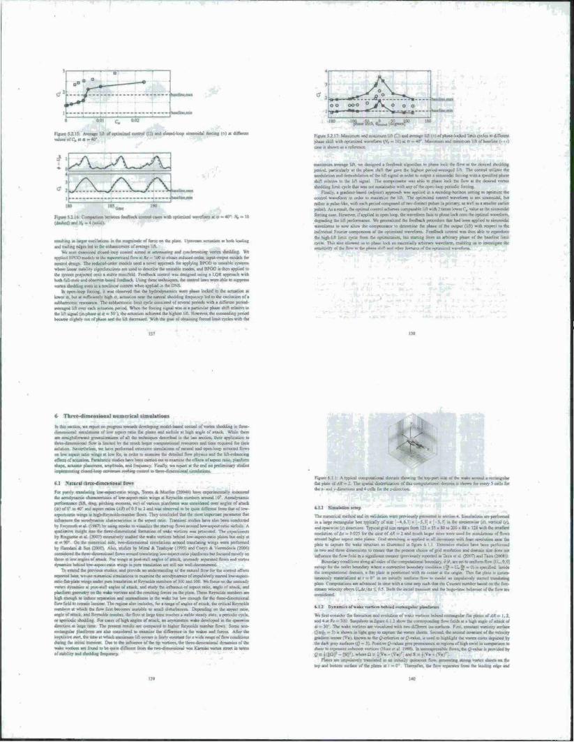
Figure 5Z1S. Avenue hfl of opxmocd conuoi (T'l) «d «luKtf-loop .
valuta otC„ u a - 40*
»dal roretng (?) ■ different F.IUT.
pbe.
1
I minimum lift C) and range lift ( jtcd waveform (ft - 10) tt o - 40* Maximum and nwurnum lift of baseline (• • •>
num lift • I) and nunp lift (") of phaae-locked but cycle» al dtfleacnt
Figure IJ 16. t ornparuo» bctowi feedback control cases wrth upomind waveform at « ■ 40*: Al» at 10
(tfei*d)tad*,,-4(K4*!t
B Utax otallatton» in Ac magnitude ol force on ihe plat* Upatraatti actuation at both leading
and trailing edge» led to (he enhancement of avenge lift. We oca» craxauncd ctoeed-roop control atrncd at aalraaaatasr. and «viataanarttagj «MB »bedding We
•pr4«dBPODinodeliU.lheni|*:rentK..I|to\»ii!»<= lOOlootxam reduced^rUra. input output modcu for
cesaxtol design Th* rcducoo-orde» model, used a novel approach for applying BPOD to unstable systems
«here linear stability ogenfunctwrts are used lo describe ihr unuablc modcv and BPOD t. then applied to the system projactod onto a stable manifold Feedback control «u designed uasng a LOR approach «nth both full -«talc and observer baaed feedback Lwng the« teclm^urA. trie cnotfcJ la», wereabte lo i^ipre».
vortex «til«»»« even in a nonlinear context when applied in BM In openloop fotvmg. it w» .»served thai the hydrodynatnict were phaac locked to the actuation at
Uiwer a. bat at mtTknatl» nigh a. actuation near the natural >heddmg freouency led to the excitation of a I The stibharmixiic limit cycle consisted of several periods with a different period
d lift over each artnatinn period When the (brcaig «ignal aaja at a particular phase shift relative to c lift ugnal (uvphaae al a ■» 50 ). the actuation achieved the highest lid. However, the succeeding period
e slightly out ofphaat and (he bit .kcrcased With the goal of ootammg forced Um« cycles with the
usaximure net age lift we Jesigned a feedback algorithm to phaac lock the flow al (he deatred ihn filing
period, patuculaily al the phaac shift thai gave the highest per.od averaged lift The contrnt uulitts the modulation and orrnodiuainm o! iSe lift serial m order to output • wuoidaJ fceciru: v.,iha rpeofird phaar
•tuft relativ« to the lift ugnal The i jinmiaiai was able to reheat lock the How at the deatred vortex
«bedding limit cycle that was not cusutnabic with my of the open-loop periodic farcing Finally, a readier« baaed (aojoustl apuioatli was applied in a rrxcding-horuon vetting to optimize the
control waveform in order to maximize the lift. The optimized control waveform i» not vimuouhu, hut
rathe/ is pulse like, with each period corrrpnacd of two distinct poises (a primary, aa weil as a umaller oarlier
pulse i A> a result, the optimal control achieves comparable lift with 2 limes lower C, value as (he unusoidal
forcing case However. 11 applied in open loop, the waveform tail» to phase lock onto the optima; waveform,
degrading (be lift performance We reneralurd the feedback procedure that had been applied to unvraosdal
wareforrut to now allow the compensator to determine the phase of (he output (lift) with respect to the
individual Founer compcasenta of the ootunuted waveform Feedback control wai then able to reproduce
dar hrgh-lift iunu cycle from the optimization, but starting from an arbitrary phase of the base
cycle This also allowed us to phase lock an essentially arbitrary waveform, enabling us to investigate the 3 of th* optom-od »svvdbrta.
6 1 htrt-dimenvional numerical simulations
■ thr» «sexton, we report on progress lunata» devrjoeaag asrjdcl ttaarif caaxtol of vortat theddasg tn ihree-
anaainrm»! aarndatjona of low aspect rats» Hal plaiei and uriods al rush angle of attack While there an atraightfurward gericralinMsana of all the «crswrue» described m the last atctioa. thctr application to
d flow is limited by lb* mash large, caanpntatinnal resource« and taw reuuued for Ihctr solution Nevertheless, we have pcrlormcd extcravrve timulaiion« of natural and open-loop actuated flows
on low aspect ratio wmgs at low Re. tt> order to examine the detailed flow physic« and the iift-enhancrng
eflact» of actuation Pararnettw studies have been earned out to examine the effects of aspect ratio, ptanform shape, actuator placement, amplitude, and frequency Finally, we report at the end on prehmirurv studies ine^aasaaiirat deaad loan aamaana- laaaVas, osatrol io tfaraa-dirissnaional tsBMuMJOns
6.1 Natanal ttrot dhaxanoaai low«
For purely n uig low-asprxt-ratio wings, Torres & Mueller (20O4n) have caperrracataOy inoanaad C cruaTBCtensuCS of low-aspect-raiwj wings al Reynolds numbers around 10* Aerodynanuc
e thft, drag, pnehing momou. etc) of varuw. plaofortm was coroidcred over angle» of arrack
(a) i»f ff » 40-araj aepin rau» (yf^
itskay-niaaihrt Sows They tonfltidcd thai (he rnod important rauametcr that
a the acrndrnarmc charactcnaucs is th» aspect ratio Transient «tudrct has« alao been «
bj Fnrymudi ci «I 11 '*?> I.v using smoke to vrsuali/r the startup flow* around kns^spcct-istio asrfoili A aualataarve insight uilo the irtree-dimrriuonal formation of wake vortices was presented. The apcrtrncttta by Ringucoc et al (2007) esncnaivrly studied the write vortue» behind low-aapoct-catso plate» but only ■ a » 90 On ihe numerical aide, two-dinvensional umulauon» around translating wmgs were performed
by lUmdam A Sun COOO) Also, studies by Mtttal * Teaduyar (!W) and Coayn «t V.acndeels (2006)
cinaatinil the rtaaa ilaiaamaial flows around itanilalasg low a^<ri-i-rauo pyasformi bat focused rnoatly on those at low angles of attack For wtnga at poat-ttall angles or attack, uxeateadv separated flows and v.«rr. dynamics behind low-aspect-ratio wings in pure translartrm arc «ill not »ell-documeotrd.
To esaead the prcvioua rtucaes, and provide an laabmaialmg of (he natural flow for the control etTorts
reported labst, we use numerical umulatiocn to examine the aeradynarmca of impulsively started low-aspect rat» ftai-plaie wings under pure trartsratioc al Kevaold» numbers of X» and JOO. We focuaoo the uratscads vortex dnatmsca at post-stall angle, of attack, and study the influence of aspect ratio, angle of attack, and planform grswnetry on the wake vortire» and the reasimiu; forces on the piai« These Reynolds mamber. are
high enough to induce separat«» and m ilnni at the »sake but low enough for the three-dimensional flow bald to lemain laminar The regime also includes, foi a range of angle« of «nack. the critical Reynolds maxsbrra at which (ha flow lint becomes unstable Io small disturtwnces Impending on lbs aspect ratio ao^c^alu^araJRrvTwlctarurmbrr the flow at large time reaches a »uble siead> sute a rwiodsc cycle
or aperiodic shedding. For cases of high angles of arrack, an asymmetric wake deveVjpcd in the «panwise direction at large torse The present mult» are c-ornrssnrd Io higher Reynolds number flows Some noo-
aartangnlar planformi are also considered io examine Ihr difference in the wake» and forces. After the impulsive start. Ihe Um at wtuch rnaAimum lift occurs is laut« coristart for i w>d. raoa* ot Ifcw condiUoc..
dormg tbs atrtatl tntasent Das to th» atfluaata of the up vortsces. the tbTeo-dstnarauooal dynamic» of th» wake vvatson an found to be quit» diflcrent from the (wo-ehmensional von rtarman vonex »treet in tenns
afarnhaatyandal
Figure 6,1 I A typical ccajyiltaliiaad domain showing the top-piart side o[ the wake around a rrcaaruracar
flat |4ate of All - 2 The snanal discretaatioo of this cornpuläimoal domain is »hown for every 5 caiU for ihe j and v direction» and 4 cells for the r-dircction
I nuUlKMi trtap
The numerical method and it* validation were previously pnauitul in section 4, Sunulaiions are performed
m a large rectangular box typically oi ' t, m the strcamwisr u). »erucal (i-l.
and iparrw.ie Cr) directions Typical grid cue ranges liom .Zi • <* - «0 u> :«' - M ■ 12K with the smallest itiaalution of At » 0.025 for (be case of AR 2 and much larger ssrxs were used for umulattoru of flows
around rogho aspect ratio riaatca Cmd socschtng a apphed m all drreaXson» »ith finer rsMluboo neat the ptarc to capture the wake structure as illustrated in figum 6 I 1 F.xicnsiw rnxhc» has« been performed
m two and three dirncnsiom to crnarc that the present choice of grid rcsoJuuoo and domain suec docs not influence the flow field in a sigmfitant manner (previ-Hi.lv reported ui lair» c! sl (200T1 and l(a
Boundary'condilior» along all «ides uf thecorrn>utaticinal brrundary. «y. are »et tour ■ except for the outlet boundary where a cottvecuvc buuridary ccasdraon (-J» - f _i« afl ■ specified bands the computational domain, a flat plate t» posfUoned with tu center at the origin This flat plate is instan- taneously rnatenalind at t - IT in an aamelh uniform flow to modei an impuisi.elv started trarrdalavg
plate Cornputations an advanced in law woh a taue arp auch that (he Counoi number based on the free stream velocity obey» U^lu/tu <_ 0 5 Both the initial transient and (he Uige-trme behavior of (he flow are
6.1.2 Dyoaatlcs of wake vorricn behold rectaogalar phutforats
We first consider the formation and evolution ot wake vortioe» rarhsnd rectanguUs flat platea tt Alt" 1.2. and 4 at Kr - ItX) SoapshoO m future 6 1 2 »how the ccrrtaporsrirag dow field» at a high angle of attack of
The wake vorucrs are visualixed with two diflcrent i«o «urtacc» Fuxt, constant vonioty surface
(D»|3 = ■♦>» «hownai Ughl gray io capture trar vortex sheeti Second, the seevrai invariant of the velocity aradteM tensor ;V«). known aa die ßcritervirn or p•value. « used to highlight the vortex core* depicted by the dark gray «urface» {Q = .•). Piwitivc Q values gitr prominence la region» of high swrrt in uataaaiawai to ahaar to rerasacrd cca^ract. swrbces (Hunt et al l-rxxi In «wmomahl. flows, the revalue .. provded bv
0«i(|XJ|p-l«|I).vvrhn. .
Plate» arc rmrsalarveiy Uanslated in an initially quiescent flow, arnerxtmg strong vortex sheets on the
ic^arsdbooom surface of the plain at ' = tv Thereaflcr th. flow separates from the tctding edge and
It« m
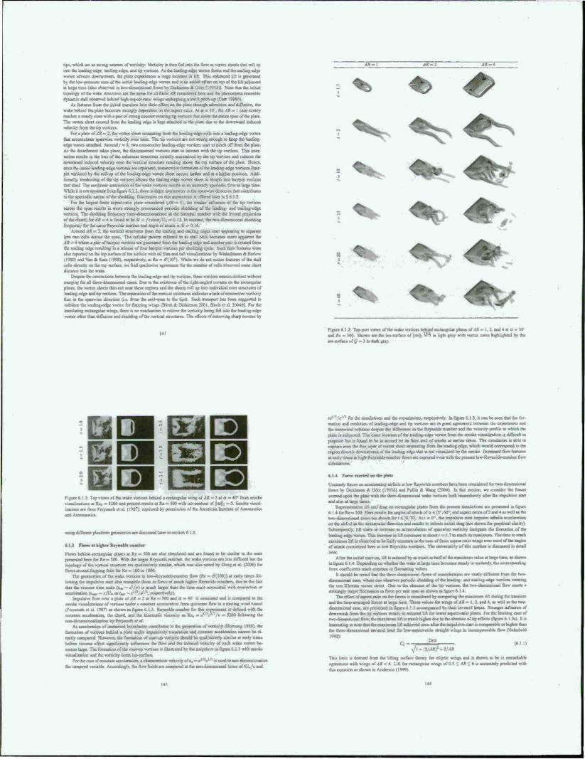
op», wtMck act a» «mi »oca of vortiary. Vbrucity a then fed into üie rt<m at vortex ihecU that toll up rnto «fac tcadirtg-cxsgc. uasung-rdec, and up voruce» Ai the tcailing-cdge vortex form, »mi the rrailmg edge vortex adverts itawguam, the plMe eapeneoca a targe increase in lift. Thu enkaoeed lift i* geocraicd by Ihe to» inmi: core of the initial leading-edge vona and is an added effect on top of the lift achieved at lane« tnava (also ohatrvad a nMo^hraoaaiooal flow» bv Dickarson Jt Got/ (IWJA)) Note that the initial topology of the wake structures an ihe aan» for ail finite AR considered heic and the phenomena resemble dymatuc anil observed behind high aspect ratio »<ji uradragotng a »will pitch up (Can )9Uo)
Aa featurei from the initial uamieru to« their effect an the plate through edvectton and diffusion, the »rake behind Ihe plate hecumev «Jungly dependent on (he aspect ratio At u = M 'he AR = I caac »lowly read» a steady «ate with a pair of strong counter ro»aria^ up von ices rhat cover Jvr cniuc »pan o( the pUir Tbc vortex sheet created from the leading edge is kept attached to the plate due to the downward induced velocity from the tap vortices.
For a plate of AR - 2. the vortes show emanating from the leading edge mils into a leading-edge vortes thai accumulates spanwis« vörticity over lame. The tip vortices arc not strong enough to keep (he leading edge vortes attached Around /* S. two »vroccuuve leading edge voruce, start lo pinch off from the pUie As Ihe raaachrneot take» place, the dr»sx>e»eeted »ssrticCT stan to mteraxS Thu inter action remit» in the loss of the columnar structures initially maintained by the tip vcxrtux» and reduce» the downward induced velocity onto the vortical structure residing above the top surface of the plate Hence. once the initial leading-edge vortices arc »syaraled. corttecutrve framation of the leading-edge voruce» (hair pin vortices) by ihe roll-up of the lading-edge vortex sheet occurs, farther and at a higher position. Addi tional'.y. wrstVmmg of the tip voruce» allows the tnuiing edge vortes: sheet to rnorph into hairpin vortices that shod The nonlavr«! inirracuoo of the wake vortices results in an uosscady aperiodic Row at large time While u is not apparent from figure 6.1 2. there is slight uyrttmctrv in the ipanwue direction that conuibme» to the aperiodic nature of the shedding Discussion on this asymmetry .» offered later in 5 «1.5
For Ihe largest frmle aspect-ratio plate considered <,Ag m 4), ihe weaker rnflueocc of Ihe op voniecs aenvn the span result» in more »troogly pronounced periodic shedding of the leading- and trailing-edge vonieex The shedding 6rs»uency (nondimensionaliasj a» (he Strouha] mrrnber with the frontal projection of the chord) f«.<A-4 is four«! to be 11 . A:»aa,V. » 0 12 In comrast. the rw,Mlmeir»»arjal sheddrng freijuency for the same Reynold» number and angle of aiuck is St
Around AR = 1. the «»meal »tructurn from the teadmg and trailing edges start appearing to separate into two ceU» aero» the span The cellular pattern referred lo a» stall cells hecomo more apparent tor «.? i »here a pair of hairpin vortices are generated from the leading edge and another pair is created from (he trailing edge resulting an a release of four hairpin vorucca per shedding cyck Such flow feature« »ere also reported on the top surface of the a u foi 1 • with oil fi 1m and tuft visua I i/auoru bv WinkrImaon A Barlow (IvHO) and Yon * Katx(l*«). respectively, at Re - t*(|0'). While we do not nonce features of the »tall cells ihrecll» on !hr top surface we find qualitative •«jerment for Ihe numtatr of oafla tvhatmaJ artmc short dutaocc into ihe wake
Ocspiic the imeraction» between the IrarVirsg rrlgy sad tip voruce». these vuruces remain distinct without g for all ihrccdiioct»««mal caac» Due lo ihe eaistetsce of the nght angled corner» on law rrxtxsxgular
AR-\ AR.*
plate», the vortex sheet» Hun out near these region» and the sheet» toll up into individual core structure» of kading-eugc and up voruce» TV leparation of rhc vortical «ructurc» rr»diea»»atarJiofcejrrsxxtis. (lux m (he snaimue direction (U from the mid-span lo the (spa) Such Iratrxpon ha» been i Igagaiiii to «aisil« ttK leavJjng-essg« sr«ex fm flajr^ 2U04AI Forthe B»»»las»ng reetaaajsil« wroa>. th« vejr»w eaava lt»»a» stl»s»t»tw and
♦ <£>
Figure 6 1 >: Top-port views of ihe wake voruce. r^irad rectangular plate» oM» - I. 2. ax» 4 at a - V) and Rt = MX) Shown arc (he is»surface of \\a>fo v4*, ,„ t.ght gray with vortca cores higUijrhJcd by the ■scvttkrtacc of Q = 3 m dark gray
o o figure r. I * Top views of the wake vsnsvtaasit»»* at Re. » 5200 and pre utatiaosarc from Freymuth et al. (I*
using difraront pumform gx>o«»ctrvo asr di»cu»»«d laier m seaion 6 1 A.
»IJ Flow» al higher Reynold» auasner
Flow» behind irxtangular plates at Re ■ 500 are also »urmlaicd and arc found to be similar to the one* rareacraMd here for Re « )00. With the larger Reynolds number, the wake vrjruce» are less diffused bui the topology of the vertical structure are qualitatively Simla», ssluch »sa» also »sted by Dong et al (2006) for flows around Happtng loil» for Ke = 100 lo 1000.
The gerjrrielrics of Ihe w*U ss»ruor> m Um ResTwlds-numher flow i*r = r7( 100)) at early times fol urn inc. Ihe impulsive start also resemble those in (lows of much higher rUynold» numbers, due to (he fact that (he vi»cou» time »cale tr„ •« c3/») u> much larger than the lime scale a*»ociated »wth corrvection or aeecaanxtiou (<W -c/t/>orr.« - »-' :/o' :. resp>
Impulsise flow over a plate of^Jta2atRc«500anda-40 t» »iratsvased and is compared lo Ihe smoke iisuali/ation» of sssrocaa under a constant acceleration from ouicssrcnt Ilou ui a starting wind lutrncl (FiesTTjiith at al l'»T> aa shown in figure 6 I 3 Reynolds Qambcr for thu c-rnarrmonl u ddincd wnh the corutani acceleration, the chord, and Ihe kinematic viscosity as Rtv, = a^r^/v m 5200 following the iKT-.-dimcnsiooaluasiun by Freymuth et at.
As acedcrauon of inuraerxed boundanc» comnbutt-s to Ac gerie»au<m .if wirM^y (Mornung l«W9». the formation of voruce» behind a pbic under impulsively trsuuuion and constant acceleration cannot be di- rectly corryarcd However, the lormanon of start up wsruce» should be qualitatively similar al early times before vsacout «fleet stgtsu^catsily nsnttaraar» rhe flow and (he induccJ vvlocils of each wake visitex be- comes large The formation of the start-up »truces u ilhutraied bv the snapshots in figure 6 I 1 with smoke \ .iwliv^'u*:-. a."*! 'he »«KT.iir', -;.»rr-. .MI ..irtati
For the caac of corartani acceleration, a criaractcrutic setuory of», » g' *c' : is laved to ooo drrwrisirraain (he leoaporxl saruhfe Accordinalv (he floss field, are compared at the nrm-dnr»m»»onal urnes of rf/./r and
l«r Ihe »unulaums and (he espenroents. resnecttveh In figure 6 1 J. it can be teen thai (be for- mation and evolution of leading-edge and up voruce» are in good a|rrecroent between Ihe e»?»9runeol and the numerical »luuon despite she ihilerencc m the Remolds number and the selocrtY profile to which the plate is subjected Th« exact locauon of the trailmg-edge vortes from Ihe smoke vuxiakrabon u eUScsalt to putpotnt but u found to be m accord by iu fai« liaul c^ nnoa» a« eariio umea The simulation i« able to capture ever. lb. Ihm layer of vortex shed e»narialirag from uV le»viutg edge. wh»di wouVd c« region dtrecüv dowmlream ol the leading edge that i. nol siaualued bv the smoke Dommanl flow txsatures al earls cnsesmhigls-RtrsTiivlds-nrimbCTttows are capt sirruOassorr»
».1.4 Force rsrrtrd on Ihr platr
Unsteady force» on accelerating airfoils ai Vow Reynolds number have bee« u»n»idcred for two-dunenjaonal flows by r^cJanaoo * troU (199») and Pullm Jk Wang (2004) la the. »eeuon, we consider the fore» exerted upon the plate with the thrtx-dirricrawxnal wake vortioea both rmtneastacty after the impulsiv« «tan and alto al Urge iimci
ls^eircxstntativt hfl and drag on rectangular ptoara ttom the preaaal sataala1»rr»i are prt^antad ra flarure 6 14forRe«.»00 Hr«r««uh» for angle» of atu | . .j aipcci ratio» of2 and 4 a» well a» the rsradirncetsional caae» arc shown for i c .0. 70 At/ - 0". the rrtnsolsrvr «tart imposes mfmilc acceleration on the airfoil in the sueamvsise ctrreclioo and rexults in infirsiie initial drag (not »bown for aiaphical olarity) Sohsssaueotly. lift sans to increase at accumulation of spanwisc vonicity irutigate» the formation of the leading edge vortex Th» maranc in lift cotwnucx to about / - I 7 u> reach its maximum The time to reach maximum lift it rsbserved lo be fairly etvrtttanl m the caac of forde aapeel rat» wings over most of the ancle» of attack utnsiderrcd here at low Reynold» number» The universality of du» number tj discussed in detail later
After the initial start-up. lift i» reduced by a» much as halfoftnc maximum value al larjjrc time, aa shown mfigure6l4 Depending on whether ihr wake at large lime r*v..n»«s »teach or ixruteady. ihe corre. force coefficient» reach coeotant or tnajtuatatsg value«
b should be noted that (he toe««wi»rm»»ona! flow» of considcralion are vanlv duTerenl from (he twe- ■hmtinmaal caac where one cfcserve. periodic »hedding of (he leading, and rrauUng-edgc »xruce. creating (he von Karman vortsrx «trtet Due to the absence of th« lap varncea. th« m i rim nut mil ftow exert» a »truangly larger flwauauon m force per unit span a» rhown in figure 6 I 4
i^ effect of aapect ratio cm itef.rOT is «id the umc averaged force» ai large time Tbeat value» for wings of AR - 1.2. and 4. a» well aa rhetvao- dirncnsiooBl caac. arc pre^nied in figure 6 1 5 acx»mrs»rncd by thcrr ins.seid limn» Stronger influence or dowawaab from the up voruce» result» in reduced lift for Uswer aaeiw-mio plate» For the limiting case of two-dimenswnal floss the maximum lilt i» much higher due lo ihr absence of up effect» i figure 6 I 5ei 111»
le that Ihe maximum lift achieved soon after (he impulsive stan ■< cornparablc or higher than ü mvtscid limit for low-aapecl-nrbo »ttatght wirtga m arxtvaareasaaattsis flaw (Iklrnreitd
1942).
Q». y -W . (nil) Jl-G/ARf-Z/AR
This trout ra derived rrom the lifting smtace Iheor) for cuipoc wragj and rt shown lo be it uwimwu»g»of4*<4. Lift for rwtarigulat wings of 0 5 •" AR < b is accurately nr
n a» shown m Aradcnon (1999)
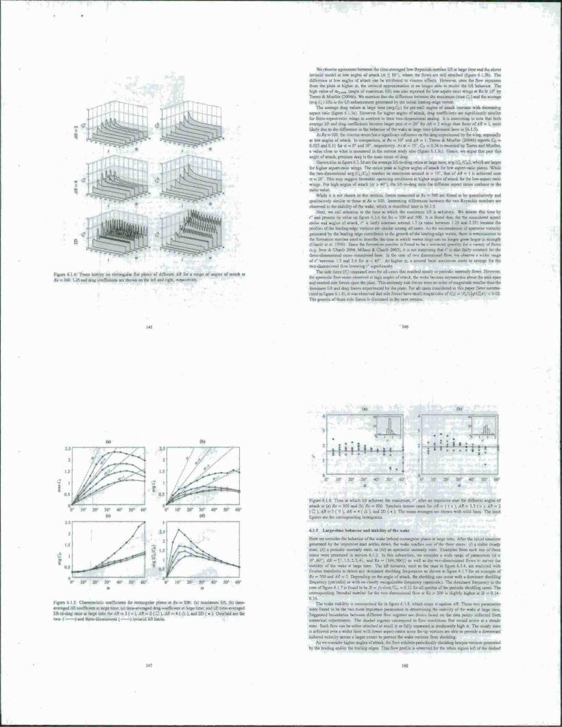
muhirii m*\ II tnC QfOO^CWflfBO lOW'fUyQOvOMHOKMV oft *U latfgC Uinc Ifid WC tb&VC
I
Figure 6 14 FOH bitturv OR ractangul« flat plate« of different AR for a range of angle* of attack at AV-J00 l.^and«Jra«cu»mewtt.air!*o«n«mthckna»Jn#hl rrapccs.^-.
oimcMl mnki s UM aoflo of attack (a < 10 I. wr»tre the flow* are »tiu euachcd t/ia^tre 6 I 5h> Tha
cUITcrmce al low angjci of anack cat be altnhuted to vutw eiTect» I h»oo. once «at flow aqwHea froan tke plate at higher a. the tmnacsd apptimnatioti t» no longer able to mode! the lift behavior The
high «aluc of Or, aaa (aofk of maximun lift) wa> al«. repurtcd ft» Itsw-astsectrauu »mp at Re * 105 by Torre» * Mueile» (20046» We mcniiuo thai the difference benwaat (he maximum (max C, t and the sacragc
(avg Ct) lift» is the lift enhancement generated by the initial leading-edge vortex. The J«m|t drag value» ■ large tune (avgC») for pre «all attfir
icpe. i ratio iliguic 6 I ">c; 1 loucva for higher angle» of attack, drag coefficients are Hgraficantrv ■ (or firosc-««pect-ratio »np as conn« to the« twoHtmtrnaannal analog h it inlcnnuag to note that both
avenge Ufl and drag coefficients become larger pa« a m 20" to4A» 2 w*tw than thoecof «ff > l.mo»t
likely due to ne difference in the beettvior of the walxat lanre irme(dtatu»««d Uicr in V* I 5) At Re « 100. the viscous «re» ha* a significant influence on the drag cxpcitcoctd In the wing. e*t*sc*sU>
at tow angle» of «nack In cwnpattaua. at R* - 10' and. I* = 1 Tom-. * Mueile» (2004*) rcpont C'„ --
0.02« «ad 0-11 fota -0' andi0-.re»pec5.vrl> Ala = I J . t'., - u :* u recorded by Torre» and Mueller.
a value clot« to »hat it «last» til in rat carnal stud» alto ifigurr 6 1 5e> lien« we atguc that pa« tan
angle of attack, pressure drag u the main came of drag.
*u*>*>*al»si«fisj«n«»rM
for higher aspect ratio wing» The ratio« peak at higher angle* of anack for tot» aspect rabo plate*. While the rs»v>4isncir«»or.j . c» it» maximum arouod o - I0\ dial of AR - 1 it achieved near
a « 20 Thi» may suggest lavorable operating condition« at higher angle* of anack (or the tow aspet■ ratio wings For rag» angle* of attack (a > 40*1. the Uft k>-drag rat» for diflerew aspect ratio» oajteacc to ike
omr value While it i* not shown in dm section, torte» meatured at Rr » 500 are foond to be qvjantiiairvei» and
qualitatively similar to those at AV » 100 Interesting difference* between the rwu Reynold* number» are
otaerved in the stabdify of the wake, which it described lair.
Sett we call attention to the tune al which the maiimum lift it achieved Wc denote this time by r and present iu value on (teure f. 1 6 lor Re = 300 and 500 hi* found ttsat. fat the corwdcred atpect
räum and angle« of attack, f u lairly constant around 1.7 (a value between 1.25 and 2 25) became the pro/ilc» of the icadcng-cdai: sorticc» are »unilai *nuir»j all va«n A* the acvumnlMieri of »panv- ■ ■ generated by the leading edge contribute» lo the growth of the leading edge voncx. there i» rettnnitceocc to the lormatioc number used In thwlsV the tune al which vortex nags can no longer grow larger in ttllttgta (Cihanb et al 1998) Smcc the tortnauon number is found to he a univcrtal taatntiiv for a variety of (lows (eg Icon 4 Chtnb 2004. Milaoo * Qnvib 2005). it is not vurpritmg that r i« abo fairly coooant for the ihinc-dirnetuKnul ca*e* coruidctec) here. In the case of two dtrnensMnat flow, \\e observe t wider range
of r r*etween 1 3 and 14 : | her a. a •econd tocal Miunn «tans to emerge fur the itt.-.-dimcmiotial flow lovvenng '* «gnifictnil«
Tl* tide f*»r« (f,) »eii»a*r^ !lowev«r.
for apemidtc flow cases obttrrved al htgh angle» of attack, the «vale became aryntmttnc about the mul-snen and eimed nde Ibrcesupoo the plate Th.» untscad» ttdc forte» »ere an order of magnitude tiriallcr man the
dominant lift and drag force* expervenced by the plate For all cases c.xuidcred .n list paper (later «mi-
rued m figure « I «X it tvaa observed dial »cWcswc have imall mas»iudc.
The gcaeatt of thcac tide force* i« ditcuttcd in the next section
itr ar JO- 4<r so» w ov io* 2tr jtr 4ty so* w
Fifsm * I i CattnnaratK niifrailldi to laaajt-ultl piste» al R* - 300 (a) maximum lift, (b) tune
«vamgad lift ci«lrtcient «I kuge time (e) iuwa«era*»d drag eoeflicient al large tune, and Id) tuw-avtnastd Ufl to-tvag talk» al large time for AR i .1* ^ 4 ( i ). and 2D ( • I Ot**jtt*d are the two ( ) and IrirtX-ditnctvuonal ( — -) im i»cid li ft limit»
(b)
o- ,o* *r 30* 40* JO «0 0 10 20 30' 40 50
Figure 6.1.6 Time al which lift achieves ihr maximum, f", after an impuli.-ve «tar to different angle» of anack at (a) Re = 300 and (b) Re m 500. Symbol* denote cases to, AR « 1 ( o ). AR
. Z ,. AR - J ( T l AR - 4 ( i. ). and 2D , . i The mean avangn are thown «nth solid lute* The utsct
■ i/iift» ate uw cta*riXs3spoiiaing; twAOfuwui-
fJsLS Lai>^4s«rbHia«»«Vae^«tahiIrtyorthrwakr
Here wc cortudcr the behavior of the wake behind rectangular plate* at Urge tune After the initial uanaucnt gaiwraasil by the impulrivc start scale* down, Ac wake rcaihr» one of the three »tases: (r) > ttatnc steady
state, (lf> a oenodtc uruteady »tale, or (Hi) an apenod«, ututcady »täte Ftamnle* from each one of thne «late* were prevented m «ev .ubtccuon. we ctstataaa a wide range of vattactctcr* (a »■
-,-nsional flow» to «rvev Ihc •laNlit« of the wake at large time The kft historic», such a» the ones m figure 6 I 4. «re auakiatt* with Fottricr tnmtform to detect any doraiittatl «hrdduvc !requenc»e» as shotrn in ftgure 6 I 7 for an < «ample of
Re = 500 and AR » > Depending on the angle of attack, the »hetklmg can c«OT)r «vrfh a dominam »heddiru: freensency (periodic) or »wlb r» clearly rccogmiable Intpxcncy (aperiodic) The dominant (reqi:
caaeoffigtwc6l 7 is found to be S - /csma/U. » 0 12 lor all spectn uf the periodic^ «hcddinj usve» The C'vrtrsrnndinf! Mjouhal raanbrr for the rwo-ibmeiwonal flow at R« o 500 i* slightly higher at Si w 0.14
0 16. The wake ttabsbty u «umman/cd lot tn Sgure 6 I S. whieb maps a against AR Thcac two parameters
were found to be the two most important psaacteau» in determining the «ability of the wake M large umc
5m**r«ril botradancs bctwoen duTcrent flow rcgxme* are drawn bated on the data ponxU collected flora
numeric«! cxperrniera» The shaded region» correspond to flow wasfrstiorw that would arme at a dead»
«ate Such flow can he rithcr attached at «mail a or fully sepansteel al moderately high a The steady «air
ii achieved over a wider limit with tower atpect ratios «nee the Up vortsce* arc able so provide a duamwasd
utduccd velocity aenxts a larger cxlent to patvcnl Ihc wake vurucc* from shedding
As we consader higher angles of attack, trst (low cj«nir«u penodH^ sbedd^
b« the leachng amVor the trailirttt edge* Thu flow profile i> cilwcrced for the while region left ol die dashed
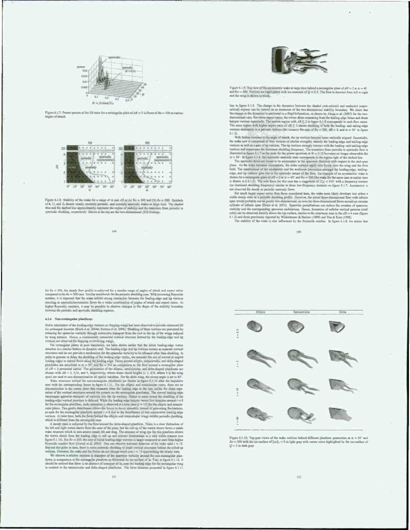
*' oT« am/cma/U.
Figiaxb.l II Posvci ipcclraiifthc lid dice loi a rectangulai plate of XA = 5 in flow* ..f Ar = 5O0 at vanoui atsgtet of attack.
20" JO* 4tr 50 60 0* 10* JO" 30* 40* 50" 60'
FigurcM! StaUlity of the wake for , range of a and ,<* at (a) Re = JOO aod <b) AV >, 500 Symbols of .. U and A denote steady, iimtcady periodic, and uro«ad> aperiodic wake» at large tone TV shaded area and the daahed line approximaicl) represvtnt the region of «ability and the transition from periodic to aperiodic shedding rrspecüvclv Show at the top are the two-datticos.c*ial (21» fi
ft &£r^
Figure 6 I 9: Top vie» oftheMyminetnc wake at large IIIK behind anxtaojuUr pUttofX* - 2 ■ o = «0 andRc = J00 vsjrus.es are highlighted »ith ,wcoouxirs of Q • 2 5 The flow it directed frem left to right and the wing if Usnwn in black.
bat m figure 6 I S The change is (he dynamic, bctwaca the sbasted t sub-cnticaJ i and unahaded (ssjper- ■ d at an extension of the twodunctmonal •lability boundary We claim thai
the change in the dynamics is aonbuted to a Hopf bifurcauon. a» .hewn by Abuui ci al. (2007) lot the two dimcruional case For lower aapect rauoa. the vortex sheet emanating from the trailing edge form» and <hcd> hairpin vsjruccs lepeauajly. The narrow region with AM < 2 in figsac 6 1 » correspond» to «uch flow stale» The one rcjioo with higher aapect ratio o(Aß>2 «how» shedding of both the leading- and tailing edge wirucoaiioraa(riymaperic«iKfaahjon<fM in figure
With further increate mtxic angle of aoack. the up vvrUo t<tor« ir«>re vertically aligoed Essentially. (he wake now i» cornprucd of four voracn or «imilai strength«, namely the leading-edge and trailing-edge vea-aceaaiwellaiapauofQpvwticea The tip vorucev Urongty interact with the leading- and trailing-ettgc vatKea and suppresses the dominant shedding frec»»eoc> Th« tnawrUon from penodie to aperiodic flow it ilkutrated in figure 6.1 7 as the peak for the power apectnas) at S » 0 J 2 bctwaca tao loraja oeaarvable (« a > 30 In figure 6 1 I. (hu aperiodic unatcadv atata correapond» to the region right of the dashed line
The aperiodic flows are found to be arvmmetnc m the tpanwuc direction with respect to the mid-span plane At the wake becomes anrnmetne. the wake vertices apply side foicos otto the wing and the flow field The combination of the asymmetry and the nonlinear interaction arnongst the It aikoj, mtga. traiiang- edge, and up vorucct give rue to the aperiodic nature or the flow An example of an uvTnrnetnc wake is shown for a rectangular plate oMA - 2 at a = 40' and Re » 500 (the snaz 1« the saene «e at carlacr ton« a »hown m s 6 I 31 The side force for this cave has a magnitude of ICrt < 0.01 with a frequency content too dominant sheading frecpctit-y) sirralar lo tho« low firiajemv cuolents on fixure (. I 7 Anranvrtr» is not <iNscr\c<i l.n ilradv or Ten gstl gsast\ssatf| lloi.»
For much larger aapect ratios than those emssdered here, the wake roost likely develops into estbet a ttabla steady «tale or a periodic shedding profile I iovsv.a. the actual thrtsr^mctwonal flow with infinite «pan would prohahiv not be purely two dimensional, as seen fur ihtee-dmscnssortal flow« around an ci cylinder of rnftmie span (Bra/a ct al 20OI1 Spam»ise perturbation» can induce the Mvsatxsn ofspanwisc voruc.ty and the ccarosponding spanwrte undulauons Hence, format« «forllutar wjrbca. patorna (Mail ccsit)canbe.st»sms^e>j»xdyar»vct^ 6l2)aridthc^r^i«ulyrcpnricdby Witiaclmar« & BarU» (I Wl) and Yoo A rv^ llvHM)
The atabilitv of the wake it aha influenced by she Revnold» marine. In figure 6 I ». we nobec thai
•00. the steads flow pnvfile is achieved foi a smaller range of angles of attack and aspect ratios cotntasrod to the »>.. 3« csssc Similar tsc^ number, it is expected that the wake exhibit strong interaction between (he leading -edge and up vortices
tt ar«rsod«c>>witanaaja. flows for a wider combmatson of angle» of attack and aapect ralxnv At higher rteynold* numbers, it may be poaaible to i*sers<c changes in the shape of the stability boundary between the pcasodic and aperiodic theddsng regime»
k-la Noss-rreuaesslar rdanferaa.
Statte IHanrsmiml of IhtlsadasgHsdests for ra^songed duranoo (Birch e» al 2004*. Poelma ci al 2<t0«) SrKsrkhng of ÜV« vxsmco are prevented by isrlaaasag (be spanwiac vonsaty through coovecuvc transport from the root to the up of the wings induced by wing rotation I lessee, a continuously connected vortical structure formed by die leading-edge and tip vortices are observed for flapping or revolving wsnga
For lasitasgiiltj plaics in pure translation, we have shown earlier that the initial Icadmg-cdgc stsrua detaches in a similar fashion to dynamic stall The Icading-cdgr and Up voruccs remain 4s separate veaticai structures and do not provide a mcchanijam for the tpanwisc vorucily to be rekaacd other than shedding. In ardor to provost or delay the shedding of the leading -edge vortex, sve consider the use of curved or angled leading edges (o induce flows along the tcadaag edge Flows around elliptic scrmctrculai. and dcha-»hapcd pUnfurnu arc simulated at n ^ 10 and Re = *<<<> m comnanvon to the flow around a recungulat plate of AM - 2 prnented earlier The gtMCnetrses of the elliptic ttstucacular. and delta-shaped planforna are chosen with AX <* 2. 4/«, and 4. respectively, whose mean chord lengths (c i/A. where h a the wing span) are used so mm riarrmiimaliar aU spatial vasnahttav For the delu wing, the sweep angle is set to 45
Wake structures behind the non-iectanguiar plaitforrna are shown in figure (> I 10 after the impulsive start with the .-iixrtsap^stiisg forces m figure o 1.11. For (he cliipUv and sermcirtular cases, there ate no divconunuities in the vortex thect thai emanates from the leading edge to the tips, unlike (he sharp sera ration of the vortical atnatnatra around the corner, on the rectangular pusnforna The cursecj leading edge ertcotanigf« tpanwue transport of vssrucity into the tip vorticrs Hence to some extent (he ihrckuog of the leaestrsg-cdgc vssrtical structure is dclavrd »lule the Icadmg-cdgc hairpsn vssrlex fim detaches around rs: I for the rectangular ptanform, such separation is observed a» a later time (l = 15) for the elliptic and semieir cular plates Thta gestue deaachrnant allows the forces to decay srnoc4hly mud c/assstsauug ftsrtssMtuni. at tot» for the rectangular planform around r * g due to the detachment of two consecutive leading edge voruces Al later lane, both the flosvt behind the elliptic and semsctrciiiar wtngt exhsbtf periods« riliitlMa*t which is different Irom the rectangular case
A steads state is »thieved hs the flow around the delta~ttHatt*d planform There n a dear dtstinrtion of the left and nghi vortrjt sheet» from the nose of the plate, bui ibe toll up of ihc vortex sheets form« a stable srake structure which in oam auairu steady lift and drag. The absence of wing tips for this ptan/orm allows the vortex sheets from the lending edge to roll up and convect downstream in a very stable manner (see figure 6 I 101 For *r » W0. the sere of .ruual leading-edge vortices i» larger cosritssrcd to ones from higher Rartsssskb number flow n.ursul ct al 200$) One can otsscrsT transient behavior of (he wake until / «: 15 Beyond this point in tune, the» is some unsteady Jsodding of small vorucat structure» bchmd the rolled up sva-uccv lussvevet. the »sake and the fisrces do not change much past / a 15 approaching the steady state
Wc observe a relative increase in transport of the spanwiic vorucity around (he two rectangular plan forms in comparison to the rocUngular planform as illuoiatcd by iso-surfasc of a Vox. in Ague 6 112 It should be noticed that there i» an absence of transport of c* near the leading edge for the rcxnangular wing as contrast to the ssssntctrrsrltr and dvHtt-shaped piarforms The force mnories presented tn figure 6 I II
F-llipuc Dclu
r> f>
Figure 6 1 10. Top port views of the wake voruce» betund Caflerss» plaeulono geornccrars at a - W and *«•. 300 with the ito^awnsce of |a>|, ~1 tnUfafnywt&vttootaU&ijMtyteuo'matBeot t?» 3u> dark gray
151
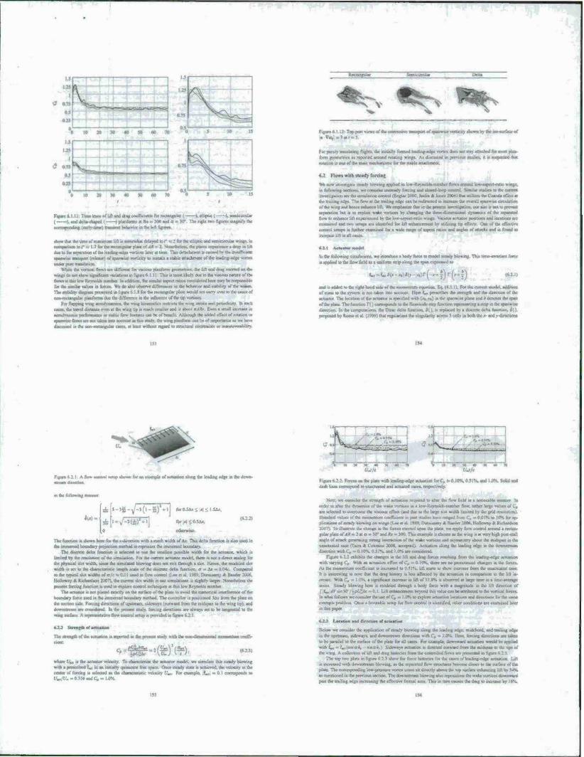
m ■%9I Aq WQoui o) tup xp unn urn in «m «» pnuuij «n-wya xp aunwaiam »Sp» aumui xp sad fammama?mnie*x^^amnBoA»ta*ittuiMOHam*£imJ*e9*iL foaaxmoMaid «puipjooqUMin
toouwpo jo»)««, do» wp w»|> Anjawp in mn mun> —aaxlaat *»jinawl«aiirp ay, aana < ;mi mi «i i»i»p aiuoaaq «uruwut» «ny paiuaiia« ap n 'tauton unuwuwp tput pwinjui •>
OH »*»»waa dp>»M|iaatjosOTMpKi;uun«a|a>K9 ap «^ t £ 9 »>^ » «*>t« <»»»<*»» *U .«Uli; iu pow»ixia «• .~njf»jjuaM>-> «n «nuj ouuitn) Äip n» 1PI;.. oon»nc» v «u»» *J1
lo uln :np m «nJtpiui ap u»ui paatw papanp a uoiaitia« afeaa ""l in» pMMta aq PI<XM» aognnM pauuiMop aphiaia x>j UID n» xtj annd sip jo aanftM xp in p||iml aq 01 ua»n ur «xxiaajnj »rax* J»j| %} | » ».9 «>— nuKtuie unuuwfi pu» <i*c*apu. -jraovSn xp a xfpo iunww pu» tuaipf im -a*»» tapaai ap »»»IT fcmow Xpww JO laaiaraqild» jcp lyimo a» xxafl
od*J "iji ■ o>«| pauiiu«» ij» naxtrptK» jxp« •pxriittapi n ;ouui» VKMJ JUJ Jnia. a(i)uii\«| t »tuo tuaiixij.: aom xp *>j mwoaHp put innnr»! »wumvt» »»>»<Jo o» %<j j « "^ )« JW aji urmtiio »» »«oitoj wij« «q
-o3^l«3n«te«voipow{iaii^i*»afl|nfi(ppi>a^iikMaicMrnun I U»-N;/»'' ju uutputp u'l *P <" »pninifiBo it i(ii» »Ktj lipoq * qXncuip pajapoui n uaq SoiAiopi zip«.) . ifcm» min « in aani aim nt pojuaaqo « %rIt J° IPl *" "»av vmnputoi ■ HO | ■ *j ajuj in gi| xp i* mxiwduiOJ si iumwoe xp Xq pai-ujpr •») ■• üuttiq dap xp »ap »w w taiu.<. aa» pjimmwui xp UJUJJ mnrnii «no« oi «inn* in! *%it o "i pax»») a itixcityx» uaiiuauxxu xp «v «ftjoj up tn ujtunp paunmaial «a *■ »op -%oi o ■■ *.)p> v°l)> »w«i» « <ii',i\ *3 »BIAWA «pi«
u»'l»»»» 3«P»-top«»| ap aaaa aaj,iaa «*uoj »up po» «<( arp in oiuwp xp «*qnpo ri« *»*j P<M»P«W»M»S0 IP"-Slf O^Ml o-'OHWOOHMcp
imiuiiilt Jip IM afp» tutpw] Mp »mn» «onmpv (pntox* KOO; ""w>i"j V •»•»!» MO paianoran aim wch|W JCpmoy /ianmaubm pm* CSXIMM x<m» XQ )n *otr>*mm toatit tarpumat ymn jo rjtat IfBi B«>di|ftHX»aAi«.i»u.M*pnrttjnnisi> j)du»»»nni go; ■ »ypv* ^( a o M; • jfrjoxMiopi* -otpu t ptno« tow».-» vmy v|dü. Mt »iri«l jyi tndn pwu »*i»j xp at »*«»s.i «p ■nuana' «i (iOOJ
■* «H %0I « *)0"0— ^3 "MJ *•*»" «^ «»»pwi .«I IB ton»«;«» sqanu «tp|o anpxv pnponj (axMunui pus xp A« pmimt) ipp<* H>|S atm\ «p o» «np pu») n»jp twnu x|i sraaw oi paoapt M»
*3 K» aapu 3ttt\ otfiMi »otj »jiunu-it>}oiM»a-««Ji t w »3»»»% »*«« »p ;o nawaAp «n >»«» <n »p» 0{ «*>■> 9f4»«iau ■ Ui pt»5 wy *p «u» <q pattatuu ■arnKam K> <pAsu»t xp BpMQoo »» T»»>(
%0 | - "JPW WTO - "/I/"VJ «I «puocfauo) i o . "-J -»tduxaj »i *"/i Xioopu xtuwian «p «a PKMK« m imoijeM«! ap MI ^ipofM ap jou^i» ii am Xpaaci «wo «>»* «uj »urwnub <ipn«ui n* • *^ pnujm< • ipts lui«otq Xpwi« «np »tinuii« »« ispmu io»itn3« *H> nuapunp ox ^i"»!»» witno» xp •< "V7 u««*
(VT«) ■(-i),(-S)--3Ö.-
".7
I :.jj«*juipjp«*o«l»Jn»a.|i>OBi»o««n( MmmxaMiMy «xttjm *«K
xp o> |iii»»»jii xn» tX—pt aw MPxpajp »mjjp; Spnn tamatS xp q pif m»» jat niiwumf put -(rfii lui» »p 01 uadtptto xp taoij pji«jno) »<«*jpn lamtnin y» »uonaojip Joowj jpi. uonam »p w> »i*|d xp UHU) rn powmmod »■ s>f|Oi>un> »HJ. piwuui \reponnu pa.ouiun xp oi p»tn ruoi AXpoMtq xp jo xwaaafjaioi wouatuna xp pmt» <n »nml xpj« axg— xp go Apxno t«xi|4 wu M m—j» »»j,
-■«»»»■ ipixftCnt «of «up n* «»nbnxpoi (OIIDIKI wcxi» en pm w utniairg fmajn mmd x|i «atatpxiOK obq «iinfip * «uomtm».« «0 ar ipp.» »>p pmno xp -«iOOl «««u»R»«1| » <»«ooo|) «XK »J*^ » ioxxxuna t$u )«). ►»ii(tuiurt.«.'.üiii(»«n|oi»«.//i>jo»W.«»A,. pewUi xp o> P»"*»0 >0 0 - iv » o "wnjanj «ipp awawp xp jo »po» »tan »XIXBJWH,J xjawi« «am» K>t« pannota *P »>uaH ■»!» « «»nojqo no »o wop *n*..w panqnuin xp »urn "«ppi» ion panXipl xp MJ lopx» «a«!» t wo «J «nap lapom joamja» MUBU xp »a -notmrnuii« xp j« w—inm xp «4 ptnuni x nanu. '«oama« xp aj «pi« an|i>«Ml naiixm xp am 01 pataxp* « oonxnu «tap «aoxp aaj.
<x7um>4 nauaunin x(i luanudai m pnqutu uonaalbMl «npwunj pauxuiui xp •ji paw mp> n ootounj «nap naj. T 1° M<P<» M»ui c om» oooaanp« xp JOJ a»«t oxnp •> «nnaonj avj.
fcr* -Wf
Xiaauiaxkai "«a««n paxmtxr put paavuxjun 01 piiothinwr» «aun tn«p » PW>S -HOT I P» Nl i 0 "HOI 0 « *5 *»» •»»»«• »«»»*»5*W| V* app1aoo»iQa«i.1
»/ra
"^N»p
SI •> M i/na • « K 01 0.
' L
i , . ■>t
(ft
«PPPMPM pu« ratp i|i«9 in «|u>» k M,T XiiiwinSim xp «axuvpgtai mp («*() |t p «woy. Xq pai«>*xd §«Mtxxu «ipn auianp * Cq naxnttw «I (!j Tioiiaun; «nap ama xp -«iio<i»jnifcuiri xp uj umtaanp
■»fc aip 111 eta» « tel«B«j«lw wqa«^ o»^ *p«aiouap.,rwx*n4»w«iu«**p MU « aatanta* «p /a tax»«»» »u »»«m»»
xp j<< umiaiuqi ap pu« tptuao« xp «aquatud "^ »u wnoaa* otui oaifn wo «1 uuruC« xp 01 n*ui j» oapa>j (ii r) b-j-uo«i«i** uniuxuoui »|i;« apn p-r^ >u*-u j^, m pjpp« o po»
(rt* ,(U, )j(*« *1PI*» -OP-I-«"!
MI pavaaixa uxh xp teop> duw «MjajB « ap(ag.n«uaQ«fMadd«»i I) lu»)»>»X| ai»|i «i»_i twmntf <px>» pp»HU 04 aaaa) Xpoq « aanpootp a« '«uoimpw«"! SoiaoMO) xp ui
l"'"—«nv IT»
taw u» ui gi; 7 01 punoj « pot «a^«t* i» c»i»ii«j«««o>»uix»i»i«jO JABU apu « «5 p^uano «aquni w «tn>>« (o»«'^ aAitaaga ap r> «"O «a»»» *» auotju« aq wananamu yi| «a iiiuixapi «a «km» owj pai paoaona an «omnjtioi no« «uoinanl wianixi tnou«n <*iy> «lu-pouVr-vwj ap vj paaiaiodbta yn axaqua 01 «oy paitaaiM ap jo> «anoautp awMvoaanp-aaap ap kqPuap i* «amum asm iioplu »1 n mq uaiicanda. «■UPlotxiatiawijcio ■iw»»»Tn«»CT aaaajdxpin ay atawyduiaa^ ^ ataaaaa axi«| pa> tuut ap H>
umi«Mi«i»a«i«iml»|!«i.w «jii»arTOo,pai3»JJpaJmur»j*po«oi|i«Jixpi««0l|X),[ a»pa *n|i«n xp » uoip«po»o.-) xp o»i|im pip ivoiK «»I * <«n*>f 0001 "»toa) \aaata ootmnajra xpaa iwp«*»OAin «ata» xp 01 »pit» ana»«, TOWW» Ant, pa«nt> pu» «utamj Xp«o*wn »apn««» a«, ^wuuaa fc»«o(Wj in !»>»* on«*l>»a»»-^^ pi»o» «.«uv »xpia^^
SOMJOJ <p«ai« MMM %MOM V>
■|0aun|ajwi »1««» xp «oj «unitanpotn untta xp >o *uo «1 oon«»j wp pauaiaii« «i 11 -oipn» cnouaal in psananp sy »»"'» tDnjniu panoa paiaxiai n «ainauxxd uuoj ■aa< aouj an pr«paa in» too taop OUM «<pa ftiuaa, pxnax i^pBiiui xp TujaSy *»j»|nnui v»jnd xy
jo «atfaa c ap <q aaaai <ipta»> »n«aali jo uildaaa a D ap jo »aau uod-doj. ^1 1 w ax*j
^ ^t» C^
jr.ijj ppajuj aaja .. 1 a jo «) m» ouanata aM ap -ipaa aqi m p
x. aoimu ,1. i»jy3 papp. ap 4*to<piV Bjaox« jo x< laa «amataj *«J aiw». Jo « in aaotaui naui« « ias% wyx ntoqc ti par laipnnt cpmn n dn foi» xp 1« '«p-aaar» «am at .(uaipouad pas «fgypi so» ap «txa*» itnwuxif» Bum ap «-miau vpou» an.« aaddsy «>.<
«ooruttt «1>I ap jo aaaxHjoi xp tn a^saiajjin xp aop nu»wi nipi*l«iaa*«oo |o»a«rixpoi*kto inn mu ppto« anrjd i»n*nn!toi xp ju; 8 | ; xm»\\ ui pMuaaai unjeunn iii|»i»i. xy. va*t» xti to «ipqnt put ».utuaq xp ui »nuaxHjip aviaio.. n« op a^ «aunj UJ «anpn a^tom x,, IOJ iaoaajeaW»qi»«3a*aqa»Baniia>3«^^ Mqu— «wou*j>j «M»| «xp a >aop i«pjoaavi«t«iiaaiuaip«anp\jaip|iMiuin«it^ t ■ I •> ***J «• xwoium» uajyiioaa «oas «a* *p «*»«» xp 00 pauau «up 00. VJIJ xp i*u>»u»ja ouojinnil «aousA K>; »wuajpp at» «Moy [«agw xp «tav«
»»au a^n-An^^ a« jo lOBViup^a afta^ MxxjpKaixp «)pa«n«n«ituauwa»ix>iiMi m »|t».*uip«a| xp jo i>Mpu«da« xpoixtp yn)wdojp«aaa»iaadaa«a»>K<aqiS«a<KpaunK J = yKJoaa^daxnlliaaaaixpitu 1 \ . ,, n, uotijaJuxo w Nata* antanaium pta awinP
1 ^ •« Z » J ^ r*<«W a^
«a»n»yua,aci in «OAxpiq mamas (Xim-AliB»t xp iJra»xn«ajn«,,o«ui8*uxu M - o pa. 001 - »K ■ «Buajtaal 1 I paana «»ap pur ■rinanwina« ■( \ xidi||a t I avptaraN aaj «waajjaoo «up pa« «n w> »xut aanx 11 IV a»*J
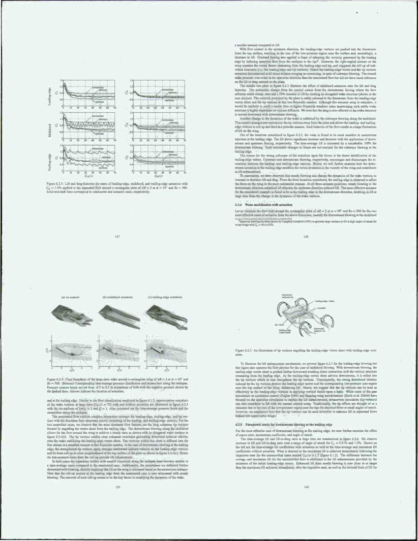
VJlt
Figure 6.2J LMi^4(H:kiaanatecMnorh>di^-«>daB.ad(kaaLMdaaa«c-«lv:acti«6t»»Mk
C. - 1-0* arsptiad to the «pt—J flowwnd a irrtangiilnr pan» of/« .2<a.y end Ar - X»
»lift. With flow cannot in the upstream detection. Ihe IcaoaTuj-cdae verncc» are pB>hod nuo ihc fiinaauia
from the top surface, resulting m the lots of ihc low-pressure region near the surface and, accordingly. »
decrease in lift. Outward forcing wa» applied a hope of irtjwirng Ac voracity gtiiuanjd by ihc leading oder by inducing fpaowac flow from the msdapan to the tip»' However, die right-angled corean on the
winj Mpamc the vortex sheets rmanaiing from the leading edge and Up. and triggered ihc rail up of indi vidual structure» (i.e., the leading-edge and tip vortices) Hence the leading-edge vortex and (he up vortices
rcnumeddiKjnneeiedai ail umomlho^ merging or cflraM^TJOg. m tpic of udcwayi Mowing The overall
wake atructutt mi wider in the spanssm direction than Ihe laiacltastcd flow but did not have much rtliaiiaa) on the lilt or drag exerted on the plate
Th* middJr two plow in figure 6 2 \ dhatra* the effect of owkhotd actuation ooio the litt and drag
hatonca The noUccaK» chance from the control aonan from lb» dussnatiaarn forcing whan the flan»
achieve* «able ucady «ate and a 76% increase in lift by creating an elongated wake structure (shown in the
next Mctitm) The voracity produced by the plate » uabiy released io the freest! tarn from ihc trading nrtgr vortex sheet and the tip vortices at this low Reynolds number Although this actuator setup u attractive. «
would be unlikely to yield a steady llou at higher Reynold* numbers since mamüuning auch stable wake structure is highly dependent on viscous diffusion We nocc that ihe drag i» »No »(Tecicd as the wake structure a moved ifoauwird vrith dawmianam blowing
Another change in the dynamics of the wake is exhibited by die sideways blowing along the Bucldsont
This control amsngrmcni repositions Ihc tip siirtKcs away from the plaic and alUiws the leading- and rnuling- cd(!c «aliccs to roll up and shed m a periodic manner Such hchasTor of the flow rerun» in a large fluobatuoo
tf Uft «(he wing
Out of the locations eonndercd m figure 6 2 }, the wake is found to he most senerbve to momentum
injection al the trailing edga The lift shows ngndVant increase and dasaeaar with the application of down-
stream and upstream forcing, respectively The tune »srragr lift u increased by a remarkable 10OK far
ifawastituaa Mowing Such rttaSrnahif changes in forces are not reatiaed for the sideways blowing at the
trailing edge
The rsassxsa for the strong asfturoc« of the actual trailing edge vortex Utssxjcam and Jn ■ nun— Mas»
upon the force» is the direct modification of the
lag. respectively, mrmaaajra anal ducourages dar m
tcraction between the hading- and trailing-cdgc voruccs Below, we will further examine how the down stream actuauoo at the trailing edge modifies the s-ortex ds-is»n»ic» m UV vicrnitv of the wir» ar»i connibutes
uUfteduoccucui To summarue. we have observed dial stead) Mowing can change the dynamics »1 the wake vorticos in
mattm or ducnaau lift and drag. From the three locations considered, the trailing edge is observed to affect
the force on the wieg as the most isibaUmtial manna At all three actuator positions, steady blowing in the deanMaaaaj direction enhanced lift whereat die upsocain direction reduced lift. The most effective actuator
for (he considered example is found to be at the trailing edge in ihe downstream direction, doubling in lift at
Urxctirncrnimuie«hang«:ntricdytiamiaofthewsJtevsMt»c«»
».14 Wake modincahoa with acraalsrie
Let us suuakn the flow field around die rectangular plate of AR ■» 2 at a = JO" and °> . TOO for the two oca« eflneove cases of actuation from the above discussion, namely the downstream Wowing at ihe midchord
^ Ni - I—r
Figure 4.Z4 (Top) Snapshot» of ihc targe tune wake around a rectangular svsig of ,«* - 2 at a - KT and ft* m MX). (Bottom) Corresponding unse-asvragc prcsxure distribution and streamlines along the midtpan Pressure contour levels are set from 0.1 so O.J m increments of 0.04 with the negative pressure shown by the dashed lines. Arrows indicate the location of actuation.
and at the trailing edge Similar to Ihc flow visualization ecmsloyed in figure 6 I J. representative snapshot» of the wake vortices at targe lime (ICr/c « 70) with and without actuation arc üluxuatrd in figure 6.14 w,th the iso-nirfaces or 6«>i; - : and (2 = I Also presented are the trme-as-oage pressure field» and the
streamlines along the mtdspan. The unactuated flow exhibits complex interaction amongst the leading-edge, trailing«%e. and tap vor-
uccs with the dominant floss structmes mojtls consisting of the leadmg- and traumg-cclge STatsce». For the
two controlled case», we observe that the most dominant flow featuies arc (he long columnar lip stxtrccs formed by engulfing the vortex sheet from the bailing edge The downstream Mossing along the mtdchotd »llosss for the Bow around the wusg to acfascv* a steadv stale aa shown with its elongated wake vorbecs in figure 6 2 4(b) The Up wwtsccs exhibit clear cotrannar structures gxiiuating downward snducod ssüociis
onto the wake stabilizing ihc leading-edge vortex sheet. The sorticity within this sheet is diffused into the free stream m a steadfast manocr a! this Reynold» tuanber. In the case of downstream blowmg at the trailing
edge, lb» strcssgtacned up voruccs apply sxroogcr downward induced velocity on the leading-edge vortices
and let them roll op m close c^a^iborhood of the top surface of the plate a* shown m figure 6.24(c) Hence
the low pressure core* from the roll-up provide lift enhancement la both case* dse separation bubble with control vuuauaed along the nudapan have become smaller in
a trme-average acme compared to Ihc unactuated case Addabooally. the strcamlinci arc deflected furthel downward with blowing, directly implying that lift on ihc wing is increased based on the momentum balance. Soar dial Ihc roll-up roouon al the trailing edge from the unactuated case is now attenuated with steady blowing. The removal of such roll-up seems to be the key Caoor m mcicbfying the chrumics of the wake
Figan625 And n M •> v. ■ i^aT^aWwtliag-rxaysxsrsexakssssisvsa
To ilkaaBssW the lift cnba ■imitiiaaiia, we preaaat ngun; 6 2 5 for the wulmg edge blowing but
«as raaan (U cs^tarea the IVm pls^ trailing-edge vorbix sheet is pushed further downward avoiding direct interaction with the vorucal structure rmanaiiag from the leading edge A» ihc trailing«dgc vortex sheet advect» ihiwisatrcaau. n is rolled tato ihc up vortices wtucfa is (am ■"■■■»»*""» the op vssrtices. Consequcmly. the «trong dsiwuwaid velocity
induced by the up vortices pmne» the leading-edge voncx and Ihc cormponding low pressure cote region onto the top surface of ihe win«, enhancing lift Hence, we suggest that (he up vortices can be oaad aa effectively as (he irararig rsigr voracot m applying vorocal forces upon a body While most of the peat ducuaasom m cuctilauon control (Eoglar 2000) and Ibpping-wing aerods-namics (Buch et al 2004») have focused on (he spanwiat circulation to explain the lift enhancements, sueamwisc circulation (up vorticcsl
can also conthbute to lift with the curren: csartfrai setup Tratuticsnatiy. the tip effect» arc thought of aa a rsutsaacc due to the km of the low-pressure region rsear tfic tips !m »tuched fVm» »I »rnall angjo c/attack. llosAsrvor. we emphaxtK here that (he tip sources can be used favotahly (o enhance Uft to separated flows
behind low -aspect -ratio wing*.
»~2-5 faraaatlrlc »tssdy far dowatlrram blowing at the trailing edge
of «apes The
impulsiv M hwgj
live case of downsucam blowing at the trailing edge, we now further examine the «00(1
aasatsaam «eefliciant. aad angle of atJaex trnw-avcntga lift and lifi-to-drag ratio »I large la» are summarised m figure 6 26 We obaervc in lift and lift-to-drag ratio over a range of angle of attack for Q = 0 5IN and I 0% Shown on
arc the tirnc^rrag» Uft coenViant» «nati aOuaboa a» wetl «a the t*»a*-as<rang and ranxaanro lift
without actssauno What u denoted at the maximum lift u actacved immetualelv follow mg the
start for the uncontrolled cases around Uml/* * 1.7 (figure 6 1 2) The difference between (be ad maximum lift for the uncontrolled flow a annhuaed to (he uft anharaemna provafad bv the
of the mitial leading edge vortex rüshaoeed lift man steady blowing ■ now close to or larger
maximum lift achieved immediately after the impulsive sun. as «veil a» the inviscid limit of lift for
I51»
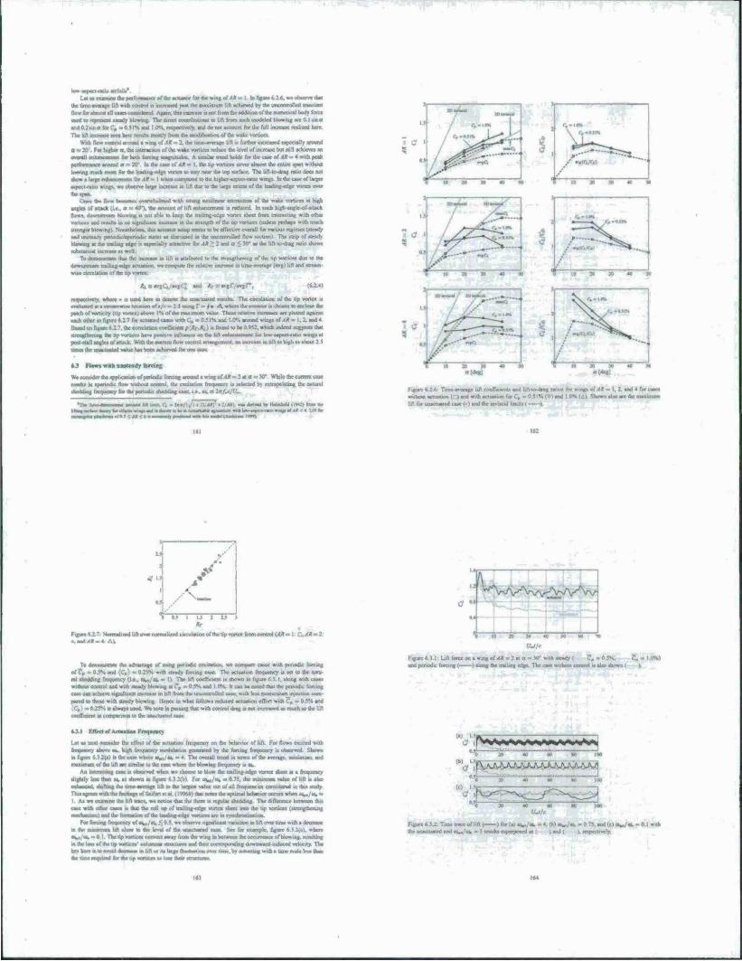
ewingoMA»« I In figiae 6 2 6. we offeree thai
i. lift achieved by the uncontrolled rtatoocnt
IWfar«kn«l'>U«Mc.co«Hktcd Agam. thu mow« » not from the addition of the numerical body force
«tans 10 up« ■till santdy «town» The direct coocnbuuom to I.ft from such -aodclcd Wowing art 0 I «no
and 0.2.10 a tor C, «< 0 5IN snd I 0*V respectively, and do not account for the full mcrease mili/ed here
The M incnMM seen bete ixiulu mostly from the modification at the wilec vortices
WMh fWcoetml around • wmguf ,4* - 2. the timc-everagc lift » rurther increased especially around a » 10 Far higher a, the interaction of the wake vortices reduce the level of tncreaae but «ill achieve* an
n Till whajirmn- frrlnfi fmrn —gi'lr-f- A vm,!*, ./rod Sold, for the case of 4» .= 4 with peak
pcrformaoc* around a *-• 20' In the case at AR = I. the up vortscr» cover almost the entire »pan without
leaving much roora for the leading edge voran to stay near the lop surface The lift-lo-drag ratio doe* no« •how a large etdsanceaoeot for AK =. t whon iBBa,an)iil 10 the higher aapari nlin »tap. In the cue of larger
aspect-ratio wing», we observe large uxresae m lift due to the large extent of the leadunr-edgc vortex over
.*.« (a, |M he, • ..verwhelror.; anat aWnf BOafnl » of the «rake vorucei at high
angles ot* attack lie . a * «tT), the amount of lift enhancement is reduced In »och hijrh anglc-ofartact
flows. sWiuUiunrr, homing u not able to keep the tmitng-cdgc vortwt sheet from murscting with other vornees and nrmka m no signtDcanl «ncreas» in the strength of the tip »orticcs (unless perhaps with nach %lronger blowing) Nonetheless, this actuator setup seems to be effective overall tor various regimes (steady
sad unsteady psnodsc/arOTiodK states as dismissed in the uncontrolled flow section) 1 he strip of steady blowing at «V trading edge is on» in illy attractive for AR > 1 snd a < W a> the Irfi-to-dng rabo shows
rubstanual increase as well
To dciiHMistiet» that the increase in lift is attributed to the strengthening of the tip vortices due to the itownsaeasn trailing-edge actuation, we coenputr the relatr« irsiease in linie average (avglUn and stream
wise circulation of the tip vortoi
aad *r ««vgr/avgr, (tU.4)
i here ID denote the unactuated results The circulation ol the up vortex kj cktcatiMofs/e» 2.5usmg r - Is A where the contour is chosen to enclose the
patch of voruci/y (tip vortes i above 1% of Use maximum value These relative increases are plotted against each other ui figure t: 7 for actustedcaacswrthC.; -0.51% and I 0% around w.ug. of/IÄ = I. 2. and«
thssad on figure 6i 7. the correlat*» coeAattt p(itV.X<) n foutsd w be 0 »^ strengthsTursg the Up voractt* have positive mlluctwc on the lift carat »arrant for lim aspect-rat» wag» at past-stall angles of attack With th* current flow cfle^rcJ arranga*»«iu aa asersas. « hl^ a. rog> s. she*«: 5
man Ihi lain lin—t aim tut In in lit If pit
*J Flos» with aaatcady terete*
We constdei the appiicaiion of periodic forcing around a wag of <* = 2 at a - V While the cuncM case
results in apsrwdK flow without control, 'he excitation freuuenct n selected hy extrapolating the natural shedthng frequency far the periodic sheodirsg case, ■ e. «s, g .'-
sss/B.]<M<*n
■si hit 1—0. Ci - lao/li/l . (V4*f • M»i wss deflvsd tr, IMnosM (tstJI crem ü» —ksaless; :n «wOla. assws ras. asasisf A»
■saav
*-"*
:o y TO *» v-
10 » » an
o[degJ
Figure »A6 Tune-average lift coeflieients and Itft-to-drag ratios for »np of 4* = 1. 2. and 4 Im c without acesstior. ( i sod with actuation for C, =- 0 51* (Cl and i OS I Al Shown also are the mat*
lift for unactuated cast r» and the inviscid linns .
1 . t*
/ t
0.«
n
•\— i 01 1 IJ I IS
Figur« 4J.7: NormaU/ied l.fl over normsliml circulation of the Im nates from control MÄ = I . 1Ä - : ».aaalaala tlaaj
To oernoo»a-a«r the advantage of usiog penodke CTcitaOun, we compare cases with periodic forcing
of?, » 0$S and {€,} m 0J5H «nth steady farcmg use The actuation Itrqocncy is set to the natu tal dsairhng fwouency (i e. eW<u, » II The hft coefficient is shown m figure 6J I. along with cases wrfhuut control and wuh steady bUrwmg at C, - 0 5% and I «V h can be noted that the period* foronc. Case 0O> aoosevc significant increase m lift from tjie uncontrolled case, with less nxiensMiarijrnectjnn com
pared to those wuh steady blowing. Hence m what follow» reduced actuation effort with C. = 0.5V. and
:5N it always used. We note in passing that mi control drag is r« increswrd as mocha, the l.ft ««•nicienl in comparison to the unactuated casa
10 20 » 40 N SO
UJ/c
Fifurc6.3.l: bfl forccon a wing of/»* - 2 at a - K> with steady ( ?»-0.SN. 7, . I ON)
and penodic forcing ( ) along the traiuog edge The case without control it also shown ( )
fc.tl FtTee« .f Aeraatsa. Frrqarwcv
Let us ne« consider the effect of the set
r^amcy Wsove ^ hgjb froou.
i Iremsracy on the behavior of lift For flow» crated wrJh
■cy saowaiaricai generated by the forcing frctasency •» observed Shown
m figure A 1 2(») i. the case where «■»,/•*.- 4 The overall trend in terms of the average, mtmmum. and masurium of the lift arc similar to the case where the blowing freouenc) is ru»
Aa iiacuinng cast it observed when we choose to blow the trailing-cdge vortex (beet at a ureawocy
«lightly less than M. a. shown m figure 6 J 2(b) For ow/eo, - 0 75. the mimmum value of lift is also
oataaxad. shifting the ume average lift to the large« value out of all freaucncics cceisidered in this study niasgrsxswiüithcftndsngsof Seifert el al (\*X>I» thai note, the optimal behas«x occurs when *AVas, «
I As we examine the lift trace, we nonce that the there is regular shedding The difference between dais
case wuh other cases a that the roll up of trailmg-edge vortex sheet into the tip vortices i iircngtheojng ittnrhaniaai) aad the forrnauon of the leaaartg-odg« varuces are in rriKtenmaalion
For forcing frequency of aW<u. < 0.5. we oossrvs ttgraflcant vanauon in lift over tune with a ckxreaat m the nueoroum hfl close w the level ,rf the lessctuated case See for evarnplc. figure 6 3 2(c). where eW«u.-0 I The up vorueea ceeiveci away from the wing at between tlse c<currcricc of blowwg. rextdtsng m the lost of the trp voruccs' columnar «truciure. and their corresponding downward induced velocity The key here is to evosd decrease m lift or its large Ouctuatjc« O\T^ liroe .^ »rfustiri« «!* a ilrnc «.sk le« tlutti th* tats» rooxaiad to «w tip vortica* at loa raaar aMsoMa«.
(b) l
iN^'a^algjrala^aaaaiagagjaag^
i v< tot
. AJ^\AAAAAJUJUUVAJVAJ>
°30 20 40 ao M too (O I5r- 1 -JBC 1 1
Figure 6,Jj. Tune trace oflift ( ) for (al oW«*> =■ *. fb» oo... «. « 0 75. and (cl «Wok, - 0.1 with aW «aattnatnrl and as^/co. « I rastalu superposed a» ( landl k respectively.
♦ -Ü/3 ♦ -4«/3
FigurefeU SrutpsntMsofthcpertcaJatallylt^^ (or thrpenntiaUy actuated cue WMk^/«h-0.75 Shcaan, are ihe c» «uitaee» of |«>|; =* 3 (light pay) miQmi.S An..« indicate iho no» direction
Let us rcvitii the actuation frequency of oW<u> « 0 75 The flow it timc-penodic. which is visualized in figure f. J j The •napahoU an «mfOcd al three equally «paced prune» (« - 0, 2x/3. and 4*/)) over i .hedaing penod The iff« srsqsxhot u a - 0 » selected io be at ox tune of maximum Uli with ihr leasiingedge vortex u covering Ihe whole lop surface of she »>ng Attune progresses IO a vorucc» «tart iu thin out near the rear comer« of the wing with reduced Wowing By the tune of p ■ 4K/).
ihe tip vurttco oense so roll up the trailing-edge vortex «BOM and hence reducea the downward induced velocity applied an the leading-edge vortex Around ihn tune, the trading edge vortex theds 60m wing. inicreiHmgly m a cleanly ihaped vortex nng (clearly vmWe with the x uualiraiion at a) as it; J) Due to dm »>nclaom/auun, the How for*» onto a »i«*-A/ raate by toepiig J>e lew. prewiirc core of tjat Uradmg-edge »wticct a» close as pottible to the top «urtacc in between then dctac-hmrni
Next, the actiiation frequency 1. varied from 0 I 10 HI time» the natural periodic «heading frequency, «a,, around an All » Z wing at a = V) The forcing inputs of ?„ » 0 5% and (C,) •» O.rj». arc «elected a> in the prri-Kiu« example« In figure i.< > -t thr vnnalionii in tune-overage lift arc «hown for different forcing frequencies 1 he ban and Ihe «hade represent the amplitude of oscillation m the lift coclTicienl Alto lUuatnued by the horizontal lax a the lift fot the iBKonnnucd caar Highlighted in figure 6 } 4 are the two range« of frequencies where the iimcavcrage lift are higher than those other forcing frequencies Thr goal in the next section 1« to lock, the flow onto the optimal Ircqucncaei for high lift without prior «jowltdati of the exact actuation frequencies (te. et^/ta. ■ O.TS and I.IV
M r ttrrmam-tcekiae coatrol
F.xuemum tceking i> a method of optimal control of nonlinear system» that doe» not explicitly require a model of the tyttcm We use 11 here in order to adapuvely tune an rxxcntiallv open loop approach to separat in» control, la particular, we apply actuation (in a (urm to mimic a «ynihctK jet actuator) at a particular frequency, and me exircmiun «ccking 10 vary the frequency in order to obtain the maximum lift
&t\»a>»a»>a_>>lataaSC^
163
r I M
10*
Figure 6 J 4: Variation in lift tor WawaaamwaliopcacM» t<* *R-2m*a-XT **m»ca&tik& Tirne«erageuftc«fTicicniMa>arepl^ The horimntal line 1 ) denote« the average lift fur the unactuaicd cave bounded by it« minimum and Tt—TT) "'*-—*-J by Bat ahadedbox
the ly-xteni near a maximum iiperxüog point, which in iho oaxecorrc^porid« lo die maximum lift achieved for a range of arnamon frequency, A diagram o: the 1 xuemum seeking algorithm 1» shown in figure h 4 : The reaulfing output »gnal n put through a high-pet» fitter to remove the DC' component and 1« demodulated with the input penurhatuin Thi« demodulated function can then be pasted through an integrator as an approximate gradient update 10 improve the guess of the maximum operating point
In the case or the current study, we aim to lock the shedding with ow,/o>. * 0 75 or 1.1 that o«rrcaponds lo frequcKv at which the tune-average lift 11 at it» local maximum (as shown in figure 6 3 4) The immersed boundary project*» method will take the control oput of actuation frequency and provide the lift force oc the wing as an output The lift u pwaed through a umc-averaging routine prior 10 entering the cxtremum seeking algorithm depicted hv the lower half of figure 6 4 1.
Tbc advantage of Ihrs method 11 that the ihnanacx of the flow need not be character-red and can be treated as a nonlinear black twx llcncc this approach seems as a promising path lo «tabuere Ihe flow about IU high-lift state I he only concern in deigning (his controller it the rat» of the speeds at which the flow react« and the controller updates dt optimal pnutt of operation if the norjinearrtv changes the 8ow held with a thorter time «ale than that for the controlicr to take us effect, the algorithm can be ineffective or in tome Distance» the Row can lock onto a difTerent cvclc from what is «rwrrved in the open-loop control caar» A dmirttion on this pom! it provided lato in the tectjon
The control paramctcn to be chosen for the implementation of the cxtremum tecking algorithm arc a and (D for the control perojrbetion, the integral gain «. and the cutoff frequency- Ü« for the high-pea« finer The perturbation ownl cor) it «elected tuch thai it n small cornpared to the variable to control («ft») and is tlowly varyirigcomrv«redtoihcmamphy«iniifinscTCTt(Jieoding) Hence weseleci the parameter» a«
a. <o»««=» m - 0.O37J and 315
The integral gain * it set to be 0 5 (near unity I and the cutoff frequency Q„ iv set to be equal 10 01 inside a high -pass 3rd order Butaattorth fillet
We creittder provtcUg the «imulationt with two difTerent initial cooditiori with raw*»» - 0.7. at tune <a which u tome large lime I'relmunan findings for the bat* «vnajtion of actuation frequrncx and time- ssr«t»«a*.aftatatttot»mmfi
Figure n 4 1: Setup of et^renorm toekmg control 10 achieve
frequencies of «W at, » 0.7$ and 1 I Since dte iruiial guest for the forcing frequencies and the control parameter« are taken to he the tame, the present controller teems to he influenced by Ihe initial condition of the lion field resulting in difTerent lock-on freixienciet
It can be noticed that the actuation frequency seem» w ciamuac taster to the optimal actuation trequcn ctot, compared to the time average lift value* This can be a revuli ofhow the lift averaging it performed. In the prevent nicutedology. wc «imply compute the average over a few periods, this can be replaced by a low |«aii filler atstead The performance and the hott lag narnosanrid bv ctetcc of averaging may have affected how soon Ihe time average lift adiicved steady ante
There are small differences in the average lift values achieved for the feedback and open loop cases (c/ r.gurc634i Thu daanxrssnct ovdd he castaed by the t^limiri^ rc^ulu m fur« 6 4 2 «^ r««»-ing reaatcd ueady values and pmxibly by the uitcraction of feedback cnnttol and nonlinear phytic» altering the orbit where oontmUed flow locks onto These .xicxtions are to be imesligatcd further aa cemputauon« arc still
6.5 Sum mar»
m otiasT so «tttMiah a bsms^raaF consorted impuluvvlv uaaalalcd low^tpeetratio Oat plates at Reynold» numben of 300 and 500. with a foci» on ihe lawcady vortex dytuouc* at post «tail angles of attack Numerical «urwlation«. validated by an oil tow-unk experiment «sere performed lo ttudv Ihr influence of aspect ratio, angle of attack, and planforro geometry on the wake vortice» and the resulting forces on the plate Immediately following the impulsive •tart, the ssassrated flowx craalt wake vcttticea (hat share the «me topology for all aspect ratios. At large tune, the up vortice» tigntficanth influence the vieles dvnanuc* and the ooireaportdntg forces on the wings Impending 00 the aspect ratio angle of attack, and Reynolds number. Ihe flow at large Urne roaches a «table steady state, a periodic cycle, or aperiodic thedding For cases of high anglet of attack, aa aiymmetrvc wake developed in the »panwise direction at large tune Thr present results arc exsmpared to higher Reynolds number now» Sonst non-r«xlaray»u»t pltxtdottns «re atao cijrtssdaied toeacaminc the ckfTercnce in the wakes and forces After the rmpuktrve atari, the utne at »ttuch maxims«» lift «etjr« 11 fauly coewiÄ tVsr a wide range of flew otsnttatom during the imnal tnuiaicrt Due to the inrtuence »r the tip »sauces, the thrce- dksxwicaatl dynamic» of the wake vorucea are found u. be quite diflcrent from the rsm-d.mcsstona! von
0 :0 » 30 40 0 10 203040 LL(r f_((-*,)/e
Figure 6*4 1 Two preliminary reault» of actuation uxeajcttcy locking 00 the local opumum fisjiatmrtt» of os^/tv». * 0 75 and I 1. thos«i respectively with f ) and I 1 Aciuauon frequency reaches «tcady values fastet relative 10 the Umc-averagc lift values Longer duration of sunulalton is required for final
Karman vortex street in term» of «ability and »bedding frequency Nexr we rxstsssdercd the application of steady and «stairsdy btowtng. with the asm of expkanng tech
ntquc» uieoriancc ,.n by ducctly modi lying the dynamics of the^wake vtsrttco Out of vanou» comrstnallOttt or forcing location and direction conndered. we identified two cssnfieurationt that provide significant lift lllltatlliaill- In Ihese casev sctuaiion appear» to »uengthee Ost tip »orticoi for increased di-wnward av duced veiociiy upon the leading -edge vortice«. Thi» n turn moves the low fsxsvsurc core directly above the top turtace of Ihe wing to greatly eeJaance lift, renodit forcing it alw observed to be eftecuvc in mcrcastng lift for vanou» aspect ratio« and angle, of attack, achieving a vmilat lift tishttnrtwteal attained by steady Inrcmg with lesj momentian irsnut Through the invciligation 00 the influence or the actuation frrquencv. it u also found that there esusts a rrequetwv at which the flow lock» on lo a tune-periodic high-lil 1 state
FiistsUy. estrcnramttxsvuig op the maximum lift l*relnninari umulationi sttosved the otTrcact ofuas prcaaxfore for taptdly rdemAtng optimal control parametcrv. even in CK.' inicntivc. three-dimensional tmnilanoaa.
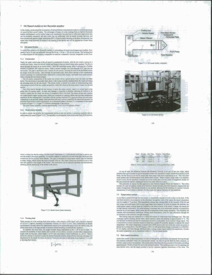
tu
«U ^H»««p^iTi—mny inii|iitii nindi^am mual (jddm aqi pu* a*;«« atixuqi unui
«H ttmm/p. <q IM «t aanavud a«wub »u TmM *»mi* »q» Aj «m »j | ,ftd Jö tJH oi I «faiWOTD«*.
*>ipujuJ!j<«mii<ji/oiion»«a»n«nwoiuj)|'in||i«M"»*»^«««ll p«tnmnf*»OWMJdmnil «j»i|ixn» ur-WWRM« *a« »j («na jpuaid « apio a{ <ppo«u nmuaiuad),» xp onp..» parjpaquw u>wa» iof»
q*»^»uv«>H üatawinmApaaujoama^^
ajtauuvq tojuooj »ou Pi
»jnafa puuro m i« 1 | Q Biqtu» pwama »q » i«mn*— |—I «p |nua*0 amnjotiiuai ipiM pur» »n*»» indjno aJboKM * «apwojd q»q« '«•»wo u*vj 0.1» A*\d--
■O0eimD»«P^"Wi«>'*llcu»<Hj«^Mi.I.||.Hdi,
jrwB»ajüj»u. t«og «nwununm KtaMip oimaoMiuiMi.iM trat aqi jo im aqi n ioww» oj.a » i|»t-n paraa» n «t«uduwi |«uni «u. I««JM»*II«I
p*Jam «n «npitoi «i anuodn J»t«u»*» |.) ajdmii r «rq q*q* yo anoq arpunjoa-orasi « o> paiaMiao» mi
nqX t***» ****** pmr*»« a m.« a«)»n>««»« •■ vaod um aautoauu, aqi «jqi tprai pwpi*Hu uaau. ««{><ur. 11 )l i^mmauM* * futppnq aqi um» A'H«->«KI qarq* wt* p&l!«p *un»|mq mindhr «ateaq»?
na» «*u inm iJto.qju «rat) am* mm xü <—»*$ BVTS'iN * •" P»»«" on «tow ton«» aqi ■«amixii ipaiuji* uotwjotoa aqi nr unu» p«
aqi Hfcnm twfimwa» tq»v aqi a»o ommnuaitp «^ *«rtpjn anbaaraai «Ewumwoai qn» Mauaw »3 unquotaa aqj. utMWJoioo J*»» MU. aatutaxiva >•, po xp omo as«q* »kfc" po* |io aqi aaaaaaq
ARNppriuirot nuaanu wununjun u» m anp (anoMi «t »mwid |3^.TTO aqi AMnwpn» pruuaqi qiiq »n «1; vntnp m» «aduo;> jammi aq: jo u.ipö« tunui aqi 01 poflwwt »n «Jo«| *«]Oo> oddo» px»iJ->a>p>u
<MU -uopauu «np agjqouj «t on», iq owtqwt a-uuj pamq at«S uimiu at >iup iMu» paiutoon «nm n»» pu» imsip.-o umi»A ^ uo ITOJJ3 JDQJ3 » wq »W30W Jmjo*köJi .t^ jrwq «*d j ; XiqJnoj <q w«i
umttailuu) inmni atp 'pqum jqi jo w« aqi q*wqi &O*UOQ*I «p 01 uoujnpuoa «n « aMOn« ioq Xpjo
p«Xo(duu«.«iw.<i~»j.uiW4»1|jip-x»oi3aqJMy pun»? •• t<w»> q». j. manop iVMiu »rt»jd • jo uwwp. «p «<; >w«on» 'sqxM« JUO ui J^.H'.UI OM tpo iqj, apowdMa jo ojpju o*j ja.so <uifmi otirmuA qi>« utq «.inioo itiüiiu s^n^x^lt« t^jnXtaajc^} wdw jiopoaoiui
»nq« ««u. { «qumK |to wq.^ r,*> i»0H3 |» »iinonwJ JOJ,
*«ar « unagpa aas CM> OCUO; Mp (Mpn 'nqttM ^o«t<»^ «an Mp
JOJ 0]]IU» jpntwAlui ><• uapio ö«i aq us s/u |3poui aqi IXSJOJ Mimnit »tmiaotq Mp snq 'tu\j)« aoioqn
• i> P «<«a »0m 4WBfr t.oi«.«A -um». JlBq^ap-lK» V» munwiiwia »» w» J «Oft« HU» fiqj, itt tn pxwtwndn anaqi mmp tataq *Man QOt M««« *» n<* I»« "» «*»"»| xp mq «xfiy qjeq ot aaueb winj aqaun iiqlhiai aMSMtas» |]<w Bqt<am «^taa^ ua.%i9 « w pifiaui iau< t imp <*jntpni
qm|* ***#»< <»»* w» I» P»» "• JO Awn«*» nwuiiun «p aauuK) XNnsajrp xp Tö« sq an «v
000! "»M !■ W««n n» 01 • «oj «p*«J» «00 pu» w..,
Oft I0U
ovi-f-} lp«Mpp«U<aa0Mptf
VO»*riiW»li^tot«ip*»in>|»iiia»l«m»ii»a»ji>j |M> pi» m 'wir» «q ]apnai jqi M) p»a»ua>to
f /j »»* Wti «d M»j »p HD« *mt« •»»«»■ ipr»»>B pomap «p man» o> p»jinh»j,} (i.»,»^ jqi ««oq.
V »W»i SO;o ■■O 1oa«<Ä*i» »oK.j « awan pna i,-ur> 0: /o V "*»»( P««t> -aar. i»p «.) »^ai cnlko, jqiiWCTip t qjw\ lapocu • aoxiim -»Hxp « 1111 ■. \j um/ 01 pu. ' rpmy M«p ^> \i 1 nq»jm. Mp aunun» «X saw nmia^i^DjN tiaocutsd» too« apmiaa iqftia **. i^ aoo. .«,, jamwq,. ol
ammm .inarpxmata 01 «uiuooi mrapu» uraaaa 01 qkVmaa qfiq iq m «|M«| »mj uwqt« >ciq-Ta»»p»qo*CT-<uacmppaU)q»»pa^«i<>io^
AiiMUp j<« uooniH: .. • Mimwiuiq » in «btiin«! > tu •
ft««« snaniXp ■ • jaj«|aP|i||jiwfe|aMi «qi n pe |inano «nqfi
—<s."»'j *««>)M "w«Ti *«-«a »«u
1*M aqi w Ktpan «p jo AmMMtnotl «naad Pavaen*
•u—OM,wap pa umundn pontifp» sq na» uaoq .«in «qj. H"1"« •
V)J° U»»»! «V <« l»|auad i|nu api»
MU a» luro U4 paaaHMi w» »*a»|j ta»« aqx ix *q <n qama /o ajlua aqi M«0Qa «pa|« «ajajap tom/ot da
paqMiK an «pta awiq« omq-vwin * in paumoui a ;«lui aqx aaaa|W) xunj HCT ni aqi »J «wnMauoa «apVMMdqjrq, -jdal Jqijopo»auoarpauaamw nioap»ajqaawaay %»■> lanuuiwpwiapoui jqioa« •m» 01 powi n ad>d |xui «rpon» qui« $ | »-waanadx» luumi aqt »j Sutpaa q«| mp oan aaqoq n qanp»
m
<»icaq potmi tX) T I i »»*J aaaia^a« ■ 1
'w»«» •■••• i*»"i\ rit
iWHii tnj. ja—.po 11,"-*^
dumdum^
aoanoML.
•«•U («iBXHi*
uiji Ajawon«o«W« «nrjcx» Appasn« tausni JJUIO «u. •. 1 aq> I« ipauämoqd ■ wtux)> | | ^ »jutij | | L amXii oi DMqi ti
(juannqijo maump. v riooip»soia«pav l*'"1'"! *» °»"wn—iinhii canoa «»üB ja) paitf um>«n»a
*>| amnajd po» jauuni aqt |iq/in»jp 04 «•»■« :tn qt»q opuoal qaiqw dumj \ntipKM ui 01 woajaaMDa UfiT» pu« »jpo «uipi»axJ ucljd -lAj an mitm^ *»("» "«> «"« uap.3u».-) pmu ftnqai« a^ »; auotpatu ami«x>dujBi «aptiuud irqi w||!q} «amid » m pnEOtaim *ia q.«q« **dDO| tnarn add» paNtd-uqaaj oau
•cataaYi mnj mm oaqat aq> pmj, quw patp) s;.-, q.liiiw> •< nnqnai na, aaoqw aqt tap MUU» ot DBpnA
aq ai tamqmi m tu>«o||« -namtK» •> qanaaiMt » 'aaHaW aWM qaa» B| -non tummi tu Brta daaai aqt 01 »a«q ponoa «i a suqw 'uonaat win aqi uaa» p "noux» 11« aqi qanoiqi if*A«i) auqj aaoQ
nai aqt ottn rmi 01 ninoiu Ihm aqi luuuqn ||tn «nq* 'a|qi»»>a «t aatpm aki| aqi jo qaaut «• tonMrnaqa
-rwfi taB3umoB*m>* je *ma» * ** pMop " XH*B» «am» IBJ. apoi» tan atp «cj BIKIU »Bfiahoui aqi »wptAaid laooni aqi luoqa paipnnt *iqui»w» turn • qn» "aMa»« Qanij i|H«»»»»» ti um» NU aaj. ««anq
tnoj) pta) «aps aqi OJOJ) »%aa» ptando <au>tl* ttonaa« M tattuni aqi jo uo-muriwr) -KI*JI« ||« aqj. »aoaad troa »ai aqi fiiaaii uqjaq
nwoi uoui aaap *.(!»<«; pun WOjaM QaMaAajaa > <q paM<q{oj -»wju pwttojjaii ■ Jo toiumiuira oDnaa>
»«aaaqqaoo «og • qaaojqi «aaari pang -adaJ paiajojjad aqi q*Kuqi aaao «"UM« «ui aqi y> iqa>aq an cBOtaa pamqwop aq 01 pmij aqi *ui»o(pr u»i|->a. twi aqi Man» 11 »an» panaopad «• acW »qj oanaa* «aq
aqi 01». ad«) x-U »xBump qaüi *« r q«noiqi paqax) «t paqj JOnia ampnn» am KHIWYTJ-U»««« «qiq«l.Aqpa.a«u«iwq?«q«ifca«li»l(ViJioa»:|a >m | :«v»« «Aury m *q (aoom aq) qtmap IOAUP
nwoltatU ajaawjiaq^mjltawnpopaianntiiorpalhiaup^ auitij i»ai«p»p|M>
• aa aVmaai aotn» toi aqi qua. -atiim jo poaamrMK» •. taoim po aqi ^ at« paw« aavsa aqi Atiaax;
n»;o trip 1« ayaiajjuaw/Ciaooiu anauuoiq» mqoir* m apwndm,.^ (imup » qit» ,«> puntraiapqw• M
pa^»au)ia«iiqx »Pqaa. toi tu.-» oj | x n« « uo« »nqlm«p «tqaunpaan vDOi7a«da«»aaaM> «ou paipwwpiaip*a*Mpai«taounip«»intintiaacutTM^
(ima*fp«mwfO li
uaaaJOS lfMpi «UU <«10ns XBatMay
*xn 6\apo3
utaqi ainir\| r tu panodu aq p.i» pur .\n|i?»j aqi ui »iwatao am 9 itonaa» ui n ««^■p»jotajauiq>-a»aa«qia»»iiiajaj«aq»nH^
pu» auiti-ini «nunao» >|qna et »on Apoaiaijjm an wqi «ana* «aq tan •pa.inaairn jqJWMii aq m» i«qi «aajo| alirj Xpuataijjm ot MU nut laqi rpmuijwKa a|«M town patpnii aq tan «annantpoia» «aqmmi «Pfaujja <w| nap an paig torqio» aqi t» po tonw jo »iOaiinia» aqj wKpni» t»n\t»- »o« «oj lataaaj na
hiqt^nsinai t>«ou r ui apno tniauiajna»« iüau^
jjqiunu vpjouÄJ« «of 1« oipnn puunj no t
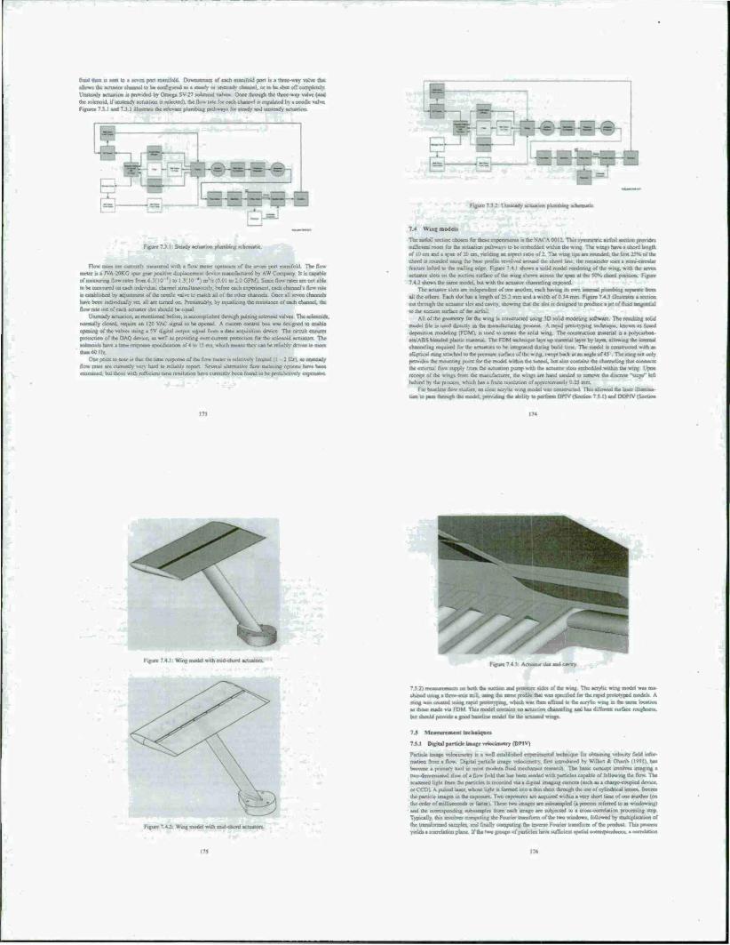
tad fen u HM to i «even pan manifold Duuiutroni of each manifold port r* a ttucc way valve that IUOWI the actuator channel to he configured aa a «scads ot tanstcady channel, or to be ihMt off complctrlv Unsteady actuation u provided by Omega SV 27 solenoid valves Once through the three-way valve (and ihcwlenoid. ifumtcach actuation u «clectodl. the Ho» rale for each channel ts regulated bs-a needle vajvc Figure. 7.1 I and 7.3 1 luiastratc the rrlcxant plumbing pathway« for steady and unsteady actuation
Figure 7} ! Steady a n pkanbing schematic
Flow rate» are cunrntly meaxutcd with a flow mcler upstream of the »even port manifold The flaw meter is a 1VA 20KG «pur gear punitive displacement device manufactured by AW Company. It m capable ofaaeatawia*. flow rate» from Since Dow rales are not able I» be measured on each individual channel stmuItancotBlv. Wore each experiment, each channel« flow rale » c«tabi»hed by adjtnimert of uNe needle valve to match all of the other channcU Once all «even chaetnei« have been individually «et. all air turned on Presumably, by equalizing ihc resistance of each channel, ihc flow rate out of each actuator «lot should be equal
Unsteady actuation, a« mentioned before, is accomplished through pulsing totenotd valvex The solenoids, normally closed, require an 120 VAC signal to be opened. A custom control boa was designed to enable opening of the valves using a SV digital output signal from a data acquisition device. The circuit ensures protection or (he DAQ device, a» well as providing over-current protection for the «olcnoid actuators. The —j—~4. nave a tune response apcedjtauoa of * to IS ma. which means thev can be reliably dmenwaaen UUUlftOlli.
On* point to note it that the Urne response of the flow meter ts rclatrvetv limited {.I 2 11/). «o unsteady flow rates are currently very hard to reliably report. Several alternative flow metering options have bean examined, hul iho»c wilh niflicienl tune levrutnn have currently been found lo he prohitalively expensive
Figure 7 J.2: Uosteady
7.4 Wint models
The airfoil «eel*« chosen («these experiments ty the NACA 0012 Thu »vmmetr«: airfoil «ectioo proMdes sufficient room for the actuation paihwav» lo be embedded within the wing The wmgs base a chord length el* 10 can and a apan of 20 cm. vieldtng an aspect rauo of 2 The wusg üps arc rounded, the first 25H of the chord ts rounded ussng the base profile revolved around die chord line the remainder uses a semi-circular feature lofted to the trailing edge Figure 7 4 I «hows a solid model rendering of the wing, with the seven actuate« «tots on Ihc suction surface of the wing shown across the «pan at the 50*» chord position Figure 7.4J «hows the same model but with Ihc actuator channeling exposed
The actuator slot« are independent of one another, each having its own internal phantom «cpacalc fa» all me others Each slot has a length of 23 2 mm and a width of 0 54 mm Figure 7 4.3 illuiirate* a section cut through the actuator slot and easily. showing that the sloi n designed to produce a iet of fluid taranrnlial to the suctioo »urface of :he airfoil
AU of the geometry for the wing ta constructed using 3D solid modeling software The resulting solid modal file u used eUrecUy as ihc manufacturing process A rapid prototyping technique known as (used dcpnatlion modeling (FDM i. is used u create die «olid wing. The construction material is a polycarbon- ate. ABS Weitdcd puuuc niatcnal The FDM technique lays up masmal layer by lays, allowing the asternal rlanrsrlmg required for the actuator« to be mteeratod during build lime The model n i-onsrnicied with an elliptical sting attached to the pressure surface of the wing, swept back at an angle of 45 The sung nut only provides ihc mounting point fur the model within dta basnet, bat at» contains dar channeling that connects Ihc external flow supply from the actuation pump w ilh the actuator slots embedded within the wing Upon receipt of the wings from the manufacturer, the wntgs are hand landed to remove the discrete "sicps" left behind by the process, which has ■ finite resolution of approximately
For baseline flow «tudies. an clear acrylic wing mode! was constructed This allowed me laset lUumma- uoa to pass through the model, providing the ability lo perform DMV (Section 7 5 I) and DOf IV (Section
m
*--** W Figure 7 4 1 Wing model wtih mid-chord actuators
Figure 7 4 1; Actuator «lot and cavity.
73.2, niiiasuri 1111111 on both ihc suction and prcsture »des ol ihc wmg The acrylic wmg model was ma- chined using a thrre-oxu mill, uamg the sans* profile thai was specdied for the rapid prototyped models A stats) was creased uamg rapid prototy-pmg. wfuch was then affixed to the aery be wmg in the same location as those made via FDM Thii model contains no actuation channeling and has different «urface roughness. but ahould provide a good baseline model for the actuated wings
7.5 Measurement techniques
7.3.1 Digital particle imsgr yrkKunetry (DPIVl
Paitack image xsjaactrnctry u a well cttaMahed tt|xjunciital tecbtuque for obtaining velocity field mfm matson from a flow Digital parucle image vclocunetry, first introduced by Wdlert A Obanb (1991). has become a primary tool in most modern fluid mechansn research The haue concept involve« imaging • two-dnrsntuwoaJ •: ha« has been «cooed with particle» capable of following the flow The •cattcred ligbl from ihc partclr» n receded «a« Agiuu imaging carncra i such ai a charge coupled devwe. orCCDl A pulvcd laser, wr«^ lis^ ii fiinned irao a *in srseet through the aK of cylirid the panicle images in the exposure Two exposures arc acquired within a very short lime of one another (on the cadcr of milliseconds or fasten These two images arc tubtamplcd (a procco referred to tt windowing) and the corresponding «ubaamptcs from each image are yuhjctied to a cross correlation processing step
•TM mpuung da; Fourier transform of ihc two windows. fuUuaad by «aatjplication of
: Wing model with mid <hord
Typically, this a Ihc transformed tamplea. and finaOv computing the imxrse Fc>uncr uamfnrm of ihc product Tina process yields a correlation plan* If the two poup. of particles have sufficient spatial conxanc«dcr
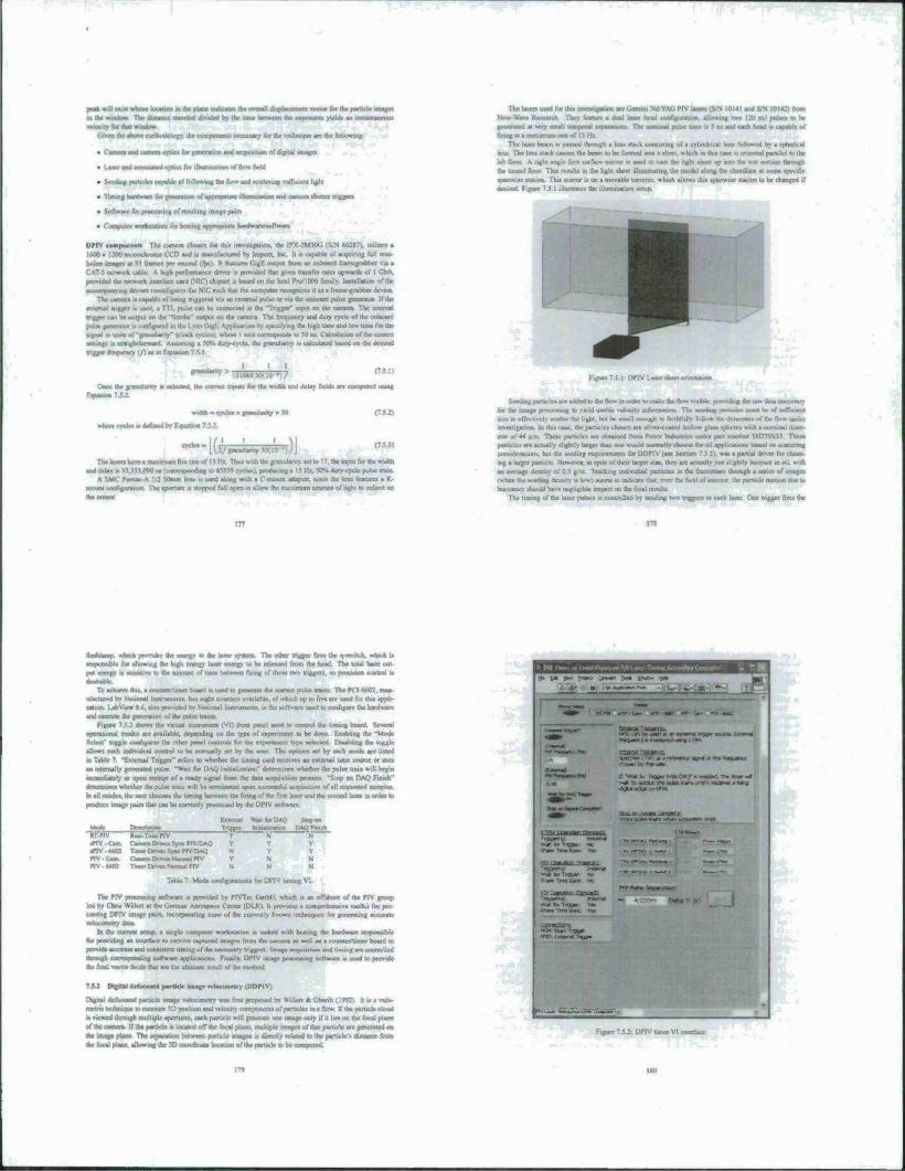
Mh.c
I for »•
• Seeiiing particle» capable of following the flow and scattering «iiflkicrd Ugh'
• Timing aaedwaiij (or yrnrrwuir of appropriate iltiamneuen and c
:*are f»* p»oce«»ingol rc»uliing image pairs
• ConptMf wnrt—bon for ho««* appropriate l»ard«M»vat)fN»ari
DPIV camponrtm Tlic camera choacn for Du» invcttigaiion. ihc IPX :M30C'. lS/N IV0M7), utilize» a
IMO x 1200 rmwochroror CCD am) it irtanu factored by tapcrx. Inc. It rt capable of xuumng full ro»
luuon fill I at M frame« per Muni (rpt) It features GigE output born an onboard framegrabber via a
I work cable A high Performance dnver a provided thai give» transfer rate» upwardi of 1 Gtfv
provided the network interface card (VIC) chipset u bated on the Intel PnVIOOO family InaialUlion of the
»irrmpaairnft dnven reertnfuria-c» the NIC ruth thai the uHituuha recognu-cs it Ml frame-grabber device
TVcarnrre » capable of bong rnggcrcd »it an citema; pultc or viathe onboard pulkc (mcralor If the
external trigger a used, a TIT pulse can be connected at the -Trigger" mput on the camera. The inierna;
The laser beam it passed through a ten« sack consisting of a cylindrical law followed by a aphcncal lent The lent Hack cauar» the beam to be formed into a abort, which 10 this caae iMmeiucd parallel to the lab floor A right angle fint surface rrarrar t* tatrd lo nan the hght ahect up rasu the teat section through
the tunnel Door Tau remit» m (he light «beet ilhutimatrng the model along the chonilmr al son specific tparrwisc ration. Thu mim» is on • movable traverse, which allow» this apanwise station to be changed if
daaareti Figure 75.1 illustrate» the illumination te*up
trigger can be output on the "Si
pulse generator i» ««»figured i signal in unit» of-granularity-
i the camera The frequency and duty cycle of ihc onboard fit Application by specifying the high tone and low time for the It where I unit correspond» to >0 n» Cilcularicin of the correci »duty cycle, the granularity .»calculated baaed on the dewred
u* aajgajaj*» g
MX
_J
the correci input» for the width and delay field» a
wrCT,rcle»«drfu»adMfcoU,tt«,7$,
' [ivinmniarity^lO *))\
iVntaxA
mum fin talc of ISIlr Thu» with the granularity sctlo 17. the input for the width
.'corrcspurtiiag r> 6SJS9 cycle» I. producing a 15 llx, SOS dury -cycle pulse train ! SOrnrn lees» n used along with a O mount artanittr. since the lens feature» a K
* configuration The aperture is »topped full open to allow the maximum amount of light to collect on
Figure 7 5 1 DPIV Laser »heel ortaaation
atare added to the flow warder to make the fto» viuhlr provvding the raw data a
for Ihc image ptinnamg lo yield usable »TIOCOV information The aeedang particle» must be of • n» to effectively »carter the light, hui he »mail enough to faithfully follow he dynamic» of the flow u investigation In this case, the panicle» chosen are <ilver-eoatad hollow glass sphere* with a nominal diam ever of 44 urn. These panicle» are obtained from Potter Industrie» under part »umber SH230S33 These panicles are actually slightly larger than one would normally choose for oil application« baaed on «esttennr consideration» bui the »ceding requircmenu for ODPIV (»ec Senior. * <• 2i «» » poiiial dmcr foe choc*. mg a larger particle. However, in »pile of their larger »usr. they are actually just »lightly buoyant ■ an average dentuy of 0 5 g/cc Tracking individual panicle» m the frcesuearr. through a acnes of image« «when Ihc »ceding density t« low) «mi to indicate that, over the ratal or»nsrtrtt thr particle motion due to buoyancy should have negligible impact on the Anal results
The timing of the laset parses is ewrstmriar) by »ending two tngger» to each laser Oase tnggei fire« Iht
m
ttnihlllgi. »rhsch provide* the energv to the laser rystcro The other trigger fire» the o-switch. whsch i» responsible for allowing the high energy later energy to be released from the head. The total laser out pat tuatgj a ranaMivc to the amount of tan* bstwtxn flung of these two trigger», to precision iiatstil at
rr.-timet board u uaed to generate the correci pulae train« The PCI«602. ma» T,. BtyaafN this ««.in ufactursd by National Instrument« baa eight counters available, of which up lo five are used for this appli- cation LabVterw g.tv. ab» provided by National Inatrurnent» it the toflwarc used to configure Ihc hatJware
iari m 11 ill I the giBtsation of the ptsiac tnuo*
Frfurt 7 5 : »how» the virtual instrument (VI) from panel used m control the liming board. Several opea»>iional mode» are available, dcpetvling on the type of experiment to be done Enabling the "Mode atttar toggle llllaiglliii |hc other panel sonii ol» (or Ihc ctpejuuctu type sekcted PutsMing the toggle
»laiwi each aidividual coruroi I. be manuall) «et by the incr The option» set by each mode are listed
in Table 7 -f-.ttcmal Tngger" refer» to whether the timing card receive» an external tune source or uses
an iranrnally generated pulae "Wait for DAQ Initialization" determine» whether the pulse tram will begin
immediately or upon receipt of a ready tigna! from the data accntiulion procesa "Stop on DAQ Finn*'
csttxntiacs whether the pulse train will be irrminated upon »uccetaful ac.)j«.t^n of all rck^tseascd taatpiea.
In all mode», the it»er choose» the liming between ÜV firing i.f tf* fint Lu« and the »ecord
raoduce mage pair» that can be correctly proce»»ed by the DPIV sofWiarc.
Moor Onamm TttTTC J^TvoTrlv
•PiV.Cam Camera Dmn Sync Pl\ TiAO t«V **0] Tsssnt Umen Sync P»V tlaC PTV-Ottai Caasm Dnvo. No.m.1 F1V PIV MO: T.mcr Onvm Nmrnal Pf%
Exsonal WanlorUAO Sanpon Tngger tntiaJirsnoa DAQ Fstuli
Y^ N N
Table 7 Mode c<mf.guj»uon. for IMMV uming VI.
Tb* PIV protesting software u provided by PIVTcc Cmbli. whsch it an uftshout of the PIV group led by C'hri» Willen at the tJcrmaii Aerospace Center (DLR) It provide* a comprehensive toolkii for pro
g DPIV image pair», incorporating mow of the curretuly known uxfaciiquc* fur psicralmg accurate
tv»r»*,;.M, m the current «etup. a tingle computes workstation .« tasked «nth ttoattng the I for providing an interface to receive captured image» front the camera at »veil as a coitTttcrAimcr board to
provide accurate and caaasttcnt titning of the iwetaatjy trigger» Image acquniiion and timing are controlled eMmtgTi lUHMitsallllg »oftwarc arspbeattoru Finally. DPIV image peiicesatttg «ofrware it incd to provide the ftaal »wtar fttkls that are litt uhariate resiih c»f the ir»rth.»J
7AJ r>trialdf«t»o*^Hta>>^rJeta^
t>grul defMuted partscle image »ei«iirietri w» f.nt r«T^«<d S Willert * Ghanb (19«) tl » a volu- nst^TK »etdiriic^ to tneasure U)r««ition arid »rkvcity cc»mr»ritmt» of rwtltcle» in . Ilcm If the panicle cloud
i» viewed Ihrough multiple apt^njecs. each panicle «sill generate one image only if it lie* on the focal plane
of the carncra. If the particle is located off the focal plar« nwltmie iraagc* of u^ panicle are gcKraled m
dte ttnagc plane The »»»paralion bt<wcen particle »mages it directly related to the particle'» di.tance from
the focal plane, allowing the in unKdinate location of the parucle lo be
m i>.Hca«a»w-^ ■ V »,-,» -
*ia (" *»■» >«««*• :««s »»». '**>
i2?,,", apRtÄ«ä»»jäia*« ^**^ a»»iaa»^r^»rnaaaiarl»ai
•tvtiaa ug»S
S-Vwatta Tsgns. towpatr« irastsn, ttw »*»*» .« »»«äMitatraiiatiir.j'liw«. dtfufedovaricm
vta»«» ".. • •»«a» Tm, Saw va»
Btikt»jt*asi icjj "*■ 'WC »s. - w» tar Tngus» a) 9*s»r rstsrwita Mo
ar» -~! mar— •*■»»—»» -'«sgarrc »«-
»>. «tart^itgaar
F,eure73iDrTV
ITS
Two hue Ixmitstint*» of the mcdiod exit*. Fust, the wc of » muwptc-aporturc muk on ■ «ingle Icn. canon produce» an image with haavilv m<a lapped paruclc images when seeding density ut «ufTictcntls high IU obtain good *patial resolution .Additionally due «a (he uull separation of aperture«, only very «mall uuerrotjsiiun voitanc* wen pmwble in outer M overcome (bar limmtwu. die DOPIV icchniqcjc »» extended u> * multiple-camera implementation iPrmra ft Ghartb 200?). wuh ach ouncn utilizing i single aperture Three camera* of equal focal length are arranged in an equilateral triangle conflguntwo with optical axe* parallel to one another Figure 7 5 J show« a »ehetnauc of the camera and the rrsoltrag me—em an« volume (the cube endoaed mnde ihe pynantd)
^ il Figure 7.5 J. DOPIV camera schematic
A mold plane calibration method is employed to quantify the deviauora cauaed by mechanical mu- alifnoeoi. optical diatortiooj and non-ideal optic» Tins provide« a mapping function which i< applied u> the obtained image* in order u> correct these dutnninm. increasing the accuracy of die technique Once ■usages arc obtained and dntrauuru cunrcted. panics» are located in eath of the three irnagc. oaing a ID Cauatatn fit algonthm Thu algorithm provide» particle locations to «sin-pud accuracy Additionally, the algorithm acrve* ix a fillet since mm-Cuus-man intcntus diitnhuiioru are not likely to be valid particle
Particle imago arc converted mto triplet image» through the uae of another algondtm Thu algorithm Una knowledge of the aperture arrangement in order to determine likely direction» along which to acarcb for particle matches. Threshold cniena arc KM which limit» the allowable amount of tpatial separation of the particle image in each of the three image« If the threshold» arc exceeded, the 21) particle is ducarded The threafaold* are usual!» set very »trtngentlv. to avoad nuaajcortficaiaan of 3D particle position» (rypicallv known a* "ghost" particle») Typically, me method is able to translate approximately 60V. of all particle image* into triplet malche* The in-plane coordinates tic parallel to the camera face) are identified by the triplet « center, with the out-of-plane cotirtimate (i e parallel to the camera optical asu) identified bv the tea]*tfdatBipki.
Once all 3D particle location* are ukmiilied a partacle tracking algonthm identifies the particle motion between two »uccexarvc frame*, gencr-i <-Ul Tracking n accomplished via a relaxation method, which i* deaenbed in derail in Perctra et at (2006) This differ* from the typical approach employed m DPIV. which aaci a cro**-corrcUt>on method to identify the average motion of group» of particle» Here. the actuai panicle» arc tracked through «pace, for although the panicle image denvty u in the range of PIV method» Ihe particle deiuitv in ph\ steal »pace i* much lower With the identification of the velocity of each
partKle. data validation a performed to remove outlier« Since the velocity vector* arc baaed on the actual panicle location», they arc randomly dutnbutcd chwstgawot dm anatxarcma.il wjhatne. Projection of theae ss*acCTC«s«n*rcguatfaridthrsso^ itsalareit»^n»rta5cV«taa*±tigtrve»oltiü
The «pecific lyatero uaod in lha atudy a capable of resolving a cubic iiMawwnirl volarne of roughh 120mm1 Image pain can be captured at frequencies up to 7 Ht
fJJ Force«
Aerödymmic force* on the wmg arc mcaxurcd using a commercially available »ix-ax*» farce balance The balance t* maraafarnarerl by ATI IncWtnal Autxenation. located m Apex. North Carolioa The apecific model awnthii study it the Nanu-» V a whom «tram-gage baaed ttoan The «aw measure» 43 mm in dianetcr and u II .55 cm thick The vemot i« delivered with an interface box that preside» power to the tranaducer at well a* signal conditioning to allow the »enwr to bo used with the Mt-pui connector cosomoo to many dau artHiwnon sy»can*. including the one described above
The Nano-tt come* in several specific coniiguraUoTis The one choaen for dn» <.<|«iiuma was the SH- IM 23 Thi» configuration provide« the ability to measure force« i» to i IX N and torque» up tt> i2$0 N- mm.
A Calibration was provided by the manulact iicr at the time of purchase Thu calibration was spot checked in the lab and found to be in relatively good agrccmr« The manufacturer'» calibration o clone with a precuiiMi jig. ensuring accurate loading o the «eruor The calibration iiii<* matrix (xfaown tn Fquatioo 7.5 41, transforming voltage* (C.) mto lorce» and lorque*. as in Fquation 7 5 5 The force «eruor a rrsounted between the model »uppret a»»cmbly arid the integrated iting on UV rr»ndd The s axu a aligned with the chord line of the model wmg. with a positive sense directed toward» the leading edge TV aligned with use vertical with the positive sense punting down towards Ihe floor of Ihe tunnel The f *«u i» aligned with the span of the model wing, with positive «cute according to a right handed coordinate system baaed on the other two axes.
PSS)
Data acc«x»*st»M Signal» bom the force tcoaor and o cards The first card la a National Iristnimcnt» PCI-603JK card This I6-Nt card has eight dulercntial (16 Hnglc-cnded) analog input channels, two analog output channel*, eight digital input/output channel*, and two 24 bu counserAimer» The second card t» a Measurement Computing PCI DAS 1000, featuring «igt» difTsrealiai (16 «iru^-crjded) analog ropv. channel«. 24 dtgKal input-output line», and three 16-b.t counter«
The PCI-60«5F i> connected to a 8NC-2090A accessory, which provide* BNC and apnng terminal ac- ecu to the majority of the card irtput/ouiput channel* The main feature thai thu accessory provide* u the
\ F, \ C, ] F, (h F, T. at« c. T' °*
I H [c*\
III 1C
•vX run SCSI pass-through conneciuc. which allow» the force rransniicer to be connected to the dau acqum- taon card while keeping the other functions of Ihe DAQ card accessible The other functions utilized by dtt* experiment include one of the digital lines along with the cixintciAimer» m order to provide synchronintion capability with DPIV mcasiacrrtcnU
Addiiiunal input voltage* are sampled by the PC1-DAS1000, since the analog input channel« are taken up wick the force tran»ducct Cocaeeuon» arc made via two CIO MJN150 »crew irrtrunaJ boards
Nauooal liisuuututu LabVicw X.a it the «oftwarc cued u> create the interface between the use and the etcmeoca of the experiment. Thi» interface i* known at a "Virtual Instrument." or VI. The Vi allow* dtt user to pnis-uk confifrta-attoa «entngs for the acquisition, as well a* the configure the «tnrage and proceaing of d«Bs«*sassa(|«aaafM4tM
For thu espenmen«. the VI was programmed to record the force» experienced by the model The user interface i« shown in Figure 7.5 4 There arc several modes prc^rammed inio the interface, with Ihe intent of providing svnchniru/ation of force data with DPIV acqumlion Table S show-» lha confisparatMO each of the mode* provsdes.
Mocst Descnpnon Ttt^iv fce^-TanePlV
MV-Cxin Cam Sync PTV/DAQ nVr**0» Trm Sync PJV/TMQ No PIV/Free O'n- NoPrv>Fai*r Fin Aeq
PTVaa IVvyinit. Pulvc Width Finite KTPIV Trigger Signal lutWCIian Acq Triggar
Y N V Y V Y V '-lis== T N Y Y , f^ n*", I '»« N M -v N N M N Y
TahlcR Mode «wdigurau.«» for data acquu.t«. VI
The data acqunilron hardware and software is hosted on s custom built PC The processor is a 140 Gil/ Pentium 4 on an ASUS P4P800 rr»rJvcrbo«rd Memory .« provided by O Skill, with 2xlGB DDR2-400 installed The operating system is Window
7.6 l»ia^Tlnic Particle I mate Veltiriiaselry (RTPIN I
Paractea»»«»»»s^l«»ctn« tor many ysxtr». The technique allow» quantitative vuualnation of fluid flaws, exnoaing rh» dvnaroic» m a manner that can dtrectly coolnbute to a prryuca! uridcritandtng of the underlying flow private* Once aaffliaaiil pnysicat insight hat been gamed about a particular flow, ooe often coruidcr* nrararailaiing the gswenaog mechanism > to achieve a desired result Thu u rspoc udly true when ctssxTot of the Dow under • ■.-*K -'.riihi iuir a atasjalNanl -rnpvs.t »r. \i\e pcrt'Vii-.anvc ••' asstaaaaajagj nvicnis
Typically, a Sow conuol expenmeni hope* to achiese ion» change in system dynamics, often through srnistifktuon or «tmprc»»i.in of f!<» inslabiliUc» This is acarrrasltsbed through the use of cine or more actu- ator» to produce a distubance witlim the flow If the Bow u «nfficsrnlly roocptrse to the creaaad dutsatsance. the ihisamics of the s>-»etn can he moiulied Momumng the cflcctivene»» of the actuation through sranor rr«ea>urc*nenui allows for the possibiliiy of closed loop c.
Many How control exrasrirnents utilcre > small numho t-' «asnrs which otlen onl» measure some char- acteristic of the flow at discrete point« Flow cSnamic« often must be inferred from these signal ■UlnaI ment* Additional)», these seiuor» can often influence the flow being imvsOtuaorl. ob*ounng the overall control objective The actual physical dynamics of the system, as well at the ctTecuvvneta of the actuator in changmg those dynamic* can he difficult to .«»ess from tm« linxitcd «mo«iril ol mformation TheuscofPiV
a acquiuoon VI front panel
in fc.if.unng anj pi"«<*«irq; the imacr :u\* i *rpcriijni> >n [he u.mjrn» rr«niu;KFT. «7^-. ifiej b> the U*CT
die MH piminrn involved m DftV may need to be done tentwarid» of tunes per «nag* pair. Long dewy»
btrttveen th» nw—i mail rod (tu actuatioc cstnu will laid 10 ineffcclnr oowrol strategics because the flw
will likely have evolved such that the computed actuator input u no longer appropriate At (he processing
■pood of ectmensung bs/dvare hi» increased over the ycatv the urne required lor processing of each image pair hat aana-ailv decreased, making the task of providing the vector field» at realtime «peed» more and
man Ultely The current implementation appear» to have accompluhed just this uuk with minimal reliance
on ctMomaed hardware, which has been the case in the past (Siegel et al. 2001. Yu ct al. 2006).
7e_l Basic Architecture
Real-Time DPtv (KTPIV i ha« a «tram identical ui a typical DPIV implementation, with a dual-headed pulsed
Ute* providing Illumination of a flow »«dad vmh «nail particle« The illuminated particle field is mvsged
iw.ee in tap« tvsxesatssn using a digital oamcra The resulting image pasr is convened into a rwo-ceancoarar velocH» field through toflwarc unwisauiig. which suhsampks each mace into «mall region» and compute. * caam-oorreletioo for the cetrrt^rsmtding rcgwns in each tmagc Peaks m the correlation plane arc 5t to
siaVfnal accuracy The uua» conclauon result» in a Jt.raacc.ncnt field, whsch a convened to a velocitv held Used oo the lens magmficatMs-i and the temporal separation between the '.aver pul«<n
Reali/aiton ofrral tune' performance, in the current work, relic« on the design and impiomcniauon of a
custom Software package capable of quickly processing parade image paus a» they are atnaaned otto system memory from the camera Upon arrival at memory, the «mages arc processed using carefully paraueiumj ilgtaabaa to compute the croas-cotaelauoo». Additionally, for use a» a feedback sensor, tome region of
interest (ROD is chosen whan further cskuuuion» are performed These calculation« can then br used tu make cttmrof deciwuaa. «vtuch arc then passed out to actuator» through a digital I/O interface in order to
chans» *e flow m a destrablr was Figure ■ f. I ilUntrele» the overall erstem architecture
Ml cii-iii« m order to real.« -real-ume" paf.«rmanir. ihe processing of an image past min» occur beSoir iha nest imeg« pan ti available in the bast PC's mtTttorv If processing t» not finished «hen the next image paar
arme« then the system »til either have to war) until the proccsatng engine u finished or the image pair will
bass- to he ctuwarded kl both cases this bei insplicatKsns Tor use «f the ITTUI. m a cemtro; loop la the first cast), the Uttrncy buildup will quickly cause the result» to lose any temporal corrclat»» «nth what is actually
happcntlig in the flow Thus, the controller will be making deemtxu too late to have the dcatrcd impact oo the flow In the »ocund case the lot« of data ma« cause the t.intmllci dynamtti In be too slow, HIM new control d««na>arai can orgy be made what new data u, »vailafilf One potsiSlc workaround to dais oauc a to me a PC vnlh mulnpir processor», spawning a new PTV processing engine when the previout image pair i«
not yet processed Tin» approach leads to slightly longer latencies, but «void» gaps in the data. In the current
lottftguraüos. trat approach u taken uamg two of the four available «ores on Ihe host machine The pulsed laser firing iale n limited m the current cooflgurauun to a rnaximum of 15 11/. The camera.
ivnchniniMd with the laser pulses, capturr« image« at JO frame« pet second (fpi). each image pair thus
takes a total of 66 7 mi to capture Each image is translcrred ti. PC memory at the nest image is captured Thus, the total transfer ume tor an image paar is elan 6« ? ms The iota! time betweeti the bcgtnriusg of the
Figure 7.6 I: Basic RTPtV arch*
exposure of the firs, image ol the pair lo the tune Ibc image« arc avatleblc m memory u 100 ma This kind of latency i« inherent to DPPV. the only way to decrease ,i .« to increase the frame fair of ihe «amcra and
provide sutTlcstal bandw «dth (or imagi transfer A fundatnenlal lower limit will always east given the need to «mil tor two linages to be exposed and uasatfciial
7».J Hardware
dam The camera utilized tor this application, a U1-Z230SE. waa
a Systems (IDS GmbH) «m» chosen for ease of
coosidention« The camera capture» a 1024 '. 76S ir«t»3c«riiromc image at 30 fps and ci PC via a USB 2.0 connection A «trobe put« it yeneraled at a u«er-«j»rcif>ed delav after the htglieung of each exposure The» urobc pulse i> lesoonsible for uiggertng the Later luning
The choice of camera likely has the greatest impact on merall «ynem performance wnce it is limned
on both frame rate and transfer apced. Additionally, unlike many «pcialty DPIV camera», it dot« not
have a built-in dut*lc-«J«tclcr mock The cWe of a CCV «it« over a CMOS unux wu made beau« CMOS based tytiesm ganxaaBy do not possess a global thttsxrtng mode, which tt necessary «u achieve the atyricriroooui frame «txaddlmg mode that allow» the pultc delay to be shorter than the frame talc of the
Ilium.nation 1 lie «amc illumination «ctup it uted for RTPIV as it used .n the cwnrtal DPIV tetup dc
«cubed in (.-haplc.
Timme The liming for RTPIV ts driven by the «rube ugnal from ihe camera This tujnal i. divide«! h>
: to provide ihe base frequency at which the laser» are triggered Later liming it accomplished through s on the inning wfrtvarc described ra more detail in (Tumtcr 7 3 1. (Jung the "Mode
!*<
tssla^taplkm^scsutvi^mv^to
.Seeding The same teeduig a» used tor normal DPIV measurement« u used for RTPIV Sec Oiapter 7 11
Cat man dataOa
Dtgtteli/O laiesacli<mwimtheac>«»i»ortinihecspcnmcnii<p^^ the US8-120gFS. manufactured by Mcasuicmcni Computing The Uaie of the digital I/O line can be set by the «oftwaic whsch «ttumassh open» or cloaas the totenstd «alv« m the flow ««ritrol loop
The PC on which the RTPIV «oftwarc i» executed i« a custom built PC. The processor i» an
Intel Corel Quad QWOfl MvfcGlte Ouad-Core Processor, installed on an ASUS PSQ rniKhcrboard Mctnorv -prov»a>d by G Skill, with 2« ICB DDRM100 installed The operating «yttcm „ Windows XPSP1
7.».4 SeftwarrtQKlPlVl
The at«<r«ts»n ie.|iliia,naewiai a» aatrs^aamuul in C»'. «vuh the Qt ttbqiy presiding «rraphical user asttrtace (GUntupport The appiitatwo interlace corm«ti ol five tabs that control each astsret o! Ü« tccliraoue la
aoo^tm u rJtt mam »palujH^oa m
•> TW XJatstn astup tab (Figure 76 2) allows üya USCT to «pectfy ttw camera corsfigiuauon Ale. which i« generated using the camera tofrwarc provided rn the manufactutcr It allows the strobe output
tohaaaga>darricra«Agtj»wrl SpecuVsUi the nulx dclai setting is crucial »o that each image i> Ulummated
at tt» correct tane Abo on thu tab it a log window, which dasBlays tXaWi inessagci u the user» as the
taaagraesr The-Image pair" lab (Figure 76J) abows the image pau that remito from pu»*iii4 the "Grab
Image Pan" buttan on the toolbar Th.« aiWrwv (or quick namirurtmn of the an image p»it to make sun light mtcnsitv and particle dcnwUei at« nillu .
PI> srtep Th. PIVsetup tabiFiew 76 4)^1^aUofoVcoctfigta^
PlVsaaapliag Determines how the «ubdiviuon of the image pair« into window IKCUTS
P «n hnage iluen aanitjliiai ami n to «horten processing lanes. Nauru-grid proceating u more ccermtitalioriall) intm.i«« than a tingle pan mtcnogaiion of the image pan. but
can increase data yield and dynam it «paus! range of the measurement
Peak <iat»taa Luruü the «earth arm tor the corretauoo peak ,r. the ctirrciat.on pUnc. helping to prcvcni •purious peaki from being idcniilKd m regtoru where the «ignal to mute rauo u low
Vinaaaln Picwiian several leau ra order to identify those regsons where the iliaputcatuual value found is ukety aaunous If the 'Ititrrpolate outlier»- checkbos a vclacte«! ttam die dav^irdrt «r«^ u rtr«accd by interpolaltrin of the eight nearest netgliboruig vcxiors.
6.2 QRTPIV r*t>cra »aaap tab
< otrsrruoe Sett the magruficatioo factor and the dcla« betweei
phi^ttnaml «ector field to be converted mto »eiocitv fields %»hic>; all..«. i)< rsvci di»
The Pml twnwaang" tab (r-qrure 7 6 5) rrmsdei all of the «irfiguration fertsag» for
pctavtjroeasang «cboas that are applied to the generated maor field
Thii area configine« tor cakulaunti ol natutic» on and in Ihe cotuour that define» the reason of iottreat. Contour« can be loaded «a dx -File" menu, providing easy «witching between
repont of mtrrcsi HcsTiootal and vertical vctoory »talrwic» (average and Rag) arc coattpund aaude
the contour Circulation can he computed on the contour and vorriciry it tumputcd innde the coruour
using finite diflcrcsicing to compute denvatnrs If no contour is «e lecied the «tattstics am rornpaed for the entire image
LagglaC l:Juu«le»outri«aofe3cpermieJitaldata w . u«a-riwdaWc text file.
Ph»t Sco the update frttcuency of the Iroc plotter
( »cluatrd Data Displays the ealculatad «tatittic» m the region of interest.
LogaV format The software ha« ihe abilir» to generate a log file to allow Ute uacr to anahve the cspen incmauimc CurTcntls the loefile n wntten in uter-roadehl* text wtm the foltowtng cxiaataaa
PairNamberdt Rc»et« to 0 every time die "Crab PIV image«- burton w pressed.
m
«opuu» «piA *MT vUdJ-HÖ -L 9 A *«»y
TW**—CIAIAUIÖ
anraiunumito cpatqo »qjo aqi q:m(M 411» »Mtqo ami nnnnu -*«»p »povfiuw»« 1Ö aqi mojj pa«wp-qm -jaolqc nontai|adt urtyj AM**nO
MMi ..»n>-pjw. KMpojd 01 paant»! «Mtinuartn )»>(qo jo aauanbac ayiwot xj\ u*ij, paquoop xuau>< »I n>« tissfqo ion sqi uuljq »x »«tu» apnnd tfonaonn aqi ioni| ipjay JOIW fovanpoxl qjt.« p»i(a«ii «tog tndojd *p maomaop 01 pip« ti .1 inq "«aq pjfxujia ioa « »po» aqi jo twWMumop ]p\j
txvmaau tutrfotd pa* »uoipc ixr. an«») miww) »»Juro tnuM>t|i _"»op>- «■ u«"«"l «uoiwimj 01 poixwuo? a» q-wq* „npnrfltt. anuauaf coot»« |fti) AMB xiaatqo auijtvi aqi put jam aqi uaawiaq itontatumuuK» un|tui Äjipnimixin; |;-jr> aptAOjd 01 Xnuqn )() siji ji> «n *X|prtHnifp|>v <*"»« wows» W otpmno qv» fmtauatoi pot Xjtprooaaanj Jtop t knpuwud qata -\uofqo tniuup 01111 paaocdac an MMvotapjowtdjetniu Tpyo» pwii)H Wfr «r%W , o » «t«» »• >«*0« AMJ.HÖ *U
jiniMiiquv p->|i*M«i r»'i
pajaap jt »|u pot t 01 put »q ur> lajjno. nrp aata aojn aqj. (0Yi *»*j) »»»»»* J» aodbi aqi «n «www powjnapo aqi JO aoojoaauiaun t (Xtpbip pnp pouodo «1 «opuut t jeatooi >ui 00 p»|Mui o uc-unq .«amp sunx. *q» oaq/A ma aanj.
«. atp j» aocnoot «p *s*aq« iro JDIOM aq»
<pn fciiMJJO«u-i»<\} ARWO f9 i »*>*J
0x1
00 p«|AM> otpj n (pat m) «WP»OO pop«, ipnauna 3uj «wutA nog mospf |*mai 00 portq UOTJOA
jofw» «i pt«itjpi«i,i aq ota «opm* AVndne «pu am «nfca tw mil aqi o) n>«uii nwiottdt oq) trnpoM pavjiq« aq «1 *»umd aqi wwn» <*nmq „aunuj dr»£_ aqi jn a*n -paarpuaoaun Xpnatuua» aw irqt uml «Stun ui <nnoi ipiq« '»»pu! txt] »p ipt« oninvraniuMiÄt ju 1K1 urs« 01 tmun jqi JO; «tqnwul « i| tndhqfcmnaojdA]JP«"(S»4 *«Ai) »a»»»o*id/ya«l»J»*ipw W} ****>. XQ tÄwfünpimft pauaäo w —n»i« « -»mooi *» BO pjjWoi w noonq Jfmnmx* tafcan AM a«0. »S» «*Wi «•!>•■* ,\W
awui pxirj oopu «p liuoo ||tn 11 «npau» jqi pot| tn«St p»|Mot u ounnq xp j| padioii u paoj otpiA JU> -«tJt p»i*»m » oonaq „a*»un MI-^. »P <am* yp*m m ■» lonan oonuad» stpid pot XHVWP >|au«d -Xiitaann iu»t< <Mt| itooj o> oconipnr -p» T>B* pnp c* tafcuii apoMd Mp «au « »m up v*«tpr »tuj, ^ j amliji paXtpinp «1 osptA OA»I
tpiUM ui pauodo «1 wpuiM «au » '*q|ooi aui uo pajSant .1 wmnq _a»«ui Avn. aqi uaq/ft Mf«|
vyi «w>°s »• p-fio** *t"p«u on nw*p as« a«p t« mW(JBdii aqi oju' UMU/OJ am UIUI; mdino ft prttln jqj, uimpi aqi jo api(>AVtp pot AauftnfcAij »v> tomnwpu» v»t] |onumjnuan«iuauu)duii pnucAp« a»xu fuiAfiMui paaalcuit aq uta tauBUM paic»|duK» ajow "auiaqs» ornwrn.-» a(daH> Xa* « Xpaqiujp» « wuj (funop PNM>M> 941 04 qimutiinn tnp *aata »aimaapwljtfopoo^« jo»rro»aqi-a»|«j«»ttTi|«oainiaujj| t»aioado owoapx aga tq tpoooamoa wp aiD)(minaujiu)oapaiuni«>io*>nutaip'aniiMtmpwaapuaipjt fmop* anu aip m Smpjoaat sap»
pfotpwqi sqi ui pai»iM Ajnranh XQ tanduo» (auamp »p -popnua;) Apuapoodapai pamiijuo" aq m >|Hi «1 lauuwAp qwj viDptii-n »ui wj uo4|un9ijuon laotAWl (904 am*l^» qtj _m<j ti»Q . »Mi HK> »»HI
yowtmat^o-uowBTtotj. 1 ^artaana joomr» jaj fcy (ptw «$ftÄ) *»«1S «Jttvv
KM ji 0 T»>H««a;i I JOi«oia» i«J «ty (wo 'jftW) P»»q«"a «"»V
^«"CMf««4»•*■»>»•• P»a*»awnaat«Pfq*»*»U UI-tl)«U«IM»V
y*WMW|*w »* «>N <Sl> l»>»«r«Jiir3
»mpaosaip/nAXTiuiwiqaqiUDpawidunoaoattmioaHx <rt) wnitpmju
»»OB■^«»a»JaVu«|W»AoopA|r>n»a^JÄo^v <ri)**Pn*A A»»«»*V
Itaotm jo uoiSai aqi unpt* <ii»p* nrow^»oq a3«My (H) »IPOHA X *»tr»AV
Ajouiau siojj «aftan qwkpgeuojd 19B0 «mai aauauaS o) auiSaa»maaotud AJJ <OJ (XHUI ui) aoij, (||) aonj. Smtwatjj AM
JIWJ »Ctuii uaAiJI aqi »j a»)duKV> ti »uiionud Aid qatq* it auiij. (0|-{.) *»apJaM ) ruaajj
^pop nuaub aqi tool} »puooantpw pat aaeooot taManui 'tmoq an tuumiv. > iaiapiuM3 Awuiau) j»j 01 uaono UKUJ oftuca afcui qa«|M » auii_J, (•-£)apidnto ■» uudi)
«Hpwnhat tjpp aqi qn* P«UIO«|»BäJ O «tfl lagt «d ponaad n uwjt«, aöui övo I»=>S- »q> >»aq» I <* »^J «*>S tt)-»>«»Ml
qw dnio» M.J .MdiSf' f *» i anuttj qt| Jtnl aftrai! AldlMÖ Wi a"*J
a ■ • . • -v-.._ ■ u
A
J J\
Figure 7.< nit* trace n.«pl«)
rigurt 7.6.» QRTPfV live ram ditpUy Region of artcrext «bowo in red
nruv.de» method» twpomibk for the pro- PtVEngm* » a generic |i11 n wig ctaav
rmvide» the
QP«i>tEnr.rar Plotting cngme. «*b<UMCJ from (he Qt MaisWtndow cum Thu obicci pfnv.de« «l>B<l allowing the fxncnuon of vector field plot» to (far duplav
QXYPtotOfi Line plotting engine, wba^cd fro«-, .he <? W«.„W,rxlo» tU« Th.» object .» mpnri.aU far generation «ml divplay uf the lime trace line plotting
QCEjuMqaiitlt—*QAjq«h«—Emftmr tauge eccwiiri»on engine QAcipiu.tMir.fcng.nr .. • generic clau which provide« baue «uppewt ft« any camera device QUEveAeeruuition i» a »ub-cla*. of QAcquw
e l»..«r. .he n„„ a**»*, ar*: the fejg, QMtgtO DfcM imyj 1*9 umi deicHbed in Section 7 IX
PI\ Aaarr«i»Mrp i rnitaince dex» for facilitating muhignd
When the program n fir« opened, the fir* uttk u to wmalur the ««men Hie u»rr MINU Iait,l»U«« luiri bom the Cawn ■»«. which i» connected to the »end« a «ignal frum the mam application to the <Wj»«ccj»l*mooengine a»can the tamil I laflaaar». fcthntiiiiaaliraiInn rvxjuac.thcia.FaahlaMaaaaga
function from the I/Eye API » called, which »llow. n *y*t». to the maw appbcatior. Th.» «llow« the o
a to be «rot, via the openiing » frame u available *
Wlicn the uaer toggle« the Crab lit« PI» laamw coat i auoi»»Jy bau» c« the toolbar. ibeaiartCraMnag funiiion in QUEyeAccpiiaitioa (after wmc intcrmcdunc «tep»l initiate« coniinuoua image acqaaiuoa via the i«Xaptur«V:<i«o function from the UEye API A» the camera acquire« imago, event menage» regard tag the availability uf new frame* arc laMrccpied by the mam apphoarjon laang nitmt Then» event» initiate the execution of procaaaFraa* io the QUEyeA.ca.ut« it ion engine, which begin« the process of proteasing «mage pam to generate vector revult»
Tha procea* begin, with the iran«mmion of the mctnury tocatumofthc image paii from the^rEyaAcqaiauion engine to the main appia-aimn On« the engine r. tonrgjia^^ corrocthinc hiding «mdmg the imag« dai« u> the engme. the engine'» thread .• atatied the QPIVEngla*:: «tart commaiiil to mitiate the processing. In the earranl jnplfmmiauon. two engine» are available If one engine u running when the next pair i» ready. dar aecoad cngmc M «tarted and rum a* a iSiatmci thrrad. Iblkiwwg exactly the »airiecham of e«ojtK«
The etart c umtat id in the (JPIVEagiu. «end» a «ignal to the engine to ran, starling the thread, procaaa laagwPatr a the function in the engine rcxpoasibV for the overall procewmg of the image pan Bawd on the uaer tcoing for multt-gnd prouaaing. the PIVEngi» other caU»proe««aI«a)g«p«ir1«lti0ri<l orprc<«naIaAg»Pa:rStagl*Paaa In ctber ca«c there functions arc reapemtibtc for «aaeutmg the erc«»- corratabon and peak finding routine» that arc the heart of the l'!V method
The forward FFT» tn executed in parallel, aa n the multiplication of the FFTv uting the open Ml" paralleluation API. If the multi-grid method 1* choaca. the image » down vampted by two for each level of grid moknjon specified Tbc final resolution u that vpccified by tha uact in the TIV Setup" tab (Section 7 6 «I Each ooarat level ■ uacd to At««!»«, «a «pprutawte wmdov, offset for the next lineal lewd to maximor dau Yield and lower the overall ugnal-totwue rauo of the meawnemrnt The final vector reault •» then validated uuna the text, aptcificd b» the uaer and ccrncrted k. . »<k<m l>w^^ .V m^nficau«. and laacr |xd»e separation value» Once the entire field t» returned voruory and Dow statistic» (average and RMS value»! arc computed At thu praat. praccauat of the image pan n umiplcte. and the thread «cad» the •. r.. aha* Mgnal. muiemmg the main applicalMin that the thread i» complete
The maw application then execute» anmc final port-proceaamg taakj are executed, including drawiag the vectot plot aad time-trace, wwdowx Once the»* uwiu are complete, if there »another image pair» new PIV engine i« »pawned to begin pruceaxing thu next pan
That whole procea» rapaatt uatil the uaer toggle, the-Crab PPV «
7.7 Bavel.aeMnw
In order to atudy the baaaunc now behmwr of tr» w^ n»ocl m U^ cunml. »n aeryhc rnocW w«. »latd. a» aäniftl It in Section 7.« Thii model allow» the later illumination to thine through the model, providing the ability to viewable both udci of the »nog.
OOPIV meaaurcment» were taken at two different Reynold» ««nherv Re - 820 and Re - 1100 The angle of attack wa. varied from 10 m 45 7 hree ^imen.iunaJ data ^» «re difficult to dnpUv fully m a two- dimen»ioeail fkahion. »»only a «election of the tCMilt» «re divplayed here. The DDPIV incatwerncat volume
■ 100 mm cube and placed auch that the flow oouU be vuuajiatd from a »hon tvataacc altead of the IcarJuig edge (tvx»gkiy &2r) to a »e^
TW6ral«Btc/iina«aarnnwB»ro«ve^ Vorticrtv value« arc «orriputed bv first prea«ctmg the landoml» »cawed vactor held eencraled by the 1TWIV proceasang ooto a rrgnhwnacd gnd aad then caanuuting the appropriate derivative» »näng ceaaei The vortictt> i» then plotted uamg uo-<urfacci. «howing all location« in (be flow that have tha M value Thoe plou are the rauh of averaging 56 onage p*ir re«lu»uon»
Figure 7 7 1 »how« the vooic.ty i»c-«urt«cc» for 10 angle of attack for both Reynold, rttaabera. A* expected, the voruaty grneralwn it «trongctt near the rurface of the wing, with the iw »irfacc» becoming rciativery «mooth a« the dieuncc away from the wing irarreaac«
: In. «urface» of vorbcity at 10' angle of attack.
At XT angle of aruck (Figure 7 7.2k the tue of the high vontnfy region locrcaacv and there a to be the begtnning.1 of wmc load of more cornplex «veragc «tructurc occurring at the "corner of the flow The measurement volume would need to be moved further dowrutream m order to lovcaugate the evolution
«ngle of attack (Figure 7 1», the vorueity "»heet«- lift further off the «urface of the wm) the matorm of the iwtx.ii aataeraled at lb. trp The flow u fulh «cparalcd from the atrtod aad the a of the voruc.ry increaacv At the higher Reynold» number, it appear» that a more ceaitplea «awe
h a alto ptaaiblc to take two-ihmaiuma.l dice» through flat tfa«c«>dimera««Jo«l dataacr That wa. done a of attack proented above, with contoun colored by velocity magnitude (in mm.»i fo. «V three «agje. o
m
ww fTO - V** I» ««*» 01 * »V *oo»»* *t*P»«0 Ti i »**J
*p T>w» jo *]*tn sl«i «up * mp otqmod «i j| i»a» tup 0*1 »ip uxvuaq *MUU»JJIP npTip Xm A"|uo *q <N txoddt uxp l»»j iq wjrnwj «pum to* luwuxp wn oqnmo ^xiir* ipnq ipi* '|Jiiiiilfcl itpWJIII n «OJJ up wtod tap iv »TO I«»» Ml 0 '*> *0 <pw~ ""»«»«od MtMtmk pa»jjip »up it pttwp »tp qfnoiip «Mp anopjoqa »op m ..•£ pur XUX '9U L **»*>4 M*»*» J« »l«o» St *>i
| \qfhii.« xp Mii(oq tftmoui BOAS po» pioqvpiui ü) $ $ i o innqn <n (»| i i »**J' »d« »p »wd uw pcuiu oi n(om ooquatK»» jo uo&u am J^ Q P<* -TO **P» *»P*>1 "P <P*»»o xawwl anjwpxnp «aagip Map » >MQ«p»pi|tiWK]in^MiMMb«oi(t(i^. vom*,;, »Kijiqami «PIOBX»» n^tfi) jqi in iioofiA luniut VTUJ xp ipiu pttoduia» « tatotp ts* top»* «i»i(»\ «n «toy nqmna tpt«tv»y ixpfcq xp at nucajd aq oi nodd* i u*»op xp luw up »\oqt pmy p»iu»*w« jo «MtAaj« «q «i««lda MNp MO mqumi «pinuAaa <a*u>j sip at 'iC|fiin*aaiU| pjutp-p<ui £q tdxOutm sip <n torn up ||t ipoouo war OMIuafa» «u. isqtn, xp JOJ 3*p» Ja*»; xp pvnpq SHpt.p pa» af*» W-Xsn MO| xp «J ***> tapa) up )• unSoq oorbi umitmt» "U. popadk» =S ">
v <P"(« "*»>«\ xp wotj psiemfc» A'lapuyap «i
Moy xp «BT. xi »ip oi poaduKO «TO Pw '•« 0 "*> *P <**■•» -wowd MIAU«* naajjip xup a u-«wp ap qSnonp ««pi »<«pjoq:> *U*B j| £ t po» IIX i 'OliX «»»'J T>«n» J« sp*» -0t *M
aopm ft o - fmxjo afft» Q j ■ s»|» Ajoop» xu«p*x|j j-£ i uiftij
adpo tutptts) Mp ipiM pusreoctf Moy aip pini «hi Vu\« mp ipi« psintMnn ^\.*i; g «apoui pumip t ipmuswd n aoip mp ucaddwti >ioq> xp *»o™ «j»»in «ny xp ry J.on« -so atp» Itnpo; xp Xptaco wonmx) Miwpxxp waojjip >»np it vwm^ sqi i(9nnn|i cmp aauumk «otp tiiP"'*X/t'tit»»«*J dijfcawxfljoaooaoyuiaipoianp v)»5|i|«««U ^P» «wprai »p «VN o»op3i>0p}x^u<np«vvyj<>uo(83itx)cnur«iiteajxp'Ck)umutp]o<io>j jxptnixpiv *«v««ppmHu» pinp i»«»o;i ;o uotll>i p|im t >uX(i »»U)(J atagj_ i/j 0p«fy| y •<.'nx|l Xpiurw -«»Himxl »>i*utJ» suau^jip saap » wnp xp iptwwp »»Hi »UH>»9<P **» »it P" Ti i > i'L ««ohj "V«»» jo a**» .oi «y
TiX»**J ■»J»WtJ»»|it» M » APWOAJ« «M«9»»«| Tt i »»U
Figure 7 7 7- Spanwuc velocity »lice at 10' angle of attack ■ leading edge.
s •—» 1 *-
M Lij»W.7aÄ
Figur« 7 7.8.- Spanwuc velocity »lice at 10 angle of attack 0.5c
Figure 1 7 v Spanwitc velocity «lice »t 10 angle of aaack l)V
Figure 7 7 10. Cbordwuc velocity »lax at 50 * angle of attack tip «alien
r ■* ^i
WMOL-^M. LfZJ Figure 7.7.11 C>c^.»< «iouty »uce a. »" angle of auaa Olli«
r m
Figure 7.7 |; Chunhaiie velocity «lice at JO angle of attack ■ 0 2/> a
i
3~H '
p- .HMB|
au. *
I] -
■ ■ 9uH»
figure 7 7 IV Spanwitc velocity »lice a) W angle of attack leading e
1—1 J—
W—»—-\ —üfc i-J 1
l- X 1 f* 1- N ■ J* 1 _ ' F~7 •
r
■K 3 K^uic 7 7 15: SfMowisr velocity »ucc.ii 30 angle of aiu . Figure 7 7 16 Orordsruc velocity tUcc ai 45 ingle of »tuck ■ tip n
fmetrnatn flow beyond thii measurement volume is influenced m such • was a* to create local o
that arc very uruuv. The voniaty nonncfacn shown in Figure 7 7 5 are certainly dilTerrnt wikttw
dims an not identical Figures 7 7 19 7 7 30. and 7.7 21 them apanwtsc slices through the data«« at three
diffcre« diurdwu« poaitwns. oamciy the leading edge. O.V and 0'r In these plots, some laigcf CUITCITOCCS
can be noticed, namely thai the stagnant region on the auction wrW it rhc lewding edge i» roue» larger for the higher rternold» nurahn case As the Ho» evolves along the «in* chord, however, the separat«
hubbies have rerv utnilat shape and extent It is possible thai as Remolds number increase» the flow nun
be reaching some kind of saturation lunii where the additional cnetp in the frnsticam feeds an instability
process, which might be the reason fot the more cotnpkcatcd structures in the vorucrtv field shown in Figure 7 7 J. Two Reynolds number cases «n't enough to answer the question ahaustitriy. however, so more
study would have to be done when the D0P1V system is again available
7.7 j DM» Measurements
DI'IV »a> pcrfotmod on the mid-chord actuator model to character!« the ban line flow characteristics at
the mwl tpanuf the wing The angle of attack was varied from (T u. 15 in 2 5 mirenienu and from 15 to W in 5 increments An cxruumvr liitpiay of all ol the PIV ii»u it not going to be attempted berv Invit-ad
nl lo show some rcprrsenuuivc plots to demonsUatc how the data it to be used A actjuanc« of 20(1 DfMV image pant were obtained for each angle ol attack at two dilTcrent flow speeds
Fach image pan was protested using the PIVview software package The -lijij...» ia.it by the wing was
eliminated through the use of an image mask, preventing processing in that region. A multi-grid processing
it wed, with interrogation windows of ante 32 x 32. with 50H overlap One« the vector field was
fit m la • tgstw»
r
m ■UK Ü
so t» tea >» sec
Figure 7.7 17 Choidwitc vrjlocily ana» at 45" angle of attack 0 I n station
r
1 i^^i^aiÄaaaaaaaaal
i ■ ^ l»l^rW3Hn
Figure 7 7 IS: l hordwitc velocity slice at «5 angle of attack - QJb station Figure 7.7 20-. Spenwttc vcioary slice at *5 angle of attack - 0.5c
Figure 7 7 If: Spanwisc velocity slice at 4T a Fignf»7 7.2!. Spanwisc vdoctty strcc at *S' angle of attack • 0 7c
found. a laudation step was performed in «der to identify ou.ly.ri» vectors Any ootiiers woe replaced by ■Wipolwion of ww ntghbon. IV processing was exototed in ■ oaidi mode, which gives « cotaoonic average of tbc 200 vector field» in addition to the individual field*
The vortex shedding {nun the wing fcj obviously an unsteady event, vu the computation of the average field it of limited use (VB»II U IS potcnliallv useful u for the identificauon of refloat of the flow where a rr—r-lHrr Dow variable it of interest. For instance, the vortmlv shed frum the leading cdpr it of intcre«. Bid so tbc region with large average vunioty ,»» region wh«.r. might be useful to probe further Fir-' •bow. the average teat* tor 45' angle of attack with Re - »OO In ihn. plot, the wie« .»oriented » n .. >n tbc tvaanl. with tbc «tc&ca «-de down. The conuwn arc <>f voracity and are scaled «tch that the negative
.tied bum the trailing edge is not vmblc. There i« obviously a region of «trocig potitiv •bed frum the loading edge of the » mg
n
t—i—A—a—i 1-»«
Figure 7 7 03 Voracity ume trace tor «5 . Re « MO
Kigure7722 Avera*«Dm'6eidfar*J\*e*IO0
i the centcT of ih» region of high average vorticity for each of the 200 IhOl ui Fiiiurc i ' ;;>. 4 time trace of the vorticity at that point can
beobtewwd T>., urr* .«* » srio»« .n Figurr Wtratfacntnc trace, tbc tiagjc-sjcarf rpcctrum it easily obtauted bs comptamg it» FFT Before lornpatmg
the FVT. the mean wa> tssbajacatii from tbc avgnal sate H .. large cswrpared with the flialuataw, To» trjectnan at srsjwn m Figure 7 ' 24 This »oeetrel content provides insight or» p the flow mav be receptive to actuation
Figure 7 724: Single sided spectrum of vorticity for 45 , Re * 800
m
Force» «rot mcaaured no the «nnguang the «»•*«. force balance eaacribed «CTtapw ' S) L.ft ami drag •T« LBragiuHil b* Htaatnoaa 7 7 I and 7 7 :, reepccrmlv Force iWtkstnt» at« tomnuterl a* in Hquatun
£.«;e»jt(a)-f.ai>(a)
D m F:smia) - f,co«(a) (77.2)
Lift Variation with angle of «lack i» tbown in Figure 7 7.25 Drag variation with angle at attack is in 7 7 2. The lift curve show» a very different ptcturt from normal »mg» at higher Reynolds number. Hoe. tbc lift increases fauty sleackl) to reiativel) high eng>» of attack and »hows tw dvarp itall event The drag
e an angle of attack increaue». «fetch u obvsously expected. It rs jnpuetant bs note u a« influenced b\ Ih« pr««eni.e of the «ing A reasonable method of uibtractsag out
tbc iting'i influence is «till under eocisidcrauoii
1 1
^r*
—
Figure 7 7 26 Baseline drag c
F.gure 7 7 25 Baseline lift c
8 Publications resulting frtira (bis award
PaJ).Ta«e«.
I S Ahu. Reduction method» for feedback »tabilizat.on of fluid flow* Ph D Thesis. ■ University. 2009.
2 Vs I J.ic Ophmi/cd Feedback Connol of Vortex Shedding on an Inclined Flut Plate PKD Thesis. California Institute of Technology. 2010.
3. Z Ma Reduction and reconstruction method» for simulation and control of fluid» Ph D Thesis, Princeton University. 2010.
4. K. Tarra. The immersed boundary projection method and it» application to simulation and control of flow» around tow-aspect-ratio wings. PhD. Thesis. California Institute of Technology. 200X.
Joarnal Articles
1 S Ahuja. I.G. Kcvrekidis, Ac C.W. Rowley. "Template-based stabilization of relative equilibria in systems with continuous symmetry" J Nonlm Sei. 17(2): 109-141. 200?
2 S Ahuja and C.W. Rowley Feedback control of umabk steady sates of flow past a flat plate using reduced-order estimators J Fluid Mech M<+-: 47«. 2010
3 L. N Cattafesta III. Q Song. D. R. Williams, C W. Rowley, and R S. Alvi Active control of flow-induced cavity oscillations. Progress m Aerospace Sciences. 44:479-502. 200K
4. K. Chen. T Colonius, and K. Taira. The leading-edge vortex and quasi-steady vortex shedding on an accelerated plate Phvsta o/FhsUk 22(1) Art. No 033601. 2010.
5. T Cotoniu» and K. Taira "A fast immersed boundary method using a nullspace approach and multi-domain fai-ticid boundary conditions". Compiler Methods in Applied Mechanics and Engineering. 197(25-28): 2131-2146. 2008.
6. T Colomus and D.R Williams. Control of vortex shedding from two- and three dimensional airfoils Submitted to Phü Tran* Ru\ See 1 !0\0.
7 J A rranck and t Culaaiu» Compressible larijc-edds simulation of separation control oa s wall-mounted hump. AJAA Journal, 4t(6): 1098-1107. 2010.
8. W.-T. Joe and T Colomus. Feedback control of vortex shedding from an inclined flat plate To appear, Theoreticaland Computational fluid Dynamics. 2010.
9 M Luchtenburg. B. Günther, B R. Noack. R_ King & G. Tadmor. A Generalized Mean Field Model lut the natural and high-frequency actuated flow around a high litt configuration, y Fluid Mechan;. 2009.
10. Z- Ma and C W Rowley Lie-Potsson mtegrators: a Hamilronian. vanational approach. ..■tonal Journal for Numerical \4rthodb in Engineering, in press 2010
It. Z Mi», CM Rowley, and G. Tadmor. Snapshot-based balanced truncation for Imear time- H 2010.
12 Z Ma. S Ahuja. and CW Row ley Reduced order models (or control of fluids using the cigcnsysttui realization algorithm. Theoretical and Computational Fluid Dvnamics, in press. 2010
• tzyruAi, B R. Noack A G Tadmor. "Global stability analysis and reduced order modeling for bluff-body flow contror. J of Theoretical and Applied Mr, ho. 642.2007.
14. B.R. Noack. M. Schlegel. B. Artlbom. G Mufachke. M Morzynski. P Corate and G Tadmor A finite-time thermodynamics of unsteady flows. J Nonequilih Thermodvn 33:101-148.2008.
15. B. R Noack. M Schlegel. M Morzynski and G Tadmor. System reduction strategy for Galerkin models of fluid flows. Submitted to ltd J. afSumer Meth in Fluids. 2009
16. M. Pastoor, L Henning. B.R Noack. R. King & G. Tadmor, Feedback shear layer control for bluff bodv drag reduction Manuscript submitted to J Fluid Meek 608:161 196. 2008
17 C.W Rowley. D.R.WilltarnvTCc4antus.RM Murray, and DG MacMynowski Linear model» for control of cavity flow oscillations Journal o/I'luul Ma hum. • 547:317 330.2006.
UCW. Rowley. I Mezi_c. S Bagheri. P. Schlattcr. and D S Henningson. Spectral analysis of nonlinear ows. Journal of Fluid Mechanics. 641 115-127, 2009
19 W Stankiewn/, M Morzynski. B R Noack and G Tadmor. Reduced order Galerkin models of flow around NACA 0012 Airfoil. Math Modeling and Anal 13 I MM
20. G. Tadmor. O. Uhmann. B R. Noack and M Morzynski. Mean Field Representation of the Natural and Actuated Cylinder Wake. Physics of Fluids 22 034102. 2010
21. G. Tadmor. O Lehmann. B R Noack. L Cordier. J Delville. J -P Bonnet and M Morzynski. Reduced order models for closed-loop wake control. A review. Phil Trans Key Sec A (2010). submitted.
23 K TjirjjndT ( olonius. The Immersed Boundary Method A Projection Approach Journal of Computational Physn . 2007
' Jira and T Colomus Three-dimensional Cows around low-aspect-ratio flat-piate wings at low Reynolds numbers J Fluid Mech 623:187 207. 2009.
24 K Taira and T Colomus, On the Effect of Tip Vortices in Low-Revnolds-Numbcr Post- Stall Flow Control. AlAA J. 47(3)749 756. 2009.
J C. W. Rowley, and T Colomus and D R Williams Lift enhancemen: for low- aspect-ratio wings with periodic excitation AIAA Journal. 48(8): 1785-1790, 2010.
26. M. Wei and C.W.Rowley Low-dimensional models of a temporally evolving free shear layeT J Fluid Mech 618 113 134. 2009.
27 D. Williams. G Tadmor. T Colomus. V. Kerstens. V. Quach and S Buntain Lift Response of a Suited Wing to Pulsanle Disturbance» AlAA Journal 47( 12) .1031 -3037. 2009.
Coofcreact Procccdinc*
„ua.C Rowley, 1 Kevrekidi». and M Wet. T Colotuus. and G Tadmor. Low- Dimensional Models (or Control of Leading-Edge Vortices- Equilibria and Linearized models. AIAA Paper 2007-709. 2007
2 S Ahuja and C. W. Rowley. Low-dimensional models for feedback stabilization of unstable steady states. AIAA Paper 2008-551. 2008
I K Aieksic. R Km«. B R Noack. O. Lehmann. M. Morzynski &G. Tadmor. Nonlinear model predictive control based on a low dimensional model of fluid flow, 2nd Int Conf on Jets. Wakes and Separated Flows. Berlin. Germany. September 16-19, 2008
4 G Bits, D. Williams, and T Colomus. Numerical simulations of natural and actuated flow over a 3D, low-aspect-ratio airfoil. AIAA Paper 2010-4713. 2010
5. S.L. Brunton. C W Rowley. K. Taint. T. Colonius. J Collins, and D R Williams Unsteady aerodynamic forces on small-scale wing», experiments, simulations, and modelv AIAA Paper 2008-S20. 2008
6 S Brunton and C W Rowley Modeling the unsteady aerodynamic forces on small-scale wings. AIAA Paper 2009-1127. 2009
7 S Brunton and C W Rowley. Unsteady aerodynamic models for agile flight at low Reynolds numbers. AIAA Paper 2010-552. 2010
8 J. Franck and T. Colonius Oscillatory control and the effects of actuation on a wall- mounted hump model. ALAA Paper 2009-4019. 2009.
.*. K Tana. T Colonius, D G MacMynowski and G Tadmor, Closed- Loop Control of Vortex Shedding on a Two-Dimensional Flat-Plate Airfoil at a Low Reynolds Number. AIAA Paper 2008-597. 200S
10 W.-T Joe, T Colonius, and D. MacMynowski Optimized control of vortex shedding from an inclined flat plate. AIAA 2009-4027. 2009
11 W.-T Joe, T Colomus. and DG. MacMynowski Optimized waveforms for feedback control ol sortc* sheddr, Notes on Numerical Fluid Mechanic» and Mulbdisaplinary Design. Vol. 108. pp 391-404. 2010
12 R. Kmg. M ScibcJd. O. Uhmann. B R Noack and G Tadmor. "Son Imear flow control based on a low dimensional model of flusd flow-, in Control and Observer Design for Nonlinear Finite and Infinite Dimensional Systems. T Meuret. IC Graichen and E D. Gilles. Editors. Lecture notes in Control & Information Science V 322. pp 369-386. Springer. 2005
13 O. Lehmann. M. Luchtenburg. B.R. Noack. R King. M. Morzynski & G. Tadmor. Wake stabilization using POD Galerkin models with interpolated modes. 44* IEEE Conference on Decision and Control and European Control Conference "ECC 2005*", Seville. Spam. 12-15 December 2005
14 M Luchtenburg. G Tadmor. O Lehmann. B R Noack, R King and M. Morzynski. Tuned POD Galerkin models lot transient feedback regulation of the cylinder wake. AIAA Paper 2006-1407.2006
15. Z. Ma and C.W. Rowley. Low-dimensional linearized model» for system» with periodic orbits, with application to the Ginzburg-Landau equation. AIAA Paper 2008-4196. 2008.
16. M Mooynski. W. Stankiewicz. B. R Noack. F. Thiele and G. Tadmor. Generalized Mean field Model with Continuous Mode Interpolation for Flow Control. AIAA Paper 2006-348«, 2006
I ? M. Munson. W Dickson. T Colomus, and M. Ghanb. A new low Reynolds number facility for active flow control. AIAA Paper 2008-694. 2008.
18 M. Pastoor. R King. B R Noack & G Tadmor. Observers A feedback control for shear layer vortices, 44th IEEE Conference on Decision and Control and European Control Conference ECC 2005. pp.50ft-511 Seville, Spain. 12.-15 Dec . 2005.
19 M Pastoor. B R Noack. R King and G Tadmor. "Spatiotemponil Waveform Observers and Feedback m Shear Layer Control". AIAA Paper 2006-1402. 2006.

I Rowley. S. Ala«». K. Tair». and T Colooho. CloMd-loop conirol of tcMÜi« fd«e voracity on a .VI wing' Simulation» and low-dimensional models, AIAA Papa 2001* »tu am
J Gonzalez. O. Lehmann. B R Noack. M Mor/yrtski & W. Stankiewici, and transient dynamic» in low order design oriented C.aicrkin models. AIAA
hap« 2007-111. 2007.
22 C Tactaor.M D. Centuon. B R Noack, O Uhnumn. M Uichtenburg and M Morzyruki. A Low Order GaJerkm Design Model for Feedback Ho» Sobiliranoo Over a 2-0 Arrfoti. AIAA Paper 2007-1J13.2007
.Uroor. O Blase». B. Noack. V MorTyiuki. T Colotuu* and K. Tain Temporal harmonic apecific POD mode afnartMsn. AIAA Paper 2008-4190.200«.
24 G. Tadmor. D Bisse». B Noack. M. Monrynsku T Coloniua and K Tain. Fast Approximated POD for a Flat Plate Benchmark with a Tone Varying Angle of Attack A!AAPaper20OK-4l<>l.2OOr;
ey. Control of a scmi- Iclingand feedback
•mi», and circular planform wing in a gusting unsrc i.: design. AIAA Paper 200».3977. 200R
26 K Tarra. C. Rowley, and T Coloniua. Feedback Control of High-Lift State for A Low- Aspect-Ratio Wing, AIAA Paper. 2010.357. 2010.
:~ K Tarn. W. Dtckson. T. Colonius, and C. Rowley. Unsteadmea* in flow over a flat plate at angle-of-attack at low Reynolds numbers AIAA Paper 2007-710. 2007
.•x K fairs. CW Rowley, and r < olomua Lock-on to a high-lin state with oscillatory forcing in a three-dirnensinnal wake flow In Active Flow Control II.. R King. EA. Notes on Numerical Fhud Mechanics and Multsotsciplinary Design, Vol. 10«, pp. »1-94. 2010
29 D. Williams, S. Doshi, J Collins, and T Colonius Control of spanwisc distribution of L irculation on NAC A 0012 and Flat Plate Wings. AIAA Paper 2007-1121. 2007.
30. D (L Williams. J. C Structure on a Semi
us and G. Tadmor ii Wing. AIAA Paper
inn, J. Collins, G Tadmor. and T Colonius. Control of a verm-circular planform wing m a gutting unsteady free stream flow I experimental issues. AIAA Paper 200K- 3976.200«
31 D. Williams. J. Collins. C Jankhot. T. Coloniua, aad G Tadmor. Control of flow structure on a semi-circular plan form wing, AIAA Paper 200H-597, 200«.
33. D. Williams. V. Quach. W Krrxcra, S. Bunta.n. G. Tadmor. C. Rowley, and T Coloniu*. Low Reynold» number wing response to an oscillating freesiream with and without feed forward control. AIAA Paper 2009-143. 2009
J4. D Williams. S. Buntam. V Ouach. and W Kmrcra. Flow field structures behind a wing m oscillating freestream. AIAA Paper 2009-3690. 2009.
15 D Williams. W. Kernen*. J Pfeiffer. R King, G Tadmor. and T Colonius Closed-Loop Control of a Wing m an Unsteady Flow. AIAA Paper 2010-35». 2010
on a Rjpid.S Pitching Plate, 36 D Williams and S Buntam Wmd Tunnel AIAA Paper 2010-4279.2010.
I1 D Williams. W. Kerstens. J Pfeiffer. R King, and T Colonnav Closed loop control of a wmg'» lift for •gust' suppression. AIAA Paper 2010-4969. 2011
M U Williams. W Kerstens. J Pfeiffer. R King, aad T Colonius. Unsteady lift suppression with a robust closed loop controller In Active Flow Control II.. R King. bd. Notes on Numerical Fhtid Mechanic* and Multidwciplmary Design. Vol. 10» pp. 19-30, 2010.
.•:>
9 Acknowledgements
1-0369) with Dr Fanba Faaaso at tacbraosl monitor The vicwa and csaxluuuru eoatssraad taps» of tbt authors and abookt no» be isttaipresad a« nu LIIIIT lupia-umist Iha oflkial poboe»
daraamsntt. coher c-preswd m implied, of the An Force Office of Scientific Research or the US
The author» arc deeply indebted turuial contribution« a many of who« work appc v
a Cenniun. Mr Jesse C
ma «tudeno, colleagues, and Haff member» who made sub le iiudcnu who were support m pan Of in full on thi» gram. >i Sunil Ahuia. Mr. Daniel Bum. Mi Soth Biinlain. M» Jeep DosK Dr Jcnnito Franck, Dr Won lac Joe Mr We»
lay Karsteaa. Mr. Daegyourn Krm. Dr Zhanhua Ma. Mr Avshalorr. Manela. Mr Juan Metli. Mr Matthew MamDi Kumhiku Tatra. Mr Vie» Ouach. Pro! Mmejun Wo. and MrJu Zhang We also dass* our
K jdiben King, Dr Douglas MacMyraswslu. Prof Bernd Noack. and Mr. Jena PfcifTcr tor
References
Anuia.K ftBurrm. R (1984), t'ormrj of rtrm-rri«rat^ rv, ««aid. AIAA t^n «12«
Ahuia. S (2009). Rcducix» method» for feedhack «abduauoo of fhnd flows. PhD thesis. PrrmctM Uat-
AJbusa. S A Rowley. C W. (2008). LowAamanaaanal a state»-. AIAA Paper 2008-553
»dels for feedback natnlitaiion of untfabJe Meady
StR™ -uii>uhk steady .laic, of Ho«'pail a flat pUicwiruj reduced-ordci feedback control of urutabk attad» «Uli» of flow past a Hat plate using reduead-order estimator»", lo be »ubmittcd 10 JFM
Ahm«. S ft Row -rcdl«»ck «Oltol of unstable «cad» .tatr. of flow r»«i a flat plate ouag reduced order estimator»'. J FlmJ Wrr* f4aV44
Ahusa, S ft Rowley. C W (20I0f>). Feedback coaarol of unauble tsxauh italcs of Saw past a flat asssr using tssjoexd-orda isbDsaton'. J FlmJ M#r* «45. 447 47».
Aaaaa. S. Rowley. C W. Korean.». 1 0, Cotonun, T. ft Taatoor. G. (2007k -hvm-iMmmnm* nodrU torc^rarolofrtadirit-eagevortKev etsu.l.bru. *rui !«KT«I^ rnt^b. AIAA Paper 2007.7W
Amnay. M ft Glcrer. A (2002o). Corarolled üaruienu of flow reatuebmerri over stalled airfoils . Iml 1 Mm Fh,m- Flaw 13(5). 690 699
Amitay, M. ft Glencr. A. (2002A). Rola of actuation frtHBiency m eonOolled flow leatuwhrneni ova a »tailed H iBamrrf 40(2). 209 2)b
M ft Glczer. A. (2006). Flow transients induced on a 2D airfoil by rw!« modulated aduaitoo . rua «7«««. 40(2). -:
Anderson. J D. (1999). Afrend}ptrfarmtmc*otWoWapi. McGraw-Hill. Bonoo
Atafary, N. Hohnes. K Laouey. 1 ft Stone, E. (IvUk Tbe dyoarmca of mhema anauaaai aa dw wail •taaaa ofa aaftukat boundary layer". J Fhml ki.
Baaua^B ft Paarson.rB (1992k Ta»H2|i !>■■ «at insajtll I I Jill '. »a CaaasW Ui I* I
Bar-Lev, M ft Yaoa, H (197S1. brual flow field ovar an impuluveh started carulat eshnde. . J Fhmt JtrW» 72.625 «47
Bartdsrr.D (2WM 1 .nea. anaivsi« o! the ol.ndcr wake mean llow . Fumphvy Uli 75(5). 730 75ft
Barkley. D ft Hcodenum. R D (1996). Thiee AmenaionaJ Floquei «ability analysis of ihe wake of a circular cylinder-, / Fluid Meek 322.215 241
? W |l9n7>. On »xirscii <treet »ske» . Journal of Fb.ni Urchom,., U, n2i (W
R . King, R . Pro, R ft W. N (2007k -Adaptive cloMd-loop sepanuoa csmtrol on a seeking . AIAA Journal 4»'
2!«
rJctov. A.. MjmnelU L * JIKWII. A. (1995). A new aspic* algorithm w,th mullignd for i calcukucsa» . AXAA Paper 95-0049
N. .»nonet 1. Moreau. £. Griffin, J * CjUafet», L N (2010). On Ac benefit» of euecu for clmcsl loop apmrn control imng plasma actuation» . AIAA Paper 2010-4259.
IJenerd. N . Brand. P. Jolibou. t A Moreau, K. (2008). Airflow fcanachmcni along a NACA 0015 urfoil by »urfacc dielectric bancr discharge actuator time resolve particle image »cloomeuy investigation'. AIAA Paper 20OM303.
Rcnard. N Mweau. I . Crnffin. J & CaturfcsU. L. N (2010). Slope «cekmg for autoooxnou* lift improw mmtypbmmimxiachmiic'Ev fJWr4».79| 80«.
FJcmjge». J (19941. A perfectly matched layer Tot the absorption of clccuonugnetic »a» «s 200
Bewlcy. T R . Mom. P A Tcmam. R (2001). 'DNS-baaed predictive control of turbulence: an optimal hcnchmaik for feedback algonihmV. J Fluid Stern 447. 179 Z2$
ant, M (2000). A general framework lot robust lomtol in Hiud mechanic»'. FnyticaD V.mlmrar Pkrmimrmi 138(3-4). 360 392
Beyer. R. * LcVeuuc R. (1992), Aralyu» of a one dimensional model for the immersed boundar» rrvetlicid', StAMJ Numtr Amd 29,2). 332 364.
BtidU. Dtciaon. W B A Dickinson. M (200*oi. Fon* product*» and flow »triicturcoruw leaaarat edge vxate» on flapping wmgs at high and low Reynold» numhen J Fjp Bm 207. 1063 1072.
Kirch. J M * Dkdanaon, M H (2001). Sparcwrac flow end the aaachnaaC of the laaduaj-aoy vortex on insect wag*'. ,V«rwv 412. 729 733
Buck | M, Dictaon, W. B. A DkJtimrsn. M H (2004*) Force prwfcsctson and Aow strw.li« of the leading edge vortex on Rapping «nags at htgh and low Ravnolda nonaben . Jamal of lipenmmul «oJaay »7. 1061 1071
Bodat». R A l-clsnucu R (2005). On the firole clement *»v 47( I k 50 66
a lift by apatnnae bioane«-. Jtmrnal of Aircraft \X*\ W
« ft) pw v.. n problem. iUV
Bran, M, Fagham. D * Pemllon, IL (2001k Socccwvc «age» aid role of tiatiatij vvrtcx caakxjuce* .n thra«-dur>eauonal *^ awtm'. Jtmrmil of Fh*t J+riHmk* *3*. I 41
Brendel. M & Mueller. TJ i!1MI. Boundary-Uycr meanircincaia on an aoioil at low Reynold* axanber \ J A*crai M
Brown. D. Conn/. R. & Minion. M (2001). •Accurate projection mcthodi for the tncooiprasaibU Na>v»ar- Stoke» equation. . J Campm Phn It». 464 499
0. * Gbsaer. A (2006). 'Transient separation control using pul«c combustion'. AIAA Paper 2006-3024.
Cain. A.. Fcr/icct. J & Reynold». W (19X4). Ducrctc orthogonal function expansion» fm nnn-uuiiomi grid» uaing the Catt Fourier transform'. J Compu Wn-i <6
Campbell. J F (1976k \ 731
Cao.L(l9«fakrivifr»»»«*«anaryv»ar»ipre»4ci^ 17
»Ml. Progrc« a» analy».. and p»edn;t««i of dytuanK o^l'. Jv»»^«/,^4in-ro/) 25(1)^ I?
ChaUaotu. Y * Vai Doorcn, P. (2006V Model reduction of lime-varying tyKcma. m Dtwoaon reduction oflarge»caJe»y«em»'. Springer Vertag, pp 131 141
Chan», W. Grraloo. R * Paul, B (2002). Analy«» of an exact fractional atep nvrtbod', JbamaoV of Cam- pfttomlPhrtKi l*0(IL 1X3 199
Chen. K. K.. Colonitn. T A Tana. K (2010). The Vcadtng-cdgc vortex and Cfuaauteady vortex abedcung on an acccleraung plate-. P*v» Ftuuh 22(3). Art no 033601
Cbonn. A 11967). 'A numerical method for aolvtng ineomprcanblc vucotn flow probkrm', J Cttnml /»»vt 2. 50 66
Chorin. A J. (1968). 'NumcriLal «olulion of Ihe Naviei Sti4te» equations'. Mothi-mnmw <tf I imputation 22.74<
Cierpka. C . Weier. T A Gcrbcth. G (200Kk 'Evolution of vortex structure» in an electromayneticallv excited reparated fin«. . EID Fluuh 45
Codina R (2001). 'Prcasur« auhtutv m fractional »top ruute dement method» for iwornpreiaible tVm« .J Omfmi /■
CoOim. W * Denru». S (19731 FUwpaat an .mpoluvely started circular cylinder ./ fW.Wcr* 60.105 127.
Qxtaona. T 12004). Modcung arüficol Sounder» uxdiiwm fot stmfni^k thm'. Amm Kn FltariMtr* 3*.);-
Colonuas. T * Ran. II (2002k A naper-gnd-acale model for »msuLaurtg ceannretatble flow on tastotadad domain»\J C.mfmt Pky, IgZ. 191-211
Colonws. T. Rowley. C W. Tadmor. C . Williama, D R_ Tarra. K_. Dsckson. W B . Ghanb. M A Dick arson, M. (2006). Closcdioop ocaxDni of leading-edge and up voruce» tor amaU UAV. ComWnrr on t,r,«- ROM Oaarm., DFG. Bwfm. Stp J7-K
Crnyn, P. A Vicrendo.-K, J (1006). SumcricaJ imestigation of lowxipcct^atio wing» at low Reynold» number»', .to»«.«. ofAinnft 4343). r
Couct. G.Ktx^moutaakoa. P. A Salihi. M (20011. 'Vortex method» with »patially varying core«'../ Coat/aw. Phy 170. 112 140
Coutanceau. M. A Bouarti. R (1977s), hxpenrr.enial dotermmauoo or the mam featurei of the vucoua Sow m tbe wake of a circular cylmder in umform trarndauon part I «teadv flow'. J. FlutdM*eh 79(2). :U
(ixitanccau. M A Bouard. R (19776), F »pcrraxxtta] drtermination of the main Icaiure» of the vtacoua Aow m lac wake of a circulat cvtinder m uniform trnulation part 2 unjRcady flow , / Fluid Urrh 79(212^
Dabin. J O (2009). Optimal vortex formation aa a umfying principle in biological propuluon'. Amu Rn Fluid Merk 41.
Darabt. A A Wygnanski. I (2004<i), Acuw nianagcrncrii or naturally separated flow over a wild surface Part I .J Fluid,Utch $10. :
Darabi. A * Wygnanski. I (20046). Active management of naturally separated flow over a «olid surface FtMtdMei* SIO. 13! 144
Deane. A F.. Kcvrckidi». 1 G , KarmadakLv G. F_ A Orxxag, S A. (1991). Low dimcaHonal miaiclv lor complex goornctrv Row» Appucation to grooved channel» and circular cylinder» Ph\i Fluith A HIOV2337 54
Danrtia. S A (.'hang. G (1970). Numerical totutxn» for »teadv flow past a circular cylinder at Ronold» number up <o 100'. J Fbml Mrrfc 42, 471 4«9.
r>ckiasu«. M II * Götz. K G (1993al Unsteady acftsdynarruc perlormaoce of model wing» at tow rtrrrotda-ttvanltcc,-. / ttp. Bta 174, 45 64
Dadmaatav M II A Got*, K C (I993A). 'Ihuteady aerodynamic paforaaarsc* of model «tag» at low Rcywald» atanbera'. Jmmtnal of F.tjunmrmal Biology 174. 45 64
Dmm.t , nbylat<*s!bU»wln?o»oaIiniruJ»urtace-.AlAAPape»69 I'll
Dong. I! .Mmal V. 4t Neyar. f. M (2006k Wake wpology and hydnrfynaauac pawaaiatic« or lowaspect ratio flarxstng toil.' immal of Fbad .Urchama 3*t> 309 343
Duwling. A. A 37.151 182
A i2(>05). FcedbaaccsTOolofa«nbusUono«;illaiuin»'. Amu Rr> Fhud torch
K. A Baeder. t D (2006), 'Numerical umuUuon or the cfTecu or spanwrse Wowiag on up varan (ca^aajon'. Jommri of Aircraft 43(4). 996 1006.
Fnglar. R QCOO* t iiculation control pneumatic aerodynamics: blown force and moment augmentation and modification, pail, present & luluie' AIAA Paper 2000-2541
I .i.lUin I Vc.-.-iv... I Orlntuii P * Mohd-Yousuf. J {UnjOi, Combined immriirtl.boundary rnule- ihlTorence method» lor thrcc-dimcnsionaj complex ilou snnuljiiioru . J Compui Pnv lt.i
Fage. A A Johanaen. K 11JÜJ. On the flow or air behind an inclined Rat plate or infuiilc «pan . Pnu Kov S.* ihmhm Srr A IMßtt* IH
Farhood. M . Beck. C L A Dullerud. G F. (2005). 'Model reduction of periodic ty-xterm a lifting ap proach'. «s*swof«-o4l. 10X5 1090
Frank (1996). (yptomale aUpaaxappn g ^.«i HttaatpHOIgi M aajBa*x»jgjj . MpH M
Frc)»»xajih.p.Firiaiab.F * Bank. W (|987|. Funher virjali/anun ofcxirnmncd wmg up and starting vmtea symau, ALU Journal 13(9). 1153 1159
N Sayaman. R A Dickinson. M II (2003). 'The aerodynamic« of frce-fligbt maoeuier. in droscptula', Sttmm 300. 493-498
Gerhard. J . FWoor. M . King. R.. Moack. B . Dillmann, A . Morzyiwki. M & Tadmor. G (2003). Model baaed control of vortex »bedding using low duncmiotial Galcrton model«, ■ '33rd AIAA Fluid« Confer ence and Exhibit'. AIAA Paper 2003-4262.
Ghanb. M.. Rambod. F A Shaiifl. K (1998). 'A uruvenal time scale for vortex ring rormalion', Journal ef Fluid Mtdianicf HO. 121 140
Glczer. A . Arruury. M A Ikitwhan. A M (2005). Aspect» of tow- and high-frequency actuation for acn> dVTiamicrioyvconUol'..4//t/»Jo»ra»>/43(7). 1501 1511
GUswiniki. R. Pan.T A Penaux. I. (I99gk Diflnbuted Laitgrange multiplier method» for iiuiinitaaaalhli ftcAyarouridmc-vtivgrig»dbndic.'.Co»tpur Mrm Appl Urck Fmgrg ISt. 181-194
OcMaletn. D . Ilandatr R *S«o»»ch.l (1993) M.»ieiing a ne-»lip (Vow boundary with an external (ore. fteid y Cmpui Phy 105. 354 366
Grrexxblari.D.CkxV^.B.rcecixer»betg.l.ScJw
barr»trda»ca»tayStrwt«va<iUal»»j>l«m 1528 1541
Caxenblao, D. A Wygnanski. I I (200uol The ocaxtrol of flow scrarauo«, by prriodac exenauon . r^og ^ensrn Scr 36(7). 487 $45
(..rocnblan, D A Wyrnanski. I ) (20006) The control «f flow aepatauoa by periodic excrtauon Prog ArrapSc. 34.487 545
Grifltn. O M (1978). Umvcraal Strouhai number «or lockmg-on of vertex abaddtng to vshratiori» of bluff cylinder. . Jammal of Find Mrchamrt (St Apr I. 591 606
Glilltnwid. U. A Ouartaptllc. L (1998). 'On stab-l.ty and cocivcrgetice or project«» mettaids baaed on prtaa»jrePi»moneoiaatson-. Im J Sumrr MnA Fluuh 26. 1039 1053.
Gurtul. 1.. Ckirdmet. R A Visbal. M (2005). Unsteady aerodynamic» of non»iender delta wmg»'. Pragma in Armspact Seiem-m 41. Sl< 55?
Mall. C 119X51. Nurnencal solution or Navier Sioke» problom» by me dual variable method'. StAMJ Air •20 Ott
Hamdani. II & Sun. M (2000), AemdMiamic (orcea and flow structure* or an airfoil m tome unatoad» mouon» at small Reynold» rtumbcr'. .<(<la Un-h 141173 187
Hartman. P (1964k Ordnutan- liigrrrmud Fauatiam. Mm Wiley and Sons
iieuu. N- King. »V A GöUing. B. (2010). Robtrat closed loop lift control on an induatry rdevant civil aircraft half model, m R Kmg. cd. 'Active Flow Control II. Vol 10« of Soft, .HI Summral Fbad UrciumKi omdlmmdorplmary Dernp.. Spnoger.pp
HB. (IMA-Dar PP im im
-. JaMm* 1943 .irr Drurc*
Hobui,F i\9t*).ü*tils»Mho«4ir<Ta(t Comwma amiApplKMtom.. AtAA F.ducatioa Sari». Warfare», DC
llogbcrg, M. Bewlcy. T. R * I fenningwo. D S (2003). -Linear feedback oontrol and tKutmiaa atvmam- 1K» in rilarie channel flow . J Fhad Mr.* 4SI I
Monday. ACL» Rrcanrdnuo. 5 (2007V Development of a traiUng «MB formed with saanwiar ..p /4»\JfcaWc/>irrc»*»/>440V US «57.
Höhnt», f.. ÜMDky. I l * Bot««. G (199*1 TMWMmrr. CVaWnrar ÄTroaanet, Pvmmttwl S-tlrm, and Symmetn: Ceanbridge Unrvtrury fron. Cambridge. I 'K
llornuag. H. (19m Vbntctty general«» and (raoapon. •> «Mb Au.ttala.ien fluid meakamaa conference . numhc.KS-3 lOth Awlrila— (had mechanic, ooajarance, Wyer AS-J.
I!».«.. F B . Shyu. R N ft ."Sang. R (1994). High angle-of attack aarfoit »'. .4l<U toerno/ 32(3V 6S5 657
. bj . HM, n Hu. F 11096V Oo aoacebang boundary cuodmont <br hoaanaad Eukr • Uyar\ / Contour /**>» 12». 201-319
Huang. U Huang, P G, txBcau. »HU llauncr, T. (2004k. Numer.cn! .tody of blowing and «action control mtrlaww on NACA00I2 »OUMY J(*rmlof Arcntfl*Hi\ !0OJ 10!)
Huang, R F Wu J » ta«.! II * Oam. R C I.200H Surface Oo» and wrm 4codK« ofananpal- trver» iWWi w.ng . J Fluml .UK* 441.265 2*2
Hu*. J C K Wrav A A A Mom. I' il»). Bdaata. «rear«, and converge) Technical Report CTR -S88. Coaler for Tur
1 IP !UfH*.4.-nl |M
Oak. M ft Rowley C w i.2uog». Modclma ol n ."<•». rw 24X.034I03)
It« aaal Maaaai g*fa Maaaajai
i.D ftCAanb.M (2004). On the irUocaadap bo the wake vonea formation procce. and cyl.nder ■.JtmnultfFK* U**mK* $\* 161 1*1
ata» far aicianaeawiia. —Had. aa.« ■ Jrn. C * Bnua. M «tone, rilndaaora-. / Oaagarf flh. 197. 23« 253.
fee. W T ftCokewav. T 120101 Optuauad eravefomr» to. feedback coo^ of von« .bedding, « R King, cu Acme Flow Control IT. VW to» of Moan oa rmmancml fW M.aanatJi «W bmt+icfhmmv Dmgm. Springet, pp. 391 404
feaha. ADA tone». Ci.«U (2006). AppHanm, of Cuxulatmm Comral Trcmmhfm. \W 214 of »lay— at.taeaaaamij aaafiliiiiiaiifiL«. AlAA.
Kelley. C. T, KevreludM. L G ft Qiao. L (2004). Newtoo-KryUn wlvcn for B«»X»e«si«4^a/aMuV04043?4
Keener», W. WiUiarn». D . Pfeiffer. 1. King. A ft Cotonuu. T (2010). Cloaed loop control of a «tog* lift tor ft« tunprcuMn'. AlAA Paper 2010-4969
Kan. J ft Bawlcy. T R (2007). A Unaar mtcmt approach to flow conn») . Ammal He*** uf Flmd
Kan. J . Kon. D ft Car». D. (2001). An aw <o ba noanf,m«-«ram. aaMhod tor aamdatroaa offlo» i.J.Comput «wr 171.132 150
Kjax i. ft lateav P (19S5). Application ofa rncuonal^^ lion.-./ CMaaaf r*w S». 30» 323
KMMBUIMtam. P A Leonard. A (199SL rfaaji waBtoioo «mulaboru of !he ftov. around an nnaauveh uartod cyloKJer u>.n( von« method» . J Fluid A4«* 29«
Km*. M. A leant, II -It (2000). -Subiuty of ertrecan »Belang feedback far general aonlaaw ftiaanu o 3*. 595 601
L^cfarnaon. G . ed( 1961). Boumi^ /^n^r <«jn<m C««nJ tn PnmipJ*! **J ApptKonmx Voi, I m* 21 Pergamorj Preia. Nc^ir rork.
Lai. M. ft PMkax C (2900V Ao manencd boundary method wttk fonnal wcond-oroet accuracy and re duccd numerical vUKOaay-. J Ompmt «r« left. 705-719.
Uli. S . Manekn. ) E ft (.lavaiki. S (2002). A aabaaacc approach to balanced truncat« tor mocU • of aotunear coatroJ fyaaan»-. Mr J JtaAor Maat^arvOMOW 12.5)9 535.
KeUcy.C T 1199}., r 16 m Frooucn ta A».
Lee C S. Tavdla. D. Wood». M 1 ft Robertv L (1989k F«y, nrocajra aad acauog Um.« m lateral «;nf .up blowing . ,<//l^ AM»«/ 17(g), 1002 1007
U« L ft UVor/a». A (2M9V'Aa antiaawl taaratocc awh^ Ä4JM J irr Comfpmt 2S(3V C32-C56.
LaaavBa^ 0. Locaicabvn. M. >toack. B. Kiraj. R^ boa wag POD Ctoterlua modeli with laterpetatad nodcv M '44th IFF.? Conference on Dccaoon and Control and Earopean Conaoi Conference ECC. Seville. Spain" pp 500 SOS
Unouco, A B . Soreruen. D C A Yang.C (199»). 4KPACX i-irn CataV. S1AJA
Lcntink. D A Dickiraon. M H (20091 -Rotational a«xie«Ma» «ab.li« toKlinj cc^ VWTKC. i« res^s •ajftvwmp.y £V«w 2IK16V 2705-2719
Unruck. M A Fa«l. H (200SV 'A high-ordct rawicncd «tertocc medwd for umulaung unueady mcom prcatAac rtov« oo mrgular dornaim' J Ctmjmt />». 204. ir
Lru. II A Kaoacin K | iWi A aurncncal ftudv of troecl tugbt . J-mrnal a./Computational Pkraa 146. 124 156
m
I uchicnbu Ldanaan. O.. Noack. B R. King. R A Mtnynakt. M. i2006V Tuned POD Galetkin nvodels for tranucM feedback ngulauon of ihc cylinder wake, m '44th AlAA Aernrpacc Science. Meeting and IUIiib.1' Paper AlAA-2006-1407
Ma. 7. A Rowley. C. W |2<XMI), L ow ilirru-u.ioruil lincanitcd modi:It for tynlenu with pcrwdic orbii«. with application lo the Cinrtur» Landau equation . AlAA Paper Z(K» 4196 4ih Flow Control Conference
Magill. J. »aLhnuu.i.. M . Kmon. (i & M.M,... .m.c tull control uung a model bawd o6»erver-./^/«rcy*40(2). '•
Marcnuk. G. (I97SV ArV»W. c/Maatertcaf AAaArmarrcr. Springet-Veilag
Meyer. K A A Burru., C S (1975). A unified analt.ii of muhtrate lad pctiodicallt trmr A-arvtng digital filler. IFFF.rrvn ItQ 16«.
Muano M A (ibarib. M (2005). tjncotvrmg the phytK. of tlappmg flat plate, with artificial evolution . Journal „fFhua" Mn+uma 534. 403 409
Mnui. K ft laccann.. S 12005V Immcncd bwiodary method. . Ammal A»*» »f Fluid Mrdaaafei 37. W\p
Miiul. S A TbCduvu I | 119MV Parallel (uate element umulalion of 3D ireompretahle fliad-.tructure hAal -. tmrrmaUonal Journal far Humwkal Utthmk m Flu,.:
MaW-Yoaaaf. J .IWTI.I. letaoda for arnnuaoon» of flow m com pier gecaneovev m Annual Rcacarch Briefs. Center for Turtwlence Reatarch. pp 3 P
Moore. B C (1981V Prwctpal tompooent aaaryw in linear vyatetra ContMuafatLily. obacrvabiliry. and modrl reduction . IFEE Tram Amamm CafM H
MomtMla, M . Noack, BAA Tadmor. G (2007). Global flow .vabuitt analvu. and reduced order aaoeV clrrvi for Wuff-Nvi. tlovt corrtml J Thro Appl A*A» 48.1 ITAX.' **>■*■ pnttt orgpl.)iam turn
Mecrynaki. M . StarducwKz. W . Noeck. B R . King. A. .Tacke, F. ft Tadrnoc G. (2007V Com liniajlti arlorpolabna fe« ootineJ.<a^ar«W nwda^ MMo oa Numrnxo. Fbad aan-aawc. and JhaftiaWajraaan Drug*. Springer Vertag. Berlin. Ocrmany pp2n0 27«
MoRvaaki. M. Suuvkarwic/. W. Noack. B A. Thatlc. f ft Tadmor. O (200a). <ieneralured meanficld modti with onrtirruom mode inlerpolation tor flow cncHrol. m '3rd AlAA Flow Control Conference- paper AlAA-2006-348J, hwoed
kAa».J.KiaaT«.A.niiu^aa\4,Ü..OaVJ.C^hai.AftG •aaag trappad »urtjert. flow control AlAA Paper 2008-1S2
\euttorget0 ft Wygnandu. I , |9gT|. The «eol a vdaaung iibbon todelay autod». m F. Seiler, ed.. 'Pre«, of Au Force Academy Workaho T R XX MM
Noack. B. AUKuuucv. K. Munynaki. M . Tadmor. C ft Thick. F. (20Q3aV A hMrarchy of Uiwdintcttuarval modeli for the traiMicnt and poat-tranueru cylinder wake'. J Fhiul Afeen 497.
Noack. B.. Atana*Kv. K. Moraynaki. M. Tadmor, G ft Thiele. F (20036). 'A hierarchy of low -tlirnctwonai tnodeU tot the traraueni and pott tramacnt cyUnder wake'. J Fluui Ma* 497. 33S 363
Noack. B R . Papaa, P. ft Monkewit/. P A (2005). 'The need for a prcuutc~(erm irpievrntatton m emptncal Galerkin model, of uaxtnprcasibk «hear flow■'. J Fluid Kin* 523.
Noack. B R.. Schlegel. M.. Miuryiuk.. M ft Tadmor. G. (2010V -Syxlem reducuon ttratcxy for Galerkin model, of fluid flow. In, J Sumrr .Urih flaMr4>.2}l 248
Noack. B.. Schlcgd. M . Ahlbom. B . Mutachkc G . Morzyntk. M Comic. P. ft Tadmor. G (2007V A unite-tune IhcrmoilvnamiL» of uretcaih flow» from Ihe onset of vertex ihecUuut lo dnelnped homogc- ncoua rutbulcncc, m B Guy ft D. Tondcur. cd*. Proceeding, of die Joint f-.uropcan Thcrniodynamic. Coolettnee IX". pp ;
Noack. B Schlegel, at, Ahlbom. B. Mulachkc. G . Morzyraki. M . Comic P ft Tadmor. G (2008). A fmttc-umc uVrroodynami« of ututcad. flow. . J SamquUthnum Thrrmodynamitz 33.10) 14»
Nocedal. ). ft Wnght, S. (1999V Numtncal OpHmHanon. Sponger
tM .hamku. M. A Sfolaiut. V (20001. t )r, umulalion ol outflow boundart condition, m finite difference calculation, for itKompretubU fluid . tm J Smner Afr/A FTuuI. 33. 499 534
Paatoor, M . Ilcnnmg. L. Noack, B R . King. A ft Tadmor. G (2008V Feadaack .hear layer control tor NutTbody «tag reduction J,.-urnal „f Fluid MnhunKi *0m\ 161 196.
Pertara. F. ft Ghanb, M. (2002V 'Dctocuting digital particle tnuurc vdocimevy wii the three -duncrruOBaJ charactowalioo of two-phawe tiowa'. .(eViomrirawn/ Srmice and r<raav>/cxi 13(51. 6«' 694 IRL: Htp , J* dot org'IO ll*MW?-n;.t<.!
Pemra. F. Ster. II. GrafT E ft C.hanb. M (2006). 'Tw,. frame 3d pamck tracking', ilrmmvmm,Scntmr am/Trrmnoloty |7(7V MM CRL: Imp Ihh. mxorg/W llkWO9f7-O!J}.'l7/7A)06
Perot, J B |I993V'Anaaal)wcifi»ctnct>oiialttrpaxB^ 5»
PeOin.C tlQ^Vncrwrjaiierrttarwind heart vmlw; . riumiavr^ rr^rth^^ 7 C<>av« /»•.•.. 10
Peak«. C. S (2002V TV intmened boundary method". A, to Sumtnca 11. 479-517.
Pauer. I. Au.«ut. J. Glauaer. M ft lligucla. H t200T, l^porüooai ckawd-leup U^ftaei control of flow nx.AUAJ 45(11 III 190.
Piiaäna. C. DitAjoa, W B ft Daduaaon. M H (2006). 'Trme-reaolved rewoamiction of the full «aoaty rMidae«mdadyaatvaralK^alc^ 225
Praadtl. L (1904V Uober Fntnaigk.airhtaagam MattaaiiaiMal Congres. . Hcatkrtoerg,Germany, pp. 4*4-491

Pmiantal. M . Mathi». C. ft Buyer. L. (19*7). 'Bcnard von karman instability: transient and forced regimes\J Fluid Mech 182. I 2;
Pullin, D I. ft Wang. Z 1. 12004). 'Unsteady force« on an accelerating pUic and application to hovenng insect flighf. Journal of Fluid Mechanics 509. 1 :1
Quach. V. Kernen», W. Williams. D.. Tadmor, G & Colonius, T (2010). Transient response of a wing lo arbitrary actuator input, in ' In! Conf Jets. Wake« «id .Separated flows'. Cincmahi. OH
Ram. R . Mittal. R ft Cattafcsla. I. (2008). Dynamic» of airfoil teparalion control unng zero-net mass-flux forcing-. AIAA Journal 4*y
Rcnruch. S C ft l.clc. S K (1997). Numerical method for incompressible vortical flout with two un- bounded direction»'. Journal of Computational Physics t37, 101 129.
Ringucitc M J. Milano. M ft Ghanb. M. (2007), 'Role of the tip vortex in the force generation or low- aspect-ratio normal flat plate»'. Journal of Fluid Mechanics SSI. 453-168.
Rodriguez. D ft Thcofilu. V (2011). On the birth of stall cclU on airfoil» 77W Cnmput Fluid Ihn (uarpted for publication)
Ro)ral»inkul. t>. Wang. /. & Gursul. I (2004). Unsteady lluul-vtructurc interactions »1 membrane airfnili at low Reynold» number»'. Exp Fluids 46(5). 859-872.
Roma.A M . Pc»kjn. C S ft Dergei. M J (1999), 'An adaptive version of the immersed boundary method'. Journal of Computational f>>-
Roshko. A (1054). On the development of turbulent wake» from vortex »trcet». Technical Report 1191. NACA
Roshko. A (1955), 'On the wake and drag of bluffbodie»'..&«r>w(o/fAr«ni*rWiro/mwr» 22(2). 124 132
pa nments on the lUm past o circular cylinder at very high Reynolds number'. Journal of Fluid Mechanics Wim '.56
Rossi, L. (1097), 'Merging computational element» in vortex simulations', SUM J Scl Compul 11(4). 1014 1027
I 2005). 'Mode) reduction for fluids using balanced proper orthogonal decomposition'. Int. J Bifurcation Chaw 15(3). 997 !ft|.«
Rowley. C W ft Williams. D. R (,2006). Dynamics and control of high-RcynoMs-numbes How over open cavities'. Annual Sw» of Fluid Methanes 38. .
Rullan. J.M. Vlachos. P P. Telionrs. DP* /.eigcr. M D (2006). Post-stall How control of »harp-edged wings via unsteady blowing'. Journal of Aircraft 43i6). 1738 1746.
Saad. Y. ft Schulu. M II (1086). GMRES. A generalized minimal residual algorithm for solving nonsym mcirtc linear »yitctm'.SXiAr./ Sei Statut Comput 7(3). 856 869
Sam, R L ft Grcsho. P M (1994), Resume and remark» on the open boundary'condition mirusymnosium'. International Journal fur Numerical Methods In Fluids 18, 983 1008
Seifert. A, Darabi. A. ft Wygnanski, I. (1996a), 'Delay of airfoil stall by periodic excitation'. J Aircraft 33(4). 601 698
Safe«, A_ DaraU. A ft Wygnanski. t. J. < I996A), 'Delay of airfoil stall by periodic excitation'. J Aircraft JJ(4). 691-698
oontrol: an overview of Reynolds Seifert. A . Grccnblatl. D ft Wygnanski. I. 1 ..2004). Active and mach numbers cITect»'. Aem Sri Tech. 8(7). 569 5*;
Shcwchuk. J. R. (1994). 'An introduction to the conjugate gradient method without the agonizing pain'. http://snrw.cs.cani.adu/~jra/irapapora.htsU
Shiels. D 11998). Simulation of controlled Huff body flow with a viscous vortex method. PhD thesis. California Institute or Technology.
Shokoolu. S. Silvcrman. L M. ft Van Doorcn. P (1983). 'Linear umc-varusblc »ystetns. Balancing and model reduction'. IEJZE Trans. Automat Contr IS. 810 822
Siegel. S. Cohen. K ft McLaughlin. I I20O3J, Real-time particle image »clocimclr» for closed-loop flow control studies, in '4lst Aerospace Sciences Meeting and Exhibit'. Reno. Nevada. USA, 6-9 January 2003 AlAA-Paper 2003-0920
Siegel. S, Cohen. K ft McLaughlin. T (2006). 'Numerical simulations of a feedback controlled circular cylinder wake'. AIAA Journal 44(6). )2sV
Sunvich. L (1987), 'Turbulence and the dynamics or coherent structures, pans I III". Q Appt Math XLV(3X56I 590
Skogestad, S ft Postlethwaite. I (2005), Muliivarioble Feedback Control Analysis and Design, 2nd can. Wiley
Stankiewic.-. W.. Morrynski. M.. Noack. B R ft Tadmoc. G (2008), Reduced order Galerkin model of flow around a NACA-0012 airfoil Math Modeling and Anal 13.113- 122
Stankicwier. W. Mootynski. M . Roszak. R.. Noack. B R. ft Tadmor. G (2008), Reduced order modelling of flow around an airfoil with a changing angle of attack'. Archives of Mechanics 60. 509 526.
Stnkwerda. J. ft Lee. Y. (1099). The accuracy of the fractional stop method', SUM J Numer Anal 37(1). a
Tadmor. G. (2004), ■Observers and feedback control Cor a routing vortex pair", IEEE Transactions on Con- m Technology 120). 36 51
Tadroor. G.. Bisset. D„ Noack. B R . M.srzynslu. M.. Cokiniu». T ft Taira, K (2008), Tci-ipo«!-harmonic specific POD mode extraction, «i '4tb Flow Control Conference i 38th AIAA Fluid Dynamic» Conference and Exhibit' AIAA Paper 2008-4190
ZM
Tadraoc. G . Cemuori. M D, Noack, B. R_ Li>ehtenburg, M, Lcfarnann. O ft Mcceyralu. M (2007), Low Order Galcrkm Model.» for the Actuated Flow Around 2-D Airfoils, m '45th AIAA Aerospace Sciences Meeting and Exhibit' AIAA Paper 2007-1113
Tadmor. G.. Gonzalez. J, Lehmann. O . Noack. B R. Morzynski. M ft W Stankicwicz (2007). Shin Modes and Transient Dynamics in Low Order. Design Onentcd Galerkin Models. In '45th AIAA Acmspacr Science» Meeting and Exhibit' Paper AIAA 2007- 111.
Tadmor. 0 . Lehmann. 0 . Noack. I) R ft Marzvtuki. M (2010), 'Mean field represcnUUon of the natural and actuated cylinder wake'. Ph\i Flmdt 22(034102)
Tadmor. G . Noack. B . ><M IJilllai. M ft Siegel. S (2004). I ov.-dime-mortal models for feedback flow control Pan II: Controller design and dynamic estimation, in '2nd AIAA Flow Control Conference'. AIAA Paper 2004-2409.
Tadmor G . Noack. R R . Schlegel. M . Moivvnski M ft Kcllcy. S (2009). Mean field models and firute- umc IhermiKlynantic- A unified fmme»»ork for low order. multi-»calc Galerkin models of fluid flows, in ' 10th Joint European Trwrmodynamics Conference (JET'
Taira. K. (2008), The immersed boundary projection method and its application to simulation and control of flows around low-aspect-ratio wings. PhD thesu. California Institute of Technology
Taira, K. ft Colonius. T. (2007). "The iinmcrsed boundary method: a projection approach'. Journal of Computational PA wir- 225. J111 2
Taira. K ft Colonius. T ("is ix. accepted). Thrcc-dunensional separated flows around low-aspect-tatio flat piaus'. Journal of Fluid Mnhamn
Taira, K. ft Colonius. T (2009«»). I-:(lect oi* lip vortices in low-rcvnolds-numbcr poststal] flow control'. AIAA J 47(3).
Taira, K. ft Colonius. T (2009o). 'I'hrcc-dimcnsTonal separated flow» around low -aspect -ratio flat plates'. J Fluid Meek 623. 187 207
Taira. K., I*ekson, W B.. Colonius. T . Dvckimon. M II ft Row lev. C W (2CXi7). Unsteadiness in flow over a flat plate at anglc-of-attack at low Rcvnolds numbers'. AIAA Paper 2007-710.
Taira. K„ Rowley, C W ft Colonius. T (2010). 'Feedback control of a high- lift state lot a low -aspect ratio wing'. AIAA Paper 2010-357.
Tcmam. R (1969), Sur I'approximation de la solution des equations de Navtcr-Stokes par la methodc des pas rractionnairc» (1)'. Arch Rat Mech. Anal. 31(7). 135 153.
•V Mueller. T. J (2004a), 'Low aspect ratio wing aerodynamic» at low Reynold» numbers'. AIAA Journal 42(5). 86S 873
Torres, G E. ft Mueller, T J. (20046), Low aspcci rauo wing aerodyruuttics at low Reynolds numbers'. AIAA Journal 42(5). 865- 873
Trcfcthen. L N. ft Bau, D. I (1907). Nitmencol Ijnear Algebra, SIAM.
Tntton, D. (1959). 'Ibtper-rnent» on the flow past a circular cvlindcr at low Reynolds number". J Fluid Mech 6. 547-567.
Tuckcrrnan. L. ft BajtJcy. D (2000), Bifurcation analysis for umestepper-, in •Numcnca! Methods for Bifurcation Problems and Large-Scale riynamica! Systems', Vol 119 of IMA W Appl Math and Appl. Springer-Verlag, pp 45J 4rV,
Varga. A (2000). Balanced truncation model reduction of periodic systems, in 'Proceedings of the 39th IEEE Conference on Decision and Control', pp. : I
Verricst, E. I. ft Kailath, T (1983). On gcncraluxd balanced realizations'. IEEE Tram. Automat Contr 2». 833 844
Wang. H.H. ft fCrstie, M (2000). Extrernum seeking for limit cycle minirruzauon'. IEEE Tram Auiomai Contr. 45(12). 24':
Wang, 7. (1999). 'Efficient implementation of the exact numerical far field boundan condition for pouson equation on an infinite domam.'. / Compui Mni 153. 667. A70
Wc. M ft Freund. J. B (2006). A ootae-controlled free shear flow'. J Fluid Mech 54*. 121 Lfl
Willen. C f.. ft Ghanb. M (1991). Digital particle image vcloamctry'. Exp.-nmenu in Fluids 10(4). IS] 193 LRL: http ffdsdoi org/10 inm/BFOOIMm
Willen, C F- ft Gharib. M (1992). •Three-dimcruiimal particle imaging with a single camera'. Experiments otFlmuly U L'RL: httpj/ds doi org/10 1007/BF001oSM0
Williams. D.. Buntam. S, Quach. V ft Kcrstens. W (2009). 'Flow structures behind a 3D wing in an oscillating frccstream'. AIAA Paper 2009-3690
Williams. D., Collins. J., Tadmor. G. ft Colonius. T (2008). 'Control of a semi-circular planform wing in a gust-rig unsteady freestream How 1 - experimental issues '. AIAA Paper 2008-3976
Williams. D„ Collins. J, Tadmor, G.. Colonius, T ft Rowley. (' (2008). Closed-loop control of pmi »tall lift an a low aspect ratio wing, in int Conf Jets. Wakes and Separated flows . Berlin. Gci-rrunv
Wuliams. D.. Doshi, S . Collins. J. ft Colonies. T (2007). Control orthe »panwise distribuuon or circulation on naca 0012 and flat plate wings AIAA Paper 2007-1121
Williams. D.. Kerstens. W. Bunuun. S . Ouach. V, Pfeifler, J . Kang. R., Tadmor. G ft Cole- Closed loop control of a wing in an unsteady flow'. AIAA Paper 2010-0358
William.», D.. Kerstens, W„ Plciffet. J. King. R & Colonius. T (2010). Unsteady lift suppression with a robust closed loop controller, m R. King, cd. Active Flow Control U". Vol 108 or Notes on Numerical Fluid Mrcnanm and !nterdnrplinar\ Dr.-ten. Springer, pp 19 30
Williams, D.. Ouach, V, Kerstens, W.. Bunuin. S.. Tadmor. G, Rowley. C ft Colonius, T (2009). Low rcynolds number wing response to an oscillating freestream with and without feed forward control'. AIAA Paper 2009-0143.
231

W,llum».D R.C'ollim.J.J«kkoi,C.Cotoo.u^T *T«»Bior.C. (200«). Coowd of few MMM oa • ■OMOCiiiv ptanform wn* , AlAA Paper 2008 597
W>n^KD.T«to«.G.C«Um.u».T.Kcn«cn».W.Ou«*.V*Bu«um.S (2009), The hi» frwjoor« «rf t «uUIed wing 10 potable disturbance*-, ^£U JbvrW 47< 12). MJI 3037
W,ll,«n,-Stubct. K A Ghnrib. M. (1990). Tnn.it.oo boa order to dm m the «ke of « «xfo.1'. J Fluul JWUr* 2I<
«WntawvA E *B»to».; R .f*0> FtowficU model to. • .«^asuW pUmiorm wmy bevond «all 4U4Jbwtwrtt(f). 100» 1007
Woo,G„Crittmdn.T.*Gtani. A (200»). Tmnoiwrycontrolof.pr»^«rM!aril«pwwcambMic* acbjMWa-. AlAA Papa 2008-4J24
:.u X Y. I Jam. A C.. ran, M * W«. J M (IWl. Po«iull Dow control or. a» esfod by UxalaoaMadyforciiigW. natfMfc* J7I.21 5»
Yaoeoko.N (1971). Thr UHM of Fronte**! Supx TV &>/*«*.o/Pnhkmt ofUmHumoUcol Pkfxka Im jHMfNN ■HMRi Sfrrm^fr* \cr;*$
Y«ru*cvych. S. Soli™«. PFt Hawaii. J C (2009X 'On • Ibn'VnWMn« «2
•aaddMajtKwaoafffo.1 «low Reynold,
dy flow feature* on ■ «aDed wing . AlAA Journal Yon. S A * Hat». > (IWK). Study of dm v 3*0). HE
Yu. H, leaae». M. Todnor. C * Wjri. S (2006). Holw« porudc Mfl vctocaMry far f loop» UMi>| fpaa imrltwwmif-. Jbaawa/ VAtmpoa Co-o—Wr; /rftnw» W Cm rroHii
I
Zhou. K.. Sakraaoo, C. * Wu, E. (1999). Balanced reabzauoo «id modd reduction fix uiwaWc ryuerm. AN J MwMrMM* CM» 9(3). 183 19«

REPORT DOCUMENTATION PAGE Form Approved
OMB No 0704-0188
The public reporting burden tor this collection of information is estimated to average 1 hour per response, including the Urne tor reviewing instructions, searching existing data sources, gathering and maintaining the data needed, and completing and reviewing the collection of information Send comments regarding this burden estimate or any other aspect of this collection of information, including suggestions for reducing the burden, to Department of Defense. Washington Headquarters Services. Directorate for Information Operations and Reports (0704-0188). 1215 Jefferson Davis Highway. Suite 1204. Arlington. VA 22202-4302 Respondents should be aware that notwithstanding any other provision of law. no person shall be subject to any penalty for failing to comply with a collection of information if it does not display a currently valid OMB control number. PLEASE DO NOT RETURN YOUR FORM TO THE ABOVE ADDRESS.
1. REPORT DATE (DD-MM- YYYY) 2. REPORT TYPE
Final Report
3. DATES COVERED (From - To)
5/2005-4/2008
4. TITLE AND SUBTITLE
CLOSED -LOOP CONTROL OF VORTEX FORMATION IN SEPARATED FLOWS WITH APPLICATIONS TO MICRO AIR VEHICLES
5a. CONTRACT NUMBER
5b. GRANT NUMBER
FA9550-05-1-0369
5c. PROGRAM ELEMENT NUMBER
6. AUTHOR(S)
CLARENCE W. ROWLEY 5d. PROJECT NUMBER
5e. TASK NUMBER
5f. WORK UNIT NUMBER
7. PERFORMING ORGANIZATION NAME(S) AND ADDRESS(ES)
CALIFORNIA INSTITUTE OF TECHNOLOGY PASADENA. CA
8. PERFORMING ORGANIZATION REPORT NUMBER
9. SPONSORING/MONITORING AGENCY NAME(S) AND ADDRESS(ES)
AFOSR 875 N , RANDOLPH ST ARLINGTON .VA 22203
10. SPONSOR/MONITOR'S ACRONYM(S)
11. SPONSOR/MONITOR'S REPORT NUMBER(S)
12. DISTRIBUTION/AVAILABILITY STATEMENT
A= Approved for public release; distribution is unlimitf
13. SUPPLEMENTARY NOTES
2ja\?-Oc\l<&|Ty 14. ABSTRACT
This research is concerned with developing theory.algorithms . and applications of model -based .closed loop flow control in order to enable robust and agile flight of micro air vehicles, the efforts are centered around the application to integrated closed-loop flow and fight control for stabilization and regulations of separated flows occuring on unmanned and micro air vehicles ( UAV/MAV).
15. SUBJECT TERMS
16. SECURITY CLASSIFICATION OF:
b. ABSTRACT c. THIS PAGE
17. LIMITATION OF ABSTRACT
18. NUMBER OF PAGES
19a. NAME OF RESPONSIBLE PERSON
19b. TELEPHONE NUMBER (Include area code)
Standard Form 298 (Rev 8/98) Prescribed by ANSI Std Z39.18
INSTRUCTIONS FOR COMPLETING SF 298
1. REPORT DATE. Full publication date, including day, month, if available. Must cite at least the year and be Year 2000 compliant, e.g. 30-06-1998; xx-06-1998; xx-xx-1998.
2. REPORT TYPE. State the type of report, such as final, technical, interim, memorandum, master's thesis, progress, quarterly, research, special, group study, etc.
3. DATE COVERED. Indicate the time during which the work was performed and the report was written, e.g., Jun 1997 - Jun 1998; 1-10 Jun 1996; May-Nov 1998; Nov 1998.
4. TITLE. Enter title and subtitle with volume number and part number, if applicable. On classified documents, enter the title classification in parentheses.
5a. CONTRACT NUMBER. Enter all contract numbers as they appear in the report, e.g. F33315-86-C-5169.
5b. GRANT NUMBER. Enter all grant numbers as they appear in the report, e.g. AFOSR-82-1234.
5c. PROGRAM ELEMENT NUMBER. Enter all program element numbers as they appear in the report, e.g. 61101 A.
5e. TASK NUMBER. Enter all task numbers as they appear in the report, e.g. 05; RF0330201; T4112.
5f. WORK UNIT NUMBER. Enter all work unit numbers as they appear in the report, e.g. 001; AFAPL30480105.
6. AUTHOR(S). Enter name(s) of person(s) responsible for writing the report, performing the research, or credited with the content of the report. The form of entry is the last name, first name, middle initial, and additional qualifiers separated by commas, e.g. Smith, Richard, J, Jr.
7. PERFORMING ORGANIZATION NAME(S) AND ADDRESS(ES). Self-explanatory.
8. PERFORMING ORGANIZATION REPORT NUMBER. Enter all unique alphanumeric report numbers assigned by the performing organization, e.g. BRL-1234; AFWL-TR-85-4017-Vol-21-PT-2.
9. SPONSORING/MONITORING AGENCY NAME(S) AND ADDRESS(ES). Enter the name and address of the organization(s) financially responsible for and monitoring the work.
10. SPONSOR/MONITOR'S ACRONYM(S). Enter, if available, e.g. BRL. ARDEC, NADC.
11. SPONSOR/MONITOR'S REPORT NUMBER(S). Enter report number as assigned by the sponsoring/ monitoring agency, if available, e.g. BRL-TR-829; -215.
12. DISTRIBUTION/AVAILABILITY STATEMENT. Use agency-mandated availability statements to indicate the public availability or distribution limitations of the report. If additional limitations/ restrictions or special markings are indicated, follow agency authorization procedures, e.g. RD/FRD, PROPIN, ITAR, etc. Include copyright information.
13. SUPPLEMENTARY NOTES. Enter information not included elsewhere such as: prepared in cooperation with; translation of; report supersedes; old edition number, etc.
14. ABSTRACT. A brief (approximately 200 words) factual summary of the most significant information.
15. SUBJECT TERMS. Key words or phrases identifying major concepts in the report.
16. SECURITY CLASSIFICATION. Enter security classification in accordance with security classification regulations, e.g. U, C, S, etc. If this form contains classified information, stamp classification level on the top and bottom of this page.
17. LIMITATION OF ABSTRACT. This block must be completed to assign a distribution limitation to the abstract. Enter UU (Unclassified Unlimited) or SAR (Same as Report). An entry in this block is necessary if the abstract is to be limited.
Standard Form 298 Back (Rev. 8/98)
Related Documents