7 -A166 935 PARTITIONING OF FUNCTION IN ADISTRIBUTED GRAPICS- V SYSTEM(U) STANFORD UNIV CA DEPT OF COMPUTER SCIENCE IF I N OMICKI MAR B5 STRN-CS-85-1082 MDA9-M-C-62 UNCLASSIFIED F/G 17/2NL EhhEEEEEE

Welcome message from author
This document is posted to help you gain knowledge. Please leave a comment to let me know what you think about it! Share it to your friends and learn new things together.
Transcript
7 -A166 935 PARTITIONING OF FUNCTION IN ADISTRIBUTED GRAPICS- VSYSTEM(U) STANFORD UNIV CA DEPT OF COMPUTER SCIENCE
IF I N OMICKI MAR B5 STRN-CS-85-1082 MDA9-M-C-62UNCLASSIFIED F/G 17/2NL
EhhEEEEEE
.Lo.
146I111W 228
IN-
Mw
w
" ~ ~llhI ''
Ils- 1.8~m
NATIONIAL OUA'AU OF STANOAPOS._ 96 S ,
S,;
'p.",
'U%.4 6%
%larch 1985 Report No. STAN-C.S-85-108ZAlso numbered C VL-85-282
Partitioning of Functionto in a Distributed Graphics Systemto
by
i "Wiiarn 1. Nowicki4LTIC
APR2j-ID
Department of Computer Science
Stanford University.' %nford, CA 94305
08
- AC'.."!, .£
: II,, L,
l , 1 -, -) -,,) ., L . .,. '-=j'i-W , " . , ''., J " " ',' ' ''I' ''",.,,', ,'," ",.._ .''
SECURITY CLASSIFICATION OF THIS PAGE ffUme D, ie e*)DOCUMENTATION PAGE READ INSTRUCTIONS
REPORT BEFORE COMPLETING FORMU. REPORT NUMBER 3. GOVT ACCESSION NO. 3. RECIPIENT*S CATALOG NUMBER
4. TITLE (md SubtlleJ S. TYPE OF REPORT A PRIOO COVERlEo
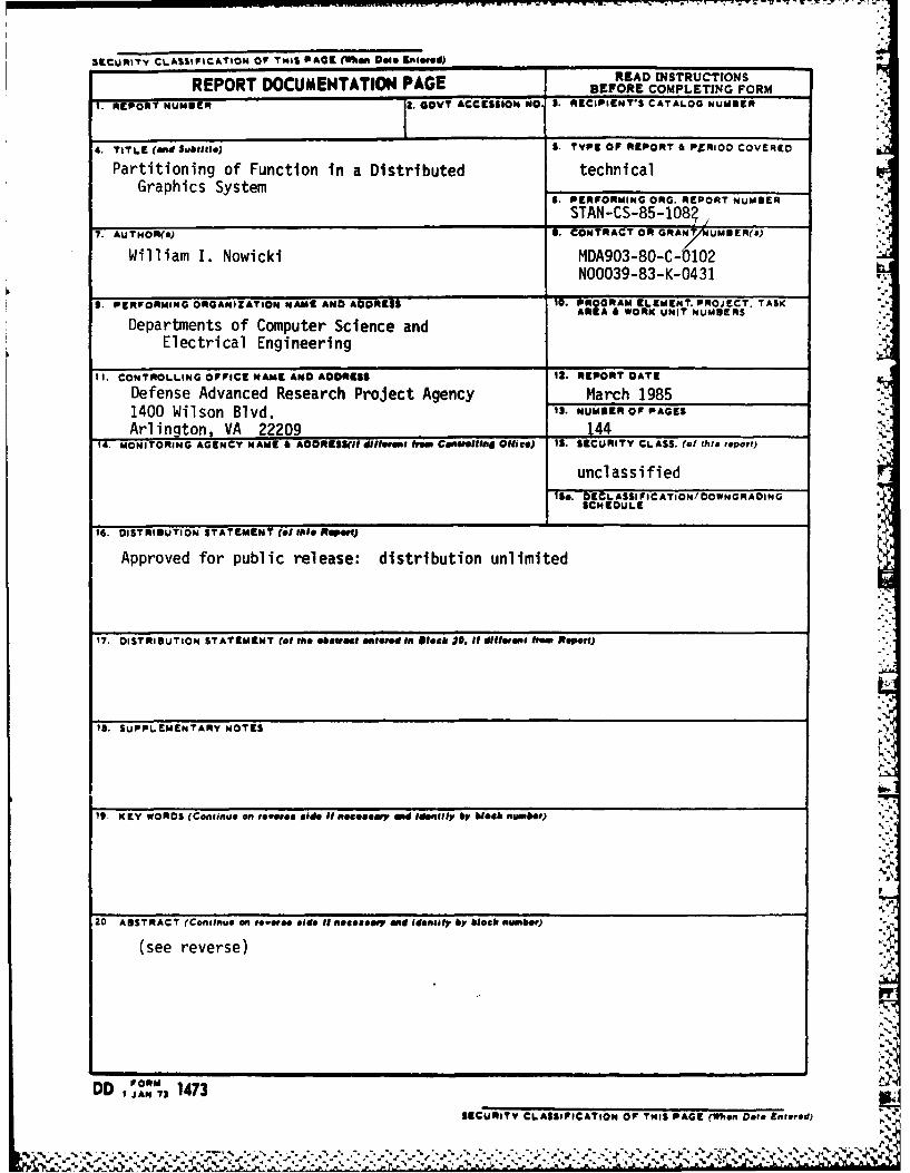
Partitioning of Function in a Distributed technicalGraphics System
6. PERFORMING ORG. REPORT NUMBER
STAN-CS-85-108?,7. AUTHOR(s) 6. CONTRACT OR GRANT UMBER(s)
William I. Nowicki MDA903-80-C-0102N00039-83-K-0431
S. PERFORMING ORGANIZATION NAME AND ADDRESS 10. PROGRAM ELEMENT. PROJECT. TASK"AREA & WORK UNIT NUMBERS
Departments of Computer Science andElectrical Engineering
II. CONTROLLING OFFICE NAME AND ADORESS I2. REPORT DATE
Defense Advanced Research Project Agency March 19851400 Wilson Blvd. 13. NUMBER OF PAGES
Arlington, VA 22209 14414. MONITORING AGENCY NAME 6 AOORESS(5I dHOsM" from C0011111#1 OU1icO) IS. SECURITY CLASS. (of this report)
unclassified
IS&. DECL ASSI IC ATION/DOWNGRADINGSCHEOULE
1. DISTRIBUTION STATEMENT (*I fll* Report)
Approved for public release: distribution unlimited
17. DISTRIBUTION STATEMENT (at the obewiaSt, 4e0ldin 81*ab 30. i different ho' Repor)
1. SUPPLEMENTARY NOTES
1. KEY WORDS (Continue an reveree side ii Re eisry 0d idenlil y block number)
.
20 ABSTRACT (Continue an reverse side i necoseay a d Identify by block numbs')
(see reverse)
DD ,o 1473SECURITY CLASSIFICATION Of THIS PAGE (When Dote Entered)
I,% ., % % ,. % " % "" "'.,% 6 . " - • • , --. * . . . . " . .-21. " -"7A . . . " ," . " • - , " " " " ' " * ' , ' ' , ,
SECURITY CLASSIFICATION OF THIS PAGE (When Oate Entered)
19. KEY WORDS (Continuedl
20 ABSTRACT (Continued)
Abstract
Although recent advances in graphics workstations promise much computing power for the future needs ofresearchers, traditional approaches to software organization waste much of this power. Most systems treat theworkstation as either a fixed-function terminal or a self-containcd personal computer; these roles havelimitations that can be overcome by considering the workstation a multi-function component of a distributedsystem. I'raditional standard graphics packages and object-oricnted window systems offer importantfunctionality, but a third approach, virtual terminal management systems, is more appropriate for adistributcd operating system.
'Ilic Stanford Distributed Systems Group has implemented such a distributed system for graphicsworkstations. organized as a collection of seners providing services to clients. Major issues are how topartitior functions between the server and its clients, and physically partition the server. In particular, theservice that displays graphical objects is called the Virtual Graphics Terminal Service (VG'1S). l'he VGTSarchitecture is described, as well as a prototype implementation.
Sl'his thesis discusses the trade-ofls involved in partitioning of function in a distributed graphics system.Performance is one important property traded for advanced functionality or decreased cost. To provideadequate perfonnance in a distributed system. communication costs should be kept low. as well as thefrequency of the communication. Ily providing modeling as well as viewing facilities, the VG'I'S reduces thecommunication required hetwcen applications and the service.
Mcasurements verify that perfonnance is insensitive to network bandwidth, but depends heavily on CPUspeed and Iprot ol characterisics. Using structure provides important speed improvements in some cases,but other basic factors such as inner loop optimization and proper batching of requests make even largerdifferences.
*!., Finally. conclusions are drawn regarding the partitioning approaches taken in the VGTS. The VGTS issuitablc for a large class of applications that perform graphics as an aid to user interface, and is portable to awide range of powerful workstations. Moreover, the VG'I'S can be used as a basis for further research onmany open questions in distributed systems.
DD I' 3 JA 1473EDITION OF 1 NOV 65 IS OBSOLETE SECURITY CLASSIFICATION OF THIS PAGE (When Gate Entered)
Partitioning of Functionin a Distributed Graphics System
William I. Nowicki
A bst ract
Although recent advances in graphics workstations promise much computing power for the future needs ofresearchers, traditional approaches to software organization waste much of this power. Most systems treat theworkstatkn as cithcr a fixcd-finction terminal or a self-containcd personal computer; these roles havelimitations that can be overcome by considering the workstation a multi-function component of a distributedsystem. I'raditional standard graphics packages and object-oriented window systems offer importantfunctionality, but a third approach, virtual terminal management systems, is more appropriate for adistributed operating system.
The Stai;ford )istributed Systems Group has implemented such a distributed system for graphicsworkstations, organized as a collection of senrers providing services to clients. Major issues are how topartitiorl Functions between the server and its clients, and physically p irtition the server. In particular, theiervice that displays graphical objects is called th6\Virtual Graphics I cnninal Servicc).(VGTS). 'lhe VG'ISarchitecture is described, as well as a prototype implementation.
-. 'is thesis discusses the trade-oTffs involved in partitioning of finction in a distributed grapiics system.Performance is one important property traded for advanced finctionality or decreased cost. To provideadequate perlormance in a distributed system, communication costs should be kept low, as iwell as the
' frequency of the communication. By providing modeling as well as viewing facilities, the VGTS,reduces thecommunication required between applications and the service. .
Measurements verify that performnance is insensitive to network bandwidth. but depends heavily on CPUspeed and prot(col characteristics. Using structure provides important speed improvements in some cases,but other basic CIctors such as inner loop optimization and proper hatching of requests make even largerdifferences.
Finally, conclusions are drawn regarding the partitioning approaches taken in the VG'I7S. hllie VGTS isV- suitable for a large class of applications that perform graphics as an aid to User interface, and is portable to a
wide range of powerful workstations. Moreover, the VG'TS can be used as a basis for further research on" many open questions in distributed systems.
Table of Contents
1. Introduction 31.1 Graphics Workstations 31.2 Role of the Workstation 3
1.2.1 'lle Workstation as Terminal 41.2.2 "'hc Workstation as Personal Computer 51.2.3 The Workstation as a Component of a Distributed System 7
1.3 Kinds of Partitions 81.3.1 Physical Partitions 81.3.2 ILogical Partitions 91.3.3 Static and Dynamic Partitions 91.3.4 Total and Partial Partitions 101.3.5 Protocol Design: the Result of Partitions 10
1.4 0,crview and Major Contributions 112. Related Work 13
2.1 Standard Graphics Packages 132.1.1 The SIGGRAPH CORE Graphics System 142.1.2 The Graphical Kernel System 162.1.3 The Programmer's Hierarchical Interactive Graphics Standard 192.1.4 'lhc I.iL. Network Graphics System 202.1.5 Virtual Device Interface and Metafilc 202.1.6 Videotex and Teletext Systems 20
2.2 Object-Oriented Window Systems' 212.2.1 Smalltalk 212.2.2 "l.isa Technology" 222.2.3 Other Window Systems 23
2.3 V:rtual 'lenninal Management Systems 232.3.1 Network Virtual Teminals 232.3.2 Rochester's Intelligent Gateway VTMS 232.3.3 Apollo I)omain 242.3.4 The Virtual Graphics Terminal Service 24
3. Architecture of the VGTS 253.1 The Environment 25
3.1.1 The Stanford University Network 253.1.2 'lle V-System 263.1.3 '11c VG'l'S Accesion For 27
3.2"llic User Model NTIS CRA&I 283.2.1 The Ideal DTIC TAB "3 283.2.2 Reality ,, Unannounced 0 29
3.3The Network Graphics Architcture Justification 303.4 "11c Virtual Graphics Terminal Protocol . - 31
3.4.1 SI)Fs and their Manipulation By ............................. 313.4.2 VGT and View Management Dist ibution I333.4.3 Input Ivent Management 6- 343.4.4 Tcxt Terminal E'mulation Availability Codes 35
3.5 The VGIS Client Protocols Avail a:.d I or 363.6 Summary and Implications of the Architecture Dist ZpP.:cial 37
I4 4
4. An Implementation of the VGTS 394.1 General Organization 39
4.1.1 VGTS Implementation Modules 394.1.2 Team and Process Structure 414.1.3 Module Sizes 424.1.4 Adaptivc Techniques 42
4.2 Screen Updating 434.2.1 Implementing Overlapping Viewports 434.2.2 Zooming and Expansion 45
4.3 Client Interface 454.3.1 Item Naming 454.3.2 Representing SDF Items 454.3.3 Interface to V-System Protocols 474.3.4 Binding the VG1P to a Byte Stream 474.3.5 Network Transport Protocols 47
4.4 The View Manager Interface 484.4.1 VG'TS Conventions 484.4.2 View Manager Menus 49
4.5 A Simple Application 514.5.1 Basic Operation 514.5.2 Commands 514.5.3 Selecting Alternate Fonts 534.5.4 Generating and Previewing Printed Copy 53
4.6 Summary of Implementation Status 535. VGTS Design Rationale 55
5.1 General Protocol Issues 555.1.1 Fundamental Implications of Partitioning 555.1.2 Replication Issues 575.1.3 Caching Issues 585.1.4 'ransport Protocol Issues 59
5.2 Perfonnance Issues 595.2.1 Code and l)ata Size 595.2.2 Resource ILimitations 605.2.3 Speed of Ixecution 60
5.3 Some Simple Models 605.3.1 Comparison to Cache Model 615.3.2 lie Time I)imension 62
5.4 Application Multiplexing Alternatives 645.4.1 I )ecentralized Control 645.4.2 Ccntralized Control 64
5.5 Unilo lmity and Portability 655'5.1 I)cvicc Independence of Applications 6555.2 Uniformity of User Interface 655,5.3 Portability of Implementation 66
5.6 Customizability 67, ~.5.6.1 Customizability by Programs 67
5.6.2 Customizability by Users 675.7 Suitability for the Future 68
5.7.1 Future Display I)evices 68
V
.4
=i, iii
5.7.2 Future Computer System Organization 685.8 Backward Compatibility 69
5.8.1 Encapsulating Existing Facilities 695.8.2 Relation to Standards 69
5.9 Summary and Motivation for Measurements 706. Measurements 73
6.1 Nature of Performance Measurements 736.1.1 Benchmark Programs 736.1.2 Test Configurations 74
6.2 Summary of Performance Results 756.3 Feasibility Evaluation 776.4 Internal Factors 79
6.4.1 Effects of Graphics Package 796.4.2 Fffects of Processor Speed 796.4.3 Effects of Graphics Hardware 81
6.5 Protocol Factors 816.5.1 Effects of Structure 826.5.2 Effects of Batching and Pipelining 826.5.3 Comparison to Bitmap Protocols 836.5.4 Effects of Transport Protocols and Their Implementations 83
6.6 Network Factors 856.7 Human Factors 86
6.7.1 Levels of Responses 866.7.2 Keystroke Data 87
6.8 Discussion of Results 876.8.1 Hardware Factors 876.8.2 Software Factors 886.8.3 Fitting the Model 88
7. Conclusions and Future Work 917.1 Structured Display Files and Virtual Terminals 917.2 User and Program Interface Separation 917.3 Transparent I)istribution 917.4 'echniques to Improve Performance 92
7.4.1 Protocol I)csign Techniques 92*- 7.4.2 Software Structuring Techniques 92
7.4.3 Internal lPerforimance ''uning Techniques 937.5 What Can be 1.earned 93
* 7.6 More Open Questions 937.6.1 Integration with Editor 937.6.2 I landling of Attributes 947.6.3 Other Interlfaccs 947.6.4 Portiing the Implenentation 947.6.5 Multiple View Surfaces 947.6.6 Extended Functionality 957.6.7 View Adapting Objects 957.6.8 View Manager Separation 95
7.7 Final Evaluation 96Appendix A. Glossary 97Appendix B. A Short VGTS Sample Program 105
% % % .
iv
Appendix C. History of the Implementation 109Appendix D. Detailed Experimental Results 111
D.1 Text Benchmark 114D.2 Vector Graphics Benchmark 116D.3 Structured Graphics Benchmark 120D.4 Illustration Data 126
References 127
L,
.r* 1
" " ' , " -, ,"", . , .- "" """""""""","". . -. ' ",''. .,, . , ,.''....,'' . ,-," " ' ,-.',". .. 2" '.;.. ,"'
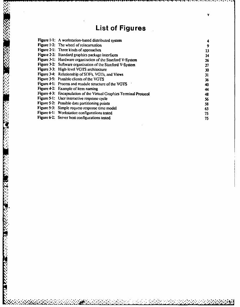
List of FiguresFigure 1-1: A workstation-based distributed system 4Figure 1-2: The wheel of reincarnation 9Figure 2-1: Three kinds of approaches 13Figume 2-2: Standard graphics package interfaces 14Figure 3-1: Hardware organization of the Stanford V-System 26' Figure 3-2: Software organization of the Stanford V-System 27Figure 3-3: High-level VGTS architecture 30
. Figure 3-4: Relationship of SDFs, VGTs, and Views 31Figure 3-5: Possible clients of the VGTS 36Figure 4-1: Process and module structure of the VGTS 40Figure 4-2: Example of item naming 44Figure 4-3: Encapsulation of the Virtual Graphics Terminal Protocol 48Figure 5-1: User interactive response cycle 56Figure 5-2: Possible data partitioning points 58Figure 5-3: Simple request-response time model 63Figure 6-1: Workstation configurations tested 75Figure 6-2: Server host configurations tested 75
i °9p
A"
91
vi
,1*
- -~ N ~-.~- .j.
vii
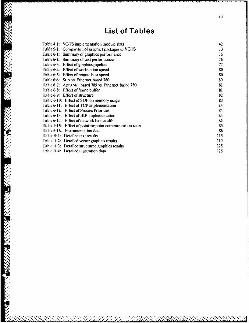
List of Tables
Table 4-1: VGTS implementation module sizes 42'Tabic 5-1: Comparison of graphics packages to VOTS 70Tabl 6-1: Summary of graphics performance 76
Table 6-2: Summary of text performance 76'rablc 6-3: Effect of graphics pipeline 77'rable 6-4: Effect of workstation speed 80Table 6-5: Effect of remote host speed 80Table 6-6: SUN vs. Ethernet-based 780 80
.4; 'Table 6-7: ARPANi-r-based 785 vs. Ethernet-based750 81Table 6-8: Effect of frame buffer 81'Fable 6-9: Effect of structure 82Table 6-10: Effect of SDF on memory usage 83Table 6-11: Effect of TCP implementation 84Table 6-12: Effect of Process Priorities 84'ablc 6-13: Effect of IKP implementation 84
'rable 6-14: Effect of network bandwidth 85'Fable 6-15: Effect of point-to-point communication rates 85Table 6-16: Instrumentation data 86Table D)-I: Detailed text results 115Table )-2: 1Detailed vector graphics results 119'l'able )-3: Detailed structured graphics results 125Tabl, l)-4: Detailed illustration data 126
-.
.-4
--'-,. ~..4',"
,m. .- . - - - ... -. * * *-* ~ ,4 4 5 .~..I' • -• •-. - - -- " " -.- • - , " " " "- "- " "• . .' -" • ." - . • - .".""• '., -" -" -" .'.,, ,;4' '.,' ," _- - t-- - -. , -4 . ,4.,,..,,,'.-" -'
Acknowledgements
First I would like to thank my principal advisor Keith Lant, who served as co-author of several papers thathave been adapted into parts of this thesis. He deserves special thanks for putting up with me through theyears. I would like to thank all other members of the Stanford distributed systems group, including DavidCheriton, who was responsihle for much of the eai ly development of the V-System. Forest Baskett started thedistributed graphics project, and initially supported the SUN workstation effort. All three members of thereading committee, along with Eric lerglund, provided many helpful comments on early drafts.
lie systems described here arc the result of the work of many people. Tom Davis and Charles Rhodesimplemcntcd the first version of the SIF manager as part of the VLSI layout editor YAI.F. Marvin Theimerperorned the initial conversion of YAI.F to the V-System, and implemented the internet server. Per Bothner,Kenneth Brooks, Craig i)unwoody, Ross Finlayson, Linda Gass, David Kaelbling and Joseph Pallas have allcontributed software to the VGTS as described in Appendix C. Tim Mann found and fixed many bugs in theV-System, including the kernel and executive. Vaughan Pratt implemented the incredibly fast vector drawingfunction discussed in Chapter 6, and provided much of the pioneering work before the VGTS was evenconceived. Andy Bechtolsheim designed the SUN workstation hardware, without which none of this wouldhave happened.
Joel Goldberger and James Koda of the USC Information Science Institute, and William Jackson and John,larson of the Xerox Palo Alto Research Center provided computer facilities for the experiments. Finally, Iwould like to dedicate this thesis to my wife Elizabeth, who made 1984 the happiest year of my life, despitethe strain of my work.
-This research was supported by the United States Defense Advanced Research Project Agency undercontracts MI)A903-80-C-0102 and N00039-83-K-O431, by NASA under contract NAGW-419, and by aNational Science Foundation graduate fellowship.
-,,Bitgraph is a trademark of Bolt, Beranek, and Newman, Inc.
h'lle following are trademarks of Digital Equipment Corporation: Dm., DEcSystemn-20, Massbus, PDP,ToPs-20, Unibus, VAX, VAXStation, VMS, VT-100.
Ethernet is a trademark of Xerox Corporation.
Geometry Engine is a trademark of Silicon Graphics, Inc.
Macintosh is a trademark of Apple Computer Corporation.
SUN WorkstLtion is a trademark ot" Sun Microsystems Inc.
UNIX is a trademark of A''&'' Ilcll Laboratories.
V-System is a trademark of Leland Stanford Junior University.
.. . . . . . . . . . . ..1
. . . . ..€. . ..". . . . . .

2 PARTITIONING OF FUNCTION IN A DISTRIIIUTEDGRAPIIICS SYSTEM
-p
-pp
-4
p.pp
4..
h4,
S..,~. __ _ 2 L~j
INTRODUCION
Introduction
When computers werc first invented, their time was so valuable that elaborate batch systems were devised.People would spend hours preparing commands and data to be read. processed, and printed out by thecomputer. In the 1960s the concept of timesharing was introduced, dedicating inexpensive terminals to eachuscr, many of whom shared a computer. The first timesharing systems were modeled after batch systems, butsoon the advantages of interactive programming became worth the extra cost. Throughout the 1970s manycomputer systems were designed specifically for timesharing.
Recent advances in VI .Sl technology make powerful yet physically small and inexpensive computer systemsfeasible. Related advances in network technology have made computer systems that communicate to othersystems t&c rule rather than the exception. One of the ideas behind timesharing can be applied with today'sdifferent cost constraints: replicate inexpensive components and share the expensive components.
1.1 Graphics Workstations
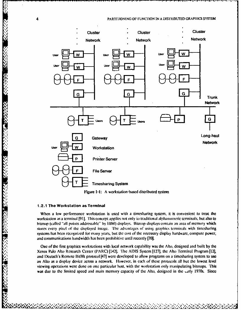
The computing resource dedicated to each single user is called the workstation. In timesharing systems theworkstation is just a fixed function terminal, but de falling cost of microprocessors results in a shift to morepowerful workstations. For the rest of the discussion we will assume that the workstation contains some kindof programmable processor, some memory, at least one display device, and at least one input device.Workstations are often connected in clusters, forming a workstation-based distributed system, as illustrated infigure 1-1.
The advent of high-performance graphics workstations has been a mixed blessing. Inexpensivemicropr cessors seem to promise unlimited computing power to satisfy everyone's needs. However, now thatthe information being processed and viewed is becoming more valuable than the hardware doing theprocessing. old techniqucs for organizing computing systems are no longer valid. In particular, commonactivities like information display often have processors deditated to them, but still require access to othercomputing resources.
Although they are interconnected, most workstation systems built to date continue to treat the workstationsolely as a fixed-function terminal or a self-contained personal computer. More interesting roles existbetween these two extremes, especially considering the next logical step in the organization of computingsystems: many computing elements per user cooperating on the same task. To accomplish this cooperation,the tasks must be partitioned or divided at appropriate points depending on many factors. This thesisattempts to investigate and characterize some experimental attempts at partitioning in a distributed graphicssystem. The goal is not a system that solves all the problems of distributed graphics, but rather to design andbuild a prototype that can be used to evaluate one approach.
1.2 Role of the Workstation
It is fairly certain that both computing power and communication capability will become more pervasive inthe future, and these trends will continue for some time. At present, however, the bottleneck in thedevelopment of network-based systems has become the software, with much of the potential of powerfulworkstation hardware being unrealized. The first key problem is to find the appropriate role for theworkstation within the context of the whole system. There are three basic approaches to the role of graphicsworkstations in a computing environment: as a terminal, as a personal computer, and as a component of adistributed system.
S..5-
4 PARTITIONING OF FUNCTION IN A DISTRIBUTED GRAPI IICS SYSTEM
* Cluster Cluster Cluster
Network Network Network
uer User l wUWe~ j
ijsrE w UserE UserE
F F F
G 0 GTrunk
Network
T Users 9 -T Pse G
W Gateway Long-haul•G 1 Gateway
Wur Workstation Network
E"-E ] Printer Server
File Server
O -ZV n Timesharing System
Figure 1-1: A workstation-based distributed system
1.2.1 The Workstation as Terminal
When a low performance workstation is used with a timesharing system, it is convenient to treat theworkstition as a teninal 1911. 'iis concept applies not only io traditioniI alhllantmeric terminals, but also tobitmap (called "alI points address ble' by I IIM) displays. Iitnp displ.tys contain an arac of nicmmory whichstores every pixel of thc displayed imnage. The advintages o4" using graphics terminals with timesharingsystems has been recognized f1or nany years, but te cost of the necessary display hardware, compute power,and communications bandwidth has been prohibitive until recently [701.
One of the first graphics workstations with local network capability was the Alto, designed and built by theXerox Palo Alto Research Center (PARC) [1421. The AI)IS System 11271, the Alto Terminal Program [121,and ) eutsch's Remote Bitlilt protocol 1471 were developed to allow programs on a timesharing system to usean Alto as a display device across a network. I lowever. in each of these protocols all but the lowest levelviewing operations were done on one particular host, with the workstation only manipulating bitmaps. Thiswas due to the limited speed and main memory capacity of the Alto, designed in the ,-rly 1970s. Since
-,%
".4 , . •' .•. . "1 - ° = . . - * ' % . . - o - .1 . " . " . " . . " o " . " . " = % "' . % = % , %w. , . ., . . - ... ,. . ... . . .. . .. j ..,. . ',. ",. . . .
INTRODUCION 5
current workstations have faster processors and larger memories, new architectures should take advantage of
this increased power.
Bell Lab's Layers System [105] for the Blit terminal [721, now called the Teletype 5620, provides a similarbit-map interface to the application. An application can run on the terminal and communicate to a (single)
host using a higher-level protocol. Unfortunately, these protocols arc not standardized, and the Layers system
is only designed for one particular kind of workstation to communicate with one kind of operating system.
Since many users are only concerned with one operating system or one terminal, these systems may besuccessful. In fact, the ability to act as a terminal is an important capability that should be included in anyworkstation-based system. However, even the designers of the Layers system are working on a more flexibleapproach that does not waste the power of more advanced workstations.
1.2.2 The Workstation as Personal Computer
For higher performance workstations, one popular approach is to construct a small model of a largertimesharing system. This is a simple and powerful idea pioneered by the Alto computer at Xerox PARC, andnow adopted in many new products. Fxamples include the various Lisp Machines [161, the Perq [1441, and
many other new commercial systems being announced weekly at the time of this writing.
One principle motivation behind the personal computer approach is to avoid the partitioning problem, andinstead offer a single "integrated" system. But in reality each personal computer is isolated, resulting in ahighly partitioned system with the following practical problems:
" Cost: There are economics of scale involved in devices such as disks. For example, 30 10 Mbytedisks cost much more than a single 300 Mbyte disk. A moderately sized disk would essentiallydouble the current cost of the workstation. Typically configured Lisp Machines sell eior $100,000to $200,000. Since many organizations do not have $100 terminals for each member, theycertainly will not spend 200 times that amount for a single user.
" Reliability: An office environment is not as controlled as a clean, air-conditioned machine room.Preventive maintenance and repair of delicate mechanical equipment is much easier forcentralized facilities.
" Flexibility: The personal computer model provides for rigid control on the number of users; ifyou are not one of the few who own one, or find one to share, you can not use any computingresources during peak hoors.
" Perrormance: There are two aspects of performance. Although fast response to user interaction(such as editing [57]) favors personal computing, high-throughput and low-interaction activities(such its compilation) favor large shared processors.
* Conirort: Adequately sized disks are large and noisy, producing an unwelcome intrusion into theoffice environment, with assmoialed power requirements and heat dissipation problems. Forexample, the Xerox I IN)I lisp workstations at Stanford are physically centralized, with only thedisplays and keyboards outside the machine room.
" Duplication: Many of the files on each disk are duplicated. This obviously wastes space, butmore importantly, it causes problems with propagation of updates and useless duplication ofsoftware maintenance effort.
'lcre will still be many commercially successfil personal computer products. For example, the entire
UNIX ti111 operating system has been ported to a workstation with a local disk interface for eachworkstation 168, 118]. Reasons for this success include the value many people put on total control, and the'personal" nature of much computing [116]. For instance, a small business would probably initially preferone self-contained personal computer.
* .~. .
6 PARTITIONING OF FUNCTION IN A DISTRIBUTED GRAPHICS SYSIEM
However, if that business outgrows the single personal computer, and wishes to share large distributeddatabases, the problems described here will eventually arise. Except for the low-performance computerspurchased for home use, most so-called "personal" computers used for science and busness are actuallypurchased by some group or department, and are therefore actually shared. Furthermore, the high cost ofthese scientific workstations has limited shipments to only a few thousand units 1153]. For larger, multi-person projects that are performed in research and development environments, small self-contained systemsare not always desirable.
Even if workstations are available, current researchers still heavily use centralized server hosts. Thefollowing are some reasons it might not be possible or desirable to run all applications on the workstation:
* The application may require fast floating point hardware.
e The application may require large virtual or physical memory.
* The application may require frequent access to a large database.
* The application may be written in a particular language or dialecL
* The application may require a license to run on each different CPU.
e The application may access secure information that should not be transmitted over a network.
* The application may perform I/O directly to a particular device.
* The application may contain dependencies on a particular machine or operating system.
Even if the necessary resources are available as an option for the workstations, they are often too expensive forwidespread use.
One could argue that since hardware costs are decreasing, the personal computer model will inevitablydominate in the end. But the decrease in hardware costs means that software costs become relatively moreimportant 11561. It is well known that the largest portion of software life-cycle costs goes to maintenance [18].'llierefore, ease of software maintenance should be an important issue in evaluating a computing systemarchitecture. With individual personal computers, all users have to do their own software maintenance. Thisresults in a potentially enormous increase in the costs associated with distributing and installing new versionsof software.
Even considering only hardware costs, self-contained personal computers may eventually become moreexpensive than other alternatives. One might reason that since memory costs are decreasing, and memoriesare getting more dense, the trend will be to computer systems with higher ratios of memory to processingpower. However. a typical computer ten years ago was an IBM System/370 with about a million bytes ofphysical memory 1104). 'l'oday. a representative computer is the IBM PC. with almost half the processingspeed. but only one tenth as much memory, lypically aboutl 10)K bytes 1541. Ofcourse the lower price of the'C means that many more people can alliwd one. On the other hand. the organi/aItion thai ten years ago had
a 370/138. can now atTord a imachinc with a processor atmut eight times f'aster and sixteen times as muchmemory. I arge computers are expanding principally by adding memory, while smaller computers are gettingless expensive principally by keeping memory small.
More interesting evidence is the relative price of memories and processors. Today an MC68000 processorcosts about $50, and a 64K bit memory chip costs about $5. 'Ihus. if a system has more than about tenmemory chips per processor chip, the memory cost will dominate. Since the cost to produce integratedcircuits in large quantities depends mostly on packaging considerations such as the number of pins, the ratioof processor to memory cost will probably stay fairly low. 'Ibhis provides motivation to design computer
a -+ m k m + . I . m + , + . l . + i + . . l ' ' m m + + . + k . ' . o + + . * +
.. L , m * I
INTRODUCTION 7
systems that take advantage of low-cost processors by replicating them for each user, but share expensiveresources such as memory.
1.2.3 The Workstation as a Component of a Distributed System
Since most researchers who use personal computers quickly recognize the problems caused by isolation,manufacturers usually provide some form of communication capability. For example, a file transfer programmay be used to transfer files either explicitly or semi-automatically between the personal disks. Otherapproaches use a remote disk or logical file system to intercept operations at the appropriate level, and routethem instead to a remote disk or file access user module. There are many practical reasons to eliminateexpensive components such as secondary storage from each workstation. A diskless workstation isinexpensive, small, quiet, and has almost no moving parts to break.
Several efforts, such as Locus at UCLA, modified standard operating systems to allow shared and replicatedfile systems [1501. Ierkeley 4.2 UNIX was intended for diskless operation, although for performance reasonsmost 4.2 systems still have local disks, and all programs still run on the workstation [681. Some attemptsextend timesharing systems to handle remote execution [531, but a more comprehensive solution is needed.The file service abstraction, developed in projects such as Woodstock [137], can be generalized into the servermodel, resulting in more flexibility of interconnection.
1.2.3.1 The Server Model
'he architecture to be presented in Chapter 3 treats the workstation as a multi-fimction component of adistributed system. We do not waste its power by treating it solely as a terminal, nor do we isolate it from therest of the world, under the false assumption that it can be all things to all users. Rather, by supporting adistributed operating system the #orkstation may perform any function best suited to the user, the hardware,and the applications at hand [79, 86, 109, 155]).
In this view, the operating system is just a collaction of servers, and a way of accessing those servers. Animplementation of this model usually consists of cooperating kernels providing an inter-processcommunication system, and services implemented as processes'. 'Ibc kernel of a server-based operatingsystem acts analogously to a hardware bus, being essentially a communications switch. In addition to thephysical wires used to connect modules in a hardware bus, a standard protocol is agreed upon to define thesemantics of the communication. Similarly, in our software model, in addition to the ability to send message,a protocol is dcfined for the meaning of the messages.
'1iis model does not make the system versus user distinction; the design is in terms of "clients" whichSinvoke the services of a particular server. For example, the concepts of "terminal" and "personal computer"
are now merely roles played by some collection of processes and processors at any given time. 'The result ismuch more flexibility in the partitioning of the resulting system.
V, "1.2.3.2 Network Transparency
By considering the workstation as a component of a distributed system, we could consider a singleunderlying communication concept for "network transparency." In general, network transparcncy is aworthwhile goal: programs should be as independent as possible of the location of their execution and theresources they use. However, every system has a boundary on this transparency, so the problem ofcommunicating to the outside this boundary must be addressed eventually. In fact, all the computing
In fact in many ways the kernel itself can be viewed as a server. providing objects such as processes and mesacs.
'# ,
PARTITIONING OF FUNCTION IN A DISTRIBUTED GRAPHICS SYSTEM
resources in the world can be considered a single computer system, with many disconnected components.'Ibis motivates communication between various kernels which may have vastly different underlyingcommunication concepts, resulting in what might be called a distributed kernel. Network communicationalways has some cost associated with it, so perfect transparency is never possible with respect to performance.Chapter 3 describes a system which has been developed to help address some of these issues.
1.3 Kinds of Partitions
The hardware trends discussed in the previous sections result in a physically distributed computing system,with a corresponding partition required of the software. There are several forms that partitioning can take,
some of which are introduced below.
1.3.1 Physical Partitions
Computations can always be done more efficicntly on machines that are built specifically for a particularpurpose. For example, a machine with large and fast disks is needed for fast searching of databases, whileinteracting with a user requires powerful graphics capability. 'Ihis suggests a physical partitioning by puttingparticular operations onto specially built machines.
Partitioning has a long history in the field of computer graphics. Due primarily to the high cost ofhardware, graphics systems of the 1960's consisted of relatively powerless graphics devices connected directlyto relatively large-scale computers, either single-user or time-shared. However, as the graphics devicesbecame more sophisticated, the load on timeshared hosts, in particular, became insufferable.
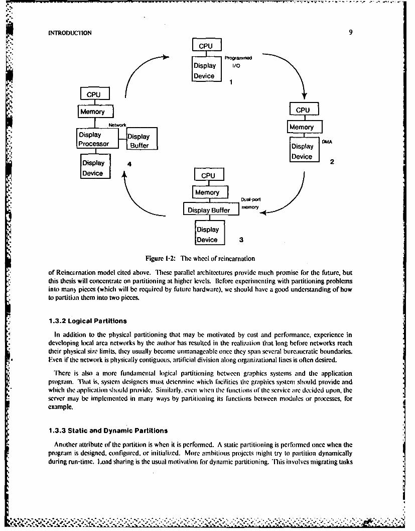
Fortunately, the minicomputers of the 1970s led to satellite graphics systems that served to offload avariable amount of graphics functions on to another machine [51, 55, 62, 148]. By judicious partitioning ofresponsibility between the host and the graphics device, it was possible to achieve both better response andhigher throughput. 'The more powerful the graphics processor, the more functions that could be omoaded,until the satellite system took on the appearance of the host. Taken to its extreme, this branch of evolutionled naturally to the personal computer - completing a round on the Wheel of Reincarnation 11011, asillustrated in Figure 1-2.
In configuration I of Figure 1-2. the processor directly controls the display device. In configuration 2, thedisplay commands are accessed directly from the processor's memory. In configuration 3, a special dual-portmemory hold the display commands. In configuration 4, a second processor has been added to sendcommands to the display from the display buffer. The display control is similar to configuration 1, except forie communication channel to the main CPU. At each step through this cycle the partionability problemsmust be addressed. In fact, the amount of distribution of finction increases at each cycle.
For the 1980"s, increasingly powerful workstations, together with the proliferation of networks, have madetruly distributed graphics possible. 'lhe higher Iaiidwidfli of available networks. when compared 1o that ofprevious host-satellitc interconnections, makes it even more Iasible to achieve better pcrlbrinance bypartitioning the application between machines, especially if the remote host is significantly more powerfulthan the local workstation. Moreover, it is now possible for a single workstation to have access to multiplebackend machines, possibly simultaneously. Many of those machines may support graphical applications thatcan not be executed on the workstation - due to memory or language requirements, for example -but can usethe workstation for output.
On a hardware level, a given computer system may contain several different processors, and even a singleprocessor may be implemented as several functional units. This is consistent with further travel on de Wheel
.
INTRODUC1ION 9
Programmed
IDisplayl 1/0
Device 1
CPU
te o rk IMemory
,Processor ,,o,,,&Prcssr Buffer RDisplay M
Device
Dsly 4 2Device C PU I
Memorry Oia-Pon
Display Buffer memory
~Display
Device 3
Figure 1-2: The wheel of reincarnation
of Rcincrnation model cited above. These parallel architectures provide much promise for the future, butthis thesis will concentrate on partitioning at higher levels. Beforc experimenting with partitioning problemsinto many pieces (which will be required by future hardware), we should have a good understanding of howto partition them into two pieces.
" 1.3.2 Logical Partitions
In addition to the physical partitioning that may be motivated by cost and performance, experience indeveloping local area networks by the author has resulted in the realization that long before networks reachtheir physical size limits, they usually become unmanageable once they span several bureaucratic boundaries.
*, Fven if the network is physically contiguous, artificial division along organizational lines is often desired.
*There is also a more fundamental logical partitioning between graphics systems and the applicationprogram. That is. system designers must determine which facilities the graphics system should provide and
* which the application should provide. Similarly. even when the I'unctions ol' the service are decided upon, theserver may be implemented in many ways by partitioning its functions between modules or processes, forexample.
1.3.3 Static and Dynamic Partitions
Another attribute of the partition is when it is performed. A static partitioning is performed once when theprogram is designed, configured, or initialized. More ambitious projects might try to partition dynamicallyduring run-time. Load sharing is the usual motivation for dynamic partitioning. 'Ihis involves migrating tasks
10 PARTITIONING OF FUNCTION IN A DISTRIBUTID GRAPHICS SYSTEM
to more evenly distribute the load among several computer systems. I oad sharing can be used only when thesystems arc relatively homogeneous. In this work we will deal with heterogeneous systems consisting ofdedicated workstations and centralized server hosts.
There have been a few attempts at dynamic partitioning in heterogeneous systems, by assigning tasks toeither the mainframe or host depending on current workloads. For instance, the ICOPS system at BrownUniversity attempted to perform dynamic partitioning1146, 128]. One application using the BrownUniversity Graphics System (BUGS) was dynamically distributed between a mainframe and aminicomputer [97]. In another example, the CAGES system at the University of North Carolina automaticallygenerated the linkages at compile time for distributed graphics programs written in PI./i [62]. Moreinteresting would be a solution to the problem of handling multiple applications or multiple languagessimultaneously.
We shall see enough problems with static partitioning that it is not clear if dynamic partitioning is worth thecost. In either case, efficient techniques for static partitioning and effective measurements and evaluations areprerequisites to solving the more general problem. Without the ability to easily experiment with staticpartitioning, dynamic partitioning should not even be attempted.
1.3.4 Total and Partial Partitions
Unfortunately the word "partition" has taken on a fairly specific meaning in the terminology of networks.It usually refers to a single network that is divided into two or more totally disconnected smaller subnetworksbecause of a failure of one or more components. A typical example of this kind of partitioning involves thefailure of several links or a gateway, causing a network to divide into disconnected parts. It is desirable tocontinue functioning as much as possible within each network partition.
However, if the disconnected subnetworks never reconnect, then the problems are just the same as those ofseveral smaller networks in isolation. The interesting situations occur only when the parts are reconnected,and inlbrmation flows again between the parts. Experience with the Stanford University Network has beenthat in reality slow or partial degradation is much more common than total failure.
This thesis concerns itself only with the information flow between the parts of a connected system, not thedetails of recovery from link errors after total partitions. A partial partitioning, in which communicationbetween the parts is possible but more costly than communication within each part, may be inevitable or evendesirable. Additional reasons for this will be discussed in in Chapter 5, in particular the sections on futurecomputing system organizations.
1.3.5 Protocol Design: the Result of Partitions
Many critical choices must be made when designing the protocols or interfaces between the parts of adistributed system. The protocols should be at a high enough level to make the conlinunication efficient, hutflexible enough to allow for nost users' needs. The dcsigner muost anticipate the degree of fuinctionality thatusers will want. and provide enough services to achieve that flunctionality, or else the system will be toorestrictive to use. At the same time, if the service provides too many features, or requires too much interactionwith the client, the performance will not be adequate. 'Ibis thesis evaluates the protocol choices made in onedesign of a distributed graphics system.
.4..,"
.. . . . . . .. ..-1''~~.~..y-
Lr.-
INTRODUCrION 11
1.4 Overview and Major Contributions
The spectrum of roles for graphics workstations from fixed-function terminal to self-contained personalcomputer was examined in this chapter, along with motivations for the study of the partitioning problem fordistributed graphics systems. The next chapter discusses three different approaches to related problems:traditional standard graphics packages, object-oriented window systems, and virtual terminal managementsystems. Chapter 3 presents the Virtual Graphics Terminal Service architecture in fairly abstract terms. Inparticular, the protocol between the server and a client application program is specified. Chapter 4 describesa prototype implementation of the Virtual Graphics Terminal Service, the VGTS user interface, and a sampleapplication program. Chapter 5 investigates some issues involved in partitioning of finction, the rationalebehind the choices made in the VGTS design, and some simple performance models to motivate experiments.Chapter 6 gives the results of these measurements, and discusses the cost/performance tradcoffs. Finally,some conclusions and directions for future work are drawn in Chapter 7.
Although many people were involved in the development of the VGTS, this thesis concentrates on thefollowing major research contributions by the author:
1. 'he virtual terminal concept was extended to support graphics by incorporating support forstructured display files, as well as conventional textual interaction. The abilities of virtualterminals to support multiple distributed applications are combined with the power andportability of structured display files.
2. The application interface for defining graphical objects was specified and implemented separatelyfrom the user interface for viewing those objects. Both the advantages and disadvantages of thisstrict separation are discussed.
3. lhe protocol used for defining objects was extended transparently across networks using severaltransport protocols, resulting in distributed graphics programs. 'hew programs were actuallyused, so performance constraints were stringent.
4. Measurements were performed to determine the effect of various factors on performance ofgraphical applications. The measurements verify that performance is insensitive to networkbandwidth, but depends heavily on C13U speed and protocol characteristics. Using structureprovides important speed improvements in some cases, but other basic factors such as inner loopoptimimation and proper batching of requests make even larger differences.
The results show that the VGTS is suitable for a large class of applications, and can be used as a basis formuch further research.
CV.
12 PARTmI'ONING OP FUNCTION IN A I)ISTRIBUTE3D GRAPIIICS SYSTE-M
'.4-2:
N.4. ,%
* -.
- 4-
1-l' "
4/"
RELATED WORK 13
-2-Related Work
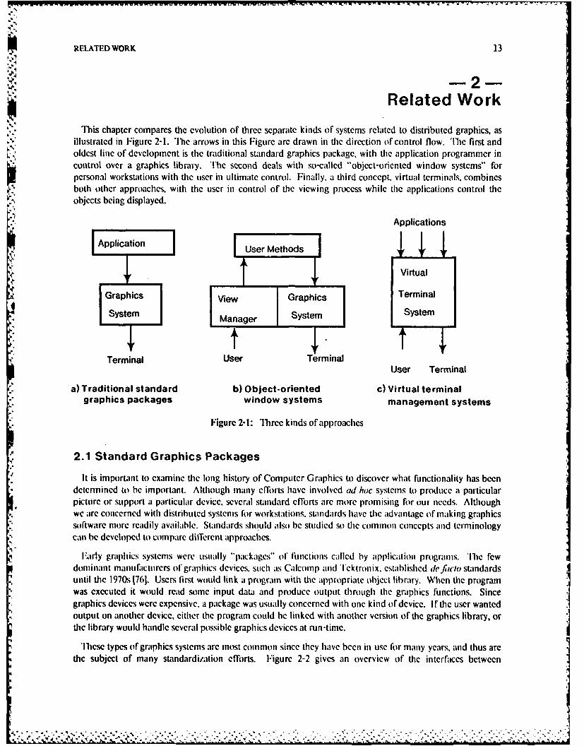
This chapter compares the evolution of three separate kinds of systems related to distributed graphics, asillustrated in Figure 2-1. The arrows in this Figure arc drawn in the direction of control flow. The first andoldest line of development is the traditional standard graphics package, with the application programmer incontrol over a graphics library. The second deals with so-called "object-oriented window systems" forpersonal workstations with the user in ultimate control. Finally, a third concept, virtual terminals, combinesboth other approaches, with the user in control of the viewing process while the applicalions control theobjects being displayed.
Applications
Application User Methods
Virtual
Graphics View Graphics Terminal
System Manager System
Terminal User TerminalUser Terminal
a) Traditional standard b) Object-oriented c) Virtual terminalgraphics packages window systems management systems
Figure 2-1: Three kinds of approaches
2.1 Standard Graphics Packages
It is important to examine the long history of Computer Graphics to discover what functionality has beendetermined to be important. Although many efforts have involved ad hoc systems to produce a particularpicture or support a particular device, several standard efforts are more promising for out needs. Althoughwe are concerned with distributed systems for workslations. standards have the advantage of making graphicssoftware more readily available. Standards should also be studied so the common concepts and terminologycan be developed to compare different approaches.
IlArly graphics systems were usually "packages" of functions called by application programs. The fewdoninant manufacturers of graphics devices, such as Calcomp and Tektronix. established de fiwlo standardsuntil the 1970s [761. Users first would link a program with the appropriate object library. When tie programwas executed it would read some input data and produce output through the graphics functions. Sincegraphics devices were expensive. a package was usually concerned with one kind of device. If the user wantedoutput on another device, either the program could be linked with another version of the graphics library, orie library would handle several possible graphics devices at run-time.
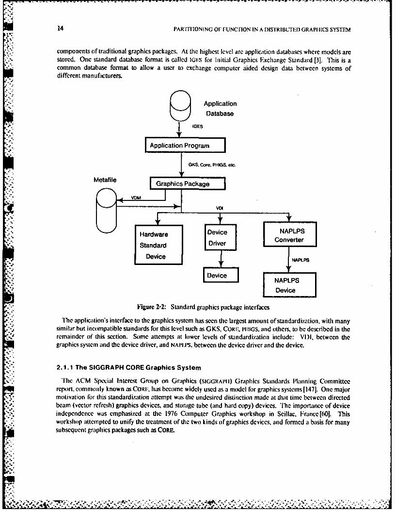
'llicse types of graphics systems arc most common since they have been in use for many years, and thus arethe subject of many standardization efforts. Figure 2-2 gives an overview of the interfaces between
14 PART'ITIONING OF FUNCFION IN A DISTRIBUTED GRAPHICS SYSTEM
components of traditional graphics packages. At the highest level arc application databases where models arestored. One standard database format is called IGt-S for Initial Graphics Exchange Standard [31. This is acommon database format to allow a user to exchange computer aided design data between systems ofdifferent manufacturers.
ApplicationDatabase
UIGES
-IA p p l ication Program
GKS, Core. PHIGS, etc." -" Metafile
!-:," I G ra p h ic s P a c ka g e
.,HardwareDeieNP S
Standard Driver Converter
Device . NAPLPS
D~vc ~evice
NAPLPSDevice
Figure 2-2: Standard graphics package interfaces
The application's interface to the graphics system has seen the largest amount of standardization, with manysimilar but incompatible standards for this level such as GKS, CORIE, PIIIIGS, and others, to be described in theremainder of this section. Some attempts at lower levels of standardization include: VI)I, between thegraphics system and the device driver, and NAI IP.S, between the device driver and the device.
2.1.1 The SIGGRAPH CORE Graphics System
'Ilic ACM Special Interest Group on Graphics (SIGGRAPII) Graphics Standards Planning Committeereport. commonly known as CORI-, has become widely used as a model for graphics systems 11471. One majormotivation for this standardization attempt was the undesired distinction made at that time between directedbeam (vector refresh) graphics devices, and storage tube (and hard copy) devices. The importance of deviceindependence was emphasized at the 1976 Computer Graphics workshop in Scillac, France [601. Thisworkshop attempted to unify the treatment of the two kinds of graphics devices, and formed a basis for manysubsequent graphics packages such as CORE.
RELATED WORK 15
2.1.1.1 Device Independence
Hard copy and storage tube devices have a simple physical concept of a current location. For example, in apen plotter the location of the pen was obviously visible. A sequence of move and draw commands was themost natural way to think of how a pen plotter created a picture. 'he CORE system extended this move anddraw concept to three dimensions, using a synthetic camera analogy. Other state information such as thecolor or size of the pen, was also extended into the COR- system. The application constructed a model of theobject in its own internal data structures, and would use the graphics package only for viewing operations.
On the other hand, directed beam graphics devices usually had display lists, which were traversedrepeatedly to display the picture. Changing one element in the display list would instantly change the item,
. being displayed, while storage tube and hard copy devices would be erased and redrawn completely for anymodifications besides additions. CORE used the concept of segmeni to represent this retained graphicsinformation.
2.1.1.2 Coordinate Systems
Another important contribution of CORE was the understanding of the importance of different coordinatesystems. The CORI. System and most other subsequent graphics packages deal with three coordinate systems:
1. World Coordinates (WC) are arbitrarily defined by the applications programmer. In CORr theseare floating point numbers in either two or three dimensions.
2. Normalized l)evicc Coordinates (NDC) are used to define a uniform coordinate system for alldisplay surfaces. In CORE these are two dimensional floating point numbers between zero andone.
3. I)evice Coordinates (DC) represent the actual units used by the display device, usually unsignedintegers of ten to sixteen bits.
CoRI implementations map from world coordinates to normalized device coordinates, with a driver for each
dc ice mapping from normalized device coordinates to actual device coordinates. This allows most of thegraphics package implementation to be retained when new graphics devices arc introduced.
2.1.1.3 CORE as a Standard
The CORI: System was defined as a set of language-independent functions, with the mapping from the
abstract function names to programming language identifiers left undefined. This resulted inimplementations that were incompatible in many details, although system models and basic concepts werefairly consistent across most implementations.
Although the CoRI: system was proposed in 1977, and was revised in 1979. in five years it has not yetbecome an official standard, and may never become one, due to the success of Iuropean standardimationeflbrts. There has been much inore experience in the areas of portability and device independence since theI979 rcport, as well as some rccoiisideration of the way modcling and viewing were separated in CORI: 11331.Since these issues are also important in a distributed system, the CoI:i system was not suitable for our work.I lowever, COR: influenced subsequent standardization attempts, described in the next sections, that haveovercome some of its problems.
11
.1
-- - .. -. .. _ _~ . . . . . . . . . . .. . . . . . . . . . . . . . . . . . . . . . . . .
16 PARTITIONING OF FUNCIION IN A IISrRIBUFED GRAPtlICS SYSTF.M
2.1.2 The Graphical Kernel System
The Graphical Kernel System [641 has become a popular standard that started in Europe with the GermanDIN (Dcutches Institute fuer Normung) and spread to America. German standards are specified andadopted more quickly than American standards because )IN is a government body while ANSI is a volunteerorganization requiring the consensus of competing industrial representatives. Although they are intended tobe as close as possible, there are some slight differences between the ISO GKS and American NationalStandards Institute Committee on Computer Graphics Programming ILanguages (ANSI X3t13) version ofGKS. Most notably, due to the complexity of the GKS standard (which already has nine levels of subsets)ANSI committee X3H35 has defined a subset of the lowest level of functionality, called the Programmer'sMinimal Interface to Graphics, or PM IG [122, 21.
2.1.2.1 GKS Workstations
GKS uses the workslafion concept to represent some logical input devices and one associated output device.Ibis is in contrast to CORE in which only supports one view surface and does not support any relationshipbetween input events from different input devices. GKS explicitly states that one application can manipulatemultiple workstations, no mention is made of several applications sharing a single workstation. Ihe idea ofplacing the I/O devices on a physically separate machine from the one running the application program wasone of the original motivations for the workstation concept [481, but most implementations of G KS have runon only one machine. Section 2.1.2.7 will discuss the problems involved in a distributed GKSimplementation. Ihe distribution capability has some subtle but important effects on the structure of GKS.
2.1.2.2 GKS Output Primitives
The graphics primitives used in GKS, similar to those in CORI., are the following six:
1. Polyline: A set of connected lines drawn between a list of points.
2. Polyniarker: Symbols of one type are centered at given positions.
3. Text: Character strings are drawn at a given position. There are many attributes to control theorientation, spacing, and justification of tcxt.
4. Fill Area: A polygon which may be filled with a uniform color, pattern, or hatch style.
5. Pixel Array: An array of pixels with individually specified colors or intensities is displayed.6. Generalized Drawing Primitive: A set of points is transfonned and passed through to the device
dependent driver.
The generalized drawing primitive is intended to take advantage of special functions of the workstation, suchas the ability 1o draw arcs or curves. Note that there is no notion of cuirren position as in CORIF andoperations arc in two dimensions only. Three dimensional extensions are currently under development.
2.1.2.3 GKS Attributes
Abstracting slightly from the hard-copy analogy, GKS and CORI: retain current values for each of severalattributes, representing the state of the drawing device used for relevant output primitives. Thus. although thenotion of current position does not appear in GKS. the stite variables necess.ary to simulate a drawing deviceare still needed. For example, the polyline primitive has line-type (solid, dashed, etc.). width, and colorattributes. Ilowevcr, in GKS bundle labh's can be used to group attributes. Instead of specifying everyattribute on every output primitive, an index into the bundlc table (a small integer) is specified, and the table
%1
N,
"N
RELATED WORK 17
gives values for all the attributes. For example, instead of specifying a color absolutely everywhere it is used,it could be defined only once to simplify changes.
2.1.2.4 GKS Segments
GKS segments are named with integers specified by the application. Segments may be transformed, madevisible or invisible, highlighted. ordered from front to back, deleted, renamed, and inserted into other opensegments. Every primitive within a segment can have an attribute called the pick identifier which establishes asecond level of naming for use with the pick input device. However, the primitives within a segment cannotbe modified; the pick identifier serves only to distinguish parts of a picture used for graphical input. 'Ihere isan explicit finction to set the pick identifier. All primitives added to the segment until the next call to thisfunction wll have the same pick identifier.
In GKS segments can be posted on actual workstations, called Workstation Dependent Segment Storage orWI)ss. In addition segments can be sent to Workstation Independent Segment Storage (WIss). Segments canbe moved back and forth between WIss and WoSs (actual workstations) under control of the application
, program.
2.1.2.5 Graphical Input in GKS
The concept of logical input devices was used as a basis for extending device independence to graphicalinput in GKS as well as CORF [1521. The CORF system treated input and output functions as orthogonalconcepts. so, for example, the selection of view surfaces had no effect on echoing. On the other hand, GKSassociates logical input devices with workstations. G KS provides the following classes of input devices:
Locator Provides a position in world coordinates and a transformation number, determined by theviewport in which the input occurred. A trackball or joystick is the typical locator device.
Stroke Provides a series of positions in world coordinates and a transfonnation number.
Valuator Provides a single real number scalar value, from a one-dimensional device such as a rotarydial.
Choice Provides the ability to choose among alternatives, like the button device in CORE. A non-negative integer indicates a selection, and zero indicates no selection.
Pick Provides a pick status, a segment name and a pick identifier (the item "picked"). Primitivesoutside segments cannot be picked. The typical pick device is the light pen, which senseswhen the beam of a CRT passes over the point underneath its tip.
String Provides a character string, similar to the keyboard device in CORE.
'llie original GKS specification did not have the stroke device class, since it can easily be built on top of otherprimitives. give, a suitable scnantic mnodel of inputl devices 1I 13].
At any time a logical input device is in one of three modes:
Request Allows the input device to accept request commands. When the application issues a request, GKSwaits until input is entered, or the operator enters a break action. Control is then passed back tothe application.
Event GKS maintains an event queue. An event report on this queue contains the logical devicenumber and a value from that device. Events are generated asynchronously by operator action.An application can wait for an event, remove it from the queue, or flush events from the queuewithout reading them.
............................ ................
- -llm - - - - - - -- ' ... - I I: -- . - I I : 1: : . 1 , I . . - - . . -: . -7 WVWT - -:: --. - -• -' ,- , -- ° - -
18 PARTITIONING OF I"UNCTION IN A DISTRIBUTED GRAPHICS SYSTEM
Sample Allows the input device to accept sample commands. Sampled devices do not cause events on anyqueue, but arc instead polled by the application. When the application issues a sample command,GKS returns the current value of the device without waiting.
2.1.2.6 GKS as a Standard
Like CORF. GKS was defined as an abstract set of operations instead of a particular interface in a particularprogramming language. However, efforts are underway to standardize language bindings, so there is a greaterchance that GKS programs can truly be portable. A FORTRAN binding is included in the ANSI standard, andwork on other language bindings such as C [114] is underway. Unfortunately, even these standard bindingefforts are hampered by the many different dialects of these languages.
Full GKS (highest levels for both input and output) includes 110 functions plus 75 inquiry functions. Thelowest level of ISO GKS requires 52 functions plus 38 inquiry functions. The lowest level of ANSI GKS (noinput) requires 31 functions plus 17 inquiry functions [122]. Of course, counting the number of finctions is avery coarse measure of complexity, but by most measures GKS seems to be a much simpler system toimplement than CORE. There are proposals for 31) extensions to GKS, since this lack is the major reason whyAmerican groups like SIGGRAPII oppose the standard.
2.1.2.7 A Distributed Implementation of GKS
One of the principle advantages of GKS for distributed workstation-based systems is the ability of theworkstation concept to allow potential distribution. A recently-announced product called NOVA*GKS is animplementation of GKS that can be distributed across several machines, but still allows only one applicationto be run at a time, and handles only one host at a time [149]. Nevertheless, NOVA*GKS can be examined as anexample of a distributed graphics system using GKS. The NOVA°GKS implementation consists of four majorlayers:
1. GKS Interface - provides the functions specified in the GKS standard, implemented as modulesthat are linked with an application program.
2. Workstation Manager - handles device independent aspects of workstations, includingworkstation independent segment storage (WISs).
3. Workstation Supervisor - provides software simulation of GKS functions that are not directlysupported by the physical workstation or the device driver.
4. l)evice Driver - low level device driver, which implements the graphics primitives and maps intodevice coordinates.
Bctwccn each set of layers, an interesting coupling scheme is used. Instead of directly calling the functions inthe lower level. all accesses must funnel down.through a single lower level siquervisor function. 'Ih lower levelsupervisor can then cither be a large case statement which fans out io all the appropriate lower levelmodules, or it can encode the functions over a communication line to a rcmotc processor, where the fan-outthen takes place. 'llius the choice of where the communication takes place and even tie kind of protocol usedcan be done at link-time with no changes to the rest of the package.
2.1.2.8 Adding Structure to GKS
Proposed G KS output level 3 supports structured segments [130). "lhe later Chapters of this thesis provideevidence that structured segments provide perfonnance increases in a distributed environment. As the nameimplies, this proposal is upward-compatible with the other levels ofGKS. 'Ilic main addition is the ability ofsegments to call other segments. An existing segment can be reopened for editing, and elements can be
RELATED WORK 19
inserted and deletcd. Editing is performed using an elemen numnber, an integer count of elements within asegment. For example, the first element in a scgment is number 1, then 2, etc. It is not clear what happenswhen an clement is added or deleted from the middle of a segment - probably all the elements change theirnumbers, leading to possible confusion. For this reason labels may be used to-refer symbolically to elementsinstead of using their numbers. Labels are known only within a segment; separate external names are used toname whole segments.
The transformation of each primitive is the concatenation of all segment transformations of the ancestors ofthe primitive. Thus a stack of matrices is stored, starting with the identity transformation, multiplying the
-.. current matrix by the call transfonnation matrix and the called segment transformation matrix, and pushingthe result onto the stack for each segment, starting with root segments.
'[ihe contents of segments can retrieved, and segments can be stored on metafiles. There is a call to writeprivate data to the segment, which seems to indicate a desire to use the segment facility as an applicationdatabase. A total of 15 new functions are added to GKS for this level, so the complexity of GKS is increasedonly slightly. However, run-time overhead could be significant, since a total of 29 attributes (in addition tothe transformation matrix) are pushed and popped during each segment traversal. The GKS output level 3proposal was a reaction to the PI1IGS effort to be described next. The principle advantage is compatibilitywith many GKS implementations and applications currently being built.
2.1.3 The Programmer's Hierarchical Interactive Graphics Standard
A more recent standardization effort has produced the Programmer's Hierarchical Interactive GraphicsStandard (Plu~s)141. As its name implies, Pos allows arbitrarily deep hierarchical specification ofgraphical objects, instead of the less general segmentation mechanism in CORe and current KS. One of thegtated reasons for this more elaborate structure of objects is the increased effectiveness of making changes tothe display in support of interactive graphics. An important design criterion was to provide adequateperformance in interactive applications, by taking advantage of today's more powerful graphics workstations.
1'he actual display primitives in PlluGs are similar to those of GKS, although they appear in a moreelaborate framework. There are both 2-dimensional and 3-dimensional functions. l)isplay primitives, alongwith attributes, viewing operators, modeling transformations, and references to other structures, can all beclcments of a structure. Structures can be edited, by deleting and inserting elements.
Pt IIGS includes the concept of workstations, but workstations do not logically store the graphics data. Anapplication program defines a picture by adding entries to the device independent structure database. Theworkstation driver then reads the database to cause the physical terminal screens to be drawn. Eachworkstation has at most one fixed-size rectangular viewing surface, and may have any number of inputdevices. Workstations have descriptor tables that describe the capabilities of the workstation. 'heapplications program can inquire about which capabilities are available and adapt accordingly. Althoughprograns written using this feature can work on several different types of worksLations, the applicationprogrannmer niust anticipate all possible configtirations when tile progranl is written.
Each auribute corresponds to a "register" of a virtual workstation; these registers are changed by commands
in the header of each structure, and obje.ts are rendered in the color that is in the register.s at the time of the
rendering. Unfortunately this introduces much complexity th de device driver, because it must keep track ofthe state of all of these virtual registers.
-4,46
20 PARTITIONING OF FUNCTION IN A DISTRIBUTED GRAPIIlCS SYSTEM
2.1.4 The LBL Network Graphics System
The Network Graphics System was developed by Lawrence Berkeley Laboratories as an extension of COREfor a network environment 1241. Although this is an on-going development cfforL as opposed to a proposedstandard, NGS is similar in spirit to PIIIGS. I.ike GKS and CORE, it was designed for vector refresh andstorage tube devices, and later extended to raster devices.
The Network Graphics System allows the definition of hierarchical structures, which can be deleted or" ,. appended, but not otherwise modified 1251. Attribute information is stored separately from the object
definitions, so it can be changed dynamically. Attributes can be bundled, or controlled explicitly andindividually. Even though bundling capability is provided, the authors state that direct control is expected tobe used most often.
2.1.5 Virtual Device Interface and Metafile
Since most graphics packages use some form of normalized device coordinates, this is another logicalcandidate for a standard partitioning point. The graphics package can be written in terms of a virtual device,which is then implemented on the physical device. Tihe Virtual Device Interface specification (VDI) is yetanother graphi:s standardization effort of ANSI committee X31133 [7]. As shown in figure 2-2, the VirtualDevice Interface specifies the low level target for graphics packages. The Virtual Device Mctafile (VDM)standard 151, similar to that developcd at Los Alamos National Laboratory [110], is an encoding of the VirtualDevice Interface into a stream of bytes to be stored on a file.
As indicated in Figure 2-2. the VDI specification could be realized in a real device, or at least a "black box"which the user treats as a hardware device. 'he device drivers would be written by the manufacturer of thegraphics device, instead of the author of the graphics system. Since the VDI specification is precisely defined,it should be possible to put the implementation of the the virtual device on a different machine than the onerunning the graphics package. Unfortunately, this interface involves both a high frequency and large amountof information interchange. 'Thus it may not be suitable for partitioning when communication costs are high.
2.1.6 Videotex and Teletext Systems
Other systems have been developed for situations with high communication costs between the graphicssystem and dhe device. FExamples that deal with partitioning are Videotex and Teletext. Videotex is aninteractive communications service that delivers color graphics information from centralized databases. Thisinfonnation is most often delivered over telephone lines, decoded by a dedicated hardware device, anddisplayed on a television monitor. Thus, videotcx is intended Ibr direct use by consumers, combining two ofthe most familiar pieces of electronic equipment in most homes today: the telephone and the television set.In addition to providing information. videotex allows users to perform transaction such as ordering products.One of the major standards in this area is the North American Iresentation I.evel Protocol Syntax(NAP'I ms) 161. Since icleplhone companies in I .urope are generally smaller and run by die government, therehave already been several videotex systems in operation in Britain (I)RF siI.) and France (ANTITOI.F).
Teletext is a similar technique designed to bring information service to home consumers. I However, teletextuses one-way broadcast transmission, often through cable television systems. 'lhe major standard in this areais the North American Broadcast Tl'eletext Specification 1111. 'Iis standard specifies exactly how the messagesare encoded for transmission. which are the lower levels (physical to transport) of protocols. The data can betransmitted on standard television channels, during the vertical blanking interval, or entire channels can bededicated to teletext. 'llic presentation level of NAM'I'S is NAPLPS.
Unfortunately, since these protocols are directed to a consumer market, they are limited in their abilities.
'mAA
'c:'. - ~, . . -- rr-------------,
RELATED WORK 21
For example, they arc often tied to specific common video resolutions that arc lower than typical scicntificworkstations. More importantly, they are intended for very inexpensive terminals, so they would waste the
power of most modern workstations. In particular, they handle only one activity at a time. Since we areinterested in future computing systems that contain multiple processors executing concurrently, we will nextexamine systems that can manage this concurrency.
2.2 Object-Oriented Window Systems
The desire to use graphics as an aid to user interface has led to the development of object-oriented windowsystems. In these systems, there might not be application programs, per se, but rather objects that respond tothe control of the user. An interesting paraphrase of the object-oriented window system philosophy is "don'tcall us. we'll call you". llat is, instead of the application program calling Functions in the graphics package,the graphics system calls user-defined functions to display themselves when needed. This mechanism, thegraphics system calling client software, is referred to as an up-call, in contrast to down-calls of traditionalgraphics packages.
'This difference in control reflects the different application areas for which these systems were developed.'he graphics systems discussed in the previous section consider the picture to be the main purpose of the
program. 'Ibus they are suitable for application areas such as commercial animation in which realism andprecise control of the picture are most important. However, many programs are intended to perfonn someother function, with graphics as a side-effect. For example, the principle function of an integrated circuiteditor is to edit integrated circuits, not to draw beautiful pictures of them. In fact, the information beingdisplayed by programs is often abstract, so "realism" is meaningless in these cases.
hi!.
2.2.1 Smalltalk
Smalltalk is a series of languages based heavily on graphics with an object-oriented window system [581.The language was first designed as a tool for research by the I.carning Research Group at Xerox Palo AltoResearch Center. In their view, the ideal system would use powerful yet compact and portable "personaldynamic media" which students could use and interact with 1901. 'he ideal personal dynamic media wascalled the dynabook, and corresponds to a futuristic view of today's graphics workstations.
A Smalltalk system is composed of objects, which consist of some private memory and a set of operations.The programmer specifies these operations as me/ids that are invoked when objects receive messages.Advantages of such an approach include extensihility, applications can define their own graphics objects andprimitives because screen updating is controlled by the application itself. On the other hand, the programmercan declare a class to be a subclass of another class, so that operations arc inherited. Only the new operationshave t) be defined, so the extensibility can be performed without much programming overhead.
4, 2.2.1.1 The Smalltalk Environment
Smalltalk is a graphical, interactive programming environment. One key aspect of tie user interface ofSmalltalk is the use of a pointing device such as a mouse to select items instead of typing commands [50J.Many of these ideas originated in the NLS system at Stanford Research Institute by Englcbart and othersduring the late 19(s and early 1970s [491. Although NLS was used only within SRI, the system is now calledAugmen and marketed by Tymeshare corporation.
Smalltalk, unlike Augment. is intended to be implemented on self-contained personal computers whichinclude a single large address space and a disk. Unfortunately, implementations of Smalltalk on commercialmicrocomputers have failed due to the performance problems of small processors and storage devices. One of
, -,., ,,, . , "' ".e .'.w , "," "J ., , "€"""""""","""" "',: ''".2 ''"2.'_''"2'.""". :'-2'' ''. .-. :''-.
22 PARTITIONING OF FUNCTION IN A DISTRIBUTED GRAPHICS SYSTEM
the few machines that can run Smalltalk with adequate performance is the Dorado, a very high-performanceand expensive scientific computer developed at Xerox PARC 1751. Workstations are becoming morepowerful, but machines in the class of the Dorado will be expensive for some time to come. Although usingthe object-oriented approach of Smalltalk at all levels may not be desired, the user interface advances arebeing adapted to other systems.
2.2.1.2 Smalltalk User Interface
The user interface of a Smalltalk system typically consists of several Views of objects on a gray background.The name "window system" comes from the appearance that these views are "windows" into the world ofobjects. The user controls a small arrow called a cursor by moving the pointing device. Directing activity to aparticular piece of information in a view is done by making a seleclion. The system provides immediate visualfeedback to indicate the selection. For example, the selection is often displayed complemented (black towhite and white to black). At any particular time, only one view is selected, indicated by a coriplementedtitle, and appearing to lie on top of any other overlapping views.
Pop-up Menus are also used to select commands. In response to a user action such as a button press, a list ofcommands appears underneath the cursor. While the button is held down, the cursor is moved to select oneof the commands in the menu. When the button is released, the selected command is carried out. Somecommand menus are particular to the object being displayed in the selected view, while other commandmenus are uniform across the entire system. Similar powerful user interfaces have been incorporated intoother object-oriented single language integrated environments, such as on the New Window System for theSymbolics Lisp Machine, through a language extension called Flavors that provides objects with inheritanceof operations from multiple super-classes [1571.
2.2.2 "Lisa Technology"
The Star word processing system by Xerox corporation 11241 incorporated many of these object-orientedideas into a commercial product using the fairly conventional programming language Mesa [871. 'lMe Starsystem used an analogy between the graphics screen and a conventional desk top. 'The screen contained icons,small symbolic images that invoked actions when selected by the inouse. For example, moving a document toa filing cabinet icon caused it to be stored in a file server, while moving it to a printer icon caused it to beprinted. The Star developers claimed that interfaces using icons were easier to learn and less error-prone thanconventional textual command languages.
The Cedar Viewers System [921 was developed at the Xerox Computer Science I aboratory for theirprototype software development environment called Cedar [46, 1401. lie Cedar environment was intendedto combine the best features of Interl.isp. in particular the Programmer's Assistant [1391. with the Mesaprogram development environment [991. The application program specified procedures to be called inresponse to input events. 'lliesc procedures used'the Cedar Graphics Plackage to draw the objects theyrepresent on the sLreen when requested 11541.
Unfortunately the Star system suffered from slow response times, and the Cedar system required veryexpensive computers such as the I)orado to run cffeclively. Similar user interface finctionality was madeavailable for much lower cost with the introduction of the Apple L.isa and Macintosh computer systems [159].'lie Lisa and Macintosh software borrowed the desk top metaphor from Star, with icons representing dataobjects such as documents. Since these machines were the first to gain widespread attention, such systemshave been called examples of lisa Technology". Lisa was intended as a low-cost office personal computer,so its perfonnance was also fairly slow, with some operations taking 30 seconds. This was due, for example, toswapping of several megabytes of object code into a physical memory that was only expandable to onemegabyte.
RELATED WORK 23
2.2.3 Other Window Systems
An important research effort has been the Canvas system [131, and its successor, called Sapphire, developedat Carnegie-Mellon University for the Spice project. Sapphire (Screen Allocation Package Providing Helpful
- Icons and Rectangular Environncnts) provides a virtual bitmap which applications can manipulate any way" they wish [95]. Applications can specify exact location and shape of the windows, or be notified when location
and shape is changed. Each window can be transparent, or can take responsibility for remembering what it- obscures. For example, pop-up menus are implemented as windows.
Some of the user interface ideas of objcct-oriented window systems have been implemented on traditionaltext-only [158, 651 or vector display terminals [89], although a full bitmap display is desirable, and becomingmore prevalent, especially in research environments[231. More important is the requirement of sharedmemory for the many procedure calls in this approach. Some systems have extended the up-call concept withremote procedure calls, with inconclusive performance results [59].
2.3 Virtual Terminal Management Systems'.4
As we have seen in the last two Sections, graphics packages put the application in control, while object-oriented window systems put the user in control. This distinction between main-stream standardizationefforts and the window system line of development has only been touched upon in the literature. Partly this isbecause of the delay involved in standardization efforts; the current standards were designed for hardware ofmore than ten years ago. Since the workstation-based distributed systems described in Chapter I did not existten years ago, these standards do not easily lend themselves to a distributed environment 191.
One of the few efforts to combine these two lines of development was a window system for a storage tubedisplay [115]. 1he basic observation from this work was dat the advantages of the two approaches can becombined if the problem is viewed as one of resource management. Since a major role of an operating systemis to manage hardware resources, recent research in resource management by operating systems, in particularthe management of terminal systems, should be examined.
2.3.1 Network Virtual Terminals
The name *virtual terminal" was first used during the development of protocols for long-haul networks[431. Problems arose due to the large number of different operating systems and terminals that needed to
communicate in the network. If there were n types of terminals and in types of operating systems, then n x mterminal handlers were needed. This led to very large software costs as networks diversified.
Instead of forcing each computer system to handle all possible types of terminals, each could handle onlyone absiractly-defined neiwork virtual ienninaL The conversion from virtual to real terminal would beperformed by the machine to which the terminal directly connects. This is similar to the virtual deviceapproach descrihed in the previous section, also use6 to provide device independence. As workstationsbecome inore powcrful. they can be considered as nodes in a network. aid the virtual to physical terminaltranslation could be performed by workstations.
2.3.2 Rochester's Intelligent Gateway VTMS
Another advantage of the virtual terminal concept is the support of multiple applications simultaneously.Traditional graphics packages described in the first section of this chapter assume one application is in totalcontrol at any time. Although the window systems discussed in the previous section display multiple contexts,usually only one application is active at any time on the personal computer. One of the first attempts to use
a
",,-.,- '- '- ' '':,-: -' ; -': ; - - . --.. ',--..-',--,-,.. .*. %*.*..,'..-,*':':'.*/: :-.:',.*:
V",,
24 PARTITIONING OF IUNCTION IN A DIS'RIBUTED GRAPI ICS SYS EM
multiple concurrent processes in multiple windows for program development was a system calledCopilot [136]. The ability to monitor concurrency naturally through a window system has been determinedby the author to be invaluable in a distributed environmenL
Rochester's Intelligent Gateway was designed to provide a uniform user interface to manage distributedresources [78, 791. The RIG Virtual Terminal Management System (VIMS), was one of the earliest systems toprovide simultaneous access to multiple, possibly distributed applications [771. VTMS mapped any numberof virtual terminals to a physical screen simultaneously, and each virtual terminal could be written to orqueried for input by applications throughout the distributed system.
In RIG the resource management problem was viewed fundamentally as a problem of processmanagement, with requests sent to server processes through messages. Table-driven command interpreterswere also provided to enforce a consistent user interface across different tools. These contributionssignificantly influenced many subsequent efforts, including the research described in this thesis. However,i,-. VMS did not provide graphics support, nor did it provide effective terminal emulation.
2.3.3 Apollo Domain
The Apollo Domain workstation-based distributed system uses some of the concepts of virtual terminals asdeveloped in VTMS [81. Domain also provides a distributed file system, and other distributed objects.However, its architecture applies to only one particular manufacturer since the network transparency ishandled at a very low level: demand paged virtual memory. Since most research computing environment arevery heterogeneous, Domain cannot be used to solve all partitioning problems [37].
2.3.4 The Virtual Graphics Terminal Service
The extension of the virtual terminal concept to graphics is the subject of the next two chapters. The systemdescribed here is called the Virtual Graphics Terminal Service, or VGIS 2, the name reflecting the VTMSconceptual base 1811. The VG'IS takes an approach different from I)omain's, handling transparency at amuch higher level: abstract operations. 'Ibis allows operations to be partitioned between machines of verydiffierent architectures running different operating systems, and using vastly different network technology.
-e e VG'I'S interface to the programmer is much simpler than most of the systems discussed in this chapter.For example, the NGS working design document 1251 has a partial list of 181 functions, while the VGTSprogramnner's interface is about 30 functions. Of course these other systems may provide more functionalityin some areas, but it is not clear that this functionality is always necessary.
The next two chapters will provide more details on the architecture and implementation of the VGTS,including more comparisons to both standards and window systems. Chapter 5 will examine these types ofdesign trade-offs in depth.
2Pronounccd "We Gee Tee Ism". that is. there is no atlcmpt at pronunciation ofrthe acronym.
. r:.
ARCIIITECrURE OF TIIF VGTS 25
-3-A rchitectu re of the VGTS
As we have seen in he last two chapters. the functional partitioning problem is an important one that is notadequately addressed by either traditional graphics packages or window systems. In order to performexperiments on tie partition of function we have first designed an architecture for a distributed graphicssystem, as described in this chapter. Only the architecture is described here; an actual implementation isdescribed in Chapter 4 and rationale for the design is given in Chapter 5.
3.1 The Environment
No single design will be appropriate for every circumstance. It is important to limit the scope of theanticipated environment because most systems that try to do everything for everybody, end up not doingmuch we'l at all. Tis section describes die particular environment for which the VG'S was designed.
3.1.1 The Stanford University Network
The VGTS architecture was designed within the context of the Stanford University Network (SUN). SUN isa rapidly evolving environment consisting of:
o graphics workstations, such as the Xerox 1100, Symbolics 3600, SUN [151 and IRIS [391;
o sta-idard timesharing systems, such as Dr-cSystem-20/Tors-20, VAX/UNIX, and VAX/VMS; and
o dedicated server machines, for high quality and high volume printing, file storage, terminalmultiplexing, and gateway services;
interconnected by various local networks, including about 25 different Ethernet segments [941. Variousmachines are also connected to long-haul networks such as the ARPANI' either directly or through gateways.This fits the general model illustrated in Figure 1-1.
SUN is representative of many workstiaion-based disiributed syslems currently in place or being developedthroughout the computer research community (14. 119]. 'hese systems typically provide the equivalent of:
" powerful workstations with:
o a general-purpose processor (I MIPS or more)o a large local physical memory (I MByte or more)o a high-resolution raster display (1000 by 1000 or more pixels)o a large virtual address space (> 20 bit)o i graphics input device (sulch its a nousc)o an optional disk
each usually dedicated to a single user at a time;
" a fast (> 1 MHz) communications network that will link the workstations;
" a number of dedicated processors providing printing, file storage, general computation support,and other services; and access to timesharing or special-purpose computers and to long-haulcomputer networks.
The architecture we arc about to describe is well-suited to any such system,
.... .. .. .. .. .. .. .. .. .. . ...-. .-........ ....... : ... ~~~......... . . . . . . . . . . . . . . . . . . . . . . . . . . . . . . .I I I i - i-
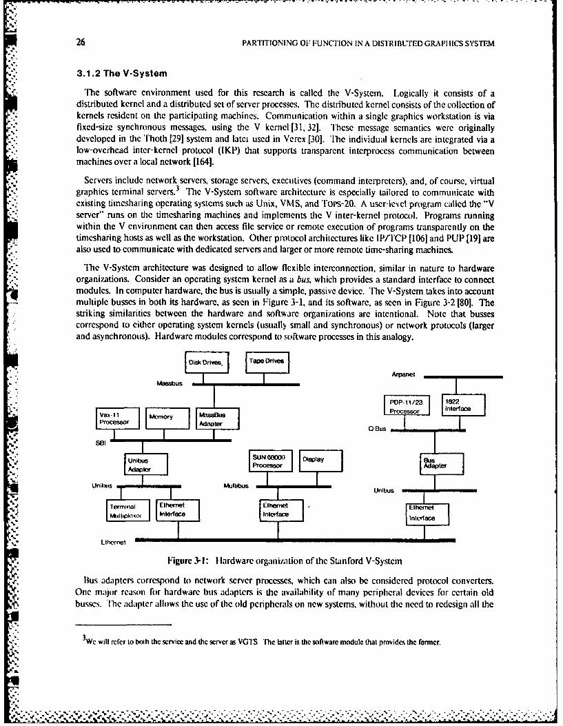
26 PARTITIONING OF FUNCTION IN A DISTRIBUTED GRAPI I ICS SYS"TEM
3.1.2 The V-System
The software environment used for this research is called the V-System. Logically it consists of adistributed kernel and a distributcd set of server processes. Thc distributed kernel consists of the collection ofkernels resident on the participating machines. Communication within a single graphics workstation is viafixed-size synchronous messages, using the V kernel [31, 32]. These message semantics were originallydeveloped in the Thoth 129] system and latei used in Verex [30]. The individual kernels are integrated via alow-overhead inter-kernel protocol (IKP) that supports transparent interprocess communication betweenmachines over a local network [1641.
Servers include network servers, storage servers, executives (command interpreters), and, of course, virtualgraphics terminal servers.3 The V-System software architecture is especially tailored to communicate withexisting timesharing operating systems such as Unix, VMS, and ''OIs-20. A user-level program called the -Vserver" runs on the timesharing machines and implements the V inter-kernel protocol. Programs runningwithin the V environment can then access file service or remote execution of programs transparently on thetimesharing hosts as well as the workstation. Other protocol architectures like IP/TCP [106] and PUP [19] arealso used to communicate with dedicated servers and larger or more remote time-sharing machines.
The V-System architecture was designed to allow flexible interconnection, similar in nature to hardwareorganizations. Consider an operating system kernel as a bus, which provides a standard interface to connectmodules. In computer hardware, the bus is usually a simple, passive device. The V-System takes into accountmultiple busses in both its hardware, as seen in Figure 3-1, and its software, as seen in Figure 3-2 [801. Thestriking similarities between the hardware and software organizations are intentional. Note that bussescorrespond to either operating system kernels (usually small and synchronous) or network protocols (largerand asynchronous). Hardware modules correspond to software processes in this analogy.
Disk Drives. Tape Drives
Massbus
SUNs u 0000 Iis1/2yPProcessor
Uness Memoryu
'II
on--es I ,-I I Idpe
Adaptner
Figure 3-Y: lardware organizaion of the Stanford V-System
Bus adapters correspond to network server processes, which can also be considered protocol converters.One major reason for hardware bus adapters is the availability of many peripheral devices for certain oldbusses. The adapter allows the use of the old peripherals on new systems, without the need to redesign all the
3We will refer to both the service and the server as VGIS, The Litter is the software module that provides the fomer.
4.
V4.-- -
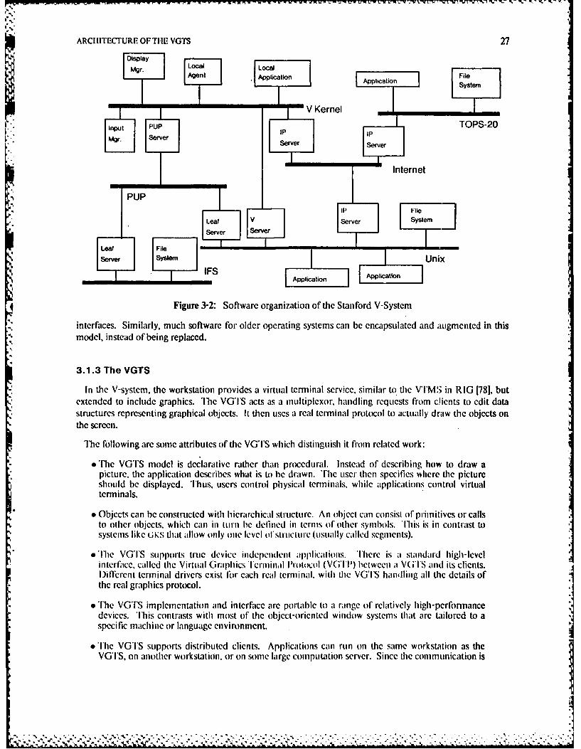
ARCI 11TECTURE OF THE VGTS 27
AetApplication Application Fysem
V InSerne
PUPTOPS-20
" File
SIUnix
interfaces. Similarly, much software for older operating systems can be encapsulated and augmented in thismodel, instead of being replaced.
3.1.3 The VGTS
in the V-system, thc workstation provides a virtual terminal service, similar to the VTIMS in RIG [78], butextended to include graphics. Tlhe VG'I'S acts as a multiplexor, handling requests from c~ients to edit datastructures representing graphical objects. It then uses a real terminal protocol to actually draw the objects onthe screen.
The following arc some attributes of" the VG'I'S which distinguish it from related work:The VGTS model is declarative rather than procedural. Instead of describing how to draw a
picture, the application deribes what is to be drawn. the user then specifies where the pictureshould be displayed. hus, users control physical terminals, while applications control virtualterminals.
* Objects can be constru~cted with hierarchical structure. An object catn consist of primitives or callsto other objects, which canin pturn e defined in terms of other symblols. Ihis is in contrast tosystenms like U KS' that allow only one level of'.strtrcl' (usually caled segment~s).
T he VGlTS supports true dcvice indepen|dent al)plicatlionS. TIhere is a standard high-levelinterface, called the Virtual Grgrhics l'erminh Protocol (VG'II) letween a Vre l'S and its clients.I)ileprnt terminal drivers exist for each real terminal, with rte VG'IS handling all the details ofthe real graphics protocol.
The loig arismelnatibnanuites rae arS whchdtingui t freom" relatiey hiwprk: nnn
devices. This contrasts witll most of the object-oriented window systems that arc tailored toaspecific machine or language environment.
* The VG'S supports distributed clients. Applications can run on the same workstation as theVG TS, on another workstation, or on some large computation server. Since he commlunication is
specific machi e or l n .u g.- --. - - .I
28 PARTITIONING OF FUNCTION IN A DISTRIBUTED GRAPI IICS SYSTEM
at a high level, the different machines may have vastly different architectures. If the application iswritten in a suitable high-level language, the same source code is used in any location.
* A single user can access several different applications simultaneously. The user can switchcontexts between these applications quickly and easily. Because of the ease with which
|-" applications can be distributed (the previous point), they can be using the local workstation orremote computing servers at the same time.
These last two aspects are the major influence of the distributed heterogeneous environment on the VGTS.Timesharing is effective when many users must share a computing resource; since current trends indicate that
*the user is quickly becoming the most important resource, we can extrapolate the philosophy that users aremore important than machines, and have one user being served by several different computing resources.
3.2 The User Model
In the modern distributed system environment, we require access to a variety of applications, distributedliterally throughout the world. We would like to take advantage of the power of advanced workstations toprovide a high-quality user interface to these resources. 1'he ideal interface must take into account fourfundamental principles:
1. The interface to application programs should be independent of particular physical devices orintervening networks.
2. The user should be allowed to perform multiple tasks simultaneously.
3. The corrmmand interaction discipline should be consistent and natural.
4. Response to user interaction should be fasL
The first principle has led to work in virtual terminals and device-independent graphics packages; thesecond to work in window systems: and the third to work in what has recently been called user interfacemanagement systems [143], the most common examples of which are command languages. Without adheringto the fourth principle, however, much of the other work is moot. Ideally, human users should never have towait for the computers: the computers should wait for the user. In a distributed environment, in particular,the supporting network protocols cannot incur inordinate overhead.
3.2.1 The Ideal
In view of these principles, consider the following user model. When users boot a workstation theycommunicate with a view mnanager4, which allows users to authenticate themselves and initiate one or moreaclivitics. "lIh,- activities may rn local to the workstation or remote. They may be written with the particularworkstation in nitd, or run in "terminal emulation" mode. They may require I/O modalities other thantraditional one-dimensional tcxI: graphics or audio. for example.
Each activity may be associated with one or more separate, device-independent virtual terminals (V'I). AV I may be created by the user or by the activity itself. Each VT may be used to emulate a different type of'ft.
-i real terminal, for example, a page-mode VI-100 or a 3-13 graphics terminal. Thus, while consistency isencouraged, the user is still able to access all resources to whidi he previously had access.
Unfortunately many similar systems refcr to this component as the window manger, even though this Ls incorrect with respect to mostterminology.
I ft " -ft ,,, , " -="'" "' . r i ' ' "..:% ,- - =- ' ' ' , " . :- " , """ . , ' ', , """ . " - -- ,- -' ' .," '
ARCI ETL CI'URI01:F TI" VGTS 29
When users wish to initiate a new activity, they must first create a new executive. l'he executive acts as acommand interpreter from which desired activities may be initiated. Users can create a new executive, withan associated VT, or terminate an existing activity and VT at any time, that is, totally asynchronous to anyother activities. When a particular activity requires additional virtual terminals, it is free to create them.These Vi's will be deallocated when the activity terminates.
Virul terminals are mapped to the screen when and where the user desires. In fact, multiple screens areintentionally allowed by the architecture, since in many applications color or gray-scale is desired, but highresolution color monitors are expensive. Thus a workstation may have, for example, one low resolution colormonitor and one high resolution monochrome monitor. Fach mapping ofa ViT to the screen is termed a view.When an activity creates a new VT, it prompts the user to specify the default view interactively, or the viewmanager cleates the view automatically, depending on user preference for screen layout. Thereafter, usersmay create as many additional views as they wish. They may manipulate views of the same VT independentof all other views of that VT, for example, to pan or zoom the view.
'he interaction discipline across VTs (and hence activities) is as consistent and natural as possible. Themechanisms for moving between VTs and reorganizing the screen are standardized in the view manager.Standard editing facilities permit the user to copy text or graphics from one VT to another. A standardcommand interpreter enforces consistent command interpretation across applications. A variety ofinformation presentation facilities arc provided to allow the user to view and manipulate data as desircd. Infact, different representations of the same data should be viewable with different formats, such as bar chartsof data contained in columns of numbers.
Ultimately. the executive mentioned above could evolve into an intelligent agent that manages the user'sdistributecd resources in much the same way a traditional command language interpreter manages a singlesystem's resources [78]. Then and only then would the user be totally unaware of where the activities areactually being executed - local to the workstation, on remote hosts, or distributed dynamically between somecombination of workstations and hosts.
3.2.2 Reality
This thesis focuses on virtual terminal management issues, with particular emphasis on distributed graphics.The resulting workstation software will be relbrred to as the Virtual Graphics Terminal Service (VGTS).Below we will consistently use the term virtual graphics terminal (VGT) in place of virtual terinal todistinguish it from more traditional work in network virtual terminals and window systems described in theprevious chapter. The VGSTS contains both a graphics package and a window system, as modules in theimplementation to be described in Chapter 4.
Although we have not solved all the problems of command interaction, simply in order to manipulate thescreen we have developed a reasonable command interface - for creating, destroying, and rearranging VGTs;managing executives: zoom ing, etc. In addition, many of the common command interaction techniques, suchal menus aid forn1s, require graphical support, which the VGTS is can provide. In short, the VGTS providesthe ficilities necessary to experiment with a variety of dinllrent command interfaces. 'l'his distinction betweenterminal management and command interfaces follows from previous work and is consistent with the recenttrend towards user interface management systems [78, 143]. The rest of this chapter describes the VGTSarchitecture in detail.
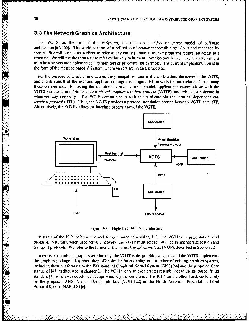
30 PARTITIONING OF FUNCTION IN A DISTRIBUTEID GRAPI IICS SYSTEM
3.3 The NetworkGraphics Architecture
The VGTS, as the rest of the V-System, fits the classic object or server model of softwarearchitecture [67, 155]: Thc world consists of a collection of resources accessible by clients and managed byservers. We will use the term client to refer to any entity (a human user or program) requesting access to aresource. We will use dhe term user to refer exclusively to humans. Architecturally. wc make few assumptionsas to how servers are implemented - as monitors or proccsses, for example. The current implementation is inthe fonn of the message-based V-System, where servers are, in fact, processes.
For the purpose of terminal interaction, the principal resource is the worksuation, the server is the VGTS,and clients consist of the user and application programs. Figure 3-3 presents the interrelationships amongthese components. Following the traditional virtual terminal model, applications communicate with theVGTS via the terminal-independent virtual graphics tenninal protocol (VGTP). and with host software inwhatever way necessary. The VGTS communicates with the hardware via the tcrminal-dependent realterminal protocol (RTP). Thus, the VGTS provides a protocol translation service between VGTP and RP.Alternatively, the VGTP defines the interface or semantics of the VGTS.
Application
Workstation Virtual Graphics
Terminal Protocol
Real Terminal
potxool VGTS Application-il
)" 16 VGTP
SVGTP"'.. ,,mnmmm
Application
21A User Other Services
Figure 3-3: High-level VGTS architecture
In terms of the ISO Reference Model for computer networking l1631, the VG'I is a presentation levelprotocol. Naturally. when used across a network, the V('IP must be encapsulated in appropriate session andtransport protocols. We refer to the former as the network graphics prolocol(NG 11). described in Section 3.5.
In terms of traditional graphics terminology, the VGTP is the graphics language and the VGTS implementsthe graphics package. Together, they offer similar functionality to a number of existing graphics systems,
.n' including those con forming to the ISO standard Graphical Kernel System (G KS) 1641 and the proposed Coresta ndard 11471 as discussed in chapter 2. The VGTP hears anoi even grea er resenblanlce to the proposed PIIIGSstandard 141. which was developed at approximately the same time. The R'II, on the other hand, could easilybe the proposed ANSI Virtual ICvice Interface (VI)I1221 or the North American Presentation Level
- *~ Protocol Syntax (NAPLPS) [61.S'2.
-' 4-
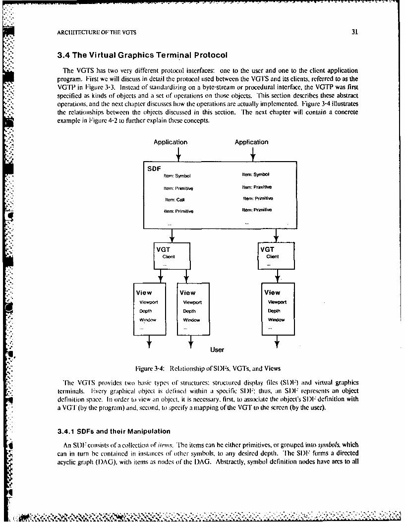
ARCI IlTECTURE OF TIlE VGTS 31
3.4 The Virtual Graphics Terminal Protocol
The VGTS has two very different protocol interfaces: one to the user and one to the client applicationprogram. First we will discuss in detail the protocol used between the VGTS and its clients, refcrred to as theVGTP in Figure 3-3. Instead of standardizing on a byte-stream or procedural interface, the VGTP was firstspecified as kinds of objects and a set of operations on those objects. This section describes these abstractoperations. and the next chapter discusscs how the operations arc actually implemented. Figure 3-4 illustratesthe relationships between the objects discussed in this section. The next chapter will contain a concreteexample in Figure 4-2 to firthcr explain these concepts.
Application Application
SDFItem: Symbol Item: Symbol
Item: Primitive Item: Primitive
Item: Call Item: Primitive
Item: Primitive Item: Primitive
SVGT VGT
t lent
View View Viewviewport viewport Vlewporl
Depth Dpth Depth
Window Window Window
~User6.
Figure 3-4: Relationship of SI)F's, VGTs, and Views
'lie VGITS provides two basic types of structures: structured display files (SI)F) and virtual graphicsterminals. Every graphical object is defined within a specific SI)F: thus, an SI)F rcpresents an objectdefinition space. In order to view an object, it is necessary. first, to associate the object's SI)F definition witha VGT (by the program) and, second, to :pccify a mapping of the VGT to the screen (by the user).
3.4.1 SDFs and their Manipulation
An SI)F consists of a collection of in s. The items can be either primitives, or grouped into symbols, whichg can in turn be contained in ilnstLlnces of other symbols, to any desired depth. The SI)F forms a directed
acyclic graph (I)AG), with items as nodes of the )AG. Abstractly, symbol definition nodes have arcs to all
32 PARTITIONING OF FUNCTION IN A DISTRIiUTErD GRAPIIlCS SYSTEM
their component items. Symbol call nodes have arcs to the symbol definition node, and primitive itemscorrespond to leaf nodes.
An SIF is similar to a segment network in PluGS, while an item is equivalent to an element [4]. An SDFmay also be thought of as a symbol sysiemn [56). Items arc named by identifiers chosen by the application, aretyped, and have type-dependent attributes. The ranges of these identifiers and attributes will be discussed inSection 4.3. Item types include:
* line* (filled) rectanglee (filled) polygon
* . bitmap* text (in arbitrary fonts)9 (filled) spline• symbol definition* symbol call
All items are defined within a 2 dimensional integer world coordinate space. Translation is the only modelingtransformation permitted on "called" symbols. All other transformations, such as rotation or projection fromhigher dimensions, are presently handled by the application program. Attributes are specified as indices intotype-specific aitribute tables similar to the bundled attributes of GKS. However, these attribute tables areshared by all VGTs and managed by the VGTS in its role as mediator between simultaneous applications. Incontrast, ( KS allows the single application to control the bundle tables. VGTS attributes are specified (at
V]. least indirectly) on each item, not inherited from calling symbols, as they are in PIIIGS, for example, or set bymodes.
A client can create and delete structured display files, symbols, or items. It may edit symbols, and obtain orchange the properties of an item. The following functions are provided to manipulate the SDF:
N, CreateSDFO =)sdfCreate a structured display file, and return its identifier in sdf This must be done before any symbolsare dcfined.
DeeteSDF(sd)Return all the items defined in the given sdfto free storage.
DefineSymbol (df ilen, namne)Enter a symbol into the symbol table, and open it for editing. The sdf is one returned from a previousCreateSDFcall. item is an application-specific integer identifier for the symbol and iamne is an optionalstring name.
EndSymbol (sdf. item. vg)Close symbol item in sdfso no more items can be changed, and cause the vgt to be redrawn to reflect thenew sj: Called at die end of a list of items defining a symbol, started with CreateSymnol orIditSynboL
EditSymbol(sdf item)Open existing symbol item in sdf for modification. This has the effect of calling DefineSymbol andinscrting all the already existing entries to the definitions lisL 'lie editing process is ended in the sameway as the initial definition process: a call to EndSymboL
DeleteS.Ynbol(sdf item)Delete the definition of symbol item from sdf Any dangling instances of this symbol, created byAddCall. will remain, but will contain nothing.
P, IN.'. "
ARCIIITECIURE OFTHE VGTS 33
AddCall(sdf item, offset, calledSymbol)Add an instance of calledSymbol to the currently open symbol in the sdf The instance is given thename item. The called symbol's origin will be placed at offset in the calling symbol's coordinate space; itis not windowed or transformed in any other way. This is equivalent to a move call unit in Sproull and'1homas's structured format protocol [1261. or an Execute call in NGS, as opposed to a Copy call. Thatis, changing the symbol definition changes all instances. This is more like a subroutine call than a macroexpansion.
Addlten (sdf item. extent. type. attributes. typeData)Add an item to the currently open symbol in the sdf giving it the name item. extent specifies thebounding box of the item in its coordinate space. type and attribute determine the type and attributesrespectively. t'pcl)ata contains any other data needed to define the item, such as the control points fora spline item or the text string for a text item.
Deleteltem (sdf item)l)elete item from the currently open symbol definition in sdf
Inquireltenm (sdf. item) =) extent. type. attributes, tvpeDataReturn the parameters for item in sdf
InquireCall (sdf item) =) calledSymbolReturn the item name, calledSymnbol, of the symbol called by the item in sdf
Changeltein (sdf item. extent, type, attribute, type Data)Change the parameters of an already existing item in sdf This is equivalent to deleting an item and thenreinserting it, so the item must be part of the open symbol.
3.4.2 VGT and View Management
Once the VGI'S client has defined some graphical objects, the client or the user needs to provideinfonnation on how the objects should appear. The VG'S lets a user see objects in any VGT anywhere onthe screen in views. Each view has a zooin factor, a window on the world coordinates of the VGT. and screencoordinates which determine its vicwport. Thus, a view defines a particular viewing transformation directlyfrom world to device coordinate space. No interniediate transformations, such as normalized devicecoordinates, are visible to the client.
Although the client can create default views, the user can change them with the view manager, and createand destroy more of them. Ia.-ch VGT can exist in zero or more views, but each view has exactly one VGTassociated with it. tach VGT is associated with at most one SIF, but each SIF may be associated with L
several VGTs. Symbol definitions are shared between VGl's that have the same Sl)F. Thus one VGT candisplay at its top level a symbol that appears as a called instance at a lower level in some other symbol inanother VGT.
Functions (br clients' manil)ulation of VG's and views include:
Create VGT(ype. name. sdf itein) -) vgtCreate a VGT of type type and return its identifier in vgt. name is a client-specified symbolic name forthe VGT that may be used later to select that VGT for input. item in sdfis placed as the top-level item I%in the VGTl: it can be .ero to indicate an initially blank VGT. The type can be some combination ofText, Graphics, and Zoonmable.
Destroy VGT (gt)I)estroy the given vgt and all the associated views.
El
t.-'.r ,' .... ..... ....'-A . . . . .. . . . . . . .
.".j , - 2 ''_ ,J, _k .j.- . q ... " '" -'#' ," " '' '" . "... . . . ..-.. . . .-.. . . . . . . . . . . . . . . . . .-.. . . . . . . . . . . .I" " P - . ."' ' _'. [
34 PARTITIONING OF FUNCTION IN A DISTRIBUTED GRAPHICS SYSTEM
DefaultView (vgi, width. height. wXmin, wYnin zoomi, showGrid) =) width, heightCreate a view of the given display, with the user determining the position on the screen with thegraphical input device. width and height give the initial size of the view: non-positive values indicatethat the user should determine the size dynamically, in which case the selected values arc returned.wXmin and wYmin are the world coordinates to map to the left bottom corner of the viewport: theamount of the world actually viewed depends on the size of the viewport and the zoom factor. Thezoom factor is the power of two to multiply world coordinates to get screen coordinates; it may benegative, to denote that a view is zoomed out. Views are not otherwise transformed. If showGrid is set,a grid of points is displayed in the viewport.
To display a new graphical object in a VGT after the VGT is created, either the old top symbol can beedited, or a new symbol can be defined and the following function called:
Displayltem (vgt. sdf item)Change the top-level item in vgl to be item in sdf The new item is displayed in every view of the VGT.
DefaultView executes an implicit Displayltem after creating the view. EndSymbol may also cause output toappear after (re)defining a symbol, although the VG°I'S redraws only the part of the view that has changed inthis case. 'he VGTS implementation is also free to perform other optimizations, such as only drawing theadditional items if the only changes before an EndSynbol are adding top-level primitives. Using thesefunctions, the VGTS client can achieve the effect of deferral modes for graphical output, including:
batch Construct the graphical object in its entirety and then display it, by executing aDefineSymbol or EditSymboL many AddItem calls, followed by an EndSymbol call. Thiscorresponds to creating an invisible segment and making it visible, or using the At SomeTime deferral mode in GKS.
incremental Construct and display the object "on the fly", that is, display each primitive item (eachvector, for example) as it is added to the object, by repeatedly executing an Edi1SymnboLAddlient EndSymbolscquence. This corresponds to creating a visible segment, using the AsSoon As Possible deferral mode in GKS.
*The latter approach may achieve better response, and is the normal mode of operation for most traditionalgraphics systems. HIowever, as results will show, the former method usually achieves higher throughput, andis the norm for programs using the VG'I'S.
3.4.3 Input Event Management
Since the VGTS was designed to support multiple simultaneous clients, it must decide which client receiveswhich input events. This is called input demultiplexing. and naturally occurs on a VGT basis. 'llie followingfinctions are available for graphical input:
GetEvent (vgt. evcnaAhsk) > eaentl)e.criptorWait for an input event to occur with respect to tie indicated vgt and return a variant record ineventDescriptor that describes the event. The record will contain the type of the event and the relevanttype-dependent information. eventMask specifies the acceptable types of input events: keyboard ormouse. 'lhe mouse events subsume button and locator devices of GKS, returning the buttons pressedand the location in virtual coordinates within the vgt. The first event in any of the indicated classes tooccur is returned.
FindSelectedObject (evenlDescriptor. search Type) =) item. edgeSelGiven an event descriptor as returned by GetEvent. return the item of the smallest object near theevent, and a set of (I eft, Right, Top. Bottom) edges which the event was near.
ARCIIITCI'URE OF THE VGTS 35
GetGmphicsStatus (vgi) = ) statusReturn the status of the graphical input device with respect to the indicated vgl including buttonspressed and location. As a side cffect, the event queue is cleared of any outstanding graphical events.
PopUp (nenu) = > selectionDisplay a menu of choices at the cursor position, consisting of an array of strings, to the user. When theuscr selects a particular item, retun the array index in selection. This is similar to the GKS choicedevice.
GetEvent and GetGraphicsSratus together provide the functionality of the GKS input modes. The VGTSmaintains an event queue for each VGT: all keyboard and mouse events related to that VGT are queued in thesame queue, in First-In-First-Out order. Thus the event mode of GKS is supported for both the keyboardand mouse through GetEvent. Pick device functionality is obtained from the indSelectedObject function,which is similar to request mode of GKS. GetGraphicsStatus allows the mouse to operate in sample mode.Sampling of the keyboard is not supported, since such a capability would be quite device dependent.
Keybo.,rd input is always associated with some VG' group. Each VGT belongs to exactly one group, and agroup typically corresponds to an activity (although an activity can create multiple groups). T7he groups areidentified by their master, which receives keyboard input when the group is selected through the userinterface. The next section describes the textual output interface, provided so the simple symmetric model ofstandard tcrminals can be used for echoing keyboard input.
3.4.4 Text Terminal Emulation
The VTS supports a text VGT mode optimized for page-mode terminal emulation. Specifically, anapplication may treat a VGT as a standard ANSI terminal [I]. such as a DEC Vl'-100. Such an applicationneed not know anything about the graphical facilities of the VGTP, and may use the ANSI terminal protocolto communicate with the VGTS. including escape sequences for cursor control. Output to the VG' is storedin a pad1771, which is a symbol within an SDF. The symbol consists of a linear array of simple text items,
", each of which represents one line.
" Note that the terminal emulation output interface is of a different nature firom (and therefore,unfortumntely, incompatible with) the graphics interface as discussed above. I lowever, this does not prevent amixed text and graphics application. One particular type of graphics item is text, permitting a client to easilyintegrate text and graphics within a graphics VG'. The terminal emulator interface is provided to optimizeperformance for a typical special case.
The VGTS architecture provides several advanced features for the support of keyboard input processing.Applications can operate in "raw" mode, or selectively enable any of the following features:
I ocal Fcho This allows instant response to keyboard input, providing useful feedback to users ofpotentially loaded timesharing systems.
Line Editing Programs that interact on a line-by-line basis, such as the executive, can cause lines to bebuffered (and usually echoed) inside the VGl'S. Sophisticated editing commands areavailable on the line buffer, and the executive (for example) can "stuff" previous commandlines into the line buffer. in conjunction with its history mechanism.
Paged Output When this mode is in effect, the VGTS will block output requests larger than one page. Amessage is displayed in the banner, and the user types a command to unblock when ready.
Graphics Escapes Inside a pad, when connected to some remote hosts through a TFNI. I' program, graphicalinput events can send escape sequences back to the application. This allows many useful
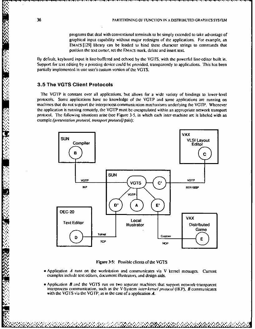
36 PARTITIONING OF FUNC[IION IN A DISTRIBUTFED GRAPlIlCS SYSIrEM
programs that deal with conventional terminals to be simply extended to take advantage ofgraphical input capability without major redesigns of the applications. For example, anEMACS [129] library can be loaded to bind these character strings to commands thatposition the text cursor, set the EMACS mark, delete and insert text.
By default, keyboard input is line-buffered and echoed by the VGTS, with the powerful line-editor built in.Support for text editing by a pointing device could be provided, transparently to applications. 'his has beenpartially implemented in one user's custom version of the VOT'S.
3.5 The VGTS Client Protocols
The VG'I'P is constant over all applications, but allows for a wide variety of bindings to lower-levelprotocols. Some applications have no knowledge of the VGTP and some applications are running onmachines that do not support the interprocess communication mechanisms underlying the VGTP. Wheneverthe application is running remotely, the VGTP must be encapsulated within an appropriate network transportprotocol. The following situations arise (see Figure 3-5, in which each inter-machine arc is labeled with anexample (presentation protocol, transport protocol) pair):
VAXSUN VLSI Layout
Compiler Editor
;-" ".SUN
voTP vGTP
IKP RTP/BSP
DEC-20
SText Editor LocalVAIllustrator Distributed
GameDene CustomE
TCP NOP
Figure 3-5: Possible clients of the VGTS
* Application A runs on the workstation and communicates via V kernel messages. Currentexamples include text editors, document illustrators, and design aids.
e Application B and the VG'IS run on two separate machines that support network-transparentinterproccss communication, such as the V-System inter-kernwl protocol (I K P), B communicateswith the VGIS via the VGIP, as in the case of a application A.
S.,. - " " . '.- -"-""" - " * -,,"",V" "
" .i"." o
.. . . ;......€. ----V -' .-- "-'- -, ' w . - ,."_'.- '
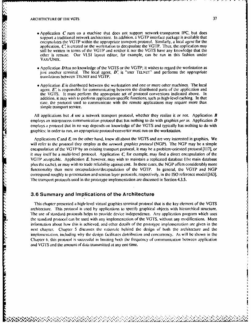
ARCITICTURE OFTII! VGTS 37
* Application C runs on a machine that does not support network-transparent IPC, but doessupport a traditional network architectfire. In addition, a VGTP interface package is available thatencapsulates the VGTP within the appropriate transport protocol. Similarly, a local agent for theapplication, C' is created on the workstation to decapsulate the VGTP. Thus, the application maystill be written in terms of the VGTP and neither it nor the VGTS have any knowledge that theother is remote. Our VLSI layout editor, for example, can be run in this fashion underVAX/UNIX.
,* . Application D has no knowledge of the VGTS or the VGTP; it wishes to regard the workstation asjust another terminal. The local agent, D, is "user EILNLE1" and performs the appropriatetranslations between TELNEr and VGTP.
* Application E is distributed between the workstation and one or more other machines. 'lhe localagont. E' is responsible for communicating between the distributed parts of the application andthe VGTS. It must perform the appropriate set of protocol conversions indicated above. Inaddition, it may wish to perform application-specific functions, such as high-level caching. In thatcase, the protocol used to communicate with the remote applications may require more thansimple transport service.
All applications but A use a network transport protocol, whether they realize it or not. Application Bemploys an interprocess communication protocol that has nothing to do with graphics per se. Application Demploys a protocol that in no way depends on knowledge of the VGTS and typically has nothing to do withgraphics: in order to run, an appropriate protocol-converter must run on the workstation.
Applications Cand E, on the other hand, know all about the VGTS and are very interested in graphics. Wewill refer to the protocol they employ as the network graphics protocol (NGP). 'he NGP may be a simple
* encapsulation of the VGTP by an existing transport protocol, it may be a problem-oriented protocol [1171, orit may itself be a multi-level protocol. Application C, for example, may find a direct encapsulation of theVGTP acceptable. Application E, however, may wish to maintain a replicated database (the main databaseplus the cache), or may wish to trade reliability against cost. In these cases, the NGP offers considerably morefunctionality than mere encapsulation/decapsulation of the VGTP. In general, the VGTP and NGPcorrespond roughly to presentation and session layer protocols, respectively, in the ISO reference model [163].
hle transport protocols used in the prototype implementation are discussed in Section 4.3.5.
3.6 Summary and Implications of the Architecture
This chapter presented a high-level virtual graphics terminal protocol that is the key element of the VGTSarchitecture. This protocol is used by applications to specify graphical objects with hierarchical structure.The use of standard protocols helps to provide device independence. Any application program which usesthe standard protocol can be used with any implementation of the VGTS. without any modifications. Moreinformation about how this is achieved, and other details of the prototype implementation are given in thenext chapter. Chapter 5 discusses the rationale behind the design of both the architecture and theimplcmentation. including why the design Icilitates distribution and concurrency. As will Ie shown in theChapter 6. this protocol is successful in limiting both the I'fcquency Of communication between applicationand VGTS and the amount of data transmitted at any one time.
hP
I

38 PARTITONING OF FUNCTION IN A DISTRIBUTED GRAPIliCS SYSTEM
4i
°-
.1' . 4" %N4\.4y - .t
AN IMPLEMENTATION OF THE VGTS 39
-4-An Implementation of the VGTS
The architecture described in the previous chapter is independent of any implementation. Programsdeveloped for one implementation of the VGTS should bc able to run with any other implementation, giventhe existence of the appropriate transport protocols. In this chapter we will first describe the organi/.ation ofone particular prototype implementation. This implementation actually adapts itself at run-time to severaldifferent varieties of workstations, and many modules can be used on other very difcrent workstations. Thetechniques used in this implementation to update the screen are discussed, followed by the client interface,and then the user interface. Finally. an example application program is described: a simple illustrationeditor.
4.1 General Organization
As noted in Section 3.2, the VGTS is only one component of the user interface software in the V-System.The other components are:
e the view manager* the exec server0 the executives* the application library
The view manager provides the means by which users can create, destroy, and modify the screen layout, aswell as create new executives. Executives represent instances of the same basic commaad interpreter, asdefined by the exec server. To create a new executive, the user communicates \ith the view manager, whichcommunicates with the exec server. he user may replace the exec server at any time. effeztively redefiningthe executive command interpreters. Logically, the view manager is another module that may be replaced.Ultimately, however, these components employ the services of the VGTS to communicate with the user.
In fact, the VGTS is merely an instance of a terminal agent. Hence. the user may also replace the VGTS atany time with simpler terminal agents, or other window systems. This facility permits a programmer todevelop new graphics facilities without having to constantly reboot his workstation. On the other hand, itprovides the mechanism by which the same user interface management system can communicate with asubstantially "reduced" terminal agent such as the simple terminal server (SIS), a subset of the VGTSarchitecture which runs on a simple text-only terminal [171.
4.1.1 VGTS Implementation Modules
At one more level of detail, each terminal agent is composed of multiple components. In particular, theVG'IS implementation consists ol'the following modules:
master multiplexor Handles all client requests by dispatching to the appropriate routine in other modules.Provides synchronization between all the possible clients, by recciving messages fromthem. The major part ol the operating system interface is contained in this module.
escape interpreter Monitors the incoming byte stream for graphics commands and calls the Sl)Fmanager to perform them. Other characters are passed through to the terminalemulator.
terminal emulator Interprets a byte stream as if it were an ANSI standard terminal [I]. Printable
V..
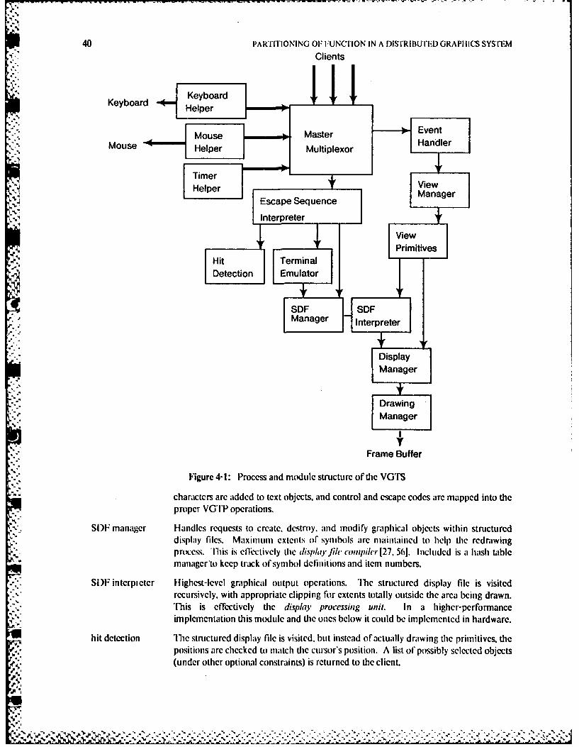
40 PARTITIONING OF:UNCrION IN A DISTRIBUTED GRAPHICS SYS'rEM
Clients
Keyboard Keyboard
Mouse 2 MasterEvent
, Mouse Helper Multiplexor Handler
TimerHelper +View
Escape Sequence Manager
InterFrt u
J'e-Hit Terminal itve
Deratcracdtio tcmtobjetaonroladecp oe r apdit h
SDF SDFSed e o a Manager mt.., Interpreter
dislayfils.Maxiiuniextntsof ynhol ar Displaye ohl i erwn
nManager
r s , h o tx tDrawingsi e e e lss Manager
p t h l h b Frame Buffer
hd iFigurc4-1: Process and m btule structure of te VG rS" characters arc added to text objects, and control and escape codes are mapped into the.:. proper VG'I'P operations.
SI)F manager Handles requests to create, destroy r and modify graphical objectl ited obructsndisplay files. Maxmns extents of symbols are lientained to help the redrawing
='" prt~m.. TIhis is ec,'tivcly (lie disphi)-fihe compih'r[27, 561. Included is a hash table.- - manager to keep track of symbol definitions and item numbers.
tm.-..Si)F interpietr Highecst-lvl graphical output operations. 'IV structured display file is visited". ' recursively, with appropriate clipping fo~r extents totally outside the area being drawn.-'- his is effectively die display processing unil. In a hiigher- performance"="',..implementation this module and the ones below it could be implemented in hardware.
A .
hit detection T-e structured display file is visited, but instead of actually drawing the primitives, the,'. positions arc checked to match die cursor's position. A list of possibly selected objects., .(under other option.Al constraints) is returned to die client.
%
AN IMPLEM[NTATION OF TIIE VOTS 41
event handler Handles the event queues, line buffering, and the blocking and unblocking of clientswaiting on events.
view manager Provides the user interface for screen management. Although this is logically a fairlyseparate entity from the lower-lcvcl functions of the VGTS, in the currentimplementation it is provided as a module which runs as a coroutine to the mastermultiplexor process.
view primitives Perform the view-changing operations. These are the operations invoked by the viewmanager, such as creating, deleting, and modifying views.
* .i display manager Low-level but possibly device-independent operations, such as handling theoverlapping viewports. Although this module does not do any frame bufferoperations directly, it uses several device-dependent parameters, such as the size of thescreen in physical coordinates. Also, some of these operations could be done inhardware on higher-performance graphics devices.
drawing manager Device-dependent graphics primitives called by the display manager. On the SUNworkstation, for example, these primitives manipulate the frame buffer. On otherlower-performance workstations this might be done by a separate process to preventthe multiplexor process from blocking for long periods of time.
input handlers Device-dependent modules for reading the keyboard and tracking the mouse. Thereis also a timer module to supply periodic messages to the multiplexor.
The relationships between these modules are illustrated in Figure 4-1. The general direction of control isindicated by the direction of the arrows. The higher level modules near the top of the figure call lower levelmodules near the bottom.
4.1.2 Team and Process Structure
"le V-System provided three techniques for structuring software: modules, processes, and teams.Modules are groups of functions that communicate through function calls and global variables. The kernelmanages independent concurrent processes, which communicate through messages or shared memory. Onlyprocesses on the same tcali share memory, separate teams are separate virtual address spaces. 'Ilie processstructure of the VGIS is also illustrated in Figure 4-1, by the presence of the thick arrows. The arrows aredrawn in the direction that messages are sent, from the sender to the receiver. The VGTS implementationconsists of four processes:
1. "lic keyboard helper process reads from the kernel console device and sends messages to themaster multiplexor.
2. Ilie mouse helper reads from the kernel mouse device and sends messages to the mastermultiplexor.
3. 'Ibc timer helper delays for , set period and sends timing messages to the master multiplexor.Several activities arc triggered by these messages, including a blanking of the screen after tenminutes if no other messages have been received.
*,- 4. "I'he master multiplexor process synchronizes all frame buffer operations, and performs most ofthe other functions.
Ihe low level interface to the console, mouse, and timer is implemented by the V kernel. Normal messagesare sent to a pscudo-proccss called the "device server" which will block until data is available. This blocking
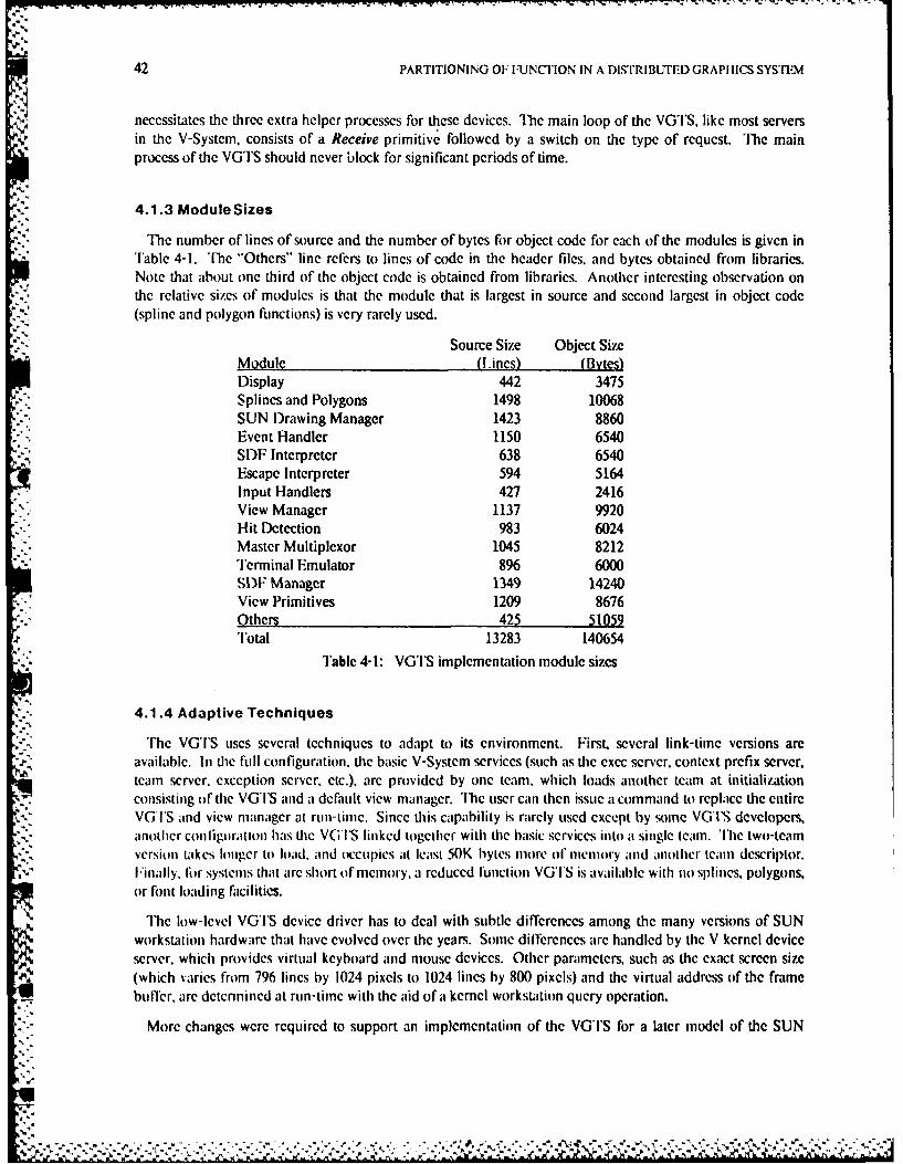
42 PARTITIONING OF FUNCION IN A DISTRIBUTED GRAPI ICS SYSTEM
necessitates the three extra helper processes for these devices. The main loop of the VGwTS, like most serversin the V-System, consists of a Receive primitive followed by a switch on the type of request. The mainprocess of the VGTS should never block for significant periods of time.
4.1.3 Module Sizes
The number of lines of source and the number of bytes for object code for each of the modules is given inTable 4-1. The "Others" line refers to lines of code in the header files, and bytes obtained from libraries.Note that about one third of the object code is obtained from libraries. Another interesting observation onthe relative sizes of modules is that the module that is largest in source and second largest in object code(spline and polygon finctions) is very rarely used.
Source Size Object SizeModule (lines) (Bytes)Display 442 3475Splines and Polygons 1498 10068SUN Drawing Manager 1423 8860Event Handler 1150 6540SDF Interpreter 638 6540Escape Interpreter 594 5164Input Handlers 427 2416View Manager 1137 9920Hit Detection 983 6024Master Multiplexor 1045 8212Terminal Emulator 896 6000SDV Manager 1349 14240View Primitives 1209 8676Others 425 51059Total 13283 140654
Table 4-1: VGTS implementation module sizes
4.1.4 Adaptive Techniques
The VGTS uses several techniques to adapt to its environment. First, several link-time versions areavailable. In the fill configuration. the basic V-System services (such as the exec server, context prefix server,team server, exception server. etc.), are provided by one team, which loads another team at initializationconsisting of the VGIS and a default view manager. The user can then issue a command to replace the entireVGIS and view manager al run-timc. Since this capability is rarely used except by some VGTS developers.another conliguration has the VGTS linked together with the basic services into a single team. The two-teamversion takes longer to load, and occupies at least 50K bytes more of memory and another team descriptor.FIinally. Ibr systems that are short of memory, a reduced function VGTS is available with no splines, polygons,or font loading facilities.
The low-level VGTS device driver has to deal with subtle differences among the many versions of SUNI* workstation hardware that have evolved over the years. Some differences are handled by the V kernel device
server, which provides virtual keyboard and mouse devices. Other parameters, such as the exact screen size(which varies from 796 lines by 1024 pixels to 1024 lines by 800 pixels) and the virtual address of the framebuler. are detennined at run-time with the aid of a kernel workstation query operation.
More changes were required to support an implementation of the VGTS for a later model of the SUN
AN IMPIMENIATION OF Till VGTS 43
workstation, called the SUN-2. Initially the single installed VGTS would query the kernel on start-up todetermine tie type of frame buffer and set a variable. This variable was tested before each primitive todetenriine which low-level graphics function to call. Although the run-time CPU overhead was acceptable,the memory usage of the combined version eventually prompted the split into separate versions for theSUN-I and SUN-2 frame buffers. Interestingly, the mere act of identifying device dependencies that hadcrept into modules that were previously thought to be device dependent, resulted in cleaning up theimplementation and marginally decreased the size of the original SUN-I implementation.
Additional techniques could be used for adaptation in future implementations of the VGTS. For example,if the V-System implemented virtual memory then the rarely-used modules could be page-faulted intophysical memory only when actually needed. l)ynamic linking could also be used to reduce the minimummemory requirements, at the expense of slightly more complicated inter-module linkages. l)ynamic linkingwould also require more complicated debugging tools, and possibly introduce reliability problems.
4.2 Screen Updating
This section discusses the techniques used for displaying objects, the end result of VGTS operations. Incontrast to many systems, the VGTS provides centralized rather than distributed control of screen updating.The next chapter, and in particular Section 5.4, will discuss the rationale behind this decision in greater detail.There are a fixed set of graphical primitives, executed under the control of the VGTS SI)F interpreter, displaymanager, and drawing manager, the lowest level modules in Figure 4-1. This centralized control eliminatesany possibility of applications interfering with each other. In fact, operations on the SUN frame buffercannot b. interrupted and restarted, so some kind of synchronization is necessary. Moreover, centralizedcontrol i the only reasonable approach for distributed applications. The user methods of object orientedwindow systems discussed in Chapter 2 rely on shared memory, which is not typically available in adistributed environment.
4.2.1 Implementing Overlapping Viewports
Originally. viewports were restricted to lie entirely on the screen and to not overlap. However, this provedto be inidequate, since screen space quickly filled Lip, and viewport manipulation commands often failed.mThe current implementation uses a novel scheme of dividing each viewport into visible non-overlapping
rectangles (called subviewports) whenever the screen layout changes. The viewports are redrawn byinterpreting the structured display file in each of the subviewporLs. [his has the advantage of no speedpenalty 1 6r updating views that are not obscured (the normal case). Views which have non-rectangular visibleportions may take longer to update for complicated SI)Fs, but almost always the actual drawing time is thedominating [mtor, which is proportional to the area being redrawn and independent of the shape of theregion. The resulting scheme is clean and simple.
One imimor advantage over systems that mainlin obscured bitmaps (such as Apollo I)omain 181, lIlitI ayers 110O51. mud Spice ian as 1131) is that no extra memory is required to store those obscured bitmaps. '[lle
SI)[ can represent extremely large objects in modest amounts of memory. As an example. consider the twooverlapping VicWports inl Figure 4-2. The SI)I data structures take up only a few hundred bytes, while thebitmap could nced many thousands of bytes. View number I lies on top, and is entirely on tie screen, so ithas only one subicwport, numbcr 1. View number 2 is partially obscured, so it has two rectangularsubvieports, numbers 2 and 3. lhe "banners" or labels on the top of each view are implemented asadditional subviewports. each displaying a single item: a string name, VGT number, optional view numberand zoom factor, and a string controlled by the application.
Another advantage of updating from the SI)F instead of from a bitmap, is that it is often actually faster to
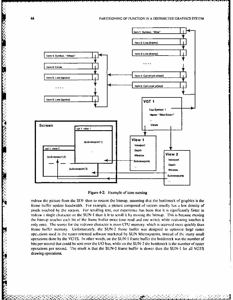
44 PARTITIONING OF FUNCTION IN A DISTRII1LTID GRAPHICS SYSITM
Ftem 1:S bol, "Bike"
Item 2: Line (frame)
Item 0: Line (spoke)VG 1
Top Symbol: 1
Name: "Bike Editor"
Screen ~ vgt 1 view 1 ~w
(subviewport 1) View 1Viewport
vqI 1 view 2Det
(subviewport 2)WidwVe 2
(subviewport 3)
Figure 4-2: Example of itern naming
rcdraw the picture from tic SDW than to restore thc bitmap, assuming that the bottleneck of" graphics is dieframe bulfer update bakidwidth. F'or exatmple. a picture composed of vectors usually has at low density ofpixels touched by tie vectors. For scrolling text, our expefiece has been that it is signiicantly fastcr toredraw aI sitngle character otn the SUN-I than it is to scroll it by tmoving the bitmap. 'I'his is because moving
* uthe bitmal) touches cach hit of' (le fr-ame bu I16r twice (one rcad and oiie write), while redrawing touches it* Only Once. TIhe sour-ce fo6r the redrawn character is main CPU memory. which is accessed more quickly thian* frame buffer memory. Unfortunately, the SUN-2 framne huller was designed to optimize large raster* ~~Opel tiOlls used itn the raster-orietited software marketed by SUN Microsystetms, instead of thc many smalld operationts done by the VG'IS. In other words, on dhe SUN-I frame buffer- the bottleneck wats the number of
bits per seccond that could be sent over the I/0 bus, while ott the SUN-2 the bottleneck is the number of raster* operations per second. 'The result is that the SUN-2 frame buffer is slower than the SUN-i for all VOTS
drawing operations.
AN IMPLEMENTATION OF THE VOTS 45
*, 4.2.2 Zooming and Expansion
The VGTS provides support for zooming and expansion depth that is independent of its clients. Zoomingconsists of redrawing the SDF with larger objects, not replicating pixels. Expansion depth, one of theattributes of each view, indicates how far down in the S)I to go when displaying a symbol. If the expansiondepth is less than the SIt tree height, an outlined box will be displayed at the appropriate point in place ofthe symbol. )epending on the size of the box, the text name of the symbol may al:,o be displayed. Views maybe zoomed and expanded independently such that a user may view an entire symbol in one view, for example,while simultaneously viewing a piece of the symbol in a zoomed-in view.
4.3 Client Interface
Before the techniques described in the last section can be used t,) display objects, the objects must bedefined by some client application program. The abstract objects and operations were discussed in theprevious chapter, Section 3.4. The details of the C language binding for this interface are discussed in theV-System Reference Manual, in the chapter on the graphics library functions [17]. This section discussessome important design choices taken in the prototype VGTS implementation regarding the client interface.
4.3.1 Item Naming
" Items within an SDF are named with 16 bit identifiers chosen by the application. It is assumed that the, application will maintain some higher-level data structures, along with the appropriate mapping to these.- internal item names. The item names are global to each SDF, but applications may also have several SI)Fs
for different name spaces. Item identifier- are referenced via a hash table, so there are no constraints on theirvalues 1731. Items that will never be referenccd can be given item number zero, and are never introduced intothe hash table. In practice. only a few "interesting" items are actually given non-zero numbers. Item
-" numbers can refer to both definitions of symbols and their instances. Symbols are also given string names,but these strings are only used for disambiguation during hit testing, or for displaying symbols at theexpansion depth. String names of symbols are not related to item numbers.
For example, a picture of a bicycle might define a symbol for a wheel. The item number of the top-level"bike' symbol could be 1, with 2 and 3 referring to other parts of the symbol. The definition of the wheelsymbol is given item number 4- [here may then be two instances (calls) of item number 4, which could begiven item numbers 5 and 6. The individual spokes ol' the wheel are components of symbol number 4, but are
- all given item number 0, since we will never want to refer to any of them individually. If it is desired to deleteor move any individual spoke, then each of these items may also be given numbers. Figure 4-2 on page 44
-. illustrates this example.
A
4.3.2 Representing SDF Items
Section 3.4 introduced some of the kinds of item types used in the VGTS. 'llie implementation uses acompact linked list of display records to represent these items internally. Fach item within an SIF has the
- following parameters:
Item A 16 bit unique (within the SI)F) identifier for this object, or zero. This identifier is" referenced by the client when performing editing operations.
Type One of the predefined types described below: either a primitive type or one to indicatestructure. Currently eight bits are allocated to this.
.4
46 PARTITIONING OFFUNCTION IN A DISTRIBUI"I',D GRAI'11CS SYS'IM
K. Typcl)ata Eight bits of type-dependent information, such as the stipple pattern index for a filledrectangle. Most attributes are storcd here, such as the font index for general text.
Xmin Minimum X coordinate of the extent. All coordinates are in "world" coordinates, stored as
signed 16 bit signed integers.
Xmax Maximum X coordinate of the extent.
Ymin Minimum Y coordinate of the extent.
Ymax Maximum Y coordinate of the extent.
Pointer Depending on the type, this is either a pointer to some data such as an ASCII text string, orfor symbol calls, a pointer to the called symbol.
Sibling All the component items within a symbol are linked together via this chain. This is acircular chain, as illustrated in Figure 4-2. Normally this relationship should not be visibleto the client, unless the client wants to step through a symbol definition in order.
Some of the meanings of the above fields depend on the type of the item. The following are the types ofitems that occur in structured display file records in the prototype implementation:
Filled Rectangle A rectangle filled with some texture. The TypeData field specifies the stipple pattern, orcolor on the IRIS system.
Horizontal Line Horizontal line from (Xmin,Ymin) to (Xmax,Ymin). Ymax is ignored.
.4. Vertical line Vertical line from (Xmin,Ymin) to (Xmin.Ymax). Xmax is ignored.
Point A point, which usually appears as a 2 by 2 pixel square at (XminYmin).
Simple Text A simple text string, with (Xmin.Ymin) as its lower left corner. This produces text in asingle fixed-width font that can be drawn very quickly. The values of Xmax and Ymaxneed not surround the text, but they are used as aids for redrawing, so should correspondroughly to the real extent.
General Line A generalized line, from (Xmin.Ymin) to (Xmax,Ymax). Note that Xmin etc. are slightlymisleading names. The SIW manager actually sorts the endpoints and calculates the extentcorrectly.
.4.
Outline Outline for a selected symbol. Xmin, Xmax, Ymin and Ymax give the box for the outline.The Typel)ata field specifies bits to select each of the edges: L.eftF-dge, RightEdge,'TopEdge or Bottoml-dge.
Text A string of general text, with a lower left corner at (Xmin,Ymin). The •l'ypcl)ata fieldspecifies the font number. Xmax is recalculated from the width information for the font.
Raster A general raster bitmap with a lower left corner at (Xmin.Ymin), and upper right corner at(Xmax,Ymax). The Typcl)ata field determines if the raster is written with ones as black orwhite. The pointer field points to the actual bitnap, in 16 bit-wide swaths.
Spline A spline object, optionally filled with a specified pattern. 'llie pointer field points to aSPIINE structure.
Filled Polygon A list of points which defines a polygon that can be optionally filled with a specifiedpattern.
U. . . , . . . -. - , -. . - • . , . .- -. .. ? . ,? ' - -- ., - -. . , -' , ,,
R- WW W WO 0 W V - -.- r' v - - - - -.
AN IMPLEMENTATION OF TI IE VGTS 47
Arcs A list of points defining a series of circular arcs. Although arcs can be very closelyapproximated by splines, this provides a simpler interface and faster implementation.
There are a few other types that are not visible to the user. For example,.symbol definitions and calls arerepresented as items with most of the same attributes.
4.3.3 Interface to V-System Protocols
The VGTS implements a subset of the standard V 1/O protocol [33]. Thus simple applications can write tostandard output and read from standard input, with no changes required when executing under the VG'IS,under the simple terminal server, or with input or output redirected to any other file. Pads arc created by thestandard request to create a ile instance, and destroyed by the standard request to release a file instance.
The VGTS also implements some of the operations in the V distributed naming protocol [341. When thestandard directory listing program is used to list the directory of the context named vgts, information aboutthe currently defined virtual terminals will be print,.d. Thus each virtual terminal is a named V I/O object.
4.3.4 Binding the VGTP to a Byte Stream
The finctions described in section 3.4 are all encapsulated in escape sequences to form a byte stream usinga very simple protocol. Each call causes a special flag character to be sent (the ASCII character called US, octal037) followed by a one-byte code indicating the function number. This is followed by each of the argumentsto the function, transmitted with the high-order byte first in each argument. Any return values are sent withthe same escape character followed by the bytes of the returned value, high-order byte first. Most parametersarc sixteen bit unsigned integers, requiring two bytes for each value.
This results in a very small number of bytes for common operations. As we shall see in the next chapter,this makes the protocol fairly insensitive to network speeds. A more ambitious project would have used anautomatic 'remote procedure call" generator 11021, but the manual method was sufficient for this project,since the functional interface did not change very often. An automatic RPC mechanism should not affect theperformance of applications, and in fact should be entirely transparent.
4.3.5 NetworkTransport Protocols
The encapsulation of the VGTP within transport protocols is illustrated in Figure 4-3. Dashed linesseparate library packages, solid lines separate programs, and arrows indicate network protocols. Allinteraction to die VG'IS is through the V Input/Output protocol (VIO), which provides a byte stream of datain terms of V incsages. 'Ilie i n te rp module decodes graphical operations out of this byte stream, providingthe server side of the remote procedure call Cacilily. The terminal emulator is also provided as a simple VIObyte stream interface. Clients use cither the VIO stream package, or the UNIX Std i o package. The stubsmodule encodes graphical ii lirmation on the standard output channel and decodes responses from standardinput
For distributed applications, one of three network transport protocols can be uscds:
1. PUP Tl.N- [191
5lioth i' Nur protocols are used as "transport" by remote VGTS clients, even though they are usually trealed as presentation-level inthe ISO hierarchy .hc distinction is in name only.
.. .......... .... ...... .................................................................... ... ...
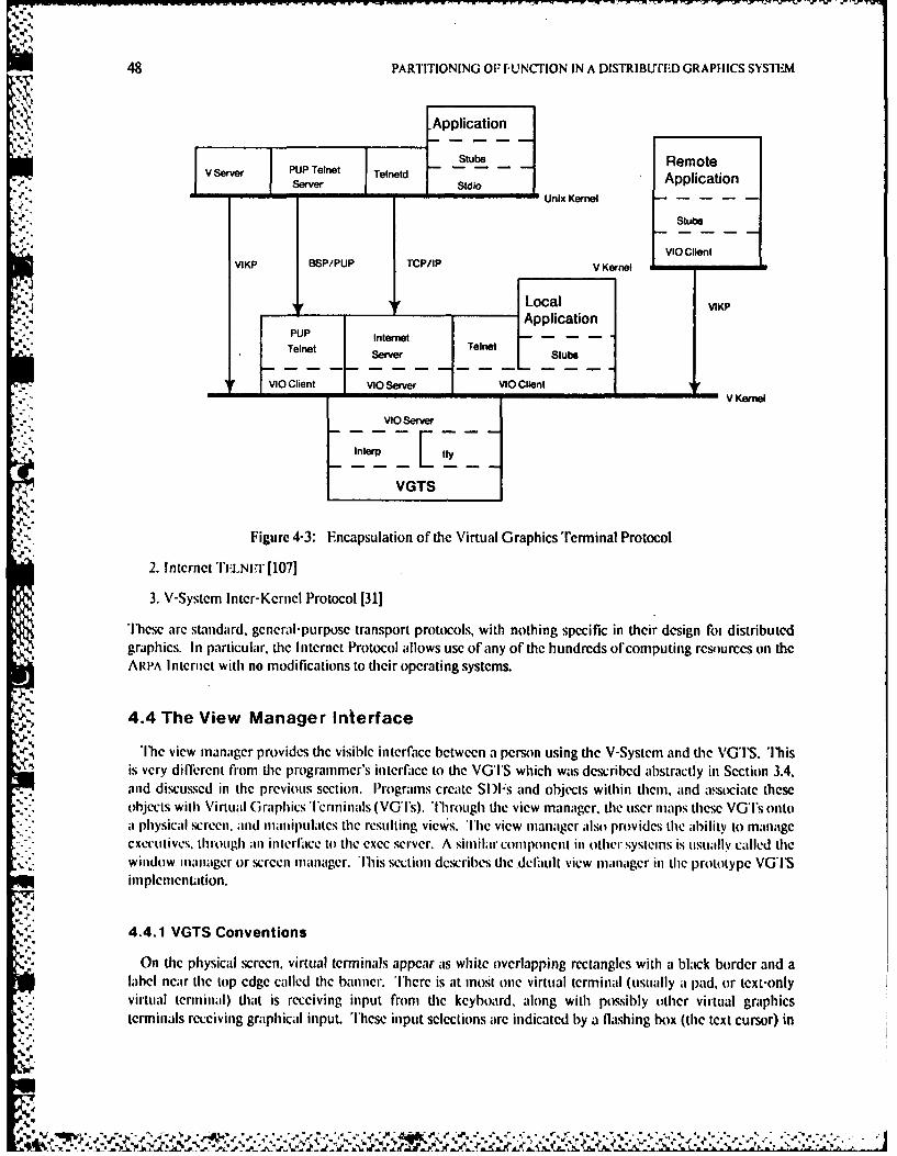
48 PARTITIONING OP -F-UNCTION IN A DISTRIBLYITD GRAPHICS SYSTEM
Application
V evr PUP Telnet -ent Stub Remote1 Srvr 1 Serverlnl Ski'o Application
Unix Kernel----
Stubs
VIKP BSP/PUP TCP/IP V Kernel F- Clen
+ tLocal VIKPApplication
PUP Internet---Telnet SevrTelnet Stb
IF VIO Clent VIO Server VIO Client VKre
VIO Server 42 VGTS
Figure 4-3: Encapsulation of the Virtual Graphics'Terminal Protocol
2. lntcrnctTIi'irr [1107]
3. V-Systcmn lntcr-Kcrncl Protocol [31]
Tccarc standard, general-purpose transport protocols, with nothing specific in their design Cot distributedgraphics. In particular, thc Internet Protocol allows usC of any of thc hundrcds of computing resources onl theARPIA lntrnict with no modifications to their operating systems.
4.4 The View Manager Interface
The view mnanager provides thc visible interface betwcen a person using thc V-System and the VGTlS. 'Iblisis very difilrcnit from the programmer's interfatce to the VGl'S which was described abstractly in Section 3.4,and discussesd in the previous section. Programs create Sl)1's and objects within themn, and associate these
hects with Virtual Graphics 'ermninals (VG'ls). Tlhrough tie view manager, the user miaps these VG's ontoa hsia crecn. and manipulates the resulting views hevwmaager also provides the ability to manage
exective, though an ilkrfilce to the exec server. A similar conipotienl in other sysicins is uisuallycle hwindo manger rcen manager. wbsscindsribes the deflult view mianager in the prototype VGTS
imnplementattion.
4.4.1 VGTS Conventions
On the physical screen, virtual terminals appear ats white overlapping rectangles with a black border and alabel near the top edge called the banner. 'Ibere is at most one virtual terminal (uisually aI pad, or text-onlyvirtual termninal) that is receiving input from the keyboard, along with possibly other virtual graphicsterminals receiving graphical input. These input selections are indicated by a flashing box (the text cursor) in
*~~*"~~ '*~"%' ' * .,Z
AN IMPLIM'-NTATION OF Ti I Il VGTS 49
the text virtual terminal, and a black label on all the views that are accepting input. Note that all virtualterminals are always active in the sense that any application may run or change the display in any virtualterminal at any time independent of these selections; selections only apply to input.
There arc a few conventions for using the mouse with the VGTS. A click consists of pressing any numberof buttons down and releasing them at a certain point on the screen. While the buttons are down there maybe some kind of feedback: usually an object that follows the cursor. The click is usually only acted uponwhen all the buttons are released, so if users decide they have made a mistake after pressing the buttons theycan slide the mouse to some harmless position before releasing the buttons. Holding all three buttons down isalso interpreted as a universal abort by most programs and the view manager. The click event is sent to theprogram associated with the view in which the event occurred (through its VGT).
Clicking the left or middle button Of the mouse in a non-selected virtual terminal will cause it to be selectedfor input. Views of selected pads will be brought to the top. The input pad can be changed by typing thecontrol up-arrow character (octal 036) followed by a single command character. The only commandcharacters interpreted by the VGTS are 1-9 to select the given pad for input.
Although the user can always create views, some are created by application programs. In particular.programs like the text editor will create a pad when a new virtual text terminal (pad) is desired. When aV-System program requests the creation of a pad. the cursor will change to the word "Pad". At this point, theuser holds down any button, and an outline of the view that will be created will be tracked on the screen. Theuser positions the view where desired, and releases the buttons. Other prompts can appear as cursor changesto denote that the next click will not be treated as normal input. Unfortunately such convenience featuresmake the view manager very device-dependent.
4.4.2 View ManagerMenus
The view manager menus can always be invoked by moving the cursor to the grey background area or any.' virtual terminal not selected for input (except in the banner area) and pressing the right button. The
following commands are available from the view manager menus:
Create View Creates another view of an existing VGT. Move the cursor to the desired position of anyone of the four corners for the new viewport. Hold any button down, and move the cursorto the diagonally opposite corner. An outline of the new view will iollow the cursor as itmoves with the button down. I.et the button up, and then point at the VGT that is desiredto be viewed with the left or middle buttons, or hit the right button and select the VGTfrom the mcnu. Normally this command is only used with graphics VGTs.
Delcte View One view is clicked and removed from the screen. If the last view of a VGT is deleted, itdoes not destroy the VGl or the process associated with it. It is still possible to createviews of the VGT by using the right button menu in the Create View command.
Move Viewport Pressing any builton selecis a viewport to move. While the btton is being held down, theoutline of the viewport will nlove, following the cursor. The button is released at thedesired position. None of the other view parameters are changed. A shortcut to thisfunction is obtained by pressing the middle button while pointing to the banner of thedesired viewport. lhe viewport outline will follow the cursor until the middle button isreleased.
Make Top Brings the view to the top. potentially obscuring other views. A shortcut to this function isobtained by pressing the left button while pointing to the banner of the desired viewport.
V.
,.
4P
50 PARTITIONING OF FUNCTION IN A DISTRIBUTED GRAPHICS SYSTEM
Make Bottom Pushes the view to the bottom, potentially making other views visible. A shortcut to thisfunction is obtained by pressing the right button while pointing to the banner of the view.
Exec Control Selects a submenu to create another executive, destroy an executive (and the teams runningin it), kill a program, or control paged output mode. When creating an executive, theoutline of the new pad will follow the cursor as the user holds the button down. The userlifts the button up at the desired position, or presses all three buttons to abort. A shortcutto the exec control menu is obtained by pressing both the middle and right buttons whilethe cursor points to the gray background or the display area of a viewport not selected forinpuL
4.
. Graphics CommandsS.,. Selects another menu of commands that are usually only applied to graphics views. A
shortcut to this menu is available by clicking the right and left buttons at the same timewhile the cursor points to the gray background or the display area of a viewport notselected for input. These graphics commands are described below:
- Center Window Click the position to become the center of the viewport. This command does not changethe position of the viewport on the screen, just the objects within the view. Normally thiscommand is applied only to graphics views.
Move Edges Push any button down next to an edge or corner, move that edge or corner to the newposition, and let the button up. The edge outline should follow the cursor as long as thebutton is held down. l)oes not move the objects being viewed relative to the screen.
Move Edges + ObjectSimilar to the previous command, but this one drags the underlying objects around withthe moved edge or corner. while the previous command keeps it stationary with respect tothe screen.
Zoom Invokes a zoom mode, indicated by a change in the cursor to the word "Zoom". Users canget out of this mode in two different ways: First, clicking the left or middle buttons whenthe cursor is inside a view of a pad returns from the view manager and selects that pad forinput. As a side effect tiat view is z1) brought to the top. Second, users can click the right
* . 4 mousc button to exit this mode. The cursor should change back to the normal arrow.
The left and middle buttons in zoom ,node zoom out and in respectively. 'lhat is, the leftbutton makes the objects look smaller, and the middle button makes them look larger. Ashortcut to this mode is available by clicking the middle and left buttons at the same time
while the cursor points to the gray background or the display area of a viewport notselected for input.
Expansion I)epth Click to determine the view. then select the new expansion depth from the menu. Symbolswill not be expanded more than this many levels into the hierarchy. Instead they will hedrawni as outlines with text for their names if there is rootm. The delault expansion depth isinfinity. so all levels will be normally expanded.
U-Ir
Redraw Redraws all the views on the screen; necessary only during debugging.
Toggle Grid Click once to turn the grid on if it is off, or off it is on in the view selected. The grid dotsare every 16 screen pixels, and always line up with the origin.
Debug Enables extra printouts, for maintenance use only. This command asks for confirmation,to discourage its accidental invocation.
S J , ." -. ". %- ."
AN IM PIFMENTATION OF TIlE VGTS 51
4.5 A Simple Application
iThc VGTS and View Manager provide many functions that encourage applications to be simple andconsistent. The s i l ed i t program, a simple illustration editor, is an example VGTS client program. It uses acompatible file format with the Alto S I L program, although some advanced features such as macros are notimplemented [141). ie main limitation of this format is that only horizontal and vertical lines arc supported,with a limited range of fonts. On the other hand, it is simpler and faster than the other V-System illustrator
- (draw), and illustrations produced by s i 1 edi t can be easily printed or inserted into other documents. Aremote version of this program executes under UNIX, although users prefer the V-System version whenpermitted by workstation memory limitations.
4.5.1 Basic Operation
The s i I ed i t program is invoked with one argument in the V-System executive:
siledit filenate.silIt first attempts to open the file name given as an argument. If no such file exists, the program creates one. Agraphics VGT is created, and the cursor changes to the "View" prompt indicating the creation or a defaultview. "'h, default view will be slightly larger than the illustration, or a whole page if the illustration is empty.The user presses and holds any button causing an outline of the new view to appear and track the cursor. Theuser moves the upper left corner of the default view, and lifts the button up when the view is positioned.Next the si 1 ed it program prints the names of the text fonts to be used, and tries to load them into theVGTS. [he existing illustration is displayed (along with some performance statistics), and the followingprompt appears:
Use mouse buttons: Mark, Select, Menu
WThis means two mouse buttons are used for the basic commands, with other commands available through*.. combinalions of buttons or from the command menu.
.he mark, indicated by an "X" shaped cross, is one end of lines and the position of added text. Once addedto the illustration, objects can be modified by selecting them and performing a modification command.
* Selected objects appear highlighted in some way, although the exact fo nn of the highlight may depend on theVGl'S implementation. In the SUN implementation, objects are normally black on white, with selected lineshalf-tone gray and selected text appearing within a gray box.
4.5.2 Commands
Commands available on the mouse are as follows:
Left Button Moves the mark to the point of the click. 'lie "X" shaped cross moves to the new location.The mark is normally moved before drawing lines or placing text.
Middle Button Selects the single object at or near the click. Any other objects previously selected are nolonger selected. The program will echo the kind of object selected, or issue a diagnostic ifno objects are found.
L.eft+ Middle Draws a line from the mark to the point of the click, of current line width. "lie line iseither horizontal or vertical, depending on which difference in position is larger. This is afaster way of drawing lines than using the menu. The mark is moved to the point of theclick, to facilitate drawing a series of connected line segments.
Middle+ Right Adds the object near the click to the selection. This is in contrast to the Middle Button,which causes exactly one object to be selected. Use this command to select several objects.
52 PARTITIONING OF FUNCTION IN A DISTRIBUTED GRAPHICS SYSTEM
Right Button Pops up a command menu, as described below.
More advanced commands are available on the menu as follows:
Quit Exits without saving the illustration. Usually the Write command should be used to save thefile, so if there have been changes since the last Write command, confirmation is requested.
Line Width Pops up a menu of default line widths. Select the desired new width from 1 to 8 units. Clickingoutside the menu results in no change.
Delete I'he selected objects are deleted.
Unselect A click is requested- the object near that click will no longer be selected.
Draw Line A click is requested, and a horizontal or vertical line is drawn between the mark and theposition of the click.
Add Text A line of text is requested, and the text is added at the position of the mark in the current font.
Modify Text Selects another menu for commands used to modifying text.
Write Writes the illustration back to the file given on the command line.
Stretch Line Position the cursor near one end of the selected line, and hold down a button. Thc end of theline will move following the cursor until the button is released. (Available only in the nativeV-System version.)
Move Position the cursor anywhere in any view of the illustration and press any button. 'lhe selectedobjects will follow the cursor until the button is released. (Available only in the native V-System version.)
Copy Position the cursor anywhere in any view of the illustration and press any button. A copy of theselected objects will follow the cursor until the button is released. (Available only in the nativeV-System version).
Box Move the cursor to one corner of the box. and press any button. While holding down thebutton, position the opposite corner of the box. The box will be drawn in the current linewidth. The box can be aborted by pressing all three buttons at the same time. (Available onlyin the native V-System version.)
Select Area Move the cursor to one corner of the area, and press any button. While holding down thebutton, position the opposite corner of the area. All objects within the area will be selected.(Availahle only in the native V-System version.)
I)chug Fnables several debugging print statements, for maintenance use only. (Available only in UNIXversion.)
The fiollowing commands are used to modify text:
Fdit 'l'ext ']'he selected text is stuffed into the VGTS line buffer, and edited by the user.
l)efault Font Displays a menu of fonts to become the new default font, for Text added with tie Add Textcommand.
Change Font Displays a menu of fonts to be the new font for the selected text.
AN IMPLEMEN'rATION OF TIlE VGTS 53
4.5.3 Selecting Alternate Fonts
Two text font/size combinations are available in SII format, with regular, bold and italic faces in eachfont/size combination. Default fonts are Helvetica7 and HelveticalO, with Helvctica7B, the bold face,Helvetica7l the italic face, etc. A third font, 'emplatc64, is used to draw circles and diagonal lines.
Other fonts can replace Helvetica by creating a file with the namefilename. fon ts. This file contains thenames of the fonts to be used, one per line. Comments are indicated by a # character at the start of a line.The default fonts are acceptable for illustrations to be included in papers, but for slides larger fonts like 12and 18 point should be used. Thus, for example, the font file:
# font file for slidesHelvetical2Helvetica18
could be used when making slides. A simple command to list the defined global symbols in the font librarycan be used to determine what fonts are available.
4.5.4 Generating and Previewing Printed Copy
A related program called s i I press produces printed illustrations from SIL format files. Alternate fontscan be selected as in die s i I ed i t program. The command line:
silpress filename.sil
converts the named illustration into a printing format file and queues it for the local laser printer. An optionis available to retain the printer format file, to merge the illustration into a document produced with theScribe or TJ:X document compilers. It may take several iterations to get proper positioning and size, but it isfaster than using a scissors and paste. T'he show program can be used to preview documents includingillustrations before they are printed.
4.6 Summary of Implementation Status
Virtual Graphics Terminal Servers have been inplemented for five varieties of SUN workstation, with twokinds of frame buffcrs. Interface libraries have been written in C and Intcrlisp. The C interface for UNIX is
callable from other languages such as Pascal. Implementations fIr the IRIS workstation and VAXStation are inprogress at the time of this writing.
Current applications include:
o Emacs and an Fmacs-like text editor [211,o a VI SI layout editor [421,o a font design system [741,e a font and bilmap editor,o two doctmet illustrators,o a document previewer,I See distributed games. ando a variety of display tools for vector graphics and raster images.
All applications may be run directly on workstations if they have enough memory. Many may also be
4, available remotely, under systems supporting appropriate network protocols and interface libraries, such as
VAX/UNIX or I)i('System.-20/''Os-20. Since all interaction goes through the VGI'S, other clients includeexecutives and any remote applications accessible via TEI .NI.'-style protocols. 'lus, we have implementedclients of types A through D in Figure 3-5. With respect to short-circuiting, the VG'S handles cursor control,hit detection, zooming, line-editing, and all screen management functions.
I
460
JI) . t4.d
n ti-s- - flit - ,% .~r-r~r'vr ~ . . X - '. x - ,X - .- . .. - "
54 PARTITIONING OF FUNCTION IN A DIS'TRIBJrIED GRAPHICS SYSTEM
The implementation is reliable and fast enough to be used as a general computing environment. In fact,this thesis was written primarily using a text editor under the VGTS, and all diagrams were produced usingthe illustration editor described in the previous section. The experience gained from this use helped to judgethe importance of criteria such as performance and reliability.
Appendix C gives some details of the development of the VGTS. including other people who contributedsoftware to the effort. The prototype implementation took less than one year by the author, with slowevolution continuing by others. The next year was spent evaluating the design, which is discussed in the nextchapter, and taking measurements, which will be discussed in Chapter 6.
'.i
.4,
|°% %
VGrS DESIGN RATIONALE 55
VGTS Design Rationale
Some of these trade-offs are discussed in this chapter, along with rationale for the way decisions wcre made inthe VGTS. One of the basic trade-offs is that for every "feature" to be added there is an associated cost. Thecost must be balanced carefully against the potential benefit of the feature. Since this was a research project,we were concerned with developing the minimum functionality to create a tool for some prototypeapplications and taking measurements, rather than a system that could meet everyone's needs.
Many of the factors interact with each other. For example, the general partitioning issues discussed in thefirst section could cause performance problems discussed in the second section, and analyzed in the thirdsection. The results of this analysis lead to the centralization decision given in the fourth section. Althoughcentralization aids in portability and uniformity, it can cause problems with customizability. In the lastsection, the suitability of the VGTS design for the future is discussed.
5.1 General Protocol Issues
Some basic problems appeared when trying to define a good interface (VGTP) to the VGTS. Although*. total application and device independence is a laudable goal, it can lead to a VGTS that supports too much
function for some applications and too little function for others. Both situations lead to excessive overhead:the first because the VGTS is doing too much; the second because the application must go to extra lengths tosubvert the VGTS. For example, if the VGTS were tailored for the basic SUN workstation, it would include avariety of routines for clipping and scaling. However, in the IRIS workstation these functions are provided inhardware by the Geometry Engilic [381. General'y, the IRIS provides considerably more functions than theSUN workstation, favoring additions to the VGIP. Thus, the VGTS itself had to be structured as a collectionof building blocks, and careful consideration was given to the intended range of graphics devices andapplications.
5.1.1 Fundamental Implications of Partitioning
Although networks should be as transparent as possible, physical distribution raises fundamental problems.In all cases we would like to limit both the frequency ofcommunication and the amount of data transmitted atany one time. In some extreme cases this might require caching mechanisms on the workstation andnecessitate complicated protocols to keep the workstation cache synchronized with the remote database.
Nevertheless. we observed that most interactive programs could be divided into a fronleid that converseswith the user and a backend that does the real prccesTing. Ihis simple model olfuser interaction is illustratedin IFigure 5-1. The ideal VGoTS would provide a common user interf'tce portion and avoid the duplication
4 and inconsistent interlces tdiat currcntly abound between applications. In so doing, it would short circuit thetraditional interactive response cycle between the user and the application [551.
*9w
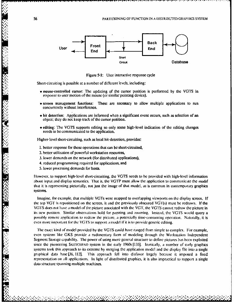
56 PARTITIONING OF FUNCTION IN A DISTRIBUTED GRAPHICS SYSTEM
Back
User Front4- End En
Shorcircutf Database
Figure 5-1: User interactive response cycle
Short-circuiting is possible at a number of different levels, including:
* mouse-controlled cursor: The updating of the cursor position is performed by the VG1'S inresponse to user motion of the mouse (or similar pointing device).
e screen management functions: These are necessary to allow multiple applications to runconcurrently without intcrfercnce.
9 hit detection: Applications are informed when a significant event occurs, such as selection of anobject: they do not keep track of the cursor position.
* editing: The VGTS supports editing so only some high-level indication of the editing changesneeds to be communicated to the application.
Higher-level short-circuiting, such as local hit-detection, provides:
1. better response for those operations that can be short-circuited,2. better utilization of powerful workstation resources,3. lower demands on the network (for distributed applications),4. reduced programming required for applications, and5. lower processing demands for hosts.
I lowever. to support high-level short-circuiting, ie VGTS needs to be provided with high-level informationabout input and display semantics. That is. the VGTP must allow tie application to communicate the modelthat it is representing pictorially, not just the image of that model, as is common in contemporary graphicssystems.
Imagine, for example, that multiple VGi's were mapped to overlapping viewports on the display screen. Ifthe top VGT is repositioncd on the screen, it and the previously obscured VGT(s) must be redrawn. If theVGI'S does not have a model of the picture associated with the VGT. the VGTS cannot redraw the picture inits new position. Similar observations hold for panning and zooming. Instead, the VG''S would query a
apppossibly remoe pplication to redraw the picture, a potenlially time-consuming operation. Naturally, it iseven more imporlant for the VGI'S to support a model if it is to provide generic editing.
cThe exact kind of model provided by the VG'S could have ranged from simple to complex. For example,even systems like GKS provide a rudimentary form of modeling through the Workstation IndependentSegment Storage capability. The power of using more general structure to define pictures has been exploited
*i since the pioneering SKI1CIIPAD system in die early 1960s 11351. Ironically, a number of early graphicssystems took this approach to its extreme by merging the application model and tie display file into a singlegraphical data base 136, 1121. 'lIis ap)roach fell into disfavor largely because it imposed a fixedrepresentation on all applications. In light of distributed graphics, it is also impractical to support a singledata structure spanning multiple machines.
* - . . . . . .
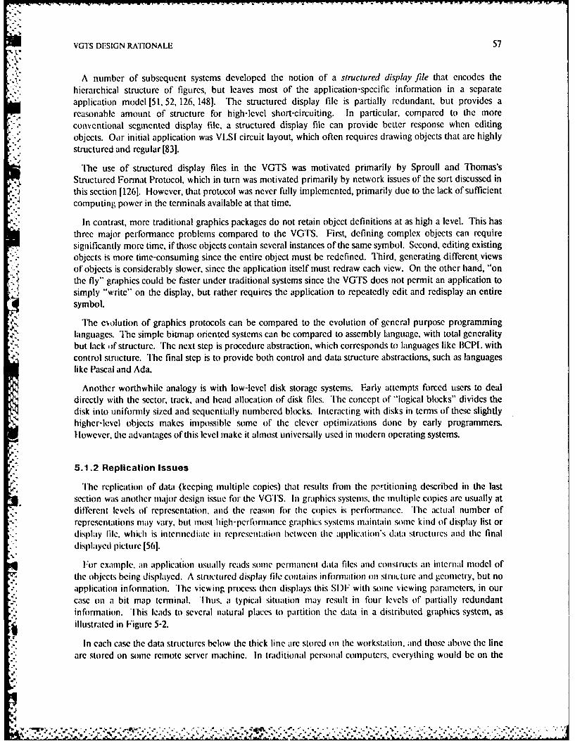
VGTS DESIGN RATIONALE 57
A number of subsequent systems developed the notion of a structured display file that encodes thehierarchical structure of figures, but leaves most of the application-specific information in a separateapplication model [51, 52, 126, 1481. The structured display file is partially redundant, but provides areasonable amount of structure for high-level short-circuiting. In particular, compared to the moreconventional segmented display file, a structured display file can provide better response when editingobjects. Our initial application was VLSI circuit layout, which often requires drawing objects that are highlystructured and regular [831.
,The use of structured display files in the VGTS was motivated primarily by Sproull and Thomas'sStructured Format Protocol, which in turn was motivated primarily by network issues of the sort discussed inthis section [1261. However, that protocol was never fully implemented, primarily due to the lack of sufficientcomputing power in the terminals available at that time.
In contrast, more traditional graphics packages do not retain object definitions at as high a level. This hasthree major performance problems compared to the VGTS. First, defining complex objects can requiresignificantly more time, if those objects contain several instances of the same symbol. Second, editing existingobjects is more time-consuming since the entire object must be redefined. Third, generating different viewsof objects is considerably slower, since the application itself must redraw each view. On the other hand, "onthe fly" graphics could be faster under traditional systems since the VGTS does not permit an application tosimply "write" on the display, but rather requires the application to repeatedly edit and redisplay an entiresymbol.
The evolution of graphics protocols can be compared to the evolution of general purpose programminglanguages. The simple biunap oriented systems can be compared to assembly language, with total generalitybut lack ofw structure. 'he next step is procedure abstraction, which corresponds to languages like BCP withcontrol structure. The final step is to provide both control and data structure abstractions, such as languageslike Pascal and Ada.
Another worthwhile analogy is with low-level disk storage systems. Farly attempts forced users to dealdirectly with the sector, track, and head allocation of disk files. The concept of "logical blocks" divides thedisk into uniformly sized and sequentially numbered blocks. interacting with disks in terms of these slightlyhigher-level objects makes impossible some of the clever optimizations done by early programmers.lowever, the advantages of this level make it almost universally used in modern operating systems.
5.1.2 Replication IssuesThe replication of data (keeping multiple copies) that results from the pz-rtitioning described in the last
section was another major design issue for the VGTS. In graphics systems, the multiple copies are usually atdifferent levels of representation, and the reason for the copies is performance. The actual number ofrepresentations may vary, but most high-perflormance graphics systems maintain some kind of display list ordisplay lile, which is intermediate in representation between the application's data structures and the finaldisplayed picture 1561.
For example. an application usually reads some permanent data files and constructs an internal model ofthe objects being displayed. A structured display file contains in formation on siructurC and geonmetry, but noapplication information. The viewing process then displays this SIF with some viewing parameters, in ourcase on a bit map terminal. Thus, a typical situation may result in four levels of partially redundantinformation. This leads to several natural places to partition the data in a distributed graphics system, asillustrated in Figure 5-2.
*" In each case the data structures below the thick line are stored on the workstation, and those above the lineare stored on some remote server machine. In traditional personal computers, everything would be on the
,%%
.- . - - .2A
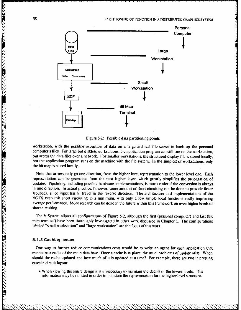
58 PARTITIONING OF iFUNCriON IN A DISTRIBUTED GRAPHICS SYSTEM
PersonalComputer
Data4Files Large
Workstation
Application
Data Structures
SmallWorkstation
_ _ _ _ Bit Map
Terminal
Figure 5-2: Possible data partitioning points
workstation, with the possible exception of data on a large archival file server to back up the personalcomputer's files. For large but diskiess workstations, de application program can still run on the workstation,but access the data files over a network. For smaller workstations, the structured display file is stored locally,but the application program runs on the machine with the file system. In the simplest of workstations, onlythe bit map is stored locally.
Note that arrows only go one direction, from the higher level representation to the lower level one. Eachrepresentation can be generated from the next higher layer, which greatly simplifies the propagation ofupdates. Pipelining. including possible hardware implementations, is much easier if the conversion is alwaysin one direction. In actual practice, however, some amount ofrshort circuiting can be done to provide fasterfeedback, si cc input has to travel in the reverse direction. 'lhe architecture and implementations of theVGTS keep this short circuiting to a minimum, with only a few simple local functions vastly improvingaverage pertormance. More research can be done in the future within this framework on even higher levels ofshort circuiting.
The V-System allows all configurations of Figure 5-2, although the first (personal computer) and last (bitmap terminal) have heen thoroughly investigated in other work discussed in Chapter 1. Ilic configurationslabeled 'sinall workstation" and "large workstation" are the focus of this work..
*5.1.3 Caching Issues
One way to further reduce communications costs would be to write an agent for each application thatmaintains a cache of the main data base. Once a cache is in place, the usual problems of update arise. Whenshould the cache updated and how much of it is updated at a time? For example, there are two interestingcases in circuit layout:
When viewing the entire design it is unncessary to maintain the details of the lowest levels. 'Ibisinformation may be omitted in order to maintain the representation for the higher-level structure.
W W vw r - W W T 'Ul
VGTS DESIGN RATIONALE 59
. When viewing a specific component it is unnecessary to maintain the reprcscntation of pieces ofthe picture not now on view.
Thus the agent would be constructed in such a way so as to maintain only the necessary data. Appropriateparts of the figure representation would contain the equivalent of invalid pages, leading to the equivalent ofpage faults.
The ideal VGTS would provide most of this support without requiring that a special-purpose agent bewritten for each application. Although the current VG'I'S architecture allows caching, the current prototypedoes not implement any. Tlie size of most SI)Fs rarely exceeds two or three thousand bytes, which is aninsignificant amount of memory compared to the size of the VGI'S itself. This and other possible VGTSextensions are discussed in the final chapter.
5.1.4 Transport Protocol Issues
Once the higher-level protocols are decided upon, the transport and lower level protocols must bedetermined. Possible choices for transport protocol include datagrams, byte streams, and packet (or message)streams. Streams are an obvious choice because they generally provide a high degree of reliability, can beused with a wide variety of terminals and networks, and simplify programming the applications and theservice. In addition, if the workstation and remote host interact frequently or in volume, high bandwidth isrequired, better achieved with virtual circuits.
If bandwidth requirements are low, then the low delay of datagrams might be more appropriate.Furthermore, interactive graphics requires real-time communication, which places greatest importance on themost recent data. In contrast, streams under load tend to lose or delay new data in favor of old data. lhegraphical representation also impacted our choice. Since high-level information was being transmitted, theloss of a single datagram would be catastrophic. Thus, only "reliable" stream-oriented protocols were used.
Fortunately, the V-System architecture allowed us to experiment with several of these protocols. Eachremote application must have an agent on the workstation, so the application and the agent may communicatewith whatever protocol they desire. Since our prototype applications had relatively modest requirements,
simple encapsulations of the VG'I'P with standard byte-stream protocols were most widely used.
5.2 Performance Issues
Besides communication issues, performance was also kept in mind during every phase of the design of theVGTS. Without careful attention, many distributed systems can end up being slower than their centralized
-. counterparts. In particular, many previous distributed systems have failed because of lack of attention to totalsystem performance. On the other hand, although poor performance guarantees that a system will fail, highperformance does not guarantee success. Other factors such as the various costs associated with highperformance cannot be neglected.
5.2.1 Code and Data Size
I)cspite the falling cost of memory, main memory can still be a major cost of a computing system. In fact,no matter how much memory a computer system has, it seems to almost always need more. Eliminatingduplication is one way to save memory, but often redundancy buys perfonance. A hardware cache is anexample of such redundancy used to speed tip a physical processor. Similar techniques to take advantage ofredundancy were used in software, as discussed in Section 5.1.2.
.7.
60 PARTITIONING OF FJNCTJON IN A DISTRIBUTFEDGRAPIIICS SYSTEM
Another way to save memory is economy of function: to not implement features that are rarely used, orthat can be done with existing capabilities, unless they are necessary. For example, some users might like tohave blinking as a primitive attribute. Since blinking can be simulated by having the application programrepeatedly add and delete an item from a symbol, blinking attributes were not included in the VGTS. Thismeans that each application program must include code for blinking if desired, but the overhead is rarelyencountered. On the other hand, diagnostics and error recovery are intended to be rarely used in properlywritten software, but many understandable error messages are included in the standard VG'TS, since whenthey are used they can provide invaluable information.
5.2.2 Resource Limitations
hlhe concern for memory costs is another prime motivation for the use of high-level display files instead ofthe more common bitmap approach. Note that the architecture does not explicitly prohibit the storing ofbitmaps. and in fact a bitmap item type is supported. However, Section 4.2.1 described how the prototypeimplementations redraw only from the SI)F, with no bitmap caching of overlapping areas necessary. Thecurrent architecture requires that to display large images the entire bitmap must be transferred into the VG'lSfor every change. Ibis has proved adequate for simple image display tasks, or editing small bitmaps such ascharacters. For more intensive image processing applications, simple raster operations could be provided onraster objects to improve performance if necessary.
6 -Some display file approaches may severely limit the maximum size or complexity of objects that can bedisplayed. For example, many traditional graphics system support only one level of structure, the segment.Since we are primarily concerned with the research community, absolute limitations should be avoidedwhenever possible. Hlowever, making some assumptions about maximum resource limitations may simplifythe design or improve performance. For example, a reasonable limit on the number of virtual terminals orviews might be an acceptable limitation, so such limitations were included in the prototype VGTSimplementation.
5.2.3 Speed of Execution
The two main measures of execution speed of interactive systems are response time and throughput.- Response time is more important when the user has to wait. Many users of early workstation systems had to
spend much of their time waiting while an "hourglass" cursor appeared on the screen. Operations which take
significant amounts of time should have been done in the "background". 'Ibis requires a priority-basedmulti-process operating system, such as the V-System.
For all other applications for which the user does not have to wait, throughput should be maximized. Sincethe hardware trends are to more specialized processors, a natural division is suggested between processes
" , optimized for response time (interactive) and those optimized for throughput (batch). A fairly commonscenario for users of the VG'S is to be running an editor on the workstation in one VGF while monitoringseveral long-running hatch operations in other VG's at the same time.
5.3 Some Simple Models
As discussed in the previous section, many attempts at distributed systems have failed due to poorperformance. In addition to the inherent cost of the computation, the costs of communication between theparts of the distributed program are incurred. Thus the total computation cost of a distributed program isalmost always higher than the total computation cost ofan equivalent centralized program.
mb.
:.:--
VGTS DESIGN RATIONALE 61
' Thcrc arc two approaches to improving the performance of distributed programs, both by identifying andovercoming these communication costs. The traditional approach is to improve the performance of theunderlying network communication mechanism. The work of Spector and others on remote memoryreferences is in this category [125]. A more promising approach taken in the VGTS was to decrease theamount of network traffic by using higher-lcvel protocols. In other words, reduce the frequency and volumeof communication by making the applications more loosely coupled.
For comparison, consider the many performance studies made of demand-paged virtual memory systems.Although performance can be improved by speeding up the handling of page faults, better results are usuallyachieved by reducing the nutmber of page faults. For example, increasing physical memory, tuning the pagesize, improving the locality of the application, or using a better selection algorithm can make as substantial adifference as the speed of the disk.
Although this section does not attempt an exhaustive analysis of the VGTS architecture, some very simplemodels can be developed. As in other simplified models of two-processor systems [132], a simple model isnecessary before a more detailed one. Although some attempts have been made to model larger systems ofmany processors [131], these have mostly been theoretical models with very little total system performancedata. At first glance one might assume tiat the factor most important at any given time is the bottleneck, andconstruct a queuing theory model. 'libe problem is that in a complete system the bottleneck is not sowell-defined.
5.3.1 Comparison to Cache Model
A cache is a well-known hardware mechanism to improve performance of a hardware design by takingadvantage. of locality properties of software 11211. The locality principle states that a program's references todata are not uniformly distributed, but instead concentrate around a set of locations at any givenmoment 11081. A small number of addresses are responsible for a large fraction of the memory references.'he virtual memory concept is made possible by taking advantage of the principle of locality at the nexthigher level in the storage hierarchy. We can extend this concept to an even higher level, and take advantageof the patterns of usage for high-level graphics functions in the VGTS.
In a distributed graphics system the processor in the cache model plays a role analogous to the workstation.and the main memory corresponds to other server hosts. T7he performance of a cache can be roughlycharacterized by four numbers:
11, l is the average time for access to the smaller but faster resource.
Tremote is the average time to reference the larger but slower resource.
Tcomm is the time it takes to communicate between the local and remote resources.
p is the "hit" rate. or probability that an average operation can be handled by the local resource.
* 'This large communications Iactor, 'I is the major difference from the hardware cache model, along withanother component that is common to both local and remote operation:
rvgt is the average time taken by the VGTS for both local and remote operations.
The average time for all operations is then:p,,
% Tavg = p Tloca I + (I - pXTcomm + Tremote) + Tvgts
'lThe ideal would be to minimize this time with respect to the various hardware and software trade-offsmentioned in the rest of this chapter.
a4
S 62 PARTITIONING OF FUNCTION IN A DISTRIBUTEIDGRAPHICS SYSTEM
In more concrete terms, this model represents a terminal by making p zero (or very small), so no operationsare performed locally. The terminal role is acceptable when Tcomm and T remote are small components of the
overall cost, which implies a very fast mainframe and high-bandwidth communication (or batch-orientedtasks). When p is near one, this models the personal computer configUration. Personal computcrs are fastestwhen T1ow is small, which implies fast personal computers (or simple interactive tasks).
When the task is too large to be handled by the personal computer or terminal configurations, the followingapproaches can make Targ smaller:
1. Reduce Tcomm (communication time) by using special protocols or network improvements. Thisrequires measurements to determine if the actual bandwidth of the network or the transport
protocols are the bottleneck.
2. Reduce T oea by using a faster workstation. As we will see by the measurement results, speedingup the processor usually has the desirable side-effect of also increasing effective network
throughput, or reducing Tomm. However, this cost must be incurred on every workstation.
3. Reduce Tremote by using a larger, faster computer for the server host. This cost can be shared
among all the workstations sharing a server.
4. Increase p by caching information on the workstation or using high-level short circuiting so that
more operations can be performed locally. Applications could also partition themselves to putmore of their functionality on the workstation. Note that this usually implies an increase of the
memory of each workstation.
5. Reduce T by improving the performance of the VGTS itself. In fact, for many simple
applications with insignificant computation demands, this factor could be the only important one.
The value of short-circuiting has already been introduced. The next section goes into more detail on therelationship between the local, remote, and communication times in the VG°lS model.
5.3.2 The Time Dimension
VGTS performance can also be examined by viewing the events along the time dimension. Figure 5-3illustrates the time used on each processor resource for one typical interaction response cycle. Timeprogre.ses Iron left to right. e111e first example is a per)nal computer configuration. The next two linesrepresent the partitioning of the problem between a workstation and a server host.
The variables in Figure 5-3 represent the following values:
TInput Represents the time to handle the input event. This is usually the same in both the local anddistributed case.
"rswapin Represents the time to swap in or otherwise change contexts to the application program on theworkstation.
"-",,-',. - '-
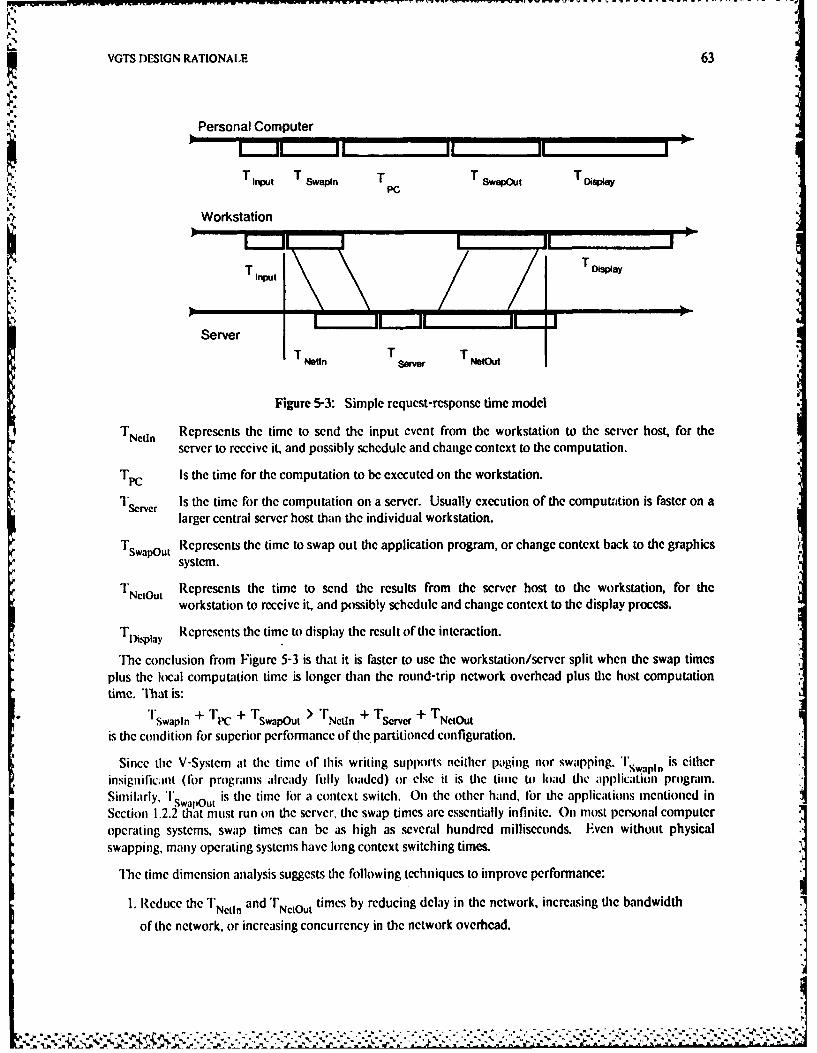
VGTS DESIGN RATIONALE 63
Personal Computer
K." T Swin T T T Diapiay
ib T1 T nTD y
ServerT Netin Ts~re T NetOut
Figure 5-3: Simple rcqucst-response time modelTNetl Represents the time to send the input event from the workstation to the server host, for the
server to receive it, and possibly schedule and change context to the computation.
Tpc Is the time for the computation to be executed on the workstation.
T'Server Is the time for the computation on a server. Usually execution of the computation is faster on alarger central server host than the individual workstation.
TswapOut Represents the time to swap out the application program, or change contcxt back to the graphicssystem.
T NetOut Represents the time to send the results from the server host to the workstation, for theworkstation to receive it, and possibly schcdule and change context to the display process.
TDisplay Represents the time to display the result of the interaction.
The conclusion from Figure 5-3 is that it is faster to use the workstation/server split when the swap timesplus the local computation time is longer than the round-trip network overhead plus the host computationtime. That is:
- Tswapln + T1C + Tswapout > TNet n + Tserver + TNetOut
is the condition for superior performance of the partitioned configuration.
Since the V-System at the time or this writing supp Ots neither paging nor swapping. Tspm is eitherinsignilicant (for programs already fully loaded) or else it is the time to load the application program.Similarly. 'wap u. is the time for a context switch. On the other hand, lbr the applications mentioned inSection 1.2.2 that must run on the server, the swap times are essentially infinite. On most personal computeroperating systems, swap times can be as high as several hundred milliseconds. Even without physicalswapping, many operating systems have long context switching times.
Thc time dimension analysis suggests the following techniques to improve performance:1. Reduce the T]'Nctn and TNctOut times by reducing delay in the network, increasing the bandwidth
of the network, or increasing concurrency in the network overhead.
% -% 1
64 PARTIIONING OF FUNCTION IN A DISTRIBUTED GRAPIhICS SYSTEM
2. Have the server send results back to the workstation as soon as possible, since the rest of its
computation can continue in the background concurrently with TDisplay.
3. Use the personal computer approach whenever possible with high timesharing loads.
Timesharing loads add a queuing delay to Tserver, which could easily make it much higher than
"pc on a powerful workstation.
These models provide the framework for interpreting the performance measurements to be given in Chapter*. 6. The following sections will discuss important design considerations that may not be directly related to*. distribution or performance.
5.4 Application Multiplexing Alternatives
One crucial job of the viewing service is to multiplex the single user and display devices to the possiblymany application programs. 'Ibis function is similar to that of the kernel or process manager of a generalpurpose operating system.
5.4.1 Decentralized Control
Most operating systems handle contention for the processor by letting one process have full control, thensaving the statc of the processor, loading the state of the next process to run, and letting that process have fullcontrol. A similar approach could be taken with graphics [35]. The reasoning is that this will allow higher
performance, since compiled programs usually have better performance than interpreted programs.However, it is not necessary to have decentralized control to have compiled display lists; it is just a question ofwhether the application program or the viewing service does the compiling.
A number of sophisticated object-oriented window systems have been built for personal computers withdecentralized control, as discussed in Section 2.2. While these window system approaches work well for localapplications, they do not extend well to remote applications, especially those written outside the framework ofthe particular language and workstation. Even systems that attempt to provide the object-oriented "Lip-call"functionality in a distributed environment have resulted in centralized control [59].
One major problem with decentralized control is that current graphics devices do not always allow the stateof the graphics device to be saved and restored. Another problem is that application programs would benon-portable at the binary level even if there were workstations that used the same processor architecture but
* different graphics architectures. 'Ibis may not seem like a problem since source-level compatibility could be* retaincd, but it could result in a version "explosion" with many copies of every graphics application, each of*. which must be maimained in parallel with tie others. Since both of these problems existed for die SUN and
IRIS workstations, the decentrali/ed approach was not possible for the prototype implementation. 'Ile* original motivation bir virtual terminals (see Section 2.3) was to eliminate tie n J i version problem.
5.4.2 Cent ralized Control
'The VGTS, on the other hand, is designed to operate in a environment composed of a variety ofapplications, programming languages, machines, and networks, with widely varying terminal interactionrequirements. A centralized approach, rarely taken in bitmap graphics systems, communicates a list of objectsto be drawn to the viewing service, and the viewing service actually renders the objects. 'Ibis virtual terminal
VGTS DESIGN RATIONALE 65
approach, previously introduced in Section 2.3, was taken in the VGI'S due to the advantages for portabilityand partitioning.
It is not a contradiction (as it might seem) that partitioning implies centralization. Centralized control wasuscd in the VGTS to provide adequate performance despite expensive communication. The actual costs ofcommunication will be measured in Chapter 6. Another side benefit of centralization is conservation ofmemory. Fach application program is smaller because it does not need to be linked with the graphics library.
5.5 Uniformity and Portability
Another set of issues concerns different aspects of uniformity. The general problem associated withuniformity is that, almost by definition, uniformity may restrict flexibility. The goal was to restrict how thingsare done, but not what can be done.
5.5.1 Device Independence of Applications
Since workstation hardware is changed constantly, software developed on one kind of workstation usuallydoes not nn on other workstations. One traditiolal approach to this problem have been query operations.Application programmers may take advantage of query operations to change behavior depending on theresults of ie query [28]. This is a highly restricted form of device independence, that requires prcmeditadonby the applications programmer of all possible devices with which the program will ever run.
Device independence has been recognized as a goal for quite some time, but is even more importanttoday [601. In fact, technology can progress so fist that by the time an application is finished, totally newgraphics devices may be available that were not even anticipated at the time the application was designed.
For example, the prototype VGTS took about one year to develop, another year to measure and a final yearto evaluate. In the meantime, the architecture of the SUN workstation had changed drastically, so theprototype implementation no longer worked on the new workstation. If the VGTS architecture had beentailored to the original workstation, then all the applications developed during these years would have to berewritten. Instead, as soon as the new version of the VGTS that handled the new workstation was installed, allclient programs could be run immediately, without any modifications. VGTS changes were limited to onelow-level module, the drawing manager, as indicated in Figure 4-1.
5.5.2 Uniformity of User Interface
In addition to uniformity across different hardware devices, uniformity across different software tools isanother desirable goal. Powerful hardware like hitmapsiand mice provide the opportunity for more advancedinterfaces, but also can cause chaos if each application choruscs it- own user interface. Every programmer hashis own idea of what is "right" and those tastes may not miatch those of the intended users. One partialsolution to this problem is the user interlace management systen concept which isolates the operation of aprogram from the details of how those operations arc invoked [1431.
The VGTS provides a step in this direction, with the following user interface standards:
" Pop-up menu feedback is implemented inside the VGTS. 'l'e view manager menus as well asthose provided by applications are handled uniformly.
" A common line editor provides simple editing functions like character and word delete to allapplications requesting keyboard input.
-%
66 PARTITIONING OF FUNCTION IN A DISTRIBUTED GRAPIIICS SYSTEM
e Banners provide a common mechanism to indicate some concise status information, such as thename of the program currently executing.
e All screen management, such as zooming and moving of views is done uniformly through the viewmanager.
* Other conventions and library packages are provided as suggestions. For example, pressing allthree buttons simultaneously signals an abort to most programs.
The result is that users quickly learned how to use new tools, instead of having to adapt to the whims of theimplementor of the new tool.
5.5.3 Portability of Implementation
It was found to be easier to modify the code of the first implementation to handle another kind ofworkstation than to start from scratch. Several techniques were used to aid in portability:
e Restricting the range of hardware. In our case, the VGTS was targeted to higher-end workstationsand future higher performance hardware instead of the lower cost popular personal computerscurrently being mass produced.
* Using a high level language. The VGTS was written in the C programming language [711. Ccompilers are widely available for many computer architectures. The UNIX timesharing systemhas been ported to many different architectures successfully by using C [661.
o Using a standard computer architecture. The prototype VGTS implementation was on theMotorola MC68000 architecture, which has several different implementations used in manycommercial products [100].
*Attention to modularity and isolation of machine dependencies. This was only achieved byactually supporting two or more devices with the same source code. Once the system worked ontwo machines, the third was easier, and so on. The first few efforts detected subtle hiddenmachine dependencies that would otherwise be overlooked, such as byte ordering problems [401.
Portability was another of many properties greatly helped by economy of features. A small system wasinherently easier to port than a larger system. For this reason many attractive features were not included inthe VGTS design unless they were. found to be necessary. For example, some users requested up/downencoding of the keyboard, or advanced support for special function keys. Unfortunately, the implementationalready worked with about ten types of keyboards, some of which did not have up/down encoding or specialfunction keys.
Although the trend to faster but cheaper graphics workstations is unmistakable, the time between the startof a design and its production is usually underestimated. For example, a major computer inanufacturerannounced a workstation product and demonstrated it in July of 1982. In the Call of 1982, a research contractwitli Sltmlobrd was negotiated that included porting the VGTS to this new workstation. By the summer of1984 the project shifted efforts to a newer kind of workstation. I lardware progress had been so great that theworkstations were obsolete before they were delivered.
A more important problem with porting the VGTS was not technological but political. Most workstationmanufcturers were unwilling to reveal low-level details of their graphics devices. If they contained customhardware, the manufacturer wanted to protect the trade secrets involved in the hardware, so othermanufacturers could not use the same techniques. If the graphics devices were simple frame buffers drivenby software, the low-level raster operation Functions were proprietary, to prevent the use of the software onother machines. In our case we had no desire to pirate trade secrets, but we failed to convince themanufacturers that it was in their best interests to give us the information.
VGTS DESIGN RATIONALE 67
5.6 Customizability
Unfortunately the goal of uniformity was in direct conflict with that of customizability. Although at firstcustomizability seems attractive, there are many hidden costs. For example, people often work together on asingle project in a research environment. Highly customized interfaces make exchange more difficult, if userscannot use their custom commands on other workstations. On the other hand, since researchers arc often
*' systems programmers themselves, they have irresistible urges to change a program that they do not like. If theinterfaces are not designed carefully and flexibly enough, users will develop their own versions of the systemanyway and the goal of uniformity is lost.
5.6.1 Customizability by Programs
The author of a program may want to specify some slightly device-dependent "hints" about the displayprocess. For example, a program may have information on the size of some object or its desired location onthe screen. [he program may also wish to advise the VGTS on how the objects should be viewed. Althoughthe VG'S architecture allows such hints, only one was provided in the prototype implementation: Anapplication can declare the size of a default view.
One example of a programmer who wanted customization of the viewing process occurred in an integratedVLSI layout editor and design-rule checker. The author of such a program requested the ability to positionan item within a view, so that a design rule violation could be centered in the viewport. Such a feature couldeasily be added by creating another VGT with the item as its top-level symbol, and then defining anotherdefault view with the desired coordinates. "'ie view manager could also include commands to center a viewon coordinates typed by a user, instead of pointed to by the mouse. Therefore, the view manipulationcapability was not added to the VGTS client interface.
A common argument is that programs should be able to perform any function that a user can perform. Thisis not provided in the current VGTS. since the user interface deals with views and physical screens, while theapplication interface intentionally hides these objects and deals with graphical items and virtual terminals.One area of future research is the design of a different kind of interface that could be used for customizedview management. However, it is important to make the clear distinction between non-uniformity on the partof the application tools, and customization of those tools on the basis of the user.
5.6.2 Customizability by Users
A user may want to specify a profile to tailor certain aspects of the user interface to his or her needs. Forexample. novice users may want an interface that is easier to learn or in which it is harder to make mistakes,while expert users want more powerful interfaces with commands available quickly. In addition, manyaspects of user interl'aces are a matter of personal taste. With respect to screen management, some peopleprefer to use arbitrarily overlapped viewports as implemented by the protype VGTS. while others prefer toutsc the liled appr oach, in which the view m;nagercauses views toexactly Iill the screen wilhoutt overlap 11401.Another open question is the proper form of menus. In the current implementation, one button click causesthe menu to appear and another causes the selection. 'Ihis reduces the probability of errors when incorrectbutton combinations are given, but requires two user actions for each menu selection. Other systems causethe menu to appear when the button is pressed, and the selection to occur when the button is released.
Some systems use profiles on a workstation or application basis, but they should really be provided on thebasis of user, since users and applications should be able to use any workstation. 'lhe VGTS architectureallows this customization of the view management process. but the current implementations do not realize thiscapability. Partially this is due to the lack of a user identification concept in the current V-System, but alsodue to the fact that the conventions as implemented have proven reasonable in actual use.prve
68 PARTITIONING OF FUNCTION IN A DISTRIBUTD GRAPhIlCS SYSTEM
5.7 Suitability for the Future
The future in the computer industry is hard to predict in detail, but some general trends are certain. Wewanted to take advantage of these trends whencver posible, instead of tying the design to technology thatwould quickly become obsolete.
5.7.1 Future Display Devices
Larger, faster bitmaps, and special-purpose graphics hardware should become less expensive in the future.For example, while this thesis was in preparation, the Apple Macintosh was made available for about $1000with a University discount; this is less than most alphanumeric terminals. The Macintosh has a fairly smalldisplay screen and low-performance processor, but the mere existence of the mouse and bitmap display in amass-produced product are encouraging. K
'111 IRIS workstation is an example of a higher-performance and therefore higher-cost system, with customhardware applied to the viewing process [39]. The current IRIS implementation renders the output primitivesusing a bit-slice microprocessor, and is too expensive for wide-spread use. However, the IRIS is indicative ofthe trend to applying special-purpose hardware to graphics systems.
Current developments include "smart memories" that use special devices to perform rendering, includinganti-aliasing and shading via ray-tracing, directly in the frame buffer [63]. Performance can be enhancedfurther by using pipelining and parallelism. With this kind of hardware the Bitilit model of operations breaksdown. Instead of moving bits around, the interface to the hardware is at a higher level: declaring primitivegraphics objects like vectors and polygons.
There are two differing opinions on the effect of this advanced specialized hardware. One line of reasoningis that since all this custom hardware is so expensive, the raw graphics device must be used at a very low levelto avoid wasting any power. 'le other line of reasoning is that new hardware can be used to allowprogramming at a higher level, with straightforward. simple, and elegant approaches replacing the specialmechanisms necessary on slower hardware. Thie first opinion appeals more to those who design and marketthe hardware, while the second appeals to those who develop the software and use the workstations. Sincesoftware costs are becoming increasingly more important, in die long run the elegant software approachshould dominate.
As the VGTS was designed, it was hard to predict what the future held, but one thing was certain: therewould be many more changes in the kinds, quality, and cost of graphics devices. One good way to takeadvantage of these new devices, given this uncertainty, was to use abstract, high-level interfaces andconcentrate on portability as done in the VG'I'S.
5.7.2 Future Computer System Organization
Ironically, tie personal computing trend may be short-lived. Computer systems are still expensive, andpeople can not alTord filly configured personal computers. On the other hand, microprocessors are almostfree. and getting cheaper. The cost of a microprocessor should eventually approach the cost of a memoryintegrated circuit, so despite the increasing densities of memory, the trend should be to less memory perprocessor instead of more memory per processor. lhe result should be computer systems that consist of manymicroprocessors working together.
For example, the cluster of workstations for which the VGTS was developed consists of about ten disklessSUN workstations connected with a local network to three VAX- l/750s, one VAX-I 1/780. and a sharedIrcSystem-20. In fact, each of the workstations is really a multiprocessor in its own right. In addition to the
VGTS DESIGN RATIONALE 69
MC68000, there arc simple finite-statc machines to refresh and update the frame buffer, a bit-slice processorto handle the Ethernet, and microprocessors in the keyboard and mouse.
For these reasons, protocols that treat the workstation as a terminal (that is, partitioning below the VDIlevel as illustrated in Figure 2-2) are not very interesting for the future. The main limitation with theseprotocols is that they assume only one connection at a time. Since future computer systems will probablyhave many processors, and a single user will probably use many processors at once, the VGTS should allow asmuch concurrency as possible. Concurrency is a useful concept both at the hardware level (as manycomputers as possible should be kept busy) and at the higher levels of user interface (the user should be ableto have many tasks in progress at the same time). As a first step, the VGTS provides the graphics operationsin a separate process, instead of as functions called by the application programs.
5.8 Backward Compatibility
Although planning for the future is important, the VGTS design did not ignore the past. It is unreasonableto expect all software to be rewritten for every new system. Fo" this reason, one VGTS goal was to be able totake advantage of as much existing software as possible. A similar approach wa's taken in the BRUWIN virtualterminal system [961: the terminal manager was designed to take advantage of existing tools, instead of beingthe focus of all new developments. Even though lI UWIN provided support for only text on a conventionalgraphics device directly connected to a timesharing system, it proved to be a useful tool. Similarly, the VOTSalso was able to access applications running under the UNIX timesharing system through remote execution.
"N' 5.8.1 Encapsulating Existing Facilities
For example, the V-System itself (including the VGTS) was compiled on a VAX/UNIX timesharing system.Eventually more software development tools were ported to the native V-System environment. The ability torun the tools under UNIX greatly eased the transition. Many specialized or proprietary programs are stillaccessed through the UNIX server interface.
In addition, through the use of terminal emulators and user TI.NI.r programs, a VGTS user can runapplications anywhere throughout the ARPA Internet. This remote terminal capability has turned out to beone of the most heavily used features of the current implementation. The next chapter will describe someexperiments using even interactive graphics programs in this manner. Fortunately, many tools can beaccessed in a batch fashion, so there is little performance degradation when they are executed remotely. Forexample, this thesis was produced with a document compiler that ran on a UNIX server host.
5.8.2 Relation to Standards
Another way of taking advantage of the past is to follow standards. The graphical facilities of the VGIS aresimilar to those several existing graphics packages, including those comiforming to the Core 11471 andGKS 1641 standardization eflorts. The principal diflercnces are:
1. standardized support for object modeling as well as viewing;
2. hierarchical structure of objects;
3. the ability to handle multiple, distributed applications simultaneously;
4. less flexibility in terms of attribute and coordinate transformation facilities.
* * -1'
%"
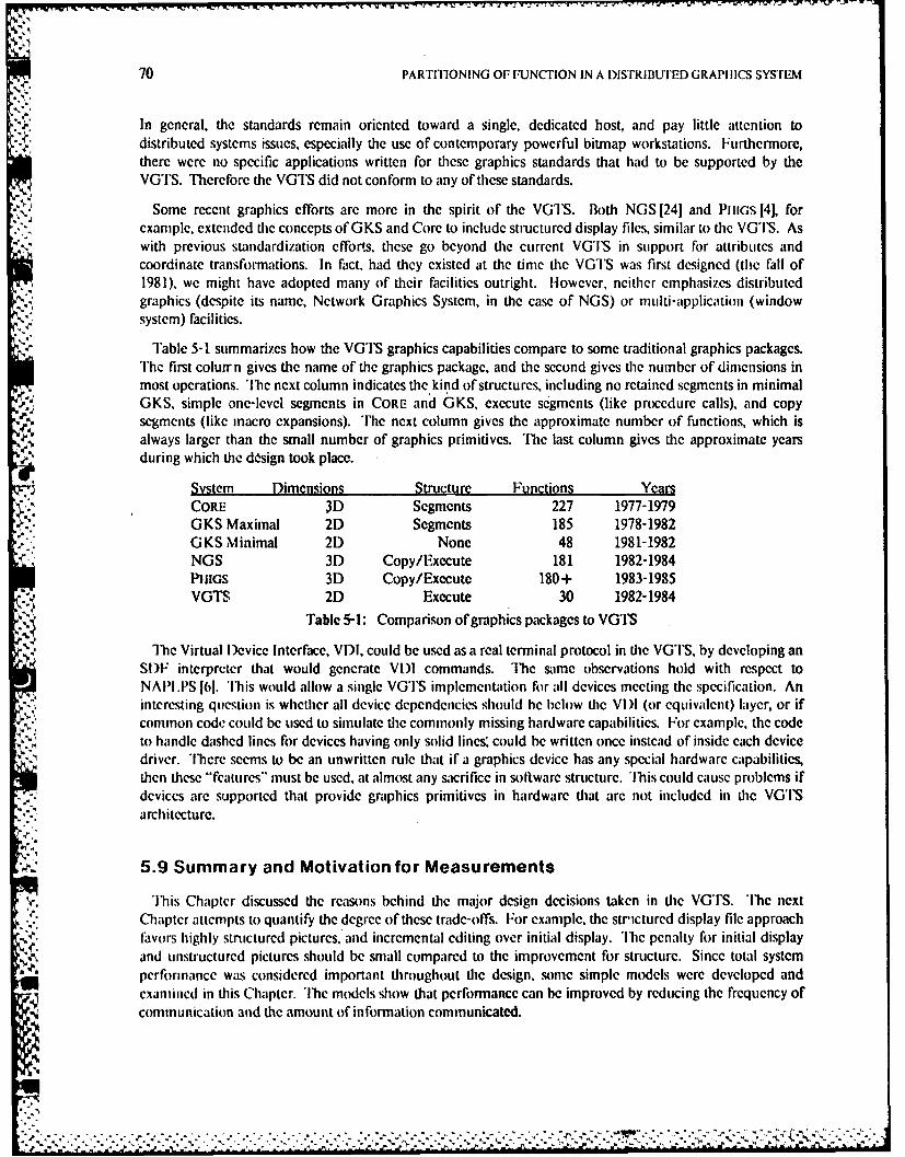
70 PARTITIONING OF FUNCTION IN A DISTRIBUTED GRAPIICS SYSTEM
In general, the standards remain oriented toward a single, dedicated host, and pay little attention todistributed systems issues, especially the use of contemporary powerful bitmap workstations. Furthermore,there were no specific applications written for these graphics standards that had to be supported by theVGTS. Therefore the VGTS did not conform to any of these standards.
Some recent graphics efforts are more in the spirit of the VGTS. Both NGS [241 and PltGs 1[41, for,: example, extended the concepts of GKS and Core to include structured display files, similar to the VG'IS. As
with previous standardization efforts, these go beyond the current VGTS in support for attributes andcoordinate transformations. In fact, had they existed at the time the VGTS was first designed (the fall of1981), we might have adopted many of their facilities outright. However, neither emphasizes distributedgraphics (despite its name, Network Graphics System, in the case of NGS) or multi-application (windowsystem) facilities.
Table 5-1 summarizes how the VGTS graphics capabilities compare to some traditional graphics packages.The first colurr n gives the name of the graphics package, and the second gives the number of dimensions inmost operations. The next column indicates the kind of structures, including no retained segments in minimalGKS, simple one-level segments in CORE and GKS, execute segments (like procedure calls), and copy
.'', segments (like macro expansions). The next column gives the approximate number of functions, which is,, always larger than the small number of graphics primitives. The last column gives the approximate years
during which the disign took place.
System Dimensions Structlure Functions YearsCORE 3D Segments 227 1977-1979GKS Maximal 2D Segments 185 1978-1982GKS Minimal 2D None 48 1981-1982NOS 3D Copy/Execute 181 1982-1984PHIGS 3D Copy/Execute 180+ 1983-1985VGTS 2D Execute 30 1982-1984
Table 5-1: Comparison of graphics packages to VGTS
lhe Virtual Device Interface, VDI, could be used as a real terminal protocol in tie VGIS, by developing anSI)F interpreter that would generate VDI commands. The same observations hold with respect toNAPLI.PS [6]. 'Ibis would allow a single VGTS implementation for all devices meeting the specification. Aninteresting question is whether all device dependencies should be below the VII (or equivalent) layer, or ifcommon code could be used to simulate the commonly missing hardware capabilities. For example, the code
to handle dashed lines for devices having only solid lines" could be written once instead of inside each devicedriver. There seems to be an unwritten rule that if a graphics device has any special hardware capabilities,then these "features" must be used, at almost any sacrifice in software structure. 'Ibis could cause problems if
- .. devices are supported that provide graphics primitives in hardware that arc not included in the VGTS:-'."architecture.
5.9 Summary and Motivation for Measurements
'Ibis Chapter discussed the reasons behind the major design decisions taken in the VGTS. The next*1¢" Chapter attempts to quantify the degree of these trade-offs. For example, the strictured display file approach
favors highly structured pictures, and incremental editing over initial display. 'Ihe penalty for initial displayand unstructured pictures should be small compared to the improvement for structure. Since total systemperformance was considered important throughout the design, some simple models were developed andexamined in this Chapter. The models show that performance can be improved by reducing the frequency ofcommunication and the amount of information communicated.
::i.?
...'.,',.-,--... . . . . . . . . . . ..-. .,. . . ...-... ... . ..'. .-. .-". .- . -. -,"-"-',"-".-.,: '-.' -' b -, "" " " "" - ' "; ',- .. "-'
. . . .... ... .....,. -.-... - .. . . .... .. - .,-. .. ..,. ,.., - ,.. . ,, , ., ,-. .'..-,'..-...,: . : '., ..--:..: -
VGTS DESIGN RATIONALE 71
cThe centralized control of the VOTS has benefits for uniformity and portability, but still allows somecustomization. Partitioning as exemplified by the VGTS should become more important as future displayand computing devices are introduced. On the other hand, users should be isolated from changing hardwareby encapsulation of existing facilities and adherence to standards. Experiments arc also needed to prove thatperformance is adequate compared to the older systems being emulated and replaced.
" -,
'o°
J.
f- -. * . . a* . '
*'* " ".,a' . . ..o
72 PARTIlIONING OF FUNCrION IN A DISIRIBUTED GRAPI II~S SYSTEM
.1'*.
'4.
4.4.)'p.'p.
MFASUREMEN[S 73
Measurements
'lTe previous chapter discussed many qualitative advantages of the VGTS design, such as portability andsuitability to luture hardware. Quantitative measures are also desired to provide a firm basis for evaluation.One ultimate measure of a system's success is whether people choose to use it to get work done, even in aresearch project. This criterion certainly applies in the case of the VGTS, since the high level of interactionenforced by the VGTS may trade off some functionality, flexibility, or performance. If the amount of thesequalities lost is small enough compared to the advantages gained, then the approach may be worthwhile for atleast some class of applications.
For example, some graphics teninals allow special effects like limited animation using tricks with the colormap. On a workstation shared with other applications, these special mechanisms cannot be used, sinceresources like the color map are shared between several different applications. This chapter will show thatcareful deign of VG'S protocols can make performance acceptably close to that of other systems that do nothave the advantages of the VGTS.
6.1 Nature of Performance Measurements
Performance measurements have been taken for three benchmark programs, two for graphics and one fortext, in a variety of test configurations. In addition, the illustration editor used to create the diagrams in thisthesis was instrumented to measure memory usage, construction, and display rates.
6.1.1 Benchmark Programs
The first graphics benchmark created a fully-connected 36-agon with a radius of 350 pixels, drawing 630vcctors or 288,364 pixels. Thus the average vector size in this benchmark was 457 pixels. Since the picturewas a fully-connected polygon, many different angles of vectors were used. TIis was intended to test theperformance of traditional vector graphics functionality. The action was repeated ten times, and the numberslisted are the mean of ten consecutive trials.
All numbers given as vectors per second in this chapter refer to this same artificial benchmark, so theyshould be valuable for relative comparisons but not absolute limits. However, since most significantcomputation was done before the timed parts of this program, and the number of items in the picture isrelatively large, the intent was to measure the peak rates of adding items to a symbol and then drawing thatsymbol. This would measure the rate of initially drawing a new picture.
The second graphics benchmark was intended to test the effects of using structure on a simple picture of thekind used in a VI.SI layout editor 1421. 'This hcnchmiark drew an array of five by six NMOS inverters 193].I:-ch of these 30 inverk'rs consisted of 26 rectangles. fIr a toill of 780 rectangles, all lilled with omIe of fourslipple pattcrns (which would appear as colors in a color implementation) representing the four NMOS layers.First the picture was drawn using a single-level S )I: and adding all 780 rectangles individually. Tibe secondpart of this test defined a contact cut symbol, then an inverter symbol, and then added 30 calls to the invertersymbol, with only 23 primitive items in the SDF.
Although the reguhzrityficiorof this drawing (the ratio of total items divided by defined items, or 30 in thiscase) is fairly high, modern VILSI designs typically have regularity factors in the same range, and the trend isto increasing regularity 183, 841. In fact. many of the designs currently under development could never bepossible with smaller regularity factors. Independent of the structure, the resulting image was the same, about400 pixels on a side.
-- -s --. .- - --. .- - - -
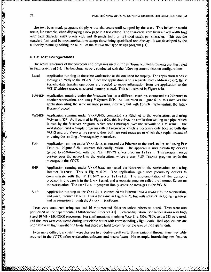
74 PARTITIONING OF FUNCIION IN A DISTRIBUTEDGRAPIIICS SYSTEM
The text benchmark programs simply wrote characters until stopped by the user. This behavior wouldoccur, for example, when displaying a new page in a text editor. The characters were from a fixed-width fontwith each character eight pixels wide and 16 pixels high, or 128 total pixels per character. '[his was thestandard font used by most applications except those doing specialized text display. It was developed by theauthor by manually editing the output of the MEIrAFON'r type design program [741.
6.1.2 Test Configurations
'The actual structures of the protocols and programs used in the performance measurements are illustratedin Figures 6-1 and 6-2. 'Ihe benchmarks were conducted with the following communication configurations:
Local Application running on the same workstation as the one used for display. ihe application sends Vmessages directly to the VG'S. Since the application is on a separate team (address space), the Vkernel's data transfer operations are needed to move information from the application to theVGTS' address space: no shared memory is used. '[his is illustrated in Figure 6-1a.
SUN-IKP Application running under the V-system but on a different machine, connected via Ethernet toanother workstation, and using V-System IKP. As illustrated in Figure 6-lb, this involves theapplication using the same message-passing interface, but with kernels implementirrg the Inter-Kernel Protocol.
VAX-IKP Application running under VAX/UNIX, connected via Ethernet to the workstation, and usingV-System IKP. As illustrated in Figure 6-2a, this involves the application writing to a pipe, whichis read by the V-server program, which sends messages over the network to a V kernel. 'heworkstation runs a simple program called fexecute which is necessary only because both theVG'TS and the V-server are servers; they both are sent messages to which they reply, instead ofinitiating the sending of messages by themselves.
PuP Application running under VAX/UNIX, connected via Ethernet to the workstation, and using PUP'I'FL.NIr. Figure 6-2b illustrates this configuration. 'Ilic application uses pseudo-tty devices(ptys) to communicate with the PUP TI.I.lNIfr server program Tel ser. 'Ibis program sendspackets over the network to the workstation, where a user PUP TlI.N-r program sends themessages to the VGTS.
E-IP Application running under VAX/UNIX, connected via Ethernet to the workstation, and usingInternet 'ITL.N..'. 'Ibis is Figure 6-2c. 'The application again uses pseudo-tty devices tocommunicate with the IP 'l'I.:,Nt..r server Telnetd. The implementation of the transportprotocol in this case is in the UNIX kernel, and a separate program called the Internet Server onthe workstation. The user 'IIi ,NEl program finally sends the messages to the VGTS.
A-IP Application running under VAX/UNIX. connected via Ethernet and ARPANI-I" to the workstation,and using Internet 'I'll NFIL'. Iis is the same as Figure 6-2c, but with network including a gatewayandan extcnsion through the ARI'ANI.I' backbone.
Tests were conducted using standard 10 Mbit/second Ethernet unless otherwise noted. 'ests were alsopcrfirmcd on the experimental 3 Mbit/second Ethernet [411. ach configuration used workstations with both8 and 10 Mhlz MC68000 processors. For configurations involving VAX-1l's, 750's, 780's, and a 785 were used,and the tests were conducted during unsociable hours with correspondingly light loads. Real applications are
*.- often run with high timesharing loads, but these are hard to control for the sake of the experiments.
Evcn more difficult to control were changes to underlying software. Some variation through time inevitablyoccurred in tie VG'I S, other workstation software, and host software. For example, introducing new features
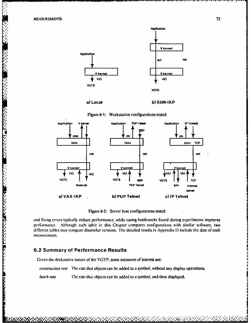
MEASUREMENTS 75
Application
Application' /IKP net
i VI.o vIo,A VGTS
VGTS
a) Local b) SUN-IKP
Figure 6-I: Workstation configurations tested
Application V-server Application PUP Telear Application IP Telneld
pipe I py + I IyUnix Unix Unix TCP
. net net net
V kernel I V kernel VIiv.., ]VIO VlO VlO +VIO VIO
VGTS VOTS BSP VGTS rCP
fexecute PUP Telnet iptn Internal
a) VAX-IKP b) PUP Telnet c) IP Telnet
Figure 6-2: Server host configurations tested
and fixing errors typically reduce performance, while casing bottlenecks found during experiments improvesperformance. Although each table in this Chapter compares configurations with similar software, twodiflnercnt tabils may compare dissimilar veiions. 'Ilic detailed results in Appendix I) include the date of eachmcasuremcrnt.
6.2 Summary of Performance Results
Given the declarative nature of the VGrP, some measures of interest are:
construction rate '11we rate that objects can be added to a symbol, without any display operations.
batch rate 11wc rate that objects can be added to a symbol, and then displayed.
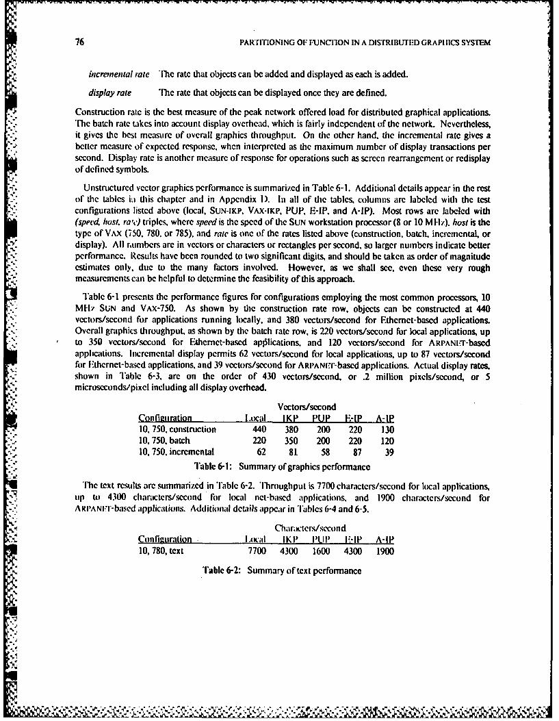
76 PARTITIONING OF FUNCTION IN A DISTRIBUTED GRAPHICS SYSTEM
incremenial rate The rate that objects can be added and displayed as each is added.
display rate The rate that objects can be displayed once they are defined.
,* Construction rate is the best measure of the peak network offered load for distributed graphical applications.The batch rate takes into account display overhead, which is fairly independent of the network. Nevertheless,it gives the best measure of overall graphics throughput. On the other hand, the incremental rate gives abetter measure of expected response, when interpreted as the maximum number of display transactions persecond. Display rate is another measure of response for operations such as screen rearrangement or redisplayof defined symbols.
Unstructured vector graphics performance is summarized in Table 6-1. Additional details appear in the restof the tables ia this chapter and in Appendix I). In all of the tables, columns are labeled with the testconfigurations listed above (local, SUN-IKP. VAX-IKP, PUP, E-IP, and A-IP). Most rows are labeled with(speed, host. ra'c) triples, where speed is the speed of the SUN workstation processor (8 or 10 MHz), host is thetype of VAX (750, 780, or 785), and rate is one of the rates listed above (construction, batch, incremental, ordisplay). All r,umbers are in vectors or characters or rectangles per second, so larger numbers indicate betterperformance. Results have been rounded to two significant digits, and should be taken as order of magnitudeestimates only, due to the many factors involved. However, as we shall see, even these very roughmeasurements can be helpful to determine the feasibility of this approach.
Table 6-1 presents the performance figures for configurations employing the most common processors, 10MI-I? SUN and VAX-750. As shown by the construction rate row, objects can be constructed at 440vectors/second for applications running locally, and 380 vectors/second for Ethemet-based applications.Overall graphics throughput, as shown by the batch rate row, is 220 vectors/second for local applications, upto 350 vectors/second for Fthernet-based apllications, and 120 vectors/second for ARlPANI.r-basedapplications. Incremental display permits 62 vectors/second for local applications, up to 87 vectors/secondfor fEthernet-based applications, and 39 vectors/second for ARPANIt.r-based applications. Actual display rates,shown in Table 6-3. arc on the order of 430 vectors/second, or .2 million pixels/second, or 5microseconds/pixel including all display overhead.
Vectors/secondConfiguration Local IKP PUP E-IP A-IP10, 750, construction 440 380 200 220 13010, 750, batch 220 350 200 220 12010, 750, incremental 62 81 58 87 39
Table 6-1: Summary of graphics performance
The text results are summarized in Table 6-2. 'Throughput is 7700 characters/second for local applications.up to 4300 characters/second for local net-based applications, and 1900 characters/second forAR rANii-based applications. Additional details appear in Tables 6-4 and 6-5.
Cha.icters/sccondConlheuration ILoAal IKP PiP I'-IP A-IP10, 780, text 7700 4300 1600 4300 1900
Table 6-2: Summary of text performance
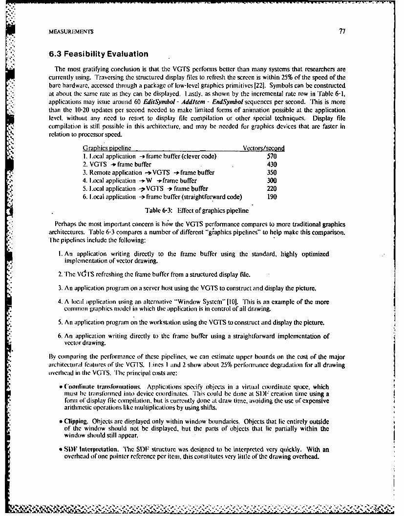
MEASUREMENT'S 77
6.3 Feasibility Evaluation
The most gratifying conclusion is that the VGTS performs better than many systems that researchers arecurrently using. Traversing the structured display files to refresh the screen is within 25% of the speed of thebare hardware, accessed through a package of low-level graphics primitives 1221. Symbols can be constructedat about the same rate as they can be displayed. Lastly. as shown by the incremental rate row in Table 6-1,applications may issue around 60 EditSymbol - Addltem - EndSymbol sequences per second. This is morethan the 10-20 updates per second needed to make limited forms of animation possible at the applicationlevel, without any need to resort to display file compilation or other special techniques. Display filecompilation is still possible in this architecture, and may be needed for graphics devices that are faster inrelation to processor speed.
Graphics nipeline Vectors/second1. Local application - frame buffer (clever code) 5702. VGTS -* frame buffer 4303. Remote application -'VGTS -* frame buffer 3504. Local application -)W .frame buffer 3005. Local application .-7VGTS -. frame buffer 2206. Local application -- frame buffer (straightforward code) 190
Table 6-3: Effect of graphics pipeline
Perhaps the most important concern is how the VGTS performance compares to more traditional graphicsarchitectures. 'Table 6-3 compares a number of different graphics pipelines" to help make this comparison.The pipelines include the following:
1. An application writing directly to the frame buffer using the standard, highly optimizedimplementation of vector drawing.
2. The vd'lS refreshing the frame buffer from a structured display file.
3. An application program on a server host using the VGlS to construct and display the picture.
4. A local application using an alternative "Window Systemn" [10]. This is an example of the morecommon graphics model in which the application is in control of all drawing.
5. An application program on the workstation using the VGTS to construct and display the picture.
6. An application writing directly to the frame buffer using a straightforward implementation ofvector drawing.
SIBy comparing the performance of these pipelines, we can estimate tipper bounds on the cost of the majorarchitectural features of the VGTS. ILines 1 and 2 show about 25% perlornance degradation for all drawing
,,*7 overhead in the VG'I'S. The principal costs are:
* (oordiniale transfornwions. Applications specify objects in a virtual coordinate space, whichinust be translrmed into device coordinates. This could be done at SI)F creation time using arform o1 display file compilation, but is currently done at draw time, avoiding the use of expensive
arithmetic operations like multiplications by using shifts.
_ * Clipping. Objects are displayed only within window boundaries. Objects that lie entirely outsideof the window should not be displayed, but the parts of objects that lie partially within thewindow should still appear.
* SIF Interpretation. T[he SDF structure was designed to be interpreted very quickly. With anoverhead of one pointer reference per item, this constitutes very little of the drawing overhead.
_X :2
--.
78 PARTITIONING OF FUNCTION IN A DISTRIBLTED GRAPHICS SYSTEM
Lines I and 4 can be used to estimate the cost of centralized control. The W system is representative of the-"minimalist" approach, with actual drawing centralized but few of the other features of the VGTS. Thus the
47% overhead of W can be attributed primarily to:
* Message overhead. This will be incurred whenever the graphics service runs as a separate processfrom the application. Besides the time for the actual message passing and context switching, theoperations must be encoded into and decoded from the message.
" Data movement. This is the cost of copying information from the address space of the applicationto the server, incurred whenever the server is not linked into each application.
Comparing line 4 to line 5 indicates a 27% performance difference when using the VGTS instead ofW. Although some of this may be due to SI)F interpretation overhead, most is due to the following VGTS
* Client stream interface. The prototype interface library encodes all graphics operations into astream of bytes, and uses the standard V 1/O protocol. 'Ibis allows for I/O redirection, evenamong machines with different byte orders.
* Server stream interface. The prototype server implementation decodes the graphics operationsfrom the byte stream and calls appropriate internal functions.
* Error checking. The VGTS attempts to do most error checking, such as verifying that tableindices are within their proper bounds, at SDF creation time, so subsequent redraws will perform
-!i at full hardware speed.
* Memory allocation. Memory must be allocated to the S1DF display records for each new object.'Once the memory is obtained from the system, this involves only a simple pointer movementdown the free list.
* SDF Sa'ing. The actual overhead for saving the display record involves storing the coordinatesand attrioutes (usually insignificant) and calculating the extent of the currently open symbol.
Despite these costs, the VGTS distributed rate (line 3) is higher than W (line 4). This shows that a significant* amount of th2 overhead is incurred on the client, which results in a benefit from concurrency. It is, in fact,
standard protocols such as V I/O and the byte stream concept that facilitate distribution.
Note that almost all of these costs must still be incurred even if SI)Fs were not used to retain the graphics:,.... information: the only saving would be the few microseconds to store into the display record. Of course, some
overheads could be avoided by using only one process, one address space, screen coordinates, etc. but theresulting system would not have the advantages described in the last chapter.
Finally, comparisons of application--screen throughput show the VGTS at its worst case, since they do nottake advantage of the display file. Iven though the initial picture sometimes takes longer to appear whenusing tie VGTS, once it is defined it can he drawni very quickly. For example. in response to screen"management operations, any W-like system would require ihe application to redisplay its contenLs at the 300
vectors per second rate, while the VGTS would redisplay at 430 vectors per second, a 43% performanceadvantage.
A simple qualitative measure of text performance is how the VGlS compares to standard RS-232 9600baud terminals, which generate about 940 characters per -second. For example, consider a typical page
'' forward command in a screen editor which changes about 1000 characters. On a 9600 baud RS-232connection this would ake about one second. With the VG'S it takes about a fifth of a second, which is fastenough to seem instantaneous to most users.
The remainder of this chapter will attempt to show the effect of varying different parameters, and evaluatethe effects to the limited extent possible in the configurations available. These parameters include:
. . ... . . . . • ~ ............. .
MEASUREMENTS 79
" speed of the workstation and graphics device
" speed of the remote host (if any)
" speed of the network
" choice and implementation of transport protocol
" level at which information is communicated, including characteristics of the virtual graphicsterminal protocol
6.4 Internal Factors
For many application programs with large proceksor demands, the importance of the speed of the graphicscan be insignificant compared to the importance of the speed of the application. These programs are ideallysuited to the VGTS architecture since the application can be run on a larger, specialized, high-performanceprocessor instead of the workstation. Thus, the major concern is when the frequency of interaction is high.
Even though the VGTS was designed for efficient partitioned operation, it is still good at local operation.As we shall see, the most important factors affecting the performance of the VGTS are the same as thoseaffecting most other programs. This might be considered as unfortunately mundane, but it means that theVGTS can take advantage of the many well-known techniques for making typical programs run faster; thereare no inherent performance reasons to prevent the use of VGTS concepts.
6.4.1 Effects of Graphics Package
One of these important factors that is often overlooked, is that for any program, most of the time is spent ina small part of the code. In the case of the graphics benchmarks, much of the execution time was spent in thevector or rectangle drawing function. The Bresenham algorithm, which is usually the fastest, was used todraw vectors 1201. However, even a straightforward implementation of the fastest algorithm was much slowerthan an implementation using clever coding of the inner loops of the Bresenham algorithm.
In the clever implementation. the vector drawing function compiles a custom-made inner loop for eachvector. This takes a little more time to set up for each vector, bLt this initial time is kept small by using tablelook-ups. As seen in Table 6-3, using compiled vectors instead of straightforward coding yielded a 200%improvement in vectors per second on the draw rate. However, using the VG'I S introduced some overheadon the drawing times since it is interpreting a structured display file. Table 6-3 showed that the Si)Foverhead is very small compared to the large improvement from compiled vectors.
Unfortunately, the speedup from chosing a good algorithm and optimizing its inner loop is good for only aone-time increase in performance. Once the best algorithm is found and its inner loops are hand-optimized,more work will not result in more Ierlbrinance improvements. On the other hand, the cost of carefullyrecoding one module or writing a Iew lines of assembly code is usually small, so the return on the investmentis good tip to a point.
6.4.2 Effects of Processor Speed
Another fairly obvious fact that is often overlooked is that the speed of an application is directly related tothe speed of the processor on which it runs. Table 6-4 compares the performance of workstations that havetwo diflerent basic clock rates, but are similar in most other respects. Use of 10 M IIZ SUN workstationsinstead of 8 MHz workstations yielded up to 22% improvement. hlie principal reason that the increase from
tz]
Il** *%N **. -:-- ~
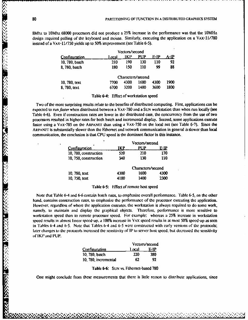
80 PARTITIONING OF FUNCTION IN A DISTRIBUTED GRAPHICS SYSTEM
8Mhz to 10Mhz 68000 processors did not produce a 25% increase in the performance was that the 10MHzdesign required polling of the keyboard and mouse. Similarly, executing the application on a VAX-11/780instead of a VAx-11/750 yields up to 50% improvement (see Table 6-5).
Vectors/secondConfiguration IoXcal IKP PUP E-P A-IP10, 780, batch 210 190 130 110 928, 780. batch 180 150 110 99 88
Characters/second10, 780, text 7700 4300 1600 4300 19008, 780, text 6700 3200 1400 3600 1800
Table 6-4: Effect of workstation speed
Two of the more surprising results relate to the benefits of distributed computing. First, applications can beexpected to run faster when distributed between a VAX-780 and a SUN workstation than when run locally (seeTable 6-6). Even if construction rates are lower in the distributed case, the concurrency from the use of twoprocessors resulted in higher rates for both batch and incremental display. Second, some applications executefaster using a VAX-785 on the ARPANTr than using a VAX-750 on the local net (see Table 6-7). Since theARPANFn" is substantially slower than the Ethernet and network communication in general is slower than localcommunication, the conclusion is that CPU speed is the dominant factor in this instance.
Vectors/secondConfiguration IKP PUP E-IP10, 780, construction 510 210 17010, 750, construction 340 130 110
Characters/second
10, 780, text 4300 1600 430010, 750, text 4100 1400 2300
Table 6-5: Effect of remote host speed
Note that Table 6-4 and 6-6 contain batch rates, to emphasize overall performance. Table 6-5, on the otherhand, contains construction rates, to emphasize the performance of the processor executing the application.However. regardless of where the application executes, the workstation is always required to do some work,namely, to maintain and display the graphical objects. 'Ilerefore, performance is more sensitive toworkstation speed than to remote processor speed. For example: whereas a 25% increase in workstationspeed results in almost linear speed-up. a 100% increase in VAX speed results in at most 50% speed-up as seenin Tables 6-4 and 6-5. Note that Tables 6-4 and 6-5 were constructed with early versions of the protocols-later changes to the protocols increased the sensitivity of III to server host speed, but decreased the sensitivityof I KI and PUP.
Vectors/second
Configuration Local E-IP10, 780, batch 220 38010, 780, incremental 62 92
Table 6-6: SUN vs. Ethernet-based 780
One might conclude from these measurements that there is little reason to distribute applications, since
l, .. ..... ... ... .. ... ... .. ......- ".. ..- "..:.'?. . ... -..- '-.--,
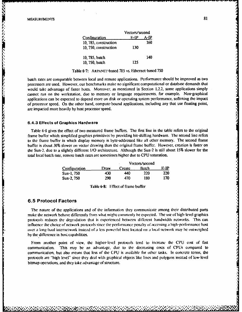
MEASURFM-MrS 81
Vectors/secondConfiguration E-IP MP10, 785, construction 16010, 750, construction 130
10, 785, batch 140
10, 750, batch 125
Table 6-7: ARPANET-based 785 vs. Ethernet-based 750
batch rates arc comparable between local and remote applications. Performance should be improved as twoprocessors are used. However. our benchmarks make no significant computational or database demands thatwould take advantage of faster hosts. Moreover, as mentioned in Section 1.2.2, some applications simplycannot run on the workstation, due to memory or language requirements, for example. Non-graphicalapplications can be expected to depend more on disk or operating system performance, softening the impactof processor speed. On the other hand, compute-bound applications, including any that use floating point,arc impacted more heavily by host processor speed.
6.4.3 Effects of Graphics Hardware
Table 6-8 gives the effect of two measured frame buffers. The first line in the table rcfcrs to the originalframe buffer which simplified graphics primitives by providing bit-shifting hardware. il'he second line refersto the frame buffer in which display memory is byte-addressed like all other memory. The second framebuffer is about 30% slower on vector drawing than the original frame buffer. However, creation is faster onthe Sun-2, due to a slightly different I/O architecture. Although the Sun-2 is still about 15% slower for thetotal local batch rate, remote batch rates are sometimes higher due to CPU saturation.
Vectors/secondConfiguration Draw Create Batch E-IPSun-1, 750 430 440 220 220Sun-2, 750 290 470 180 170
Tale 6-8: Effcct of frame buffer
6.5 Protocol Factors
The nature of the applications and of the information they communicate among their distributed partsmake the network behave differently from what might commonly be expected. h'lc use of high-level graphicsprotocols reduces the degradation that is experienced between dilferent bandwidth networks. This caninfluence ihe choice of network protocols since the perlbr)ance penally ol'accessing a high-perlinnance hostover a long-haul inicrnetwork insicad of a less powerlul host located o)11 a local network may bc oluweighedby the difference in host capabilities.
From another point of view, the higher-lcvel protocols tend to increase the CPU cost of fastcommunication. 'l'his may be an advantage, due to the decreasing costs of CPUs compared tocommunication, but also means that less of the CPU is available for other tasks. In concrete tcrms, theprotocols are "high level" since they deal with graphical objects like lines and polygons instead of low-levelbitmap operations, and they take advantage of structure.
-:
82 PARTITIONING OF FUNCTION IN A DISTRIBUTED GRAPI IICS SYSTEM
6.5.1 Effects of Structure
As discussed in Section 3.4, the VGTP allows objects to be defined in terms of graphical primitives such asvectors or rectangles, or in terms of other objects. Once the objects are defined, they can be made to appearon or disappear from the screen with short commands of only a few bytes. The performance advantages ofretaining the display files on a dedicated workstation, introduced in Section 5.1, have been known for sometime [881. The following tests were performed with a program that used the structuring facilities of the VGTSto create 30 instances of a symbol consisting of 26 rectangles each.
The results for the structure benchmark are given in Table 6-9. The first thing to notice is the very low ratefor incremental performance, especially over long-delay networks like the ARPANET. By batching andpipelining the operations, performance increases by a factor of 7 for local operations, 30 for Ethernetoperations, and 40 for ARPANE'f operations. Using structure instead of an unstructured list of primitive itemsincreases performance again by factors of 3 to 4 for both local and remote operations.
Rectangles/secondConfiguration Local E-IP A-IP10, 750, incremental 41 5 210, 750, pipelined incremental 61 66 3610, 750, batch unstructured 310 180 8110, 750, batch structured 1070 670 370
Table 6-9: Effect of structure
Some other interesting observations can be made fiom Table 6-9 that reflect the value of batching andstructure. First, the time to define and display the picture for a local application was about 1 millisecond peritem. 'Ibis is roughly the time to perform a local Send - Receive - Reply sequence in the V kernel [311, so anyprotocol that uses a message transaction for each item will be slower. Secondly, it is raster to run thisbenchmark over the ARPANIEIT and use structure than it is to run the same program locally and useincremental or unstructured display. The latter is comparable to traditional graphics systems. It is also fasterto run the program across the Ethernet and use structure than it is to run the program locally, even withbatching.
Structure introduces a slight amount of overhead, since the VGTS must trace through the symbol datastructure. However, in this benchmark the structure interpretation introduced an overhcad of about 20milliseconds out of about 900, or less than 3% of the local draw time. 'Ihus there is little performanceadvantage to use a segmented display file instead of an arbitrarily structured one. By using a linear list insteadof a linked list, display records could be 16 bytes instead of 20. or a 20% savings in memory. Unfortunatelythis would make insertion and deletion much more difficulL Moreover, the SDF representation is alreadyquite concise, as will be shown in Section 6.5.3.
" 6.5.2 Effects of Batching and Pipelining
Comparing the batch and incremental rates in Table 6-1 as well as Table 6-9, shows the importance ofbatching. The original implementation of the VG'TP employed a return value for each operation. In thecurrent implementation operations are batched so that values are returned only after an entire sequence ofoperations (such as all changes to a given symbol) have been performed. This change reduced network delayssubstantially, yielding performance improvements of up to factors of 301
The first two lines of Table 6-9 give the effect of another important change to the VGTP. By removing the* return values from the lditSynbol and EndSymbol operations, even incremental operations could be, pipelined, resulting in much more concurrency than the "stop-and-wait" protocol resulting from return values
.1
MEASUREMENTS 83
on each transaction. The reduced message traffic caused an increase of 50% for local operations, and increasesof factors of 10 to 15 for remote operations In fact, remote incremental operations are almost always fasterthan local incremental operations due to this concurrency.
6.5.3 Comparison to Bitmap Protocols
Many approaches to graphics within a distributed system use protocols based on bitmap manipulation.Unfortunately, bitmap protocols can be inefficient in both their bandwidth and memory utilization. Byreducing the length of the descriptions of graphical objects, they are made independent of the structure of thebitmap as well as being smaller in both transmission and storage.
The advantages of the SDF for memory usage are indicated in Table 6-10. In the vector benchmark, theSDF represented the fully-connected polygon with 20 bytes per item, or 12,600 bytes. This compares to the800 by 800 bitmap area, which would take 80,000 bytes. In practice, most pictures are even less dense thanthe fully-connected polygon, so the advantage would be even greater. In particular, the SI)F approach hasthe advantage as long as there are more that 20 bytes of bitmap space for each item in the SI)F. The rectanglebenchmark shows that even without using structure, a factor of about two in memory savings is possible.Using structure, the 900 bytes used by the SDF is a factor of 37 less than the space for the bitmap. Similar
'-$ large improvement factors in network bandwidth requirements will be discussed in Section 6.6.
Bytes of memory usedBenchmark SDF Bitmapvector 12,600 80,000rectangle, unstructured 15,600 34,000rectangle, structured 900 34,000
Table 6-10: Effect of SDF on memory usage
6.5.4 Effects of Transport Protocols and Their Implementations
As noted for Table 6-5, three different transport protocols were used, with significantly differentperforrunce results. "he V-system supports both a local protocol and two general inter-network byte-streamprotocols. The local protocol provides an interprocess communications facility between V-system processes.The two general protocols are the Xerox PUP family implemented through the RTP/lSIV level, and the ARI'AInternet protocol family implemented through the TCP level. User THl.NI programs exist on top of both.The network configurations were illustrated in Figure 6-2.
Unfortunately it is very hard to compare only the effect of protocol design, because of manyimplementation issues that vary betwec, the protocols. For example, the implementation of PUP lISP didnot use any of the windowing features available in the protocol, resulting in inuch lower performance thian theIP. More iiportant. the packet size tsed in the IKII implcinetatioi wits 1024 bytes, while hoth I'l Pand IPused packets of I0I or 200 bytes. On the other hand, the incremental rates fbr the I K11 experiments were verypoor,. due to the fact that a UNIX server process was polling every few seconds for Output from a pipe. whilethe other protocols were interrupt driven.6'lhus the implementation of the protocol may have a greater effectthat any properties inherent in the protocol itself.
Fortunately we were able to experiment with different implementations of the same protocol. During thecourse of our experiments, there were two major implementations of the ARPA Internet Protocol available for
Gl e UNIX V-scrvcr could be modified in 4.2 to use the select syslem call 1681. which would eliminate this delay.
84 PARTITIONING 01 FUNCTION IN A DISTRIBUFED GRAPHICS SYSTEM
VAX/UNIX systems. 'The first was done by Bolt, Beranek and Newman (BBN) and was for the 4.1 version ofUNIX [611. The second was done by the Universi'ty of California at Berkeley for the 4.2 version of UNIX [681.The relative performances of these two implementations of the same protocol are given in table 6-11. The 4.2implementation is 1.4% faster for batch construction and display rates. The difference in peak throughputrates is even more significant, but even this higher rate is several orders of magnitude below the actualbandwidth of the network. Possible reasons for this will be discussed in the next section.
Vectors/second4.2 4.1
Configuration IP/TCP 1PfCP10, 750, construction 140 11010, 750, batch 93 8110. 750, incremental 7.8 4.8
Table 6-11: Effect of TCP implementation
'rable 6-12 indicates the effect of changing the relative priorities of the application program or the TEl NETserver program. This test was done using the PUP protocol on a local 10 Mbit/second Ethernet. The firstcolumn gives the results for normal operation. For the second column, the operating system gave priority tothe "l'nl.NI-r server program. Batch performance actually decreased, since more network packets were sent.For the third column, both the application and the TI.t.NE-r server were given priority, which increased boththe batch and incremental rates. However, as shown in the last column, the best performance was obtained bygiving priority to the application.
Vectors/second
Telser &Configuration Normal "'elser Apolication Armlication10, 750, batch 170 160 190 20010, 750, incremental 47 48 58 58
Table 6-12: Effect of Process Priorities
Another interesting comparison is between remote execution on a timesharing host and execution onanother workstation. Table 6-13 displays this comparison. 'lie construction rate is about the same on theVAX/UNIX system and on the V-System. The incremental rates on the VAX/UNIX implenenttion are verypoor without pipelining, due to the high delay. Note. however, that the total batch rate and the pipelinedincremental rate are much higher on the VAX than on another workstation. This is due to the fact that there isactually little concurrency in the remote workstation case, due to the synchronous VIKP messages. Muchbetter performance could be obtained by replying to the message bef!,re it is processed, instead of after theoperations are performed.
Vectors/secondSUN VAX
Confiauration IKP IKP10, 750, construction 380 38010. 750, batch 190 35010, 750, incremental 29 4.610, 750, pipelined incremental 44 81
%N ' Table 6-13: Effect of lKP implementation
,5,
MEASURFMFNTI3S 85
6.6 Network Factors
The use of networks implies both limitations in bandwidth and increased delays. All of thc above factors(and our design and implementation) combine to render the actual network bandwidth insignificant. Table6-14 shows that although a 3 Mbit/second Ethernet is about 60 times faster than the 56 Kbit/second linksused in the ARPANI'r, using a backend host on the local network yields less than a 50% performanceimprovement over using a backend host on the ARPANIETI8 . Moreover, there was very little measurableperformance difference between using the 3 Mbit/second experimental Ethernet rather than 10 Mbit/secondstandard Ethernet [44]. The column labeled ElO-IP refers to standard 10 Mbit/second Ethernet. Althoughthe Ethernet is about 180 times faster than the links used in the ARPANET, the Ethernet construction rates areless than twice the ARPAN.. rate. In fact, most of the difl'erence in the total batch rate is due to the delay ofthe ARP,I..I' and intervening gateway, not any bandwidth restriction. Earlier implementations of theprotocols had even less of difference.
Vectors/second
Configuration E-IP EIO-IP A-IP10, 750 4.2, construction 220 230 13010, 750 4.2, batch 210 220 120
Table 6-14: Effect of network bandwidth
These results can be attributed primarily to the level of communication as discussed in section 6.5.1, and theconclusion that processor speed is the usual bottleneck. "['his is consistent with other measurements ofEthernet performance 1120] that show very low utilization of the available bandwidth of the Ethernet, andcomparatively long delays on the ARPA Network. Thus, these systems rarely approach the limits described inanalytical studies that concentrate on performance under heavy loads [145J. In fact, these protocols can beused on vc:y low-bandwidth communication links.
Each AddlItem call sends 20 bytes of data, so a construction rate of 230 items per second (the Ethernet loadgiven in Table 6-14) corresponds to only 4600 bytes per second, or about 40 Kbits/second. about 0.4% of theEthernct' bandwidth. )ue to the small amount of data, graphics could even be possible over standard speedtelephone lines. For example, at 1200 bits/second, a peak rate of 7.5 items/second should be possible. To testthis, tie experiment was run successfully on a workstation over a 1200 hits/second telephone link. Several
%other rates were tested using point-to-point RS-232 connections at various speeds, with the results given inTable 6-15.
Items/secondConfiguration 1200 2400 4800 9600 E-IP10, 750 4.2. construction 7.4 14 26 54 16610, 750 4.2, batch 6.2 12 23 46 13110, 750 4.2, structure 84 142 230 320 380
-I. Ille 6-15: I'ffct of point-to-point communication rates
For the structure benchmark. even at 1200 bits/second, the measured creation rate was 7.4 items/second,very close to the maximum 7.5 calculated above. This rate is slightly less than linear in relation to the
. bandwidth, indicating that even at low speeds the CPU can be a factor. Moreover, the total rate when usingstructure was 84 items/second at 1200 bits/second, which is twice as fast as running the program locally withincremental drawing (the first entry in Table 6-9). Structure and lack of significant delays also makes this
B In flct. the experimental Ethcrnet Ls really about 2.93 Mbit/sccond. Thc differce between this and 3 Mbit/sccond is greater than
the 56 Kbit/Acond of the ARPANIr link!
... ......-.... :-..-........................................ .....................................................
-A SS 925 PARTITIONING OF FUNCTION IN A DISTRIBUTED GRAPHICSSYSTEH(U) STANFORD UNIV CA DEPT OF COMPUTER SCIENCENOWICKI MAR 85 STAN-CS-85-1882 NDAg93-8-C-8102
UCLASSIFIED F/G 17/2
EIEIIEEEIIIIIIEEIIIIIEEEEEEEIIEEIIIIEEEE
agL.
I 'lll 11111.8III.6
MICROC04v -!ON TEST CHART
NATIONAL BUAEAU OF STA9OAAIOS -963-
W,.
V.%I%
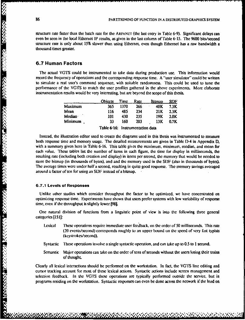
86 PARTITIONING OF FUNCTION IN A DISTRI3UrED GRAPHICS SYSTEM
structure rate faster than the batch rate for the ARI'ANLEr (the last entry in 'Table 6-9). Significant delays caneven be seen in the local Ethernet III results, as given in the last column of'able 6-15. The 9600 bits/secondstructure rate is only about 15% slower than using Ethernet, even though Ethernet has a raw bandwidth athousand times greater.
6.7 Human Factors
Thc actual VGTS could be instrumented to take data during production use. This information wouldrecord the frequency of operations and the corresponding response time. A "user simulator" could be writtento simulate a real user's command sequence, with suitable randomness. This could be used to tune theperformance of the VGTS to match the user profiles gathered in the above experiments. More elaborateinstrumentation results would be very interesting, but are beyond the scope of this thesis.
Obiects Time Rate Bitmao SDFMaximum 365 1370 266 40K 7.3KMean 116 485 234 21K 2.3KMedian 101 430 235 19K 2.0KMinimum 33 160 203 13K 0.7K
Table 6-16: Instrumentation data
Instead, the illustration editor used to create the diagrams used in this thesis was instrumented to measureboth response time and memory usage. The detailed mcasurements are given in Table 13-4 in Appendix D,with a summary given here in Table 6-16. This table gi~es the maximum, minimum, median, and mean foreach value. These tables list the number of items in each figure, the time for display in milliseconds, theresulting rate (including both creation and display) in items per second, the memory that would be needed tostore the bitmap (in thousands of bytes), and and the memory used in the Si)F (also in thousands of bytes).The average times were under halfa second, resulting in quite good response. The memory savings averagedaround a factor often for using an SDF instead of a bitmap.
6.7.1 Levels of Responses
Unlike other studies which consider throughput the factor to be optimized, we have concentrated onoptimizing response time. Experiments have shown that users prefer systems with low variability of responsetime, even if the throughput is slightly lower [98].
One natural division of functions from a linguistic point of view is into the following three generalcategories [15 11:
Lexical These operations require immediate user feedback, on the order of 50 milliseconds. 'Ibis rate(20 evenLs/second) corresponds roughly to an upper bound on the speed of very lIst typists(keystrokc/second).
Syntactic 'lbcse operations involve a single syntactic operation, and can take up to 0.5 to 1 second.
Semantic Major operations can take on the order of tens of seconds without the users losing their trainsof thought.
Clearly all lexical interactions should be performed on the workstation. In fact, the VG'S line editing andcursor tracking account for most of these lexical actions. Syntactic actions include screen management andselection feedback. In the VGIS these operations are typically performed outside the service, but inprograms residing on the workstation. Syntactic responses can even be done across the network if the load on
i?
MEASUREMENM S 87
the remote host is not very high. Larger-scale semantic operations, like loading and running large programs,searching central databases, or compilation, are typically done on remote server hosts or distributed between aserver host and the workstation.
6.7.2 Keystroke Data
Many studies have been done for text editors to determine the common operations [26, 57]. These studiescan bc extended to graphics, but are also valuable in their own right since a large part of any user's interactionis still textual. The main conclusion of these studies is that the majority of the users' time is spent doing verysimple repetitive tasks. Thus we concentrated on making these few simple tasks faster by taking advantage ofthe power of the local workstation.
6.8 Discussion of Results
*: To summarize our findings, the primary factors affecting performance of our distributed graphicsapplications are, in approximate order of importance:
1. Speed of the workstation.
2. Speed of the remote host, if any.
3. Level of communication, as determined by the virtual graphics terminal protocol.
4. Bandwidth of the networks employed.
Essentially the same observations hold for text. Note that these obscrvadons relate to the degree ofperformance improvement relative to the degree of change in the indicated parameters. Thus, a 50%performance improvement due to a 200% increase in processor speed could be considered relatively greaterthan a 300% improvement in perfoirmance due to a 6000% increase in network speed. ' he importance ofCPU speed and amortizing communication costs over large buffers was a major conclusion of one of the fewother similar studies 185).
It is relatively easy to rate the sensitivity to hardware factors. Software factors are another matter; it is easyto measure die absolute performance improvement resulting from a change in software, but quite difficult tomeasure de cost of the software change. Nevertheless, certain conclusions will be drawn based on availableinformation. Also note that there are limits beyond which changing one factor will not affect performance;for example, a CPU-bound application running on a remote host will be little affectcd by an increase inworkstation speed.
CPU speed rates at the top of the list simply because desired specd-ups can be achieved almost indefinitelyby substititing more powerful workstations and backend hosts. Continuous improvement is not possible withnetwork protocols. IK V. 1br example, provides as good performance on the local net as can be achieved.Another way of saying dis is that network protocols are limited by the available hardware, and tie mostimportant piece of hardware is the CPU.
6.8.1 HardwareFactors
As workstations become more powerful, one might think that oflloading functions from hosts to theworkstation means that slower backend hosts can be used. In reality. faster hosts arc required to keep tip withthe increased demands of the workstations. On the other hand, one might think that as networks become
88 PARTITIONING OF FUNCTION IN A DISTRIBUTED GRAPi IICS SYSTEM
faster, communication is cheap. Unfortunately, network interfaces have not kept pace with bandwidth, sothat many network operations remain CPU-bound. In both cases, the offloading and increased bandwidthmay allow more users to share the same resource, but do not increase the performance for individual users.Hence, fasier hosts are needed, not slower ones.
Similarly, network controllers are now being marketed with microprocessors that are intended to offioadtask3 from thc main processor. Our experience has been that such controllers are usually slower, not faster,than simpler and cheaper controllers that perform fewer finctions but use fixed logic at a higher speed.
With respect to network bandwidth, sensitivity is directly related to communication requirements.Conmunications requirements are inversely related to the frequency of communication and the amount ofinformation transmitted, both of which are reduced by the techniques discussed above. Therefore, theremarkable insensitivity of our applications to network bandwidth implies that they are quite sensitive to the"level" of communication.
6.8.2 Software Factors
This high level of communication is due to the Virtual Graphics Terminal Protocol design. In particular,the ability to batch many operations into a single update using a small number of bytes provided largeincreases in performance.
It is hard to make direct comparisons about network protocols independent of their implementations. Forexample, a protocol inside the kernel of an operating system is usually more responsive than if it isimplemented on top of the kernel. Of course, a processor runs at the same speed both in kernel and userstate. "lbe increased responsiveness comes with the cost of increasing the size of the (usually always resident)kernel and the related difficulties of debugging at lower levels.
In our particular case, despite the fact that the PUP protocols are simpler than the ARPA Internet protocols,ARPA Internet-based "ITNI:r connections can sometimes run about twice as fast as PUP-based ones. This isattributed primarily to the fact that PUP is implemented as an application outside the Unix kernel whereasthe ARPA Internet protocols are implemented inside the kernel.
For very time-critical functions such as network communications, mcssages and process context switches areexpensive even in systems designed to provide very fast message passing and light-weight processes. 'T7heinterested reader should refer to [821 for a more detailed analysis of the networking issues which are not ofdirect concern of this thesis.
6.8.3 Fitting the Model
The experiments given in this chapter give some estimates of the times used in the models of Section 5.3.For example, peak pipclincd incremental rates are about 60 interactions per second, or TNeOuI + TNeIn of•about I/,th ,cond. I Ithis is less than the swapping tines '. + then the workstation/host
Swipl Sw:11101tsplit will be faster. even with coniparable computation times. most or today's personal computers take muchlonger than 1/60 second to swap an application out and back in. The advantage will increase with morepowerful hosts and less powerful workstations.
Of course, care must be taken when generalizing these results to other programs. These benchmarks wereintended as communication-intensive limits, since they only do graphics and no real computation. Moresophisticated applications could be expected to achieve even larger speed-ups when distributed. Theinstrumentation results show that the synthetic benchmarks are not fundamentally different from actual
* applications, except for slightly slower rates due to the computation by the application. No claim is made that
'4
MEASUREMENTS 89
these results allow us to predict the performance of an arbitrary program. On the other hand, a protocol that- provided one hundred items per second in our experiments will probably be faster that one that provided ten
items per second. More analytical work needs to be done to accurately predict performance, but these resultsprovide a start.
N., V
5.o
"

90 PARTITIONING OP FUNCTION IN A DISTRIBUTED GRAPHICS SYSTEM
}'1
5%
5%
4
N
P.
1
V
4
-t..---",.x-.t~.4 .*...*.--..,
,- --
*-*~
--5~~ -. * ~. *..s..~ . 7 .(C F,. - - S - *'4~''t4. ... '5 st5*5.........~ %.,;.t.'t. *. .s.-.xs, .. '. '5-
S - . - - S *
CONCLUSIONS AND FUTURE WORK 91
-7-Conclusions and Future Work
The previous chapters described the motivation for, the design, implementation, rationale, andmeasurements of a simple distributed graphics system. This Chapter draws a number of conclusions from thiswork, and presents possible extensions for the future.
7.1 Structured Display Files and Virtual Terminals
The first important conclusion is that the structured display file technique can be combined with the virtualterminal concept, resulting in an architecture for distributed graphics. The virtual terminal concept, describedin Section 2.3, provides the user with access to multiple simultaneous distributed resources. The VirtualGraphics Terminal Server mediates between application programs that share a workstation dedicated to asingle user.
The declarative nature of structured display files outlined in Chapter 3 reduces communication, and allowshigher-level short circuiting. The performance and decreased memory utilization motivations for structuregiven in Section 5.1.1, are supported by the measurements in Section 6.5.1. In particular, SDFs can yield bothhigher performance and lower memory requirements than traditional graphics systems. These advantagesincrease ats pictures become more structured, and applications perform more incremental updates. TheVGTS performs cursor motion, screen management, and keyboard echoing internally (as described in Section5.1), resulting in a short-circuit of the interactive response cycle for these common operations.
7.2 User and Program Interface Separation
The VGTS architecture first specified only the application program interface for defining and modifyingobjects, it Section 3.4. A separate user interface for viewing those objects was then specified in Section 4.4.'The prototype implementation rigidly enforced this distinction: applications could not inquire the size of thescreen, Ibr example, and adapt themselves accordingly.
The resulting principle advantage is absolute device independence and portability, which is vital for thereuse of software with rapidly-changing workstation hardware. Concern for the portability of the prototypesaved reimplementing most of the modules described in Section 4.1.1 for new devices, such as the Sun-2frame buffer. The principle disadvantage is that customization is made more difficult. Section 5.6 discussedwhen customization by both users and programmers is desirable, but also mentioned reasons not to allowarbitrary customization.
7.3 Transparent Distribution
Although distributed graphics is possible with the SIF approach. it still may not always be desirable. Forexample, in many cases running the benchmarks locally was raster than running them distributed.Unfortunately, for the reasons given in 1.2.2, it is not always possible to run all applications on theworkstation. Even if the necessary resources arc available as an option for the workstations, they are typicallytoo expensive for widespread use. In other words, even with today's advanced hardware, we still need largervirtual and physical memories, and faster processors, at lower prices.
The protocol uscd for defining objects (the VG'IP) was extended transparently across networks usingseveral transport protocols, described in Section 4.3.5. The same source program can be compiled and linked
k I
92 PARTITIONING OF FUNCTION IN A DISTRIBUTED GRAPHICS SYSTEM
for any of a number of environments, and the same binary can be accessed through three different transportprotocols. Distribution allows applications to run on thc best suited computational resource, and use multipleresources to achieve concurrency. These programs were actually used, so performance constraints werestringent. Results such as those in Table 6-6 show that distributed operation was often faster than localoperation.
7.4 Techniques to Improve Performance
The tables in Chapter 6 show that VGTS performance is close to the best possible speed. In the best case,the VGTS can give much better response than systems that do not retain any information on the structure ofthe image, or allow for concurrent operation. More instrumentation of applications would provide usefulinformation, but is beyond the scope of this thesis. The measurements presented in Chapter 6 alreadyindicate several ways that performance can be improved.
* 7.4.1 Protocol Design Techniques
Once the decision to distribute is made, a more subjective decision is what and when to distribute. In ourexperience, a few simple operations and applications can be done locally, such as text and illustration editors,and the resulting average performance is adequate. The simple but powerful modeling facilities provided bythe VGTS allow this short circuiting.
The use of Structured Display Files also means that once objects are defined, instances of them can appearor disappear with a very small amount of communication. This makes the protocols very insensitive tonetwork bandwidth, as shown in Tables 6-14 and 6-15. Since delay causes more restrictions than bandwidth,many simple operations should be batched together for each interaction. Return values should also beeliminated whenever possible to increase concurrency by allowing pipelining to occur. Although directquantitative comparisons could not be made between the factors affecting performance, batching certainly hasa very important effect.
7.4.2 Software Structuring Techniques
One interesting rule of design learned from the VGTS implementation experience was to use softwarestructuring mechanisms only for die appropriate purpose:
. Use separate processes where separate threads of control arc needed, otherwise use one process.For example, the main part of the VGTS consists of many modules but only one process.
e Use teams (complete address spaces) for programs that.should be executed as a unit. Partitioningthe V(;IS into separate teams caused a great increase in memory consumption, due to thecommon library functions.
* Use modules for parts or a program that can be separately compiled. A direct procedure callinterface was still lIster than other kinds of communication.
Much performance can be lost if one of these partitioning mechanisms is used improperly. Even on a systemlike V where mcssiage passing is fast, it is still slow compared to a procedure call. In particular, Table 6-9shows that the drawing rate can approach one item per millisecond, which is about the samc time it takes toperfonn a mes.ge Send/Receive/Reply cycle. 'Ibus each message should cause many lower-level actionsinstead of just one, reiterating the importance of batching.
,V
CONCLUSIONS AND FUTURE WORK 93
7.4.3 Internal Performance Tuning Techniques
Once hardware and protocol decisions arc made, performance can be improved by using standard softwaretuning tcchniques such as inner loop optimi7ation and increasing buffer sizes and blocking factors. In fact,reasonable performance can be obtained using the standard transport protocols compared in Table 6-1,without resorting to special-purpose protocols and incurring all the problems of being non-standard. On theother hand, the use of structure and proper batching and buffering strategies must be done at every level, toavoid bottlenecks.
7.5 What Can be Learned
In light of the VGI'S experience, we can evaluate some aspects that were later determined to beunsuccessfil, for the benefit of fiture designers:
S'lle declarative nature of the VGTP and lack of a simplified interface library discouragedapplication programmers accustomed to more procedural graphics systems.
* Application programs developed their own conventions since there were few common user-interface libraries.
* Encoding graphical information in the same stream as text at the lowest level did not allowredirection of graphics commands into a file or background graphics programs.
* The lack of raster operations in the programmer's interface discouraged the use of the VGTS forimage processing applications.
*Several minor device-dependencies in the implementation were not made apparent until portswere actually attempted, due to lack of a well-specified device interface.
*'he close coupling of the view manager to the rest of the VGTS discouraged attempts atcustomization through user profiles.
Most of these problems can be easily overcome by the work described in the next section.
7.6 More Open Questions
The VGTS effort raised more questions than it answered. The following is certainly not an exhaustive list,but it should give an overview of possible future topics in this area.
7.6.1 Integration with Editor
One u.,ftl function in many window systems is the ability to select text (or other data) from one place andsluffit into another. )uc to the simple structure of text, this would be relatively easy to add for clients usingthe byte-stream terminal emulation interface. For advanced graphical objects. S)F and higher-levelinterfaces could be used. Unfortunately this requires common data representations at the applications level,beyond that with which the current VGS prototype is concerned. Since sonic performance and flexibility isalready lost by enforcing the level used by the VGTS, getting applications to agree on even higher levels couldbe quite difficult. On the other hand, there are many potential benefits from even higher levels ofstandardization.
S. " - - . . -
94 PARTrFIONING OF I'UNCiON IN A i)ISTRIBUTED GRAPHICS SYSTEM
7.6.2 Handling of Attributes
The VGTS used a limited number of attributes for its primitives, most stored as a small integer used as atable index to get the actual value. This approach, similar to bundled attributes of GKS, has proven to besimple yet powerfil. However, in the VGTS most values arc predefined at compile-time; they should bedynamically defined at run-time. For example, for text fonts the DefineFont ftnction returns an attribute tobe used in subsequent Text items. Similar functions should be available to dcfine colors, fill patterns, and
1line styles.
in keeping with the declarative approach of the VGTS, each item has its attributes explicitly specified. Forexample, if a symbol contains 500 blue lines, then eacti line contains the information that its color is blue.Tlhis is in contrast to the approach taken by traditional graphics packages. which would have a command to
-set the current line color to blue and then draw 500 lines. Although the traditional approach requiresadditional state during interpretation of the SDF, it would allow the inheritance of attributes from containingenvironments. An open issue is the value of this inheritance capability.
7.6.3 Other Interfaces
If VGTS allowed inheritance of attributes, then it could support an interface compatible with G KS. Theapplication could still take advantage of the structuring capabilities of the VGTS if the interface is upward-compatible with GKS, in the manner of Steinhart [130]. Such a redesign is in progress at the time of thiswriting.
Other virtual terminal emulators could provide, for example. NAPIPS virtual terminals as another possibleinterface. These interfaces could be implemented as an alternative library package, retaining the currentmessage interface. A new message interface could be designed, with the conversion to byte-streams done inthe "'1N'NLI" programs. The relation between the V-System concept of file instances and VG'S objects suchas SDF, VGT, and VGT group could be made cleaner.
7.6.4 Porting the Implementation
At the time of this writing, although two totally incompatible frame buffers are supported, the VGTS hasnot yet been fully ported to another graphics device besides SUN workstations. Many potential graphicsdevices were either too expensive or provide too low a performance level to adequately support animplementation of the VG'S. A port is currently in progress to the VAxStation, which should prove that theimplementation is independent of processor architecture as well as graphics architecture.
7.6.5 Multiple View Surfaces
Another aspect of the design never fully exploited was the use of multiple screens per workstation. Atypical con figtin might have al color scren fi)r computer aided design, and a hlack and white screen for
general textual interaction. Applications should run with no modifications on such a configuration. A naturalextension of the user interface (used on other systems with multiple view surfices) would have one cursor forboth screens. When the cursor is moved past an edge on one screen, it appears on the edge of the adjacentscreen.
Most of the current VGTS implementation could be used with multiple view surfaces. The internal datastructures for views could easily be augmented by a pointer to a frame buffer descriptor structure, containingpointers to the primitive functions to operate on the particular frame buffer. This approach is similar to thepixrect specification by SUN Microsystems 11231. In fact, pixrca would be a good candidate for this layer,
'%.q,
CONCLUSIONS AND FUTURE WORK 95
were it not proprietary to a single manufacturer. Another candidate would be one of the Virtual DeviceInterface standards, or normalized device coordinates at a well-specified internal interface.
7.6.6 Extended Functionality
Sincc the VGTS evolved in an environmcnt rich in system programmers, thcre was no shortage of suggestedenhancements, including three dimensional SIFs, color, floating-point, image processing, and generalcoordinate transformations. Currently the few programs that use floating point or three dimensions executeon server hosts in batch mode. because our workstations do not have adequate numeric performance. Thebatch programs convert to two-dimensional integer coordinates that are then displayed by the VGTS. Simpleanimation is possible in the current implementation, by defining successive stages as symbols and then rapidlychanging between the symbols. Future floating point processors in workstations may make it possible toabsorb some of these functions into the workstation's viewing service.
A fourth dimension, time, could also be considered for actions like animation or nubber banding. Oneapproach would be to add graphics primitives that would cause changes to the screen, but not be stored in anSI)F. These would be similar to temporary (or non-retained) segments in the Core, but would conflict withthe declarative nature of the current design. More attractive would be to specify rubber banding or trajectoryas attributes of objects.
7.6.7 View Adapting Objects
One principle advantage of the up-call approach taken by most object-oriented window systems is theability for graphical objects to adapt to their viewing environment. For example, when a view becomesnarrower, document paragraphs could be reformated to break into correspondingly narrower lines. Similarfunctionality could be added to the VGTS in several ways. The current VGTS includes a function to returnthe size specified by the user for a default view. Tlhis could be extended to allow querying the view for its size,but requires some kind of asynchronous notification which would be hard to cleanly add to the architecture.The notification could be done on the basis of VGTs instead views, since VGl's are already visible objects toclients, and multiple views are allowed per VGT. However. in the prototype a graphics VGT has no size, anda text VGT is a fixed size once created.
A more promising approach is to specify the viewing constraints as additional attributes of the object. Forexample, the current prototype implements "reference lines", displayed as lines with text labels drawn nearthe edge of the views in which they appear. Thus the same object in the same VGT can appear differently indifferent sized views. ihe key problem is to design a method of specifying these viewing constraints withmore gencrality but retaining adequate performance at viewing time.
7.6.8 View Manager Separation
One of the most requested areas of custonization was the view manager. The VGTS architecturaldistinction bctwcen the application program's interface and the user's interface means that userS should beable to experiment with alternate or parameterized view managers without affecting any applicationprograms. For example, tiled and overlapped viewports should both be provided. In addition, work needs tobe done to develop more advanced command interfaces on top of the VGTS.
% PARITIONING 01: FUNCTION IN A DISTRIBUTED GRAPI IICS SYSTEM
7.7 Final Evaluation
Even with the deficiencies noted in Section 7.5. few other systems provide as powerful a set of features onequivalent workstations. The VGTS approach is well-suitcd to environments under the following conditions:
1. Workstations can provide adequate user response without requiring performance extremely closeto hardware speeds.
2. Computing resources much more powerful than workstations are available across some kind ofnetwork.
3. Portability and device independence is important due to a heterogeneous or rapidly changinghardware base.
4. Productivity of potential users could be increased by providing multiple simultaneous contexts.
5. Application programs deal primarily with incremental changes or structured pictures instead of. producir.g images to be only viewed once.
As a resulL the VGTS is in daily use at Stanford and several other sites. Moreover, it has been valuable forthe performance measurements and design studies described here.
.. . .
GLOSSARY 97
- ppendix A -Glossary
This work encompasses three different subfields of computer science: Operating Systems, Networks, andComputer Graphics. Unfortunately some ternis hac different meanings in more than one of these fields.This glossary should help to provide one set of consistent definitions. Many of these definitions are adaptedfrom the literature l61. 64]. while others are particular to this work. For more details, refer to te referencesprovided in the bibliography or the text section -.s indicated.
Amis A system developed by Robert Sproull at Xerox Palo Alto Research Center [127] to allow anInterl isp program running on a timeshared computer to perlorm raster graphics operationson a workstation.
ANSI American National Standards Institute. In the United States such standards are voluntaryonly. Computer related standards can be obtained from the X3 Secretariat at the Computerand Business Equipment Manufacturers Association in Washington 1). C.
, ARPA Advanced Research Project Agency of the United States Department of Defense. An agencythat funds major computer science research projects, including the ARPANET, a nation-widecomputer network [1061.
APA All Points Addressable. IBM terminology for a bitmap raster graphics device.
Backend 'he part of a computer system (hardware or software) that does not interact with a user. It isseparated from interaction with the user by the front end. For hardware, backends can beoptimized for batch operation, favoring throughput over response time. For software,requests are made from other programs or software modules instead of directly by the user.
BCPL Basic Cambridge Programming Language. A very simple language with control structuresbut no data structuring facilities.
BitlBlt Bit-boundary BLock Transfer. 'The operation of moving blocks of bits from and to arbitrarylocations within computer words.
Bitgraph A terminal built and marketed by Bolt Beranek and Newman of Cambridge, Massachusetts,based on an MC68000 processor and a bitmap display.
Bitmap A digital image memory containing a description of each of the addressable pixels in a rasterdisplay. The color or intensity level of each pixel is directly determined by the value of a setof bits in the bitmap.
Blit A terminal built at Bell ILaboratories based on an MC68000 processor and a bitmapdisplay 1721. A reenginecred version is being marketed under the name Teletype 5620. iescreen management soltware supplied for the Blit is called I .aycrs 11051.
lSP Byte Stream Protocol. A transport protocol in the PUP Internetwork Architecture [19]. BSPimplements a reliable virtual circuit on top of the internet datagrams of the network layer.
C A programming language designed at Bell Laboratories for the Unix operating system 1711.The language is above the level of assembler, but allows machine-dependent constructionsfor low-level systems programs such as device drivers.
CAI) Computer Aided I)csign. The application of computers to the design process.
...................................... ".- - - - - - - - - - -
- -.-.
98 PARTITIONING OF FUNCTION IN A DISTRIBUTED GRAP!IICS SYSTEM
CAGES Configurable Applications for Graphics Employing Satellites. A system developed at theUniversity of North Carolina that allowed a programmer to assign modules in interactivegraphics programs to one of two processors at load time [621. The implementation used anIBM 360/75 connected to a DEC PDP-11/45 with 88K bytes of memory. Programs werewritten in a subset of PL/I.
Calcomp California Computer Corporation. An early manufacturer of computer graphics output (penplotting) devices.
Cedar An experimental computing environment developed at Xerox Palo Alto ResearchCenter [461, using the language Mesa [99] with extensions taken from Interl .isp [1 381.
!A%
Clipping A process to insure that an image lies within a certain (usually rectangular) boundary ofvisible space.
CORE A graphics subroutine package specification developed in 1979 by the ACM SIGGRAPIIGraphics System Planning Committee [147].
CPU Central Processing Unit. Tlhe part of a computer system that fetches and executesinstructions.
Cursor A special symbol used to specify a particular position on a screen.
Datagram A network protocol in which every packet includes a full address and is routed separately-"'4 from all other packets. This is in contrast to virtual circuit networks in which addressing and
routing are performed on a connection basis.
DFS Distributed File System. A general concept (providing network transparent file access), andin particular a project at the Xerox Palo Alto Research Center to develop a distributed filesystem [1341.
Display File A data structure used to generate an image. Foley and van Dam discuss the many possibleuses for display files [56]. Alternately called display lists or display buffers.
DISDB Device Independent Structure DataBase. A concept in the Lawrence Berkeley IaboratoriesNetwork Graphics System [241, similar to the Wiss of GKS. Application programs use theworkstation-independent layer to create, modify, and delete information in tile database.while the workstation-dependent layers read the structure information to update the displays.
Dragging The translation of a selected displayed object along a path specified by a graphic input device.
'l'his is a form of image transformation.
Dorado A high-performance personal scientific computer built at Xerox PARC [751.
. I)ynabook A concept of a powerful portable personal computer system that could be used in educationuinch like a notebook is currently being used 1901.
Emacs A screen display editor that is extensible by using an interpreter for a powerfullanguage 11291. ' e original version was implemented in 1974 for the l):(systcm-10 andDitcSystem-20 line of computers. There are now many versions for a variety of machines
and operating systems.
Fcape A facility to access functions that are normally not part of the interface specification.
Ethernet A particular kind of local area network that uses carrier sense multiple access with collisiondetection. lhe official specification for the data link and physical layers was developedjointly by Xerox, Digital Equipment, and Intel Corporations [441.
vz
GLOSSARY 99
Extent Also called the bounding box. le smallest orthogonal rectangle containing the object inquestion. "'his is obtained by calculating the maximum and minimum coordinates of theobjects along each axis.
Frame Buffer The digital memory used to store the bitmap in a raster display.
Frontend The part of a computer system that deals with the user. The frontend should be optimizedf)r fast response time, with longcr operations made part of the backend.
OKS Graphical Kernel System. A standard graphics package definition adopted by theInternational Standards Organization [641 and the American National Standards Institute.
Hit Detection lie operation of associating an event on a graphics input device with an item in the displaylist. This is the function of a Pick device.
IcoS InterCOnnected Processor System. A graphics system developed at Brown University todynamically distribute parts of an application program between two processors [97, 146, 1281,an IBM 360/67 and a Meta 4 with 64K bytes of memory and a 50K bits per second serialconnection. A single application program written in the Algol-W language was used forperformance measurements.
IKP Inter-Kernel Protocol. The protocol used in the V-System between kernels to provide thetransparency of message passing.
Inquire Operations that return information from the graphics system.
InterLisp An experimental computing environment developed at Xerox Palo Alto Research Center,based on a form of the Lisp language [1381. The Interl.isp system has been ported to severaldifferent computing environments, from personal computers to timesharing systems.
IP Internet Protocol 1106]. A network-level protocol used in the ARPANET.
1ptn Internet Protocol TelNct. The V-System program that allows a user to have a terminalsession on a remote server host.
IRIS Integrated Raster Imaging System. A high-performance color graphics workstationdeveloped at Stanford University [391, and now marketed by Silicon Graphics, Inc. ofMountain View California.
ISO International Standards Organization.
Keystroke One user action, such as pressing a key on a keyboard. Used to model the psychology ofo* human-computer interaction [261.
Layers A software system developed for the Illit terminal developed by Bell laboratories [105].
I.RG ILearing Research Group. The group that developed the Smalltalk language: called deSoftware Concepts Group since 1981.
, Mainframe A very large and expensive computer, typically purchased by a group and maintained in acomputer room.
, Mbyte Megabyte. The twentieth power of two, number of bytes, usually referring to computermemory. Actual number is 1048576, significantly larger than one Million.
MC60O0 A currently popular microproce-sor produced by Motorola Corporation [100]. It is a 32 bitarchitecture 169), with several different implementations. Unfortunately this name was used
* ?~<~'~ ~:~:>- }~*I ~ ~ 7,
100 PARTITIONING OF FUNCTION IN A DISTRIBUTEI) GRAP1ICS SYSTEM
for both the architecture and the first hnplemcntation (a 16 bit implementation with 23address bits).
Mesa A language developed at Xerox PARC for writing systems programs. Mesa supports systemsof separate modules with controlled sharing of information. Thie basic Mesa language hasbeen extended in the Cedar experimental programming environment [461.
Mhz McgaHertZ. One million cycles per second. One parameter of microcomputer performanceis the clock speed.
Mips Million Instructions Per Second. A common (but inaccurate) measure of computer systemperformance.
Mouse A graphics input device that operates by sensing relative position changes when travelingover a flat surface [501.
Mux Multiplexor. A device which mediates between several entities all wishing to use a common
resource.
NABTS North American Broadcast 'eletext Specification [111.
NAPLPS North American Presentation Level Protocol Syntax (6].
NIX Normalized Device Coordinates. A very low-level but resolution independent coordinatesystem. For example, the coordinates of the view surface as floating point numbers rangingfrom zero to one with (0,0) the lower left corner and (1,1) the upper righL
NGP Network Graphics Protocol. The transport layer protocol used to communicate between a
workstation and the system running a remote graphics application.
NGS Network Graphics System. Designed at the Lawrence Berkeley Laboratory [251, and partiallyimplemented [241.
NLS oN-I.ine System. A software system developed at SRI [491 that used computers with graphicsworkstation to augment the abilities of knowledge workers. It iS now marketed by TymshareCorporation.
NMos N-channel Metal Oxide Silicon. A process for making very large scale integrated circuits [931.
NVT Network Virtual Terminal. A concept originally developed for long-haul networks [1621, toease the connection of a variety of real terminals to a variety of computer systems withouthaving to support all possible combinations.
PARC 'Ilhe Xerox Palo Alto Research Center.
Pel I BM terminology for Pixel.
Perq A workstation built by 'lire Rivers Corporation [1441.
PIIIc'IS Programmer's I lierarchical Interface to the Graphics System. A draft standard for a graphicspackage with hierarchical segment structure [4].
Pick A graphical input event which returns the identification of an item within a display file.
Pilot An operating system for workstations developed at Xerox IPARC, written in the Mesalanguage and used as the basis for the Xerox )evelopment F-nvironment [1601.
-:2
'I
GLOSSARY 101
Pixel Picture Element. lbe smallest display area on a raster display surface whose characteristicscan be controlled independently of its neighbors.
Pixrect A layer in the graphics architecture of SUN Microsystcms Inc. [123].
Pop-up A type of menu that only appears when a choice must be made.
Pty Pseudo-terminal. An operating system object that behaves as a terminal on one side, butcommunicates to a program (typically a server "l'ELNtil') on the other side.
Raster A rectangular array of pixels. A raster display is one that use an array of pixels to produce theimage, in contrast to a series of lines, for example.
RasterOp A Raster Operation. One of the many bit-oriented operations between one two bit-arraysproducing another bit-array [103).
RPC Remote Procedure Call. An attempt to preserve the semantics of local procedure calls acrossa network, usually done as an extension to a compiler [102]."
RS-232 A Recommended Standard 232 of the Electronics Industries Association. Used to connectmost low to medium speed terminals to computers. The communication is full-duplex usingtwisted pairs between two points, over short distances. A functionally similar interface usedoutside the United States is ccrrr specification V24.
RTP Rcndez-vous and Termination Protocol. Part of the PUP Internetwork Architecture [19],used to set up and terminate byte stream protocol connections.
Rubber BandingAn interactive technique that moves the common vertex of one or more objects such as lineswhile the other end points remain fixed.
Scan Conversion''lie process of converting an image defined in terms of graphical objects into a raster (arrayof pixels).
Screen CoordinatesDevice dependent coordinates, usually integer raster units. Only the lowest-level device
V', driver uses this coordinate system.
Scrolling Continuous vertical (or horizontal) movement of display elements within a viewport. As newobjects appear at one edge (such as lines of text along the bottom), old objects disappear atthe opposite edge.
SIF Structured )isplay File. A directed, acyclic graph of items, each of which is either a primitiveitem or a symbol, which is a list of other items. SIFs are Ianil)ulatcd via the VGI', whichis described in Section 3.4.
Segment An ordered collection of output primitives defining an image.
SIGGRAPII Association for Computing Machinery Special Interest Group on computer Graphics.
Smalltalk A language and system developed at the Xerox Learning Research Group, now known as theSoftware Concepts Group 158].
SUN Stanford University Network. Also applies to a particular workstation, a trademark of SUNMicrosystems Incorporated.
-4A
102 PARTITIONING OF FUNCI1ON [N A DISTRIBUTED GRAPIhICS SYSTEM
Symbol A list of graphical items grouped together and given a name. '[his name can bc used to addinstances of the symbol to other symbols, producing levels of structure in an SDF.
TCP Transmission Control Protocol. A transport protocol in the ARPA protocol architecture [1061.
TELNEr A protocol to allow remote logins [1071.
TOPS-20 A timesharing system from Digital Equipment Corporation for the l)icSystem-20 line ofA computers.
UNIX A portable timesharing system developed by AT&T Bell I aboratories in the early 1970s [111.
User The human end-user of a computer system or set of software. Thus the user interface dealswith the person trying to use the system to get work done, in contrast to the programmerinterface which is used by the developer.
VAX Virtual Address eXtension. A line of computers built by Digital Equipment Corporationwith a 32 bit architecture 1451.
VDI Virtual Device Interface. A proposed standard interface between a graphics package and adevice driver, as shown in Figure.2-2.
VDM Virtual Device Metafile. A method for storing graphics information on a file. Figure 2-2illustrates how VDM fits into the architecture of standard graphics packages.
VGT Virtual Graphics Terminal. A concept of the VGTS which combines advantages oftraditional graphics packages and window systems within the framework of a virtual terminalmanagement system. Section 3.4.2 defines the semantics of a VGT, which is associated withone item in an SDF (usually a symbol).
VGTP Virtual Graphics Terminal Protocol. The protocol used between the VGTS and a client.Described in Section 3A.
View A mapping of a virtual terminal onto a physical output device. Default views are provided bythe application programmer, while the user creates and manipulates views with the ViewManager, as described in Section 4A.
Vicwport A rectangular area of a physical output device which presents the contents of a window. TheVGI'S prototype implementation supports potentially overlapping viewports, so the actualareas of the screen that are visible for each viewport are called subviewports. Section 4.2.1describes this process in more detail.
V-Kcrnel A small real-time portable operating system kernel [311, descended from 'llioth [29] andVerex [301.
VLSI Very ILarge Scale Integration 1931. VISI is both the reason why graphics workstations arebecoming cconomical, and one of the major users ol those workstations.
VMS Virtual Memory System. 'he operating system supplied by Digital Equipment Corporationfor the VAX computer (45].
V-Server A program running within some predefined operating system that provides services such asfile access and remote execution to clients in a V-System 1311.
V-System A system of distributed servers and a synchronous message-based kernel developed by thel)istributed Systems Group of Stanford University [17].
. ,. .,4..:,;.. . , .< , ,. , . .,se ,,,',i .',' ,,
5-,.
GLOSSARY 103
VT Virtual Terminal. A concept originally developed for long-haul networks [162], to ease theconnection of a variety of real terminals to a variety of computer systems without having tosupport all possible combinations.
SViTmS Virtual Terminal Management System. An agent in the Rochester Intelligent Gateway whichmanaged terminal interaction [771.
. WDSS Workstation Dependent Segment Storage. A concept used in G KS [64].
WIss Workstation Independent Segment Storage. A concept used in G KS [641.
Window Iliat part of the virtual (or world) coordinate space that is being displayed in a particularview. This is the standard graphics package terminology [1471, in contrast to the "windowsystem" terminology (see Chapter 2) which uses the term to refer to the view itself.
Woodstock A stateless file server project at Xerox PARC [1371. One of the first experiments atpartitioning between an application program and its disk.
World CoordinateslThe coordinate system of the application program's model of an object. The input to the
viewing pipeline in most graphics systems [1471.
Workstation A computing resource dedicated to a user. This may range from a small, fixed-functionterminal to a large self-contained personal computer.
Zoom Changing the sealing factor mapping from virtual coordinates to physical coordinates to givethe appearance of having moved towards or away from the object of interest.
"
1%°
!-
5-"
5-
U.
mq~
.r.N
104 PARTIlIONING OF FUNCTION IN A DISTRIBUTE DGRAPIIICS SYSTEM
4-
9,
p
9...
.4.9.,
.4.
'4.
9--
.'-.. ,~.
4 -9.
-9-.
.9
9--'6
A ShIORT VGTS SAMPLE PROGRAM 105
-Appendix B-A Short VGTS Sample Program
The following program has actually bccn run both Linder Unix and under the V system executive. The* #i fdef Vsystem directives allow the programmer to conditionally compile code for onc environment or
the othcr. It also must be compiled with thc appropriate compiler and linked with the corrcct library. It firstcreaces an SI)F and VG'l'. then displays 100 random objects of various kinds.
" test.c - a test of the remote VGTS implementation"Bill Nowicki September 1982
2 Al include <Vgts.h># include <Vio.h>
# define Objects 100 /* number of objects/
* short sdf, vgt;
Quito
DeleteVGT(vgt, 1):DeleteSDF(sdf);ResetTTY();exlt();
ma ino(
int 1:short item;
* long start, end;
# ifndef Vsystemprintf("Remote VGTS test program\n");
AlN else Vsystemprintf("VGTS test program\n");
# endif Vsystemfflush(stdout);GetTTYfl:sdf = CreateSDF():DefineSymbol( sdf, 1. "test" )Addltem( sdf, 2, 4, 40, 4, 60, NM, SOF..ILLEDRECTANGLE, NULL )EndSymbol( sdf, 1, 0 );vgt =CreateVGT(sdf, GRAPHICS+ZOOMABLE, 1, "random objects" )DefaultView(vgt. 500. 320. 0, 0, 0, 0, 0, 0);
A i
106 PARTITIONING OF FUNCI'ION IN A DISTRIBUTED GRAPHICS SYSTEM
time(&start);for (1P12; i<Objects; i++ )
sshort x = Random( -2, 155);
. short y =Random( -10. 169);
short top = y + Random( 6. 100 );short right = x + Random( 4, 120 );short layer = Random( NM, NG );
EditSymbol(sdf, 1);Deleteltem( sdf, i-10);switch (Random(l, 6) )
case 1:Addltem( sdf, i, x. right, y, top, layer,
SDFFILLEDRECTANGLE, NULL );break;
case 2:Addltem ( sdf, i. x, x+1000, y, y+16, 0, SDF_SIMPLETEXT,"Here is some simple text" );
break;
case 3:Addltem( sdf, i. x. right, y, y+l, 0,
SDFHORIZONTALLINE, NULL );break;
case 4:Addltem( sdf, i. x, x+1, y. top, 0,
SDFVERTICALLINE, NULL );'• "break;
case 5:Addltem( sdf, i, x, right, y, top, 0,
SDFGENERAL_LINE, NULL );break;
case 6:Addltem( sdf, i, x, right, top, y, 0.
SDFGENERAL_LINE, NULL );break;
IEndSymbol( sdf, 1, vgt );
-. 1time(&end);if (end==start) end z start+1;printf("%d objects in %d seconds, or %d objects/second\r\n",
Objects, end-start. Objects/(end-start));printf("Donel\r\n");Quito;
!)
A',-
"A ,
A SHORT VGTS SAMPLE PROGRAM 107
Random( first, last )C(
* generates a random number* between "first" and "last" inclusive.0/
int value = rand()/2;value %= (last - first + 1);value += first;return(value);
I
,°
Jr
{'
~ ~ *~~ \~ ~ W~4~ N
-- - - - ~ -, w'w-b - !~'~SI~' ;'r~J,'~.,-i.' . ~
108 PARTITIONING OFI'UNCflON IN A DISTRIBUTED GRAPhICS SYSTEM
-3
.2Nd
'K.~4~
'I,
r
SD.
.4.WAES
tip
- N.% 5 %. .
I IISTORY OF TIlE IMPLEMENTATION 109
- Appendix C-History of the Implementation
The SDF manager was originally written by Charles "Rocky" Rhodes, incorporated into the Yale VLSIlayout program by Tom Davis [421, and converted to use the V kernel by Marvin Theimer during the summerof 1982. Most of the conversion into the VGTS by the author was done in late summer and fall of 1982, withsignificant events as follows:
July, 1982 The Yal e program was converted to run under the V kernel,
August 27. 1982 The SI)F manager operations could be called via C function calls from the Yaleprogram, but was a separate module. The window manager and related drawing
routines could be linked together with any client wanting to use them.
September 1, 1982 A terminal program was written to combine standard terminal emulation functions, aPUP User TFjNIr implementation, and the Sl)F manager functions in one program.This was based on an earlier implementation of PUP User TPLNUr by the author.
September 18, 1982 The terminal program was augmented to decode the escape sequences, so that aprogram running on a remote host could manipulate an SI)F. A set of"stub" functionswas written that allowed programs to run either on the SUN directly or on any hostreachable through a TELNET connection.
October 2, 1982 Yale was ported to the VAX, using the stub routines to simulate ie local VGTSenvironment. A few remote test programs were written at this time, including theprogram in Appendix B.
November 1, 1982 Overlapping viewports added. Arbitrary lines were also added and debugged. Anothertest program to display wire-frame drawings projected from three dimensions waswritten.
January 1983 A simple illustration editor was written by the author to edit diagrams for papers on theVGTS. All of the diagrams in this thesis are produced with this program.
February 17, 1983 The text editor Ved operated under the VGTS along with other executives.
March 5. 1983 Graphics applications, including previously mentioned test programs, and both thedistributed and local versions of the Yale program were operated tinder the VGTSand coexisted with each other. The VGTS/Executive combination was installed forproduction use by other members of the Distributed Systems Group.
March, 1983 The abilP'" to display text in arbitrary fonts was added, in addition to the specialfixed-with font.
April 5, 1983 Continuous mouse monitoring added, so real-time feedback was possible. With thesenew additions to the illustrator program, and the Ved editor, usability was greatlyincreased. The view manager also provided feedback when positioning viewports.
April 20, 1983 Raster objects were added, and a test program which displays half-tone photographicimages was written. Another test program successfully displayed a database containinga map of the world.
May, 1983 Filled polygons and splines were added, and a drawing editor program was developedto test them.
-. .~r.j~ -. '.'~&'J ''?....................................................
110 PARTITIONING OF FUNCTION IN A I)ISTRIBUTEDGRAPIIICS SYSTEM
July, 1983 Banners added and integrated into the executive. Screen saver added to turn off SUNvideo if nothing has happened in the last ten minutes. View manager menus werereorganized.
September, 1983 Added line editor and integrated into the executive. Removed line editors from mostapplication programs. Added directory protocol support.
November, 1983 Split off exec server instead of linking directly to executives.
July, 1984 Initial port to the SUN-2 frame buffer. Only simple text and rectangle objects workedat this point. View manager shortcuts installed.
Other people who have contributed to the VGI'S implementation were as follows:
P. M. Bothner Primitives for display of rasters and arbitrary fonts, on both SUN-1 and SUN-2 framebuffers.
K. P. Brooks Continuous mouse monitoring, arc and fast filled polygons, design of GKS compatibilitypackage.
D. R. Cheriton IDesign of I/O protocol, and the V kernel: Co-principal investigator for the DistributedSystems Group.
T. R. Davis Original application, which was integrated with SDF management and display routines, aswell as original view manager in the YALE program.
J. C. Dunwoody Automatic pagination of pad output, simple terminal server, mouse text selection for line
editor.
R. S. Finlayson Port to the SUN-2 frame buffer, including most of the graphics primitives for the SUN-2.
L. Gass Hit detection functions (FindSelectedObject).
D. R. Kaclbling Filled splines and polygons, and an application program that uses them (Draw).
K. A. Lantz Virtual Terminal concept, overall architecture of user interface; research supervisor, andCo-principal investigator for the Distributed Systems Group.
T. P. Mann V-Kernel support for frame buffer access, many minor bug fixes in related software.
J. I. Pallas Improved cursor visibility, some minor bug fixes, and short cuts to get to viewmanagement functions.
V. R. Pratt Fast vector drawing function implementation.
C. C. Rhodes Initial SDF management functions, partial port to the Iris.
M. M. 'lbeiner Conversion of YALE to the V-System, and the internet server.
Undoubtedly there are others who have helped in one way or another, but these are the major contributors.
* ..-
DETAILED EXPERIMENTAL RESULTS 111
- Appendix D -
Detailed Experimental Results
This appendix contains the specific results from benchmarks and instrumentation discussed in Chapter 6.There are three kinds of synthetic benchmarks: text, graphics, and structure. Measurements were also takenfrom the illustration editor, using the illustrations in this thesis as data. Within each kind of benchmark theresults are grouped first by workstation type, which appears in the first column. The following workstationswere used for the tests:
Sun-i This was the first model of workstation marketed as model 100 by Sun Microsystems, Inc. ofMountain View, California. It is connected to experimental (3 Mbit/sccond) Ethernet with acontroller built by Sun Microsystems. It contains a 10Mhz MC68000 processor, with 1Mbyteof memory accessed with no wait slates. Kc)board and optical mouse are polled by software.
Sun-l.5 This was the first upgrade to the Sun-I by Sun Microsystems, called model 100U. It isconnected to standard 10 Mbit/second Ethernet with a controller made by 3ComCorporation, also of Mountain View, California. It contains a 10Mhz MC68010 processor,with 2Mbyte of memory accessed with wait states, with a resulting effective speed of about
*. 8Mhz. Keyboard and optical mouse are polled by software.
Sun-2upg This was another upgrade to the same physical workstation made by Sun Microsystems, alsocalled model 2/100. It contains a 10Mhz MC68010 processor, with 2Mbyte of memoryaccessed with no wait states. It is connected to standard 10 Mbit/second Ethernet with acontroller made by 3Com Corporation. Keyboard and optical mouse are polled by software.It is actually slightly slower on graphics than the Sun-i, probably due to a different busarbitration circuit.
Sun-2 This was the second workstation product made by Sun Microsystems, called model 2/120. Itcontains a 10Mhz MC68010 processor, with 2Mbyte of memory accessed with no wait states,the same processor as the Sun-2upg, but a different graphics architecture. The screen bitmapis larger than the previous Suns, but is addressed as linear memory instead of the cleverscheme of the Sun-I. This makes smaller operations much slower, while large operationstake about the same time. It is connected to standard 10 Mbit/second Ethernet with acontroller made by 3Com Corporation. Keyboard and optical mouse arc connected byRS232 serial lines.
Cadlinc An older but similar workstation design, with an 8Mhz MC68000 processor. Only 512Kbytes of memory are accessed with no wait states, and another 512K bytes are available on theMultibus. Keyboard and mechanical mouse are controlled by a dedicated microprocessor,connected to th MC68000 through an RS232 serial connection.
m.1
ko o
.. . . ...,.-. . . .
112
The following server hosts were used in the experiments:
Diablo A VAX-11/780 running 4.1 Unix during experiments, with 4 Mbyte memory, connected to3Mbit/second Experimental Ethernet. Operated by the SUMEX project in the StanfordUniversity Medical Center.
Navajo A VAX-I 1/780 running 4.1 Unix during experiments, with 4 Mbytc memory, connected to3Mbit/second Fxperimcntal Ethernet. Owned by the Stanford Numerical Analysis groupof the Computer Science Department.
Whitney A VAX-11/780 running 4.1 Unix, with 8 Mbyte memory, connected to 3Mbit/sccondExperimental Fthcrnct. Owned by the Robotics group of the Stanford Computer ScienceDepartment.
Carmel A VAX-] 1/750 running 4.1 Unix during experiments, with 2 Mbytc memory, connected to3Mbit/second Experimental Fhrnet. Owned by the Stanford Computer ScienceDepartment for file server development.
Coyote A VAX- 1/750 running 4.2 Unix, with 2 Mbyte memory, connected to both 3Mbit/second
Experimental Ethernet and 1OMbit/second Ethernet. Owned by the Robotics group of theStanford Computer Science Department.
Gregorio A VAX-11/750 running 4.2 Unix, with 5 Mbyte memory, connected to both 3Mbit/secondExperimental Ethernet and 1.Mbit/second Ethernet. Owned by the Distributed SystemsGroup, and used for VAX operating system support, both the VAX V kernel polt and Unix.
Pescadero A VAX- 1/750 running 4.2 Unix, with 6 Mbyte memory, connected to both 3Mbit/secondExperimental Ethernet and 1OMbit/second Ethernet. Owned by the Distributed SystemsGroup, and used as the primary file server for V-System development.
ISI-A A VAX-11/780 running 4.1 Unix. with 4 Mbyte memory, connected to the ARPANET,
located in the Information Science Institute in Marina del Rey, California. about 500 milessouth of Stanford. Used for lnterLisp support.
ISI-H A VAX-l1/750 running 4.2 Unix, with 2 Mbyte memory, connected to the ARPANET, alsolocated in tie Information Science Institute. Used for Unix development.
Camelot A VAX-1l/780 running 4.2 Unix, with 4 Mbyte memory, connected to 3Mbit/secondExperimental Ethernet. ILocated in the Center for Educational Research at Stanford, andoperated by the Low Overhead Timesharing System (LOTS).
Parc-C A VAX-11/785 running 4.2 Unix, with 8 Mbyte memory, connected to the ARPANET.
Located in and owned by the Xerox Palo Alto Research Center. Used as a mail gateway.
7. *1.** .-..
113
The next column gives the protocols used in the experiments. These were discussed at the begining ofChapter 6, and arc illustrated in Figures 6-1 and 6-2.
Local The application runs on the same workstation that is used for display. Communication is bylocal V kernel messages.
VAX-IKP The V-System I/O protocol. using a message protocol implemented directly above the data-linklayer of Ethcrnet. The application runs on a VAX UNIX system and communicates via pipes to aUnix program that simulates a V-kernel by sending kernel packets on the Ethernet.
SUN-w ' The application runs on another workstation, and sends V messages directly using the Inter-
PuP The PUP Byte Stream Protocol on a directly connected Ethernet.
PuGv The PUP Byte Stream Protocol through one or more gateways to another Ethernet.
IP Internet Protocol on a directly connected Ethernet.
IPGW Internet Protocol through one or more gateways.
A-II' Internet Protocol, over an Ethernet to a PDP-1I /23 acting as a gateway to the ARPANET.
nnnn A four digit number, one of 1200" 2400, 4800, or 9600, refers to the baud rate of a VAX terminalport that was attached to an RS-232 port on the workstation. A simple V-System programallowed normal UNIX terminal sessions on this terminal port.
I ".'M
-w
'1
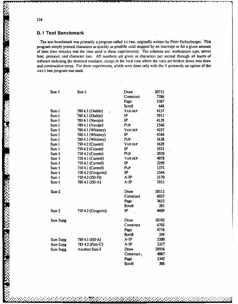
V.V.V
114
D.1 Text Benchmark
The text benchmark was primarily a program called tt ime, originally written by Peter Eichenberger. Thisprogram simply printed characters as quickly as possible until stopped by an interrupt or for a given amountof time (two minutes was the time used in these experiments). The columns are: workstation type, serverhost, protocol, and character rate. All numbers are given as characters per second through all layers ofsoftware including the terminal emulator, except in the local case where the rates are broken down into drawand construction times. For these experiments, which were done only with the V protocols, an option of thev e c t i me program was used.
,%
Sun-1 Sun-1 Draw 20711Construct 7286Page 5387Scroll 448
Sun-I 780 4.1 (Diablo) VAX-IKP 4157Sun-I 780 4.1 (Diablo) IP 3911Sun-I 780 4.1 (Navajo) IP 4139Sun-i 780 4.1 (Navajo) PuP 1566Sun-i 780 4.1 (Whitney) VAX-IKP 4257
.p. Sun-i 780 4.1 (Whitney) IP 4344. Sun-I 780 4.1 (Whitney) PuP 1638
Sun-1 750 4.2 (Coyote) VAX-IKP 3628Sun-I 750 4.2 (Coyote) IP 3521Sun-1 750 4.2 (Coyote) PUP 2030Sun-i 750 4.1 (Carmel) VAX-IKP 4078Sun-1 750 4.1 (Carmel) IP 2299Sun-I 750 4.1 (Carmel) Pup 1371Sun-I 750 4.2 (G regorio) IP 1544Sun- 1 750 4.2 (ISI-H) A-IP 2170Sun-1 780 4.1 (ISI-A) A-IP 1911
Sun-2 Draw 10111Construct 6037Page 3653Scroll 201
Sun-2 750 4.2 (Grcgorio) IP 4409
Sun-2upg Draw 18193Construct 6702
Page 4776Scroll 354
Sun-2upg 780 4.1 (ISI-A) A-IP 2200Sun-2upg 785 4.2 (Pare-C) A-IP 2317Sun-2upg Another Sun-2 Draw 18916
Construct 4067Page 3342Scroll 386
V
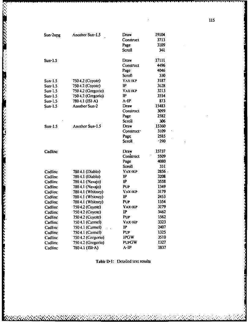
115
Sun-2upg Another Sun-1.5 Draw 19104Construct 3713Page 3109Scroll 34.1
Sun-1.5 Draw 17111Constuct 4496Page 4046Scroll 330
Sun-1.5 750 4.2 (Coyote) VAX-IKP 3187Sun-1.5 750 4.2 (Coyote) IP 3628Sun-1.5 750 4.2 (Grcgorio) VAX-IKP 3213Sun-1.5 750 4.2 (Grcegorio) lP 3554Sun-1.5 780 4.1 (ISMI-) A-IP 873Sun-1.5 Another Sun-2 Draw 15483
Construct 3099Page 2582Scroll 306
Sun-1.5 Another Sun-1.5 Draw 153604Construct- 3109
page 2585scroll .290
Cadlinc Draw 15737Construct 5509Page 4080scroll 331
Cadlinc 780 4.1 (D~iablo) VAX*JKP 2856Cadlinc 780 4.1 (D~iablo) IP 3208Cadlinc 780 4.1 (Navajo) IP 3558Cadlinc 780 4.1 (Navajo) Pup 1349Cadlinc 780 4.1 (Whitney) VAX-IKP 3179Cadlinc 780 4.1 (Whitncy) IP 2453Cadlinc 780 4.1 (Whitney) Pup 1354Cadlinc 750 4.2 (Coyote) VAX-IKP 3179Cadlinc 750 4.2 (Coyote) IP 3462Cadlinc 750 4.2 (Coyote) Pup 1562Cadlinc 750 4.1 (Carmel) VAX-IKP 3323Cadlinc 750 4.1 (Carmecl) IP 2407Cadlinc 750 4.1 (Carmel) Pup 1325Cadlinc 750 4.2 (Grcgorio) IIPGW 3510Cadlinc 750 4.2 (Grcgorio) PuPOW 1327Cadlinc 780 4.1 (1SI-A) A-lP 1837
Table D-1: Detailed text results
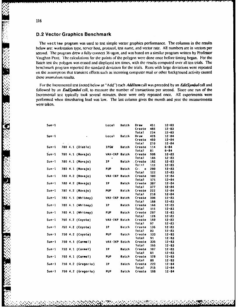
N116
D.2 Vector Graphics Benchmark
lc v e c time program was used to test simple vector graphics performance. The columns in thc resultsbelow are: workstation type, server host, protocol, test name, and vector rate. All numbers are in vectors persecond. The program drew a fully-connect 36-agon, and was based on a similar program written by ProfessorVaughan Pratt. The calculations for tie points of the polygon were done once before timing began. For theI1Batch test te polygon was erased and displayed ten times, with the results computed over all ten trials. Thebenchmark program reported the standard deviation for the trials. Runs with large deviations were repeatedon the assumption that transient effects such as incoming computer mail or other background activity caused
- these anomalous results.
For the Incremental test (noted below as "'Add")each Addltemcall was preceded by an EditSymbolcall andfollowed by an EndSymbol call, to measure the number of transactions per second. Since one run of theIncremental test typically took several minutes, these were only repeated once. All experiments wereperformed when timesharing load was low. '[The last column gives the month and year the measurementswere taken.
Sun-1 Local Batch Draw 451 12-83Create 485 12-83Total 234 12-83
Sun-I Local Batch Draw 428 12-84Create 450 12-84Total 219 12-84
" Sun-I 780 4.1 (Diablo) IPGW Batch Create 114 6-84Total 81 6-84
Sun-I 780 4.1 (Navajo) VAX-IKP Batch Create 508 12-83Total 185 12-83
- . Sun-i 780 4.1 (Navajo) IP Batch Create 162 12-83Tot-il 111 12-83
Sun-I 780 4.1 (Navajo) PUP Batch Cg e 200 12-83Total 122 12-83
Sun-I 780 4.2 (Navajo) VAX-IKP Batch Create 180 12-84Total 171 12-84
Sun-I 780 4.2 (Navajo) IP Batch Create 387 12-84Total 377 12-84
- Sun-i 780 4.2 (Navajo) PUP Batch Create 222 12-84Total 218 12-84
Sun-i 780 4.1 (Whitney) VAX-IKP Batch Create 396 12-83Total 168 12-83
Sun-I 780 4.1 (Whitney) IP Batch Create 168 12-83Total 111 12-83
Sun-I 780 4.1 (Whitney) PUP Batch Create 207 12-83
Total 128 12-83Sun-I 750 4.2 (Coyote) VAX-IKP Batch Create 160 12-83
Total 97 12-83Sun-I 750 4.2 (Coyote) IP Batch Create 136 12-83
Total 93 12-83Sun-I 750 4.2 (Coyote) PUP Batch Create 133 12-83
Total 91 12-83Sun-i 750 4.1 (Carmel) VAX-IKP Batch Create 335 12-83
Total 155 12-83Sun-1 750 4.1 (Carmel) IP Batch Create 107 12-83
Total 81 12-83Sun-i 750 4.1 (Carmel) PUP Batch Create 128 12-83
Total 80 12-83Sun-I 750 4.2 (Gregorio) IP Batch Create 220 12-84
Total 215 12-84Sun-i 750 4.2 (Gregorio) PUP Batch Create 198 12-84
• . ,. ... , ............. , ,' , ..- ... ,.. -.... ., .. .',. . , ., ,
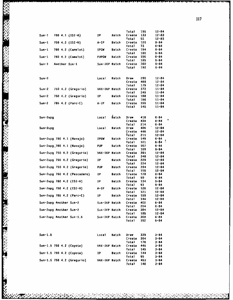
117
Total 195 12-84Sun-i 780 4.1 ([SI-A) IP Batch Create 133 12-83
Total 92 12-83
Sun-I 750 4.2 (ISI-H) A-IP Batch Create 120 6-84Total 73 6-84
Sun-i 780 4.2 (Camelot) IPGW Batch Create 154 6-84Total 100 6-84
Sun-i 780 4.2 (Camelot) PUPGW Batch Create 156 6-84Total 105 6-84
Sun-I Another Sun-i Sun-ZKP Batch Create 360 6-84Total 192 6-84
Sun-2 Local Batch Draw 290 12-84Create 468 12-84Total 179 12-84
Sun-2 750 4.2 (Gregorio) VAX-IKP Batch Create 372 11-84Total 345 11-84
Sun-2 750 4.2 (Gregorio) IP Batch Create 168 11-84Total 166 11-84
Sun-2 785 4.2 (Parc-C) A-IP Batch Create 155 11-84Total 145 11-84
Sun-2upg Local Batch Draw 418 6-84Create 439 6-84Total 214 6-84
Sun-2upg Local Batch Draw 406 12-84Create 446 12-84total 211 12-84
Sun-2upg 780 4.1 (Navajo) IPGW Batch Create 149 6-84Total 101 6 - 4
Sun-2upg,780 4.1 (Navajo) PUP Batch Create 167 6-84Total 109 6-84
Sun-2upg 750 4.2 (Gregotio) VAX-IKP Batch Create 381 12-84Total 348 12-84
Sun-2upg 750 4.2 (Gregorio) IP Batch Create 229 12-84Total 224 12-84
Sun-2upg 750 4.2 (Gregorio) PUP Batch Create 204 12-84Total 198 12-84
Sun-2upg 750 4.2 (Pescadero) IP Batch Create 128 6-84Total 90 6-84
Sun-2upg 780 4.2 (ISI-A) IP Batch Create 134 9-84Total 93 9-84
Sun-2upg 750 4.2 (ISI-H) A-IP Batch Create 126 12-84Total 121 12-84
Sun-2upg 785 4.2 (Parc-C) IP Batch Create 159 12-84Total 144 12-84
Sun-2upg Another Sun-2 Sun-IKP Batch Create 402 6-84Total 204 6-84
Sun-2upg Another Sun-2 Sun-IKP Batch Create 384 12-84Total 185 12-84
Sun-Zupg Another Sun-1.5 Sun-IKP Batch Create 360 6-84Total 192 6-84
Sun-1.5 Local Batch Draw 339 3-84Create 364 3-84
Total 176 3-84Sun-1.5 750 4.2 (Coyote) VAX-IKP Batch Create 445 3-84
Total 145 3-84Sun-1.5 750 4.2 (Coyote) IP Batch Create 144 3-84
Total 95 3-84Sun-1.5 750 4.2 (Gregorio) VAX-IKP Batch Create 453 3-84
Total 146 3-84
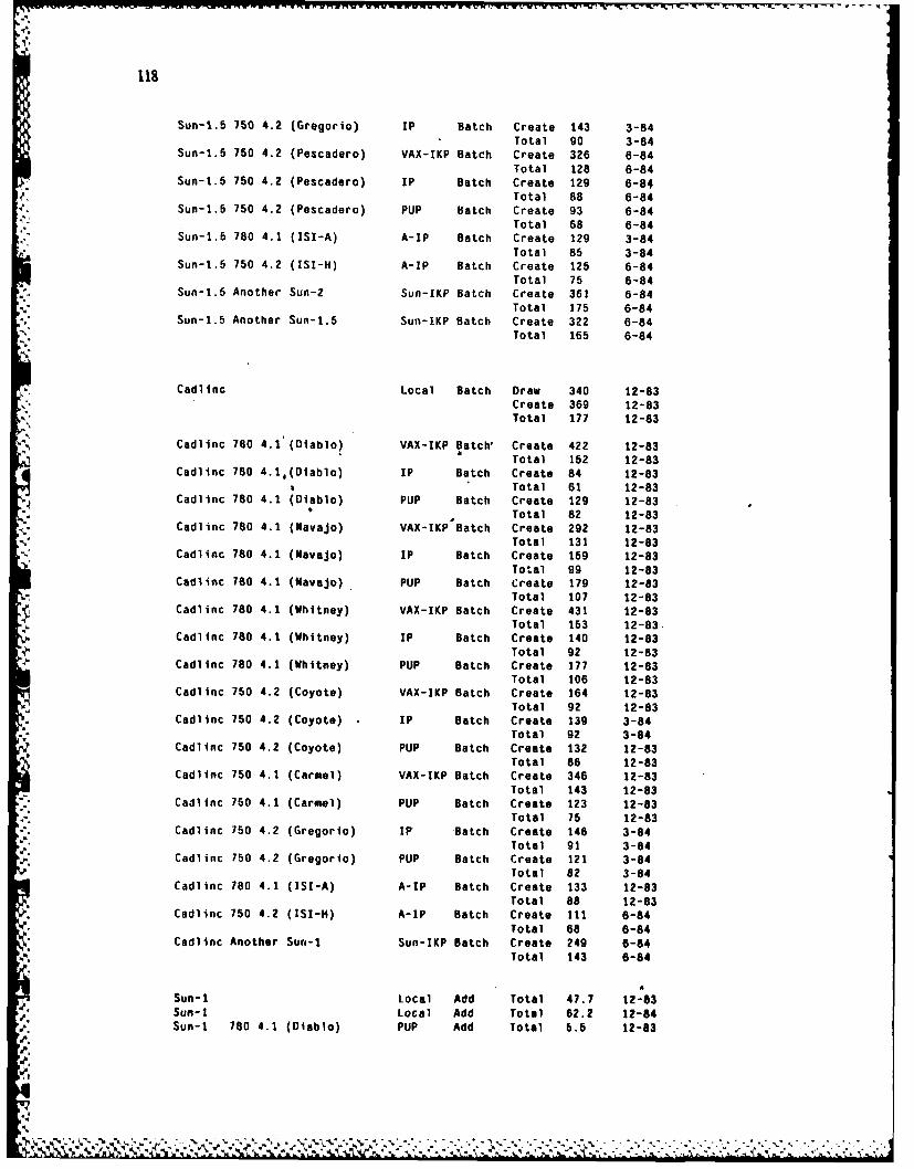
118
Sun-t.5 750 4.2 (Gregorio) IP Batch Create 143 3-84Total 90 3-84
Sun-1.5 750 4.2 (Pescadero) VAX-IKP Batch Create 326 6-84Total 128 6-84
Sun-1.5 760 4.2 (Pescadero) IP Batch Create 129 6-84Total 88 6-84
Sun-1.5 750 4.2 (Pescadero) PUP Batch Create 93 6-84Total 68 6-84
Sun-1.5 780 4.1 (ISI-A) A-IP Batch Create 129 3-84Total 85 3-84
Sun-1.5 750 4.2 (ISI-H) A-IP Batch Create 125 6-84Total 75 6-84
Sun-1.5 Another Sun-2 Sun-IKP Batch Create 361 6-84Total 175 6-84
Sun-1.5 Another Sun-1.5 Sun-IKP Batch Create 322 6-84Total 165 6-84
Cadlinc Local Batch Draw 340 12-83Create 369 12-83Total 177 12-83
Cadlinc 780 4.1 (Diablo) VAX-IKP Batch' Create 422 12-83Total 152 12-83
Cadlinc 780 4.1,(Diablo) IP Batch Create 84 12-83Total 61 12-83
Cadlinc 780 4.1 (Diablo) PUP Batch Create 129 12-83Total 82 12-83
Cadlinc 780 4.1 (Navajo) VAX-IKP Batch Create 292 12-83Total 131 12-83
Cadlinc 780 4.1 (Navajo) IP Batch Create 159 12-83Total 99 12-83
Cadlinc 760 4.1 (Navajo) PUP Batch Create 179 12-83Total 107 12-83
Cadlinc 780 4.1 (Whitney) VAX-IKP Batch Create 431 12-83Total 153 12-83.
Cadlinc 780 4.1 (Whitney) IP Batch Create 140 12-83Total 92 12-83
Cadlinc 780 4.1 (Whitney) PUP Batch Create 177 12-83Total 106 12-83
Cadlinc 750 4.2 (Coyote) VAX-IKP Batch Create 164 12-83Total 92 12-83
CadlInc 750 4.2 (Coyote) IP Batch Create 139 3-84Total 92 3-84
Cadlinc 750 4.2 (Coyote) PUP Batch Create 132 12-83Total 86 12-83
Cadlinc 750 4.1 (Carmel) VAX-IKP Batch Create 346 12-83Total 143 12-83
Cadlinc 750 4.1 (Carmel) PUP Batch Create 123 12-83Total 75 12-83
Cadlinc 750 4.2 (Gregorio) IF "Batch Create 146 3-84Total 91 3-84
Cadlinc 750 4.2 (Gregorio) PUP Batch Create 121 3-84
Total 82 3-84Cadlinc 780 4.1 (ISI-A) A-IP Batch Create 133 12-83
Total 88 12-83Cadlinc 750 4.2 (ISI-H) A-IP Batch Create 111 6-84
Total 68 6-84Cadlinc Another Sun-1 Sun-IKP Batch Create 249 6-84
Total 143 6-84
Sun-I Local Add Total 47.7 12-83Sun-i Local Add Total 62.2 12-84
Sun-I 780 4.1 (Diablo) PUP Add Total 5.5 12-83
N
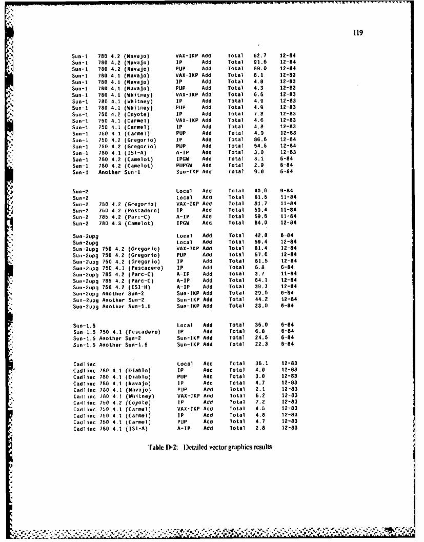
119
Sun-I 780 4.2 (Navajo) VAX-IKP Add Total 62.7 12-84
Sun-I 780 4.2 (Navajo) IP Add Total 91.6 12-84
Sun-I 780 4.2 (Navdjo) PUP Add Total 59.0 12-84
Sun-i 780 4.1 (Navajo) VAX-IKP Add Total 6.1 12-83
Sun-i 780 4.1 (Navajo) IP Add Total 4.8 12-83
Sun-i 780 4.1 (Navajo) PUP Add Total 4.3 12-83
Sun-I 780 4.1 (Whitney) VAX-IKP Add Total 6.5 12-83
Sun-I 780 4.1 (Whitney) IP Add Total 4.9 12-83Sun-i 780 4.1 (Whitney) PUP Add Total 4.g 12-83
Sun-i 750 4.2 (Coyote) IP Add Total 7.8 12-83
Sun-I 750 4.1 (Carmel) VAX-IKP Add Total 4.6 12-83
Sun-i 750 4.1 (Carmel) IP Add Total 4.8 12-83
Sun-1 750 4.1 (Carmel) PUP Add Total 4.9 12-83
Sun-I 750 4.2 (Gregorio) IP Add Total 86.6 12-84
Sun-I 750 4.2 (Gregorio) PUP Add lotal 54.5 12-84
Sun-I 780 4.1 (ISI-A) A-IP Add Total 3.0 12-83
Sun-I 780 4.2 (Camelot) IPGW Add Total 3.1 6-84Sun-I 780 4.2 (Camelot) PUPGW Add Total 2.9 6-84
Sun-i Another Sun-I Sun-IKP Add Total 9.0 6-84
Sun-2 Local Add Total 40.6 9-84
Sun-2 Local Add Total 61.5 11-84
Sun-2 750 4.2 (Gregorio) VAX-IKP Add Total 81.7 11-84
Sun-2 750 4.2 (Pescadero) IP Add Total 59.4 11-84
Sun-2 785 4.2 (Parc-C) A-IP Add Total 69.6 11-84
Sun-2 780 4.2 (Camelot) IPGW Add Total 84.0 12-84
Suo-2upg Local Add Total 42.0 6-84
Sun-2upg Local Add Total 59.4 12-84Sun-2upg 750 4.2 (Gregorio) VAX-IKP Add Total 81.4 12-84
Sun-2upg 750 4.2 (Gregorio) PUP Add Total 57.6 12-84
Sun-2upg 750 4.2 (Gregorio) IF Add Total 81.5 12-84
Sun-2upg 750 4.1 (Pescadero) IP Add Total 6.8 6-84
Su.-2upg 785 4.2 (Parc-C) A-IP Add Total 3.7 11-84
Suit-2upg 785 4.2 (Parc-C) A-IP Add Total 64.1 12-84
Sun-2upg 750 4.2 (ISI-H) A-IP Add Total 39.3 12-84
Su'n-2upg Another Sun-2 Sun-IKP Add Total 29.0 6-84
Sun-2upg Another Sun-2 Sue-IKP Add Total 44.2 12-84
% Sun-2upg Another Sun-1.5 Sun-IKP Add Total 23.0 6-84
Sun-1.5 Local Add Total 35.0 6-84
Sug-1.5 750 4.1 (Pescadero) IP Add Total 6.8 6-84
Sun-1.5 Another Sun-2 Sun-IKP Add Total 24.6 6-84
Sun-1.5 Another Sun-1.5 Sun-IKP Add Total 22.3 6-84
Cadlinc Local Add Total 36.1 12-83
Cadlinc 780 4.1 (Diablo) IP Add Total 4.0 12-83
Cadlinc 780 4.1 (Diablo) PUP Add Total 3.0 12-83
Cadlinc 780 4.1 (Navajo) IP Add Total 4.7 12-83
Cadlinc 780 4.1 (Navajo) PUP Add Total 2.1 12-83
Cadlinc /80 4.1 (Whitney) VAX-IKP Add Total 6.2 12-83Cadlinc 750 4.2 (Coyote) IP Add Total 7.2 12-83
Cadlinc 750 4.1 (Carmel) VAX-IKP Add Total 4.5 12-83
Cadlinc 750 4.1 (Carmel) IP Add Total 4.8 12-83
Cadlinc 750 4.1 (Carmel) PUP Add Total 4.7 12-83
Cadlinc 780 4.1 (ISI-A) A-IP Add Total 2.8 12-83
T'able D-2: Dctailed vector graphics results
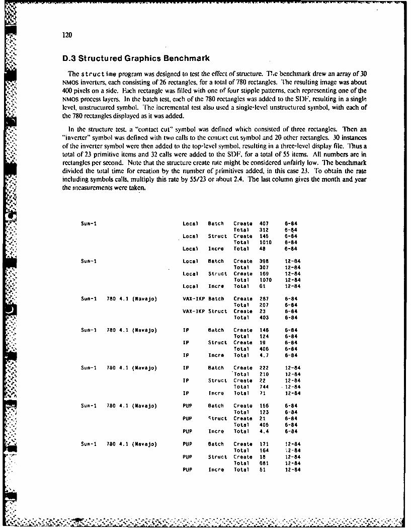
120
D.3 Structured Graphics Benchmark
The struct ime program was designed to test the effect of structure. 111,c benchmark drew an array of 30NMOS invertcrs, each consisting of 26 rectangles, for a total of 780 rectangles. The resulting image was about400 pixels on a side. Each rectangle was filled with one of four stipple patterns, each representing one of theNMOS process layers. In the batch test, each of the 780 rectangles was added to the SDF, resulting in a singlelevel, unstructured symbol. The incremental test also used a single-level unstructured symbol, with each ofthe 780 rectangles displayed as it was added.
In the structure test. a "contact cut" symbol was defined which consisted of three rectangles. Then an"inverter" symbol was defined with two calls to the contact cut symbol and 20 other rectangles. 30 instancesof the inverter symbol were then added to the top-level symbol, resulting in a three-level display file. Thus atotal of 23 primitive items and 32 calls were added to the SDF. for a total of 55 items. All numbers are inrectangles per second. Note that the structure create rate might be considered unfairly low. The benchmarkdivided the total time for creation by the number of primitives added, in this case 23. To obtain the rateincluding symbols calls, multiply this rate by 55/23 or about 2.4. The last column gives the month and yearthe ricasurcments were taken.
Sun-1 Local Batch Create 407 6-84Total 312 6-84
-. Local Struct Create 145 6-84Total 1010 6-84
Local Incre Total 48 6-84
Sun-1 Local Batch Create 398 12-84Total 307 12-84
Local Struct Create 169 12-84Total 1070 12-84
Local Incre Total 61 12-84
Sun-1 780 4.1 (Navajo) VAX-IKP Batch Create 287 6-84
Total 207 6-84
VAX-IKP Struct Create 23 6-84Total 403 6-84
Sun-I 780 4.1 (Navajo) IP Batch Create 148 6-84Total 124 6-84
IP Struct Create 19 6-84Total 406 6-84
IP Incre Total 4.7 6-84
Sun-i 780 4.1 (Navajo) IP Batch Create 222 12-84Total 210 12-84
IP Struct Create 22 12-84Total 744 12-84
A IP Incre Total 71 12-84
Sun-1 780 4.1 (Navajo) PUP Batch Create 156 6-84% Total 123 6-84
PUP Struct Create 21 6-84Total 405 6-84
, PUP Incre Total 4.4 6-84
*,p ., Sun-1 780 4.1 (Navajo) PUP Batch Create 171 12-84Total 164 "t2-84
*.-.- PUP Struct Create 18 12-84Total 681 12-84
PUP Incre Total 61 12-84
" q
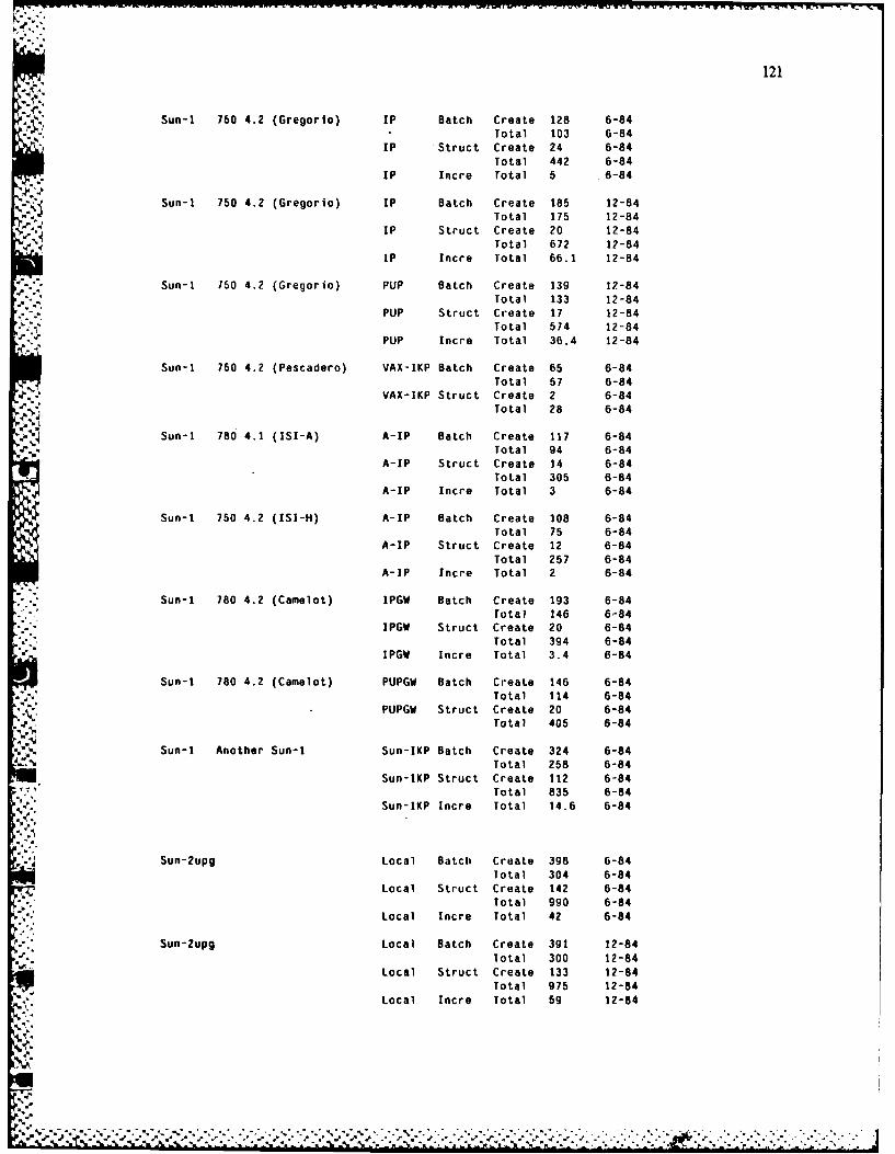
121
Sun-i 760 4.2 (Gregorlo) IP Batch Create 128 6-84Total 103 6-84
IP Struct Create 24 6-84Total 442 6-84
IP Incre Total 5 .6-84
Sun-I 750 4.2 (Gregorio) IP Batch Create 185 12-84Total 175 12-84
IP Struct Create 20 12-84Total 672 12-84
IP Incre Total 66.1 12-84
Sun-i 750 4.2 (Gregorio) PUP Batch Create 139 12-84Total 133 12-84
PUP Struct Create 17 12-84Total 574 12-84
PUP Incre Total 36.4 12-84
Sun-i 750 4.2 (Pescadero) VAX-IKP Batch Create 65 6-84Total 57 6-84
VAX-IKP Struct Create 2 6-84Total 28 6-84
Sun-i 780 4.1 (ISI-A) A-IP Batch Create 117 6-84Total 94 6-84
A-IP Struct Create 14 6-84Total 305 6-84
A-IP Incre Total 3 6-84
Sun-1 750 4.2 (ISI-H) A-IP Batch Create 108 6-84Total 75 6-84
A-IP Struct Create 12 6-84Total 257 6-84
A-IP Incre Total 2 6-84
Sun-l 780 4.2 (Camelot) IPGW Batch Create 193 6-84
Total 146 6-84IPGW Struct Create 20 6-84
.e Total 394 6-84IPGW Incre Total 3.4 6-84
Sun-I 780 4.2 (Camelot) PUPGW Batch Create 146 6-84Total 114 6-84
PUPGW Struct Create 20 6-84
Total 405 6-84
Sun-I Another Sun-I Sun-IKP Batch Create 324 6-84Total 258 6-84
Sun-IKP Struct Create 112 6-84Total 835 6-84
Sun-IKP Incre Total 14.6 6-84
Sun-2upg Local Batch Create 398 6-84Total 304 6-84
Local Struct Create 142 6-84Total 990 6-84
" Local Incre Total 42 6-84
Sun-2upg Local Batch Create 391 12-84
Total 300 12-84Local Struct Create 133 12-84
Total 975 12-84Local Incre Total 59 12-84
V . "% - , . , ".-.-.• -. -•-.-% -,-.-%-.-.- , .-. .- ,- . . "". -. • - , • - - -4, _ _ - " , - . '" , '. "". . ' '' , ' '' , ' " " ' . ". " . , " . . . . - . " .
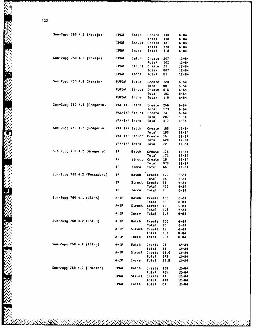
122
Sun-Zupg 780 4.1 (Navajo) IPGW Batch Create 140 6-84Total 118 6-84
IPGW Struct Create 18 6-84Total 378 6-84
IPGW Incre Total 4.5 6-84
Sun-2upg 780 4.2 (Navajo) IPGW Batch Create 207 12-84Total 202 12-84
IPGW Struct Create 21 12-84Total 687 12-84
IPGW Incre Total 61 12-84
Sun-2upq 780 4.1 (Navajo) PUPGW Batch Create 128 6-84Total 99 6-84
PUPGW Struct Create 6.8 6-84Total 182 6-84
PUPGW Incre Total 1.5 6-84
Sun-2upU 760 4.2 (Gregorio) VAX-IKP Batch Create 258 6-84Total 173 6-84
VAX-IKP Struct Create 14 6-84Total 287 6-84
VAX-IKP Incre Total 4.7 6-84
Sun-2upq 750 4.2 (Gregorlo) VAX-IKP Batch Create 199 12-84Total 196 12-84
VAX-IKP Struct Create 15 12-84Total 620 12-84
VAX-IKP Incre Total 72 12-84
Sun-2upg 750 4.2 (Gregorlo) IP Batch Create 176 12-84Total 171 12-84
IP Struct Create 19 12-84Total 670 12-84
IP Incre Total 65 12-84
Sun-2upg 750 4.2 (Pescadero) IP Batch Create 120 6-84Total 98 6-84
IP Struct Create 25 6-84Total 456 6-84
IP Incre Total 7 6-84
Sun-2upg 780 4.1 (ISI-A) A-IP Batch Create 106 6-84Total 88 6-84
A-IP Struct Create 13 6-84Total 278 6-84
A-IP Incre Total 3.4 6-84
Sun-2upg 750 4.2 (IsI-H) A-IP Batch Create 100 6-84Total 76 6-84
A-IP Struct Create 12 6-84
Total 257 6-84A-IP Incre Total 2.7 6-84
Sun-2upg 750 4.2 (15I-11) A-IP Batch Create 91 12-84Total 81 12-84
;-V A-IP Struct Create 11.0 12-84Total 373 12-84
A-IP Incre Total 35.9 12-84
Sun-2upg 780 4.2 (Camelot) IPGW Batch Create 189 12-84Total 185 12-84
IPGW Struct Create 14 12-84Total 473 12-84
IPGW Incre Total 64 12-84
"a
m~*
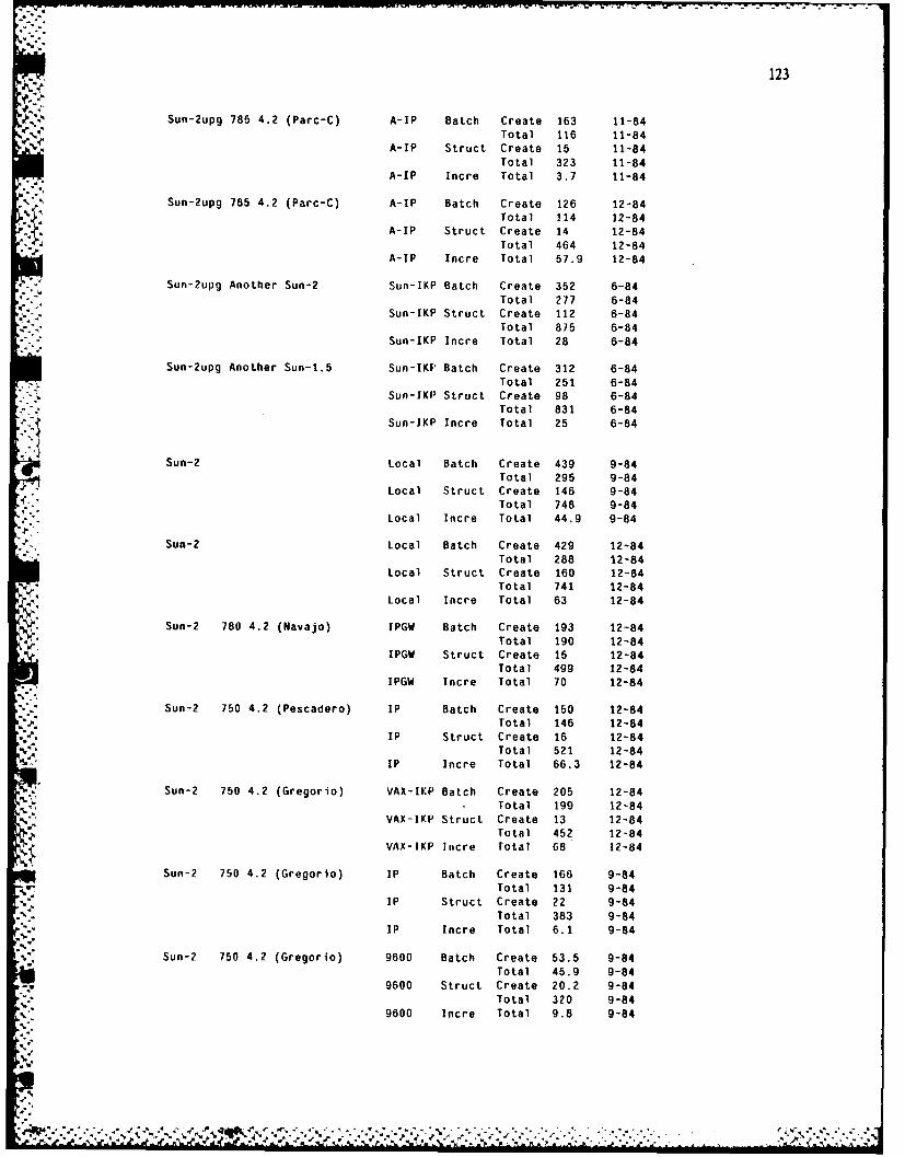
123
Sun-2upg 785 4.2 (Parc-C) A-IP Batch Create 163 11-84Total 116 11-84
A-IP Struct Create 15 11-84Total 323 11-84
A-IP Incre Total 3.7 11-84
Sun-2upg 785 4.2 (Parc-C) A-IP Batch Create 126 12-84Total 114 12-84
A-IP Struct Create 14 12-84Total 464 12-84
A-IP Incre Total 57.9 12-84
Sun-2upg Another Sun-2 Sun-IKP Batch Create 352 6-84Total 277 6-84
Sun-IKP Struct Create 112 6-84Total 875 6-84
Sun-IKP Incre Total 28 6-84
Sun-2upg Another Sun-1.5 Sun-IKF' Batch Create 312 6-84Total 251 6-84
Sun-IKP Struct Create 98 6-84Total 831 6-84
Sun-IKP Incre Total 25 6-84
Sun-2 Local Batch Create 439 9-84Total 295 9-84
Local Struct Create 146 9-84Total 748 9-84
Local Incre Total 44.9 9-84
Sun-2 Local Batch Create 429 12-84Total 288 12-84
Local Struct Create 160 12-84Total 741 12-84
Local Incre Total 63 12-84
Sun-2 780 4.2 (Navajo) IPGW Batch Create 193 12-84Total 190 12-84
IPGW Struct Create 15 12-84Total 499 12-84
IPGW Incre Total 70 12-84
Sun-2 750 4.2 (Pescadero) IP Batch Create 150 12-84Total 146 12-84
IP Struct Create 16 12-84Total 521 12-84
IP Incre Total 66.3 12-84
Sun-2 750 4.2 (Gregorio) VAX-IKP Batch Create 205 12-84. Total 199 12-84
VAX-IKP Struct Create 13 12-84Total 452 12-84
VAX-IKP Incre total 68 12-84
Sun-2 750 4.2 (Gregorlo) IP Batch Create 166 9-84Total 131 9-84
IP Struct Create 22 9-84Total 383 9-84
. IP Incre Total 6.1 9-84
Sun-2 750 4.2 (Gregorio) 9600 Batch Create 53.5 9-84Total 45.9 9-84
9600 Struct Create 20.2 9-84Total 320 9-84
9600 Incre Total 9.8 9-84
., 4. .4-
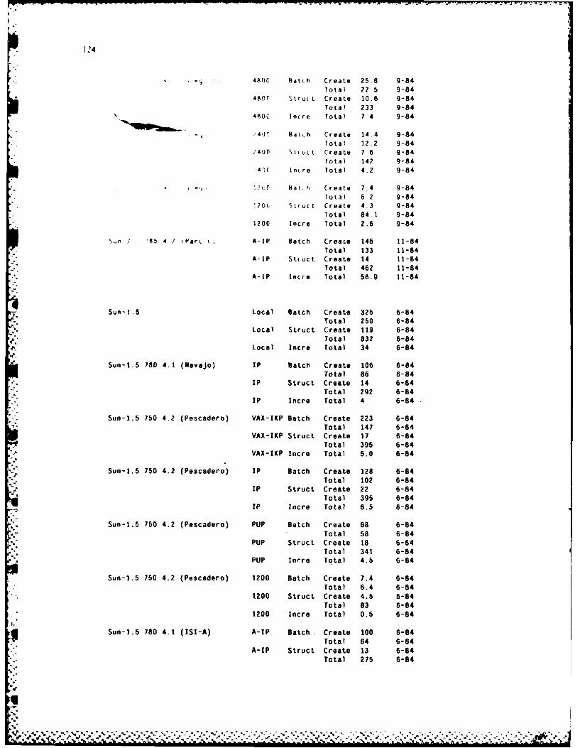
124
480C Batch Create 25.8 9-84
Total 22.5 9-84480C tru( L Create 10.6 9-84
Total 233 9-844800 Incre Total 7.4 9-84
40 Bat.h Create 14.4 9-84
Total 12.2 9-84
2400 truct Create 7.6 9-84
Total 142 9-844)C Incre Total 4.2 9-84
,? 0 bat,h Create 7.4 9-84
Total 6 2 9-84.20t Struct Create 4.3 9-84
Total 84.1 9-841200 Incre Total 2.6 9-84
S.n 2 '5 4 1 (ParC LI A-IP Batch Create 146 11-84
Total 133 11-84A-IP Stfuct Create 14 11-84
Total 462 11-84A-IP Incre Total 56.9 11-84
Sun-1.5 Local Batch Create 326 6-84Total 250 6-84
Local Struct Create 119 6-84
Total 832 6-84Local Incre Total 34 6-84
Sun-1.5 780 4.1 (Navajo) IP Batch Create 106 6-84
Total 86 6-84IP Struct Create 14 6-84
Total 292 6-84IP Incre Total 4 6-84
Sun-1.5 750 4.2 (Pescadero) VAX-IKP Batch Create 223 6-84Total 147 6-84
VAX-IKP Struct Create 17 6-84Total 395 6-84
VAX-IKP Incre Total 5.0 6-84
Sun-1.5 750 4.2 (Pescadero) IP Batch Create 128 6-84Total 102 6-84
IP Struct Create 22 6-84Total 395 6-84
Ip Incre Total 6.5 6-84
Sun-1.5 750 4.2 (Pescadero) PUP Batch Create 68 6-84
Total 58 6-84
PUP Struct Create 18 6-84
Total 341 6-84PUP Inrre Total 4.5 6-84
Sun-1.5 750 4.2 (Pescadero) 1200 Batch Create 7.4 6-84
Total 6.4 6-841200 Struct Create 4.5 6-84
Total 83 6-841200 Incre Total 0.5 6-84
Sun-1.5 780 4.1 (ISI-A) A-IP Batch. Create 100 6-84
Total 84 6-84A-IP Struct Create 13 6-84
Total 275 6-84
- -
% .. . .
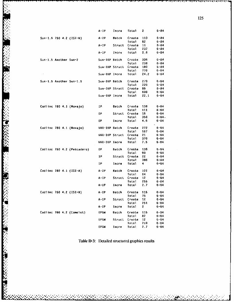
125
A-IF Incre Total 2 6-84
Sun-l.5 750 4.2 (ISI-H) A-IF Batch Create 113 6-84Total 82 6-84
A-IF Struct Create 11 6-84Total 232 6-84
A-IP Incre Total 0.8 6-84
Sun-1.5 Another Sun-2 Sun-IKP Batch Create 306 6-84Total 238 6-84
Sun-IKP Struct Create 100 6-84Total 770 6-84
Sun-IKP Incre Total 24.2 6-84
Sun-1.5 Another Sun-1.5 Sun-IKP Batch Create 279 6-84Total 220 6-84
Sun-IKP Struct Create 85 6-84Total 690 6-84
Sun-IKP Incre Total 22.1 6-84
Cadlinc 780 4.1 (Navajo) IF Batch Create 138 6-84Total 111 6-84
IF Struct Create 18 6-84Total 350 6-84,
IF Incre Total 4.6 6-84
Cadlinc 780 4.1 (Navajo) VAX-IKP Batch Create 272 6-84Total 187 6-84
VAX-IKP Struct Create 21 6-84Total 370 6-84
VAX-IKF Incre Total 7.5 6-84
Cadlinc 750 4.2 (Fescadero) IF Batch Create 130 6-84Total 99 6-84
IF Struct Create 22 6-84Total 386 6-84
IF Incre Total 4 6-84
Cadlinc 780 4.1 (151-A) A-IP Batch Create 102 6-84Total 84 6-84
A-IF Struct Create 12 6-84Total 255 6-84
A-IP Incre Total 2.7 6-84
Cadlinc 750 4.2 (151-H) A-IF Batch Create 115 6-84Total 75 6-84
A-IF Struct Create 12 6-84Total 251 6-84
A-IF Incre Total 2 6-84
Cadlinc 780 4.2 (Camelot) IPGW Batch Create 115 6-34Total 82 6-84
IPGW Struc. Create 12 6-84lotal 2b9 0-84
IPGW Incre Total 2.7 6-84
Table D-3: Dectailed structured graphics results
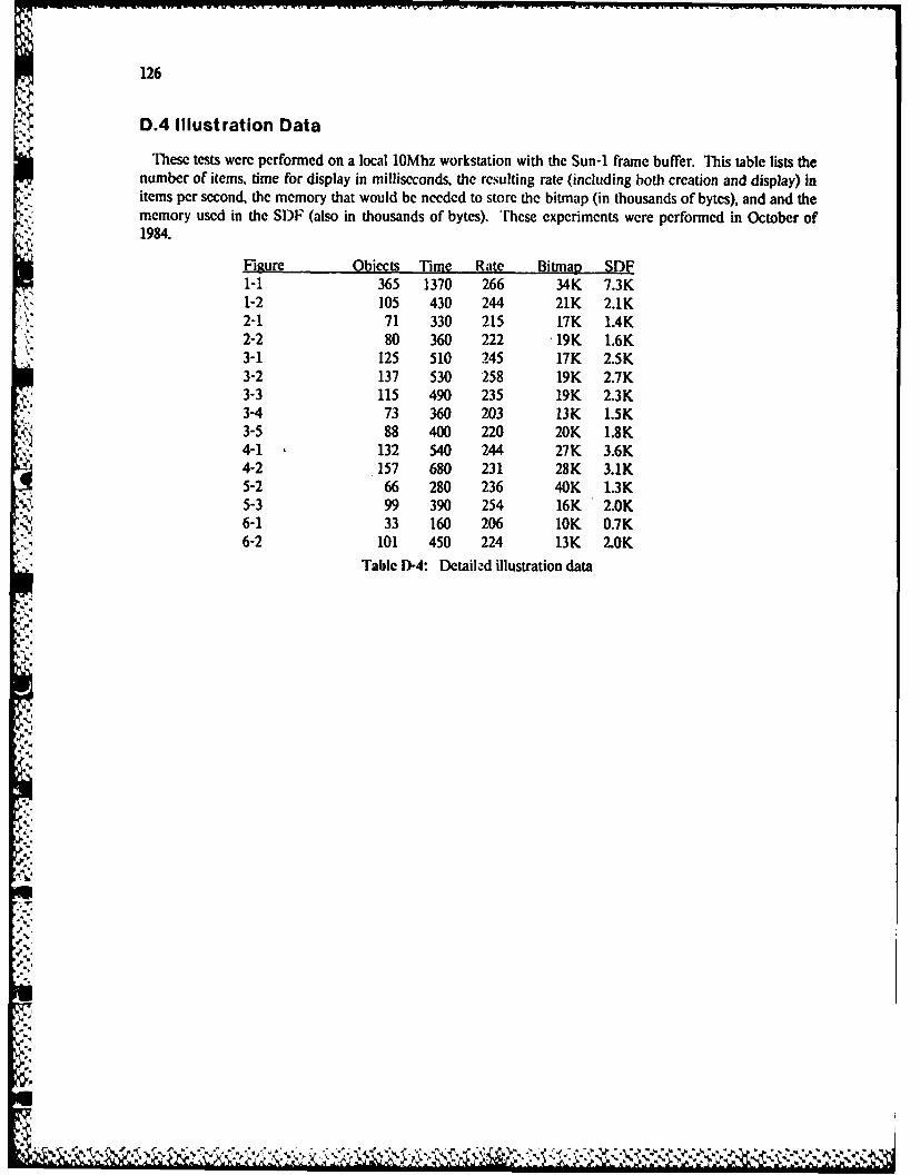
126
D.4 Illustration Data
These tests were performed on a local l0Mhz workstation with the Sun-1 frame buffer. This table lists thenumber of items, time for display in milliseconds, the resulting rate (including both creation and display) initems per second, the memory that would be needed to store the bitmap (in thousands of bytes), and and thememory used in the SDF (also in thousands of bytes). These experiments wcre performed in October of1984.
Figure Obects Time Rate Bitmap SDF1-1 365 1370 266 34K 7.3K1-2 105 430 244 21K 2.1K2-1 71 330 215 17K 1.4K2-2 80 360 222 19K 1.6K3-1 125 510 245 17K 2.5K3-2 137 530 258 19K 2.7K3-3 115 490 235 19K 2.3K3-4 73 360 203 13K 1.5K3-5 88 400 220 20K 1.8K4-1 132 540 244 27K 3.6K4-2 - 157 680 231 28K 3.1K5-2 66 280 236 40K 1.3K5-3 99 390 254 16K 2.0K6-1 33 160 206 10K 0.7K6-2 101 450 224 13K 2.0K
Table D-4: Detailed illustration data
.4
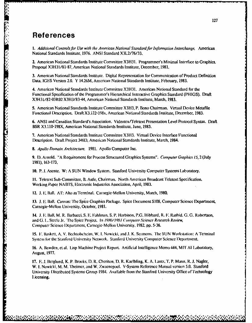
127
References
1. Additional Controls for Use with the American National Standard for Information Interchange. American.J. National Standards Institute, 1976. ANSI Standard X3L2/76/33.
2. American National Standards Institute Committee X3H31. Programmer's Minimal Interface to Graphics.Proposal X31-131/81-87, American National Standards Institute, December, 1981.
3. American National Standards Institute. Digital Representation for Communication of Product DefinitionData, IGFS Version 2.0. Y 14.26M, American National Standards Institute, February, 1983.
• 4. American National Standards Institute Committee X3H31. American National Standard for theFunctional Specification of the Programmer's Hierarchical Interactive Graphics Standard (PHIGS). DraftX3H31/82-03R02 X3H3/83-44, American National Standards Institute, March, 1983.
5. American National Standards Institute Committee X3H3, P. Bono Chairman. Virtual Device MetafileFunctional Description. Draft X3.122-198x. American National Standards Institute, December, 1983.
,.
6. ANSI and Canadian Standard's Association. Videotex/Teletext Presentation Level Protocol Syntax. DraftBSR X3.110-198X, American National Standards Institute, June, 1983.
7. American National Standards Institute Committee X3H3. Virtual Device Interface FunctionalDescription. Draft Project 346D, American National Standards Institute, March, 1984.
8. Apollo Domain Architecture. 1981. Apollo Computer Inc.
9. D. Arnold. "A Requirement for Process Structured Graphics Systems". Computer Graphics 15, 2 (July1981), 163-173.
10. P. J. Asente. W: A SUN Window System. Stanford University Computer Systems laboratory.
11. Teletext Sub-Committee, B. Astle. Chairman. North American Broadcast Teletext Specification.Working Paper NAI'S, Electronic Industries Association, April, 1983.
12. J. 1.. Ball. AT: Alto as Terminal. Carnegie-Mellon University, March, 1980.
13. J. E. Ball. Canvas: Thc Spice Graphics Package. Spice )ocument S108. Computer Science Department,Carnegie-Mellon University, October, 1981.
14. J. F. Ikll, M. R. Barbacci. S. F. Fahlnan, S. P. Harbison. P.G. Hibbard, R. F. Rashid. G. G. Robertson,and G. i.. Steele Jr. The Spice Project. In 1980//981 Compuler Science Research Review,Computer Science )epartment, Carnegie-Mellon University. 1982, pp. 5-36.
15. F. Baskett, A. V. Iclchtolscheini, W. I. Nowicki, and J. K. Scamons. The SUN Workstation: A TcrminalSystem for the Stanford University Network. Stanford University Computer Science Dep)artment.
16. A. Bawden. et al. Lisp Machine Project Report. Artificial Intelligence Memo 444, MIT Al Laboratory,August, 1977.
17. E. J. Berglund, K. P. Brooks. 1). R. Cheriton. 1). R. Kaelbling, K. A. I antz, T. P. Mann, R. J. Nagler,W. I. Nowicki, M. M. Theimcr. and W. Zwaenepoel. V-System Reference Manual version 5.0. StanfordUniversity Distributed Systems Group 1984. Available from the Stanford University Office of TcchnologyI .icensing.
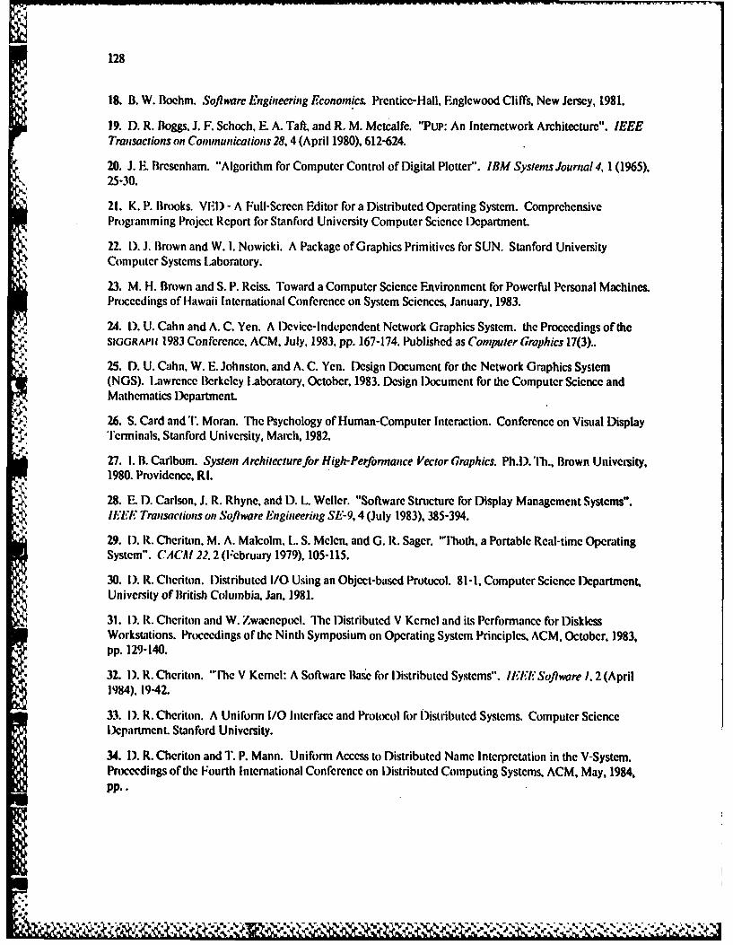
128
18. B. W. Boehm. Software Engineering Economics. Prentice-Hall, Englcwood Cliffs, New Jersey, 1981.
19. D. R. Boggs, J. F. Schoch, E. A. Taft, and R. M. Metcalfe. "Pup: An Internetwork Architecture". IEEETransactions on Communications 28, 4 (April 1980), 612-624.
20. J. E. Brescnham. "Algorithm for Computer Control of Digital Plotter". IBM Systems Journal 4, 1 (1965),25-30.
21. K. P. Brooks. VIEI) -A Full-Screcn Editor for a Distributed Operating System. ComprehensiveProgramming Project Report for Stanford University Computer Science Department.
22. L). J. Brown and W. 1. Nowicki. A Package of Graphics Primitives for SUN. Stanford UniversityComputer Systems Laboratory.
23. M. H. Brown and S. P. Reiss. Toward a Computer Science Environment for Powerful Personal Machines.Proceedings of Ilawaii International Conference on System Sciences, January, 1983.
24. 1). U. Cahn and A. C. Yen. A Device-Independent Network Graphics System. the Proceedings of theSIGGRAPI! 1983 Conference, ACM, July, 1983, pp. 167-174. Published as Computer Graphics 17(3)..
25. D. U. Cahn, W. E. Johnston, and A. C. Yen. Design Document for the Network Graphics System(NGS). Lawrence Berkeley Laboratory, October, 1983. Design Document for the Computer Science andMathematics lepartment.
26. S. Card and T. Moran. The Psychology of Human-Computer Interaction. Conference on Visual DisplayTerminals, Stanford University, March, 1982.
27. 1. B. Carlbom. System Architecture for High-Performance Vector Graphics. Ph.D. Ti., Brown University,1980. Providence, RI.
28. E. D. Carlson, J. R. Rhyne, and 1). L. Weller. "Software Structure for Display Management Systems".IF/F. Transactions on Soptware Engineering SE-9, 4 (July 1983), 385-394.
29. 1). R. Cheriton, M. A. Malcolm, L. S. Melen, and G. R. Sager. "'lioth, a Portable Real-time OperatingSystem". CACAI 22. 2 (February 1979), 105-115.
30. I). R. Clieriton. Distributed I/O Using an Object-based Protocol. 81-1, Computer Science Icpartment,University of British Columbia, Jan, 1981.
31. I). R. Cheriton and W. Zwaenepoel. 'he lDistributed V Kernel and its Performance for DisklessWorkstations. Proceedings of the Ninth Symposium on Operating System Principles. ACM, October, 1983,pp. 129-140.
32. I). R. Cheriton. "The V Kernel: A Software Base for )istributcd Systems". IEh* Software 1, 2 (April1984), 19-42.
33. I). R. Cheriton. A Uniform I/O Interface and Protocol for Distributed Systems. Computer ScienceDepartment. Stanford University.
34. 1). R. Cheriton and 1'. P. Mann. Uniform Access to Distributed Name Interpretation in the V-System.Proceedings of the Fourth International Conference on Distributed Computing Systems, ACM, May, 1984,PP..
4.l [V ',- .

129
35. D. R. Cheriton and C. Rhodes. Animated Graphics in Windows. Personal Communication.
36. C. Christensen and E. N. Pinson. Multi-function Graphics for a Large Computer System. Fall JointComputer Conference, AF1PS, 1967, pp. 697-.
37. 1). Clark. M.I.T. Campus Network Implcmentation Planning Document. Internal Draft, MITL.aboratoy fir Computer Sience, October, 1982.
38. J. H. Clark. "'he Geometry Engine: A VLSI Geometry System for Graphics". Computer Graphics 16, 3(July 1982), 127-133.
39. J. H. Clark and Tl. R. Davis. "Workstation Unites Real-time Graphics with Unix, Ethernct". Electronics(Octobcr20 1983), 113-119.
40. D. Cohen. "On Holy Wars and a Plea for Peace". IEEE Computer 14. 9 (October 1981).
41. R. C. Crane and E. A. 'Taft. Practical Considerations in Ethernet Local Network Design. Proceedings ofHawaii hternational Conference on System Sciences. January, 1980. Also published as Xerox Palo AltoResearch Center Tcchnical Report CSL-80-2.
42. T. R. Davis. Yet Another Layout Editor. Stanford University Computer Systems Laboratory 1982.
43. J. D. Day. "Terminal Protocols". IEEE Transactiqns on Communications COA1-28, 4 (April 1980),585-593.
44. l)igical Fxquipmcnt Corporation, Maynard, MA. Intel Corporation, Santa Clara, CA, and XeroxCorporafion. Stamford, Cl'. The Ethernet. A Local Area Network. Data Link Layer amd Physical LayerSpecifications. 1980.
45. vAx-// Architecture landbook. Digital Equipment Corporation, 1980.
46. i. i)eutsch and F. A. Taft. Requirements for an Experimental Programming Environment. CSL80-10, Xerox Palo Alto Research Center, June, 1980.
47. P. )eutsch. A Bitmap Terminal Protocol. Xerox Palo Alto Research Center, May, 1981.
48. J. Encarnacao. G. Enderle, K. Kansy. G. Nets. F. G. Schlechtcndal. J. Weiss, and P. Wisskerchen. TheWorkstation Concept of G KS and the Resulting Conceptual l)iffercnccs to the GSPC CORE System. theProceedings of the SIGGRAPII 1980 Conference, ACM, July, 1980. Published as Computer Graphics 14(3)..
49. I). C. Engelbart. R. W. Watson, and J. C. Norton. ihe Augmented Knowledge Workshop. NationalComputer Conference, 1973, pp. 9-21.
50. W. K. Fnglish. I). C. Fngelbart, and M. IL. Berman. "l)isplay Selection Techniques for TextManipulation". 1,EE Tranwsactionsn luma, Factors in Ih'ctronmics II1'-,. I (March 1967).
51. Picture ,Vystent 2 User's Afanual. Evans and Sutherland Corporation, Salt I.ake City, Utah, 1977.
52. P5300 User's ManuaL Evans and Sutherland Corporation, Salt Lake City, Utah, 1981.
53. D. Ferrari. "The Evolution of lerkelcy Unix". IEE Distributed Processing Newsletter 6, SI-2 (June1984), 3-6.
54. M. Fleming editor. Business Micro Overview, 1984. Marketing survey by International Resource)evelopment. Inc., Norwalk, cr.
130
55. J. D. Foley. "A Tutorial on Satellite Graphics Systems". IEEE Computer 9, 8 (August 1976), 14-21.
56. J. D. Foley and A. Van Dam. Fundamentals of Interactive Computer Graphics. Addison-Wesley, 1982.
57. R. N. Goldberg. Software Design Issues in the Architecture and Inplementation of Distributed TextEditors. Ph.D. Th.. Department of Computer Science, Rutgers University, 1982. Technical Report I)CS-TR-110.
58. A. Goldberg and D. Robson. Smalltalk-80 the Language and its Inplementation. Addison-WesleyPublishing Company, 1983.
59. J. A. Gosling and 1). S. H. Rosenthal. A Window Manager for Bitmapped Displays and Unix. Carnegie-Mellon University Information Technology Center, Presentcd at Berkeley 4.2 Unix Workshop.
60. R. A. Guedj and H. Tucker, eds. IFIP Workshop on Methodology in Computer Graphics. Seillac,France, North Holland.
61. R. F. Gurwitz. R. F. Gurwitz, Bolt iBeranek and Newman, Inc. SRI ARPA Network Information CenterIEN 168.
62. G. Hamlin and J. D. Foley. Configurable Applications for Graphics Fmploying Satellites (CAGES). theProceedings of the SIGGRAPIJ 1975 Confcrence, ACM, June, 1975, pR. 9-19. Published as Computer Graphics9(1), Summer 1975..
63. M. R. Hannah. Distributed Archilecturesfor Compi4ter Graphics Displays. Ph.D. Th., Department ofElectrical Engineering, Stanford University, 1984.
64. International Standards Organization TC97/SC5/WG2 and American National Standards InstituteCommittee X3H3. Information Processing Systems Computer Graphics Graphical Kernel System, DraftInternational Standard 7942. Also published as special Issue of Compuler Graphics 18(1) and ANSIdocument X3H3/83-25r3.
65. R. J. K. Jacob. User-Level Window Managers for UNIX. UniForum Conference Proceedings,/usr/group, January, 1984, pp. 124-133.
66. S. C, Johnson and 1). M. Ritchie. "P( rtability of C Programs and the UNIX System". Bell SystemTechnical Journal 57, 6 (July 1978), 2021-2048.
67. A. K. Jones. The Object Model: A Conceptual Tool for Structuring Software. In Operating Systems: AnAdvanced Coursc, R. Bayer. R.M. Graham, and G. Seegmuller, Eds., Springer-Verlag, 1978, pp. 7-16.
68. W. N. Joy et al. Berkeley 4.2 Unix System Manual. University of California at Berkeley 1983.
69. G. Kane. 68(000 Microprocessor lamdbook. Osbourne/McGraw-Hill. 1981.
70. J. K. Kennedy. A System for Time-Sharing Graphic Consoles. Fall Joint Computer Conference, AFIPS,1966, pp. 211-222.
71. B. W. Kernighan and D. M. Ritchie. The C Programming Language. Prentice-Hall, 1978.
72. B. W. Kernighan. Blit Notes. Personal Communication, 1983.
73. D. F. Knuth. The Art ofComputer Programming Volume 3: Sorting and Searching. Addison-Wesley,1973.
131
74. D. E. Knuth. TXA' and M.3TAFONT, New Directions in Typesetting. The American Mathematical Societyand Digital Press, 1979.
75. B. W. Lampson and K. A. Pier. A Processor for a High-Performance Personal Computer. Proceedings ofthe 7th International Symposium on Computer Architecture, May, 1980.
76. F. F. I.anghorst and T. B. Clarkson. "Realizing Graphics Standards for Microcomputers". Byte(February 1983), 256-268.
77. K. A. ILantz and R. F. Rashid. Virtual Terminal Management in a Multiple Process FnvironmenL. Seventh Symposium on Operating Systems Principles, ACM, December, 1979, pp. 86-97. Published as
Operaling Systems Review 13(5).
78. K. A. Lant. Uniform Interfaces for Distributed Systems. Ph.D. Th., University of Rochester, 1980.
79. K. A. Lantz, K. 1). Gradischnig, J. A Feldman, and R. F. Rashid. "Rochester's Intelligent Gateway".Computer 15. 10 (October 1982), 54-68.
80. K. A. Lantz, 1). R. Cheriton, and W. I. Nowicki. Third Generation Graphics for )istributed Systems.Si'AN-CS-82-958, Stanford University Computer Systems ILaboratory, February, 1983.
81. K. A. Lantz, and W. [. Nowicki. Virtual Terminal Services in Workstation-based Distributed Systems.Seventeenth International Conference on System Sciences, ACM/lEEE, January, 1984, pp. 196-205.
82. K. A. Lantz, W. 1. Nowicki and M. M. Theimer. Factors Affecting the Performance of l)istributedApplications. Proceedings of the SIGCOMM 1984 Symposium on Communications Architectures andProtocols. ACM, June, 1984, pp. 116-123.
83. W. W. Lattin. VLSI Design Methodology: the Problems of the 80's for Microprocessor lDesign. FirstCaltech Conference on VISI, California Institute of Technology, Pasadena, California, January, 1979, pp..
-,: 84. W. W. Lattin, J. A. lBayliss, 1). I.. Budde, J. R. Rattner, and W. S. Richardson. "A Methodology for VLSIChip Design". L.ambda (VLSI Design) 2, 2 (Second Quarter 1981), 34-44.
85. F. 1). Lazowska, J. Zahorjan, I). R. Cheriton, and W. Zwaenepocl. Fille Access Performance of DiskicssWorkstations. 84-06-01. University of Washington )epartment of Computer Science, June, 1984.
86. P. J. Leach. P. H. l.evine, B. P. Douros. J. A. Hamilton, I). L. Nelson, and 11. L. Stumpf. "l'heArchitecture ofan Integrated Local Network". IEEEJournalonSoftware and Applications SAC-I, 5(November 1983), 842-857.
87. 1). E. Lipkie. S. R. Evans, J. K. Newlin, and R. L. Weissman. "Star Graphics: An Object OrientedImplementation". Coinputer Graphics 16. 3 (July 1982).
88. W. I). Little and R. Williams. Fnhanced Graphics Performance with User Controlled Segment Files. theProceedings of thc SIGGRAIPII 1976 Conference, ACM, July, 1976, pp. 179-182. Published as (onputerGraphics 10(2), Summer 1976..
89. R. J. ILittlefield. Priority Windows: A Device Independent, Vector Oriented Approach. the Proceedings* of the SIGGRAPII 1984 Conference, ACM, July, 1984, pp. 187-193. Published as Computer Graphics 18(3)..
90. Learning Research Group. Personal Dynamic Media. SSL-76-1, Xerox Palo Alto Research Center,March, 1976.
k
k.:
132
91. J. M. McCarthy. 'llor -a Display Based Timesharing System. AFIPS Confcrcnce Proccdings, Spring,
1967, pp. 623-633.
92. S. McGregor. Cedar Viewers Package. Personal Communication at Xerox Palo Alto Research Center.
93. C. Mead and L. Conway. Itroduction to Vl.Si Sysents. Addison-Wesley, 1980.
94. R. Metcalfe and 1). R. Boggs. "I-thernct: Distributed Packet Switching for Local Computer Networks".CACJ /9,.7 (July 1976).
95. B. A. Meyers. User's Guide lo the Sapphire Window Manager. PERQ Systems Corporation, 1984.Computer Science l)cparmcnt, Carnegic-Mellon University.
96. N. Meyrowitz. BRUWIN: An Adaptable i)esign Strategy for Window Manager/Virtual Terminal Systems.Eigth Symposium on Operating Systems Principles, ACM, December, 1981, pp. 180-189. Published asSIGOP Operaing Systems Review 15(5)..
97. J. Michel and J. I). Foley. Experience with Distributed Processing on a Host/Satellite Graphics System.the Proceedings of the SIGGRAPII 1976 Conference, ACM, July, 1976, pp. 190-195. Published as ComputerGraphics 10(2). Summer 1976..
98. L. H. Millc-r. An Investigation of the Effects of Output Variability and Output Bandwidth on UserPerformance in an Interactive Computer System. University of Southern California Information ScienceInstitute, 1976.
99. J. G. Mitchell. W. Maybury, and R. Sweet. Mesa Language Manual. CSL 79-3, Xerox Palo AltoResearch Cecer, April, 1979.
100. MC68000 16-bit Microprocessor User's Manual. 1980. Motorola Corporation, Document numberMC68000UM(AD2).
101 . IH. Mycr and I. 1-. Sutherland. "On the Design of Display Processors". Comm. ACM 11, 6 (June1968), 410-41,1.
102. B. J. Nelson. Remote Procedure Call. Ph.D. Th., Computer Science Department, Carnegie-MellonUniversity, 198 1. Also published as CM U technical report CM U-CS-81-119.
103. W. M. Newman and R. F. Sproull. Principles of Imeractive Computer Graphics McGraw-Hill, 1979.
104. A. Padegs. "Systcm/360 and Beyond". IAI Journal of Research and Development 25, 5 (September1981), 377-390.
105. R. Pike. "Graphics in Overlaying Bitmap Layers". Computer Graphics 17,3 (July 1983), 331-356.
• "- 106. J. It. Postel. IE. Internct Protocol I landbt)k. SRI ARI'A Network Infoirmation Center.
107. J. B. Postel and J. Reynolds. T.N1,NI.7r Protocol Specification. SRI ARPA Network Infinnation CenterR FC 854.
108. G. S. Rao. "Performance Analysis of Cache Memories". Journal of the ACM 25 (1978), 378-395.
109. R. F. Rashid and G. G. Robertson. Accent: A Communication Oriented Network Operating SystemKernel. Eigth Symposium on Operating Systems Principles, ACM, IXccmbcr, 1981. pp. 64-75. Published asSIGOPS Operating S),stems Review 15(5)..
p.p Pp.,
133
110. T. N. Reed. "A Metafile for Effecient Sequential and Random Display of Graphics". ComputerGraphics 16, 3 (July 1982), 39-43.
111. I). M. Ritchie and K. Thompson. "Ilie UNIX Time-sharing System". Bell System Technical Journal 57,6 (July 1978), 1931-1946.
112. !. G. Roberts. Graphical Communication and Control Languages. Proceedings of the InformationSystem Sciences 2nd Congress. 1964, pp. 211-.113. 1). S. H. Rosenthal, J. C. Michener, G. Pfaff, R. Kesencr, and M. Sabin. The Detailcd Semantics ofGraphics Input Devices. the Proceedings of the SIGGRAPII 1982 Conference, ACM, July, 1982. Published as
Computer Graphics 16(3)..
114. D. S. H. Rosenthal and P. J. W. ten Hagcn. GKS in C. Proccedings of EUROGRAPIIiCS, September,1982, pp. 359-369.
115. 1). S. H. Rosenthal. "Managing Graphical Resources". Computer Graphics 17, 1 (January 1983), 38-45.
116. J. H. Saltzer. The Research Probiems of Decentralized Systems with Largely Autonomous Nodes. InOperating Systems: An Advanced Course, R. Bayer. R. M. Graham, and G. Scegmuller, lds., Springer-Verlag,1978, pp. 584-593.
117. J. H. Saltcr. 1). P. Reed. and D. 1). Clark. End-to-end Arguments in System Design. Proceedings ofthe 2nd International Conference on Distributed Computing Systems,,INRIA/LR1, April, 1981, pp. 509-512.
118. J. K. Seamons. Unix Version 7 for the SUN Workstation, LucasFilms Ltd. Personal C munication.
119. J. Seybold. "The Xerox 'Professional Workstation"'. The Seybold Report 10, 16 (April 1981), 3-18.
120. J. F. Shoch. lnter-network Naming, Addressing, and Routing. Proc. Fall COMPCON, September,1978, pp. 72-79.
121. 1). P. Siewiorek, C. G. Bell, and A. Newell. Computer Structures: Principles and Fxaimples McGraw-
Hill, 1982.
122. R. W. Simons. Minimal GKS. the Proceedings of the SIGGRAPII 1983 Conference, ACM, July, 1983,pp. 183-189. Published as Computer Graphics 17(3)..
123. SUN Window System Alanual. SUN Microsystems, Inc., 1984.
124. 1). C. Smith. F. Ylarslem, C. Irby, and R. Kimball. 'lie Star User Interface: An Overview. Xerox PaloAlto Research Center 1981.
125. A. Z. Spector. "lPerforming Remote Operations Efficiently on a ILocal Computer network". Comm.ACM 25,4 (April 1982). 246-200. Presented at the 8th Symposium on Operating Systems Principles, ACM,I kcember 1981,.
126. R. F. Sproull and E. L. Iliomas. "A Network Graphics Protocol". Computer Graphics 8. 3 (Fall 1974).
127. R. F. Sproull. Raster Graphics for Interactive Programming Environments. :CSI.-79-6", Xerox PaloAlto Research Center, June, 1979. Also appeared in COMPUTER GRAI'KICS 13(2) August, 1979, Pages 83-93.
128. G. M. Stabler. A System for Interconnected Processing. Ph,1). Th., Brown University, 1974. Providence,RI.
134
129. R. M. Stallman. EMACS: The Extensible, Customizable Display Editor. 519a, MIT Artificial IntelligenceLaboratory, 1981.
130. J. E. Steinhart. Proposal for OKS Output Level 3. Proposal X3H31/84-09R1 X3H35/84-02, AmericanNational Standards Institute, 1984.
131. H. S. Stone. "Miltiprocessor Scheduling with the Aid of Network Flow Algorithms". IEEETransactions on Software Engineering SE-3, 1 (January 1977),.
132. ff. S. Stone. "Critical Load Factors in Two-Processor Distributed Systems". IEI,7 Transaclions onSoftware Engineering SE-4, 3 (May 1978), 254-258.
133. D. H. Straaycr. "Graphics Standards: The Pace Quickens". Computer Graphics Forum 2, 1 (March1983).
134. H. Sturgis, J. Mitchell. and J. Israel. "Issues in the l)esign and Use of a Distributed File System".*SIGOPS Operatings Systeins Review 14. 3 (July 1980), 55-69.
-.
135. 1. E. Sutherland. SKI.Tciip^D: A Man-machine Graphical Communication System. Spring JointComputer Conference, May, 1963, pp. 329-346. Also available as MIT Lincoln Laboratory Technical Report296, May 1965. ,
136. D. C. Swinchart. Copilot: A Multiple Process Approach to Interactive Programming Systems. AIM-230and STAN-CS-74-412, Stanford Artificial Intelligencelaboratory Memo, July, 1974.
137. D. C. Swinehart, G. McDaniel, D. Boggs. WFS: A Simple Shared File System for a DistributedEnvironment. CSL 79-13, Xeroxlo Alto Research Center, October, 1979. Also appeared in the Proceedingsof the 7th ACM Symposium on Urating Systems Principles, pages 9-17, published as SIGOPS OperalingSyslems Review 13(5).
138. W. Teitelman et al. lnterLisp Reference Manual. Xerox Palo Alto Research Center.
139. W. "eitelman. A Display Oriented Programmer's Assistant. CSI.-77-3, Xerox Palo Alto ResearchCenter, March. 1977.
140. W. 'I'citelman. 'Tihe Cedar Programming Fnvrionment: A Midtern Report. CSI_ 83-11, Xerox Palo AltoResearch Center, )ecember, 1983. "
141. C. P. Tacker. R. F. Sproull. and R. D. Bates. Sl., ANALYZF, GOBBLE. BUILD Reference Manual.Xerox Palo Alto Research Center.
142. C. P. Thacker. F. M. McCreight, 11. W. Lampson, R. F. Sproull, and D. R. Boggs. Alto: A PersonalComputer. In (ompulr Structures: Principles and Examples, I). 11. Siewiorek, C. G. Bell, and A. Newell,I-ds.. McGraw-I lill, 1982, pp. 549-572.
143. J. J. Thomas, G. I lamlin, W. Buxton, I). Rosenthal, A. Yen, and I). Kasik (lFds.). "Graphical InputInteraction 'lechniqucs: Workshop Summary". Computer Graphics /7, 1 (January 1983), 5-30.
144. I'FRQ Manual Th1iree Rivers Corporation, 1980.
145. F. A. Tobagi and V. B. Hunt. Performance Analysis of Carrier Sense Multiple Access with CollisionDetection. Local Area Communications Network Symposium, May, 1979.
.4
'S
135
146. A. van Dam, G. M. Stabler, and R. J. Harrington. "Intelligent Satellites for Interactive Graphics".Proceedings of the IEEE 62, 4 (April 1974). 483-492.
147. A. van Dam et al. "Report of the SIGGRAP1I Graphics System Planning Committee". ComputerGraphics 13, 3 (August 1979).
148. Series 3400 Technical Manual, Volume I: Graphics Display System. Vector General Inc., WoodlandHills, CA, 1978. Publication Number M110700.
149. C. N. Waggoner, C. Tucker, and C. J. Nelson. NOVA*GKS, A Distributed Implementation of theGraphical Kcrncl System. the Proceedings of the SIGGRAPII 1984 Conference, ACM, July, 1984, pp. 275-282.Published its Computer Graphics 18(3)..
150. B. Walker. G. Popek, R. English, C. Kline, and G. "lnicl. The LOCUS Distributed Operating System.Proceedings of the Ninth Symposium on Operating Systems Principles, October, 1983, pp. 49-70. Publishedas SIGOPS Operating Systems Review 17(5).
151. W. L. Wallace and J. D. Foley. "The Art of Natural Graphics Man-Machine Conversation".Proceedings of the IEEE 62,4 (April 1974), 462-470.
152. W. L. Wallace. "'hc Semantics of Graphics Input Devices". Computer Graphics 10, 1 (Spring 1976),61-65.
€-'- 153. P. Wallich. "A Review of Engineering Workstations". IEEE Spectrum 21, 10 (October 1984), 48-53.
154. J. Warnock and D. K. Wyatt. A Device Independent Graphics Imaging Model for Use with Raster-* Devices. the Proceedings of the SIGGRAPI! 1982 Conference, ACM, July, 1982. Published as Computer
Graphics 16(3)..
155. R. W. Watson. Distributed System Architecture Model. In Distributed Systems Architecture andImplementation: An Advanced Course, B. W. Lampson, I-d., Springer-Verlag, 1981, pp. 10-43.
156. P. Wegner. "Capital-Intensive Software Technology". IEEE Software 1, 3 (July 1984).
157. I). Weinrcb and 1). A. Moon. Introduction to Using the Window System. 1981. Symbolics LispMachine Manual, under license from Massachusetts Institute of'Technology, Cambridge, Massachusetts,1981.
-, 158. M. Weiser, C. Torek, and R. J. Wood. Three Window Systems. Computer Science Department,University of Maryland, December, 1983.
159. G. Williams. "'lllc Lisa Computer System". Byte (February 1983), 33-50.
160. Xerox Corporation, Office Systems )ivision. Xerox )evelopment Environment Product Overview.Palo Ali, Calilrnia, February, 1984.
161. F. 1-. Yen. "A Graphics Glossary". ('omputerGraplhics 15, 2 (July 1981), 208-229. Also appeared asTechnical Report 086-01 at Gruman l)ata Systems Corporation, June, 1980.
162. H. Zimmermann. Proposal for a Virtual Terminal Protocol. TER 533.1, Reseau Cyclades, July, 1976.
163. H. Zimmermann. "The ISO Model of Architecture for Open Systems Interconnection". IEEETransactions on Communication COM-28, 4 (April 1980), 425-432.
~136
164. W. Zwaencpocl. Message Passing on a Local nel work. Ph.D. Th., Stanford University, Novcmbcr 1984.
'a
W -. I % . a
noNE
Related Documents