Joining of dissimilar aluminium alloys AA2014 T651
and AA6063 T651 by friction stir welding process
Ranjith. R
Assistant Professor
Department of Mechanical Engineering
Dr.N.G.P. Institute of Technology
kalapatti, Coimbatore
India.
Senthil Kumar. B
Assistant Professor
Department of Mechanical Engineering
Kumaraguru College of Technology
Saravanampatti, Coimbatore
India.
Abstract: - In this work joining of two dissimilar aluminium alloys AA2014 T651 and AA6063 T651 was carried out using friction stir welding. The weld was obtained by varying its tilt angle (2
◦-4
◦), tool
offset (0.5mm towards AS, centre line, 0.5mm towards Rs) and Pin diameter (5mm – 7mm). Tensile
strength & %Elongation was carried out to evaluate the strength of the weld. Optical microscope study was carried out to study the uniform stirring of materials. The result shows that better
interlocking and bonding of materials occurs at 4 degree tilt angle. The tensile strength is better when
the tool is offset towards AA2014 side because of complete fusion of harder material. When, it is
offset towards AA6063 side results in insufficient heat generation on advancing side. This leads to incomplete fusion of AA2014. Pin diameter has greatest impact on heat generation. The 6 mm pin
diameter, 4 degree tilt angle and 0.5 mm offset towards advancing side give the optimum tensile
strength of 371 MPa.
Key-Words: - Friction Stir Welding, Dissimilar Alloy, Stirring of Materials, Tensile Strength.
1 Introduction
Friction stir welding was invented at the
welding institute UK in December 1991. It is solid state joining process in which metal
undergoes deformation state and by applying
external pressure weld obtains. The process is
primarily used on aluminium and by this process the original material properties
remains unchanged. In this process the
material to be welded is clamped tightly. The friction stir welding consists of pin and the
shoulder. The rotating tool which is harder
than the material to be welded is rotating at the speed. The tool is tilted for the certain angle
and it is plunged until the tool shoulder
touches the surface of the material in the
centre line of the material that is to be welded. Once it is plunged in the tool is rotated for
certain time without any feed for heat
generation and this time is called indentation
time. Once the feed is given the material gets soften and flow towards the tool rotating
direction and welding occurs.
Aluminium alloys AA2014T651 and
AA6063T651 is selected for study. AA2014T651 has widely used for aircraft
structural application has weldable issues such
as hot cracking, voids, precipitates dissolution while welded by fusion welding[1]. Increase in
tool rotation speed increases heat generation
and increase in welding speed decreases generation of heat, when the heat input is high
fracture occurred at heat affected while
fracture occurred on weld nugget for low heat
input [2]. For dissimilar joints the shifting of tool towards high strength material gives
WSEAS TRANSACTIONS on APPLIED and THEORETICAL MECHANICS Ranjith R., Senthil Kumar B.
E-ISSN: 2224-3429 179 Volume 9, 2014
better weldability [3]. The larger pin diameter
stirs more material but in the case of smaller pin diameter the heat input was high, the
shoulder contact area decides the frictional
heat generation [4,5]. The weld strength
decreases when the thickness of the plates increases [6,7]. The harder material should be
kept on advancing side [8, 9]. The proper back
plate should be provided whose thermal conductivity is lesser than that of the welded
material. Using of both threaded and
unthreaded tool results in similar stirring action [10].Tool offset towards the higher
strength material side increases weld strength
[16]. The plunging of rotating tool in lower
strength material side results in increased tool life [18]. From literature survey it is revealed
that more work had been carried out by
varying the various aspect of friction stir welding such as varying rotating speed and
feed [15,19], varying the tool position [20,22].
It has been observed that few papers exist on the varying the following combination tilt
angle, tool position and tool geometry on
dissimilar aluminium alloy. An investigation
on Effect of tool position on the fatigue properties of dissimilar 2024-7075 sheets and
found that better weld strength obtains when
the tool is offset toward harder material side[23]. In present work, various
investigation are carried out to find the effect
of varying tilt angle, tool geometry and tool
position on mechanical and microstructure of
dissimilar friction welded joints of
AA2014T651 and AA6063T651.
2 Experimental Procedure The extruded plates of AA2014 and
AA6063 of 6mm thickness in T651 condition
were friction stir welded in butt joint
configuration. The size of the plates was 210mm x 55mm. The chemical
composition of the AA6063 and AA2014 is
shown in Table1 and Table2. Throughout the experiment AA2014 is kept on the advancing
side. The experiments were conducted in
vertical end milling machine. The friction stir
tool is made of HSS of various pin diameter 5mm, 6mm and 7mm respectively. The
friction stir pin length is 5.8mm and diameter
of the shoulder is 20mm. the tool has the constant rotational speed of 2000rpm and
welding feed of 16mm/min. The tilt angle of
the tool was varied between 3 to 5 degrees.
The position of the tool is varied form +0.5mm to -0.5mm with respect to the centre line. The
tool was rotated in the clock wise direction.
The unthreaded tool was plunged at centre line until the shoulder touches the surface of the
plate, the indentation time is kept constant i.e.
30sec. and then the tool is moving towards so that weld can obtained. In case of offset the
tool is plunged in once after it is positioned.
component Si Fe Cu Mn Mg Cr Zn Ti Al Others
Weight % 0.434 0.339 0.0580 0.0290 0.384 0.00790 0.152 0.0120 98.6 Remaining
Table 1. Composition of aluminium alloy AA6063 T651
component Si Fe Cu Mn Mg Cr Zn Ti Al Others
Weight % 0.770 0.237 4.43 0.650 0.660 0.0310 0.0480 0.0520 93.1 Remaining
Table 2. Composition of aluminium alloy AA2014 T651
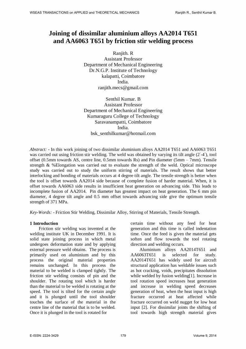
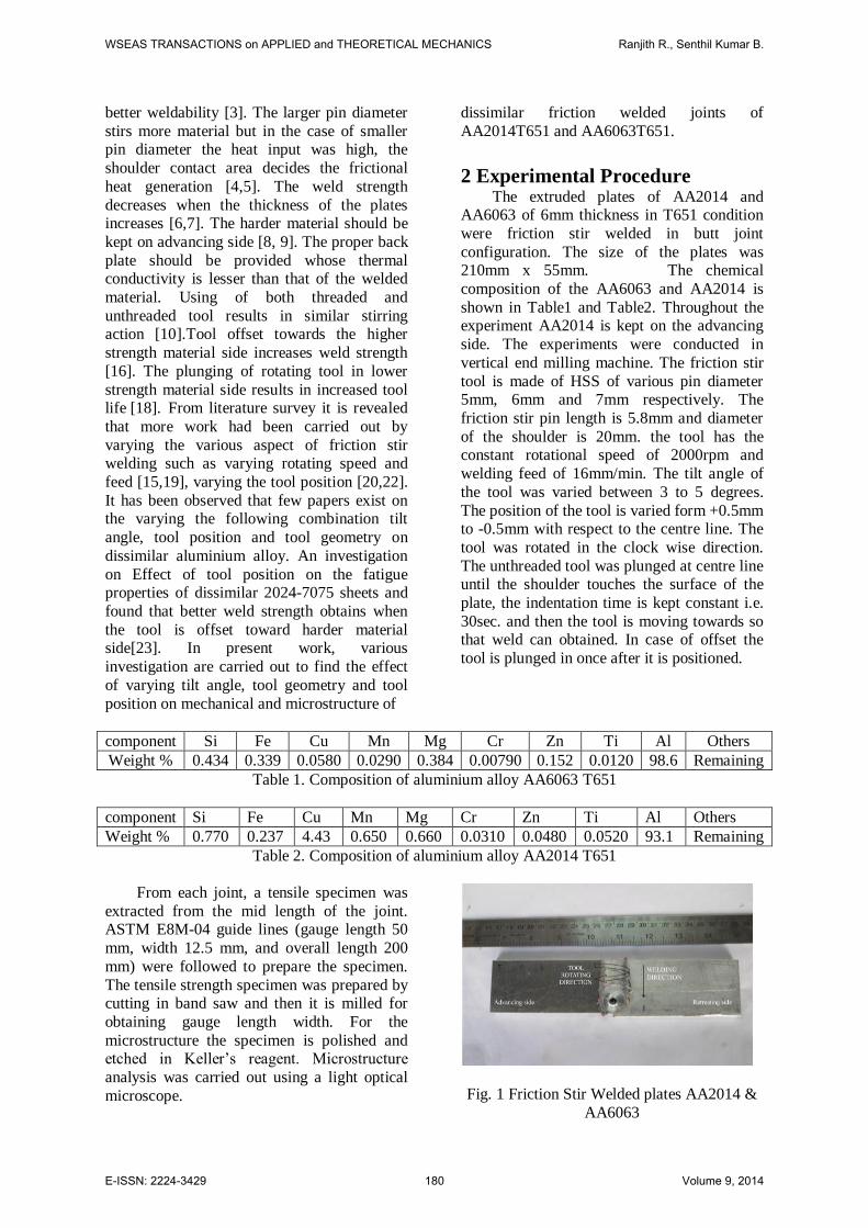
From each joint, a tensile specimen was
extracted from the mid length of the joint. ASTM E8M-04 guide lines (gauge length 50
mm, width 12.5 mm, and overall length 200
mm) were followed to prepare the specimen.
The tensile strength specimen was prepared by cutting in band saw and then it is milled for
obtaining gauge length width. For the
microstructure the specimen is polished and etched in Keller’s reagent. Microstructure
analysis was carried out using a light optical
microscope.
Fig. 1 Friction Stir Welded plates AA2014 &
AA6063
WSEAS TRANSACTIONS on APPLIED and THEORETICAL MECHANICS Ranjith R., Senthil Kumar B.
E-ISSN: 2224-3429 180 Volume 9, 2014
3 Results and discussion
3.1 Mechanical properties
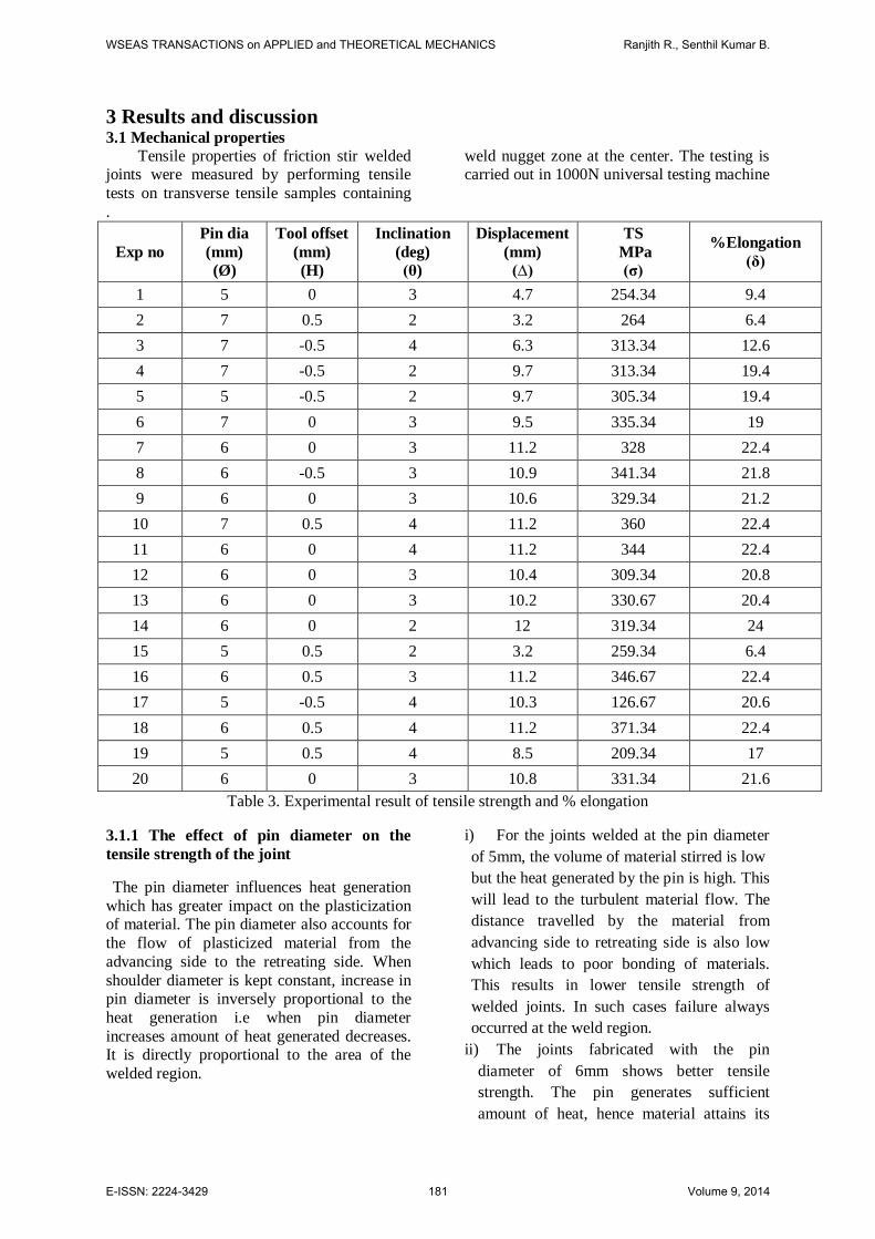
Tensile properties of friction stir welded joints were measured by performing tensile
tests on transverse tensile samples containing
weld nugget zone at the center. The testing is carried out in 1000N universal testing machine
.
Exp no
Pin dia
(mm)
(Ø)
Tool offset
(mm)
(H)
Inclination
(deg)
(θ)
Displacement
(mm)
(∆)
TS
MPa
(σ)
%Elongation
(δ)
1 5 0 3 4.7 254.34 9.4
2 7 0.5 2 3.2 264 6.4
3 7 -0.5 4 6.3 313.34 12.6
4 7 -0.5 2 9.7 313.34 19.4
5 5 -0.5 2 9.7 305.34 19.4
6 7 0 3 9.5 335.34 19
7 6 0 3 11.2 328 22.4
8 6 -0.5 3 10.9 341.34 21.8
9 6 0 3 10.6 329.34 21.2
10 7 0.5 4 11.2 360 22.4
11 6 0 4 11.2 344 22.4
12 6 0 3 10.4 309.34 20.8
13 6 0 3 10.2 330.67 20.4
14 6 0 2 12 319.34 24
15 5 0.5 2 3.2 259.34 6.4
16 6 0.5 3 11.2 346.67 22.4
17 5 -0.5 4 10.3 126.67 20.6
18 6 0.5 4 11.2 371.34 22.4
19 5 0.5 4 8.5 209.34 17
20 6 0 3 10.8 331.34 21.6
Table 3. Experimental result of tensile strength and % elongation
3.1.1 The effect of pin diameter on the
tensile strength of the joint
The pin diameter influences heat generation
which has greater impact on the plasticization of material. The pin diameter also accounts for
the flow of plasticized material from the
advancing side to the retreating side. When
shoulder diameter is kept constant, increase in pin diameter is inversely proportional to the
heat generation i.e when pin diameter
increases amount of heat generated decreases. It is directly proportional to the area of the
welded region.
i) For the joints welded at the pin diameter
of 5mm, the volume of material stirred is low
but the heat generated by the pin is high. This
will lead to the turbulent material flow. The
distance travelled by the material from
advancing side to retreating side is also low
which leads to poor bonding of materials.
This results in lower tensile strength of
welded joints. In such cases failure always
occurred at the weld region.
ii) The joints fabricated with the pin
diameter of 6mm shows better tensile
strength. The pin generates sufficient
amount of heat, hence material attains its
WSEAS TRANSACTIONS on APPLIED and THEORETICAL MECHANICS Ranjith R., Senthil Kumar B.
E-ISSN: 2224-3429 181 Volume 9, 2014
deformation state. This enhances uniform
flow of material from advancing side to
retreating side which results in superior
tensile strength.
iii) For the joints welded at the pin diameter
of 7mm, the heat developed by the pin is low
and the heat is distributed to large volume of
material which leads to incomplete fusion of
material.
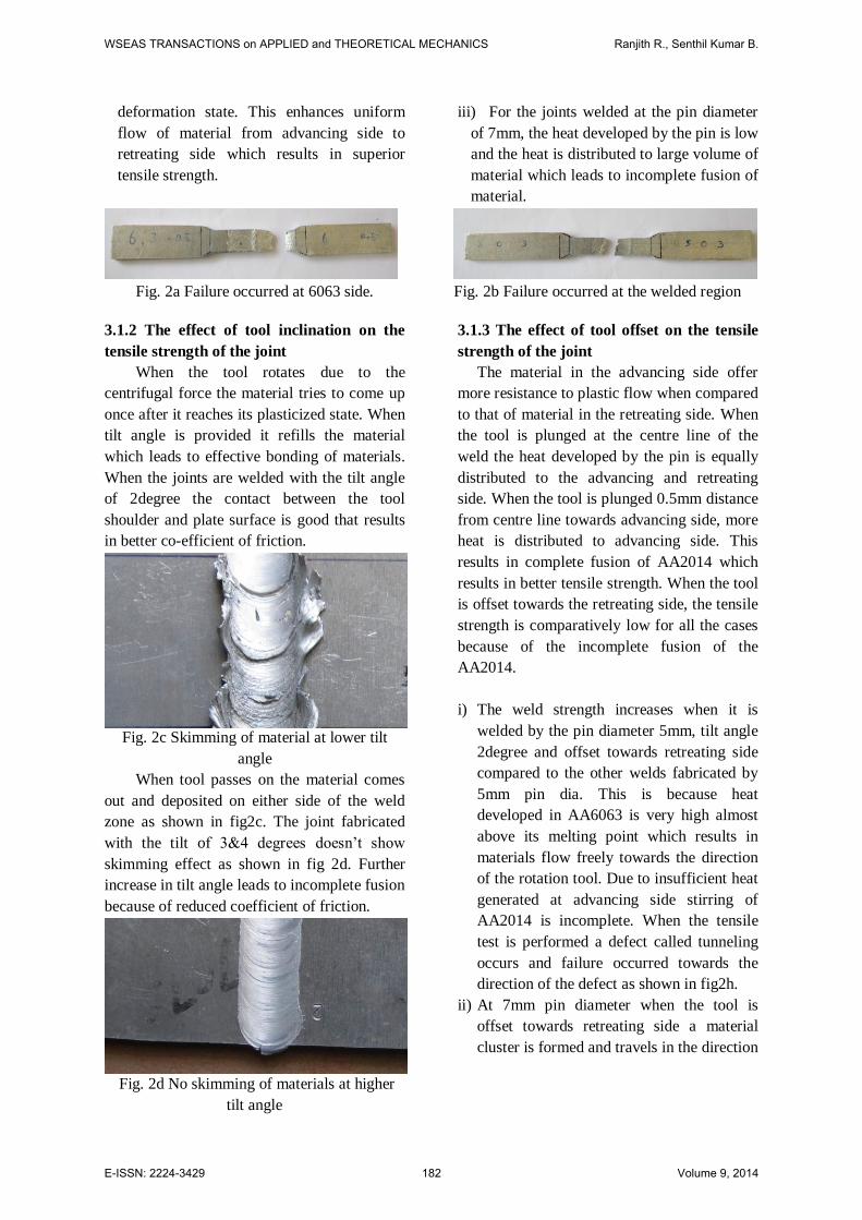
Fig. 2a Failure occurred at 6063 side. Fig. 2b Failure occurred at the welded region
3.1.2 The effect of tool inclination on the
tensile strength of the joint
When the tool rotates due to the
centrifugal force the material tries to come up
once after it reaches its plasticized state. When
tilt angle is provided it refills the material
which leads to effective bonding of materials.
When the joints are welded with the tilt angle
of 2degree the contact between the tool
shoulder and plate surface is good that results
in better co-efficient of friction.
Fig. 2c Skimming of material at lower tilt
angle
When tool passes on the material comes
out and deposited on either side of the weld
zone as shown in fig2c. The joint fabricated
with the tilt of 3&4 degrees doesn’t show
skimming effect as shown in fig 2d. Further
increase in tilt angle leads to incomplete fusion
because of reduced coefficient of friction.
Fig. 2d No skimming of materials at higher
tilt angle
3.1.3 The effect of tool offset on the tensile
strength of the joint
The material in the advancing side offer
more resistance to plastic flow when compared
to that of material in the retreating side. When
the tool is plunged at the centre line of the
weld the heat developed by the pin is equally
distributed to the advancing and retreating
side. When the tool is plunged 0.5mm distance
from centre line towards advancing side, more
heat is distributed to advancing side. This
results in complete fusion of AA2014 which
results in better tensile strength. When the tool
is offset towards the retreating side, the tensile
strength is comparatively low for all the cases
because of the incomplete fusion of the
AA2014.
i) The weld strength increases when it is
welded by the pin diameter 5mm, tilt angle
2degree and offset towards retreating side
compared to the other welds fabricated by
5mm pin dia. This is because heat
developed in AA6063 is very high almost
above its melting point which results in
materials flow freely towards the direction
of the rotation tool. Due to insufficient heat
generated at advancing side stirring of
AA2014 is incomplete. When the tensile
test is performed a defect called tunneling
occurs and failure occurred towards the
direction of the defect as shown in fig2h.
ii) At 7mm pin diameter when the tool is
offset towards retreating side a material
cluster is formed and travels in the direction
WSEAS TRANSACTIONS on APPLIED and THEORETICAL MECHANICS Ranjith R., Senthil Kumar B.
E-ISSN: 2224-3429 182 Volume 9, 2014
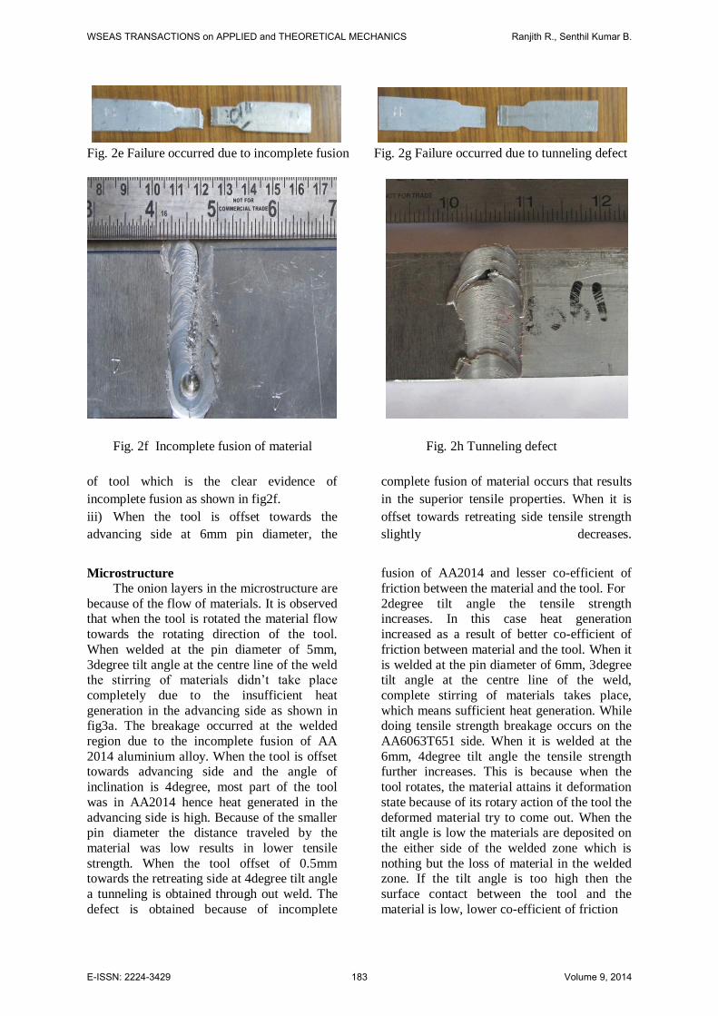
Fig. 2e Failure occurred due to incomplete fusion Fig. 2g Failure occurred due to tunneling defect
Fig. 2f Incomplete fusion of material Fig. 2h Tunneling defect
of tool which is the clear evidence of
incomplete fusion as shown in fig2f.
iii) When the tool is offset towards the
advancing side at 6mm pin diameter, the
complete fusion of material occurs that results
in the superior tensile properties. When it is
offset towards retreating side tensile strength
slightly decreases.
Microstructure The onion layers in the microstructure are
because of the flow of materials. It is observed that when the tool is rotated the material flow
towards the rotating direction of the tool.
When welded at the pin diameter of 5mm,
3degree tilt angle at the centre line of the weld the stirring of materials didn’t take place
completely due to the insufficient heat
generation in the advancing side as shown in fig3a. The breakage occurred at the welded
region due to the incomplete fusion of AA
2014 aluminium alloy. When the tool is offset towards advancing side and the angle of
inclination is 4degree, most part of the tool
was in AA2014 hence heat generated in the
advancing side is high. Because of the smaller pin diameter the distance traveled by the
material was low results in lower tensile
strength. When the tool offset of 0.5mm towards the retreating side at 4degree tilt angle
a tunneling is obtained through out weld. The
defect is obtained because of incomplete
fusion of AA2014 and lesser co-efficient of
friction between the material and the tool. For
2degree tilt angle the tensile strength increases. In this case heat generation
increased as a result of better co-efficient of
friction between material and the tool. When it
is welded at the pin diameter of 6mm, 3degree tilt angle at the centre line of the weld,
complete stirring of materials takes place,
which means sufficient heat generation. While doing tensile strength breakage occurs on the
AA6063T651 side. When it is welded at the
6mm, 4degree tilt angle the tensile strength further increases. This is because when the
tool rotates, the material attains it deformation
state because of its rotary action of the tool the
deformed material try to come out. When the tilt angle is low the materials are deposited on
the either side of the welded zone which is
nothing but the loss of material in the welded zone. If the tilt angle is too high then the
surface contact between the tool and the
material is low, lower co-efficient of friction
WSEAS TRANSACTIONS on APPLIED and THEORETICAL MECHANICS Ranjith R., Senthil Kumar B.
E-ISSN: 2224-3429 183 Volume 9, 2014
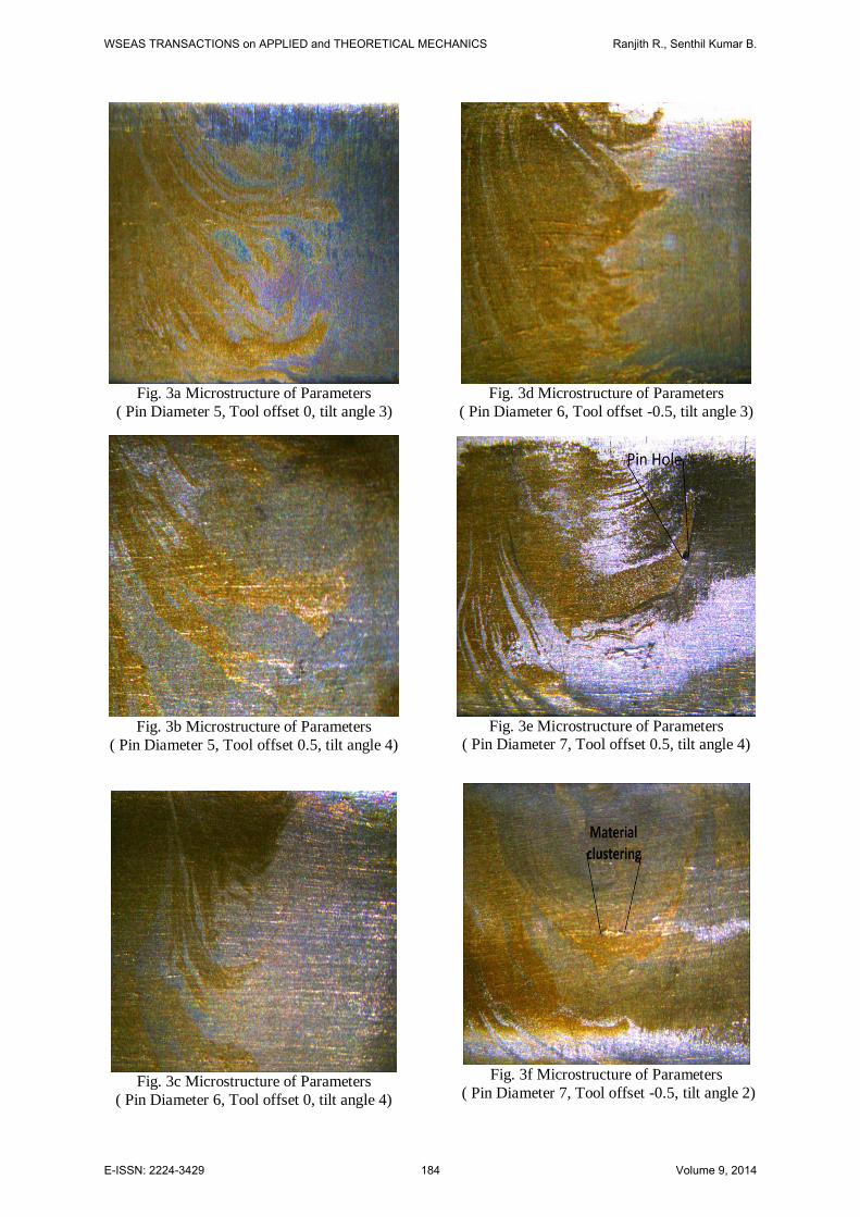
Fig. 3a Microstructure of Parameters
( Pin Diameter 5, Tool offset 0, tilt angle 3)
Fig. 3b Microstructure of Parameters
( Pin Diameter 5, Tool offset 0.5, tilt angle 4)
Fig. 3c Microstructure of Parameters
( Pin Diameter 6, Tool offset 0, tilt angle 4)
Fig. 3d Microstructure of Parameters
( Pin Diameter 6, Tool offset -0.5, tilt angle 3)
Fig. 3e Microstructure of Parameters
( Pin Diameter 7, Tool offset 0.5, tilt angle 4)
Fig. 3f Microstructure of Parameters
( Pin Diameter 7, Tool offset -0.5, tilt angle 2)
WSEAS TRANSACTIONS on APPLIED and THEORETICAL MECHANICS Ranjith R., Senthil Kumar B.
E-ISSN: 2224-3429 184 Volume 9, 2014
results in lesser heat generation. If we provide
the tilt angle it interlock the materials and backfills it. So the interlocking of material at
the 4degree tilt angle is optimum.
The microstructure reveals that the
material had flow till the end. The onion rings was pretty clear so it reveals the complete
stirring of materials has obtained. When the
offset of 0.5mm towards the AA2014 is given for the tilt angle of 4 degree gives the better
tensile strength of all the combined
experiments. When the tool offset is 0.5mm towards
the advancing side at 4degree tilt angle, at
7mm pin diameter, pinhole defect was found
in the advancing side as shown in fig3e. When the tensile test is performed the failure occurs
at the AA6063T651 side. It reveals that better
stirring of material. Despite of defect the tensile strength obtain was high because of the
reasons, 4degree tilt angle gives the better
interlocking and bonding of material and the heat generated was sufficient for the complete
fusion of materials. The microstructure also
reveals the materials are completely stirred till
the end. At 0.5mm offset towards the retreating side at 2degree tilt an island like
structure found at the weld region as shown in
fig3f. This reveals that incomplete fusion of metal at that particular region.
Conclusion
Aluminum alloy AA2014T651 and AA6063T651 was successfully friction stir
weld employing different process parameters.
Their influence on mechanical properties of developed joints was investigated. Following
conclusion can be drawn from the present
work. 1) At Lower Pin Diameter heat generation was
high but material stirred region was low.
Increasing pin diameter increases welded
region. If the pin diameter is too high the heat generation was low results in welding
defects such as tunneling defect, pinhole
and insufficient fusion of materials. 2) Material skimming occurred when the tilt
angle was low. At 4degree tilt angle the
material interlocking and refilling rate was high, hence tensile strength increases.
3) When the tool is offset towards advancing
side AA2014 alloy completely plasticized
because of high heat input on that side, offset of tool towards retreating side results
in incomplete fusion of metal because of
lesser heat input on harder material i.e. on
aluminium alloy AA2014T651. 4) 6mm pin diameter when it is offset towards
the advancing side at 4degree tilt angle
gives the tensile strength of 371MPa which
is 87.7% strength of the base metal. 5) Optimum tensile strength was found when
pin diameter is equal to the thickness of the
plate. The future work can be done on welding of dissimilar aluminum alloys
AA6082 & AA5083 on higher pin
diameters.
References:
[1] Chaitanya Sharma, Dheerendra Kumar
Dwivedi , Pradeep Kumar, Effect of welding
parameters on microstructure and mechanical properties of friction stir welded joints of
AA7039 aluminum alloy,Materials and
Design Vol.36 (2012) pp.379–390. [2] S.Tutunchilar, M. Haghpanahi, M.K.
Besharati Givi, P. Asadi, P. Bahemmat,
Simulation of material flow in friction stir processing of a cast Al–Si alloy Materials and
Design Vol.40 (2012) pp.415–426.
[3] Takehiko Watanabe, Hirofumi Takayama,
Atsushi Yanagisawa, Joining of aluminum alloy to steel by friction stir welding,Journal
of Materials Processing Technology Vol.178
(2006) pp.342–349. [4] S. Rajakumar, C. Muralidharan, V.
Balasubramanian, Influence of friction stir
welding process and tool parameters on
strength properties of AA7075-T6 aluminium alloy joints, Materials and Design (2010)
article in press.
[5] Y.K.Yousif, K.M.Daws, B.I.Kazem, Prediction of Friction Stir Welding
Characteristic Using Neural network , Jordan
Journal of Mechanical and Industrial Engineering Vol.2 (2008) pp.151 – 155.
[6] Y. M. Hwang, P. L. Fan, C . H. Lin,
Experimental study on Friction Stir Welding
of copper metals, Journal of Materials Processing Technology Vol.210 (2010)
pp.1667–1672.
[7] Cemal Meran, The joint properties of brass plates by friction stir welding, Materials
and Design Vol.27 (2006) pp.719–726.
[8] K.L. Harikrishna, J.J.S. Dilip, K. Ramaswamy Choudary, V.V. Subba Rao, S.R.
Koteswara Rao, G.D. Janaki Ram, N. Sridhar
and G. Madhusudhan Reddy, Friction stir
welding of magnesium alloy ZM21,
WSEAS TRANSACTIONS on APPLIED and THEORETICAL MECHANICS Ranjith R., Senthil Kumar B.
E-ISSN: 2224-3429 185 Volume 9, 2014
Transactions of The Indian Institute of Metals
Vol. 63, Issue 5, October 2010, pp. 807 – 811. [9] Hasan Okuyucu , Adem Kurt , Erol
Arcaklioglu, Artificial neural network
application to the friction stir welding of
aluminum plates, Materials and Design Vol.28 (2007) pp.78–84.
[10] Olivier Lorraina, Véronique Favier,
Hamid Zahrouni, Didier Lawrjaniec, Understanding the material flow path of
friction stir welding process using unthreaded
tools, Journal of Materials Processing Technology Vol.210 (2010) pp.603–609.
[11] K. Surekha, A. Els-Botes, Development
of high strength, high conductivity copper by
friction stir processing, Materials and Design Vol.32 (2011) pp.911–916.
[12] Y.C. Chen, K. Nakata, Effect of tool
geometry on microstructure and mechanical properties of friction stir lap welded
magnesium alloy and steel, Materials and
Design Vol.30 (2009) pp.3913–3919. [13] X. Cao, M. Jahazi, Effect of welding
speed on the quality of friction stir welded butt
joints of a magnesium alloy, Materials and
Design Vol.30 (2009) pp.2033–2042P. [14] Heurtier, M.J. Jones, C. Desrayaud, J.H.
Driver,F. Montheillet, D. Allehaux,
Mechanical and thermal modelling of Friction Stir Welding, Journal of Materials Processing
Technology Vol.171 (2006) pp.348–357.
[15] Qingfeng Zeng, Jiakui Zu, Litong Zhang,
Guanzhong Dai, Designing expert system with artificial neural networks for in situ toughened
Si3N4, Materials and Design Vol.23 (2002)
pp.287-290. [16] P. Cavaliere, F. Panella, Effect of tool
position on the fatigue properties of dissimilar
2024-7075 sheets joined by friction stir welding, Journal of materials processing
technology Vol.206 (2008) pp.249–255.
[17] M.Sarvghad Moghaddam, R.Parvizi, M,
Haddad-Sabzevar, A.Davoodi, Microstructural and mechanical properties of friction stir
welded Cu–30Zn brass alloy at various feed
speeds: Influence of stir bands, Materials and Design Vol.32 (2011) pp.2749–2755
[18] Huseyin Uzun, Claudio Dalle Donne ,
Alberto Argagnotto, Tommaso Ghidini,Carla Gambaro, Friction stir welding of dissimilar
Al 6013-T4 To X5CrNi18-10 stainless steel,
Materials and Design Vol.26 (2005) pp.41–
46. [19] L. Ceschini , I. Boromei , G. Minak , A.
Morri , F. Tarterini, Effect of friction stir
welding on microstructure, tensile and fatigue properties of the AA7005/10 vol.%Al2O3p
composite, Composites Science and
Technology Vol.67 (2007) pp.605–615. [20] R. Palanivel , P. Koshy Mathews , N.
Murugan , I. Dinaharan, Effect of tool
rotational speed and pin profile on
microstructure and tensile strength of dissimilar friction stir welded AA5083-H111
and AA6351-T6 aluminum alloys, Materials
and Design Vol.40 (2012) pp.7–16. [21] M. Geigera, F. Micarib, M. Merkleina, L.
Fratinib, D. Contornob, A. Gieraa,, D. Stauda,
Friction Stir Knead Welding of steel aluminium butt joints, International Journal of
Machine Tools & Manufacture Vol.48 (2008)
pp.515–521.
[22] K.L. Harikrishna, J.J.S. Dilip, K. Ramaswamy Choudary, V.V. Subba Rao4,
S.R. Koteswara Rao,G.D. Janaki Ram, N.
Sridhar and G. Madhusudhan Reddy, Friction stir welding of magnesium alloy ZM21,
Transactions of The Indian Institute of Metals
Vol. 63, Issue 5, October 2010, pp. 807 – 811
[23] J. A. Esparza, w. C. Davis, e. A. Trillo, l. E. Murr, Friction-stir welding of magnesium
alloy az31b, Journal of materials science
letters Vol.21, 2002, pp.917– 920. [24] M. Abbasi Gharacheh, A.H. Kokabi, G.H.
Daneshi, B. Shalchi, R. Sarrafi, The influence
of the ratio of ‘‘rotational speed/traverse speed’’ (o/v) on mechanical properties of
AZ31 friction stir welds, International Journal
of Machine Tools & Manufacture Vol.46
(2006) pp.1983–1987 [25] M. Ericsson, R. Sandstro m, Influence of
welding speed on the fatigue of friction stir
welds and comparison with MIG and TIG International Journal of Fatigue Vol.25
(2003) pp.1379–1387.
WSEAS TRANSACTIONS on APPLIED and THEORETICAL MECHANICS Ranjith R., Senthil Kumar B.
E-ISSN: 2224-3429 186 Volume 9, 2014