ARL-TR-7515 ● NOV 2015 US Army Research Laboratory Gas Metal Arc Weld (GMAW) Qualification of 7020-T651 Aluminum by John F Chinella, Nick Kapustka, and Seth Shira Approved for public release; distribution is unlimited.

Welcome message from author
This document is posted to help you gain knowledge. Please leave a comment to let me know what you think about it! Share it to your friends and learn new things together.
Transcript
ARL-TR-7515 ● NOV 2015
US Army Research Laboratory
Gas Metal Arc Weld (GMAW) Qualification of 7020-T651 Aluminum by John F Chinella, Nick Kapustka, and Seth Shira Approved for public release; distribution is unlimited.
NOTICES
Disclaimers The findings in this report are not to be construed as an official Department of the Army position unless so designated by other authorized documents. Citation of manufacturer’s or trade names does not constitute an official endorsement or approval of the use thereof. Destroy this report when it is no longer needed. Do not return it to the originator.
ARL-TR-7515 ● NOV 2015
US Army Research Laboratory
Gas Metal Arc Weld (GMAW) Qualification of 7020-T651 Aluminum by John F Chinella Weapons and Materials Research Directorate, ARL Nick Kapustka and Seth Shira Edison Welding Institute, Columbus, Ohio Approved for public release; distribution is unlimited.
ii
REPORT DOCUMENTATION PAGE Form Approved OMB No. 0704-0188
Public reporting burden for this collection of information is estimated to average 1 hour per response, including the time for reviewing instructions, searching existing data sources, gathering and maintaining the data needed, and completing and reviewing the collection information. Send comments regarding this burden estimate or any other aspect of this collection of information, including suggestions for reducing the burden, to Department of Defense, Washington Headquarters Services, Directorate for Information Operations and Reports (0704-0188), 1215 Jefferson Davis Highway, Suite 1204, Arlington, VA 22202-4302. Respondents should be aware that notwithstanding any other provision of law, no person shall be subject to any penalty for failing to comply with a collection of information if it does not display a currently valid OMB control number. PLEASE DO NOT RETURN YOUR FORM TO THE ABOVE ADDRESS.
1. REPORT DATE (DD-MM-YYYY)
November 2015 2. REPORT TYPE
Final 3. DATES COVERED (From - To)
1 September 2014–30 September 2015 4. TITLE AND SUBTITLE
Gas Metal Arc Weld (GMAW) Qualification of 7020-T651 Aluminum 5a. CONTRACT NUMBER
5b. GRANT NUMBER
5c. PROGRAM ELEMENT NUMBER
6. AUTHOR(S)
John F Chinella, Nick Kapustka, and Seth Shira 5d. PROJECT NUMBER
5e. TASK NUMBER
5f. WORK UNIT NUMBER
7. PERFORMING ORGANIZATION NAME(S) AND ADDRESS(ES)
US Army Research Laboratory ATTN: RDRL-WMM-F Aberdeen Proving Ground, MD 5069-5069
8. PERFORMING ORGANIZATION REPORT NUMBER
ARL-TR-7515
9. SPONSORING/MONITORING AGENCY NAME(S) AND ADDRESS(ES)
DASA R&T/Chief, Global Technology Integration Division, Programs and Engineering Directorate, 3073 Aberdeen Boulevard, Aberdeen, Maryland 21005
10. SPONSOR/MONITOR'S ACRONYM(S)
11. SPONSOR/MONITOR'S REPORT NUMBER(S)
12. DISTRIBUTION/AVAILABILITY STATEMENT
Approved for public release; distribution is unlimited.
13. SUPPLEMENTARY NOTES
14. ABSTRACT
This study determines weld joint characteristics of high-strength aluminum (Al), fusion-weld filler metals, Al-magnesium (Mg) alloys AA5087, AA5556A, and Al-Mg6-Zr fusion welded with the gas metal arc weld (GMAW) pulse (P) and spray (S) methods to AA7020-T651 Al. The study qualifies pulse and spray weld method weld joints of 25- and 40-mm-thick Al 7020-T651 plates with visual, radiographic, and metallographic examinations, and bend and tension tests. These fusion-weld filler metals and compositions have capabilities to better match the high strength levels of candidate Al structural and protection materials (e.g., Al-Zn-Mg 7020) for application to land vehicles. The 7020 alloy has demonstrated improved durability and shock resistance over the 7017 or 7039 alloys and improved yield strengths over 5083 and 6061 Al; therefore, high-strength Al, with tough, ductile, weld joints may provide improved protection and crash safety by means of a rigid vehicle structure. This investigation revealed 7020-T651 (has best tensile 43.4–46 ksi strength results) with 5087 filler and the GMAW-P-mode yield strengths of 28–31 ksi, and elongations of 6.8%–9.4%. The 7020 alloy is recommended as “weldable” with tensile strength requirements of 43–46 ksi. 15. SUBJECT TERMS
7020, 5087, 5556A, aluminum, GMAW, weld
16. SECURITY CLASSIFICATION OF: 17. LIMITATION OF ABSTRACT
UU
18. NUMBER OF PAGES
94
19a. NAME OF RESPONSIBLE PERSON
John F Chinella a. REPORT
Unclassified b. ABSTRACT
Unclassified c. THIS PAGE
Unclassified 19b. TELEPHONE NUMBER (Include area code)
410-920-2117 Standard Form 298 (Rev. 8/98) Prescribed by ANSI Std. Z39.18

iii
Contents
List of Figures v
List of Tables ix
1. Introduction 1
2. Background 1
3. Test Methodology 3
3.1 Experimental Materials 3
3.2 Procedures 5
3.2.1 Task 1: Multipass Welding Procedure Development 5
3.2.2 Task 2: Qualification Plates 7
3.2.3 Task 3: Ballistic Shock Panel Fabrication 9
4. Results 11
4.1 Task 1: Multipass Welding Procedure Development 11
4.2 Task 2: Fabrication and Tests of Qualification Plates 18
4.3 Task 3: Ballistic Shock Panel Fabrication 29
5. Discussion 31
6. Conclusions 34
7. References and Notes 36
Appendix A. Materials 39
Appendix B. Task 1 Results 41
Appendix C. Task 2 Results: Qualification Panels 53
Appendix D. Task 3 Results: Ballistic Shock Panel Fabrication 69

iv
List of Symbols, Abbreviations, and Acronyms 77
Distribution List 79
v
List of Figures
Fig. 1 ABB IRB 1600 Robot and Fronius welding system with push-pull type wire feed system ....................................................................................6
Fig. 2 Drawing, side bend specimen, and weldments of 25.04-mm-thick plate ........................................................................................................7
Fig. 3 Drawing, tension specimens, and welds of 25.04-mm-thick plate ........7
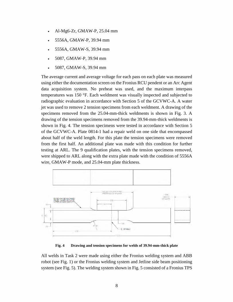
Fig. 4 Drawing and tension specimens for welds of 39.94-mm-thick plate ....8
Fig. 5 Tasks 2 and 3 Fronius TPS 5000 weld system, Jetline Engineering side beam, and push-pull wire feed........................................................9
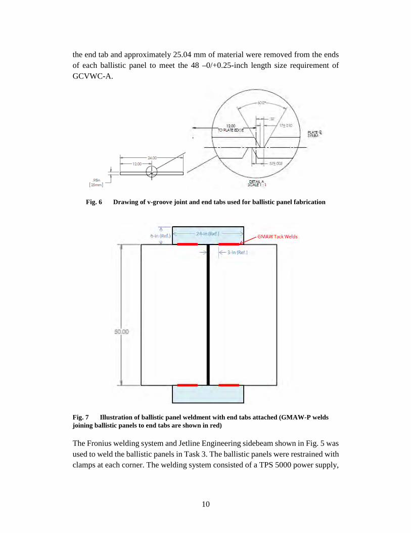
Fig. 6 Drawing of v-groove joint and end tabs used for ballistic panel fabrication ............................................................................................10
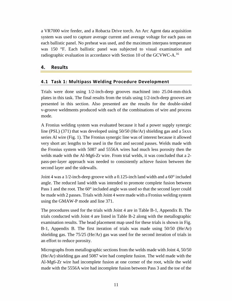
Fig. 7 Illustration of ballistic panel weldment with end tabs attached (GMAW-P welds joining ballistic panels to end tabs are shown in red) .......................................................................................................10
Fig. 8 Radiographic images, Task 1 plate, 5087 wire, GMAW-P .................14
Fig. 9 Micrographs, Task 1 plate, 5087 wire, GMAW-P ...............................15
Fig. 10 Photographs, tested bend specimens, Task 1 plate, Al-Mg6-Zr wire, GMAW-P .............................................................................................16
Fig. 11 Photographs, tested bend specimens, Task 1 plate, 5556A wire, GMAW-P .............................................................................................16
Fig. 12 Photographs, tested bend specimens, Task 1 plate, 5556A wire, GMAW-S .............................................................................................16
Fig. 13 Photographs, tested bend specimens, Task 1 plate, 5087 wire, GMAW-P ...........................................................................................................17
Fig. 14 Photographs, tested bend specimen, Task 1 plate, 5087 wire, GMAW-S ...........................................................................................................17
Fig. 15 Fractured, tension specimens, Task 1, 5556A, GMAW-P (left), 5087, GMAW-P (right) ..................................................................................17
Fig. 16 Bead map, Task 2, 25.04-mm-thick QPs, excluding 0814-1 ...............19
Fig. 17 Radiographic images, 25.04-mm-thick QP 0813-2, 5087 wire, GMAW-P .............................................................................................21
Fig. 18 Fracture faces, tension specimens, 25.04-mm-thick QP 0813-2, 5087 wire, GMAW-P ....................................................................................22
Fig. 19 Side view, fractured tension specimens, 25.04-mm-thick QP 0813-2, 5087 wire, GMAW-P ...........................................................................22
Fig. 20 Bead map, 39.94-mm-thick QP 0820-1, 5087 wire, GMAW-P ..........24
Fig. 21 Photographs, Side A, 39.94-mm-thick QP 0820-1, 5087 wire, GMAW-P ...........................................................................................................25
vi
Fig. 22 Radiographic images, 39.94-mm-thick QP 0820-1, 5087 wire, GMAW-P .............................................................................................26
Fig. 23 Fracture faces, tensile specimens, 39.94-mm-thick QP 0820-1, 5087 wire, GMAW-P ....................................................................................26
Fig. 24 Side view, fractured tension specimens, 39.94-mm-thick QP 0820-1, 5087 wire, GMAW-P ...........................................................................26
Fig. 25 Bead placement map for the 25.04-mm-thick ballistic panels .............29
Fig. 26 Photographs of 25.04-mm-thick ballistic panel 7020-01-EWI prior removal of end tabs ..............................................................................30
Fig. 27 Bead placement maps (L-R) for 7020-04, 05, 06-EWI, 39.94-mm-thick ballistic panels ...........................................................30
Fig. 28 Photographs of 39.94-mm-thick ballistic panel 7020-05-EWI, prior to removal of end tabs ..............................................................................31
Fig. B-1 Bead placement map, Joints 3 and 4 trials, Fronius power supply, GMAW-P .............................................................................................44
Fig. B-2 Micrograph, 0728-2 Al-Mg6-Zr wire, 75He-25Ar SG, Joint 4, Fronius PSL 371 ................................................................................................45
Fig. B-3 Micrographs, 0730-1, 5556A wire, 75He-25Ar SG, Joint 4, Fronius PSL 371 ................................................................................................45
Fig. B-4 Micrographs, 0731-1, 5087 wire, 75He-25Ar SG, Joint 4, Fronius PS line 371.................................................................................................45
Fig. B-5 Micrograph, 0731-4, 5087 wire, 50He-50Ar SG, Joint 5, GMAW-S, Fronius PSL 972 ..................................................................................46
Fig. B-6 Drawing of the plates welded in Task 1 ...............................................46
Fig. B-7 Radiographic images, Task 1 plate, Al-Mg6-Zr wire, GMAW-P .......47
Fig. B-8 Micrographs, Task 1 plate, Al-Mg6-Zr wire, GMAW-P .....................47
Fig. B-9 Radiographic images, Task 1 plate, 5556A wire, GMAW-P ..............47
Fig. B-10 Micrographs, Task 1 plate, 5556A wire and the GMAW-P ................48
Fig. B-11 Radiographic images, Task 1 plate, 5556A wire, GMAW-S ..............48
Fig. B-12 Micrographs, Task 1 plate, 5556A wire, GMAW-S ............................48
Fig. B-13 Radiographic images, Task 1 plate, 5087 wire, GMAW-S .................49
Fig. B-14 Micrograph, Task 1 plate, 5087 wire, GMAW-S ................................49
Fig. B-15 Micrographs, Task 1 plate, 5087 wire, GMAW-S ...............................49
Fig. B-16 Weld procedure 806-1, 5087 wire, GMAW-P, page 1 ........................50
Fig. B-17 Weld procedure 806-1, 5087 wire, GMAW-P, page 2 ........................51
Fig. B-18 Weld procedure 806-1, 5087 wire, GMAW-P, page 3 ........................52
vii
Fig. C-1 Drawing of the 25.04-mm-thick qualification panels (QPs) ................59
Fig. C-2 Drawing of the 39.94-mm-thick QPs ...................................................59
Fig. C-3 Radiographic images, 25.04-mm-thick QP 0813-1, 5556A wire, GMAW-P .............................................................................................60
Fig. C-4 Fracture faces, 0813-1 tensile specimens, 25.04-mm QP, 5556A wire, GMAW-P .............................................................................................60
Fig. C-5 Side view, fractured tensile specimens, 25.04-mm-thick QP 0813-1, 5556A wire, GMAW-P ........................................................................60
Fig. C-6 Bead map for first 1-inch QP 0814-1, 5556A wire, GMAW-S mode .61
Fig. C-7 Radiographic images, first 25.04-mm-thick QP 0814-1, 5556A wire, GMAW-S .............................................................................................61
Fig. C-8 Fracture faces, tension specimens, 25.04-mm-thick QP 0814-1, 5556A wire, GMAW-S ....................................................................................61
Fig. C-9 Side view, fractured tension specimens, 25.04-mm-thick QP 0814-1, 5556A wire, GMAW-S ........................................................................62
Fig. C-10 Radiographic images, second 25.04-mm-thick QP 0908-1, 5556A wire, GMAW-S ....................................................................................62
Fig. C-11 Radiographic images, 25.04-mm-thick QP 0814-2, 5087 wire, GMAW-S .............................................................................................62
Fig. C-12 Fracture faces, tension specimens, 25.04-mm-thick QP 0814-2, 5087 wire, GMAW-S ....................................................................................63
Fig. C-13 Side view, fractured tension specimens, 25.04-mm-thick QP 0814-2, 5087 wire, GMAW-S ...........................................................................63
Fig. C-14 Radiographic images, 25.04-mm-thick QP 0815-1, Al-Mg6-Zr wire, GMAW-P .............................................................................................63
Fig. C-15 Fracture faces, tension specimens, 25.04-mm-thick QP 0815-1, Al-Mg6-Zr wire, GMAW-P .................................................................64
Fig. C-16 Side view, fractured tension specimens, 25.04-mm-thick QP 0815-1, Al-Mg6-Zr wire, GMAW-P .................................................................64
Fig. C-17 Bead map, 39.94-mm-thick QP 0818-1, 5556A wire, GMAW-P .......64
Fig. C-18 Radiographic images, 39.94-mm-thick QP 0818-1, 5556A wire, GMAW-P .............................................................................................65
Fig. C-19 Fracture faces, tension specimens, 39.94-mm-thick QP 0818-1, 5556A wire, GMAW-P ....................................................................................65
Fig. C-20 Side view, fractured tension specimens, 39.94-mm-thick QP 0818-1, 5556A wire, GMAW-P ........................................................................65
Fig. C-21 Bead map, 39.94-mm-thick QP 0909-1, 5556A wire, GMAW-S .......66
Fig. C-22 Radiographic images, 39.94-mm-thick QP 0909-1, 5556A wire, GMAW-S .............................................................................................66
viii
Fig. C-23 Fracture faces, tension specimens, 39.94-mm-thick QP 0909-1, 5556A wire, GMAW-S ....................................................................................66
Fig. C-24 Side view, fractured tension specimens, 39.94-mm-thick QP 0909-1, 5556A wire, GMAW-S ........................................................................67
Fig. C-25 Bead map, 39.94-mm-thick QP 0910-1, 5087 wire, GMAW-S ..........67
Fig. C-26 Radiographic images, 39.94-mm-thick QP 0910-1, 5087 wire, GMAW-S .............................................................................................67
Fig. C-27 Fracture faces, tension specimens, 39.94-mm-thick QP 0910-1, 5087 wire, GMAW-S ....................................................................................68
Fig. C-28 Side view, fractured tension specimens, 39.94-mm-thick QP 0910-1, 5087 wire, GMAW-S ...........................................................................68
Fig. D-1 Radiographic images, 25.04-mm-thick ballistic panel 7020-01-EWI .73
Fig. D-2 Radiographic images, 25.04-mm-thick ballistic panel 7020-02-EWI .73
Fig. D-3 Radiographic images, 25.04-mm-thick ballistic panel 7020-03-EWI .74
Fig. D-4 Photographs, 39.94-mm-thick ballistic panel 7020-04-EWI, after removal of end tabs ..............................................................................74
Fig. D-5 Photographs, 39.94-mm-thick ballistic panel 7020-06-EWI, after removal of end tabs ..............................................................................75
Fig. D-6 Radiographic images, 39.94-mm-thick ballistic panel 7020-04-EWI .75
Fig. D-7 Radiographic images, 39.94-mm-thick ballistic panel 7020-05-EWI .76
Fig. D-8 Radiographic images, 39.94-mm-thick ballistic panel 7020-06-EWI .76
ix
List of Tables
Table 1 Filler metal, wire, certified chemical composition, and weight-percent analysis ...................................................................................................4
Table 2 7020-T651 base metal, certified chemical composition, and weight-percent analysis ......................................................................................4
Table 3 Filler metals and base metals; Aluminum Association chemical composition limits ..................................................................................4
Table 4 Base metal, 7020-T651 plate, certified mechanical properties in tension ....................................................................................................5
Table 5 Identities, weld, and evaluation methods for the 25.04-mm-thick plates welded in Task 1 ..................................................................................13
Table 6 Bend test results, Task 1, 16.5-inch weld plate ....................................16
Table 7 Tension test results, Task 1, 16.5-inch weld plate ...............................18
Table 8 Identities, wire, process, and plate thickness, Task 2 qualification plates ....................................................................................................18
Table 9 Weld procedure 25.04-mm QP 0813-2, 5087 wire, GMAW-P ...........21
Table 10 Tension test results, 25.04-mm-thick QP 0813-2, 5087 wire, GMAW-P ...........................................................................................................21
Table 11 Weld procedure 39.94-mm-thick QP 0820-1, 5087 wire, GMAW-P ..25
Table 12 Tension test results 39.94-mm-thick QP 0820-1, 5087 wire, GMAW-P ...........................................................................................................26
Table 13 Mechanical properties in tension, Tasks 1 and 2, 16.5- and 24-inch welds, tensile strength ranked ..............................................................28
Table 14 Comparisons, Task 1 and 2, ultimate strength in tension versus GCVWC-A requirements.....................................................................29
Table A-1 Base metal, 7020-T651 plate, identities, and certificates ....................40
Table A-2 Filler metal, wire, diameters, identities, and certificates .....................40 Table B-1 Trial procedures, Joints 3 and 4, GMAW-P, and Fronius welding
system ..................................................................................................42
Table B-2 Trials conducted with GMAW-P, Joint 4, and Fronius weld system ..42
Table B-3 Procedures used for weld 0731-4, 5087 wire, Joint 5, GMAW-S .......42
Table B-4 Task 1 Procedure 16.5-inch plate 0804-1, Al-Mg6-Zr wire, GMAW-P ...........................................................................................................43
Table B-5 Task 1 Procedure 16.5-inch plate 0805-1, 5556A wire, GMAW-P .....43
Table B-6 Task 1 Procedure 16.5-inch plate 805-2, 5556A wire, GMAW-S .......43
Table B-7 Task 1 Procedure 16.5-inch plate 806-1, 5087 wire, GMAW-P .........44
Table B-8 Task 1 Procedure 16.5-inch plate 0807-1, 5087 wire, GMAW-S .......44
x
Table C-1 Weld procedure 25.04-mm-thick QP 0813-1, 5556A wire, GMAW-P ...........................................................................................................54
Table C-2 Tension test results 25.04-mm-thick QP 0813-1, 5556A wire, GMAW-P ...........................................................................................................54
Table C-3 Weld procedure first 25.04-mm-thick QP 0814-1, 5556A wire, GMAW-S .............................................................................................54
Table C-4 Tension test results, first 25.04-mm-thick QP 0814-1, 5556A wire, GMAW-S .............................................................................................55
Table C-5 Weld procedure, second 25.04-mm thick QP 0908-1, 5556A wire, GMAW-S .............................................................................................55
Table C-6 Procedure 0814-2, 25.04-mm-thick QP, 5087 wire, GMAW-S mode 55
Table C-7 Tension test results 25.04-mm-thick QP 0814-2, 5087 wire, GMAW-S mode .....................................................................................................56
Table C-8 Weld procedure 0815-1, 25.04-mm-thick QP, Al-Mg6-Zr wire, GMAW-P .............................................................................................56
Table C-9 Tension test results 25.04-mm-thick QP 0815-1, Al-Mg6-Zr wire, GMAW-P mode ...................................................................................56
Table C-10 Weld procedure 39.94-mm-thick QP 0818-1, 5556A wire, GMAW-P .............................................................................................56
Table C-11 Tension test results, 39.94-mm-thick QP 0818-1, 5556A wire, GMAW-P .............................................................................................57
Table C-12 Weld procedures 39.94-mm-thick QP 0909-1, 5556A wire, GMAW-S .............................................................................................57
Table C-13 Tension test results 39.94-mm-thick QP 0909-1, 5556A wire, GMAW-S .............................................................................................58
Table C-14 Weld procedures 39.94-mm QP 0910-1, 5087 wire, GMAW-S 58
Table C-15 Tension test results 39.94-mm-thick QP 0910-1, 5087 wire, GMAW-S mode ...................................................................................58
Table D-1 Procedures and data acquisition values, 7020-01-EWI, 25.04-mm-thick ballistic panel ..............................................................................70
Table D 2 Procedures and data acquisition values, 7020-02-EWI, 25.04-mm-thick ballistic panel ..............................................................................70
Table D-3 Procedures and data acquisition values, 7020-03-EWI, 25.04-mm-thick ballistic panel ..............................................................................71
Table D-4 Procedures and data acquisition values, 7020-04-EWI, 39.94-mm-thick ballistic panel ..............................................................................71
xi
Table D-5 Procedures and data acquisition values, 7020-05-EWI, 39.94-mm-thick ballistic panel ..............................................................................72
Table D-6 Procedures and data acquisition values 7020-06-EWI, 39.94-mm-thick ballistic panel .......................................................................................72

xii
INTENTIONALLY LEFT BLANK.
1
1. Introduction
The investigation determines weld qualities and test performance characteristics of European sourced (Italy) high-strength aluminum (Al) fusion-weld filler metals, supplied in the form of 1.6-mm-diameter wire. Two of the 3 subject alloys, AA5087 and AA5556A, conform to alloy composition limits specified by the Aluminum Association (AA),1 a commercial aluminum, 6% magnesium-zirconium (Al-Mg6-Zr) alloy is not registered. The closest US equivalent AA filler metal alloys are respectfully, 5183 and 5556; there are no AA close equivalent alloys to Al-Mg-6Zr. Furthermore, the objective is to qualify the material to be welded, the base metal, AA7020-T651 Al (Germany).2–12 Qualification of 7020-T651 will allow for a revision of MIL-DTL-4606313 and provide a weldable protection material by use of these weld fillers and the metal inert gas weld method (i.e., the gas metal arc weld [GMAW] method). Specifically, the study qualifies individual 5087, 5556A, and Al-Mg6-Zr alloy filler metals9 performance following pulse and spray weld methods of welding of 25- and 40-mm-thick Al 7020-T651 base metal plates. The GMAW weld process, the weld filler metals in wire form, and the 7020-T651 plate base metal are of interest for their adequate rates of fabrication for manufacture of Al-hulled vehicles and vehicle refit or field repair. These fusion-weld filler metals, not available and not qualified for use in the United States, are of interest because of their unique compositions and capability to better match the high strength levels of candidate Al vehicle protection materials aluminum-zinc-magnesium (Al-Zn-Mg) 7020, 7017, and Al-Mg 5059, which offer improved ballistic protection over the fielded MIL-DTL-46027 5083 Al.14 The 7020 alloy is of specific interest due to its fabricability; the potential for improvements over 5083 or 505914,15 Al in ballistic and blast protection, strength, intrusion of floors; and improved environmental durability and ballistic shock resistance compared with Al 7017 or 7039.
2. Background
This investigation first evaluates weld procedures and qualities of the 5087, 5556A, and Al-Mg6-Zr weld filler metals GMAW fabricated with 7020-T651 base metal and then evaluates the fabrication of ballistic test panels. The investigations follow the requirements of the Ground Combat Vehicle Welding Code-Aluminum (GCVWC-A)16 for weld fabrication and ballistic testing. More specifically, the results first report welds and test results by the Edison Welding Institute (EWI) performed on 25- and 40-mm 7020-T651 plate with visual, radiographic, and
2
metallographic examinations, and with mechanical bend test and tension tests from the welded plates. The final section comprises EWI weld fabrication of 5087/7020 ballistic test panels using the best results of weld procedure and weld tests.
Preliminary weld trials were conducted by EWI using semi-automatic welding, 25.04-mm-thick 7020-T651 plate, and the weld fillers. The trials evaluated wire alloy type, shielding gas mixture, the process modes of pulse spray transfer (P) and spray transfer (S), joint design, weld power supply system, welding program, welding program parameters, bead placement, and travel speed. All filler metals were 1/16 inches in diameter, and the base metal thickness used throughout this task was 25.04 mm. For all weld trials no preheat was used, and the maximum interpass temperature was less than 150 °F. The trials were first done using plates with 1/2-inch-deep grooves to simulate one side of the offset double v-groove joint used for the ballistic panels.
Following groove trial welds, double-side v-groove joints 25.04 mm thick were semi-automatic welded 16.5 inches long by use of a Fronius TPS 5000 power welding system with the best procedures of the preliminary result P and S modes for filler metal wires 5556A and 5087 and the P mode for Al-Mg6-Zr.
The 16.5-inch plates were characterized by requirements of the GCVWC-A with qualities of visual and metallographic examinations, radiographic examination, and bend testing. Following bend testing, the 2 best GMAW-P 5087 and 5556A weld plates were tension tested. After the welding and testing of the 16.5-inch plates, 24-inch-long plates were semi-automatic multipass welded using the best identified procedures for the 9 combinations of wire type, process mode, and base metal thickness listed as follows:
• 5556A, GMAW-P, 25.04 mm
• 5556A, GMAW-S, 25.04 mm
• 5087, GMAW-P, 25.04 mm
• 5087, GMAW-S, 25.04 mm
• Al-Mg6-Zr, GMAW-P, 25.04 mm
• 5556A, GMAW-P, 25.04 mm
• 5556A, GMAW-S, 25.04 mm
• 5087, GMAW-P, 25.04 mm
• 5087, GMAW-S, 25.04 mm
3
These plates were inspected by visual and radiographic examination in accordance with the GCVWC-A. Two tension test specimens were also prepared from each welded plate, 18 total, and tested in accordance with the GCVWC-A.
Based on the radiographic and metallographic examinations, bend test, and tension test results from the welded plates, the 5087 filler wire, the GMAW-P process mode, and the corresponding procedures were selected to weld three 25- and three 40-mm-thick ballistic panels. These ballistic panels were subjected to visual and radiographic examination in accordance with the GCVWC-A. The ballistic panels and were supplied to the US Army Research Laboratory (ARL) for testing.
3. Test Methodology
3.1 Experimental Materials
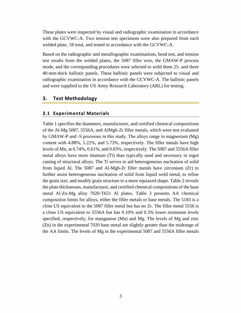
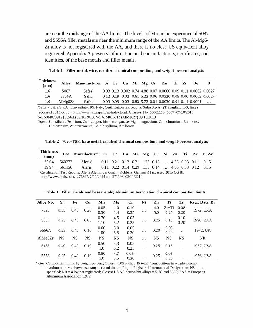
Table 1 specifies the diameters, manufacturer, and certified chemical compositions of the Al-Mg 5087, 5556A, and AlMg6-Zr filler metals, which were test evaluated by GMAW-P and -S processes in this study. The alloys range in magnesium (Mg) content with 4.88%, 5.22%, and 5.73%, respectively. The filler metals have high levels of Mn, at 0.74%, 0.61%, and 0.83%, respectively. The 5087 and 5556A filler metal alloys have more titanium (Ti) than typically used and necessary in ingot casting of structural alloys. The Ti serves to aid heterogeneous nucleation of solid from liquid Al. The 5087 and Al-Mg6-Zr filler metals have zirconium (Zr) to further assist heterogeneous nucleation of solid from liquid weld metal, to refine the grain size, and modify grain structure to a more equiaxed shape. Table 2 reveals the plate thicknesses, manufacturer, and certified chemical compositions of the base metal Al-Zn-Mg alloy 7020-T651 Al plates. Table 3 presents AA chemical composition limits for alloys, either the filler metals or base metals. The 5183 is a close US equivalent to the 5087 filler metal but has no Zr. The filler metal 5556 is a close US equivalent to 5556A but has 0.10% and 0.3% lower minimum levels specified, respectively, for manganese (Mn) and Mg. The levels of Mg and zinc (Zn) in the experimental 7020 base metal are slightly greater than the midrange of the AA limits. The levels of Mg in the experimental 5087 and 5556A filler metals
4
are near the midrange of the AA limits. The levels of Mn in the experimental 5087 and 5556A filler metals are near the minimum range of the AA limits. The Al-Mg6-Zr alloy is not registered with the AA, and there is no close US equivalent alloy registered. Appendix A presents information on the manufacturers, certificates, and identities, of the base metals and filler metals.
Table 1 Filler metal, wire, certified chemical composition, and weight-percent analysis
Thickness (mm) Alloy Manufacturer Si Fe Cu Mn Mg Cr Zn Ti Zr Be B
1.6 5087 Safraa 0.03 0.13 0.002 0.74 4.88 0.07 0.0060 0.09 0.11 0.0002 0.0027 1.6 5556A Safra 0.12 0.19 0.02 0.61 5.22 0.06 0.0320 0.09 0.00 0.0002 0.0027 1.6 AlMg6Zr Safra 0.03 0.09 0.03 0.83 5.73 0.01 0.0030 0.04 0.11 0.0001 …
aSafra = Safra S.p.A., Travagliato, BS, Italy; Certification test reports: Safra S.p.A., (Travagliato, BS, Italy) [accessed 2015 Oct 8]. http://www.safraspa.it/en/index.html. Charges: No. 58001113 (5087) 09/10/2013, No. 50M020912 (5556A) 09/10/2013, No. 61M016912 (AlMg6Zr) 09/10/2013 Notes: Si = silicon, Fe = iron, Cu = copper, Mn = manganese, Mg = magnesium, Cr = chromium, Zn = zinc,
Ti = titanium, Zr = zirconium, Be = beryllium, B = boron
Table 2 7020-T651 base metal, certified chemical composition, and weight-percent analysis
Thickness (mm) Lot Manufacturer Si Fe Cu Mn Mg Cr Ni Zn Ti Zr Ti+Zr
25.04 560273 Alerisa 0.11 0.21 0.13 0.31 1.32 0.13 … 4.63 0.03 0.11 0.15 39.94 561156 Aleris 0.11 0.22 0.14 0.29 1.33 0.14 … 4.66 0.03 0.12 0.15
aCertification Test Reports: Aleris Aluminum Gmbh (Koblenz, Germany) [accessed 2015 Oct 8]. http://www.aleris.com. 271397, 2/11/2014 and 271398, 02/11/2014
Table 3 Filler metals and base metals; Aluminum Association chemical composition limits
Alloy No. Si Fe Cu Mn Mg Cr Ni Zn Ti Zr Reg.: Date, By
7020 0.35 0.40 0.20 0.05 0.50
1.0 1.4
0.10 0.35 … 4.0
5.0 Zr+Ti 0.25
0.08 0.20 1972, EAA
5087 0.25 0.40 0.05 0.70 1.10
4.5 5.2
0.05 0.25 … 0.25 0.15 0.10
0.20 1990, EAA
5556A 0.25 0.40 0.10 0.60 1.00
5.0 5.5
0.05 0.20 … 0.20 0.05
0.20 … 1972, UK
AlMg6Zr NS NS NS NS NS NS … NS NS NS NR
5183 0.40 0.40 0.10 0.50 1.0
4.3 5.2
0.05 0.25 … 0.25 0.15 … 1957, USA
5556 0.25 0.40 0.10 0.50 1.0
4.7 5.5
0.05-0.20 … 0.25 0.05
0.20 … 1956, USA
Notes: Composition limits by weight-percent; Others: 0.05 each, 0.15 total; Compositions in weight-percent maximum unless shown as a range or a minimum; Reg. = Registered International Designation; NS = not specified; NR = alloy not registered; Closest US AA equivalent alloys = 5183 and 5556; EAA = European Aluminum Association, 1972.
5
Table 4 details the certified mechanical properties measured in tension of the base metal 7020-T651 25.04- and 39.94-mm-thick plates. The strength levels of these 7020-T651 plates rank high in levels of yield strength. Among 46 individual samples of 2 lots of 7020-T651 plates tested at ARL, 11 of 46 and 8 of 46 rated highest in strength. The strength levels of these 7020-T651 base metal plates exceed requirements of Al 5083 and 5059 under MIL-DTL-46027K, and meet all strength requirements of 7039 alloy specified under MIL-DTL-46063.
Table 4 Base metal, 7020-T651 plate, certified mechanical properties in tension
Thickness (mm) Manufacturer Lot Weld
group
0.2% YS
(MPa)
0.2% YS
(ksi)
UTS (MPa)
UTS (ksi)
El (%)
0.2% YS
rank
25.04 Aleris 560273 BP, EWI 374 54.2 419 60.8 14.4 11/46
39.94 Aleris 561156 BP, EWI 369 53.5 414 60.0 12.6 8/46
Notes: The 0.2% YS rank show panel strengths in comparison to ARL’s 46 individual 7020-T651 plates with yield strengths of 319–390 MPa (46.3–56.6 ksi); UTS = ultimate tension strength; YS = yield strength; El = elongation
3.2 Procedures
3.2.1 Task 1: Multipass Welding Procedure Development
In this task, welding procedures were developed for 5 combinations of filler metal type and process mode. GMAW-P and GMAW-S procedures were developed for 5087 and 5556A filler wires. GMAW-P procedures were also developed for filler metal Al-Mg6-Zr. All filler metals were 1/16 inch in diameter, and the base metal thickness used throughout this task was 25.04 mm (rounded to 25 mm). For all welds made in this task, no preheat was used, and the maximum interpass temperature was less than 150 °F.
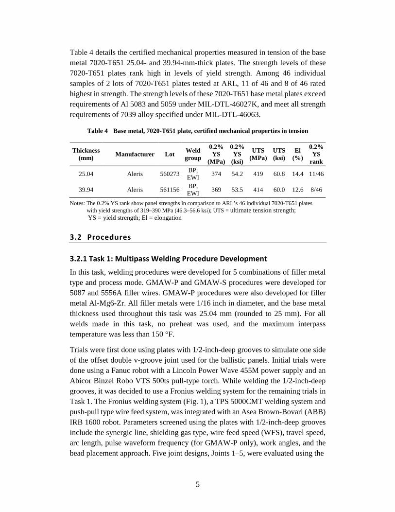
Trials were first done using plates with 1/2-inch-deep grooves to simulate one side of the offset double v-groove joint used for the ballistic panels. Initial trials were done using a Fanuc robot with a Lincoln Power Wave 455M power supply and an Abicor Binzel Robo VTS 500ts pull-type torch. While welding the 1/2-inch-deep grooves, it was decided to use a Fronius welding system for the remaining trials in Task 1. The Fronius welding system (Fig. 1), a TPS 5000CMT welding system and push-pull type wire feed system, was integrated with an Asea Brown-Bovari (ABB) IRB 1600 robot. Parameters screened using the plates with 1/2-inch-deep grooves include the synergic line, shielding gas type, wire feed speed (WFS), travel speed, arc length, pulse waveform frequency (for GMAW-P only), work angles, and the bead placement approach. Five joint designs, Joints 1–5, were evaluated using the
6
1/2-inch-deep grooves. The shielding gases evaluated were 50/50 argon/helium (He/Ar) and 75/25 (He/Ar). All weldments were visually inspected. Select weldments were subjected to radiographic evaluation and/or evaluation of metallographic cross sections.
Fig. 1 ABB IRB 1600 Robot and Fronius welding system with push-pull type wire feed system
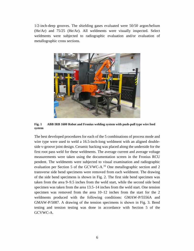
The best developed procedures for each of the 5 combinations of process mode and wire type were used to weld a 16.5-inch-long weldment with an aligned double-side v-groove joint design. Ceramic backing was placed along the underside for the first root pass weld for these weldments. The average current and average voltage measurements were taken using the documentation screen in the Fronius RCU pendent. The weldments were subjected to visual examination and radiographic evaluation per Section 5 of the GCVWC-A.16 One metallographic section and 2 transverse side bend specimens were removed from each weldment. The drawing of the side bend specimens is shown in Fig. 2. The first side bend specimen was taken from the area 9–9.5 inches from the weld start, while the second side bend specimen was taken from the area 13.5–14 inches from the weld start. One tension specimen was removed from the area 10–12 inches from the start for the 2 weldments produced with the following conditions: GMAW-P/5556A and GMAW-P/5087. A drawing of the tension specimens is shown in Fig. 3. Bend testing and tension testing was done in accordance with Section 5 of the GCVWC-A.
7
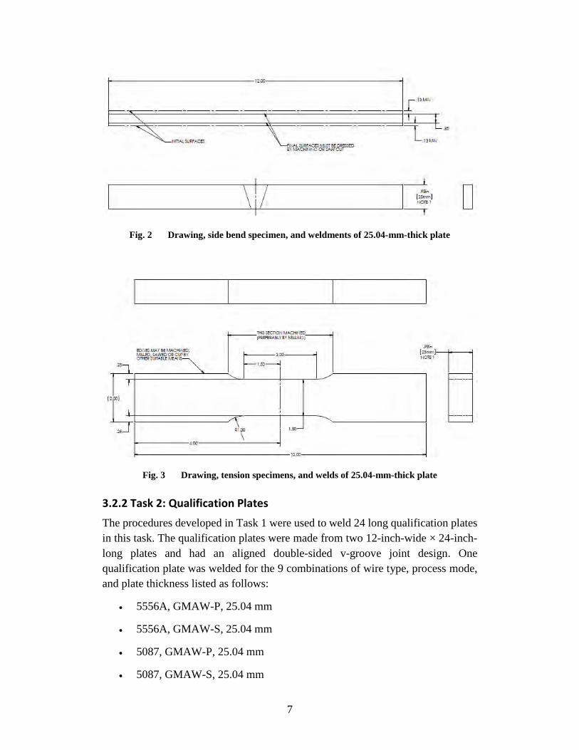
Fig. 2 Drawing, side bend specimen, and weldments of 25.04-mm-thick plate
Fig. 3 Drawing, tension specimens, and welds of 25.04-mm-thick plate
3.2.2 Task 2: Qualification Plates
The procedures developed in Task 1 were used to weld 24 long qualification plates in this task. The qualification plates were made from two 12-inch-wide × 24-inch-long plates and had an aligned double-sided v-groove joint design. One qualification plate was welded for the 9 combinations of wire type, process mode, and plate thickness listed as follows:
• 5556A, GMAW-P, 25.04 mm
• 5556A, GMAW-S, 25.04 mm
• 5087, GMAW-P, 25.04 mm
• 5087, GMAW-S, 25.04 mm
8
• Al-Mg6-Zr, GMAW-P, 25.04 mm
• 5556A, GMAW-P, 39.94 mm
• 5556A, GMAW-S, 39.94 mm
• 5087, GMAW-P, 39.94 mm
• 5087, GMAW-S, 39.94 mm
The average current and average voltage for each pass on each plate was measured using either the documentation screen on the Fronius RCU pendent or an Arc Agent data acquisition system. No preheat was used, and the maximum interpass temperatures was 150 °F. Each weldment was visually inspected and subjected to radiographic evaluation in accordance with Section 5 of the GCVWC-A. A water jet was used to remove 2 tension specimens from each weldment. A drawing of the specimens removed from the 25.04-mm-thick weldments is shown in Fig. 3. A drawing of the tension specimens removed from the 39.94-mm-thick weldments is shown in Fig. 4. The tension specimens were tested in accordance with Section 5 of the GCVWC-A. Plate 0814-1 had a repair weld on one side that encompassed about half of the weld length. For this plate the tension specimens were removed from the first half. An additional plate was made with this condition for further testing at ARL. The 9 qualification plates, with the tension specimens removed, were shipped to ARL along with the extra plate made with the condition of 5556A wire, GMAW-P mode, and 25.04-mm plate thickness.
Fig. 4 Drawing and tension specimens for welds of 39.94-mm-thick plate
All welds in Task 2 were made using either the Fronius welding system and ABB robot (see Fig. 1) or the Fronius welding system and Jetline side beam positioning system (see Fig. 5). The welding system shown in Fig. 5 consisted of a Fronius TPS
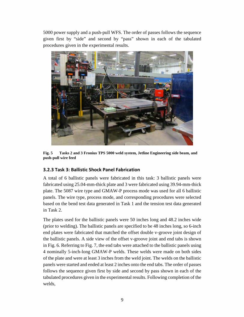
9
5000 power supply and a push-pull WFS. The order of passes follows the sequence given first by “side” and second by “pass” shown in each of the tabulated procedures given in the experimental results.
Fig. 5 Tasks 2 and 3 Fronius TPS 5000 weld system, Jetline Engineering side beam, and push-pull wire feed
3.2.3 Task 3: Ballistic Shock Panel Fabrication
A total of 6 ballistic panels were fabricated in this task: 3 ballistic panels were fabricated using 25.04-mm-thick plate and 3 were fabricated using 39.94-mm-thick plate. The 5087 wire type and GMAW-P process mode was used for all 6 ballistic panels. The wire type, process mode, and corresponding procedures were selected based on the bend test data generated in Task 1 and the tension test data generated in Task 2.
The plates used for the ballistic panels were 50 inches long and 48.2 inches wide (prior to welding). The ballistic panels are specified to be 48 inches long, so 6-inch end plates were fabricated that matched the offset double v-groove joint design of the ballistic panels. A side view of the offset v-groove joint and end tabs is shown in Fig. 6. Referring to Fig. 7, the end tabs were attached to the ballistic panels using 4 nominally 5-inch-long GMAW-P welds. These welds were made on both sides of the plate and were at least 3 inches from the weld joint. The welds on the ballistic panels were started and ended at least 2 inches onto the end tabs. The order of passes follows the sequence given first by side and second by pass shown in each of the tabulated procedures given in the experimental results. Following completion of the welds,
10
the end tab and approximately 25.04 mm of material were removed from the ends of each ballistic panel to meet the 48 –0/+0.25-inch length size requirement of GCVWC-A.
Fig. 6 Drawing of v-groove joint and end tabs used for ballistic panel fabrication
Fig. 7 Illustration of ballistic panel weldment with end tabs attached (GMAW-P welds joining ballistic panels to end tabs are shown in red)
The Fronius welding system and Jetline Engineering sidebeam shown in Fig. 5 was used to weld the ballistic panels in Task 3. The ballistic panels were restrained with clamps at each corner. The welding system consisted of a TPS 5000 power supply,
11
a VR7000 wire feeder, and a Robacta Drive torch. An Arc Agent data acquisition system was used to capture average current and average voltage for each pass on each ballistic panel. No preheat was used, and the maximum interpass temperature was 150 °F. Each ballistic panel was subjected to visual examination and radiographic evaluation in accordance with Section 10 of the GCVWC-A.16
4. Results
4.1 Task 1: Multipass Welding Procedure Development
Trials were done using 1/2-inch-deep grooves machined into 25.04-mm-thick plates in this task. The final results from the trials using 1/2-inch-deep grooves are presented in this section. Also presented are the results for the double-sided v-groove weldments produced with each of the combinations of wire and process mode.
A Fronius welding system was evaluated because it had a power supply synergic line (PSL) (371) that was developed using 50/50 (He/Ar) shielding gas and a 5xxx series Al wire (Fig. 1). The Fronius synergic line was of interest because it allowed very short arc lengths to be used in the first and second passes. Welds made with the Fronius system with 5087 and 5556A wires had much less porosity then the welds made with the Al-Mg6-Zr wire. From trial welds, it was concluded that a 2-pass-per-layer approach was needed to consistently achieve fusion between the second layer and the sidewalls.
Joint 4 was a 1/2-inch-deep groove with a 0.125-inch land width and a 60° included angle. The reduced land width was intended to promote complete fusion between Pass 1 and the root. The 60° included angle was used so that the second layer could be made with 2 passes. Trials with Joint 4 were made with a Fronius welding system using the GMAW-P mode and line 371.
The procedures used for the trials with Joint 4 are in Table B-1, Appendix B. The trials conducted with Joint 4 are listed in Table B-2 along with the metallographic examination results. The bead placement map used for these trials is shown in Fig. B-1, Appendix B. The first iteration of trials was made using 50/50 (He/Ar) shielding gas. The 75/25 (He/Ar) gas was used for the second iteration of trials in an effort to reduce porosity.
Micrographs from metallographic sections from the welds made with Joint 4, 50/50 (He/Ar) shielding gas and 5087 wire had complete fusion. The weld made with the Al-Mg6-Zr wire had incomplete fusion at one corner of the root, while the weld made with the 5556A wire had incomplete fusion between Pass 3 and the toe of the
12
Pass 2 weld. The incomplete fusion between Pass 3 and the toe of Pass 2 for the weld made with the 5556A wire was attributed to overlap at the Pass 2 toe, or too narrow of a land width prior to depositing Pass 3. As a result of this weld, the toe of all future Pass 2 welds was dressed with a carbide bur tool to remove overlap. The welds made with Joint 4, 50/50 (He/Ar) shielding gas, and either 5087 or 5556A had some porosity in the root passes and minimal porosity in the fill passes. The welds made with the same joint and shield gas but with Al-Mg6-Zr wire had porosity scattered throughout the welds.
Micrographs from metallographic sections removed from the welds made with Joint 4 and 75/25 (He/Ar) shielding gas are shown in Figs. B-2, B-3, and B-4. The welds made with the Al-Mg6-Zr, and 5087 wires had complete fusion, whereas the weld made with the 5556A wire had incomplete fusion between Pass 1 and one corner of the root. The weld made with the Al-Mg6-Zr wire and 75/25 (He/Ar) shielding gas had much lower porosity than the weld made with this wire and 50/50 (He/Ar) shielding gas. The welds made with 5556A and 5087 wires and 75/25 (He/Ar) shielding gas also had lower porosity levels than the welds made with the same corresponding wire and 50/50 (He/Ar) shielding gas. Based on the results of the trials with Joint 4, 75/25 (He/Ar) shielding gas was selected for the Task 2 and Task 3 welds made with the GMAW-P mode.
A limited number of 1/2-inch-deep grooves were welded to determine GMAW-S procedures for 5556A and 5087 wires. Joint 5, which consisted of a 1/2-inch-deep groove, a 0.155-inch land, and a 60° included angle was used for these trials along with 50/50 (He/Ar) shielding gas. Trial 0731-4 was made using 5087 wire, the GMAW-S mode, a Fronius welding system, and line 972. The procedures used for this weld are listed in Table B-3, and a micrograph removed from a section of the weldment is shown in Fig. B-5. The same bead placement approach shown in Fig. B-1 was used for this weld. As shown in Fig. B-5, this weld had complete fusion. The weld had a relatively low porosity level, with some porosity scattered throughout the weld. A radiograph of trial 0731-4 met the radiographic evaluation requirements of Section 10 of the GCVWC-A.
The following decisions were made for use of future welds based on the trials with the 1/2-inch-deep grooves:
• 75/25 (He/Ar) shielding gas for welds with the GMAW-P mode
• 50/50 (He/Ar) shielding gas for welds with the GMAW-S mode
• Joint 5 (0.155-inch land width, 60° included angle) design
• A Fronius welding system with GMAW-P synergic line to allow adequate adjustment of the arc length
13
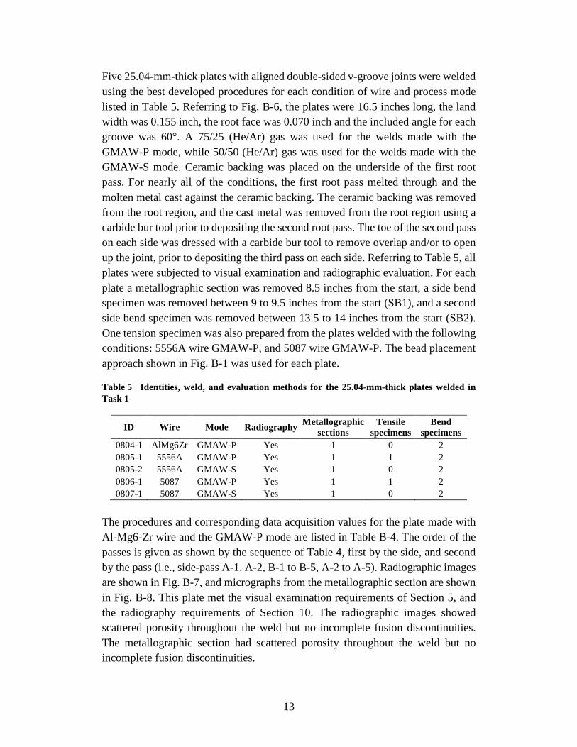
Five 25.04-mm-thick plates with aligned double-sided v-groove joints were welded using the best developed procedures for each condition of wire and process mode listed in Table 5. Referring to Fig. B-6, the plates were 16.5 inches long, the land width was 0.155 inch, the root face was 0.070 inch and the included angle for each groove was 60°. A 75/25 (He/Ar) gas was used for the welds made with the GMAW-P mode, while 50/50 (He/Ar) gas was used for the welds made with the GMAW-S mode. Ceramic backing was placed on the underside of the first root pass. For nearly all of the conditions, the first root pass melted through and the molten metal cast against the ceramic backing. The ceramic backing was removed from the root region, and the cast metal was removed from the root region using a carbide bur tool prior to depositing the second root pass. The toe of the second pass on each side was dressed with a carbide bur tool to remove overlap and/or to open up the joint, prior to depositing the third pass on each side. Referring to Table 5, all plates were subjected to visual examination and radiographic evaluation. For each plate a metallographic section was removed 8.5 inches from the start, a side bend specimen was removed between 9 to 9.5 inches from the start (SB1), and a second side bend specimen was removed between 13.5 to 14 inches from the start (SB2). One tension specimen was also prepared from the plates welded with the following conditions: 5556A wire GMAW-P, and 5087 wire GMAW-P. The bead placement approach shown in Fig. B-1 was used for each plate.
Table 5 Identities, weld, and evaluation methods for the 25.04-mm-thick plates welded in Task 1
ID Wire Mode Radiography Metallographic sections
Tensile specimens
Bend specimens
0804-1 AlMg6Zr GMAW-P Yes 1 0 2 0805-1 5556A GMAW-P Yes 1 1 2 0805-2 5556A GMAW-S Yes 1 0 2 0806-1 5087 GMAW-P Yes 1 1 2 0807-1 5087 GMAW-S Yes 1 0 2
The procedures and corresponding data acquisition values for the plate made with Al-Mg6-Zr wire and the GMAW-P mode are listed in Table B-4. The order of the passes is given as shown by the sequence of Table 4, first by the side, and second by the pass (i.e., side-pass A-1, A-2, B-1 to B-5, A-2 to A-5). Radiographic images are shown in Fig. B-7, and micrographs from the metallographic section are shown in Fig. B-8. This plate met the visual examination requirements of Section 5, and the radiography requirements of Section 10. The radiographic images showed scattered porosity throughout the weld but no incomplete fusion discontinuities. The metallographic section had scattered porosity throughout the weld but no incomplete fusion discontinuities.
14
The procedures and data acquisition values for the plate made with 5556A wire and the GMAW-P mode are listed in Table B-5. The order of passes follows the sequence of side and pass of Table B-5. This plate met the visual examination criteria of Section 5.8.2 GCVWC-A.16 Radiographic images are shown in Fig. B-9. Incomplete fusion discontinuities were absent in the radiographic images. Although porosity was present near the center of the weld, the plate met the radiography requirements. Micrographs from the metallographic section are shown in Fig. B-10. Incomplete fusion was not identified in the metallographic section, and the porosity level was relatively low.
The procedures and data acquisition values for the plate made with 5556A wire and the GMAW-S mode are listed in Table B-6. Radiographic images are shown in Fig. B-11, and micrographs from the metallographic section are shown in Fig. B-12. Although scattered porosity was present in the radiographic images, the plate met the radiographic examination requirements. Incomplete fusion was not observed in the radiographic images. Referring to Fig. B-12, scattered porosity was present throughout the weld cross section, but no incomplete fusion discontinuities were identified.
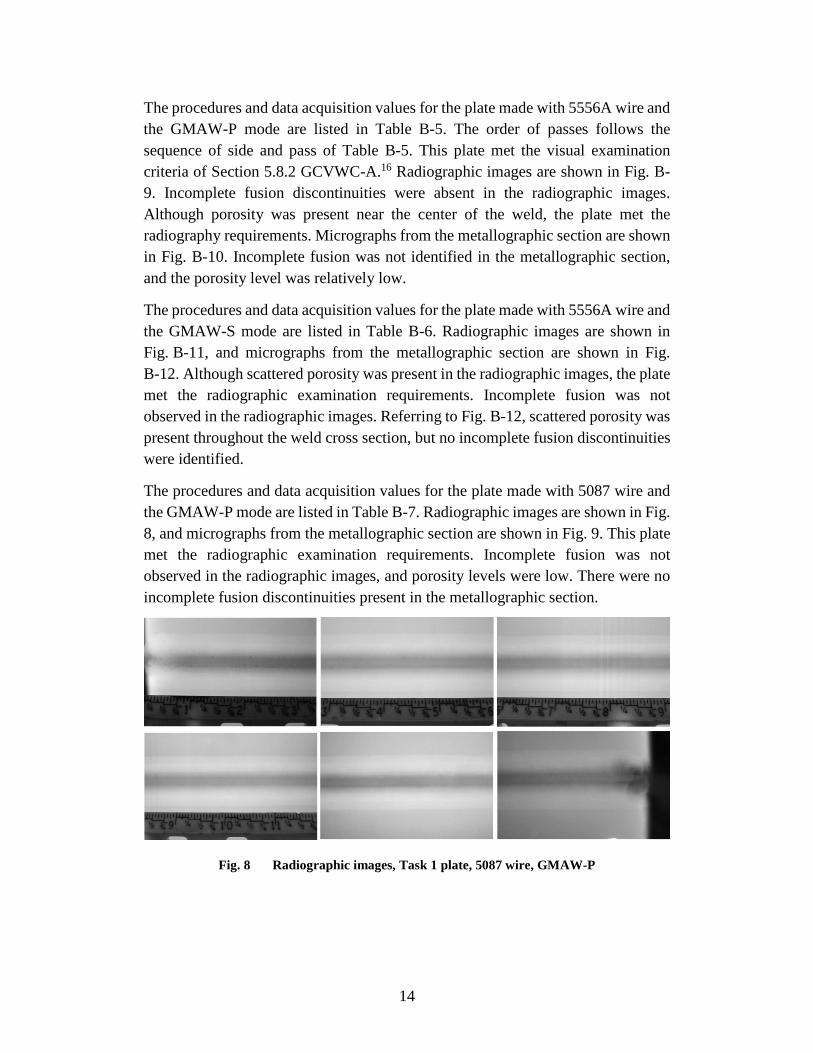
The procedures and data acquisition values for the plate made with 5087 wire and the GMAW-P mode are listed in Table B-7. Radiographic images are shown in Fig. 8, and micrographs from the metallographic section are shown in Fig. 9. This plate met the radiographic examination requirements. Incomplete fusion was not observed in the radiographic images, and porosity levels were low. There were no incomplete fusion discontinuities present in the metallographic section.
Fig. 8 Radiographic images, Task 1 plate, 5087 wire, GMAW-P
15
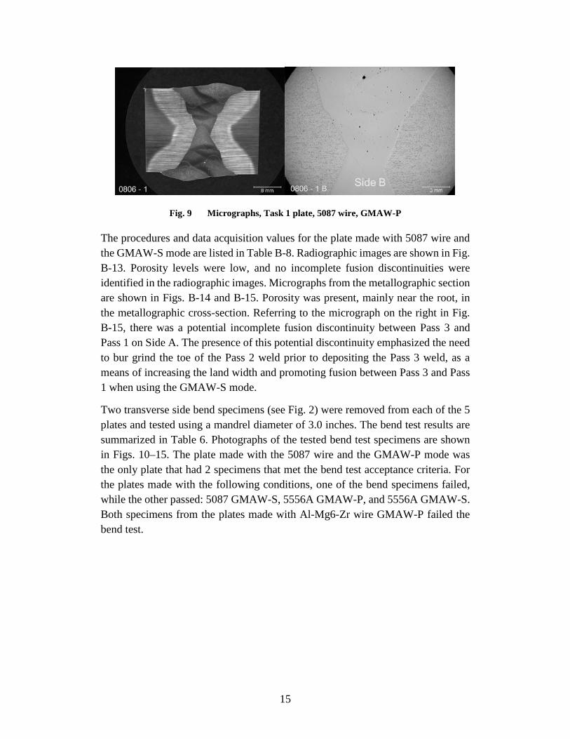
Fig. 9 Micrographs, Task 1 plate, 5087 wire, GMAW-P
The procedures and data acquisition values for the plate made with 5087 wire and the GMAW-S mode are listed in Table B-8. Radiographic images are shown in Fig. B-13. Porosity levels were low, and no incomplete fusion discontinuities were identified in the radiographic images. Micrographs from the metallographic section are shown in Figs. B-14 and B-15. Porosity was present, mainly near the root, in the metallographic cross-section. Referring to the micrograph on the right in Fig. B-15, there was a potential incomplete fusion discontinuity between Pass 3 and Pass 1 on Side A. The presence of this potential discontinuity emphasized the need to bur grind the toe of the Pass 2 weld prior to depositing the Pass 3 weld, as a means of increasing the land width and promoting fusion between Pass 3 and Pass 1 when using the GMAW-S mode.
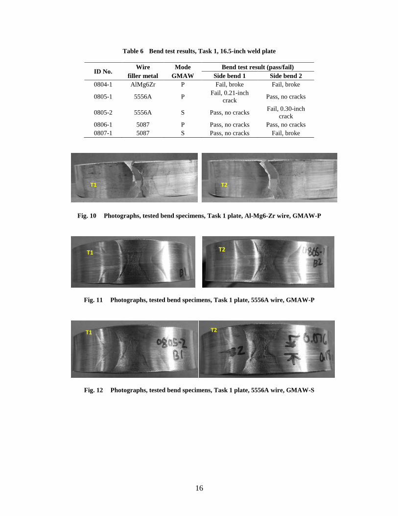
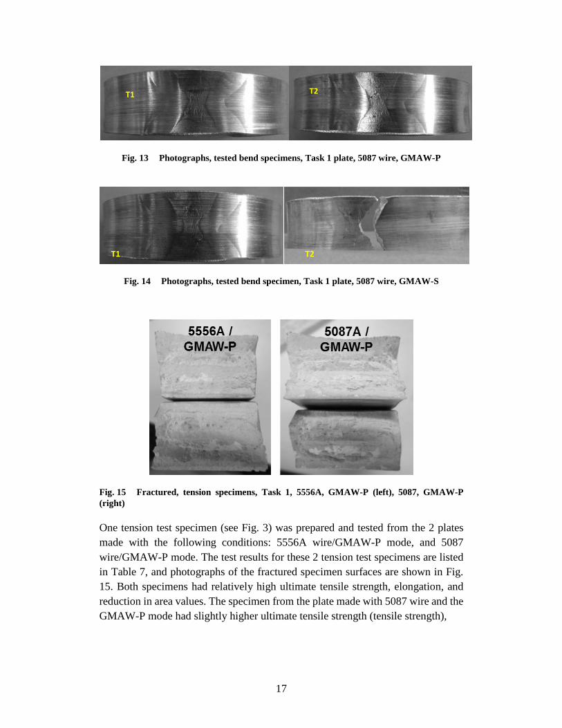
Two transverse side bend specimens (see Fig. 2) were removed from each of the 5 plates and tested using a mandrel diameter of 3.0 inches. The bend test results are summarized in Table 6. Photographs of the tested bend test specimens are shown in Figs. 10–15. The plate made with the 5087 wire and the GMAW-P mode was the only plate that had 2 specimens that met the bend test acceptance criteria. For the plates made with the following conditions, one of the bend specimens failed, while the other passed: 5087 GMAW-S, 5556A GMAW-P, and 5556A GMAW-S. Both specimens from the plates made with Al-Mg6-Zr wire GMAW-P failed the bend test.
16
Table 6 Bend test results, Task 1, 16.5-inch weld plate
ID No. Wire Mode Bend test result (pass/fail)
filler metal GMAW Side bend 1 Side bend 2 0804-1 AlMg6Zr P Fail, broke Fail, broke
0805-1 5556A P Fail, 0.21-inch crack Pass, no cracks
0805-2 5556A S Pass, no cracks Fail, 0.30-inch crack
0806-1 5087 P Pass, no cracks Pass, no cracks 0807-1 5087 S Pass, no cracks Fail, broke
Fig. 10 Photographs, tested bend specimens, Task 1 plate, Al-Mg6-Zr wire, GMAW-P
Fig. 11 Photographs, tested bend specimens, Task 1 plate, 5556A wire, GMAW-P
Fig. 12 Photographs, tested bend specimens, Task 1 plate, 5556A wire, GMAW-S
T1 T2
T1 T2
T1 T2
17
Fig. 13 Photographs, tested bend specimens, Task 1 plate, 5087 wire, GMAW-P
Fig. 14 Photographs, tested bend specimen, Task 1 plate, 5087 wire, GMAW-S
Fig. 15 Fractured, tension specimens, Task 1, 5556A, GMAW-P (left), 5087, GMAW-P (right)
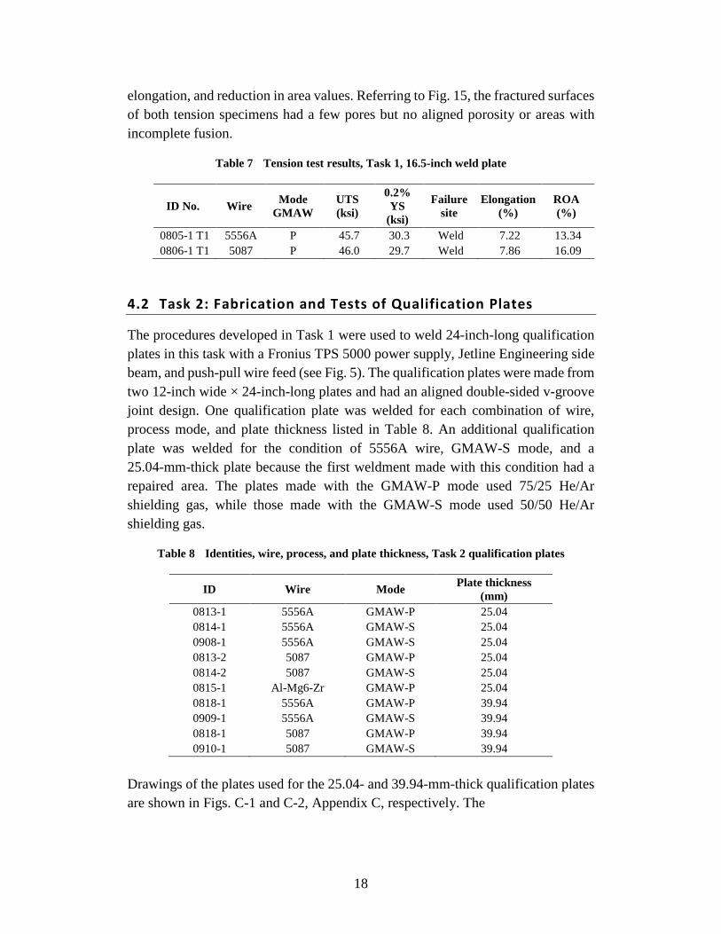
One tension test specimen (see Fig. 3) was prepared and tested from the 2 plates made with the following conditions: 5556A wire/GMAW-P mode, and 5087 wire/GMAW-P mode. The test results for these 2 tension test specimens are listed in Table 7, and photographs of the fractured specimen surfaces are shown in Fig. 15. Both specimens had relatively high ultimate tensile strength, elongation, and reduction in area values. The specimen from the plate made with 5087 wire and the GMAW-P mode had slightly higher ultimate tensile strength (tensile strength),
T1 T2
T1 T2
18
elongation, and reduction in area values. Referring to Fig. 15, the fractured surfaces of both tension specimens had a few pores but no aligned porosity or areas with incomplete fusion.
Table 7 Tension test results, Task 1, 16.5-inch weld plate
ID No. Wire Mode GMAW
UTS (ksi)
0.2% YS
(ksi)
Failure site
Elongation (%)
ROA (%)
0805-1 T1 5556A P 45.7 30.3 Weld 7.22 13.34 0806-1 T1 5087 P 46.0 29.7 Weld 7.86 16.09
4.2 Task 2: Fabrication and Tests of Qualification Plates
The procedures developed in Task 1 were used to weld 24-inch-long qualification plates in this task with a Fronius TPS 5000 power supply, Jetline Engineering side beam, and push-pull wire feed (see Fig. 5). The qualification plates were made from two 12-inch wide × 24-inch-long plates and had an aligned double-sided v-groove joint design. One qualification plate was welded for each combination of wire, process mode, and plate thickness listed in Table 8. An additional qualification plate was welded for the condition of 5556A wire, GMAW-S mode, and a 25.04-mm-thick plate because the first weldment made with this condition had a repaired area. The plates made with the GMAW-P mode used 75/25 He/Ar shielding gas, while those made with the GMAW-S mode used 50/50 He/Ar shielding gas.
Table 8 Identities, wire, process, and plate thickness, Task 2 qualification plates
ID Wire Mode Plate thickness (mm)
0813-1 5556A GMAW-P 25.04 0814-1 5556A GMAW-S 25.04 0908-1 5556A GMAW-S 25.04 0813-2 5087 GMAW-P 25.04 0814-2 5087 GMAW-S 25.04 0815-1 Al-Mg6-Zr GMAW-P 25.04 0818-1 5556A GMAW-P 39.94 0909-1 5556A GMAW-S 39.94 0818-1 5087 GMAW-P 39.94 0910-1 5087 GMAW-S 39.94
Drawings of the plates used for the 25.04- and 39.94-mm-thick qualification plates are shown in Figs. C-1 and C-2, Appendix C, respectively. The
19
joint design was the same as that used for the 16-inch-long plates in Task 1 and consisted of a 0.155-inch land width, a 0.070-inch root face, and a 60° included angle.
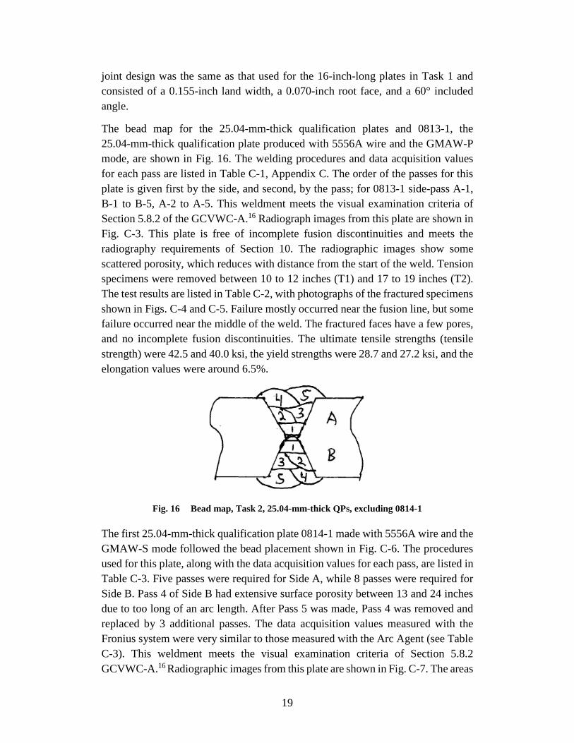
The bead map for the 25.04-mm-thick qualification plates and 0813-1, the 25.04-mm-thick qualification plate produced with 5556A wire and the GMAW-P mode, are shown in Fig. 16. The welding procedures and data acquisition values for each pass are listed in Table C-1, Appendix C. The order of the passes for this plate is given first by the side, and second, by the pass; for 0813-1 side-pass A-1, B-1 to B-5, A-2 to A-5. This weldment meets the visual examination criteria of Section 5.8.2 of the GCVWC-A.16 Radiograph images from this plate are shown in Fig. C-3. This plate is free of incomplete fusion discontinuities and meets the radiography requirements of Section 10. The radiographic images show some scattered porosity, which reduces with distance from the start of the weld. Tension specimens were removed between 10 to 12 inches (T1) and 17 to 19 inches (T2). The test results are listed in Table C-2, with photographs of the fractured specimens shown in Figs. C-4 and C-5. Failure mostly occurred near the fusion line, but some failure occurred near the middle of the weld. The fractured faces have a few pores, and no incomplete fusion discontinuities. The ultimate tensile strengths (tensile strength) were 42.5 and 40.0 ksi, the yield strengths were 28.7 and 27.2 ksi, and the elongation values were around 6.5%.
Fig. 16 Bead map, Task 2, 25.04-mm-thick QPs, excluding 0814-1
The first 25.04-mm-thick qualification plate 0814-1 made with 5556A wire and the GMAW-S mode followed the bead placement shown in Fig. C-6. The procedures used for this plate, along with the data acquisition values for each pass, are listed in Table C-3. Five passes were required for Side A, while 8 passes were required for Side B. Pass 4 of Side B had extensive surface porosity between 13 and 24 inches due to too long of an arc length. After Pass 5 was made, Pass 4 was removed and replaced by 3 additional passes. The data acquisition values measured with the Fronius system were very similar to those measured with the Arc Agent (see Table C-3). This weldment meets the visual examination criteria of Section 5.8.2 GCVWC-A.16 Radiographic images from this plate are shown in Fig. C-7. The areas
20
between 0 and 3 inches and between 12.5 and 18 inches failed to meet the radiography requirements of Section 10 due to excessive porosity. These areas both have weld starts at the beginning of them. No incomplete fusion was detected in the radiographic images. Tension specimens were removed from 8 to 10 inches (T1) and 10 to 12 inches (T2). The test results are listed in Table C-4. Photographs of the fractured specimens are shown in Figs. C-7 and C-8. Failure mostly occurred near the interior of the weld. The fracture faces have a few pores but no incomplete fusion discontinuities. The ultimate tensile strengths are 41.5 and 43.9 ksi, the yield strengths 29.4 and 30.0 ksi, and the elongation values 6.2% and 6.6%.
The second 25.04-mm-thick qualification plate 0908-1 produced with 5556A wire and the GMAW-S mode followed the bead map shown in Fig. 16. The welding procedures and data acquisition values for each pass are listed in Table C-5. Five passes were required on each side of this weldment. The area from 3 to 25 inches meets the visual examination requirements of Section 5.8.2. The area from 0 to 3 inches on Side B contained surface porosity. Extensive porosity was present on the weld surface between 0 and 3 inches even after the cap was partially removed. Radiographic images from this plate are shown in Fig. C-11. The area between 0 and 12 inches fails to meet the radiography requirements due to excessive porosity. Porosity reduced with distance from the start, and the area between 12 and 24 inches meets the radiography requirements. Tension specimens were not removed from this plate.
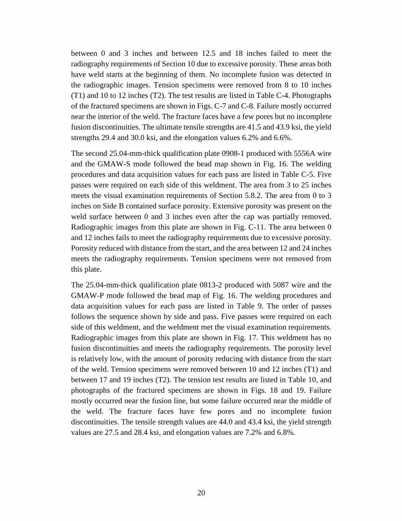
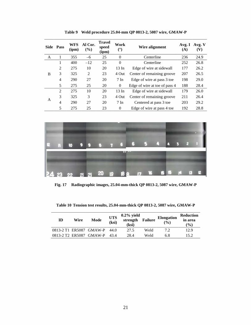
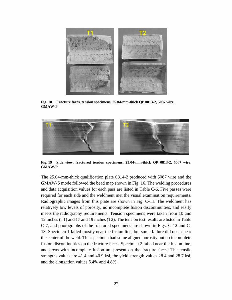
The 25.04-mm-thick qualification plate 0813-2 produced with 5087 wire and the GMAW-P mode followed the bead map of Fig. 16. The welding procedures and data acquisition values for each pass are listed in Table 9. The order of passes follows the sequence shown by side and pass. Five passes were required on each side of this weldment, and the weldment met the visual examination requirements. Radiographic images from this plate are shown in Fig. 17. This weldment has no fusion discontinuities and meets the radiography requirements. The porosity level is relatively low, with the amount of porosity reducing with distance from the start of the weld. Tension specimens were removed between 10 and 12 inches (T1) and between 17 and 19 inches (T2). The tension test results are listed in Table 10, and photographs of the fractured specimens are shown in Figs. 18 and 19. Failure mostly occurred near the fusion line, but some failure occurred near the middle of the weld. The fracture faces have few pores and no incomplete fusion discontinuities. The tensile strength values are 44.0 and 43.4 ksi, the yield strength values are 27.5 and 28.4 ksi, and elongation values are 7.2% and 6.8%.
21
Table 9 Weld procedure 25.04-mm QP 0813-2, 5087 wire, GMAW-P
Side Pass WFS (ipm)
Al Cor. (%)
Travel speed (ipm)
Work (°) Wire alignment Avg. I
(A) Avg. V
(V)
A 1 355 –6 25 0 Centerline 236 24.9
B
1 400 –12 25 0 Centerline 252 26.8 2 275 10 20 13 In Edge of wire at sidewall 177 26.2 3 325 2 23 4 Out Center of remaining groove 207 26.5 4 290 27 20 7 In Edge of wire at pass 3 toe 198 29.0 5 275 25 20 0 Edge of wire at toe of pass 4 188 28.4
A
2 275 10 20 13 In Edge of wire at sidewall 179 26.0 3 325 3 23 4 Out Center of remaining groove 211 26.4 4 290 27 20 7 In Centered at pass 3 toe 203 29.2 5 275 25 23 0 Edge of wire at pass 4 toe 192 28.8
Fig. 17 Radiographic images, 25.04-mm-thick QP 0813-2, 5087 wire, GMAW-P
Table 10 Tension test results, 25.04-mm-thick QP 0813-2, 5087 wire, GMAW-P
ID Wire Mode UTS (ksi)
0.2% yield strength
(ksi) Failure Elongation
(%)
Reduction in area
(%) 0813-2 T1 ER5087 GMAW-P 44.0 27.5 Weld 7.2 12.9 0813-2 T2 ER5087 GMAW-P 43.4 28.4 Weld 6.8 15.2
22
Fig. 18 Fracture faces, tension specimens, 25.04-mm-thick QP 0813-2, 5087 wire, GMAW-P
Fig. 19 Side view, fractured tension specimens, 25.04-mm-thick QP 0813-2, 5087 wire, GMAW-P
The 25.04-mm-thick qualification plate 0814-2 produced with 5087 wire and the GMAW-S mode followed the bead map shown in Fig. 16. The welding procedures and data acquisition values for each pass are listed in Table C-6. Five passes were required for each side and the weldment met the visual examination requirements. Radiographic images from this plate are shown in Fig. C-11. The weldment has relatively low levels of porosity, no incomplete fusion discontinuities, and easily meets the radiography requirements. Tension specimens were taken from 10 and 12 inches (T1) and 17 and 19 inches (T2). The tension test results are listed in Table C-7, and photographs of the fractured specimens are shown in Figs. C-12 and C-13. Specimen 1 failed mostly near the fusion line, but some failure did occur near the center of the weld. This specimen had some aligned porosity but no incomplete fusion discontinuities on the fracture faces. Specimen 2 failed near the fusion line, and areas with incomplete fusion are present on the fracture faces. The tensile strengths values are 41.4 and 40.9 ksi, the yield strength values 28.4 and 28.7 ksi, and the elongation values 6.4% and 4.8%.
23
The bead map of Fig. 16 was followed for 0815-1, the 25.04-mm-thick qualification plate produced with Al-Mg6-Zr wire and the GMAW-P mode. The welding procedures and data acquisition values for each pass are listed in Table C-8. Five passes were required per side, and the completed weldment met the visual examination criteria of Section 5.8.2. Radiographic images from this weldment are shown in Fig. C-14. The weldment meets the radiography requirements, with no incomplete fusion discontinuities, and low porosity content from 5 to 24 inches. The weldment has some acceptable porosity from 0 to 5 inches. Tension specimens were taken from 10 to 12 inches (T1) and 17 to 19 inches (T2). The tension test results are listed in Table C-9 and photographs of the fractured specimens are shown in Figs. C-15 and C-16. The failure location was mixed, with some failure near the interior of the weld and some failure near the fusion line. The fracture faces have a few pores but no incomplete fusion discontinuities. The tensile strength values are 42.6 and 44.2 ksi, the yield strength values 28.3 and 28.8 ksi, and the elongation values 7.3% and 7.4%.
Weldment 0818-1 is the 39.94-mm qualification plate welded with 5556A wire and the GMAW-P mode. The bead map is shown in Fig. C-17, and the procedures and data acquisition values for each pass are listed in Table C-10. Nine passes were required for each side. Side A met the visual examination requirements, but Side B did not because there was under-fill of 0.015 inch or less between 13 and 17 inches and between 18.5 and 25 inches. Section 5.8.2 of the GCVWC-A does not allow any under-fill. Radiographic images from 0818-1 are shown in Fig. C-18. This weldment meets the radiography requirements. Incomplete fusion was not detected, and porosity levels decreased with distance from the weld start. Tension specimens were removed between 10 and 12 inches (T1) and 17 and 19 inches (T2). The tensile test results are listed in Table C-11, and photographs of the fractured specimens are shown in Figs. C-19 and C-20. The fracture faces have areas with incomplete fusion. Failure mostly occurred near the fusion line, but some failure occurred near the middle of the weld. The tensile strength values are 34.9 and 37.1 ksi, the yield strength values 29.2 and 27.2 ksi, and elongation values 5.1% and 6.4%.
Weldment 0909-1 is the 39.94-mm qualification plate welded with 5556A wire and the GMAW-S mode. The bead map is shown in Fig. C-21, and the procedures and data acquisition values for each pass are listed in Table C-12. Ten passes were required for each side. The weldment meets the visual examination criteria of Section 5.8.2. Radiographic images from 0909-1 are shown in Fig. C-22. The area between 0 and 12 inches fails to meet the radiography requirements due to excessive porosity. Porosity levels decrease with distance from the weld start. The area between 12 and 24 inches meets the radiography requirements, and tension specimens were removed between 14 and 16 inches (T1) and 19 and 225.04 mm
24
(T2). Tension test results are listed in Table C-13, and photographs of the fractured specimens are shown in Figs. C-23 and C-24. The fracture faces have areas with incomplete fusion. Failure mostly occurred near the fusion line. The tensile strength values are 39.1 and 39.8 ksi, the yield strength values 28.7 and 30.3 ksi, and elongation values 5.6% and 5.2%.
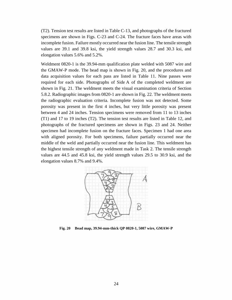
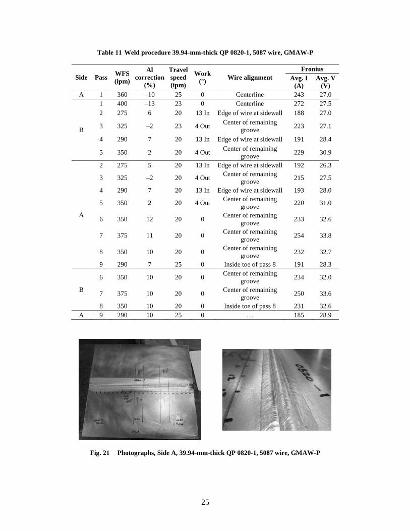
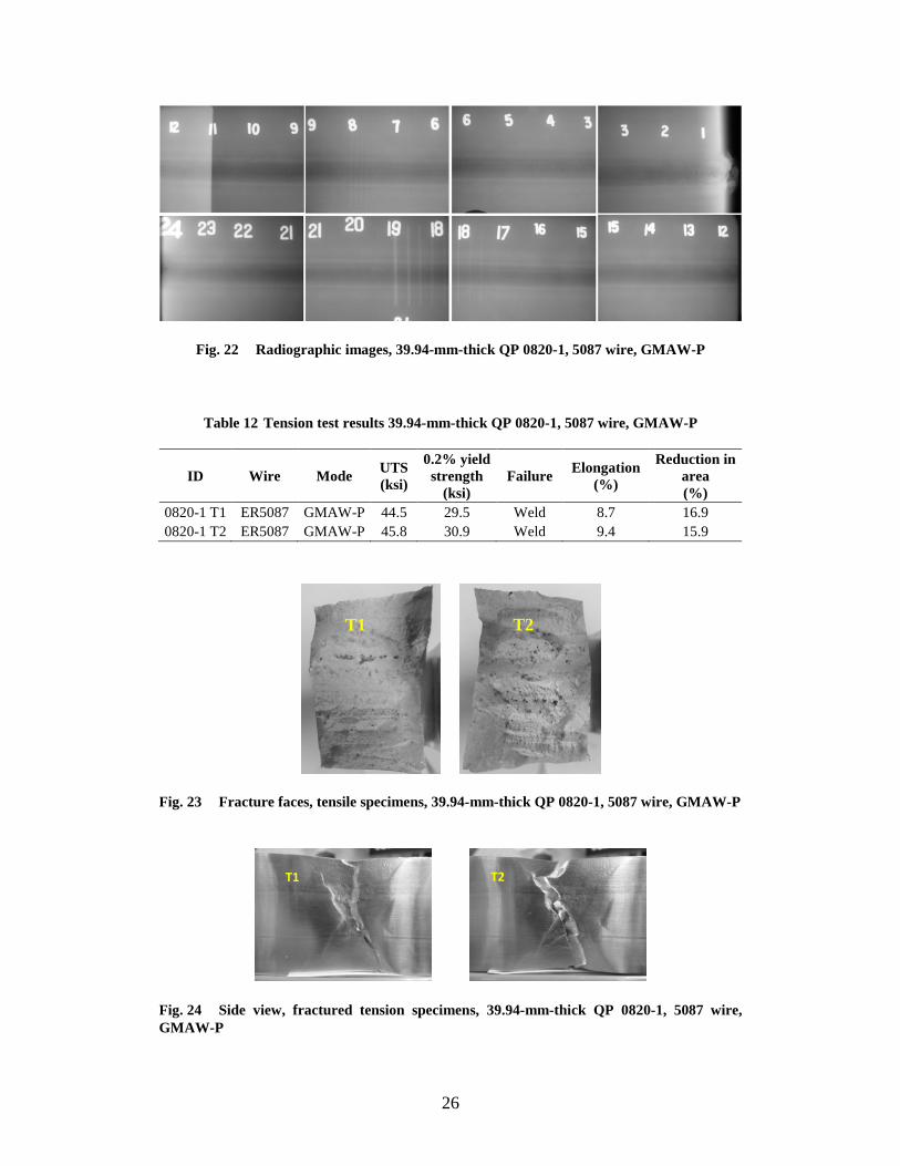
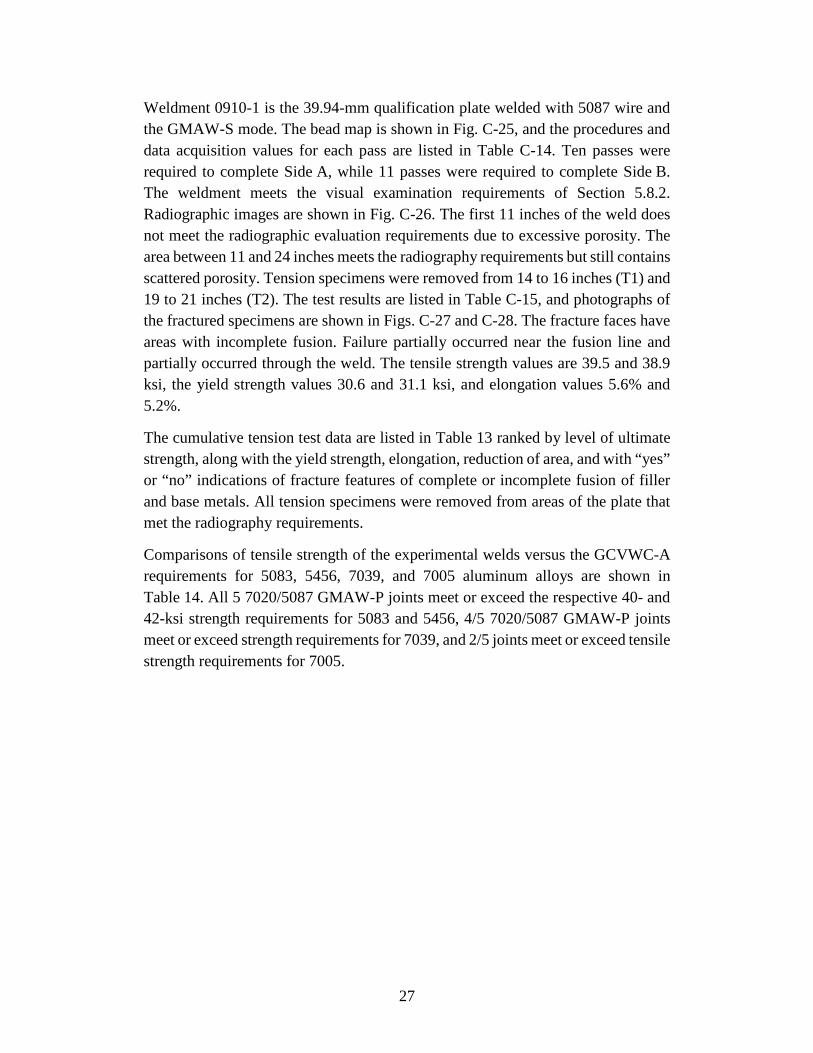
Weldment 0820-1 is the 39.94-mm qualification plate welded with 5087 wire and the GMAW-P mode. The bead map is shown in Fig. 20, and the procedures and data acquisition values for each pass are listed in Table 11. Nine passes were required for each side. Photographs of Side A of the completed weldment are shown in Fig. 21. The weldment meets the visual examination criteria of Section 5.8.2. Radiographic images from 0820-1 are shown in Fig. 22. The weldment meets the radiographic evaluation criteria. Incomplete fusion was not detected. Some porosity was present in the first 4 inches, but very little porosity was present between 4 and 24 inches. Tension specimens were removed from 11 to 13 inches (T1) and 17 to 19 inches (T2). The tension test results are listed in Table 12, and photographs of the fractured specimens are shown in Figs. 23 and 24. Neither specimen had incomplete fusion on the fracture faces. Specimen 1 had one area with aligned porosity. For both specimens, failure partially occurred near the middle of the weld and partially occurred near the fusion line. This weldment has the highest tensile strength of any weldment made in Task 2. The tensile strength values are 44.5 and 45.8 ksi, the yield strength values 29.5 to 30.9 ksi, and the elongation values 8.7% and 9.4%.
Fig. 20 Bead map, 39.94-mm-thick QP 0820-1, 5087 wire, GMAW-P
25
Table 11 Weld procedure 39.94-mm-thick QP 0820-1, 5087 wire, GMAW-P
Side Pass WFS (ipm)
Al correction
(%)
Travel speed (ipm)
Work (°) Wire alignment
Fronius Avg. I
(A) Avg. V
(V) A 1 360 –10 25 0 Centerline 243 27.0
B
1 400 –13 23 0 Centerline 272 27.5 2 275 6 20 13 In Edge of wire at sidewall 188 27.0
3 325 –2 23 4 Out Center of remaining groove 223 27.1
4 290 7 20 13 In Edge of wire at sidewall 191 28.4
5 350 2 20 4 Out Center of remaining groove 229 30.9
A
2 275 5 20 13 In Edge of wire at sidewall 192 26.3
3 325 –2 20 4 Out Center of remaining groove 215 27.5
4 290 7 20 13 In Edge of wire at sidewall 193 28.0
5 350 2 20 4 Out Center of remaining groove 220 31.0
6 350 12 20 0 Center of remaining groove 233 32.6
7 375 11 20 0 Center of remaining groove 254 33.8
8 350 10 20 0 Center of remaining groove 232 32.7
9 290 7 25 0 Inside toe of pass 8 191 28.3
B
6 350 10 20 0 Center of remaining groove 234 32.0
7 375 10 20 0 Center of remaining groove 250 33.6
8 350 10 20 0 Inside toe of pass 8 231 32.6 A 9 290 10 25 0 … 185 28.9
Fig. 21 Photographs, Side A, 39.94-mm-thick QP 0820-1, 5087 wire, GMAW-P
26
Fig. 22 Radiographic images, 39.94-mm-thick QP 0820-1, 5087 wire, GMAW-P
Table 12 Tension test results 39.94-mm-thick QP 0820-1, 5087 wire, GMAW-P
ID Wire Mode UTS (ksi)
0.2% yield strength
(ksi) Failure Elongation
(%)
Reduction in area (%)
0820-1 T1 ER5087 GMAW-P 44.5 29.5 Weld 8.7 16.9 0820-1 T2 ER5087 GMAW-P 45.8 30.9 Weld 9.4 15.9
Fig. 23 Fracture faces, tensile specimens, 39.94-mm-thick QP 0820-1, 5087 wire, GMAW-P
Fig. 24 Side view, fractured tension specimens, 39.94-mm-thick QP 0820-1, 5087 wire, GMAW-P
T1 T2
T1 T2
27
Weldment 0910-1 is the 39.94-mm qualification plate welded with 5087 wire and the GMAW-S mode. The bead map is shown in Fig. C-25, and the procedures and data acquisition values for each pass are listed in Table C-14. Ten passes were required to complete Side A, while 11 passes were required to complete Side B. The weldment meets the visual examination requirements of Section 5.8.2. Radiographic images are shown in Fig. C-26. The first 11 inches of the weld does not meet the radiographic evaluation requirements due to excessive porosity. The area between 11 and 24 inches meets the radiography requirements but still contains scattered porosity. Tension specimens were removed from 14 to 16 inches (T1) and 19 to 21 inches (T2). The test results are listed in Table C-15, and photographs of the fractured specimens are shown in Figs. C-27 and C-28. The fracture faces have areas with incomplete fusion. Failure partially occurred near the fusion line and partially occurred through the weld. The tensile strength values are 39.5 and 38.9 ksi, the yield strength values 30.6 and 31.1 ksi, and elongation values 5.6% and 5.2%.
The cumulative tension test data are listed in Table 13 ranked by level of ultimate strength, along with the yield strength, elongation, reduction of area, and with “yes” or “no” indications of fracture features of complete or incomplete fusion of filler and base metals. All tension specimens were removed from areas of the plate that met the radiography requirements.
Comparisons of tensile strength of the experimental welds versus the GCVWC-A requirements for 5083, 5456, 7039, and 7005 aluminum alloys are shown in Table 14. All 5 7020/5087 GMAW-P joints meet or exceed the respective 40- and 42-ksi strength requirements for 5083 and 5456, 4/5 7020/5087 GMAW-P joints meet or exceed strength requirements for 7039, and 2/5 joints meet or exceed tensile strength requirements for 7005.
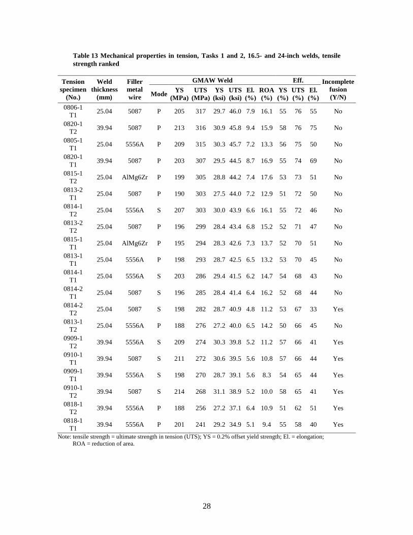
28
Table 13 Mechanical properties in tension, Tasks 1 and 2, 16.5- and 24-inch welds, tensile strength ranked
Tension specimen
(No.)
Weld thickness
(mm)
Filler metal wire
GMAW Weld Eff. Incomplete fusion (Y/N) Mode YS
(MPa) UTS
(MPa) YS
(ksi) UTS (ksi)
El. (%)
ROA (%)
YS (%)
UTS (%)
El. (%)
0806-1 T1 25.04 5087 P 205 317 29.7 46.0 7.9 16.1 55 76 55 No
0820-1 T2 39.94 5087 P 213 316 30.9 45.8 9.4 15.9 58 76 75 No
0805-1 T1 25.04 5556A P 209 315 30.3 45.7 7.2 13.3 56 75 50 No
0820-1 T1 39.94 5087 P 203 307 29.5 44.5 8.7 16.9 55 74 69 No
0815-1 T2 25.04 AlMg6Zr P 199 305 28.8 44.2 7.4 17.6 53 73 51 No
0813-2 T1 25.04 5087 P 190 303 27.5 44.0 7.2 12.9 51 72 50 No
0814-1 T2 25.04 5556A S 207 303 30.0 43.9 6.6 16.1 55 72 46 No
0813-2 T2 25.04 5087 P 196 299 28.4 43.4 6.8 15.2 52 71 47 No
0815-1 T1 25.04 AlMg6Zr P 195 294 28.3 42.6 7.3 13.7 52 70 51 No
0813-1 T1 25.04 5556A P 198 293 28.7 42.5 6.5 13.2 53 70 45 No
0814-1 T1 25.04 5556A S 203 286 29.4 41.5 6.2 14.7 54 68 43 No
0814-2 T1 25.04 5087 S 196 285 28.4 41.4 6.4 16.2 52 68 44 No
0814-2 T2 25.04 5087 S 198 282 28.7 40.9 4.8 11.2 53 67 33 Yes
0813-1 T2 25.04 5556A P 188 276 27.2 40.0 6.5 14.2 50 66 45 No
0909-1 T2 39.94 5556A S 209 274 30.3 39.8 5.2 11.2 57 66 41 Yes
0910-1 T1 39.94 5087 S 211 272 30.6 39.5 5.6 10.8 57 66 44 Yes
0909-1 T1 39.94 5556A S 198 270 28.7 39.1 5.6 8.3 54 65 44 Yes
0910-1 T2 39.94 5087 S 214 268 31.1 38.9 5.2 10.0 58 65 41 Yes
0818-1 T2 39.94 5556A P 188 256 27.2 37.1 6.4 10.9 51 62 51 Yes
0818-1 T1 39.94 5556A P 201 241 29.2 34.9 5.1 9.4 55 58 40 Yes
Note: tensile strength = ultimate strength in tension (UTS); YS = 0.2% offset yield strength; El. = elongation; ROA = reduction of area.
29
Table 14 Comparisons, Task 1 and 2, ultimate strength in tension versus GCVWC-A requirements
GCVWC-A requirement Comparison: Meet or exceed GCVWC-A
tensile strength requirement
Material No. Alloy
Product thickness (inches)
Minimum tensile
strength (ksi)
GMAW-P 5087
GMAW-P, S
5556A
GMAW-P Al-Mg6-
Zr 25.04,
39.94 mm 25.04 mm 25.04 mm
25 5083 0.51-1.50 40 5/5 5/5 2/2 25 5456 0.51-1.50 42 5/5 4/5 2/2 27 7039 All 44 4/5 2/5 1/2 27 7005 All 46 2/5 1/5 0/2
Notes: P = Pulse, S = Spray; 5/5 = 5 specimens of 5 pass requirement.
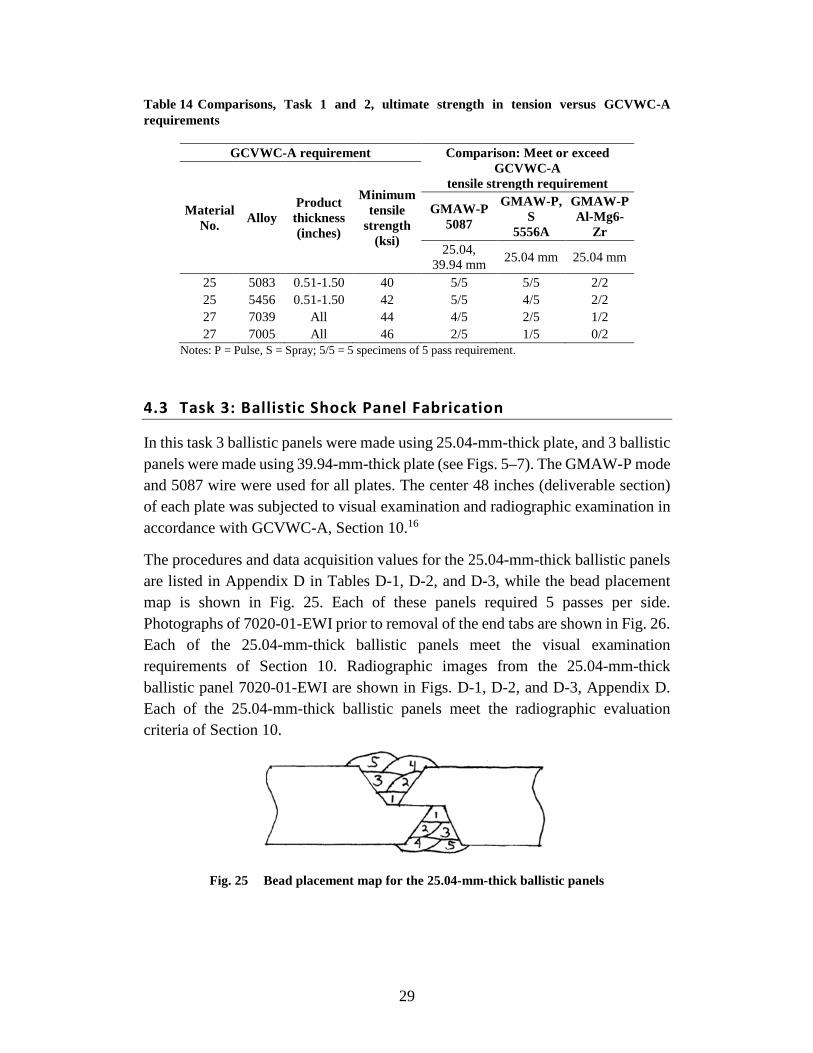
4.3 Task 3: Ballistic Shock Panel Fabrication
In this task 3 ballistic panels were made using 25.04-mm-thick plate, and 3 ballistic panels were made using 39.94-mm-thick plate (see Figs. 5–7). The GMAW-P mode and 5087 wire were used for all plates. The center 48 inches (deliverable section) of each plate was subjected to visual examination and radiographic examination in accordance with GCVWC-A, Section 10.16
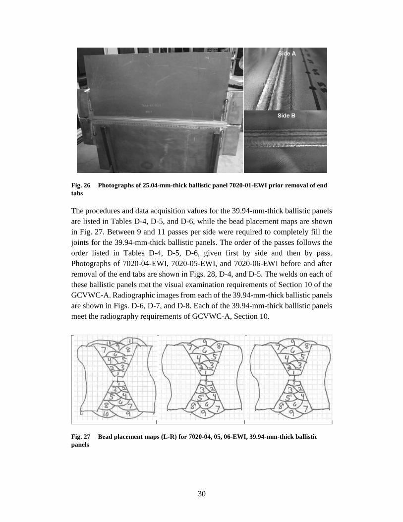
The procedures and data acquisition values for the 25.04-mm-thick ballistic panels are listed in Appendix D in Tables D-1, D-2, and D-3, while the bead placement map is shown in Fig. 25. Each of these panels required 5 passes per side. Photographs of 7020-01-EWI prior to removal of the end tabs are shown in Fig. 26. Each of the 25.04-mm-thick ballistic panels meet the visual examination requirements of Section 10. Radiographic images from the 25.04-mm-thick ballistic panel 7020-01-EWI are shown in Figs. D-1, D-2, and D-3, Appendix D. Each of the 25.04-mm-thick ballistic panels meet the radiographic evaluation criteria of Section 10.
Fig. 25 Bead placement map for the 25.04-mm-thick ballistic panels
30
Fig. 26 Photographs of 25.04-mm-thick ballistic panel 7020-01-EWI prior removal of end tabs
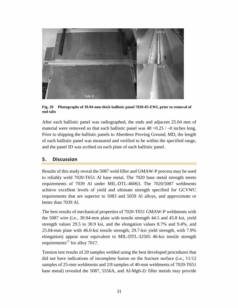
The procedures and data acquisition values for the 39.94-mm-thick ballistic panels are listed in Tables D-4, D-5, and D-6, while the bead placement maps are shown in Fig. 27. Between 9 and 11 passes per side were required to completely fill the joints for the 39.94-mm-thick ballistic panels. The order of the passes follows the order listed in Tables D-4, D-5, D-6, given first by side and then by pass. Photographs of 7020-04-EWI, 7020-05-EWI, and 7020-06-EWI before and after removal of the end tabs are shown in Figs. 28, D-4, and D-5. The welds on each of these ballistic panels met the visual examination requirements of Section 10 of the GCVWC-A. Radiographic images from each of the 39.94-mm-thick ballistic panels are shown in Figs. D-6, D-7, and D-8. Each of the 39.94-mm-thick ballistic panels meet the radiography requirements of GCVWC-A, Section 10.
Fig. 27 Bead placement maps (L-R) for 7020-04, 05, 06-EWI, 39.94-mm-thick ballistic panels
31
Fig. 28 Photographs of 39.94-mm-thick ballistic panel 7020-05-EWI, prior to removal of end tabs
After each ballistic panel was radiographed, the ends and adjacent 25.04 mm of material were removed so that each ballistic panel was 48 +0.25 / –0 inches long. Prior to shipping the ballistic panels to Aberdeen Proving Ground, MD, the length of each ballistic panel was measured and verified to be within the specified range, and the panel ID was scribed on each plate of each ballistic panel.
5. Discussion
Results of this study reveal the 5087 weld filler and GMAW-P process may be used to reliably weld 7020-T651 Al base metal. The 7020 base metal strength meets requirements of 7039 Al under MIL-DTL-46063. The 7020/5087 weldments achieve excellent levels of yield and ultimate strength specified for GCVWC requirements that are superior to 5083 and 5059 Al alloys, and approximate or better than 7039 Al.
The best results of mechanical properties of 7020-T651 GMAW-P weldments with the 5087 wire (i.e., 39.94-mm plate with tensile strength 44.5 and 45.8 ksi, yield strength values 29.5 to 30.9 ksi, and the elongation values 8.7% and 9.4%, and 25.04-mm plate with 46.0-ksi tensile strength, 29.7-ksi yield strength, with 7.9% elongation) appear near equivalent to MIL-DTL-32505 46-ksi tensile strength requirements17 for alloy 7017.
Tension test results of 20 samples welded using the best developed procedures that did not have indications of incomplete fusion on the fracture surface (i.e., 11/12 samples of 25-mm weldments and 2/8 samples of 40-mm weldments of 7020-T651 base metal) revealed the 5087, 5556A, and Al-Mg6-Zr filler metals may provide
Side B
Side B
Side A
32
fusion welds with excellent mechanical properties with yield strengths of 29–31 ksi (200–214 MPa) and ultimate strengths of 40–46 ksi (276–317 MPa) with elongations of 6.2%–9.4%, regardless of the wire type, weld mode, or plate thickness. Qualification plates made with the best performing 5087 weld filler wire and the GMAW-P mode suggest that strength in tension is not affected by changes in weld volume resulting from changes of plate thickness.
The joint design or weld procedures were not fully optimized, most specifically for the 39.94-mm qualification weld plates, as shown by defective welds (i.e., fracture features of incomplete fusion of filler metal) and base metal on fracture features on 6/8 tension specimens (i.e., the 5566A-P and S, and 5087-S). Nevertheless, the fracture features of 25-mm plate welds tension specimens revealed welds with complete fusion; 2 of 8 complete fusion welds on 40-mm-thick 7020 base metal plate—specifically with the GMAW-P procedure and 1.6-mm-diameter 5087 filler metal wire—provided excellent mechanical properties and the best overall mechanical properties in tension of the study, a 2-specimen average 30.2-ksi YS, 45.2-ksi UTS, 9.1% elongation, and 16.4% reduction of area.
EWI weld engineers recommend that power supply programs specific for 75/25 (He/Ar) shield gas and 5087 and/or 5556A wire may provide improved results as an alternative to the Fronious wire program 371. To minimize lack of fusion observed in tension with 39.94-mm plate, additional approaches for consideration may include 1) development of preliminary weld procedure on thick plate to eliminate effects of variance of time-temperature; 2) use of a weld joint with slightly greater included angle of 63°–64° rather than 60°; 3) grinding the toes of weld passes with carbide bits to open the weld joint and remove any possible cold lap of metal; 4) maintaining power levels and settings of fill passes; and 5) preheating of the base metal. Purging of gas lines and optimal control of flow rate may lessen turbulent flow of shield gas and lessen porosity in the welds, most specifically for high levels of He, which may affect low buoyancy and the readings of flow meters.
Weld efficiencies, the ratio percentages of weld properties/base metal properties, for 5 nondefective tension specimens of the 5087 filler the 25- and 40-mm 7020-T651 plate and the GMAW-P mode/procedures are as follows: 1) yield strength 51%–58%; 2) ultimate strength 71%–76 %; and 3) elongation 47%–75%.
Weld efficiencies, the ratio percentages of weld properties/base metal properties, of 5 nondefective tension specimens of 5556A filler with the 25-mm 7020-T651 plate and the GMAW-P and GNAW-S mode/procedures are as follows: 1) yield strength 50%–56%; 2) ultimate strength 66%–75%; and 3) elongation 43%–50%.
33
Weld efficiencies, the ratio percentages of weld properties/base metal properties of 2 nondefective tension specimens of Al-Mg6-Zr filler with the 25-mm 7020-T651 plate and the GMAW-P mode/procedures, are as follows: 1) yield strength 52%–53%; 2) ultimate strength 70%–73%; and 3) elongation 51%.
In comparisons to tensile strength requirements of GCVWC-A (see Table 14) for welds of plate base metals, the 25.04- and 39.94-mm-thick 5087/7020 GMAW-P weld specimens reveal capabilities for excellent tensile strengths that meet or exceed the following:
• material no. 25 (5083) at 40 ksi, with 5/5 specimens
• material no. 25 (5456) at 42 ksi, with 5/5 specimens
• material no. 27 (7039) at 44 ksi, with 4/5 specimens
• material no. 27 (7005) at 46 ksi, with 2/5 specimens
The 25.04-mm-thick 5556A/7020 weld specimens of 16-inch and 24-inch plates, reveal tensile strengths of GMAW-P and S specimens that meet or exceed the following:
• material no. 25 (5083) at 40 ksi, with 5/5 specimens
• material no. 25 (5456) at 42 ksi, with 4/5specimens
• material no. 27 (7039) at 44 ksi, with 2/5 specimens
• material no. 27 (7005) at 46 ksi, with 1/5 specimens
The 25.04-mm-thick Al-Mg6-Zr/7020 24-inch plates reveal tensile strengths of GMAW-P specimens that meet or exceed the following:
• material no. 25 (5083) at 40 ksi, with 2/2specimens
• material no. 25 (5456) at 42 ksi, with 2/2specimens
• material no. 27 (7039) at 44 ksi, with 1/2 specimens
• material no. 27 (7005) at 46 ksi, with 0/2 specimens
The 5087 wire, GMAW-P mode, 75He-25Ar shield gas, and the corresponding procedures were selected to weld the ballistic panels at EWI because of the following attributes: 1) radiographic examination showed low levels of porosity; 2) acceptable no-crack or no-break failure bend test results; and 3) tensile strength higher than other wire/mode combinations.
34
6. Conclusions
This investigation of the 5087 filler metal wire and the 7020-T651 Al base metal, demonstrates that GMAW welds of 7020-T651 base metal and 5087 filler metal have performance capabilities that are important for US light armor vehicles and meet or exceed requirements specified by the GCVWC-A in levels of weld quality and mechanical properties.
Tension specimens of qualification plates, which were welded using the best developed procedures and that did not have indications of incomplete fusion on the fracture surface, had tension strength of about 40–46 ksi (276–317 MPa), regardless of the wire type, weld mode, or plate thickness.
The 5087 filler metal with 75He/25Ar shield gas provides the better qualities of welds in levels of porosity and mechanical bend and tension tests. The 5087 filler metal wire is commercially unavailable in the United States and is unique from presently available US filler metals in containing Zr, a grain refiner. Tension tests demonstrate that 7020-T651 welds may met or exceed levels specified for all aluminum materials specified by the GCVWC-A.
The best results of mechanical properties of 7020-T651 GMAW-P weldments with the 5087 wire (i.e., 39.94-mm plate with tensile strength 44.5 and 45.8 ksi, yield strength values 29.5–30.9 ksi, and the elongation values 8.7% and 9.4%, and 25.04-mm plate with 46.0-ksi tensile strength, 29.7-ksi yield strength, with 7.9% elongation) appear near equivalent to EWI reported values of 7017-T651/5556 GMAW-P welds with tensile strength 46.3 ksi, yield strength 31.8 ksi, and 7.5% elongation.
Yield strengths of 27.2–31.1 ksi for the GMAW-P 7020-T651 base metal 5087 filler metal welds are strong and proportionately efficient to the base metal and superior to the 24–25 ksi YS of friction stir welds of 5059, which are not proportionally efficient to 5059 YS. High levels of YS are important to maintain structural integrity of vehicles, to resist intrusion of hulls or floors into the vehicle, and help keep doors secure and operable during and after exposure of vehicles to blast.
This investigation qualifies aluminum alloy AA7020-T651 for fusion-weld fabrication by use of 5087 and 5556A weld filler metals and the GMAW-P method. Procedures appropriate for field repair or manufacture were developed to enhance qualities of welds and to lessen amounts of defects.
The results of this investigation strongly support a revision of MIL-DTL-46063 and/or MIL-DTL-32505, with 7020 as a weldable protection material and call for
35
further development for application and fielding. A 7020 weld tensile strengthrequirement of 43 to 46 ksi appears acceptable as a requirement for a revised MIL-DTL-32505 based on the 7020/5087 GMAW-P test results. Together with prior investigations of 7020-T651 base metal, European alloy/fielded 7020-T651 appears to have advantages in protection level over the US-fielded 5083, and capabilities to meet protection levels specified for US alloy 7039. Literature and prior ballistic tests reveal 7020 Al a has significantly lower risk of stress corrosion cracking (SCC) and ballistic shock failures than 7039 or 7017 Als. Additional testing is required to determine environmental durability of 7020 base metal weldments to combined states of stress and environmental exposure to determine resistance to SCC. Further development of weld procedures by weld equipment manufacturers and vehicle manufacturers may be helpful to improve qualities of welds.
Anticipated benefits of fielding 7020-T651 as a replacement for 5083 are improved levels of ballistic, blast, and spall protection; improved rigidity of vehicle structures; and equal or greater life cycles. Anticipated benefits of fielding 7020-T651 as a replacement for 7039-T6 or 7017-T651 are improved resistance to ballistic shock and spall, improved durability from stress corrosion cracking, and improved life cycles. As shown by the subject base metal, Al 7020-T651 yield and tensile strength may be made to meet requirements of MIL-DTL-46063 for 7039 Al.
36
7. References and Notes
1. The Aluminum Association. International alloy designations and chemical composition limits for wrought aluminum and wrought aluminum alloys. Standards, registration record series teal sheets, teal sheets. Arlington (VA): The Aluminum Association; 2009 [accessed 2015 Oct 8]. www.aluminum.org.
2. Chinella JF. Aluminum 7020-T651 characteristics and ballistic protection, with V50 statistics of 5083 and 7039 aluminum and RHA steel. Aberdeen Proving Ground (MD): Army Research Laboratory (US); 2011 Sep. Report No.: ARL-TR-5790.
3. Chinella JF. V50 ballistic protection, and material properties of 7020 aluminum. Aberdeen Proving Ground (MD): Army Research Laboratory (US); 2012 Sep. Report No.: ARL-TR-6148.
4. Chinella JF. Protection comparisons of aluminum 7020-T651 and 5083-H131. Aberdeen Proving Ground (MD): Army Research Laboratory (US); 2013 Sep. Report No.: ARL-TR-6574.
5. Chinella JF. Protection statistics and performance of aluminum 7020-T651. Aberdeen Proving Ground (MD): Army Research Laboratory (US); 2013 Nov. Report No.: ARL-TR-6727.
6. Kent KG. Weldable Al: Zn: Mg alloys. Metallurgical Reviews. 1970;15(147):135–146.
7. Romeyn A. Welding Al-Zn-Mg alloys. Melbourne (Victoria): Defense Science and Technology Organisation, Materials Research Laboratories; 1983 June. Report No.: MRL-R-888.
8. Hori H. Tensile properties of friction stir welded joints – studies on characteristics of friction stir welded joints in structural aluminum alloys (Report 3). Welding International. 2007;21(9):626–633.
9. McQueen H, Leo P, Cerri E. Al-Zn-Mg for extrusion–hot workability. In TMS 2009, Al Alloys: Fabrication, Characterization and Applications II; Yin W, Das S, Long Z, editors. Warrendale (PA): The Minerals, Metals, and Materials Society (TMS); 2009.
10. Wereskiold JC, Deschamps A, Bréchet Y. Characterization and precipitation kinetics in an Al-Zn-Mg alloy. Mats Sci Eng. A 2000; 293:267–274.
37
11. Deschamps A, Texier G, Ringeval S, Delfaut-Durut L. Influence of cooling rate on the precipitation microstructure in a medium strength Al-Zn-Mg alloy. Materials Science and Eng A. 2009;501:133–139.
12. Holroyd NJH, Hardie D. Effect of inherent defects on initiation of stress-corrosion cracks in weldable Al-Zn-Mg alloys. Metals Technology. 1982;9:229–234.
13. MIL-DTL-46063H. Armor plate, aluminum alloy 7039. Aberdeen Proving Ground (MD): Army Research Laboratory (US); 1998 Sep 14.
14. MIL-DTL-46027K. Armor plate, aluminum alloy weldable 5083, 5456, and 5059. Aberdeen Proving Ground (MD): Army Research Laboratory (US); 2007 July 31.
15. Doherty KJ, Thompson B, Shira S. Friction stir processing of aluminum alloy 5059-H131 for enhanced ductility. Aberdeen Proving Ground (MD): Army Research Laboratory (US); 2013 July. Report No.: ARL-TR-6499.
16. 19207-124723011. Ground combat vehicle welding code – aluminum. Warren (MI): Army Tank-Automotive and Armaments Command (US); 2008 Jan 1.
17. MIL-DTL-32505. Armor plate, aluminum alloy 7017 weldable and 7020 appliqué. Aberdeen Proving Ground (MD): Army Research Laboratory (US); 2014 Nov 13.

38
INTENTIONALLY LEFT BLANK.
39
Appendix A. Materials
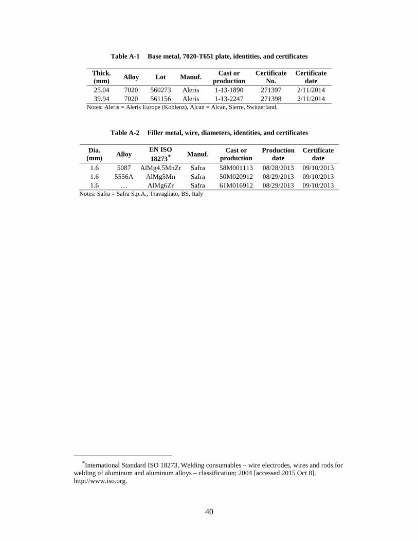
40
Table A-1 Base metal, 7020-T651 plate, identities, and certificates
Thick. (mm) Alloy Lot Manuf. Cast or
production Certificate
No. Certificate
date 25.04 7020 560273 Aleris 1-13-1890 271397 2/11/2014 39.94 7020 561156 Aleris 1-13-2247 271398 2/11/2014
Notes: Aleris = Aleris Europe (Koblenz), Alcan = Alcan, Sierre, Switzerland.
Table A-2 Filler metal, wire, diameters, identities, and certificates
Dia. (mm) Alloy
EN ISO 18273*
Manuf. Cast or production
Production date
Certificate date
1.6 5087 AlMg4.5MnZr Safra 58M001113 08/28/2013 09/10/2013 1.6 5556A AlMg5Mn Safra 50M020912 08/29/2013 09/10/2013 1.6 … AlMg6Zr Safra 61M016912 08/29/2013 09/10/2013
Notes: Safra = Safra S.p.A., Travagliato, BS, Italy
*International Standard ISO 18273, Welding consumables – wire electrodes, wires and rods for
welding of aluminum and aluminum alloys – classification; 2004 [accessed 2015 Oct 8]. http://www.iso.org.
41
Appendix B. Task 1 Results
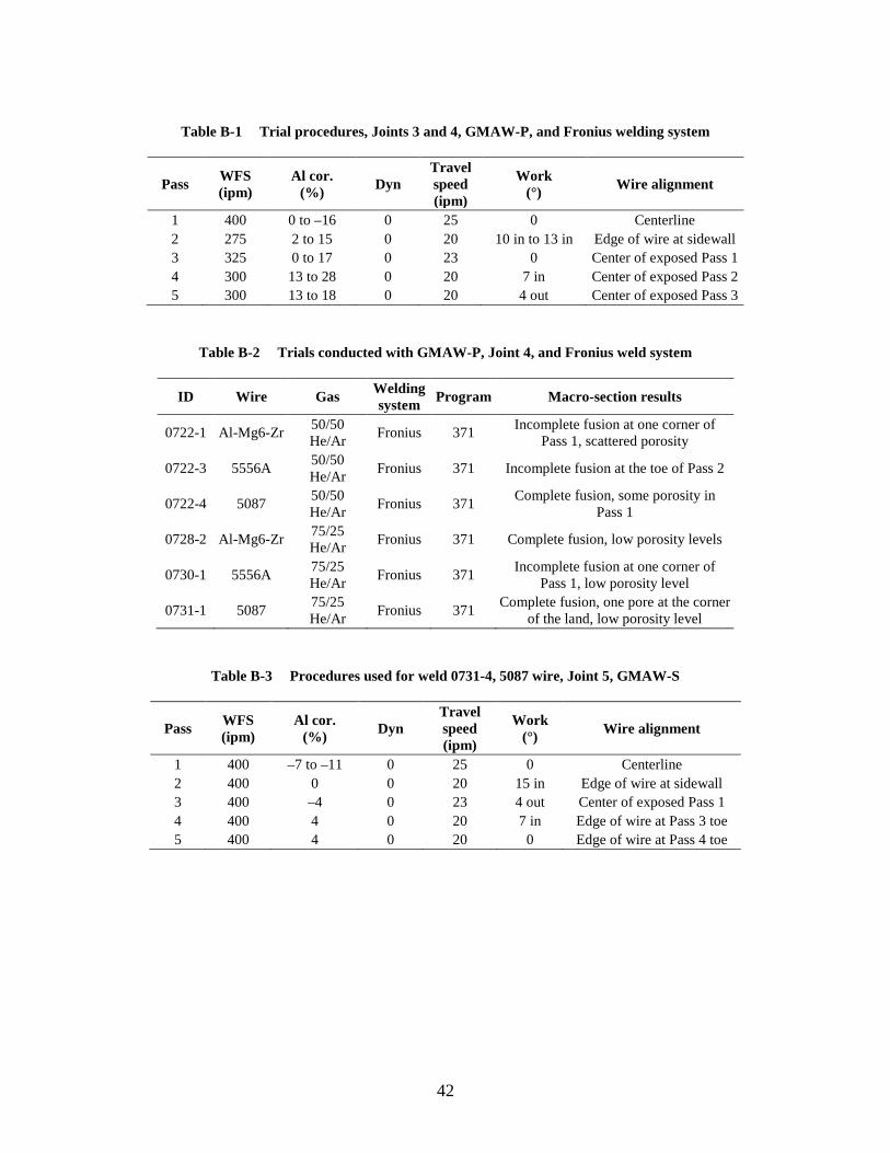
42
Table B-1 Trial procedures, Joints 3 and 4, GMAW-P, and Fronius welding system
Pass WFS (ipm)
Al cor. (%) Dyn
Travel speed (ipm)
Work (°) Wire alignment
1 400 0 to –16 0 25 0 Centerline 2 275 2 to 15 0 20 10 in to 13 in Edge of wire at sidewall 3 325 0 to 17 0 23 0 Center of exposed Pass 1 4 300 13 to 28 0 20 7 in Center of exposed Pass 2 5 300 13 to 18 0 20 4 out Center of exposed Pass 3
Table B-2 Trials conducted with GMAW-P, Joint 4, and Fronius weld system
ID Wire Gas Welding system Program Macro-section results
0722-1 Al-Mg6-Zr 50/50 He/Ar Fronius 371 Incomplete fusion at one corner of
Pass 1, scattered porosity
0722-3 5556A 50/50 He/Ar Fronius 371 Incomplete fusion at the toe of Pass 2
0722-4 5087 50/50 He/Ar Fronius 371 Complete fusion, some porosity in
Pass 1
0728-2 Al-Mg6-Zr 75/25 He/Ar Fronius 371 Complete fusion, low porosity levels
0730-1 5556A 75/25 He/Ar Fronius 371 Incomplete fusion at one corner of
Pass 1, low porosity level
0731-1 5087 75/25 He/Ar Fronius 371 Complete fusion, one pore at the corner
of the land, low porosity level
Table B-3 Procedures used for weld 0731-4, 5087 wire, Joint 5, GMAW-S
Pass WFS (ipm)
Al cor. (%) Dyn
Travel speed (ipm)
Work (°) Wire alignment
1 400 –7 to –11 0 25 0 Centerline 2 400 0 0 20 15 in Edge of wire at sidewall 3 400 –4 0 23 4 out Center of exposed Pass 1 4 400 4 0 20 7 in Edge of wire at Pass 3 toe 5 400 4 0 20 0 Edge of wire at Pass 4 toe
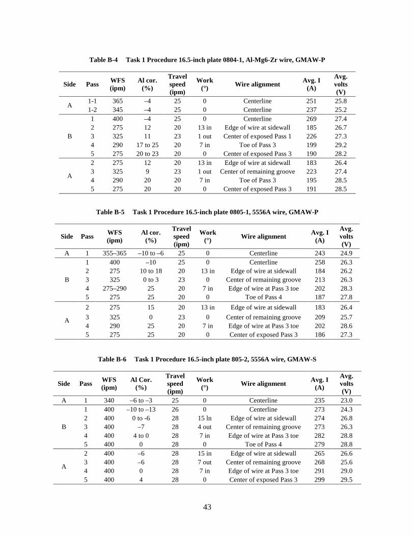
43
Table B-4 Task 1 Procedure 16.5-inch plate 0804-1, Al-Mg6-Zr wire, GMAW-P
Side Pass WFS (ipm)
Al cor. (%)
Travel speed (ipm)
Work (°) Wire alignment Avg. I
(A)
Avg. volts (V)
A 1-1 365 –4 25 0 Centerline 251 25.8 1-2 345 –4 25 0 Centerline 237 25.2
B
1 400 –4 25 0 Centerline 269 27.4 2 275 12 20 13 in Edge of wire at sidewall 185 26.7 3 325 11 23 1 out Center of exposed Pass 1 226 27.3 4 290 17 to 25 20 7 in Toe of Pass 3 199 29.2 5 275 20 to 23 20 0 Center of exposed Pass 3 190 28.2
A
2 275 12 20 13 in Edge of wire at sidewall 183 26.4 3 325 9 23 1 out Center of remaining groove 223 27.4 4 290 20 20 7 in Toe of Pass 3 195 28.5 5 275 20 20 0 Center of exposed Pass 3 191 28.5
Table B-5 Task 1 Procedure 16.5-inch plate 0805-1, 5556A wire, GMAW-P
Side Pass WFS (ipm)
Al cor. (%)
Travel speed (ipm)
Work (°) Wire alignment Avg. I
(A)
Avg. volts (V)
A 1 355–365 –10 to –6 25 0 Centerline 243 24.9
B
1 400 –10 25 0 Centerline 258 26.3 2 275 10 to 18 20 13 in Edge of wire at sidewall 184 26.2 3 325 0 to 3 23 0 Center of remaining groove 213 26.3 4 275–290 25 20 7 in Edge of wire at Pass 3 toe 202 28.3 5 275 25 20 0 Toe of Pass 4 187 27.8
A
2 275 15 20 13 in Edge of wire at sidewall 183 26.4 3 325 0 23 0 Center of remaining groove 209 25.7 4 290 25 20 7 in Edge of wire at Pass 3 toe 202 28.6 5 275 25 20 0 Center of exposed Pass 3 186 27.3
Table B-6 Task 1 Procedure 16.5-inch plate 805-2, 5556A wire, GMAW-S
Side Pass WFS (ipm)
Al Cor. (%)
Travel speed (ipm)
Work (°) Wire alignment Avg. I
(A)
Avg. volts (V)
A 1 340 –6 to –3 25 0 Centerline 235 23.0
B
1 400 –10 to –13 26 0 Centerline 273 24.3 2 400 0 to -6 28 15 ln Edge of wire at sidewall 274 26.8 3 400 –7 28 4 out Center of remaining groove 273 26.3 4 400 4 to 0 28 7 in Edge of wire at Pass 3 toe 282 28.8 5 400 0 28 0 Toe of Pass 4 279 28.8
A
2 400 –6 28 15 in Edge of wire at sidewall 265 26.6 3 400 –6 28 7 out Center of remaining groove 268 25.6 4 400 0 28 7 in Edge of wire at Pass 3 toe 291 29.0 5 400 4 28 0 Center of exposed Pass 3 299 29.5
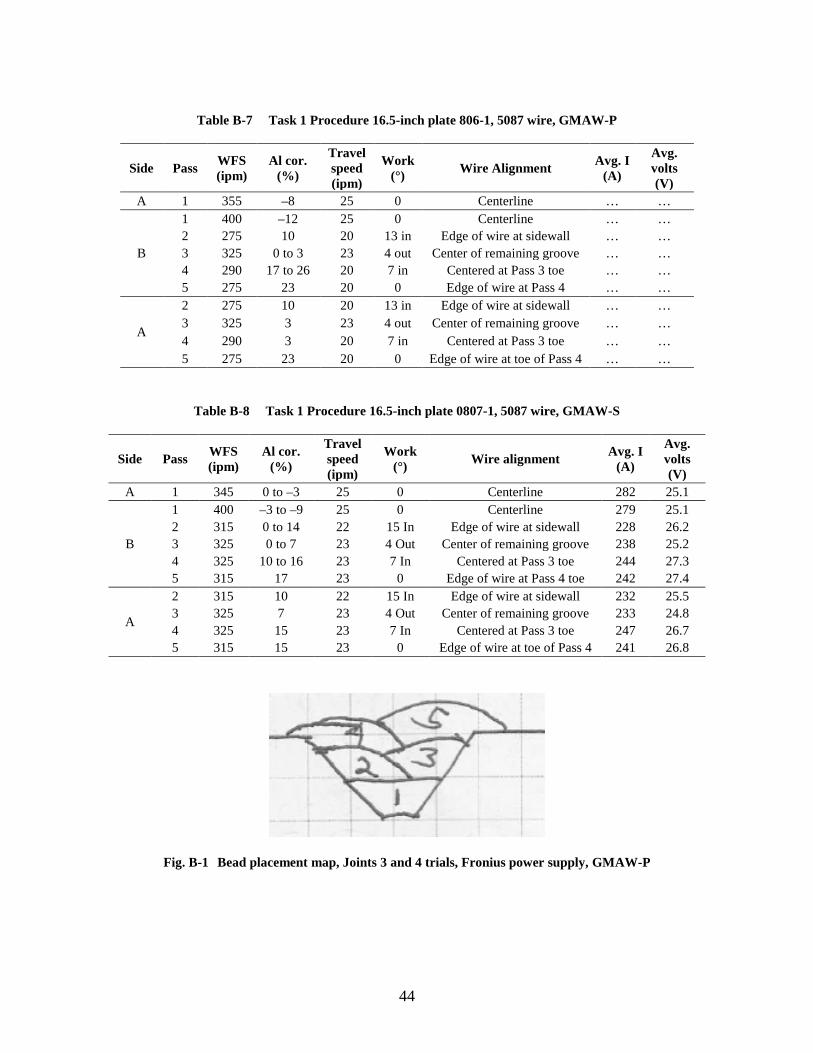
44
Table B-7 Task 1 Procedure 16.5-inch plate 806-1, 5087 wire, GMAW-P
Side Pass WFS (ipm)
Al cor. (%)
Travel speed (ipm)
Work (°) Wire Alignment Avg. I
(A)
Avg. volts (V)
A 1 355 –8 25 0 Centerline … …
B
1 400 –12 25 0 Centerline … … 2 275 10 20 13 in Edge of wire at sidewall … … 3 325 0 to 3 23 4 out Center of remaining groove … … 4 290 17 to 26 20 7 in Centered at Pass 3 toe … … 5 275 23 20 0 Edge of wire at Pass 4 … …
A
2 275 10 20 13 in Edge of wire at sidewall … … 3 325 3 23 4 out Center of remaining groove … … 4 290 3 20 7 in Centered at Pass 3 toe … … 5 275 23 20 0 Edge of wire at toe of Pass 4 … …
Table B-8 Task 1 Procedure 16.5-inch plate 0807-1, 5087 wire, GMAW-S
Side Pass WFS (ipm)
Al cor. (%)
Travel speed (ipm)
Work (°) Wire alignment Avg. I
(A)
Avg. volts (V)
A 1 345 0 to –3 25 0 Centerline 282 25.1
B
1 400 –3 to –9 25 0 Centerline 279 25.1 2 315 0 to 14 22 15 In Edge of wire at sidewall 228 26.2 3 325 0 to 7 23 4 Out Center of remaining groove 238 25.2 4 325 10 to 16 23 7 In Centered at Pass 3 toe 244 27.3 5 315 17 23 0 Edge of wire at Pass 4 toe 242 27.4
A
2 315 10 22 15 In Edge of wire at sidewall 232 25.5 3 325 7 23 4 Out Center of remaining groove 233 24.8 4 325 15 23 7 In Centered at Pass 3 toe 247 26.7 5 315 15 23 0 Edge of wire at toe of Pass 4 241 26.8
Fig. B-1 Bead placement map, Joints 3 and 4 trials, Fronius power supply, GMAW-P

45
Fig. B-2 Micrograph, 0728-2 Al-Mg6-Zr wire, 75He-25Ar SG, Joint 4, Fronius PSL 371
Fig. B-3 Micrographs, 0730-1, 5556A wire, 75He-25Ar SG, Joint 4, Fronius PSL 371
Fig. B-4 Micrographs, 0731-1, 5087 wire, 75He-25Ar SG, Joint 4, Fronius PS line 371
Pass 1
Pass 1
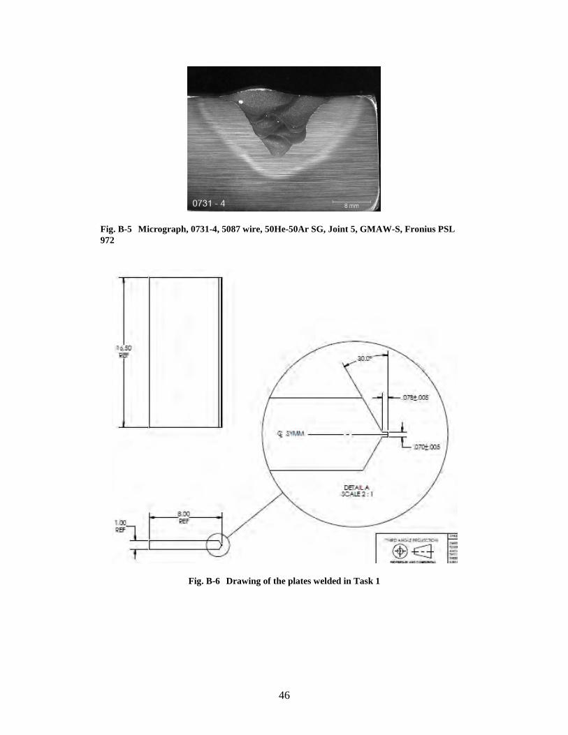
46
Fig. B-5 Micrograph, 0731-4, 5087 wire, 50He-50Ar SG, Joint 5, GMAW-S, Fronius PSL 972
Fig. B-6 Drawing of the plates welded in Task 1
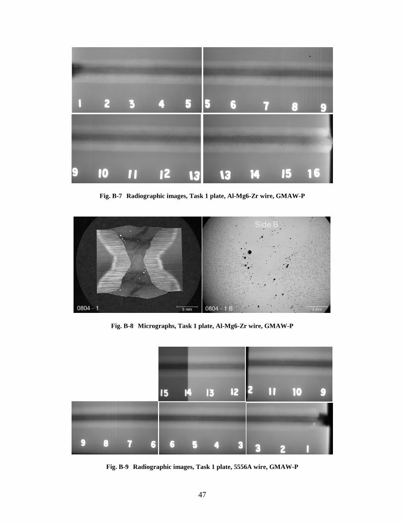
47
Fig. B-7 Radiographic images, Task 1 plate, Al-Mg6-Zr wire, GMAW-P
Fig. B-8 Micrographs, Task 1 plate, Al-Mg6-Zr wire, GMAW-P
Fig. B-9 Radiographic images, Task 1 plate, 5556A wire, GMAW-P
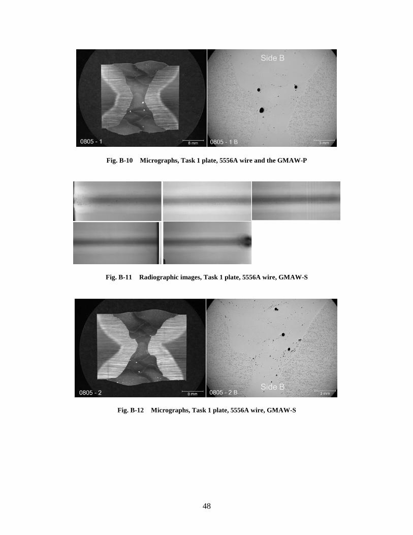
48
Fig. B-10 Micrographs, Task 1 plate, 5556A wire and the GMAW-P
Fig. B-11 Radiographic images, Task 1 plate, 5556A wire, GMAW-S
Fig. B-12 Micrographs, Task 1 plate, 5556A wire, GMAW-S
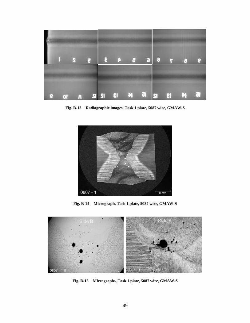
49
Fig. B-13 Radiographic images, Task 1 plate, 5087 wire, GMAW-S
Fig. B-14 Micrograph, Task 1 plate, 5087 wire, GMAW-S
Fig. B-15 Micrographs, Task 1 plate, 5087 wire, GMAW-S
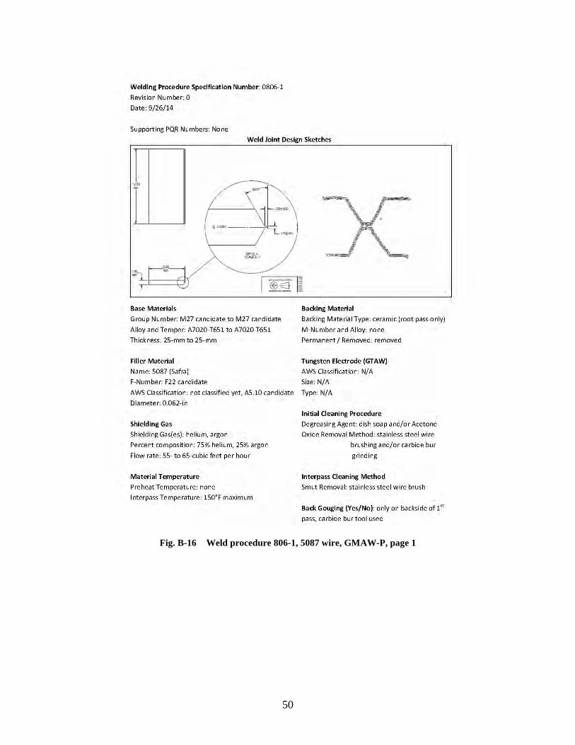
50
Fig. B-16 Weld procedure 806-1, 5087 wire, GMAW-P, page 1
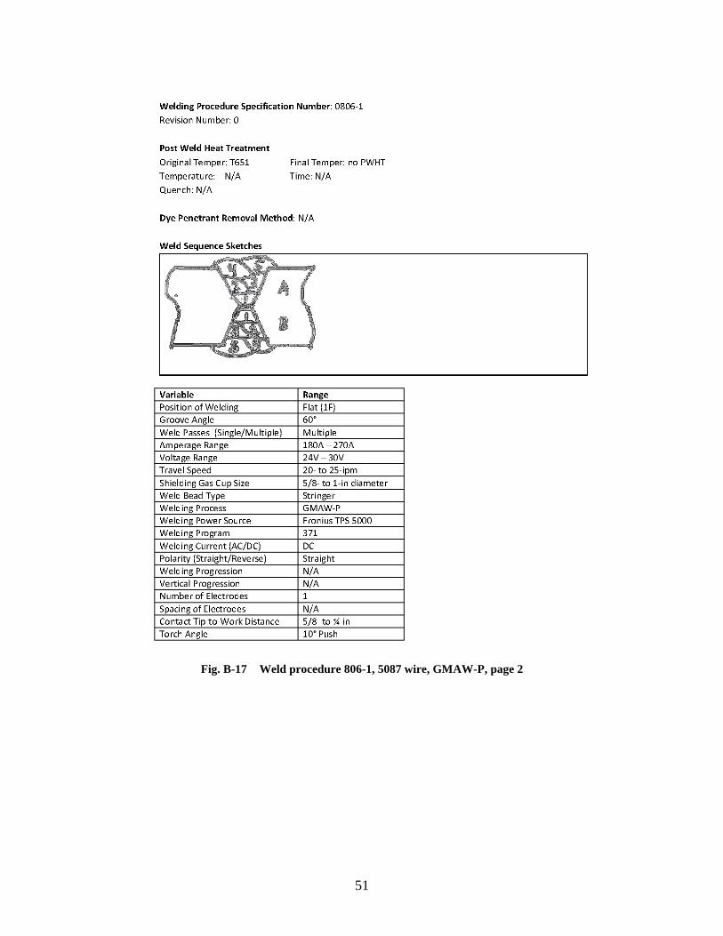
51
Fig. B-17 Weld procedure 806-1, 5087 wire, GMAW-P, page 2
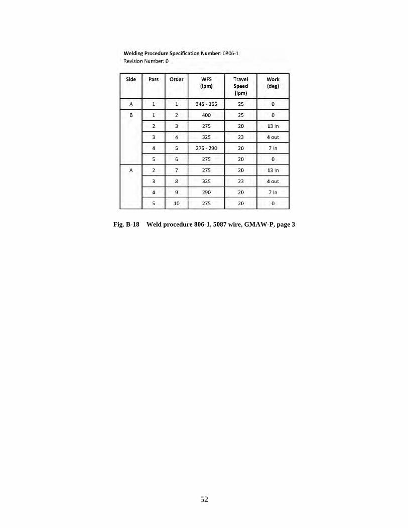
52
Fig. B-18 Weld procedure 806-1, 5087 wire, GMAW-P, page 3
53
Appendix C. Task 2 Results: Qualification Panels
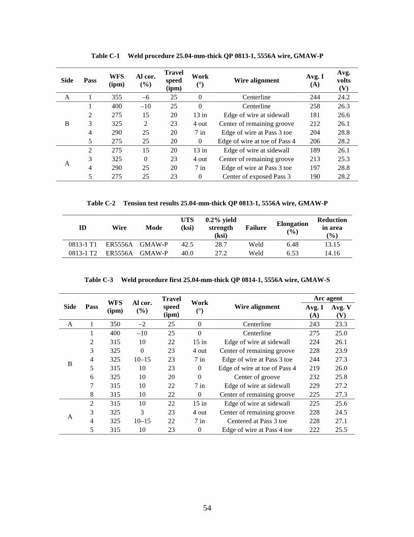
54
Table C-1 Weld procedure 25.04-mm-thick QP 0813-1, 5556A wire, GMAW-P
Side Pass WFS (ipm)
Al cor. (%)
Travel speed (ipm)
Work (°) Wire alignment Avg. I
(A)
Avg. volts (V)
A 1 355 –6 25 0 Centerline 244 24.2
B
1 400 –10 25 0 Centerline 258 26.3 2 275 15 20 13 in Edge of wire at sidewall 181 26.6 3 325 2 23 4 out Center of remaining groove 212 26.1 4 290 25 20 7 in Edge of wire at Pass 3 toe 204 28.8 5 275 25 20 0 Edge of wire at toe of Pass 4 206 28.2
A
2 275 15 20 13 in Edge of wire at sidewall 189 26.1 3 325 0 23 4 out Center of remaining groove 213 25.3 4 290 25 20 7 in Edge of wire at Pass 3 toe 197 28.8 5 275 25 23 0 Center of exposed Pass 3 190 28.2
Table C-2 Tension test results 25.04-mm-thick QP 0813-1, 5556A wire, GMAW-P
ID Wire Mode UTS (ksi)
0.2% yield strength
(ksi) Failure Elongation
(%)
Reduction in area
(%) 0813-1 T1 ER5556A GMAW-P 42.5 28.7 Weld 6.48 13.15 0813-1 T2 ER5556A GMAW-P 40.0 27.2 Weld 6.53 14.16
Table C-3 Weld procedure first 25.04-mm-thick QP 0814-1, 5556A wire, GMAW-S
Side Pass WFS (ipm)
Al cor. (%)
Travel speed (ipm)
Work (°) Wire alignment
Arc agent Avg. I
(A) Avg. V
(V) A 1 350 –2 25 0 Centerline 243 23.3
B
1 400 –10 25 0 Centerline 275 25.0 2 315 10 22 15 in Edge of wire at sidewall 224 26.1 3 325 0 23 4 out Center of remaining groove 228 23.9 4 325 10–15 23 7 in Edge of wire at Pass 3 toe 244 27.3 5 315 10 23 0 Edge of wire at toe of Pass 4 219 26.0 6 325 10 20 0 Center of groove 232 25.8 7 315 10 22 7 in Edge of wire at sidewall 229 27.2 8 315 10 22 0 Center of remaining groove 225 27.3
A
2 315 10 22 15 in Edge of wire at sidewall 225 25.6 3 325 3 23 4 out Center of remaining groove 228 24.5 4 325 10–15 22 7 in Centered at Pass 3 toe 228 27.1 5 315 10 23 0 Edge of wire at Pass 4 toe 222 25.5
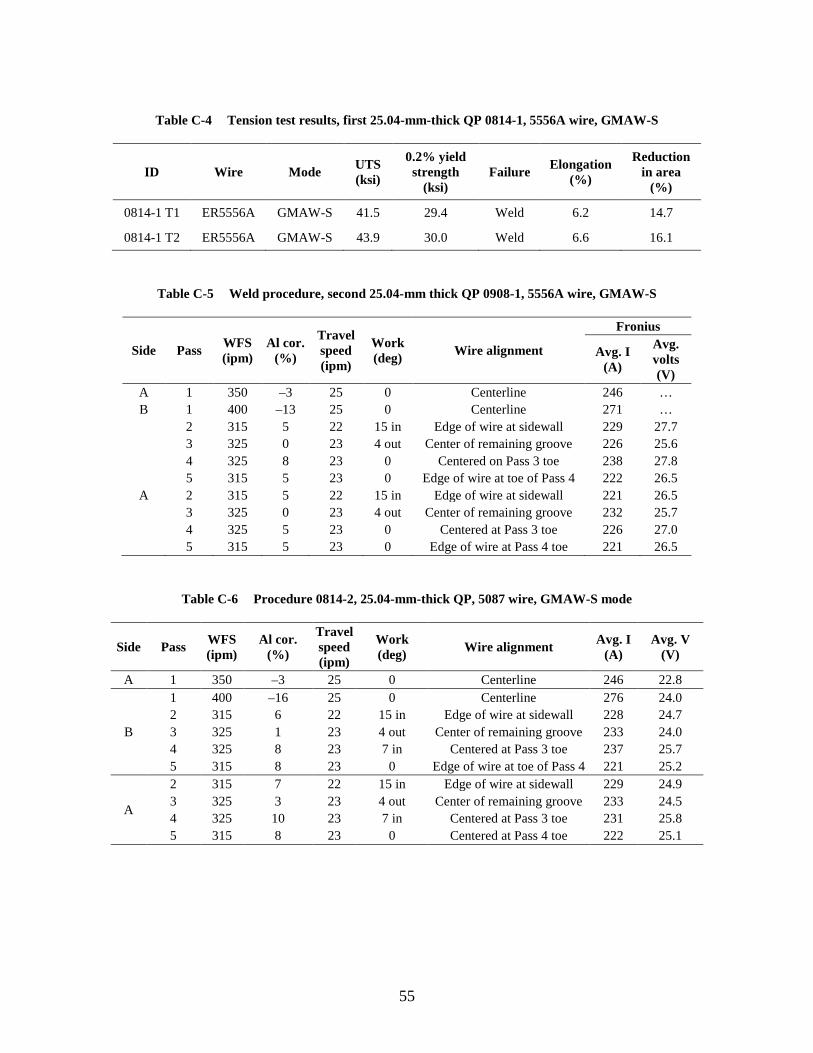
55
Table C-4 Tension test results, first 25.04-mm-thick QP 0814-1, 5556A wire, GMAW-S
ID Wire Mode UTS (ksi)
0.2% yield strength
(ksi) Failure Elongation
(%)
Reduction in area
(%)
0814-1 T1 ER5556A GMAW-S 41.5 29.4 Weld 6.2 14.7
0814-1 T2 ER5556A GMAW-S 43.9 30.0 Weld 6.6 16.1
Table C-5 Weld procedure, second 25.04-mm thick QP 0908-1, 5556A wire, GMAW-S
Side Pass WFS (ipm)
Al cor. (%)
Travel speed (ipm)
Work (deg) Wire alignment
Fronius
Avg. I (A)
Avg. volts (V)
A 1 350 –3 25 0 Centerline 246 … B 1 400 –13 25 0 Centerline 271 … 2 315 5 22 15 in Edge of wire at sidewall 229 27.7 3 325 0 23 4 out Center of remaining groove 226 25.6 4 325 8 23 0 Centered on Pass 3 toe 238 27.8 5 315 5 23 0 Edge of wire at toe of Pass 4 222 26.5
A 2 315 5 22 15 in Edge of wire at sidewall 221 26.5 3 325 0 23 4 out Center of remaining groove 232 25.7 4 325 5 23 0 Centered at Pass 3 toe 226 27.0 5 315 5 23 0 Edge of wire at Pass 4 toe 221 26.5
Table C-6 Procedure 0814-2, 25.04-mm-thick QP, 5087 wire, GMAW-S mode
Side Pass WFS (ipm)
Al cor. (%)
Travel speed (ipm)
Work (deg) Wire alignment Avg. I
(A) Avg. V
(V)
A 1 350 –3 25 0 Centerline 246 22.8
B
1 400 –16 25 0 Centerline 276 24.0 2 315 6 22 15 in Edge of wire at sidewall 228 24.7 3 325 1 23 4 out Center of remaining groove 233 24.0 4 325 8 23 7 in Centered at Pass 3 toe 237 25.7 5 315 8 23 0 Edge of wire at toe of Pass 4 221 25.2
A
2 315 7 22 15 in Edge of wire at sidewall 229 24.9 3 325 3 23 4 out Center of remaining groove 233 24.5 4 325 10 23 7 in Centered at Pass 3 toe 231 25.8 5 315 8 23 0 Centered at Pass 4 toe 222 25.1
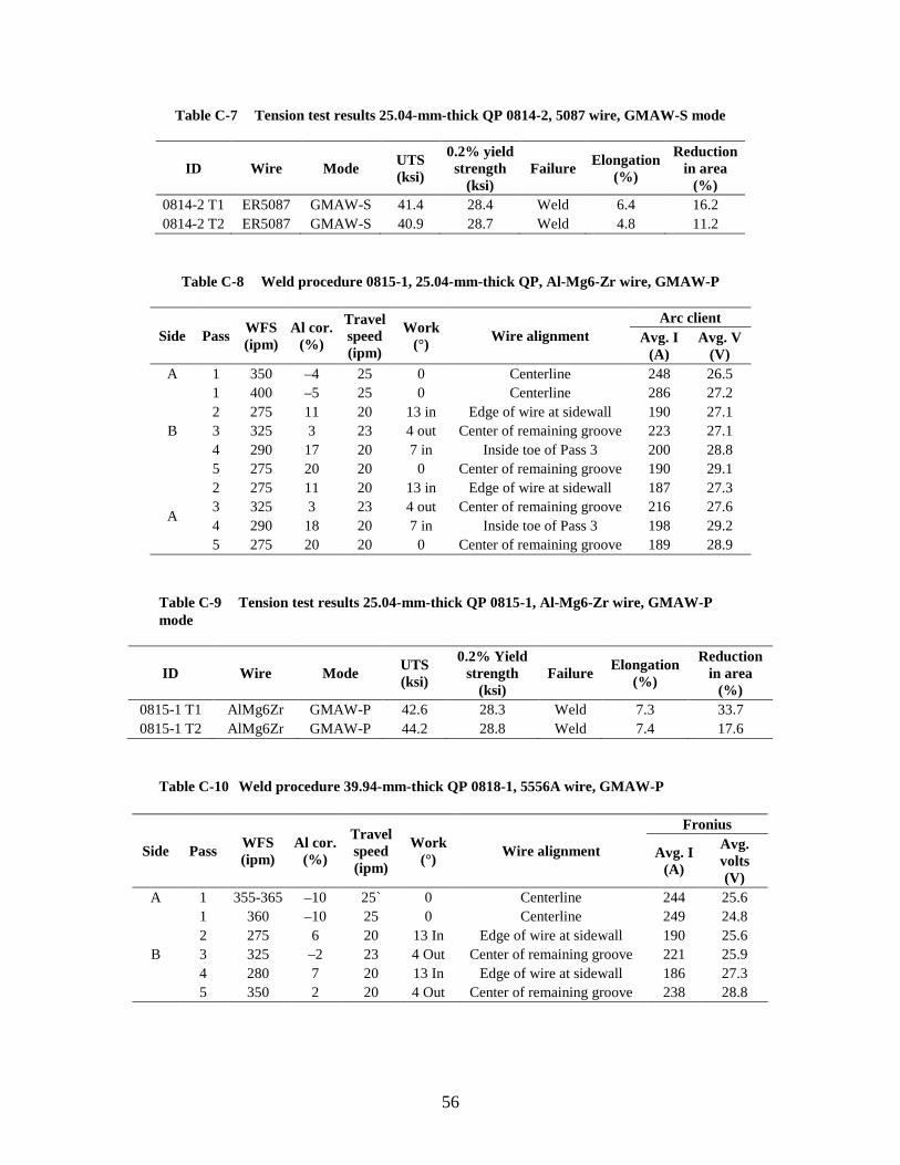
56
Table C-7 Tension test results 25.04-mm-thick QP 0814-2, 5087 wire, GMAW-S mode
ID Wire Mode UTS (ksi)
0.2% yield strength
(ksi) Failure Elongation
(%)
Reduction in area
(%) 0814-2 T1 ER5087 GMAW-S 41.4 28.4 Weld 6.4 16.2 0814-2 T2 ER5087 GMAW-S 40.9 28.7 Weld 4.8 11.2
Table C-8 Weld procedure 0815-1, 25.04-mm-thick QP, Al-Mg6-Zr wire, GMAW-P
Side Pass WFS (ipm)
Al cor. (%)
Travel speed (ipm)
Work (°) Wire alignment
Arc client Avg. I
(A) Avg. V
(V) A 1 350 –4 25 0 Centerline 248 26.5
B
1 400 –5 25 0 Centerline 286 27.2 2 275 11 20 13 in Edge of wire at sidewall 190 27.1 3 325 3 23 4 out Center of remaining groove 223 27.1 4 290 17 20 7 in Inside toe of Pass 3 200 28.8 5 275 20 20 0 Center of remaining groove 190 29.1
A
2 275 11 20 13 in Edge of wire at sidewall 187 27.3 3 325 3 23 4 out Center of remaining groove 216 27.6 4 290 18 20 7 in Inside toe of Pass 3 198 29.2 5 275 20 20 0 Center of remaining groove 189 28.9
Table C-9 Tension test results 25.04-mm-thick QP 0815-1, Al-Mg6-Zr wire, GMAW-P mode
ID Wire Mode UTS (ksi)
0.2% Yield strength
(ksi) Failure Elongation
(%)
Reduction in area
(%) 0815-1 T1 AlMg6Zr GMAW-P 42.6 28.3 Weld 7.3 33.7 0815-1 T2 AlMg6Zr GMAW-P 44.2 28.8 Weld 7.4 17.6
Table C-10 Weld procedure 39.94-mm-thick QP 0818-1, 5556A wire, GMAW-P
Side Pass WFS (ipm)
Al cor. (%)
Travel speed (ipm)
Work (°) Wire alignment
Fronius
Avg. I (A)
Avg. volts (V)
A 1 355-365 –10 25` 0 Centerline 244 25.6
B
1 360 –10 25 0 Centerline 249 24.8 2 275 6 20 13 In Edge of wire at sidewall 190 25.6 3 325 –2 23 4 Out Center of remaining groove 221 25.9 4 280 7 20 13 In Edge of wire at sidewall 186 27.3 5 350 2 20 4 Out Center of remaining groove 238 28.8
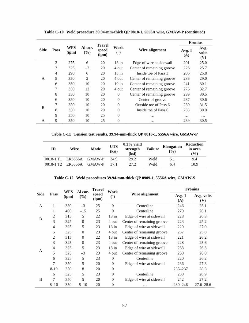
57
Table C-10 Weld procedure 39.94-mm-thick QP 0818-1, 5556A wire, GMAW-P (continued)
Table C-11 Tension test results, 39.94-mm-thick QP 0818-1, 5556A wire, GMAW-P
ID Wire Mode UTS (ksi)
0.2% yield strength
(ksi) Failure Elongation
(%)
Reduction in area
(%) 0818-1 T1 ER5556A GMAW-P 34.9 29.2 Weld 5.1 9.4 0818-1 T2 ER5556A GMAW-P 37.1 27.2 Weld 6.4 10.9
Table C-12 Weld procedures 39.94-mm-thick QP 0909-1, 5556A wire, GMAW-S
Side Pass WFS (ipm)
Al cor. (%)
Travel speed (ipm)
Work (°) Wire alignment
Fronius Avg. I
(A) Avg. volts
(V) A 1 350 –3 25 0 Centerline 246 25.1
B
1 400 –15 25 0 Centerline 279 26.1 2 315 5 22 13 in Edge of wire at sidewall 228 26.3 3 325 0 23 4 out Center of remaining groove 223 25.2 4 325 5 23 13 in Edge of wire at sidewall 229 27.0
A
5 325 0 23 4 out Center of remaining groove 237 25.8 2 315 0 22 13 in Edge of wire at sidewall 221 26.2 3 325 0 23 4 out Center of remaining groove 228 25.6 4 325 5 23 13 in Edge of wire at sidewall 233 26.3 5 325 –3 23 4 out Center of remaining groove 230 26.0 6 325 5 23 0 Centerline 220 26.2 7 350 5 20 0 Edge of wire at sidewall 236 27.3
8-10 350 8 20 0 … 235–237 28.3
B 6 325 5 23 0 Centerline 230 26.9 7 350 5 20 0 Edge of wire at sidewall 242 27.2
8–10 350 5–10 20 0 … 239–246 27.6–28.6
Side Pass WFS (ipm)
Al cor. (%)
Travel speed (ipm)
Work (°) Wire alignment
Fronius
Avg. I (A)
Avg. volts (V)
A
2 275 6 20 13 in Edge of wire at sidewall 201 25.0 3 325 –2 20 4 out Center of remaining groove 226 25.7 4 290 6 20 13 in Inside toe of Pass 3 206 25.8 5 350 2 20 4 out Center of remaining groove 236 29.0 6 350 10 20 10 in Center of remaining groove 241 30.1 7 350 12 20 4 out Center of remaining groove 276 32.7 8 350 10 20 0 Center of remaining groove 239 30.5
B
6 350 10 20 0 Center of groove 237 30.6 7 350 10 20 0 Outside toe of Pass 6 230 31.5 8 350 10 20 0 Inside toe of Pass 6 233 30.9 9 350 10 25 0 … … …
A 9 350 10 25 0 … 239 30.5
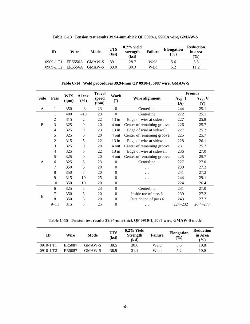
58
Table C-13 Tension test results 39.94-mm-thick QP 0909-1, 5556A wire, GMAW-S
ID Wire Mode UTS (ksi)
0.2% yield strength
(ksi) Failure Elongation
(%)
Reduction in area
(%) 0909-1 T1 ER5556A GMAW-S 39.1 28.7 Weld 5.6 8.3 0909-1 T2 ER5556A GMAW-S 39.8 30.3 Weld 5.2 11.2
Table C-14 Weld procedures 39.94-mm QP 0910-1, 5087 wire, GMAW-S
Side Pass WFS (ipm)
Al cor. (%)
Travel speed (ipm)
Work (°) Wire alignment
Fronius Avg. I
(A) Avg. V
(V) A 1 350 –3 23 0 Centerline 244 25.1
B
1 400 –18 23 0 Centerline 272 25.1 2 315 2 22 13 in Edge of wire at sidewall 227 25.8 3 325 0 20 4 out Center of remaining groove 226 25.7 4 325 0 23 13 in Edge of wire at sidewall 227 25.7 5 325 0 20 4 out Center of remaining groove 225 25.7
A
2 315 5 22 13 in Edge of wire at sidewall 228 26.1 3 325 0 20 4 out Center of remaining groove 231 25.7 4 325 5 22 13 in Edge of wire at sidewall 236 27.0 5 325 0 20 4 out Center of remaining groove 225 25.7 6 325 5 23 0 Centerline 227 27.0 7 350 5 20 0 … 238 27.2 8 350 5 20 0 … 241 27.2 9 315 10 25 0 … 244 29.1
10 350 10 20 0 … 224 26.4
B
6 325 5 23 0 Centerline 231 27.0 7 350 5 20 0 Inside toe of pass 6 239 27.2 8 350 5 20 0 Outside toe of pass 6 243 27.2
9–11 315 5 25 0 … 224–232 26.4–27.4
Table C-15 Tension test results 39.94-mm-thick QP 0910-1, 5087 wire, GMAW-S mode
ID Wire Mode UTS (ksi)
0.2% Yield Strength
(ksi) Failure Elongation
(%)
Reduction in Area
(%) 0910-1 T1 ER5087 GMAW-S 39.5 30.6 Weld 5.6 10.8 0910-1 T2 ER5087 GMAW-S 38.9 31.1 Weld 5.2 10.0
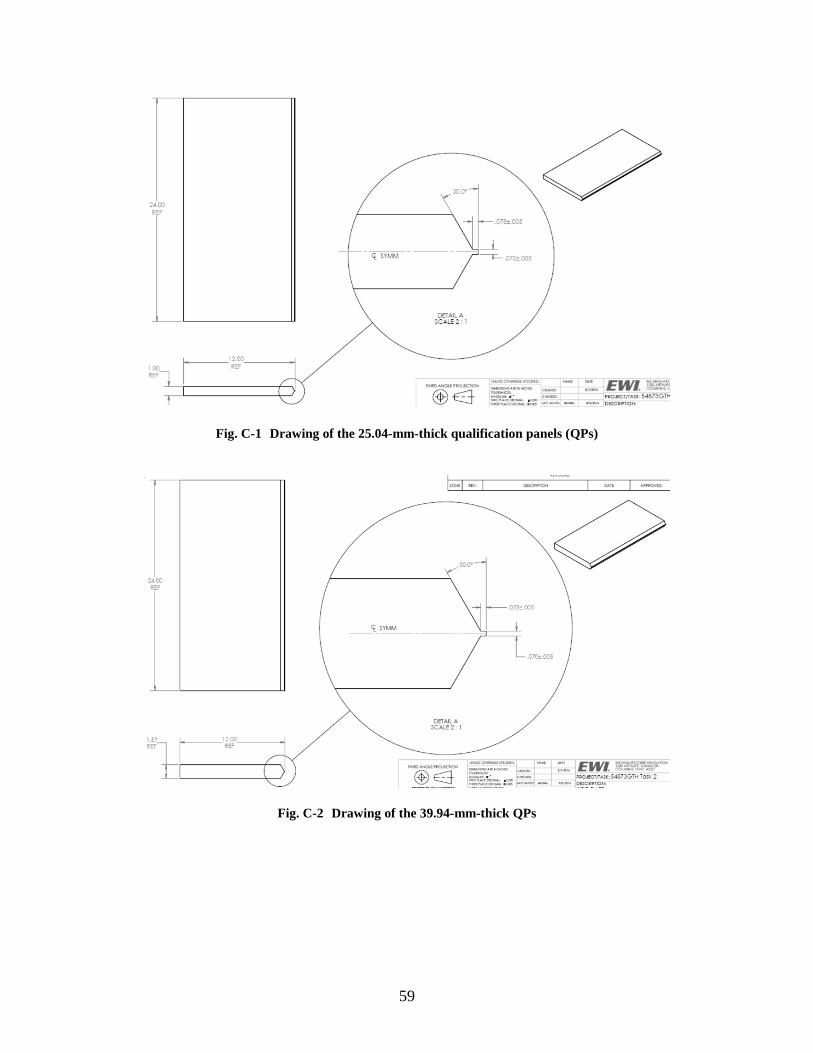
59
Fig. C-1 Drawing of the 25.04-mm-thick qualification panels (QPs)
Fig. C-2 Drawing of the 39.94-mm-thick QPs
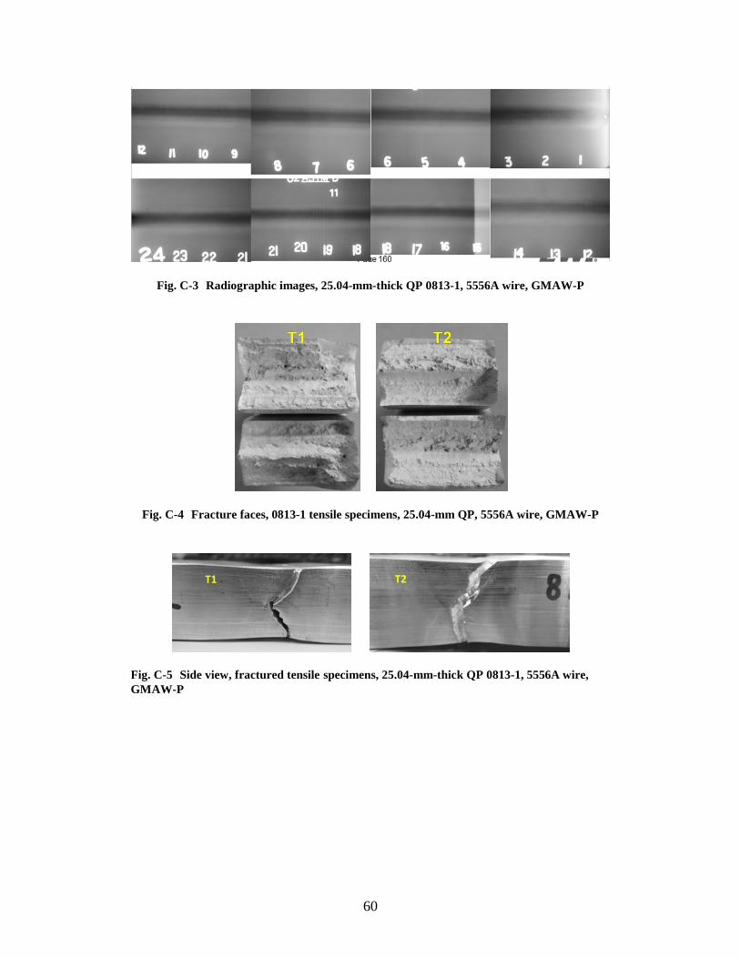
60
Fig. C-3 Radiographic images, 25.04-mm-thick QP 0813-1, 5556A wire, GMAW-P
Fig. C-4 Fracture faces, 0813-1 tensile specimens, 25.04-mm QP, 5556A wire, GMAW-P
Fig. C-5 Side view, fractured tensile specimens, 25.04-mm-thick QP 0813-1, 5556A wire, GMAW-P
T1 T2
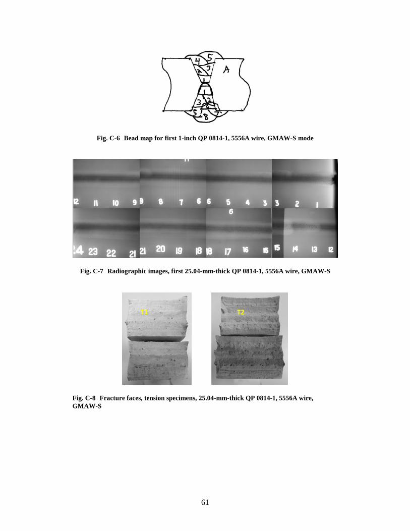
61
Fig. C-6 Bead map for first 1-inch QP 0814-1, 5556A wire, GMAW-S mode
Fig. C-7 Radiographic images, first 25.04-mm-thick QP 0814-1, 5556A wire, GMAW-S
Fig. C-8 Fracture faces, tension specimens, 25.04-mm-thick QP 0814-1, 5556A wire, GMAW-S
T2 T1
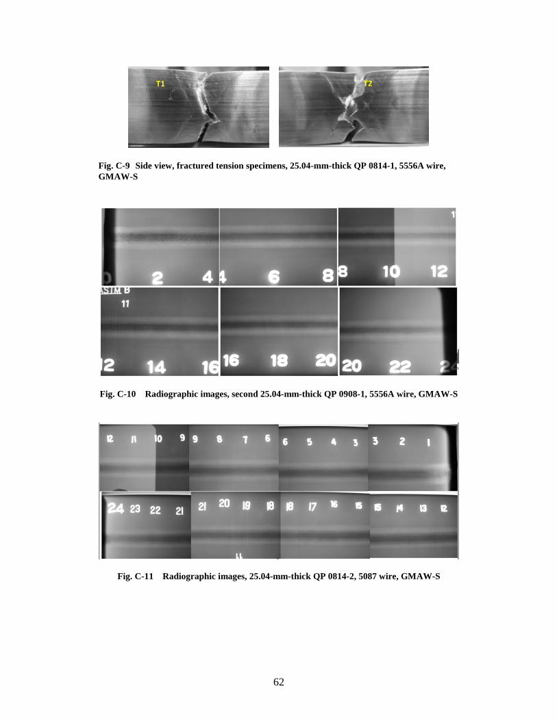
62
Fig. C-9 Side view, fractured tension specimens, 25.04-mm-thick QP 0814-1, 5556A wire, GMAW-S
Fig. C-10 Radiographic images, second 25.04-mm-thick QP 0908-1, 5556A wire, GMAW-S
Fig. C-11 Radiographic images, 25.04-mm-thick QP 0814-2, 5087 wire, GMAW-S
T2 T1
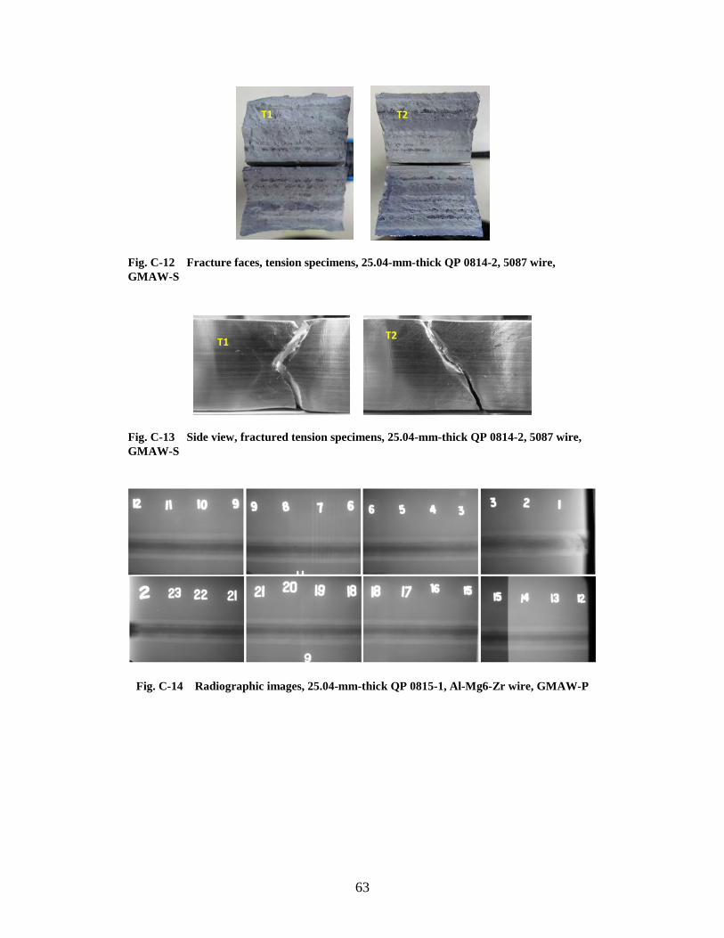
63
Fig. C-12 Fracture faces, tension specimens, 25.04-mm-thick QP 0814-2, 5087 wire, GMAW-S
Fig. C-13 Side view, fractured tension specimens, 25.04-mm-thick QP 0814-2, 5087 wire, GMAW-S
Fig. C-14 Radiographic images, 25.04-mm-thick QP 0815-1, Al-Mg6-Zr wire, GMAW-P
T1 T2
T1 T2
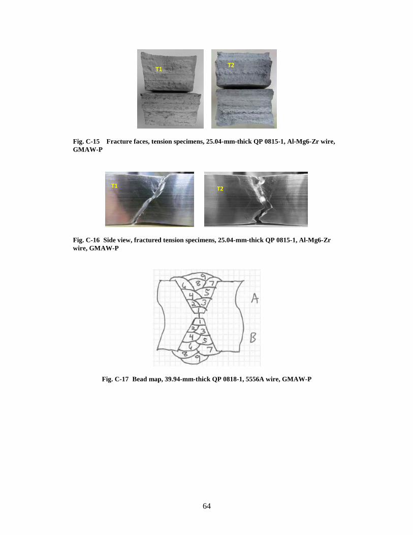
64
Fig. C-15 Fracture faces, tension specimens, 25.04-mm-thick QP 0815-1, Al-Mg6-Zr wire, GMAW-P
Fig. C-16 Side view, fractured tension specimens, 25.04-mm-thick QP 0815-1, Al-Mg6-Zr wire, GMAW-P
Fig. C-17 Bead map, 39.94-mm-thick QP 0818-1, 5556A wire, GMAW-P
T1 T2
T1 T2
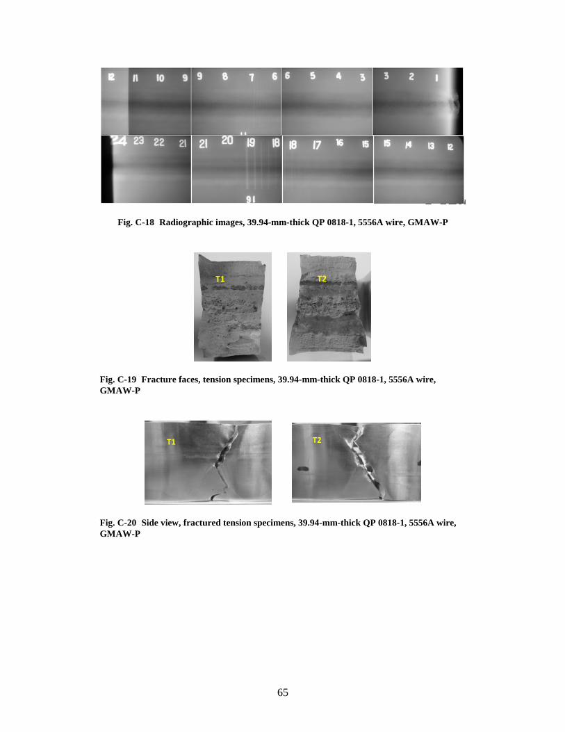
65
Fig. C-18 Radiographic images, 39.94-mm-thick QP 0818-1, 5556A wire, GMAW-P
Fig. C-19 Fracture faces, tension specimens, 39.94-mm-thick QP 0818-1, 5556A wire, GMAW-P
Fig. C-20 Side view, fractured tension specimens, 39.94-mm-thick QP 0818-1, 5556A wire, GMAW-P
T2 T1
T1 T2
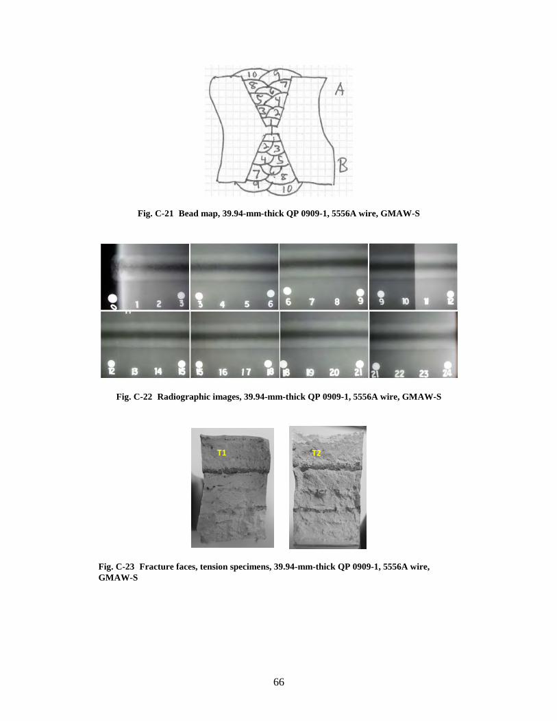
66
Fig. C-21 Bead map, 39.94-mm-thick QP 0909-1, 5556A wire, GMAW-S
Fig. C-22 Radiographic images, 39.94-mm-thick QP 0909-1, 5556A wire, GMAW-S
Fig. C-23 Fracture faces, tension specimens, 39.94-mm-thick QP 0909-1, 5556A wire, GMAW-S
T1 T2
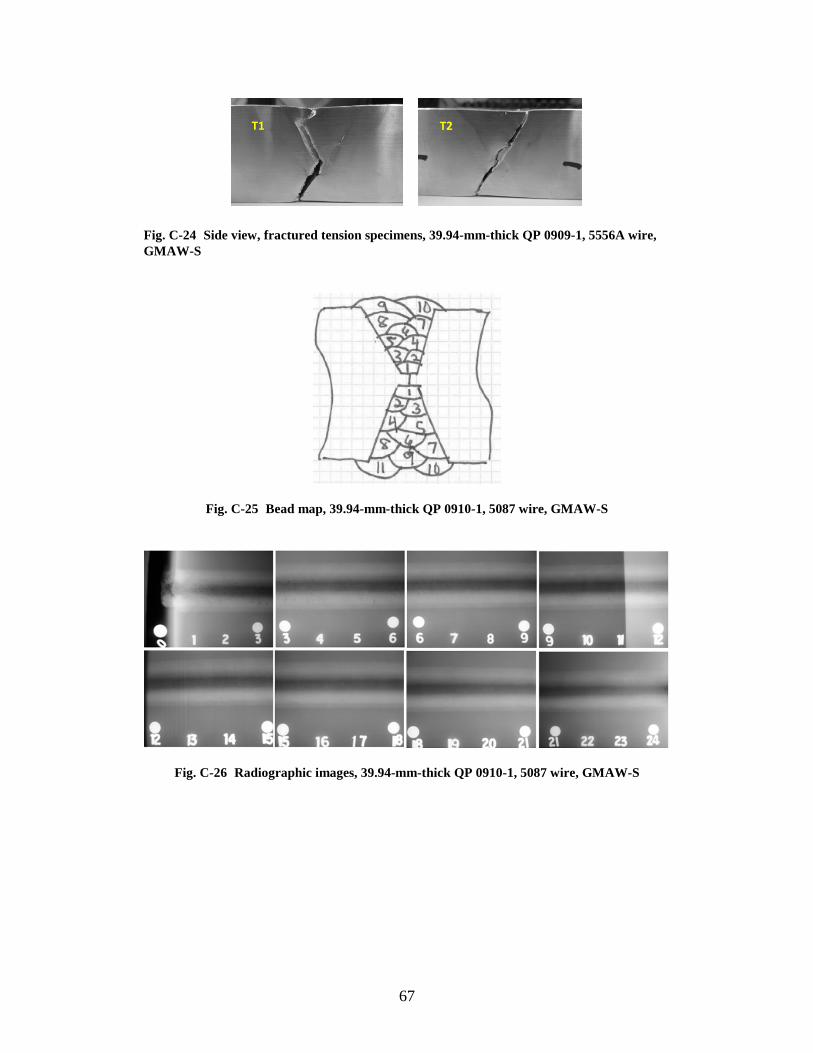
67
Fig. C-24 Side view, fractured tension specimens, 39.94-mm-thick QP 0909-1, 5556A wire, GMAW-S
Fig. C-25 Bead map, 39.94-mm-thick QP 0910-1, 5087 wire, GMAW-S
Fig. C-26 Radiographic images, 39.94-mm-thick QP 0910-1, 5087 wire, GMAW-S
T1 T2
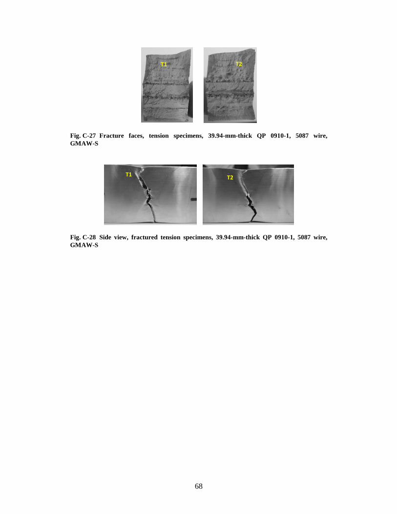
68
Fig. C-27 Fracture faces, tension specimens, 39.94-mm-thick QP 0910-1, 5087 wire, GMAW-S
Fig. C-28 Side view, fractured tension specimens, 39.94-mm-thick QP 0910-1, 5087 wire, GMAW-S
T1 T2
T1 T2
69
Appendix D. Task 3 Results: Ballistic Shock Panel Fabrication
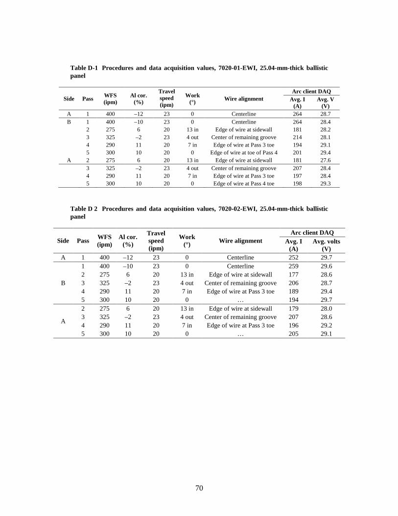
70
Table D-1 Procedures and data acquisition values, 7020-01-EWI, 25.04-mm-thick ballistic panel
Side Pass WFS (ipm)
Al cor. (%)
Travel speed (ipm)
Work (°) Wire alignment
Arc client DAQ Avg. I
(A) Avg. V
(V) A 1 400 –12 23 0 Centerline 264 28.7 B 1 400 –10 23 0 Centerline 264 28.4
2 275 6 20 13 in Edge of wire at sidewall 181 28.2 3 325 –2 23 4 out Center of remaining groove 214 28.1 4 290 11 20 7 in Edge of wire at Pass 3 toe 194 29.1 5 300 10 20 0 Edge of wire at toe of Pass 4 201 29.4
A 2 275 6 20 13 in Edge of wire at sidewall 181 27.6 3 325 –2 23 4 out Center of remaining groove 207 28.4 4 290 11 20 7 in Edge of wire at Pass 3 toe 197 28.4 5 300 10 20 0 Edge of wire at Pass 4 toe 198 29.3
Table D 2 Procedures and data acquisition values, 7020-02-EWI, 25.04-mm-thick ballistic panel
Side Pass WFS (ipm)
Al cor. (%)
Travel speed (ipm)
Work (°) Wire alignment
Arc client DAQ Avg. I
(A) Avg. volts
(V) A 1 400 –12 23 0 Centerline 252 29.7
B
1 400 –10 23 0 Centerline 259 29.6 2 275 6 20 13 in Edge of wire at sidewall 177 28.6 3 325 –2 23 4 out Center of remaining groove 206 28.7 4 290 11 20 7 in Edge of wire at Pass 3 toe 189 29.4 5 300 10 20 0 … 194 29.7
A
2 275 6 20 13 in Edge of wire at sidewall 179 28.0 3 325 –2 23 4 out Center of remaining groove 207 28.6 4 290 11 20 7 in Edge of wire at Pass 3 toe 196 29.2 5 300 10 20 0 … 205 29.1
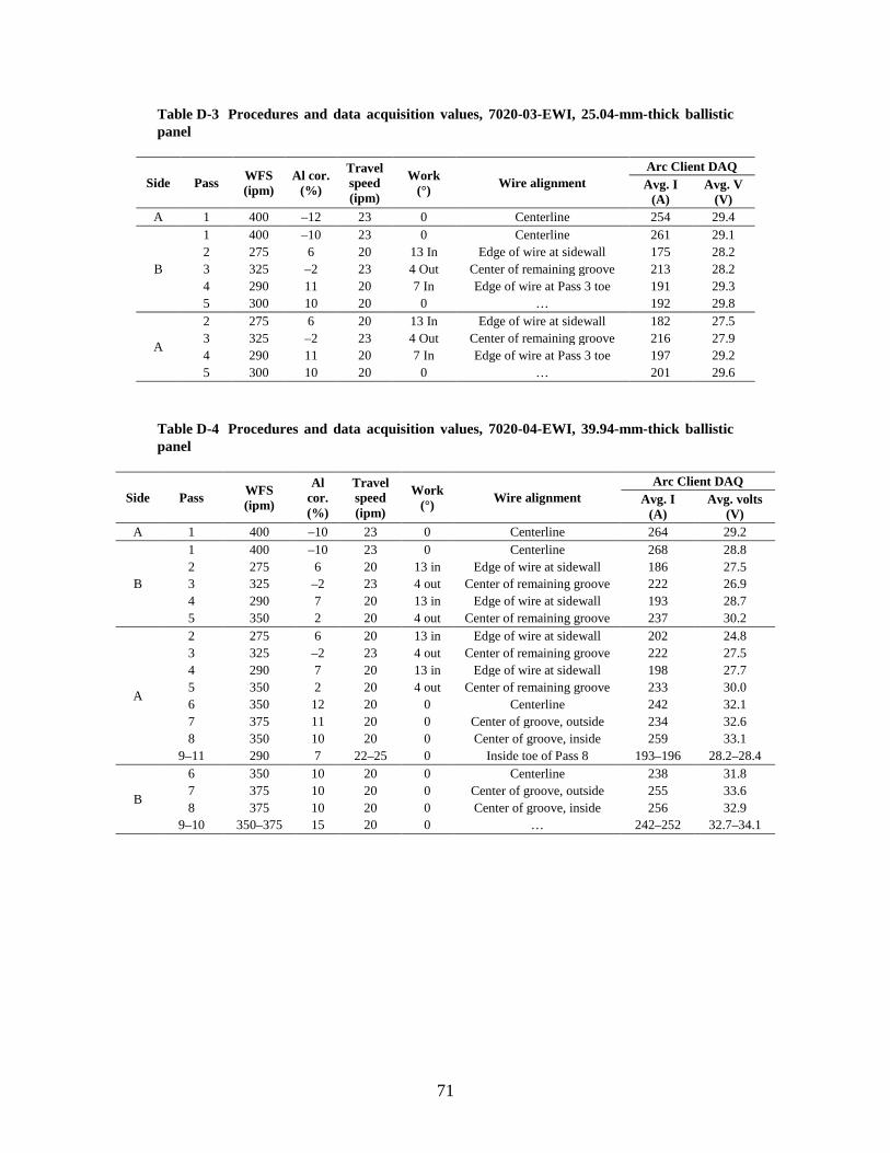
71
Table D-3 Procedures and data acquisition values, 7020-03-EWI, 25.04-mm-thick ballistic panel
Side Pass WFS (ipm)
Al cor. (%)
Travel speed (ipm)
Work (°) Wire alignment
Arc Client DAQ Avg. I
(A) Avg. V
(V) A 1 400 –12 23 0 Centerline 254 29.4
B
1 400 –10 23 0 Centerline 261 29.1 2 275 6 20 13 In Edge of wire at sidewall 175 28.2 3 325 –2 23 4 Out Center of remaining groove 213 28.2 4 290 11 20 7 In Edge of wire at Pass 3 toe 191 29.3 5 300 10 20 0 … 192 29.8
A
2 275 6 20 13 In Edge of wire at sidewall 182 27.5 3 325 –2 23 4 Out Center of remaining groove 216 27.9 4 290 11 20 7 In Edge of wire at Pass 3 toe 197 29.2 5 300 10 20 0 … 201 29.6
Table D-4 Procedures and data acquisition values, 7020-04-EWI, 39.94-mm-thick ballistic panel
Side Pass WFS (ipm)
Al cor. (%)
Travel speed (ipm)
Work (°) Wire alignment
Arc Client DAQ Avg. I
(A) Avg. volts
(V) A 1 400 –10 23 0 Centerline 264 29.2
B
1 400 –10 23 0 Centerline 268 28.8 2 275 6 20 13 in Edge of wire at sidewall 186 27.5 3 325 –2 23 4 out Center of remaining groove 222 26.9 4 290 7 20 13 in Edge of wire at sidewall 193 28.7 5 350 2 20 4 out Center of remaining groove 237 30.2
A
2 275 6 20 13 in Edge of wire at sidewall 202 24.8 3 325 –2 23 4 out Center of remaining groove 222 27.5 4 290 7 20 13 in Edge of wire at sidewall 198 27.7 5 350 2 20 4 out Center of remaining groove 233 30.0 6 350 12 20 0 Centerline 242 32.1 7 375 11 20 0 Center of groove, outside 234 32.6 8 350 10 20 0 Center of groove, inside 259 33.1
9–11 290 7 22–25 0 Inside toe of Pass 8 193–196 28.2–28.4
B
6 350 10 20 0 Centerline 238 31.8 7 375 10 20 0 Center of groove, outside 255 33.6 8 375 10 20 0 Center of groove, inside 256 32.9
9–10 350–375 15 20 0 … 242–252 32.7–34.1
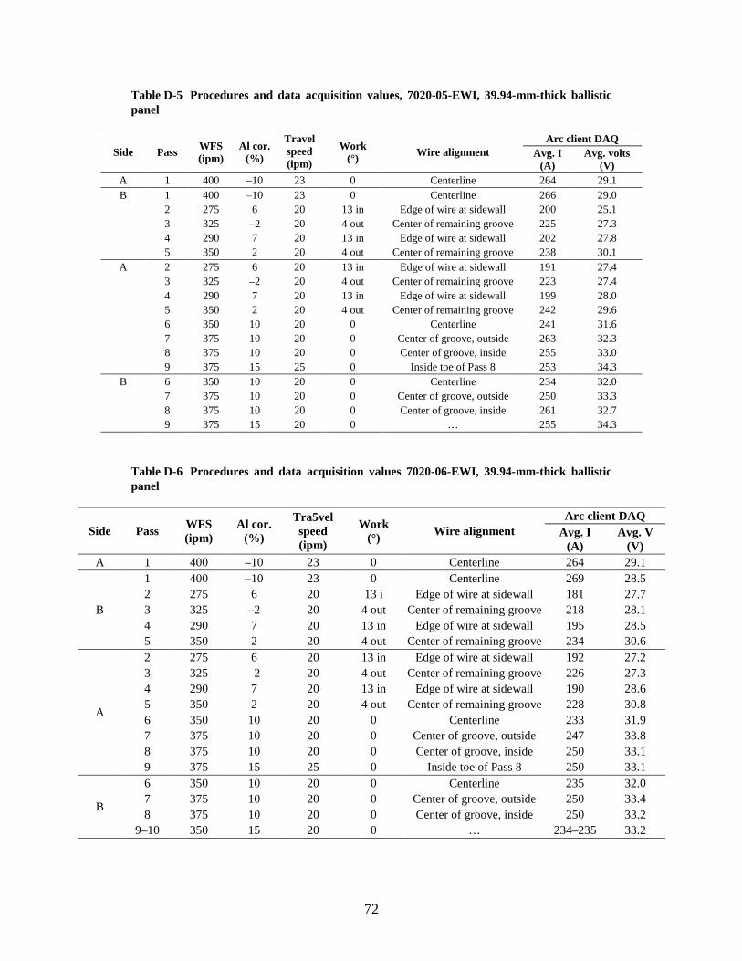
72
Table D-5 Procedures and data acquisition values, 7020-05-EWI, 39.94-mm-thick ballistic panel
Side Pass WFS (ipm)
Al cor. (%)
Travel speed (ipm)
Work (°) Wire alignment
Arc client DAQ Avg. I
(A) Avg. volts
(V) A 1 400 –10 23 0 Centerline 264 29.1 B 1 400 –10 23 0 Centerline 266 29.0
2 275 6 20 13 in Edge of wire at sidewall 200 25.1 3 325 –2 20 4 out Center of remaining groove 225 27.3 4 290 7 20 13 in Edge of wire at sidewall 202 27.8 5 350 2 20 4 out Center of remaining groove 238 30.1
A 2 275 6 20 13 in Edge of wire at sidewall 191 27.4 3 325 –2 20 4 out Center of remaining groove 223 27.4 4 290 7 20 13 in Edge of wire at sidewall 199 28.0 5 350 2 20 4 out Center of remaining groove 242 29.6 6 350 10 20 0 Centerline 241 31.6 7 375 10 20 0 Center of groove, outside 263 32.3 8 375 10 20 0 Center of groove, inside 255 33.0 9 375 15 25 0 Inside toe of Pass 8 253 34.3
B 6 350 10 20 0 Centerline 234 32.0 7 375 10 20 0 Center of groove, outside 250 33.3 8 375 10 20 0 Center of groove, inside 261 32.7 9 375 15 20 0 … 255 34.3
Table D-6 Procedures and data acquisition values 7020-06-EWI, 39.94-mm-thick ballistic panel
Side Pass WFS (ipm)
Al cor. (%)
Tra5vel speed (ipm)
Work (°) Wire alignment
Arc client DAQ Avg. I
(A) Avg. V
(V) A 1 400 –10 23 0 Centerline 264 29.1
B
1 400 –10 23 0 Centerline 269 28.5 2 275 6 20 13 i Edge of wire at sidewall 181 27.7 3 325 –2 20 4 out Center of remaining groove 218 28.1 4 290 7 20 13 in Edge of wire at sidewall 195 28.5 5 350 2 20 4 out Center of remaining groove 234 30.6
A
2 275 6 20 13 in Edge of wire at sidewall 192 27.2 3 325 –2 20 4 out Center of remaining groove 226 27.3 4 290 7 20 13 in Edge of wire at sidewall 190 28.6 5 350 2 20 4 out Center of remaining groove 228 30.8 6 350 10 20 0 Centerline 233 31.9 7 375 10 20 0 Center of groove, outside 247 33.8 8 375 10 20 0 Center of groove, inside 250 33.1 9 375 15 25 0 Inside toe of Pass 8 250 33.1
B
6 350 10 20 0 Centerline 235 32.0 7 375 10 20 0 Center of groove, outside 250 33.4 8 375 10 20 0 Center of groove, inside 250 33.2
9–10 350 15 20 0 … 234–235 33.2
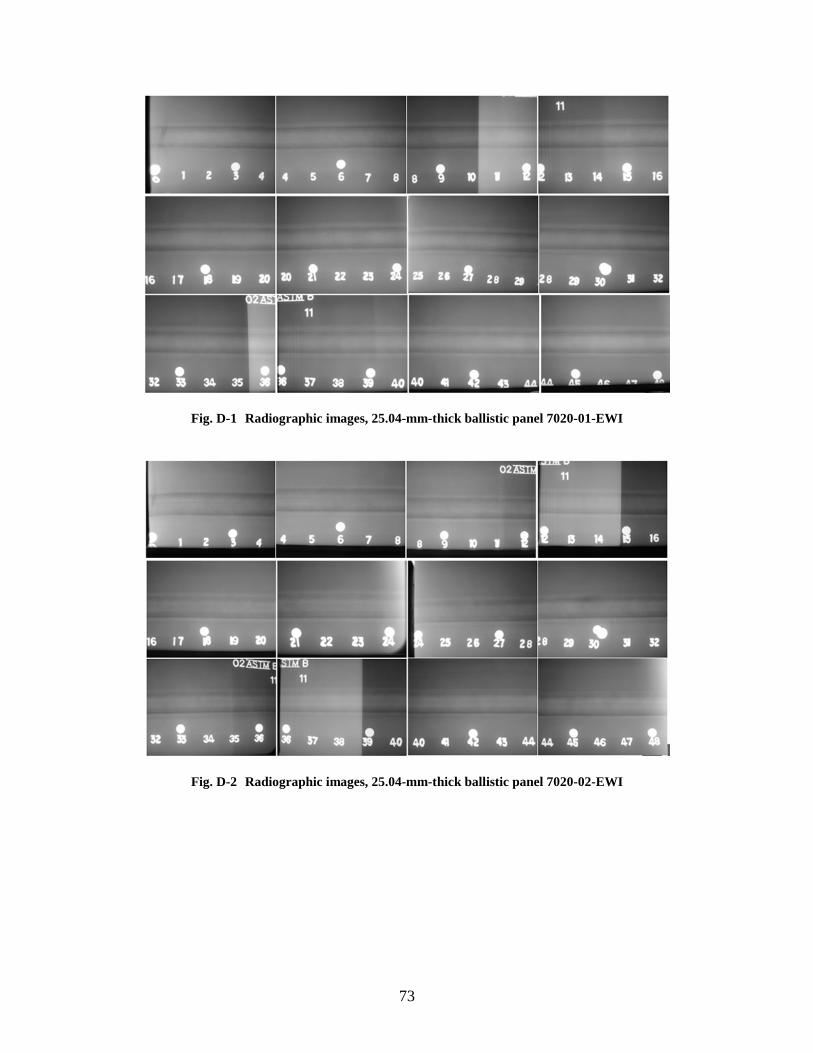
73
Fig. D-1 Radiographic images, 25.04-mm-thick ballistic panel 7020-01-EWI
Fig. D-2 Radiographic images, 25.04-mm-thick ballistic panel 7020-02-EWI
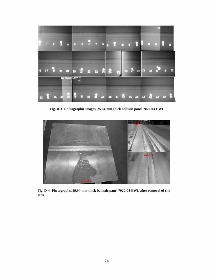
74
Fig. D-3 Radiographic images, 25.04-mm-thick ballistic panel 7020-03-EWI
Fig. D-4 Photographs, 39.94-mm-thick ballistic panel 7020-04-EWI, after removal of end tabs
Side A
Side A
Side B
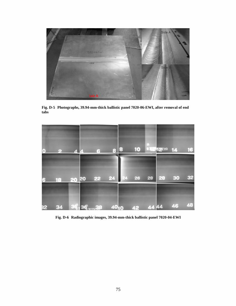
75
Fig. D-5 Photographs, 39.94-mm-thick ballistic panel 7020-06-EWI, after removal of end tabs
Fig. D-6 Radiographic images, 39.94-mm-thick ballistic panel 7020-04-EWI
Side B
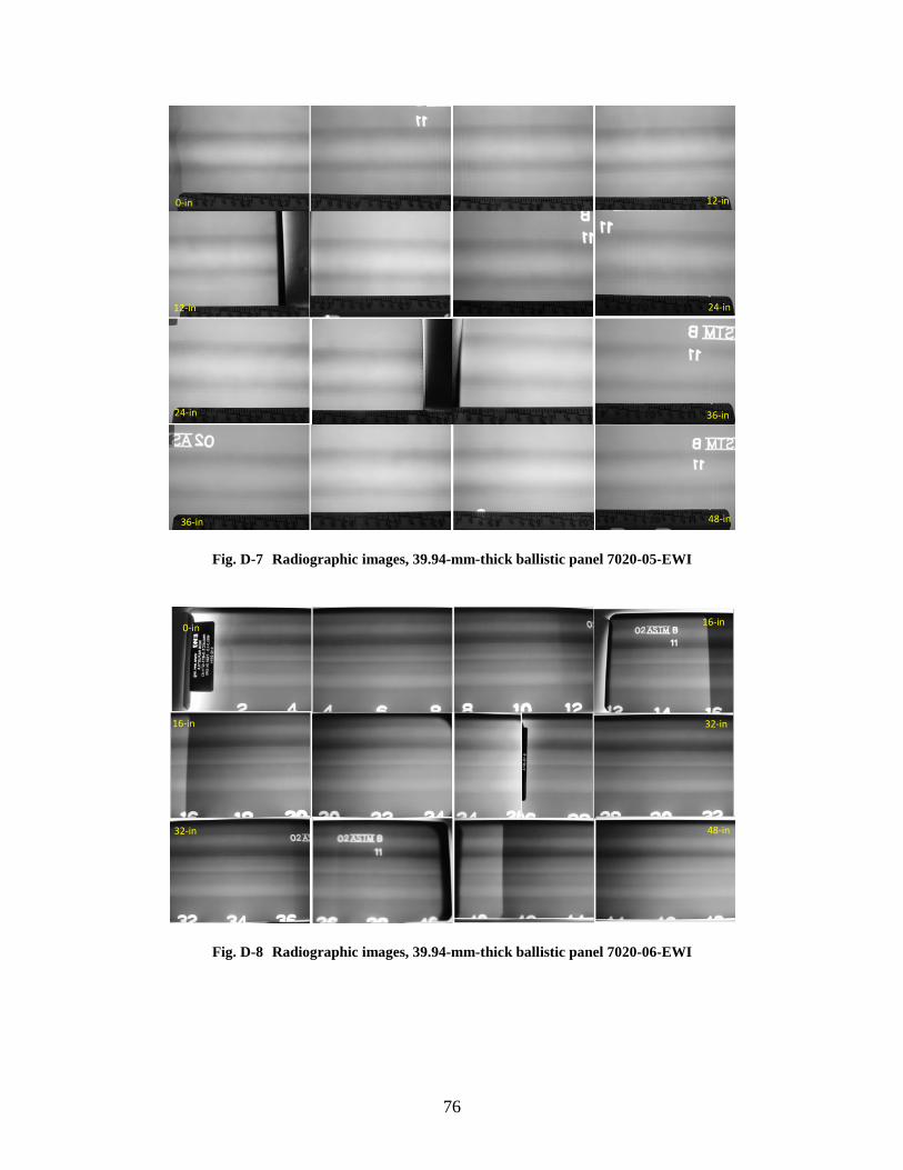
76
Fig. D-7 Radiographic images, 39.94-mm-thick ballistic panel 7020-05-EWI
Fig. D-8 Radiographic images, 39.94-mm-thick ballistic panel 7020-06-EWI
0-in
12-in
24-in
36-in
12-in
24-in
36-in
48-in
0-in
16-in
32-in
16-in
32-in
48-in
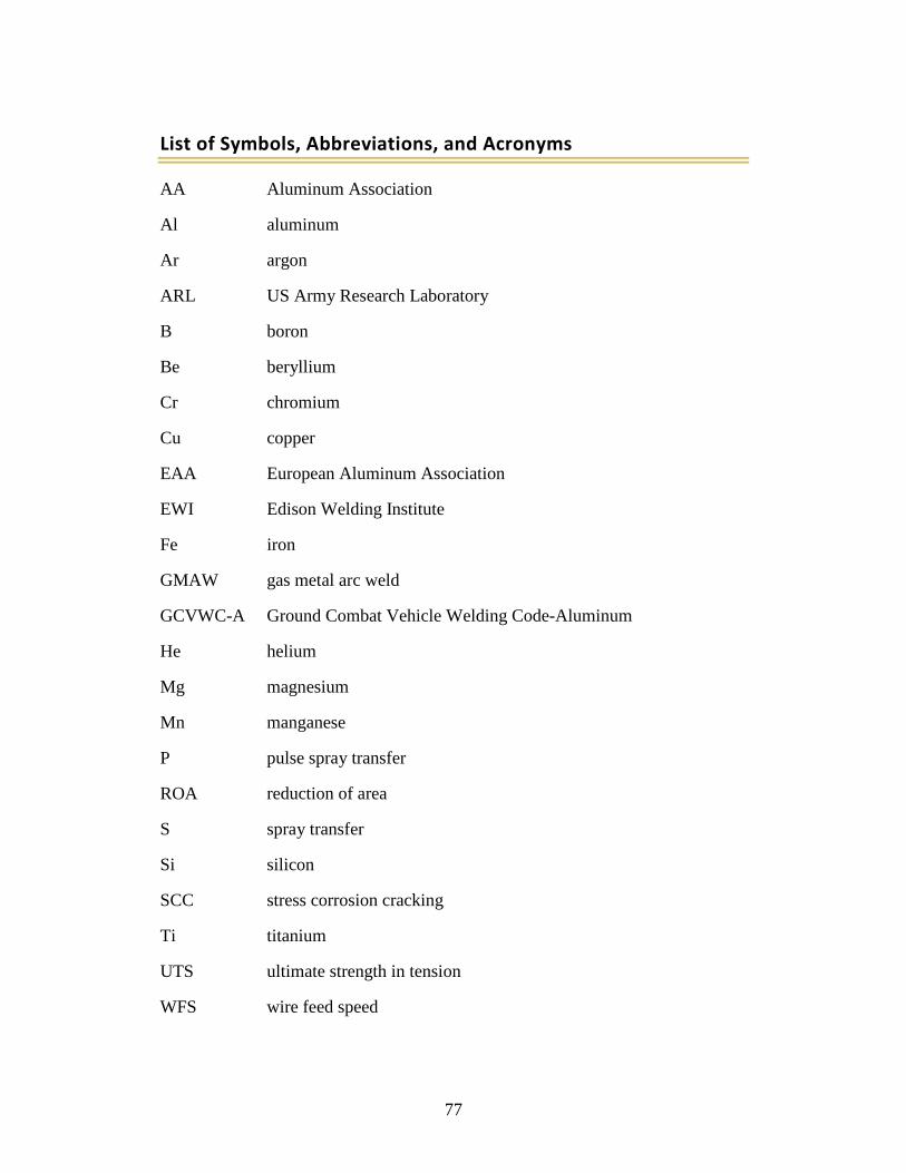
77
List of Symbols, Abbreviations, and Acronyms
AA Aluminum Association
Al aluminum
Ar argon
ARL US Army Research Laboratory
B boron
Be beryllium
Cr chromium
Cu copper
EAA European Aluminum Association
EWI Edison Welding Institute
Fe iron
GMAW gas metal arc weld
GCVWC-A Ground Combat Vehicle Welding Code-Aluminum
He helium
Mg magnesium
Mn manganese
P pulse spray transfer
ROA reduction of area
S spray transfer
Si silicon
SCC stress corrosion cracking
Ti titanium
UTS ultimate strength in tension
WFS wire feed speed
78
YS yield strength
Zn zinc
Zr zirconium
79
1 DEFENSE TECHNICAL (PDF) INFORMATION CTR DTIC OCA 2 DIRECTOR (PDF) US ARMY RESEARCH LAB RDRL CIO LL IMAL HRA MAIL & RECORDS MGMT 1 GOVT PRINTG OFC (PDF) A MALHOTRA 1 DIR USARL (PDF) RDRL WMM F J CHINELLA

80
INTENTIONALLY LEFT BLANK.
Related Documents


![GMAW chapter22[1]](https://static.cupdf.com/doc/110x72/577d22881a28ab4e1e97a08e/gmaw-chapter221.jpg)