1207 | Page Experimental Investigation on Dissimilar Welding of Austenite and Ferrite Stainless Steel by MIG Welding Process Subodh kumar 1 , A. R. Ansari 2 PG Student 1 , Assistant Professor 2 Department of Production Engineering, Bit Sindri, Dhanbad, (India) ABSTRACT Joining of dissimilar metals is really a challenging task due to difference in their thermal, mechanical and chemical properties welded under a common welding condition. A variety of problems evolves in dissimilar welding like cracking, large weld residual stress, migration of atoms during welding causing stress concentration on one side of the weld, compressive and tensile stresses, stress corrosion cracking etc. To overcome these challenges, it is required to study the effect of welding process parameter on mechanical property. However, joining of dissimilar metals has found its use extensively in power generation, electronic, petrochemical and chemical industries, nuclear reactors due to environmental concerns, energy saving, high performance, cost saving and so on. The aim of this research is to experimentally investigate the dissimilar welding of Austenitic Stainless Steel (AISI 316) and Ferritic Stainless Steel (AISI 430) weld ment using ER 304L by MIG(commonly known as GMAW) welding process. The effects of the various parameters like current and voltage for MDR, heat input, tensile strength, percentage elongation, temperature profile of the weld zone and metallography have been clearly depicted in the respective sections.It has been reported that at low and moderate current MDR, weld width and tensile strength all increase but at high temperature these properties show tremendous decline in their values. Keywords: Austenite, Ferrite, MIG Welding, GMAW,316-430 Dissimilar Welding I. INTRODUCTION Welding is a manufacturing process of creating a permanent joint obtained by the fusion of the surface of the parts dissimilar to each other. The heat required for the fusion of the material may be obtained by burning of gas or by an electric arc. The latter method is more extensively used because of greater welding speed. Welding is extensively used in fabrication as an alternative method for casting or forging and as a replacement for bolted and riveted joints. It is also used as a repair medium e.g. to reunite a metal at a crack or to build up a small part that has broken off such as a gear tooth or to repair a worn surface such as a bearing surface.to be joined together, with or without the application of pressure and a filler material. The materials to be joined may be similar or

Welcome message from author
This document is posted to help you gain knowledge. Please leave a comment to let me know what you think about it! Share it to your friends and learn new things together.
Transcript
1207 | P a g e
Experimental Investigation on Dissimilar Welding of
Austenite and Ferrite Stainless Steel
by MIG Welding Process
Subodh kumar1, A. R. Ansari
2
PG Student1, Assistant Professor
2
Department of Production Engineering, Bit Sindri, Dhanbad, (India)
ABSTRACT
Joining of dissimilar metals is really a challenging task due to difference in their thermal, mechanical and chemical
properties welded under a common welding condition. A variety of problems evolves in dissimilar welding like
cracking, large weld residual stress, migration of atoms during welding causing stress concentration on one side of
the weld, compressive and tensile stresses, stress corrosion cracking etc. To overcome these challenges, it is
required to study the effect of welding process parameter on mechanical property. However, joining of dissimilar
metals has found its use extensively in power generation, electronic, petrochemical and chemical industries, nuclear
reactors due to environmental concerns, energy saving, high performance, cost saving and so on.
The aim of this research is to experimentally investigate the dissimilar welding of Austenitic Stainless Steel (AISI
316) and Ferritic Stainless Steel (AISI 430) weld ment using ER 304L by MIG(commonly known as GMAW) welding
process. The effects of the various parameters like current and voltage for MDR, heat input, tensile strength,
percentage elongation, temperature profile of the weld zone and metallography have been clearly depicted in the
respective sections.It has been reported that at low and moderate current MDR, weld width and tensile strength all
increase but at high temperature these properties show tremendous decline in their values.
Keywords: Austenite, Ferrite, MIG Welding, GMAW,316-430 Dissimilar Welding
I. INTRODUCTION
Welding is a manufacturing process of creating a permanent joint obtained by the fusion of the surface of the parts
dissimilar to each other. The heat required for the fusion of the material may be obtained by burning of gas or by an
electric arc. The latter method is more extensively used because of greater welding speed. Welding is extensively
used in fabrication as an alternative method for casting or forging and as a replacement for bolted and riveted joints.
It is also used as a repair medium e.g. to reunite a metal at a crack or to build up a small part that has broken off such
as a gear tooth or to repair a worn surface such as a bearing surface.to be joined together, with or without the
application of pressure and a filler material. The materials to be joined may be similar or
1208 | P a g e
II. MATERIAL SELECTION & PROPERTIES
This chapter studies about the types of stainless steels involved in this project such as ferritic stainless steel and
austenitic stainless steel and their properties. Stainless Steels are iron-base alloys containing10% or more chromium,
which imparts to the metal the corrosion-resistant properties for which stainless steels are so highly regarded.
2.1.Workpiece material
The materials used to carry out experiment areAusteneticStainless steel AISI 316 andFerritic Stainless steel 430.The
chemical composition and properties of Stainless steel AISI 316 and 430 are shown in table 2.1 and 2.2respe.
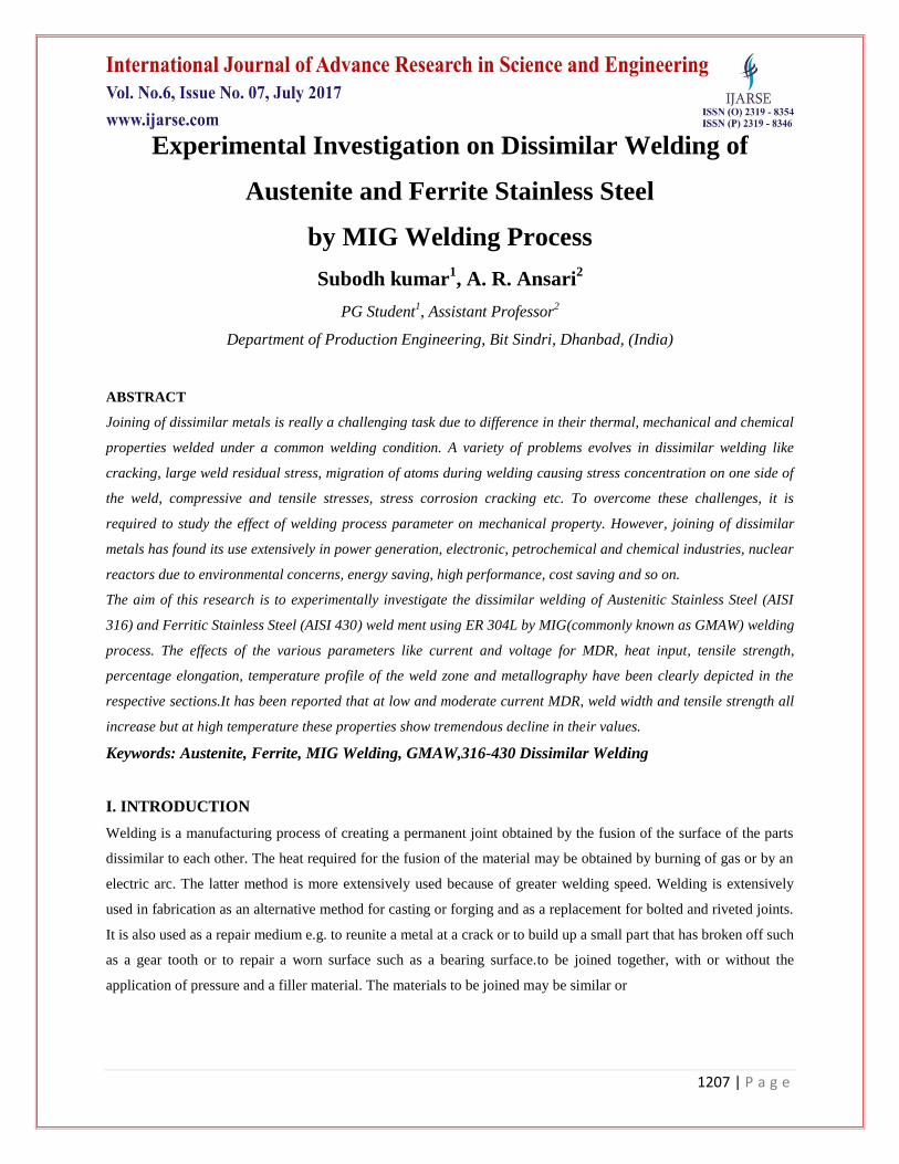
Table 2.1: Chemical Composition of AISI 316 &430 Table 2.2: Properties of AISI 316 &AISI430
SL NO. ELEMENTS %WEIGHT
(TYPE 316)
%WEIGHT
(TYPE 430)
1. Carbon 0.08 0.12
2. Manganese 1.51 1
3. Silicon 2.9 1
4. Chromium 17.4 16-18
5. Phosphorous 0.04 0.04
6. Molybdenum 1.96
7. Nickel 9.5 0.5
8. Cobalt 0.51
2.2 Filler metal
The filler material used for the experiment is Stainless steel ER304 electrodes with size of 1.20 mm diameter
Table 2.3: Composition of ER 304 electrode
Fig.3.2: Square butt joint for MIG welding
2.3.Shielding Gas
The shielding gas used is CO2. This gas has been used as it produces the deepest penetration.
SLNO. PROPERTY AISI 316 AISI 430
1. Density in kg/m3
8000 7750
2. Elastic modulus in
MPa
193 200
3. Thermal conductivity
in W/Kgk
16.3 26.1
4. Specific heat in J/Kgk 500 460
5. Tensile strength 515 483
6. Yield strength in Mpa 205 310
ELEMENTS COMPOSITION
Carbon 0.03
Manganese 2
Phosphorous 0.045
Sulphur 0.03
Silicon 1
Chromium 18-20
Nickel 8-12
1209 | P a g e
III. EXPERIMENTAL WORK AND SAMPLE PREPARATION
3.1.Sample preparation forwelding
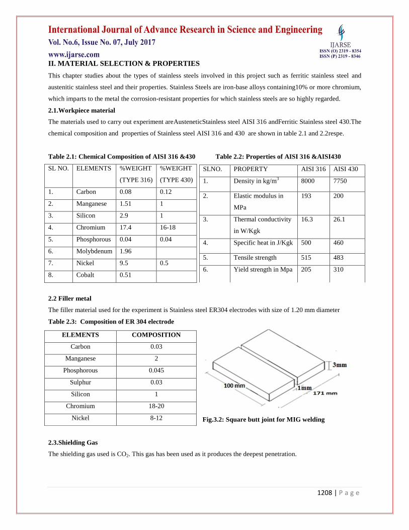
Table 3.1:Welding condition and process parameters
Fig.3.1& 3.4: sample of Stainless steel316&430 with clamping device and standard tensile specimen
AISI 316 Stainless steel and AISI 430 Stainless steel plates with the dimensions of 100x85x3mm arejoined together
with the square butt weld design. Weld design is shown inFig.3.1. MIG welding process was used using consumable
electrode ER304 with diameter 1.2 mm. In each placement, distance between the nozzle and workpiece and the
electrode extension were 20 and 10 millimeter, respectively. The welding electrode is held perpendicular to the
welding surface. Welding is started and the flow rate of shielding gas is adjusted by using knob. The plates were
welded at single pass.
The samples were tackwelded at either end so that a 1mm gap was left at the bottomof the plates. The shielding gas
used was pure carbon dioxide with flow rate 10L/min. A set of preliminary trials were performed in order to
optimize the experimental welding parameter and ensure good weld quality. Used welding condition and process
parameters are given in Table 3.1.
3.2 Sample preparation for microstructure study and FESEM
After welding of both the specimen together with the MIG welding, a 20*10*3 mm section of the combination was
cut using WIRE EDM machine. The part was cut in such a way that it includes the base metals of both the type, heat
affected zone and the weld pool. Weld metal zone is the part melted during welding and retained in the weld. HAZ
is the part of the parent metal that was not melted but metallurgically affected by the welding heat. These specimens
were polished using emery paper of 1000 meshes. The final polishing was done by cloth polishing in the disc
polishing machine using alumina powder. The specimens were etched by using a etchant which comprised a mixture
of 30ml concentrated HNO3,30ml concentrated HCl and 30ml concentrated CH3COOH in the ratio 1:1:1, applied
Process parameter Value
Welding current(Amp) 60,80,90 and 100
Welding speed(mm/sec) 1.7
Electrode polarity DCEP
Arc voltage(volt) 20,25 ,30 and 30
Filler wire diameter(mm) 1.2
Electrode ER304L
Number of passes 1
Shielding gas flow
rate(L/min)
10
Feed rate(m/min) 3.2
Stick out length(mm) 12
1210 | P a g e
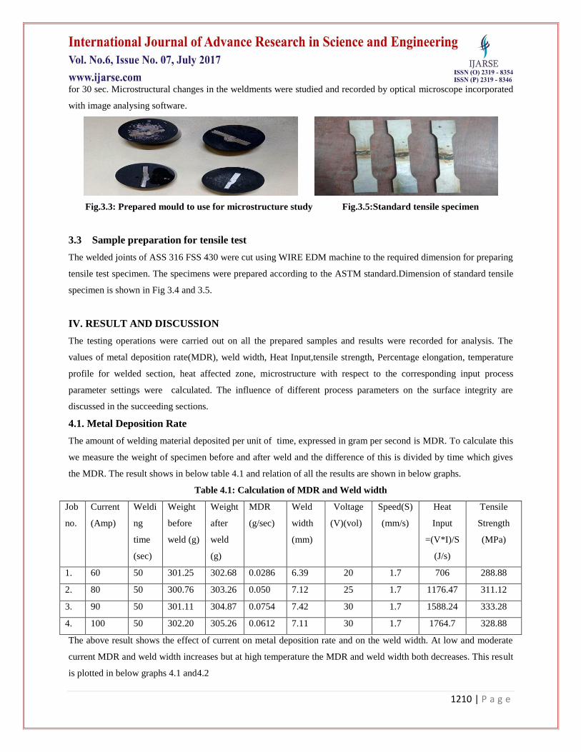
for 30 sec. Microstructural changes in the weldments were studied and recorded by optical microscope incorporated
with image analysing software.
Fig.3.3: Prepared mould to use for microstructure study Fig.3.5:Standard tensile specimen
3.3 Sample preparation for tensile test
The welded joints of ASS 316 FSS 430 were cut using WIRE EDM machine to the required dimension for preparing
tensile test specimen. The specimens were prepared according to the ASTM standard.Dimension of standard tensile
specimen is shown in Fig 3.4 and 3.5.
IV. RESULT AND DISCUSSION
The testing operations were carried out on all the prepared samples and results were recorded for analysis. The
values of metal deposition rate(MDR), weld width, Heat Input,tensile strength, Percentage elongation, temperature
profile for welded section, heat affected zone, microstructure with respect to the corresponding input process
parameter settings were calculated. The influence of different process parameters on the surface integrity are
discussed in the succeeding sections.
4.1. Metal Deposition Rate
The amount of welding material deposited per unit of time, expressed in gram per second is MDR. To calculate this
we measure the weight of specimen before and after weld and the difference of this is divided by time which gives
the MDR. The result shows in below table 4.1 and relation of all the results are shown in below graphs.
Table 4.1: Calculation of MDR and Weld width
Job
no.
Current
(Amp)
Weldi
ng
time
(sec)
Weight
before
weld (g)
Weight
after
weld
(g)
MDR
(g/sec)
Weld
width
(mm)
Voltage
(V)(vol)
Speed(S)
(mm/s)
Heat
Input
=(V*I)/S
(J/s)
Tensile
Strength
(MPa)
1. 60 50 301.25 302.68 0.0286 6.39 20 1.7 706 288.88
2. 80 50 300.76 303.26 0.050 7.12 25 1.7 1176.47 311.12
3. 90 50 301.11 304.87 0.0754 7.42 30 1.7 1588.24 333.28
4. 100 50 302.20 305.26 0.0612 7.11 30 1.7 1764.7 328.88
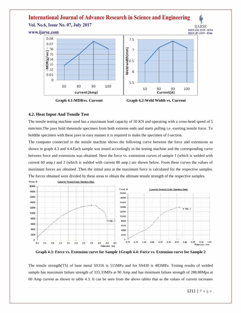
The above result shows the effect of current on metal deposition rate and on the weld width. At low and moderate
current MDR and weld width increases but at high temperature the MDR and weld width both decreases. This result
is plotted in below graphs 4.1 and4.2
1211 | P a g e
Graph 4.1:MDRvs. Current Graph 4.2:Weld Width vs. Current
4.2. Heat Input And Tensile Test
The tensile testing machine used has a maximum load capacity of 50 KN and operating with a cross-head speed of 5
mm/min.The jaws hold thetensile specimen from both extreme ends and starts pulling i.e. exerting tensile force. To
holdthe specimen with these jaws in easy manner it is required to make the specimen of I-section.
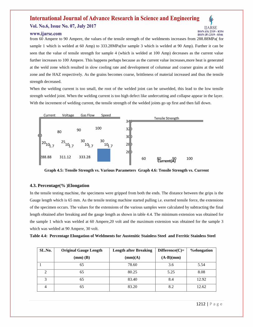
The computer connected to the tensile machine shows the following curve between the force and extensions as
shown in graph 4.3 and 4.4.Each sample was tested accordingly in the testing machine and the corresponding curve
between force and extensions was obtained. Here the force vs. extensions curves of sample 1 (which is welded with
current 60 amp.) and 2 (which is welded with current 80 amp.) are shown below. From these curves the values of
maximum forces are obtained .Then the initial area at the maximum force is calculated for the respective samples.
The forces obtained were divided by these areas to obtain the ultimate tensile strength of the respective samples.
Graph 4.3: Force vs. Extension curve for Sample 1Graph 4.4: Force vs. Extension curve for Sample 2
The tensile strength(TS) of base metal SS316 is 515MPa and for SS430 is 483MPa. Testing results of welded
sample has maximum failure strength of 333.33MPa at 90 Amp and has minimum failure strength of 288.88Mpa at
60 Amp current as shown in table 4.3. It can be seen from the above tables that as the values of current increases
1212 | P a g e
from 60 Ampere to 90 Ampere, the values of the tensile strength of the weldments increases from 288.88MPa( for
sample 1 which is welded at 60 Amp) to 333.28MPa(for sample 3 which is welded at 90 Amp). Further it can be
seen that the value of tensile strength for sample 4 (which is welded at 100 Amp) decreases as the current value
further increases to 100 Ampere. This happens perhaps because as the current value increases,more heat is generated
at the weld zone which resulted in slow cooling rate and development of columnar and coarser grains at the weld
zone and the HAZ respectively. As the grains becomes coarse, brittleness of material increased and thus the tensile
strength decreased.
When the welding current is too small, the root of the welded joint can be unwelded, this lead to the low tensile
strength welded joint. When the welding current is too high defect like undercutting and collapse appear in the layer.
With the increment of welding current, the tensile strength of the welded joints go up first and then fall down.
6080 90 100
20 25 30 3010 10 10 101.7 1.7 1.7 1.7
288.88 311.12 333.28 328.88
Current Voltage Gas Flow Speed
260
280
300
320
340
60 80 90 100Current(A)
Tensile Strength
Graph 4.5: Tensile Strength vs. Various Parameters Graph 4.6: Tensile Strength vs. Current
4.3. Percentage(% )Elongation
In the tensile testing machine, the specimens were gripped from both the ends. The distance between the grips is the
Gauge length which is 65 mm. As the tensile testing machine started pulling i.e. exerted tensile force, the extensions
of the specimen occurs. The values for the extensions of the various samples were calculated by subtracting the final
length obtained after breaking and the gauge length as shown in table 4.4. The minimum extension was obtained for
the sample 1 which was welded at 60 Ampere,20 volt and the maximum extension was obtained for the sample 3
which was welded at 90 Ampere, 30 volt.
Table 4.4: Percentage Elongation of Weldments for Austenitic Stainless Steel and Ferritic Stainless Steel
SL.No. Original Gauge Length
(mm) (B)
Length after Breaking
(mm)(A)
Difference(C)=
(A-B)(mm)
%elongation
1 65 78.60 3.6 5.54
2 65 80.25 5.25 8.08
3 65 83.40 8.4 12.92
4 65 83.20 8.2 12.62
1213 | P a g e
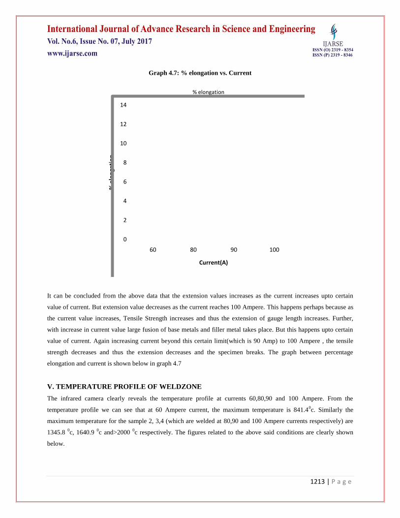
Graph 4.7: % elongation vs. Current
0
2
4
6
8
10
12
14
60 80 90 100
% e
lon
gati
on
Current(A)
% elongation
It can be concluded from the above data that the extension values increases as the current increases upto certain
value of current. But extension value decreases as the current reaches 100 Ampere. This happens perhaps because as
the current value increases, Tensile Strength increases and thus the extension of gauge length increases. Further,
with increase in current value large fusion of base metals and filler metal takes place. But this happens upto certain
value of current. Again increasing current beyond this certain limit(which is 90 Amp) to 100 Ampere , the tensile
strength decreases and thus the extension decreases and the specimen breaks. The graph between percentage
elongation and current is shown below in graph 4.7
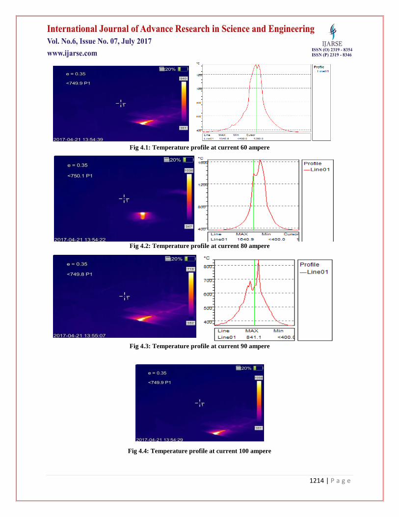
V. TEMPERATURE PROFILE OF WELDZONE
The infrared camera clearly reveals the temperature profile at currents 60,80,90 and 100 Ampere. From the
temperature profile we can see that at 60 Ampere current, the maximum temperature is 841.40c. Similarly the
maximum temperature for the sample 2, 3,4 (which are welded at 80,90 and 100 Ampere currents respectively) are
1345.8 0c, 1640.9
0c and>2000
0c respectively. The figures related to the above said conditions are clearly shown
below.
1214 | P a g e
Fig 4.1: Temperature profile at current 60 ampere
Fig 4.2: Temperature profile at current 80 ampere
Fig 4.3: Temperature profile at current 90 ampere
Fig 4.4: Temperature profile at current 100 ampere
1215 | P a g e
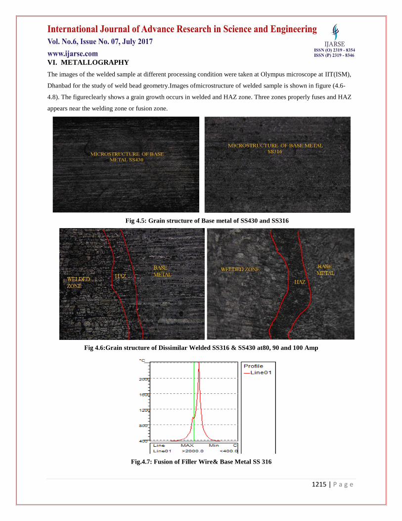
VI. METALLOGRAPHY
The images of the welded sample at different processing condition were taken at Olympus microscope at IIT(ISM),
Dhanbad for the study of weld bead geometry.Images ofmicrostructure of welded sample is shown in figure (4.6-
4.8). The figureclearly shows a grain growth occurs in welded and HAZ zone. Three zones properly fuses and HAZ
appears near the welding zone or fusion zone.
Fig 4.5: Grain structure of Base metal of SS430 and SS316
Fig 4.6:Grain structure of Dissimilar Welded SS316 & SS430 at80, 90 and 100 Amp
Fig.4.7: Fusion of Filler Wire& Base Metal SS 316 .
1216 | P a g e
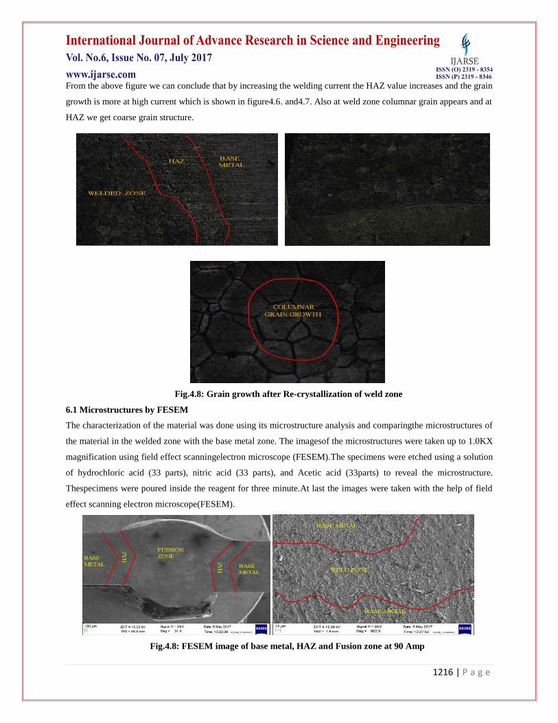
From the above figure we can conclude that by increasing the welding current the HAZ value increases and the grain
growth is more at high current which is shown in figure4.6. and4.7. Also at weld zone columnar grain appears and at
HAZ we get coarse grain structure.
.Fig.4.8: Grain growth after Re-crystallization of weld zone
6.1 Microstructures by FESEM
The characterization of the material was done using its microstructure analysis and comparingthe microstructures of
the material in the welded zone with the base metal zone. The imagesof the microstructures were taken up to 1.0KX
magnification using field effect scanningelectron microscope (FESEM).The specimens were etched using a solution
of hydrochloric acid (33 parts), nitric acid (33 parts), and Acetic acid (33parts) to reveal the microstructure.
Thespecimens were poured inside the reagent for three minute.At last the images were taken with the help of field
effect scanning electron microscope(FESEM).
Fig.4.8: FESEM image of base metal, HAZ and Fusion zone at 90 Amp
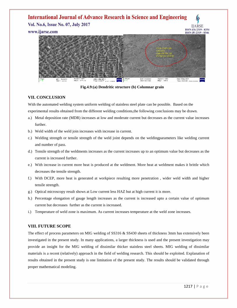
1217 | P a g e
Fig.4.9:(a) Dendritic structure (b) Columnar grain
VII. CONCLUSION
With the automated welding system uniform welding of stainless steel plate can be possible. Based on the
experimental results obtained from the different welding conditions,the following conclusions may be drawn.
a.) Metal deposition rate (MDR) increases at low and moderate current but decreases as the current value increases
further.
b.) Weld width of the weld join increases with increase in current.
c.) Welding strength or tensile strength of the weld joint depends on the weldingparameters like welding current
and number of pass.
d.) Tensile strength of the weldments increases as the current increases up to an optimum value but decreases as the
current is increased further.
e.) With increase in current more heat is produced at the weldment. More heat at weldment makes it brittle which
decreases the tensile strength.
f.) With DCEP, more heat is generated at workpiece resulting more penetration , wider weld width and higher
tensile strength.
g.) Optical microscopy result shows at Low current less HAZ but at high current it is more.
h.) Percentage elongation of gauge length increases as the current is increased upto a certain value of optimum
current but decreases further as the current is increased.
i.) Temperature of weld zone is maximum. As current increases temperature at the weld zone increases.
VIII. FUTURE SCOPE
The effect of process parameters on MIG welding of SS316 & SS430 sheets of thickness 3mm has extensively been
investigated in the present study. In many applications, a larger thickness is used and the present investigation may
provide an insight for the MIG welding of dissimilar thicker stainless steel sheets. MIG welding of dissimilar
materials is a recent (relatively) approach in the field of welding research. This should be exploited. Explanation of
results obtained in the present study is one limitation of the present study. The results should be validated through
proper mathematical modeling.
1218 | P a g e
REFRENCES
[1] Abdul wahab H. Khuder and Esam J. Ebraheam, “Study the factors effecting onwelding joint of dissimilar
metals”, Al-Khwarizmi engineering journal, April (2011), Vol. 7, No. 1, pp.-76-81.
[2] Amit Kumar, Dr. R. S. Jadoun and Ankur Singh Bist, “Optimization of MIG welding parameters using
Artificial Neural Network (ANN) and Genetic Algorithm (GA)”, International journal of engineering sciences
& research technology, July (2014), 3(7), pp.- 614-620.
[3] AjitHooda, AshwaniDhingra and Satpal Sharma, “Optimization of MIG welding process parameter to predict
maximum yield strength in AISI 1040”, International journal of Mechanical engineering and Robotics
research, October (2012), Vol. 1,No. 3, pp.-203-213.
[4] Balasubramanian V., Ravisankar V. and Madhusudhan Reddy G., “Effect of pulsed current welding on
mechanical properties of high strengthaluminiumalloy", International Journal of Advanced Manufacturing
Technology, (2008), vol36, pp. 254-262.
[5] C. N. Patel and Chaudhary, S., “Parametric Optimization of Weld Strength of Metal Inert Gas Welding and
Tungsten Inert Gas Welding by using Analysis of Variance and Grey Relational Analysis”, International
Journal of Research in Modern Engineering and Emerging Technology, (2013), Vol. 1, No. 3.
[6] Ghazvinloo H.R., Honarbakhsh-Raouf A. and Shadfar N., " Effect of arc voltage, welding current and welding
speed on fatigue life, impact energy and bead penetration of AA6061 joints produced by robotic MIG
welding". Indian Journal of Science and Technology,(2010), Vol. 3.
[7] Lakshminarayanan A. K., BalasubramanianV. AndElangovan K., "Effect of welding processes on tensile
properties of AA6061 Aluminium alloy joints". International Journal of Advanced Manufacturing
Technology,(2009), Vol. 40, pp286-296.
[8] M. P. Lightfoot, G. J. Bruce, N. A. McPherson and K. Woods, “The application of artificial neural networks to
weld-induced deformation in ship plate”, Welding J., AWS and WRC, February(2005), pp. 23– 26.
[9] Monika K., BalaChennaiah M., Nanda Kumar P. and PrahaladaRao P., "The Effect of Heat input on the
Mechanical Properties of MIG Welded DissimilarJoints". International Journal of Engineering Research &
Technology, (2013), vol2, pp. 1406-1413.
[10] M. Aghakhani, E. Mehrdad, and E. Hayati, “Parametric optimization of gas metal arc welding process by
Taguchi method on weld dilution”, International Journal of Modeling and Optimization, August (2011), Vol.
1, No. 3, pp.- 216-220.
[11] Okuyucu H., A. Kurt and E. Arcaklioglu, “Artificial neural network application to the friction stir welding of
aluminium plates”, J. of Materials & Design, (2007), Vol. 29, pp. 78-84.
[12] Pawan Kumar, Dr. B. K. Roy and Nishant, “Parametres optimization for gas metal arc welding of austenitic
stainless steel (AISI 304) & low carbon steel using Taguchi’s technique”, International journal of engineering
and management research, August (2013), pp.-18-22.
[13] PradipD.Chaudhari and Nitin N. More, “Effect of welding process parameters on tensile strength”, IOSR
journal of engineering, May (2014), Vol. 04, Issue 05, pp.-01-05.
Related Documents