COPY PLEASE READ THIS IMPORTANT NOTICE The material presented in this document has been pre- pared for the general information of the reader and should not be used or relied on for specific applications without first securing competent advice. The Nickel Development Institute, its members, staff and consultants, nor Peritech Pty Ltd, its members, staff and consultants, do not represent or warrant its suitability for any general or specific use and assume no responsibility of any kind in connection with the information herein. Noel F Herbst Presented To The Welding Technology Institute Of Australia - Victorian Branch February 4th 1998 1 INTRODUCTION 3 2 PREQUALIFICATION 3 3 DISSIMILAR WELD STRENGTH 3 4 NON-FUSION JOINTS 3 5 CONTROLLING FACTORS IN DISSIMI- LAR METAL WELDING 4 5.1 Melting temperatures 4 5.2 Expansion 4 5.2.1 Fusion welds 4 5.2.2 Brazing 6 5.3 Thermal conductivity 6 5.4 Pre- and post-heating 6 5.5 Weld pool properties 6 5.5.1 Metal mixing 6 5.5.2 Dilution calculation 6 5.5.3 Microstucture determination 7 5.5.4 Microstructure stability 8 5.5.5 Corrosion 8 5.5.6 Magnetic effects on dilution 10 6 JOINT DESIGN 10 6.1 Austenitic stainless steel - carbon steel 10 6.1.1 Low temperature applications: 10 6.1.2 High temperature applications 11 6.2 Ferritic/martensitic stainless steels - car- bon steel 12 6.3 High nickel alloys 13 6.4 Copper alloys 13 6.4.1 Dissimilar fusion welds 13 6.4.2 Copper penetration. 13 6.4.3 Dissimilar metal brazing 14 6.5 Aluminium alloys 15 6.5.1 Aluminium/copper welds 15 6.5.2 Aluminium/steel welds 15 6.6 Titanium welds 16 7 FRICTION WELDING 16 8 EXPLOSION WELDING 16 9 ROLL BONDING 16 10 ACKNOWLEDGEMENT 17 11 INDEX DISSIMILAR METAL WELDING

Welcome message from author
This document is posted to help you gain knowledge. Please leave a comment to let me know what you think about it! Share it to your friends and learn new things together.
Transcript
COPY
PLEASE READ THIS IMPORTANT NOTICE
The material presented in this document has been pre-
pared for the general information of the reader and should
not be used or relied on for specific applications without
first securing competent advice.
The Nickel Development Institute, its members, staff and
consultants, nor Peritech Pty Ltd, its members, staff and
consultants, do not represent or warrant its suitability for
any general or specific use and assume no responsibility
of any kind in connection with the information herein.
Noel F Herbst
Presented To The Welding Technology Institute Of Australia - Victorian BranchFebruary 4th 1998
1 INTRODUCTION 3
2 PREQUALIFICATION 3
3 DISSIMILAR WELD STRENGTH 3
4 NON-FUSION JOINTS 3
5 CONTROLLING FACTORS IN DISSIMI-LAR METAL WELDING 4
5.1 Melting temperatures 4
5.2 Expansion 4
5.2.1 Fusion welds 4
5.2.2 Brazing 6
5.3 Thermal conductivity 6
5.4 Pre- and post-heating 6
5.5 Weld pool properties 6
5.5.1 Metal mixing 6
5.5.2 Dilution calculation 6
5.5.3 Microstucture determination 7
5.5.4 Microstructure stability 8
5.5.5 Corrosion 8
5.5.6 Magnetic effects on dilution 10
6 JOINT DESIGN 10
6.1 Austenitic stainless steel - carbon steel10
6.1.1 Low temperature applications: 10
6.1.2 High temperature applications 11
6.2 Ferritic/martensitic stainless steels - car-bon steel 12
6.3 High nickel alloys 13
6.4 Copper alloys 13
6.4.1 Dissimilar fusion welds 13
6.4.2 Copper penetration. 13
6.4.3 Dissimilar metal brazing 14
6.5 Aluminium alloys 15
6.5.1 Aluminium/copper welds 15
6.5.2 Aluminium/steel welds 15
6.6 Titanium welds 16
7 FRICTION WELDING 16
8 EXPLOSION WELDING 16
9 ROLL BONDING 16
10 ACKNOWLEDGEMENT 17
11 INDEX
DISSIMILAR METAL WELDING

This page intentionally left blank
Dissimilar Metal Welding
1 INTRODUCTION
All welding processes have a component of
dissimilar metal welding about them
The fact that metals have to be joined is an
admission that they are most probably from
two different sources. By far the greatest
tonnage of welding would be in joining the
same general type of material— perhaps the
most common situation would be in struc-
tural steel where two low-medium carbon
steel components are welded together.
Even in this simple case there can still be a
problem if one piece is at the high end of the
carbon range and theother is at the low end.
A more demanding case is where there are
two quite different materials that have to be
joined. This paper is designed as a review
of the practice of dissimilar metal welding
of this latter class of join.
2 PREQUALIFICATION
One aspect of dissimilar metal welding that
needs stressing is that recommendations in
this area are largely recommendations of
the first material with which to start the
pre-qualification test with. Because of the
large number of permutations possible, it is
essential that any combination of parent
metals, fillers and welding variables must
be given a pre-qualification test to ensure
that the system is able to meet the design re-
quirements.
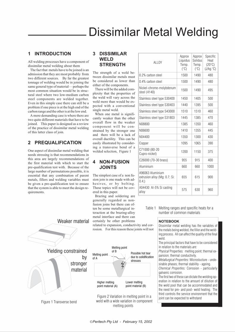
3 DISSIMILARWELDSTRENGTH
The strength of a weld be-
tween dissimilar metals must
be considered as lower than
either of the components.
There will be the added com-
plexity that the properties of
the weld will vary across the
weld more than would be ex-
pected with a conventional
single metal weld.
When one metal is signifi-
cantly weaker than the other
overall flow in the weaker
component will be con-
strained by the stronger one
and there will be a lack of
overall ductility. This can be
easily illustrated by consider-
ing a transverse bend of a
welded selection, Figure 1
4 NON-FUSIONJOINTS
The simplest case of a non fu-
sion join is one made with ad-
hesives , or by bol t ing.
These topics will not be cov-
ered in this paper.
Brazing and soldering are
generally regarded as non-
fusion joins but there can of-
ten be some metallurgical in-
teraction at the brazing-alloy
metal interface and there can
certainly be other problems
related to expansion, conductivity and cor-
rosion. For this reason these joints will not
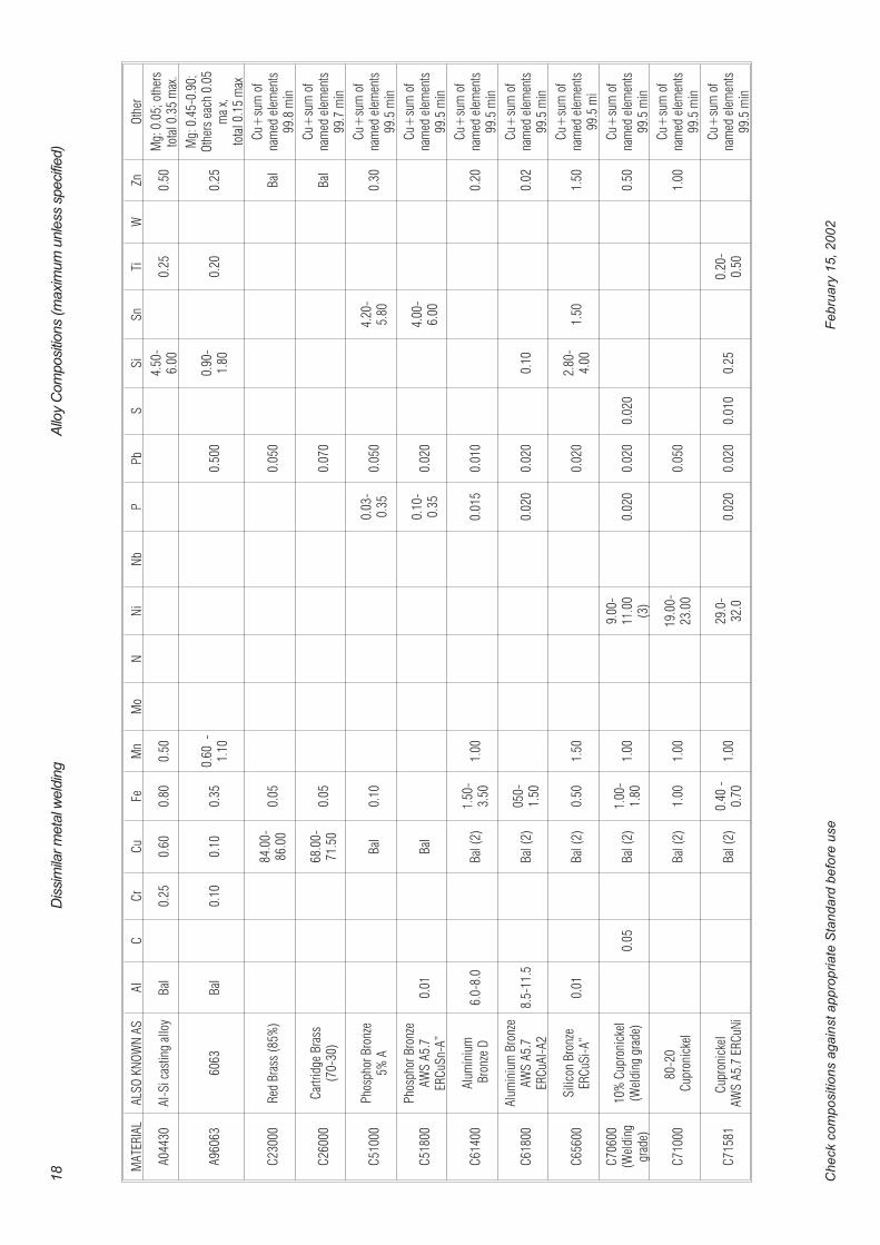
�Peritech Pty Ltd - February 15, 2002
ALLOY
ApproxLiquidusTemp.(°C)
ApproxSolidusTemp.(°C)
SpecificHeat
(20°C)(J/kg.°C)
0.2% carbon steel 1500 1490 480
0.4% carbon steel 1500 1490 480
Nickel-chrome-molybdenumsteel (4140)
1500 1490 495
Stainless steel type S30400 1450 1405 500
Stainless steel type S30403 1440 1395 500
Stainless steel type S43000 1510 1510 460
Stainless steel type S31803 1445 1385 470
N08800 1385 1350 460
N06600 1410 1355 445
N04400 1350 1300 430
Copper 1095 1065 390
C71000 (80-20Cupro-nickel)
1200 1150 375
C26000 (70-30 brass) 955 915 400
Aluminium 660 660 1000
A96063 Aluminiumextrusion alloy (Mg: 0.7; Si:0.4;)
655 615 900
A04430 Al-5% Si castingalloy
575 630 960
Table 1 Melting ranges and specific heats for anumber of common materials
NOTEBOOK
Dissimilar metal welding has the variables of
the metals being welded, the filler and the weld-
ing process. All can affect the quality of the final
weld.
The principal factors that have to be considered
in relation to the materials are:
Physical Properties: melting point; thermal ex-
pansion; thermal conductivity.
Metallurgical Properties: Microstucture - unde-
sirable phases; thermal stability - ageing.
Chemical Properties: Corrosion - particularly
galvanic corrosion.
The first two of these can dictate the welding op-
eration in relation to the amount of dilution of
the weld pool that can be accommodated and
the need for pre- and post- weld heating. The
third controls the service environment that the
joint can be expected to withstand
Weaker material
Yielding constrainedby
strongermaterial
Figure 1 Transverse bend
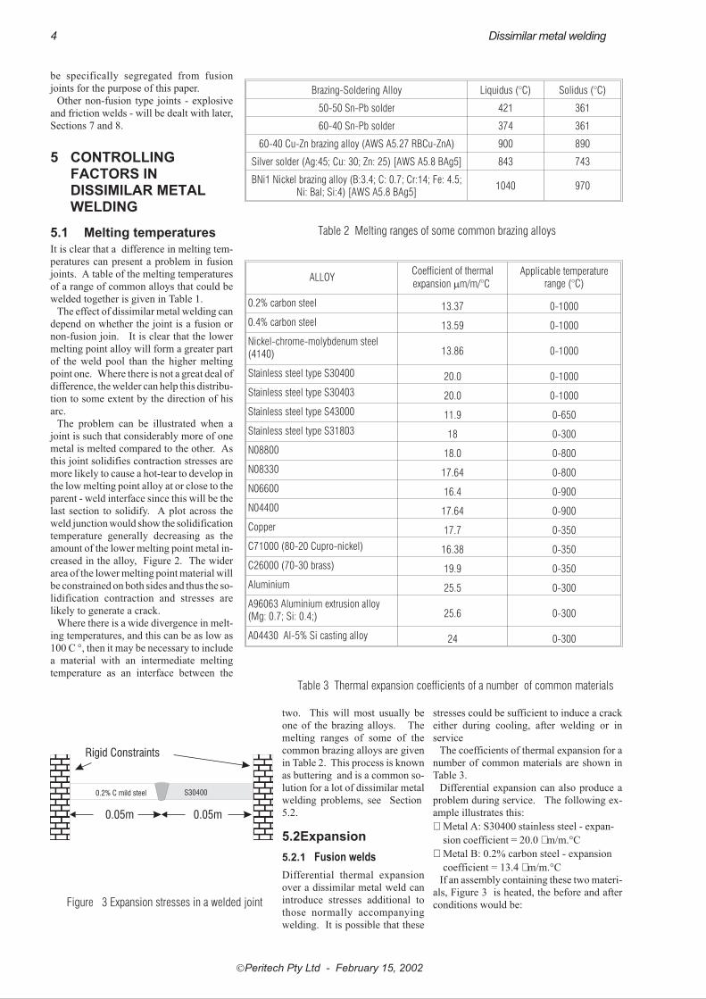
Figure 2 Variation in melting point in aweld with a wide variation in component
melting points
be specifically segregated from fusion
joints for the purpose of this paper.
Other non-fusion type joints - explosive
and friction welds - will be dealt with later,
Sections 7 and 8.
5 CONTROLLINGFACTORS INDISSIMILAR METALWELDING
5.1 Melting temperatures
It is clear that a difference in melting tem-
peratures can present a problem in fusion
joints. A table of the melting temperatures
of a range of common alloys that could be
welded together is given in Table 1.
The effect of dissimilar metal welding can
depend on whether the joint is a fusion or
non-fusion join. It is clear that the lower
melting point alloy will form a greater part
of the weld pool than the higher melting
point one. Where there is not a great deal of
difference, the welder can help this distribu-
tion to some extent by the direction of his
arc.
The problem can be illustrated when a
joint is such that considerably more of one
metal is melted compared to the other. As
this joint solidifies contraction stresses are
more likely to cause a hot-tear to develop in
the low melting point alloy at or close to the
parent - weld interface since this will be the
last section to solidify. A plot across the
weld junction would show the solidification
temperature generally decreasing as the
amount of the lower melting point metal in-
creased in the alloy, Figure 2. The wider
area of the lower melting point material will
be constrained on both sides and thus the so-
lidification contraction and stresses are
likely to generate a crack.
Where there is a wide divergence in melt-
ing temperatures, and this can be as low as
100 C °, then it may be necessary to include
a material with an intermediate melting
temperature as an interface between the
two. This will most usually be
one of the brazing alloys. The
melting ranges of some of the
common brazing alloys are given
in Table 2. This process is known
as buttering and is a common so-
lution for a lot of dissimilar metal
welding problems, see Section
5.2.
5.2Expansion
5.2.1 Fusion welds
Differential thermal expansion
over a dissimilar metal weld can
introduce stresses additional to
those normally accompanying
welding. It is possible that these
stresses could be sufficient to induce a crack
either during cooling, after welding or in
service
The coefficients of thermal expansion for a
number of common materials are shown in
Table 3.
Differential expansion can also produce a
problem during service. The following ex-
ample illustrates this:
� Metal A: S30400 stainless steel - expan-
sion coefficient = 20.0 � m/m.°C
� Metal B: 0.2% carbon steel - expansion
coefficient = 13.4 � m/m.°C
If an assembly containing these two materi-
als, Figure 3 is heated, the before and after
conditions would be:
�Peritech Pty Ltd - February 15, 2002
4 Dissimilar metal welding
Brazing-Soldering Alloy Liquidus (°C) Solidus (°C)
50-50 Sn-Pb solder 421 361
60-40 Sn-Pb solder 374 361
60-40 Cu-Zn brazing alloy (AWS A5.27 RBCu-ZnA) 900 890
Silver solder (Ag:45; Cu: 30; Zn: 25) [AWS A5.8 BAg5] 843 743
BNi1 Nickel brazing alloy (B:3.4; C: 0.7; Cr:14; Fe: 4.5;Ni: Bal; Si:4) [AWS A5.8 BAg5]
1040 970
Table 2 Melting ranges of some common brazing alloys
ALLOYCoefficient of thermal
expansion �m/m/°C
Applicable temperaturerange (°C)
0.2% carbon steel 13.37 0-1000
0.4% carbon steel 13.59 0-1000
Nickel-chrome-molybdenum steel(4140) 13.86 0-1000
Stainless steel type S30400 20.0 0-1000
Stainless steel type S30403 20.0 0-1000
Stainless steel type S43000 11.9 0-650
Stainless steel type S31803 18 0-300
N08800 18.0 0-800
N08330 17.64 0-800
N06600 16.4 0-900
N04400 17.64 0-900
Copper 17.7 0-350
C71000 (80-20 Cupro-nickel) 16.38 0-350
C26000 (70-30 brass) 19.9 0-350
Aluminium 25.5 0-300
A96063 Aluminium extrusion alloy(Mg: 0.7; Si: 0.4;) 25.6 0-300
A04430 Al-5% Si casting alloy 24 0-300
Table 3 Thermal expansion coefficients of a number of common materials
0.05m 0.05m
Rigid Constraints
0.2% C mild steel S30400
Figure 3 Expansion stresses in a welded joint

Metal A: .......cold length = 0.05m.....................hot length = 0.05050m1
.....................expansion = 0.00050mMetal B: ........cold length = 0.05 m.....................hot length = 0.05033 m.....................expansion = 0.00033m
This will mean that there will be a com-
pressive internal stress, �� induced in the
component. This can be calculated from the
expansion, ie strain, and the elastic modu-
lus, E, as:
� = E x strain
It is possible to consider the difference in
strain on either side of the weld, assuming
the weld to be a ‘fixed’ point
The strain in the mild steel component
will be:
� MS =211.9 x 0.00033= 69 MPa
and in the stainless steel it will be
� SS = 215.3 x 0.00050= 107 MPa
It must be appreciated that there have been
several approximations in these calcula-
tions, not the least being the temperature
distribution selected. The main point to be
made is that there will be expansion, it will
be different to that expected with homoge-
neous welds and it will generate internal
stressing, distortion or both.
Stress analysis of joints between the
chrome-molybdenum steels used in steam
service and either S30400 or S31600 aus-
tenitic stainless steels shows that the ther-
mal expansion stresses occurring across the
joint are nearly double that caused by the
operating pressure.2
Where this stress produces a fluctuating
load—as it would in a thermal
cycling situation—it is possi-
ble that fatigue loading could
occur. The welding of boiler
tubes to minimise in cost by
using the higher alloyed stain-
less steels only where these are
necessary has led to failures
that can be related in part to the
differential expansion from
dissimilar metal welds3.
It is for this reason that the
operating stress on dissimilar
metal weld joints between
stainless and carbon steels
should be kept at a minimum.
To avoid undue stressing the
weld metal should, if possible,
have an expansion coefficient
intermediate between the two
parent alloys, ie providing a
buttering layer, Figure 4 . If
this path is chosen, the high
nickel alloys, N08800 or
N08330 are likely materials
for the buttering layer.
A table of expansion coefficients for some
common structural materials is given in Ta-
ble 3
Thermal expansion can be altered by al-
loying. Nickel is a particularly interesting
�Peritech Pty Ltd - February 15, 2002
Dissimilar metal welding 5
Carbon orlow alloy steel
‘Buttering’ layerwelded on
Buttered layerprepared forwelding
Second metal setup for welding
Completed weld
Figure 4 Buttering with an intermediate expansion co-efficient alloy
NOTEBOOK
Variation in the expansion coefficients of the
components of a dissimilar weld cannot only
produce distortion in the weld but, more par-
ticularly, can initiate fatigue failure in compo-
nents subjected to thermal cycling.
If the component is likely to have to accommo-
date this type of service stressing then it may be
necessary to provide an intermediate, buttering,
layer with an expansion coefficient midway be-
tween each of the parent metals.
ALLOY
Coefficient ofthermal
conductivityW/mK
At100°C
At500°C
0.2% carbon steel 51.1 39.1
0.4% carbon steel 50.7 37.9
Nickel-chrome-molybdenum steel (4140) 42.7 36.4
Stainless steel typeS30400 16.3 21.5
Stainless steel typeS30403 16.3 21.5
Stainless steel typeS43000
24.9 28.8
Stainless steel typeS31803 15
18(300°C)
N08800 13.0 19.5
N06600 15.9 22.1
N04400 21.7 29.3
Copper 387.6375.5
(300°C)
C71000 (80-20Cupro-nickel) 36 - - -
C26000 (70-30 brass) 121147
(200°C)
Aluminium 239 - - -
A96063 Aluminiumextrusion alloy (Mg: 0.7;
Si: 0.4;) Annealed218 - - -
A04430 Al-5% Si castingalloy 159 - - -
Table 4 Thermal conductivity coefficientsfor a number of common materials
NOTEBOOK
Thermal conductivity variations in the components of a dissimilar weld can give
problems with over-heating one component and/or under-heating the other.
Directing the arc to the lower conductivity component may assist to minimise this
problem.
1 To calculate expansion: L1 = L0(1 + �t) where � is the coefficient of thermal expansion and t is the temperature rise. Assuming anaverage temperature rise over the 5 cm of 500°C, L1=5(1+20.0*10-6
*500)) = 5.05 cm2 American Welding Society Welding Handbook 7th Ed Vol 4, Chapter 12 Dissimilar Metal Welding p523 (1982)3 Avery R E Pay attention to dissimilar welds - Guidelines for welding dissimilar metals Chemical Engineering Progress May 1991.
Reprinted as NiDI publication 14018
example since alloying with copper in-
creases its thermal expansion but iron, chro-
mium and molybdenum will reduce the
expansion coefficient
5.2.2 Brazing
When dissimilar metals with differing ex-
pansion coefficients are brazed, the clear-
ance required for correct capillary action
during brazing must be calculated. For ex-
ample if a tube with a high thermal expan-
sion is a press fit at room temperature
around another with low thermal expan-
sion, it is probable that the clearance at the
brazing temperature will be too much to
permit the correct capillary action. If the re-
verse arrangement of tubing is used, the
clearance will be too small.
If two solid components of differing ex-
pansion coefficients are being brazed, the
brazing alloy should have an intermediate
brazing coefficient.
5.3 Thermal conductivity
The effect of thermal conductivity variation
is similar to both melting point and thermal
expansion problems. The problems arise
when one half of a joint has a markedly dif-
ferent coefficient of thermal conductivity
compared to the other. Directing the weld-
ing heat source can qualitatively allow for
this, preheating the high conductivity
metal can also assist this.
Thermal conductivity changes with tem-
perature. A tabulation of some metallic
thermal conductivities with the applicable
temperature range are given in Table 4 .
It is interesting to note that conductivity
increases with increasing temperature for
some metals, eg UNS S30400, but de-
creases with others, eg carbon and low al-
loy steels.
Components where distortion is critical
may require procedures to counteract the
effect of a thermal conductivity that could
cause problems. This may require heat in-
put on some occasions - or extraction on
others.
5.4 Pre- and post-heating
If pre-heating or post-heating is required
on one half of a joint for metallurgical rea-
sons, this must also be the case for the
whole of a dissimilar metal joint containing
that alloy.
Pre-heating is frequently important for
higher carbon and/or restrained plain car-
bon steels to prevent post-weld cracking.
This will not present a serious problem with
most dissimilar metal joints although in
some cases where pre-assembly or jigging
is required, there may be some handling
difficulties.
Post-weld heating is not as simple. It is
conceivable for example that a carbon steel
welded to a UNS S30400 stainless steel
may accentuate the possibility of sensitisa-
tion corrosion due to the combination of
welding heat input plus the post weld heat-
ing. Sensitisation is the decrease in aqueous
corrosion resistance due to carbide precipi-
tation.
Heat treatment can be considered as a post
weld heating operation.. If one side is to be
heat treated by, say ageing, then the effect
on the other side must be considered, eg two
different age hardening alloys may have
different ageing treatments. Clearly other
types of heat treatment could cause con-
cern.
5.5 Choice of WeldingProcess
The main points that must be considered
when selecting the basic process for com-
pleting a dissimilar metal weld is a need for
precision location of the arc to permit dif-
ferential heat transfer between either side of
the weld.
Other factors relating to pre-heat,
post-weld heat treatment, shielding gases
etc depend on the most sensitive side of the
weld, eg in welding a hardenable carbon
steel to an austenitic stainless steel, a
pre-heat must be given to ensure there is
control over martensite formation in the
weld pool and the heat affected zone of the
carbon steel.
As mentioned above, the effect a necessary
treatment on one side of the weld would have
on the other side - or the weld pool - must
always be considered.
5.6 Weld pool properties
5.6.1 Metal mixing
Metal mixing is essentially a mechanical pro-
cess and for any mixing to occur, the metals
must be wetted by the filler metal. This could
require specialised fluxes.
The normal considerations in mixing that
apply to all welding operations will also ap-
ply to dissimilar metal joints.
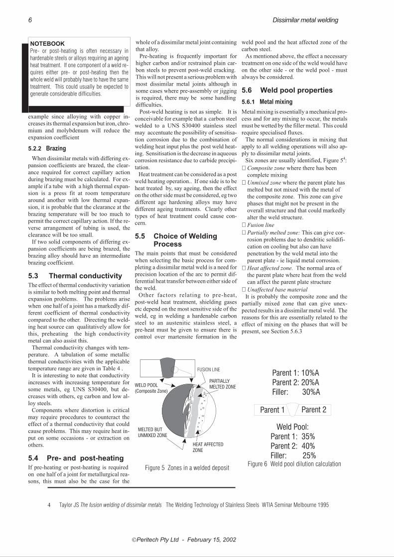
Six zones are usually identified, Figure 54:
� Composite zone where there has been
complete mixing
� Unmixed zone where the parent plate has
melted but not mixed with the metal of
the composite zone. This zone can give
phases that might not be present in the
overall structure and that could markedly
alter the weld structure.
� Fusion line
� Partially melted zone: This can give cor-
rosion problems due to dendritic solidifi-
cation on cooling but also can have
penetration by the weld metal into the
parent plate - ie liquid metal corrosion.
� Heat affected zone. The normal area of
the parent plate where heat from the weld
can affect the parent plate structure
� Unaffected base material
It is probably the composite zone and the
partially mixed zone that can give unex-
pected results in a dissimilar metal weld. The
reasons for this are essentially related to the
effect of mixing on the phases that will be
present, see Section 5.6.3
�Peritech Pty Ltd - February 15, 2002
6 Dissimilar metal welding
NOTEBOOK
Pre- or post-heating is often necessary in
hardenable steels or alloys requiring an ageing
heat treatment. If one component of a weld re-
quires either pre- or post-heating then the
whole weld will probably have to have the same
treatment. This could usually be expected to
generate considerable difficulties.
WELD POOL(Composite Zone)
MELTED BUTUNMIXED ZONE
HEAT AFFECTEDZONE
PARTIALLYMELTED ZONE
FUSION LINE
Figure 5 Zones in a welded deposit
Parent 1: 10%AParent 2: 20%AFiller: 30%A
Parent 1 Parent 2
Weld Pool:Parent 1: 35%Parent 2: 40%Filler: 25%
Figure 6 Weld pool dilution calculation
4 Taylor JS The fusion welding of dissimilar metals The Welding Technology of Stainless Steels WTIA Seminar Melbourne 1995
5.6.2 Dilution calculation
The basic concept behind calculation of
weld pool composition relies on the lever
rule so familiar to metallurgical calcula-
tions.
If it is assumed, as a simple situation, that
a weld pool between two dissimilar metals,
A and B, contains half of metal A and half
of metal B then the composition of the pool
must be an equal mixture of each alloy.
In the case of a three component system, it
will be remembered that the composition of
the weld pool will depend on the ratio of
each metal. On the phase diagram the three
alloy lever rule is used for graphical calcu-
lation of the weld pool composition.
Referring again to a binary alloy. If it con-
tains one quarter of metal A and three quar-
ters of metal B, the composition must
reflect this.
If there is a third alloy introduced as a
filler material then the composition of the
weld pool will be controlled by the amount
of filler present. As an example of this, the
effect of the ratio of parent metals and filler
metal for a mild steel/UNS S30400 weld
with and without S30900 filler is shown in
Table 6.
For example, assume that each compo-
nent has the following composition of metal
A.
Parent 1: 10%
Parent 2: 20%
Filler wire: 30%
Also assume that the weld pool contains
the following proportion of each compo-
nent, (See Figure 6):
Parent 1: 35%
Parent 2: 40%
Filler wire: 25%
The amount of metal A in the weld pool
will therefore be:
(0.35 x 10%)+(0.4*x 20%)+
(0.25 x 30%)=19%
This calculation assumes the unlikely
situation that there has been no loss by oxi-
dation during welding. If necessary, an es-
timated correction could be made for this.
All of the above assumed relatively sim-
ple ratios of each of the contributing materi-
als. There are a number of factors that will
affect these proportions:
� Thin materials: The low heat input re-
quired to melt for thin materials to-
gether with the low cross sectional area
to conduct heat away will be expected
to generate a higher proportion of these
in the weld pool.
� Location relative to the weld face: The
closer the weld run is to the parent
metal face, the greater will be the con-
tamination from the parent. Root runs
will have the most contamination.
� Weld run placement: Placing a second
run on top, rather than between previ-
ous runs should produce less contami-
nation from underlying runs.
� Penetration: Factors that would nor-
mally be expected to give more penetra-
tion can be expected to give more
dilution, eg GTAW, higher current,
slower travel rate.
5.6.3 Microstucture determination
When metals are
mixed, they will ei-
ther mutually dis-
solve in each other,
form a mixture of
phases or appear as
a mechanical mix-
ture of the two met-
als with virtually no
mutual solubility.
The structure after
‘mixing’ will de-
pend on the actual
zone in the weld,
Figure 5. These
considerations are
illustrated in the
phase diagrams for
three systems:
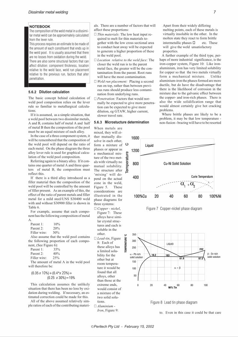
� Copper - nickel,
Figure 7: These
alloys have simi-
lar crystal struc-
tures and each is
soluble in the
other.
� Lead-tin, Figure
8: Each of
these alloys has
a limited solu-
bility for the
other but at
room tempera-
ture it would be
found that all
alloys, other
than those at the
extreme ends,
would consist of
a mixture of the
two solid solu-
tions.
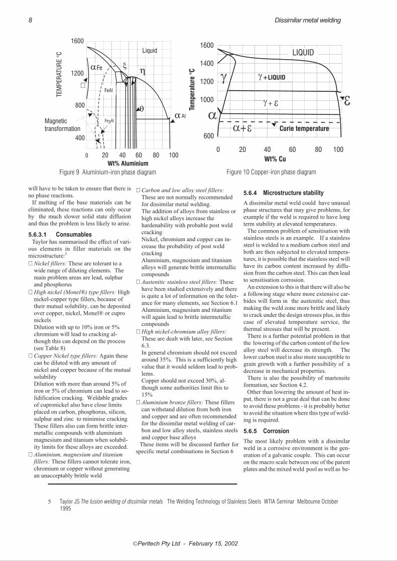
� Aluminium -
Iron, Figure 9:
Apart from their widely differing
melting points, each of these metals is
virtually insoluble in the other. In the
molten state they react to form brittle
intermetallic phases ������ etc. These
will give the weld unsatisfactory
properties.
A further example of the third type, per-
haps of more industrial significance, is the
iron-copper system, Figure 10: Like iron-
aluminium, iron has very limited solubility
for copper so that the two metals virtually
form a mechanical mixture. Unlike
aluminium-iron the phases formed are more
ductile, but do have the disadvantage that
there is the likelihood of corrosion in the
mixture due to the galvanic effect between
the copper- and iron-rich phases. There is
also the wide solidification range that
would almost certainly give hot cracking
problems.
Where brittle phases are likely to be a
problem, it may be that low temperature -
non-fusion - brazing will have to be resorted
to. Even in this case it could be that care
�Peritech Pty Ltd - February 15, 2002
Dissimilar metal welding 7
NOTEBOOK
The composition of the weld metal in a dissimi-
lar metal weld can be approximately calculated
from the lever rule.
This process requires an estimate to be made of
the amount of each constituent that ends up in
the weld pool. It is usually assumed that there
are no losses from oxidation during the weld.
There are also some structural factors that can
affect dilution: component thickness, location
relative to the weld face, weld run placement
relative to the previous run, factors that alter
penetration.
Figure 7 Copper-nickel phase diagram
Figure 8 Lead tin phase diagram
will have to be taken to ensure that there is
no phase reactions.
If melting of the base materials can be
eliminated, these reactions can only occur
by the much slower solid state diffusion
and thus the problem is less likely to arise.
5.6.3.1 ConsumablesTaylor has summarised the effect of vari-
ous elements in filler materials on the
microstructure:5
� Nickel fillers: These are tolerant to a
wide range of diluting elements. The
main problem areas are lead, sulphur
and phosphorus
� High nickel (Monel®) type fillers: High
nickel-copper type fillers, because of
their mutual solubility, can be deposited
over copper, nickel, Monel® or cupro
nickels
Dilution with up to 10% iron or 5%
chromium will lead to cracking al-
though this can depend on the process
(see Table 8)
� Copper Nickel type fillers: Again these
can be diluted with any amount of
nickel and copper because of the mutual
solubility
Dilution with more than around 5% of
iron or 5% of chromium can lead to so-
lidification cracking. Weldable grades
of cupronickel also have close limits
placed on carbon, phosphorus, silicon,
sulphur and zinc to minimise cracking
These fillers also can form brittle inter-
metallic compounds with aluminium
magnesium and titanium when solubil-
ity limits for these alloys are exceeded.
� Aluminium, magnesium and titanium
fillers: These fillers cannot tolerate iron,
chromium or copper without generating
an unacceptably brittle weld
� Carbon and low alloy steel fillers:
These are not normally recommended
for dissimilar metal welding.
The addition of alloys from stainless or
high nickel alloys increase the
hardenability with probable post weld
cracking
Nickel, chromium and copper can in-
crease the probability of post weld
cracking
Aluminium, magnesium and titanium
alloys will generate brittle intermetallic
compounds
� Austenitic stainless steel fillers: These
have been studied extensively and there
is quite a lot of information on the toler-
ance for many elements, see Section 6.1
Aluminium, magnesium and titanium
will again lead to brittle intermetallic
compounds
� High nickel-chromium alloy fillers:
These are dealt with later, see Section
6.3.
In general chromium should not exceed
around 35%. This is a sufficiently high
value that it would seldom lead to prob-
lems.
Copper should not exceed 30%, al-
though some authorities limit this to
15%
� Aluminium bronze fillers: These fillers
can withstand dilution from both iron
and copper and are often recommended
for the dissimilar metal welding of car-
bon and low alloy steels, stainless steels
and copper base alloys
These items will be discussed further for
specific metal combinations in Section 6
5.6.4 Microstructure stability
A dissimilar metal weld could have unusual
phase structures that may give problems, for
example if the weld is required to have long
term stability at elevated temperatures.
The common problem of sensitisation with
stainless steels is an example. If a stainless
steel is welded to a medium carbon steel and
both are then subjected to elevated tempera-
tures, it is possible that the stainless steel will
have its carbon content increased by diffu-
sion from the carbon steel. This can then lead
to sensitisation corrosion.
An extension to this is that there will also be
a following stage where more extensive car-
bides will form in the austenitic steel, thus
making the weld zone more brittle and likely
to crack under the design stresses plus, in this
case of elevated temperature service, the
thermal stresses that will be present.
There is a further potential problem in that
the lowering of the carbon content of the low
alloy steel will decrease its strength. The
lower carbon steel is also more susceptible to
grain growth with a further possibility of a
decrease in mechanical properties.
There is also the possibility of martensite
formation, see Section 4.2.
Other than lowering the amount of heat in-
put, there is not a great deal that can be done
to avoid these problems - it is probably better
to avoid the situation where this type of weld-
ing is required.
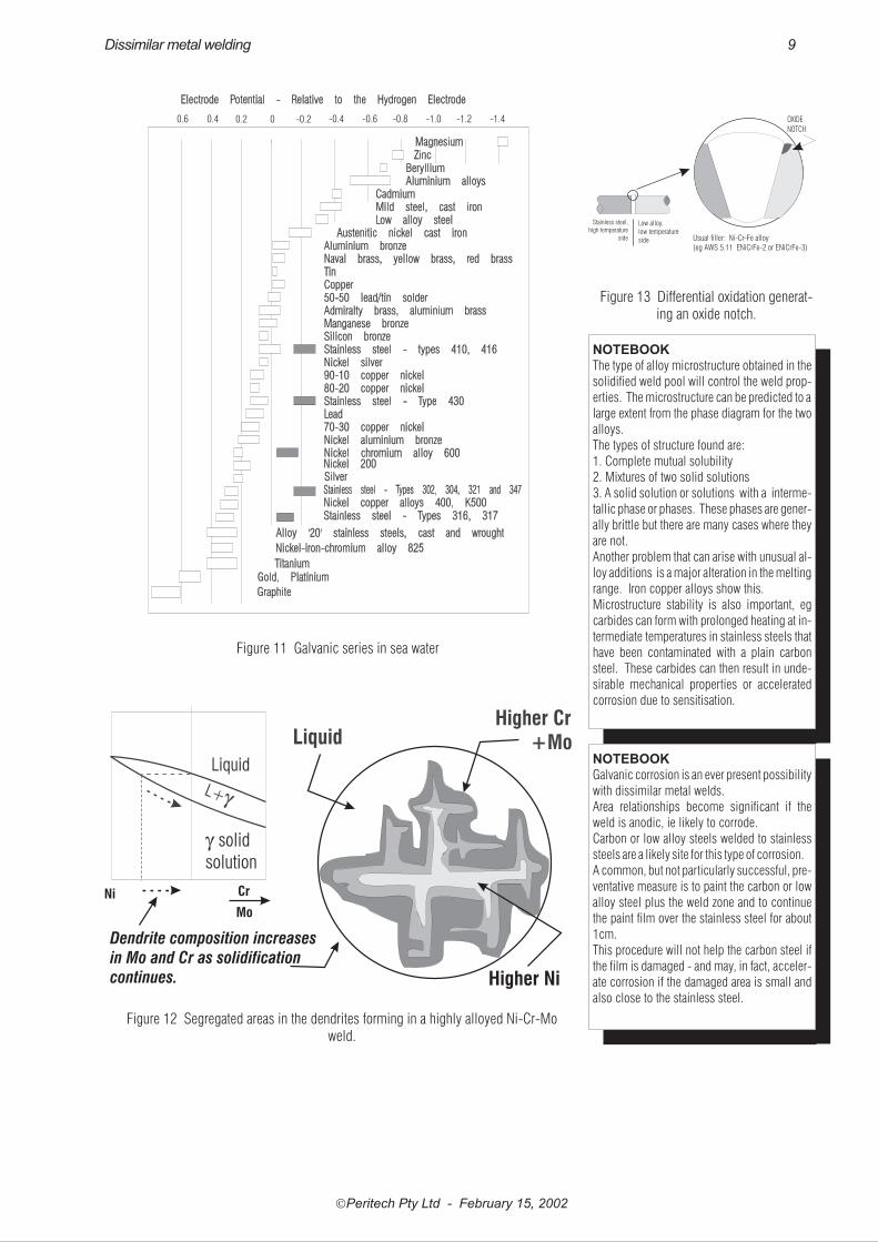
5.6.5 Corrosion
The most likely problem with a dissimilar
weld in a corrosive environment is the gen-
eration of a galvanic couple. This can occur
on the macro scale between one of the parent
plates and the mixed weld pool as well as be-
�Peritech Pty Ltd - February 15, 2002
8 Dissimilar metal welding
Liquid
Fe3AlMagnetictransformation
Wt% Aluminium
0 20 40 60 80 100
1600
1200
800
400
TEM
PER
ATU
RE
°C
Fe
FeAl
Al
Figure 9 Aluminium-iron phase diagram
LIQUID
+LIQUID
+
+
0 20 40 60 80 100
Wt% Cu
Tem
per
atu
re°C
1600
1400
1200
1000
600Curie temperature
Figure 10 Copper-iron phase diagram
5 Taylor JS The fusion welding of dissimilar metals The Welding Technology of Stainless Steels WTIA Seminar Melbourne October1995
�Peritech Pty Ltd - February 15, 2002
Dissimilar metal welding 9
0.2 0 -0.2 -0.4 -0.6 -0.8 -1.0 -1.2 -1.40.40.6
Figure 11 Galvanic series in sea water
Ni
Mo
Cr
Dendrite composition increases
in Mo and Cr as solidification
continues.
Liquid
Higher Ni
Higher Cr+Mo
Figure 12 Segregated areas in the dendrites forming in a highly alloyed Ni-Cr-Moweld.
Stainless steel,
high temperature
side
Low alloy,
low temperature
side
OXIDE
NOTCH
Usual filler: Ni-Cr-Fe alloy
(eg AWS 5.11 ENiCrFe-2 or ENiCrFe-3)
Figure 13 Differential oxidation generat-ing an oxide notch.
NOTEBOOK
The type of alloy microstructure obtained in the
solidified weld pool will control the weld prop-
erties. The microstructure can be predicted to a
large extent from the phase diagram for the two
alloys.
The types of structure found are:
1. Complete mutual solubility
2. Mixtures of two solid solutions
3. A solid solution or solutions with a interme-
tallic phase or phases. These phases are gener-
ally brittle but there are many cases where they
are not.
Another problem that can arise with unusual al-
loy additions is a major alteration in the melting
range. Iron copper alloys show this.
Microstructure stability is also important, eg
carbides can form with prolonged heating at in-
termediate temperatures in stainless steels that
have been contaminated with a plain carbon
steel. These carbides can then result in unde-
sirable mechanical properties or accelerated
corrosion due to sensitisation.
NOTEBOOK
Galvanic corrosion is an ever present possibility
with dissimilar metal welds.
Area relationships become significant if the
weld is anodic, ie likely to corrode.
Carbon or low alloy steels welded to stainless
steels are a likely site for this type of corrosion.
A common, but not particularly successful, pre-
ventative measure is to paint the carbon or low
alloy steel plus the weld zone and to continue
the paint film over the stainless steel for about
1cm.
This procedure will not help the carbon steel if
the film is damaged - and may, in fact, acceler-
ate corrosion if the damaged area is small and
also close to the stainless steel.
tween the mixed weld pool and the other
parent plate.
The galvanic series, indicating which
metals are likely to corrode is shown in Fig-
ure 11. Metals higher on the chart, ie the
more electro-negative ones, will corrode
when in contact with those lower down, ie
the more electropositive ones.
There is a compounding effect in that gal-
vanic corrosion can be markedly affected
by area. If the anodic, ie corroding, half of
the couple is small in area relative to the
supporting cathodic, ie non-corroding half,
then galvanic corrosion will be markedly
accelerated.
A weld bead is usually relatively small
compared to the surrounding parent metal.
If the bead is anodic to either of the parents,
it would therefore be expected to corrode
relatively quickly. It may be that it could be
partially protected by the other parent metal
but this may be inadequate.
Where corrosion of either the weld bead or
the more anodic parent metal is a possibility,
eg in a carbon steel - stainless steel weld, one
solution commonly used is to paint over the
carbon steel and the weld, extending the
paint film about 1cm over the stainless
steel. This is done in the hope that mois-
ture will be excluded from the interface and
thus eliminate the corrosion problem.
The area relationship can sometimes be
an advantage, ie if the anodic area is large
compared to the cathodic area then the gal-
vanic effect can virtually be ignored. This
point can be illustrated with fasteners. It is
not unusual to employ stainless steel fas-
teners to fix aluminium sheeting. The
large aluminium area is well able to sup-
port the galvanic action of the smaller
stainless steel fastener area without any
deleterious effect.
Galvanic corrosion can also occur on the
micro scale between different phases in the
weld metal or, more usually, in segregated
areas within the weld pool. Highly alloyed
welds, particularly those involved with the
nickel-chrome-molybdenum corrosion re-
sistant alloys, can exhibit molybdenum
segregation in the weld dendrites, Figure
12.
Apart from the general dissolution aspect
of galvanic corrosion, there is the secon-
dary effect of hydrogen evolution at the
cathodic half of the galvanic cell. If this
cathode happens to be a high strength steel
�Peritech Pty Ltd - February 15, 2002
10 Dissimilar metal welding
Austenite
Martensite
FerriteF+M
A+FA+M
Austenitic alloys
Duplex Alloys
M+F
Martensitic
Alloys
Ferritic alloys
A+M+F
10%
80%
20%
40%
100%
5%
0 4 8 12 16 20 24 28 32 36 40
28
24
20
16
12
32
8
4
0Nic
kelE
quiv
alen
t:%
Ni +
30x%
C+
0.5%
Mn
Chromium Equivalent: %Cr + %Mo + 1.5x%Si + 0.5x%Nb
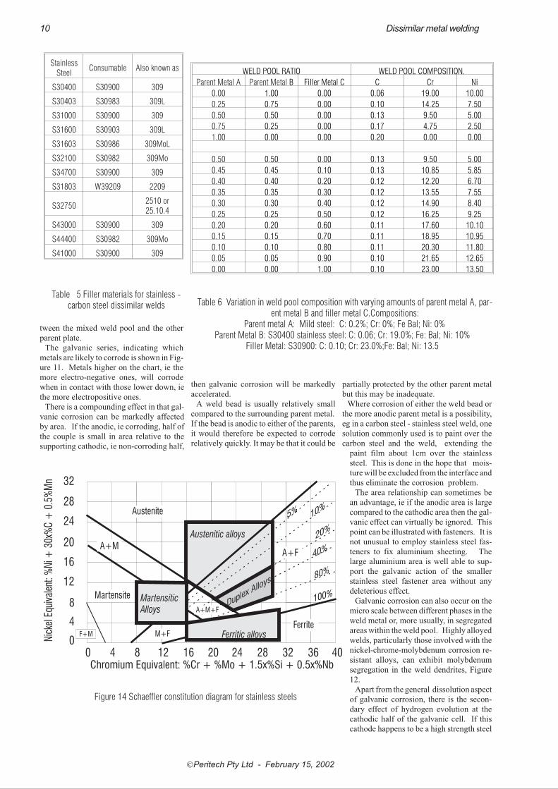
Figure 14 Schaeffler constitution diagram for stainless steels
StainlessSteel
Consumable Also known as
S30400 S30900 309
S30403 S30983 309L
S31000 S30900 309
S31600 S30903 309L
S31603 S30986 309MoL
S32100 S30982 309Mo
S34700 S30900 309
S31803 W39209 2209
S327502510 or25.10.4
S43000 S30900 309
S44400 S30982 309Mo
S41000 S30900 309
Table 5 Filler materials for stainless -carbon steel dissimilar welds
WELD POOL RATIO WELD POOL COMPOSITION.
Parent Metal A Parent Metal B Filler Metal C C Cr Ni
0.00 1.00 0.00 0.06 19.00 10.00
0.25 0.75 0.00 0.10 14.25 7.50
0.50 0.50 0.00 0.13 9.50 5.00
0.75 0.25 0.00 0.17 4.75 2.50
1.00 0.00 0.00 0.20 0.00 0.00
0.50 0.50 0.00 0.13 9.50 5.00
0.45 0.45 0.10 0.13 10.85 5.85
0.40 0.40 0.20 0.12 12.20 6.70
0.35 0.35 0.30 0.12 13.55 7.55
0.30 0.30 0.40 0.12 14.90 8.40
0.25 0.25 0.50 0.12 16.25 9.25
0.20 0.20 0.60 0.11 17.60 10.10
0.15 0.15 0.70 0.11 18.95 10.95
0.10 0.10 0.80 0.11 20.30 11.80
0.05 0.05 0.90 0.10 21.65 12.65
0.00 0.00 1.00 0.10 23.00 13.50
Table 6 Variation in weld pool composition with varying amounts of parent metal A, par-ent metal B and filler metal C.Compositions:
Parent metal A: Mild steel: C: 0.2%; Cr: 0%; Fe Bal; Ni: 0%Parent Metal B: S30400 stainless steel: C: 0.06; Cr: 19.0%; Fe: Bal; Ni: 10%
Filler Metal: S30900: C: 0.10; Cr: 23.0%;Fe: Bal; Ni: 13.5

then there is a strong possibility that this hy-
drogen will be absorbed into the lattice gen-
erating conditions where hydrogen
embrittlement may result.
High temperature oxidation can also oc-
cur at the junction between dissimilar met-
als with oxidation occurring preferentially
in one of the metals right at the interface.
This will generate an oxide ‘notch’, Figure
13, that will act as a stress concentrator
5.6.6 Magnetic effects on dilution
The effect of the magnetic characteristics
of metals on welds is well known . Where
only one of the metals is magnetic, a DC arc
can be deflected towards that metal with ex-
cess melting of that half of the joint. This
can occur when welding carbon steels to
nickel alloys or austenitic stainless steels. It
can be minimised by operator action or
overcome by using an AC arc
6 JOINT DESIGN
The major considerations with dissimilar
metals are related to correct filler material
and eventual joint serviceability, However,
because many dissimilar metal welds are
associated with one of the stainless steels, it
is recommended that reference be made to
AS 1554.6 for indications of appropriate
physical joint designs
6.1 Austenitic stainlesssteel - carbon steel
The choice of consumable with these alloys
is largely related to the effect of contamina-
tion of the weld pool by the carbon steel.
6.1.1 Low temperature applications:
For low to moderate temperature service it
is usual to use a stainless steel filler. Pre-
qualified fillers are listed for most stainless
steels in AS 1554.6 (p45) with 309 type
stainless steel being the most common. A
listing of the grades suggested for some of
the more common steels adapted from this
Standard is given in Table 5 .
Consumable selection can be understood
by reference to the Scaeffler DeLong dia-
gram, Figure 14
It is possible to predict the type of alloy
that will be obtained in the weld pool by re-
lating these to the approximate ranges of the
particular alloy groups superimposed on
this diagram.
For example, Figure 15 shows what type
of alloy would be expected in a weld pool
with equal amounts of S30400 and mild
steel present in the pool, a condition that
would be expected in an autogenous weld. .
This condition would not usually be ac-
ceptable since it can be seen that a marten-
sitic structure with its attendant undesirable
properties would occur.
If a higher alloyed consumable, such as
UNS S30900, were used and it was as-
sumed that it would form 1/3 of the weld
pool then the final structure would be as
shown in Figure 16.
These conditions are also demonstrated in
Table 6 where it can be seen that the compo-
sition of the weld pool approaches a satis-
factory combination with progressively
higher proportions of the higher alloyed
consumable - alloy “C” in this table.
The Schaefller diagram does not accu-
rately display the ‘real’ situation since it
deals only with the room temperature result.
The solidification pattern is considerably
different.
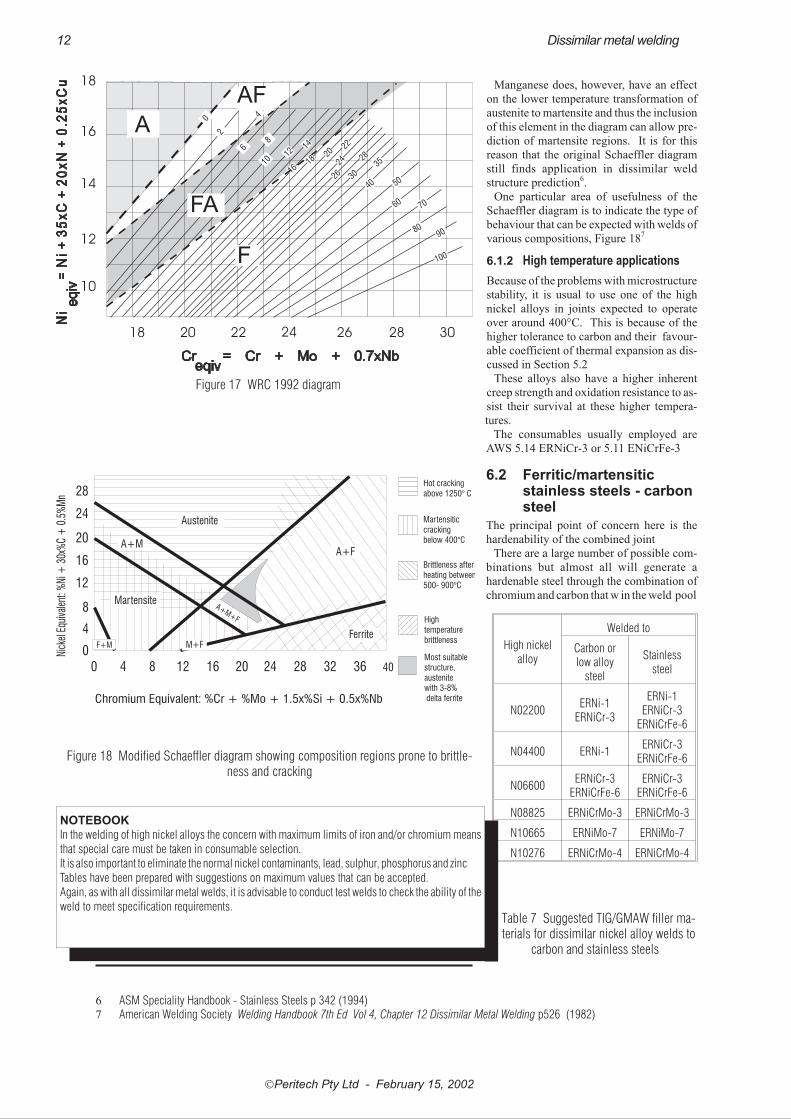
There have been a series of modifications
to the Schaeffler diagram to allow for this
with the WRC 1992 diagram, Figure 17 ,
being the most recent.
This diagram does not include manganese
as an alloying addition and as such is unable
to predict the possibility of martensite for-
mation. Manganese has little effect on the
high temperature formation of ferrite or its
transformation to austenite and therefore is
of little significance in the fundamental use
of the WRC diagram, ie the prediction of
room temperature ferrite.
�Peritech Pty Ltd - February 15, 2002
Dissimilar metal welding 11
NOTEBOOK
The Schaeffler diagram was an attempt to de-
scribe the solidification of stainless steel in or-
der to calculate the composition that would give
the required amount of ferrite in the solidifying
weld pool to inhibit hot cracking. In effect it,
and the subsequent De Long modification, de-
scribed the final structure achieved. This makes
these diagrams useful in determining what type
of consumable will be needed to give a particu-
lar microstructure in the weld pool - in particu-
lar, whether martensite will be present. The role
of predicting free ferrite has been assumed by
the WRC-1992 diagram which is more appro-
priate to the solidification stage.
Austenite
Martensite
FerriteF+M
A+FA+M
M+F
A+M+F
10%
80%
20%
40%
100%
5%
0 4 8 12 16 20 24 28 32 36 40
28
24
20
16
12
32
8
4
0Nic
kelE
quiv
alen
t:%
Ni +
30x%
C+
0.5%
Mn
Chromium Equivalent: % Cr + %Mo + 1.5x%Si + 0.5x%Nb
MS
304
Figure 15 Probable weld pool composition from a mild steel-S30400 weld with nofiller material, ie within the martensite range and hence there will be a high probability
of cracking
Austenite
Martensite
FerriteF+M
A+FA+M
M+F
A+M+F
10%
80%
20%
40%
100%
5%
0 4 8 12 16 20 24 28 32 36 40
28
24
20
16
12
32
8
4
0Nic
kelE
quiv
alen
t:%
Ni +
30x%
C+
0.5%
Mn
Chromium Equivalent: % Cr + %Mo + 1.5x%Si + 0.5x%Nb
MS
304
309
Figure 16 Probable weld pool composition from a mild steel-S30400 weld with nofiller material. In this case the structure is within the austenite range so that cracking is
improbable
Manganese does, however, have an effect
on the lower temperature transformation of
austenite to martensite and thus the inclusion
of this element in the diagram can allow pre-
diction of martensite regions. It is for this
reason that the original Schaeffler diagram
still finds application in dissimilar weld
structure prediction6.
One particular area of usefulness of the
Schaeffler diagram is to indicate the type of
behaviour that can be expected with welds of
various compositions, Figure 187
6.1.2 High temperature applications
Because of the problems with microstructure
stability, it is usual to use one of the high
nickel alloys in joints expected to operate
over around 400°C. This is because of the
higher tolerance to carbon and their favour-
able coefficient of thermal expansion as dis-
cussed in Section 5.2
These alloys also have a higher inherent
creep strength and oxidation resistance to as-
sist their survival at these higher tempera-
tures.
The consumables usually employed are
AWS 5.14 ERNiCr-3 or 5.11 ENiCrFe-3
6.2 Ferritic/martensiticstainless steels - carbonsteel
The principal point of concern here is the
hardenability of the combined joint
There are a large number of possible com-
binations but almost all will generate a
hardenable steel through the combination of
chromium and carbon that w in the weld pool
�Peritech Pty Ltd - February 15, 2002
12 Dissimilar metal welding
NOTEBOOK
In the welding of high nickel alloys the concern with maximum limits of iron and/or chromium means
that special care must be taken in consumable selection.
It is also important to eliminate the normal nickel contaminants, lead, sulphur, phosphorus and zinc
Tables have been prepared with suggestions on maximum values that can be accepted.
Again, as with all dissimilar metal welds, it is advisable to conduct test welds to check the ability of the
weld to meet specification requirements.
High nickelalloy
Welded to
Carbon orlow alloy
steel
Stainlesssteel
N02200ERNi-1
ERNiCr-3
ERNi-1ERNiCr-3
ERNiCrFe-6
N04400 ERNi-1ERNiCr-3
ERNiCrFe-6
N06600ERNiCr-3
ERNiCrFe-6ERNiCr-3
ERNiCrFe-6
N08825 ERNiCrMo-3 ERNiCrMo-3
N10665 ERNiMo-7 ERNiMo-7
N10276 ERNiCrMo-4 ERNiCrMo-4
Table 7 Suggested TIG/GMAW filler ma-terials for dissimilar nickel alloy welds to
carbon and stainless steels
18 20 22 24 26 28 30
18
16
14
12
10
0
6
2
12
84
10
14
16
F
A
AF
FA40
80
60
26
100
50
24
22
90
18
70
35
30
20 28
Figure 17 WRC 1992 diagram
Austenite
Martensite
FerriteF+M
A+FA+M
M+F
28
24
20
16
12
8
4
0Nick
elEq
uiva
lent
: %Ni
+30
x%C
+0.
5%M
n
0 4 8 12 16 20 24 28 32 36 40
Chromium Equivalent: %Cr + %Mo + 1.5x%Si + 0.5x%Nb
A+M+F
Hot crackingabove 1250° C
Martensiticcrackingbelow 400°C
Brittleness afterheating between500- 900°C
Hightemperaturebrittleness
Most suitablestructure,austenitewith 3-8%delta ferrite
Figure 18 Modified Schaeffler diagram showing composition regions prone to brittle-ness and cracking
6 ASM Speciality Handbook - Stainless Steels p 342 (1994)7 American Welding Society Welding Handbook 7th Ed Vol 4, Chapter 12 Dissimilar Metal Welding p526 (1982)
This can be minimised by using a filler
metal with the same composition as the car-
bon/low alloy steel but it is still probable
that there will be sufficient chromium
pickup from the stainless steel to give a
martensitic weld pool
If hardenability is a problem, then it may
be better to use a buttering layer of high
nickel stainless steel on both components.
Types 309 or 310 can be used . These may
then be heat treated to obtain the desired
properties. The weld can then be completed
with an austenitic alloy such as type 308
stainless steel
The following general rules have been
proposed for joining the 4xx series stainless
steels8
� For welding one hardenable chromium
steel to another with a higher chromium
content, filler material with chromium
content equal to that of either steel may
be used. Furthermore, any filler mate-
rial whose chromium content lies be-
tween these limits is equally
satisfactory provide the weldment is
properly heat treated.
� A general rule for welding any chro-
mium steel to any low alloy steel is to
use a filler metal that has the same com-
position as the low alloy steel, provided
that it meets the service requirements of
the application. With any low alloy
steel filler metal, the chromium that is
picked up by the dilution with the chro-
mium steel base metal must be consid-
ered.
� For welding any chromium steel to a
carbon steel, carbon steel filler metal
can alternatively be used, but it is pref-
erable to use a less hardenable filler
metal.
6.3 High nickel alloys
The principal problems here are associated
with contamination of the nickel alloy.
Nickel alloys are particularly sensitive to
sulphur because of a low melting point
eutectic that gives cracks and later failure in
high temperature service.
Other contaminants that must be avoided
are phosphorus, lead and zinc.
The major alloying elements can also give
problems and it is usual to use the dilution
calculations explained in Section 5.6.2 to
determine the weld pool composition and
then relate this to tabulations of generally
acceptable impurity levels such as that
shown in Table 8.
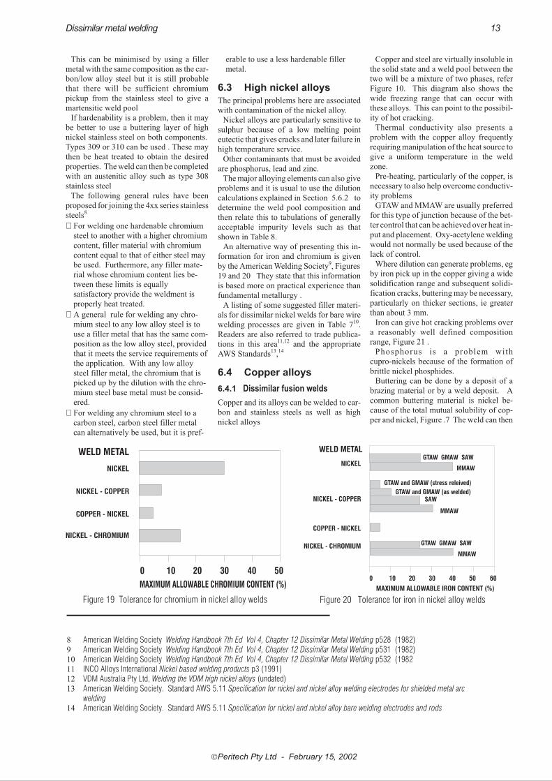
An alternative way of presenting this in-
formation for iron and chromium is given
by the American Welding Society9, Figures
19 and 20 They state that this information
is based more on practical experience than
fundamental metallurgy .
A listing of some suggested filler materi-
als for dissimilar nickel welds for bare wire
welding processes are given in Table 710.
Readers are also referred to trade publica-
tions in this area11,12 and the appropriate
AWS Standards13,14
6.4 Copper alloys
6.4.1 Dissimilar fusion welds
Copper and its alloys can be welded to car-
bon and stainless steels as well as high
nickel alloys
Copper and steel are virtually insoluble in
the solid state and a weld pool between the
two will be a mixture of two phases, refer
Figure 10. This diagram also shows the
wide freezing range that can occur with
these alloys. This can point to the possibil-
ity of hot cracking.
Thermal conductivity also presents a
problem with the copper alloy frequently
requiring manipulation of the heat source to
give a uniform temperature in the weld
zone.
Pre-heating, particularly of the copper, is
necessary to also help overcome conductiv-
ity problems
GTAW and MMAW are usually preferred
for this type of junction because of the bet-
ter control that can be achieved over heat in-
put and placement. Oxy-acetylene welding
would not normally be used because of the
lack of control.
Where dilution can generate problems, eg
by iron pick up in the copper giving a wide
solidification range and subsequent solidi-
fication cracks, buttering may be necessary,
particularly on thicker sections, ie greater
than about 3 mm.
Iron can give hot cracking problems over
a reasonably well defined composition
range, Figure 21 .
Phosphorus is a problem with
cupro-nickels because of the formation of
brittle nickel phosphides.
Buttering can be done by a deposit of a
brazing material or by a weld deposit. A
common buttering material is nickel be-
cause of the total mutual solubility of cop-
per and nickel, Figure .7 The weld can then
�Peritech Pty Ltd - February 15, 2002
Dissimilar metal welding 13
0 10 20 30 40 50
WELD METAL
NICKEL
NICKEL - COPPER
COPPER - NICKEL
NICKEL - CHROMIUM
MAXIMUM ALLOWABLE CHROMIUM CONTENT (%)
Figure 19 Tolerance for chromium in nickel alloy welds
GTAW GMAW SAW
GTAW GMAW SAW
MMAW
GTAW and GMAW (stress releived)
GTAW and GMAW (as welded)SAW
MMAW
MMAW
WELD METAL
NICKEL
NICKEL - COPPER
COPPER - NICKEL
NICKEL - CHROMIUM
0 10 20 30 40 50 60
MAXIMUM ALLOWABLE IRON CONTENT (%)
Figure 20 Tolerance for iron in nickel alloy welds
8 American Welding Society Welding Handbook 7th Ed Vol 4, Chapter 12 Dissimilar Metal Welding p528 (1982)9 American Welding Society Welding Handbook 7th Ed Vol 4, Chapter 12 Dissimilar Metal Welding p531 (1982)10 American Welding Society Welding Handbook 7th Ed Vol 4, Chapter 12 Dissimilar Metal Welding p532 (198211 INCO Alloys International Nickel based welding products p3 (1991)12 VDM Australia Pty Ltd, Welding the VDM high nickel alloys (undated)13 American Welding Society. Standard AWS 5.11 Specification for nickel and nickel alloy welding electrodes for shielded metal arc
welding14 American Welding Society. Standard AWS 5.11 Specification for nickel and nickel alloy bare welding electrodes and rods

�Peritech Pty Ltd - February 15, 2002
14 Dissimilar metal welding
FILLER GROUP
TYPICAL FILLERMATERIALS
ALLOYING ELEMENT
AWS 5.11 AWS 5.14 Fe [see Note] Ni and Cu Cr C,Si and Mn
NICKEL BASEDFILLERS
ENI-1 ERNI-1Cracking commences at
about 25-40%Fe with ERNi1being more susceptible
No limits
About 30-35%.Above this valuesigma phase can
form
Levels normally found incommercial practice can
usually be tolerated
NICKEL-COPPERBASED FILLERS
ENiCu-7 ERNiCu-7
ENiCu7 can take up to 30%before hot cracking,
ERNiCu7 commences tocrack at 10-15%. Flux
control available with SAWcan allow even more iron.
With the gas shieldedprocesses values between 5
and 10% have beensuggested
No limits
6-8% is theacceptable upper
limit. Hot crackingcan occur above
this value
C: Values above about 0.4can give graphitisation
Si: values greater than about1%give unacceptable weld
ductility.Mn: Increases weld ductility.Some fillers use up to 9% to
help prevent cracking
NICKEL-IRON-CHROMIUM-
MOLYBDENUMFILLERS
ENiCrMo-3 ERNiCrMo-3
Can accept up to 10-15%but above that level becomes
similar to an austeniticstainless steel and
susceptible to hot cracking
Ni: satisfactory toall levels
Cu: Can accept upto about 15% copperbefore hot cracking
occurs
30% Cr is about themaximum level.This is the is the
approximatecomposition of the
filler. Problemswill therefore arise
if welding highchromiummaterials
Apart from silicon, whichshould be limited to 1%,values found in normalcommercial products
should not be a problem
NICKEL-CHROMIUM-IRON FILLERS
ENiCrFe-3 ERNiCr-3
Up to 50% iron can betolerated with MMAW but
only 25-30% with noncoated filler materials
Ni: satisfactory to alllevelsCu: Can accept up toabout 15% copperbefore hot crackingoccurs
Maximum level is30-35% without
cracking orproblems
associated withsecond phases
Apart from silicon, whichshould be limited to 1%,values found in normalcommercial products
should not be a problem
PLAIN CARBONOR LOW ALLOY
FILLERSVARIOUS VARIOUS
All values of iron can betolerated since the filler is
essentially iron
The structure shouldbe calculated from
theSchaeffler-DeLongdiagram to avoid
martensite formation
Cu can cause hotshortness in theweld pool so thatcarbon and lowalloy steel fillers
should not be usedfor welding high
copper nickel basealloys
The structure should becalculated from the
Schaeffler-DeLong diagramto avoid martensidte
formation
AUSTENITICSTAINLESS
STEEL FILLERSVARIOUS VARIOUS
The structure should becalculated from the
Schaeffler-DeLong diagram.The aim should be to avoidmartensite and end up withabout 4-10% ferrite to avoid
hot cracking
The structure shouldbe calculated from
theSchaeffler-DeLongdiagram. The aimshould be to avoidmartensite and end
up with about 4-10%ferrite to avoid hot
cracking
Cu can cause hotshortness in theweld pool so that
austenitic stainlesssteel fillers should
not be used forwelding high
copper nickel basealloys
The structure should becalculated from the
Schaeffler-DeLong diagram.The aim should be to avoidmartensite and end up withabout 4-10% ferrite to avoid
hot cracking
COPPER NICKELFILLERS
5.6 - ECuNi 5.7 - ERCuNi70-30 cupro-nickels have al imi t o f 5-10% befo recracking occurs
No limits5% max imumbefore hot crackingoccurs
Not normally present in theusual applications wherethese alloys are welded butsubstantial quantities wouldbe harmful.
Table 8 Weld pool composition limits for some grades of nickel alloys and welding electrodes.Note: Iron is often limited to 5% maximum in the surface layer of high alloy welds to minimise corrosion problems
be completed with a filler suitable for the
nickel buttering layer.
Brasses can be welded to steel if the zinc is
less than about 20% and the brass is not di-
rectly heated by the arc. It is usual to use a
copper tin buttering layer (ERCuSn-A) and
then use this same material as a filler.
There is a wide range of filler materials
specified for this type of junction. These
will vary according to the type of copper al-
loy and the welding procedure. Some ex-
amples for GTAW, with suggested
pre-heats, are given in Table 915. Probably
the most common filler for steel junctions
is aluminium bronze (CuAl-A2). Silicon
bronze CuSi-A and phosphor bronze (Cu-
Sn-A) are also used for non-nickel bearing
materials.
6.4.2 Copper penetration.
One of the most important considerations
with copper welding on steel is the potential
for grain boundary penetration by the cop-
per into the steel. This is sometimes re-
ferred to as liquid metal corrosion.
Molten copper has a low surface tension
on iron and will quickly penetrate down
grain boundaries. Internal stress acceler-
ates this type of corrosion.
Because of this, care must be taken when
welding or brazing copper materials to steel
to ensure that the conditions are such that
liquid metal attack does not occur.
This defect is also sometimes known as
infiltration
6.4.3 Dissimilar metal brazing
Because of the tendency of the copper
nickel alloys to hot cracking, Figure 21 and
stress cracking (ie copper infiltration) the
silver brazing alloys are preferred for this
type of operation. Phosphorus is a particu-
�Peritech Pty Ltd - February 15, 2002
Dissimilar metal welding 15
NOTEBOOK
Dissimilar welds containing copper base alloys can be made
between copper alloys as well as with high nickel alloys, car-
bon and low alloy steels and stainless steels.
In many cases iron pick up can lead to hot cracking but but-
tering can be a way of minimising this problem.
Silicon bronze, aluminium bronze and phosphor bronze are
common filler/buttering alloys.
Copper infiltration is a potential danger with steels. This is
penetration of copper along the grain boundaries of the steel.
Internal stress in the steel can promote this type of liquid
metal embrittlement
Fe Cu
Ni
Hot short range
20
20
20
40
40
40
60
60
60
80
80
80
Ni%
Fe%
Cu%
Figure 21 Hot short range in cupronickel alloys caused by iron
contamination
METAL A
METAL B
CopperPhosphorbronzes
Aluminiumbronzes
Siliconbronzes
Cupronickels
Low zinc brasses, egC23000
ERCuSn-A540°C
Phosphor bronzes egC51000
ERCuSn-A540°C
Aluminium bronzes,eg C61400
ERCuAl-A2540°C
ERCuAl-A2200°C
Silicon bronzes,eg C65500
ERCuSn-A540°C
ERCuSi-A65°C max
ERCuAl-A265°C max
Cupronickels, egC70600
ERCuAl-A2540°C
ERCuSn-A65°Cmax
ERCuAl-A265°Cmax
ERCuAl-A265°Cmax
Nickel, eg N02200 andnickel-copper, eg
N04400 alloys
ERCuNi orERCuNi-7
540°C These combinationsnot usually welded
ERCuNi orERCuNi-765°C max
High nickel alloys, egN08800, N06600
ERNiCr-3540°C
ERNiCr-365°C max
Low carbon steelsERCuAl-A2
540°CERCuSn-A
200°CERCuAl-A2
150°CERCuAl-A265°C max
ERCuAl-A265°C max
Low alloy steelsERCuAl-A2
540°CERCuSn-A
260°CERCuAl-A2
260°CERCuAl-A2
200°CERCuAl-A265°C max
Stainless steels, egS30400
ERCuAl-A2540°C
ERCuSn-A200°C
ERCuAl-A265°C max
ERCuAl-A265°C max
ERCuAl-A265°C max
Table 9 Suggested fillers and pre-heat temperatures for GTAW welding dissimilarwelds with copper alloys
Copper
Aluminium
Aluminium plug weld
Figure 22 Plug welded aluminium copper joint
15 ASM International ASM Handbook Vol 6 Welding Brazing and Soldering (1993), p769

lar problem and fillers with phosphorus
must not be used.
To minimise hot cracking, nickel silvers
should be stress relieved prior to brazing
6.5 Aluminium alloys
6.5.1 Aluminium/copper welds
Aluminium and copper form brittle inter-
metallic compounds that restrict the appli-
cation of dissimilar metal welding between
these two alloys
Some success has been achieved by coat-
ing the copper with silver and then welding
the aluminium in such a way that the weld
does not penetrate through the silver layer.
Soft solders using high zinc solder of
eutectic composition (Zn:95; Al:5). This
alloy has a melting point of 382°C and is
used in some heat exchanger applications
Ultrasonics have also been used to pro-
vide an initial coat of zinc or other low melt-
ing point solders onto aluminium for
subsequent joining to other alloys
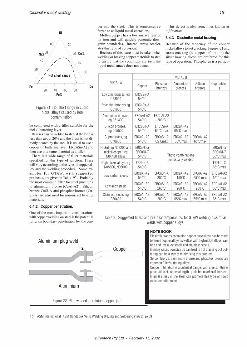
There are ways of mechanically fixing
aluminium to copper, or placing a plug
weld through a composite aluminium cop-
per junction, Figure 22.
Friction or explosive welding has also
been used. see Sections 7 and 8. A less vio-
lent form of welding can also be obtained
by cold pressure welding at relatively high
pressures. This is used for joining copper to
aluminium for electrical conductors
6.5.2 Aluminium/steel welds
Apart from the wide difference in melting
points, Table 1 , aluminium forms a series of
brittle intermetallic compounds with iron,
Figure 9. This makes fusion welds between
these metals brittle.
The variations in thermal conductivity,
Table 4 and thermal expansion, Table 3
would also give problems.
If it is necessary, aluminium can be
welded to steel if the steel component is first
coated with aluminium. This is usually
done by dipping an abraded steel part into
molten aluminium at around 690-705°C
immediately after abrading. Friction weld-
ing can also be used to provide the coating,
Section 7. The steel can then be joined to
aluminium provided the steel is not melted.
Subsequent diffusion between the two
metals can cause problems by the forma-
t ion of the problem phases at the
aluminium-iron interface so that the weld is
usually restricted to service temperatures of
less than 250°C.
6.6 Titanium welds
Titanium forms unsatisfactory intermetallic
compounds with iron, nickel and chromium
- the three metals most likely to require dis-
similar metal welds.
It is possible to make satisfactory
titanium-vanadium welds and vanadium is
also compatible with iron so there is poten-
tial to use a vanadium interface for a
titanium-steel weld, provided fusion did
not extend through the vanadium interface.
In the case of nickel alloys, a satisfactory
interface has been developed using niobium
and copper as the transition layers. The ti-
tanium is welded to the niobium and the
nickel alloy is welded to the copper
7 FRICTION WELDING
Friction welding relies on producing a nar-
row heating range followed by an
‘upsetting’ or forging stage, Figure 23
Although often cited as a method of pro-
ducing dissimilar metal welds, it is still pos-
sible to obtain problems at the interface but
since there is no molten zone and there is a
relatively short time at temperature for dif-
fusion to occur, the problems associated with
intermetallic phases are minimised.
Should the energy input be too much, a liq-
uid phase would form and problems associ-
ated with intermetallic phases could arise.
Satisfactory welds have been obtained be-
tween high hardenability steels, eg tool
steels, and lower carbon varieties. This appli-
cation is used in the joining of hardened tool
steels to mild steel shanks In some cases a
post weld temper may be required to soften
the tool steel heat affected zone
The process is also used for the production
of aluminium to stainless steel and copper
base alloys. It finds particular application in
coating steel with aluminium prior to fusion
welding, Section 6.5.2.
8 EXPLOSION WELDING
This is a solid state welding operation simi-
lar to friction welding. The weld is accom-
plished in a fraction of a second, Figure 24.
There is some heat input associated with
the energy of the explosion. The weld is es-
sentially accomplished by solid state con-
�Peritech Pty Ltd - February 15, 2002
16 Dissimilar metal welding
NOTEBOOK
Friction welding is a type of forge welding
where the heating zone is very small. There
should be no, or very little molten metal hence
microstructure problems should be non-
existent. The process is used for difficult joins,
eg tool steel/mild steel; aluminium/copper.
NOTEBOOK
Aluminium has two principal difficulties when attempting dissimilar metal welds.
The first is its very high thermal conductivity, the second is the strong possibility that it will form brit-
tle intermetallic compounds with the other metal.
This usually means that a brazed layer is used as a buttering interface or a mechanical type join is
used.
Fixed element
Frictionstage
Upsetting/forging stageFigure 23 Friction welding stages

tact but there is some melting in the ‘jet’
component of the weld.
The weld is initiated from one end of the
assembly with the two components being
placed at an angle of around 2~4°. The ex-
plosive must ensure that the weld is made
progressively along the length of the join
This process is used in the production of
clad plate. It is also the normal method of ti-
tanium or zirconium cladding steel with the
titanium ranging from 3 to 25mm16
It should be mentioned that explosive
forming is only a small part of clad plate
production, over 90% is produced by roll
bonding the two materials.
9 ROLL BONDING
Roll bonding is the preferred method of pro-
ducing clad plate.
Clad plate is used extensively for vessels
where the interior surface must be corrosion
resistant but the cost of the corrosion resis-
tant alloy is very high.
The initial stage in producing a roll
bonded joint is to clean both components
and, perhaps, nickel plate the corrosion re-
sistant alloy to minimise the possibility of
chromium oxidation during rolling
The rolling process is then done usually
with a sandwich approach, ie two sets of
plate are rolled at once with the corrosion
resistant alloy in the middle. This also helps
to minimise surface oxidation of the corro-
sion resistant alloy
In some cases explosion bonded plate is
hot rolled after cladding to reduce the thick-
ness of the clad component.
10 ACKNOWLEDGEMENT
This paper has drawn on various publica-
tions of the American Welding Society.
ASM International, the Nickel Develop-
ment Institute and technical literature pro-
vided by the various alloy manufactures.
�Peritech Pty Ltd - February 15, 2002
Dissimilar metal welding 17
NOTEBOOK
Explosion welding is a type of forge welding where metal movement is particularly fast.. There is a
small amount of molten metal formed during the process but the majority of the bond would be a
solid state weld.
The process is used extensively in the production of clad plate although the majority of this prod-
uct is produced by another type of forge welding - roll bonding.
Molten metal jet
Metal A
Metal B
Weld
Metal A
Explosive
Spacer - usually rubber
Detonation direction
Metal B
Figure 24 Explosion welding
16 Smith L M Engineering with clad steel Offshore Technology Conference, Houston, 1992. Reprinted as NiDI 10064
MA
TER
IAL
ALS
OK
NO
WN
AS
Al
CC
rC
uFe
Mn
Mo
NN
iN
bP
Pb
SS
iS
nTi
WZn
Oth
er
A04
430
Al-
Sic
astin
gal
loy
Bal
0.25
0.60
0.80
0.50
4.50
-6.
000.
250.
50M
g:0.
05;o
ther
sto
tal0
.35
max
.
A96
063
6063
Bal
0.10
0.10
0.35
0.60
-1.
100.
500
0.90
-1.
800.
200.
25
Mg:
0.45
-0.9
0;O
ther
sea
ch0.
05m
ax,
tota
l0.1
5m
ax
C23
000
Red
Bra
ss(8
5%)
84.0
0-86
.00
0.05
0.05
0B
alC
u+su
mof
nam
edel
emen
ts99
.8m
in
C26
000
Car
trid
geB
rass
(70-
30)
68.0
0-71
.50
0.05
0.07
0B
alC
u+su
mof
nam
edel
emen
ts99
.7m
in
C51
000
Pho
spho
rB
ronz
e5%
AB
al0.
100.
03-
0.35
0.05
04.
20-
5.80
0.30
Cu+
sum
ofna
med
elem
ents
99.5
min
C51
800
Pho
spho
rB
ronz
eA
WS
A5.
7ER
CuS
n-A
”0.
01B
al0.
10-
0.35
0.02
04.
00-
6.00
Cu+
sum
ofna
med
elem
ents
99.5
min
C61
400
Alu
min
ium
Bro
nze
D6.
0-8.
0B
al(2
)1.
50-
3.50
1.00
0.01
50.
010
0.20
Cu+
sum
ofna
med
elem
ents
99.5
min
C61
800
Alu
min
ium
Bro
nze
AW
SA
5.7
ERC
uAl-
A2
8.5-
11.5
Bal
(2)
050-
1.50
0.02
00.
020
0.10
0.02
Cu+
sum
ofna
med
elem
ents
99.5
min
C65
600
Sili
con
Bro
nze
ERC
uSi-
A”
0.01
Bal
(2)
0.50
1.50
0.02
02.
80-
4.00
1.50
1.50
Cu+
sum
ofna
med
elem
ents
99.5
mi
C70
600
(Wel
ding
grad
e)
10%
Cup
roni
ckel
(Wel
ding
grad
e)0.
05B
al(2
)1.
00-
1.80
1.00
9.00
-11
.00
(3)
0.02
00.
020
0.02
00.
50C
u+su
mof
nam
edel
emen
ts99
.5m
in
C71
000
80-2
0C
upro
nick
elB
al(2
)1.
001.
0019
.00-
23.0
00.
050
1.00
Cu+
sum
ofna
med
elem
ents
99.5
min
C71
581
Cup
roni
ckel
AW
SA
5.7
ERC
uNi
Bal
(2)
0.40
-0.
701.
0029
.0-
32.0
0.02
00.
020
0.01
00.
250.
20-
0.50
Cu+
sum
ofna
med
elem
ents
99.5
min
Check
com
positio
ns
again
stappro
priate
Sta
ndard
befo
reuse
Febru
ary
15,2002
18
Dis
sim
ilarm
eta
lweld
ing
Allo
yC
om
posi
tions
(maxi
mum
unle
sssp
eci
fied)
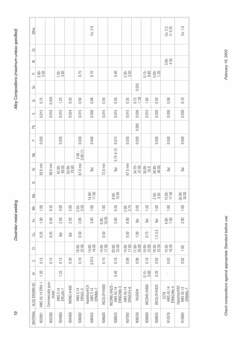
MA
TER
IAL
ALS
OK
NO
WN
AS
Al
CC
rC
uFe
Mn
Mo
NN
iN
bP
Pb
SS
iS
nTi
WZn
Oth
er
N02
061
AW
SA
5.14
ERN
i-1
1.50
0.15
0.25
1.00
1.00
93.0
min
0.03
00.
015
0.75
2.00
-3.
50
N02
200
Com
mer
cial
lypu
reni
ckel
0.15
0.25
0.40
0.35
99.0
min
0.01
00.
035
N04
060
AW
S5.
14ER
CuN
i-7
1.25
0.15
Bal
2.50
4.00
62.0
0-69
.00
0.02
00.
015
1.25
1.50
-3.
00
N04
400
MO
NEL
®40
00.
30B
al2.
502.
0063
.00-
70.0
00.
024
0.50
N06
082
AW
S5.
14ER
NiC
r-3
0.10
18.0
0-22
.00
0.50
3.00
2.50
-3.
5067
.0m
in2.
00-
3.00
(1)
0.03
00.
015
0.50
0.75
N06
455
Has
tello
y®C
4A
WS
5.14
ERN
iMo-
70.
015
14.0
0-18
.00
3.00
1.00
14.0
0-17
.00
Bal
0.04
00.
030
0.08
0.70
Co:
2.0
N06
600
INC
OLO
Y®60
00.
1514
.00-
17.0
00.
506.
00-
10.0
01.
0072
.0m
in0.
015
0.50
N06
625
INC
ON
EL®
625
-A
WS
A5.
14ER
NiC
rMo-
30.
400.
1020
.00-
23.0
05.
000.
508.
00-
10.0
0B
al3.
15-4
.15
0.01
50.
015
0.50
0.40
N07
092
AW
SA
5.14
ERN
iCrF
e-6
0.08
14.0
0-17
.00
0.50
8.00
2.00
-2.
7567
.0m
in0.
030
0.01
50.
352.
50-
3.50
N08
330
RA
330®
0.08
17.0
0-20
.00
1.00
Bal
2.00
34.7
0-37
.00
0.03
00.
005
0.03
00.
75-1
.50
0.02
5
N08
800
INC
ON
EL®
800
0.15
-0.
600.
1019
.00-
23.0
00.
75B
al1.
5030
.00-
35.0
0.01
51.
000.
15-
0.60
N08
825
INC
OLO
Y®82
50.
200.
0519
.50-
23.5
01.
5-3.
5B
al1.
002.
50-
3.50
38.0
0-46
.00
0.03
00.
030
0.50
0.60
-1.
20
N10
276
C27
6A
WS
A5.
14ER
NiC
rMo-
4‘
0.02
14.5
0-16
.50
4.00
-7.
001.
0015
.00-
17.0
0B
al0.
030
0.03
00.
083.
00-
4.50
Co:
2.5;
V:0
.35
N10
665
Has
tello
y®B
2A
WS
A5.
14ER
NiM
o-7
0.02
1.00
2.00
1.00
26.0
0-30
.00
Bal
0.04
00.
030
0.10
Co:
1.0
Check
com
positio
ns
again
stappro
priate
Sta
ndard
befo
reuse
Febru
ary
15,2002
19
Dis
sim
ilarm
eta
lweld
ing
Allo
yC
om
posi
tions
(maxi
mum
unle
sssp
eci
fied)
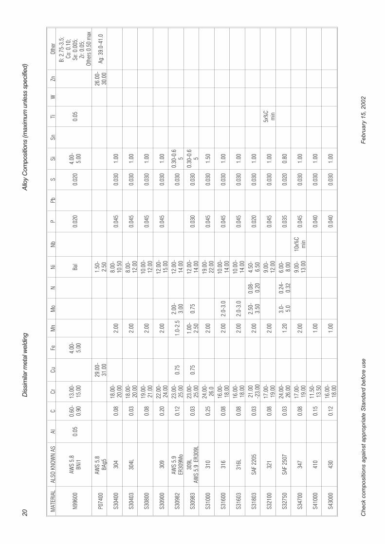
MA
TER
IAL
ALS
OK
NO
WN
AS
Al
CC
rC
uFe
Mn
Mo
NN
iN
bP
Pb
SS
iS
nTi
WZn
Oth
er
N99
600
AW
S5.
8B
Ni1
0.05
0.60
-0.
9013
.00-
15.0
04.
00-
5.00
Bal
0.02
00.
020
4.00
-5.
000.
05
B:2
.75-
3.5;
Co:
0.10
;S
e:0.
005;
Zr:0
.05;
Oth
ers
0.50
max
P07
400
AW
S5.
8B
Ag5
29.0
0-31
.00
1.50
-2.
5026
.00-
30.0
0A
g:39
.0-4
1.0
S30
400
304
0.08
18.0
0-20
.00
2.00
8.00
-10
.50
0.04
50.
030
1.00
S30
403
304L
0.03
18.0
0-20
.00
2.00
8.00
-12
.00
0.04
50.
030
1.00
S30
800
0.08
19.0
0-21
.00
2.00
10.0
0-12
.00
0.04
50.
030
1.00
S30
900
309
0.20
22.0
0-24
.00
2.00
12.0
0-15
.00
0.04
50.
030
1.00
S30
982
AW
S5.
9ER
309M
o0.
1223
.00-
25.0
00.
751.
0-2.
52.
00-
3.00
12.0
0-14
.00
0.03
00.
30-0
.65
S30
983
309L
AW
S5.
9ER
309L
0.03
23.0
0-25
.00
0.75
1.00
-2.
500.
7512
.00-
14.0
00.
030
0.03
00.
30-0
.65
S31
000
310
0.25
24.0
0-26
.02.
0019
.00-
22.0
00.
045
0.03
01.
50
S31
600
316
0.08
16.0
0-18
.00
2.00
2.0-
3.0
10.0
0-14
.00
0.04
50.
030
1.00
S31
603
316L
0.08
16.0
0-18
.00
2.00
2.0-
3.0
10.0
0-14
.00
0.04
50.
030
1.00
S31
803
SA
F22
050.
0321
.00
-23.
002.
002.
50-
3.50
0.08
-0.
204.
50-
6.50
0.02
00.
030
1.00
S32
100
321
0.08
17.0
0-19
.00
2.00
9.00
-12
.00
0.04
50.
030
1.00
5x%
Cm
in
S32
750
SA
F25
070.
0324
.00-
26.0
01.
203.
0-5.
00.
24-
0.32
6.00
-8.
000.
035
0.02
00.
80
S34
700
347
0.08
17.0
0-19
.00
2.00
9.00
-13
.00
10x%
Cm
in0.
045
0.03
01.
00
S41
000
410
0.15
11.5
0-13
.50
1.00
0.04
00.
030
1.00
S43
000
430
0.12
16.0
0-18
.00
1.00
0.04
00.
030
1.00
Check
com
positio
ns
again
stappro
priate
Sta
ndard
befo
reuse
Febru
ary
15,2002
20
Dis
sim
ilarm
eta
lweld
ing
Allo
yC
om
posi
tions
(maxi
mum
unle
sssp
eci
fied)
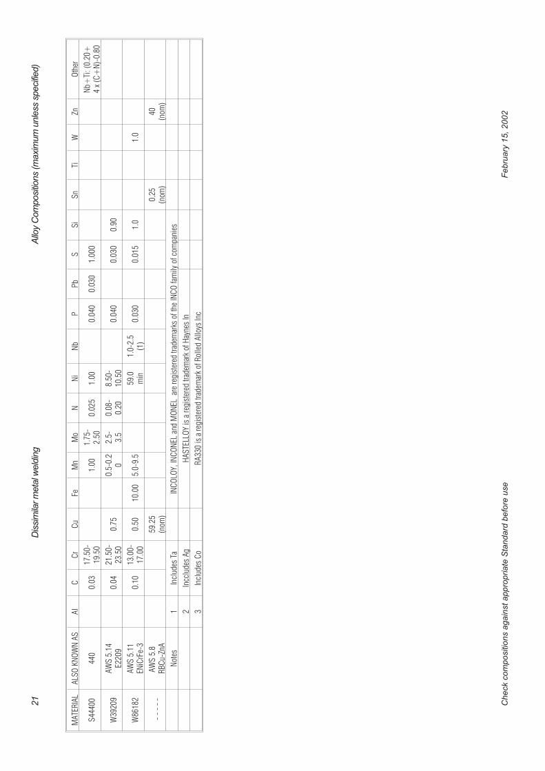
MA
TER
IAL
ALS
OK
NO
WN
AS
Al
CC
rC
uFe
Mn
Mo
NN
iN
bP
Pb
SS
iS
nTi
WZn
Oth
er
S44
400
440
0.03
17.5
0-19
.50
1.00
1.75
-2.
500.
025
1.00
0.04
00.
030
1.00
0N
b+Ti
:(0.
20+
4x
(C+
N)-
0.80
W39
209
AW
S5.
14E2
209
0.04
21.5
0-23
.50
0.75
0.5-
0.2
02.
5-3.
50.
08-
0.20
8.50
-10
.50
0.04
00.
030
0.90
W86
182
AW
S5.
11EN
iCrF
e-3
0.10
13.0
0-17
.00
0.50
10.0
05.
0-9.
559
.0m
in1.
0-2.
5(1
)0.
030
0.01
51.
01.
0
--
--
-A
WS
5.8
RB
Cu-
ZnA
59.2
5(n
om)
0.25
(nom
)40
(nom
)
Not
es1
Incl
udes
TaIN
CO
LOY,
INC
ON
ELan
dM
ON
ELar
ere
gist
ered
trad
emar
ksof
the
INC
Ofa
mily
ofco
mpa
nies
2In
cclu
des
Ag
HA
STE
LLO
Yis
are
gist
ered
trad
emar
kof
Hay
nes
In
3In
clud
esC
oR
A33
0is
are
gist
ered
trad
emar
kof
Rol
led
Allo
ysIn
c
Check
com
positio
ns
again
stappro
priate
Sta
ndard
befo
reuse
Febru
ary
15,2002
21
Dis
sim
ilarm
eta
lweld
ing
Allo
yC
om
posi
tions
(maxi
mum
unle
sssp
eci
fied)
INDEXAaluminium alloys to copperbrittle intermetallic compounds . . . . . . . 16high zinc solder . . . . . . . . . . . . . . . 16plug weld . . . . . . . . . . . . . . . . . . 16silver coating . . . . . . . . . . . . . . . . 16welding . . . . . . . . . . . . . . . . . . . 16
aluminium alloys to steelaluminium coating of the steel. . . . . . . . 16diffusion problems · · · · · · · · · · · · · 16
brittle intermetallic compounds . . . . . . . 16thermal conductivity. . . . . . . . . . . . . 16welding . . . . . . . . . . . . . . . . . . . 16
Bboiler tubes · · · · · · · 5brass - welding to steel · · · · · 15brazingeffect of expansion on capilliary action . . . . 6
brittle phasesminimised by brazing . . . . . . . . . . . . . 7
Cclad plate · · · · · · · · 17copper alloyscopper penetration . . . . . . . . . . . . . 15infiltration · · · · · · · · · · · · · · · · · 15surface tension · · · · · · · · · · · · · · 15
cupro-nickelproblems with phosphorus · · · · · · · · · 13
solidification range - iron contamination . . . 13suggested dissimilar weld fillers. . . . . . . 15thermal conductivity. . . . . . . . . . . . . 13
corrosion · · · · · · · · 8galvanic couple. . . . . . . . . . . . . . . . 8area
advantage · · · · · · · · · · · · · · · · 10
stainless steel fastener 10area affects · · · · · · · · · · · · · · · · 10carbon steel - stainless stee
paint protection· · · · · · · · · · · · · · 10hydrogen evolution · · · · · · · · · · · · 10micro scale
molybdenum segregation· · · · · · · · · 10micro scale between phases · · · · · · · · 10
Ddilution calculation · · · · · · 7lever rule . . . . . . . . . . . . . . . . . . . 7
Eexplosion welding · · · · · · 16clad plate . . . . . . . . . . . . . . . . . . 17molten 'jet' . . . . . . . . . . . . . . . . . 17
Fferritic/martensitic stainless steels - carbon steel4xx series stainless steels . . . . . . . . . . 13buttering . . . . . . . . . . . . . . . . . . 13
filler impurity limitationsaluminium bronze fillers . . . . . . . . . . . 8aluminium, magnesium and titanium fillers . . 8austenitic stainless steel fillers . . . . . . . . 8
carbon and low alloy steel fillers . . . . . . . 8copper nickel fillers . . . . . . . . . . . . . . 8high nickel (Monel®) fillers. . . . . . . . . . 8high nickel-chromium alloy fillers . . . . . . . 8nickel fillers . . . . . . . . . . . . . . . . . 8Nickel fillers . . . . . . . . . . . . . . . . . 8
fluxselection for wetting . . . . . . . . . . . . . 6
friction welding · · · · · · 16aluminium to copper base alloys. . . . . . . 16aluminium to stainless steel . . . . . . . . . 16diffusion limitation. . . . . . . . . . . . . . 16tool steel shanks . . . . . . . . . . . . . . 16
Ggalvanic series · · · · · · · 9grain growth · · · · · · · 8
Hhigh temperature oxidation · · · · 11hydrogen embrittlementcathodic reaction . . . . . . . . . . . . . . 10
Iinfiltration · · · · · · · · 15
Llever ruledilution calculation . . . . . . . . . . . . . . 7
lower melting point alloys · · · · 4contraction stresses . . . . . . . . . . . . . 4effect of arc direction . . . . . . . . . . . . . 4hot cracking . . . . . . . . . . . . . . . . . 4use of intermediate alloys . . . . . . . . . . 4
Mmagnetic effectsarc deflection . . . . . . . . . . . . . . . . 11
melting ranges - table · · · · · 3melting temperatures · · · · · 4metal mixing · · · · · · · 6microstucturebrittle intermetallic phases, eg Al-Fe . . . . . 7galvanic effect, eg Cu-Fe . . . . . . . . . . . 7mixture of the two solid solutions, eg Pb-Sn . 7mutual solubility, eg Cu-Ni . . . . . . . . . . 7stability. . . . . . . . . . . . . . . . . . . . 8wide solidification range, eg Cu-Fe . . . . . . 7
Microstucturestabilitycarbide formation · · · · · · · · · · · · · · 8carbon depletion and grain size · · · · · · · 8elevated tempeature · · · · · · · · · · · · · 8sensitisation · · · · · · · · · · · · · · · · · 8
microstuctures · · · · · · · 7
Nnickel alloy
- effect of phosphorus . . . . . . . . . . . 13- effect of sulphur . . . . . . . . . . . . . 13chromium tolerance . . . . . . . . . . . . . 13iron tolerance . . . . . . . . . . . . . . . . 13
lead - effect of . . . . . . . . . . . . . . . 13weld pool composition limits . . . . . . . . 14zinc - effect of. . . . . . . . . . . . . . . . 13
nickel silverbrazing . . . . . . . . . . . . . . . . . . . 16
Ooxidationoxide ‘notch’ . . . . . . . . . . . . . . . . 11
Pphase diagram · · · · · · · 7copper-nickel . . . . . . . . . . . . . . . . . 7lead-tin . . . . . . . . . . . . . . . . . . . . 7
post-heatingsensitisation . . . . . . . . . . . . . . . . . 6
post-weld heating · · · · · · 6prequalification of dissimilar welds · · 3pre-weld heating · · · · · · 6
Qqualification of dissimilar welds · · · 3
Rroll bonding · · · · · · · 17clad plate . . . . . . . . . . . . . . . . . . 17
SScaeffler DeLong diagram · · · · 11solidification rangewide range and hot cracking . . . . . . . . . 7
specific heats · · · · · · · 3stainless - carbon steelfiller metals . . . . . . . . . . . . . . . . . 10high temperature applications . . . . . . . . 12low temperature applications . . . . . . . . 11Scaeffler DeLong diagram. . . . . . . . . . 11martnsite formation prediction · · · · · · · 11weld pool alloy prediction · · · · · · · · · 11
WRC 1992 diagram . . . . . . . . . . . . . 11martensite formation prediction · · · · · · 11
Tthermal conductivity · · · · · · 6distortion . . . . . . . . . . . . . . . . . . . 6effect of temperature. . . . . . . . . . . . . 6
thermal expansion · · · · · · 4coefficients . . . . . . . . . . . . . . . . . . 4intermediate expansion coefficient . . . . . . 5stress calculation. . . . . . . . . . . . . . . 5stresses and cracking . . . . . . . . . . . . 4minimising · · · · · · · · · · · · · · · · · 5
thermal cycling - cracking . . . . . . . . . . 5titanium welds· · · · · · · 16transition layers . . . . . . . . . . . . . . . 16
Uunmixed zone · · · · · · · 6
�Peritech Pty Ltd - February 15, 2002
22 Dissimilar metal welding

Wweld strength · · · · · · · 3
welding zones · · · · · · · 6composite . . . . . . . . . . . . . . . . . . 6heat affected . . . . . . . . . . . . . . . . . 6partially melted . . . . . . . . . . . . . . . . 6
unmixed . . . . . . . . . . . . . . . . . . . 6wettingflux selection . . . . . . . . . . . . . . . . . 6
WRC 1992 · · · · · · · 11
�Peritech Pty Ltd - February 15, 2002
Dissimilar metal welding 23
Related Documents