User Manual
Model 2534 Digital Storage Oscilloscope
Version 1.01
General Safety Summary
General Safety Summary Review the following safety precautions to avoid injury and prevent damage to this product or any products connected to it. To avoid potential hazards, use this product only as specified. Only qualified personnel should perform service procedures. To Avoid Fire or Personal Injury Use Proper Power Cord. Use only the power cord specified for this product and certified for the country of use.
Connect and Disconnect Properly. Do not connect or disconnect probes or test leads while they are connected to a voltage source.
Ground the Product. This product is grounded through the grounding conductor of the power cord. To avoid electric shock, the grounding conductor must be connected to earth ground. Before making connections to the input or output terminals of the product, ensure that the product is properly grounded.
Connect the Probe Properly. The probe ground lead is at ground potential. Do not connect the ground lead to an elevated voltage.
Observe All Terminal Ratings. To avoid fire or shock hazard, observe all ratings and marking on the product. Consult the product manual for further ratings information before making connections to the product.
Do Not Operate Without Covers. Do not operate this product with covers or panels removed.
Avoid Exposed Circuitry. Do not touch exposed connections and components when power is present.
Do Not Operate With Suspected Failures. If you suspect there is damage to this product, have it inspected by qualified service personnel.
General Safety Summary
Do Not Operate in Wet/Damp Conditions.
Do Not Operate in an Explosive Atmosphere.
Keep Product Surfaces Clean and Dry.
Symbols and Terms on the Product. Protective Ground (Earth) Terminal. CAUTION. Refer to user manual. Caution indicates a hazard to property including this product
General Safety Summary
Intentionally left blank
Contents
5
Contents
Contents ..........................................................................................5 1. Getting Started ...............................................................7
Inspect package content......................................................7 Front Panel ............................................................................8 Rear panel ...........................................................................14 Interpreting the display.......................................................15
2. Basic Operation ...........................................................17 Probe Compensation .........................................................17 Using Autoset ......................................................................18 Vertical Controls..................................................................20
CH1, CH2 Menu..........................................................22 REF Function...............................................................39
Horizontal Controls .............................................................42 Trigger Controls ..................................................................55 ACQUIRE Menu..................................................................67 UTILITY Menu .....................................................................78 MEASURE Menu ................................................................91 SAVE/LOAD Menu ...........................................................106 CURSOR Menu.................................................................117 DISPLAY Menu .................................................................123 RUN Controls ....................................................................126
3. Application Examples................................................129 Make Simple Measurements ..........................................129
Contents
6
Capture a Single-Shot Signal......................................... 131 Reduce the Random Noise on a Signal ....................... 133 Trigger on a Video Signal ............................................... 135 PASS/FAIL Measurement............................................... 138 Waveform Recorder ........................................................ 140 Cursor Measurements..................................................... 144
4. System Message and General Problems ............. 151 System Message.............................................................. 151 Gerneral Problems........................................................... 154
5. Specifications and Characteristics ......................... 157 Characteristics.................................................................. 157
Appendix A: Service and Warranty Information .................. 165

Getting Started
7
1. Getting Started Inspect package content Inspect the shipping container for damage. If the shipping container and/or packaging material are damaged, it should be kept until the content of the shipment has been checked for completeness and the oscilloscope has been checked mechanically and electrically. Verify that you received the following items:
Oscilloscope Two high performance 150MHz oscilloscope probes Power cord User Manual Test report USB data cable
If the content is incomplete or if there is mechanical damage or a defect, please contact your authorized distributor.
Getting Started
8
Front Panel This section provides an introduction to the front panel of the model 2534 oscilloscope. Generally, you set up the front panel controls first and then make your measurements. The keys or knobs on the front panel bring up softkey menus on the display that provide further access to the oscilloscope’s features. The entry knob is usually used to select or change values. Five softkeys are located along the right side of the display screen. The following figure shows the front panel of model 2534:
Front panel
Getting Started
9
1. PRINT key Press this key to print the current display to a USB mass storage device.
2. AUTO key When you press the AUTO key, the oscilloscope will quickly determine which channels are active and automatically scale the display to show the signals on these channels.
3. Entry knob The Entry knob is used to select items from menus and input values. Its function changes when a different menu is displayed. The curved arrow symbol to the left of the Entry knob lights up when the Entry knob is active and can be used to select a value.
4. Utility and Save/Load Menu UTILITY Access the system utility functions, such as Language Setup, I/O Setup, and Print Setup etc. SAVE/LOAD You can save your current setup and waveform data to the oscilloscope’s internal memory or to a USB mass storage device and retrieve the setup or waveform later.
5. Measure and Waveform Menu MEASURE
Getting Started
10
Perform automated measurements of waveform parameters. ACQUIRE The ACQUIRE menu lets you set the oscilloscope to acquire waveforms in Normal, Peak Detect, or Average mode and lets you select Real Time or Equivalent sampling. CURSOR Press the CURSOR key to activate the cursors for making custom voltage or time measurements on scope signals. DISPLAY You can change the appearance of waveforms and the display screen, select the color schemes, and adjust the contrast, etc.
6. RUN control keys
The RUN/STOP key will be green when the oscilloscope is waiting for a trigger event. When the trigger mode is set to Normal, the display will not update until a trigger event occurs. If the trigger mode is set to Auto, the oscilloscope looks for a trigger; if no trigger is found, it will be triggered automatically and the input signals will be displayed.

Getting Started
11
Press the RUN/STOP key again to stop acquiring data. The RUN/STOP key will be red. Now you may examine the acquired waveform by panning and zooming.
Press the SINGLE key to acquire a single waveform trace. The key will remain orange until the oscilloscope is triggered. After the trigger event, the waveform is displayed and triggering is disabled until re-armed by pressing the SINGLE key again.
7. Vertical controls You can use the vertical position control knob to move the waveforms up or down on the display. There is one vertical position control knob for each channel. You can press the channel key CH1 or CH2 to switch the channel on or off or access the associated channel menu via the softkeys. There is one channel on/off key for each channel. You can press the MATH key to access the FFT (Fast Fourier Transform), multiply, subtract, and add functions. You can press the REF key to save or load a reference waveform from the internal memory or an external USB mass storage device. You can use the vertical scale control knob to change the vertical scale of a waveform. The waveform display will
Getting Started
12
contract or expand relative to the ground reference level. There is one vertical scale control knob for each channel.
8. Horizontal controls When the oscilloscope is in run mode, the horizontal position control knob lets you set the acquisition window relative to the trigger point. When acquisition is stopped, you can turn this knob to pan through the stored waveform data horizontally. This lets you see the captured waveform before or after the trigger. Press the horizontal MENU key to access the menu where you can activate a delayed sweep or select X-Y or Roll modes. Turn the horizontal sweep rate control knob to adjust the sweep speed. This changes the time base on the display. When adjusted after the waveform has been acquired and the oscilloscope is stopped, this has the effect of stretching or compressing the waveform horizontally.
9. Trigger controls
These controls are used to control how the oscilloscope triggers to capture waveforms.
10. Probe compensation terminals
Getting Started
13
Use these two probe compensation terminals to match each probe’s characteristics to the oscilloscope channel to which it is connected.
11. External trigger input This is the external trigger input BNC connector.
12. Channel input BNC This is the channel’s input BNC connector. Connect the oscilloscope probe or BNC cable to the BNC Connector.
13. MENU On/Off key Press this key to toggle the menu display on and off.
14. Softkeys Five menu softkeys are used to select the control and parameter setting functions. Each softkey has a label along the right side of the screen.
15. Power switch Press once to turn power on, press again to turn power off.
16. LCD display The 320*240 matrix (5.7 inch) LCD displays captured waveforms, setup information, measurement results, and softkeys for setting up parameters.
Getting Started
14
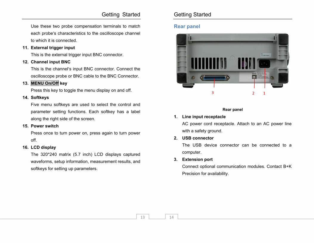
Rear panel
Rear panel
1. Line input receptacle AC power cord receptacle. Attach to an AC power line with a safety ground.
2. USB connector The USB device connector can be connected to a computer.
3. Extension port Connect optional communication modules. Contact B+K Precision for availability.
2 1 3

Getting Started
15
Interpreting the display The oscilloscope display contains channel acquisition information, setup information, measurement results, and soft keys for setting up measurement parameters.
Interpreting the display
1. Readout shows the real time clock. 2. The USB icon displays when a USB device is connected. 3. Acquisition status readout shows RUN, STOP, WAIT, or
ROLL. 4. The square brackets show the location of the current
display window within the recorded waveform. The
Getting Started
16
record line color corresponds to the selected waveform color.
5. The trigger position icon shows the trigger location within the record.
6. The trigger position icon shows the trigger location in the current displayed waveforms.
7. This readout shows the frequency of the trigger signal. 8. The trigger status readout shows the trigger status. 9. These are soft keys which allow you to set up additional
parameters. 10. The display area contains the displayed waveforms,
channel identifiers, and trigger and ground level indicators. The channel information is shown in the same color as the channel’s waveform.
11. This readout shows the delay setting or the trigger location within the record, trigger source, trigger type, and trigger level.
12. The horizontal readout shows the Main or Delayed time base setting.
13. The channel readouts show the scale factor, coupling, bandwidth limit, digital filter, and invert status.
14. Waveform baseline icons show the zero-volt levels of the waveforms. The icon colors correspond to the waveform colors.
Basic Operation
17
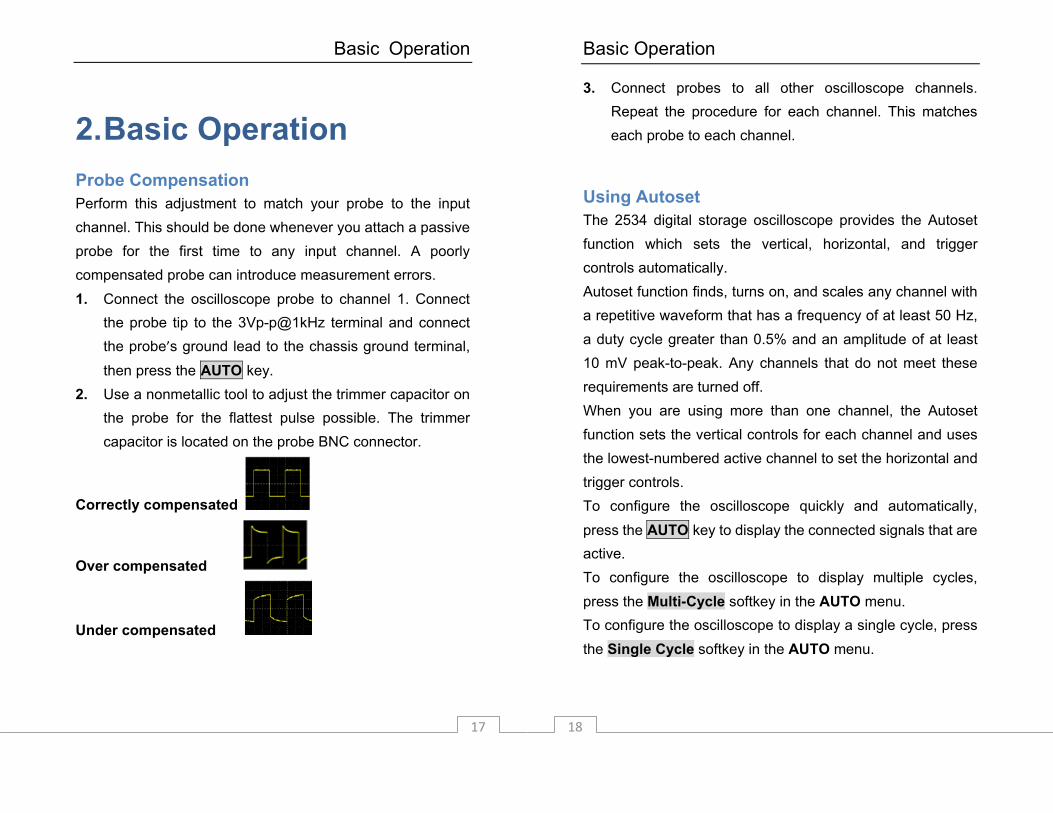
2. Basic Operation Probe Compensation Perform this adjustment to match your probe to the input channel. This should be done whenever you attach a passive probe for the first time to any input channel. A poorly compensated probe can introduce measurement errors. 1. Connect the oscilloscope probe to channel 1. Connect
the probe tip to the 3Vp-p@1kHz terminal and connect the probe’s ground lead to the chassis ground terminal,
then press the AUTO key. 2. Use a nonmetallic tool to adjust the trimmer capacitor on
the probe for the flattest pulse possible. The trimmer capacitor is located on the probe BNC connector.
Correctly compensated
Over compensated
Under compensated
Basic Operation
18
3. Connect probes to all other oscilloscope channels. Repeat the procedure for each channel. This matches each probe to each channel.
Using Autoset The 2534 digital storage oscilloscope provides the Autoset function which sets the vertical, horizontal, and trigger controls automatically. Autoset function finds, turns on, and scales any channel with a repetitive waveform that has a frequency of at least 50 Hz, a duty cycle greater than 0.5% and an amplitude of at least 10 mV peak-to-peak. Any channels that do not meet these requirements are turned off. When you are using more than one channel, the Autoset function sets the vertical controls for each channel and uses the lowest-numbered active channel to set the horizontal and trigger controls. To configure the oscilloscope quickly and automatically, press the AUTO key to display the connected signals that are active. To configure the oscilloscope to display multiple cycles, press the Multi-Cycle softkey in the AUTO menu. To configure the oscilloscope to display a single cycle, press the Single Cycle softkey in the AUTO menu.
Basic Operation
19
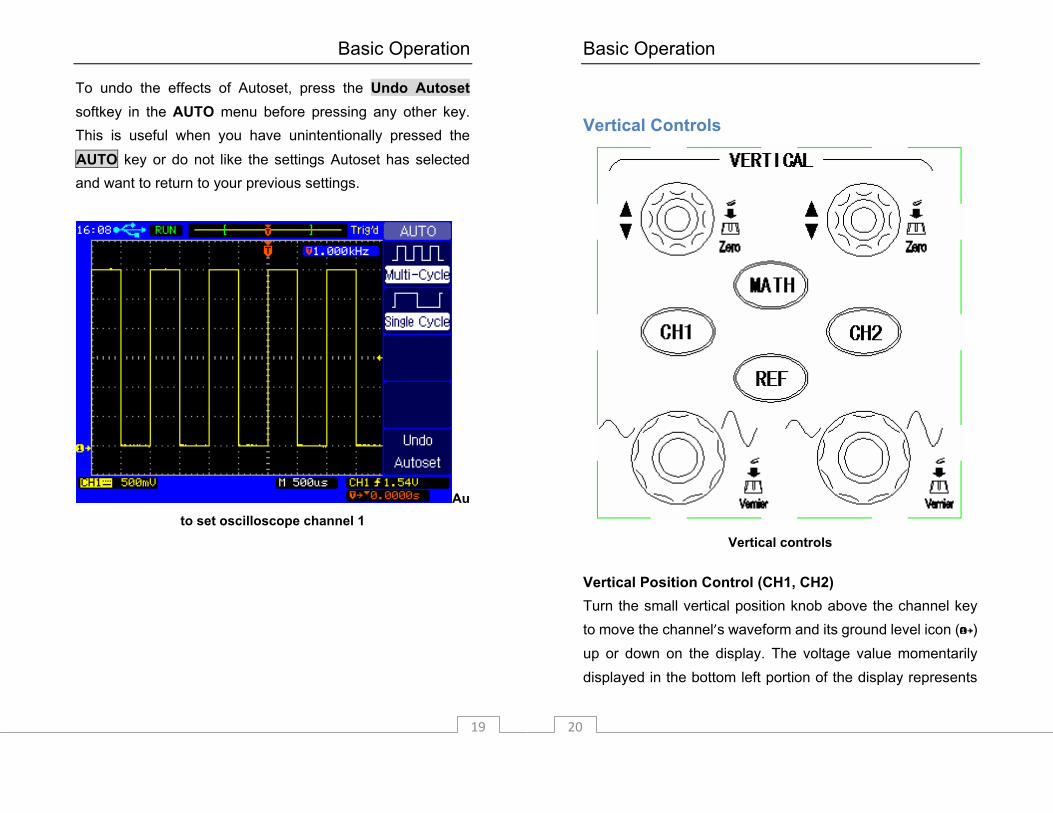
To undo the effects of Autoset, press the Undo Autoset softkey in the AUTO menu before pressing any other key. This is useful when you have unintentionally pressed the AUTO key or do not like the settings Autoset has selected and want to return to your previous settings.
Auto set oscilloscope channel 1
Basic Operation
20
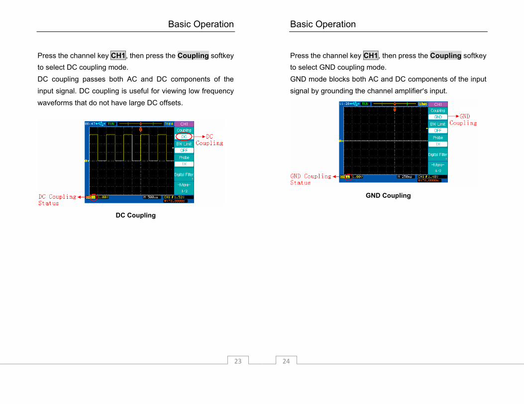
Vertical Controls
Vertical controls
Vertical Position Control (CH1, CH2) Turn the small vertical position knob above the channel key to move the channel’s waveform and its ground level icon ( ) up or down on the display. The voltage value momentarily displayed in the bottom left portion of the display represents

Basic Operation
21
the voltage difference between the vertical center of the display and the ground level( ). Press the small vertical position knob above the channel key to bring the channel’s waveform and its ground level icon ( ) directly back to the vertical center of the display. Channel key CH1, CH2, MATH, REF Press the channel key from the front panel to display the channel’s menu. Pressing it again turns the display of the channel on or off. The channel is displayed when the key is illuminated. You must be viewing the menu for a channel before you can turn it off. For example, if CH1 and CH2 are both displayed and the CH2 menu is now displayed. In order to turn CH1 off, you should press the CH1 key first and CH1 menu will be displayed; then press CH1 key again to turn off CH1.
Vertical Scale Control (CH1, CH2) Turn the large vertical scale knob below the channel key to set the scale factor for the channel. The vertical scale knob changes the channel scale in a 1-2-5 step sequence. The scale factor value is displayed in the bottom left portion of the display. Press the large vertical scale knob to toggle between Fine and Coarse. When fine is selected, you can change the channel’s vertical sensitivity in smaller steps. This is useful when you want to scale the displayed waveform to an exact
Basic Operation
22
size. When coarse is selected, the vertical scale knob changes the channel scale in a 1-2-5 step sequence.
CH1, CH2 Menu Press the channel key CH1 to display the channel’s menu and turn the display of the channel on.
Channel Coupling Press the channel key CH1, then press the Coupling softkey to select AC coupling mode. AC coupling places a high pass filter in series with the input waveform that blocks the DC component of the input signal. AC coupling is useful for viewing waveforms with DC offsets.
AC Coupling
Basic Operation
23
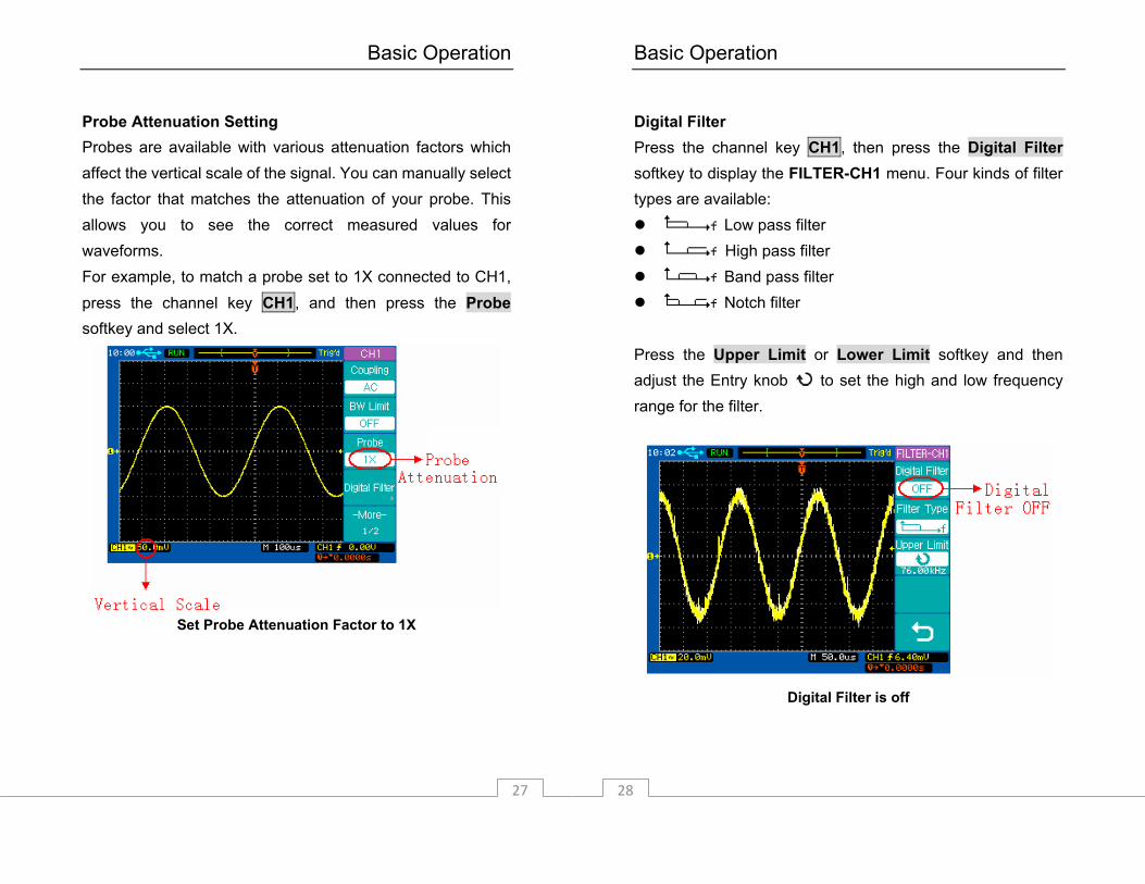
Press the channel key CH1, then press the Coupling softkey to select DC coupling mode. DC coupling passes both AC and DC components of the input signal. DC coupling is useful for viewing low frequency waveforms that do not have large DC offsets.
DC Coupling
Basic Operation
24
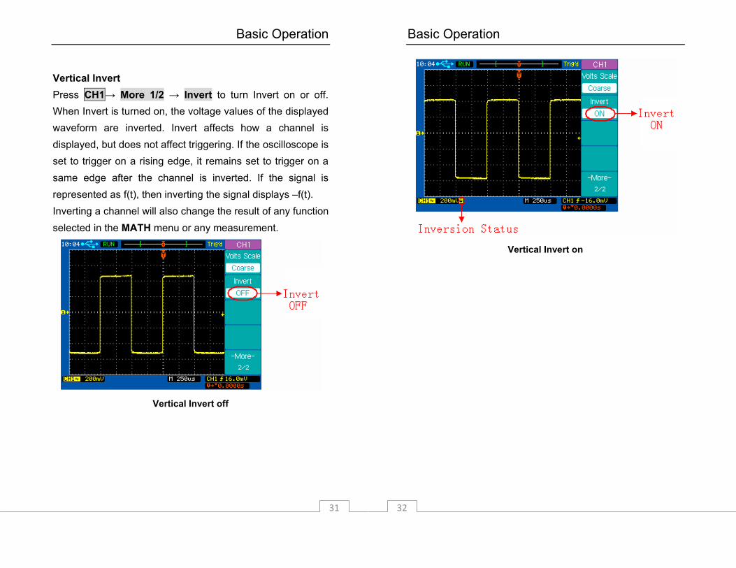
Press the channel key CH1, then press the Coupling softkey to select GND coupling mode. GND mode blocks both AC and DC components of the input signal by grounding the channel amplifier’s input.
GND Coupling

Basic Operation
25
Bandwidth Limit When Bandwidth limit is on, the maximum bandwidth for the channel is approximately 20 MHz. For waveforms with frequencies below this, turning bandwidth limit on removes unwanted high frequency noise from the waveform. The bandwidth limit also limits the trigger signal path’s bandwidth of any channel that has BW Limit turned on. Press the channel key CH1, then press the BW Limit softkey to turn the bandwidth limit off for the selected channel 1. BW Limit off mode passes both the high and low frequency components.
BW Limit off
Basic Operation
26
Press the channel key CH1, then press the BW Limit softkey to turn the bandwidth limit on for the selected channel 1. BW Limit on mode blocks the high frequency components over 20MHz.
BW Limit on
Basic Operation
27
Probe Attenuation Setting Probes are available with various attenuation factors which affect the vertical scale of the signal. You can manually select the factor that matches the attenuation of your probe. This allows you to see the correct measured values for waveforms. For example, to match a probe set to 1X connected to CH1, press the channel key CH1, and then press the Probe softkey and select 1X.
Set Probe Attenuation Factor to 1X
Basic Operation
28
Digital Filter Press the channel key CH1, then press the Digital Filter softkey to display the FILTER-CH1 menu. Four kinds of filter types are available:
Low pass filter High pass filter Band pass filter Notch filter
Press the Upper Limit or Lower Limit softkey and then adjust the Entry knob to set the high and low frequency range for the filter.
Digital Filter is off

Basic Operation
29
Digital Filter is on
Basic Operation
30
Vertical Scale Turn the large vertical scale knob below the channel key to set the scale factor for the channel. The channel scale factor value is displayed in the bottom left portion of the display. Press CH1→ More 1/2 → Volts Scale to select Coarse or Fine adjustment. You can also press the large vertical scale knob to toggle between Coarse and Fine. When Coarse is selected, the vertical scale knob changes the channel scale in a 1-2-5 step sequence. When Fine is selected, the vertical scale knob changes the channel scale using a smaller step size.
Fine Vertical Scale
Basic Operation
31
Vertical Invert Press CH1→ More 1/2 → Invert to turn Invert on or off. When Invert is turned on, the voltage values of the displayed waveform are inverted. Invert affects how a channel is displayed, but does not affect triggering. If the oscilloscope is set to trigger on a rising edge, it remains set to trigger on a same edge after the channel is inverted. If the signal is represented as f(t), then inverting the signal displays –f(t). Inverting a channel will also change the result of any function selected in the MATH menu or any measurement.
Vertical Invert off
Basic Operation
32
Vertical Invert on
Basic Operation
33
MATH Functions
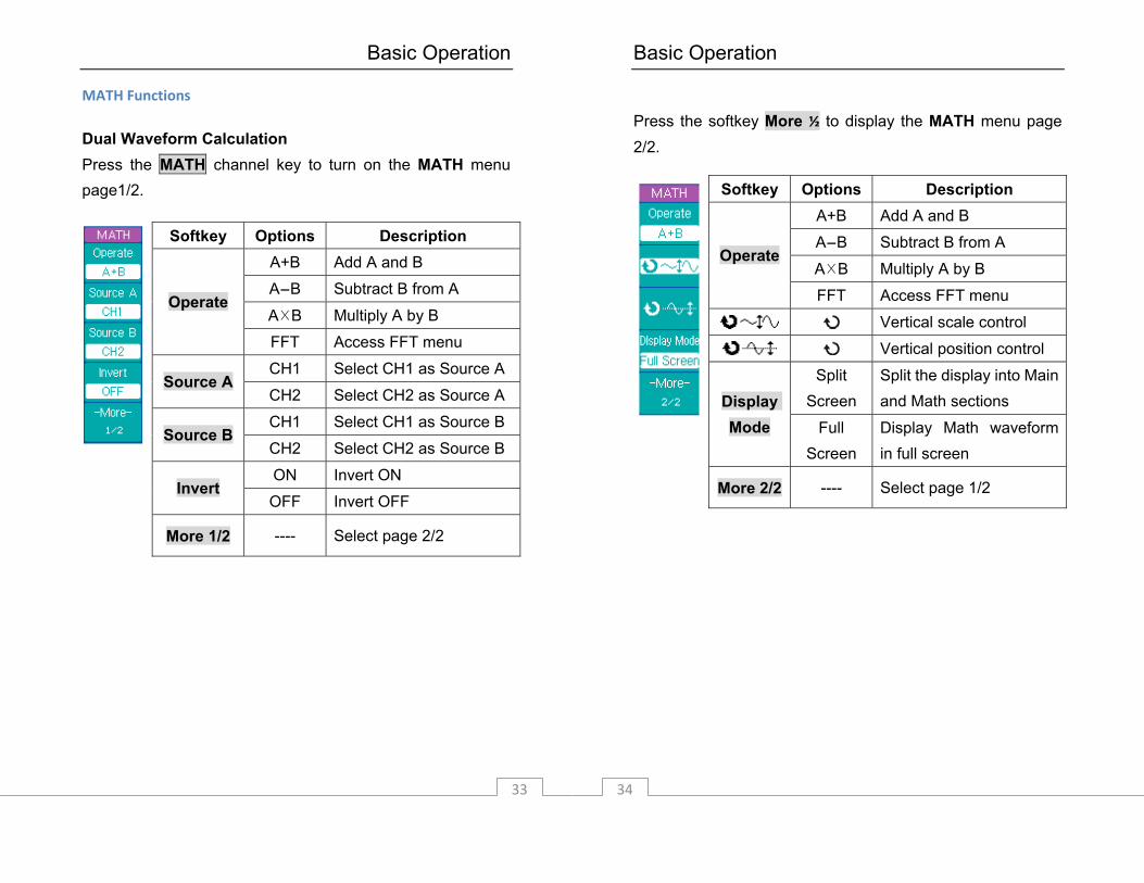
Dual Waveform Calculation Press the MATH channel key to turn on the MATH menu page1/2.
Softkey Options Description A+B Add A and B
A-B Subtract B from A
A×B Multiply A by B Operate
FFT Access FFT menu
CH1 Select CH1 as Source A Source A
CH2 Select CH2 as Source A
CH1 Select CH1 as Source B Source B
CH2 Select CH2 as Source B
ON Invert ON Invert
OFF Invert OFF
More 1/2 ---- Select page 2/2
Basic Operation
34
Press the softkey More ½ to display the MATH menu page 2/2.
Softkey Options Description A+B Add A and B
A-B Subtract B from A
A×B Multiply A by B Operate
FFT Access FFT menu
Vertical scale control
Vertical position control
Split Screen
Split the display into Main and Math sections Display
Mode Full Screen
Display Math waveform in full screen
More 2/2 ---- Select page 1/2
Basic Operation
35
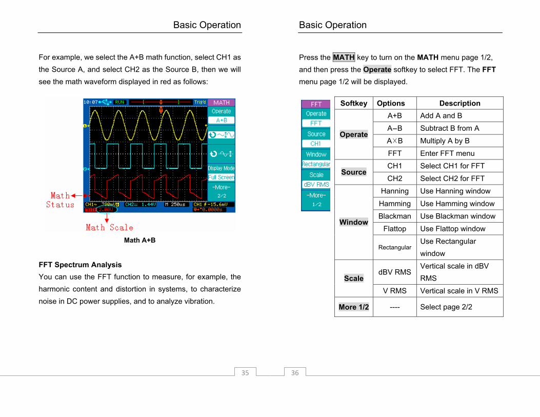
For example, we select the A+B math function, select CH1 as the Source A, and select CH2 as the Source B, then we will see the math waveform displayed in red as follows:
Math A+B
FFT Spectrum Analysis You can use the FFT function to measure, for example, the harmonic content and distortion in systems, to characterize noise in DC power supplies, and to analyze vibration.
Basic Operation
36
Press the MATH key to turn on the MATH menu page 1/2, and then press the Operate softkey to select FFT. The FFT menu page 1/2 will be displayed.
Softkey Options Description A+B Add A and B
A-B Subtract B from A
A×B Multiply A by B Operate
FFT Enter FFT menu
CH1 Select CH1 for FFT Source
CH2 Select CH2 for FFT
Hanning Use Hanning window
Hamming Use Hamming window
Blackman Use Blackman window
Flattop Use Flattop window Window
Rectangular Use Rectangular window
dBV RMS Vertical scale in dBV RMS Scale
V RMS Vertical scale in V RMS
More 1/2 ---- Select page 2/2
Basic Operation
37
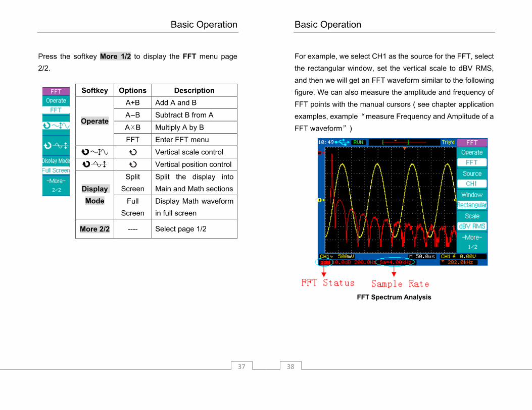
Press the softkey More 1/2 to display the FFT menu page 2/2.
Softkey Options Description A+B Add A and B
A-B Subtract B from A
A×B Multiply A by B Operate
FFT Enter FFT menu
Vertical scale control
Vertical position control
Split Screen
Split the display into Main and Math sectionsDisplay
Mode Full Screen
Display Math waveform in full screen
More 2/2 ---- Select page 1/2
Basic Operation
38
For example, we select CH1 as the source for the FFT, select the rectangular window, set the vertical scale to dBV RMS, and then we will get an FFT waveform similar to the following figure. We can also measure the amplitude and frequency of FFT points with the manual cursors ( see chapter application examples, example “measure Frequency and Amplitude of a FFT waveform”)
FFT Spectrum Analysis
Basic Operation
39
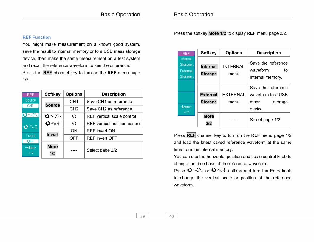
REF Function You might make measurement on a known good system, save the result to internal memory or to a USB mass storage device, then make the same measurement on a test system and recall the reference waveform to see the difference. Press the REF channel key to turn on the REF menu page 1/2.
Softkey Options Description CH1 Save CH1 as reference
Source CH2 Save CH2 as reference
REF vertical scale control
REF vertical position control
ON REF invert ON Invert
OFF REF invert OFF
More 1/2
---- Select page 2/2
Basic Operation
40
Press the softkey More 1/2 to display REF menu page 2/2.
Press REF channel key to turn on the REF menu page 1/2 and load the latest saved reference waveform at the same time from the internal memory. You can use the horizontal position and scale control knob to change the time base of the reference waveform. Press or softkey and turn the Entry knob to change the vertical scale or position of the reference waveform.
Softkey Options Description
Internal Storage
INTERNAL menu
Save the reference waveform to internal memory.
External Storage
EXTERNAL menu
Save the reference waveform to a USB mass storage device.
More 2/2
---- Select page 1/2

Basic Operation
41
Press REF→ Internal Storage →Save to save the waveform of the Source channel as the reference waveform to internal memory.
Save a Reference waveform
Note: The reference waveform function is unavailable when X-Y mode is selected.
Basic Operation
42
Horizontal Controls Use the horizontal controls to adjust the time base, adjust the trigger location, and to examine waveform details more closely.
Horizontal Controls

Basic Operation
43
Horizontal Position Control When the oscilloscope is in run mode, this control lets you set the acquisition window relative to the trigger point. When acquisition is stopped, you can turn this knob to pan through the data horizontally. This lets you see the captured waveform before the trigger or after the trigger. The trigger position is marked with the letter “T” at the top of the graticule and also in the waveform record icon at the top of the screen. The small inverted triangle is the time reference indicator. When you change the horizontal scale, the waveforms contract or expand about this point. Press the horizontal position control knob to set the time delay to zero. Then the trigger position indicator ( ) overlays the time reference indicator( ). Note: The horizontal position control is unavailable when
X-Y horizontal mode is selected. Horizontal Scale Control Use the horizontal scale control to adjust the time base. The scale expands or contracts around the center of the screen. The horizontal scale factor can be set in a 1-2.5-5 sequence. Press the horizontal scale control knob to toggle between Main and Delayed horizontal mode. Horizontal MENU key
Basic Operation
44
Press the horizontal MENU key to display the HORIZONTAL menu. This menu lets you select the horizontal mode: Main, Delayed, Roll, or X-Y, and set the Holdoff time.
Press the horizontal MENU key to display the HORIZONTAL menu page 1/2.
Softkey Options Description √ Main mode is ON
Main ---- Main mode is OFF
√ Delayed mode is ON Delayed
---- Delayed mode is OFF
√ X-Y mode is ON X-Y
---- X-Y mode is OFF
√ Roll mode is ON Roll
---- Roll mode is OFF
-More- 1/2
---- Select page 2/2
Basic Operation
45
Press the softkey More 1/2 to display the HORIZONTAL menu page 2/2.
Main Horizontal Mode The Main horizontal mode is the normal viewing mode for the oscilloscope. When acquisition is stopped, you can use the horizontal controls to pan and zoom the waveform. When the oscilloscope is operating in Main mode, use the horizontal scale knob to change horizontal scale factor and use the horizontal position knob to set the delay time. When the oscilloscope is stopped, use the horizontal control knobs to pan and zoom the waveform. The time base (second/division) value is displayed at the bottom of the screen.
Softkey Options Description
Holdoff Set the holdoff time between two triggers.
Holdoff Reset
---- Reset the holdoff time to the default value of 100 ns.
Trig-Offset Reset
---- Reset the delay time to zero.
-More- 2/2
---- Select page 1/2
Basic Operation
46
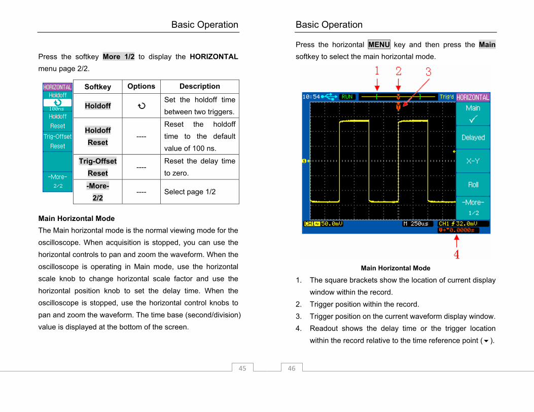
Press the horizontal MENU key and then press the Main softkey to select the main horizontal mode.
Main Horizontal Mode
1. The square brackets show the location of current display window within the record.
2. Trigger position within the record. 3. Trigger position on the current waveform display window. 4. Readout shows the delay time or the trigger location
within the record relative to the time reference point ( ).
Basic Operation
47
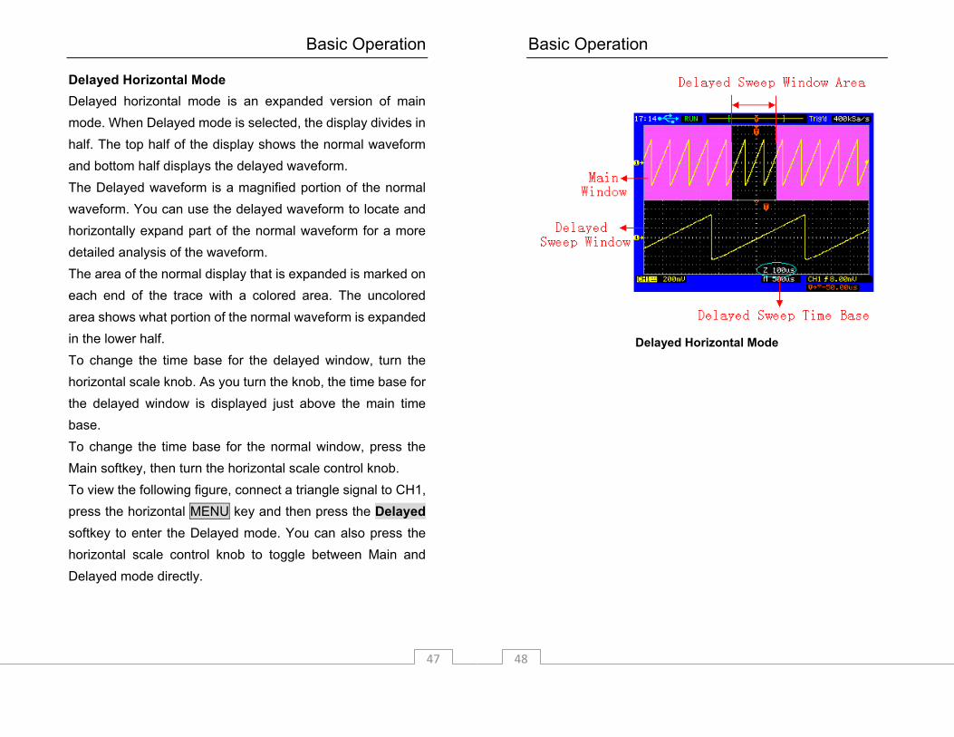
Delayed Horizontal Mode Delayed horizontal mode is an expanded version of main mode. When Delayed mode is selected, the display divides in half. The top half of the display shows the normal waveform and bottom half displays the delayed waveform. The Delayed waveform is a magnified portion of the normal waveform. You can use the delayed waveform to locate and horizontally expand part of the normal waveform for a more detailed analysis of the waveform. The area of the normal display that is expanded is marked on each end of the trace with a colored area. The uncolored area shows what portion of the normal waveform is expanded in the lower half. To change the time base for the delayed window, turn the horizontal scale knob. As you turn the knob, the time base for the delayed window is displayed just above the main time base. To change the time base for the normal window, press the Main softkey, then turn the horizontal scale control knob. To view the following figure, connect a triangle signal to CH1, press the horizontal MENU key and then press the Delayed softkey to enter the Delayed mode. You can also press the horizontal scale control knob to toggle between Main and Delayed mode directly.
Basic Operation
48
Delayed Horizontal Mode

Basic Operation
49
X-Y Horizontal Mode X-Y mode changes the display from a volts-versus-time display to a volts-versus-volts display. The time base is turned off. The CH1 signal is plotted on the X axis and CH2 signal is plotted on the Y axis. You can use X-Y mode to compare the frequency and phase relationships between two signals. X-Y mode can also be used with voltage transducers to display, for example, strain versus displacement, flow versus pressure, volts versus current, or voltage versus frequency. In order to get a better view of the waveform, the proper vertical scale should be selected before entering the X-Y mode. Example: Use the X-Y mode to compare two signals with the same frequency and different phase. Connect the two signals to CH1 and CH2 respectively. Press horizontal MENU key and then X-Y softkey to select X-Y mode. The displayed ellipse (a Lissajous figure) indicates the phase relationship of the two signals.
Basic Operation
50
X-Y Horizontal Mode
Basic Operation
51
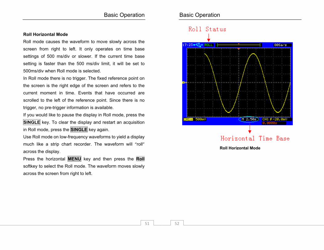
Roll Horizontal Mode Roll mode causes the waveform to move slowly across the screen from right to left. It only operates on time base settings of 500 ms/div or slower. If the current time base setting is faster than the 500 ms/div limit, it will be set to 500ms/div when Roll mode is selected. In Roll mode there is no trigger. The fixed reference point on the screen is the right edge of the screen and refers to the current moment in time. Events that have occurred are scrolled to the left of the reference point. Since there is no trigger, no pre-trigger information is available. If you would like to pause the display in Roll mode, press the SINGLE key. To clear the display and restart an acquisition in Roll mode, press the SINGLE key again. Use Roll mode on low-frequency waveforms to yield a display much like a strip chart recorder. The waveform will “roll” across the display. Press the horizontal MENU key and then press the Roll softkey to select the Roll mode. The waveform moves slowly across the screen from right to left.
Basic Operation
52
Roll Horizontal Mode
Basic Operation
53
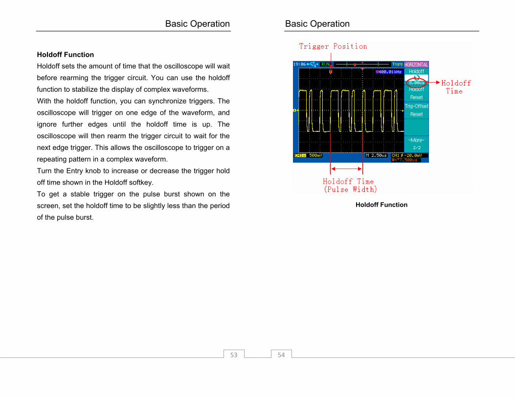
Holdoff Function Holdoff sets the amount of time that the oscilloscope will wait before rearming the trigger circuit. You can use the holdoff function to stabilize the display of complex waveforms. With the holdoff function, you can synchronize triggers. The oscilloscope will trigger on one edge of the waveform, and ignore further edges until the holdoff time is up. The oscilloscope will then rearm the trigger circuit to wait for the next edge trigger. This allows the oscilloscope to trigger on a repeating pattern in a complex waveform. Turn the Entry knob to increase or decrease the trigger hold off time shown in the Holdoff softkey. To get a stable trigger on the pulse burst shown on the screen, set the holdoff time to be slightly less than the period of the pulse burst.
Basic Operation
54
Holdoff Function
Basic Operation
55
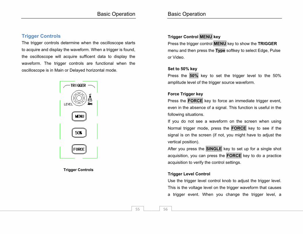
Trigger Controls The trigger controls determine when the oscilloscope starts to acquire and display the waveform. When a trigger is found, the oscilloscope will acquire sufficent data to display the waveform. The trigger controls are functional when the oscilloscope is in Main or Delayed horizontal mode.
Trigger Controls
Basic Operation
56
Trigger Control MENU key Press the trigger control MENU key to show the TRIGGER menu and then press the Type softkey to select Edge, Pulse or Video.
Set to 50% key Press the 50% key to set the trigger level to the 50% amplitude level of the trigger source waveform.
Force Trigger key Press the FORCE key to force an immediate trigger event, even in the absence of a signal. This function is useful in the following situations. If you do not see a waveform on the screen when using Normal trigger mode, press the FORCE key to see if the signal is on the screen (if not, you might have to adjust the vertical position). After you press the SINGLE key to set up for a single shot acquisition, you can press the FORCE key to do a practice acquisition to verify the control settings.
Trigger Level Control Use the trigger level control knob to adjust the trigger level. This is the voltage level on the trigger waveform that causes a trigger event. When you change the trigger level, a
Basic Operation
57
horizontal line temporarily appears to show you the trigger level on the screen. After the line disappears, the trigger level is marked with a small left arrow.
Auto and Normal Trigger Modes Press the trigger MENU key to display the TRIGGER menu and press the Mode softkey to select Auto or Normal trigger mode. Note: The Auto and Normal trigger mode are unavailable
when the Video trigger type is selected. Auto mode Use the auto trigger mode for signals other than low repetitive-rate signals and for unknown signal levels. To display a DC signal, you must use Auto trigger mode since there is no edge to trigger on. When you press the RUN/STOP key to start acquiring a waveform, the oscilloscope first fills the pre-trigger buffer. It then starts to search for a trigger after the pre-trigger buffer is filled and continues to flow data through this buffer while it searches for the trigger. While searching for the trigger, if the oscilloscope overflows the pre-trigger buffer, the first data put into the buffer is the first pushed out. When a trigger is found, the pre-trigger buffer will contain the events that occurred just before the trigger. If no trigger is found, the oscilloscope generates a trigger and displays the data as though a trigger had occurred. In this case, the background of the Auto
Basic Operation
58
indicator at the top of the display will flash, indicating that the oscilloscope auto triggered. When you press the SINGLE key, the oscilloscope will fill the pre-trigger buffer and continue to flow data through the pre-trigger buffer until the Auto trigger overrides the searching and forces a trigger. At the end of the trace, the oscilloscope will stop and display the results.
Normal mode Use Normal trigger mode for low repetitive-rate signals or when Auto trigger is not required. In Normal mode the oscilloscope must fill the pre-trigger buffer with data before it will begin searching for a trigger event. While searching for the trigger, if the oscilloscope overflows the pre-trigger buffer; the first data put into the buffer is the first pushed out. When the trigger event is found, the oscilloscope will fill the post-trigger buffer and display the results. If the acquisition was initiated by RUN/STOP, the process repeats. If the acquisition was initiated by SINGLE, then the acquisition stops. In either Auto or Normal mode, the trigger may be missed. This is because the oscilloscope will not recognize a trigger event until the pre-trigger buffer is full.

Basic Operation
59
Video Trigger Choose video triggering to trigger on the odd fields, even fields, or on all the lines of a NTSC or PAL/SECAM video signal. Press the trigger control MENU key to display the TRIGGER menu, then press the Type softkey to select Video trigger.
Basic Operation
60
Softkey Options Description Video Video triggering
Edge Edge triggering Type Pulse Pulse width triggering
CH1 Trigger on CH1
CH2 Trigger on CH2
EXT Trigger on EXT
EXT/5 Trigger on EXT/5
Source
Alternating Trigger on CH1 and CH2 alternately Positive polarity
Polarity Negative polarity
Odd Field Trigger on odd fields
Even Field Trigger on even fields
All Lines Trigger on all lines Sync
Line # Trigger on a specific line
NTSC Trigger on NTSC signal Standard
PAL/SECAM Trigger on PAL or SECAM signal
Basic Operation
61
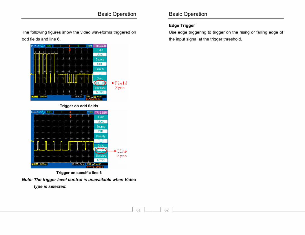
The following figures show the video waveforms triggered on odd fields and line 6.
Trigger on odd fields
Trigger on specific line 6
Note: The trigger level control is unavailable when Video type is selected.
Basic Operation
62
Edge Trigger Use edge triggering to trigger on the rising or falling edge of the input signal at the trigger threshold.
Basic Operation
63
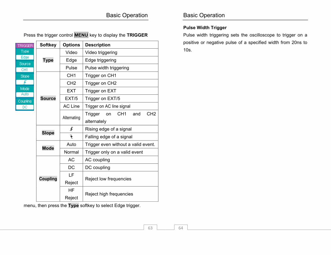
Press the trigger control MENU key to display the TRIGGER
menu, then press the Type softkey to select Edge trigger.
Softkey Options Description Video Video triggering
Edge Edge triggering Type Pulse Pulse width triggering
CH1 Trigger on CH1
CH2 Trigger on CH2
EXT Trigger on EXT
EXT/5 Trigger on EXT/5
AC Line Trigger on AC line signal
Source
Alternating Trigger on CH1 and CH2 alternately
Rising edge of a signal Slope
Falling edge of a signal
Auto Trigger even without a valid event. Mode
Normal Trigger only on a valid event
AC AC coupling
DC DC coupling
LF Reject
Reject low frequencies
Coupling
HF Reject
Reject high frequencies
Basic Operation
64
Pulse Width Trigger Pulse width triggering sets the oscilloscope to trigger on a positive or negative pulse of a specified width from 20ns to 10s.
Basic Operation
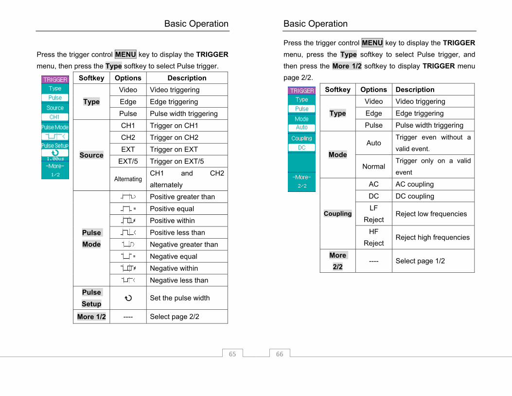
65
Press the trigger control MENU key to display the TRIGGER menu, then press the Type softkey to select Pulse trigger.
Softkey Options Description Video Video triggering
Edge Edge triggering Type Pulse Pulse width triggering
CH1 Trigger on CH1
CH2 Trigger on CH2
EXT Trigger on EXT
EXT/5 Trigger on EXT/5 Source
Alternating CH1 and CH2 alternately
Positive greater than
Positive equal
Positive within
Positive less than
Negative greater than
Negative equal
Negative within
Pulse Mode
Negative less than
Pulse Setup
Set the pulse width
More 1/2 ---- Select page 2/2
Basic Operation
66
Press the trigger control MENU key to display the TRIGGER menu, press the Type softkey to select Pulse trigger, and then press the More 1/2 softkey to display TRIGGER menu page 2/2.
Softkey Options Description Video Video triggering
Edge Edge triggering Type Pulse Pulse width triggering
Auto Trigger even without a
valid event. Mode
Normal Trigger only on a valid
event
AC AC coupling
DC DC coupling
LF Reject
Reject low frequencies Coupling
HF Reject
Reject high frequencies
More 2/2
---- Select page 1/2
Basic Operation
67
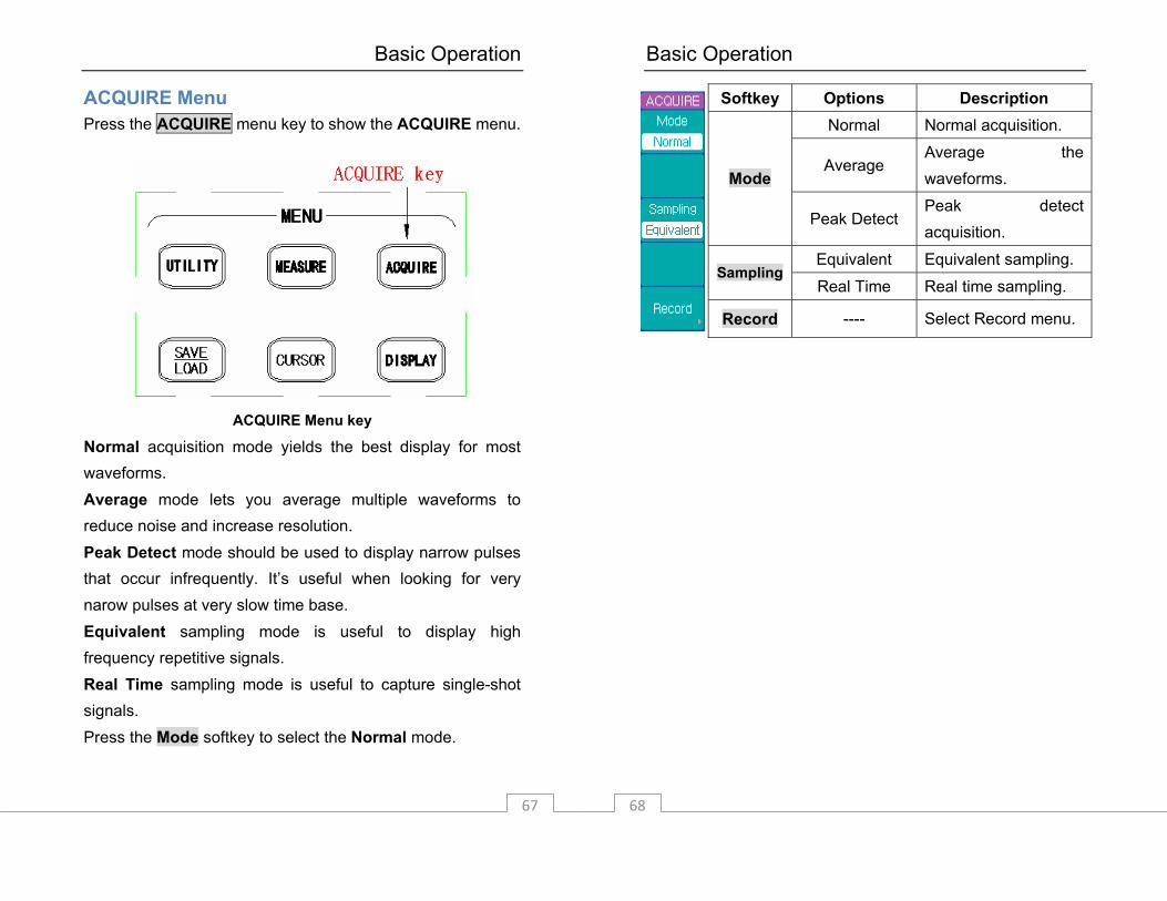
ACQUIRE Menu Press the ACQUIRE menu key to show the ACQUIRE menu.
ACQUIRE Menu key
Normal acquisition mode yields the best display for most waveforms. Average mode lets you average multiple waveforms to reduce noise and increase resolution. Peak Detect mode should be used to display narrow pulses that occur infrequently. It’s useful when looking for very narow pulses at very slow time base. Equivalent sampling mode is useful to display high frequency repetitive signals. Real Time sampling mode is useful to capture single-shot signals. Press the Mode softkey to select the Normal mode.
Basic Operation
68
Softkey Options Description Normal Normal acquisition.
Average Average the waveforms. Mode
Peak Detect Peak detect acquisition.
Equivalent Equivalent sampling. Sampling
Real Time Real time sampling.
Record ---- Select Record menu.
Basic Operation
69
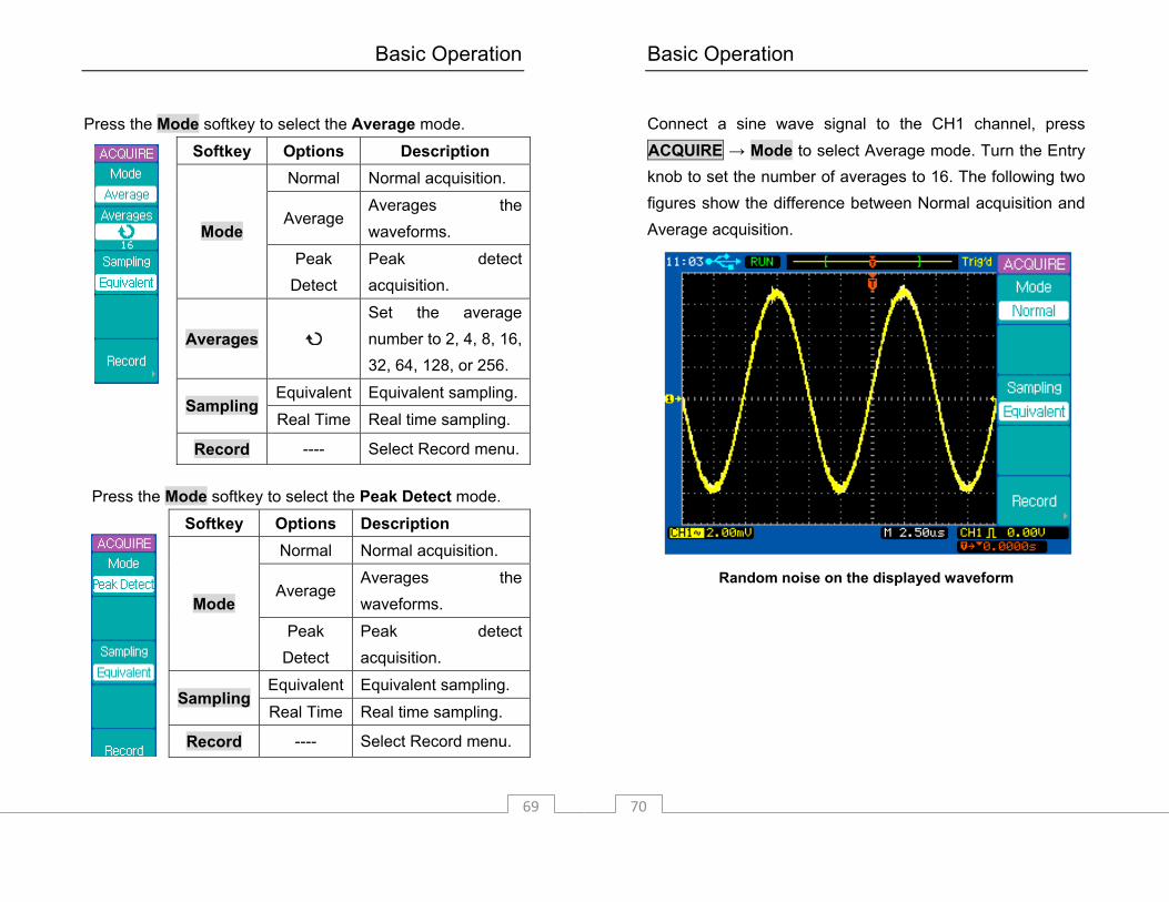
Press the Mode softkey to select the Average mode.
Softkey Options Description Normal Normal acquisition.
Average Averages the waveforms. Mode
Peak Detect
Peak detect acquisition.
Averages
Set the average number to 2, 4, 8, 16, 32, 64, 128, or 256.
Equivalent Equivalent sampling. Sampling
Real Time Real time sampling.
Record ---- Select Record menu.
Press the Mode softkey to select the Peak Detect mode.
Softkey Options Description Normal Normal acquisition.
Average Averages the waveforms. Mode
Peak Detect
Peak detect acquisition.
Equivalent Equivalent sampling. Sampling
Real Time Real time sampling.
Record ---- Select Record menu.
Basic Operation
70
Connect a sine wave signal to the CH1 channel, press ACQUIRE → Mode to select Average mode. Turn the Entry knob to set the number of averages to 16. The following two figures show the difference between Normal acquisition and Average acquisition.
Random noise on the displayed waveform
Basic Operation
71
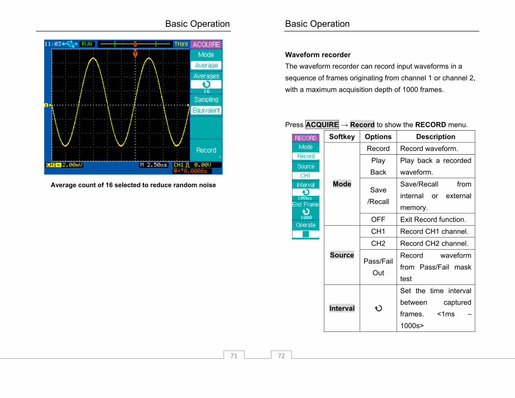
Average count of 16 selected to reduce random noise
Basic Operation
72
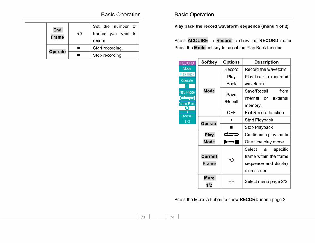
Waveform recorder The waveform recorder can record input waveforms in a sequence of frames originating from channel 1 or channel 2, with a maximum acquisition depth of 1000 frames. Press ACQUIRE → Record to show the RECORD menu.
Softkey Options Description Record Record waveform.
Play Back
Play back a recorded waveform.
Save /Recall
Save/Recall from internal or external memory.
Mode
OFF Exit Record function.
CH1 Record CH1 channel.
CH2 Record CH2 channel. Source
Pass/Fail Out
Record waveform from Pass/Fail mask test
Interval
Set the time interval between captured frames. <1ms – 1000s>
Basic Operation
73
End Frame
Set the number of frames you want to record
Start recording. Operate
Stop recording
Basic Operation
74
Play back the record waveform sequence (menu 1 of 2) Press ACQUIRE → Record to show the RECORD menu. Press the Mode softkey to select the Play Back function.
Softkey Options Description Record Record the waveform
Play Back
Play back a recorded waveform.
Save /Recall
Save/Recall from internal or external memory.
Mode
OFF Exit Record function Start Playback
Operate Stop Playback
Continuous play modePlay Mode One time play mode
Current Frame
Select a specific frame within the frame sequence and display it on screen
More 1/2
---- Select menu page 2/2
Press the More ½ button to show RECORD menu page 2
Basic Operation
75
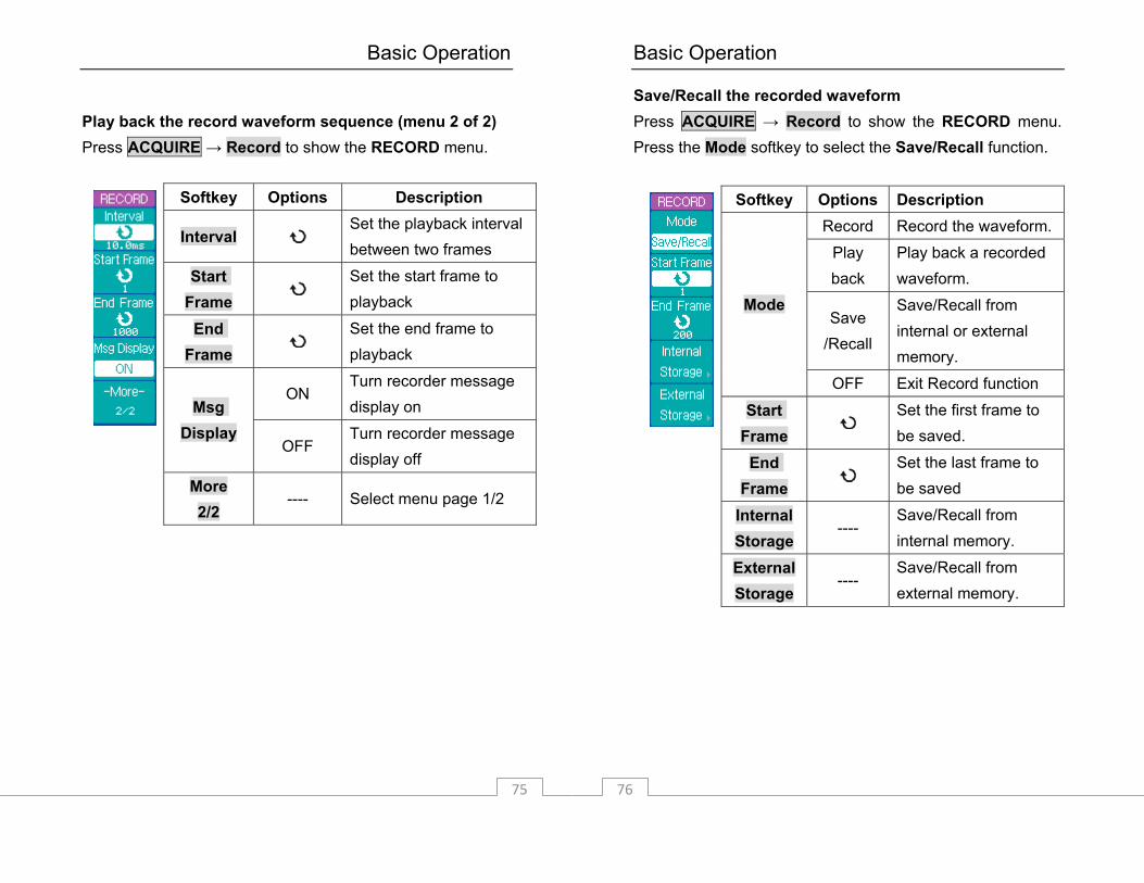
Play back the record waveform sequence (menu 2 of 2) Press ACQUIRE → Record to show the RECORD menu.
Softkey Options Description
Interval Set the playback interval between two frames
Start Frame
Set the start frame to playback
End Frame
Set the end frame to playback
ON Turn recorder message display on Msg
Display OFF
Turn recorder message display off
More 2/2
---- Select menu page 1/2
Basic Operation
76
Save/Recall the recorded waveform Press ACQUIRE → Record to show the RECORD menu. Press the Mode softkey to select the Save/Recall function.
Softkey Options Description Record Record the waveform.
Play back
Play back a recorded waveform.
Save /Recall
Save/Recall from internal or external memory.
Mode
OFF Exit Record function Start
Frame
Set the first frame to be saved.
End Frame
Set the last frame to be saved
Internal Storage
---- Save/Recall from internal memory.
External Storage
---- Save/Recall from external memory.

Basic Operation
77
Exit the waveform recorder Press the Mode softkey to select the OFF option and return to the ACQUIRE menu.
Softkey Options Description Record Record the waveform
Play back Play back the record
Save /Recall
Save/Recall from internal or external memory
Mode
OFF Exit Record function
---- Return to ACQUIRE menu
Basic Operation
78
UTILITY Menu Press the UTILITY menu key to show the UTILITY menu.
UTILITY Menu key
Basic Operation
79
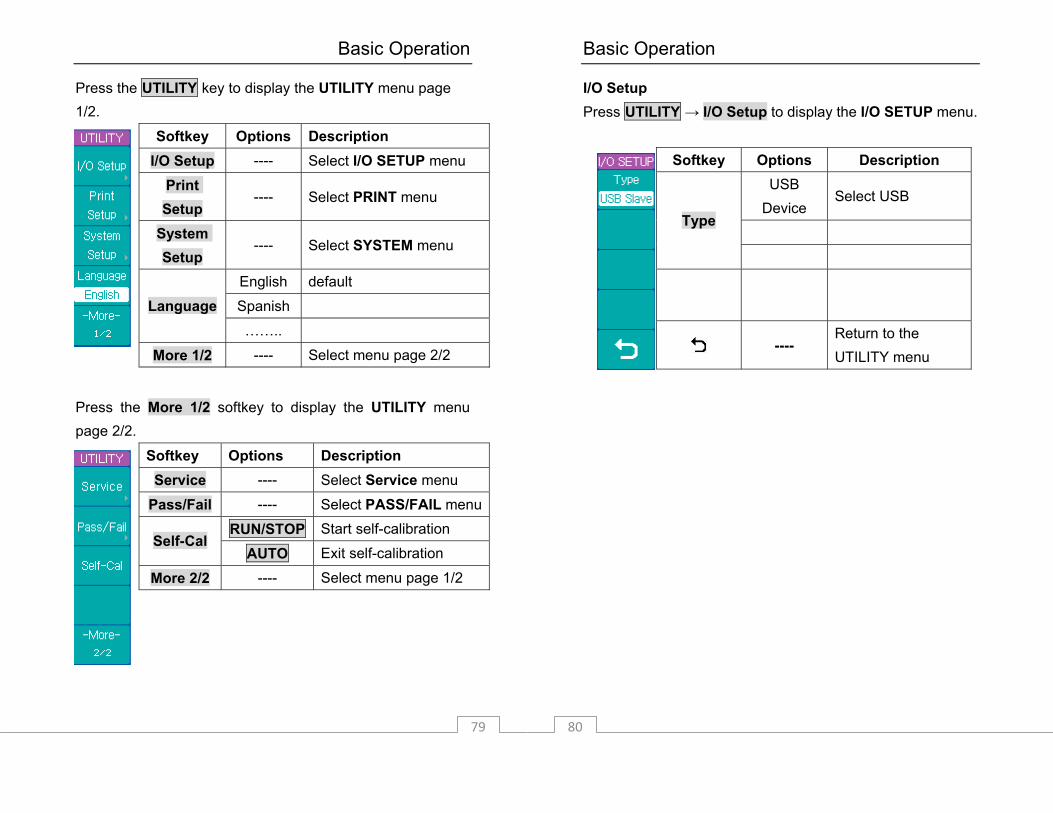
Press the UTILITY key to display the UTILITY menu page 1/2.
Softkey Options Description I/O Setup ---- Select I/O SETUP menu
Print Setup
---- Select PRINT menu
System Setup
---- Select SYSTEM menu
English default
Spanish Language ……..
More 1/2 ---- Select menu page 2/2
Press the More 1/2 softkey to display the UTILITY menu page 2/2.
Softkey Options Description Service ---- Select Service menu
Pass/Fail ---- Select PASS/FAIL menu
RUN/STOP Start self-calibration Self-Cal
AUTO Exit self-calibration
More 2/2 ---- Select menu page 1/2
Basic Operation
80
I/O Setup Press UTILITY → I/O Setup to display the I/O SETUP menu.
Softkey Options Description USB
Device Select USB
Type
---- Return to the UTILITY menu

Basic Operation
81
Print Setup Press UTILITY → Print Setup to display the PRINT menu. Press the Print to softkey to select File.
Softkey Options Description
Print to File Print to file
BMP BMP file format File Type
CSV CSV file format
---- Return to the UTILITY menu
Connect a USB mass storage device to the USB host connector on the front or rear panel. Press the File Type softkey to select the file format you want. BMP is a bitmap of the screen and CSV are comma-separated values. CSV format can be imported into spreadsheets such as Excel. Press the PRINT key to save the file to the USB mass storage device.
Basic Operation
82
System Setup Press UTILITY → System Setup to display the SYSTEM menu.
Softkey Options Description
Key press sound on Key Sound Key press sound off
Alarm sound on Alarm Sound Alarm sound off
ON Frequency counter on Counter
OFF Frequency counter off
Set Date &Time
---- Select the DATE&TIME menu
---- Return to the UTILITY menu
Note: With Alarm set to “On”, you will hear a beep under the following conditions: A control reached its limit or an invalid setting or configuration was encountered, in which case you will also see a warning message displayed on screen (example: Auto button is pressed without detecting a signal).
Basic Operation
83
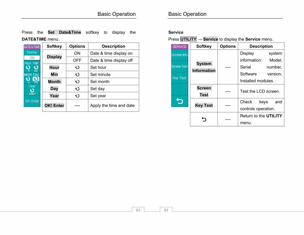
Press the Set Date&Time softkey to display the DATE&TIME menu.
Softkey Options Description ON Date & time display on
Display OFF Date & time display off
Set hour Hour Min Set minute
Set month Month Day Set day
Year Set year
OK! Enter ---- Apply the time and date
Basic Operation
84
Service Press UTILITY → Service to display the Service menu.
Softkey Options Description
System Information
----
Display system information: Model, Serial number, Software version, Installed modules.
Screen Test
---- Test the LCD screen.
Key Test ---- Check keys and controls operation.
---- Return to the UTILITY menu.
Basic Operation
85
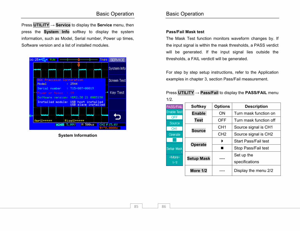
Press UTILITY → Service to display the Service menu, then press the System Info softkey to display the system information, such as Model, Serial number, Power up times, Software version and a list of installed modules.
System Information
Basic Operation
86
Pass/Fail Mask test The Mask Test function monitors waveform changes by. If the input signal is within the mask thresholds, a PASS verdict will be generated. If the input signal lies outside the thresholds, a FAIL verdictl will be generated. For step by step setup instructions, refer to the Application examples in chapter 3, section Pass/Fail measurement. Press UTILITY → Pass/Fail to display the PASS/FAIL menu 1/2.
Softkey Options Description ON Turn mask function on Enable
Test OFF Turn mask function off
CH1 Source signal is CH1 Source
CH2 Source signal is CH2 Start Pass/Fail test
Operate Stop Pass/Fail test
Setup Mask ---- Set up the specifications
More 1/2 ---- Display the menu 2/2
Basic Operation
87
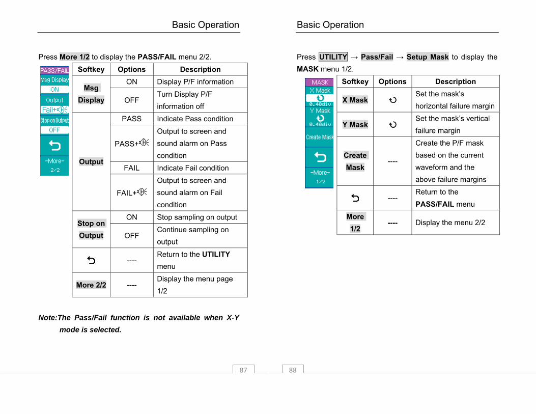
Press More 1/2 to display the PASS/FAIL menu 2/2.
Softkey Options Description ON Display P/F information
Msg Display OFF
Turn Display P/F information off
PASS Indicate Pass condition
PASS+
Output to screen and sound alarm on Pass condition
FAIL Indicate Fail condition Output
FAIL+
Output to screen and sound alarm on Fail condition
ON Stop sampling on output Stop on Output OFF
Continue sampling on output
---- Return to the UTILITY menu
More 2/2 ---- Display the menu page 1/2
Note:The Pass/Fail function is not available when X-Y mode is selected.
Basic Operation
88
Press UTILITY → Pass/Fail → Setup Mask to display the MASK menu 1/2.
Softkey Options Description
X Mask Set the mask’s horizontal failure margin
Y Mask Set the mask’s vertical failure margin
Create Mask
----
Create the P/F mask based on the current waveform and the above failure margins
---- Return to the PASS/FAIL menu
More 1/2
---- Display the menu 2/2

Basic Operation
89
Press More 1/2 to display the MASK menu 2/2.
Softkey Options Description
Internal Storage
---- Store the PASS/FAIL tolerance mask to internal memory.
External Storage
----
Store the PASS/FAIL tolerance mask to external USB mass storage device.
---- Return to the PASS/FAIL menu.
More 2/2 ---- Display the menu page ½.
Basic Operation
90
Self-Calibration If you want to maximize the measurement accuracy, you can perform a self-calibration. Self-calibration uses internally-generated signals to calibrate circuits that affect channel scale, offset, and trigger parameters. Disconnect all inputs and allow the oscilloscope to warm up for at least 30 minutes before performing a self-calibration. Press UTILITY → Self-Cal to display the self-calibration page. Press the AUTO key to exit the self-calibration page. Press the RUN key to start the self-calibration.
Self Calibration
Basic Operation
91
Note: Warm up the oscilloscope for at least 30 minutes before performing self-calibration.
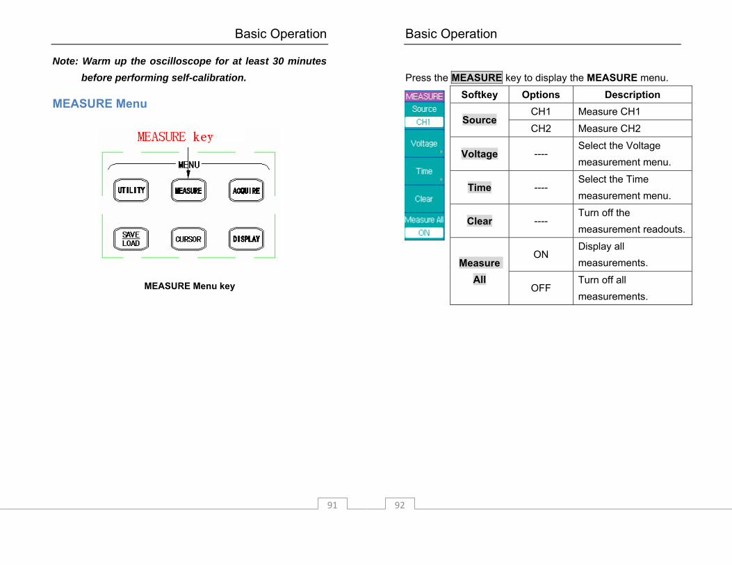
MEASURE Menu
MEASURE Menu key
Basic Operation
92
Press the MEASURE key to display the MEASURE menu.
Softkey Options Description CH1 Measure CH1
Source CH2 Measure CH2
Voltage ---- Select the Voltage measurement menu.
Time ---- Select the Time measurement menu.
Clear ---- Turn off the measurement readouts.
ON Display all measurements. Measure
All OFF
Turn off all measurements.

Basic Operation
93
Voltage Measurements Press MEASURE → Voltage to display the VOLTAGE menu page 1/4.
Softkey Options Description
Peak-Peak ----
The Peak-Peak value is the difference between maximum and minimum values.
Amplitude ---- The Amplitude value is the difference between its High and Low values.
Max ---- Max is the maximum voltage in the waveform display.
Min ---- Min is the minimum voltage in the waveform display
More 1/4 ---- Display menu page 2/4
Basic Operation
94
Press the More 1/4 softkey to display the VOLTAGE menu page 2/4.
Softkey Options Description
High ----
Measures the flattop voltage (average value) of the upper part of the waveform.
Low ----
Measures the flat base voltage (average value) of the upper part of the waveform.
Average ----
Average value is the sum of the samples divided by the number of samples over the entire waveform.
RMS ----
RMS value is the true Root Mean Square voltage over the entire waveform.
More 2/4
---- Display menu page ¾.
Basic Operation
95
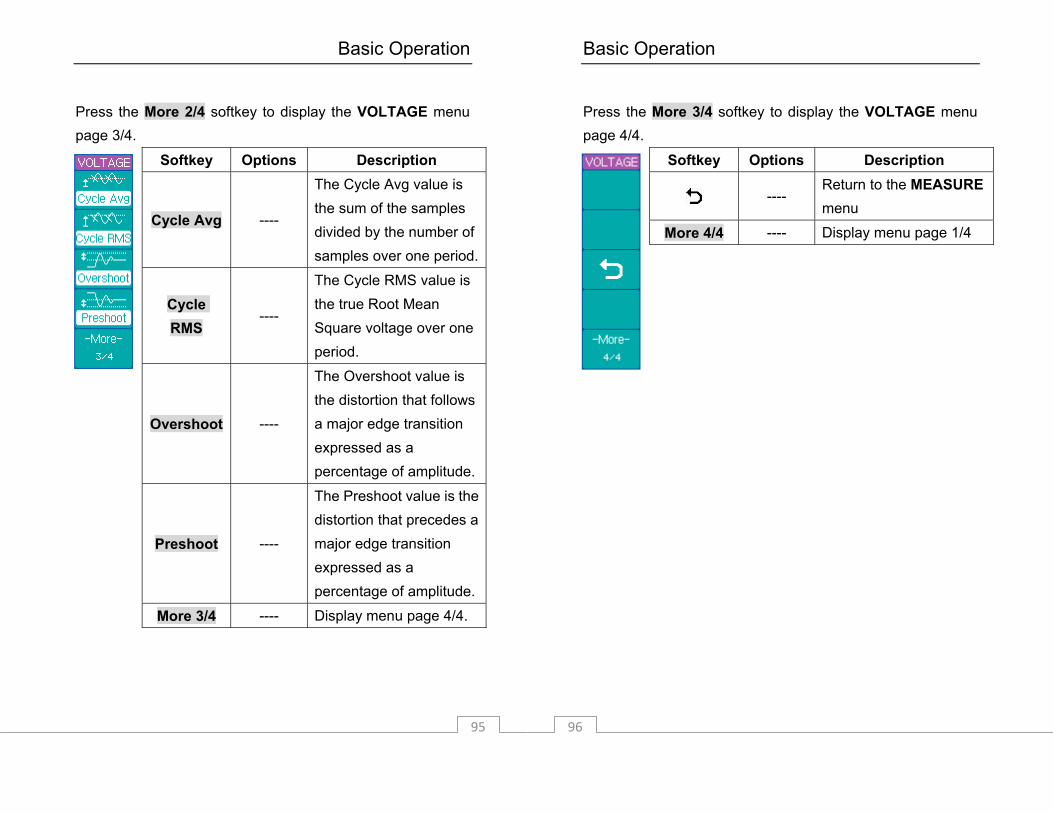
Press the More 2/4 softkey to display the VOLTAGE menu page 3/4.
Softkey Options Description
Cycle Avg ----
The Cycle Avg value is the sum of the samples divided by the number of samples over one period.
Cycle RMS
----
The Cycle RMS value is the true Root Mean Square voltage over one period.
Overshoot ----
The Overshoot value is the distortion that follows a major edge transition expressed as a percentage of amplitude.
Preshoot ----
The Preshoot value is the distortion that precedes a major edge transition expressed as a percentage of amplitude.
More 3/4 ---- Display menu page 4/4.
Basic Operation
96
Press the More 3/4 softkey to display the VOLTAGE menu page 4/4.
Softkey Options Description
---- Return to the MEASURE menu
More 4/4 ---- Display menu page 1/4
Basic Operation
97
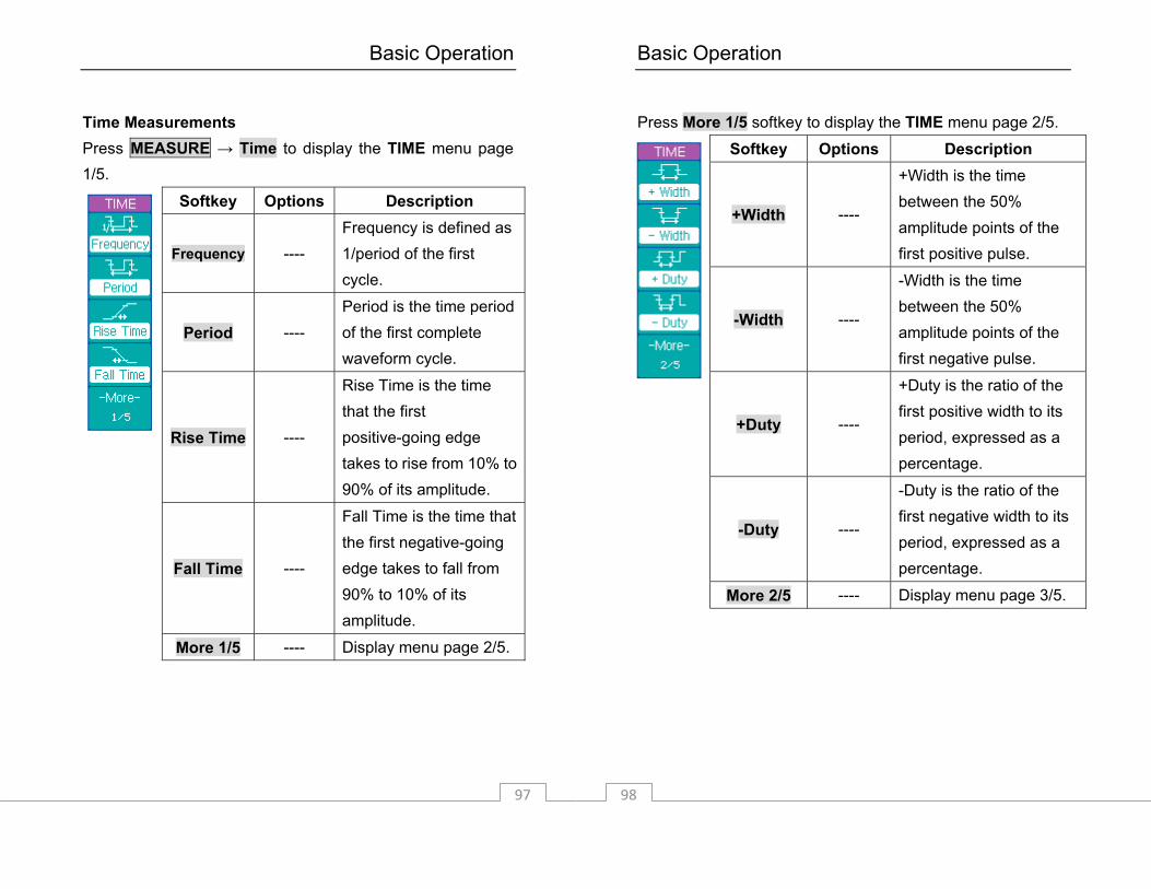
Time Measurements Press MEASURE → Time to display the TIME menu page 1/5.
Softkey Options Description
Frequency ---- Frequency is defined as 1/period of the first cycle.
Period ---- Period is the time period of the first complete waveform cycle.
Rise Time ----
Rise Time is the time that the first positive-going edge takes to rise from 10% to 90% of its amplitude.
Fall Time ----
Fall Time is the time that the first negative-going edge takes to fall from 90% to 10% of its amplitude.
More 1/5 ---- Display menu page 2/5.
Basic Operation
98
Press More 1/5 softkey to display the TIME menu page 2/5.
Softkey Options Description
+Width ----
+Width is the time between the 50% amplitude points of the first positive pulse.
-Width ----
-Width is the time between the 50% amplitude points of the first negative pulse.
+Duty ----
+Duty is the ratio of the first positive width to its period, expressed as a percentage.
-Duty ----
-Duty is the ratio of the first negative width to its period, expressed as a percentage.
More 2/5 ---- Display menu page 3/5.

Basic Operation
99
Press the More 2/5 softkey to display the TIME menu page 3/5.
Softkey Options Description
Delay ----
Measures the delay between 2 waveforms using the first rising edge of each channel as reference.
Delay ----
Measures the delay between 2 waveforms using the first falling edge of each channel as reference.
Delay ----
Measures the delay between 2 waveforms using the time between the first rising edge of CH1 and the first falling edge of CH2 (50% amplitude point.
Basic Operation
100
Delay ----
Measures the delay between 2 waveforms using the time between the first falling edge of CH1 and the first rising edge of CH2.
More 3/5 ---- Display menu page 4/5.

Basic Operation
101
Press the More 3/5 softkey to display the TIME menu page 4/5.
Softkey Options Description
Phase 1→2
----
Phase 1→2 is the time in degrees between corresponding points from waveforms 1 to waveform 2. [See note]
Phase 2→1
----
Phase 2→1 is the time in degrees between corresponding points from waveforms 1 to waveform 2. [See note]
X at Max ----
X at Max is the X axis value (i.e., time) referred to the trigger point at the first displayed occurrence of the waveform Maximum, starting from the left side of the display to the following waveform maximum.
Basic Operation
102
X at Min ----
X at Min is the X axis value (i.e., time) referred to the trigger point at the first displayed occurrence of the waveform Minimum, starting from the left side of the display, to the following waveforms minimum
More 4/5 ---- Display menu page 5/5
Note: time in degrees between the two points is calculated by measuring the time between the two points, dividing the time by the waveform’s period, then multiplying the fraction by 360 degrees. Press the More 4/5 softkey to display the TIME menu page 5/5.
Softkey Options Description
---- Return to the MEASURE menu
More 5/5 ---- Display menu page 1/5
Basic Operation
103
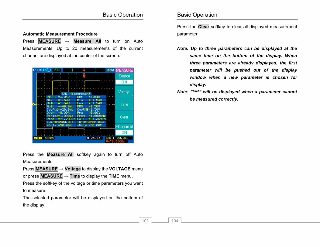
Automatic Measurement Procedure Press MEASURE → Measure All to turn on Auto Measurements. Up to 20 measurements of the current channel are displayed at the center of the screen.
Press the Measure All softkey again to turn off Auto Measurements. Press MEASURE → Voltage to display the VOLTAGE menu or press MEASURE → Time to display the TIME menu. Press the softkey of the voltage or time parameters you want to measure. The selected parameter will be displayed on the bottom of the display.
Basic Operation
104
Press the Clear softkey to clear all displayed measurement parameter. Note: Up to three parameters can be displayed at the
same time on the bottom of the display. When three parameters are already displayed, the first parameter will be pushed out of the display window when a new parameter is chosen for display.
Note: “****” will be displayed when a parameter cannot be measured correctly.
Basic Operation
105
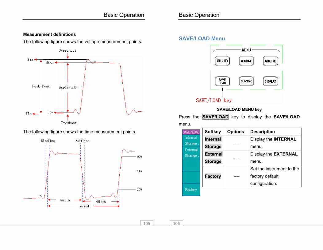
Measurement definitions The following figure shows the voltage measurement points.
The following figure shows the time measurement points.
Basic Operation
106
SAVE/LOAD Menu
SAVE/LOAD MENU key
Press the SAVE/LOAD key to display the SAVE/LOAD menu.
Softkey Options Description Internal Storage
---- Display the INTERNAL menu.
External Storage
---- Display the EXTERNAL menu.
Factory ---- Set the instrument to the factory default configuration.
Basic Operation
107
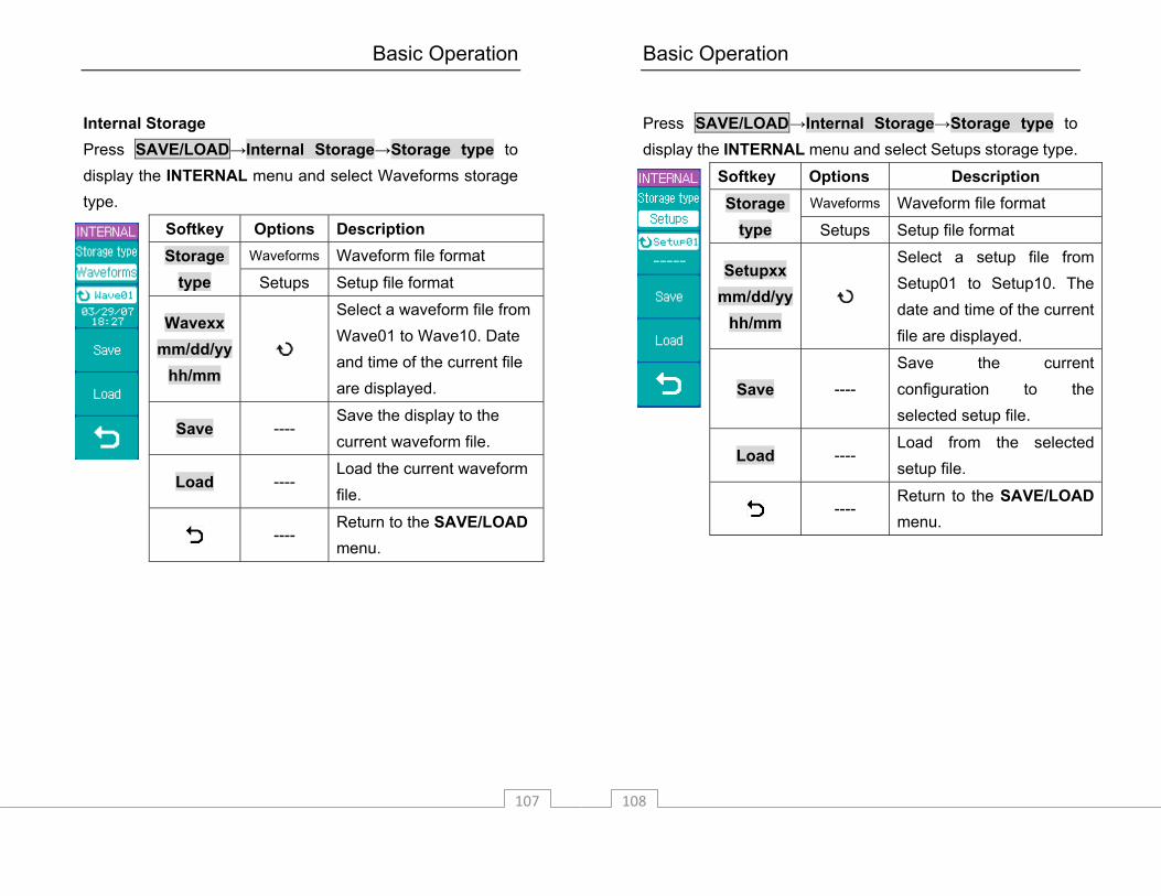
Internal Storage Press SAVE/LOAD→Internal Storage→Storage type to display the INTERNAL menu and select Waveforms storage type.
Softkey Options Description Waveforms Waveform file format Storage
type Setups Setup file format
Wavexx mm/dd/yy
hh/mm
Select a waveform file from Wave01 to Wave10. Date and time of the current file are displayed.
Save ---- Save the display to the current waveform file.
Load ---- Load the current waveform file.
---- Return to the SAVE/LOAD menu.
Basic Operation
108
Press SAVE/LOAD→Internal Storage→Storage type to display the INTERNAL menu and select Setups storage type.
Softkey Options Description Waveforms Waveform file format Storage
type Setups Setup file format
Setupxx mm/dd/yy
hh/mm
Select a setup file from Setup01 to Setup10. The date and time of the current file are displayed.
Save ---- Save the current configuration to the selected setup file.
Load ---- Load from the selected setup file.
---- Return to the SAVE/LOAD menu.

Basic Operation
109
External Storage Press SAVE/LOAD→External Storage to display the EXTERNAL menu.
Softkey Options Description
New ---- Create a new file or folder in the external memory.
Rename ---- Rename the current file or folder.
Load ---- Load the current file.
Delete ---- Delete the current file or folder.
---- Return to the SAVE/LOAD menu
Note: The above External Storage menu is only available
if a USB flashdrive is connected to the front panel USB host port.
Basic Operation
110
Press SAVE/LOAD→External Storage→New to display the New menu.
Softkey Options Description New File ---- Display the New File menu.
New Folder
---- Display the New Folder menu.
---- Return to the EXTERNAL menu

Basic Operation
111
Press SAVE/LOAD→External Storage→New→New File to display the New File menu.
Softkey Options Description Setups Save as setup files
Waveforms Save as waveform files
BMP Save as BMP files Save as
CSV Save as CSV files
Enter Character
---- Enter the selected character and go to the next character position.
Delete Character
---- Delete the selected character.
Save ---- Save the new file.
---- Return to the New menu.
Note: The maximum length of a file name is 8 characters. Press Enter Character to select a character position in the file name. Turn the entry knob to select a character. Press Delete Character to delete the selected character. Press Enter Character to enter the selected character and go to the next character position.
Basic Operation
112
Press SAVE/LOAD→External Storage→New→New Foler to display the New Folder menu.
Softkey Options Description
Enter Character
---- Enter the selected character and go to the next character position.
Delete Character
---- Delete the selected character.
Save ---- Save the new folder.
----
Return to the New menu.

Basic Operation
113
Press SAVE/LOAD→External Storage→Rename to display the Rename menu.
Softkey Options Description
Enter Character
---- Enter the selected character and go to the next character position.
Delete Character
---- Delete the selected character.
OK ---- Rename the selected file or folder.
---- Return to the EXTERNAL menu.
Basic Operation
114
Press SAVE/LOAD→External Storage→Delete to display the Delete menu.
Softkey Options Description
OK ---- Confirm the deletion of the selected file or folder.
Cancel ---- Cancel the deletion operation.
---- Return to the EXTERNAL menu.
Basic Operation
115
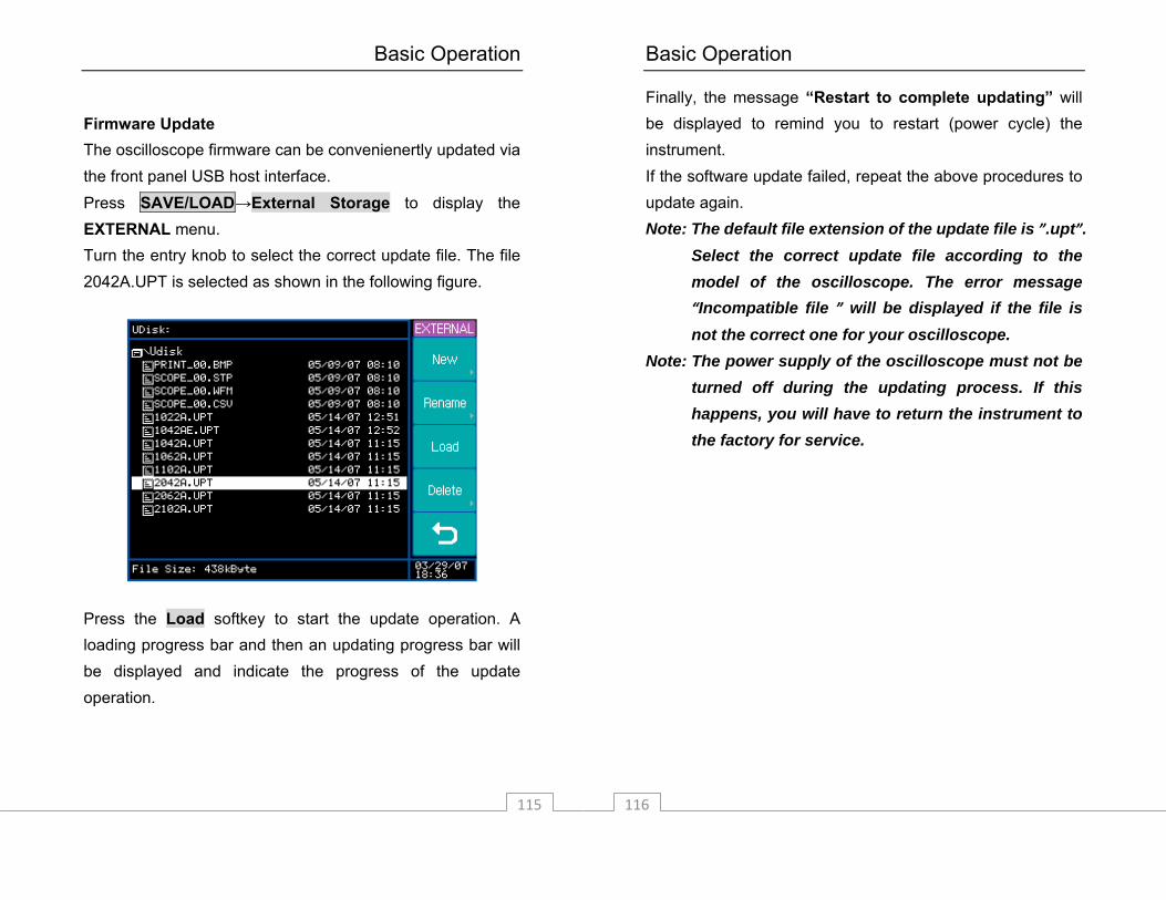
Firmware Update The oscilloscope firmware can be convenienertly updated via the front panel USB host interface. Press SAVE/LOAD→External Storage to display the EXTERNAL menu. Turn the entry knob to select the correct update file. The file 2042A.UPT is selected as shown in the following figure.
Press the Load softkey to start the update operation. A loading progress bar and then an updating progress bar will be displayed and indicate the progress of the update operation.
Basic Operation
116
Finally, the message “Restart to complete updating” will be displayed to remind you to restart (power cycle) the instrument. If the software update failed, repeat the above procedures to update again. Note: The default file extension of the update file is ”.upt”.
Select the correct update file according to the model of the oscilloscope. The error message “Incompatible file ” will be displayed if the file is not the correct one for your oscilloscope.
Note: The power supply of the oscilloscope must not be turned off during the updating process. If this happens, you will have to return the instrument to the factory for service.
Basic Operation
117
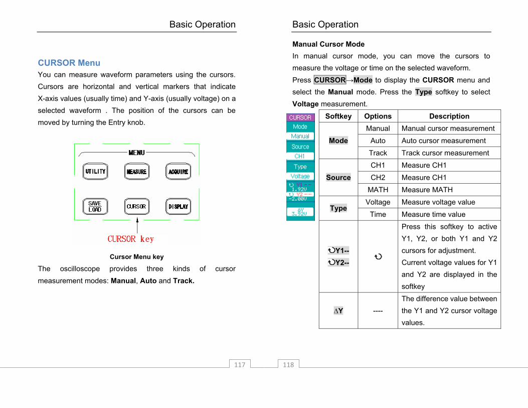
CURSOR Menu You can measure waveform parameters using the cursors. Cursors are horizontal and vertical markers that indicate X-axis values (usually time) and Y-axis (usually voltage) on a selected waveform . The position of the cursors can be moved by turning the Entry knob.
Cursor Menu key
The oscilloscope provides three kinds of cursor measurement modes: Manual, Auto and Track.
Basic Operation
118
Manual Cursor Mode In manual cursor mode, you can move the cursors to measure the voltage or time on the selected waveform. Press CURSOR→Mode to display the CURSOR menu and select the Manual mode. Press the Type softkey to select Voltage measurement.
Softkey Options Description Manual Manual cursor measurement
Auto Auto cursor measurement Mode Track Track cursor measurement
CH1 Measure CH1
CH2 Measure CH1 Source MATH Measure MATH
Voltage Measure voltage value Type
Time Measure time value
Y1-- Y2--
Press this softkey to active Y1, Y2, or both Y1 and Y2 cursors for adjustment. Current voltage values for Y1 and Y2 are displayed in the softkey
∆Y ---- The difference value between the Y1 and Y2 cursor voltage values.

Basic Operation
119
Press CURSOR→Mode to display the CURSOR menu and select the Manual mode. Press the Type softkey to select Time measurement.
Softkey Options Description Manual Manual cursor measurement
Auto Auto cursor measurement Mode Track Track cursor measurement
CH1 Measure CH1
CH2 Measure CH1 Source MATH Measure MATH
Voltage Measure voltage value Type
Time Measure time value
X1-- X2--
Press this softkey to select X1, X2, or both X1 and X2 cursors for adjustment. Current time values for X1 and X2 are displayed in the softkey
∆X 1/∆X
----
∆X is the time difference value between the X1 and X2 cursors. 1/∆X is the frequency “between” the X1 and X2 cursors.
Basic Operation
120
Track Cursor Mode In the track mode, the screen displays two cross hair cursors. The cross hair of the cursor is positioned on the waveform automatically. You can adjust the selected cursor's horizontal position on the waveform by turning the entry knob. The oscilloscope displays the values of the coordinates on the screen, either in the softkey area or on the top right corner in case the menu is off.

Basic Operation
121
Press CURSOR→Mode to display the CURSOR menu and select the Track mode.
Softkey Options Description Manual Manual cursor measurement
Auto Auto cursor measurement Mode Track Track cursor measurement
CH1 Track CH1 with Cursor A
CH2 Track CH2 with Cursor A Cursor A None Turn off Cursor A
CH1 Track CH1 with Cursor B
CH2 Track CH2 with Cursor B Cursor B None Turn off Cursor B
Ax-- Ay--
Press this softkey to select cursor A for adjustment. The current X, Y axis values for the tracking point of cursor A are displayed in the softkey.
Bx-- By--
Press this softkey to select cursor B for adjustment. The current X, Y axis values for the tracking point of Cursor B are displayed in the softkey.
Basic Operation
122
Auto Cursor Mode The Auto mode cursors are displayed only when the auto measurement function is enabled. The oscilloscope displays the auto cursors corresponding to the latest auto measurement parameter. The Auto cursors will not be displayed when no auto measurement parameter is selected.
Basic Operation
123
DISPLAY Menu
Display Menu key
Basic Operation
124
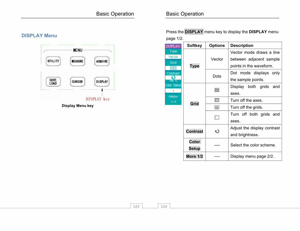
Press the DISPLAY menu key to display the DISPLAY menu page 1/2.
Softkey Options Description
Vector Vector mode draws a line between adjacent sample points in the waveform. Type
Dots Dot mode displays only the sample points.
Display both grids and axes.
Turn off the axes.
Turn off the grids. Grid
Turn off both grids and axes.
Contrast Adjust the display contrast and brightness.
Color Setup
---- Select the color scheme.
More 1/2 ---- Display menu page 2/2.

Basic Operation
125
Press More 1/2 softkey to display the DISPLAY menu page 2/2.
Softkey Options Description
ON
The scope updates the waveform without erasing the previously-displayed waveforms.
Persist
OFF Turn off the persistence function
Clear
Persistence ----
Press the softkey to erase the previous sample points.
Normal Select the color display.
Waveforms
Monochrome Select the monochrome display.
More 2/2 ---- Display menu page 1/2.
Basic Operation
126
RUN Controls
Run controls
Press the SINGLE key to execute a single-shot acquisition. The key will illuminate in orange until the oscilloscope is triggered. When the oscilloscope is triggered, the waveform will be acquired and displayed, after which the oscilloscope will ignore any further triggers. The RUN/STOP key is used to manually start/stop the oscilloscope’s acquisition system. In run mode, the oscilloscope will start looking for a trigger and the

Basic Operation
127
RUN/STOP key be green. When the trigger mode is set to Normal mode, the display will not update until a trigger is found. If the trigger mode is set to Auto mode, the oscilloscope looks for a trigger, and if no trigger is found, it will be triggered automatically and the input signal(s) will be displayed immediately. Press the RUN/STOP key again to stop acquiring data. The RUN/STOP key will be a red color. Now you can pan across and zoom in on the acquired waveform.
Basic Operation
128

Application Examples
129
3. Application Examples This section presents 7 typical application examples. These examples highlight the features of the oscilloscope and give you ideas on how to solve your own test problems.
Make a Simple Measurements You need to measure the amplitude and frequency of an unknown signal on CH1. Perform following steps to quickly display the signal.
Connect the channel 1 probe to the unknown signal. Press the AUTO key.
The oscilloscope automatically sets the vertical, horizontal, and trigger controls. You can adjust any of these controls manually if you need to optimize the display of the waveform. When you are using both CH1 and CH2 channels, the Autoset function sets the vertical controls for each channel and uses the CH1 channel to set the horizontal and trigger controls. The oscilloscope can automatically display most signals. Perform following steps to measure signal amplitude and frequency.
Application Examples
130
Press the MEASURE key to display the MEASURE menu.
Press the Voltage softkey to display the VOLTAGE menu.
Press the Amplitude softkey to measure the amplitude. The amplitude value will be displayed at the bottom of the screen.
Press the MEASURE key again to display the MEASURE menu.
Press the Time softkey to display the TIME menu. Press the Frequency softkey to measure the frequency.
The frequency value will be displayed at the bottom of the screen to the right of the voltage value.
Application Examples
131
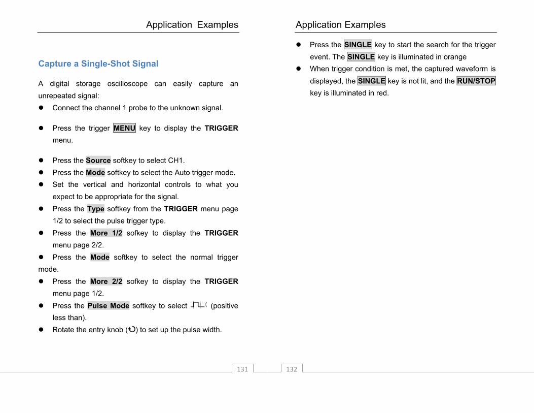
Capture a Single-Shot Signal
A digital storage oscilloscope can easily capture an unrepeated signal:
Connect the channel 1 probe to the unknown signal.
Press the trigger MENU key to display the TRIGGER menu.
Press the Source softkey to select CH1. Press the Mode softkey to select the Auto trigger mode. Set the vertical and horizontal controls to what you
expect to be appropriate for the signal. Press the Type softkey from the TRIGGER menu page
1/2 to select the pulse trigger type. Press the More 1/2 sofkey to display the TRIGGER
menu page 2/2. Press the Mode softkey to select the normal trigger
mode. Press the More 2/2 sofkey to display the TRIGGER
menu page 1/2.
Press the Pulse Mode softkey to select (positive less than).
Rotate the entry knob ( ) to set up the pulse width.
Application Examples
132
Press the SINGLE key to start the search for the trigger event. The SINGLE key is illuminated in orange
When trigger condition is met, the captured waveform is displayed, the SINGLE key is not lit, and the RUN/STOP key is illuminated in red.
Application Examples
133
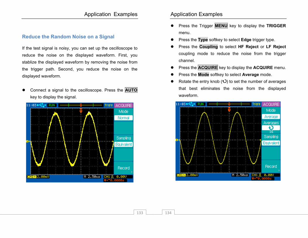
Reduce the Random Noise on a Signal
If the test signal is noisy, you can set up the oscilloscope to reduce the noise on the displayed waveform. First, you stablize the displayed waveform by removing the noise from the trigger path. Second, you reduce the noise on the displayed waveform.
Connect a signal to the oscilloscope. Press the AUTO key to display the signal.
Application Examples
134
Press the Trigger MENU key to display the TRIGGER menu.
Press the Type softkey to select Edge trigger type. Press the Coupling to select HF Reject or LF Reject
coupling mode to reduce the noise from the trigger channel.
Press the ACQUIRE key to display the ACQUIRE menu. Press the Mode softkey to select Average mode. Rotate the entry knob ( ) to set the number of averages
that best eliminates the noise from the displayed waveform.

Application Examples
135
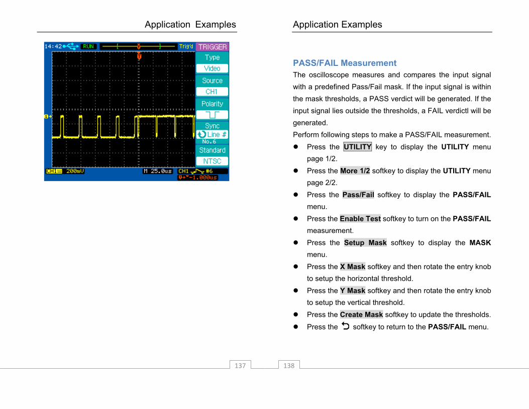
Trigger on a Video Signal
The video trigger can be used to capture standard video signals. The trigger circuit detects the vertical and horizontal intervals of the waveform and produces triggers based on the video trigger settings you have selected. Trigger on Odd or Even Fields of the Video Signal
Press the Trigger MENU key to display the TRIGGER menu.
Press the Type softkey to select the Video trigger mode. Press the Source softkey to select CH1 (this assumes
the signal is on channel 1). Press the Polarity softkey to select negative polarity . Press the Sync softkey to select Odd Field or Even
Field.
Application Examples
136
Trigger on a Specific Line or All Lines of the Video Signal
Press the Trigger MENU key to display the TRIGGER menu.
Press the Type softkey to select the Video trigger mode. Press the Source softkey to select CH1. Press the Polarity softkey to select negative polarity . Press the Sync softkey to select Line # or All Lines.
Application Examples
137
Application Examples
138
PASS/FAIL Measurement The oscilloscope measures and compares the input signal with a predefined Pass/Fail mask. If the input signal is within the mask thresholds, a PASS verdict will be generated. If the input signal lies outside the thresholds, a FAIL verdictl will be generated. Perform following steps to make a PASS/FAIL measurement.
Press the UTILITY key to display the UTILITY menu page 1/2.
Press the More 1/2 softkey to display the UTILITY menu page 2/2.
Press the Pass/Fail softkey to display the PASS/FAIL menu.
Press the Enable Test softkey to turn on the PASS/FAIL measurement.
Press the Setup Mask softkey to display the MASK menu.
Press the X Mask softkey and then rotate the entry knob to setup the horizontal threshold.
Press the Y Mask softkey and then rotate the entry knob to setup the vertical threshold.
Press the Create Mask softkey to update the thresholds.
Press the softkey to return to the PASS/FAIL menu.
Application Examples
139
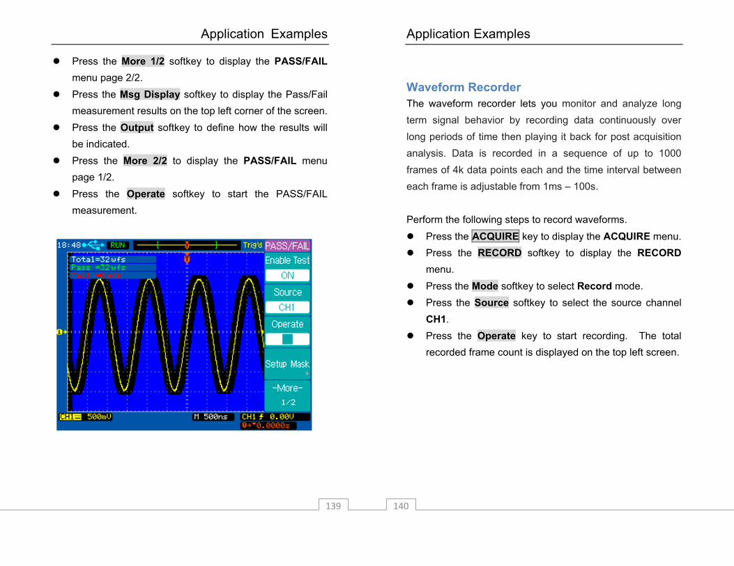
Press the More 1/2 softkey to display the PASS/FAIL menu page 2/2.
Press the Msg Display softkey to display the Pass/Fail measurement results on the top left corner of the screen.
Press the Output softkey to define how the results will be indicated.
Press the More 2/2 to display the PASS/FAIL menu page 1/2.
Press the Operate softkey to start the PASS/FAIL measurement.
Application Examples
140
Waveform Recorder The waveform recorder lets you monitor and analyze long term signal behavior by recording data continuously over long periods of time then playing it back for post acquisition analysis. Data is recorded in a sequence of up to 1000 frames of 4k data points each and the time interval between each frame is adjustable from 1ms – 100s. Perform the following steps to record waveforms.
Press the ACQUIRE key to display the ACQUIRE menu. Press the RECORD softkey to display the RECORD
menu. Press the Mode softkey to select Record mode. Press the Source softkey to select the source channel
CH1. Press the Operate key to start recording. The total
recorded frame count is displayed on the top left screen.
Application Examples
141
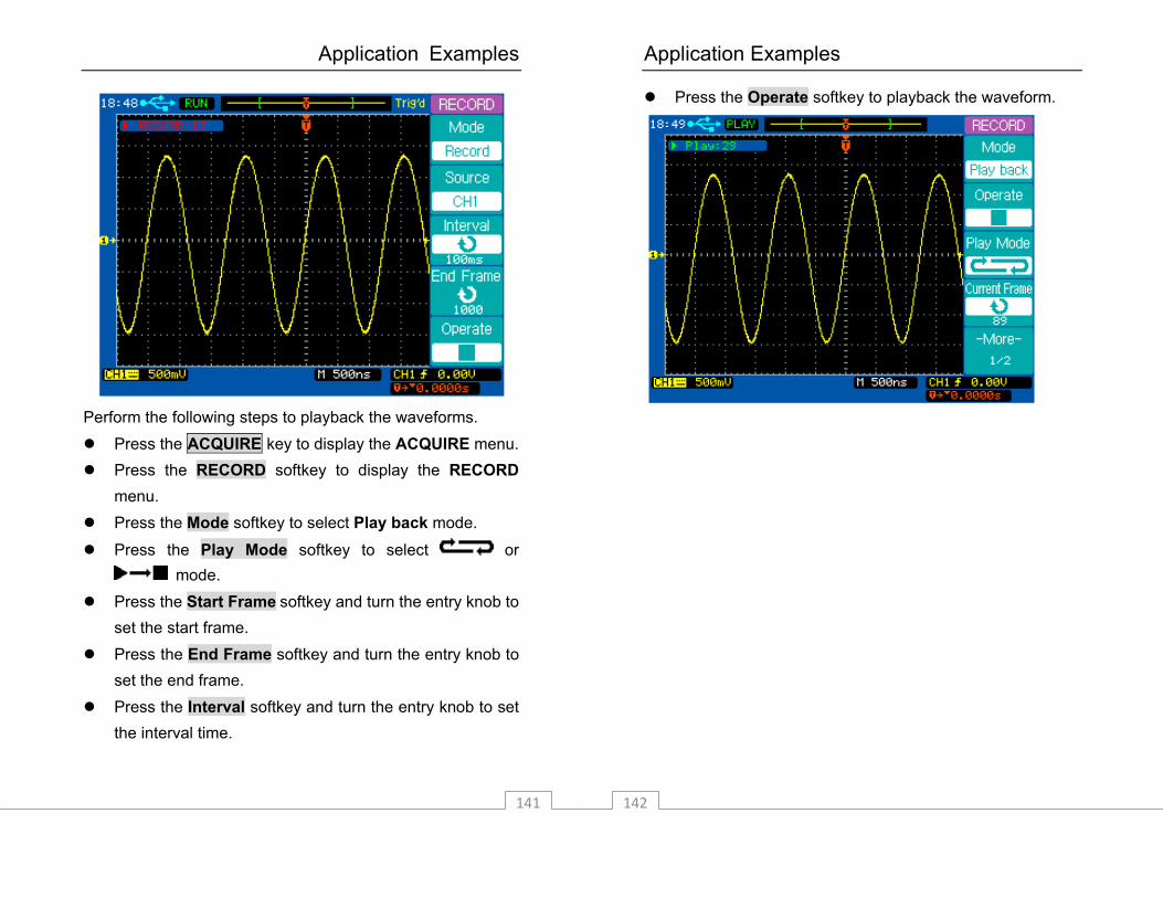
Perform the following steps to playback the waveforms.
Press the ACQUIRE key to display the ACQUIRE menu. Press the RECORD softkey to display the RECORD
menu. Press the Mode softkey to select Play back mode.
Press the Play Mode softkey to select or mode.
Press the Start Frame softkey and turn the entry knob to set the start frame.
Press the End Frame softkey and turn the entry knob to set the end frame.
Press the Interval softkey and turn the entry knob to set the interval time.
Application Examples
142
Press the Operate softkey to playback the waveform.

Application Examples
143
Perform the following steps to save or recall the waveform recorded.
Press the ACQUIRE key to display the ACQUIRE menu. Press the RECORD softkey to display the RECORD
menu. Press the Mode softkey to select Save/Recall mode. Press the Start Frame softkey and turn the entry knob to
set the start frame. Press the End Frame softkey and turn the entry knob to
set the end frame. Press the Internal Storage softkey to save or load the
recorded waveform from the internal memory.
Application Examples
144
Cursor Measurements You can use the cursors to quickly take time and voltage measurements on a waveform. You can use the cursors to measure the amplitude and frequency of a FFT waveform. You can also use the cursors to measure the phase difference between two signals with the same frequency when X-Y horizontal mode is selected. Measure the time on a waveform Perform the following steps to take time and frequency measurements.
Press the CURSOR key to display the CURSOR menu. Press the Mode softkey to select the Manual mode. Press the Type softkey to select the Time type. Press the X1--/ X2— softkey or press the entry knob
to select the X1 cursor. Rotate the entry knob to move the X1 cursor. Press the X1--/ X2— softkey or press the entry knob
to select the X2 cursor. Rotate the entry knob to move the X2 cursor. ∆X and 1/∆X are displayed in the softkey area. ∆X is the
time difference between X1 and X2; 1/∆X is the frequency “between” X1 and X2.

Application Examples
145
Perform the following steps to make a voltage measurement on a waveform.
Press the CURSOR key to display the CURSOR menu. Press the Mode softkey to select the Manual mode. Press the Type softkey to select the Voltage type. Press the Y1--/ Y2— softkey or press the entry knob
to select the Y1 cursor. Rotate the entry knob to move the Y1 cursor. Press the Y1--/ Y2— softkey or press the entry knob
to select the Y2 cursor. Rotate the entry knob to move the Y2 cursor. The ∆Y displayed in the softkey area is the voltage
difference between Y1 and Y2.
Application Examples
146
Measure the frequency and amplitude on an FFT waveform Perform the following steps to take frequency measurements.
Press the MATH key to display the Math menu. Press the Operate softkey to select FFT and display the
FFT menu. Press the CURSOR key to display the CURSOR menu. Press the Mode softkey to select the Manual mode. Press the Source softkey to select FFT. Press the Type softkey to select the Time type. Press the X1--/ X2— softkey or press the entry knob
to select the X1 cursor. Rotate the entry knob to move the X1 cursor. Press the X1--/ X2— softkey or press the entry knob
to select the X2 cursor. Rotate the entry knob to move the X2 cursor. The ∆X displayed in the softkey area is the frequency
difference between X1 and X2. 1/∆X is the time difference between X1 and X2.
Perform the following steps to take amplitude measurements on an FFT waveform.
Press the MATH key to display the Math menu.
Application Examples
147
Press the Operate softkey to select FFT and display the FFT menu.
Press the CURSOR key to display the CURSOR menu. Press the Mode softkey to select the Manual mode. Press the Source softkey to select FFT. Press the Type softkey to select the Voltage type. Press the Y1--/ Y2— softkey or press the entry knob
to select the Y1 cursor. Rotate the entry knob to move the Y1 cursor. Press the Y1--/ Y2— softkey or press the entry knob
to select the Y2 cursor. Rotate the entry knob to move the Y2 cursor. The ∆Y displayed in the softkey area is the voltage
difference between Y1 and Y2.
Application Examples
148
Measure the Phase Difference Between Two Signals of the Same Frequency under X-Y Display Mode.
Connect a sine wave signal to channel 1 and a sine wave signal of the same frequency but different phase to channel 2.
Press the horizontal MENU key to display the Horizontal menu.
Press the X-Y softkey to select the X-Y display mode. Center the signal on the display with the vertical position
knob of each channel. Use the vertical scale control knob of each channel to
expand the signal for convenient view. Press the CURSOR key to display the CURSOR menu. Press the Mode softkey to select the Manual mode. Press the Source softkey to select CH2. Press the Type softkey to select the Voltage type. Press the Y1--/ Y2— softkey or press the entry knob
to select the Y1 cursor. Rotate the entry knob to move the Y1 cursor to the
top of the signal. Press the Y1--/ Y2— softkey or press the entry knob
to select the Y2 cursor. Rotate the entry knob to move the Y2 cursor to the
bottom of the signal.

Application Examples
149
The ∆Y displayed in the softkey area is the voltage difference D (or 2B) between Y1 and Y2.
Press the Y1--/ Y2— softkey or press the entry knob to select the Y1 cursor.
Rotate the entry knob to move the Y1 cursor to the upper intersection of the signal and the Y axis.
Press the Y1--/ Y2— softkey or press the entry knob to select the Y2 cursor.
Rotate the entry knob to move the Y2 cursor to the lower intersection of the signal and the Y axis.
The ∆Y displayed in the softkey area is the voltage difference C (or 2A) between Y1 and Y2.
Calculate the phase difference using the formulas
DCarcsin±=θ or
BAarcsin=θ .

System Message and General Problems
151
4. System Message and General Problems
System Message
Function is not available: The control knob, key, or softkey is not available under a specific operating condition. The control is at its limit: This message will be displayed when the maximum or minimum value is reached by turning the Entry knob, Vertical Control knobs, Horizontal Control knobs, or Trigger Level knob. Total is at its maximun: This message will be displayed when the maximum value of Total count for PASS/FAIL is reached. Record is completed: This message will be displayed when the number of waveforms (set in the End Frame softkey) have been recorded. No external memory: This message will be displayed when you try to save a file to an external mass storage device which has not been installed. Save error: This message will be displayed when a failure to save a file to the internal or external memory occurs.
System Message and General Problems
152
Empty storage memory: This message will be displayed when you try to load a file which does not exist from the internal memory. Unrecognized file: This message will be displayed when you try to load a file which cannot be recognized by the oscilloscope. Update failed: This message will be displayed when a software update has failed. No record data: This message will be displayed when you try to save a record file without record data. Record is failed: This message will be displayed when waveform record is failed. Fatory setup is recalled: This message will be displayed when the default factory configuration is recalled. No signal is found: This message will be displayed when you press the AUTO key without any signal connected to either channel. Invalid data: This message will be displayed when you try to save a *.CSV file without any valid CSV data. Load finished: This message will be displayed when a file has been successfully loaded from the internal or external memory. Save finished: This message will be displayed when a file has been successfully saved to the internal or external memory.
System Message and General Problems
153
Incompatible file: This message will be displayed when the update software is not compatible with the model type. Load error: This message will be displayed when you fail to load a file from the internal or external memory. Restart to complete updating: This message will be displayed to let you restart (power cycle) the oscilloscope when the software update is successfully finished. USB device is installed: This message will be displayed when a USB device is connected and recognized by the oscilloscope. USB device is removed: This message will be displayed when a USB device is removed from the oscilloscope. USB host error: This message will be displayed when the USB host control circuit is not working correctly. Setup finished: This message will be displayed when the date and time are set successfully. Setup failed: This message will be displayed when the date and time are not set successfully.
System Message and General Problems
154
General Problems
If there is no display on the screen: Check that the power cord is connected to the
oscilloscope and to a live power source. Check that the power switch is on. Check that the display contrast is adjust properly. Contact B+K Precision if there is still no display.
If there is no waveform displayed: Check that the oscilloscope probe lead wires are
securely inserted into the connector assembly and that the probe clips make good contact with the probe lead wires.
Check that the probe clips are securely connected to points in the circuit under test and that the probe ground clip is connected to the circuit ground.
Check that the circuit under test is powered on. Press the AUTO key again.
If the waveform display is not stable: Check that the trigger source channel is actually the
channel to which the signal is connected.
System Message and General Problems
155
Check that the proper trigger type is selected. The video type is only used to trigger on a video signal. The proper trigger type is essential for a stable display.
Try using HF Reject or LF Reject to reduce the noise of the trigger signal.
If the amplitude is not identical with the actual voltage: Check that the attenuation factor of the probe is with the
same as the attenuation factor set in the channel menu.

Specifications
157
5. Specifications and Characteristics
Characteristics The characteristics given below are typical performance values and are not warranted. Characteristics are valid after a 30 minute warm-up time and within ±5 of the last self-calibration temperature.
Vertical system Scope channels 2 channels plus external trigger input.
Bandwidth 60 MHz
Calculated rise time
(=0.35/bandwidth)
5.83 ns
Coupling AC, DC, GND
BW Limit 20 MHz selectable
Vertical sensitivity 2mV/div – 5V/div, 1-2-5- sequence
DC Vertical Gain
Accuracy
2 mV/div to 5 mV/div: ±4%
10 mV/div to 5 V/div: ±3%
DC Measurement
Accuracy
2 mV/div to 5 mV/div range:
±(4% × reading + 0.1 × V/div + 0.5 mV)
10 mV/div to 5 V/div range:
±(3% × reading + 0.1 × V/div + 1.0 mV)
Specifications
158
Position range ±8 divisions from the center of the screen
Attenuation factor ×1, ×10, × 100, × 1000
Channel common
mode rejection
100:1 at 60Hz
20:1 at 10MHz[
Lower frequency
limit, AC coupled
≤5Hz at BNC
≤1Hz when using a 10X passive probe
Channel to
channel crosstalk
≥100:1 at 1MHz
≥100:1 at 10MHz
Input Impedance 1 MΩ ±1% || 19 pF
Maximum input CAT II, 400Vpk
Differential delay 150 ps between two channels with the same
scale and coupling settings

Specifications
159
Horizontal system
Time base range 2.5 ns/div to 50 s/div
Modes Main, Delayed, Roll, and X-Y
Time base accuracy ±0.01%
Input of X-Y mode Channel 1 is the X-axis input
Channel 2 is the Y-axis input
Bandwidth of X-Y mode 60 MHz
Phase error of X-Y mode ±3°
Measurements
Voltage measurement
Maximum, Minimum, Peak-to-Peak, High, Low,
Amplitude, Average, RMS, Cycle Average,
Cycle RMS, Overshoot, Preshoot
Time measurement
Frequency, Period, +Width, -Width, +Duty,
-Duty, Rise time, Fall time, Delay, Phase, X at
MAX, X at MIN
Math CH1-CH2, CH1+CH2, CH1×CH2, FFT (2k
points)
Cursors Manual, Automatic and Track
Counter Built-in 5-digit frequency counter. Count up to
the oscilloscope’s maximum bandwidth.
Trigger system Source CH1, CH2, EXT, EXT/5AC Line, Alternating.
Modes Auto, Normal, Single
Specifications
160
Coupling DC, AC, LF-Reject, HF-Reject
Type Edge, Pulse, Video
Trigger sensitivity,
Edge Trigger Type,
DC coupling
CH1,CH2: 1div from DC to 10MHz
EXT: 100mV from DC to 10MHz
200mV from 10MHz to full Bandwidth
EXT/5: 500mV from DC to full Bandwidth
Trigger sensitivity,
Edge Trigger Type,
AC coupling
Same as DC coupling at 50 Hz and above
Trigger sensitivity,
Edge Trigger Type,
LF REJ
Same as the DC coupling limits for frequencies
above 100kHz, attenuates signals below 8kHz
Trigger sensitivity,
Edge Trigger Type,
HF REJ
Same as the DC coupling limits from DC to 10kHz,
attenuates signals above 150kHz
Trigger sensitivity,
Video Trigger Type
Internal: Pk to Pk amplitude of 2 divisions
EXT: 400 mV
EXT/5: 2V
Signal formates
and Field Rates,
Video Trigger Type
Supports NTSC, PAL, and SECAM broadcast
systems for any field or any line
Trigger level range
±8 divisions from screen center
EXT: ±1.6V
EXT/5: ±8V
Holdoff Range 100ns to 1.5s
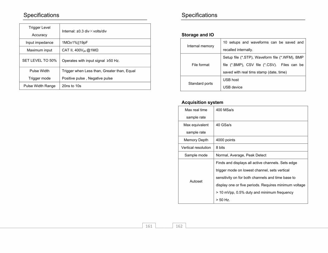
Specifications
161
Trigger Level
Accuracy Internal: ±0.3 div×volts/div
Input impedance 1MΩ±1%||19pF
Maximum input CAT II, 400Vpk @1MΩ
SET LEVEL TO 50% Operates with input signal ≥50 Hz.
Pulse Width
Trigger mode
Trigger when Less than, Greater than, Equal
Positive pulse , Negative pulse
Pulse Width Range 20ns to 10s
Specifications
162
Storage and IO
Internal memory 10 setups and waveforms can be saved and
recalled internally.
File format
Setup file (*.STP), Waveform file (*.WFM), BMP
file (*.BMP), CSV file (*.CSV). Files can be
saved with real tims stamp (date, time)
Standard ports USB host
USB device
Acquisition system
Max real time
sample rate
400 MSa/s
Max equivalent
sample rate
40 GSa/s
Memory Depth 4000 points
Vertical resolution 8 bits
Sample mode Normal, Average, Peak Detect
Autoset
Finds and displays all active channels. Sets edge
trigger mode on lowest channel, sets vertical
sensitivity on for both channels and time base to
display one or five periods. Requires minimum voltage
> 10 mVpp, 0.5% duty and minimum frequency
> 50 Hz.
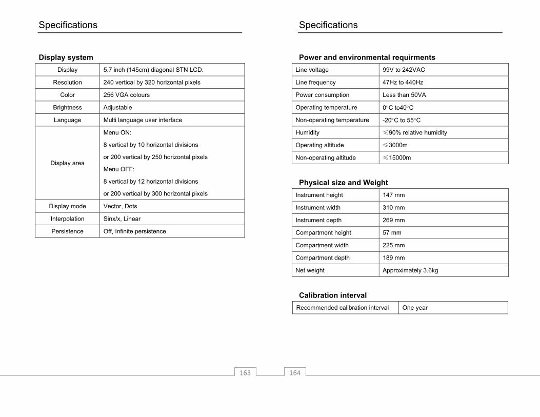
Specifications
163
Display system
Display 5.7 inch (145cm) diagonal STN LCD.
Resolution 240 vertical by 320 horizontal pixels
Color 256 VGA colours
Brightness Adjustable
Language Multi language user interface
Display area
Menu ON:
8 vertical by 10 horizontal divisions
or 200 vertical by 250 horizontal pixels
Menu OFF:
8 vertical by 12 horizontal divisions
or 200 vertical by 300 horizontal pixels
Display mode Vector, Dots
Interpolation Sinx/x, Linear
Persistence Off, Infinite persistence
Specifications
164
Power and environmental requirments
Line voltage 99V to 242VAC
Line frequency 47Hz to 440Hz
Power consumption Less than 50VA
Operating temperature 0°C to40°C
Non-operating temperature -20°C to 55°C
Humidity ≤90% relative humidity
Operating altitude ≤3000m
Non-operating altitude ≤15000m
Physical size and Weight
Instrument height 147 mm
Instrument width 310 mm
Instrument depth 269 mm
Compartment height 57 mm
Compartment width 225 mm
Compartment depth 189 mm
Net weight Approximately 3.6kg
Calibration interval
Recommended calibration interval One year

Specifications
165
Appendix A: Service and Warranty Information
Service Information
Warranty Service: Please return the product in the original packaging with proof of purchase to the address below. Clearly state in writing the performance problem and return any leads, probes, connectors and accessories that you are using with the device. Non-Warranty Service: Return the product in the original packaging to the address below. Clearly state in writing the performance problem and return any leads, probes, connectors and accessories that you are using with the device. Customers not on open account must include payment in the form of a money order or credit card. For the most current repair charges please visit www.bkprecision.com and click on “service/repair”. Return all merchandise to B&K Precision Corp. with pre-paid shipping. The flat-rate repair charge for Non-Warranty Service does not include return shipping. Return shipping to locations in North American is included for Warranty Service. For overnight shipments and non-North American shipping fees please contact B&K Precision Corp. B&K Precision Corp. 22820 Savi Ranch Parkway Yorba Linda, CA 92887 www.bkprecision.com 714-921-9095
Include with the returned instrument your complete return shipping address, contact name, phone number and description of problem.
Specifications
166
Limited Two‐Year Warranty B&K Precision Corp. warrants to the original purchaser that its products and the component parts thereof, will be free from defects in workmanship and materials for a period of one year from date of purchase. B&K Precision Corp. will, without charge, repair or replace, at its option, defective product or component parts. Returned product must be accompanied by proof of the purchase date in the form of a sales receipt. To obtain warranty coverage in the U.S.A., this product must be registered by completing a warranty registration form on www.bkprecision.com within fifteen (15) days of purchase. Exclusions: This warranty does not apply in the event of misuse or abuse of the product or as a result of unauthorized alterations or repairs. The warranty is void if the serial number is altered, defaced or removed. B&K Precision Corp. shall not be liable for any consequential damages, including without limitation damages resulting from loss of use. Some states do not allow limitations of incidental or consequential damages. So the above limitation or exclusion may not apply to you. This warranty gives you specific rights and you may have other rights, which vary from state-to-state. B&K Precision Corp. 22820 Savi Ranch Parkway Yorba Linda, CA 92887 www.bkprecision.com 714-921-9095

Specifications
167
Specifications
168
22820 Savi Ranch Parkway Yorba Linda, CA 92887 www.bkprecision.com
© 2008 B&K Precision Corp.
Printed in China