www.autoenginuity.com/vsi This document is copyrighted by Dearborn Group, Inc. Permission is granted to copy all and/or entire page portions of this manual, provided such copies are for use with the product provided by DG Technologies (Dearborn Group, Inc.) or any of its affiliates, and that each instance of DG Technologies, Dearborn Group, Inc., and our website www.dgtech.com remains on all copies as on the original. Page 1 of 15 VSI-2534 User Manual Version 2.2 April 2011 Foreword This document describes AutoEnginuity (DG) VSI-2534, and SAE J2534 Pass-Thru device with its primary purpose to program automotive ECUs (Electronic Control Units). It provides module programming for development, end-of-line testing and re-programming. The VSI-2534 is also useful for vehicle diagnostics, development, general design, hardware-in- the-loop simulation and anywhere communications with a vehicle network are required. © 2006 - 2011 Dearborn Group, Inc. 33604 West Eight Mile Road Farmington Hills, MI 48335 Phone (248) 888-2000 • Fax (248) 888-9977

Welcome message from author
This document is posted to help you gain knowledge. Please leave a comment to let me know what you think about it! Share it to your friends and learn new things together.
Transcript

www.autoenginuity.com/vsi
This document is copyrighted by Dearborn Group, Inc. Permission is granted to copy all and/or entire page portions of this manual, provided such copies are for use with the product provided by DG Technologies (Dearborn Group, Inc.) or any of its affiliates, and that each instance of DG Technologies, Dearborn Group, Inc., and our website www.dgtech.com remains on all copies as on the original.
Page 1 of 15
VSI-2534 User Manual
Version 2.2
April 2011
Foreword This document describes AutoEnginuity (DG) VSI-2534, and SAE J2534 Pass-Thru device with its primary purpose to program automotive ECUs (Electronic Control Units). It provides module programming for development, end-of-line testing and re-programming. The VSI-2534 is also useful for vehicle diagnostics, development, general design, hardware-in-the-loop simulation and anywhere communications with a vehicle network are required.
© 2006 - 2011 Dearborn Group, Inc. 33604 West Eight Mile Road Farmington Hills, MI 48335
Phone (248) 888-2000 • Fax (248) 888-9977

www.autoenginuity.com/vsi
This document is copyrighted by Dearborn Group, Inc. Permission is granted to copy all and/or entire page portions of this manual, provided such copies are for use with the product provided by DG Technologies (Dearborn Group, Inc.) or any of its affiliates, and that each instance of DG Technologies, Dearborn Group, Inc., and our website www.dgtech.com remains on all copies as on the original.
Page 2 of 15
Table of Contents VSI-2534 User Manual .............................................................................................................. 1 Foreword .................................................................................................................................... 1 1 Introduction ........................................................................................................................ 3
1.1 VSI-2534 hardware specifications............................................................................... 4 1.2 Power connector ......................................................................................................... 4 1.3 Hardware overview ..................................................................................................... 5
2 Software Setup ................................................................................................................... 7 3 Hardware Configuration.....................................................................................................10
3.1 First Time Hardware Connection to the PC ................................................................10 3.2 Typical Hardware Connection to the PC ..........................................................................11 3.3 Hardware Configuration Information ................................................................................12 3.4 Hardware/Firmware Update of the VSI-2534 ...................................................................13
Appendix A – Pin Assignment for the OBD II Cable ..................................................................14

www.autoenginuity.com/vsi
This document is copyrighted by Dearborn Group, Inc. Permission is granted to copy all and/or entire page portions of this manual, provided such copies are for use with the product provided by DG Technologies (Dearborn Group, Inc.) or any of its affiliates, and that each instance of DG Technologies, Dearborn Group, Inc., and our website www.dgtech.com remains on all copies as on the original.
Page 3 of 15
1 Introduction How it works: A PC is connected to a vehicle through the VSI-2534 “Pass-Thru device” to the OBD-II J1962 connector and on to the ECUs. The VSI-2534 provides the translation interface between the PC and the vehicle or module. The user application on the PC sends and receives data to the vehicle using J2534 function calls to this device. Provides support for: the most current version of the J2534 API (Version 04.04). Supports the following protocols:
CAN (ISO 11898, J2284), Single-Wire CAN, ISO15765, ISO 9141, KWP2000, J1850 PWM (Ford SCP), J1850 VPWM (both GM Class 2 and Chrysler), SCI and GM-UART
Features:
USB 2.0 connection to a PC for fast downloads. (Operates at full network speed with fast and efficient data transfers.)
Connects to a vehicle with an OBDII cable or a custom cable.
Runs the SAE J1699 Vehicle Validation software.
On or off-board J2534 module programming.
Programming voltages – 5 to 20 V in 100 mV steps.
Useful for diagnostics or module development.
www.autoenginuity.com/vsi
This document is copyrighted by Dearborn Group, Inc. Permission is granted to copy all and/or entire page portions of this manual, provided such copies are for use with the product provided by DG Technologies (Dearborn Group, Inc.) or any of its affiliates, and that each instance of DG Technologies, Dearborn Group, Inc., and our website www.dgtech.com remains on all copies as on the original.
Page 4 of 15
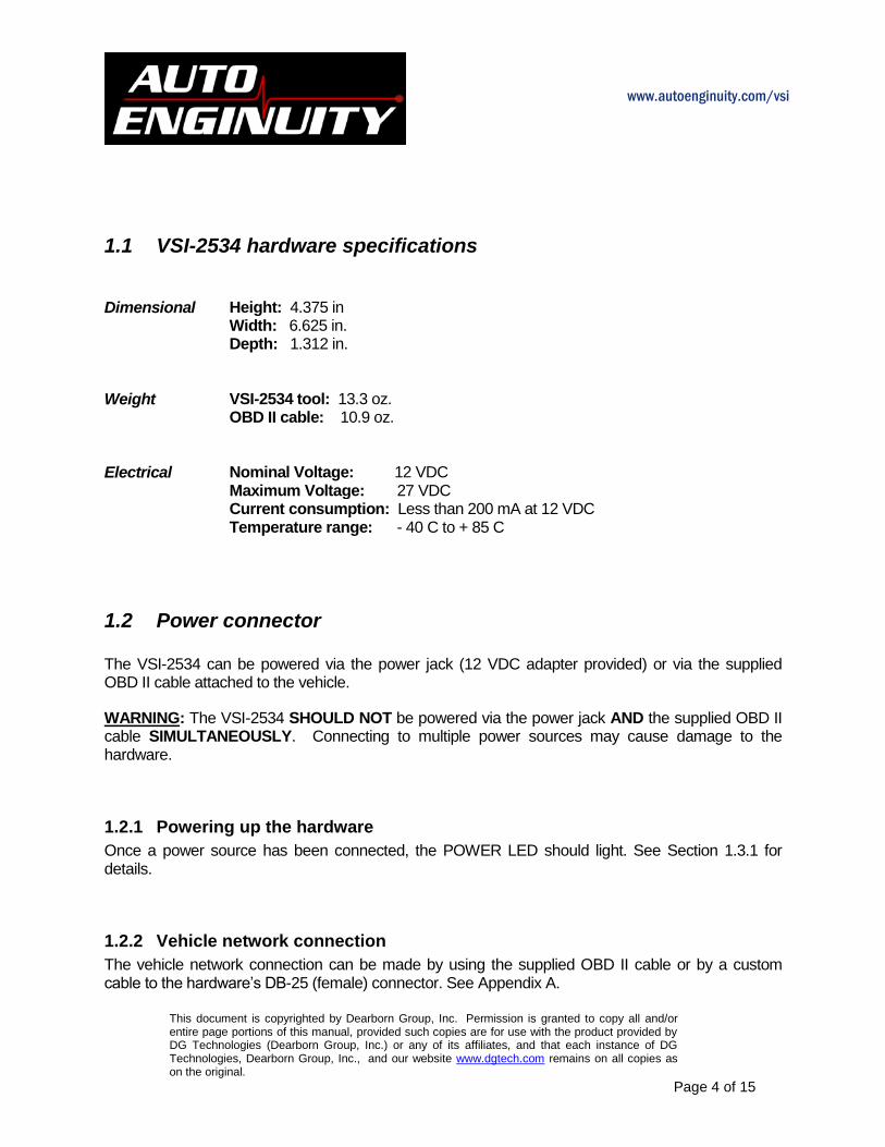
1.1 VSI-2534 hardware specifications
Dimensional Height: 4.375 in
Width: 6.625 in. Depth: 1.312 in.
Weight VSI-2534 tool: 13.3 oz.
OBD II cable: 10.9 oz. Electrical Nominal Voltage: 12 VDC
Maximum Voltage: 27 VDC Current consumption: Less than 200 mA at 12 VDC Temperature range: - 40 C to + 85 C
1.2 Power connector The VSI-2534 can be powered via the power jack (12 VDC adapter provided) or via the supplied OBD II cable attached to the vehicle.
WARNING: The VSI-2534 SHOULD NOT be powered via the power jack AND the supplied OBD II cable SIMULTANEOUSLY. Connecting to multiple power sources may cause damage to the hardware.
1.2.1 Powering up the hardware
Once a power source has been connected, the POWER LED should light. See Section 1.3.1 for details.
1.2.2 Vehicle network connection
The vehicle network connection can be made by using the supplied OBD II cable or by a custom cable to the hardware’s DB-25 (female) connector. See Appendix A.

www.autoenginuity.com/vsi
This document is copyrighted by Dearborn Group, Inc. Permission is granted to copy all and/or entire page portions of this manual, provided such copies are for use with the product provided by DG Technologies (Dearborn Group, Inc.) or any of its affiliates, and that each instance of DG Technologies, Dearborn Group, Inc., and our website www.dgtech.com remains on all copies as on the original.
Page 5 of 15
1.3 Hardware overview The following figures show the external features of the VSI-2534:
Figure 1: VSI-2534 Indicators
1.3.1 Status Indicators
The VSI-2534 has three status LEDs that indicate activity of the following functions:
PC Connection – Indicates that the VSI-2534 has established a connection to the PC, and if the link is “active.”
Vehicle Connection – Indicates that the vehicle network connection is established / active.
Power – Indicates that the VSI-2534 is connected to a power supply (either via the jack plug or through a vehicle connection), and whether or not the unit is operating properly.
See details in the following table:

www.autoenginuity.com/vsi
This document is copyrighted by Dearborn Group, Inc. Permission is granted to copy all and/or entire page portions of this manual, provided such copies are for use with the product provided by DG Technologies (Dearborn Group, Inc.) or any of its affiliates, and that each instance of DG Technologies, Dearborn Group, Inc., and our website www.dgtech.com remains on all copies as on the original.
Page 6 of 15
LED Name LED State Description
PC Connection
Off PC has not initialized communication with
VSI-2534 via the USB data link.
On
(Solid Red)
PC has initialized communication with VSI-2534 via the USB data link. No bus activity.
On
(Alternating Red / Green)
Activity on the PC-VSI-2534 connection via USB data link.
Vehicle Connection
Off No vehicle network protocol channel has
been initialized for use.
On
(Red)
One or more vehicle network protocol channels have been initialized for use. No
bus activity.
On
(Alternating Red / Green)
There is activity on one or more vehicle network protocol channels.
Power
Off No power supplied to the VSI-2534 unit.
On
(Solid Green)
Unit is powered either via the vehicle connector or the external power jack. Unit is
operating properly.
On
(Solid Red)
Unit is powered either via the vehicle connector or the external power jack. Unit is
not operating properly.
Table 1: LED Descriptions

www.autoenginuity.com/vsi
This document is copyrighted by Dearborn Group, Inc. Permission is granted to copy all and/or entire page portions of this manual, provided such copies are for use with the product provided by DG Technologies (Dearborn Group, Inc.) or any of its affiliates, and that each instance of DG Technologies, Dearborn Group, Inc., and our website www.dgtech.com remains on all copies as on the original.
Page 7 of 15
2 Software Setup
1. Locate the “Setup_VSI2534.EXE” file on the CD and double-click on it to start the software setup, and then click “Next”.
2. Exit all open Windows programs and click “Next” to continue.
3. Choose Destination Location for the installation. The default location is C:\Program
Files\VSI-2534. Click “Next” to continue.

www.autoenginuity.com/vsi
This document is copyrighted by Dearborn Group, Inc. Permission is granted to copy all and/or entire page portions of this manual, provided such copies are for use with the product provided by DG Technologies (Dearborn Group, Inc.) or any of its affiliates, and that each instance of DG Technologies, Dearborn Group, Inc., and our website www.dgtech.com remains on all copies as on the original.
Page 8 of 15
4. Click “Next” to continue.
5. Installing…
6. Ensure that you do not have the VSI-2534 hardware connected to the PC’s USB port.
Click “OK” to continue.

www.autoenginuity.com/vsi
This document is copyrighted by Dearborn Group, Inc. Permission is granted to copy all and/or entire page portions of this manual, provided such copies are for use with the product provided by DG Technologies (Dearborn Group, Inc.) or any of its affiliates, and that each instance of DG Technologies, Dearborn Group, Inc., and our website www.dgtech.com remains on all copies as on the original.
Page 9 of 15
7. Installation is complete. Click “Finish”.

www.autoenginuity.com/vsi
This document is copyrighted by Dearborn Group, Inc. Permission is granted to copy all and/or entire page portions of this manual, provided such copies are for use with the product provided by DG Technologies (Dearborn Group, Inc.) or any of its affiliates, and that each instance of DG Technologies, Dearborn Group, Inc., and our website www.dgtech.com remains on all copies as on the original.
Page 10 of 15
3 Hardware Configuration
3.1 First Time Hardware Connection to the PC
Step 1: Connect the VSI-2534 to a power source (Power adapter or powered from the OBD II cable). Note: do not power unit from multiple sources. Power LED must be a solid Green. When the “Found New Hardware Wizard” screen appears, select: “Yes now – and every time I connect a new device” – then click on “Next”.
Step2: Click “Next”.
Step3: Click “Finish”.

www.autoenginuity.com/vsi
This document is copyrighted by Dearborn Group, Inc. Permission is granted to copy all and/or entire page portions of this manual, provided such copies are for use with the product provided by DG Technologies (Dearborn Group, Inc.) or any of its affiliates, and that each instance of DG Technologies, Dearborn Group, Inc., and our website www.dgtech.com remains on all copies as on the original.
Page 11 of 15
3.2 Typical Hardware Connection to the PC
Step 1: Connect the VSI-2534 to a power source (12V Power adapter or powered from the OBD II cable). Note: Do not power unit from multiple sources. Power LED must be a solid GREEN. Step 2: Connect the VSI-2534’s USB cable to the PC that the software was installed on and note that the Power LED is a solid Green and the PC Connection LED is a solid RED.
Step 3: Using an application such as the DG 2534 SDK (Software Development Kit) a user can open a link to the hardware and connect with a protocol to a Vehicle or an Electronic Control Module (ECU). Note: after this connection, the Vehicle Connection LED is a solid RED.

www.autoenginuity.com/vsi
This document is copyrighted by Dearborn Group, Inc. Permission is granted to copy all and/or entire page portions of this manual, provided such copies are for use with the product provided by DG Technologies (Dearborn Group, Inc.) or any of its affiliates, and that each instance of DG Technologies, Dearborn Group, Inc., and our website www.dgtech.com remains on all copies as on the original.
Page 12 of 15
3.3 Hardware Configuration Information By running the “VSI-2534 Config Utility.exe”, located in Start > Programs > VSI-2534, a user can find out Hardware version, protocol support, and other information.
Protocols Supported: J1850VPW, J1850PWM, CAN, ISO9141, ISO14230, ISO15765, SCI_A_ENGINE:1, SCI_A_TRANS:1, SCI_B_ENGINE:1, SCI_B_TRANS:1, SWCAN_ISO15765_PS, SWCAN_PS, GM_UART_PS J2534 API Version: 04.04
The “Get Firmware Version” button provides the Firmware version of the VSI-2534 hardware. Note: Do not have any other application running that uses the J2534 library.

www.autoenginuity.com/vsi
This document is copyrighted by Dearborn Group, Inc. Permission is granted to copy all and/or entire page portions of this manual, provided such copies are for use with the product provided by DG Technologies (Dearborn Group, Inc.) or any of its affiliates, and that each instance of DG Technologies, Dearborn Group, Inc., and our website www.dgtech.com remains on all copies as on the original.
Page 13 of 15
The “Turn Logging ON” checkbox enables the Configuration button. The Configuration button enables the user to set “Logging Type” and “Logging Method” to create VSI-2534 DLL log. Note: Do not have any other application running that uses the J2534 library.
3.4 Hardware/Firmware Update of the VSI-2534
. Step 1: Click on “Start” > “Programs” > “VSI-2534” > “FirmwareUpdater”.
Step 2: Click on “Yes”.
Step 3: Updating the Firmware...
Step 4: Firmware has been updated. Click “OK”
www.autoenginuity.com/vsi
This document is copyrighted by Dearborn Group, Inc. Permission is granted to copy all and/or entire page portions of this manual, provided such copies are for use with the product provided by DG Technologies (Dearborn Group, Inc.) or any of its affiliates, and that each instance of DG Technologies, Dearborn Group, Inc., and our website www.dgtech.com remains on all copies as on the original.
Page 14 of 15
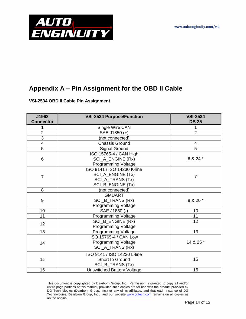
Appendix A – Pin Assignment for the OBD II Cable VSI-2534 OBD II Cable Pin Assignment
J1962 Connector
VSI-2534 Purpose/Function VSI-2534 DB 25
1 Single Wire CAN 1
2 SAE J1850 (+) 2
3 (not connected)
4 Chassis Ground 4
5 Signal Ground 5
6 ISO 15765-4 / CAN High
SCI_A_ENGINE (Rx) Programming Voltage
6 & 24 *
7
ISO 9141 / ISO 14230 K-line SCI_A_ENGINE (Tx) SCI_A_TRANS (Tx) SCI_B_ENGINE (Tx)
7
8 (not connected)
9 GMUART
SCI_B_TRANS (Rx) Programming Voltage
9 & 20 *
10 SAE J1850 (-) 10
11 Programming Voltage 11
12 SCI_B_ENGINE (Rx) Programming Voltage
12
13 Programming Voltage 13
14
ISO 15765-4 / CAN Low Programming Voltage SCI_A_TRANS (Rx)
14 & 25 *
15
ISO 9141 / ISO 14230 L-line Short to Ground
SCI_B_TRANS (Tx)
15
16 Unswitched Battery Voltage 16

www.autoenginuity.com/vsi
This document is copyrighted by Dearborn Group, Inc. Permission is granted to copy all and/or entire page portions of this manual, provided such copies are for use with the product provided by DG Technologies (Dearborn Group, Inc.) or any of its affiliates, and that each instance of DG Technologies, Dearborn Group, Inc., and our website www.dgtech.com remains on all copies as on the original.
Page 15 of 15
Not Used 3, 8, 17 -19, 21 - 23
* NOTE: These pairs of pins are either connected together in the VSI-2534 tool or connected in the OBD II cable.
Pins 6 and 24 are connected together within the VSI-2534 tool. Pins 9 and 20 are connected together within the OBD II cable. Pins 14 and 25 are connected together within the VSI-2534 tool.
Related Documents