research Basic evaluation of an antimicrobial gel for peri-implantitis treatment case report The indispensable use of CBCT in the posterior mandible industry Automatic crestal sinus lift by motorised impaction device implants international magazine of oral implantology issn 1868-3207 Vol. 17 • Issue 1/2016 1 2016

Welcome message from author
This document is posted to help you gain knowledge. Please leave a comment to let me know what you think about it! Share it to your friends and learn new things together.
Transcript
researchBasic evaluation of an antimicrobial gel for peri-implantitis treatment
case reportThe indispensable use of CBCT in the posterior mandible
industryAutomatic crestal sinus lift by motorised impaction device
implants international magazine of oral implantology
issn 1868-3207 Vol. 17 • Issue 1/2016
12016

It is not a trick. It is
legendary science. Discover the magic of
the tapered standard.
Material Surface
Straumann® Bone Level Tapered Implant
Designed for excellent primary stability thanks to an
apically tapered implant with groundbreaking material
and surface technology for maximizing predictability.
The Bone Level Tapered Implant – the new tapered stan-
dard. Engineered in Switzerland, home of Straumann.
http://blt.straumann.com
implants 03
editorial |
1 2016
Exploring new grounds
Dear colleagues,
for more than 46 years, further education has been a topic dear to the hearts of DGZI’s editorial board. Already since its foundation in 1970, DGZI has contributed considerably to the education of our colleagues, especially by founding the DGZI study groups in 1990. These are small learning groups in which new tech-niques and case presentations are practiced.
Three years ago, our Young-Generation study group was founded, bringing a breath of fresh air to our learning groups. Starting in Cologne, Germany, and featuring another branch in Hamburg under the leadership of Dr Navid Salehi, who has since become a member of our extended board, the study groups have enriched the DGZI’s field of activities. The heads of our study groups, Dr Umut Baysal and Dr Navid Salehi, have been supported by Dr Markus Quitzke in 2015. Their next step will be the foundation of another study group in Germany’s capital Berlin, which is going to be led by Rabi Omari.
The foundation of the Berlin study group on 19 March 2016 at the Westin Grand Berlin Hotel surely is a highlight in 2016. Around 100 colleagues attended the founding assembly, illustrating the growing inter-est of our young colleagues in peer learning. Participants of this event received four further education points and the corresponding certificate.
Wishing you a both exciting and enlightening reading experience of this issue of implants: international magazine of oral implantology!_
Warm regards,
Dr Rolf VollmerFirst Vice President and Treasurer of the German Association of Dental Implantology
Dr Rolf Vollmer
| content
| editorial
03 Exploring new groundsDr Rolf Vollmer
| research
06 Basic evaluation of an antimicrobial gel for peri-implantitis treatmentDr Georg Bach & Christian Müller
16 Lateral maxillary incisor implant–Key issues for aesthetic success Drs Philippe Russe & Patrick Limbour
24 Maxillary implant supported removable or fi xed prostheses Dr Scott D. Ganz
| case report
30 The indispensable use of CBCT in the posterior mandibleSouheil Hussaini
| industry
36 Automatic crestal sinus lift by motorised impaction deviceDr Georges Khoury & Dr Marc Revise
40 For a healthy start, always use a new healing abutmentDr Chandur Wadhwani & Steve Hurson
42 Introducing NucleOSS
| events
46 Where innovation comes to life
| news
44 manufacturer news
48 news
| about the publisher
50 imprint
page 6
page 36
page 16
page 40
page 24
page 46
04 implants1 2016
Cover image courtesy of NucleOSS
www.nucleoss.com
Implant planning made easy
Planmeca PlanScan®
Planmeca ProMax® 3D
33D
Planmeca Romexis® software
·
· · · · Planmeca Romexis® Cloud
www.planmeca.com
Planmeca Oy Asentajankatu 6, 00880 Helsinki, Finland. Tel. +358 20 7795 500, fax +358 20 7795 555, [email protected]
| research
06 implants1 2016
Basic evaluation of an antimicrobial gel for peri-implantitis treatment Authors: Dr Georg Bach & Christian Müller, Germany
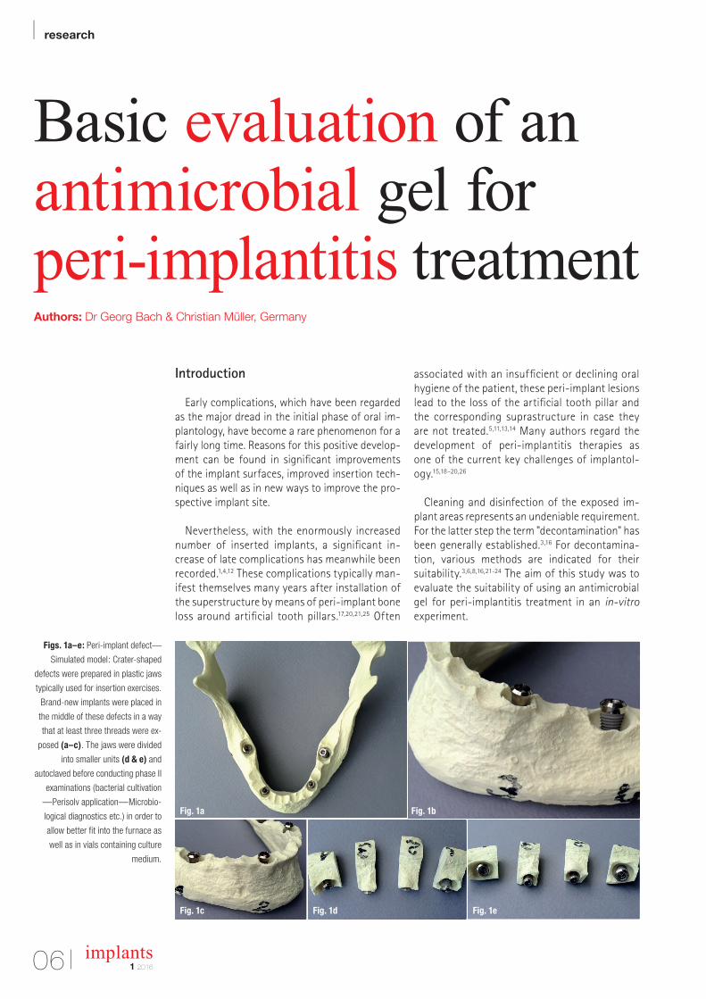
Figs. 1a–e: Peri-implant defect—
Simulated model: Crater-shaped
defects were prepared in plastic jaws
typically used for insertion exercises.
Brand-new implants were placed in
the middle of these defects in a way
that at least three threads were ex-
posed (a–c). The jaws were divided
into smaller units (d & e) and
autoclaved before conducting phase II
examinations (bacterial cultivation
—Perisolv application—Microbio-
logical diagnostics etc.) in order to
allow better fit into the furnace as
well as in vials containing culture
medium.
Introduction
Early complications, which have been regarded as the major dread in the initial phase of oral im-plantology, have become a rare phenomenon for a fairly long time. Reasons for this positive develop-ment can be found in significant improvements of the implant surfaces, improved insertion tech-niques as well as in new ways to improve the pro-spective implant site.
Nevertheless, with the enormously increased number of inserted implants, a significant in-crease of late complications has meanwhile been recorded.1,4,12 These complications typically man-ifest themselves many years after installation of the superstructure by means of peri-implant bone loss around artificial tooth pillars.17,20,21,25 Often
associated with an insufficient or declining oral hygiene of the patient, these peri-implant lesions lead to the loss of the artificial tooth pillar and the corresponding suprastructure in case they are not treated.5,11,13,14 Many authors regard the development of peri-implantitis therapies as one of the current key challenges of implantol-ogy.15,18–20,26
Cleaning and disinfection of the exposed im-plant areas represents an undeniable requirement. For the latter step the term "decontamination" has been generally established.3,16 For decontamina-tion, various methods are indicated for their suitability.3,6,8,16,21-24 The aim of this study was to evaluate the suitability of using an antimicrobial gel for peri-implantitis treatment in an in-vitro experiment.
Fig. 1bFig. 1a
Fig. 1c Fig. 1d Fig. 1e

Nobel Biocare Global Symposium
June 23–26, 2016 – New York
© Nobel Biocare Services AG, 2016. All rights reserved. Nobel Biocare, the Nobel Biocare logotype and all other trademarks are, if nothing else is stated or is evident from the context in a certain case, trade-
marks of Nobel Biocare. Please refer to nobelbiocare.com/trademarks for more information. Product images are not necessarily to scale. Disclaimer: Some products may not be regulatory cleared/released for
nobelbiocare.com/global-symposium-2016
An experience beyond the ordinary
The Nobel Biocare Global Symposium 2016 program will
as in-depth hands-on training. Held at the Waldorf Astoria
innovation can come to life in your daily work.
Design your own learning experience
and hands-on sessions – from over 150 of the best speakers
and presenters in the world. This must-attend event will
Where innovation comes to life
Register
now
Read more about the Symposium
implants1 2016
| research
08
Material and Methods
Two test phases were performed:
a) Phase I: Decontamination procedure of brand-new sterile implants, which have been inoculated with bacteria and subsequently coated with antimi-crobial gel.
b) Phase II: Decontamination procedure of brand-new sterile implants placed in a plastic jaw with sim-ulated bone defects after subsequent inoculation with bacteria and final exposure to antimicrobial gel.
Phase I: Decontamination procedure to implants inoculated with bacteria
To evaluate general suitability of the decontami-nation process, brand-new ITI implants (Institut Straumann AG, Basel, Switzerland) were microbio-logically processed and analysed at the Institute for Medical Diagnostics Bioscientia (Freiburg, Ger-many).
Implant contamination—microbial procedure:The implants were exposed and inoculated with a
bacterial suspension (overnight cultures of MRSA ATCC 33591):
By means of sterile forceps, the implants were placed in 10 ml peptone yeast extract broth each. The tubes were incubated for 48 h at 36 °C and 5–10 % CO2. After 48 h of incubation, the liquid was removed by means of vacuum filtration and the implant was transferred back to the initial container with sterile forceps for immediate further process-
ing. Exclusively, implants with a medium bacterial growth were used for further examinations, im-plants with low or very low bacterial growth were excluded. Two test series were conducted with four implants each.
Decontamination procedure with contaminated whole implant bodies:
After completion of the microbiological work, three out of four implants were confronted with an-timicrobial gel for two min in the sense of a decon-tamination procedure and immediately transferred to the Institute for microbiological analysis. One im-plant served as positive control, without conduction of the decontamination procedure. – Antimicrobial Gel: An antimicrobial gel known for its application in periodontology was used (PERI-SOLV, REGEDENT AG, Zurich, Switzerland). It is typically used for adjuvant cleaning and decontam-ination of the outer tooth root area and the surrounding tissue.10 Furthermore, in the literature the gel is described to feature a softening effect towards degenerative tissue before debridement of periodontal pockets.9 According to the manufac-turer, the gel does not affect healthy tissue9 and, however, features an antimicrobial effect.2,7
– Gel composition: The gel contains amino acids (glutamic acid, leucine and lysine), carboxymethyl cellulose, titanium dioxide as well as ultra pure water and features a pH value below 10. The trans-parent liquid represents a 0.95 % sodium hypo-chlorite solution and is admixed immediately be-fore the application. After mixing hypochlorite and amino acids, so-called Chloramines (NCA), a short-lived active substance class, are formed. These substances are part of the body's own im-mune system.9
– Gel Preparation: The set (gel and liquid) is stored in the refrigerator. One hour prior to planned applica-tion, the set is removed from the refrigerator to al-low the contents of the kit to warm up to room temperature. Both components (gel and liquid) are arranged in separate syringes and are connected by means of screwing (Luer-lock connection). Both components were thoroughly mixed by mov-ing the stamps back and forth 10–15 times. The activated and operational gel was finally left in the transparent syringe. A non-invasive/blunt appli-cation tip is attached and the implants are coated with the gel.
Bacterial growth on implant Implant 1 Implant 2 Implant 3 Implant 4control
A: MRSA – – – + + +
B: MRSA – + – + + +
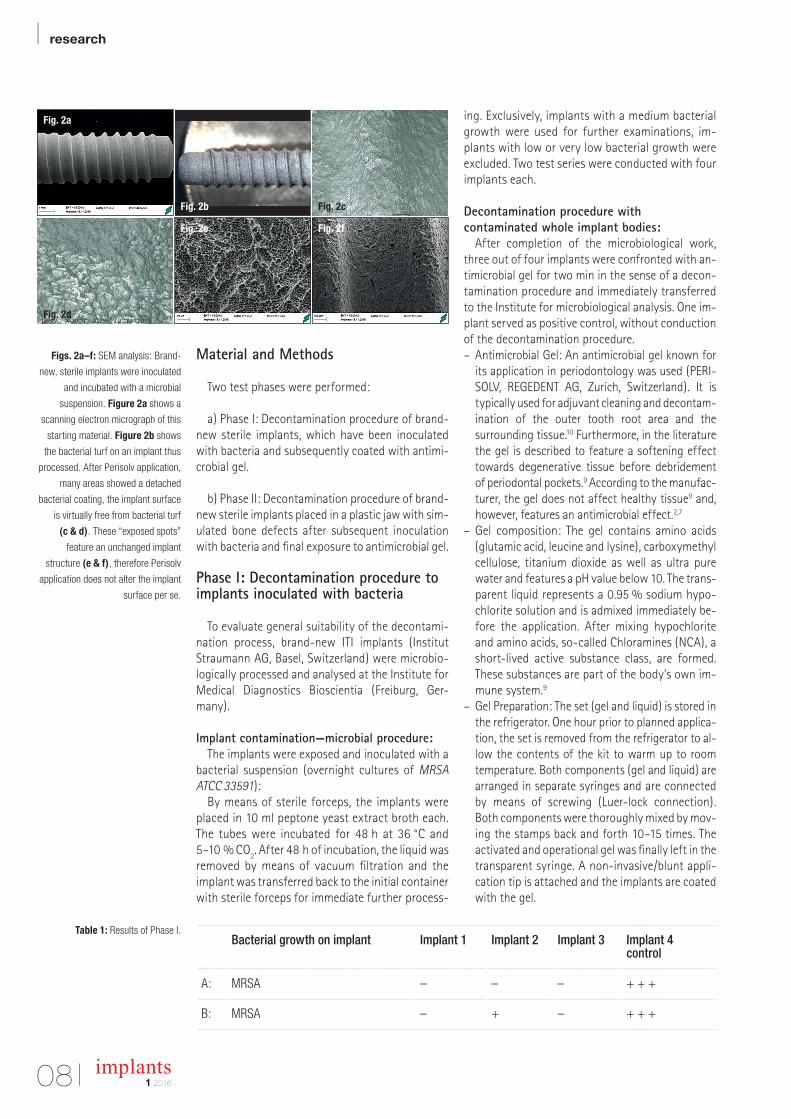
Figs. 2a–f: SEM analysis: Brand-
new, sterile implants were inoculated
and incubated with a microbial
suspension. Figure 2a shows a
scanning electron micrograph of this
starting material. Figure 2b shows
the bacterial turf on an implant thus
processed. After Perisolv application,
many areas showed a detached
bacterial coating, the implant surface
is virtually free from bacterial turf
(c & d). These “exposed spots”
feature an unchanged implant
structure (e & f), therefore Perisolv
application does not alter the implant
surface per se.
Table 1: Results of Phase I.
Fig. 2a
Fig. 2b Fig. 2c
Fig. 2d
Fig. 2e Fig. 2f
GLOBAL
CONFERENCE 2016
© MIS Corporation. All rights Reserved.
®
BARCELONA DREAM TEAM
MAKE IT SIMPLE
MIS is proud to introduce the Global Conference Speakers Team: Alexander Declerck � Anas Aloum � Andrea Pilloni � Arndt Happe � Björn-Owe Aronsson � Carles Martí-pagés � Carlo P. Marinello � Christian Coachman � David García Baeza � Eduard Ferrés-padró � Eli Machtei � Eric Van Dooren � Federico Hernández Alfaro � Florian Schober � France Lambert � Gabi Chaushu � Galip Gürel � Giulio Rasperini � Guillermo J. Pradíes Ramiro� Gustavo Giordani � Hilal Kuday � Ignacio Sanz Martin � José E. Maté-sánchez De Val � José Nart � Juan Arias Romero � Korkud Demirel � Lior Shapira � Marco Esposito � Mariano Sanz Alonzo � Miguel Troiano � Mirela Feraru-Bichacho � Mithridade Davarpanah � Moshe Goldstein � Nardi Casap � Nelson Carranza � Nitzan Bichacho � Nuno Sousa Dias � Pablo Galindo-Moreno � Stavros Pelekanos � Stefen Koubi � Tommie Van de Velde � Victor Clavijo � Vincent Fehmer � Yuval Jacoby. To learn more about the conference visit: www.mis-implants.com/barcelona
May 26-29, Barcelona
implants1 2016
| research
10
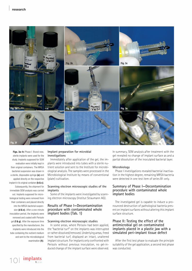
Figs. 3a–h: Phase I: Brand-new,
sterile implants were used for the
study. Implants supposed for SEM
evaluation were initially kept in
their original containers. The MRSA
bacterial suspension was drawn in
a sterile, disposable syringe (a) and
applied directly on the respective
implant in its original container (b & c).
Subsequently, the shipment for
immediate SEM analysis was carried
out. Implants supposed for micro-
biological testing were removed from
their containers and placed directly
into the MRSA bacterial suspen-
sion (d & e). After a one-minute
inoculation period, the implants were
removed and coated with Perisolv
gel (f & g). After the exposure time
specified by the manufacturer, the
implants were introduced into the
tube containing the nutrient medium
and sent to the microbiological
examination (h).
Fig. 3a
Fig. 3b Fig. 3c
Fig. 3d Fig. 3e
Fig. 3f Fig. 3g Fig. 3h
Implant preparation for microbial investigations
Immediately after application of the gel, the im-plants were introduced into tubes with a sterile nu-trient solution and sent to the Institute for microbi-ological analysis. The samples were processed in the Microbiological Institute by means of conventional (plate) cultivation.
Scanning electron microscopic studies of the implants
Some of the implants were investigated by scann-ing electron microscopy (Institut Straumann AG).
Results of Phase I—Decontamination procedure with contaminated whole implant bodies (Tab. 1)
Scanning electron microscopic studiesIn some areas, where Perisolv had been applied,
the “bacterial turf” on the implants was interrupted or rather dissolved/removed. Underlying areas, freed from bacterial turf, displayed an intact, unaltered implant structure. For implants only confronted with Perisolv without previous inoculation, no gel-in-duced change of the implant surface were observed.
In summary, SEM analysis after treatment with the gel revealed no change of implant surface as and a partial dissolution of the inoculated bacterial layer.
MicrobiologyPhase I investigations revealed bacterial inactiva-
tion in the highest degree, remaining MRSA bacteria were detected in one test item of series B1 only.
Summary of Phase I—Decontamination procedure with contaminated whole implant bodies
The investigated gel is capable to induce a pro-nounced destruction of pathological bacteria pres-ent on implant surfaces without altering this implant surface structure.
Phase II: Testing the effect of the antimicrobial gel on contaminated implants placed in a plastic jaw with a simulated peri-implant tissue defect
After the first test phase to evaluate the principle suitability of the gel application, a second test phase was conducted.
Beyond CAD/CAMPatient-specific prosthetic solutions for all major implant systems
In order to provide truly ideal solutions, you need restorative versatility,
flexibility within your workflow and design options that are as individual
as each patient. By choosing ATLANTIS, you get the freedom, esthetics,
simplicity and reliability that go beyond CAD/CAM.
DEN
TSPL
Y Im
pla
nts
does
not w
aiv
e any
rig
ht to its
tra
dem
ark
s by
not u
sing
the
sym
bols
® o
r ™
. 32670
848
-USX-1
512
© 2
015
DEN
TSPL
Y Im
pla
nts.
All
right
s re
serv
ed
Follow DENTSPLY Implants
www.dentsplyimplants.com
implants1 2016
| research
12
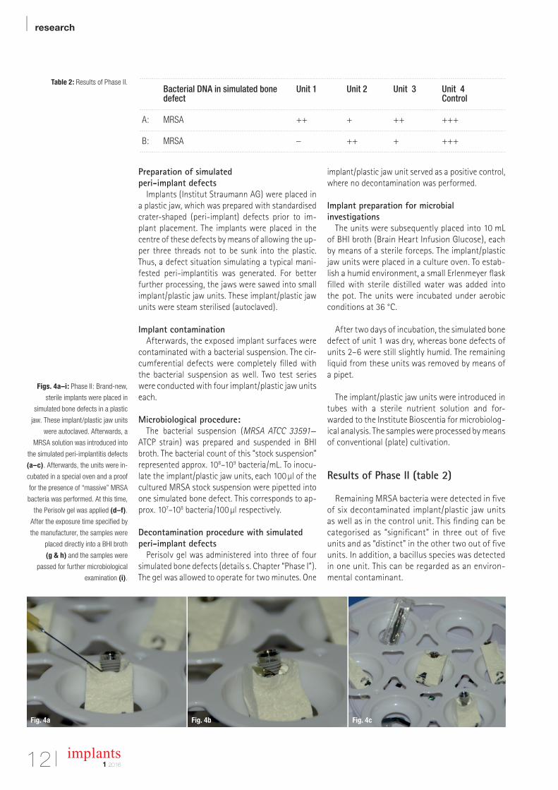
Preparation of simulated peri-implant defects
Implants (Institut Straumann AG) were placed in a plastic jaw, which was prepared with standardised crater-shaped (peri-implant) defects prior to im-plant placement. The implants were placed in the centre of these defects by means of allowing the up-per three threads not to be sunk into the plastic. Thus, a defect situation simulating a typical mani-fested peri-implantitis was generated. For better further processing, the jaws were sawed into small implant/plastic jaw units. These implant/plastic jaw units were steam sterilised (autoclaved).
Implant contamination Afterwards, the exposed implant surfaces were
contaminated with a bacterial suspension. The cir-cumferential defects were completely filled with the bacterial suspension as well. Two test series were conducted with four implant/plastic jaw units each.
Microbiological procedure: The bacterial suspension (MRSA ATCC 33591—
ATCP strain) was prepared and suspended in BHI broth. The bacterial count of this “stock suspension” represented approx. 108–109 bacteria/mL. To inocu-late the implant/plastic jaw units, each 100 µl of the cultured MRSA stock suspension were pipetted into one simulated bone defect. This corresponds to ap-prox. 107–108 bacteria/100 µl respectively.
Decontamination procedure with simulated peri-implant defects
Perisolv gel was administered into three of four simulated bone defects (details s. Chapter “Phase I”). The gel was allowed to operate for two minutes. One
implant/plastic jaw unit served as a positive control, where no decontamination was performed.
Implant preparation for microbial investigations
The units were subsequently placed into 10 mL of BHI broth (Brain Heart Infusion Glucose), each by means of a sterile forceps. The implant/plastic jaw units were placed in a culture oven. To estab-lish a humid environment, a small Erlenmeyer flask filled with sterile distilled water was added into the pot. The units were incubated under aerobic conditions at 36 °C.
After two days of incubation, the simulated bone defect of unit 1 was dry, whereas bone defects of units 2–6 were still slightly humid. The remaining liquid from these units was removed by means of a pipet.
The implant/plastic jaw units were introduced in tubes with a sterile nutrient solution and for-warded to the Institute Bioscentia for microbiolog-ical analysis. The samples were processed by means of conventional (plate) cultivation.
Results of Phase II (table 2)
Remaining MRSA bacteria were detected in five of six decontaminated implant/plastic jaw units as well as in the control unit. This finding can be categorised as “significant” in three out of five units and as “distinct" in the other two out of five units. In addition, a bacillus species was detected in one unit. This can be regarded as an environ-mental contaminant.
Table 2: Results of Phase II.
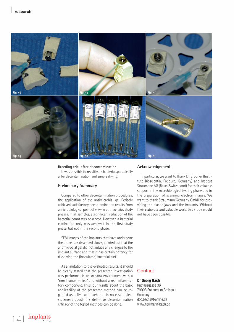
Figs. 4a–i: Phase II: Brand-new,
sterile implants were placed in
simulated bone defects in a plastic
jaw. These implant/plastic jaw units
were autoclaved. Afterwards, a
MRSA solution was introduced into
the simulated peri-implantitis defects
(a–c). Afterwards, the units were in-
cubated in a special oven and a proof
for the presence of “massive” MRSA
bacteria was performed. At this time,
the Perisolv gel was applied (d–f).
After the exposure time specified by
the manufacturer, the samples were
placed directly into a BHI broth
(g & h) and the samples were
passed for further microbiological
examination (i).
Bacterial DNA in simulated bone defect
Unit 1 Unit 2 Unit 3 Unit 4Control
A: MRSA ++ + ++ +++
B: MRSA – ++ + +++
Fig. 4a Fig. 4b Fig. 4c
| | PROSTHETIC COMPONENTS
|
[ Industry Standard Internal Hex Connection ]
Solid Zirconia
NEW!
[ Industry Standard Conical Connection ]
[ Industry compatible prosthetics ]
+49 (0) 69-2475 144 30 www.glidewelldirect.com [email protected]
Glidewell Direct is actively seeking distribution channels.
| research
14 implants1 2016
Breeding trial after decontaminationIt was possible to recultivate bacteria sporadically
after decontamination and simple drying.
Preliminary Summary
Compared to other decontamination procedures, the application of the antimicrobial gel Perisolv achieved satisfactory decontamination results from a microbiological point of view in both in-vitro study phases. In all samples, a significant reduction of the bacterial count was observed. However, a bacterial elimination only was achieved in the first study phase, but not in the second phase.
SEM images of the implants that have undergone the procedure described above, pointed out that the antimicrobial gel did not induce any changes to the implant surface and that it has certain potency for dissolving the (inoculated) bacterial turf.
As a limitation to the evaluated results, it should be clearly stated that the presented investigation was performed in an in-vitro environment with a “non-human milieu” and without a real inflamma-tory component. Thus, our results about the basic applicability of the presented method can be re-gard ed as a first approach, but in no case a clear statement about the definitive decontamination efficacy of the tested methods can be done.
Acknowledgement
In particular, we want to thank Dr Brodner (Insti-tute Bioscientia, Freiburg, Germany) and Institut Straumann AG (Basel, Switzerland) for their valuable support in the microbiological testing phase and in the preparation of scanning electron images. We want to thank Straumann Germany GmbH for pro-viding the plastic jaws and the implants. Without their elaborate and valuable work, this study would not have been possible._
Fig. 4d Fig. 4e Fig. 4f
Fig. 4g
Fig. 4d
Fig. 4h
Fig. 4e
Fig. 4i
Fig. 4f
Contact
Dr Georg Bach Rathausgasse 3679098 Freiburg im [email protected]
Register
now
Information and registration: www.camlogcongress.com
TACKLING EVERYDAY CHALLENGESAt the 6th International CAMLOG Congress we will focus on scientifically sound and
practical solutions. Experience our practical hands-on workshops, an innovative pre-
congress on digitalization and exciting lectures. Participate in interactive discussions and
meet internationally renowned speakers in the Network Lounge in a relaxed atmosphere.
The attractive ICE Congress center in Krakow offers the perfect platform. Krakow is a
lively and fascinating UNESCO World Heritage Site and enthusiastic in many ways.
Other congress highlights are the Special Speaker, the legendary CAMLOG Party and
the attractive partner programs.
Register early – we look forward to meeting you!
| research
16 implants1 2016
Lateral maxillary incisor implant–Key issues for aesthetic successAuthors: Drs Philippe Russe & Patrick Limbour, France
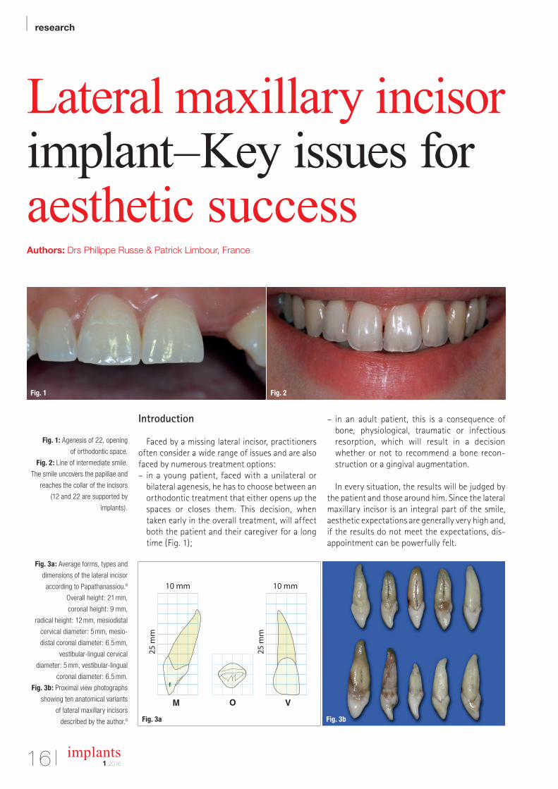
Fig. 1: Agenesis of 22, opening
of orthodontic space.
Fig. 2: Line of intermediate smile.
The smile uncovers the papillae and
reaches the collar of the incisors
(12 and 22 are supported by
implants).
Fig. 3a: Average forms, types and
dimensions of the lateral incisor
according to Papathanassiou.6
Overall height: 21 mm,
coronal height: 9 mm,
radical height: 12 mm, mesiodistal
cervical diameter: 5 mm, mesio-
distal coronal diameter: 6.5 mm,
vestibular-lingual cervical
diameter: 5 mm, vestibular-lingual
coronal diameter: 6.5 mm.
Fig. 3b: Proximal view photographs
showing ten anatomical variants
of lateral maxillary incisors
described by the author.6
Introduction
Faced by a missing lateral incisor, practitioners often consider a wide range of issues and are also faced by numerous treatment options:
– in a young patient, faced with a unilateral or bilateral agenesis, he has to choose between an orthodontic treatment that either opens up the spaces or closes them. This decision, when taken early in the overall treatment, will affect both the patient and their caregiver for a long time (Fig. 1);
– in an adult patient, this is a consequence of bone, physiological, traumatic or infectious resorption, which will result in a decision whether or not to recommend a bone reconstruction or a gingival augmentation.
In every situation, the results will be judged by the patient and those around him. Since the lateral maxillary incisor is an integral part of the smile, aesthetic expectations are generally very high and, if the results do not meet the expectations, disappointment can be powerfully felt.
Fig. 1 Fig. 2
O VM
10 mm 10 mm
25 m
m
25 m
m
Fig. 3bFig. 3a
research |
171 2016
implants
When describing the different treatment stages, a number of pitfalls and difficulties will be high
lighted and advice and clinical protocols will be given, in order to ensure that the results of this implant/prosthetic treatment are predictable and as aesthetically attractive as possible. This first article is concerned with these issues as regards the preprosthetic stages; the second will consider the most important aspects of the prosthetic stages as well as aesthetic outcomes and their evolution over the long term.
AnamnesisOnce the usual contraindications for oral and
implant surgery have been eliminated, particular attention should be given to the patient’s answers concerning their smoking habits. Indeed, meta analysis give an accurate picture of the consequences of smoking, with increases of: – periimplantitis1,2 and bone loss2; – failure rates.3
The conclusions of Snider et al.4 can provide recommendations for the practitioner faced with a patient who is a smoker: – the best is to ask the patient to stop smoking...; – if this approach is not acted on, then the patient must be warned of the increased risk of failure and of postoperative complications.
This last issue is important, as smoking can be considered a lost opportunity as far as implant treatment is concerned.
“It is preferable to avoid patients that
are smokers.”Clinical examination
The smile lineWhen replacing a tooth in an aesthetic region,
understanding the location of the smile line is one of the determining issues during the clinical examination. There are two factors to consider: the exposure of papillae and visibility of the collar of the lateral incisor, and there is one significant problem: any aesthetic deficit experienced by the patient tends to make them change their smile line, which can happen more or less as a conscious process and this can be a source of significant errors. Analysis of gingival composition is also a determining issue in positioning the collar of the lateral incisors in a location that is aesthetically optimal. The gullwing profile, where the collar of the lateral incisors is slightly more coronal than that of the front teeth or the canine teeth, is considered to be more attractive acco rding to Chiche5 (Fig. 2).
Dental aestheticsAs regards dental aesthetics, the proportions of
the proposed implant supported tooth can reflect two different scenarios:
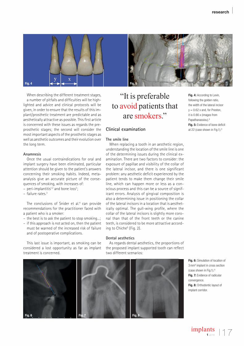
Fig. 4: According to Levin,
following the golden ratio,
the width of the lateral incisor
y = 0.62 x and, for Preston,
it is 0.66 x (images from
Papathanassiou).6
Fig. 5: Evidence of bone deficit
at 22 (case shown in Fig.1).6
Fig. 6: Simulation of location of
3 mm6 implant in cross section
(case shown in Fig.1).6
Fig. 7: Evidence of radicular
convergence.
Fig. 8: Orthodontic layout of
implant corridor.
Fig. 6 Fig. 7 Fig. 8
Fig. 4 Fig. 5
| research
implants1 201618
– there is a unilateral missing tooth and the controlateral incisor has normal and aesthetically pleasing proportions. The objective will be to create a lateral incisor implant that is a mirror image;
– with the same situation but where the controlateral incisor is small; this is a situation that occurs frequently in unilateral agenesis where the incisor that is present is riziform or, if there is agenesis of both lateral incisors, the clinical examination should gather the information required to decide on the dimensions and coronal axes of the proposed lateral incisors. An analysis of the occlusion and the dimensions of the central incisors are the clinical parameters that make it possible to establish the characteristics of the planned prosthetic teeth.
The anatomy of the lateral incisor has been the subject of various publications, including, notably, by Pa pathanassiou6 who defined average dimensions and a typical form (Fig. 3a) and also presented numerous morphological variants affecting these dimensions and also other characteristics such as the crown/root ratio and the coronal and root axes (Fig. 3b). These morphological criteria, which can now be found using 3D imaging, have had a significant influence on the location of implants in all spatial planes in order to achieve the goal of harmony of form and dimension. Other publications, such as those by Levin7 and Preston,8 make it pos
sible to estimate the width of absent lateral incisors on the basis of the central incisors (Fig. 4).
“Establish the ideal width and orientation
of the planned prosthetic crown.”
Implant locationA clinically significant deficit signals the need for
reconstruction of hard tissue but, conversely, a site without a tooth with no loss of volume should be subjected to a threedimensional Xray, as thick soft tissue can hide a lack of hard tissue (Fig. 5). A thin tissue biotype or a lack of attached gingiva can be a sign that gingival augmentation surgery will be required, particularly if a bone graft needs to be performed.
OcclusionFor orthodontic treatments, the anterior guid
ance should be analyzed carefully. It can be tempting to increase the perimeter of the maxillary arcade in order to obtain, at the least, implant corridors that are sufficiently wide at the level of 12 or 22. However, an overjet will make it very likely that the natural teeth will move in relation to the implant prosthesis with highly negative consequences for the sustainability of the cosmetic outcome.
DocumentationTaking photographs at the start of the treatment
will make it possible to maintain a record of the initial condition, which is always useful if there are medical/legal problems at the end of the treatment. In addition, the images often make it possible to see problems relating to width, axis or asymmetry that sometimes go unnoticed during a clinical examination.
“Check anterior guidance and absence
of overjet.”
Complementary tests
2-D imagingPanoramic Xrays or retroalveolar radiography
make it possible to check the depth of implantable
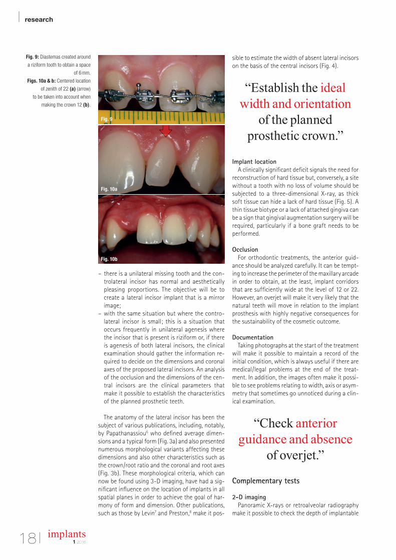
Fig. 9: Diastemas created around
a riziform tooth to obtain a space
of 6 mm.
Figs. 10a & b: Centered location
of zenith of 22 (a) (arrow)
to be taken into account when
making the crown 12 (b).
Fig. 9
Fig. 10a
Fig. 10b
research |
1 2016
implants 19
bone in relation to the floor of the nasal cavity, the bone level in relation to that of adjacent teeth and the parallelism of the central incisor and canine.
3-D imaging3D imaging is required to check the vestibular
palatal dimensions of the bone crest. There are three possibilities: – the crest is sufficiently wide to take an implant without any bone augmentation;
– the crest is narrow, bone augmentation is required prior to siting the implant (Fig. 6);
– intermediate situations where the siting of the implant will be accompanied either by bone splitting or by guided bone regeneration.
– Orthodontic preparation
When the adjacent teeth present apical convergence, the orthodontic preparation should create a mesiodistal dimension at the level of the root that allows the implant to pass with a margin of at least 1 mm of bone (Figs. 7 & 8). Where there is a controlateral incisor of a normal size, the rule for the orthodontist is to measure the width of that tooth carefully and to recreate the same width in the crown of the planned implant. Where the controlateral incisor is riziform, the orthodontist should plan the future face of the tooth in order to achieve two laterals with the same shape.
Diastemas around the riziform tooth make it possible to achieve a smile that, in the end, is almost symmetrical (Fig. 9). The riziform incisor does not have to be in the centre of the space but should be positioned in such a way that the papillae and the future zenith of the tooth are optimized. The zenith should be located 0.4 mm distal from the centre of the tooth for a lateral incisor, according to Chu et al.9 (Figs. 10a & b). Sometimes, a zenith situated more than 1 mm from a line between the collars of the central incisor and the canine should be surgically altered by coronal lengthening as a lateral incisor that is too short can also be aesthetically unacceptable.
“The orthodontist should anticipate
the future prosthetic morphology of the riziform incisor.”
Hard tissue augmentation
Where a bone reconstruction is indicated, this should take into account one of the key factors for the overall cosmetic outcome: restoration of papillary support in order to avoid any unsightly black triangles between the lateral incisor and the adjacent teeth or any concave area above the implant crown that would create an ugly shadow.
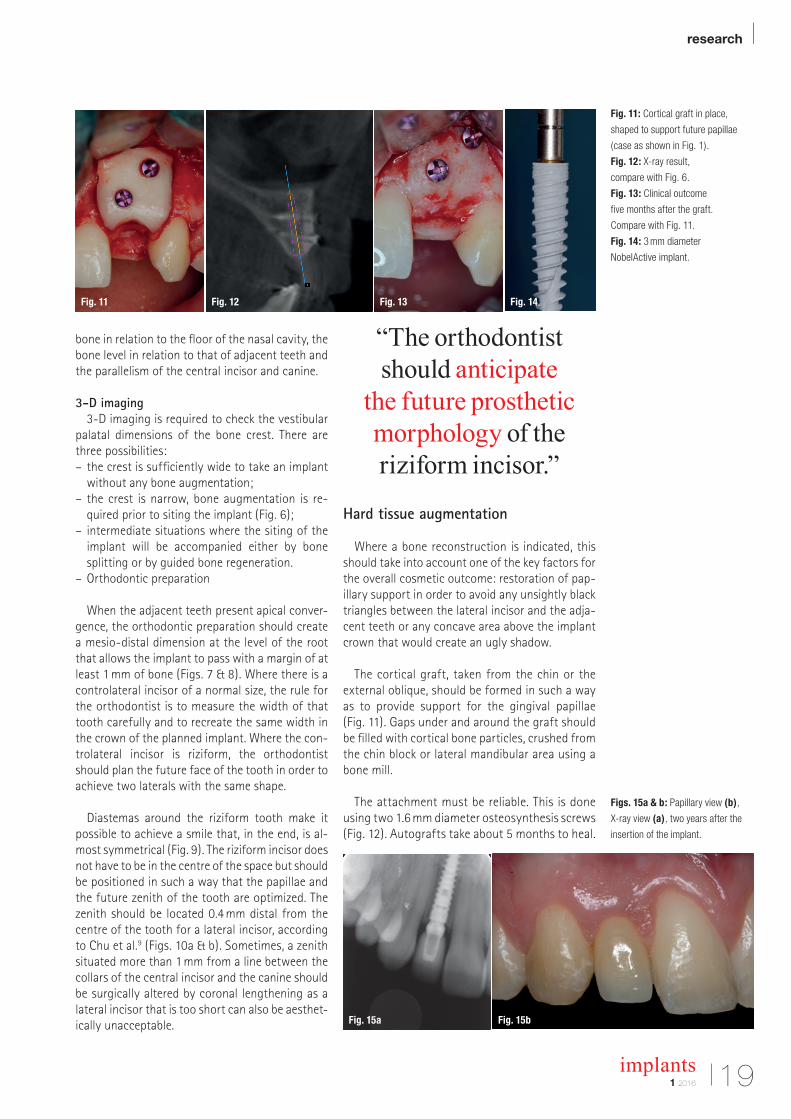
The cortical graft, taken from the chin or the external oblique, should be formed in such a way as to provide support for the gingival papillae (Fig. 11). Gaps under and around the graft should be filled with cortical bone particles, crushed from the chin block or lateral mandibular area using a bone mill.
The attachment must be reliable. This is done using two 1.6 mm diameter osteosynthesis screws (Fig. 12). Autografts take about 5 months to heal.
Fig. 11: Cortical graft in place,
shaped to support future papillae
(case as shown in Fig. 1).
Fig. 12: X-ray result,
compare with Fig. 6.
Fig. 13: Clinical outcome
five months after the graft.
Compare with Fig. 11.
Fig. 14: 3 mm diameter
NobelActive implant.
Figs. 15a & b: Papillary view (b),
X-ray view (a), two years after the
insertion of the implant.
Fig. 11
Fig. 15a Fig. 15b
Fig. 12 Fig. 13 Fig. 14
| research
implants1 201620
Ideally, the implant should be inserted between 4.5 and 5.5 months after the graft (Fig. 13).
“Fully reconstruct papillary support.”
Insertion of implant
Choice of implantThe mesiodistal dimension of the gap will deter
mine the choice of the implant. When this is close to or less than the average size of 6.5 mm, the bone and papillary volume around standard size implants will be limited. According to Hasan et al.10 and Bourauel et al.,11 the disadvantage of small diameter
implants is that they transmit higher stresses to the crestal bone than do standard implants. When replacing a lateral maxillary incisor, it is possible to arrange both the anterior guidance and the deduction in such a way as to make them largely affect the natural teeth, in the absence of any significant malpositioning, and in this way reduce the stresses applied to the implants. Under these conditions, small diameter implants have the advantage of increasing surrounding residual bone volume as well as space available for papillary healing.
In a forthcoming study of 120 NobelActive 3 mm diameter implants, one of the conclusions confirmed the importance of these small diameter implants as regards the additional height of the papillae, resulting in an improvement in the Fürhauser pink aesthetic score12 (Figs. 14, 15a & b).
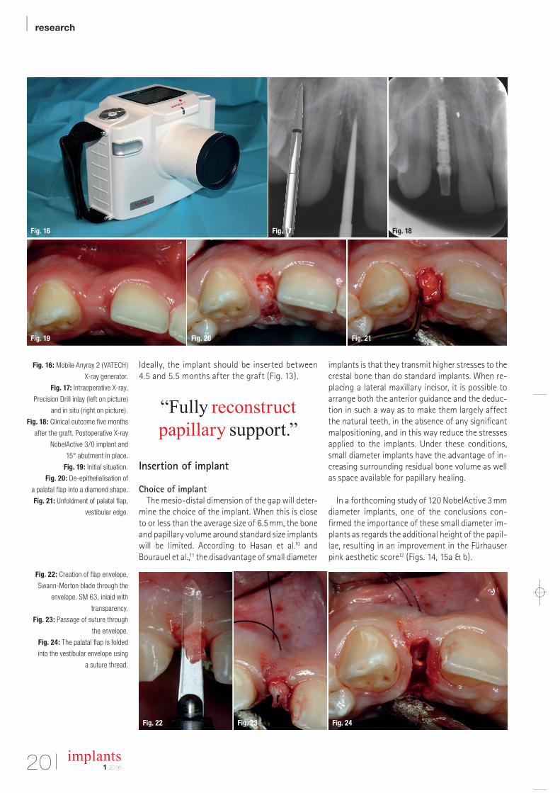
Fig. 16: Mobile Anyray 2 (VATECH)
X-ray generator.
Fig. 17: Intraoperative X-ray,
Precision Drill inlay (left on picture)
and in situ (right on picture).
Fig. 18: Clinical outcome five months
after the graft. Postoperative X-ray
NobelActive 3/0 implant and
15° abutment in place.
Fig. 19: Initial situation.
Fig. 20: De-epithelialisation of
a palatal flap into a diamond shape.
Fig. 21: Unfoldment of palatal flap,
vestibular edge.
Fig. 22: Creation of flap envelope,
Swann-Morton blade through the
envelope. SM 63, inlaid with
transparency.
Fig. 23: Passage of suture through
the envelope.
Fig. 24: The palatal flap is folded
into the vestibular envelope using
a suture thread.
Fig. 16
Fig. 19 Fig. 20 Fig. 21
Fig. 22 Fig. 23 Fig. 24
Fig. 17 Fig. 18
Become an author for implants—international magazine of oral implantology
Please contact:
Georg IsbanerEditorial [email protected]
| researchBasic evaluation of an antimicrobial gel for peri-implantitis treatment
| case reportThe indispensable use of CBCT in the posterior mandible
| industryAutomatic crestal sinus lift by motorised impaction device
implants international magazine of oral implantology
issn 1868-3207 Vol. 17 • Issue 1/2016
12016
Publish your
expertise!
Oemus_Autorenanzeige_210x148_en_Layout 1 16.03.16 13:51 Seite 1AD
research |
211 2016
implants
“Favor small diameter implants.”
3-D positioningAs regards replacement of a lateral maxillary in
cisor, the tolerances for the location of the implant are very small because of the narrow width of the implant corridor. Two recent metaanalysis13,14 concerning the precision of surgical guides resulting from 3D imagery, even if these do not apply specifically to the lateral incisor replacement, has found a deviation in the order of a millimetre at
the point the implant emerges and 4 to 5 degrees as regards the drilling axis. For Van Assche et al.,14 the average imprecision at the apex of the implant is 1.24 mm.
Since these measurements are incompatible with a 12 or 22 implant corridor, it is important to check the first drill hole(s) during the operation, whether the surgery is guided or being carried out freehand. If the implant clinic does not have retroalveolar Xray equipment, portable generators such as the AnyRay II (VATECH) are available on the market, which allow you to produce intraoperative images (Fig. 16).
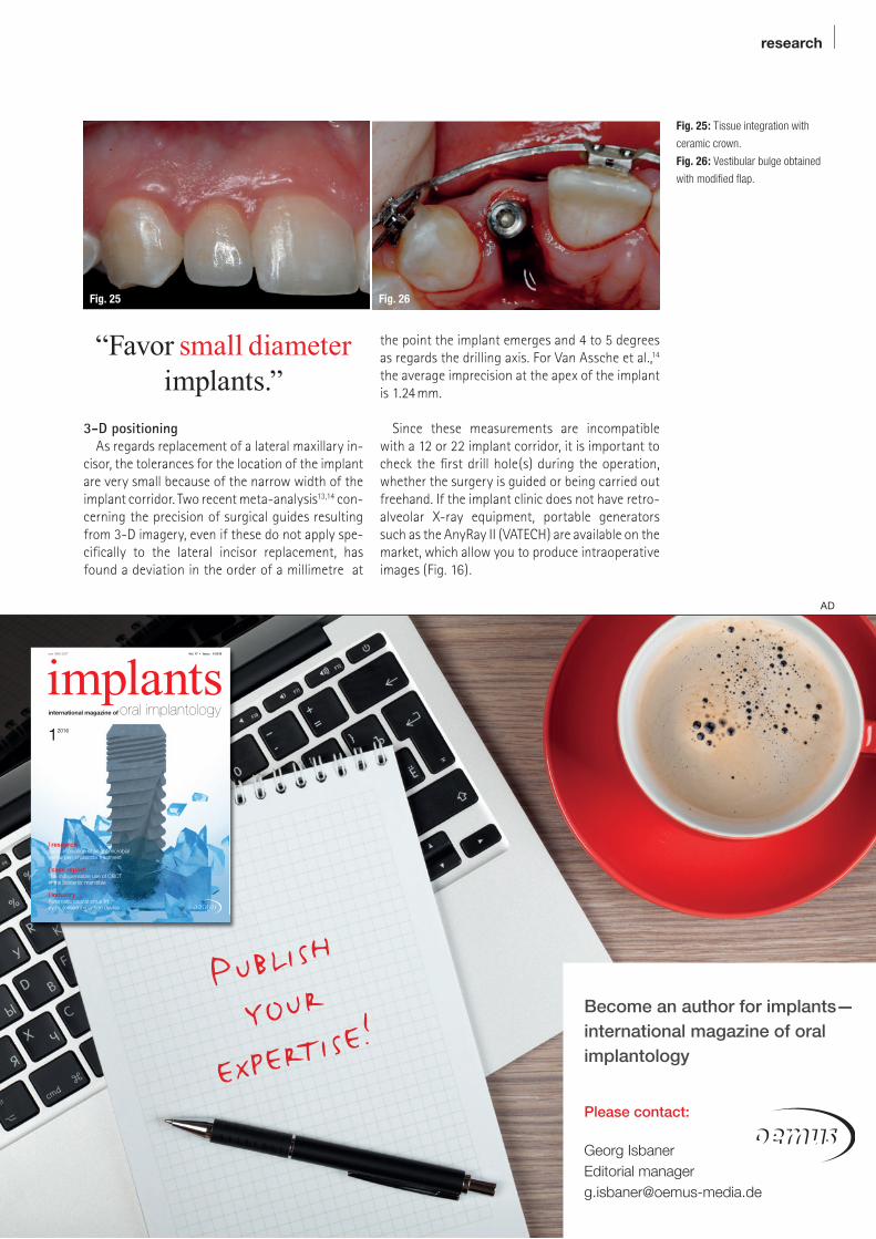
Fig. 25: Tissue integration with
ceramic crown.
Fig. 26: Vestibular bulge obtained
with modified flap.
Fig. 25 Fig. 26
Become an author for implants—international magazine of oral implantology
Please contact:
Georg IsbanerEditorial [email protected]
| researchBasic evaluation of an antimicrobial gel for peri-implantitis treatment
| case reportThe indispensable use of CBCT in the posterior mandible
| industryAutomatic crestal sinus lift by motorised impaction device
implants international magazine of oral implantology
issn 1868-3207 Vol. 17 • Issue 1/2016
12016
Publish your
expertise!
Oemus_Autorenanzeige_210x148_en_Layout 1 16.03.16 13:51 Seite 1AD
| research
implants1 201622
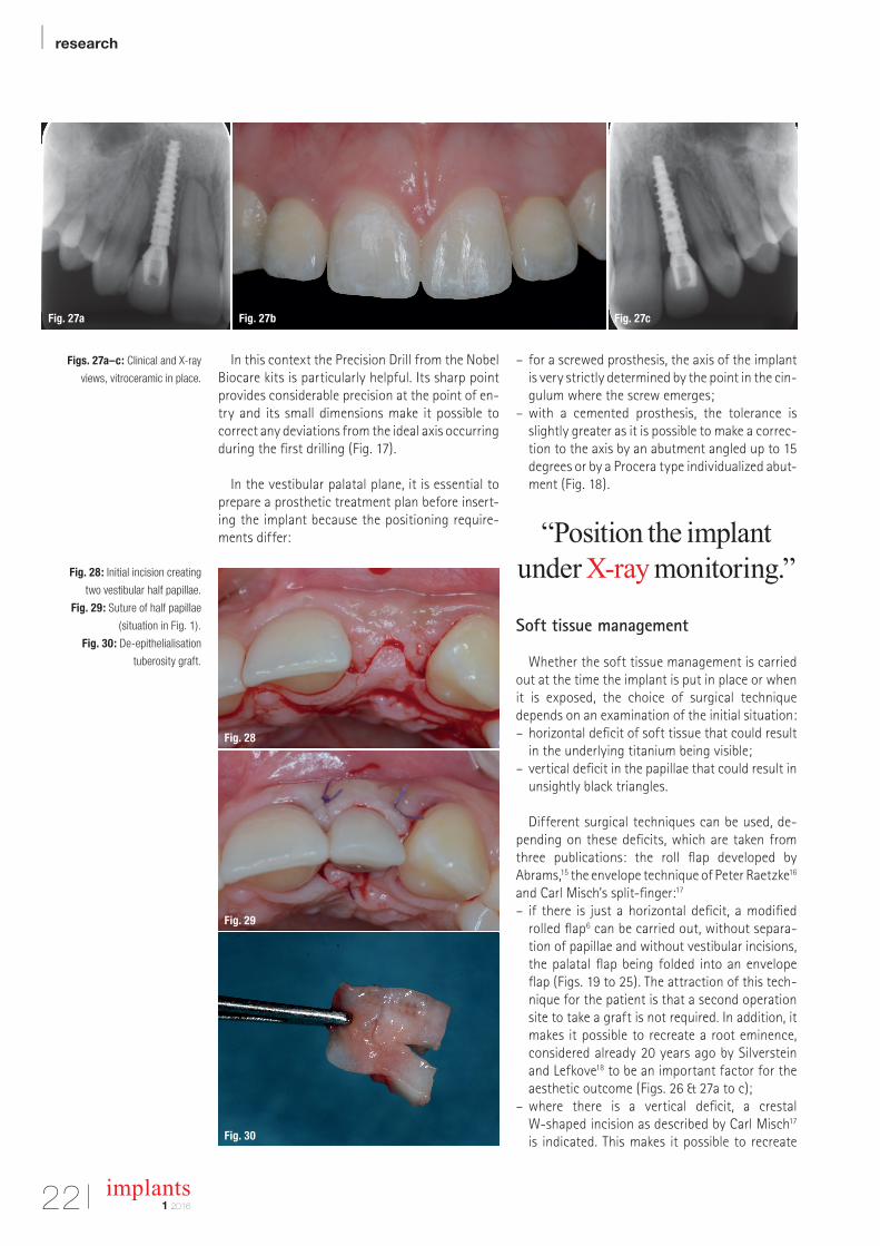
In this context the Precision Drill from the Nobel Biocare kits is particularly helpful. Its sharp point provides considerable precision at the point of entry and its small dimensions make it possible to correct any deviations from the ideal axis occurring during the first drilling (Fig. 17).
In the vestibular palatal plane, it is essential to prepare a prosthetic treatment plan before inserting the implant because the positioning requirements differ:
– for a screwed prosthesis, the axis of the implant is very strictly determined by the point in the cingulum where the screw emerges;
– with a cemented prosthesis, the tolerance is slightly greater as it is possible to make a correction to the axis by an abutment angled up to 15 degrees or by a Procera type individualized abutment (Fig. 18).
“Position the implant under X-ray monitoring.”
Soft tissue management
Whether the soft tissue management is carried out at the time the implant is put in place or when it is exposed, the choice of surgical technique depends on an examination of the initial situation: – horizontal deficit of soft tissue that could result in the underlying titanium being visible;
– vertical deficit in the papillae that could result in unsightly black triangles.
Different surgical techniques can be used, depending on these deficits, which are taken from three publications: the roll flap developed by Abrams,15 the envelope technique of Peter Raetzke16 and Carl Misch’s splitfinger:17
– if there is just a horizontal deficit, a modified rolled flap6 can be carried out, without separation of papillae and without vestibular incisions, the palatal flap being folded into an envelope flap (Figs. 19 to 25). The attraction of this technique for the patient is that a second operation site to take a graft is not required. In addition, it makes it possible to recreate a root eminence, considered already 20 years ago by Silverstein and Lefkove18 to be an important factor for the aesthetic outcome (Figs. 26 & 27a to c);
– where there is a vertical deficit, a crestal Wshaped incision as described by Carl Misch17 is indicated. This makes it possible to recreate
Figs. 27a–c: Clinical and X-ray
views, vitroceramic in place.
Fig. 28: Initial incision creating
two vestibular half papillae.
Fig. 29: Suture of half papillae
(situation in Fig. 1).
Fig. 30: De-epithelialisation
tuberosity graft.
Fig. 27a Fig. 27b
Fig. 28
Fig. 29
Fig. 30
Fig. 27c
research |
1 2016
implants 23
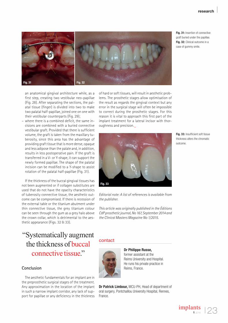
an anatomical gingival architecture while, as a first step, creating two vestibular neopapillae (Fig. 28). After separating the sections, the palatal tissue (finger) is divided into two to make two palatal halfpapillae, joined one on one with their vestibular counterparts (Fig. 29);
– where there is a combined deficit, the same incisions are combined with a buried connective vestibular graft. Provided that there is sufficient volume, the graft is taken from the maxillary tuberosity, since this area has the advantage of providing graft tissue that is more dense, opaque and less adipose than the palate and, in addition, results in less postoperative pain. If the graft is transferred in a V or Yshape, it can support the newly formed papillae. The shape of the palatal incision can be modified to a Yshape to assist rotation of the palatal halfpapillae (Fig. 31).
If the thickness of the buccal gingival tissues has not been augmented or if collagen substitutes are used that do not have the opacity characteristics of tuberosity connective tissue, the aesthetic outcome can be compromised. If there is recession of the external table or the titanium abutment under thin connective tissue, the grey titanium colour can be seen through the gum as a grey halo above the crown collar, which is detrimental to the aesthetic appearance (Figs. 32 & 33).
“Systematically augment the thickness of buccal
connective tissue.”
Conclusion
The aesthetic fundamentals for an implant are in the preprosthetic surgical stages of the treatment. Any approximation in the location of the implant in such a narrow implant corridor, any lack of support for papillae or any deficiency in the thickness
of hard or soft tissues, will result in aesthetic problems. The prosthetic stages allow optimisation of the result as regards the gingival context but any error in the surgical stage will often be impossible to correct during the prosthetic stages. For this reason it is vital to approach this first part of the implant treatment for a lateral incisor with thoroughness and precision._
Editorial note: A list of references is available from the publisher.
This article was originally published in the Éditions CdP prosthetic journal, No 167, September 2014 and the Clinical Masters Magazine No 1/2015.
Fig. 31: Insertion of connective
graft buried under the papillae.
Fig. 32: Clinical outcome in a
case of gummy smile.
Fig. 33: Insufficient soft tissue
thickness alters the chromatic
outcome.
contact
Dr Philippe Russe, former assistant at the Reims University and Hospital.He runs his private practice in Reims, France.
Dr Patrick Limbour, MCU-PH, Head of department of oral surgery, Pontchaillou University Hospital, Rennes, France.
Fig. 31 Fig. 32
Fig. 33
| research
24 implants1 2016
Maxillary implant supported removable or fixed prostheses Author: Dr Scott D. Ganz, USA
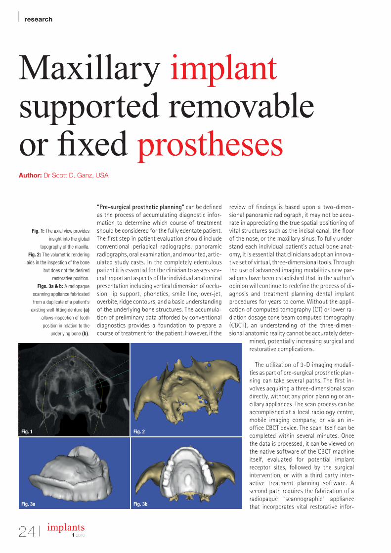
“Pre-surgical prosthetic planning” can be defined as the process of accumulating diagnostic infor-mation to determine which course of treatment should be considered for the fully edentate patient. The first step in patient evaluation should include conventional periapical radiographs, panoramic radiographs, oral examination, and mounted, artic-ulated study casts. In the completely edentulous patient it is essential for the clinician to assess sev-eral important aspects of the individual anatomical presentation including vertical dimension of occlu-sion, lip support, phonetics, smile line, over-jet, overbite, ridge contours, and a basic understanding of the underlying bone structures. The accumula-tion of preliminary data afforded by conventional diagnostics provides a foundation to prepare a course of treatment for the patient. However, if the
review of findings is based upon a two-dimen-sional panoramic radiograph, it may not be accu-rate in appreciating the true spatial positioning of vital structures such as the incisal canal, the floor of the nose, or the maxillary sinus. To fully under-stand each individual patient’s actual bone anat-omy, it is essential that clinicians adopt an innova-tive set of virtual, three-dimensional tools. Through the use of advanced imaging modalities new par-adigms have been established that in the author’s opinion will continue to redefine the process of di-agnosis and treatment planning dental implant procedures for years to come. Without the appli-cation of computed tomography (CT) or lower ra-diation dosage cone beam computed tomography (CBCT), an understanding of the three-dimen-sional anatomic reality cannot be accurately deter-
mined, potentially increasing surgical and restorative com plications.
The utilization of 3-D imaging modali-ties as part of pre-surgical prosthetic plan-ning can take several paths. The first in-volves acquiring a three- dimensional scan directly, without any prior planning or an-cillary appliances. The scan process can be accomplished at a local radiology centre, mobile imaging company, or via an in- office CBCT device. The scan itself can be completed within several minutes. Once the data is processed, it can be viewed on the native software of the CBCT machine itself, evaluated for potential implant receptor sites, followed by the surgical intervention, or with a third party inter-active treatment planning software. A second path requires the fabrication of a radiopaque “scannographic” appliance that incorporates vital restorative infor-Fig. 3a
Fig. 1
Fig. 3b
Fig. 2
Fig. 1: The axial view provides
insight into the global
topography of the maxilla.
Fig. 2: The volumetric rendering
aids in the inspection of the bone
but does not the desired
restorative position.
Figs. 3a & b: A radiopaque
scanning appliance fabricated
from a duplicate of a patient’s
existing well-fitting denture (a)
allows inspection of tooth
position in relation to the
underlying bone (b).
research |
251 2016
implants
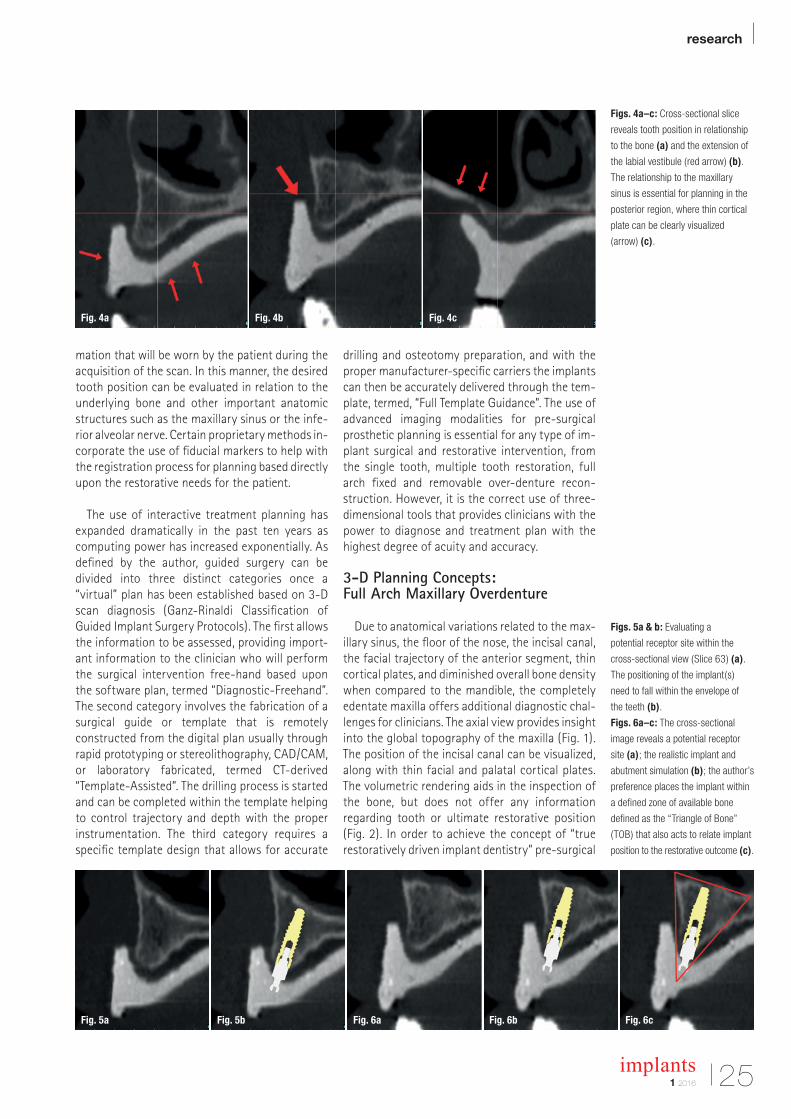
Figs. 4a–c: Cross-sectional slice
reveals tooth position in relationship
to the bone (a) and the extension of
the labial vestibule (red arrow) (b).
The relationship to the maxillary
sinus is essential for planning in the
posterior region, where thin cortical
plate can be clearly visualized
(arrow) (c).
Figs. 5a & b: Evaluating a
potential receptor site within the
cross-sectional view (Slice 63) (a).
The positioning of the implant(s)
need to fall within the envelope of
the teeth (b).
Figs. 6a–c: The cross-sectional
image reveals a potential receptor
site (a); the realistic implant and
abutment simulation (b); the author’s
preference places the implant within
a defined zone of available bone
defined as the “Triangle of Bone”
(TOB) that also acts to relate implant
position to the restorative outcome (c).
mation that will be worn by the patient during the acquisition of the scan. In this manner, the desired tooth position can be evaluated in relation to the underlying bone and other important anatomic structures such as the maxillary sinus or the infe-rior alveolar nerve. Certain proprietary methods in-corporate the use of fiducial markers to help with the registration process for planning based directly upon the restorative needs for the patient.
The use of interactive treatment planning has expanded dramatically in the past ten years as computing power has increased exponentially. As defined by the author, guided surgery can be divided into three distinct categories once a “virtual” plan has been established based on 3-D scan diagnosis (Ganz-Rinaldi Classification of Guided Implant Surgery Protocols). The first allows the information to be assessed, providing import-ant information to the clinician who will perform the surgical intervention free-hand based upon the software plan, termed “Diagnostic-Freehand”. The second category involves the fabrication of a surgical guide or template that is remotely constructed from the digital plan usually through rapid prototyping or stereolithography, CAD/CAM, or laboratory fabricated, termed CT-derived “Template-Assisted”. The drilling process is started and can be completed within the template helping to control trajectory and depth with the proper instrumentation. The third category requires a specific template design that allows for accurate
drilling and osteotomy preparation, and with the proper manufacturer-specific carriers the implants can then be accurately delivered through the tem-plate, termed, “Full Template Guidance”. The use of advanced imaging modalities for pre-surgical prosthetic planning is essential for any type of im-plant surgical and restorative intervention, from the single tooth, multiple tooth restoration, full arch fixed and removable over-denture recon-struction. However, it is the correct use of three- dimensional tools that provides clinicians with the power to diagnose and treatment plan with the highest degree of acuity and ac curacy.
3-D Planning Concepts: Full Arch Maxillary Overdenture
Due to anatomical variations related to the max-illary sinus, the floor of the nose, the incisal canal, the facial trajectory of the anterior segment, thin cortical plates, and diminished overall bone density when compared to the mandible, the completely edentate maxilla offers additional diagnostic chal-lenges for clinicians. The axial view provides insight into the global topography of the maxilla (Fig. 1). The position of the incisal canal can be visualized, along with thin facial and palatal cortical plates. The volumetric rendering aids in the inspection of the bone, but does not offer any information regarding tooth or ultimate restorative position (Fig. 2). In order to achieve the concept of “true restoratively driven implant dentistry” pre-surgical
Fig. 4a
Fig. 5a Fig. 5b Fig. 6a Fig. 6b Fig. 6c
Fig. 4b Fig. 4c
| research
26 implants1 2016
prosthetic planning should start prior to any scan being taken. A scanning appliance can be fabri-cated from a duplicate of a patient’s existing well-fitting denture, or a new diagnostic set-up which positions the teeth at the ideal vertical di-mension of occlusion, centric relation, and func-tional/aesthetic components (Fig. 3a). The patient wears the scannographic appliance during the scan, ideally held in place with a pre-determined bite registration to minimize movement. The scan reconstruction will then contain both the tooth position and the underlying bone (Fig. 3b).
The combination of the anatomical scan data with the radiopaque template allows unprece-dented diagnostic potential. The template reveals the tooth position (red arrows) in relationship to the underlying bone in the cross-sectional slice (Fig. 4a). The thin cortical plates can be clearly vi-sualized, along with the extension of the labial ves-tibule (red arrow, Fig. 4b). The relationship to the maxillary sinus is important when deciding if im-plants might be an option in the posterior region (Fig. 4c). In this example the pneumatisation of the sinus has resulted in extremely thin lateral cortical plate (see red arrows). The radiopaque template is helpful when evaluating other receptor sites, and positioning a simulated implant within the
cross-sectional view (Slice 63, Fig. 5a). For an over-denture application the positioning of im-plants need to fall within the envelope of the teeth, and it is even more practical to visualize the abut-ments that might be utilized (Fig. 5b). For this ex-ample a realistic stock “ball type” abutment was utilized on the virtual realistic implant. In order to provide some guidance, it is the author’s preference to place the implant within a defined zone of avail-able bone (Figs. 6a & b). This zone has been previ-ously defined as the “Triangle of Bone” (TOB) that also acts as a decision tree to connect the implant placement to the restorative outcome (Fig. 6c). Po-sitioning the implant within the zone of the TOB, or actually bisecting the triangle, allows for the most bone volume to surround the implant. Following this formula, the implant and abutment will be po-sitioned in a favourable restorative position.
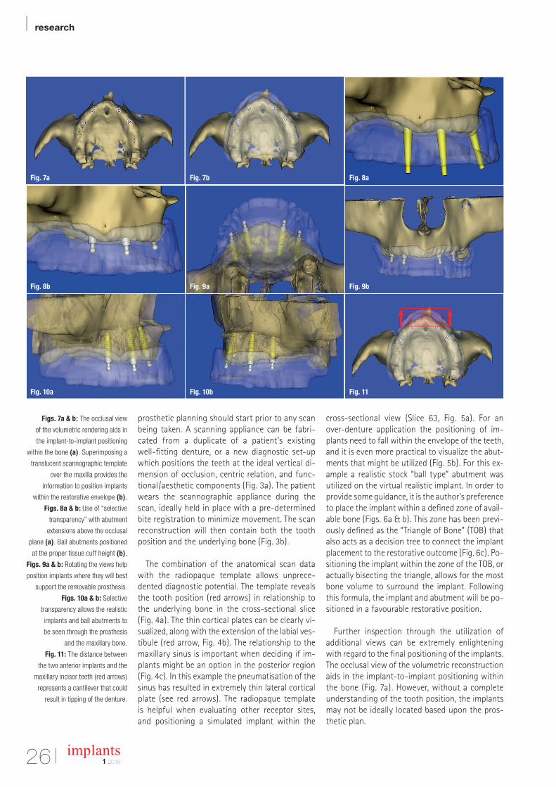
Further inspection through the utilization of additional views can be extremely enlightening with regard to the final positioning of the implants. The occlusal view of the volumetric reconstruction aids in the implant-to-implant positioning within the bone (Fig. 7a). However, without a complete understanding of the tooth position, the implants may not be ideally located based upon the pros-thetic plan.
Figs. 7a & b: The occlusal view
of the volumetric rendering aids in
the implant-to-implant positioning
within the bone (a). Superimposing a
translucent scannographic template
over the maxilla provides the
information to position implants
within the restorative envelope (b).
Figs. 8a & b: Use of “selective
transparency” with abutment
extensions above the occlusal
plane (a). Ball abutments positioned
at the proper tissue cuff height (b).
Figs. 9a & b: Rotating the views help
position implants where they will best
support the removable prosthesis.
Figs. 10a & b: Selective
transparency allows the realistic
implants and ball abutments to
be seen through the prosthesis
and the maxillary bone.
Fig. 11: The distance between
the two anterior implants and the
maxillary incisor teeth (red arrows)
represents a cantilever that could
result in tipping of the denture.
Fig. 7a
Fig. 8b
Fig. 10a
Fig. 7b
Fig. 9a
Fig. 10b
Fig. 8a
Fig. 9b
Fig. 11
research |
271 2016
implants
Superimposing a translucent scannographic template over the maxilla provides the important information to position the implants within the restorative envelope (Fig. 7b). The prosthesis de-sign can be evaluated to determine whether to fabricate a complete denture that would extend to incorporate a conventional post-palatal seal, or an open-palate horseshoe type prosthesis. To aid in the final positioning, it is helpful to visualize the outline of the occlusion using the author’s con-cept of “selective transparency”, and extend the abutments above the occlusal plane (Fig. 8a). “Se-lective transparency” is a software tool which can help separate one anatomical structure from an-other by adjusting the opacity of the various ob-jects. Once the implants are placed, the ball abut-ments can then be positioned at the proper tissue cuff height (Fig. 8b). Rotating the views can sub-stantiate the plan to place the implants where they will be support the removable prosthesis (Figs. 9a & b).
It is important to assess the clearance within the denture to allow for sufficient thickness of acrylic within the over-denture abutment housing avoiding potential fracture of the prosthesis. This “prosthetic space” requirement may be different depending upon the type of attachment used. Using the power of digital technology and selective transparency, the realistic im-plant and ball abutment can be seen through the prosthesis and the underlying bone (Figs. 10a & b). These illustrations reveal that the two right implants are par-allel, while the left implants are seen to follow the natural trajectory of the max-illary alveolus (a), and the reverse is true after rotating the maxillary volumetric re-construction to view the left side (b). Fi-nally, when considering the mechanical forces of mastication and movement of the prosthesis, a line can be drawn be-tween the two most anterior implants that establishes the potential for rotation in the occlusal plane (Fig. 11). A second line can be drawn at the most anterior as-pect of the maxillary teeth. The distance
between the two anterior implants and the max-illary incisor teeth (red arrows) represents a can-tilever that could result in tipping of the denture when the patient bites into an apple.
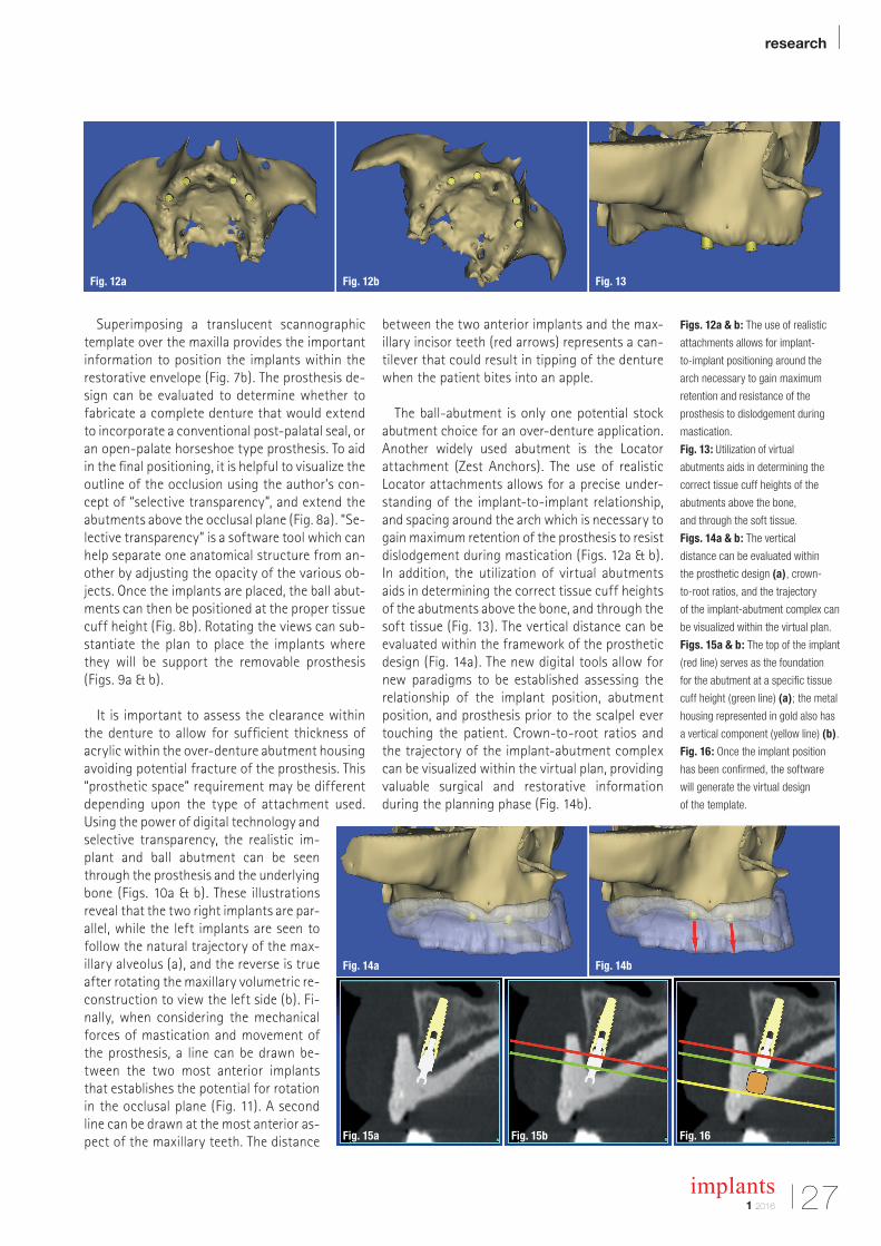
The ball-abutment is only one potential stock abutment choice for an over-denture application. Another widely used abutment is the Locator attachment (Zest Anchors). The use of realistic Locator attachments allows for a precise under-standing of the implant-to-implant relationship, and spacing around the arch which is necessary to gain maximum retention of the prosthesis to resist dislodgement during mastication (Figs. 12a & b). In addition, the utilization of virtual abutments aids in determining the correct tissue cuff heights of the abutments above the bone, and through the soft tissue (Fig. 13). The vertical distance can be evaluated within the framework of the prosthetic design (Fig. 14a). The new digital tools allow for new paradigms to be established assessing the relationship of the implant position, abutment position, and prosthesis prior to the scalpel ever touching the patient. Crown-to-root ratios and the trajectory of the implant-abutment complex can be visualized within the virtual plan, providing valuable surgical and restorative information during the planning phase (Fig. 14b).
Figs. 12a & b: The use of realistic
attachments allows for implant-
to-implant positioning around the
arch necessary to gain maximum
retention and resistance of the
prosthesis to dislodgement during
mastication.
Fig. 13: Utilization of virtual
abutments aids in determining the
correct tissue cuff heights of the
abutments above the bone,
and through the soft tissue.
Figs. 14a & b: The vertical
distance can be evaluated within
the prosthetic design (a), crown-
to-root ratios, and the trajectory
of the implant-abutment complex can
be visualized within the virtual plan.
Figs. 15a & b: The top of the implant
(red line) serves as the foundation
for the abutment at a specific tissue
cuff height (green line) (a); the metal
housing represented in gold also has
a vertical component (yellow line) (b).
Fig. 16: Once the implant position
has been confirmed, the software
will generate the virtual design
of the template.
Fig. 14a
Fig. 15a Fig. 15b Fig. 16
Fig. 14b
Fig. 12a Fig. 12b Fig. 13
| research
28 implants1 2016
In addition to the axial, panoramic, and three- dimensional reconstructed volume, the importance of the cross-sectional image is critical to fully ap-preciate the relationship between the implant posi-tion within the bone, and the emergence through the tooth. One area that has not been emphasized however, is the ability to determine the prosthetic space required for the abutment as it relates to the thickness of soft tissue supporting the overdenture (Fig. 15a). The realistic ball abutment can be clearly visualized sitting on the coronal aspect of the im-plant (red line), and the tissue cuff height of the abutment (green line). One component that is not easy to determine is the metal housing that will be processed within the denture. This component part is not yet available within the software libraries to the author’s present knowledge. Therefore an ap-proximation was digitally represented (gold), so that the extra height can be visualized (yellow line), revealing the thin palatal aspect of the overdenture (Fig. 15b). Once the virtual plan has been estab-lished a surgical template can be designed by the software and then fabricated through 3-D printing, stereolithography, or a CAD/CAM process to assist in the placement of the implants within the antici-pated restorative needs of the patient (Fig. 16).
3-D Planning Concepts: Full Arch Maxillary Fixed Prosthesis
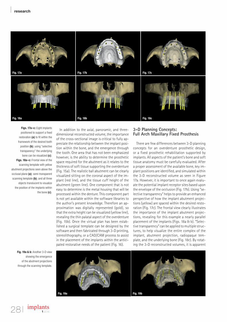
There are few differences between 3-D planning concepts for an overdenture prosthetic design, or a fixed prosthetic rehabilitation supported by implants. All aspects of the patient’s bone and soft tissue anatomy must be carefully evaluated. After a proper assessment of the available bone, key im-plant positions are identified, and simulated within the 3-D reconstructed volume as seen in Figure 17a. However, it is important to once again evalu-ate the potential implant receptor sites based upon the envelope of the occlusion (Fig. 17b). Using “se-lective transparency” helps to provide an enhanced perspective of how the implant abutment projec-tions (yellow) are spaced within the desired resto-ration (Fig. 17c). The frontal view clearly illustrates the importance of the implant abutment projec-tions, revealing for this example a nearly parallel placement of the implants (Figs. 18a & b). “Selec-tive transparency” can be applied to multiple struc-tures, to help visualize the entire complex of the implant, abutment projection, radiopaque tem-plate, and the underlying bone (Fig. 18c). By rotat-ing the 3-D reconstructed volumes, it is apparent
Figs. 17a–c: Eight implants
positioned to support a fixed
restoration (a) to fit within the
framework of the desired tooth
position (b); using “selective
transparency” the underlying
bone can be visualized (c).
Figs. 18a–c: Frontal view of the
scanning template with yellow
abutment projections seen above the
occlusal plane (a); semi-transparent
scanning template (b); and all three
objects translucent to visualize
the position of the implants within
the bone (c).
Fig. 19a & b: Another 3-D view
showing the emergence
of the abutment projections
through the scanning template.
Fig. 17a
Fig. 18a
Fig. 19a Fig. 19b
Fig. 17b
Fig. 18b
Fig. 17c
Fig. 18c
research |
291 2016
implants
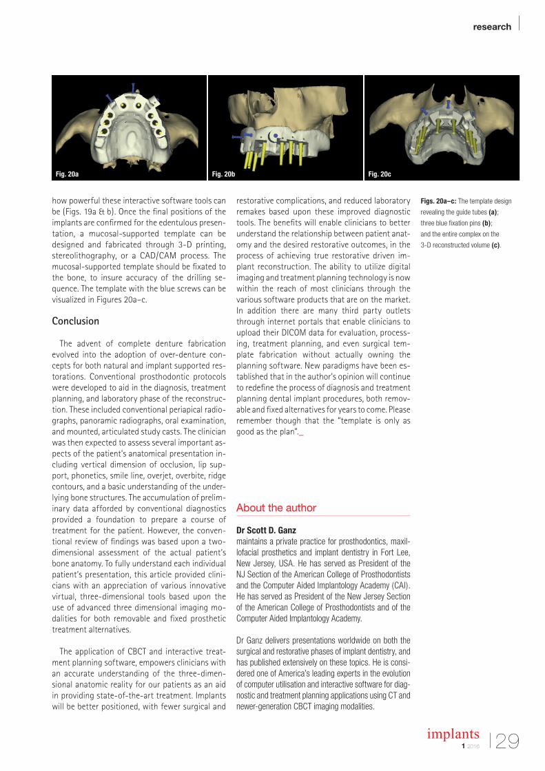
how powerful these interactive software tools can be (Figs. 19a & b). Once the final positions of the implants are confirmed for the edentulous presen-tation, a mucosal-supported template can be designed and fabricated through 3-D printing, stereolithography, or a CAD/CAM process. The mucosal-supported template should be fixated to the bone, to insure accuracy of the drilling se-quence. The template with the blue screws can be visualized in Figures 20a–c.
Conclusion
The advent of complete denture fabrication evolved into the adoption of over-denture con-cepts for both natural and implant supported res-torations. Conventional prosthodontic protocols were developed to aid in the diagnosis, treatment planning, and laboratory phase of the reconstruc-tion. These included conventional periapical radio-graphs, panoramic radiographs, oral exam ination, and mounted, articulated study casts. The clinician was then expected to assess several important as-pects of the patient’s anatomical presentation in-cluding vertical dimension of occlusion, lip sup-port, phonetics, smile line, overjet, overbite, ridge contours, and a basic understanding of the under-lying bone structures. The accumulation of prelim-inary data afforded by conventional diagnostics provided a foundation to prepare a course of treatment for the patient. However, the conven-tional review of findings was based upon a two- dimensional assessment of the actual patient’s bone anatomy. To fully understand each individual patient’s presentation, this article provided clini-cians with an appreciation of various innovative virtual, three-dimensional tools based upon the use of advanced three dimensional imaging mo-dalities for both removable and fixed prosthetic treatment alternatives.
The application of CBCT and interactive treat-ment planning software, empowers clinicians with an accurate understanding of the three-dimen-sional anatomic reality for our patients as an aid in providing state-of-the-art treatment. Implants will be better positioned, with fewer surgical and
restorative complications, and reduced laboratory remakes based upon these improved diagnostic tools. The benefits will enable clinicians to better understand the relationship between patient anat-omy and the desired restorative outcomes, in the process of achieving true restorative driven im-plant reconstruction. The ability to utilize digital imaging and treatment planning technology is now within the reach of most clinicians through the various software products that are on the market. In addition there are many third party outlets through internet portals that enable clinicians to upload their DICOM data for evaluation, process-ing, treatment planning, and even surgical tem-plate fabrication without actually owning the planning software. New paradigms have been es-tablished that in the author’s opinion will continue to redefine the process of diagnosis and treatment planning dental implant procedures, both remov-able and fixed alternatives for years to come. Please remember though that the “template is only as good as the plan”._
About the author
Dr Scott D. Ganzmaintains a private practice for prosthodontics, maxil-lofacial prosthetics and implant dentistry in Fort Lee, New Jersey, USA. He has served as President of the NJ Section of the American College of Prosthodontists and the Computer Aided Implantology Academy (CAI). He has served as President of the New Jersey Section of the American College of Prosthodontists and of the Computer Aided Implantology Academy.
Dr Ganz delivers presentations worldwide on both the surgical and restorative phases of implant dentistry, and has published extensively on these topics. He is consi-dered one of America’s leading experts in the evolution of computer utilisation and interactive software for diag-nostic and treatment planning applications using CT and newer-generation CBCT imaging modalities.
Figs. 20a–c: The template design
revealing the guide tubes (a);
three blue fixation pins (b);
and the entire complex on the
3-D reconstructed volume (c).
Fig. 20a Fig. 20b Fig. 20c
| case report
30 implants1 2016
The indispensable use of CBCT in the posterior mandibleAuthor: Souheil Hussaini, Dubai
The submandibular fossa (SF) is an important an-atomic landmark of the mandible, where the sub-mandibular gland resides. During dental practice, particular attention is paid to SF when conducting the placement of dental implants and other surgi-cal procedures. Any procedure undertaken has to be carried out with great care and attention in or-der to avoid perforation of this area. Anatomical variations of SF can occur, such as a deeply prom-inent and flat area with no depression. On very rare occasions, the mylohyoid ridge cannot be detected radiographically or bimanually as the observation of this variation is not always possible using a con-ventional radiograph. However, as a modern imag-ing resource, cone beam computed tomography (CBCT) allows an accurate three-dimensional as-sessment of SF as well as the identification of its degree of concavity.
The aim of this article is to discuss the successful circumvention of SF as a result of CBCT images taken during the treatment of a 65-year-old non-smoking, healthy male. Primary implant sta-bility required an implant length longer than the previously failed implant. A stable insertion of the implant between SF and the inferior alveolar nerve (IAN) was made possible by utilising CBCT. The pa-tient presented no sensorial disturbance in the re-gion and the treatment was considered successful 14 months after restoration.
Furthermore, this clinical case demonstrates the importance of 3-D imaging and its clinical neces-sity, as it enables the practitioner to reach a defin-itive diagnosis during treatment planning in spite of the patient’s misleading complaint.
The submandibular fovea (or submandibular fossa or submaxillary fovea) is an impression on
the medial side of the body of the mandible below the mylohyoid line. It is the location for the sub-mandibular gland.1 Mandibles with lingual concav-ity pose a potentially increased risk of lingual cor-tical perforation during surgery, particularly with an endosseous implant placement. Cross-sectional imaging provides excellent delineation of mandib-ular anatomy and gives important information on the depth of the submandibular gland fossa during preoperative assessment of the posterior mandible for dental implant fixture placement and other sur-gical procedures.2,3 Radiographically, SF can be seen as an undefined ovoid radiolucent area in both the right and left sides of the mandible. Con-ventional radiographs widely used in dental prac-tice, such as periapical and panoramic, provide a two-dimensional (2-D) image of a three-dimen-sional (3-D) structure.4,5 For this reason, SF may not be clearly visible in most cases, due to the super-imposition of anatomic landmarks;5-8 the pattern of trabecular bone,9 the thinning of the mandible as well as the location below the mylohyoid line.5-7
Nowadays, CBCT represents an advanced tech-nology in dental practice. This technology allows an accurate three-dimensional (3-D) evaluation of osseous structures in the maxillofacial region and makes it possible to assess SF in sagittal, axial, and coronal slices and to obtain detailed information concerning this anatomic landmark.5,7,8,10 The im-portance of SF in dental practice, especially for dental implant placements and other surgical pro-cedures in mandibular molar regions, is highlighted by the literature on this subject.2,3 The detection of SF location and depth is important in order to avoid perforation, haemorrhage or asphyxia due to dif-ficulty in breathing following suffocation.11 In ad-dition, an effective diagnostic radiographic tech-nique of SF enables the practitioner to place an
case report |
311 2016
implants
implant between SF and the inferior alveolar nerve (IAN).2,3,5–7,9,10
Case
This article discusses the unexpected findings that continuously emerged throughout the treat-ment process due to the absence of CBCT imaging in the initial phase of diagnosis, as well as the in-sufficiency of panoramic radiographic images in that clinical situation.
The patient’s initial situation was characterised
by a lose three-unit fixed partial denture, 45 im-plant supported, 46 pontic and 47 implant sup-ported. Initially, the patient opposed the use of a radiograph and, as a consequence, the need for implant ex traction was misdiagnosed. Eventually, in order to complete the extraction, all three types of common radiography techniques—periapical, panoramic and CBCT5—were needed and ap-plied.5,7,10
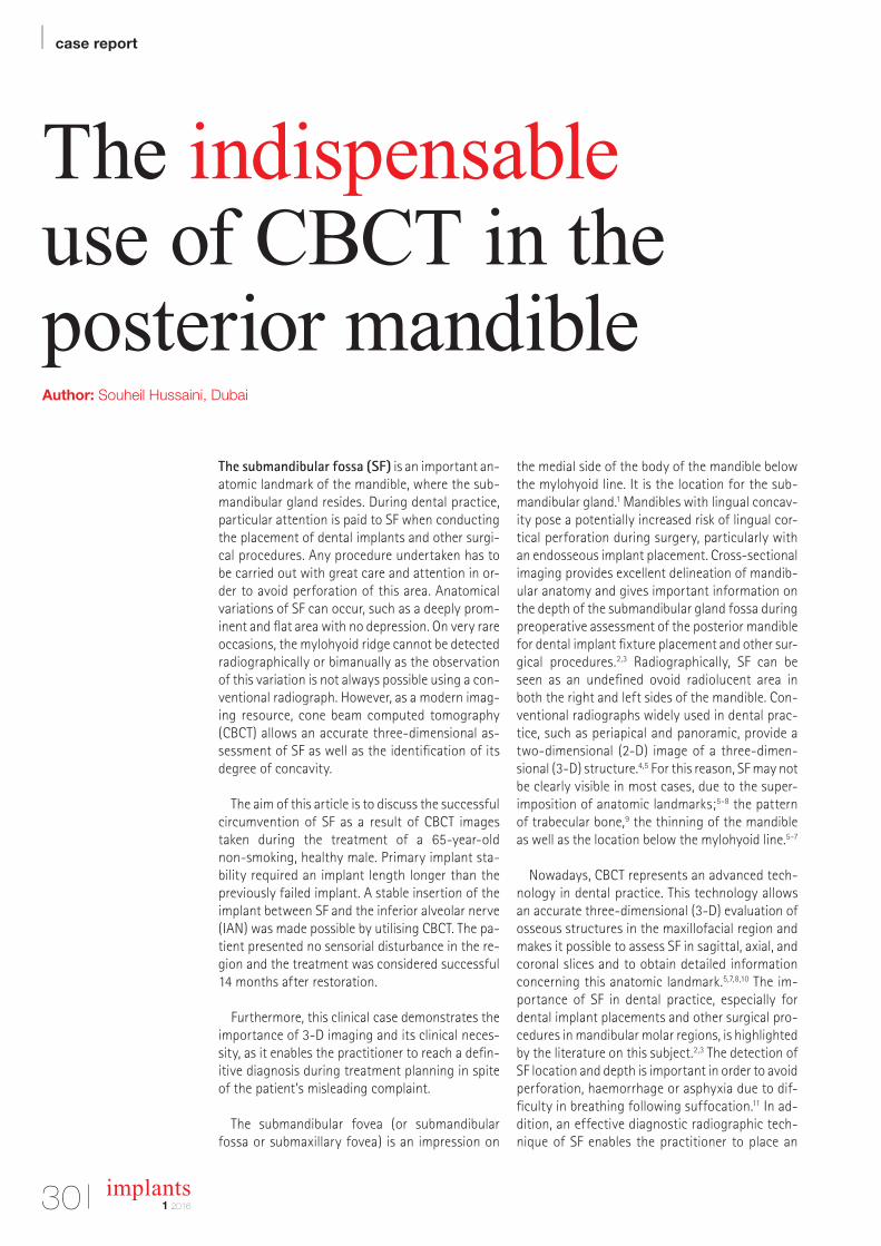
The main complaint of the 65-year-old non-smoking male with no medical history or use of medication was “my bridge is moving and re-quires re-cementing”. During an emergency ap-pointment, the patient enquired about the costs for the re-cementing of a three-unit bridge. The patient presented a six-month-old periapical radiograph (Figs. 1a) while declining to take any further X-rays for a simple bridge re-cementing procedure. According to the patient, the implants
were placed five years ago and without incision by a now-retired dentist who could no longer be con-tacted. After analysing the radiograph and making a clinical assessment, the provisional diagnosis showed that the bridge was moving due to an abutment screw loosening (Fig. 2). The resulting treatment plan called for the removal of the three-unit bridge and the re-tightening of the abutment screw to the manufacturers recommended pre-load as well as the re-cementing of the bridge (plan A).
The patient approved the suggested procedures
and signed the treatment plan. The bridge was found to be firmly attached to the anterior implant and loosely connected to the posterior one. The existing bridge had to be cut out and replaced by a new three-unit bridge (plan B). A small opening of the screw access hole was attempted on both implant restorations 45 and 47 (Fig. 3). Although the access hole did not lead to the abutment screw, the bridge mobility was increased. A periapical radiograph was obtained to evaluate the peri- implant status of the posterior implant (Fig. 1b). The radiolucency observed around the fixture indi-cated implant failure and the crown in the anterior implant had to be sacrificed in order to get to its abutment safely. At this stage (plan C), the proce-dures were set out as follows: removal of the posterior implant followed by a re-implant, a new temporary crown on tooth 45 and, after two months, fitting of a two-unit bridge instead of the previous three-unit bridge restoration. This deci-
Fig. 1a Fig. 1b Fig. 2
Fig. 3 Fig. 4 Fig. 5
Fig. 1a: Periapical radiograph.
Fig. 1b: Digital periapical radiograph.
Fig. 2: Occlusal view of the bridge.
Fig. 3: Occlusal view after attempting
to get to the abutment.
Fig. 4: Panoramic radiograph,
diagnosis.
Fig. 5: Occlusal view of PFM bridge.
| case report
32 implants1 2016
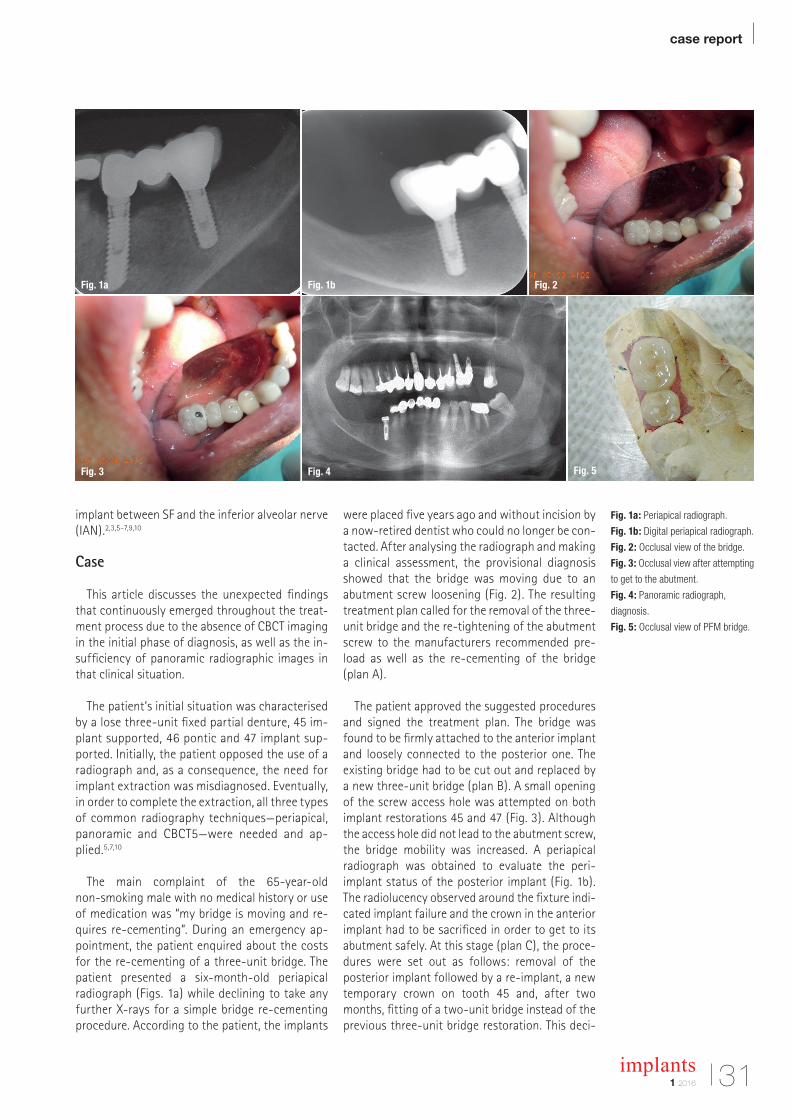
Fig. 6: Re-implant placed flapless.
Fig. 7: Panoramic radiograph,
restoration
Table 1: Technical data.
sion resulted from the fact that the mesio-distal length of the bridge required to accommodate three teeth was 18 mm and not 21 mm.
The height of the extracted implant and the available bone was 8 mm when the panoramic im-age was evaluated (Fig. 4). As the available diag-nosis information did not provide data regarding the desired diameter and angulation of the implant to be placed, the patient’s consent for CBCT (plan D) was obtained and added to the contractual treatment plan. Only then, the radiograph of the molar region of the right mandible was performed. CBCT (Planmeca ProMax 3D s, Planmeca Oy, Hel-sinki, Finland, Table 1) and the measurements in millimeters of the bone height and angulation us-ing tools of the Planmeca software (Romexis 2.5.1.R), in the most representative CBCT transver-sal slice demonstrated the possibility of placing a 13 mm implant (853213 – 3.2mmD, 13mmL Implant Direct Legacy3, Implant Direct, CA, USA) with 35 degree lingual angulation to avoid SF (Fig. 5).
Treatment timeline
The timeline detailing the entire treatment was as follows: – 31 March 2014 Diagnosis and treatment plan-ning
– 2 April 2014 quality control (QC) phone call with no patient response, possibly due to disappoint-ment over many changes in treatment plan
– 6 April 2014 implant placement 3.2 x 13 mm im-plant direct (Fig. 6),
– 15 April 2014 QC with positive response, – 14 June 2014 uncovering and impression using open tray technique,
– 17 June 2014 QC with positive response, – 21 June 2014 prosthesis 2 unit bridge PFM ce-mented with Temp Bond (Fig. 7),
– post-operative one-year maintenance visit on 10 August 2015 showed healthy functional re-sults as recorded (Fig. 8).
Analysis of patient images
1. Axial CBCT slice in which the angle required (35 degree) to bypass SF corresponding to longest necessary length (13 mm) and diameter (3.2 mm) was measured (Fig. 9).
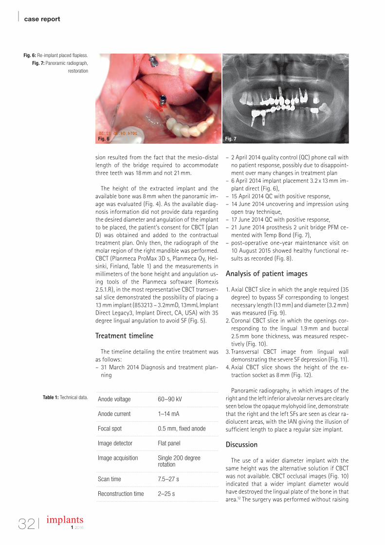
2. Coronal CBCT slice in which the openings cor-responding to the lingual 1.9 mm and buccal 2.5 mm bone thickness, was measured respec-tively (Fig. 10).
3. Transversal CBCT image from lingual wall demonstrating the severe SF depression (Fig. 11).
4. Axial CBCT slice shows the height of the ex-traction socket as 8 mm (Fig. 12).
Panoramic radiography, in which images of the right and the left inferior alveolar nerves are clearly seen below the opaque mylohyoid line, demonstrate that the right and the left SFs are seen as clear ra-diolucent areas, with the IAN giving the illusion of sufficient length to place a regular size implant.
Discussion
The use of a wider diameter implant with the same height was the alternative solution if CBCT was not available. CBCT occlusal images (Fig. 10) indicated that a wider implant diameter would have destroyed the lingual plate of the bone in that area.12 The surgery was performed without raising
Fig. 6 Fig. 7
Anode voltage 60–90 kV
Anode current 1–14 mA
Focal spot 0.5 mm, fixed anode
Image detector Flat panel
Image acquisition Single 200 degree rotation
Scan time 7.5–27 s
Reconstruction time 2–25 s
a flap for better post-operative healing.13 Traditionally, we do not require CBCT im-ages for a single implant placement.14 However, this case signifies the impor-tance of 3-D imaging in certain situations like deep SF (Fig. 11).
When the bone width is narrow, perios-teal elevation is recommended to be able to safely observe the osteotomic drills as they reach to the final depth. This proce-dure is only advised when a panoramic image is the only diagnostic tool we have as it adversely causes further bone loss during the healing phase.13 In the present case, no periosteal elevation was per-formed (Fig. 6) and the patient did not have post-operative pain and swelling.
CBCT is a modern technology, which al-lows the three-dimensional evaluation (sagittal, axial and coronal) of maxillofa-cial structures. Among its many advan-tages are the absence of superimposition of structures in obtained slices, acquisi-tion of a 3-D reconstruction (spatial vision for illustrative purpose), as well as the use of lower radiation doses in comparison to medical CT.15–17 SF location, size, shape and its possible variations can be fully as-
sessed by CBCT.2,3,18-22 Due to the limita-tions of periapical and panoramic tech-niques, the radiographic assessment of SF is not always available. Jacobs et al. re-ported that SF was detected in 94% of their assessed panoramic radiographs, but only 49% of those were clearly visi-ble.23-25 Therefore, it can be reasonably concluded that the lack of observation of SF in conventional radiograph does not prove its actual absence.
In our reported case, we were able to
evaluate the mandible of the patients in 3-D and here SFs were actually deeply prominent and hypoplastic. Also, it was impossible to perform the surgery with-out 3-D imaging. A preoperative imaging study is important prior to any surgical procedure in the posterior mandibular re-gion.2,8 CBCT can be very helpful for the detection of SF variations that could be otherwise missed using conventional ra-diographic examination techniques.2,5,7,10 In the present case, the diagnosis of the anatomic limitation was possible to be vi-sualised due to CBCT examination. Fur-thermore, the accurate measurements of SF and the vision of 3-D spatial recon-structions, which are exclusive tools of
Fig. 8: Panoramic radiograph, one-year post-op.
Fig. 9: Bone width lingual wall 1.9 mm and buccal 2.5 mm.
Fig. 8
Fig. 9
the revolutionary bovine bone graft
composite
Hypro-Oss®
Bioimplon GmbHFriedrich-List-Str. 27
35398 Gießen+49 (0)641 6868 1123
www.bioimplon.de
each granule is a composite of 30% Atelo-Collagen Type I, 70% hydroxyapatite
atelopeptidized, free of antigenic telopeptides
haemostatic and bacteriostatic properties
bioactive growth factors
natural crystalline structure of hydroxyapatite component
no need for steroids as anti-haematoma medication
excellent handling due to sticky Atelo-Collagen components
highest quality of new bone formation
conductive and inductive properties
AD
1.90
2.50
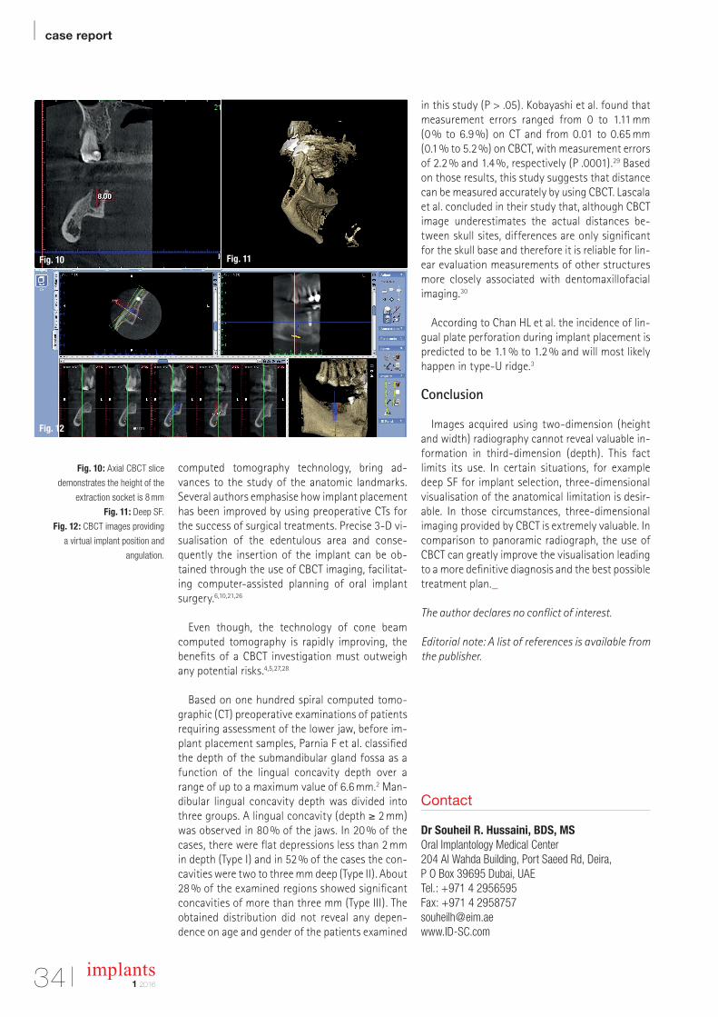
| case report
34 implants1 2016
Fig. 10: Axial CBCT slice
demonstrates the height of the
extraction socket is 8 mm
Fig. 11: Deep SF.
Fig. 12: CBCT images providing
a virtual implant position and
angulation.
Contact
Dr Souheil R. Hussaini, BDS, MSOral Implantology Medical Center 204 Al Wahda Building, Port Saeed Rd, Deira,P O Box 39695 Dubai, UAETel.: +971 4 2956595Fax: +971 4 [email protected] www.ID-SC.com
Fig. 10 Fig. 11
Fig. 12
computed tomography technology, bring ad-vances to the study of the anatomic landmarks. Several authors emphasise how implant placement has been improved by using preoperative CTs for the success of surgical treatments. Precise 3-D vi-sualisation of the edentulous area and conse-quently the insertion of the implant can be ob-tained through the use of CBCT imaging, facilitat-ing computer-assisted planning of oral implant surgery.6,10,21,26
Even though, the technology of cone beam computed tomography is rapidly improving, the benefits of a CBCT investigation must outweigh any potential risks.4,5,27,28
Based on one hundred spiral computed tomo-
graphic (CT) preoperative examinations of patients requiring assessment of the lower jaw, before im-plant placement samples, Parnia F et al. classified the depth of the submandibular gland fossa as a function of the lingual concavity depth over a range of up to a maximum value of 6.6 mm.2 Man-dibular lingual concavity depth was divided into three groups. A lingual concavity (depth ≥ 2 mm) was observed in 80 % of the jaws. In 20 % of the cases, there were flat depressions less than 2 mm in depth (Type I) and in 52 % of the cases the con-cavities were two to three mm deep (Type II). About 28 % of the examined regions showed significant concavities of more than three mm (Type III). The obtained distribution did not reveal any depen-dence on age and gender of the patients examined
in this study (P > .05). Kobayashi et al. found that measurement errors ranged from 0 to 1.11 mm (0 % to 6.9 %) on CT and from 0.01 to 0.65 mm (0.1 % to 5.2 %) on CBCT, with measurement errors of 2.2 % and 1.4 %, respectively (P .0001).29 Based on those results, this study suggests that distance can be measured accurately by using CBCT. Lascala et al. concluded in their study that, although CBCT image underestimates the actual distances be-tween skull sites, differences are only significant for the skull base and therefore it is reliable for lin-ear evaluation measurements of other structures more closely associated with dentomaxillofacial imaging.30
According to Chan HL et al. the incidence of lin-gual plate perforation during implant placement is predicted to be 1.1 % to 1.2 % and will most likely happen in type-U ridge.3
Conclusion
Images acquired using two-dimension (height and width) radiography cannot reveal valuable in-formation in third-dimension (depth). This fact limits its use. In certain situations, for example deep SF for implant selection, three-dimensional visualisation of the anatomical limitation is desir-able. In those circumstances, three-dimensional imaging provided by CBCT is extremely valuable. In comparison to panoramic radiograph, the use of CBCT can greatly improve the visualisation leading to a more definitive diagnosis and the best possible treatment plan._
The author declares no conflict of interest.
Editorial note: A list of references is available from the publisher.
www.anthogyr.com
EXO SAFE®NEW!
Innovative solution
for dental extraction
The bone plate is precious, preserve it!
With Exo Safe® bene t fro the ntho r innovation to preserve the bone plate
an obilise the tooth easil The re ular auto atic stro es an their constant
intensit facilitate the ra ual enlar e ent of the perio ontal li a ent space
Exo Safe® uarantees ou a repro ucible an precise sur ical esture This atrau atic
evice contributes to a better acceptance of the treat ent b our patients
T S S , venue n r as uin
Sallanches rance hone
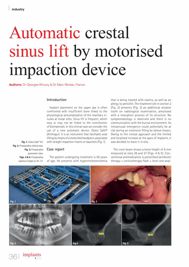
| industry
36 implants1 2016
Automatic crestal sinus lift by motorised impaction deviceAuthors: Dr Georges Khoury & Dr Marc Revise, France
Fig. 1: Osteo Safe® Kit.
Fig. 2: Preoperative clinical view.
Fig. 3: Preoperative
panoramic view.
Figs. 4 & 5: Preoperative
subsinus height at 26–27.
Introduction
Implant placement on the upper jaw is often confronted with insufficient bone linked to the physiological pneumatisation of the maxillary si-nuses at molar sites. Sinus lift is frequent, which may or may not be linked to the contribution of biomaterials. In this clinical case we consider the use of a new automatic device: Osteo Safe® (Anthogyr). It is an instrument that facilitates axial lifting by means of a motorised handpiece, associated with straight impaction inserts or bayonets (Fig. 1).
Case report
The patient undergoing treatment is 56 years of age. He presents with hypercholesterolemia
that is being treated with statins, as well as an allergy to penicillin. The treatment site in section 2 (Fig. 2) presents (Fig. 3) an additional wisdom tooth on radiological examination, ankylosed with a resorption process of its structure. No symptomatology is observed and there is no communication with the buccal environment. Its intrasinusal emergence could potentially be at risk during an extensive filling by lateral means. Owing to the crestal approach and the limited and localised increase at the apex of implants, it was decided to leave it in situ.
The cone beam shows a bone height of 6 mm measured at sites 26 and 27 (Figs. 4 & 5). Con-ventional premedication is prescribed (antibiotic therapy + corticotherapy flash + level-one anal-
Fig. 3 Fig.4 Fig. 5
Fig. 1 Fig. 2
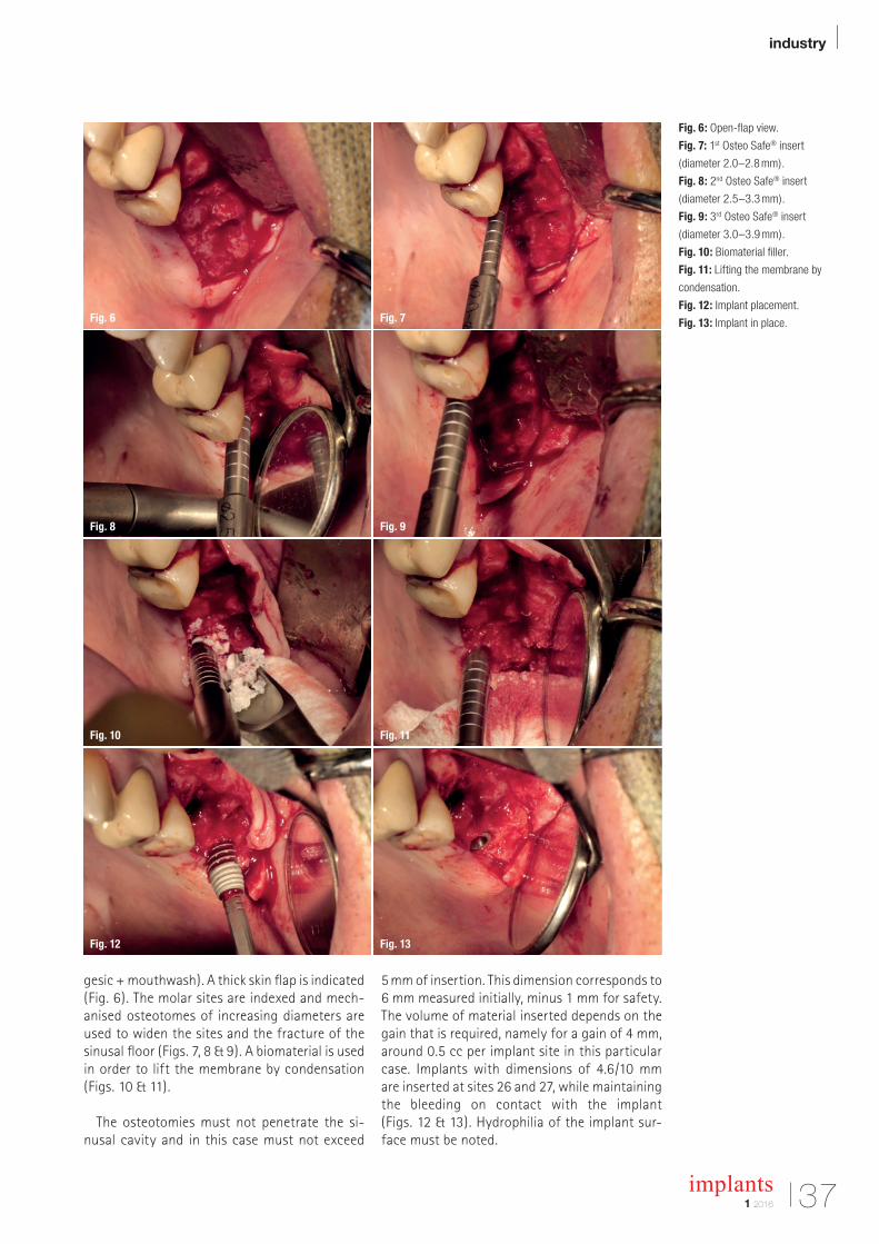
industry |
371 2016
implants
gesic + mouthwash). A thick skin flap is indicated (Fig. 6). The molar sites are indexed and mech-anised osteotomes of increasing diameters are used to widen the sites and the fracture of the sinusal floor (Figs. 7, 8 & 9). A biomaterial is used in order to lift the membrane by condensation (Figs. 10 & 11).
The osteotomies must not penetrate the si-nusal cavity and in this case must not exceed
5 mm of insertion. This dimension corresponds to 6 mm measured initially, minus 1 mm for safety. The volume of material inserted depends on the gain that is required, namely for a gain of 4 mm, around 0.5 cc per implant site in this particular case. Implants with dimensions of 4.6/10 mm are inserted at sites 26 and 27, while maintaining the bleeding on contact with the implant (Figs. 12 & 13). Hydrophilia of the implant sur-face must be noted.
Fig. 6
Fig. 9
Fig. 12
Fig. 7
Fig. 10
Fig. 13
Fig. 8
Fig. 11
Fig. 6: Open-flap view.
Fig. 7: 1st Osteo Safe® insert
(diameter 2.0–2.8 mm).
Fig. 8: 2nd Osteo Safe® insert
(diameter 2.5–3.3 mm).
Fig. 9: 3rd Osteo Safe® insert
(diameter 3.0–3.9 mm).
Fig. 10: Biomaterial filler.
Fig. 11: Lifting the membrane by
condensation.
Fig. 12: Implant placement.
Fig. 13: Implant in place.

| industry
38 implants1 2016
Postoperative effects are moderate and the pain is contained by level-one analgesics (Para cetamol); the symptoms abated within 48 hours. The X-ray controls every four months show stabilised bone volume at the apexes of the implants (Figs. 14 & 15).
The patient is then given an appointment to take impressions. Two short pop-in transfers and a closed impression holder were used, with the aim of inserting two separate crowns. A retro alveolar con-trol X-ray was taken, although there was no doubt about the correct positioning of the transfers.
Two customised abutments (made by Simeda, Anthogyr) with a juxtagingival homothetic pre-paration (Fig. 16) were ordered. The prostho-dontist, Christophe Gigandet, made two single ce-ramo-metallic crowns with non-precious metal frameworks (Fig. 19). The abutments were placed in the patient’s mouth and adjusted with strict ad-herence to the gingival contour (Fig. 17).
An X-ray was taken to check how well the struc-tures had adapted (Fig. 18). The points of contact and the occlusion were examined. After filling the
access cavities of the abutments, the crowns were sealed with glass ionomer cement (GC FujiCEM 2). The juxtagingival limits facilitate an easy and com-plete cleaning of the cement excess.
Conclusion
The Osteo Safe® mechanised procedure enables better control of the power of impacts in these crestal sinus lift indications. This system signifi-cantly reduces the learning curve as a result of the regularity of the impacts at constant power (non-operator dependent)._
Figs. 14 & 15: Stable bone volume
at the implant apex in 26–27.
Fig. 16: Simeda customised
abutments.
Fig. 17: Customised abutments in
the patient mouth.
Fig. 18: X-ray control of the
customised abutments.
Fig. 19: Ceramo-metallic crowns.
Contact
Dr Georges Khoury 83 Boulevard Exelmans75016 Paris Dr Marc Revise 3, rue Pierre Guérin 75016 Paris
Fig. 18 Fig. 19
Fig. 16 Fig. 17
Fig. 14 Fig. 15
DGZI internationalAnnual congress
Gold Sponsor Silver Sponsor Bronze Sponsor
30 September and1 October, 2016Munich | The Westin Grand MunichOnly a limited number of seats and hotel capacities!
Scientific Director:
Prof. Dr Herbert Deppe/DEProf. (CAI) Dr Roland Hille/DE
How much aestheticis required in theimplantology?
FAX REPLY | +49 341 48474-290
I would like to receive further information on the
46th dgzi international annual congresson 30 September and 1 October, 2016, in Munich, Germany.
Practise Stamp
implants 1/16
dgzi-jahreskongress.de
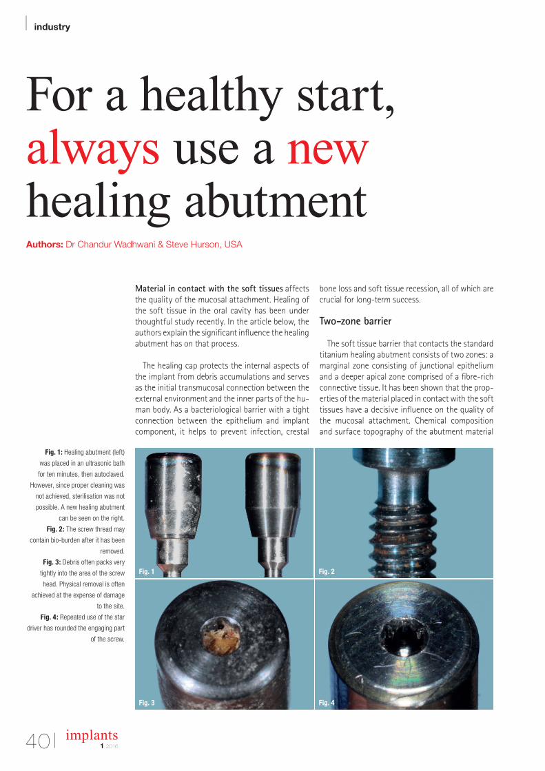
| industry
40 implants1 2016
For a healthy start, always use a new healing abutmentAuthors: Dr Chandur Wadhwani & Steve Hurson, USA
Fig. 1: Healing abutment (left)
was placed in an ultrasonic bath
for ten minutes, then autoclaved.
However, since proper cleaning was
not achieved, sterilisation was not
possible. A new healing abutment
can be seen on the right.
Fig. 2: The screw thread may
contain bio-burden after it has been
removed.
Fig. 3: Debris often packs very
tightly into the area of the screw
head. Physical removal is often
achieved at the expense of damage
to the site.
Fig. 4: Repeated use of the star
driver has rounded the engaging part
of the screw.
Material in contact with the soft tissues affects the quality of the mucosal attachment. Healing of the soft tissue in the oral cavity has been under thoughtful study recently. In the article below, the authors explain the significant influence the healing abutment has on that process.
The healing cap protects the internal aspects of the implant from debris accumulations and serves as the initial transmucosal connection between the external environment and the inner parts of the hu-man body. As a bacteriological barrier with a tight connection between the epithelium and implant component, it helps to prevent infection, crestal
bone loss and soft tissue recession, all of which are crucial for long-term success.
Two-zone barrier
The soft tissue barrier that contacts the standard titanium healing abutment consists of two zones: a marginal zone consisting of junctional epithelium and a deeper apical zone comprised of a fibre-rich connective tissue. It has been shown that the prop-erties of the material placed in contact with the soft tissues have a decisive influence on the quality of the mucosal attachment. Chemical composition and surface topography of the abutment material
Fig. 2Fig. 1
Fig. 4Fig. 3
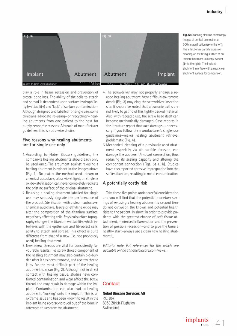
industry |
411 2016
implants
play a role in tissue recession and prevention of crestal bone loss. The ability of the cells to attach and spread is dependent upon surface hydrophilic-ity (wettability) and “lack” of surface contamination. Although designed and labelled for single use, some clinicians advocate re-using—or “recycling”—heal-ing abutments from one patient to the next for purely economic reasons. A breach of manufacturer guidelines, this is not a wise choice.
Five reasons why healing abutments are for single use only
1. According to Nobel Biocare guidelines, the company’s healing abutments should each only be used once. The argument against re-using a healing abutment is evident in the images above (Fig. 1). No matter the method used—steam or chemical autoclave, ultra-violet light, or ethylene oxide—sterilisation can never completely recreate the pristine surface of the original abutment.
2. Re-using a healing abutment labelled for single use may seriously degrade the performance of the product. Sterilisation with a steam autoclave, chemical autoclave, lasers or ethylene oxide may alter the composition of the titanium surface, negatively affecting cells. Physical surface topog-raphy changes the titanium wettability, which in-terferes with the epithelium and fibroblast cells’ ability to attach and spread. This effect is quite different from that of a new (i.e. not previously used) healing abutment.
3. New screw threads are vital for consistently fa-vourable results. The screw thread component of the healing abutment may also contain bio-bur-den after it has been removed, and a screw thread is by far the most difficult part of the healing abutment to clean (Fig. 2). Although not in direct contact with healing tissue, studies have con-firmed contamination and wear affect the screw thread and may result in damage within the im-plant. Contamination can also lead to healing abutments “locking” onto the implant. This is an extreme issue and has been known to result in the implant being reverse-torqued out of the bone in attempts to unscrew the abutment.
4. The screwdriver may not properly engage a re-used healing abutment. Very difficult-to-remove debris (Fig. 3) may clog the screwdriver insertion site. It should be noted that ultrasonic baths are not likely to get rid of this tightly packed material. Also, with repeated use, the screw head itself can become mechanically damaged. Case reports in the literature report that such damage—unneces-sary if you follow the manufacturer’s single-use guidelines—makes healing abutment retrieval problematic (Fig. 4).
5. Mechanical cleaning of a previously used abut-ment—especially via air particle abrasion—can damage the abutment/implant connection, thus reducing its sealing capacity and altering the component connection (Figs. 5a & b). Studies have also reported abrasive impregnation into the softer titanium, resulting in metal contamination.
A potentially costly risk
Take these five points under careful consideration and you will find that the potential monetary sav-ings of re-using a healing abutment a second time do not outweigh the known and potential health risks to the patient. In short: in order to provide pa-tients with the greatest chance of soft tissue at-tachment, minimised inflammation and the preven-tion of possible recession—and to give the bone a healthy start—always use a clean new healing abut-ment!_
Editorial note: Full references for this article are available online at nobelbiocare.com/news.
Fig. 5a Fig. 5b
Contact
Nobel Biocare Services AG P.O. Box 8058 Zürich-FlughafenSwitzerland
Fig. 5: Scanning electron microscopy
images of conical connection at
500 x magnification (a–to the left).
The effect of air particle abrasion
cleaning on the fitting surface of an
implant abutment is clearly evident
(b–to the right). The implant-
abutment interface with a new, clean
abutment surface for comparison.
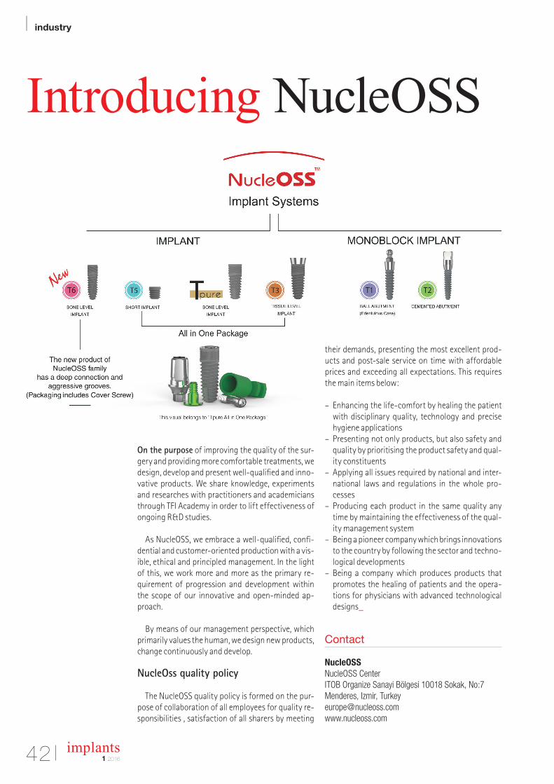
| industry
42 implants1 2016
Introducing NucleOSS
On the purpose of improving the quality of the sur-gery and providing more comfortable treatments, we design, develop and present well-qualified and inno-vative products. We share knowledge, experiments and researches with practitioners and academicians through TFI Academy in order to lift effectiveness of ongoing R&D studies.
As NucleOSS, we embrace a well-qualified, confi-dential and customer-oriented production with a vis-ible, ethical and principled management. In the light of this, we work more and more as the primary re-quirement of progression and development within the scope of our innovative and open-minded ap-proach.
By means of our management perspective, which primarily values the human, we design new products, change continuously and develop.
NucleOss quality policy
The NucleOSS quality policy is formed on the pur-pose of collaboration of all employees for quality re-sponsibilities , satisfaction of all sharers by meeting
their demands, presenting the most excellent prod-ucts and post-sale service on time with affordable prices and exceeding all expectations. This requires the main items below:
– Enhancing the life-comfort by healing the patient with disciplinary quality, technology and precise hygiene applications
– Presenting not only products, but also safety and quality by prioritising the product safety and qual-ity constituents
– Applying all issues required by national and inter-national laws and regulations in the whole pro-cesses
– Producing each product in the same quality any time by maintaining the effectiveness of the qual-ity management system
– Being a pioneer company which brings innovations to the country by following the sector and techno-logical developments
– Being a company which produces products that promotes the healing of patients and the opera-tions for physicians with advanced technological designs_
Contact
NucleOSS NucleOSS CenterITOB Organize Sanayi Bölgesi 10018 Sokak, No:7Menderes, Izmir, [email protected]
Organization/Registration:OEMUS MEDIA AGHolbeinstraße 2904229 Leipzig, GermanyTel.: +49 341 48474-308Fax: +49 341 [email protected]
Ceramic implants – practical experiences andrecent trends
2ND ANNUAL MEETING OF
JUNE 10 – 11, 2016 IN BERLIN, GERMANY STEIGENBERGER HOTEL AM KANZLERAMT
Organizer:ISMI - International Society of Metal Free ImplantologyLohnerhofstraße 278467 Konstanz, GermanyTel.: 0800 4764-000Fax: 0800 [email protected]
Speaker:Prof. Dr. Joseph Choukroun/Nice (FR)Prof. Dr. Matthias Heiliger/Kreuzlingen (DE)Prof. Dr. Marcel Wainwright/Düsseldorf (DE)Prof. Dr. Jose Mendonça-Caridad/Santiago di Compostela (ES)Dr. Dr. Johann Lechner/Munich (DE)Dr. Tilmann Fritsch/Bayerisch Gmain (DE)Dr. Stefan König/Bochum (DE)Dr. Dominik Nischwitz/Tübingen (DE)Dr. Sammy Noumbissi/Silver Spring, MD (US)Dr. Jens Schug/Zug (CH)Dr. Karl Ulrich Volz/Konstanz (DE)
Scientific Director:Dr. Karl Ulrich Volz/Konstanz (DE)
Venue:Steigenberger Hotel am KanzleramtElla-Trebe-Straße 5, 10557 Berlin, Germanywww.steigenberger.com
www.ismi-meeting.com
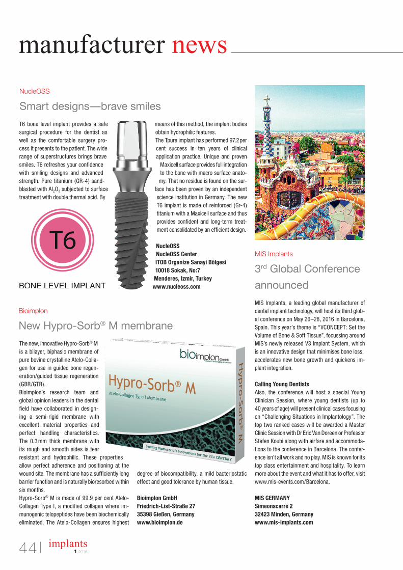
manufacturer news
44 implants1 2016
The new, innovative Hypro-Sorb® M is a bilayer, biphasic membrane of pure bovine crystalline Atelo-Colla-gen for use in guided bone regen-eration/guided tissue regeneration (GBR/GTR).Bioimplon’s research team and global opinion leaders in the dental field have collaborated in design-ing a semi-rigid membrane with excellent material properties and perfect handling characteristics. The 0.3 mm thick membrane with its rough and smooth sides is tear resistant and hydrophilic. These properties allow perfect adherence and positioning at the wound site. The membrane has a sufficiently long barrier function and is naturally bioresorbed within six months.Hypro-Sorb® M is made of 99.9 per cent Atelo- Collagen Type I, a modified collagen where im-munogenic telopeptides have been biochemically eliminated. The Atelo-Collagen ensures highest
degree of biocompatibility, a mild bacteriostatic effect and good tolerance by human tissue.
Bioimplon GmbHFriedrich-List-Straße 2735398 Gießen, Germanywww.bioimplon.de
T6 bone level implant provides a safe surgical procedure for the dentist as well as the comfortable surgery pro-cess it presents to the patient. The wide range of superstructures brings brave smiles. T6 refreshes your confidence with smiling designs and advanced strength. Pure titanium (GR-4) sand-blasted with Al2O3 subjected to surface treatment with double thermal acid. By
means of this method, the implant bodies obtain hydrophilic features. The Tpure implant has performed 97.2 per cent success in ten years of clinical application practice. Unique and proven
Maxicell surface provides full integration to the bone with macro surface anato-my. That no residue is found on the sur-
face has been proven by an independent science institution in Germany. The new T6 implant is made of reinforced (Gr-4) titanium with a Maxicell surface and thus provides confident and long-term treat-ment consolidated by an efficient design.
NucleOSS NucleOSS CenterITOB Organize Sanayi Bölgesi 10018 Sokak, No:7Menderes, Izmir, Turkeywww.nucleoss.com
MIS Implants, a leading global manufacturer of dental implant technology, will host its third glob-al conference on May 26–28, 2016 in Barcelona, Spain. This year’s theme is “VCONCEPT: Set the Volume of Bone & Soft Tissue”, focussing around MIS’s newly released V3 Implant System, which is an innovative design that minimises bone loss,accelerates new bone growth and quickens im-plant integration.
Calling Young DentistsAlso, the conference will host a special Young Clinician Session, where young dentists (up to 40 years of age) will present clinical cases focusing on “Challenging Situations in Implantology”. The top two ranked cases will be awarded a Master Clinic Session with Dr Eric Van Doreen or Professor Stefen Koubi along with airfare and accommoda-tions to the conference in Barcelona. The confer-ence isn’t all work and no play. MIS is known for its top class entertainment and hospitality. To learn more about the event and what it has to offer, visit www.mis-events.com/Barcelona.
MIS GERMANYSimeonscarré 232423 Minden, Germanywww.mis-implants.com
Bioimplon
New Hypro-Sorb® M membrane
NucleOSS
Smart designs—brave smiles
MIS Implants
3rd Global Conference
announced
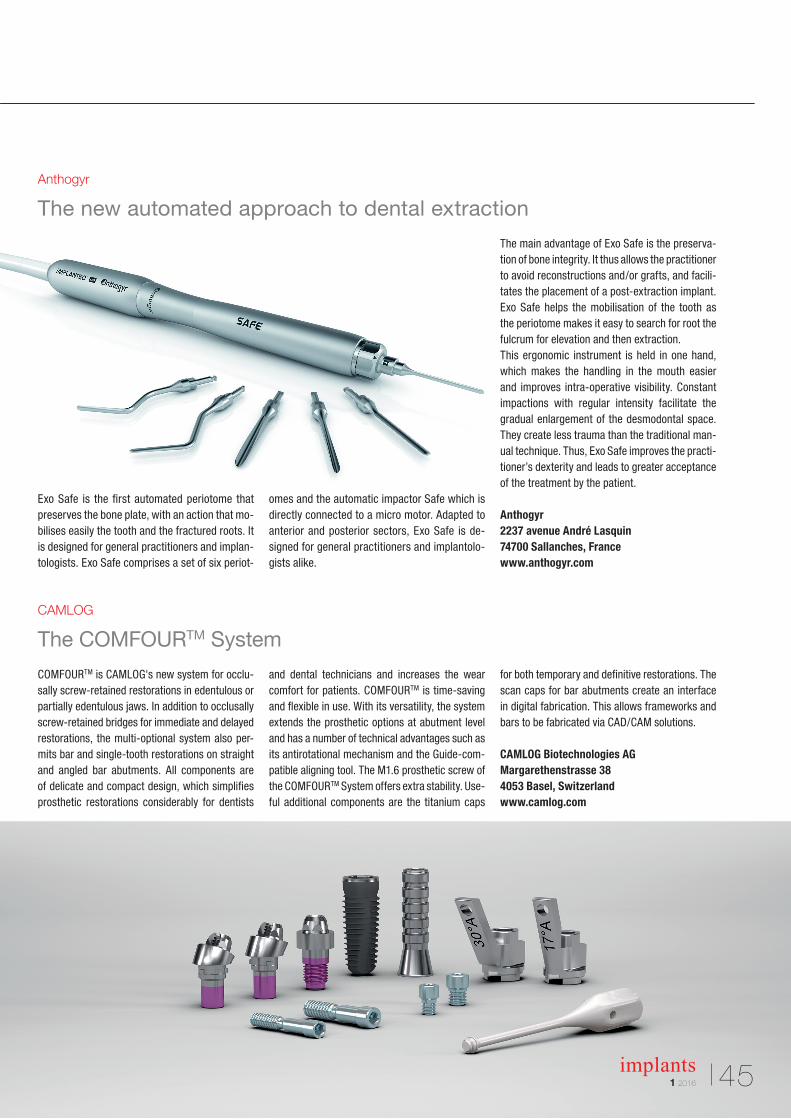
1 2016
implants 45
Exo Safe is the first automated periotome that preserves the bone plate, with an action that mo-bilises easily the tooth and the fractured roots. It is designed for general practitioners and implan-tologists. Exo Safe comprises a set of six periot-
omes and the automatic impactor Safe which is directly connected to a micro motor. Adapted to anterior and posterior sectors, Exo Safe is de-signed for general practitioners and implantolo-gists alike.
The main advantage of Exo Safe is the preserva-tion of bone integrity. It thus allows the practitioner to avoid reconstructions and/or grafts, and facili-tates the placement of a post-extraction implant. Exo Safe helps the mobilisation of the tooth as the periotome makes it easy to search for root the fulcrum for elevation and then extraction.This ergonomic instrument is held in one hand, which makes the handling in the mouth easier and improves intra-operative visibility. Constant impactions with regular intensity facilitate the gradual enlargement of the desmodontal space. They create less trauma than the traditional man-ual technique. Thus, Exo Safe improves the practi-tioner’s dexterity and leads to greater acceptance of the treatment by the patient.
Anthogyr2237 avenue André Lasquin74700 Sallanches, Francewww.anthogyr.com
Anthogyr
The new automated approach to dental extraction
CAMLOG
The COMFOURTM System
COMFOURTM is CAMLOG's new system for occlu-sally screw-retained restorations in edentulous or partially edentulous jaws. In addition to occlusally screw-retained bridges for immediate and delayed restorations, the multi-optional system also per-mits bar and single-tooth restorations on straight and angled bar abutments. All components are of delicate and compact design, which simplifies prosthetic restorations considerably for dentists
and dental technicians and increases the wear comfort for patients. COMFOURTM is time-saving and flexible in use. With its versatility, the system extends the prosthetic options at abutment level and has a number of technical advantages such as its antirotational mechanism and the Guide-com-patible aligning tool. The M1.6 prosthetic screw of the COMFOURTM System offers extra stability. Use-ful additional components are the titanium caps
for both temporary and definitive restorations. The scan caps for bar abutments create an interface in digital fabrication. This allows frameworks and bars to be fabricated via CAD/CAM solutions.
CAMLOG Biotechnologies AGMargarethenstrasse 384053 Basel, Switzerlandwww.camlog.com
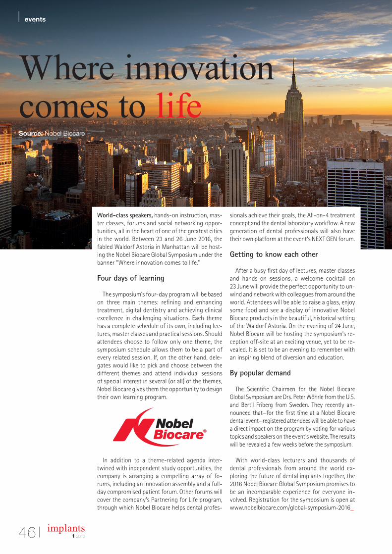
| events
46 implants1 2016
Where innovation comes to lifeSource: Nobel Biocare
World-class speakers, hands-on instruction, mas-ter classes, forums and social networking oppor-tunities, all in the heart of one of the greatest cities in the world. Between 23 and 26 June 2016, the fabled Waldorf Astoria in Manhattan will be host-ing the Nobel Biocare Global Symposium under the banner “Where innovation comes to life.”
Four days of learning
The symposium’s four-day program will be based on three main themes: refining and enhancing treatment, digital dentistry and achieving clinical excellence in challenging situations. Each theme has a complete schedule of its own, including lec-tures, master classes and practical sessions. Should attendees choose to follow only one theme, the symposium schedule allows them to be a part of every related session. If, on the other hand, dele-gates would like to pick and choose between the different themes and attend individual sessions of special interest in several (or all) of the themes, Nobel Biocare gives them the opportunity to design their own learning program.
In addition to a theme-related agenda inter-twined with independent study opportunities, the company is arranging a compelling array of fo-rums, including an innovation assembly and a full-day compromised patient forum. Other forums will cover the company’s Partnering for Life program, through which Nobel Biocare helps dental profes-
sionals achieve their goals, the All-on-4 treatment concept and the dental laboratory workflow. A new generation of dental professionals will also have their own platform at the event’s NEXT GEN forum.
Getting to know each other
After a busy first day of lectures, master classes and hands-on sessions, a welcome cocktail on 23 June will provide the perfect opportunity to un-wind and network with colleagues from around the world. Attendees will be able to raise a glass, enjoy some food and see a display of innovative Nobel Biocare products in the beautiful, historical setting of the Waldorf Astoria. On the evening of 24 June, Nobel Biocare will be hosting the symposium’s re-ception off-site at an exciting venue, yet to be re-vealed. It is set to be an evening to remember with an inspiring blend of diversion and education.
By popular demand
The Scientific Chairmen for the Nobel Biocare Global Symposium are Drs. Peter Wöhrle from the U.S. and Bertil Friberg from Sweden. They recently an-nounced that—for the first time at a Nobel Biocare dental event—registered attendees will be able to have a direct impact on the program by voting for various topics and speakers on the event’s website. The results will be revealed a few weeks before the symposium.
With world-class lecturers and thousands of dental professionals from around the world ex-ploring the future of dental implants together, the 2016 Nobel Biocare Global Symposium promises to be an incomparable experience for everyone in-volved. Registration for the symposium is open at www.nobelbiocare.com/global-symposium-2016_
Membership Application Form
I hereby to apply for membership of the DGZI – German Association of Dental Implantology(Deutschen Gesellschaft für Zahnärztliche Implantologie e.V.). Please send this form via FAX to +49 211 16970-66.
Do you have experience in implantology? (mandatory)
Yes No
I hereby agree to have my personal data processed for all purposes of the DGZI.
Full membership (outside Germany) Assistant doctors (outside Germany) Students/auxiliaries (outside Germany)
125 Euro p.a. 60 Euro p.a. 60 Euro p.a.
I have transferred the annual fee to the DGZI bank account c/o Dr Rolf Vollmer:IBAN: DE33 5735 1030 0050 0304 36 | KSK Altenkirchen | SWIFT/BIC: MALADE51AKI
Personal Data
Deutsche Gesellschaft für Zahnärztliche Implantologie e.V.Central Office: Paulusstraße 1, 40237 Düsseldorf, GermanyPhone: +49 211 16970-77 | FAX: +49 211 16970-66 | [email protected] | www.dgzi.de
FOR FURTHER INFORMATION PLEASE CONTACT
Name First name Date of birth
Title Citizenship
Street City, ZIP code Country
Phone, Country and Area code Fax
E-Mail Homepage
Special qualification Spoken languages
Payment (by credit card)
Please use your: (Please mark as appropriate)
Visa MasterCard
Card holder’s name Card number
Expiry date
Signature Place, Date
IM 1/16
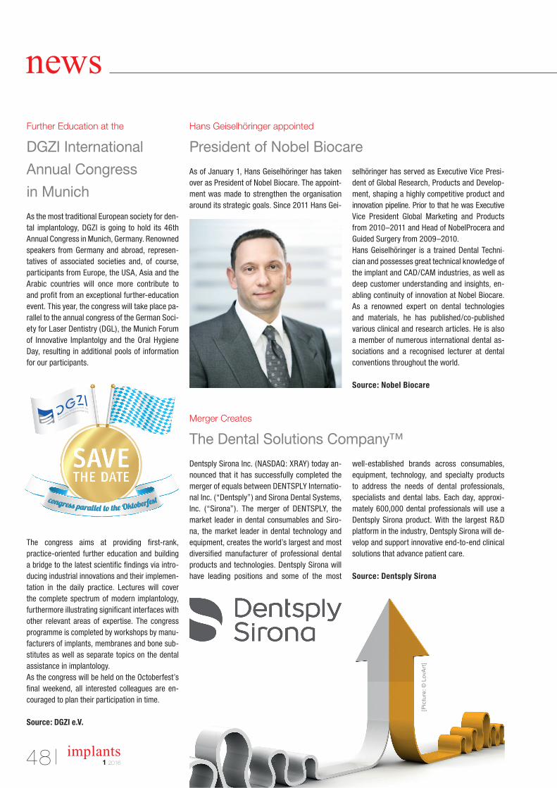
48 implants1 2016
news
Hans Geiselhöringer appointed
President of Nobel Biocare
Merger Creates
The Dental Solutions Company™
Further Education at the
DGZI International
Annual Congress
in Munich
As of January 1, Hans Geiselhöringer has taken over as President of Nobel Biocare. The appointment was made to strengthen the organisation around its strategic goals. Since 2011 Hans Gei
selhöringer has served as Executive Vice President of Global Research, Products and Development, shaping a highly competitive product and innovation pipeline. Prior to that he was Executive Vice President Global Marketing and Products from 2010–2011 and Head of NobelProcera and Guided Surgery from 2009–2010. Hans Geiselhöringer is a trained Dental Technician and possess es great technical knowledge of the implant and CAD/CAM industries, as well as deep customer understanding and insights, enabling continuity of innovation at Nobel Biocare. As a renowned expert on dental technologies and materials, he has published/copublished various clinical and research articles. He is also a member of numerous international dental associations and a recognised lecturer at dental conventions through out the world.
Source: Nobel Biocare
Dentsply Sirona Inc. (NASDAQ: XRAY) today announced that it has successfully completed the merger of equals between DENTSPLY International Inc. (“Dentsply”) and Sirona Dental Systems, Inc. (“Sirona”). The merger of DENTSPLY, the market leader in dental consumables and Sirona, the market leader in dental technology and equipment, creates the world’s largest and most diversified manufacturer of professional dental products and technologies. Dentsply Sirona will have leading positions and some of the most
wellestablished brands across consumables, equipment, technology, and specialty products to address the needs of dental professionals, specialists and dental labs. Each day, approximately 600,000 dental professionals will use a Dentsply Sirona product. With the largest R&D platform in the industry, Dentsply Sirona will develop and support innovative endtoend clinical solutions that advance patient care.
Source: Dentsply Sirona
As the most traditional European society for dental implantology, DGZI is going to hold its 46th Annual Congress in Munich, Germany. Renowned speakers from Germany and abroad, representatives of associated societies and, of course, participants from Europe, the USA, Asia and the Arabic countries will once more contribute to and profit from an exceptional furthereducation event. This year, the congress will take place parallel to the annual congress of the German Society for Laser Dentistry (DGL), the Munich Forum of Innovative Implantolgy and the Oral Hygiene Day, resulting in additional pools of information for our participants.
The congress aims at providing firstrank, practiceoriented further education and building a bridge to the latest scientific findings via introducing industrial innovations and their implementation in the daily practice. Lectures will cover the complete spectrum of modern implantology, furthermore illustrating significant interfaces with other relevant areas of expertise. The congress programme is completed by workshops by manufacturers of implants, membranes and bone substitutes as well as separate topics on the dental assistance in implantology.As the congress will be held on the Octoberfest’s final weekend, all interested colleagues are encouraged to plan their participation in time.
Source: DGZI e.V.
[Pic
ture
: © L
ovA
rt]
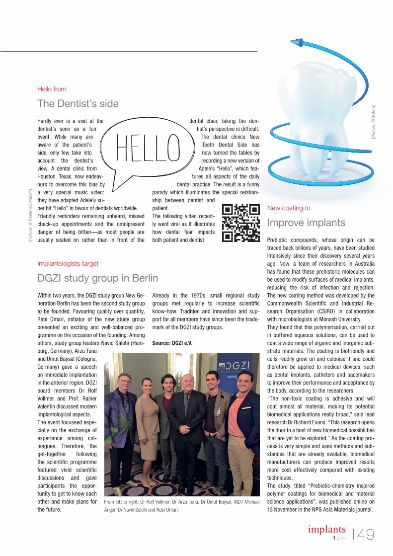
491 2016
implants
New coating to
Improve implants
Hello from
The Dentist’s side
Implantologists target
DGZI study group in Berlin
Prebiotic compounds, whose origin can be traced back billions of years, have been studied intensively since their discovery several years ago. Now, a team of researchers in Australia has found that these prehistoric molecules can be used to modify surfaces of medical implants, reducing the risk of infection and rejection. The new coating method was developed by the Commonwealth Scientific and Industrial Re search Organisation (CSIRO) in collaboration with microbiologists at Monash University.They found that this polymerisation, carried out in buffered aqueous solutions, can be used to coat a wide range of organic and inorganic substrate materials. The coating is biofriendly and cells readily grow on and colonise it and could therefore be applied to medical devices, such as dental implants, catheters and pacemakers to improve their performance and acceptance by the body, according to the researchers. “The nontoxic coating is adhesive and will coat almost all material, making its poten tial biomedical applications really broad,” said lead research Dr Richard Evans. “This research opens the door to a host of new biomedical possibilities that are yet to be explored.” As the coating process is very simple and uses methods and substances that are already available, biomedical manufacturers can produce improved results more cost effectively compared with existing techniques.The study, titled “Prebioticchemistry inspired polymer coatings for biomedical and material science applications”, was published online on 13 November in the NPG Asia Materials journal.
Hardly ever is a visit at the dentist’s seen as a fun event. While many are aware of the patient’s side, only few take into account the dentist’s view. A dental clinic from Houston, Texas, now endeavours to overcome this bias by a very special music video: they have adapted Adele’s super hit “Hello” in favour of dentists worldwide.Friendly reminders remaining unheard, missed checkup appointments and the omnipresent danger of being bitten—as most people are usually seated on rather than in front of the
dental chair, taking the dentist’s perspective is difficult.
The dental clinics New Teeth Dental Side has now turned the tables by recording a new version of
Adele’s “Hello”, which features all aspects of the daily
dental practise. The result is a funny parody which illuminates the special relationship between dentist and patient. The following video recently went viral as it illustrates how dental fear impacts both patient and dentist:
Within two years, the DGZI study group New Generation Berlin has been the second study group to be founded. Favouring quality over quantity, Rabi Omari, initiator of the new study group presented an exciting and wellbalanced programme on the occasion of the founding. Among others, study group leaders Navid Salehi (Hamburg, Germany), Arzu Tuna and Umut Baysal (Cologne, Germany) gave a speech on immediate implantation in the anterior region. DGZI board members Dr Rolf Vollmer and Prof. Rainer Valentin discussed modern implantological aspects. The event focussed especially on the exchange of experience among colleagues. Therefore, the gettogether following the scientific programme featured vivid scientific discussions and gave participants the opportunity to get to know each other and make plans for the future.
Already in the 1970s, small regional study groups met regularly to increase scientific knowhow. Tradition and innovation and support for all members have since been the trademark of the DGZI study groups.
Source: DGZI e.V.
[Pic
ture
: © K
ost
enko
Ma
xim
]
[Pic
ture
: © 3
dfo
to]
From left to right: Dr Rolf Vollmer, Dr Arzu Tuna, Dr Umut Baysal, MDT Michael
Anger, Dr Navid Salehi and Rabi Omari.
implants1 201650
| about the publisher
Congresses, courses and symposia
International symposium Osteology Monaco
21–23 April 2016 Venue: Monacowww.osteology-monaco.org
Third MIS Global Conference: 360° Implantology
26–28 May 2016 Venue: Barcelona, Spainwww.mis-implants.com
2nd Annual Meeting of ISMI
10–11 June 2016 Venue: Berlin, Germanywww.ismi.me
46th International Annual DGZI Congress
30 September–1 October 2016 Venue: Munich, Germanywww.dgzi.de
Imprint
PublisherTorsten R. Oemus [email protected]
CEOIngolf Dö[email protected]
Members of the BoardJürgen [email protected]
Lutz V. [email protected]
Chief Editorial ManagerDr Torsten Hartmann (V. i. S. d. P.)[email protected]
Editorial CouncilDr Rolf [email protected]
Dr Georg [email protected]
Prof (CAI) Dr Roland [email protected]
Dr Suheil [email protected]
Editorial Offi ceGeorg [email protected]
Claudia [email protected]
Executive ProducerGernot [email protected]
Designer Sandra [email protected]
Theresa [email protected]
Customer ServiceMarius [email protected]
Published byOEMUS MEDIA AGHolbeinstraße 2904229 Leipzig, GermanyTel.: +49 341 48474-0Fax: +49 341 [email protected]
Printed bySilber Druck oHGAm Waldstrauch 134266 Niestetal, Germany
implants international magazine of oral implantology is published in cooperation with the German Association of Dental Implantology (DGZI).
DGZI DGZI Central Offi ce Paulusstraße 140237 Düsseldorf, GermanyTel.: +49 211 16970-77Fax: +49 211 16970-66offi [email protected]
Copyright Regulationsimplants international magazine of oral implantology is published by OEMUS MEDIA AG and will appear in 2016 with one issue every quarter. The magazine and all articles and illustra-tions therein are protected by copyright. Any utilization without the prior consent of editor and publisher is inadmi ssible and liable to prosecution. This applies in particular to duplicate copies, translations, microfi lms, and storage and processing in electronic systems. Reproductions, including extracts, may only be made with the permission of the publisher. Given no statement to the contrary, any submissions to the editorial department are understood to be in agreement with a full or partial publishing of said submission. The editorial department reserves the right to check all submitted articles for formal errors and factual authority, and to make amendments if necessary. No responsibility shall be taken for unsolicited books and manuscripts. Articles bearing symbols other than that of the editorial department, or which are distinguished by the name of the author, represent the opinion of the afore-mentioned, and do not have to comply with the views of OEMUS MEDIA AG. Responsibility for such articles shall be borne by the author. Responsibility for advertisements and other specially labeled items shall not be borne by the editorial department. Likewise, no responsibility shall be assumed for information published about associations, companies and commercial markets. All cases of consequential liability arising from inaccurate or faulty representation are excluded. General terms and conditions apply, legal venue is Leipzig, Germany.
implants international magazine of oral implantology
www.dgzi.dewww.oemus.comwww.implants.de
Nobel Biocare Global Symposium 2016
23–25 June 2016 Venue: New York, USAwww.nobelbiocare.com

Nobel Biocare Services AG, 2015. All rights reserved. Nobel Biocare, the Nobel Biocare logotype and all other trademarks are, if nothing else is stated or is evident from the context in a certain case, trademarks of Nobel
NobelParallel™ Conical ConnectionThe NobelParallel Conical Connection is straightforward in design and application. It offers
treating more patients better.
Visit nobelbiocare.com/nobelparallel
Simplystraightforward
Related Documents