© ISO 2021 Non-active surgical implants — Joint replacement implants — Specific requirements for hip-joint replacement implants ICS: 11.040.40 Reference number ISO/DIS 21535:2021(E) DRAFT INTERNATIONAL STANDARD ISO/DIS 21535 ISO/TC 150/SC 4 Secretariat: BSI Voting begins on: Voting terminates on: 2021-07-22 2021-10-14 THIS DOCUMENT IS A DRAFT CIRCULATED FOR COMMENT AND APPROVAL. IT IS THEREFORE SUBJECT TO CHANGE AND MAY NOT BE REFERRED TO AS AN INTERNATIONAL STANDARD UNTIL PUBLISHED AS SUCH. IN ADDITION TO THEIR EVALUATION AS BEING ACCEPTABLE FOR INDUSTRIAL, TECHNOLOGICAL, COMMERCIAL AND USER PURPOSES, DRAFT INTERNATIONAL STANDARDS MAY ON OCCASION HAVE TO BE CONSIDERED IN THE LIGHT OF THEIR POTENTIAL TO BECOME STANDARDS TO WHICH REFERENCE MAY BE MADE IN NATIONAL REGULATIONS. RECIPIENTS OF THIS DRAFT ARE INVITED TO SUBMIT, WITH THEIR COMMENTS, NOTIFICATION OF ANY RELEVANT PATENT RIGHTS OF WHICH THEY ARE AWARE AND TO PROVIDE SUPPORTING DOCUMENTATION. This document is circulated as received from the committee secretariat. ISO/CEN PARALLEL PROCESSING Licensed to: Rundgren, Mattis Mr Downloaded: 2021-07-22 Single user licence only, copying and networking prohibited

Welcome message from author
This document is posted to help you gain knowledge. Please leave a comment to let me know what you think about it! Share it to your friends and learn new things together.
Transcript
© ISO 2021
Non-active surgical implants — Joint replacement implants — Specific requirements for hip-joint replacement implants
ICS: 11.040.40
Reference numberISO/DIS 21535:2021(E)
DRAFT INTERNATIONAL STANDARDISO/DIS 21535
ISO/TC 150/SC 4 Secretariat: BSI
Voting begins on: Voting terminates on:2021-07-22 2021-10-14
THIS DOCUMENT IS A DRAFT CIRCULATED FOR COMMENT AND APPROVAL. IT IS THEREFORE SUBJECT TO CHANGE AND MAY NOT BE REFERRED TO AS AN INTERNATIONAL STANDARD UNTIL PUBLISHED AS SUCH.
IN ADDITION TO THEIR EVALUATION AS BEING ACCEPTABLE FOR INDUSTRIAL, TECHNOLOGICAL, COMMERCIAL AND USER PURPOSES, DRAFT INTERNATIONAL STANDARDS MAY ON OCCASION HAVE TO BE CONSIDERED IN THE LIGHT OF THEIR POTENTIAL TO BECOME STANDARDS TO WHICH REFERENCE MAY BE MADE IN NATIONAL REGULATIONS.
RECIPIENTS OF THIS DRAFT ARE INVITED TO SUBMIT, WITH THEIR COMMENTS, NOTIFICATION OF ANY RELEVANT PATENT RIGHTS OF WHICH THEY ARE AWARE AND TO PROVIDE SUPPORTING DOCUMENTATION.
This document is circulated as received from the committee secretariat.
ISO/CEN PARALLEL PROCESSING
Licensed to: Rundgren, Mattis MrDownloaded: 2021-07-22Single user licence only, copying and networking prohibited
ISO/DIS 21535:2021(E)
ii © ISO 2021 – All rights reserved
COPYRIGHT PROTECTED DOCUMENT
© ISO 2021All rights reserved. Unless otherwise specified, or required in the context of its implementation, no part of this publication may be reproduced or utilized otherwise in any form or by any means, electronic or mechanical, including photocopying, or posting on the internet or an intranet, without prior written permission. Permission can be requested from either ISO at the address below or ISO’s member body in the country of the requester.
ISO copyright officeCP 401 • Ch. de Blandonnet 8CH-1214 Vernier, GenevaPhone: +41 22 749 01 11Email: [email protected]: www.iso.org
Published in Switzerland Licensed to: Rundgren, Mattis MrDownloaded: 2021-07-22Single user licence only, copying and networking prohibited
ISO/DIS 21535:2021(E)
Foreword ........................................................................................................................................................................................................................................ivIntroduction ..................................................................................................................................................................................................................................v1 Scope ................................................................................................................................................................................................................................. 12 Normative references ...................................................................................................................................................................................... 13 Terms and definitions ..................................................................................................................................................................................... 24 Intended performance ................................................................................................................................................................................... 65 Design attributes .................................................................................................................................................................................................. 7
5.1 General ........................................................................................................................................................................................................... 75.2 Tolerances and dimensions .......................................................................................................................................................... 8
5.2.1 Tolerances and dimensions of taper connections ............................................................................... 85.2.2 Tolerances on diameters of articulating surfaces, sphericity of articulating
surfaces and surface finish of articulating surfaces .......................................................................... 85.3 Thickness of acetabular components, bipolar heads, and dual mobility heads ............................. 8
5.3.1 General...................................................................................................................................................................................... 85.3.2 Thickness of UHMWPE in acetabular components, bipolar heads, and dual
mobility heads .................................................................................................................................................................... 95.3.3 Thickness of metal and ceramic acetabular shell and acetabular liner
components; and, bipolar heads and dual mobility heads .......................................................... 96 Materials ....................................................................................................................................................................................................................107 Design evaluation .............................................................................................................................................................................................10
7.1 General ........................................................................................................................................................................................................ 107.2 Pre-clinical evaluation ................................................................................................................................................................... 10
7.2.1 General................................................................................................................................................................................... 107.2.2 Test methods and performance requirements ...................................................................................12
7.3 Clinical investigation ....................................................................................................................................................................... 198 Manufacture ...........................................................................................................................................................................................................199 Sterilization ............................................................................................................................................................................................................1910 Packaging ..................................................................................................................................................................................................................1911 Information to be supplied by the manufacturer ............................................................................................................19
11.1 General ........................................................................................................................................................................................................ 1911.2 Product type and dimensions ................................................................................................................................................. 2011.3 Structural and functional compatibility of components ..................................................................................2011.4 Marking ...................................................................................................................................................................................................... 2011.5 Information for the patient ....................................................................................................................................................... 2011.6 Information for the surgeon ..................................................................................................................................................... 2111.7 Electronic instructions for use ............................................................................................................................................... 21
Annex A (informative) Evaluation of range of relative angular motion of the femoral and acetabular components of a total hip replacement ......................................................................................................22
Annex ZA (informative) Relationship between this European standard and the General Safety and Performance Requirements of Regulation (EU) 2017/745 aimed to be covered .........................................................................................................................................................................................................................25
Bibliography .............................................................................................................................................................................................................................28
© ISO 2021 – All rights reserved iii
Contents Page
Licensed to: Rundgren, Mattis MrDownloaded: 2021-07-22Single user licence only, copying and networking prohibited
ISO/DIS 21535:2021(E)
Foreword
ISO (the International Organization for Standardization) is a worldwide federation of national standards bodies (ISO member bodies). The work of preparing International Standards is normally carried out through ISO technical committees. Each member body interested in a subject for which a technical committee has been established has the right to be represented on that committee. International organizations, governmental and non-governmental, in liaison with ISO, also take part in the work. ISO collaborates closely with the International Electrotechnical Commission (IEC) on all matters of electrotechnical standardization.
International Standards are drafted in accordance with the rules given in the ISO/IEC Directives, Part 2.
The main task of technical committees is to prepare International Standards. Draft International Standards adopted by the technical committees are circulated to the member bodies for voting. Publication as an International Standard requires approval by at least 75 % of the member bodies casting a vote.
Attention is drawn to the possibility that some of the elements of this document may be the subject of patent rights. ISO shall not be held responsible for identifying any or all such patent rights.
ISO 21535 was prepared by Technical Committee ISO/TC 150, Implants for surgery, Subcommittee SC 4, Bone and joint replacements.
This third edition cancels and replaces the second edition (ISO 21535:2007), which has been technically revised.
iv © ISO 2021 – All rights reserved
Licensed to: Rundgren, Mattis MrDownloaded: 2021-07-22Single user licence only, copying and networking prohibited
ISO/DIS 21535:2021(E)
Introduction
There are three levels of standards dealing with non-active surgical implants.
These are as follows, with level 1 being the highest:
— level 1: general requirements for non-active surgical implants and instrumentation used in association with implants;
— level 2: particular requirements for families of non-active surgical implants;
— level 3: specific requirements for types of non-active surgical implant.
This standard is a level 3 standard and contains requirements applying specifically to hip joint replacements.
The level 1 standard, ISO 14630, contains requirements that apply to all non-active surgical implants. It also indicates that there are additional requirements in the level 2 and level 3 standards.
The level 2 standards apply to more restricted sets or families of implants such as those designed for use in osteosynthesis, cardiovascular surgery or joint replacement. For joint replacement implants the level 2 standard is ISO 21534.
To address all requirements, it is recommended that a standard of the lowest available level be consulted first.
© ISO 2021 – All rights reserved v
Licensed to: Rundgren, Mattis MrDownloaded: 2021-07-22Single user licence only, copying and networking prohibited

Licensed to: Rundgren, Mattis MrDownloaded: 2021-07-22Single user licence only, copying and networking prohibited
Non-active surgical implants — Joint replacement implants — Specific requirements for hip-joint replacement implants
1 Scope
This document provides specific requirements for hip joint replacement implants. With regard to safety, this document specifies requirements for intended performance, design attributes, materials, design evaluation, manufacture, sterilization, packaging, information supplied by the manufacturer, and methods of test.
This document applies to both total and partial hip joint replacement implants. It applies to components made of metallic and non-metallic materials.
This document applies to a wide variety of hip replacement implants, but for some specific hip replacement implant types, some considerations, not specifically covered in this document, may be applicable. Further details are given in Clause 7.2.1.1.
The requirements which are specified in this document are not intended to require the re-design or re-testing of devices which have been legally marketed and for which there is a history of sufficient and safe clinical use. For such devices compliance with this document shall be demonstrated by providing evidence of the sufficient and safe clinical use.
2 Normative references
The following referenced documents are indispensable for the application of this document. For dated references, only the edition cited applies. For undated references, the latest edition of the referenced document (including any amendments) applies.
ISO 6475, Implants for surgery — Metal bone screws with asymmetrical thread and spherical under-surface — Mechanical requirements and test methods
ISO 7206-1:2008, Implants for surgery — Partial and total hip joint prostheses — Part 1: Classification and designation of dimensions
ISO 7206-2, Implants for surgery — Partial and total hip joint prostheses — Part 2: Articulating surfaces made of metallic, ceramic and plastics materials
ISO 7206-4, Implants for surgery — Partial and total hip joint prostheses — Part 4: Determination of endurance properties and performance of stemmed femoral components
ISO 7206-6, Implants for surgery — Partial and total hip joint prostheses — Part 6: Endurance properties testing and performance requirements of neck region of stemmed femoral components
ISO 7206-10, Implants for surgery — Partial and total hip-joint prostheses — Part 10: Determination of resistance to static load of modular femoral heads
ISO 7206-12, Implants for surgery — Partial and total hip joint prostheses — Part 12: Deformation test method for acetabular shells
ISO 7206-13, Implants for surgery — Partial and total hip joint prostheses — Part 13: Determination of resistance to torque of head fixation of stemmed femoral components
ISO 11491, Implants for surgery — Determination of impact resistance of ceramic femoral heads for hip joint prostheses
DRAFT INTERNATIONAL STANDARD ISO/DIS 21535:2021(E)
© ISO 2021 – All rights reserved 1
Licensed to: Rundgren, Mattis MrDownloaded: 2021-07-22Single user licence only, copying and networking prohibited
ISO/DIS 21535:2021(E)
ISO 14242-1, Implants for surgery — Wear of total hip-joint prostheses — Part 1: Loading and displacement parameters for wear-testing machines and corresponding environmental conditions for test
ISO 14242-2, Implants for surgery — Wear of total hip-joint prostheses — Part 2: Methods of measurement
ISO 14242-3, Implants for surgery — Wear of total hip-joint prostheses — Part 3: Loading and displacement parameters for orbital bearing type wear testing machines and corresponding environmental conditions for test
ISO 14242-4, Implants for surgery — Wear of total hip-joint prostheses — Part 4: Testing hip prostheses under variations in component positioning which results in direct edge loading
ISO 14630, Non-active surgical implants — General requirements
ISO 17853, Wear of implant materials — Polymer and metal wear particles — Isolation and characterization
ISO 21534:2007, Non-active surgical implants — Joint replacement implants — Particular requirements
ASTM F543, Standard Specification and Test Methods for Metallic Medical Bone Screws
ASTM F1820, Standard Test Method for Determining the Forces for Disassembly of Modular Acetabular Devices
ASTM F1875, Standard Practice for Fretting Corrosion Testing of Modular Implant Interfaces: Hip Femoral Head-Bore and Cone Taper Interface
ASTM F1877, Standard Practice for Characterization of Particles
ASTM F2009, Standard Test Method for Determining the Axial Disassembly Force of Taper Connections of Modular Prostheses
ASTM F2033, Standard Specification for Total Hip Joint Prosthesis and Hip Endoprosthesis Bearing Surfaces Made of Metallic, Ceramic, and Polymeric Materials
ASTM F2345, Standard Test Methods for Determination of Static and Cyclic Fatigue Strength of Ceramic Modular Femoral Heads
ASTM F2580, Standard Practice for Evaluation of Modular Connection of Proximally Fixed Femoral Hip Prosthesis
ASTM F2582, Standard Test Method for Impingement of Acetabular Prostheses
ASTM F3018, Standard Guide for Assessment of Hard-on-Hard Articulation Total Hip Replacement and Hip Resurfacing Arthroplasty Devices
ASTM F3047M, Standard Guide for High Demand Hip Simulator Wear Testing of Hard-on-hard Articulations
ASTM F3090, Standard Test Method for Fatigue Testing of Acetabular Devices for Total Hip Replacement
ASTM F3143, Standard Test Method for Determination of Frictional Torque and Friction Factor for Hip Replacement Bearings Under Standard Conditions Using a Reciprocal Friction Simulator
ASTM F3446, Standard Test Method for Determination of Frictional Torque and Friction Factor for Hip Implants Using an Anatomical Motion Hip Simulator
3 Terms and definitions
For the purposes of this document the terms and definitions in ISO 21534, ISO 7206-1, ISO 7206-2 and ISO 7206-10 and the following apply.
ISO and IEC maintain terminological databases for use in standardization at the following addresses:
— ISO Online browsing platform: available from https:// www .iso .org/ obp
2 © ISO 2021 – All rights reserved
Licensed to: Rundgren, Mattis MrDownloaded: 2021-07-22Single user licence only, copying and networking prohibited
ISO/DIS 21535:2021(E)
— IEC Electropedia: available from https:// www .electropedia .org/
3.1acetabular componentimplant intended to be fixed to the prepared biological acetabulum
Note 1 to entry: The acetabular component can be of monobloc or modular construction. If modular, typically there can be two sub-components, each fulfilling a different function: one is the bearing surface and the other provides the means of fixation to the prepared biological acetabulum. The bearing surface is also referred to as the liner (or the insert) and the other sub-component is sometimes referred to as the shell.
3.2bipolar femoral hiptype of partial hip joint replacement consisting of a bipolar femoral component and a femoral component
3.3bipolar headbipolar femoral componentcomponent of a partial hip joint replacement with a concave (inner) surface intended to articulate with the spherical head of the femoral component and a convex (outer) spherical surface intended to articulate with the biological acetabulum
Note 1 to entry: The bipolar head can be a monobloc component or a modular component.
3.4constrained hiptype of total hip joint replacement intended to prevent hip dislocation in more than one anatomic plane, which consists of femoral and acetabular components, which are connected across the joint
Note 1 to entry: A dual mobility constrained hip is a type of constrained hip which consists of a femoral component (3.7), a dual mobility head (3.5), and a modular constrained acetabular component, which are connected across the joint. This type of constrained hip is also called a “tripolar hip”. Although the term “tripolar” is used to describe the construct, there are only two bearings.
3.5dual mobility headdual mobility femoral componentcomponent of a total hip joint replacement with a concave (inner) surface intended to articulate with the spherical head of the femoral component and a convex (outer) spherical surface intended to articulate with an acetabular component
Note 1 to entry: The dual mobility head can be a monobloc component or a modular component.
3.6dual mobility hiptype of total hip joint replacement consisting of a femoral component (3.7), dual mobility head (3.5) and an acetabular component (3.1)
3.7femoral componentpart of a total or partial hip joint replacement which is intended to be fixed to the proximal femur
Note 1 to entry: The femoral component fulfills two different functions: one is to provide the bearing surface and the other is to provide the means of fixation to the proximal femur.
Note 2 to entry: The femoral component can be monobloc or modular. If modular, typically there are 2 sub-components, each fulfilling a different function: one is the modular femoral head (3.8) and the other is the modular femoral stem.
Note 3 to entry: A modular femoral stem (see Note 2 to entry) can itself be modular, consisting of a single or multi-component modular femoral stem and a single or multi-component modular femoral neck and taper connection(s).
© ISO 2021 – All rights reserved 3
Licensed to: Rundgren, Mattis MrDownloaded: 2021-07-22Single user licence only, copying and networking prohibited
ISO/DIS 21535:2021(E)
Note 4 to entry: The femoral component of a resurfacing hip joint replacement can also be referred to as the femoral cap.
3.8femoral headthe part of a total or partial hip joint replacement which articulates with:
a) the natural acetabulum or a bipolar head (3.3), in the case of a partial hip joint replacement (3.12);
b) the acetabular component (3.1) or a dual mobility head (3.5), in the case of a total hip joint replacement (3.16)
3.9hip joint replacementimplant used to replace one or both of the articulating surfaces of the hip joint
Note 1 to entry: An implant intended to replace only the femoral articulating surface of the hip joint is referred to as partial hip joint replacement (see 3.12).
Note 2 to entry: An implant intended to replace the femoral and acetabular surfaces of the hip joint is referred to as total hip joint replacement (see 3.16).
Note 3 to entry: The term hip arthroplasty refers to the act of implanting a hip joint replacement.
3.10modular componentfemoral or acetabular component that consists of two or more sub-components
Note 1 to entry: A modular component can be supplied preassembled or as separate components to be assembled by the user.
3.11monobloc componentcomponent that consists of a single part with no modularity
Note 1 to entry: Derived from ISO 7206-1:2008, 3.6
3.12partial hip joint replacementimplant comprising a femoral component (3.7) intended to replace the femoral articulating surface of the hip joint
Note 1 to entry: Modular partial hip joint replacement implants incorporate either a bipolar or a unipolar head.
Note 2 to entry: The term hip hemiarthroplasty refers to the act of implanting a partial hip joint replacement.
Note 3 to entry: A partial hip joint replacement is sometimes referred to as a “hemi”.
3.13reference devicea legally-marketed device which, when compared to the device under investigation, satisfies both of the following conditions:
1) it has the same intended use, similar materials and a similar design with regard to the specific dimensional or performance criteria under evaluation to address the same clinical and technical requirements; and
2) there is evidence of clinical use in sufficient numbers; for a sufficient period of time; and, at a minimum, without known or reasonably-known evidence of device-related recalls with regard to the specific dimensional or performance criteria under evaluation.
4 © ISO 2021 – All rights reserved
Licensed to: Rundgren, Mattis MrDownloaded: 2021-07-22Single user licence only, copying and networking prohibited
ISO/DIS 21535:2021(E)
Note 1 to entry: The term “reference” is not intended to imply that the device under investigation and the reference device are “equivalent” or that the reference device is a “predicate” device. This is because in some regulatory regimes the terms “equivalent” and “predicate” have a meaning, which is beyond that intended by the term “reference” as used in this document.
Note 2 to entry: For the purposes of this document, a reference device is the comparison device for the performance parameter under consideration. For each performance parameter there can be a different reference device. The reference device can be different from the device under investigation with respect to other parameters.
Note 3 to entry: Some regulatory regimes require that a legally-marketed device is one that is legally marketed in their own country or jurisdiction. This fact may need to be taken into account when selecting a reference device for the purposes of this document.
Note 4 to entry: There is no agreed interpretation for what constitutes “sufficient numbers” or a “sufficient period of time” in the above definition. ISO 21534:2007, Clause 6.1, Note 3 gives an example of what may be a sufficient number of implants and a sufficient number of years of evidence. The example in ISO 21534: 2007, Clause 6.1 is not included here as a requirement, only as an example which may be useful when interpreting what may be “sufficient clinical evidence”. Typically, a determination of what constitutes “sufficient numbers” and a “sufficient period of time” is demonstrated by using statistical methods and clinical judgement in the evaluation of device performance.
Note 5 to entry: A justification for a “similar material” might include information that although the materials are not the same, the material(s) used for the device under investigation can be shown to perform similarly with regard to the test or its underlying clinical concern.
Note 6 to entry: Examples of design features that may be taken into consideration when evaluating whether a device has ‘similar design’ to the device under investigation include means of fixation, modularity, constraint, key dimensions, processing, surface treatment, etc. A justification for a “similar design” therefore might include information that although the designs are not the same, the design of the device under investigation can be shown to perform similarly with regard to the test or its underlying clinical concern.
Note 7 to entry: Identification of a reference device is at the discretion of the manufacturer and regulatory body in accordance with the regulatory requirements in the jurisdictions where the device is marketed.
3.14resurfacing hip joint replacementtype of total or partial hip joint replacement intended to replace (1) only the femoral articulating surface of the joint in a partial hip replacement, which usually consists of a monobloc femoral cap component, with a central stem, that is placed over the head of a prepared biological femoral head and intended to articulate with the biological acetabulum; or (2) both the femoral and acetabular articulating surfaces of the joint in a total hip replacement, which consists of a monobloc femoral cap component; and a matching monobloc or modular acetabular component (3.1)
3.15sufficient and safe clinical useClinical use of a legally-marketed device a) in sufficient numbers, b) for a sufficient period of time and c) at a minimum, without known or reasonably-known evidence of device-related recalls.
Note 1 to entry: There is no agreed interpretation for what constitutes “sufficient numbers” or “sufficient period of time” in the above definition. Typically, these are demonstrated by using statistical methods and clinical judgement in the evaluation of device performance.
Note 2 to entry: Some regulatory regimes require that a legally-marketed device is one which is legally marketed in their country or jurisdiction.
Note 3 to entry: For a legally-marketed system of hip replacement implants there may be evidence to demonstrate sufficient and safe clinical use for some parts of the system (e.g. some components and some sizes) but not for others. For those parts of the system for which there is sufficient evidence the requirements of this document relating to design and testing shall not apply.
Note 4 to entry: This document does apply to those parts of a legally-marketed hip replacement implant system for which there is not sufficient evidence to demonstrate sufficient and safe clinical use.
© ISO 2021 – All rights reserved 5
Licensed to: Rundgren, Mattis MrDownloaded: 2021-07-22Single user licence only, copying and networking prohibited
ISO/DIS 21535:2021(E)
Note 5 to entry: Identification of a device with sufficient and safe clinical use is at the discretion of the manufacturer and regulatory body in accordance with the regulatory requirements in the jurisdictions where the device is marketed.
3.16total hip joint replacementimplant comprising a femoral component (3.7) and an acetabular component (3.1) intended to replace both of the articulating surfaces of the hip joints
Note 1 to entry: The term total hip arthroplasty refers to the act of implanting a total hip joint replacement.
3.17UHMWPEultra-high molecular weight polyethylene.
Note 1 to entry: This term includes the following types of polyethylene-based materials: 1) conventional UHMWPE (not intentionally cross-linked), 2) crosslinked UHMWPE achieved by radiation treatment or other means and 3) crosslinked or not crosslinked UHMWPE with the addition of Vitamin E or another anti-oxidant.
3.18unipolar headhead of a femoral component (3.7) intended to articulate with the biological acetabulum
3.19worst casedesignation given 1) to an implant component or combination of components in an implant family which is most susceptible to failure in a given test (e.g. based on size, geometry, design features, materials, means of fixation, surface treatments or coatings, modularity); and, 2) to testing condition(s) which produce the most severe anticipated physiological condition(s) or failure mode(s) for the requirements to which the implant is under evaluation
Note 1 to entry: For any given implant component or combination of components or set of testing conditions, there can be more than one worst case.
Note 2 to entry: For any modification to the device design or change in compatibility with other components, the design should be assessed to determine if a new worst case(s) is created for a given test.
4 Intended performance
The requirements of this clause are not intended to require the re-design or re-testing of devices which have been legally marketed and for which there is a history of sufficient and safe clinical use.
The requirements of ISO 21534:2007, Clause 4, shall apply together with the following.
The range of angular movement between the femoral and acetabular components of a total hip replacement shall have the following minimum values:
— 100° in flexion/extension;
— 60° in abduction/adduction;
— 90° in internal/external rotation.
NOTE Annex A shows a method by which the range of motion between the femoral and acetabular components of a total hip replacement can be measured.
6 © ISO 2021 – All rights reserved
Licensed to: Rundgren, Mattis MrDownloaded: 2021-07-22Single user licence only, copying and networking prohibited
ISO/DIS 21535:2021(E)
5 Design attributes
5.1 General
The requirements of this clause are not intended to require the re-design or re-testing of devices which have been legally marketed and for which there is a history of sufficient and safe clinical use.
The design attributes, to meet the intended performance, shall conform to the requirements of Clause 5 of ISO 21534: 2007, and those specified in 5.2 and 5.3 to meet the intended use.
In addition, account shall be taken of at least the following points, if applicable:
a) the femoral head diameter, offset(s) and other head features (e.g. skirts),
b) the stem length; stem medial/lateral and anterior/posterior dimensions; stem shape (straight, curved, tapered, collared, collarless); and the amount of ante-version or retro-version,
c) the neck length and the neck/stem angle(s),
d) head offset length,
e) all modular components and connections (e.g. femoral taper adapters, modular hip stem sleeves),
f) the means of fixation for all components which appose bone or bone cement,
g) the size and location of any porous coated surface or intentionally roughened surface,
NOTE Additional information may be found in ISO 13179-1, ASTM F1854 and in FDA Guidance Document, “Guidance Document for Testing Orthopedic Implants with Modified Metallic Surfaces Apposing Bone or Bone Cement, April 1994”; and ISO 13779-2, ASTM F1609, and FDA Guidance Documents for “510(k) Information needed for Hydroxyapatite Coated Orthopedic Implants”
h) the inner and outer diameter of acetabular components,
i) the recommended positioning (e.g. as stated in the surgical technique manual) of the femoral stem and the acetabular component (e.g. cup inclination angle, cup and stem version angles),
j) for revision cups or for acetabular reconstruction specific design features (e.g. flanges, augments, patient matched external shell geometries),
k) for components to be cemented, the intended thickness of the cement mantle,
l) for acetabular shells, the design and location of features intended for fixation such as the screws and the screw holes,
m) for modular acetabular systems, the features intended to attach the acetabular liner to the acetabular shell,
n) the diametral clearance as described in ASTM F2033 and ASTM F3018,
o) the Cup Articular Arc Angle (CAAA) and Contact Patch Edge to Rim (CPER) distance both as described in ASTM F3018,
p) the degree of constraint,
q) the accessories to be used with the hip system (e.g. screws, distal stem centralizer, dome/screw hole plug).
© ISO 2021 – All rights reserved 7
Licensed to: Rundgren, Mattis MrDownloaded: 2021-07-22Single user licence only, copying and networking prohibited
ISO/DIS 21535:2021(E)
5.2 Tolerances and dimensions
5.2.1 Tolerances and dimensions of taper connections
For taper connections particular attention shall be paid to the dimensions and tolerance of the following:
1. the surface finish, straightness, circularity (where specified), angle and diameter of the bore
2. the surface finish, straightness, circularity (where specified), angle and diameter of the cone
3. the bore and cone nominal engagement length.
NOTE 1 The term surface finish is defined in ISO 7206-2. Examples for the use of the terms bore, cone, bore angle, cone angle, straightness, circularity, diameter, concentricity and engagement length can be found in ISO 7206-10.
NOTE 2 Instead of straightness and circularity it is also possible to use profile of the surface as an alternative parameter for the bore and cone.
In the design of modular components, the risk of generation of wear particles and occurrence of fretting and crevice corrosion at modular component interfaces shall be taken into account.
5.2.2 Tolerances on diameters of articulating surfaces, sphericity of articulating surfaces and surface finish of articulating surfaces
The tolerances on the diameters of the articulating surfaces, the sphericity of the articulating surfaces and the surface finish of the articulating surfaces of:
1. femoral components intended for total or partial hip joint replacement
2. acetabular components
3. bipolar heads
4. constrained hip components
5. dual mobility hip components, and
6. resurfacing hip joint replacements
shall be in accordance with ISO 7206-2 or ASTM F2033 or, where not specified in ISO 7206-2 or ASTM F2033, shall be the same or better than the tolerances on the diameters of the articulating surfaces, the sphericity of the articulating surfaces and the surface finish of the articulating surfaces in at least one reference device as defined in 3.13.
NOTE For articulating surfaces that are not intended to be spherical (e.g. some surfaces intended to articulate with the natural acetabulum), the sphericity requirement is not applicable.
5.3 Thickness of acetabular components, bipolar heads, and dual mobility heads
5.3.1 General
When evaluating thickness of acetabular components, bipolar heads, and dual mobility heads, the nominal thickness and associated tolerance(s) shall be taken into account.
8 © ISO 2021 – All rights reserved
Licensed to: Rundgren, Mattis MrDownloaded: 2021-07-22Single user licence only, copying and networking prohibited
ISO/DIS 21535:2021(E)
5.3.2 Thickness of UHMWPE in acetabular components, bipolar heads, and dual mobility heads
5.3.2.1 Acetabular components
The UHMWPE component shall have the following minimum thickness (in the least material condition) in areas including the dome, 45-degree angle to the component axis, rim, and locking mechanism:
a) 5 mm for components with a metal or other backing
NOTE the 5 mm thickness is the minimum thickness of the UHMWPE component and not the minimum thickness of the UHMWPE component plus the thickness of the metal or other backing;
b) 6 mm for components without metal or other backing.
If the UHMWPE acetabular component does not meet the requirements for thickness stated above, the minimum thickness in the areas stated above shall be the same or greater than the minimum thickness in all corresponding areas of at least one reference device as defined in 3.13. Otherwise, a clinical investigation can be required to verify the acceptability of the component (7.3).
5.3.2.2 Bipolar heads
For bipolar heads the minimum thickness of the UHMWPE component shall be 5 mm in areas including the dome, 45-degree angle to the component axis, rim, and locking mechanism.
If the UHMWPE bipolar head does not meet the requirements for thickness stated above, the minimum thickness in the areas stated above shall be the same or greater than the minimum thickness in all corresponding areas of at least one reference device as defined in 3.13. Otherwise, a clinical investigation can be required (7.3).
5.3.2.3 Dual mobility heads
For dual mobility heads the minimum thickness of the UHMWPE dual mobility head shall be the same as the bipolar head, as specified in 5.3.2.2. Similarly, the minimum thickness of the UHMWPE acetabular component shall be as specified in 5.3.2.1.
5.3.3 Thickness of metal and ceramic acetabular shell and acetabular liner components; and, bipolar heads and dual mobility heads
For an acetabular shell made of a typical titanium alloy (i.e., ISO 5832-3, ASTM F136 or ASTM F1472) or a typical cobalt-chrome alloy (i.e., ISO 5832-12 or ASTM F1537) and not made by additive manufacturing, the minimum thickness shall be 3 mm in areas including the dome, 45-degree angle to the component axis, rim, and locking mechanism.
If a surface coating is applied to the shell, the thickness of the shell shall be determined by deducting the coating thickness from the total thickness.
If the thickness in the areas stated above is less than 3 mm, then the minimum thickness in those areas shall be the same or greater than the minimum thickness in the corresponding areas of at least one reference device as defined in 3.13. Otherwise, a clinical investigation can be required to verify the acceptability of the component (7.3).
For metal and ceramic:
a) bipolar heads, dual mobility heads and acetabular liner components;
b) acetabular shell components not made of a typical titanium or cobalt-chrome alloy (see above lists); and
c) acetabular shells and acetabular liner components; and, bipolar heads and dual mobility heads that are additively manufactured,
© ISO 2021 – All rights reserved 9
Licensed to: Rundgren, Mattis MrDownloaded: 2021-07-22Single user licence only, copying and networking prohibited
ISO/DIS 21535:2021(E)
the minimum thickness in the areas stated above shall be the same or greater than the minimum thickness in the corresponding areas of at least one reference device as defined in 3.13. Otherwise, a clinical investigation can be required (7.3).
6 Materials
The requirements of this clause are not intended to require the re-design or re-testing of devices which have been legally marketed and for which there is a history of sufficient and safe clinical use.
The requirements of ISO 21534:2007, Clause 6, shall apply together with the following.
Unalloyed titanium and titanium alloys shall not be used as the articulating surfaces of total hip joint replacements, unless an appropriate surface treatment is undertaken and demonstrated to be suitable in clinical use compared to at least one reference device as defined in 3.13.
7 Design evaluation
7.1 General
The requirements of ISO 21534:2007, Clause 7, shall apply together with the requirements specified in 7.2 and 7.3.
7.2 Pre-clinical evaluation
7.2.1 General
The requirements of this clause are not intended to require the re-design or re-testing of devices which have been legally marketed and for which there is a history of sufficient and safe clinical use.
For each test specified in 7.2.2 sterilized components shall be tested unless a justification is provided for the use of non-sterilized components.
7.2.1.1 Tests to be performed
Clause 7.2.2 lists the tests to be performed.
The test methods listed in 7.2.2 were developed to mitigate the effect of known failure modes. These tests cannot evaluate failure modes for which they were not designed. Therefore, the intended use, materials and design of the device under investigation should be analysed to determine whether additional failure modes exist. If additional failure modes are identified, these shall be stated and appropriate testing shall be performed.
NOTE 1 The test methods specified in 7.2.2 might need to be modified for specific types of hip replacement implants. For example, for dual mobility hip components and for constrained hip replacement implants the wear testing, range of motion testing and disassembly force (locking mechanism) testing might need to be modified.
NOTE 2 Additively manufactured materials may require additional evaluation, particularly related to the fatigue strength.
7.2.1.2 Circumstances when a test can be omitted
Each test in 7.2.2 is required unless:
1. the test is not applicable
2. performing the test is considered unnecessary based on the risk analysis for the device
3. the clause states that the test is a recommendation or should (rather than shall) be performed
10 © ISO 2021 – All rights reserved
Licensed to: Rundgren, Mattis MrDownloaded: 2021-07-22Single user licence only, copying and networking prohibited
ISO/DIS 21535:2021(E)
In these cases, a justification for omitting the test shall be documented for each test omitted.
For stemmed femoral components tests 7.2.2.1 and 7.2.2.2 are always applicable.
Examples of situations in which one or more tests may not be applicable include:
a) the hip stem is a monobloc component, unipolar head, partial hip joint replacement that is not for use with a bipolar head; so, the tests specified in 7.2.2.3 to 7.2.2.18 would not apply as these tests address features or components which this type of implant does not have; or
b) the total hip joint replacement does not include a modular metal or ceramic head so, tests specified in 7.2.2.3, 7.2.2.6, 7.2.2.8, 7.2.2.9 and 7.2.2.11 (for the head and stem taper interface) would not apply as these tests have to do with modular metal or ceramic heads.
7.2.1.3 Test the worst case
For each test specified in 7.2.2 the worst case or worst cases shall be tested. A justification for selecting the chosen component(s) and conditions for testing shall be documented.
NOTE Finite element analysis can be helpful in selecting the most appropriate size(s) of component(s) for testing. See for example, ASTM F2996.
7.2.1.4 Process to be followed when no pass-fail performance requirement has been specified or when a pass-fail performance requirement has been specified, but has not been met, and when a reference device exists for comparison
In some cases, no pass-fail performance requirement has been specified in a subclause of 7.2.2.
In some other cases:
1) a pass-fail performance requirement has been specified in a subclause of 7.2.2; but
2) the device under investigation did not meet the pass-fail performance requirement.
In both of these cases, the performance of the device under investigation shall be the same as or better than the performance of at least one reference device as defined in 3.13.
The comparison of the performance of the device under investigation with the performance of one or more reference devices shall be made using at least one of the following methods:
— side-by-side testing (a test program in which the devices are tested in parallel under identical test conditions);
— comparison of the results of tests performed on the device under investigation with the results of tests performed previously on a reference device where it can be demonstrated that the test conditions are identical; or
— comparison of the results of tests performed on the device under investigation with the results of tests reported on a reference device in peer-reviewed literature where it can be demonstrated that the test conditions are identical.
The methods listed above are listed in order of most preferred to least preferred in terms of reliability, repeatability, and demonstrating comparability with reference devices. It is recommended to follow this order when determining which method to use.
When following this process, the method chosen shall be stated and justified.
In some cases:
3) no pass-fail performance requirement has been specified in a subclause of 7.2.2 (or a pass-fail performance requirement has been specified but has not been met by the device under investigation); and
© ISO 2021 – All rights reserved 11
Licensed to: Rundgren, Mattis MrDownloaded: 2021-07-22Single user licence only, copying and networking prohibited
ISO/DIS 21535:2021(E)
4) a reference device exists as defined in 3.13 but a comparison of the performance of the device under investigation to a reference device(s) does not show similar or better results.
In these cases, a biomechanical rationale shall be provided, which provides an in-depth analysis of the in-vivo loads and physiological conditions in comparison to the test results obtained, with an adequate safety factor.
In some cases:
5) no pass-fail performance requirement has been specified in a subclause of 7.2.2 (or a pass-fail performance requirement has been specified but has not been met by the device under investigation);
6) a reference device exists as defined in 3.13 but a comparison of the performance of the device under investigation to a reference device(s) does not show similar or better results; and
7) no adequate biomechanical rationale can be provided.
In these cases, the device under investigation shall not satisfy the requirements of this standard. In these cases, a pre-market clinical investigation can be required (see 7.3).
7.2.1.5 Process to be followed when no pass-fail performance requirement has been specified or when a pass-fail performance requirement has been specified, but has not been met, and when a reference device does not exist for comparison
In some cases:
1) no pass-fail performance requirement has been specified in a subclause of 7.2.2 (or a pass-fail performance requirement has been specified but has not been met by the device under investigation); and
2) no reference device as defined in 3.13 exists.
In these cases, a biomechanical rationale shall be provided, which provides an in-depth analysis of the in-vivo loads and physiological conditions in comparison to the test results obtained, with an adequate safety factor.
In some cases:
3) no pass-fail performance requirement has been specified in a subclause of 7.2.2 (or a pass-fail performance requirement has been specified but has not been met by the device under investigation);
4) no reference device as defined in 3.13 exists; and
5) no adequate biomechanical rationale can be provided.
In these cases, the device under investigation shall not satisfy the requirements of this standard. In these cases, a pre-market clinical investigation can be required (see 7.3).
7.2.2 Test methods and performance requirements
7.2.2.1 Endurance testing of stemmed femoral components
Stemmed femoral components of total and partial hip replacement implants shall be tested in accordance with ISO 7206-4.
The components shall satisfy the performance requirements given in ISO 7206-4.
12 © ISO 2021 – All rights reserved
Licensed to: Rundgren, Mattis MrDownloaded: 2021-07-22Single user licence only, copying and networking prohibited
ISO/DIS 21535:2021(E)
Otherwise, if the performance requirement is not met, the performance shall be the same or greater than the performance of at least one reference device as defined in 3.13 using at least one of the methods specified in 7.2.1.4 or, if a reference device does not exist, using the method specified in 7.2.1.5.
For resurfacing hip femoral components, the static and fatigue strengths of the stem shall be evaluated. The strengths shall be the same or greater than the strengths of at least one reference device as defined in 3.13 using at least one of the methods specified in 7.2.1.4; or, if a reference device does not exist, using the method specified in 7.2.1.5.
NOTE For stemmed femoral components at least one specimen can be tested to failure in order to determine the performance limit. To determine the performance limit, the number of cycles and/or the applied load can be increased until failure occurs.
7.2.2.2 Endurance properties of the neck region of stemmed femoral components
The neck region of stemmed femoral components shall be tested in accordance with ISO 7206-6.
The components shall satisfy the performance requirements given in ISO 7206-6.
Otherwise, if the performance requirement is not met, the performance shall be the same or greater than the performance of at least one reference device as defined in 3.13 using at least one of the methods specified in 7.2.1.4; or, if a reference device does not exist, using the method specified in 7.2.1.5.
7.2.2.3 Pull-off characteristics of femoral heads and pull-off/lever-off characteristics of bipolar heads, dual mobility heads and constrained hips
Femoral heads shall be tested in static tension (pull-off test) using the test method in ISO 7206-10 or ASTM F2009.
The femoral head pull-off force shall be the same or greater than the femoral head pull-off force of at least one reference device as defined in 3.13 using at least one of the methods specified in 7.2.1.4; or, if a reference device does not exist, using the method specified in 7.2.1.5.
For bipolar heads and dual mobility heads the pull-off and lever-off strengths (force required to dissociate the bipolar head or dual mobility head from the femoral head) shall be evaluated. The strengths shall be the same or greater than the strengths of at least one reference device as defined in 3.13 using at least one of the methods specified in 7.2.1.4; or, if a reference device does not exist, using the method specified in 7.2.1.5.
In addition, for constrained hips, bipolar heads and dual mobility heads the lever-off strength post-impingement (see 7.2.2.12) shall be evaluated. The strength shall be the same or greater than the post-impingement lever-off strength of at least one reference device as defined in 3.13 using at least one of the methods specified in 7.2.1.4; or, if a reference device does not exist, using the method specified in 7.2.1.5.
For constrained hips the pull-off and lever-off strengths (force required to dissociate the constrained acetabular component (e.g. the liner) from the femoral head) shall be evaluated. The strengths shall be the same or greater than the strengths of at least one reference device as defined in 3.13 using at least one of the methods specified in 7.2.1.4; or, if a reference device does not exist, using the method specified in 7.2.1.5.
7.2.2.4 Wear testing of hip joint replacements
The wear characteristics of total hip joint replacement implants comprising a femoral component with an integral head or a modular head articulating on an acetabular component, shall be tested in accordance with either ISO 14242-1 or 14242-3 and the wear shall be measured in accordance with ISO 14242-2.
© ISO 2021 – All rights reserved 13
Licensed to: Rundgren, Mattis MrDownloaded: 2021-07-22Single user licence only, copying and networking prohibited
ISO/DIS 21535:2021(E)
The wear shall be the same or less than the wear of at least one reference device as defined in 3.13 using at least one of the methods specified in 7.2.1.4; or, if a reference device does not exist, using the method specified in 7.2.1.5.
For UHMWPE components, the following additional tests are recommended:
1. wear testing of aged components
2. wear testing of components with the addition of third-body particles
3. wear testing of components with a roughened femoral head
4. wear testing of components under ISO 14242-1 with steep acetabular cup inclination angle per ISO 14242-4.
NOTE 1 Information and guidance with regard to wear testing of components with the addition of third body particles are given in ASTM F3047M.
NOTE 2 ISO 5834-3 or ASTM F2003 provide established methods for accelerated ageing.
When deciding which tests to perform, the materials (including coatings) used in the hip system and the fixation methods need to be taken into account. An adequate justification for the methods used for ageing of the polyethylene component and for the materials and methods used for third-body particle and roughened femoral head wear testing should be provided. If performed, the wear shall be the same or less than the wear of at least one reference device as defined in 3.13 using at least one of the methods specified in 7.2.1.4; or, if a reference device does not exist, using the method specified in 7.2.1.5.
For bipolar heads (inner bearing) the wear characteristics shall be evaluated. The wear shall be the same or less than the wear of at least one reference device as defined in 3.13 using at least one of the methods specified in 7.2.1.4; or, if a reference device does not exist, using the method specified in 7.2.1.5.
For dual mobility hips, the wear characteristics shall be evaluated, as follows:
— Outer bearing only wear: To evaluate the worst case outer bearing wear between the dual mobility head and acetabular components of a dual mobility hip, the inner articulation between the dual mobility head and femoral head shall be locked to prevent motion at this interface. Then, wear testing shall be performed in accordance with either ISO 14242-1 or 14242-3.
— Overall Wear: In addition, to evaluate the total wear of a dual mobility hip, both articulations shall be unlocked and wear testing shall be performed in accordance with either ISO 14242-1 or 14242-3.
NOTE 3 The “overall wear” would typically be less than the “outer bearing only wear” because when testing the “overall wear” the motion is predominantly at the inner articulation.
The outer bearing only wear and the overall wear for a dual mobility hip shall be the same or less than the outer bearing only wear and the overall wear, respectively, of at least one reference device as defined in 3.13 using at least one of the methods specified in 7.2.1.4; or, if a reference device does not exist, using the method specified in 7.2.1.5.
Following wear testing in accordance with either ISO 14242-1 or 14242-3, the fluid from the joint simulator should be analysed. Applicable standards for the isolation and characterization of wear particles include ISO 17853 and ASTM F1877. Wear particle analysis for dual mobility is recommended for the overall wear test.
NOTE 4 Wear particles may need to undergo biological evaluation according to ISO 10993-1.
7.2.2.5 Minimum and maximum angles (range of motion)
For total hip joint replacements, the requirement to measure the intended minimum and maximum angles between the skeletal parts referred to in ISO 21534:2007, Clause 4a), shall be satisfied using the method described in Annex A of this standard (ISO 21535).
14 © ISO 2021 – All rights reserved
Licensed to: Rundgren, Mattis MrDownloaded: 2021-07-22Single user licence only, copying and networking prohibited
ISO/DIS 21535:2021(E)
For total hip joint replacements, the range of motion between the femoral and acetabular components shall be evaluated. The range of motion shall satisfy the performance requirements given in Clause 4.
For partial hip replacements, it is not necessary to evaluate the range of motion between the unipolar or bipolar head and the natural acetabulum (outer bearing).
For bipolar heads, the range of motion between the bipolar and femoral head components shall be evaluated. The range of motion can be less than given in Clause 4. The range of motion shall either satisfy the performance requirements given in Clause 4; or, shall be the same or greater than the range of motion of at least one reference device as defined in 3.13 using at least one of the methods specified in 7.2.1.4; or, if a reference device does not exist, using the method specified in 7.2.1.5.
For constrained hips, the range of motion shall be evaluated. The range of motion shall either satisfy the performance requirements given in Clause 4; or, shall be the same or greater than the range of motion of at least one reference device as defined in 3.13 using at least one of the methods specified in 7.2.1.4; or, if a reference device does not exist, using the method specified in 7.2.1.5.
For dual mobility hips, the range of motion shall be evaluated for the femoral head/dual mobility head articulation, and for the total articulation of the dual mobility system. The range of motion for the femoral head/dual mobility head articulation can be less than given in Clause 4. The range of motion for the femoral head/dual mobility head articulation shall either satisfy the performance requirements given in Clause 4; or, shall be the same or greater than the range of motion of at least one reference device as defined in 3.13 using at least one of the methods specified in 7.2.1.4; or, if a reference device does not exist, using the method specified in 7.2.1.5. The range of motion for the total articulation of the dual mobility system shall satisfy the performance requirements given in Clause 4.
For constrained hips or total hips with a modular skirted head or tapered sleeve, the range of motion can be less than given in Clause 4. In such cases, an appropriate warning shall be added to the labelling - see 11.6.
7.2.2.6 Resistance to torque of femoral head/taper combinations
Femoral head/taper combinations shall be tested in accordance with ISO 7206-13.
The resistance to torque (the torque required to rotate the femoral head on the taper) shall be the same or greater than the resistance to torque of at least one reference device as defined in 3.13 using at least one of the methods specified in 7.2.1.4; or, if a reference device does not exist, using the method specified in 7.2.1.5.
7.2.2.7 Deformation of acetabular shell
Acetabular shells shall be tested in accordance with ISO 7206-12.
The deformation of the acetabular shell shall be the same or less than the deformation of the acetabular shell of at least one reference device as defined in 3.13 using at least one of the methods specified in 7.2.1.4; or, if a reference device does not exist, using the method specified in 7.2.1.5.
7.2.2.8 Femoral head compression (static and fatigue) for ceramic femoral heads
Ceramic femoral heads shall be tested in static compression (burst test) using the test method in ISO 7206-10.
At least 5 femoral heads shall be tested and the average fracture strength shall exceed 46 kN. No head shall fail at less than 20 kN.
NOTE The above fracture strength requirements are taken from the FDA Guidance Document for the Preparation of Premarket Notification for Ceramic Ball Hip Systems, January 1995.
Otherwise, if the performance requirement is not met, the average static compression strength shall be the same or greater than the average static compression strength of at least one reference device as
© ISO 2021 – All rights reserved 15
Licensed to: Rundgren, Mattis MrDownloaded: 2021-07-22Single user licence only, copying and networking prohibited
ISO/DIS 21535:2021(E)
defined in 3.13 using at least one of the methods specified in 7.2.1.4; or, if a reference device does not exist, using the method specified in 7.2.1.5.
Ceramic femoral heads shall be tested in fatigue compression using the test method in ASTM F2345. The ceramic heads shall be axially loaded for 10 million cycles with a load amplitude of 14kN. All heads shall pass the test without fracture.
Otherwise, if the performance requirement is not met, the average fatigue compression strength shall be the same or greater than the average fatigue compression strength of at least one reference device as defined in 3.13 using at least one of the methods specified in 7.2.1.4; or, if a reference device does not exist, using the method specified in 7.2.1.5.
Ceramic heads which have undergone fatigue testing using the test method in ASTM F2345 shall undergo a post-fatigue burst test using the test method in ISO 7206-10. No head shall fail at less than 20 kN.
Otherwise, if the performance requirement is not met, the post-fatigue burst strength shall be the same or greater than the post-fatigue burst strength of at least one reference device as defined in 3.13 using at least one of the methods specified in 7.2.1.4; or, if a reference device does not exist, using the method specified in 7.2.1.5.
7.2.2.9 Femoral head impact
Ceramic femoral heads shall be tested using one of the test methods in ISO 11491.
The impact resistance of ceramic femoral heads shall be the same or greater than the impact resistance of at least one reference device as defined in 3.13 using one of the methods specified in 7.2.1.4; or, if a reference device does not exist, using the method specified in 7.2.1.5.
7.2.2.10 Disassembly force for modular acetabular devices
The attachment strength between the modular acetabular shell and liner (that is, push-out, lever-out or offset pull-out, and torque-out) shall be evaluated according to the procedures given by ASTM F1820.
NOTE The terms axial disassembly and push-out are synonymous.
In the push-out test the force to separate the liner from the shell shall be the same or greater than the push-out force of at least one reference device as defined in 3.13 using one of the methods specified in 7.2.1.4; or, if a reference device does not exist, using the method specified in 7.2.1.5.
In the lever-out or offset pull-out test the force to lever out the liner from the shell shall be the same or greater than the lever-out or offset pull-out force of at least one reference device as defined in 3.13 using one of the methods specified in 7.2.1.4; or, if a reference device does not exist, using the method specified in 7.2.1.5.
In the torque-out test the torque to rotate the liner within the shell shall be the same or greater than the torque to rotate the liner within the shell of at least one reference device as defined in 3.13 using one of the methods specified in 7.2.1.4; or, if a reference device does not exist, using the method specified in 7.2.1.5.
7.2.2.11 Fretting corrosion of modular interfaces
The bore and cone interface of the head and stem junction of modular hip implants shall be subjected to cyclic loading to measure fretting corrosion according to the test methods given in ASTM F1875 or according to an alternative validated test method.
NOTE 1 ASTM F3129 may be used to measure the material loss from the taper.
16 © ISO 2021 – All rights reserved
Licensed to: Rundgren, Mattis MrDownloaded: 2021-07-22Single user licence only, copying and networking prohibited
ISO/DIS 21535:2021(E)
All other modular interfaces shall be subjected to cyclic loading to measure fretting corrosion using an appropriate test method.
NOTE 2 A revision of ASTM F1875 (ASTM WK60713) is currently under development and will include a test method for accelerated fretting corrosion testing of modular connections.
The fretting corrosion properties (for example the material loss) shall be the same or less than the fretting corrosion properties of at least one reference device as defined in 3.13 using at least one of the methods specified in 7.2.1.4; or, if a reference device does not exist, using the method specified in 7.2.1.5.
NOTE 3 Where modular interfaces exist having the same design, but a different diameter, then in this case it may not be necessary to test each combination, provided the worst case (3.19) has been tested.
7.2.2.12 Impingement testing of the acetabular cup and stem
Acetabular and femoral component dislocation; separation or loosening of a modular acetabular liner from the shell; fracture or gross deformation of any component; modular component locking mechanism fracture or failure; or, wear under dynamic impingement conditions shall be evaluated according to ASTM F2582. If failure occurs prior to reaching 1 million impingement cycles, the number of cycles to failure shall be recorded.
The impingement properties shall be the same or better than the impingement properties of at least one reference device as defined in 3.13 using at least one of the methods specified in 7.2.1.4; or, if a reference device does not exist, using the method specified in 7.2.1.5.
7.2.2.13 Fatigue of modular connections of proximally fixed femoral hip prosthesis
Modular femoral hip stems shall be tested according to ASTM F2580. At least 5 specimens shall be tested.
The fatigue properties shall be the same or better than the fatigue properties of at least one reference device as defined in 3.13 using at least one of the methods specified in 7.2.1.4; or, if a reference device does not exist, using the method specified in 7.2.1.5.
7.2.2.14 Other modular connection static and fatigue properties
In addition to the modular component connection tests outlined in Clauses 7.2.2.3, 7.2.2.6, 7.2.2.8, 7.2.2.9, 7.2.2.10, and 7.2.2.11, the assembly and disassembly strength of modular connections under static and fatigue loading and associated effects including fracture, corrosion, and fretting should be evaluated. If testing is conducted, at least 5 specimens shall be tested in each test.
If testing is performed, the resistance of modular connections to disassembly under static and fatigue loading conditions shall be the same or greater than the corresponding results for at least one reference device as defined in 3.13 using at least one of the methods specified in 7.2.1.4; or, if a reference device does not exist, using the method specified in 7.2.1.5.
NOTE 1 The modular components to be tested should be assembled as described in the applicable surgical technique manual using the applicable instrumentation.
NOTE 2 ASTM F1814 provides guidance for evaluating modular femoral components.
7.2.2.15 Frictional torque of total hip joint replacements
The frictional torque of the bearing of total hip joint replacements shall be evaluated using either ASTM F3446 or ASTM F3143.
The frictional torque shall be the same or less than the frictional torque of at least one reference device as defined in 3.13 using at least one of the methods specified in 7.2.1.4; or, if a reference device does not exist, using the method specified in 7.2.1.5.
© ISO 2021 – All rights reserved 17
Licensed to: Rundgren, Mattis MrDownloaded: 2021-07-22Single user licence only, copying and networking prohibited
ISO/DIS 21535:2021(E)
7.2.2.16 Fatigue strength of metallic acetabular shell
The acetabular shell fatigue strength shall be evaluated using the test method given in ASTM F3090.
The fatigue properties shall be the same or better than the fatigue properties of at least one reference device as defined in 3.13 using at least one of the methods specified in 7.2.1.4; or, if a reference device does not exist, using the method specified in 7.2.1.5.
7.2.2.17 Assessment of hard-on-hard articulation for total hip joint replacements and resurfacing hip joint replacements
The following additional tests are recommended for hard-on-hard articulations as included in ASTM F3018:
— Adverse/high-demand hip simulator testing, as specified in ASTM F3047M, including:
— Wear testing of components under ISO 14242-1 with a steep acetabular cup inclination angle; and, with edge loading due to dynamic separation condition combined with steep cup inclination angle per ISO 14242-4
— Wear testing of components with the addition of third-body particles;
— High demand gait cycles such as ‘fast jogging’ with higher peak loads and faster test frequencies than used in ISO 14242-1 and ISO 14242-3;
— Stop-Dwell-Start tests with dwell times and stop-dwell-start cyclic rates representative of typical patient activities; and
It is also recommended that the articulating surfaces are examined pre- and post-wear testing using optical or electro-optical techniques (e.g. microscopy, interferometry, scanning electron microscopy).
— Static, fatigue, and post-fatigue static strength of modular and monobloc acetabular ceramic components
— Intra-operative chipping resistance of modular and monobloc acetabular ceramic components
The above properties of the hard-on-hard articulations shall be the same or better than the properties of at least one reference device as defined in 3.13 using at least one of the methods specified in 7.2.1.4; or, if a reference device does not exist, using the method specified in 7.2.1.5.
7.2.2.18 Testing of acetabular cup flanges and screws
The acetabular shell flange static and fatigue strength shall be evaluated under cantilever bending loading conditions.
The static and fatigue properties shall be the same or better than the static and fatigue properties of at least one reference device as defined in 3.13 using at least one of the methods specified in 7.2.1.4; or, if a reference device does not exist, using the method specified in 7.2.1.5.
The acetabular shell screws shall be evaluated for torsional strength, breaking angle, axial pullout strength, insertion and removal torque using the test methods given in ASTM F543.
The screws shall satisfy the torsional strength and breaking angle requirements given in ISO 6475 or ASTM F543.
Otherwise, if the torsional strength or breaking angle requirements are not met, the performance of the screws shall be the same or greater than the performance of at least one reference device as defined in 3.13 using at least one of the methods specified in 7.2.1.4; or, if a reference device does not exist, using the method specified in 7.2.1.5.
The axial pullout strength, insertion and removal torque of the screws shall be the same or better than the corresponding properties of at least one reference device as defined in 3.13 using at least one of
18 © ISO 2021 – All rights reserved
Licensed to: Rundgren, Mattis MrDownloaded: 2021-07-22Single user licence only, copying and networking prohibited
ISO/DIS 21535:2021(E)
the methods specified in 7.2.1.4; or, if a reference device does not exist, using the method specified in 7.2.1.5.
7.3 Clinical investigation
A pre-market clinical investigation can be necessary in cases where:
1) no pass-fail performance requirement has been specified in a subclause of 7.2.2 (or a pass-fail performance requirement has been specified but has not been met by the device under investigation); and
EITHER:
2) a reference device as defined in 3.13 exists but a comparison of the performance of the device under investigation to a reference device(s) does not show similar or better results (see 7.2.1.4); and
3) no adequate biomechanical rationale can be provided (see 7.2.1.4).
OR
4) no reference device as defined in 3.13 exists; and
5) no adequate biomechanical rationale can be provided (see 7.2.1.5).
In these cases, the device under investigation shall not satisfy the requirements of this standard. In these cases, a pre-market clinical investigation can be required to demonstrate adequate performance and safety.
NOTE Pre-market clinical investigations are required in certain regulatory regimes and compliance with this standard does not imply that for the device under investigation no pre-marketing clinical investigations are required.
8 Manufacture
The requirements of ISO 21534:2007, Cause 8 shall apply together with the following.
— Implants manufactured from cast cobalt chromium alloys shall be solution treated if appropriate.
— Any heat treatment undertaken shall be recorded and documented. This requirement applies both to implants manufactured by conventional means and to implants manufactured by additive manufacturing.
9 Sterilization
The requirements of ISO 21534:2007, Clause 9, shall apply.
10 Packaging
The requirements of ISO 21534:2007, Clause 10, shall apply.
11 Information to be supplied by the manufacturer
11.1 General
The requirements of ISO 21534:2007, Clause 11, shall apply together with the requirements specified in 11.2 to 11.5.
NOTE Further guidance can be found in ASTM F2943.
© ISO 2021 – All rights reserved 19
Licensed to: Rundgren, Mattis MrDownloaded: 2021-07-22Single user licence only, copying and networking prohibited
ISO/DIS 21535:2021(E)
11.2 Product type and dimensions
The following shall be stated on the label:
a) product type;
b) nominal head diameter (see ISO 7206-1) for a hip joint monobloc femoral component or for a modular femoral head;
c) nominal diameter (see ISO 7206-1) of the articulating surface of an acetabular component;
11.3 Structural and functional compatibility of components
For a femoral component or a modular femoral head which is intended to be structurally and functionally compatible only with specific acetabular cups, the label, instruction leaflet or manual shall state the acetabular cups with which it is compatible.
For an acetabular component which is intended to be structurally and functionally compatible only with specific femoral components, the label, instruction leaflet or manual shall state the femoral components with which it is compatible.
For a femoral component and head of modular construction, the label, instruction leaflet or manual shall state for each, the corresponding components with which they are structurally and functionally compatible.
NOTE In general, components manufactured by one company might not be compatible with components manufactured by another company. This applies in particular to modular components which incorporate a male or female taper connection.
11.4 Marking
A monobloc femoral component shall be marked to identify the nominal diameter of the femoral head.
A modular femoral head shall be marked to identify its nominal outer diameter and the characteristics of the cone and bore connection.
The stemmed part of a modular femoral component of a hip joint replacement implant having a male/female cone connection for a modular femoral head shall be marked to identify the category of the connection. Markings should be placed on the femoral neck or on the planar area at the proximal end of the conical region to which the head is fitted.
An acetabular component which bears the articulating surface of a total hip joint replacement shall be marked to identify the nominal diameter of the articulating surface.
All of these markings shall be legible using normal or corrected vision.
All of these markings shall be placed on the implant where they will not impair its intended function. If the implant cannot be marked without impairing the intended function, then the requirement to mark the implant shall not apply.
11.5 Information for the patient
The manufacturer should include in the instructions for use or manual at least the following statements or equivalent.
“Patients receiving hip joint replacements should be advised that the longevity of the implant may depend on their weight and level of activity.”
20 © ISO 2021 – All rights reserved
Licensed to: Rundgren, Mattis MrDownloaded: 2021-07-22Single user licence only, copying and networking prohibited
ISO/DIS 21535:2021(E)
11.6 Information for the surgeon
The manufacturer should include in the instructions for use or manual at least the following precaution or equivalent.
“Component malposition or the use of a constrained hip or a total hip with a modular skirted head or tapered sleeve can decrease joint range of motion and can increase the potential for component wear, impingement, premature dislocation or revision. In these cases the surgeon should inform the patient that high range of motion activities should be avoided.”
11.7 Electronic instructions for use
NOTE In some jurisdictions an electronic instruction leaflet is permitted instead of a paper leaflet. In these jurisdictions the information required in Clauses 11.3, 11.5 and 11.6 can be provided in electronic instead of paper format.
© ISO 2021 – All rights reserved 21
Licensed to: Rundgren, Mattis MrDownloaded: 2021-07-22Single user licence only, copying and networking prohibited
ISO/DIS 21535:2021(E)
Annex A (informative)
Evaluation of range of relative angular motion of the femoral and
acetabular components of a total hip replacement
A.1 Secure the acetabular component in an appropriate vice or other fixture.
A.2 Secure the femoral component, which might be integral or modular, in a rig in order to allow the articulating surfaces of the femoral and the acetabular component to be in contact and rotate about axes through the centre of the articulating surface of the acetabulum. Using an appropriate protractor or corresponding angular measuring instrument, move by hand the femoral component in the plane of its stem and neck until the neck of the femoral component makes contact with the acetabulum at the medial surface and then at the lateral surface. Measure the angle, ε, between the two positions to an accuracy of ± 1° as shown in Figure A.1 a). This angle, ε, is the angle of abduction/adduction.
A.3 Repeat A.2 producing movement in the plane through the centre of the head perpendicular to that of the stem and neck as shown in Figure A.1 b) and measure the angle, δ, between the two extreme positions shown. This angle, δ, is the angle of flexion/extension.
A.4 With the acetabular component initially in the position illustrated in Figures A.1 b) and A.1 c), rotate the femoral component about axis AA first in one direction and then in the other and measure the angle, γ, corresponding to the range of free movement from one limit to the other. The angle γ is the angle of internal/external rotation.
22 © ISO 2021 – All rights reserved
Licensed to: Rundgren, Mattis MrDownloaded: 2021-07-22Single user licence only, copying and networking prohibited
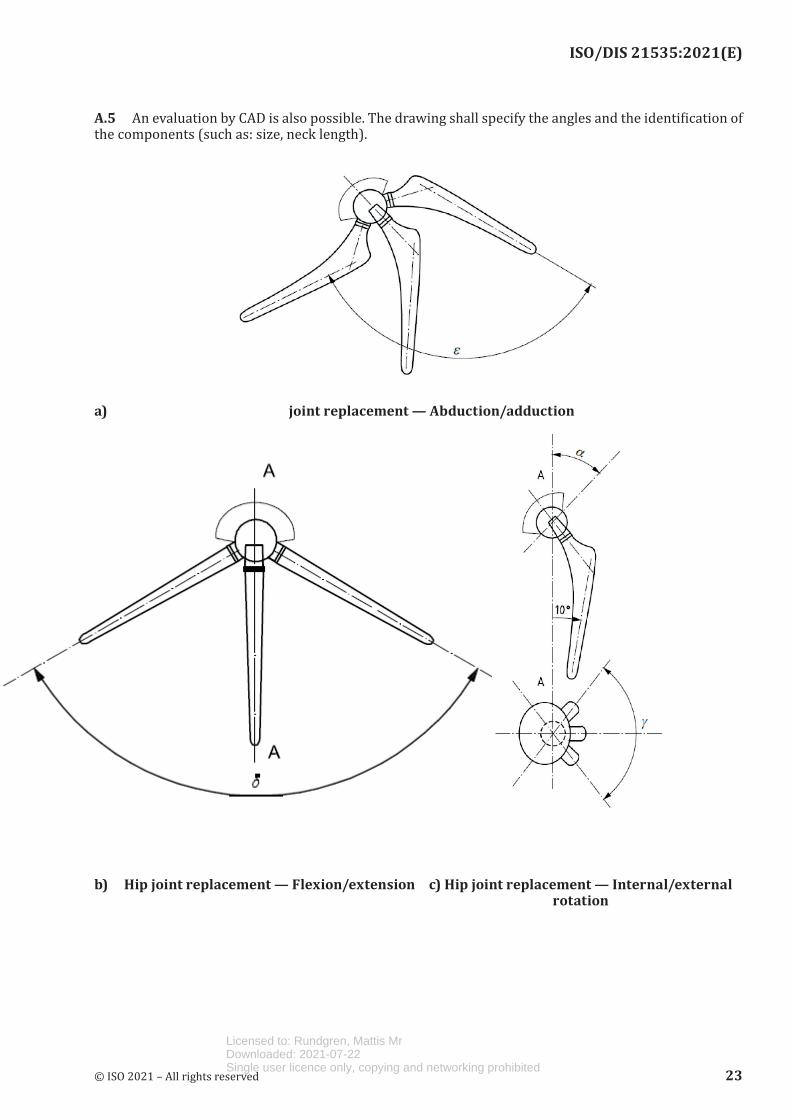
ISO/DIS 21535:2021(E)
A.5 An evaluation by CAD is also possible. The drawing shall specify the angles and the identification of the components (such as: size, neck length).
a) joint replacement — Abduction/adduction
b) Hip joint replacement — Flexion/extension c) Hip joint replacement — Internal/external rotation
© ISO 2021 – All rights reserved 23
Licensed to: Rundgren, Mattis MrDownloaded: 2021-07-22Single user licence only, copying and networking prohibited
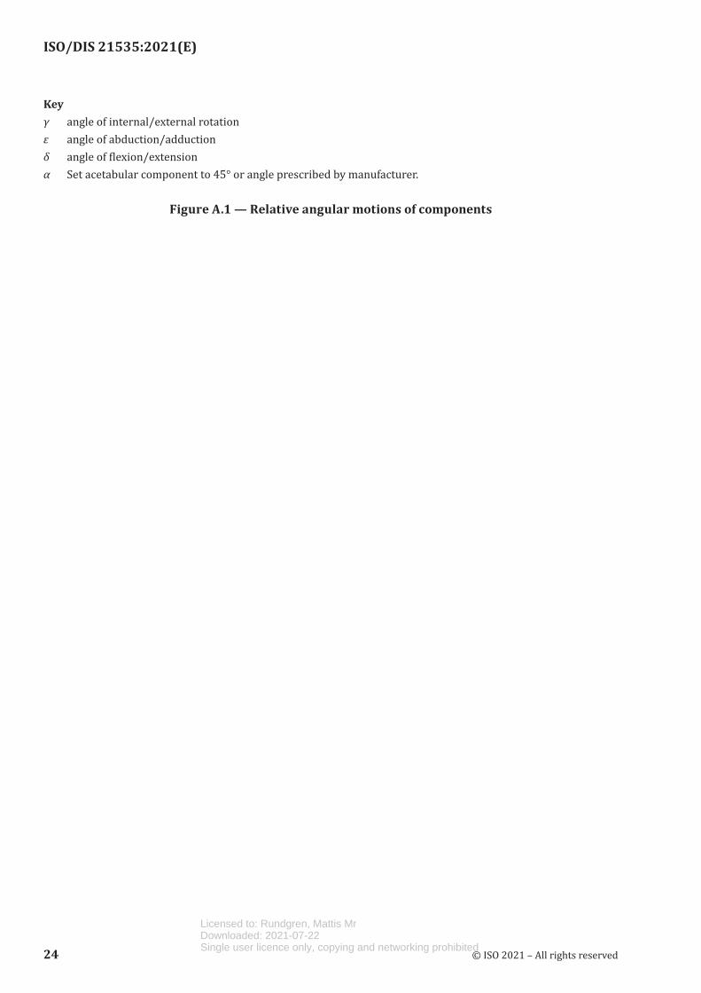
ISO/DIS 21535:2021(E)
Keyγ angle of internal/external rotationε angle of abduction/adductionδ angle of flexion/extensionα Set acetabular component to 45° or angle prescribed by manufacturer.
Figure A.1 — Relative angular motions of components
24 © ISO 2021 – All rights reserved
Licensed to: Rundgren, Mattis MrDownloaded: 2021-07-22Single user licence only, copying and networking prohibited
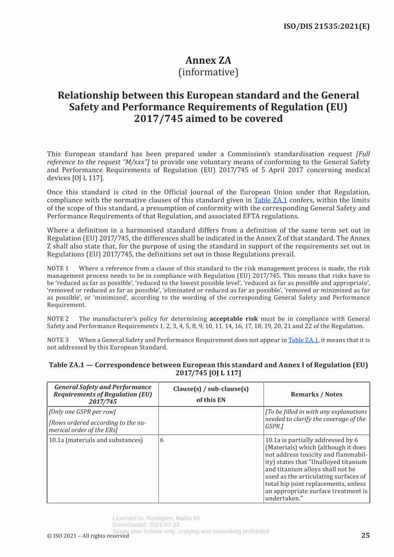
ISO/DIS 21535:2021(E)
Annex ZA (informative)
Relationship between this European standard and the General
Safety and Performance Requirements of Regulation (EU) 2017/745 aimed to be covered
This European standard has been prepared under a Commission’s standardisation request [Full reference to the request “M/xxx”] to provide one voluntary means of conforming to the General Safety and Performance Requirements of Regulation (EU) 2017/745 of 5 April 2017 concerning medical devices [OJ L 117].
Once this standard is cited in the Official Journal of the European Union under that Regulation, compliance with the normative clauses of this standard given in Table ZA.1 confers, within the limits of the scope of this standard, a presumption of conformity with the corresponding General Safety and Performance Requirements of that Regulation, and associated EFTA regulations.
Where a definition in a harmonised standard differs from a definition of the same term set out in Regulation (EU) 2017/745, the differences shall be indicated in the Annex Z of that standard. The Annex Z shall also state that, for the purpose of using the standard in support of the requirements set out in Regulations (EU) 2017/745, the definitions set out in those Regulations prevail.
NOTE 1 Where a reference from a clause of this standard to the risk management process is made, the risk management process needs to be in compliance with Regulation (EU) 2017/745. This means that risks have to be ‘reduced as far as possible’, ‘reduced to the lowest possible level’, ‘reduced as far as possible and appropriate’, ‘removed or reduced as far as possible’, ‘eliminated or reduced as far as possible’, ’removed or minimized as far as possible’, or ‘minimized’, according to the wording of the corresponding General Safety and Performance Requirement.
NOTE 2 The manufacturer’s policy for determining acceptable risk must be in compliance with General Safety and Performance Requirements 1, 2, 3, 4, 5, 8, 9, 10, 11, 14, 16, 17, 18, 19, 20, 21 and 22 of the Regulation.
NOTE 3 When a General Safety and Performance Requirement does not appear in Table ZA.1, it means that it is not addressed by this European Standard.
Table ZA.1 — Correspondence between European this standard and Annex I of Regulation (EU) 2017/745 [OJ L 117]
General Safety and Performance Requirements of Regulation (EU)
2017/745
Clause(s) / sub-clause(s)of this EN
Remarks / Notes
[Only one GSPR per row]
[Rows ordered according to the nu-merical order of the ERs]
[To be filled in with any explanations needed to clarify the coverage of the GSPR.]
10.1a (materials and substances) 6 10.1a is partially addressed by 6 (Materials) which (although it does not address toxicity and flammabil-ity) states that “Unalloyed titanium and titanium alloys shall not be used as the articulating surfaces of total hip joint replacements, unless an appropriate surface treatment is undertaken.”
© ISO 2021 – All rights reserved 25
Licensed to: Rundgren, Mattis MrDownloaded: 2021-07-22Single user licence only, copying and networking prohibited
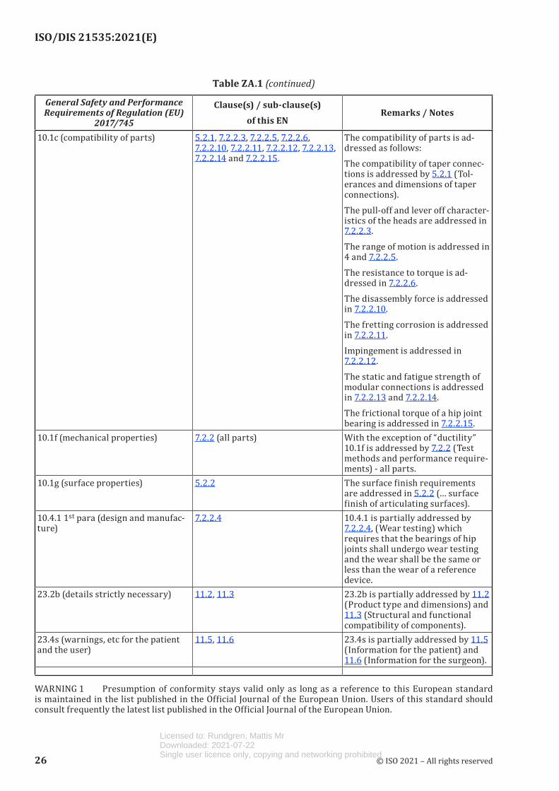
ISO/DIS 21535:2021(E)
General Safety and Performance Requirements of Regulation (EU)
2017/745
Clause(s) / sub-clause(s)of this EN
Remarks / Notes
10.1c (compatibility of parts) 5.2.1, 7.2.2.3, 7.2.2.5, 7.2.2.6, 7.2.2.10, 7.2.2.11, 7.2.2.12, 7.2.2.13, 7.2.2.14 and 7.2.2.15.
The compatibility of parts is ad-dressed as follows:The compatibility of taper connec-tions is addressed by 5.2.1 (Tol-erances and dimensions of taper connections).The pull-off and lever off character-istics of the heads are addressed in 7.2.2.3.The range of motion is addressed in 4 and 7.2.2.5.The resistance to torque is ad-dressed in 7.2.2.6.The disassembly force is addressed in 7.2.2.10.The fretting corrosion is addressed in 7.2.2.11.Impingement is addressed in 7.2.2.12.The static and fatigue strength of modular connections is addressed in 7.2.2.13 and 7.2.2.14.The frictional torque of a hip joint bearing is addressed in 7.2.2.15.
10.1f (mechanical properties) 7.2.2 (all parts) With the exception of “ductility” 10.1f is addressed by 7.2.2 (Test methods and performance require-ments) - all parts.
10.1g (surface properties) 5.2.2 The surface finish requirements are addressed in 5.2.2 (… surface finish of articulating surfaces).
10.4.1 1st para (design and manufac-ture)
7.2.2.4 10.4.1 is partially addressed by 7.2.2.4, (Wear testing) which requires that the bearings of hip joints shall undergo wear testing and the wear shall be the same or less than the wear of a reference device.
23.2b (details strictly necessary) 11.2, 11.3 23.2b is partially addressed by 11.2 (Product type and dimensions) and 11.3 (Structural and functional compatibility of components).
23.4s (warnings, etc for the patient and the user)
11.5, 11.6 23.4s is partially addressed by 11.5 (Information for the patient) and 11.6 (Information for the surgeon).
WARNING 1 Presumption of conformity stays valid only as long as a reference to this European standard is maintained in the list published in the Official Journal of the European Union. Users of this standard should consult frequently the latest list published in the Official Journal of the European Union.
Table ZA.1 (continued)
26 © ISO 2021 – All rights reserved
Licensed to: Rundgren, Mattis MrDownloaded: 2021-07-22Single user licence only, copying and networking prohibited
ISO/DIS 21535:2021(E)
WARNING 2 Other Union legislation may be applicable to the product(s) falling within the scope of this standard.
© ISO 2021 – All rights reserved 27
Licensed to: Rundgren, Mattis MrDownloaded: 2021-07-22Single user licence only, copying and networking prohibited
ISO/DIS 21535:2021(E)
Bibliography
[1] ISO 5834-3, Implants for surgery — Ultra-high-molecular-weight polyethylene — Part 3: Accelerated ageing methods
[2] ISO 10993-1, Biological evaluation of medical devices – Part 1: Evaluation and testing within a risk management process
[3] ISO 13179-1, Implants for surgery — Plasma-sprayed unalloyed titanium coatings on metallic surgical implants — Part 1: General requirements
[4] ISO 13779-2, Implants for surgery — Hydroxyapatite — Part 2: Thermally sprayed coatings of hydroxyapatite
[5] ASTM F1609, Standard Specification for Calcium Phosphate Coatings for Implantable Materials
[6] ASTM F1814, Standard guide for evaluating modular hip and knee joint components
[7] ASTM F1854, Standard Test Method for Stereological Evaluation of Porous Coatings on Medical Implants
[8] ASTM F2003, Standard Practice for Accelerated Aging of Ultra-High Molecular Weight Polyethylene after Gamma Irradiation in Air
[9] ASTM F2068, Femoral Prostheses – Metallic Implants
[10] ASTM F2091, Acetabular Prostheses
[11] ASTM F2943, Standard Guide for Presentation of End User Labeling Information for Musculoskeletal Implants
[12] ASTM F2996, Standard Practice for Finite Element Analysis (FEA) of Non-Modular Metallic Orthopaedic Hip Femoral Stems
[13] ASTM F3129, Standard Guide for Characterization of Material Loss from Conical Taper Junctions in Total Joint Prostheses
[14] ASTM WK60713, (Revision of ASTM F1875) Standard Practice for Fretting Corrosion Testing of Modular Implant Interfaces: Hip Femoral Modular Head/Taper Junctions including an Accelerated method
[15] Guidance FDA, Document for the Preparation of Premarket Notification for Ceramic Ball Hip Systems, January 1995.
[16] Guidance Document FDA, “Guidance Document for Testing Orthopedic Implants with Modified Metallic Surfaces Apposing Bone or Bone Cement, April 1994”
[17] FDA Guidance Documents for, “510(k) Information needed for Hydroxyapatite Coated Orthopedic Implants”
28 © ISO 2021 – All rights reserved
Licensed to: Rundgren, Mattis MrDownloaded: 2021-07-22Single user licence only, copying and networking prohibited
Related Documents


![Sterilization of Surgical Implants: Did You Know… Surgical Implants1106.pdf · ‘implants’.” [21 CFR 812.3(d)].2 Ideally, implants and implantable devices should come indivdual](https://static.cupdf.com/doc/110x72/5e55ceb061dfae6379651fb0/sterilization-of-surgical-implants-did-you-know-surgical-aimplantsaa.jpg)