BULLETIN 20.00-2 FEBRUARY 2012 DeZURIK 3-WAY AND 4-WAY PTW/PFW VALVES TECHNICAL SPECIFICATIONS

Welcome message from author
This document is posted to help you gain knowledge. Please leave a comment to let me know what you think about it! Share it to your friends and learn new things together.
Transcript
BULLETIN 20.00-2
FEBRUARY 2012
DeZURIK 3-WAY AND 4-WAY PTW/PFW VALVES
TECHNICAL SPECIFICATIONS
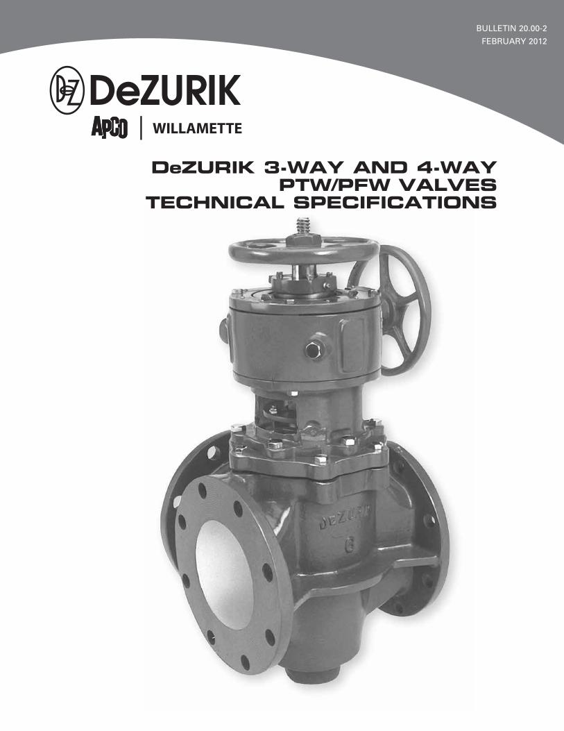
General SpecificationsStyle: 3- and 4-Way Tapered Plug Valves.
Materials: Cast Iron, ASTM A126, Class B Aluminum, ASTM B26, Alloy 713.0 Carbon Steel, ASTM A216, Grade WCB 316 Stainless Steel, ASTM A351, CF8M Cast Iron body with hard natural rubber lining. Flange faces and all internal surfaces are lined.
Sizes: 3–16" (80–400mm)
End Connections:ANSI Class 150 flanged Flanged with BS4504 and DIN, PN 10 drilling Flanged with BS4504 and DIN, PN 16 drilling Flanged, Class 150 BS Table D Flanged, Class 150 BS Table E Flanged, Class 150, JIS 10
Body Rating: 125 psi (861 kPa) C.W.P. non-shock working pressure rating.
Packing: Acrylonitrile Butadiene, to -20° to 250°F (-29 to 121°C) PTFE, -50° to +450°F (-46° to 232°C) Non-Asbestos Square Braided Fiberglass, to 1000°F (538°C)
Plug Styles:Single Style PlugStandard in all 3-Way valves to provide straight through and 90° flow combinations.
Double Style Plug Available in all 3-Way valves to provide 90° flow combinations.
Transfer Style PlugStandard in all 4-Way valves to provide 90° flow combinations.
Plug Facings:Metal plug, furnished in the same material as the valve body, except cast iron which has a stainless steel plug.
Chloroprene (CR), generally recommended for alkaline services to 180°F (82°C).
Acrylonitrile Butadiene (NBR), generally recommended for temperatures to 180°F (82°C).
Chloro-Sulfonyl Polyethylene (CSM), generally recommended for oxidizing services to 200°F (93°C).
Hard Natural Rubber (NRH), generally recommended for chlorine services.
Chloro-Isobutene-Isoprene (CIIR), generally recommended for temperatures to 250°F (121°C).
Fluoro Rubber (FKM), recommended for general chemical service at elevated temperatures.
Hard Natural Rubber (NRCR) with soft rubber chloroprene plug overlay (CR) for dead-tight shutoff with lever or double handwheel actuators.
Shutoff: Resilient plug facings provide dead-tight shutoff when used with lift, turn, reseat levers or handwheel actuators.
Valves with all-metal or hard rubber plugs do not provide drip-tight shutoff. A soft rubber overlay can be furnished on hard rubber plugs to provide dead-tight shutoff in valves with lever or lift, turn, reseat double handwheel actuators.
Bearings: Hard rubber lined valves are furnished with hard rubber bearings; all other valves are furnished with 316 stainless steel bearings.
Options: 316 Stainless Steel Plug, ASTM A743, CF8M
2 © 2012 DeZURIK
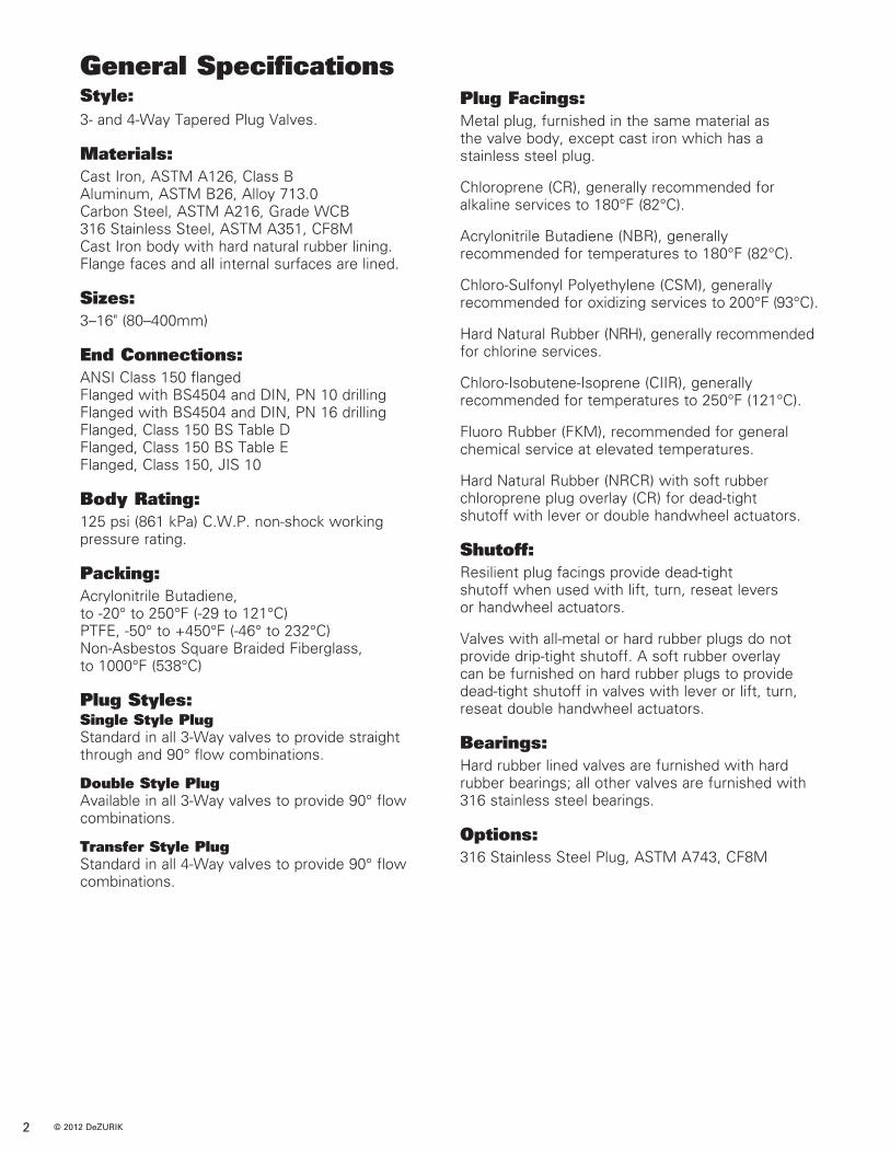
Flow Combinations
Combination 0
Combination 1For tight shutoff, it is recommended that the flow be against the back side of the plug.
Combination 2 For tight shutoff, it is recommended that the flow be against the back side of the plug.
Combination 3For tight shutoff, it is recommended that the flow be against the back side of the plug.
Combination 4 For tight shutoff, it is recommended that the higher pressure be from port flange number 1.
Valve Selection
Cv values = flow in GPM of water at 1 psi pressure drop, in 3-Way valves with flow between ports one and three.Kv values = flow in m3/hr. of water at 100 kPa pressure drop.* Cv/Kv value in 3- or 4-Way valves when flow turns 90° in the valve (flow through adjacent ports).
Pressure RatingsCWP non-shock working pressure rating of all 3- and 4-Way valves is 125 psi (861 kPa). The maximum shutoff pressure differential must not exceed the units shown for each actuator type.
Size
Note: Cylinders are sized for full 125 CWP rating.
*Higher maximum shutoff pressure differential available on application.
Actuator Type
Lever
Single Handwheel/Chainwheel
Double Handwheel/Chainwheel
Cylinder
Electric Motor
Max. Shutoff Pressure Differential
3–6" 125 psi 35 psi 80–150mm 861 kPa 241 kPa
8 & 10" 100 psi 35 psi 200 & 250mm 689 kPa 241 kPa
3–16" 35 psi* 35 psi 80–400mm 241 kPa 241 kPa
3–16" 125 psi 35 psi 80–400mm 861 kPa 241 kPa
3–16" 35 psi* 35 psi 80–400mm 241 kPa 241 kPa
3–16" 35 psi* 35 psi 80–400mm 241 kPa 241 kPa
4-Way3-Way
Combination Port Plug Plug Travel Number Open Style Rotation Stops
0 – All 360° No
1 1 Single 90° Yes
2 2 Double 90° Yes
3 3 Single 90° Yes
4 – Transfer 90° Yes
Combination Number
3" 240 195 80mm 208 169
4" 390 316 100mm 337 273
5" 900 730 125mm 780 630
6" 900 730 150mm 780 630
8" 1550 1255 200mm 1340 1090
10" 2550 2065 250mm 2210 1790
12" 3600 2915 300mm 3110 2520
14" 4100 3320 350mm 3550 2870
16" 6250 5065 400mm 5410 4380
Straight Through Flow Cv/Kv
Valve Size
90° Flow*Cv/Kv
Cv/Kv Values
DeZURIK 3- and 4-Way Plug Valves are designed and/or tested to meet the following standards: ANSI B16.1 Hydrostatic Testing
ANSI B16.1 and Flange Connection DrillingANSI B16.5
JIS 10; DIN 10,16; Foreign Standards for flange boltingBS IO-D,E,F
ISA-A39.2 Standard Control Valve Capacity Test Procedures for Incompressible Fluids
Applicable Standards
3
3-Way 4-Way
1
2
1
2
3
1
2
3
1
2
3
1
2
3
1
2
3
1
2
3
1
2
3
1
2
3
1
2
3
4 4
3
4
4
AccessoriesAdd to valve and actuator weight.
Extension Fittings for Lever Actuated Valves (CODE EL)Fittings Only = 10 lbs (5 kg) Extension Pipe/Per Foot = 4 lbs (2 kg)
Floorstand for Lever Actuated Valves (CODE FS)Floorstand Only = 95 lbs (43 kg) Extension Pipe/Per Foot = 4 lbs (2 kg)
Floorstand for Handwheel Actuated Valves (CODE FSDI)Floorstand Only = 95 lbs (43 kg) Extension Rod (Code ER)/Per Foot = 2 lbs (1 kg)
Solenoid Valve (CODE 4V) = 7 lbs (3 kg)
Position Indicating Switch (CODE SE) = 6 lbs (3kg)
Control Station Pneumatic (CODE CNP) = 8 lbs (4 kg)
3 & 4" 3 80 & 100mm 1
5 & 6" 4 125 & 150mm 2
8 & 10" 5 200 & 250mm 2
12" 8 300mm 4
14 & 16" 10 350 & 400mm 5
Weight lbs/kg
Valve Size
Levers
Valve for Lever OperationAdd weights of all other actuators as shown below.
3" 55 65 25 32 80mm 25 29 11 15
4" 105 125 50 60 100mm 48 57 23 27
5" 160 175 100 110 125mm 73 79 45 50
6" 165 180 110 125 150mm 75 82 50 57
8" 250 275 125 135 200mm 113 125 57 61
10" 370 430 240 300 250mm 168 195 109 136
12" 500 560 300 360 300mm 227 254 136 163
14" 650 715 360 425 360mm 295 324 163 193
16" 1070 1120 650 700 400mm 485 508 295 318
ValveSize
Cast Iron, Carbon Steeland Stainless Steel Aluminum
4-Way 4-Way 3-Waylbs/kg lbs/kg
3-Way
ValveSize
Single Handwheel
Double Handwheel
Single Chainwheel*
Double Chainwheel*
On-OffCylinder
Cylinder with Positioner
ActuatorsAdd valve weights above.
* Chain for chainwheel actuators — 0.5 lbs (0.2 kg) per foot.Note: Net weight in pounds (kilograms) — Weights are approximate and do not include crating.
3" 55 62 66 84 72 84 80mm 25 28 30 38 33 38
4" 58 75 69 97 93 105 100mm 26 34 31 44 42 48
5 & 6" 58 75 69 97 115 127 125 & 150mm 26 34 31 44 52 58
8" 63 70 79 97 115 127 200mm 29 32 36 44 52 58
10" 166 177 182 209 250 262 250mm 75 80 83 95 113 119
12" 183 194 220 247 250 262 300mm 83 88 100 112 113 119
14" 183 194 220 241 310 322 360mm 83 88 100 109 141 146
16" 186 197 223 250 310 322 400mm 84 89 101 113 141 146
lbs/kg
Weights
OrderingTo order, simply complete the valve order code from the information shown. An ordering example is shown for your reference.
Packing Give packing code as follows:6 = Acrylonitrile-Butadiene -20ºF to 250ºF (-29ºC to 121ºC) Standard in all valves except cast iron hard rubber lined bodies (CIH)7 = PTFE -50° to 450°F (-46° to 233°C)8 = Fiberglass, Braided to 1000°F (540°C)
Valve StyleGive valve style code as follows:PTW = Plug 3-WayPFW = Plug 4-Way
Valve SizeGive valve size code as follows: 3 = 3" 80mm 10 = 10" 250mm
4 = 4" 100mm 12 = 12" 300mm
5 = 5" 125mm 14 = 14" 350mm
6 = 6" 150mm 16 = 16" 400mm
8 = 8" 200mm
End ConnectionGive valve size code as follows:F1 = Flanged, ANSI Class 150
F110 = Flanged, Class 150, DIN 10 or BS 4504/10
F116 = Flanged, Class 150, DIN 16 or BS 4504/16
F1D = Flanged, Class 150, BS Table D
F1E = Flanged, Class 150, BS Table E
F1J1 = Flanged, Class 150, JIS 10
Body MaterialGive body material code as follows:CI = Cast Iron
AL = Aluminum
CS = Carbon Steel
S2 = 316 Stainless Steel
CIH = Cast Iron, Hard Rubber Lined
Note: CIH bodies available with NRH or NRCR plug facing only.
Plug StyleGive plug style code as follows: 3-Way Valves 4 Way Valves
S = Single T = Transfer
D = Double
Combination Number 3-Way Valves 4-Way Valves
0 = Combination 0 0 = Combination 0
1 = Combination 1 4 = Combination 4
2 = Combination 2*
3 = Combination 3
Note: Combination 0 available with cylinder actuators on application. *Combination 2 requires double plug style.
Plug FacingGive plug facing code as follows:M = Metal (Same material as body except cast iron which has a stainless steel plug.)CR = Chloroprene to -20° to 180°F (-29 to 83°C)NRH = Hard Natural Rubber Plug facing for Cast Iron Hard Rubber Lined Valves (CIH) to -20° to 180°F (-29° to 83°C)CIIR = Chloro-Isobutene-Isoprene to -20° to 250°F (-29° to 121°C)NBR = Acrylonitrile-Butadiene to -20° to 180°F (-29° to 83°C)CSM = Chloro-Sulfonyl Polyethylene to -20° to 200°F (-29° to 94°C)FKM = Fluoro Rubber to -20° to 450°F (-29° to 232°C)NRCR = Hard natural rubber with soft Chloroprene overlay (CIH bodies only) to -20° to 180°F (-29° to 83°C)
Note: Cylinder actuators should be used with metal plugs. Cylinders are not recommended for use with resilient faced plugs. GS actuators are not available with resilient faced plugs.
OptionsGive options codes as follows:ARRA = Conform to: American Recovery and Reinvestment Act of 2009,
Buy American, Section 1605, Use of American Iron, Steel and Manufactured Goods
DST = Dry Seat Test S2 = 316 Stainless Steel Plug
Actuators & AccessoriesAll actuators must be ordered by adding the actuator code to the basicvalve order code. Refer to the following pages for descriptions and ordering information.
Ordering Example:PTW,4,F1,CI,6,S-1-M*
5
Note: The limiting factor in valve selection is the lowest temperature limit
of the packing or seat.
6
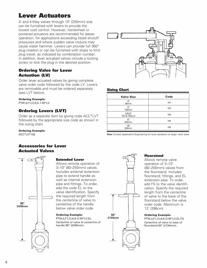
Lever Actuators3- and 4-Way valves through 10" (250mm) size can be furnished with levers to provide the lowest cost control. However, handwheel or powered actuators are recommended for easier operation, for applications exceeding listed shutoff pressures and where sudden valve closure may cause water hammer. Levers can provide full 360° plug rotation or can be furnished with stops to limit plug travel, as indicated by combination number. In addition, lever actuated valves include a locking screw to lock the plug in the desired position.
Ordering Valve for Lever Actuation (LV)Order lever actuated valves by giving complete valve order code followed by the code LV. Levers are removable and must be ordered separately (see LVT below).
Ordering Example:PTW,4,F1,CI,6,S-1-M*LV
Ordering Levers (LVT)Order as a separate item by giving code ACC*LVT followed by the appropriate size code as shown in the sizing chart.
Ordering Example: ACC*LVT102
Accessories for Lever Actuated Valves
Extended LeverAllows remote operation of 3–10" (80–250mm) valves. Includes external extension pipe to extend handle as well as internal extension pipe and fittings. To order, add the code EL to the valve identification. Specify the required length from the centerline of valve to centerline of the handle below valve order code.
Ordering Example:PTW,4,F1,CI,6,S-O-M*LV,EL Centerline of valve to centerline of handle 96" (2438mm).
FloorstandAllows remote valve operation of 3–10" (80–250mm) valves from the floorstand. Includes floorstand, fittings, and EL extension pipe. To order, add FS to the valve identifi-cation. Specify the required length from the centerline of valve to the base of the floorstand below the valve order code. Maximum is 13' (396cm).
Ordering Example:PTW,4,F1,CI,6,S-O-M*LV,EL,FSCenterline of valve to base of floorstand 84" (2134mm).
Code
101
102
103
104
105
Sizing Chart
Valve Size3"
80mm
4"100mm
5 & 6"125 & 150mm
8"200mm
10"250mm
Note: Contact Application Engineering for lever actuators on larger valve sizes.
96" 2438mm
84" 2134mm
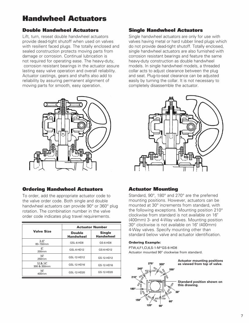
Handwheel Actuators
Actuator MountingStandard, 90°, 180° and 270° are the preferred mounting positions. However, actuators can be mounted at 30° increments from standard, with the following exceptions. Mounting position 210° clockwise from standard is not available on 16" (400mm) 3- and 4-Way valves. Mounting position 30° clockwise is not available on 16" (400mm) 4-Way valves. Specify mounting other than standard below valve and actuator identification.
Ordering Example: PTW,4,F1,CI,6,S-1-M*GS-6-HD8 Actuator mounted 90° clockwise from standard.
Valve SizeActuator Number
DoubleHandwheel
SingleHandwheel
3–6"80–150mm
8"200mm
10"250mm
12 & 14"300 & 350mm
16"400mm
GSL-6-HD8
GSL-6-HD12
GSL-12-HD12
GSL-12-HD16
GSL-12-HD20
GS-6-HD8
GS-6-HD12
GS-12-HD12
GS-12-HD16
GS-12-HD20
Double Handwheel ActuatorsLift, turn, reseat double handwheel actuators provide dead-tight shutoff when used on valves with resilient faced plugs. The totally enclosed and sealed construction protects moving parts from damage or corrosion. Continual lubrication is not required for operating ease. The heavy-duty, corrosion resistant bearings in the actuator assure lasting easy valve operation and overall reliability. Actuator castings, gears and shafts also add to reliability by assuring permanent alignment of moving parts for smooth, easy operation.
Ordering Handwheel ActuatorsTo order, add the appropriate actuator code to the valve order code. Both single and double handwheel actuators can provide 90° or 360° plug rotation. The combination number in the valve order code indicates plug travel requirements.
Single Handwheel ActuatorsSingle handwheel actuators are only for use with valves having metal or hard rubber lined plugs which do not provide dead-tight shutoff. Totally enclosed, single handwheel actuators are also furnished with corrosion resistant bearings and feature the same heavy-duty construction as double handwheel models. In single handwheel models, a threaded collar acts to adjust clearance between the plug and seat. Plug-to-seat clearance can be adjusted easily by turning the collar. It is not necessary to completely disassemble the actuator.
7
Actuator mounting positions as viewed from top of valve.
Standard position shown on this drawing.
3" 13.75 80mm 349
4" 14.38 100mm 365
6" 15.88 150mm 403
8" 17.38 200mm 442
10" 18.75 250mm 476
12" 19.75 300mm 502
14" 21.25 350mm 540
16" 23.63 400mm 600
Min. C/L Valve to Top of FlangeValve Size
InchMillimeter
8
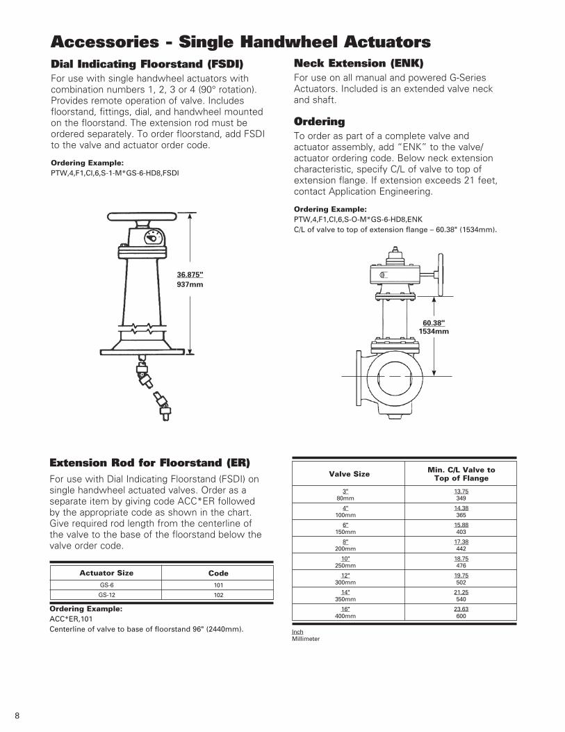
Accessories - Single Handwheel ActuatorsDial Indicating Floorstand (FSDI)For use with single handwheel actuators with combination numbers 1, 2, 3 or 4 (90° rotation). Provides remote operation of valve. Includes floorstand, fittings, dial, and handwheel mounted on the floorstand. The extension rod must be ordered separately. To order floorstand, add FSDI to the valve and actuator order code.
Ordering Example: PTW,4,F1,CI,6,S-1-M*GS-6-HD8,FSDI
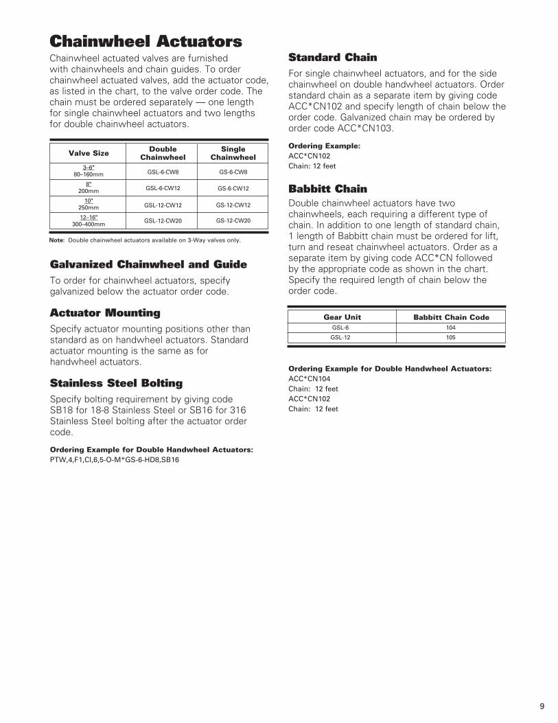
Neck Extension (ENK) For use on all manual and powered G-Series Actuators. Included is an extended valve neck and shaft.
OrderingTo order as part of a complete valve and actuator assembly, add “ENK” to the valve/actuator ordering code. Below neck extension characteristic, specify C/L of valve to top of extension flange. If extension exceeds 21 feet, contact Application Engineering.
Ordering Example: PTW,4,F1,CI,6,S-O-M*GS-6-HD8,ENKC/L of valve to top of extension flange – 60.38" (1534mm).
Extension Rod for Floorstand (ER) For use with Dial Indicating Floorstand (FSDI) on single handwheel actuated valves. Order as a separate item by giving code ACC*ER followed by the appropriate code as shown in the chart. Give required rod length from the centerline of the valve to the base of the floorstand below the valve order code.
Ordering Example: ACC*ER,101 Centerline of valve to base of floorstand 96" (2440mm).
GS-6
GS-12
101
102
Actuator Size Code
36.875"937mm
60.38" 1534mm
Chainwheel ActuatorsChainwheel actuated valves are furnished with chainwheels and chain guides. To order chainwheel actuated valves, add the actuator code, as listed in the chart, to the valve order code. The chain must be ordered separately — one length for single chainwheel actuators and two lengths for double chainwheel actuators.
Valve Size Double Chainwheel
3–6"80–160mm
8"200mm
10"250mm
12–16"300–400mm
Single Chainwheel
GSL-6-CW8
GSL-6-CW12
GSL-12-CW12
GSL-12-CW20
GS-6-CW8
GS-6-CW12
GS-12-CW12
GS-12-CW20
Note: Double chainwheel actuators available on 3-Way valves only.
Galvanized Chainwheel and GuideTo order for chainwheel actuators, specify galvanized below the actuator order code.
Actuator MountingSpecify actuator mounting positions other than standard as on handwheel actuators. Standard actuator mounting is the same as for handwheel actuators.
Stainless Steel BoltingSpecify bolting requirement by giving code SB18 for 18-8 Stainless Steel or SB16 for 316 Stainless Steel bolting after the actuator order code.
Ordering Example for Double Handwheel Actuators:PTW,4,F1,CI,6,5-O-M*GS-6-HD8,SB16
Standard ChainFor single chainwheel actuators, and for the side chainwheel on double handwheel actuators. Order standard chain as a separate item by giving code ACC*CN102 and specify length of chain below the order code. Galvanized chain may be ordered by order code ACC*CN103.
Ordering Example: ACC*CN102Chain: 12 feet
Babbitt ChainDouble chainwheel actuators have two chainwheels, each requiring a different type of chain. In addition to one length of standard chain, 1 length of Babbitt chain must be ordered for lift, turn and reseat chainwheel actuators. Order as a separate item by giving code ACC*CN followed by the appropriate code as shown in the chart. Specify the required length of chain below the order code.
Ordering Example for Double Handwheel Actuators:ACC*CN104 Chain: 12 feet ACC*CN102 Chain: 12 feet
GSL-6 104
GSL-12 105
Gear Unit Babbitt Chain Code
9
10
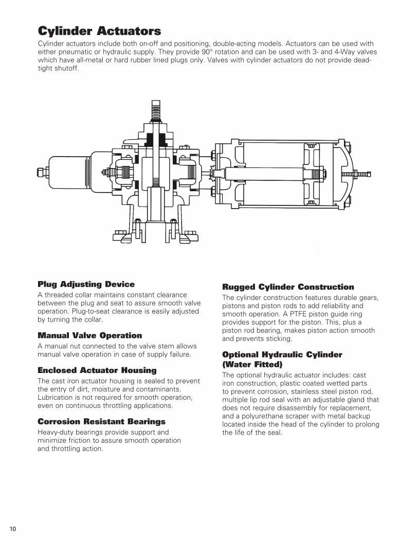
Cylinder ActuatorsCylinder actuators include both on-off and positioning, double-acting models. Actuators can be used with either pneumatic or hydraulic supply. They provide 90° rotation and can be used with 3- and 4-Way valves which have all-metal or hard rubber lined plugs only. Valves with cylinder actuators do not provide dead-tight shutoff.
Rugged Cylinder ConstructionThe cylinder construction features durable gears, pistons and piston rods to add reliability and smooth operation. A PTFE piston guide ring provides support for the piston. This, plus a piston rod bearing, makes piston action smooth and prevents sticking.
Optional Hydraulic Cylinder (Water Fitted)The optional hydraulic actuator includes: cast iron construction, plastic coated wetted parts to prevent corrosion, stainless steel piston rod, multiple lip rod seal with an adjustable gland that does not require disassembly for replacement, and a polyurethane scraper with metal backup located inside the head of the cylinder to prolong the life of the seal.
Plug Adjusting DeviceA threaded collar maintains constant clearance between the plug and seat to assure smooth valve operation. Plug-to-seat clearance is easily adjusted by turning the collar.
Manual Valve OperationA manual nut connected to the valve stem allows manual valve operation in case of supply failure.
Enclosed Actuator HousingThe cast iron actuator housing is sealed to prevent the entry of dirt, moisture and contaminants. Lubrication is not required for smooth operation, even on continuous throttling applications.
Corrosion Resistant BearingsHeavy-duty bearings provide support and minimize friction to assure smooth operation and throttling action.
Cylinder ActuatorsOrdering Cylinder ActuatorsTo order cylinder actuators, add the actuator number from the following chart to the valve order code. Also add the code letter “A” or “B” to indicate the appropriate actuator mounting for the combination number.
Supply pressure is 50–100 psi (345–689 kPa). When ordering hydraulic actuators, specify supply media if oil or water.
Preferred mounting positions are standard, 90°, 180° and 270°. However, actuators can be mounted at 30 degree increments clockwise from standard.
Ordering Example: PTW,4,F1,CI,6,S-1-M*GS-6-PC6-AActuator mounted 180° from standard.
Sizing Chart
3" 80mm
4" 100mm
5–8" 125–200mm
10–12" 250–300mm
14–16" 350–400mm
ActuatorValve Size
GS-6-PC6
GS-6-PC6
GS-6-PC8
GS-12-PC8
GS-12-PC10
A
Code Actuator Mounting
3-Way Valves - Combination 1 with actuator mounted standard or 60°, 120°, 180°,
240° or 300° clockwise from standard.
3-Way Valves - Combination 2 or 3 with actuator mounted 30°, 90°, 150°, 210°, 270° or 330°.
B
3-Way Valves - Combination 2 or 3 with actuator mounted standard or 60°, 120°, 180°,
240° or 300° clockwise from standard.
4-Way Valves - Combination 4or
4-Way Valves - Combination 4or
3-Way Valves - Combination 1with actuator mounted 30°, 90°, 150°,
210°, 270° or 330° clockwise from standard.
11
Mounting CodeA code letter from the mounting chart must be added to the cylinder actuator ordering code. Select the appropriate code based on valve style, combination number, and actuator mounting.
Positioning Cylinder ActuatorsAccurate positioners provide precise throttling control. A variety of models are available including pneumatic, hydraulic and electronic. Positioners are enclosed and mounted on the actuator.
The unique DeZURIK method of mounting positioners eliminates backlash in the positioner feedback system. A cam mounted solidly to the plug stem and spring loaded cam follower always transmit exact plug position. Positioner feedback is directly from the valve stem. Span and zero adjustments are simple and readily accessible. High gain and high positioner capacity, along with properly sized actuators, assure pneumatic control.
OrderingTo order, specify positioner model and desired signal range by adding positioner code from the chart on page 12 to the valve and actuator order code. Also specify positioner action.
On 3-Way Valves, specify air-to-open port number (port other than the combination number).
On 4-Way Valves, air-to-open port number (2 or 4) to port number 1 (Port No. 1 is always open).
Ordering Example:PTW,4,F1,CI,6,S-1-M*GS-6-PC6-A,P36C,AFR2,GAir-to-open port number 2.3–15 psi (20–103 kPa) signal range.
12
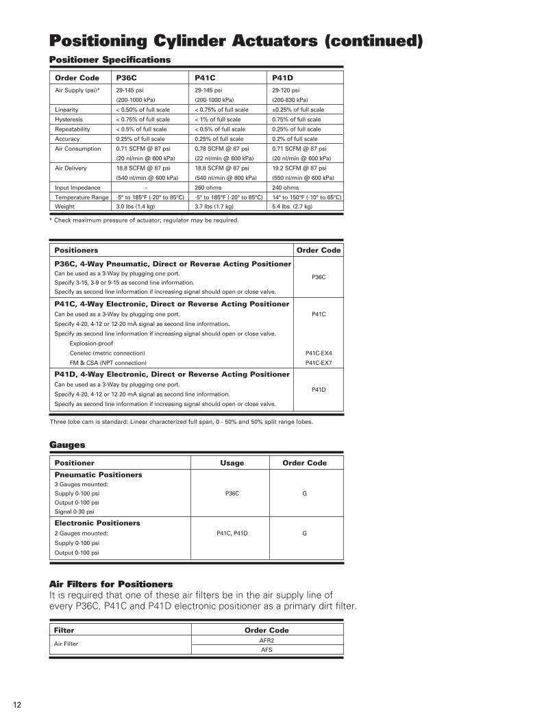
Order Code P36C P41C P41D
Air Supply (psi)* 29-145 psi 29-145 psi 29-120 psi
(200-1000 kPa) (200-1000 kPa) (200-830 kPa)
Linearity < 0.50% of full scale < 0.75% of full scale ±0.25% of full scale
Hysteresis < 0.75% of full scale < 1% of full scale 0.75% of full scale
Repeatability < 0.5% of full scale < 0.5% of full scale 0.25% of full scale
Accuracy 0.25% of full scale 0.25% of full scale 0.2% of full scale
Air Consumption 0.71 SCFM @ 87 psi 0.78 SCFM @ 87 psi 0.71 SCFM @ 87 psi
(20 nl/min @ 600 kPa) (22 nl/min @ 600 kPa) (20 nl/min @ 600 kPa)
Air Delivery 18.8 SCFM @ 87 psi 18.8 SCFM @ 87 psi 19.2 SCFM @ 87 psi
(540 nl/min @ 600 kPa) (540 nl/min @ 600 kPa) (550 nl/min @ 600 kPa)
Input Impedance - 260 ohms 240 ohms
Temperature Range -5° to 185°F (-20° to 85°C) -5° to 185°F (-20° to 85°C) 14° to 150°F (-10° to 65°C)
Weight 3.0 lbs (1.4 kg) 3.7 lbs (1.7 kg) 5.4 lbs. (2.7 kg)
Positioner Specifications
* Check maximum pressure of actuator; regulator may be required.
Positioners Order Code
P36C, 4-Way Pneumatic, Direct or Reverse Acting PositionerCan be used as a 3-Way by plugging one port.
Specify 3-15, 3-9 or 9-15 as second line information. P36C
Specify as second line information if increasing signal should open or close valve.
P41C, 4-Way Electronic, Direct or Reverse Acting PositionerCan be used as a 3-Way by plugging one port. P41C
Specify 4-20, 4-12 or 12-20 mA signal as second line information.
Specify as second line information if increasing signal should open or close valve.
Explosion-proof
Cenelec (metric connection) P41C-EX4
FM & CSA (NPT connection) P41C-EX7
P41D, 4-Way Electronic, Direct or Reverse Acting PositionerCan be used as a 3-Way by plugging one port.
Specify 4-20, 4-12 or 12-20 mA signal as second line information. P41D
Specify as second line information if increasing signal should open or close valve.
Three lobe cam is standard: Linear characterized full span, 0 - 50% and 50% split range lobes.
Air Filters for PositionersIt is required that one of these air filters be in the air supply line of every P36C, P41C and P41D electronic positioner as a primary dirt filter.
Filter Order Code
Air Filter AFR2
AFS
Gauges
Positioner Usage Order Code
Pneumatic Positioners3 Gauges mounted:
Supply 0-100 psi P36C G
Output 0-100 psi
Signal 0-30 psi
Electronic Positioners2 Gauges mounted: P41C, P41D G
Supply 0-100 psi
Output 0-100 psi
Positioning Cylinder Actuators (continued)
Accessories – Cylinder Actuators
13
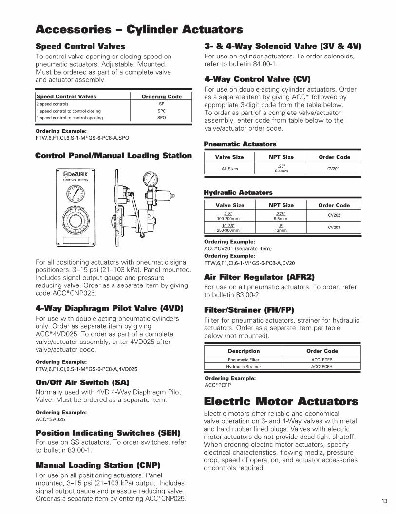
3- & 4-Way Solenoid Valve (3V & 4V)For use on cylinder actuators. To order solenoids, refer to bulletin 84.00-1.
4-Way Control Valve (CV)For use on double-acting cylinder actuators. Order as a separate item by giving ACC* followed by appropriate 3-digit code from the table below. To order as part of a complete valve/actuator assembly, enter code from table below to the valve/actuator order code.
Air Filter Regulator (AFR2)For use on all pneumatic actuators. To order, refer to bulletin 83.00-2.
Filter/Strainer (FH/FP)Filter for pneumatic actuators, strainer for hydraulic actuators. Order as a separate item per table below (not mounted).
Pneumatic Filter ACC*PCFP
Hydraulic Strainer ACC*PCFH
Description Order Code
Ordering Example: ACC*CV201 (separate item)Ordering Example: PTW,6,F1,CI,6-1-M*GS-6-PC8-A,CV20
Valve Size NPT Size Order Code
4–8" .375" 100-200mm 9.5mm
10–36" .5" 250-900mm 13mm
CV202
CV203
Hydraulic Actuators
All Sizes
.25" CV201 6.4mm
Valve Size NPT Size Order Code
Pneumatic Actuators
Electric Motor ActuatorsElectric motors offer reliable and economical valve operation on 3- and 4-Way valves with metal and hard rubber lined plugs. Valves with electric motor actuators do not provide dead-tight shutoff. When ordering electric motor actuators, specify electrical characteristics, flowing media, pressure drop, speed of operation, and actuator accessories or controls required.
Ordering Example: ACC*PCFP
2 speed controls
1 speed control to control closing
1 speed control to control opening
Speed Control ValvesSP
SPC
SPO
Ordering Code
Speed Control ValvesTo control valve opening or closing speed on pneumatic actuators. Adjustable. Mounted. Must be ordered as part of a complete valve and actuator assembly.
Ordering Example:PTW,6,F1,CI,6,S-1-M*GS-6-PC8-A,SPO
Control Panel/Manual Loading Station
For all positioning actuators with pneumatic signal positioners. 3–15 psi (21–103 kPa). Panel mounted. Includes signal output gauge and pressure reducing valve. Order as a separate item by giving code ACC*CNP025.
4-Way Diaphragm Pilot Valve (4VD)For use with double-acting pneumatic cylinders only. Order as separate item by giving ACC*4VD025. To order as part of a complete valve/actuator assembly, enter 4VD025 after valve/actuator code.
Ordering Example: PTW,6,F1,CI,6,S-1-M*GS-6-PC8-A,4VD025
On/Off Air Switch (SA)Normally used with 4VD 4-Way Diaphragm Pilot Valve. Must be ordered as a separate item.
Ordering Example: ACC*SA025
Position Indicating Switches (SEH)For use on GS actuators. To order switches, refer to bulletin 83.00-1.
Manual Loading Station (CNP)For use on all positioning actuators. Panel mounted, 3–15 psi (21–103 kPa) output. Includes signal output gauge and pressure reducing valve. Order as a separate item by entering ACC*CNP025.
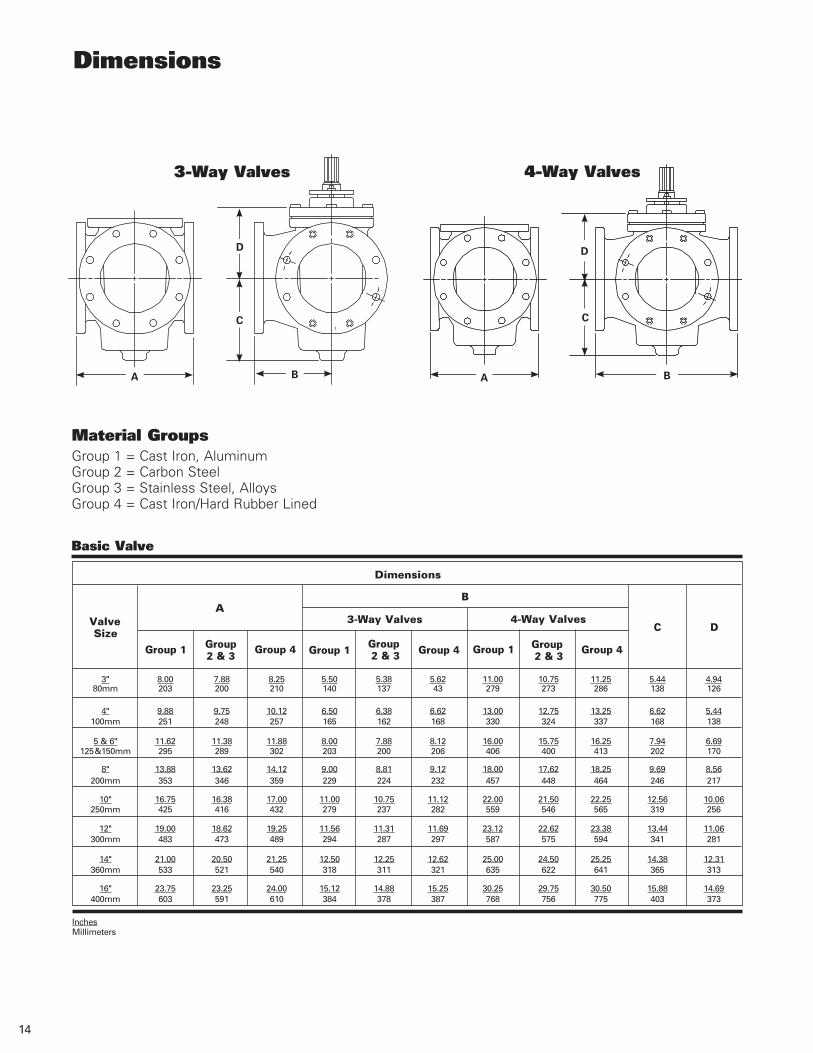
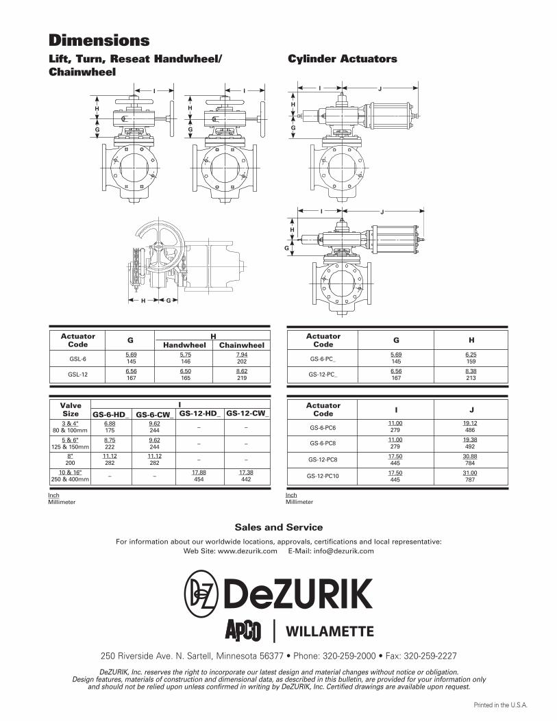
Dimensions
3-Way Valves 4-Way Valves
Material GroupsGroup 1 = Cast Iron, Aluminum Group 2 = Carbon Steel Group 3 = Stainless Steel, Alloys Group 4 = Cast Iron/Hard Rubber Lined
14
Basic Valve
InchesMillimeters
ValveSize
Dimensions
3-Way Valves 4-Way ValvesA
Group 1 Group2 & 3
Group 4 Group 1 Group 2 & 3 Group 4 Group 1 Group
2 & 3Group 4
C D
B
3" 8.00 7.88 8.25 5.50 5.38 5.62 11.00 10.75 11.25 5.44 4.94 80mm 203 200 210 140 137 43 279 273 286 138 126
4" 9.88 9.75 10.12 6.50 6.38 6.62 13.00 12.75 13.25 6.62 5.44 100mm 251 248 257 165 162 168 330 324 337 168 138
5 & 6" 11.62 11.38 11.88 8.00 7.88 8.12 16.00 15.75 16.25 7.94 6.69
125 & 150mm 295 289 302 203 200 206 406 400 413 202 170
8" 13.88 13.62 14.12 9.00 8.81 9.12 18.00 17.62 18.25 9.69 8.56 200mm 353 346 359 229 224 232 457 448 464 246 217
10" 16.75 16.38 17.00 11.00 10.75 11.12 22.00 21.50 22.25 12.56 10.06 250mm 425 416 432 279 237 282 559 546 565 319 256
12" 19.00 18.62 19.25 11.56 11.31 11.69 23.12 22.62 23.38 13.44 11.06 300mm 483 473 489 294 287 297 587 575 594 341 281
14" 21.00 20.50 21.25 12.50 12.25 12.62 25.00 24.50 25.25 14.38 12.31 360mm 533 521 540 318 311 321 635 622 641 365 313
16" 23.75 23.25 24.00 15.12 14.88 15.25 30.25 29.75 30.50 15.88 14.69 400mm 603 591 610 384 378 387 768 756 775 403 373
A B
C
D
A B
C
D
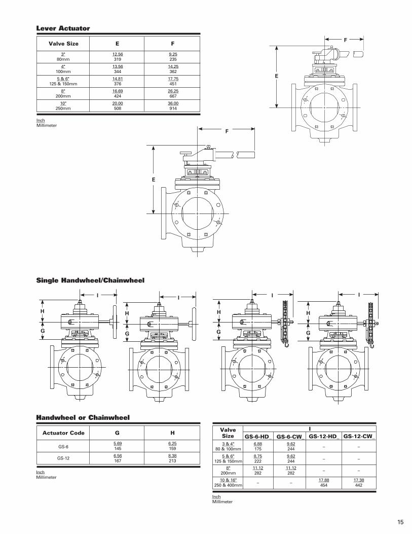
Single Handwheel/Chainwheel
InchMillimeter
15
F
F
E
E
I
H
G
I
H
G
I
H
G
I
H
G
Lever Actuator
InchMillimeter
Valve Size E
3" 12.56 9.25 80mm 319 235
4" 13.56 14.25 100mm 344 362
5 & 6" 14.81 17.75 125 & 150mm 376 451
8" 16.69 26.25 200mm 424 667
10" 20.00 36.00 250mm 508 914
F
Actuator Code G
5.69 6.25 145 159
6.56 8.38 167 213
H
Handwheel or Chainwheel
GS-6
GS-12
InchMillimeter
GS-6-CW_Valve Size GS-6-HD_
3 & 4" 6.88 9.62 – – 80 & 100mm 175 244
5 & 6" 8.75 9.62 – – 125 & 150mm 222 244
8" 11.12 11.12 –
– 200mm 282 282
10 & 16" –
– 17.88 17.38
250 & 400mm 454 442
IGS-12-CW_GS-12-HD_
InchMillimeter
GS-6-CW_Valve Size GS-6-HD_
3 & 4" 6.88 9.62 – – 80 & 100mm 175 244
5 & 6" 8.75 9.62 – – 125 & 150mm 222 244
8" 11.12 11.12 –
– 200 282 282
10 & 16" –
– 17.88 17.38
250 & 400mm 454 442
IGS-12-CW_GS-12-HD_
Cylinder ActuatorsDimensionsLift, Turn, Reseat Handwheel/Chainwheel
Actuator Code G
5.69 5,75 7.94 145 146 202
6.56 6.50 8.62 167 165 219
H
GSL-6
GSL-12
ChainwheelHandwheelActuator
Code G
5.69 6.25 145 159
6.56 8.38 167 213
H
GS-6-PC_
GS-12-PC_
InchMillimeter
Actuator Code I
11.00 19.12 279 486
11.00 19.38 279 492
17.50 30.88 445 784
17.50 31.00 445 787
J
GS-6-PC6
GS-6-PC8
GS-12-PC8
GS-12-PC10
I
H
G
I
H
G
JI
H
G
I J
H
G
H G
DeZURIK, Inc. reserves the right to incorporate our latest design and material changes without notice or obligation. Design features, materials of construction and dimensional data, as described in this bulletin, are provided for your information only
and should not be relied upon unless confirmed in writing by DeZURIK, Inc. Certified drawings are available upon request.
Printed in the U.S.A.
250 Riverside Ave. N. Sartell, Minnesota 56377 • Phone: 320-259-2000 • Fax: 320-259-2227
For information about our worldwide locations, approvals, certifications and local representative:Web Site: www.dezurik.com E-Mail: [email protected]
Sales and Service
Related Documents


![{KKKKmmmmaaaa---]]] ----©mmmm----bbb ---¯ nnnssssââââ …lfa.kerala.gov.in/docs/audit_report/panchayat/kottayam/elikkulam09_… · FenFen- ---¡pfw {Kma¡pfw {Kma¡pfw {Kma-](https://static.cupdf.com/doc/110x72/5f78fae61406ab6bec26f33c/kkkkmmmmaaaa-mmmm-bbb-nnnssss-lfa-fenfen-pfw.jpg)