PPE, 4 – 20 inch Precision Electric Control Valves and Control Stations Instruction D11014 August 2018

Welcome message from author
This document is posted to help you gain knowledge. Please leave a comment to let me know what you think about it! Share it to your friends and learn new things together.
Transcript

PPE, 4 – 20 inch Precision Electric Control Valves and Control Stations
Instruction D11014 August 2018

PPE, 4-20 inch Precision Electric Control Valves and Control Stations __________________________________________________________________________
_________________________________________________________________________________ D11014 Page 2 August 2018
Instructions These instructions provide installation, operation, and maintenance information for DeZURIK Precision Electric Control Valves. They include procedures which, when followed, help to assure satisfactory performance of these valves. All warnings and cautions included in these instructions must be followed to avoid personal injury and equipment damage. These instructions are intended for use by personnel who are responsible for installation, operation and maintenance of Precision Electric Control Valves. Refer to the Data Plate attached to the valve, and also to the Product Bulletin for information regarding materials of construction and product limitations.
Safety Messages Safety messages in these instructions and on label(s) on the valve are flagged with one of the words; Caution, Warning, or Danger. The messages must be carefully read and followed to avoid equipment damage, personal injury and/or death. Safety label(s) on the product indicate hazards that can cause equipment damage, personal injury or death. If a safety label becomes difficult to see or read, or if a label has been removed, please contact DeZURIK for replacement label(s).
Personnel involved in the installation or maintenance of valves should be constantly alert to potential emission of pipeline material and take appropriate safety precautions. Always wear suitable protection when dealing with hazardous pipeline materials. Handle valves, which have been removed from service with suitable protection for any potential pipeline material in the valve.
Inspection Your Precision Electric Control Valve has been packaged to provide protection during shipment; however, it can be damaged in transport. Carefully inspect the unit for damage upon arrival and file a claim with the carrier if damage is apparent.
Replacement Parts Recommended spare parts are listed on the assembly drawing. These parts should be stocked to minimize downtime.
Order parts from your DeZURIK sales representative, or directly from DeZURIK. When ordering parts, please include the 7-digit part number and 4-digit revision number (example: 9999999R000) located on the data plate attached to the valve assembly. Also include the part name, the assembly drawing number, the balloon number and the quantity stated on the assembly drawing.
DeZURIK Service DeZURIK service personnel are available for start-up and repair of DeZURIK products. DeZURIK also offers customized training programs and consultation services. For more information contact a DeZURIK sales representative or visit our website at www.dezurik.com.

PPE, 4 – 20 inch Precision Electric Control Valves and Control Stations
__________________________________________________________________________
_________________________________________________________________________________ August 2018 Page 3 D11014
TABLE OF CONTENTS SECTION PAGE Description - - - - - - - - - - - - - - - - - - - - - - - - - - - - - - - - - - - - - - - - - - - - - - - - - - - - - - - - - - - - - - - - - 4 Lubrication - - - - - - - - - - - - - - - - - - - - - - - - - - - - - - - - - - - - - - - - - - - - - - - - - - - - - - - - - - - - - - - - - 4 AC Power Requirements - - - - - - - - - - - - - - - - - - - - - - - - - - - - - - - - - - - - - - - - - - - - - - - - - - - - - - - 4 Alignment Tool Set- - - - - - - - - - - - - - - - - - - - - - - - - - - - - - - - - - - - - - - - - - - - - - - - - - - - - - - - - - - - 4 Installation - - - - - - - - - - - - - - - - - - - - - - - - - - - - - - - - - - - - - - - - - - - - - - - - - - - - - - - - - - - - - - - - - - 4 Self-Locking Fasteners - - - - - - - - - - - - - - - - - - - - - - - - - - - - - - - - - - - - - - - - - - - - - - - - - - - - - - - - - 4 Valve Disassembly - - - - - - - - - - - - - - - - - - - - - - - - - - - - - - - - - - - - - - - - - - - - - - - - - - - - - - - - - - - - 5 Valve Reassembly - - - - - - - - - - - - - - - - - - - - - - - - - - - - - - - - - - - - - - - - - - - - - - - - - - - - - - - - - - - 7 Motor Replacement - - - - - - - - - - - - - - - - - - - - - - - - - - - - - - - - - - - - - - - - - - - - - - - - - - - - - - - - - - - 9 Limit Switch Replacement - - - - - - - - - - - - - - - - - - - - - - - - - - - - - - - - - - - - - - - - - - - - - - - - - - - - - - 14 Potentiometer Replacement - - - - - - - - - - - - - - - - - - - - - - - - - - - - - - - - - - - - - - - - - - - - - - - - - - - - 14 Resolver Replacement - - - - - - - - - - - - - - - - - - - - - - - - - - - - - - - - - - - - - - - - - - - - - - - - - - - - - - - - 14 Control Module Replacement - - - - - - - - - - - - - - - - - - - - - - - - - - - - - - - - - - - - - - - - - - - - - - - - - - - - 15 Adjustments
Packing - - - - - - - - - - - - - - - - - - - - - - - - - - - - - - - - - - - - - - - - - - - - - - - - - - - - - - - - - - - - - - - - - 16 Closed Position Stop - - - - - - - -- - - - - - - - - - - - - - - - - - - - - - - - - - - - - - - - - - - - - - - - - - - - - - - - - 16 Closed Position Switches - - - -- - - - - - - - - - - - - - - - - - - - - - - - - - - - - - - - - - - - - - - - - - - - - - - - - 16 Open Position Switches - - - - - - - - - - - - - - - - - - - - - - - - - - - - - - - - - - - - - - - - - - - - - - - - - - - - - - 18 Potentiometer Adjustment – Using 5 Volt DC Power Supply - - - - - - - - - - - - - - - - - - - - - - - - - - - - 19 Potentiometer Adjustment – Using an Ohmmeter - - - - - - - - - - - - - - - - - - - - - - - - - - - - - - - - - - - - 21 Resolver Adjustment – Using 24 Volt DC Power Supply - - - - - - - - - - - - - - - - - - - - - - - - - - - - - - - 22 Open Position Switches, when using a Resolver - - - - - - - - - - - - - - - - - - - - - - - - - - - - - - - - - - - - 24
Control Stations Wiring - - - - - - - - - - - - - - - - - - - - - - - - - - - - - - - - - - - - - - - - - - - - - - - - - - - - - - - - - - - - - - - - - - - 26 Description of Features - - - - - - - - - - - - - - - - - - - - - - - - - - - - - - - - - - - - - - - - - - - - - - - - - - - - - - 31 Display Adjustment -- - - - - - - - - - - - - - - - - - - - - - - - - - - - - - - - - - - - - - - - - - - - - - - - - - - - - - - - - 33 Analog Station (CPE103, CPE104) - - - - - - - - - - - - - - - - - - - - - - - - - - - - - - - - - - - - - - - - - - - - - - 33 Time Durations station (CPE101, CPE102) - - - - - - - - - - - - - - - - - - - - - - - - - - - - - - - - - - - - - - - - 34 Schematic No 1 – Time Duration Control (Current models) - - - - - - - - - - - - - - - - - - - - - - - - - - - - - 35 Schematic No 2 – Analog Control (Current models) - - - - - - - - - - - - - - - - - - - - - - - - - - - - - - - - - - 36 Schematic No 3 – Time Duration Control (Earlier models) - - - - - - - - - - - - - - - - - - - - - - - - - - - - - - 37 Schematic No 4 – Analog Control (Earlier models) - - - - - - - - - - - - - - - - - - - - - - - - - - - - - - - - - - - 38 Schematic No 5 – Time Duration Control Plus Resolver - - - - - - - - - - - - - - - - - - - - - - - - - - - - - - - 40
List of Figures Figure 1 – Harmonic Drive Components - - - - - - - - - - - - - - - - - - - - - - - - - - - - - - - - - - - - - - - - - - 7 Figure 2 – Packing Ring Arrangement - - - - - - - - - - - - - - - - - - - - - - - - - - - - - - - - - - - - - - - - - - - - 7 Figure 3 – Exploded View for New Style Harmonic Drive - - - - - - - - - - - - - - - - - - - - - - - - - - - - - - - 11 Figure 4 – Hub and Pin Dimensions - - - - - - - - - - - - - - - - - - - - - - - - - - - - - - - - - - - - - - - - - - - - - 12 Figure 5 – Wave Generator Components, in Sequence of Installation - - - - - - - - - - - - - - - - - - - - - - 13 Figure 6 – Top View of Limit Switch - - - - - - - - - - - - - - - - - - - - - - - - - - - - - - - - - - - - - - - - - - - - - - 17 Figure 6B – Limit Switch, showing adjusting screws - - - - - - - - - - - - - - - - - - - - - - - - - - - - - - - - - - 17 Figure 7 – Control Station Switch Layout - - - - - - - - - - - - - - - - - - - - - - - - - - - - - - - - - - - - - - - - - - 32 Figure 8 – Potentiometer and Switch Locations on Circuit Board (Analog Control Station) - - - - - - - 34
List of Tables Table A – Body Flange, Tapped Hole Sizes - - - - - - - - - - - - - - - - - - - - - - - - - - - - - - - - - - - - - - - 5 Table B – Fastening Torque for Harmonic Drive Components - - - - - - - - - - - - - - - - - - - - - - - - - - 8 Table C – Hub and Pin Dimensions - - - - - - - - - - - - - - - - - - - - - - - - - - - - - - - - - - - - - - - - - - - - - 11

PPE, 4-20 inch Precision Electric Control Valves and Control Stations __________________________________________________________________________
_________________________________________________________________________________ D11014 Page 4 August 2018
Description The DeZURIK Precision Electric Control Valve package consists of a DeZURIK Concentric Plug Valve and a Precision Electric Actuator. The Concentric Valve can be ordered with either a V-Port or Straight (Veeless) plug. The Precision Electric Actuator drives the valve plug a ¼ turn through a precision speed reducer and an AC synchronous motor for either Duration Pulse or Analog control. When used with a DeZURIK Control Station, the DeZURIK Precision Electric Control Valve can be operated automatically from the user’ control system or with an analog signal. These Control Stations also provide means for remote manual operation by way of selectable switches.
Lubrication This valve does not require routine maintenance lubrication. If the valve is disassembled, the harmonic drive components and O-ring must be lubricated as follows:
Harmonic Drive Components – lubricate with Beacon No.325, Andok B, or Shell Aeroshell No.5 grease. O-ring – lubricate with Dow Corning No. DC-44.
AC Power Requirement AC power required is 115/60/1 or 115/50/1 (115 Volts, 60 or 50 Hertz, single phase). Current consumption is less than 1 ampere, fused at 2 amperes. Valve speed of operation is 20% longer when using 50 Hertz power.
Alignment Tool Set DeZURIK offers an alignment tool set that is used to adjust limit switches and potentiometers, and is also needed whenever the Control Module of the valve is serviced. This tool set contains DeZURIK tool numbers G-2125 and G-2139, and can be ordered through your local DeZURIK representative using Part Number 1202324.
Installation Install the valve with flow coming in against the face of the plug. In horizontal pipelines mount the valve so that the plug shaft is also horizontal and to allow the plug to rotate to the top of the valve when open.
Flange Drilling Flanges on U.S. Standard valves are drilled to ANSI Class 150 specifications, except some holes are tapped in each flange. See Table A for tap size, depth and quantity of tapped holes for different valve sizes.
Self-Locking Fasteners Wherever ‘self-locking’ fasteners are required during reassembly it is recommended to use a chemical ‘service removable’ compound. One of these is Loctite™, Grade 246. This allows removal of these fasteners during future maintenance activities. If new fasteners will be used, use self-locking screws such as Tru-Flex or Nylon Patch type screws.

PPE, 4 – 20 inch Precision Electric Control Valves and Control Stations
__________________________________________________________________________
_________________________________________________________________________________ August 2018 Page 5 D11014
Valve Disassembly To safely remove the valve from the pipeline, carefully follow these steps.
1 Relieve pipeline pressure.
2 Turn off all electrical power to the valve. 3 This valve operates with a powered actuator. Disconnect and lock out the electrical power to
prevent accidental operation of the actuator.
4 If the valve is in a position so the plug is horizontal, open or close the valve so the plug is in the
lowest position of rotation. This will prevent the plug from swinging down by gravity during disassembly.
5 Disconnect the Amphenol connector from the Control Module. 6 Remove the four screws which fasten the Control Module to the adaptor at the bottom end of
the valve.
Table A Body Flange Tapped Hole Sizes
Valve Tap Tap Tapped HolesSize Size Depth (inches) Each Flange4 5/8-11 NC 15/16 45 3/4-10 NC 1 4
3/4-10 NC through 46 3/4-10 NC 1 48 3/4-10 NC 13/16 4
10 7/8-9 NC 8-Jul 412 7/8-9 NC 15/16 414 1-8 NC 1 416 1-8 NC through 818 1⅛-7 NC 1⅛ 4
1⅛-7 NC through 420 1⅛-7 NC 1¼ 4
1⅛-7 NC 1½ 4

PPE, 4-20 inch Precision Electric Control Valves and Control Stations __________________________________________________________________________
_________________________________________________________________________________ D11014 Page 6 August 2018
Valve Disassembly (continued) 7 Remove the Control Module, being careful not to rotate the lever on the Control Module shaft. 8 Remove the screw which fastens the stem extension shaft to the bottom of the plug journal. 9 Remove the four screws which fasten the adaptor to the bottom of the valve. 10 Remove the adaptor and stem extension shaft from the bottom of the valve. 11 If the stem packing is to be replaced, remove packing from the adaptor. 12 At the drive end of the valve, remove the six screws which fasten the motor cover to the motor
housing, and remove the cover. 13 Remove the screws which fasten the junction box cover to the motor housing, and remove the
cover. 14 Disconnect the wires from terminals 1, 2, 3 and 16. Feed these wires into the motor area
through the grommet in the back of the junction box. 15 Remove the safety interlock switch from the motor housing. 16 Remove the six screws which fasten the motor housing to the valve adaptor, and remove the
motor housing complete with the conduit and Amphenol connector. 17 Remove the screws which fasten the motor plate to the adaptor. 18 Remove the motor plate and motor by turning the motor shaft clockwise until the motor plate
has rotated about 10 degrees. Thread two of the motor plate screws, removed in step 17, back in to the reverse side of the adaptor. These screws must be spaced on opposing sides so that when tightened, they will push the motor plate off. The circular spline and wave generator of the Harmonic Drive will come off with the motor plate.
19 Remove the two screws used to push off the motor plate. NOTE: On some 14 and 16 inch valves the circular spline is attached to the adaptor rather
than the motor plate. If your valve is of this type, it is necessary to remove the circular spline from the adaptor (see step 19).
20 14 and 16-inch valves only; carefully remove the six screws which the circular spline to the adaptor and remove the circular spline. The screws are self-locking and must be removed carefully to avoid thread damage to the tapped holes in the adaptor.
21 Carefully remove the six screws which fasten the flexspline of the Harmonic Drive to the plug stem and remove the flexspline. The screws are self-locking and must be removed carefully to avoid thread damage to the tapped holes in the plug.
22 Remove the screws which fasten the adaptor to the bonnet, and remove the adaptor. The carbon bearings and seal will come off with the adaptor.
23 Loosen the two screws in the stop lever, and remove the stop lever and key from the end of the plug.
24 Remove the screws and remove the bonnet from the valve. 25 If the stem packing is to be replaced, remove the packing gland and packing. 26 If this plug has spacers located on either the top and /or the bottom journal, be sure to keep
them for use in reassembly.

PPE, 4 – 20 inch Precision Electric Control Valves and Control Stations
__________________________________________________________________________
_________________________________________________________________________________ August 2018 Page 7 D11014
Valve Reassembly
1 Be sure the plug journal, body and bonnet bearings are clean and dry, and that any spacers removed during disassembly are placed in the proper location on the plug journals.
2 Slide the plug into the valve body. 3 Install the bonnet gasket. If a new plug is being installed, it may be necessary to use spacers of
different thickness. 4 Set the bonnet on the valve body and fasten it in place with its screws. Check to see that the
plug turns freely, but does not have end play. If necessary, change the spacers on the top plug journal to get free rotation while maintaining no end play. Tighten the bonnet screws to their proper torque.
5 Install the packing and gland as shown in Figure 2. Install the packing one ring at a time.
6 Set the stop lever on the plug stem. Be sure the key fits the keyway, and then tighten the clamping screws.
7 Be certain that the seal and bearing are in place in the adaptor, and then mount the adaptor to the bonnet. Install the seal with the lips toward the bearing, the top of the adaptor.
Packing Ring Arrangement

PPE, 4-20 inch Precision Electric Control Valves and Control Stations __________________________________________________________________________
_________________________________________________________________________________ D11014 Page 8 August 2018
Valve Reassembly (continued) 8 Fasten the flexspline to the plug stem; if the circular spline has been removed, fasten it to the
motor plate or adaptor, depending on your type or size of valve. Install the screws dry, and tighten them to the torque shown in Table B.
NOTE: These screws need to be self-locking or retained with an appropriate ‘service
removable’ chemical locking treatment. See the section called Self-Locking Fasteners on page four of this document.
9 Liberally apply Beacon No 325, Andok B or Shell Aeroshell No 5 grease to the wave generator
ball bearings, the outer surface of the wave generator where it comes in contact with the flexspline cup and the teeth on the outer rim of the flexspline.
10 Install the motor/wave generator plate/circular spline assembly on the adaptor. This installation also engages the flexspline to the circular spline. It is a very tight fit. If the parts do not mesh readily, do not use force. Manually turn the motor shaft one or two revolutions and try it again until the units engage.
11 Check for correct flexspline – circular spline alignment as follows: a. Remove the small pipe plug from the side of the adaptor. This provides contact to the
surface of the flexspline. b. Install a precision dial indicator so that the detector rod passes through the inspection
hole and measures the surface of the flexspline. Turning the motor end shaft will cause the readings on the dial indicator to show two rises per motor output shaft rotation. Two equal rises equal to within 0.002-inch (0.05 mm) should occur.
NOTE: It will require at least 4 complete revolutions of the motor end shaft if the valve normally operates at nearly 3 minutes for full stroke. It will require at least 20 complete revolutions of the motor end shaft if the valve normally operates at nearly 6½ minutes for full stroke.
c. If the measured ‘rises’ as noted on the dial indicator are not within 0.002-inch (0.05 mm) remove the motor/motor plate assembly and manually turn the motor shaft several complete revolutions. Remount these components and perform the test again to determine proper flexspline – circular spline alignment.
d. When the correct alignment has been obtained, remove the inspection tools and screw the pipe plug back into the side of the adaptor.
12 Fasten the motor housing to the adaptor and attach the safety interlock switch to the motor housing.
Table B Fastener Torque Specifications
Flexspline Circular Spline Valve Torque TorqueSize Screw Torque Newton Screw Torque Newton
Inches / mm Size Ft. Lbs meters Size Ft. Lbs meters4 / 100 #10 - 32 5 - 6 7 - 8 #8 - 32 3 - 4 4 - 5
6 / 150 & 8 / 200 5/16 - 18 23 - 24 31 - 33 #10 - 32 5 - 6 7 - 810 / 250 & 12 / 300 ⅜ - 16 41 - 42 56 - 57 ¼ - 20 13 - 14 18 - 1914 / 350 - 20 / 500 ⅜ - 16 41 - 42 56 - 57 ⅜ - 16 41 - 42 56 - 57
PPE, 4 – 20 inch Precision Electric Control Valves and Control Stations
__________________________________________________________________________
_________________________________________________________________________________ August 2018 Page 9 D11014
Valve Reassembly (continued)
13 Pull the motor wires through the grommet into the junction box and connect them to terminals 1, 2, 3, and 16.
14 Install the junction box cover. 15 Fasten the stem extension to the bottom of the valve plug journal. 16 Place one of the wave springs in the bottom of the packing chamber of the Control Module
adaptor, install the packing, and place the other wave spring on top of the last row of packing. 17 Lubricate the O-ring with Dow Corning DC-44, and then place it in the groove in the face of the
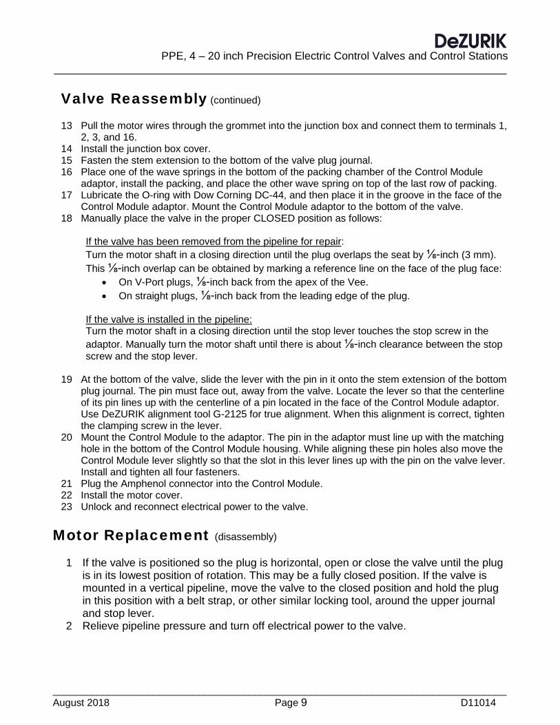
Control Module adaptor. Mount the Control Module adaptor to the bottom of the valve. 18 Manually place the valve in the proper CLOSED position as follows:
If the valve has been removed from the pipeline for repair: Turn the motor shaft in a closing direction until the plug overlaps the seat by ⅛-inch (3 mm). This ⅛-inch overlap can be obtained by marking a reference line on the face of the plug face:
• On V-Port plugs, ⅛-inch back from the apex of the Vee. • On straight plugs, ⅛-inch back from the leading edge of the plug.
If the valve is installed in the pipeline: Turn the motor shaft in a closing direction until the stop lever touches the stop screw in the adaptor. Manually turn the motor shaft until there is about ⅛-inch clearance between the stop screw and the stop lever.
19 At the bottom of the valve, slide the lever with the pin in it onto the stem extension of the bottom plug journal. The pin must face out, away from the valve. Locate the lever so that the centerline of its pin lines up with the centerline of a pin located in the face of the Control Module adaptor. Use DeZURIK alignment tool G-2125 for true alignment. When this alignment is correct, tighten the clamping screw in the lever.
20 Mount the Control Module to the adaptor. The pin in the adaptor must line up with the matching hole in the bottom of the Control Module housing. While aligning these pin holes also move the Control Module lever slightly so that the slot in this lever lines up with the pin on the valve lever. Install and tighten all four fasteners.
21 Plug the Amphenol connector into the Control Module. 22 Install the motor cover. 23 Unlock and reconnect electrical power to the valve.
Motor Replacement (disassembly)
1 If the valve is positioned so the plug is horizontal, open or close the valve until the plug is in its lowest position of rotation. This may be a fully closed position. If the valve is mounted in a vertical pipeline, move the valve to the closed position and hold the plug in this position with a belt strap, or other similar locking tool, around the upper journal and stop lever.
2 Relieve pipeline pressure and turn off electrical power to the valve.
PPE, 4-20 inch Precision Electric Control Valves and Control Stations __________________________________________________________________________
_________________________________________________________________________________ D11014 Page 10 August 2018
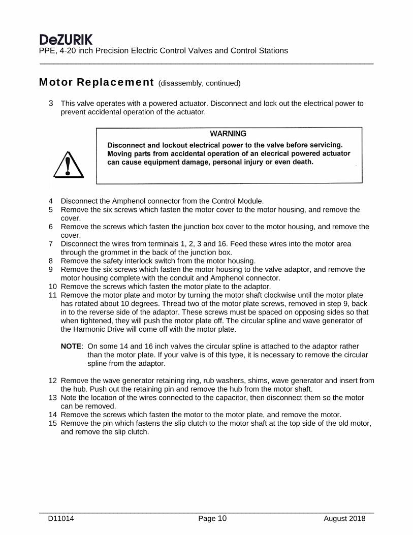
Motor Replacement (disassembly, continued) 3 This valve operates with a powered actuator. Disconnect and lock out the electrical power to
prevent accidental operation of the actuator.
4 Disconnect the Amphenol connector from the Control Module. 5 Remove the six screws which fasten the motor cover to the motor housing, and remove the
cover. 6 Remove the screws which fasten the junction box cover to the motor housing, and remove the
cover. 7 Disconnect the wires from terminals 1, 2, 3 and 16. Feed these wires into the motor area
through the grommet in the back of the junction box. 8 Remove the safety interlock switch from the motor housing. 9 Remove the six screws which fasten the motor housing to the valve adaptor, and remove the
motor housing complete with the conduit and Amphenol connector. 10 Remove the screws which fasten the motor plate to the adaptor. 11 Remove the motor plate and motor by turning the motor shaft clockwise until the motor plate
has rotated about 10 degrees. Thread two of the motor plate screws, removed in step 9, back in to the reverse side of the adaptor. These screws must be spaced on opposing sides so that when tightened, they will push the motor plate off. The circular spline and wave generator of the Harmonic Drive will come off with the motor plate. NOTE: On some 14 and 16 inch valves the circular spline is attached to the adaptor rather
than the motor plate. If your valve is of this type, it is necessary to remove the circular spline from the adaptor.
12 Remove the wave generator retaining ring, rub washers, shims, wave generator and insert from
the hub. Push out the retaining pin and remove the hub from the motor shaft. 13 Note the location of the wires connected to the capacitor, then disconnect them so the motor
can be removed. 14 Remove the screws which fasten the motor to the motor plate, and remove the motor. 15 Remove the pin which fastens the slip clutch to the motor shaft at the top side of the old motor,
and remove the slip clutch.

PPE, 4 – 20 inch Precision Electric Control Valves and Control Stations
__________________________________________________________________________
_________________________________________________________________________________ August 2018 Page 11 D11014
Figure 3 - Exploded View for New Style Harmonic Drive
PPE, 4-20 inch Precision Electric Control Valves and Control Stations __________________________________________________________________________
_________________________________________________________________________________ D11014 Page 12 August 2018
Motor Replacement (reassembly)
1 Attach the slip clutch to the top motor shaft of the new motor. 2 The new motor may have a hole drilled in place for the wave generator hub. If this pin hole is in
place go to step 6 to continue with the next steps of assembly. 3 If the new motor does not have a hub pinned to it nor has a pin hole in place, remove the hub
from the old motor, use it as a drill guide to drill a new pin-hole in the new motor shaft, following steps 4 and 5.
NOTE: The location of the hub and wave generator components in relation to the circular
spline and flexspline of the Harmonic Drive is very critical to the operation and service life of the unit. Use extreme care when measuring, drilling and pinning the hub to the motor shaft.
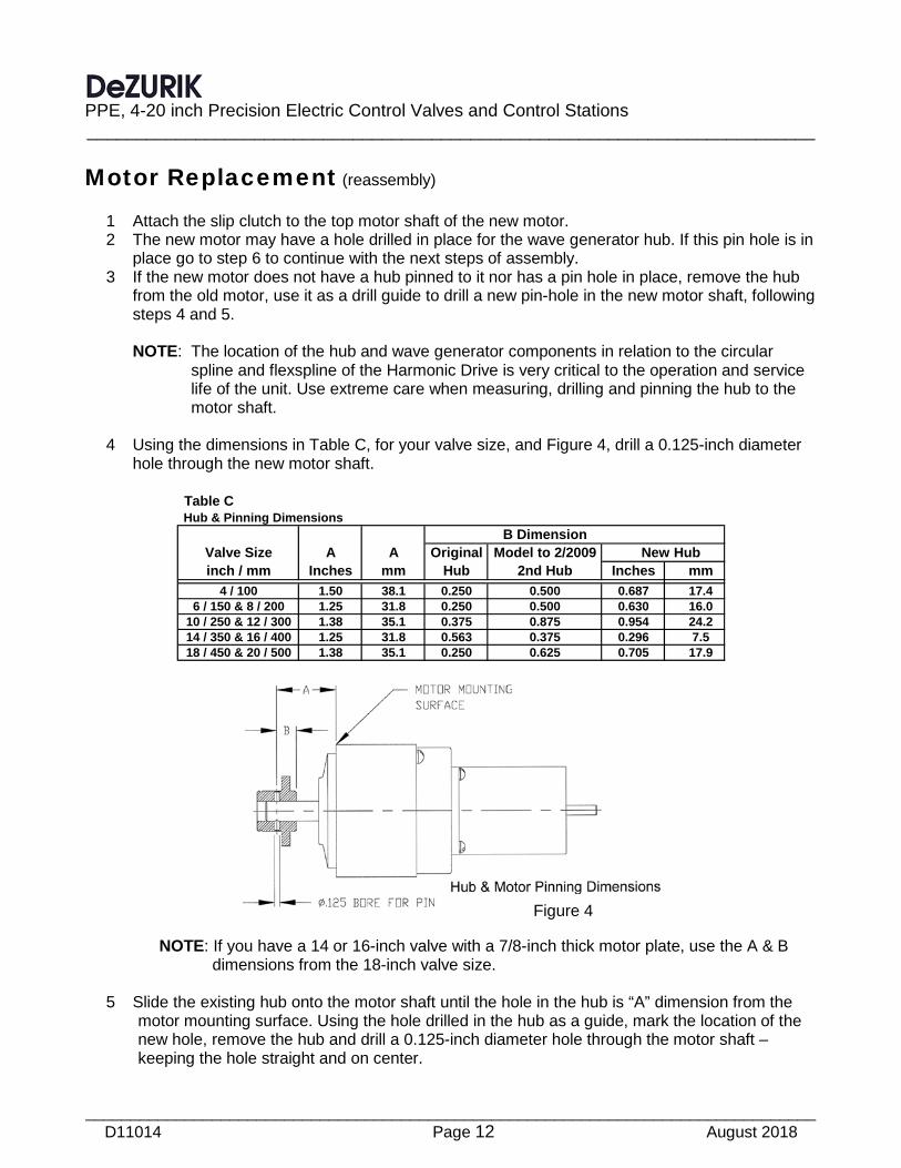
4 Using the dimensions in Table C, for your valve size, and Figure 4, drill a 0.125-inch diameter
hole through the new motor shaft.
Table C Hub & Pinning Dimensions
B DimensionValve Size A A Original Model to 2/2009 New Hubinch / mm Inches mm Hub 2nd Hub Inches mm
4 / 100 1.50 38.1 0.250 0.500 0.687 17.46 / 150 & 8 / 200 1.25 31.8 0.250 0.500 0.630 16.0
10 / 250 & 12 / 300 1.38 35.1 0.375 0.875 0.954 24.214 / 350 & 16 / 400 1.25 31.8 0.563 0.375 0.296 7.518 / 450 & 20 / 500 1.38 35.1 0.250 0.625 0.705 17.9
NOTE: If you have a 14 or 16-inch valve with a 7/8-inch thick motor plate, use the A & B
dimensions from the 18-inch valve size.
5 Slide the existing hub onto the motor shaft until the hole in the hub is “A” dimension from the motor mounting surface. Using the hole drilled in the hub as a guide, mark the location of the new hole, remove the hub and drill a 0.125-inch diameter hole through the motor shaft – keeping the hole straight and on center.
Figure 4
PPE, 4 – 20 inch Precision Electric Control Valves and Control Stations
__________________________________________________________________________
_________________________________________________________________________________ August 2018 Page 13 D11014
Motor Replacement (reassembly, continued) 6 Slide the hub onto the motor shaft until the pinning holes line up. Drive a 0.125 diameter pin
into the holes. Be sure the connection is tight and that the pin is engaged to a point flush or slightly below the surface of the hub.
7 Mount the new motor to the motor plate. 8 Liberally apply Beacon No 325, Andok B or Shell Aeroshell No 5 grease to the wave generator
ball bearings, the outer surface of the wave generator where it comes in contact with the flexspline cup and the teeth on the outer rim of the flexspline.
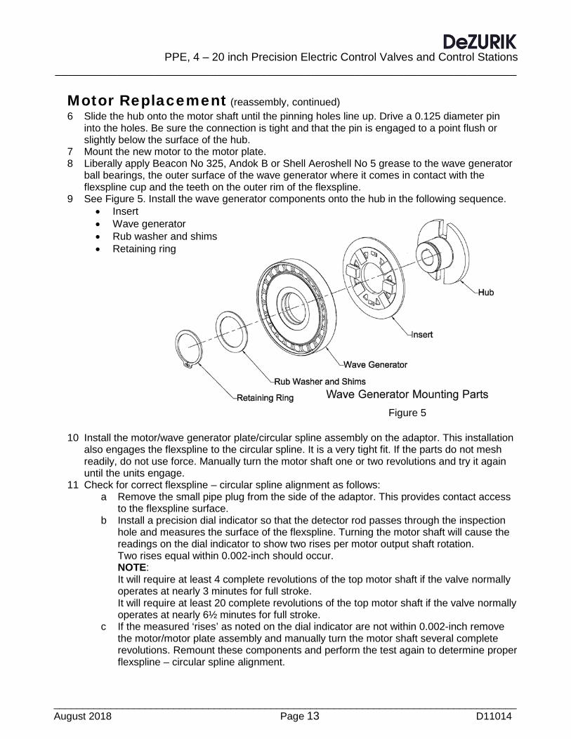
9 See Figure 5. Install the wave generator components onto the hub in the following sequence. • Insert • Wave generator • Rub washer and shims • Retaining ring
10 Install the motor/wave generator plate/circular spline assembly on the adaptor. This installation
also engages the flexspline to the circular spline. It is a very tight fit. If the parts do not mesh readily, do not use force. Manually turn the motor shaft one or two revolutions and try it again until the units engage.
11 Check for correct flexspline – circular spline alignment as follows: a Remove the small pipe plug from the side of the adaptor. This provides contact access
to the flexspline surface. b Install a precision dial indicator so that the detector rod passes through the inspection
hole and measures the surface of the flexspline. Turning the motor shaft will cause the readings on the dial indicator to show two rises per motor output shaft rotation. Two rises equal within 0.002-inch should occur. NOTE: It will require at least 4 complete revolutions of the top motor shaft if the valve normally operates at nearly 3 minutes for full stroke. It will require at least 20 complete revolutions of the top motor shaft if the valve normally operates at nearly 6½ minutes for full stroke.
c If the measured ‘rises’ as noted on the dial indicator are not within 0.002-inch remove the motor/motor plate assembly and manually turn the motor shaft several complete revolutions. Remount these components and perform the test again to determine proper flexspline – circular spline alignment.
Figure 5

PPE, 4-20 inch Precision Electric Control Valves and Control Stations __________________________________________________________________________
_________________________________________________________________________________ D11014 Page 14 August 2018
Motor Replacement (reassembly, continued) d When the correct alignment has been obtained, remove the inspection tools and screw
the pipe plug back into the side of the adaptor. 12 Fasten the motor housing to the adaptor and attach the safety interlock switch to the motor
housing. 13 Pull the motor wires through the grommet into the junction box and connect them to terminals
1, 2, 3, and 16. 14 Install the junction box cover. 15 Install the motor cover. 16 Plug the Amphenol connector into the Control Module. 17 Unlock and reconnect electrical power to the valve. 18 It should not be necessary to make further adjustments. It is recommended, however, that the
OPEN and CLOSED position switches be checked by electrically operating the valve to its fully open and closed position. Note that the closed position switch stops the valve before the stop lever touches the mechanical stop. If the switches do not trip as indicated, they must be readjusted. See the ADJUSTMENTS section of these instructions.
Limit Switch, Potentiometer or Resolver Replacement (removal)
1 This valve operates with a powered actuator. Disconnect and lock out the electrical power to prevent accidental operation of the actuator.
2 Remove the six screws which fasten the Control Module cover and remove the cover. 3 All of these devices are servo mounted to their mounting plate. 4 Loosen the screw in the split clamp which holds the gear to the device shaft, and slide the
gear and clamp off the shaft. 5 Loosen the screws in the two cleat clamps. Rotate the clamps until the flat surface is against
the device housing. Remove the device from the mounting plate. 6 Disconnect wires from the device being replaced, one at a time, and connect them to the new
device, at the same terminals.

PPE, 4 – 20 inch Precision Electric Control Valves and Control Stations
__________________________________________________________________________
_________________________________________________________________________________ August 2018 Page 15 D11014
Limit Switch, Potentiometer or Resolver Replacement (installation)
1 Mount the new device into its receptacle in the Control Module mounting plate with the cleat clamps.
2 Slide the gear and clamp onto the device shaft, making sure that the gear meshes correctly with the mating gear. When the mesh is correct, tighten the clamp. NOTE: Before tightening the clamp, wind the anti-backlash gear according to the instructions
provided in the appropriate Adjustment section of these instructions. 3 Adjust the replaced device as described in the appropriate Adjustment section of these
instructions.
Control Module Replacement (removal) 1 This valve operates with a powered actuator. Disconnect and lock out the electrical power to
prevent accidental operation of the actuator.
2 Manually place the valve in the closed position. 3 Disconnect the Amphenol connector from the Control Module. 4 Remove the four screws which fasten the Control Module to the adaptor at the bottom of the
valve and remove the Control Module.
Control Module Replacement (installation)
Note: All switches, potentiometers and the resolver, if so equipped, have been set at the factory. The location of the lever attached to the new Control Module shaft has been wired in place to retain these settings. Be very careful when removing this wire from the lever so that the lever is not moved in relation to the Control Module.
1 Mount the Control Module to the adaptor. The pin in the face of the adaptor face must line up
with the hole in the mounting face of the control module housing. The slot in the Control Module lever must line up with the pin in the valve lever.
2 Attach the Amphenol connector to its receptacle on the Control Module. 3 Reconnect electrical power to the valve. 4 It is recommended that switch, potentiometer and resolver, if so equipped, settings be verified.
Operate the valve to the fully closed and open positions, checking to see that the switches trip and stop the valve just before the stop lever touches the stop bolt. If the switches do not trip where they should, it will be necessary to readjust all devices inside the Control Module. See the appropriate Adjustments section in these instructions.
PPE, 4-20 inch Precision Electric Control Valves and Control Stations __________________________________________________________________________
_________________________________________________________________________________ D11014 Page 16 August 2018
Adjustments, Packing 1 If the packing leaks, tighten the gland nuts in equal ¼-turn increments, however only enough to
stop the leak. 2 Do not continue tightening after the leakage stops. 3 If the packing leakage cannot be stopped by tightening the gland nuts, the packing rings must
be replaced. NOTE: Tighten the nuts evenly and gently – just enough to stop the leak. Over tightening will cause excessive torque and decrease packing life.
Adjustments, Closed Position Stop 1 The valve must be removed from the line for this adjustment procedure. 2 Turn the motor shaft in a closing direction until the plug overlaps the seat by ⅛-inch (3 mm).
This ⅛-inch overlap can be obtained by marking a reference line on the face of the plug: o On V-Port plugs, ⅛-inch back from the apex of the Vee. o On straight plugs, ⅛-inch back from the leading edge of the plug.
3 Loosen the nut that locks the stop screw in place and turn the stop screw until it just touches the stop lever.
4 Tighten the nut to lock the stop screw in place.
Adjustments, Closed Position Switch, (No.1 Closed Limit & No.3 Auxiliary)
1 This valve operates with a powered actuator. Disconnect and lock out the electrical power to prevent accidental operation of the actuator.
2 Disconnect the Amphenol connector from the Control Module. 3 Remove the four screws which fasten the Control Module to the adaptor at the bottom of the
valve. 4 Remove the Control Module, being careful not to rotate the lever on the Control Module shaft. 5 Remove the six screws which fasten the control module cover to the Control Module, and
remove the cover. 6 Clamp the Control Module housing in a vise in a manner to allow access to both sides of the
module. 7 Place alignment tool G-2139 on the Control Module shaft so the pin in the alignment tool fits
into the hole in the Control Module base. 8 Rotate the Control Module lever so that the removable pin the alignment tool goes through the
hole in the longer arm of the alignment tool and into the slot of the Control Module lever. 9 See Figure 6 for reference. Find the red line at the top end of the switch stack. This red line
should be in the zone marked “Switch Actuated”. If the red line is not in this zone, go to the next step. If the red line is already in the proper zone, go to step 13.
10 Loosen the screw in the clamp that holds the gear to the switch shaft.

PPE, 4 – 20 inch Precision Electric Control Valves and Control Stations
__________________________________________________________________________
_________________________________________________________________________________ August 2018 Page 17 D11014
Adjustments, Closed Position Switch, (No.1 Closed Limit & No.3 Auxiliary, Continued)
11 Manually rotate the switch shaft until the red line is positioned as shown in Figure 6. 12 Tighten the screw in the clamp that holds the gear to the switch shaft.
NOTE: All currently constructed valves are equipped with 4 limit switches. These switches are
numbered and tagged from 1 through 4. Switch numbers 1 & 3 are the Closed Limit and Auxiliary Closed Limit switch. Switch numbers 2 & 4 are the Open Limit and Auxiliary Open Limit Switch. Switch #1 is at the top – opposite the shaft end.
When setting the switches use the designated steps first for Switch No.1, then repeat these steps for Switch No.3.
Older valves equipped with two switches are designated as Switch No.1 (Close) and Switch No.2 (Open).
13 Connect an ohmmeter to terminals “C” and “N.O.” of switch No.1 (No.3 when setting the auxiliary). NOTE: When adjusting the Adjust Screws, always loosen the Lockscrew first, and retighten
this Lockscrew before proceeding with the next adjustment. Be very careful not to over tighten these Lockscrews. In Figure 6-B the Lockscrews are shown as the small round head screws immediately to the left of the larger adjusting screw.
14 Loosen Lock Screw “B” of switch No.1 (No.3 if auxiliary).
Figure 6 Figure 6-B

PPE, 4-20 inch Precision Electric Control Valves and Control Stations __________________________________________________________________________
_________________________________________________________________________________ D11014 Page 18 August 2018
Adjustments, Closed Position Switch, (No.1 Closed Limit & No.3 Auxiliary, Continued)
15 Turn Adjust Screw “B” of switch No.1 (No.3 if auxiliary) counterclockwise until the switch opens or a stop is reached.
a. If the switch is already open before any adjustment is made, turn the Adjust Screw counter clockwise until the switch closes then opens again.
b. If a stop is reached before the switch opens, tighten Lockscrew “B”. Loosen Lockscrew “A” and turn Adjust Screw “A” counter clockwise until its stop is reached and tighten Lockscrew “A”.
c. Repeat the procedure starting with step 14 until this switch opens using Adjust Screw “B”.
d. When the switch is in the proper position, tighten Lockscrew “B” and loosen Lockscrew “A”. Turn Adjust Screw “A” counter clockwise until the stop is reached, then turn Adjust Screw “A” clockwise ½ revolution. Tighten Lockscrew “A”.
16 Repeat steps 13 through 15 to set Switch No.3.
Adjustments, Open Position Switch, (No.2 Closed Limit & No.4 Auxiliary)
NOTE: It is very important to note that if the valve being set up and/or adjusted is equipped with a Resolver, a separate set of adjustment procedures need to be used to set the OPEN Limit Switch. See Adjustment; Resolver, Open Position Switch, for steps to set the switch under these circumstances.
1 Adjust the Open Limit switch after the Closed Limit switch has been successfully adjusted. 2 Rotate the Control Module lever so the removable pin in alignment tool G-2139 goes through
the hole in the shorter arm of the alignment tool and into the slot in the Control Module lever. NOTE: All currently constructed valves are equipped with 4 limit switches. These switches are
numbered and tagged from 1 through 4. Switch numbers 1 & 3 are the Closed Limit and Auxiliary Closed Limit switch. Switch numbers 2 & 4 are the Open Limit and Auxiliary Open Limit Switch. Switch #1 is at the top – opposite the shaft end.
When setting the switches use the designated steps first for Switch No.2, then repeat these steps for Switch No.4.
Older valves equipped with two switches are designated as Switch No.1 (Close) and Switch No.2 (Open).
3 Connect an ohmmeter to terminals “C” and “NO” of switch No.2 (No.4 when setting the
auxiliary). NOTE: When adjusting the Adjust Screws, always loosen the Lockscrew first, and retighten
this Lockscrew before proceeding with the next adjustment. Be very careful not to over tighten these Lockscrews. In Figure 6-B the Lockscrews are shown as the smaller round head screws immediately to the left of the larger adjusting screw.
PPE, 4 – 20 inch Precision Electric Control Valves and Control Stations
__________________________________________________________________________
_________________________________________________________________________________ August 2018 Page 19 D11014
Adjustments, Open Position Switch, (No.2 Closed Limit & No.4 Auxiliary, continued)
4 Loosen Lock Screw “A” of switch No.2 (No.4 if auxiliary). 5 Turn Adjust Screw “A” of switch No.2 (No.4 if auxiliary) clockwise until the switch opens or a
stop is reached. • If the switch is already open before any adjustment is made, turn Adjust Screw “A”
clockwise until the switch closes then opens again. • If a stop is reached before the switch opens, tighten Lockscrew “A”. Loosen Lockscrew
“B” and turn Adjust Screw “B” clockwise until its stop is reached and tighten Lockscrew “B”.
• Repeat the procedure starting with step 5 until this switch opens with Adjust Screw “A”. • When the switch is in the proper position, tighten Lockscrew “A” and loosen
Lockscrew “B”. Turn Adjust Screw “B” clockwise until the stop is reached, then turn Adjust Screw “B” counter clockwise ½ revolution. Tighten Lockscrew “B”.
6 Repeat steps 3 through 5 to set Auxiliary Switch No.4. 7 Remove the alignment tool from the Control Module shaft.
NOTE: The location of the lever on the bottom of the Control Module has been set with the
alignment tool. Be very careful when handling the Control Module to prevent this lever from being moved in relation to the Control Module base.
8 Mount the Control Module to the adaptor. The pin in the adaptor must line up with the hole in
the bottom of the Control Module housing. The slot in the Control Module lever must line up with the pin in the valve lever.
9 Install the cover on the Control Module with the six screws. 10 Plug the Amphenol connector into the receptacle on the Control Module.
Potentiometer Adjustment; Using a 5 Volt DC Power Supply NOTE: The potentiometer can be adjusted on the valve or by using Alignment Tool G-2139.
1 Move the valve to the closed position. 2 This valve operates with a powered actuator. Disconnect and lock out the electrical power to
prevent accidental operation of the actuator.
3 If the potentiometer will be adjusted with the Control Module mounted on the valve go to
step 10. 4 If Alignment Tool G-2139 will be used, disconnect the Amphenol connector from the
Control Module.

PPE, 4-20 inch Precision Electric Control Valves and Control Stations __________________________________________________________________________
_________________________________________________________________________________ D11014 Page 20 August 2018
Potentiometer Adjustment; Using a 5 Volt DC Power Supply (continued)
5 Remove the six screws which fasten the Control Module cover to the control module, and
remove the cover. 6 Remove the four screws which fasten the Control Module to the adaptor at the bottom of the
valve. 7 Remove the Control Module, being careful not to rotate the lever on the Control Module shaft. 8 Clamp the Control Module housing in a vise in a manner to allow access to both sides of the
module. 9 Attach the alignment tool and rotate the Control Module lever so the removable pin in the
alignment tool fits into the hole in the longer arm of the tool and into the slot of the Control Module lever.
10 Apply 5 volts DC to the “CW” and “CCW” terminals of the potentiometer. 11 Measure the voltage across the “CCW” and “S” terminals. If the reading is 0.2 volts DC, the
potentiometer is properly adjusted and needs no further adjustment. Proceed to step 20. 12 If the reading is not 0.2 volts DC, continue with the following steps. 13 Loosen the screw in the split clamp which holds the gear to the potentiometer shaft and slide
this gear from the potentiometer shaft. 14 Manually turn the potentiometer shaft until there is 0.2 volts DC across the “CCW” and “S”
terminals. 15 Slide the anti-backlash gear onto the potentiometer shaft until the first half of the gear meshed
with the large drive gear. 16 Wind the second half of the anti-backlash gear tight and slide it in to mesh with the large drive
gear, making sure that all teeth are in contact with the larger drive gear. Tighten the screw in the split clamp.
17 Check the voltage value again across the “CCW” & “S” terminals. To make a final, fine adjustment of this value, loosen the servo mount clamp screws, and rotate the potentiometer body slightly until the reading is 0.2 volts DC. Tighten the servo clamp screws.
18 If the Control Module is mounted to the valve proceed to step 21. 19 Remove the alignment tool from the Control Module shaft.
NOTE: The location of the lever on the bottom of the Control Module has been set with the
alignment tool. Be very careful when handling the Control Module to prevent this lever from being moved in relation to the Control Module base.
20 Mount the Control Module to the adaptor. The pin in the adaptor must line up with the hole in
the bottom of the Control Module housing. The slot in the lever must line up with the pin in the valve lever.
21 Mount the cover to the Control Module. 22 Reconnect the Amphenol connector to its receptacle on the Control Module. 23 Reconnect electrical power to the valve.

PPE, 4 – 20 inch Precision Electric Control Valves and Control Stations
__________________________________________________________________________
_________________________________________________________________________________ August 2018 Page 21 D11014
Potentiometer Adjustment; Using an Ohmmeter
NOTE: The potentiometer can be adjusted on the valve or by using the Alignment Tool G-2139.
1 Move the valve to the closed position. 2 This valve operates with a powered actuator. Disconnect and lock out the electrical power to
prevent accidental operation of the actuator.
3 If the potentiometer will be adjusted with the Control Module mounted on the valve, remove
the six screws which fasten the Control Module cover and remove the cover and go to step 10.
4 If Alignment Tool G-2139 will be used, disconnect the Amphenol connector from the Control Module.
5 Remove the six screws which fasten the Control Module cover to the Control Module, and remove the cover.
6 Remove the four screws which fasten the Control Module to the adaptor at the bottom of the valve.
7 Remove the Control Module, being careful not to rotate the lever on the Control Module shaft. 8 Clamp the Control Module housing in a vise in a manner to allow access to both sides of the
module. 9 Attach the alignment tool and rotate the Control Module lever so the removable pin in the
alignment tool fits into the hole in the longer arm of the tool and into the slot of the Control Module lever.
10 Verify the total resistance of the potentiometer. Connect an ohmmeter to terminals “CW” and “CCW” of the potentiometer and measure the resistance. Record this value.
11 Measure the resistance between terminals “CCW” and “S”. If this reading is 4 percent of the total resistance measured in step 12 the potentiometer is properly adjusted and needs no further adjustment. Proceed to step 22.
(Example: 4 percent of 1000 ohms = 40 ohms) If the reading is not 4 percent of the total resistance recorded proceed with the following steps.
12 Loosen the screw in the split clamp which holds the gear to the potentiometer shaft and slide this gear from the potentiometer shaft.
13 Manually turn the potentiometer shaft until the resistance reading between terminals “CCW “ and “S” is 4 percent of the total resistance recorded in step 11.
14 Slide the anti-backlash gear onto the potentiometer shaft until the first half of the gear is meshed with the large drive gear.
15 Wind the second half of the anti-backlash gear tight and slide it in to mesh with the large drive gear, making sure that all teeth are in contact with the larger drive gear. Tighten the screw in the split clamp.

PPE, 4-20 inch Precision Electric Control Valves and Control Stations __________________________________________________________________________
_________________________________________________________________________________ D11014 Page 22 August 2018
Potentiometer Adjustment; Using an Ohmmeter (continued) 16 Check the resistance value between terminals “CCW” & “S”. To make a final, fine adjustment
of this value loosen the servo mount clamp screws, and rotate the potentiometer body slightly until the resistance is 4 percent of the value recorded in step 11. Tighten the servo clamp screws.
17 If the Control Module is mounted to the valve proceed to step 22. 18 Remove the alignment tool from the Control Module shaft.
NOTE: The location of the lever on the bottom of the Control Module has been set with the alignment tool. Be very careful when handling the Control Module to prevent this lever from being moved in relation to the Control Module base.
19 Mount the Control Module to the adaptor. The pin in the adaptor must line up with the hole in
the bottom of the Control Module housing. The slot in the lever must line up with the pin in the valve lever.
20 Mount the cover to the Control Module. 21 Reconnect the Amphenol connector to its receptacle on the Control Module. 22 Reconnect electrical power to the valve.
Resolver Adjustment; Using a 24VDC Power and Ammeter NOTE: The resolver can be adjusted on the valve or by using Alignment Tool G-2139.
1 Move the valve to the closed position. 2 This valve operates with a powered actuator. Disconnect and lock out all electrical power to
the valve to prevent accidental operation of the actuator.
3 If the resolver will be adjusted with the Control Module mounted on the valve - go to step 23. 4 If Alignment Tool G-2139 will be used, disconnect the Amphenol connector from the
Control Module. 5 Remove the six screws which fasten the Control Module cover to the Control module, and
remove the cover. 6 Remove the four screws which fasten the Control Module to the adaptor at the bottom of the
valve. 7 Remove the Control Module, being careful not to rotate the lever on the Control Module shaft. 8 Clamp the Control Module housing in a vise in a manner to allow access to both sides of the
module.

PPE, 4 – 20 inch Precision Electric Control Valves and Control Stations
__________________________________________________________________________
_________________________________________________________________________________ August 2018 Page 23 D11014
Resolver Adjustment; Using a 24VDC Power and Ammeter (continued)
9 Attach the alignment tool and rotate the Control Module lever so the removable pin in the alignment tool fits into the hole in the longer arm of the tool and into the slot of the Control Module lever.
When connecting the 24 Volts DC power supply to the resolver it is absolutely required that proper polarity be observed. Connecting the power supply to the wrong terminals (example: backwards) will render the resolver permanently damaged and inoperable. This will cause the need for resolver replacement. 10 Locate terminal pins “C”, “E” & “F” in the Amphenol connector mounted on the side of the
Control Module. 11 Connect the positive “+” wire of the 24 VDC power supply to the pin marked “C”. 12 Connect the negative “-“ wire of the 24 VDC power supply to the pin marked “E”. 13 Connect the negative “-“ wire of the ammeter to the pin marked “E”. 14 Connect the positive “+” wire of the ammeter to the pin marked “F”. 15 Recheck the connections making certain there are no other pins being contacted and turn on
the 24VDC power supply. 16 Loosen the screw in the split clamp which holds the gear to the resolver shaft and slide this
gear from the resolved shaft. 17 Manually turn the resolver shaft until the signal at the ammeter is 4.25 mA. 18 Slide the anti-backlash gear onto the resolver shaft until the first half meshes with the drive gear. 19 Wind the second half of the anti-backlash gear tight and slide it into mesh with the larger drive
gear. Tighten the screw in the split clamp. 20 Observe the mA reading at the ammeter. To make final precise adjustments of the reading,
loosen the two servo clamp screws slightly, and rotate the resolver body until the reading is 4.25 mA. Tighten the two servo clamp screws.
21 Rotate the Control Module lever so that the removable pin in alignment tool G-2139 goes through the hole in the shorter arm of the alignment tool and is very near to, but not in, the slot in the Control Module lever.
22 Observe the mA reading at the ammeter. Move the Control Module lever until the reading is 19.75 mA. This is the proper open position when using a resolver. It is required to reset the Open Limit Switch. Proceed to the Adjustment, Resolver, Open Position Switch to complete the resolver and open limit switch adjustment.
23 If the Control Module is mounted on the valve, remove the six screws which fasten the cover to the Control Module and remove this cover.
24 Remove the screws which fasten the junction box cover to the motor housing and remove the cover.
When connecting the 24 Volts DC power supply to the resolver it is absolutely required that proper polarity be observed. Connecting the power supply to the wrong terminals (example: backwards) will render the resolver permanently damaged and inoperable. This will cause the need for resolver replacement.

PPE, 4-20 inch Precision Electric Control Valves and Control Stations __________________________________________________________________________
_________________________________________________________________________________ D11014 Page 24 August 2018
Resolver Adjustment; Using a 24VDC Power and Ammeter (continued)
25 Locate terminal screws “29”, “30” & “31” in the junction box. 26 Connect the positive “+” wire of the 24 VDC power supply to terminal 29 in the junction box. 27 Connect the negative “-“ wire of the 24VDC power supply to terminal 30 in the junction box. 28 Connect the negative “-“ wire of the ammeter to terminal 30 in the junction box. 29 Connect the positive “+” wire of the ammeter to terminal 31 in the junction box. 30 Recheck all connections making certain that there are no other terminals are coming in
contact with the connections to the power supply and ammeter and turn on the 24 VDC power supply.
31 Loosen the screw in the split clamp which holds the gear to the resolver shaft and slide this gear from the resolver shaft.
32 Manually turn the resolver shaft until the signal at the ammeter is 4.25 mA. 33 Slide the anti-backlash gear onto the resolver shaft until the first half meshes with the drive
gear. 34 Wind the second half of the anti-backlash gear tight and slide it into mesh with the larger drive
gear. Tighten the screw in the split clamp. 35 Observe the mA reading at the ammeter. To make final precise adjustments of the reading,
loosen the two servo clamp screws slightly, and rotate the resolver body until the reading is 4.25 mA. Tighten the two servo clamp screws.
36 Remove the screws which fasten the cover to the motor housing and remove the cover. 37 Using the manual override knob on the top of the motor manually move the valve toward the
open position while observing the reading from the ammeter connected to the resolver. 38 Observe the mA reading at the ammeter. Position the motor until the reading is 19.75 mA. 39 This is the proper open position when using a resolver. It is required so reset the Open Limit
Switch. Proceed to Adjustment, Resolver, Open Position Switch to complete the resolver and open limit switch adjustment.
Adjustment, Resolver; Open Position Switch
1 Adjust the Open Limit Switch after the Closed Limit Switch has been successfully set, the resolver has been set to its proper closed position and the valve or Control Module lever is in its proper open position.
2 Maintain the valve or Control Module lever position so that the reading from ammeter the remains at 19.75 mA. NOTE: All currently constructed valves are equipped with 4 limit switches. These switches are
numbered and tagged from 1 through 4. Switch numbers 1 & 3 are the Closed Limit and Auxiliary Closed Limit switch. Switch numbers 2 & 4 are the Open Limit and Auxiliary Open Limit switch. Switch No.1 is at the top – opposite the shaft end.
When setting the switches use the designated steps first for switch no.2, then repeat these steps for switch No.4.
Older valves equipped with two switches are designated as Switch No.1 (Close) and Switch No.2 (Open).
PPE, 4 – 20 inch Precision Electric Control Valves and Control Stations
__________________________________________________________________________
_________________________________________________________________________________ August 2018 Page 25 D11014
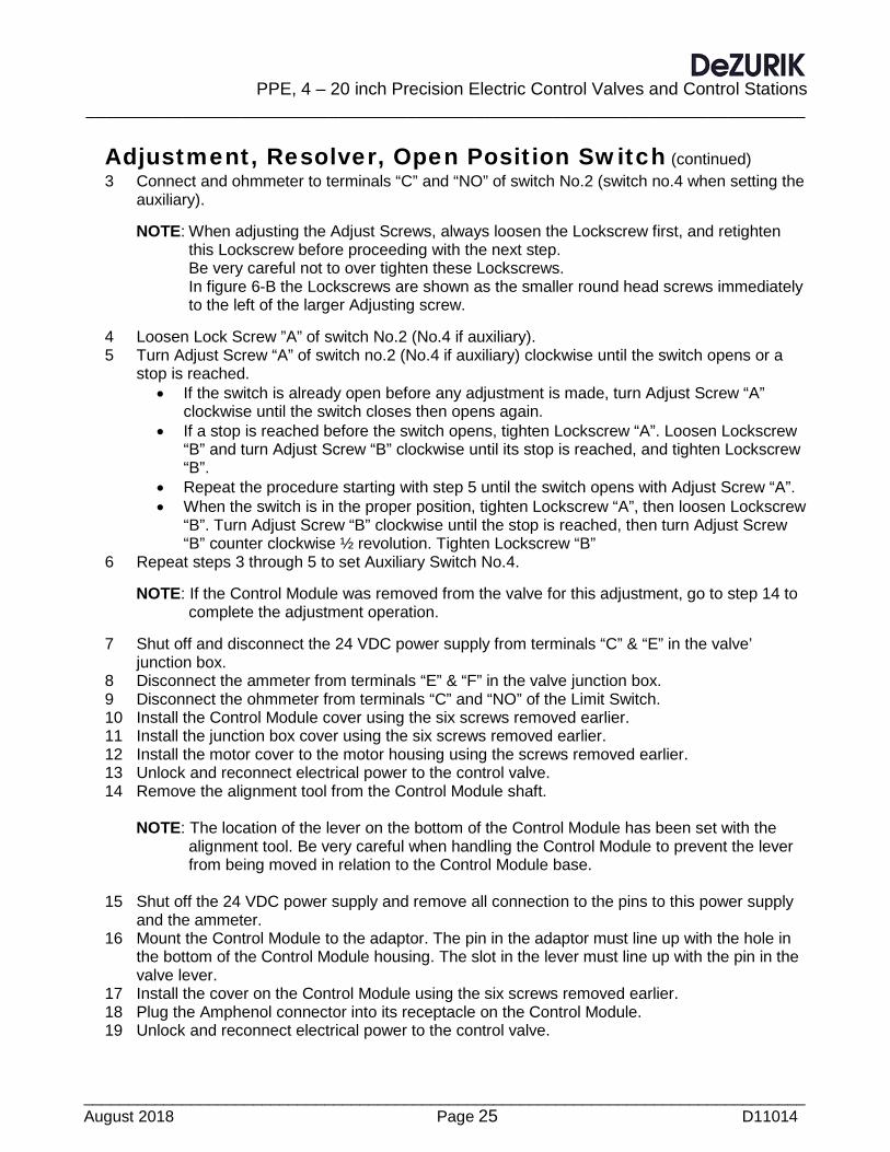
Adjustment, Resolver, Open Position Switch (continued) 3 Connect and ohmmeter to terminals “C” and “NO” of switch No.2 (switch no.4 when setting the
auxiliary).
NOTE: When adjusting the Adjust Screws, always loosen the Lockscrew first, and retighten this Lockscrew before proceeding with the next step.
Be very careful not to over tighten these Lockscrews. In figure 6-B the Lockscrews are shown as the smaller round head screws immediately
to the left of the larger Adjusting screw.
4 Loosen Lock Screw ”A” of switch No.2 (No.4 if auxiliary). 5 Turn Adjust Screw “A” of switch no.2 (No.4 if auxiliary) clockwise until the switch opens or a
stop is reached. • If the switch is already open before any adjustment is made, turn Adjust Screw “A”
clockwise until the switch closes then opens again. • If a stop is reached before the switch opens, tighten Lockscrew “A”. Loosen Lockscrew
“B” and turn Adjust Screw “B” clockwise until its stop is reached, and tighten Lockscrew “B”.
• Repeat the procedure starting with step 5 until the switch opens with Adjust Screw “A”. • When the switch is in the proper position, tighten Lockscrew “A”, then loosen Lockscrew
“B”. Turn Adjust Screw “B” clockwise until the stop is reached, then turn Adjust Screw “B” counter clockwise ½ revolution. Tighten Lockscrew “B”
6 Repeat steps 3 through 5 to set Auxiliary Switch No.4. NOTE: If the Control Module was removed from the valve for this adjustment, go to step 14 to complete the adjustment operation.
7 Shut off and disconnect the 24 VDC power supply from terminals “C” & “E” in the valve’ junction box.
8 Disconnect the ammeter from terminals “E” & “F” in the valve junction box. 9 Disconnect the ohmmeter from terminals “C” and “NO” of the Limit Switch. 10 Install the Control Module cover using the six screws removed earlier. 11 Install the junction box cover using the six screws removed earlier. 12 Install the motor cover to the motor housing using the screws removed earlier. 13 Unlock and reconnect electrical power to the control valve. 14 Remove the alignment tool from the Control Module shaft.
NOTE: The location of the lever on the bottom of the Control Module has been set with the
alignment tool. Be very careful when handling the Control Module to prevent the lever from being moved in relation to the Control Module base.
15 Shut off the 24 VDC power supply and remove all connection to the pins to this power supply
and the ammeter. 16 Mount the Control Module to the adaptor. The pin in the adaptor must line up with the hole in
the bottom of the Control Module housing. The slot in the lever must line up with the pin in the valve lever.
17 Install the cover on the Control Module using the six screws removed earlier. 18 Plug the Amphenol connector into its receptacle on the Control Module. 19 Unlock and reconnect electrical power to the control valve.

PPE, 4-20 inch Precision Electric Control Valves and Control Stations __________________________________________________________________________
_________________________________________________________________________________ D11014 Page 26 August 2018
Control Station Wiring Before connecting a Control Station to the valve it is necessary to identify your control station (Analog or Time Duration, with or without a Part Number stamped on the front cover). Older Control Stations will not have the Part Number stamped on the front. Look below for the Section of these instructions which covers your Control Station. The wiring between all styles of valves and control stations is shown in Schematics 1 through 5 at the end of these instructions. To minimize electrical noise problems, run the wiring between the control station and valve’ potentiometer(s) in a separate conduit, away from AC wiring such a motor power and switch wiring. Leave enough wire length so the control station can be pulled out, on its rack, for servicing.
Connecting a Time Duration Control Station (Part number stamped on control station case) See Schematic No.1 for reference.
1 This valve operates with a powered actuator, Disconnect and lock out the electrical power to prevent accidental operation of the actuator.
2 Remove the junction box cover from the valve, and check the location of the jumper wires on the valve’ terminal strip. All connection options described below are for connecting an existing control valve to a new Time Duration Control Station
• The correct wiring for this control station is to have jumpers between terminals 3 and 12, and between 2 and 9, and a wire connected between the red motor lead on the capacitor and terminal16 on the valve terminal strip. See Schematic No.1.
PPE, 4 – 20 inch Precision Electric Control Valves and Control Stations
__________________________________________________________________________
_________________________________________________________________________________ August 2018 Page 27 D11014
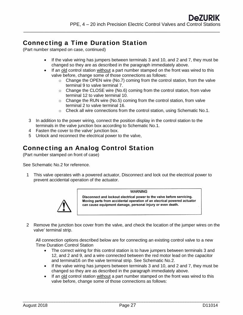
Connecting a Time Duration Station (Part number stamped on case, continued)
• If the valve wiring has jumpers between terminals 3 and 10, and 2 and 7, they must be changed so they are as described in the paragraph immediately above.
• If an old control station without a part number stamped on the front was wired to this valve before, change some of those connections as follows:
o Change the OPEN wire (No.7) coming from the control station, from the valve terminal 9 to valve terminal 7.
o Change the CLOSE wire (No.6) coming from the control station, from valve terminal 12 to valve terminal 10.
o Change the RUN wire (No.5) coming from the control station, from valve terminal 2 to valve terminal 16.
o Check all wire connections from the control station, using Schematic No.1.
3 In addition to the power wiring, connect the position display in the control station to the terminals in the valve junction box according to Schematic No.1.
4 Fasten the cover to the valve’ junction box. 5 Unlock and reconnect the electrical power to the valve,
Connecting an Analog Control Station (Part number stamped on front of case) See Schematic No.2 for reference.
1 This valve operates with a powered actuator, Disconnect and lock out the electrical power to prevent accidental operation of the actuator.
2 Remove the junction box cover from the valve, and check the location of the jumper wires on the valve’ terminal strip.
All connection options described below are for connecting an existing control valve to a new Time Duration Control Station
• The correct wiring for this control station is to have jumpers between terminals 3 and 12, and 2 and 9, and a wire connected between the red motor lead on the capacitor and terminal16 on the valve terminal strip. See Schematic No.2.
• If the valve wiring has jumpers between terminals 3 and 10, and 2 and 7, they must be changed so they are as described in the paragraph immediately above.
• If an old control station without a part number stamped on the front was wired to this valve before, change some of those connections as follows:
PPE, 4-20 inch Precision Electric Control Valves and Control Stations __________________________________________________________________________
_________________________________________________________________________________ D11014 Page 28 August 2018
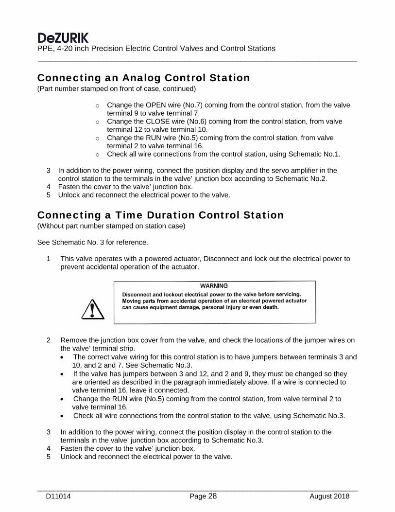
Connecting an Analog Control Station (Part number stamped on front of case, continued)
o Change the OPEN wire (No.7) coming from the control station, from the valve
terminal 9 to valve terminal 7. o Change the CLOSE wire (No.6) coming from the control station, from valve
terminal 12 to valve terminal 10. o Change the RUN wire (No.5) coming from the control station, from valve
terminal 2 to valve terminal 16. o Check all wire connections from the control station, using Schematic No.1.
3 In addition to the power wiring, connect the position display and the servo amplifier in the
control station to the terminals in the valve’ junction box according to Schematic No.2. 4 Fasten the cover to the valve’ junction box. 5 Unlock and reconnect the electrical power to the valve.
Connecting a Time Duration Control Station (Without part number stamped on station case) See Schematic No. 3 for reference.
1 This valve operates with a powered actuator, Disconnect and lock out the electrical power to prevent accidental operation of the actuator.
2 Remove the junction box cover from the valve, and check the locations of the jumper wires on the valve’ terminal strip. • The correct valve wiring for this control station is to have jumpers between terminals 3 and
10, and 2 and 7. See Schematic No.3. • If the valve has jumpers between 3 and 12, and 2 and 9, they must be changed so they
are oriented as described in the paragraph immediately above. If a wire is connected to valve terminal 16, leave it connected.
• Change the RUN wire (No.5) coming from the control station, from valve terminal 2 to valve terminal 16.
• Check all wire connections from the control station to the valve, using Schematic No.3.
3 In addition to the power wiring, connect the position display in the control station to the terminals in the valve’ junction box according to Schematic No.3.
4 Fasten the cover to the valve’ junction box. 5 Unlock and reconnect the electrical power to the valve.

PPE, 4 – 20 inch Precision Electric Control Valves and Control Stations
__________________________________________________________________________
_________________________________________________________________________________ August 2018 Page 29 D11014
Connecting an Analog Control Station (Without part number stamped on station case) See Schematic No.4 for reference.
1 This valve operates with a powered actuator, Disconnect and lock out the electrical power to prevent accidental operation of the actuator.
2 Remove the junction box cover from the valve, and check the locations of the jumper wires on the valve’ terminal strip.
• The correct valve wiring for this control station is to have jumpers between terminals 3 and
10, and 2 and 7. See Schematic No.4. • If the valve has jumpers between 3 and 12, and 2 and 9, they must be changed so they
are oriented as described in the paragraph immediately above. If a wire is connected to valve terminal 16, leave it connected.
• Change the RUN wire (No.5) coming from the control station, from valve terminal 2 to valve terminal 16.
• Check all wire connections from the control station to the valve, using Schematic No.4. 3 In addition to the power wiring, connect the position display and servo amplifier in the control
station to the terminals in the valve’ junction box according to Schematic No.4. 4 Fasten the cover to the valve’ junction box. 5 Unlock and reconnect the electrical power to the valve.
Connecting a Time Duration Control Station and Resolver (Part number stamped on control station case) See Schematic No.5 for reference.
1 This valve operates with a powered actuator, Disconnect and lock out the electrical power to prevent accidental operation of the actuator.

PPE, 4-20 inch Precision Electric Control Valves and Control Stations __________________________________________________________________________
_________________________________________________________________________________ D11014 Page 30 August 2018
Connecting a Time Duration Control Station and Resolver (Part number stamped on control station case)
2 Remove the junction box cover from the valve, and check the location of the jumper wires on the valve’ terminal strip.
All connection options described below are for connecting an existing control valve equipped with a resolver to a new Time Duration Control Station
• The correct wiring for this control station is to have jumpers between terminals 3 and 12, and 2 and 9, and a wire connected between the red motor lead on the capacitor and terminal16 on the valve terminal strip. See Schematic No.5.
• If the valve wiring has jumpers between terminals 3 and 10, and 2 and 7, they must be changed so they are as described in the paragraph immediately above.
• If an old control station without a part number stamped on the front was wired to this valve before, change some of those connections as follows:
o Change the OPEN wire (No.7) coming from the control station, from the valve terminal 9 to valve terminal 7.
o Change the CLOSE wire (No.6) coming from the control station, from valve terminal 12 to valve terminal 10.
o Change the RUN wire (No.5) coming from the control station, from valve terminal 2 to valve terminal 16.
o Check all wire connections from the control station, using Schematic No.1.
3 In addition to the power wiring, connect the position display in the control station to the terminals in the valve junction box according to Schematic No.5.
4 Bring in and connect 24 VDC power to the junction box and connect as follows:
• Connect the “+” wire from the power supply to terminal 29. • Connect the “-“ wire from the power supply to terminal 30
5 Bring in and connect an external signal line (4-20mA) to the junction box and connect as
follows:
• Connect the “+” wire for the 4-20mA line to terminal 31. • Connect the “-“ wire for the 4-20mA line to terminal 30, along with the “-“ power supply wire.
6 Fasten the cover to the valve’ junction box. 7 Unlock and reconnect the electrical power to the valve.

PPE, 4 – 20 inch Precision Electric Control Valves and Control Stations
__________________________________________________________________________
_________________________________________________________________________________ August 2018 Page 31 D11014
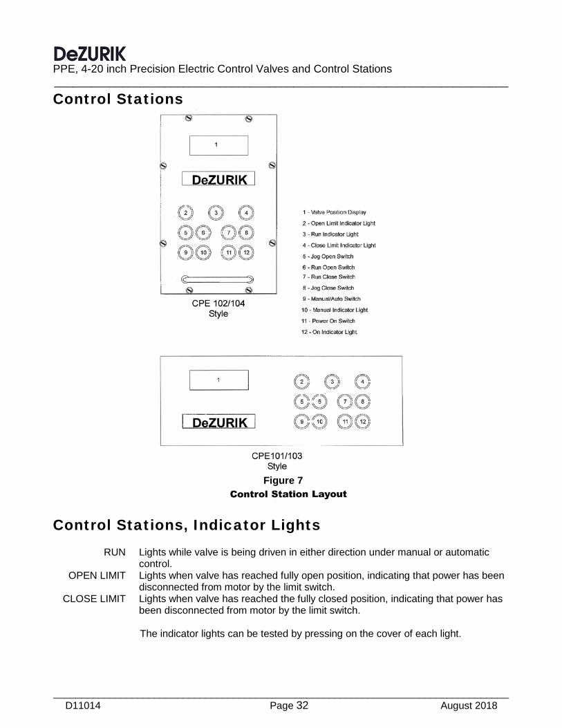
Control Stations, Descriptions of Features Both types of control station (Analog and Time Duration) have push-button switches to operate the valve manually. Both types also have a digital display that shows valve position, and indicating lights that show when the valve is fully closed, fully open or moving. Both types of control stations are available in a vertical, fully enclosed configuration or a horizontal, rack mounted configuration. See Figure 7.
Control Stations, Push-Button Switches ON Power on-off switch for valve and control station. When control station is off,
valve can not be operated electrically. MANUAL/AUTO Selects MANUAL (front panel switches) or AUTOMATIC (user’s control signal)
inputs for exclusive control of the valve. JOG OPEN In manual control, valve is driven open while switch is being pressed. RUN OPEN In manual control, valve is driven open or stopped by push-on, push-off switch. JOG CLOSE In manual control, valve is driven closed while switch is being pressed. RUN CLOSE In manual control, valve is driven closed or stopped by push-on, push-off
switch.
PPE, 4-20 inch Precision Electric Control Valves and Control Stations __________________________________________________________________________
_________________________________________________________________________________ D11014 Page 32 August 2018
Control Stations
Control Stations, Indicator Lights RUN Lights while valve is being driven in either direction under manual or automatic control. OPEN LIMIT Lights when valve has reached fully open position, indicating that power has been
disconnected from motor by the limit switch. CLOSE LIMIT Lights when valve has reached the fully closed position, indicating that power has been disconnected from motor by the limit switch. The indicator lights can be tested by pressing on the cover of each light.
Figure 7

PPE, 4 – 20 inch Precision Electric Control Valves and Control Stations
__________________________________________________________________________
_________________________________________________________________________________ August 2018 Page 33 D11014
Control Stations, Valve Position Display A three and a half digit display shows the position of the valve as a percent of full open. This display is part of a voltmeter that senses voltage from one of the two potentiometers connected to the valve.
Control Stations, Display Adjustment Adjust the display to show “0.0” when the valve is fully closed, and “100.0” when fully open, using the following procedure. These adjustments are made on the display device located inside the control station. The rack needs to be released and opened, forward, to gain access to these adjustments.
1 Manually close the valve until the close limit light turns on. 2 Set the display to “0.0” using the display’ Zero Adjustment Potentiometer. 3 Manually open the valve until the open limit light turns on. 4 Set the display to “100.0” using the display’ Span Adjust Potentiometer.
Analog Control Station (Models CPE-103 and CPE-104) With an Analog Control Station, the valve is fully closed at a minimum signal, and is fully open at the maximum signal. Valve position is directly proportional to the input signal for intermediate positions. DeZURIK Analog Control Stations are available with 1-5 mA, 4-20 mA, 10-50 mA, or 1-5 volt signal ranges. A servo amplifier in the Analog Control Station compares the analog input signal with a voltage from one of the two potentiometers mounted to the valve and, when the signals are not equal, sends 115 V AC to the motor to change the valve position until the signals become equal. If power fails the valve remains in its last position.
Analog Control Station (Control Station Adjustment) These adjustments are made on the servo amplifier located inside the control station. The rack needs to be released and opened, forward, to gain access to these adjustments. To adjust the Analog Control Station servo amplifier, proceed as follows:
1 Figure 8 shows the location of DIP switches and adjusting potentiometers. 2 Close the DIP switch that controls the analog signal which will be used. Set only one switch to
the closed position, (“ON”). The DIP switches are located near terminal 14 on the main printed circuit board.
Analog Signal Format Switch Number 1-5 mA 1 4-20 mA 2 10-50 mA 3 1-5 volt 4

PPE, 4-20 inch Precision Electric Control Valves and Control Stations __________________________________________________________________________
_________________________________________________________________________________ D11014 Page 34 August 2018
Analog Control Station (Control Station Adjustment, continued)
3 With the control station in AUTO mode, connect a signal source to the analog input terminals and adjust it to the minimum signal level.
4 With the signal at its minimum level, set the “OFFSET potentiometer so that the valve reaches its fully closed position, but is not overdriven. Observe the position display for position indication.
5 Adjust the signal source to the maximum level, and set the “FEEDBACK GAIN” potentiometer so that the valve reaches its fully open position, but is not overdriven.
6 The “DEADBAND” for the valve control should be set to avoid hunting or overshoot. Before beginning move the control signal to a point near mid-scale (example: 12mA). To make this adjustment, turn the “DEADBAND” potentiometer fully counter clockwise, and change the analog input signal by at least 5 percent. If any hunting or overshoot occurs, turn the “DEADBAND” potentiometer one revolution clockwise and repeat the 5 percent signal change. Continue this procedure until there is no hunting or overshoot.
Time Duration Control Station (Models CPE-101 and CPE-102) With a Time Duration Control Station, power pulses of variable duration of 115 V AC are applied to terminal 13 move the valve in the OPEN direction, or to terminal 14 to move the valve in the CLOSED direction. Valve plug travel is proportional to the duration of the power pulse. The normal minimum power pulse duration is 50 milliseconds. See Control Stations, Display Adjustment to set the three and one half digit visual valve position display.
Figure 8
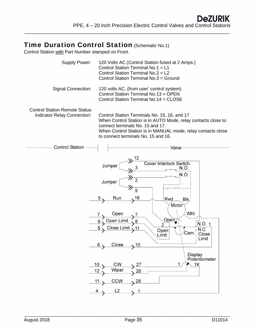
PPE, 4 – 20 inch Precision Electric Control Valves and Control Stations
__________________________________________________________________________
_________________________________________________________________________________ August 2018 Page 35 D11014
Time Duration Control Station (Schematic No.1) Control Station with Part Number stamped on Front. Supply Power: 120 Volts AC (Control Station fused at 2 Amps.) Control Station Terminal No.1 = L1 Control Station Terminal No.2 = L2 Control Station Terminal No.3 = Ground Signal Connection: 120 volts AC, (from user’ control system) Control Station Terminal No.13 = OPEN Control Station Terminal No.14 = CLOSE Control Station Remote Status Indicator Relay Connection: Control Station Terminals No. 15, 16, and 17 When Control Station is in AUTO Mode, relay contacts close to connect terminals No. 15 and 17. When Control Station is in MANUAL mode, relay contacts close to connect terminals No. 15 and 16.
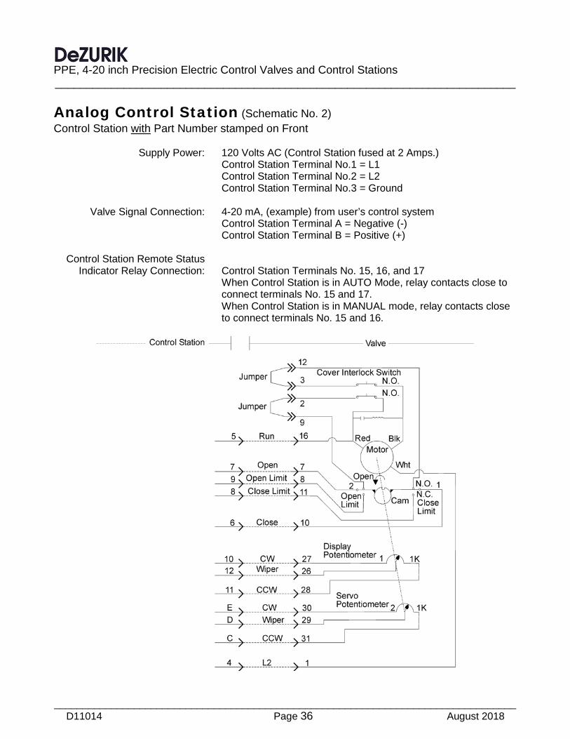
PPE, 4-20 inch Precision Electric Control Valves and Control Stations __________________________________________________________________________
_________________________________________________________________________________ D11014 Page 36 August 2018
Analog Control Station (Schematic No. 2) Control Station with Part Number stamped on Front Supply Power: 120 Volts AC (Control Station fused at 2 Amps.) Control Station Terminal No.1 = L1 Control Station Terminal No.2 = L2 Control Station Terminal No.3 = Ground Valve Signal Connection: 4-20 mA, (example) from user’s control system Control Station Terminal A = Negative (-) Control Station Terminal B = Positive (+) Control Station Remote Status Indicator Relay Connection: Control Station Terminals No. 15, 16, and 17 When Control Station is in AUTO Mode, relay contacts close to connect terminals No. 15 and 17. When Control Station is in MANUAL mode, relay contacts close to connect terminals No. 15 and 16.
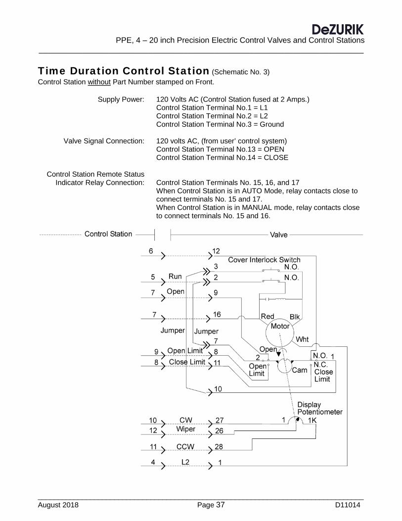
PPE, 4 – 20 inch Precision Electric Control Valves and Control Stations
__________________________________________________________________________
_________________________________________________________________________________ August 2018 Page 37 D11014
Time Duration Control Station (Schematic No. 3) Control Station without Part Number stamped on Front. Supply Power: 120 Volts AC (Control Station fused at 2 Amps.) Control Station Terminal No.1 = L1 Control Station Terminal No.2 = L2 Control Station Terminal No.3 = Ground Valve Signal Connection: 120 volts AC, (from user’ control system) Control Station Terminal No.13 = OPEN Control Station Terminal No.14 = CLOSE Control Station Remote Status Indicator Relay Connection: Control Station Terminals No. 15, 16, and 17 When Control Station is in AUTO Mode, relay contacts close to connect terminals No. 15 and 17. When Control Station is in MANUAL mode, relay contacts close to connect terminals No. 15 and 16.
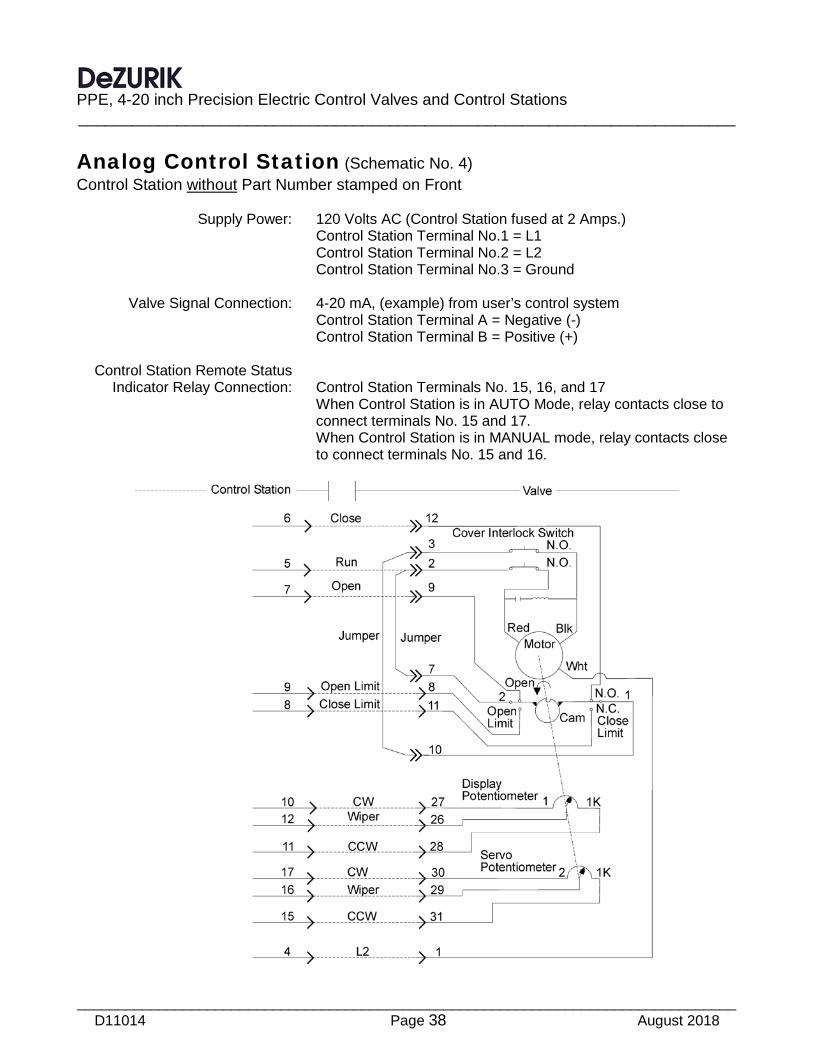
PPE, 4-20 inch Precision Electric Control Valves and Control Stations __________________________________________________________________________
_________________________________________________________________________________ D11014 Page 38 August 2018
Analog Control Station (Schematic No. 4) Control Station without Part Number stamped on Front Supply Power: 120 Volts AC (Control Station fused at 2 Amps.) Control Station Terminal No.1 = L1 Control Station Terminal No.2 = L2 Control Station Terminal No.3 = Ground Valve Signal Connection: 4-20 mA, (example) from user’s control system Control Station Terminal A = Negative (-) Control Station Terminal B = Positive (+) Control Station Remote Status Indicator Relay Connection: Control Station Terminals No. 15, 16, and 17 When Control Station is in AUTO Mode, relay contacts close to connect terminals No. 15 and 17. When Control Station is in MANUAL mode, relay contacts close to connect terminals No. 15 and 16.

PPE, 4 – 20 inch Precision Electric Control Valves and Control Stations
__________________________________________________________________________
_________________________________________________________________________________ August 2018 Page 39 D11014
Time Duration Control Station and Resolver (Schematic No.5) Control Station with Part Number stamped on Front. Supply Power: 120 Volts AC (Control Station fused at 2 Amps.) Control Station Terminal No.1 = L1 Control Station Terminal No.2 = L2 Control Station Terminal No.3 = Ground Valve Signal Connection: 120 volts AC, (from user’ control system) Control Station Terminal No.13 = OPEN Control Station Terminal No.14 = CLOSE Resolver Signal Connection: Power and mA Signal connections go directly to terminals in
valve junction box – as shown in Schematic No. 5 and described on Page 28 in Connections
Control Station Remote Status Indicator Relay Connection: Control Station Terminals No. 15, 16, and 17 When Control Station is in AUTO Mode, relay contacts close to connect terminals No. 15 and 17. When Control Station is in MANUAL mode, relay contacts close to connect terminals No. 15 and 16.
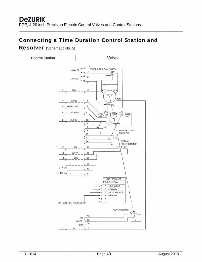
PPE, 4-20 inch Precision Electric Control Valves and Control Stations __________________________________________________________________________
_________________________________________________________________________________ D11014 Page 40 August 2018
Connecting a Time Duration Control Station and Resolver (Schematic No. 5) Control Station ──────┤ ├────── Valve
Printed in U.S.A.
Guarantee Products, auxiliaries and parts thereof of DeZURIK, Inc. manufacture are warranted to the original purchaser for a period of twenty-four (24) months from date of shipment from factory, against defective workmanship and material, but only if properly installed, operated and serviced in accordance with DeZURIK, Inc. recommendations. Repair or replacement, at our option, for items of DeZURIK, Inc. manufacture will be made free of charge, (FOB) our facility with removal, transportation and installation at your cost, if proved to be defective within such time, and this is your sole remedy with respect to such products. Equipment or parts manufactured by others but furnished by DeZURIK, Inc. will be repaired or replaced, but only to the extent provided in and honored by the original manufacturers warranty to DeZURIK, Inc., in each case subject to the limitations contained therein. No claim for transportation, labor or special or consequential damages or any other loss, cost or damage shall be allowed. You shall be solely responsible for determining suitability for use and in no event shall DeZURIK, Inc. be liable in this respect. DeZURIK, Inc. does not guarantee resistance to corrosion, erosion, abrasion or other sources of failure, nor does DeZURIK, Inc. guarantee a minimum length of service. Your failure to give written notice to us of any alleged defect under this warranty within twenty (20) days of its discovery, or attempts by someone other than DeZURIK, Inc. or its authorized representatives to remedy the alleged defects therein, or failure to return product or parts for repair or replacement as herein provided, or failure to install and operate said products and parts according to instructions furnished by DeZURIK, Inc., or misuse, modification, abuse or alteration of such product, accident, fire, flood or other Act of God, or failure to pay entire contract price when due shall be a waiver by you of all rights under this warranty. The foregoing guarantee shall be null and void if, after shipment from our factory, the item is modified in any way or a component of another manufacturer, such as but not limited to, an actuator is attached to the item by anyone other than DeZURIK, Inc. Factory Service personnel. All orders accepted shall be deemed accepted subject to this limited warranty, which shall be exclusive of any other or previous Warranty, and this shall be the only effective guarantee or warranty binding on DeZURIK, Inc., despite anything to the contrary contained in the purchase order or represented by any agent or employee of DeZURIK, Inc., in writing or otherwise, notwithstanding, including but not limited to implied warranties. Metric fasteners should not be used with ASME Class 150/300 bolt holes and flange bolt patterns. If you use metric fasteners with ASME Class 150/300 bolt holes and flange bolt patterns, it may lead to product failure, injury, and loss of life. DeZURIK Inc. disclaims all liability associated with the use of metric fasteners with ASME Class 150/300 bolt holes and flange patterns, including but not limited to personal injury, loss of life, loss of product, production time, equipment, property damage, lost profits, consequential damages of any kind and environment damage and/or cleanup. Use of metric fasteners with ASME Class 150/300 bolt holes and flange bolt patterns is a misuse that voids all warranties and contractual assurances. If you use metric fasteners with ASME Class 150/300 bolt holes and flange bolt patterns, you do so at your sole risk and any liability associated with such use shall not be the responsibility of DeZURIK, Inc. In addition to the foregoing, DeZURIK’s Manufacturer’s Conditions apply. THE FOREGOING REPAIR AND REPLACEMENT OBLIGATIONS ARE IN LIEU OF ALL OTHER WARRANTIES, OBLIGATIONS AND LIABILITIES, INCLUDING ALL WARRANTIES OF FITNESS FOR A PARTICULAR PURPOSE OR OF MERCHANTABILITY OR OTHERWISE, EXPRESSED OR IMPLIED IN FACT OR BY LAW, AND STATE DEZURIK, INC.’S ENTIRE AND EXCLUSIVE LIABILITY AND YOUR EXCLUSIVE REMEDY FOR ANY CLAIM IN CONNECTION WITH THE SALE AND FURNISHING OF SERVICES, GOODS OR PARTS, THEIR DESIGN, SUITABILITY FOR USE, INSTALLATION OR OPERATIONS.
Limitation of liability LIMITATION OF LIABILITY: IN NO EVENT SHALL DEZURIK, INC. BE LIABLE FOR ANY DIRECT, INDIRECT, SPECIAL OR CONSEQUENTIAL DAMAGES WHATSOEVER, AND DEZURIK, INC.’S LIABILITY, UNDER NO CIRCUMSTANCES, WILL EXCEED THE CONTRACT PRICE FOR THE GOODS AND/OR SERVICES FOR WHICH LIABILITY IS CLAIMED. ANY ACTION BY YOU FOR BREACH OF CONTRACT MUST BE COMMENCED WITHIN 12 MONTHS AFTER THE DATE OF SALE.
Sales and Service For information about our worldwide locations, approvals, certifications and local representative:
Web site: www.dezurik.com E-Mail: [email protected]
250 Riverside Ave. N., Sartell, MN 56377 ● Phone: 320-259-2000 ● Fax: 320-259-2227
DeZURIK, Inc. reserves the right to incorporate our latest design and material changes without notice or obligation. Design features, materials of construction and dimensional data, as described in this manual, are provided for your information only
and should not be relied upon unless confirmed in writing by DeZURIK, Inc. Certified drawings are available upon request.
Related Documents