Max: 45kg/100lbs MOUIN_PFW6850_V01 Installation Guide Installationsanleitung, Guía de Instalacíon, Guida de Installazione, Guide d’Installation, Installatie gids PFW 6850

Welcome message from author
This document is posted to help you gain knowledge. Please leave a comment to let me know what you think about it! Share it to your friends and learn new things together.
Transcript

Max: 45kg/100lbsMOUIN_PFW6850_V01
Installation GuideInstallationsanleitung, Guía de Instalacíon, Guida de Installazione, Guide d’Installation, Installatie gids
PFW 6850
www.vogels.com
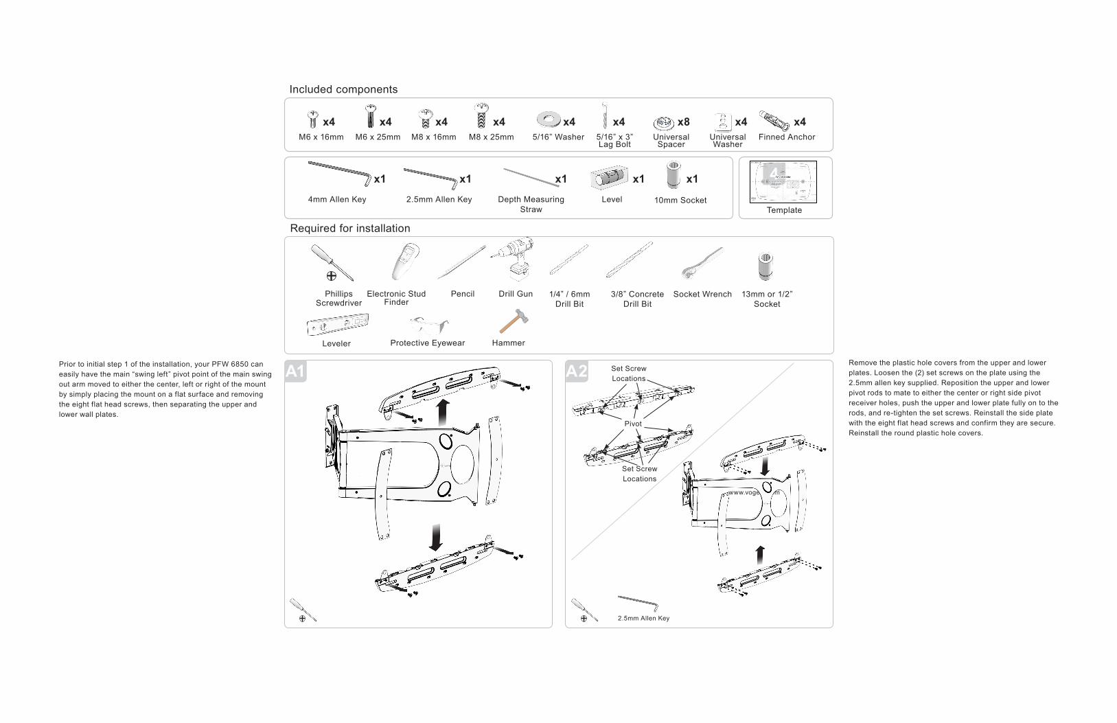
M6 x 16mm M6 x 25mm M8 x 16mm M8 x 25mm 5/16” Washer 5/16” x 3” Lag Bolt
Universal Spacer
Universal Washer
Finned Anchor
2.5mm Allen Key Depth Measuring Straw
Level4mm Allen Key
Phillips Screwdriver
Protective Eyewear HammerLeveler
Electronic Stud Finder
Pencil Drill Gun
2.5mm Allen Key
10mm SocketTemplate
x4 x4 x4 x4 x4 x4 x8 x4 x4
1/4” / 6mmDrill Bit
3/8” Concrete Drill Bit
Socket Wrench 13mm or 1/2” Socket
x1 x1 x1 x1 x1 4
A2A1Remove the plastic hole covers from the upper and lower plates. Loosen the (2) set screws on the plate using the 2.5mm allen key supplied. Reposition the upper and lower pivot rods to mate to either the center or right side pivot receiver holes, push the upper and lower plate fully on to the rods, and re-tighten the set screws. Reinstall the side plate with the eight flat head screws and confirm they are secure. Reinstall the round plastic hole covers.
Prior to initial step 1 of the installation, your PFW 6850 can easily have the main “swing left” pivot point of the main swing out arm moved to either the center, left or right of the mount by simply placing the mount on a flat surface and removing the eight flat head screws, then separating the upper and lower wall plates.
Included components
Required for installation
Pivot
Set ScrewLocations
Set ScrewLocations
www.vogels.com
1 2
443
21
Installation GuideInstallationsanleitung, Guía de Instalacíon, Guida de Installazione, Guide d’Installation, Installatie gids
PFW 6850
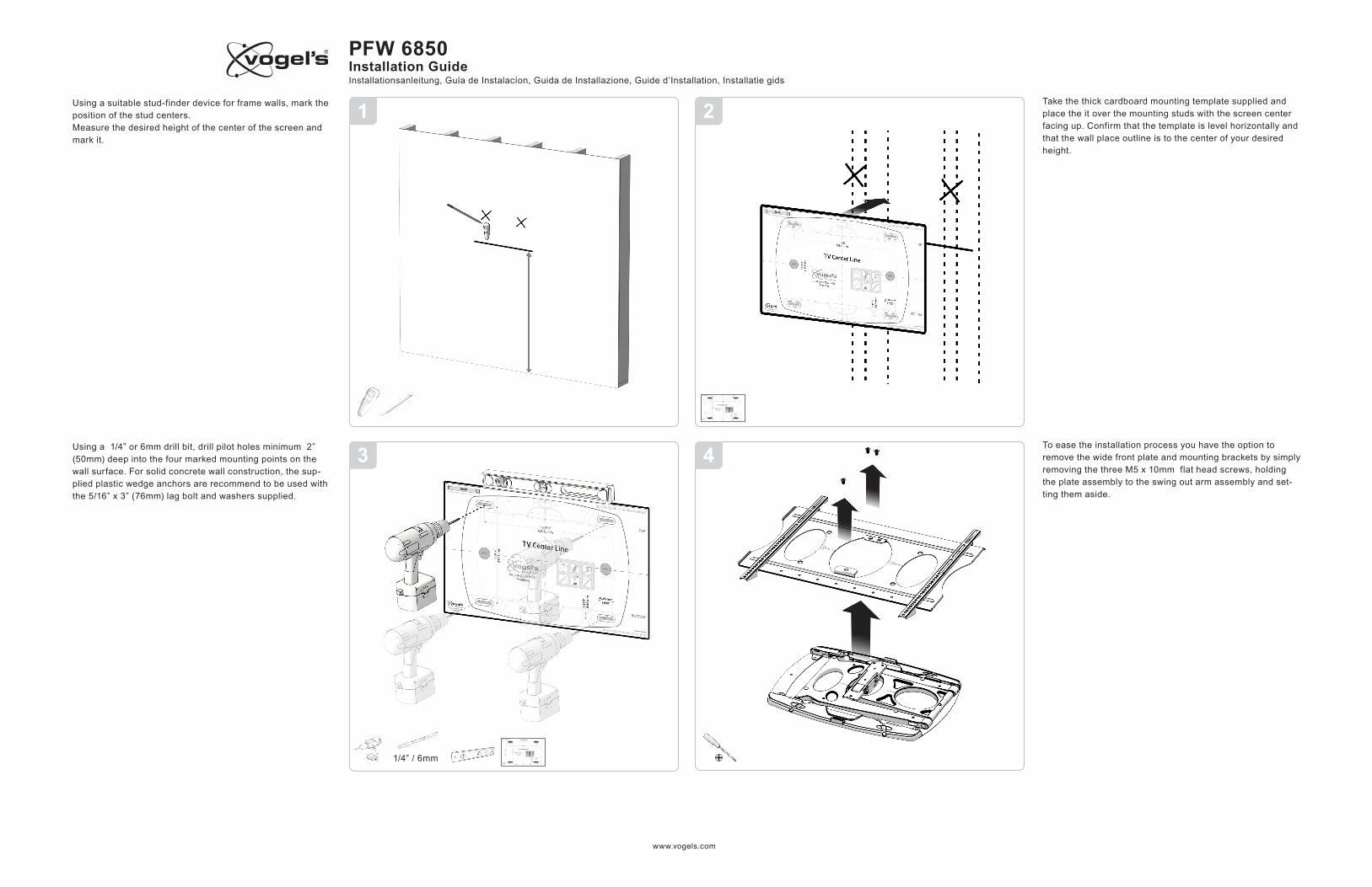
To ease the installation process you have the option to remove the wide front plate and mounting brackets by simply removing the three M5 x 10mm flat head screws, holding the plate assembly to the swing out arm assembly and set-ting them aside.
Take the thick cardboard mounting template supplied and place the it over the mounting studs with the screen center facing up. Confirm that the template is level horizontally and that the wall place outline is to the center of your desired height.
Using a suitable stud-finder device for frame walls, mark the position of the stud centers.Measure the desired height of the center of the screen and mark it.
Using a 1/4” or 6mm drill bit, drill pilot holes minimum 2” (50mm) deep into the four marked mounting points on the wall surface. For solid concrete wall construction, the sup-plied plastic wedge anchors are recommend to be used with the 5/16” x 3” (76mm) lag bolt and washers supplied.
1/4” / 6mm
www.vogels.com
1 2
487
65
Installation GuideInstallationsanleitung, Guía de Instalacíon, Guida de Installazione, Guide d’Installation, Installatie gids
PFW 6850
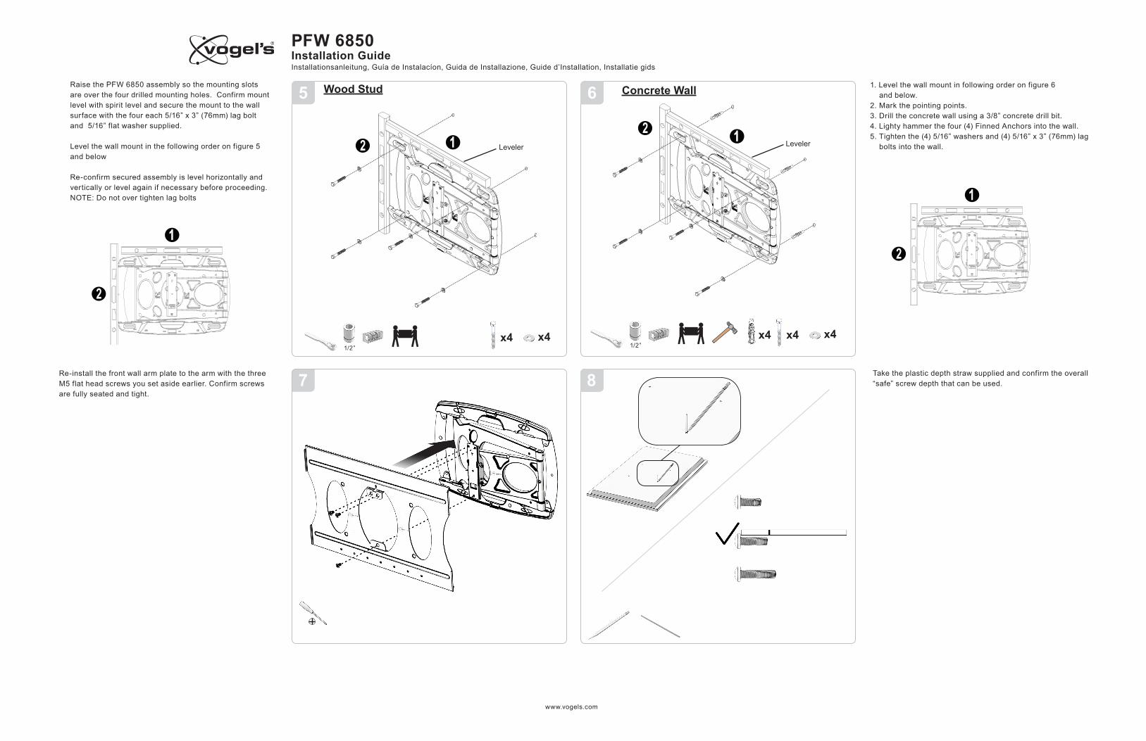
Take the plastic depth straw supplied and confirm the overall “safe” screw depth that can be used.
Re-install the front wall arm plate to the arm with the three M5 flat head screws you set aside earlier. Confirm screws are fully seated and tight.
Wood Stud
Leveler
1/2”x4x4
Raise the PFW 6850 assembly so the mounting slots are over the four drilled mounting holes. Confirm mount level with spirit level and secure the mount to the wall surface with the four each 5/16” x 3” (76mm) lag bolt and 5/16” flat washer supplied.
Level the wall mount in the following order on figure 5 and below
Re-confirm secured assembly is level horizontally and vertically or level again if necessary before proceeding.NOTE: Do not over tighten lag bolts
Concrete Wall
Leveler
1/2”x4x4x4
1. Level the wall mount in following order on figure 6 and below. 2. Mark the pointing points.3. Drill the concrete wall using a 3/8” concrete drill bit.4. Lighty hammer the four (4) Finned Anchors into the wall.5. Tighten the (4) 5/16” washers and (4) 5/16” x 3” (76mm) lag bolts into the wall.

www.vogels.com
1 2
4
10A
11
9
10B
Installation GuideInstallationsanleitung, Guía de Instalacíon, Guida de Installazione, Guide d’Installation, Installatie gids
PFW 6850
Once the correct pitch and depth screws are pulled from the hardware pack supplied, secure the two brackets to the rear of the display with the proper screws and plate washer holes. Plastic spacers are also supplied in case you need additional clearance between the bracket and the rear of the display. NOTE: Do not over tighten the screws.
With the upper and lower security screws loosened on each bracket (two people recommended) raise the display and place the top hook of the bracket over the receiver plate on the wall mount. Allow the lower end of the bracket to lay flat against the mating plate on the mount.
Center the display horizontally on the plate and check the display is level on the mount. To adjust level, adjust the left or right top screw to achieve desired level of the display. Once level, secure the lower left and right security screws on the bracket to “fix” the mount to the wall mount.
x4x4x4x4
Place the display face down on a smooth flat surface. Place the left and right mounting brackets over the four mounting points on the rear of the display arrow pointing up to the top of the display, making sure the brackets are lined up with the center top to bottom on the display.

www.vogels.com
1 2
1514
1312
Installation GuideInstallationsanleitung, Guía de Instalacíon, Guida de Installazione, Guide d’Installation, Installatie gids
PFW 6850
We recommend where possible that the power and signal cables be run separately through the mount until mating at the display plug in points to minimize possible “cross talk” interference. With the covers removed, cable can be run inside the upper and lower main arm and through the slots behind the plastic beauty covers.
Install the upper and lower “push on” plastic “beauty covers” to the upper and lower wall plates. Reinstall the upper and lower plastic cable covers to the mounts main swing arm.
Installation complete
10mm Deep Socket
2.5mm Allen key
2.5mm Allen key
Tilting of the display on the mount is easily accomplished by placing one hand on top of the display edge center and one hand on the bottom of the display edge center and gently pulling out on the top edge to the desired tilt angle. No lock-ing of the set tilt angle is required as the mount has built-in friction control. If additional tension is required, use the socket and M4 allen key to adjust the desired tension.Extra tension can be applied to the pivot of the arms by tightening the nuts on the arm with supplied 10mm deep socket, and the set screws on the base with the supplied 2.5mm allen key. NOTE: Do not over tighten.

www.vogels.com
24.80630
20.73526
21.38543
1.0025
15.86403
29.49749
15°MAX TILT
32.20818
12.56319
1.6041
26.33669
23.06586
16.00406
18.00457
23.66
(D2)601
10.50
(D1)267
(MULTI POSITION ARM 3 PLS)NOTE: IF THE NEXT ARM OPTIONAL
POSITION IS USED ADD 7" TO (D1) & (D2)
12.12308
1.8547
1.5038
21.00
(D1)533
34.16
(D2)868
(MULTI POSITION ARM 3 PLS)NOTE: IF THE NEXT ARM OPTIONAL
POSITION IS USED ADD 7" TO (D1) & (D2)
Installation GuideInstallationsanleitung, Guía de Instalacíon, Guida de Installazione, Guide d’Installation, Installatie gids
PFW 6850
95V0-000-015-0X_2
Related Documents


![{KKKKmmmmaaaa---]]] ----©mmmm----bbb ---¯ nnnssssââââ …lfa.kerala.gov.in/docs/audit_report/panchayat/kottayam/elikkulam09_… · FenFen- ---¡pfw {Kma¡pfw {Kma¡pfw {Kma-](https://static.cupdf.com/doc/110x72/5f78fae61406ab6bec26f33c/kkkkmmmmaaaa-mmmm-bbb-nnnssss-lfa-fenfen-pfw.jpg)