Article
Well Plan Parameter Guideline for Directional Drilling in the Gulf of Thailand Jirawat Chewaroungroaja,* and Anusara Hentoogb Department of Mining and Petroleum Engineering, Faculty of Engineering, Chulalongkorn University, Bangkok 10330, Thailand E-mail: a,*[email protected] (Corresponding author), [email protected]
Abstract. Complex structured reservoir in the Gulf of Thailand (GOT) dictates directional drilling design requirement. Torque and drag analysis is used in determination of drill ability from the planned well trajectory. A set of well construction and typical reservoir data in GOT provide constraints for well plan parameters. Both typical 2-dimension (2D) and 3-dimension (3D) well profiles are studied. Each well profile requires different well plan parameters, namely kick off points, build up and drop off rates, inclinations, turn rates, and turn degrees. Sets of well plan parameter guideline for each well type are provided for pre-check drill ability of the designs. For each well profile types, the maximum first inclinations are shown as results for given sets of well plan parameters. The deeper kick off point for 2D well profile benefits on torque and effective tension limits than shallower one. For 3D well design, kick off point and the first inclination have strong effects on torque and effective tension whereas turn degree, build up rate, and turn rate have weaker effects. In addition, high turn degree is drillable with deep kick off point, low build up rate and high turn rate combined. Keywords: Gulf of Thailand, directional drilling, well planning, torque and drag.
ENGINEERING JOURNAL Volume 25 Issue 3 Received 13 January 2021 Accepted 8 February 2021 Published 31 March 2021 Online at https://engj.org/ DOI:10.4186/ej.2021.25.3.15
DOI:10.4186/ej.2021.25.3.15
16 ENGINEERING JOURNAL Volume 25 Issue 3, ISSN 0125-8281 (https://engj.org/)
1. Introduction
Offshore drilling in Thailand began in the late 1960’s followed by the discoveries of hydrocarbons in the commercial quantities in the Gulf of Thailand (GOT) by the early 1970’s. Gas production started in early 1980’s when infrastructure was installed. During the 1980’s drilling in the GOT being less than 100 wells per year was common [1]. Increasing gas production and the complex geological structures of the fields result in the drilling activity levels continue increased to the 2000’s. The faults of the GOT are important because they configured main hydrocarbon traps. They are stratigraphically and structurally complex and comprise hundreds of small separate hydrocarbon accumulations [2]. This poses the main challenges to the development strategies of the fields. Because of the thin fluvial sandstone hydrocarbon reservoirs that are intensely faulted into numerous but small accumulations, commercial viability has been achievable through directional drilling from numerous small wellhead platforms [3-5]. The requirement to drill and complete hundreds of new wells to maintain production output means that the well design and execution must be at the shorter time and at the cheaper cost to keep the viability of the fields. Several initiatives and improvements, such as synthetic drilling fluid, PDC bit, rotary topdrive, steerable drilling techniques, slimhole monobore design, LWD, and rig advancement for batch drilling have brought the drilling cycle of the well from approximately 70 days to less than 5 days [6-8]
Conventional well planning method can pre-analyze stress, torque and drag of planning wellbore before drilling. Torque and drag are key factors in planning directional wells, especially extended reach and horizontal wells. Torque is a force required for rotate drill pipe, drag is an incremental force to move pipe up or down from hole. Torque and drag are related; high drag force and high torque loads normally occur at the same time. Drill string torque and drag are primary caused by friction force between string and wellbore Drag is also related to well trajectory design. Downward drag in directional well can cause excessive axial compression and lead to buckling. Torque and drag behavior depend on local friction factor and specific operational and rig limitation. Excessive torque and drag force have consequences in drilling failures such as twisted off, buckling, stuck pipe, etc. Optimizing well profiles to minimize torque and drag problems has been discussed in many publications [9-11]. Torque and drag simulation through wellbore profile helps eliminate risk and uncertainty at pre-job stage. Although the method is still considered effective, but the selected well design may not be the best one technically or economically. Well planning process involves cross functional parties, e.g. drilling engineers, subsurface geoscientists, well planners, and directional drillers [12]. It requires full collaboration to integrate the well planning data and reduce the number of complicated or bottle neck processes in supporting the concept of “Drilling Factory Model” [13].
2. Torque and Drag
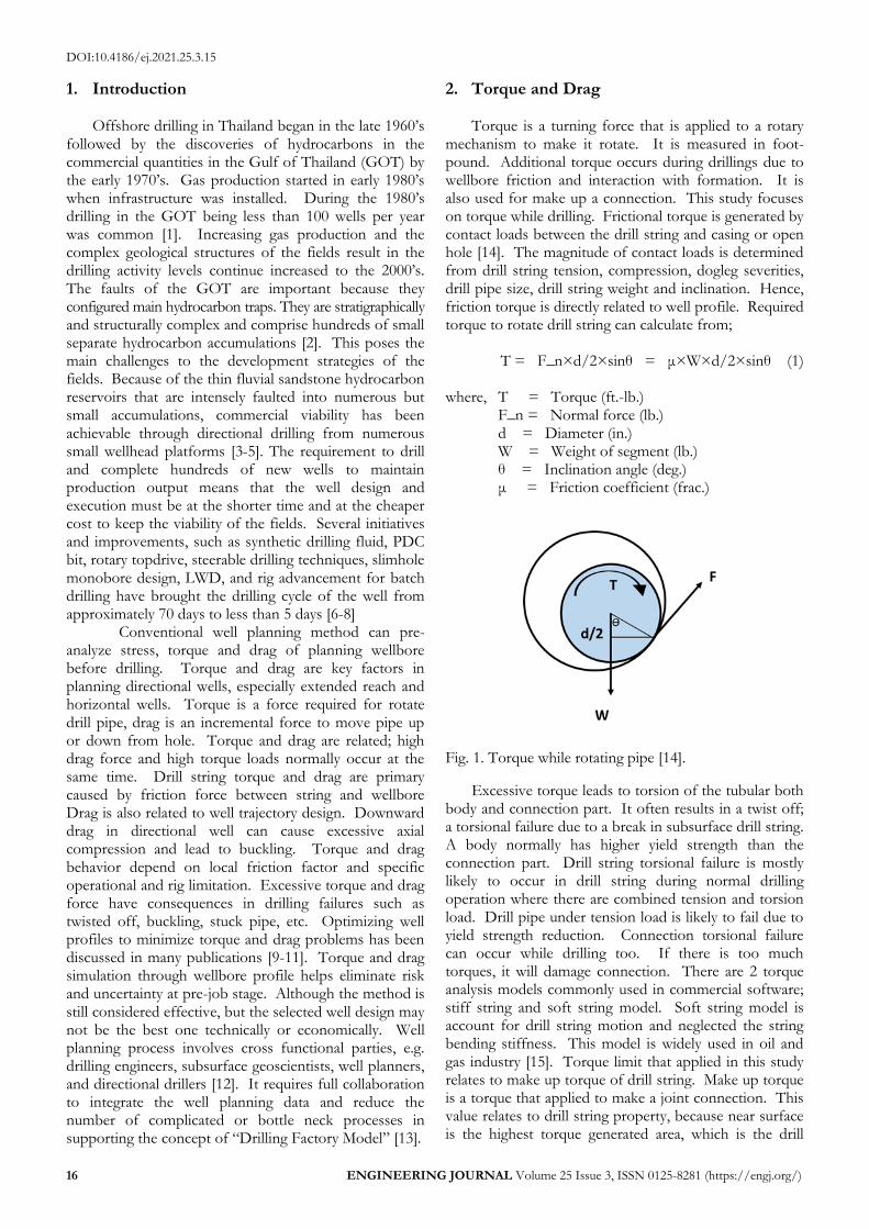
Torque is a turning force that is applied to a rotary mechanism to make it rotate. It is measured in foot-pound. Additional torque occurs during drillings due to wellbore friction and interaction with formation. It is also used for make up a connection. This study focuses on torque while drilling. Frictional torque is generated by contact loads between the drill string and casing or open hole [14]. The magnitude of contact loads is determined from drill string tension, compression, dogleg severities, drill pipe size, drill string weight and inclination. Hence, friction torque is directly related to well profile. Required torque to rotate drill string can calculate from;
T = F_n×d/2×sinθ = μ×W×d/2×sinθ (1)
where, T = Torque (ft.-lb.)
F_n = Normal force (lb.) d = Diameter (in.) W = Weight of segment (lb.)
θ = Inclination angle (deg.) μ = Friction coefficient (frac.)
Fig. 1. Torque while rotating pipe [14].
Excessive torque leads to torsion of the tubular both body and connection part. It often results in a twist off; a torsional failure due to a break in subsurface drill string. A body normally has higher yield strength than the connection part. Drill string torsional failure is mostly likely to occur in drill string during normal drilling operation where there are combined tension and torsion load. Drill pipe under tension load is likely to fail due to yield strength reduction. Connection torsional failure can occur while drilling too. If there is too much torques, it will damage connection. There are 2 torque analysis models commonly used in commercial software; stiff string and soft string model. Soft string model is account for drill string motion and neglected the string bending stiffness. This model is widely used in oil and gas industry [15]. Torque limit that applied in this study relates to make up torque of drill string. Make up torque is a torque that applied to make a joint connection. This value relates to drill string property, because near surface is the highest torque generated area, which is the drill
DOI:10.4186/ej.2021.25.3.15
ENGINEERING JOURNAL Volume 25 Issue 3, ISSN 0125-8281 (https://engj.org/) 17
pipe section. Hence, drill pipe’s make up torque is used as a criterion.
Drag is a friction between a moving device and other moving or nonmoving part such as formation. It acts opposite side of object movement and is related to well trajectory profile and wellbore smoothness [16]. Downward drag in directional well can cause excessive axial compression and lead to buckling. Torque and drag behavior depend on local friction factor and specific operational and rig limitation [17].
Drag force is calculated using the following equation;
𝐹𝐷 = 𝐹𝑛 × 𝜇 ×𝑇
𝑉 (2)
where, 𝐹𝐷= Drag force (lbs.)
𝐹𝑛 = Normal force (lbs.) μ = Friction coefficient (frac.) T = Trip speed (in/s) V = Resultant speed (in/s)
Resultant speed is calculated from;
𝑉 = √𝑇2 + (𝑑 × 𝜋 ×𝑅𝑃𝑀
60) (3)
where,
d = Drill string diameter (in.) RPM = Rotational speed per minute (rpm.)
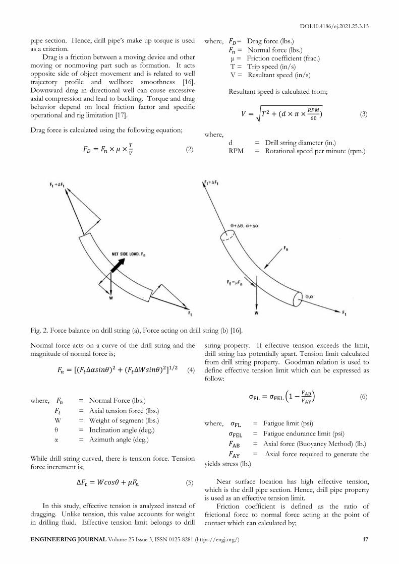
Fig. 2. Force balance on drill string (a), Force acting on drill string (b) [16].
Normal force acts on a curve of the drill string and the magnitude of normal force is;
𝐹𝑛 = [(𝐹𝑡∆𝛼𝑠𝑖𝑛𝜃)2 + (𝐹𝑡∆𝑊𝑠𝑖𝑛𝜃)2]1/2 (4)
where, 𝐹𝑛 = Normal Force (lbs.)
𝐹𝑡 = Axial tension force (lbs.)
W = Weight of segment (lbs.)
θ = Inclination angle (deg.)
α = Azimuth angle (deg.)
While drill string curved, there is tension force. Tension force increment is;
∆𝐹𝑡 = 𝑊𝑐𝑜𝑠𝜃 + 𝜇𝐹𝑛 (5)
In this study, effective tension is analyzed instead of dragging. Unlike tension, this value accounts for weight in drilling fluid. Effective tension limit belongs to drill
string property. If effective tension exceeds the limit, drill string has potentially apart. Tension limit calculated from drill string property. Goodman relation is used to define effective tension limit which can be expressed as follow:
σFL = σFEL (1 −FAB
FAY) (6)
where, 𝜎FL = Fatigue limit (psi)
𝜎FEL = Fatigue endurance limit (psi)
𝐹AB = Axial force (Buoyancy Method) (lb.)
𝐹AY = Axial force required to generate the
yields stress (lb.)
Near surface location has high effective tension,
which is the drill pipe section. Hence, drill pipe property is used as an effective tension limit.
Friction coefficient is defined as the ratio of frictional force to normal force acting at the point of contact which can calculated by;
DOI:10.4186/ej.2021.25.3.15
18 ENGINEERING JOURNAL Volume 25 Issue 3, ISSN 0125-8281 (https://engj.org/)
𝜇 =𝐹𝑓
𝐹𝑛 (7)
There are two types of coefficient of frictional
factors; case hole frictional factor and open hole frictional factor. This factor accounts for hole cleaning quality and micro tortuosity [18]. Friction factor while drilling relates to drilling fluid, pipe type and cutting concentration. The general frictional factor for cased hole is 0.25. For open hole section, frictional factor is depended on local geological lithology. Frictional factor for open hole section is 0.28-0.35 [19]. The severe frictional factors are applied in this study which are 0.25 for cased hole section, and 0.35 for open hole section
Excessive torque and drag force can be observed in tight hole condition, poor hole cleaning, differential stick. If well is in good condition, the main cause of torque and drag is siding friction. The more deviated well profile creates higher siding friction and excessive torque and drag. Torque and drag modeling is proven technique for wellbore construction [2].
3. Well Plan Parameters
This study provides optimum sets of directional well plan parameters i.e. kick off point (KOP), inclination (INC), build rate (BUR) base on torque and drag as
criterion. Well planning was performed in a commercial software. To allow efficiency of well parameters varying process, a constrain set of well construction and reservoir data are defined. Reservoir data, i.e. lithology, pressure data, are required. The data represent typical properties of reservoir in GOT. Reservoir in GOT typically consists of Miocene gas sand with highly faulted sand shale interbedded [2]. Deposition environment is fluvial-deltaic. Formation dip angle is very gentle. Also, general operations in GOT are applied i.e. hole geometry, casing design, drill string components. A 3 string hole design has been applied in GOT due to small reservoir unit and structure complexity with 2 casing sections which was surfaced and intermediated casing [7]. However, in some of the deep well with high downhole pressure a 4 string hole design is applicable [8].
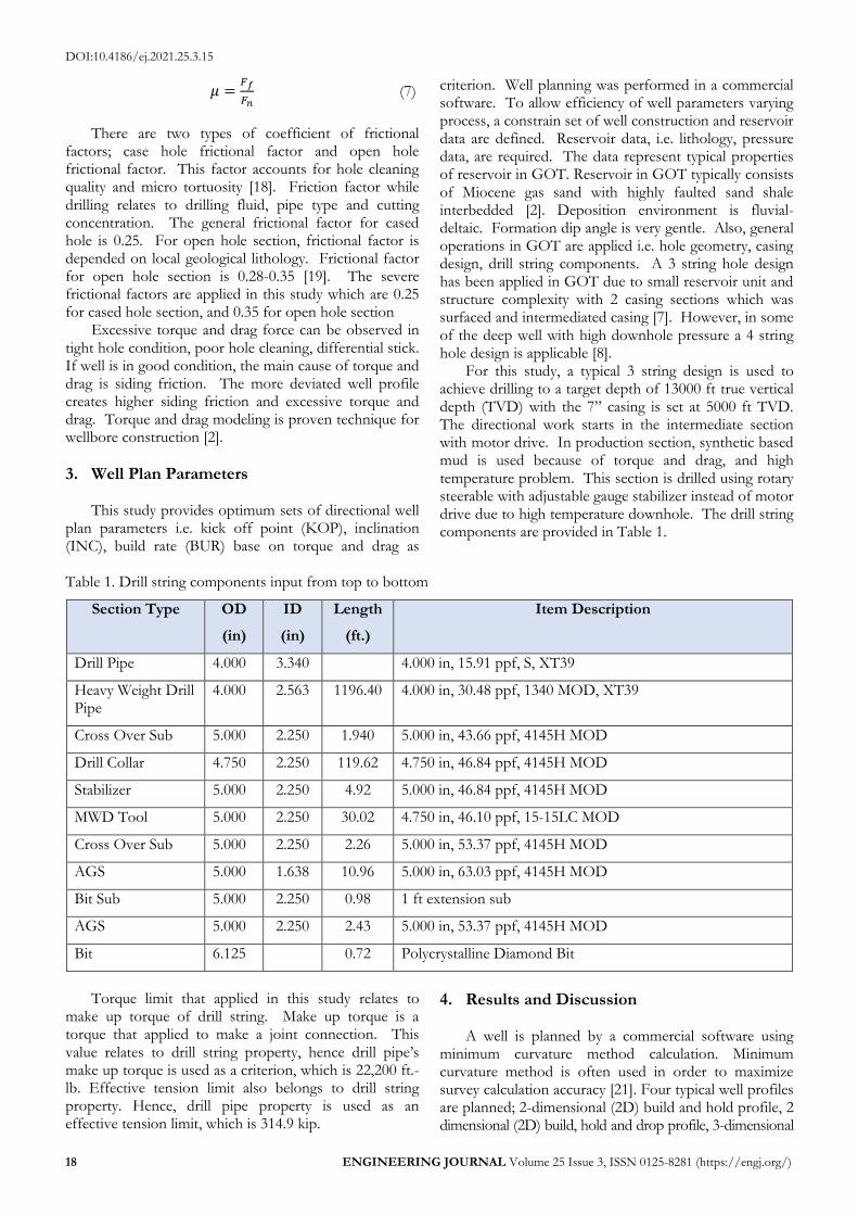
For this study, a typical 3 string design is used to achieve drilling to a target depth of 13000 ft true vertical depth (TVD) with the 7” casing is set at 5000 ft TVD. The directional work starts in the intermediate section with motor drive. In production section, synthetic based mud is used because of torque and drag, and high temperature problem. This section is drilled using rotary steerable with adjustable gauge stabilizer instead of motor drive due to high temperature downhole. The drill string components are provided in Table 1.
Table 1. Drill string components input from top to bottom
Section Type OD
(in)
ID
(in)
Length
(ft.)
Item Description
Drill Pipe 4.000 3.340 4.000 in, 15.91 ppf, S, XT39
Heavy Weight Drill Pipe
4.000 2.563 1196.40 4.000 in, 30.48 ppf, 1340 MOD, XT39
Cross Over Sub 5.000 2.250 1.940 5.000 in, 43.66 ppf, 4145H MOD
Drill Collar 4.750 2.250 119.62 4.750 in, 46.84 ppf, 4145H MOD
Stabilizer 5.000 2.250 4.92 5.000 in, 46.84 ppf, 4145H MOD
MWD Tool 5.000 2.250 30.02 4.750 in, 46.10 ppf, 15-15LC MOD
Cross Over Sub 5.000 2.250 2.26 5.000 in, 53.37 ppf, 4145H MOD
AGS 5.000 1.638 10.96 5.000 in, 63.03 ppf, 4145H MOD
Bit Sub 5.000 2.250 0.98 1 ft extension sub
AGS 5.000 2.250 2.43 5.000 in, 53.37 ppf, 4145H MOD
Bit 6.125 0.72 Polycrystalline Diamond Bit
Torque limit that applied in this study relates to
make up torque of drill string. Make up torque is a torque that applied to make a joint connection. This value relates to drill string property, hence drill pipe’s make up torque is used as a criterion, which is 22,200 ft.-lb. Effective tension limit also belongs to drill string property. Hence, drill pipe property is used as an effective tension limit, which is 314.9 kip.
4. Results and Discussion
A well is planned by a commercial software using minimum curvature method calculation. Minimum curvature method is often used in order to maximize survey calculation accuracy [21]. Four typical well profiles are planned; 2-dimensional (2D) build and hold profile, 2 dimensional (2D) build, hold and drop profile, 3-dimensional
DOI:10.4186/ej.2021.25.3.15
ENGINEERING JOURNAL Volume 25 Issue 3, ISSN 0125-8281 (https://engj.org/) 19
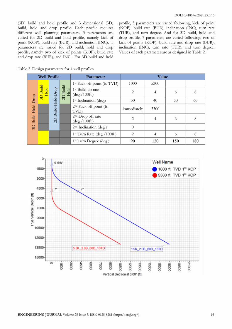
(3D) build and hold profile and 3 dimensional (3D) build, hold and drop profile. Each profile requires different well planning parameters. 3 parameters are varied for 2D build and hold profile, namely kick of point (KOP), build rate (BUR), and inclination (INC). 5 parameters are varied for 2D build, hold and drop profile, namely two of kick of points (KOP), build rate and drop rate (BUR), and INC. For 3D build and hold
profile, 5 parameters are varied following; kick of point (KOP), build rate (BUR), inclination (INC), turn rate (TUR), and turn degree. And for 3D build, hold and drop profile, 7 parameters are varied following; two of kick of points (KOP), build rate and drop rate (BUR), inclination (INC), turn rate (TUR), and turn degree. Values of each parameter are as designed in Table 2.
Table 2. Design parameters for 4 well profiles
Well Profile Parameter Value
3D
Build
-Ho
ld-D
rop
3D
Build
-
Ho
ld
2D
Build
-Ho
ld-D
rop
2D
Build
-
Ho
ld
1st Kick off point (ft. TVD) 1000 5300
1st Build up rate (deg./100ft.)
2 4 6 8
1st Inclination (deg.) 30 40 50 60
2nd Kick off point (ft. TVD)
immediately 5300
2nd Drop off rate (deg./100ft.)
2 4 6 8
2nd Inclination (deg.) 0
1st Turn Rate (deg./100ft.) 2 4 6 8
1st Turn Degree (deg.) 90 120 150 180
DOI:10.4186/ej.2021.25.3.15
20 ENGINEERING JOURNAL Volume 25 Issue 3, ISSN 0125-8281 (https://engj.org/)
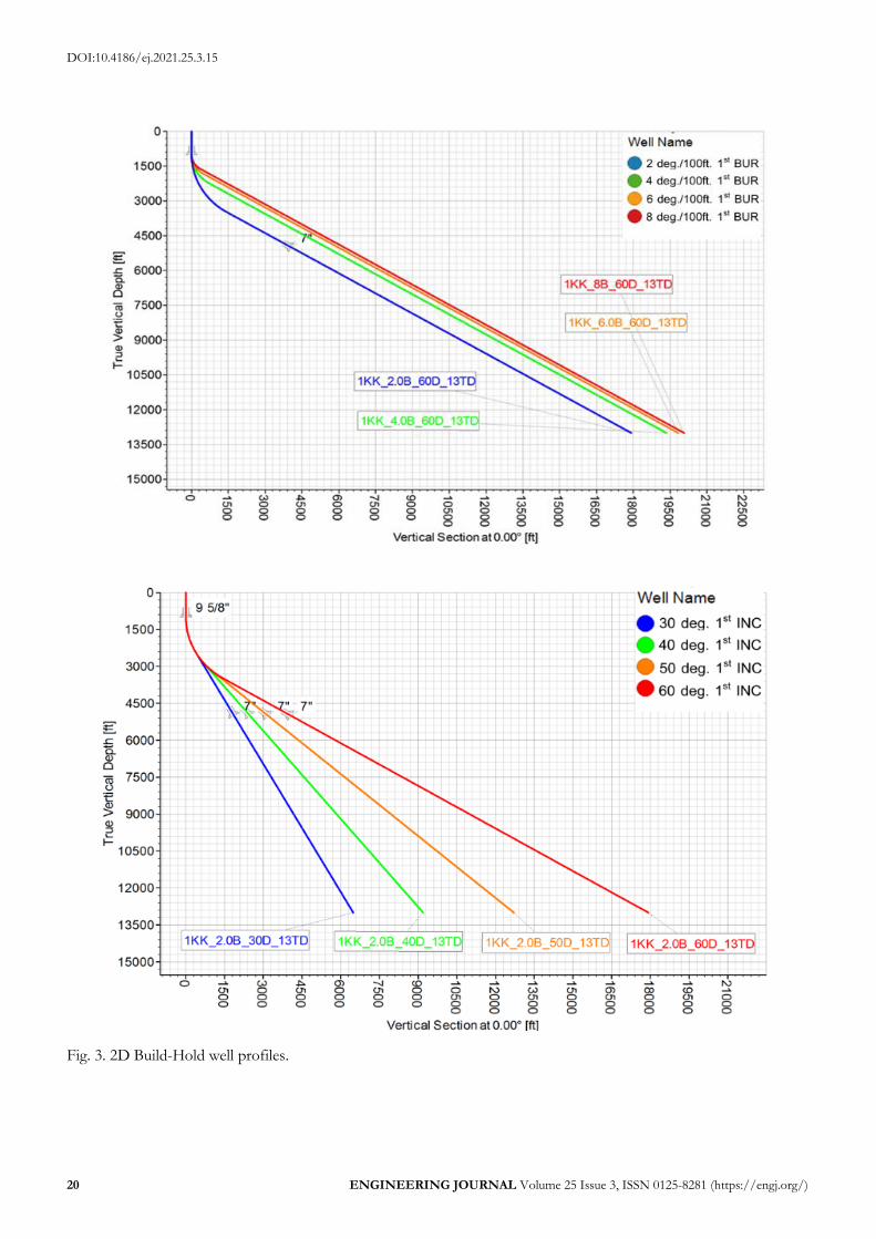
Fig. 3. 2D Build-Hold well profiles.
DOI:10.4186/ej.2021.25.3.15
ENGINEERING JOURNAL Volume 25 Issue 3, ISSN 0125-8281 (https://engj.org/) 21
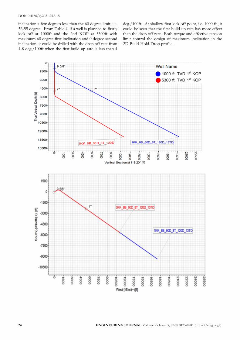
Three different sets of varying design parameters, namely kick off point (KOP), build up rate (BUR) and inclination (INC) respectively are shown in Fig. 3. Note that the label of each line represents values of each
design parameters. For example 1KK_2.0B_60D_13TD means the well having kick off point at 1000 ft, 2 deg/100ft build up rate, 60 degree inclination, and 13000 ft. true vertical depth (TVD).
Table 3. Maximum INC for well planning guideline 2D build and hold.
KOP / BUR 2 4 6 8
1000 55 51 49 49
5300 60 60 60 60
The maximum inclination design is provided as a
guideline in Table 3. For example, the maximum inclination for 2D Build-Hold well profile with kick off point at 1000ft. and 2 deg./100ft build up rate is 55 degree. Note that the limit of maximum inclination for this study is set at 60 degree. At the shallow kick off
point at 1000 ft, the maximum inclination we can design is lower than maximum limit of 60 degree, i.e. 49 – 55 degree. Torque limit dictates the design of maximum inclination for this 2D Build-Hold profile where as effective tension limit is concerned only with combination of shallow kick off point and high build up rate.
DOI:10.4186/ej.2021.25.3.15
22 ENGINEERING JOURNAL Volume 25 Issue 3, ISSN 0125-8281 (https://engj.org/)

DOI:10.4186/ej.2021.25.3.15
ENGINEERING JOURNAL Volume 25 Issue 3, ISSN 0125-8281 (https://engj.org/) 23
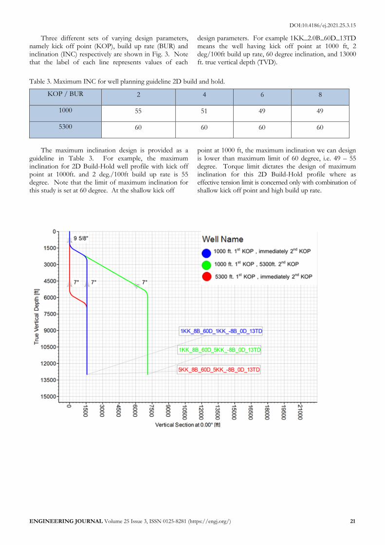
Fig. 4. 2D Build-Hold-Drop well profiles.
Figure 4 demonstrate examples of 2-dimension build, hold, and drop well profile. The first set of well profiles has variations in the kick off points. For example 1KK_8B_60D_5KK_-8B_0D_13TD represents the well having 1st KOP at 1000 ft, 8 deg./100ft 1st BUR, 60 deg. 1st INC, 2nd KOP at 5300 ft, -8 deg./100ft 2nd BUR, 0
deg. 2nd INC, and 13000 ft TVD. The second, third and fourth set of well profiles show the variations in the first inclination, the first build rate, and the second build rate respectively while keeping the first kick off point at 1000 ft, the second kick off point at 5300 ft and 0 degree second inclination.
Table 4. Well Planning Guideline 2D Build-Hold-Drop.
1st KOP 2nd KOP 1st BUR /2nd BUR -2 -4 -6 -8
1000 immediately 2 30* 60 60 60
1000 immediately 4 60 60 60 60
1000 immediately 6 60 60 60 60
1000 immediately 8 60 60 60 60
1000 5300 2 60 60 60 60
1000 5300 4 59 60 60 60
1000 5300 6 57 59 60 60
1000 5300 8 56 57 56 56
5300 immediately 2 60 60 60 60
5300 immediately 4 60 60 60 60
5300 immediately 6 60 60 60 60
5300 immediately 8 60 60 60 60
“*” in Table 4 means that the case cannot be designed with inclination lower than 30 degree. Also noted that negative value of the 2nd BUR means drop off rate. Table 4 provides the values of the maximum first
inclination of the well that we can plan with the 2nd inclination of 0 degree. In most cases we are able to plan the well at the maximum limit of 60 degree on the first inclination, with few wells having the maximum first
DOI:10.4186/ej.2021.25.3.15
24 ENGINEERING JOURNAL Volume 25 Issue 3, ISSN 0125-8281 (https://engj.org/)
inclination a few degrees less than the 60 degree limit, i.e. 56-59 degree. From Table 4, if a well is planned to firstly kick off at 1000ft and the 2nd KOP at 5300ft with maximum 60 degree first inclination and 0 degree second inclination, it could be drilled with the drop off rate from 4-8 deg./100ft when the first build up rate is less than 4
deg./100ft. At shallow first kick off point, i.e. 1000 ft., it could be seen that the first build up rate has more effect than the drop off rate. Both torque and effective tension limit control the design of maximum inclination in the 2D Build-Hold-Drop profile.

DOI:10.4186/ej.2021.25.3.15
ENGINEERING JOURNAL Volume 25 Issue 3, ISSN 0125-8281 (https://engj.org/) 25
DOI:10.4186/ej.2021.25.3.15
26 ENGINEERING JOURNAL Volume 25 Issue 3, ISSN 0125-8281 (https://engj.org/)
DOI:10.4186/ej.2021.25.3.15
ENGINEERING JOURNAL Volume 25 Issue 3, ISSN 0125-8281 (https://engj.org/) 27
DOI:10.4186/ej.2021.25.3.15
28 ENGINEERING JOURNAL Volume 25 Issue 3, ISSN 0125-8281 (https://engj.org/)
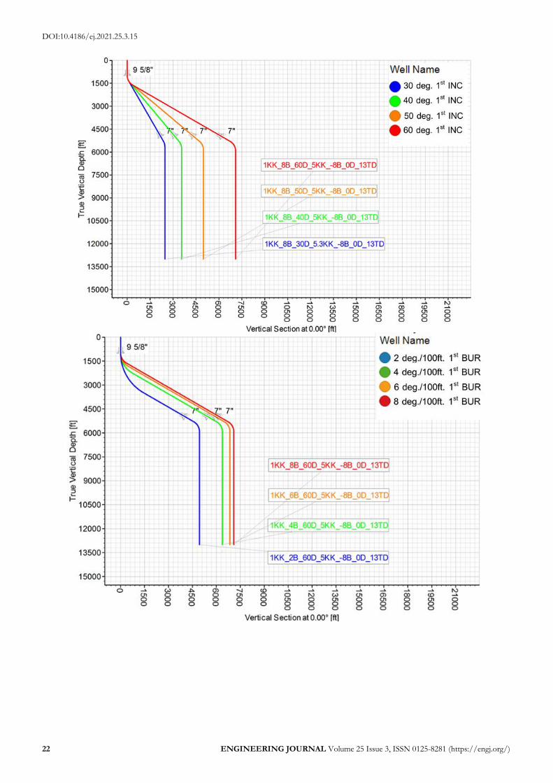
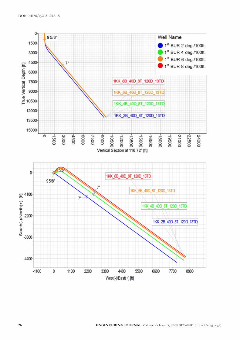
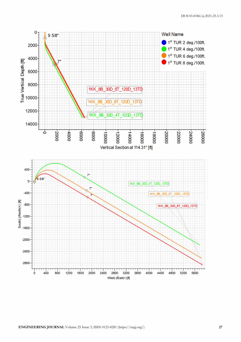
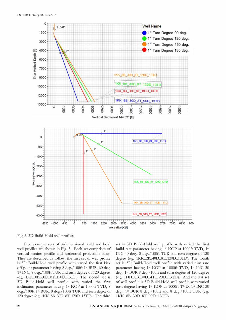
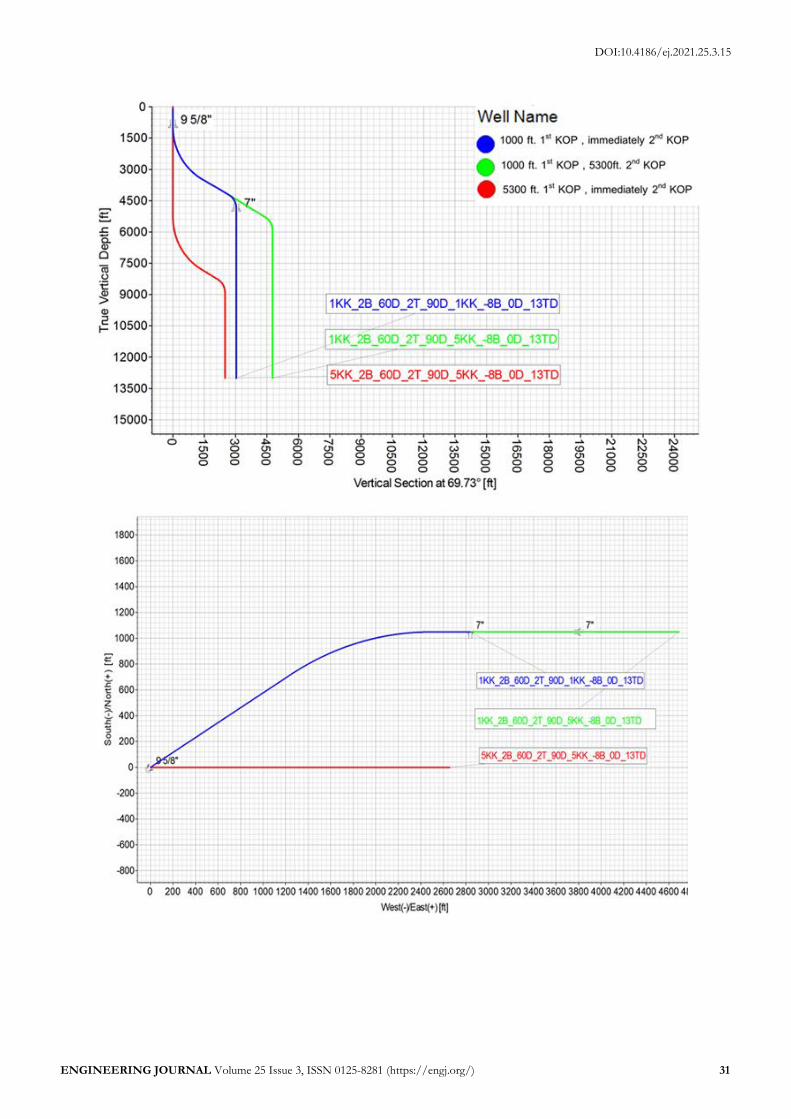
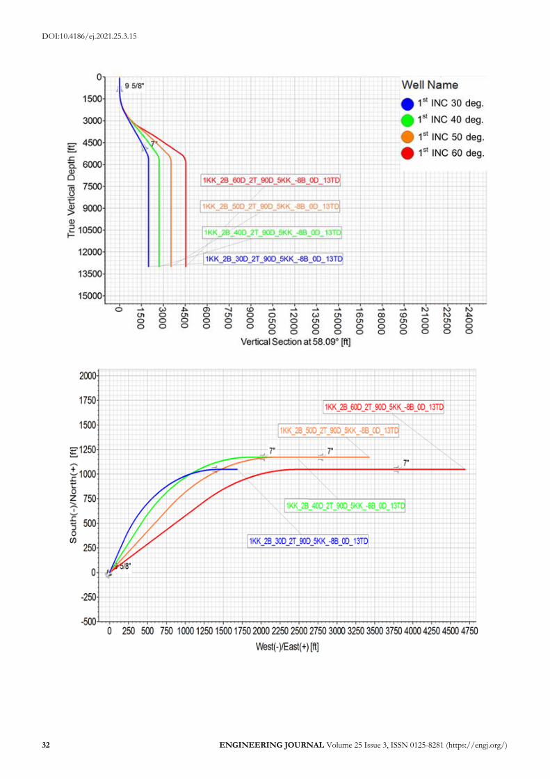
Fig. 5. 3D Build-Hold well profiles.
Five example sets of 3-dimensional build and hold well profiles are shown in Fig. 5. Each set comprises of vertical section profile and horizontal projection plots. They are described as follow: the first set of well profile is 3D Build-Hold well profile with varied the first kick off point parameter having 8 deg./100ft 1st BUR, 60 deg. 1st INC, 8 deg./100ft TUR and turn degree of 120 degree. (e.g. 1KK_8B_60D_8T_120D_13TD). The second set is 3D Build-Hold well profile with varied the first inclination parameter having 1st KOP at 1000ft TVD, 8 deg./100ft 1st BUR, 8 deg./100ft TUR and turn degree of 120 degree (e.g. 1KK_8B_30D_8T_120D_13TD). The third
set is 3D Build-Hold well profile with varied the first build rate parameter having 1st KOP at 1000ft TVD, 1st INC 40 deg., 8 deg./100ft TUR and turn degree of 120 degree (e.g. 1KK_2B_40D_8T_120D_13TD). The fourth set is 3D Build-Hold well profile with varied turn rate parameter having 1st KOP at 1000ft TVD, 1st INC 30 deg., 1st BUR 8 deg./100ft and turn degree of 120 degree (e.g. 1HH_8B_30D_4T_120D_13TD). And the last set of well profile is 3D Build-Hold well profile with varied turn degree having 1st KOP at 1000ft TVD, 1st INC 30 deg., 1st BUR 8 deg./100ft and 8 deg./100ft TUR (e.g. 1KK_8B_30D_8T_90D_13TD).
DOI:10.4186/ej.2021.25.3.15
ENGINEERING JOURNAL Volume 25 Issue 3, ISSN 0125-8281 (https://engj.org/) 29
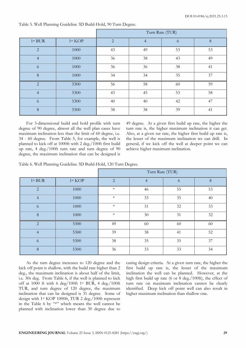
Table 5. Well Planning Guideline 3D Build-Hold, 90 Turn Degree.
Turn Rate (TUR)
1st BUR 1st KOP 2 4 6 8
2 1000 43 49 53 53
4 1000 36 38 43 49
6 1000 36 36 38 41
8 1000 34 34 35 37
2 5300 56 58 60 59
4 5300 43 45 53 58
6 5300 40 40 42 47
8 5300 38 38 39 41
For 3-dimensional build and hold profile with turn degree of 90 degree, almost all the well plan cases have maximum inclination less than the limit of 60 degree, i.e. 34 - 60 degree. From Table 5, for example, the well is planned to kick off at 1000ft with 2 deg./100ft first build up rate, 4 deg./100ft turn rate and turn degree of 90 degree, the maximum inclination that can be designed is
49 degree. At a given first build up rate, the higher the turn rate is, the higher maximum inclination it can get. Also, at a given tur rate, the higher first build up rate is, the lesser of the maximum inclination we can drill. In general, if we kick off the well at deeper point we can achieve higher maximum inclination.
Table 6. Well Planning Guideline 3D Build-Hold, 120 Turn Degree.
Turn Rate (TUR)
1st BUR 1st KOP 2 4 6 8
2 1000 * 46 55 53
4 1000 * 33 35 40
6 1000 * 31 32 33
8 1000 * 30 31 32
2 5300 49 60 60 60
4 5300 39 38 41 52
6 5300 38 35 35 37
8 5300 36 33 33 34
As the turn degree increases to 120 degree and the kick off point is shallow, with the build rate higher than 2 deg., the maximum inclination is about half of the limit, i.e. 30s deg. From Table 6, if the well is planned to kick off at 1000 ft with 6 deg/100ft 1st BUR, 4 deg./100ft TUR, and turn degree of 120 degree, the maximum inclination that can be designed is 31 degree. Some of design with 1st KOP 1000ft, TUR 2 deg./100ft represent in the Table 6 by “*” which means the well cannot be planned with inclination lower than 30 degree due to
casing design criteria. At a given turn rate, the higher the first build up rate is, the lesser of the maximum inclination the well can be planned. However, at the high first build up rate (6 or 8 deg./100ft), the effect of turn rate on maximum inclination cannot be clearly identified. Deep kick off point well can also result in higher maximum inclination than shallow one.
DOI:10.4186/ej.2021.25.3.15
30 ENGINEERING JOURNAL Volume 25 Issue 3, ISSN 0125-8281 (https://engj.org/)
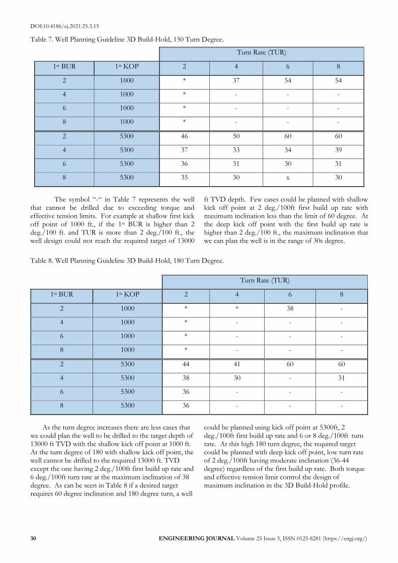
Table 7. Well Planning Guideline 3D Build-Hold, 150 Turn Degree.
Turn Rate (TUR)
1st BUR 1st KOP 2 4 6 8
2 1000 * 37 54 54
4 1000 * - - -
6 1000 * - - -
8 1000 * - - -
2 5300 46 50 60 60
4 5300 37 33 34 39
6 5300 36 31 30 31
8 5300 35 30 x 30
The symbol “-“ in Table 7 represents the well that cannot be drilled due to exceeding torque and effective tension limits. For example at shallow first kick off point of 1000 ft., if the 1st BUR is higher than 2 deg./100 ft. and TUR is more than 2 deg./100 ft., the well design could not reach the required target of 13000
ft TVD depth. Few cases could be planned with shallow kick off point at 2 deg./100ft first build up rate with maximum inclination less than the limit of 60 degree. At the deep kick off point with the first build up rate is higher than 2 deg./100 ft., the maximum inclination that we can plan the well is in the range of 30s degree.
Table 8. Well Planning Guideline 3D Build-Hold, 180 Turn Degree.
Turn Rate (TUR)
1st BUR 1st KOP 2 4 6 8
2 1000 * * 38 -
4 1000 * - - -
6 1000 * - - -
8 1000 * - - -
2 5300 44 41 60 60
4 5300 38 30 - 31
6 5300 36 - - -
8 5300 36 - - -
As the turn degree increases there are less cases that we could plan the well to be drilled to the target depth of 13000 ft TVD with the shallow kick off point at 1000 ft. At the turn degree of 180 with shallow kick off point, the well cannot be drilled to the required 13000 ft. TVD except the one having 2 deg./100ft first build up rate and 6 deg./100ft turn rate at the maximum inclination of 38 degree. As can be seen in Table 8 if a desired target requires 60 degree inclination and 180 degree turn, a well
could be planned using kick off point at 5300ft, 2 deg./100ft first build up rate and 6 or 8 deg./100ft turn rate. At this high 180 turn degree, the required target could be planned with deep kick off point, low turn rate of 2 deg./100ft having moderate inclination (36-44 degree) regardless of the first build up rate. Both torque and effective tension limit control the design of maximum inclination in the 3D Build-Hold profile.
DOI:10.4186/ej.2021.25.3.15
ENGINEERING JOURNAL Volume 25 Issue 3, ISSN 0125-8281 (https://engj.org/) 31
DOI:10.4186/ej.2021.25.3.15
32 ENGINEERING JOURNAL Volume 25 Issue 3, ISSN 0125-8281 (https://engj.org/)
DOI:10.4186/ej.2021.25.3.15
ENGINEERING JOURNAL Volume 25 Issue 3, ISSN 0125-8281 (https://engj.org/) 33
DOI:10.4186/ej.2021.25.3.15
34 ENGINEERING JOURNAL Volume 25 Issue 3, ISSN 0125-8281 (https://engj.org/)
DOI:10.4186/ej.2021.25.3.15
ENGINEERING JOURNAL Volume 25 Issue 3, ISSN 0125-8281 (https://engj.org/) 35
DOI:10.4186/ej.2021.25.3.15
36 ENGINEERING JOURNAL Volume 25 Issue 3, ISSN 0125-8281 (https://engj.org/)
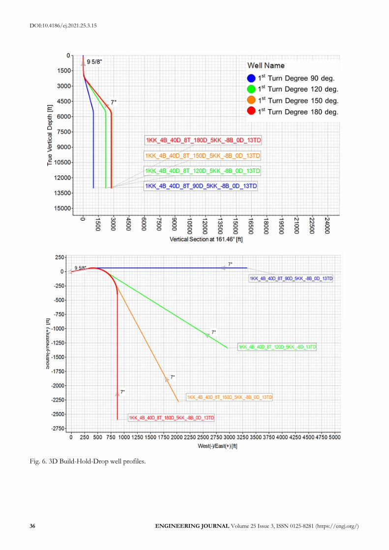
Fig. 6. 3D Build-Hold-Drop well profiles.
DOI:10.4186/ej.2021.25.3.15
ENGINEERING JOURNAL Volume 25 Issue 3, ISSN 0125-8281 (https://engj.org/) 37
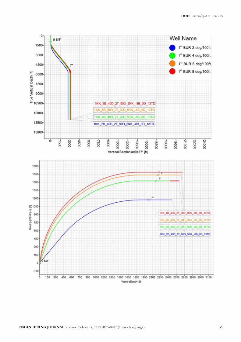
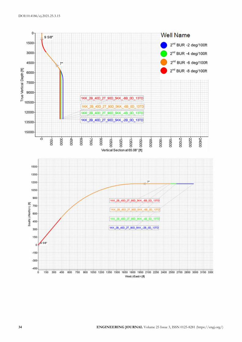
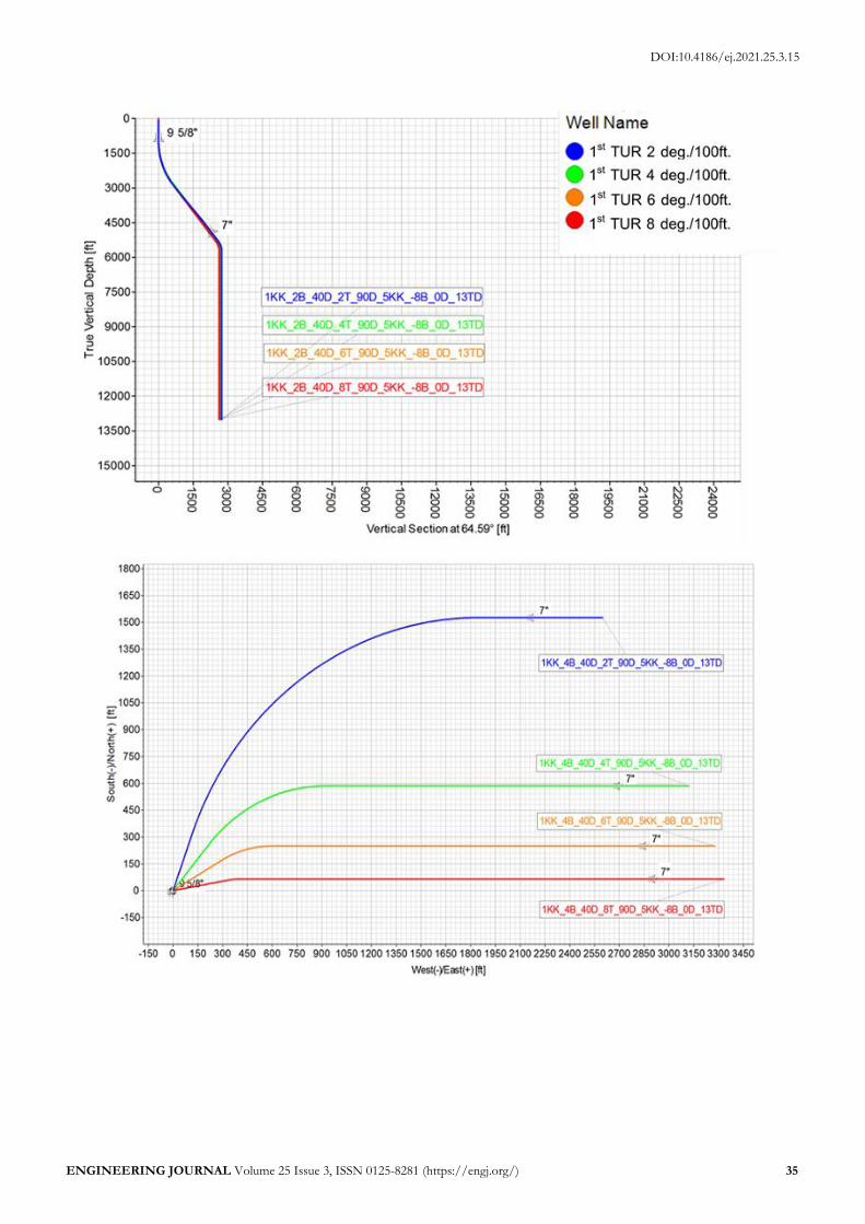
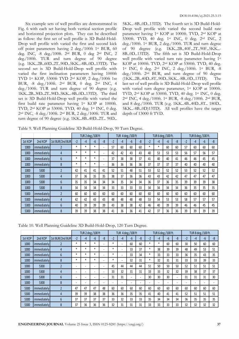
Six example sets of well profiles are demonstrated in Fig. 6 with each set having both vertical section profile and horizontal projection plots. They can be described as follow: the first set of well profile is 3D Build-Hold-Drop well profile with varied the first and second kick off point parameters having 2 deg./100ft 1st BUR, 60 deg. INC, -8 deg./100ft. 2nd BUR, 0 deg 2nd INC, 2 deg./100ft. TUR and turn degree of 90 degree (e.g. 1KK_2B_60D_2T_90D_5KK_-8B_0D_13TD). The second set is 3D Build-Hold-Drop well profile with varied the first inclination parameters having 1000ft TVD 1st KOP, 5300ft TVD 2nd KOP, 2 deg./100ft 1st BUR, -8 deg./100ft. 2nd BUR, 0 deg. 2nd INC, 4 deg./100ft. TUR and turn degree of 90 degree (e.g. 1KK_2B_30D_2T_90D_5KK_-8B_0D_13TD). The third set is 3D Build-Hold-Drop well profile with varied the first build rate parameter having 1st KOP at 1000ft. TVD, 2nd KOP at 5300ft. TVD, 40 deg. 1st INC, 0 deg. 2nd INC, -8 deg./100ft. 2nd BUR, 2 deg./100ft. TUR and turn degree of 90 degree (e.g. 1KK_8B_40D_2T_ 90D_
5KK_-8B_0D_13TD). The fourth set is 3D Build-Hold-Drop well profile with varied the second build rate parameter having 1st KOP at 1000ft. TVD, 2nd KOP at 5300ft. TVD, 40 deg. 1st INC, 0 deg. 2nd INC, 2 deg./100ft. 1st BUR, 2 deg./100ft. TUR and turn degree of 90 degree (e.g. 1KK_2B_40F_2T_90F_5KK_-8B_0D_13TD). The fifth set is 3D Build-Hold-Drop well profile with varied turn rate parameter having 1st KOP at 1000ft. TVD, 2nd KOP at 5300ft. TVD, 40 deg. 1st INC, 0 deg. 2nd INC, 2 deg./100ft. 1st BUR, -8 deg./100ft. 2nd BUR, and turn degree of 90 degree (1KK_2B_40D_8T_90D_5KK_-8B_0D_13TD). The last set of well profile is 3D Build-Hold-Drop well profile with varied turn degree parameter, 1st KOP at 1000ft. TVD, 2nd KOP at 5300ft. TVD, 40 deg. 1st INC, 0 deg. 2nd INC, 4 deg./100ft. 1st BUR, -8 deg./100ft. 2nd BUR, and 8 deg./100ft. TUR (e.g. 1KK_4B_40D_8T_ 180D_ 5KK_-8B_0D)13TD). All well profiles have the target depth of 13000 ft TVD.
Table 9. Well Planning Guideline 3D Build-Hold-Drop, 90 Turn Degree.
Table 10. Well Planning Guideline 3D Build-Hold-Drop, 120 Turn Degree.
1st KOP 2nd KOP 1st BUR/2nd BUR -2 -4 -6 -8 -2 -4 -6 -8 -2 -4 -6 -8 -2 -4 -6 -8
1000 immediately 2 * * * - 57 60 60 60 * * 60 60 57 60 60 60
1000 immediately 4 * * * - 42 42 43 43 40 53 53 53 56 57 56 57
1000 immediately 6 * * * - 37 38 38 37 41 40 40 41 46 46 45 45
1000 immediately 8 * * * - 36 36 36 36 37 37 37 37 40 40 40 40
1000 5300 2 42 41 41 41 52 51 48 51 53 52 52 52 53 52 52 52
1000 5300 4 37 36 35 35 38 37 36 36 43 43 42 42 47 47 47 47
1000 5300 6 35 35 34 34 34 35 34 34 36 37 36 35 39 39 39 38
1000 5300 8 34 34 34 34 33 33 33 33 34 34 34 34 36 35 35 35
5300 immediately 2 60 60 60 60 60 60 60 60 60 60 60 60 60 60 60 60
5300 immediately 4 42 42 43 43 48 48 48 48 53 54 53 53 58 57 57 57
5300 immediately 6 40 39 39 39 43 38 38 42 46 40 39 39 46 46 45 45
5300 immediately 8 39 39 38 38 41 36 36 41 42 37 36 36 39 39 39 39
TUR 2 deg./100 ft TUR 4 deg./100 ft TUR 6 deg./100 ft. TUR 8 deg./100 ft.
1st KOP 2nd KOP 1st BUR/2nd BUR -2 -4 -6 -8 -2 -4 -6 -8 -2 -4 -6 -8 -2 -4 -6 -8
1000 immediately 2 * * * - * - 60 60 * * 60 60 30 50 60 60
1000 immediately 4 * * * - * - 33 37 * 38 39 39 48 49 53 51
1000 immediately 6 * * * - * - 33 34 * 33 33 33 36 35 43 35
1000 immediately 8 * * * - * - 32 31 * 32 31 31 33 33 39 33
1000 5300 2 - - - - 45 44 44 44 51 50 50 50 52 51 51 51
1000 5300 4 - - - - 33 32 31 31 33 33 32 32 39 38 37 37
1000 5300 6 - - - - 31 31 - - 30 30 30 - 31 31 31 30
1000 5300 8 - - - - - - - - - - - - - - - -
5300 immediately 2 47 47 47 48 60 60 60 60 60 60 60 60 60 60 60 60
5300 immediately 4 39 39 38 38 36 36 35 35 41 40 41 41 52 51 51 51
5300 immediately 6 37 37 37 37 33 32 33 33 35 34 34 34 36 35 35 35
5300 immediately 8 37 36 36 36 32 31 31 31 33 33 33 33 32 32 32 32
TUR 2 deg./100 ft TUR 4 deg./100 ft TUR 6 deg./100 ft. TUR 8 deg./100 ft.
DOI:10.4186/ej.2021.25.3.15
38 ENGINEERING JOURNAL Volume 25 Issue 3, ISSN 0125-8281 (https://engj.org/)
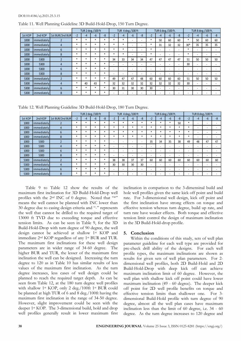
Table 11. Well Planning Guideline 3D Build-Hold-Drop, 150 Turn Degree.
Table 12. Well Planning Guideline 3D Build-Hold-Drop, 180 Turn Degree.
Table 9 to Table 12 show the results of the maximum first inclination for 3D Build-Hold-Drop well profiles with the 2nd INC of 0 degree. Noted that “*” means the well cannot be planned with INC lower than 30 degree due to casing design criteria and “-” represents the well that cannot be drilled to the required target of 13000 ft TVD due to exceeding torque and effective tension limits. As can be seen in Table 9, for the 3D Build-Hold-Drop with turn degree of 90 degree, the well design cannot be achieved at shallow 1st KOP and immediate 2nd KOP regardless of any 1st BUR and TUR. The maximum first inclinations for these well design parameters are in wider range of 34-60 degree. The higher BUR and TUR, the lesser of the maximum first inclination the well can be designed. Increasing the turn degree to 120 as in Table 10 has similar results of less values of the maximum first inclination. As the turn degree increases, less cases of well design could be planned to reach the required target depth. As can be seen from Table 12, at the 180 turn degree well profiles with shallow 1st KOP, only 2 deg./100ft 1st BUR could be planned at high TUR of 6 and 8 deg./100ft having the maximum first inclination in the range of 34-50 degree. However, slight improvement could be seen with the deeper 1st KOP. The 3-dimensional build, hold and drop well profiles generally result in lower maximum first
inclination in comparison to the 3-dimensinal build and hole well profiles given the same kick off point and build rate. For 3-dimensional well design, kick off point and the first inclination have strong effects on torque and effective tension whereas turn degree, build up rate, and turn rate have weaker effects. Both torque and effective tension limit control the design of maximum inclination in the 3D Build-Hold-drop profile.
5. Conclusion Within the conditions of this study, sets of well plan
parameter guideline for each well type are provided for pre-check drill ability of the designs. For each well profile types, the maximum inclinations are shown as results for given sets of well plan parameters. For 2-dimensional well profiles, both 2D Build-Hold and 2D Build-Hold-Drop with deep kick off can achieve maximum inclination limit of 60 degree. However, the well plan with shallow kick off point could have lower maximum inclination (49 - 60 degree). The deeper kick off point for 2D well profile benefits on torque and effective tension limits than shallower one. For 3-dimensional Build-Hold profile with turn degree of 90 degree, almost all the well plan cases have maximum inclination less than the limit of 60 degree, i.e. 34 - 60 degree. As the turn degree increases to 120 degree and
1st KOP 2nd KOP 1st BUR/2nd BUR -2 -4 -6 -8 -2 -4 -6 -8 -2 -4 -6 -8 -2 -4 -6 -8
1000 immediately 2 * * * * * * - - * 50 60 60 * 50 60 60
1000 immediately 4 * * * * * * - - * 31 32 32 30* 35 35 35
1000 immediately 6 * * * * * * - - * - - - * - - -
1000 immediately 8 * * * * * * - - * - - - * - - -
1000 5300 2 * * * * 34 33 34 34 47 47 47 47 51 50 50 50
1000 5300 4 * * * * - - - - - - - - 30 - - -
1000 5300 6 * * * * - - - - - - - - - - - -
1000 5300 8 * * * * - - - - - - - - - - - -
5300 immediately 2 * * * * 49 47 47 48 60 60 60 60 51 50 50 50
5300 immediately 4 * 40 43 * 32 32 32 32 32 32 32 32 30 - - -
5300 immediately 6 * * * * 30 31 30 30 30 - - - - - - -
5300 immediately 8 * * * * - - - - - - - - - - - -
TUR 2 deg./100 ft TUR 4 deg./100 ft TUR 6 deg./100 ft. TUR 8 deg./100 ft.
1st KOP 2nd KOP 1st BUR/2nd BUR -2 -4 -6 -8 -2 -4 -6 -8 -2 -4 -6 -8 -2 -4 -6 -8
1000 immediately 2 * * * * * * * * * * * 50 * - - -
1000 immediately 4 * * * * * * * * * * * * * - - -
1000 immediately 6 * * * * * * * * * * * * * - - -
1000 immediately 8 * * * * * * * * * * * * * - - -
1000 5300 2 * * * * - - - - 35 34 35 38 49 48 47 47
1000 5300 4 * * * * - - - - - - - - - - - -
1000 5300 6 * * * * - - - - - - - - - - - -
1000 5300 8 * * * * - - - - - - - - - - - -
5300 immediately 2 * * * * 38 38 37 37 60 60 60 60 60 60 60 60
5300 immediately 4 * * * * 30 30 30 30 - - - - - - - -
5300 immediately 6 * * * * - - - - - - - - - - - -
5300 immediately 8 * * * * - - - - - - - - - - - -
TUR 2 deg./100 ft TUR 4 deg./100 ft TUR 6 deg./100 ft. TUR 8 deg./100 ft.
DOI:10.4186/ej.2021.25.3.15
ENGINEERING JOURNAL Volume 25 Issue 3, ISSN 0125-8281 (https://engj.org/) 39
the kick off point is shallow, with the build rate higher than 2 deg., the maximum inclination is about half of the limit, i.e. 30s degree. When the turn degree increases there are less cases that we could plan the well to be drilled to the target depth at the shallow kick off point. For 3-dimensional Build-Hold-Drop profile with 90 turn degree, the maximum first inclinations for different set of well plan parameters are in the wider range from 30-60 degree. As the turn degree increases, less cases of well design could be planned to reach the required target depth regardless of the first kick off point. For 3-dimensional well design, kick off point and the first inclination have strong effects on torque and effective tension whereas turn degree, build up rate, and turn rate have weaker effects. In addition, high turn degree is drillable with deep kick off point, low build up rate and high turn rate combined. Lower first build up rate, i.e. 2 degree per 100 ft., could provide a robust design for planning both 2D and 3D Build-Hold profiles.
References [1] J. Hibbeler, R. Seymour, and P. Rae, “Faster,
deeper, cheaper – Slimhole Well construction in the Gulf of Thailand,” in SPE Annual Technical Conference and Exhibition, Houston, TX, 2004, SPE 90999.
[2] A. Racey, “Petroleum geology,” in Geology of Thailand. London, UK: Geological Society of London Special Publication, 2011, ch. 13, pp. 251-292.
[3] E. Jardine, “Dual petroleum system governing the prolific Pattani Basin, offshore Thailand,” in Petroleum Systems of SE Asia and Australia Conference, Jakarta, Indonesia, 1997, pp. 351-363.
[4] J. Valusek, “Unocal Thailand slashes well planning cycle time,” Oil & Gas Journal, vol. 97, no. 2, pp. 45-48, 1999,
[5] G. C. Kaeng, J. Natepracha, S. Sausan, P. Chongrueanglap, N. Anansatitporn, and Srisuriyon, K., “Behind fault well planning: The strong influence of geological structure in planning complex well trajectories in the Gulf of Thailand,” in Offshore Technology Conference Asia, Kuala Lumper, Malaysia, 2016, OTC 26745-MS.
[6] W. Yodinlom, N. Luckanakul, and Tanamaitreejitt, P., “World class drilling in the Gulf of Thailand: North Pailin project,”’ in SPE/IADC Drilling Conference, Amsterdam, The Netherlands, 2003, SPE/IADC 79896.
[7] G. J. Plessis, C. S. Wright, A. Aranas, M. J. Jellison, and A. Muradov, “Drillpipe fatigue in a fast drilling environment: How to cope with the extreme!,” in IADC/SPE Asia Pacific Drilling Conference and Exhibiton, Bangkok, Thailand, 2006, IADC/SPE 103908.
[8] N. Thaiprsert, T. Pensook, N. Tangcharoen, and K. Pattanapong, “Drilling performance improvement with rotary steerable system RSS for shallow soft formation in the Gulf of Thailand,” in International
Petroleum Technology Conference, Bangkok, Thailand, 2016, IPTC 18920-MS.
[9] M. C. Sheppard, C. Wick, and T. Burgess, “Designing well paths to reduce drag and torque,” SPE Drilling Engineering, vol. 2, no. 4, pp. 344-350, Dec, 1987.
[10] T. E. Alfsen, S. Heggen, H. Blikra, and H. Tjotta “Pushing the limits for extended reach drilling: New world record from Platform Statfjord C, Well C2,” SPE Drilling & Completion, vol. 10, no. 2, pp. 71-76, Jun, 1995.
[11] T. Aarrestad, and H. Blikra, “Torque and drag – Two factors in extended-reach drilling,” Journal of Petroleum Technology, vol. 46, no. 9, pp. 800-83, Sep. 1994.
[12] K. Boonsri, and J. Natepracha, “Potential for pre-well planning in development field – The next step to reducing time and enhancing well planning by collaboration drilling’s and geoscience’s workflow – Case study: Development field in Gulf of Thailand,” SPE/IADC Drilling Technology Conference, Bangkok, Thailand, 2014, SPE 170516-MS.
[13] M. Luckanakul, and N. Chuemthaisong, “Well planning optimization process: The collaboration way of saving well planning time in Gulf of Thailand,” in International Petroleum Technology Conference, Bangkok, Thailand, 2016, IPTC 18993-MS.
[14] C. Johancsik, D. Friesen and R. Dawson, “Torque and drag in directional wells-prediction and measurement” Journal of Petroleum Technology, vol. 36, no. 6, pp. 987-992, 1984.
[15] S. Miska, Z. Zamanipour, A. Merlo, and M. N. Porche, “Dynamic soft string model and its practical application,” in SPE/IADC Drilling Conference and Exhibition, London, UK, 2015, SPE/IADC 173084.
[16] A. Hashemi, A. Ghanbarzadeh, and S. Hosseini, “Optimization of dogleg severity in directional drilling oil wells using particle swarm algorithm,” Journal of Chemical and Petroleum Engineering, vol. 48, no. 2, pp. 139-151, Dec. 2014.
[17] M. Payne, and F. Abbassian, “Advanced torque and drag considerations in extended-reach wells,” SPE Drilling & Completion, vol. 12, no. 1, pp. 55-62, 1997.
[18] R. Samuel, and X. Liu, “Wellbore tortuosity, torsion, drilling indices, and energy: What do they have to do with well path design?,” in SPE Annual Technical Conference and Exhibition, New Orleans, LA, 2009, SPE 124710.
[19] R. Samuel, “Friction factors: What are they for torque, drag, vibration, bottom hole assembly and transient surge/swab analyses?,” Journal of Petroleum Science and Engineering, vol. 773, no. 3, pp. 58-266, Sep, 2010.
[20] B. Roychoudhuri, and B. Ramagopal, “Torque and drag software analysis for deciding well construction and remedial action,” in SPE Indian Oil and Gas
DOI:10.4186/ej.2021.25.3.15
40 ENGINEERING JOURNAL Volume 25 Issue 3, ISSN 0125-8281 (https://engj.org/)
Technical Conference and Exhibition, Mumbai, India, 2008. SPE 112514-MS.
[21] O. A. Adewuya, and S. V. Pham, “A robust torque and drag analysis approach for well planning and
drillstring design,” in IADC/SPE Drilling Conference, Dallas, TX, 1998, SPE 39321.
Jirawat Chewarouungroaj received a bachelor degree in petroleum engineering from Chulalongkorn University, Bangkok, Thailand and a master degree in energy and mineral resources from University of Texas at Austin, USA. In 2000, he received a Ph.D. in petroleum engineering from University of Texas at Austin, USA.
He is currently an Assistant Professor in petroleum engineering at Faculty of Engineering, Chulalongkorn University. His research interests are drilling and production of petroleum fields. Anusara Hentoog received a bachelor degree in geology and master degree in petroleum engineering from Chulalongkorn University, Bangkok, Thailand, in 2012 and 2017 respectively. Anusara Hentoog, photograph and biography not available at the time of publication.