Bohai Drilling Engineering Company Limited, CNPC, P. R. China 2010-2 Directional Drilling Training

Welcome message from author
This document is posted to help you gain knowledge. Please leave a comment to let me know what you think about it! Share it to your friends and learn new things together.
Transcript
Bohai Drilling Engineering Company
Limited, CNPC, P. R. China
2010-2
Directional Drilling Training
Contents
BHDC-Directional Drilling Company
DD TRAINING
1. Introduction
2. Definition of Directional Drilling
3. Directional Well Planning
4. Directional Drilling Tools
5. Bottom Hole Assemblies
6. Drilling Fluids
7. Directional Drilling Operations
8. DD at the Rig-site
BHDC-Directional Drilling Company
DD TRAINING
1. Introduction
1.1 Historical Background
1.2 Technology Advances
1.3 Applications of Directional Drilling
BHDC-Directional Drilling Company
DD TRAINING
1.1 Historical Background In earlier times, directional drilling was used primarily as a
remedial operation, either to sidetrack around stuck tools, bring
the well bore back to vertical, or in drilling relief wells to kill
blowouts.
In the early 1930’s the first controlled directional well was drill-
ed in Huntington Beach,California. The well was drilled from
an onshore location into offshore oil sands using whipstocks,
knuckle joints and spudding bits. An early version of the single
shot instru-ment was used to orient the whipstock.
Current expenditures for hydrocarbon production have dictated
the necessity of controlled directional drilling, and today it is no
longer the dreaded operation that it once was. Probably the
most important aspect of controlled directional drilling is that it
enables producers all over the world to develop subsurface
deposits that could never be reached economically in
any other manner.
BHDC-Directional Drilling Company
DD TRAINING
1.2 Technology Advances The development of reliable mud motors was probably the single
most important advance in directional drilling technology. Survey-
ing technology also has advanced in great strides.
The development of the steering tool replaced the magnetic single
shot instrument as ameans of orienting a mud motor with a bent
sub or housing.
In the early 1980’s ANADRILL MWD started to gain widespread
acceptance as an accurate and cost-effective surveying tool. Today
the MWD has virtually replaced the steering tool on kick-offs and is
used exclusively with the steerable mud motor. A newgeneration
MWD has been developed with the additions of gamma ray,
resistivity, and DWOB/DTOR giving the MWD real time
formation evaluation capabilities.
BHDC-Directional Drilling Company
DD TRAINING
1.3 Applications of Directional Drilling
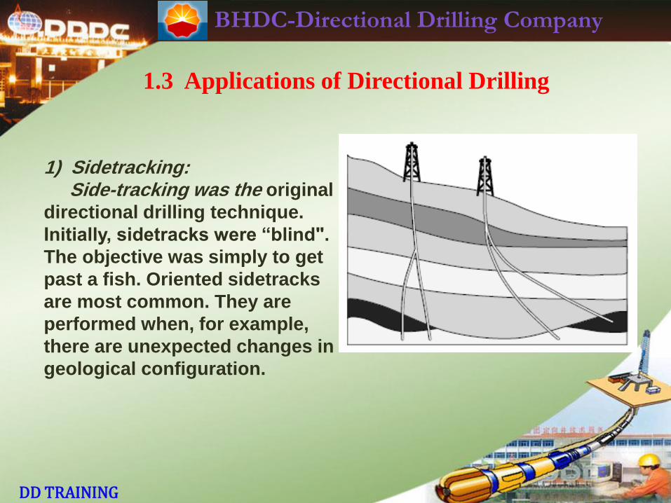
1) Sidetracking: Side-tracking was the original
directional drilling technique.
Initially, sidetracks were “blind".
The objective was simply to get
past a fish. Oriented sidetracks
are most common. They are
performed when, for example,
there are unexpected changes in
geological configuration.
BHDC-Directional Drilling Company
DD TRAINING
1.3 Applications of Directional Drilling
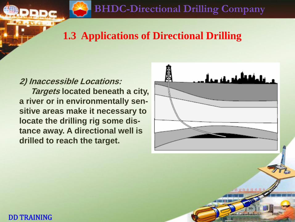
2) Inaccessible Locations: Targets located beneath a city,
a river or in environmentally sen-
sitive areas make it necessary to
locate the drilling rig some dis-
tance away. A directional well is
drilled to reach the target.
BHDC-Directional Drilling Company
DD TRAINING
1.3 Applications of Directional Drilling
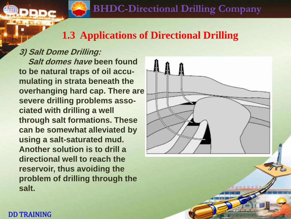
3) Salt Dome Drilling: Salt domes have been found
to be natural traps of oil accu-
mulating in strata beneath the
overhanging hard cap. There are
severe drilling problems asso-
ciated with drilling a well
through salt formations. These
can be somewhat alleviated by
using a salt-saturated mud.
Another solution is to drill a
directional well to reach the
reservoir, thus avoiding the
problem of drilling through the
salt.
BHDC-Directional Drilling Company
DD TRAINING
1.3 Applications of Directional Drilling
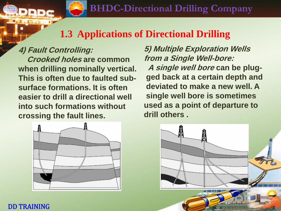
4) Fault Controlling: Crooked holes are common
when drilling nominally vertical.
This is often due to faulted sub-
surface formations. It is often
easier to drill a directional well
into such formations without
crossing the fault lines.
5) Multiple Exploration Wells from a Single Well-bore: A single well bore can be plug-
ged back at a certain depth and
deviated to make a new well. A
single well bore is sometimes
used as a point of departure to
drill others .
BHDC-Directional Drilling Company
DD TRAINING
1.3 Applications of Directional Drilling
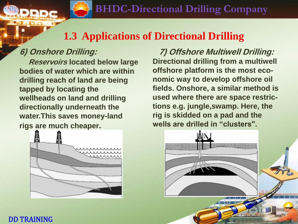
6) Onshore Drilling: Reservoirs located below large
bodies of water which are within
drilling reach of land are being
tapped by locating the
wellheads on land and drilling
directionally underneath the
water.This saves money-land
rigs are much cheaper.
7) Offshore Multiwell Drilling: Directional drilling from a multiwell
offshore platform is the most eco-
nomic way to develop offshore oil
fields. Onshore, a similar method is
used where there are space restric-
tions e.g. jungle,swamp. Here, the
rig is skidded on a pad and the
wells are drilled in “clusters".
BHDC-Directional Drilling Company
DD TRAINING
1.3 Applications of Directional Drilling
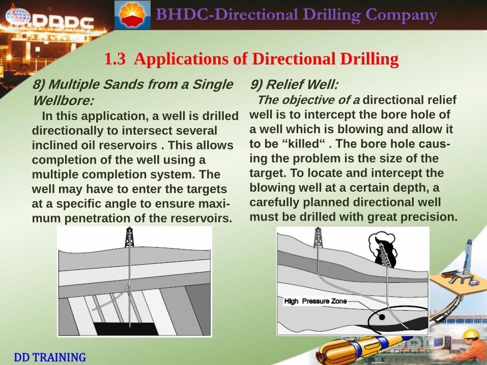
8) Multiple Sands from a Single Wellbore: In this application, a well is drilled
directionally to intersect several
inclined oil reservoirs . This allows
completion of the well using a
multiple completion system. The
well may have to enter the targets
at a specific angle to ensure maxi-
mum penetration of the reservoirs.
9) Relief Well: The objective of a directional relief
well is to intercept the bore hole of
a well which is blowing and allow it
to be “killed“ . The bore hole caus-
ing the problem is the size of the
target. To locate and intercept the
blowing well at a certain depth, a
carefully planned directional well
must be drilled with great precision.
BHDC-Directional Drilling Company
DD TRAINING
1.3 Applications of Directional Drilling
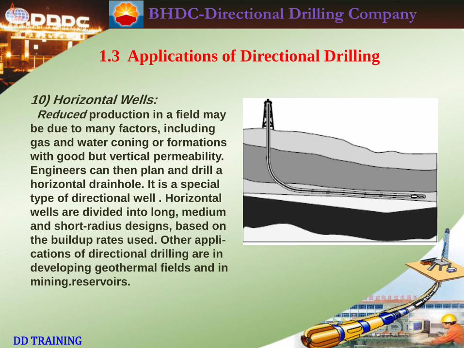
10) Horizontal Wells: Reduced production in a field may
be due to many factors, including
gas and water coning or formations
with good but vertical permeability.
Engineers can then plan and drill a
horizontal drainhole. It is a special
type of directional well . Horizontal
wells are divided into long, medium
and short-radius designs, based on
the buildup rates used. Other appli-
cations of directional drilling are in
developing geothermal fields and in
mining.reservoirs.
BHDC-Directional Drilling Company
DD TRAINING
2. Definition of Directional Drilling
BHDC-Directional Drilling Company
DD TRAINING
2. Definition of Directional Drilling
Controlled directional drilling is the science of
deviating a well bore along a planned course to a
subsurface target whose location is a given lateral
distance and direction from the vertical. At a specified
vertical depth, this definition is the fundamental concept of
controlled directional drilling even in a well bore which is
held as close to vertical as possible as well as a
deliberately planned deviation from the vertical.
BHDC-Directional Drilling Company
DD TRAINING
2. Definition of Directional Drilling
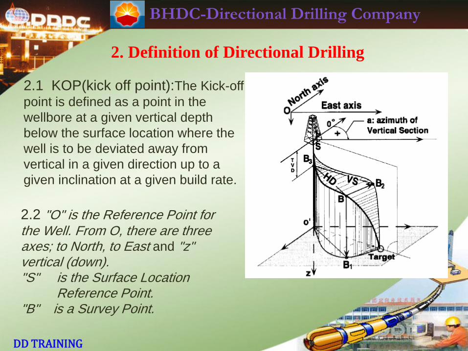
2.1 KOP(kick off point):The Kick-off
point is defined as a point in the
wellbore at a given vertical depth
below the surface location where the
well is to be deviated away from
vertical in a given direction up to a
given inclination at a given build rate.
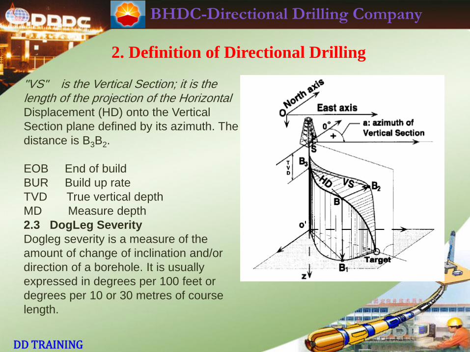
2.2 "O" is the Reference Point for the Well. From O, there are three axes; to North, to East and "z" vertical (down). "S" is the Surface Location Reference Point. "B" is a Survey Point.
BHDC-Directional Drilling Company
DD TRAINING
2. Definition of Directional Drilling
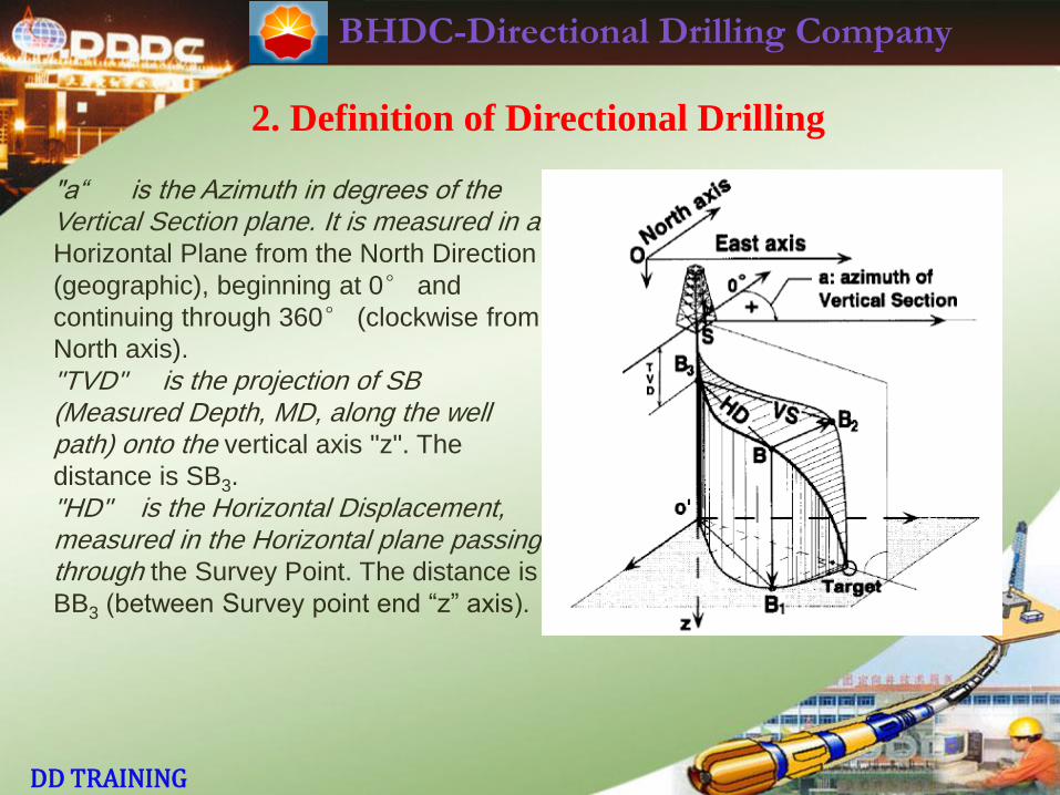
"a“ is the Azimuth in degrees of the Vertical Section plane. It is measured in a Horizontal Plane from the North Direction
(geographic), beginning at 0° and
continuing through 360° (clockwise from
North axis).
"TVD" is the projection of SB (Measured Depth, MD, along the well path) onto the vertical axis "z". The
distance is SB3.
"HD" is the Horizontal Displacement, measured in the Horizontal plane passing through the Survey Point. The distance is
BB3 (between Survey point end “z” axis).
BHDC-Directional Drilling Company
DD TRAINING
2. Definition of Directional Drilling
"VS" is the Vertical Section; it is the length of the projection of the Horizontal Displacement (HD) onto the Vertical
Section plane defined by its azimuth. The
distance is B3B2.
EOB End of build
BUR Build up rate
TVD True vertical depth
MD Measure depth
2.3 DogLeg Severity
Dogleg severity is a measure of the
amount of change of inclination and/or
direction of a borehole. It is usually
expressed in degrees per 100 feet or
degrees per 10 or 30 metres of course
length.
BHDC-Directional Drilling Company
DD TRAINING
2. Definition of Directional Drilling
2.3 True North(TN): True North (TN) is the direction of a line from any geogra-
phical location on the earth’s surface to the North Geometric Pole.
2.4 Magnetic North(MN): Magnetic North is the direction of a line from any geo-
graphical location on the earth’s surface to the North Magnetic Pole.
Easterly Magnetic Declination values are expressed as a positive value.
Westerly Magnetic Declination values are expressed as a negative value.
Values of Magnetic Declination (DEC) change with time and location. As the
movement of Magnetic North (MN) is constant and predictable, Magnetic
Declination can be calculated for any given point on the earth at any given time.
2.5 Grid North is the direction of a line from any geographical location within a
grid system paralleling the Universal True Meridian as determined by observation
of Polaris.
Grid convergence is the angle between a True North direction and
Grid North direction.
BHDC-Directional Drilling Company
DD TRAINING
2. Definition of Directional Drilling
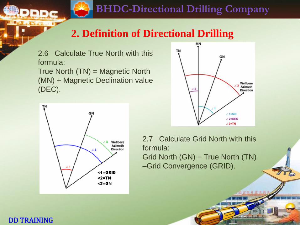
2.6 Calculate True North with this
formula:
True North (TN) = Magnetic North
(MN) + Magnetic Declination value
(DEC).
2.7 Calculate Grid North with this
formula:
Grid North (GN) = True North (TN)
–Grid Convergence (GRID).
BHDC-Directional Drilling Company
DD TRAINING
3. Directional Well Planning
BHDC-Directional Drilling Company
DD TRAINING
3. Directional Well Planning
3.1 Survey Calculation Methods
3.1.1 Introduction
Regardless of which conventional survey method is used (single-shot, multishot,
steering tool, surface readout gyro, MWD), the following three pieces of informa-
tion are known at the end of a successful survey:
· Survey Measured Depth
· Borehole Inclination
· Borehole Azimuth (corrected to relevant North).
In order to ascertain the latest bottom-hole position, it is necessary to perform a
survey calculation which includes the three inputs listed above. Only then can
the latest bottom-hole coordinates be plotted on the directional well plot (TVD vs
Vertical Section on the vertical plot, N/S vs E/W rectangular coordinates on
horizontal plot). Projections to the target, etc., can then be done.
BHDC-Directional Drilling Company
DD TRAINING
3. Directional Well Planning
3.1 Survey Calculation Methods
3.1.1 Introduction
A number of survey calculation methods have been used in directional drilling. Of
these, only four have had widespread use:
· Tangential
· Average Angle
· Radius of Curvature
· Minimum Curvature.
The Tangential Method is the oldest, least sophisticated and most inaccurate
method.This method should never be used.
Average Angle and Radius of Curvature methods are in common field use.
Average Angle method (in particular) lends itself easily to a hand-held calculator.
Radius of Curvature method is more widely used. However, official survey
reports should not use either if the above methods except when demanded by
the customer.
BHDC-Directional Drilling Company
DD TRAINING
3. Directional Well Planning
3.1 Survey Calculation Methods
3.1.1 Introduction
Minimum Curvature method should be used for all office calculations and official
survey reports. Where possible, it should also be the field calculation method
chosen. The DD is advised to have at the well-site a hand-held calculator which
is programmed for both Radius of Curvature and Minimum Curvature methods of
survey calculation.
BHDC-Directional Drilling Company
DD TRAINING
3. Directional Well Planning
3.1 Survey Calculation Methods
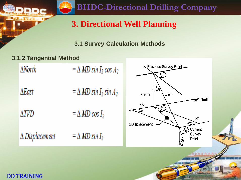
3.1.2 Tangential Method
This method uses only the inclination and direction at the latest survey
station . The well bore is then assumed to be tangential to these angles. On any
curved section of the hole there are flaws in this assumption and this method of
survey calculation cannot provide realistic results for anything but a hold section
of the well.
On an "S" type well, if the build and drop rates are the same, and over similar
intervals, then the error at the end of the well would be small since errors
introduced in the build and drop sections would tend to negate one another.
In a build and hold well, the TVD would be less (i.e. shallower) than the true
TVD. With the well turning to the right in the North East quadrant, one would
introduce errors that would result in a position too far to the East, and not far
enough to the North.
BHDC-Directional Drilling Company
DD TRAINING
3. Directional Well Planning
3.1 Survey Calculation Methods
3.1.2 Tangential Method
BHDC-Directional Drilling Company
DD TRAINING
3. Directional Well Planning
3.1 Survey Calculation Methods
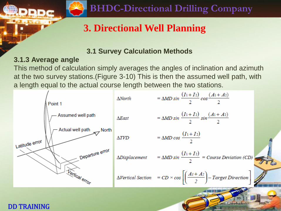
3.1.3 Average angle
This method of calculation simply averages the angles of inclination and azimuth
at the two survey stations.(Figure 3-10) This is then the assumed well path, with
a length equal to the actual course length between the two stations.
BHDC-Directional Drilling Company
DD TRAINING
3. Directional Well Planning
3.1 Survey Calculation Methods
3.1.3 Average angle
Provided that the distance between the stations is not too great in relation to the
curvature of the well path, this method of survey calculations provides a simple,
yet accurate means of calculating a well bore survey.
BHDC-Directional Drilling Company
DD TRAINING
3. Directional Well Planning
3.1 Survey Calculation Methods
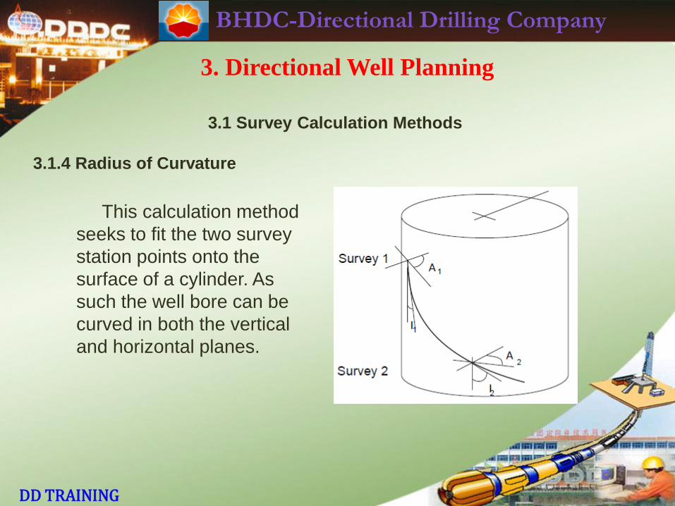
3.1.4 Radius of Curvature
This calculation method
seeks to fit the two survey
station points onto the
surface of a cylinder. As
such the well bore can be
curved in both the vertical
and horizontal planes.
BHDC-Directional Drilling Company
DD TRAINING
3. Directional Well Planning
3.1 Survey Calculation Methods
3.1.4 Radius of Curvature
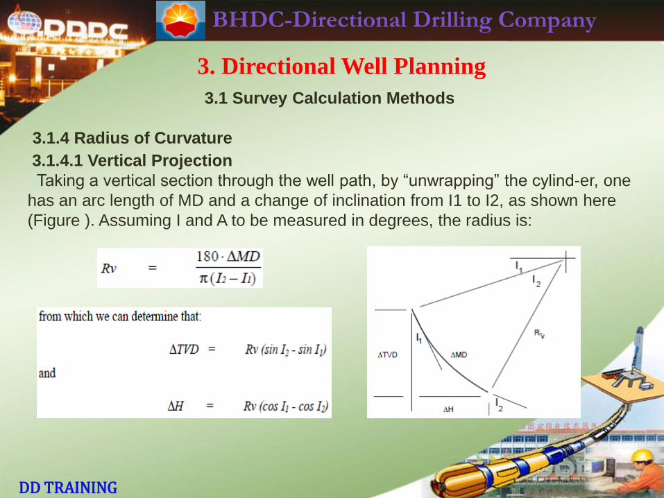
3.1.4.1 Vertical Projection
Taking a vertical section through the well path, by “unwrapping” the cylind-er, one
has an arc length of MD and a change of inclination from I1 to I2, as shown here
(Figure ). Assuming I and A to be measured in degrees, the radius is:
BHDC-Directional Drilling Company
DD TRAINING
3. Directional Well Planning
3.1 Survey Calculation Methods
3.1.4 Radius of Curvature
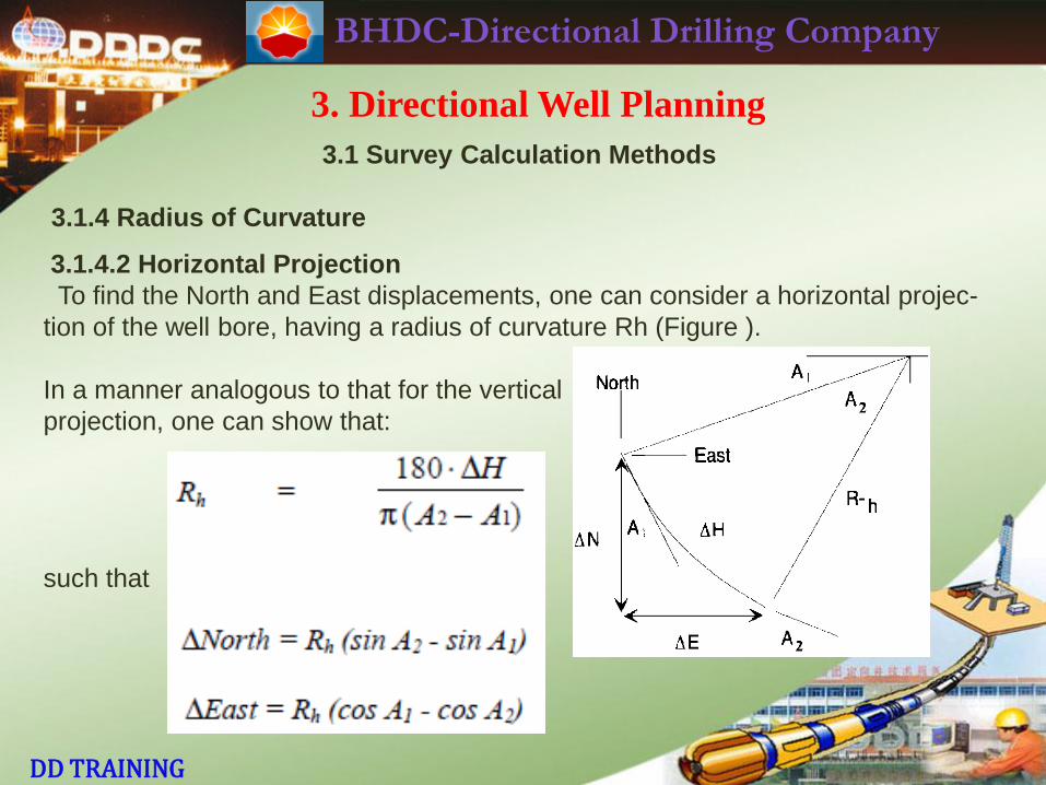
3.1.4.2 Horizontal Projection
To find the North and East displacements, one can consider a horizontal projec-
tion of the well bore, having a radius of curvature Rh (Figure ).
In a manner analogous to that for the vertical
projection, one can show that:
such that
BHDC-Directional Drilling Company
DD TRAINING
3. Directional Well Planning
3.1 Survey Calculation Methods
3.1.4 Radius of Curvature
Accuracy Whereas the average angle method is quite accurate when the well curvature is small and stations are close together, the radius of curvature method
is accurate for stations spaced far apart, and with higher rates of curvature.
BHDC-Directional Drilling Company
DD TRAINING
3. Directional Well Planning
3.1 Survey Calculation Methods
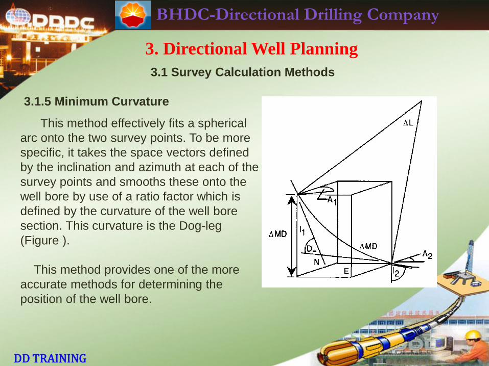
3.1.5 Minimum Curvature
This method effectively fits a spherical
arc onto the two survey points. To be more
specific, it takes the space vectors defined
by the inclination and azimuth at each of the
survey points and smooths these onto the
well bore by use of a ratio factor which is
defined by the curvature of the well bore
section. This curvature is the Dog-leg
(Figure ).
This method provides one of the more
accurate methods for determining the
position of the well bore.
BHDC-Directional Drilling Company
DD TRAINING
3. Directional Well Planning
3.1 Survey Calculation Methods
3.1.5 Minimum Curvature
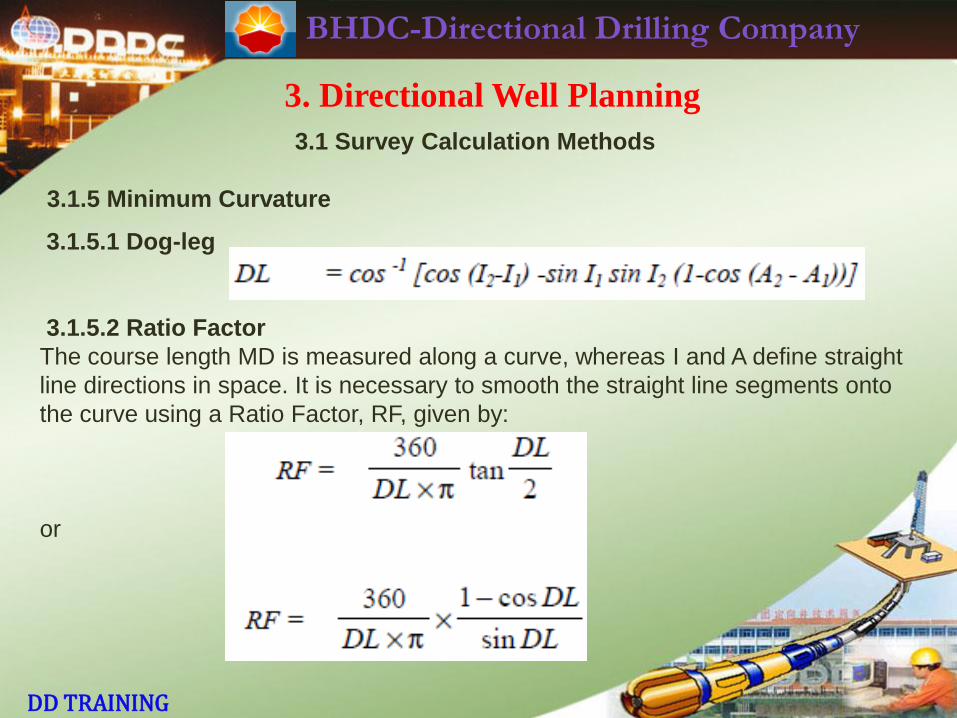
3.1.5.1 Dog-leg
3.1.5.2 Ratio Factor
The course length MD is measured along a curve, whereas I and A define straight
line directions in space. It is necessary to smooth the straight line segments onto
the curve using a Ratio Factor, RF, given by:
or
BHDC-Directional Drilling Company
DD TRAINING
3. Directional Well Planning
3.1 Survey Calculation Methods
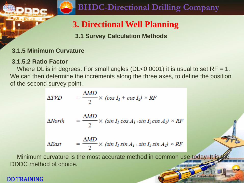
3.1.5 Minimum Curvature
3.1.5.2 Ratio Factor
Where DL is in degrees. For small angles (DL<0.0001) it is usual to set RF = 1.
We can then determine the increments along the three axes, to define the position
of the second survey point.
Minimum curvature is the most accurate method in common use today. It is the
DDDC method of choice.
BHDC-Directional Drilling Company
DD TRAINING
3. Directional Well Planning
3.1 Survey Calculation Methods
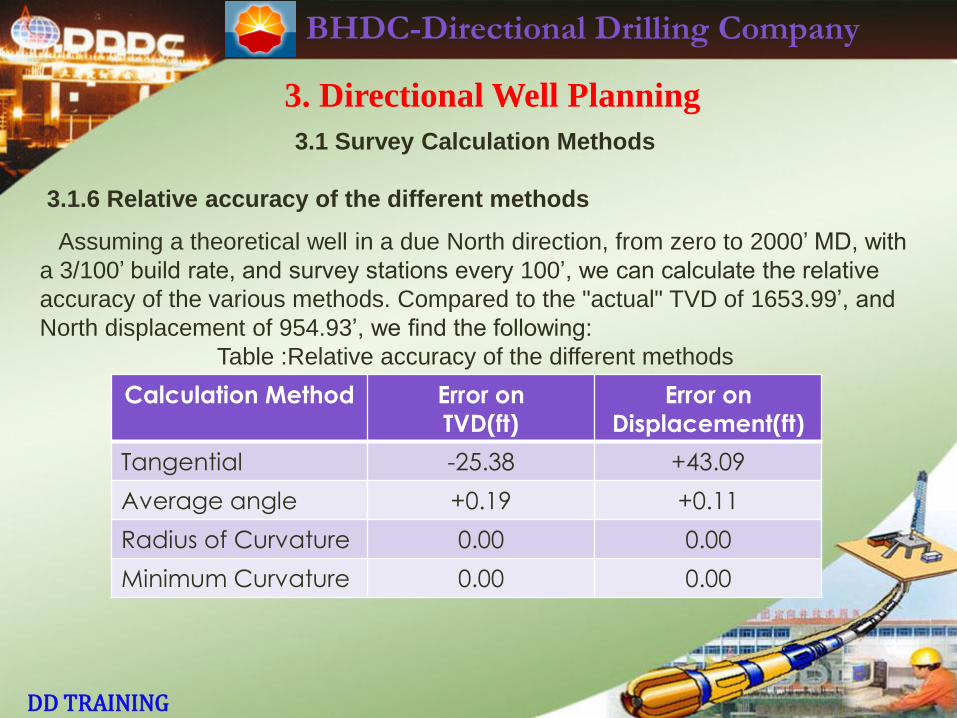
3.1.6 Relative accuracy of the different methods
Assuming a theoretical well in a due North direction, from zero to 2000’ MD, with
a 3/100’ build rate, and survey stations every 100’, we can calculate the relative
accuracy of the various methods. Compared to the "actual" TVD of 1653.99’, and
North displacement of 954.93’, we find the following:
Table :Relative accuracy of the different methods
Calculation Method Error on
TVD(ft)
Error on
Displacement(ft)
Tangential -25.38 +43.09
Average angle +0.19 +0.11
Radius of Curvature 0.00 0.00
Minimum Curvature 0.00 0.00
BHDC-Directional Drilling Company
DD TRAINING
3. Directional Well Planning
3.1 Survey Calculation Methods
3.1.6 Relative accuracy of the different methods
Clearly, this is only an indication of the relative accuracy, and favours those
methods that assume the well bore to be made up of a series of segments of arcs
and circles. The actual well bore may behave very differently.
In addition, this comparison does not include any turn, so reasonable amounts
of caution should be used when comparing on method to another. However, it is
fairly reasonable to assume that methods which compare badly in a single plane
situation will almost certainly behave worse in a three dimensional case.
BHDC-Directional Drilling Company
DD TRAINING
3. Directional Well Planning
3.2 Basic Well Planning
3.2.1 Introduction
The careful planning of a directional project prior to the commencement of
actual operations is probably the single most important factor of a project. Each
directional well is unique in the sense that it has specific objectives. Care has to
be exercised at the planning stage to ensure that all aspects of the well are
tailored to meet those objectives.Drilling a directional well basically involves
drilling a hole from one point in space (the surface location) to another point in
space (the target) in such a way that the hole can then be used for its intended
purpose. To be able to do this we must first define the surface and target locations.
Location The first thing to do is to define a local coordinate system originating at
the structure reference point. In many land wells, this will be the surface location.
The target location is then converted to this local coordinate system, if necessary.
BHDC-Directional Drilling Company
DD TRAINING
3. Directional Well Planning
3.2 Basic Well Planning
3.2.1 Introduction
Target Size During the drilling phase of a directional well, the trajectory of the
wellbore in relation to the target is constantly monitored. Often, costly decisions
have to be made in order to ensure that the objectives of the well are met. A well
defined target is essential in making these decisions. The technology available
today allows us to drill extremely accurate wells. The cost of drilling the well is
largely dependent on the accuracy required so the acceptable limits of the target
must be well defined before the well is commenced.
Good communication with the relevant department (Geology or Exploration)
before beginning the well can help to avert this kind of error. This is particularly
true when a correction run is being contemplated. The first step of any plan to
correct the azimuth of a well should always be consultation with the Geology
Department.
BHDC-Directional Drilling Company
DD TRAINING
3. Directional Well Planning
3.2 Basic Well Planning
3.2.1 Introduction
Wellbore Profile Knowing the position of the surface location and given the
location of the Target, its TVD and rectangular coordinates, it is possible to
determine the best geometric well profile from surface to the bottom-hole target. In
general, Directional wells can be either:
· Straight
· Slant type
· “S" type
· Horizontal
The type of profile selected will depend upon the Geological objective and
production mechanism of the well. Once the profile has been selected, the well
can be planned. From a Directional Drilling point of view, this involves choosing
the following:
BHDC-Directional Drilling Company
DD TRAINING
3. Directional Well Planning
3.2 Basic Well Planning
3.2.2 Determining the Kick-off Point
The Kick-off point is defined as a point in the wellbore at a given vertical depth
below the surface location where the well is to be deviated away from vertical in a
given direction up to a given inclination at a given build rate. The selection of the
Kick-off point is made by considering the geometrical well-path and the geological
characteristics. The optimum inclination of the well is a function of the maximum
permissible build rate (and drop rate if applicable) and the location of the target.
BHDC-Directional Drilling Company
DD TRAINING
3. Directional Well Planning
3.2 Basic Well Planning
3.2.3 Determining Build and Drop Rates
The maximum permissible build/drop rate is normally determined by one or
more of the following:
· The total depth of the well.
· Maximum Torque and Drag limitations.
· High dogleg severity in the build section of the well results in high torque and
drag while drilling the remainder of the well. This can be a severe limiting factor
in deeper wells.
· The formations through which the build section must pass. Higher build rates
are often not possible to achieve in soft formations.
· Mechanical limitations of the drill string or casing.
· Mechanical limitations of logging tools and production strings.
· Formation of “Keyseats" in the Kick-off arc.
BHDC-Directional Drilling Company
DD TRAINING
3. Directional Well Planning
3.2 Basic Well Planning
3.2.3 Determining Build and Drop Rates
Optimum build/drop rates in conventional wells vary from place to place but are
commonly in the range of 1.5° to 3° per 100 ft (30m).
Once the desired build rate and inclination have been established, the kick-off
point can be determined. There is usually some flexibility in order to accommodate
casing points. From a mathematical point of view the two well types must be
further broken down into those where the radius of build, or sum of the radii of
build is greater or lesser than the total displacement of the well.
BHDC-Directional Drilling Company
DD TRAINING
3. Directional Well Planning
3.2 Basic Well Planning
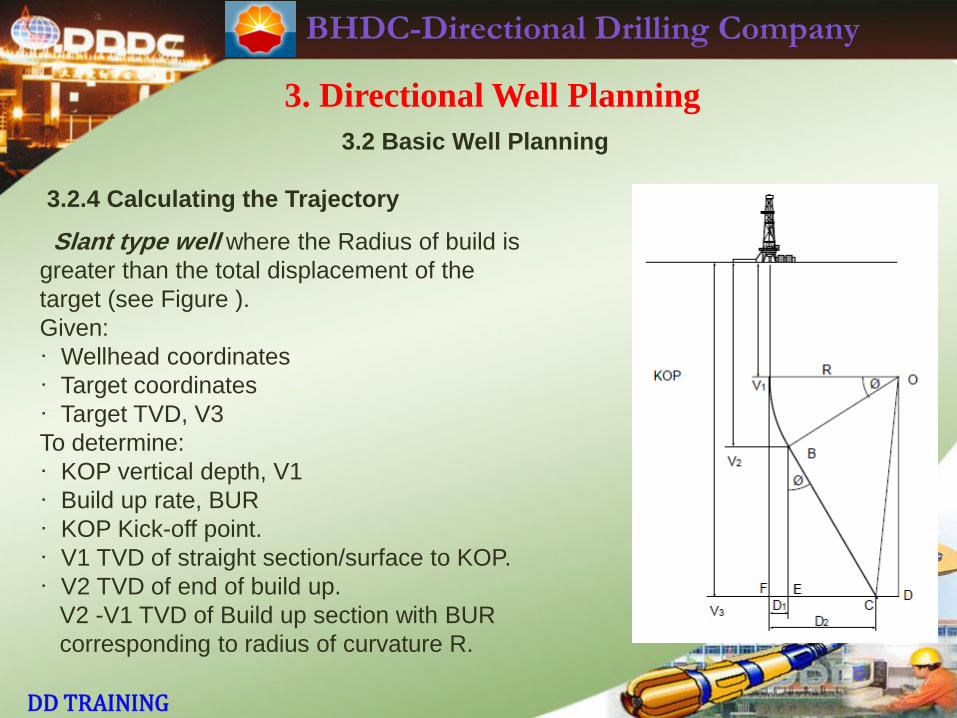
3.2.4 Calculating the Trajectory
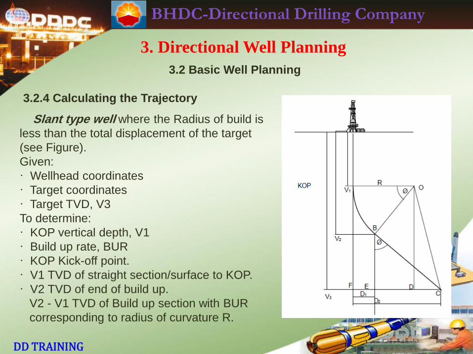
Slant type well where the Radius of build is
less than the total displacement of the target
(see Figure).
Given:
· Wellhead coordinates
· Target coordinates
· Target TVD, V3
To determine:
· KOP vertical depth, V1
· Build up rate, BUR
· KOP Kick-off point.
· V1 TVD of straight section/surface to KOP.
· V2 TVD of end of build up.
V2 - V1 TVD of Build up section with BUR
corresponding to radius of curvature R.
BHDC-Directional Drilling Company
DD TRAINING
3. Directional Well Planning
3.2 Basic Well Planning
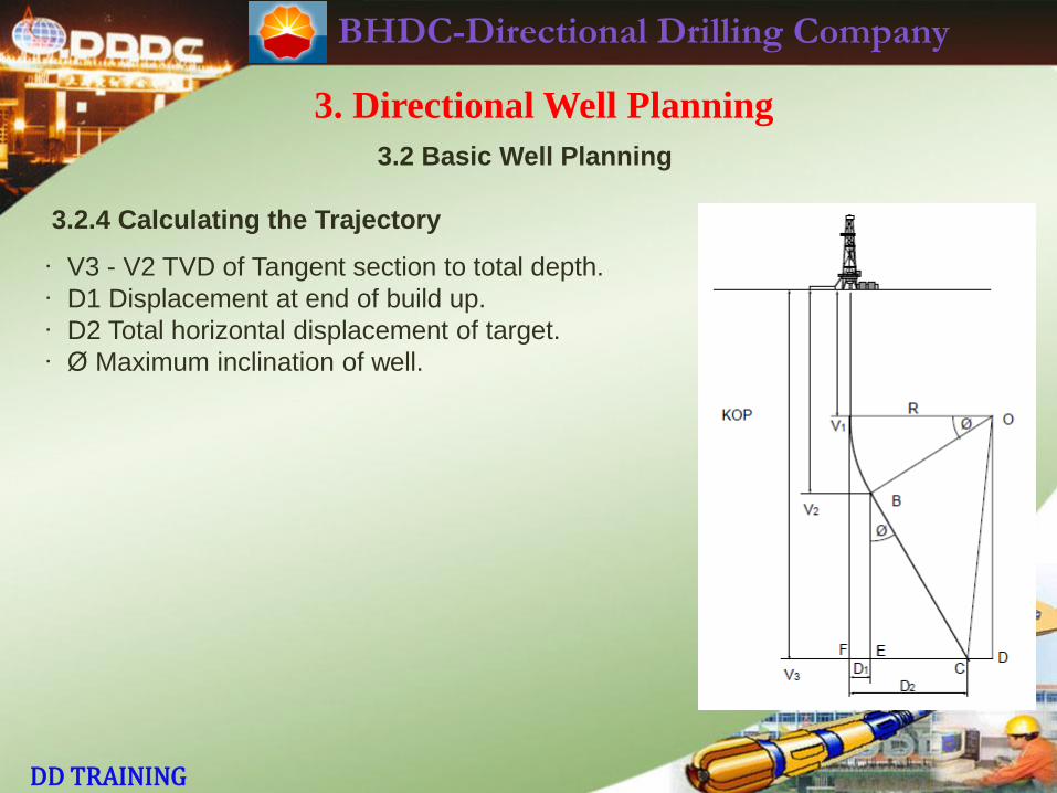
3.2.4 Calculating the Trajectory
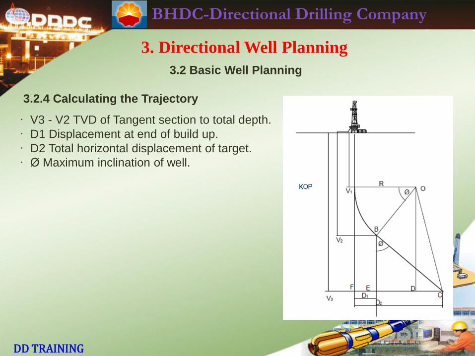
· V3 - V2 TVD of Tangent section to total depth.
· D1 Displacement at end of build up.
· D2 Total horizontal displacement of target.
· Ø Maximum inclination of well.
BHDC-Directional Drilling Company
DD TRAINING
3. Directional Well Planning
3.2 Basic Well Planning
3.2.4 Calculating the Trajectory
Slant type well where the Radius of build is
greater than the total displacement of the
target (see Figure ).
Given:
· Wellhead coordinates
· Target coordinates
· Target TVD, V3
To determine:
· KOP vertical depth, V1
· Build up rate, BUR
· KOP Kick-off point.
· V1 TVD of straight section/surface to KOP.
· V2 TVD of end of build up.
V2 -V1 TVD of Build up section with BUR
corresponding to radius of curvature R.
BHDC-Directional Drilling Company
DD TRAINING
3. Directional Well Planning
3.2 Basic Well Planning
3.2.4 Calculating the Trajectory
· V3 - V2 TVD of Tangent section to total depth.
· D1 Displacement at end of build up.
· D2 Total horizontal displacement of target.
· Ø Maximum inclination of well.
BHDC-Directional Drilling Company
DD TRAINING
3. Directional Well Planning
3.2 Basic Well Planning
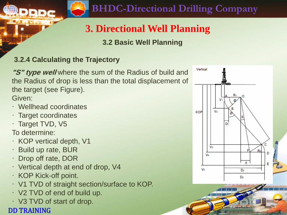
3.2.4 Calculating the Trajectory
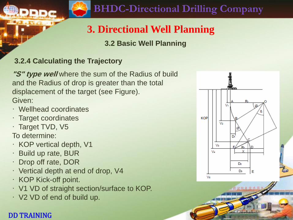
"S" type well where the sum of the Radius of build and
the Radius of drop is less than the total displacement of
the target (see Figure).
Given:
· Wellhead coordinates
· Target coordinates
· Target TVD, V5
To determine:
· KOP vertical depth, V1
· Build up rate, BUR
· Drop off rate, DOR
· Vertical depth at end of drop, V4
· KOP Kick-off point.
· V1 TVD of straight section/surface to KOP.
· V2 TVD of end of build up.
· V3 TVD of start of drop.
BHDC-Directional Drilling Company
DD TRAINING
3. Directional Well Planning
3.2 Basic Well Planning
3.2.4 Calculating the Trajectory
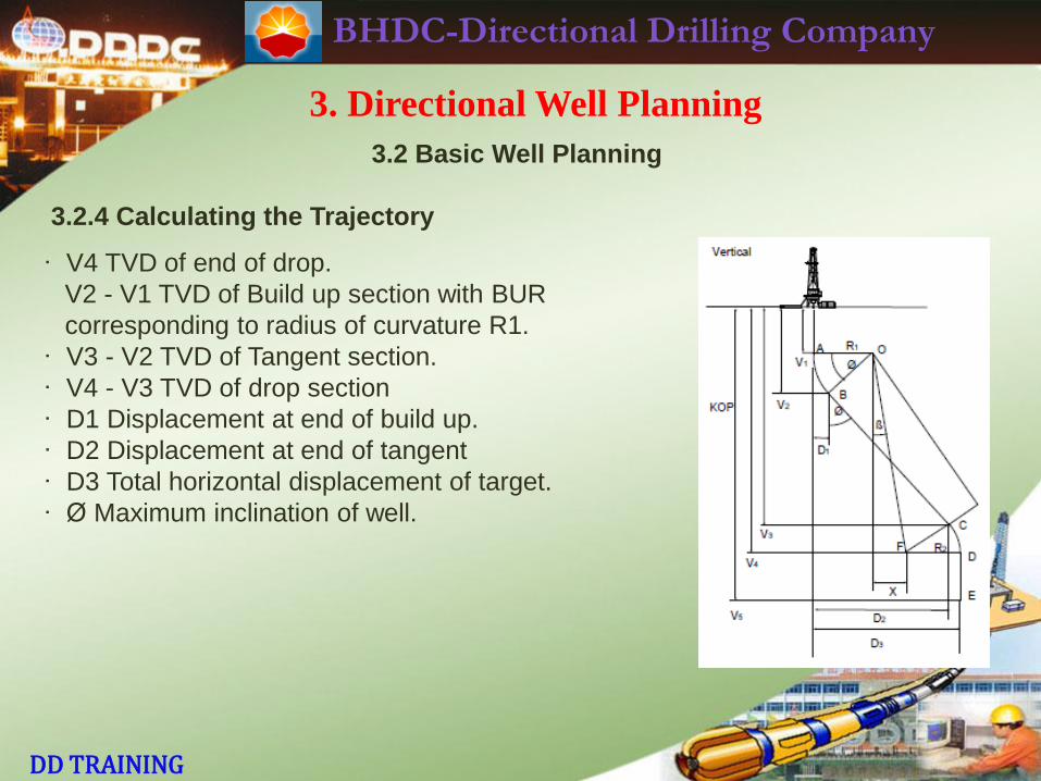
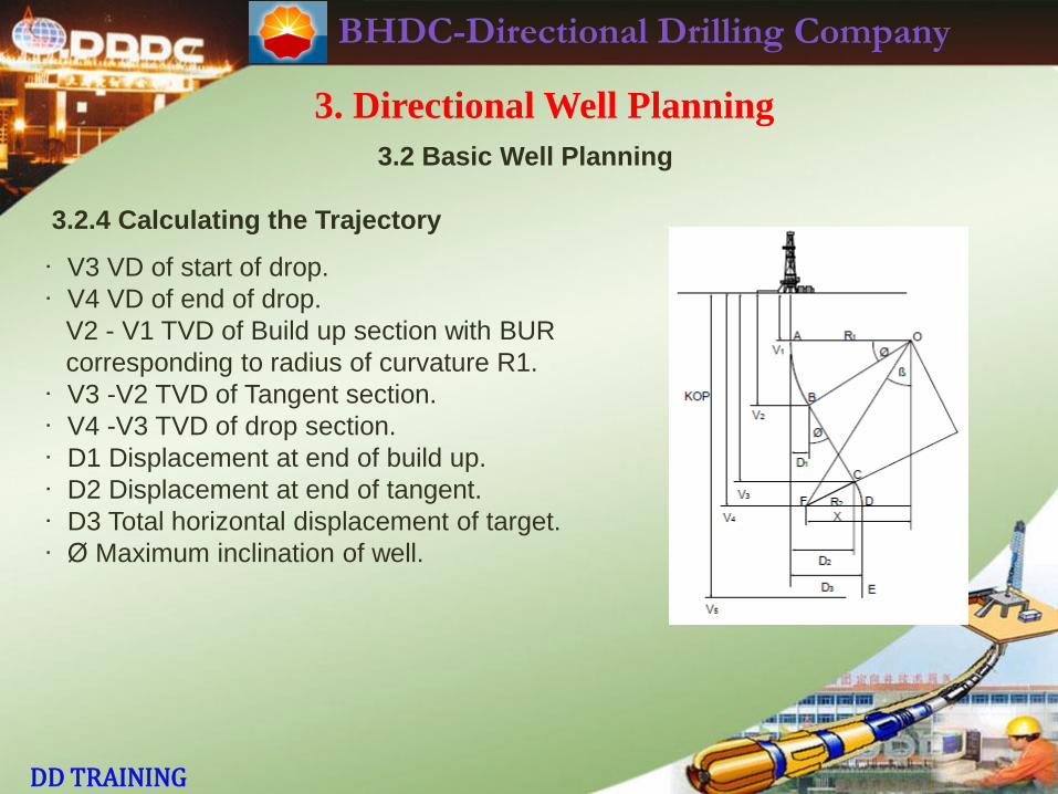
· V4 TVD of end of drop.
V2 - V1 TVD of Build up section with BUR
corresponding to radius of curvature R1.
· V3 - V2 TVD of Tangent section.
· V4 - V3 TVD of drop section
· D1 Displacement at end of build up.
· D2 Displacement at end of tangent
· D3 Total horizontal displacement of target.
· Ø Maximum inclination of well.
BHDC-Directional Drilling Company
DD TRAINING
3. Directional Well Planning
3.2 Basic Well Planning
3.2.4 Calculating the Trajectory
"S" type well where the sum of the Radius of build
and the Radius of drop is greater than the total
displacement of the target (see Figure).
Given:
· Wellhead coordinates
· Target coordinates
· Target TVD, V5
To determine:
· KOP vertical depth, V1
· Build up rate, BUR
· Drop off rate, DOR
· Vertical depth at end of drop, V4
· KOP Kick-off point.
· V1 VD of straight section/surface to KOP.
· V2 VD of end of build up.
BHDC-Directional Drilling Company
DD TRAINING
3. Directional Well Planning
3.2 Basic Well Planning
3.2.4 Calculating the Trajectory
· V3 VD of start of drop.
· V4 VD of end of drop.
V2 - V1 TVD of Build up section with BUR
corresponding to radius of curvature R1.
· V3 -V2 TVD of Tangent section.
· V4 -V3 TVD of drop section.
· D1 Displacement at end of build up.
· D2 Displacement at end of tangent.
· D3 Total horizontal displacement of target.
· Ø Maximum inclination of well.
BHDC-Directional Drilling Company
DD TRAINING
3. Directional Well Planning
3.3 Anticollision and Advanced Well Planning
3.3.1 Anti-collision Considerations
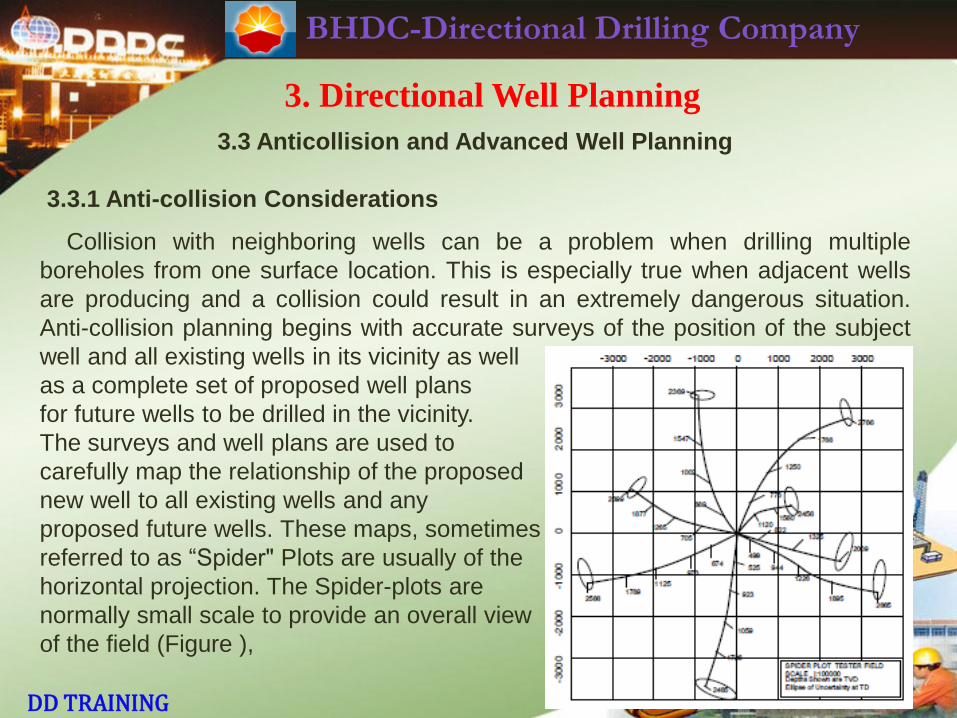
Collision with neighboring wells can be a problem when drilling multiple
boreholes from one surface location. This is especially true when adjacent wells
are producing and a collision could result in an extremely dangerous situation.
Anti-collision planning begins with accurate surveys of the position of the subject
well and all existing wells in its vicinity as well
as a complete set of proposed well plans
for future wells to be drilled in the vicinity.
The surveys and well plans are used to
carefully map the relationship of the proposed
new well to all existing wells and any
proposed future wells. These maps, sometimes
referred to as “Spider" Plots are usually of the
horizontal projection. The Spider-plots are
normally small scale to provide an overall view
of the field (Figure ),
BHDC-Directional Drilling Company
DD TRAINING
3. Directional Well Planning
3.3 Anticollision and Advanced Well Planning
3.3.1 Anti-collision Considerations
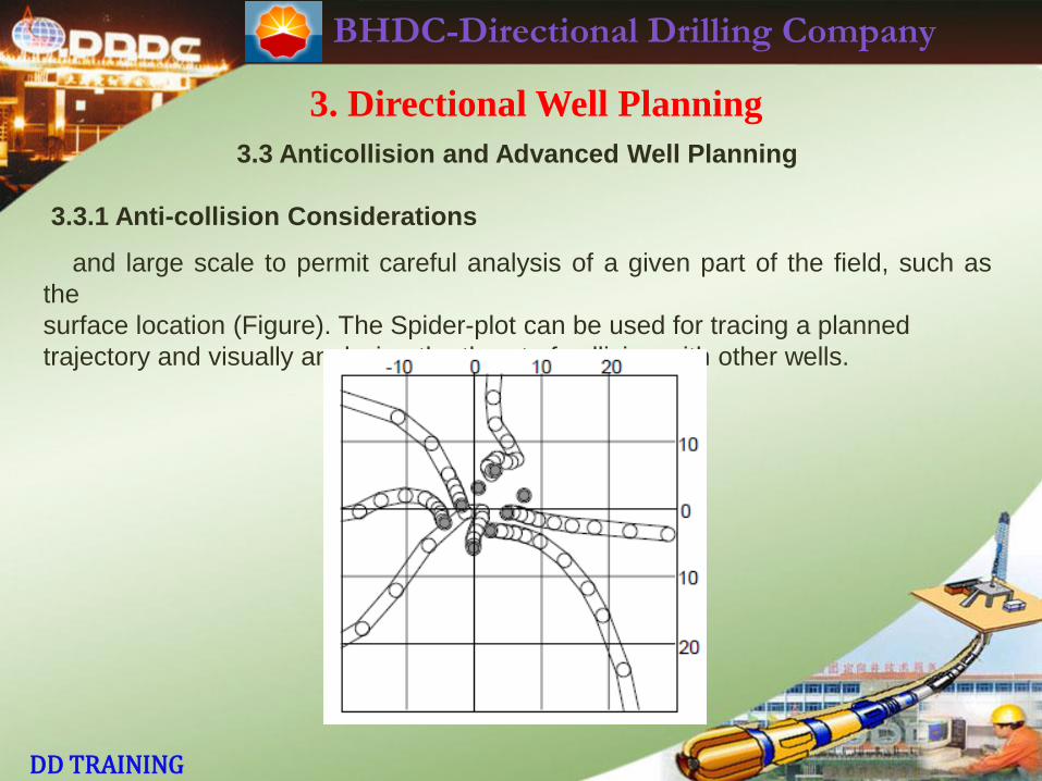
and large scale to permit careful analysis of a given part of the field, such as
the
surface location (Figure). The Spider-plot can be used for tracing a planned
trajectory and visually analyzing the threat of collision with other wells.
BHDC-Directional Drilling Company
DD TRAINING
3. Directional Well Planning
3.3 Anticollision and Advanced Well Planning
3.3.1 Anti-collision Considerations
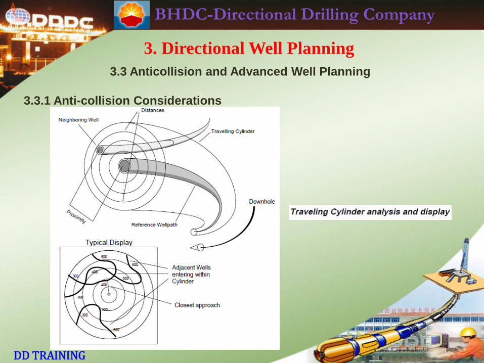
Computerized Directional Drilling planning programs usually offer some form of
anti-collision, or proximity analysis. Analysis by manual calculation is not practical
due to the large number of survey stations involved. One of the more commonly
used types of proximity analysis is known as a Traveling Cylinder.
Traveling Cylinder analysis (see Figure) involves imagining a cylinder with a
given radius enclosing the wellbore from one depth to another, the zone of interest.
Any well entering this cylinder i.e. approaching closer than the radius of the
cylinder to the central well, is plotted and displayed graphically. The traveling
cylinder analysis is a useful planning tool, enabling the planner to test various
trajectories and select the one which is most suitable. During the drilling process,
the trajectory of the well can be extrapolated and analyzed to ensure that
unsafe proximity to adjacent wells is avoided.
BHDC-Directional Drilling Company
DD TRAINING
3. Directional Well Planning
3.3 Anticollision and Advanced Well Planning
3.3.1 Anti-collision Considerations
BHDC-Directional Drilling Company
DD TRAINING
3. Directional Well Planning
3.3 Anticollision and Advanced Well Planning
3.3.2 Well Plan Maps
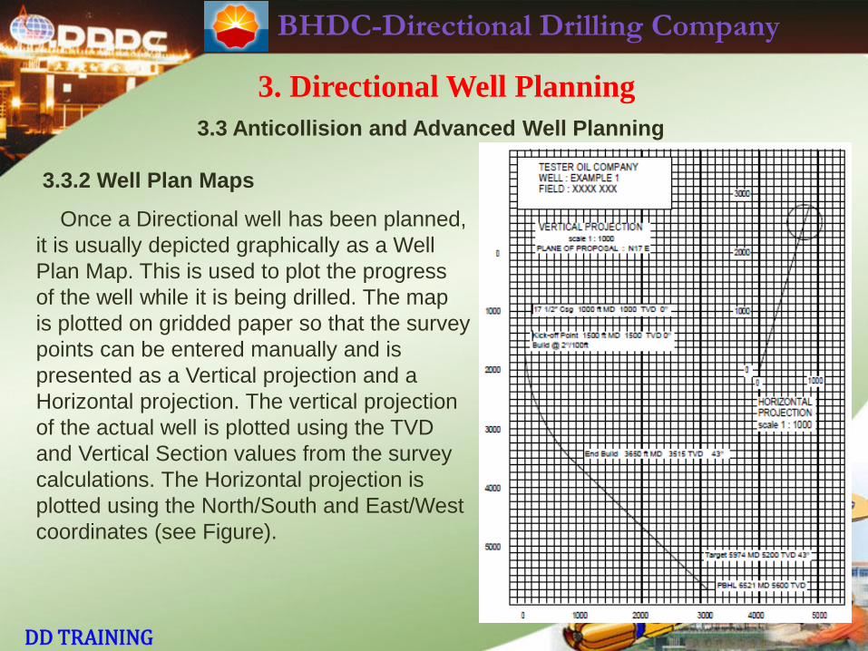
Once a Directional well has been planned,
it is usually depicted graphically as a Well
Plan Map. This is used to plot the progress
of the well while it is being drilled. The map
is plotted on gridded paper so that the survey
points can be entered manually and is
presented as a Vertical projection and a
Horizontal projection. The vertical projection
of the actual well is plotted using the TVD
and Vertical Section values from the survey
calculations. The Horizontal projection is
plotted using the North/South and East/West
coordinates (see Figure).
BHDC-Directional Drilling Company
DD TRAINING
3. Directional Well Planning
3.3 Anticollision and Advanced Well Planning
3.3.3 Computer Programs
Directional Drilling Computer Programs are commercially available and most
are quite adequate. Some are designed to run on small, hand-held calculators
while others require powerful computers. The key factor in selection is need. If the
program is needed to calculate surveys and plan wells, then a small hand held
calculator is sufficient, if the program is needed to drive a large plotter and
generate well plan maps, store bulk survey data and run a sophisticated BHA
database, then obviously something larger and more powerful is called for. DDDC
has its own software packages; e.g. Steer,and Compass.
BHDC-Directional Drilling Company
DD TRAINING
3. Directional Well Planning
3.3 Anticollision and Advanced Well Planning
3.3.3 Computer Programs
3.3.3.1 Survey Calculations
Preferably, the program should offer a selection of survey calculation methods:
Balanced Tangential, Average angle, Radius of Curvature, Minimum Curvature.
(...), etc. The survey calculation output is important and should allow the user to
specify the required format. Minimum Curvature is the DDDC preferred method
and is the industry standard.
3.3.3.2 Planning
A good planning program should be flexible. Well planning often calls for
unconventional well profiles, so the planning program should allow the user as
much freedom as possible to specify the requirements of the well. In addition to
Build-and Hold, and "S" Type wells, the user may wish to plan wells with several
targets, several build rates or planned sums, and horizontal wells with inclinations
above 90 degrees. The program could also allow the inclusion of known formation
tendencies such as left or right hand walk, or building/dropping tendencies.
BHDC-Directional Drilling Company
DD TRAINING
3. Directional Well Planning
3.3 Anticollision and Advanced Well Planning
3.3.3 Computer Programs
3.3.3.3 Anti-collision
Volume of Uncertainty and some form of proximity analysis, e.g., Traveling
Cylinder, with projections (perpendicular to the well on a parallel horizontal plane)
are essential features for a Directional Drilling program. The quality and format of
the output can make this tool easier to understand and use.
3.3.3.4 Extrapolation and Interpolation
Extrapolation allows bit-to-target analysis and “look ahead" capabilities. This is
particularly important when drilling horizontal wells where target intersection is
critical. Interpolation allows more accurate plotting of Geological features.
BHDC-Directional Drilling Company
DD TRAINING
4. Directional Drilling Tools
BHDC-Directional Drilling Company
DD TRAINING
4. Directional Drilling Tools
The major drilling tools likely to be used by the DD are discussed briefly here.
For more detailed information on a particular tool, it is necessary to refer to the
"Composite Catalog" or to the manufacturer’s data sheets.
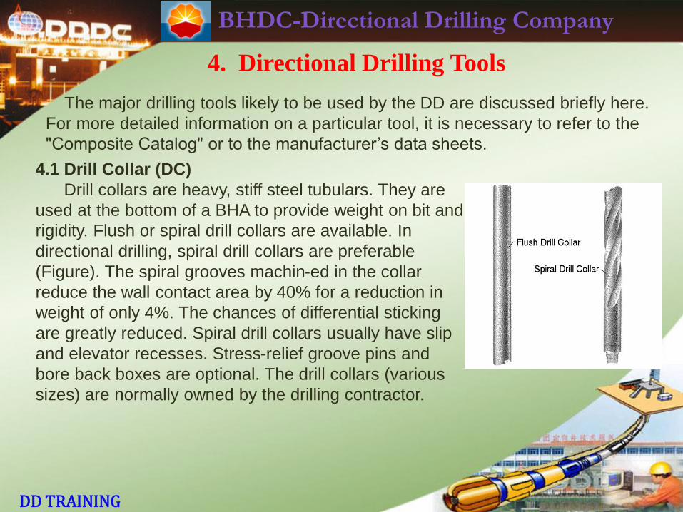
4.1 Drill Collar (DC)
Drill collars are heavy, stiff steel tubulars. They are
used at the bottom of a BHA to provide weight on bit and
rigidity. Flush or spiral drill collars are available. In
directional drilling, spiral drill collars are preferable
(Figure). The spiral grooves machin-ed in the collar
reduce the wall contact area by 40% for a reduction in
weight of only 4%. The chances of differential sticking
are greatly reduced. Spiral drill collars usually have slip
and elevator recesses. Stress-relief groove pins and
bore back boxes are optional. The drill collars (various
sizes) are normally owned by the drilling contractor.
BHDC-Directional Drilling Company
DD TRAINING
4. Directional Drilling Tools
4.2 Short Drill Collar (SDC)
Often called a pony collar, this is simply a shortened version of a steel drill collar.
Short drill collars may be manufactured or a steel drill collar may be cut to make
two or more short collars. For the DD, the SDC and the short non-magnetic drill
collar (SNMDC) have their widest application in the make-up of locked BHAs.
SDCs of various lengths (e.g. 5’, 10’, 15’) are normally provided by the DD
company.
4.3 Non-Magnetic Drill Collar (NMDC)
Non-magnetic drill collars are usually flush (non-spiral). They are manufactured
from high-quality, corrosion-resistant, austenitic stainless steel. Magnetic survey
instruments run in the hole need to be located in a non-magnetic drill collar of
sufficient length to allow the measurement of the earth’s magnetic field without
magnetic interference. Survey instruments are isolated from magnetic
disturbance caused by steel components in the BHA and drillpipe.
BHDC-Directional Drilling Company
DD TRAINING
4. Directional Drilling Tools
4.4 Short Non-Magnetic Drill Collar (SNMDC)
A short version of the NMDC, SNMDCs are often made by cutting a full-length
NMDC. The SNMDC may be used between a mud motor and an MWD collar to
counteract magnetic interference from below. It is also used in locked BHAs,
particularly where the borehole's inclination and direction give rise to high
magnetic interference. Finally, BHAs for horizontal wells often use a SNMDC.
4.5 Float Sub
This is a PIN x BOX sub which is bored out to take a float valve. It is often run
above a mud motor. In conventional rotary BHAs, a float valve is inserted either
in the bit sub (in the case of a pendulum BHA) or in the bored-out near-bit
stabilizer. Poppet and flapper designs of float valve are available. Note that some
clients may not allow the use of a float valve (because of kick-control problems).
The DD should check the client's regulations on arrival at the rig. The float sub is
usually provided by the DD company. The float valve is usually provided by the
drilling contractor.
BHDC-Directional Drilling Company
DD TRAINING
4. Directional Drilling Tools
4.6 Bit Sub
This is a BOX x BOX sub which is run directly above the bit (hence its name)
when no near-bit stabilizer is used. It is bored out to take a float valve. Various
sizes of bit sub are normally provided by the drilling contractor.
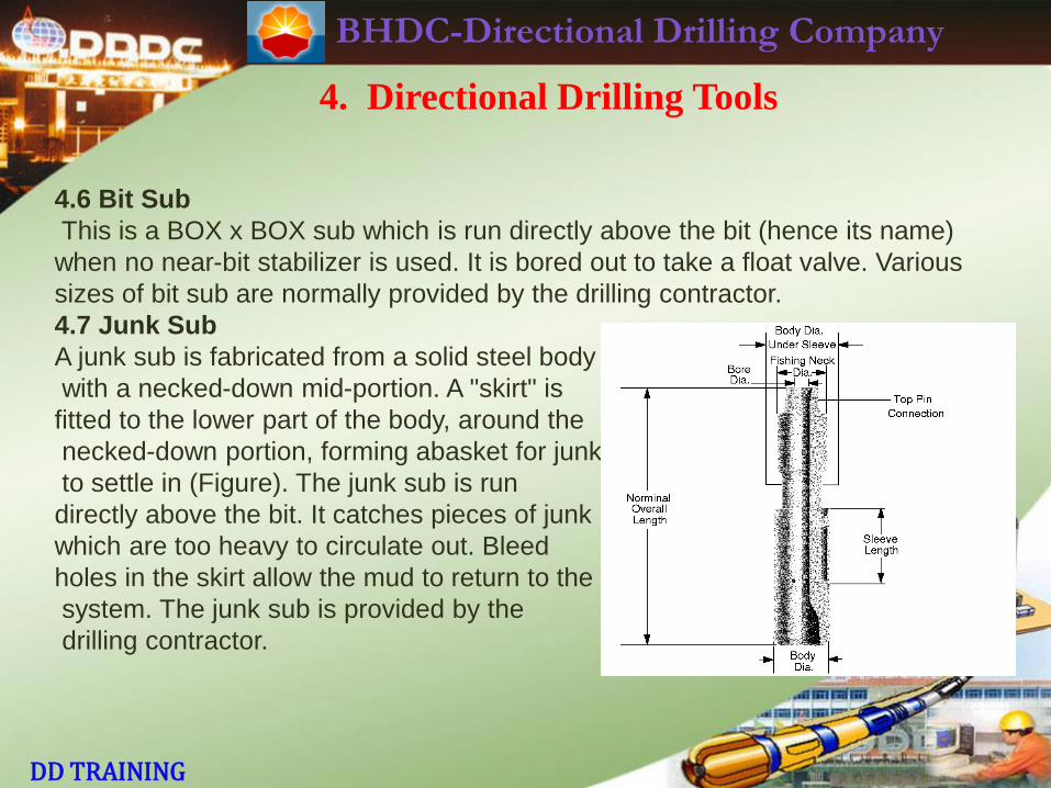
4.7 Junk Sub
A junk sub is fabricated from a solid steel body
with a necked-down mid-portion. A "skirt" is
fitted to the lower part of the body, around the
necked-down portion, forming abasket for junk
to settle in (Figure). The junk sub is run
directly above the bit. It catches pieces of junk
which are too heavy to circulate out. Bleed
holes in the skirt allow the mud to return to the
system. The junk sub is provided by the
drilling contractor.
BHDC-Directional Drilling Company
DD TRAINING
4. Directional Drilling Tools
4.8 Extension Sub
This is a short sub which can be used to fine-tune a BHA. It is normally PIN x
BOX. A float sub can be used as an extension sub. The extension sub is usually
provided by the DD company.
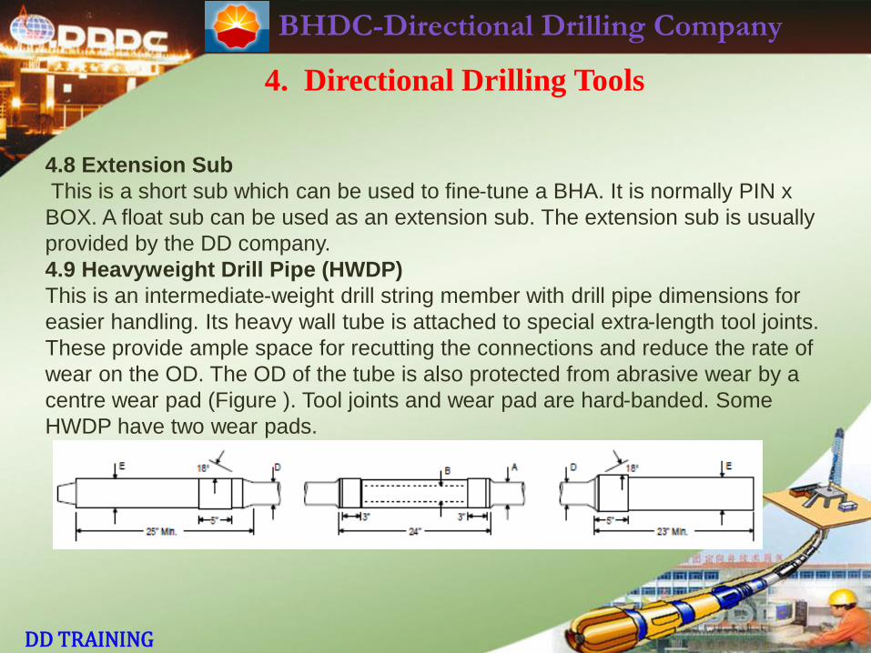
4.9 Heavyweight Drill Pipe (HWDP)
This is an intermediate-weight drill string member with drill pipe dimensions for
easier handling. Its heavy wall tube is attached to special extra-length tool joints.
These provide ample space for recutting the connections and reduce the rate of
wear on the OD. The OD of the tube is also protected from abrasive wear by a
centre wear pad (Figure ). Tool joints and wear pad are hard-banded. Some
HWDP have two wear pads.
BHDC-Directional Drilling Company
DD TRAINING
4. Directional Drilling Tools
4.9 Heavyweight Drill Pipe (HWDP)
HWDP is less rigid than DCs and has much less wall contact. Chances of
differential sticking are reduced. Its three-point wall contact feature solves two
serious problems in directional drilling. It permits high-RPM drilling with reduced
torque. HWDP can be run through hole angle and direction changes with less
connection and fatigue problems. Today, the trend in BHA design is to minimize
the number of DCs in the BHA and use HWDP to comprise a major portion of
available weight on bit.
HWDP is normally provided by the drilling contractor. However, it is the DD’s
responsibility to ensure there are sufficient joints of HWDP on the rig. For normal
directional jobs, 30 joints of HWDP should be sufficient.
BHDC-Directional Drilling Company
DD TRAINING
4. Directional Drilling Tools
4.10 Stabilizer
Stabilizers are an indispensable part of almost all rotary directional BHAs.
Near-bit stabilizers have BOX x BOX connections. They are usually bored out to
accept a float valve. String stabilizers have PIN x BOX connections. Most
stabilizers have a right-hand spiral. For directional control, 360 wall coverage (in
plan view) is recommended. Stabilizer blades are "dressed" with various possible
types of hard-facing . The leading edge of most stabilizer designs also has hard-
facing applied. It is possible to order variations of stabilizer design. Stabilizers
are used to:
· Control hole deviation.
· Reduce the risk of differential sticking.
· Ream out doglegs and keyseats.
There are many designs of stabilizer. The most common types are:
BHDC-Directional Drilling Company
DD TRAINING
4. Directional Drilling Tools
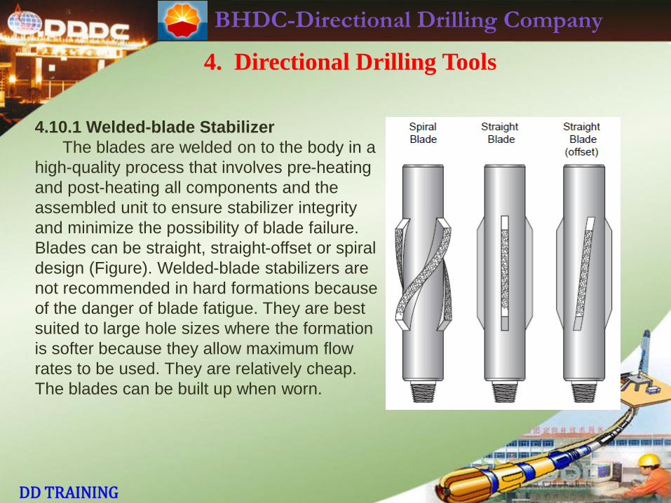
4.10.1 Welded-blade Stabilizer
The blades are welded on to the body in a
high-quality process that involves pre-heating
and post-heating all components and the
assembled unit to ensure stabilizer integrity
and minimize the possibility of blade failure.
Blades can be straight, straight-offset or spiral
design (Figure). Welded-blade stabilizers are
not recommended in hard formations because
of the danger of blade fatigue. They are best
suited to large hole sizes where the formation
is softer because they allow maximum flow
rates to be used. They are relatively cheap.
The blades can be built up when worn.
BHDC-Directional Drilling Company
DD TRAINING
4. Directional Drilling Tools
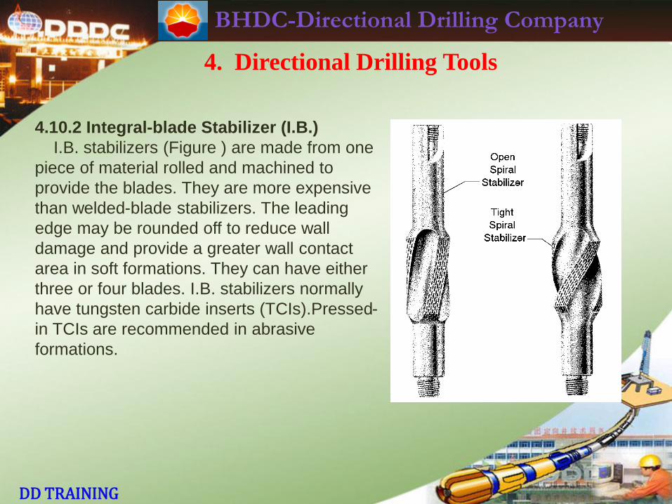
4.10.2 Integral-blade Stabilizer (I.B.)
I.B. stabilizers (Figure ) are made from one
piece of material rolled and machined to
provide the blades. They are more expensive
than welded-blade stabilizers. The leading
edge may be rounded off to reduce wall
damage and provide a greater wall contact
area in soft formations. They can have either
three or four blades. I.B. stabilizers normally
have tungsten carbide inserts (TCIs).Pressed-
in TCIs are recommended in abrasive
formations.
BHDC-Directional Drilling Company
DD TRAINING
4. Directional Drilling Tools
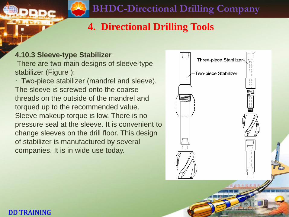
4.10.3 Sleeve-type Stabilizer
There are two main designs of sleeve-type
stabilizer (Figure ):
· Two-piece stabilizer (mandrel and sleeve).
The sleeve is screwed onto the coarse
threads on the outside of the mandrel and
torqued up to the recommended value.
Sleeve makeup torque is low. There is no
pressure seal at the sleeve. It is convenient to
change sleeves on the drill floor. This design
of stabilizer is manufactured by several
companies. It is in wide use today.
BHDC-Directional Drilling Company
DD TRAINING
4. Directional Drilling Tools
4.10.3 Sleeve-type Stabilizer
· Three-piece stabilizer (mandrel, sleeve and saver sub). The sleeve is screwed
onto the mandrel first, by hand. The saver sub is then screwed into the mandrel
and this connection is torqued up to the recommended value. In this case, there
is a mud pressure seal at the mandrel/saver sub connection. Makeup torque of
this connection is the full value for that size of API connection. Great care must be
taken (clean and dope the shoulders properly, use correct makeup torque),
otherwise downhole washouts etc. will result. It can be quite difficult any
time-consuming to change/service the sleeve. For these reasons, this design of
sleeve-type stabilizer is not as widely used today as it was some years ago.
BHDC-Directional Drilling Company
DD TRAINING
4. Directional Drilling Tools
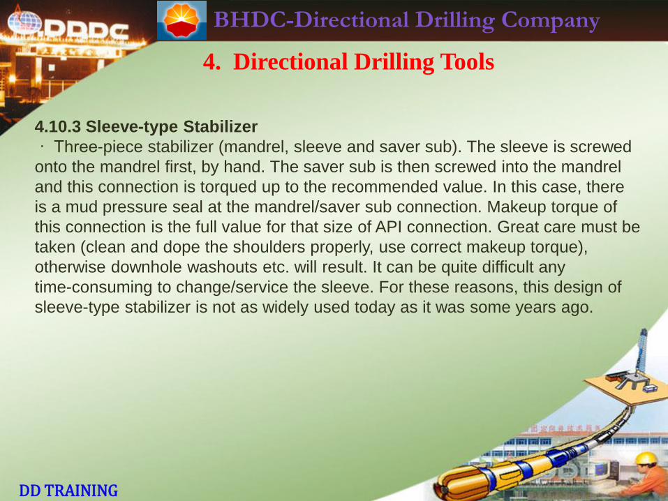
4.10.4 Clamp-on Stabilizer
Several designs are available e.g. REED,
Servco-loc, EMTEC. An example is shown
in Figure. Clamp-on stabilizers allow more
flexibility in BHA design. They can be
positioned on NMDCs, MWD, PDMs etc. at
the required spacing to maintain directional
control. Nonmagnetic clamp-on stabilizers
are available on request Some clients are
apprehensive about running clamp-on
because of the danger of them moving
position downhole. Sometimes they’re
difficult to take off after POOH.
BHDC-Directional Drilling Company
DD TRAINING
4. Directional Drilling Tools
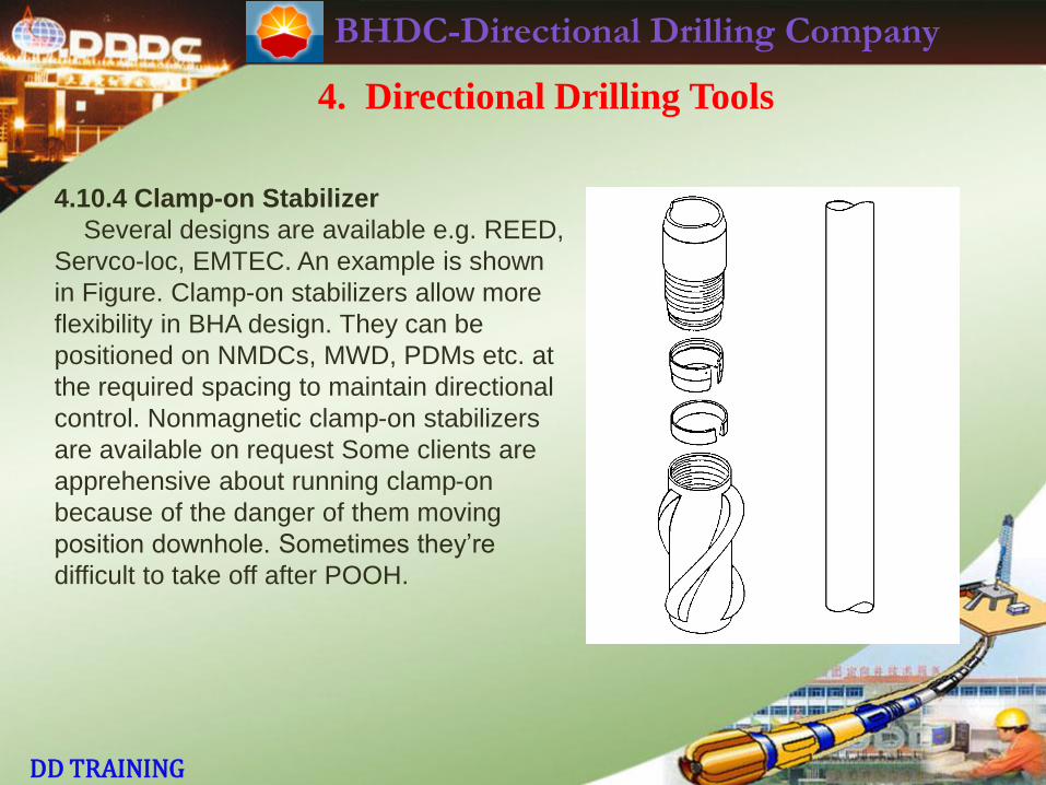
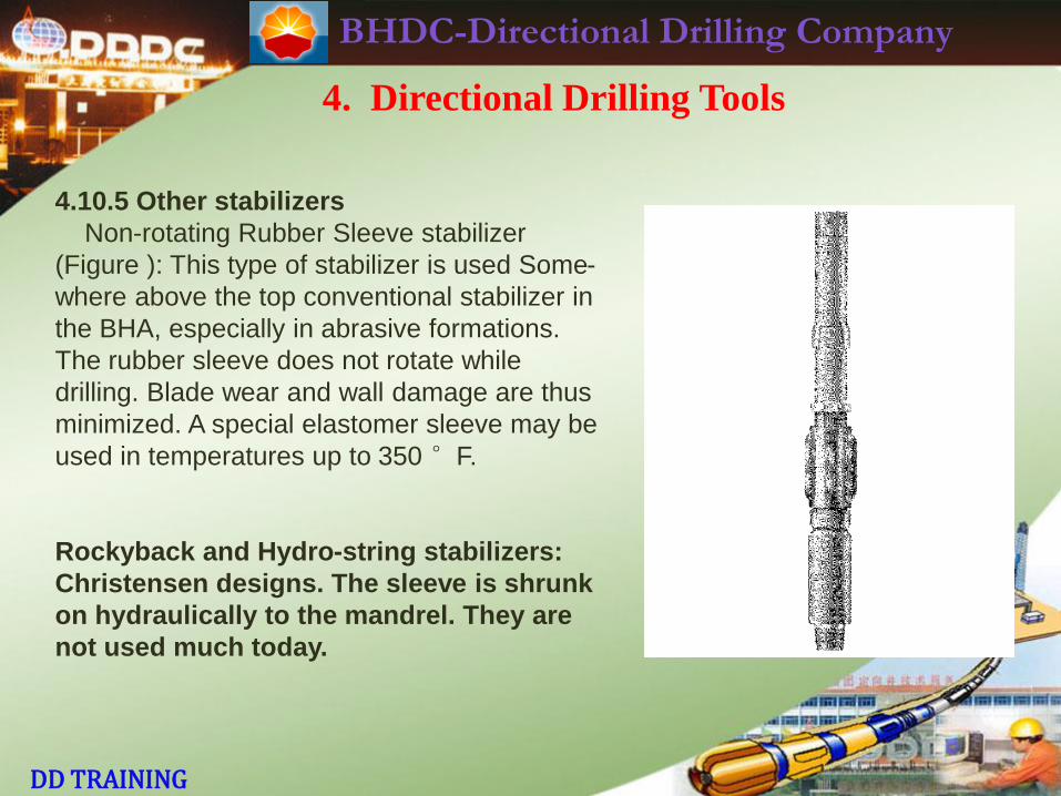
4.10.5 Other stabilizers
Non-rotating Rubber Sleeve stabilizer
(Figure ): This type of stabilizer is used Some-
where above the top conventional stabilizer in
the BHA, especially in abrasive formations.
The rubber sleeve does not rotate while
drilling. Blade wear and wall damage are thus
minimized. A special elastomer sleeve may be
used in temperatures up to 350 °F.
Rockyback and Hydro-string stabilizers:
Christensen designs. The sleeve is shrunk
on hydraulically to the mandrel. They are
not used much today.
BHDC-Directional Drilling Company
DD TRAINING
4. Directional Drilling Tools
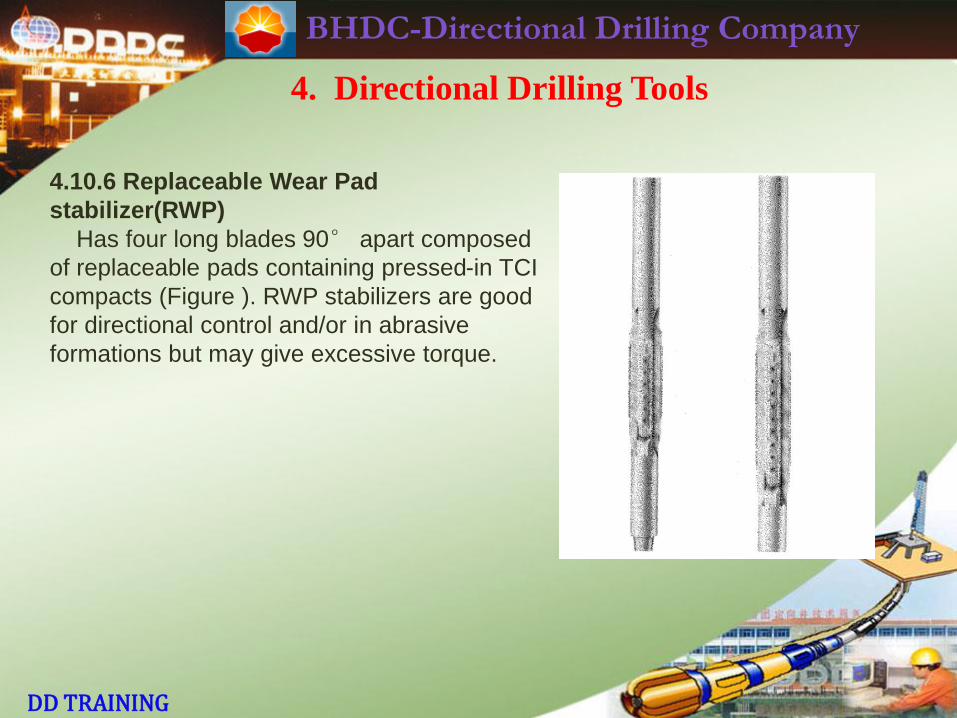
4.10.6 Replaceable Wear Pad
stabilizer(RWP)
Has four long blades 90° apart composed
of replaceable pads containing pressed-in TCI
compacts (Figure ). RWP stabilizers are good
for directional control and/or in abrasive
formations but may give excessive torque.
BHDC-Directional Drilling Company
DD TRAINING
4. Directional Drilling Tools
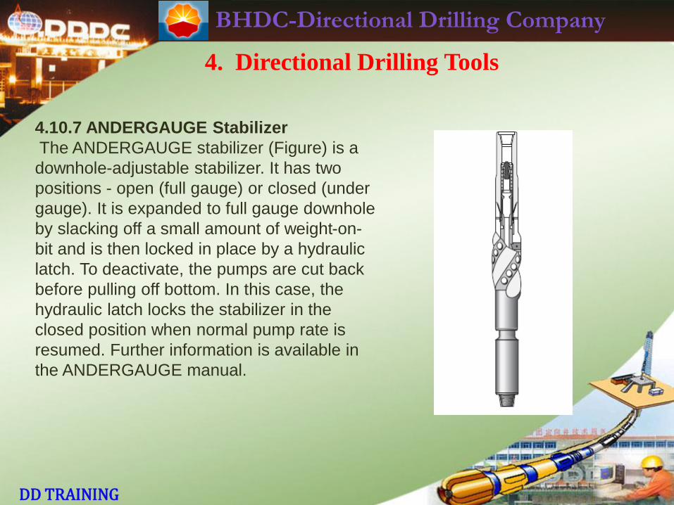
4.10.7 ANDERGAUGE Stabilizer
The ANDERGAUGE stabilizer (Figure) is a
downhole-adjustable stabilizer. It has two
positions - open (full gauge) or closed (under
gauge). It is expanded to full gauge downhole
by slacking off a small amount of weight-on-
bit and is then locked in place by a hydraulic
latch. To deactivate, the pumps are cut back
before pulling off bottom. In this case, the
hydraulic latch locks the stabilizer in the
closed position when normal pump rate is
resumed. Further information is available in
the ANDERGAUGE manual.
BHDC-Directional Drilling Company
DD TRAINING
4. Directional Drilling Tools
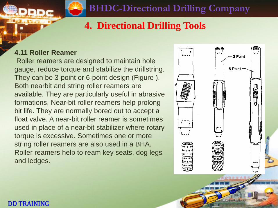
4.11 Roller Reamer
Roller reamers are designed to maintain hole
gauge, reduce torque and stabilize the drillstring.
They can be 3-point or 6-point design (Figure ).
Both nearbit and string roller reamers are
available. They are particularly useful in abrasive
formations. Near-bit roller reamers help prolong
bit life. They are normally bored out to accept a
float valve. A near-bit roller reamer is sometimes
used in place of a near-bit stabilizer where rotary
torque is excessive. Sometimes one or more
string roller reamers are also used in a BHA.
Roller reamers help to ream key seats, dog legs
and ledges.
BHDC-Directional Drilling Company
DD TRAINING
4. Directional Drilling Tools
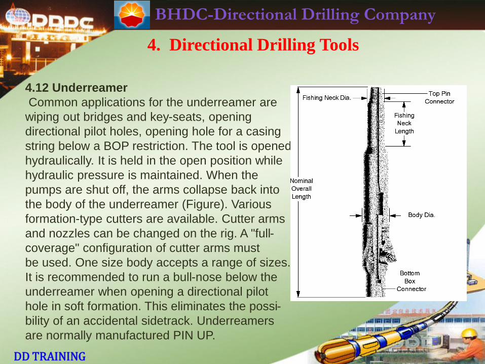
4.12 Underreamer
Common applications for the underreamer are
wiping out bridges and key-seats, opening
directional pilot holes, opening hole for a casing
string below a BOP restriction. The tool is opened
hydraulically. It is held in the open position while
hydraulic pressure is maintained. When the
pumps are shut off, the arms collapse back into
the body of the underreamer (Figure). Various
formation-type cutters are available. Cutter arms
and nozzles can be changed on the rig. A "full-
coverage" configuration of cutter arms must
be used. One size body accepts a range of sizes.
It is recommended to run a bull-nose below the
underreamer when opening a directional pilot
hole in soft formation. This eliminates the possi-
bility of an accidental sidetrack. Underreamers
are normally manufactured PIN UP.
BHDC-Directional Drilling Company
DD TRAINING
4. Directional Drilling Tools
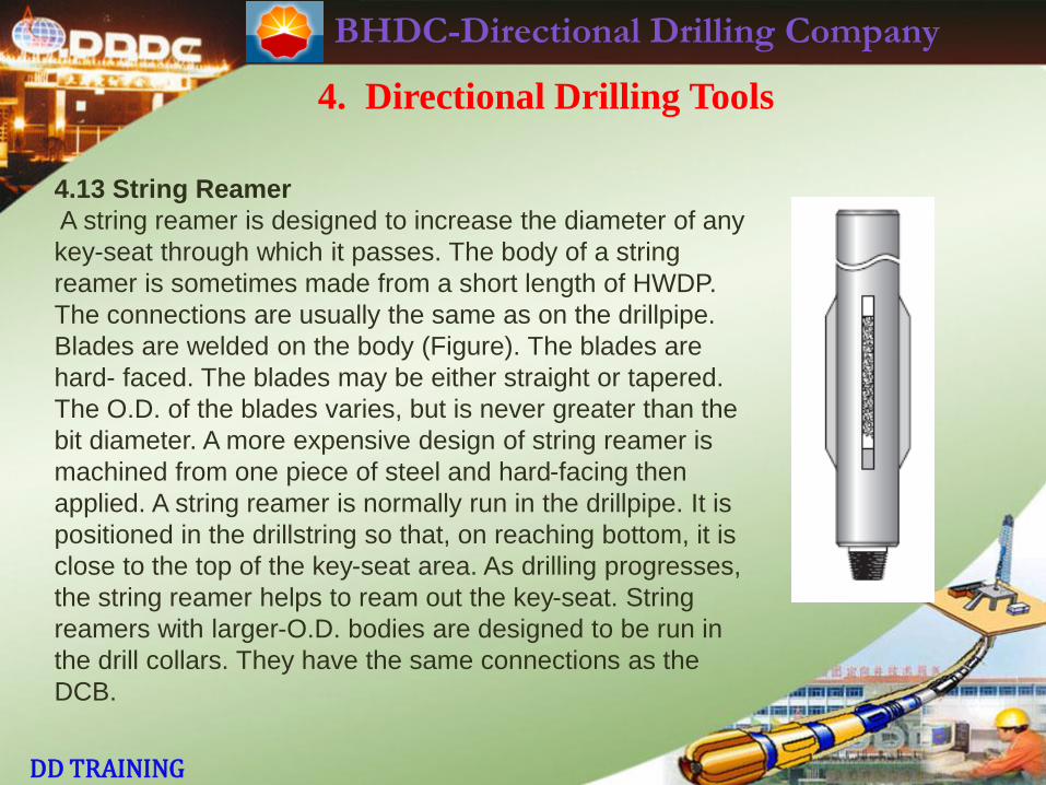
4.13 String Reamer
A string reamer is designed to increase the diameter of any
key-seat through which it passes. The body of a string
reamer is sometimes made from a short length of HWDP.
The connections are usually the same as on the drillpipe.
Blades are welded on the body (Figure). The blades are
hard- faced. The blades may be either straight or tapered.
The O.D. of the blades varies, but is never greater than the
bit diameter. A more expensive design of string reamer is
machined from one piece of steel and hard-facing then
applied. A string reamer is normally run in the drillpipe. It is
positioned in the drillstring so that, on reaching bottom, it is
close to the top of the key-seat area. As drilling progresses,
the string reamer helps to ream out the key-seat. String
reamers with larger-O.D. bodies are designed to be run in
the drill collars. They have the same connections as the
DCB.
BHDC-Directional Drilling Company
DD TRAINING
5. Bottom Hole Assemblies
BHDC-Directional Drilling Company
DD TRAINING
5. Bottom Hole Assemblies
About this chapter
The design of the rotary bottom hole assembly (BHA) is, together with
orientation, the most critical part of the DD job. Minimizing trips for BHA
changes is the objective of every client. They all want to "make hole" and
drill a usable hole to TD as soon as possible. A DD’s reputation depends,
to a large extent, on the judgment and "feel" he has for choosing the
appropriate BHA for a given situation.
This chapter is meant to be an introduction to BHA principles, concepts
and design. It is not meant to be a theoretical approach to the subject.
The objective is to give broad guide-lines in selecting BHAs. Deciding on
the changes to be made to a BHA (e.g. not over-reacting to unexpected
BHA tendencies) is often more difficult than in selecting the basic BHA.
BHDC-Directional Drilling Company
DD TRAINING
5. Bottom Hole Assemblies
About this chapter
It is important that the DD keep an open mind about BHA design. A DD
may think he’s got his BHAs all figured out until he moves to a new area.
He may be baffled to find that few or none of his previous BHAs work as
expected. This is understandable. As long as the "learning curve" is short,
the client will not complain. Finally, keeping accurate, comprehensive
records of BHA performance is vital. When a "new" DD arrives in an area,
the only aid he has in selecting the BHAs is the performance of previous
wells. There is no excuse for a DD departing the rig not to leave proper
hand-over BHA performance records to his relief.

BHDC-Directional Drilling Company
DD TRAINING
5. Bottom Hole Assemblies
5.1 Rotary BHA
Before the advent of MWD tools and/or steerable motors, the “classic"
approach to a typical DD job (e.g. kickoff point in 17 1/2" hole) was as
follows:
1. One or more rotary BHAs (typically in 36" and 26" hole sizes) were
used to drill the top hole section. A 17-1/2" rotary BHA was used to drill
out the 20" casing shoe and drill down to the kickoff point. The well would
normally be planned to have sufficient open hole from the 20" casing to
the kickoff point to eliminate the possibility of magnetic interference when
kicking off.
2. A bit (17 1/2" or smaller) / mud motor / bent sub combination was RIH.
Magnetic (or, where necessary gyro) single-shot surveys were taken at
short intervals. Hole inclination was built to 8° in hard formation and
typically +/- 15° in softer formation. Having achieved the required hole
azimuth (lead angle taken into account), this BHA was then POOH.

BHDC-Directional Drilling Company
DD TRAINING
5. Bottom Hole Assemblies
5.1 Rotary BHA
3. A rotary build BHA was RIH. The inclination was built up close to the
required maximum angle on the well plan. By controlling the drilling
parameters (particularly WOB and RPM) every effort was made to hold
the well azimuth on course. This BHA was then POOH.
4. A rotary lockup BHA was then RIH. In a slant well, the normal objective
was to hold the inclination until the next casing point. Small variations in
inclination were permissible. Again, drilling parameters were varied as
deemed necessary. Because the BHA was “stiff”, in theory it gave the best
possibility of keeping the well azimuth within the prescribed limits.
From the above scenario, it is clear that several trips were required for
BHA changes (even assuming that the well behaved perfectly from a DD
standpoint). When directional problems occurred (unpredictable BHA
behavior), several days were often lost. Even worse, a "crooked hole"
occasionally resulted.
BHDC-Directional Drilling Company
DD TRAINING
5. Bottom Hole Assemblies
5.1 Rotary BHA
MWD surveys meant that the DD had more control over survey
intervals. It became common to survey every single in the kickoff and
buildup phases. Even better, in soft formation it became possible to build
up to the required maximum angle (even up to +/- 50° inclination) with
the bit/mud motor/ bent sub/ MWD combination, provided hole friction did
not become excessive. This eliminated one round trip.
The arrival of steerable motors meant that a complete hole phase
became possible using a single BHA which included a bit steerable motor/
string stabilizer/ MWD combination.
The significant extra cost incurred from using the steerable motor was
counteracted by the savings in trip time and the rig convenience and
reduced wear on the drill-string.
BHDC-Directional Drilling Company
DD TRAINING
5. Bottom Hole Assemblies
5.1 Rotary BHA
5.1.1 Rotary BHA Theory
Once the initial deflection and direction of the well (i.e. the kickoff) has
been achieved by the bit/ mud motor/ bent
sub, the remainder of the well (apart from
correction runs) is drilled using conventional
rotary drilling techniques.
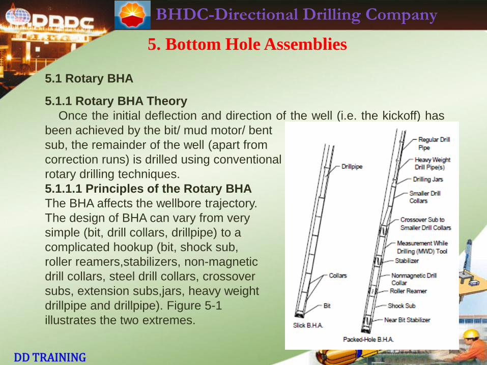
5.1.1.1 Principles of the Rotary BHA
The BHA affects the wellbore trajectory.
The design of BHA can vary from very
simple (bit, drill collars, drillpipe) to a
complicated hookup (bit, shock sub,
roller reamers,stabilizers, non-magnetic
drill collars, steel drill collars, crossover
subs, extension subs,jars, heavy weight
drillpipe and drillpipe). Figure 5-1
illustrates the two extremes.
BHDC-Directional Drilling Company
DD TRAINING
5. Bottom Hole Assemblies
5.1 Rotary BHA
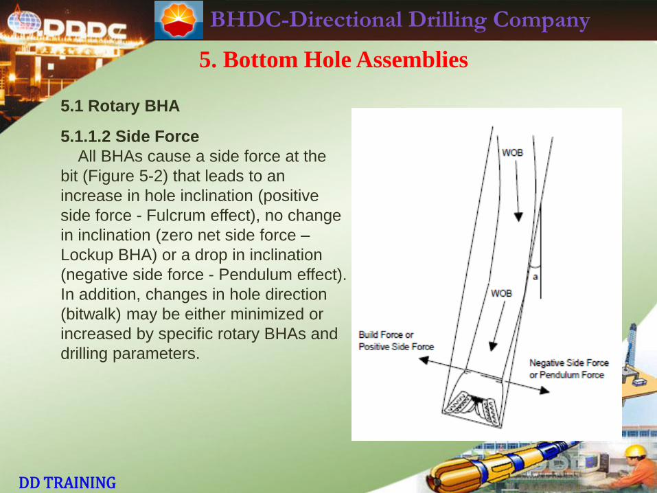
5.1.1.2 Side Force
All BHAs cause a side force at the
bit (Figure 5-2) that leads to an
increase in hole inclination (positive
side force - Fulcrum effect), no change
in inclination (zero net side force –
Lockup BHA) or a drop in inclination
(negative side force - Pendulum effect).
In addition, changes in hole direction
(bitwalk) may be either minimized or
increased by specific rotary BHAs and
drilling parameters.
BHDC-Directional Drilling Company
DD TRAINING
5. Bottom Hole Assemblies
5.1 Rotary BHA
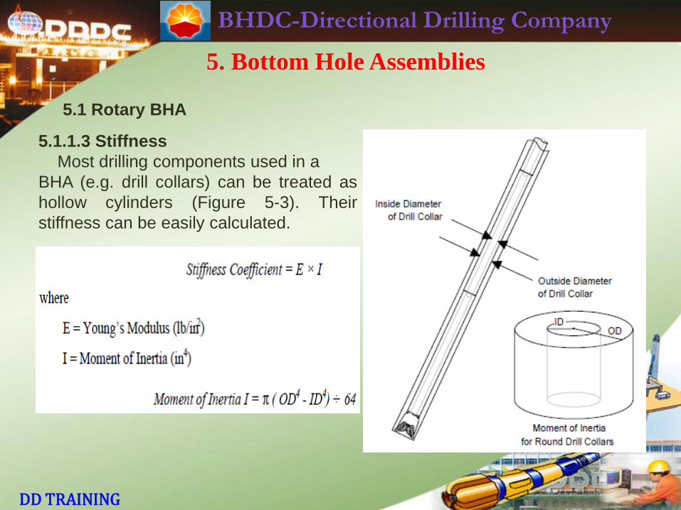
5.1.1.3 Stiffness
Most drilling components used in a
BHA (e.g. drill collars) can be treated as
hollow cylinders (Figure 5-3). Their
stiffness can be easily calculated.
BHDC-Directional Drilling Company
DD TRAINING
5. Bottom Hole Assemblies
5.1 Rotary BHA
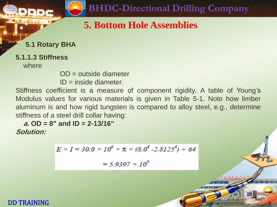
5.1.1.3 Stiffness
where
OD = outside diameter
ID = inside diameter.
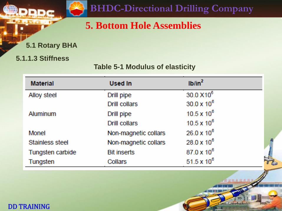
Stiffness coefficient is a measure of component rigidity. A table of Young’s
Modulus values for various materials is given in Table 5-1. Note how limber
aluminum is and how rigid tungsten is compared to alloy steel, e.g., determine
stiffness of a steel drill collar having:
a. OD = 8" and ID = 2-13/16“
Solution:
BHDC-Directional Drilling Company
DD TRAINING
5. Bottom Hole Assemblies
5.1 Rotary BHA
5.1.1.3 Stiffness
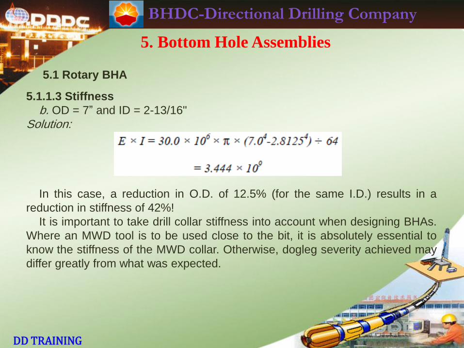
b. OD = 7” and ID = 2-13/16"
Solution:
In this case, a reduction in O.D. of 12.5% (for the same I.D.) results in a
reduction in stiffness of 42%!
It is important to take drill collar stiffness into account when designing BHAs.
Where an MWD tool is to be used close to the bit, it is absolutely essential to
know the stiffness of the MWD collar. Otherwise, dogleg severity achieved may
differ greatly from what was expected.
BHDC-Directional Drilling Company
DD TRAINING
5. Bottom Hole Assemblies
5.1 Rotary BHA
5.1.1.3 Stiffness
Table 5-1 Modulus of elasticity
BHDC-Directional Drilling Company
DD TRAINING
5. Bottom Hole Assemblies
5.1 Rotary BHA
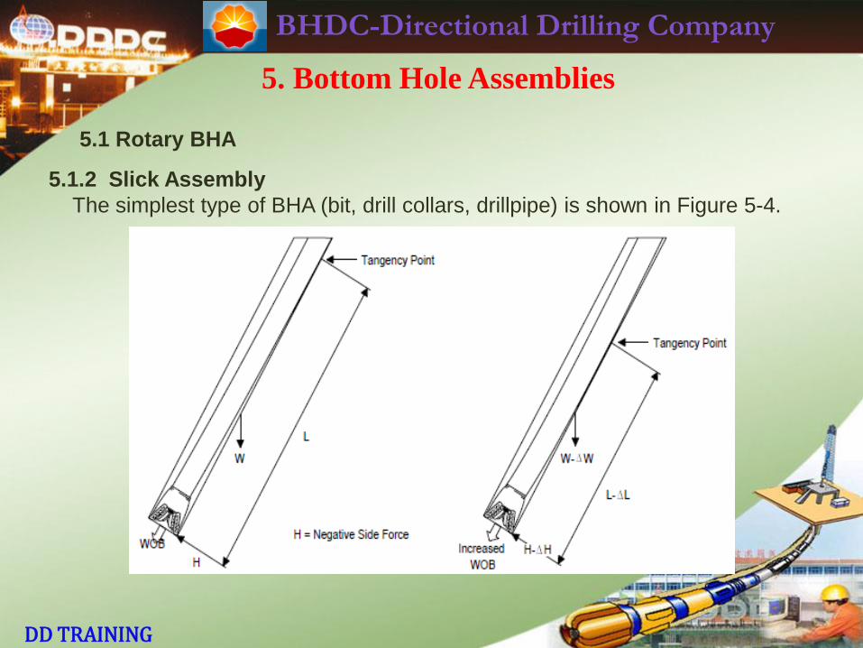
5.1.2 Slick Assembly
The simplest type of BHA (bit, drill collars, drillpipe) is shown in Figure 5-4.
BHDC-Directional Drilling Company
DD TRAINING
5. Bottom Hole Assemblies
5.1 Rotary BHA
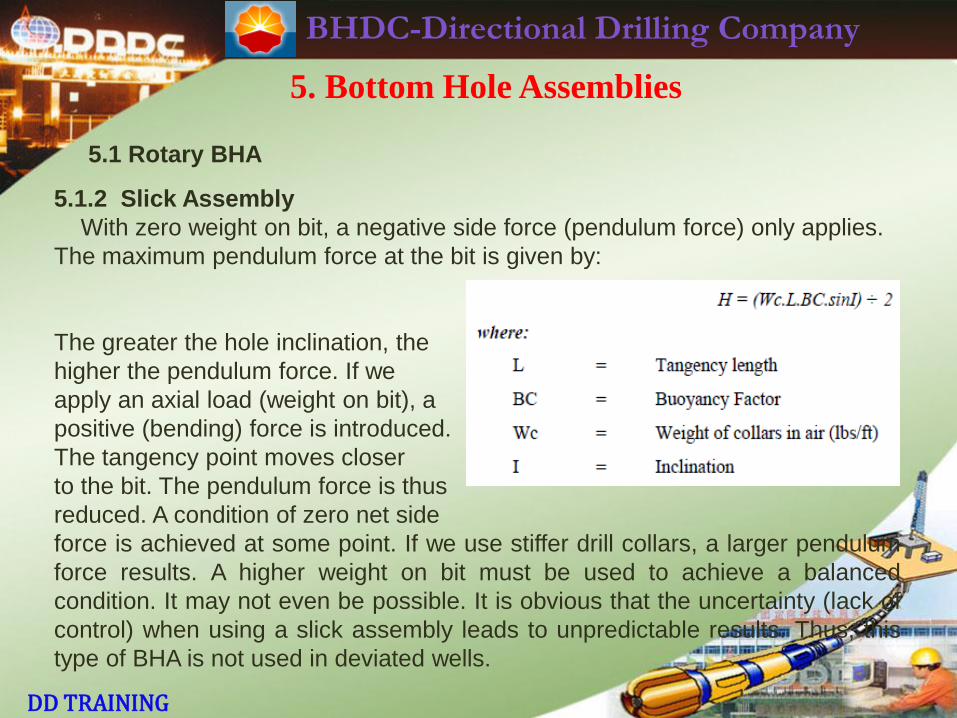
5.1.2 Slick Assembly
With zero weight on bit, a negative side force (pendulum force) only applies.
The maximum pendulum force at the bit is given by:
The greater the hole inclination, the
higher the pendulum force. If we
apply an axial load (weight on bit), a
positive (bending) force is introduced.
The tangency point moves closer
to the bit. The pendulum force is thus
reduced. A condition of zero net side
force is achieved at some point. If we use stiffer drill collars, a larger pendulum
force results. A higher weight on bit must be used to achieve a balanced
condition. It may not even be possible. It is obvious that the uncertainty (lack of
control) when using a slick assembly leads to unpredictable results. Thus, this
type of BHA is not used in deviated wells.
BHDC-Directional Drilling Company
DD TRAINING
5. Bottom Hole Assemblies
5.1 Rotary BHA
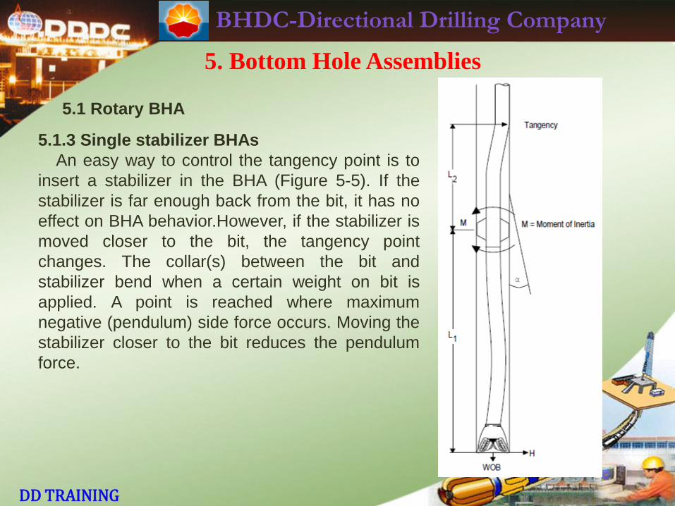
5.1.3 Single stabilizer BHAs
An easy way to control the tangency point is to
insert a stabilizer in the BHA (Figure 5-5). If the
stabilizer is far enough back from the bit, it has no
effect on BHA behavior.However, if the stabilizer is
moved closer to the bit, the tangency point
changes. The collar(s) between the bit and
stabilizer bend when a certain weight on bit is
applied. A point is reached where maximum
negative (pendulum) side force occurs. Moving the
stabilizer closer to the bit reduces the pendulum
force.
BHDC-Directional Drilling Company
DD TRAINING
5. Bottom Hole Assemblies
5.1 Rotary BHA
5.1.3 Single stabilizer BHAs
Eventually, a point is reached where zero side force occurs. Moving the
stabilizer further down gives a positive side force. The collar directly above the
stabilizer bends when weight is applied. The stabilizer forces the bit towards the
high side of the hole. This is called the fulcrum effect. Increases in weight on bit
(up to a certain point) lead to increased buildup rate.
The more limber the collar directly above the near-bit stabilizer, the greater
the buildup rate. The smaller the O.D. of the collar directly above the near-bit,
the closer to the bit the contact point becomes. Thus, a higher positive side
force is achieved. Single-stabilizer buildup BHAs are not normally used. Under
no circumstances should a single stabilizer be run if, later in the hole, multi-
stabilizer BHAs are to be run. More predictable BHA behavior and better hole
condition results from using two or more stabilizers in every BHA.
BHDC-Directional Drilling Company
DD TRAINING
5. Bottom Hole Assemblies
5.1 Rotary BHA
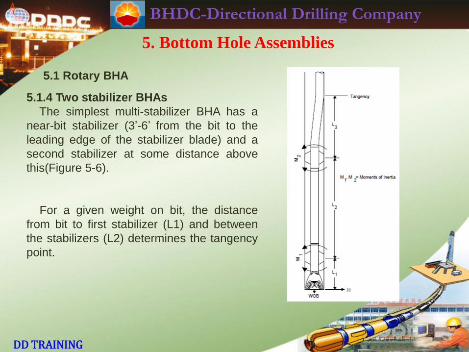
5.1.4 Two stabilizer BHAs
The simplest multi-stabilizer BHA has a
near-bit stabilizer (3’-6’ from the bit to the
leading edge of the stabilizer blade) and a
second stabilizer at some distance above
this(Figure 5-6).
For a given weight on bit, the distance
from bit to first stabilizer (L1) and between
the stabilizers (L2) determines the tangency
point.
BHDC-Directional Drilling Company
DD TRAINING
5. Bottom Hole Assemblies
5.1 Rotary BHA
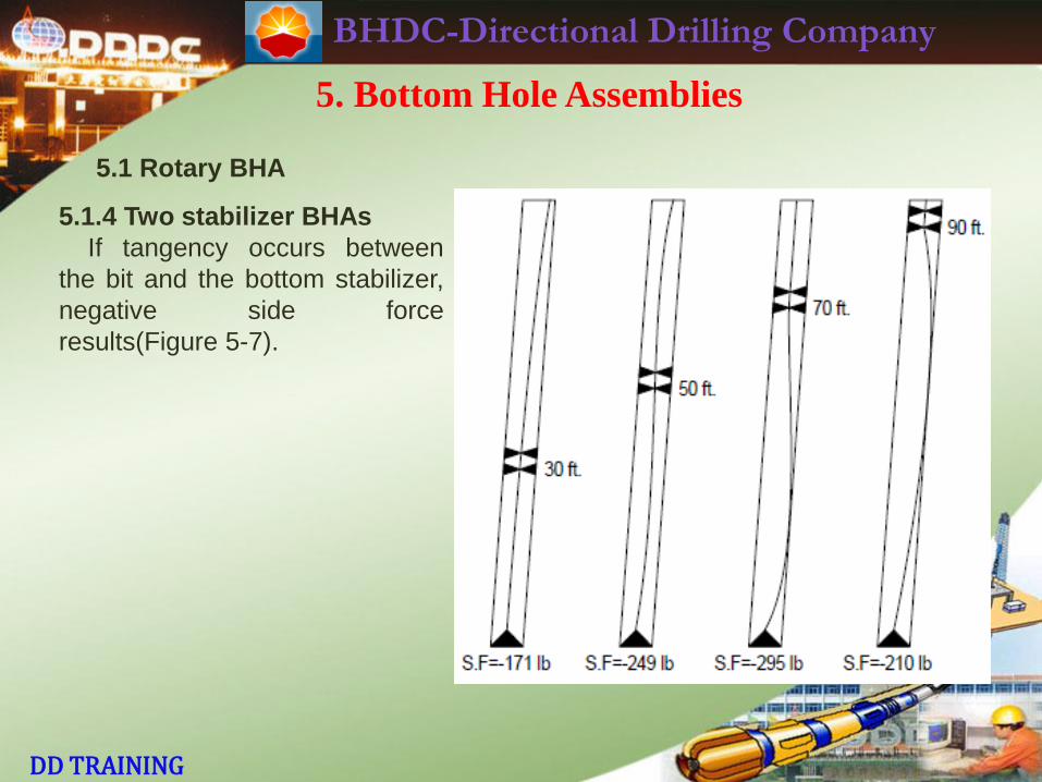
5.1.4 Two stabilizer BHAs
If tangency occurs between
the bit and the bottom stabilizer,
negative side force
results(Figure 5-7).
BHDC-Directional Drilling Company
DD TRAINING
5. Bottom Hole Assemblies
5.1 Rotary BHA
5.1.4 Two stabilizer BHAs
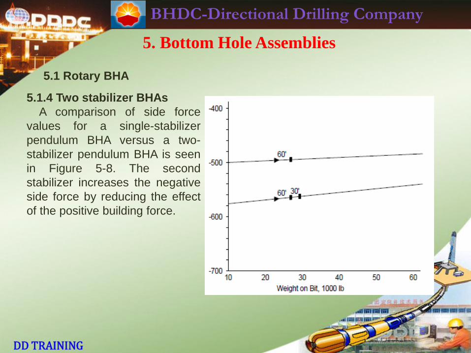
A comparison of side force
values for a single-stabilizer
pendulum BHA versus a two-
stabilizer pendulum BHA is seen
in Figure 5-8. The second
stabilizer increases the negative
side force by reducing the effect
of the positive building force.
BHDC-Directional Drilling Company
DD TRAINING
5. Bottom Hole Assemblies
5.1 Rotary BHA
5.1.4 Two stabilizer BHAs
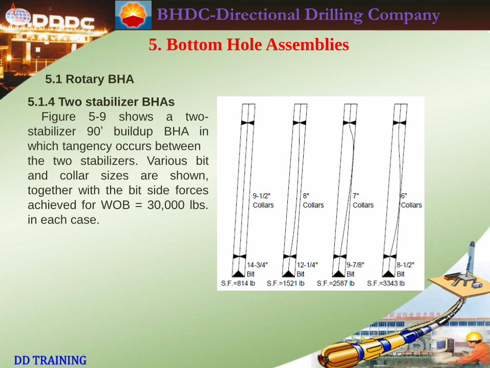
Figure 5-9 shows a two-
stabilizer 90’ buildup BHA in
which tangency occurs between
the two stabilizers. Various bit
and collar sizes are shown,
together with the bit side forces
achieved for WOB = 30,000 lbs.
in each case.
BHDC-Directional Drilling Company
DD TRAINING
5. Bottom Hole Assemblies
5.1 Rotary BHA
5.1.4 Two stabilizer BHAs
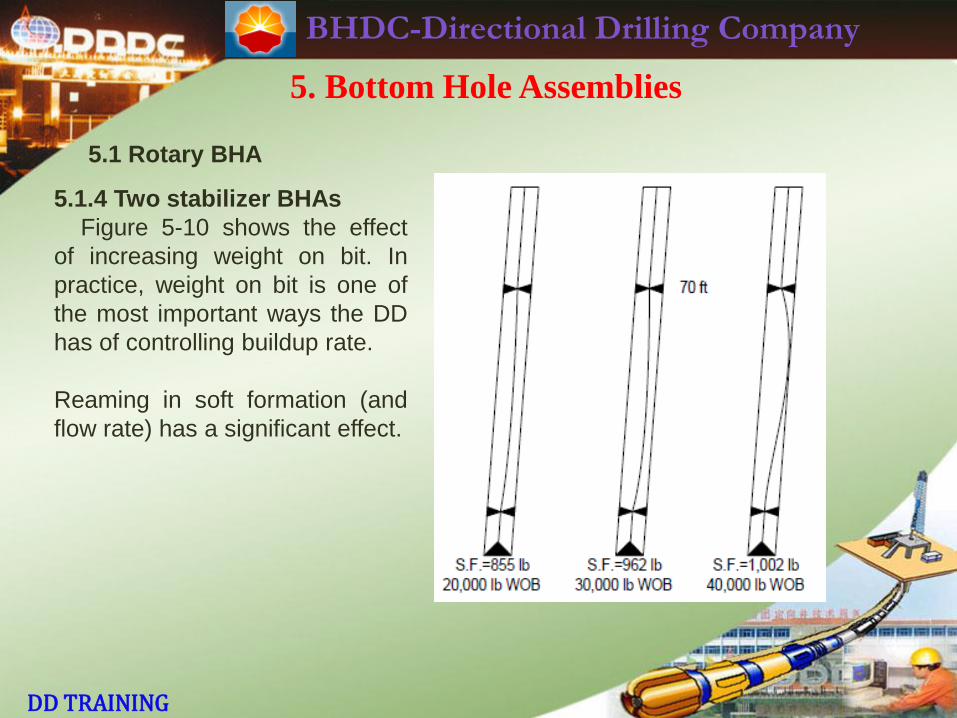
Figure 5-10 shows the effect
of increasing weight on bit. In
practice, weight on bit is one of
the most important ways the DD
has of controlling buildup rate.
Reaming in soft formation (and
flow rate) has a significant effect.
BHDC-Directional Drilling Company
DD TRAINING
5. Bottom Hole Assemblies
5.1 Rotary BHA
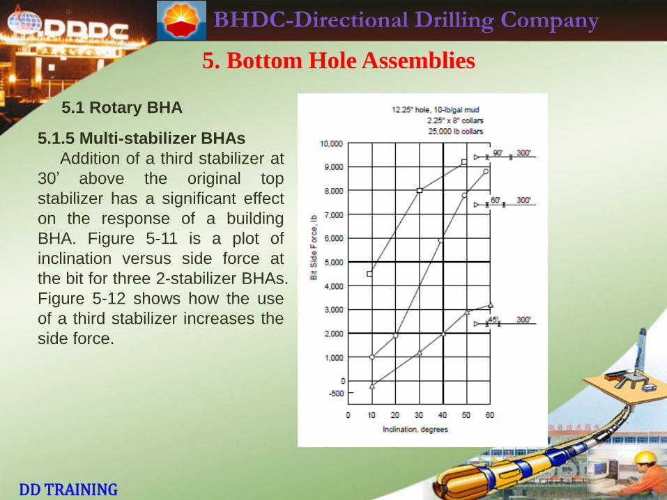
5.1.5 Multi-stabilizer BHAs
Addition of a third stabilizer at
30’ above the original top
stabilizer has a significant effect
on the response of a building
BHA. Figure 5-11 is a plot of
inclination versus side force at
the bit for three 2-stabilizer BHAs.
Figure 5-12 shows how the use
of a third stabilizer increases the
side force.
BHDC-Directional Drilling Company
DD TRAINING
5. Bottom Hole Assemblies
5.1 Rotary BHA
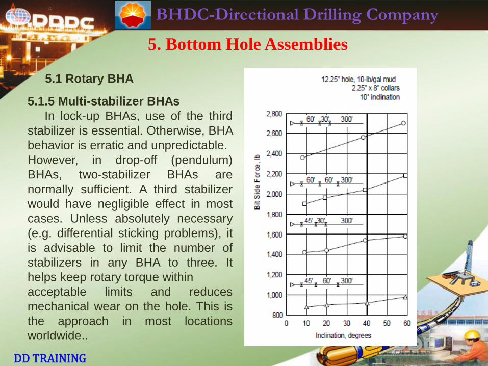
5.1.5 Multi-stabilizer BHAs
In lock-up BHAs, use of the third
stabilizer is essential. Otherwise, BHA
behavior is erratic and unpredictable.
However, in drop-off (pendulum)
BHAs, two-stabilizer BHAs are
normally sufficient. A third stabilizer
would have negligible effect in most
cases. Unless absolutely necessary
(e.g. differential sticking problems), it
is advisable to limit the number of
stabilizers in any BHA to three. It
helps keep rotary torque within
acceptable limits and reduces
mechanical wear on the hole. This is
the approach in most locations
worldwide..
BHDC-Directional Drilling Company
DD TRAINING
5. Bottom Hole Assemblies
5.1 Rotary BHA
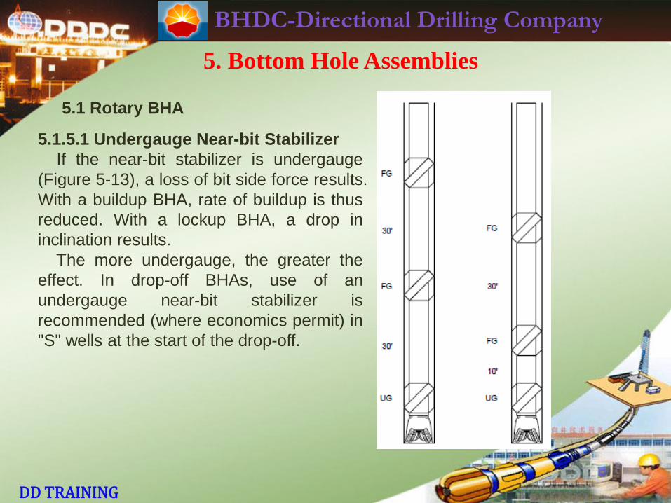
5.1.5.1 Undergauge Near-bit Stabilizer
If the near-bit stabilizer is undergauge
(Figure 5-13), a loss of bit side force results.
With a buildup BHA, rate of buildup is thus
reduced. With a lockup BHA, a drop in
inclination results.
The more undergauge, the greater the
effect. In drop-off BHAs, use of an
undergauge near-bit stabilizer is
recommended (where economics permit) in
"S" wells at the start of the drop-off.
BHDC-Directional Drilling Company
DD TRAINING
5. Bottom Hole Assemblies
5.1 Rotary BHA
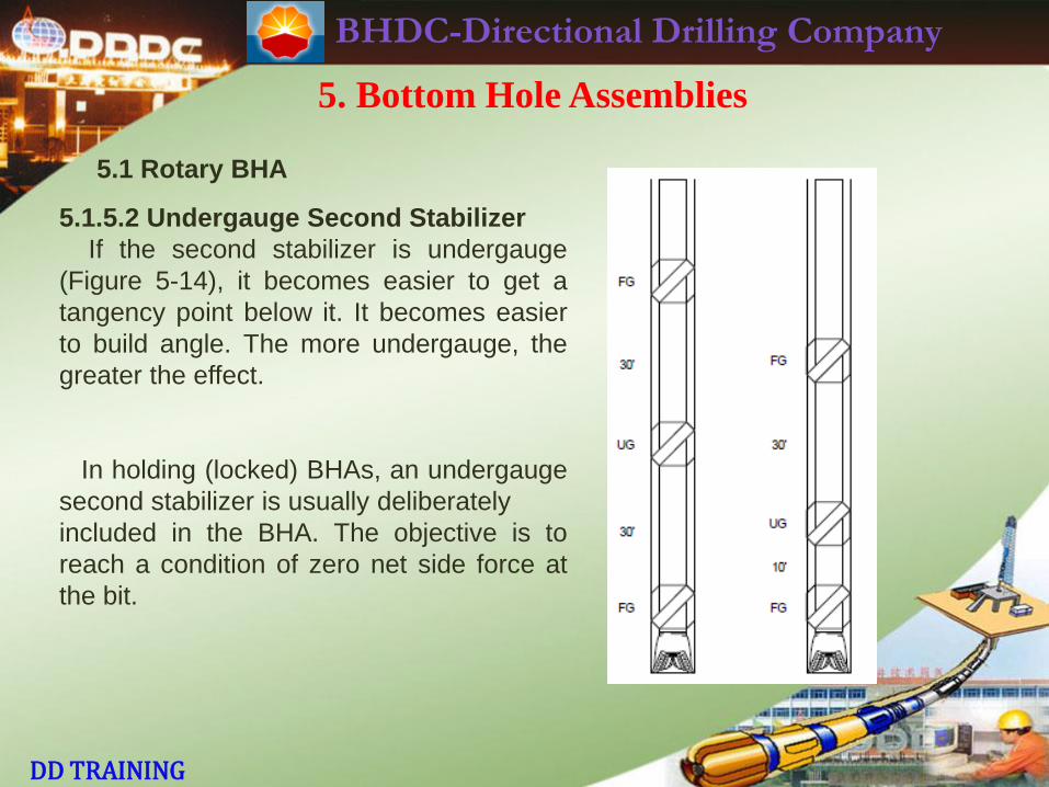
5.1.5.2 Undergauge Second Stabilizer
If the second stabilizer is undergauge
(Figure 5-14), it becomes easier to get a
tangency point below it. It becomes easier
to build angle. The more undergauge, the
greater the effect.
In holding (locked) BHAs, an undergauge
second stabilizer is usually deliberately
included in the BHA. The objective is to
reach a condition of zero net side force at
the bit.
BHDC-Directional Drilling Company
DD TRAINING
5. Bottom Hole Assemblies
5.1 Rotary BHA
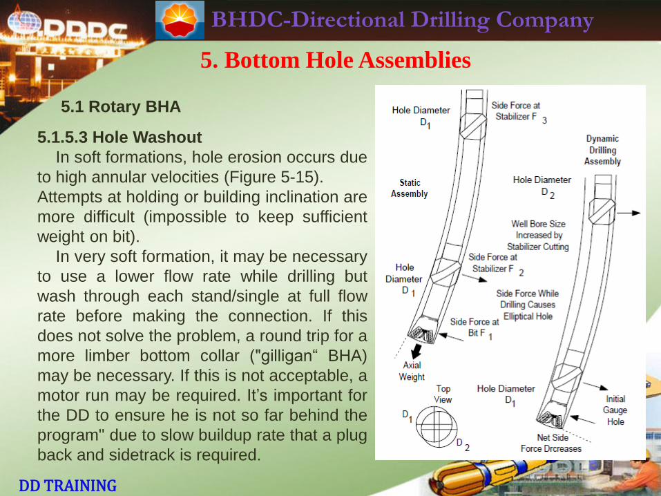
5.1.5.3 Hole Washout
In soft formations, hole erosion occurs due
to high annular velocities (Figure 5-15).
Attempts at holding or building inclination are
more difficult (impossible to keep sufficient
weight on bit).
In very soft formation, it may be necessary
to use a lower flow rate while drilling but
wash through each stand/single at full flow
rate before making the connection. If this
does not solve the problem, a round trip for a
more limber bottom collar ("gilligan“ BHA)
may be necessary. If this is not acceptable, a
motor run may be required. It’s important for
the DD to ensure he is not so far behind the
program" due to slow buildup rate that a plug
back and sidetrack is required.
BHDC-Directional Drilling Company
DD TRAINING
5. Bottom Hole Assemblies
5.1 Rotary BHA
5.1.5.3 Hole Washout
Sometimes it may be necessary to drill a pilot hole first and follow up with a
hole opener/under-reamer. Let us examine typical BHAs designed to build, hold
or drop. It is important to note that these are only guidelines. Experience in a
particular field/area will help the DD in “fine-tuning" the BHA.
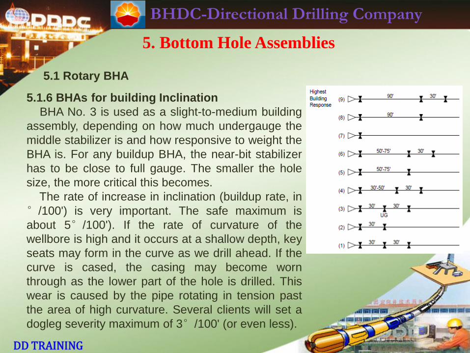
5.1.6 BHAs for building Inclination
Figure 5-16 shows examples of commonly used BHAs for building inclination.
Rates of build of the order of 5°/100' and higher are possible with BHA No. 9,
depending on the geology, inclination, hole diameter, collar diameter and drilling
parameters.
BHDC-Directional Drilling Company
DD TRAINING
5. Bottom Hole Assemblies
5.1 Rotary BHA
5.1.6 BHAs for building Inclination
BHA No. 3 is used as a slight-to-medium building
assembly, depending on how much undergauge the
middle stabilizer is and how responsive to weight the
BHA is. For any buildup BHA, the near-bit stabilizer
has to be close to full gauge. The smaller the hole
size, the more critical this becomes.
The rate of increase in inclination (buildup rate, in
°/100') is very important. The safe maximum is
about 5°/100'). If the rate of curvature of the
wellbore is high and it occurs at a shallow depth, key
seats may form in the curve as we drill ahead. If the
curve is cased, the casing may become worn
through as the lower part of the hole is drilled. This
wear is caused by the pipe rotating in tension past
the area of high curvature. Several clients will set a
dogleg severity maximum of 3°/100' (or even less).
BHDC-Directional Drilling Company
DD TRAINING
5. Bottom Hole Assemblies
5.1 Rotary BHA
5.1.6 BHAs for building Inclination
It's important to be aware of the client's acceptable limit for buildup rate. The
effective stiffness of a drill collar increases as RPM is increased. This leads to a
reduced buildup rate.
As hole inclination increases, it becomes easier to build angle. Thus, where
MWD is available, it is advisable to survey every single during the buildup phase.
This allows the DD to avoid unnecessary and unwanted doglegs. Weight on bit
may need to be reduced and/or reaming initiated where such an acceleration in
buildup rate occurs.
It is common practice to use the minimum number of drill collars in the BHA.
Two stands of collars is typical. The remaining weight on bit is got from
heavyweight drillpipe. A weight calculation must be made at the BHA design
stage (taking into account hole inclination, buoyancy factor, drilling jar position
and safety factor). On no account should the drillpipe be run in compression in a
normal directional well.
BHDC-Directional Drilling Company
DD TRAINING
5. Bottom Hole Assemblies
5.1 Rotary BHA
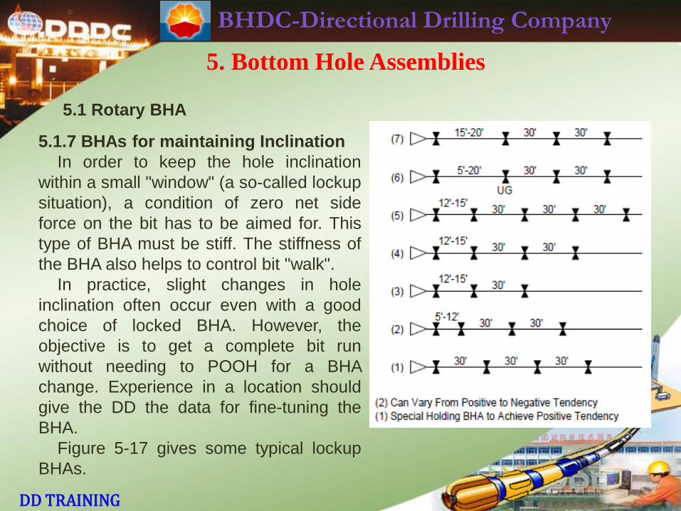
5.1.7 BHAs for maintaining Inclination
In order to keep the hole inclination
within a small "window" (a so-called lockup
situation), a condition of zero net side
force on the bit has to be aimed for. This
type of BHA must be stiff. The stiffness of
the BHA also helps to control bit "walk".
In practice, slight changes in hole
inclination often occur even with a good
choice of locked BHA. However, the
objective is to get a complete bit run
without needing to POOH for a BHA
change. Experience in a location should
give the DD the data for fine-tuning the
BHA.
Figure 5-17 gives some typical lockup
BHAs.
BHDC-Directional Drilling Company
DD TRAINING
5. Bottom Hole Assemblies
5.1 Rotary BHA
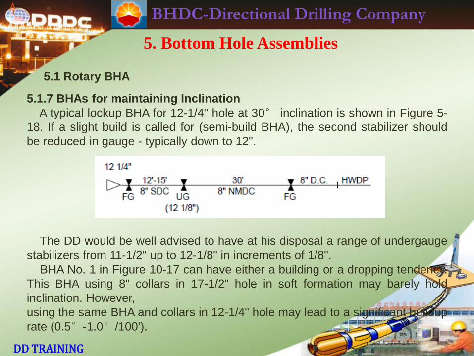
5.1.7 BHAs for maintaining Inclination
A typical lockup BHA for 12-1/4" hole at 30° inclination is shown in Figure 5-
18. If a slight build is called for (semi-build BHA), the second stabilizer should
be reduced in gauge - typically down to 12".
The DD would be well advised to have at his disposal a range of undergauge
stabilizers from 11-1/2" up to 12-1/8" in increments of 1/8".
BHA No. 1 in Figure 10-17 can have either a building or a dropping tendency.
This BHA using 8" collars in 17-1/2" hole in soft formation may barely hold
inclination. However,
using the same BHA and collars in 12-1/4" hole may lead to a significant buildup
rate (0.5°-1.0°/100').

BHDC-Directional Drilling Company
DD TRAINING
5. Bottom Hole Assemblies
5.1 Rotary BHA
5.1.7 BHAs for maintaining Inclination
The response of this type of BHA is determined by the following factors:
1. Hole size.
2. Distance between the near-bit and lower string stabilizers.
3. Stiffness of the collar directly above the near-bit.
4. Gauge of the stabilizers.
5. Formation effects.
6. Drilling parameters.
To summarize, reducing the gauge of the second stabilizer gives the same
result as leaving the stabilizer alone but increasing the distance between it and
the near-bit by a certain amount. However, for directional control purposes, the
former approach is better.
Lockup BHAs account for the biggest percentage of hole drilled in deviated
wells. Thus, the DD’s judgment and expertise in BHA selection is vital in saving
trips.
BHDC-Directional Drilling Company
DD TRAINING
5. Bottom Hole Assemblies
5.1 Rotary BHA
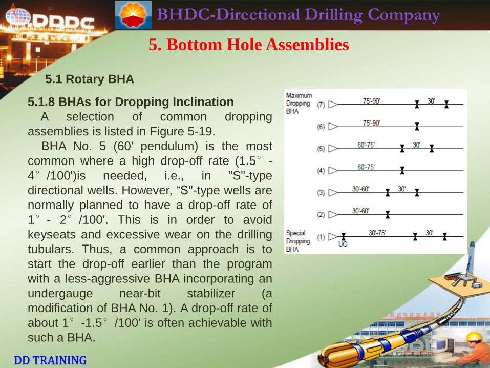
5.1.8 BHAs for Dropping Inclination
A selection of common dropping
assemblies is listed in Figure 5-19.
BHA No. 5 (60' pendulum) is the most
common where a high drop-off rate (1.5°-
4°/100')is needed, i.e., in "S"-type
directional wells. However, “S"-type wells are
normally planned to have a drop-off rate of
1°- 2°/100'. This is in order to avoid
keyseats and excessive wear on the drilling
tubulars. Thus, a common approach is to
start the drop-off earlier than the program
with a less-aggressive BHA incorporating an
undergauge near-bit stabilizer (a
modification of BHA No. 1). A drop-off rate of
about 1°-1.5°/100' is often achievable with
such a BHA.
BHDC-Directional Drilling Company
DD TRAINING
5. Bottom Hole Assemblies
5.1 Rotary BHA
5.1.8 BHAs for Dropping Inclination
When the inclination has fallen to about 15° (at which point the gravity force
is much less), a round trip is made. BHA No. 5 is then used to drill to TD. This
plan should, however, be discussed with the client before the job starts. An
"extra" trip is involved.
Rate of drop-off usually slows significantly below 8°-10° inclination. When
the inclination falls to 2°, the well is considered vertical. However, the
inclination should continue to be monitored, to ensure it does not start to
increase again. It's advisable to ream each connection.
There is very little control over hole direction when using a pendulum BHA.
Sometimes the well walks excessively when using a tricone bit during the drop-
off. The DD should thus have some tolerance available in hole direction when he
starts the drop-off. RPM should be kept high (this also helps the drop-off rate).
BHDC-Directional Drilling Company
DD TRAINING
5. Bottom Hole Assemblies
5.1 Rotary BHA
5.1.8 BHAs for Dropping Inclination
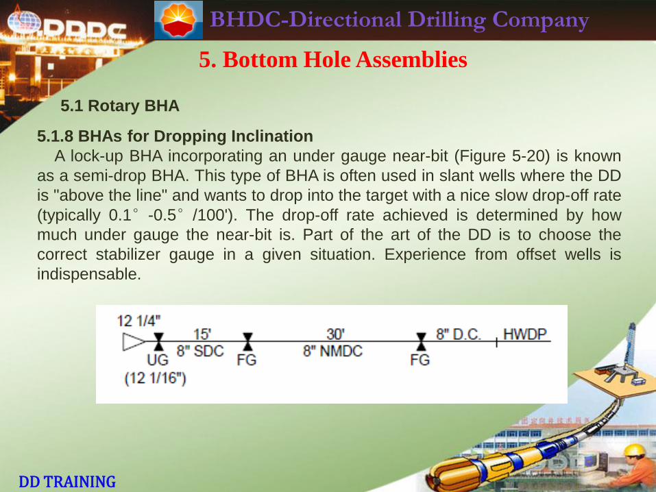
A lock-up BHA incorporating an under gauge near-bit (Figure 5-20) is known
as a semi-drop BHA. This type of BHA is often used in slant wells where the DD
is "above the line" and wants to drop into the target with a nice slow drop-off rate
(typically 0.1°-0.5°/100'). The drop-off rate achieved is determined by how
much under gauge the near-bit is. Part of the art of the DD is to choose the
correct stabilizer gauge in a given situation. Experience from offset wells is
indispensable.
BHDC-Directional Drilling Company
DD TRAINING
5. Bottom Hole Assemblies
5.2 Common BHA Problems
5.2.1 Formation Effects
It often happens that when a certain TVD is reached, BHA behavior changes
significantly e.g. A BHA which held inclination down to 5,000’ may start to drop
angle.Why? Assuming that the near-bit has not gone undergauge, it’s probably
due to formation effects (change in formation, change in dip or strike of the
formation etc.). It’s vital to keep a good database and try to anticipate the
problem for the following well.
Abrasive formations pose problems for the DD. Ensure the bit has good
gauge protection. Use stabilizers with good abrasion resistance, e.g. geothermal
dressing or pressed-in TCIs. Check the gauge of the stabilizers when POOH.
Watch out for a groove cut on the leading edge of stabilizers - indication of need
to change out the stabilizer.
When it’s difficult to drop inclination, sometimes a larger O.D. drill collar is
used as the lower part of the pendulum. Another possibility is the use of a
tungsten short collar – the concentration of the same weight into a much shorter
element should give a more effective pendulum side force.
BHDC-Directional Drilling Company
DD TRAINING
5. Bottom Hole Assemblies
5.2 Common BHA Problems
5.2.2 Worn Bits
In a long hole section in soft formation interbedded with hard stringers, the
long-toothed bit may get worn. ROP will fall sharply. Net side force will decrease
due to stabilizers undercutting the hole.
Thus, a BHA which had been holding inclination up to that point will start to
drop angle. However, if the survey point is significantly behind the bit, this
decrease in angle will not be seen in time. If the worn teeth are misinterpreted
as a balled-up bit and continued lengthy efforts made to drill further, serious
damage may be done to the hole. It has happened that a drop in inclination of 6
(with a severe dogleg severity) has happened in this situation. In addition, a bit
having worn teeth has a tendency to lose direction. Thus, it is important to
POOH a worn bit in such a situation.

BHDC-Directional Drilling Company
DD TRAINING
5. Bottom Hole Assemblies
5.2 Common BHA Problems
5.2.3 Accidental Sidetrack
In soft formation, where a multi-stabilizer BHA (either Buildup or Lockup) is
run immediately after a mud motor/bent sub kickoff run, great care must be
taken. Circulation should be broken just before the kickoff point. The BHA should
be washed/worked down, using full flow rate. The DD must be on the drill floor
while this is happening. Try to work through tight spots. If string rotation is
absolutely necessary, keep RPM low and cut rotating time to the absolute
minimum. The risk of sidetracking the well (with subsequent expensive plug-
back and redrill) is high. Several kickoffs have been lost in various parts of the
world by carelessness on the part of the DD.
Where the kickoff is done in a pilot hole in soft formation, an under-reamer or
hole opener is used to open the hole prior to running casing. Again, to avoid an
unwanted sidetrack, a bull-nose (not a bit) and possibly an extension sub/short
collar should be run below the under-reamer/hole opener.
BHDC-Directional Drilling Company
DD TRAINING
5. Bottom Hole Assemblies
5.2 Common BHA Problems
5.2.4 Pinched Bit
In hard formation, it’s especially important to check each bit for gauge wear
etc. when it’s POOH. When RIH with a new bit and/or BHA, it’s imperative that
the driller start reaming at the first sign of under-gauge hole (string taking
weight). If he tries to “cram“ the bit to bottom, it will become “pinched". Bit life will
be very short.
5.2.5 Differential Sticking
Where differential sticking is a problem, more than three stabilizers may be
run in an effort to minimize wall contact with the drill collars. However, the
distance between these “extra" stabilizers normally has to be such that they
have little effect. They only lead to increased rotary torque.
It is vital to minimize time taken for surveys (even with MWD) in a potential
differential sticking area.
BHDC-Directional Drilling Company
DD TRAINING
5. Bottom Hole Assemblies
5.3 BHA Equipment and Tools
It’s the responsibility of the DD to ensure that everything needed (within
reason) for future BHAs is available on the rig. This applies regardless of
whether the tools come from ANADRILL, the client or a third party. As stated in
the DD UOP, the DD must check all the directional equipment thoroughly on
arrival at the rigsite. Additional equipment must be ordered with plenty of lead
time. Sufficient backup of motors, bent subs, etc., should be at the wellsite.
For rotary BHAs, following are some suggestions:
1. A selection of stabilizers (normally a combination of sleeve- type and
integral blade design for 17-1/2" and smaller hole sizes) with 360 wall coverage
should be available.
BHDC-Directional Drilling Company
DD TRAINING
5. Bottom Hole Assemblies
5.3 BHA Equipment and Tools
2. Short drill collars are a vital component of a lockup BHA. If possible, a
selection of short collars (e.g. 5’, 10’ and 15) should be available. In addition, in
a well where magnetic interference from the drill-string (mud motor) is expected
to be a problem during the buildup phase, non-magnetic (rather than steel) short
collars should be provided
3. Check that the rig has sufficient drill collars and HWDP available.
4. Check that the client has sufficient bit nozzles of each size (including
what’s needed when running a mud motor).
5. Have at least one spare non-magnetic drill collar of each size. As NMDCs
are more prone to galling, damaged collars should be returned to the shop for
re-cutting/re-facing when replacements arrive.
6. Any crossover subs, float subs, bit subs etc. required later must be on the
rig.
Think ahead! The DD should be thinking at least one BHA ahead!
BHDC-Directional Drilling Company
DD TRAINING
5. Bottom Hole Assemblies
5.4 Recap
1. To build inclination, always use a full-gauge nearbit stabilizer.
2. The more limber the bottom collar, the greater the buildup rate achievable.
3. Take frequent surveys (e.g. every single with MWD) during the buildup phase
(all wells) and the drop-off phase ("S"-type wells) in order to react quickly to
unexpected trends.
4. A jetting BHA is a modified buildup BHA. Don’t jet too far! Watch the WOB
available for jetting/spudding.
5. To drop inclination, either use an under-gauge near-bit (semi-drop BHA, for
low drop-off rate) or no near-bit (pendulum BHA, for sharp drop-off rate).
6. A locked BHA which is holding inclination with an under-gauge stabilizer
above the short collar will start to drop inclination if this stabilizer is made full -
gauge.
7. In an “S”-type well, try to start the drop-off early using a semi-drop BHA.
Change to a pendulum BHA at, say, 15 inclination.
8. Try not to have to build inclination into the target - better to drop slowly into
the target.
BHDC-Directional Drilling Company
DD TRAINING
5. Bottom Hole Assemblies
5.4 Recap
9. Three stabilizers are normally sufficient in a BHA. In pendulum BHAs, two
stabilizers should suffice.
10. Use as few drill collars as possible. Use heavyweight drillpipe as remaining
available weight on bit.
11. Try to use a fairly standard (reasonably predictable) BHA. Do not try any
“fancy“ BHAs in a new area. Get some experience in the field first!
12. “Gilligan” BHAs are not standard. Only use one when absolutely necessary.
13. DD should be on the drill floor when washing/working rotary BHA through
kickoff section in soft formation. Avoid sidetracking the well!
14. After a kickoff or correction run in medium and hard formations, ream
carefully through the motor run with the following rotary BHA until hole drag is
normal.
15. In hard and/or abrasive formations, gauge stabilizers carefully when POOH.
Replace stabilizers as required. Check the bit. If bit is undergauge, reaming will
be required! Do not let the driller "pinch" the bit in hard formation.
16. Check all DD equipment before and after the job. It's good practice to caliper
all the DD tools and leave list on drill floor for drillers. Watch out for galled
shoulders!
BHDC-Directional Drilling Company
DD TRAINING
5. Bottom Hole Assemblies
5.4 Recap
17. In potential differential sticking areas, minimize survey time. If using single-
shot surveys, reciprocate pipe. Leave pipe still only for minimum interval
required.
18. A BHA which behaves perfectly in one area may act very differently in
another area.Local experience is essential in “fine-tuning" the BHAs!
19. Deciding when to POOH for a BHA change is one of DD's main
responsibilities. Ideally, this should coincide with a trip for bit change.
20. In the tangent section of a well, a BHA change may simply entail changing
the sleeve on the stabilizer directly above the short collar. The trick is - by how
much does the DD change the gauge? Sometimes a change in gauge of 1/16"
may lead to a significant change in BHA behavior!
21. High RPM "stiffens” the BHA- helps to stop walk due to formation tendencies.
22. It's usually easier to build inclination with lower RPM. However, DD may
want to use high RPM during buildup phase (for directional control). WOB is the
major drilling parameter influencing buildup rate.
BHDC-Directional Drilling Company
DD TRAINING
5. Bottom Hole Assemblies
5.4 Recap
23. To help initiate right-hand walk, it's advisable to use higher WOB and lower
RPM.
24. In soft formation, it may be necessary to reduce mud flow rate to get
sufficient WOB and reduce hole washout. Be careful! Wash each joint/stand at
normal (full) flow rate before making the connection.
25. Reaming is effective in controlling buildup rate in soft formation. It becomes
less effective as formation gets harder. However, even in hard formation,
reaming before each connection helps keep hole drag low.
26. Lower dogleg severity = smoother wellbore = lower friction = lower rotary
torque = less keyseat problems = less wear on tubulars = less problems on trips.
All these things mean a happier client! however, we must hit the target also!
BHDC-Directional Drilling Company
DD TRAINING
6. Drilling Fluids

BHDC-Directional Drilling Company
DD TRAINING
6. Drilling Fluids
About this chapter
The DD should have a basic knowledge of mud systems and
properties. The condition of the mud and the smoothness of the
wellbore are probably the two biggest factors influencing the
success or otherwise of a directional well. As the drive for efficiency
in drilling continues, hydraulics and hydraulic optimization becomes
more important. Thus, it is vital that the DD has a working
knowledge of hydraulics, particularly that related to running PDMs.
The DD is expected to have at least some input into the hydraulics
program. In BHAs, which utilize a PDM, the DD must know how to
choose flow rate, bit nozzles, etc. The approach to hydraulics in this
manual covers the basics only. However, it is adequate for the DD. If
the DD understands everything covered in this chapter, he should be
able to discuss and recommend a reasonable hydraulics program to
the drilling supervisor/drilling superintendent.
BHDC-Directional Drilling Company
DD TRAINING
6. Drilling Fluids
6.1 The functions of drilling fluids
· Removal of cuttings from the hole
· Cooling and lubrication of the bit and drill string
· Control of subsurface pressure
· Maintenance of a stable wellbore and isolation of fluids from the
formation
· Suspension of cuttings and weighting material and release of the
drilled cuttings on the surface
· Buoyancy effect on drill string and casing
· Protect drill string and casing
· Maximization of penetration rate
· Transmission of hydraulic power to bit and downhole tools
· Control of drill string, casing, and drilling equipment corrosion
BHDC-Directional Drilling Company
DD TRAINING
6. Drilling Fluids
6.2 Drilling Fluid Composition
The term drilling fluid can be considered to encompass all of the
compositions used to assist in the production and subsequent
removal of the drilled cuttings from a borehole in the earth. Each
drilling fluid can be classified as belonging to one of two broad
groups, Water-based and Oil-based.
In water-based systems, the continuous phase and major
component is water, the other components being active solids, inert
solids, and chemicals. The formulation of the four components gives
rise to the diverse and varied properties of water-based fluids. Water,
as the continuous phase in any water- based fluid, may be fresh,
hard, or salty. The primary function of the liquid is to provide the
initial density and viscosity which can be modified to obtain any
desirable rheological property.
BHDC-Directional Drilling Company
DD TRAINING
6. Drilling Fluids
6.2 Drilling Fluid Composition
The formulation of the four components gives rise to the diverse
and varied properties related to the following:
· Density
· Rheology
· Filtrate
· Chemical Inhibition
· Solids content
Any other property can be considered to be of secondary
importance to these. Thus, when the condition of the drilling fluid is
discussed, it should be in terms which relate to the above
fundamental properties.
The active (colloidal) solids increase the viscosity and determine
the filtration properties of the fluid. Colloidal solids in the form of
clays are added to form a colloidal suspension; polymers can also
be used to increase the viscosity and decrease the fluid
loss of water- based drilling fluids.
BHDC-Directional Drilling Company
DD TRAINING
6. Drilling Fluids
6.2 Drilling Fluid Composition
The inert solids in drilling fluids are weighting materials and non-
reactive drilled solids. The weighting materials are added to the
fluids to increase the density in order to control subsurface
pressures.
Chemicals are added to drilling fluids to modify the behavior of
the components present. The chemicals fall into two groups, organic
and inorganic. Each group may be subdivided according to specific
function such as dispersant, pH control agent, defoamer, and
lubricant.
If oil is the continuous phase of the drilling fluid, then it is
classified as an oil-based fluid. It may contain water as the
discontinuous phase in any proportion up to 50%. If the percentage
of water or brine (mixture of water and electrolyte) is over 10%, then
the fluid is considered to be an Invert Emulsion.
BHDC-Directional Drilling Company
DD TRAINING
6. Drilling Fluids
6.2 Drilling Fluid Composition
The solid phase is essentially the same as that of the water-based
drilling fluids, containing weighting materials, drilled solids, and
clays. However, the clays and other colloids are oleophilic (oil-
loving), and surfactants have to be added to stabilize the emulsion.
When the continuous phase of the drilling fluid is gas, it is
invariably associated with some proportion of entrained water either
added purposely or from the formation, thereby forming a mist at
low water concentrations or a foam at higher water concentrations
when surfactants or foaming agents are added. The gas used may
be either air or natural gas, and the resulting foam or mist carries the
drilled solids to the surface. Gas or air drilling is particularly useful
when drilling in competent formations, when drilling low pressure
gas or water wells, or when there is severe lost circulation.
BHDC-Directional Drilling Company
DD TRAINING
6. Drilling Fluids
6.2 .1 Drilling Fluids Tests
1 - Density The density of the drilling fluid is one of the most important
characteristics because the hydrostatic pressure controls fluid influx
downhole and greatly influences drilling efficiency. This is measured
with the mud balance.
2 - Rheology Routine field measurements of the viscosity of a drilling
fluid are made with a Marsh funnel which measures a timed flow of a
known volume. This is known as the Funnel Viscosity (FV). The apparent
viscosity of a mud is composed of two variables, plastic viscosity (PV)
and yield point (YP). These values, as well as timed gel strength
measurements, which denote thixotropic properties of a drilling fluid, are
made with a direct-indicating viscosimeter.
Plastic viscosity Plastic viscosity is that part of flow resistance in a
mud caused primarily by the friction between the suspended particles
and by the viscosity of the continuous liquid phase. Plastic viscosity
depends on the viscosity of the continuous phase fluid and on the
concentration of solids present and the size and shape of their particles

BHDC-Directional Drilling Company
DD TRAINING
6. Drilling Fluids
6.2 .1 Drilling Fluids Tests
Yield point Yield point is a measure of forces between particles. These
forces are a result of positive and negative electrical charges located on
or near the surface of particles. Yield point is a measurement under
flowing conditions of those forces in the mud which cause gel structure
to develop when the mud is allowed to come to rest. The forces tend to
move the solids particles into an arrangement such that the attractive
and repulsive forces are best satisfied. A gel measurement is an
indication of these forces under rest conditions.
3 - Filtrate One of the most important properties of a drilling mud is the
filtration rate or water loss, which is the measure of the relative amount
of mud sheath deposited on the permeable wall of the hole. A low
pressure filter press is an instrument which meets API specifications for
filtration measurements.
BHDC-Directional Drilling Company
DD TRAINING
6. Drilling Fluids
6.2 .1 Drilling Fluids Tests
4 - Chemical Inhibition pH is an abbreviation for potential hydrogen
ion. The pH number ranges from 0 to 14, 7 being neutral, and are indices
of the acidity (below 7) or alkalinity (above 7) of the fluid . The numbers
are a function of the hydrogen ion concentration in gram ionic weights
per liter which, in turn, is a function of the dissociation of water as given
by the following expression:
The pH may be expressed as the logarithm (base 10) of the reciprocal
(or the negative logarithm) of the hydrogen ion concentration. The pH of
a solution offers valuable information as to the immediate acidity or
alkalinity as contrasted to the total acidity or alkalinity (which may be
titrated). The pH scale is therefore logarithmic and each number
indicates an alkalinity ten times as great as that of the preceding number.
For example, a pH of 9 indicates an alkalinity ten times as great as a pH
of 8.
BHDC-Directional Drilling Company
DD TRAINING
6. Drilling Fluids
6.2 .1 Drilling Fluids Tests
There are 2 principal methods of determining the pH of drilling fluids.
One of these is based on the effect of acids and alkalis on the color of
certain chemical indicators. This is called the litmus test. The other is
based on the fact that when certain electrodes are immersed in a liquid,
the voltage developed between them will vary according to the pH of the
liquid. Because the pH scale is logarithmic, the alkalinity of the high pH
mud can vary a considerable amount with no measurable change in pH.
Analysis of the mud filtrate to determine the alkalinity is more significant
than pH measurement in highly alkaline systems.
Chlorides (salt concentration) The salt or chloride test is very
significant in areas where salt can contaminate the drilling fluid. Such
areas include a majority of the oil fields in the United States.
BHDC-Directional Drilling Company
DD TRAINING
6. Drilling Fluids
6.2 .1 Drilling Fluids Tests
Hardness and calcium concentration By "hard water" we mean water
containing dissolved calcium and magnesium salts. The common
evidence of hardness in water is the difficulty of producing a lather in it
with soap. In many oil fields the water available is quite hard. As is well
understood, drilling clays have low yield when mixed in hard water. The
harder the water, the more clay (bentonite) it takes to make a satisfactory
gel mud. This dissolved calcium can come from anhydrite or "gyppy"
formation. Calcium salt can also be picked up in drilling cement plugs
and sometimes in penetrating sections of limey shale. Any extensive
calcium contamination results in abnormally high water loss and fast gel
rate.
Resistivity of the drilling mud and filtrate Control of the resistivity of
mud and mud filtrate while drilling may be desirable to permit better
evaluation of formation characteristics from electric logs. The
determination of resistivity is essentially the measurements of
resistance to electrical current flow through a sample configuration.
BHDC-Directional Drilling Company
DD TRAINING
6. Drilling Fluids
6.2 .1 Drilling Fluids Tests
5- Sand Content Sand is abrasive to pumps, hose, some tools included
in the BHA and watercourse in the bit. It always carries the danger of
settling in the hole when the pumps are shut down and sticking the drill
string. It weights the mud unduly and is especially objectionable where
there is a tendency to loose circulation in near-surface formations.
Control of sand content to a maximum of about 1% by volume is
generally considered good practice.
Sand content of the drilling fluid may be reduced by any one of several
methods such as extra settling tanks, centrifugal de-sander, desilter
etc.... Where there is a thick section of fine sand, penetration should be
slowed to enable the pumps to handle the volume of sand entering the
fluid.
BHDC-Directional Drilling Company
DD TRAINING
6. Drilling Fluids
6.3 Drill String Hydraulics
The main purpose of a hydraulics program is to drill the well in the
most efficient manner. This is done by circulating mud at an adequate
volume and pressure to cool the bit, clean the bottom of the hole (to
prevent re-drilling cuttings), provide a jetting action to help drill the hole
by hydraulic erosion and transport the cuttings out of the hole.
While hydraulics is not the main area of responsibility of the DD, he
must understand what’s involved. There are occasions (e.g. when
running a mud motor) when the DD has to specify both flow rate and
nozzle sizes. There are other occasions (e.g. when running an
Andergauge stabilizer and/or an MWD tool in the BHA) when the extra
drillstringpressure drops involved have to be estimated or calculated
and communicated to the company representative / mud engineer /
toolpusher. Rig hydraulic limitations must be known. On no account

BHDC-Directional Drilling Company
DD TRAINING
6. Drilling Fluids
6.3 Drill String Hydraulics
should a situation arise where, on reaching bottom, the rig is unable to
pump sufficient fluid due to the extra pressure losses introduced by DD
tools. As many rigs operate close to the rig’s maximum pump pressure
(in order to maximize ROP), the above scenario is by no means
improbable. Thus, planning ahead is vital. The DD should be able to
calculate the total pressure losses in the hydraulic system. To do this, he
must first know the rig equipment.
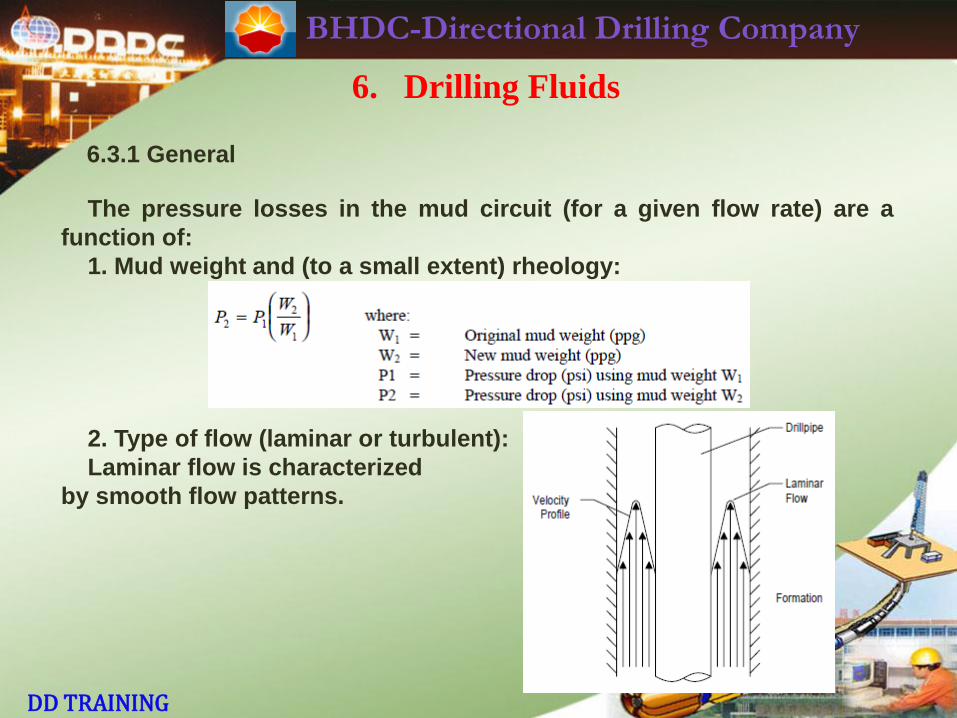
BHDC-Directional Drilling Company
DD TRAINING
6. Drilling Fluids
6.3.1 General
The pressure losses in the mud circuit (for a given flow rate) are a
function of:
1. Mud weight and (to a small extent) rheology:
2. Type of flow (laminar or turbulent):
Laminar flow is characterized
by smooth flow patterns.
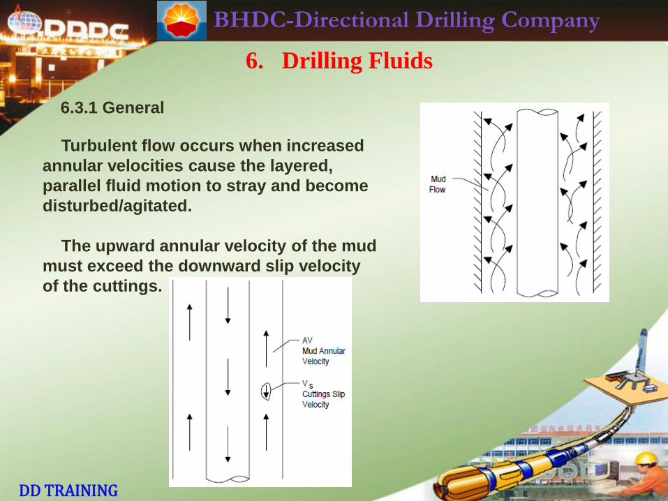
BHDC-Directional Drilling Company
DD TRAINING
6. Drilling Fluids
6.3.1 General
Turbulent flow occurs when increased
annular velocities cause the layered,
parallel fluid motion to stray and become
disturbed/agitated.
The upward annular velocity of the mud
must exceed the downward slip velocity
of the cuttings.
BHDC-Directional Drilling Company
DD TRAINING
6. Drilling Fluids
6.3.1 General
In general, turbulent flow occurs in surface lines, drill pipe and drill
collars. In the annulus, laminar, transitional and turbulent flow can be
present at the same time. Note that, while turbulent flow is best for
cuttings removal, it also erodes the hole more than laminar flow. In
turbulent flow, viscosity has little effect on flowing pressure losses.
However, mud weight has to be accounted for in the hydraulic
calculation in all cases.
BHDC-Directional Drilling Company
DD TRAINING
6. Drilling Fluids
6.3.2 Flow Rate
For each size of hole, there is a range of flow rates within which the
operator will like to drill (e.g. 600-700 GPM for 12-1/4" hole using a
standard rotary BHA). This flow rate has to be sufficient to clean the hole.
The client may, however, prefer laminar flow in soft formations to reduce
hole washout. Mud weight, yield point and pipe rotation all significantly
increase cuttings transport efficiency. A hydraulic calculation usually
entails using a preferred flow rate as one of the inputs.
Since the composition of the BHA is normally already decided upon,
the variables become the nozzle sizes. We know what the maximum
allowable standpipe pressure is. As we will see, the pressure loss
through the bit nozzles is normally a very significant portion of the total
system pressure loss.
All the individual components of the total system pressure loss are
affected by the flow rate.
Flow Rate (GPM) = Pump Discharge Volume (Gal/stroke) Pump Rate (strokes/minute)
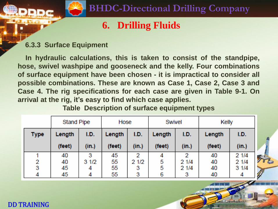
BHDC-Directional Drilling Company
DD TRAINING
6. Drilling Fluids
6.3.3 Surface Equipment
In hydraulic calculations, this is taken to consist of the standpipe,
hose, swivel washpipe and gooseneck and the kelly. Four combinations
of surface equipment have been chosen - it is impractical to consider all
possible combinations. These are known as Case 1, Case 2, Case 3 and
Case 4. The rig specifications for each case are given in Table 9-1. On
arrival at the rig, it’s easy to find which case applies.
Table Description of surface equipment types
BHDC-Directional Drilling Company
DD TRAINING
6. Drilling Fluids
6.3.4 Mud Pumps
The DD must check what type of mud pumps are on the rig (usually,
but not always, triplex). He must also check the liner size being used.
This will determine the Discharge Rate of the pump (given as
gallons/stroke or litres / stroke) for a certain stroke length. Allowance
should be made for pump efficiency (e.g. 97% for mud pumps in good
condition).
Mud Pump Discharge Pressure Rating must also be known. For a
given mud pump, this will be determined by the liner size. This pressure
limit determines what our maximum standpipe pressure can be. Thus,
we need to know it. Most toolpushers prefer to operate well below this
pressure limit - to prolong the life of the mud pump components. The
pump operating speed (SPM) should not exceed the continuous
operating RPM of the pump or prime mover. The pressure begins
declining at the mud pump discharge and continues through the
circulating system to a pressure of 0 psi where the returning mud
reaches the pits.
BHDC-Directional Drilling Company
DD TRAINING
6. Drilling Fluids
6.3.4 Mud Pumps
Total System Pressure Loss =
Pressure loss through Surface Equipment +
Pressure loss through Drill Pipe Bore +
Pressure loss through heavyweight drillpipe +
Pressure loss through Drill Collars (steel + nonmagnetic) +
Pressure loss through MWD + Pressure loss through e.g.
Andergauge stabilizer +
Pressure loss through Mud Motor/Turbine +
Pressure loss through Bit +
Pressure loss in Annulus from Bit to top of Drill Collars +
Pressure loss in Annulus around HWDP and drillpipe.

BHDC-Directional Drilling Company
DD TRAINING
6. Drilling Fluids
6.4 Hydraulic Optimization
The average mud hydraulics program is designed so that one half to
two thirds of the available hydraulic horsepower is expended at the bit.
The higher value is usually more effective in softer formations, due to
the extra cleaning required on the bit-cutting structure and the drilling
action due to the hydraulic jetting force.
In normal drilling, as we get deeper, the horsepower available at the bit
decreases. This may become critical, especially when we drill deeper
than planned or when the mud weight has to be increased.
The required AV depends on the settling rate (slip velocity) of the
cuttings, which is a measure of the lifting capacity of the mud. The ROP
will determine the volume of cuttings for a given hole size.
Higher AV causes a higher pressure drop in the open hole section.
This can contribute to lost circulation.
BHDC-Directional Drilling Company
DD TRAINING
6. Drilling Fluids
6.4.1 Mud Motor Runs
When a mud motor run is planned, the maximum allowable flow rate is
often significantly less than when using a conventional rotary BHA. This
is especially true of 1:2 lobe PDMs (e.g., a 7 3/4" DELTA 500 Dynadrill has
a maximum recommended flow rate of 450 GPM). Steerable and high-
torque PDMs have much higher flow rate capability.
Pressure drop across the PDM must be accounted for in the hydraulic
calculation. It is significant. Any PDM rotating off bottom will have a
certain "no-load pressure loss". This is different for each size and type
of motor. The DD will also know the maximum recommended motor
differential pressure for each size and make of PDM, for a given flow rate,
mud weight etc.
Depending on the situation (hardness of formation etc.), the DD will
operate the PDM somewhere below this differential pressure. Again,
high-torque motors have a much higher allowable pressure drop across
the motor than 1:2 designs.
BHDC-Directional Drilling Company
DD TRAINING
6. Drilling Fluids
6.4.1 Mud Motor Runs
The maximum allowable pressure drop across the bit when using a
PDM varies widely between different types of motor (1:2 lobe or
multilobe etc.). The DD will know the specifications of the particular PDM.
A hydraulic calculation is performed similar to the first situation
(conventional rotary drilling ) except that we now have an additional
pressure loss in the system (Pmotor) and we have a restraint on the
pressure drop across the bit (Pbit)
When using a 1:2 type mud motor, total system pressure loss is
almost always well below the rig pressure limit (unless when run at great
depths). However, with a high-torque PDM (steerable or straight-
housing), because of the high Pmotor and Pbit and the much higher flow
rate which is possible, unless the DD is careful, he could end up in a
situation where he’s not able to pump the preferred GPM, due to
reaching the upper pressure limitation of the rig.

BHDC-Directional Drilling Company
DD TRAINING
6. Drilling Fluids
6.4.1 Mud Motor Runs
Performance drilling with a high-torque PDM often means operating at
close to the limits of motor differential pressure and pressure drop
across the bit for a certain flow rate. Thus, careful and timely planning is
vital in order to fine-tune the hydraulics. The DD should ensure that he
has all relevant specifications for the PDM(s) he has at the rig-site. He
should also leave some allowance for variations in mud properties etc.
BHDC-Directional Drilling Company
DD TRAINING
6. Drilling Fluids
9.5 Recap
1. DD needs to be aware of basic mud properties (e.g. Mud Weight,
Viscosity, Water Loss, Yield Point, Gel Strength).
2. Do not forget to take into account pressure losses through MWD,
Andergauge etc.
3. Always ensure that company representative has adequate stock of bit
nozzles of required sizes on rig. Plan ahead! Motor runs often require the
use of bigger nozzles than conventional rotary BHAs (especially in 1:2
PDM case).
4. In the case of a PDM run, ensure that you doublecheck the hydraulic
calculation. Several factors have to be taken into account—rig pressure
limit, motor specifications, type of formation, type of bit, mud properties
etc.
5. When running mud motors, the DD almost always either designs the
hydraulics program or at least has some input into it. Thus, he must
know at least a minimum amount of hydraulics!
6. The DD should know how to run a hydraulics program on the
computer.
BHDC-Directional Drilling Company
DD TRAINING
7. Directional Drilling Operations
BHDC-Directional Drilling Company
DD TRAINING
7. Directional Drilling Operations
A lot of the DD’s time is spend on the drill floor. His duties may involve
supervising BHA make-up, orienting, setting drilling parameters, doing a simple
projection, performing a sidetrack, nudging a well etc.
It is worthwhile to mention again that, during the time the DD is not on the drill
floor, the driller must have explicit instructions as to drilling parameters, BHA
changes etc. There must be good lines of communication with the drillers,
toolpushers and, of course, the drilling supervisor(s).
As steerable systems are in wide use today, it is vital that the drillers are
educated in the basics of PDM operation. They must be able to recognize, for
example, when a PDM stalls out. DWOB and DTOR are very useful tools,
especially when using PDC bits. Most drillers are willing to learn how to use this
data. While the DD has to keep a close watch on the drilling operation, he cannot
be on the drill floor all the time! It is a good idea to get the Anadrill MWD
engineers familiar with some of the DD basics and procedures.
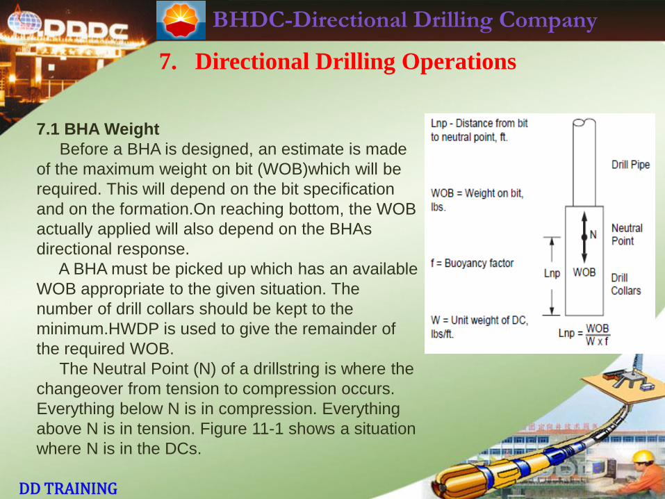
BHDC-Directional Drilling Company
DD TRAINING
7. Directional Drilling Operations
7.1 BHA Weight
Before a BHA is designed, an estimate is made
of the maximum weight on bit (WOB)which will be
required. This will depend on the bit specification
and on the formation.On reaching bottom, the WOB
actually applied will also depend on the BHAs
directional response.
A BHA must be picked up which has an available
WOB appropriate to the given situation. The
number of drill collars should be kept to the
minimum.HWDP is used to give the remainder of
the required WOB.
The Neutral Point (N) of a drillstring is where the
changeover from tension to compression occurs.
Everything below N is in compression. Everything
above N is in tension. Figure 11-1 shows a situation
where N is in the DCs.
BHDC-Directional Drilling Company
DD TRAINING
7. Directional Drilling Operations
7.1 BHA Weight
The weight per foot of each size of DC and HWDP is known. Thus, the weight
in air of any BHA is easily calculated. However, we must then correct this
weight to actual downhole conditions in a deviated well.
In any well, the buoyancy effect of the mud on the drillstring must be accounted
for. A table of values of Buoyancy Factor (BF) is available . The higher the mud
weight, the lower the value of BF and the smaller the weight available for use
on WOB. Buoyancy can have a significant effect on the WOB calculation. In 14
ppg mud, 21% of the weight in air is “lost” due to buoyancy.
BHDC-Directional Drilling Company
DD TRAINING
7. Directional Drilling Operations
7.2 Tool Handling
The DD should be on the drill floor when a directional BHA is being laid down
or picked up. The following rules should be observed. Rig floor safety
procedures must be strictlyadhered to.
1. A copy of the next BHA should be given to the driller and the assistant driller
inadvance. The tools to be picked up should be marked and identified to the
assistant driller (or, possibly, the crane operator). There must be no confusion
about what’s to be laid down/picked up.
2. A crane must be used when handling PDMs, NMDCs, DCs, Stabilizers, EQ
jars etc.On land rigs, great care must be taken not to allow tools to be damaged
by using the cathead or a fork-lift.
3. Ensure all DD tools have thread protectors fitted, especially when they’re
being picked up or laid down.
4. Do not obstruct the driller’s view when handling a BHA. Never stand between
the driller and the rotary table.
5. Be aware of any activity on the drill floor and in the derrick. Wear all
appropriate safety gear (hard hat, boots, coveralls, safety glasses, gloves)
BHDC-Directional Drilling Company
DD TRAINING
7. Directional Drilling Operations
7.2 Tool Handling
6. Plan (in consultation with the driller) the most efficient and sensible way to
pick up/lay down the BHA.
7. Before POOH, ensure that the driller is aware of what BHA components you
need in slips when he reaches the bit. The driller will then decide (based on his
pipe tally) whether to POOH "on a single", “on a double" or "on even stands".
8. Inspect the face of each BHA component for damage before torquing the
connection. Minor shoulder damage may be repaired by filing the shoulder
carefully. Check for thread damage also. NMDCs are particularly prone to
galling. If in doubt, lay out the component and pick up a replacement.
9. Ensure that the proper drill collar compound is used on every component
below the HWDP. The dope brush and thread compound container should be
kept as clean as possible.
10. Check the makeup torque of each connection. The length of the tong arm
should be known. If the makeup torque sensor is broken, the driller will use the
"EZY-TORQ"(if available). In any case, an accurate reading of tong line pull
(and hence makeup torque) must be taken before the driller is allowed to
BHDC-Directional Drilling Company
DD TRAINING
7. Directional Drilling Operations
7.2 Tool Handling
proceed further. This sometimes involves rig down-time, while the hose or
sensor is being repaired or replaced.
11.When changing stabilizer sleeves, use of a hammer is sometimes necessary.
Ensure that the roughneck using the hammer has eye protection. Everybody
else should stand well clear, out of danger.
12. The driller should not use the weight of the NMDCs to force a float valve
(placed on top of the bit) into the near-bit stabilizer. This method can lead to the
float valve rubber seal being forced into the area between the bit and stabilizer
threads. When the bit is torqued up, the threads will be destroyed on both bit
and stabilizer. The float bore on the stabilizer should be cleaned out, doped and
the valve installed on the drill floor, checking that it has gone in past the thread
area.
13. Stay clear of the rotary table when the driller opens the BOP.
14. The MWD engineer normally supervises the picking up/laying down of the
MWD collar. If he’s not available, the DD should ensure that the
MWD collar is handled carefully.
BHDC-Directional Drilling Company
DD TRAINING
7. Directional Drilling Operations
7.2 Tool Handling
15. Mud motors must be handled with special care. The lift sub on the PDM
should not be used for handling other tools.
16. Be careful not to omit the baffle plate (TOTCO ring) from the BHA, if
appropriate.
17. Occasionally the DD may be asked by the company representative to grade
the bit when POOH. While bit grading is subjective, it is important for the DD’s
credibility that his opinion of the bit condition makes sense.
18. Good relations between the DD and the driller are vital to the success of
any directional job! The DD should work with the driller, not act superior.
Cooperation leads to success!
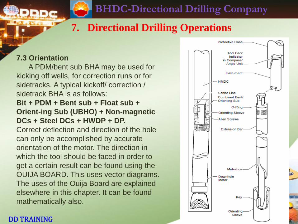
BHDC-Directional Drilling Company
DD TRAINING
7. Directional Drilling Operations
7.3 Orientation
A PDM/bent sub BHA may be used for
kicking off wells, for correction runs or for
sidetracks. A typical kickoff/ correction /
sidetrack BHA is as follows:
Bit + PDM + Bent sub + Float sub +
Orient-ing Sub (UBHO) + Non-magnetic
DCs + Steel DCs + HWDP + DP.
Correct deflection and direction of the hole
can only be accomplished by accurate
orientation of the motor. The direction in
which the tool should be faced in order to
get a certain result can be found using the
OUIJA BOARD. This uses vector diagrams.
The uses of the Ouija Board are explained
elsewhere in this chapter. It can be found
mathematically also.
BHDC-Directional Drilling Company
DD TRAINING
7. Directional Drilling Operations
7.3 Orientation
In order to actually know how the scribe line on the bent sub is faced, some
method of surveying must be used. The survey should give us Inclination,
Direction and Tool Face. In all cases, the bent sub scribe line is the master
reference for the tool face. Up until reliable MWD tools arrived, orientation was
normally done using MMO (Magnetic Method of Orientation) or Mule Shoe
method. MMO is seldom, if ever, used today. In places where single-shot
kickoffs are performed, the mule shoe method is what’s used.
The components of the mule shoe orientation method are illustrated in Figure .
Hole inclination, direction and tool face are read from the survey disc. The tool
face is an indication of the position of the bent sub scribe line. A decision on
where to set the set the tool face next is based on interpretation of the result of
the last setting(s).
BHDC-Directional Drilling Company
DD TRAINING
7. Directional Drilling Operations
7.3 Orientation
7.3.1 Reactive Torque
Reactive torque is created by the drilling mud pushing against the stator.
When drilling with a PDM, as weight-on-bit is increased, the drilling torque
created by the motor increases. There is a corresponding counter-clockwise
torque on the motor housing. This tries to twist the motor and, hence, the whole
BHA counter-clockwise. This changes the facing of the bent sub, i.e., the tool
face orientation.
The big disadvantage of using a PDM/bent sub deflection method is that
reactive torque makes it difficult to keep a steady tool face. Using single-shot
surveys, the DD must estimate the magnitude of the reactive torque. He initially
sets the tool face to the right of the desired tool face position by that angular
distance, so that the reactive torque will allow the bit to drill off in the correct
direction. This is one area where the "art" of the DD comes into play.
BHDC-Directional Drilling Company
DD TRAINING
7. Directional Drilling Operations
7.3 Orientation
7.3.1 Reactive Torque
On-bottom drilling parameters, especially pump pressure, should be kept
constant when using a PDM. This should lead to constant reactive torque and a
steady tool face(provided there are no formation changes).
Reducing the flow rate leads to less reactive torque. Reducing WOB also
leads to less reactive torque. Finally, use of a less aggressive bit means less
reactive torque.
With the jetting deflection method, reactive torque does not apply. However,
there is a tendency for the bit to screw to the right during jetting. Usually this is
no more than 20°.It can be easily compensated for when the tool face is set.
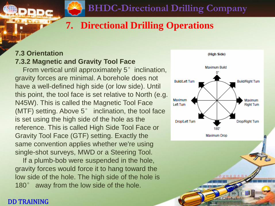
BHDC-Directional Drilling Company
DD TRAINING
7. Directional Drilling Operations
7.3 Orientation
7.3.2 Magnetic and Gravity Tool Face
From vertical until approximately 5°inclination,
gravity forces are minimal. A borehole does not
have a well-defined high side (or low side). Until
this point, the tool face is set relative to North (e.g.
N45W). This is called the Magnetic Tool Face
(MTF) setting. Above 5° inclination, the tool face
is set using the high side of the hole as the
reference. This is called High Side Tool Face or
Gravity Tool Face (GTF) setting. Exactly the
same convention applies whether we're using
single-shot surveys, MWD or a Steering Tool.
If a plumb-bob were suspended in the hole,
gravity forces would force it to hang toward the
low side of the hole. The high side of the hole is
180° away from the low side of the hole.
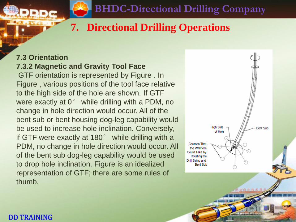
BHDC-Directional Drilling Company
DD TRAINING
7. Directional Drilling Operations
7.3 Orientation
7.3.2 Magnetic and Gravity Tool Face
GTF orientation is represented by Figure . In
Figure , various positions of the tool face relative
to the high side of the hole are shown. If GTF
were exactly at 0° while drilling with a PDM, no
change in hole direction would occur. All of the
bent sub or bent housing dog-leg capability would
be used to increase hole inclination. Conversely,
if GTF were exactly at 180° while drilling with a
PDM, no change in hole direction would occur. All
of the bent sub dog-leg capability would be used
to drop hole inclination. Figure is an idealized
representation of GTF; there are some rules of
thumb.
BHDC-Directional Drilling Company
DD TRAINING
7. Directional Drilling Operations
7.3 Orientation
7.3.3 Single Shot Kickoff/Correction Run/Oriented Sidetrack
This is probably the single most difficult and most critical part of the DD’s job.
We will deal here with magnetic (non-gyro) situation.
In the mule shoe orientation method, there are five components involved in
giving the DD the Tool Face on his Magnetic Single-Shot survey disc.
a) The scribe-line on the bent sub.
b) The key of the UBHO sleeve (align exactly above a).
c) The mule shoe stinger at the bottom of the survey Running-Gear. The groove
of the mule shoe lands on b).
d) The position of the T-head of the snubber at the top of the survey Running-
Gear.This should be aligned exactly with the center of the groove on the mule
shoe when the survey orientation running gear is made up.
e) The tail on the cross-hairs (in case of Sperry-Sun instrument) on the glass of
the compass/angle unit. in other instruments, it may be an arrow or a short,
heavy line. This will be 180° away from d).
BHDC-Directional Drilling Company
DD TRAINING
7. Directional Drilling Operations
7.3 Orientation
7.3.3 Single Shot Kickoff/Correction Run/Oriented Sidetrack
7.3.3.1 Steering Tool
Uses a single-conductor wireline (continuous Tool Face readings on surface
equipment).Either Analog or Digital displays are available.
· Uses similar alignment system to Single-Shot (Mule Shoe groove seats on
Key of sleeve inside special full-Flow UBHO sub).
· Reactive Torque can be seen very clearly with Analog Display.
· Can use either Circulating Head (drill 1 stand at a time) or Side-Entry Sub
with Standoff for Kelly Bushing.
· Can only be used in oriented (non-rotary) drilling.
· Has a facility to "trigger" a film-disc magnetic singleshot survey downhole
before being pulled out at the end of the motor run. This is a useful means of
double-checking the last survey given by the steering tool.
BHDC-Directional Drilling Company
DD TRAINING
7. Directional Drilling Operations
7.3 Orientation
7.3.3 Single Shot Kickoff/Correction Run/Oriented Sidetrack
7.3.3.2 Use of MWD Tool in PDM/TURBINE/STEERABLE BHA
Much easier for the DD. However, offset angle (clockwise, looking downhole)
from MWD Tool Face Reference around to position of Bent Sub Scribe Line
must be measured accurately. This offset is then entered into MWD surface
computer. Tool Face readings on MWD Surface Readout will therefore give the
position of the bent sub scribe line either as a magnetic tool face (below 5º
inclination) or as a gravity tool face (when a good High Side of the hole has
been established).
In case of MWD Tool failure (and to allow a Single-Shot check of hole
Inclination,Direction and Tool Face to be run, if required) a UBHO Sub is
sometimes run directly above the MWD.
· Key of UBHO Sleeve is aligned exactly above Bent Sub Scribe-Line (after all
connections are torqued up).
· Single-Shot Survey Disc will therefore give the same information as if doing
Single-Shot Orientation. (Only difference is that we are further back from the
bit with our survey).
BHDC-Directional Drilling Company
DD TRAINING
7. Directional Drilling Operations
7.3 Orientation
7.3.3 Single Shot Kickoff/Correction Run/Oriented Sidetrack
7.3.3.3 GYRO Single-Shot Orientation
a) Uses same UBHO sub/sleeve/key as with Magnetic Single-Shot orientation.
b) Uses a mule shoe stinger at bottom of Survey Running Gear (same system
as with Magnetic Single-Shot orientation).
c) Remainder of gyro Running Gear is different from (but equivalent to) that of
Magnetic Single-Shot system.
d) Normally, this system is only used at shallow depths, when close to other
wells/conductors. As soon as magnetic interference has declined to an
acceptable level, change over to magnetic single-shot or (if available) MWD
surveys.

BHDC-Directional Drilling Company
DD TRAINING
7. Directional Drilling Operations
7.4 Open hole Sidetracking
There are two main types of open-hole sidetrack:
1. "Blind" Sidetrack This is a sidetrack in a vertical hole, usually performed to avoid junk (e.g. core barrel, BHA). A cement plug is set on top of the “fish". The
well is side-tracked off the cement plug using a bit/PDM/bent sub BHA. Some
inclination(and hence displacement) is built in a random direction. The sidetrack
BHA is POOH. The inclination is then dropped off to vertical using a pendulum
assembly. The sidetrack is usually considered successful when the depth of the
"fish" has been passed.
2. Oriented Sidetrack This is a sidetrack performed to hit a specific target. It may be necessary due to an unsuccessful fishing job in a deviated well. The
original target tolerance may be kept or the client may give an increased target
size.
Sometimes, after reaching TD, the open-hole logs may not look promising.
The client may decide to plug back and do an open-hole sidetrack with a much-
different bottom hole location. A direction change of 60º or more is not
uncommon.
BHDC-Directional Drilling Company
DD TRAINING
7. Directional Drilling Operations
7.4 Open hole Sidetracking
Another application is in horizontal drilling. The client may drill a pilot hole at a
specific inclination. At TD, the well is logged. The exact TVD of the target zone
is ascertained.
The pilot hole is then plugged back and sidetracked to become a horizontal
well.If the cement plug is harder than the formation, the sidetrack should be
fairly straightforward. However, even in this situation, certain procedures must
be observed in order to enhance the chances of a successful sidetrack. When
sidetracking, three important rules of thumb are:
1. A good cement plug is vital.
· The only way to ascertain the hardness of the plug is to drill some of it.
Setting
weight alone on the plug tells us nothing. Sometimes there's a hard "skin" at the
top of the plug. It holds significant weight-on-bit without rotation. However,
when a few feet of plug is drilled away, there may be soft slurry underneath!
BHDC-Directional Drilling Company
DD TRAINING
7. Directional Drilling Operations
7.4 Open hole Sidetracking
2. The DD should not rush the job. Otherwise, the chances of a successful
sidetrack are greatly reduced. It is vital that the DD is on the drill floor while the
cement plug is being "dressed". As the DD will be doing the sidetrack, he must
see and be happy with the hardness of the plug.
3. A proper sidetracking bit will increase the chances of a successful sidetrack
by 50% in any formation. The harder the formation, the more important the bit
choice becomes.
BHDC-Directional Drilling Company
DD TRAINING
7. Directional Drilling Operations
7.4 Open hole Sidetracking
7.4.1 Bit Selection for Sidetrack
17 1/2" Hole: Normally not a problem. A milled tooth bit should last 25 hours. 12 1/4” Hole: A Tricone bit with Sealed Bearings and Gauge Protection should last for 15 hours (even with a high-speed PDM). However, the DD should watch
for surface indications of bit damage (e.g. frequent PDM stalling, abnormally
low ROP).
8 1/2" Hole: If the formation is Medium-Hard, the sidetrack may need more than one bit run. Therefore, we must orient the Motor, even for a “blind" sidetrack (in
order to build inclination most efficiently). In Hard formation, a special
Sidetracking Diamond bit (flatbottomed) should be used. In 8 1/2" hole sizes, a
diamond bit should be used.
BHDC-Directional Drilling Company
DD TRAINING
7. Directional Drilling Operations
7.4 Open hole Sidetracking
7.4.2 Open-hole Sidetracking Procedure
1. RIH with OEDP. Set cement plug. Flush pipe. POOH.
2. Make up a rotary BHA to "dress" the plug. Use a milled-tooth bit. In a vertical
well,this is normally a slick assembly. In a deviated well, the BHA will normally
contain stabilizers. The exact BHA will depend on the well profile.
3. RIH to casing shoe. Wait on cement (WOC) at least 12 hours.
4. Tag cement. “Dress" the plug. This involves drilling several feet of the plug
using medium parameters. The ROP achieved is compared with that for the
same depth on the mud log when the formation was drilled. As a rule, an ROP
of 60’/hour is the maximum ROP acceptable when dressing the sidetrack plug.
Obviously, in hard formation, it is more difficult to sidetrack.
Decide if the plug is hard enough. The DD should be happy with the plug before
he proceeds further with the sidetrack. If the plug is acceptable, it should be
dressed down to the desired sidetrack point. Circulate the hole clean. POOH.
BHDC-Directional Drilling Company
DD TRAINING
7. Directional Drilling Operations
7.4 Open hole Sidetracking
7.4.2 Open-hole Sidetracking Procedure
5. If the cement hardness is not acceptable, the options are either to POOH to
the casing shoe and WOC some more or drill out the complete cement plug and
set another one. It is generally accepted today that, if the cement plug has not
hardened sufficiently in 24 hours, it is counterproductive to wait any longer.
Either assume that the plug is good enough or drill it out and set another.
Repeat steps 1-4. It is advisable to leave a little of the bottom of the original
plug. This reduces the chances of contamination of the new cement plug.
6. Make up the sidetracking BHA. This is typically:
BIT + PDM + BENT SUB + FLOAT SUB + UBHO + NMDC + DCs.
Notice:The choice of bent sub or housing will depend on the formation hardness. The greater the offset, the greater the side force and the easier it is to get off the plug. However, there are dogleg constraints. If the sidetracking point is shallow compared to the final hole depth, dogleg becomes a more important consideration. For example, in a 12 1/4“ hole, a 7 3/4" O.D. PDM would be used with either a 1 1/2° or a 2° bent sub.
BHDC-Directional Drilling Company
DD TRAINING
7. Directional Drilling Operations
7.4 Open hole Sidetracking
7.4.2 Open-hole Sidetracking Procedure
7. RIH to top of cement plug. Work pipe. Orient pipe using either single-shot or
MWD surveys. If it's a “blind" sidetrack, orient in a random direction but keep a
mark on the pipe and on the frame of the rotary table. Lock the top drive/rotary
table. Record off-bottom circulating pressure.
8. Tag cement plug. Use a low Pmotor in order to achieve a low ROP. This
allows the bit a chance to cut a shoulder, thus increasing the chances of getting
off the plug."Time-drill" the first 10' in small increments. Control ROP to 4'/hour.
DD and client must be patient! The harder the formation, the longer this will take.
9. Check drilled cuttings samples. If the percentage of drilled cuttings increases
steadily, we may increase WOB. The footage drilled with the motor depends on
the hole size, formation hardness and bit condition. If there is 50% drilled
formation in samples, we should be safely sidetracked.
In a “blind" sidetrack to bypass a fish in a vertical hole, an inclination of 3°
(possibly 6° in soft formation) should be seen on the survey disc/MWD before
deciding to POOH. This should ensure adequate displacement at the top of the
fish.
BHDC-Directional Drilling Company
DD TRAINING
7. Directional Drilling Operations
7.4 Open hole Sidetracking
7.4.2 Open-hole Sidetracking Procedure
10. The next BHA will depend on the situation. In a “blind" sidetrack of a vertical
hole, it would be a 60' pendulum BHA, designed to drop inclination to vertical.
Following are some guidelines:
· Keep the next BHA as limber as possible.
· If running a stiff BHA on the next run, be careful! Try to run an under- gauge
near-bit stabilizer, if this is practical.
· If the formation is soft, beware of "sidetracking the sidetrack". Minimize
rotation while RIH.
· If the formation is Medium-Hard, ream carefully through the motor run until
hole Drag is normal.
7.4.3 Jetting BHA for Sidetracking
Sometimes a jetting BHA is used to sidetrack off a cement plug in soft formation.
It is recommended to use one large nozzle and two blanks, to minimize the
possibility of washing out all around the plug.
BHDC-Directional Drilling Company
DD TRAINING
7. Directional Drilling Operations
7.4 Open hole Sidetracking
7.4.4 Low-side Sidetracking
Sometimes, in deviated wells of inclination >10°, if no change in hole
direction is required, it may be decided to use a pendulum BHA and sidetrack
off the low side of the hole. This involves setting a cement plug (as above). The
60' pendulum BHA is used to "dress" the plug. At the sidetrack point, low WOB
and high RPM are used to allow the bit to cut a shoulder on the low side. The
harder the formation, the more time is required to do this.
At inclinations 35°, it is advisable to run a less drastic drop-off BHA. A 30'
pendulum should be sufficient. Otherwise, gravity forces may lead to excessive
dogleg.
Attempting a low-side sidetrack where hole inclination <10° is difficult,
especially in hard formation. If low WOB is used in hard formation, ROP will be
very low.
BHDC-Directional Drilling Company
DD TRAINING
7. Directional Drilling Operations
7.4 Open hole Sidetracking
7.4.5 Steerable PDM
Using a steerable mud motor BHA, the cement plug can be “dressed" and the
hole sidetracked in one run. Provided the BHA behaves as expected, the next
casing point may be reached (assuming the bit and motor are still good).
7.4.6 Turbo drill
For doing a deep sidetrack in hard (and possibly hot) formation, a diamond
bit, short turbine and bent sub have often been used successfully.
A pendulum BHA incorporating a sidetracking bit and turbine (no bent sub)
has also been used successfully to get off the low side of a cement plug.
7.4.7 Open-hole Whip-stock
There are certain situations where a whip-stock would be used in open-hole
sidetracking. A good example is in a geothermal well, to bypass a fish where
high BHT precludes use of a PDM. A cement plug is set and “dressed" as
described above. The hole is circulated clean. The whip-stock BHA is made up,
run to bottom, oriented (if required) and the toe of the wedge is seated firmly on
the cement plug. The remainder of the procedure is described in Chapter V.

BHDC-Directional Drilling Company
DD TRAINING
7. Directional Drilling Operations
7.5 Cased hole sidetracking
Sometimes, usually for geological reasons, it becomes necessary to
sidetrack a hole from inside the casing. There are two approaches:
1. Permanent casing whip-stock: This entails anchoring a whip-stock inside
the casing and milling a window. Several round trips are required. The operation
is performed by a specialist. In deep, geothermal wells, for instance, the
permanent casing whip-stock is the method used to do a cased-hole sidetrack.
2. Section Milling A section of casing is milled at the desired depth interval
using a section mill. Common types of section mill are the Servco K-mill and the
Tristate Metal Muncher. At least 50' of casing (preferably 75') should be milled.
It is best to start milling the section directly below a casing collar. Normally,
two runs are required to mill the section.
The section mill is usually run by a specialist. However, the DD may
occasionally be asked to run it (if it's provided by DDDC). It is a relatively simple
tool to use, provided proper precautions are taken - high mud viscosity, use of
ditch magnets etc. (Refer to appropriate service manual).
BHDC-Directional Drilling Company
DD TRAINING
7. Directional Drilling Operations
7.5 Cased hole sidetracking
The same procedure applies to setting the cement plug, waiting on cement
and “dressing“ the plug as in the open-hole sidetrack. The cement plug is set
from about 100' below the milled section up to 50'-100' above the top of the
section.
Again, the hardness of the plug is critical to the success of the operation.
Apart from permitting the bit to get into the formation, it is important that the
plug will not be eroded by the rotation and later tripping of the pipe.
The cement plug is dressed down to about 4' from the top of the milled
section. At this point, the hole is circulated clean before POOH for a
sidetracking BHA (bit, PDM, bent sub etc. as before).
The same procedure as before applies to getting off the cement plug etc. It
must be "time-drilled". When the bit has passed the depth of the bottom of the
window and there is a significant % of drilled cuttings coming over the shakers,
the sidetrack should end up as a success.
BHDC-Directional Drilling Company
DD TRAINING
7. Directional Drilling Operations
7.5 Cased hole sidetracking
Beware of magnetic interference as the magnetic compass/D&I package
passes the bottom of the window!
If the hole inclination is >5° (i.e. a good high side had been established
when the casing was set), Gravity Tool Face (GTF) can be used to steer the bit
out of the casing in the desired direction. GTF is not effected by magnetism.
When the D&I package is far enough away from the casing, azimuth error will
be acceptable and a survey calculation can be made.
BHDC-Directional Drilling Company
DD TRAINING
8. DD at the Rig-site
BHDC-Directional Drilling Company
DD TRAINING
8. DD at the Rig-site
8.1 Introduction
The DD has other rig-site responsibilities not directly related to drilling. These
include keeping an accurate inventory of the DD tools. The logistics involved in
getting equipment to and from the rig-site varies, depending on the location. it is
vital that the DD keep the various reports up to date. This information is needed
by the location manager and, often, the unit technical manager.
Finally, knowing the rig-site politics and abiding by the rules makes the DD job
run much more smoothly than otherwise. The degree to which the DD is "his own
boss“ often depends as much on himself as it does on the client. This chapter
highlights the above.

BHDC-Directional Drilling Company
DD TRAINING
8. DD at the Rig-site
8.2 On Arrival at the Rig
On arrival at the rig, the following is a recommended routine.
8.2.1. Familiarize yourself with the safety procedures on board (life raft, life boat
assignments, frequency of fire drills and abandon ship drills etc.).
8.2.2. Meet the company representative. Discuss briefly the well program. Be
aware of the present operation on the rig. Confirm that there is at least one
directional plot on board (if you’re going to do a blind sidetrack, obviously this
does not apply). Put up a copy of the plot on the wall of the company rep’s office.
The anti-collision map ("Spider Plot"), if applicable, is usually updated after each
well and shows the relative positions of the wells drilled to date.
8.2.3. Meet the toolpusher. Check that there are sufficient drill collars and HWDP
at the rig.
8.2.4. Meet the driller on tour. If there’s any instructions to be given to him, do it
now. For instance, if he’s drilling down to the kickoff point, he will need to be
informed if a multishot survey will be taken prior to POOH, the composition of the
next BHA etc.
8.2.5. Attend safety meeting with the other DDDC cell members, if applicable.
BHDC-Directional Drilling Company
DD TRAINING
8. DD at the Rig-site
8.2 On Arrival at the Rig
8.2.6. Do a complete inventory of the directional tools. It is advisable to caliper
everything as you check them. The serial numbers of every tool must be
recorded. While it takes a few hours to caliper everything properly, a lot of the
tools (apart from those that will be re-cut and new tools that arrive) will only need
to be calipered once in the course of a project. Thus, it’s important to do it
properly the first time.
8.2.7. Use a check-list. If there’s any tool obviously missing, check that it has
been ordered.Call the DDDC office if necessary. Also check for damaged
threads and shoulders.Check the D+C hours already on the mud motors, if a
different DDDC DD was on the rig most recently.
8.2.8. On a new job (e.g. multiwell platform) which is expected to last several
months or more, it is advisable to get a rack fabricated by the welder to hold all
the subs,stabilizers and, possibly, short collars. This minimizes the space
occupied by the DD tools. It also helps protect the tools, makes them easy to
find and easy to pick up/lay down.

BHDC-Directional Drilling Company
DD TRAINING
8. DD at the Rig-site
8.2 On Arrival at the Rig
8.2.9. Fill out a DD inventory sheet. Give a copy to the company representative.
Post one copy in the doghouse to facilitate the driller’s BHA paperwork.
8.2.10. Check all the survey instrument kits systematically (gyro and/or magnetic,
singleshot and/or multishot). Run a check shot for confirmation. Take a short
multishot test , if applicable. Order any necessary missing equipment from the
base. If you will be using the rig floor power supply (e.g. in case of gyro), ensure
that the voltages are compatible.
8.2.11. Check all the survey running gear. Make up the complete mule shoe
orienting barrel assembly. Make up the bottom-landing shock absorber assembly
also. If it’s a hot hole, ensure that the long protective barrel is at the rig-site.
8.2.12. The running gear which might be needed during the course of the well is
normally stored on a rack behind the drawworks. Ensure the storage place is dry
and clean.
8.2.13. Excess running gear should be stored in the steel box in which it arrived
on the rig.

BHDC-Directional Drilling Company
DD TRAINING
8. DD at the Rig-site
8.2 On Arrival at the Rig
8.2.14. Check the rig equipment. Ensure the slick line unit is in good condition
and that there is sufficient line on the drum. Watch out for “kinks" in the slick line.
It is recommended to get the driller/assistant driller to cut off some slick line
before attaching the upper part of the single-shot running gear.
8.2.15. Familiarize yourself with the driller's console. Check that there are
adequate sensors operational and that there is nothing obviously wrong with the
drill-floor equipment from a DD viewpoint.
8.2.16. Run the GEOMAG program, in conjunction with the MWD engineer.
Otherwise, use Zone maps to determine the number of NMDCs needed in the
BHAs in this well.
8.2.17. If on a multiwell platform, or close to other wells, ensure that the surface
coordinates of the well to be drilled (referenced to the fixed origin) are entered
in the Advisor and/or Macintosh so that the anti- collision program can be
run later.
BHDC-Directional Drilling Company
DD TRAINING
8. DD at the Rig-site
8.3 General DD duties as the well progresses
8.3.1. Ensure that the drilling supervisor is kept up to date on the progress of the
well from a DD standpoint. He must be informed of your intentions to change the
BHA If a correction run is required, the DD should explain why. He should also
make recommendations as to when the correction should be done. Sometimes a
target extension is the better option. That decision is made by the client.
8.3.2. Ensure that the driller and assistant driller is given a copy of the next BHA
in good time. Mark all the tools to be picked up. Ensure no unnecessary lost rig
time occurs because of confusion over BHA components.
8.3.3. Have good communication with the drillers. Drilling parameters usually
have to be changed regularly.
8.3.4. Surveys should be taken as necessary. Give the updated survey
calculation sheet to the drilling supervisor promptly.
8.3.5. During a kickoff, it is not always easy to have time to plot all the surveys. A
good DD will know how the kickoff is progressing without having to plot every
survey. The desired hole direction is known. It is very easy to calculate whether
or not the build-up rate achieved is "keeping up with the program".
BHDC-Directional Drilling Company
DD TRAINING
8. DD at the Rig-site
8.3 General DD duties as the well progresses
8.3.6. Even during the kickoff, each survey should be calculated promptly and
given to the company representative. Where DDDC’s MWD tool is in use, this is
usually taken care of by the MWD engineer.
8.3.7. When the kickoff is almost finished, it s necessary to plot a few surveys.
After the kickoff, plot the latest survey position on the DD plot promptly. Project
ahead. Use BHA history from previous wells in the area to help in decision-
making.
8.3.8. Keep all DD paperwork up to date. Consumables, run charges, personnel
charges (where applicable) should be noted on the DDDC Daily Drilling Report. All other relevant forms - Mud Motor Report, Survey Calculations & Analysis,
BHA Analysis, Steerable Report, DD Tool Inventory etc. should be
comprehensively filled out.
8.3.9. Perform basic maintenance on UBHO subs, Roller Reamers, stabilizer
sleeves etc.
8.3.10. Underreamers and Hole Openers should be stored in an oil bath (usually
a length of casing which is filled with oil) when not in use.

BHDC-Directional Drilling Company
DD TRAINING
8. DD at the Rig-site
8.3 General DD duties as the well progresses
8.3.11. Survey instrument kit should be kept in the quarters (in cases where
MWD tools are in use) or in the driller’s dog-house (provided it’s clean and
secure).
8.3.12. The DD should be on the drill floor when EQ Jars or Shock Guard is
being picked up or laid down. Ensure the Jack Nut (if applicable) is screwed
down torqued to correct value before RIH.
8.3.13. It’s advisable to be on the drill floor when the driller’s change tour. Don’t
rely on the driller to relay your instructions to his relief.
8.3.14. Ensure that the company representative has up-to-date survey
information on his desk at report time. He shouldn’t have to come looking for
survey calculation data!
8.3.15. Grading of the bits is often a joint effort between the DD and the driller.
BHDC-Directional Drilling Company
DD TRAINING
8. DD at the Rig-site
8.4 Location Politics
The DD has a responsible and rewarding job at the rig-site. However, there
are some minefields which, if not avoided, can lead to major problems for the
DD. Some advice and guidelines are listed below.
8.4.1. DDDC is a service company. We work to please the client. The service
quality which we provide will make us a major force in directional drilling.
8.4.2. Drilling of a directional well is a joint effort between the client and the DD
company. From the preplanning stage to the actual drilling of a directional well,
the plan may be changed several times. However, once the final plan is agreed,
it is up to the people on the rig to make their contribution to a successful well.
8.4.3. The amount of authority that the DD actually has at the wellsite depends
on several factors:
· The level of experience and competence of the DD.
· The level of confidence the client has in the particular DD. This is often
Based on the previous performance of the DD.
· The amount of experience the client has in drilling directional wells.
BHDC-Directional Drilling Company
DD TRAINING
8. DD at the Rig-site
8.4 Location Politics
· The amount of control the drilling superintendent wishes to have over BHA
selection etc.
· Whether or not the company representative is a former DD or at least has a
good knowledge of DD techniques.
8.4.4. Some DDs like to make all the decisions involved in drilling a directional
well - amount of lead angle, BHA composition, deciding on when to do a correc-
tion run, choosing drilling parameters, possibly specifying bits. This is fine,
provided the client is happy with this arrangement. However, a situation should
never arise where the DD oversteps his authority. There are many clients who
make all the major DD decisions for the DD. In such a case, the DD is merely
someone who makes up BHAs, steers a mud motor, calculates surveys and
keeps the DD plot up to date. Lots of DDs are happy with this arrangement.
Some are not. They would be better suited to a DD job where they had more
autonomy. Ideally, the DD and the client together should make a lot of the
decisions.
BHDC-Directional Drilling Company
DD TRAINING
8. DD at the Rig-site
8.4 Location Politics
8.4.5. It is important to keep the DDDC manager/supervisor informed of the
progress of the well.
8.4.6. If there is a disagreement between the DD and the company
representative over a decision related to DD (e.g. BHA composition) it may be
necessary to (confidentially) call the DDDC manager/supervisor and inform him
of the situation. Try not to be made a scapegoat for something you never did!
8.4.7. The DD should ensure that he is not "caught in the middle” between the
geologist and the drilling supervisor. Unless told otherwise, the DD always
should follow instructions from the drilling supervisor only. Any internal disagree-
ment between the drilling supervisor and the geologist is no concern of the DD.
8.4.8. If possible, it is advisable to be present when the drilling supervisor makes
his morning phone report to the drilling superintendent. Some input may be
needed from the DD, e.g. When is the next BHA change planned ? Is a
correction run likely ? Is a request for a target extension imminent?
BHDC-Directional Drilling Company
DD TRAINING
8. DD at the Rig-site
8.4 Location Politics
8.4.9. As mentioned earlier in this manual, if a mud pump needs repair while
ROP is high (particularly in larger hole sizes at shallow depths), the DD should
recommend that drilling cease until the pump is back on line. This may not suit
the toolpusher, as it increases the rig down-time. However, drilling with
insufficient annular velocity can lead to serious hole problems later.
8.4.10. On returning to base after the job, the DD would be well advised to visit
the drilling superintendent and thus "close the loop". A short discussion on the
well just drilled might lead to a slightly different approach to drilling the next well.
This will, hopefully, lead to increased drilling efficiency.
BHDC-Directional Drilling Company
DD TRAINING
Related Documents