GMC-SN
6.5' E
ANNUAL RATE OF CHANGE
RÉGIMEN DE VARIACIÓN ANUAL //
GMC-S GMC-S
GMC-C
GMC-N GMC-C
GMC-N
HS1, HS2, HS3, HS4 & HS6:
PAPI 3º
HS2
GATE HSGATE FSGATE ES GATE GS
GATE KS
GATE IS
RWY 02/20
DS
GATE
TERMINAL DE CARGA
AIS, MET
CORPORATIVAAVIACIÓNTERMINAL
TERMINAL T2
GATE KNGATE LN
GATE MNGATE PNGATE QNGATE RN
CARTOGRÁFICO
NAVE J
GUARDIA
HANGAR
PARKING PARKING
S13
M14 M12
D5
XX
X
XX
X
XXX
XX
X
XX
X
FN
GATE
EN
GATE
BN
GATE
32
31
42
CS
GATE
BS
GATE
AS
GATE
MS
GATE
NS
GATE
PS
GATE
QS
GATE
900 902 904 906
HS3
HS4
HS1
HS6
DTHR 430
NORTEC.I.
DN
GATE
CN
GATE
185
184
183
182
181
175
174
173
172
171
165
164
163
162
161
157
157A156
155A
155154
154A153
152A
152151
151A 141
141A
142
142A
143
143A
144139 138
138A 137 136
135
134A
134
133A
133 132 131
129128A
128
127
126A
126
125
124A
124
122
121A
121
119
A
119
11811
7
116
115
114
113
A
113
11211
1
110
109
108
107
10610
5
104
103
102
101
A
101
100
96
95
93
92
91
63
62
61
51
52
53
54
55
56
57
49
48A
4847
46A
4645
44A
43
42
4140
31
32
33
34
35
36
37
38
200R
200 202 204 206 208 210 212 21421
6
217
218
220
221
222
236 238 240 242
244 24
5
246
247
248
270
272
273
2742762
77
282284286290291292294
295
296
298
34030
0
302
420
421
422
425
400410
412
414
342
X1 X2 X3
87
86
85
84
83A
83
82
81A
81
72
71
26
25
24
23
22
21
11
12
13
14
1504
03
0201
GATE AN
44
RAMPA-1 // RAMP-1
RAMPA-2 // RAMP-2
RAMPA-0 // RAMP-0
AVIATION)EXCLUSIVE USE CORPORATE
CORPORATIVA //(USO EXCLUSIVO AVIACIÓN
RAMP-15RAMPA-15 //
GATE LS
RAMPA-32 // RAMP-32
RAMPA-31 // RAMP-31
AIPESPAÑA
PLANO DE ESTACIONAMIENTOY ATRAQUE DE AERONAVES-OACI
AIS-ESPAÑA
35
AD 2-LEBL PDC 1.1
TWR 118.100
CLR 121.800118.325
XXXGMC N 121.700
BARCELONA/El PratGMC CGMC S
121.650122.225
VAR 0? (2015)
0 150 300 m
CLAVE/LEGEND
AREA NOT VISIBLE FROM TWR
AREA NOT USABLE
PRKG
NO INTRUSION BARS
BDRY FREQ GMC
ZONA NO UTILIZABLE //
ZONA NO VISIBLE DESDE TWR //
BARRAS DE NO INTRUSIÓN //
ELEV APN 4
94
RAMPA-32 // RAMP-32: PCN 149/R/A/W/T.
RAMPA-31 // RAMP-31: PCN 148/R/A/W/T;
RAMPA-30 // RAMP-30: PCN 118/F/A/W/T;
RAMPAS-10 a 17 // RAMPS-10 to 17: PCN 141/R/A/W/T;
RAMPAS-3 & 9 // RAMPS-3 & 9: PCN 87/R/B/W/T;
RAMPAS-1 & 2 // RAMPS-1 & 2: PCN 79/R/B/W/T;
RAMPA-0 // RAMP-0: PCN 50/R/B/W/T;
RESISTENCIA APN // APN STRENGTH:
SEE AD 2-LEBL ITEM 20 AND 22.
GENERAL TAXIING PROCEDURES AND LOW VISIBILITY PROCEDURES:
VER AD 2-LEBL CASILLAS 20 Y 22. //
PROCEDIMIENTOS GENERALES DE RODAJE Y PROCEDIMIENTOS DE VISIBILIDAD REDUCIDA :
RAMPAS-16 & 17 // RAMPS-16 & 17: TODOS // ALL.
RAMPAS // RAMPS-2, 10, 11, 12, 13, 14 & 15: PRKG DE CONTACTO // CONTACT PRKG;
RAMPA-9 // RAMP-9: 173, 174 & 175;
RAMPA-3 // RAMP-3: 136, 137, 138 & 139;
HIDRANT OUTLETS AT PRKG:
TOMA DE HIDRANTES EN PRKG: //
(EXC 224, 247), RAMP-13, RAMP-14, RAMP-15 (EXC 290, 291,292, 294, 296 & 298).
VISUAL DOCKING GUIDANCE SYSTEM: CONTACT PRKG OF RAMP-2 (EXC 102, 114, 121A), RAMP-10, RAMP-11, RAMP-12
RAMPA-12 (EXC 224, 247), RAMPA-13, RAMPA-14, RAMPA-15 (EXC 290, 291,292, 294, 296 & 298). //
SISTEMA DE GUÍA DE ATRAQUE VISUAL: PRKG DE CONTACTO DE RAMPA-2 (EXC 102, 114, 121A), RAMPA-10, RAMPA-11,
APN LGT: POSTES PROYECTORES // FLOODLIGHTING POLES.
GATE AN: MAX ACFT WITH CODE LETTER B.
GATE AN: MAX ACFT CON LETRA DE CLAVE B. //
LUGARES CRÍTICOS: VER AD 2-LEBL GMC. // HOT SPOT: SEE AD 2-LEBL GMC.
ELEV, DIM: M.
AIRAC AMDT 01/18
WEF 01-MAR-18C
HA
NG
ES: IN
CLU
SIO
N O
F T
WY B
11 N
AM
E,
NE
W I
NTER
MEDIA
TE H
OLDIN
G P
OSITIO
N O
N G
ATE B
N,
RE
MO
VAL
OF I
NTER
MEDIA
TE H
OLDIN
G P
OSITIO
N O
N T
WY U
5 I
N E
AST T
O W
EST DIR
EC
TIO
N.
CA
MBIO
S: IN
CLU
SIÓ
N D
E N
OM
BRE D
E T
WY B
11,
NU
EV
O P
UN
TO D
E E
SPERA I
NTER
MEDIO E
N G
ATE B
N Y E
LIMIN
ACIÓ
N D
E P
UN
TO D
E E
SPERA I
NTER
MEDIO E
N T
WY U
5 E
N S
EN
TID
O E
STE A O
ESTE. //
ESCALA // SCALE 1:9 000
02
L25R 0
7
L 07 R2
5
20
RWY 07L/25R
COMBUSTIBLE
TWR SUR
PARKING
C.I. SUR
RAMPA-9 // RAMP-9
RAMPA-3 // RAMP-3
RAMPA-10 // RAMP-10
RAMPA-16 // RAMP-16
RAMPA-12 // RAMP-12
RAMPA-13 // RAMP-13
RAMPA-17 // RAMP-17
L 07
TERMINAL T1
S14
RN
T13
T14
N16
M16
Z8
PNS12
T12
LN
P7
N15
M15
AS
N14
L14
BS
N13
M13
L13
CS
Y5Y6Y7
Z7 Z6 Z5
T11
S11
KN
B10
S10
T10
JN
B9
S9
T9HN
P6
N10
N11
M11DS
N12
L12
L11
ESM10 FS
N9
R6
E6
N8N7
M8GSM9 HS
M7 E5
E7
T8
S8
B8
GN
B7
S7
T7
P5
R5 R4
N6
M6
E4
B6
S6
FN
D4
D3
CNS5EN
D2
U1
S4 S3
UB
U2
U3L
U3R
L10 L9 L8
E3
E2
J5
J6
Q7Q8
D1
E1
J7J8
NS
Q9
J9
Q10
J10
QS PS
XXX
U4
S2
U4
U5
U6
U7
LS
MS1LS1
ES1 FS1 GS1 HS1
B11
JN
GATE
HN
GATE
GN
GATE
RWY 02/20
20
RAMP-11RAMPA-11 //
RAMP-14RAMPA-14 //
RAMP-30RAMPA-30 //
120
224226 228 230 232 234
250252254256258260262264266268
278280
320
322
330
332
334314
312
310

INTENCIONADAMENTE EN B
LANCO
INTENTIONALLY B
LANK

AIS-ESPAÑA AIRAC AMDT 13/17
AIP AD 2-LEBL PDC 1.3ESPAÑA WEF 04-JAN-18
R0 01 41°18'30.60"N 002°05'27.34"E R C560 – –
R0 02 41°18'31.19"N 002°05'26.98"E R C560 – –
R0 03 41°18'31.78"N 002°05'26.63"E R C560 – –
R0 04 41°18'32.37"N 002°05'26.28"E R C560 – –
R0 11 41°18'29.17"N 002°05'24.71"E R C560 – –
R0 12 41°18'29.73"N 002°05'24.37"E R C560 – –
R0 13 41°18'30.29"N 002°05'24.03"E R C560 – –
R0 14 41°18'30.85"N 002°05'23.70"E R C560 – –
R0 15 41°18'31.41"N 002°05'23.35"E R C560 – –
R0 21 41°18'28.15"N 002°05'24.31"E – C560 – –
R0 22 41°18'28.75"N 002°05'23.95"E R C560 – –
R0 23 41°18'29.34"N 002°05'23.60"E R C560 – –
R0 24 41°18'29.93"N 002°05'23.24"E R C560 – –
R0 25 41°18'30.52"N 002°05'22.89"E R C560 – –
R0 26 41°18'31.11"N 002°05'22.54"E R C560 – –
R0 31 41°18'25.38"N 002°05'22.70"E R F900 – –
R0 32 41°18'26.06"N 002°05'22.30"E R F900 – –
R0 33 41°18'26.74"N 002°05'21.90"E R F900 – –
R0 34 41°18'27.42"N 002°05'21.48"E R F900 – –
R0 35 41°18'28.10"N 002°05'21.07"E R F900 – –
R0 36 41°18'28.77"N 002°05'20.66"E R F900 – –
R0 37 41°18'29.45"N 002°05'20.25"E R F900 – –
R0 38 41°18'30.13"N 002°05'19.84"E R F900 – –
R0 40 41°18'23.90"N 002°05'22.52"E – C560 – –
R0 41 41°18'24.45"N 002°05'22.17"E – C560 – –
R0 42 41°18'25.06"N 002°05'21.75"E R F900 – –
R0 43 41°18'25.74"N 002°05'21.35"E R F900 – –
R0 44 41°18'26.42"N 002°05'20.94"E R F900 – INCOMP. 44A
R0 44A 41°18'26.76"N 002°05'20.76"E R GLEX – INCOMP. 44, 45
R0 45 41°18'27.09"N 002°05'20.53"E R F900 – INCOMP. 44A
R0 46 41°18'27.77"N 002°05'20.12"E R F900 – INCOMP. 46A
R0 46A 41°18'28.12"N 002°05'19.94"E R GLEX – INCOMP. 46, 47
R0 47 41°18'28.45"N 002°05'19.71"E R F900 – INCOMP. 46A
R0 48 41°18'29.13"N 002°05'19.30"E R F900 – INCOMP.48A
R0 48A 41°18'29.48"N 002°05'19.12"E R GLEX – INCOMP. 48, 49
R0 49 41°18'29.81"N 002°05'18.90"E R F900 – INCOMP. 48A
R0 51 41°18'23.04"N 002°05'18.20"E – F50 – –
R0 52 41°18'24.06" N 002°05'17.58"E – F50 – –
R0 53 41°18'24.96"N 002°05'16.93"E – GLF4 – –
RAMPA PUESTO COORDENADAS SALIDAMAX ACFT
APROAR OBSERVACIONESRAMP STAND COORDINATES EXIT NOSE TO REMARKS
CARACTERÍSTICAS DE LOS PUESTOS DE ESTACIONAMIENTOAIRCRAFT STANDS CHARACTERISTICS
AIRAC AMDT 13/17 AIS-ESPAÑA
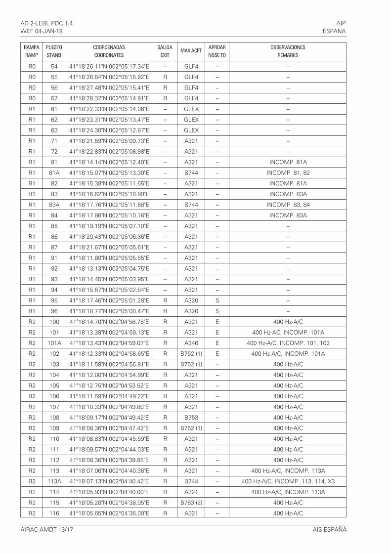
AD 2-LEBL PDC 1.4 AIPWEF 04-JAN-18 ESPAÑA
R0 54 41°18'26.11"N 002°05'17.34"E – GLF4 – –
R0 55 41°18'26.64"N 002°05'15.92"E R GLF4 – –
R0 56 41°18'27.48"N 002°05'15.41"E R GLF4 – –
R0 57 41°18'28.32"N 002°05'14.91"E R GLF4 – –
R1 61 41°18'22.33"N 002°05'14.06"E – GLEX – –
R1 62 41°18'23.31"N 002°05'13.47"E – GLEX – –
R1 63 41°18'24.30"N 002°05'12.87"E – GLEX – –
R1 71 41°18'21.59"N 002°05'09.73"E – A321 – –
R1 72 41°18'22.83"N 002°05'08.98"E – A321 – –
R1 81 41°18'14.14"N 002°05'12.40"E – A321 – INCOMP. 81A
R1 81A 41°18'15.07"N 002°05'13.30"E – B744 – INCOMP. 81, 82
R1 82 41°18'15.38"N 002°05'11.65"E – A321 – INCOMP. 81A
R1 83 41°18'16.62"N 002°05'10.90"E – A321 – INCOMP. 83A
R1 83A 41°18'17.76"N 002°05'11.68"E – B744 – INCOMP. 83, 84
R1 84 41°18'17.86"N 002°05'10.16"E – A321 – INCOMP. 83A
R1 85 41°18'19.19"N 002°05'07.10"E – A321 – –
R1 86 41°18'20.43"N 002°05'06.36"E – A321 – –
R1 87 41°18'21.67"N 002°05'05.61"E – A321 – –
R1 91 41°18'11.80"N 002°05'05.55"E – A321 – –
R1 92 41°18'13.13"N 002°05'04.75"E – A321 – –
R1 93 41°18'14.45"N 002°05'03.95"E – A321 – –
R1 94 41°18'15.67"N 002°05'02.84"E – A321 – –
R1 95 41°18'17.46"N 002°05'01.28"E R A320 S –
R1 96 41°18'18.77"N 002°05'00.47"E R A320 S –
R2 100 41º18'14.70"N 002º04'58.78"E R A321 E 400 Hz-A/C
R2 101 41°18'13.39"N 002°04'59.13"E R A321 E 400 Hz-AC, INCOMP. 101A
R2 101A 41º18'13.43"N 002º04'59.07"E R A346 E 400 Hz-A/C, INCOMP. 101, 102
R2 102 41°18'12.33"N 002°04'58.65"E R B752 (1) E 400 Hz-A/C, INCOMP. 101A
R2 103 41°18'11.58"N 002°04'56.81"E R B752 (1) – 400 Hz-A/C
R2 104 41°18'12.00"N 002°04'54.99"E R A321 – 400 Hz-A/C
R2 105 41º18'12.75"N 002º04'53.52"E R A321 – 400 Hz-A/C
R2 106 41°18'11.59"N 002°04'49.22"E R A321 – 400 Hz-A/C
R2 107 41º18'10.33"N 002º04'49.80"E R A321 – 400 Hz-A/C
R2 108 41º18'09.17"N 002º04'49.42"E R B753 – 400 Hz-A/C
R2 109 41º18'08.36"N 002º04'47.42"E R B752 (1) – 400 Hz-A/C
R2 110 41°18'08.83"N 002°04'45.59"E R A321 – 400 Hz-A/C
R2 111 41°18'09.57"N 002°04'44.03"E R A321 – 400 Hz-A/C
R2 112 41º18'08.36"N 002º04'39.85"E R A321 – 400 Hz-A/C
R2 113 41°18'07.06"N 002°04'40.36"E R A321 – 400 Hz-A/C, INCOMP. 113A
R2 113A 41º18'07.13"N 002º04'40.42"E R B744 – 400 Hz-A/C, INCOMP. 113, 114, X3
R2 114 41º18'05.93"N 002º04'40.00"E R A321 – 400 Hz-A/C, INCOMP. 113A
R2 115 41°18'05.28"N 002°04'38.05"E R B763 (2) – 400 Hz-A/C
R2 116 41°18'05.65"N 002°04'36.00"E R A321 – 400 Hz-A/C
RAMPA PUESTO COORDENADAS SALIDAMAX ACFT
APROAR OBSERVACIONESRAMP STAND COORDINATES EXIT NOSE TO REMARKS

AIS-ESPAÑA AIRAC AMDT 13/17
AIP AD 2-LEBL PDC 1.5ESPAÑA WEF 04-JAN-18
R2 117 41°18'06.29"N 002°04'34.78"E R A321 – 400 Hz-A/C
R2 118 41º18'05.11"N 002º04'30.52"E R A321 – 400 Hz-A/C
R2 119 41°18'03.90"N 002°04'30.88"E R A321 – 400 Hz-AC, INCOMP. 119A
R2 119A 41º18'03.88"N 002º04'31.07"E R B744 – 400 Hz-A/C, INCOMP. 119, 120, X2
R2 120 41º18'02.68"N 002º04'30.25"E R B752 (1) – 400 Hz-A/C, INCOMP. 119A
R2 121 41°18'01.78"N 002°04'28.23"E R B762 – 400 Hz-A/C, INCOMP. 121A
R2 121A 41º18'02.43"N 002º04'26.96"E R B744 – 400 Hz-A/C, INCOMP. 121, 122
R2 122 41°18'02.37"N 002°04'26.53"E R A321 – 400 Hz-A/C, INCOMP. 121A
R2 124 41°18'01.48"N 002°04'22.57"E R A321 – 400 Hz-A/C, INCOMP. 124A
R2 124A 41º18'01.27"N 002º04'22.49"E R B744 – 400 Hz-A/C, INCOMP. 124, 125, X1
R2 125 41º18'00.97"N 002º04'21.43"E R B763 (2) – 400 Hz-A/C, INCOMP. 124A
R2 126 41º18'01.39"N 002º04'19.46"E R A321 E 400 Hz-A/C, INCOMP. 126A
R2 126A 41º18'01.45"N 002º04'19.09"E R B744 E 400 Hz-A/C, INCOMP. 126, 127
R2 127 41º18'01.18"N 002º04'17.82"E R B734 E 400 Hz-A/C, INCOMP. 126A
R2 128 41º18'02.22"N 002º04'16.88"E R A321 E 400 Hz-A/C, INCOMP. 128A
R2 128A 41º18'02.51"N 002º04'16.70"E R B744 E 400 Hz-A/C, INCOMP. 128, 129
R2 129 41°18'02.68"N 002°04'15.41"E R A321 E 400 Hz-A/C, INCOMP. 128A
R2 X1 41°17'55.48"N 002°04'19.42"E – A321 – INCOMP. 124A (3)
R2 X2 41°18'00.18"N 002°04'33.12"E – A321 – INCOMP. 119A (3)
R2 X3 41°18'03.18"N 002°04'41.86"E – A321 – INCOMP. 113A (3)
R3 131 41°17'53.93"N 002°04'13.93"E – B763 (2) – –
R3 132 41°17'53.12"N 002°04'11.54"E – B763 (2) – –
R3 133 41°17'52.60"N 002°04'08.96"E – A321 – INCOMP. 133A
R3 133A 41°17'52.14"N 002°04'08.77"E – B763 (2) – INCOMP. 133, 134
R3 134 41°17'52.06"N 002°04'07.35"E – A321 – INCOMP. 133A, 134A
R3 134A 41 17'51.33"N 002°04'06.48"E – B763 (2) – INCOMP. 134, 135
R3 135 41°17'51.50"N 002°04'05.76"E – A321 – INCOMP. 134A
R3 136 41°17'59.25"N 002°04'07.66"E R B744 – –
R3 137 41°17'58.28"N 002°04'04.84"E R B744 – –
R3 138 41°17'56.96"N 002°04'02.54"E R B763 (2) W INCOMP. 138A
R3 138A 41°17'57.31"N 002°04'02.01"E R B744 W INCOMP. 138, 139
R3 139 41°17'56.15"N 002°04'00.21"E R A306 W INCOMP. 138A
R3 141 41º17’49.05"N 002º03’56.32"E – B764 – INCOMP. 141A
R3 141A 41º17’49.21"N 002º03’55.76"E B748 (4) – INCOMP. 141, 142
R3 142 41º17’50.80"N 002º03’55.26"E – B764 – INCOMP. 141A, 142A
R3 142A 41º17’51.44"N 002º03’54.41"E – B744 – INCOMP. 142, 143
R3 143 41º17’52.55"N 002º03’54.20"E – B764 – INCOMP. 142A, 143A
R3 143A 41º17’53.60"N 002º03’53.11"E – B744 – INCOMP. 143, 144
R3 144 41º17’54.35"N 002º03’53.87"E – B752 (1) – INCOMP. 143A
R3 151 41°17'47.21"N 002°03'50.22"E – E120 – INCOMP. 151A
R3 151A 41°17'47.13"N 002°03'51.13"E – A321 – INCOMP. 151
R3 152 41°17'47.95"N 002°03'49.78"E – E120 – INCOMP. 152A
R3 152A 41°17'48.42"N 002°03'50.35"E – A321 – INCOMP. 152, 153
RAMPA PUESTO COORDENADAS SALIDAMAX ACFT
APROAR OBSERVACIONESRAMP STAND COORDINATES EXIT NOSE TO REMARKS
AIRAC AMDT 13/17 AIS-ESPAÑA
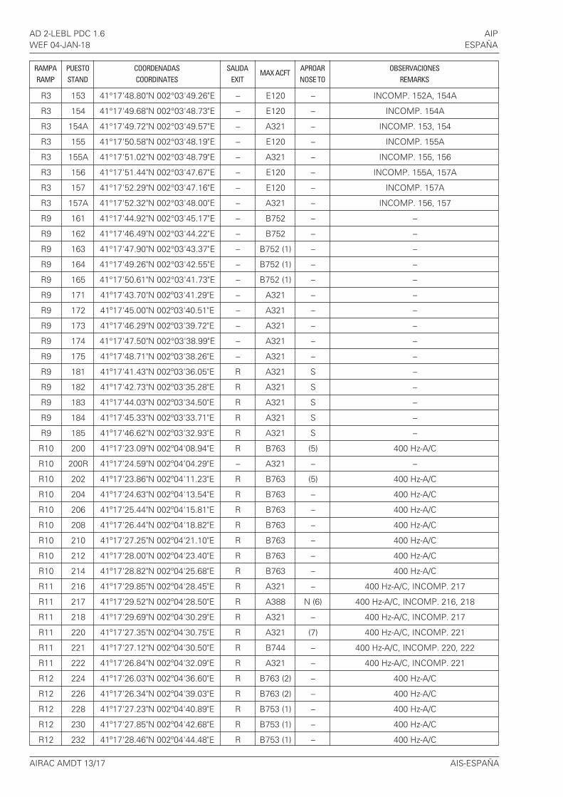
AD 2-LEBL PDC 1.6 AIPWEF 04-JAN-18 ESPAÑA
R3 153 41°17'48.80"N 002°03'49.26"E – E120 – INCOMP. 152A, 154A
R3 154 41°17'49.68"N 002°03'48.73"E – E120 – INCOMP. 154A
R3 154A 41°17'49.72"N 002°03'49.57"E – A321 – INCOMP. 153, 154
R3 155 41°17'50.58"N 002°03'48.19"E – E120 – INCOMP. 155A
R3 155A 41°17'51.02"N 002°03'48.79"E – A321 – INCOMP. 155, 156
R3 156 41°17'51.44"N 002°03'47.67"E – E120 – INCOMP. 155A, 157A
R3 157 41°17'52.29"N 002°03'47.16"E – E120 – INCOMP. 157A
R3 157A 41°17'52.32"N 002°03'48.00"E – A321 – INCOMP. 156, 157
R9 161 41°17'44.92"N 002°03'45.17"E – B752 – –
R9 162 41°17'46.49"N 002°03'44.22"E – B752 – –
R9 163 41°17'47.90"N 002°03'43.37"E – B752 (1) – –
R9 164 41°17'49.26"N 002°03'42.55"E – B752 (1) – –
R9 165 41°17'50.61"N 002°03'41.73"E – B752 (1) – –
R9 171 41º17'43.70"N 002º03'41.29"E – A321 – –
R9 172 41º17'45.00"N 002º03'40.51"E – A321 – –
R9 173 41º17'46.29"N 002º03'39.72"E – A321 – –
R9 174 41°17'47.50"N 002°03'38.99"E – A321 – –
R9 175 41º17'48.71"N 002º03'38.26"E – A321 – –
R9 181 41º17'41.43"N 002º03'36.05"E R A321 S –
R9 182 41º17'42.73"N 002º03'35.28"E R A321 S –
R9 183 41º17'44.03"N 002º03'34.50"E R A321 S –
R9 184 41º17'45.33"N 002º03'33.71"E R A321 S –
R9 185 41º17'46.62"N 002º03'32.93"E R A321 S –
R10 200 41º17'23.09"N 002º04'08.94"E R B763 (5) 400 Hz-A/C
R10 200R 41º17’24.59"N 002º04’04.29"E – A321 – –
R10 202 41º17'23.86"N 002º04'11.23"E R B763 (5) 400 Hz-A/C
R10 204 41º17'24.63"N 002º04'13.54"E R B763 – 400 Hz-A/C
R10 206 41º17'25.44"N 002º04'15.81"E R B763 – 400 Hz-A/C
R10 208 41º17'26.44"N 002º04'18.82"E R B763 – 400 Hz-A/C
R10 210 41º17'27.25"N 002º04'21.10"E R B763 – 400 Hz-A/C
R10 212 41º17'28.00"N 002º04'23.40"E R B763 – 400 Hz-A/C
R10 214 41º17'28.82"N 002º04'25.68"E R B763 – 400 Hz-A/C
R11 216 41º17'29.85"N 002º04'28.45"E R A321 – 400 Hz-A/C, INCOMP. 217
R11 217 41º17'29.52"N 002º04'28.50"E R A388 N (6) 400 Hz-A/C, INCOMP. 216, 218
R11 218 41º17'29.69"N 002º04'30.29"E R A321 – 400 Hz-A/C, INCOMP. 217
R11 220 41º17'27.35"N 002º04'30.75"E R A321 (7) 400 Hz-A/C, INCOMP. 221
R11 221 41º17'27.12"N 002º04'30.50"E R B744 – 400 Hz-A/C, INCOMP. 220, 222
R11 222 41º17'26.84"N 002º04'32.09"E R A321 – 400 Hz-A/C, INCOMP. 221
R12 224 41º17'26.03"N 002º04'36.60"E R B763 (2) – 400 Hz-A/C
R12 226 41º17'26.34"N 002º04'39.03"E R B763 (2) – 400 Hz-A/C
R12 228 41º17'27.23"N 002º04'40.89"E R B753 (1) – 400 Hz-A/C
R12 230 41º17'27.85"N 002º04'42.68"E R B753 (1) – 400 Hz-A/C
R12 232 41º17'28.46"N 002º04'44.48"E R B753 (1) – 400 Hz-A/C
RAMPA PUESTO COORDENADAS SALIDAMAX ACFT
APROAR OBSERVACIONESRAMP STAND COORDINATES EXIT NOSE TO REMARKS

AIS-ESPAÑA AIRAC AMDT 13/17
AIP AD 2-LEBL PDC 1.7ESPAÑA WEF 04-JAN-18
R12 234 41º17'29.07"N 002º04'46.27"E R B753 (1) – 400 Hz-A/C
R12 236 41º17'29.91"N 002º04'48.73"E R B753 (1) – 400 Hz-A/C
R12 238 41º17'30.54"N 002º04'50.57"E R B753 (1) – 400 Hz-A/C
R12 240 41º17'31.16"N 002º04'52.38"E R B753 (1) – 400 Hz-A/C
R12 242 41º17'31.82"N 002º04'53.68"E R A321 – 400 Hz-A/C
R12 244 41º17'32.28"N 002º04'55.49"E R A321 – 400 Hz-A/C, INCOMP. 245
R12 245 41º17'31.91"N 002º04'55.55"E R B744 E 400 Hz-A/C, INCOMP. 244, 246
R12 246 41º17'32.51"N 002º04'56.74"E R A321 E 400Hz-A/C, INCOMP. 245, 247
R12 247 41º17'31.81"N 002º04'59.12"E R A333 – INCOMP. 246
R13 248 41º17'29.71"N 002º04'58.40"E R B764 – 400 Hz-A/C
R13 250 41º17'28.49"N 002º04'57.32"E R A333 E 400 Hz-A/C
R13 252 41º17'27.55"N 002º04'55.41"E R B753 (1) E 400 Hz-A/C
R13 254 41º17'26.92"N 002º04'53.58"E R B753 (1) – 400 Hz-A/C
R13 256 41º17'26.31"N 002º04'51.78"E R B753 (1) – 400 Hz-A/C
R13 258 41º17'25.46"N 002º04'49.60"E R A321 – 400 Hz-A/C
R13 260 41º17'24.92"N 002º04'47.84"E R B752 (1) – 400 Hz-A/C
R13 262 41º17'24.26"N 002º04'46.07"E R B752 (1) – 400 Hz-A/C
R13 264 41º17'23.63"N 002º04'44.23"E R B752 (1) – 400 Hz-A/C
R13 266 41º17'23.22"N 002º04'42.09"E R B763 (2) – 400 Hz-A/C
R13 268 41º17'22.47"N 002º04'39.91"E R A321 – 400 Hz-A/C
R14 270 41º17'20.59"N 002º04'35.37"E R B744 – 400 Hz-A/C
R14 272 41º17'17.75"N 002º04'36.77"E R A321 – 400 Hz-A/C, INCOMP. 273
R14 273 41º17'17.17"N 002º04'36.68"E R B744 – 400 Hz-A/C, INCOMP. 272, 274
R14 274 41º17'16.75"N 002º04'38.01"E R A321 – 400 Hz-A/C, INCOMP. 273
R14 276 41º17'15.84"N 002º04'38.77"E R A321 – 400 Hz-A/C, INCOMP. 277
R14 277 41º17'15.61"N 002º04'38.44"E R B744 (8) (9) 400 Hz-A/C, INCOMP. 276, 278
R14 278 41º17'14.90"N 002º04'38.85"E R A321 – 400 Hz-A/C, INCOMP. 277
R14 280 41º17'13.89"N 002º04'36.90"E R B752 (10) 400 Hz-A/C
R15 282 41º17'12.79"N 002º04'35.40"E R A320 – 400 Hz
R15 284 41º17'11.99"N 002º04'33.04"E R A320 W –
R15 286 41º17'11.17"N 002º04'30.66"E R A320 W –
R15 290 41º17'09.74"N 002º04'26.95"E R (11) A321 W (12) INCOMP. 291
R15 291 41º17'09.26"N 002º04'25.51"E R B744 W (12) INCOMP. 290, 292, 294
R15 292 41º17'08.72"N 002º04'25.62"E R A321 W (12) INCOMP. 291
R15 294 41º17'08.17"N 002º04'24.01"E R A321 W (12) INCOMP. 291, 295
R15 295 41º17'08.19"N 002º04'22.38"E R B744 W (12) INCOMP. 294, 296, 298
R15 296 41º17'07.62"N 002º04'22.39"E R A321 W (12) INCOMP. 295
R15 298 41º17'07.07"N 002º04'20.77"E R A321 W (12) INCOMP. 295
R16 300 41º17'34.35"N 002º04'35.99"E – B763 (2) – –
R16 302 41º17'32.16"N 002º04'39.11"E – B763 (2) – –
R16 310 41º17'37.08"N 002º04'41.57"E – A321 – –
R16 312 41º17'35.89"N 002º04'42.27"E – A321 (13) – –
R16 314 41º17'34.32"N 002º04'43.22"E – A321 – –
RAMPA PUESTO COORDENADAS SALIDAMAX ACFT
APROAR OBSERVACIONESRAMP STAND COORDINATES EXIT NOSE TO REMARKS

AIRAC AMDT 13/17 AIS-ESPAÑA
AD 2-LEBL PDC 1.8 AIPWEF 04-JAN-18 ESPAÑA
R16 320 41º17'38.30"N 002º04'45.15"E – A321 – –
R16 322 41º17'37.12"N 002º04'45.87"E – A321 (13) – –
R16 330 41º17'40.20"N 002º04'50.69"E – A321 – –
R16 332 41º17'39.02"N 002º04'51.40"E – A321 (13) – –
R16 334 41º17'37.44"N 002º04'52.34"E – A321 – –
R16 340 41º17’41.45"N 002º04’53.96"E – B77W – –
R16 342 41º17’38.44"N 002º04’56.16"E – A321 – –
R17 400 41º17'20.48"N 002º04'55.20"E – A321 – –
R17 410 41º17'19.94"N 002º04'51.55"E – A321 – –
R17 412 41º17'18.43"N 002º04'52.46"E – A321 – –
R17 414 41º17'17.16"N 002º04'53.23"E – A321 (13) – –
R17 420 41º17'17.82"N 002º04'45.35"E – CRJX – INCOMP. 421
R17 421 41º17'17.41"N 002º04'45.93"E – B763 – INCOMP. 420, 422
R17 422 41º17'17.17"N 002º04'46.50"E – CRJX – INCOMP. 421
R17 425 41º17'15.46"N 002º04'49.15"E – B764 – -
R32 900 41º18’42.05"N 002º06’01.67"E – A321 – –
R32 902 41°18'43.18"N 002°06'04.95"E – A321 – –
R32 904 41°18'44.77"N 002°06'09.61"E – A321 – –
R32 906 41°18'46.83"N 002°06'14.71"E – B763 – –
RAMPA PUESTO COORDENADAS SALIDAMAX ACFT
APROAR OBSERVACIONESRAMP STAND COORDINATES EXIT NOSE TO REMARKS
Observaciones / Remarks:Los puestos de estacionamiento de RAMPA-0 están destinados a vuelos de aviación corporativa y privada. / The stands onRAMP-0 are for corporate and private aviation flights.Los puestos de estacionamiento de RAMPAS-1 a 3 están asociados al terminal T2. / The stands on RAMPS-1 to 3 areassociated with terminal T2.Los puestos de estacionamiento de RAMPAS-9 a 17 están asociados al terminal T1. / The stands on RAMPS-9 to 17 areassociated with terminal T1.(1) Envergadura máxima 38.05 m (modelo de ACFT sin winglets). / Maximum wingspan of 38.05 m (ACFT model without
winglets).(2) Envergadura máxima 47.57 m (modelo de ACFT sin winglets). / Maximum wingspan of 47.57 m (ACFT model without
winglets).(3) Sólo utilizable como contingencia ante saturación de plataforma. / Usable only as a contingency in the event of apron
saturation.(4) Puede estacionar A388 si en el puesto de estacionamiento 142A hay estacionado, como máximo, B764. / The A388 can
park if there is, at most, a B764 parked on stand 142A.(5) Obligatorio aproar al oeste cuando el puesto de estacionamiento 200R esté ocupado. / ACFT are required to nose to the
west when stand 200R is occupied.(6) ACFT B777: obligatorio aproar a la dirección indicada y continuar con pull-forward. / ACFT B777 are required to nose in
the direction indicated and then continue with the pull-forward.(7) ACFT B737: Prohibido aproar al norte. / ACFT B737 are prohibited to nose to the north.(8) Puede estacionar hasta A388 si en el puesto de estacionamiento 425 hay estacionado, como máximo, A321. / Up to the
A388 can park if there is, at most, an A321 parked on stand 425.(9) ACFT A388 y B748: obligatorio retroceder hasta TWY J8 aproando al oeste. / ACFT A388 and B748: are required to
push-back to TWY J8, nosing to the west.(10) Aeronaves con letra de clave D (envergadura superior a 36 m): obligatorio aproar al oeste. / ACFT with code letter D
(wingspan greater than 36 m) are required to nose to the west.(11) Se permite la salida autónoma para modelos de aeronave de tamaño igual o inferior al CRJX. / Autonomous departure is
allowed for ACFT models equal to or smaller than the CRJX.(12) Obligatorio retroceder hasta TWY J10 aproando al oeste. / ACFT are required to push-back to TWY J10, nosing to the
west.(13) Envergadura máxima 34.09 m (modelo de aeronave sin sharklets). / Maximum wingspan of 34.09 m (ACFT model
without sharklets).

AIP AD 2-LEBL PDC 1.9ESPAÑA WEF 04-JAN-18
AIS-ESPAÑA AIRAC AMDT 13/17
GENERALIDADES
Este sistema contiene información de guía azimut (muestrala posición de la aeronave en relación con el eje del área deestacionamiento) y de la distancia a la posición de paradaque se proporciona a través de una unidad de presentacióndelante de la cabina de la aeronave.
UNIDAD DE PRESENTACIÓN DE T1
Consta de:a) Dos líneas de 5 caracteres cada una de presentación
alfanumérica, compuesta de indicadores amarillos, en laque se puede dar la siguiente información: hora UTC,número del puesto de estacionamiento, inicio del atraqueo situación de espera ("WAIT"), tipo de aeronave, distanciarestante para la posición de parada (en metros), posiciónde parada ("STOP"), aeronave estacionada en posicióncorrecta ("OK"), fallo en la verificación del avión (mensaje1: "ID"; mensaje 2: "FAIL"), bloqueo de puerta (mensaje 1:"GATE"; mensaje 2: "BLOCK"), vista bloqueada (mensaje 1:"VIEW"; mensaje 2: "BLOCK"), exceso de velocidad en laaproximación ("SLOW DOWN"), calzos puestos ("CHOCKON"), posición de parada sobrepasada ("TOO FAR"),ralentización por mal tiempo o por aeronave extraviadadurante el atraque ("SLOW"), demasiado deprisa ("TOOFAST"), parada SBU ("SBU").
b) Presentación de guía azimut (línea de eje y flechasindicadoras del sentido a seguir para el centrado, amarillasy rojas) así como luces rojas cuando indica la detención dela aeronave.
c) Indicador de distancia al punto de parada compuesto porlíneas amarillas formando una columna vertical centrada(índice de acercamiento), acabando en una columnavertical centrada más estrecha y más pequeña.
INSTRUCCIONES AL PILOTO EN T1
1) Comprobar que el tipo de aeronave indicado es el correcto.2) Rodar alineado con el eje, observando la línea de guía
central.3) Comprobar que el indicador de distancia está
completamente amarillo. Significa que el sistema hacapturado la aeronave.
4) Observar la guía de azimut para seguir la dirección yposición correcta. Una flecha roja intermitente indica ladirección del giro.
5) Si la aeronave se aproxima con una velocidad superior a laaceptada el sistema mostrará el mensaje SLOW DOWN yse deberá reducir la velocidad.
6) El indicador de distancia se activa a 20 m de la posición deparada. Cuando el avión se encuentre a menos de 12 m dela posición de parada, en el índice de acercamiento seindicará mediante la desactivación de una fila del símbolode línea central cada 0.5 m cubiertos por el avión. De estemodo, cuando la última fila se apague, quedarán 0.5 mhasta la parada.
7) Cuando se alcanza la posición de parada correcta, lapantalla mostrará el mensaje STOP y se encenderán dosluces rojas. Cuando el avión quede estacionado, semostrará el mensaje OK.
GENERAL
This system contains information about azimuth guidance(shows the aircraft position with relation to the centre line ofthe parking area) and distance to the stop position, that isprovided by a display unit, in front of the cockpit.
DISPLAY UNIT AT T1
It consists of:a) Two lines of 5 alphanumeric characters, comprised of
yellow indicators, which can provide the followinginformation: UTC time, stand number, start of docking orholding situation ("WAIT"), type of aircraft, distanceremaining to the stopping position (in metres), stoppingposition ("STOP"), aircraft parked in the correct position("OK"), failure in aircraft verification (message 1: "ID";message 2: “FAIL"), gate blocked (message 1: "GATE";message 2: "BLOCK"), blocked view (message 1: "VIEW";message 2: “BLOCK"), excess approach speed ("SLOWDOWN"), chocks on ("CHOCK ON"), stopping positionexceeded ("TOO FAR"), slowing due to bad weather or lostaircraft during docking ("SLOW"), too fast ("TOO FAST"),SBU stop ("SBU").
b) Azimuth guide presentation (centre line and arrowsindicating the direction to follow for centring, yellow andred), as well as red lights to indicate aircraft detection.
c) Indicator of the distance to the stopping point made up ofyellow lines making a centred vertical column (approachindex), finishing in a narrower, smaller centred verticalline.
INSTRUCTION FOR THE PILOT AT T1
1) Check that the type of aircraft indicated is correct.2) Taxi aligned with the centre line, observing the central
guideline.3) Check that the distance indicator is completely yellow.
This means that the system has captured the aircraft.
4) Observe the azimuth guide to follow the correct directionand position. A red flashing arrow indicates the turndirection.
5) If the aircraft approaches at a speed higher than thatallowed, the system will show the message SLOWDOWN and speed must be reduced.
6) The distance indicator activates 20 m from the stoppingposition. When the aircraft is less than 12 m from thestopping position, the approach index will be indicated bydeactivating one row of the central line symbol for every0.5 m covered by the aircraft. Thus, when the last rowturns off, there will be 0.5 m to the stopping point.
7) When the correct stopping position is reached, the screenwill display the STOP message and two red lights will turnon. When the aircraft is parked, the display shows OK.
SISTEMA DE GUÍA DE ATRAQUEDOCKING GUIDANCE SYSTEMS
AD 2-LEBL PDC 1.10 AIPWEF 04-JAN-18 ESPAÑA
AIRAC AMDT 13/17 AIS-ESPAÑA
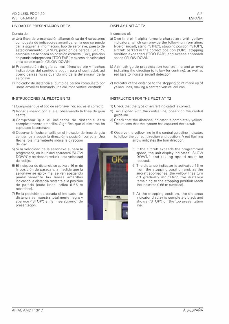
UNIDAD DE PRESENTACIÓN DE T2
Consta de:a) Una línea de presentación alfanumérica de 4 caracteres
compuesta de indicadores amarillos, en la que se puededar la siguiente información: tipo de aeronave, puesto deestacionamiento ("STND"), posición de parada ("STOP"),aeronave estacionada en posición correcta ("OK"), posiciónde parada sobrepasada ("TOO FAR") y exceso de velocidaden la aproximación ("SLOW DOWN").
b) Presentación de guía azimut (línea de eje y flechasindicadoras del sentido a seguir para el centrado), asícomo barras rojas cuando indica la detención de laaeronave.
c) Indicador de distancia al punto de parada compuesto porlíneas amarillas formando una columna vertical centrada.
INSTRUCCIONES AL PILOTO EN T2
1) Comprobar que el tipo de aeronave indicado es el correcto.2) Rodar alineado con el eje, observando la línea de guía
central.3) Comprobar que el indicador de distancia está
completamente amarillo. Significa que el sistema hacapturado la aeronave.
4) Observar la flecha amarilla en el indicador de línea de guíacentral, para seguir la dirección y posición correcta. Unaflecha roja intermitente indica la direccióndel giro.
5) Si la velocidad de la aeronave supera laprogramada, en la unidad aparecerá "SLOWDOWN" y se deberá reducir esta velocidadde rodaje.
6) El indicador de distancia se activa a 16 m dela posición de parada y, a medida que laaeronave se aproxima, se van apagandopaulatinamente las l íneas amaril lasindicando la distancia restante a la posiciónde parada (cada línea indica 0.66 mrecorridos).
7) En la posición de parada el indicador dedistancia se muestra totalmente negro yaparece ("STOP") en la línea superior depresentación.
DISPLAY UNIT AT T2
It consists of:a) One line of 4 alphanumeric characters with yellow
indicators, which can provide the following information:type of aircraft, stand ("STND"), stopping position ("STOP"),aircraft parked in the correct position ("OK"), stoppingposition exceeded ("TOO FAR") and excess approachspeed ("SLOW DOWN").
b) Azimuth guide presentation (centre line and arrowsindicating the direction to follow for centring), as well asred bars to indicate aircraft detection.
c) Indicator of the distance to the stopping point made up ofyellow lines, making a centred vertical column.
INSTRUCTION FOR THE PILOT AT T2
1) Check that the type of aircraft indicated is correct.2) Taxi aligned with the centre line, observing the central
guideline.3) Check that the distance indicator is completely yellow.
This means that the system has captured the aircraft.
4) Observe the yellow line in the central guideline indicator,to follow the correct direction and position. A red flashing
arrow indicates the turn direction.
5) If the aircraft exceeds the programmedspeed, the unit display indicates “SLOWDOWN” and taxiing speed must bereduced.
6) The distance indicator is activated 16 mfrom the stopping position and, as theaircraft approaches, the yellow lines turnoff gradually indicating the distanceremaining to the stopping position (eachline indicates 0.66 m travelled).
7) At the stopping position, the distanceindicator display is completely black andshows ("STOP") on the top presentationline.