CNC multi-spindle automatic turning machines GMC / GMC ISM series GMC GMC ISM

Welcome message from author
This document is posted to help you gain knowledge. Please leave a comment to let me know what you think about it! Share it to your friends and learn new things together.
Transcript
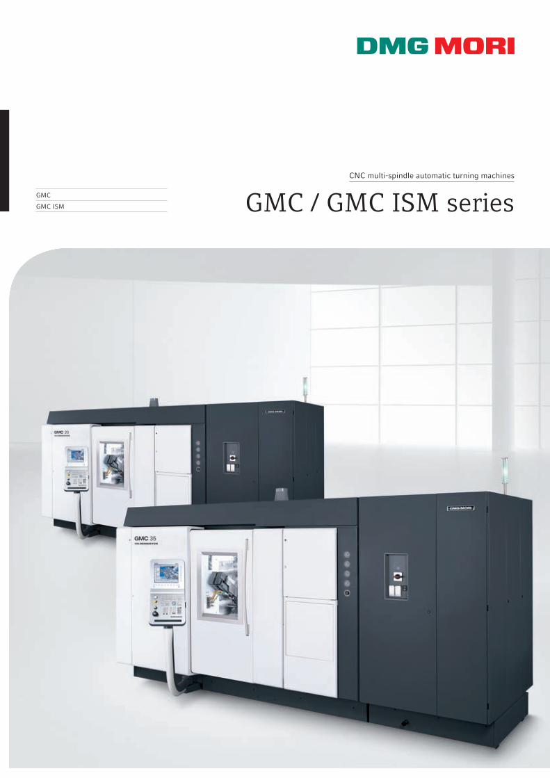
CNC multi-spindle automatic turning machines
GMC / GMC ISM seriesGMC
GMC ISM
02
GMC / GMC ISM series
GMC – shortest production timesper piece with up to 56 NC axes.
Applications and Parts
Machine and technology
Control technology
Technical data
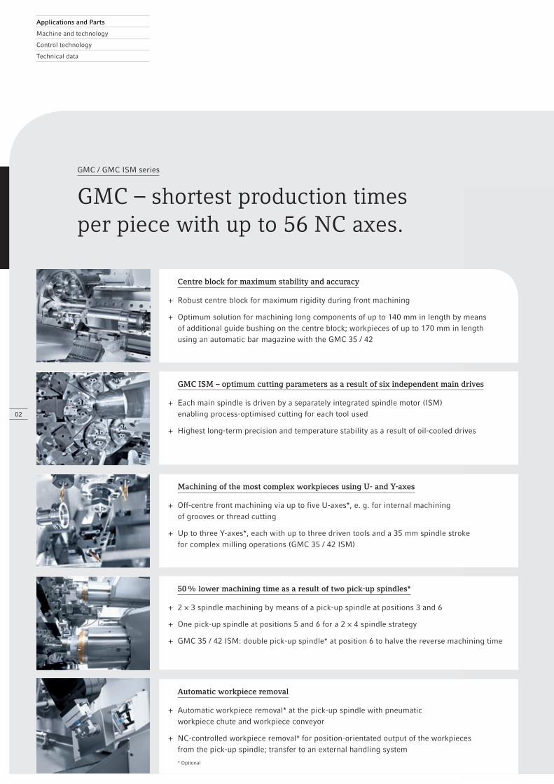
Centre block for maximum stability and accuracy
+ Robust centre block for maximum rigidity during front machining
+ Optimum solution for machining long components of up to 140 mm in length by means of additional guide bushing on the centre block; workpieces of up to 170 mm in length using an automatic bar magazine with the GMC 35 / 42
GMC ISM – optimum cutting parameters as a result of six independent main drives
+ Each main spindle is driven by a separately integrated spindle motor (ISM) enabling process-optimised cutting for each tool used
+ Highest long-term precision and temperature stability as a result of oil-cooled drives
Machining of the most complex workpieces using U- and Y-axes
+ Off-centre front machining via up to five U-axes*, e. g. for internal machining of grooves or thread cutting
+ Up to three Y-axes*, each with up to three driven tools and a 35 mm spindle stroke for complex milling operations (GMC 35 / 42 ISM)
50 % lower machining time as a result of two pick-up spindles*
+ 2 × 3 spindle machining by means of a pick-up spindle at positions 3 and 6
+ One pick-up spindle at positions 5 and 6 for a 2 × 4 spindle strategy
+ GMC 35 / 42 ISM: double pick-up spindle* at position 6 to halve the reverse machining time
Automatic workpiece removal
+ Automatic workpiece removal* at the pick-up spindle with pneumatic workpiece chute and workpiece conveyor
+ NC-controlled workpiece removal* for position-orientated output of the workpieces from the pick-up spindle; transfer to an external handling system
* Optional
1
4
2
5
3
6
03
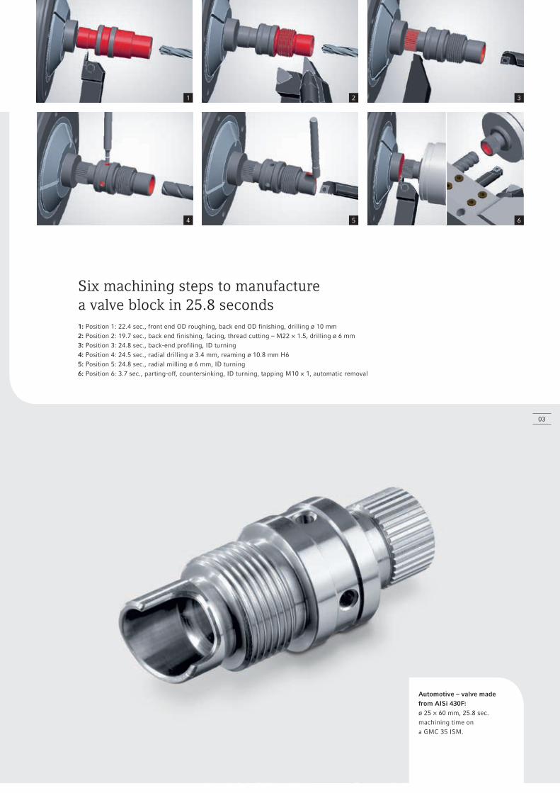
Automotive – valve madefrom AISi 430F: ø 25 × 60 mm, 25.8 sec. machining time on a GMC 35 ISM.
Six machining steps to manufacture a valve block in 25.8 seconds1: Position 1: 22.4 sec., front end OD roughing, back end OD finishing, drilling ø 10 mm2: Position 2: 19.7 sec., back end finishing, facing, thread cutting – M22 × 1.5, drilling ø 6 mm3: Position 3: 24.8 sec., back-end profiling, ID turning4: Position 4: 24.5 sec., radial drilling ø 3.4 mm, reaming ø 10.8 mm H65: Position 5: 24.8 sec., radial milling ø 6 mm, ID turning6: Position 6: 3.7 sec., parting-off, countersinking, ID turning, tapping M10 × 1, automatic removal
04
GMC / GMC ISM series
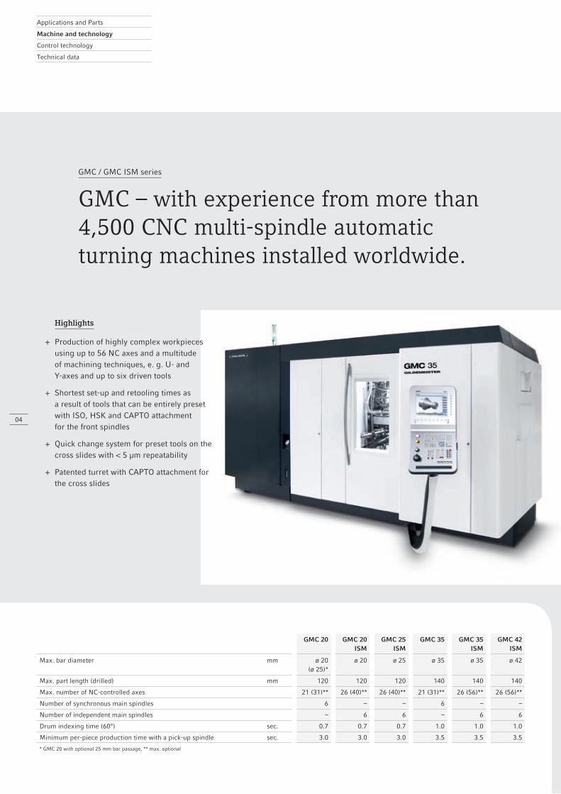
GMC – with experience from more than 4,500 CNC multi-spindle automaticturning machines installed worldwide.
GMC 20 GMC 20 ISM
GMC 25 ISM
GMC 35 GMC 35 ISM
GMC 42 ISM
Max. bar diameter mm ø 20(ø 25)*
ø 20 ø 25 ø 35 ø 35 ø 42
Max. part length (drilled) mm 120 120 120 140 140 140
Max. number of NC-controlled axes 21 (31)** 26 (40)** 26 (40)** 21 (31)** 26 (56)** 26 (56)**
Number of synchronous main spindles 6 – – 6 – –
Number of independent main spindles – 6 6 – 6 6
Drum indexing time (60°) sec. 0.7 0.7 0.7 1.0 1.0 1.0
Minimum per-piece production time with a pick-up spindle sec. 3.0 3.0 3.0 3.5 3.5 3.5
* GMC 20 with optional 25 mm bar passage, ** max. optional
Applications and Parts
Machine and technology
Control technology
Technical data
Highlights
+ Production of highly complex workpieces using up to 56 NC axes and a multitude of machining techniques, e. g. U- and Y-axes and up to six driven tools
+ Shortest set-up and retooling times as a result of tools that can be entirely preset with ISO, HSK and CAPTO attachment for the front spindles
+ Quick change system for preset tools on the cross slides with < 5 μm repeatability
+ Patented turret with CAPTO attachment for the cross slides
1 2
3
a
b
c
d
X6
X6
05
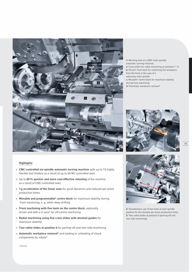
Highlights
+ CNC-controlled six-spindle automatic turning machine with up to 13 highly flexible tool holders as a result of up to 56 NC-controlled axes
+ Up to 65 % quicker and more cost-effective retooling of the machine as a result of CNC-controlled axes
+ 1 g acceleration of the linear axes for great dynamics and reduced per-piece production times
+ Movable and programmable* centre block for maximum stability during front machining, e. g. when deep drilling
+ Front machining with five tools on the centre block, optionally driven and with a U-axis* for off-centre machining
+ Radial machining using five cross slides with dovetail guides for maximum stability
+ Two radial slides at position 6 for parting-off and rear-side machining
+ Automatic workpiece removal* and loading or unloading of chuck components by robots*
* Optional
1: Working area of a GMC multi-spindle automatic turning machine:a: Cross slides for radial machining at positions 1 – 5 b: Driven* front tools for machining the workpiece from the front in the case of a stationary main spindlec: Movable* centre block for maximum stability during front machiningd: Pneumatic workpiece removal*
2: Simultaneous use of two tools at each spindle position for the shortest per-piece production times3: Two radial slides at position 6 (parting-off and rear-side machining)
a
b
c
d
e
06
Applications and Parts
Machine and technology
Control technology
Technical data
GMC / GMC ISM series
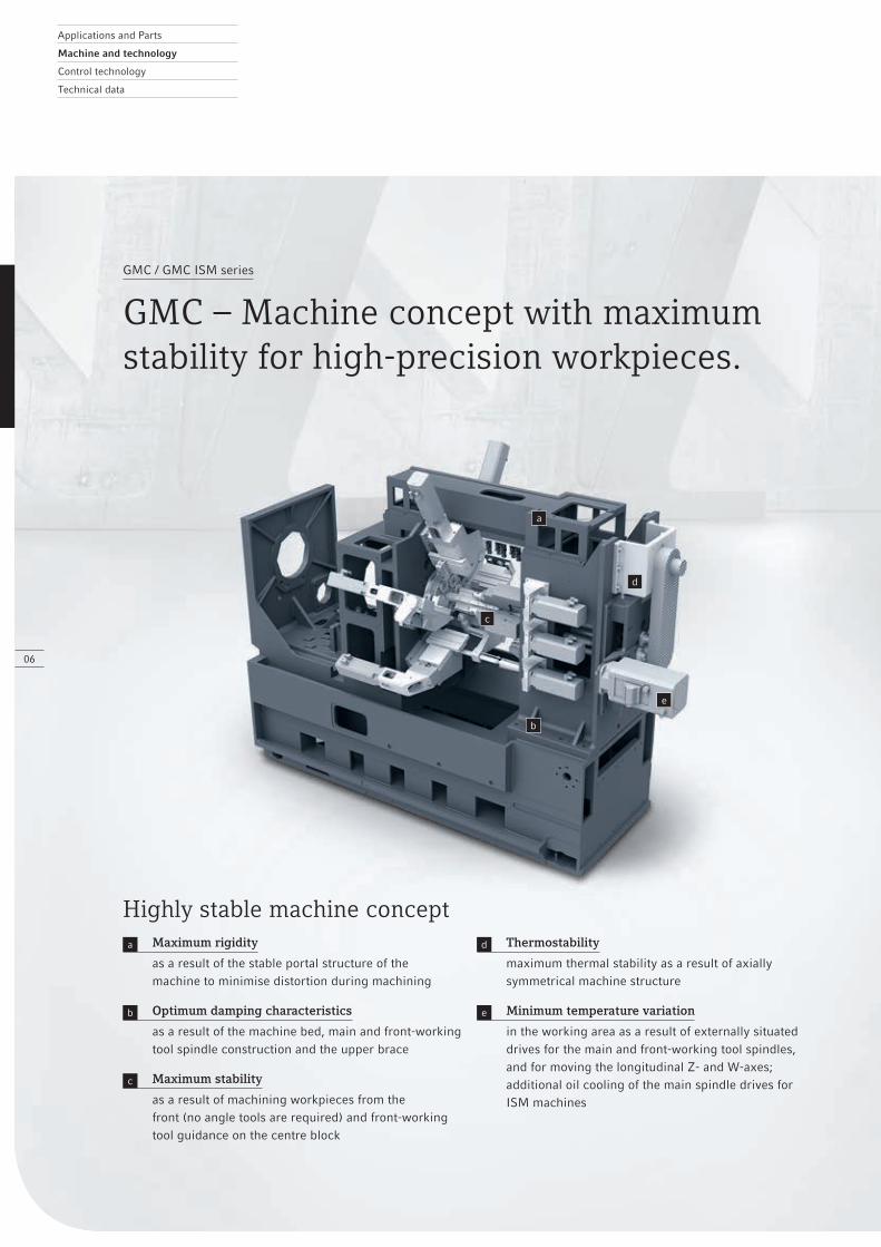
GMC – Machine concept with maximumstability for high-precision workpieces.
Highly stable machine concepta Maximum rigidity
as a result of the stable portal structure of the machine to minimise distortion during machining
b Optimum damping characteristics
as a result of the machine bed, main and front-working tool spindle construction and the upper brace
c Maximum stability
as a result of machining workpieces from the front (no angle tools are required) and front-working tool guidance on the centre block
d Thermostability
maximum thermal stability as a result of axially symmetrical machine structure
e Minimum temperature variation
in the working area as a result of externally situated drives for the main and front-working tool spindles, and for moving the longitudinal Z- and W-axes; additional oil cooling of the main spindle drives for ISM machines
1 2
3
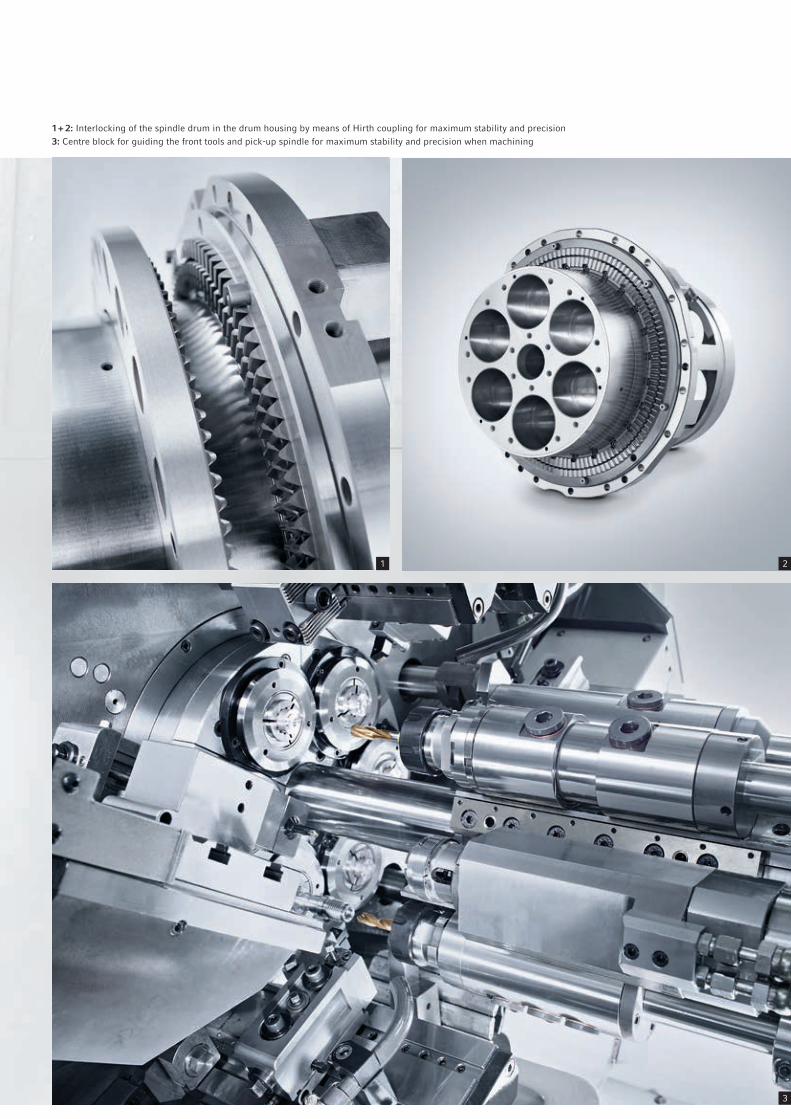
1 + 2: Interlocking of the spindle drum in the drum housing by means of Hirth coupling for maximum stability and precision3: Centre block for guiding the front tools and pick-up spindle for maximum stability and precision when machining
Applications and Parts
Machine and technology
Control technology
Technical data
U5*
X2
W5
W4U
4*
X4
Z4
X3
Z3
W3
Z2
W7* = Centre
block
5.5 sec.
1
15.7 sec.
2
12.7 sec.
3
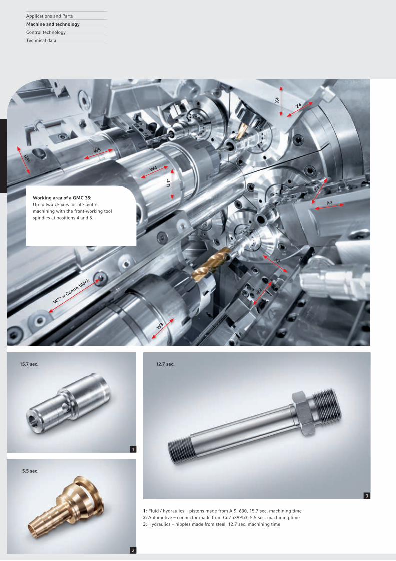
1: Fluid / hydraulics – pistons made from AlSi 630, 15.7 sec. machining time2: Automotive – connector made from CuZn39Pb3, 5.5 sec. machining time3: Hydraulics – nipples made from steel, 12.7 sec. machining time
Working area of a GMC 35: Up to two U-axes for off-centre machining with the front-working tool spindles at positions 4 and 5.
09
GMC / GMC ISM series
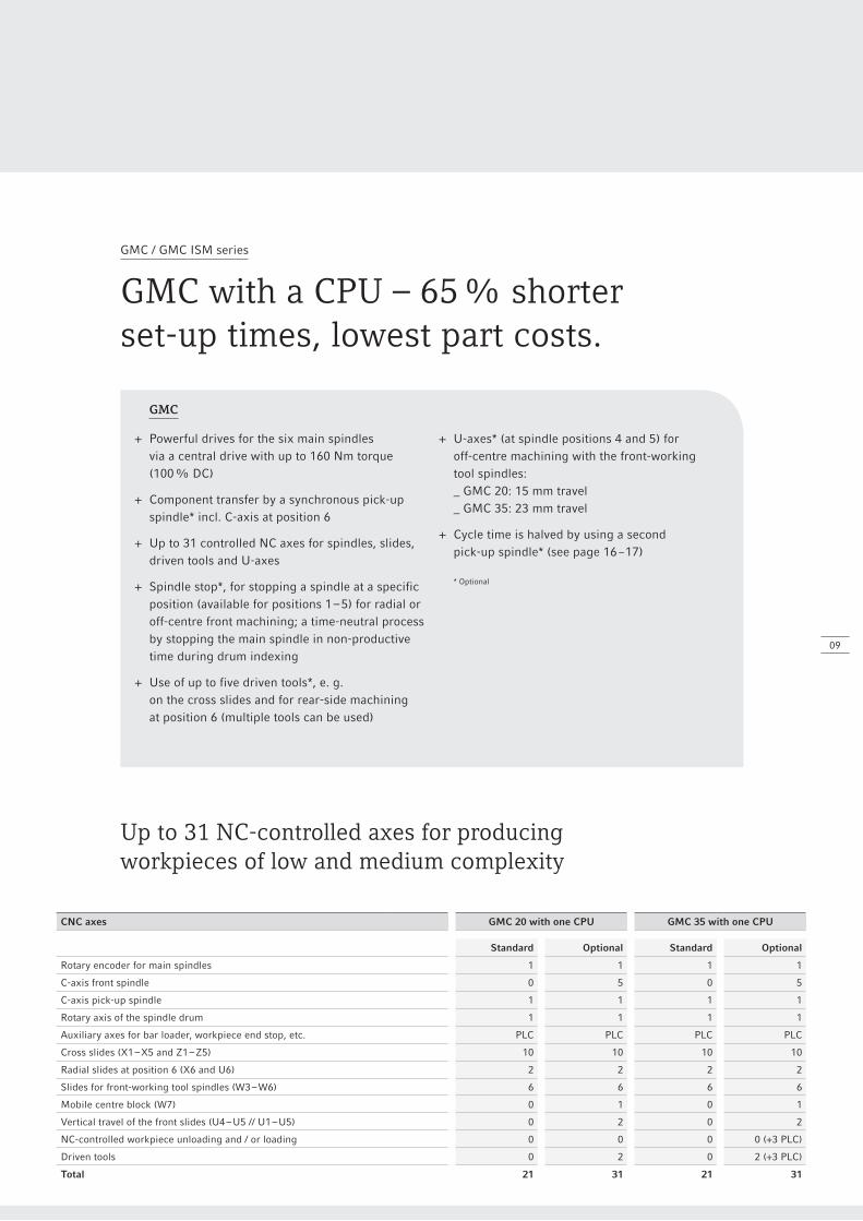
GMC with a CPU – 65 % shorterset-up times, lowest part costs.
GMC
+ Powerful drives for the six main spindles via a central drive with up to 160 Nm torque (100 % DC)
+ Component transfer by a synchronous pick-up spindle* incl. C-axis at position 6
+ Up to 31 controlled NC axes for spindles, slides, driven tools and U-axes
+ Spindle stop*, for stopping a spindle at a specific position (available for positions 1 – 5) for radial or off-centre front machining; a time-neutral process by stopping the main spindle in non-productive time during drum indexing
+ Use of up to five driven tools*, e. g. on the cross slides and for rear-side machining at position 6 (multiple tools can be used)
+ U-axes* (at spindle positions 4 and 5) for off-centre machining with the front-working tool spindles: _ GMC 20: 15 mm travel _ GMC 35: 23 mm travel
+ Cycle time is halved by using a second pick-up spindle* (see page 16 – 17) * Optional
Up to 31 NC-controlled axes for producing workpieces of low and medium complexity
CNC axes GMC 20 with one CPU GMC 35 with one CPU
Standard Optional Standard Optional
Rotary encoder for main spindles 1 1 1 1
C-axis front spindle 0 5 0 5
C-axis pick-up spindle 1 1 1 1
Rotary axis of the spindle drum 1 1 1 1
Auxiliary axes for bar loader, workpiece end stop, etc. PLC PLC PLC PLC
Cross slides (X1 – X5 and Z1 – Z5) 10 10 10 10
Radial slides at position 6 (X6 and U6) 2 2 2 2
Slides for front-working tool spindles (W3 – W6) 6 6 6 6
Mobile centre block (W7) 0 1 0 1
Vertical travel of the front slides (U4 – U5 // U1 – U5) 0 2 0 2
NC-controlled workpiece unloading and / or loading 0 0 0 0 (+3 PLC)
Driven tools 0 2 0 2 (+3 PLC)
Total 21 31 21 31
Applications and Parts
Machine and technology
Control technology
Technical data
c
da
a
b
e
10
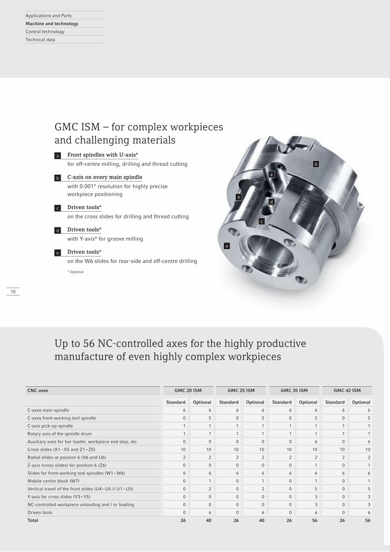
Up to 56 NC-controlled axes for the highly productive manufacture of even highly complex workpieces
CNC axes GMC 20 ISM GMC 25 ISM GMC 35 ISM GMC 42 ISM
Standard Optional Standard Optional Standard Optional Standard Optional
C-axes main spindle 6 6 6 6 6 6 6 6
C-axes front-working tool spindle 0 5 0 5 0 5 0 5
C-axis pick-up spindle 1 1 1 1 1 1 1 1
Rotary axis of the spindle drum 1 1 1 1 1 1 1 1
Auxiliary axes for bar loader, workpiece end stop, etc. 0 0 0 0 0 6 0 6
Cross slides (X1 – X5 and Z1 – Z5) 10 10 10 10 10 10 10 10
Radial slides at position 6 (X6 and U6) 2 2 2 2 2 2 2 2
Z-axis (cross slides) for position 6 (Z6) 0 0 0 0 0 1 0 1
Slides for front-working tool spindles (W1 – W6) 6 6 6 6 6 6 6 6
Mobile centre block (W7) 0 1 0 1 0 1 0 1
Vertical travel of the front slides (U4 – U5 // U1 – U5) 0 2 0 2 0 5 0 5
Y-axis for cross slides (Y3 – Y5) 0 0 0 0 0 3 0 3
NC-controlled workpiece unloading and / or loading 0 0 0 0 0 3 0 3
Driven tools 0 6 0 6 0 6 0 6
Total 26 40 26 40 26 56 26 56
GMC ISM – for complex workpieces and challenging materialsa Front spindles with U-axis*
for off-centre milling, drilling and thread cutting
b C-axis on every main spindle
with 0.001° resolution for highly precise workpiece positioning
c Driven tools*
on the cross slides for drilling and thread cutting
d Driven tools*
with Y-axis* for groove milling
e Driven tools*
on the W6 slides for rear-side and off-centre drilling
* Optional
11
GMC / GMC ISM series
GMC ISM with two CPUs – optimum cutting values for every process.
GMC ISM + Machining highly complex workpieces by means of up to 56 controlled NC axes
for spindles, slides, driven tools*, U- and Y-axes*
+ Separate drive for each of the six main spindles via an integrated spindle motor with C-axis (0.001°) for optimum cutting parameters for every process
+ Synchronous motor drives for maximum metal removal with up to 15 kW and 35 Nm torque (100% DC)
+ Maximum precision as a result of six spindle bearings, four of which are pre-tensioned
+ Maximum temperature stability as a result of the main drives being oil-cooled GMC ISM with two CPUs – optimum cutting parameters for every process.
+ Synchronous component transfer to a driven pick-up spindle* incl. C-axis at position 6
+ Use of up to six driven workpiece units*, e. g. on the cross slides and for rear-sided machining at position 6 (multiple tools can be used)
+ U-axes* for off-centre machining with the front-working tool spindles: _ GMC 20 / 25: 15 mm travel for spindle positions 4 and 5 _ GMC 35 / 42: 23 mm travel for spindle positions 1 to 5
+ Production time per piece is halved by using a second pick-up spindle* (see pages 16 – 19)
* Optional
Applications and Parts
Machine and technology
Control technology
Technical data
3
1
2
45
12
GMC / GMC ISM series
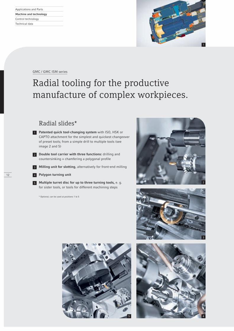
Radial tooling for the productivemanufacture of complex workpieces.
Radial slides*1 Patented quick tool-changing system with ISO, HSK or
CAPTO attachment for the simplest and quickest changeover of preset tools; from a simple drill to multiple tools (see image 2 and 5)
2 Double tool carrier with three functions: drilling and countersinking + chamfering a polygonal profile
3 Milling unit for slotting, alternatively for front-end milling
4 Polygon turning unit
5 Multiple turret disc for up to three turning tools, e. g. for sister tools, or tools for different machining steps
* Optional, can be used at positions 1 to 5
Z
U
1
3
4
2
GMC / GMC ISM series
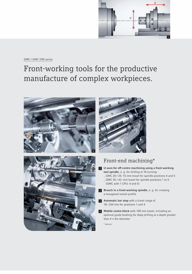
Front-working tools for the productivemanufacture of complex workpieces.
Front-end machining*1 U-axes for off-centre machining using a front-working
tool spindle, e. g. for drilling or ID turning: _ GMC 20 / 25: 15 mm travel for spindle positions 4 and 5 _ GMC 35 / 42: mm travel for spindle positions 1 to 5
(GMC with 1 CPU: 4 and 5)
2 Broach in a front-working spindle, e. g. for creating a hexagonal socket profile
3 Automatic bar stop with a travel range of 18 – 254 mm for positions 1 and 4
4 Mobile centre block with 100 mm travel, including an optional guide bushing for deep drilling at a depth greater than 4 × the diameter
* Optional
XY
Z
C
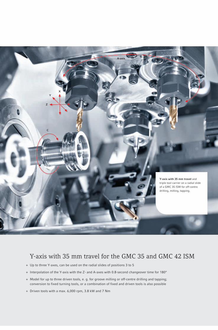
Y-axis with 35 mm travel andtriple tool carrier on a radial slide of a GMC 35 ISM for off-centre drilling, milling, tapping.
A-axis
Y-axis with 35 mm travel for the GMC 35 and GMC 42 ISM + Up to three Y-axes, can be used on the radial slides of positions 3 to 5
+ Interpolation of the Y-axis with the Z- and A-axes with 0.8-second changeover time for 180°
+ Model for up to three driven tools, e. g. for groove milling or off-centre drilling and tapping; conversion to fixed turning tools, or a combination of fixed and driven tools is also possible
+ Driven tools with a max. 6,000 rpm, 3.8 kW and 7 Nm
X
Y
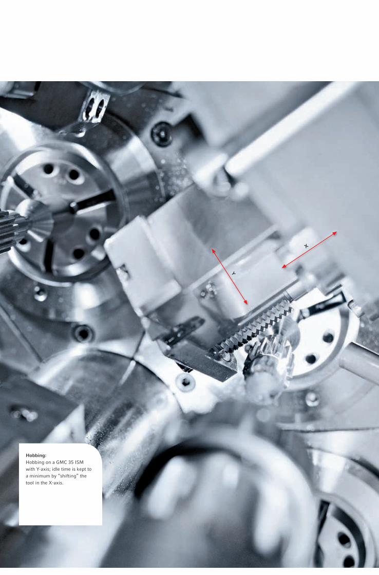
Hobbing: Hobbing on a GMC 35 ISM with Y-axis; idle time is kept to a minimum by “shifting” the tool in the X-axis.
Applications and Parts
Machine and technology
Control technology
Technical data
2
1
W5
W6
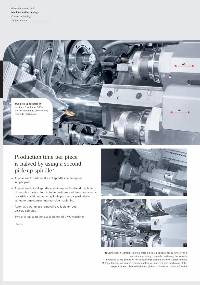
1: Combination toolholder on the cross slides of position 5 for parting-off and rear-side machining; rear-side machining device with
hydraulic stroke extension for collision-free pick-up of all workpiece lengths2: Simultaneous parting-off, component transfer and rear-side machining of the
respective workpiece with the two pick-up spindles at positions 5 and 6
Production time per piece is halved by using a second pick-up spindle*
+ At position 3: traditional 2 × 3 spindle machining for simple parts
+ At position 5: 2 × 4 spindle machining for front-end machining of complex parts at four spindle positions and the simultaneous rear-side machining at two spindle positions – particularly suited to time-consuming rear-side machining
+ Automatic workpiece removal* available for both pick-up spindles
+ Two pick-up spindles* available for all GMC machines
* Optional
Two pick-up spindles at positions 5 and 6 for 50 % shorter machining times duringrear-side machining.
17
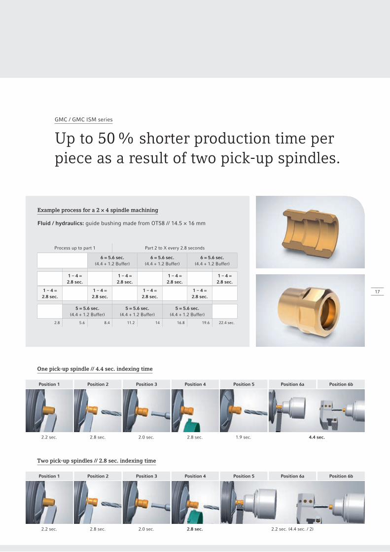
Example process for a 2 × 4 spindle machining
Fluid / hydraulics: guide bushing made from OT58 // 14.5 × 16 mm
Process up to part 1 Part 2 to X every 2.8 seconds
6 = 5.6 sec.(4.4 + 1.2 Buffer)
6 = 5.6 sec.(4.4 + 1.2 Buffer)
6 = 5.6 sec.(4.4 + 1.2 Buffer)
1 – 4 =2.8 sec.
1 – 4 =2.8 sec.
1 – 4 =2.8 sec.
1 – 4 =2.8 sec.
1 – 4 =2.8 sec.
1 – 4 =2.8 sec.
1 – 4 =2.8 sec.
1 – 4 =2.8 sec.
5 = 5.6 sec.(4.4 + 1.2 Buffer)
5 = 5.6 sec.(4.4 + 1.2 Buffer)
5 = 5.6 sec.(4.4 + 1.2 Buffer)
2.8 5.6 8.4 11.2 14 16.8 19.6 22.4 sec.
GMC / GMC ISM series
Up to 50 % shorter production time perpiece as a result of two pick-up spindles.
Two pick-up spindles // 2.8 sec. indexing time
One pick-up spindle // 4.4 sec. indexing time
Position 1
2.2 sec.
2.2 sec.
Position 2
2.8 sec.
2.8 sec.
Position 3
2.0 sec.
2.0 sec.
Position 4
2.8 sec.
2.8 sec.
Position 5
1.9 sec.
Position 6a
4.4 sec.
Position 6b
Position 1 Position 2 Position 3 Position 4 Position 5 Position 6a Position 6b
2.2 sec. (4.4 sec. / 2)
Applications and Parts
Machine and technology
Control technology
Technical data
1 2
A
B
3
3
18
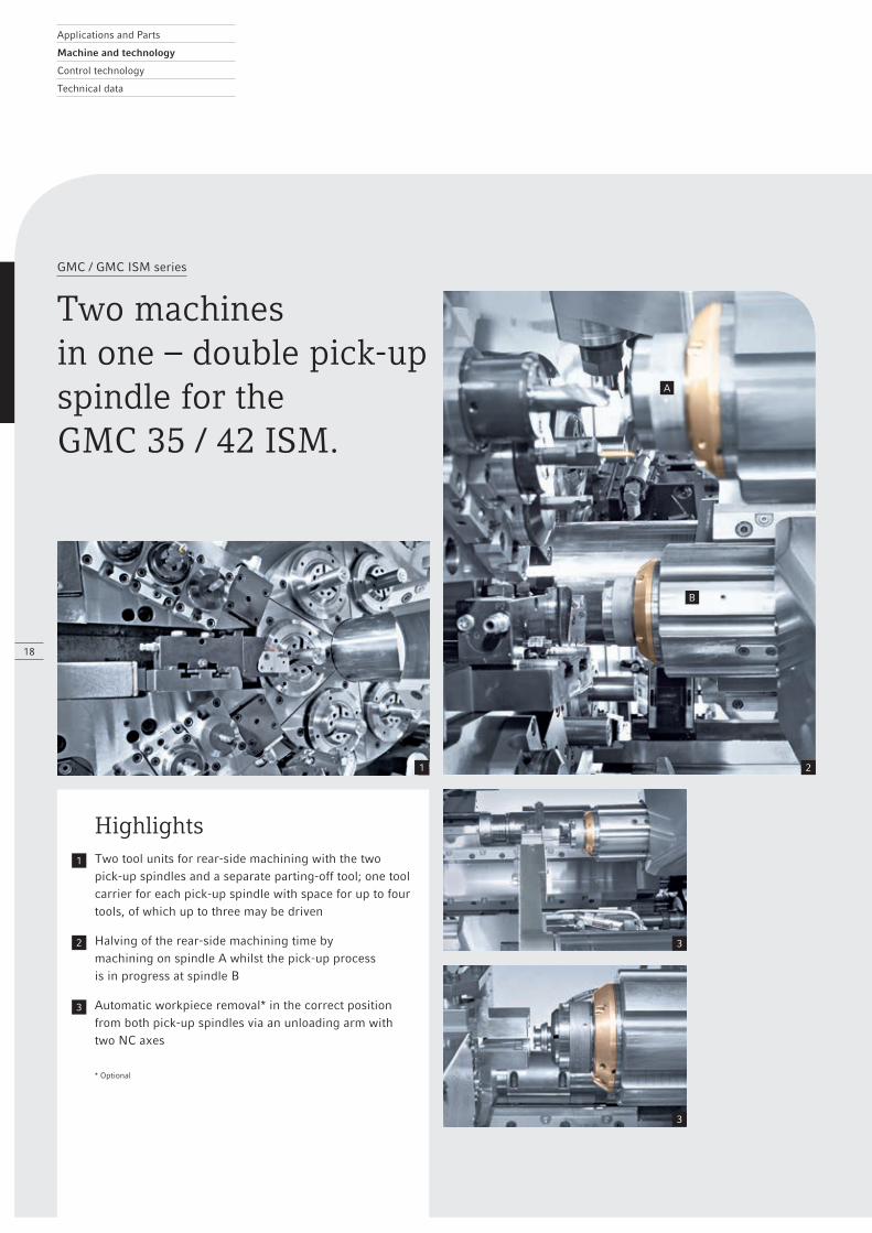
GMC / GMC ISM series
Two machines in one – double pick-upspindle for the GMC 35 / 42 ISM.
Highlights1 Two tool units for rear-side machining with the two
pick-up spindles and a separate parting-off tool; one tool carrier for each pick-up spindle with space for up to four tools, of which up to three may be driven
2 Halving of the rear-side machining time by machining on spindle A whilst the pick-up process is in progress at spindle B
3 Automatic workpiece removal* in the correct position from both pick-up spindles via an unloading arm with two NC axes
* Optional
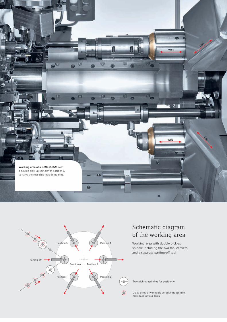
W61U61
W62
U62
Parting-off
Position 1 Position 2
Position 3
Position 4Position 5
Position 6
Two pick-up spindles for position 6
Up to three driven tools per pick-up spindle,maximum of four tools
Schematic diagram of the working areaWorking area with double pick-up spindle including the two tool carriers and a separate parting-off tool
Working area of a GMC 35 ISM with a double pick-up spindle* at position 6 to halve the rear-side machining time.
Applications and Parts
Machine and technology
ê Spindle options
Control technology
Technical data
20
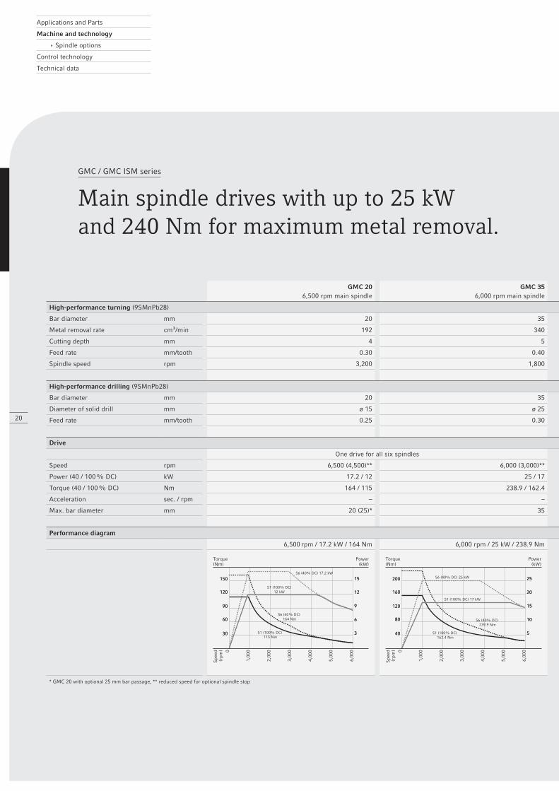
GMC / GMC ISM series
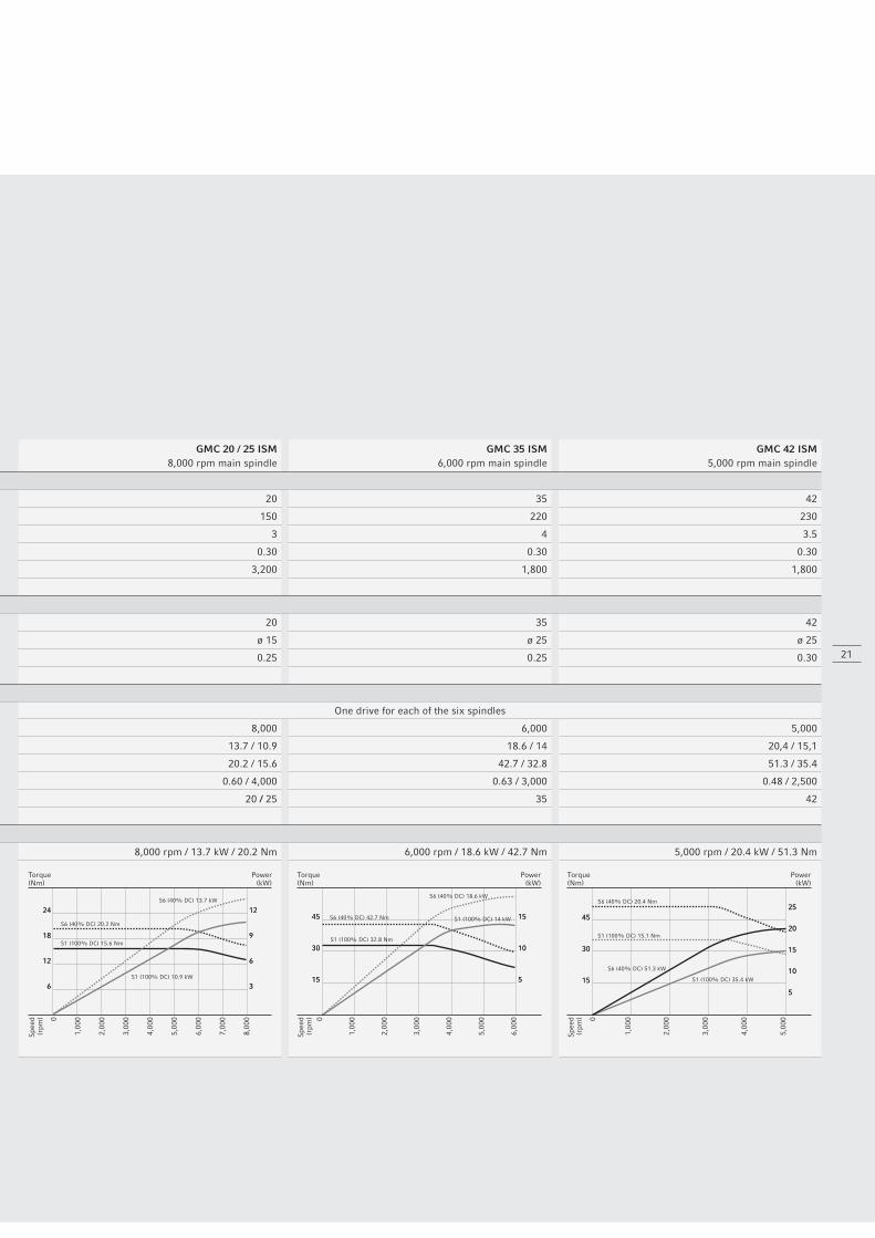
Main spindle drives with up to 25 kW and 240 Nm for maximum metal removal.
GMC 206,500 rpm main spindle
GMC 356,000 rpm main spindle
GMC 20 / 25 ISM8,000 rpm main spindle
GMC 35 ISM6,000 rpm main spindle
GMC 42 ISM5,000 rpm main spindle
High-performance turning (9SMnPb28)
Bar diameter mm 20 35 20 35 42
Metal removal rate cm³/min 192 340 150 220 230
Cutting depth mm 4 5 3 4 3.5
Feed rate mm/tooth 0.30 0.40 0.30 0.30 0.30
Spindle speed rpm 3,200 1,800 3,200 1,800 1,800
High-performance drilling (9SMnPb28)
Bar diameter mm 20 35 20 35 42
Diameter of solid drill mm ø 15 ø 25 ø 15 ø 25 ø 25
Feed rate mm/tooth 0.25 0.30 0.25 0.25 0.30
Drive
One drive for all six spindles One drive for each of the six spindles
Speed rpm 6,500 (4,500)** 6,000 (3,000)** 8,000 6,000 5,000
Power (40 / 100 % DC) kW 17.2 / 12 25 / 17 13.7 / 10.9 18.6 / 14 20,4 / 15,1
Torque (40 / 100 % DC) Nm 164 / 115 238.9 / 162.4 20.2 / 15.6 42.7 / 32.8 51.3 / 35.4
Acceleration sec. / rpm – – 0.60 / 4,000 0.63 / 3,000 0.48 / 2,500
Max. bar diameter mm 20 (25)* 35 20 / 25 35 42
Performance diagram
6,500 rpm / 17.2 kW / 164 Nm 6,000 rpm / 25 kW / 238.9 Nm 8,000 rpm / 13.7 kW / 20.2 Nm 6,000 rpm / 18.6 kW / 42.7 Nm 5,000 rpm / 20.4 kW / 51.3 Nm
* GMC 20 with optional 25 mm bar passage, ** reduced speed for optional spindle stop
S1 (100% DC)12 kW
S1 (100% DC) 115 Nm
S6 (40% DC) 17.2 kW
S6 (40% DC) 164 Nm
0
1,00
0
2,00
0
3,00
0
4,00
0
5,00
0
6,00
0
15
12
9
6
3
15
12
9
6
3
150
120
90
60
30
150
120
90
60
30
Spe
ed(r
pm)
Power(kW)
Torque(Nm)
S1 (100% DC) 17 kW
S1 (100% DC) 162.4 Nm
S6 (40% DC) 25 kW
S6 (40% DC) 239.9 Nm
0
1,00
0
2,00
0
3,00
0
4,00
0
5,00
0
6,00
0
25
20
15
10
5
25
20
15
10
5
200
160
120
80
40
200
160
120
80
40
Spe
ed(r
pm)
Power(kW)
Torque(Nm)
21
GMC 206,500 rpm main spindle
GMC 356,000 rpm main spindle
GMC 20 / 25 ISM8,000 rpm main spindle
GMC 35 ISM6,000 rpm main spindle
GMC 42 ISM5,000 rpm main spindle
High-performance turning (9SMnPb28)
Bar diameter mm 20 35 20 35 42
Metal removal rate cm³/min 192 340 150 220 230
Cutting depth mm 4 5 3 4 3.5
Feed rate mm/tooth 0.30 0.40 0.30 0.30 0.30
Spindle speed rpm 3,200 1,800 3,200 1,800 1,800
High-performance drilling (9SMnPb28)
Bar diameter mm 20 35 20 35 42
Diameter of solid drill mm ø 15 ø 25 ø 15 ø 25 ø 25
Feed rate mm/tooth 0.25 0.30 0.25 0.25 0.30
Drive
One drive for all six spindles One drive for each of the six spindles
Speed rpm 6,500 (4,500)** 6,000 (3,000)** 8,000 6,000 5,000
Power (40 / 100 % DC) kW 17.2 / 12 25 / 17 13.7 / 10.9 18.6 / 14 20,4 / 15,1
Torque (40 / 100 % DC) Nm 164 / 115 238.9 / 162.4 20.2 / 15.6 42.7 / 32.8 51.3 / 35.4
Acceleration sec. / rpm – – 0.60 / 4,000 0.63 / 3,000 0.48 / 2,500
Max. bar diameter mm 20 (25)* 35 20 / 25 35 42
Performance diagram
6,500 rpm / 17.2 kW / 164 Nm 6,000 rpm / 25 kW / 238.9 Nm 8,000 rpm / 13.7 kW / 20.2 Nm 6,000 rpm / 18.6 kW / 42.7 Nm 5,000 rpm / 20.4 kW / 51.3 Nm
* GMC 20 with optional 25 mm bar passage, ** reduced speed for optional spindle stop
S1 (100% DC) 10.9 kW
S1 (100% DC) 15.6 Nm
S6 (40% DC) 13.7 kW
S6 (40% DC) 20.2 Nm
0
1,00
0
2,00
0
3,00
0
4,00
0
5,00
0
6,00
0
7,00
0
8,00
0
24
18
12
6
24
18
12
6
Spe
ed(r
pm)
Power(kW)
Torque(Nm)
12
9
6
3
12
9
6
3
S1 (100% DC) 14 kW
S1 (100% DC) 32.8 Nm
S6 (40% DC) 18.6 kW
S6 (40% DC) 42.7 Nm
0
1,00
0
2,00
0
3,00
0
4,00
0
5,00
0
6,00
0
45
30
15
45
30
15
15
10
5
15
10
5
Spe
ed(r
pm)
Power(kW)
Torque(Nm)
S1 (100% DC) 35.4 kW
S1 (100% DC) 15.1 Nm
S6 (40% DC) 51.3 kW
S6 (40% DC) 20.4 Nm
0
1,00
0
2,00
0
3,00
0
4,00
0
5,00
0
25
20
15
10
5
25
20
15
10
5
Spe
ed(r
pm)
Power(kW)
Torque(Nm)
45
30
15
45
30
15
Applications and Parts
Machine and technology
ê Spindle options
Control technology
Technical data
22
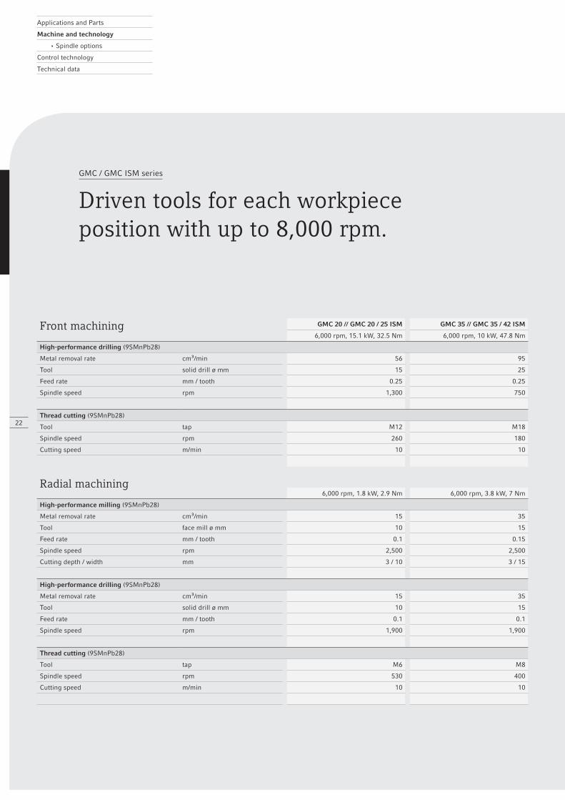
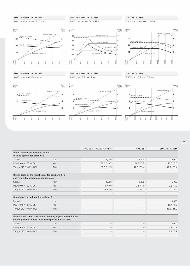
GMC / GMC ISM series
Driven tools for each workpieceposition with up to 8,000 rpm.
Front machining GMC 20 // GMC 20 / 25 ISM GMC 35 // GMC 35 / 42 ISM
6,000 rpm, 15.1 kW, 32.5 Nm 6,000 rpm, 10 kW, 47.8 Nm
High-performance drilling (9SMnPb28)
Metal removal rate cm³/min 56 95
Tool solid drill ø mm 15 25
Feed rate mm / tooth 0.25 0.25
Spindle speed rpm 1,300 750
Thread cutting (9SMnPb28)
Tool tap M12 M18
Spindle speed rpm 260 180
Cutting speed m/min 10 10
Radial machining6,000 rpm, 1.8 kW, 2.9 Nm 6,000 rpm, 3.8 kW, 7 Nm
High-performance milling (9SMnPb28)
Metal removal rate cm³/min 15 35
Tool face mill ø mm 10 15
Feed rate mm / tooth 0.1 0.15
Spindle speed rpm 2,500 2,500
Cutting depth / width mm 3 / 10 3 / 15
High-performance drilling (9SMnPb28)
Metal removal rate cm³/min 15 35
Tool solid drill ø mm 10 15
Feed rate mm / tooth 0.1 0.1
Spindle speed rpm 1,900 1,900
Thread cutting (9SMnPb28)
Tool tap M6 M8
Spindle speed rpm 530 400
Cutting speed m/min 10 10
S1 (100% DC) 10.7 kW
S1 (100% DC) 19.5 Nm
S6 (40% DC) 15.1 kW
S6 (40% DC) 32.5Nm
0
1,00
0
2,00
0
3,00
0
4,00
0
5,00
0
6,00
0
Spe
ed(r
pm)
Power(kW)
Torque(Nm)
30
20
10
30
20
10
12
8
4
12
8
4
S1 (100% DC) 0.9 kW
S1 (100% DC) 2 Nm
S6 (40% DC) 1.8 kW
S6 (40% DC) 2.9 Nm
0
1,00
0
2,00
0
3,00
0
4,00
0
5,00
0
6,00
0
Spe
ed(r
pm)
Power(kW)
Torque(Nm)
3
2
1
3
2
1
1.5
1.0
0.5
1.5
1.0
0.5
S1 (100% DC) 7 kW
S1 (100% DC) 33.4 Nm
S6 (40% DC) 10 kW
S6 (40% DC) 47.8 Nm
0
1,00
0
2,00
0
3,00
0
4,00
0
5,00
0
6,00
0
Spe
ed(r
pm)
Power(kW)
Torque(Nm)
10
8
6
4
2
10
8
6
4
2
50
40
30
20
10
50
40
30
20
10
S1 (100% DC) 1.9 kW
S1 (100% DC) 4.2 Nm
S6 (40% DC) 3.8 kW
S6 (40% DC) 7 Nm
0
1,00
0
2,00
0
3,00
0
4,00
0
5,00
0
6,00
0
Spe
ed(r
pm)
Power(kW)
Torque(Nm)
9
6
3
9
6
3
3
2
1
3
2
1
S1 (100% DC) 5.7 kW
S1 (100% DC) 16 Nm
S6 (40% DC) 10.4 kW
S6 (40% DC) 25 Nm
0
1,00
0
2,00
0
3,00
0
4,00
0
5,00
0
6,00
0
Spe
ed(r
pm)
Power(kW)
Torque(Nm)
30
20
10
30
20
10
9
6
3
9
6
3
S1 (100% DC) 1.9 kW
S1 (100% DC) 3.8 Nm
S6 (40% DC) 3.8 kW
S6 (40% DC) 5.3 Nm
0
1,00
0
2,00
0
3,00
0
4,00
0
5,00
0
6,00
0
7,00
0
8,00
0
Spe
ed(r
pm)
Power(kW)
Torque(Nm)
6
4
2
6
4
2
3
2
1
3
2
1
23
GMC 20 // GMC 20 / 25 ISM GMC 35 GMC 35 / 42 ISM
Front spindles for positions 1 – 5 // Pick-up spindle for position 6
Speed rpm 6,000 6,000 6,000
Power (40 / 100 % DC) kW 15.1 / 10.7 10.0 / 7.0 10.0 / 7.0
Torque (40 / 100 % DC) Nm 32.5 / 19.5 47.8 / 33.4 47.8 / 33.4
Driven tools on the radial slides for positions 1 – 5 and rear-sided machining at position 6
Speed rpm 6,000 6,000 6,000
Power (40 / 100 % DC) kW 1.8 / 0.9 3.8 / 1.9 3.8 / 1.9
Torque (40 / 100 % DC) Nm 2.9 / 2.0 7.0 / 4.2 7.0 / 4.2
Double pick-up spindle for position 6
Speed rpm – – 6,000
Power (40 / 100 % DC) kW – – 10.4 / 5.7
Torque (40 / 100 % DC) Nm – – 25.0 / 16.0
Driven tools // For rear-sided machining at position 6 with the double pick-up spindle (max. three pieces in each case)
Speed rpm – – 8,000
Power (40 / 100 % DC) kW – – 3.8 / 1.9
Torque (40 / 100 % DC) Nm – – 5.3 / 3.8
GMC 20 // GMC 20 / 25 ISM GMC 35 // GMC 35 / 42 ISM GMC 35 / 42 ISM
6,000 rpm / 15.1 kW / 32.5 Nm 6,000 rpm / 10 kW / 47.8 Nm 6,000 rpm / 10.4 kW / 25 Nm
GMC 20 // GMC 20 / 25 ISM GMC 35 // GMC 35 / 42 ISM GMC 35 / 42 ISM
6,000 rpm / 1.8 kW / 2.9 Nm 6,000 rpm / 3.8 kW / 7 Nm 8,000 rpm / 3.8 kW / 5.3 Nm
Applications and Parts
Machine and technology
ê Technical expertise
Control technology
Technical data
24
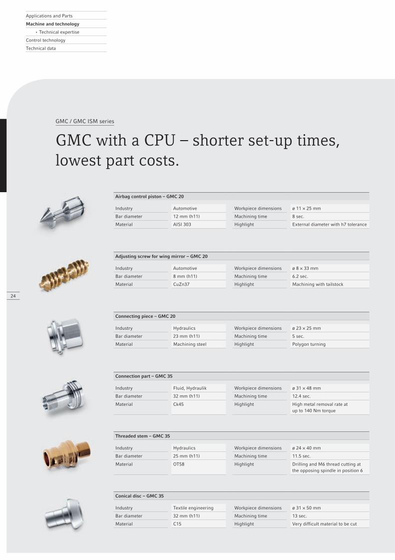
GMC / GMC ISM series
GMC with a CPU – shorter set-up times, lowest part costs.
Airbag control piston – GMC 20
Industry Automotive Workpiece dimensions ø 11 × 25 mm
Bar diameter 12 mm (h11) Machining time 8 sec.
Material AISI 303 Highlight External diameter with h7 tolerance
Adjusting screw for wing mirror – GMC 20
Industry Automotive Workpiece dimensions ø 8 × 33 mm
Bar diameter 8 mm (h11) Machining time 6.2 sec.
Material CuZn37 Highlight Machining with tailstock
Connecting piece – GMC 20
Industry Hydraulics Workpiece dimensions ø 23 × 25 mm
Bar diameter 23 mm (h11) Machining time 5 sec.
Material Machining steel Highlight Polygon turning
Connection part – GMC 35
Industry Fluid, Hydraulik Workpiece dimensions ø 31 × 48 mm
Bar diameter 32 mm (h11) Machining time 12.4 sec.
Material Ck45 Highlight High metal removal rate atup to 140 Nm torque
Threaded stem – GMC 35
Industry Hydraulics Workpiece dimensions ø 24 × 40 mm
Bar diameter 25 mm (h11) Machining time 11.5 sec.
Material OT58 Highlight Drilling and M6 thread cutting at the opposing spindle in position 6
Conical disc – GMC 35
Industry Textile engineering Workpiece dimensions ø 31 × 50 mm
Bar diameter 32 mm (h11) Machining time 13 sec.
Material C15 Highlight Very difficult material to be cut
25
GMC / GMC ISM series
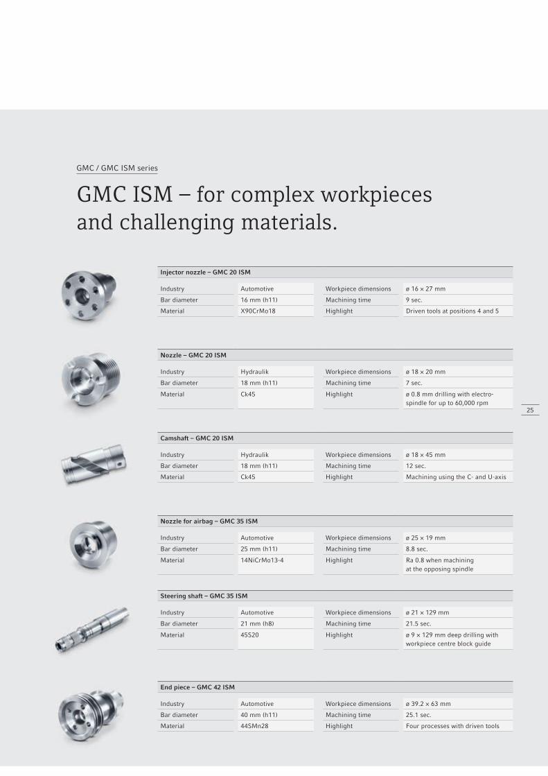
GMC ISM – for complex workpiecesand challenging materials.
Injector nozzle – GMC 20 ISM
Industry Automotive Workpiece dimensions ø 16 × 27 mm
Bar diameter 16 mm (h11) Machining time 9 sec.
Material X90CrMo18 Highlight Driven tools at positions 4 and 5
Nozzle – GMC 20 ISM
Industry Hydraulik Workpiece dimensions ø 18 × 20 mm
Bar diameter 18 mm (h11) Machining time 7 sec.
Material Ck45 Highlight ø 0.8 mm drilling with electro-spindle for up to 60,000 rpm
Camshaft – GMC 20 ISM
Industry Hydraulik Workpiece dimensions ø 18 × 45 mm
Bar diameter 18 mm (h11) Machining time 12 sec.
Material Ck45 Highlight Machining using the C- and U-axis
Nozzle for airbag – GMC 35 ISM
Industry Automotive Workpiece dimensions ø 25 × 19 mm
Bar diameter 25 mm (h11) Machining time 8.8 sec.
Material 14NiCrMo13-4 Highlight Ra 0.8 when machiningat the opposing spindle
Steering shaft – GMC 35 ISM
Industry Automotive Workpiece dimensions ø 21 × 129 mm
Bar diameter 21 mm (h8) Machining time 21.5 sec.
Material 45S20 Highlight ø 9 × 129 mm deep drilling withworkpiece centre block guide
End piece – GMC 42 ISM
Industry Automotive Workpiece dimensions ø 39.2 × 63 mm
Bar diameter 40 mm (h11) Machining time 25.1 sec.
Material 44SMn28 Highlight Four processes with driven tools
Applications and Parts
Machine and technology
Control technology
ê Automation
Technical data
2
3
4
1
26
GMC / GMC ISM series
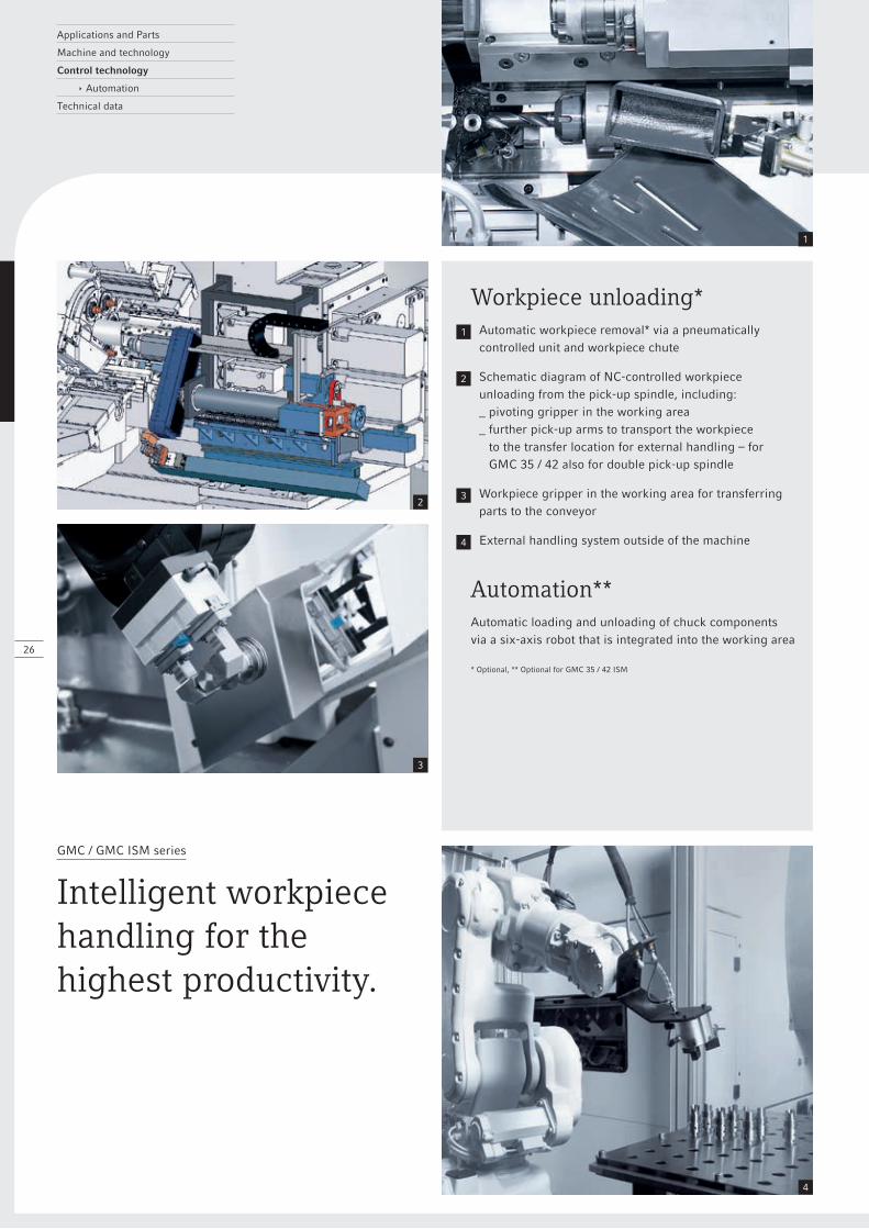
Intelligent workpiece handling for the highest productivity.
Workpiece unloading*1 Automatic workpiece removal* via a pneumatically
controlled unit and workpiece chute
2 Schematic diagram of NC-controlled workpiece unloading from the pick-up spindle, including: _ pivoting gripper in the working area _ further pick-up arms to transport the workpiece
to the transfer location for external handling – for GMC 35 / 42 also for double pick-up spindle
3 Workpiece gripper in the working area for transferring parts to the conveyor
4 External handling system outside of the machine
Automation** Automatic loading and unloading of chuck components
via a six-axis robot that is integrated into the working area * Optional, ** Optional for GMC 35 / 42 ISM
27
CIMCO Edit 6 + Simple and intuitive programming
+ 3D workpiece simulation (Backplot)
+ Flexible programming using individual macros
+ 2D design and reading of DXF files*
+ Configurable file comparison between the processed and original program
+ Available for all DMG MORI machines and control systems * Optional
CNC Calc2 + Complete 2D CAD system for Edit 6
+ Create complex geometries quickly and easily
+ Generate tool paths
+ Import DXF files
+ Simple conversion to ISO format
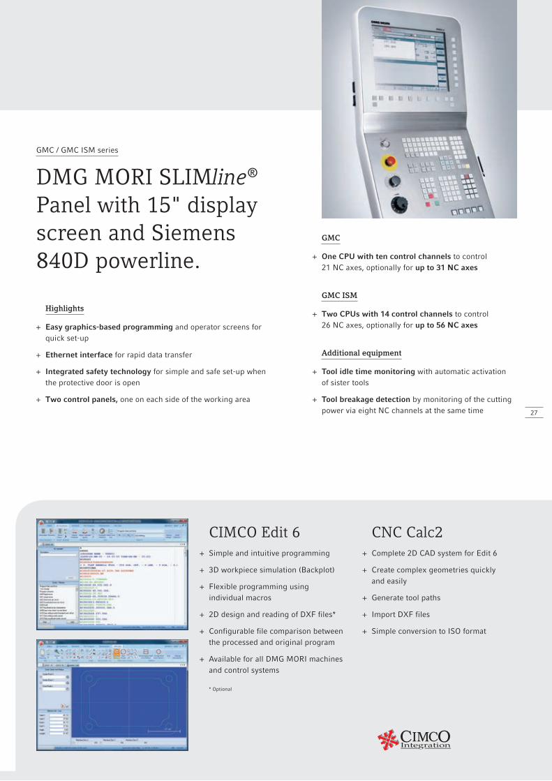
GMC / GMC ISM series
DMG MORI SLIMline® Panel with 15" displayscreen and Siemens 840D powerline.
Highlights
+ Easy graphics-based programming and operator screens for quick set-up
+ Ethernet interface for rapid data transfer
+ Integrated safety technology for simple and safe set-up when the protective door is open
+ Two control panels, one on each side of the working area
GMC
+ One CPU with ten control channels to control 21 NC axes, optionally for up to 31 NC axes
GMC ISM
+ Two CPUs with 14 control channels to control 26 NC axes, optionally for up to 56 NC axes
Additional equipment
+ Tool idle time monitoring with automatic activation of sister tools
+ Tool breakage detection by monitoring of the cutting power via eight NC channels at the same time
Applications and Parts
Machine and technology
Control technology
Technical data
ê Working area
C1
D W7
W1 – W5 // W6
AA
A
A A
A
B1
6 3
2
5 4
= Machine zero, = Slide zero
28
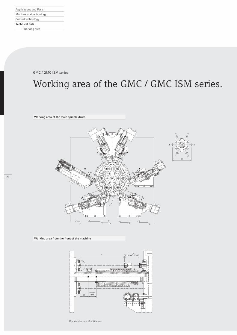
GMC / GMC ISM series
Working area of the GMC / GMC ISM series.
Working area of the main spindle drum
Working area from the front of the machine
GX
6 U
6+U
+X
E
X1–
X5
Z1–Z5
+Z
+X
F GX
6 U
6+U
+X
E
X1–
X5
Z1–Z5
+Z
+X
F
29
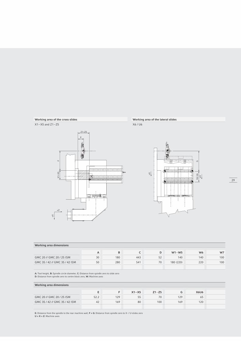
Working area of the cross slides Working area of the lateral slides
X1 – X5 and Z1 – Z5 X6 / U6
Working area dimensions
A B C D W1 – W5 W6 W7
GMC 20 // GMC 20 / 25 ISM 30 180 443 52 140 140 100
GMC 35 / 42 // GMC 35 / 42 ISM 50 280 541 70 180 (220) 220 100
A: Tool height, B: Spindle circle diameter, C: Distance from spindle zero to slide zeroD: Distance from spindle zero to centre block zero, W: Machine axes
Working area dimensions
E F X1 – X5 Z1 – Z5 G X6U6
GMC 20 // GMC 20 / 25 ISM 52.2 129 55 70 129 65
GMC 35 / 42 // GMC 35 / 42 ISM 42 169 80 100 169 120
E: Distance from the spindle to the rear machine wall, F + G: Distance from spindle zero to X- / U-slides zeroU + X + Z: Machine axes
Applications and Parts
Machine and technology
Control technology
Technical data
ê Layout plans
30
GMC / GMC ISM series
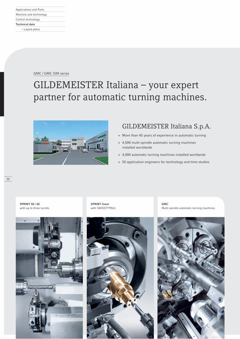
GILDEMEISTER Italiana – your expertpartner for automatic turning machines.
GILDEMEISTER Italiana S.p.A. + More than 45 years of experience in automatic turning
+ 4,500 multi-spindle automatic turning machines installed worldwide
+ 4,000 automatic turning machines installed worldwide
+ 50 application engineers for technology and time studies
SPRINT 50 / 65with up to three turrets.
SPRINT linearwith SWISSTYPEkit.
GMCMulti-spindle automatic turning machines.
600
2,00
0
1,80
0
1,55
0
10,170
4,8705,300
2,11
8
2,40
1
600
2,00
0
1,80
0
1,55
0
10,170
4,8705,300
2,11
8
2,40
1
1,75
03,
042
1,55
0
4,470 550 660
2,17
0
1,24
0
4,4708,750
31
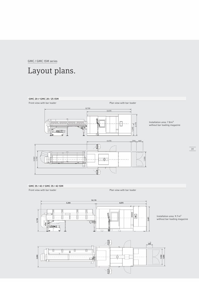
GMC / GMC ISM series
Layout plans.
GMC 20 // GMC 20 / 25 ISM
Front view with bar loader Plan view with bar loader
GMC 35 / 42 // GMC 35 / 42 ISM
Front view with bar loader Plan view with bar loader
Installation area: 7.8 m²without bar loading magazine
Installation area: 9.7 m²without bar loading magazine
Applications and Parts
Machine and technology
Control technology
Technical data
32
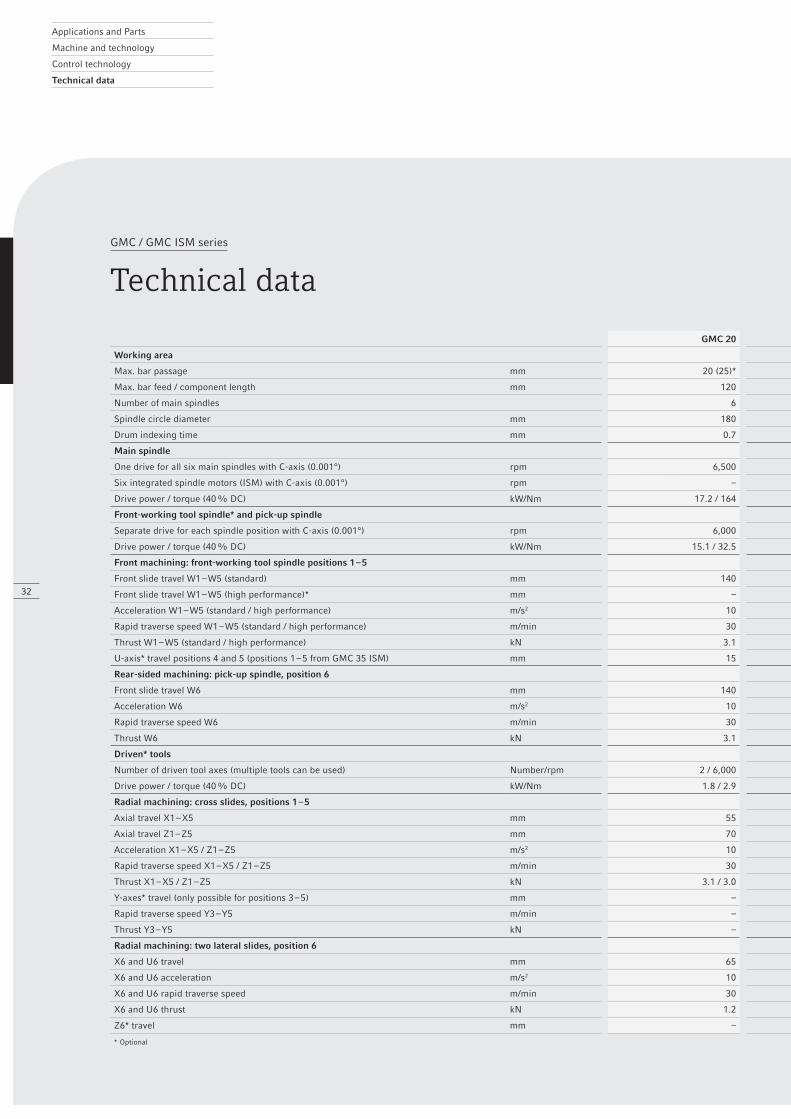
GMC / GMC ISM series
Technical data
GMC 20 GMC 20 ISM GMC 25 ISM GMC 35 GMC 35 ISM GMC 42 ISM
Working area
Max. bar passage mm 20 (25)* 20 25 35 35 42
Max. bar feed / component length mm 120 120 120 140 140 140
Number of main spindles 6 6 6 6 6 6
Spindle circle diameter mm 180 180 180 280 280 280
Drum indexing time mm 0.7 0.7 0.7 1.0 1.0 1.0
Main spindle
One drive for all six main spindles with C-axis (0.001°) rpm 6,500 – – 6,000 – –
Six integrated spindle motors (ISM) with C-axis (0.001°) rpm – 8,000 8,000 – 6,000 5,000
Drive power / torque (40 % DC) kW/Nm 17.2 / 164 13.7 / 20.2 13.7 / 20.2 25 / 238.9 18.6 / 42.7 20.4 / 51.3
Front-working tool spindle* and pick-up spindle
Separate drive for each spindle position with C-axis (0.001°) rpm 6,000 6,000 6,000 6,000 6,000 6,000
Drive power / torque (40 % DC) kW/Nm 15.1 / 32.5 15.1 / 32.5 15.1 / 32.5 10.0 / 47.8 10.0 / 47.8 10.0 / 47.8
Front machining: front-working tool spindle positions 1 – 5
Front slide travel W1 – W5 (standard) mm 140 140 140 180 (220)* 180 (220)* 180 (220)*
Front slide travel W1 – W5 (high performance)* mm – – – – 180 180
Acceleration W1 – W5 (standard / high performance) m/s2 10 10 10 10 10 / 7 10 / 7
Rapid traverse speed W1 – W5 (standard / high performance) m/min 30 30 30 30 30 / 21 30 / 21
Thrust W1 – W5 (standard / high performance) kN 3.1 3.1 3.1 3.7 3.7 / 8.5 5.9 / 8.5
U-axis* travel positions 4 and 5 (positions 1 – 5 from GMC 35 ISM) mm 15 15 15 23 23 23
Rear-sided machining: pick-up spindle, position 6
Front slide travel W6 mm 140 140 140 220 220 220
Acceleration W6 m/s2 10 10 10 10 10 10
Rapid traverse speed W6 m/min 30 30 30 30 30 30
Thrust W6 kN 3.1 3.1 3.1 3.7 3.7 5.9
Driven* tools
Number of driven tool axes (multiple tools can be used) Number/rpm 2 / 6,000 6 / 6,000 6 / 6,000 5 / 6,000 6 / 6,000 6 / 6,000
Drive power / torque (40 % DC) kW/Nm 1.8 / 2.9 1.8 / 2.9 1.8 / 2.9 3.8 / 7.0 3.8 / 7.0 3.8 / 7.0
Radial machining: cross slides, positions 1 – 5
Axial travel X1 – X5 mm 55 55 55 80 80 80
Axial travel Z1 – Z5 mm 70 70 70 100 100 100
Acceleration X1 – X5 / Z1 – Z5 m/s2 10 10 10 10 10 10
Rapid traverse speed X1 – X5 / Z1 – Z5 m/min 30 30 30 30 30 30
Thrust X1 – X5 / Z1 – Z5 kN 3.1 / 3.0 3.1 / 3.0 3.1 / 3.0 3.1 / 3.0 3.1 / 3.0 3.1 / 4.0
Y-axes* travel (only possible for positions 3 – 5) mm – – – – 35 35
Rapid traverse speed Y3 – Y5 m/min – – – – 15 15
Thrust Y3 – Y5 kN – – – – 1.7 1.7
Radial machining: two lateral slides, position 6
X6 and U6 travel mm 65 65 65 120 120 120
X6 and U6 acceleration m/s2 10 10 10 10 10 10
X6 and U6 rapid traverse speed m/min 30 30 30 30 30 30
X6 and U6 thrust kN 1.2 1.2 1.2 1.2 1.2 1.2
Z6* travel mm – – – – 4 4
* Optional

33
GMC 20 GMC 20 ISM GMC 25 ISM GMC 35 GMC 35 ISM GMC 42 ISM
Working area
Max. bar passage mm 20 (25)* 20 25 35 35 42
Max. bar feed / component length mm 120 120 120 140 140 140
Number of main spindles 6 6 6 6 6 6
Spindle circle diameter mm 180 180 180 280 280 280
Drum indexing time mm 0.7 0.7 0.7 1.0 1.0 1.0
Main spindle
One drive for all six main spindles with C-axis (0.001°) rpm 6,500 – – 6,000 – –
Six integrated spindle motors (ISM) with C-axis (0.001°) rpm – 8,000 8,000 – 6,000 5,000
Drive power / torque (40 % DC) kW/Nm 17.2 / 164 13.7 / 20.2 13.7 / 20.2 25 / 238.9 18.6 / 42.7 20.4 / 51.3
Front-working tool spindle* and pick-up spindle
Separate drive for each spindle position with C-axis (0.001°) rpm 6,000 6,000 6,000 6,000 6,000 6,000
Drive power / torque (40 % DC) kW/Nm 15.1 / 32.5 15.1 / 32.5 15.1 / 32.5 10.0 / 47.8 10.0 / 47.8 10.0 / 47.8
Front machining: front-working tool spindle positions 1 – 5
Front slide travel W1 – W5 (standard) mm 140 140 140 180 (220)* 180 (220)* 180 (220)*
Front slide travel W1 – W5 (high performance)* mm – – – – 180 180
Acceleration W1 – W5 (standard / high performance) m/s2 10 10 10 10 10 / 7 10 / 7
Rapid traverse speed W1 – W5 (standard / high performance) m/min 30 30 30 30 30 / 21 30 / 21
Thrust W1 – W5 (standard / high performance) kN 3.1 3.1 3.1 3.7 3.7 / 8.5 5.9 / 8.5
U-axis* travel positions 4 and 5 (positions 1 – 5 from GMC 35 ISM) mm 15 15 15 23 23 23
Rear-sided machining: pick-up spindle, position 6
Front slide travel W6 mm 140 140 140 220 220 220
Acceleration W6 m/s2 10 10 10 10 10 10
Rapid traverse speed W6 m/min 30 30 30 30 30 30
Thrust W6 kN 3.1 3.1 3.1 3.7 3.7 5.9
Driven* tools
Number of driven tool axes (multiple tools can be used) Number/rpm 2 / 6,000 6 / 6,000 6 / 6,000 5 / 6,000 6 / 6,000 6 / 6,000
Drive power / torque (40 % DC) kW/Nm 1.8 / 2.9 1.8 / 2.9 1.8 / 2.9 3.8 / 7.0 3.8 / 7.0 3.8 / 7.0
Radial machining: cross slides, positions 1 – 5
Axial travel X1 – X5 mm 55 55 55 80 80 80
Axial travel Z1 – Z5 mm 70 70 70 100 100 100
Acceleration X1 – X5 / Z1 – Z5 m/s2 10 10 10 10 10 10
Rapid traverse speed X1 – X5 / Z1 – Z5 m/min 30 30 30 30 30 30
Thrust X1 – X5 / Z1 – Z5 kN 3.1 / 3.0 3.1 / 3.0 3.1 / 3.0 3.1 / 3.0 3.1 / 3.0 3.1 / 4.0
Y-axes* travel (only possible for positions 3 – 5) mm – – – – 35 35
Rapid traverse speed Y3 – Y5 m/min – – – – 15 15
Thrust Y3 – Y5 kN – – – – 1.7 1.7
Radial machining: two lateral slides, position 6
X6 and U6 travel mm 65 65 65 120 120 120
X6 and U6 acceleration m/s2 10 10 10 10 10 10
X6 and U6 rapid traverse speed m/min 30 30 30 30 30 30
X6 and U6 thrust kN 1.2 1.2 1.2 1.2 1.2 1.2
Z6* travel mm – – – – 4 4
* Optional
Applications and Parts
Machine and technology
Control technology
Technical data
ê Options
34
GMC / GMC ISM series
Technical data
GMC 20 GMC 20 ISM GMC 25 ISM GMC 35 GMC 35 ISM GMC 42 ISM
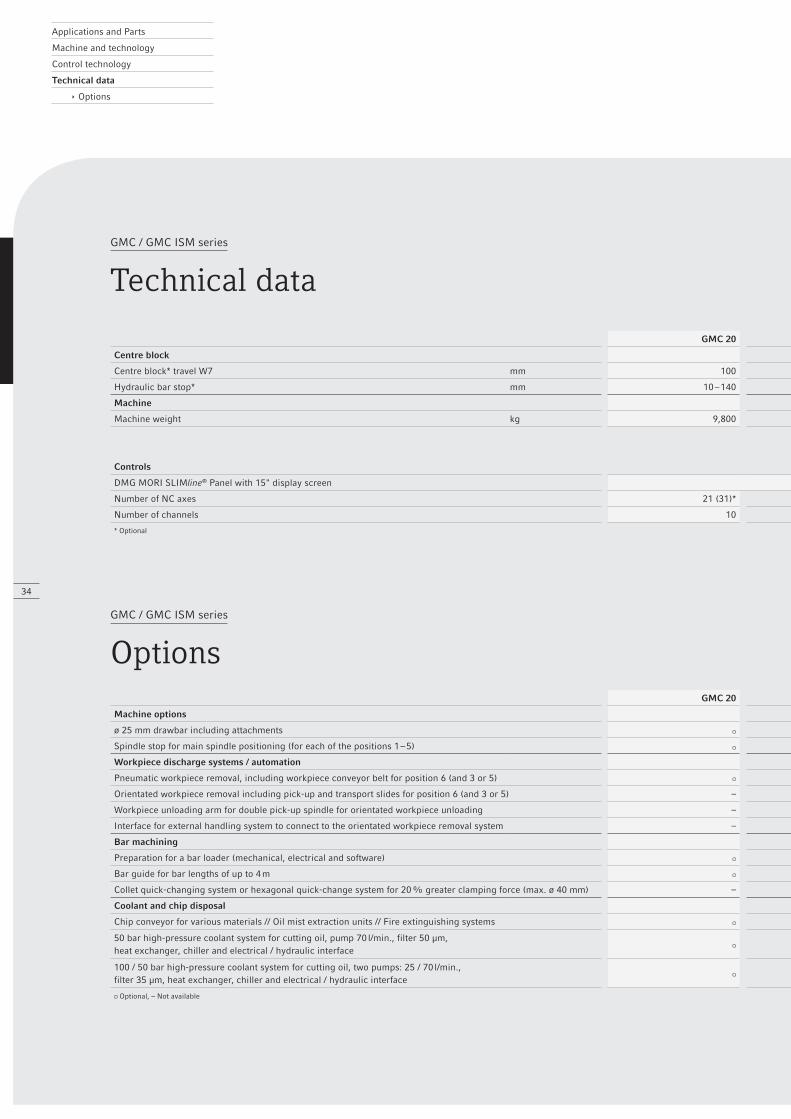
Centre block
Centre block* travel W7 mm 100 100 100 100 100 100
Hydraulic bar stop* mm 10 – 140 10 – 140 10 – 140 18 – 254 18 – 254 18 – 254
Machine
Machine weight kg 9,800 10,300 10,300 13,000 13,100 13,100
Controls
DMG MORI SLIMline® Panel with 15" display screen Siemens 840D powerline
Number of NC axes 21 (31)* 26 (40)* 26 (40)* 21 (31)* 26 (56)* 26 (56)*
Number of channels 10 14 14 10 14 14
* Optional
GMC / GMC ISM series
OptionsGMC 20 GMC 20 ISM GMC 25 ISM GMC 35 GMC 35 ISM GMC 42 ISM
Machine options
ø 25 mm drawbar including attachments – – – – –
Spindle stop for main spindle positioning (for each of the positions 1 – 5) – – – –
Workpiece discharge systems / automation
Pneumatic workpiece removal, including workpiece conveyor belt for position 6 (and 3 or 5)
Orientated workpiece removal including pick-up and transport slides for position 6 (and 3 or 5) – – –
Workpiece unloading arm for double pick-up spindle for orientated workpiece unloading – – – –
Interface for external handling system to connect to the orientated workpiece removal system – – –
Bar machining
Preparation for a bar loader (mechanical, electrical and software)
Bar guide for bar lengths of up to 4 m
Collet quick-changing system or hexagonal quick-change system for 20 % greater clamping force (max. ø 40 mm) – – –
Coolant and chip disposal
Chip conveyor for various materials // Oil mist extraction units // Fire extinguishing systems
50 bar high-pressure coolant system for cutting oil, pump 70 l/min., filter 50 μm,heat exchanger, chiller and electrical / hydraulic interface
100 / 50 bar high-pressure coolant system for cutting oil, two pumps: 25 / 70 l/min.,filter 35 μm, heat exchanger, chiller and electrical / hydraulic interface
Optional, – Not available

35
GMC 20 GMC 20 ISM GMC 25 ISM GMC 35 GMC 35 ISM GMC 42 ISM
Centre block
Centre block* travel W7 mm 100 100 100 100 100 100
Hydraulic bar stop* mm 10 – 140 10 – 140 10 – 140 18 – 254 18 – 254 18 – 254
Machine
Machine weight kg 9,800 10,300 10,300 13,000 13,100 13,100
Controls
DMG MORI SLIMline® Panel with 15" display screen Siemens 840D powerline
Number of NC axes 21 (31)* 26 (40)* 26 (40)* 21 (31)* 26 (56)* 26 (56)*
Number of channels 10 14 14 10 14 14
* Optional
GMC 20 GMC 20 ISM GMC 25 ISM GMC 35 GMC 35 ISM GMC 42 ISM
Machine options
ø 25 mm drawbar including attachments – – – – –
Spindle stop for main spindle positioning (for each of the positions 1 – 5) – – – –
Workpiece discharge systems / automation
Pneumatic workpiece removal, including workpiece conveyor belt for position 6 (and 3 or 5)
Orientated workpiece removal including pick-up and transport slides for position 6 (and 3 or 5) – – –
Workpiece unloading arm for double pick-up spindle for orientated workpiece unloading – – – –
Interface for external handling system to connect to the orientated workpiece removal system – – –
Bar machining
Preparation for a bar loader (mechanical, electrical and software)
Bar guide for bar lengths of up to 4 m
Collet quick-changing system or hexagonal quick-change system for 20 % greater clamping force (max. ø 40 mm) – – –
Coolant and chip disposal
Chip conveyor for various materials // Oil mist extraction units // Fire extinguishing systems
50 bar high-pressure coolant system for cutting oil, pump 70 l/min., filter 50 μm,heat exchanger, chiller and electrical / hydraulic interface
100 / 50 bar high-pressure coolant system for cutting oil, two pumps: 25 / 70 l/min.,filter 35 μm, heat exchanger, chiller and electrical / hydraulic interface
Optional, – Not available

Applications and Parts
Machine and technology
Control technology
Technical data
ê Options
36
GMC / GMC ISM series
OptionsGMC 20 GMC 20 ISM GMC 25 ISM GMC 35 GMC 35 ISM GMC 42 ISM
Front slide facilities
Independent feed for the centre block (W7)
Guide bushing for long workpieces on the centre block (in each case for positions 1 – 5)
Turning tool holder on the centre block (in each case for positions 1 – 5)
Extended front slide travel to 220 mm (in each case for positions 1 – 5) – – –
Front-working tool spindles with ISO, HSK or CAPTO taper, coolant supply up to 120 bar (in each case for positions 1 – 5)
Drive for front-working tool spindles (in each case for positions 1 – 5)
Enhanced high-performance drive for front-working tool spindles (in each case for positions 1 – 5) – – –
Synchronous device for driven front-working tool spindle (in each case for positions 1 – 5)
Milling device for driven front-working tool spindle (in each case for positions 1 – 5)
Attachments for thread rolling heads, turning heads or tapping heads (in each case for positions 1 – 5)
Two-axis front slides with U-axis (in each case for positions 4 and 5 / positions 1 to 5 from GMC 35 ISM)
Front-working heads for U-axis grooving or milling – – –
Facilities for rear-side machining
Pick-up spindle for position 6 including drawbar attachment, rotating ejector and hydraulics
Second pick-up spindle for positions 3 or 5 including drive, drawbar attachment, rotating ejector and hydraulics
Preparation of electrics and software for driven tools on lateral slides U6
Radial drilling, milling or deburring device, also as double or combined tools for lateral slides U6
Axial drilling, milling or deburring device (90° angle drive), also as double or combined tools for lateral slides U6
Double pick-up spindle at position 6 – – – –
For the double pick-up spindle: two rear-side machining units, in each case for four tools; one parting-off slide – – – –
Cross slide facilities
Preparation of electrics and software for driven tools
Polygonal turning, thread milling, including drive
Radial drilling, milling or deburring device, also as double or combined tools
Y-axis with radial drilling, milling or deburring device, for two or three tools – – – –
Axial drilling, milling or deburring device (90° angle drive), also as double or combined tools
Quick-change turret with CAPTO C4 taper for turning or milling – – –
Disc turrets with CAPTO C4 taper for up to three turning tools – – –
Control system / software / tool monitoring
Cutting power monitoring system for four or eight channels
Mechanical drill breakage check for each tool position
CIMCO Edit 6 for easily and quickly generating NC programs
2D CAD system including DXF import for CIMCO Edit 6
Optional, – Not available

37
GMC 20 GMC 20 ISM GMC 25 ISM GMC 35 GMC 35 ISM GMC 42 ISM
Front slide facilities
Independent feed for the centre block (W7)
Guide bushing for long workpieces on the centre block (in each case for positions 1 – 5)
Turning tool holder on the centre block (in each case for positions 1 – 5)
Extended front slide travel to 220 mm (in each case for positions 1 – 5) – – –
Front-working tool spindles with ISO, HSK or CAPTO taper, coolant supply up to 120 bar (in each case for positions 1 – 5)
Drive for front-working tool spindles (in each case for positions 1 – 5)
Enhanced high-performance drive for front-working tool spindles (in each case for positions 1 – 5) – – –
Synchronous device for driven front-working tool spindle (in each case for positions 1 – 5)
Milling device for driven front-working tool spindle (in each case for positions 1 – 5)
Attachments for thread rolling heads, turning heads or tapping heads (in each case for positions 1 – 5)
Two-axis front slides with U-axis (in each case for positions 4 and 5 / positions 1 to 5 from GMC 35 ISM)
Front-working heads for U-axis grooving or milling – – –
Facilities for rear-side machining
Pick-up spindle for position 6 including drawbar attachment, rotating ejector and hydraulics
Second pick-up spindle for positions 3 or 5 including drive, drawbar attachment, rotating ejector and hydraulics
Preparation of electrics and software for driven tools on lateral slides U6
Radial drilling, milling or deburring device, also as double or combined tools for lateral slides U6
Axial drilling, milling or deburring device (90° angle drive), also as double or combined tools for lateral slides U6
Double pick-up spindle at position 6 – – – –
For the double pick-up spindle: two rear-side machining units, in each case for four tools; one parting-off slide – – – –
Cross slide facilities
Preparation of electrics and software for driven tools
Polygonal turning, thread milling, including drive
Radial drilling, milling or deburring device, also as double or combined tools
Y-axis with radial drilling, milling or deburring device, for two or three tools – – – –
Axial drilling, milling or deburring device (90° angle drive), also as double or combined tools
Quick-change turret with CAPTO C4 taper for turning or milling – – –
Disc turrets with CAPTO C4 taper for up to three turning tools – – –
Control system / software / tool monitoring
Cutting power monitoring system for four or eight channels
Mechanical drill breakage check for each tool position
CIMCO Edit 6 for easily and quickly generating NC programs
2D CAD system including DXF import for CIMCO Edit 6
Optional, – Not available
Related Documents