Integrated Control Solutions & Energy Savings NO POWER & SIGNAL CABLES TOGETHER READ CAREFULLY IN THE TEXT! ultimateSAM Direct Steam Humidification System Sistema di umidificazione ultimateSAM User manual Manuale d’uso

Welcome message from author
This document is posted to help you gain knowledge. Please leave a comment to let me know what you think about it! Share it to your friends and learn new things together.
Transcript

I n t e g r a t e d C o n t r o l S o l u t i o n s & E n e r g y S a v i n g s
NO POWER
& SIGNAL
CABLES
TOGETHER
READ CAREFULLY IN THE TEXT!
ultimateSAM
Direct Steam Humidifi cation SystemSistema di umidifi cazione ultimateSAM
User manualManuale d’uso
GENERAL WARNINGS
The CAREL Industries humidifi ers are advanced products, whose operation is specifi ed in the technical documentation supplied with the product or can be downloaded, even prior to purchase, from the website www.carel.com. Each CAREL Industries product, in relation to its advanced level of technology, requires setup/confi guration/programming/commissioning to be able to operate in the best possible way for the specifi c application. The failure to complete such operations, which are required/indicated in the user manual, may cause the fi nal product to malfunction; CAREL Industries accepts no liability in such cases. The customer (manufacturer, developer or installer of the fi nal equipment) accepts all liability and risk relating to the confi guration of the product in order to reach the expected results in relation to the specifi c fi nal installation and/or equipment. CAREL Industries may, based on specifi c agreements, acts as a consultant for the installation/commissioning/use of the unit, however in no case does it accept liability for the correct operation of the humidifi er and the fi nal installation if the warnings or suggestions provided in this manual or in other product technical documents are not heeded. In addition to observing the above warnings and suggestions, the following warnings must be followed for the correct use of the product:
• DANGER OF ELECTRIC SHOCK : The humidifi er contains live electrical components. Disconnect the power supply before accessing inside parts or during maintenance and installation.
• DANGER OF WATER LEAKS: The humidifi er automatically and constantly fi lls/drains certain quantities of water. Malfunctions in the connections or in the humidifi er may cause leaks.
• DANGER OF BURNS: The humidifi er contains high temperature components and delivers steam at 100°C/ 212°F.
IMPORTANTIMPORTANT
• The installation of the product must include an earth connection, using the special yellow-green terminal available in the humidifi er.
• The environmental and power supply conditions must conform to the values specifi ed on the product rating labels.
• The product is designed exclusively to humidify rooms either directly or through distribution systems (ducts).
• Only qualifi ed personnel who are aware of the necessary precautions and able to perform the required operations correctly may install, operate or carry out technical service on the product.
• Only water with the characteristics indicated in this manual must be used for steam production. • All operations on the product must be carried out according to the instructions provided in this manual
and on the labels applied to the product. Any uses or modifi cations that are not authorized by the manufacturer are considered improper. CAREL Industries declines all liability for any such unauthorized use.
• Do not attempt to open the humidifi er in ways other than those specifi ed in the manual.• Observe the standards in force in the place where the humidifi er is installed.• Keep the humidifi er out of the reach of children and animals. • Do not install and use the product near objects that may be damaged when in contact with water (or
condensate). CAREL Industries declines all liability for direct or indirect damage following water leaks from the humidifi er.
• Do not use corrosive chemicals, solvents or aggressive detergents to clean the inside and outside parts of the humidifi er, unless specifi cally indicated in the user manual.
• Do not drop, hit or shake the humidifi er, as the inside parts and the linings may be irreparably damaged.
CAREL Industries adopts a policy of continual development. Consequently, CAREL reserves the right to make changes and improvements to any product described in this document without prior warning. The technical specifi cations shown in the manual may be changed without prior warning. The liability of CAREL Industries in relation to its products is specifi ed in the CAREL Industries general contract conditions, availa-ble on the website www.carel.com and/or by specifi c agreements with customers; specifi cally, to the extent where allowed by applicable legislation, in no case will CAREL Industries, its employees or subsidiaries be liable for any lost earnings or sales, losses of data and information, costs of replacement goods or services, damage to things or people, downtime or any direct, indirect, incidental, actual, punitive, exemplary, special or consequential damage of any kind whatsoever, whether contractual, extra-contractual or due to negli-gence, or any other liabilities deriving from the installation, use or impossibility to use the product, even if CAREL Industries or its subsidiaries are warned of the possibility of such damage.
DISPOSAL:
The humidifi er is made up of metal parts and plastic parts. In reference to European Union directive 2002/96/EC issued on 27 January 2003 and the related national legislation, please note that:1. WEEE cannot be disposed of as municipal waste and such waste must be collected and disposed of
separately;2. the public or private waste collection systems defi ned by local legislation must be used. In addition,
the equipment can be returned to the distributor at the end of its working life when buying new equipment;
3. the equipment may contain hazardous substances: the improper use or incorrect disposal of such may have negative effects on human health and on the environment;
4. the symbol (crossed-out wheeled bin) shown on the product or on the packaging and on the instruc-tion sheet indicates that the equipment has been introduced onto the market after 13 August 2005 and that it must be disposed of separately;
5. in the event of illegal disposal of electrical and electronic waste, the penalties are specifi ed by local waste disposal legislation.
Warranty on the materials: 2 years (from the date of production, excluding consumables).
Approval: the quality and safety of CAREL products are guaranteed by the ISO 9001 certifi ed design and
production system, as well as by the mark.
AVVERTENZE
Gli umidifi catori CAREL Industries sono prodotti avanzati, il cui funzionamento è specifi cato nella documentazione tecnica fornIta col prodotto o scaricabile, anche anteriormente all’acquisto, dal sito internet www.carel.com. Ogni prodotto CAREL Industries, in relazione al suo avanzato livello tecnologico, necessIta di una fase di qualifi ca/confi gurazione/programmazione affi nché possa funzionare al meglio per l’applicazione specifi ca. La mancanza di tale fase di studio, come indicata nel manuale, può generare malfunzionamenti nei prodotti fi nali di cui CAREL Industries non potrà essere ritenuta responsabile. Il cliente (costruttore, progettista o installatore dell’equipaggiamento fi nale) si assume ogni responsabilità e rischio in relazione alla confi gurazione del prodotto per il raggiungimento dei risultati previsti in relazione all’installazione e/o equipaggiamento fi nale specifi co. CAREL Industries in questo caso, previ accordi specifi ci, può intervenire come consulente per la buona riuscIta della installazione/start-up macchina/utilizzo, ma in nessun caso può essere ritenuta responsabile per il buon funzionamento dell’umidifi catore ed impianto fi nale qualora non siano state seguite le avvertenze o raccomandazioni descritte in questo manuale, o in altra documentazione tecnica del prodotto. In particolare, senza esclusione dell’obbligo di osservare le anzidette avvertenze o raccomandazioni, per un uso corretto del prodotto si raccomanda di prestare attenzione alle seguenti avvertenze:
• PERICOLO SCOSSE ELETTRICHE: L’umidifi catore contiene componenti sotto tensione elettrica. Togliere l’alimentazione di rete prima di accedere a parti interne, in caso di manutenzione e durante l’installazione.
• PERICOLO PERDITE D’ACQUA: L’umidifi catore carica/scarica automaticamente e costantemente quantità d’acqua. Malfunzionamenti nei collegamenti o nell’umidifi catore possono causare perdite.
• PERICOLO DI USTIONE: L’umidifi catore contiene componenti ad alta temperatura, ed eroga vapore a 100°C/ 212°F.
ATTENZIONEATTENZIONE
• L’installazione del prodotto deve obbligatoriamente comprendere una connessione di terra, utilizzando l’apposito morsetto di colore giallo-verde presente nell’umidifi catore.
• Condizioni ambientali e tensione di alimentazione devono essere conformi ai valori specifi cati nelle etichette ‘dati di targa’ del prodotto.
• Il prodotto è progettato esclusivamente per umidifi care ambienti in modo diretto o mediante sistemi di distribuzione (condotte).
• Installazione, utilizzo e manutenzione devono essere eseguite da personale qualifi cato, consapevole delle precauzioni necessarie e in grado di effettuare correttamente le operazioni richieste.
• Per la produzione di vapore si deve utilizzare esclusivamente acqua con caratteristiche indicate nel presente manuale.
• Tutte le operazioni sul prodotto devo essere eseguite secondo le istruzioni contenute nel presente manuale e nelle etichette applicate al prodotto. Usi e modifi che non autorizzati dal produttore sono da considerarsi impropri. CAREL Industries non si assume alcuna responsabilità per tali utilizzi non autorizzati.
• Non tentare di aprire l’umidifi catore in modi diversi da quelli indicati nel manuale.• Attenersi alle normative vigenti nel luogo in cui si installa l’umidifi catore. • Tenere l’umidifi catore fuori dalla portata di bambini e animali. • Non installare e utilizzare il prodotto nelle vicinanze di oggetti che possono danneggiarsi a contatto con
l’acqua (o condensa d’acqua). CAREL Industries declina ogni responsabilità per danni conseguiti o diretti a seguito di perdite d’acqua dell’umidifi catore.
• Non utilizzare prodotti chimici corrosivi, solventi o detergenti aggressivi per pulire le parti Interne ed esterne dell’umidifi catore, salvo non vi siano indicazioni specifi che nei manuali d’uso.
• Non fare cadere, battere o scuotere l’umidifi catore, poiché le parti interne e di rivestimento potrebbero subire danni irreparabili.
CAREL Industries adotta una politica di continuo sviluppo. Pertanto si riserva il diritto di effettuare modifi che e miglioramenti a qualsiasi prodotto descritto nel presente documento senza preavviso. I dati tecnici presenti nel manuale possono subire modifi che senza obbligo di preavviso. La responsabilità di CAREL Industries in relazione al proprio prodotto è regolata dalle condizioni generali di contratto CAREL Industries pubblicate nel sito www.carel.com e/o da specifi ci accordi con i clienti; in particolare, nella misura consentIta dalla normativa applicabile, in nessun caso CAREL Industries, i suoi dipendenti o le sue fi liali/ affi liate saranno responsabili di eventuali mancati guadagni o vendite, perdite di dati e di informazioni, costi di merci o servizi sostitutivi, danni a cose o persone, interruzioni di attività, o eventuali danni diretti, indiretti, incidentali, patrimoniali, di copertura, punitivi, speciali o consequenziali in qualunque modo causati, siano essi contrattuali, extra contrattuali o dovuti a negligenza o altra responsabilità derivanti dall’ utilizzo del prodotto o dalla sua installazione, anche se CAREL Industries o le sue fi liali/affi liate siano state avvisate della possibilità di danni.
SMALTIMENTO:
L’umidifi catore è composto da parti di metallo e parti di plastica. In riferimento alla Direttiva 2002/96/CE del Parlamento Europeo e del Consiglio del 27 gennaio 2003 e alle relative normative nazionali di attuazione, informiamo che:1. sussiste l’obbligo di non smaltire i RAEE come rifi uti urbani e di effettuare, per detti rifi uti, una
raccolta separata;2. per lo smaltimento vanno utilizzati i sistemi di raccolta pubblici o privati previsti dalla leggi locali. È
inoltre possibile riconsegnare al distributore l’apparecchiatura a fi ne vIta in caso di acquisto di una nuova;
3. questa apparecchiatura può contenere sostanze pericolose: un uso improprio o uno smaltimento non corretto potrebbe avere effetti negativi sulla salute umana e sull’ambiente;
4. il simbolo (contenitore di spazzatura su ruote barrato) riportato sul prodotto o sulla confezione e sul foglio istruzioni indica che l’apparecchiatura è stata immessa sul mercato dopo il 13 Agosto 2005 e che deve essere oggetto di raccolta separata;
5. in caso di smaltimento abusivo dei rifi uti elettrici ed elettronici sono previste sanzioni stabilite dalle vigenti normative locali in materia di smaltimento.
Garanzia sui materiali: 2 anni (dalla data di produzione, escluse le parti di consumo).
Omologazioni: la qualità e la sicurezza dei prodotti CAREL sono garantite dal sistema di progettazione e
produzione certifi cato ISO 9001, nonché dal marchio .
ENG
“Ultimate SAM” +0300013IE - rel. 2.0 - 05.09.20115
Content
1. INTRODUCTION AND ASSEMBLY 7
1.1 ultimateSAM Humidifi cation System (SA*) ..............................................................................................................................................................................................................7
1.2 Distributor dimensions and weights ............................................................................................................................................................................................................................7
1.3 Opening the packaging .......................................................................................................................................................................................................................................................8
1.4 Assembling the SA*****2** frame ................................................................................................................................................................................................................................8
1.5 Inserting and attaching uprights ..................................................................................................................................................................................................................................9
1.6 Positioning................................................................................................................................................................................................................................................................................10
1.7 Mounting ....................................................................................................................................................................................................................................................................................11
1.8 Upright steam fl ow-rate ....................................................................................................................................................................................................................................................13
2. STEAM INLET CONNECTIONS 14
2.1 Inlet adapters (SAKI******) ...............................................................................................................................................................................................................................................14
2.2 Installing inlet adapters .....................................................................................................................................................................................................................................................15
3. DRAIN CONNECTIONS 16
3.1 Installing P-traps on header drains .............................................................................................................................................................................................................................16
3.2 Trap, strainer, and separator kits for distributor inlets connected to pressurized steam supplies .....................................................................................16
3.3 Inlet drains for distributors connected to atmospheric steam supplies ............................................................................................................................................17
4. STEAM SUPPLY CONNECTIONS 18
4.1 Control valves (SAKV******) kits for pressurized steam supplies .............................................................................................................................................................18
4.2 Fitting kits (SAKR******) for threaded control valves .......................................................................................................................................................................................18
4.3 Actuator kits for control valves .....................................................................................................................................................................................................................................18
4.4 Connecting pressurized steam to an ultimateSAM distributor ................................................................................................................................................................19
4.5 Connecting atmospheric steam to a bottom-feed ultimateSAM distributor ................................................................................................................................19
5. OPERATION 20
6. TROUBLESHOOTING 20
6.1 Water is spitting from the nozzles on the uprights. ........................................................................................................................................................................................20
6.2 Steam does not discharge from the distributors when the valve is open. .......................................................................................................................................20
6.3 Steam valve will not open ...............................................................................................................................................................................................................................................20
6.4 Steam valve will not close ................................................................................................................................................................................................................................................20
6.5 Steam valve is leaking.........................................................................................................................................................................................................................................................20
6.6 Humidity exceeds set point ............................................................................................................................................................................................................................................20
6.7 Humidity remains below set point .............................................................................................................................................................................................................................20
6.8 Condensate in duct .............................................................................................................................................................................................................................................................21
6.9 Steam leaks from P-traps. .................................................................................................................................................................................................................................................21
7. MAINTENANCE 21
8. SPARE PARTS 21
8.1 Adjustable feet Kit for SAB* / SAT* ..............................................................................................................................................................................................................................21
8.2 Horizontal manifold Kit (steam feed – condensate drain) for SAB* / SAT* ........................................................................................................................................21
8.3 Uprights kit for SAB* / SAT* .............................................................................................................................................................................................................................................22
8.4 Frame element and top side Kit for SAB* / SAT* ................................................................................................................................................................................................22
8.5 Corner Kit for SAB* / ...........................................................................................................................................................................................................................................................22
8.6 Retainer ring kit for SAB*...................................................................................................................................................................................................................................................23
8.7 Gaskets kit ..................................................................................................................................................................................................................................................................................23
8.8 Filter “Y” kit ..................................................................................................................................................................................................................................................................................23
8.9 Condensate drain separator Kit ....................................................................................................................................................................................................................................23
8.10 F&T Condensate drain Kit .................................................................................................................................................................................................................................................23
8.11 Inverted bucket Condensate drain Kit .....................................................................................................................................................................................................................24
8.12 Spare upright kit, SA0 (single-pipe) versions .......................................................................................................................................................................................................24
8.13 Spare manifold kit, SA0 (single-pipe) versions ....................................................................................................................................................................................................24
9. SPECIFICATIONS / SPECIFICHE 25
9.1 Distributor details / Dettagli distributore .............................................................................................................................................................................................................25
9.2 Distributor details / Dettagli distributore ...............................................................................................................................................................................................................25
9.3 Distributor weight tables / Tabella pesi distributore .......................................................................................................................................................................................26
9.4 Distributor weight tables / Tabella pesi distributore .......................................................................................................................................................................................26
9.5 Distributor weight tables / Tabella pesi distributore .......................................................................................................................................................................................27
9.6 Inlet adapters / Adattatori ingresso vapore .........................................................................................................................................................................................................28
9.7 Inlet adapters / Adattatori ingresso vapore ..........................................................................................................................................................................................................29
9.8 Inlet adapters / Adattatori ingresso vapore .........................................................................................................................................................................................................30
9.9 Valves and valve fi tting kits (fl anged) / Kit valvole e connessioni (fl angiate) ...................................................................................................................................30
9.10 Valves and valve fi tting kits (only for North American markets) / Kit valvole e connessioni (solo per il mercato Americano) .........................31
9.11 Valves and valve fi tting kits (only for North American markets) / Kit valvole e connessioni (solo per il mercato Americano) .........................31
9.12 Valves and valve fi tting kits (fl anged) / Kit valvole e connessioni (fl angiato) ...................................................................................................................................32
9.13 Valves and valve fi tting kits (only for North American markets) / Kit valvole e connessioni (solo per il mercato Americano) .........................32
9.14 Electrical actuators / Attuatori elettrici ....................................................................................................................................................................................................................33
9.15 Electrical actuators / Attuatori elettrici ...................................................................................................................................................................................................................33
9.16 Electrical actuators (only for North American markets) / Attuatori elettrici (solo per il mercato Americano) ............................................................33
9.17 Electrical actuators (only for North American markets) / Attuatori elettrici (solo per il mercato Americano) ............................................................34
9.18 Electrical actuators (only for North American markets) / Attuatori elettrici (solo per il mercato Americano) ............................................................34
9.19 Electrical actuators (only for North American markets) / Attuatori elettrici (solo per il mercato Americano) ............................................................35
9.20 Electrical actuators (only for North American markets) / Attuatori elettrici (solo per il mercato Americano) ............................................................35
9.21 Trap and strainer F&T kits (fl anged) / Kit fi ltro e scaricatore di condensa F&T (fl angiato) .......................................................................................................36
9.22 Trap and strainer kits inverted bucket (fl anged) / Kit fi ltro e scaricatore di condensa secchiello rovesciato (fl angiato) ......................................36
9.23 Trap and strainer kits F&T (only for North American markets) / Kit fi ltro e scaricatore di condensa F&T (solo per il mercato Americ.) ..37
9.24 Trap, strainer and separator kits F&T / Kit fi ltro separatore e scaricatore di condensa F&T .....................................................................................................37
9.25 Trap, strainer and separator kits F&T / Kit fi ltro, separatore e scaricatore di condensa F&T ....................................................................................................38
9.26 Mooth steam inlet kit for SA0 (single pipe) versions / Kit ingresso vapore liscio per versioni SA0 (single pipe) .....................................................38
9.27 Thermostatic fl oat steam trap / Scaricatore termostatico ...........................................................................................................................................................................40
9.28 AHU wall cover kit for SA0 (single pipe) / Kit copertura parete UTA per SA0 (single pipe) .....................................................................................................40
ENG
“Ultimate SAM” +0300013IE - rel. 2.0 - 05.09.20117
1.1 ultimateSAM Humidifi cation System (SA*)Each UltimateSAM Humidifi cation System consists of the following:
• humidifi er steam distributor;
• steam trap(s) and strainer(s) (sold separately);
• a controlling humidistat and/or sensor (sold separately);
• a steam control valve & actuator for use with pressurized steam sources
(sold separately);
• other optional equipment that may be required.
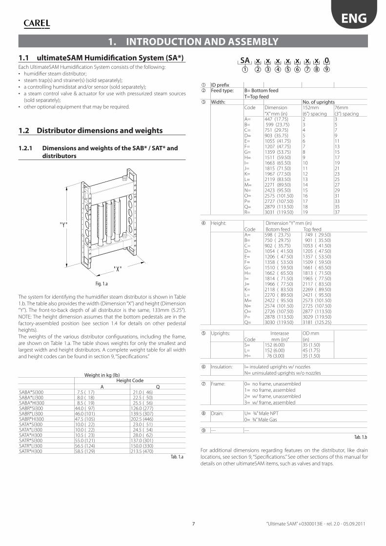
1.2 Distributor dimensions and weights
1.2.1 Dimensions and weights of the SAB* / SAT* and
distributors
" X "
" Y "
Fig. 1.a
The system for identifying the humidifi er steam distributor is shown in Table
1.b. The table also provides the width (Dimension “X”) and height (Dimension
“Y”). The front-to-back depth of all distributor is the same, 133mm (5.25”).
NOTE: The height dimension assumes that the bottom pedestals are in the
factory-assembled position (see section 1.4 for details on other pedestal
heights).
The weights of the various distributor confi gurations, including the frame,
are shown on Table 1.a. The table shows weights for only the smallest and
largest width and height distributors. A complete weight table for all width
and height codes can be found in section 9, “Specifi cations.”
Weight in kg (lb)
Height CodeA Q
SABA*SI300 7.5 ( 17) 21.0 ( 46)SABA*LI300 8.0 ( 18) 22.5 ( 50)SABA*HI300 8.5 ( 19) 25.5 ( 56)SABR*SI300 44.0 ( 97) 126.0 (277)SABR*LI300 46.0 (101) 139.5 (307)SABR*HI300 47.5 (105) 202.5 (446)SATA*SI300 10.0 ( 22) 23.0 ( 51)SATA*LI300 10.0 ( 22) 24.5 ( 54)SATA*H300 10.5 ( 23) 28.0 ( 62)SATR*SI300 55.0 (121) 137.0 (301)SATR*LI300 56.5 (124) 150.0 (330)SATR*H300 58.5 (129) 213.5 (470)
Tab. 1.a
1. INTRODUCTION AND ASSEMBLY
2
SA x1 3
x4
x5
x6
x7
x8
x9
0
ID prefi x Feed type: B= Bottom feed
T=Top feed Width: No. of uprights
Code Dimension
“X” mm (in)
152mm
(6”) spacing
76mm
(3”) spacingA= 447 (17.75) 2 3B= 599 (23.75) 3 5C= 751 (29.75) 4 7D= 903 (35.75) 5 9E= 1055 (41.75) 6 11F= 1207 (47.75) 7 13G= 1359 (53.75) 8 15H= 1511 (59.50) 9 17I= 1663 (65.50) 10 19J= 1815 (71.50) 11 21K= 1967 (77.50) 12 23L= 2119 (83.50) 13 25M= 2271 (89.50) 14 27N= 2423 (95.50) 15 29O= 2575 (101.50) 16 31P= 2727 (107.50) 17 33Q= 2879 (113.50) 18 35R= 3031 (119.50) 19 37
Height:
Code
Dimension “Y” mm (in)
Botom feed Top feedA= 598 ( 23.75) 749 ( 29.50)B= 750 ( 29.75) 901 ( 35.50)C= 902 ( 35.75) 1053 ( 41.50)D= 1054 ( 41.50) 1205 ( 47.50)E= 1206 ( 47.50) 1357 ( 53.50)F= 1358 ( 53.50) 1509 ( 59.50)G= 1510 ( 59.50) 1661 ( 65.50)H= 1662 ( 65.50) 1813 ( 71.50)I= 1814 ( 71.50) 1965 ( 77.50)J= 1966 ( 77.50) 2117 ( 83.50)K= 2118 ( 83.50) 2269 ( 89.50)L= 2270 ( 89.50) 2421 ( 95.50)M= 2422 ( 95.50) 2573 (101.50)N= 2574 (101.50) 2725 (107.50)O= 2726 (107.50) 2877 (113.50)P= 2878 (113.50) 3029 (119.50)Q= 3030 (119.50) 3181 (125.25)
Uprights: Interasse
Code mm (in)”
OD mm
(in)S= 152 (6.00) 35 (1.50)L= 152 (6.00) 45 (1.75)H= 76 (3.00) 35 (1.50)
Insulation: I= insulated uprights w/ nozzles
N= uninsulated uprights w/o nozzles
Frame: 0= no frame, unassembled
1= no frame, assembled
2= w/ frame, unassembled
3= w/ frame, assembled
Drain: U= ¾” Male NPT
0= ¾” Male Gas
--- ---
Tab. 1.b
For additional dimensions regarding features on the distributor, like drain
locations, see section 9, “Specifi cations.” See other sections of this manual for
details on other ultimateSAM items, such as valves and traps.
ENG
“Ultimate SAM” +0300013IE - rel. 2.0 - 05.09.2011 8
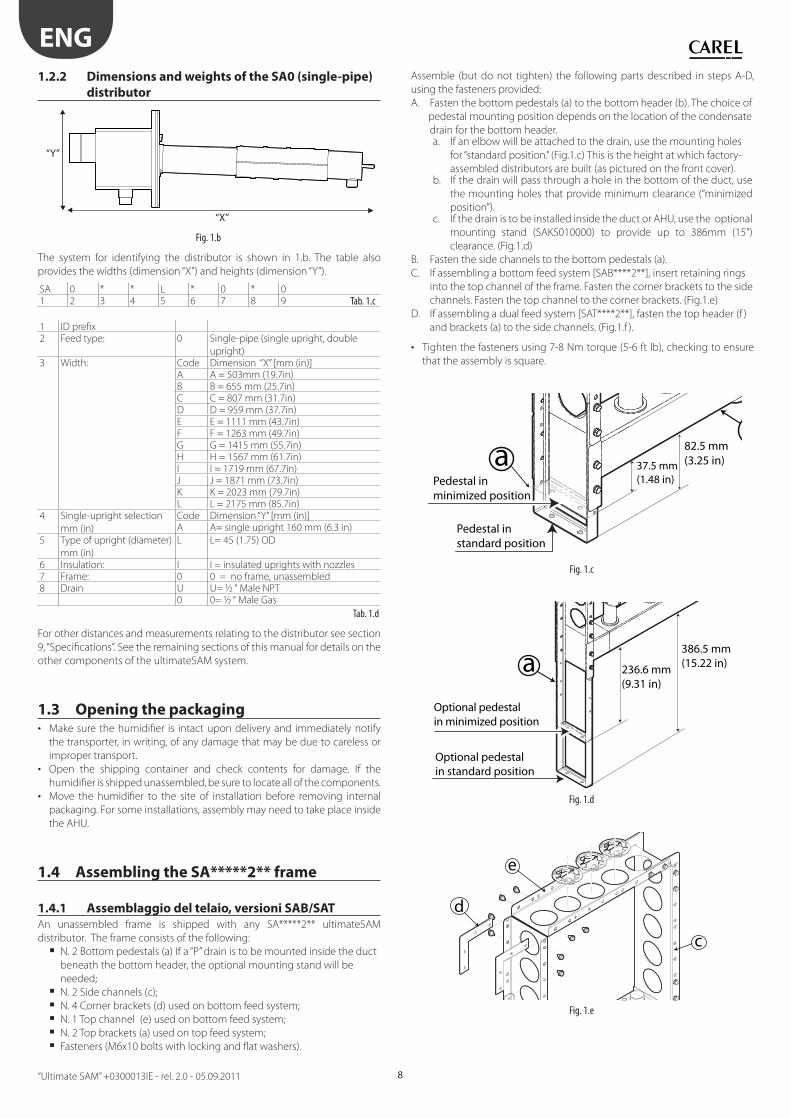
1.2.2 Dimensions and weights of the SA0 (single-pipe)
distributor
“Y”
“X”
Fig. 1.b
The system for identifying the distributor is shown in 1.b. The table also
provides the widths (dimension “X”) and heights (dimension “Y”).
SA 0 * * L * 0 * 01 2 3 4 5 6 7 8 9 Tab. 1.c
1 ID prefi x2 Feed type: 0 Single-pipe (single upright, double
upright)3 Width: Code Dimension “X” [mm (in)]
A A = 503mm (19.7in)B B = 655 mm (25.7in)C C = 807 mm (31.7in)D D = 959 mm (37.7in)E E = 1111 mm (43.7in)F F = 1263 mm (49.7in)G G = 1415 mm (55.7in)H H = 1567 mm (61.7in)I I = 1719 mm (67.7in)J J = 1871 mm (73.7in)K K = 2023 mm (79.7in)L L = 2175 mm (85.7in)
4 Single-upright selection
mm (in)
Code Dimension “Y” [mm (in)]A A= single upright 160 mm (6.3 in)
5 Type of upright (diameter)
mm (in)
L L= 45 (1.75) OD
6 Insulation: I I = insulated uprights with nozzles7 Frame: 0 0 = no frame, unassembled 8 Drain U U= ½ “ Male NPT
0 0= ½ “ Male Gas
Tab. 1.d
For other distances and measurements relating to the distributor see section
9, “Specifi cations”. See the remaining sections of this manual for details on the
other components of the ultimateSAM system.
1.3 Opening the packaging• Make sure the humidifi er is intact upon delivery and immediately notify
the transporter, in writing, of any damage that may be due to careless or
improper transport.
• Open the shipping container and check contents for damage. If the
humidifi er is shipped unassembled, be sure to locate all of the components.
• Move the humidifi er to the site of installation before removing internal
packaging. For some installations, assembly may need to take place inside
the AHU.
1.4 Assembling the SA*****2** frame
1.4.1 Assemblaggio del telaio, versioni SAB/SAT
An unassembled frame is shipped with any SA*****2** ultimateSAM
distributor. The frame consists of the following:
N. 2 Bottom pedestals (a) If a “P” drain is to be mounted inside the duct
beneath the bottom header, the optional mounting stand will be
needed;
N. 2 Side channels (c);
N. 4 Corner brackets (d) used on bottom feed system;
N. 1 Top channel (e) used on bottom feed system;
N. 2 Top brackets (a) used on top feed system;
Fasteners (M6x10 bolts with locking and fl at washers).
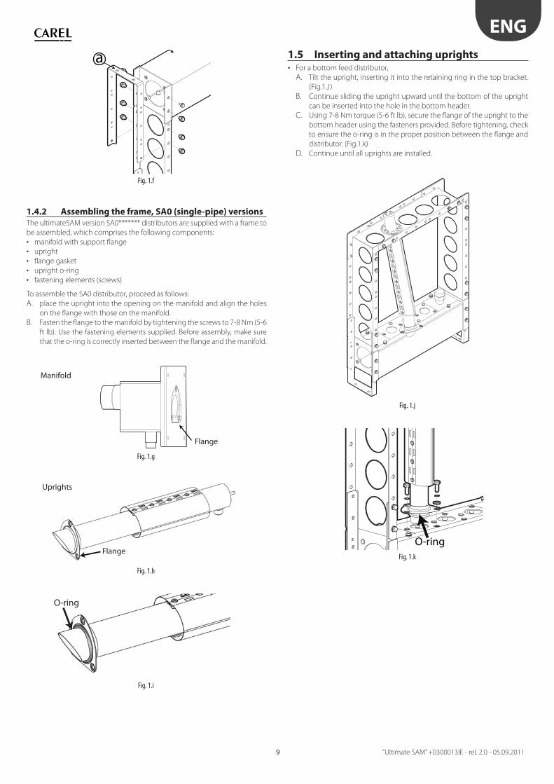
Assemble (but do not tighten) the following parts described in steps A-D,
using the fasteners provided:
A. Fasten the bottom pedestals (a) to the bottom header (b). The choice of
pedestal mounting position depends on the location of the condensate
drain for the bottom header. a. If an elbow will be attached to the drain, use the mounting holes
for “standard position.” (Fig.1.c) This is the height at which factory-
assembled distributors are built (as pictured on the front cover).b. If the drain will pass through a hole in the bottom of the duct, use
the mounting holes that provide minimum clearance (“minimized
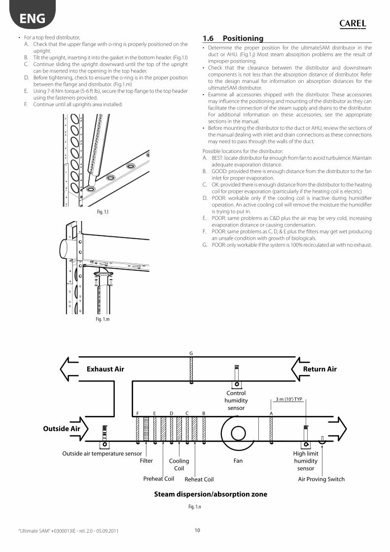
position”).c. If the drain is to be installed inside the duct or AHU, use the optional
mounting stand (SAKS010000) to provide up to 386mm (15”)
clearance. (Fig.1.d)
B. Fasten the side channels to the bottom pedestals (a).
C. If assembling a bottom feed system [SAB****2**], insert retaining rings
into the top channel of the frame. Fasten the corner brackets to the side
channels. Fasten the top channel to the corner brackets. (Fig.1.e)
D. If assembling a dual feed system [SAT****2**], fasten the top header (f )
and brackets (a) to the side channels. (Fig.1.f ).
• Tighten the fasteners using 7-8 Nm torque (5-6 ft lb), checking to ensure
that the assembly is square.
a 37.5 mm (1.48 in)
82.5 mm (3.25 in)
Pedestal inminimized position
Pedestal instandard position
Fig. 1.c
a 236.6 mm (9.31 in)
386.5 mm (15.22 in)
Optional pedestal in minimized position
Optional pedestal in standard position
Fig. 1.d
e
d
c
Fig. 1.e
ENG
“Ultimate SAM” +0300013IE - rel. 2.0 - 05.09.20119
a
Fig. 1.f
1.4.2 Assembling the frame, SA0 (single-pipe) versions
The ultimateSAM version SA0******* distributors are supplied with a frame to
be assembled, which comprises the following components:
• manifold with support fl ange
• upright
• fl ange gasket
• upright o-ring
• fastening elements (screws)
To assemble the SA0 distributor, proceed as follows:
A. place the upright into the opening on the manifold and align the holes
on the fl ange with those on the manifold.
B. Fasten the fl ange to the manifold by tightening the screws to 7-8 Nm (5-6
ft lb). Use the fastening elements supplied. Before assembly, make sure
that the o-ring is correctly inserted between the fl ange and the manifold.
Fig. 1.g
Fig. 1.h
O-ring
Fig. 1.i
1.5 Inserting and attaching uprights • For a bottom feed distributor,
A. Tilt the upright, inserting it into the retaining ring in the top bracket.
(Fig.1.J)
B. Continue sliding the upright upward until the bottom of the upright
can be inserted into the hole in the bottom header.
C. Using 7-8 Nm torque (5-6 ft lb), secure the fl ange of the upright to the
bottom header using the fasteners provided. Before tightening, check
to ensure the o-ring is in the proper position between the fl ange and
distributor. (Fig.1.k)
D. Continue until all uprights are installed.
Fig. 1.j
O-ringFig. 1.k
Manifold
Uprights
Flange
Flange
ENG
“Ultimate SAM” +0300013IE - rel. 2.0 - 05.09.2011 10
• For a top feed distributor,
A. Check that the upper fl ange with o-ring is properly positioned on the
upright.
B. Tilt the upright, inserting it into the gasket in the bottom header. (Fig.1.l)
C. Continue sliding the upright downward until the top of the upright
can be inserted into the opening in the top header.
D. Before tightening, check to ensure the o-ring is in the proper position
between the fl ange and distributor. (Fig.1.m)
E. Using 7-8 Nm torque (5-6 ft lb), secure the top fl ange to the top header
using the fasteners provided.
F. Continue until all uprights area installed.
Fig. 1.l
Fig. 1.m
1.6 Positioning• Determine the proper position for the ultimateSAM distributor in the
duct or AHU. (Fig.1.j) Most steam absorption problems are the result of
improper positioning.
• Check that the clearance between the distributor and downstream
components is not less than the absorption distance of distributor. Refer
to the design manual for information on absorption distances for the
ultimateSAM distributor.
• Examine all accessories shipped with the distributor. These accessories
may infl uence the positioning and mounting of the distributor as they can
facilitate the connection of the steam supply and drains to the distributor.
For additional information on these accessories, see the appropriate
sections in the manual.
• Before mounting the distributor to the duct or AHU, review the sections of
the manual dealing with inlet and drain connections as these connections
may need to pass through the walls of the duct.
Possible locations for the distributor:
A. BEST: locate distributor far enough from fan to avoid turbulence. Maintain
adequate evaporation distance.
B. GOOD: provided there is enough distance from the distributor to the fan
inlet for proper evaporation.
C. OK: provided there is enough distance from the distributor to the heating
coil for proper evaporation (particularly if the heating coil is electric)
D. POOR: workable only if the cooling coil is inactive during humidifi er
operation. An active cooling coil will remove the moisture the humidifi er
is trying to put in.
E. POOR: same problems as C&D plus the air may be very cold, increasing
evaporation distance or causing condensation.
F. POOR: same problems as C, D, & E plus the fi lters may get wet producing
an unsafe condition with growth of biologicals.
G. POOR: only workable if the system is 100% recirculated air with no exhaust.
G
F E D B AC
Exhaust Air Return Air
Outside Air
Steam dispersion/absorption zone
Filter Fan
Preheat Coil
CoolingCoil
Reheat Coil Air Proving Switch
High limithumidity
sensor
Outside air temperature sensor
humiditysensor
Control3 m (10’) TYP
Fig. 1.n

ENG
“Ultimate SAM” +0300013IE - rel. 2.0 - 05.09.201111
1.7 Mounting• Before mounting the distributor to the duct or AHU, be sure to review the
information in the “Positioning” section of the manual. (See section 1.6.)
• Check that the structural integrity of the duct or AHU is suffi cient to
support the weight of the distributor where the bottom brackets are
located. Reinforce these areas if necessary. Weight tables are provided in
section 9.1 of the manual.
• Center the distributor within the duct as much as possible.
1.7.1 Mounting SAB/SAT models
Fig. 1.o
Mascherare
Fig. 1.p
NOTE: The inlet adapter, control valve, actuator, trap, and strainer shown
above are available as options. The “P” drains are not provided as part of the
ultimateSAM system.
• Attach any optional inlet and/or drain connections to the distributor that
will need to pass through the wall of the duct. (Fig.1.k) See section 2 for
information in inlet connections. See section 3 for information on drain
connections.
• Unless the distributor has been assembled inside the duct or AHU, cut an
opening in the duct through which the distributor can be inserted. The
opening can be in either the side or bottom of the duct, depending on
accessibility. (Fig.1.k)
• Cut out any additional openings in the duct or AHU as needed for the inlet
and/or drain connections.
• If desired, shim the inlet side of the distributor so that condensate in the
header with fl ow toward the drain pipe. A 1% grade (~1 cm per meter,
~1/8” per foot) is suggested.
1.7.2 Mounting SA0 (single-pipe) versions
Fig. 1.q
Installation with manifold outside the duct
Fig. 1.r
Follow the installation procedure described below:
1. assemble the SA0 steam distributor (see paragraph 1.4.2 Assembling the
frame, SA0 versions);
2. apply the drilling template to the duct where the steam distributor will
be installed;
3. drill the required holes;
4. insert the gasket and rest it against the support fl ange;
5. insert the fastening screws to secure the support fl ange;
6. place the upright in the 100 mm opening made in the duct;
7. tighten the support fl ange screws to 7-8Nm (5-6ft), using the fastening
elements supplied (if necessary, try to remove screws);
8. If necessary, secure the end of the upright.
(see to the end of the manual for details).
ENG
“Ultimate SAM” +0300013IE - rel. 2.0 - 05.09.2011 12
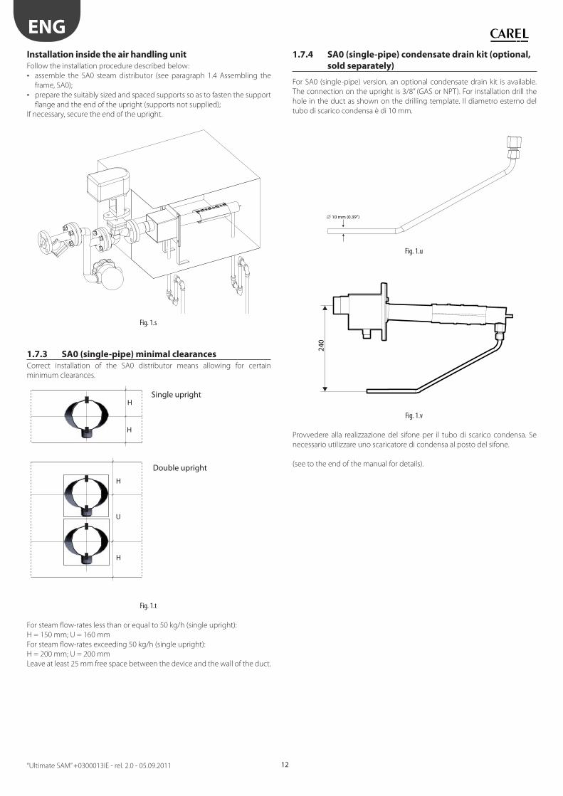
Installation inside the air handling unit
Follow the installation procedure described below:
• assemble the SA0 steam distributor (see paragraph 1.4 Assembling the
frame, SA0);
• prepare the suitably sized and spaced supports so as to fasten the support
fl ange and the end of the upright (supports not supplied);
If necessary, secure the end of the upright.
Fig. 1.s
1.7.3 SA0 (single-pipe) minimal clearances
Correct installation of the SA0 distributor means allowing for certain
minimum clearances.
H
H
H
H
U
Fig. 1.t
For steam fl ow-rates less than or equal to 50 kg/h (single upright):
H = 150 mm; U = 160 mm
For steam fl ow-rates exceeding 50 kg/h (single upright):
H = 200 mm; U = 200 mm
Leave at least 25 mm free space between the device and the wall of the duct.
1.7.4 SA0 (single-pipe) condensate drain kit (optional,
sold separately)
For SA0 (single-pipe) version, an optional condensate drain kit is available.
The connection on the upright is 3/8” (GAS or NPT). For installation drill the
hole in the duct as shown on the drilling template. Il diametro esterno del
tubo di scarico condensa è di 10 mm.
10 mm (0.39”)
Fig. 1.u
240
Fig. 1.v
Provvedere alla realizzazione del sifone per il tubo di scarico condensa. Se
necessario utilizzare uno scaricatore di condensa al posto del sifone.
(see to the end of the manual for details).
Single upright
Double upright
ENG
“Ultimate SAM” +0300013IE - rel. 2.0 - 05.09.201113
1.8 Upright steam fl ow-rateThe uprights on the ultimateSAM come in two diff erent diameters. In the
“S” confi guration (6th digit of the ultimateSAM code) the diameter of the
uprights is 35 mm, to increase fl ow-rate on single uprights there is also the “L”
confi guration (6th digit of the ultimateSAM code) in which the diameter of
the uprights is 45 mm.
1.8.1 Steam fl ow-rate, SAB/SAT versions
For ultimateSAM multi-upright models (SAB/SAT), the maximum steam fl ow-
rate for each upright also depends on the confi guration of the ultimateSAM.
In fact, with top feed the upright steam fl ow-rate increases as condensate
fl ows in the same direction as draining. Below are the fl ow-rates for the two
versions.
Upright confi guration Type “S” Type “L”Upright diameter 35 mm (1.37”) 45 mm
(1.77”)Maximum single upright fl ow-rate in the ultimate-
SAM SAB* confi guration
10 kg/h 16.7 kg/h
Maximum single upright fl ow-rate in the ultimate-
SAM SAT* confi guration
30 kg/h 50 kg/h
Tab. 1.e
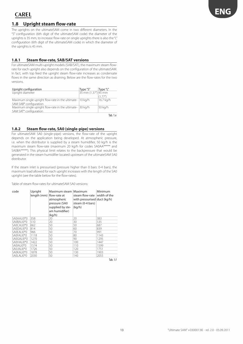
1.8.2 Steam fl ow-rate, SA0 (single-pipe) versions
For ultimateSAM SA0 (single-pipe) versions, the fl ow-rate of the upright
depends on the application being developed. At atmospheric pressure,
i.e. when the distributor is supplied by a steam humidifi er, 50 kg/h is the
maximum steam fl ow-rate (maximum 20 kg/h for codes SA0AA***** and
SA0BA*****). This physical limit relates to the backpressure that would be
generated in the steam humidifi er located upstream of the ultimateSAM SA0
distributor.
If the steam inlet is pressurised (pressure higher than 0 bars: 0-4 bars), the
maximum load allowed for each upright increases with the length of the SA0
upright (see the table below for the fl ow-rates).
Table of steam fl ow-rates for ultimateSAM SA0 versions:
code Upright length (mm)
Maximum steam fl ow-rate at atmospheric pressure (SA0 supplied by ste-am humidifi er) (kg/h)
Maximum steam fl ow-rate with pressurised steam (0-4 bars) (kg/h)
Minimum width of the duct (kg/h)
SA0AALI0*0 358 20 20 383SA0BALI0*0 510 20 30 535SA0CALI0*0 662 50 50 687SA0DALI0*0 814 50 60 839SA0EALI0*0 966 50 70 991SA0FALI0*0 1118 50 80 1143SA0GALI0*0 1270 50 90 1295SA0HALI0*0 1422 50 100 1447SA0IALI0*0 1574 50 110 1599SA0JALI0*0 1726 50 120 1751SA0KALI0*0 1878 50 130 1903SA0LALI0*0 2030 50 140 2055
Tab. 1.f
ENG
“Ultimate SAM” +0300013IE - rel. 2.0 - 05.09.2011 14
2. STEAM INLET CONNECTIONS
2.1 Inlet adapters (SAKI******)
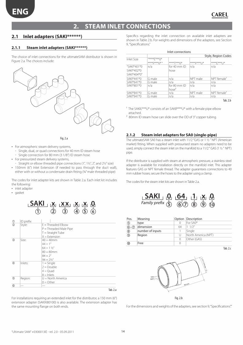
2.1.1 Steam inlet adapters (SAKI******)
The choice of inlet connections for the ultimateSAM distributor is shown in
Figure 2.a. The choices include:
Fig. 2.a
• For atmospheric steam delivery systems,
- Single, dual, or quad connections for 40 mm ID steam hose
- Single connection for 80 mm (3 1/8”) ID steam hose
• For pressurized steam delivery systems,
- Straight or elbow threaded pipe connections (1”, 1½”, 2”, and 2½” size)
• 150mm (6”) Inlet Extension (if needed to pass through the duct wall),
either with or without a condensate drain fi tting (¾” male threaded pipe)
The codes for inlet adapter kits are shown in Table 2.a. Each inlet kit includes
the following:
• inlet adapter
• gasket
2 3 4 5 6
SAKI xx x x 0x1
ID prefi x Style: E = Threaded Elbow
P = Threaded Male Pipe
T = Straight Tube
X = Extension Size: 40 = 40mm
44 = 1”
64 = 1 ½”
80 = 80mm
84 = 2”
94 = 2½” Inlets: 1 = Single
2 = Double
4 = Quad
8 = Inlets Region: U = North America
0 = Other --- ---
Tab. 2.a
For installations requiring an extended inlet for the distributor, a 150 mm (6”)
extension adapter (SAKIX80100) is also available. The extension adapter has
the same mounting fl ange on both ends.
Specifi cs regarding the inlet connection on available inlet adapters are
shown in Table 2.b. For weights and dimensions of the adapters, see Section
9, “Specifi cations.”
Inlet connectionsStyle, Region Codes
Inlet Size “****E***0*
****P***0* “ ****T***0* ****P***U* ****E***U*“SAKI*401*0
SAKI*402*0
SAKI*404*0”
n/a for 40 mm ID
hose
n/a n/a
SAKI*441*0 G male n/a NPT male NPT female¹SAKI*641*0 G male n/a n/a n/aSAKI*801*0 n/a for 80 mm ID
hose²
n/a n/a
SAKI*841*0 G male n/a NPT male NPT female¹SAKI*941*0 G male n/a n/a n/a
Tab. 2.b
¹ The SAKIE***U* consists of an SAKIP***U* with a female pipe elbow
attached.
² 80mm ID steam hose can slide over the OD of 3” copper tubing.
2.1.2 Steam inlet adapters for SA0 (single-pipe)
The ultimateSAM SA0 has a steam inlet with 11/2 “GAS or 1 ½ ” NPT (American
market) fi tting. When supplied with pressurised steam no adapters need to be
used, simply connect the steam inlet on the manifold to a 11/2 “ GAS (1 ½ ” NPT)
pipe.
If the distributor is supplied with steam at atmospheric pressure, a stainless steel
adapter is available for installation directly on the manifold inlet. This adapter
features GAS or NPT female thread. The adapter guarantees connections to 40
mm rubber hoses; secure the hoses to the adapter using a clamp.
The codes for the steam inlet kits are shown in Table 2.a.
5 6 7 8 9 10Family prefix
SAKI 0 64 1 x 0
Pos. Meaning Option Description type 0 For SA0*
- dimension 64 1 1/2”
number of inputs 1 Single
Region U North America (NPT)
0 Other (GAS)
Free 0
Tab. 2.c
90 mm
GAS 11/2”
(NPT 11/2”)
40 m
m (1
,57”
)
Fig. 2.b
For the dimensions and weights of the adapters, see section 9, “Specifi cations”.”
ENG
“Ultimate SAM” +0300013IE - rel. 2.0 - 05.09.201115
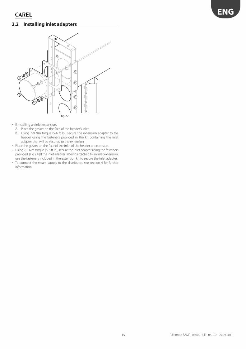
2.2 Installing inlet adapters
Fig. 2.c
• If installing an inlet extension,
A. Place the gasket on the face of the header’s inlet.
B. Using 7-8 Nm torque (5-6 ft lb), secure the extension adapter to the
header using the fasteners provided in the kit containing the inlet
adapter that will be secured to the extension.
• Place the gasket on the face of the inlet of the header or extension.
• Using 7-8 Nm torque (5-6 ft lb), secure the inlet adapter using the fasteners
provided. (Fig.2.b) If the inlet adapter is being attached to an inlet extension,
use the fasteners included in the extension kit to secure the inlet adapter.
• To connect the steam supply to the distributor, see section 4 for further
information.
ENG
“Ultimate SAM” +0300013IE - rel. 2.0 - 05.09.2011 16
3. DRAIN CONNECTIONS
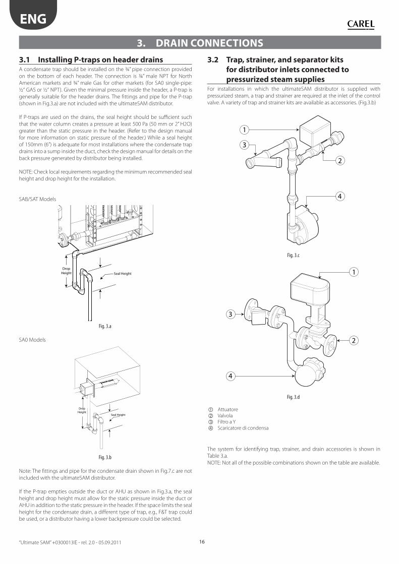
3.1 Installing P-traps on header drainsA condensate trap should be installed on the ¾” pipe connection provided
on the bottom of each header. The connection is ¾” male NPT for North
American markets and ¾” male Gas for other markets (for SA0 single-pipe:
½“ GAS or ½“ NPT). Given the minimal pressure inside the header, a P-trap is
generally suitable for the header drains. The fi ttings and pipe for the P-trap
(shown in Fig.3.a) are not included with the ultimateSAM distributor.
If P-traps are used on the drains, the seal height should be suffi cient such
that the water column creates a pressure at least 500 Pa (50 mm or 2” H2O)
greater than the static pressure in the header. (Refer to the design manual
for more information on static pressure of the header.) While a seal height
of 150mm (6”) is adequate for most installations where the condensate trap
drains into a sump inside the duct, check the design manual for details on the
back pressure generated by distributor being installed.
NOTE: Check local requirements regarding the minimum recommended seal
height and drop height for the installation.
SAB/SAT Models
DropHeight Seal Height
Fig. 3.a
SA0 Models
DropHeight
Seal Height
Fig. 3.b
Note: The fi ttings and pipe for the condensate drain shown in Fig.7.c are not
included with the ultimateSAM distributor.
If the P-trap empties outside the duct or AHU as shown in Fig.3.a, the seal
height and drop height must allow for the static pressure inside the duct or
AHU in addition to the static pressure in the header. If the space limits the seal
height for the condensate drain, a diff erent type of trap, e.g., F&T trap could
be used, or a distributor having a lower backpressure could be selected.
3.2 Trap, strainer, and separator kits
for distributor inlets connected to
pressurized steam supplies For installations in which the ultimateSAM distributor is supplied with
pressurized steam, a trap and strainer are required at the inlet of the control
valve. A variety of trap and strainer kits are available as accessories. (Fig.3.b)
1
3
4
2
Fig. 3.c
2
3
4
1
Fig. 3.d
Attuatore
Valvola
Filtro a Y
Scaricatore di condensa
The system for identifying trap, strainer, and drain accessories is shown in
Table 3.a.
NOTE: Not all of the possible combinations shown on the table are available.
ENG
“Ultimate SAM” +0300013IE - rel. 2.0 - 05.09.201117
A complete list of available kits, as well as information on other features, is
provided in Tab.3.b.
2 43 5 6
SAKT xxx x 0x1
ID prefi x
Material: F =
S =
Iron
SS
Type: S =
T =
Condensate separator
Trap & strainer assembly
Size: 15 =
20 =
25 =
32 =
40 =
44=
50=
65=
84=
DN 15 fl ange
DN 20 fl ange
DN 25 fl ange
DN 32 fl ange
DN 40 fl ange
1” pipe thread
DN 50 fl ange
DN 65 fl ange
2” pipe thread
Region: U =
0 =
North America
Other
--- ---
Tab. 3.a
Table 3.b provides a complete listing of all of the traps, strainers, and other
accessories available for the use with the ultimateSAM distributor. In addition,
the table provides information on the size and type of inlet-outlet connection
for each accessory.
Inlet-Outlet ConnectionsMaterial, Type, Region Codes
Size “****FT**0*
****FS**0*
****FT**U* ****ST**U*
SAKT**15*0 Flange DN 15 n/a n/aSAKT**20*0 Flange DN 20 n/a n/aSAKT**25*0 Flange DN 25 n/a n/aSAKT**32*0 Flange DN 32 n/a n/aSAKT**40*0 Flange DN 40 n/a n/aSAKT**44*0 n/a 1” NPT Female 1”NPT FemaleSAKT**50*0 Flange DN 50 n/a n/aSAKT**65*0 Flange DN 65 n/a n/aSAKT**84*0 n/a 2” NPT Female 2” NPT Female
Tab. 3.b
Before installing an optional fl anged trap and strainer kit, be sure that the
fl ange size matches the fl ange on the control valve. For an optional threaded
trap and strainer kit, be sure that the kit is properly sized for the control valve.
(Refer to the design manual for more information.)
Table 7.c lists the items and quantity of threaded fi ttings that are included
in each threaded trap and strainer kit. Flanged trap and strainer kits are fully
integrated.
Item List for SAKT*T**U0Item (NPT) SAKT*T44*0 SAKT*T84*0
Y-type stainer 1 (1”) 1 (1”)
F&T trap 1 (¾”) 1 (¾”)
Bushing F-M (size) 1 (¾”x1”) 1 (¾”x2”)
Elbow F-M (size) 1 (¾”) 1 (¾”)
Elbow F-F (size) 1 (1”) 1 (2”)
Nipple M-M (size) 2 (¾”x6”)
1 (1”x3”)
1 (1”x6”)
2 (¾”x6”)
1 (2”x3”)
1 (2”x6”)
Tee F-F-F (size) 1 (1”) 1 (2”)
Union F-F (size) 1 (¾”x¾”) 1 (¾”x¾”)
Tab. 3.c
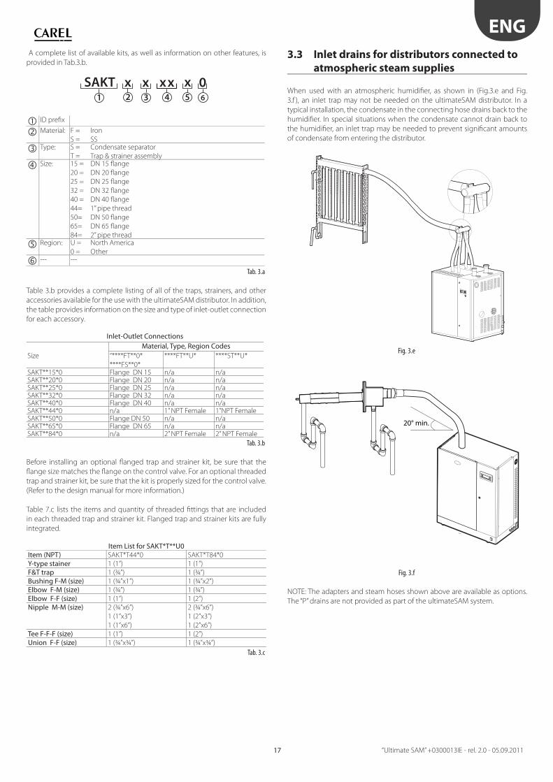
3.3 Inlet drains for distributors connected to
atmospheric steam supplies
When used with an atmospheric humidifi er, as shown in (Fig.3.e and Fig.
3.f ), an inlet trap may not be needed on the ultimateSAM distributor. In a
typical installation, the condensate in the connecting hose drains back to the
humidifi er. In special situations when the condensate cannot drain back to
the humidifi er, an inlet trap may be needed to prevent signifi cant amounts
of condensate from entering the distributor.
Fig. 3.e
20° min.
Fig. 3.f
NOTE: The adapters and steam hoses shown above are available as options.
The “P” drains are not provided as part of the ultimateSAM system.
ENG
“Ultimate SAM” +0300013IE - rel. 2.0 - 05.09.2011 18
4. STEAM SUPPLY CONNECTIONS
4.1 Control valves (SAKV******) kits for
pressurized steam suppliesA control valve is needed to regulate the fl ow of pressurized steam to an
ultimateSAM distributor. Actuators for the control valve are sold separately.
If a valve and actuator kit was not ordered with the ultimateSAM distributor,
refer to the design manual for information on how to size and select a control
valves and actuators. Information on actuators is provided in section 4.2.
The codes for valve kits are shown in table 4.a.
2 3 4 6 7
SAKV x x 0x1
x5
x
ID prefi x
--- ---
Material: 0 = Brass
F = Iron
Operating
pressure:
0 = Up to 1bar (15psi) for North America
0 = Up to 0,67 bar (8,7psi) for Other
H = 1-4bar (15-50psi) for North America
H = 0,67-4bar (8,7-50psi) for Other
Nominal
Size:
Kv (EU)
Cv (US)
A= 0,4
B= 0,63
C= 1
D= 1,6
E= 2,5
F= 4
G= 6,3
H= 10
I= 16
J= 25
K= 40
L= 58
Region: U = North America
0 = Other
--- ---
Tab. 4.a
Specifi cs regarding the inlet connection on available control valves are
shown in Table 4.b.
Inlet-Outlet ConnectionsMaterial, Pressure, Region Codes
Valve Size *****F0*0* *****FH*0* *****00*U* *****0H*U*SAKV0**A*0
SAKV0**B*0
not available not available ½"NPT Female not available
SAKV0**C*0 not available Flange DN 15 ½" NPT Female ½" NPT Female SAKV0**D*0 Flange DN 15 Flange DN 15 ½" NPT Female ½" NPT FemaleSAKV0**E*0 Flange DN 15 Flange DN 15 ½" NPT Female ½" NPT FemaleSAKV0**F*0 Flange DN 15 not available ½" NPT Female ½" NPT FemaleSAKV0**G*0 Flange DN 20 Flange DN 20 ¾" NPT Female ¾" NPT FemaleSAKV0**H*0 Flange DN 25 Flange DN 25 1" NPT Female 1" NPT FemaleSAKV0**I*0 Flange DN 32 Flange DN 32 1¼" NPT Female 1¼" NPT FemaleSAKV0**J*0 Flange DN 40 Flange DN 40 1½" NPT Female 1½" NPT FemaleSAKV0**K*0 Flange DN 50 Flange DN 50 2" NPT Female not availableSAKV0**L*0 Flange DN 65 Flange DN 65 not available not available
Tab. 4.b
If the inlet pressure to the control valve is greater than 0.7 bar (10 psig),
the valve may generate signifi cant noise due to the near sonic velocity of
the steam. (See section 6.1 of the design manual for more information.)
Because the noise and coincident vibration may shorten valve life, frequent
inspections of the valve may be required.
For information about the weight, dimensions, construction materials, and
rangeability of each valve, see section 9, “Specifi cations”.
4.2 Fitting kits (SAKR******) for threaded
control valvesNOTE: For fl anged control valves, the installer must provide the appropriate
fi ttings and piping to connect the valve to the ultimateSAM distributor.
For control valves having threaded connections, optional fi tting kits are available
to facilitate the connection of the valve to both the distributor inlet and the steam
traps and strainers (section 4.3). The codes for the fi tting kits are shown in table 4.c.
2 3 6
SAKR 001
x5
U4
xx
ID prefi x
--- ---
Material: F = Ghisa
S = Inox
Size: 24= ½” Tubo
34= ¾” Tubo
44= 1” Tubo
54= 1 ¼” Tubo
64= 1 ½” Tubo
84= 2” Tubo
Region: U = North America
--- --- Tab. 4.c
Both iron and stainless steel fi tting kits for the North American region have
NPT threads. The list of threaded pipe fi ttings provided in each kit is shown
in table 4.d.
Fitting List for SAKR0***U0Pipe Size (NPT)
Bushing F-M (size)
3” Nipple M-M (size)
Union F-F (size)
******24** 2 (½”x1”) 2 (1”) 1 (1”)******34** 2 (¾”x1”) 2 (1”) 1 (1”)******44** n/a 2 (1”) 1 (1”)******54** 2 (1¼”x2”) 2 (2”) 1 (2”)******64** 2 (1½”x2”) 2 (2”) 1 (2”)******84** n/a 2 (2”) 1 (2”) Tab. 4.d
4.3 Actuator kits for control valvesEach control valve needs an actuator to control its motion. The system for
identifying actuator kits is shown in Table 4.e. NOTE: Not all of the possible
combinations shown on the table are available. Tables 4.f and 4.g indicate
which electronic or pneumatic actuator can be paired with which control valve.
2 3 6
SAKA 001
x5
x4
xx
ID prefi x
--- ---
Type: E = Electronic P = Pneumatic
Identifi er: 01 Sequential #
02
---
Region: U = North America 0 = Others
--- --- Tab. 4.e
Electronic Actuator SelectionMaterial, Pressure, Region Codes
Valve Size *****F0*0* *****FH*0* *****00*U* *****0H*U*SAKV0**A*0
SAKV0**B*0
not available not available SAKAE001U0 not available
SAKV0**C*0 not available SAKAE00200 SAKAE001U0 SAKAE002U0"SAKV0**D*0
SAKV0**E*0
SAKAE00100 SAKAE00200 SAKAE001U0 SAKAE002U0
SAKV0**F*0 SAKAE00100 SAKAE00200 SAKAE001U0 SAKAE002U0SAKV0**G*0 SAKAE00100 not available SAKAE001U0 SAKAE002U0SAKV0**H*0 SAKAE00100 SAKAE00200 SAKAE001U0 SAKAE002U0SAKV0**I*0 SAKAE00100 SAKAE00200 SAKAE002U0 SAKAE002U0"SAKV0**J*0
SAKV0**K*0
SAKAE00100 SAKAE00200 SAKAE002U0 not available
SAKV0**L*0 SAKAE00100 SAKAE00200 not available not available
Tab. 4.f
ENG
“Ultimate SAM” +0300013IE - rel. 2.0 - 05.09.201119
NOTE: for valve types “*****FH*0*” the actuator is included in the valve kit, so
the code (SAKAE00200) indicated above is to be used when ordering a spare
actuator only.
Pneumatic Actuator SelectionMaterial, Pressure, Region Codes
Valve Size *****F0*0* *****H0*0*
*****00*U* *****0H*U*
SAKV0**A*0
SAKV0**B*0
n/a SAKAP001U0 n/a
SAKV0**C*0
SAKV0**D*0
SAKV0**E*0
SAKV0**F*0
SAKV0**G*0
n/a SAKAP001U0 SAKAP002U0
SAKV0**H*0 n/a SAKAP001U0 SAKAP003U0SAKV0**I*0
SAKV0**J*0
n/a SAKAP002U0 SAKAP003U0
SAKV0**K*0 n/a SAKAP003U0 n/aSAKV0**L*0 n/a n/a n/a
Tab. 4.g
For weights and dimensions of the actuators, see Section 9, “Specifi cations.”
This section also provides information regarding control signal requirements
for the actuators.
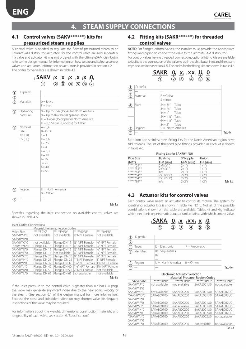
4.4 Connecting pressurized steam to an
ultimateSAM distributor
1
3
4
2
2
3
4
1
Fig. 4.a Fig. 4.b
• For threaded control valves, SAKV****U*, with an optional fi tting kit,
SAKR****U*, attach the fi ttings to the valve as shown in fi gure 4.a.
• Attach the optional actuator, SAKA******, to the control valve.
• Connect the valve/actuator assembly to the inlet adapter on the distributor
header. For optimal performance, the valve should be attached directly to
the inlet. If a connecting pipe is needed between the valve and inlet, the
length of the pipe should be as short as possible. The actuator should be
oriented in the upright position. See fi gures 1.k and 4.c.
• Assemble the fi ttings and components included in the optional trap
and strainer kit, SAKT******, and attach the trap assembly to the valve.
For steam operation, strainers should be installed in the horizontal position,
although it is acceptable to mount the strainer pointing downward. The
horizontal position prevents water from collecting in the bonnet thereby
reducing the risk of airborne droplets.
Fig. 4.c
NOTE: The “P” drains shown above are not provided as part of the ultimateSAM
system.
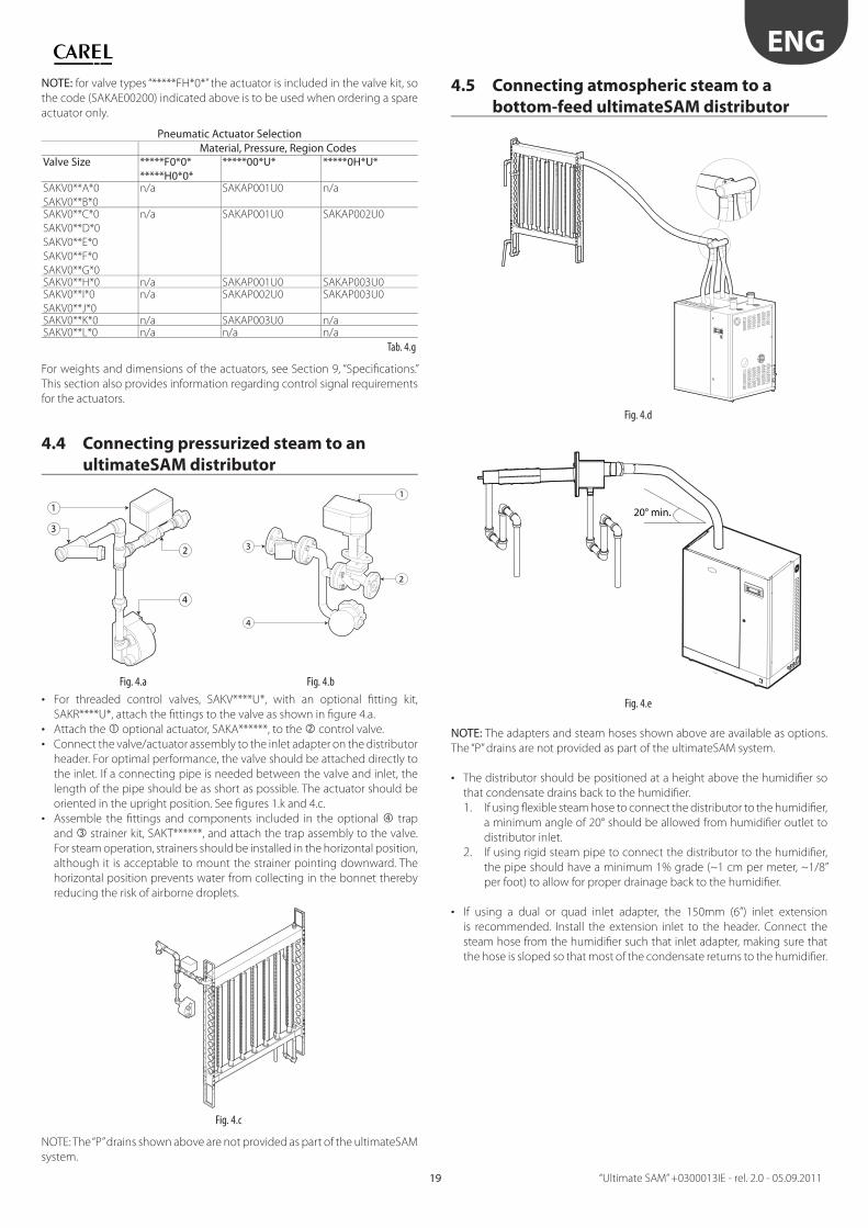
4.5 Connecting atmospheric steam to a
bottom-feed ultimateSAM distributor
Fig. 4.d
20° min.
Fig. 4.e
NOTE: The adapters and steam hoses shown above are available as options.
The “P” drains are not provided as part of the ultimateSAM system.
• The distributor should be positioned at a height above the humidifi er so
that condensate drains back to the humidifi er.
1. If using fl exible steam hose to connect the distributor to the humidifi er,
a minimum angle of 20° should be allowed from humidifi er outlet to
distributor inlet.
2. If using rigid steam pipe to connect the distributor to the humidifi er,
the pipe should have a minimum 1% grade (~1 cm per meter, ~1/8”
per foot) to allow for proper drainage back to the humidifi er.
• If using a dual or quad inlet adapter, the 150mm (6”) inlet extension
is recommended. Install the extension inlet to the header. Connect the
steam hose from the humidifi er such that inlet adapter, making sure that
the hose is sloped so that most of the condensate returns to the humidifi er.
ENG
“Ultimate SAM” +0300013IE - rel. 2.0 - 05.09.2011 20
5. OPERATION
Operationally, the ultimateSAM Humidifi cation System discharges steam
into the duct or air handler. The method by which the steam discharge is
controlled depends upon whether the steam comes from a pressurized
source or an atmospheric source. For pressurized steam supplies, the steam
fl ow rate is controlled by the valve/actuator. The control valve opens or closes
in response to a control signal that is sent to the actuator. Both electronic
and pneumatic actuators are confi gured so that there is a linear relationship
between the steam fl ow rate and the control signal.
For atmospheric steam supplies, the fl ow rate is controlled by the rate at
which the humidifi er produces steam. All of the steam generated by the
humidifi er is discharged by the ultimateSAM distributor into the duct or AHU.
The control signal for the actuator or atmospheric humidifi er is either
generated by a humidistat or a humidity sensor and controller. The controller
can be either stand-alone or part of a Building Automation System.
6. TROUBLESHOOTING
6.1 Water is spitting from the nozzles on the
uprights. 1. The header P-traps are not draining. Clean and check plumbing. Check
that height of trap exceeds the static pressure of the duct/AHU, especially
if under negative pressure.
2. The steam trap on the valve/trap assembly is not functioning. Clean or replace.
3. The steam line has been taken from the bottom of the steam source or
is not sloped properly. Change line to take off from the top and check
proper slopes.
4. The steam main is overloaded with water. Locate cause and Correct if
necessary.
5. Check valve sizing to maximum distributor capacity. Resize valve within
distributor capacity.
6.2 Steam does not discharge from the
distributors when the valve is open.1. Verify that valve is open. Correct if necessary.
2. Verify that steam is available and valves are open. Correct if necessary.
3. Verify that the steam pressure has not changed. Too high pressure could
jam the valve.
4. Carefully place a mirror or metal object close to one of the steam
discharge slots. If it fogs, steam is discharging, but evaporating very
quickly. No problem. NEVER PLACE YOUR HAND OVER OR NEAR THE
STEAM DISCHARGE NOZZLES.
5. The Y-strainer may be clogged. Clean or replace.
6.3 Steam valve will not open1. Verify power or air pressure to the valve actuator. Correct if necessary.
2. Verify control signal or pressure range to the valve actuator. Correct if
necessary.
3. Verify control signal polarity to the valve actuator. Correct if necessary.
4. Remove actuator and test to see if it operates. Valve may be jammed -
clean or replace.
5. Verify that the steam pressure has not changed. Too high pressure could
jam the valve.
6. Verify proper valve orientation - electric valves must face up.
6.4 Steam valve will not close1. Verify control signal to the valve actuator. Correct if necessary.
2. Verify control signal polarity to the valve actuator. Correct if necessary.
3. Remove actuator and test to see if it operates. Valve may be jammed -
clean or replace.
4. Verify that the steam pressure has not changed. Too high pressure could
jam the valve.
5. Verify proper valve orientation - electric valves must face up.
6.5 Steam valve is leaking1. Verify full range control signal to the valve actuator. Correct if necessary.
2. Verify control signal polarity to the valve actuator. Correct if necessary.
3. Remove actuator and test to see if it operates. Valve may be jammed -
clean or replace.
4. Verify that the steam pressure has not changed. Too high pressure could
jam the valve.
6.6 Humidity exceeds set point1. Verify full range control signal to the valve actuator is compatible. Correct
if necessary.
2. Verify control signal polarity to the valve actuator. Correct if necessary.
3. Check calibration of controller. Correct if necessary.
4. Insure humidity sensors are installed correctly and not located in drafts
(wall). Correct if necessary.
5. Remove actuator and test to see if it operates. Valve may be jammed -
clean or replace.
6. Verify that the steam pressure has not changed. Too high pressure could
cause valve to leak.
7. Verify stable boiler pressure. Wide swings in pressure could be fi ghting
the humidity controls.
8. From BAS system, change to P type control (not PI or PID).
6.7 Humidity remains below set point1. Verify full range control signal to the valve actuator is compatible. Correct
if necessary.
2. Verify control signal polarity to the valve actuator. Correct if necessary.
3. Check calibration of controller. Correct if necessary.
4. Insure humidity sensors are installed correctly and not located in drafts
(wall). Correct if necessary.
5. Remove actuator and test to see if it operates. Valve may be jammed -
clean or replace.
6. Verify that the steam pressure has not changed. Too high pressure could
jam valve. Too low will not meet capacity.
7. Verify stable boiler pressure. Wide swings in pressure could be fi ghting
the humidity controls.
8. From BAS system, change to P type control (not PI or PID).
9. Check that air fl ow switch is not fl uttering. Correct if necessary.
10. Check that hi-limit controller is not located too close to steam discharge
distributors. Correct if necessary.
11. Humidifi er is undersized. Check humidity load calculations.
ENG
“Ultimate SAM” +0300013IE - rel. 2.0 - 05.09.201121
6.8 Condensate in duct1. Verify humidifi er capacity versus air volume.
2. See section 6.1 in trouble-shooting section of this manual.
3. Verify that hi-limit controller is working. Correct if necessary.
4. Verify evaporation distance to obstructions or elbows. Correct if
necessary.
5. Verify steam valve is not leaking. Correct if necessary.
6. Uninsulated duct may be running through an area where ambient
temperature is below internal duct dew point. Insulate duct externally.
6.9 Steam leaks from P-traps.1. Check that height of trap exceeds the static pressure of the duct/AHU,
especially if under negative pressure. Correct if necessary.
2. Check valve sizing to maximum distributor capacity. Resize valve within
distributor capacity.
3. Check that inlet steam pressure does not exceed the limits of the valve.
7. MAINTENANCE
The ultimateSAM distributor itself requires no regular maintenance since its
design has no moving parts. It is recommended that the external surfaces
of the distributor should be inspected once a year. If there is evidence of a
steam leak at one of the static seals, contact Carel.
For optional equipment, such as valves, actuators, traps, and strainers, follow
the maintenance instructions in the user manuals that are provided with each
of these devices. These accessories should be inspected at least once a year.
For systems in which the inlet pressure to the control valve is greater than
0.7 bar (10 psig), more frequent inspections of the valve may be required. In
addition, steam hoses should be inspected yearly for evidence of cracking or
hardening.
8. SPARE PARTS
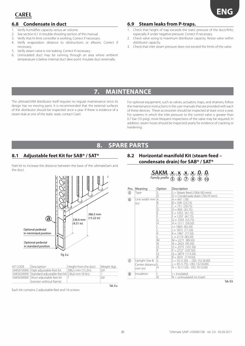
8.1 Adjustable feet Kit for SAB* / SAT*
Feet kit to increase the distance between the base of the ultimateSam and
the duct.
a 236.6 mm (9.31 in)
386.5 mm (15.22 in)
Optional pedestal in minimized position
Optional pedestal in standard position
Fig. 8.a
kIT CODE Description Height from the duct Weight (kg)SAKS010000 High adjustable feet kit 386,5 mm (15.2in) 0,9SAKS020000 Standard adjustable feet kit 236,6 mm (9.3in) 1SAKS030000 Short adjustable feet kit
(version without frame)
? 0,8
Tab. 8.a
Each kit contains 2 adjustable feet and 16 screws
8.2 Horizontal manifold Kit (steam feed –
condensate drain) for SAB* / SAT*
5 6 7 8 9 10Family prefixSAKM x x x x 0 0
Pos. Meaning Option Description Type S S = Steam feed (100x100 mm)
D D = Condensate drain (70x70 mm)
Unit width mm
(in)
A A = 447 (18)B B = 599 (23.75)C C = 751 (29.75)D D = 903 (35.75)E E = 1055 (41.75)F F = 1207 (47.75)G G = 1359 (53.75)H H = 1511 (59.50)I I = 1663 (65.50)J J = 1815 (71.50)K K = 1967 (77.50)L L = 2119 (83.50)M M = 2271 (89.50)N N = 2423 (95.50)O O = 2575 (101.50)P P = 2727 (107.50)Q Q = 2879 (113.50)R R = 3031 (119.50)
Upright Size &
Center distance
mm (in)
S S = 35 (1.50) - OD; 152 (6.00)L L = 45 (1.75) - OD; 152 (6.00)H H = 35 (1.50) - OD; 76 (3.00)
Insulation I I = insulatedN N = uninsulated no insert
Tab. 8.b
ENG
“Ultimate SAM” +0300013IE - rel. 2.0 - 05.09.2011 22
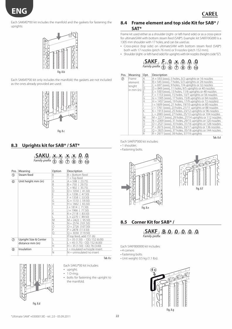
Each SAKMD*00 kit includes the manifold and the gaskets for fastening the
uprights:
Fig. 8.b
Each SAKMS*00 kit only includes the manifold; the gaskets are not included
as the ones already provided are used:
Fig. 8.c
8.3 Uprights kit for SAB* / SAT*
5 6 7 8 9 10Family prefixSAKU x x x x 0 0
Pos. Meaning Option Description Steam feed B B = Bottom feed
T T = Top feed
Unit height mm (in) A A = 598 ( 23.75)B B = 750 ( 29.75)C C = 902 ( 35.75)D D = 1054 ( 41.50)E E = 1206 ( 47.50)F F = 1358 ( 53.50)G G = 1510 ( 59.50)H H = 1662 ( 65.50)I I = 1814 ( 71.50)J J = 1966 ( 77.50)K K = 2118 ( 83.50)L L = 2270 ( 89.50)M M = 2422 ( 95.50)N N = 2574 (101.50)O O = 2726 (107.50)P P = 2878 (113.50)Q Q = 3030 (119.50)
If top feed, add 151 (6)
Upright Size & Center distance mm (in)
S S = 35 (1.50) - OD; 152 (6.00)L L = 45 (1.75) - OD; 152 (6.00)H H = 35 (1.50) - OD; 76 (3.00)
Insulation I I = insulated w/nozzle insertN N = uninsulated no insert
Tab. 8.c
Fig. 8.d
Each SAKU*00 kit includes:
• upright;
• 1 O-ring;
• bolts for fastening the upright to
the manifold.
8.4 Frame element and top side Kit for SAB* /
SAT*Frame kit used either as a shoulder (right- or left-hand side) or as a cross-piece
for ultimateSAM with bottom steam feed (SAB*). Example: kit SAKFF0G000 is a
1305 mm shoulder with 17 holes, and can be used as:
• Cross-piece (top side) on ultimateSAM with bottom steam feed (SAB*)
both with 17 nozzles (pitch 76 mm) or 9 nozzles (pitch 152 mm);
• Shoulder (right- or left-hand side) for uprights with 64 nozzles (height code “G”).
5 6 7 8 9 10Family prefixSAKF F 0 x 0 0 0
Pos. Meaning Opt. Description Frame
element
lenght
in mm (in)
A A = 593 (xxxx), 5 holes, 3/2 uprights or 16 nozzlesB B = 545 (xxxx), 7 holes, 5/3 uprights or 24 nozzlesC C = 697 (xxxx), 9 holes, 7/4 uprights or 32 nozzlesD D = 849 (xxxx), 11 holes, 9/5 uprights or 40 nozzlesE E = 1001(xxxx), 13 holes, 11/6 uprights or 48 nozzlesF F = 1153 (xxxx), 15 holes, 13/7 uprights or 56 nozzlesG G = 1305 (xxxx), 17 holes, 15/8 uprights or 64 nozzlesH H = 1457 (xxxx), 19 holes, 17/9 uprights or 72 nozzles)I I = 1609 (xxxx), 21 holes, 19/10 uprights or 80 nozzlesJ J = 1761 (xxxx), 23 holes, 21/11 uprights or 88 nozzlesK K = 1913 (xxxx), 25 holes, 23/12 uprights or 96 nozzlesL L = 2065 (xxxx), 27 holes, 25/13 uprights or 104 nozzlesM M = 2217 (xxxx), 29 holes, 27/14 uprights or 112 nozzlesN N = 2369 (xxxx), 31 holes, 29/15 uprights or 120 nozzlesO O = 2521 (xxxx), 33 holes, 31/16 uprights or 128 nozzlesP P = 2673 (xxxx), 35 holes, 33/17 uprights or 136 nozzlesQ Q = 2825 (xxxx), 37 holes, 35/18 uprights or 144 nozzlesR R = 2977 (xxxx), 39 holes, 37/19 uprights
Tab. 8.d
Each SAKF0*000 kit includes:
• 1 shoulder;
• Fastening bolts.
Fig. 8.e
Fig. 8.f
8.5 Corner Kit for SAB* /
SAKF B 0 0 0 0 0Family prefix
Each SAKFB00000 kit includes:
• 4 corners
• Fastening bolts
• Unit weight: 0.5 kg (1.1 lbs).
4 x
Fig. 8.g
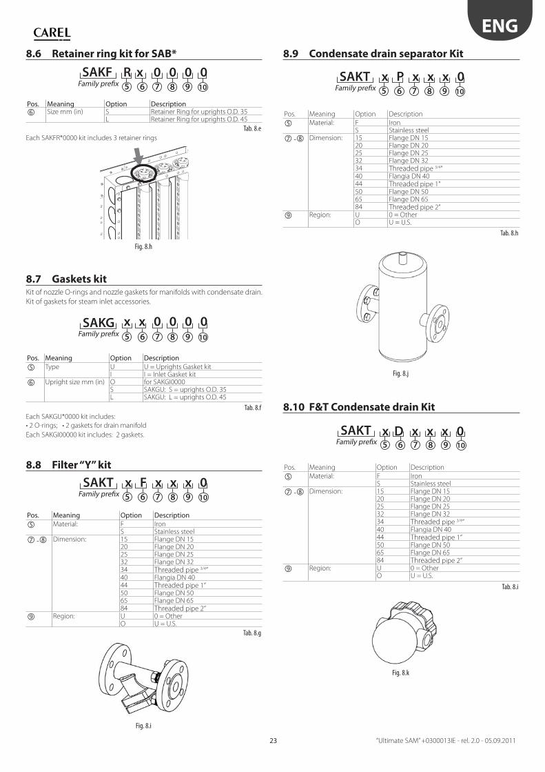
ENG
“Ultimate SAM” +0300013IE - rel. 2.0 - 05.09.201123
8.6 Retainer ring kit for SAB*
5 6 7 8 9 10Family prefixSAKF R x 0 0 0 0
Pos. Meaning Option Description Size mm (in) S Retainer Ring for uprights O.D. 35
L Retainer Ring for uprights O.D. 45
Tab. 8.e
Each SAKFR*0000 kit includes 3 retainer rings
Fig. 8.h
8.7 Gaskets kitKit of nozzle O-rings and nozzle gaskets for manifolds with condensate drain.
Kit of gaskets for steam inlet accessories.
5 6 7 8 9 10Family prefixSAKG x x 0 0 0 0
Pos. Meaning Option Description Type U U = Uprights Gasket kit
I I = Inlet Gasket kit
Upright size mm (in) O for SAKGI0000S SAKGU: S = uprights O.D. 35L SAKGU: L = uprights O.D. 45
Tab. 8.f
Each SAKGU*0000 kit includes:
• 2 O-rings; • 2 gaskets for drain manifold
Each SAKGI00000 kit includes: 2 gaskets.
8.8 Filter “Y” kit
5 6 7 8 9 10Family prefixSAKT x F x x x 0
Pos. Meaning Option Description Material: F Iron
S Stainless steel
- Dimension: 15 Flange DN 1520 Flange DN 2025 Flange DN 2532 Flange DN 3234 Threaded pipe 3/4”40 Flangia DN 4044 Threaded pipe 1”50 Flange DN 5065 Flange DN 6584 Threaded pipe 2”
Region: U 0 = OtherO U = U.S.
Tab. 8.g
Fig. 8.i
8.9 Condensate drain separator Kit
5 6 7 8 9 10Family prefixSAKT x P x x x 0
Pos. Meaning Option Description
Material: F IronS Stainless steel
- Dimension: 15 Flange DN 1520 Flange DN 2025 Flange DN 2532 Flange DN 3234 Threaded pipe 3/4”40 Flangia DN 4044 Threaded pipe 1”50 Flange DN 5065 Flange DN 6584 Threaded pipe 2”
Region: U 0 = OtherO U = U.S.
Tab. 8.h
Fig. 8.j
8.10 F&T Condensate drain Kit
5 6 7 8 9 10Family prefixSAKT x D x x x 0
Pos. Meaning Option Description
Material: F IronS Stainless steel
- Dimension: 15 Flange DN 1520 Flange DN 2025 Flange DN 2532 Flange DN 3234 Threaded pipe 3/4”40 Flangia DN 4044 Threaded pipe 1”50 Flange DN 5065 Flange DN 6584 Threaded pipe 2”
Region: U 0 = OtherO U = U.S.
Tab. 8.i
Fig. 8.k
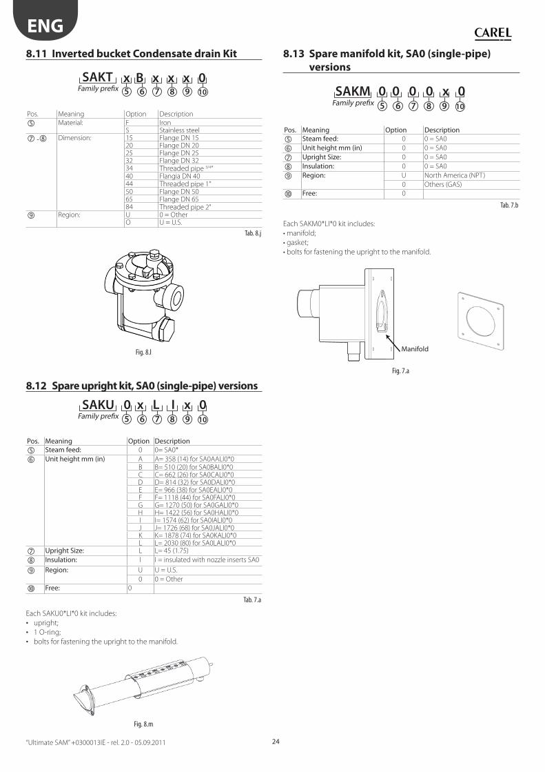
ENG
“Ultimate SAM” +0300013IE - rel. 2.0 - 05.09.2011 24
8.11 Inverted bucket Condensate drain Kit
5 6 7 8 9 10Family prefixSAKT x B x x x 0
Pos. Meaning Option Description
Material: F IronS Stainless steel
- Dimension: 15 Flange DN 1520 Flange DN 2025 Flange DN 2532 Flange DN 3234 Threaded pipe 3/4”40 Flangia DN 4044 Threaded pipe 1”50 Flange DN 5065 Flange DN 6584 Threaded pipe 2”
Region: U 0 = OtherO U = U.S.
Tab. 8.j
Fig. 8.l
8.12 Spare upright kit, SA0 (single-pipe) versions
5 6 7 8 9 10Family prefixSAKU 0 x L I x 0
Pos. Meaning Option Description Steam feed: 0 0= SA0*
Unit height mm (in) A A= 358 (14) for SA0AALI0*0B B= 510 (20) for SA0BALI0*0C C= 662 (26) for SA0CALI0*0D D= 814 (32) for SA0DALI0*0E E= 966 (38) for SA0EALI0*0F F= 1118 (44) for SA0FALI0*0G G= 1270 (50) for SA0GALI0*0H H= 1422 (56) for SA0HALI0*0I I= 1574 (62) for SA0IALI0*0J J= 1726 (68) for SA0JALI0*0K K= 1878 (74) for SA0KALI0*0L L= 2030 (80) for SA0LALI0*0
Upright Size: L L= 45 (1.75)
Insulation: I I = insulated with nozzle inserts SA0
Region: U U = U.S.
0 0 = Other
Free: 0
Tab. 7.a
Each SAKU0*LI*0 kit includes:
• upright;
• 1 O-ring;
• bolts for fastening the upright to the manifold.
Fig. 8.m
8.13 Spare manifold kit, SA0 (single-pipe)
versions
5 6 7 8 9 10Family prefixSAKM 0 0 0 0 x 0
Pos. Meaning Option Description Steam feed: 0 0 = SA0
Unit height mm (in) 0 0 = SA0
Upright Size: 0 0 = SA0
Insulation: 0 0 = SA0
Region: U North America (NPT)
0 Others (GAS)
Free: 0
Tab. 7.b
Each SAKM0*LI*0 kit includes:
• manifold;
• gasket;
• bolts for fastening the upright to the manifold.
Fig. 7.a
Manifold
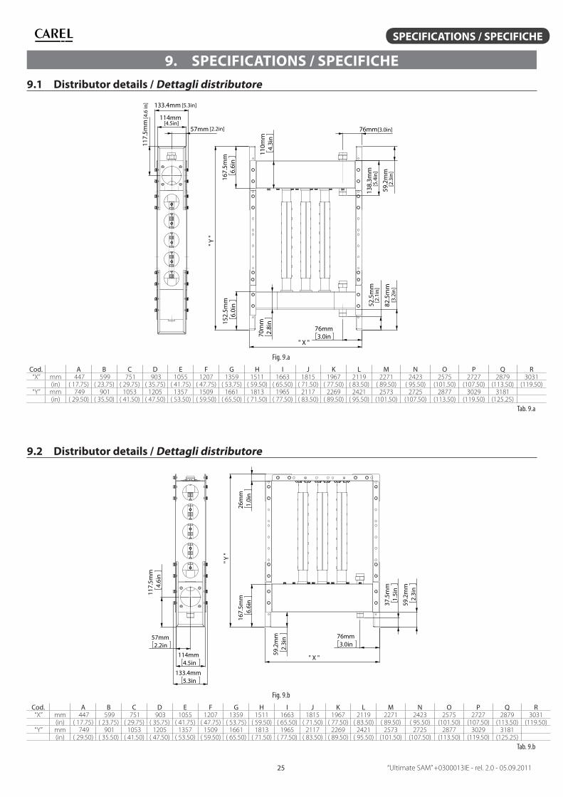
“Ultimate SAM” +0300013IE - rel. 2.0 - 05.09.201125
SPECIFICATIONS / SPECIFICHE
9. SPECIFICATIONS / SPECIFICHE
9.1 Distributor details / Dettagli distributore
57mm
114mm
133.4mm
117.
5mm
76mm3.0in
" X "
52.5
mm
82.5
mm
76mm
138.
3mm
59.2
mm
" Y "
70m
m2.
8in
110m
m4.
3in
152.
5mm
6.0i
n16
7.5m
m6.
6in
[5.3in]
[4.6
in]
[4.5in][2.2in] [3.0in]
[5.4
in]
[2.3
in]
[2.1
in]
[3.2
in]
Fig. 9.a
Cod. A B C D E F G H I J K L M N O P Q R“X” mm 447 599 751 903 1055 1207 1359 1511 1663 1815 1967 2119 2271 2423 2575 2727 2879 3031
(in) ( 17.75) ( 23.75) ( 29.75) ( 35.75) ( 41.75) ( 47.75) ( 53.75) ( 59.50) ( 65.50) ( 71.50) ( 77.50) ( 83.50) ( 89.50) ( 95.50) (101.50) (107.50) (113.50) (119.50)“Y” mm 749 901 1053 1205 1357 1509 1661 1813 1965 2117 2269 2421 2573 2725 2877 3029 3181
(in) ( 29.50) ( 35.50) ( 41.50) ( 47.50) ( 53.50) ( 59.50) ( 65.50) ( 71.50) ( 77.50) ( 83.50) ( 89.50) ( 95.50) (101.50) (107.50) (113.50) (119.50) (125.25)
Tab. 9.a
9.2 Distributor details / Dettagli distributore
57mm2.2in
114mm4.5in
133.4mm5.3in
117.5m
m4.
6in
59.2mm
2.3in 76mm
3.0in
37.5mm
1.5in
59.2mm
2.3in
" X "
" Y "
167.5m
m6.
6in
26mm
1.0in
Fig. 9.b
Cod. A B C D E F G H I J K L M N O P Q R“X” mm 447 599 751 903 1055 1207 1359 1511 1663 1815 1967 2119 2271 2423 2575 2727 2879 3031
(in) ( 17.75) ( 23.75) ( 29.75) ( 35.75) ( 41.75) ( 47.75) ( 53.75) ( 59.50) ( 65.50) ( 71.50) ( 77.50) ( 83.50) ( 89.50) ( 95.50) (101.50) (107.50) (113.50) (119.50)“Y” mm 749 901 1053 1205 1357 1509 1661 1813 1965 2117 2269 2421 2573 2725 2877 3029 3181
(in) ( 29.50) ( 35.50) ( 41.50) ( 47.50) ( 53.50) ( 59.50) ( 65.50) ( 71.50) ( 77.50) ( 83.50) ( 89.50) ( 95.50) (101.50) (107.50) (113.50) (119.50) (125.25)
Tab. 9.b
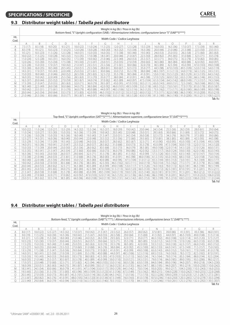
“Ultimate SAM” +0300013IE - rel. 2.0 - 05.09.2011 26
SPECIFICATIONS / SPECIFICHE
9.3 Distributor weight tables / Tabella pesi distributore
Weight in kg (lb) / Peso in kg (lb)Bottom-feed, “S” Upright confi guration (SAB) / Alimentazione inferiore, confi gurazione lance “S” (SAB**S****)
Ht.Cod.
Width Code / Codice Larghezza
A B C D E F G H I J N O P Q RA 7.5 (17) 8.5 (18) 9.0 (20) 9.5 (21) 10.0 (22) 11.0 (24) 11.5 (25) 12.0 (27) 12.5 (28) 13.5 (29) 16.0 (35) 16.5 (36) 17.0 (37) 17.5 (39) 18.5 (40)B 8.5 (19) 9.5 (21) 10.5 (23) 11.0 (25) 12.0 (26) 13.0 (28) 14.0 (30) 14.5 (32) 15.5 (34) 16.5 (36) 20.0 (44) 21.0 (46) 21.5 (48) 22.5 (50) 23.5 (51)C 9.5 (21) 10.5 (23) 11.5 (26) 12.5 (28) 14.0 (31) 15.0 (33) 16.0 (35) 17.5 (38) 18.5 (40) 19.5 (43) 24.0 (53) 25.0 (55) 26.5 (58) 27.5 (60) 28.5 (63)D 10.0 (22) 11.5 (25) 13.0 (28) 14.5 (32) 15.5 (35) 17.0 (38) 18.5 (41) 20.0 (44) 21.0 (47) 22.5 (50) 28.0 (62) 29.5 (65) 31.0 (68) 32.5 (71) 33.5 (74)E 11.0 (24) 12.5 (28) 14.5 (31) 16.0 (35) 17.5 (39) 19.0 (42) 21.0 (46) 22.5 (49) 24.0 (53) 25.5 (57) 32.5 (71) 34.0 (75) 35.5 (78) 37.0 (82) 39.0 (85)F 12.0 (26) 13.5 (30) 15.5 (34) 17.5 (38) 19.5 (43) 21.5 (47) 23.0 (51) 25.0 (55) 27.0 (59) 29.0 (63) 36.5 (80) 38.5 (84) 40.0 (88) 42.0 (92) 44.0 (97)G 12.5 (28) 15.0 (33) 17.0 (37) 19.0 (42) 21.0 (47) 23.5 (51) 25.5 (56) 27.5 (61) 30.0 (66) 32.0 (70) 40.5 (89) 42.5 (94) 45.0 (99) 47.0 (103) 49.0 (108)H 13.5 (30) 16.0 (35) 18.5 (40) 20.5 (45) 23.0 (51) 25.5 (56) 28.0 (61) 30.0 (67) 32.5 (72) 35.0 (77) 44.5 (98) 47.0 (103) 49.5 (109) 52.0 (114) 54.0 (119)I 14.5 (31) 17.0 (37) 19.5 (43) 22.0 (49) 25.0 (55) 27.5 (61) 30.0 (66) 33.0 (72) 35.5 (78) 38.0 (84) 48.5 (107) 51.5 (113) 54.0 (119) 56.5 (125) 59.5 (131)J 15.0 (33) 18.0 (40) 21.0 (46) 24.0 (52) 26.5 (59) 29.5 (65) 32.5 (72) 35.5 (78) 38.5 (84) 41.0 (91) 53.0 (116) 55.5 (123) 58.5 (129) 61.5 (135) 64.5 (142)K 16.0 (35) 19.0 (42) 22.0 (49) 25.5 (56) 28.5 (63) 31.5 (70) 35.0 (77) 38.0 (84) 41.0 (91) 44.5 (98) 57.0 (125) 60.0 (132) 63.5 (139) 66.5 (146) 69.5 (153)L 16.5 (37) 20.0 (44) 23.5 (52) 27.0 (59) 30.5 (67) 34.0 (74) 37.0 (82) 40.5 (89) 44.0 (97) 47.5 (104) 61.0 (134) 64.5 (142) 68.0 (149) 71.5 (157) 74.5 (164)M 17.5 (39) 21.0 (47) 25.0 (55) 28.5 (63) 32.0 (71) 36.0 (79) 39.5 (87) 43.0 (95) 47.0 (103) 50.5 (111) 65.0 (143) 69.0 (151) 72.5 (160) 76.0 (168) 80.0 (176)N 18.5 (40) 22.5 (49) 26.0 (58) 30.0 (66) 34.0 (75) 38.0 (84) 42.0 (92) 46.0 (101) 49.5 (109) 53.5 (118) 69.5 (152) 73.0 (161) 77.0 (170) 81.0 (178) 85.0 (187)O 19.0 (42) 23.5 (51) 27.5 (61) 31.5 (70) 36.0 (79) 40.0 (88) 44.0 (97) 48.5 (106) 52.5 (116) 56.5 (125) 73.5 (162) 77.5 (171) 82.0 (180) 86.0 (189) 90.0 (198)P 20.0 (44) 24.5 (54) 29.0 (64) 33.5 (73) 37.5 (83) 42.0 (93) 46.5 (102) 51.0 (112) 55.5 (122) 60.0 (132) 77.5 (171) 82.0 (180) 86.5 (190) 91.0 (200) 95.0 (210)Q 21.0 (46) 25.5 (56) 30.0 (66) 35.0 (77) 39.5 (87) 44.0 (97) 49.0 (108) 53.5 (118) 58.5 (128) 63.0 (139) 81.5 (180) 86.5 (190) 91.0 (200) 95.5 (211) 100.5 (221)
Tab. 9.c
Weight in kg (lb) / Peso in kg (lb)Top-feed, “S” Upright confi guration (SAT**S****) / Alimentazione superiore, confi gurazione lance “S” (SAT**S****)
Ht.Cod.
Width Code / Codice Larghezza
A B C D E F G H I J N O P Q RA 10.0 (22) 11.0 (24) 12.0 (27) 13.5 (29) 14.5 (32) 15.5 (34) 16.5 (37) 18.0 (39) 19.0 (42) 20.0 (44) 24.5 (54) 25.5 (56) 26.5 (59) 28.0 (61) 29.0 (64)B 11.0 (24) 12.0 (27) 13.5 (30) 15.0 (33) 16.5 (36) 17.5 (39) 19.0 (42) 20.5 (45) 22.0 (48) 23.0 (51) 28.5 (63) 30.0 (66) 31.5 (69) 32.5 (72) 34.0 (75)C 11.5 (26) 13.0 (29) 15.0 (33) 16.5 (36) 18.0 (40) 19.5 (43) 21.5 (47) 23.0 (51) 24.5 (54) 26.0 (58) 32.5 (72) 34.5 (76) 36.0 (79) 37.5 (83) 39.0 (86)D 12.5 (27) 14.5 (31) 16.0 (36) 18.0 (40) 20.0 (44) 22.0 (48) 23.5 (52) 25.5 (56) 27.5 (60) 29.5 (65) 37.0 (81) 38.5 (85) 40.5 (89) 42.5 (93) 44.5 (98)E 13.5 (29) 15.5 (34) 17.5 (39) 19.5 (43) 22.0 (48) 24.0 (53) 26.0 (57) 28.0 (62) 30.5 (67) 32.5 (71) 41.0 (90) 43.0 (95) 45.0 (100) 47.5 (104) 49.5 (109)F 14.0 (31) 16.5 (36) 19.0 (41) 21.0 (47) 23.5 (52) 26.0 (57) 28.5 (62) 31.0 (68) 33.0 (73) 35.5 (78) 45.0 (99) 47.5 (104) 50.0 (110) 52.0 (115) 54.5 (120)G 15.0 (33) 17.5 (39) 20.0 (44) 23.0 (50) 25.5 (56) 28.0 (62) 30.5 (68) 33.5 (73) 36.0 (79) 38.5 (85) 49.0 (108) 52.0 (114) 54.5 (120) 57.0 (126) 60.0 (131)H 15.5 (35) 18.5 (41) 21.5 (47) 24.5 (54) 27.5 (60) 30.0 (66) 33.0 (73) 36.0 (79) 39.0 (86) 42.0 (92) 53.5 (117) 56.0 (124) 59.0 (130) 62.0 (136) 65.0 (143)I 16.5 (36) 19.5 (43) 23.0 (50) 26.0 (57) 29.0 (64) 32.5 (71) 35.5 (78) 38.5 (85) 41.5 (92) 45.0 (99) 57.5 (126) 60.5 (133) 63.5 (140) 67.0 (147) 70.0 (154)J 17.5 (38) 21.0 (46) 24.0 (53) 27.5 (61) 31.0 (68) 34.5 (76) 38.0 (83) 41.0 (91) 44.5 (98) 48.0 (106) 61.5 (135) 65.0 (143) 68.5 (150) 72.0 (158) 75.0 (165)K 18.0 (40) 22.0 (48) 25.5 (56) 29.0 (64) 33.0 (72) 36.5 (80) 40.0 (88) 44.0 (96) 47.5 (104) 51.0 (112) 65.5 (144) 69.5 (153) 73.0 (161) 76.5 (169) 80.5 (177)L 19.0 (42) 23.0 (50) 27.0 (59) 30.5 (68) 34.5 (76) 38.5 (85) 42.5 (93) 46.5 (102) 50.5 (111) 54.0 (119) 70.0 (154) 73.5 (162) 77.5 (171) 81.5 (179) 85.5 (188)M 20.0 (44) 24.0 (53) 28.0 (62) 32.5 (71) 36.5 (80) 40.5 (89) 45.0 (99) 49.0 (108) 53.0 (117) 57.5 (126) 74.0 (163) 78.0 (172) 82.0 (181) 86.5 (190) 90.5 (199)N 20.5 (45) 25.0 (55) 29.5 (65) 34.0 (75) 38.5 (84) 42.5 (94) 47.0 (104) 51.5 (113) 56.0 (123) 60.5 (133) 78.0 (172) 82.5 (181) 87.0 (191) 91.5 (201) 95.5 (211)O 21.5 (47) 26.0 (58) 31.0 (68) 35.5 (78) 40.0 (88) 45.0 (99) 49.5 (109) 54.0 (119) 59.0 (129) 63.5 (140) 82.0 (181) 87.0 (191) 91.5 (201) 96.0 (212) 101.0 (222)P 22.5 (49) 27.0 (60) 32.0 (71) 37.0 (82) 42.0 (92) 47.0 (103) 52.0 (114) 56.5 (125) 61.5 (136) 66.5 (146) 86.5 (190) 91.0 (201) 96.0 (211) 101.0 (222) 106.0 (233)Q 23.0 (51) 28.5 (62) 33.5 (74) 38.5 (85) 44.0 (96) 49.0 (108) 54.0 (119) 59.5 (131) 64.5 (142) 69.5 (153) 90.5 (199) 95.5 (210) 100.5 (222) 106.0 (233) 111.0 (244)
Tab. 9.d
9.4 Distributor weight tables / Tabella pesi distributore
Weight in kg (lb) / Peso in kg (lb)Bottom-feed, “L” Upright confi guration (SAB**L****) / Alimentazione inferiore, confi gurazione lance “L” (SAB**L****)
Ht.Cod.
Width Code / Codice Larghezza
A B C D E F G H I J N O P Q RA 8.0 (17) 10.0 (22) 12.5 (27) 14.5 (32) 17.0 (37) 19.0 (42) 21.5 (47) 23.5 (52) 26.0 (57) 28.0 (62) 37.0 (81) 39.0 (86) 41.5 (91) 43.5 (96) 46.0 (101)B 9.0 (19) 11.5 (25) 14.0 (30) 16.5 (36) 19.0 (42) 21.5 (47) 24.0 (53) 26.5 (58) 29.0 (64) 31.5 (69) 41.5 (92) 44.0 (97) 46.5 (103) 49.0 (108) 51.5 (114)C 9.5 (21) 12.5 (28) 15.5 (34) 18.0 (40) 21.0 (46) 24.0 (52) 26.5 (59) 29.5 (65) 32.0 (71) 35.0 (77) 46.5 (102) 49.0 (108) 52.0 (114) 54.5 (120) 57.5 (127)D 10.5 (23) 13.5 (30) 17.0 (37) 20.0 (44) 23.0 (51) 26.0 (57) 29.0 (64) 32.5 (71) 35.5 (78) 38.5 (85) 51.0 (112) 54.0 (119) 57.0 (126) 60.5 (133) 63.5 (139)E 11.5 (25) 15.0 (33) 18.5 (40) 21.5 (48) 25.0 (55) 28.5 (63) 32.0 (70) 35.5 (78) 38.5 (85) 42.0 (93) 55.5 (122) 59.0 (130) 62.5 (137) 66.0 (145) 69.5 (152)F 12.5 (27) 16.0 (35) 20.0 (44) 23.5 (52) 27.0 (60) 31.0 (68) 34.5 (76) 38.0 (84) 42.0 (92) 45.5 (100) 60.5 (133) 64.0 (141) 67.5 (149) 71.5 (157) 75.0 (165)G 13.5 (29) 17.5 (38) 21.5 (47) 25.0 (56) 29.0 (64) 33.0 (73) 37.0 (82) 41.0 (91) 45.0 (99) 49.0 (108) 65.0 (143) 69.0 (152) 73.0 (161) 77.0 (169) 81.0 (178)H 14.0 (31) 18.5 (41) 22.5 (50) 27.0 (59) 31.5 (69) 35.5 (78) 40.0 (88) 44.0 (97) 48.5 (106) 52.5 (116) 69.5 (153) 74.0 (163) 78.5 (172) 82.5 (182) 87.0 (191)I 15.0 (33) 19.5 (43) 24.0 (53) 29.0 (63) 33.5 (73) 38.0 (83) 42.5 (93) 47.0 (103) 51.5 (113) 56.0 (124) 74.5 (164) 79.0 (174) 83.5 (184) 88.0 (194) 92.5 (204)J 16.0 (35) 21.0 (46) 25.5 (57) 30.5 (67) 35.5 (78) 40.5 (89) 45.0 (99) 50.0 (110) 55.0 (121) 59.5 (131) 79.0 (174) 84.0 (185) 89.0 (195) 93.5 (206) 98.5 (217)K 17.0 (37) 22.0 (48) 27.0 (60) 32.5 (71) 37.5 (82) 42.5 (94) 48.0 (105) 53.0 (116) 58.0 (128) 63.0 (139) 84.0 (184) 89.0 (196) 94.0 (207) 99.0 (218) 104.5 (230)L 18.0 (39) 23.0 (51) 28.5 (63) 34.0 (75) 39.5 (87) 45.0 (99) 50.5 (111) 56.0 (123) 61.5 (135) 66.5 (147) 88.5 (195) 94.0 (207) 99.5 (219) 105.0 (230) 110.0 (242)M 18.5 (41) 24.5 (54) 30.0 (66) 36.0 (79) 41.5 (91) 47.5 (104) 53.0 (117) 59.0 (129) 64.5 (142) 70.0 (154) 93.0 (205) 99.0 (217) 104.5 (230) 110.5 (243) 116.0 (255)N 19.5 (43) 25.5 (56) 31.5 (70) 37.5 (83) 43.5 (96) 49.5 (109) 55.5 (123) 61.5 (136) 67.5 (149) 73.5 (162) 98.0 (215) 104.0 (228) 110.0 (242) 116.0 (255) 122.0 (268)O 20.5 (45) 27.0 (59) 33.0 (73) 39.5 (87) 45.5 (101) 52.0 (114) 58.5 (128) 64.5 (142) 71.0 (156) 77.5 (170) 102.5 (226) 109.0 (239) 115.0 (253) 121.5 (267) 127.5 (281)P 21.5 (47) 28.0 (62) 34.5 (76) 41.0 (91) 48.0 (105) 54.5 (120) 61.0 (134) 67.5 (149) 74.0 (163) 81.0 (178) 107.0 (236) 114.0 (250) 120.5 (265) 127.0 (279) 133.5 (294)Q 22.5 (49) 29.0 (64) 36.0 (79) 43.0 (94) 50.0 (110) 56.5 (125) 63.5 (140) 70.5 (155) 77.5 (170) 84.5 (185) 112.0 (246) 119.0 (261) 125.5 (276) 132.5 (292) 139.5 (307)
Tab. 9.e
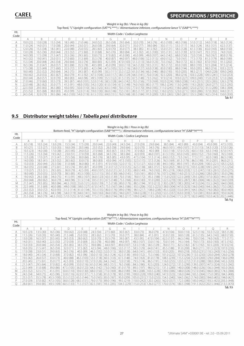
“Ultimate SAM” +0300013IE - rel. 2.0 - 05.09.201127
SPECIFICATIONS / SPECIFICHE
Weight in kg (lb) / Peso in kg (lb)Top-feed, ”L” Upright confi guration (SAT**L****) / Alimentazione inferiore, confi gurazione lance “L” (SAB**L****)
Ht.Code
Width Code / Codice Larghezza
A B C D E F G H I J N O P Q RA 10.0 (22) 13.0 (28) 15.5 (34) 18.5 (40) 21.0 (46) 24.0 (52) 26.5 (58) 29.5 (64) 32.0 (70) 34.5 (76) 45.5 (100) 48.5 (106) 51.0 (112) 54.0 (118) 56.5 (124)B 11.0 (24) 14.0 (31) 17.0 (38) 20.0 (44) 23.0 (51) 26.0 (58) 29.0 (64) 32.0 (71) 35.0 (77) 38.0 (84) 50.5 (111) 53.5 (117) 56.5 (124) 59.5 (131) 62.5 (137)C 12.0 (26) 15.5 (34) 18.5 (41) 22.0 (48) 25.0 (55) 28.5 (63) 32.0 (70) 35.0 (77) 38.5 (85) 41.5 (92) 55.0 (121) 58.5 (128) 61.5 (136) 65.0 (143) 68.0 (150)D 13.0 (28) 16.5 (36) 20.0 (44) 23.5 (52) 27.5 (60) 31.0 (68) 34.5 (76) 38.0 (84) 41.5 (92) 45.5 (100) 59.5 (131) 63.5 (139) 67.0 (147) 70.5 (155) 74.0 (163)E 14.0 (30) 17.5 (39) 21.5 (47) 25.5 (56) 29.5 (65) 33.0 (73) 37.0 (82) 41.0 (90) 45.0 (99) 49.0 (107) 64.5 (142) 68.0 (150) 72.0 (159) 76.0 (167) 80.0 (176)F 14.5 (32) 19.0 (41) 23.0 (51) 27.0 (60) 31.5 (69) 35.5 (78) 40.0 (87) 44.0 (97) 48.0 (106) 52.5 (115) 69.0 (152) 73.0 (161) 77.5 (170) 81.5 (179) 86.0 (189)G 15.5 (34) 20.0 (44) 24.5 (54) 29.0 (64) 33.5 (74) 38.0 (83) 42.5 (93) 47.0 (103) 51.5 (113) 56.0 (123) 73.5 (162) 78.0 (172) 82.5 (182) 87.0 (192) 91.5 (202)H 16.5 (36) 21.0 (47) 26.0 (57) 30.5 (68) 35.5 (78) 40.5 (89) 45.0 (99) 50.0 (110) 54.5 (120) 59.5 (131) 78.5 (172) 83.0 (183) 88.0 (193) 92.5 (204) 97.5 (214)I 17.5 (38) 22.5 (49) 27.5 (60) 32.5 (72) 37.5 (83) 42.5 (94) 47.5 (105) 52.5 (116) 58.0 (127) 63.0 (138) 83.0 (183) 88.0 (194) 93.0 (205) 98.0 (216) 103.5 (227)J 18.0 (40) 23.5 (52) 29.0 (64) 34.5 (75) 39.5 (87) 45.0 (99) 50.5 (111) 55.5 (122) 61.0 (134) 66.5 (146) 88.0 (193) 93.0 (205) 98.5 (217) 104.0 (228) 109.0 (240)K 19.0 (42) 25.0 (55) 30.5 (67) 36.0 (79) 41.5 (92) 47.5 (104) 53.0 (117) 58.5 (129) 64.5 (141) 70.0 (154) 92.5 (203) 98.0 (216) 103.5 (228) 109.5 (241) 115.0 (253)L 20.0 (44) 26.0 (57) 32.0 (70) 38.0 (83) 44.0 (96) 49.5 (109) 55.5 (122) 61.5 (135) 67.5 (148) 73.5 (162) 97.0 (214) 103.0 (227) 109.0 (240) 115.0 (253) 121.0 (266)M 21.0 (46) 27.0 (60) 33.5 (73) 39.5 (87) 46.0 (101) 52.0 (114) 58.5 (128) 64.5 (142) 70.5 (156) 77.0 (169) 102.0 (224) 108.0 (238) 114.5 (251) 120.5 (265) 126.5 (279)N 22.0 (48) 28.5 (62) 35.0 (77) 41.5 (91) 48.0 (105) 54.5 (120) 61.0 (134) 67.5 (148) 74.0 (163) 80.5 (177) 106.5 (234) 113.0 (249) 119.5 (263) 126.0 (277) 132.5 (292)O 22.5 (50) 29.5 (65) 36.5 (80) 43.0 (95) 50.0 (110) 56.5 (125) 63.5 (140) 70.5 (155) 77.0 (170) 84.0 (185) 111.0 (245) 118.0 (260) 125.0 (275) 131.5 (290) 138.5 (304)P 23.5 (52) 30.5 (68) 38.0 (83) 45.0 (99) 52.0 (114) 59.0 (130) 66.0 (146) 73.5 (161) 80.5 (177) 87.5 (192) 116.0 (255) 123.0 (271) 130.0 (286) 137.0 (302) 144.0 (317)Q 24.5 (54) 32.0 (70) 39.5 (86) 46.5 (103) 54.0 (119) 61.5 (135) 69.0 (151) 76.0 (168) 83.5 (184) 91.0 (200) 120.5 (265) 128.0 (281) 135.5 (298) 142.5 (314) 150.0 (330)
Tab. 9.f
9.5 Distributor weight tables / Tabella pesi distributore
Weight in kg (lb) / Peso in kg (lb)Bottom-feed, ”H” Upright confi guration (SAB**H****) / Alimentazione inferiore, confi gurazione lance “H” (SAB**H****)
Ht.Code
Width Code / Codice Larghezza
A B C D E F G H I J N O P Q RA 8.5 (18) 10.5 (24) 13.0 (29) 15.5 (34) 17.5 (39) 20.0 (44) 22.0 (49) 24.5 (54) 27.0 (59) 29.0 (64) 38.5 (84) 40.5 (89) 43.0 (94) 45.0 (99) 47.5 (105)B 9.5 (21) 12.5 (27) 15.0 (33) 18.0 (39) 20.5 (46) 23.5 (52) 26.5 (58) 29.0 (64) 32.0 (70) 34.5 (76) 46.0 (101) 49.0 (107) 51.5 (113) 54.5 (120) 57.0 (126)C 10.5 (23) 14.0 (30) 17.0 (38) 20.5 (45) 24.0 (52) 27.0 (60) 30.5 (67) 33.5 (74) 37.0 (82) 40.5 (89) 53.5 (118) 57.0 (125) 60.5 (133) 63.5 (140) 67.0 (147)D 11.5 (26) 15.5 (34) 19.5 (42) 23.0 (51) 27.0 (59) 30.5 (68) 34.5 (76) 38.5 (84) 42.0 (93) 46.0 (101) 61.5 (135) 65.0 (143) 69.0 (152) 73.0 (160) 76.5 (169)E 12.5 (28) 17.0 (37) 21.5 (47) 25.5 (56) 30.0 (66) 34.5 (76) 38.5 (85) 43.0 (95) 47.5 (104) 51.5 (114) 69.0 (152) 73.5 (161) 77.5 (171) 82.0 (180) 86.5 (190)F 14.0 (30) 18.5 (41) 23.5 (52) 28.5 (62) 33.0 (73) 38.0 (83) 43.0 (94) 47.5 (105) 52.5 (115) 57.5 (126) 76.5 (169) 81.5 (179) 86.5 (190) 91.0 (201) 96.0 (211)G 15.0 (33) 20.0 (44) 25.5 (56) 31.0 (68) 36.0 (80) 41.5 (91) 47.0 (103) 52.0 (115) 57.5 (127) 63.0 (138) 84.5 (185) 89.5 (197) 95.0 (209) 100.5 (221) 105.5 (232)H 16.0 (35) 22.0 (48) 27.5 (61) 33.5 (74) 39.5 (87) 45.0 (99) 51.0 (112) 57.0 (125) 62.5 (138) 68.5 (151) 92.0 (202) 98.0 (215) 103.5 (228) 109.5 (241) 115.5 (254)I 17.0 (37) 23.5 (51) 29.5 (65) 36.0 (79) 42.5 (93) 49.0 (107) 55.0 (121) 61.5 (135) 68.0 (149) 74.0 (163) 99.5 (219) 106.0 (233) 112.5 (247) 118.5 (261) 125.0 (275)J 18.0 (40) 25.0 (55) 32.0 (70) 38.5 (85) 45.5 (100) 52.5 (115) 59.5 (130) 66.0 (145) 73.0 (161) 80.0 (176) 107.5 (236) 114.0 (251) 121.0 (266) 128.0 (281) 135.0 (296)K 19.0 (42) 26.5 (58) 34.0 (75) 41.5 (91) 48.5 (107) 56.0 (123) 63.5 (139) 70.5 (156) 78.0 (172) 85.5 (188) 115.0 (253) 122.5 (269) 129.5 (285) 137.0 (302) 144.5 (318)L 20.0 (44) 28.0 (62) 36.0 (79) 44.0 (96) 51.5 (114) 59.5 (131) 67.5 (148) 75.5 (166) 83.0 (183) 91.0 (200) 122.5 (270) 130.5 (287) 138.5 (304) 146.5 (322) 154.0 (339)M 21.5 (47) 29.5 (65) 38.0 (84) 46.5 (102) 55.0 (121) 63.0 (139) 71.5 (158) 80.0 (176) 88.5 (194) 97.0 (213) 130.5 (287) 138.5 (305) 147.0 (324) 155.5 (342) 164.0 (360)N 22.5 (49) 31.5 (69) 40.0 (88) 49.0 (108) 58.0 (127) 67.0 (147) 75.5 (167) 84.5 (186) 93.5 (206) 102.5 (225) 138.0 (304) 147.0 (323) 156.0 (343) 164.5 (362) 173.5 (382)O 23.5 (52) 33.0 (72) 42.0 (93) 51.5 (114) 61.0 (134) 70.5 (155) 80.0 (176) 89.0 (196) 98.5 (217) 108.0 (238) 145.5 (320) 155.0 (341) 164.5 (362) 174.0 (382) 183.0 (403)P 24.5 (54) 34.5 (76) 44.5 (98) 54.0 (119) 64.0 (141) 74.0 (163) 84.0 (185) 94.0 (207) 104.0 (228) 113.5 (250) 153.5 (337) 163.0 (359) 173.0 (381) 183.0 (403) 193.0 (424)Q 25.5 (56) 36.0 (79) 46.5 (102) 57.0 (125) 67.0 (148) 77.5 (171) 88.0 (194) 98.5 (217) 109.0 (240) 119.5 (263) 161.0 (354) 171.5 (377) 182.0 (400) 192.0 (423) 202.5 (446)
Tab. 9.g
Weight in kg (lb) / Peso in kg (lb)Top-feed, “H” Upright confi guration (SAT**H****) / Alimentazione superiore, confi gurazione lance “H” (SAT**H****)
Ht.Code
Width Code / Codice Larghezza
A B C D E F G H I J N O P Q RA 10.5 (23) 13.5 (30) 16.5 (36) 19.0 (42) 22.0 (48) 24.5 (54) 27.5 (60) 30.5 (67) 33.0 (73) 36.0 (79) 47.0 (104) 50.0 (110) 52.5 (116) 55.5 (122) 58.5 (128)B 11.5 (26) 15.0 (33) 18.5 (40) 21.5 (48) 25.0 (55) 28.5 (62) 31.5 (70) 35.0 (77) 38.0 (84) 41.5 (91) 55.0 (120) 58.0 (128) 61.5 (135) 64.5 (142) 68.0 (150)C 13.0 (28) 16.5 (37) 20.5 (45) 24.5 (53) 28.0 (62) 32.0 (70) 35.5 (79) 39.5 (87) 43.5 (95) 47.0 (104) 62.5 (137) 66.5 (146) 70.0 (154) 74.0 (163) 77.5 (171)D 14.0 (31) 18.0 (40) 22.5 (50) 27.0 (59) 31.0 (69) 35.5 (78) 40.0 (88) 44.0 (97) 48.5 (107) 53.0 (116) 70.0 (154) 74.5 (164) 79.0 (173) 83.0 (183) 87.5 (192)E 15.0 (33) 20.0 (44) 24.5 (54) 29.5 (65) 34.5 (75) 39.0 (86) 44.0 (97) 49.0 (107) 53.5 (118) 58.5 (129) 78.0 (171) 82.5 (182) 87.5 (192) 92.5 (203) 97.0 (214)F 16.0 (35) 21.5 (47) 26.5 (59) 32.0 (71) 37.5 (82) 42.5 (94) 48.0 (106) 53.5 (117) 58.5 (129) 64.0 (141) 85.5 (188) 91.0 (200) 96.0 (211) 101.5 (223) 107.0 (235)G 17.0 (38) 23.0 (51) 29.0 (63) 34.5 (76) 40.5 (89) 46.5 (102) 52.0 (115) 58.0 (128) 64.0 (141) 69.5 (153) 93.0 (205) 99.0 (218) 105.0 (231) 110.5 (243) 116.5 (256)H 18.0 (40) 24.5 (54) 31.0 (68) 37.0 (82) 43.5 (96) 50.0 (110) 56.5 (124) 62.5 (138) 69.0 (152) 75.5 (166) 101.0 (222) 107.0 (236) 113.5 (250) 120.0 (264) 126.0 (278)I 19.5 (42) 26.0 (57) 33.0 (73) 40.0 (88) 46.5 (103) 53.5 (118) 60.5 (133) 67.5 (148) 74.0 (163) 81.0 (178) 108.5 (239) 115.5 (254) 122.0 (269) 129.0 (284) 136.0 (299)J 20.5 (45) 27.5 (61) 35.0 (77) 42.5 (93) 50.0 (110) 57.0 (126) 64.5 (142) 72.0 (158) 79.5 (174) 86.5 (191) 116.0 (255) 123.5 (272) 131.0 (288) 138.0 (304) 145.5 (320)K 21.5 (47) 29.5 (64) 37.0 (82) 45.0 (99) 53.0 (116) 61.0 (134) 68.5 (151) 76.5 (168) 84.5 (186) 92.5 (203) 124.0 (272) 131.5 (290) 139.5 (307) 147.5 (324) 155.5 (342)L 22.5 (49) 31.0 (68) 39.0 (86) 47.5 (105) 56.0 (123) 64.5 (142) 73.0 (160) 81.0 (179) 89.5 (197) 98.0 (215) 131.5 (289) 140.0 (308) 148.0 (326) 156.5 (344) 165.0 (363)M 23.5 (52) 32.5 (71) 41.5 (91) 50.0 (110) 59.0 (130) 68.0 (150) 77.0 (169) 86.0 (189) 94.5 (208) 103.5 (228) 139.0 (306) 148.0 (326) 157.0 (345) 166.0 (365) 174.5 (384)N 24.5 (54) 34.0 (75) 43.5 (96) 53.0 (116) 62.0 (137) 71.5 (158) 81.0 (178) 90.5 (199) 100.0 (220) 109.0 (240) 147.0 (323) 156.0 (344) 165.5 (364) 175.0 (385) 184.5 (406)O 25.5 (57) 35.5 (78) 45.5 (100) 55.5 (122) 65.5 (144) 75.0 (165) 85.0 (187) 95.0 (209) 105.0 (231) 115.0 (253) 154.5 (340) 164.5 (362) 174.0 (383) 184.0 (405) 194.0 (427)P 27.0 (59) 37.0 (82) 47.5 (105) 58.0 (128) 68.5 (151) 79.0 (173) 89.0 (196) 99.5 (219) 110.0 (242) 120.5 (265) 162.0 (357) 172.5 (380) 183.0 (402) 193.5 (425) 203.5 (448)Q 28.0 (61) 39.0 (85) 49.5 (109) 60.5 (133) 71.5 (157) 82.5 (181) 93.5 (205) 104.5 (229) 115.0 (253) 126.0 (277) 170.0 (374) 180.5 (398) 191.5 (422) 202.5 (446) 213.5 (470)
Tab. 9.h
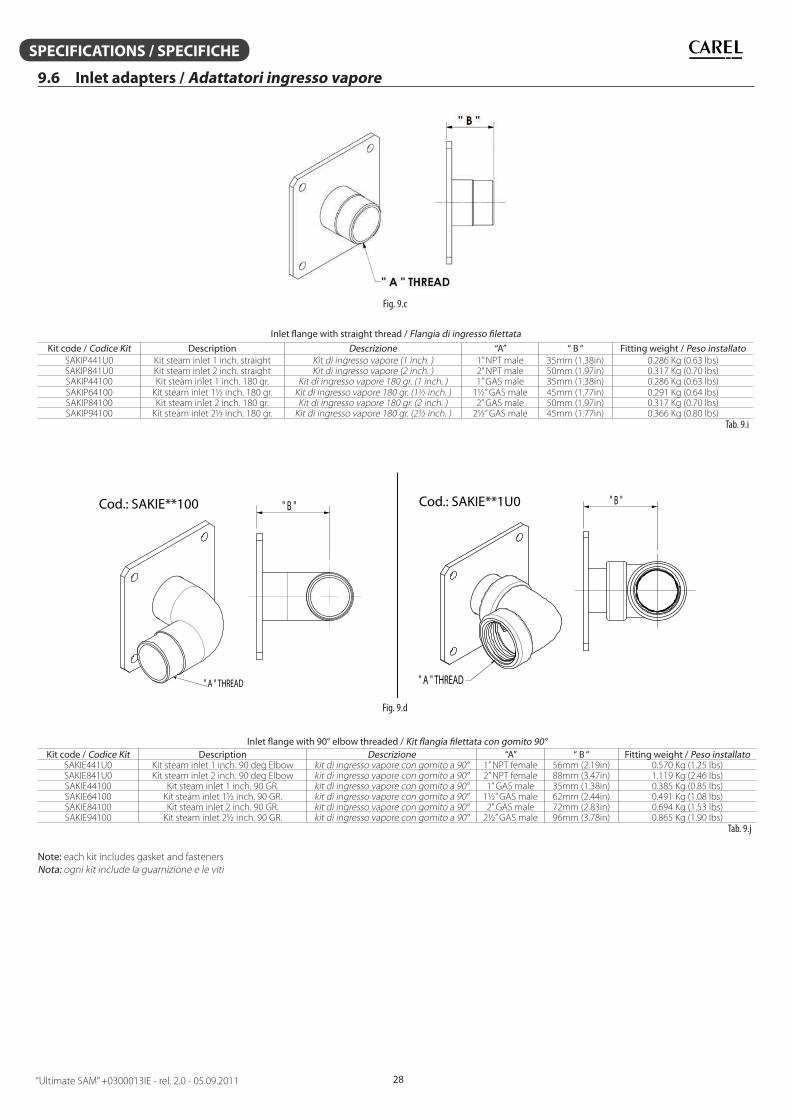
“Ultimate SAM” +0300013IE - rel. 2.0 - 05.09.2011 28
SPECIFICATIONS / SPECIFICHE
9.6 Inlet adapters / Adattatori ingresso vapore
Fig. 9.c
Inlet fl ange with straight thread / Flangia di ingresso fi lettata
Kit code / Codice Kit Description Descrizione “A” “ B “ Fitting weight / Peso installatoSAKIP441U0 Kit steam inlet 1 inch. straight Kit di ingresso vapore (1 inch. ) 1” NPT male 35mm (1.38in) 0.286 Kg (0.63 lbs)SAKIP841U0 Kit steam inlet 2 inch. straight Kit di ingresso vapore (2 inch. ) 2” NPT male 50mm (1.97in) 0.317 Kg (0.70 lbs)SAKIP44100 Kit steam inlet 1 inch. 180 gr. Kit di ingresso vapore 180 gr. (1 inch. ) 1” GAS male 35mm (1.38in) 0.286 Kg (0.63 lbs)SAKIP64100 Kit steam inlet 1½ inch. 180 gr. Kit di ingresso vapore 180 gr. (1½ inch. ) 1½” GAS male 45mm (1.77in) 0.291 Kg (0.64 lbs)SAKIP84100 Kit steam inlet 2 inch. 180 gr. Kit di ingresso vapore 180 gr. (2 inch. ) 2” GAS male 50mm (1.97in) 0.317 Kg (0.70 lbs)SAKIP94100 Kit steam inlet 2½ inch. 180 gr. Kit di ingresso vapore 180 gr. (2½ inch. ) 2½” GAS male 45mm (1.77in) 0.366 Kg (0.80 lbs)
Tab. 9.i
" A " THREAD
" B "
" A " THREAD
" B "Cod.: SAKIE**100 Cod.: SAKIE**1U0
Fig. 9.d
Inlet fl ange with 90° elbow threaded / Kit fl angia fi lettata con gomito 90°Kit code / Codice Kit Description Descrizione “A” “ B “ Fitting weight / Peso installato
SAKIE441U0 Kit steam inlet 1 inch. 90 deg Elbow kit di ingresso vapore con gomito a 90° 1” NPT female 56mm (2.19in) 0.570 Kg (1.25 lbs)SAKIE841U0 Kit steam inlet 2 inch. 90 deg Elbow kit di ingresso vapore con gomito a 90° 2” NPT female 88mm (3.47in) 1.119 Kg (2.46 lbs)SAKIE44100 Kit steam inlet 1 inch. 90 GR. kit di ingresso vapore con gomito a 90° 1” GAS male 35mm (1.38in) 0.385 Kg (0.85 lbs)SAKIE64100 Kit steam inlet 1½ inch. 90 GR. kit di ingresso vapore con gomito a 90° 1½” GAS male 62mm (2.44in) 0.491 Kg (1.08 lbs)SAKIE84100 Kit steam inlet 2 inch. 90 GR. kit di ingresso vapore con gomito a 90° 2” GAS male 72mm (2.83in) 0.694 Kg (1.53 lbs)SAKIE94100 Kit steam inlet 2½ inch. 90 GR. kit di ingresso vapore con gomito a 90° 2½” GAS male 96mm (3.78in) 0.865 Kg (1.90 lbs)
Tab. 9.j
Note: each kit includes gasket and fasteners
Nota: ogni kit include la guarnizione e le viti
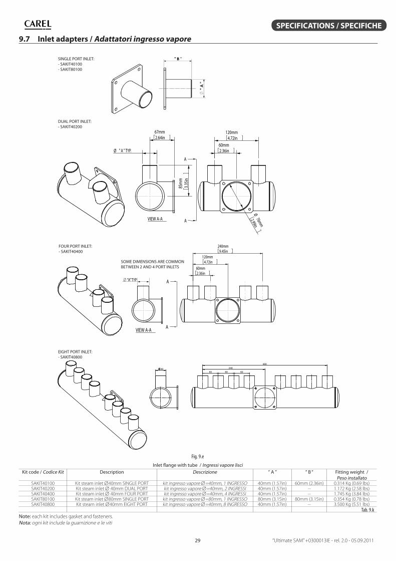
“Ultimate SAM” +0300013IE - rel. 2.0 - 05.09.201129
SPECIFICATIONS / SPECIFICHE
9.7 Inlet adapters / Adattatori ingresso vapore
SINGLE PORT INLET:- SAKIT40100- SAKIT80100
VIEW A-A
120mm4.72in
60mm2.36in
Ø76mm
2.99in
A
A
85m
m3.3
5in
67mm2.64in
Ø " A " TYP.
DUAL PORT INLET:- SAKIT40200
A
A
60mm2.36in
120mm4.72in
240mm9.45in
VIEW A-A
FOUR PORT INLET:- SAKIT40400
SOME DIMENSIONS ARE COMMON BETWEEN 2 AND 4 PORT INLETS
“A” TYP
EIGHT PORT INLET:- SAKIT40800
60 240
480
60 60 40
Fig. 9.e
Inlet fl ange with tube / Ingressi vapore lisciKit code / Codice Kit Description Descrizione “ A ” “ B “ Fitting weight /
Peso installatoSAKIT40100 Kit steam inlet 40mm SINGLE PORT kit ingresso vapore =40mm, 1 INGRESSO 40mm (1.57in) 60mm (2.36in) 0.314 Kg (0.69 lbs)SAKIT40200 Kit steam inlet 40mm DUAL PORT kit ingresso vapore =40mm, 2 INGRESSI 40mm (1.57in) -- 1.172 Kg (2.58 lbs)SAKIT40400 Kit steam inlet 40mm FOUR PORT kit ingresso vapore =40mm, 4 INGRESSI 40mm (1.57in) -- 1.745 Kg (3.84 lbs)SAKIT80100 Kit steam inlet 80mm SINGLE PORT kit ingresso vapore =80mm, 1 INGRESSO 80mm (3.15in) 80mm (3.15in) 0.354 Kg (0.78 lbs)SAKIT40800 Kit steam inlet 40mm EIGHT PORT kit ingresso vapore =40mm, 8 INGRESSO 40mm (1.57in) -- 3.500 Kg (5.51 lbs)
Tab. 9.k
Note: each kit includes gasket and fasteners.
Nota: ogni kit include la guarnizione e le viti
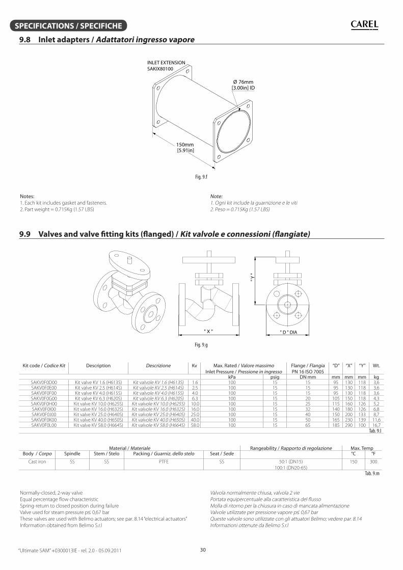
“Ultimate SAM” +0300013IE - rel. 2.0 - 05.09.2011 30
SPECIFICATIONS / SPECIFICHE
9.8 Inlet adapters / Adattatori ingresso vapore
150mm[5.91in]
[3.00in] IDØ 76mm
INLET EXTENSIONSAKIX80100
Fig. 9.f
Notes: 1. Each kit includes gasket and fasteners.
2. Part weight = 0.715Kg (1.57 LBS)
Note: 1. Ogni kit include la guarnizione e le viti
2. Peso = 0.715Kg (1.57 LBS)
9.9 Valves and valve fi tting kits (fl anged) / Kit valvole e connessioni (fl angiate)
" X "
" Y "
" D " DIA
Fig. 9.g
Kit code / Codice Kit Description Descrizione Kv Max. Rated / Valore massimoInlet Pressure / Pressione in ingresso
Flange / FlangiaPN 16 ISO 7005
“D” “X” “Y” Wt.
kPa psig DN mm mm mm mm kgSAKV0F0D00 Kit valve KV 1.6 (H613S) Kit valvole KV 1.6 (H613S) 1.6 100 15 15 95 130 118 3,6SAKV0F0E00 Kit valve KV 2.5 (H614S) Kit valvole KV 2.5 (H614S) 2.5 100 15 15 95 130 118 3,6SAKV0F0F00 Kit valve KV 4.0 (H615S) Kit valvole KV 4.0 (H615S) 4.0 100 15 15 95 130 118 3,6SAKV0F0G00 Kit valve KV 6.3 (H620S) Kit valvole KV 6.3 (H620S) 6.3 100 15 20 105 150 118 4,3SAKV0F0H00 Kit valve KV 10.0 (H625S) Kit valvole KV 10.0 (H625S) 10.0 100 15 25 115 160 126 5,2SAKV0F0I00 Kit valve KV 16.0 (H632S) Kit valvole KV 16.0 (H632S) 16.0 100 15 32 140 180 126 6,8SAKV0F0J00 Kit valve KV 25.0 (H640S) Kit valvole KV 25.0 (H640S) 25.0 100 15 40 150 200 133 8,7SAKV0F0K00 Kit valve KV 40.0 (H650S) Kit valvole KV 40.0 (H650S) 40.0 100 15 50 165 230 139 11,6SAKV0F0L00 Kit valve KV 58.0 (H664S) Kit valvole KV 58.0 (H664S) 58.0 100 15 65 185 290 100 16,7
Tab. 9.l
Material / Materiale Rangeability / Rapporto di regolazione Max. TempBody / Corpo Spindle Stem / Stelo Packing / Guarniz. dello stelo Seat / Sede °C °F
Cast iron SS SS PTFE SS 50:1 (DN15)
100:1 (DN20-65)
150 300
Tab. 9.m
Normally-closed, 2-way valve
Equal percentage fl ow characteristic
Spring-return to closed position during failure
Valve used for steam pressure p0,67 bar
These valves are used with Belimo actuators; see par. 8.14 “electrical actuators”
Information obtained from Belimo S.r.l
Valvola normalmente chiusa, valvola 2 vie
Portata equipercentuale alla caratteristica del fl usso
Molla di ritorno per la chiusura in caso di mancata alimentazione
Valvole utilizzate per pressione vapore p0,67 bar
Queste valvole sono utilizzate con gli attuatori Belimo; vedere par. 8.14
Informazioni ottenute da Belimo S.r.l
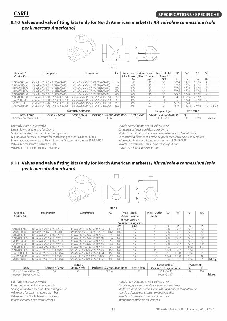
“Ultimate SAM” +0300013IE - rel. 2.0 - 05.09.201131
SPECIFICATIONS / SPECIFICHE
9.10 Valves and valve fi tting kits (only for North American markets) / Kit valvole e connessioni (solo
per il mercato Americano)
" B "
" A "
" X "
Fig. 9.h
Kit code / Codice Kit
Description Descrizione Cv Max. Rated / Valore maxInlet Pressure / Press. in ingr.
Inlet - OutletPorts /
"X" "A" "B" Wt.
kPa psig FPT in in in lbSAKV00HCU0 Kit valve CV 1.0 HP (599-03072) Kit valvole CV 1.0 HP (599-03072) 1.0 345 50 ½" 2 7/8 1 5/8 2 3/16 3SAKV00HDU0 Kit valve CV 1.6 HP (599-03073) Kit valvole CV 1.6 HP (599-03073) 1.6 345 50 ½" 2 7/8 1 5/8 2 3/16 3SAKV00HEU0 Kit valve CV 2.5 HP (599-03074) Kit valvole CV 2.5 HP (599-03074) 2.5 345 50 ½" 2 7/8 1 5/8 2 3/16 3SAKV00HFU0 Kit valve CV 4.0 HP (599-03075) Kit valvole CV 4.0 HP (599-03075) 4.0 345 50 ½" 2 7/8 1 5/8 2 3/16 3SAKV00HGU0 Kit valve CV 6.3 HP (599-03076) Kit valvole CV 6.3 HP (599-03076) 6.3 345 50 ¾" 3 3/8 1 5/8 2 3/16 4SAKV00HHU0 Kit valve CV 10.0 HP (599-03077) Kit valvole CV 10.0 HP (599-03077) 10.0 345 50 1" 4 1 9/16 2 3/16 5SAKV00HIU0 Kit valve CV 16.0 HP (599-03078) Kit valvole CV 16.0 HP (599-03078) 16.0 345 50 1 ¼" 5 1 5/8 2 3/16 7SAKV00HJU0 Kit valve CV 25.0 HP (599-03079) Kit valvole CV 25.0 HP (599-03079) 25.0 345 50 1 ½" 5 1/8 1 5/8 2 ¼ 8SAKV00HKU0 Kit valve CV 40.0 HP (599-03080) Kit valvole CV 40.0 HP (599-03080) 40.0 345 50 2" 6 ¼ 1 15/16 2 9/16 16 Tab. 9.n
Material / Materiale Rangeability / Rapporto di regolazione
Max. temp
Body / Corpo Spindle / Perno Stem / Stelo Packing / Guarniz. dello stelo Seat / Sede °C °FBronze / Bronzo (Cv>10) SS SS EPDM SS 100:1 (Cv>1) 120 250 Tab. 9.o
Normally-closed, 2-way valve
Linear fl ow characteristic for Cv>10
Spring-return to closed position during failure
Maximum diff erential pressure for modulating service is 3.45bar [50psi]
Information above was used from Siemens Document Number 155-184P25
Valve used for steam pressure p1 bar
Valve used for North American markets
Valvola normalmente chiusa, valvola 2 vie
Caratteristica lineare del fl usso per Cv>10
Molla di ritorno per la chiusura in caso di mancata alimentazione
La massima diff erenza di pressione per la modulazione è 3.45bar [50psi]
Informazioni ottenute Siemens documento 155-184P25
Valvole utilizzate per pressione di vapore p1 bar
Valvole per il mercato Americano
9.11 Valves and valve fi tting kits (only for North American markets) / Kit valvole e connessioni (solo
per il mercato Americano)
" B "
" A "
" X "
Fig. 9.i
Kit code / Codice Kit
Description Descrizione Cv Max. Rated / Valore massimoInlet Pressure /
Pressione in ingresso
Inlet - OutletPorts /
“X” “A” “B” Wt.
kPa psig FPT in in in lbSAKV000AU0 Kit valve CV 0.4 (599-02015) Kit valvole CV 0.4 (599-02015) 0,4 100 15 ½” 2 ¾ 15/16 15/16 0,96SAKV000BU0 Kit valve CV 0.63 (599-02017) Kit valvole CV 0.63 (599-02017) 0,63 100 15 ½” 2 ¾ 15/16 15/16 0,96SAKV000CU0 Kit valve CV 1.0 (599-02019) Kit valvole CV 1.0 (599-02019) 1,0 100 15 ½” 2 ¾ 15/16 15/16 0,96SAKV000DU0 Kit valve CV 1.6 (599-02021) Kit valvole CV 1.6 (599-02021) 1.6 100 15 ½” 2 ¾ 15/16 15/16 0,96SAKV000EU0 Kit valve CV 2.5 (599-02023) Kit valvole CV 2.5 (599-02023) 2.5 100 15 ½” 2 ¾ 15/16 15/16 0,96SAKV000FU0 Kit valve CV 4.0 (599-02025) Kit valvole CV 4.0 (599-02025) 4.0 100 15 ½” 2 ¾ 15/16 15/16 0,96SAKV000GU0 Kit valve CV 6.3 (599-02027) Kit valvole CV 6.3 (599-02027) 6.3 100 15 ¾” 3 ¼ 15/16 11/16 1,13SAKV000HU0 Kit valve CV 10.0 (599-02029) Kit valvole CV 10.0 (599-02029) 10.0 100 15 1” 3 7/8 19/16 13/16 1,7SAKV000IU0 Kit valve CV 16.0 (599-03024) Kit valvole CV 16.0 (599-03024) 16.0 100 15 1 ¼” 5 1 5/8 23/16 7SAKV000JU0 Kit valve CV 25.0 (599-03025) Kit valvole CV 25.0 (599-03025) 25.0 100 15 1 ½” 5 1/8 1 5/8 2 ¼ 8SAKV000KU0 Kit valve CV 40.0 (599-03026) Kit valvole CV 40.0 (599-03026) 40.0 100 15 2” 6 ¼ 1 15/16 29/16 16 Tab. 9.p
Material Rangeability / Rapporto di regolazione
Max. TempBody Spindle / Perno Stem / Stelo Packing / Guarniz. dello stelo Seat / Sede °C °F
Brass / Ottone (Cv<10)
Bronze / Bronzo (Cv>10)
SS SS EPDM SS “50:1 (Cv<1)
100:1 (Cv>1)”
120 250
Tab. 9.q
Normally-closed, 2-way valve
Equal percentage fl ow characteristic
Spring-return to closed position during failure
Valve used for steam pressure p1 bar
Valve used for North American markets
Information obtained from Siemens
Valvola normalmente chiusa, valvola 2 vie
Portata equipercentuale alla caratteristica del fl usso
Molla di ritorno per la chiusura in caso di mancata alimentazione
Valvole utilizzate per pressione vapore p1bar
Valvole utilizzate per il mercato Americano
Informazioni ottenute da Siemens
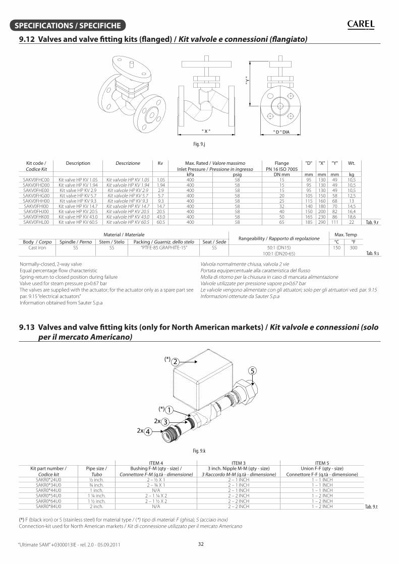
“Ultimate SAM” +0300013IE - rel. 2.0 - 05.09.2011 32
SPECIFICATIONS / SPECIFICHE
9.12 Valves and valve fi tting kits (fl anged) / Kit valvole e connessioni (fl angiato)
" X "
" Y "
" D " DIA
Fig. 9.j
Kit code / Codice Kit
Description Descrizione Kv Max. Rated / Valore massimoInlet Pressure / Pressione in ingresso
Flange PN 16 ISO 7005
"D" "X" "Y" Wt.
kPa psig DN mm mm mm mm kgSAKV0FHC00 Kit valve HP KV 1.05 Kit valvole HP KV 1.05 1.05 400 58 15 95 130 49 10,5SAKV0FHD00 Kit valve HP KV 1.94 Kit valvole HP KV 1.94 1.94 400 58 15 95 130 49 10,5SAKV0FHE00 Kit valve HP KV 2.9 Kit valvole HP KV 2.9 2.9 400 58 15 95 130 49 10,5SAKV0FHG00 Kit valve HP KV 5.7 Kit valvole HP KV 5.7 5.7 400 58 20 105 150 58 12,5SAKV0FHH00 Kit valve HP KV 9.3 Kit valvole HP KV 9.3 9.3 400 58 25 115 160 68 13SAKV0FHI00 Kit valve HP KV 14.7 Kit valvole HP KV 14.7 14.7 400 58 32 140 180 70 14,5SAKV0FHJ00 Kit valve HP KV 20.5 Kit valvole HP KV 20.5 20.5 400 58 40 150 200 82 16,4SAKV0FHK00 Kit valve HP KV 43.0 Kit valvole HP KV 43.0 43.0 400 58 50 165 230 86 18,6SAKV0FHL00 Kit valve HP KV 60.5 Kit valvole HP KV 60.5 60.5 400 58 65 185 290 111 22 Tab. 9.r
Material / MaterialeRangeability / Rapporto di regolazione
Max. Temp
Tab. 9.s
Body / Corpo Spindle / Perno Stem / Stelo Packing / Guarniz. dello stelo Seat / Sede °C °FCast iron SS SS “PTFE-85 GRAPHITE-15” SS 50:1 (DN15)
100:1 (DN20-65)
150 300
Normally-closed, 2-way valve
Equal percentage fl ow characteristic
Spring-return to closed position during failure
Valve used for steam pressure p0.67 bar
The valves are supplied with the actuator; for the actuator only as a spare part see
par. 9.15 “electrical actuators”
Information obtained from Sauter S.p.a
Valvola normalmente chiusa, valvola 2 vie
Portata equipercentuale alla caratteristica del fl usso
Molla di ritorno per la chiusura in caso di mancata alimentazione
Valvole utilizzate per pressione vapore p0,67 bar
Le valvole vengono alimentate con gli attuatori; solo per gli atrtuatori ved. par. 9.15
Informazioni ottenute da Sauter S.p.a
9.13 Valves and valve fi tting kits (only for North American markets) / Kit valvole e connessioni (solo
per il mercato Americano)
2
3
12x
4
5
(*)
(*)
2x
Fig. 9.k
ITEM 4 ITEM 3 ITEM 5Kit part number /
Codice kitPipe size /
TuboBushing F-M (qty - size) /
Connettore F-M (q.tà - dimensione)3 inch. Nipple M-M (qty - size)
3 Raccordo M-M (q.tà - dimensione)Union F-F (qty - size)
Connettore F-F (q.tà - dimensione)SAKR0*24U0 ½ inch. 2 – ½ X 1 2 – 1 INCH 1 – 1 INCHSAKR0*34U0 ¾ inch. 2 – ¾ X 1 2 – 1 INCH 1 – 1 INCHSAKR0*44U0 1 inch. N/A 2 – 1 INCH 1 – 1 INCHSAKR0*54U0 1 ¼ inch. 2 – 1 ¼ X 2 2 – 2 INCH 1 – 2 INCHSAKR0*64U0 1 ½ inch. 2 – 1 ½ X 2 2 – 2 INCH 1 – 2 INCHSAKR0*84U0 2 inch. N/A 2 – 2 INCH 1 – 2 INCH Tab. 9.t
(*) F (black iron) or S (stainless steel) for material type / (*) tipo di material: F (ghisa), S (acciaio inox)
Connection-kit used for North American markets / Kit di connessione utilizzato per il mercato Americano
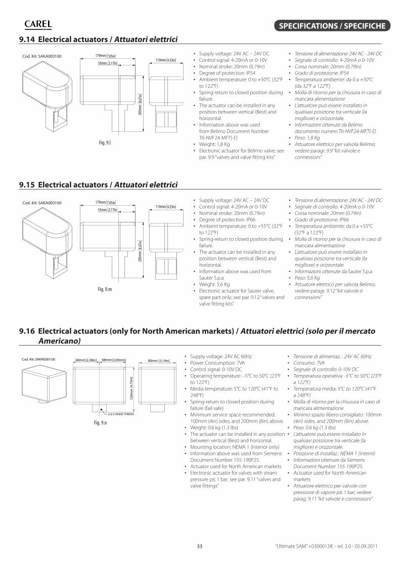
“Ultimate SAM” +0300013IE - rel. 2.0 - 05.09.201133
SPECIFICATIONS / SPECIFICHE
9.14 Electrical actuators / Attuatori elettrici
55mm 2.17in
179mm 7.05in
205m
m8.0
7in
110mm 4.33inCod. Kit: SAKA0E0100
Fig. 9.l
• Supply voltage: 24V AC – 24V DC
• Control signal: 4-20mA or 0-10V
• Nominal stroke: 20mm (0.79in)
• Degree of protection: IP54
• Ambient temperature: 0 to +50°C (32°F
to 122°F)
• Spring-return to closed position during
failure.
• The actuator can be installed in any
position between vertical (Best) and
horizontal.
• Information above was used
from Belimo Document Number
T6-NVF24-MFT(-E)
• Weight: 1,8 Kg
• Electronic actuator for Belimo valve; see
par. 9.9 “valves and valve fi tting kits”
• Tensione di alimentazione: 24V AC - 24V DC
• Segnale di controllo: 4-20mA o 0-10V
• Corsa nominale: 20mm (0.79in)
• Grado di protezione: IP54
• Temperatura ambiente: da 0 a +50°C
(da 32°F a 122°F)
• Molla di ritorno per la chiusura in caso di
mancata alimentazione
• L’attuatore può essere installato in
qualsiasi posizione tra verticale (la
miglliore) e orizzontale.
• Informazioni ottenute da Belimo
documento numero T6-NVF24-MFT(-E)
• Peso: 1,8 Kg
• Attuatore elettrico per valvola Belimo;
vedere paragr. 9.9 “kit valvole e
connessioni”
9.15 Electrical actuators / Attuatori elettrici
55mm 2.17in
179mm 7.05in
205m
m8.0
7in
110mm 4.33inCod. Kit: SAKA0E0100
Fig. 9.m
• Supply voltage: 24V AC – 24V DC
• Control signal: 4-20mA or 0-10V
• Nominal stroke: 20mm (0.79in)
• Degree of protection: IP66
• Ambient temperature: 0 to +55°C (32°F
to 122°F)
• Spring-return to closed position during
failure.
• The actuator can be installed in any
position between vertical (Best) and
horizontal.
• Information above was used from
Sauter S.p.a
• Weight: 5,6 Kg
• Electronic actuator for Sauter valve,
spare part only; see par. 9.12 “valves and
valve fi tting kits”
• Tensione di alimentazione: 24V AC - 24V DC
• Segnale di controllo: 4-20mA o 0-10V
• Corsa nominale: 20mm (0.79in)
• Grado di protezione: IP66
• Temperatura ambiente: da 0 a +55°C
(32°F a 122°F)
• Molla di ritorno per la chiusura in caso di
mancata alimentazione
• L’attuatore può essere installato in
qualsiasi posizione tra verticale (la
miglliore) e orizzontale.
• Informazioni ottenute da Sauter S.p.a
• Peso: 5,6 Kg
• Attuatore elettrico per valvola Belimo;
vedere paragr. 9.12 “kit valvole e
connessioni”
9.16 Electrical actuators (only for North American markets) / Attuatori elettrici (solo per il mercato
Americano)
[2.38in]60mm [2.69mm]68mm
[4.7
5in]
120m
m
3/4 G INSIDE THREAD
[3.19in]80mmCod. Kit: SAKAE001U0
Fig. 9.n
• Supply voltage: 24V AC 60Hz
• Power Consumption: 7VA
• Control signal: 0-10V DC
• Operating temperature: –5°C to 50°C (23°F
to 122°F)
• Media temperature: 5°C to 120°C (41°F to
248°F)
• Spring-return to closed position during
failure (fail-safe)
• Minimum service space recommended:
100mm (4in) sides, and 200mm (8in) above.
• Weight: 0.6 kg (1.3 lbs)
• The actuator can be installed in any position
between vertical (Best) and horizontal.
• Mounting location: NEMA 1 (Interior only)
• Information above was used from Siemens
Document Number 155-190P25.
• Actuator used for North American markets
• Electronic actuator for valves with steam
pressure p 1 bar; see par. 9.11 “valves and
valve fi ttings”
• Tensione di alimentaz. : 24V AC 60Hz
• Consumo: 7VA
• Segnale di controllo: 0-10V DC
• Temperatura operativa: -5°C to 50°C (23°F
a 122°F)
• Temperatura media: 5°C to 120°C (41°F
a 248°F)
• Molla di ritorno per la chiusura in caso di
mancata alimentazione
• Minimo spazio libero consigliato: 100mm
(4in) sides, and 200mm (8in) above.
• Peso: 0.6 kg (1.3 lbs)
• L’attuatore può essere installato in
qualsiasi posizione tra verticale (la
miglliore) e orizzontale.
• Posizione di installaz.: NEMA 1 (interni)
• Informazioni ottenute da Siemens
Document Number 155-190P25.
• Actuator used for North American
markets
• Attuatore elettrico per valvole con
pressione di vapore p 1 bar; vedere
parag. 9.11 “kit valvole e connessioni”
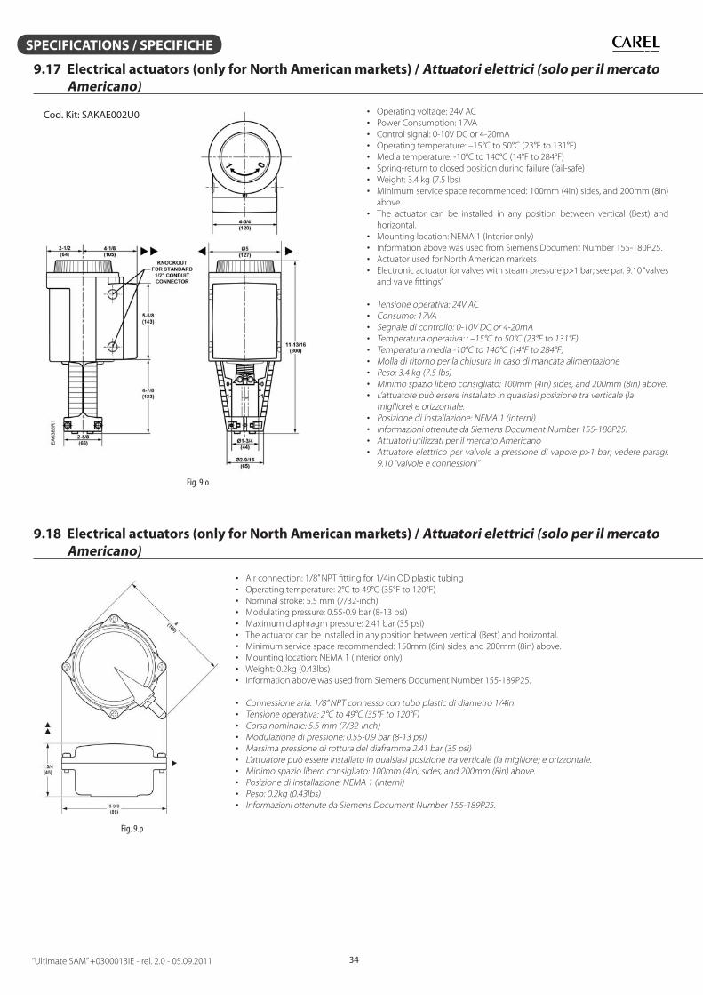
“Ultimate SAM” +0300013IE - rel. 2.0 - 05.09.2011 34
SPECIFICATIONS / SPECIFICHE
9.17 Electrical actuators (only for North American markets) / Attuatori elettrici (solo per il mercato
Americano)
Cod. Kit: SAKAE002U0
Fig. 9.o
• Operating voltage: 24V AC
• Power Consumption: 17VA
• Control signal: 0-10V DC or 4-20mA
• Operating temperature: –15°C to 50°C (23°F to 131°F)
• Media temperature: -10°C to 140°C (14°F to 284°F)
• Spring-return to closed position during failure (fail-safe)
• Weight: 3.4 kg (7.5 lbs)
• Minimum service space recommended: 100mm (4in) sides, and 200mm (8in)
above.
• The actuator can be installed in any position between vertical (Best) and
horizontal.
• Mounting location: NEMA 1 (Interior only)
• Information above was used from Siemens Document Number 155-180P25.
• Actuator used for North American markets
• Electronic actuator for valves with steam pressure p1 bar; see par. 9.10 “valves
and valve fi ttings”
• Tensione operativa: 24V AC
• Consumo: 17VA
• Segnale di controllo: 0-10V DC or 4-20mA
• Temperatura operativa: : –15°C to 50°C (23°F to 131°F)
• Temperatura media -10°C to 140°C (14°F to 284°F)
• Molla di ritorno per la chiusura in caso di mancata alimentazione
• Peso: 3.4 kg (7.5 lbs)
• Minimo spazio libero consigliato: 100mm (4in) sides, and 200mm (8in) above.
• L’attuatore può essere installato in qualsiasi posizione tra verticale (la
miglliore) e orizzontale.
• Posizione di installazione: NEMA 1 (interni)
• Informazioni ottenute da Siemens Document Number 155-180P25.
• Attuatori utilizzati per il mercato Americano
• Attuatore elettrico per valvole a pressione di vapore p1 bar; vedere paragr.
9.10 “valvole e connessioni”
9.18 Electrical actuators (only for North American markets) / Attuatori elettrici (solo per il mercato
Americano)
Fig. 9.p
• Air connection: 1/8” NPT fi tting for 1/4in OD plastic tubing
• Operating temperature: 2°C to 49°C (35°F to 120°F)
• Nominal stroke: 5.5 mm (7/32-inch)
• Modulating pressure: 0.55-0.9 bar (8-13 psi)
• Maximum diaphragm pressure: 2.41 bar (35 psi)
• The actuator can be installed in any position between vertical (Best) and horizontal.
• Minimum service space recommended: 150mm (6in) sides, and 200mm (8in) above.
• Mounting location: NEMA 1 (Interior only)
• Weight: 0.2kg (0.43lbs)
• Information above was used from Siemens Document Number 155-189P25.
• Connessione aria: 1/8” NPT connesso con tubo plastic di diametro 1/4in
• Tensione operativa: 2°C to 49°C (35°F to 120°F)
• Corsa nominale: 5.5 mm (7/32-inch)
• Modulazione di pressione: 0.55-0.9 bar (8-13 psi)
• Massima pressione di rottura del diaframma 2.41 bar (35 psi)
• L’attuatore può essere installato in qualsiasi posizione tra verticale (la miglliore) e orizzontale.
• Minimo spazio libero consigliato: 100mm (4in) sides, and 200mm (8in) above.
• Posizione di installazione: NEMA 1 (interni)
• Peso: 0.2kg (0.43lbs)
• Informazioni ottenute da Siemens Document Number 155-189P25.
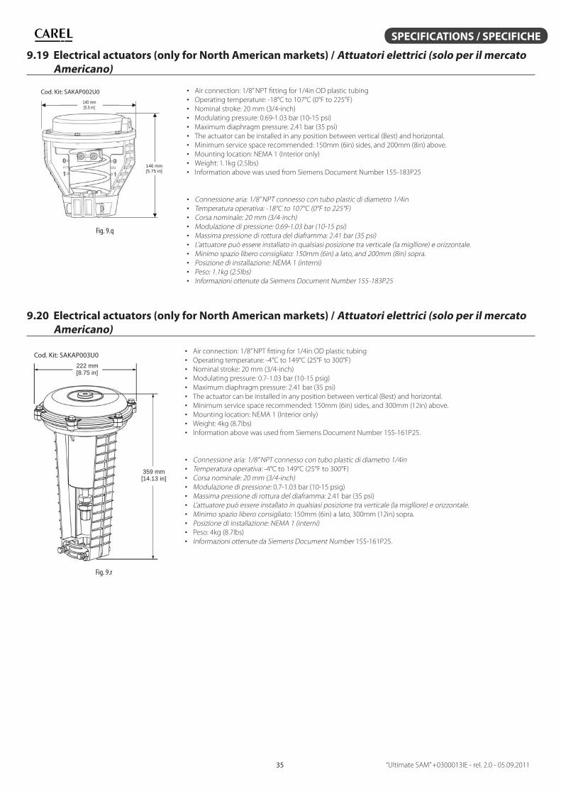
“Ultimate SAM” +0300013IE - rel. 2.0 - 05.09.201135
SPECIFICATIONS / SPECIFICHE
9.19 Electrical actuators (only for North American markets) / Attuatori elettrici (solo per il mercato
Americano)
140 mm [5.5 in]
146 mm [5.75 in]
Cod. Kit: SAKAP002U0
Fig. 9.q
• Air connection: 1/8” NPT fi tting for 1/4in OD plastic tubing
• Operating temperature: -18°C to 107°C (0°F to 225°F)
• Nominal stroke: 20 mm (3/4-inch)
• Modulating pressure: 0.69-1.03 bar (10-15 psi)
• Maximum diaphragm pressure: 2.41 bar (35 psi)
• The actuator can be installed in any position between vertical (Best) and horizontal.
• Minimum service space recommended: 150mm (6in) sides, and 200mm (8in) above.
• Mounting location: NEMA 1 (Interior only)
• Weight: 1.1kg (2.5lbs)
• Information above was used from Siemens Document Number 155-183P25
• Connessione aria: 1/8” NPT connesso con tubo plastic di diametro 1/4in
• Temperatura operativa: -18°C to 107°C (0°F to 225°F)
• Corsa nominale: 20 mm (3/4-inch)
• Modulazione di pressione: 0.69-1.03 bar (10-15 psi)
• Massima pressione di rottura del diaframma: 2.41 bar (35 psi)
• L’attuatore può essere installato in qualsiasi posizione tra verticale (la miglliore) e orizzontale.
• Minimo spazio libero consigliato: 150mm (6in) a lato, and 200mm (8in) sopra.
• Posizione di installazione: NEMA 1 (interni)
• Peso: 1.1kg (2.5lbs)
• Informazioni ottenute da Siemens Document Number 155-183P25
9.20 Electrical actuators (only for North American markets) / Attuatori elettrici (solo per il mercato
Americano)
222 mm [8.75 in]
359 mm [14.13 in]
Cod. Kit: SAKAP003U0
Fig. 9.r
• Air connection: 1/8” NPT fi tting for 1/4in OD plastic tubing
• Operating temperature: -4°C to 149°C (25°F to 300°F)
• Nominal stroke: 20 mm (3/4-inch)
• Modulating pressure: 0.7-1.03 bar (10-15 psig)
• Maximum diaphragm pressure: 2.41 bar (35 psi)
• The actuator can be installed in any position between vertical (Best) and horizontal.
• Minimum service space recommended: 150mm (6in) sides, and 300mm (12in) above.
• Mounting location: NEMA 1 (Interior only)
• Weight: 4kg (8.7lbs)
• Information above was used from Siemens Document Number 155-161P25.
• Connessione aria: 1/8” NPT connesso con tubo plastic di diametro 1/4in
• Temperatura operativa: -4°C to 149°C (25°F to 300°F)
• Corsa nominale: 20 mm (3/4-inch)
• Modulazione di pressione: 0.7-1.03 bar (10-15 psig)
• Massima pressione di rottura del diaframma: 2.41 bar (35 psi)
• L’attuatore può essere installato in qualsiasi posizione tra verticale (la miglliore) e orizzontale.
• Minimo spazio libero consigliato: 150mm (6in) a lato, 300mm (12in) sopra.
• Posizione di installazione: NEMA 1 (interni)
• Peso: 4kg (8.7lbs)
• Informazioni ottenute da Siemens Document Number 155-161P25.
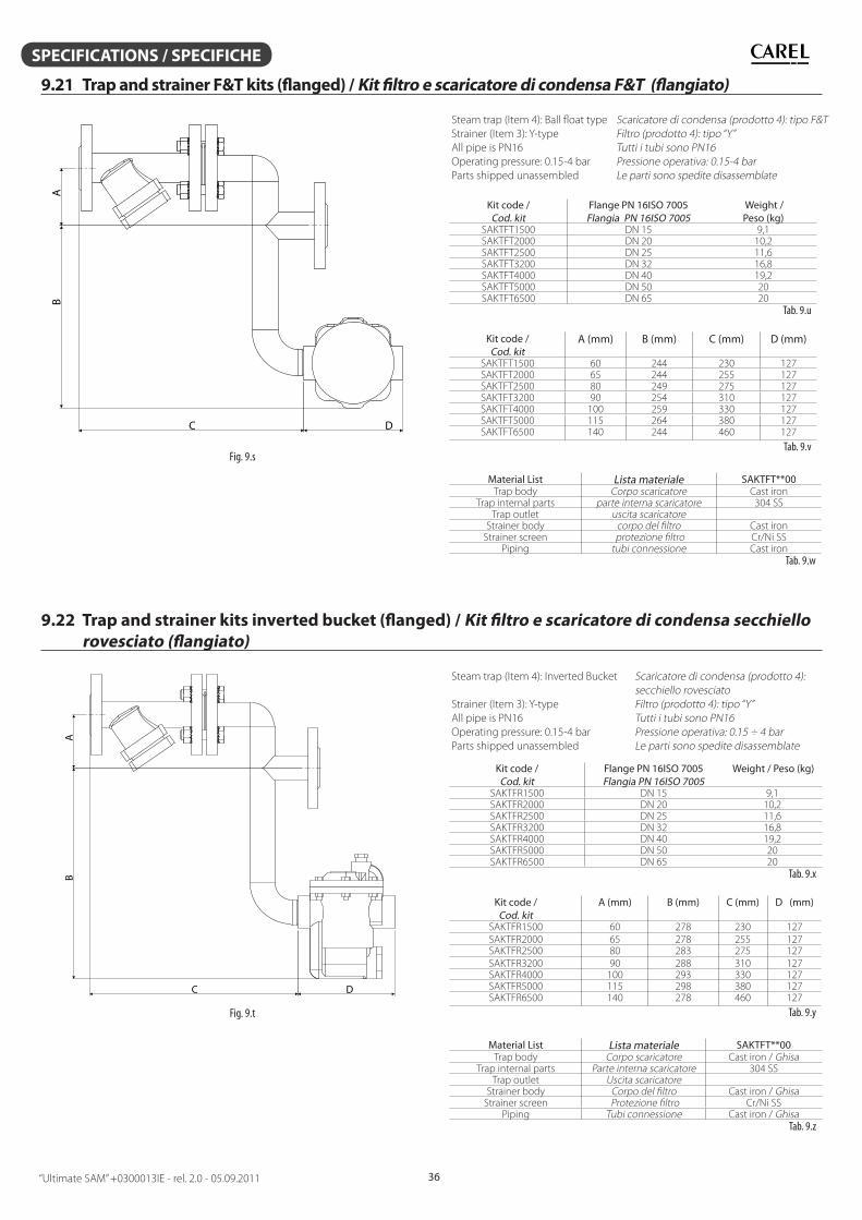
“Ultimate SAM” +0300013IE - rel. 2.0 - 05.09.2011 36
SPECIFICATIONS / SPECIFICHE
9.21 Trap and strainer F&T kits (fl anged) / Kit fi ltro e scaricatore di condensa F&T (fl angiato)
A
C D
B
Fig. 9.s
Steam trap (Item 4): Ball fl oat type
Strainer (Item 3): Y-type
All pipe is PN16
Operating pressure: 0.15-4 bar
Parts shipped unassembled
Scaricatore di condensa (prodotto 4): tipo F&T
Filtro (prodotto 4): tipo “Y”
Tutti i tubi sono PN16
Pressione operativa: 0.15-4 bar
Le parti sono spedite disassemblate
Kit code / Cod. kit
Flange PN 16ISO 7005Flangia PN 16ISO 7005
Weight / Peso (kg)
SAKTFT1500 DN 15 9,1SAKTFT2000 DN 20 10,2SAKTFT2500 DN 25 11,6SAKTFT3200 DN 32 16,8SAKTFT4000 DN 40 19,2SAKTFT5000 DN 50 20SAKTFT6500 DN 65 20
Tab. 9.u
Kit code / Cod. kit
A (mm) B (mm) C (mm) D (mm)
SAKTFT1500 60 244 230 127SAKTFT2000 65 244 255 127SAKTFT2500 80 249 275 127SAKTFT3200 90 254 310 127SAKTFT4000 100 259 330 127SAKTFT5000 115 264 380 127SAKTFT6500 140 244 460 127
Tab. 9.v
Material List Lista materiale SAKTFT**00Trap body Corpo scaricatore Cast iron
Trap internal parts parte interna scaricatore 304 SSTrap outlet uscita scaricatore
Strainer body corpo del fi ltro Cast ironStrainer screen protezione fi ltro Cr/Ni SS
Piping tubi connessione Cast iron
Tab. 9.w
9.22 Trap and strainer kits inverted bucket (fl anged) / Kit fi ltro e scaricatore di condensa secchiello
rovesciato (fl angiato)
A
B
C D
Fig. 9.t
Steam trap (Item 4): Inverted Bucket
Strainer (Item 3): Y-type
All pipe is PN16
Operating pressure: 0.15-4 bar
Parts shipped unassembled
Scaricatore di condensa (prodotto 4):
secchiello rovesciato
Filtro (prodotto 4): tipo “Y”
Tutti i tubi sono PN16
Pressione operativa: 0.15 ÷ 4 bar
Le parti sono spedite disassemblate
Kit code / Cod. kit
Flange PN 16ISO 7005Flangia PN 16ISO 7005
Weight / Peso (kg)
SAKTFR1500 DN 15 9,1SAKTFR2000 DN 20 10,2SAKTFR2500 DN 25 11,6SAKTFR3200 DN 32 16,8SAKTFR4000 DN 40 19,2SAKTFR5000 DN 50 20SAKTFR6500 DN 65 20
Tab. 9.x
Kit code / Cod. kit
A (mm) B (mm) C (mm) D (mm)
SAKTFR1500 60 278 230 127
SAKTFR2000 65 278 255 127SAKTFR2500 80 283 275 127
SAKTFR3200 90 288 310 127SAKTFR4000 100 293 330 127 SAKTFR5000 115 298 380 127SAKTFR6500 140 278 460 127
Tab. 9.y
Material List Lista materiale SAKTFT**00Trap body Corpo scaricatore Cast iron / Ghisa
Trap internal parts Parte interna scaricatore 304 SSTrap outlet Uscita scaricatore
Strainer body Corpo del fi ltro Cast iron / GhisaStrainer screen Protezione fi ltro Cr/Ni SS
Piping Tubi connessione Cast iron / GhisaTab. 9.z
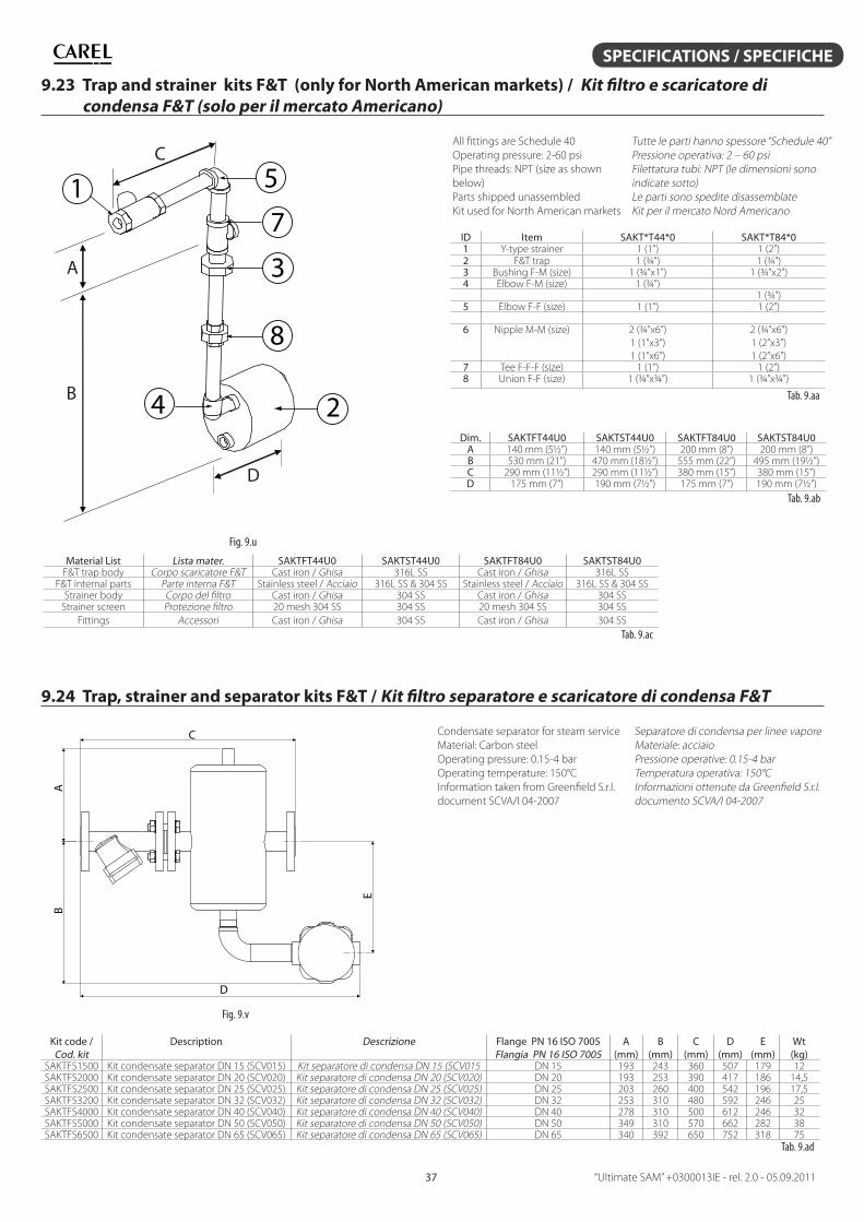
“Ultimate SAM” +0300013IE - rel. 2.0 - 05.09.201137
SPECIFICATIONS / SPECIFICHE
9.23 Trap and strainer kits F&T (only for North American markets) / Kit fi ltro e scaricatore di
condensa F&T (solo per il mercato Americano)
C
A
B
D
2
1
4
8
3
5
7
Fig. 9.u
All fi ttings are Schedule 40
Operating pressure: 2-60 psi
Pipe threads: NPT (size as shown
below)
Parts shipped unassembled
Kit used for North American markets
Tutte le parti hanno spessore “Schedule 40”
Pressione operativa: 2 – 60 psi
Filettatura tubi: NPT (le dimensioni sono
indicate sotto)
Le parti sono spedite disassemblate
Kit per il mercato Nord Americano
ID Item SAKT*T44*0 SAKT*T84*01 Y-type strainer 1 (1”) 1 (2”)2 F&T trap 1 (¾”) 1 (¾”)3 Bushing F-M (size) 1 (¾”x1”) 1 (¾”x2”)4 Elbow F-M (size) 1 (¾”)
1 (¾”)5 Elbow F-F (size) 1 (1”) 1 (2”)
6 Nipple M-M (size) 2 (¾”x6”)
1 (1”x3”)
1 (1”x6”)
2 (¾”x6”)
1 (2”x3”)
1 (2”x6”)7 Tee F-F-F (size) 1 (1”) 1 (2”)8 Union F-F (size) 1 (¾”x¾”) 1 (¾”x¾”)
Tab. 9.aa
Dim. SAKTFT44U0 SAKTST44U0 SAKTFT84U0 SAKTST84U0A 140 mm (5½”) 140 mm (5½”) 200 mm (8”) 200 mm (8”)B 530 mm (21”) 470 mm (18½”) 555 mm (22”) 495 mm (19½”)C 290 mm (11½”) 290 mm (11½”) 380 mm (15”) 380 mm (15”)D 175 mm (7”) 190 mm (7½”) 175 mm (7”) 190 mm (7½”)
Tab. 9.ab
Material List Lista mater. SAKTFT44U0 SAKTST44U0 SAKTFT84U0 SAKTST84U0F&T trap body Corpo scaricatore F&T Cast iron / Ghisa 316L SS Cast iron / Ghisa 316L SS
F&T internal parts Parte interna F&T Stainless steel / Acciaio 316L SS & 304 SS Stainless steel / Acciaio 316L SS & 304 SSStrainer body Corpo del fi ltro Cast iron / Ghisa 304 SS Cast iron / Ghisa 304 SS
Strainer screen Protezione fi ltro 20 mesh 304 SS 304 SS 20 mesh 304 SS 304 SS
Fittings Accessori Cast iron / Ghisa 304 SS Cast iron / Ghisa 304 SS
Tab. 9.ac
9.24 Trap, strainer and separator kits F&T / Kit fi ltro separatore e scaricatore di condensa F&T
A
B
C
D
E
Fig. 9.v
Condensate separator for steam service
Material: Carbon steel
Operating pressure: 0.15-4 bar
Operating temperature: 150°C
Information taken from Greenfi eld S.r.l.
document SCVA/I 04-2007
Separatore di condensa per linee vapore
Materiale: acciaio
Pressione operative: 0.15-4 bar
Temperatura operativa: 150°C
Informazioni ottenute da Greenfi eld S.r.l.
documento SCVA/I 04-2007
Kit code / Cod. kit
Description Descrizione Flange PN 16 ISO 7005Flangia PN 16 ISO 7005
A (mm)
B (mm)
C (mm)
D (mm)
E (mm)
Wt (kg)
SAKTFS1500 Kit condensate separator DN 15 (SCV015) Kit separatore di condensa DN 15 (SCV015 DN 15 193 243 360 507 179 12SAKTFS2000 Kit condensate separator DN 20 (SCV020) Kit separatore di condensa DN 20 (SCV020) DN 20 193 253 390 417 186 14,5SAKTFS2500 Kit condensate separator DN 25 (SCV025) Kit separatore di condensa DN 25 (SCV025) DN 25 203 260 400 542 196 17,5SAKTFS3200 Kit condensate separator DN 32 (SCV032) Kit separatore di condensa DN 32 (SCV032) DN 32 253 310 480 592 246 25SAKTFS4000 Kit condensate separator DN 40 (SCV040) Kit separatore di condensa DN 40 (SCV040) DN 40 278 310 500 612 246 32SAKTFS5000 Kit condensate separator DN 50 (SCV050) Kit separatore di condensa DN 50 (SCV050) DN 50 349 310 570 662 282 38SAKTFS6500 Kit condensate separator DN 65 (SCV065) Kit separatore di condensa DN 65 (SCV065) DN 65 340 392 650 752 318 75
Tab. 9.ad
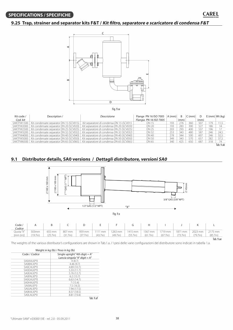
“Ultimate SAM” +0300013IE - rel. 2.0 - 05.09.2011 38
SPECIFICATIONS / SPECIFICHE
9.25 Trap, strainer and separator kits F&T / Kit fi ltro, separatore e scaricatore di condensa F&T
A
C
E
B
D
Fig. 9.w
Kit code / Cod. kit
Description / Descrizione Flange PN 16 ISO 7005Flangia PN 16 ISO 7005
A (mm) B (mm)
C (mm) D (mm)
E (mm) Wt (kg)
SAKTFW1500 Kit condensate separator DN 15 (SCV015) Kit separatore di condensa DN 15 (SCV015 DN 15 193 276 360 507 179 11,5SAKTFW2000 Kit condensate separator DN 20 (SCV020) Kit separatore di condensa DN 20 (SCV020) DN 20 193 283 390 527 186 14SAKTFW2500 Kit condensate separator DN 25 (SCV025) Kit separatore di condensa DN 25 (SCV025) DN 25 203 293 400 537 196 17SAKTFW3200 Kit condensate separator DN 32 (SCV032) Kit separatore di condensa DN 32 (SCV032) DN 32 253 343 480 587 246 24,5SAKTFW4000 Kit condensate separator DN 40 (SCV040) Kit separatore di condensa DN 40 (SCV040) DN 40 278 344 500 607 246 32,5SAKTFW5000 Kit condensate separator DN 50 (SCV050) Kit separatore di condensa DN 50 (SCV050) DN 50 349 343 570 657 282 37,5SAKTFW6500 Kit condensate separator DN 65 (SCV065) Kit separatore di condensa DN 65 (SCV065) DN 65 340 425 650 687 318 74
Tab. 9.ak
9.1 Distributor details, SA0 versions / Dettagli distributore, versioni SA0
“X”1/2” GAS (1/2” NPT)
45m
m
1”1/
2 G
AS
(1”1/
2 NPT
)
3/8” GAS (3/8” NPT)
160
x 16
0 m
m
100
x 10
0 m
m
Fig. 9.x
Code / Codice
A B C D E F G H I J K L
Quota “X”
[mm (in)]
503mm
(19.7in)
655 mm
(25.7in)
807 mm
(31.7in)
959 mm
(37.7in)
1111 mm
(43.7in)
1263 mm
(49.7in)
1415 mm
(55.7in)
1567 mm
(61.7in)
1719 mm
(67.7in)
1871 mm
(73.7in)
2023 mm
(79.7in)
2175 mm
(85.7in)
Tab. 9.ae
The weights of the various distributor’s confi gurations are shown in Tab.1.a. / I pesi delle varie confi gurazioni del distributore sono indicati in tabella 1.a.
Weight in kg (lb) / Peso in kg (lb)Code / Codice Single upright “4th digit = A”
Lancia singola “4° digit = A”SA0AALI0*0 4 (8.7)SA0BALI0*0 4.46 (9.7)SA0CALI0*0 4.89 (10.7)SA0DALI0*0 5.33 (11.7)SA0EALI0*0 5.76 (12.7)SA0FALI0*0 6.2 (13.7)SA0GALI0*0 6.63 (14.7)SA0HALI0*0 7 (15.4)SA0IALI0*0 7.5 (16.5)SA0JALI0*0 7.94 (17.5)SA0KALI0*0 8.37 (18.5)SA0LALI0*0 8.81 (19.4)
Tab. 9.af
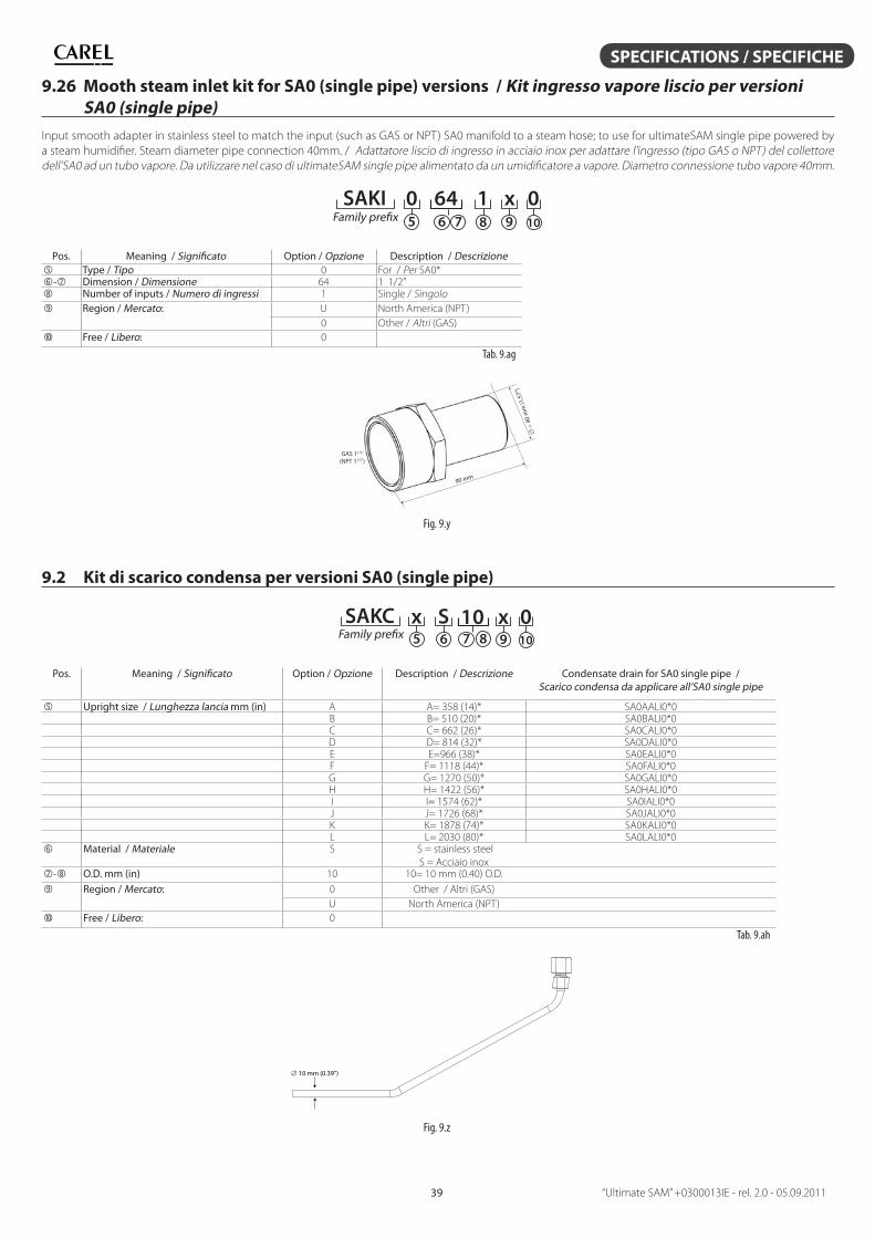
“Ultimate SAM” +0300013IE - rel. 2.0 - 05.09.201139
SPECIFICATIONS / SPECIFICHE
9.26 Mooth steam inlet kit for SA0 (single pipe) versions / Kit ingresso vapore liscio per versioni
SA0 (single pipe)
Input smooth adapter in stainless steel to match the input (such as GAS or NPT) SA0 manifold to a steam hose; to use for ultimateSAM single pipe powered by
a steam humidifi er. Steam diameter pipe connection 40mm. / Adattatore liscio di ingresso in acciaio inox per adattare l’ingresso (tipo GAS o NPT) del collettore
dell’SA0 ad un tubo vapore. Da utilizzare nel caso di ultimateSAM single pipe alimentato da un umidifi catore a vapore. Diametro connessione tubo vapore 40mm.
5 6 7 8 9 10Family prefix
SAKI 0 64 1 x 0
Pos. Meaning / Signifi cato Option / Opzione Description / Descrizione Type / Tipo 0 For / Per SA0*- Dimension / Dimensione 64 1 1/2” Number of inputs / Numero di ingressi 1 Single / Singolo
Region / Mercato: U North America (NPT)
0 Other / Altri (GAS)
Free / Libero: 0
Tab. 9.ag
90 mm
GAS 11/2”
(NPT 11/2”)
40 m
m (1
,57”
)
Fig. 9.y
9.2 Kit di scarico condensa per versioni SA0 (single pipe)
5 6 7 8 9 10Family prefixSAKC 0x S 10 x
Pos. Meaning / Signifi cato Option / Opzione Description / Descrizione Condensate drain for SA0 single pipe / Scarico condensa da applicare all’SA0 single pipe
Upright size / Lunghezza lancia mm (in) A A= 358 (14)* SA0AALI0*0B B= 510 (20)* SA0BALI0*0C C= 662 (26)* SA0CALI0*0D D= 814 (32)* SA0DALI0*0E E=966 (38)* SA0EALI0*0F F= 1118 (44)* SA0FALI0*0G G= 1270 (50)* SA0GALI0*0H H= 1422 (56)* SA0HALI0*0I I= 1574 (62)* SA0IALI0*0J J= 1726 (68)* SA0JALI0*0K K= 1878 (74)* SA0KALI0*0L L= 2030 (80)* SA0LALI0*0
Material / Materiale S S = stainless steel
S = Acciaio inox- O.D. mm (in) 10 10= 10 mm (0.40) O.D.
Region / Mercato: 0 Other / Altri (GAS)
U North America (NPT)
Free / Libero: 0
Tab. 9.ah
10 mm (0.39”)
Fig. 9.z
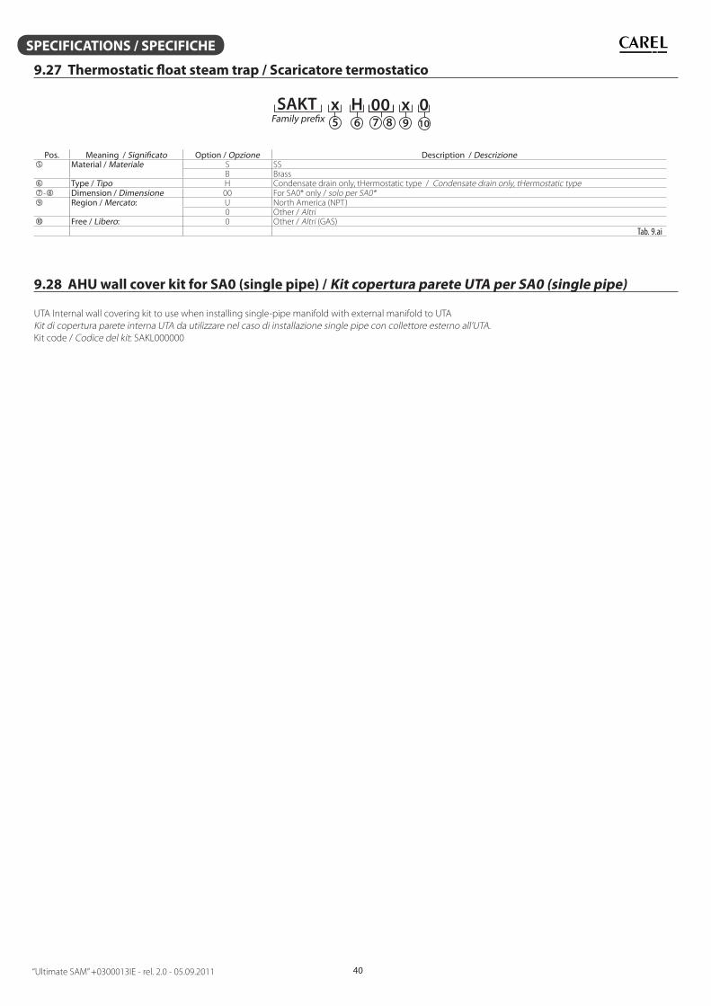
“Ultimate SAM” +0300013IE - rel. 2.0 - 05.09.2011 40
SPECIFICATIONS / SPECIFICHE
9.27 Thermostatic fl oat steam trap / Scaricatore termostatico
5 6 7 8 9 10Family prefixSAKT 0x H 00 x
Pos. Meaning / Signifi cato Option / Opzione Description / Descrizione Material / Materiale S SS
B Brass Type / Tipo H Condensate drain only, tHermostatic type / Condensate drain only, tHermostatic type- Dimension / Dimensione 00 For SA0* only / solo per SA0* Region / Mercato: U North America (NPT)
0 Other / Altri Free / Libero: 0 Other / Altri (GAS)
Tab. 9.ai
9.28 AHU wall cover kit for SA0 (single pipe) / Kit copertura parete UTA per SA0 (single pipe)
UTA Internal wall covering kit to use when installing single-pipe manifold with external manifold to UTA
Kit di copertura parete interna UTA da utilizzare nel caso di installazione single pipe con collettore esterno all’UTA.
Kit code / Codice del kit: SAKL000000
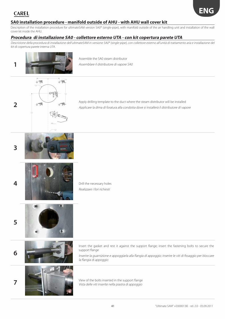
ENG
“Ultimate SAM” +0300013IE - rel. 2.0 - 05.09.201141
SA0 installation procedure - manifold outside of AHU - with AHU wall cover kitDescription of the installation procedure for ultimateSAM version SA0* (single-pipe), with manifold outside of the air handling unit and installation of the wall
cover kit inside the AHU.
Procedura di installazione SA0 - collettore esterno UTA - con kit copertura parete UTADescrizione della procedura di installazione dell’ultimateSAM in versione SA0* (single-pipe), con collettore esterno all’unità di trattamento aria e installazione del
kit di copertura parete interna UTA.
1Assemble the SA0 steam distributor
Assemblare il distributore di vapore SA0
2
Ø 100 mm
125 mm
(4.92”)
(4.92”)
(3.94”)
(8.74”)
(0.28”)
125 mm
222 mm
Ø 12 mm
Ø 7 mm
(0.47”)
(optional)Venduto separatamente/sold separately
Apply drilling template to the duct where the steam distributor will be installed
Applicare la dima di foratura alla condotta dove si installerà il distributore di vapore
3
Drill the necessary holes
Realizzare i fori richiesti
4
5
6
Insert the gasket and rest it against the support fl ange; insert the fastening bolts to secure the
support fl ange
Inserire la guarnizione e appoggiarla alla fl angia di appoggio; inserire le viti di fi ssaggio per bloccare
la fl angia di appoggio
7View of the bolts inserted in the support fl ange
Vista delle viti inserite nella piastra di appoggio
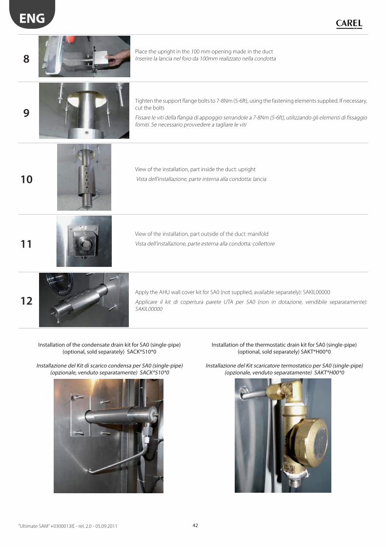
ENG
“Ultimate SAM” +0300013IE - rel. 2.0 - 05.09.2011 42
8Place the upright in the 100 mm opening made in the duct
Inserire la lancia nel foro da 100mm realizzato nella condotta
9
Tighten the support fl ange bolts to 7-8Nm (5-6ft), using the fastening elements supplied. If necessary,
cut the bolts
Fissare le viti della fl angia di appoggio serrandole a 7-8Nm (5-6ft), utilizzando gli elementi di fi ssaggio
forniti. Se necessario provvedere a tagliare le viti
10View of the installation, part inside the duct: upright
Vista dell’installazione, parte interna alla condotta: lancia
11View of the installation, part outside of the duct: manifold
Vista dell’installazione, parte esterna alla condotta: collettore
12Apply the AHU wall cover kit for SA0 (not supplied, available separately): SAKIL00000
Applicare il kit di copertura parete UTA per SA0 (non in dotazione, vendibile separatamente):
SAKIL00000
Installation of the condensate drain kit for SA0 (single-pipe)(optional, sold separately) SACK*S10*0
Installazione del Kit di scarico condensa per SA0 (single-pipe) (opzionale, venduto separatamente) SACK*S10*0
Installation of the thermostatic drain kit for SA0 (single-pipe)(optional, sold separately) SAKT*H00*0
Installazione del Kit scaricatore termostatico per SA0 (single-pipe)(opzionale, venduto separatamente) SAKT*H00*0


CAREL INDUSTRIES HeadQuartersVia dell’Industria, 11 - 35020 Brugine - Padova (Italy)Tel. (+39) 049.9716611 - Fax (+39) 049.9716600e-mail: [email protected] - www.carel.com
Agenzia / Agency:
“Ult
ima
te S
AM
” +0
30
00
13
IE -
re
l. 2
.0 -
05
.09
.20
11
Related Documents