Suranaree J. Sci. Technol. 15(4):271-285
1 Department of Mechanical and Manufacturing Engineering, Faculty of Engineering, UniversityPutra Malaysia, 43400 Serdang, Selangor, Malaysia. Tel.:006-0122749592; E-mail: [email protected]
2 Department of Aerospace Engineering, Faculty of Engineering, University Putra Malaysia, 43400 Serdang,Selangor, Malaysia.
* Corresponding author
SIMULATION OF FATIGUE CRACK GROWTH IN FRICTIONSTIR WELDED JOINTS IN 2024-T351 AL ALLOY
Amirreza Fahim Golestaneh1*, Aidy Ali1, Wong Shaw Voon1, Faizal Mustapha2
and Mehdi Zadeh Mohammadi1
Received: Jul 27, 2008; Revised: Nov 17, 2008; Accepted: Nov 26, 2008
Abstract
The aim of the present work is to predict the fatigue life of friction stir welded joints in 2024-T351 Alalloy using the finite element method in the framework of fracture analysis code for two-dimensions(FRANC2D/L). The simulation was conducted under linear elastic fracture mechanics, based on Paris’model and maximum tensile stress and displacement correlation methods were applied to calculate thecrack direction and stress intensity factor, respectively. One strategy has been presented, how crackpropagation was investigated based on the corresponding Paris constants for each FSW zone. Numeri-cal results were validated with experimental and analytical work.
Keywords: Simulation, finite element method, fatigue crack growth, Paris model, friction stir welding
Introduction
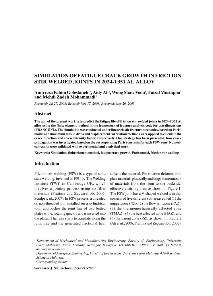
Friction stir welding (FSW) is a type of solidstate welding, invented in 1991 by The WeldingInstitute (TWI) in Cambridge UK, whichinvolves a joining process using no fillermaterials (Fratinia and Zuccarellob, 2006;Scialpi et al., 2007). In FSW process, a threadedor non-threaded pin installed on a cylindricaltool, approaches the joint line of two buttedplates while, rotating quickly and is inserted intothe plates. Then pin starts to translate along thejoint line and the generated frictional heat
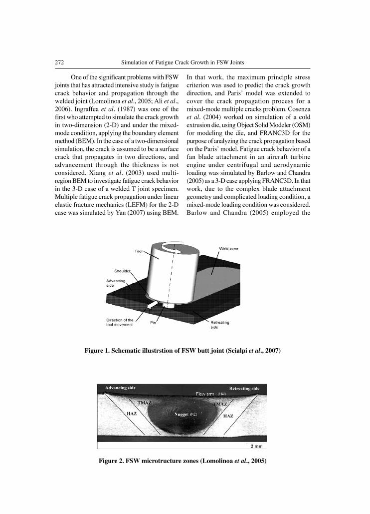
softens the material. Pin rotation deforms bothplate materials plastically and drags some amountof materials from the front to the backside,effectively stirring them as shown in Figure 1.The FSW joint has a V-shaped welded area thatconsists of five different sub-areas called (1) thenugget zone (NZ), (2) the flow arm zone (FAZ),(3) the thermomechanically affected zone(TMAZ), (4) the heat affected zone (HAZ), and(5) the parent zone (PZ), as shown in Figure 2(Ali et al., 2006; Fratinia and Zuccarellob, 2006).
272 Simulation of Fatigue Crack Growth in FSW Joints
Figure 1. Schematic illustrstion of FSW butt joint (Scialpi et al., 2007)
One of the significant problems with FSWjoints that has attracted intensive study is fatiguecrack behavior and propagation through thewelded joint (Lomolinoa et al., 2005; Ali et al.,2006). Ingraffea et al. (1987) was one of thefirst who attempted to simulate the crack growthin two-dimension (2-D) and under the mixed-mode condition, applying the boundary elementmethod (BEM). In the case of a two-dimensionalsimulation, the crack is assumed to be a surfacecrack that propagates in two directions, andadvancement through the thickness is notconsidered. Xiang et al. (2003) used multi-region BEM to investigate fatigue crack behaviorin the 3-D case of a welded T joint specimen.Multiple fatigue crack propagation under linearelastic fracture mechanics (LEFM) for the 2-Dcase was simulated by Yan (2007) using BEM.
In that work, the maximum principle stresscriterion was used to predict the crack growthdirection, and Paris’ model was extended tocover the crack propagation process for amixed-mode multiple cracks problem. Cosenzaet al. (2004) worked on simulation of a coldextrusion die, using Object Solid Modeler (OSM)for modeling the die, and FRANC3D for thepurpose of analyzing the crack propagation basedon the Paris’ model. Fatigue crack behavior of afan blade attachment in an aircraft turbineengine under centrifugal and aerodynamicloading was simulated by Barlow and Chandra(2005) as a 3-D case applying FRANC3D. In thatwork, due to the complex blade attachmentgeometry and complicated loading condition, amixed-mode loading condition was considered.Barlow and Chandra (2005) employed the
Figure 2. FSW microtructure zones (Lomolinoa et al., 2005)
273Suranaree J. Sci. Technol. Vol. 15 No. 4; October - December 2008
maximum tangential stress criterion in orderto predict crack growth direction and theNewman-Forman equation to calculate thegrowth rate.
As briefly reported above, previous workrepresents extensive research on crack propa-gation through one material with homogeneousproperties, however the main target here was tostudy the fatigue crack behavior through theFSW joint consisting of different zones withdifferent material characteristics. The numericalstudy was carried out by means of finite elementmethod (FEM), in the workspace of FRANC2D/L and based on Paris model. Finally the fatiguelifetimes of the FSW joint were predicted forvarious loading conditions and represented inthe frame of S-N curve. The numerical simulationresults were validated with the performedexperiments. The numerical predictions basedon Paris model were compared with the analyti-cally calculated lifetimes by Hobsson-Brownmodel (Ali et al., 2008).
Simulation Process
The simulation work in this study consists oftwo individual processes: (1) modeling andmeshing, which was carried out by CASCA
software, (2) simulating and analyzing, byFRANC2D/L. This software is able to simulatelayered structures in addition to crack propaga-tion through planar (plane stress, plane strain,and axisymmetric) structures.
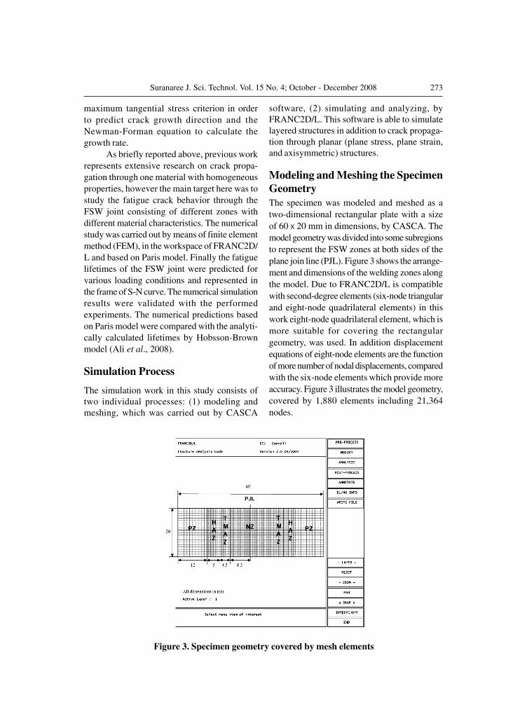
Modeling and Meshing the SpecimenGeometryThe specimen was modeled and meshed as atwo-dimensional rectangular plate with a sizeof 60 � 20 mm in dimensions, by CASCA. Themodel geometry was divided into some subregionsto represent the FSW zones at both sides of theplane join line (PJL). Figure 3 shows the arrange-ment and dimensions of the welding zones alongthe model. Due to FRANC2D/L is compatiblewith second-degree elements (six-node triangularand eight-node quadrilateral elements) in thiswork eight-node quadrilateral element, which ismore suitable for covering the rectangulargeometry, was used. In addition displacementequations of eight-node elements are the functionof more number of nodal displacements, comparedwith the six-node elements which provide moreaccuracy. Figure 3 illustrates the model geometry,covered by 1,880 elements including 21,364nodes.
Figure 3. Specimen geometry covered by mesh elements
274 Simulation of Fatigue Crack Growth in FSW Joints
Analysis and Simulation
In this research, in order to verify theapplied methods and strategies, the entire crackgrowth process through the FSW zones for oneloading condition (270 MPa Max applied stress)was simulated and validated step-by-step. Thenthe same procedure was followed for otherloading conditions in order to predict fatiguelifetimes of the FSW joint.
Problem Type
The plane stress condition was appliedto the simulation in order to simplify the effectof thickness and concentrate the analysis on thecrack propagation in two dimensions along themodel surface.
Material Properties
Four materials with different properties
were considered here in order to representvarious welding zones within the model. In otherwords FSW zones were introduced to the modelby attributing the material properties of the zonesto the mesh elements. The Von Mises criterionwas set for all of the zones with the mechanicalproperties and stress-strain relationship shownin Tables 1 and 2. Although Young’s modulus(E) and Poisson’s ratio ( ) are the same for thezones, the hardening modulus (H) and exponent(n) vary along the welding. This variation canbe attributed to the performed heat treatment.Based on the strong effect of hardness andresidual stress characteristics on the fatiguebehavior of the crack (Lomolinoa et al., 2005;Fersini and Parondi, 2007), here variations ofhardness and residual stress characteristics alongthe welding zones were considered as shown inTable 1.
Table 1. Material properties of FSW zones
FSW regimes NZ TMAZ HAZ PZ
Young’s modulus (GPa) 68.00 68.00 68.00 68.00Poisson’s ratio 0.33 0.33 0.33 0.33Yield stress (MPa) 350.00 272.00 448.00 370.00Hardening constant - 800.00 719.00 770.00Hardening exponent - 0.1266 0.05546 0.086Hardness (Hv1) 142.00 118.00 167.00 132.00Residual stress (MPa) -41.00 95.00 -20.00 0.00
Table 2. Stress-strain data of FSW zones
PZ HAZ TMAZ NZStrain Stress Strain Stress Strain Stress Strain Stress
(MPa) (MPa) (MPa) (MPa)
0.0003 20 0.00040 25 0.00070 50.34 0.00044 30.430.0006 40 0.00060 35 0.00123 75.86 0.00080 51.300.0009 45 0.00100 58 0.00160 106.90 0.00120 69.560.0014 90 0.00126 83 0.00200 131.03 0.00150 91.300.0021 125 0.00150 95 0.00310 186.21 0.00210 130.430.0034 220 0.00200 130 0.00450 268.96 0.00320 186.950.0050 300 0.00280 175 0.00570 331.03 0.00430 286.960.0058 320 0.00438 280 0.00550 331.910.0084 440 0.00558 3300.0120 487 0.00898 480
0.01166 540
275Suranaree J. Sci. Technol. Vol. 15 No. 4; October - December 2008
Loading Process
For the first time, Elber (1974) showed,the existence of residual stress within the plasticwake along the crack faces, keeps the crack facesclose for the significant portion of the cycles.Many studies have investigated the crack closureeffects on fatigue crack growth (Alizadeh et al.,2007; Fersini and Parondi, 2007). The obtainedresults represented a reduction in the effectivestress intensity factor range ( Keff), whichguarantees more accurate fatigue life estimation.In the present work, in order to take the effectsof residual stress and crack closure into account,the effective stress range ( eff) was calculatedas:
if (1)
else
(2)
where max is the maximum applied stress, min
is the minimum applied stress, res denotesresidual stress, and op represents openingstress value. It is worth noting that whenever the
maximum applied stress exceeds the materialyield strength, some amount of residual stress isreleased as the result of plastic deformation. Inthis research, for the case when the specimen isloaded by 270 MPa Max stress, the maximumand minimum stresses after incorporating theresidual stress ( max+res , min+res) are:
(3)
where R = 0.1 represents the stress ratio, whichis the proportion of minimum stress to maximumstress. Due to maximum stress exceeds the yieldstrength of TMAZ (272 MPa), the residual stressrelaxation was incorporated as follows:
Figure 4. Loading, initiated crack, and applies constraints to the model
276 Simulation of Fatigue Crack Growth in FSW Joints
(4)
where Max rex is the maximum stress afterincorporating the relaxation. Therefore the newvalue of minimum stress can be calculated asMin rex = min+res
_ (366 _ 318) = 75 MPa.According to equation (1) and op = 110 MPa,which was considered independent of thecrack length for different loading conditions, theeffective stress range is eff = Max rex
_op =
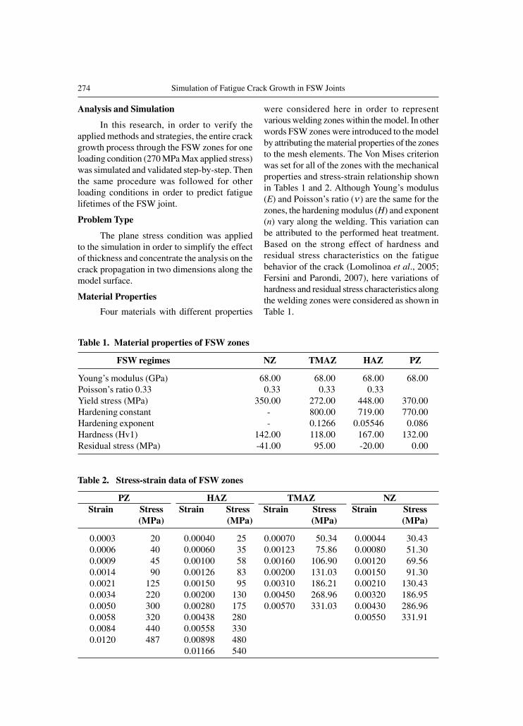
208 MPa. Finally the calculated value of loadingwas applied along the two opposite edges of themodel as distributing loading, however the loadis attributed to the elements nodes as theconcentrated loading by FRANC2D/L. Figure4 represents the model under applied distributedloading. The equivalent concentrated loadswhich are attributed to the elements nodes areshown in the same Figure.
Boundary Conditions
In the present research, two individualfixities were applied to two nodes on the oppositesides of the initiated crack in order to constrain
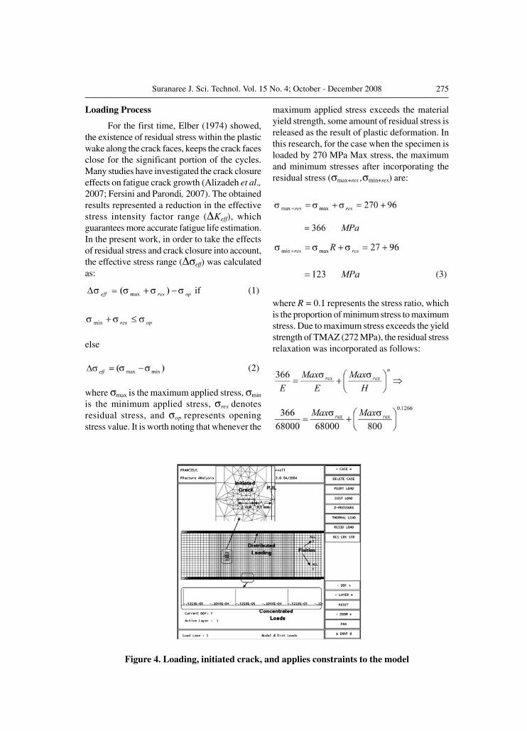
Figure 5. Stress distribution within the specimen in Y direction for the 270 MPa Max stress
the specimen in all directions. See Figure 4. Theconstraints have been embedded to the right sideof the model where they have less influence onthe initiated crack. Figure 5 illustrates the negligibleeffect of the fixities on the existing crack.
Crack Initiation
Previous research confirms the intenseeffects of hardness and residual stress on crackinitiation how, a decrease in the hardness char-acteristic leads to a decrease in fatigue threshold,and consequently, crack initiation is facilitated.Residual stress has a direct influence on crackinitiation that high tensile residual stressenhances crack initiations (Bussu and Irving,2003; Lomolinoa et al., 2005). Therefore herethe initial crack was introduced in TMAZ withthe lowest hardness (118 Hv1) and with thehighest residual stress of 96 MPa. The right andleft tips of the crack were 9.5 and 10.5 mm awayfrom PJL as illustrated in Figure 4.
In this work, first the entire crack propa-gation process was modeled in detail throughthe FSW zones for loading condition of 270 MPaMax stress. Therefore the initial crack with a
277Suranaree J. Sci. Technol. Vol. 15 No. 4; October - December 2008
length of 1 mm was introduced into the TMAZ.The smallest initial crack size identified by thereplication work, for the stress condition of 270MPa Max applied stress, was about 0.112 mm,however this value escalated to 0.62 mm for the300 MPa. Therefore in the simulation the fatiguelifetimes were predicted by considering theinitial crack with the size of 0.2 mm in TMAZfor high cycle fatigue (HCF) (loading conditionsbelow 300 MPa Max applied stress) and 1 mminitial crack for LCF (loading conditions above300 MPa Max applied stress) conditions.
Crack Propagation
Although the performed research confirmsthe identical results of different methods forcalculating the crack growth direction and stressintensity factors, here, the maximum tensilestress method (Xiang et al., 2003; Scialpi et al.,2007) and the displacement correlation technique(Scialpi et al., 2007; Yan, 2007) were employedsuccessively.
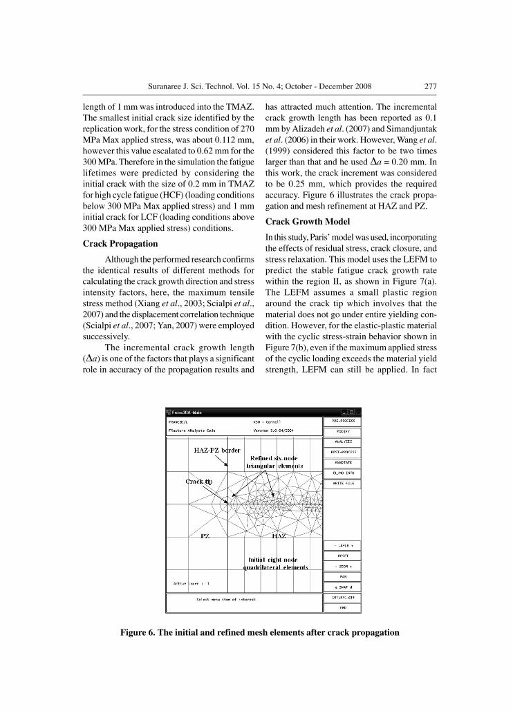
The incremental crack growth length( a) is one of the factors that plays a significantrole in accuracy of the propagation results and
Figure 6. The initial and refined mesh elements after crack propagation
has attracted much attention. The incrementalcrack growth length has been reported as 0.1mm by Alizadeh et al. (2007) and Simandjuntaket al. (2006) in their work. However, Wang et al.(1999) considered this factor to be two timeslarger than that and he used a = 0.20 mm. Inthis work, the crack increment was consideredto be 0.25 mm, which provides the requiredaccuracy. Figure 6 illustrates the crack propa-gation and mesh refinement at HAZ and PZ.
Crack Growth Model
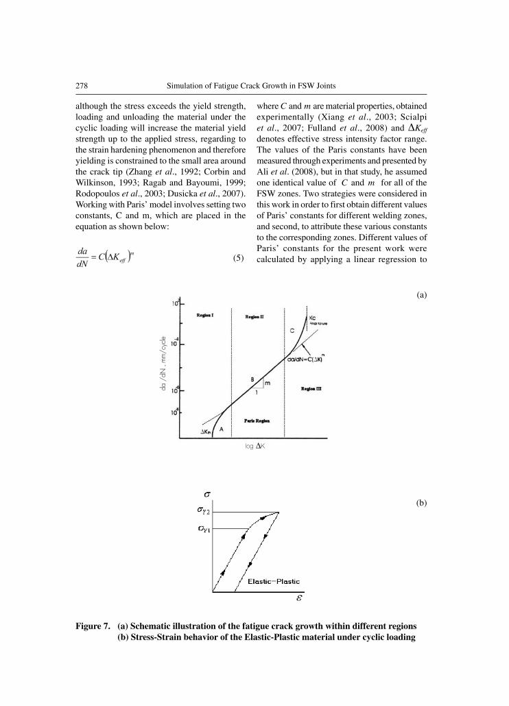
In this study, Paris’ model was used, incorporatingthe effects of residual stress, crack closure, andstress relaxation. This model uses the LEFM topredict the stable fatigue crack growth ratewithin the region II, as shown in Figure 7(a).The LEFM assumes a small plastic regionaround the crack tip which involves that thematerial does not go under entire yielding con-dition. However, for the elastic-plastic materialwith the cyclic stress-strain behavior shown inFigure 7(b), even if the maximum applied stressof the cyclic loading exceeds the material yieldstrength, LEFM can still be applied. In fact
278 Simulation of Fatigue Crack Growth in FSW Joints
although the stress exceeds the yield strength,loading and unloading the material under thecyclic loading will increase the material yieldstrength up to the applied stress, regarding tothe strain hardening phenomenon and thereforeyielding is constrained to the small area aroundthe crack tip (Zhang et al., 1992; Corbin andWilkinson, 1993; Ragab and Bayoumi, 1999;Rodopoulos et al., 2003; Dusicka et al., 2007).Working with Paris’ model involves setting twoconstants, C and m, which are placed in theequation as shown below:
(5)
where C and m are material properties, obtainedexperimentally (Xiang et al., 2003; Scialpiet al., 2007; Fulland et al., 2008) and Keff
denotes effective stress intensity factor range.The values of the Paris constants have beenmeasured through experiments and presented byAli et al. (2008), but in that study, he assumedone identical value of C and m for all of theFSW zones. Two strategies were considered inthis work in order to first obtain different valuesof Paris’ constants for different welding zones,and second, to attribute these various constantsto the corresponding zones. Different values ofParis’ constants for the present work werecalculated by applying a linear regression to
Figure 7. (a) Schematic illustration of the fatigue crack growth within different regions(b) Stress-Strain behavior of the Elastic-Plastic material under cyclic loading
(a)
(b)
���� �
��������������
279Suranaree J. Sci. Technol. Vol. 15 No. 4; October - December 2008
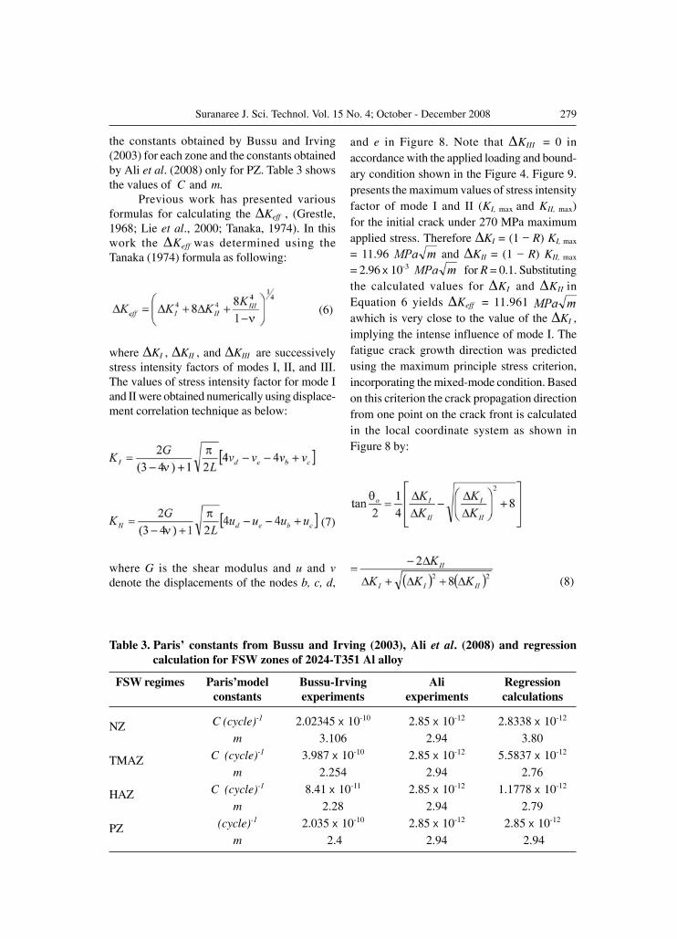
the constants obtained by Bussu and Irving(2003) for each zone and the constants obtainedby Ali et al. (2008) only for PZ. Table 3 showsthe values of C and m.
Previous work has presented variousformulas for calculating the Keff , (Grestle,1968; Lie et al., 2000; Tanaka, 1974). In thiswork the Keff was determined using theTanaka (1974) formula as following:
(6)
where KI , KII , and KIII are successivelystress intensity factors of modes I, II, and III.The values of stress intensity factor for mode Iand II were obtained numerically using displace-ment correlation technique as below:
(7)
where G is the shear modulus and u and vdenote the displacements of the nodes b, c, d,
Table 3. Paris’ constants from Bussu and Irving (2003), Ali et al. (2008) and regressioncalculation for FSW zones of 2024-T351 Al alloy
FSW regimes Paris’model Bussu-Irving Ali Regressionconstants experiments experiments calculations
NZ C (cycle)-1 2.02345 ��10-10 2.85 ��10-12 2.8338 ��10-12
m 3.106 2.94 3.80
TMAZ C (cycle)-1 3.987 ��10-10 2.85 ��10-12 5.5837 ��10-12
m 2.254 2.94 2.76
HAZ C (cycle)-1 8.41 ��10-11 2.85 ��10-12 1.1778 ��10-12
m 2.28 2.94 2.79
PZ (cycle)-1 2.035 ��10-10 2.85 ��10-12 2.85 ��10-12
m 2.4 2.94 2.94
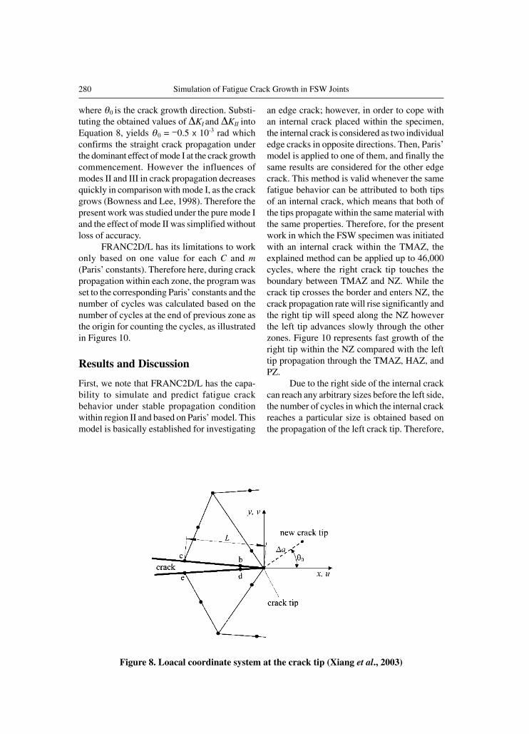
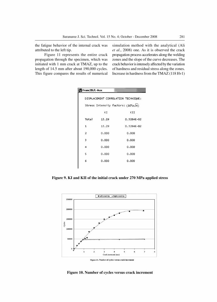
and e in Figure 8. Note that KIII = 0 inaccordance with the applied loading and bound-ary condition shown in the Figure 4. Figure 9.presents the maximum values of stress intensityfactor of mode I and II (KI, max and KII, max)for the initial crack under 270 MPa maximumapplied stress. Therefore KI = (1 _ R) KI, max
= 11.96 and KII = (1 _ R) KII, max
= 2.96 ��10-3 for R = 0.1. Substitutingthe calculated values for KI and KII inEquation 6 yields Keff = 11.961 awhich is very close to the value of the KI ,implying the intense influence of mode I. Thefatigue crack growth direction was predictedusing the maximum principle stress criterion,incorporating the mixed-mode condition. Basedon this criterion the crack propagation directionfrom one point on the crack front is calculatedin the local coordinate system as shown inFigure 8 by:
(8)
280 Simulation of Fatigue Crack Growth in FSW Joints
where 0 is the crack growth direction. Substi-tuting the obtained values of KI and KII intoEquation 8, yields 0 = _0.5 � 10-3 rad whichconfirms the straight crack propagation underthe dominant effect of mode I at the crack growthcommencement. However the influences ofmodes II and III in crack propagation decreasesquickly in comparison with mode I, as the crackgrows (Bowness and Lee, 1998). Therefore thepresent work was studied under the pure mode Iand the effect of mode II was simplified withoutloss of accuracy.
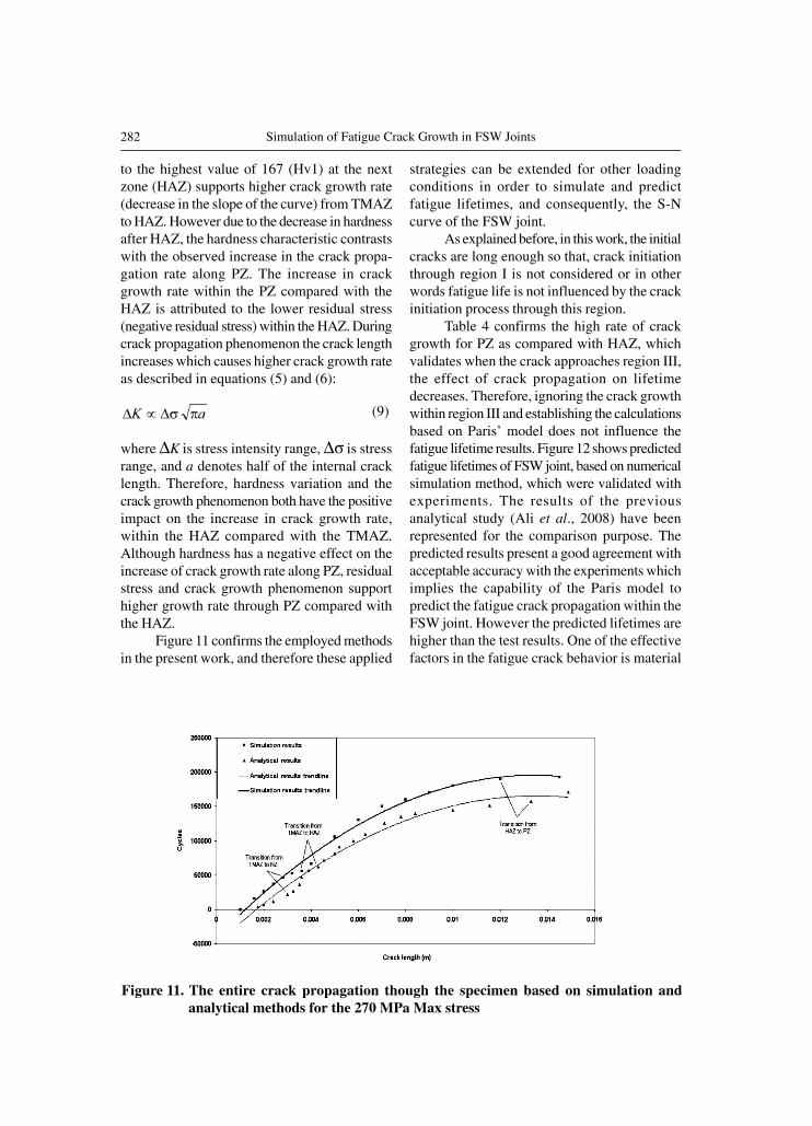
FRANC2D/L has its limitations to workonly based on one value for each C and m(Paris’ constants). Therefore here, during crackpropagation within each zone, the program wasset to the corresponding Paris’ constants and thenumber of cycles was calculated based on thenumber of cycles at the end of previous zone asthe origin for counting the cycles, as illustratedin Figures 10.
Results and Discussion
First, we note that FRANC2D/L has the capa-bility to simulate and predict fatigue crackbehavior under stable propagation conditionwithin region II and based on Paris’ model. Thismodel is basically established for investigating
an edge crack; however, in order to cope withan internal crack placed within the specimen,the internal crack is considered as two individualedge cracks in opposite directions. Then, Paris’model is applied to one of them, and finally thesame results are considered for the other edgecrack. This method is valid whenever the samefatigue behavior can be attributed to both tipsof an internal crack, which means that both ofthe tips propagate within the same material withthe same properties. Therefore, for the presentwork in which the FSW specimen was initiatedwith an internal crack within the TMAZ, theexplained method can be applied up to 46,000cycles, where the right crack tip touches theboundary between TMAZ and NZ. While thecrack tip crosses the border and enters NZ, thecrack propagation rate will rise significantly andthe right tip will speed along the NZ howeverthe left tip advances slowly through the otherzones. Figure 10 represents fast growth of theright tip within the NZ compared with the lefttip propagation through the TMAZ, HAZ, andPZ.
Due to the right side of the internal crackcan reach any arbitrary sizes before the left side,the number of cycles in which the internal crackreaches a particular size is obtained based onthe propagation of the left crack tip. Therefore,
Figure 8. Loacal coordinate system at the crack tip (Xiang et al., 2003)
281Suranaree J. Sci. Technol. Vol. 15 No. 4; October - December 2008
the fatigue behavior of the internal crack wasattributed to the left tip.
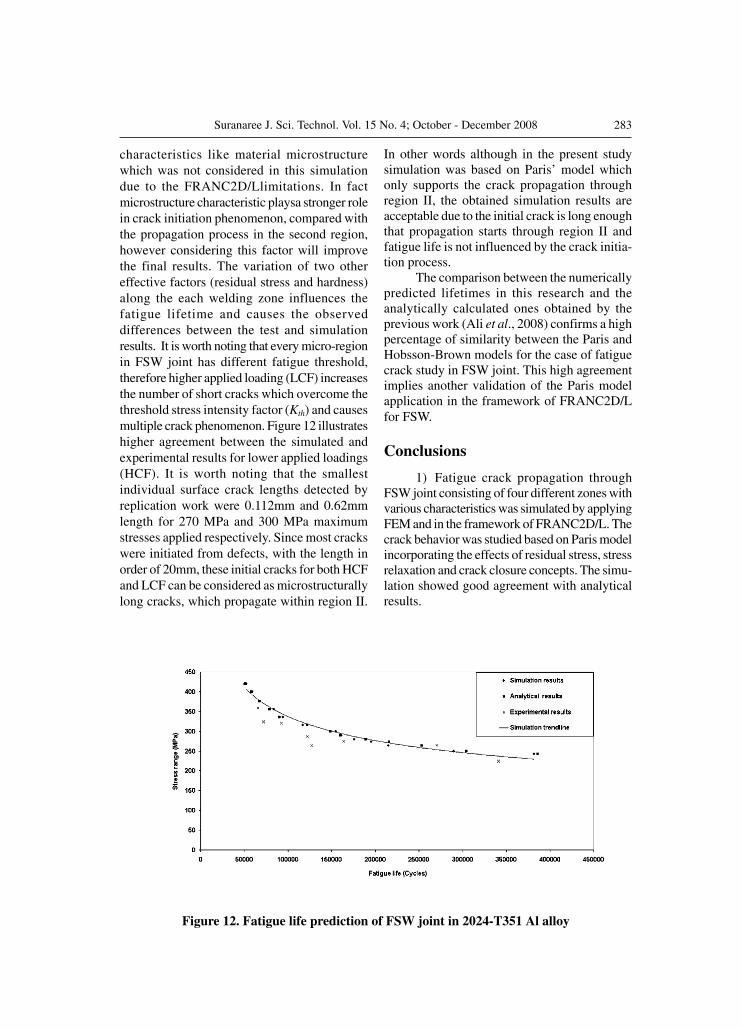
Figure 11 represents the entire crackpropagation through the specimen, which wasinitiated with 1 mm crack at TMAZ, up to thelength of 14.5 mm after about 190,000 cycles.This figure compares the results of numerical
Figure 10. Number of cycles versus crack increment
simulation method with the analytical (Aliet al., 2008) one. As it is observed the crackpropagation process accelerates along the weldingzones and the slope of the curve decreases. Thecrack behavior is intensely affected by the variationof hardness and residual stress along the zones.Increase in hardness from the TMAZ (118 Hv1)
Figure 9. KI and KII of the initial crack under 270 MPa applied stress
282 Simulation of Fatigue Crack Growth in FSW Joints
to the highest value of 167 (Hv1) at the nextzone (HAZ) supports higher crack growth rate(decrease in the slope of the curve) from TMAZto HAZ. However due to the decrease in hardnessafter HAZ, the hardness characteristic contrastswith the observed increase in the crack propa-gation rate along PZ. The increase in crackgrowth rate within the PZ compared with theHAZ is attributed to the lower residual stress(negative residual stress) within the HAZ. Duringcrack propagation phenomenon the crack lengthincreases which causes higher crack growth rateas described in equations (5) and (6):
(9)
where K is stress intensity range, is stressrange, and a denotes half of the internal cracklength. Therefore, hardness variation and thecrack growth phenomenon both have the positiveimpact on the increase in crack growth rate,within the HAZ compared with the TMAZ.Although hardness has a negative effect on theincrease of crack growth rate along PZ, residualstress and crack growth phenomenon supporthigher growth rate through PZ compared withthe HAZ.
Figure 11 confirms the employed methodsin the present work, and therefore these applied
strategies can be extended for other loadingconditions in order to simulate and predictfatigue lifetimes, and consequently, the S-Ncurve of the FSW joint.
As explained before, in this work, the initialcracks are long enough so that, crack initiationthrough region I is not considered or in otherwords fatigue life is not influenced by the crackinitiation process through this region.
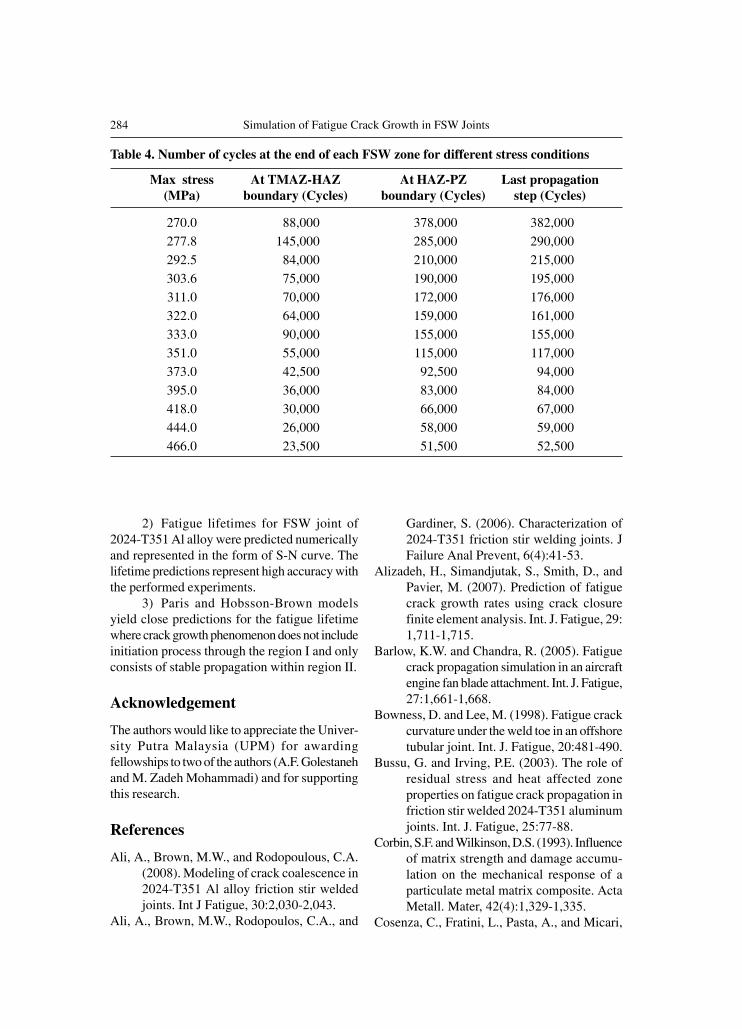
Table 4 confirms the high rate of crackgrowth for PZ as compared with HAZ, whichvalidates when the crack approaches region III,the effect of crack propagation on lifetimedecreases. Therefore, ignoring the crack growthwithin region III and establishing the calculationsbased on Paris’ model does not influence thefatigue lifetime results. Figure 12 shows predictedfatigue lifetimes of FSW joint, based on numericalsimulation method, which were validated withexperiments. The results of the previousanalytical study (Ali et al., 2008) have beenrepresented for the comparison purpose. Thepredicted results present a good agreement withacceptable accuracy with the experiments whichimplies the capability of the Paris model topredict the fatigue crack propagation within theFSW joint. However the predicted lifetimes arehigher than the test results. One of the effectivefactors in the fatigue crack behavior is material
Figure 11. The entire crack propagation though the specimen based on simulation andanalytical methods for the 270 MPa Max stress
283Suranaree J. Sci. Technol. Vol. 15 No. 4; October - December 2008
characteristics like material microstructurewhich was not considered in this simulationdue to the FRANC2D/Llimitations. In factmicrostructure characteristic playsa stronger rolein crack initiation phenomenon, compared withthe propagation process in the second region,however considering this factor will improvethe final results. The variation of two othereffective factors (residual stress and hardness)along the each welding zone influences thefatigue lifetime and causes the observeddifferences between the test and simulationresults. It is worth noting that every micro-regionin FSW joint has different fatigue threshold,therefore higher applied loading (LCF) increasesthe number of short cracks which overcome thethreshold stress intensity factor (Kth) and causesmultiple crack phenomenon. Figure 12 illustrateshigher agreement between the simulated andexperimental results for lower applied loadings(HCF). It is worth noting that the smallestindividual surface crack lengths detected byreplication work were 0.112mm and 0.62mmlength for 270 MPa and 300 MPa maximumstresses applied respectively. Since most crackswere initiated from defects, with the length inorder of 20mm, these initial cracks for both HCFand LCF can be considered as microstructurallylong cracks, which propagate within region II.
In other words although in the present studysimulation was based on Paris’ model whichonly supports the crack propagation throughregion II, the obtained simulation results areacceptable due to the initial crack is long enoughthat propagation starts through region II andfatigue life is not influenced by the crack initia-tion process.
The comparison between the numericallypredicted lifetimes in this research and theanalytically calculated ones obtained by theprevious work (Ali et al., 2008) confirms a highpercentage of similarity between the Paris andHobsson-Brown models for the case of fatiguecrack study in FSW joint. This high agreementimplies another validation of the Paris modelapplication in the framework of FRANC2D/Lfor FSW.
Conclusions
1) Fatigue crack propagation throughFSW joint consisting of four different zones withvarious characteristics was simulated by applyingFEM and in the framework of FRANC2D/L. Thecrack behavior was studied based on Paris modelincorporating the effects of residual stress, stressrelaxation and crack closure concepts. The simu-lation showed good agreement with analyticalresults.
Figure 12. Fatigue life prediction of FSW joint in 2024-T351 Al alloy
284 Simulation of Fatigue Crack Growth in FSW Joints
2) Fatigue lifetimes for FSW joint of2024-T351 Al alloy were predicted numericallyand represented in the form of S-N curve. Thelifetime predictions represent high accuracy withthe performed experiments.
3) Paris and Hobsson-Brown modelsyield close predictions for the fatigue lifetimewhere crack growth phenomenon does not includeinitiation process through the region I and onlyconsists of stable propagation within region II.
Acknowledgement
The authors would like to appreciate the Univer-sity Putra Malaysia (UPM) for awardingfellowships to two of the authors (A.F. Golestanehand M. Zadeh Mohammadi) and for supportingthis research.
References
Ali, A., Brown, M.W., and Rodopoulous, C.A.(2008). Modeling of crack coalescence in2024-T351 Al alloy friction stir weldedjoints. Int J Fatigue, 30:2,030-2,043.
Ali, A., Brown, M.W., Rodopoulos, C.A., and
Table 4. Number of cycles at the end of each FSW zone for different stress conditions
Max stress At TMAZ-HAZ At HAZ-PZ Last propagation(MPa) boundary (Cycles) boundary (Cycles) step (Cycles)
270.0 88,000 378,000 382,000
277.8 145,000 285,000 290,000
292.5 84,000 210,000 215,000
303.6 75,000 190,000 195,000
311.0 70,000 172,000 176,000
322.0 64,000 159,000 161,000
333.0 90,000 155,000 155,000
351.0 55,000 115,000 117,000
373.0 42,500 92,500 94,000
395.0 36,000 83,000 84,000
418.0 30,000 66,000 67,000
444.0 26,000 58,000 59,000
466.0 23,500 51,500 52,500
Gardiner, S. (2006). Characterization of2024-T351 friction stir welding joints. JFailure Anal Prevent, 6(4):41-53.
Alizadeh, H., Simandjutak, S., Smith, D., andPavier, M. (2007). Prediction of fatiguecrack growth rates using crack closurefinite element analysis. Int. J. Fatigue, 29:1,711-1,715.
Barlow, K.W. and Chandra, R. (2005). Fatiguecrack propagation simulation in an aircraftengine fan blade attachment. Int. J. Fatigue,27:1,661-1,668.
Bowness, D. and Lee, M. (1998). Fatigue crackcurvature under the weld toe in an offshoretubular joint. Int. J. Fatigue, 20:481-490.
Bussu, G. and Irving, P.E. (2003). The role ofresidual stress and heat affected zoneproperties on fatigue crack propagation infriction stir welded 2024-T351 aluminumjoints. Int. J. Fatigue, 25:77-88.
Corbin, S.F. and Wilkinson, D.S. (1993). Influenceof matrix strength and damage accumu-lation on the mechanical response of aparticulate metal matrix composite. ActaMetall. Mater, 42(4):1,329-1,335.
Cosenza, C., Fratini, L., Pasta, A., and Micari,
285Suranaree J. Sci. Technol. Vol. 15 No. 4; October - December 2008
F. (2004). Damage and fracture study ofcold extrusion dies. Eng. Fract. Mech., 71:1,021-1,033.
Dusicka, P., Itani, A.M., and Buckle, I.G. (2007).Cyclic response of plate steels under largeinelastic strains. J. Constr. Steel Res., 63:156-164.
Elber, W. (1974). Effect of shot-peening residualstresses on the fracture and crack-growthproperties of D6AC steel. Fracture Tough-ness and Slow-Stable Cracking, ASTM STP,559:45-58.
Fersini, D. and Parondi, A. (2007). Fatigue be-havior of Al 2024-T3 friction stir weldedlap joint. Eng. Fract. Mech., 74:468-480.
Fratinia, L., and Zuccarellob, B. (2006). Ananalysis of through-thickness residualstresses in aluminum FSW butt joints. Int.J. Mach. Tool Manu, 46:611-619.
Fulland, M., Sander, M., Kullmer, G., and Richard,H.A. (2008). Analysis of fatigue crackpropagation in the frame of a hydraulicpress. Eng. Fract. Mech., 75:892-900.
Grestle, W. (1986). Finite and boundary elementmodeling of crack propagation in two- andthree-dimensions using interactive computergraphics. Cornell University.
Ingraffea, A.R., Blandford, G., and Liggett, J.A.(1987). Automatic modeling of mixed-modefatigue and quasi-static crack propagationusing the boundary element method. 4th
National Symposium on Fracture, ASTMSTP.
Lie, S., Xiang, Z., Wang, B., and Cen, Z. (2000).Experimental and numerical simulation of3D fatigue crack for plate-to-plate weldedjoints. Int. J. Fatigue, 22:411-424.
Lomolinoa, S., Tovob, R., and dos Santos, J.(2005). On the fatigue behavior and designcurves of friction stir butt-welded Alalloys. Int. J. Fatigue, 27:305-316.
Ragab, A-R.A.F., and Bayoumi, S.E.A. (1999).Engineering solid mechanics: fundamen-
tals and applications. 2ed: Boca Raton,Fl.: CRC Press.
Rodopoulos, C.A., Romero, J.S., Curtis, S.A.,de los Rios, E.R., and Peyre, P. (2003).Effect of controlled shot peening andlaser shock peening on the fatigue perfor-mance of 2024-T351 aluminum alloy.JMEPEG, 12:414-419.
Scialpi, A., de Filippis, L.A.C., and Cavaliere,P. (2007). Influence of shoulder geometryon microstructure and mechanicalproperties of friction stir welded 6082aluminum alloy. Mater Design, 28:1,124-1,129.
Simandjutak, S., Alizadeh, H., Smith, D.J., andPavier, M.J. (2006). Three dimensionalfinite element prediction of crack closureand fatigue crack growth rate for a cornercrack. Int. J. Fatigue, 28:335-345.
Tanaka, K. Fatigue crack propaagtion from acrack inclined to the cyclic tensile axis.(1974). Eng. Fract. Mech., 6:493-507.
Wang, H., Buchholz, F.G., Richard, H.A., Jagg,S., and Scholtes, B. (1999). Numerical andexperimental analysis of residual stressesfor fatigue crack growth. Comp. MaterSci., 16:104-112.
Xiang, Z., Lie, S.T., Wang, B., and Cen, Z.(2003). A simulation of fatigue crackpropagation in a welded T-joint using 3Dboundary element method. Int. J. Pre.sVes. Pip., 80:111-120.
Yan, X. (2007). Automated simulation of fatiguecrack propagation for two-dimensionallinear elastic fracture mechanics problemsby boundary element method. Eng. Fract.Mech., 74:2,225-2,246.
Zhang, X., Chan, A.S.L., and Davies, G.A.O.(1992). Numerical simulation of fatiguecrack growth under complex loadingsequences. Eng. Fract. Mech., 42:305-321.


![NUMERICAL SIMULATION OF FRICTION STIR WELDING · · 2014-08-29NUMERICAL SIMULATION OF FRICTION STIR WELDING by Miroslav MIJAJLOVI], Dragan MIL^I] *, and Miodrag MIL^I] Mechanical](https://static.cupdf.com/doc/110x72/5ac4ed7c7f8b9a220b8d109b/numerical-simulation-of-friction-stir-simulation-of-friction-stir-welding-by-miroslav.jpg)
![NUMERICAL SIMULATION OF FRICTION STIR …thermalscience.vinca.rs/pdfs/papers-2014/TSCI1403967M.pdfNUMERICAL SIMULATION OF FRICTION STIR WELDING by Miroslav MIJAJLOVI], Dragan MIL^I]](https://static.cupdf.com/doc/110x72/5ac4f5057f8b9a12608d405c/numerical-simulation-of-friction-stir-simulation-of-friction-stir-welding-by.jpg)