RESIDUAL STRESSES IN FRICTION STIR WELDING: NUMERICAL SIMULATION AND EXPERIMENTAL VERIFICATION G. Buffa 1 , L. Fratini 1 , S. Pasta 2 1 Dipartimento di Tecnologia Meccanica, Produzione e Ingegneria Gestionale, Universit di Palermo, Italy; 2 Dipartimento di Meccanica, Universit di Palermo, Italy ABSTRACT In the present paper the effects of the thermal and mechanical actions on the residual stress field occurring in friction stir welding (FSW) of AA7075-T6 were investigated. Both numerical and experimental analyses were carried out to highlight the metallurgical phenomena and induced residual stresses in FS welded blanks. The welding process was simulated using a continuous rigid-viscoplastic finite element model (FEM) in a single block approach through the software DEFORM-3D TM , Lagrangian implicit code designed for metal forming processes. Then, the temperature histories at each node of the FE model were extracted and transferred to a further FE model of the joint considering an elasto-plastic behavior of the AA7075-T6 material. The map of the residual stress were extrapolated from the numerical model along several directions. Thus the cut-compliance methodology was used to compare the residual stress profiles with those of the numerical model. The numerical-experimental comparisons have shown how the numerical model can be successfully used to predict the residual stress field in FSW joint by considering all the local mechanical action of the tool. INTRODUCTION In recent years, friction stir welding (FSW), which was invented at TWI in 1991 [1], has emerged as an excellent technique for joining aluminum structures that are difficult to be welded with the traditional fusion welding technique. This process uses a specially designed rotating pin that is first inserted into the adjoining edges of the blank sheets with a proper tilt angle and then moved all along the welding line. Such a pin produces frictional and plastic deformation heating in the welding zone; actually, no melting of material is observed in FSW. Furthermore, as the tool moves, material is forced to flow around the tool in a quite complex flow pattern. Several studies were conducted to deeply understand the process mechanics [2], material flow [3], metallurgical aspects [4], and both static and dynamic strength [5]. Other researches have focused the attention to the weld residual stress. Peel et al. [6] investigated the influence of the tool feed rate on the residual stresses of FSW aluminum joints by using synchrotron X-rays measurement; the residual stresses were highlighted and found out that, in FSW, the weld zone is subjected to longitudinal (parallel to tool travel) and transverse (perpendicular to tool travel) residual stresses. Staron et al. [7] and PrevØy et al. [8] used non-destructive technique for determining the residual 444 Copyright ©JCPDS-International Centre for Diffraction Data 2009 ISSN 1097-0002

Welcome message from author
This document is posted to help you gain knowledge. Please leave a comment to let me know what you think about it! Share it to your friends and learn new things together.
Transcript
RESIDUAL STRESSES IN FRICTION STIR WELDING: NUMERICAL SIMULATION AND EXPERIMENTAL VERIFICATION
G. Buffa1, L. Fratini1, S. Pasta2
1 Dipartimento di Tecnologia Meccanica, Produzione e Ingegneria Gestionale, Università di
Palermo, Italy; 2 Dipartimento di Meccanica, Università di Palermo, Italy
ABSTRACT In the present paper the effects of the thermal and mechanical actions on the residual stress field occurring in friction stir welding (FSW) of AA7075-T6 were investigated. Both numerical and experimental analyses were carried out to highlight the metallurgical phenomena and induced residual stresses in FS welded blanks. The welding process was simulated using a continuous rigid-viscoplastic finite element model (FEM) in a single block approach through the software DEFORM-3DTM, Lagrangian implicit code designed for metal forming processes. Then, the temperature histories at each node of the FE model were extracted and transferred to a further FE model of the joint considering an elasto-plastic behavior of the AA7075-T6 material. The map of the residual stress were extrapolated from the numerical model along several directions. Thus the cut-compliance methodology was used to compare the residual stress profiles with those of the numerical model. The numerical-experimental comparisons have shown how the numerical model can be successfully used to predict the residual stress field in FSW joint by considering all the local mechanical action of the tool. INTRODUCTION In recent years, friction stir welding (FSW), which was invented at TWI in 1991 [1], has emerged as an excellent technique for joining aluminum structures that are difficult to be welded with the traditional fusion welding technique. This process uses a specially designed rotating pin that is first inserted into the adjoining edges of the blank sheets with a proper tilt angle and then moved all along the welding line. Such a pin produces frictional and plastic deformation heating in the welding zone; actually, no melting of material is observed in FSW. Furthermore, as the tool moves, material is forced to flow around the tool in a quite complex flow pattern. Several studies were conducted to deeply understand the process mechanics [2], material flow [3], metallurgical aspects [4], and both static and dynamic strength [5]. Other researches have focused the attention to the weld residual stress. Peel et al. [6] investigated the influence of the tool feed rate on the residual stresses of FSW aluminum joints by using synchrotron X-rays measurement; the residual stresses were highlighted and found out that, in FSW, the weld zone is subjected to longitudinal (parallel to tool travel) and transverse (perpendicular to tool travel) residual stresses. Staron et al. [7] and Prevéy et al. [8] used non-destructive technique for determining the residual
444Copyright ©JCPDS-International Centre for Diffraction Data 2009 ISSN 1097-0002
stress in FSW butt-joints in order to investigate the possibility to modify the residual stress state in the joint by exerting external mechanical tensioning or low plasticity burnishing during the welding process. Fratini et al. [9] have also used the hole drilling technique to achieve the residual stress profiles for 6082-T6, 2024-T4, and 7075-T6 aluminum alloys. Although this residual stresses seems to improve the fatigue strength of the joint [10]; they can be considered an obstacle inhibiting the full application of the FSW process in manufacturing process since a detrimental bending and distortion is introduced. Numerical model were also successfully used to predict the residual stresses in FSW butt joint. Chao et al. [11] for to stainless steel, Chen and Kovacevic [12] and Reynolds et al. [13] for aluminum alloys have developed thermal analyses, based on properly tuned analytical models, and subsequent mechanical ones to obtain the residual stress state due to the thermal input. A few consideration can be developed on the latter papers: first of all the local mechanical action of the tool, and in particular of the tool pin, is not considered. Just the subsequent thermal flux is taken into account and in this way a sort of macro effect of the process on the material is investigated. What is more, the used thermal models, describing the heat flux due to the tool action, are always axial-symmetric: in other words no effect of the asymmetric material flow occurring in FSW processes is considered. As a consequence symmetric profiles of temperature, strain and strain rate are obtained with respect to the tool axis. In the present paper the effects of the thermal and mechanical actions on the residual stress, occurring in FSW processes of AA7075-T6 aluminum alloy were investigated. Particularly, both numerical simulations and experimental tests were performed to highlight the occurring metallurgical phenomena and induced residual stress field in the FS welded blanks. The FSW process was simulated using a continuous rigid-viscoplastic FEM model with the DEFORM-3DTM [14] software, previously developed by some of the authors to simulate the FSW process with a single block approach [15, 16]. Thus, the temperature history in each node of the FE model was extracted and transferred to a further FE model of the joint considering an elasto-plastic behavior of the AA7075-T6 material. The adopted model was developed with Abaqus/Standard [17] using the coupled temperature-displacement analysis option. As far as the experiments are regarded, the cut-compliance methodology described by Prime [18] was used to determine the profiles of residual stress; this provides extremely accurate measurements of the longitudinal and transversal residual stresses. Furthermore, the method enables the residual stresses at the crack tip to be determined, which play an important role in fatigue crack growth. The performed analysis permitted to fully predict the residual stress distribution in the longitudinal, transverse and through-thickness directions. NUMERICAL MODEL The FSW has been simulated using a continuous FEM model with FEA software DEFORM-3DTM, Lagrangian implicit code designed for metal forming processes, previously developed by some of the authors to simulate the FSW process with a single block approach [15,16]. The workpiece is modeled as a rigid visco-plastic material, and the welding tool is assumed rigid. This assumption is reasonable as the yield strength of the sheet (conventionally aluminum alloy) is significantly lower than the yield strength of the tool (tool steel or carbide). It should observed, anyway, that such assumption in the material model denies the possibility to get residual stresses in the workpiece after the tool motion; actually, as it is well known, an elasto-plastic material model must be used in order to get the final residual stress state in the worked material. Such option was not used in the FSW modeling since the numerical simulation
445Copyright ©JCPDS-International Centre for Diffraction Data 2009 ISSN 1097-0002
would become unstable, with several convergence problems and meaningless CPU times. Both the sinking and advancing of the tool into the specimen has been considered, using the formerly indicated process and geometrical parameters. For the thermal characteristics of the selected AA7075-T6 aluminium alloy, the following values were used at 20°C: thermal
conductivity k=180N/(s°C) and thermal capacity c=2.4N/(mm2°C) were taken from literature; the
variation of k and c with temperature was also taken into account. A rigid-viscoplastic temperature and strain rate dependent material model was employed:
CBAT K (1) where, is the equivalent plastic strain rate, is the equivalent plastic strain, T is the temperature value, K=2.69E10, A=-3.3155, B=0.1324 and C=0.0192, are material constants [15, 16]. A constant interface heat exchange coefficient of 11N/(mm-s-°C) was utilized for the tool
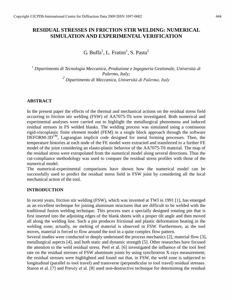
sheet contact surface. During the developed experiments and in the respective numerical simulations the following tool design was utilized: a pin height of 2.7mm, a cylindrical pin diameter equal to 4mm, a shoulder diameter equal to 12mm and a 0.5mm fillet radius at the pin-shoulder interface were chosen. This tool, as a rigid body, was meshed, for the thermal analysis, with about 3,000 tetrahedral elements. As far as the modelling of the workpiece is regarded about 10,000 tetrahedral elements with single edges of about 0.75mm were used; in this way, four to five elements were placed along the sheet thickness. A non-uniform mesh with adaptive re-meshing was adopted with smaller elements close to the tool and a re-meshing referring volume was identified all along the tool feed movement, Fig. 1.
Fig.1. The FE continuum model at the beginning of the simulation
A constant shear friction factor of 0.46 was used for the tool-sheet interface on the basis of a previous experimental thermal characterization and a numerical sensitivity analysis for the shear friction factor (m) [15, 16]. All the simulations were performed using the same procedure and process parameters; in particular tool sinking of 0.1mm, tool rotating speed of 700rpm, a tilt angle of 2° and an advancing velocity equal to 1.7mm/s. Once the process simulation was developed, the temperature histories of each node of the FE model, determined both by the frictional forces and deformation works decaying into heat, were extracted from the post processing result file. In particular temperature histories for all the nodes,
446Copyright ©JCPDS-International Centre for Diffraction Data 2009 ISSN 1097-0002
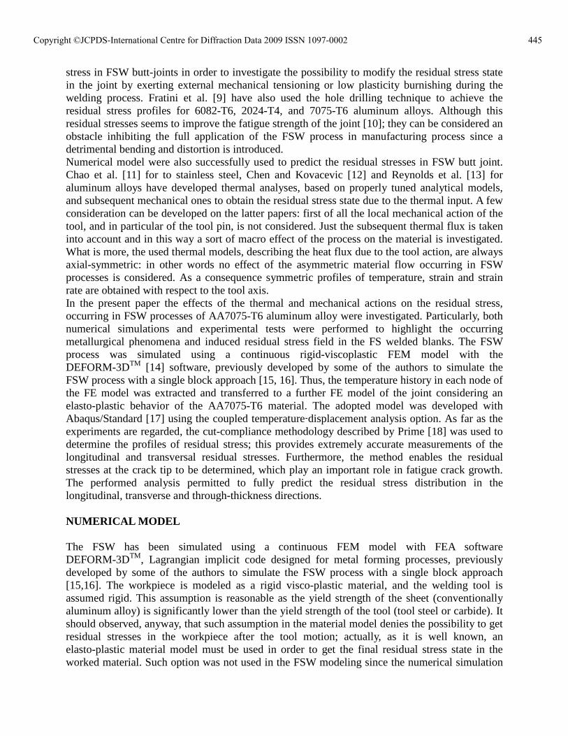
with values taken with a 0.3s period for a total time of 36s (length covered by the tool about 60mm) were considered. Such data were linearly interpolated to get local values of the temperature for a given position in the model and a given time during the process; furthermore, the temperature data were transferred to a further FE model of the joint considering an elasto-plastic behavior of the AA7075-T6 material. The interpolation and transfer operations were performed utilizing the commercial program MatlabTM. The elastoplastic FEM model was developed with Abaqus/Standard [17] using the Coupled Temperature-Displacement analysis option and made of about 5000 brick elements of uniform geometry, characterized by 8-nodes and tri-linear displacement and temperature functions, reduced integration with hourglass control. The boundary conditions of the model gave the clamping and supporting conditions which were assured during the process. What is more, at each node of the model the corresponding temperature history was given as transitory boundary condition reproducing the thermal effects of the process derived both the friction forces work decaying into heat and the deformation work, again decaying into heat. At the end of the process the mechanical constraints were released in order to reproduce the unclamping of the joint after the FSW process. Fig. 2 shows the map of the temperature distribution during the welding phase:
Fig.2. Map of the temperature during the welding process.
EXPERIMENTAL SETUP a) Friction stir welds The friction stir welds were carried out by using a properly designed clamping fixture that allows the user to fix the two sheets to be welded on a milling machine. The steel plates composing the fixture where finished at the grinding machine in order to assure a uniform pressure distribution on the two fixed specimens. As far as the utilized tool is regarded, it was made in H13 steel quenched at 1020°C, characterized by a 52 HRc hardness. The AA7075-T6 aluminum alloy was used in the experiments. The sheet metals were received in 1m x 2m x 3mm thick blanks and were reduced to 100x70mm specimens. The mechanical characterization of the parent material was carried out by means of micro-hardness and tensile tests on properly prepared specimens. Table 1 shows the obtained results in terms of Young�s modulus (E), yield strength (óy), ultimate tensile stress (óu) and Vickers microhardness (Hv).
447Copyright ©JCPDS-International Centre for Diffraction Data 2009 ISSN 1097-0002
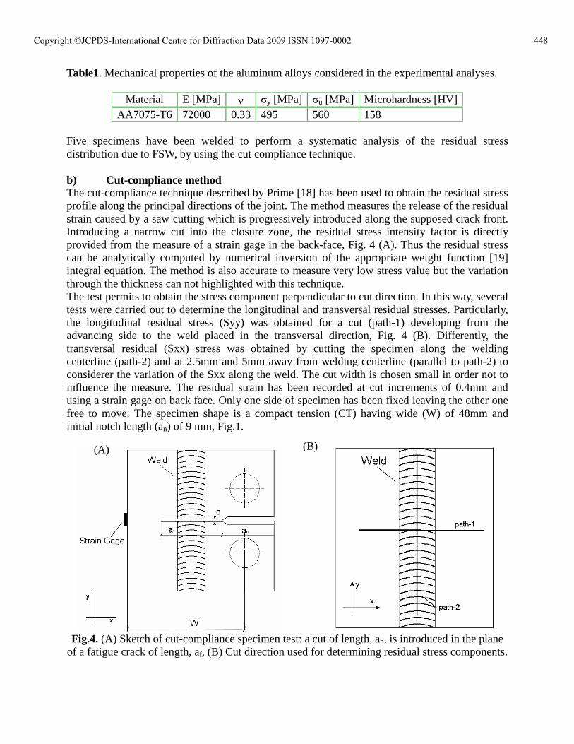
Table1. Mechanical properties of the aluminum alloys considered in the experimental analyses.
Material E [MPa] óy [MPa] óu [MPa] Microhardness [HV] AA7075-T6 72000 0.33 495 560 158
Five specimens have been welded to perform a systematic analysis of the residual stress distribution due to FSW, by using the cut compliance technique. b) Cut-compliance method The cut-compliance technique described by Prime [18] has been used to obtain the residual stress profile along the principal directions of the joint. The method measures the release of the residual strain caused by a saw cutting which is progressively introduced along the supposed crack front. Introducing a narrow cut into the closure zone, the residual stress intensity factor is directly provided from the measure of a strain gage in the back-face, Fig. 4 (A). Thus the residual stress can be analytically computed by numerical inversion of the appropriate weight function [19] integral equation. The method is also accurate to measure very low stress value but the variation through the thickness can not highlighted with this technique. The test permits to obtain the stress component perpendicular to cut direction. In this way, several tests were carried out to determine the longitudinal and transversal residual stresses. Particularly, the longitudinal residual stress (Syy) was obtained for a cut (path-1) developing from the advancing side to the weld placed in the transversal direction, Fig. 4 (B). Differently, the transversal residual (Sxx) stress was obtained by cutting the specimen along the welding centerline (path-2) and at 2.5mm and 5mm away from welding centerline (parallel to path-2) to considerer the variation of the Sxx along the weld. The cut width is chosen small in order not to influence the measure. The residual strain has been recorded at cut increments of 0.4mm and using a strain gage on back face. Only one side of specimen has been fixed leaving the other one free to move. The specimen shape is a compact tension (CT) having wide (W) of 48mm and initial notch length (an) of 9 mm, Fig.1.
Fig.4. (A) Sketch of cut-compliance specimen test: a cut of length, an, is introduced in the plane
of a fatigue crack of length, af, (B) Cut direction used for determining residual stress components.
(A) (B)
448Copyright ©JCPDS-International Centre for Diffraction Data 2009 ISSN 1097-0002
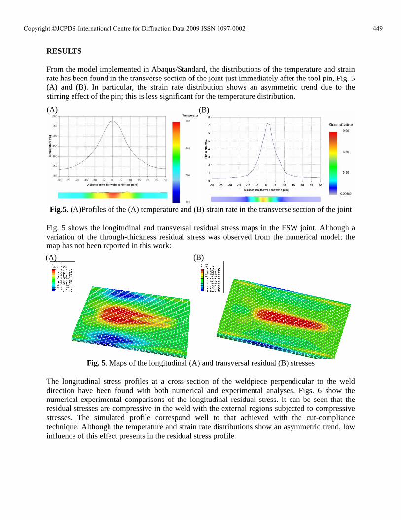
RESULTS From the model implemented in Abaqus/Standard, the distributions of the temperature and strain rate has been found in the transverse section of the joint just immediately after the tool pin, Fig. 5 (A) and (B). In particular, the strain rate distribution shows an asymmetric trend due to the stirring effect of the pin; this is less significant for the temperature distribution.
Fig.5. (A)Profiles of the (A) temperature and (B) strain rate in the transverse section of the joint
Fig. 5 shows the longitudinal and transversal residual stress maps in the FSW joint. Although a variation of the through-thickness residual stress was observed from the numerical model; the map has not been reported in this work:
Fig. 5. Maps of the longitudinal (A) and transversal residual (B) stresses
The longitudinal stress profiles at a cross-section of the weldpiece perpendicular to the weld direction have been found with both numerical and experimental analyses. Figs. 6 show the numerical-experimental comparisons of the longitudinal residual stress. It can be seen that the residual stresses are compressive in the weld with the external regions subjected to compressive stresses. The simulated profile correspond well to that achieved with the cut-compliance technique. Although the temperature and strain rate distributions show an asymmetric trend, low influence of this effect presents in the residual stress profile.
(A) (B)
(A) (B)
449Copyright ©JCPDS-International Centre for Diffraction Data 2009 ISSN 1097-0002
Distance from the welding line [MPa]
-15 -10 -5 0 5 10 15
Long
itudi
nal r
esid
ual s
tres
s [M
Pa]
-40
-20
0
20
40
60
80
100
NumericalExperimental
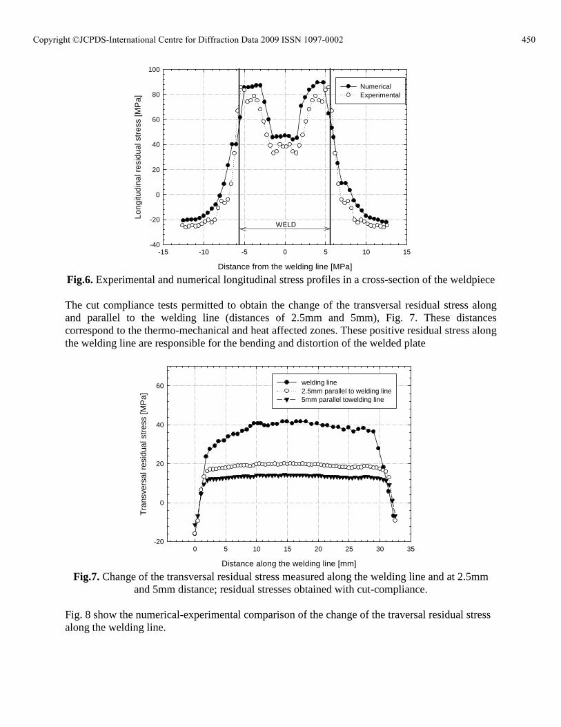
WELD
Fig.6. Experimental and numerical longitudinal stress profiles in a cross-section of the weldpiece The cut compliance tests permitted to obtain the change of the transversal residual stress along and parallel to the welding line (distances of 2.5mm and 5mm), Fig. 7. These distances correspond to the thermo-mechanical and heat affected zones. These positive residual stress along the welding line are responsible for the bending and distortion of the welded plate
Distance along the welding line [mm]
0 5 10 15 20 25 30 35
Tra
nsve
rsal
res
idua
l str
ess
[MP
a]
-20
0
20
40
60 welding line 2.5mm parallel to welding line5mm parallel towelding line
Fig.7. Change of the transversal residual stress measured along the welding line and at 2.5mm
and 5mm distance; residual stresses obtained with cut-compliance.
Fig. 8 show the numerical-experimental comparison of the change of the traversal residual stress along the welding line.
450Copyright ©JCPDS-International Centre for Diffraction Data 2009 ISSN 1097-0002
Distance along the welding line [mm]
0 5 10 15 20 25 30 35
Tra
nsve
rsal
res
idua
l str
ess
[MP
a]
-20
0
20
40
60ExperimentalNumerical
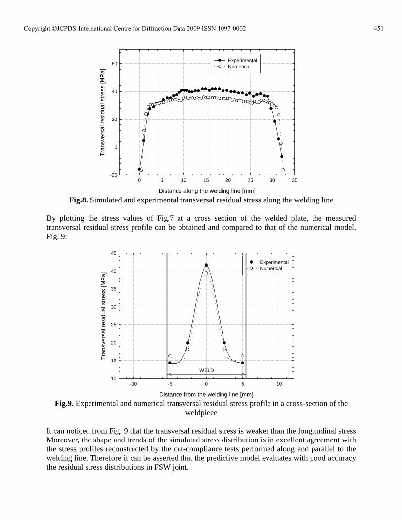
Fig.8. Simulated and experimental transversal residual stress along the welding line
By plotting the stress values of Fig.7 at a cross section of the welded plate, the measured transversal residual stress profile can be obtained and compared to that of the numerical model, Fig. 9:
Distance from the welding line [mm]
-10 -5 0 5 10
Tra
nsve
rsal
res
idua
l str
ess
[MP
a]
10
15
20
25
30
35
40
45
ExperimentalNumerical
WELD
Fig.9. Experimental and numerical transversal residual stress profile in a cross-section of the
weldpiece It can noticed from Fig. 9 that the transversal residual stress is weaker than the longitudinal stress. Moreover, the shape and trends of the simulated stress distribution is in excellent agreement with the stress profiles reconstructed by the cut-compliance tests performed along and parallel to the welding line. Therefore it can be asserted that the predictive model evaluates with good accuracy the residual stress distributions in FSW joint.
451Copyright ©JCPDS-International Centre for Diffraction Data 2009 ISSN 1097-0002
CONCLUSIONS Several considerations on the residual stress in FSW rise from this work: � The continuous model proposed assumes the sheets to be welded as a �single block� This FE
model takes into account the actual interaction between the tool and the workpiece allow to get a description of the process closer to reality. In particular asymmetric distributions of temperature, strain and strain rate are calculated by such models. Differently, the other FE models presented in literature can not consider this effect since they starts from analytical representation of the thermal flow occurring in FSW process.
� It should be observed that residual stresses in FSW processes are due both to thermal and
mechanical causes. The former are due to the friction forces work and to the deformation work both decaying into heat. The latter are strictly connected to the strong gradients of strain and strain rates occurring due to the tool pin action on the material to be welded and which determine relevant microstructure changes in the parent material but low influence in the residual stresses.
� In the present research the residual stress state occurring in FSW of butt joint was predicted
taking into account all the thermal effects. In other words the thermal histories used to calculate the residual stresses in the material were derived by a coupled thermo-mechanical FE analysis and then took into account the heat generated by both friction forces work and to deformation work. In this way the followed approach allowed to get a bit closer to reality with respect to others research groups.
� A wide range of experimental tests using the cut-compliance method were performed to
obtain both longitudinal and transversal residual stress in the FSW joint. The comparison with the simulated residual stress has shown a good agreement; therefore, this model can be successfully used to predict the residual stress by considering all the local mechanical action of the tool.
ACKNOWLEDGEMENTS This work was made using MIUR (Italian Ministry for University and Scientific Research) funds REFERENCE [1] Thomas WM. Friction stir butt welding. 1991;International Patent Application No.
9125978.8. [2] Mishra RS, Ma ZY. Friction stir welding and processing. Materials Science and
Engineering. 2005;50:1-77. [3] Guerra M, Schmidt C, McClure JC, Murr LE, Nunes AC. Flow patterns during friction
stir welding. Materials Characterization. 2002;49(2):95-101. [4] Sutton MA, Bangcheng Y, Reynolds AP, Junhui Y. Banded microstructure in 2024-T351
and 2524-T351 aluminum friction stir welds Part II. Mechanical characterization. Materials Science and Engineering. 2004;364:66-74.
[5] Cirello A, Buffa G, Fratini L, Pasta S. AA6082-T6 Friction Stir Welded Joints Fatigue
452Copyright ©JCPDS-International Centre for Diffraction Data 2009 ISSN 1097-0002
Resistance: Influence of Process Parameters. Int Mech E Part B Journal of Engineering Manufacturing. 2006;220(6):805-812.
[6] Peel M, Steuwer A, Preuss M, Withers PJ. Microstructure, mechanical properties and residual stresses as a function of welding speed in aluminium AA5083 friction stir welds. Acta Materialia. 2003;51(16):4791-4801.
[7] Staron P, Kocak M, Williams S. Residual stresses in friction stir welded Al sheets. Applied Physics A: Materials Science and Processing. 2002;74(SUPPL.II):S1161-S1162.
[8] Prevéy P, Mahoney M. Improved fatigue performance of friction stir welds with low
plasticity burnishing: residual stress design and fatigue performance assessment. Materials Science Forum 2003;426-432 (4):2933-2940.
[9] Fratini L, Zuccarello B. An analysis of through-thickness residual stresses in aluminium FSW butt joints. International Journal of Machine Tools and Manufacture. 2006;46(6):611-619.
[10] Fratini L, Pasta S, Reynolds AP. Fatigue crack growth in 2024-T351 friction stir welded joints: Longitudinal residual stress and microstructural effects. International Journal of Fatigue. 2008;doi:10.1016/j.ijfatigue.2008.05.004.
[11] Chao YJ, Qi X, Teng W. Heat transfer in friction stir welding � Experimental and numerical studies. Transaction of the ASME. 2003;105:138-145.
[12] Chen C, Kovacevic R. Thermomechanical modelling and force analysis of friction stir welding by the finite element method. Proceedings of the Institution of Mechanical Engineers, Part C: Journal of Mechanical Engineering Science. 2004;218(5):509-520.
[13] Khandkar MZH, Khan JA, Reynolds AP, Sutton MA. Predicting residual thermal stresses in friction stir welded metals. Journal of Materials Processing Technology. 2006;174(1-3):195-203.
[14] DEFORM. Deform-3DTM user manual. 2003. [15] Buffa G, Hua J, Shivpuri R, Fratini L. A continuum based fem model for friction stir
welding - Model development. Materials Science and Engineering A. 2006;419(1-2):389-396.
[16] Buffa G, Hua J, Shivpuri R, Fratini L. Design of the friction stir welding tool using the continuum based FEM model. Materials Science and Engineering A. 2006;419(1-2):381-388.
[17] ABAQUS user manual vol. I I, and III. ABAQUS, Inc Standard 6.6.1 Standard User manual. 2004.
[18] Prime MB. Residual stress measurement by successive extension of a slot: The crack compliance method. Applied Mechanics Reviews. 1999;52(2):75-96.
[19] Schindler HJ. Experimental determination of crack closure by the cut compliance technique. ASTM Special Technical Publication; 1999. p. 175-187.
453Copyright ©JCPDS-International Centre for Diffraction Data 2009 ISSN 1097-0002
Related Documents