ww.sciencedirect.com
i n t e rn a t i o n a l j o u r n a l o f h y d r o g e n en e r g y 3 9 ( 2 0 1 4 ) 1 5 1 5 8e1 5 1 6 8
Available online at w
ScienceDirect
journal homepage: www.elsevier .com/locate/he
Modeling of hybrid photovoltaic/wind/fuel cellspower system
N. Mezzai a,*, D. Rekioua a, T. Rekioua a, A. Mohammedi a, K. Idjdarane a,S. Bacha b
a Laboratoire LTII, Universite de Bejaia, 06000 Bejaia, Algeriab G2lab INPG Grenoble, France
a r t i c l e i n f o
Article history:
Available online 28 June 2014
Keywords:
Fuel cells
Photovoltaic
Wind system
Battery storage
Modeling
* Corresponding author. Tel.: þ213 34215090E-mail address: [email protected] (N
http://dx.doi.org/10.1016/j.ijhydene.2014.06.00360-3199/Copyright © 2014, Hydrogen Energ
a b s t r a c t
In this paper, identification and modeling of a hybrid photovoltaic/wind/fuel cells power
system is presented. This system comprises also a battery storage supplying a load via an
inverter. The identification of each subsystem has been made and then the proposed
system is modeled and simulated under Matlab/Simulink Package. The power control of
the hybrid system is introduced by using LabVIEW Software. The mathematical model
topology and its power management of the global system with battery bank system are
significant contributions of our work. The proposed control strategy has been experi-
mentally implanted and practical results are compared to those obtained by simulation
under the same metrological conditions, showing the effectiveness of the proposed hybrid
system.
Copyright © 2014, Hydrogen Energy Publications, LLC. Published by Elsevier Ltd. All rights
reserved.
Introduction
In recent years, hybrid power systems using renewable energy
sources have received considerable attention worldwide
[1e5], [6e18] and [21e37]. These systems may include
different components as DC or AC distribution system, storage
system, converters, filters and control system for load man-
agement,which can be connected in different architectures [1,
2 and 16]. Most researches based on renewable hybrid system
include optimization using maximum power point tracking
methods, technico-economic feasibility of the HPS using
mathematical models in Matlab/Simulink, and on energy
management in real time. For instance, in Ref. [26], authors
present a real-time energy management of a stand-alone
hybrid wind-micro turbine energy system using
; fax: þ213 34205061.. Mezzai).15y Publications, LLC. Publ
optimization. Moreover, power Management of a Stand-Alone
Wind/Photovoltaic/Fuel Cell Energy System is presented in
Ref. [27], but the simulation model for the hybrid energy sys-
tem has been developed using MATLAB/Simulink. However,
intelligent optimal energy management system for hybrid
power sources including fuel cell and battery is presented by
authors in Ref. [28]. They compare conventional management
system without the fan temperature control and with a fixed
hydrogen pressure and a CC/CV charging framework. In
addition, Refs. [29,35] present an optimization and techno-
economic feasibility analysis of hybrid (photovoltaic/wind/
fuel cell) energy systems considering the effects of electrical
load and energy storage technology. Authors in Ref. [30] ex-
amines dynamic operation and control strategies for a
microgrid hybrid windephotovoltaic-fuel cell based power
supply system using intelligent controllers for maximum
ished by Elsevier Ltd. All rights reserved.
Nomenclature
Cbatt capacity battery, Ah
Cp power coefficient
ENernst voltage Nernst, V
Es solar radiation, W/m2
Ipv output-terminal current, A
Iph diode-current, A
Ish shunt-leakage current, A
Isc short circuit current, A
I0 saturation current of the diode, A
Impp maximum current at PPM, A
K Boltzmann constant, Joule/K
nb number of cells
Pmpp maximum power point, W
PPV photovoltaic power, W
q electron charge, C
Rbatt internal resistance, U
Rs series resistance, U
Rsh shunt resistance, U
Tj temperature cells, K
Tjref reference temperature of the PV cell, K
TPEMFC absolute operating temperature of the stack, K
Uact activation overvoltage, V
Uconc concentration or diffusion over-voltage, V
Uohm resistive or ohmic over-voltage, V
Vmpp maximum voltage at PPM, V
Voc open circuit voltage, V
VPEMFC fuel cell voltage, V
Xbatt reactance battery, Ah
Zbatt impedance battery, Ah
Greek letters
aSC temperature coefficient of short-current, A/K
ai constants
b road slope angle, �
boc voltage temperature coefficient, V/K
DT heating of the accumulator, K
rair air density
4 shift-phase between current and voltage, �
Abbreviations
AC alternate current
DC direct current
FC fuel cell
HPS hybrid power system
PMSM permanent magnet synchronous motor
PEMFC proton exchange membrane fuel cells
PV photovoltaic
NI national instruments
DAQ data acquisition
i n t e r n a t i o n a l j o u r n a l o f h y d r o g e n en e r g y 3 9 ( 2 0 1 4 ) 1 5 1 5 8e1 5 1 6 8 15159
power point tracking control. Other works are focused on
hybrid Systems with storage system [31e34]. For example in
Ref. [30], authors examine the possibility of hybrid plants with
a variable consumption in necessary conditions, by using
adaptive controller, including fuzzy controller. And in
Ref. [31], authors present a hybrid power source fed by
renewable energy sources (wind and photovoltaic) and fuel
cell sources, with an energy storage device (battery/ultra-
capacitors). All other cited works in this paper [8, 9, 35, 36 and
37] use Matlab/simulink to study the mathematical model of
HPS.
Data-acquisition systems are widely used in renewable
energy source applications in order to collect data regarding
the installed system performance, for evaluation purposes.
The collected data is first conditioned using exact electronic
circuits and then interfaced to a PC using a data-acquisition
card [1,2]. LabVIEW is an environmental development pro-
gram, developed by NI. Similar to C and BASIC's environment
development. There is an obvious difference between Lab-
VIEW and other computer languages. Other computer lan-
guages are used to generate a based code on the language of
the text, whereas LabVIEW uses a graphical editing language
G. The resulting program is the formof a block diagram [19,20].
In this paper, modeling hybrid photovoltaic/wind/fuel cells
power system is presented. The control of the global system is
made using LABVIEW software. This program is used for
further process, display and storage of the collected data in a
hard disk PC. The sizing of the proposed system is detailed. It
depends mainly on the site location that dictates the average
wind speed, the turbine orientation and the average energy
consumption of the application. The originality of our work
focuses first on the identification of the different parameters
of each subsystem separately before its installation in the site.
Second, the design and the installation of various voltage and
current sensors, data acquisition in LabVIEW environment
which allowed us to have real-time data that permits the
management and data processing. And finally, the overall
system can be designed and installed for higher power and
can be considered as a prototype for the development of
multi-sources renewable energy systems. The global obtained
system is fully practical and the mathematical model, based
on real parameters, is more elaborated. The obtained results
are presented to demonstrate the effectiveness of the pro-
posed system.
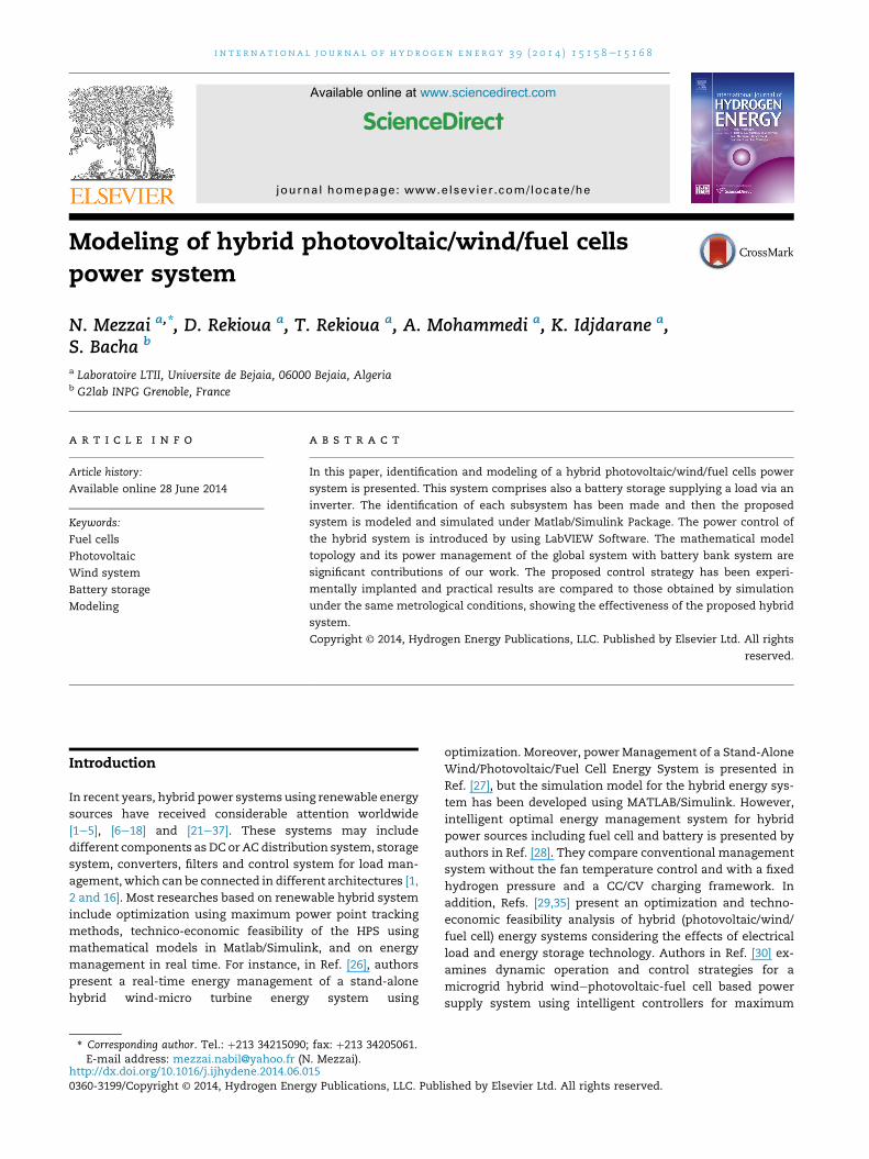
Proposed hybrid system with DC bus
In the hybrid systemwith DC bus, the power supplied by each
source is centralized on a DC bus. Thus, the energy conversion
system to provide AC power has then to be converted
continuously. The generators are connected in series with the
inverter to power the loads alternatives. The inverter should
supply the alternating loads from the DC bus and the batteries
are sized to supply peak loads. The advantage of this topology
is the simplicity of the operation and the load demand is
satisfied without interruption even when the generators
charge the short-term storage units. The different sources can
be photovoltaic and wind energy; fuel cells and diesel gener-
ators (see Fig. 1).
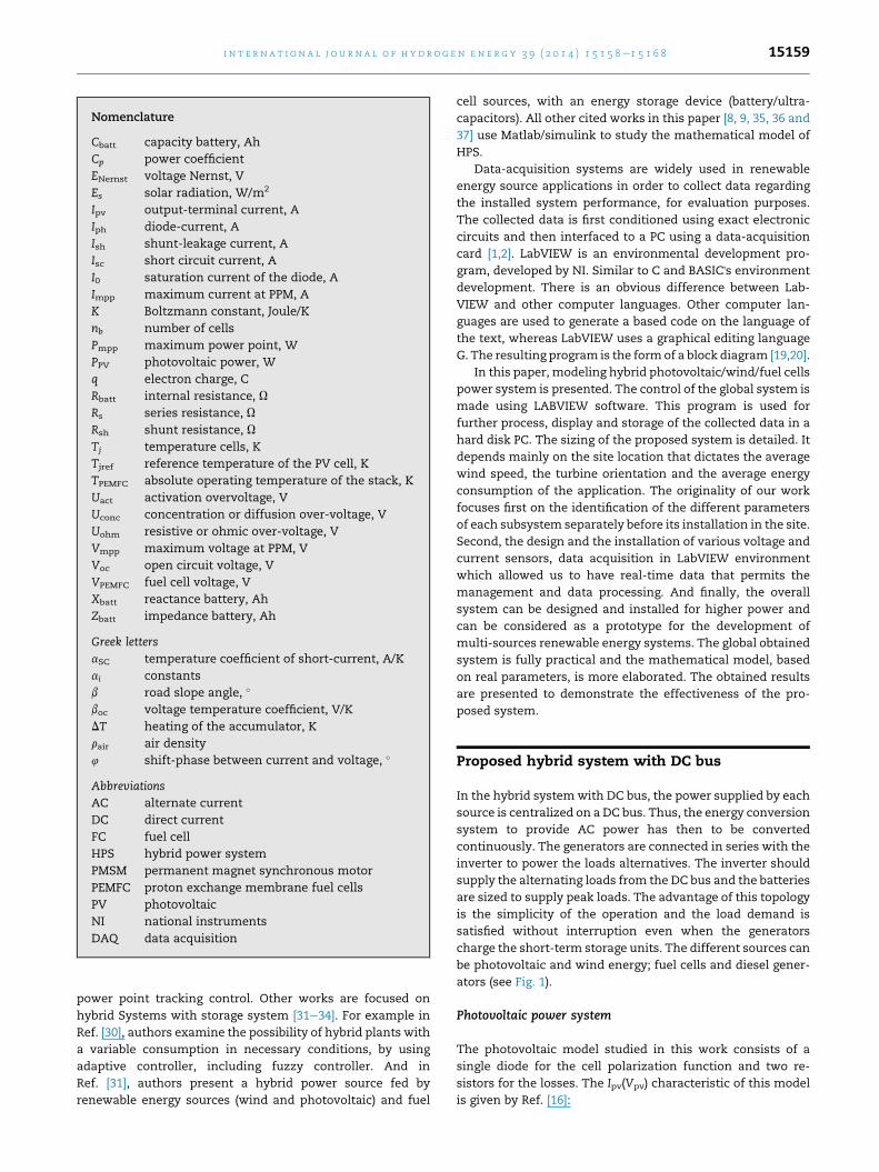
Photovoltaic power system
The photovoltaic model studied in this work consists of a
single diode for the cell polarization function and two re-
sistors for the losses. The Ipv(Vpv) characteristic of this model
is given by Ref. [16]:
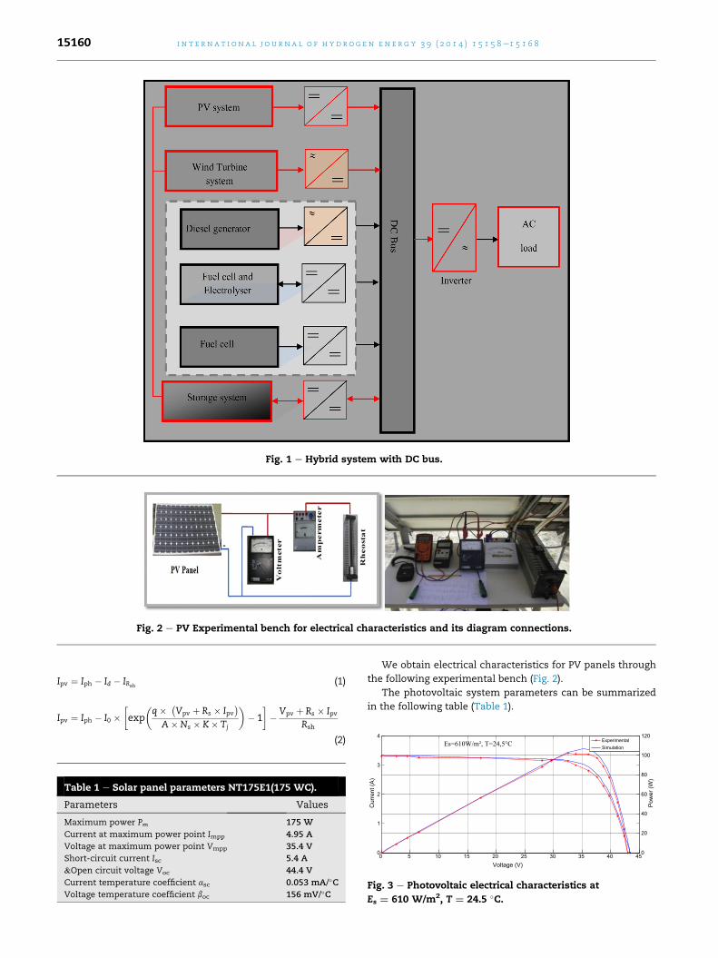
Fig. 1 e Hybrid system with DC bus.
Fig. 2 e PV Experimental bench for electrical characteristics and its diagram connections.
4 120Es=610W/m², T=24,5°C
i n t e rn a t i o n a l j o u r n a l o f h y d r o g e n en e r g y 3 9 ( 2 0 1 4 ) 1 5 1 5 8e1 5 1 6 815160
Ipv ¼ Iph � Id � IRsh(1)
Ipv ¼ Iph � I0 ��exp
�q� �
Vpv þ Rs � Ipv�
A�Ns � K� Tj
�� 1
�� Vpv þ Rs � Ipv
Rsh
(2)
Table 1 e Solar panel parameters NT175E1(175 WC).
Parameters Values
Maximum power Pm 175 W
Current at maximum power point Impp 4.95 A
Voltage at maximum power point Vmpp 35.4 V
Short-circuit current Isc 5.4 A
&Open circuit voltage Voc 44.4 V
Current temperature coefficient asc 0.053 mA/�CVoltage temperature coefficient boc 156 mV/�C
We obtain electrical characteristics for PV panels through
the following experimental bench (Fig. 2).
The photovoltaic system parameters can be summarized
in the following table (Table 1).
0 5 10 15 20 25 30 35 40 450
1
2
3
Voltage (V)
Cur
rent
(A)
0
20
40
60
80
100
Pow
er (W
)
Fig. 3 e Photovoltaic electrical characteristics at
Es ¼ 610 W/m2, T ¼ 24.5 �C.
0 2 4 6 8 10 12 140
0.05
0.1
0.15
0.2
0.25
0.3
0.35
0.4
0.45
0.5
Tip-speed ration
Coe
ffici
ent C
p
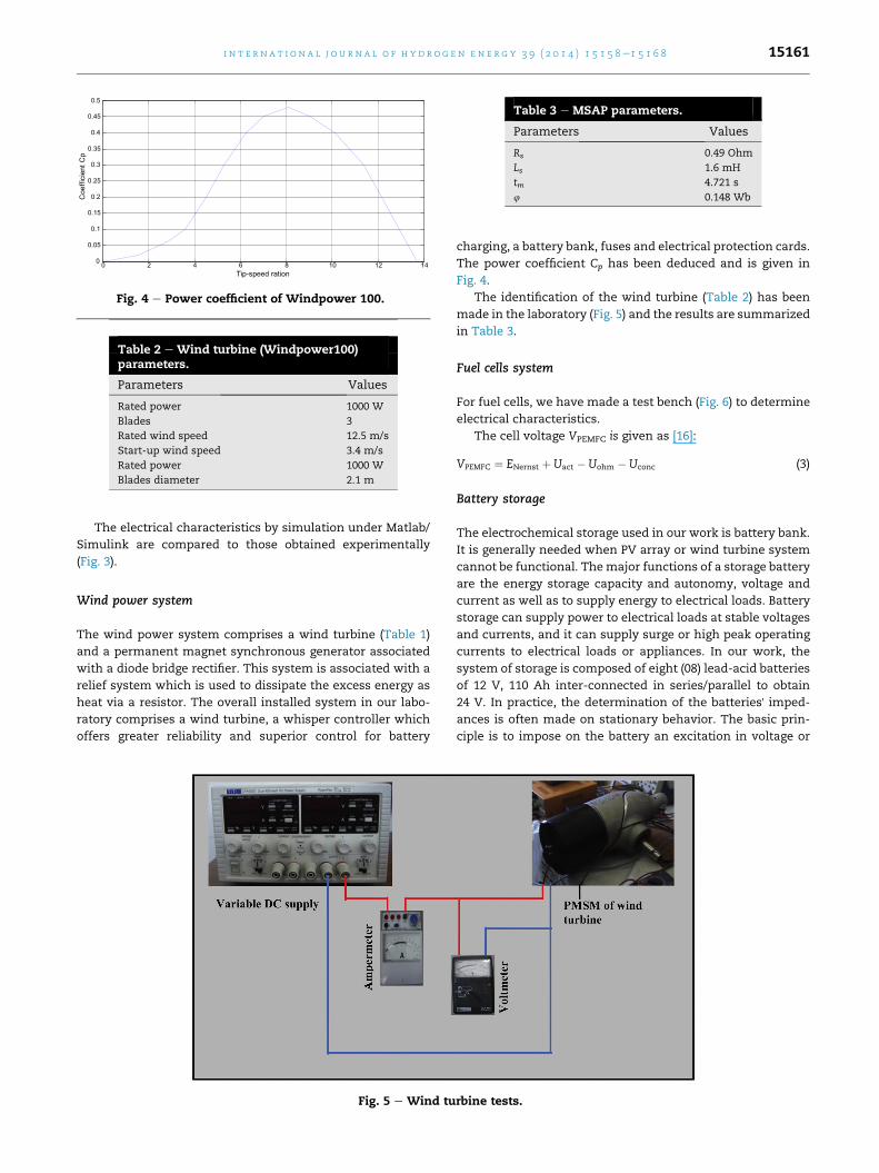
Fig. 4 e Power coefficient of Windpower 100.
Table 2 e Wind turbine (Windpower100)parameters.
Parameters Values
Rated power 1000 W
Blades 3
Rated wind speed 12.5 m/s
Start-up wind speed 3.4 m/s
Rated power 1000 W
Blades diameter 2.1 m
Table 3 e MSAP parameters.
Parameters Values
Rs 0.49 Ohm
Ls 1.6 mH
tm 4.721 s
4 0.148 Wb
i n t e r n a t i o n a l j o u r n a l o f h y d r o g e n en e r g y 3 9 ( 2 0 1 4 ) 1 5 1 5 8e1 5 1 6 8 15161
The electrical characteristics by simulation under Matlab/
Simulink are compared to those obtained experimentally
(Fig. 3).
Wind power system
The wind power system comprises a wind turbine (Table 1)
and a permanent magnet synchronous generator associated
with a diode bridge rectifier. This system is associated with a
relief system which is used to dissipate the excess energy as
heat via a resistor. The overall installed system in our labo-
ratory comprises a wind turbine, a whisper controller which
offers greater reliability and superior control for battery
Fig. 5 e Wind tu
charging, a battery bank, fuses and electrical protection cards.
The power coefficient Cp has been deduced and is given in
Fig. 4.
The identification of the wind turbine (Table 2) has been
made in the laboratory (Fig. 5) and the results are summarized
in Table 3.
Fuel cells system
For fuel cells, we have made a test bench (Fig. 6) to determine
electrical characteristics.
The cell voltage VPEMFC is given as [16]:
VPEMFC ¼ ENernst þ Uact � Uohm � Uconc (3)
Battery storage
The electrochemical storage used in our work is battery bank.
It is generally needed when PV array or wind turbine system
cannot be functional. Themajor functions of a storage battery
are the energy storage capacity and autonomy, voltage and
current as well as to supply energy to electrical loads. Battery
storage can supply power to electrical loads at stable voltages
and currents, and it can supply surge or high peak operating
currents to electrical loads or appliances. In our work, the
system of storage is composed of eight (08) lead-acid batteries
of 12 V, 110 Ah inter-connected in series/parallel to obtain
24 V. In practice, the determination of the batteries' imped-
ances is often made on stationary behavior. The basic prin-
ciple is to impose on the battery an excitation in voltage or
rbine tests.
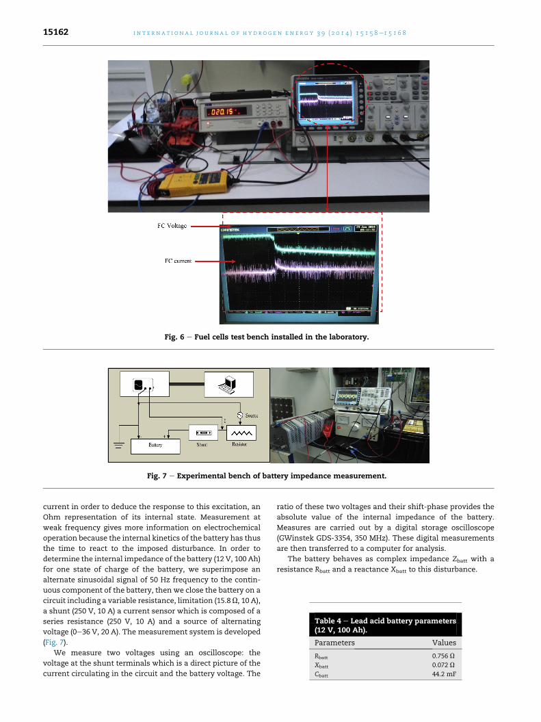
Fig. 6 e Fuel cells test bench installed in the laboratory.
Fig. 7 e Experimental bench of battery impedance measurement.
Table 4 e Lead acid battery parameters(12 V, 100 Ah).
Parameters Values
Rbatt 0.756 U
Xbatt 0.072 U
Cbatt 44.2 mF
i n t e rn a t i o n a l j o u r n a l o f h y d r o g e n en e r g y 3 9 ( 2 0 1 4 ) 1 5 1 5 8e1 5 1 6 815162
current in order to deduce the response to this excitation, an
Ohm representation of its internal state. Measurement at
weak frequency gives more information on electrochemical
operation because the internal kinetics of the battery has thus
the time to react to the imposed disturbance. In order to
determine the internal impedance of the battery (12 V, 100 Ah)
for one state of charge of the battery, we superimpose an
alternate sinusoidal signal of 50 Hz frequency to the contin-
uous component of the battery, then we close the battery on a
circuit including a variable resistance, limitation (15.8 U, 10 A),
a shunt (250 V, 10 A) a current sensor which is composed of a
series resistance (250 V, 10 A) and a source of alternating
voltage (0e36 V, 20 A). The measurement system is developed
(Fig. 7).
We measure two voltages using an oscilloscope: the
voltage at the shunt terminals which is a direct picture of the
current circulating in the circuit and the battery voltage. The
ratio of these two voltages and their shift-phase provides the
absolute value of the internal impedance of the battery.
Measures are carried out by a digital storage oscilloscope
(GWinstek GDS-3354, 350 MHz). These digital measurements
are then transferred to a computer for analysis.
The battery behaves as complex impedance Zbatt with a
resistance Rbatt and a reactance Xbatt to this disturbance.
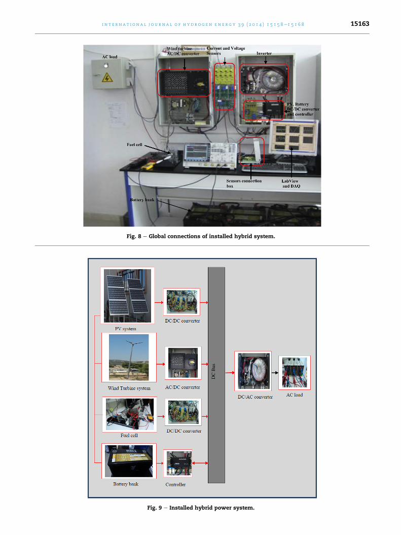
Fig. 8 e Global connections of installed hybrid system.
Fig. 9 e Installed hybrid power system.
i n t e r n a t i o n a l j o u r n a l o f h y d r o g e n en e r g y 3 9 ( 2 0 1 4 ) 1 5 1 5 8e1 5 1 6 8 15163
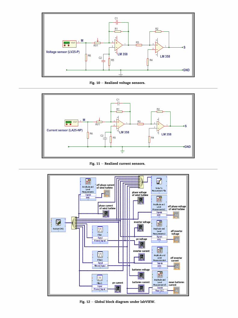
Fig. 10 e Realized voltage sensors.
Fig. 11 e Realized current sensors.
Fig. 12 e Global block diagram under labVIEW.
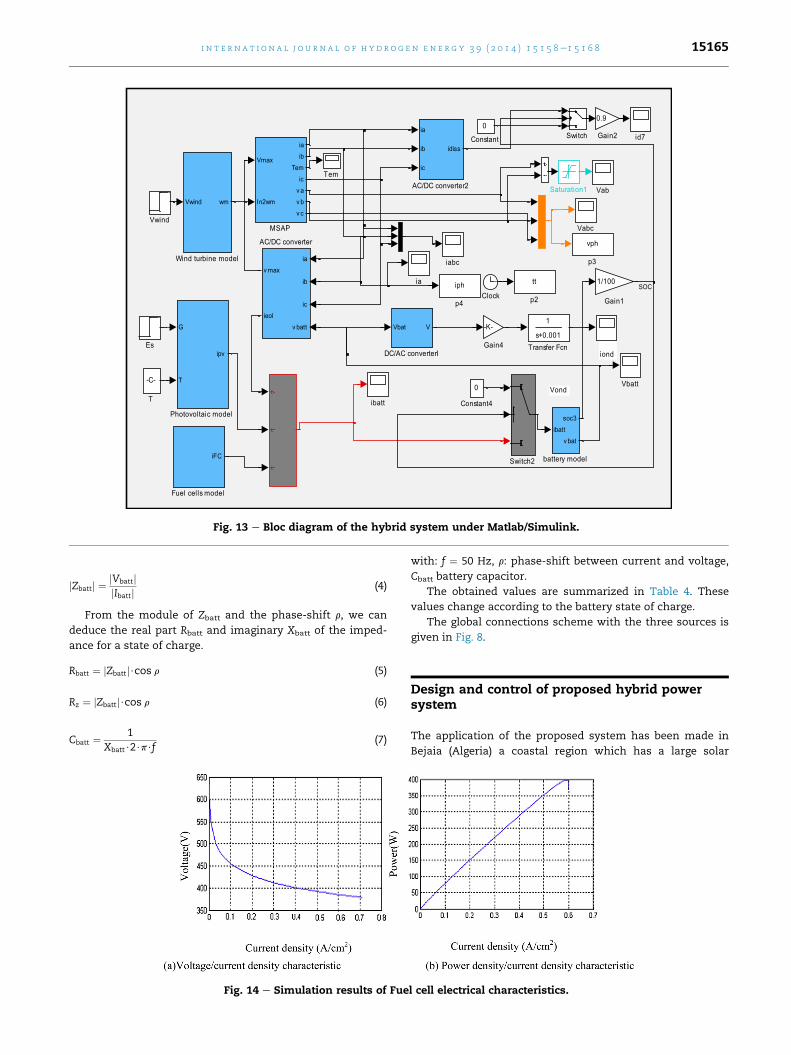
Fig. 13 e Bloc diagram of the hybrid system under Matlab/Simulink.
i n t e r n a t i o n a l j o u r n a l o f h y d r o g e n en e r g y 3 9 ( 2 0 1 4 ) 1 5 1 5 8e1 5 1 6 8 15165
jZbattj ¼ jVbattjjIbattj (4)
From the module of Zbatt and the phase-shift r, we can
deduce the real part Rbatt and imaginary Xbatt of the imped-
ance for a state of charge.
Rbatt ¼ jZbattj$cos r (5)
Rz ¼ jZbattj$cos r (6)
Cbatt ¼ 1Xbatt$2$p$f
(7)
Fig. 14 e Simulation results of Fue
with: f ¼ 50 Hz, r: phase-shift between current and voltage,
Cbatt battery capacitor.
The obtained values are summarized in Table 4. These
values change according to the battery state of charge.
The global connections scheme with the three sources is
given in Fig. 8.
Design and control of proposed hybrid powersystem
The application of the proposed system has been made in
Bejaia (Algeria) a coastal region which has a large solar
l cell electrical characteristics.

Time 15.051 15.07 15.09 15.11 15.13 15.151
-15
-10
-5
0
5
10
15
Time (s)
Phas
e cu
rren
t of w
ind
turb
ine
(A)
(a) Experimental (b) Simulation
Fig. 15 e Phase current of wind turbine.
Time 15,051 15,07 15,09 15,11 15,13 15,151
-30
-20
-10
0
10
20
30
Time (s)Volta
ge c
ompo
sed
of w
ind
turb
ine
(v)
(a) Experimental (b) Simulation
Fig. 16 e Voltage composed of wind turbine.
i n t e rn a t i o n a l j o u r n a l o f h y d r o g e n en e r g y 3 9 ( 2 0 1 4 ) 1 5 1 5 8e1 5 1 6 815166
potential. The global irradiation on horizontal plane recorded
over ten years in Bejaia [16] is much important during the
period from April to September compared to the rest of the
year. Also, themonthly average speed with an annual average
wind speed of 3.975 m/s. Considering their complementar-
ities, we can conclude that the coupling of a photovoltaic and
a wind system is very interesting for the electrical energy
production during a year, so Bejaia is an appropriate place to
implement a hybrid photovoltaic/wind system with fuel cells
and battery bank. Fig. 9 represents the installed HPS. The
different subsystem has been designed with the different
realized converter and the different realized sensors.
The designed voltage sensor used is a Hall Effect sensor
LV25P equivalent to a transformer andwhich is composed of a
Time
PV c
urre
nt (A
)
(a) Experimental
Fig. 17 e Photovo
primary and a secondary coil (Fig. 10). The principle of
designed current sensor is the same as the voltage one. Cur-
rent measurement creates an output voltage proportional
thereto (Fig. 11).
The LabVIEW simulation diagram which is used to design
and calculate the electrical hybrid system parameters using
the DAQ card is based on the below mentioned block diagram
(Fig. 12).
Simulation and experimental results
The following figures have been taken during the operation of
the data acquisition, for a temperature of 24.5 �C, an
15,051 15,07 15,09 15,11 15,13 15,1510
2
4
6
8
10
Time (s)
(b) Simulation
ltaic current.
Time 15.051 15.07 15.09 15.11 15.13 15.15125
25.4
25.8
26.2
26.6
27
Time (s)
Batte
ries
volta
ge (v
)
(b) Simulation
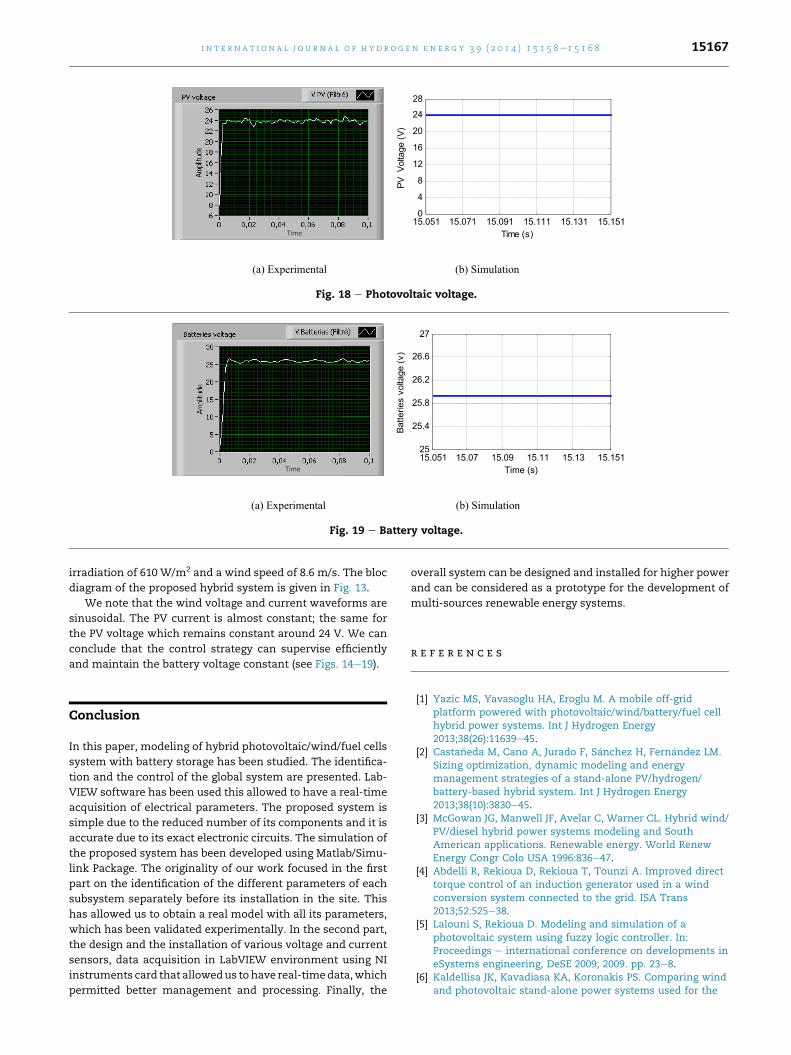
Fig. 19 e Battery voltage.
Time 15.051 15.071 15.091 15.111 15.131 15.1510
4
8
12
16
20
24
28
Time (s)
PV V
olta
ge (V
)
(a) Experimental (b) Simulation
Fig. 18 e Photovoltaic voltage.
i n t e r n a t i o n a l j o u r n a l o f h y d r o g e n en e r g y 3 9 ( 2 0 1 4 ) 1 5 1 5 8e1 5 1 6 8 15167
irradiation of 610 W/m2 and a wind speed of 8.6 m/s. The bloc
diagram of the proposed hybrid system is given in Fig. 13.
We note that the wind voltage and current waveforms are
sinusoidal. The PV current is almost constant; the same for
the PV voltage which remains constant around 24 V. We can
conclude that the control strategy can supervise efficiently
and maintain the battery voltage constant (see Figs. 14e19).
Conclusion
In this paper, modeling of hybrid photovoltaic/wind/fuel cells
system with battery storage has been studied. The identifica-
tion and the control of the global system are presented. Lab-
VIEW software has been used this allowed to have a real-time
acquisition of electrical parameters. The proposed system is
simple due to the reduced number of its components and it is
accurate due to its exact electronic circuits. The simulation of
the proposed system has been developed using Matlab/Simu-
link Package. The originality of our work focused in the first
part on the identification of the different parameters of each
subsystem separately before its installation in the site. This
has allowed us to obtain a real model with all its parameters,
which has been validated experimentally. In the second part,
the design and the installation of various voltage and current
sensors, data acquisition in LabVIEW environment using NI
instruments card that allowedus tohave real-timedata,which
permitted better management and processing. Finally, the
overall system can be designed and installed for higher power
and can be considered as a prototype for the development of
multi-sources renewable energy systems.
r e f e r e n c e s
[1] Yazic MS, Yavasoglu HA, Eroglu M. A mobile off-gridplatform powered with photovoltaic/wind/battery/fuel cellhybrid power systems. Int J Hydrogen Energy2013;38(26):11639e45.
[2] Casta~neda M, Cano A, Jurado F, S�anchez H, Fern�andez LM.Sizing optimization, dynamic modeling and energymanagement strategies of a stand-alone PV/hydrogen/battery-based hybrid system. Int J Hydrogen Energy2013;38(10):3830e45.
[3] McGowan JG, Manwell JF, Avelar C, Warner CL. Hybrid wind/PV/diesel hybrid power systems modeling and SouthAmerican applications. Renewable energy. World RenewEnergy Congr Colo USA 1996:836e47.
[4] Abdelli R, Rekioua D, Rekioua T, Tounzi A. Improved directtorque control of an induction generator used in a windconversion system connected to the grid. ISA Trans2013;52:525e38.
[5] Lalouni S, Rekioua D. Modeling and simulation of aphotovoltaic system using fuzzy logic controller. In:Proceedings e international conference on developments ineSystems engineering, DeSE 2009; 2009. pp. 23e8.
[6] Kaldellisa JK, Kavadiasa KA, Koronakis PS. Comparing windand photovoltaic stand-alone power systems used for the

i n t e rn a t i o n a l j o u r n a l o f h y d r o g e n en e r g y 3 9 ( 2 0 1 4 ) 1 5 1 5 8e1 5 1 6 815168
electrification of remote consumers. Renew Sustain EnergyRev 2007;11:57e77.
[7] Rekioua T, Rekioua D. Direct torque control strategy ofpermanent magnet synchronous machines. In: 2003 IEEEBologna PowerTech e conference proceedings, vol. 2; 2003.pp. 861e6.
[8] Metwally A. Modeling and simulation of a photovoltaic fuelcell hybrid system. A Dissertation in Candidacy for theDegree of Doctor in Engineering (Dr.-Ing.), Faculty ofElectrical Engineering. Germany: University of Kassel; 2005.
[9] Rekioua D, Bensmail S, Bettar N. Development of hybridphotovoltaic-fuel cell system for stand-alone application. IntJ Hydrogen Energy 2014;39(3):1604e11.
[10] Haruni AMO, Gargoom A, Haque ME, Negnevitsky M.Dynamic operation and control of a hybrid wind-diesel standalone power systems. In: Conference proceedings e IEEEapplied power electronics conference and exposition e APEC;2010. pp. 162e9.
[11] Rekioua D, Rekioua T. DSP-controlled direct torque control ofinduction machines based on modulated hysteresis control.In: Proceedings of the international conference onmicroelectronics, ICM 2009; 2009. pp. 378e81.
[12] Lysen EH. Hybrid technology; 2000. http://climatetechwiki.org/technology/hybrid-technology.
[13] Prasad AR, Natarajan E. Optimization of integratedphotovoltaic-wind power generation systems with batterystorage. Energy 2006;31:1943e54.
[14] Dali M, Belhadj J, Roboam X, Blaquiere JM. Control andenergy management of a wind-photovoltaic hybrid system.In: 12th European conference on power electronics andapplications (EPE’2007), Aalborg, Denmark, 02e05September; 2007. pp. 1e10.
[15] Razak JAb, Sopian K, Ali Y, Alghoul MA, Zaharim A, Ahmad I.Optimization of PV-wind-hydro-diesel hybrid system byminimizing excess capacity. Eur J Sci Res 2009;25(4):663e71.
[16] Rekioua D, Matagne E. Optimization of photovoltaic powersystems: modelization, simulation and control. Green EnergyTechnol 2012;102.
[17] Koutroulis E, Kalaitzakis K. Development of an integrateddata-acquisition system for renewable energy sourcessystems monitoring. Renew Energy 2003;28:139e52.
[18] Bryant CL. Real-time data acquisition and control system forthe measurement of motor and neural data. J NeurosciMethods 2005;142:193e200.
[19] LabVIEW user manual. ed. National Instruments; Jan 1998.[20] Yadav Y, Roshan R, Umashankar S, Vijayakumar D,
Khotari DP. Real time simulation of solar photovoltaicmodule using labview data acquisition card. In: Internationalconference on energy efficient technologies for sustainability(ICEETS); 2013. pp. 512e23.
[21] Ortjohann E, Mohd A, Schmelter A, Hamsic N, Lingemann M.Simulation and implementation of an expandable hybridpower system. In: IEEE international symposium onindustrial electronics ISIE 2007; 2007. pp. 377e82.
[22] Paiva JEMS, Carvalho AS. An integrated hybrid power systembased on renewable energy sources. In: IECON proceedings(industrial electronics conference); 2009. pp. 4548e54.
[23] Nehrir MH, Wang C, Strunz K, Aki H, Ramakumar R, Bing J,et al. A review of hybrid renewable/alternative energysystems for electric power generation: configurations,
control, and applications. IEEE Trans Sustain Energy2011;2(4):392e403.
[24] Ghoddami, Delghavi BM, Yazdani A. An integrated wind-photovoltaic-battery system with reduced power-electronicinterface and fast control for grid-tied and off-gridapplications. Renew Energy 2012;45:128e37.
[25] Garcı́a P, Torreglosa JP, Fern�andez LM, Jurado F. Optimalenergy management system for stand-alone wind turbine/photovoltaic/hydrogen/battery hybrid system withsupervisory control based on fuzzy logic. Int J HydrogenEnergy 2013;38(33):14146e58.
[26] Pourmousavi SA, Nehrir MH, Colson CM, Wang C. Real-timeenergy management of a stand-alone hybrid wind-microturbine energy system using particle swarmoptimization. IEEE Trans Sustain Energy 2010;1(3):193e201.
[27] Wang C, Nehrir MH. Power management of a stand-alonewind/photovoltaic/fuel cell energy system. IEEE Trans EnergyConvers 2008;23(3):957e67.
[28] Wai R-J, Jhung S-J, Liaw J-J, Chang Y-R. Intelligent optimalenergy management system for hybrid power sourcesincluding fuel cell and battery. IEEE Trans Power Electron2013;28(7):3231e44.
[29] Baniasad Askari I, Baniasad Askari L, Kaykhah MM, BaniasadAskari H. Optimisation and techno-economic feasibilityanalysis of hybrid (photovoltaic/wind/fuel cell) energysystems in Kerman, Iran; considering the effects of electricalload and energy storage technology. Int J Sustain Energy2014;33(3):635e49.
[30] Ou T-C, Hong C-M. Dynamic operation and control ofmicrogrid hybrid power systems. Energy 2014;66(1):314e23.
[31] Gheydi M, Effatnejad R, Ramezanpour P. Evaluation ofuncertainty in hybrid plants, including wind turbine,photovoltaic, fuel cell, and battery system using fuzzy logic.Indian J Sci Technol 2014;7(2):113e22.
[32] Bizon N. Load-following mode control of a standalonerenewable/fuel cell hybrid power source. Energy ConversManag 2014;77:763e72.
[33] Saravanan S, Thangavel S. Fuzzy logic controller basedpower management for a standalone solar/wind/fuel cell fedhybrid system. J Renew Sustain Energy 2013;5(5):1e6.
[34] LakshmanRao SP, Kurian CP, Singh BK, Abhinav K, Nandy G.Design and simulation of grid connected hybrid solar-WECSusing SIMULINK/MATLAB. In: Proceedings of the 2014international conference on advances in energy conversiontechnologies e intelligent energy management: technologiesand challenges, ICAECT 2014; 2014.
[35] Mostofi F, Safavi M. Application of ABC algorithm for grid-independent hybrid hydro/photovoltaic/wind/fuel cell powergeneration system considering cost and reliability. Int JRenew Energy Res 2013;3(4):922e7.
[36] Mendis N, Muttaqi KM, Sayeef S, Perera S. Operation of awind-diesel-battery based hybrid remote area power supplysystem. In: 6th international conference on electrical andcomputer engineering ICECE2010, 18e20 December 2010,Dhaka, Bangladesh; 2010. pp. 334e7.
[37] Gyawali N, Ohsawa Y, Yamamoto O. Power management ofdouble-fed induction generator-based wind power systemwith integrated Smart energy storage havingsuperconducting magnetic energy storage/fuel-cell/electrolyser. IET Renew Power Gener 2011;5(6):407e21.