Holter System
Directions for Use
ii Welch Allyn Holter System
Copyright 2006 - 2013 Welch Allyn. All rights are reserved. No one is permitted to reproduce or duplicate, in any form, this manual or any part thereof without permission from Welch Allyn.
Welch Allyn or its vendors assume no responsibility for any injury to anyone, or for any illegal or improper use of the product, that may result from failure to use this product in accordance with the instructions, cautions, warnings, or statement of intended use published in this manual.
Welch Allyn, PCH100, PCH200, HR100, HR300 and HR1200 are registered trademarks of Welch Allyn.
SD is a trademark of Toshiba.
Bluetooth is a trademark of Bluetooth SIG, Inc., USA.
Software in this product is Copyright 2006 - 2013 Welch Allyn or its vendors. All rights are reserved. The software is protected by United States of America copyright laws and international treaty provisions applicable worldwide. Under such laws, the licensee is entitled to use the copy of the software incorporated with this instrument as intended in the operation of the product in which it is embedded. The software may not be copied, decompiled, reverse-engineered, disassembled, or otherwise reduced to human-perceivable form. This is not a sale of the software or any copy of the software; all right, title, and ownership of the software remain with Welch Allyn or its vendors.
For information about any Welch Allyn product, call Welch Allyn Technical Support:
Reorder Number: 705874
Global Instrumentation part number 006-700-0035 Version H
Refer to WEB Site “www.WelchAllyn.com” for device directions for use and supporting documentation. To obtain a paper copy of the device directions for use, please contact Welch Allyn.
Printed in USA
USA +1 800 535 6663+1 315 685 4560
Australia +61 2 9638 3000+800 074 793
Canada +1 800 561 8797 China +86 21 6327 9631
European Call Center +353 46 90 67790 France +33 1 55 69 58 49
Germany +49 7477 9271 70 Japan +81 3 3219 0071
Latin America +1 305 669 9003 Netherlands +31 157 505 000
Singapore +65 6419 8100 South Africa +27 11 777 7555
United Kingdom +44 207 365 6780 Sweden +46 85 853 6551
Manufactured for: Welch Allyn4341 State Street RoadSkaneateles Falls, NY 13153 USA
Manufactured by:Manufacturer:
Global Instrumentation, LLC8104 Cazenovia RoadManlius, NY 13104 USA
Contract Medical International GmbHLauensteiner Strasse 3701277 DresdenGermanyTel: +49 (0) 351 213 88 88Fax: +49 (0) 351 213 88 99Contact: European Regulatory ManagerEmail: [email protected]
Directions for Use Table of Contents iii
Table of ContentsIntended Use . . . . . . . . . . . . . . . . . . . . . . . . . . . . . . . . . . . . . . . . . . . . . . . . . . . . 1Indications for Use . . . . . . . . . . . . . . . . . . . . . . . . . . . . . . . . . . . . . . . . . . . . . . . . 2Contraindications . . . . . . . . . . . . . . . . . . . . . . . . . . . . . . . . . . . . . . . . . . . . . . . . . 2Warnings and Cautions. . . . . . . . . . . . . . . . . . . . . . . . . . . . . . . . . . . . . . . . . . . . . 3
Warnings . . . . . . . . . . . . . . . . . . . . . . . . . . . . . . . . . . . . . . . . . . . . . . . . . . . . 3Cautions . . . . . . . . . . . . . . . . . . . . . . . . . . . . . . . . . . . . . . . . . . . . . . . . . . . . . 3
Symbols . . . . . . . . . . . . . . . . . . . . . . . . . . . . . . . . . . . . . . . . . . . . . . . . . . . . . . . . 4Introduction. . . . . . . . . . . . . . . . . . . . . . . . . . . . . . . . . . . . . . . . . . . . . . . . . . . . . . 7
Inspection upon Delivery . . . . . . . . . . . . . . . . . . . . . . . . . . . . . . . . . . . . . . . . 7Before you begin. . . . . . . . . . . . . . . . . . . . . . . . . . . . . . . . . . . . . . . . . . . . . . . . . . 7
System Requirements . . . . . . . . . . . . . . . . . . . . . . . . . . . . . . . . . . . . . . . . . . 7Optional Requirements . . . . . . . . . . . . . . . . . . . . . . . . . . . . . . . . . . . . . . . . . 8Operator Requirements . . . . . . . . . . . . . . . . . . . . . . . . . . . . . . . . . . . . . . . . . 8Features . . . . . . . . . . . . . . . . . . . . . . . . . . . . . . . . . . . . . . . . . . . . . . . . . . . . . 9
Holter System Application Directions for Use . . . . . . . . . . . . . . . . . . . . . . . . . . 10Activating the Welch Allyn Holter Software . . . . . . . . . . . . . . . . . . . . . . . . . 10Recorder Illustrations . . . . . . . . . . . . . . . . . . . . . . . . . . . . . . . . . . . . . . . . . . 11Operation . . . . . . . . . . . . . . . . . . . . . . . . . . . . . . . . . . . . . . . . . . . . . . . . . . . 12
Patient Preparation . . . . . . . . . . . . . . . . . . . . . . . . . . . . . . . . . . . . . . . . . . . . . . . 13Holter Procedure Patient Preparation . . . . . . . . . . . . . . . . . . . . . . . . . . . . . . 13Preparing for Electrode Placement on Patient . . . . . . . . . . . . . . . . . . . . . . . 13Starting the Welch Allyn Holter System Application. . . . . . . . . . . . . . . . . . . 19Starting a Test . . . . . . . . . . . . . . . . . . . . . . . . . . . . . . . . . . . . . . . . . . . . . . . 19Test Report Review, Editing and Printing . . . . . . . . . . . . . . . . . . . . . . . . . . . 26
Settings. . . . . . . . . . . . . . . . . . . . . . . . . . . . . . . . . . . . . . . . . . . . . . . . . . . . . . . . 33Physician’s Guide . . . . . . . . . . . . . . . . . . . . . . . . . . . . . . . . . . . . . . . . . . . . . . . . 41Welch Allyn Service Policy . . . . . . . . . . . . . . . . . . . . . . . . . . . . . . . . . . . . . . . . . 47Maintenance. . . . . . . . . . . . . . . . . . . . . . . . . . . . . . . . . . . . . . . . . . . . . . . . . . . . 48
Cleaning the Recorder and Patient Cable. . . . . . . . . . . . . . . . . . . . . . . . . . . 48Inspecting the Recorder . . . . . . . . . . . . . . . . . . . . . . . . . . . . . . . . . . . . . . . . 48Testing the Recorder . . . . . . . . . . . . . . . . . . . . . . . . . . . . . . . . . . . . . . . . . . 49Storing the Recorder . . . . . . . . . . . . . . . . . . . . . . . . . . . . . . . . . . . . . . . . . . 49Discarding the Equipment . . . . . . . . . . . . . . . . . . . . . . . . . . . . . . . . . . . . . . 49
Technical Specifications . . . . . . . . . . . . . . . . . . . . . . . . . . . . . . . . . . . . . . . . . . . 49Accessories . . . . . . . . . . . . . . . . . . . . . . . . . . . . . . . . . . . . . . . . . . . . . . . . . 52Electromagnetic Emissions and Immunity Information . . . . . . . . . . . . . . . . 53FCC information . . . . . . . . . . . . . . . . . . . . . . . . . . . . . . . . . . . . . . . . . . . . . . 56
Troubleshooting . . . . . . . . . . . . . . . . . . . . . . . . . . . . . . . . . . . . . . . . . . . . . . . . . 57Software License . . . . . . . . . . . . . . . . . . . . . . . . . . . . . . . . . . . . . . . . . . . . . . . . 60

iv Table of Contents Welch Allyn Holter System
Directions for Use 1
Directions for Use
Intended Use
The Welch Allyn Holter System is intended to be used as a Holter ambulatory electrocardiograph system for the purpose of screening for ECG rhythm disturbances up to a 48-hour period. The Welch Allyn Holter System is intended for use under the supervision of a physician or those knowledgeable in all aspects of ECG morphology, rhythm, and arrhythmia.
This procedure is known as a Holter procedure and captures infrequent or activity provoked ECG rhythm abnormalities outside of the physician’s office.
The Welch Allyn Holter System is comprised of the Welch Allyn Holter Recorder and the Welch Allyn Holter System Application.
As the patient wears the recorder component of the system, it records ambulatory electrocardiograph data. The Welch Allyn Holter System Application analyzes the recorder data.
The Welch Allyn Holter System is not intended for infants weighing less than 10 Kg (22 lbs).
The Welch Allyn Holter System acquires ambulatory ECG waveforms from patients. The recorder and associated accessories provide signal acquisition for up to three channels (HR100 and HR300) or up to eight channels (HR1200) of patient ECG waveforms through surface electrodes adhered to the body.
The subject devices provide the following diagnostic functions:
• Acquire, view, store, and print ambulatory ECG waveforms from patients. The recorder and associated accessories provide signal acquisition for up to 12 leads of patient ECG waveforms through surface electrodes adhered to the patient.
• Using optional Holter algorithms to generate measurements, data presentations and graphical presentations on an advisory basis for patients. These are presented for review and interpretation by the clinician based upon knowledge of the patient, the results of the physical examination, the ambulatory ECG data full disclosure displays, and other clinical findings.
• Using optional interpretive algorithms to generate measurements, data presentations, graphical presentations, and interpretive statements on an advisory basis for patients. These are presented for review and interpretation by the clinician based upon knowledge of the patient, the results of the physical examination, the ambulatory ECG data full disclosure displays, and other clinical findings.
Caution US Federal law restricts this device to sale by or on the order of a physician.
2 Directions for Use Welch Allyn Holter System
Indications for Use
The Welch Allyn Holter System is intended for acquiring ambulatory ECG signals from patients. Patients are people with coronary problems or people with suspected coronary problems. This ambulatory electrocardiograph, and associated analysis system, can be used on patients without any limitation on patient age or gender.
The Holter Recorder procedure is one of the many tools that clinicians use to capture infrequent or activity provoked ECG rhythm abnormalities outside of the physician’s office. Indications for conducting Holter recording are:
• Arrhythmias
• Chest pain
• Unexplained syncope
• Shortness of breath
• Palpitations
• Evaluation of a pacemaker
• Regulation of anti-arrhythmic drugs
• Evaluation of a patient after myocardial infarction
• Family history of heart disease
ContraindicationsComputer assisted ECG data acquisition and interpretation is a valuable tool when used properly. However, no automated interpretation is completely reliable and interpretations should be reviewed by a qualified physician before treatment, or non-treatment, of any patient.
The Welch Allyn Holter System is not intended for infants weighing less than 10 Kg (22 lbs).
Using optional interpretive algorithms to generate measurements, data presentations, graphical presentations, and interpretive statements on an advisory basis for patients.
WARNING Safety—Computer assisted ECG data acquisition and interpretation is a valuable tool when used properly. However, no automated interpretation is completely reliable and a qualified physician shall review the interpretations before treatment, or non-treatment, of any patient.
Directions for Use 3
Warnings and CautionsFamiliarize yourself with these warnings. Specific warnings and cautions are also found throughout this manual.
WarningsA warning statement in this manual identifies a condition or practice which, if not corrected or discontinued immediately, could lead to patient injury, illness, or death.
CautionsA caution statement in this manual identifies a condition or practice which, if not corrected or discontinued immediately, could lead to equipment failure, equipment damage, or data loss.
WARNING Safety—For patients with a pacemaker, maintain a minimum of 6 inches between the recorder and pacemaker. Turn the recorder off immediately and provide appropriate patient care if you suspect the recorder affected the pacemaker.
WARNING Safety—Remove electrodes, patient lead wires, and recorder from patient before defibrillation.
WARNING Safety—The conductive parts of electrodes and associated connectors for type BF or CF applied parts, including neutral electrode, should not contact other conductive parts including earth.
WARNING Safety— Inspect recorder and accessories before each use.
WARNING Safety—Peripheral equipment and accessories that touch the patient must comply with all appropriate safety, EMC, and regulatory requirements.
WARNING Safety— System is not designed for use with high-frequency (HF) surgical equipment and does not protect against hazards to the patient.
WARNING Explosion hazard—Do not use in the presence of a flammable anesthetic mixture with air or oxygen or nitrous oxide.
WARNING Fire hazard— Replace batteries using AA (LR6) alkaline batteries. Note polarity.
WARNING Using non-approved cables and accessories may affect the EMC performance.
WARNING Stacking of devices or storage near other equipment is not recommended.
Caution US Federal law restricts this system to sale by or on the order of a physician.
Caution Do NOT use acetone, ether, freon, petroleum derivatives, or other solvents to clean the recorder.
Caution Do NOT let soap or water come into contact with the battery contacts or patient connector pins.
Caution DO NOT submerse, autoclave, or steam clean the recorder or the patient cabling.
Caution Welch Allyn-certified components are required.
4 Directions for Use Welch Allyn Holter System
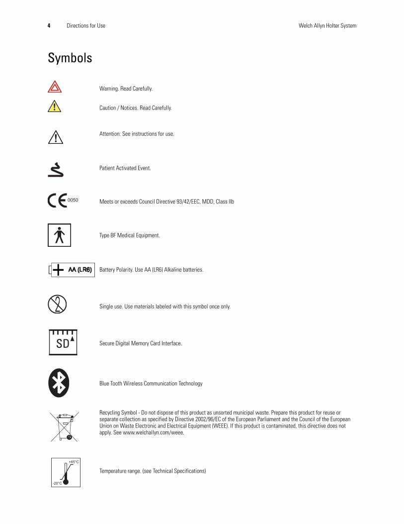
Symbols
Warning. Read Carefully.
Caution / Notices. Read Carefully.
Attention: See instructions for use.
Patient Activated Event.
Meets or exceeds Council Directive 93/42/EEC, MDD, Class IIb
Type BF Medical Equipment.
Battery Polarity. Use AA (LR6) Alkaline batteries.
Single use. Use materials labeled with this symbol once only.
Secure Digital Memory Card Interface.
Blue Tooth Wireless Communication Technology
Recycling Symbol - Do not dispose of this product as unsorted municipal waste. Prepare this product for reuse or separate collection as specified by Directive 2002/96/EC of the European Parliament and the Council of the European Union on Waste Electronic and Electrical Equipment (WEEE). If this product is contaminated, this directive does not apply. See www.welchallyn.com/weee.
Temperature range. (see Technical Specifications)
SD
Directions for Use 5
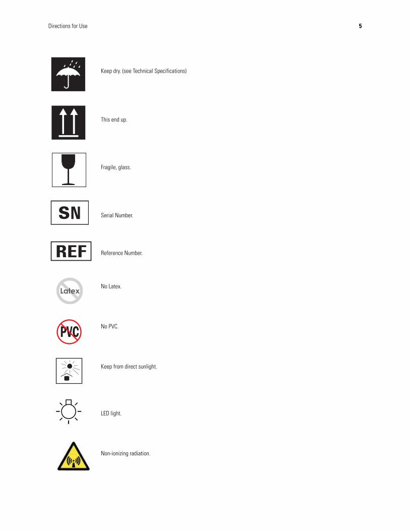
Keep dry. (see Technical Specifications)
This end up.
Fragile, glass.
Serial Number.
Reference Number.
No Latex.
No PVC.
Keep from direct sunlight.
LED light.
Non-ionizing radiation.

6 Directions for Use Welch Allyn Holter System
Temperature range. (see Technical Specifications).
Pressure range. (see Technical Specifications).
Serial Number.
Directions for Use 7
IntroductionThis manual is written for clinical professionals with a working knowledge of medical procedures and terminology as required for monitoring cardiac patients. You must read and understand this manual and all other information accompanying the ambulatory electrocardiograph and related options or accessories before:
• using the Welch Allyn Holter Recorder and the accompanying Welch Allyn Holter software for clinical applications
• before setting up, configuring, troubleshooting, or servicing the recorder
Inspection upon DeliveryYour new Holter System Application was carefully inspected before shipment. Please inspect all components upon delivery for any damage which may have occurred in transit. If you notice any damage, please contact your shipping agent. If items are missing, contact technical support.
Before you beginYour system must meet the recommended requirements to function properly. Please review the System Requirements before attempting to install or use the system.
System Requirements• 300MHz Pentium class processor or faster
• Windows XP (32-Bit), Windows Vista (32-Bit/64-Bit), Windows 7 (32/64-Bit) with all major service pack updates, Windows 8 (32/64-Bit)
• 256Mb RAM minimum
• 40GB hard drive minimum
• Mouse and keyboard
• Compact Disc (CD) Reader
• Secure Digital Card Reader
• Printer with resolution greater than 300 dpi
• Monitor with screen resolution set to 1024 x 768
Hard Drive Space Required
Hard drive space required for program installation:
30Mb for Holter System Application
8Mb for electronic manuals (optional)
8 Directions for Use Welch Allyn Holter System
Typical Hard Drive Usage
• 1Gb for sixteen 24-hour patient reports @ 200 samples per second with full disclosure
Storage requirements examples
• 24-hour patient report @ 200 samples per second with full disclosure requires 64Mb of hard drive space
• 48-hour patient report @ 200 samples per second with full disclosure requires 128Mb of hard drive space
Optional Requirements
Requirements for backup
• CD Writer to write Holter report files to CD
Requirements for Bluetooth Communications
• Support for Universal Serial Bus (USB) 1.1 or 2.0
• Bluetooth Communications Device (Welch Allyn Part Number 704555)
Operator RequirementsOperator of the PCH100 and PCH200 Holter System application shall have the following level of experience:
• Knowledge of operating a Windows based PC system, including mouse and keyboard.
• For the reviewer of the analysis information - operator shall be proficient in reviewing ECG’s and understanding various beat classifications. Refer to the physicians guide.
• For operators performing subject hookup to the HR100 and HR300 recorders shall have experience on how to properly perform an electrode preparation.
• For operators performing maintenance operation on the software, database and data files should have previous experience in those specific operations
Caution Windows® requires a minimum 250Mb of free hard drive space available at all times for virtual memory, print spooling and caching. Failing to comply will degrade system performance or crash the system.
Caution Backup on Windows Vista or Windows 7 cannot be restored on Windows XP.
Caution Welch Allyn-certified components are required.
Caution The PCH100 and PCH200 application will not run under any Windows Compatibility Modes (ie. Windows 95, 98, NT 4.0, 2000).
Directions for Use 9
FeaturesAll models:
• Lightweight and small size provides comfort for the patient.
• Either of two patient-activated event buttons enables patients to mark times they feel are significant. (Both event buttons have the same function.)
• System status feedback: LCD and LED (HR 100) or LCD (HR 300 & HR 1200).
• Removable Secure Digital Memory Card up to 48-hours of ECG storage and transferring ECG data.
• Holter Analysis system provides real-time ECG data via Bluetooth Wireless Communication to verify patient electrode placement and electronic transfer of ECG recordings.
• Operates on AA alkaline (LR6) batteries: one (HR 100) or two (HR 300 & HR 1200).
• Removable patient cable.
• LCD window provides ECG waveform views to ensure proper electrode connection.
• Time of day display.
• Navigational keypad - enter, cancel, up, down, right, left keys (HR300 & HR1200).
10 Directions for Use Welch Allyn Holter System
Holter System Application Directions for Use
Activating the Welch Allyn Holter SoftwareYou must activate your Holter software within 30 days, or the software will lock itself. The activation message displays each time you launch the software until you activate. The best way to activate your software is through the Internet.
Activating through the Internet
1. Click the Holter icon. The activation message displays.
2. Select Yes or No.
• If you select No, a message displays reminding you that you must activate within 30 days. (Caution: after 30 days, the software will not launch.)
• If you select Yes, the system automatically activates itself and the activation screen will not display again. This completes the activation requirement.
Activating Manually (No Internet Connection)
If the software cannot detect an Internet connection, you must activate the application manually.
1. Launch the Holter System software. The activation message displays.
2. Select Yes or No.
• If you select No, a message displays reminding you that you must activate within 30 days. (Caution: after 30 days, the software will not launch.)
• If you select Yes, the Manual Activation dialog displays. Click the Print button. Contact Welch Allyn Technical Support (see page ii). You will be asked to provide the information displayed on the printout:
• User name
• Password
• PC Serial Number 1
• PC Serial Number 2
3. Once you receive the Activation Code, type it into the Activation Code box and click Activate. The application launches and the activation screen will not display again. This completes the activation requirement.
Directions for Use 11
Recorder Illustrations
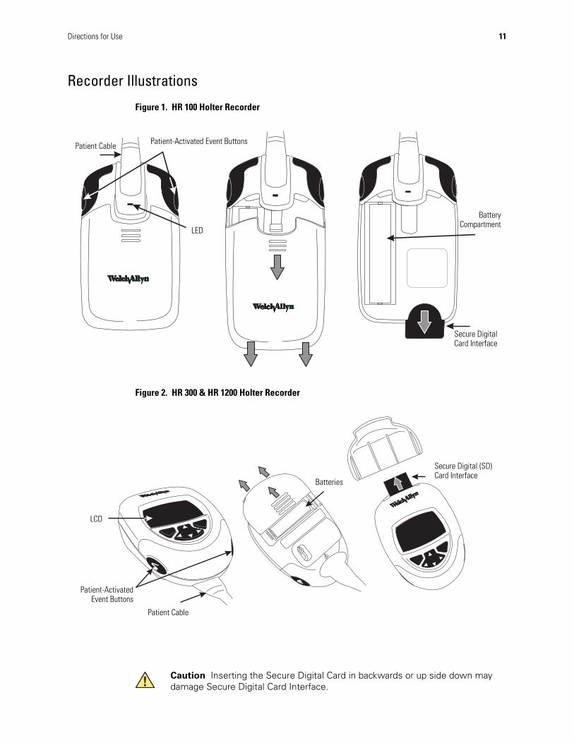
Figure 1. HR 100 Holter Recorder
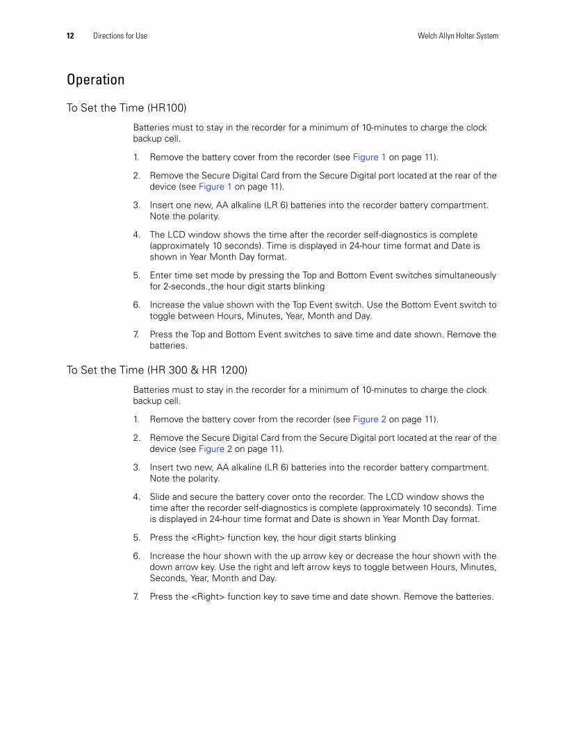
Figure 2. HR 300 & HR 1200 Holter Recorder
LED
Patient Cable
BatteryCompartment
Secure Digital Card Interface
Patient-Activated Event Buttons
Secure Digital (SD) Card Interface
LCD
Patient-ActivatedEvent Buttons
Patient Cable
Batteries
Caution Inserting the Secure Digital Card in backwards or up side down may damage Secure Digital Card Interface.
12 Directions for Use Welch Allyn Holter System
Operation
To Set the Time (HR100)
Batteries must to stay in the recorder for a minimum of 10-minutes to charge the clock backup cell.
1. Remove the battery cover from the recorder (see Figure 1 on page 11).
2. Remove the Secure Digital Card from the Secure Digital port located at the rear of the device (see Figure 1 on page 11).
3. Insert one new, AA alkaline (LR 6) batteries into the recorder battery compartment. Note the polarity.
4. The LCD window shows the time after the recorder self-diagnostics is complete (approximately 10 seconds). Time is displayed in 24-hour time format and Date is shown in Year Month Day format.
5. Enter time set mode by pressing the Top and Bottom Event switches simultaneously for 2-seconds.,the hour digit starts blinking
6. Increase the value shown with the Top Event switch. Use the Bottom Event switch to toggle between Hours, Minutes, Year, Month and Day.
7. Press the Top and Bottom Event switches to save time and date shown. Remove the batteries.
To Set the Time (HR 300 & HR 1200)
Batteries must to stay in the recorder for a minimum of 10-minutes to charge the clock backup cell.
1. Remove the battery cover from the recorder (see Figure 2 on page 11).
2. Remove the Secure Digital Card from the Secure Digital port located at the rear of the device (see Figure 2 on page 11).
3. Insert two new, AA alkaline (LR 6) batteries into the recorder battery compartment. Note the polarity.
4. Slide and secure the battery cover onto the recorder. The LCD window shows the time after the recorder self-diagnostics is complete (approximately 10 seconds). Time is displayed in 24-hour time format and Date is shown in Year Month Day format.
5. Press the <Right> function key, the hour digit starts blinking
6. Increase the hour shown with the up arrow key or decrease the hour shown with the down arrow key. Use the right and left arrow keys to toggle between Hours, Minutes, Seconds, Year, Month and Day.
7. Press the <Right> function key to save time and date shown. Remove the batteries.
Directions for Use 13
Patient Preparation
Holter Procedure Patient PreparationWhen making the appointment, tell the patient:
• Do not remove any electrodes or disconnect lead wires.
• Do not swim, bathe, or shower during the recording period.
• Do wear loose fitting, comfortable clothing to the appointment (shirt-and-pants or blouse-and-skirt combinations are better than one-piece garments.)
Preparing for Electrode Placement on Patient
WARNING Safety—Leave 5 feet (1.5 meters) of open area around the patient during recorder hookup and removal.
WARNING Safety—Do not connect external devices to the recorder. Connect patient lead wires only to the patient electrodes.
WARNING Safety—Keep the recorder and patient cable clean, especially the components that touch patients.Caution Verify that dates on applicable accessories have not expired.
Table 1. Recommended accessories
Accessory Quantity
Electrodes 5 or 7
AA Alkaline Batteries (LR6) 1 for HR 1002 for HR 300 & HR 1200
Disposable Safety Razor 1
Abrading pad 1
Alcohol Prep Pads 2
Pouch 1
Patient Diary 1
14 Directions for Use Welch Allyn Holter System
To Prepare the Patient and Place Electrodes
Help the patient get comfortable. Patient preparation is important for a successful Holter procedure.
1. Describe the procedure to the patient.
2. Prepare electrode locations. See Figure 4 on page 15 for 5-lead placement, Figure 5 on page 16 for 7-lead placement, Figure 8 on page 18 for 12-lead placement.
3. Shave the area for electrode placement, if necessary.
4. Clean electrode sites with alcohol.
5. Allow electrode site to dry.
6. Attach the electrodes to the lead wires before attaching to patient.
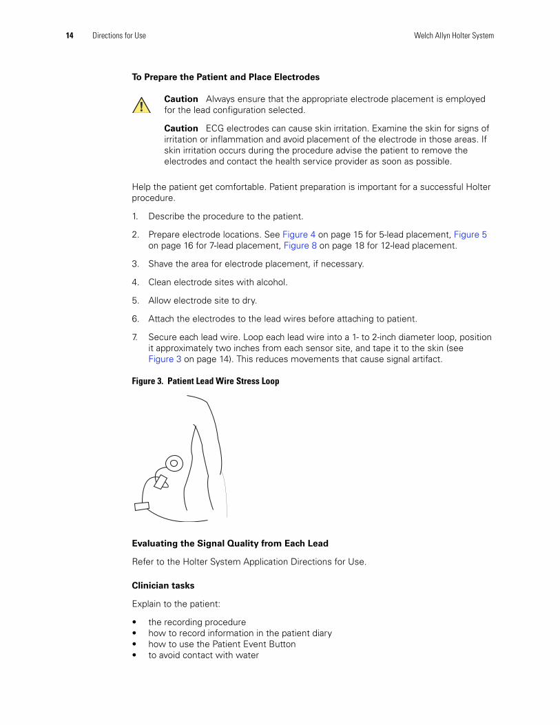
7. Secure each lead wire. Loop each lead wire into a 1- to 2-inch diameter loop, position it approximately two inches from each sensor site, and tape it to the skin (see Figure 3 on page 14). This reduces movements that cause signal artifact.
Figure 3. Patient Lead Wire Stress Loop
Evaluating the Signal Quality from Each Lead
Refer to the Holter System Application Directions for Use.
Clinician tasks
Explain to the patient:
• the recording procedure• how to record information in the patient diary• how to use the Patient Event Button• to avoid contact with water
Caution Always ensure that the appropriate electrode placement is employed for the lead configuration selected.
Caution ECG electrodes can cause skin irritation. Examine the skin for signs of irritation or inflammation and avoid placement of the electrode in those areas. If skin irritation occurs during the procedure advise the patient to remove the electrodes and contact the health service provider as soon as possible.
Directions for Use 15
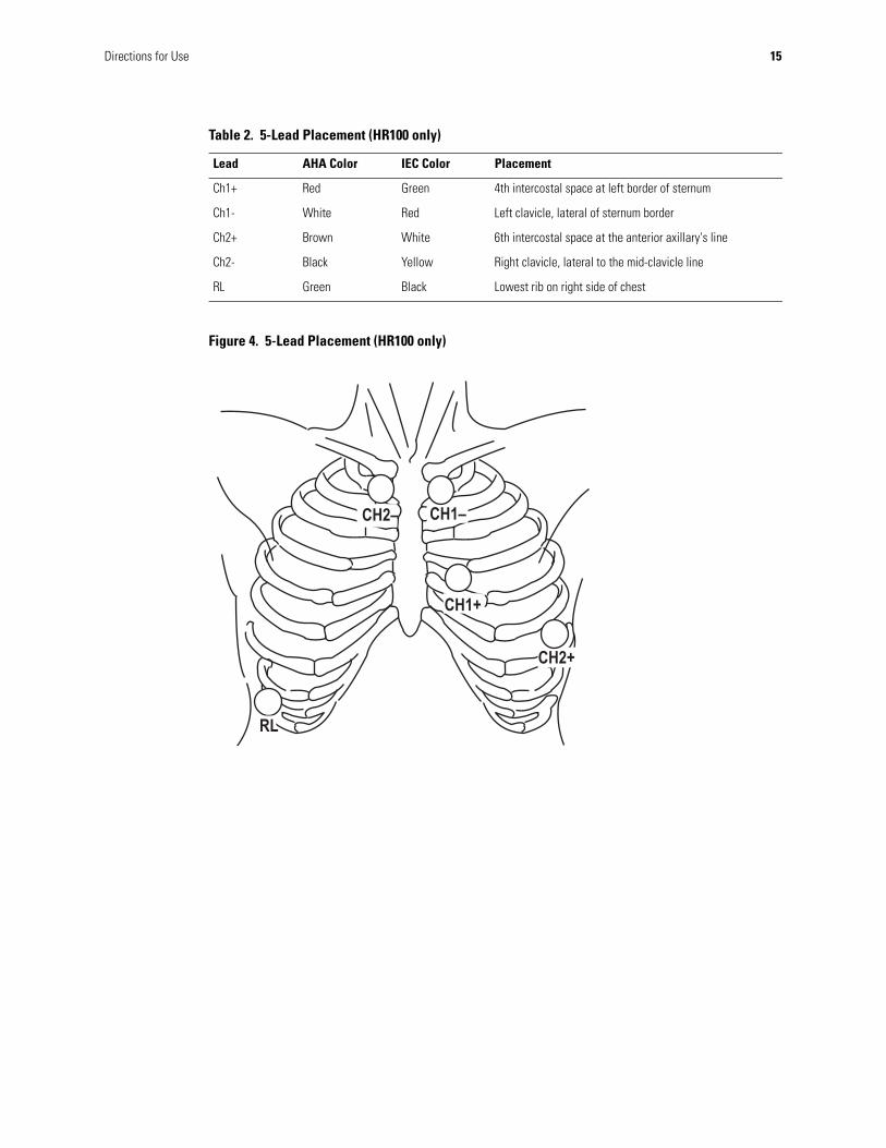
Figure 4. 5-Lead Placement (HR100 only)
Table 2. 5-Lead Placement (HR100 only)
Lead AHA Color IEC Color Placement
Ch1+ Red Green 4th intercostal space at left border of sternum
Ch1- White Red Left clavicle, lateral of sternum border
Ch2+ Brown White 6th intercostal space at the anterior axillary's line
Ch2- Black Yellow Right clavicle, lateral to the mid-clavicle line
RL Green Black Lowest rib on right side of chest
16 Directions for Use Welch Allyn Holter System
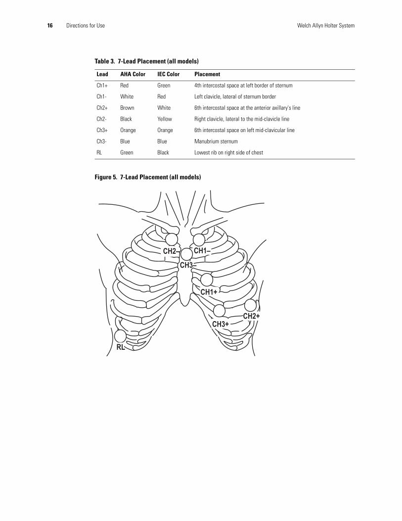
Figure 5. 7-Lead Placement (all models)
Table 3. 7-Lead Placement (all models)
Lead AHA Color IEC Color Placement
Ch1+ Red Green 4th intercostal space at left border of sternum
Ch1- White Red Left clavicle, lateral of sternum border
Ch2+ Brown White 6th intercostal space at the anterior axillary's line
Ch2- Black Yellow Right clavicle, lateral to the mid-clavicle line
Ch3+ Orange Orange 6th intercostal space on left mid-clavicular line
Ch3- Blue Blue Manubrium sternum
RL Green Black Lowest rib on right side of chest
Directions for Use 17
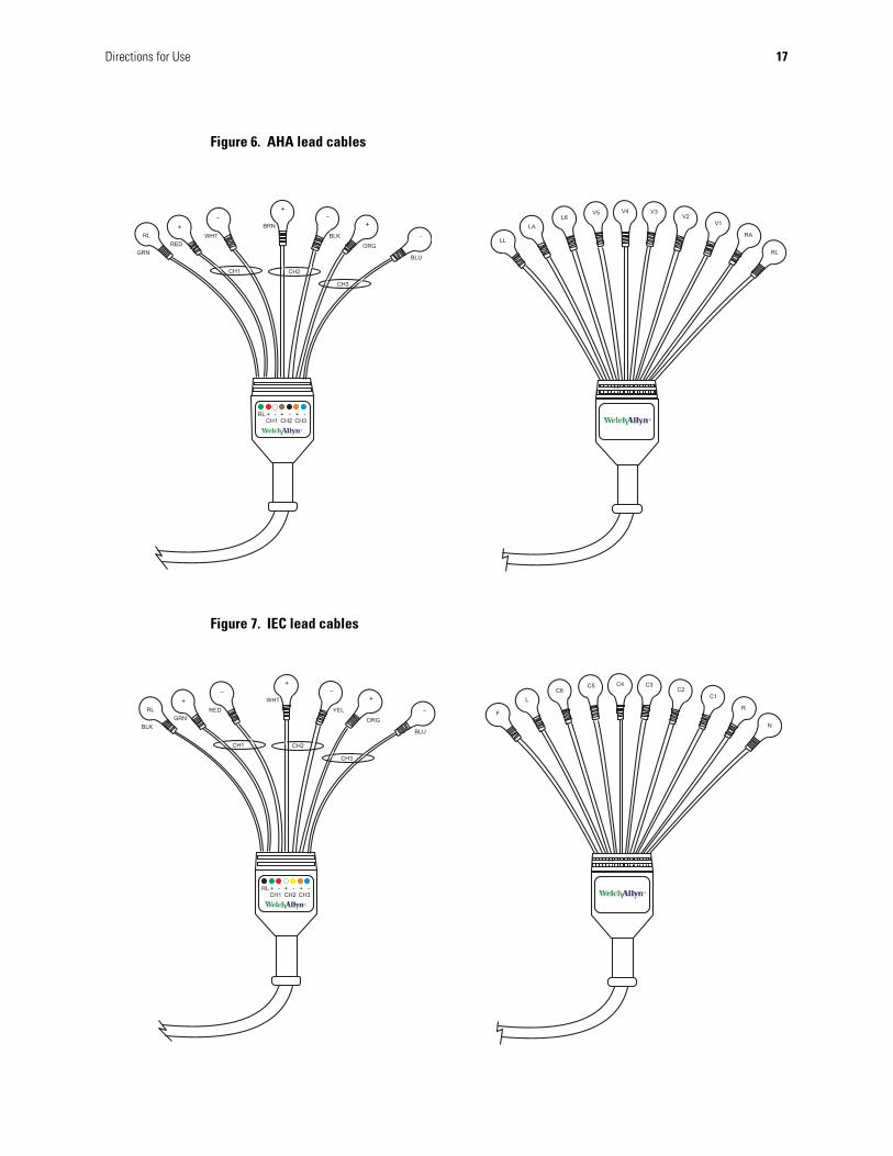
Figure 6. AHA lead cables
Figure 7. IEC lead cables
18 Directions for Use Welch Allyn Holter System
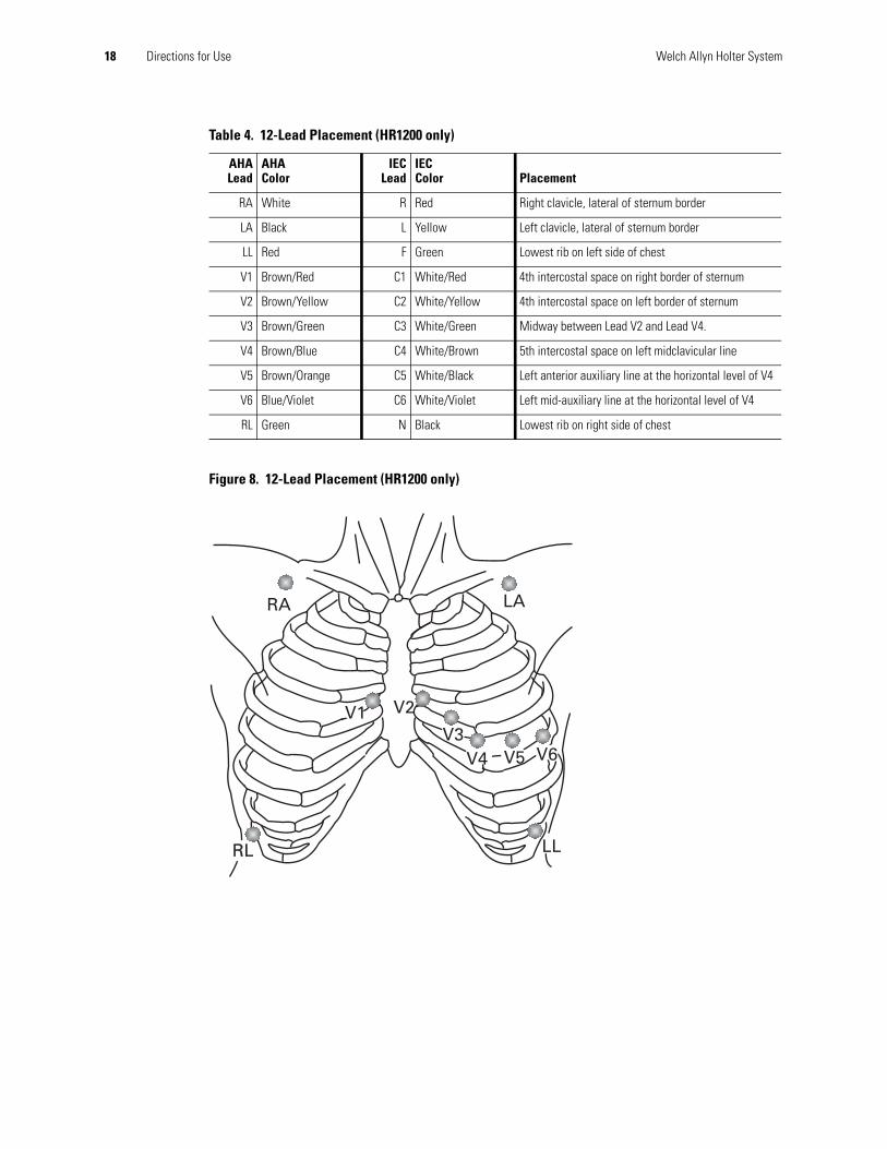
Figure 8. 12-Lead Placement (HR1200 only)
Table 4. 12-Lead Placement (HR1200 only)
AHALead
AHAColor
IECLead
IECColor Placement
RA White R Red Right clavicle, lateral of sternum border
LA Black L Yellow Left clavicle, lateral of sternum border
LL Red F Green Lowest rib on left side of chest
V1 Brown/Red C1 White/Red 4th intercostal space on right border of sternum
V2 Brown/Yellow C2 White/Yellow 4th intercostal space on left border of sternum
V3 Brown/Green C3 White/Green Midway between Lead V2 and Lead V4.
V4 Brown/Blue C4 White/Brown 5th intercostal space on left midclavicular line
V5 Brown/Orange C5 White/Black Left anterior auxiliary line at the horizontal level of V4
V6 Blue/Violet C6 White/Violet Left mid-auxiliary line at the horizontal level of V4
RL Green N Black Lowest rib on right side of chest
RA
LL
LA
RL
V6V5V4V3
V2V1
Directions for Use 19
Starting the Welch Allyn Holter System Application
Starting the Welch Allyn Holter System Application
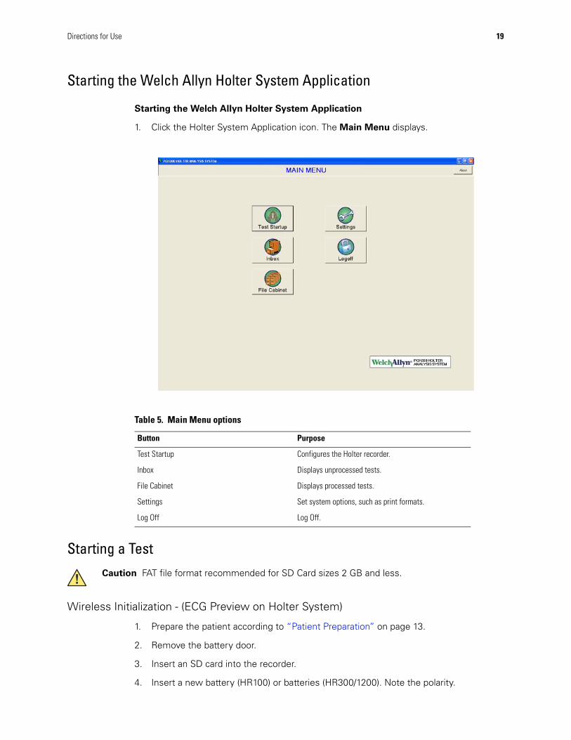
1. Click the Holter System Application icon. The Main Menu displays.
Starting a Test
Wireless Initialization - (ECG Preview on Holter System)
1. Prepare the patient according to “Patient Preparation” on page 13.
2. Remove the battery door.
3. Insert an SD card into the recorder.
4. Insert a new battery (HR100) or batteries (HR300/1200). Note the polarity.
Table 5. Main Menu options
Button Purpose
Test Startup Configures the Holter recorder.
Inbox Displays unprocessed tests.
File Cabinet Displays processed tests.
Settings Set system options, such as print formats.
Log Off Log Off.
Caution FAT file format recommended for SD Card sizes 2 GB and less.
20 Directions for Use Welch Allyn Holter System
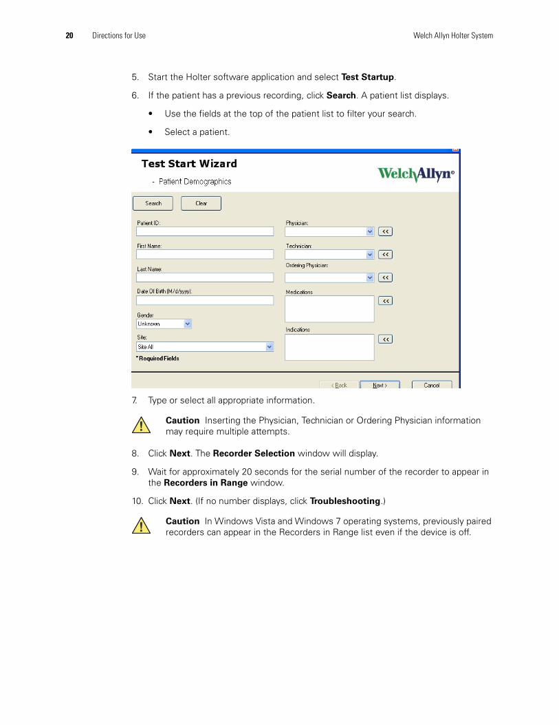
5. Start the Holter software application and select Test Startup.
6. If the patient has a previous recording, click Search. A patient list displays.
• Use the fields at the top of the patient list to filter your search.
• Select a patient.
7. Type or select all appropriate information.
8. Click Next. The Recorder Selection window will display.
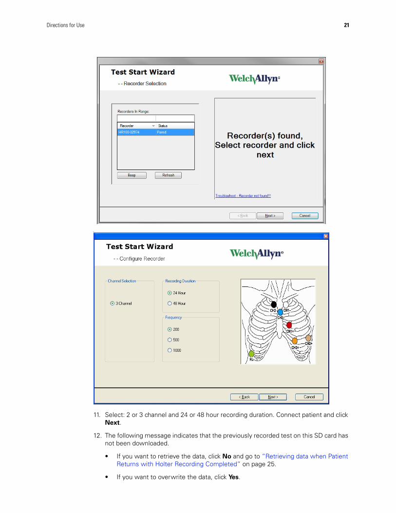
9. Wait for approximately 20 seconds for the serial number of the recorder to appear in the Recorders in Range window.
10. Click Next. (If no number displays, click Troubleshooting.)
Caution Inserting the Physician, Technician or Ordering Physician information may require multiple attempts.
Caution In Windows Vista and Windows 7 operating systems, previously paired recorders can appear in the Recorders in Range list even if the device is off.
Directions for Use 21
v
11. Select: 2 or 3 channel and 24 or 48 hour recording duration. Connect patient and click Next.
12. The following message indicates that the previously recorded test on this SD card has not been downloaded.
• If you want to retrieve the data, click No and go to “Retrieving data when Patient Returns with Holter Recording Completed” on page 25.
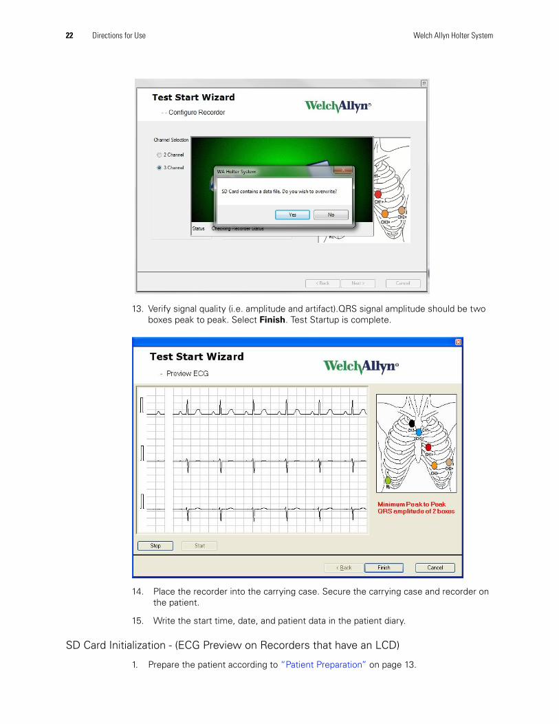
• If you want to overwrite the data, click Yes.
22 Directions for Use Welch Allyn Holter System
13. Verify signal quality (i.e. amplitude and artifact).QRS signal amplitude should be two boxes peak to peak. Select Finish. Test Startup is complete.
14. Place the recorder into the carrying case. Secure the carrying case and recorder on the patient.
15. Write the start time, date, and patient data in the patient diary.
SD Card Initialization - (ECG Preview on Recorders that have an LCD)
1. Prepare the patient according to “Patient Preparation” on page 13.
Directions for Use 23
2. Remove the battery door.
3. Remove the SD card from the recorder.
4. Start the Holter software application and select Test Startup.
5. Enter patient information as desired. If this test has a previous recording, use search to find the patient information. Select Next.
6. If the SD card has not been inserted into the reader, the window displays an animation until the card is inserted.
7. Select channels and recorder.
8. Select Finish.
9. Insert the configured SD card into the recorder.
10. Insert a new battery (HR100) or batteries (HR300/1200). Note the polarity.
11. Slide and secure the battery cover onto the recorder.
• HR 100 — The LED flashes green in a sequence of two flashes, pause, three flashes, pause, four flashes, pause, then flashes once approximately every three seconds when operating. If the LED flashes yellow (any sequence) see “Troubleshooting” on page 57.
• HR100, HR 300 & HR 1200 — The LCD window shows the time of day after the recorder self-diagnostics are complete (approximately 10 seconds). The recorder is collecting ECG data and functioning properly. After the self test, the recorder will display ECG on the display for 5 minutes and then display the current time. If the recorder does not display time or displays an error code, see “Troubleshooting” on page 57
12. Place the recorder into the carrying case. Secure the carrying case and recorder on the patient.
13. Write the start time, date, and patient data in the patient diary.
Recorder Manual Initialization - (Supported on HR100 Recorders that have an LCD)
1. Prepare the patient according to “Patient Preparation” on page 13.
2. Remove battery door.
3. Insert an SD card into the recorder.
4. Insert a new battery. Note the polarity.
5. After a few seconds the LCD will display E2 – Initialize.
6. Enter manual initialization by pressing both event buttons simultaneously for 2 seconds.
7. Manual initialization allows entering of a four digit Patient ID, Duration and number of Channels.
24 Directions for Use Welch Allyn Holter System
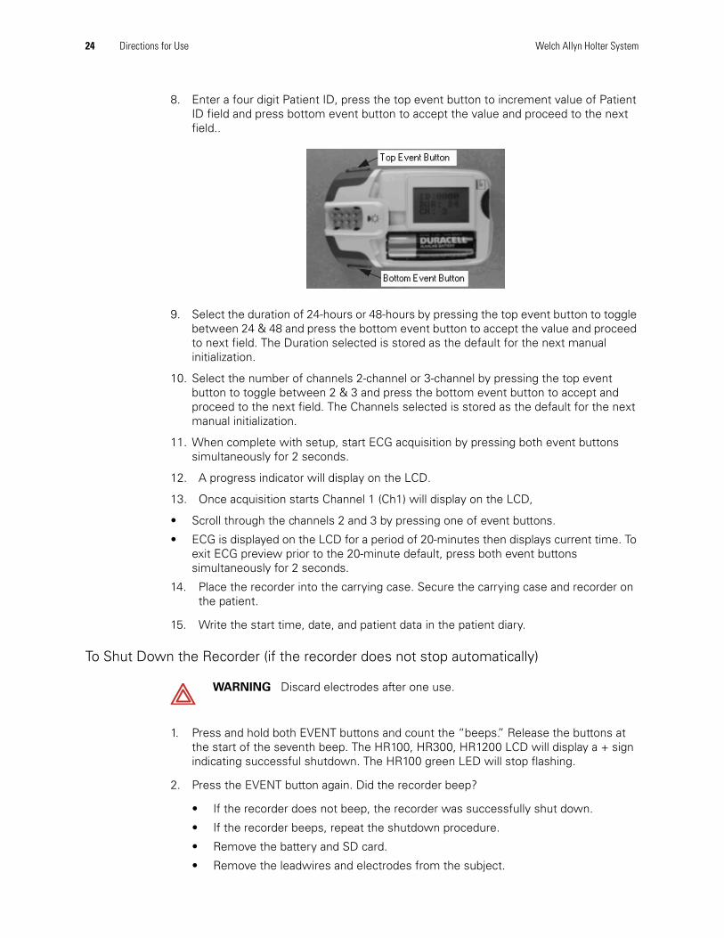
8. Enter a four digit Patient ID, press the top event button to increment value of Patient ID field and press bottom event button to accept the value and proceed to the next field..
9. Select the duration of 24-hours or 48-hours by pressing the top event button to toggle between 24 & 48 and press the bottom event button to accept the value and proceed to next field. The Duration selected is stored as the default for the next manual initialization.
10. Select the number of channels 2-channel or 3-channel by pressing the top event button to toggle between 2 & 3 and press the bottom event button to accept and proceed to the next field. The Channels selected is stored as the default for the next manual initialization.
11. When complete with setup, start ECG acquisition by pressing both event buttons simultaneously for 2 seconds.
12. A progress indicator will display on the LCD.
13. Once acquisition starts Channel 1 (Ch1) will display on the LCD,
• Scroll through the channels 2 and 3 by pressing one of event buttons.
• ECG is displayed on the LCD for a period of 20-minutes then displays current time. To exit ECG preview prior to the 20-minute default, press both event buttons simultaneously for 2 seconds.
14. Place the recorder into the carrying case. Secure the carrying case and recorder on the patient.
15. Write the start time, date, and patient data in the patient diary.
To Shut Down the Recorder (if the recorder does not stop automatically)
1. Press and hold both EVENT buttons and count the “beeps.” Release the buttons at the start of the seventh beep. The HR100, HR300, HR1200 LCD will display a + sign indicating successful shutdown. The HR100 green LED will stop flashing.
2. Press the EVENT button again. Did the recorder beep?
• If the recorder does not beep, the recorder was successfully shut down.
• If the recorder beeps, repeat the shutdown procedure.
• Remove the battery and SD card.
• Remove the leadwires and electrodes from the subject.
WARNING Discard electrodes after one use.
Directions for Use 25
Retrieving data when Patient Returns with Holter Recording Completed
1. Open recorder door and remove battery.
2. Remove SD card from recorder.
3. Be sure the Holter software application is running and insert an SD card into the SD card reader connected to the computer.
4. The Holter software application will upload and analyze the recorded test information automatically. Monitor the progress in the lower right hand corner of your screen.
26 Directions for Use Welch Allyn Holter System
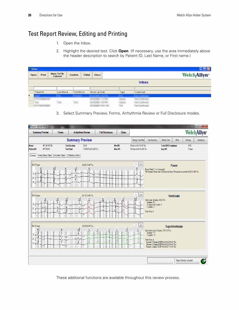
Test Report Review, Editing and Printing 1. Open the Inbox.
2. Highlight the desired test. Click Open. (If necessary, use the area immediately above the header description to search by Patient ID, Last Name, or First name.)
3. Select Summary Preview, Forms, Arrhythmia Review or Full Disclosure modes.
These additional functions are available throughout this review process.
Directions for Use 27
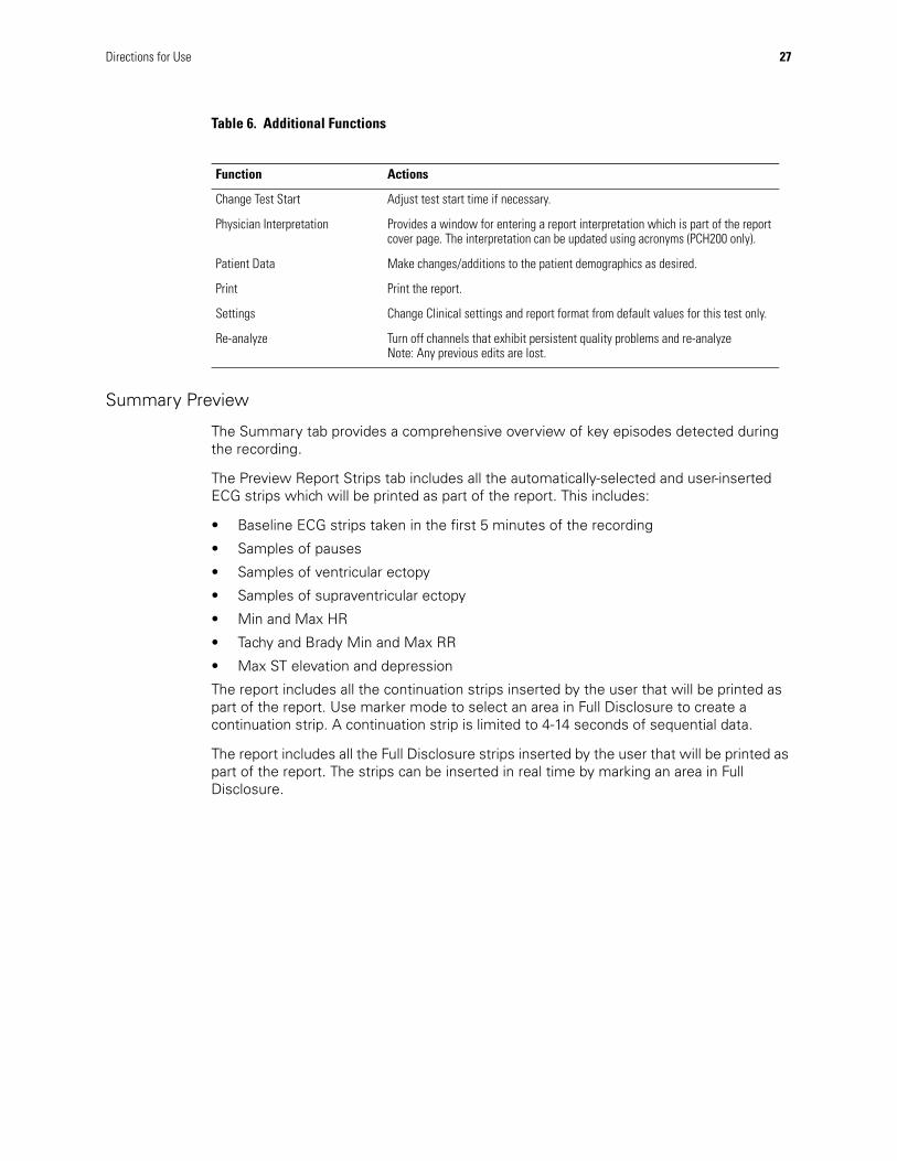
Table 6. Additional Functions
Summary Preview
The Summary tab provides a comprehensive overview of key episodes detected during the recording.
The Preview Report Strips tab includes all the automatically-selected and user-inserted ECG strips which will be printed as part of the report. This includes:
• Baseline ECG strips taken in the first 5 minutes of the recording
• Samples of pauses
• Samples of ventricular ectopy
• Samples of supraventricular ectopy
• Min and Max HR
• Tachy and Brady Min and Max RR
• Max ST elevation and depression
The report includes all the continuation strips inserted by the user that will be printed as part of the report. Use marker mode to select an area in Full Disclosure to create a continuation strip. A continuation strip is limited to 4-14 seconds of sequential data.
The report includes all the Full Disclosure strips inserted by the user that will be printed as part of the report. The strips can be inserted in real time by marking an area in Full Disclosure.
Function Actions
Change Test Start Adjust test start time if necessary.
Physician Interpretation Provides a window for entering a report interpretation which is part of the report cover page. The interpretation can be updated using acronyms (PCH200 only).
Patient Data Make changes/additions to the patient demographics as desired.
Print Print the report.
Settings Change Clinical settings and report format from default values for this test only.
Re-analyze Turn off channels that exhibit persistent quality problems and re-analyzeNote: Any previous edits are lost.
28 Directions for Use Welch Allyn Holter System
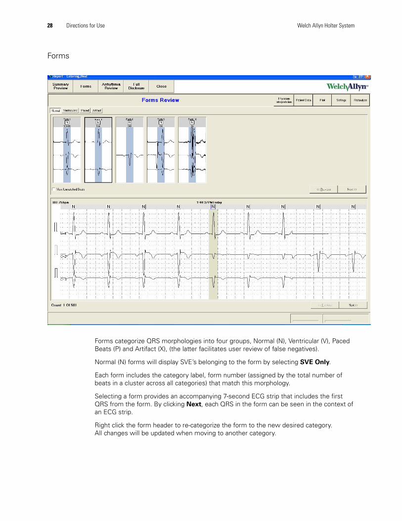
Forms
Forms categorize QRS morphologies into four groups, Normal (N), Ventricular (V), Paced Beats (P) and Artifact (X), (the latter facilitates user review of false negatives).
Normal (N) forms will display SVE’s belonging to the form by selecting SVE Only.
Each form includes the category label, form number (assigned by the total number of beats in a cluster across all categories) that match this morphology.
Selecting a form provides an accompanying 7-second ECG strip that includes the first QRS from the form. By clicking Next, each QRS in the form can be seen in the context of an ECG strip.
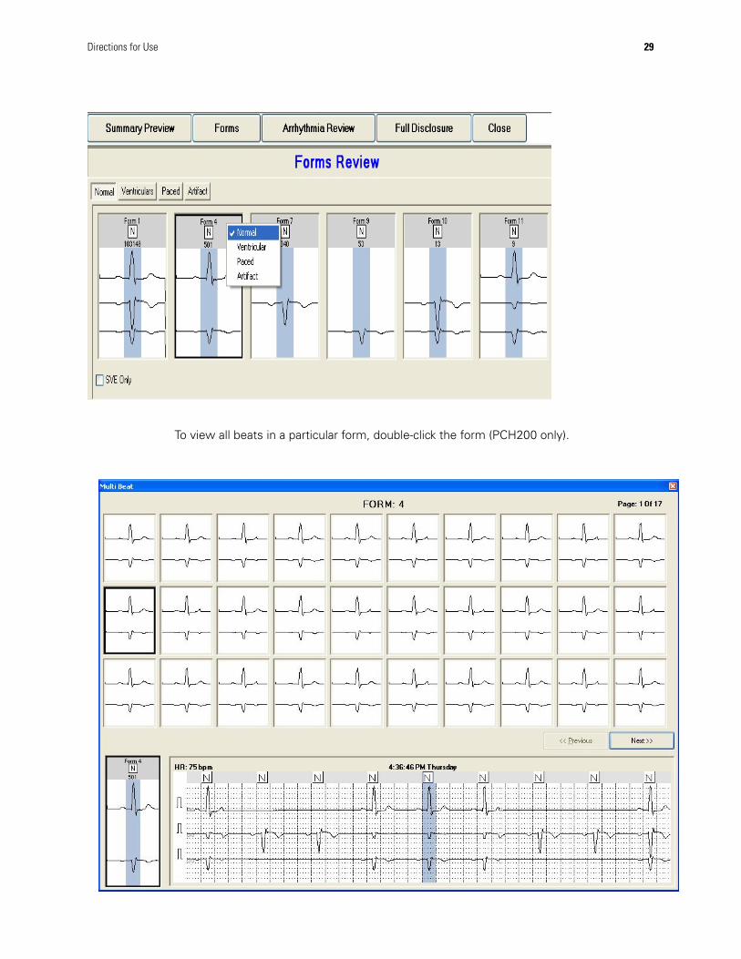
Right click the form header to re-categorize the form to the new desired category. All changes will be updated when moving to another category.
Directions for Use 29
To view all beats in a particular form, double-click the form (PCH200 only).

30 Directions for Use Welch Allyn Holter System
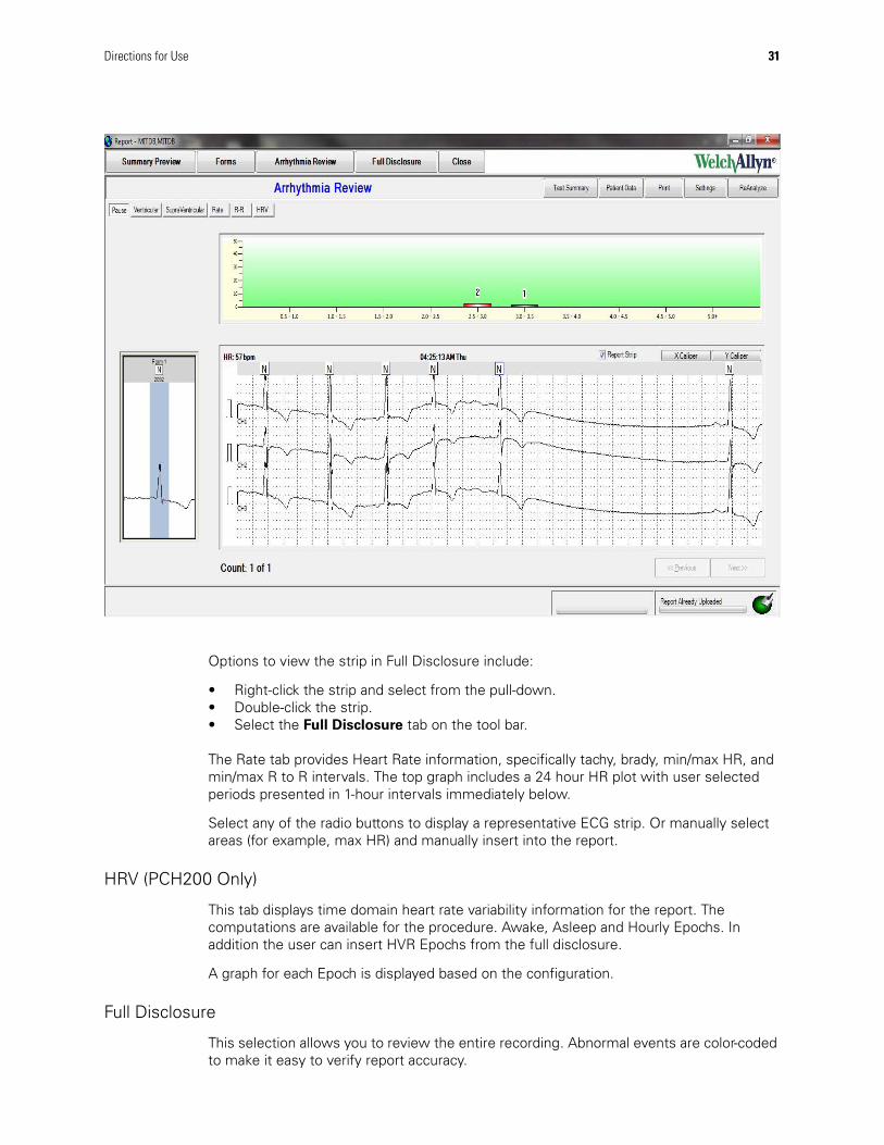
Arrhythmia Review
The display for Pause episodes, Ventricular ectopy, and Supraventricular ectopy includes a histogram of the episodes, a sample 7-second strip (of the worst case occurrence) and a form associated with the highlighted QRS.
In addition for the Ventricular and Supra Ventricular ectopy a chronological histogram can be viewed. The Rate tab displays Heart rate graphs for “Beat to Beat” or “HR Minute”.
The R-R Tab displays graphs for “R-R Beat to Beat” or “R-R Histogram”
View any of the events by selecting the respective bar on the histogram and using Next to view ECG strips for all occurrences.
The individual beats and/or the form may be edited at any time.
Right-click any ECG strip to delete or add to the final report (all beats within the strip are labeled as artifact or added).
Right-click any ECG strip to print (7-second diagnostic strip will be printed out to the selected printer).
Directions for Use 31
Options to view the strip in Full Disclosure include:
• Right-click the strip and select from the pull-down.• Double-click the strip.• Select the Full Disclosure tab on the tool bar.
The Rate tab provides Heart Rate information, specifically tachy, brady, min/max HR, and min/max R to R intervals. The top graph includes a 24 hour HR plot with user selected periods presented in 1-hour intervals immediately below.
Select any of the radio buttons to display a representative ECG strip. Or manually select areas (for example, max HR) and manually insert into the report.
HRV (PCH200 Only)
This tab displays time domain heart rate variability information for the report. The computations are available for the procedure. Awake, Asleep and Hourly Epochs. In addition the user can insert HVR Epochs from the full disclosure.
A graph for each Epoch is displayed based on the configuration.
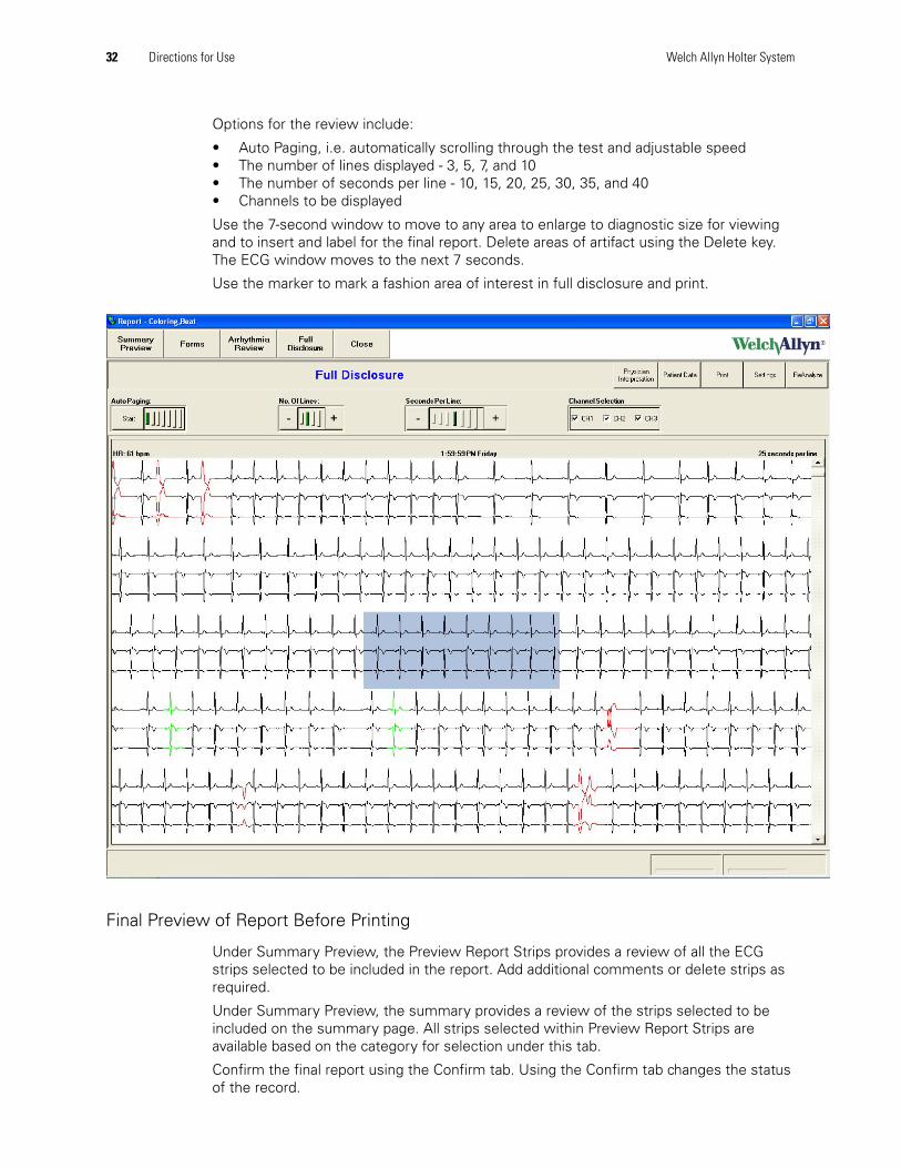
Full Disclosure
This selection allows you to review the entire recording. Abnormal events are color-coded to make it easy to verify report accuracy.
32 Directions for Use Welch Allyn Holter System
Options for the review include:
• Auto Paging, i.e. automatically scrolling through the test and adjustable speed• The number of lines displayed - 3, 5, 7, and 10• The number of seconds per line - 10, 15, 20, 25, 30, 35, and 40• Channels to be displayed
Use the 7-second window to move to any area to enlarge to diagnostic size for viewing and to insert and label for the final report. Delete areas of artifact using the Delete key. The ECG window moves to the next 7 seconds.
Use the marker to mark a fashion area of interest in full disclosure and print.
Final Preview of Report Before Printing
Under Summary Preview, the Preview Report Strips provides a review of all the ECG strips selected to be included in the report. Add additional comments or delete strips as required.
Under Summary Preview, the summary provides a review of the strips selected to be included on the summary page. All strips selected within Preview Report Strips are available based on the category for selection under this tab.
Confirm the final report using the Confirm tab. Using the Confirm tab changes the status of the record.
Directions for Use 33
SettingsReport Format screen options
Print format
Select report pages for the standard report.
To print the report immediately after the test data has been transferred from the recorder, check Auto Print Report on Download.
To print the report in color check Print In Color.
To print RR intervals on a diagnostic strip check Show RR on Diagnostic Strip.
To print narrative summary on the summary page check Show Narrative Summary, if this is unchecked the summary information will be printed in a tabular format.
Other Strip Settings
Select the number of automatically generated strips.
Manage pre-defined user strip labels.
To sort the strips according to strip times check Strip Time Order Sorting.
ECG Data format
Select Strips - Mini (8 strips per printed page) or Diagnostic (2 per printed page).
Select Beat label annotations, i.e., N, S, P, X for display and printouts.
Select Channels included on a full disclosure printout
Select 10, 30, or 60 seconds per line on a full disclosure printout.
Patient demographics required
Set mandatory entries required by the Test Start Wizard.
Strip setting
Set desired gain per channel.
Facility
Set name and logo to be printed on the top left and right of the cover page.
Clinical Settings
See the Physician’s Guide for more information.
Table 7. Clinical Settings specifications
Clinical Settings Range Default
Pause 1.0 – 5.0 seconds 2.0 seconds
Tachycardia 80 – 250 BPM 100 BPM
34 Directions for Use Welch Allyn Holter System
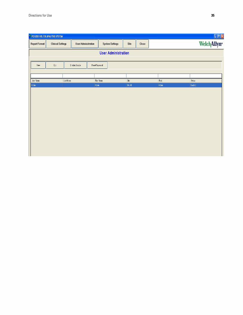
User Administration options
Setup user logins and authority levels here.
Bradycardia 20 – 119 BPM 60 BPM
ST Depression 0.1 – 5.0 mm 1.0 mm
ST Elevation 0.1 – 5.0 mm 3.0 mm
ST Duration 1 - 180 seconds 60 seconds
ST Reset 1 – 180 seconds 60 seconds
SVE Prematurity 10-100 percent 25 percent
SVE Atrial Tachy 30-150 BPM 80 BPM
Table 7. Clinical Settings specifications
Clinical Settings Range Default
New Add new user (user first and last name). Limit 40 characters. Maximum of 20 users are allowed. The system prompts when max number is reached.
User ID Limit 20 characters.
Edit Edit user selected in list.
Disable/Enable User Turn user access off or on for user selected in list.
Reset Password Reset user selected password for user selected in list. The new password generated will be the same as your user name and requires change upon login.
Enable Administration Check box “unchecked” allows access without user login.
Directions for Use 35
36 Directions for Use Welch Allyn Holter System
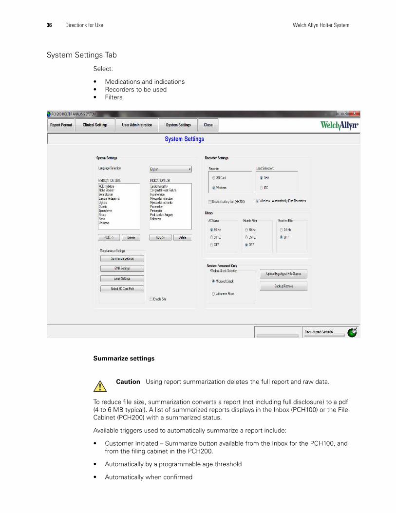
System Settings Tab
Select:
• Medications and indications• Recorders to be used• Filters
Summarize settings
To reduce file size, summarization converts a report (not including full disclosure) to a pdf (4 to 6 MB typical). A list of summarized reports displays in the Inbox (PCH100) or the File Cabinet (PCH200) with a summarized status.
Available triggers used to automatically summarize a report include:
• Customer Initiated – Summarize button available from the Inbox for the PCH100, and from the filing cabinet in the PCH200.
• Automatically by a programmable age threshold
• Automatically when confirmed
Caution Using report summarization deletes the full report and raw data.
Directions for Use 37
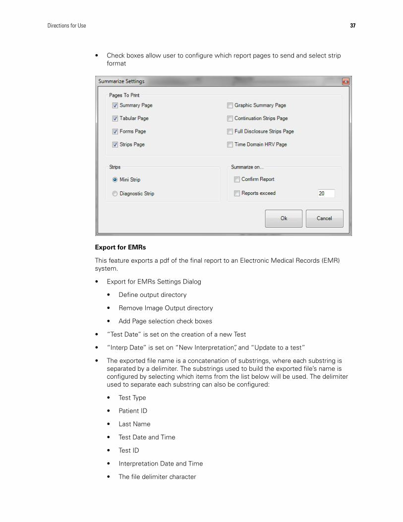
• Check boxes allow user to configure which report pages to send and select strip format
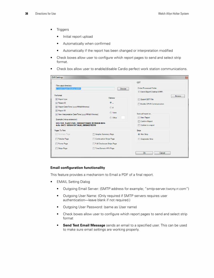
Export for EMRs
This feature exports a pdf of the final report to an Electronic Medical Records (EMR) system.
• Export for EMRs Settings Dialog
• Define output directory
• Remove Image Output directory
• Add Page selection check boxes
• “Test Date” is set on the creation of a new Test
• “Interp Date” is set on “New Interpretation”, and “Update to a test”
• The exported file name is a concatenation of substrings, where each substring is separated by a delimiter. The substrings used to build the exported file’s name is configured by selecting which items from the list below will be used. The delimiter used to separate each substring can also be configured:
• Test Type
• Patient ID
• Last Name
• Test Date and Time
• Test ID
• Interpretation Date and Time
• The file delimiter character
38 Directions for Use Welch Allyn Holter System
• Triggers
• Initial report upload
• Automatically when confirmed
• Automatically if the report has been changed or interpretation modified
• Check boxes allow user to configure which report pages to send and select strip format.
• Check box allow user to enable/disable Cardio perfect work station communications.
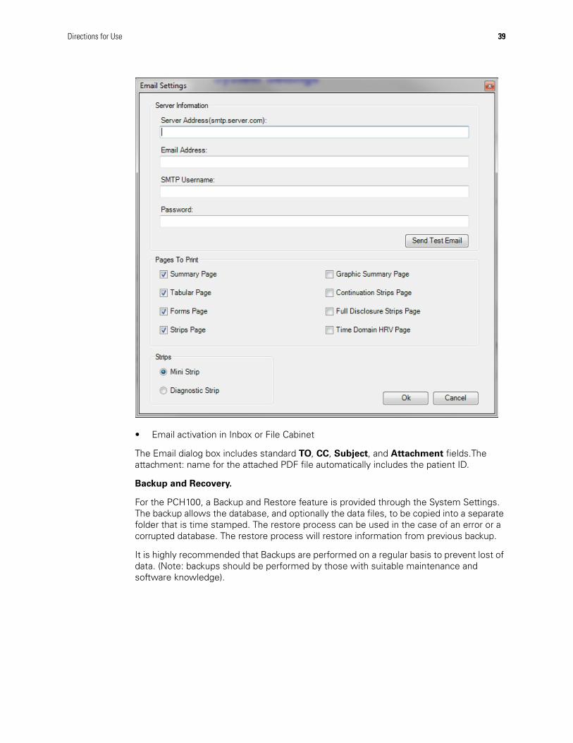
Email configuration functionality
This feature provides a mechanism to Email a PDF of a final report.
• EMAIL Setting Dialog
• Outgoing Email Server: (SMTP address for example; “smtp-server.twcny.rr.com”)
• Outgoing User Name: (Only required if SMTP servers requires user authentication—leave blank if not required.)
• Outgoing User Password: (same as User name)
• Check boxes allow user to configure which report pages to send and select strip format
• Send Test Email Message sends an email to a specified user. This can be used to make sure email settings are working properly.
Directions for Use 39
• Email activation in Inbox or File Cabinet
The Email dialog box includes standard TO, CC, Subject, and Attachment fields.The attachment: name for the attached PDF file automatically includes the patient ID.
Backup and Recovery.
For the PCH100, a Backup and Restore feature is provided through the System Settings. The backup allows the database, and optionally the data files, to be copied into a separate folder that is time stamped. The restore process can be used in the case of an error or a corrupted database. The restore process will restore information from previous backup.
It is highly recommended that Backups are performed on a regular basis to prevent lost of data. (Note: backups should be performed by those with suitable maintenance and software knowledge).
40 Directions for Use Welch Allyn Holter System
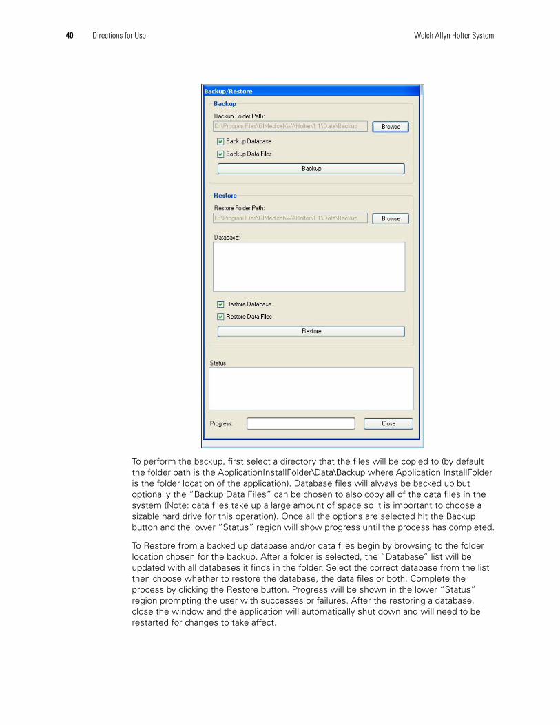
To perform the backup, first select a directory that the files will be copied to (by default the folder path is the ApplicationInstallFolder\Data\Backup where Application InstallFolder is the folder location of the application). Database files will always be backed up but optionally the “Backup Data Files” can be chosen to also copy all of the data files in the system (Note: data files take up a large amount of space so it is important to choose a sizable hard drive for this operation). Once all the options are selected hit the Backup button and the lower “Status” region will show progress until the process has completed.
To Restore from a backed up database and/or data files begin by browsing to the folder location chosen for the backup. After a folder is selected, the “Database” list will be updated with all databases it finds in the folder. Select the correct database from the list then choose whether to restore the database, the data files or both. Complete the process by clicking the Restore button. Progress will be shown in the lower “Status” region prompting the user with successes or failures. After the restoring a database, close the window and the application will automatically shut down and will need to be restarted for changes to take affect.
Directions for Use 41
Physician’s GuideOverview
The Welch Allyn Holter System performs analysis up for to 48-hour of ECG digital data as a continuous segment of data. The analysis processing consists of the following sub-processing components:
• Signal Conditioning.• QRS Detection and Feature Extraction.• Clustering.• Beat Classification.• Heart Rate Calculation.• ST Measurement.• Pattern Determination.• Strip Determination.
The analysis program consists of two major stages. The first stage, main analysis, is responsible for QRS detection, classification, feature extraction, and clustering. The second stage is responsible for pattern, tabulation, and strip determination. This stage is commonly referred to as a re-compile process. During a full analysis, both the main analysis and re-compile stages are executed. The full analysis will typically take two minutes to analyze a 3-channel, 24-hour recording. The Re-compile typically takes only seconds. The Re-Compile occurs multiple times, usually after the clinician has performed edits. For instance, if the clinician changes the hookup time to a different hour or minute, the recompile process would re-tabulate the results based on the new time. Other edits that could trigger a re-compile include:
• ST Episode threshold changes.• SVE prematurity threshold changes.• Pause threshold changes.• Brady and Tachy threshold changes.• Form Edits.• Beat Edits.
Signal Conditioning
The signal processing performed during the analysis is used to remove some of the noise and artifacts normally found during an ambulatory recording. The following types of noise and artifacts may occur:
• Drift - gradual baseline wander usually caused by respiration.• Shift - sudden baseline changes in electrode skin impedance or external contact to
electrode site.• Rail - amplitude saturation of the signal.• Continuous noise of a single frequency- usually associated with high electrode
impedance and mains 50 or 60 Hz interference.• Burst of noise- usually several frequencies mixed together due to electrical signals
from active muscles.• Spikes- large amplitude shifts of a short duration.
The analysis program applies a collection of several filters to correct for these types of issues. These filters are optimized for the specific sub-process requirements.
42 Directions for Use Welch Allyn Holter System
QRS Detection and Feature Extraction
The analysis program detects each QRS for each channel. Each detected QRS has several locations identified including Isoelectric, Q, R, S and ST points. From these locations, additional measurements are made for the width, height, morphology, ST Level, and noise assessment.
Clustering
The analysis program groups beats based on morphology related information. The clusters created are based on which channels are active. For instance, a single channel event in Ch 1 would only be grouped with other single channel events.
Beat Classification
The beat classification is performed by evaluating QRS detections, features, R-R intervals, clustering information and noise assessment. The outcome of the classification results in the following beat types:
• Normal• Ventricular• Supraventricular• Artifact
Heart Rate Calculation
The analysis program assigns an R-R interval to each detected QRS based on the time interval to the last labeled QRS. A QRS can be assigned with an unknown R-R interval if the region between the last detected QRS and current QRS contains artifact classifications. Artifact regions can be automatically classified by the analysis program or labeled through clinician editing.
The heart rate calculation is reported on each beat. The heart rate for a specific beat is based on the average of 9 R-R intervals centered on the specific beat. This would require the 4 previous R-R intervals, the current beat R-R interval and the next 4 R-R intervals. A valid heart rate will require at least 5 out of 9 valid R-R intervals. If the heart rate cannot be calculated, it will be assigned as an unknown heart rate.
The heart rate errors associated with one false positive detection (interpolated noise) would be a +12.5% increase in reported heart rate. A false negative detection (missed beat) would result in a -10% error in reported heart rate. The duration of time required to correct the heart rate calculation would be 9 beats.
The HR is displayed for each strip and it represents the HR for the beat closest to the center of the strip. If the clinician selects another beat in the strip, its HR values will be displayed. If the HR cannot be calculated, it will be displayed as a --- value.
The HR displayed in Full Disclosure refers to the HR value found for the highlighted strip. This HR value is based on the HR of the beat closest to the center of the strip. Refer to Strip HR above.
ST Measurement
The ST Level is measured on normal beats with a width less than 110 msec. The ST level is measured on each channel based on the delta between the isoelectric point and ST Level point. The Isoelectric point is defined as an average of points between P and Q. The ST Level point is a rate sensitive offset relative to the R-wave.
Directions for Use 43
ST Episodes are determined by summing the average ST level over a period of time. Once the average ST Level exceeds the clinician selectable threshold, a ST Episode will be started. The end point of the ST Episode is determined when the average level falls below the clinician selectable threshold. A valid ST episode is reported when the length of the ST episode exceeds the clinician selectable threshold. If a second ST episode starts within the ST Reset threshold, the second ST episode is considered as part of the previous episode.
The clinician has separate ST Elevation and ST Depression thresholds. During each ST episode, the location of the maximum average values is maintained. The analysis program does not identify ST slope levels. The clinician can review the ST strip examples to determine if the ST segment slope is up, down or flat.
ST episodes are determined for each channel and for Elevation and Depression. These ST episodes are sorted based on maximum level of depression or elevation and automatically presented as strips within the report. The strip time reflects the time of maximum depression or elevation. The duration of the ST episodes, ranges of displacement, or heart rates are not reported.
Pattern Determination
The analysis program detects the following ventricular pattern types. N represents any normal beat including S beats.
Table 8. Ventricular events patterns
Supraventricular detection is based on normal beats only. The normal beat must be premature to the previous normal beat or to the running NN average rate. The prematurity threshold is configurable. The analysis program detects the following supraventricular pattern types:
Table 9. Supraventricular events patterns
The analysis program detects the following Rate related patterns:
Ventricular Event Type Pattern
Isolated N-V-N
Couplets N-V-V-N
Runs (three or more Ventriculars) N-V-V-V-N
Bigeminy N-V-N-V-N-V-N
Supraventricular Event Type Pattern
Isolated N-S-N
Couplets N-S-S-N
Runs (three or more Supraventriculars) N-S-S-S-N
44 Directions for Use Welch Allyn Holter System
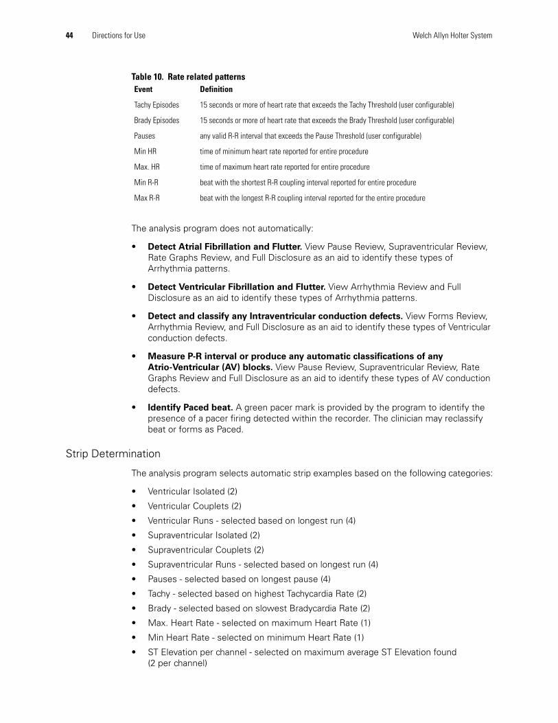
Table 10. Rate related patterns
The analysis program does not automatically:
• Detect Atrial Fibrillation and Flutter. View Pause Review, Supraventricular Review, Rate Graphs Review, and Full Disclosure as an aid to identify these types of Arrhythmia patterns.
• Detect Ventricular Fibrillation and Flutter. View Arrhythmia Review and Full Disclosure as an aid to identify these types of Arrhythmia patterns.
• Detect and classify any Intraventricular conduction defects. View Forms Review, Arrhythmia Review, and Full Disclosure as an aid to identify these types of Ventricular conduction defects.
• Measure P-R interval or produce any automatic classifications of any
Atrio-Ventricular (AV) blocks. View Pause Review, Supraventricular Review, Rate Graphs Review and Full Disclosure as an aid to identify these types of AV conduction defects.
• Identify Paced beat. A green pacer mark is provided by the program to identify the presence of a pacer firing detected within the recorder. The clinician may reclassify beat or forms as Paced.
Strip Determination
The analysis program selects automatic strip examples based on the following categories:
• Ventricular Isolated (2)
• Ventricular Couplets (2)
• Ventricular Runs - selected based on longest run (4)
• Supraventricular Isolated (2)
• Supraventricular Couplets (2)
• Supraventricular Runs - selected based on longest run (4)
• Pauses - selected based on longest pause (4)
• Tachy - selected based on highest Tachycardia Rate (2)
• Brady - selected based on slowest Bradycardia Rate (2)
• Max. Heart Rate - selected on maximum Heart Rate (1)
• Min Heart Rate - selected on minimum Heart Rate (1)
• ST Elevation per channel - selected on maximum average ST Elevation found (2 per channel)
Event Definition
Tachy Episodes 15 seconds or more of heart rate that exceeds the Tachy Threshold (user configurable)
Brady Episodes 15 seconds or more of heart rate that exceeds the Brady Threshold (user configurable)
Pauses any valid R-R interval that exceeds the Pause Threshold (user configurable)
Min HR time of minimum heart rate reported for entire procedure
Max. HR time of maximum heart rate reported for entire procedure
Min R-R beat with the shortest R-R coupling interval reported for entire procedure
Max R-R beat with the longest R-R coupling interval reported for the entire procedure
Directions for Use 45
• ST Depression per channel - selected on maximum average ST Depression found (2 per channel)
Report Content
The Analysis program provides results in several different formats. The application provides a sample report (MIT 219) you may print to help you understand the report content described below. Each report contains a header and footer that describes patient, date and time of procedure, current clinical settings, and other data. Each report page is sequentially numbered.
Summary Page
The Summary page contains a section with Patient detail information. This page contains examples of the most severe arrhythmia categories. Pauses, Ventricular and Supraventricular examples are presented as a mini strip format. Adjacent to each strip is some numerical information relative to that pattern category. Both Ventricular and Supraventricular Runs present numerical information for the Longest, Slowest and Fastest Run. The Longest refers to the ventricular run with the largest number of ventricular beats. Slowest and Fastest refer to Runs that contain the highest and lowest Ventricular or Supraventricular Heart Rate. The Ventricular Heart Rate is based on the average Heart Rate of all ventricular beats within the run. Supraventricular heart Rate is based on the Heart Rate of all Supraventricular beats within the run.
Tabular
The tabular page(s) contains hourly information as well as procedure total related information. It contains 25 hours to allow for a partial hour at the beginning and end of the recording. The tabular contains hourly counts for:
• Minimum Heart Rate
• Average Heart Rate
• Maximum Heart Rate
• Total QRS count
• Ventricular Run Count
• Ventricular Couplet Count
• Ventricular Isolate Count
• Total Ventricular Count
• Ventricular /1000
• Supraventricular Run Count
• Supraventricular Couplet Count
• Supraventricular Isolated Count
• Total Supraventricular Count
• Total Pause Count
Strips
The hard copy strips are presented in two different formats including diagnostic and mini format. The diagnostic page contains two strips that are full scale. The Mini strips are organized as 4 rows of two columns. Calibration marks are provided at the left side of the strip. This calibration mark represents a 1-millivolt amplitude signal in the strip. The clinician can select different scaling factors of x0.25, x0.5, x1.0, x2.0 and x4.0.
46 Directions for Use Welch Allyn Holter System
The calibration width represents a 100 msec marker. Diagnostic strips contain additional tick marks that are 3 seconds apart. These markers are located at the top of each diagnostic strip presentation. Each strip contains the time of day, day of the week, strip type and heart rate at a minimum. For some types of strips, additional information is presented such as Pause duration, ST Level and Run length with Run heart rate.
Forms
The Forms Page represents the form or clusters that were created. Each form indicates a form count, form classification, and the number of beats in the form. A representative example is shown for each form. Forms can be based on any combination of channels processed.
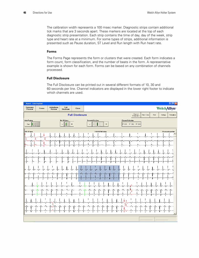
Full Disclosure
The Full Disclosure can be printed out in several different formats of 10, 30 and 60 seconds per line. Channel indicators are displayed in the lower right footer to indicate which channels are used.
Directions for Use 47
Welch Allyn Service PolicyAll repairs on products under warranty must be performed or approved by Welch Allyn. Unauthorized repairs void the warranty. In addition, whether or not covered under warranty, any product repair shall exclusively be performed by Welch Allyn certified service personnel.
If the product fails to function properly—or if you need assistance, service, or spare parts—contact the nearest Welch Allyn Technical Support Center. For phone numbers, see page ii.
Before contacting Welch Allyn, try to duplicate the problem, and check all accessories to ensure that they are not causing the problem. When calling, please be prepared to provide:
• Product name and model number and complete description of the problem.• Serial number of your product (if applicable).• Complete name, address and phone number of your facility.• For out-of-warranty repairs or spare parts orders, a purchase order (or credit card)
number.• For parts orders, the required spare or replacement part numbers.
If your product requires warranty, extended warranty, or non-warranty repair service, please call first the nearest Welch Allyn Technical Support Center. A representative will assist you troubleshooting the problem and will make every effort to solve it over the phone, avoiding potential unnecessary returns.
In case a return cannot be avoided, the representative will record all necessary information and will provide a Return Material Authorization (RMA) number, as well as the appropriate return address. An RMA number must be obtained prior to any return.
If you have to return goods for service, follow these recommended packing instructions:
• Remove all cables, sensors, and ancillary products (as appropriate) before packing, unless you suspect they are associated with the problem.
• Wherever possible use the original shipping carton and packing materials. • Include a packing list and the Welch Allyn Return Material Authorization (RMA)
number.
It is recommended that all returned goods be insured. Claims for loss or damage to the product must be initiated by the sender.
48 Directions for Use Welch Allyn Holter System
MaintenanceThe PCH100 and PCH200 Holter software requires no calibration.
Please note for the maintenance and cleaning instructions in the documentation for your computer.
For maintenance of the computer on which the PCH100 or PCH200 Holter system is installed, the following programs are regularly carried out:
• Virus protection software
• Software to detect spyware
• Microsoft Windows updates
• Backup (see "System Settings")
Cleaning the Recorder and Patient CableNote: The HR100 / HR300 / HR1200 Holter Recorders do not require calibration.
For maintenance and cleaning procedures, refer to the documentation that came with your computer.
Cleaning Instructions
1. Remove the battery or batteries and close the battery cover.
2. Wipe the Holter recorder exterior and accessories with a damp cloth. Use mild detergent diluted in water.
3. Dry with a clean, soft cloth or paper towel.
4. Reconnect the patient cable to the recorder.
5. Clean the Patient Cable in the same manner before each procedure.
Inspecting the Recorder
WARNING Keep the recorder and patient cable clean, especially the components that touch patients.
Caution Do NOT use acetone, ether, freon, petroleum derivatives, or other solvents to clean the recorder.
Caution Do NOT let soap or water come into contact with the battery contacts or patient connector pins.
Caution DO NOT submerse, autoclave, or steam clean the recorder or the patient cabling.
WARNING Inspect patient cable, patient leads wires, LED or LCD window, and enclosure for cracks or breaks before each use.
Directions for Use 49
Before performing a Holter procedure:
1. Inspect the patient cable, patient lead wires, LED or LCD window, and enclosure.
2. Verify that the patient cable is fully inserted.
Testing the Recorder
Whenever the recorder is serviced or problems are suspected, perform these test
procedures:
1. Verify that the recorder is working properly, using an ECG simulator to acquire a standard ECG of known amplitude (7-lead for HR100 and HR300, 12-lead for HR1200).
2. Upload the ECG data to the workstation and verify the waveforms appear normal, with proper amplitude, and without distortion or excessive noise.
Storing the RecorderRemove the batteries before storing the recorder. Observe the environmental storage conditions. See “Technical Specifications” on page 49.
Discarding the EquipmentDiscard the recorder and accessories according to local laws.
Please follow the state’s recycling laws or your facility’s recycling policy to ensure proper disposal of the recorder and accessories. For more information on recycling, call the Environment Protection Agency or local authorities.
Technical SpecificationsDeviations from the range of specifications stated below may result in device performance degradation.
Attention: Do not dispose of this product as unsorted municipal waste. Prepare this product for reuse or separate collection as specified by Directive 2002/96/EC of the European Parliament and the Council of the European Union on Waste Electronic and Electrical Equipment (WEEE). If this product is contaminated, this directive does not apply. See www.welchallyn.com/weee.
Table 11. Holter Recorder Characteristics
Characteristic HR 100 HR 300 & HR 1200
Length 3.8 in (96.5 mm) 4.4 in (112 mm)
Width 2.2 in (56 mm) 3.1 in (78 mm)
Height 0.7 in (18 mm) 1.4 in (36 mm)
Weight with battery (or batteries) and patient cable
7 oz. (198 g) 14 oz. (396 g)
50 Directions for Use Welch Allyn Holter System
Table 12. Operation
Power source AA (size LR6) Alkaline battery or batteries
Recording period up to a 48-hours continuousMinimum 5 days (HR300-XXXXX R only)
Storage capacity SanDisk® 256 MB Secure Digital (SD) card for 200 sps (HR100, HR300, HR1200)SanDisk® 1 GB ULTRA II SD card for 200 sps (HR100)SanDisk® 1 GB ULTRA II SD card for 200, 500, 1000 sps (HR300, HR1200)SanDisk® 2 GB ULTRA II SD card for 200, 500, 1000 sps (HR1200)
FAT file format recommended for SD Card sizes 2 GB and less
Storage period Data remains valid for >5 years or until SD card is initialized
Battery Life minimum of 24-hours
Pacemaker Detection ANSI/AAMI EC38-1998
Effective A/D bit Resolution
0.5 uV
Dynamic Range +/-300 mV
Frequency Response 0.05 Hz to 100 Hz
Sampling Rate HR100 200 spsHR300 128 sps (HR300-XXXXX R only)HR300/HR1200 200, 500, 1000 sps
User Adjustable Parameters
None
Applied Currents HR100 NoneHR300 NoneHR1200 Lead connection failures are detected by a 0.4 V bias, which
is applied to each patient electrode connection through a 40 Mohmohm resistor with respect to the reference electrode.
Table 13. Environmental Specifications
Operating Temperature 32° F to +113° F (0° to 45° C)
Storage Temperature -4° F to +149° F (-20° to +65° C)
Operating Humidity 5 to 95% non-condensing
Storage Humidity 5 to 95% non-condensing
Operating Altitude -500 to 15,000 ft (-150 to 4500 m)
Storage Altitude -500 to 50,000 ft (-150 to 15500 m)
Operating Shock 2.95 in (75 mm) drop to hard surface on any axis
Storage Shock 31.5 in (0.8 m) drop to hard surface on any axis
Operating Vibration 0.0002 G2/Hz from 5 to 350 Hz, ramping to 0.0001 G2/Hz from 350 to 500 Hz, random vibration spectrum, 10 minutes in each of three orthogonal axes.
Storage Vibration Packaged recorder and accessories survived standard drop and vibration procedure published by the National Safe Transit Association, pre-shipment test procedure, March 1977.
Table 14. Protection against ingress of water
Holter recorder No protection against water ingress
Patient Cable No protection against water ingress
Directions for Use 51
Table 17. Bluetooth Protocol
Conformance to Regulatory Standards
International Electrotechnical Commission
• CAN/CSA C22.2 No. 601.1-M90
• IEC 60601-2-47, 2001
• USA: UL60601-1
• IEC 601-1-2, conforms to EN 55011
• EN 61000-4-2:1999
• EN 61000-4-3, 1995
• EN 61000-4-5, 1995
American Advancement of Medical Instrumentation
• ANSI/AAMI EC38-2007
Table 15. Device Classification
AECG Device Type Type I
EMC Class IIb
IEC Type Type BF
Table 16. Software Technical Specifications
Specification Value
Rate 30 to 250 BPM
QRS Detection amplitude 0.5 mV
Analysis Channels any combination of up to three channels
Report Durations up to 48 hours
Pacemaker Detection ANSI/AAMI EC38-1998
A/D bit Resolution 0.5 µV
Sampling Rate 200 sps, 500 sps, 1000 sps
Mains Filter 50, 60 Hz, off (default=60Hz)
Muscle Filter 35, 60 Hz, off (default=off)
Baseline Filter 0.5 Hz, off (default=off)
FREQUENCY RANGE 2402-2480 MHZ
PEAK OUTPUT POWER -11dBm (EIRP)
EMISSION DESIGNATOR 864K F1D
RATED POWER 0 dBm
MODULATION GMSK
52 Directions for Use Welch Allyn Holter System
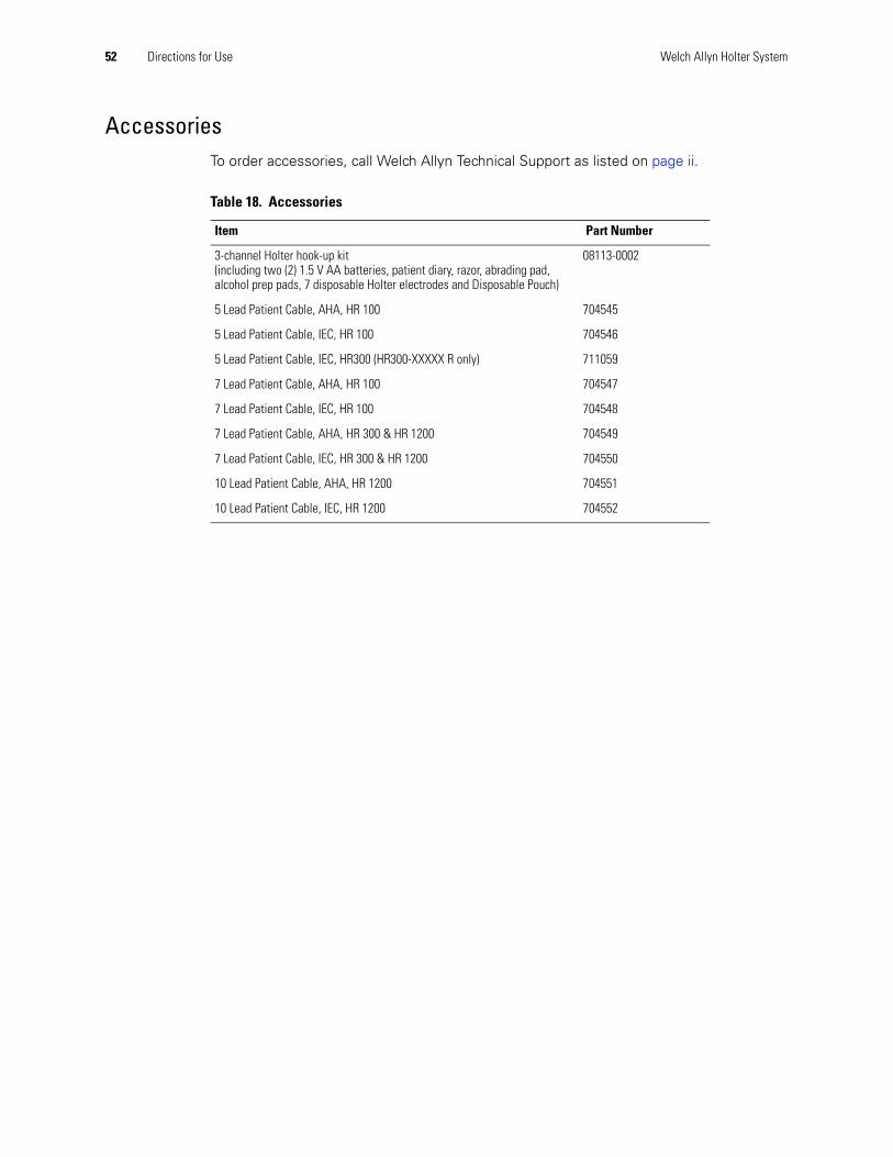
AccessoriesTo order accessories, call Welch Allyn Technical Support as listed on page ii.
Table 18. Accessories
Item Part Number
3-channel Holter hook-up kit(including two (2) 1.5 V AA batteries, patient diary, razor, abrading pad, alcohol prep pads, 7 disposable Holter electrodes and Disposable Pouch)
08113-0002
5 Lead Patient Cable, AHA, HR 100 704545
5 Lead Patient Cable, IEC, HR 100 704546
5 Lead Patient Cable, IEC, HR300 (HR300-XXXXX R only) 711059
7 Lead Patient Cable, AHA, HR 100 704547
7 Lead Patient Cable, IEC, HR 100 704548
7 Lead Patient Cable, AHA, HR 300 & HR 1200 704549
7 Lead Patient Cable, IEC, HR 300 & HR 1200 704550
10 Lead Patient Cable, AHA, HR 1200 704551
10 Lead Patient Cable, IEC, HR 1200 704552
Directions for Use 53
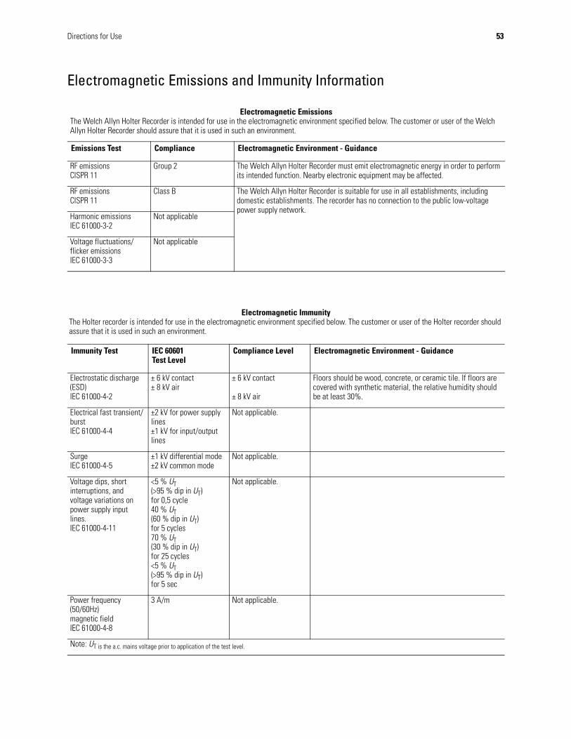
Electromagnetic Emissions and Immunity Information
Electromagnetic EmissionsThe Welch Allyn Holter Recorder is intended for use in the electromagnetic environment specified below. The customer or user of the Welch Allyn Holter Recorder should assure that it is used in such an environment.
Emissions Test Compliance Electromagnetic Environment - Guidance
RF emissionsCISPR 11
Group 2 The Welch Allyn Holter Recorder must emit electromagnetic energy in order to perform its intended function. Nearby electronic equipment may be affected.
RF emissionsCISPR 11
Class B The Welch Allyn Holter Recorder is suitable for use in all establishments, including domestic establishments. The recorder has no connection to the public low-voltagepower supply network.
Harmonic emissionsIEC 61000-3-2
Not applicable
Voltage fluctuations/flicker emissionsIEC 61000-3-3
Not applicable
Electromagnetic ImmunityThe Holter recorder is intended for use in the electromagnetic environment specified below. The customer or user of the Holter recorder should assure that it is used in such an environment.
Immunity Test IEC 60601Test Level
Compliance Level Electromagnetic Environment - Guidance
Electrostatic discharge (ESD)IEC 61000-4-2
± 6 kV contact± 8 kV air
± 6 kV contact
± 8 kV air
Floors should be wood, concrete, or ceramic tile. If floors are covered with synthetic material, the relative humidity should be at least 30%.
Electrical fast transient/burstIEC 61000-4-4
±2 kV for power supply lines±1 kV for input/output lines
Not applicable.
SurgeIEC 61000-4-5
±1 kV differential mode±2 kV common mode
Not applicable.
Voltage dips, short interruptions, and voltage variations on power supply input lines.IEC 61000-4-11
<5 % UT(>95 % dip in UT)for 0,5 cycle40 % UT(60 % dip in UT)for 5 cycles70 % UT(30 % dip in UT)for 25 cycles<5 % UT(>95 % dip in UT)for 5 sec
Not applicable.
Power frequency (50/60Hz)magnetic fieldIEC 61000-4-8
3 A/m Not applicable.
Note: UT is the a.c. mains voltage prior to application of the test level.
54 Directions for Use Welch Allyn Holter System
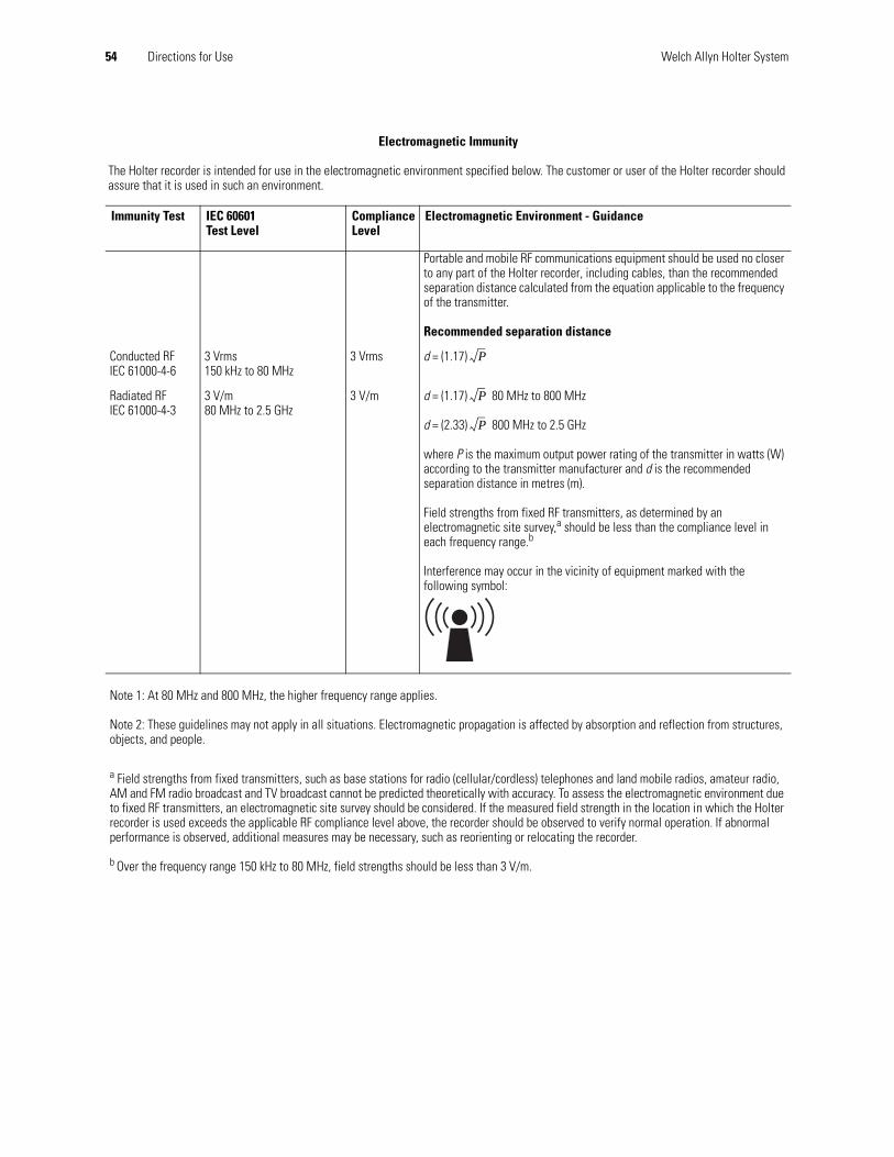
Electromagnetic Immunity
The Holter recorder is intended for use in the electromagnetic environment specified below. The customer or user of the Holter recorder should assure that it is used in such an environment.
Immunity Test IEC 60601Test Level
Compliance Level
Electromagnetic Environment - Guidance
Portable and mobile RF communications equipment should be used no closer to any part of the Holter recorder, including cables, than the recommended separation distance calculated from the equation applicable to the frequency of the transmitter.
Recommended separation distance
Conducted RFIEC 61000-4-6
3 Vrms150 kHz to 80 MHz
3 Vrms d = (1.17)
Radiated RFIEC 61000-4-3
3 V/m80 MHz to 2.5 GHz
3 V/m d = (1.17) 80 MHz to 800 MHz
d = (2.33) 800 MHz to 2.5 GHz
where P is the maximum output power rating of the transmitter in watts (W) according to the transmitter manufacturer and d is the recommended separation distance in metres (m).
Field strengths from fixed RF transmitters, as determined by an electromagnetic site survey,a should be less than the compliance level in each frequency range.b
Interference may occur in the vicinity of equipment marked with the following symbol:
Note 1: At 80 MHz and 800 MHz, the higher frequency range applies.
Note 2: These guidelines may not apply in all situations. Electromagnetic propagation is affected by absorption and reflection from structures, objects, and people.
a Field strengths from fixed transmitters, such as base stations for radio (cellular/cordless) telephones and land mobile radios, amateur radio, AM and FM radio broadcast and TV broadcast cannot be predicted theoretically with accuracy. To assess the electromagnetic environment due to fixed RF transmitters, an electromagnetic site survey should be considered. If the measured field strength in the location in which the Holter recorder is used exceeds the applicable RF compliance level above, the recorder should be observed to verify normal operation. If abnormal performance is observed, additional measures may be necessary, such as reorienting or relocating the recorder.
b Over the frequency range 150 kHz to 80 MHz, field strengths should be less than 3 V/m.
P
P
P
Directions for Use 55
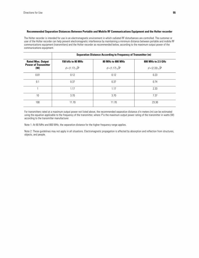
Recommended Separation Distances Between Portable and Mobile RF Communications Equipment and the Holter recorder
The Holter recorder is intended for use in an electromagnetic environment in which radiated RF disturbances are controlled. The customer or user of the Holter recorder can help prevent electromagnetic interference by maintaining a minimum distance between portable and mobile RF communications equipment (transmitters) and the Holter recorder as recommended below, according to the maximum output power of the communications equipment.
Separation Distance According to Frequency of Transmitter (m)
Rated Max. Output Power of Transmitter
(W)
150 kHz to 80 MHz
d = (1.17)
80 MHz to 800 MHz
d = (1.17)
800 MHz to 2.5 GHz
d = (2.33)
0.01 0.12 0.12 0.23
0.1 0.37 0.37 0.74
1 1.17 1.17 2.33
10 3.70 3.70 7.37
100 11.70 11.70 23.30
For transmitters rated at a maximum output power not listed above, the recommended separation distance d in meters (m) can be estimated using the equation applicable to the frequency of the transmitter, where P is the maximum output power rating of the transmitter in watts (W) according to the transmitter manufacturer.
Note 1: At 80 MHz and 800 MHz, the separation distance for the higher frequency range applies.
Note 2: These guidelines may not apply in all situations. Electromagnetic propagation is affected by absorption and reflection from structures, objects, and people.
P P P
56 Directions for Use Welch Allyn Holter System
FCC information
The HR100/HR300 device contains FCC ID: ED9LMX9820ASM or FCC ID: POOWML-C40.
The HR1200 device contains FCC ID: POOWML-C40.
This device complies with Part 15 of the FCC Rules. Operation is subject to the following conditions:
• This device may not cause harmful interference.
• This device must accept any interference received, including interference that may cause undesired operation.
This equipment has been tested and found to comply with the limits pursuant to Part 15 of the FCC Rules. These limits are designed to provide reasonable protection against harmful interference in a residential installation. This equipment generates, uses and radiates radio frequency energy and, if not installed and used in accordance with the instructions, may cause harmful interference to radio communication. However, there is no guarantee that interference will not occur in a particular installation. If this equipment does cause harmful interference to radio or television reception, which can be determined by turning the equipment off and on, the user is encouraged to try to correct the interference by one or more of the following measures:
• Reorient or relocate the receiving antenna.
• Increase the separation between the equipment and receiver.
• Connect the equipment into an outlet on a circuit different from that to which the receiver is connected.
• Consult the dealer or an experienced radio/TV technician for help.
WARNING For patients with a pacemaker, maintain a minimum of 6 inches between the recorder and pacemaker. Turn the recorder off immediately and provide appropriate patient care if you suspect the recorder affected the pacemaker. The Health Industry Manufacturers Association recommends a minimum 6-inch distance between a wireless radio and a pacemaker, which is consistent with the recommendations of Wireless Technology Research. The wireless radio is active for the first 15 minutes of the procedure only.
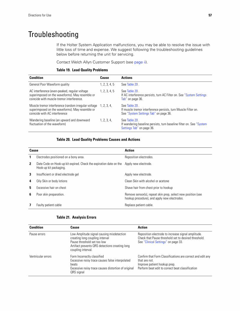
Directions for Use 57
TroubleshootingIf the Holter System Application malfunctions, you may be able to resolve the issue with little loss of time and expense. We suggest following the troubleshooting guidelines below before returning the unit for servicing.
Contact Welch Allyn Customer Support (see page ii).
Table 19. Lead Quality Problems
Table 20. Lead Quality Problems Causes and Actions
Table 21. Analysis Errors
Condition Cause Actions
General Poor Waveform quality 1, 2, 3, 4, 5 See Table 20 .
AC interference (even-peaked, regular voltage superimposed on the waveforms). May resemble or coincide with muscle-tremor interference.
1, 2, 3, 4, 5 See Table 20 .If AC interference persists, turn AC Filter on. See “System Settings Tab” on page 36.
Muscle tremor interference (random irregular voltage superimposed on the waveforms). May resemble or coincide with AC interference
1, 2, 3, 4, See Table 20 .If muscle tremor interference persists, turn Muscle Filter on. See “System Settings Tab” on page 36.
Wandering baseline (an upward and downward fluctuation of the waveform)
1, 2, 3, 4, See Table 20 .If wandering baseline persists, turn baseline filter on. See “System Settings Tab” on page 36.
Cause Action
1 Electrodes positioned on a bony area. Reposition electrodes.
2 Date Code on Hook-up kit expired. Check the expiration date on the Hook-up kit packaging.
Apply new electrode.
3 Insufficient or dried electrode gel Apply new electrode.
4 Oily Skin or body lotions Clean Skin with alcohol or acetone
5 Excessive hair on chest Shave hair from chest prior to hookup
6 Poor skin preparation. Remove sensor(s), repeat skin prep, select new position (see hookup procedure), and apply new electrodes.
7 Faulty patient cable Replace patient cable.
Condition Cause Action
Pause errors Low Amplitude signal causing misdetection creating long coupling intervalPause threshold set too lowArtifact prevents QRS detections creating long coupling interval.
Reposition electrode to increase signal amplitude.Check that Pause threshold set to desired threshold. See “Clinical Settings” on page 33.
Ventricular errors Form Incorrectly classifiedExcessive noisy trace causes false interpolated beatsExcessive noisy trace causes distortion of original QRS signal
Confirm that Form Classifications are correct and edit any that are not.Improve patient hookup prep.Perform beat edit to correct beat classification
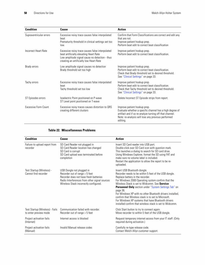
58 Directions for Use Welch Allyn Holter System
Table 22. Miscellaneous Problems
Supraventricular errors Excessive noisy trace causes false interpolated beatPrematurity threshold in clinical settings set too low.
Confirm that Form Classifications are correct and edit any that are not.Improve patient hookup prep.Perform beat edit to correct beat classification
Incorrect Heart Rate Excessive noisy trace causes false interpolated beat artificially elevating Heart RateLow amplitude signal cause no detection - thus creating an artificially low Heart Rate
Improve patient hookup prep.Perform beat edit to correct beat classification.
Brady errors Low amplitude signal causes no detectionBrady threshold set too high
Improve patient hookup prep.Perform beat edit to correct beat classification.Check that Brady threshold set to desired threshold. See “Clinical Settings” on page 33.
Tachy errors Excessive noisy trace causes false interpolated beatTachy threshold set too low
Improve patient hookup prep.Perform beat edit to correct beat classification.Check that Tachy threshold set to desired threshold. See “Clinical Settings” on page 33.
ST Episodes errors Isoelectric Point positioned on P-waveST Level point positioned on T-wave
Delete Incorrect ST Episode strips from report.
Excessive Form Count Excessive noisy traces causes distortion to QRS creating different clusters
Improve patient hookup prep.Evaluate whether a specific channel has a high degree of artifact and if so re-analyze turning off that channel. Note: re-analysis will lose any previous performed editing.
Condition Cause Action
Condition Cause Action
Failure to upload report from recorder
SD Card Reader not plugged inSD Card Reader location has changedSD Card is corruptSD Card upload was terminated before completion
Insert SD Card reader into USB port.Double-click over SD Card icon with question mark. This launches a dialog to search for SD card drive.Using Windows Explorer, format the SD using FAT and make sure no volume label is included. Restart the application to allow the report to be re-uploaded.
Test Startup (Wireless) - Cannot find recorder
USB Dongle not plugged inRecorder out of range > 5 feetRecorder does not have fresh batteriesRadio Interferences from other signal sourcesWireless Stack incorrectly configured.
Insert USB Bluetooth dongle. Recorder needs to be within 5 feet of the USB dongle.Replace battery in the recorder.For Windows 2000 Operating system confirm that the Wireless Stack is set to Widcomm. See Service Personnel Only section under “System Settings Tab” on page 36.For Windows XP with no other Bluetooth drivers installed, confirm that Wireless stack is to set to Microsoft. For Windows XP systems that have Bluetooth drivers installed confirm that wireless stack is set to Widcomm.
Test Startup (Wireless) - Fails to enter preview mode
Communication failed with recorder.Recorder out of range > 5 feet
Click Start button to try to connect again.Move recorder to within 5 feet of the USB dongle.
Project activation fails (Internet)
Internet access is blocked Request temporary internet access from your IT staff. (Only required during activation.)
Project activation fails (Manual)
Invalid Manual release codes Carefully re-type release code.Contact Welch Allyn customer support.
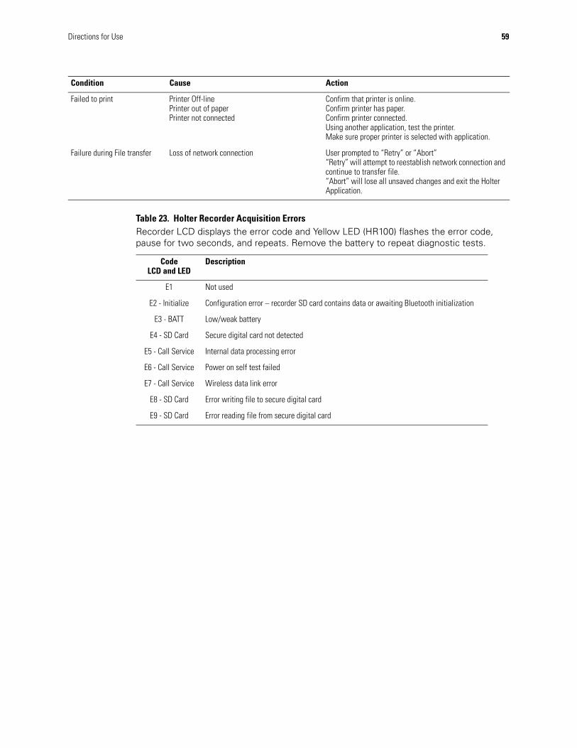
Directions for Use 59
Failed to print Printer Off-linePrinter out of paperPrinter not connected
Confirm that printer is online.Confirm printer has paper.Confirm printer connected.Using another application, test the printer.Make sure proper printer is selected with application.
Failure during File transfer Loss of network connection User prompted to “Retry” or “Abort”“Retry” will attempt to reestablish network connection and continue to transfer file.“Abort” will lose all unsaved changes and exit the Holter Application.
Condition Cause Action
Table 23. Holter Recorder Acquisition Errors Recorder LCD displays the error code and Yellow LED (HR100) flashes the error code, pause for two seconds, and repeats. Remove the battery to repeat diagnostic tests.
CodeLCD and LED
Description
E1 Not used
E2 - Initialize Configuration error – recorder SD card contains data or awaiting Bluetooth initialization
E3 - BATT Low/weak battery
E4 - SD Card Secure digital card not detected
E5 - Call Service Internal data processing error
E6 - Call Service Power on self test failed
E7 - Call Service Wireless data link error
E8 - SD Card Error writing file to secure digital card
E9 - SD Card Error reading file from secure digital card

60 Directions for Use Welch Allyn Holter System
Software LicenseThe software provided with the Welch Allyn Holter System consists of software written by Welch Allyn, Inc. or its vendors (the Welch Allyn Holter System Software), as well as software written by third parties (the Third-Party Software). The Welch Allyn Holter System Software is governed by this license, and the Third-Party Software is governed by licenses that can be found in the license files in the directories for the respective Third-Party Software contained on the CD-ROM Disc that is furnished with the Welch Allyn Holter System. If any updates are periodically provided for the Welch Allyn Holter System Software or any Third-Party Software, such software updates will be governed by the relevant license for that software unless a different license agreement is provided with the update.
READ THE TERMS AND CONDITIONS OF THIS LICENSE AGREEMENT AND THE LICENSES FOR THE THIRD-PARTY SOFTWARE CAREFULLY BEFORE OPERATING THE Welch Allyn Holter System. THE Welch Allyn Holter System SOFTWARE AND THIRD-PARTY SOFTWARE ARE COPYRIGHTED AND LICENSED (NOT SOLD). BY OPERATING THE Welch Allyn Holter System YOU ARE ACCEPTING AND AGREEING TO THE TERMS OF THIS LICENSE AGREEMENT AND THE LICENSES FOR THE THIRD-PARTY SOFTWARE. IF YOU ARE NOT WILLING TO BE BOUND BY THE TERMS OF THIS LICENSE AGREEMENT AND THE LICENSES FOR THE THIRD-PARTY SOFTWARE, YOU SHOULD PROMPTLY RETURN THE Welch Allyn Holter System TO WELCH ALLYN. THIS LICENSE AGREEMENT REPRESENTS THE COMPLETE AGREEMENT CONCERNING THE Welch Allyn Holter System SOFTWARE BETWEEN YOU AND WELCH ALLYN, AND IT SUPERSEDES ANY PRIOR PROPOSAL, REPRESENTATION, OR UNDERSTANDING YOU MAY HAVE HAD.
END USER LICENSE AGREEMENT FOR Welch Allyn Holter System SOFTWARE
1. License Grant. Welch Allyn, Inc. (hereinafter Welch Allyn) hereby grants to you, and you accept, a nonexplosive license to use the machine-readable, object code form of the Welch Allyn Holter System Software, whether provided on the media packaged with the Welch Allyn Holter System or pre-installed on the Welch Allyn Holter System (collectively referred to as the “Software”), as well as the accompanying User Instructions or Documentation, only as authorized in this License Agreement. The Software may be used only on one computer. Neither concurrent use on two or more devices or computers, nor use in a network, is permitted without separate authorization from Welch Allyn.
* You agree that you will not assign, re-license, transfer, rent, or share your rights under this License Agreement, except that you may permanently transfer all of your rights under this License Agreement as part of a sale or other transfer to a third party of the Welch Allyn Holter System with which the Software was packaged and sold, provided that you transfer all of the Software without retaining a copy, and the transferee agrees to the terms of this License Agreement.
* You agree that you will not reverse assemble, reverse compile, or otherwise translate the Software.
* You may use the Software media for backup purposes. No copies of the Software or any portion thereof may be made by you or any person under your authority or control.
2. Welch Allyn's Rights. You acknowledge and agree that the Software and the User's Instructions or Documentation are proprietary products of Welch Allyn, protected under U.S. copyright law. You further acknowledge and agree that all ownership rights and title in and to the Software, including associated intellectual property rights, are and shall remain with Welch Allyn. This License Agreement does not convey to you any ownership in or to
Directions for Use 61
the Software, but only a limited right of use that is revocable in accordance with the terms of this License Agreement.
3. License Fees. The Software is licensed to you in consideration of your purchase of the Welch Allyn Holter System.
4. Term. This License Agreement is effective upon your operation of the Welch Allyn Holter System and shall continue until terminated. You may terminate this License Agreement by returning the Welch Allyn Holter System to the dealer from which you purchased it within the time permitted for returns under your purchase agreement. Welch Allyn may terminate this License Agreement if you violate any condition of, or default in performing any obligation required by, the License Agreement. Upon termination by Welch Allyn, you agree to return the Software to Welch Allyn.
5. Limited Warranty. Welch Allyn warrants, for your benefit alone, for a period of 12 months after the date of commencement of this License Agreement (referred to as the “Warranty Period”) that during the Warranty Period the Welch Allyn Holter System Software will operate substantially in accordance with the functional descriptions or specifications in the User's Instructions or Documentation. Updates to the Welch Allyn Holter System Software are covered by an Update Warranty Period of 90 days after delivery of the Update to you. Welch Allyn does not warrant that the Welch Allyn Holter System Software is free from defects, nor that it will operate error-free or produce results that will meet your requirements. If during the Warranty Period, a defect in the Welch Allyn Holter System Software appears, you may return it to Welch Allyn and at Welch Allyn's sole discretion, it will either: 1) fix or replace the Welch Allyn Holter System Software, or 2) refund to you the price you paid for the Welch Allyn Holter System. If a defect in an Update of the Welch Allyn Holter System Software appears during the Update Warranty Period, you may notify Welch Allyn, and Welch Allyn will use all commercially reasonable efforts to fix or replace the Updated Welch Allyn Holter System Software. You agree that the foregoing constitutes your sole and exclusive remedy against Welch Allyn for the failure of any warranties made under this License Agreement. EXCEPT FOR THE WARRANTIES SET FORTH ABOVE, THE SOFTWARE IS LICENSED “AS IS,” AND WELCH ALLYN DISCLAIMS ANY AND ALL OTHER WARRANTIES, WHETHER EXPRESS OR IMPLIED, INCLUDING, WITHOUT LIMITATION, ANY IMPLIED WARRANTIES OF MERCHANTABILITY OR FITNESS FOR A PARTICULAR PURPOSE.
6. Limitation of Liability. The cumulative liability of Welch Allyn to you or any other party for any loss or damages resulting from any claims, demands, or actions arising out of or relating to this License Agreement shall not exceed the price you paid for the Welch Allyn Holter System. In no event shall Welch Allyn be liable for any indirect, incidental, consequential, special, or exemplary damages or lost profits, even if Welch Allyn has been advised of the possibility of such damages.
7. Governing Law. This License Agreement shall be construed and governed in accordance with the laws of the State of New York, USA.
8. No Waiver. The failure of either party to enforce any rights under this License Agreement or to take action against the other party in the event of any breach hereunder shall not be deemed a waiver by that party as to the subsequent enforcement of such rights.

62 Directions for Use Welch Allyn Holter System
63
Limited WarrantyHolter System Application, HR100, HR300 and HR1200 Holter Recorder and Accessories.
This product is sold by Welch Allyn under the warranties set forth in the following paragraphs. These warranties are extended only to the end user with respect to the purchase of this product directly from Welch Allyn or Welch Allyn’s authorized distributors as new merchandise.
For a period of 1 year from the date of original delivery to the buyer, the recorder, software, and hardware components are warranted to be free from functional defects in materials and workmanship and to conform in all material respects to the description of the product contained in the Directions For Use and accompanying labels and/or inserts. For a period of 3 months this same warranty is made for accessories (including patient cables) provided by Welch Allyn. Warranty of accessories purchased separately from listed suppliers will be the responsibility of the listed suppliers.
This warranty is valid only if (a) all equipment is approved for use with the recorder by Welch Allyn and are installed according to instructions provided by Welch Allyn or its authorized distributors; (b) the product is properly operated under conditions of normal use in accordance with applicable safety and regulatory requirements; (c) replacements and repairs are made in accordance with the instructions provided by Welch Allyn; (d) only recorder or other software authorized by Welch Allyn is used on the workstation; (e) the product has not been configured, modified, adjusted or repaired other than by Welch Allyn or by persons expressly authorized by Welch Allyn, or in accordance with written instructions provided by Welch Allyn; (f) the product has not been subject to misuse, negligence or accident.
Welch Allyn’s sole and exclusive obligation, and buyer’s sole and exclusive remedy under the above warranties, is limited to repairing or replacing, free of charge, a product which is reported to Welch Allyn customer service as listed on page ii. Welch Allyn shall not be otherwise liable for any damages including, but not limited to, incidental, consequential, or special damages.
There are no express or implied warranties which extend beyond the warranties in this document. Welch Allyn makes no warranty of merchantability or fitness for a particular purpose.

64 Limited Warranty Welch Allyn Holter System


4341 State Street Road, PO Box 220, Skaneateles Falls, NY 13153-0220 USA800 535 6663 www.welchallyn.com