Welch Allyn ® XScribe™ CARDIAC STRESS TESTING SYSTEM INSTALLATION MANUAL Manufactured by Welch Allyn, Inc. Skaneateles Falls, NY U.S.A CAUTION: Federal law restricts this device to sale by or on the order of a physician.

Welcome message from author
This document is posted to help you gain knowledge. Please leave a comment to let me know what you think about it! Share it to your friends and learn new things together.
Transcript

Welch Allyn® XScribe™ CARDIAC STRESS TESTING SYSTEM
INSTALLATION MANUAL
Manufactured by Welch Allyn, Inc. Skaneateles Falls, NY U.S.A
CAUTION: Federal law restricts this device to sale by or on the order of a physician.

© 2019 Welch Allyn This document contains confidential information that belongs to Welch Allyn, Inc. No part
of this document may be transmitted, reproduced, used, or disclosed outside of the receiving organization
without the express written consent of Welch Allyn, Inc. Welch Allyn and X Scribe are registered trademarks of
Welch Allyn, Inc. Software V6.2.1 For patent information, please visit www.welchallyn.com/patents
For information about any Welch Allyn product, visit: https://www.welchallyn.com/en/about-us/locations.html
Customer Service and Technical Support: https://www.welchallyn.com/en/other/contact-us.html
1.888.667.8272, [email protected]
9515-209-60-ENG Rev D
Revision date: 2019-08
901144 CARDIAC STRESS TESTING SYSTEM
EU IMPORTER
Welch Allyn, Inc.
4341 State Street Road
Skaneateles Falls, NY 13153 USA
www.welchallyn.com
Welch Allyn Limited
Navan Business Park, Dublin Road,
Navan, Co. Meath C15 AW22
Ireland

Page | 1
TABLE OF CONTENTS
SCOPE .................................................................................................................................................................... 4
HARDWARE CONNECTIONS .............................................................................................................................................. 4 USE OF AN UNINTERRUPTABLE POWER SUPPLY (OPTIONAL) ................................................................................................... 4 SYSTEM CONFIGURATION ................................................................................................................................................. 5
STRESS CART ASSEMBLY ........................................................................................................................................ 7
CART PARTS AND OPTIONS............................................................................................................................................... 8 Cart Base (9911-023-45) ....................................................................................................................................... 8 Z200+ Work Surface and Accessories .................................................................................................................... 8 Standard Display Mount supports LCD or Touch Monitor (9911-023-31) ............................................................. 9 SunTech Tango Mount Kit for Standard 24” LCD display (9911-023-32) .............................................................. 9 SunTech Tango Mount Kit for 24” Touch Monitor Display (9911-023-33) ............................................................ 9 Slide Out Keyboard Tray (9911-023-44) .............................................................................................................. 10 Storage Drawer (9911-023-41) ........................................................................................................................... 10 Storage Accessories (9911-023-42) ..................................................................................................................... 10 WAM Holder (9911-023-43) ................................................................................................................................ 11 Surface Extension side shelf (9911-023-45) ........................................................................................................ 11
CART ASSEMBLY STEPS .................................................................................................................................................. 12 STEP 1 Uncrate the base ..................................................................................................................................... 12 STEP 2 Assemble work surface onto base ........................................................................................................... 13 STEP 3 Fasten display mount to work surface ..................................................................................................... 14 STEP 4 Display mount assembly .......................................................................................................................... 15 STEP 4 Display mount assembly (continued)....................................................................................................... 16 STEP 5 Accessories, thermal printer paper catch tray ......................................................................................... 17 STEP 5 Accessories, keyboard tray ...................................................................................................................... 18 STEP 5 Accessories, storage drawer .................................................................................................................... 19 STEP 5 Accessories, storage bins ......................................................................................................................... 20 STEP 5 Accessories, work surface extension........................................................................................................ 21 STEP 5 Accessories, WAM holder ........................................................................................................................ 22 STEP 5 Accessories, cart back .............................................................................................................................. 23
INSTALLATION OF SYSTEM COMPONENTS ........................................................................................................... 24
STEP 1 INSTALLING THE ISOLATION TRANSFORMER ............................................................................................................. 24 STEP 2 INSTALLING THE COMPUTER ................................................................................................................................ 25
For units with slide out keyboard tray ................................................................................................................ 26 For units without keyboard tray .......................................................................................................................... 26
STEP 3 INSTALLING FRONT END MODULES ........................................................................................................................ 27 Cart module bay .................................................................................................................................................. 27 Module installation into cart .............................................................................................................................. 27
STEP 3 INSTALLING FRONT END MODULES (CONTINUED) ..................................................................................................... 28 WAM module installation ................................................................................................................................... 28
STEP 3 INSTALLING FRONT END MODULES (CONTINUED) ..................................................................................................... 29 For units with Trigger Module ............................................................................................................................. 29 Trigger module front for AM12 connection to the ECG A connector and one analog out connection. .............. 29
RJ45 AND LAN ISOLATION ADAPTER CONNECTIONS (OPTIONAL) .......................................................................................... 29 Remote Keypad (Optional) .................................................................................................................................. 30
STEP 6 DISPLAY ASSEMBLY ............................................................................................................................................ 32 For units with 24” LCD display ............................................................................................................................ 32
STEP 6 DISPLAY ASSEMBLY (CONTINUED) ......................................................................................................................... 33

TABLE OF CONTENTS
Page | 2
For units with 24” LCD display and blood pressure monitor arm ........................................................................ 33 STEP 6 DISPLAY ASSEMBLY (CONTINUED) ......................................................................................................................... 34 STEP 6 DISPLAY ASSEMBLY (CONTINUED) ......................................................................................................................... 35
For units with 24” Touch Monitor panel display ................................................................................................. 35 STEP 7 ORGANIZING THE CABLES ................................................................................................................................... 38 SUPPORTING INFORMATION ........................................................................................................................................... 39 COMPLETED XSCRIBE SYSTEM WITH THE LCD AND TANGO M2 MOUNTED ............................................................................. 39 CONNECT THE EXERCISE DEVICE ...................................................................................................................................... 40
Treadmill ............................................................................................................................................................. 40 Ergometer ........................................................................................................................................................... 40
FRONT-END COMPONENTS ............................................................................................................................................ 40 Material Supplied for Installation ....................................................................................................................... 40 Optional Kit to add Wireless ECG Acquisition ..................................................................................................... 40 Optional Kit for Trigger Module Installation on the Treadmill Rail ..................................................................... 40
XSCRIBE SOFTWARE INSTALLATION AND CONFIGURATION .................................................................................................... 40 System Setup (Windows 10 PC) ........................................................................................................................... 41 Completing the Windows 10 Installation ............................................................................................................ 41
XSCRIBE SOFTWARE INSTALLATION PROCESS ..................................................................................................................... 44 Activate the XScribe software ............................................................................................................................. 48
XSCRIBE LICENSE ACTIVATION REQUEST ............................................................................................................... 48 XScribe License Activation ................................................................................................................................... 49 Remove Unneeded Icons/Arrange Icons ............................................................................................................. 50 Optional Laser Printer Configuration: ................................................................................................................. 50 Optional Touch Monitor Configuration ............................................................................................................... 50 Section 3 – XScribe Setup .................................................................................................................................... 52 Section 4 – Test XScribe Basic Functions ............................................................................................................. 53

Page | 3
TABLE OF FIGURES
FIGURE 1 STRESS SYSTEM COMPONENTS ................................................................................................................................. 5 FIGURE 2 EXAMPLE OF A STRESS CART WITH THE Z200+ THERMAL WRITER, TANGO M2, AND TOUCH MONITOR ................................ 7 FIGURE 3 EXAMPLE OF A STRESS CART WITH A WINDOWS LASERJET PRINTER, TANGO M2, AND TOUCH MONITOR .............................. 7

Page | 4
SCOPE
This document describes the assembly of a Stress system. It is designed to be used as a whole for the installation
process or in part as a troubleshooting tool for ensuring correct connection, configuration, and functioning of the
Stress system.
Because the Stress system can be purchased in different configurations and with different options, your system’s
feature set may be different from the feature set shown in this document.
Read all instructions before you begin the installation process. Follow the instructions in the order given.
If you have any questions regarding execution of these instructions, contact technical support at:
1.888.667.8272
Hardware Connections
Caution. The following cautions apply:
The computer, display, and printer must be plugged into the isolation transformer. The optional Tango BP
monitor may also be plugged into the isolation transformer.
The isolation transformer must be plugged into a dedicated circuit.
The treadmill must be plugged into a dedicated circuit.
Use of an Uninterruptable Power Supply (Optional)
If you use an uninterruptable power supply (UPS), insert it between the isolation transformer and the computer
and monitor.
WARNING! Electronic interference.
The Trigger module can be installed in the stress cart, mounted on the treadmill handrail utilizing a
custom treadmill rail clamp kit, or in another convenient location. The AM12 patient cable should be
installed in a location that prevents it to be in close proximity to power cords, transformers, or other
powered devices to minimize the possibility to introduce noise into the ECG signal.
SCOPE
Page | 5
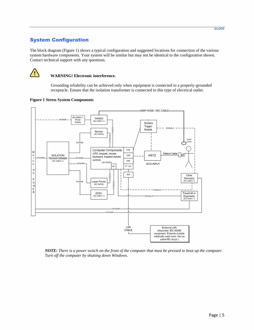
System Configuration
The block diagram (Figure 1) shows a typical configuration and suggested locations for connection of the various
system hardware components. Your system will be similar but may not be identical to the configuration shown.
Contact technical support with any questions.
WARNING! Electronic interference.
Grounding reliability can be achieved only when equipment is connected to a properly-grounded
receptacle. Ensure that the isolation transformer is connected to this type of electrical outlet.
Figure 1 Stress System Components
NOTE: There is a power switch on the front of the computer that must be pressed to boot up the computer.
Turn off the computer by shutting down Windows.

SCOPE
Page | 6
NOTE: The Certified Separating Device (Isolation Transformer) will power up to four devices. When
more than four devices require power, the Tango BP Monitor must be powered by another available AC
power outlet. The SunTech Tango unit does not require connection to the isolation transformer, as it is a
medical device that includes its own isolated power supply. The Tango may be powered by the isolation
transformer as a convenience.
Make a note of which ports are used to connect the treadmill, ergometer, and blood pressure monitor. You will need
this information to configure the Stress software.
Caution. Treadmill/Ergometer communication.
Power Management should be disabled for USB ports to prevent USB ports from being powered down.
This is beneficial for maintaining communication with the treadmill or ergometer exercise equipment.

Page | 7
STRESS CART ASSEMBLY
The steps below show how to place Stress system components on a Stress cart. If you are not placing your system on
a cart, you can use these steps for instructions on connecting the different components.
Figure 2 Example of a Stress Cart with the
Z200+ Thermal Writer, Tango M2, and Touch
Monitor
Figure 3 Example of a Stress Cart with a
Windows LaserJet Printer, Tango M2, and
Touch Monitor
Caution. Unstable workstation.
For best results, place the system equipment on the cart as described in these instructions.
All carts require the following three component kits:
Base
Work surface
Display mount and blood pressure monitor mount
Stress carts may include accessories such as:
SunTech Tango BP monitor mount
Storage solutions
Workflow solutions
Each cart assembly kit includes tools and hardware necessary for assembly.
STRESS CART ASSEMBLY
Page | 8
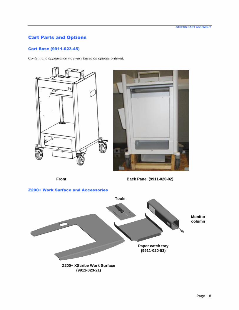
Cart Parts and Options
Cart Base (9911-023-45)
Content and appearance may vary based on options ordered.
Front Back Panel (9911-020-02)
Z200+ Work Surface and Accessories
Paper catch tray
(9911-020-53)
Monitor
column
Tools
Z200+ XScribe Work Surface
(9911-023-21)
STRESS CART ASSEMBLY
Page | 9
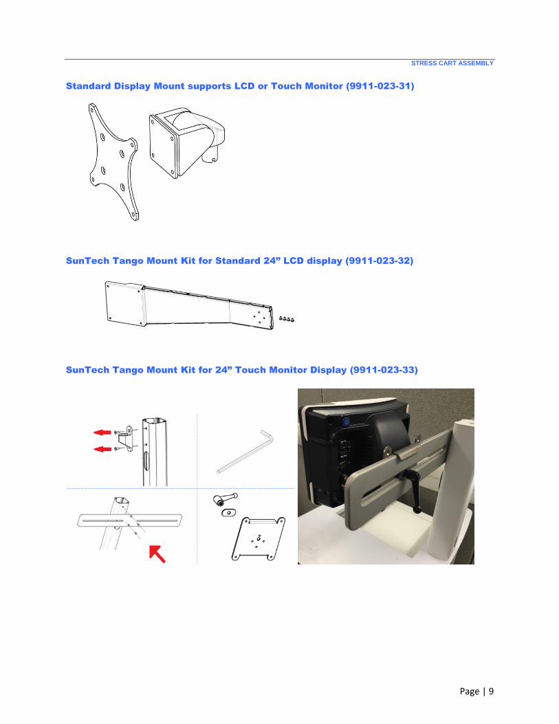
Standard Display Mount supports LCD or Touch Monitor (9911-023-31)
SunTech Tango Mount Kit for Standard 24” LCD display (9911-023-32)
SunTech Tango Mount Kit for 24” Touch Monitor Display (9911-023-33)
STRESS CART ASSEMBLY
Page | 10
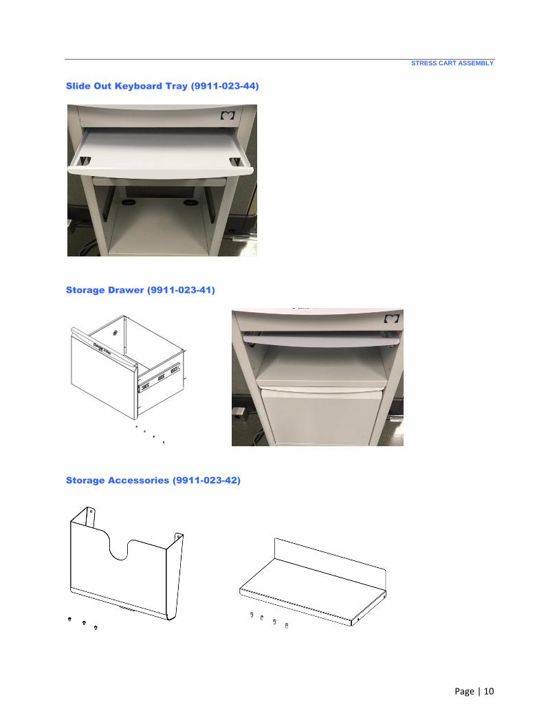
Slide Out Keyboard Tray (9911-023-44)
Storage Drawer (9911-023-41)
Storage Accessories (9911-023-42)
STRESS CART ASSEMBLY
Page | 11
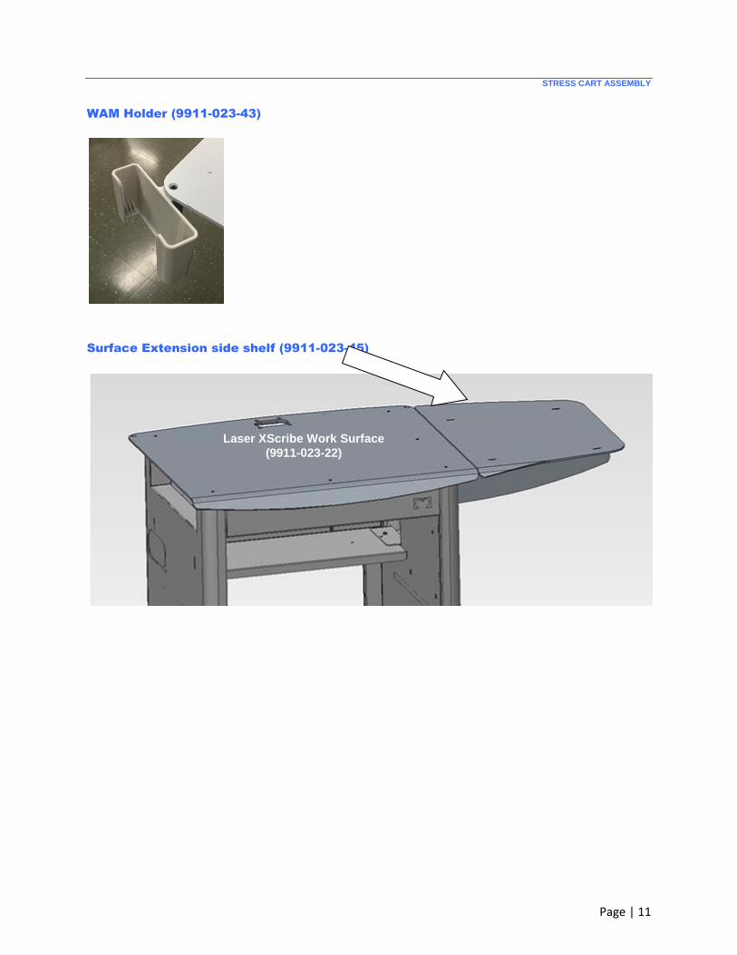
WAM Holder (9911-023-43)
Surface Extension side shelf (9911-023-45)
Laser XScribe Work Surface
(9911-023-22)

STRESS CART ASSEMBLY
Page | 12
Cart Assembly Steps
STEP 1 Uncrate the base
Lift the shipping carton off cart base
Unpack ramp
Roll cart base off shipping pallet
STRESS CART ASSEMBLY
Page | 13
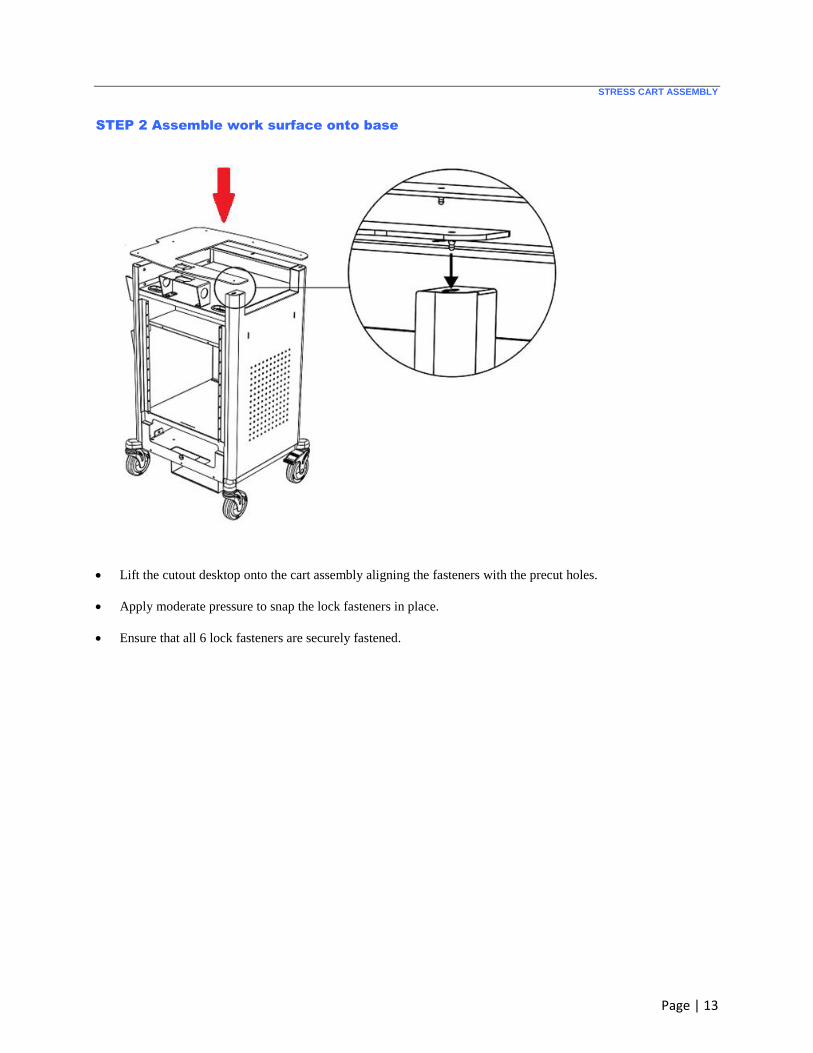
STEP 2 Assemble work surface onto base
Lift the cutout desktop onto the cart assembly aligning the fasteners with the precut holes.
Apply moderate pressure to snap the lock fasteners in place.
Ensure that all 6 lock fasteners are securely fastened.
STRESS CART ASSEMBLY
Page | 14
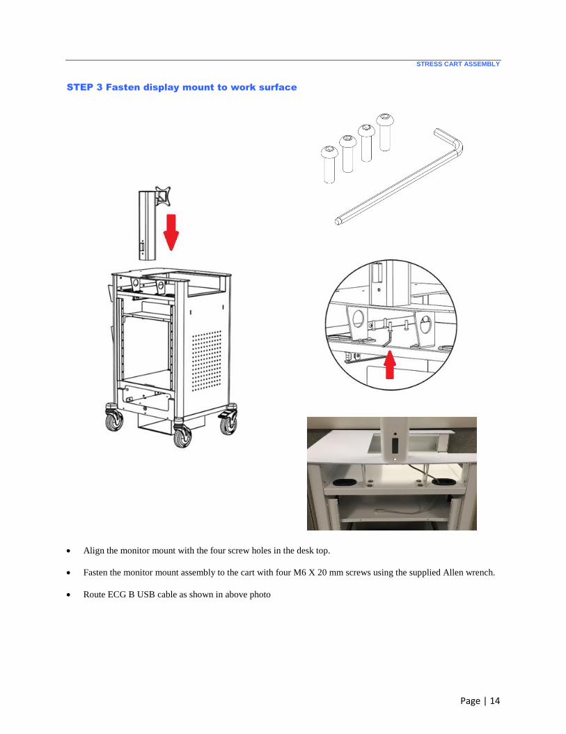
STEP 3 Fasten display mount to work surface
Align the monitor mount with the four screw holes in the desk top.
Fasten the monitor mount assembly to the cart with four M6 X 20 mm screws using the supplied Allen wrench.
Route ECG B USB cable as shown in above photo
STRESS CART ASSEMBLY
Page | 15
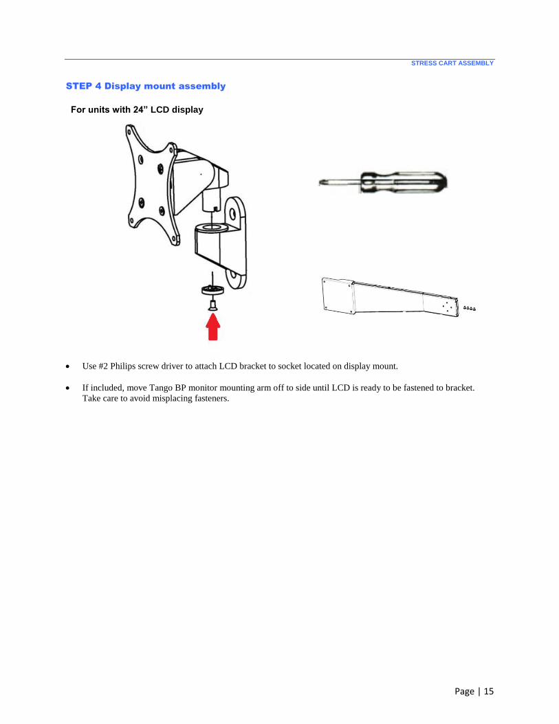
STEP 4 Display mount assembly
For units with 24” LCD display
Use #2 Philips screw driver to attach LCD bracket to socket located on display mount.
If included, move Tango BP monitor mounting arm off to side until LCD is ready to be fastened to bracket.
Take care to avoid misplacing fasteners.
STRESS CART ASSEMBLY
Page | 16
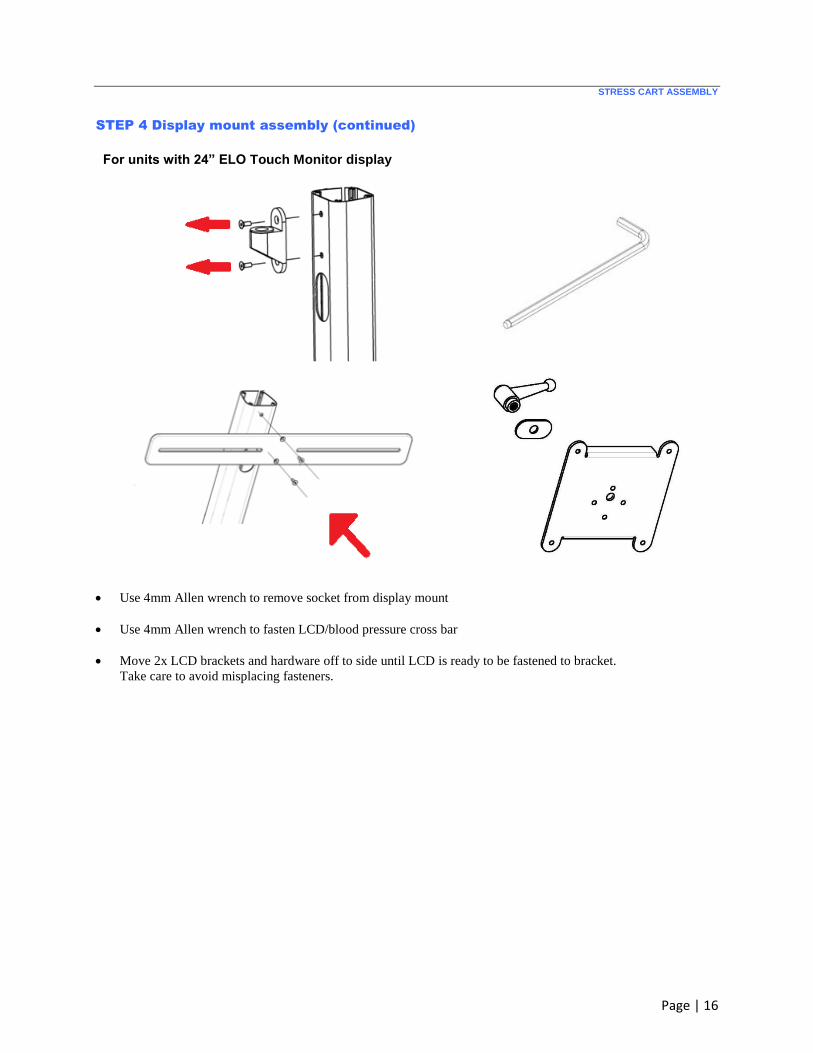
STEP 4 Display mount assembly (continued)
For units with 24” ELO Touch Monitor display
Use 4mm Allen wrench to remove socket from display mount
Use 4mm Allen wrench to fasten LCD/blood pressure cross bar
Move 2x LCD brackets and hardware off to side until LCD is ready to be fastened to bracket.
Take care to avoid misplacing fasteners.
STRESS CART ASSEMBLY
Page | 17
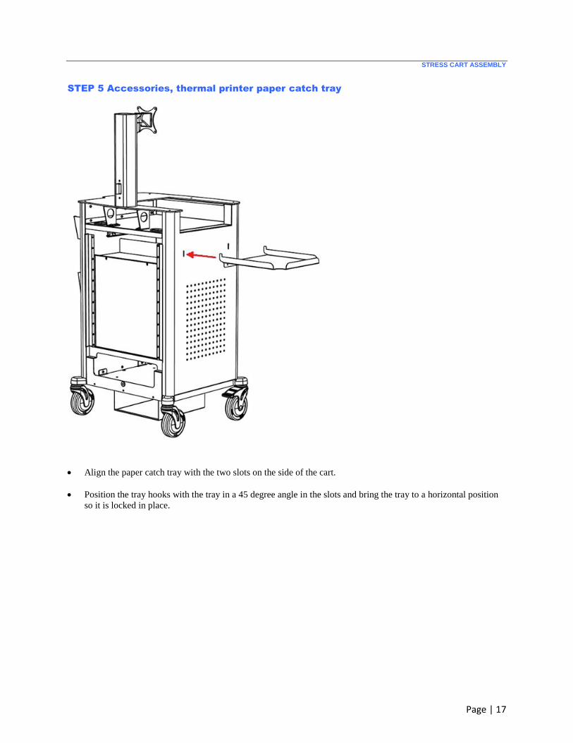
STEP 5 Accessories, thermal printer paper catch tray
Align the paper catch tray with the two slots on the side of the cart.
Position the tray hooks with the tray in a 45 degree angle in the slots and bring the tray to a horizontal position
so it is locked in place.
STRESS CART ASSEMBLY
Page | 18
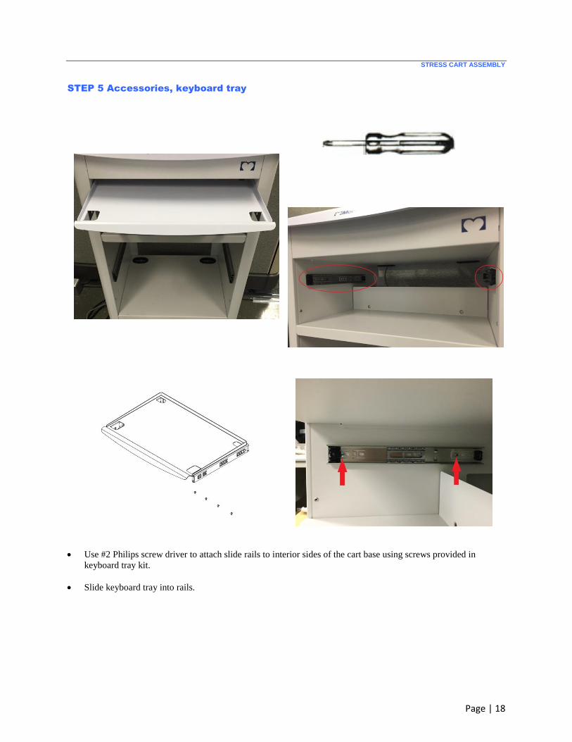
STEP 5 Accessories, keyboard tray
Use #2 Philips screw driver to attach slide rails to interior sides of the cart base using screws provided in
keyboard tray kit.
Slide keyboard tray into rails.
STRESS CART ASSEMBLY
Page | 19
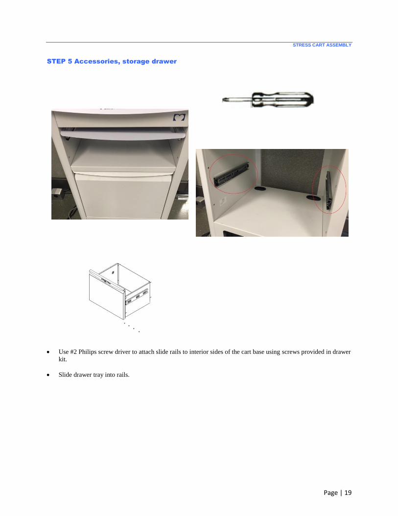
STEP 5 Accessories, storage drawer
Use #2 Philips screw driver to attach slide rails to interior sides of the cart base using screws provided in drawer
kit.
Slide drawer tray into rails.

STRESS CART ASSEMBLY
Page | 20
STEP 5 Accessories, storage bins
Use #2 Philips screw driver to attach folder bin to side of the cart base using screws provided in the kit.
Use 4mm Allen wrench to attach storage shelf to inside of the cart base using screws provided in the kit.
STRESS CART ASSEMBLY
Page | 21
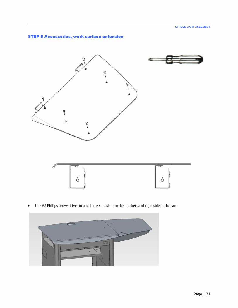
STEP 5 Accessories, work surface extension
Use #2 Philips screw driver to attach the side shelf to the brackets and right side of the cart
STRESS CART ASSEMBLY
Page | 22
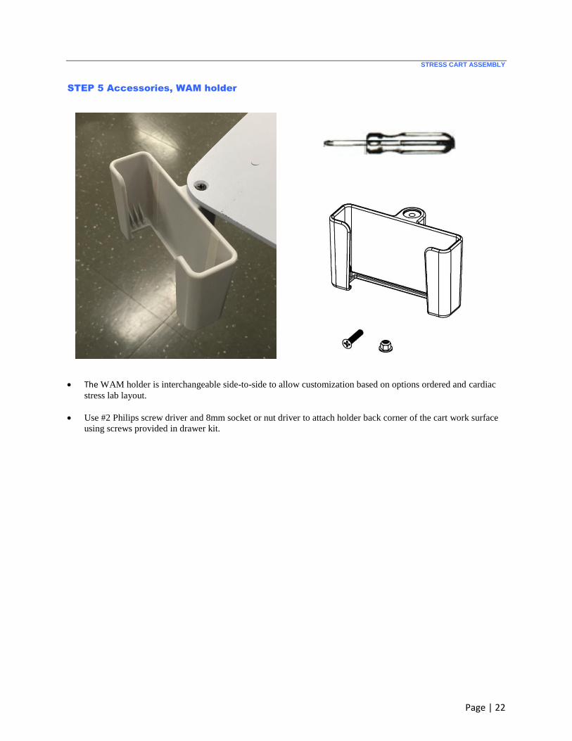
STEP 5 Accessories, WAM holder
The WAM holder is interchangeable side-to-side to allow customization based on options ordered and cardiac
stress lab layout.
Use #2 Philips screw driver and 8mm socket or nut driver to attach holder back corner of the cart work surface
using screws provided in drawer kit.
STRESS CART ASSEMBLY
Page | 23
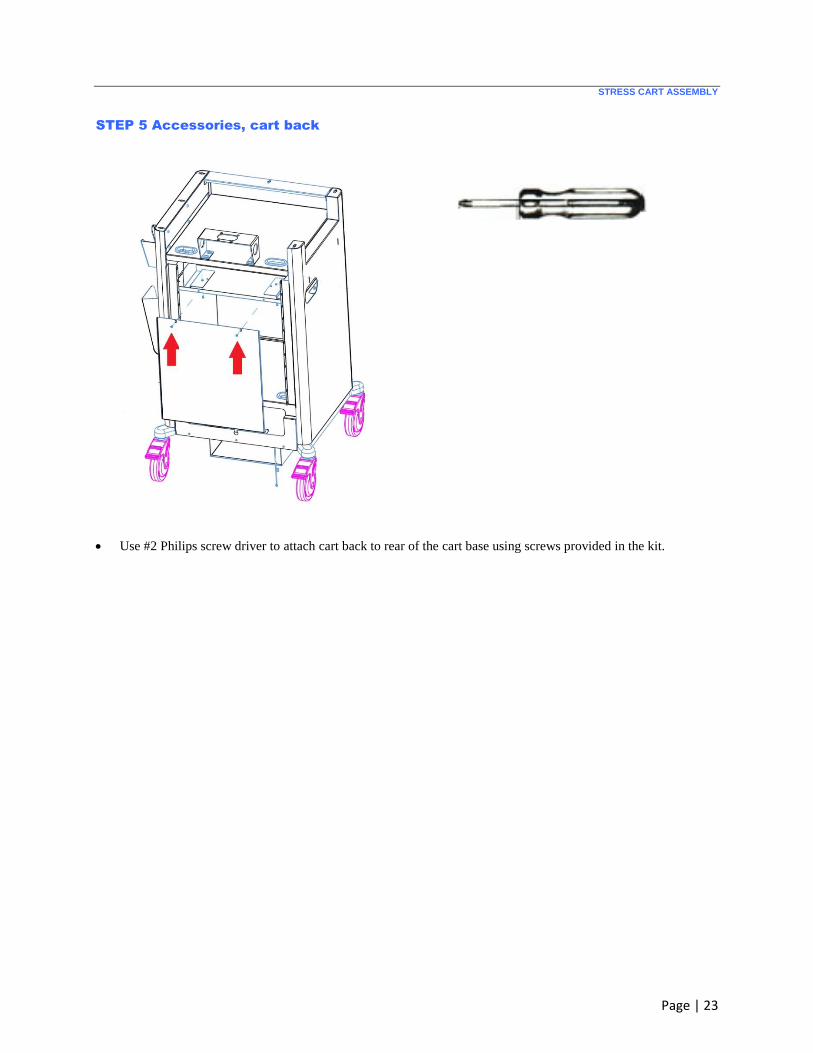
STEP 5 Accessories, cart back
Use #2 Philips screw driver to attach cart back to rear of the cart base using screws provided in the kit.
Page | 24
INSTALLATION OF SYSTEM COMPONENTS
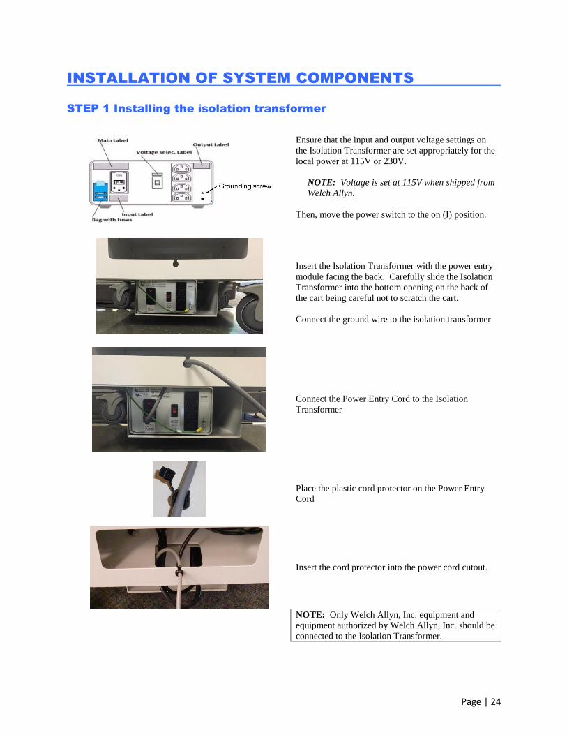
STEP 1 Installing the isolation transformer
Ensure that the input and output voltage settings on
the Isolation Transformer are set appropriately for the
local power at 115V or 230V.
NOTE: Voltage is set at 115V when shipped from
Welch Allyn.
Then, move the power switch to the on (I) position.
Insert the Isolation Transformer with the power entry
module facing the back. Carefully slide the Isolation
Transformer into the bottom opening on the back of
the cart being careful not to scratch the cart.
Connect the ground wire to the isolation transformer
Connect the Power Entry Cord to the Isolation
Transformer
Place the plastic cord protector on the Power Entry
Cord
Insert the cord protector into the power cord cutout.
NOTE: Only Welch Allyn, Inc. equipment and
equipment authorized by Welch Allyn, Inc. should be
connected to the Isolation Transformer.

INSTALLATION OF SYSTEM COMPONENTS
Page | 25
STEP 2 Installing the computer
Slide the computer into the front opening in the cart.
All computer connections are accessible through the
cart back opening.
INSTALLATION OF SYSTEM COMPONENTS
Page | 26
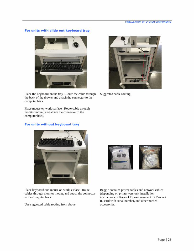
For units with slide out keyboard tray
Place the keyboard on the tray. Route the cable through
the back of the drawer and attach the connector to the
computer back.
Place mouse on work surface. Route cable through
monitor mount, and attach the connector to the
computer back.
Suggested cable routing
For units without keyboard tray
Place keyboard and mouse on work surface. Route
cables through monitor mount, and attach the connector
to the computer back.
Use suggested cable routing from above.
Baggie contains power cables and network cables
(depending on printer version), installation
instructions, software CD, user manual CD, Product
ID card with serial number, and other needed
accessories.
INSTALLATION OF SYSTEM COMPONENTS
Page | 27
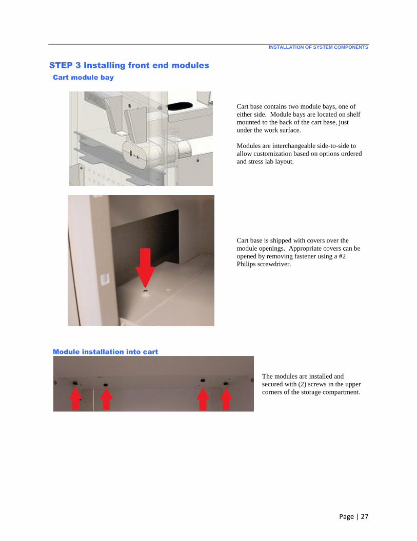
STEP 3 Installing front end modules
Cart module bay
Cart base contains two module bays, one of
either side. Module bays are located on shelf
mounted to the back of the cart base, just
under the work surface.
Modules are interchangeable side-to-side to
allow customization based on options ordered
and stress lab layout.
Cart base is shipped with covers over the
module openings. Appropriate covers can be
opened by removing fastener using a #2
Philips screwdriver.
Module installation into cart
The modules are installed and
secured with (2) screws in the upper
corners of the storage compartment.
INSTALLATION OF SYSTEM COMPONENTS
Page | 28
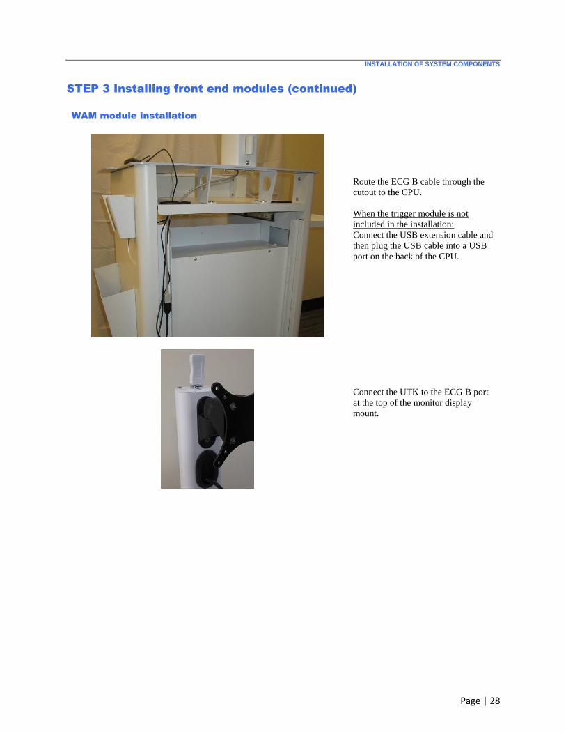
STEP 3 Installing front end modules (continued)
WAM module installation
Route the ECG B cable through the
cutout to the CPU.
When the trigger module is not
included in the installation:
Connect the USB extension cable and
then plug the USB cable into a USB
port on the back of the CPU.
Connect the UTK to the ECG B port
at the top of the monitor display
mount.

INSTALLATION OF SYSTEM COMPONENTS
Page | 29
STEP 3 Installing front end modules (continued)
For units with Trigger Module
Trigger module is shown installed flush with oval cutout located on side
of cart.
Trigger module front for AM12
connection to the ECG A connector
and one analog out connection.
Trigger module back supports (2)
analog out connections currently
non-functional, ECG B connector for
the UTK connection, (1) TTL out
connection, and USB PC connector.
RJ45 and LAN Isolation Adapter Connections (Optional)
Connect the LAN isolator adapter to
the RJ45 connection on CPU back
and connect the institution LAN
cable to the isolator. Then use the
Velcro to install it in a convenient
location.
INSTALLATION OF SYSTEM COMPONENTS
Page | 30
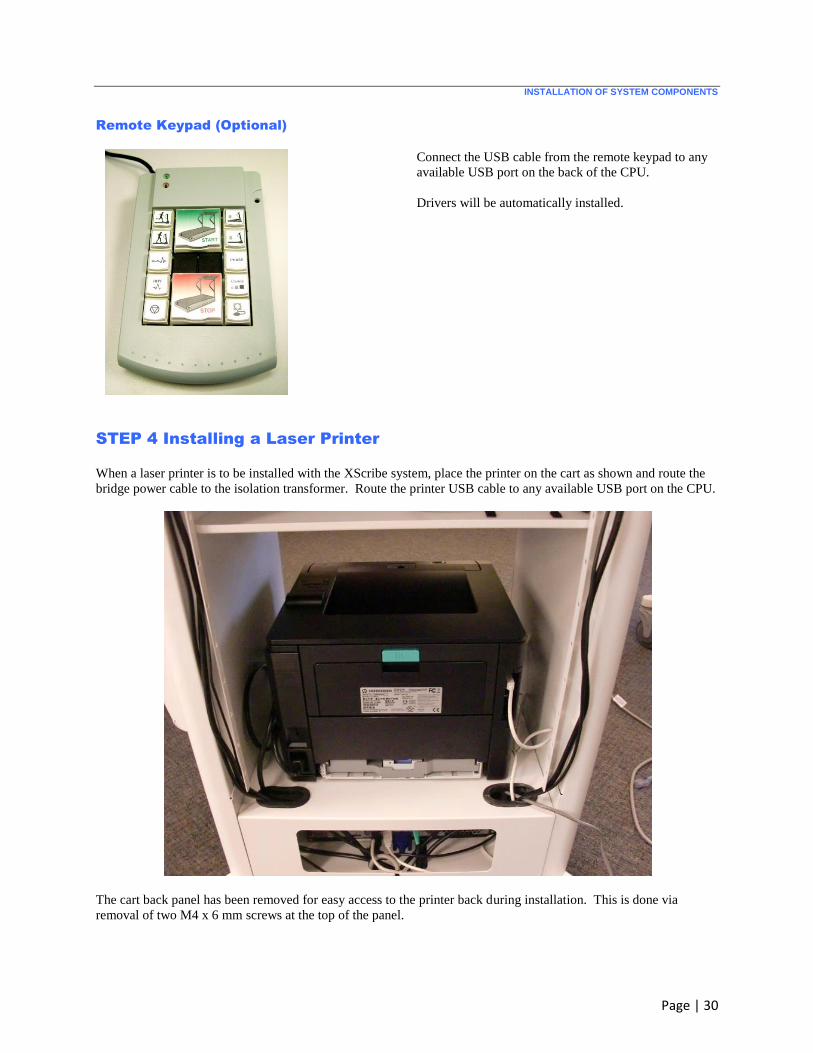
Remote Keypad (Optional)
Connect the USB cable from the remote keypad to any
available USB port on the back of the CPU.
Drivers will be automatically installed.
STEP 4 Installing a Laser Printer
When a laser printer is to be installed with the XScribe system, place the printer on the cart as shown and route the
bridge power cable to the isolation transformer. Route the printer USB cable to any available USB port on the CPU.
The cart back panel has been removed for easy access to the printer back during installation. This is done via
removal of two M4 x 6 mm screws at the top of the panel.
INSTALLATION OF SYSTEM COMPONENTS
Page | 31
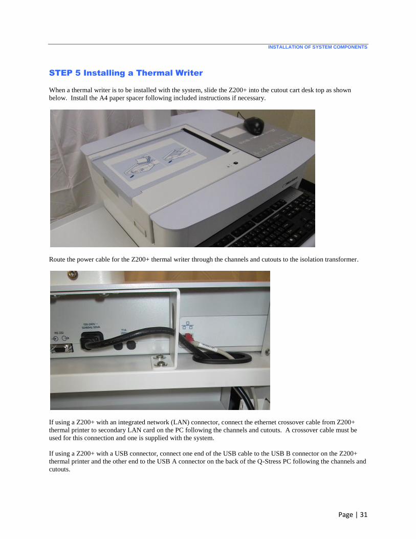
STEP 5 Installing a Thermal Writer
When a thermal writer is to be installed with the system, slide the Z200+ into the cutout cart desk top as shown
below. Install the A4 paper spacer following included instructions if necessary.
Route the power cable for the Z200+ thermal writer through the channels and cutouts to the isolation transformer.
If using a Z200+ with an integrated network (LAN) connector, connect the ethernet crossover cable from Z200+
thermal printer to secondary LAN card on the PC following the channels and cutouts. A crossover cable must be
used for this connection and one is supplied with the system.
If using a Z200+ with a USB connector, connect one end of the USB cable to the USB B connector on the Z200+
thermal printer and the other end to the USB A connector on the back of the Q-Stress PC following the channels and
cutouts.
INSTALLATION OF SYSTEM COMPONENTS
Page | 32
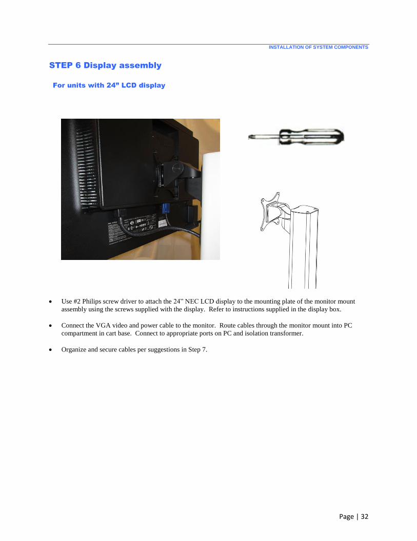
STEP 6 Display assembly
For units with 24” LCD display
Use #2 Philips screw driver to attach the 24” NEC LCD display to the mounting plate of the monitor mount
assembly using the screws supplied with the display. Refer to instructions supplied in the display box.
Connect the VGA video and power cable to the monitor. Route cables through the monitor mount into PC
compartment in cart base. Connect to appropriate ports on PC and isolation transformer.
Organize and secure cables per suggestions in Step 7.
INSTALLATION OF SYSTEM COMPONENTS
Page | 33
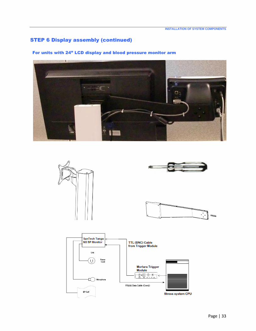
STEP 6 Display assembly (continued)
For units with 24” LCD display and blood pressure monitor arm

INSTALLATION OF SYSTEM COMPONENTS
Page | 34
STEP 6 Display assembly (continued)
The Tango BP monitor arm is bolted between the 24” LCD display and the monitor mount, placing the monitor
at the same height and depth as the LCD.
Tango BP monitor arm is interchangeable side-to-side to allow customization based on options ordered and
cardiac stress lab layout.
Use #2 Philips screw driver to attach the 24” LCD display to the mounting plate of the monitor mount assembly
using the screws supplied with the display. Refer to instructions supplied in the display box.
Connect the VGA video and power cable to the monitor. Route cables through the monitor mount into PC
compartment in cart base. Connect to appropriate ports on PC and isolation transformer.
Use #2 Philips screw driver to attach the Tango BP monitor to the arm using the 4x 8-32 screws supplied with
the arm. It may be helpful to connect power and data cables to the monitor before fastening to the arm.
Route and secure the Tango BP monitor cables to the trigger module and the PC as shown above and described
in the XScribe user manual SunTech Tango Interface section.
Organize and secure cables per suggestions in Step 7.
INSTALLATION OF SYSTEM COMPONENTS
Page | 35
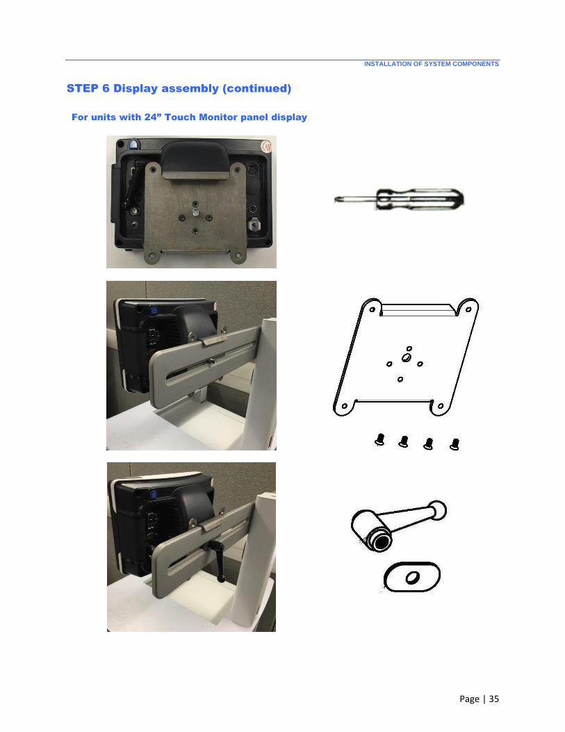
STEP 6 Display assembly (continued)
For units with 24” Touch Monitor panel display
INSTALLATION OF SYSTEM COMPONENTS
Page | 36
INSTALLATION OF SYSTEM COMPONENTS
Page | 37
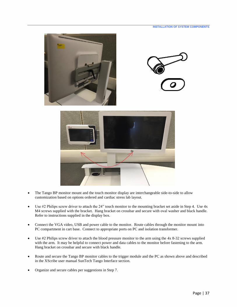
The Tango BP monitor mount and the touch monitor display are interchangeable side-to-side to allow
customization based on options ordered and cardiac stress lab layout.
Use #2 Philips screw driver to attach the 24” touch monitor to the mounting bracket set aside in Step 4. Use 4x
M4 screws supplied with the bracket. Hang bracket on crossbar and secure with oval washer and black handle.
Refer to instructions supplied in the display box.
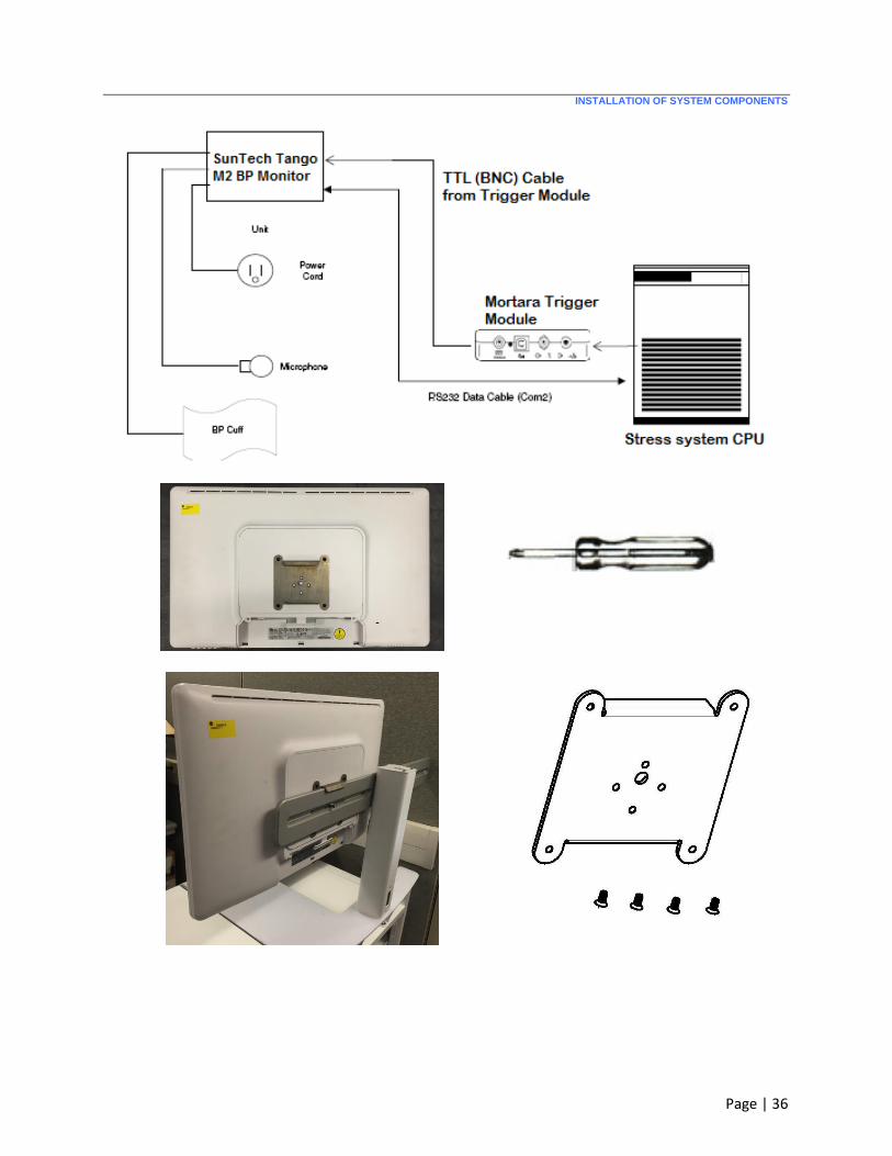
Connect the VGA video, USB and power cable to the monitor. Route cables through the monitor mount into
PC compartment in cart base. Connect to appropriate ports on PC and isolation transformer.
Use #2 Philips screw driver to attach the blood pressure monitor to the arm using the 4x 8-32 screws supplied
with the arm. It may be helpful to connect power and data cables to the monitor before fastening to the arm.
Hang bracket on crossbar and secure with black handle.
Route and secure the Tango BP monitor cables to the trigger module and the PC as shown above and described
in the XScribe user manual SunTech Tango Interface section.
Organize and secure cables per suggestions in Step 7.
INSTALLATION OF SYSTEM COMPONENTS
Page | 38
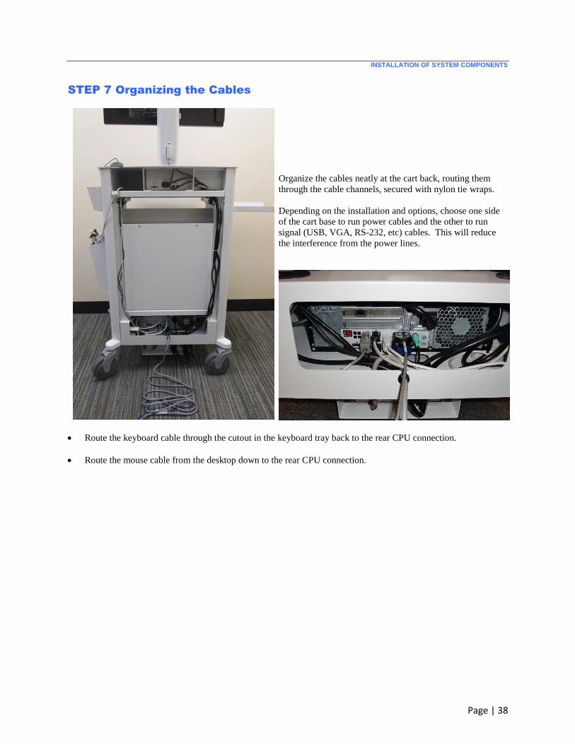
STEP 7 Organizing the Cables
Organize the cables neatly at the cart back, routing them
through the cable channels, secured with nylon tie wraps.
Depending on the installation and options, choose one side
of the cart base to run power cables and the other to run
signal (USB, VGA, RS-232, etc) cables. This will reduce
the interference from the power lines.
Route the keyboard cable through the cutout in the keyboard tray back to the rear CPU connection.
Route the mouse cable from the desktop down to the rear CPU connection.

INSTALLATION OF SYSTEM COMPONENTS
Page | 39
Supporting Information
The system serial number is available in the Programs
menu (Start All Programs Welch Allyn
Modality Manager Modality Manager Activation
Tool) and is also on the Product Identification card
label.
User manuals are electronically available on the
included User Manual CD. The appropriate language
PDF can be copied to the computer desktop for quick
access.
The software CD is also included.
A business card with your contact information can be
inserted in the mouse pad pocket.
A cardiac stress lead placement and prep poster is
included in a mailing tube.
Instruct the customer to place items in a safe and
convenient location.
Completed XScribe System with the LCD and Tango M2 Mounted
Finished Cart with the Z200+ Thermal Writer configuration, 24” LCD, SunTech Tango M2 BP monitor and
Computer components installed.

INSTALLATION OF SYSTEM COMPONENTS
Page | 40
Connect the Exercise Device
Treadmill
Connect the treadmill to the computer via the Serial cable provided (recommended) or USB cable. No further
preparation is needed.
Ergometer
Use the instructions that came with the ergometer device to connect it to the Stress computer.
Front-End Components
Material Supplied for Installation
Trigger Module (optional) includes
Trigger Module (30012-024-50, Qty 1)
Cable USB Type A-to-B Full Speed (6400-012)
AM12 patient cable ordered with system includes
AM12 Patient Cable (9293-048-54, Qty 1)
Stress Belt Assembly (8485-026-50, Qty 1)
Optional Kit to add Wireless ECG Acquisition
Optional WAM Kit (41000-036-50) includes:
WAM (30012-019-54)
UTK module with USB extension cable (30012-021-51 and 6400-015)
Carry Case with Belt (8485-026-50)
WAM holder for stress cart attachment (9911-023-43)
Optional Kit for Trigger Module Installation on the Treadmill Rail
TM55/TM65 Treadmill Rail Clamp Kit
Trigger Module Rail Clamp Kit (9911-022-50)
Includes installation instructions
XScribe Software Installation and Configuration
When a turnkey standalone configuration is purchased, software installation and activation are performed at the
factory prior to system shipment.
When a distributed configuration consisting of client workstations, review stations, and server systems is purchased,
software installation is performed on-site by authorized Welch Allyn personnel. Refer to the following pages for
instruction.
Refer to the XScribe User Manual (9515-209-50-ENG) for instructions on how to configure and operate the cardiac
stress testing application.

INSTALLATION OF SYSTEM COMPONENTS
Page | 41
System Setup (Windows 10 PC)
Do not power on the system.
AC Power Setup
Ensure that the input and output voltage settings on the isolation transformer are set appropriately for the local
power at 115V or 230V.
Verify that all components to be connected to the isolation transformer are able to accept the specified output
voltage. Reconfigure any components that require manual input voltage adjustments.
NOTE: Some components are auto switching and do not require you to set the proper voltage.
Then move the power switch to the on (I) position.
VISUAL INSPECTION
ATTENTION: The Computer is an ESD sensitive assembly. Use appropriate precaution when opening the
enclosure to inspect and handle the electronics.
Inspect the PC to ensure all internal hardware and cabling is properly assembled and nothing became
dislodged during the shipping process.
Connect the keypad, mouse, and display to the PC.
Connect the AC power cords to the appropriate components.
DO NOT connect the optional laser printer at this point in time
Completing the Windows 10 Installation
1. Power up the computer and allow the operating system to start. This should be the first time the computer has
been turned on since being received from the manufacturer. Final Installation of Windows 10 should begin
automatically.
At the “Hi there” screen, configure the Country or region, App Language, Keyboard layout, and Time Zone
options to their proper settings (per the customer preference) and then click on Next.
2. At the “Here’s the legal stuff” screen click Accept.
3. At the “Get going fast” screen click Customize Settings.
4. At the first “Customize settings” screen turn all “Personalization” and “Location settings” to Off and then click
on Next.
5. At the second “Customize settings” screen turn all “Connectivity and error reporting” to Off and then click on
Next.
6. At the third “Customize settings” screen set the “Browser protection and update” to Off and then click on Next.
7. At the “Create an account for this PC” screen type in a user name of temp. Type in a password of temp into
the 2 fields provided (password, retype password), enter tmp into the hint field and then click on Next.
WARNING: Only use letters, numerical digits, and the dash character when entering the Computer Name. If

INSTALLATION OF SYSTEM COMPONENTS
Page | 42
other characters are used, the Exam Manager Service may not operate properly when running the XScribe
application.
8. At the “Register and Protect” screen leave items blank and unselect all checkboxes then click on Next.
Windows loading will take approximately three minutes.
9. From the search box type “power” and then open the “Power & sleep settings”. Select “Additional power
settings” to open the “Power Options” window. Change When the Computer Sleeps. Set “Turn off the
display” and “Put the computer to sleep” to Never and Save Changes.
10. Turn off hybrid sleep by selecting Change advanced power settings select Sleep and then Allow hybrid
sleep, set all options to Off under Allow hybrid sleep. Click OK to return to Edit Plan Settings. Click on
Control Panel in the navigation window of the Edit Plan Settings.
11. In Control Panel, select Uninstall a Program in the Programs group. Postpone any reboots until you are
finished with all Uninstalls and the Windows Updates below.
a. The following programs must always be uninstalled. Right-click on each and select Uninstall. Follow
the prompts.
FoxitPhantomPDF
HP Registration Service
HP Support Assistant
HP Support Solutions Framework
HPLineDisplayUSBDriverWin7Vista64bit
OPOS for HP Line Display
Microsoft Office
b. Programs with names containing text similar to the following must NEVER be uninstalled:
Intel etc.
Microsoft.NET Framework etc.
Microsoft Visual C++ 20xx Redistributable etc.
Audio Driver etc.
Hardware Diagnostics etc.
c. Any non-Welch Allyn software that is installed MUST be configured to prevent ANY popup messages
that require user interaction during a XScribe exam, or that software should be uninstalled. Balloon
messages that dismiss themselves are allowed.
d. When finished, the minimal list of installed programs should be similar to the following:

INSTALLATION OF SYSTEM COMPONENTS
Page | 43
12. Close the “Programs and Features” window.
13. Disable automatic Windows updates.
1. Open the Run command (Win + R), in it type:gpedit.msc and press enter.
2. Navigate to:Computer Configuration -> Administrative Templates -> Windows Components -> Windows
Update
3. Open this and change the Configure Automatic Updates setting to ‘2 – Notify for download and notify for
install’
4. Open the Settings app (Win + I) and navigate to -> Update and Security -> Windows Updates. Click
‘Check for updates’. This applies the new configuration setting.
14. Shut down and restart the computer.
15. Ensure that the Boot Order in BIOS is set with the SATA hard drive listed first in the boot order. Refer to
computer manufacturer’s instruction for entering BIOS on startup and configuring Boot Order.
16. Right-click on the Start menu and select Properties. Select the Taskbar tab and uncheck Use Aero Peek to
preview the desktop.
INSTALLATION OF SYSTEM COMPONENTS
Page | 44
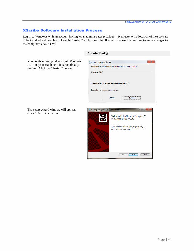
XScribe Software Installation Process
Log in to Windows with an account having local administrator privileges. Navigate to the location of the software
to be installed and double-click on the “Setup” application file. If asked to allow the program to make changes to
the computer, click “Yes”.
XScribe Dialog
You are then prompted to install Mortara
PDF on your machine if it is not already
present. Click the “Install” button.
The setup wizard window will appear.
Click “Next” to continue.
INSTALLATION OF SYSTEM COMPONENTS
Page | 45
XScribe Dialog
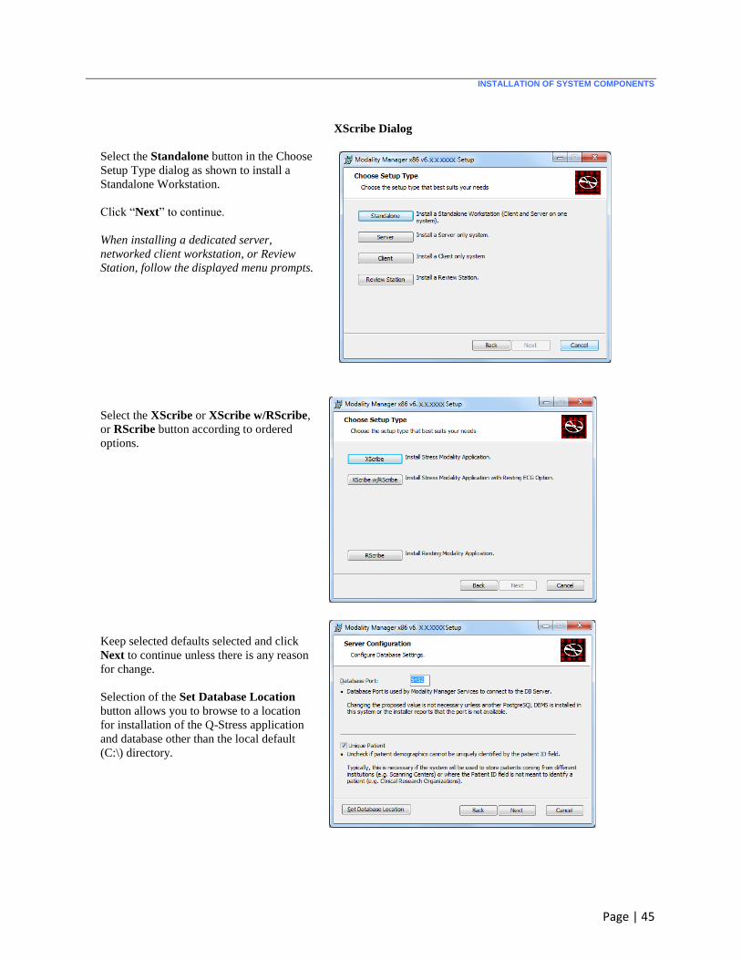
Select the Standalone button in the Choose
Setup Type dialog as shown to install a
Standalone Workstation.
Click “Next” to continue.
When installing a dedicated server,
networked client workstation, or Review
Station, follow the displayed menu prompts.
Select the XScribe or XScribe w/RScribe,
or RScribe button according to ordered
options.
Keep selected defaults selected and click
Next to continue unless there is any reason
for change.
Selection of the Set Database Location
button allows you to browse to a location
for installation of the Q-Stress application
and database other than the local default
(C:\) directory.
INSTALLATION OF SYSTEM COMPONENTS
Page | 46
XScribe Dialog
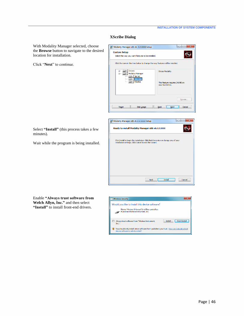
With Modality Manager selected, choose
the Browse button to navigate to the desired
location for installation.
Click “Next” to continue.
Select “Install” (this process takes a few
minutes).
Wait while the program is being installed.
Enable “Always trust software from
Welch Allyn, Inc.” and then select
“Install” to install front-end drivers.
INSTALLATION OF SYSTEM COMPONENTS
Page | 47
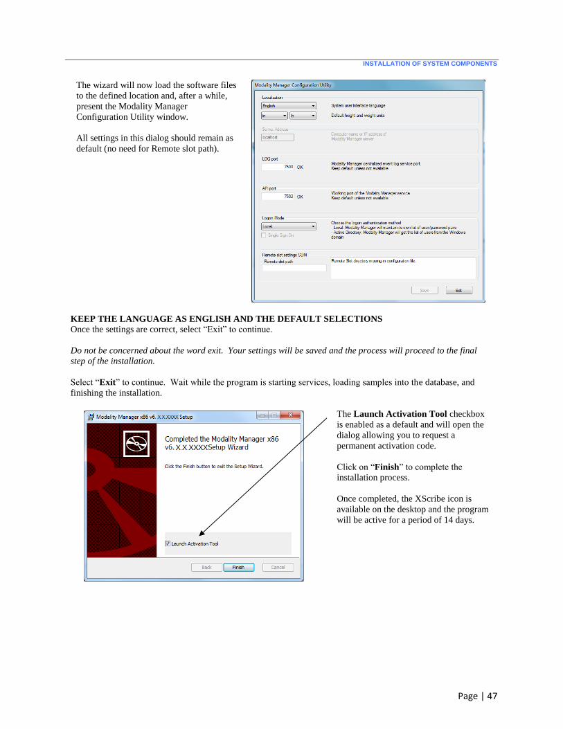
The wizard will now load the software files
to the defined location and, after a while,
present the Modality Manager
Configuration Utility window.
All settings in this dialog should remain as
default (no need for Remote slot path).
KEEP THE LANGUAGE AS ENGLISH AND THE DEFAULT SELECTIONS
Once the settings are correct, select “Exit” to continue.
Do not be concerned about the word exit. Your settings will be saved and the process will proceed to the final
step of the installation.
Select “Exit” to continue. Wait while the program is starting services, loading samples into the database, and
finishing the installation.
The Launch Activation Tool checkbox
is enabled as a default and will open the
dialog allowing you to request a
permanent activation code.
Click on “Finish” to complete the
installation process.
Once completed, the XScribe icon is
available on the desktop and the program
will be active for a period of 14 days.
INSTALLATION OF SYSTEM COMPONENTS
Page | 48
Activate the XScribe software
To prepare for permanent activation, navigate to the following menus if the Modality Manager Activation Tool is
not already open:
Start menu
All Programs
Welch Allyn Modality Manager
Modality Manager Activation Tool (click “Yes” when prompted to allow changes to the computer)
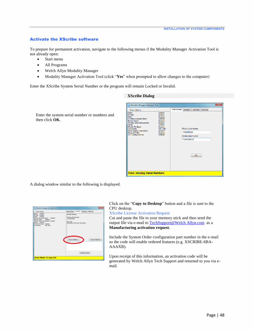
Enter the XScribe System Serial Number or the program will remain Locked or Invalid.
XScribe Dialog
Enter the system serial number or numbers and
then click OK.
A dialog window similar to the following is displayed.
Click on the “Copy to Desktop” button and a file is sent to the
CPU desktop.
XScribe License Activation Request
Cut and paste the file to your memory stick and then send the
output file via e-mail to TechSupport@Welch Allyn.com as a
Manufacturing activation request.
Include the System Order configuration part number in the e-mail
so the code will enable ordered features (e.g. XSCRIBE-6BA-
AAAXB).
Upon receipt of this information, an activation code will be
generated by Welch Allyn Tech Support and returned to you via e-
mail.

INSTALLATION OF SYSTEM COMPONENTS
Page | 49
XScribe License Activation
Start the Modality Manager Activation Tool if the dialog is not already displayed:
Start menu
All Programs
Welch Allyn Modality Manager
Modality Manager Activation Tool (click “Yes” when prompted to allow changes to the computer)
After 14-days have passed, the program becomes invalid as shown below.
Enter the received activation code into the large text box
located above the “Activate License” button.
Click the Activate License button and the Software License Status will show as Valid.

INSTALLATION OF SYSTEM COMPONENTS
Page | 50
Remove Unneeded Icons/Arrange Icons
Remove all unneeded icons from the desktop to reduce clutter for the customer by right clicking on the icon and
selecting the “Delete” option. The only required icons are: Recycle Bin and XScribe.
Arrange the icons on the desktop by right-clicking on an empty space on the desktop, and then select View►Auto
Arrange Icons.
Optional Laser Printer Configuration:
HP LaserJet Mx01
1. Use the installation disc that accompanies the HP Mx01printer to install the printer.
2. Once the printer is installed, click on Start►Devices and Printers. Right click on the HP LaserJet M50x
Series PCL 6 printer and then select Printer Properties.
3. Click on the Advanced tab and then select “New Driver” to add one of the following drivers based on whether
the PC is a 32 bit or 64 bit system.
PCL5 v5.4 32bit
PCL5 v5.4 64 bit
Note: The drivers can be found on the installation CD (QStress\Drivers\HPPCL5Drv).
4. Once the driver is loaded, be sure it is selected from the driver menu and click Apply.
5. While still on the Advanced tab, uncheck the Enable Advanced Printing Features checkbox, then click OK.
6. Right click on the HP LaserJet M50xSeries PCL 6 printer and then select Printing Preferences. Click on the
Paper/Quality tab. Under Print Quality, select 600 dpi and then set the default paper size to Letter for US
customers and to A4 for International customers.
7. Right click on the HP LaserJet M401 Series PCL 6 printer once again, select Printer Properties, and from
the General tab click on Print test page and verify it prints correctly.
Optional Touch Monitor Configuration
Elo Model ET2401L Touch monitor
1. Remove the cable cover on the back of the monitor to access the connector panel.
2. Connect 4 cables from monitor to CPU: VGA, Audio input, USB touch screen output, and DC power input.
INSTALLATION OF SYSTEM COMPONENTS
Page | 51
3. Reinstall the cable cover and secure with appropriate screws.
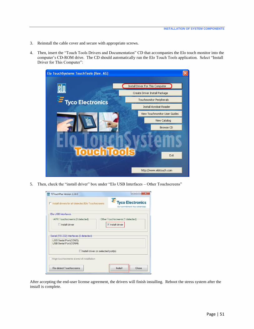
4. Then, insert the “Touch Tools Drivers and Documentation” CD that accompanies the Elo touch monitor into the
computer’s CD-ROM drive. The CD should automatically run the Elo Touch Tools application. Select “Install
Driver for This Computer”:
5. Then, check the “install driver” box under “Elo USB Interfaces – Other Touchscreens”
After accepting the end-user license agreement, the drivers will finish installing. Reboot the stress system after the
install is complete.

INSTALLATION OF SYSTEM COMPONENTS
Page | 52
Section 3 – XScribe Setup
Secondary Network Card IP Configuration for Q200+ Writer LAN Connection
1. On the XScribe PC, log in as Administrator.
2. Click Start > Settings > Control Panel.
3. Double click Network Connections.
4. Double click the appropriate Local Area Network icon. The Local Area Connection Properties
dialog box will appear.
5. In the items list, select Internet Protocol (TCPIP), and click Properties. The Properties dialog box
will appear.
Network settings are:
IP Address: 192.168.10.100
Subnet Mask: 255.255.255.0
Default Gateway: 192.168.10.1
6. Click OK in each dialog box to save the entries and exit.
Install Trigger Module (optional)
1. Attach the Trigger Module to one of the rear USB ports of the PC.
The Trigger Module driver is automatically installed for XScribe v6.x.x.
2. Allow Windows to automatically detect the device for the selected USB port.
Connect the UTK and Pair the WAM
1. If Trigger Module is not included, attach the UTK extension cable to one of the rear USB ports of the PC.
The UTK driver is automatically installed for XScribe v6.x.x.
2. If Trigger Module is included, attach the UTK to the ECG B connector on the Trigger Module.
Connect the AM12
1. If Trigger Module is not included, attach the AM12 patient cable to one of the rear USB ports of the PC.
The AM12 driver is automatically installed for XScribe v6.x.x.
2. If Trigger Module is included, attach the AM12 patient cable to the ECG A connector on the Trigger Module.
INSTALLATION OF SYSTEM COMPONENTS
Page | 53
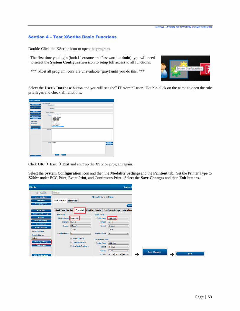
Section 4 – Test XScribe Basic Functions
Double-Click the XScribe icon to open the program.
The first time you login (both Username and Password: admin), you will need
to select the System Configuration icon to setup full access to all functions.
*** Most all program icons are unavailable (gray) until you do this. ***
Select the User’s Database button and you will see the” IT Admin” user. Double-click on the name to open the role
privileges and check all functions.
Click OK Exit Exit and start up the XScribe program again.
Select the System Configuration icon and then the Modality Settings and the Printout tab. Set the Printer Type to
Z200+ under ECG Print, Event Print, and Continuous Print. Select the Save Changes and then Exit buttons.
INSTALLATION OF SYSTEM COMPONENTS
Page | 54
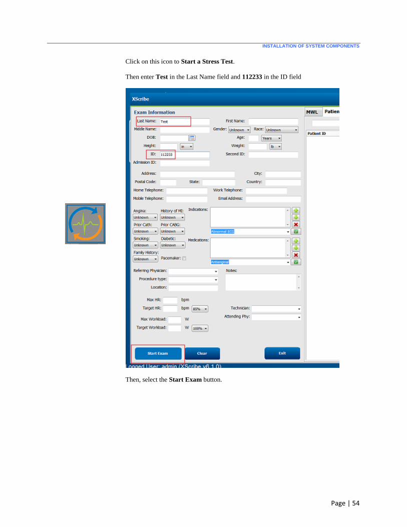
Click on this icon to Start a Stress Test.
Then enter Test in the Last Name field and 112233 in the ID field
Then, select the Start Exam button.
INSTALLATION OF SYSTEM COMPONENTS
Page | 55
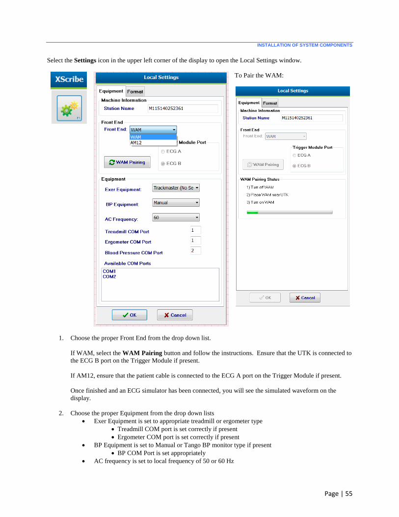
Select the Settings icon in the upper left corner of the display to open the Local Settings window.
To Pair the WAM:
1. Choose the proper Front End from the drop down list.
If WAM, select the WAM Pairing button and follow the instructions. Ensure that the UTK is connected to
the ECG B port on the Trigger Module if present.
If AM12, ensure that the patient cable is connected to the ECG A port on the Trigger Module if present.
Once finished and an ECG simulator has been connected, you will see the simulated waveform on the
display.
2. Choose the proper Equipment from the drop down lists
Exer Equipment is set to appropriate treadmill or ergometer type
Treadmill COM port is set correctly if present
Ergometer COM port is set correctly if present
BP Equipment is set to Manual or Tango BP monitor type if present
BP COM Port is set appropriately
AC frequency is set to local frequency of 50 or 60 Hz
INSTALLATION OF SYSTEM COMPONENTS
Page | 56
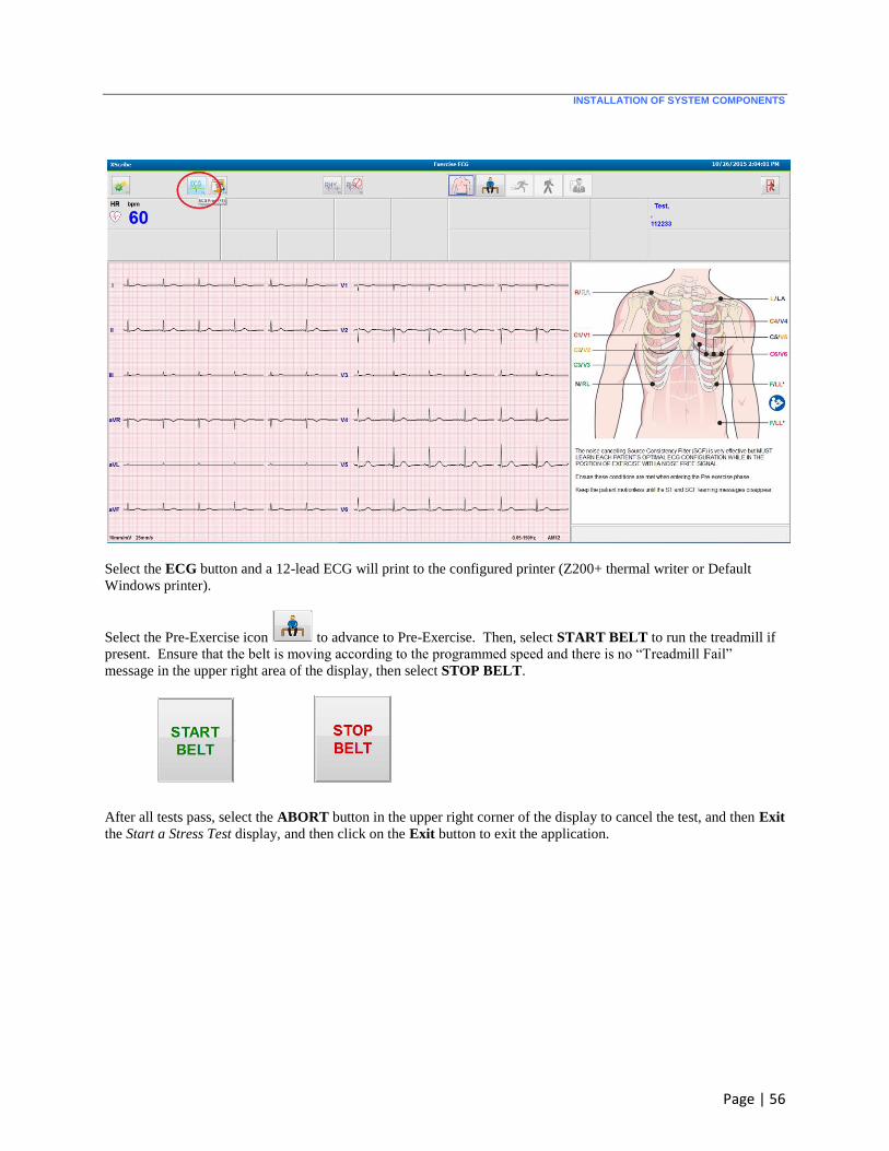
Select the ECG button and a 12-lead ECG will print to the configured printer (Z200+ thermal writer or Default
Windows printer).
Select the Pre-Exercise icon to advance to Pre-Exercise. Then, select START BELT to run the treadmill if
present. Ensure that the belt is moving according to the programmed speed and there is no “Treadmill Fail”
message in the upper right area of the display, then select STOP BELT.
After all tests pass, select the ABORT button in the upper right corner of the display to cancel the test, and then Exit
the Start a Stress Test display, and then click on the Exit button to exit the application.
Related Documents