Equipment Submittal Submersible Pumps and Control System
November 2014
Project: ………………… Fargo Lift Station
Marion County, Oregon
Owner: …………… Marion County Public Works
5155 Silverton Road
Salem, OR 97305
Tel: (503) 588-5036
Contact: Bob Pankrantz
Supplier: ……………… Xylem Water Solutions USA, Inc.
Flygt Products
2630 North Marine Drive
Portland, OR 97217
Tel: (503) 240-1980
Fax: (503) 240-3445

Page 1 of 2
Scope of Supply
Re: Marion County - Fargo LS retrofit
Pumps and Accessories
Qty Description
2 Flygt Model NP-3171.095 4" volute Submersible pump equipped with a 460 Volt
/ 3 phase / 60 Hz 35 HP 3550 RPM motor, 278 impeller, 1 x 50 Ft. length of
submersible cable, FLS leakage detector, volute is prepared for Flush Valve
1 Startup and training by factory trained technician
2 4” discharge connection
2 2” x 4” intermediate guide bar bracket
2 2” upper guide bar bracket
2 SS kellems grip for cable.
Level Sensors and Accessories
Qty Description
1 Level transducer, 0-5M range, 39’ cable
2 Flygt ENM-10 float sensor, 40’ cable
2 Flygt Chain sling unit with grip eye
1 Cable holder, stainless steel
Xylem Water Solutions USA, Inc. Flygt Products
2630 North Marine Dr
Portland, Oregon 97217
Tel (503) 240-1980
Fax (503) 240-3445

Page 2 of 2
Controls
Qty Description
1 Duplex control panel for use with 35 hp, 460 volt, 3 phase pumps and including the following features:
Type 4 floor mounted enclosure Inner door interlocked main circuit breaker Pump circuit breaker for each pump Flygt SmartRun variable speed drives 3 phase surge arrestor Control power transformer Anti-condensation heater with thermostat Current transformers for each pump Inner door mounted components:
o High level indicator o Overflow indicator o Power OK indicator o 15A GFCI duplex receptacle
Inner door mounted components for each pump: o Run indicator o Elapsed time meter
DC power supply and battery backup for controller Red alarm beacon light Audible alarm Dry alarm output contacts for SCADA interfacing:
o High level o Pump 1 fail o Pump 2 fail o Power fail
Space allowance for existing radio Wires numbered Terminal blocks, control relays and circuit breakers as required UL508A listed
1 Pump disconnect panel including the following features: Type 4X 304ss wall mounted enclosure Anti-condensation heater with thermostat Single channel analog barrier Four channel intrinsically safe barrier Three Flygt ENM-10 float sensors, 30’ cable One level transducer, 0-5M range, 39’ cable Terminal blocks as required Wires numbered UL698A listed

TABLE OF CONTENTS
Section 1 Submersible Pumps Pump Technical Data and Performance Curve Dimensional Drawing Power Cable Data Performance Specification
Section 2 Submersible Pumps Accessories Discharge Connection Upper Guide Bar Bracket Intermediate Guide Bar Bracket Flygt Grip Eye Unit Cable Grip
Section 3 Level Sensors and Accessories Level Transducer** Float Level Sensor** Cable Holder Chain Sling and Grip Eye
Section 4 Pump Controls Control Drawings Pump Control Panel Bill of Materials Pump Control Panel Component Data Sheets Pump Disconnect Panel Bill of Materials Pump Disconnect Panel Component Data Sheets
Section 5 Warranty and Service Warranty Service Locations Contact List
** Included in Section 4

Section 1 Submersible Pumps

Patented self cleaning semi-open channel impeller, ideal f or pumping inwaste water applications. Possible to be upgraded with Guide-pin®f or ev en better clogging resistance. Modular based design with highadaptat ion grade.
Head
278 168mm278 168mm
61.2%
0
10
20
30
40
50
60
70
80
90
100
110
120
130
140
150
160
170
180
190
200
[f t]
0 100 200 300 400 500 600 700 [US g.p.m.]
Impeller
Frequency
Motor
Rated v oltage
-
Rated power
Rated speed
Number of poles
Rated current
460 V60 Hz
35 hp
2
3530 1/min
40 A
NP 3171 SH 3~ 278
Motor #
3~
Suction Flange Diameter
Dimensional drwgNP, FP 3171. 091, 095, 181, 185, 350, 390 SH
2" GUIDE BARS FOR NEW INSTALLATION 3" GUIDE BARS FOR RETROFIT * DIMENSION TO END OF GUIDE BARS * * DIMENSION FOR 2"/3" GUIDE BARS
NP,FP 3171.091, 095, 181, 185, 350, 390 SH
MIN
LEV
EL
(TO FURTHEST POINT)
REF.LINE
DN100
REF.LINE
GUIDE BARS
Z Z
Z Z VIEW
MIN
CL
OF
DIS
CH
*
**72/22
200
100
250
476 **561/610
**85/135
2"/3"
116
249
60 **
326/
265
400
292
84 99
5
70
1046 **770/820
209
168 168
209
209
209
45°
BOLT Ø20(4x)
Impeller diameter 168 mmNumber of blades 2
N3171.095 25-18-2AA-W 35hpStator v ariant 9
Phases
Starting current 292 A
Technical specification
Note: Picture might not correspond to the current configuration.
Power f actor
Ef f ic iency
1/1 Load3/4 Load1/2 Load
1/1 Load3/4 Load1/2 Load
0.910.890.82
91.0 %91.5 %92.0 %
100 mmCurve according to: ISO 9906 grade 2 annex 1 or 2
P - Semi permanent, WetInstallation:
Configuration
Impeller material Hard-Iron ™
General
Discharge Flange Diameter 100 mm
Water, pure
Last updateCreated on
2014-11-11Created byProject IDProject

Head
EfficiencyTotal efficiency
Shaft power P2Power input P1
NPSH-values
278 168mm278 168mm
61.2%
135 ft
53.8 %
49.5 %
19.3 hp
20.9 hp
14 ft 304 US g.p.m.
278 168mm278 168mm
135 ft
53.8 %
49.5 %
19.3 hp
20.9 hp
14 ft 304 US g.p.m.
278 168mm278 168mm
135 ft
53.8 %
49.5 %
19.3 hp
20.9 hp
14 ft 304 US g.p.m.
278 168mm (P2)278 168mm (P2)
135 ft
53.8 %
49.5 %
19.3 hp
20.9 hp
14 ft 304 US g.p.m.
278 168mm (P1)278 168mm (P1)
135 ft
53.8 %
49.5 %
19.3 hp
20.9 hp
14 ft 304 US g.p.m.
278 168mm278 168mm
135 ft
53.8 %
49.5 %
19.3 hp
20.9 hp
14 ft 304 US g.p.m.
0102030405060708090
100110120130140150160170180190200
[ft]
01020304050
[%]
14
16
18
20
[hp]
101520253035[ft]
0 50 100 150 200 250 300 350 400 450 500 550 600 650 700 750 800 [US g.p.m.]
Motor #
60 Hz
Phases 3~
460 VNumber of poles 2
Rated power 35 hp
Starting currentRated current 40 A
Rated speed 3530 1/min
N3171.095 25-18-2AA-W 35hpStator variant
Number of blades 2
Power factor
NP 3171 SH 3~ 278
Suction Flange Diameter
Performance curvePump
Impeller diameter 168 mm
Motor
Rated voltage
292 A
Efficiency
1/1 Load3/4 Load1/2 Load
1/1 Load3/4 Load1/2 Load
Frequency9 0.91
91.0 %
0.890.82
91.5 %92.0 %
100 mm
Curve according to: ISO 9906 grade 2 annex 1 or 2
Discharge Flange Diameter 100 mm
Water, pure
Last updateCreated on
2014-11-11Created byProject IDProject
Head
278 168mm
61.2%
135 ft
304 US g.p.m.0
5
10
15
20
25
30
35
40
45
50
55
60
65
70
75
80
85
90
95
100
105
110
115
120
125
130
135
140
145
150
155
160
165
170
175
180
185
190
195
200
205
210
[ft]
0 50 100 150 200 250 300 350 400 450 500 550 600 650 700 750 800 [US g.p.m.]
1
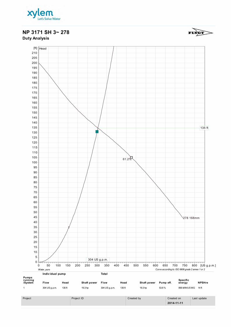
NP 3171 SH 3~ 278Duty Analysis
Curve according to: ISO 9906 grade 2 annex 1 or 2
Indiv idual pump Total
1 304 US g.p.m. 135 ft 19.3 hp 304 US g.p.m. 135 ft 19.3 hp 53.8 % 856 kWh/US MG 14 ft
Pumps running Specific /System Flow Head Shaft power Flow Head Shaft power Pump eff. energy NPSHre
Water, pure
Last updateCreated on
2014-11-11Created byProject IDProject

Head
EfficiencyTotal efficiency
Shaft power P2Power input P1
NPSH-values
278 168mm278 168mm
61.2%
55 Hz55 Hz
61.2%
50 Hz50 Hz
61.2%
45 Hz45 Hz
61.2%
40 Hz40 Hz
61.2%
278 168mm278 168mm55 Hz55 Hz50 Hz50 Hz45 Hz45 Hz40 Hz40 Hz 278 168mm278 168mm55 Hz55 Hz50 Hz50 Hz45 Hz45 Hz40 Hz40 Hz
278 168mm (P2)278 168mm (P2)
55 Hz55 Hz
50 Hz50 Hz
45 Hz45 Hz40 Hz40 Hz
278 168mm (P1)278 168mm (P1)
55 Hz55 Hz
50 Hz50 Hz
45 Hz45 Hz40 Hz40 Hz
278 168mm278 168mm
55 Hz55 Hz50 Hz50 Hz
45 Hz45 Hz40 Hz40 Hz
0
10
20
30
40
50
60
70
80
90
100
110
120
130
140
150
160
170
180
190
200
[ft]
0
10
20
30
40
50
[%]
0
4
8
12
16
20
[hp]
5
10
15
20
25
30
35
[ft]
0 50 100 150 200 250 300 350 400 450 500 550 600 650 700 750 800 [US g.p.m.]
NP 3171 SH 3~ 278VFD Curve
Curve according to: ISO 9906 grade 2 annex 1 or 2Water, pure
Last updateCreated on
2014-11-11Created byProject IDProject
Head
278 168mm
61.2%
135 ft
304 US g.p.m.
55 Hz
61.2%
50 Hz
61.2%
45 Hz
61.2%
40 Hz
61.2%
05
101520253035404550556065707580859095
100105110115120125130135140145150155160165170175180185190195200205210
[ft]
0 50 100 150 200 250 300 350 400 450 500 550 600 650 700 750 800 [US g.p.m.]
1
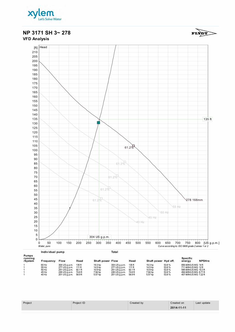
NP 3171 SH 3~ 278VFD Analysis
Curve according to: ISO 9906 grade 2 annex 1 or 2
Indiv idual pump Total
1 60 Hz 304 US g.p.m. 135 ft 19.3 hp 304 US g.p.m. 135 ft 19.3 hp 53.8 % 856 kWh/US MG 14 ft1 55 Hz 277 US g.p.m. 111 ft 14.5 hp 277 US g.p.m. 111 ft 14.5 hp 53.8 % 711 kWh/US MG 12 ft1 50 Hz 251 US g.p.m. 92.1 ft 10.9 hp 251 US g.p.m. 92.1 ft 10.9 hp 53.8 % 595 kWh/US MG 10.3 ft1 45 Hz 226 US g.p.m. 74.6 ft 7.94 hp 226 US g.p.m. 74.6 ft 7.94 hp 53.8 % 494 kWh/US MG 8.71 ft1 40 Hz 201 US g.p.m. 58.9 ft 5.57 hp 201 US g.p.m. 58.9 ft 5.57 hp 53.8 % 407 kWh/US MG 7.22 ft
Pumps running Specific /System Frequency Flow Head Shaft power Flow Head Shaft power Hyd eff. energy NPSHre
Water, pure
Last updateCreated on
2014-11-11Created byProject IDProject

NP 3171 SH 3~ 278Dimensional drawing
Dimensional drwgNP,FP 3171.091,095,181,185,350,390 SH
2" GUIDE BARS FOR NEW INSTALLATION 3" GUIDE BARS FOR RETROFIT * DIMENSION TO END OF GUIDE BARS ** DIMENSION FOR 2"/3" GUIDE BARS
NP,FP 3171.091, 095, 181, 185, 350, 390 SH
MIN
LEV
EL
(TO FURTHEST POINT)
REF.LINE
DN100
REF.LINE
GUIDE BARS
Z Z
Z Z VIEW
MIN
CL O
F DI
SCH
*
**72/22
200
100
250
476 **561/610
**85/135
2"/3"
116
249
60 **
326/
265
400
292
84 99
5
70
1046 **770/820
209
168 168
209
209
209
45°
BOLT Ø20(4x)
Last updateCreated on
2014-11-11Created byProject IDProject

2012‐10
‐12
Flyygt Suubmer
rsible
Motorr Cablles
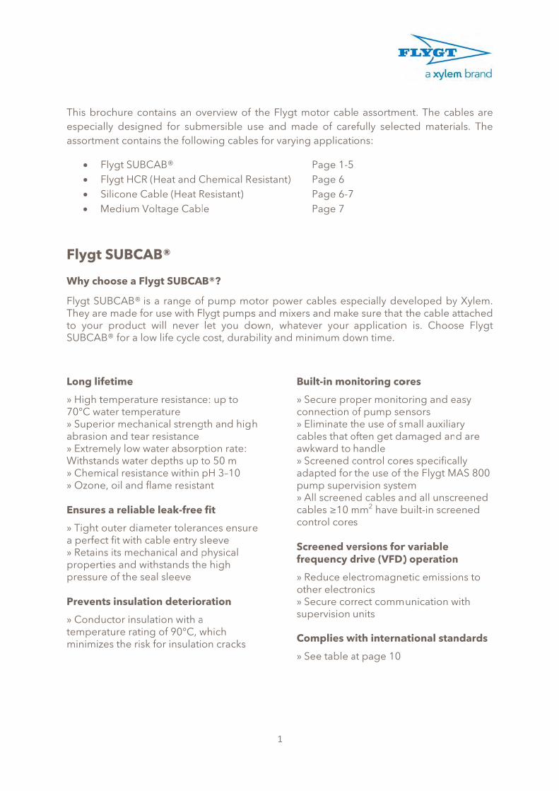
This broespeciaassortm
S
Flygt
Why ch
Flygt SUThey arto yourSUBCA
Long lif
» High t70°C wa» Superabrasio» ExtremWithsta» Chem» Ozone Ensures
» Tight a perfec» Retainpropertpressur Preven
» Condtemperminimiz
ochure conally designe
ment contain
Flygt SUBCFlygt HCR (Silicone CaMedium Vo
t SUBCA
hoose a Fly
UBCAB® is re made forr product wB® for a low
fetime
temperaturater temperior mechann and tear
mely low waands water d
mical resistae, oil and fl
s a reliable
outer diamct fit with cans its mechaties and witre of the sea
nts insulatio
uctor insularature ratingzes the risk
ntains an oved for subns the follo
CAB® (Heat and Cable (Heat Roltage Cabl
AB®
ygt SUBCA
a range ofr use with Fwill never w life cycle
re resistancerature nical strengresistance ater absorpdepths up tnce within ame resista
e leak-free
meter toleraable entry sanical and pthstands theal sleeve
on deterio
ation with ag of 90°C, wfor insulati
verview of mersible uwing cable
Chemical ReResistant) le
AB®?
f pump molygt pumpslet you docost, durab
e: up to
gth and high
ption rate: to 50 m pH 3–10 ant
fit
nces ensuresleeve physical e high
ration
a which on cracks
1
the Flygt mse and ma
es for varyin
esistant)
otor power s and mixerown, whatebility and m
h
e
B
» co» caaw» adp» caco Scfr
» ot» su C
»
motor cablade of careng applicati
Page 1-5Page 6 Page 6-7Page 7
cables esprs and makever your
minimum do
uilt-in mon
Secure proonnection oEliminate tables that owkward to Screened cdapted for ump superAll screeneables ≥10 montrol core
creened verequency d
Reduce elether electroSecure cor
upervision
Complies w
See table a
e assortmeefully selecons:
pecially deve sure that application
own time.
nitoring co
oper monitoof pump sehe use of s
often get dahandle control corethe use of tvision syste
ed cables amm2 have bs
ersions fordrive (VFD)
ectromagneonics rrect communits
with interna
at page 10
ent. The cacted materi
veloped bythe cable a
n is. Choos
ores
oring and eensors mall auxiliaamaged an
es specificathe Flygt Mem nd all unsc
built-in scre
r variable ) operation
etic emissio
unication w
ational stan
bles are als. The
y Xylem. attached se Flygt
easy
ary d are
ally MAS 800
reened eened
n
ons to
with
ndards

Genera
Flygt Sproduct For remwith cocontrol with tw800 pum
The scrunwantquarries
FeatureMax. shand instemperOuter sheathimateriaConducinsulatiomateria
ConducmateriaRated V(phase tearth, pto phasMore informa
al propertie
UBCAB® its in applic
mote pump ontrol cores
solution ofisted pair omp supervi
reened Flyed electros, and indu
e Fheath ulation
rature
7(A
ng al
Cty
ctor on
al
Hrupnta
ctors al
C
Voltage to
phase se)
E64N
ation FMM
es for Flyg
s designedations whe
control, Fls. You onlyf a motor cof screenedision system
ygt SUBCAmagnetic r
ustrial areas
Flygt SUBC70 °C and 9AWG 60 °C
Chlorinatedype: 5GM5
High densityubber (HEP
propylene rnumbers maable below
Copper stra
Europe: ≥ 1600/1000 V450/750 V North AmerFlygt standaM1997.47.0M1997.47.0
t SUBCAB®
d for use re the amb
ygt providey need onable plus ad control cm.
AB® is usedradiation. T.
AB® 0 °C
C and 90 °C
polyethyle)
y ethylene-PR/3GI3) orubber (EPRarked * in th have EPR, nds
0 mm2 and. Remaining
rica and Caard docume0004, M1990024
2
®
with standbient tempe
es a simplee cable in
a separate cores specif
d with VarTypical app
C)
ene rubber
propylene r Ethylene-R/3GI3). Parhe assortmthe rest HE
d 7G6+s(2xg models:
nada: 600 Vents
97.47.0009,
dard and eerature doe
e and reliabstead of ucontrol cabfically adap
riable Freqplications f
Scr70 °(AW
(CPE Chlrub
rt ent
EPR.
Higpro
Copscre
x0,5):
V
EurNor600
FlygM1
explosion ps not excee
ble solutionsing the cle. The ran
pted for the
quency Drivfor this cab
eened Flyg°C and 90 °
WG 60 °C an
orinated pober (CPE ty
h density eopylene rub
pper strandeened tinneope: 600/1rth America0 V
gt standard997.47 002
proof submed 70°C.
n through itconventiona
ge includee use of Fly
ves (VFD) ble include
gt SUBCAB°C nd 90 °C)
olyethyleneype: 5GM5
ethylene-bber (HEPR/
ds includinged copper 1000 V a and Cana
d document23
mersible
ts cables al pump s cables
ygt MAS
to limit e mines,
B®
e )
/3GI3)
g wires
da:
t

S
Flygt S
Type
3 core
4 core
** See p
Fig. 1
SUBCAB®10-35 mm
Fig. 4
Screened SUB2,5-50 mm
UBCAB® a
Denomin(mm
3G1
3G2
4G1
4G2
4G4
4G6
page 9
® m2
BCAB® m2
ssortment
nation m2)
F
.5
.5
.5
.5
4
6
Sc
Part No.(* EPR)
lygt SUBCA
94 20 40*
94 19 31*
94 20 41*
94 20 42*
94 20 43*
94 20 44*
3
Fig. 2 SUBCAB®
50-120 mm2
Fig. 5
creened SUBC70-120 mm2
Nominal current
capacity at 30°C (Amp)**
AB® without
23
32
23
32
42
54
2
CAB® 2
Outer diamete
(mm)
control cor
10 - 11
11 - 12
10.5 - 11.
12.5 - 13.
16 - 17
18 - 19
Scre
control e
r Weightkg/m
es
0.16
0.24
5 0.20
5 0.28
0.44
0.57
Fig. 3
ened SUBCA1,5 mm2
Fig. 6
SUBCAB® lement desig1,2,3 and 5
t Bendingradius (cm)
10
11
10
12
16
18
B®
n in fig.
g Fig. No.

Type
4 core
7 core
** See p
Denomin(mm
4G1.5 +
4G2.5 +
4G4 + 2
4G6 + 2
4G10 + S
4G16 + S
4G25 + S
4G35 + S
3x50 + 2GS(2x0
3x70 + 2GS(2x0
3x95 + 2GS(2x0
3x120 + 2GS(2x0
7G2.5 +
7G4 + 2
7G6 + S(
page 9
nation m2)
2x1.5 9
2x1.5 9
2x1.5 9
2x1.5 9
S(2x0.5) 9
S(2x0.5) 9
S(2x0.5) 9
S(2x0.5) 9
G35/2 + 0.5) 9
G35/2 + 0.5) 9
G50/2 + 0.5) 9
G70/2 + 0.5) 9
2x1.5 9
2x1.5 9
2x0.5) 9
Part No.(* EPR)
Flygt SUBC
94 20 61*
94 20 59*
94 20 60*
94 20 56*
94 19 81
94 19 82
94 19 83
94 19 84
94 19 85
94 19 86
94 19 87
94 19 88
94 20 82*
94 20 80*
94 19 80
4
Nominal current
capacity at 30°C (Amp)**
CAB® with co
23
32
42
54
75
100
127
157
192
246
298
346
32
42
54
Outer diameter
(mm)
ontrol cores
15 - 16
17 - 18
20 - 22
24 - 26
24 - 26
26 - 28
32 - 34
35 - 37
35 - 37
38 - 41
47 - 50
54 - 56
20 - 22
22 – 24
24 - 26
Weightkg/m
s
0.32
0.43
0.63
0.83
0.85
1.30
1.70
2.24
2.60
3.30
4.50
5.70
0.60
0.84
0,85
t Bendingradius (cm)
15
17
20
24
26
26
32
35
35
38
47
54
20
22
24
g Fig.No.
1
1
1
1
2
2
2
2
Temp
Tempe
The curIf the amhandle accordi
Examp
Select c
• Sele
Calc
Cho
Ambien
Accord
Am
21-25
26-30
31-35
36-40
41-45
46-50
51-55
56-60
61-70
MaxiThe ma
Examp
Flygt SUweighs
Bend
The min
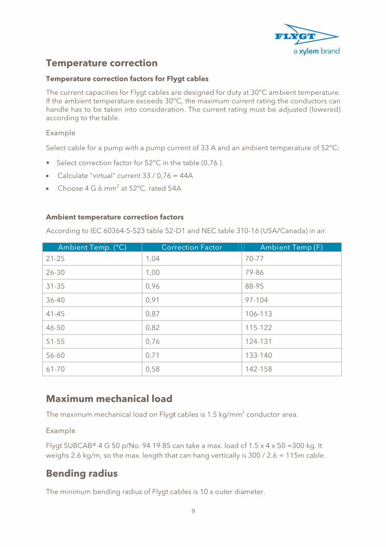
perature
rature corr
rrent capacmbient temhas to be tng to the ta
le
cable for a p
ect correctio
culate "virtu
oose 4 G 6 m
nt tempera
ing to IEC 6
bient Tem
mum mximum me
le
UBCAB® 4 G2.6 kg/m, s
ding rad
nimum ben
e correct
rection fac
ities for Flymperature e
taken into able.
pump with
on factor fo
ual" current
mm2 at 52°
ature corre
60364-5-52
p. (°C)
echanicchanical loa
G 50 p/No.so the max.
ius
nding radius
tion
ctors for Fly
gt cables axceeds 30°considerati
a pump cu
or 52°C in th
t 33 / 0,76 =
C. rated 54
ection facto
23 table 52-
Cor
1,04
1,00
0,96
0,91
0,87
0,82
0,76
0,71
0,58
cal load
ad on Flygt
. 94 19 85 c
. length tha
s of Flygt ca
9
ygt cables
re designe°C, the maxion. The cu
rrent of 33
he table (0,
= 44A
4A
ors
-D1 and NE
rection Fac
t cables is 1
can take a mat can hang
ables is 10
d for duty aximum currurrent rating
A and an a
76 ).
EC table 31
ctor
1.5 kg/mm2
max. load o vertically is
x outer dia
at 30°C ament rating tg must be a
ambient tem
0-16 (USA/
Ambi
70-77
79-86
88-95
97-104
106-113
115-122
124-131
133-140
142-158
conductor
f 1.5 x 4 x 5s 300 / 2.6
meter.
bient tempthe conducadjusted (lo
mperature o
/Canada) in
ent Temp
r area.
50 =300 kg= 115m ca
perature. ctors can owered)
of 52°C:
n air.
(F)
. It ble.

FlygtFlygt SU
IEC 602
IEC 602
IEC 608
IEC 608
IEC 603
IEC 603
IEC 603
CSA C2
UL 1581
CCC.GB
EN 505
Othe
Cable T
Flygt HC
Flygt HC
Flygt HC
Flygt HC
Silicone
Silicone
Medium
Medium
Medium
t SUBCAUBCAB® ca
Standard
245
228 class 5
811-1-1 CLA
811-2-1 CLA
332-1
332-2
364-5-523
22.2 No.49-
1
B5013/IEC6
25-2-21
r cables
Type
CR
CR
CR
CR
e cable
e cable
m voltage c
m voltage c
m voltage c
AB® stanables comp
d
AUSE 9
AUSE 10
-1992
60245
s standa
Sta
IEC
IEC
SS
NE
VD
IEC
able DI
able DI
able DI
dards aly with the
TypeFlexible cain general
Conducto
Oil resistan
Oil resistan
Flame reta
Flame reta
Current
Flexible cain general
Flexible cain general
Flexible cain general
Flexible cain general
rds and
andard/Ap
C 60287
C 60332-3
S 424 02 46
EMA WC 27
DE 0207
C 60332-1
N VDE 250
N VDE 298
N VDE 207
10
and apprfollowing g
e able VD
r VD
nt VD
nt VD
ardant VD
ardant VD
VD
able VD
able HD
able EN
able EN
d approv
pproval
Cat A
7500
0
8 part 4
7
rovals general stan
Standa
DE 0207 pa
DE 0250
DE 0282 pa
DE 0472 pa
DE 0472 pa
DE 0295
DE 0298
DE 0472
D 22.4
N 50525-2-2
N 50363-1:2
vals
Type
Curren
Flame
Condu
Materi
Curren
Flame
Materi
Curren
Insulat
ndards:
ard
rt 20
rt 810
rt 803-A
rt 804-B
21
2005
nt rating
retardant
uctor insula
ial
nt rating
retardant
ial
nt rating
tion materia
Typ
Material
Material
Material
Oil resista
Flame ret
Conducto
Current
Testing
Flexible cgeneral
Cables fosubmersi
Material
ation mater
al
pe
ant
tardant
or
cable in
or ble use
ial

NP3171.095 SPECIFICATIONS REQUIREMENTS Furnish and install 2 submersible non-clog wastewater pump(s). Each pump shall be equipped with an 35 HP submersible electric motor, connected for operation on 460 volts, phase, 60 hertz service, with 50 feet of submersible cable (SUBCAB) suitable for submersible pump applications. The power cable shall be sized according to NEC and ICEA standards and also meet with P-MSHA Approval. The pump shall be supplied with a mating cast iron 4 inch discharge connection and be capable of delivering 300 GPM at 131 TDH. Each pump shall be fitted with chain sling unit and Flygt grip eye. The working load of the lifting system shall be 50% greater than the pump unit weight. PUMP DESIGN CONFIGURATION The pump shall be supplied with a mating cast iron __4___ inch discharge connection and be capable of delivering __300__ GPM at _131__ FT. TDH. The pump(s) shall be automatically and firmly connected to the discharge connection, guided by no less than two guide bars extending from the top of the station to the discharge connection. There shall be no need for personnel to enter the wet-well. Sealing of the pumping unit to the discharge connection shall be accomplished by a machined metal to metal watertight contact. Sealing of the discharge interface with a diaphragm, O-ring or profile gasket will not be acceptable. No portion of the pump shall bear directly on the sump floor. Each pump shall be fitted with chain sling unit and grip eye. PUMP CONSTRUCTION Major pump components shall be of grey cast iron, ASTM A-48, Class 35B, with smooth surfaces devoid of blow holes or other irregularities. The lifting handle shall be of stainless steel. All exposed nuts or bolts shall be of stainless steel construction. All metal surfaces coming into contact with the pumpage, other than stainless steel or brass, shall be protected by a factory applied spray coating of acrylic dispersion zinc phosphate primer with a polyester resin paint finish on the exterior of the pump. Sealing design shall incorporate metal-to-metal contact between machined surfaces. Critical mating surfaces where watertight sealing is required shall be machined and fitted with Nitrile rubber O-rings. Fittings will be the result of controlled compression of rubber O-rings in two planes and O-ring contact of four sides without the requirement of a specific torque limit. Rectangular cross sectioned gaskets requiring specific torque limits to achieve compression shall not be considered as adequate or equal. No secondary sealing compounds, elliptical O-rings, grease or other devices shall be used. COOLING SYSTEM Each unit shall be provided with an integral motor cooling system. A stainless steel motor cooling jacket shall encircle the stator housing, providing for dissipation of motor heat regardless of the type of pump installation. An impeller, integral to the cooling system and driven by the pump shaft, shall provide the necessary circulation of the cooling liquid through the jacket. The cooling liquid shall pass about the stator housing in the closed loop system in turbulent flow providing for superior heat transfer. The cooling system shall have one fill port and one drain port integral to the cooling jacket. The cooling system shall provide for continuous pump operation in liquid or ambient temperatures of up to 104°F (40°C.). Operational restrictions at temperatures below 104°F are not acceptable. Fans, blowers or auxiliary cooling systems that are mounted external to the pump motor are not acceptable. CABLE ENTRY SEAL The cable entry seal design shall preclude specific torque requirements to insure a watertight and submersible seal. The cable entry shall consist of dual cylindrical elastomer grommets, flanked by washers, all having a close tolerance fit against the cable outside diameter and the entry inside diameter. The grommets shall be compressed by the cable entry unit, thus providing a strain relief function. The assembly shall provide ease of changing the cable when necessary using the same entry seal. The cable entry junction chamber and motor shall be sealed from each other, which

shall isolate the stator housing from foreign material gaining access through the pump top. Epoxies, silicones, or other secondary sealing systems shall not be considered equal. MOTOR The pump motor shall be a NEMA B design, induction type with a squirrel cage rotor, shell type design, housed in an air filled, watertight chamber. The stator windings shall be insulated with moisture resistant Class H insulation rated for 180°C (356°F). The stator shall be insulated by the trickle impregnation method using Class H monomer-free polyester resin resulting in a winding fill factor of at least 95%. The motor shall be inverter duty rated in accordance with NEMA MG1, Part 31.The stator shall be heat-shrink fitted into the cast iron stator housing. The use of multiple step dip and bake-type stator insulation process is not acceptable. The use of pins, bolts, screws or other fastening devices used to locate or hold the stator and that penetrate the stator housing are not acceptable. The motor shall be designed for continuous duty while handling pumped media of up to 104°F. The motor shall be capable of no less than 30 evenly spaced starts per hour. The rotor bars and short circuit rings shall be made of aluminum. Three thermal switches shall be embedded in the stator end coils, one per phase winding, to monitor the stator temperature. These thermal switches shall be used in conjunction with and supplemental to external motor overload protection and shall be connected to the motor control panel. The junction chamber shall be sealed off from the stator housing and shall contain a terminal board for connection of power and pilot sensor cables using threaded compression type terminals. The use of wire nuts or crimp-type connectors is not acceptable. The motor and the pump shall be produced by the same manufacturer.
The motor service factor (combined effect of voltage, frequency and specific gravity) shall be 1.15. The motor shall have a voltage tolerance of +/- 10%. The motor shall be designed for continuous operation in up to a 40°C ambient and shall have a NEMA Class B maximum operating temperature rise of 80°C. A motor performance chart shall be provided upon request exhibiting curves for motor torque, current, power factor, input/output kW and efficiency. The chart shall also include data on motor starting and no-load characteristics. Motor horsepower shall be sufficient so that the pump is non-overloading throughout its entire performance curve, from shut-off to run-out. The motor and cable shall be capable of continuous submergence underwater without loss of watertight integrity to a depth of 65 feet or greater. BEARINGS The integral pump/motor shaft shall rotate on two bearings. The motor bearings shall be sealed and permanently grease lubricated with high temperature grease. The upper motor bearing shall be a two row angular contact ball bearing. The lower bearing shall be a two row angular contact ball bearing to handle the thrust and radial forces. The minimum L10 bearing life shall be 50,000 hours at any usable portion of the pump curve. MECHANICAL SEALS Each pump shall be provided with a positively driven dual, tandem mechanical shaft seal system consisting of two seal sets, each having an independent spring. The lower primary seal, located between the pump and seal chamber, shall contain one stationary and one positively driven rotating corrosion and abrasion resistant tungsten-carbide ring. The upper secondary seal, located between the seal chamber and the seal inspection chamber shall be a leakage-free seal. The upper seal shall contain one stationary and one positively driven rotating corrosion and abrasion resistant tungsten-carbide seal ring. The rotating seal ring shall have small back-swept grooves laser inscribed upon its face to act as a pump as it rotates, returning any fluid that should enter the dry motor chamber back into the lubricant chamber. All seal rings shall be individual solid sintered rings. Each seal interface shall be held in place by its own spring system. The seals shall not depend upon direction of rotation for sealing. Mounting of the lower seal on the impeller hub is not acceptable. Shaft seals without positively driven rotating members or conventional double mechanical seals containing either a common single or double spring acting between the upper and lower seal faces are not acceptable. The seal springs shall be isolated from the pumped media to prevent materials from packing around them, limiting their performance.

Each pump shall be provided with a lubricant chamber for the shaft sealing system. The lubricant chamber shall be designed to prevent overfilling and shall provide capacity for lubricant expansion. The seal lubricant chamber shall have one drain and one inspection plug that are accessible from the exterior of the motor unit. The seal system shall not rely upon the pumped media for lubrication. The area about the exterior of the lower mechanical seal in the cast iron housing shall have cast in an integral concentric spiral groove. This groove shall protect the seals by causing abrasive particulate entering the seal cavity to be forced out away from the seal due to centrifugal action. A separate seal leakage chamber shall be provided so that any leakage that may occur past the upper, secondary mechanical seal will be captured prior to entry into the motor stator housing. Such seal leakage shall not contaminate the motor lower bearing. The leakage chamber shall be equipped with a float type switch that will signal if the chamber should reach 50% capacity. PUMP SHAFT The pump and motor shaft shall be a single piece unit. The pump shaft is an extension of the motor shaft. Shafts using mechanical couplings shall not be acceptable. The shaft shall be stainless steel – ASTM A479 S43100-T. Shaft sleeves will not be acceptable. IMPELLER The impeller shall be of Hard-IronTM (ASTM A-532 (Alloy III A) 25% chrome cast iron), dynamically balanced, semi-open, multi-vane, back swept, screw-shaped, non-clog design. The impeller leading edges shall be mechanically self-cleaned automatically upon each rotation as they pass across a spiral groove located on the volute suction. The leading edges of the impeller shall be hardened to Rc 60 and shall be capable of handling solids, fibrous materials, heavy sludge and other matter normally found in wastewater. The screw shape of the impeller inlet shall provide an inducing effect for the handling of up to 5% sludge and rag-laden wastewater. The impeller to volute clearance shall be readily adjustable by the means of a single trim screw. The impeller shall be locked to the shaft, held by an impeller bolt and shall be coated with alkyd resin primer. VOLUTE / SUCTION COVER The pump volute shall be a single piece gray cast iron, ASTM A-48, Class 35B, non-concentric design with smooth passages of sufficient size to pass any solids that may enter the impeller. Minimum inlet and discharge size shall be as specified. The volute shall have a replaceable suction cover insert ring in which are cast spiral-shaped, sharp-edged groove(s). The spiral groove(s) shall provide trash release pathways and sharp edge(s) across which each impeller vane leading edge shall cross during rotation so to remain unobstructed. The insert ring shall be cast of Hard-IronTM (ASTM A-532 (Alloy III A) 25% chrome cast iron) and provide effective sealing between the multi-vane semi-open impeller and the volute housing. PROTECTION Each pump motor stator shall incorporate three thermal switches, one per stator phase winding and be connected in series, to monitor the temperature of the motor. Should the thermal switches open, the motor shall stop and activate an alarm. A float switch shall be installed in the seal leakage chamber and will activate if leakage into the chamber reaches 50% chamber capacity, signaling the need to schedule an inspection. The thermal switches and float switch shall be connected to a Mini CAS control and status monitoring unit. The Mini CAS unit shall be designed to be mounted in the pump control panel. .

Section 2 Submersible Pumps Accessories

Issued: Supersedes: 4/14 2/12
Standard CP/NP Discharge Connections (Cast Iron)
Note:The discharge connection shown hereis typical in appearence for most pumps.
B
DC
K
J I
A
E
GF
H
2" - 3045, 3057, CP/DP/FP-3068.
2 1/2" - DP/FP-3068.
3" - 3045, 3057, CP-3068.
3" - DP-3068, 3080, 3085, 3102, 3127, 3153. 4" - 3080, 3085, 3102, 3127, 3153, 3171, 3202.
6" - 3102, 3127(MT), 3153, 3171.
6" - 3153, 3171, 3202.
6" - R3231 6" - 3127(LT), 3301, 3315.
4
7 7/8
5 1/2
9 7/8
9 7/8
11
11
19 3/4
11 1/8
4 1/2
4 3/4
4 1/8
8
8
10
10
15 3/4
10
5 1/2
7 7/8
5 1/2
10 5/8
10 5/8
12 3/16
12 3/16
19 3/4
12 3/16
7 1/4
11 7/16
10 3/4
15 3/8
15 3/8
15 3/8
15 15/16
23 5/8
15 15/16
6 3/4
9 7/8
6 3/4
15 3/4
15 3/4
17 3/4
17 3/4
15 3/4
18
3 15/16
6 1/2
3 15/16
7 7/8
7 7/8
9 7/8
9 7/8
7 7/8
10 1/8
7/8
4 9/16
7/8
4 9/16
4 9/16
4 9/16
4 9/16
6 7/8
4 9/16
3 13/16
11 5/8
6 3/4
14
14 3/8
15 9/16
15 9/16
20 11/16
15 9/16
---
45°
---
45°
22.5°
22.5°
22.5°
22.5°22.5°
2"-11 1/2 NPT
2 1/2"
3-8 NPT
3"
4"
6"
6"
6"6"
2"
2 1/2"
2"
3"
4"
5 1/2"
5 1/2"
6"6"
486 55 01
493 17 06
555 48 01
444 68 05
540 13 05
444 70 06
602 33 06
388 25 06604 56 06
PartNumber
Disch.Inlet
Disch.Outlet
All dimensions (inches)
D E F G H IA B C
---
5 5/8
---
6
7 1/2
9 1/2
9 7/16
9 7/16
9 7/16
K
---
90° x 4
---
90° x 4
45° x 8
45° x 8
45° x 8
45° x 845° x 8
JPumpModel
Note: Alternative discharge connections may be available, contact Flygt Application Engineering.
Caution:Contact Flygt applications engineering department when making a pump/discharge connection combination other than those paired in the chart above.

Issued: Supersedes:
Upper Guide Bar Bracket (for 3000, 5500 & 8000 Series Pumps)
Note: use with 3" nominal guide bars
Note: use with 2" nominal guide bars
OPTIONAL:NUT RAILFEATURE
Standard for the following pumps:
Standard for the following pumps:
9/11 8/10
NUT RAIL
BRACKET
LATERAL NUT
NP/FP-3171NP/FP-3202
CP/NP/RP-3231CP-3240NP-3301
CP/NP-3306CP/NP-3312
NP-3315CP-3351
CP/NP-3356CP/NP-3400
CP-3501CP-3531CP-3602CP-3800HP-5570
11-11/16"
7-1/8"
4-3/8"
4-1/4"
3/8" PLAIN WASHER (2)14-46 50 07
3/8" LOCKWASHER (2)14-46 50 67
3/8"-16 LATERAL NUT14-46 37 05
HEX. HEAD BOLT (2),3/8"-16 x 7/8"14-46 20 25
MOUNTING HARDWARE14-59 00 00 (stainless steel)
MOUNTING HARDWARE14-59 00 00 (stainless steel)
DP-3068DP-3080
CP/DP/FP/NP-3085NP-3102NP-3127
NP/FP-3153NP/FP-3171
HP-5520, 5530DP-8050, 8053, 8056, 8058
3/8" PLAIN WASHER (2)14-46 50 07
3/8" LOCKWASHER (2)14-46 50 67
3/8"-16 LATERAL NUT14-46 37 05
HEX. HEAD BOLT (2),3/8"-16 x 7/8"14-46 20 25
2" UPPER GUIDE BAR BRACKET
613 68 00 Galvanized Steel613 68 04 316 Stainless Steel
3" UPPER GUIDE BAR BRACKET
661 54 00 Galvanized Steel661 54 01 316 Stainless Steel
6-11/16"
9-13/16"
1/2" Ø1/2"4-9/16"
3-1/8"
5-1/2"


Wire M
anagement P
roducts?????
IMPORTANT!
It is important that you read allbreaking strength, safety andtechnical data relating to thisproduct on pages T-43 throughT-48.
E
M
Single Eye, Split Mesh, Rod Closing
Single Eye, Split Mesh, Lace Closing
E
M
E
M
Single Eye, Closed Mesh
Single Eye, Closed Mesh*For permanent support when cable end is available to be installed through grip.Cable Diameter Approx. Breaking E M Catalog Range Inches (cm) Strength Lbs. (N) Inches (cm) Inches (cm) Numbers
.50”-.62” (1.27-1.57) 530 (2,357) 7” (17.78) 10” (25.40) 02401013
.63”-.74” (1.60-1.88) 790 (3,514) 8” (20.32) 10” (25.40) 02401014
.75”-.99” (1.90-2.51) 1,020 (4,537) 8” (20.32) 13” (33.02) 02401015
1.00”-1.24” (2.54-3.15) 1,610 (7,161) 9” (22.86) 14” (35.56) 02401017
1.25”-1.49” (3.17-3.78) 1,610 (7,161) 10” (25.40) 15” (38.10) 02401018
1.50”-1.74” (3.81-4.42) 1,610 (7,161) 12” (30.48) 17” (43.18) 02401019
1.75”-1.99” (4.44-5.05) 2,150 (9,563) 14” (35.56) 19” (48.26) 02401020
2.00”-2.49” (5.08-6.32) 3,260 (14,500) 16” (40.64) 21” (53.34) 02401021
2.50”-2.99” (6.35-7.59) 3,260 (14,500) 18” (45.72) 23” (58.42) 02401022
3.00”-3.49” (7.62-8.86) 4,900 (21,795) 21” (53.34) 25” (63.50) 02401023
3.50”-3.99” (8.89-10.13) 4,900 (21,795) 24” (60.96) 27” (68.58) 02401024
Single Eye, Split Mesh, Lace Closing*For permanent support when cable end is not available.Cable Diameter Approx. Breaking E M Catalog Range Inches (cm) Strength Lbs. (N) Inches (cm) Inches (cm) Numbers
.50”-.62” (1.27-1.57) 530 (2,357) 7” (17.78) 10” (25.40) 02202013
.63”-.74” (1.60-1.88) 790 (3,514) 8” (20.32) 10” (25.40) 02202014
.75”-.99” (1.90-2.51) 1,020 (4,537) 8” (20.32) 13” (33.02) 02202015
1.00”-1.24” (2.54-3.15) 1,610 (7,161) 9” (22.86) 14” (35.56) 02202017
1.25”-1.49” (3.17-3.78) 1,610 (7,161) 10” (25.40) 15” (38.10) 02202018
1.50”-1.74” (3.81-4.42) 1,610 (7,161) 12” (30.48) 17” (43.18) 02202019
1.75”-1.99” (4.44-5.05) 2,150 (9,563) 14” (35.56) 19” (48.26) 02202020
2.00”-2.49” (5.08-6.32) 3,260 (14,500) 16” (40.64) 21” (53.34) 02202021
2.50”-2.99” (6.35-7.59) 3,260 (14,500) 18” (45.72) 23” (58.42) 02202022
3.00”-3.49” (7.62-8.86) 4,900 (21,795) 21” (53.34) 25” (63.50) 02202023
3.50”-3.99” (8.89-10.13) 4,900 (21,795) 24” (60.96) 27” (68.58) 02202024
Single Eye, Split Mesh, Rod Closing*For support when cable end is not available.Cable Diameter Approx. Breaking E M Catalog Range Inches (cm) Strength Lbs. (N) Inches (cm) Inches (cm) Numbers
.50”-.62” (1.27-1.57) 790 (3,514) 7” (17.78) 81/2” (21.59) 02203013
.63”-.74” (1.60-1.88) 790 (3,514) 8” (20.32) 81/2” (21.59) 02203014
.75”-.99” (1.90-2.51) 1,020 (4,537) 8” (20.32) 101/2” (26.67) 02203015
1.00”-1.24” (2.54-3.15) 1,610 (7,161) 9” (22.86) 121/2” (31.75) 02203017
1.25”-1.49” (3.17-3.78) 1,610 (7,161) 10” (25.40) 141/2” (36.83) 02203018
1.50”-1.74” (3.81-4.42) 1,610 (7,161) 12” (30.48) 151/2” (39.37) 02203019
1.75”-1.99” (4.44-5.05) 2,150 (9,563) 14” (35.56) 161/2” (41.91) 02203020
2.00”-2.49” (5.08-6.32) 3,260 (14,500) 16” (40.64) 191/2” (49.53) 02203021
2.50”-2.99” (6.35-7.59) 3,260 (14,500) 18” (45.72) 211/2” (54.61) 02203022
3.00”-3.49” (7.62-8.86) 5,750 (25,576) 21” (53.34) 231/2” (59.69) 02203023
3.50”-3.99” (8.89-10.13) 5,750 (25,576) 24” (60.96) 251/2” (64.77) 02203024
E-Eye length M-Mesh length at nominal diameter* Change catalog number from 022 to 024 for stainless steel. Consult factory foravailability.
T-31Dimensions in Inches (mm) www.hubbell-wiring.comDimensions in Inches (mm) www.hubbell-wiring.com
Wire M
anagement P
roductsS
upport Grips
Support GripsStandard Duty SupportSingle Eye, Single Weave, Stainless Steel

Section 3 Level Sensors and Accessories

Issued: Supersedes:
Mounting Hardwareto be supplied by user.
CABLE HOLDER304L Stainless Steel653 31 00
Used for all pumps.
10-1/4
8-1/2
1-3/4 1-3/4
3-3/4
3-7/16
3/8
19/32
1-3/161/4
1/8
9/09
Cable Holder
11/00

Supersedes:Issued:AccessoriesWater & Wastewater
Flygt Pump LiftTM Lifting System
11/09
The normal method of lowering and raising a CP pump in and out of a lift station is by use of a chain or cable attached to the pump. The length of the chain or cable is dependent on the depth of the station. The average length would probably be between 18 to 20 ft. and in certain cases may be much longer. In many cases, depending on the lifting device (usually a hoist), the operator may have to take a second or third bite on the pump chain in order to lift the pump clear of the station.
An added accessory to the Flygt line is the pattented Flygt Pump LiftTM System which consists of 33 ft. of nylon line, a short length of high tensile strength stainless steel chain and a forged “Grip-Eye” of wrought alloy steel.
The operation of this positive recovery system is as follows:
1. Connect the small eye of the grip-eye to the end of the hoist cable.
2. Slip the end of the nylon line through the large eye of the grip-eye. The nylon line simply acts as a guide for the grip-eye on its way down to the short length of the pump lifting chain.
3. While keeping the nylon line (guide line) taut, proceed to lower the grip-eye until it is well positioned over the pump lifting chain.
4. Release the tension on the nylon guide line. The lifting chain will now take a position to become engaged in the grip-eye.
5. Gradually take up tension on the hoist cable and the grip-eye will make a positive grip on the pump lifting chain. Continue hoisting until the pump is clear of the station.
Caution: The Grip-Eyes may only be used with the corresponding special Flygt Chain Sling Units.
Grip-Eyes are not warrantied if other chains are used.
Refer to the following pages for pump models and correct assembly.
4/08
GRIP-EYE CHAIN SLING
HOIST HOOK NYLON LINE
(Customer to supply extra shackle) A shackle can be used in conjunction with the standard ring should customer choose not to remove and replace pump handle.
FIG. 2(Standard) The end ring of the Chain Sling is slipped over the pump lifting handle.
FIG. 1

Supersedes:Issued:AccessoriesWater & Wastewater
Flygt Pump LiftTM Lifting System
8/00 5/97
Chain Sling Ass'y
Grip-Eye
A
B
C
D
E
442 18 00
620 09 00
13-1/2
2-3/8
7-7/8
2-3/8
1/2
*442 18 06
620 09 00
11-1/4
2-3/4
7-7/8
2-3/8
5/8
*442 18 05
620 09 01
24-13/16
2-3/16
13-3/4
4-3/4
7/8
Fig. 1 Fig. 2Item
All dimensions are in inches *Stainless Steel
B
A
C
E
D
Fig. 1
D
BE
AC
Fig. 2
pmup eht gnirewoLpmup eht gnitfiL
Supersedes:Issued:AccessoriesWater & Wastewater
Flygt Pump LiftTM Lifting System
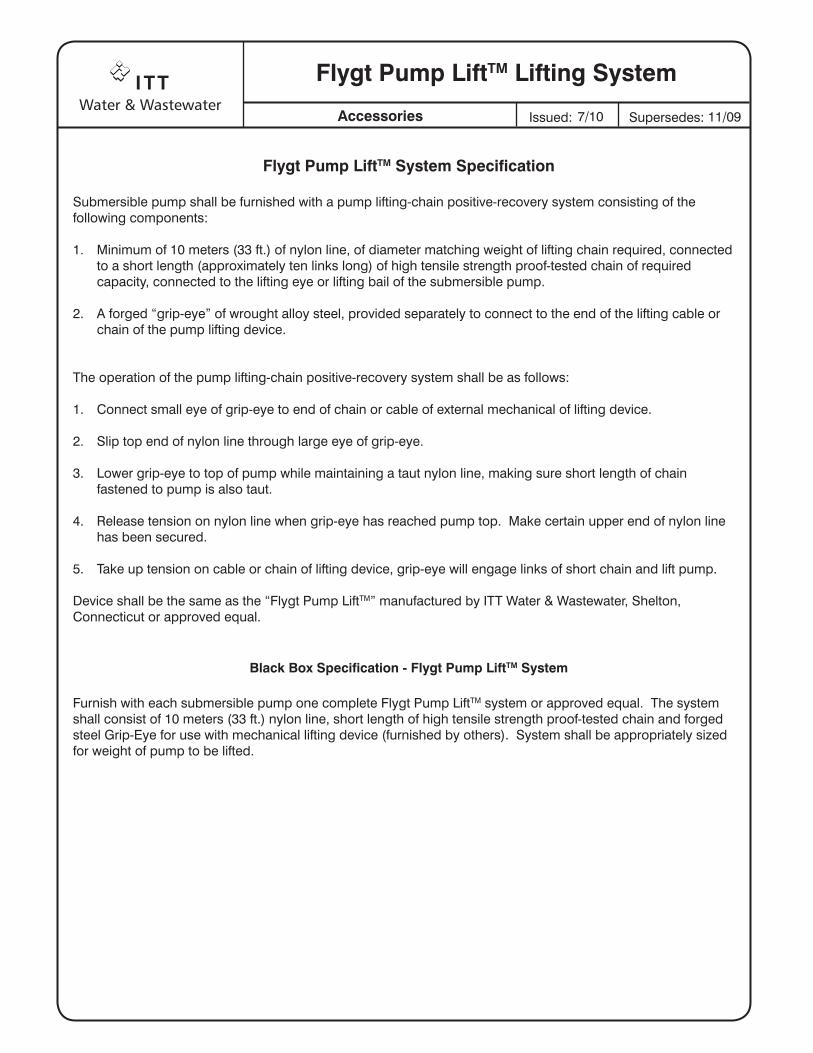
Flygt Pump LiftTM System Specification
Submersible pump shall be furnished with a pump lifting-chain positive-recovery system consisting of the following components:
1. Minimum of 10 meters (33 ft.) of nylon line, of diameter matching weight of lifting chain required, connected to a short length (approximately ten links long) of high tensile strength proof-tested chain of required capacity, connected to the lifting eye or lifting bail of the submersible pump.
2. A forged “grip-eye” of wrought alloy steel, provided separately to connect to the end of the lifting cable or chain of the pump lifting device.
The operation of the pump lifting-chain positive-recovery system shall be as follows:
1. Connect small eye of grip-eye to end of chain or cable of external mechanical of lifting device.
2. Slip top end of nylon line through large eye of grip-eye.
3. Lower grip-eye to top of pump while maintaining a taut nylon line, making sure short length of chain fastened to pump is also taut.
4. Release tension on nylon line when grip-eye has reached pump top. Make certain upper end of nylon line has been secured.
5. Take up tension on cable or chain of lifting device, grip-eye will engage links of short chain and lift pump.
Device shall be the same as the “Flygt Pump LiftTM” manufactured by ITT Water & Wastewater, Shelton, Connecticut or approved equal.
Black Box Specification - Flygt Pump LiftTM System
Furnish with each submersible pump one complete Flygt Pump LiftTM system or approved equal. The system shall consist of 10 meters (33 ft.) nylon line, short length of high tensile strength proof-tested chain and forged steel Grip-Eye for use with mechanical lifting device (furnished by others). System shall be appropriately sized for weight of pump to be lifted.
7/10 11/09

Section 4 Pump Control Panel and
Pump Disconnect Panel
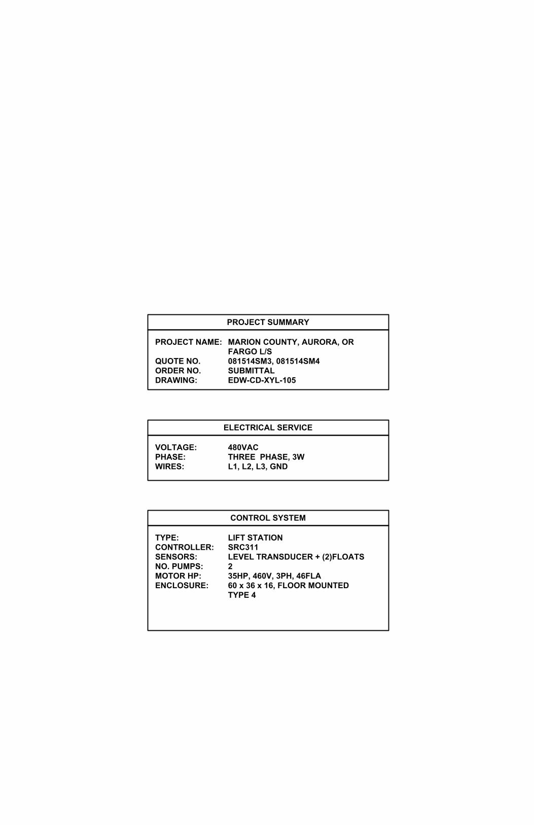
PROJECT SUMMARY
PROJECT NAME: MARION COUNTY, AURORA, ORFARGO L/S
QUOTE NO. 081514SM3, 081514SM4ORDER NO. SUBMITTALDRAWING: EDW-CD-XYL-105
VOLTAGE: 480VACPHASE: THREE PHASE, 3WWIRES: L1, L2, L3, GND
ELECTRICAL SERVICE
CONTROL SYSTEM
TYPE: LIFT STATIONCONTROLLER: SRC311SENSORS: LEVEL TRANSDUCER + (2)FLOATSNO. PUMPS: 2MOTOR HP: 35HP, 460V, 3PH, 46FLAENCLOSURE: 60 x 36 x 16, FLOOR MOUNTED
TYPE 4
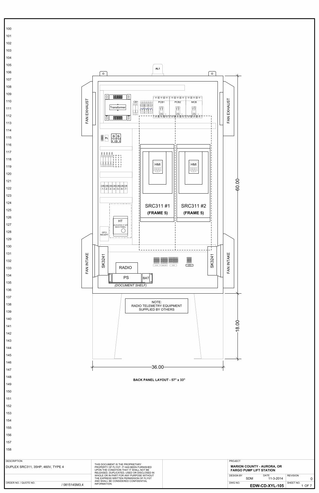
NOTE:RADIO TELEMETRY EQUIPMENT
SUPPLIED BY OTHERS
SHEET NO.
REVISION
DWG NO.EDW-CD-XYL-105
0
OF 7
PROJECT
DESIGN BY DATE11-3-2014
THIS DOCUMENT IS THE PROPRIETARY PROPERTY OF FLYGT. IT HAS BEEN FURNISHED UPON THE CONDITION THAT IT SHALL NOT BE RELEASED, DUPLICATED, USED OR DISCLOSED IN WHOLE OR IN PART FOR ANY PURPOSE WITHOUT THE EXPRESS WRITTEN PERMISSION OF FLYGT AND SHALL BE CONSIDERED CONFIDENTIAL INFORMATION.ORDER NO. / QUOTE NO.
DESCRIPTION
DUPLEX SRC311, 35HP, 460V, TYPE 4
MARION COUNTY - AURORA, OR FARGO PUMP LIFT STATION
SDM
/ 081514SM3,4 1
100
101
102
103
104
105
106
107
108
109
110
111
112
113
114
115
116
117
118
119
120
121
122
123
124
125
126
127
128
129
130
131
132
133
134
135
136
137
138
139
140
141
142
143
144
145
146
147
148
149
150
151
152
153
154
155
156
157
158
GFCIRECEPT
9 10 12 13
SIGNAL PDP
SLDN1 80 81 SLD 82 83
TransformerFerraz
FSShawmut
Cat. No. FSPDB2A
FerrazFSShawmut
Cat. No. FSPDB2A
FerrazFSShawmut
Cat. No. FSPDB2A
BACK PANEL LAYOUT - 57" x 33"
ON
OFF
ON
OFF
CB
3
1 2 3 4
CR1
ON
OFF
TS1FL
CB
2
TS2
CB1 PCB1 PCB2 MCB
SK
3241
SK
3241
SRC311 #1(FRAME 5)
SRC311 #2(FRAME 5)
CR3
CR4
CR5
CR2
CR7
CR6
CB
5C
B6
CB
4
HT(ELEVATED 3" OFF
BACK PANEL)
1 2
AL1
60.0
018
.00
36.00
PUMPSENSORSAC PDP
FAN
INTA
KE
FAN
INTA
KE
FAN
EX
HA
US
T
FAN
EX
HA
US
T
RADIO
PS
SCADA
104100 101 105102 103 106 107
(DOCUMENT SHELF)
HMI HMI
BAT
SHEET NO.
REVISION
DWG NO.EDW-CD-XYL-105
0
OF 7
PROJECT
DESIGN BY DATE11-3-2014
THIS DOCUMENT IS THE PROPRIETARY PROPERTY OF FLYGT. IT HAS BEEN FURNISHED UPON THE CONDITION THAT IT SHALL NOT BE RELEASED, DUPLICATED, USED OR DISCLOSED IN WHOLE OR IN PART FOR ANY PURPOSE WITHOUT THE EXPRESS WRITTEN PERMISSION OF FLYGT AND SHALL BE CONSIDERED CONFIDENTIAL INFORMATION.ORDER NO. / QUOTE NO.
DESCRIPTION
DUPLEX SRC311, 35HP, 460V, TYPE 4
MARION COUNTY - AURORA, OR FARGO PUMP LIFT STATION
SDM
/ 081514SM3,4 2
200
201
202
203
204
205
206
207
208
209
210
211
212
213
214
215
216
217
218
219
220
221
222
223
224
225
226
227
228
229
230
231
232
233
234
235
236
237
238
239
240
241
242
243
244
245
246
247
248
249
250
251
252
253
254
255
256
257
258
90 91 92 93
FLOATS, LXDCR
96 97 G
ISR
ISB
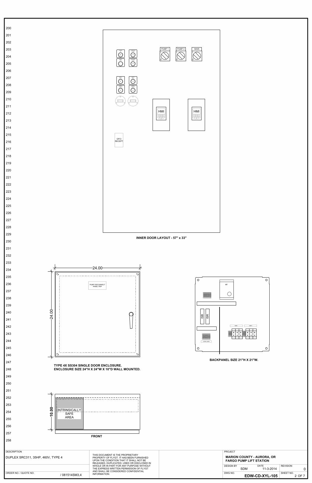
TYPE 4X SS304 SINGLE DOOR ENCLOSURE.ENCLOSURE SIZE 24"H X 24"W X 10"D WALL MOUNTED.
HT
10 11 12 13 14 15 N
1 2 3 4
PUMP 1 PUMP 2
BACKPANEL SIZE 21"H X 21"W.
INTRINSICALLYSAFEAREA10
.00
FRONT
24.0
0
24.00
G
R
PUMP 1FAULT
PUMP 1RUNNING
G
R
PUMP 1FAULT
PUMP 1RUNNING
R
OVERFLOWALARM
R
HIGH LEVELALARM
W
POWEROK
RADIOTEST
PUMP DISCONNECTPANEL PDP
G G
HMI HMI
GFCIRECEPT
I
O
I
O
I
O
PUMP 1 PUMP 2 MAIN
INNER DOOR LAYOUT - 57" x 33"

Hazardous AreaClass I Groups A,B,C,DClass II Groups E,F,GClass III
PDB1 L1 L2 L3
2L3
2L2
2L1
1L3
1L2
1L1
1T3
1T2
1T1
400400
2(WHT)
35 HP 460V46 FLAPUMP 1
T1
T2FLS SENSOR
2T3
2T2
2T1
35 HP 460V46 FLAPUMP 2
T1
T2
PUMP 1
PUMP 2
SHT.6
3L1 3L3
CB113A
SRC311 #1
GND
L1 U
L2 V
L3 W
SRC311 #2
GND
L1 U
L2 V
L3 W
PDPPCB180A
PCB280A
1T1
1T2
1T3
2T1
2T2
2T3
1
2
3
4
1
GND
GND
FLS SENSOR
GND
GND
SHT.6
XFR2KVA
PANELGROUND
X1
H1 H4H3 H2
X2120V
L1 L2 L3
FROM DISTRIBUTION PANEL480VAC, THREE PHASE, 60 HZ, 3 WIRE + GND
GND
MCB150A
ENCLOSURE HEATER200W
FAN
HT
6 ENCLOSURE FAN#1TS1
FAN
7
ENCLOSURE FAN#28TS2
FAN
CB45A
CB315A GFCI-15A
GFCI RECEPTACLEGENERAL USE
5
SHEET NO.
REVISION
DWG NO.EDW-CD-XYL-105
0
OF 7
PROJECT
DESIGN BY DATE11-3-2014
THIS DOCUMENT IS THE PROPRIETARY PROPERTY OF FLYGT. IT HAS BEEN FURNISHED UPON THE CONDITION THAT IT SHALL NOT BE RELEASED, DUPLICATED, USED OR DISCLOSED IN WHOLE OR IN PART FOR ANY PURPOSE WITHOUT THE EXPRESS WRITTEN PERMISSION OF FLYGT AND SHALL BE CONSIDERED CONFIDENTIAL INFORMATION.ORDER NO. / QUOTE NO.
DESCRIPTION
DUPLEX SRC311, 35HP, 460V, TYPE 4
MARION COUNTY - AURORA, OR FARGO PUMP LIFT STATION
SDM
/ 081514SM3,4 3
300
301
302
303
304
305
306
307
308
309
310
311
312
313
314
315
316
317
318
319
320
321
322
323
324
325
326
327
328
329
330
331
332
333
334
335
336
337
338
339
340
341
342
343
344
345
346
347
348
349
350
351
352
353
354
355
356
357
358

500 500
358358
ALARMSILENCE
23
24
21
ALARM SILENCE RELAYNO - 421NC - 422
AUDIBLE ALARM
ALARM BEACON
CR3A1 A2
12
CR3
11 14
CR3
3 2
RX1 X2
AL3
OVERFLOW LEVEL RELAYNO - 420,517,704
HIGH LEVEL RELAYNO - 421,518,706
11 14
HIGH LEVELCR2
1 2(WHT)
FL
BLK RED
11 14
OVERFLOWCR1
CR1A1 A2
CR2A1 A2
FAN
HT
10
12
13
PUMP DISCONNECT PANEL - PDP
N1
N1
3
FSHH
FSH
12
13
11 14
SRC 2 FAULTCR5
11 14
SRC 1 FAULTCR4
Hazardous AreaClass I Groups A,B,C,DClass II Groups E,F,GClass III
9
42
52
31 33
51
ISR
41
CH.1
CH.2
11
12
21
22
13
14
23
24
613
613
CB62A
CB52A
RX1 X2
AL5
RX1 X2
AL4
OVERFLOW LEVEL IND
HIGH LEVEL INDICATOR
10
9
21
AA
90
91
92
93
9
10
12
13
CB210A
25
SHEET NO.
REVISION
DWG NO.EDW-CD-XYL-105
0
OF 7
PROJECT
DESIGN BY DATE11-3-2014
THIS DOCUMENT IS THE PROPRIETARY PROPERTY OF FLYGT. IT HAS BEEN FURNISHED UPON THE CONDITION THAT IT SHALL NOT BE RELEASED, DUPLICATED, USED OR DISCLOSED IN WHOLE OR IN PART FOR ANY PURPOSE WITHOUT THE EXPRESS WRITTEN PERMISSION OF FLYGT AND SHALL BE CONSIDERED CONFIDENTIAL INFORMATION.ORDER NO. / QUOTE NO.
DESCRIPTION
DUPLEX SRC311, 35HP, 460V, TYPE 4
MARION COUNTY - AURORA, OR FARGO PUMP LIFT STATION
SDM
/ 081514SM3,4 4
400
401
402
403
404
405
406
407
408
409
410
411
412
413
414
415
416
417
418
419
420
421
422
423
424
425
426
427
428
429
430
431
432
433
434
435
436
437
438
439
440
441
442
443
444
445
446
447
448
449
450
451
452
453
454
455
456
457
458

PUMP 1 RUN LIGHT
458458
GX1 X2
RL1
17 18
RUNRL2
31
23
PUMP 2 RUN LIGHTGX1 X2
RL2
17 18
RUNRL2
ETM1
ETM2
PUMP 1 RUN TIME HRS
PUMP 2 RUN TIME HRS
32 CR4A1 A2
CR5A1 A2
14 15
FAULTRL1
14 15
FAULTRL1
RX1 X2
AL1
RX1 X2
AL2
PUMP 2 FAULT LIGHT
PUMP 2 FAULT RELAYNO - 423,710
PUMP 1 FAULT LIGHT
PUMP 1 FAULT RELAYNO - 422,708
21 24
HIGH LEVELCR2
21 24
OVERFLOWCR1
CR6A1 A2
HIGH LEVEL RELAYNO - 602,615
36
37
38
700 700
3 2
SRC311 #1
SRC311 #2
WX1 X2
PL1
CR7A1 A2
POWER FAIL RELAYNC - 708
POWER OK LIGHT
SHEET NO.
REVISION
DWG NO.EDW-CD-XYL-105
0
OF 7
PROJECT
DESIGN BY DATE11-3-2014
THIS DOCUMENT IS THE PROPRIETARY PROPERTY OF FLYGT. IT HAS BEEN FURNISHED UPON THE CONDITION THAT IT SHALL NOT BE RELEASED, DUPLICATED, USED OR DISCLOSED IN WHOLE OR IN PART FOR ANY PURPOSE WITHOUT THE EXPRESS WRITTEN PERMISSION OF FLYGT AND SHALL BE CONSIDERED CONFIDENTIAL INFORMATION.ORDER NO. / QUOTE NO.
DESCRIPTION
DUPLEX SRC311, 35HP, 460V, TYPE 4
MARION COUNTY - AURORA, OR FARGO PUMP LIFT STATION
SDM
/ 081514SM3,4 5
500
501
502
503
504
505
506
507
508
509
510
511
512
513
514
515
516
517
518
519
520
521
522
523
524
525
526
527
528
529
530
531
532
533
534
535
536
537
538
539
540
541
542
543
544
545
546
547
548
549
550
551
552
553
554
555
556
557
558

98
4-20MASRC#1
1
2
4
6
8
10
12
3
5
7
9
11
13
+24V
EXT BLOCK
ALM RESET
LSHH
+10V
T2 SENSOR
GND
LVL OUT
GND
LVL INPUT(4-20MA)
ACTIVE PUMP
STO-
STO+ (+24V)
1
2
4
6
8
10
12
3
5
7
9
11
13
SRC311 #1
SRC311 #2
RJ45
15
17
14
16
18
RL1-C
RL1-NO
RL1-NC
RL2-B
RL2-A
SHT.5
15
17
14
16
18
RL1-C
RL1-NO
RL1-NC
RL2-B
RL2-A
RJ45PUMP #2
FLS SENSORRES T1
T2
85
86
WHT
81
80
83
82
GND
GND
RED(+)
BRN(-)
PRIMARYLEVEL
SENSORLXDCR14-20MA
2
1
2
4
3
(OUT+)
(+)(+)
(IN+)
(OUT+)
(+)
31 33
(IN-)
ISB1
(IN+)
CH.1
CH.2
14
13
24
23
44
52
51
42
414428
PUMP DISCONNECT PANELPDP
1
3
99
98
GND
Hazardous AreaClass I Groups A,B,C,DClass II Groups E,F,GClass III
GND SLD
+24V
EXT BLOCK
ALM RESET
LSHH
+10V
T2 SENSOR
GND
LVL OUT
GND
LVL INPUT(4-20MA)
ACTIVE PUMP
STO-
STO+ (+24V)
81
80
83
82
SLD
SLD
GND SLD
4
4-20MASRC#2
BLK
WHT
BLK
WHT
BLK
WHT
BLK 87
88
21 24
HIGH LEVELCR6
11 14
HIGH LEVELCR6
SHT.5
PUMP #1FLS SENSOR
RES T1
T2
SHEET NO.
REVISION
DWG NO.EDW-CD-XYL-105
0
OF 7
PROJECT
DESIGN BY DATE11-3-2014
THIS DOCUMENT IS THE PROPRIETARY PROPERTY OF FLYGT. IT HAS BEEN FURNISHED UPON THE CONDITION THAT IT SHALL NOT BE RELEASED, DUPLICATED, USED OR DISCLOSED IN WHOLE OR IN PART FOR ANY PURPOSE WITHOUT THE EXPRESS WRITTEN PERMISSION OF FLYGT AND SHALL BE CONSIDERED CONFIDENTIAL INFORMATION.ORDER NO. / QUOTE NO.
DESCRIPTION
DUPLEX SRC311, 35HP, 460V, TYPE 4
MARION COUNTY - AURORA, OR FARGO PUMP LIFT STATION
SDM
/ 081514SM3,4 6
600
601
602
603
604
605
606
607
608
609
610
611
612
613
614
615
616
617
618
619
620
621
622
623
624
625
626
627
628
629
630
631
632
633
634
635
636
637
638
639
640
641
642
643
644
645
646
647
648
649
650
651
652
653
654
655
656
657
658

DUPLEXRECEPTACLEGFI
RADIO ONLY
COM
COM
COM
COM
IN1
IN2
IN3
IN4
IN1
IN2
IN3
IN4
41 44
SRC 1 FAULTCR4
41 44
SRC 2 FAULTCR5
100
101
102
103
104
105
QUICK TALK RADIO(EXISTING)
41 44
HIGH LEVELCR2
106
107
558558
RADIOTEST
41 42
POWER FAILCR7
CB72A
GFCI RECEPTACLERADIO USE ONLY
102
103
104
105
106
107
100
101
BAT1+ -
NOTE:RADIO TELEMETRY EQUIPMENT
SUPPLIED BY OTHERS
SHEET NO.
REVISION
DWG NO.EDW-CD-XYL-105
0
OF 7
PROJECT
DESIGN BY DATE11-3-2014
THIS DOCUMENT IS THE PROPRIETARY PROPERTY OF FLYGT. IT HAS BEEN FURNISHED UPON THE CONDITION THAT IT SHALL NOT BE RELEASED, DUPLICATED, USED OR DISCLOSED IN WHOLE OR IN PART FOR ANY PURPOSE WITHOUT THE EXPRESS WRITTEN PERMISSION OF FLYGT AND SHALL BE CONSIDERED CONFIDENTIAL INFORMATION.ORDER NO. / QUOTE NO.
DESCRIPTION
DUPLEX SRC311, 35HP, 460V, TYPE 4
MARION COUNTY - AURORA, OR FARGO PUMP LIFT STATION
SDM
/ 081514SM3,4 7
700
701
702
703
704
705
706
707
708
709
710
711
712
713
714
715
716
717
718
719
720
721
722
723
724
725
726
727
728
729
730
731
732
733
734
735
736
737
738
739
740
741
742
743
744
745
746
747
748
749
750
751
752
753
754
755
756
757
758
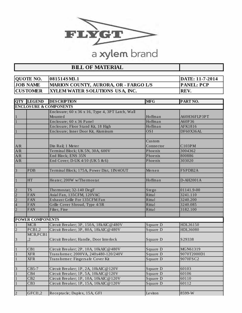
DATE: 11-7-2014
PANEL: PCP
REV.
QTY LEGEND DESCRIPTION MFG PART NO.
ENCLOSURE & COMPONENTS
1
Enclosure; 60 x 36 x 16, Type 4, 3PT Latch, Wall
Mounted Hoffman A60H36FLP3PT
1 Enclosure; 60 x 36 Panel Hoffman A60P36
Enclosure; Floor Stand Kit, 18 High Hoffman AFK1816
1 Enclosure; Inner Door Kit, Aluminum OSI DF60X36AL
A/R Din Rail; 1 Meter
Custom
Connector C103PM
A/R Terminal Block; UK 5N, 30A, 600V Phoenix 3004362
A/R End Block; ENS 35N Phoenix 800886
A/R End Cover; D-UK 4/10 (UK 5 & 6) Phoenix 303020
3 PDB Terminal Block; 175A, Power Dist, 1IN/4OUT Mersen FSPDB2A
1 HT Heater; 200W w/Thermostat Hoffman D-AH2001A
2 TS Thermostat; 32-140 DegF Stego 01141.9-00
2 FAN Axial Fan, 135CFM, 120VAC Rittal 3241.110
2 FAN Exhaust Grille For 135CFM Fan Rittal 3240.200
4 FAN Grille Cover Shroud, Type 4/3R Rittal 3240.085
2 FAN Filter, Fine Rittal 3182.100
POWER COMPONENTS
1 MCB Circuit Breaker; 3P, 150A, 18kAIC@480V Square D HDL36150
2 PCB1,2 Circuit Breaker; 3P, 80A, 18kAIC@480V Square D HDL36080
3
MCB,PCB1
,2 Circuit Breaker; Handle, Door Interlock Square D S29338
1 CB1 Circuit Breaker; 2P, 10A, 10kAIC@480V Square D MGN61319
1 XFR Transformer; 2000VA, 240x480-120/240V Square D 9070T2000D1
1 XFR Transformer: Fingersafe Cover Kit Square D 9070FSC2
3 CB5-7 Circuit Breaker; 1P, 2A, 10kAIC@120V Square D 60103
1 CB4 Circuit Breaker; 1P, 5A, 10kAIC@120V Square D 60106
1 CB2 Circuit Breaker; 1P, 10A, 10kAIC@120V Square D 60110
1 CB3 Circuit Breaker; 1P, 15A, 10kAIC@120V Square D 60112
2 GFCI1,2 Receptacle; Duplex, 15A, GFI Leviton 8599-W
BILL OF MATERIAL
JOB NAME
CUSTOMER
MARION COUNTY, AURORA, OR - FARGO L/S
XYLEM WATER SOLUTIONS USA, INC.
QUOTE NO. 081514SM3.1
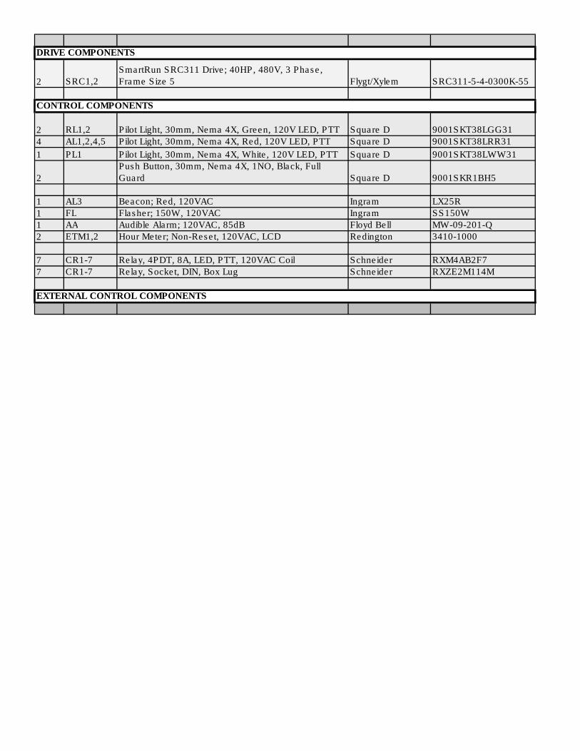
DRIVE COMPONENTS
2 SRC1,2
SmartRun SRC311 Drive; 40HP, 480V, 3 Phase,
Frame Size 5 Flygt/Xylem SRC311-5-4-0300K-55
CONTROL COMPONENTS
2 RL1,2 Pilot Light, 30mm, Nema 4X, Green, 120V LED, PTT Square D 9001SKT38LGG31
4 AL1,2,4,5 Pilot Light, 30mm, Nema 4X, Red, 120V LED, PTT Square D 9001SKT38LRR31
1 PL1 Pilot Light, 30mm, Nema 4X, White, 120V LED, PTT Square D 9001SKT38LWW31
2
Push Button, 30mm, Nema 4X, 1NO, Black, Full
Guard Square D 9001SKR1BH5
1 AL3 Beacon; Red, 120VAC Ingram LX25R
1 FL Flasher; 150W, 120VAC Ingram SS150W
1 AA Audible Alarm; 120VAC, 85dB Floyd Bell MW-09-201-Q
2 ETM1,2 Hour Meter; Non-Reset, 120VAC, LCD Redington 3410-1000
7 CR1-7 Relay, 4PDT, 8A, LED, PTT, 120VAC Coil Schneider RXM4AB2F7
7 CR1-7 Relay, Socket, DIN, Box Lug Schneider RXZE2M114M
EXTERNAL CONTROL COMPONENTS

Spec-00290 F
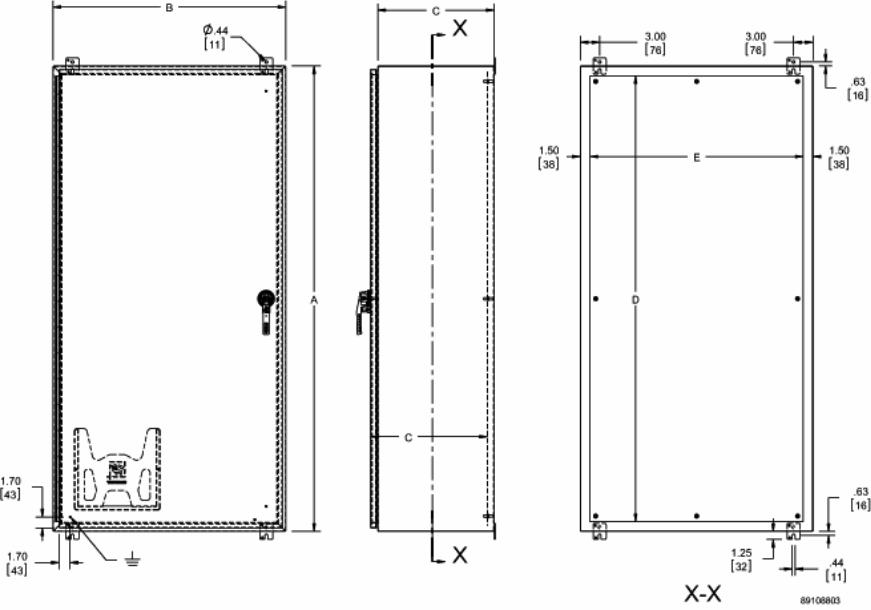
Wall-Mount EnclosurEs Type 4 Wall-MounT enclosures
EQUIPMENT PROTECTIONSUBJECT TO CHANGE WITHOUT NOTICEMild stEEl1
Spec-00290F763.422.2211763.422.2600
Mild stEElWall-Mount EnclosurEstypE 4 Wall-Mount EnclosurEs
continuous HingE WitH claMps, typE 4
industry standards
UL 508A Listed; Type 4, 12, 13; File No. E61997cUL Listed per CSA C22.2 No. 94; Type 4, 12, 13; File No. E61997
NEMA/EEMAC Type 3, 4, 12, and 13CSA, File No. 42186: Type 4 and 12IEC 60529, IP66
applicationThese single-door enclosures feature a hinged door with clamps on three sides to create a secure seal in indoor or outdoor environments. The gray polyester powder finish inside and out provides enhanced corrosion protection in outdoor applications.
spEciFications• 16 or 14 gauge steel (see table)• Seams continuously welded and ground smooth
• External wall-mounting brackets• Formed external flanges around all sides of enclosure opening• Stainless steel door clamps on three sides of door• Removable heavy gauge stainless steel continuous hinge pin• Hasp and staple provided for padlocking• Data pocket is high-impact thermoplastic• Collar studs provided for mounting optional panels• Bonding provision on door
FinisHANSI 61 gray polyester powder paint inside and out
accEssoriEsSee also Accessories.Industrial Corrosion InhibitorsFast-Operating Clamp AssemblyIncandescent Light PackageCompact Cooling FansSteel and Stainless Steel Window Kits See also the Popular Accessories table forlloing the Standard Products table.
ModiFication and custoMiZationHoffman excels at modifying and customizing products to your specifications. Contact your local Hoffman sales office or distributor for complete information.Bulletin: A4
Standard Product
Catalog Number AxBxC in. AxBxC mmBodyGauge Panel
ConductivePanel
Panel SizeD x E (in.)
Panel SizeD x E (mm) F (in.) F (mm)
Numberof Clamps
DataPocket
A16H12ALP 16.00 x 12.00 x 6.00 406 x 305 x 152 16 A16P12 A16P12G 13.00 x 9.00 330 x 229 1.25 32 4 SmallA16H16ALP 16.00 x 16.00 x 6.00 406 x 406 x 152 16 A16P16 A16P16G 13.00 x 13.00 330 x 330 3.00 76 4 SmallA16H20ALP 16.00 x 20.00 x 6.00 406 x 508 x 152 16 A20P16 A20P16G 17.00 x 13.00 432 x 330 3.00 76 4 SmallA20H16ALP 20.00 x 16.00 x 6.00 508 x 406 x 152 16 A20P16 A20P16G 17.00 x 13.00 432 x 330 3.00 76 4 SmallA20H20ALP 20.00 x 20.00 x 6.00 508 x 508 x 152 16 A20P20 A20P20G 17.00 x 17.00 432 x 432 3.00 76 4 SmallA24H12ALP 24.00 x 12.00 x 6.00 610 x 305 x 152 16 A12P24 A12P24G 9.00 x 21.00 229 x 533 1.25 32 5 SmallA24H16ALP 24.00 x 16.00 x 6.00 610 x 406 x 152 16 A24P16 A24P16G 21.00 x 13.00 533 x 330 3.00 76 5 SmallA24H20ALP 24.00 x 20.00 x 6.00 610 x 508 x 152 16 A24P20 A24P20G 21.00 x 17.00 533 x 432 3.00 76 5 SmallA24H24ALP 24.00 x 24.00 x 6.00 610 x 610 x 152 16 A24P24 A24P24G 21.00 x 21.00 533 x 533 3.00 76 5 SmallA30H20ALP 30.00 x 20.00 x 6.00 762 x 508 x 152 14 A30P20 A30P20G 27.00 x 17.00 686 x 432 3.00 76 5 SmallA30H24ALP 30.00 x 24.00 x 6.00 762 x 610 x 152 14 A30P24 A30P24G 27.00 x 21.00 686 x 533 3.00 76 5 LargeA36H24ALP 36.00 x 24.00 x 6.00 914 x 610 x 152 14 A36P24 A36P24G 33.00 x 21.00 838 x 533 3.00 76 5 LargeA16H12BLP 16.00 x 12.00 x 8.00 406 x 305 x 203 16 A16P12 A16P12G 13.00 x 9.00 330 x 229 1.25 32 4 SmallA20H16BLP 20.00 x 16.00 x 8.00 508 x 406 x 203 16 A20P16 A20P16G 17.00 x 13.00 432 x 330 3.00 76 4 SmallA20H20BLP 20.00 x 20.00 x 8.00 508 x 508 x 203 16 A20P20 A20P20G 17.00 x 17.00 432 x 432 3.00 76 4 SmallA20H24BLP 20.00 x 24.00 x 8.00 508 x 610 x 203 16 A24P20 A24P20G 21.00 x 17.00 533 x 432 3.00 76 4 SmallA24H20BLP 24.00 x 20.00 x 8.00 610 x 508 x 203 16 A24P20 A24P20G 21.00 x 17.00 533 x 432 3.00 76 5 SmallA24H24BLP 24.00 x 24.00 x 8.00 610 x 610 x 203 16 A24P24 A24P24G 21.00 x 21.00 533 x 533 3.00 76 5 SmallA24H30BLP 24.00 x 30.00 x 8.00 610 x 762 x 203 14 A30P24 A30P24G 27.00 x 21.00 686 x 533 3.00 76 7 SmallA30H20BLP 30.00 x 20.00 x 8.00 762 x 508 x 203 14 A30P20 A30P20G 27.00 x 17.00 686 x 432 3.00 76 5 SmallA30H24BLP 30.00 x 24.00 x 8.00 762 x 610 x 203 14 A30P24 A30P24G 27.00 x 21.00 686 x 533 3.00 76 5 LargeA30H30BLP 30.00 x 30.00 x 8.00 762 x 762 x 203 14 A30P30 A30P30G 27.00 x 27.00 686 x 686 3.00 76 7 LargeA36H24BLP 36.00 x 24.00 x 8.00 914 x 610 x 203 14 A36P24 A36P24G 33.00 x 21.00 838 x 533 3.00 76 5 LargeA36H30BLP 36.00 x 30.00 x 8.00 914 x 762 x 203 14 A36P30 A36P30G 33.00 x 27.00 838 x 686 3.00 76 7 LargeA42H30BLP 42.00 x 30.00 x 8.00 1067 x 762 x 203 14 A42P30 A42P30G 39.00 x 27.00 991 x 686 3.00 76 8 SmallA42H36BLP 42.00 x 36.00 x 8.00 1067 x 914 x 203 14 A42P36 A42P36G 39.00 x 33.00 991 x 838 3.00 76 8 LargeA48H36BLP 48.00 x 36.00 x 8.00 1219 x 914 x 203 14 A48P36 A48P36G 45.00 x 33.00 1143 x 838 3.00 76 8 LargeA60H36BLP 60.00 x 36.00 x 8.00 1524 x 914 x 203 14 A60P36 A60P36G 57.00 x 33.00 1448 x 838 3.00 76 9 LargeA20H16CLP 20.00 x 16.00 x 10.00 508 x 406 x 254 14 A20P16 A20P16G 17.00 x 13.00 432 x 330 3.00 76 4 SmallA24H20CLP 24.00 x 20.00 x 10.00 610 x 508 x 254 14 A24P20 A24P20G 21.00 x 17.00 533 x 432 3.00 76 5 SmallA30H24CLP 30.00 x 24.00 x 10.00 762 x 610 x 254 14 A30P24 A30P24G 27.00 x 21.00 686 x 533 3.00 76 5 LargeA36H30CLP 36.00 x 30.00 x 10.00 914 x 762 x 254 14 A36P30 A36P30G 33.00 x 27.00 838 x 686 3.00 76 7 LargeA48H30CLP 48.00 x 30.00 x 10.00 1219 x 762 x 254 14 A48P30 A48P30G 45.00 x 27.00 1143 x 686 3.00 76 8 SmallA48H36CLP 48.00 x 36.00 x 10.00 1219 x 914 x 254 14 A48P36 A48P36G 45.00 x 33.00 1143 x 838 3.00 76 8 LargeA60H36CLP 60.00 x 36.00 x 10.00 1524 x 914 x 254 14 A60P36 A60P36G 57.00 x 33.00 1448 x 838 3.00 76 9 LargeA30H24DLP 30.00 x 24.00 x 12.00 762 x 610 x 305 14 A30P24 A30P24G 27.00 x 21.00 686 x 533 3.00 76 5 LargeA36H30DLP 36.00 x 30.00 x 12.00 914 x 762 x 305 14 A36P30 A36P30G 33.00 x 27.00 838 x 686 3.00 76 7 LargeA48H36DLP 48.00 x 36.00 x 12.00 1219 x 914 x 305 14 A48P36 A48P36G 45.00 x 33.00 1143 x 838 3.00 76 8 LargeA36H30FLP 36.00 x 30.00 x 16.00 914 x 762 x 406 14 A36P30 A36P30G 33.00 x 27.00 838 x 686 3.00 76 7 LargeA48H36FLP 48.00 x 36.00 x 16.00 1219 x 914 x 406 14 48P36 A48P36G 45.00 x 33.00 1143 x 838 3.00 76 8 LargeA60H36FLP 60.00 x 36.00 x 16.00 1524 x 914 x 406 14 A60P36 A60P36G 57.00 x 33.00 1448 x 838 3.00 76 9 LargePurchase panels separately. Optional stainless steel, conductive, composite and aluminum panels are available for most sizes.

Spec-00290 F
Wall-Mount EnclosurEs Type 4 Wall-MounT enclosures
PH 763.422.2211 • FAX 763.422.2600 • HOFFMANONLINE.COMEQUIPMENT PROTECTION Mild stEEl 2
Popular Accessories Enclosure Width (B Dimension) Hole Seals Window Kits12 in. (305 mm) AS050 APWK53NF16 in. (406 mm) AS050 APWK53NF20 in. (508 mm) AS050 APWK53NF24 in. (610 mm) AS050 APWK53NF30 in. (762 mm) AS050 APWK53NF36 in. (914 mm) AS050 APWK53NF
Spec-00484 J
Mounting Accessories Mounting Kits
EQUIPMENT PROTECTIONSUBJECT TO CHANGE WITHOUT NOTICEAccessories3
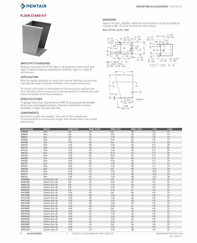
FLoor stAnd kit
industrY stAndArdsProduct maintains UL/CSA Type 4, 4X (stainless steel only) and Type 12 when properly installed on Hoffman Type 4 or Type 12 enclosures.
APPLicAtionKits are easily installed on most wall-mount Hoffman enclosures. Can also be used to elevate Hoffman free-stand enclosures.
To install, drill holes in the bottom of the enclosure and bolt the floor stands to the enclosure.It is not necessary to remove the wall-mount brackets from the enclosure.
sPeciFicAtions12 gauge steel floor stand has an ANSI 61 gray polyester powder finish over pretreated surfaces. Stainless steel floor stand is available in Type 316 and Type 304.
coMPonentsEach kit includes two stands. Two sets of floor stands are recommended for enclosures larger than double door free-stand enclosures.
orderingSpecial heights, depths, materials and finishes can be provided on custom order. Consult factory for information.Bulletin: A4SY, A80
Catalog Number Material Height, H (in.) Height, H (mm) Width, C (in.) Width, C (mm) L (in.) L (mm)AFK0608 Steel 6.00 152 8.06 205 7.06 179AFK0610 Steel 6.00 152 10.06 256 7.06 179AFK0612 Steel 6.00 152 12.06 306 7.06 179AFK0618 Steel 6.00 152 18.06 459 7.06 179AFK1208 Steel 12.00 305 8.06 205 8.12 206AFK1210 Steel 12.00 305 10.06 256 8.12 206AFK1212 Steel 12.00 305 12.06 306 8.12 206AFK1216 Steel 12.00 305 16.06 408 8.12 206AFK1218 Steel 12.00 305 18.13 461 8.12 206AFK1220 Steel 12.00 305 20.06 510 8.12 206AFK1808 Steel 18.00 457 8.06 205 9.17 233AFK1810 Steel 18.00 457 10.06 256 9.17 233AFK1812 Steel 18.00 457 12.06 306 9.17 233AFK1816 Steel 18.00 457 16.06 408 9.17 233AFK2408 Steel 24.00 610 8.06 205 10.23 260AFK2410 Steel 24.00 610 10.06 256 10.23 260AFK2412 Steel 24.00 610 12.06 306 10.23 260AFK2416 Steel 24.00 610 16.06 408 10.23 260AFK0608SS Stainless Steel, 304 6.00 152 8.06 205 9.09 231AFK0610SS Stainless Steel, 304 6.00 152 10.06 256 9.09 231AFK0612SS Stainless Steel, 304 6.00 152 12.06 306 9.09 231AFK0618SS Stainless Steel, 304 6.00 152 18.06 459 9.09 231AFK0624SS Stainless Steel, 304 6.00 152 24.06 611 9.09 231AFK1208SS Stainless Steel, 304 12.00 305 8.06 205 9.09 231AFK1210SS Stainless Steel, 304 12.00 305 10.06 256 9.09 231AFK1212SS Stainless Steel, 304 12.00 305 12.06 306 9.09 231AFK1216SS Stainless Steel, 304 12.00 305 16.06 408 9.09 231AFK1218SS Stainless Steel, 304 12.00 305 18.06 459 9.09 231AFK1224SS Stainless Steel, 304 12.00 305 24.06 611 9.09 231AFK1808SS Stainless Steel, 304 18.00 457 8.06 205 9.09 231AFK1810SS Stainless Steel, 304 18.00 457 10.06 256 9.09 231AFK1812SS Stainless Steel, 304 18.00 457 12.06 306 9.09 231AFK1816SS Stainless Steel, 304 18.00 457 16.06 408 9.09 231AFK1818SS Stainless Steel, 304 18.00 457 18.06 459 9.09 231AFK1824SS Stainless Steel, 304 18.00 457 24.06 611 9.09 231AFK2408SS Stainless Steel, 304 24.00 610 8.06 205 9.09 231AFK2410SS Stainless Steel, 304 24.00 610 10.06 256 9.09 231AFK2412SS Stainless Steel, 304 24.00 610 12.06 306 9.09 231

Spec-00484 J
Mounting Accessories Mounting Kits
PH 763.422.2211 • FAX 763.422.2600 • HOFFMANONLINE.COMEQUIPMENT PROTECTION Accessories 4
Catalog Number Material Height, H (in.) Height, H (mm) Width, C (in.) Width, C (mm) L (in.) L (mm)AFK2416SS Stainless Steel, 304 24.00 610 16.06 408 9.09 231AFK2418SS Stainless Steel, 304 24.00 610 18.06 459 9.09 231AFK2424SS Stainless Steel, 334 24.00 610 24.06 611 9.09 231AFK0608SS6 Stainless Steel, 316 6.00 152 8.06 205 9.09 231AFK0610SS6 Stainless Steel, 316 6.00 152 10.06 256 9.09 231AFK0612SS6 Stainless Steel, 316 6.00 152 12.06 306 9.09 231AFK0618SS6 Stainless Steel, 316 6.00 152 18.06 459 9.09 231AFK0624SS6 Stainless Steel, 316 6.00 152 24.06 611 9.09 231AFK1208SS6 Stainless Steel, 316 12.00 305 8.06 205 9.09 231AFK1210SS6 Stainless Steel, 316 12.00 305 10.06 256 9.09 231AFK1212SS6 Stainless Steel, 316 12.00 305 12.06 306 9.09 231AFK1216SS6 Stainless Steel, 316 12.00 305 16.06 408 9.09 231AFK1218SS6 Stainless Steel, 316 12.00 305 18.06 459 9.09 231AFK1224SS6 Stainless Steel, 316 12.00 305 24.06 611 9.09 231AFK1808SS6 Stainless Steel, 316 18.00 457 8.06 205 9.09 231AFK1810SS6 Stainless Steel, 316 18.00 457 10.06 256 9.09 231AFK1812SS6 Stainless Steel, 316 18.00 457 12.06 306 9.09 231AFK1816SS6 Stainless Steel, 316 18.00 457 16.06 408 9.09 231AFK1818SS6 Stainless Steel, 316 18.00 457 18.06 459 9.09 231AFK1824SS6 Stainless Steel, 316 18.00 457 24.06 611 9.09 231AFK2408SS6 Stainless Steel, 316 24.00 610 8.06 205 9.09 231AFK2410SS6 Stainless Steel, 316 24.00 610 10.06 256 9.09 231AFK2412SS6 Stainless Steel, 316 24.00 610 12.06 306 9.09 231AFK2416SS6 Stainless Steel, 316 24.00 610 16.06 408 9.09 231AFK2418SS6 Stainless Steel, 316 24.00 610 18.06 459 9.09 231AFK2424SS6 Stainless Steel, 316 24.00 610 24.06 611 9.09 231

25
Custom Connector Corporation • 1738 E. 30th, Cleveland, OH 44114 • 216/241-1679 • Fax 216/241-5529E-mail: [email protected] • Web: www.customconnector.com
RELAY SOCKET ACCESSORIES DIN RAIL DRAWINGS & SPECIFICATIONS
PART NO. DESCRIPTION SERIES NO.
C-103-PM Prepunched Aluminum DIN Rail (1 Meter Lengths) ES, GT, MT, OT, ST(note: Other lengths available, consult factory)
C-104-PM Prepunched Steel DIN Rail (1 Meter Lengths) ES, GT, MT, OT, ST(note: Other lengths available, consult factory)
C-105-PM Prepunched Steel DIN Rail (1 Meter Lengths) ES, GT, MT, OT, ST(note: Other lengths available, consult factory)
C-106-2PM Prepunched Steel DIN Rail (2 Meter Lengths) ES, GT, MT, OT, ST(note: Other lengths available, consult factory)
.984[25.00]
1.063[27.00]
.287[7.29]
.943[23.95]
1.378[35.00]
.177[4.50]
R.
1.083[27.50] 1.378[35.00]TYP.
39.370 [1000.00]
R.
1.063[27.00]
.295[7.50]
1.378[35.00]
.709[18.00]
.205[5.20]
.492[12.50] .984[25.00]
39.370[1000.00]
1.063[27.00]1.378[35.00]
.709[18.00]
.492[12.50] .984[25.00]
39.370[1000.00] .590[15.00]
R.
.248[6.30]
.039[1.00]
.709[18.00]
.492[12.50] .984[25.00]
78.740[2000.00]
R.
.248[6.30] 1.378[35.00] 1.063[27.00]
.295[7.50]
OTHER STYLES AND HOLE PATTERNS AVAILABLE. CONSULT FACTORY


I2
FSPDB Finger-Safe Power Distribution Blocks
Safety evolvingMersen FSPDBs introduce a new level of safety and ease for installing power distribution blocks. An IP20 level of finger-safe protection is achieved using FSPDBs,eliminating the need for special covers or custom Plexiglas sheets to protect your panels. FSPDBs (sizes 1 to 4) simply snap onto 35mm DIN rail to provide the quickest installation. Modular design also allows for multi pole applications by use of assembly pins. FSPDBs provide a safe, convenient way of splicing cables, splitting primary power into a variety of secondary circuits or providing a fixed junction tap-o f point.
Ratings:Volts : 600VAmps: : 175 to 840ASCCR : 100kA with proper fuse.
Contact Technical Services for instruction sheet and/or DC Ratings.
Features/Benefits: • Finger-safe protection
Fully insulated block ensures touch safe isolation of live parts. Recessed termination screws and wire openings provide IP20 grade protection and qualify as “finger-safe” per IEC 529
• Compact modularitySingle or multiple pole configurations in the most compact foot rint. Allows users to build smaller or higher density panels.
• Snap on DIN-rail mountingSizes 1 to 4 feature integral DIN rail adaptors allowing for quick and easy installations on 35mm DIN rail yielding lower installed costs.
• Captive termination screwsUnique channel design ensures captive metric wire termination screws. Screws can never be lost.
• Available accessoriesFor multi-pole panel mounting, simply snap in pins for rigid fi . Cap plugs provide the ability to maintain touch safety on unused openings. Circuit identification markers simply snap into blocks to ID circuits. nd anchors provide rigid end stops.
• Multiple wire ratingsProvide users more versatility by offering capability of using multiple conductors in #2 and 2/0 openings.
• AC & DC ratingsFSPDB1, 2, and 3 have been evaluated for use at 1000V (AC or DC) provided they are installed on DIN-rails only and with barriers between poles of opposite polarity of sufficient size to maintain requi ed spacings.
Approvals: • UL Recognized Component
Guide XCFR2, File E73571 • CSA Certified: Class 6228, Fil
69363

For the most current product performance data visit us-ferrazshawmut.mersen.com and use catalog search. I3
I
Catalog Numbers
A
B
C
DE
F
G
H
J
K
A
B
C
DE
F
G
HI
K
J
Figure 1 Figure 2
Dimension
FSPDB1A FSPDB2A FSPDB3A FSPDB4A FSPDB5A
FSPDB1C FSPDB2C FSPDB3C FSPDB4C FSPDB5C
Figure 1 Figure 1 Figure 2 Figure 1 Figure 2
mm in mm in mm in mm in mm in
A 25.4 1.00 28.4 1.12 46.9 1.85 39 1.54 72 2.84
B 43.3 1.70 57.8 2.28 64.3 2.53 108 4.25 91 3.58
C 49.5 1.95 56.0 2.21 64.3 2.53 80 3.15 80 3.15
D 45.1 1.78 51.6 2.03 59.8 2.36 75.5 2.97 - -
E 39.4 1.55 39.4 1.55 51.5 2.03 50.1 1.97 50.1 1.97
F 72.6 2.86 87.7 3.45 100.8 3.97 145.5 5.73 145 5.71
G 59.6 2.35 74.6 2.94 82.4 3.24 120.6 4.75 127.5 5.02
H 5.3 0.21 5.1 0.20 6.5 0.26 7 0.28 3 0.12
I - - - - 31.5 1.24 - - 52 2.04
J 5.3 0.21 6.4 0.25 6.5 0.26 6.5 0.26 6.5 0.26
K 10 0.40 11.7 0.46 8.9 0.35 16 0.63 8.5 0.34
Catalog No. Description
FSPIN1 Accessory pin to form multiple pole block
FSCIM1Circuit identification marker for 2/0 & #2 max. conductors (Qty of 100)
FSCIM2 Circuit identification marker for 350, 400 & 600 kcmil max. conductors (Qty of 100)
FSCAP1 Cap plug for spare 2/0 openings
FSCAP2 Cap plug for spare 350 kcmil openings
FSCP3 Cap plug for spare 600 kcmil opening
FSEA Pair of end anchors
Multiple Wire Ratings (Same Size & Type Wires Only)
2/0 Openings #2 Openings
(2) #4 AWG (2) #10 AWG (2) #6 AWG (2-4) #12 AWG
(2) #6 AWG (2) #12 AWG (2) #8 AWG (2-4) #14 AWG
(2) #8 AWG (2) #14 AWG (2-4) #10 AWG
•Contact Mersen Technical Services at [email protected] for fuse type and maximum ampere required.
Dimensions
FSPDB Finger-Safe Power Distribution Blocks
Catalog Number Ampere Rating (Based on NEC Table 310-16 for 75° C Cu wire only)
Line LoadShort Circuit Current Rating
Aluminum Copper Wire Range Wire Range Openings Per Pole
(Connector rated for 90° C Cu/AL wire)
(Connector rated for 75° C Cu wire only)
AWG/ mm2 Openings AWG/ kcmil
mm2
FSPDB1A FSPDB1C 175 2/0-#14 70-2.5 1 2/0-#14 70-2.5 1 100kA•
FSPDB2A FSPDB2C 175 2/0-#14 70-2.5 1 #2-#14 35-2.5 4 100kA•
FSPDB3A FSPDB3C 310350-#6 185-16
1 #8-#14 8-2.5 8 100kA•2/0-#14 70-2.5
FSPDB4A FSPDB4C 335 400-#6 185-16 1 400-#6 185-16 1 100kA•
FSPDB5A FSPDB5C 840 600-#4 300-25 2 600-#4 300-25 2 100kA•
Accessories

Construction
• Attractive and durable housing is anodizedaluminum
• Thermostat, standard on all units, is adjustablefrom 0°F to 100°F (-18°C to 38°C)
• Fan draws cool air from the bottom of theenclosure and passes this air across thethermostat and heating elements beforebeing released into enclosure cavity
• Heated air is discharged through the top ofthe heater unit
• Four 10-32 self-tapping screws are includedwith each heater
• Ball bearing fan runs continuously for eventemperature distribution
• Terminal strip with clamp connector thataccepts both solid and stranded wire
Finish
Brushed aluminum.
Industry Standards
UL Component RecognizedCSA ListedCE
Hoffman electric heaters should be centered aslow as possible on an interior enclosure panel.This permits the unit to heat the cool airlocated at the bottom of the enclosure. Formaximum efficiency and longevity, the heatershould be mounted in a vertical position withthe terminal block to the bottom and the airoutlet openings at the top in a sealedenclosure free from dust or debris. However,the unit will also effectively distribute heat ifturned 90 degrees with the terminal block outthe bottom and the air outlet at the side.Although enclosure panels are preferable,heaters may be installed on any flat sheet metalsurface. Do not install heaters on wood panels.
Heat sensitive components should not beplaced near the heater discharge area since thisair can be quite warm.The clearance rangedefines the space that must be kept free ofthese components for proper and safeoperation of the heater.
Application
Designed to protect sensitive mechanical,electrical, and electronic equipment from theharmful effects of condensation, corrosion, andlow temperatures.Thermostatically controlledfan-driven heater units maintain a stabletemperature within enclosures so criticalcomponents can perform more reliably over a longer period of time.
Catalog WeightNumber Watts Voltage Hz Amps lb. (kg.)DAH1001A 100 115 50/60 0.9 4.00 (1.81)
DAH1002A 100 230 50/60 0.6 4.00 (1.81)
DAH2001A 200 115 50/60 1.7 4.00 (1.81)
DAH2002A 200 230 50/60 0.9 4.00 (1.81)
DAH4001B 400 115 50/60 3.3 6.00 (2.72)
DAH4002B 400 230 50/60 1.7 6.00 (2.72)
DAH8001B 800 115 50/60 6.5 6.00 (2.72)
DAH8002B 800 230 50/60 3.3 6.00 (2.72)
Standard Sizes Electric Heaters
9.46 Data subject to change without notice 763 422 2211 FAX 763 422 2600 ©2003 Hoffman Enclosures Inc.
Electric Heaters
Installation
CAUTION
These electric heaters are not designed for use in dusty, dirty, corrosive, or hazardouslocations.
Portions of the heater can get hot. Adequateprotection must be taken to protect peoplefrom potential burns, and to protect othercomponents from this heat.
Hoffman recommends this heater only beinstalled in a totally-enclosed metalenclosure.
Do not install heaters on wood panels.
Rev. A October 2004

9.47Data subject to change without notice 763 422 2211 FAX 763 422 2600 ©2003 Hoffman Enclosures Inc.
Heaters
Electric H
eaters
9
Bulletin
D85
Dimensions and Clearance Range for DAH1001A, -2A and DAH2001A, -2A
Dimensions and Clearance Range for DAH4001B, -2B and DAH8001B, -2B
Bulletin
D85

Technical Data
Regu
latin
g
KT 011 Small Thermostat
||
KT01
1/11
-12/
US
Specifications are subject to change without notice. Suitability of this product for its intended use and any associated risks must be determined by the end customer/ buyer in its final application.
STEGO, Inc. · 1395 South Marietta Parkway · Building 800 · Marietta, GA 30067 · Tel: (770) 984-0858 · Fax: (770) 984-0615Toll free: 1-888-783-4611 (US & Canada only) · www.stegousa.com
Compact design
Wide adjustment range
Color coded temperature dials
DIN rail mountable
Thermostat NC (normally closed)Thermostat opens on temperature rise - for regulating heaters or for switching signal devices.Comes with red temperature dial.
Thermostat NO (normally open)Thermostat closes on temperature rise - for regulating filter fans and heat exchangers or forswitching signal devices. Comes with blue temperature dial.
Switching difference 12.6 °F ± 7 °F tolerance (7 K ± 4 K)
Sensor element thermostatic bimetal
Contact type snap-action contact
Service life > 100,000 cycles
Max. switching capacity 15 A resistive / 2 A inductive @ AC 120 V
10 A resistive / 2 A inductive @ AC 250 V
DC 30 W
Max. inrush current AC 16 A for 10 sec.
Connection 2-pole terminal, clamping torque 0.5 Nm max.:
solid wire - AWG 14 max. (2.5 mm²)
stranded wire (with wire end ferrule) - AWG 16 (1.5 mm²)
Housing plastic, UL 94V-0, light grey
Mounting clip for 35 mm DIN rail, EN 60715
(or for Exhaust Filter EF 118 Series)
Mounting position vertical
Operating / Storage temperature -49 to +176 °F (-45 to +80 °C)
Dimensions 2.4 x 1.3 x 1.7” (60 x 33 x 43 mm)
Weight approx. 1.4 oz. (40 g)
Protection type IP20
Setting range Part No. (NC) Part No. (NO) Approvals+32 to +140 °F 01140.9-00 01141.9-00 UL File No. E164102, CSA, VDE
0 to +60 °C 01146.9-00 01147.9-00 UL File No. E164102, CSA, VDE-10 to +50 °C 01142.0-00 N/A UL File No. E164102, CSA, VDE+10 to +70 °C N/A 01149.9-00 UL File No. E164102, CSA, VDE-15 to +45 °C 01157.0-00 01156.0-00 UL File No. E164102, CSA, VDE+20 to +80 °C 01159.0-00 01158.0-00 UL File No. E164102, CSA, VDE
1.3” (33 mm)
1.7
”(4
3m
m)
2.4
”(6
0m
m)
NC (red) NO (blue) Wiring examples
KT 011 Thermostat Heater KT 011 Thermostat e.g. Fan KT 011 Thermostat e.g. Signal Device

Industrial Buyers Guide 207For additional technical information visit www.rittal-corp.com
Metric measurements for this product are exact, imperial measurements are rounded to the nearest whole number
Air Displacement: 12 - 39 cfm (20 - 66 m3/h)Part No. (Filter Fan and Filter Unit) 3237.100 3237.110 3237.124 3238.100 3238.110 3238.124
Rated operating voltage V, Hz 230, 50/60 115, 50/60 24 (DC) 230, 50/60 115, 50/60 24 (DC)
Dimensions inches (mm)
B1/H1 5 x 5 (116.5 x 116.5) 6 x 6 (148.5 x 148.5)
B2/H2 4 x 4 (92 x 92) 5 x 5 (124 x 124)
T1 1 (16) 1 (16)
Max. installation depth mm T2 2 (43) 2 (58.5)
Air throughput, unimpeded air flow 12/15 cfm (20/25 m3/h) 12 cfm (20 m3/h) 32/39 cfm (55/66 m3/h) 32 cfm (55 m3/h)
“Air throughput with outlet filterincluding standard filter mat cfm” 1 x SK 3237.200: 9/11 cfm (15/18 m3/h) 1 x SK 3238.200: 25/29 cfm (43/50 m3/h)
2 x SK 3238.200: 27/33 cfm (46/56 m3/h)
Diagonal fan Self-starting shaded pole motor DC motor Self-starting shaded
pole motor DC motor
Rated current 0.065 A/0.052 A 0.14 A/0.12 A 0.14 A 0.12 A/0.11 A 0.24 A/0.23 A 0.28 A
Power consumption 11 W/9 W 3 W 19 W/17 W 6 W
Pre-fuse 2 A
Noise level 38/43 dB (A) 38 dB (A) 46/49 dB (A) 46 dB (A)
Operating temperature range F° (C°) 5 to 131° F (–15 to +55° C)
Storage temperature range F °(C°) -22 to 180° F (–30 to +85° C)
Color RAL 7035
Part No. outlet filter 3237.200 3238.200
Accessories PU Page
Filter mats 5 3321.700 3322.700 270
Fine filter mats 5 – 3238.055 270
Hose-proof hood - 304 stainless steel 1 3237.0801) 3238.0802) 272
Hose-proof hood - RAL 7035 1 3237.0851) 3238.0853) 272
Blanking cover 1 3237.020 3238.020 -
Thermostat 1 3110.000 265
Digital temperature display 1 3114.200 266
Hygrostat 1 3118.000 265
Speed control 1 3120.200 268
Special voltages and colors available on request. We reserve the right to make technical modifications.1) UL type 3R 2) UL type 4X 3) UL type 3R/4
Filter Fan
Configuration: Filter fan unit ready for installation, including filter mats, self adhesive mojunting template and instructions.
Protection Ratings: NEMA 12 / IP 54 standardNEMA 12 / IP 55 with additional fine filter matNEMA 3R / 4X / IP 56 with additional fine filter mat and hose-proof hood
Property Rights: German Registered Design No. M 93 04 846
Certifications:CE - 3527009UL/cUL - 76083
H2
B2
H1
T2
B1
T1
B = WidthT = Depth

Industrial Buyers Guide 209For additional technical information visit www.rittal-corp.com
Air Displacement: 106 - 147 cfm (180 - 250 m3/h)Part No. (Filter Fan and Filter Unit) 3240.100 3240.110 3240.124 3241.100 3241.110 3241.124
Rated operating voltage V, Hz 230, 50/60 115, 50/60 24 (DC) 230, 50/60 115, 50/60 24 (DC)
Dimensions inches (mm)
B1/H1 10 x 10 (255 x 255)
B2/H2 9 x 9 (224 x 224)
T1 .98 (25)
Max. installation depth inches (mm) T2 4.21 (107)
Air throughput, unimpeded air flow 106/94 cfm (180/160 m3/h) 106 cfm (180 m3/h) 135/147 cfm (230/250 m3/h) 135 cfm (230 m3/h)
Air throughput with outlet filterincluding standard filter mat
1 x SK 3240.200: 81/71 cfm (138/121 m3/h)2 x SK 3240.200: 97/82 cfm (165/140 m3/h)1 x SK 3243.200: 97/82 cfm (165/140 m3/h)
1 x SK 3240.200: 108/120 cfm (183/205 m3/h)2 x SK 3240.200: 119/135 cfm (203/230 m3/h)1 x SK 3243.200: 119/135 cfm (203/230 m3/h)
Diagonal fan Self-starting shaded pole motor DC motor Self-starting shaded pole motor DC motor
Rated current 0.19 A/0.18 A 0.38 A/0.36 A 0.07 A 0.27 A/0.28 A 0.54 A/0.52 A 0.2 A
Power consumption 33 W/33 W 10 W 42 W/46 W 43 W/46 W 25 W
Pre-fuse 2 A 4 A 2 A 4 A 2 A
Noise level 51/46 dB (A) 51 dB (A) 54/56 dB (A) 54 dB (A)
Operating temperature range F° (C°) -22 to 131° F (–30 to +55° C)
Storage temperature range F° (C°) -22 to 185° F (–30 to +85° C)
Color RAL 7035
Part No. outlet filter 3240.200
Accessories PU Page
Filter mats 5 3172.100 270
Fine filter mats 5 3182.100 270
Hose-proof hood - 304 stainless steel 1 3240.0801) 272
Hose-proof hood - RAL 7035 1 3240.0852) 272
Blanking cover 1 3240.020 -
Thermostat 1 3110.000 265
Digital temperature display 1 3114.200 266
Hygrostat 1 3118.000 265
Speed control 1 3120.200 268
Special voltages and colors available on request. We reserve the right to make technical modifications.1) UL type 4X 2) UL type 3R/4
Filter Fan

Industrial Buyers Guide272 Inch and pound measurements are rounded to the nearest whole number
Accessories
Filter mats for air conditionersRittal cooling units are low-maintenance and are supplied without filter mats. Filter mats may be used for extreme conditions.
Material:Open-celled polyurethane foamed plastic withexcellent physical and mechanical properties.Temperature-resistant from -40 to 176° F (-40 to +80° C).Thickness: 0.4" (10 mm)
For TopTherm air conditioners H x W x D inches (mm) PU Part No.
3302.300/3302.310 4 x 8 x 0.4 (95 x 190 x 10) 3 3286.110
3302. . . ./3303. . . ./3361. . . . 8 x 10 x 0.4 (200 x 265 x 10) 3 3286.300
3304. . . ./3305. . . ./3328. . . ./3329. . . ./3332. . . ./ 3366. . . . 11 x 14 x 0.4 (268 x 344 x 10) 3 3286.400
3273. . . ./3382. . . ./3383. . . ./3384. . . ./3385. . . ./ 3359. . . . 10 x 21 x 0.4 (255 x 530 x 10) 3 3286.500
3386. . . ./3387. . . . 12 x 28 x 0.4 (300 x 720 x 10) 3 3286.600
3377. . . . 8 x 8 x 0.4 (210 x 205 x 10) 3 3253.010
For discontinued air conditioners H x W x D inches (mm) PU Part No.
3296. . . ./3272.100/3290. . . ./3280.100/3299. . . ./ 3261. . . . 13 x 21 x 0.4 (332 x 539 x 10) 3 3286.100
3265.100/3266.100 13 x 11 x 0.4 (332 x 270 x 10) 3 3267.100
3256. . . . 12 x 16 x 0.4 (300 x 395 x 10) 3 3254.000
3293. . . ./3281.100/3298. . . ./3279.100/3260. . . ./ 3269. . . ./3262.100/3393. . . ./3381.100/3391. . . . 12 x 13 x 0.4 (313 x 334 x 10) 3 3294.100
3255. . . ./3395. . . . 10 x 14 x 0.4 (245 x 350 x 10) 3 3253.000
3394. . . . 8 x 12 x 0.4 (200 x 315 x 10) 3 3285.000
3292.134/3278.134 10 x 13 x 0.4 (250 x 325 x 10) 3 3286.000
For Dimensions inches (mm)
Part No. Stain-less
Part No. RAL 7035
3237... 9 x 6 x 2(230 x 150 x 40) 3237.0801) 3237.0852)
3238... 10 x 7 x 2(245 x 176 x 55) 3238.0801) 3238.0852)
3239... 13 x 9 x 2(33 x 233 x 55) 3239.0801) 3239.0852)
3240, 3241...
15 x 11 x 3(390 x 282 x 85) 3240.0801) 3240.0852)
3243, 3244...
19 x 14 x 4(480 x 350 x 110) 3243.080 3243.085
3321. . . 10 x 6 x 2 (260 x 150 x 40) 3321.800 3321.835
3322. . . 11 x 7 x 2 (270 x 176 x 55) 3322.800 3322.835
3323. . . 16 x 9 x 2 (410 x 233 x 55) 3323.800 3323.835
3324. . . 3325. . .
20 x 11 x 3 (500 x 282 x 85) 3324.800 3324.835
3326. . . 3327. . .
22 x 14 x 4 (560 x 350 x 110) 3326.800 3326.835
1)UL Type 4X2)UL Type 4
Hose-proof hoodsFor filter fan units/outlet filters
When the hose-proof hood is mounted above the filter fan unit and outlet filter a rating of IP 56 (UL 3R) to EN 60 529/10.91 is achieved. Particularly suitable for use in the food industry.
Material: Stainless steel Painted steel RAL 7035 (light gray)
Protection Ratings: In conjunction with the filter fan units/outlet filters, UL Type 3R + 12 is met. UL and cUL recognized
UL file: E76083
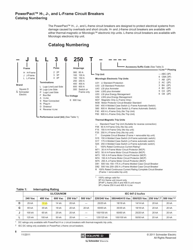
© 2011 Schneider ElectricAll Rights Reserved
PowerPact™ H-, J-, and L-Frame Circuit Breakers Catalog Numbering
811/2011 ™
The PowerPact™ H-, J-, and L-frame circuit breakers are designed to protect electrical systems from damage caused by overloads and short circuits. H- and J-frame circuit breakers are available with either thermal-magnetic or Micrologic™ electronic trip units. L-frame circuit breakers are available with Micrologic electronic trip unit.
Catalog Numbering
Table 1: Interrupting RatingUL/CSA/NOM IEC 647-2 Icu/Ics
240 Vac 480 Vac 600 Vac 250 Vdc1 500 Vdc1
1 DC ratings only available with PowerPact H or J circuit breakers with thermal-magnetic trip units.
220/240 Vac 380/440/415 Vac 500/525 Vac 250 Vdc1,2
2 IEC DC rating only available on PowerPact J-frame circuit beakers.
500 Vdc1,2
D 25 kA 18 kA 14 kA 20 kA — 25/25 kA 18/18 kA 14/14 kA 20 kA 20 kA
G 65 kA 35 kA 18 kA 20 kA 20 kA 65/65 kA 35/35 kA 18/18 kA 20 kA 20 kA
J 100 kA 65 kA 25 kA 20 kA — 100/100 kA 65/65 kA 25/25 kA 20 kA 20 kA
L 125 kA 100 kA 50 kA 20 kA — 125/125 kA 100/100 kA 50/50 kA 20 kA 20 kA
Trip Unit
Micrologic Electronic Trip Units
U31 LI Standard Protection U33 LSI Standard Protection U43 LSI plus Ammeter U44 LSIG plus Ammeter U53 LSI plus Energy Management U54 LSIG plus Energy Management M37 Magnetic Only (L-Frame Only)M38 Motor Protector Circuit Breaker StandardS40 400 A Molded Case Switch (L-Frame Automatic Switch)S60 600 A Molded Case Switch (L-Frame Automatic Switch)F40 400 A L-Frame Only (No Trip Unit)F60 600 A L-Frame Only (No Trip Unit)
Thermal-Magnetic Trip Units
— Standard Fixed Trip Unit (Suitable for reverse connection)F06 60 A H-Frame Only (No trip unit)F15 150 A H-Frame Only (No trip unit)F25 250 A J-Frame Only (No trip unit)T Complete Circuit Breaker (Frame + removable trip unit)S15 150 A Molded Case Switch (H-Frame automatic switch)S17 175 A Molded Case Switch (J-Frame automatic switch)S25 250 A Molded Case Switch (J-Frame automatic switch)C 100% Rated Continuous Current Rating1
M71 30 A H-Frame Motor Circuit Protector (MCP)M72 50 A H-Frame Motor Circuit Protector (MCP)M73 100 A H-Frame Motor Circuit Protector (MCP)M74 150 A H-Frame Motor Circuit Protector (MCP)M75 250 A J-Frame Motor Circuit Protector (MCP)D81 500 Vdc 150–175 A J-Frame Molded Case Circuit BreakerD82 500 Vdc 200–250 A J-Frame Molded Case Circuit BreakerR 100% Rated Continuous Current Rating Complete Circuit Breaker
(Frame + removable trip unit)
1 100% ratings valid for:3P H/J frame unit mount only3P/4P L-frame 250 A and 400 A unit mount3P L-frame 250 A and 400 A I-Line
I-Line™ Phasing
— ABC (3P)6 CBA (3P)1 AB (2P)2 AC (2P)3 BA (2P)4 BC (2P)5 CA (2P)6 CB (2P)
Frame
H H-FrameJ J-FrameL L-Frame
Poles
2 2P3 3P4 4P
Amperage
060 60 A100 100 A150 150 A250 250 A400 400 A600 600 A000 Switch or
Frame only
Voltage
6 600 Vac
Terminations
L Lugs Line/Load SideM Lugs Line SideP Lugs Load SideF Bus BarA I-LineS Rear ConnectedN Plug-inD DrawoutK Reverse I-Line
Performance Level (kA) (See Table 1)
Accessory Suffix Code (See Table 2)
– J L L 3 6 250 T – – – – –
Brand
_ Square DN Schneider
Electric
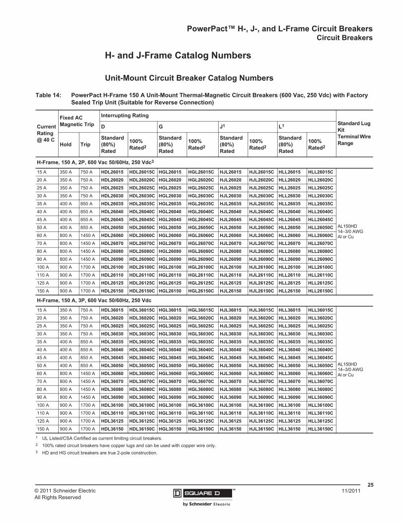
PowerPact™ H-, J-, and L-Frame Circuit BreakersCircuit Breakers
2511/2011© 2011 Schneider Electric
All Rights Reserved™
H- and J-Frame Catalog Numbers
Unit-Mount Circuit Breaker Catalog Numbers
Table 14: PowerPact H-Frame 150 A Unit-Mount Thermal-Magnetic Circuit Breakers (600 Vac, 250 Vdc) with Factory Sealed Trip Unit (Suitable for Reverse Connection)
Current Rating @ 40 C
Fixed AC Magnetic Trip
Interrupting RatingStandard Lug KitTerminal Wire Range
D G J1 L1
Hold TripStandard (80%) Rated
100% Rated2
Standard (80%) Rated
100% Rated2
Standard (80%) Rated
100% Rated2
Standard (80%) Rated
100% Rated2
H-Frame, 150 A, 2P, 600 Vac 50/60Hz, 250 Vdc3
15 A 350 A 750 A HDL26015 HDL26015C HGL26015 HGL26015C HJL26015 HJL26015C HLL26015 HLL26015C
AL150HD14–3/0 AWGAl or Cu
20 A 350 A 750 A HDL26020 HDL26020C HGL26020 HGL26020C HJL26020 HJL26020C HLL26020 HLL26020C25 A 350 A 750 A HDL26025 HDL26025C HGL26025 HGL26025C HJL26025 HJL26025C HLL26025 HLL26025C30 A 350 A 750 A HDL26030 HDL26030C HGL26030 HGL26030C HJL26030 HJL26030C HLL26030 HLL26030C35 A 400 A 850 A HDL26035 HDL26035C HGL26035 HGL26035C HJL26035 HJL26035C HLL26035 HLL26035C40 A 400 A 850 A HDL26040 HDL26040C HGL26040 HGL26040C HJL26040 HJL26040C HLL26040 HLL26040C45 A 400 A 850 A HDL26045 HDL26045C HGL26045 HGL26045C HJL26045 HJL26045C HLL26045 HLL26045C50 A 400 A 850 A HDL26050 HDL26050C HGL26050 HGL26050C HJL26050 HJL26050C HLL26050 HLL26050C60 A 800 A 1450 A HDL26060 HDL26060C HGL26060 HGL26060C HJL26060 HJL26060C HLL26060 HLL26060C70 A 800 A 1450 A HDL26070 HDL26070C HGL26070 HGL26070C HJL26070 HJL26070C HLL26070 HLL26070C80 A 800 A 1450 A HDL26080 HDL26080C HGL26080 HGL26080C HJL26080 HJL26080C HLL26080 HLL26080C90 A 800 A 1450 A HDL26090 HDL26090C HGL26090 HGL26090C HJL26090 HJL26090C HLL26090 HLL26090C100 A 900 A 1700 A HDL26100 HDL26100C HGL26100 HGL26100C HJL26100 HJL26100C HLL26100 HLL26100C110 A 900 A 1700 A HDL26110 HDL26110C HGL26110 HGL26110C HJL26110 HJL26110C HLL26110 HLL26110C125 A 900 A 1700 A HDL26125 HDL26125C HGL26125 HGL26125C HJL26125 HJL26125C HLL26125 HLL26125C150 A 900 A 1700 A HDL26150 HDL26150C HGL26150 HGL26150C HJL26150 HJL26150C HLL26150 HLL26150C
H-Frame, 150 A, 3P, 600 Vac 50/60Hz, 250 Vdc
15 A 350 A 750 A HDL36015 HDL36015C HGL36015 HGL36015C HJL36015 HJL36015C HLL36015 HLL36015C
AL150HD14–3/0 AWGAl or Cu
20 A 350 A 750 A HDL36020 HDL36020C HGL36020 HGL36020C HJL36020 HJL36020C HLL36020 HLL36020C25 A 350 A 750 A HDL36025 HDL36025C HGL36025 HGL36025C HJL36025 HJL36025C HLL36025 HLL36025C30 A 350 A 750 A HDL36030 HDL36030C HGL36030 HGL36030C HJL36030 HJL36030C HLL36030 HLL36030C35 A 400 A 850 A HDL36035 HDL36035C HGL36035 HGL36035C HJL36035 HJL36035C HLL36035 HLL36035C40 A 400 A 850 A HDL36040 HDL36040C HGL36040 HGL36040C HJL36040 HJL36040C HLL36040 HLL36040C45 A 400 A 850 A HDL36045 HDL36045C HGL36045 HGL36045C HJL36045 HJL36045C HLL36045 HLL36045C50 A 400 A 850 A HDL36050 HDL36050C HGL36050 HGL36050C HJL36050 HJL36050C HLL36050 HLL36050C60 A 800 A 1450 A HDL36060 HDL36060C HGL36060 HGL36060C HJL36060 HJL36060C HLL36060 HLL36060C70 A 800 A 1450 A HDL36070 HDL36070C HGL36070 HGL36070C HJL36070 HJL36070C HLL36070 HLL36070C80 A 800 A 1450 A HDL36080 HDL36080C HGL36080 HGL36080C HJL36080 HJL36080C HLL36080 HLL36080C90 A 800 A 1450 A HDL36090 HDL36090C HGL36090 HGL36090C HJL36090 HJL36090C HLL36090 HLL36090C100 A 900 A 1700 A HDL36100 HDL36100C HGL36100 HGL36100C HJL36100 HJL36100C HLL36100 HLL36100C110 A 900 A 1700 A HDL36110 HDL36110C HGL36110 HGL36110C HJL36110 HJL36110C HLL36110 HLL36110C125 A 900 A 1700 A HDL36125 HDL36125C HGL36125 HGL36125C HJL36125 HJL36125C HLL36125 HLL36125C150 A 900 A 1700 A HDL36150 HDL36150C HGL36150 HGL36150C HJL36150 HJL36150C HLL36150 HLL36150C
1 UL Listed/CSA Certified as current limiting circuit breakers.2 100% rated circuit breakers have copper lugs and can be used with copper wire only.3 HD and HG circuit breakers are true 2-pole construction.

© 2011 Schneider ElectricAll Rights Reserved
PowerPact™ H-, J-, and L-Frame Circuit Breakers Accessories and Auxiliaries
10411/2011 ™
Rotary Operating Handles
Directly Mounted Rotary Operating Handles
Door-Mounted (Extended) Rotary Operating Handle
Directly Mounted Rotary Operating Handle
pushto
trip
0616
3068
Installation The directly mounted rotary operating handle replaces the circuit breaker front accessory cover (secured by screws).
Operation
The direct rotary handle maintains:• Suitability for isolation• Indication of three positions: I (ON), Tripped and O (OFF)• Access to the “push-to-trip” button• Visibility of, and access to, trip unit settings• The circuit breaker may be locked in the OFF position by using one to three
padlocks (not supplied)
Models • Standard with black handle• VDE type with red handle and yellow bezel for machine tool control
Variations
Accessories transform the standard direct rotary handle for the following situations:• Motor control centers (MCCs):
– Opening of door prevented when circuit breaker is on– Closing of circuit breaker inhibited when door is open
• Machine tool control; complies with CNOMO E03.81.501N; degree of protection IP54• Early make or early break contacts may be installed into direct mount rotary handle
Standards The directly-mounted rotary operating handle is UL Listed under file E103955 and CSA Certified under file LR 69561
I/ON(Closed)
Tripped
O/OFF(Open)
Door Mounted Rotary Operating Handle
Installation
The door-mounted (extended) rotary operating handle is made up of:• A unit that replaces the front accessory cover of the circuit breaker (secured by screws)• An assembly (handle and front plate) on the door that is always secured in the same position, whether the
circuit breaker is installed vertically or horizontally• An adjustable extension shaft• The handle mechanism can be used in NEMA 3R and 12 enclosure applications
Operation
The door mounted operating handle makes it possible to operate circuit breakers installed in enclosure from the front. The door mounted operating handle maintains:• Suitability for isolation• Indication of the three positions OFF (O), ON (I) and tripped• Visibility of and access to trip unit settings when the door is open• Degree of protection: IP40 as per IEC 529Defeatable interlock prevents opening of door when circuit breaker is onThe circuit breaker may be locked in the off position by using one to three padlocks, padlock shackle diameter 0.19–0.31 in. (5–8 mm); padlocks are not supplied; locking prevents opening of the enclosure door
Shaft Length
The shaft length is the distance between the back of the circuit breaker and the door:• Minimum shaft length is 7.4 (185 mm)• Maximum shaft length is 24 in. (600 mm)• Extended shaft length must be adjusted
Models • Standard with black handle• VDE type with red handle and yellow bezel for machine tool control
Variations For drawout configurations, the extended rotary handle is also available with a telescopic shaft containing two stable positions
Standards The door-mounted rotary operating handle is UL Listed under file E103955 and CSA Certified under file LR 69561

PowerPact™ H-, J-, and L-Frame Circuit BreakersAccessories and Auxiliaries
10511/2011© 2011 Schneider Electric
All Rights Reserved™
Class 9421 NEMA Door Mounted Rotary Operating Handles
Table 91: Rotary Operated Handles
H- and J-Frame L-Frame
Device DescriptionFactory Installed
Suffix
Field Installable
Kit No.
Factory Installed
Suffix
Field Installable
Kit No.
Direct Mounted
Standard Handle Black Handle only RD10 S29337 RD10 S32597
Standard Black Handle with One early-break switch RD12 S29337 +
S29345 — —
Two early-make switches RD13 S29337 + S29346 — —
Red handle on yellow bezel
Handle Only RD20 S29339 RD20 S32599
One early-break switch RD22 S29339 + S29345 — —
Two early-make switches RD23 S29339 + S29346 — —
MCC Conversion Accessory — S429341 — S32606
CNOMO Conversion Accessory — — — S32602
Door Mounted
Standard black handle Handle Only RE10 S29338 RE10 S32598
Standard Black Handle with: Two early make switches RE13 S29338 + S29345 — —
Red handle on yellow bezel Handle Only RE20 S29340 RE20 S32600
Telescoping RT10 S29343 RT10 S32603
Accessories
Key lock adapter — S429344 — S32604
Key locks
Ronis 1351.500 — S41940 — S41940
Profalux KS5 B24 D4Z — S42888 — S42888
2 Ronis keylocks with 1 key — S41950 — S41950
2 Profalux keylocks with 1 key — S42878 — S42878
Indication Auxiliary SwitchOne early-break switch — — — S32605
Two early-make switches — — — S29346
Installation
The extended rotary operating handle is made up of:• A mounting plate that provides a rotary actuator for a standard toggle circuit breaker• Handle assemblies available for NEMA 3, 3R, 4, and 4X• Available in standard or short (3 in.) handle assemblies
OperationThe door mounted operating handle makes it possible to operate circuit breakers installed in enclosure from the front. Provides ON (I) and OFF (O) indicationThe circuit breaker may be locked in the off position
Shaft Length
The shaft length is the distance between the back of the circuit breaker and the door:• Minimum mounting depth is 5.5 in. (138 mm)• Maximum mounting depth is 10.75 in. (273 mm) with standard shaft• Maximum mounting depth is 21.3 in. (543 mm) with long shaft
H- and J-Frame Class 9421 Door-Mounted Operating MechanismDescription Catalog No.
Standard Shaft Kit 9421LJ1Long Shaft Kit 9421LJ4

www.schneider-electric.us
7M
INIA
TU
RE
AN
D M
OL
DE
D C
AS
EC
IRC
UIT
BR
EA
KE
RS
© 2012 Schneider ElectricAll Rights Reserved
7-17
Multi 9™ Miniature Circuit Breakers
UL 489 C60 480 Vac and UL489A C60 Miniature Circuit BreakersClass 860 / Refer to Catalog 0860CT0201
Multi 9 C60 UL 489 Listed 480V Miniature Circuit Breakers• UL 489 Listed, CSA C22.2 No. 5.1; Also IEC 60947-2; CE marked• 480Y/277 Vac @ 10 kA (2P and 3P), 277 Vac @ 10 kA (1P)• 0.5 A through 20 A• 1P, 2P, 3P, 18 mm wide per pole
• UL 486B Listed single-barrel lug: (2) 18–10 AWG (1-25 mm2) cables, Cu only• Optional ring tongue terminals
• A wide range of electrical and mechanical accessories• Suitable for reverse feeding• Trip-free mechanism• Positive indication of contact disconnect
Multi 9 C60 UL 489A Listed Miniature Circuit Breakers for DC Telecommunication ApplicationsA limited range of C60 products are UL Listed as UL 489A circuit breakers for protection of DC telecommunications circuits.
Interrupting Rating. . . . . . . . . . . . . . . . . . . . . . . . . . . . . . . . . . . . . . . .Page 7-3Accessories . . . . . . . . . . . . . . . . . . . . . . . . . . . . . . . . . . . . . . . . . . . Page 7-20Dimensions . . . . . . . . . . . . . . . . . . . . . . . . . . . . . . . . . . . . . . . . . . . Page 7-54
Trip Curve Use Magnetic Release
C For typical loads 7–10 x ampere rating (7–14 for DC)
D For high inrush 10–14 x ampere rating
Table 7.28: UL 489 Circuit Breakers (480Y/277 Vac)
Rating (A)
C Curve—7–10 Times Ampere Rating (7–14 DC) D Curve—10–14 Times Ampere Rating
1P 2P 3P 1P 2P 3P
Cat. No. $ Price Cat. No. $ Price Cat. No. $ Price Cat. No. $ Price Cat. No. $ Price Cat. No. $ Price
Single-Barrel Wire Lug
0.5 MGN61300 168.00 — — — — MGN61333 168.00 — — — —
1 MGN61301 168.00 MGN61312 357.00 MGN61323 519.00 MGN61334 168.00 MGN61345 357.00 MGN61356 519.00
2 MGN61302 168.00 MGN61313 357.00 MGN61324 519.00 MGN61335 168.00 MGN61346 357.00 MGN61357 519.00
3 MGN61303 168.00 MGN61314 357.00 MGN61325 519.00 MGN61336 168.00 MGN61347 357.00 MGN61358 519.00
4 MGN61304 168.00 MGN61315 357.00 MGN61326 519.00 MGN61337 168.00 MGN61348 357.00 MGN61359 519.00
5 MGN61305 168.00 MGN61316 357.00 MGN61327 519.00 MGN61338 168.00 MGN61349 357.00 MGN61360 519.00
6 MGN61306 168.00 MGN61317 357.00 MGN61328 519.00 MGN61339 168.00 MGN61350 357.00 MGN61361 519.00
8 MGN61307 168.00 MGN61318 357.00 MGN61329 519.00 MGN61340 168.00 MGN61351 357.00 MGN61362 519.00
10 MGN61308 168.00 MGN61319 357.00 MGN61330 519.00 MGN61341 168.00 MGN61352 357.00 MGN61363 519.00
15 MGN61309 168.00 MGN61320 357.00 MGN61331 519.00 MGN61342 168.00 MGN61353 357.00 MGN61364 519.00
20 MGN61310 168.00 MGN61321 357.00 MGN61332 519.00 MGN61343 168.00 MGN61354 357.00 MGN61365 519.00
Ring Tongue Terminal
0.5 MGN61366 168.00 — — — — MGN61399 168.00 — — — —
1 MGN61367 168.00 MGN61378 357.00 MGN61389 519.00 MGN61400 168.00 MGN61411 357.00 MGN61422 519.00
2 MGN61368 168.00 MGN61379 357.00 MGN61390 519.00 MGN61401 168.00 MGN61412 357.00 MGN61423 519.00
3 MGN61369 168.00 MGN61380 357.00 MGN61391 519.00 MGN61402 168.00 MGN61413 357.00 MGN61424 519.00
4 MGN61370 168.00 MGN61381 357.00 MGN61392 519.00 MGN61403 168.00 MGN61414 357.00 MGN61425 519.00
5 MGN61371 168.00 MGN61382 357.00 MGN61393 519.00 MGN61404 168.00 MGN61415 357.00 MGN61426 519.00
6 MGN61372 168.00 MGN61383 357.00 MGN61394 519.00 MGN61405 168.00 MGN61416 357.00 MGN61427 519.00
8 MGN61373 168.00 MGN61384 357.00 MGN61395 519.00 MGN61406 168.00 MGN61417 357.00 MGN61428 519.00
10 MGN61374 168.00 MGN61385 357.00 MGN61396 519.00 MGN61407 168.00 MGN61418 357.00 MGN61429 519.00
15 MGN61375 168.00 MGN61386 357.00 MGN61397 519.00 MGN61408 168.00 MGN61419 357.00 MGN61430 519.00
20 MGN61376 168.00 MGN61387 357.00 MGN61398 519.00 MGN61409 168.00 MGN61420 357.00 MGN61431 519.00
Table 7.29: UL 489A Circuit Breakers for DC Telecommunications Applications (1P, 2 Modules, C curve)
Rating (A) Cat. No. $ Price Rating (A) Cat. No. $ Price
0.5 60406 120.00 10 60414 101.00
1 60407 101.00 13 60415 101.00
2 60408 101.00 15 60416 101.00
3 60409 101.00 20 60417 101.00
4 60410 101.00 30 60418 101.00
5 60411 101.00 40 60419 111.00
6 60412 101.00 50 60420 117.00
8 60413 101.00 60 60421 123.00
1P UL489 C60
2P UL489 C60
3PUL489 C60
DE2 Discount Schedule
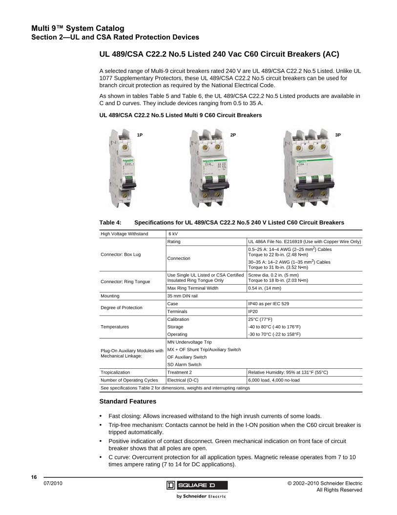
© 2002–2010 Schneider ElectricAll Rights Reserved
Multi 9™ System Catalog Section 2—UL and CSA Rated Protection Devices
1607/2010
UL 489/CSA C22.2 No.5 Listed 240 Vac C60 Circuit Breakers (AC)
A selected range of Multi-9 circuit breakers rated 240 V are UL 489/CSA C22.2 No.5 Listed. Unlike UL 1077 Supplementary Protectors, these UL 489/CSA C22.2 No.5 circuit breakers can be used for branch circuit protection as required by the National Electrical Code.
As shown in tables Table 5 and Table 6, the UL 489/CSA C22.2 No.5 Listed products are available in C and D curves. They include devices ranging from 0.5 to 35 A.
Standard Features
• Fast closing: Allows increased withstand to the high inrush currents of some loads.
• Trip-free mechanism: Contacts cannot be held in the I-ON position when the C60 circuit breaker is tripped automatically.
• Positive indication of contact disconnect. Green mechanical indication on front face of circuit breaker shows that all poles are open.
• C curve: Overcurrent protection for all application types. Magnetic release operates from 7 to 10 times ampere rating (7 to 14 for DC applications).
UL 489/CSA C22.2 No.5 Listed Multi 9 C60 Circuit Breakers
Table 4: Specifications for UL 489/CSA C22.2 No.5 240 V Listed C60 Circuit Breakers
High Voltage Withstand 6 kV
Connector: Box Lug
Rating UL 486A File No. E216919 (Use with Copper Wire Only)
Connection
0.5–25 A: 14–4 AWG (2–25 mm2) Cables Torque to 22 lb-in. (2.48 N•m)
30–35 A: 14–2 AWG (1–35 mm2) Cables Torque to 31 lb-in. (3.52 N•m)
Connector: Ring TongueUse Single UL Listed or CSA Certified Insulated Ring Tongue Only
Screw dia. 0.2 in. (5 mm)Torque to 18 lb-in. (2.03 N•m)
Max Ring Terminal Width 0.54 in. (14 mm)
Mounting 35 mm DIN rail
Degree of ProtectionCase IP40 as per IEC 529
Terminals IP20
Temperatures
Calibration
Storage
Operating
25°C (77°F)
-40 to 80°C (-40 to 176°F)
-30 to 70°C (-22 to 158°F)
Plug-On Auxiliary Modules with Mechanical Linkage:
MN Undervoltage Trip
MX + OF Shunt Trip/Auxiliary Switch
OF Auxiliary Switch
SD Alarm Switch
Tropicalization Treatment 2 Relative Humidity: 95% at 131°F (55°C)
Number of Operating Cycles Electrical (O-C) 6,000 load, 4,000 no-load
See specifications Table 2 for dimensions, weights and interrupting ratings
1P 2P 3P

Multi 9™ System CatalogSection 2—UL and CSA Rated Protection Devices
1707/2010© 2002–2010 Schneider Electric
All Rights Reserved
• D curve: Overcurrent protection for loads with high inrush currents (motors, transformers). Magnetic release operates between 10 and 14 times ampere rating (no dc rating for D curve).
• Suitable for reverse feeding.
• Allows locking in O-OFF position using padlock attachment.
Connections
Three versions of field wiring connectors are available for the 240 Vac UL 489/CSA C22.2 No.5 Listed devices:
• Box lug, meeting UL 486A requirements
• Ring tongue terminal with 5 mm screw
• Ring Tongue terminals with Fingersafe (IP20) shrouds
The circuit breakers can be ordered with the following combinations of connectors:
• Line terminal box lug/load terminal box lug
• Line terminal ring tongue/load terminal ring tongue (for fingersafe version, add -F suffix to catalog number)
Standards
• UL 489 Circuit Breaker: File No. E215117
• Single pole 15–20 A is UL Listed as SWD (switching duty).
• 1-, 2-, and 3-pole 15–35 A are HID (high intensity discharge) rated.
• CSA C22.2 No. 5.1 Circuit Breakers: File No. 179014
• IEC 60947-2
• CE Marked
Figure 5: Connection Options for 240 Vac UL 489/CSA C22.2 No.5 Listed Devices
Box Lug
Box Lug
Ring Tongue
Ring Tongue
Fingersafe Ring Tongue
Fingersafe Ring Tongue

© 2002–2010 Schneider ElectricAll Rights Reserved
Multi 9™ System Catalog Section 2—UL and CSA Rated Protection Devices
1807/2010
Catalog Numbers
NOTE: UL 489/CSA C22.2 No.5 Listed Multi 9 circuit breakers are calibrated at 25°C (77°F). Please refer to the rating tables (page 83) for applications at temperatures greater than 25°C (77°F).
NOTE: The NEC requires that the continuous load applied to the circuit breaker shall not exceed 80% of the circuit breaker ampere rating.
Table 5: Catalog Numbers for C Curve, UL 489/CSA C22.2 No.5 Listed 240 Vac C60 Miniature Circuit Breakers (Box Lug and Ring Tongue Terminal Combinations)
Rating 1P 2P 3P
Box/Box Ring/Ring1
1 IP-20 Fingersafe ring tongue terminals may be ordered with an F suffix (example: 60210F)
Box/Box Ring/Ring1 Box/Box Ring/Ring1
0.5 A
1 A
1.5 A
60100
60101
60102
60200
60201
60202
60134
60135
60136
60234
60235
60236
—
60168
60169
—
60268
60269
2 A
3 A
4 A
60103
60104
60105
60203
60204
60205
60137
60138
60139
60237
60238
60239
60170
60171
60172
60270
60271
60272
5 A
6 A
7 A
60106
60107
60108
60206
60207
60208
60140
60141
60142
60240
60241
60242
60173
60174
60175
60273
60274
60275
8 A
10 A
13 A
60109
60110
60111
60209
60210
60211
60143
60144
60145
60243
60244
60245
60176
60177
60178
60276
60277
60278
15 A
20 A
25 A
60112
60113
60114
60212
60213
60214
60146
60147
60148
60246
60247
60248
60179
60180
60181
60279
60280
60281
30 A
35 A
60115
60116
60215
60216
60149
60150
60249
60250
60182
60183
60282
60283
Table 6: Catalog Numbers for D Curve, UL 489/CSA C22.2 No.5 Listed 240 Vac C60 Miniature Circuit Breakers (Line/Load as Box Lug or Ring Tongue Terminals)
Rating 1P 2P 3P
Box/Box Ring/Ring1
1 IP-20 Fingersafe ring tongue terminals may be ordered with an F suffix (example: 60210F)
Box/Box Ring/Ring1 Box/Box Ring/Ring1
0.5 A
1 A
1.5 A
60117
60118
60119
60217
60218
60219
60151
60152
60153
60251
60252
60253
—
60184
60185
—
60284
60285
2 A
3 A
4 A
60120
60121
60122
60220
60221
60222
60154
60155
60156
60254
60255
60256
60186
60187
60188
60286
60287
60288
5 A
6 A
7 A
60123
60124
60125
60223
60224
60225
60157
60158
60159
60257
60258
60259
60189
60190
60191
60289
60290
60291
8 A
10 A
13 A
60126
60127
60128
60226
60227
60228
60160
60161
60162
60260
60261
60262
60192
60193
60194
60292
60293
60294
15 A
20 A
25 A
60129
60130
60131
60229
60230
60231
60163
60164
60165
60263
60264
60265
60195
60196
60197
60295
60296
60297
30 A
35 A
60132
60133
60232
60233
60166
60167
60266
60267
60198
60199
60298
60299

MECHANICAL
TERMINAL TERMINAL PRODUCTI.D. ACCOMMODATION I.D.
Brass, hot
Grounding
Silver, neutral
15A 125V, NEMA 5-15R; 20A 125V Feed-Through
ELECTRICAL
DIELECTRIC CURRENT TEMP.VOLTAGE INTERR. RISE
Withstands 10kA 1500V
perUL 498
F3
Hos
pita
l & C
omm
erci
al G
rade
GFC
I Dev
ices
15A 125V & 20A 125VHospital & Commercial Grade, GFCI's 2 YEAR LIMITED
To learn more about Leviton devices or for answers to technical questions call our Techline at 1-800-824-3005 or visit us at: www.leviton.com
30C max at fullrated current
after 50 cyclesoverload at150% rated
current for bothAC and DC appl.
per UL 498
ENVIRONMENTAL
FLAMMABILITY OPERATING TEMP.
Rated V-2 per UL 94 -35C to 65C
Ratings permanently
marked on device
#14 - #12 AWG solid or stranded
copper wire
8598-HG & 8898-HG SERIES 8598,8898, 8599-L & 8599-CP SERIES 8590 SERIES 8299 SERIES
1.7 (43.2 mm)
1.12 (28 mm)
2.7
(68.
6 m
m)
4.21
(10
6.93
mm
)
15A 125VRECEPTACLE
CLASS ACLASS ALEVITONLEVITON
GFC
I C
LAS
S
2
0 A
MP
125V
1.53 (38.9 mm)
TEST TEST
TESTTEST
TES
T ME
NS
UE
LTE
ST M
EN
SU
EL
TES
T MO
NTH
LYTE
ST M
ON
THLY
SU
IVE
Z IN
STR
UC
TIO
NS
UIV
EZ
INS
TRU
CTI
ON
FOLL
OW
DIR
EC
TIO
NS
FOLL
OW
DIR
EC
TIO
NS RESETRESET RESET RESET
8590-W8598-E 8599-CPI8599-I
Back & Side Wired
TRIP LEVEL
5±1 mA
8599-LW
20A 125V, NEMA 5-20R at Receptacle & Feed-Through
8598-HGR
GFCI®
1.7 (43.2 mm)
1.12 (28 mm)
2.7
(68.
6 m
m)
4.21
(10
6.93
mm
)
15A 125VRECEPTACLE
CLASS ACLASS ALEVITONLEVITON
GFC
I C
LAS
S
2
0 A
MP
125V
1.53 (38.9 mm)
TEST TEST
TESTTEST
TES
T ME
NS
UE
LTE
ST M
EN
SU
EL
TES
T MO
NTH
LYTE
ST M
ON
THLY
SU
IVE
Z IN
STR
UC
TIO
NS
UIV
EZ
INS
TRU
CTI
ON
FOLL
OW
DIR
EC
TIO
NS
FOLL
OW
DIR
EC
TIO
NS RESETRESET RESET RESET
1.7 (43.2 mm)
1.12 (28 mm)
2.7
(68.
6 m
m)
4.21
(10
6.93
mm
)
15A 125VRECEPTACLE
CLASS ALEVITON
GFC
I C
LAS
S
2
0 A
MP
125V
1.53 (38.9 mm)
OFF
O
SWITCH
RESETRESET
FOLL
OW
DIR
EC
TIO
NS
SU
IVE
Z IN
STR
UC
TIO
N
TES
T MO
NTH
LYTE
ST M
EN
SU
ELTEST
TEST
GROUND FAULT CIRCUITINTERRUPTER-MISC. MOTORCONTROLLER AND SWITCH
1.7 (43.2 mm)
1.12 (28 mm)
2.7
(68.
6 m
m)
4.21
(10
6.93
mm
)
15A 125VRECEPTACLE
CLASS ALEVITON
TEST
TEST
TES
T ME
NS
UE
LTE
ST M
ON
THLY
SU
IVE
Z IN
STR
UC
TIO
NFO
LLO
W D
IRE
CTI
ON
S RESET RESET
GFC
I125V
60HZ
FEE
D TH
RO
UG
H 20A
CLA
SS
A
AC
ON
LYS
WIT
CH
1000
W 1
20V
1.53 (38.9 mm)
COLOR SHALLOW WALLBOX EXTENDERFOR GFCI's
Brown 6197Ivory 6197-IWhite 6179-W
8299-G
15A 125V, NEMA 5-15R;20A 125V Feed-Through
FACE GFCI GFCI GFCI GFCI GFCI GFCICOLOR HOSPITAL GRADE COMMERCIAL GRADE COMMERCIAL GRADE COMMERCIAL GRADE COMMERCIAL GRADE COMMERCIAL GRADE
SMARTLOCK® SMARTLOCK® SMARTLOCK® SMARTLOCK® DUPLEX w/ RED & BLANK FACEDUPLEX w/ LED DUPLEX w/ LED DUPLEX w/ 41/2” Leads BLACK BUTTONS S-P SWITCH
Contractor Pack 1.5HP@120V ACMeets 2003 Meets 2003 Meets 2003 Meets 2003 Meets 2003 Meets 2003
UL Requirements UL Requirements UL Requirements UL Requirements UL Requirements UL Requirements
Brown 8598-HG 8598 8599 – – –Ivory 8598-HGI 8598-I 8599-I† 8599-LI 8599-CPI 8590-IWhite 8598-HGW 8598-W 8599-W† 8599-LW 8599-CPW 8590-WGray 8598-HGG 8598-G 8599-G – – –Red 8598-HGR 8598-R 8599-R – – –Black – 8598-E 8599-E – – 8590-EAlmond 8598-HGA 8598-A 8599-A† – 8599-CPA –
Brown 8898-HG 8898 8899 – – –Ivory 8898-HGI 8898-I 8899-I† – – –White 8898-HGW 8898-W 8899-W† – – –Gray 8898-HGG 8898-G 8899-G – – –Red 8898-HGR 8898-R – – – –Black – – 8899-E – – –Almond 8898-HGA 8898-A 8899-A† – – –
#LR-57811 #057–
AC HORSEPOWER RATINGS
1.5
STANDARDS & CERTIFICATIONS
NEMA ANSI UL UL CSA NOMWD-6 C-73 943 Fed Spec C22.2
Class A Listed& 498 WC-596
FACE GFCI COMBO DEVICE RECEPTACLECOLOR & SINGLE-POLE SWITCH
Meets 2003 UL Requirements
Ivory 8299-IWhite 8299-WGray 8299-GAlmond 8299-A
† Includes matching nylon wallplate.
F Section 4/27/05 2:08 PM Page 4

Product Data Sheet 9070FSC2TERM COVER (10 kits/package)
List Price $30.00 USD
Availability Stock Item: This item is normally stocked in our distribution facility.
TechnicalCharacteristics
Category 16204 - Transformers, Industrial Control, Fuse Blocks & Accessories, Type T
Discount Schedule CP8
GTIN 00785901904755
Package Quantity 10
Weight 0.07 lbs.
Availability Code Stock Item: This item is normally stocked in our distribution facility.
Returnability Y
Country of Origin US
Shipping and Ordering
As standards, specifications, and designs change from time to time, please ask for confirmation of the information given in this document.
Generated: 08/21/2012 16:32:02
© 2012 Schneider Electric. All rights reserved.
1

Industrial Control TransformersType T Transformers
8© 1999–2005 Schneider Electric All Rights Reserved 08/2005
120 Volt Control Secondary
Voltage and Connection Options
Voltage Code
Voltages Connections
Primary Secondary Primary Secondary
D1220 x 440230 x 460240 x 480
110115120
220/230/240 V:Connect to H1 and H4Jumper H1 with H3Jumper H2 with H4
440/460/480 V:Connect to H1 and H4Jumper H2 with H3
Connect to X1 and X2
H1
X2 X1
H2H3 H4
DimensionsVA Catalog
NumberFigure
Acc. Key
A B C E F Slots
UL CE IN mm IN mm IN mm IN mm IN mm IN mm
25 25 9070T25D1 1 I 3.09 79 3.00 76 2.58 66 2.00 51 2.50 64 0.20 x 0.38 5 x 10
50 50 9070T50D1 1 I 3.09 79 3.00 76 2.58 66 2.00 51 2.50 64 0.20 x 0.38 5 x 10
75 75 9070T75D1 1 I 3.34 85 3.38 86 2.89 73 2.38 61 2.81 71 0.20 x 0.48 5 x 12
100 100 9070T100D1 1 I 3.34 85 3.38 86 2.89 73 2.38 61 2.81 71 0.20 x 0.48 5 x 12
150 150 9070T150D1 1 I 3.59 91 3.75 95 3.20 81 2.88 73 3.13 80 0.20 x 0.38 5 x 10
200 200 9070T200D1 1 I 3.59 91 3.75 95 3.20 81 2.88 73 3.13 80 0.20 x 0.38 5 x 10
250 160 9070T250D1 2 I 5.30 135 3.75 95 3.21 82 2.88 73 3.13 80 0.20 x 0.38 5 x 10
300 200 9070T300D1 2 I 4.74 120 4.50 114 3.84 98 2.56 65 3.75 95 0.20 x 0.38 5 x 10
350 250 9070T350D1 2 I 5.11 130 4.50 114 3.84 98 3.00 76 3.75 95 0.20 x 0.38 5 x 10
500 300 9070T500D1 2 I 5.49 139 4.50 114 3.84 98 3.56 90 3.75 95 0.20 x 0.38 5 x 10
750 500 9070T750D1 2 I 5.61 143 5.25 133 4.51 115 3.43 87 4.38 111 0.28 x 0.56 7 x 14
1000 630 9070T1000D1 2 I 6.30 160 5.25 133 4.51 115 4.31 109 4.38 111 0.28 x 0.56 7 x 14
1500 1000 9070T1500D1 2 I 5.92 150 7.06 179 6.17 157 4.13 105 5.81 148 0.28 x 0.56 7 x 14
2000 1500 9070T2000D1 2 I 7.17 182 7.06 179 6.17 157 4.56 116 5.81 148 0.28 x 0.56 7 x 14
3000 2000 9070T3000D1 3 I 7.24 184 9.00 229 8.75 222 4.63 118 7.63 194 0.44 x 1.13 11 x 29
5000 3000 9070T5000D1 3 I 9.15 232 9.00 229 8.75 222 6.56 167 7.63 194 0.44 x 1.13 11 x 29
Figure 3
BD
A
EF
C
DA B
F E
C
Figure 2Figure 1
C
BDA
EF

Technical Specification
SRC 311 - SmartRun™
SRC311 v.3.0TS
Software version 3.x


Technical SpecificationProduct design
The SRC 311 is a pump drive with the SmartRun™ functionality, which is dedicated forwastewater pump stations. The drive is one of the components that is included in a pumpsystem solution for pump stations. The system consists of a level sensor, a level switch,and the drive that controls and monitors the pumps in the pump station. The system isreliable, energy efficient, and does not need extra monitor or control devices. The systemcan include up to three drives and pumps with alternation and full redundancy.
ApprovalSRC 311 version Approvals
200–240V CE, cUL
380–480V CE, cUL
500–600V CE, cUL, CSA
Facility requirementsCheck that the following requirements are met:
Environment
The drive must be protected from direct sunlight and from rainfall.
Altitude
Maximum altitude for non-de-rated operation is 1000 m (3281 ft).
Maximum altitude with UL approval is 2000 m (6562 ft).
Maximum altitude without UL approval is 4000 m (13 123 ft).
Ambient temperature
Activity °C (°F)
Operation –10 – 40 (14 – 104)
De-rated operation Maximum 50 (122)
Storage –40 – 60 (–40 – 140)
Humidity requirements
The relative humidity must not exceed 95% (non-condensing).
Air requirements
The air surrounding the unit must be free from:
• Excessive dust• Acids• Salt
Conformal coating is applied according to IEC standard 60721–3–2, Class 3C2.
Input voltageDepending upon the model and power rating, the drives are designed for directconnection to the following supplies
Technical Specification
SRC 311 - SmartRun™ Technical Specification 3

Model Number Supply Voltage Phases Frequency (Hz)
SRC311-X-X-XXXXX-XX 200 – 240 V ± 10% 1 50, 60
3
380 – 480 V ± 10% 3
500 – 600 V ± 10% 3
All SRC 311 monitor phase imbalance. A phase imbalance of > 3% results in SRC 311tripping. For input supplies which have a supply imbalance greater than 3%, an input linereactor is recommended. Alternatively, SRC 311 can be operated as a single-phase supplydrive with 50% de-rating.
Output power and current ratingsAll drives have an overload capacity of 150% for 60 seconds.
IP66
Table 1: 200 – 240 V (± 10%) 3–phase input, 3–phase output
kW HP Frame Size Nominal InputCurrent (A)
Fuse/MCB, type B) (A) Supply cable(mm2)
NominalOutputCurrent (A)
SUBCAB®
cable (mm2)None UL UL
4.0 5.0 3 17.3 20 20 6.0 18.0 2.5
Table 2: 380 – 480 V (± 10%) 3–phase input, 3–phase output
kW HP Frame Size Nominal InputCurrent (A)
Fuse/MCB, type B) (A) Supply cable(mm2)
NominalOutputCurrent (A)
SUBCAB®
cable (mm2)
None UL UL
4.0 5.0 2 10.8 16 15 2.5 9.5 1.5
5.5 7.5 3 13.3 16 15 2.5 14.0 2.5
7.5 10.0 3 18.5 25 25 4.0 18.0 2.5
Table 3: 500– 600 V (± 10%) 3–phase input, 3–phase output
kW HP Frame Size Nominal InputCurrent (A)
Fuse/MCB, type B) (A) Supply cable(mm2)
NominalOutputCurrent (A)
SUBCAB®
cable (mm2)
None UL UL
4.0 – 2 7.1 10 10 2.5 6.5 1.5
5.5 – 2 14.4 25 20 2.5 9.0 2.5
7.5 – 3 14.4 25 20 2.5 12.0 2.5
11.0 – 3 23.6 40 35 2.5 17.0 2.5
IP55
Table 4: 200 – 240 V (± 10%) 3–phase input, 3–phase output
kW HP Frame Size Nominal InputCurrent (A)
Fuse/MCB, type B) (A) Supply cable(mm2)
NominalOutputCurrent (A)
SUBCAB®
cable (mm2)
None UL UL
5.5 7.5 4 25.0 32 30 6.0 24.0 4.0
7.5 10.0 4 32.9 40 35 10.0 30.0 6.0
15.0 20.0 5 69.6 80 80 25.0 61.0 16.0
Technical Specification
4 SRC 311 - SmartRun™ Technical Specification

kW HP Frame Size Nominal InputCurrent (A)
Fuse/MCB, type B) (A) Supply cable(mm2)
NominalOutputCurrent (A)
SUBCAB®
cable (mm2)
None UL UL
22.0 30.0 6 92.3 125 125 35.0 90.0 25.0
37.0 50.0 6 150.2 200 175 70.0 150.0 35.0
Table 5: 380 – 480 V (± 10%) 3–phase input, 3–phase output
kW HP Frame Size Nominal InputCurrent (A)
Fuse/MCB, type B) (A) Supply cable(mm2)
NominalOutputCurrent (A)
SUBCAB®
cable (mm2)None UL UL
11.0 15 4 26.5 32 30 6.0 24 6.0
15.0 20 4 32.9 40 40 6.0 30.0 6.0
18.5 25 4 46.6 63 60 16.0 39.0 10.0
22.0 30 4 54.1 63 60 16.0 46.0 10.0
30 40 5 69.6 80 80 35.0 61.0 16.0
37 50 5 76.9 100 100 35.0 70.0 25.0
45.0 60 6 92.3 125 125 50 .0 90.0 25.0
55.0 75 6 116.9 160 150 70.0 110.0 35.0
75.0 120 6 153.2 200 175 70.0 150.0 35.0
Table 6: 500 – 600 V (± 10%) 3–phase input, 3–phase output
kW HP Frame Size Nominal InputCurrent (A)
Fuse/MCB, type B) (A) Supply cable(mm2)
NominalOutputCurrent (A)
SUBCAB®
cable (mm2)None UL UL
15.0 - 4 35.0 63 40 6.0 22.0 6.0
22.0 - 4 53.8 80 60 10.0 34.0 10.0
30.0 - 4 67.5 100 70 16.0 43.0 16.0
37.0 - 5 81.3 125 100 25.0 54.0 25.0
45.0 - 5 97.5 125 125 35 .0 65.0 35.0
55.0 - 6 131.3 200 150 35.0 78.0 35.0
75.0 - 6 162.5 250 200 50.0 105.0 50.0
90.0 - 6 187.5 250 250 70.0 130.0 70.0
110.0 - 6 187.5 250 250 70.0 150.0 70.0
Cable length
The maximum cable length is 100 m (328 ft). Screened cable must be used.
The PWM output switching from any inverter using a long motor cable can cause anincrease in the voltage at the motor terminals, depending on the cable length andinductance. The rise time and peak voltage can affect the service life of the motor. Flygtrecommends using an output choke for motor cable lengths of 50 m or more to ensuregood motor service life.
For UL-compliant installation, use copper wire with a minimum insulation temperaturerating of 75°C (167°F). When using fuses, the type must be Class CC or Class J.
Technical Specification
SRC 311 - SmartRun™ Technical Specification 5

DimensionsFrame size 2 – 3
A
E
BC
D
G
H
F
I
Frame size 2 3
A mm (in) 257.0 (10.12) 310.0 (12.20)
B mm (in) 220.0 (8.67) 276.5 (10.89)
C mm (in) 200.0 (7.87) 251.5 (9.90)
D mm (in) 28.5 (1.12) 33.4 (1.31)
E mm (in) 238.0 (9.37) 256.0 (10.08)
F mm (in) 188.0 (7.40) 210.5 (8.29)
G mm (in) 176.0 (6.93) 197.5 (7.78)
H mm (in) 4.2 (0.17) 4.2 (0.17)
I mm (in) 8.5 (0.33) 8.5 (0.33)
Frame size 4 – 6
A BC
DEGF
HI
Frame size 4 5 6
A mm (in) 450.0 (17.72) 540.0 (21.26) 865.0 (34.06)
B mm (in) 428.0 (16.85) 515.0 (20.28) 830.0 (32.68)
Technical Specification
6 SRC 311 - SmartRun™ Technical Specification

Frame size 4 5 6
C mm (in) 433.0 (17.05) 520.0 (20.47) 840.0 (33.07)
D mm (in) 8.0 (0.315) 8.0 (0.315) 10.0 (0.394)
E mm (in) 252.0 (9.92) 270.0 (10.63) 330.0 (12.99)
F mm (in) 171.0 (6.73) 235.0 (9.25) 330.0 (12.99)
G mm (in) 110.0 (4.33) 175.0 (6.89) 200.0 (7.87)
H mm (in) 4.25 (0.167) 4.25 (0.167) 5.50 (0.217)
I mm (in) 7.5 (0.295) 7.5 (0.295) 11.0 (0.295)
WeightFrame 2 3 4 5 6
Kg 4.8 7,3 11,5 22,5 50,0
Torque values for installationScrew Frame size Torque Nm (lbs-in)
Control terminal All 0.8 (7)
Power terminal 2 – 3 1 (8.85)
4 1.2 – 1.5 (10.6 – 13.2)
5 2.5 – 4.5 (22.5 – 39.8)
6 8 (70.8)
Mounting clearance
Y
X
X
Y
X Minimum 200 mm (7.87 in)Y Minimum 10 mm (0.349 in)
Typical drive heat losses are 3% of operating load conditions.
NOTICE:
The operating ambient temperature of the drive must be maintained.
Technical Specification
SRC 311 - SmartRun™ Technical Specification 7

Terminals
1 2 3 4 5 6 7 8 9 1011Control Terminal Unit 1
1 2 3 4 5 6
Power terminal Unit 1 and 2 Control Terminal Unit 2
3
1 2
4 5
6
7
891011
12 15
16 1920 21
22
23
1825
26
2728
1324
WS0
03610
1213 1 2 3 4 5 6 7 8 9 10111213
M M14
17
1. Incoming power2. RFI-toroid core, for sizes 2 and 33. Brown lead4. Black lead5. Grey lead6. Ground (earth)7. Pump 18. T1, (pump 1)9. T2, (pump 1)10. T31 (pump 1)11. T41 (pump 1)12. Black lead13. Control screen lead14. Level switch15. • EU: Grey
• US: Red16. Screen lead of the shared communication cable17. Signal leads of the shared communication cable18. Pump 219. T1 (pump 2)20. T2 (pump 2)21. T31 (pump 1)22. T41 (pump 1)23. Screen lead of the shared communication cable24. Screen lead of the level sensor cable25. Level sensor signal lead26. Level sensor lead –27. Level sensor lead +28. White
Figure 1: Two pump system
1 Isolate and terminate T3 and T4 in an end-sleeve.
Technical Specification
8 SRC 311 - SmartRun™ Technical Specification

Ext block+24 V
Alarm resetHigh level in
GndT2 in
Lvl signal outGndLvl signal inActive pumpInhibit inInhibit out
+ 10 V
12
34
56
78
910
1112
13
Control Term
inal Unit 1
Relay 1 NORelay 1 Com
Relay 1 NCRelay 2 comRelay 2 NO
1415
1617
18
Relay Term
inal Unit 1
Ext block+24 V
Alarm resetHigh level in
GndT2 in
Lvl signal outGndLvl signal inActive pumpInhibit inInhibit out
+ 10 V
12
34
56
78
910
1112
13
Control Term
inal Unit 3
Relay 1 NORelay 1 Com
Relay 1 NCRelay 2 comRelay 2 NO
1415
1617
18
Relay Term
inal Unit 3
Ext block+24 V
Alarm resetHigh level in
GndT2 in
Lvl signal outGndLvl signal inActive pumpInhibit inInhibit out
+ 10 V
12
34
56
78
910
1112
13
Control Term
inal Unit 2
Relay 1 NORelay 1 Com
Relay 1 NCRelay 2 comRelay 2 NO
1415
1617
18
Relay Term
inal Unit 2
+-
MM
M
WS0
07550
Figure 2: Three pump system
Ext block+24 V
Alarm resetHigh level in
GndT2 in
Lvl signal outGndLvl signal inActive pumpInhibit inInhibit out
+ 10 V
12
34
56
78
910
1112
13
Control Term
inal Unit 1
Relay 1 NORelay 1 Com
Relay 1 NCRelay 2 comRelay 2 NO
1415
1617
18
Relay Term
inal Unit 1
Ext block+24 V
Alarm resetHigh level in
GndT2 in
Lvl signal outGndLvl signal inActive pumpInhibit inInhibit out
+ 10 V
12
34
56
78
910
1112
13
Control Term
inal Unit 3
Relay 1 NORelay 1 Com
Relay 1 NCRelay 2 comRelay 2 NO
1415
1617
18
Relay Term
inal Unit 3
Ext block+24 V
Alarm resetHigh level in
GndT2 in
Lvl signal outGndLvl signal inActive pumpInhibit inInhibit out
+ 10 V
12
34
56
78
910
1112
13
Control Term
inal Unit 2
Relay 1 NORelay 1 Com
Relay 1 NCRelay 2 comRelay 2 NO
1415
1617
18
Relay Term
inal Unit 2
WS0
07551
Figure 3: Three pump I/O alternation system
Table 7: Power
Terminal Type Function
1 L1/L Incoming power to the drive
Technical Specification
SRC 311 - SmartRun™ Technical Specification 9

Terminal Type Function
2 L2/N Incoming power to the drive
3 L3 Incoming power to the drive
4 U Outgoing power for the pump
5 V Outgoing power for the pump
6 W Outgoing power for the pump
Table 8: Control I/O
Terminal Type Function
1 +24V utput (maximum 100 mA2) +24V external supply for backup power
2 Digital input 8-30V DC Pump block input
3 Digital input 8-30V DC External alarm reset
4 Digital input 8-30V DC Level switch
5 + 10V output (maximum 20 mA Out) Unused
6 Analog input 0-20 mA Pump sensor (T2)
7 Ground (earth)
8 Analog output 4-20 mA Level sensor output
9 Ground (earth)
10 Analog input 4-20 mA Level sensor input
11 Digital output 0-10 V Pump running output
12 Hardware inhibit input
13 Hardware inhibit output (0V)
Relay
14 Relay 1 common, 250V AC, 30V DC, 5A User configurable relay #1 (A-sum alarm)
15 Relay 1 NO, 250V AC, 30V DC, 5A User configurable relay #1 (A-sum alarm)
16 Relay 1 NC, 250V AC, 30V DC, 5A User configurable relay #1 (A-sum alarm)
17 Relay 2 common, 250V AC, 30V DC, 5A User configurable relay #2 (Pump runningoutput)
18 Relay 2 NO, 250V AC, 30V DC, 5A User configurable relay #2 (Pump runningoutput)
Table 9: Extension relay card
Terminal Type Function
1 Relay 3 common, 250V AC, 30V DC, 5A User configurable relay #3
2 Relay 3 contact, 250V AC, 30V DC, 5A User configurable relay #3
3 Relay 4 common, 250V AC, 30V DC, 5A User configurable relay #4
4 Relay 4 contact, 250V AC, 30V DC, 5A User configurable relay #4
5 Relay 5 common, 250V AC, 30V DC, 5A Relay #5 (Pump running output)
6 Relay 5 contact, 250V AC, 30V DC, 5A Pump running output
Table 10: External I/O controller card
Terminal Type Function
1 Extended digital input 1 External I/O Auto mode
2 Extended digital input 2 External Hand mode
2 The limitation in current allows FLS to be connected
Technical Specification
10 SRC 311 - SmartRun™ Technical Specification
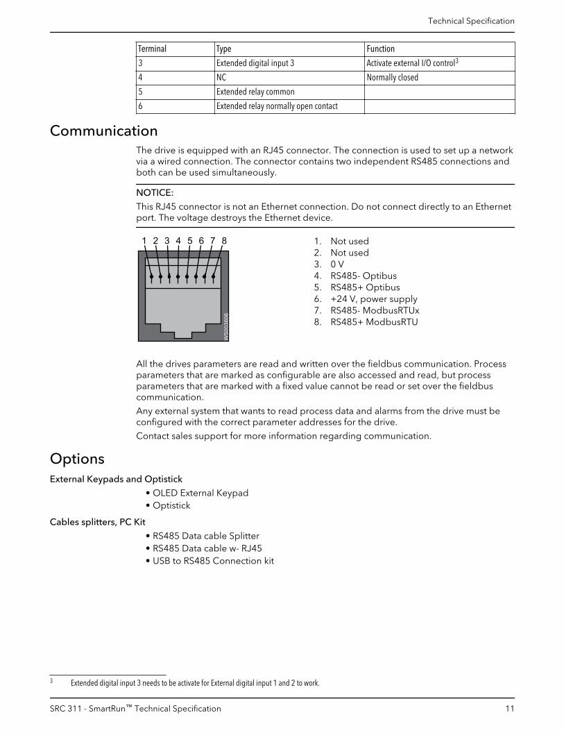
Terminal Type Function
3 Extended digital input 3 Activate external I/O control3
4 NC Normally closed
5 Extended relay common
6 Extended relay normally open contact
CommunicationThe drive is equipped with an RJ45 connector. The connection is used to set up a networkvia a wired connection. The connector contains two independent RS485 connections andboth can be used simultaneously.
NOTICE:
This RJ45 connector is not an Ethernet connection. Do not connect directly to an Ethernetport. The voltage destroys the Ethernet device.
1 8765432WS0
03606
1. Not used2. Not used3. 0 V4. RS485- Optibus5. RS485+ Optibus6. +24 V, power supply7. RS485- ModbusRTUx8. RS485+ ModbusRTU
All the drives parameters are read and written over the fieldbus communication. Processparameters that are marked as configurable are also accessed and read, but processparameters that are marked with a fixed value cannot be read or set over the fieldbuscommunication.
Any external system that wants to read process data and alarms from the drive must beconfigured with the correct parameter addresses for the drive.
Contact sales support for more information regarding communication.
OptionsExternal Keypads and Optistick
• OLED External Keypad• Optistick
Cables splitters, PC Kit
• RS485 Data cable Splitter• RS485 Data cable w- RJ45• USB to RS485 Connection kit
3 Extended digital input 3 needs to be activate for External digital input 1 and 2 to work.
Technical Specification
SRC 311 - SmartRun™ Technical Specification 11

Xylem |’zīləm|
1) The tissue in plants that brings water upward from the roots2) A leading global water technology company
We're 12,000 people unified in a common purpose: creating innovativesolutions to meet our world's water needs. Developing new technologies thatwill improve the way water is used, conserved, and re-used in the future is centralto our work. We move, treat, analyze, and return water to the environment, andwe help people use water efficiently, in their homes, buildings, factories andfarms. In more than 150 countries, we have strong, long-standing relationshipswith customers who know us for our powerful combination of leading productbrands and applications expertise, backed by a legacy of innovation.
For more information on how Xylem can help you, go to xyleminc.com
Xylem Water SolutionsManufacturing AB361 80 EmmabodaSwedenTel: +46-471-24 70 00Fax: +46-471-24 47 01http://tpi.xyleminc.com
Visit our Web site for the latest version of this documentand more information
The original instruction is in English. All non-Englishinstructions are translations of the original instruction.
© 2012 Xylem Inc
882877_3.0_en-US_2013-10_TS.SRC311

1
2
3
4
5
6
7
8
9
10
48
Pilot Lights—UL Types 4, 4X, 13/NEMA 4, 4X, 13 For use in hazardous locations, see page 53 . Legend plate not included .
Description Voltage Style With Red Fresnel Color Cap
With Green Fresnel Color Cap
With Other Color Cap (2)
Without Color Cap
9001SKP1
StandardPilot Light(Fresnel color cap shown)
110–120 V, 50–60 Hz Transformer SKP1R31 SKP1G31 SKP1b SKP1220–240 V, 50–60 Hz Transformer SKP7R31 SKP7G31 SKP7b SKP724–28 Vac/Vdc Full Voltage SKP35R31 SKP35G31 SKP35b SKP35For other voltages (1)
Transformer, Flashing or LED (3)
SKPaR31 SKPaG31 SKPab SKPa
Full Voltage, Neon or Resistor (4)
SKPaR31 SKPaG31 SKPab SKPa
9001SKT1
Push-To-TestPilot Light(Fresnel color cap shown)
110–120 V, 50–60 Hz Transformer SKT1R31 SKT1G31 SKT1b SKT1220–240 V, 50–60 Hz Transformer SKT7R31 SKT7G31 SKT7b SKT724–28 Vac/Vdc Full Voltage SKT35R31 SKT35G31 SKT35b SKT35For other voltages(1)
92% SKTaR31 SKTaG31 SKTab SKTaFull Voltage, Neon or Resistor (4)
SKTaR31 SKTaG31 SKTab SKTa
9001SKTR38
Remote TestPilot Light(Fresnel color cap shown)
120 Vac Only Resistor SKTR38R31 SKTR38G31 SKTR38b SKTR3824–28 Vac Only Full Voltage SKTR35R31 SKTR35G31 SKTR35b SKTR35For other voltages(1)
Full Voltage or Resistor (5)
SKTRaR31 SKTRaG31 SKTRab SKTRa
(1) Replace a with the voltage assembly code as chosen from the tables on page 54. Example: SKTaR31 with 208 Vac red LED voltage = SKT37LRR31.
(2) Replace b with the color code as chosen from the color code table below. Example: SKP1b with a blue fresnel cap = SKP1L31.
(3) The cap must be the same color as the LED light module chosen, e.g., for a green LED, use a green color cap.(4) On neon light modules, use clear color caps only.(5) Use only full voltage or resistor voltage assembly codes on remote test pilot lights. Do not choose LED, neon or transformer codes.
For AC use only.
Color Caps Color b Plastic Fresnel b Plastic Domed
AmberBlueClearGreenRedWhiteYellow
A31L31C31G31R31W31Y31
A9L9C9G9R9W9Y9
Harmony™ 9001K/SK/KX 30 mm push buttons9001SK – Pilot lights
References (continued)
Product range:page 36
Specificationspage 38
Dimensions:page 60
Mounting:page 61
Note: When ordering, add prefix “9001” to the reference.
To select and order Contact Blocks, Light Modules, Knobs, and Accessories, see pages 50 to 59.
R
M
M O.L.
L2
321
L1
STOPSTART
L2
C
Test
L1
M
STOP
LSI
M3
(TEST) C
(TEST) C L2
L2
L1(SIG)
CR
M2
M1
L2(TEST) C
START
TEST BUTTONL1 L2
L1(SIG)
L1(SIG)
Push-to-test Pilot Light
Remote Test Pilot Light
Typical Wiring Diagrams
R
M
M O.L.
L2
321
L1
STOPSTART
L2
C
Test
L1
M
STOP
LSI
M3
(TEST) C
(TEST) C L2
L2
L1(SIG)
CR
M2
M1
L2(TEST) C
START
TEST BUTTONL1 L2
L1(SIG)
L1(SIG)
Push-To-Test Pilot Light
Remote Test Pilot Light
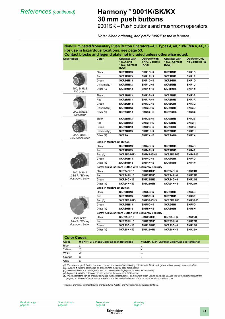
1
2
3
4
5
6
7
8
9
10
41
Non-Illuminated Momentary Push Button Operators—UL Types 4, 4X, 13/NEMA 4, 4X, 13 For use in hazardous locations, see page 53 . Contact blocks and legend plate not included unless otherwise noted .
Description Color Operator with 1 N .O . and1 N .C . Contact (KA1)
Operator with 1 N .O . Contact (KA2)
Operator with 1 N .C . Contact(KA3)
Operator Only No Contacts (5)
9001SKR1BFull Guard
Black SKR1BH13 SKR1BH5 SKR1BH6 SKR1BRed SKR1RH13 SKR1RH5 SKR1RH6 SKR1RGreen SKR1GH13 SKR1GH5 SKR1GH6 SKR1GUniversal (1) SKR1UH13 SKR1UH5 SKR1UH6 SKR1UOther (2) SKR1bH13 SKR1bH5 SKR1bH6 SKR1b
9001SKR3BNo Guard
Black SKR3BH13 SKR3BH5 SKR3BH6 SKR3BRed SKR3RH13 SKR3RH5 SKR3RH6 SKR3RGreen SKR3GH13 SKR3GH5 SKR3GH6 SKR3GUniversal (1) SKR3UH13 SKR3UH5 SKR3UH6 SKR3UOther (2) SKR3bH13 SKR3bH5 SKR3bH6 SKR3b
9001SKR2BExtended Guard
Black SKR2BH13 SKR2BH5 SKR2BH6 SKR2BRed SKR2RH13 SKR2RH5 SKR2RH6 SKR2RGreen SKR2GH13 SKR2GH5 SKR2GH6 SKR2GUniversal (1) SKR2UH13 SKR2UH5 SKR2UH6 SKR2UOther (2) SKR2b SKR2bH5 SKR2bH6 SKR2b
9001SKR4B 1-3/8 in (35 mm)
Mushroom Button
Snap-In Mushroom ButtonBlack SKR4BH13 SKR4BH5 SKR4BH6 SKR4BRed SKR4RH13 SKR4RH5 SKR4RH6 SKR4RRed (3) SKR4R05H13 SKR4R05H5 SKR4R05H6 SKR4R05Green SKR4GH13 SKR4GH5 SKR4GH6 SKR4GOther (4) SKR4dH13 SKR4dH5 SKR4dH6 SKR4dScrew-On Mushroom Button with Set Screw SecurityBlack SKR24BH13 SKR24BH5 SKR24BH6 SKR24BRed SKR24RH13 SKR24RH5 SKR24RH6 SKR24RGreen SKR24GH13 SKR24GH5 SKR24GH6 SKR24GOther (4) SKR24dH13 SKR24dH5 SKR24dH6 SKR24d
9001SKR5 2-1/4 in (57 mm)
Mushroom Button
Snap-In Mushroom ButtonBlack SKR5BH13 SKR5BH5 SKR5BH6 SKR5BRed SKR5RH13 SKR5RH5 SKR5RH6 SKR5RRed (3) SKR5R05H13 SKR5R05H5 SKR5R05H6 SKR5R05Green SKR5GH13 SKR5GH5 SKR5GH6 SKR5GOther (4) SKR5dH13 SKR5dH5 SKR5dH6 SKR5dScrew-On Mushroom Button with Set Screw SecurityBlack SKR25BH13 SKR25BH5 SKR25BH6 SKR25BRed SKR25RH13 SKR25RH5 SKR25RH6 SKR25RGreen SKR25GH13 SKR25GH5 SKR25GH6 SKR25GOther (4) SKR25dH13 SKR25dH5 SKR25dH6 SKR25d
Color CodesColor b SKR1, 2, 3 Place Color Code in Reference d SKR4, 5, 24, 25 Place Color Code in ReferenceBlue L LYellow Y YWhite W —Orange S SGray E —(1) The universal push button operators contain one each of the following color inserts: black, red, green, yellow, orange, blue and white.(2) Replace b with the color code as chosen from the color code table above.(3) Knob has the words “Emergency Stop” in raised letters highlighted in white for readability.(4) Replace d with the color code as chosen from the color code table above(5) These operators can be ordered complete with contact blocks. For maximum block usage, see page 51. Add the “H” number chosen from
page 51 to the end of the operator reference number and add the cost of the “H” number to the operator cost.
To select and order Contact Blocks, Light Modules, Knobs, and Accessories, see pages 50 to 59.
Harmony™ 9001K/SK/KX 30 mm push buttons9001SK – Push buttons and mushroom operators
References (continued)
Product range:page 36
Specificationspage 38
Dimensions:page 60
Mounting:page 61
Note: When ordering, add prefix “9001” to the reference.
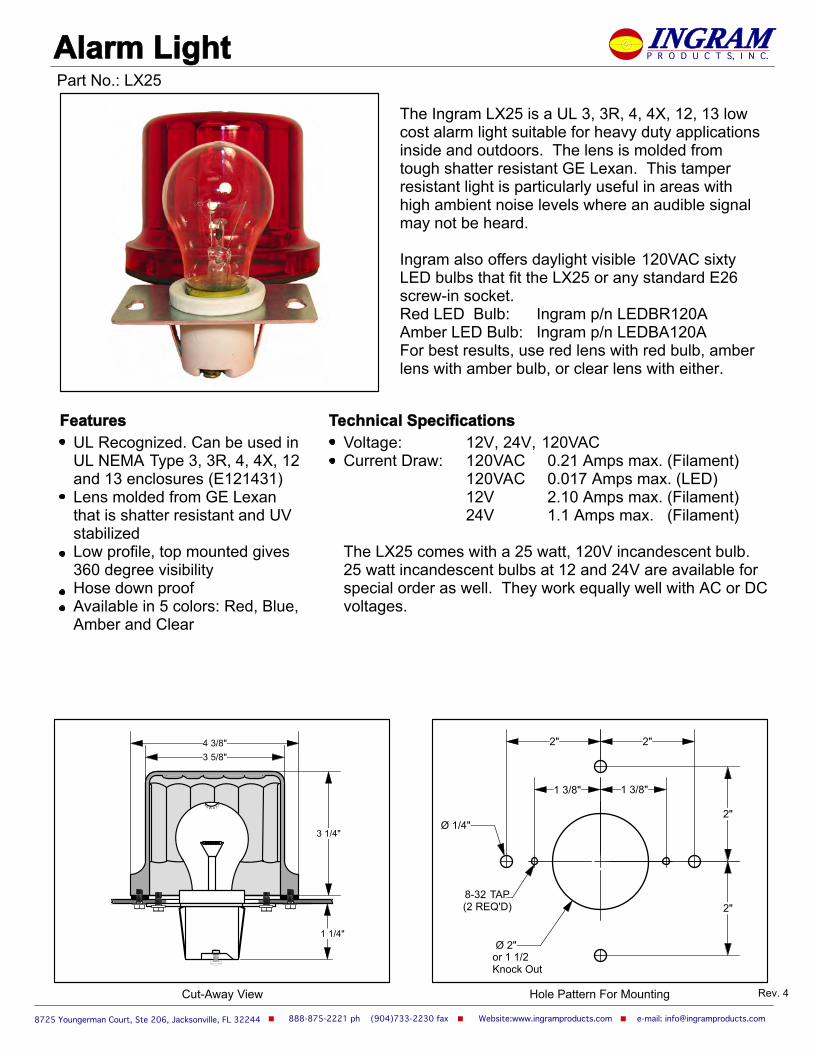
Website:www.ingramproducts.com e-mail: [email protected] ph (904)733-2230 fax
UL Recognized. Can be used in UL NEMA Type 3, 3R, 4, 4X, 12 and 13 enclosures (E121431)Lens molded from GE Lexan that is shatter resistant and UV stabilizedLow profile, top mounted gives 360 degree visibilityHose down proofAvailable in 5 colors: Red, Blue, Amber and Clear
Alarm Light
The Ingram LX25 is a UL 3, 3R, 4, 4X, 12, 13 low cost alarm light suitable for heavy duty applications inside and outdoors. The lens is molded from tough shatter resistant GE Lexan. This tamper resistant light is particularly useful in areas with high ambient noise levels where an audible signal may not be heard.
Ingram also offers daylight visible 120VAC sixty LED bulbs that fit the LX25 or any standard E26 screw-in socket.Red LED Bulb: Ingram p/n LEDBR120AAmber LED Bulb: Ingram p/n LEDBA120AFor best results, use red lens with red bulb, amber lens with amber bulb, or clear lens with either.
Features Technical SpecificationsVoltage: 12V, 24V, 120VACCurrent Draw: 120VAC 0.21 Amps max. (Filament)
120VAC 0.017 Amps max. (LED)12V 2.10 Amps max. (Filament)24V 1.1 Amps max. (Filament)
The LX25 comes with a 25 watt, 120V incandescent bulb.25 watt incandescent bulbs at 12 and 24V are available for special order as well. They work equally well with AC or DC voltages.
8725 Youngerman Court, Ste 206, Jacksonville, FL 32244
INGRAMP R O D U C T S, I N C.
Part No.: LX25
Rev. 4Cut-Away View Hole Pattern For Mounting
3 5/8"4 3/8"
3 1/4"
40 W ATT
1 1/4"
or 1 1/2 Knock Out
8-32 TAP(2 REQ'D)
2"2"
1 3/8" 1 3/8"
2"
2"
Ø 1/4"
Ø 2"

Enclosure Wall
Shatter ResistantG.E. Lexan Globe
Mounting Bracket
2" Knock outor 2" hole
#8 - 32 MountingScrew
Gasket
LX25 Assembly
25W A TT

This highly reliable encapsulated solid state flasher is designed for use with incandescent or LED resistive loads. It can be used to directly flash 15 to 150-watt incandescent light bulb.
E121431
Operating voltage is 120 volts AC
Full wave AC output
Maximum tungsten load is 1.25 amps
Minimum pilot load is 10 VA
Flash rate: 75 flashes per minute ±5%, factory set
Operating temperature is -20°C to 40°C
Insulated 20 gauge wire leads are 6" long
Website:www.ingramproducts.com e-mail: [email protected] ph (904)778-2444 fax8725 Youngerman Court, Ste 206, Jacksonville, FL 32244
Solid State Flasher
Technical Specifications
Part No.: SSF150W
INGRAMP R O D U C T S, I N C.
On/Off Recycling Ratio
OnTime
OffTime
OffTime
OnTime
OffTime
OnTime
OnTime
Reset
Off
Energized
De-energized
Input Power
Output
Applied
0.4 seconds off time followed by 0.4 second on time
OffTime
SSF150WFLASHER
H
N
3KΩ RESISTOR20 WATT
R BK
For flasher to operate properly with low current drawLED bulbs, a shunt resistor should be used
Connection
FLASHER
MAX LOADTUNGSTEN 1.25 amps
PILOT DUTY 10 VA
120 VAC INPUT
1/2"
Ø 1/4"
1 1/2"1.000"
1.000"
Ø 15/16"
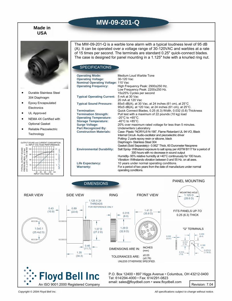
0.46(11.7)
1.125 X 24
1.0±0.1(25.4±2.5)
1.35(34.3)
REAR VIEW SIDE VIEW
0.43(10.9)
0.89(22.6)
INCHES(mm)
(±0.76)±0.03TOLERANCES ARE:
DIMENSIONS ARE IN:
(27.2 D)1.07 D
(32.8 D)1.29 D
FRONT VIEWRING
FOR REFERENCE ONLY
(8.0)0.315
THREADS
(35.8 D)1.41 D
MW-09-201-Q
The MW-09-201-Q is a warble tone alarm with a typical loudness level of 95 dB(A). It can be operated over a voltage range of 30-120VAC and warbles at a rate of 15 times per second. The terminals are standard 0.25" quick-connect blades. The case is designed for panel mounting in a 1.125" hole with a knurled ring nut.
SPECIFICATIONS
DIMENSIONS
Operating Mode: Medium Loud Warble Tone Operating Voltage: 30-120 Vac Nominal Operating Voltage: 110 Vac Operating Frequency: High Frequency Peak: 2900±250 Hz. Low Frequency Peak: 2200±250 Hz. 15±25% Cycles per second Typical Operating Current: 5 mA at 30 Vac 20 mA at 120 Vac Typical Sound Pressure: 85±5 dB(A), at 30 Vac, at 24 inches (61 cm), at 25°C 95±5 dB(A), at 120 Vac, at 24 inches (61 cm), at 25°C. Termination: Quick Connect Blades, 0.25 (6.3) Width, 0.032 (0.8) Thickness Termination Strength: Pull test with a maximum of 22 pounds (10 kg) load Operating Temperature: -20°C to +65°C. Storage Temperature: -40°C to +85°C. Surge Voltage: 20% over maximum rated voltage for less than 5 minutes. Part Recognized By: Underwriters Laboratory Construction Materials: Case- Plastic “NORYL® N-190”, Flame Retardant UL 94-VO, Black Internal Circuit- Audio-oscillator and piezoelectric driver Potting- 2 parts epoxy resin or silicone, black Diaphragm- Stainless Steel 304 Gasket (Sold Separately)– 0.062” Thick, 60 Durometer Neoprene Environmental Durability: Salt Spray- Withstand exposure to salt spray per ASTM B117 for a period of 300 hours with no decrease in sound output Humidity- 95% relative humidity at +40°C continuously for 100 hours. Vibration- Withstands vibration between 0 and 55 Hz. on all axes. Life Expectancy: 10 years under normal operating conditions. Warranty: For a period of two years from the date of manufacture under normal operating conditions.
MOUNTING HOLE
PANEL MOUNTING
0.25 (6.3) THICKFITS PANELS UP-TO
1.125 D(28.6 D)
0.070 D(1.78 D)
0.160
(6.4)0.250
(4)
(7.9)
0.312(7.9)
0.312
"Q" TERMINALS
0.032(0.81)
P.O. Box 12400 • 897 Higgs Avenue • Columbus, OH 43212-0400 Tel: 614/294-4000 • Fax: 614/291-0823 email: [email protected] • www.floydbell.com
All specifications subject to change without notice. Copyright © 2004 Floyd Bell Inc.
Made in USA
TYP
ICAL
OU
TPU
T S
OU
ND
INPUT VOLTAGE Vac40
80
90
100
8060
INP
UT
CU
RR
ENT
(mA)
5
15
10
100PR
ESS
UR
E dB
(A),
at 2
feet
vs. INPUT VOLTAGE PERFORMANCE.
20
120
70
• Durable Stainless Steel 304 Diaphragm
• Epoxy Encapsulated Electronics
• UL Approved
• NEMA 4X Certified with Optional Gasket
• Reliable Piezoelectric Technology
An ISO 9001:2000 Registered Company Revision: 7.04

Frequency 2900 500 HzMedium Loud Series - 95db(A) at 2 feet
+
Medium Warble Series
CaseStyle
Volume Control Option/UL Model# Voltage
Sound Levelat
min maxV V
Currentat
min maxV V
T**
05 -UL MW-05-616-P 5-16Vdc 80 95 8mA 18mA P
05 -UL MW-05-530-P 5-30Vdc 80 95 8mA 18mA P
05 -UL MW-05-550-P 15-36Vac/dc 75 95 3mA 8mA P
09 X-UL MW-09-616-Q 5-16Vdc 80 95 8mA 18mA Q
09 X-UL MW-09-616-S 5-16Vdc 80 95 8mA 18mA S
09 X-UL MW-09-616-W 5-16Vdc 80 95 8mA 18mA W
09 X-UL MW-09-530-Q 5-30Vdc 80 95 8mA 18mA Q
09 X-UL MW-09-530-S 5-30Vdc 80 95 8mA 18mA S
09 X-UL MW-09-530-W 5-30Vdc 80 95 8mA 18mA W
09 X-UL MW-09-531-Q 5-24Vac/dc 75 95 4mA 24mA Q
09 X-UL MW-09-531-S 5-24Vac/dc 75 95 4mA 24mA S
09 X-UL MW-09-531-W 5-24Vac/dc 75 95 4mA 24mA W
09 X-UL MW-09-948-Q 9-48Vdc 90 95 4mA 24mA Q
09 X-UL MW-09-948-S 9-48Vdc 90 95 4mA 24mA S
09 X-UL MW-09-948-W 9-48Vdc 90 95 4mA 24mA W
09 X-UL MW-09-550-Q 15-36Vac/dc 75 95 3mA 8mA Q
09 X-UL MW-09-550-S 15-36Vac/dc 75 95 3mA 8mA S
09 X-UL MW-09-550-W 15-36Vac/dc 75 95 3mA 8mA W
09 X-UL MW-09-201-Q 40-120Vac 75 95 3mA 8mA Q
09 X-UL MW-09-201-S 40-120Vac 75 95 3mA 8mA S
09 X-UL MW-09-201-W 40-120Vac 75 95 3mA 8mA W
09 X-UL MW-09-301-Q 140-220Vac 75 95 3mA 8mA Q
09 X-UL MW-09-301-S 140-220Vac 75 95 3mA 8mA S
09 X-UL MW-09-301-W 140-220Vac 75 95 3mA 8mA W
X: Denotes model is available with optional volume control.This simple manual shutter provides variable attenuation up to 20dBa typical.
UL: Denotes model is a UL Recognized Component
**Terminations:
W- Leads: 2 wires 24 AWG StrandedCopper, vinyl insultated. 2.75"long, 1/4" end stripped, color-coded.
P-PC Pins: 2 PC Pins. 180 apart onA 0.500" R from center, 0.032"diameter.
o
S-Screw terminals: 6-32 x 1/4" longstainless steel screw for wirewith lug attachment.
Q-0.250" quick connect terminals:0.250" width, 0.033" thickness,brass electro-tin plated for push-on (quick connect) attachmentsor direct solder.
09/09/02

8
Model 34 Electronic LCD Hour Meter
Description
Features
Specifi cations
••••••
Display: LCD with large 0.28” [7mm] high fi gures black on light background
Run indicator: Blinking decimal point
Reset: Remote, manual and non-reset (remote reset not available on surface mount housing)
Hour Meter Resolution: 0.01 or 0.1 Hour, displayed; 1 second, internal
Accuracy: ± 0.1% @ room temperature ± 0.2% over the specifi ed temperature range
Records & Displays: 9999999.9 - hours & 1/10’s or 999999.99 - hours & 1/100’s
Power: Self powered - battery life 15+ years
Terminations: Standard 0.250” [6.4mm] spades 1 meter wire (inductive)
Output: Format: Open-Drain MOSFET with Source connected to Common (see note 3)
Maximum Withstanding voltage: 30VDC, reference to Common Maximum Load current: 0.1Amp
Environmental: Temperature: (Storage and Operating) -40 to +185˚F [-40 to +85˚C] Humidity: 95% RH per SAE J1378 Vibration: 20g @ 10 to 80 Hz per SAE J1378 Shock: 44 to 55g’s per SAE J1378 Dielectric: 1000VAC 50/60 Hz for 1 minute Compliance: Compliant to the European WEEE and RoHS Directives
Sealing: Totally sealed
EMC Compliance: EN61326:1997 with A1:1998 and A2:2001 for industrial environments
Protection Against: Alternator load dump: 150V EMI (Electromag- netic Interface): +400V @ 500Hz inductive switching and reverse polarity
Enclosure: Totally sealed from moisture and dirt, NEMA 4/4X, 12, & IP66 compliant from the front when properly mounted using the optional gasket. (Not applicable to Snap-In Model)
Approvals: UL and cUL Recognized (fi le # ELIY2.E36690), CE, SAE, NEMA 4/4X compliant
Weight: 1oz [28g]
••••••••
Description
The Redington Model 34 LCD Hour Meter provides a large display, with 0.28” [7mm] high characters, in the industry size housings. The Hour Meters are available in 5 different housings, including a surface mount inductive input model. All models are totally sealed and are capable of submersion in 6’ [2 meters] of water. A wide operating voltage, 10-300VDC and 20-300VAC, and inductive input make the Model 34 versatile for all indoor and outdoor applications. All models are NEMA 4/4X, 12, & IP66 rated when used with the optional gasket and have a polarized lens which assures high visability in an outdoor environment.
Options
• Totally sealed from moisture and dirtAC or DC voltage input in the same unitTachometer/Hour Meter versionsCompact depthFits in existing panel openingsAlways on display15+ Year Battery Life
Maintenance Meters are offered with a maximum of 3 “Redi-Alerts” to alert users when service is due. Models are available with front panel fi eld or fac-tory programmable alerts. Not only does the display fl ash to get attention, but it displays a choice of 7 different .08”[2mm] maintenance icons. Models are available as a Preset Timer with a MOSFET output for the actuation of external alarms or indicator lamps. Users can program or specify the service interval and fl ash duration for each Redi-Alert. Flash duration is the amount of time in hours that the specifi c icon fl ashes before and after the service interval. If a front panel manual reset of the Redi-Alert is required the front panel models with switches must be specifi ed.
A choice of 6 housingsA choice of reset modesFront panel programmablePreset Timer with outputCan be programmed with starting timeProgrammable output thresholds Preset Hour Meter/time up or down Up to 3 Redi-Alerts/7 icons
Inputs: 10-300VDC and 20-300VAC-50/60Hz <2mA VIH 20VAC or 10VDC minimum VIL 3VAC or 3VDC maximum
www.trumeter.com

9
Model 34 Electronic LCD Hour Meter
Dimensions
FunctionsPreset Hour Meter: The preset function is centered on the output signal. When the time reaches the preset value, the output signal is turned “on”. The Preset function is time “up”.Upon reaching the preset value the preset can be automatically reset, or it can await an external reset.
Inductive Models: The surface mount Inductive unit is designed with an inductive interface. The unit will sense the firing of a spark plug on most small gasoline powered internal combustion engines. The wire lead from the unit is wrapped around the spark plug wire. Inductive models are available with and without tachometers. Most small engines provide 1 spark per RPM, in which case the maximum RPM is 30,000. Some small engines provide 2 sparks per RPM, the maximum RPM is then 15,000. Models are available that can be field (front panel switches) or factory programmed for 1.0, 2.0, or 0.5 sparks/pulses per RPM.
Front Panel Switch Functions: Front panel switches can be used for reset, display selection and programming. The two front Panel switches are used as follows:
SEL: During programming this switch is used to select options. The SEL switch is used during programming to move horizontally in the programming flow chart.
RST: This is the reset switch during normal operation. During programming the RST switch is used to enter an option. The RST switch is used during programming to move vertically in the programming flow chart.
Available Icons
SERVICE
CHANGE
OIL
OIL FILTER
AIR FILTER
LAMP
MUFFLER
1.60 [40.6]
1.41 [35.8] .05 [1.3].05 [1.3]
.75 [19.0]
.88 [22.3].25 [6.3]
1.43 [36.3]
.34 [8.6]
.89 [22.6].28 [7.0]
1.10 [27.9] .50 [12.7]
1.75 [44.4]
1.41 [35.8].05 [1.3].05 [1.3]
.75 [19.0]
.88 [22.3].25 [6.3]
1.43 [36.3]
.34 [8.6]
.89 [22.6]
.28 [7.0]1.10 [27.9] .50 [12.7]
1.29 [32.7].05 [1.3]
.03 [0.7]
.75 [19.0]
.88 [22.3].25 [6.3]
1.43 [36.3]
.34 [8.6]
.79 [20.0].28 [7.0]
.50 [12.7]
2.21 [56.1]
1.98 [50.3]
.05 [1.3]
Rectangular Flush Mount 2-Hole Mount
Panel Cutout: 1.45” [36.8mm] x 0.95” [24.1mm]Maximum Panel Thickness: 0.375” [9.5mm]
Panel Cutout: 1.45” [36.8mm] x 0.95” [24.1mm]
Panel Cutout: 1.45” [36.8mm] x 0.95” [24.1mm]Maximum Panel Thickness: 0.375” [9.5mm]
Flush Round/SAE Mount
www.trumeter.com

10
Model 34 Electronic LCD Hour Meter
Applications
Medical Devices Control Panels Production EquipmentGenerators Garden Tractor Marine Equipment
Notes1. When interfacing the Model 34 with a Solid State Relay or AC Sensor, the leakage current needs to be considered. Contact the factory or see the application note at www.redingtoncounters.com
2. Exceeding the Absolute Voltage Range and the Absolute Maximum Limits may result in damage to the unit.
3. The open-drain MOSFET acts like an open-collector NPN trasistor. Care should be taken since there is no current limiting protection in the unit.
1.29 [32.7]
.05 [1.3]
.03 [0.7]
.75 [19.0]
.88 [22.3].25 [6.3]
1.43 [36.3]
.34 [8.6]
.28 [7.0]
.50 [12.7]
2.87 [72.9]1.98 [50.3]
.79 [20.0]
.05 [1.3]
1.29 [32.7]
.05 [1.3]
.05 [1.3]
.75 [19.0]
.88 [22.3].25 [6.3]
1.43 [36.3]
.34 [8.6]
.79 [20.0].28 [7.0]
.50 [12.7]
1.10 [27.9]
1.60 [40.6]
2.12 [54.0]
1.41 [35.8]
.05 [1.3]
.50 [12.7]
.89 [22.6].28 [7.0]
1.10 [27.9]
1.75 [44.4]
.55 [14.0]
39.37 [1000.00]
3-Hole Mount Snap-In Mount
Surface Mount
Panel Cutout: 1.45” [36.8mm] x 0.95” [24.1mm]
Panel Cutout: 1.46” [37mm] x 0.95” [24.1mm]Minimum Panel Thickness: 0.04” [1.0mm]
Maximum Panel Thickness: 0.125” [3.18mm]
www.trumeter.com

Part Number Description Gasket
3410-0000 AC/DC HOUR METER 2 HOLE 1/4" SPADE TERMINALS NON-RESET 5003-010
3410-0010 AC/DC HOUR METER 2 HOLE 1/4" SPADE TERMINALS REMOTE-RESET 5003-010
3410-0020 AC/DC HOUR METER 2 HOLE 1/4" SPADE TERMINALS PROGRAMMING 5003-010
3410-1000AC/DC HOUR METER THREE HOLE CASE 1/4" SPADE TERMINALS NON-
RESET5003-017
3410-1010AC/DC HOUR METER THREE HOLE CASE 1/4" SPADE TERMINALS
REMOTE-RESET5003-017
3410-2000AC/DC HOUR METER FLUSH RECT CASE 1/4" SPADE TERMINALS NON-
RESET5003-009
3410-2010AC/DC HOUR METER FLUSH RECT CASE 1/4" SPADE TERMINALS
REMOTE-RESET5003-009
3410-3000AC/DC HOUR METER ROUND SAE CASE 1/4" SPADE TERMINALS NON-
RESET5003-009
3410-3010AC/DC HOUR METER ROUND SAE CASE 1/4" SPADE TERMINALS
REMOTE-RESET **SPECIAL ORDER** MOQ = 50 PCS5003-009
3410-5000AC/DC HOUR METER SNAP-IN CASE 1/4" SPADE TERMINALS NON-
RESET
3410-5010AC/DC HOUR METER SNAP-IN CASE 1/4" SPADE TERMINALS REMOTE-
RESET
NOTE PART NUMBERS MUST END IN -XX20 TO BE PROGRAMMABLE
5003-010 NEMA 4X GASKET TWO HOLE MOUNT
5003-017 NEMA 4X GASKET THREE HOLE MOUNT
5003-009 NEMA 4X GASKET SAE ROUND MOUNT
www.trumeter.com
5003-009 NEMA 4X GASKET FLUSH RECT MOUNT

Zelio® Plug-in Relays RXM Miniature RelaysProduct Description
4© 2005–2008 Schneider Electric All Rights Reserved 01/2008
Product Description
The RXM miniature relay range consists of:
1. 12 A relays with DPDT contacts, 10 A relays with 3PDT contacts, 6 A relays with 4PDT contacts, and 3 A “low level” relays with 4PDT contacts. All of these relays have the same dimensions.
2. Sockets with mixed or separate contact terminals.
3. Protection modules (diode, RC circuit or varistor). All these modules are common to all sockets.
4. A metal hold-down clip for all sockets.
5. A plastic hold-down clip for all sockets.
6. A 2-pole bus jumper that can be used on sockets with separate contact terminals to simplify wiring when creating a jumper between the coil terminals.
7. Clip-in markers for all the sockets except RXZ E2M114.
Relay Description
1. Spring return push button for testing the contacts (green: DC, red: AC).
2. Mechanical “relay status” indicator.
3. Optional removable lock-down door and push button, enabling forced maintaining of the contacts for test or maintenance purposes. During operation, this lock-down door must always be in the closed position.
4. Bipolar LED (depending on version) indicating the relay status.
5. Removable marker for relay identification.
6. Four notches for DIN rail mounting adapter or panel mounting adapter.
7. Eight, eleven, or fourteen pins.
8. Area by which the product can be easily gripped.
9. Mounting adapter enabling direct mounting of the relay on a panel.
10. Mounting adapter enabling direct mounting of the relay on a DIN rail.
Socket Description
Sockets with Mixed Contact Terminals
1. Connection by screw clamp terminals or box lug connector.
2. Fourteen female contacts for the relay pins.
3. Location for protection modules.
4. Locking components for plastic and metal hold-down clips.
5. Locating slot for mounting on DIN rail.
6. Two or four mounting holes for panel mounting.
NOTE: The inputs are mixed with the relay coil terminals, with the outputs being located on the opposite side of the socket.
7
6
2
1
5
3
4or
1
2
7
3
4
56
8
9 910
1
2
3
4
5
Outputs
Inputs
Coil Terminals
6

RXM Miniature Relays Zelio® Plug-in RelaysSpecifications and Characteristics
501/2008 © 2005–2008 Schneider Electric All Rights Reserved
Sockets with Separate Contact Terminals
1. Box lug connector.
2. Eight, eleven, or fourteen female contacts for the relay pins.
3. Location for protection modules.
4. Locking components for plastic and metal hold-down clips.
5. Locating slot for mounting on DIN rail.
6. Two mounting holes for panel mounting.
7. Location for bus jumpers (see mounting on sockets on page 11).
NOTE: The inputs and outputs are separated from the relay coil terminals.
1
6
2
3
4
5 7
Outputs
Inputs
Coil Terminals
General characteristics
Conforming to standards IEC/EN 61810-1 (iss. 2), UL 508, CSA C22-2 n° 14
Product certifications cULus File E164862 CCN NLDX, NLDX7; cURus File E164862 CCN NLDX2, NLDX8; CSA pending; CE; RoHS compliant
Ambient air temperature around the device
Storage -40–185 °F (-40–85 °C)
Operation -40–131 °F (-40–55 °C)
Vibration resistance Conforming to IEC/EN 60068-2-6 > 6 gn (10–50 Hz)
Degree of protection Conforming to IEC/EN 60529 IP 40
Shock resistanceconforming to IEC/EN 60068-2-27
Opening 10 gn
Closing 5 gn
Protection category (see page 38) RT I
Mounting position Any
Insulation characteristics
Rated insulation voltage (Ui) 250 V (IEC), 300 V (UL, CSA)
Rated impulse withstand voltage (Uimp) 3.6 kV (1.2/50 µs)
Dielectric strength(rms voltage)
Between coil and contact 2,500 Vac
Between poles 2,500 Vac
Between contacts 1,500 Vac
Contact characteristics
Relay type RXM2ABppp RXM3ABppp RXM4ABppp RXM4GBppp
Number and type of contacts (see page 12) DPDT 3PDT 4PDT 4PDT
Contact materials AgNi AgAu–Bifurcated
Conventional thermal current (Ith)
For ambient temperature y 131 °F (55 °C) 12 A 10 A 6 A 3 A
Rated operational current
Conforming to IEC in utilization category AC-1
N.O. 12 A 10 A 6 A 2 A
N.C. 6 A 5 A 3 A 1 A
Conforming to UL Resistive @277 Vac, hp @120 Vac 12 A, 1/2 hp 10 A, 1/3 hp 8 A, 1/3 hp 3 A, 1/16 hp
Maximum operating rateIn operating cycles/hour
No load 18,000
Under load 1,200
Switching voltage Maximum 250 Vac/Vdc
Switching capacityMinimum 10 mA on 17 V 2 mA on 5 V
Maximum 3,000 VA 2,500 VA 1,500 VA 750 VA
Utilization coefficient 20%
Mechanical durability in millions of operating cycles 10
Electrical durabilityin millions of operating cycles Resistive load 0.1

6© 2005–2008 Schneider Electric All Rights Reserved 01/2008
Zelio® Plug-in Relays RXM Miniature RelaysSpecifications and Characteristics
Electrical durability of contacts
Resistive load AC
A=RXM2ABppp B=RXM3ABppp C=RXM4ABppp D=RXM4GBppp
105
106
107
2 30 1
A BDCD
urab
ility
(N
umbe
r of
ope
ratin
g cy
cles
)
Switching capacity (kVA)
Coil characteristics
Average consumptionAC 1.2 VA
DC 0.9 W
Drop-out voltage thresholdAC u 0.15 Uc
DC u 0.1 Uc
Operating time(response time)
Between coil energization and making of the N.O. contact
AC 20 ms
DC 20 ms
Between coil de-energization and making of the N.C. contact
AC 20 ms
DC 20 ms
Coil voltage Uc 12 V 24 V 48 V 110 V 120 V 125 V 220 V 230 V 240 V
Relay coil voltage codes JD BD ED FD — GD MD — —
DC
Average resistance at 68 °F (20 °C) ± 10% 160 Ω 650 Ω 2,600 Ω 11,000 Ω — 11,000 Ω 14,000 Ω — —
Operating voltage limitsMin. 9.6 V 19.2 V 38.4 V 88 V — 100 V 176 V — —
Max. 13.2 V 26.4 V 52.8 V 121 V — 138 V 242 V — —
Relay coil voltage codes — B7 E7 — F7 — M7 P7 U7
AC
Average resistance at 68 °F (20 °C) ± 15% — 180 Ω 770 Ω — 4,430 Ω — 15,000 Ω 15,000 Ω 15,500 Ω
Operating voltage limitsMin. — 19.2 V 38.4 V — 96 V — 176 V 184 V 192 V
Max. — 26.4 V 52.8 V — 132 V — 242 V 253 V 264 V
Socket characteristics
Socket type RXZE2S108M RXZE2S111M RXZE2S114M RXZE2M114 RXZE2M114M
Relay types used RXM2ppppp RXM3ppppp RXM4ppppp RXM2ppppp1
RXM4pppppRXM2ppppp1
RXM4ppppp
Product certifications cURus File E172326 CCN SWIV2, SWIV8; CSA (pending); CE; RoHS compliant
Conventional thermal current (Ith) 12 A 10 A
Degree of protection Conforming to IEC/EN 60529 IP 20
Connection
Solid wire without cable end 1 conductor: AWG 20–12 (0.5–2.5 mm2)2 conductors: AWG 20–14 (0.5–1.5 mm2)
Flexible wire with cable end 1 conductor: AWG 24–14 (0.2–2.5 mm2)2 conductors: AWG 24–16 (0.2–1.5 mm2)
Flexible wire without cable end 1 conductor: AWG 24–14 (0.2–2.5 mm2)2 conductors: AWG 24–16 (0.2–1.5 mm2)
Maximum tightening torque 5.3 lbf-in (0.6 Npm) (M3 screw)
Contact terminal arrangement Separate Mixed
Bus jumper Ith: 5 A Yes No1 When mounting relay RXM2ppppp on socket RXZE2Mpppp, the thermal current must not exceed 10 A.

RXM Miniature Relays Zelio® Plug-in RelaysOrdering Information
701/2008 © 2005–2008 Schneider Electric All Rights Reserved
RXMpAB2F7
Miniature relays with lockable test button, without LED (sold in lots of 10)
Number and type of contacts - Thermal current (Ith)
DPDT - 12 A 3PDT - 10 A 4PDT - 6 A
Coil Voltage Catalog NumberWeight
Catalog NumberWeight
Catalog NumberWeight
lb. kg lb. kg lb. kg
12 Vdc RXM2AB1JD 0.082 0.037 RXM3AB1JD 0.084 0.038 RXM4AB1JD 0.080 0.036
24 Vdc RXM2AB1BD 0.082 0.037 RXM3AB1BD 0.084 0.038 RXM4AB1BD 0.080 0.036
48 Vdc RXM2AB1ED 0.082 0.037 RXM3AB1ED 0.084 0.038 RXM4AB1ED 0.080 0.036
110 Vdc RXM2AB1FD 0.082 0.037 RXM3AB1FD 0.084 0.038 RXM4AB1FD 0.080 0.036
220 Vdc — — — — — — RXM4AB1MD 0.080 0.036
24 Vac RXM2AB1B7 0.082 0.037 RXM3AB1B7 0.084 0.038 RXM4AB1B7 0.080 0.036
48 Vac RXM2AB1E7 0.082 0.037 RXM3AB1E7 0.084 0.038 RXM4AB1E7 0.080 0.036
120 Vac RXM2AB1F7 0.082 0.037 RXM3AB1F7 0.084 0.038 RXM4AB1F7 0.080 0.036
230 Vac RXM2AB1P7 0.082 0.037 RXM3AB1P7 0.084 0.038 RXM4AB1P7 0.080 0.036
240 Vac — — — — — — RXM4AB1U7 0.080 0.036
Miniature relays with lockable test button, with LED (sold in lots of 10)
12 Vdc RXM2AB2JD 0.082 0.037 RXM3AB2JD 0.084 0.038 RXM4AB2JD 0.080 0.036
24 Vdc RXM2AB2BD 0.082 0.037 RXM3AB2BD 0.084 0.038 RXM4AB2BD 0.080 0.036
48 Vdc RXM2AB2ED 0.082 0.037 RXM3AB2ED 0.084 0.038 RXM4AB2ED 0.080 0.036
110 Vdc RXM2AB2FD 0.082 0.037 RXM3AB2FD 0.084 0.038 RXM4AB2FD 0.080 0.036
125 Vdc — — — — — — RXM4AB2GD 0.080 0.036
24 Vac RXM2AB2B7 0.082 0.037 RXM3AB2B7 0.084 0.038 RXM4AB2B7 0.080 0.036
48 Vac RXM2AB2E7 0.082 0.037 RXM3AB2E7 0.084 0.038 RXM4AB2E7 0.080 0.036
120 Vac RXM2AB2F7 0.082 0.037 RXM3AB2F7 0.084 0.038 RXM4AB2F7 0.080 0.036
230 Vac RXM2AB2P7 0.082 0.037 RXM3AB2P7 0.084 0.038 RXM4AB2P7 0.080 0.036
RXM4GB2F7
Miniature relays with low level contacts, without LED (sold in lots of 10)
Miniature relays with low level contacts, with LED (sold in lots of 10)
Number and type of contacts - Thermal current (Ith) Number and type of contacts - Thermal current (Ith)
4PDT - 3 A 4PDT - 3 A
Coil Voltage Catalog NumberWeight
Coil Voltage Catalog NumberWeight
lb. kg lb. kg
12 Vdc RXM4GB1JD 0.080 0.036 12 Vdc RXM4GB2JD 0.080 0.036
24 Vdc RXM4GB1BD 0.080 0.036 24 Vdc RXM4GB2BD 0.080 0.036
48 Vdc RXM4GB1ED 0.080 0.036 48 Vdc RXM4GB2ED 0.080 0.036
110 Vdc RXM4GB1FD 0.080 0.036 110 Vdc RXM4GB2FD 0.080 0.036
24 Vac RXM4GB1B7 0.080 0.036 24 Vac RXM4GB2B7 0.080 0.036
48 Vac RXM4GB1E7 0.080 0.036 48 Vac RXM4GB2E7 0.080 0.036
120 Vac RXM4GB1F7 0.080 0.036 120 Vac RXM4GB2F7 0.080 0.036
230 Vac RXM4GB1P7 0.080 0.036 230 Vac RXM4GB2P7 0.080 0.036
240 Vac RXM4GB2U7 0.080 0.036

RXM Miniature Relays Zelio® Plug-in RelaysOrdering Information
901/2008 © 2005–2008 Schneider Electric All Rights Reserved
RXZ E2M114M withrelay RXM4AB2P7TQ
RXZ E2S114M withrelay RXM4AB2F7TQ
Miniature relays with lockable test button, without LED (sold in lots of 100)Number and type of contacts - Thermal current (Ith)DPDT - 12 A 4PDT - 6 A
Coil Voltage Catalog NumberWeight
Catalog NumberWeight
lb. kg lb. kg
12 Vdc — — — RXM4AB1JDTQ 0.080 0.036
24 Vdc RXM2AB1BDTQ 0.082 0.037 RXM4AB1BDTQ 0.080 0.036
48 Vdc — — — RXM4AB1EDTQ 0.080 0.036
110 Vdc — — — RXM4AB1FDTQ 0.080 0.036
220 Vdc — — — RXM4AB1MDTQ 0.080 0.036
24 Vac RXM2AB1B7TQ 0.082 0.037 RXM4AB1B7TQ 0.080 0.036
48 Vac — — — RXM4AB1E7TQ 0.080 0.036
120 Vac RXM2AB1F7TQ 0.082 0.037 RXM4AB1F7TQ 0.080 0.036
230 Vac RXM2AB1P7TQ 0.082 0.037 RXM4AB1P7TQ 0.080 0.036
Miniature relays with LED (sold in lots of 100)
24 Vdc — — — RXM4AB2BDTQ 0.080 0.036
24 Vac RXM2AB2B7TQ 0.082 0.037 RXM4AB2B7TQ 0.080 0.036
230 Vac RXM2AB2P7TQ 0.082 0.037 RXM4AB2P7TQ 0.080 0.036
Sockets (sold in lots of 10)
Contact terminal arrangement Connection Relay type Catalog NumberWeightlb. kg
MixedScrew clamp terminals RXM2pppp 1
RXM4pppp RXZE2M114 2 0.11 0.048
Box lug connector RXM2pppp 1
RXM4pppp RXZE2M114M 2 0.12 0.056
Separate Box lug connectorRXM2pppp RXZE2S108M 3 0.13 0.058RXM3pppp RXZE2S111M 2 0.15 0.066RXM4pppp RXZE2S114M 2 0.15 0.070
1 When mounting relay RXM2ppppp on socket RXZE2Mpppp, the thermal current must not exceed 10 A.2 Thermal current Ith: 10 A3 Thermal current Ith: 12 A
RXM 041pp7
Protection modules (sold in lots of 20)
Description Voltage For use with Catalog NumberWeightoz. g
Diode 6–250 Vdc All sockets RXM040W 0.11 3.0
RC circuit24–60 Vac All sockets RXM041BN7 0.35 10.0110–240 Vac All sockets RXM041FU7 0.35 10.0
Varistor6–24 Vac/Vdc All sockets RXM021RB 1.06 30.024–60 Vac/Vdc All sockets RXM021BN 1.06 30.0110–240 Vac/Vdc All sockets RXM021FP 1.06 30.0
REXL4pp
Timing relays
Description For use with Catalog NumberWeightlb. kg
2 timed DPDT contacts (function A—On-delay)
Sockets RXZ EpppppREXL2pp 4 0.09 0.042
4 timed 4PDT contacts (function A—On-delay) REXL4pp 4 0.09 0.042
4 Please refer to the Zelio® Time - Timers catalog (9050CT0001R2/05).
RXZ400
Accessories (sold in lots of 10)
Description For use with Catalog NumberWeightoz. g
Metal hold-down clip All sockets RXZ400 0.04 1.0Plastic hold-down clip All sockets RXZR335 0.18 5.0Bus jumper, 2-pole (Ith: 5 A) All sockets with separate contacts RXZS2 0.18 5.0Mounting adapter for DIN rail 5 All relays RXZE2DA 0.14 4.0Mounting adapter for mounting directly to a panel All relays RXZE2FA 0.07 2.0
Clip-in markersAll relays (sheet of 108 markers) RXZL520 2.82 80.0All sockets except RXZE2M114 RXZL420 0.04 1.0
5 Test button becomes inaccessible.

10© 2005–2008 Schneider Electric All Rights Reserved 01/2008
Zelio® Plug-in Relays RXM Miniature RelaysDimensions
RelaysRXMpppppp RXM2 RXM3 RXM4Common view Pin side view
1.57 (40) 0.83(21)
1.06
(27)
0.28(7)
0.24(6)
0.10(2.5)
0.10(2.5)
210.26(6.5)
0.24(6)
0.16(4)
0.53(13.5)
0.10(2.5)
0.10(2.5)
0.18(4.5)
21
0.53(13.5)
= =
0.10(2.5
0.10(2.5)0.53
(13.5)
= ==
SocketsRXZE2M114 RXZE2M114M
RXZE2Spppp RXZE2S108M RXZE2S111M RXZE2S114MCommon side view Pin side view
(1) Relays(2) Add-on protection module(3) Hold-down clip(4) 2 elongated holes Ø 0.14 x 0.26 (3.5 x 6.5)(5) 2 bus jumpers
(1)
(2)
(3)
1.00(25.5)
347
A214
A113
246
448
145
12
1
11
9
21
10
31
11
41
12
22
2
32
3
42
4
(4)
0.75(19)
1.57(40)
1.18(30)
0.35(9)
0.91(23)
0.83(21)1.18(30)2.72
(69)0.28(7)
1.56
(39.
5)
2.40
(61)
0.14
(3.5
)3.
11(7
9)
0.14(3.5)
0.67(17)
1.69(43)
0.93(23.5)
1.97(50)
1.06(27)
2.64(67)
1.57
(40)
3.15
(80)
44
8
34
7
24
6
14
5
42
4
32
3
22
2
12
1
A1
13
A2
1441
12
31
11
21
10
11
9
(3)
(1)
(2)
0.14(3.5)
0.28(7)
2.40(61)
0.91(23)
(3)
(2)
(1)
(5)
0.28(7)
0.75(19)
1.14(29)2.76
(70)
0.14
(3.5
)3.
11(7
9)
0.93(23.5)1.06(27)
1.50
(38)
41
12
11
9
44
8
14
5
A1
13
A2
14
42
4
12
1
0.14(3.5)
319
346
A1
13
A2
14
32
3
218
245
22
2
117
144
12
1
0.93(23.5)1.06(27)
1.50
(38)
0.14(3.5)
0.93(23.5)1.06(27)
1.50
(38)
0.14(3.5)
41
12
31
11
21
10
11
944
8
34
7
24
6
14
542
4
32
3
22
2
12
1
A1
13
A2
14
Dimensions = Inches(mm)

RXM Miniature Relays Zelio® Plug-in RelaysDimensions
1101/2008 © 2005–2008 Schneider Electric All Rights Reserved
Plastic clamp and clip-in markers
RXZR335 RXZL420 Mounting on all sockets
(1) Clip-in markers for all sockets except RXZE2M114.
2.24(57)
1.06
(27)
0.47
(12)
0.56
(14.
2)
1.04(26.5)
3.19(81)
3.72
(94.
5)
(1)
Bus jumper Metal clamp
RXZS2 Mounting on sockets with separate contacts (view from below) RXZ400
Example of bus jumper mounting on sockets
(1) 2 bus jumpers (polarity A2)(2) 2 bus jumpers (polarity A1)
0.09
(2.2
)
0.29
(7.3
)
0.98(25)
0.87(22) 0.09
(2.3)
(1)(1)
(2)(2)
1.46(37)
1.02
(26)
0.05(1.2)
Mounting adapter for rail 1 Mounting adapter for panelRXZE2DA RXZE2FA
1 Test button becomes inaccessible
1.50
(38)
0.24(6)
0.16(4)
0.94(24)
0.12 (3)
1.89
(48)
0.91(23)2.01
(51)
1.89(48)
1.93(49)
0.14(3.5)
1.69
(43)
1.50
(38)
0.16(4)
0.94(24)
0.14(3.5)
Dimensions = Inches(mm)

12© 2005–2008 Schneider Electric All Rights Reserved 01/2008
Zelio® Plug-in Relays RXM Miniature RelaysWiring Diagrams
Miniature relaysRXM2ppppp RXM3ppppp RXM4ppppp
Numbers shown in italics correspond to NEMA marking. Viewed from pin end.
A2
A1
414442
111412
1
125
149
11
4
428
4412
4113
A1
14
A2
A2
A1
313432
212422
111412
1
12
4
147
11
2
22
5
248
21
3
32
6
349
3113
A1
14
A2
A2
A1
414442
212422
313432
111412
1
125
149
11
4
428
4412
41
2
226
2410
21
3
327
3411
3113
A1
14
A2

DATE: 11-7-2014
PANEL: PDP
REV:
QTY LEGEND DESCRIPTION MFG PART NO.
ENCLOSURE & COMPONENTS
1Enclosure; 24 x 24 x 8, Nema 4X, SS304, Wall Mount, 3 Point Latch Hoffman A24H2408SSLP3PT
1 Enclosure; 24 x 24 Panel Hoffman A24P24
1 Enclosure; Drip Shield 24 In, SS304 Hoffman ADK24SS6
A/R Din Rail; 1 Meter Custom Connector C103PM
A/R Terminal Block; UK 5N, 30A, 600V Phoenix 3004362A/R End Block; ENS 35N Phoenix 800886A/R End Cover; D-UK 4/10 (UK 5 & 6) Phoenix 3030206 Distribution Block; 175A, 1IN/1OUT Mersen FSPDB1A
1 HT Heater; 100W, 120V Hoffman D-AH1001A
CONTROL COMPONENTS
1 ISRBarrier, Pulse, Two Channel, Isolated, 24-230VAC/DC PR Electronics 5202B4
1 ISBBarrier, Analog, Single Channel, Isolated, 24-230VAC/DC PR Electronics 5104B-B2A
EXTERNAL EQUIPMENT
2 FSHH,FSH Float; ENM-10 Level Regulator, 40 Ft Xylem 5828830
1 LXDCRLevel Transducer, 3400 Series Hydro-Static, 0-30 Ft Range, 39 Ft Cable (Std) MJK 209925
MARION COUNTY, AURORA, OR - FARGO L/S
XYLEM WATER SOLUTIONS USA, INC
QUOTE NO. 081514SM4.1
BILL OF MATERIAL
JOB NAME
CUSTOMER

Spec-00090 G
Wall-Mount EnclosurEs Wall-Mount EnclosurEs and accEssoriEs
EQUIPMENT PROTECTION SOLUTIONSSUBJECT TO CHANGE WITHOUT NOTICEstainlEss stEEl1
Spec-00090G763.422.2211763.422.2600
stainlEss stEElWall-Mount EnclosurEsWall-Mount EnclosurEs and accEssoriEs
continuous HingE WitH 3-Point latcH, tyPE 4X
inDustry stanDarDs
UL 508A Listed; Type 3R, 4, 4X, 12; File No. E61997cUL Listed per CSA C22.2 No 94; Type 3R, 4, 4X, 12; File No. E61997
NEMA/EEMAC Type 3R, 4, 4X, 12, 13IEC 60529, IP66Meets NEMA Type 3RX requirements
aPPlicationThese enclosures feature Hoffman’s exclusive POWERGLIDE™ Handle with 3-point latching, ideal for indoor or outdoor applications that require corrosion protection, convenient access, and padlocking security.
sPEciFications• 14 gauge Type 304 or 316L stainless steel bodies and doors• Seams continuously welded and ground smooth• Seamless foam-in-place gasket• Rolled lip around three sides of door • Internal 3-point latch and Type 316L stainless steel padlocking
POWERGLIDE Handle • Remove door by pulling stainless steel continuous hinge pin• Data pocket is high-impact thermoplastic• Collar studs provided for mounting optional panels• Exterior hardware on Type 316L stainless steel enclosures
matches enclosure material• Bonding provision on door; grounding stud on body
FinisHDoor, sides, top and bottom have smooth #4 brushed finish. Handle is electropolished.
accEssoriEsSee also Accessories.Panels for Type 3R, 4, 4X, 12 and 13 EnclosuresSteel and Stainless Steel Window KitsH2OMIT™ Vent Drains, Type 4XH2OMIT™ Thermoelectric Dehumidifier
MoDiFication anD custoMiZationHoffman excels at modifying and customizing products to your specifications. Contact your local Hoffman sales office or distributor for complete information.Bulletin: A4SW3
Standard Product
Catalog Number AxBxC in./mmStainlessSteel Type
F in./mm
SteelPanel
ConductivePanel
StainlessSteel Panel
Panel SizeD x E in./mm
DataPocket
A24H2006SSLP3PT 24.00 x 20.00 x 6.00 610 x 508 x 152
304 3.0076
A24P20 A24P20G A24P20SS6 21.00 x 17.00533 x 432
Small
A24H2006SS6LP3PT 24.00 x 20.00 x 6.00 610 x 508 x 152
316L 3.0076
A24P20 A24P20G A24P20SS6 21.00 x 17.00533 x 432
Small
A24H2008SSLP3PT 24.00 x 20.00 x 8.00 610 x 508 x 203
304 3.0076
A24P20 A24P20G A24P20SS6 21.00 x 17.00533 x 432
Small
A24H2008SS6LP3PT 24.00 x 20.00 x 8.00 610 x 508 x 203
316L 3.0076
A24P20 A24P20G A24P20SS6 21.00 x 17.00533 x 432
Small
A24H2408SSLP3PT 24.00 x 24.00 x 8.00 610 x 610 x 203
304 3.0076
A24P24 A24P24G A24P24SS6 21.00 x 21.00533 x 533
Small
A24H2408SS6LP3PT 24.00 x 24.00 x 8.00 610 x 610 x 203
316L 3.0076
A24P24 A24P24G A24P24SS6 21.00 x 21.00533 x 533
Small
A30H2408SSLP3PT 30.00 x 24.00 x 8.00 762 x 610 x 203
304 3.0076
A30P24 A30P24G A30P24SS6 27.00 x 21.00686 x 533
Large
A30H2408SS6LP3PT 30.00 x 24.00 x 8.00 762 x 610 x 203
316L 3.0076
A30P24 A30P24G A30P24SS6 27.00 x 21.00686 x 533
Large
A30H3008SSLP3PT 30.00 x 30.00 x 8.00 762 x 762 x 203
304 3.0076
A30P30 A30P30G A30P30SS6 27.00 x 27.00686 x 686
Large
A30H3008SS6LP3PT 30.00 x 30.00 x 8.00 762 x 762 x 203
316L 3.0076
A30P30 A30P30G A30P30SS6 27.00 x 27.00686 x 686
Large
A36H2408SSLP3PT 36.00 x 24.00 x 8.00 914 x 610 x 203
304 3.0076
A36P24 A36P24G A36P24SS6 33.00 x 21.00838 x 533
Large
A36H2408SS6LP3PT 36.00 x 24.00 x 8.00 914 x 610 x 203
316L 3.0076
A36P24 A36P24G A36P24SS6 33.00 x 21.00838 x 533
Large
A36H3008SSLP3PT 36.00 x 30.00 x 8.00 914 x 762 x 203
304 3.0076
A36P30 A36P30G A36P30SS6 33.00 x 27.00838 x 686
Large
A36H3008SS6LP3PT 36.00 x 30.00 x 8.00 914 x 762 x 203
316L 3.0076
A36P30 A36P30G A36P30SS6 33.00 x 27.00838 x 686
Large
A48H3608SSLP3PT 48.00 x 36.00 x 8.00 1219 x 914 x 203
304 3.0076
A48P36 A48P36G A48P36SS6 45.00 x 33.001143 x 838
Large
A48H3608SS6LP3PT 48.00 x 36.00 x 8.00 1219 x 914 x 203
316L 3.0076
A48P36 A48P36G A48P36SS6 45.00 x 33.001143 x 838
Large
A24H2010SSLP3PT 24.00 x 20.00 x 10.00 610 x 508 x 254
304 3.0076
A24P20 A24P20G A24P20SS6 21.00 x 17.00533 x 432
Small
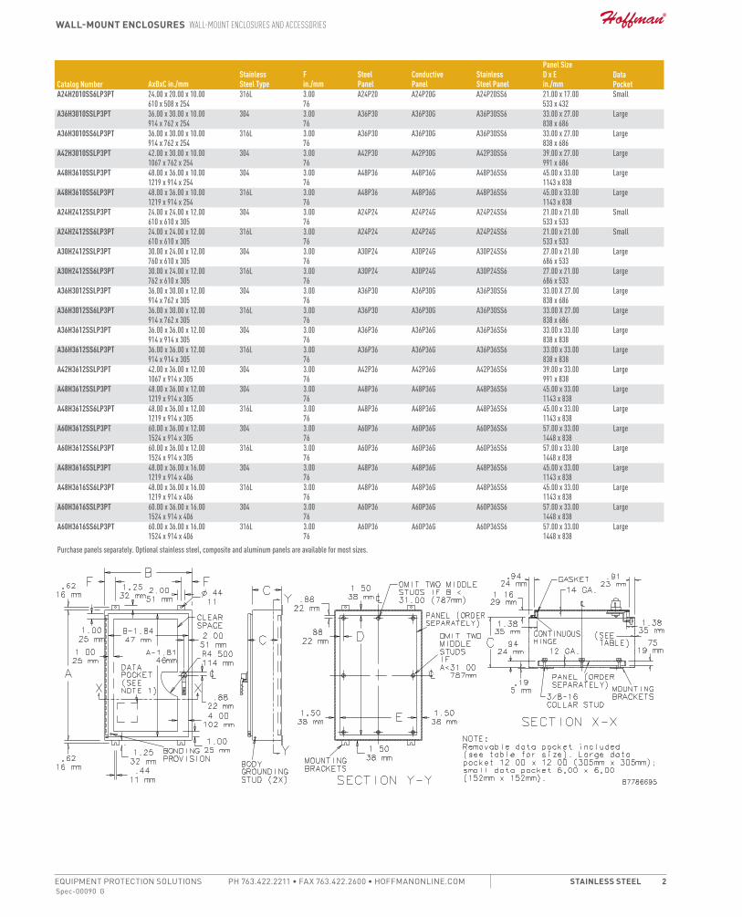
Spec-00090 G
Wall-Mount EnclosurEs Wall-Mount EnclosurEs and accEssoriEs
PH 763.422.2211 • FAX 763.422.2600 • HOFFMANONLINE.COMEQUIPMENT PROTECTION SOLUTIONS stainlEss stEEl 2
Catalog Number AxBxC in./mmStainlessSteel Type
F in./mm
SteelPanel
ConductivePanel
StainlessSteel Panel
Panel SizeD x E in./mm
DataPocket
A24H2010SS6LP3PT 24.00 x 20.00 x 10.00 610 x 508 x 254
316L 3.0076
A24P20 A24P20G A24P20SS6 21.00 x 17.00533 x 432
Small
A36H3010SSLP3PT 36.00 x 30.00 x 10.00 914 x 762 x 254
304 3.0076
A36P30 A36P30G A36P30SS6 33.00 x 27.00838 x 686
Large
A36H3010SS6LP3PT 36.00 x 30.00 x 10.00 914 x 762 x 254
316L 3.0076
A36P30 A36P30G A36P30SS6 33.00 x 27.00838 x 686
Large
A42H3010SSLP3PT 42.00 x 30.00 x 10.00 1067 x 762 x 254
304 3.0076
A42P30 A42P30G A42P30SS6 39.00 x 27.00991 x 686
Large
A48H3610SSLP3PT 48.00 x 36.00 x 10.00 1219 x 914 x 254
304 3.0076
A48P36 A48P36G A48P36SS6 45.00 x 33.001143 x 838
Large
A48H3610SS6LP3PT 48.00 x 36.00 x 10.00 1219 x 914 x 254
316L 3.0076
A48P36 A48P36G A48P36SS6 45.00 x 33.001143 x 838
Large
A24H2412SSLP3PT 24.00 x 24.00 x 12.00 610 x 610 x 305
304 3.0076
A24P24 A24P24G A24P24SS6 21.00 x 21.00533 x 533
Small
A24H2412SS6LP3PT 24.00 x 24.00 x 12.00 610 x 610 x 305
316L 3.0076
A24P24 A24P24G A24P24SS6 21.00 x 21.00533 x 533
Small
A30H2412SSLP3PT 30.00 x 24.00 x 12.00 760 x 610 x 305
304 3.0076
A30P24 A30P24G A30P24SS6 27.00 x 21.00686 x 533
Large
A30H2412SS6LP3PT 30.00 x 24.00 x 12.00 762 x 610 x 305
316L 3.0076
A30P24 A30P24G A30P24SS6 27.00 x 21.00686 x 533
Large
A36H3012SSLP3PT 36.00 x 30.00 x 12.00 914 x 762 x 305
304 3.0076
A36P30 A36P30G A36P30SS6 33.00 X 27.00838 x 686
Large
A36H3012SS6LP3PT 36.00 x 30.00 x 12.00 914 x 762 x 305
316L 3.0076
A36P30 A36P30G A36P30SS6 33.00 X 27.00838 x 686
Large
A36H3612SSLP3PT 36.00 x 36.00 x 12.00 914 x 914 x 305
304 3.0076
A36P36 A36P36G A36P36SS6 33.00 x 33.00838 x 838
Large
A36H3612SS6LP3PT 36.00 x 36.00 x 12.00 914 x 914 x 305
316L 3.0076
A36P36 A36P36G A36P36SS6 33.00 x 33.00838 x 838
Large
A42H3612SSLP3PT 42.00 x 36.00 x 12.00 1067 x 914 x 305
304 3.0076
A42P36 A42P36G A42P36SS6 39.00 x 33.00991 x 838
Large
A48H3612SSLP3PT 48.00 x 36.00 x 12.00 1219 x 914 x 305
304 3.0076
A48P36 A48P36G A48P36SS6 45.00 x 33.001143 x 838
Large
A48H3612SS6LP3PT 48.00 x 36.00 x 12.00 1219 x 914 x 305
316L 3.0076
A48P36 A48P36G A48P36SS6 45.00 x 33.001143 x 838
Large
A60H3612SSLP3PT 60.00 x 36.00 x 12.00 1524 x 914 x 305
304 3.0076
A60P36 A60P36G A60P36SS6 57.00 x 33.001448 x 838
Large
A60H3612SS6LP3PT 60.00 x 36.00 x 12.00 1524 x 914 x 305
316L 3.0076
A60P36 A60P36G A60P36SS6 57.00 x 33.001448 x 838
Large
A48H3616SSLP3PT 48.00 x 36.00 x 16.00 1219 x 914 x 406
304 3.0076
A48P36 A48P36G A48P36SS6 45.00 x 33.001143 x 838
Large
A48H3616SS6LP3PT 48.00 x 36.00 x 16.00 1219 x 914 x 406
316L 3.0076
A48P36 A48P36G A48P36SS6 45.00 x 33.001143 x 838
Large
A60H3616SSLP3PT 60.00 x 36.00 x 16.00 1524 x 914 x 406
304 3.0076
A60P36 A60P36G A60P36SS6 57.00 x 33.001448 x 838
Large
A60H3616SS6LP3PT 60.00 x 36.00 x 16.00 1524 x 914 x 406
316L 3.0076
A60P36 A60P36G A60P36SS6 57.00 x 33.001448 x 838
Large
Purchase panels separately. Optional stainless steel, composite and aluminum panels are available for most sizes.

Spec-00480 E
Drip ShielDS Drip ShielDS
EQUIPMENT PROTECTIONSUBJECT TO CHANGE WITHOUT NOTICEAcceSSorieS1
Spec-00480e763.422.2211763.422.2600
AcceSSorieSDrip ShielDSDrip ShielDS
Drip ShielD Kit for type 12 encloSureS
Protects door hardware from dripping water and settling dust. Attaches quickly and easily to the enclosure with stainless steel screws and sealing washers (hardware is furnished). Stainless steel hinge pin and stainless steel door clamping assemblies are furnished to replace the standard hinge pin and door clamping assemblies. A tube of sealing compound is also supplied with each kit. Manufactured from 14 gauge steel with an ANSI 61 gray polyester powder paint finish over pretreated surfaces.Bulletin: A80
Catalog Number For
Fits EnclosureSize B in./mm
ADK12A Single-Door Wall-Mount Enclosures 12.00305
ADK16A Single-Door Wall-Mount Enclosures 16.00406
ADK20A Single-Door Wall-Mount Enclosures 20.00508
ADK24A Single-Door Wall-Mount/Floor-Mount Enclosures with Continuous Hinge 24.00610
ADK30A Single-Door Wall-Mount/Floor-Mount Enclosures with Continuous Hinge 30.00762
ADK36A Single-Door Wall-Mount/Floor-Mount Enclosures with Continuous Hinge 36.00914
ADK42A Two-Door Floor-Mount, Continuous Hinge Enclosures 42.001067
ADK48A Two-Door Floor-Mount, Continuous Hinge Enclosures-Door Floor-Mount Enclosures
48.001219
ADK60A Two-Door Floor-Mount, Continuous Hinge Enclosuresoor Floor-Mount Enclosures
60.001524
ADK72A Two-Door Floor-Mount, Continuous Hinge Enclosuresoor Floor-Mount Enclosures
72.001829
Two-Door Drip Shield kits are not designed for use on 48.00-in. (1219-mm) wide and 60.00-in. (1524-mm) wide Two-Door Type 12 Wall-Mount Enclosures.
Drip ShielD Kit for type 12 free-StAnDing AnD floor-Mount encloSureS With conceAleD hingeSProtects door hardware from dripping water and settling dust. Attaches quickly and easily to the enclosure with stainless steel screws and sealing washers (hardware is furnished). A tube of sealing compound is also supplied with each kit. Manufactured from 14 gauge steel with an ANSI 61 gray polyester powder paint finish over pretreated surfaces.
Bulletin: A80
Catalog Number ForFits Enclosure Size B in./mm
ADK24HH Single-Door Free-Stand/Floor-Mount Enclosures 24.00610
ADK30HH Single-Door Free-Stand/Floor-Mount Enclosures 30.00762
ADK36HH Single-Door Free-Stand/Floor-Mount Enclosures 36.00914
ADK42HH Two-Door Free-Stand/Floor-Mount Enclosures 42.001067
ADK48HH Two-Door Free-Stand/Floor-Mount Enclosures 48.001067
ADK60HH Two-Door Free-Stand/Floor-Mount Enclosures 60.001524
ADK72HH Two-Door Free-Stand/Floor-Mount Enclosures 72.001829
StAinleSS Steel Drip ShielD Kit for type 4 AnD 4X WAll-Mount encloSureS
Easily installed on Type 4 and 4X wall-mount enclosures (excluding quick-release latch models). Protects door from dripping water and settling dust. Attaches quickly and easily to the enclosure with stainless steel screws and sealing washers (furnished). A tube of sealing compound is supplied with each kit. Manufactured from 14 gauge Type 316 stainless steel. Kits can be special ordered for other Hoffman enclosures. Consult factory for more information. Product maintains UL/CSA Type 4, 4X and 12 rating when properly installed on a Hoffman enclosure.Bulletin: A4SY
Catalog NumberFits Enclosure Size B in./mm
ADK12SS6 12.00305
ADK16SS6 16.00406
ADK20SS6 20.00508
ADK24SS6 24.00610
ADK30SS6 30.00762
ADK36SS6 36.00914

25
Custom Connector Corporation • 1738 E. 30th, Cleveland, OH 44114 • 216/241-1679 • Fax 216/241-5529E-mail: [email protected] • Web: www.customconnector.com
RELAY SOCKET ACCESSORIES DIN RAIL DRAWINGS & SPECIFICATIONS
PART NO. DESCRIPTION SERIES NO.
C-103-PM Prepunched Aluminum DIN Rail (1 Meter Lengths) ES, GT, MT, OT, ST(note: Other lengths available, consult factory)
C-104-PM Prepunched Steel DIN Rail (1 Meter Lengths) ES, GT, MT, OT, ST(note: Other lengths available, consult factory)
C-105-PM Prepunched Steel DIN Rail (1 Meter Lengths) ES, GT, MT, OT, ST(note: Other lengths available, consult factory)
C-106-2PM Prepunched Steel DIN Rail (2 Meter Lengths) ES, GT, MT, OT, ST(note: Other lengths available, consult factory)
.984[25.00]
1.063[27.00]
.287[7.29]
.943[23.95]
1.378[35.00]
.177[4.50]
R.
1.083[27.50] 1.378[35.00]TYP.
39.370 [1000.00]
R.
1.063[27.00]
.295[7.50]
1.378[35.00]
.709[18.00]
.205[5.20]
.492[12.50] .984[25.00]
39.370[1000.00]
1.063[27.00]1.378[35.00]
.709[18.00]
.492[12.50] .984[25.00]
39.370[1000.00] .590[15.00]
R.
.248[6.30]
.039[1.00]
.709[18.00]
.492[12.50] .984[25.00]
78.740[2000.00]
R.
.248[6.30] 1.378[35.00] 1.063[27.00]
.295[7.50]
OTHER STYLES AND HOLE PATTERNS AVAILABLE. CONSULT FACTORY


I2
FSPDB Finger-Safe Power Distribution Blocks
Safety evolvingMersen FSPDBs introduce a new level of safety and ease for installing power distribution blocks. An IP20 level of finger-safe protection is achieved using FSPDBs,eliminating the need for special covers or custom Plexiglas sheets to protect your panels. FSPDBs (sizes 1 to 4) simply snap onto 35mm DIN rail to provide the quickest installation. Modular design also allows for multi pole applications by use of assembly pins. FSPDBs provide a safe, convenient way of splicing cables, splitting primary power into a variety of secondary circuits or providing a fixed junction tap-o f point.
Ratings:Volts : 600VAmps: : 175 to 840ASCCR : 100kA with proper fuse.
Contact Technical Services for instruction sheet and/or DC Ratings.
Features/Benefits: • Finger-safe protection
Fully insulated block ensures touch safe isolation of live parts. Recessed termination screws and wire openings provide IP20 grade protection and qualify as “finger-safe” per IEC 529
• Compact modularitySingle or multiple pole configurations in the most compact foot rint. Allows users to build smaller or higher density panels.
• Snap on DIN-rail mountingSizes 1 to 4 feature integral DIN rail adaptors allowing for quick and easy installations on 35mm DIN rail yielding lower installed costs.
• Captive termination screwsUnique channel design ensures captive metric wire termination screws. Screws can never be lost.
• Available accessoriesFor multi-pole panel mounting, simply snap in pins for rigid fi . Cap plugs provide the ability to maintain touch safety on unused openings. Circuit identification markers simply snap into blocks to ID circuits. nd anchors provide rigid end stops.
• Multiple wire ratingsProvide users more versatility by offering capability of using multiple conductors in #2 and 2/0 openings.
• AC & DC ratingsFSPDB1, 2, and 3 have been evaluated for use at 1000V (AC or DC) provided they are installed on DIN-rails only and with barriers between poles of opposite polarity of sufficient size to maintain requi ed spacings.
Approvals: • UL Recognized Component
Guide XCFR2, File E73571 • CSA Certified: Class 6228, Fil
69363

For the most current product performance data visit us-ferrazshawmut.mersen.com and use catalog search. I3
I
Catalog Numbers
A
B
C
DE
F
G
H
J
K
A
B
C
DE
F
G
HI
K
J
Figure 1 Figure 2
Dimension
FSPDB1A FSPDB2A FSPDB3A FSPDB4A FSPDB5A
FSPDB1C FSPDB2C FSPDB3C FSPDB4C FSPDB5C
Figure 1 Figure 1 Figure 2 Figure 1 Figure 2
mm in mm in mm in mm in mm in
A 25.4 1.00 28.4 1.12 46.9 1.85 39 1.54 72 2.84
B 43.3 1.70 57.8 2.28 64.3 2.53 108 4.25 91 3.58
C 49.5 1.95 56.0 2.21 64.3 2.53 80 3.15 80 3.15
D 45.1 1.78 51.6 2.03 59.8 2.36 75.5 2.97 - -
E 39.4 1.55 39.4 1.55 51.5 2.03 50.1 1.97 50.1 1.97
F 72.6 2.86 87.7 3.45 100.8 3.97 145.5 5.73 145 5.71
G 59.6 2.35 74.6 2.94 82.4 3.24 120.6 4.75 127.5 5.02
H 5.3 0.21 5.1 0.20 6.5 0.26 7 0.28 3 0.12
I - - - - 31.5 1.24 - - 52 2.04
J 5.3 0.21 6.4 0.25 6.5 0.26 6.5 0.26 6.5 0.26
K 10 0.40 11.7 0.46 8.9 0.35 16 0.63 8.5 0.34
Catalog No. Description
FSPIN1 Accessory pin to form multiple pole block
FSCIM1Circuit identification marker for 2/0 & #2 max. conductors (Qty of 100)
FSCIM2 Circuit identification marker for 350, 400 & 600 kcmil max. conductors (Qty of 100)
FSCAP1 Cap plug for spare 2/0 openings
FSCAP2 Cap plug for spare 350 kcmil openings
FSCP3 Cap plug for spare 600 kcmil opening
FSEA Pair of end anchors
Multiple Wire Ratings (Same Size & Type Wires Only)
2/0 Openings #2 Openings
(2) #4 AWG (2) #10 AWG (2) #6 AWG (2-4) #12 AWG
(2) #6 AWG (2) #12 AWG (2) #8 AWG (2-4) #14 AWG
(2) #8 AWG (2) #14 AWG (2-4) #10 AWG
•Contact Mersen Technical Services at [email protected] for fuse type and maximum ampere required.
Dimensions
FSPDB Finger-Safe Power Distribution Blocks
Catalog Number Ampere Rating (Based on NEC Table 310-16 for 75° C Cu wire only)
Line LoadShort Circuit Current Rating
Aluminum Copper Wire Range Wire Range Openings Per Pole
(Connector rated for 90° C Cu/AL wire)
(Connector rated for 75° C Cu wire only)
AWG/ mm2 Openings AWG/ kcmil
mm2
FSPDB1A FSPDB1C 175 2/0-#14 70-2.5 1 2/0-#14 70-2.5 1 100kA•
FSPDB2A FSPDB2C 175 2/0-#14 70-2.5 1 #2-#14 35-2.5 4 100kA•
FSPDB3A FSPDB3C 310350-#6 185-16
1 #8-#14 8-2.5 8 100kA•2/0-#14 70-2.5
FSPDB4A FSPDB4C 335 400-#6 185-16 1 400-#6 185-16 1 100kA•
FSPDB5A FSPDB5C 840 600-#4 300-25 2 600-#4 300-25 2 100kA•
Accessories

Construction
• Attractive and durable housing is anodizedaluminum
• Thermostat, standard on all units, is adjustablefrom 0°F to 100°F (-18°C to 38°C)
• Fan draws cool air from the bottom of theenclosure and passes this air across thethermostat and heating elements beforebeing released into enclosure cavity
• Heated air is discharged through the top ofthe heater unit
• Four 10-32 self-tapping screws are includedwith each heater
• Ball bearing fan runs continuously for eventemperature distribution
• Terminal strip with clamp connector thataccepts both solid and stranded wire
Finish
Brushed aluminum.
Industry Standards
UL Component RecognizedCSA ListedCE
Hoffman electric heaters should be centered aslow as possible on an interior enclosure panel.This permits the unit to heat the cool airlocated at the bottom of the enclosure. Formaximum efficiency and longevity, the heatershould be mounted in a vertical position withthe terminal block to the bottom and the airoutlet openings at the top in a sealedenclosure free from dust or debris. However,the unit will also effectively distribute heat ifturned 90 degrees with the terminal block outthe bottom and the air outlet at the side.Although enclosure panels are preferable,heaters may be installed on any flat sheet metalsurface. Do not install heaters on wood panels.
Heat sensitive components should not beplaced near the heater discharge area since thisair can be quite warm.The clearance rangedefines the space that must be kept free ofthese components for proper and safeoperation of the heater.
Application
Designed to protect sensitive mechanical,electrical, and electronic equipment from theharmful effects of condensation, corrosion, andlow temperatures.Thermostatically controlledfan-driven heater units maintain a stabletemperature within enclosures so criticalcomponents can perform more reliably over a longer period of time.
Catalog WeightNumber Watts Voltage Hz Amps lb. (kg.)DAH1001A 100 115 50/60 0.9 4.00 (1.81)
DAH1002A 100 230 50/60 0.6 4.00 (1.81)
DAH2001A 200 115 50/60 1.7 4.00 (1.81)
DAH2002A 200 230 50/60 0.9 4.00 (1.81)
DAH4001B 400 115 50/60 3.3 6.00 (2.72)
DAH4002B 400 230 50/60 1.7 6.00 (2.72)
DAH8001B 800 115 50/60 6.5 6.00 (2.72)
DAH8002B 800 230 50/60 3.3 6.00 (2.72)
Standard Sizes Electric Heaters
9.46 Data subject to change without notice 763 422 2211 FAX 763 422 2600 ©2003 Hoffman Enclosures Inc.
Electric Heaters
Installation
CAUTION
These electric heaters are not designed for use in dusty, dirty, corrosive, or hazardouslocations.
Portions of the heater can get hot. Adequateprotection must be taken to protect peoplefrom potential burns, and to protect othercomponents from this heat.
Hoffman recommends this heater only beinstalled in a totally-enclosed metalenclosure.
Do not install heaters on wood panels.
Rev. A October 2004

9.47Data subject to change without notice 763 422 2211 FAX 763 422 2600 ©2003 Hoffman Enclosures Inc.
Heaters
Electric H
eaters
9
Bulletin
D85
Dimensions and Clearance Range for DAH1001A, -2A and DAH2001A, -2A
Dimensions and Clearance Range for DAH4001B, -2B and DAH8001B, -2B
Bulletin
D85

Pulse isolator
5202B2 channels - 2 or 4 outputs–Dual output–5-port 3.75 kVAC galvanic isolation–Cable error detection–Universal supply by AC or DC–
ConnectionApplication
Pulse isolator with safety barrier for the supply of NAMURsensors installed in the hazardous area.
•
Pulse isolator with safety barrier for the detection ofmechanical contacts installed in the hazardous area.
•
One input signal can be used on two separate outputs.•A cable error alarm can be detected on a separate output.•
Technical characteristicsPR5202B1 and 5202B2 have relays with change-overcontacts or open NPN collectors available in the safe area.
•
PR5202B4 has 4 SPST relays, which are activatedsimultaneously two and two, available in the safe area. Eachrelay can be programmed to the function N.O. or N.C.
•
Inputs, outputs and supply are floating and galvanicallyseparated.
•
5202B is designed according to strict safety requirements andis therefore suitable for application in SIL 2 installations.
•
Mounting / installationMounted vertically or horizontally on a DIN rail. Up to 84channels per meter can be mounted.
•
This page is automatically generated on the basis of information provided on www.prelectronics.com and affiliated websites. It is provided to you as a service and for informationpurpose only. While we have attempted to maintain the information as accurately as possible, the page may contain errors or omissions for which we disclaim any and all liability

Environmental ConditionsSpecifications range....................................... -20°C to +60°CCalibration temperature................................. 20...28°CRelative humidity............................................ < 95% RH (non-cond.)Protection degree........................................... IP20
Mechanical specificationsDimensions (HxWxD)..................................... 109 x 23.5 x 130 mmWeight approx................................................ 230 gWire size........................................................ 1 x 2.5 mm2 stranded wireScrew terminal torque.................................... 0.5 Nm
Common specificationsSupply voltage, universal............................... 21.6...253 VAC, 50...60 Hz or
19.2...300 VDCFuse............................................................... 400 mA SB / 250 VACMax. power consumption............................... ≤ 1.5 W (2 channels), 5202B1
and 5202B2Max. power consumption............................... ≤ 2.0 W (2 channels), 5202B4Internal consumption...................................... ≤ 1.5 W (2 channels), 5202B1
and 5202B2Internal consumption...................................... ≤ 2.0 W (2 channels), 5202B4Isolation voltage, test /working........................................................... 3.75 kVAC / 250 VACAuxiliary supplies: NAMURsupply............................................................. 8 VDC / 8 mAEMC immunity influence................................ < ±0.5%Extended EMC immunity: NAMURNE 21, A criterion, burst................................. < ±1%
Input specificationsSensor types.................................................. NAMUR according to EN
60947-5-6 / Mechanicalcontact
Frequency range............................................ 0...5 kHzPulse length................................................... > 0.1 msInput resistance.............................................. 1 kΩTrig level, signal............................................. < 1.2 mA, > 2.1 mATrig level, cable fault...................................... < 0.1 mA, > 6.5 mA
Output specificationsRelay output: Max. switchingfrequency....................................................... 20 HzMax. voltage................................................... 250 VRMSMax. current................................................... 2 AACMax. AC power.............................................. 100 VAMax. load at 24 VDC...................................... 1 AOpto, NPN outputs: Max. switchingfrequency....................................................... 5 kHzMin. pulse length, NPN output....................... > 0.1 msMax. load, current / voltage............................ 80 mA / 30 VDCVoltage drop at 25 mA / 80mA.................................................................. < 0.75 VDC / < 2.5 VDC
ApprovalsEMC............................................................... EN 61326-1LVD................................................................ EN 61010-1PELV/SELV.................................................... IEC 364-4-41 and EN 60742ATEX.............................................................. DEMKO 99ATEX127186UL................................................................... UL 913, UL 508GOST R......................................................... YesGOST Ex........................................................ Yes
5202B-091013

Lerbakken 10 · DK-8410 Rønde Tel. +45 8637 2677 · Fax +45 8637 3085
www.prelectronics.dk
PRetrans 5104B
1- or 2-channel version
3- / 5-port 3.75 kVAC galvanic isolation
Loop supply > 17.1 V in Ex area
20 programmable measurement ranges
Universal supply by AC or DC
Application:
•Supplyvoltageandsafetybarrierfor2-wiretransmittersmountedinahazardousarea.
•Safetybarrierforanaloguecurrent/voltagesignalsfromahazardousarea.
•1:1orsignalconversionofanaloguecurrent/voltagesignals.
Technical characteristics:
•The20factory-calibratedmeasurementrangesinthe5104BcanbeselectedbytheinternalDIP-switcheswithouttheneedforrecalibration.Specialmeasurementrangescanbedelivered.
•PR5104Bisbasedonmicroprocessortechnologyforgainandoffset.Theanaloguesignalistransmittedataresponsetimeoflessthan25ms.
•Inputs,outputs,andsupplyarefloatingandgalvanicallyseparated.
•Theoutputcanbeconnectedeitherasanactivecurrent/voltagetransmitterorasa2-wiretransmitter.
Mounting / installation:
•MountedverticallyorhorizontallyonaDINrail.Bywayofthe2-channelversionupto84channelspermetrecanbemounted.
•NB:5104BisrecommendedasExbarrierfor5331D,5333D,5334B,5343B,6331B,6333B,and6334B.
Ex REPEATER / POWER SUPPLY
3-wire transmitter
Current, mA
Voltage
2-wire transmitter
Output
Supply
Supply
Supply
Supply
Output
Output
Output

5104BY104-UK(1017)
5104B
Order : 5104B
0…20 mA : A4…20 mA : B0…10 V : E2…10 V : FSpecial : X
Special : 00…20 mA : 14…20 mA : 20…1 V : 40.2…1 V : 50…10 V : 62…10 V : 7
Single : ADouble : B
Type Input Output Channels
Electrical specifications:
Specifications range:-20°Cto+60°CCommon specifications:Supplyvoltage,universal.................. 21.6...253VAC 50...60Hz or19.2...300VDCInternalconsumption........................ ≤2W(2channels)Max.consumption............................. ≤3W(2channels)Fuse................................................... 400mASB/250VACIsolationvoltage,test/operation...... 3.75kVAC/250VACSignal/noiseratio............................. Min.60dB(0...100kHz)Responsetime(0...90%,100...10%)... <25msCalibrationtemperature..................... 20...28°CAccuracy,thegreaterofthegeneralandbasicvalues:
Auxiliarysupply:Loopsupply(pin44...42and54...52). 28...17.1VDC/0...20mAMax.wiresize.......................................... 1x2.5mm2strandedwireScrewterminaltorsion....................... 0.5NmRelativehumidity............................... <95%RH(non-cond.)Dimensions(HxWxD)......................... 109x23.5x130mmDINrailtype....................................... DIN46277Protectiondegree.............................. IP20Weight............................................... 225gCurrent input:Measurementrange.......................... 0...20mAMin.measurementrange(span)........ 16mAMax.offset......................................... 20%ofmax.valueInputresistance................................. Nom.10Ω+PTC10 Ω
Voltage input:Measurementrange.......................... 0...10VDCMin.measurementrange(span)........ 8VDCMax.offset......................................... 20%ofmax.valueInputresistance................................. >2MΩCurrent output and 2-wire 4...20 mA output:Signalrange(span)............................ 0...20mAMin.signalrange(span).................... 16mAMax.offset......................................... 20%ofmax.valueLoad(max.)........................................ 20mA/600Ω/12VDCLoadstability..................................... ≤0.01%ofspan/100ΩCurrentlimit....................................... ≤28mAMax.externalloopsupply................. 29VDCEffectofexternalloopsupplyvoltagechange.................................. <0.005%ofspan/VVoltage output:Signalrange(span)............................ 0...1VDC/0...10VDCMin.signalrange(span).................... 0.8VDC/8VDCMax.offset......................................... 20%ofmax.valueLoad(min.)......................................... 500kΩEEx / I.S. approval:DEMKO99ATEX126013.................... II(1)GD [EExia]IICApplicableinzone............................ 0,1,2,20,21or22Ex / I.S. data: Um..................................................... :250VUo...................................................... :28VDCIo........................................................ :93mADCPo...................................................... :0.65WLo....................................................... :3mHCo...................................................... :0.08µF
UL,applicableinzone....................... IS,Cl.I,Div.1,Gr.A,B,C,D IS,Cl.I,zone0/1,Gr.IIC IS,Cl.II,Div.1Gr.E,F,G ULControlDrawingNo.............. 5104QU01Marine approval:DetNorskeVeritas,Ships&Offshore.. Stand.forCertific.No.2.4GOST R approval:VNIIFTRI,CertNo.............................. www.prelectronics.comObserved authority requirements: Standard:EMC2004/108/EC............................ EN61326-1LVD2006/95/EC................................ EN61010-1PELV/SELV......................................... IEC364-4-41 andEN60742ATEX94/9/EC.................................... EN50014,EN50020and EN50281-1-1UL...................................................... UL913,UL508
Of span=Ofthepresentlyselectedrange
Basic values
Temperaturecoefficient
Basicaccuracy
Inputtype
mA
Volt
≤±16µA
≤±8mV
≤±1.6µA/°C
≤±0.8mV/°C
General values
Temperaturecoefficient
Absoluteaccuracy
Inputtype
All ≤±0.1%ofspan ≤±0.01%ofspan/°C
EMCimmunityinfluence........................... <±0.5%ofspanExtendedEMCimmunity:NAMURNE21,Acriterion,burst.............. <±1%ofspan
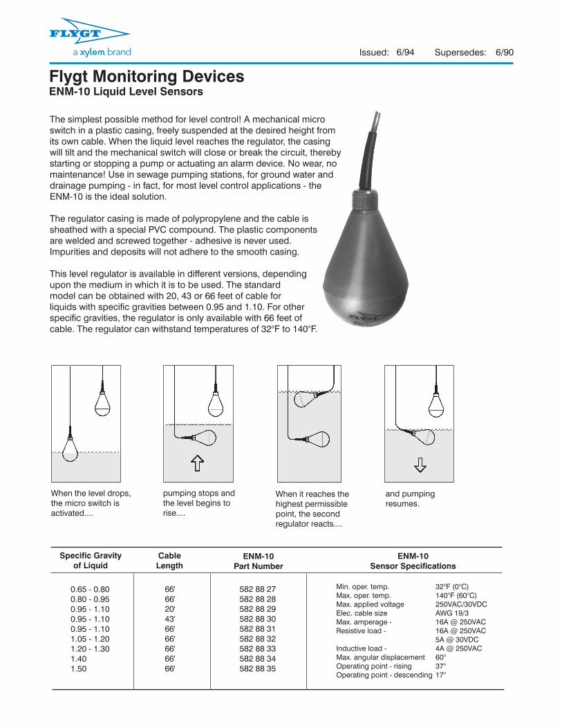
Issued: Supersedes:
When the level drops, the micro switch is activated....
When it reaches the highest permissible point, the second regulator reacts....
pumping stops and the level begins to rise....
and pumping resumes.
66'66'20'43'66'66'66'66'66'
582 88 27582 88 28582 88 29582 88 30582 88 31582 88 32582 88 33582 88 34582 88 35
0.65 - 0.800.80 - 0.950.95 - 1.100.95 - 1.100.95 - 1.101.05 - 1.201.20 - 1.301.401.50
Min. oper. temp. 32°F (0°C) Max. oper. temp. 140°F (60°C) Max. applied voltage 250VAC/30VDCElec. cable size AWG 19/3Max. amperage - 16A @ 250VAC Resistive load - 16A @ 250VAC 5A @ 30VDCInductive load - 4A @ 250VACMax. angular displacement 60° Operating point - rising 37°Operating point - descending 17°
Specific Gravityof Liquid
CableLength
ENM-10Sensor Specifications
ENM-10Part Number
The simplest possible method for level control! A mechanical micro switch in a plastic casing, freely suspended at the desired height from its own cable. When the liquid level reaches the regulator, the casing will tilt and the mechanical switch will close or break the circuit, thereby starting or stopping a pump or actuating an alarm device. No wear, no maintenance! Use in sewage pumping stations, for ground water and drainage pumping - in fact, for most level control applications - the ENM-10 is the ideal solution.
The regulator casing is made of polypropylene and the cable is sheathed with a special PVC compound. The plastic components are welded and screwed together - adhesive is never used. Impurities and deposits will not adhere to the smooth casing.
This level regulator is available in different versions, depending upon the medium in which it is to be used. The standard model can be obtained with 20, 43 or 66 feet of cable for liquids with specific gravities between 0.95 and 1.10. For other specific gravities, the regulator is only available with 66 feet of cable. The regulator can withstand temperatures of 32°F to 140°F.
Flygt Monitoring DevicesENM-10 Liquid Level Sensors
6/94 6/90

Issued: Supersedes:
In Figure 1, liquid level is below the lowest level sensor (FLS 1). All sensors are hanging straight in the wet well, therefore, the circuits in the sensor are not complete and no signal is being sent to the control. Both pumps are OFF.
In Figure 2, as the liquid level rises, FLS-1 tilts and the sensors mechanical micro-switch completes the circuit sending a signal to energize the control. At this point both pumps are still in the OFF mode.
In Figure 3, the liquid level has risen to a level that tilts level sensor #2, completing its circuit.
a) This signal to the control activates the contactor in the control which, in turn, starts the lead pump.
b) Level sensor #2 also at this time activates the alternator in the control which automatically selects the other pump to become the lead pump on the next start-up cycle. The alternation of the pumps as the "lead" pump serves two purposes:
1) The two pumps will accumulate approximately equal amounts of wear thus maximizing their useful life.
2) Allows for many more starts per hour as the starting frequency is divided between the two pumps.
If the capacity of the lead pump is greater than the inflow to the station, the liquid level will start to drop. The pump will continue to run (due to a holding circuit in the control) until the level drops below sensor #1. Sensor #1, on drawdown, acts as the low level shut-off. Pump OFF.
Figure 4 shows the sequence when the capacity of the lead pump is less than the inflow to the station. In this case, the liquid level will gain on the pump and rise to sensor #3 which will then send a signal to the main control starting the second or lag pump. If their combined capacity is greater than the inflow, both pumps will continue to operate (due to the holding circuit in the control) until the liquid level drops below the low level shut off sensor #1.
Figure 5 indicates a condition where the inflow to the station is greater than the combined capacity of both pumps. The liquid level will rise to the high level sensor
#4. When sensor #4 tilts, it will send a signal to an alarm system, normally an alarm bell or red alarm light. There are other options for alarm conditions such as alert by telephone, etc. The alarm system issues a warning that something has happened in the station that could result in an overflow condition. This could be a control problem, one or both pumps not operating, pumps not operating up to capacity, etc. Regardless of the cause, an alarm calls for immediate action.
For most installations, the low level shut-off sensor should be located approximately at the top of the pump volute. However, there are certain situations where maximum cooling may be required such as when pumping warm liquids; in certain cases with pumps that do not have cooling jackets; some large horsepower units, etc. Also in situations where the NPSH requires a liquid level that is above the pump volute. When in doubt, contact Flygt Application Engineering.
Flygt Monitoring DevicesENM-10 Liquid Level Sensors
6/94 6/90

Issued: Supersedes:
Fig. 2
Fig. 4
Fig. 5
Fig. 3
Fig. 1
FLS-1
FLS-2
FLS-3
FLS-4
Flygt Monitoring DevicesENM-10 Liquid Level Sensors
6/94 6/90

Issued: Supersedes:
Flygt Monitoring DevicesENM-10 Liquid Level Sensors
ENM-10 Level SensorConnected for Pump-Down
The Flygt ENM-10 Liquid Level Sensor can be utilized to monitor a "Pump Down" operation (as in a lift station application) or a "Pump UP" (filling) operation as may be required in certain industrial applications. The ENM-10 sensor cable contains three wires; Red, Black and White. The Red wire is common to both sequences. Using the Red and Black wires as the liquid level pilot circuit, the
ENM-10 will operate in the "Pump Down" mode, activating the pumps at a selected high liquid level and shut off at a selected low liquid level. Using the Red and White wires as the pilot circuit will activate the pumps in a "Pump UP" mode controlling the filling of a sump, tank etc. In this case the pumps are activated at a selected low level and shut off at a selected high level.
WHITE
24VPOWER IN
TO ENM-10CONTROL
WHITE CONDUCTOR TIED OFF & TAPED.
BLACKRED
PUMP OFF
PUMP ON
WHITE
24VPOWER IN
TO ENM-10CONTROL
BLACKRED
WHITE CONDUCTOR TIED OFF & TAPED.
ENM-10 Level SensorConnected for Filling
BLACKRED
PUMP ON
BLACKCONDUCTOR TIED OFF & TAPED.
WHITE
PUMP OFF
24VPOWER IN
TO ENM-10CONTROL
BLACKRED
BLACK CONDUCTOR TIED OFF & TAPED.
WHITE
24VPOWER IN
TO ENM-10CONTROL
The Flygt ENM-10 Liquid Level Sensoris not a "floating" device.
The On/Off pump operating sequence is performed by its submerged tilting action.
POSITION 1
POSITION 2
6/94 6/90

Issued: Supersedes:
Flygt Monitoring DevicesENM-10 Liquid Level Sensors
3/11 6/94
The liquid in which level regulation is practiced most frequently is water. Of the millions of regulators in use all over the world today, it is estimated that nine out of ten work in water.
The ENM-10 is virtually insensitive to many aggressive liquids with its body of polypropylene, a cord of PVC
0 = No affect, 1= Minor to Moderate Resistance and 2 = Non-Resistant.The density of a liquid determines the bouyancy of the regulator. The ENM-10 is made for seven different densities.
or NBR/PVC nitrile/PVC rubber and a protective sleeve of EPDM rubber.
The table shows how resistant the material is to different chemicals at two different temperatures. The classification is broken down into three categories:
Chemical Resistance List
CHEMICAL RESISTANCE LIST
0 = No affect, 1 = Minor to moderate, 2 = Severe affect. — = No information available.
The liquid in which level regulation is practiced most frequently is, of course, water. Of the millions of regu-lators in use all over the world today, it is estimated that nine out of ten work in water.However, with a float body of polypropylene, a cable of PVC or NBR/PVC nitrile/PVC rubber and a ben-ding relief of EPDM rubber, the ENM-10 is virtually insensitive to many aggressive liquids.The table shows how resistant the ENM-10 equipped with either PVC or NBR/PVC nitrile/PVC rubber cable, is to different chemicals at two different temperatures.
The classification is broken down into the followingcategories:0 = No effect, 1 = Minor to moderate and 2 = Severe effect. The sign — means that information is not avai-lable.Keep in mind also that the density of the liquid deter-mines the bouyancy of the regulator. The ENM-10 is made for seven different densities. See page 2.
PVC cable NBR/PVC PVC cable NBR/PVC PVC cable NBR/PVC nitrile/PVC nitrile/PVC Solvents and nitrile/PVCAcids rubber cable Salts rubber cable miscellaneous rubber cable
20°C 60°C 20°C 60°C 20°C 60°C 20°C 60°C 20°C 60°C 20°C 60°C (68°F) (140°F) (68°F) (140°F) (68°F) (140°F) (68°F) (140°F) (68°F) (140°F) (68°F) (140°F)
Acetic Acid 50% 1 2 0 0Acetic Acid 75% 2 2 0 0Benzoic Acid 2 2 0 0Boric Acid 5% 0 — 0 0Butyric Acid 2 2 2 2
Chromic Acid 10% 0 2 2 2Citric Acid 0 1 0 0HydrobromicAcid 5% 1 2 0 0HydrochloricAcid 10% 0 1 0 1HydrochloricAcid 37% 1 2 0 2
Hydrocyanic Acid 10% 0 0 1 2Hydrofluori Acid 5% 0 2 0 1Hypochloric Acid 1 2 2 2Maleic Acid 2 2 2 2Nitric Acid 5% 1 1 1 1
Nitric Acid 65% 2 2 2 2Oleic Acid 1 2 2 2Oxalic Acid 50% 1 1 1 2Phosphoric Acid 25% 0 0 1 2Phosphoric Acid 85% 0 0 1 2
Sulphuric Acid 10% 1 2 1 2Sulphuric Acid 78% 2 2 2 2Tannic Acid 0 0 0 0Tartaric Acid 1 1 1 1
Bases
Ammonium Hydroxide 0 — 0 0Calcium Hydroxide 0 0 0 0Potassium Hydroxide 1 2 0 0Sodium Hydroxide 1 2 0 0
Aluminium Chloride 0 0 0 0Calcium Sulphate 0 0 0 0Calcium Chloride 0 0 0 0Calcium Nitrate 0 0 0 0Copper Chloride 0 0 0 0
Copper Sulphate 0 0 0 0Ferric Chloride 0 0 0 0Ferrous Sulphate 0 0 0 0Magnesium Chloride 0 0 0 0Potassium Sulphate 0 0 0 0
Potassium Nitrate 0 0 0 0Potassium Carbonate 1 1 1 1Potassium Bicarbonate 0 0 0 0
Sodium Sulphate 0 0 0 0Sodium Chloride 0 0 0 0Sodium Nitrate 0 0 0 0Sodium Bicarbonate 0 0 0 0Sodium Carbonate 0 0 0 0
Tin Chloride 1 1 1 1Zinc Sulphate 0 0 0 0Zinc Chloride 0 0 0 0
Oils
Castor Oil 1 1 1 1Cocoanut Oil 0 — 0 2Corn Oil 2 2 2 2Diesel Oil 2 2 2 2
Linseed Oil 2 2 2 2Mineral Oils 2 2 2 2Olive Oil 1 1 1 1Silicone Oils 0 0 0 0
Aceton 2 2 2 2Aniline 2 2 1 2Benzene 2 2 2 2Butyl Alcohol 2 2 0 1Carbon Tetrachloride 2 2 2 2
Chlorobenzene 2 2 2 2Chloroform 2 2 2 2Ethyl Alcohol 2 2 0 1Ethyl Ether 2 2 2 2Ethyl Acetate 2 2 2 2
Ethylene Dichloride 2 2 2 2Ethylene Chloride 2 2 2 2Formaldehyde 37% 1 2 0 0Gasoline 2 2 2 2Kerosene 2 2 2 2
Methyl Alcohol 2 2 0 0Methyl Ethyl Ketone 2 2 2 2Methylene Chloride 2 2 2 2Nitrobenzene 2 2 2 2Phenol 2 2 2 2
Toluene 2 2 2 2Trichlorethylene 2 2 2 2Turpentine 2 2 2 2Xylene 2 2 2 2
Gases
Carbon Dioxide 0 0 0 0Carbon Monoxide 0 0 0 0Chlorine (wet) 2 2 2 2Hydrogen Sulphide 0 0 1 1Sulphur Dioxide (wet) 1 1 2 2
Always observe local regulations: Take particular note of: • risk of fire/explosio• hygiene requirements

Data Sheet Expert™ Hydrostatic Level Transmitters
US 2.75 Expert 081110
MJK Expert™ 3400 Level Transmitter is de-signed for use in waterworks, sewage treatment plants and industrial applications where accurate and long term stable level measuring is required. It is very robust and designed for applications in rough environments with aggressive chemicals and aggressive fluids.
A major design feature is the programming facil-ity. With a standard USB interface and a laptop computer, the servicing transmitter can be programmed on-the-fly to the required measur-ing range.
Specifications MJK Expert™ 3400 Hydrostatic Level Transmitter
Nominal measuring range 0 - 1 ft. 0 - 3 ft. 0 - 10 ft. 0 - 30 ft. 0 - 100 ft. 0 - 300 ft. 0 - 1000 ft.
Measuring principle Ceramic capacitive, relative pressure
Min. programmable range 0 -.9 ft. 0 -.9 ft. 0 - 3 ft. 0 - 9' 0 - 30' 0 - 90' 0 - 300'
Max. programmable range 0 - 3 ft. 0 - 3 ft. 0 - 10' 0 - 30' 0 - 100' 0 - 300' 0 - 1000'
Max. overpressure 75 psi 75 psi 100 psi 150 psi 275 psi 600 psi 600 psi
Temperature range -5 °F to 105 °F
Temp. deviation, zero point Better than ± 0.01 % / °F
Temperature deviation, FS Better than ± 0.005 % / °F
Linearity / Stability Better than ± 0.5 % FS / ± 0.5 % FS
Measurement accuracy Better than ± 0.1 % FS @ 50-85 °F, and better than ± 0.2 % FS @ full temp. range
Long time stability Better than ± 0.1 % FS per year
Materials Housing: PPS (Ryton), diaphragm: 99,9 % Al2O3, measurement cell packing: Viton®
Supply voltage 10 - 30 V DC (12 - 30 V DC for cable lengths above 315 ft.)
Output signal 2-wire 4 - 20 mA (passive transmitter)
Cable 2 × AWG 20 (pressure) + 5 x AWG 25 (data), shielded, PUR insulation
Cable length 39 ft. 39 ft. 39 ft. 39 ft. 114 ft. 314 ft. 1014 ft.
Enclosure NEMA 6P, withstands a static pressure equal to max. overpressure
Approvals UL® Class 1 Division 1 Group A-D, ATEX: II 2G EEx ia IIC T5/T6 andCE: EN61000-6-3/-4:2001, EN61000-6-1/-2:1999,EN50014:1997 E, EN50020:2002
➀ Can be delivered with other cable lengths on request.
2.4 in.
9.3
in.
Dimensions and Accessories
Cable bracket for MJK model 3400(1 pc. is delivered with each transmitter)
Order numbers
MJK Expert™ 3400 Level Transmitter
5.31 1.26
Dia.1.97
1” NP
T
5.31 1.42
Dia.1.97
MJK Expert™ 3400 Level Transmitter
Order Numbers
209921 Expert™ 3400, range 0 - 1 ft. WG 209928 Expert™ 3400, range 0 - 1000 ft. WG
209922 Expert™ 3400, range 0 - 3 ft. WG 209991 Expert™ 3400, range 0 - 1 ft. 1" NPT top
209923 Expert™ 3400, range 0 - 10 ft. WG 209992 Expert™ 3400, range 0 - 3 ft. 1" NPT top
209925 Expert™ 3400, range 0 - 30 ft. WG 209993 Expert™ 3400, range 0 - 10 ft. 1" NPT top
209926 Expert™ 3400, range 0 - 100 ft. WG 209996 Expert™ 3400, range 0 - 100 ft. 1" NPT top
209927 Expert™ 3400, range 0 - 300 ft. WG 202925 Expert™ 3400 w/ special meas. range

CATALOG CUBIC DESCR IPT ION PKG . STD. UPC
NUMBER IN . COLOR OUTLETS TY PE PK G . BAR CO DE
5320-0 17.5 Gray 3–1/2" Shr ink 20
5320-1 17.5 Whi te 3–1/2" Shr ink 20
5320-2 17.5 Bronze 3–1/2" Shr ink 20
5320-5 17.5 Gray 3–1/2" Carded 6
5320-6 17.5 Whi te 3–1/2" Carded 6
5320-7 17.5 Bronze 3–1/2" Carded 6
5324-0 17.0 Gray 3–3/4" Shr ink 20
5324-5 17.0 Gray 3–3/4" Carded 6
SINGLE-GANG BOXES
DIE CAST ALUMINUM
ORDERING INFORMATION - DIMENSIONS
Applications
• For use in branch circuit wiring
in wet, damp, or dry locations
• May be used as a weatherproof
junction box, or as a housing for
receptacles, switches, and GFCI’s
Product Features
• Reinforced connector outlets
• State-of-the-art powder coat finish
• Eight box mounting options with
detachable lugs provided
• Two closure plugs included
• Ground screw installed
• Multi-lingual instructions
in each package
Compliances
• – Standard 514A
• – C22.2 No. 18
• NEMA 3R Rated
®
®
SINGLE-GANG BOXES: GENERAL DIMENSIONS
END VIEW
ONE OUTLET
END VIEW
TWO OUTLETS
5320-0 TO 5320-7
5324-0 TO 5324-5
5321-0 TO
5321-7, 5330-0 5322-0, 5331-0
5323-0, 5332-0
2 " D E E P, W I T H L U G S – T H R E E T H R E A D E D O U T L E T S – 4 - 1 / 2 " x 2 - 3 / 4 "
CATALOG CUBIC DESCR IPT ION PKG . STD. UPC
NUMBER IN . COLOR OUTLETS TY PE PK G . BAR COD E
5321-0 17.0 Gray 4–1/2" Shr ink 20
5321-1 17.0 Whi te 4–1/2" Shr ink 20
5321-2 17.0 Bronze 4–1/2" Shr ink 20
5321-5 17.0 Gray 4–1/2" Carded 6
5321-6 17.0 Whi te 4–1/2" Carded 6
5321-7 17.0 Bronze 4–1/2" Carded 6
5330-0 16.5 Gray 4–3/4" Shr ink 20
2 " D E E P, W I T H L U G S – F O U R T H R E A D E D O U T L E T S – 4 - 1 / 2 " x 2 - 3 / 4 "
CATALOG CUBIC DESCR IPT ION PKG . STD. UPC
NUMBER IN . COLOR OUTLETS TY PE PK G . BAR CO DE
5322-0 16.5 Gray 5–1/2" Shr ink 20
5331-0 16.0 Gray 5–3/4" Shr ink 20
5323-0 17.0 Gray 5–1/2" Shr ink 20
5332-0 16.5 Gray 5–3/4" Shr ink 20
2 " D E E P, W I T H L U G S – F I V E T H R E A D E D O U T L E T S – 4 - 1 / 2 " x 2 - 3 / 4 "
CATALOG CUBIC DESCR IPT ION PKG . STD. UPC
NUMBER IN . COLOR OUTLETS TYPE PKG . BAR CODE
5385-0 21.3 Gray 3–1/ 2 " Shr ink 15
5386-0 21.3 Gray 3–3/ 4 " Shr ink 15
5387-0 21.3 Gray 3–1" Shr ink 15
2 - 5 / 8 " D E E P, W I T H L U G S – T H R E E T H R E A D E D O U T L E T S – 4 - 1 / 2 " x 2 - 3 / 4 "
5385-0 TO 5387-0
D5W
EATH
ER
PR
OO
F B
OX
ES,
CO
VE
RS A
ND
LIG
HTIN
G

www.taymac.com 12
M E T A L L O W P R O F I L E I N - U S E C O V E R SSuperior Commercial Quality Die-Cast Metal Construction
Patented Quick-Fit™ Keyhole Mounting System Allows
Installation in Under a Minute
TAYMAC ITEM # UPC NUMBER DESCRIPTION DEPTH COLOR SHELF PACK SHELF PACK WEIGHT (LBS)
Metal Low Profile In-Use CoversMX4280S 0-92326-10128-8 Vertical 8-in-1 2” Grayy 6 4.75
MX4280WH 0-92326-11740-1 Vertical 8-in-1 2” White 6 4.75
MX4280Z 0-92326-11739-5 Vertical 8-in-1 2” Bronze 6 4.75
MX4380S 0-92326-10134-9 Horizontal 8-in-1 2” yGray 3 2.53
MX5280S 0-92326-10135-6 Vertical Deep 8-in-1 2.5” Grayy 2 1.80
MX7280S 0-92326-10137-0 Vertical 2-Gang 55-in-1 2” yGray 2 2.35
Patented Universal-Fit™ Technology
Mounting Hardware, Gasket and Installation InstructionsIncluded
Meets or Exceeds Extra Duty Specifications
Lockable Open or Closed
& 2011 NEC® Compliant
3R Compliant
Multiple combinations of duplex, GFCI, switch, and rounds: 1 1/4", 1 3/8", 1 9/16", 1 5/8", 1 11/16", 2 1/8", 2 1/4", 2 7/16"
+ + ++= =+
Switch 1 1/4" 1 3/8" 1 9/16" & 1 5/8" 1 11/16" 2 1/8"
WithoutAdaptor2 1/4"
=Adapter
(Included)DuplexGFCI
+ += orAdapter
(Included)
DuplexGFCI Switch 1 3/8" 1 9/16"& 1 5/8"
1 11/16" 2 1/8"1 1/4"Adapter
(Included)Adapter
(Included)
or
WithoutAdaptor2 1/4"
DuplexGFCI Switch 1 3/8" 1 9/16"& 1 5/8"
1 11/16" 2 1/8"1 1/4"Adapter
(Included)Adapter
(Included)
or
WithoutAdaptor2 1/4"
Meets or Exceeds EXTRA-DUTY SSpecifications!

Section 5 Warranty and Service

WARRANTY XYLEM WATER SOLUTIONS USA, INC.
For the period defined, XYLEM WATER SOLUTIONS USA, INC. offers a commercial warranty to the original End Purchaser against defects in workmanship and material on Flygt Products. Warranty covers Flygt parts and labor as outlined in ADDENDUM – A.
COVERAGE: XYLEM WATER SOLUTIONS USA, INC. will pay the cost of parts and labor during the warranty period, provided that the Flygt product, with cable attached, is returned prepaid to an XYLEM WATER SOLUTIONS USA, INC. Authorized Service Facility for Flygt Product repairs. Coverage for Flygt parts and labor will be provided for the period shown in ADDENDUM - A. The warranty period will begin from date of shipment or date of a valid Start-up (For permanently installed pumps only). In cases where the Start-up date is used as the beginning of the warranty on a permanently installed Flygt pump, a Start-up Report completed by an approved service technician from an XYLEM WATER SOLUTIONS USA, INC. Authorized Service Facility for Flygt products must be received by the XYLEM WATER SOLUTIONS USA, INC. Area Service Manager for Flygt Products within thirty (30) days of the initial onset of the unit placed into service. If not received, the beginning of the warranty coverage will default to the Flygt product ship date. A Start-up for a permanently installed Flygt pump must occur within one (1) year from the date of shipment from an XYLEM WATER SOLUTIONS USA, INC. authorized facility for Flygt Products or warranty will automatically default to ship date as start of warranty. (See STORAGE section) When using the start-up date as the beginning of the warranty, a copy of the Start-up Report will be required to support any Warranty Claims. Warranty on Flygt Dewatering pumps will begin with ship date only. No other date on Flygt Dewatering pumps will be considered. XYLEM WATER SOLUTIONS USA, INC.’S sole obligation under this Warranty for Flygt Products shall be to replace, repair or grant credit for Flygt Products upon XYLEM WATER SOLUTIONS USA, INC.’S exclusive determination that the Flygt Product does not conform to the above warranty. In the event that the Flygt product is replaced, warranty on the replacement product will be equal to the balance remaining on the original product or ninety (90) days, whichever is greater. MISUSE: This Warranty shall not apply to any Flygt product or part of Flygt product which (i) has been subjected to misuse, misapplication, accident, alteration, neglect, or physical damage (ii) has been installed, operated, used and/or maintained in a manner which is in an application that is contrary to XYLEM WATER SOLUTIONS USA, INC.’S printed instructions as it pertains to installation, operation and maintenance of Flygt Products, including but without limitation to (iii) operation of equipment without being connected to monitoring devices supplied with specific products for protection; or (iv) damaged due to a defective power supply, improper electrical protection, faulty installation or repair, ordinary wear and tear, corrosion or chemical attack, an act of God, an act of war or by an act of terrorism; or (v) has been damaged resulting from the use of accessory equipment not sold by XYLEM WATER SOLUTIONS USA, INC. or not approved by XYLEM WATER SOLUTIONS USA, INC. in connection with Flygt products. WEAR PARTS: This warranty does not cover costs for standard and/or scheduled maintenance performed, nor does it cover Flygt parts that, by virtue of their operation, require replacement through normal wear (aka: Wear Parts), unless a defect in material or workmanship can be determined by XYLEM WATER SOLUTIONS USA, INC.. Wear Parts are defined as Cutters, Cutting Plates, Impellers, Agitators, Diffusers, Wear Rings (Stationary or Rotating), Volutes (when used in an abrasive environment), oil, grease, cooling fluids and/or any items deemed necessary to perform and meet the requirements of normal maintenance on all Flygt equipment.

WARRANTY XYLEM WATER SOLUTIONS USA, INC.
DISCLAIMERS: (i) XYLEM WATER SOLUTIONS USA, INC.’S warranties are null and void when Flygt Products are exported outside of the United States of America without the knowledge and written consent of XYLEM WATER SOLUTIONS USA, INC. U.S.A., INC.; (ii) XYLEM WATER SOLUTIONS USA, INC. makes no independent warranty or representation with respect to parts or products manufactured by others and provided by XYLEM WATER SOLUTIONS USA, INC. (however, XYLEM WATER SOLUTIONS USA, INC. will extend to the Purchaser any warranty received from XYLEM WATER SOLUTIONS USA, INC.’S supplier for such parts or products).
LIMITATIONS: XYLEM WATER SOLUTIONS USA, INC. NEITHER ASSUMES, NOR AUTHORIZES ANY PERSON OR COMPANY TO ASSUME FOR XYLEM WATER SOLUTIONS USA, INC., ANY OTHER OBLIGATION IN CONNECTION WITH THE SALE OF ITS FLYGT EQUIPMENT. ANY ENLARGEMENT OR MODIFICATION OF THIS WARRANTY BY A FLYGT PRODUCT DISTRIBUTOR, OR OTHER SELLING AGENT SHALL BECOME THE EXCLUSIVE RESPONSIBILITY OF SUCH ENTITY. THE FOREGOING WARRANTY IS EXCLUSIVE AND IN LIEU OF ANY AND ALL OTHER EXPRESS OR IMPLIED WARRANTIES, GUARANTEES, CONDITIONS OR TERMS OF WHATEVER NATURE RELATING TO FLYGT PRODUCT(S), INCLUDING AND WITHOUT LIMITATION ANY IMPLIED WARRANTIES OF MERCHANTABILITY AND FITNESS FOR A PARTICULAR PURPOSE WHICH ARE HEREBY EXPRESSLY DISCLAIMED AND EXCLUDED. PURCHASER’S EXCLUSIVE REMEDY AND XYLEM WATER SOLUTIONS USA, INC.’S AGGREGATE LIABILITY FOR BREACH OF ANY OF THE FOREGOING WARRANTIES IS LIMITED TO REPAIRING OR REPLACING FLYGT PRODUCTS AND SHALL IN ALL CASES BE LIMITED TO THE AMOUNT PAID BY THE PURCHASER HEREUNDER. IN NO EVENT IS XYLEM WATER SOLUTIONS USA, INC. LIABLE FOR ANY OTHER FORM OF DAMAGES, WHETHER DIRECT, INDIRECT, LIQUIDATED, INCIDENTAL, CONSEQUENTIAL, PUNITIVE, EXEMPLARY OR SPECIAL DAMAGES, INCLUDING BUT NOT LIMITED TO LOSS OF USE, LOSS OF PROFIT, LOSS OF ANTICIPATED SAVINGS OR REVENUE, LOSS OF INCOME, LOSS OF BUSINESS, LOSS OF PRODUCTION, LOSS OF OPPORTUNITY OR LOSS OF REPUTATION.
XYLEM WATER SOLUTIONS USA, INC. WILL NOT BE HELD RESPONSIBLE FOR TRAVEL EXPENSES, RENTED EQUIPMENT, OUTSIDE CONTRACTOR'S FEES, OR ANY EXPENSES ASSOCIATED WITH A FLYGT PRODUCT REPAIR SHOP NOT AUTHORIZED BY XYLEM WATER SOLUTIONS USA, INC. U.S.A., INC. REIMBURSEMENT COSTS FOR CRANES AND/OR ANY SPECIAL EQUIPMENT USED IN CONJUNCTION FOR THE REMOVAL AND/OR REINSTALLATION OF ANY FLYGT EQUIPMENT IS NOT COVERED UNDER THIS WARRANTY.
ANY UNAUTHORIZED ALTERATIONS TO SUPPLIED FLYGT EQUIPMENT USED WITHOUT XYLEM WATER SOLUTIONS USA, INC. SUPPLIED FLYGT BRAND CABLE OR CONTROLS WILL NOT BE COVERED UNDER THIS WARRANTY, UNLESS IT CAN BE PROVEN SUCH ANCILLARY EQUIPMENT IS SUITABLE FOR THE PURPOSE AND EQUAL TO XYLEM WATER SOLUTIONS USA, INC. SUPPLIED FLYGT BRAND CABLES OR CONTROLS THAT WOULD ORIGINALLY HAVE BEEN SUPPLIED WITH THE TYPE OF EQUIPMENT IN USE.
REQUIREMENTS: A copy of Electrical System Schematics of the Control used (including a Control’s Bill of Material) could be required to support a Warranty Claim when a non Flygt Brand Control is used. In addition, a written record, hereby known as “the log”, will be associated with each unit serial number and must be maintained by the organization having product maintenance responsibility. The log must record each preventative maintenance activity and any repair activity during the life of the warranty or verification that an XYLEM WATER SOLUTIONS USA, INC. authorized Service Contract for Flygt Products is in force and must be available for review and/or auditing. Failure to meet these conditions could render this warrant null and void. Such logs could be required to determine warranty coverage.

WARRANTY XYLEM WATER SOLUTIONS USA, INC.
STORAGE: Should a delay occur between ship date and the date of start-up, maintenance as outlined in XYLEM WATER SOLUTIONS USA, INC.’S Care & Maintenance Manual for Flygt Products must be performed by the “CONTRACTOR” and/or “OWNER” during any such period of storage. Documentation providing proof and outlining what maintenance was performed must be provided to XYLEM WATER SOLUTIONS USA, INC. or its Flygt Products representative within thirty (30) days of said maintenance, or the XYLEM WATER SOLUTIONS USA, INC. warranty for Flygt Products could be considered void.
CONTROLS: Warranty coverage for permanently installed controls will start for the end purchaser on the date of shipment.. This warranty does not apply to controls that have been damaged due to a defective and/or improper input power supply, improper electrical protection, accidental damage, improper or unauthorized installation and/or repair, unauthorized alteration, negligence, environmental corrosion or chemical attack, improper maintenance or storage of control, any act of God, an act of war, an act of terrorism or damage resulting from the use of accessory equipment not approved by XYLEM WATER SOLUTIONS USA, INC.. Further, this warranty does not apply in the event an adjustment is found to correct the alleged defect.
Solid state devices will be covered for a period of one (1) year. Electrical control panels containing controllers, PLC’s, drives, soft starts, and other computerized equipment will require Transient Voltage Surge Suppression (TVSS) protection in order to satisfy the requirements of this warranty. The protection equipment associated with the control must be kept in working condition during the life of the warranty. Auxiliary equipment supplied with the control (air-conditioners etc.) is limited by the respective original equipment manufacturer’s warranty offered. Consumable items such as: light bulbs, fuses, and relays are covered under normal operating conditions. Electrical surges experienced during startups and/or during normal operating use of the control panel will cause the consumable items not to be covered under this warranty policy. Components not supplied by XYLEM WATER SOLUTIONS USA, INC. will not covered by this warranty.
TOP (The Optimum Pump Station) XYLEM WATER SOLUTIONS USA, INC. will warrant the Flygt TOP pre-engineered fiberglass pump station components against defects in material and workmanship for a period of one (1) year from date of start-up or eighteen (18) months from date of shipment and is valid only to the original owner of the station. Warranty shall cover the cost of labor and materials required to correct any warrantable defect, excluding any removal and reinstallation costs, FOB XYLEM WATER SOLUTIONS USA, INC.’S authorized warranty service location for Flygt’s TOP.
Flygt Products contained within a TOP pre-engineered fiberglass pump station will carry the standard XYLEM WATER SOLUTIONS USA, INC. warranty for Flygt products and/or accessories installed in the TOP pre-engineered fiberglass pump station.
All Flygt Product restrictions and/or limitations as outlined and described within the context of this warranty are germane to all sections of this XYLEM WATER SOLUTIONS USA, INC. Warranty document.
XYLEM WATER SOLUTIONS USA, INC. US

WARRANTYXYLEM WATER SOLUTIONS USA, INC.
Ver 8 -120909
ADDENDUM A – WARRANTY COVERAGE BY PRODUCT
Months Months Months Months MonthsPRODUCT PRODUCT SERIES AND CONFIGURATION
1 - 12 13 - 18 19 - 36 37 - 39 40 - 60
Axial Flow/ Mixed Flow/ Centrifugal Pumps & Mixers3000 Series (NP
100% 50% 25%
Electrical Control Panels (permanently installed) Xylem Manufactured Control Panels - 3 - Years 100% - 1 YR LIMITED - 2 - YR
Abrasion/Corrosion Resistant & Chopper/ Grinder Pumps3000 Series (MP, MF, MH, FS, FP, HP, HS)5000 Series (HP, HS)8000.280 Series (DP, DZ, DT, DS, DF)
100%
Dewatering Pumps2000 Series (BS, KS)3000 Series (CS, NS, DS)8000.280 Series (DS, DF)
100% (From Ship Date)
TOPS Fiberglass Pump Station 100% (From Ship Date)
Accessories Permanent / Portable100%
(From ShipDate)
Hydro ejectors/ Aerators HE, JA 100%
Portable Pump Controls Control Boxes (Nolta, MSHA etc,)100%
(From ShipDate)
Small Pumps 3045, 3057, SX100%
(From ShipDate)
Parts - * All new spare parts100%
(From ShipDate)
* - Parts that fail where used in a repair are warranted for one (1) year from the date of the repair for the failed part only – no labor.

Corporate Headquarters
Xylem Water Solutions USA, Inc.Flygt/WEDECO Products14125 South Bridge CircleCharlotte, NC 28273 Tel. (704) 409-9700Fax.(704) 295-9080
[email protected]://www.xyleminc.com
To find a Flygt product sales office near you, visit:
http://www.xyleminc.com
Xylem Water Solutions USA, Inc.
Flygt Product Direct Sales Offices

Flygt Product Direct Sales Offices
California:
Xylem Water Solutions USA, Inc.790-A Chadbourne Road Fairfield, CA 94534-9643 Tel: (707) 422-9894 Fax: (707) 422-9808
[email protected]://xyleminc.com
Xylem Water Solutions USA, Inc.11161 Harrel Street Mira Loma, CA 91752 Tel: (951) 332-3668 Fax: (951) 332-3679
[email protected]://xyleminc.com
Xylem Water Solutions USA, Inc.13350 Gregg Street Suite 108 Poway, CA 92064Tel: (858) 679 9344Fax: (858) 679 9480
[email protected]://xyleminc.com
Connecticut:
Xylem Water Solutions USA, Inc.1000 Bridgeport Ave., Suite 402 Shelton, CT 06484 Tel: (203) 712-8999 Fax: (203) 712-8998
[email protected]://xyleminc.com
Florida:
Xylem Water Solutions USA, Inc.Florida, LLC2152 Sprint Blvd Apopka, FL 32703 Tel: (407) 880-2900 Fax: (407) 880-2962
[email protected]://xyleminc..com
Xylem Water Solutions USA, Inc.Florida, LLC1730 Tenth Street W Riviera Beach, FL 33404 Tel: (561) 848-1200 Fax: (561) 848-1299
[email protected]://xyleminc.com
Xylem Water Solutions USA, Inc.Florida, LLC5771 Country Lakes Drive Ft. Myers, FL 33905 Tel: (239) 693-5226 Fax: (239) 693-1485
[email protected]://xyleminc.com
Georgia:
Xylem Water Solutions USA, Inc.124 Airport Park Drive Garden City, GA 31408 Tel: (912) 966-1577 Fax: (912) 966-1579
[email protected]://xyleminc.com
Xylem Water Solutions USA, Inc.90 Horizon Drive Suwanee, GA 30024 Tel: (770) 932-4320 Fax: (770) 932-4321
[email protected]://xyleminc.com
Illinois:
Xylem Water Solutions USA, Inc.8402 West 183rd Street Suite ATinley Park, IL 60477 Tel: (708) 342-0484 Fax: (708) 342-0491
[email protected]://xyleminc.com
Indiana:
Xylem Water Solutions USA, Inc.Indiana, LLC7615 West New York St.Indianapolis, IN 46214 Tel: (317) 273-4470Fax: (317) 273-4480
[email protected]://xyleminc.com
Xylem Water Solutions USA, Inc.Indiana, LLC950 Maxwell AvenueEvansville, IN 47711 Tel: (812) 421-2486Fax: (812) 421-4612
[email protected]://xyleminc.com
Kentucky:
Xylem Water Solutions USA, Inc.3865 Produce Road Suite 225 Louisville, KY 40218 Tel: (502) 969-0186 Fax: (502) 969-0576
[email protected]://xyleminc.com
Massachusetts:
Xylem Water Solutions USA, Inc.78K Olympia Avenue Woburn, MA 01801 Tel: (781) 935-6516 Fax: (781) 938-0364
[email protected]://xyleminc.com
New York:
Xylem Water Solutions USA, Inc.600 Mile Crossing Blvd Suite 3 Rochester, NY 14624 Tel: (585) 426-0280 Fax: (585) 426-3947
[email protected]://xyleminc.com
North Carolina:
Xylem Water Solutions USA, Inc.14125 South Bridge CircleCharlotte, NC 28273 Tel: (704) 504-8804 Fax: (704) 504 8773
[email protected]://xyleminc.com
Ohio:
Xylem Water Solutions USA, Inc.1615 State Route 131Milford, OH 45150Tel: (513) 831-7867 Fax: (513) 831-7868
[email protected]://xyleminc.com
Xylem Water Solutions USA, Inc.121 Commerce Park DriveWesterville, OH 43082Tel: (513) 831-7867Fax: (614) 895-2646
[email protected]://xyleminc.com
Oregon:
Xylem Water Solutions USA, Inc.2630 North Marine Drive Portland, OR 97217 Tel: (503) 240-1980 Fax: (503) 240-3445
[email protected]://xyleminc.com
Pennsylvania:
Xylem Water Solutions USA, Inc.2330 Yellow Springs Road Malvern, PA 19355 Tel: (610) 647-6620 Fax: (610) 647-5563
[email protected]://xyleminc.com
Texas:
Xylem Water Solutions USA, Inc.2400 Tarpley Road Carrollton, TX 75006-2407 Tel: (972) 418-2400 Fax: (972) 416-9570
[email protected]://xyleminc.com
Xylem Water Solutions USA, Inc.204 Industrial Boulevard Cedar Park, TX 78613 Tel: (512) 260-0281 Fax: (512) 260-0286
[email protected]://xyleminc.com
Xylem Water Solutions USA, Inc.1959 Saratoga Blvd, Bldg. 29 Corpus Christi, TX 78417 Tel: (361) 808-7867 Fax: (361) 225-2965
flygt_tx2@~xyleminc.comhttp://xyleminc.com
Xylem Water Solutions USA, Inc.17352 Bell North DriveSchertz, TX 78154 Tel: (210) 946-7867Fax: (210) 651-3057
[email protected]://xyleminc.com
Wisconsin:
Xylem Water Solutions USA, Inc.N27 W23291 Roundy Drive Pewaukee, WI 53072 Tel: (262) 544-1922 Fax: (262) 544-1399
[email protected]://xylemwin.com

SUBMERSIBLE PUMPS & MIXERS
Engineered for Life
Authorized Service & Sales Facility
for
Warranty & Non-Warranty Repair Work
To order service or parts or answer any questions, contact your local branch office:
XYLEM / FLYGT PRODUCTS
2630 North Marine Drive
Portland, OR 97217
PHONE: 503-240-1980
FAX: 503-240-3445
Replacement Parts Sales and Service: Dave Olson (Ext. 2902175) [email protected]
Sales Person: Simon Cartwright (Ext. 2902174)
[email protected] Andee Kramer (Ext. 2902170)
Application Engineer: Adam Sheehan (Ext. 2902176) [email protected]
Certified Factory Trained Technician: Saxon Williams (Ext. 2902180)