Engineering Materials
Module 7: Toughness and Impact Test
PREPARED BY
IAT Curriculum Unit
August 2010
© Institute of Applied Technology, 2010
ATM 1112 – Engineering Materials
Module 7: Toughness and Impact Test 2
Module 7: Toughness and Impact Test
Module Objectives After the completion of this module, the student will be able to:
Define toughness.
Describe in simple words the ways in which toughness of materials are measured.
Explain the main factors that affect the toughness of materials.
Name different methods of evaluating the toughness of materials.
Describe and explain the pendulum impact test.
Describe the main parts of the BROOKS Pendulum Impact Tester (Model IT50).
Carry out the impact (toughness) test on different materials according to a written procedure and analyze the tests results.
Module Contents Topic Page No.
1 Toughness definition 3
2 Factors affecting toughness 3
3 Toughness and Impact Tests 4
4 The pendulum impact test 5
5 The impact test procedure 9
6 Supplementary resources 12
7 References 12
ATM 1112 – Engineering Materials
Module 7: Toughness and Impact Test 3
Introduction
Toughness is an important mechanical property of materials considered by
engineers when choosing a material for a specific design or application.
It describes the material's resistance to fracture and often expressed in terms of
the amount of energy a material can absorb before fracture. Tough materials can
absorb a considerable amount of energy before fracture while brittle materials
absorb very little.
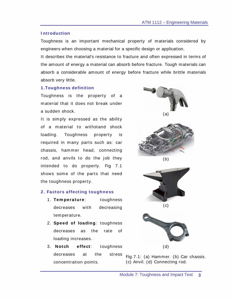
1.Toughness definition
Toughness is the property of a
material that it does not break under
a sudden shock.
It is simply expressed as the ability
of a material to withstand shock
loading. Toughness property is
required in many parts such as: car
chassis, hammer head, connecting
rod, and anvils to do the job they
intended to do properly. Fig 7.1
shows some of the parts that need
the toughness property.
2. Factors affecting toughness
1. Temperature: toughness
decreases with decreasing
temperature.
2. Speed of loading: toughness
decreases as the rate of
loading increases.
3. Notch effect: toughness
decreases at the stress
concentration points.
(a)
(b)
(c)
(d)
Fig.7.1: (a) Hammer. (b) Car chassis. (c) Anvil. (d) Connecting rod.
ATM 1112 – Engineering Materials
Module 7: Toughness and Impact Test 4
2.1 Examples of toughness of materials arranged in a descending
order
1. Copper
2. Nickel
3. Iron
4. Aluminum
5. Lead
6. Tin
7. Cobalt
3.Toughness and Impact Tests
There are basically three types of impact tests for evaluating the toughness
of materials:
• The Pendulum test.
• The Drop Weight test.
• The Instrumented test
In this module, we will only discuss the most commonly used impact which
is the “Pendulum Test”.
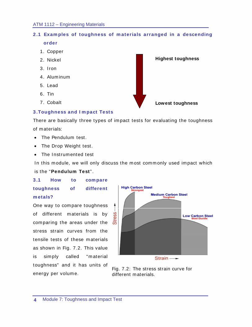
3.1 How to compare
toughness of different
metals?
One way to compare toughness
of different materials is by
comparing the areas under the
stress strain curves from the
tensile tests of these materials
as shown in Fig. 7.2. This value
is simply called “material
toughness” and it has units of
energy per volume.
Fig. 7.2: The stress strain curve for different materials.
Highest toughness
Lowest toughness
ATM 1112 – Engineering Materials
Module 7: Toughness and Impact Test 5
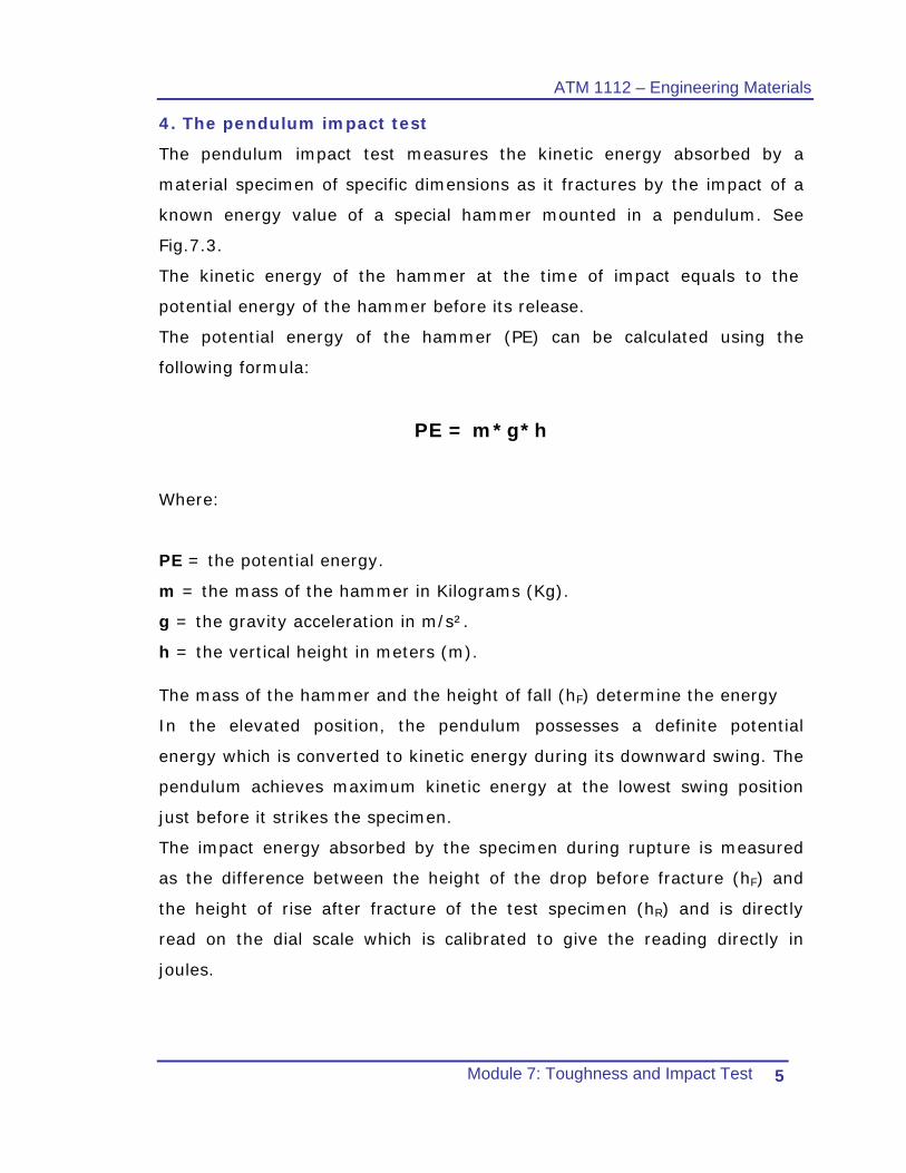
4. The pendulum impact test
The pendulum impact test measures the kinetic energy absorbed by a
material specimen of specific dimensions as it fractures by the impact of a
known energy value of a special hammer mounted in a pendulum. See
Fig.7.3.
The kinetic energy of the hammer at the time of impact equals to the
potential energy of the hammer before its release.
The potential energy of the hammer (PE) can be calculated using the
following formula:
PE = m*g*h
Where:
PE = the potential energy.
m = the mass of the hammer in Kilograms (Kg).
g = the gravity acceleration in m/s².
h = the vertical height in meters (m).
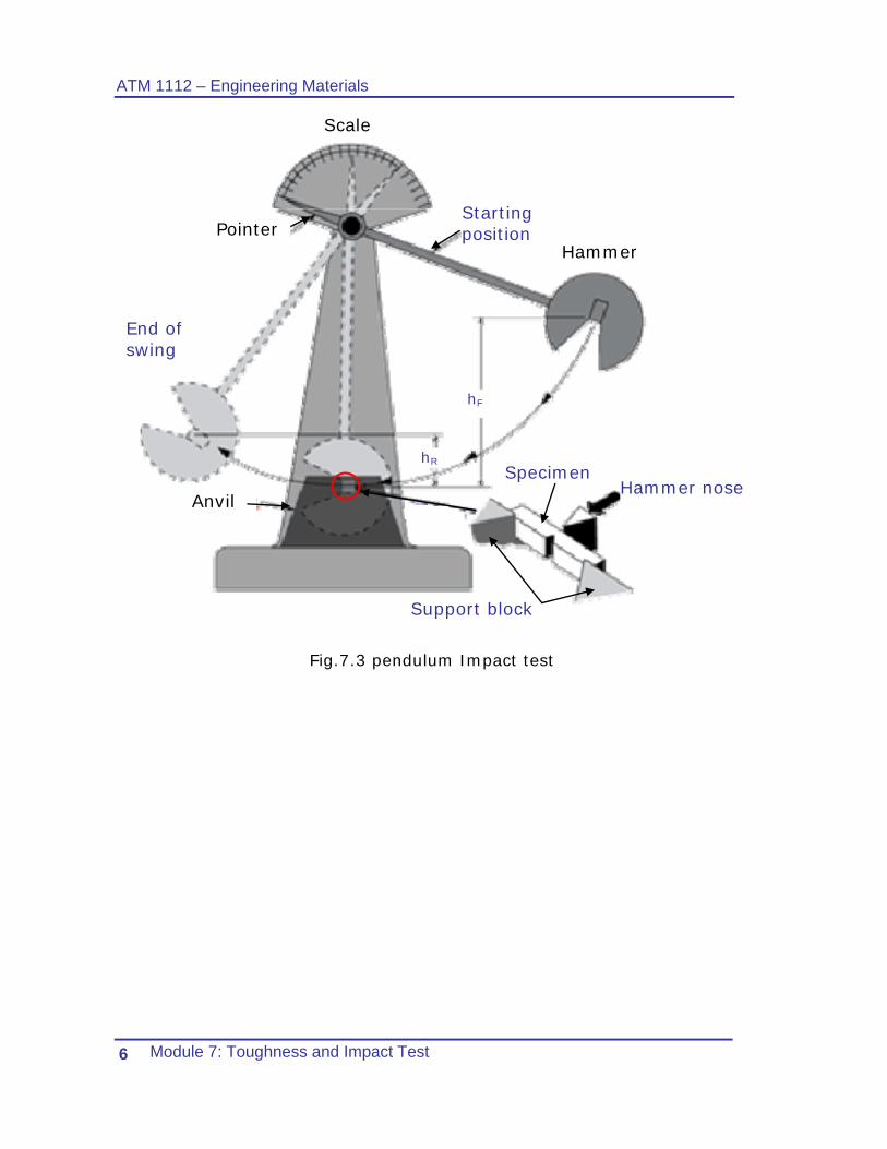
The mass of the hammer and the height of fall (hF) determine the energy
In the elevated position, the pendulum possesses a definite potential
energy which is converted to kinetic energy during its downward swing. The
pendulum achieves maximum kinetic energy at the lowest swing position
just before it strikes the specimen.
The impact energy absorbed by the specimen during rupture is measured
as the difference between the height of the drop before fracture (hF) and
the height of rise after fracture of the test specimen (hR) and is directly
read on the dial scale which is calibrated to give the reading directly in
joules.
ATM 1112 – Engineering Materials
Module 7: Toughness and Impact Test 6
Hammer
Starting position
End of swing
Pointer
Scale
Specimen hR
Anvil
hF
Hammer nose
Support block
Fig.7.3 pendulum Impact test
ATM 1112 – Engineering Materials
Module 7: Toughness and Impact Test 7
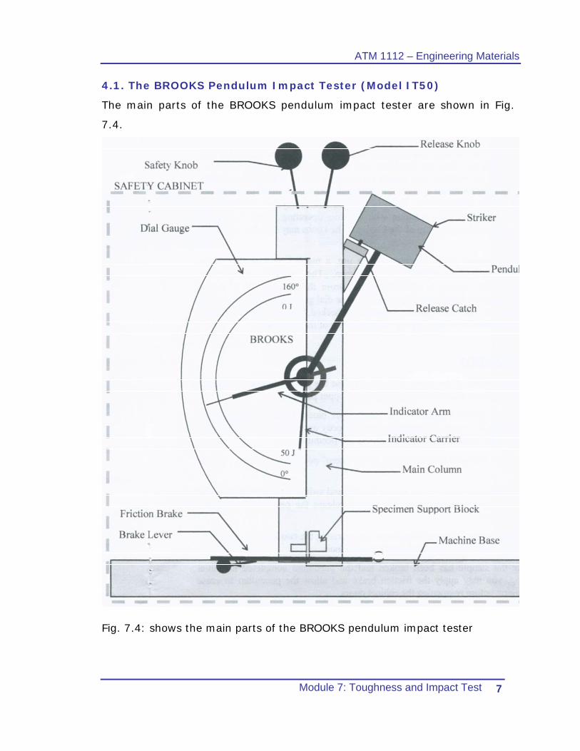
4.1. The BROOKS Pendulum Impact Tester (Model IT50)
The main parts of the BROOKS pendulum impact tester are shown in Fig.
7.4.
Fig. 7.4: shows the main parts of the BROOKS pendulum impact tester
ATM 1112 – Engineering Materials
Module 7: Toughness and Impact Test 8
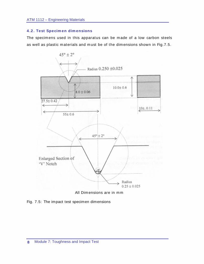
4.2. Test Specimen dimensions
The specimens used in this apparatus can be made of a low carbon steels
as well as plastic materials and must be of the dimensions shown in Fig.7.5.
All Dimensions are in mm
Fig. 7.5: The impact test specimen dimensions
ATM 1112 – Engineering Materials
Module 7: Toughness and Impact Test 9
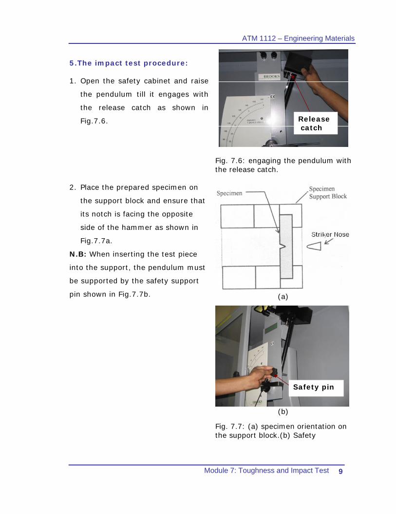
5.The impact test procedure: 1. Open the safety cabinet and raise
the pendulum till it engages with
the release catch as shown in
Fig.7.6.
Fig. 7.6: engaging the pendulum with the release catch.
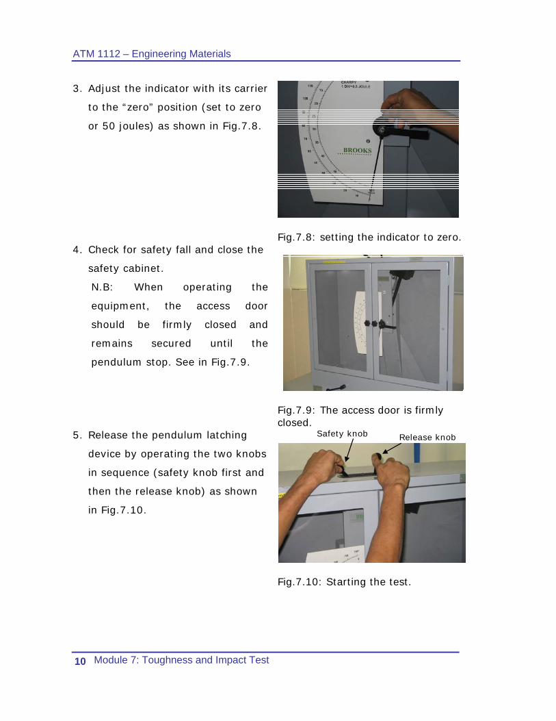
2. Place the prepared specimen on
the support block and ensure that
its notch is facing the opposite
side of the hammer as shown in
Fig.7.7a.
N.B: When inserting the test piece
into the support, the pendulum must
be supported by the safety support
pin shown in Fig.7.7b.
(a)
(b)
Fig. 7.7: (a) specimen orientation on the support block.(b) Safety
Release catch
Safety pin
ATM 1112 – Engineering Materials
Module 7: Toughness and Impact Test 10
3. Adjust the indicator with its carrier
to the “zero” position (set to zero
or 50 joules) as shown in Fig.7.8.
Fig.7.8: setting the indicator to zero.
4. Check for safety fall and close the
safety cabinet.
N.B: When operating the
equipment, the access door
should be firmly closed and
remains secured until the
pendulum stop. See in Fig.7.9.
Fig.7.9: The access door is firmly closed.
5. Release the pendulum latching
device by operating the two knobs
in sequence (safety knob first and
then the release knob) as shown
in Fig.7.10.
Safety knob Release knob
Fig.7.10: Starting the test.
ATM 1112 – Engineering Materials
Module 7: Toughness and Impact Test 11
6. After the specimen breaks and the
pendulum complete its initial
swing, apply the friction brake to
stop the pendulum and open the
cabinet as shown in Fig.7.11.
Brake lever
Fig.7.11: Using the brake lever to stop the pendulum.
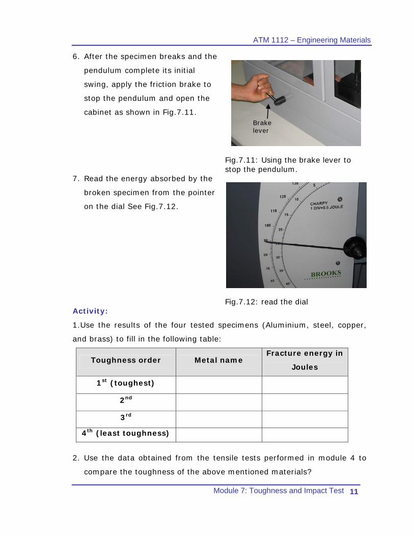
7. Read the energy absorbed by the
broken specimen from the pointer
on the dial See Fig.7.12.
Fig.7.12: read the dial Activity:
1.Use the results of the four tested specimens (Aluminium, steel, copper,
and brass) to fill in the following table:
Toughness order Metal name Fracture energy in
Joules
1st (toughest)
2nd
3rd
4th (least toughness)
2. Use the data obtained from the tensile tests performed in module 4 to
compare the toughness of the above mentioned materials?
ATM 1112 – Engineering Materials
Module 7: Toughness and Impact Test 12
For further reading, you can use the following links
http://www.ndt-ed.org/EducationResources/CommunityCollege/Materials/Mechanical/Toughness.htm
6 Supplementary recourses
1. Mechanical and Non-destructive testing video.
7 References
1. The BROOKS Pendulum Impact Tester (Model IT50) instruction
manual.
2. Modern engineering materials edition 1.
3. Engineering materials 1. “An introduction to Properties, Applications,
and Design”.
4. Different internet sites.

ATM 1112 – Engineering Materials
Module 7: Toughness and Impact Test 13
Student’s notes
............................................................................................................
............................................................................................................
............................................................................................................
............................................................................................................
............................................................................................................
............................................................................................................
............................................................................................................
............................................................................................................
............................................................................................................
............................................................................................................
............................................................................................................
............................................................................................................
............................................................................................................
............................................................................................................
............................................................................................................
............................................................................................................
............................................................................................................
............................................................................................................
............................................................................................................
............................................................................................................
............................................................................................................


![AutoCAD 2D I Module13[1] - Maysaa Nazarmaysaaiat.weebly.com/uploads/5/8/8/3/5883161/autocad_2d_i_modul… · Institute of Applied Technology Fillets Module 13 2 Auto CAD Self-paced](https://static.cupdf.com/doc/110x72/5b09ba8c7f8b9a93738e50a9/autocad-2d-i-module131-maysaa-of-applied-technology-fillets-module-13-2-auto.jpg)