Basic Hydraulics and Pneumatics Module 1: Introduction to Pneumatics PREPARED BY IAT Curriculum Unit March 2011 © Institute of Applied Technology, 2011

Welcome message from author
This document is posted to help you gain knowledge. Please leave a comment to let me know what you think about it! Share it to your friends and learn new things together.
Transcript
Basic Hydraulics and Pneumatics
Module 1: Introduction to Pneumatics
PREPARED BY
IAT Curriculum Unit
March 2011
© Institute of Applied Technology, 2011

ATM 1122 – Basic Hydraulics and Pneumatics
Module 1: Introduction to Pneumatics
Module Objectives After the completion of this module, the student will be able to:
Identify the common uses of pneumatic systems.
Identify the main parts of a pneumatic system.
Identify the main components of the pneumatic work station TP 101.
Understand how to to construct a pneumatic circuit
Explain the structure and signal flow of a pneumatic system.
List the main parts in the compressed air preparation stage.
Identify the symbol of air compressor and its function.
Identify the symbol of air tank and its function.
Explain the purpose of using the cooling and drying unit
Identify the main parts of the air service unit.
Identify the symbol of air filter and its function.
Identify the symbol of air pressure regulator and its function.
Identify the symbol of lubricator and its function.
Identify some important pneumatic accessories.
ATM 1112 – Basic Hydraulics and Pneumatics
2 Module 1: Introduction to pneumatics
Module Contents
1 Introduction….. ..............................................................................3
1.1 What does pneumatic mean……................................................ 3 1.2 Defentition of pneumatics… ..................................................... 3 1.3 What is the fluid power…......................................................... 3
2 Applications of pneumatics ……......................................................5
2.1 industrial applications ……........................................................ 5 2.2 Industrial processes … ............................................................ 5 2.3 Some of the pneumatic applications in our life … ........................ 6
3 Advantages and disadvantages of pneumatics … ...........................8
3.1 Advantages................................................................................. 8 3.2 Disadvantages............................................................................. 8
4 Structure and signal flow of pneumatic systems … ........................9
4.1 Primary levels of the pneumatic system … ...................................... 9
5 Air generation and distribution ….................................................11
5.1 Preparation the compressed air.. ................................................. 11 5.2 Main parts in the compressed air preparation.. ................................. 12
5.2.1 Air compressor … ................................................................. 12 5.2.2 Air Tank (reservoir)…............................................................ 13 5.2.3 Cooling and drying unit…....................................................... 14 5.2.4 Piping…............................................................................... 15 5.2.5 Air service unit… .................................................................. 17
6 Pneumatic accessories .................................................................20
6.1 Manifold (distributor) …… ...................................................... 20 6.2 Shut-off valves … ................................................................. 20 6.3 Tubes and fittings … ............................................................. 20 6.4 Pressure gauges … ............................................................... 21
References.........................................................................................22
ATM 1122 – Basic Hydraulics and Pneumatics
Module 1: Introduction to pneumatics 3
1 Introduction
1.1 What Does Pneumatic Mean?
Pneumatics comes from the Greek word pneuma, which means 'breath or
wind'. It is basically the use of under pressure gas that helps in performing a
certain work in science and technology.
1.2 Definition of pneumatics
Pneumatics is the transmission and control of forces and movements by means
of compressed air. (The use of compressed air as a medium to do work).
1.3 What is the fluid power?
Fluid power is the energy transmitted and controlled by means of a
pressurized fluid, either liquid or gas. The term fluid power applies to both
hydraulics and pneumatics. Hydraulics (oil or water) use liquids under pressure
while pneumatics use compressed air or other neutral gases.
Pneumatics technology has for some considerable time been used in carrying
out the simplest mechanical tasks, but nowadays has played a vital and
important role in automation and development of sophisticated technologies.
ATM 1112 – Basic Hydraulics and Pneumatics
4 Module 1: Introduction to pneumatics
2 Applications of pneumatics:
2.1 industrial applications
Pneumatic systems are used in many industrial applications such as:
Material handling
Clamping
Shifting
Positioning
Branching of material flow
Packaging
Filling
Transfer of materials
Sorting of parts
Stamping and embossing of components
2.2 Industrial processes
Pneumatic systems are used in carrying out machining and some industrial
processes such as:
Drilling
Turning
Milling
Sawing
Finishing
Forming
ATM 1122 – Basic Hydraulics and Pneumatics
Module 1: Introduction to pneumatics 5
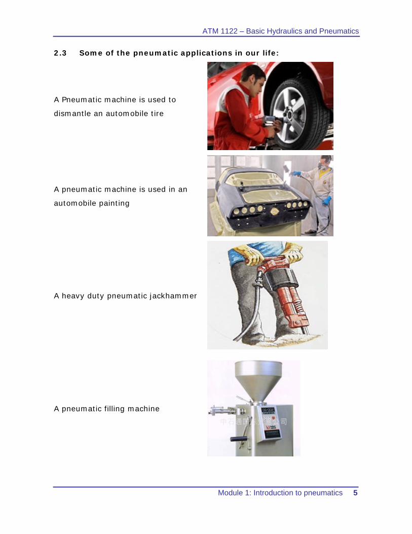
2.3 Some of the pneumatic applications in our life:
A Pneumatic machine is used to
dismantle an automobile tire
A pneumatic machine is used in an
automobile painting
A heavy duty pneumatic jackhammer
A pneumatic filling machine
ATM 1112 – Basic Hydraulics and Pneumatics
6 Module 1: Introduction to pneumatics
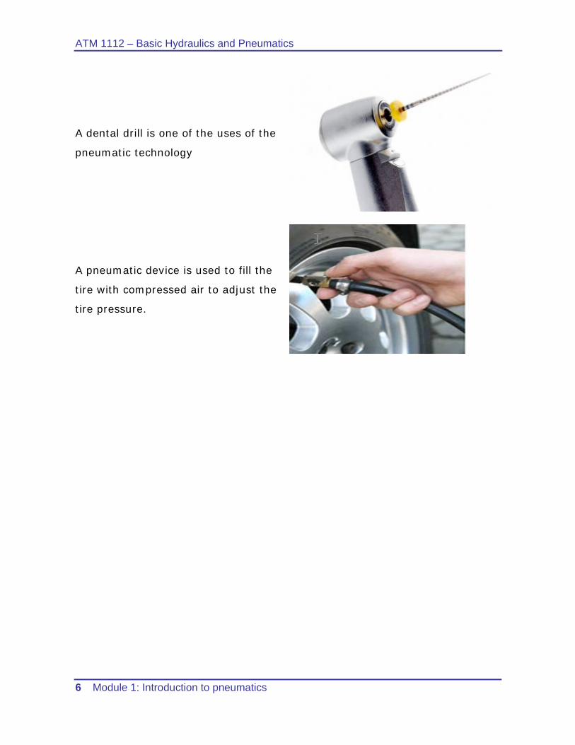
A dental drill is one of the uses of the
pneumatic technology
A pneumatic device is used to fill the
tire with compressed air to adjust the
tire pressure.
ATM 1122 – Basic Hydraulics and Pneumatics
Module 1: Introduction to pneumatics 7
3 Advantages and disadvantages of pneumatics:
3.1 Advantages:
1- Availability: Air is available everywhere in unlimited quantities.
2- Transport: Air can be easily transported in pipelines, even over large
distances.
3- Storage: Compressed air can be stored in a reservoir/tank and removed
as required.
4- Temperature: Compressed air is relatively insensitive to temperature
fluctuations.
5- Cleanliness: Unubricated exhaust air is clean.
6- The running cost is relatively inexpensive
7- Speed: Compressed air is a very fast working medium. This enables high
working speeds to be attained.
8- Overload safe: Pneumatic tools and operating components can be loaded
to the point of stopping and are therefore overload safe.
3.2 Disadvantages:
1- Preparation: Compressed air requires good preparation. Dirt and
condensates should be removed.
2- Speed: As air is compressible; it is difficult to achieve uniform and
constant piston speed.
3- Force requirement: Compressed air is economical only up to a certain
force requirement. Under the normal working pressure of 600 to 700 kPa
(6 to 7 bar).
4- Noise level: The exhaust air is loud (noise). This problem has now,
however been largely solved due to the development of sound
absorption material and silencers.
ATM 1112 – Basic Hydraulics and Pneumatics
8 Module 1: Introduction to pneumatics
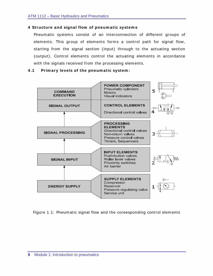
4 Structure and signal flow of pneumatic systems
Pneumatic systems consist of an interconnection of different groups of
elements. This group of elements forms a control path for signal flow,
starting from the signal section (input) through to the actuating section
(output). Control elements control the actuating elements in accordance
with the signals received from the processing elements.
4.1 Primary levels of the pneumatic system:
Figure 1.1: Pneumatic signal flow and the coreesponding control elements
ATM 1122 – Basic Hydraulics and Pneumatics
Module 1: Introduction to pneumatics 9
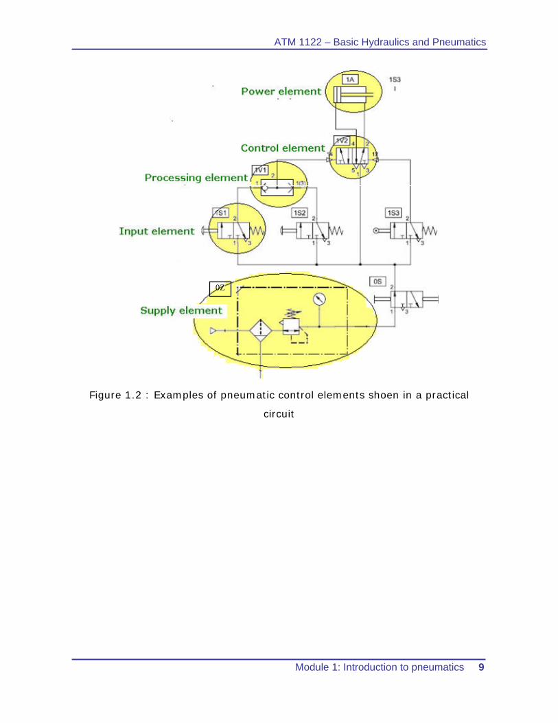
0Z
Figure 1.2 : Examples of pneumatic control elements shoen in a practical
circuit
ATM 1112 – Basic Hydraulics and Pneumatics
10 Module 1: Introduction to pneumatics
5 Air generation and distribution
The main function of the air generation and distribution is to provide the
system with compressed air which is dry, clean, and at the required pressure
The compressed air supply for a pneumatic system should be adequately
calculated and made available in the appropriate quality.
Air is compressed by the air compressor and delivered to an air distribution
system in the factory. To ensure that the quality of the air is acceptable, air
service unit is utilized to prepare the air before being supplied to the control
system.
Malfunctions can be considerably reduced in the system if the compressed air
is correctly prepared. A number of aspects must be considered
5.1 Preparation of the compressed air:
The following points should be considered in preparing compressed air plants:
1. Quantity of air required to meet the demand of the system
2. Type of compressor to be used to produce the quantity required
3. Pressure requirements
4. Storage requirements
5. Requirements for air cleanliness
6. Acceptable humidity levels to reduce corrosion and sticky operation
7. Lubrication requirements, if necessary
8. Temperature of the air and effects on the system
9. Line sizes and valve sizes to meet demand
10. Material selection to meet environmental and system requirements
11. Drainage points and exhaust outlets in the distribution system
12. Layout of the distribution system to meet demand.
ATM 1122 – Basic Hydraulics and Pneumatics
Module 1: Introduction to pneumatics 11
5.2 Main parts in the compressed air preparation
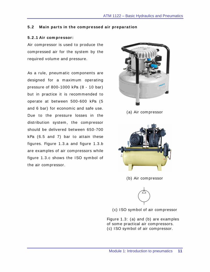
5.2.1 Air compressor:
Air compressor is used to produce the
compressed air for the system by the
required volume and pressure.
As a rule, pneumatic components are
designed for a maximum operating
pressure of 800-1000 kPa (8 - 10 bar)
but in practice it is recommended to
operate at between 500-600 kPa (5
and 6 bar) for economic and safe use.
Due to the pressure losses in the
distribution system, the compressor
should be delivered between 650-700
kPa (6.5 and 7) bar to attain these
figures. Figure 1.3.a and figure 1.3.b
are examples of air compressors while
figure 1.3.c shows the ISO symbol of
the air compressor.
(a) Air compressor
(b) Air compressor
(c) ISO symbol of air compressor
Figure 1.3: (a) and (b) are examples of some practical air compressors. (c) ISO symbol of air compressor.
ATM 1112 – Basic Hydraulics and Pneumatics
12 Module 1: Introduction to pneumatics
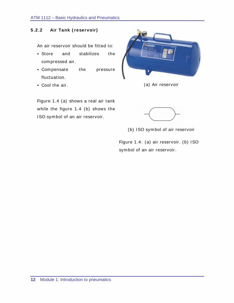
5.2.2 Air Tank (reservoir)
An air reservoir should be fitted to:
Store and stabilizes the
compressed air.
Compensate the pressure
fluctuation.
Cool the air.
Figure 1.4 (a) shows a real air tank
while the figure 1.4 (b) shows the
ISO symbol of an air reservoir.
(a) Air reservoir
(b) ISO symbol of air reservoir
Figure 1.4: (a) air reservoir. (b) ISO
symbol of an air reservoir.
ATM 1122 – Basic Hydraulics and Pneumatics
Module 1: Introduction to pneumatics 13
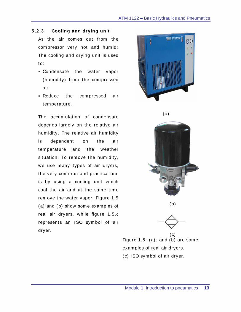
5.2.3 Cooling and drying unit
As the air comes out from the
compressor very hot and humid;
The cooling and drying unit is used
to:
Condensate the water vapor
(humidity) from the compressed
air.
Reduce the compressed air
temperature.
The accumulation of condensate
depends largely on the relative air
humidity. The relative air humidity
is dependent on the air
temperature and the weather
situation. To remove the humidity,
we use many types of air dryers,
the very common and practical one
is by using a cooling unit which
cool the air and at the same time
remove the water vapor. Figure 1.5
(a) and (b) show some examples of
real air dryers, while figure 1.5.c
represents an ISO symbol of air
dryer.
(a)
(b)
(c)
Figure 1.5: (a): and (b) are some
examples of real air dryers.
(c) ISO symbol of air dryer.
ATM 1112 – Basic Hydraulics and Pneumatics
14 Module 1: Introduction to pneumatics
5.2.4 Piping
The pipe diameter of the air distribution system should be selected in such a
way that the pressure loss from the pressurized reservoir to the consuming
device ideally does not exceed approx. 10 kPa (0.1 bar).
5.2.4.1 Selection of the pipe diameter:
1. Flow rate
2. Line length
3. Permissible pressure loss
4. Operating pressure
5. Number of flow control points in the line
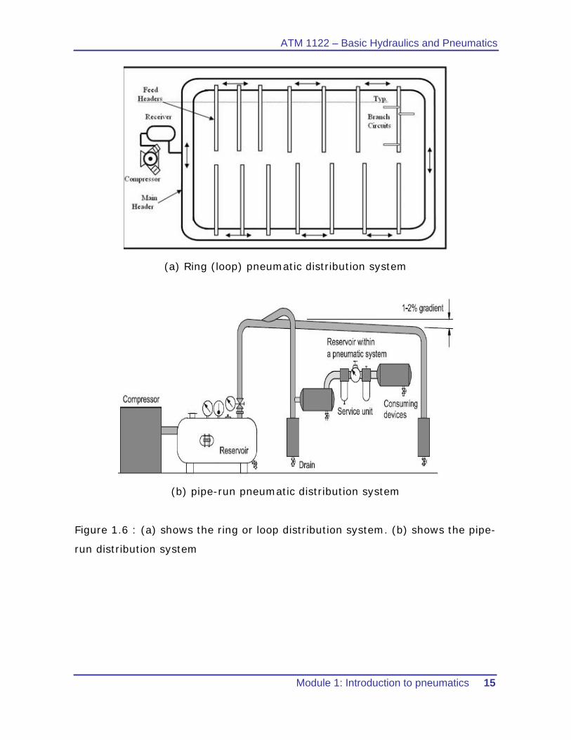
5.2.4.2 Piping layout
Ring circuits (figure 1.6.a) are most frequently used as main lines. This
method of installing pressure lines also achieves a constant supply in the case
of high air consumption. In pipe-run layout, the pipe lines must be installed in
the direction of flow with a gradient of 1 to 2% as shown in figure 1.6 b. This
is particularly important in the case of branch lines. Condensate can be
removed from the lines at the lowest point. Any branching of air consumption
points where lines run horizontally should always be installed on the upper
side of the main line. Branching for condensate removal is installed on the
underside of the main line. Shut-off valves can be used to block sections of
compressed air lines if these are not required or need to be closed down for
repair or maintenance purposes.
ATM 1122 – Basic Hydraulics and Pneumatics
Module 1: Introduction to pneumatics 15
(a) Ring (loop) pneumatic distribution system
(b) pipe-run pneumatic distribution system
Figure 1.6 : (a) shows the ring or loop distribution system. (b) shows the pipe-
run distribution system
ATM 1112 – Basic Hydraulics and Pneumatics
16 Module 1: Introduction to pneumatics
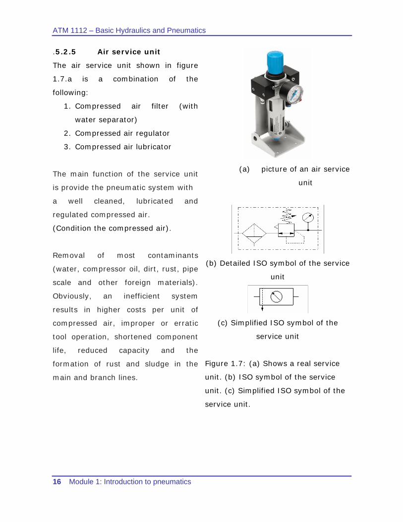
.5.2.5 Air service unit
The air service unit shown in figure
1.7.a is a combination of the
following:
1. Compressed air filter (with
water separator)
2. Compressed air regulator
3. Compressed air lubricator
The main function of the service unit
is provide the pneumatic system with
a well cleaned, lubricated and
regulated compressed air.
(Condition the compressed air).
Removal of most contaminants
(water, compressor oil, dirt, rust, pipe
scale and other foreign materials).
Obviously, an inefficient system
results in higher costs per unit of
compressed air, improper or erratic
tool operation, shortened component
life, reduced capacity and the
formation of rust and sludge in the
main and branch lines.
(a) picture of an air service
unit
(b) Detailed ISO symbol of the service
unit
(c) Simplified ISO symbol of the
service unit
Figure 1.7: (a) Shows a real service
unit. (b) ISO symbol of the service
unit. (c) Simplified ISO symbol of the
service unit.
ATM 1122 – Basic Hydraulics and Pneumatics
Module 1: Introduction to pneumatics 17
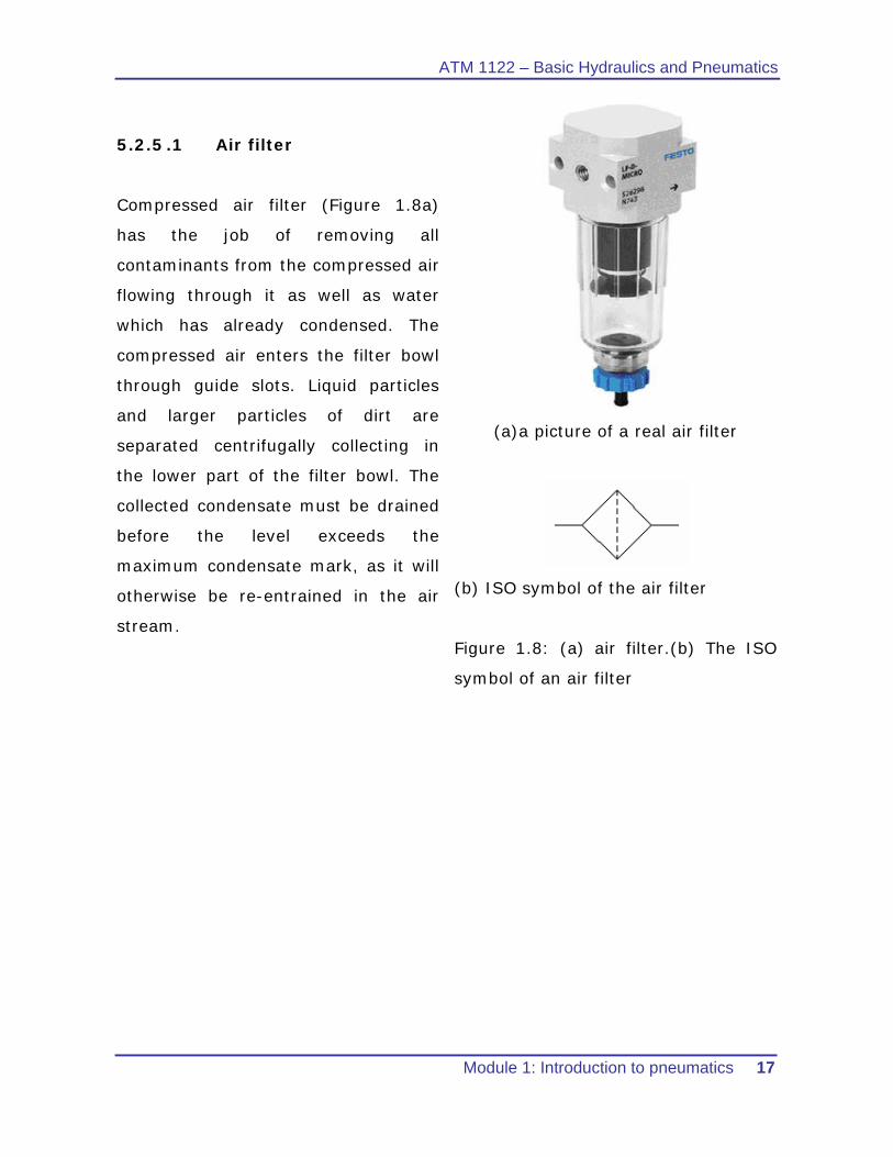
5.2.5 .1 Air filter
Compressed air filter (Figure 1.8a)
has the job of removing all
contaminants from the compressed air
flowing through it as well as water
which has already condensed. The
compressed air enters the filter bowl
through guide slots. Liquid particles
and larger particles of dirt are
separated centrifugally collecting in
the lower part of the filter bowl. The
collected condensate must be drained
before the level exceeds the
maximum condensate mark, as it will
otherwise be re-entrained in the air
stream.
(a)a picture of a real air filter
(b) ISO symbol of the air filter
Figure 1.8: (a) air filter.(b) The ISO
symbol of an air filter
ATM 1112 – Basic Hydraulics and Pneumatics
18 Module 1: Introduction to pneumatics
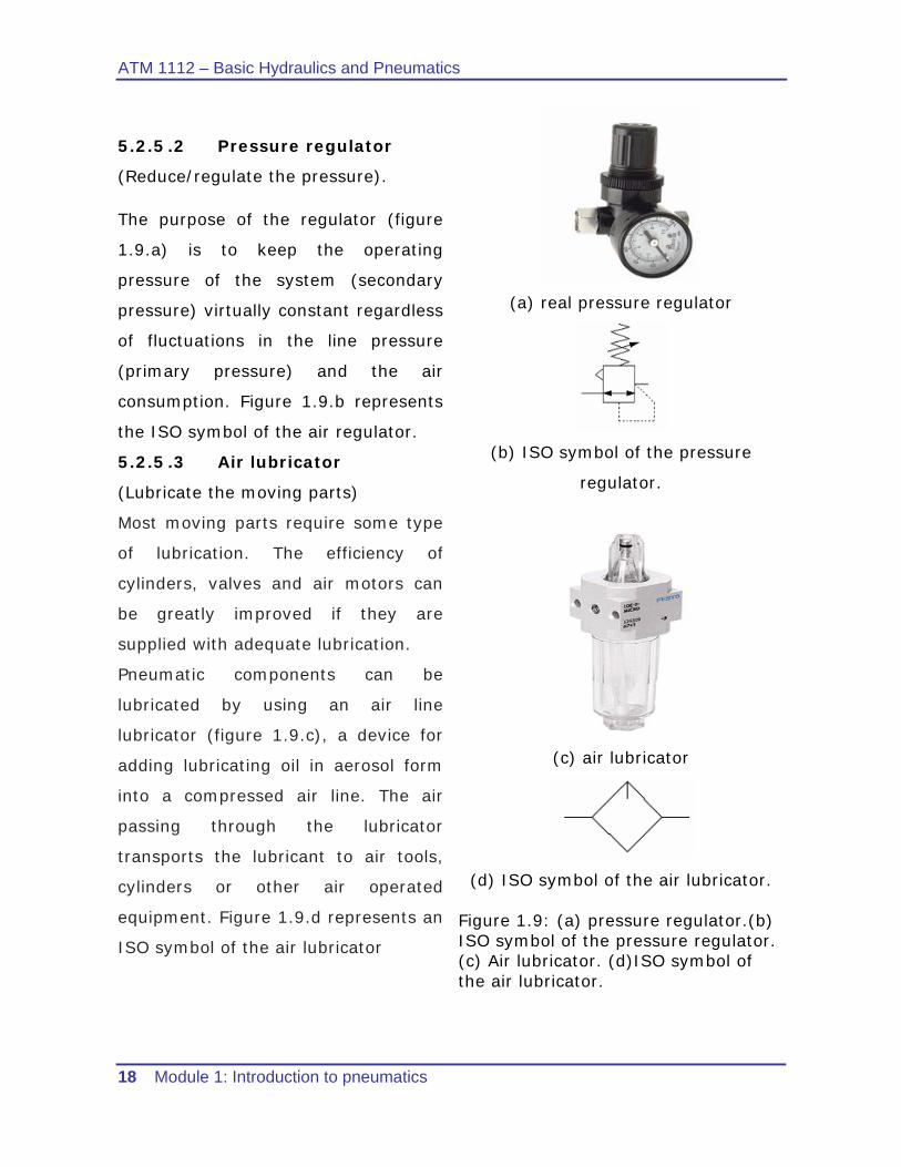
5.2.5 .2 Pressure regulator
(Reduce/regulate the pressure).
The purpose of the regulator (figure
1.9.a) is to keep the operating
pressure of the system (secondary
pressure) virtually constant regardless
of fluctuations in the line pressure
(primary pressure) and the air
consumption. Figure 1.9.b represents
the ISO symbol of the air regulator.
5.2.5 .3 Air lubricator
(Lubricate the moving parts)
Most moving parts require some type
of lubrication. The efficiency of
cylinders, valves and air motors can
be greatly improved if they are
supplied with adequate lubrication.
Pneumatic components can be
lubricated by using an air line
lubricator (figure 1.9.c), a device for
adding lubricating oil in aerosol form
into a compressed air line. The air
passing through the lubricator
transports the lubricant to air tools,
cylinders or other air operated
equipment. Figure 1.9.d represents an
ISO symbol of the air lubricator
(a) real pressure regulator
(b) ISO symbol of the pressure
regulator.
(c) air lubricator
(d) ISO symbol of the air lubricator. Figure 1.9: (a) pressure regulator.(b) ISO symbol of the pressure regulator. (c) Air lubricator. (d)ISO symbol of the air lubricator.
ATM 1122 – Basic Hydraulics and Pneumatics
Module 1: Introduction to pneumatics 19
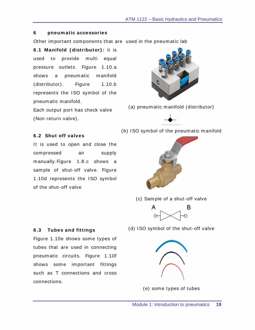
6 pneumatic accessories
Other important components that are used in the pneumatic lab
6.1 Manifold (distributor): it is
used to provide multi equal
pressure outlets. Figure 1.10.a
shows a pneumatic manifold
(distributor). Figure 1.10.b
represents the ISO symbol of the
pneumatic manifold.
Each output port has check valve
(Non return valve).
6.2 Shut off valves
It is used to open and close the
compressed air supply
manually.Figure 1.8.c shows a
sample of shut-off valve. Figure
1.10d represents the ISO symbol
of the shut-off valve
6.3 Tubes and fittings
Figure 1.10e shows some types of
tubes that are used in connecting
pneumatic circuits. Figure 1.10f
shows some important fittings
such as T connections and cross
connections.
(a) pneumatic manifold (distributor)
(b) ISO symbol of the pneumatic manifold
(c) Sample of a shut-off valve
(d) ISO symbol of the shut-off valve
(e) some types of tubes
ATM 1112 – Basic Hydraulics and Pneumatics
20 Module 1: Introduction to pneumatics
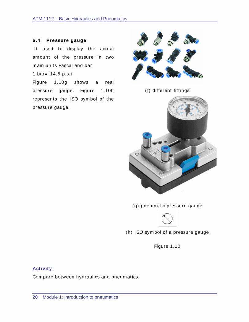
6.4 Pressure gauge
It used to display the actual
amount of the pressure in two
main units Pascal and bar
1 bar= 14.5 p.s.i
Figure 1.10g shows a real
pressure gauge. Figure 1.10h
represents the ISO symbol of the
pressure gauge.
(f) different fittings
(g) pneumatic pressure gauge
(h) ISO symbol of a pressure gauge
Figure 1.10
Activity:
Compare between hydraulics and pneumatics.
ATM 1122 – Basic Hydraulics and Pneumatics
Module 1: Introduction to pneumatics 21
References
1. Festo Didactic pneumatic basic level textbook TP 101.
2. Introduction to fluid power by James L. Johnson
3. http://www.omega.com/auto/pdf/CompressedAirTips.pdf

ATM 1112 – Basic Hydraulics and Pneumatics
22 Module 1: Introduction to pneumatics
Student notes
……………………………………………………………………………………………………………………………..........................
……………………………………………………………………………………………………………………………..........................
……………………………………………………………………………………………………………………………..........................
……………………………………………………………………………………………………………………………..........................
……………………………………………………………………………………………………………………………..........................
……………………………………………………………………………………………………………………………..........................
……………………………………………………………………………………………………………………………..........................
……………………………………………………………………………………………………………………………..........................
……………………………………………………………………………………………………………………………..........................
……………………………………………………………………………………………………………………………..........................
……………………………………………………………………………………………………………………………..........................
……………………………………………………………………………………………………………………………..........................
……………………………………………………………………………………………………………………………..........................
……………………………………………………………………………………………………………………………..........................
……………………………………………………………………………………………………………………………..........................
……………………………………………………………………………………………………………………………..........................
……………………………………………………………………………………………………………………………..........................
……………………………………………………………………………………………………………………………..........................
……………………………………………………………………………………………………………………………..........................
……………………………………………………………………………………………………………………………..........................
……………………………………………………………………………………………………………………………..........................
……………………………………………………………………………………………………………………………..........................
……………………………………………………………………………………………………………………………..........................
……………………………………………………………………………………………………………………………..........................
……………………………………………………………………………………………………………………………..........................
……………………………………………………………………………………………………………………………..........................
……………………………………………………………………………………………………………………………..........................
Related Documents