Application for a Conditional Use Permit for Non-metallic Mineral Mining
Breezy Point Properties
Towns of Maxville and Nelson, Buffalo County, Wisconsin
Summit Project No. 2226-0001
June 2014
TABLE OF CONTENTS 1.0 Application Requirements................................................................................................. 1
1.1 Completed Application ....................................................................................................... 1
1.2 General Information ........................................................................................................... 1
1.2.1 Adjacent Landowners/Legal Description ....................................................................... 1
1.2.2 Owner Information ......................................................................................................... 2
1.2.3 Operator Contact Information ........................................................................................ 2
1.2.4 Lease Agreement ............................................................................................................ 2
1.2.5 Permit Application Fee ................................................................................................... 2
1.3 Operation Plan ..................................................................................................................... 2
1.3.1 CUP Consideration Factors ............................................................................................ 2
1.3.2 Nature of the deposit and mining methods and equipment used to extract and process the material .............................................................................................................................. 4
1.3.3 Estimated life of the mine and an operation timeline for resource extraction and site reclamation .............................................................................................................................. 5
1.3.4 Mining approach and contemporaneous reclamation to minimize the area disturbed ... 5
1.3.5 Depth of excavation and depth to groundwater table ..................................................... 6
1.3.6 Proposed hours and days of operation ............................................................................ 7
1.3.7 Hauling plan satisfying the requirements of the Buffalo County Highway Department 7
1.3.8 Onsite nonmetallic mineral processing facilities ............................................................ 7
1.3.9 Water requirements for the operation ............................................................................. 8
1.3.10 Precautions used to minimize particulate matter from becoming airborne .................. 8
1.3.11 Grading, drainage, and measures to be taken to control erosion .................................. 8
1.3.12 Measures to be taken to comply with applicable air and water quality standards ........ 9
2.0 Nuisance Mitigation Plan ...................................................................................................... 9
2.1 Noise...................................................................................................................................... 9
2.2 Air Quality .......................................................................................................................... 9
2.3 Lighting .............................................................................................................................. 10
2.4 Odor .................................................................................................................................... 10
2.5 Water Quality ................................................................................................................... 10
CERTIFICATION PAGE .......................................................................................................... 11

LIST OF FIGURES Figure 1 Site Location Figure 2 Site Features Figure 3 Topography and Drainage Figure 4 Soils and Wetlands Figure 5 Area Water Wells Figure 6 Conceptual Mine Plan Figure 7 Post Mining Topography Figure 8 Haul Routes LIST OF APPENDICES Appendix I CUP Application Appendix II Adjacent Landowner Information/Property Legal Descriptions Appendix III Lease Agreement Appendix IV Soils Information Appendix V Test Boring Logs Appendix VI Generalized Cross Sections
1
Application for a Conditional Use Permit for Non-metallic Mineral Mining
Breezy Point Properties
Towns of Maxville and Nelson, Buffalo County, Wisconsin
1.0 Application Requirements
1.1 Completed Application
The completed application has been included as Appendix I.
1.2 General Information
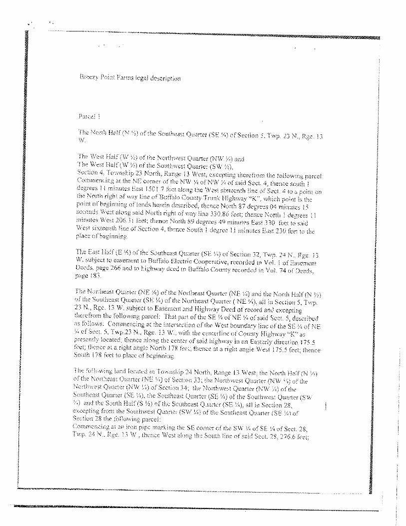
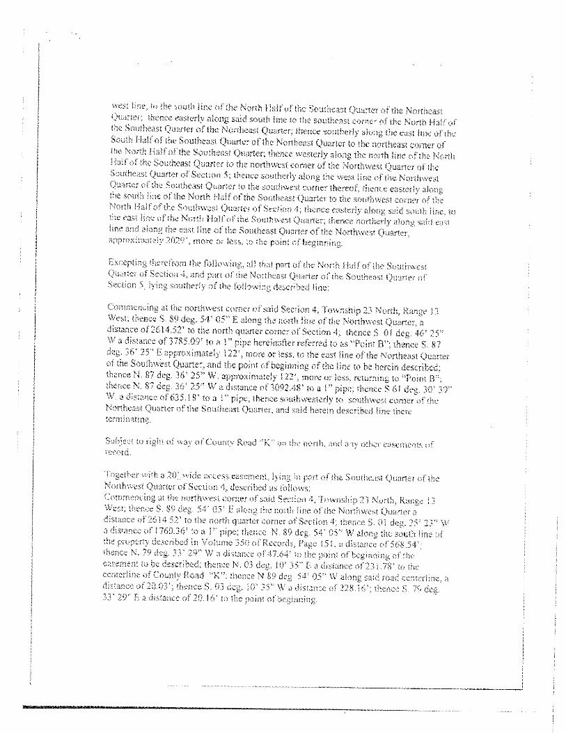
1.2.1 Adjacent Landowners/Legal Description
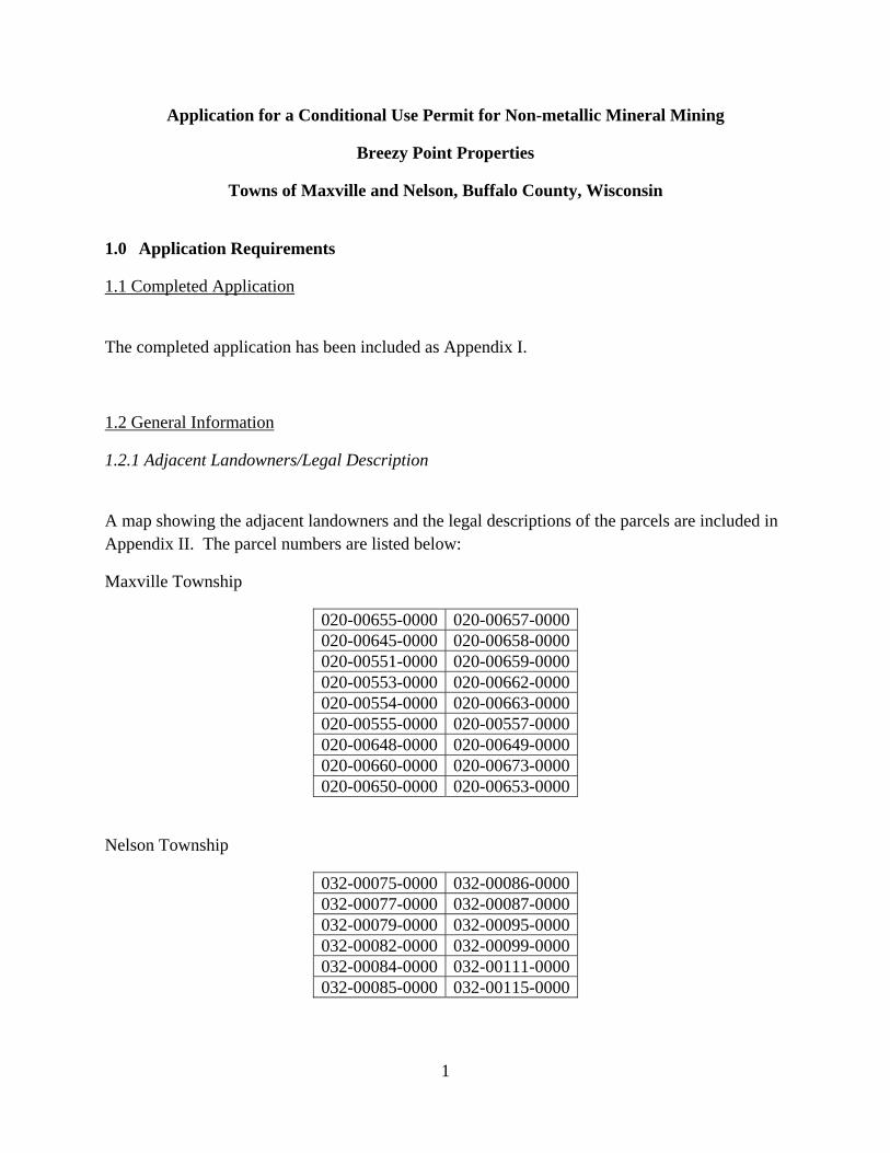
A map showing the adjacent landowners and the legal descriptions of the parcels are included in Appendix II. The parcel numbers are listed below:
Maxville Township
020-00655-0000 020-00657-0000020-00645-0000 020-00658-0000020-00551-0000 020-00659-0000020-00553-0000 020-00662-0000020-00554-0000 020-00663-0000020-00555-0000 020-00557-0000020-00648-0000 020-00649-0000020-00660-0000 020-00673-0000020-00650-0000 020-00653-0000
Nelson Township
032-00075-0000 032-00086-0000032-00077-0000 032-00087-0000032-00079-0000 032-00095-0000032-00082-0000 032-00099-0000032-00084-0000 032-00111-0000032-00085-0000 032-00115-0000
2
1.2.2 Owner Information
Breezy Point Farms, Inc.; Breezy Point Acres, LLC; Breezy Point Forests, LLC; Breezy Point Lands, LLC; Breezy Point Properties, LLC
Deric J. Lindstrom W2184 County Road K Durand, Wisconsin 54736 715-495-5021 (cell) 715-673-4982 (home)
1.2.3 Operator Contact Information Wisconsin Proppant Resources, Inc. 103 20th Street NE Stewartville, Minnesota 55976 Eric Clement, President – (563) 203.7377 (cell)
1.2.4 Lease Agreement
A signed copy of the lease or a letter signed by the owner of the property which authorizes the operator to enter the owner’s land for the purpose of nonmetallic mining as defined in the Buffalo County Zoning Ordinance. See Appendix III for a copy of the Lease Agreement.
1.2.5 Permit Application Fee
The permit application fee is included with the application.
1.3 Operation Plan
1.3.1 CUP Consideration Factors
1. The location, nature, and size of the proposed operation or use
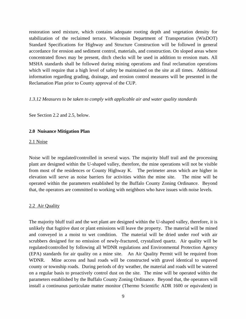
The owner and operator propose a relatively small-footprint and short duration mining and re-vegetation effort at the Breezy Point properties in the Town of Maxville, Buffalo County, Wisconsin (Figure 1).

3
The nature of the project is to construct a “bluff trail”, or a terrace, in the side of the bluff. The bluff trail will have positive benefits for the landscape and wildlife in the area, including:
restoring the area back to pre-settlement vegetation;
creating habitat for flora and fauna species;
reducing erosion;
improving storm-water quality; and
increasing the recreational value of the property.
2. The physical size of the site in relation to the proposed use
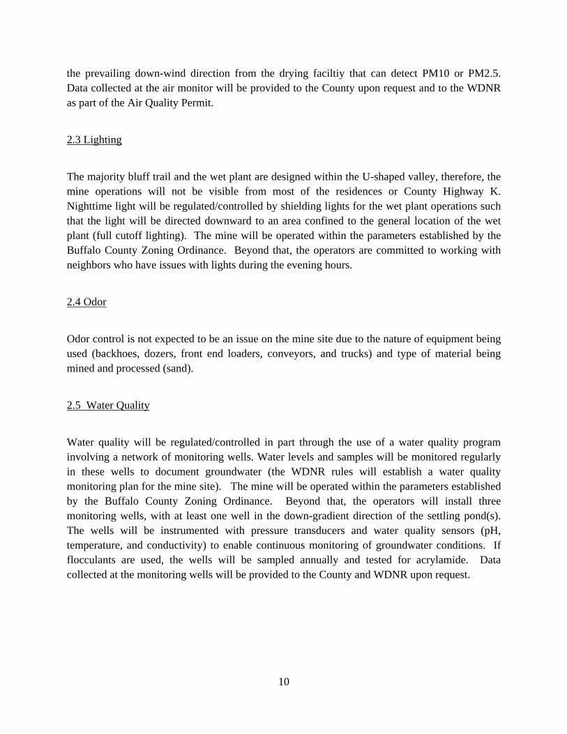
The area of Breezy Point properties encompassing the entire mining area is approximately 450 acres, however, the actual excavation will be conducted in an area covering 10% of this area, or approximately 45 acres (Figure 2). The sand washing and drying area and temporary access roads will require approximately 55 additional acres.
3. The location of the site with respect to anticipated traffic and existing or future streets or roads giving access to the proposed use.
The site is located between County Highway K, Lindstrom Valley Road, and County Highway V (Figure 2). No increases in traffic are proposed for Lindstrom Valley Road or County Highway V. The operators anticipate that approximately 60 to100 loads per day will be transported offsite going west on County Highway K and then north and south on State Highway 25. See Section 1.3.7 for information on haul routes. The operator has contacted the Buffalo County Highway Department to evaluate safety, design standards of County Highway K for both traffic and weight, and modifications to the existing driveway permit, if necessary.
4. Its compatibility with existing uses of the proposed land use, including adjacent lands.
The site is within the Agricultural District and is surrounded by agricultural and forested land. Article 5, Section 51.1 lists nonmetallic mining as a conditional use in the Agricultural District. The operation is compatible with existing land uses, since the proposed project will stabilize and improve the long-term sustainability of the hillsides and increase the recreational value that is currently realized. The proposed plan will improve wildlife habitat and the area will be significantly more accessible for the landowner. The hillsides will be less susceptible to erosion after the bluff trail has been established due to the proposed terrace design.
5. Its harmony with current and future development of the district.
As of the date of application, the owner and operator are not aware of any proposed residential development in the area. The proposed excavation and re-vegetation operation and is in harmony with the future development of the district. The erosion control, reduction of storm

4
water, reduction of invasive species, and enhancement of wildlife habitat are some of the benefits of the project that are consistent with district-wide objectives.
6. Existing factors including, but not limited to: topography, drainage, water quantity and quality, air quality, soil types, soil erosion, and vegetative cover.
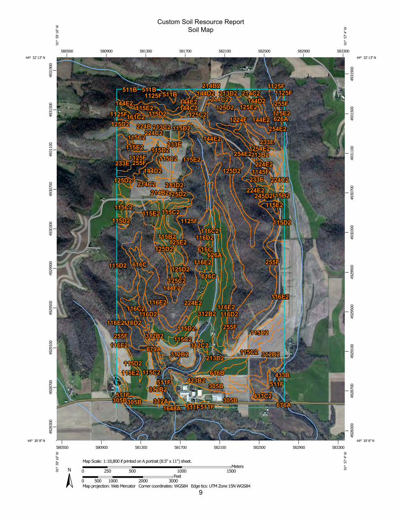
The site is characterized by relatively steep topography (Figure 3) that forms a U-shaped valley. The soils are predominantly silt loams of various complexes (Figure 4 and Appendix IV). A potential wetland in the extreme southwest corner of the area (Figure 4) was indicated by the Wisconsin Surface Water Viewer, however, this area will not be impacted by mining or processing activities. Area wells are presented on Figure 5. No detrimental impacts are anticipated from the project, conversely, the terrace design and re-introduction of native vegetation will enhance the recreational value of the area, decrease erosion potential, and decrease the amount of storm water leaving the site.
7. The relationship of the proposed use to the public interest, the purpose and intent of this ordinance, and substantial justice to all parties concerned.
The construction of the bluff trail will take place entirely on private property. The value of the sand as proppant makes the project feasible. The relatively short duration of the project (3-5 years), the small footprint on the property (10%), and the resulting bluff trail will not significantly change the character or appearance of the area. The project meets the purpose and intent of the ordinance and will adhere to all applicable rules and regulations. These rules and regulations will guide the proposed mining operation and provide substantial justice to all parties concerned.
1.3.2 Nature of the deposit and mining methods and equipment used to extract and process the material
Based on test borings advanced at the site, the geology includes surficial soil and bedrock units consisting of the Cambrian-age Jordan sandstone. The test boring logs are presented in Appendix V and a generalized geologic cross section is presented in Appendix VI. The sand deposit consists of subrounded to well rounded, spherical, quartzose sandstone. The Jordan sandstone can be friable to moderately cemented. In western Wisconsin, the Jordan Formation comprises a large majority of the bluffs that are present in the area. Bluffs are erosional features that are the result of thousands of years of storm water runoff. In many places, the Ordovician Prairie du Chien group, and the Oneota Dolomite in particular, comprises the “cap” of the bluffs. The Oneota Dolomite is primarily a massive dolostone unit containing chert nodules, stromatolites, and varying amounts of accessory minerals. The resistant Oneota Dolomite creates upland ridges in the area, as gullies and streams incise slowly down through this unit trying to establish hydrodynamic equilibrium with the much lower Mississippi River Valley. The Oneota Dolomite

5
in many areas has a basal unit called the Coon Valley Member (Mossler, 2008), which is a mixed siliciclastic and carbonate unit. The Coon Valley Member overlies the Jordan Sandstone; the contact can be sharp and undulatory, and appears to represent a regional unconformity. The Jordan Sandstone is composed of the Van Oser and Norwalk Members. The upper Van Oser Member contains sand of the quality sought by the proppant industry. The Van Oser Member contains varying amount of silica and calcium carbonate cement, and is often friable and easily eroded. This physical characteristic is the reason that many steep-sided slopes and narrow, steep ravines have developed over time by storm water runoff. The Jordan Formation is nominally 100 feet thick, and our experience indicates that the upper 50 feet (although highly variable) has high quality proppant material.
The Operator proposes to extract sandstone from the Cambrian Jordan Formation at the proposed Breezy Point Mine Site. The loose sandstone will be mined to the extent practical using earthmoving equipment, including backhoes, dozers, front end loaders, conveyors, and trucks. Activities at the site will include blasting (potentially but not expected), excavation, crushing, screening, washing, drying, stockpiling, and loading of material to be transported off-site.
1.3.3 Estimated life of the mine and an operation timeline for resource extraction and site reclamation
Mining activities at the proposed mine site will proceed in phases. Four phases are proposed for mining and the phases are shown on Figure 6. Mining is expected to commence during the fall of 2014 and would be completed as early as 2018. The wash and dry plant construction will be in progress at the same time as Phase 1 mining is beginning. The site will be mined sequentially starting with Phase 1 on the eastern side of the property. Each mining phase is expected to be completed in approximately one to two years depending on actual production (the duration of each mining phase may change depending on variations in the quality of mineable sand, differences in overburden thicknesses, and the actual quantity of sand mined each year). Reclamation will begin immediately upon completion of the phase and will be ongoing throughout the life of the project. Post mining contours are presented on Figure 7 and generalized cross section is in Appendix VI.
1.3.4 Mining approach and contemporaneous reclamation to minimize the area disturbed
The mining would follow the contour of the bottom of the proppant sand layer at an elevation of approximately 1,050 feet above sea level. The basic steps include:

6
Installing silt fencing and other erosion control BMPs as needed down-slope of the trail area;
Precision logging over the area where proppant material is present below the topsoil (say 100 feet wide for purposes of discussion);
Removing remaining vegetation and reclaiming stumps and brush as mulch material;
Blading topsoil into a berm on the down-slope edge of the clear cut area;
Stabilizing and seeding topsoil storage berm;
Cutting a “wedge” into the bedrock to remove sandstone – benching and wall angle will depend on rock mechanics (assume vertical walls with benches at 35 feet);
Sloping the terrace at a slight grade back toward the hill;
Leaving a “trench” at the base of the cut to create elongate depressions (retention basins) for water storage;
Sloping each 600-foot linear trench to a low middle point (i.e., 300 feet on each side);
Spreading topsoil back over terrace;
Planting native vegetation – primarily prairie species with oak openings in a strategic pattern and leaving a narrow meandering trail for access; and
Monitoring reclamation success and high-wall stability.
These steps result in a “bluff trail” shown in cross section in Appendix VI.
Management of topsoil will follow methods described in Section 625 of the WisDOT Standard Specification for Highway and Structure Construction (2012 Edition). All A-horizon and B-horizon soils will remain onsite for use in reclamation. Berms shown on the mine plan have been proposed at locations that will assist in preventing run off to surrounding properties. Berms will be seeded with WisDOT seed mixture No. 20 to minimize erosion. Interim reclamation of previous mining phase areas will begin when the mine opening commences for the mining phase area. Reclamation of all subsequent mining phases will be completed similarly as mining progresses on the property. A Reclamation Plan fulfilling the requirements of Chapter NR 135 will be submitted to the County prior to Board of Adjustment review.
1.3.5 Depth of excavation and depth to groundwater table
The extent of the excavation is expected to reach a minimum contour of 1,050 feet above sea level. Groundwater is expected to be below an elevation of 900 feet above sea level in this area, leaving approximately 150 feet between the bottom of the bluff trail and the groundwater.

7
1.3.6 Proposed hours and days of operation
The mining and hauling operations are proposed to be 6:00 am to 8:00 pm during daylight savings time, 6:00 am to 6:00 pm during central standard time Monday thru Friday and 8:00 am to 12:00 pm on Saturday. The mine operators will coordinate with school officials and school bus routes to eliminate or minimize truck traffic during bus-loading hours. The wet/dry processing plant is proposed to operate 24 hours per day, 7 days per week.
1.3.7 Hauling plan satisfying the requirements of the Buffalo County Highway Department
The operators will utilize several different options for trans-loading facilities and distribution outlets for the sand excavated to construct the bluff trail. The first primary proposed route is to take County Highway K west to State Highway 25 south to Wabasha, Minnesota. The second primary proposed route is to take County Highway K west to State Highway 25 north to US Highway 10 west to Plum City. The secondary proposed route is to take County Highway K west to State Highway 25 north to US Highway 10 east through Mondovi. By utilizing all three options, the amount of truck traffic in any one direction can be reduced by two-thirds. The operation will be in conformance with Buffalo County requirements including tracking pads or washing station, trucks covered while in transit, and an agreement with the Buffalo County Highway Department pertaining to hauling on County Highway K. The proposed haul routes are presented on Figure 8.
1.3.8 Onsite nonmetallic mineral processing facilities
Conveyors will be used to route material to the wet plant from the bluff trail. The material will first be screened to remove debris and coarse material. Wet processing equipment will consist of feeders, conveyors, screens, sand slurry pumps, density separators, discharge collection tank, sand screw, fresh water pumps, scrubber, and stacker. Dry processing will include dryers, screeners, air filters, blowers, a bag house, and scrubbers. Due to the low percentage of silt and clay sized particles in the mined material (see Appendix V), processing will generate less fines than most other processing facilities in Wisconsin. It is the intent of the operators not to use flocculants, however, if flocculants are used, a fines management plan will be developed and furnished to the County to address quality assurance and quality control measures to make sure that flocculants contain less than 1 part per million (ppm) of acrylamide (as mandated by federal law), and that the dosage rate does not exceed 1 ppm (as prescribed by EPA). These steps ensure that concentrations in groundwater cannot exceed the 0.1 part per billion standard. Beyond that, groundwater monitoring wells will be installed around the settling pond, monitored continuously for physical parameters, and sampled annually for acrylamide (see Section 2.5). The intent of
8
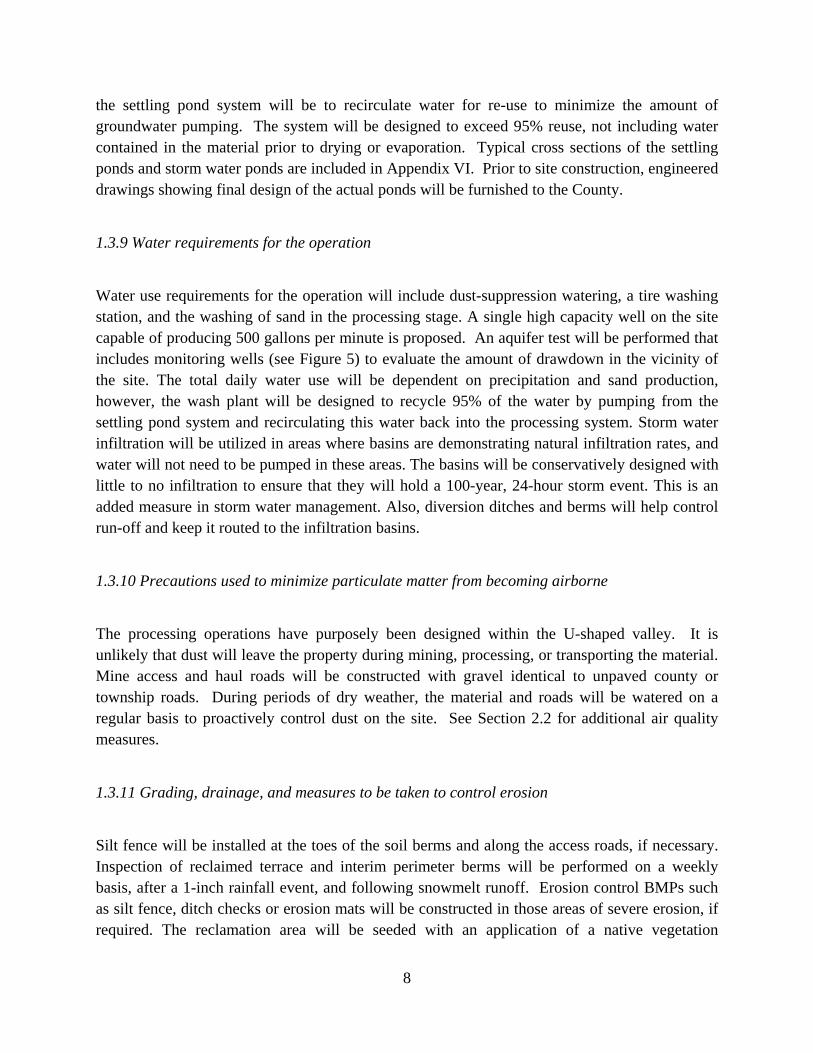
the settling pond system will be to recirculate water for re-use to minimize the amount of groundwater pumping. The system will be designed to exceed 95% reuse, not including water contained in the material prior to drying or evaporation. Typical cross sections of the settling ponds and storm water ponds are included in Appendix VI. Prior to site construction, engineered drawings showing final design of the actual ponds will be furnished to the County.
1.3.9 Water requirements for the operation
Water use requirements for the operation will include dust-suppression watering, a tire washing station, and the washing of sand in the processing stage. A single high capacity well on the site capable of producing 500 gallons per minute is proposed. An aquifer test will be performed that includes monitoring wells (see Figure 5) to evaluate the amount of drawdown in the vicinity of the site. The total daily water use will be dependent on precipitation and sand production, however, the wash plant will be designed to recycle 95% of the water by pumping from the settling pond system and recirculating this water back into the processing system. Storm water infiltration will be utilized in areas where basins are demonstrating natural infiltration rates, and water will not need to be pumped in these areas. The basins will be conservatively designed with little to no infiltration to ensure that they will hold a 100-year, 24-hour storm event. This is an added measure in storm water management. Also, diversion ditches and berms will help control run-off and keep it routed to the infiltration basins.
1.3.10 Precautions used to minimize particulate matter from becoming airborne
The processing operations have purposely been designed within the U-shaped valley. It is unlikely that dust will leave the property during mining, processing, or transporting the material. Mine access and haul roads will be constructed with gravel identical to unpaved county or township roads. During periods of dry weather, the material and roads will be watered on a regular basis to proactively control dust on the site. See Section 2.2 for additional air quality measures.
1.3.11 Grading, drainage, and measures to be taken to control erosion
Silt fence will be installed at the toes of the soil berms and along the access roads, if necessary. Inspection of reclaimed terrace and interim perimeter berms will be performed on a weekly basis, after a 1-inch rainfall event, and following snowmelt runoff. Erosion control BMPs such as silt fence, ditch checks or erosion mats will be constructed in those areas of severe erosion, if required. The reclamation area will be seeded with an application of a native vegetation
9
restoration seed mixture, which contains adequate rooting depth and vegetation density for stabilization of the reclaimed terrace. Wisconsin Department of Transportation (WisDOT) Standard Specifications for Highway and Structure Construction will be followed in general accordance for erosion and sediment control, materials, and construction. On sloped areas where concentrated flows may be present, ditch checks will be used in addition to erosion mats. All MSHA standards shall be followed during mining operations and final reclamation operations which will require that a high level of safety be maintained on the site at all times. Additional information regarding grading, drainage, and erosion control measures will be presented in the Reclamation Plan prior to County approval of the CUP.
1.3.12 Measures to be taken to comply with applicable air and water quality standards
See Section 2.2 and 2.5, below.
2.0 Nuisance Mitigation Plan
2.1 Noise
Noise will be regulated/controlled in several ways. The majority bluff trail and the processing plant are designed within the U-shaped valley, therefore, the mine operations will not be visible from most of the residences or County Highway K. The perimeter areas which are higher in elevation will serve as noise barriers for activities within the mine site. The mine will be operated within the parameters established by the Buffalo County Zoning Ordinance. Beyond that, the operators are committed to working with neighbors who have issues with noise levels.
2.2 Air Quality
The majority bluff trail and the wet plant are designed within the U-shaped valley, therefore, it is unlikely that fugitive dust or plant emissions will leave the property. The material will be mined and conveyed in a moist to wet condition. The material will be dried under roof with air scrubbers designed for no emission of newly-fractured, crystalized quartz. Air quality will be regulated/controlled by following all WDNR regulations and Environmental Protection Agency (EPA) standards for air quality on a mine site. An Air Quality Permit will be required from WDNR. Mine access and haul roads will be constructed with gravel identical to unpaved county or township roads. During periods of dry weather, the material and roads will be watered on a regular basis to proactively control dust on the site. The mine will be operated within the parameters established by the Buffalo County Zoning Ordinance. Beyond that, the operators will install a continuous particulate matter monitor (Thermo Scientific ADR 1600 or equivalent) in
10
the prevailing down-wind direction from the drying faciltiy that can detect PM10 or PM2.5. Data collected at the air monitor will be provided to the County upon request and to the WDNR as part of the Air Quality Permit.
2.3 Lighting
The majority bluff trail and the wet plant are designed within the U-shaped valley, therefore, the mine operations will not be visible from most of the residences or County Highway K. Nighttime light will be regulated/controlled by shielding lights for the wet plant operations such that the light will be directed downward to an area confined to the general location of the wet plant (full cutoff lighting). The mine will be operated within the parameters established by the Buffalo County Zoning Ordinance. Beyond that, the operators are committed to working with neighbors who have issues with lights during the evening hours.
2.4 Odor
Odor control is not expected to be an issue on the mine site due to the nature of equipment being used (backhoes, dozers, front end loaders, conveyors, and trucks) and type of material being mined and processed (sand).
2.5 Water Quality
Water quality will be regulated/controlled in part through the use of a water quality program involving a network of monitoring wells. Water levels and samples will be monitored regularly in these wells to document groundwater (the WDNR rules will establish a water quality monitoring plan for the mine site). The mine will be operated within the parameters established by the Buffalo County Zoning Ordinance. Beyond that, the operators will install three monitoring wells, with at least one well in the down-gradient direction of the settling pond(s). The wells will be instrumented with pressure transducers and water quality sensors (pH, temperature, and conductivity) to enable continuous monitoring of groundwater conditions. If flocculants are used, the wells will be sampled annually and tested for acrylamide. Data collected at the monitoring wells will be provided to the County and WDNR upon request.

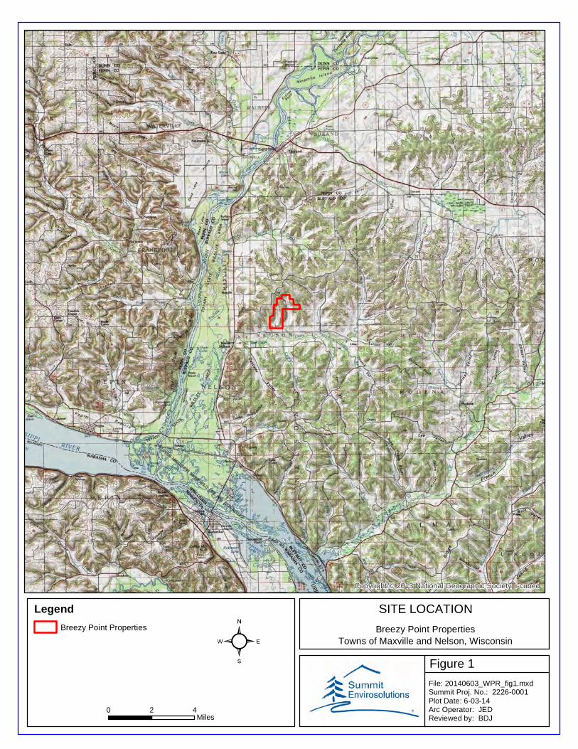
Figure 1
SITE LOCATION
Breezy Point PropertiesTowns of Maxville and Nelson, Wisconsin
Copyright:© 2013 National Geographic Society, i-cubed
0 2 4Miles
File: 20140603_WPR_fig1.mxdSummit Proj. No.: 2226-0001Plot Date: 6-03-14Arc Operator: JEDReviewed by: BDJ
²Legend
Breezy Point Properties
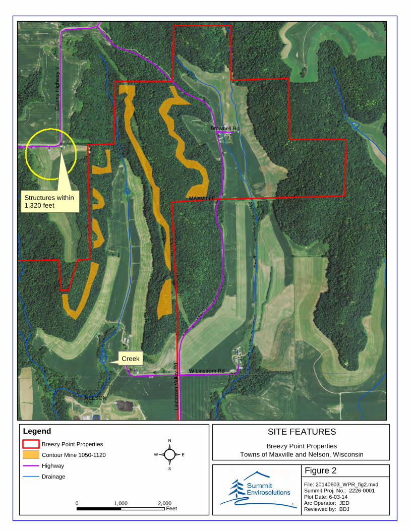
Figure 2
SITE FEATURES
Breezy Point PropertiesTowns of Maxville and Nelson, Wisconsin
Lin
dst
rom
Va
lley
Rd
Cou
nty
Hig
hwa
y V
W Linstrom Rd
Brownell Rd
MAXVILLE
NELSON
0 1,000 2,000Feet
File: 20140603_WPR_fig2.mxdSummit Proj. No.: 2226-0001Plot Date: 6-03-14Arc Operator: JEDReviewed by: BDJ
²Legend
Breezy Point Properties
Contour Mine 1050-1120
Highway
Drainage
Structures within 1,320 feet
Creek

Figure 3
TOPOGRAPHY AND DRAINAGE
Breezy Point PropertiesTowns of Maxville and Nelson, Wisconsin
Copyright:© 2013 National Geographic Society, i-cubed
0 1,000 2,000Feet
File: 20140603_WPR_fig3.mxdSummit Proj. No.: 2226-0001Plot Date: 6-03-14Arc Operator: JEDReviewed by: BDJ
²Legend
Storm Water Flow Direction
Breezy Point Properties
Contour Mine 1050-1120
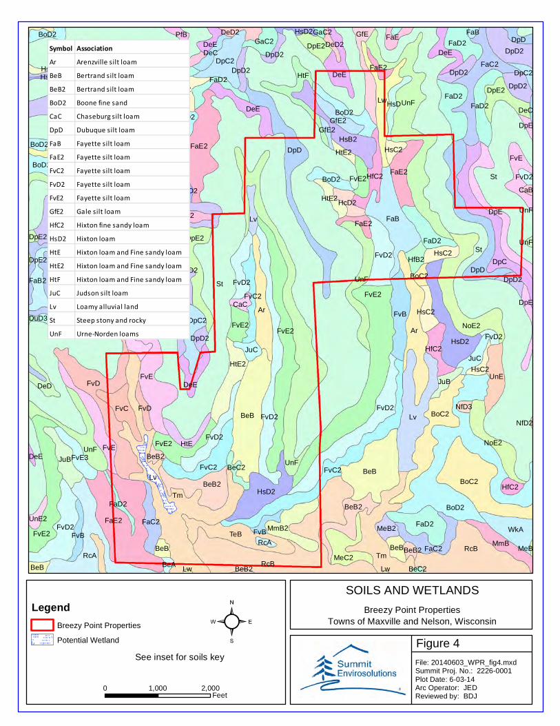
Figure 4
SOILS AND WETLANDS
Breezy Point PropertiesTowns of Maxville and Nelson, Wisconsin
St
St
St
St
St
Tm
RcB
UnF
Lv
BoD2
UnF
FvD
Ar
FvE2
BeB
FaE2
RcBTm
BeB
Ar
RcA
GaC2
FvE
BoC2
FaB
DpD
DpD
Lw
TeB
FaE2
FvD2
DpC
NoE2
FvE2
BoC2
DpD2
HfB2
UnF
HsD2
FaE2
UnF
FaC2
FvD2
FvB
FaD2
FvE
HsD2BeB2
DpE2
HtF
HsB2
FvC2
FvD2
WkA
HtE2
DpD2
FaD2
UnE
GfE
FvC
JuB
DpC2
FaD2
FvE
DeE
HsC2
GaB2
BeB2
DpD2
MmB2
FvE2
MeC2
FaC2
DpE2
FaD2
Lv
FaD2
FaB2
BoD2
DpD2
FaC2
JuC
HsC2
BoD2
HfC2
BeB
FvE2
FvC2
FvD2
FaC2
UnF
DpE
FaB2
DpD2
NoE2
Lv
DeE
FaE2
FaE
FaD2
DeD2
FvD2
FaE2
FaC2
CaC
MmB
DeE
HfC2
Lw
FvD2
HtE
FvC2
DpC2
DeE
FaC2
BoD2
HfC2
FvE3
FaD2
DpD2
GfE2
JuC
HfC2
FvE2
DeD
FvB
DeD2
HsD
FaD2
DpE
DpE2
DsC3
GaC2
DeE2 HsC2
BoD2 FvE2
JuB
BeB
HtE2
FvD
FaE
DeC
HfB2
FaC2
HcD2
DpD2
FaD2
DeE
FvB
BoD2
MeB2
DeD2DpD
PfB
FaE2
BeB
BeC2
DpD2
HsC2
DeE2
CaC
DpD2
HsC2
UnE2
FaD2
FaE2
DpD2
DpD2
HsD2
HtE2
DpC2
BoC2
BoD2
HsD2
BeB2
DpE
DeD2
GfE2
HfD2
BeB2
BeA
RcA
FvD2
FvD2
NfD3
HsD2HsB
FaB
CaB
DeE
DeC
DpE2
GaC2
UnF
BeC2BeB2Lw
MeB
DuD3
NfD2
DpE2
Lw
UnF
0 1,000 2,000Feet
File: 20140603_WPR_fig4.mxdSummit Proj. No.: 2226-0001Plot Date: 6-03-14Arc Operator: JEDReviewed by: BDJ
²Legend
Breezy Point Properties
Potential Wetland
Symbol AssociationAr Arenzville silt loamBeB Bertrand silt loamBeB2 Bertrand silt loamBoD2 Boone fine sandCaC Chaseburg silt loamDpD Dubuque silt loamFaB Fayette silt loamFaE2 Fayette silt loamFvC2 Fayette silt loamFvD2 Fayette silt loamFvE2 Fayette silt loamGfE2 Gale silt loamHfC2 Hixton fine sandy loamHsD2 Hixton loamHtE Hixton loam and Fine sandy loamHtE2 Hixton loam and Fine sandy loamHtF Hixton loam and Fine sandy loamJuC Judson silt loamLv Loamy alluvial landSt Steep stony and rockyUnF Urne-Norden loams
See inset for soils key
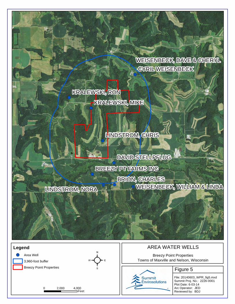
Figure 5
AREA WATER WELLS
Breezy Point PropertiesTowns of Maxville and Nelson, Wisconsin
!>
!>
!>
!>
!>
!>
!>
!>
!>!>
KRALEWSKI, RON
BRION, CHARLES
LINDSTROM, NORA
KRALEWSKI, MIKE
LINDSTROM, CHRIS
DAVID STELLPFLUG
CYRIL WEISENBECK
BREEZY PT FARMS INC
WEISENBECK, DAVE & CHERYL
WEISENBECK, WILLIAM & LINDA
0 2,000 4,000Feet
File: 20140603_WPR_fig5.mxdSummit Proj. No.: 2226-0001Plot Date: 6-03-14Arc Operator: JEDReviewed by: BDJ
²Legend!> Area Well
3,960-foot buffer
Breezy Point Properties

Figure 6
CONCEPTUAL MINE PLAN
Breezy Point PropertiesTowns of Maxville and Nelson, Wisconsin
Copyright:© 2013 National Geographic Society, i-cubed
0 500 1,000Feet
File: 20140603_WPR_fig6.mxdSummit Proj. No.: 2226-0001Plot Date: 6-03-14Arc Operator: JEDReviewed by: BDJ
²Legend
Property
Phase 1
Phase 2
Phase 3
Phase 4
Wet Processing Structure
Dry Processing Building
Scale/Office Building
Top Soil Berm
Access Road
Silt Fence
Mobile Conveyor
Sand Stockpile
Settling Pond
Processing Area
Storm Water Pond
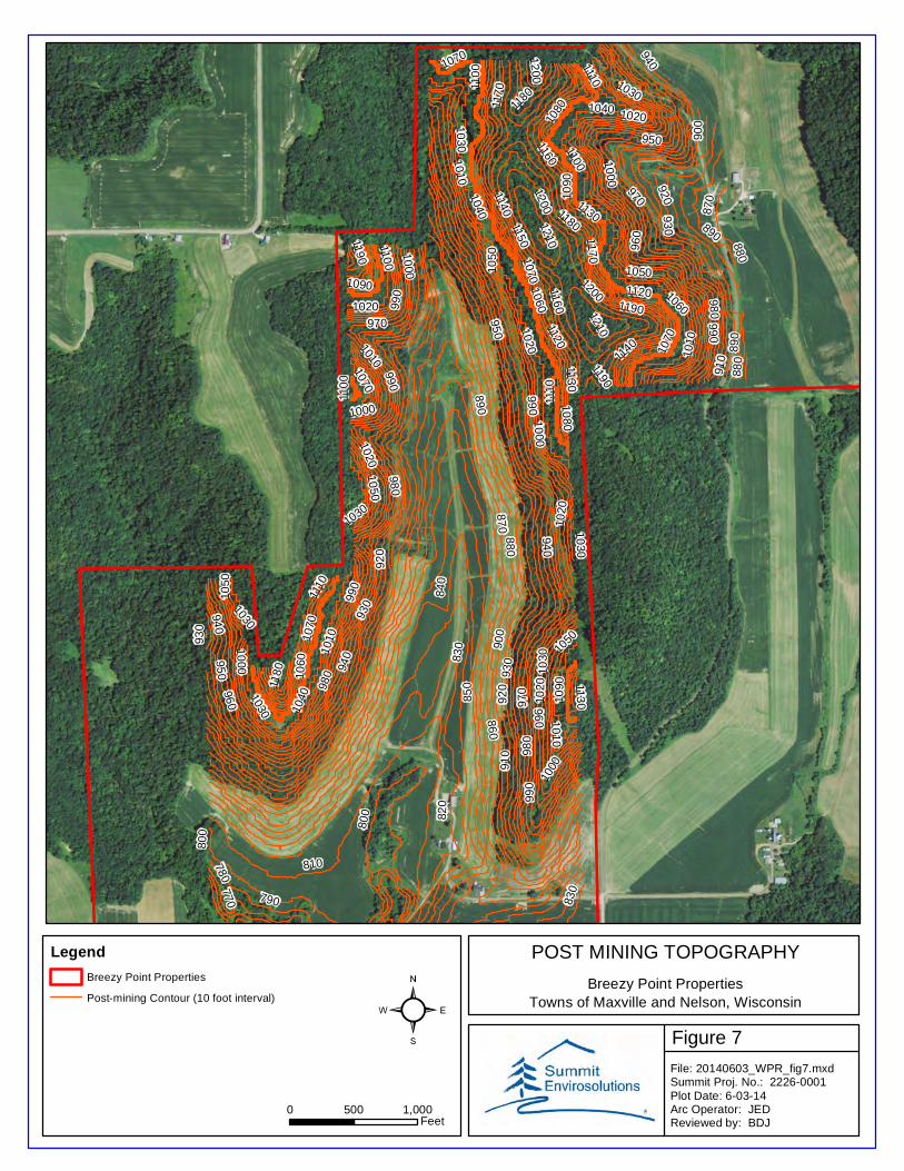
Figure 7
POST MINING TOPOGRAPHY
Breezy Point PropertiesTowns of Maxville and Nelson, Wisconsin
980
970
960
950
940
930
920
990
910
900
890
860
880
1000
870
1010
850
840
1110
1040
1020
1030
110
0
1050
10601120
1070
1080
1090
1130
11401150
830
1160
820
810
1170
1180
1190
800
790
780770
1200
1210
1000
1070
1090
1050
1050
1190
1180
1080
990
1100
970
1060
940
1090
1020
1120
1010
1190
1070
1020
1110
1030
1020
1020
1010
1000
1040
1140
1130
1020
1200
1200
900
1130
1180
1000
1110
1060
1070
1000
990 98
0
960
950
940
1030
1050
930
1070
930
110
099
01160
880
890
870
1000
1210
1030
110010
30
980
930
1030
940
910
960
1010
800
1050
970
990
920
1040
830
880
890
1030
920
980
950
1010
990
117
0
0 500 1,000Feet
File: 20140603_WPR_fig7.mxdSummit Proj. No.: 2226-0001Plot Date: 6-03-14Arc Operator: JEDReviewed by: BDJ
²Legend
Breezy Point Properties
Post-mining Contour (10 foot interval)

Figure 8
HAUL ROUTES
Breezy Point PropertiesTowns of Maxville and Nelson, Wisconsin
Sources: Esri, DeLorme, NAVTEQ, USGS, Intermap, iPC, NRCAN, EsriJapan, METI, Esri China (Hong Kong), Esri (Thailand), TomTom, 2013
0 2 4Miles
File: 20140603_WPR_fig8.mxdSummit Proj. No.: 2226-0001Plot Date: 6-03-14Arc Operator: JEDReviewed by: BDJ
²Legend
Breezy Point Properties
First Primary Route
Second Primary Route
Secondary Route
County Highway K
State Highway 25
US Highway 10

Appendix I
CUP Application


Buffalo County Application for a Conditional Use Permit Non‐metallic Mineral Mining ‐ 7/15/2014 Page 2 of 6
Hauling Information.
First Primary Route: (Briefly describe this route, by direction and roadways utilized to end locations).
___County Highway K west to State Highway 25 south to Wabasha, Minnesota__________________________________________________
Loads per day __60‐100_, Number of trucks used _12‐20____,Loads per year _13,200‐22,000___ Tons per year 330,000‐550,000______
Town Board Review: Application was mailed to applicable Town Clerk and Town Chairperson _________________ date; by _______________________ staff signature Describe any action or discussion By Town Board: ___________________________________________________________________________ Highway Department Review: Application was forwarded to Highway Department _________________________ date; by ______________________________ staff signature TIA required: ______________ (yes/no). HIA required ______________ (yes/no). Road/s agreement required __________________ (yes/no) Highway Department Signature _____________________________________________________________ Date: ________________________
required TIA received; date____________________, received by ____________________________________ (staff signature)
required HIA received; date____________________, received by ____________________________________ (staff signature)
required road agreement received; date_____________, received by _________________________________ (staff signature)
required road agreement received; date_____________, received by _________________________________ (staff signature)
Second Primary Route: (Briefly describe this route, by direction and roadways utilized to end locations).
___County Highway K west to State Highway 25 north to US Highway 10 west to Plum City___________________________________
Loads per day __60‐100_, Number of trucks used _12‐20____,Loads per year _13,200‐22,000___ Tons per year 330,000‐550,000___
Town Board Review: Application was mailed to applicable Town Clerk and Town Chairperson _________________ date; by _______________________ staff signature Describe any action or discussion By Town Board: ___________________________________________________________________________ Highway Department Review: Application was forwarded to Highway Department _________________________ date; by ______________________________ staff signature TIA required: ______________ (yes/no). HIA required ______________ (yes/no). Road/s agreement required __________________ (yes/no) Highway Department Signature _____________________________________________________________ Date: ________________________
required TIA received; date____________________, received by ____________________________________ (staff signature)
required HIA received; date____________________, received by ____________________________________ (staff signature)
required road agreement received; date_____________, received by _________________________________ (staff signature)
required road agreement received; date_____________, received by _________________________________ (staff signature) Use additional sheets for additional haul routes

Buffalo County Application for a Conditional Use Permit Non‐metallic Mineral Mining ‐ 7/15/2014 Page 3 of 6
Temporary Route: (Briefly describe this route, by direction and roadways utilized to end locations).
___County Highway K west to State Highway 25 north to US Highway 10 east to Mondovi______________________________
Loads per day __60‐100_, Number of trucks used _12‐20____,Loads per year _13,200‐22,000___ Tons per year 330,000‐550,000_____
Town Board Review: Application was mailed to applicable Town Clerk and Town Chairperson _________________ date; by _______________________ staff signature Describe any action or discussion By Town Board: ___________________________________________________________________________ Highway Department Review: Application was forwarded to Highway Department _________________________ date; by ______________________________ staff signature TIA required: ______________ (yes/no). HIA required ______________ (yes/no). Road/s agreement required __________________ (yes/no) Highway Department Signature _____________________________________________________________ Date: ________________________
required TIA received; date____________________, received by ____________________________________ (staff signature)
required HIA received; date____________________, received by ____________________________________ (staff signature)
required road agreement received; date_____________, received by _________________________________ (staff signature)
required road agreement received; date_____________, received by _________________________________ (staff signature) Use additional sheets for additional haul routes


Buffalo County Application for a Conditional Use Permit Non‐metallic Mineral Mining ‐ 7/15/2014 Page 5 of 6
Application for a Conditional Use Permit for Non‐metallic Mineral Mining – Checklist The following information is required before the application will be accepted and considered complete.
Applicant Check‐In
StaffInitials
DateReceived
Complete Conditional Use Permit – Nonmetallic Mining permit application, signed and dated by owner and agent
Complete legal descriptions and parcel address for all subject parcels
Lease agreement if Operator is not the Property Owner
Meeting with town board Date:_________________
Pre application meeting with County Staff date: ________________
Eleven (11) folded paper copies of application materials and related plans
One (1) copy of all application materials in digital form
Written explanation of proposal and how it complies with criteria for approval (see Zoning Ordinance., Section 212 for Conditional Use Permit/s)
Topographic maps showing the following: perimeter of mine boundary, direction of
flow of storm water runoff
Vicinity maps showing the location of the site and following: Adjacent property owners, residential wells within 3,960 feet, surface water within 2,640 feet, existing structures within 2,640 feet, and haul routes to end locations (distance measured from mine boundary)
Site maps including: excavation areas with delineated mine phases, existing and proposed
structures, locations of erosion control berms and topsoil storage, location of settling ponds and storm water ponds, wetland boundaries, and area for material stockpiling.
Grading, drainage, and erosion control plan or resource management plan
Description of water requirements and wash plant facilities (if applicable).
Are high capacity wells required? ______________ (yes/no)
Nuisance mitigation plan
Conditional Use Application fee paid (see page 6 of this application for fee schedule)
Town Board(s) Response
Highway Department Response
Land Resources Committee Response
Reclamation Plan
Other Application materials as required by staff: (specify additional requirements)
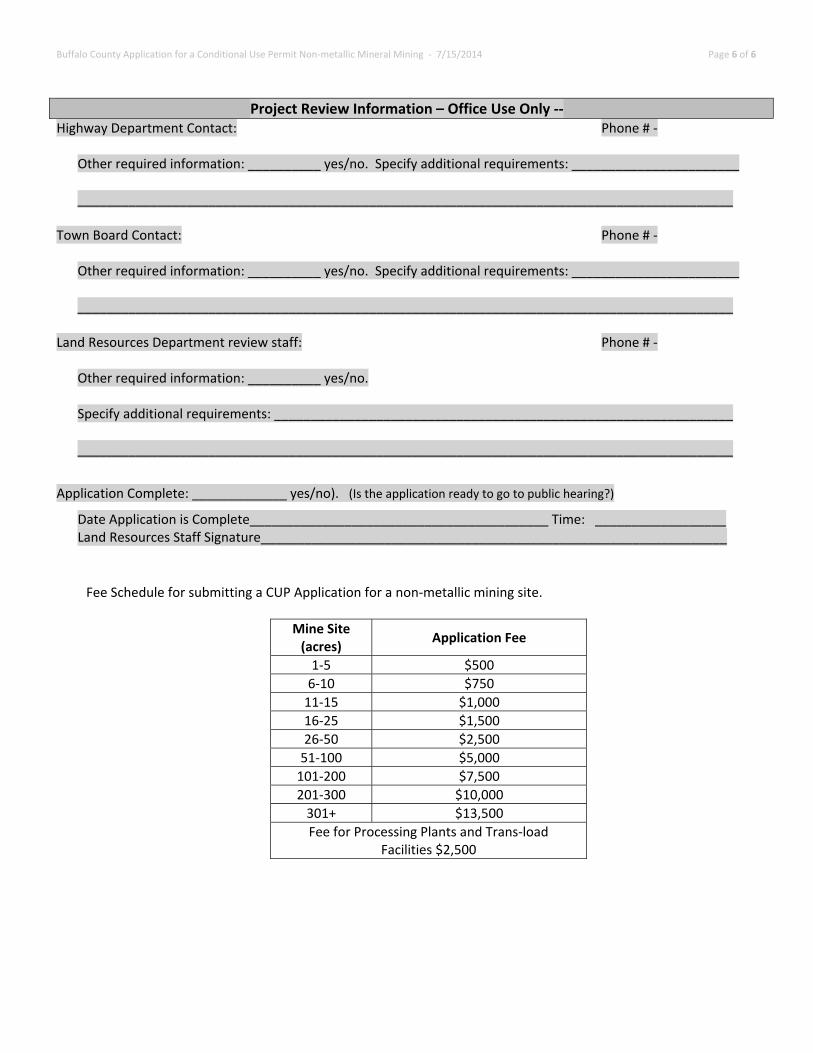
Buffalo County Application for a Conditional Use Permit Non‐metallic Mineral Mining ‐ 7/15/2014 Page 6 of 6
Project Review Information – Office Use Only ‐‐ Highway Department Contact: Phone # ‐
Other required information: __________ yes/no. Specify additional requirements: _______________________ __________________________________________________________________________________________
Town Board Contact: Phone # ‐
Other required information: __________ yes/no. Specify additional requirements: _______________________ __________________________________________________________________________________________
Land Resources Department review staff: Phone # ‐
Other required information: __________ yes/no. Specify additional requirements: _______________________________________________________________ __________________________________________________________________________________________
Application Complete: _____________ yes/no). (Is the application ready to go to public hearing?)
Date Application is Complete_________________________________________ Time: __________________ Land Resources Staff Signature________________________________________________________________
Fee Schedule for submitting a CUP Application for a non‐metallic mining site.
Mine Site (acres)
Application Fee
1‐5 $500
6‐10 $750
11‐15 $1,000
16‐25 $1,500
26‐50 $2,500
51‐100 $5,000
101‐200 $7,500
201‐300 $10,000
301+ $13,500
Fee for Processing Plants and Trans‐load Facilities $2,500

Appendix II
Adjacent Landowner Information/Property Legal Descriptions

ADJACENT LANDOWNERS
Breezy Point PropertiesTowns of Maxville and Nelson, Wisconsin
J. Reinhardt
J. Traun
K. Hurlburt
W. & S. Lindstrom
Hurlburt's Liberty Hill Farms
D. & C. Weisenbeck
T. & B. Sobotika
S. Lindstrom
R. & M. Kralewski
Milky Way Acres Farm
W. & L. Weisenbeck
C. Weisenbeck
M. & P. Holt
Patrick Wittig
Breezy Point Properties
0 2,000 4,000Feet
File: 20140618_WPR_alo.mxdSummit Proj. No.: 2226-0001Plot Date: 6-18-14Arc Operator: JEDReviewed by: BDJ
²Legend
Breezy Point Properties
Note: Property boundaries are approximatte. Landowners and porpeerty boundaries were determined by scanning and georeferencing pages 8 and 18 from the Buffalo County Plat Book


Appendix III
Lease Agreement


Appendix IV
Soils Information
United StatesDepartment ofAgriculture
A product of the NationalCooperative Soil Survey,a joint effort of the UnitedStates Department ofAgriculture and otherFederal agencies, Stateagencies including theAgricultural ExperimentStations, and localparticipants
Custom Soil ResourceReport for
Buffalo County,Wisconsin
NaturalResourcesConservationService
June 24, 2014

PrefaceSoil surveys contain information that affects land use planning in survey areas. Theyhighlight soil limitations that affect various land uses and provide information aboutthe properties of the soils in the survey areas. Soil surveys are designed for manydifferent users, including farmers, ranchers, foresters, agronomists, urban planners,community officials, engineers, developers, builders, and home buyers. Also,conservationists, teachers, students, and specialists in recreation, waste disposal,and pollution control can use the surveys to help them understand, protect, or enhancethe environment.
Various land use regulations of Federal, State, and local governments may imposespecial restrictions on land use or land treatment. Soil surveys identify soil propertiesthat are used in making various land use or land treatment decisions. The informationis intended to help the land users identify and reduce the effects of soil limitations onvarious land uses. The landowner or user is responsible for identifying and complyingwith existing laws and regulations.
Although soil survey information can be used for general farm, local, and wider areaplanning, onsite investigation is needed to supplement this information in some cases.Examples include soil quality assessments (http://www.nrcs.usda.gov/wps/portal/nrcs/main/soils/health/) and certain conservation and engineering applications. Formore detailed information, contact your local USDA Service Center (http://offices.sc.egov.usda.gov/locator/app?agency=nrcs) or your NRCS State SoilScientist (http://www.nrcs.usda.gov/wps/portal/nrcs/detail/soils/contactus/?cid=nrcs142p2_053951).
Great differences in soil properties can occur within short distances. Some soils areseasonally wet or subject to flooding. Some are too unstable to be used as afoundation for buildings or roads. Clayey or wet soils are poorly suited to use as septictank absorption fields. A high water table makes a soil poorly suited to basements orunderground installations.
The National Cooperative Soil Survey is a joint effort of the United States Departmentof Agriculture and other Federal agencies, State agencies including the AgriculturalExperiment Stations, and local agencies. The Natural Resources ConservationService (NRCS) has leadership for the Federal part of the National Cooperative SoilSurvey.
Information about soils is updated periodically. Updated information is availablethrough the NRCS Web Soil Survey, the site for official soil survey information.
The U.S. Department of Agriculture (USDA) prohibits discrimination in all its programsand activities on the basis of race, color, national origin, age, disability, and whereapplicable, sex, marital status, familial status, parental status, religion, sexualorientation, genetic information, political beliefs, reprisal, or because all or a part of anindividual's income is derived from any public assistance program. (Not all prohibitedbases apply to all programs.) Persons with disabilities who require alternative means
2

for communication of program information (Braille, large print, audiotape, etc.) shouldcontact USDA's TARGET Center at (202) 720-2600 (voice and TDD). To file acomplaint of discrimination, write to USDA, Director, Office of Civil Rights, 1400Independence Avenue, S.W., Washington, D.C. 20250-9410 or call (800) 795-3272(voice) or (202) 720-6382 (TDD). USDA is an equal opportunity provider andemployer.
3
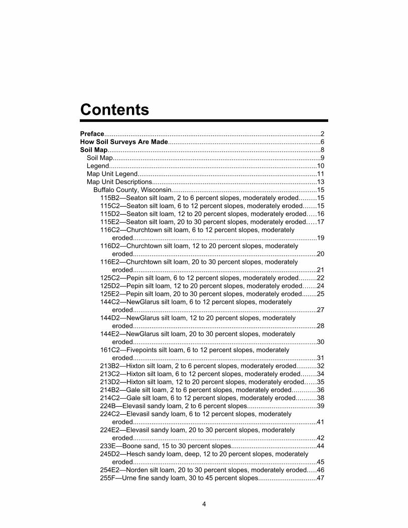
ContentsPreface....................................................................................................................2How Soil Surveys Are Made..................................................................................6Soil Map..................................................................................................................8
Soil Map................................................................................................................9Legend................................................................................................................10Map Unit Legend................................................................................................11Map Unit Descriptions........................................................................................13
Buffalo County, Wisconsin..............................................................................15115B2—Seaton silt loam, 2 to 6 percent slopes, moderately eroded.........15115C2—Seaton silt loam, 6 to 12 percent slopes, moderately eroded.......15115D2—Seaton silt loam, 12 to 20 percent slopes, moderately eroded.....16115E2—Seaton silt loam, 20 to 30 percent slopes, moderately eroded.....17116C2—Churchtown silt loam, 6 to 12 percent slopes, moderately
eroded...................................................................................................19116D2—Churchtown silt loam, 12 to 20 percent slopes, moderately
eroded...................................................................................................20116E2—Churchtown silt loam, 20 to 30 percent slopes, moderately
eroded...................................................................................................21125C2—Pepin silt loam, 6 to 12 percent slopes, moderately eroded.........22125D2—Pepin silt loam, 12 to 20 percent slopes, moderately eroded.......24125E2—Pepin silt loam, 20 to 30 percent slopes, moderately eroded........25144C2—NewGlarus silt loam, 6 to 12 percent slopes, moderately
eroded...................................................................................................27144D2—NewGlarus silt loam, 12 to 20 percent slopes, moderately
eroded...................................................................................................28144E2—NewGlarus silt loam, 20 to 30 percent slopes, moderately
eroded...................................................................................................30161C2—Fivepoints silt loam, 6 to 12 percent slopes, moderately
eroded...................................................................................................31213B2—Hixton silt loam, 2 to 6 percent slopes, moderately eroded...........32213C2—Hixton silt loam, 6 to 12 percent slopes, moderately eroded........34213D2—Hixton silt loam, 12 to 20 percent slopes, moderately eroded......35214B2—Gale silt loam, 2 to 6 percent slopes, moderately eroded.............36214C2—Gale silt loam, 6 to 12 percent slopes, moderately eroded...........38224B—Elevasil sandy loam, 2 to 6 percent slopes.....................................39224C2—Elevasil sandy loam, 6 to 12 percent slopes, moderately
eroded...................................................................................................41224E2—Elevasil sandy loam, 20 to 30 percent slopes, moderately
eroded...................................................................................................42233E—Boone sand, 15 to 30 percent slopes..............................................44245D2—Hesch sandy loam, deep, 12 to 20 percent slopes, moderately
eroded...................................................................................................45254E2—Norden silt loam, 20 to 30 percent slopes, moderately eroded.....46255F—Urne fine sandy loam, 30 to 45 percent slopes...............................47
4

305B—Richwood silt loam, 1 to 6 percent slopes.......................................49312A—Festina silt loam, 0 to 3 percent slopes...........................................50312B2—Festina silt loam, 2 to 6 percent slopes, moderately eroded.........51312C2—Festina silt loam, 6 to 12 percent slopes, moderately eroded.......52423B2—Meridian silt loam, 2 to 6 percent slopes, moderately eroded.......53433B—Forkhorn sandy loam, 2 to 6 percent slopes...................................55433C2—Forkhorn sandy loam, 6 to 12 percent slopes, moderately
eroded...................................................................................................56511B—Plainfield sand, 2 to 6 percent slopes..............................................57511F—Plainfield sand, 15 to 60 percent slopes..........................................59616B—Chaseburg silt loam, 1 to 4 percent slopes, occasionally flooded...60616C—Chaseburg silt loam, 4 to 12 percent slopes, occasionally
flooded..................................................................................................61626A—Arenzville silt loam, 0 to 3 percent slopes, occasionally flooded.....62676A—Kickapoo fine sandy loam, 0 to 3 percent slopes, occasionally
flooded..................................................................................................64679A—Ettrick silt loam, 0 to 2 percent slopes, shallow, frequently
flooded..................................................................................................651125F—Dorerton, very stony-Elbaville complex, 30 to 60 percent
slopes....................................................................................................661145F—Gaphill-Rockbluff complex, 30 to 60 percent slopes.....................681224F—Boone-Elevasil complex, 15 to 50 percent slopes.........................711648A—Northbend-Ettrick silt loams, 0 to 3 percent slopes, frequently
flooded..................................................................................................73References............................................................................................................76
Custom Soil Resource Report
5

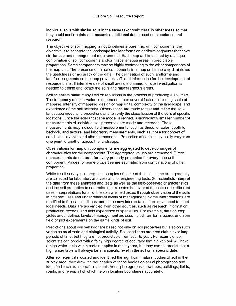
How Soil Surveys Are MadeSoil surveys are made to provide information about the soils and miscellaneous areasin a specific area. They include a description of the soils and miscellaneous areas andtheir location on the landscape and tables that show soil properties and limitationsaffecting various uses. Soil scientists observed the steepness, length, and shape ofthe slopes; the general pattern of drainage; the kinds of crops and native plants; andthe kinds of bedrock. They observed and described many soil profiles. A soil profile isthe sequence of natural layers, or horizons, in a soil. The profile extends from thesurface down into the unconsolidated material in which the soil formed or from thesurface down to bedrock. The unconsolidated material is devoid of roots and otherliving organisms and has not been changed by other biological activity.
Currently, soils are mapped according to the boundaries of major land resource areas(MLRAs). MLRAs are geographically associated land resource units that sharecommon characteristics related to physiography, geology, climate, water resources,soils, biological resources, and land uses (USDA, 2006). Soil survey areas typicallyconsist of parts of one or more MLRA.
The soils and miscellaneous areas in a survey area occur in an orderly pattern that isrelated to the geology, landforms, relief, climate, and natural vegetation of the area.Each kind of soil and miscellaneous area is associated with a particular kind oflandform or with a segment of the landform. By observing the soils and miscellaneousareas in the survey area and relating their position to specific segments of thelandform, a soil scientist develops a concept, or model, of how they were formed. Thus,during mapping, this model enables the soil scientist to predict with a considerabledegree of accuracy the kind of soil or miscellaneous area at a specific location on thelandscape.
Commonly, individual soils on the landscape merge into one another as theircharacteristics gradually change. To construct an accurate soil map, however, soilscientists must determine the boundaries between the soils. They can observe onlya limited number of soil profiles. Nevertheless, these observations, supplemented byan understanding of the soil-vegetation-landscape relationship, are sufficient to verifypredictions of the kinds of soil in an area and to determine the boundaries.
Soil scientists recorded the characteristics of the soil profiles that they studied. Theynoted soil color, texture, size and shape of soil aggregates, kind and amount of rockfragments, distribution of plant roots, reaction, and other features that enable them toidentify soils. After describing the soils in the survey area and determining theirproperties, the soil scientists assigned the soils to taxonomic classes (units).Taxonomic classes are concepts. Each taxonomic class has a set of soilcharacteristics with precisely defined limits. The classes are used as a basis forcomparison to classify soils systematically. Soil taxonomy, the system of taxonomicclassification used in the United States, is based mainly on the kind and character ofsoil properties and the arrangement of horizons within the profile. After the soilscientists classified and named the soils in the survey area, they compared the
6
individual soils with similar soils in the same taxonomic class in other areas so thatthey could confirm data and assemble additional data based on experience andresearch.
The objective of soil mapping is not to delineate pure map unit components; theobjective is to separate the landscape into landforms or landform segments that havesimilar use and management requirements. Each map unit is defined by a uniquecombination of soil components and/or miscellaneous areas in predictableproportions. Some components may be highly contrasting to the other components ofthe map unit. The presence of minor components in a map unit in no way diminishesthe usefulness or accuracy of the data. The delineation of such landforms andlandform segments on the map provides sufficient information for the development ofresource plans. If intensive use of small areas is planned, onsite investigation isneeded to define and locate the soils and miscellaneous areas.
Soil scientists make many field observations in the process of producing a soil map.The frequency of observation is dependent upon several factors, including scale ofmapping, intensity of mapping, design of map units, complexity of the landscape, andexperience of the soil scientist. Observations are made to test and refine the soil-landscape model and predictions and to verify the classification of the soils at specificlocations. Once the soil-landscape model is refined, a significantly smaller number ofmeasurements of individual soil properties are made and recorded. Thesemeasurements may include field measurements, such as those for color, depth tobedrock, and texture, and laboratory measurements, such as those for content ofsand, silt, clay, salt, and other components. Properties of each soil typically vary fromone point to another across the landscape.
Observations for map unit components are aggregated to develop ranges ofcharacteristics for the components. The aggregated values are presented. Directmeasurements do not exist for every property presented for every map unitcomponent. Values for some properties are estimated from combinations of otherproperties.
While a soil survey is in progress, samples of some of the soils in the area generallyare collected for laboratory analyses and for engineering tests. Soil scientists interpretthe data from these analyses and tests as well as the field-observed characteristicsand the soil properties to determine the expected behavior of the soils under differentuses. Interpretations for all of the soils are field tested through observation of the soilsin different uses and under different levels of management. Some interpretations aremodified to fit local conditions, and some new interpretations are developed to meetlocal needs. Data are assembled from other sources, such as research information,production records, and field experience of specialists. For example, data on cropyields under defined levels of management are assembled from farm records and fromfield or plot experiments on the same kinds of soil.
Predictions about soil behavior are based not only on soil properties but also on suchvariables as climate and biological activity. Soil conditions are predictable over longperiods of time, but they are not predictable from year to year. For example, soilscientists can predict with a fairly high degree of accuracy that a given soil will havea high water table within certain depths in most years, but they cannot predict that ahigh water table will always be at a specific level in the soil on a specific date.
After soil scientists located and identified the significant natural bodies of soil in thesurvey area, they drew the boundaries of these bodies on aerial photographs andidentified each as a specific map unit. Aerial photographs show trees, buildings, fields,roads, and rivers, all of which help in locating boundaries accurately.
Custom Soil Resource Report
7

Soil MapThe soil map section includes the soil map for the defined area of interest, a list of soilmap units on the map and extent of each map unit, and cartographic symbolsdisplayed on the map. Also presented are various metadata about data used toproduce the map, and a description of each soil map unit.
8
9
Custom Soil Resource ReportSoil Map
4928
300
4928
700
4929
100
4929
500
4929
900
4930
300
4930
700
4931
100
4931
500
4931
900
4928
300
4928
700
4929
100
4929
500
4929
900
4930
300
4930
700
4931
100
4931
500
4931
900
580500 580900 581300 581700 582100 582500 582900 583300
580500 580900 581300 581700 582100 582500 582900 583300
44° 32' 13'' N91
° 5
9' 1
6'' W
44° 32' 13'' N
91° 5
7' 4
'' W
44° 30' 8'' N
91° 5
9' 1
6'' W
44° 30' 8'' N
91° 5
7' 4
'' W
N
Map projection: Web Mercator Corner coordinates: WGS84 Edge tics: UTM Zone 15N WGS840 500 1000 2000 3000
Feet0 250 500 1000 1500
MetersMap Scale: 1:18,800 if printed on A portrait (8.5" x 11") sheet.

MAP LEGEND MAP INFORMATION
Area of Interest (AOI)Area of Interest (AOI)
SoilsSoil Map Unit Polygons
Soil Map Unit Lines
Soil Map Unit Points
Special Point FeaturesBlowout
Borrow Pit
Clay Spot
Closed Depression
Gravel Pit
Gravelly Spot
Landfill
Lava Flow
Marsh or swamp
Mine or Quarry
Miscellaneous Water
Perennial Water
Rock Outcrop
Saline Spot
Sandy Spot
Severely Eroded Spot
Sinkhole
Slide or Slip
Sodic Spot
Spoil Area
Stony Spot
Very Stony Spot
Wet Spot
Other
Special Line Features
Water FeaturesStreams and Canals
TransportationRails
Interstate Highways
US Routes
Major Roads
Local Roads
BackgroundAerial Photography
The soil surveys that comprise your AOI were mapped at 1:20,000.
Please rely on the bar scale on each map sheet for mapmeasurements.
Source of Map: Natural Resources Conservation ServiceWeb Soil Survey URL: http://websoilsurvey.nrcs.usda.govCoordinate System: Web Mercator (EPSG:3857)
Maps from the Web Soil Survey are based on the Web Mercatorprojection, which preserves direction and shape but distortsdistance and area. A projection that preserves area, such as theAlbers equal-area conic projection, should be used if more accuratecalculations of distance or area are required.
This product is generated from the USDA-NRCS certified data as ofthe version date(s) listed below.
Soil Survey Area: Buffalo County, WisconsinSurvey Area Data: Version 7, Dec 23, 2013
Soil map units are labeled (as space allows) for map scales 1:50,000or larger.
Date(s) aerial images were photographed: Nov 1, 2010—Jul 20,2011
The orthophoto or other base map on which the soil lines werecompiled and digitized probably differs from the backgroundimagery displayed on these maps. As a result, some minor shiftingof map unit boundaries may be evident.
Custom Soil Resource Report
10

Map Unit Legend
Buffalo County, Wisconsin (WI011)
Map Unit Symbol Map Unit Name Acres in AOI Percent of AOI
115B2 Seaton silt loam, 2 to 6 percentslopes, moderately eroded
10.6 0.8%
115C2 Seaton silt loam, 6 to 12 percentslopes, moderately eroded
53.1 3.9%
115D2 Seaton silt loam, 12 to 20percent slopes, moderatelyeroded
44.1 3.3%
115E2 Seaton silt loam, 20 to 30percent slopes, moderatelyeroded
82.8 6.1%
116C2 Churchtown silt loam, 6 to 12percent slopes, moderatelyeroded
13.6 1.0%
116D2 Churchtown silt loam, 12 to 20percent slopes, moderatelyeroded
53.3 3.9%
116E2 Churchtown silt loam, 20 to 30percent slopes, moderatelyeroded
97.9 7.2%
125C2 Pepin silt loam, 6 to 12 percentslopes, moderately eroded
16.7 1.2%
125D2 Pepin silt loam, 12 to 20 percentslopes, moderately eroded
46.0 3.4%
125E2 Pepin silt loam, 20 to 30 percentslopes, moderately eroded
17.2 1.3%
144C2 NewGlarus silt loam, 6 to 12percent slopes, moderatelyeroded
2.9 0.2%
144D2 NewGlarus silt loam, 12 to 20percent slopes, moderatelyeroded
18.4 1.4%
144E2 NewGlarus silt loam, 20 to 30percent slopes, moderatelyeroded
29.0 2.1%
161C2 Fivepoints silt loam, 6 to 12percent slopes, moderatelyeroded
4.4 0.3%
213B2 Hixton silt loam, 2 to 6 percentslopes, moderately eroded
11.9 0.9%
213C2 Hixton silt loam, 6 to 12 percentslopes, moderately eroded
9.5 0.7%
213D2 Hixton silt loam, 12 to 20 percentslopes, moderately eroded
19.1 1.4%
214B2 Gale silt loam, 2 to 6 percentslopes, moderately eroded
9.4 0.7%
Custom Soil Resource Report
11

Buffalo County, Wisconsin (WI011)
Map Unit Symbol Map Unit Name Acres in AOI Percent of AOI
214C2 Gale silt loam, 6 to 12 percentslopes, moderately eroded
34.0 2.5%
224B Elevasil sandy loam, 2 to 6percent slopes
14.5 1.1%
224C2 Elevasil sandy loam, 6 to 12percent slopes, moderatelyeroded
10.6 0.8%
224E2 Elevasil sandy loam, 20 to 30percent slopes, moderatelyeroded
19.1 1.4%
233E Boone sand, 15 to 30 percentslopes
13.9 1.0%
245D2 Hesch sandy loam, deep, 12 to20 percent slopes, moderatelyeroded
3.6 0.3%
254E2 Norden silt loam, 20 to 30percent slopes, moderatelyeroded
14.5 1.1%
255F Urne fine sandy loam, 30 to 45percent slopes
62.6 4.6%
305B Richwood silt loam, 1 to 6percent slopes
67.0 4.9%
312A Festina silt loam, 0 to 3 percentslopes
1.7 0.1%
312B2 Festina silt loam, 2 to 6 percentslopes, moderately eroded
69.7 5.1%
312C2 Festina silt loam, 6 to 12 percentslopes, moderately eroded
2.5 0.2%
423B2 Meridian silt loam, 2 to 6 percentslopes, moderately eroded
23.2 1.7%
433B Forkhorn sandy loam, 2 to 6percent slopes
1.3 0.1%
433C2 Forkhorn sandy loam, 6 to 12percent slopes, moderatelyeroded
8.6 0.6%
511B Plainfield sand, 2 to 6 percentslopes
2.6 0.2%
511F Plainfield sand, 15 to 60 percentslopes
58.9 4.3%
616B Chaseburg silt loam, 1 to 4percent slopes, occasionallyflooded
2.2 0.2%
616C Chaseburg silt loam, 4 to 12percent slopes, occasionallyflooded
10.6 0.8%
626A Arenzville silt loam, 0 to 3percent slopes, occasionallyflooded
17.2 1.3%
676A Kickapoo fine sandy loam, 0 to 3percent slopes, occasionallyflooded
0.1 0.0%
Custom Soil Resource Report
12

Buffalo County, Wisconsin (WI011)
Map Unit Symbol Map Unit Name Acres in AOI Percent of AOI
679A Ettrick silt loam, 0 to 2 percentslopes, shallow, frequentlyflooded
4.1 0.3%
1125F Dorerton, very stony-Elbavillecomplex, 30 to 60 percentslopes
355.7 26.3%
1145F Gaphill-Rockbluff complex, 30 to60 percent slopes
7.2 0.5%
1224F Boone-Elevasil complex, 15 to50 percent slopes
7.9 0.6%
1648A Northbend-Ettrick silt loams, 0 to3 percent slopes, frequentlyflooded
0.9 0.1%
Totals for Area of Interest 1,353.9 100.0%
Map Unit DescriptionsThe map units delineated on the detailed soil maps in a soil survey represent the soilsor miscellaneous areas in the survey area. The map unit descriptions, along with themaps, can be used to determine the composition and properties of a unit.
A map unit delineation on a soil map represents an area dominated by one or moremajor kinds of soil or miscellaneous areas. A map unit is identified and namedaccording to the taxonomic classification of the dominant soils. Within a taxonomicclass there are precisely defined limits for the properties of the soils. On the landscape,however, the soils are natural phenomena, and they have the characteristic variabilityof all natural phenomena. Thus, the range of some observed properties may extendbeyond the limits defined for a taxonomic class. Areas of soils of a single taxonomicclass rarely, if ever, can be mapped without including areas of other taxonomicclasses. Consequently, every map unit is made up of the soils or miscellaneous areasfor which it is named and some minor components that belong to taxonomic classesother than those of the major soils.
Most minor soils have properties similar to those of the dominant soil or soils in themap unit, and thus they do not affect use and management. These are callednoncontrasting, or similar, components. They may or may not be mentioned in aparticular map unit description. Other minor components, however, have propertiesand behavioral characteristics divergent enough to affect use or to require differentmanagement. These are called contrasting, or dissimilar, components. They generallyare in small areas and could not be mapped separately because of the scale used.Some small areas of strongly contrasting soils or miscellaneous areas are identifiedby a special symbol on the maps. If included in the database for a given area, thecontrasting minor components are identified in the map unit descriptions along withsome characteristics of each. A few areas of minor components may not have beenobserved, and consequently they are not mentioned in the descriptions, especiallywhere the pattern was so complex that it was impractical to make enough observationsto identify all the soils and miscellaneous areas on the landscape.
The presence of minor components in a map unit in no way diminishes the usefulnessor accuracy of the data. The objective of mapping is not to delineate pure taxonomic
Custom Soil Resource Report
13

ReferencesAmerican Association of State Highway and Transportation Officials (AASHTO). 2004.Standard specifications for transportation materials and methods of sampling andtesting. 24th edition.
American Society for Testing and Materials (ASTM). 2005. Standard classification ofsoils for engineering purposes. ASTM Standard D2487-00.
Cowardin, L.M., V. Carter, F.C. Golet, and E.T. LaRoe. 1979. Classification ofwetlands and deep-water habitats of the United States. U.S. Fish and Wildlife ServiceFWS/OBS-79/31.
Federal Register. July 13, 1994. Changes in hydric soils of the United States.
Federal Register. September 18, 2002. Hydric soils of the United States.
Hurt, G.W., and L.M. Vasilas, editors. Version 6.0, 2006. Field indicators of hydric soilsin the United States.
National Research Council. 1995. Wetlands: Characteristics and boundaries.
Soil Survey Division Staff. 1993. Soil survey manual. Soil Conservation Service. U.S.Department of Agriculture Handbook 18. http://www.nrcs.usda.gov/wps/portal/nrcs/detail/national/soils/?cid=nrcs142p2_054262
Soil Survey Staff. 1999. Soil taxonomy: A basic system of soil classification for makingand interpreting soil surveys. 2nd edition. Natural Resources Conservation Service,U.S. Department of Agriculture Handbook 436. http://www.nrcs.usda.gov/wps/portal/nrcs/detail/national/soils/?cid=nrcs142p2_053577
Soil Survey Staff. 2010. Keys to soil taxonomy. 11th edition. U.S. Department ofAgriculture, Natural Resources Conservation Service. http://www.nrcs.usda.gov/wps/portal/nrcs/detail/national/soils/?cid=nrcs142p2_053580
Tiner, R.W., Jr. 1985. Wetlands of Delaware. U.S. Fish and Wildlife Service andDelaware Department of Natural Resources and Environmental Control, WetlandsSection.
United States Army Corps of Engineers, Environmental Laboratory. 1987. Corps ofEngineers wetlands delineation manual. Waterways Experiment Station TechnicalReport Y-87-1.
United States Department of Agriculture, Natural Resources Conservation Service.National forestry manual. http://www.nrcs.usda.gov/wps/portal/nrcs/detail/soils/home/?cid=nrcs142p2_053374
United States Department of Agriculture, Natural Resources Conservation Service.National range and pasture handbook. http://www.nrcs.usda.gov/wps/portal/nrcs/detail/national/landuse/rangepasture/?cid=stelprdb1043084
76

United States Department of Agriculture, Natural Resources Conservation Service.National soil survey handbook, title 430-VI. http://www.nrcs.usda.gov/wps/portal/nrcs/detail/soils/scientists/?cid=nrcs142p2_054242
United States Department of Agriculture, Natural Resources Conservation Service.2006. Land resource regions and major land resource areas of the United States, theCaribbean, and the Pacific Basin. U.S. Department of Agriculture Handbook 296.http://www.nrcs.usda.gov/wps/portal/nrcs/detail/national/soils/?cid=nrcs142p2_053624
United States Department of Agriculture, Soil Conservation Service. 1961. Landcapability classification. U.S. Department of Agriculture Handbook 210. http://www.nrcs.usda.gov/Internet/FSE_DOCUMENTS/nrcs142p2_052290.pdf
Custom Soil Resource Report
77

Appendix V
Test Boring Logs

Summit Envirosolutions, Inc.
1217 Bandana Boulevard North
St. Paul, MN 55180-5114
Project Name
Summit Project No.
County
:
:
:
:
:
Date
Company/MethodSample Method
Observer(s)
Weather
:
:
:
:
:
infeet
LOG OF BORING
Surface grade elelvation:
Project Location
Depth GRAPHICLOG
0 1000 0DIAMETER (MM)
1
*MEAN PARTICLEPERCENT
LOSSELEV
(FT
AMSL)
Description Performed By:
(< #200 MESH)100
PERCENT 20/70 PERCENT 20/40
Page 1 of 1
0
5
10
15
20
25
30
35
40
45
50
55
60
65
70
75
80
85
90
95
100
105
110
115
120
125
130
135
140
1165
1160
1155
1150
1145
1140
1135
1130
1125
1120
1115
1110
1105
1100
1095
1090
1085
1080
1075
1070
1065
1060
1055
1050
1045
1040
1035
1030
2157-0010
Maxville, WI
Buffalo
4/30/14
Thein Well/Air Rotary
Grab
BLG/RLA
TB-1WPR - Lindstrom
Brian Gulbranson
~1169 ft amsl*
End of Boring at 140 feet.
582178 m E, 4930858 m N. Coordinates are UTM Zone 15N (NAD83).
*Elevation extracted from National Elevation Dataset
8.7
30.9
55.6
60.7
65.8
62.4
59.8
48.9
32.3
26.6
28.0
15.5
2.7
1.4
4.6
0.22
0.35
0.48
0.51
0.54
0.53
0.50
0.45
0.39
0.37
0.37
0.27
0.15
0.12
0.16
15.1
4.7
3.0
1.8
1.8
2.2
4.4
2.1
3.1
3.7
5.4
9.4
18.5
33.3
42.9
42.1
75.3
86.6
89.9
90.3
89.9
88.6
93.9
91.8
88.5
82.8
38.4
11.2
8.0
10.9

Summit Envirosolutions, Inc.
1217 Bandana Boulevard North
St. Paul, MN 55180-5114
Project Name
Summit Project No.
County
:
:
:
:
:
Date
Company/MethodSample Method
Observer(s)
Weather
:
:
:
:
:
infeet
LOG OF BORING
Surface grade elelvation:
Project Location
Depth GRAPHICLOG
0 1000 0DIAMETER (MM)
1
*MEAN PARTICLEPERCENT
LOSSELEV
(FT
AMSL)
Description Performed By:
(< #200 MESH)100
PERCENT 20/70 PERCENT 20/40
Page 1 of 1
0
5
10
15
20
25
30
35
40
45
50
55
60
65
70
75
80
85
90
95
100
105
110
115
120
125
130
135
140
145
1185
1180
1175
1170
1165
1160
1155
1150
1145
1140
1135
1130
1125
1120
1115
1110
1105
1100
1095
1090
1085
1080
1075
1070
1065
1060
1055
1050
1045
1040
2157-0010
Maxville, WI
Buffalo
4/30/14 - 5/1/14
Thein Well/Air Rotary
Grab
BLG/RLA
TB-2WPR - Lindstrom
Brian Gulbranson
~1188 ft amsl*
End of Boring at 149.5 feet.
582367 m E, 4930274 m N. Coordinates are UTM Zone 15N (NAD83).
*Elevation extracted from National Elevation Dataset
7.2
6.5
3.6
6.2
7.3
28.4
38.0
43.3
30.4
34.2
61.9
55.9
48.1
41.1
23.0
23.6
16.5
1.9
0.20
0.19
0.20
0.17
0.19
0.32
0.40
0.45
0.37
0.42
0.56
0.48
0.46
0.42
0.34
0.30
0.25
0.12
28.0
27.5
25.0
29.9
20.8
17.1
11.7
7.7
7.0
5.7
2.7
2.7
1.7
4.7
6.3
8.9
12.9
23.2
39.9
37.6
43.4
30.5
32.4
55.1
66.6
72.3
74.9
75.5
83.7
89.5
92.3
88.0
83.6
62.3
43.7
8.6

Summit Envirosolutions, Inc.
1217 Bandana Boulevard North
St. Paul, MN 55180-5114
Project Name
Summit Project No.
County
:
:
:
:
:
Date
Company/MethodSample Method
Observer(s)
Weather
:
:
:
:
:
infeet
LOG OF BORING
Surface grade elelvation:
Project Location
Depth GRAPHICLOG
0 1000 0DIAMETER (MM)
1
*MEAN PARTICLEPERCENT
LOSSELEV
(FT
AMSL)
Description Performed By:
(< #200 MESH)100
PERCENT 20/70 PERCENT 20/40
Page 1 of 1
0
5
10
15
20
25
30
35
40
45
50
55
60
65
70
75
80
85
90
95
100
105
110
115
120
870
865
860
855
850
845
840
835
830
825
820
815
810
805
800
795
790
785
780
775
770
765
760
755
2157-0010
Maxville, WI
Buffalo
5/2/14
Thein Well/Air Rotary
Grab
BLG/RLA
TB-4WPR - Lindstrom
Brian Gulbranson
~872 ft amsl*
End of Boring at 120 feet.
582253 m E, 4929055 m N. Coordinates are UTM Zone 15N (NAD83).
*Elevation extracted from National Elevation Dataset
38.050.5
56.8
47.0
41.7
66.7
0.410.49
0.53
0.46
0.41
0.59
7.34.8
4.3
2.6
2.1
2.6
80.482.4
82.3
91.5
94.5
84.0

Appendix VI
Generalized Cross Sections

CROSS-SECTION A to A'Breezy Point Properties
Towns of Maxville and Nelson, Wisconsin
Elevation(ft amsl)
700
1200
1300
1000
900
800
1100
File: XsecSummit Proj. No.: 2226-0001Plot Date: 06-20-13Arc Operator: RLAReviewed by: JED
TB1
TB2
TB4
TB3
Transect Location
A
A'
Legend
Prairie du Chien Group
Jordan Sandstone
Prairie du Chien Group
Tunnel City Group
²
Wonewoc Sandstone
A A'
Contact
Dashed Where Inferred
Unconsolidated/Soil
Jordan Sandstone
Tunnel City Group
Wonewoc Sandstone
Ground Surface
0 2,000Feet
H = 5V
N S

File: 20140624_XS.mxdSummit Proj. No.: 266-0001Plot Date: 6-24-14Arc Operator: JEDReviewed by: HS
Bluff Trail Concept - Oak Openings Cross Section
Buffalo County, Wisconsin
Drawing prepared by TKDA

.
POST MINING CROSS SECTION
Breezy Point PropertiesTowns of Maxville and Nelson, Wisconsin
File: 20140708cross_section.mxdSummit Proj. No.: 2226-0001Plot Date: 7-08-14Arc Operator: JEDReviewed by: BDJTransect Location
A A'
A A'
500 1,000 1,500 2,000 2,500 3,000
No Vertical Exaggeration (H=V)
0 3,500 Feet
Terraces
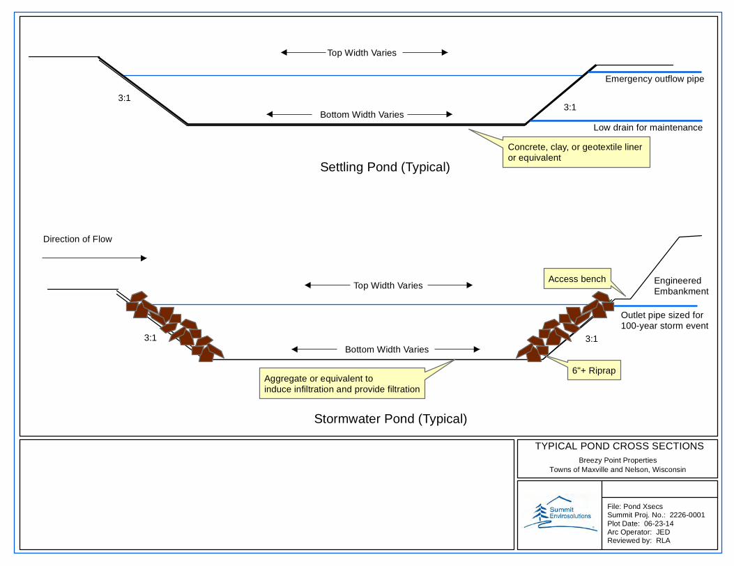
TYPICAL POND CROSS SECTIONSBreezy Point Properties
Towns of Maxville and Nelson, Wisconsin
File: Pond XsecsSummit Proj. No.: 2226-0001Plot Date: 06-23-14Arc Operator: JEDReviewed by: RLA
Settling Pond (Typical)
Stormwater Pond (Typical)
3:13:1
Concrete, clay, or geotextile liner or equivalent
3:1
6"+ Riprap
Direction of Flow
Outlet pipe sized for100-year storm event
Aggregate or equivalent to induce infiltration and provide filtration
Access bench
Emergency outflow pipe
Low drain for maintenance
EngineeredEmbankment
Bottom Width Varies
Top Width Varies
Top Width Varies
Bottom Width Varies
3:1