8/6/2019 11.IJAEST Vol No 6 Issue No 2 Transmitted Reference UWB Receiver for High Capacity Wireless Application 237 241
http://slidepdf.com/reader/full/11ijaest-vol-no-6-issue-no-2-transmitted-reference-uwb-receiver-for-high-capacity 1/5
Transmitted Reference UWB receiver for high
capacity wireless application
Preeti Rani
1
*M.Tech Research Scholar,
Electronics and Communication Engineering Department,Rayat Institute of Engineering and Information Technology,
SBS Nagar, Punjab- 144533, India.
(Corrosponding Author, E-mail: [email protected])
Parvinder Singh
2
2Senior Lecturer,
Electronics and Communication Engineering Department,Rayat Institute of Engineering and Information Technology,
SBS Nagar, Punjab- 144533, India.
(E-mail: [email protected])
Abstract — A high capacity multiple-user TR-UWB system is
proposed and its performance in AWGN Channel is investigated.
Here, we have proposed a modified signal model and
corresponding receiver algorithm assuming lower frame length.
We have investigated that in low crowded area with finite
number of users this system provides improved BER results at adata rate of more than 500 Mbps. Frame duration (T f ) and
Delay(Td) less than channel length(Th) is considered and received
signal equations corresponding to 1,2 and 3 number of users arederived with autocorrelation and cross-correlation terms.
Keywords- TR-UWB, AWGN Channel, Iterative algo, BMSR.
I. Introduction
Ultra wideband systems are gaining popularity due to their high data rate, low power consumption, low probability of interception and detection and high degree of penetration. InUWB system the bandwidth should not be less than 500 MHz.
As an alternative to the complex Rake receiver without channelestimation, a simple scheme called transmitted-reference (TR)scheme is proposed in which a reference pulse is transmittedalong with the data pulse with a delay T d between them. Wehave implemented our ideas after reviewing simple signalmodel and receiver algorithms reported in [1] and derive amodified signal model and corresponding iterative algorithmwhich provide improved results. The first TR-UWB systemthat can be considered practical was proposed by Hoctor andTomlinson [2], [3]. Pulses are transmitted in pairs referred to as“doublets”, where the first is fixed and considered a “carrier”and the second is modulated by the data. The delay between the pulses can be varied, which serves as a user code. In our proposed TR system, a reference pulse is transmitted beforeeach data-modulated pulse for the purpose of determining theAdded white Gaussian noise response. The proposed Autocorrelation receiver correlates the data signal with the referenceto use all the energy of the data signal without requiringadditional channel estimation. Only an analog delay line isneeded to align the reference and data pulses[4]. In this TR-UWB system, we are considering frame duration (T f ) andnumber of frames per symbol (Nf ),it is investigated that datarate is inversely proportional to the product of frame durationand number of frames per symbol, for high data rate Tf and Nf should be low but number of users are proportional to Nf . If we
decrease Nf to achieve high data rate the number of usersdecreases, second alternative is to decrease Tf which is proposed in this paper. We have designed a TR-UWB systemin which a second order Gaussian pulses are generated whichconsist of reference and data pulses and then transmitted in
AWGN environment with small frame duration which resultsin inter-frame interference (IFI), autocorrelation terms andcross-correlation terms[5], [6]. Recently many data model had been proposed [7], [8] which are based upon time reversaltechnique. So, by considering modified data model anditerative receiver algorithm the symbol value can be extractedunder noisy environment after neglecting IFI.
II. TR- UWB SYSTEM
Consider multiple (finite) users TR-UWB system inwhich pulses are transmitted in pairs with in a frame and each
pair of pulses are associated with symbol value si . The pulsescan be transmitted over AWGN environment i.e. a channelwith white Gaussian noise. The transmitted signal at theoutput of the antenna can be written as
U (t) = )
+ siZ( )……………….(1)
Where Z(t) is the convolution product of physical channel
Z p(t) and UWB pulse shape g(t), consisting of the transmit pulse including the antenna distortion and low pass/band passfiltering. Although most channels are assumed uncorrelated,the distorted pulse shape g(t) can have a duration of severalnanoseconds and thus may introduce some correlations in Z(t).However, these correlations are usually small compared to the
total channel energy and go down quickly as the correlation
lag increases.
A. Single frame per symbol.
Let s1 is the symbol value associated with the user andexpanding equation (1) for single user, we get
U (t) = Z (t) +s1 Z (t – Td)
Signal at the multiplier output will be,V1 (t) = U (t) * U (t – Td)
V1(t) = [Z(t) + s1 Z(t – Td)] * [Z(t – Td) +s1 Z(t –2Td)]
= [ Z2(t – Td) + Z(t)Z(t – 2Td)]s1 +[ Z(t)Z(t – Td)
Preeti Rani* et al / (IJAEST) INTERNATIONAL JOURNAL OF ADVANCED ENGINEERING SCIENCES AND TECHNOLOGIES
Vol No. 6, Issue No. 2, 237 - 241
ISSN: 2230-7818 @ 2011 http://www.ijaest.iserp.org. All rights Reserved. Page 237
8/6/2019 11.IJAEST Vol No 6 Issue No 2 Transmitted Reference UWB Receiver for High Capacity Wireless Application 237 241
http://slidepdf.com/reader/full/11ijaest-vol-no-6-issue-no-2-transmitted-reference-uwb-receiver-for-high-capacity 2/5
+ Z (t – Td) Z (t – 2Td)]
Also, we define autocorrelation function,
After integration and dump process the received samples are:
V1(k) = [G(0,k – Td/ Tsam) + G(2Td ,k )]s1 + [G(Td,k)
+ G(Td,k – Td/ Tsam)]……………………..…(3)
In equation (3), the terms G(0,k) representing the channelsegments and the autocorrelation terms G(ґ,k) with ґ∈ (Td,2Td,) can be assumed very small for an uncorrelatedchannel.
B. Two frames per symbol
Let s1 and s2 be the symbol values associated with the users
and extending equation (1) for two users, we getU (t) = ) + siZ( )
U (t) = [Z(t) + s1Z(t Td)]+[Z(t Tf ) +s2Z (t Tf Td)]
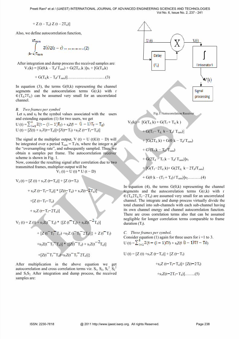
The signal at the multiplier output, V (t) = U (t)U(t − D) will be integrated over a period Tsam = T f /n, where the integer n isthe “oversampling rate”, and subsequently sampled. Thus, we
obtain n samples per frame. The autocorrelation receiver scheme is shown in Fig. 1. Now, consider the resulting signal after correlation due to twotransmitted frames, multiplier output will be
V1 (t) = U (t) * U (t − D)
V2 (t) = [Z (t) + s1Z (t Td)] + [Z (t Tf )
+ s2Z (t Tf Td)] * [Z(t Td) + s1Z(t Td)]
+[Z (t Tf Td)
+ s2Z (t Tf 2Td)]
V2 (t) = Z (t) + s1Z(t Td) * {[Z (t Td) + s1Z(t Td)]
+ [Z (t Tf Td) +s2Z (t Tf 2Td)]} + Z (t Tf )
+s2Z(t Tf Td)] * {[Z(t Td) + s1Z(t Td)]
+[Z(t Tf Td)+s2Z(t Tf 2Td)]}
After multiplication in the above equation we getautocorrelation and cross correlation terms viz. S1, S2, S1
2, S2
2
and S1S2. After integration and dump process, the received
samples are:
Fig.1. Autocorrelation Receiver
V2(k) = [G(Td ,k) + G(Tf + Td, k )
+ G(Tf − Td, k − Td/ Tsam)]
+ [G(2Td ,k) + G(0 ,k − Td/ Tsam)
+ G (Tf ,k − Td /Tsam)
+ G(2Td − Tf ,k − Td/ Tsam)]s1
+ [G(Tf −2Td ,k)+ G(2Td, k − 2Td/Tsam)
+ G(0 ,k – (Tf + Td) / Tsam)]s2……….(4)
In equation (4), the terms G(0,k) representing the channelsegments and the autocorrelation terms G(ґ,k) with ґ
∈ (Td,2Td,Tf −2Td) are assumed very small for an uncorrelatedchannel. The integrate and dump process virtually divide thetotal channel into sub-channels with each sub-channel havingits own channel energy and channel autocorrelation function.
There are cross correlation terms also that can be assumednegligible for longer correlation terms comparable to frameduration (Tf ).
C. Three frames per symbol.
Consider equation (1) again for three users for i =1 to 3.U (t) = ) + siZ( )
U (t) = [Z (t) +s1Z (t Td)] + [Z (t Tf )
+s2Z (t Tf Td)]+ [Z(t 2Tf )
+s3Z(t 2Tf Td)]……..(5)
Preeti Rani* et al / (IJAEST) INTERNATIONAL JOURNAL OF ADVANCED ENGINEERING SCIENCES AND TECHNOLOGIES
Vol No. 6, Issue No. 2, 237 - 241
ISSN: 2230-7818 @ 2011 http://www.ijaest.iserp.org. All rights Reserved. Page 238

8/6/2019 11.IJAEST Vol No 6 Issue No 2 Transmitted Reference UWB Receiver for High Capacity Wireless Application 237 241
http://slidepdf.com/reader/full/11ijaest-vol-no-6-issue-no-2-transmitted-reference-uwb-receiver-for-high-capacity 3/5
After correlation due to three transmitted frames, multiplier output will be
V2 (t) = U (t) * U (t − D)
V2(t) = { [Z (t) +s1Z (t Td)]+[Z (t Tf )
+s2Z(t Tf Td)] + [Z(t 2Tf )
+ s3Z(t 2Tf Td)] }
* { [Z(t Td) + s1Z(t Td)]+[Z (t Tf Td)
+ s2Z(t Tf 2Td)]+[Z(t 2Tf Td)
+ s3Z(t 2Tf Td)]}
After multiplication in the above equation, we get long terms
of s1, s2 and s3. Again consider the autocorrelation functionmentioned in equation (2), after integration and dump process,
the received samples contains terms of s1 and s2 same as inequation (4) plus extra terms of s3 ,so we are only consideringextra terms in the following equation.
V2 (k) = Z(2Tf + Td, k) + Z(0,k – (2Tf + Td)
+ Z (2Tf, k– Td/ Tsam) + …….
after expansion of signal equation for two and three users, weconclude that if we further increase the number of users theequations become more complex. So, the signal equationmentioned in (1) is suitable for finite number of users but stillhigh data rate can be attained at finite number of users withlesser value of frame duration.
D. Improved model (finite number of users).
If we consider more than one frame and expand thesignal equation we find that there are autocorrelation, crosscorrelation and inter frame interference (IFI) terms available
in the final equation. Cross correlation occurs due to antennaaffect which go down quickly as correlation length increases,so for lesser number of frames these terms can be neglected
while auto correlation terms (with in one frame) are includedin the improved data model
So data model becomes,V = Zs + I + noise
Where,V = sample vector (collect k samples)
Z = shifted versions of channel correlation vectors
s = unknown symbol vector
I = shifted versions of offset vector I i (similar to Z)
WhereIi = Z(Td, i) + Z(Td, i − Td/ Tsam)
So in the receiver our purpose is to estimate the value of „Z‟and„s‟. However, the receiver algorithm must ignore IFI terms.We are considering iterative receiver algorithm rather than
blind algorithm because it provides better results than blindreceiver algorithm under AWGN environment.Iterative algorithm (for three users)Consider simple data model,
v = Zs …………….……..….(6)
s = [s1, s2, s3] (symbol values for three users)with modified data model the equation will be,
v = Sz ……….…….......…. (7)
Where S is the data symbol matrix. This means that unknowndata symbols and channel matrix can be obtained by using
iterative algorithm similar as follows:
Initial estimate: set the channel vector to initial estimatei.e z = zo
E. Iteration
(a) With known channel vector z, we can calculate the
value of symbol vector using equation (6) ass = Z
†v
Where † is the Moore-Penrose pseudo-inverse
(b) Make hard decisions on the source symbols s, usingtheir finite alphabet property.
(c) With known data symbol s, the channel vector can be estimated again based on (7), as
z = S†vAlthough iterative algorithm is complex, as in there are
efficient techniques to invert such matrices with a very lowcomputation complexity. We can use blind receiver algorithmto estimate Z and consider it as Z0 Therefore, we can use
known average PDPs as an initial channel estimate, which willsignificantly improve the convergence of the iterativealgorithms. As a result, we only need two iterations for our case.
III. Simulation Results and Discussion
The simulation parameters are as follows. The pulse
shape is the second derivative of a Gaussian function withwidth parameter tc = 0.1ns, the delay between two pulses indoublet is Td = 0.4ns and channel is an AWGN channel. The
frame time Tf
= 4ns set to avoid IFI and is fixed for all users,the oversampling rate is n = 20 samples per frame whichmeans that sampling period Tsam = 0.2 ns.
A. BER vs SNR
Fig.2 shows the performance of proposed system atvarious number of transmitted reference frames (i.e. Nf =1, 2,
3, 4). We conclude that BER varies with change in number of
Preeti Rani* et al / (IJAEST) INTERNATIONAL JOURNAL OF ADVANCED ENGINEERING SCIENCES AND TECHNOLOGIES
Vol No. 6, Issue No. 2, 237 - 241
ISSN: 2230-7818 @ 2011 http://www.ijaest.iserp.org. All rights Reserved. Page 239

8/6/2019 11.IJAEST Vol No 6 Issue No 2 Transmitted Reference UWB Receiver for High Capacity Wireless Application 237 241
http://slidepdf.com/reader/full/11ijaest-vol-no-6-issue-no-2-transmitted-reference-uwb-receiver-for-high-capacity 4/5
8 10 12 14 16 18 2010
-8
10-7
10-6
10-5
10-4
10-3
10-2
10-1
100
Eb/No
B E R
Fig.2. BER vs SNR plots for AWGN channel model
frames and the duration of frames, so for high data rate weconsider constant value of frame duration (Tf = 4ns) and vary
the number of frames per symbol and inter-frame interferencecan be ignored by considering modified data model anditerative algorithm.
We have calculated the improved BER results and considering Nf = 3, a sharp decrease in BER occurs between 18dB to 20dBvalue of SNR.
B. Data Rate Vs frame duration (T f )
In the second case, we considered the effect of variable
frame duration on data rate and observed that maximum datarate with single user is 1 Gbps. If we further increase thenumber
0 2 4 6 8 10 12 140
100
200
300
400
500
600
700
800
900
1000
Frame duration(ns)
D a t a R a t e ( M b p s )
Fig.3.Data Rate vs. Frame duration plots for AWGN
Channel.
of users we investigated that data rate more than 100 Mbps
can be achieved which is much higher than what is supported by all the existing wireless technologies. System with three
users at a given symbol duration, we have reported here thatdata rate decreases with increase in frame duration as shownin fig.3. Therefore, if we don‟t want to compromise with
number of users, one of the alternatives to design a high datarate TR-UWB system is by decreasing the value of frameduration which has been used here. Fig.3.clearly shows thatthis system can provide better data rate performance in lowcrowded area.
C. Performance comparison: AWGN channel Vs. IEEE CM1
((LOS) channel model.
In this section, we compare our AWGN channel model performance with UWB channel model (CM1). We have
compared our system with the one reported in [1] on the basisof bit error rate. We have simulated our system with samevalue of parameters as mentioned in [1] and investigated that
BER performance of our system is much improved. Fig.4.shows the performance comparison of proposed AWGNmodel and IEEE CM1 (channel) model mentioned in [1-3]using iterative and blind receiver algorithms. It is clear from
the figure that our system provides much improved bit error rate at the same level of signal to noise ratio.The improvementin BER is more than 2dB than reported in [1].The performance
of our system is also better than matched filter
14 15 16 17 18 19 20 21 22 23 2410
-7
10-6
10-5
10-4
10-3
10-2
10-1
100
Eb/No[dB]
B E R
Fig.4.BER vs. SNR plots for proposed AWGN channel and IEEE CM1
channel (LOS) for different receiver algorithm.
And BMSR (blind multi symbol receiver). Matched filter receiver uses a single (matched) complete bank of receiver
delays for each received chip, and the iterative receiver usesimproved data model. If we increase the number of iterationsand use the improved data model, it can help to reduce muchof the floor effect at high SNRs.
IV. Conclusions and Future Work In this paper, a modified version of Transmitted Referenceultra wideband system has been proposed with improved data
model. The performance of the proposed system isinvestigated under Gaussian white noise environment for varying number of users with their numerical equations. BER
----*------*-------- Nf =1
----o------o------ Nf
=2
-----^-------^---- Nf
=3
-----+-------+------ Nf
=4
----*------*-------- Nf =1
----o------o------- Nf =2
-----^-------^------ Nf =3
-*- proposed TR UWB
---o--iterative algo (CM1)
--^---^--- BMSR (CM1)
Preeti Rani* et al / (IJAEST) INTERNATIONAL JOURNAL OF ADVANCED ENGINEERING SCIENCES AND TECHNOLOGIES
Vol No. 6, Issue No. 2, 237 - 241
ISSN: 2230-7818 @ 2011 http://www.ijaest.iserp.org. All rights Reserved. Page 240

8/6/2019 11.IJAEST Vol No 6 Issue No 2 Transmitted Reference UWB Receiver for High Capacity Wireless Application 237 241
http://slidepdf.com/reader/full/11ijaest-vol-no-6-issue-no-2-transmitted-reference-uwb-receiver-for-high-capacity 5/5
performance of the system for different number of reference pulses are investigated and it is reported that improved resultsoccur at Nf = 3.Further we compare our system with IEEE
CM1 channel(LOS ) and concluded that BER performance of our system using AWGN channel is dramatically improvedthan IEEE CM1 channel (LOS) .There is substantial future optimization work that can beconsidered on the proposed framework. Most important
among them is the narrowband interference, which isimportant both for commercial and UWB militaryapplications. Synchronization becomes easy withoversampling and this may be considered for future work.
REFERENCES[1] Quang Hieu Dang, Antonio Trindade, Alle-Jan van der Veen ,and Geert
Leus,“Signal model and receiver algorithms for a transmit-reference
ultra wideband communication System”. IEEE journal on selected areas
in communications, Vol. 24,No. 4,April 2006.
[2 R. T. Hoctor and H. W. Tomlinson, “An overview of delay-hopped
transmitted-reference RF communicateons”,Technique Information
Series:G.E. Research and Development Center, January 2002.
[3] N. van Stralen, A. Dentinger, K. Welles, R. Gauss, R. Hoctor, and H.
Tomlinson, “Delay hopped transmitted reference experimental results,”inProc. IEEE Conf. Ultra Wideband Syst. Technol., 2002, pp. 93–98.
[4] S. Franz and U. Mitra, “Integration Interval Optimization and
Performance Analysis for UWB Transmitred Reference Systems,”
Proc.IEEE UWBST‟04, 2004.
[5] F.Troesch, F. Althaus, and A. Wittneben, "Modified pulse repetition
coding boosting energy detector performance in low data rate systems,"
in IEEE Int. Conf: Ultra-Wideband (ICU), Zurich, Switzerland, Sept. 5- 8,
2005.
[6] Seonkeol Woo, Hoongee Yang, Sunghyun Yang and Bongsoon Kang, “A
TR-UWB Receiver using Correlation in Frequency Domain,” The 2nd
International Conference on Wireless Broadband and Ultra Wideband
Communications (AusWireless 2007)0-7695-2842-2/07.
[7] X. Liu, B.-Z. Wang, S. Xiao, and J. Deng, “Performance of impuse radio
UWB communications based on time reversal technique,” Progress In
Electromagnetics Research, PIER 79, 401–413, 2008.
[8] Sang-Dong Kim and Jong-Hun Lee, “A new Transmitted-Reference
Automotive UWB Radar using Unequaled Amplitude,” International
Journal of Signal Processing, Image Processing and Pattern
RecognitionVol. 2, No. 2, June 2009.
Preeti Rani* et al / (IJAEST) INTERNATIONAL JOURNAL OF ADVANCED ENGINEERING SCIENCES AND TECHNOLOGIES
Vol No. 6, Issue No. 2, 237 - 241
ISSN: 2230-7818 @ 2011 http://www.ijaest.iserp.org. All rights Reserved. Page 241