1 Provisioning Quality Controlled Medium Access in UltraWideBand (UWB) WPANs Chunyu Hu†, Hwangnam Kim‡, Jennifer C. Hou‡, Dennis Chi‡ Sai Shankar N* † Department of Electrical and Computer Engineering Staff Engineer ‡ Department of Computer Science Qualcomm Standards Engineering Dept. University of Illinois at Urbana-Champaign 5775 Morehouse Drive Urbana, IL 61801 USA San Diego, CA, 92121 USA E-mail:{chunyuhu, hkim27, jhou, dychi}@uiuc.edu E-mail: [email protected] Abstract— Quality of service (QoS) provisioning is one of the most important criteria in newly emerging UWB-operated WPANs, as they are expected to support a wide variety of applications from time-constrained, multimedia streaming to throughput-hungry, content transfer applications. As such, the Enhanced Distributed Coordinated Access (EDCA) mechanism has been adopted by MultiBand OFDM Alliance in its UWB MAC proposal. In this paper, we conduct a rigorous, compre- hensive, theoretical analysis and show that with the currently recommended parameter setting, EDCA cannot provide adequate QoS. In particular, without responding to the system dynamics (e.g., taking into account of the number of active class-i stations), EDCA cannot allocate bandwidth in a deterministic proportional manner and the system bandwidth is under-utilized. After identifying the deficiency of EDCA, we propose, in compliance with the EDCA-incorporated UWB MAC protocol proposed in [18] [23] [24], a framework, along with a set of theoretically grounded methods for controlling medium access with deterministic QoS for UWB networks. We show that in this framework, 1) real-time traffic is guaranteed of deterministic bandwidth via a contention-based reservation access method; 2) best-effort traffic is provided with deterministic proportional QoS; and moreover, 3) the bandwidth utilization is maximized. We have also validated and evaluated the QoS provisioning capability and practicality of the proposed MAC framework both via simulation and empirically by leveraging the MADWifi (Multiband Atheros Driver for WiFi) Linux driver for Wireless LAN devices with the Atheros chipset. I. I NTRODUCTION With the maturity of several enabling techniques (ranging from communication theory to semiconductor technologies), ultra wide band (UWB) networks have become a promising candidate for Wireless Personal Area Networks (WPANs), capable of transmitting packets at a high rate (480+ Mbps) for short-range communication (up to 20 meters). The MultiBand OFDM Alliance (MBOA), established in 2003 and merged with the WiMedia Alliance in 2004, represents a leading force with 170+ participating members. Efforts are put forth to standardize both PHY and MAC specifications. *: The work was done when the author was with Philips Research USA. Technical Report No. UIUCDCS-R-2005-2600 (Engr. No. UILU-ENG- 2005-1795), July 2005 To support peer-to-peer mobile applications, it is necessary for the network to support mobility and allow devices to move in/out of a piconet without significant performance degradation. Therefore, a distributed MAC architecture with loose coordina- tion is preferred to a centralized design. This, combined with several other design concerns, rules out the IEEE 802.15.3 MAC specification [1], which is TDMA-based and requires a central Piconet Coordinator. A new MAC protocol has to be defined to meet the WPAN requirements as well as to utilize the high data rates as afforded by UWB. One of the vital requirements for WPANs is quality of service (QoS) and efficient bandwidth utilization. As a WPAN is envisioned to support a vast number of applications vary- ing in type, nature and/or user preference, QoS provisioning has to be a built-in function in the PHY/MAC specification. There have been many research efforts, largely focusing on designing and evaluating the PHY layer performance [2] and [12] and PHY-related issues in the MAC layer [19], [16], [24]. In particular, Merz et al. [19] addressed the problem of dynamically selecting appropriate power and link rates. Lu et al. [16] addressed the time acquisition issue. A MAC protocol specification for UWB currently being developed by MBOA [18] [23] [24] has proposed to leverage an Enhanced Distributed Coordinated Access (EDCA) mechanism for QoS provisioning. The main intent of this paper is to investigate, through analytic modeling, simulation, and experimentation, how deterministic QoS provisioning can be realized in such an EDCA-incorporated UWB protocol. EDCA is a fully distributed service differentiation mech- anism originally defined in IEEE 802.11e. Note that IEEE 802.11e is proposed as a supplement to IEEE 802.11 MAC Distributed Coordination Function (DCF), and aims to support QoS for IEEE 802.11. For a detailed description of IEEE 802.11 and 802.11e MAC, refer to [11] and [3]. In EDCA, medium access is contention-based and prioritized by two configurable parameters: the contention window size (CW) and the arbitration inter frame space (AIFS). The contention window size determines the number of backoff slots (which is uniformly distributed in [0,CW − 1]) a station has to count

Welcome message from author
This document is posted to help you gain knowledge. Please leave a comment to let me know what you think about it! Share it to your friends and learn new things together.
Transcript

1
Provisioning Quality Controlled Medium Access inUltraWideBand (UWB) WPANs
Chunyu Hu†, Hwangnam Kim‡, Jennifer C. Hou‡, Dennis Chi‡ Sai Shankar N*† Department of Electrical and Computer Engineering Staff Engineer
‡ Department of Computer Science Qualcomm Standards Engineering Dept.University of Illinois at Urbana-Champaign 5775 Morehouse Drive
Urbana, IL 61801 USA San Diego, CA, 92121 USAE-mail:{chunyuhu, hkim27, jhou, dychi}@uiuc.edu E-mail: [email protected]
Abstract— Quality of service (QoS) provisioning is one ofthe most important criteria in newly emerging UWB-operatedWPANs, as they are expected to support a wide variety ofapplications from time-constrained, multimedia streaming tothroughput-hungry, content transfer applications. As such, theEnhanced Distributed Coordinated Access (EDCA) mechanismhas been adopted by MultiBand OFDM Alliance in its UWBMAC proposal. In this paper, we conduct a rigorous, compre-hensive, theoretical analysis and show that with the currentlyrecommended parameter setting, EDCA cannot provide adequateQoS. In particular, without responding to the system dynamics(e.g., taking into account of the number of active class-i stations),EDCA cannot allocate bandwidth in a deterministic proportionalmanner and the system bandwidth is under-utilized.
After identifying the deficiency of EDCA, we propose, incompliance with the EDCA-incorporated UWB MAC protocolproposed in [18] [23] [24], a framework, along with a set oftheoretically grounded methods for controlling medium accesswith deterministic QoS for UWB networks. We show that inthis framework, 1) real-time traffic is guaranteed of deterministicbandwidth via a contention-based reservation access method; 2)best-effort traffic is provided with deterministic proportional QoS;and moreover, 3) the bandwidth utilization is maximized. We havealso validated and evaluated the QoS provisioning capability andpracticality of the proposed MAC framework both via simulationand empirically by leveraging the MADWifi (Multiband AtherosDriver for WiFi) Linux driver for Wireless LAN devices with theAtheros chipset.
I. INTRODUCTION
With the maturity of several enabling techniques (rangingfrom communication theory to semiconductor technologies),ultra wide band (UWB) networks have become a promisingcandidate for Wireless Personal Area Networks (WPANs),capable of transmitting packets at a high rate (480+ Mbps) forshort-range communication (up to 20 meters). The MultiBandOFDM Alliance (MBOA), established in 2003 and mergedwith the WiMedia Alliance in 2004, represents a leading forcewith 170+ participating members. Efforts are put forth tostandardize both PHY and MAC specifications.
*: The work was done when the author was with Philips Research USA.Technical Report No. UIUCDCS-R-2005-2600 (Engr. No. UILU-ENG-
2005-1795), July 2005
To support peer-to-peer mobile applications, it is necessaryfor the network to support mobility and allow devices to movein/out of a piconet without significant performance degradation.Therefore, a distributed MAC architecture with loose coordina-tion is preferred to a centralized design. This, combined withseveral other design concerns, rules out the IEEE 802.15.3MAC specification [1], which is TDMA-based and requiresa central Piconet Coordinator. A new MAC protocol has to bedefined to meet the WPAN requirements as well as to utilizethe high data rates as afforded by UWB.
One of the vital requirements for WPANs is quality ofservice (QoS) and efficient bandwidth utilization. As a WPANis envisioned to support a vast number of applications vary-ing in type, nature and/or user preference, QoS provisioninghas to be a built-in function in the PHY/MAC specification.There have been many research efforts, largely focusing ondesigning and evaluating the PHY layer performance [2] and[12] and PHY-related issues in the MAC layer [19], [16],[24]. In particular, Merz et al. [19] addressed the problemof dynamically selecting appropriate power and link rates.Lu et al. [16] addressed the time acquisition issue. A MACprotocol specification for UWB currently being developed byMBOA [18] [23] [24] has proposed to leverage an EnhancedDistributed Coordinated Access (EDCA) mechanism for QoSprovisioning. The main intent of this paper is to investigate,through analytic modeling, simulation, and experimentation,how deterministic QoS provisioning can be realized in such anEDCA-incorporated UWB protocol.
EDCA is a fully distributed service differentiation mech-anism originally defined in IEEE 802.11e. Note that IEEE802.11e is proposed as a supplement to IEEE 802.11 MACDistributed Coordination Function (DCF), and aims to supportQoS for IEEE 802.11. For a detailed description of IEEE802.11 and 802.11e MAC, refer to [11] and [3]. In EDCA,medium access is contention-based and prioritized by twoconfigurable parameters: the contention window size (CW)and the arbitration inter frame space (AIFS). The contentionwindow size determines the number of backoff slots (which isuniformly distributed in [0, CW − 1]) a station has to count
down before a transmission attempt can be made. The AIFSvalue determines the number of slots that has to be sensed idlebefore the backoff procedure is initialized/resumed. See Fig. 1for an illustration. Flows of different priorities are assigneddifferent parameter values to increase/decrease their chance ofgaining medium access. Although this is intuitively correct, it isimportant to understand quantitatively how, and to what extent,the two parameters favor/disfavor data transmission from high-priority/low-priority flows.
Several studies on evaluating the performance of EDCA havebeen made via simulation in the context of IEEE 802.11e in[7], [14], [15], [17] and [20]. Several theoretical models thatshed insights on how service differentiation can be achievedhave been reported in [8], [10], [13], [21], [22], [26], and [27],again in the context of IEEE 802.11e. Most of the models, ifnot all, are based on Bianchi’s model [4] or Calı’s model [5]that were proposed to study the performance of IEEE 802.11DCF under the asymptotic condition (i.e., all the stationsalways have packets ready for transmission). Among all themodels, those reported in [13] and [26] analyze the effect ofvarying the contention window size on the performance ofservice differentiation, and those reported in [8], [10], [21],[22], and [27] also study the effect of varying AIFS values onthe performance. In most (if not all) of the work that studysthe AIFS effect, such as [10], [21], [22], and [27] a differentcontention window range [1, CW ] (rather than [0, CW −1]) isassumed. As has been pointed out in [9], this subtle differenceresults in considerable degradation in the system throughput.In summary, a model that conforms to the standard and fullyincorporates both parameters is yet to observe. A joint studybased on that on how, and to what extend, the two parametersaffect the performance is expected.
In this paper, we propose a comprehensive, accurate, andyet simple model to characterize data activities in EDCA andjointly study the effect of varying both the contention windowsize and AIFS values. Instead of using a p-persistent model(that is commonly assumed in literature), we use a discrete-time Markov chain to describe the transition of the channelstate. In particular, the model has revealed a common pitfallused in the p-persistent model (i.e., the probability of accessingany slot is p) and its adverse effect on the model accuracy.With the results derived in the proposed model (and corrobo-rated in the simulation study with the use of UWB-specifiedparameters), we have made several important observations thatwill help in the design of the EDCA-incorporated UWB: 1)Traffic classes with small values of AIFS dominate channelaccess, depriving traffic classes with larger AIFS values oftheir channel access. 2) With the currently proposed param-eter setting, the differentiation mechanism fails to allocatebandwidth among stations of different classes at deterministicQoS. That is, given the currently proposed parameter setting,the EDCA-incorporated UWB MAC protocol does not fullysupport both real-time data streams and best-effort applicationsat their configured QoS. 3) The available bandwidth is under-utilized given the proposed parameter setting.
Guided by the derived model, we then devise, in compliancewith the EDCA-incorporated UWB MAC protocol (and inparticular, the superframe structure) proposed in [18] [23][24], a framework, along with a set of theoretically groundedmethods for controlling medium access with deterministicQoS for UWB networks. In particular, we derive the optimalcontention window sizes that give deterministic proportionalQoS for different traffic classes. In this enhanced UWB MACprotocol, 1) real-time traffic is guaranteed of deterministicbandwidth via a contention-based reservation access method;2) best-effort traffic is provided with deterministic proportionalQoS; and moreover, 3) the bandwidth utilization is maximized.The performance of the enhanced UWB MAC protocol isevaluated via both analytical derivation, simulation studies, andempirical experiments (leveraging the MADWifi (MultibandAtheros Driver for WiFi) Linux driver for Wireless LANdevices with the Atheros chipset).
The rest of the paper is organized as follows. After intro-ducing the network model and stating the assumptions, wepresent in Section II the analytical model that characterizesthe EDCA service differentiation mechanism. In Section II,we carry out simulation to validate the model via simulation.The validation process also reveals the deficiency of thecurrent parameter settings used in the UWB MAC protocol.In Section IV, we devise a framework for controlling mediumaccess with deterministic QoS for UWB networks. We evaluatethe performance of the enhanced UWB MAC protocol both viasimulation and empirically in Sections V–VI, and conclude thepaper in Section VII.
II. AN ANALYTICAL MODEL FOR EDCA
A. Network Model and Assumptions
We envision a general single-cell UWB-operated wirelessnetwork without any central coordinator. All stations can heareach other, i.e., there exists no hidden terminal. We assumethat no capture technique is used and that every stationis backlogged and always has packet(s) to send (i.e., theasymptotic condition commonly used to analyze the saturationperformance holds).
There are M priority classes, with the number of stationsin each class being Nj , j = 1, · · · ,M . (We will addresshow to on-line determine Nj in the dynamic case later.)Each class is configured with a set of QoS parameters fordistributed access contention: the inter-frame space AIFSj
(= SIFS+AIFSNj×aSlotT ime and the contention windowsize CWj . Without loss of generality, we assume AIFSN1 ≤AIFSN2 ≤ · · · ≤ AIFSNM . In particular, let m denotethe priority index such that AIFSN1 = · · · = AIFSNm �=AIFSNm+1 ≤ AIFSNm+2 . . ..
All stations share and access the channel with the use of theenhanced distributed coordinated access (EDCA) mechanism.That is, a random backoff interval value is uniformly chosenin [0, CWi − 1] and used to initialize the backoff timer, whereCWi is the current contention window for traffic class i. The
2

DIFS/AIFS
Busy Medium Backoff Slots Next Frame
Slot Time
Select Slot and Decrement Backoff as longas medium is idle
Defer Access
SIFS
PIFS
DIFS
AIFS[i]
AIFS[j]
Contention Window
Immediate access whenMedium is free >= DIFS/AIFS[i]
Fig. 1. The relation between different inter-frame spaces.
... ...... ...
... ...... ...
... ...
... ...... ...
... ...... ...
CaMSMSm Sm+1S1
Ia1 Ia1+1
CajCa1
IaMIaj
Fig. 2. The discrete Markov chain that describes the channel state transition
backoff timer is decreased as long as the channel is sensed idle,stopped when data transmission (initiated by other stations) isin progress, and reactivated when the channel is sensed idleagain for more than AIFS[i], where i denotes the traffic class.The time immediately following an idle period of length shortinter-frame space (SIFS) is slotted, with each slot equal to thetime needed for any station to detect the transmission of apacket from any other station. When the backoff timer expires,the station attempts for frame transmission at the beginningof the next slot time. Finally, if the data frame is successfullyreceived, the receiver transmits an acknowledgment frame aftera SIFS, 1 If an acknowledgment is not received, the data frameis presumed to be lost, and a retransmission is scheduled.The value of CWi is set to CWmin,i in the first transmissionattempt, and is doubled at each retransmission up to a pre-determined value CWmax,i.
Let aj�= AIFSNj + 1. For ease of explanation, we divide
the slots subsequent to a busy period into consecutive con-tention zones. Specifically, as illustrated in Fig. 3, contentionzone j (j = 1, · · · ,M −1) starts at the aj-th slot and endsat (including) the (aj+1−1)-th slot. The M -th contention zoneincludes the aM -th slot and all the slots beyond. An importantobservation that will be used throughout the derivation is —under EDCA, only stations of the first j classes are eligible totransmit in the j-th contention zone. Also, as the a1-th slot isthe first slot immediately following a busy period and (as willbe shown later) plays an important role in the performance, weterm it as the post-busy slot.
B. Channel State Space
For ease of explanation, we treat a collision period or asuccessful transmission as a virtual (busy) slot. The channelstate, denoted by s(t), is sampled at the end of each busy/idleslot. There are three types of possible channel states:
1) State Ik (k = a1, a1 + 1, · · · , aM −1): the idle channelstate in the k-th slots after the busy slot. (Recall that thefirst slot is the one immediately after a busy slot plus a
1The necessity of returning an acknowledgment is due to that typicallyWLAN devices are equipped with half-duplex radios and therefore are unableto simultaneously transmit and receive.
CZ: contention zone
1 CZ2
a1
CZ3
a2 a3
���� post−busy slot
���
���
��������������������
����������������
����
...
SIFS
busy periodbusy period
0
CZ
Fig. 3. An illustration of the notions of contention zones and the post-busy slot. In this example, there are three classes with different AIFS values.aj = AIFSNj + 1.
SIFS.) In other words, when the channel is in Ik, it meansthere are k−1 consecutive idle slots subsequent to a busyslot and the k-th slot is still idle. In addition, IaM
is thechannel state in which there are ≥ aM consecutive idleslots.
2) State Sj : a successful transmission made by a station ofclass j.
3) State Caj: either a collision subsequent to an idle slot that
is in the j-th contention zone or a collision subsequentto such a collision. By the definition of the contentionzone, collision Caj
only involves stations of the first jclasses.
The channel state space is thus defined as S = { Ik, Sj , Caj:
j = 1, · · · ,M and a1 ≤ k ≤ aM}.
C. Transitions of Channel States
We use a discrete-time Markov chain (Fig. 2) to describethe transition of channel states. Possible transitions are:
1) Ik → { Ik+1, S1,· · · , Sj , Caj}, for aj ≤ k ≤ aj+1 − 1,
j = 1, · · · ,M − 1: An idle slot state can transition toanother idle slot state, a collision state, or a successfultransmission state. Specifically, an idle slot state inthe j-th contention zone can transition to a successfultransmission (made by one of the stations of the first jclasses), or to a collision Caj
(caused by two or morestations of the first j classes attempting for transmission),or to the next idle slot in the time order.
2) IaM→ { IaM
, S1,· · · , SM , CaM}: The only exception
in the transition from an idle slot state occurs when the
3

idle slot is in the M -th contention zone. By the definitionof the M -th contention zone, an idle slot state in theM -th contention zone can transition to itself. Hence, asshown in Figure 2, instead of having an outgoing arrowinto other idle slot states, state IaM
contains a self-looppointing to itself.
3) Sj → { Sj , Ia1 }, for j = 1, · · · ,m: As a station willtransmit immediately once its backoff timer counts downto zero, when the backoff timer freezes upon detectionof the busy medium, the timer value is always positiveand has at least 1 slot time. Therefore, stations thatdid not participate in transmission in the busy periodwill not transmit in the post-busy slot (i.e., the a1-th slot immediately after a busy period). This peculiaraccess behavior to the post-busy slot is often ignored inprevious work, which assumes uniform and independentaccess to any slot (a.k.a. p-persistent). Because of thisbehavior, subsequent to a successful transmission, eitheranother successful transmission made by the same stationfollows, or the channel becomes idle. This implies, forj ≤ m, state Sj can either transition to itself or the idleslot state Ia1 .
4) Sj → { Ia1 }, for j = m + 1, · · · ,M : As stations ofclasses j >m are assigned larger AIFS values, they arenot eligible to access the post-busy slot. Hence, statesSj , j > m, will transit exclusively to the idle slot stateIa1 .
5) Caj→ { Caj
, Ia1 , S1,· · · , Sm }, for j = 1, · · · ,M :Transitions from collision states can be similarly ex-plained as in cases 3–4 and hence are not elaboratedon here.
D. Derivation of State Transition Probabilities
Now we are in a position to derive the transition probabilitiesof all the possible transitions. We assume that stations of classj access a slot other than an post-busy slot independently anduniformly with probability τj . τj is termed as the attempt prob-ability. For ease of exposition, we first consider the case thatthe contention window size CWj is fixed. Then we extend themodel to accommodate that case that the contention windowsize changes in compliance with the the binary exponentialbackoff procedure.
Before we proceed, we define the following terms fornotational convenience:
Aj∆=
j∏h=1
(1 − τh)Nh , Bj∆=
j∏h=1
(1 − τh
CWh
)Nh
. (1)
a) Transitions from the idle slot state to other states:Recall that in the j-th contention zone, only the first j classesare eligible to contend for channel access. Hence, we derive,for each contention zone, transition probabilities from an idlechannel state. For notational convenience, we define aM+1 =aM + 1.
For k ∈ [aj , aj+1), j = 1, 2, · · · ,M , and u ≤ j,
P [Ik → Ik+1] = Aj , (2)
P [Ik → Su] = Nuτu(1 − τu)Nu−1j∏
h=1,h�=u
(1 − τh)Nh
=Nuτu
1 − τuAj (3)
P [Ik → Caj ] = 1 − P [Ik → Ik+1] −j∑
u=1
P [Ik → Su] (4)
b) Transitions from a successful transmission state to otherstates: After a station of the first m classes finishes asuccessful transmission, it may gain the channel access againif it chooses 0 as the next backoff timer value. This occurswith probability 1
CWj, since the backoff timer value is selected
uniformly in [0, CWj − 1]. On the other hand, if the station isof of class m+1 to M , it is not eligible to access the post-busyslot. Moreover, all the other stations have frozen their backofftimer with the remaining timer value at least 1 slot, and hencewill not attempt to transmit either. In this case, the post-busyslot is idle with probability 1. We have
P [Sj → Sj ] =1
CWj, for j = 1, · · · ,m, (5)
P [Sj → Ia1 ] =
{1 − 1
CWj, for j = 1, · · · ,m,
1 , for j = m + 1, · · · ,M.(6)
c) Transitions from a collision state to other states:Recall that by the definition of m, AIFSN1 = · · · =AIFSNm, i.e., the first m contention zones is practicallythe same one. Consequently, we merge the collision statesCak
, k = 1, · · · ,m, into one state, and denote it by Cam.
The transition probabilities originating from Caj, for j =
m, · · · ,M and u ≤ m are given below, with their detailedderivation given in Lemma 1–2 in Appendix I.
For j = m, · · · ,M and u ≤ m,
P [Caj → Ia1 ] =1
P [Ik → Su]
{Bm − Aj
[1 +
m∑k=1
Nkτk
1 − τk×
(1 − 1
CWk
)+
j∑k=m+1
Nkτk
1 − τk
]}, (7)
P [Caj → Su] =1
P [Ik → Su]Nu
τu
CWu
(Bm
1 − τuCWu
− Aj
τu
),
(8)
P [Caj → Caj ] = 1 − P [Caj → Ia1 ] −m∑
u=1
P [Caj → Su]. (9)
With all the derived transition probabilities, we can computethe stationary probabilities of channel states by solving theequilibrium equations for the Markov chain, s = sP. Let theequilibrium channel state be denoted by s.
E. Derivation of the Attempt Probability
Recall that each station attempts to transmit in a slot (otherthan the post-busy slot) independently and uniformly with
4

probability τj , where j is the priority class which the stationbelongs to.
Given a fixed contention window size, CWj , for each classj, τj can be simply expressed as 2
CWj– the inverse of the
average waiting (backoff) time. Note that the backoff timeris frozen when data transmission (initiated by other stations)is in progress, and resumed when the channel is sensed idleagain for more than AIFS[i]. The expression results fromthat the backoff time at the beginning of any eligible slot isapproximately uniformly distributed in [0, CWj −2], where aneligible slot refers to any non-post-busy slot.
An iterative algorithm to derive CWj and τj: In the casethat the contention window size CWj changes in compliancewith the binary exponential backoff procedure, we develop aniterative algorithm to derive the average contention windowsize CWj .
Consider the view of a tagged station of class j. Let pcoll(j)denote the probability that when the tagged station transmitsa frame in an eligible slot, the frame incurs a collision; andp(r)coll(j) denotes this probability in the r-th iteration. The
average contention window size, CWj(r)
, in the r-th iterationcan be computed from its probability mass function:
q(j, �)�= P [CW
(r)j = W (j, �) ]
= p0
(p(r)coll(j)
)�
for � = 0, . . . , Lj , (10)
where p0 is the normalization factor, and can be obtained bynoting
∑Lj
�=0 q(j, �) = 1. Lj is the retry limit for class j andW (j, �) = min{2�CWmin(j), CWmax(j)}, � = 0, · · · , Lj .The attempt probability for the next iteration, τ
(r+1)j , can be
computed from CWj(r)
by τ(r+1)j = 2
CWj(r) .
The probability pcoll(j) is yet to be derived. As this proba-bility varies in different contention zones, we will flirtly derivethe conditional probability of collision given that the systemis in the contention zone k (j ≤ k ≤ M ), and then theprobability that the system is in the contention zone k. Theformer probability can be expressed as pcoll(j, k) = 1− Ak
1−τj,
i.e., the probability that at least one other station of the firstk classes transmits in the same slot. The latter probability thatthe system is in the contention zone k is
∑ak+1−1h=ak
P[s = Ih].Now pcoll(j) can be expressed as
pcoll(j) =1c0
M+1∑k=j
(1 − Ak
1 − τj
)(ak+1−1∑h=ak
P[s = Ih]
),
(11)
where c0 =∑aM
h=akP[s = Ih] and recall aM+1
∆= aM+1. Notethat all the stationary probabilities used here should be derivedfrom the perspective of of the tagged station, i.e., the numberof stations in the class which the tagged station belongs to isreduced by 1 in all the relevant calculation.
The average attempt probabilities calculated in the iterativealgorithm will replace all the τj terms in Eqs. (5)-(9). Since af-ter a successful transmission, a station will reset its contention
window size to the minimum value, CWj in Eqs. (2)-(9) willbe replaced by CWmin(j) after a successful transmission.
F. Derivation of the System ThroughputWe compute the system throughput by calculating the av-
erage amount of successful transmission (in bits) over theexpected length of a slot (By a slot, we mean either a successfultransmission, a collision, or an idle slot). Specifically, let tsdenote the length of an idle slot (which is a PHY parameter),and TD and TC , respectively, the average length of a successfultransmission and the average length of a collision period. Withthe results derived in Sections II-C and II-E, the expected slottime can be expressed as
t = ts
aM∑k=a1
P[s = Ik] + TD
M∑j=1
P[s = Sj ] + TC
M∑j=1
P[s = Caj ].
(12)
In the basic distributed access mechanism, i.e.,, withoutthe RTS-CTS floor acquisition mechanism, a successful trans-mission contains transmission of a DATA frame and a SIFSfollowed by an ACK. The second term results from that aftereach successful transmission, the backoff timer of a station isresumed only after an idle period of AIFS, and for ease ofcomputation, we consider AIFSmin (
∆= min{AIFSNj , j =1, · · · ,M}) as part of a successful transmission, i.e., TD =DATA + SIFS + ACK + AIFSmin, where DATA is thetransmission time of a data frame.
A collision is detected by a sender station upon the timeoutof the sender timer, and by other stations when they receivecorrupted packets. After detecting a collision, a receiver noderesumes its backoff timer after an idle period of EIFS, whereEIFS is set to EIFS = SIFS + ACK + AIFSmin, sothat both colliding and non-colliding stations resume theirbackoff timers or start to sense the channel at approximatelythe same time. This gives TC = DATAmax + SIFS +ACK + AIFSmin, where DATAmax is the largest DATAframe incurred in the collision. In the case that the RTS-CTSmechanism is used, TD and TC can be derived in a similarmanner.
The throughput of stations of class ηj (j = 1, · · · ,M ) canbe expressed as
ηj =m × P[s = Sj ]
t, (13)
where m is the average payload (in bits) carried in a DATAframe. Note that the underlying assumption in Eq. (13) isthat the size of data frames of all classes has the samedistribution. It is, however, straightforward to extend Eq. (13) toaccommodate the case that the size of data frames of differentclasses has its individual distribution.
III. DEFICIENCY OF CURRENT UWB PARAMETER
SETTINGS
We have performed a simulation study to both validatethe analytic model derived in Section II and to evaluatethe performance of EDCA (in conjunction with the current
5

0
0.05
0.1
0.15
0.2
0.25
0 10 20 30 40 50
Thr
ough
put (
norm
aliz
ed)
Number of nodes in each class
Class 1 (analytical)Class 2 (analytical)Class 1 (simulation)Class 2 (simulation)
0
0.05
0.1
0.15
0.2
0.25
0 10 20 30 40 50
Thr
ough
put (
norm
aliz
ed)
Number of nodes in each class
Class 1 (analytical)Class 2 (analytical)Class 1 (simulation)Class 2 (simulation)
0
0.05
0.1
0.15
0.2
0.25
0 10 20 30 40 50
Thr
ough
put (
norm
aliz
ed)
Number of nodes in each class
Class 1 (analytical)Class 2 (analytical)Class 3 (analytical)Class 1 (simulation)Class 2 (simulation)Class 3 (simulation)
(a) 2 classes: CW1,2=[8,8], [16,16] (b) 2 classes: CW1,2=[16,16], [32,32] (c) 3 classes: CW1,2,3=[8,16], [16,32], [32,64]
Fig. 4. Analytical and simulation results for multiple classes (each with a different contention window size but the same AIFS value (AIFSN = 2)).
parameter setting as suggested in MBOA MAC [18], [23]).In particular, we will study both the individual and combinedimpacts of the contention window size and the AIFS value onthe performance. An empirical study leveraging the MADWifi(Multiband Atheros Driver for WiFi) Linux driver for WirelessLAN devices with the Atheros chipset has also be performed(with parameters set to optimal values derived in Section IV),the result of which will reported in Section V.
The PHY and MAC parameters, as suggested in MBOAMAC [24] for UWB-operated WPANs, have been used in oursimulation. They are listed in Table I. Note that the UWBPHY will support a rate set of {53.3, 80, 110, 160, 200, 320,400, and 480 Mbps}, among which support for transmittingand receiving at data rates of {53.3, 110 and 200 Mbps} ismandatory. We choose the highest mandatory rate, 200 Mbps,as the data rate. Both analytical and simulation results for otherdata rates exhibit similar trends and thus are not reported. Eachsimulation run lasts for 200 simulation seconds. Due to thespace limit, in what follows we present three representativesets of simulation results in Figs. 4–7.
TABLE I
PHY AND MAC PARAMETERS AS SUGGESTED IN MBOA UWB MAC.
Channel Rate 200 Mb/sBasic Rate 55 Mb/sSlot Time 8 µsecSIFS 10 µsecACK Time 13.125 µsecMPDU1 + FCS2 41.25 µsecData Payload 1024 Bytes1MPDU: Message Data Protocol Unit.2FCS: Frame Check Sequence
Impact of the contention window size (CW): In the firstset of results, we use the same AIFS value for all classes andassign different values of CW for each class. We considerthree cases: In the first two cases (Fig. 4(a) and (b)), thereare two priority classes each assigned a CW value (a) CW1 =8, CW2 = 16, and (b) CW1 = 16, CW2 = 32. In the thirdcase (Fig. 4(c)), there are 3 classes, each assigned a CW range:CW1 ∈ [8, 16], CW2 ∈ [16, 32] and CW2 ∈ [32, 64]. Severalobservations are in order.
First, the analytical results agree with the simulation resultsvery well, being in the interval [0.9774, 1.0794] of the simu-lation results.
Second, stations that use smaller values of CW (e.g., 8 vs. 16and 32, 16 vs. 32) grasp a large portion of available bandwidth.Clearly, a scheme that varies the values of CW is effectivein allocating bandwidth in a QoS-controlled manner amongdifferent classes. (We will elaborate on how to determine theoptimal values of CW to achieve deterministic proportionalservices differentiation in Section IV.)
Third, in general the throughput attained by each classdecreases as the number of stations increases. This is consistentwith our intuition, since the larger the number of stations themore likely collisions will occur. However, as shown in Fig. 4(a), (b) and (c), the throughput curves corresponding to class 1exhibit a peculiar trend. Specifically, in Fig. 4 (a), instead of amonotone decrease (as the number of stations in each class, Nincreases), the throughput increases (though slowly) betweenN = 10 and N = 30, before it concedes to the decreasingtrend. Similar trends are observed in Fig. 4 (b) and (c), althoughwhen N is larger (the curves are cut off before the decreasingtrend shows).
The above phenomenon is a result of the peculiar accessbehavior of the post-busy slot. Recall in the post-busy slot, onlya subset of stations are eligible to contend for channel access,with a probability inversely proportional to their respective CW.Therefore we observe two access patterns: one is in the post-busy slot, and the other is in all the other slots. The later affectsthe former yet the former is independent of the later. Whenthe collision is sparse, the probability that the post-busy slotis accessed is also slim. However, when collisions occur morefrequently, the post-busy slot is also more likely to be accessed.Moreover, the probability that access to the post-busy slot issuccessful exhibits a similar trend as that for non- post-busyslots, but only lags in phase. Indeed we observe that when thenumber, N , of stations grows large, almost all non-post-busyslots incur collisions, and yet it is possible for a successfultransmission or an idle period to occur in the post-busy slot.The combination of the two trends induces the interesting,peculiar fluctuation in the throughput. Note that as stationsof class 1 usually have the smallest contention windows, they
6

0
0.1
0.2
0.3
0.4
0.5
0 10 20 30 40 50
Thr
ough
put r
atio
Number of nodes in each class
Class 2 / Class 1 (analytical)Class 3 / Class 1 (analytical)Class 2 / Class 1 (simulation)Class 3 / Class 1 (simulation)
Fig. 5. Ratio of the throughput attained by a class i + 1 station to that by aclass 1 station, i = 1, 2. The configuration is the same as in Fig. 4 (c).
dominate in accessing the post-busy slot. This explains why thepeculiar trend is only observed in the aggregated throughputattained by class-1 stations.
To verify whether or not EDCA can provide deterministicproportional QoS, we calculate, with the results shown in Fig. 4(c), the ratio of the throughput attained by a class i+1 stationto that by a class i station, i = 1, 2. As shown in Fig. 5,instead of being fixed at a stable level, the throughput ratiofirst decreases as Ni grows and then levels off as Ni continuesto grow. This is again due to the peculiar behavior that resultsfrom that the access patterns to the post-busy slot and othernon-post-busy slots are different. When Ni increases abovecertain level, the probability that access to the post-busy slotis successful decreases to the same level as that for non-post-busy slots, and the throughput ratio levels off. Anotherobservation is that, although the throughput ratio indicates thatstations of higher-priority classes do attain more throughputwith the use of smaller CW ranges, the throughput ratio alsodepends on the number of stations in the system (which usuallycannot be known a priori). Moreover, to provide deterministicproportional QoS, one has to determine the optimal CW rangesas a function of the number of stations of each class and thespecified, proportional QoS.
Impact of the AIFS value: Now we study the impact ofvarying AIFS values on the performance of service differentia-tion. We consider two priority classes, both configured with thesame congestion window size CW = 16 but different AIFSvalues. The high-priority class has AIFSN1 = 2, and the otherhas AIFSN2 = 3, 5, or 7. Fig. 6 gives both the simulationresults and the analytical results. Several observations are inorder.
First, the analytical results agree very well with the simu-lation results. Second (and more importantly), stations of thehigh-priority class (and with smaller AIFS values) almost graspall the available bandwidth. In particular, when the number ofstations in both classes reaches 12, 6 and 4 in three cases(a), (b) and (c), respectively, the throughput attained by class-2 stations is less than 1% of the bandwidth (200Mbps). This
results from the fact that stations of class 1 can make accessattempts in both contention zones 1 and 2, while stationsof class 2 can only make attempts contention zone 2. Thissuggests that QoS provisioning by assigning different AIFSvalues to different access categories may lead to starvation ofstations of low-priority access categories.
Combined impact of both the contention window and theAIFS value: Lastly we study the combined impact of boththe contention window and the AIFS value on the performanceof service differentiation. Again we use the configuration ofthe four access categories (AC) as defined in MBOA UWBMAC (and in IEEE 802.11e). Fig. 7 gives both simulationand analytical results for three different combinations of CWand AIFS values. All the observations made in the studies ofvarying either the contention window size or the AIFS valueare observed (although in a mixed manner). In particular, inthe presence of stations with the smallest AIFS (AIFSN=2),stations of all the other classes (AC3 and AC4) attain verylittle (close to zero) throughput.
IV. A FRAMEWORK FOR QOS PROVISIONING IN UWBMAC
A. The Challenges
As mentioned in Section I, UWB MAC is expected tofulfill the following objectives: (i) support real-time flows(such as on-line music in the digital home environment withfast access and small jitters; and (ii) provide different levelsof deterministic QoS to best-effort traffic of different accesscategories.
Guided by our analytical/simulation study, we have thefollowing findings: first, objective (i) can be achieved byassigning small AIFS values to AC1. However, there are twodrawbacks associated with this approach: (a) although stationsin the AC1 category grasp most of the bandwidth, the nature ofcontention-based access cannot always guarantee small jitters;and (b) objective (i) is achieved really at the expense of starvingstations of AC3–AC4 (Figs. 6 and 7). This suggests that ifvarying the AIFS values is indeed used as a control dimensionto provide controlled access to real-time traffic, it should beused with caution and well-thought design.
Second, although objective (ii) can be, to some extent,achieved by assigning different CW ranges to different accesscategories, the achieved throughput ratio has been shown todepend on the number of stations in the system (which usuallycannot be known a priori) and cannot be fixed at a stablelevel under the currently recommended parameter setting. Asa matter of fact, to provide deterministic proportional QoS, theoptimal CW values as a function of the number of stationsof each AC and the specified, proportional QoS is yet tobe determined. Finally, both objectives (i) and (ii) should berealized without compromising bandwidth utilization.
To truly achieve objectives (i) and (ii) while maximizingthe bandwidth utilization, we will leverage the superframestructure together with a beacon mechanism proposed in [18]
7

0
0.05
0.1
0.15
0.2
0.25
0.3
0.35
0 10 20 30 40 50
Thr
ough
put (
norm
aliz
ed)
Number of nodes in each class
Class 1 (analytical)Class 2 (analytical)Class 1 (simulation)Class 2 (simulation)
0
0.05
0.1
0.15
0.2
0.25
0.3
0.35
0 10 20 30 40 50
Thr
ough
put (
norm
aliz
ed)
Number of nodes in each class
Class 1 (analytical)Class 2 (analytical)Class 1 (simulation)Class 2 (simulation)
0
0.05
0.1
0.15
0.2
0.25
0.3
0.35
0 10 20 30 40 50
Thr
ough
put (
norm
aliz
ed)
Number of nodes in each class
Class 1 (analytical)Class 2 (analytical)Class 1 (simulation)Class 2 (simulation)
(a) 2 classes: AIFSN1,2=2, 3 (b) 2 classes: AIFSN1,2=2, 5 (c) 2 classes: AIFSN1,2=2, 7
Fig. 6. Analytical and simulation results for multiple classes (each with a different AIFS value but the same contention window size (CW = 16)).
0
0.05
0.1
0.15
0.2
0.25
0 10 20 30 40 50
Thr
ough
put (
norm
aliz
ed)
Number of nodes in each class
Class 1 (analytical)Class 2 (analytical)Class 1 (simulation)Class 2 (simulation)
0
0.05
0.1
0.15
0.2
0.25
0 10 20 30 40 50
Thr
ough
put (
norm
aliz
ed)
Number of nodes in each class
Class 1 (analytical)Class 2 (analytical)Class 3 (analytical)Class 1 (simulation)Class 2 (simulation)Class 3 (simulation)
0
0.05
0.1
0.15
0.2
0.25
0 10 20 30 40 50
Thr
ough
put (
norm
aliz
ed)
The number of nodes
Class 1 (analytical)Class 2 (analytical)Class 3 (analytical)Class 4 (analytical)Class 1 (simulation)Class 2 (simulation)Class 3 (simulation)Class 4 (simulation)
(a) 2 classes: AC1 and AC2 (b) 3 classes: AC1, AC2 and AC3 (c) 4 classes: AC1-4
Fig. 7. Analytical and simulation results under different combinations of CW and AIFS values (as defined for different categories in MBOA UWB MAC).The configuration of the four access categories, AC1-AC4, are respectively CW1,2,3,4 = [8, 16], [16, 32], [32, 1024], [32, 1024], AIFSN1,2,3,4 = 2, 2, 3, 7.
BP DTPDTP
BPST BPST BPSTSuperframe Superframe
BeaconingPeriod
Data Transfer Period Data Transfer PeriodBP
Fig. 8. The superframe structure in the MBOA MAC protocol.
[24]. The superframe structure was originally proposed to easetime-synchronization and certain distributed coordination. Asillustrated by Fig. 8, the time is organized in superframes, eachbeing divided into 1) a Beacon Period (BP) and 2) the DataTransfer Period (DTP). The beacon period is slotted and is usedfor all devices in the same UWB-operated network to registerand identify themselves. Reservation can be made either in thebeacon messages or in the data packets transmitted in the DTP.
B. Contention-based Reservation and Reservation-basedTransmission for Real-time Traffic
To leverage the superframe structure with a beacon mecha-nism, we further divide the Data Transfer Period (DTP) intotwo parts: Reservation-based Data Transfer Period (RDP) andContention-based Data Transfer Period (CDP), as illustratedin Fig. 9. RDP is used for stations with real-time traffic totransmit after the reservation has been made. CDP is used for
Reserved DataTransfer Period(RDP)
BeaconPeriod(BP)
Contention−based Data Transfer Period(CDP)
Superframe
Fig. 9. Superframe structure.
stations with best effort traffic and/or real-time traffic in thereservation phase and is governed by EDCA.
A station with real-time traffic is required to use acontention-based reservation access method: it classifies thefirst packet of a real-time stream as traffic in the AC1 categoryand transmits it with the use of a small AIFS value. Sufficientinformation is also contained in this packet to make reservationin a RDP. After the reservation made is successfully confirmed(in a beacon message), the station with the real-time stream canthen transmit in their reserved time slots in a RDP and henceincur no contention. In this manner, the amount of traffic thattakes advantage of the aggressive bandwidth-grasping featurein the AC1 category is constrained only to the first packet ofa real-time stream. Traffic in the other AC categories will notstarve. Also, the reservation can be made within a short time(as traffic with a small AIFS value and small CW can access themedium quickly), with bandwidth being reserved in a periodicfashion in each of the subsequent RDPs.
8

The lengths of the superframe and the BP have beenspecified in [18] [24]. The length of the RDP may varydynamically depending on the amount of real-time trafficpresent. The system can be configured to control the maximumRDP duration in a superframe, thus ensuring a certain portionof bandwidth for best-effort traffic. The bandwidth utilizationand QoS provisioning in CDPs will be largely determined byhow best-effort data traffic is governed to access slots in theCDPs, which is our focus in the reminder of the section.
C. Deterministic Proportional QoS Provisioning for Best-effortTraffic
As mentioned above, schemes that assign small AIFS valuesto high-priority access categories risk the possibility that sta-tions of low-priority access categories (AC3–AC4) will starve.As such, we propose to consider only the dimension of varyingcontention window sizes in provisioning deterministic QoS tobest-effort traffic.
For most applications in WPANs, the throughput attainedby stations of different classes is perhaps the major measureof quality of service. As the available bandwidth in a wirelessenvironment is variable and changes as the number of stationsincreases, instead of providing QoS in the form of abso-lute bandwidth, we aim to provide deterministic proportionalQoS among best-effort traffic. We define the ratio, rj , j =2, · · · ,M , of per-station throughput attained by a station ofclass j to that attained by a station of class 1, i.e., ηj
Nj= rj
η1N1
,j = 2, · · · ,M .
As indicated in Section III, given the parameter settingscurrently recommended in [18], [23], the throughput ratiorj dynamically changes as the number of stations varies(Fig. 5) and cannot be fixed at a stable level. Also, it is notclear whether or not the current parameter setting renders themaximal system throughput, although it has been proved in [5]that the current IEEE 802.11 parameter setting cannot achievethe maximal system throughput. In what follows, we study,by leveraging the analytical model derived in Section II, howthe contention window sizes can be optimally set to providedeterministic proportional QoS and to maximize the systemthroughput.
d) Formulation of the throughput maximization and de-terministic proportional QoS provisioning problem: Weconsider a UWB-operated network with M classes. Stations ofall the classes are configured with the same AIFS value, but areassigned different contention window sizes CWj , 1 ≤ j ≤ M .Then the problem of combined throughput maximization anddeterministic proportional QoS provisioning can be formallystated as
Problem 1: Given the throughput ratio rj , j = 2, · · · ,M ,determine the optimal contention window sizes CWj , j =
1, · · · ,M such that
Maximize η =M∑
j=1
ηj (14)
s.t.ηj
Nj= rj
η1
N1, for j = 2, · · · ,M (15)
Proposed solution: In the model given in Section II, thesystem throughput is derived as a function of the number ofclass-i stations (Ni), the contention window size (CWi), theAIFS values (ai). In principle, the optimization problem canbe solved numerically. However, a simple, closed-form solutionwould be desirable so that stations can dynamically track theparameters in the solution, and on-line calculate the optimalsolution.
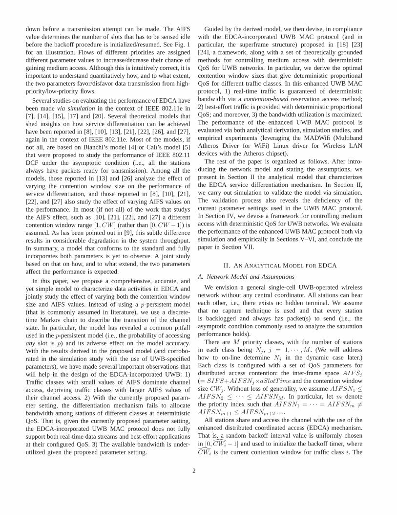
Before delving into the derivation, we make the followingobservation. Figure 10 depicts the system throughput as afunction of the contention window size (CW) in the case ofone traffic class (N = 5, 10, 20 and 50). As shown in Fig. 10(and as mentioned earlier), the analytical results derived underthe proposed model agree very well with the simulation results,but those derived under the p-persistent model (which assumethat all the stations independently access to any slot with afixed probability) fails to do so. Nevertheless, both modelsgive approximately the same optimal value of CW at whichthe system throughput is maximized. This is not a coincidence,because at the operational point where the maximal throughputis achieved (e.g., CW = 20 when N = 5), the channel is notoverly congested and the peculiar effect of the access patternto the post-busy slot has not yet became significant. Similartrends have also been observed in the case of multiple trafficclasses. This observation suggests that as far as derivation ofthe optimal congestion window size is concerned, one canleverage the p-persistent model, subject to the proportionalconstraint Eq. (15). (We will further validate this conjecturein the simulation study in Section V.)
In the p-persistent model, stations of class j transmit in aslot independently and uniformly with probability τj . Giventhe contention window size CWj , τj can be calculated as τj =
2CWj+1 . Then the stationary probabilities of channel states, i.e.,the idle state, the successful class-j transmission state, and thecollision state, can be readily derived as
PI =∏j=1
(1 − τj)Nj = AM , (16)
PSj= Nj
τj
1 − τjAM , (17)
PC = 1 − PI −M∑
j=1
PSj. (18)
For ease of exposition, we assume that the size of all dataframes is a constant, and thus the duration of a successful trans-mission and a collision period are the same (i.e., TD = TC).(The assumption can be relaxed with modest modification.)Plugging the above stationary probabilities into Eqs. (12) and
9
0 100 200 300 400 5000
0.05
0.1
0.15
0.2
0.25
0.3
0.35
Contention window size
Thr
ough
put (
norm
aliz
ed)
p−persistent modelOur proposed modelSimulation
N = 5
N = 50
N = 20
N = 10
Fig. 10. The relationship between the saturationthroughput and the contention window size. Thereis only one class in the system. N is the numberof nodes.
0 5 10 15 20 25 30 35 40 45 500
0.1
0.2
0.3
0.4
0.5
0.6
0.7
0.8
0.9
1
Number of nodes in each class
Thr
ough
put r
atio
Expected ratioAnalyticalSimulation
Ratio of class2 / class1
Ratio of class3 / class1
0 100 200 300 400 500 600 700 8000
0.05
0.1
0.15
0.2
0.25
0.3
0.35
Contention window size of class 1
Thr
ough
put (
norm
aliz
ed)
Theoretical optimal pointsSimulationOur proposed model
N = [5, 5]
N = [50, 50]
N = [20, 20]
N = [10, 10]
(a) (b)
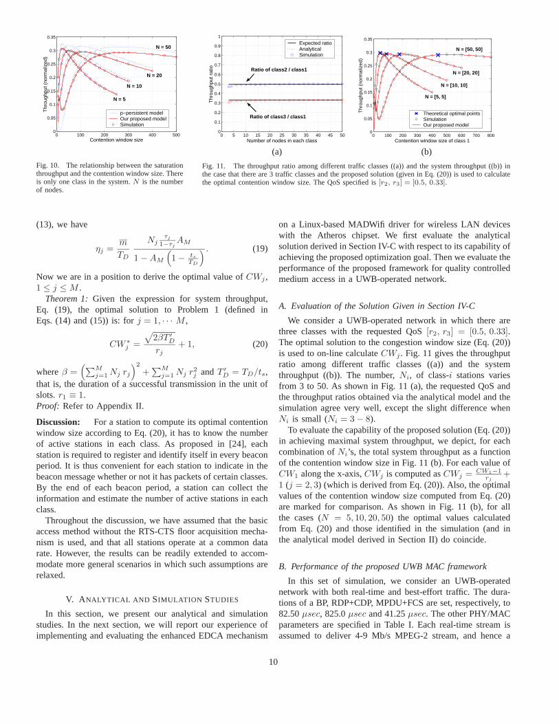
Fig. 11. The throughput ratio among different traffic classes ((a)) and the system throughput ((b)) inthe case that there are 3 traffic classes and the proposed solution (given in Eq. (20)) is used to calculatethe optimal contention window size. The QoS specified is [r2, r3] = [0.5, 0.33].
(13), we have
ηj =m
TD
Njτj
1−τjAM
1 − AM
(1 − ts
TD
) . (19)
Now we are in a position to derive the optimal value of CWj ,1 ≤ j ≤ M .
Theorem 1: Given the expression for system throughput,Eq. (19), the optimal solution to Problem 1 (defined inEqs. (14) and (15)) is: for j = 1, · · · M ,
CW ∗j =
√2βT ′
D
rj+ 1, (20)
where β =(∑M
j=1 Nj rj
)2
+∑M
j=1 Nj r2j and T ′
D = TD/ts,that is, the duration of a successful transmission in the unit ofslots. r1 ≡ 1.Proof: Refer to Appendix II.
Discussion: For a station to compute its optimal contentionwindow size according to Eq. (20), it has to know the numberof active stations in each class. As proposed in [24], eachstation is required to register and identify itself in every beaconperiod. It is thus convenient for each station to indicate in thebeacon message whether or not it has packets of certain classes.By the end of each beacon period, a station can collect theinformation and estimate the number of active stations in eachclass.
Throughout the discussion, we have assumed that the basicaccess method without the RTS-CTS floor acquisition mecha-nism is used, and that all stations operate at a common datarate. However, the results can be readily extended to accom-modate more general scenarios in which such assumptions arerelaxed.
V. ANALYTICAL AND SIMULATION STUDIES
In this section, we present our analytical and simulationstudies. In the next section, we will report our experience ofimplementing and evaluating the enhanced EDCA mechanism
on a Linux-based MADWifi driver for wireless LAN deviceswith the Atheros chipset. We first evaluate the analyticalsolution derived in Section IV-C with respect to its capability ofachieving the proposed optimization goal. Then we evaluate theperformance of the proposed framework for quality controlledmedium access in a UWB-operated network.
A. Evaluation of the Solution Given in Section IV-C
We consider a UWB-operated network in which there arethree classes with the requested QoS [r2, r3] = [0.5, 0.33].The optimal solution to the congestion window size (Eq. (20))is used to on-line calculate CWj . Fig. 11 gives the throughputratio among different traffic classes ((a)) and the systemthroughput ((b)). The number, Ni, of class-i stations variesfrom 3 to 50. As shown in Fig. 11 (a), the requested QoS andthe throughput ratios obtained via the analytical model and thesimulation agree very well, except the slight difference whenNi is small (Ni = 3 − 8).
To evaluate the capability of the proposed solution (Eq. (20))in achieving maximal system throughput, we depict, for eachcombination of Ni’s, the total system throughput as a functionof the contention window size in Fig. 11 (b). For each value ofCW1 along the x-axis, CWj is computed as CWj = CW1−1
rj+
1 (j = 2, 3) (which is derived from Eq. (20)). Also, the optimalvalues of the contention window size computed from Eq. (20)are marked for comparison. As shown in Fig. 11 (b), for allthe cases (N = 5, 10, 20, 50) the optimal values calculatedfrom Eq. (20) and those identified in the simulation (and inthe analytical model derived in Section II) do coincide.
B. Performance of the proposed UWB MAC framework
In this set of simulation, we consider an UWB-operatednetwork with both real-time and best-effort traffic. The dura-tions of a BP, RDP+CDP, MPDU+FCS are set, respectively, to82.50 µsec, 825.0 µsec and 41.25 µsec. The other PHY/MACparameters are specified in Table I. Each real-time stream isassumed to deliver 4-9 Mb/s MPEG-2 stream, and hence a
10

station with real-time traffic makes reservation for at most 9Mb/s bandwidth when the real-time stream arrives. The tunableparameters for real-time traffic are set to [CWmin, CWmax] =[8, 16], and AIFSN = 2. The AIFS value for best-efforttraffic of all classes is set to AIFSN = 3 and the CW valuesof different classes are on-line calculated in compliance withEq. (20). There are two traffic classes for best-effort traffic,with the number of class i stations being 10. (Similar trendshave been observed when the number of class i stations is setto other values.) Each simulation run lasts for 200 simulationseconds.
Performance in the presence of two classes of best-efforttraffic and one real-time stream: Fig. 12 depicts the totalthroughput and the throughput attained by each class in thepresence of two classes of best-effort traffic and a real-timestream. The real-time stream is active in the period of [50s,150s]. As shown in Fig. 12, the real-time stream is allocatedmost of the bandwidth in [50s, 150s], while the best-efforttraffic uses the remaining bandwidth. The bandwidth allocatedfor the real-time stream is 41.25·10−6
(82.50+825.0)·10−6 × 200 · 106 ≈9(Mb/s). No matter whether or not the real-time stream isactive, the best-effort traffic shares the remaining bandwidth ina deterministic proportional manner (as specified by r3/2).
Performance in the presence of two classes of best-efforttraffic and two groups of real-time streams: Fig. 13gives the total throughput and the throughput attained byeach class in the presence of two real-time streams and twoclasses of best-effort traffic. The first group of real-time streamsoriginates from 5 nodes, becomes active at 50s and terminatesafter 100s. The second group of real-time streams originatesfrom another 5 nodes, becomes active at 70s and terminatesafter 60 seconds.
As shown in Fig. 13, with this communication pattern, wehave five intervals in the entire simulation time. In [0, 50s], thebest-effort traffic of two different classes shares the availablebandwidth according to the specified QoS (r3/2); in [50s, 70s],the first group of real-time streams join to acquire bandwidth,with the best-effort traffic of two different classes sharing theremaining bandwidth in CDPs, again according to the specifiedQoS; in [70s, 130s], the second group of real-time streamsjoin, and together with the first group, acquire most of thebandwidth. The best-effort traffic of two different classes isallocated the remaining small bandwidth in a deterministicproportional manner; in [130s, 150s], the best-effort trafficis allocated more bandwidth since the second group of real-time traffic streams terminates; Finally, in [150s, 200s], thebest-effort traffic is allocated the entire available bandwidth.Even in the presence of real-time traffic, best-effort traffic oftwo different classes is allocated bandwidth in a deterministicproportional manner (as specified by r3/2).
VI. EMPIRICAL STUDY
We have developed an experimental prototype to validate theanalytical and simulation results, to demonstrate the practicality
of the enhanced EDCA algorithm, and to understand imple-mentation issues of integrating the algorithm into the currentIEEE 802.11 protocol family. We first summarize how weimplement an experimental prototype of the enhanced EDCAmechanism (that includes the service differentiation algorithmdescribed in Section IV-C) on a Linux-based MADWifi driverfor wireless LAN devices with the Atheros chipset. (Note thatas no UWB chipsets and drivers are commercially available onthe market, we can only implement our proposed frameworkon a WiFi device. Fortunately the chosen chipset does notrequire loading of IEEE 802.11-specific firmware, but insteadrelies on a Hardware Access Layer (HAL) module that allowschanges of several device parameters through its well-definedinterface. This allows us to readily implement the enhancedEDCA mechanism.) Then we present representative empiricalresults.
A. Developing an Experimental Prototype
We have leveraged the Linux-based MADWifi (MultibandAtheros Driver for WiFi) driver for wireless LAN devices withthe Atheros chipset, and implemented much of the functionalityof the enhanced EDCA mechanism. The major reason we chosethis chipset is that it fulfills most of the criteria necessary toimplement the proposed change. A majority of other drivers,including those developed for Intel and Prism chipsets, requirea specific firmware. As the firmware implements much ofthe device functionality, such as enforcing radio regulations,allowing the device to act as an access point, and handlingIEEE 802.11 management [25], the use of firmware typicallyrestricts any modifications to operating parameters.
The Atheros hardware, on the other hand, does not requireloading of firmware, but instead relies on a Hardware Ac-cess Layer (HAL) module that is provided in a binary-onlyform. The HAL module operates between the hardware anddriver to manage much of the chip-specific operations and toenforce the required FCC regulations. The HAL is similarto firmware in that it ensures that users do not set invalidoperating parameters, but implements less functionality thanother firmware and actually provides an interface that allowschanges of various device parameters, including the minimumand maximum contention windows. The only restriction thatHAL enforces on the contention windows is that their valuesmust be set to 2x − 1, where 1 ≤ x ≤ 11. Therefore,the contention window value calculated from Eq. (20) inSection IV-C must be approximated. Another advantage of theAtheros chipset is that, because the chipset is basic, most of theMAC functionality is handled in the driver, as opposed to thefirmware. Therefore, the IEEE 802.11 MAC protocol, includingthe state machine and protocol support, can be easily modifiedto support the enhanced EDCA mechanism.
How to support floating point operations: Apart fromseveral low-level implementation details (which the interestedreader is referred to [6]), there are two major implementationissues that arises in the course of prototype implementation.
11

0
0.2
0.4
0.6
0.8
1
0 50 100 150 200
Thr
ough
put (
norm
aliz
ed)
Time (s)
Total Class 1: Real-TimeClass 2: Best-Effort (high)Class 3: Best-Effort (low)
0
0.2
0.4
0.6
0.8
1
0 50 100 150 200
Thr
ough
put (
norm
aliz
ed)
Time (s)
Total Class 1: Real-TimeClass 2: Best-Effort (high)Class 3: Best-Effort (low)
(a) QoS specification: r3/2 = 0.5 (b) QoS specification: r3/2 = 0.25
Fig. 12. The total throughput and the throughput attained by each class in the presence of two classes of best-effort traffic and a real-time stream.
0
0.2
0.4
0.6
0.8
1
0 50 70 100 130 150 200
Thr
ough
put (
norm
aliz
ed)
Time (s)
Total Class 1: Real-TimeClass 2: Best-Effort (high)Class 3: Best-Effort (low)
0
0.2
0.4
0.6
0.8
1
0 50 70 100 130 150 200
Thr
ough
put (
norm
aliz
ed)
Time (s)
Total Class 1: Real-TimeClass 2: Best-Effort (high)Class 3: Best-Effort (low)
(a) QoS specification: r3/2 = 0.5 (b) QoS specification: r3/2 = 0.25
Fig. 13. The total throughput and the throughput attained by each class in the presence of two real-time streams and two classes of best-effort traffic.
First, floating point operations (such as sqrt) are requiredin the enhanced EDCA mechanism, but the kernel driversdo not contain floating point operation routines. There are anumber of possible solutions, including using a lookup tableor adapting the floating point unit and emulation code in thekernel. They were found to be not viable. In the former casethe lookup table would be extremely large in order to store allthe possible values. In the latter case, even if the floating-pointunit and emulation code are adapted correctly in the kernel,a separate math library would have to be written because theC runtime library cannot be used inside the kernel. Therefore,in order to realize the necessary functionality and to ensurethat only essential, performance-critical code is implementedin the kernel, we have divided the EDCA implementation intokernel and user-space components such that all floating-pointoperations are performed in the user-space. The practice ofsplitting the implementation between kernel and user-space isquite common in Linux.
Given that the prototype must be divided between thekernel and user-space, the two components must be able tocommunicate with each other. As described in Section IV-C,
each station has to estimate the number of active stations ineach class, and send the estimated result to the user-space. Theuser-space component will then calculate the new contentionwindow for each class, and instrument the HAL in the kernel-space to set the parameters accordingly. Linux provides variousmethods for interprocess communication between kernel anduser-space components, such as system calls, ioctl calls, ornetlink sockets. As system calls and ioctl calls do not allowthe kernel to initiate communication with the user-space. for theuser-space component to remain synchronized with the kernel-space component, it must continually poll the kernel, which hasbeen tested (in our experiment) to be inefficient. Instead, weleverage the netlink socket facility, as it provides a full-duplex,bi-directional link between the kernel and user-space compo-nents, thereby allowing the kernel to initiate communicationwith the user-space component whenever necessary.
How to include additional information required by EDCAwith consideration of backward compatibility: The sec-ond implementation issue is that, to support on-line compu-tation of optimal contention window sizes, each station mustknow the number of active stations in each class in the system.
12

TABLE II
RELEVANT PARAMETERS USED BY THE ATHEROS DRIVER.
tslot 20 µsSIFS 10 µsDIFS 50 µsPLCP Data Rate 1 MbpsPreamble Length 18 bytesPLCP Header Length 6 bytesData Rate 11 MbpsMAC Header Length 28 bytesACK Length 14 bytes
Although new fields can be introduced into the IEEE 802.11MAC header of data and management frames, we have decidednot to do so, to ensure as few code changes as possible andbackward compatibility with stations that do not employ theenhanced EDCA mechanism.
Instead, we will place the needed information in the body ofa beacon frame. As defined in [11], the body of a beacon frameconsists of fixed fields, which are mandatory and fixed-length,and information elements, which are variable-length and maybe mandatory or optional. Information elements are defined tohave a common general format consisting of a 1 octet ElementID field, a 1 octet length field, and a variable-length element-specific information field, whose length is specified in thelength field. We decide that the Information element is idealfor placing the additional information because it can supporta variable number of service classes, and a majority of theelement ids are not being used. Also, it is legitimate to includeoptional information elements in a beacon frame body, and ifthe MAC protocol does not support an information element, itis simply ignored.
B. Empirical Results
The network topology used for the empirical study consistsof two mobile stations and one AP (Access Point) that werewithin four feet of each other. Each station runs Fedora Core2 with the Linux 2.6.9 kernel. Each station had a CBR trafficsource that generates 500-byte UDP packets and send thepackets to the AP at a rate high enough to keep its systembuffer full. The stations starts transmitting packets immediatelyafter they associate with the AP. Table II summarizes therelevant parameters used by the Atheros driver.
For each experiment, the total system throughput, thethroughput attained by each station, and the throughput ratio ofthe two stations are shown. In the course of collecting statistics,we ignore the first few seconds in each experiment becauseeach station may not always have a packet to send while thetraffic source attempts to fill the station’s system buffer tocapacity (i.e., the asymptotic condition may not hold). Unlessotherwise stated, each set of results is the average of 20 runsof the experiments, where each run lasts 100 seconds and eachstation updates its traffic classes every 0.5 second. Although awide variety of scenarios have been tested, due to the spacelimit, we report below two sets of representative results.
Performance in the presence of two traffic classes withconstant traffic sources: In this set of experiments, both theclass-1 and class-2 stations are active during the entire durationof the experiment. Fig. 14 shows the throughput results whenr2 = 4. The total system throughput was kept high and steadyduring the duration of the experiment, and the throughput ratiobetween the two traffic classes was fairly close to the specifiedvalue.
Performance in the presence of two traffic classes withon-off traffic sources: In this set of experiments, only theclass-2 station is active during the entire experiment. The class-1 station sends packets in an on-off manner, with the durationof its on and off periods being set to ∼ 20 sec.
Fig. 15 shows the throughput results when r12 = 4. Note thatwhen the class-1 station is inactive, the bandwidth is allocatedto the class-2 station. The throughput ratio is kept reasonablyclose to 4, and the total channel throughput remains fairlyhigh during the entire experiment, regardless of the changesin the number of active stations. Note, however, that thereis a slight decrease in the total channel throughput when theclass-1 station is inactive. This is because the class-1 station isassigned a CW value of 3 when both stations are active, and theclass-2 station is assigned a CW value of 7 when the class-1station is inactive. As a result, during the inactive periods, eventhough the class-2 station has no other station to contend with,it cannot achieve as high a throughput because of its longerbackoff time.
Possible sources of error: Although the above results showthat the enhanced EDCA mechanism performs reasonably wellunder various scenarios, the throughput ratio between the twoclasses could have been closer to the specified QoS. The erroris, in part, attributed to the fact that the HAL module of theAtheros driver places restrictions on the value of CWmin: thevalue calculated by Eq. (20) must be rounded to the closest2x − 1 value, where 1 ≤ x ≤ 11. Another possible sourceof error is that these experiments were not performed in aclosed environment. As a result, nearby stations and APs alsocontended for channel access. In our experiments, each stationreceived, on average, approximately 40-50 beacon packets persecond from nearby APs.
VII. CONCLUSION
The EDCA mechanism has been proposed by MultiBandOFDM Alliance [18] to support service differentiation inUWB-operated WPANs. EDCA achieves service differentiationessentially by configuring different traffic classes with differentcontention window sizes and AIFS values. In this paper, wehave conducted a rigorous, comprehensive, and theoreticalanalysis of the EDCA mechanism, and have shown that withthe currently recommended parameter setting, EDCA cannotprovide deterministic proportional QoS. In particular, stationsof a high-priority class (i.e., with a small AIFS value) will dom-inate the channel access, depriving stations of the other classesthe chance to access the channel. Also, without responding to
13

0
0.5
1
1.5
2
2.5
3
3.5
4
4.5
5
0 10 20 30 40 50 60 70 80 90 100
Thr
ough
put [
Mbp
s]
Time [sec]
TotalClass 1Class 2
0
1
2
3
4
5
6
0 10 20 30 40 50 60 70 80 90 100
Thr
ough
put R
atio
Time [sec]
(a) Throughput (b) Throughput ratio
Fig. 14. Throughput attained by two traffic classes with constant traffic sources. r12 = 4.
0
1
2
3
4
5
0 10 20 30 40 50 60 70 80 90 100
Thr
ough
put [
Mbp
s]
Time [sec]
TotalClass 1Class 2
0
1
2
3
4
5
6
0 10 20 30 40 50 60 70 80 90 100
Thr
ough
put R
atio
Time [sec]
(a) Throughput (b) Throughput ratio
Fig. 15. Throughput attained by two traffic lasses with on-off traffic source. r12 = 4.
the system dynamics (e.g., taking into account of the numberof active class-i stations), EDCA cannot allocate bandwidth ina deterministic proportional manner and the system bandwidthis under-utilized.
After identifying the deficiency of EDCA in service dif-ferentiation, we propose, in compliance with the EDCA-incorporated UWB MAC protocol proposed in [18] [23] [24], aframework, along with a set of theoretically grounded methodsfor controlling medium access with deterministic QoS forUWB networks. In this framework, 1) real-time traffic isguaranteed of deterministic bandwidth via a contention-basedreservation access method; 2) best-effort traffic is providedwith deterministic proportional QoS; and moreover, 3) thebandwidth utilization is maximized. The performance of theproposed framework has been validated and evaluated in ana-lytic, simulation, and empirical studies.
As mentioned in Section IV-B, to prevent best-effort trafficfrom starvation, the system should be configured to controlthe maximum RDP duration in a superframe, thus ensuring acertain portion of bandwidth for best-effort traffic. This entailsadmission control of real-time traffic. As part of our futurework, we will design an auxiliary admission control protocolthat determines when and for how long real-time streams can
reserve certain amount of bandwidth. Also, we have focusedin this work service differentiation (for best-effort traffic) inthe form of deterministic proportional bandwidth allocation.It would be interesting to extend the work to accommodateservice differentiation in the form of statistical end-to-enddelay guarantees.
REFERENCES
[1] IEEE 802.15.3 specification. http://www.ieee802.org/15/pub/TG3.html.[2] MultiBand OFDM Alliance SIG, MultiBand OFDM physical layer
proposal for IEEE 802.15 task group 3a, Sept. 2004.[3] IEEE 802.11e/d13.0. Draft Supplement to Part 11: Wireless Medium
Access Control (MAC) and physical layer (PHY) specifications: MACEnhancements for Quality of Service (QoS), Jan. 2005.
[4] G. Bianchi. Performance analysis of the IEEE 802.11 distributedcoordination function. IEEE JSAC, 18(3), Mar. 2000.
[5] F. Cali, M. Conti, and E. Gregori. Dynamic tuning of the IEEE 802.11protocol to achieve a theoretical throughput limit. IEEE/ACM Trans. onNetworking, 8(6), Dec. 2000.
[6] D. Chi. Design and implementation of the generic wireless device driverlayer to support QoS provisioning. Master’s thesis, University of Illinoisat Urbana-Champaign, Aug. 2005.
[7] S. Choi, J. del Prado, S. Shankar, and S. Mangold. IEEE 802.11econtention-based channel access (EDCF) performance evaluation. InProc. of IEEE ICC, May 2003.
[8] Y. Ge. QoS provisioning for IEEE 802.11 MAC protocols. Ph.D Thesis,University of Ohio State, 2004.
14

[9] C. Hu, H. Kim, and J. C. Hou. An analysis of the binary exponentialbackoff algorithm in distributed MAC protocols. In Tech. Rep. No.UIUCDCS-R-2005-2599. http://lion.cs.uiuc.edu/∼chunyuhu, July 2005.
[10] J. Hui and M. Devetsikiotis. Performance analysis of IEEE 802.11eEDCA by a unified model. In Proc. of GLOBECOM, Nov. 2004.
[11] IEEE Computer Society. IEEE standard 802.11: wireless LAN mediumaccess control (MAC) and physical layer (PHY) specifications. TheInstitute of Electrical and Electronics Engineers, New York, NY, 1997.
[12] N. Laurenti and P. Toniolo. Performance of the multi-band OFDM UWBsystem with time-varying channels. In Proc. of WPMC, Sept. 2004.
[13] B. Li and R. Battiti. Performance analysis of an enhanced IEEE 802.11distributed coordination function supporting service differentiation. InQuality for All, QofIS, 2003.
[14] A. Lindgren, A. Almquist, and O. Schelen. Evaluation of quality ofService schemes for IEEE 802.11 wireless LANs. In Proc. of IEEELCN, Nov. 2001.
[15] A. Lindgren, A. Almquist, and O. Schelen. Quality of service schemesfor IEEE 802.11 wireless lans - an evaluation. In Special Issue of theJournal on Special Topics in MONET on Performance Evaluation of QoSArchitectures in Mobile Networks, 8(3), June 2003.
[16] K. Lu, D. Wu, Y. Fang, and R. C. Qiu. On medium access control forhigh data rate ultra-wideband ad hoc networks. In Proc. of IEEE WCNC,Mar. 2005.
[17] S. Mangold, S. Choi, P. May, and G. Hiertz. IEEE 802.11e - fair resourcesharing between overlapping basic service sets. In Proc. of IEEE PIMRC,Sept. 2002.
[18] MBOA. Distributed medium access control (MAC) for wireless net-works. Draft specification 0.93, Feb. 2005.
[19] R. Merz, J.-Y. L. Boudec, J. Widmer, and B. Radunovic. A rate-adaptiveMAC protocol for low-power ultra-wide band ad-hoc networks. In Proc.of Ad-Hoc Now, July 2004.
[20] D. Pong and T. Moors. Call admission control for IEEE 802.11contention access mechanism. In Proc. of IEEE GLOBECOM, Dec.2003.
[21] V. Ramaiyan and A. Kumar. Fixed point analysis of single cell IEEE802.11e WLANs: Uniqueness, multistability and throughput differentia-tion. In Proc. of ACM SIGMETRICS, June 2005.
[22] J. W. Robinson and T. S. Randhawa. Saturation throughput analysis ofIEEE 802.11e enhanced distributed coordination function. IEEE JSAC,22(5), 2004.
[23] J. D. Sai Shankar N, V. Gaddam and K. Challapali. The new MBOAMAC specification: A distributed MAC protocol and OFDM based PHYfor next generation WPANs.
[24] S. Shankar, J. del Prado Pavon, V. G, and K. Challapali. Performanceevaluation of the multiband OFDM alliance (MBOA) specification: Adistributed MAC protocol and OFDM PHY layer for next generationultra wide band (UWB) WPANs. In submission, 2005.
[25] J. Tourrilhes. Linux wireless LAN howto.http://www.hpl.hp.com/personal/Jean Tourrilhes/Linux/Linux.Wireless.pdf,January 2005.
[26] Y. Xiao. An analysis for differentiated service in IEEE 802.11 and IEEE802.11e wireless LANs. In Proc. of IEEE ICDCS, Mar. 2004.
[27] J. Zhao, Z. Guo, Q. Zhang, and W. Zhu. Performance study of MAC forservice differentiation in IEEE 802.11. In Proc. of GLOBECOM, 2002.
APPENDIX ILEMMA 1 AND LEMMA 2
Lemma 1: Given the Markov chain described in Section II(Fig. 2), the transition probability from state Caj
, j =m, · · · ,M to state Ia1 can be approximately expressed as
P [Caj → Ia1 ] =1
P [Ik → Su]
{Bm − Aj
[1 +
m∑k=1
Nkτk
1 − τk
(1 − 1
CWk
)
+
j∑k=m+1
Nkτk
1 − τk
⎤⎦⎫⎬⎭ . (21)
Proof: P (Caj→ Ia1) is the probability that the post-
busy slot after a collision slot Cajis idle. For notational
convenience, tag the collision slot and its post-busy slot byslot1 and slot2, respectively. Let Ej denote the event that(n1, n2, · · · , nj) stations transmit in slot1, where nk (nk =0, 1, · · · , Nk) is the number of stations in class k. We have
P [Caj → Ia1 ] = P[slot2 is idle, given slot1 is a collision of Caj
]=∑n1
∑n2
· · ·∑nj︸ ︷︷ ︸∑j
k=1 nk≥2
P [slot2 is idle |Ej ] P[Ej | slot1 is Caj
].
(22)
Given the event Ej , slot2 is idle if and only if none of thestations of the first m classes transmit in slot2. Therefore,
P [slot2 is idle |Ej ] =m∏
k=1
(1 − 1
CWk
)nk
. (23)
To compute precisely the probability P(Ej |slot1 is Caj
)it is necessary to enumerate the channel states and expandthe channel state space S into (n1, n2, · · · , nM ). Hence, weleverage the fact that the channel state immediately followinga busy period is mostly likely to be the idle state, becauseonly nodes that are involved in the busy period will contend inthe post-busy slot (slot2). Based on this argument (which wascollaborated by the simulation results), we have
P[Ej | slot1 is Caj
]=
1
P [Ik → Su]
j∏k=1
(Nk
nk
)τk
nk (1 − τk)Nk−nk .
(24)
Plugging Eqs. (23) and (24) into Eq. (22), and after performingsome algebraic operations, (21) follows.
Lemma 2: Given the Markov chain described in Section II(Fig. 2), the transition probability from state Caj
, j =m, · · · ,M to state Su (u ≤ m) can be approximately ex-pressed as
P[Caj
→ Su
]=
1P [Ik → Su]
Nuτu
CWu
(Bm
1 − τu
CWu
− Aj
τu
).
(25)
Proof: Following the notation defined in theproof of Lemma 1, P [Caj
→ Su] is the probabilityP [slot2 is a successful trans. of class u|slot1 is a collision Caj
],or simply P [slot2 is Su|slot1 is Caj
]. By conditioning on the
15

event Ej , we have
P[Caj →Su
]=∑n1
∑n2
· · ·∑nj︸ ︷︷ ︸∑j
k=1 nk≥2
P [slot2 is Su|Ej ] P[Ej | slot2 is Caj
].
(26)
A successful transmission of class u follows a collision of Caj
if and only if only one station of class u chooses to transmitin slot2 with probability 1
CWu. That is,
P [slot2 is Su|Ej ]
= nu1
CWu
(1 − 1
CWu
)nk−1 m∏k=1,k �=u
(1 − 1
CWk
)nk
=nu
CWu − 1
m∏k=1
(1 − 1
CWk
)nu
. (27)
The probability P[Ej |slot1 is Caj
]is the same as Eq. (24). Plugging
Eqs. (27) and (24) into Eq. (26), we can derive P[Caj → Su
]as
given in Eq. (25).
APPENDIX IIPROOF OF THEOREM 1
Theorem 1: Given the expression for system throughput,Eq. (19), the optimal solution to Problem 1 (defined inEqs. (14) and (15)) is: for j = 1, · · · M ,
CW ∗j =
√2βT ′
D
rj+ 1, (28)
where β =(∑M
j=1 Nj rj
)2
+∑M
j=1 Nj r2j and T ′
D = TD/ts,that is, the duration of a successful transmission in the unit ofslots. r1 ≡ 1.
Proof: The throughput by class j (Eq. (19)) is
ηj =m
TD
Njτj
1−τjAM
1 − AM
(1 − ts
TD
) ,
where m, ts and TD are constant variables, representing theaverage packet size, the length of an idle slot and the durationof a successful transmission, respectively. AM =
∏Mh=1(1 −
τh)Nh as defined in Eq. (1).
Let x∆= τ1
1−τ1, α
∆= mTD
, and θ = 1 − ts
TDand A
∆= AM .Then we can further simplify the above equation as
ηj = αNj
τj
1−τjA
1 − θA. (29)
To fulfill the proportional bandwidth allocation requirementEq. (15), we have
rj =ηj
Nj/
η1
N1=
τj
1 − τj
1x
⇒ τj =rj x
1 + rj x. (30)
The total system throughput is the summation of the throughputachieved by each class, i.e.,
η =M∑
j=1
ηj = αM∑
j=1
Nj rjxA
1 − θA
=
⎛⎝αM∑
j=1
Nj rj
⎞⎠ x1A − θ
. (31)
By Eq. (30), we have 1 − τj = 1 − rj x1+rj x = 1
1+rj x , and
A =M∏
j=1
(1 − τj)Nj =1∏M
j=1 (1 + rj x)Nj. (32)
Using the Taylor series to approximate A, we have
(A−1)(x) = 1 − d0 x + d1 x2 + o(x2)
= 1 − d0 x + d1 x2, (33)
where
d0 = −(A−1)′(0) =M∑
j=1
Nj rj , (34)
d1 = (A−1)′′(0) =12
⎡⎢⎣⎛⎝ 2∑
j=1
Nj rj
⎞⎠2
+M∑
j=1
Nj r2j
⎤⎥⎦ . (35)
The total system throughput can then be expressed in terms ofx:
η(x) = αd0x
1 − d0x + d1x2 − θ=
αd0
1−θx − d0 + d1x
. (36)
Let the denominator of the above equation be defined asy(x) ∆= 1−θ
x − d0 + d1x. By setting dy(x)dx = 0, we have
x∗ =√
1−θd1
=√
2βT ′
D(where the second equality results from
1 − θ = ts
TD= 1
T ′D
and d1 = 12β). Note that d2y(x)
dx2 > 0, i.e.,y(x) is minimized at x∗.
From the two relations, τ1 = 2CW1+1 and x = τ1
1−τ1, it is
easy to obtain CW1 = 2x +1. Therefore, the system throughput
η(x) is maximized at
CW ∗1 =
√2βT ′
D + 1, (37)
and the proportional bandwidth allocation is achieved at
CW ∗j =
√2βT ′
D
rj+ 1, (38)
for j = 2, · · · ,M .
16
Related Documents


![Project: IEEE P802.15 Working Group for Wireless Personal Area Networks (WPANS) Submission Title: [ Wideband Antenna Design for UWB System ] Date Submitted:](https://static.cupdf.com/doc/110x72/5514b78a550346ea6e8b64c1/project-ieee-p80215-working-group-for-wireless-personal-area-networks-wpans-submission-title-wideband-antenna-design-for-uwb-system-date-submitted.jpg)


![TC241 Novel Technique for Locating an Intruder in 3D ... · PDF fileThese radars use UltraWideBand (UWB) pulses [1] ... rod radius is 7,5 mm , ... A system based on z-polarized cuboid](https://static.cupdf.com/doc/110x72/5a8fdac17f8b9a4a268dee92/tc241-novel-technique-for-locating-an-intruder-in-3d-radars-use-ultrawideband.jpg)