Columbia University Unit 2: SystemVerilog for Design Adam Waksman Simha Sethumadhavan

Welcome message from author
This document is posted to help you gain knowledge. Please leave a comment to let me know what you think about it! Share it to your friends and learn new things together.
Transcript

Columbia University
Unit 2: SystemVerilog for Design
Adam Waksman Simha Sethumadhavan

Columbia University
Hardware Description Languages (HDLs)
• Hardware life-cycle (8 steps) • Specification
• High level specification • Architecture • Microarchitecture
• HDL Design • HDL Validation • Synthesis • Layout • Fabrication (physical process)

Columbia University
Hardware Description Languages (HDLs)
• HDLs serve two different purposes • Hardware Design
• Code defines the functionality of the hardware design
• Design Validation • Creates a binary executable for validation/simulation
• Commercial tools automatic part of the process • Synthesis
• Done automatically by compiler (Synopsys VCS)
• Layout • Done with automated tools (Synopsys or Cadence)
Computer Hardware Design

Columbia University
Flavors of SystemVerilog
• Structural SystemVerilog • Low level, specify logic gates
• Guaranteed to synthesize
• Behavioral SystemVerilog • Higher level language constructs
• Not guaranteed to synthesize
• For this class • Use behavioral SystemVerilog • Be careful of synthesizability • All code should either:
• Be synthesizable • Be explicitly for validation

Columbia University
Language Basics Outline
• Basic Types and Style • SystemVerilog Primitives
• Basic Data Types
• Assign and Always
• Building Larger Components • Parameters and Instantiation
• Conditional Statements
• Advanced Data Types
• Advanced Example

Columbia University
SystemVerilog Primitives (pg. 37)
• Each primitive represents a signal carried by a wire • 0: Clear digital 0 • 1: Clear digital 1 • X: Means either “don’t know” or “don’t care”
• Useful for debugging • Also useful for ‘don’t care’ bits in logic
• Z: High impedance, non-driven circuit • Value is not clearly 0 or 1 • Useful for testing, debugging, and tri-state logic
• Constants/Multi-bit primitives • All wires carrying the same value
• ‘1, ‘0, ‘z, ‘x
• Specific values • 16’b1100101011111110 • 16’d51966 • 16’hcafe
• Sets – example, odd numbers • 16’bxxxxxxxxxxxxxxx1

Columbia University
Basic Data Types: Wire (pg. 43)
• Wire (4-state variable) • Generic wire, can carry any signal (0, 1, x, z) • No semantic type safety between wires
• Any wire can connect to any wire
• Almost anything will compile • Including dangling wires, fused wires
• Use “assign” keyword to store a value • wire x; • assign x = ‘1;
• Can assign one wire to another • Wire x; • Assign x = y;
Columbia University
Basic Data Types: Wire (pg.43)
• Assignment • Assignments are permanent (think physical wires) • All assignments happen continuously and in parallel
• This is incorrect code • Cannot assign two values to ‘wire a’ • SystemVerilog is not declarative
• The compiler won’t warn you • Validation might catch this
wire a, b; assign a = 1’b1; assign b = a; assign a = 1’b0;

Columbia University
Basic Data Types: Wire (pg.43)
• Splitting wires, accessing subsets • Wires can be arbitrarily wide • Subsets accessed with [x:y] (0-based)
• Can access a region or a single bit
• Example: Decoder
wire [31:0] myInt; wire [63:0] myLong; assign myLong [31:0] = myInt; assign myLong [63:32] = ‘0;
wire [31:0] value; wire fifthBit; // 0-based (this is the sixth bit 1-based) assign fifthBit = value[5];
wire [31:0] instruction; wire [5:0] opcode; assign opcode = instruction[31:26];
Columbia University
Basic Data Types: Input, Output, Module (pg. xxv)
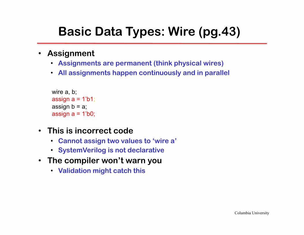
• Inputs and outputs – Inputs are wires that come in from the “outside world”
– Outputs are wires that go out to the “outside world”
• Module – One discrete piece of hardware
– Can be instanced multiple times
Computer Architecture Lab
module adder(a, b, cin, cout, s); input a, b, cin; output cout, s; assign s = a ^ b ^ cin; assign cout = (a & b) | (a & cin); | (b & cin); endmodule
input wire output
module
Columbia University
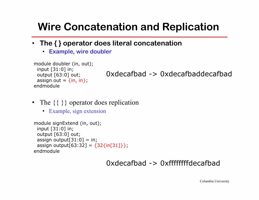
Wire Concatenation and Replication
• The { } operator does literal concatenation • Example, wire doubler
• The {{ }} operator does replication
• Example, sign extension module signExtend (in, out); input [31:0] in; output [63:0] out; assign output[31:0] = in; assign output[63:32] = {32{in[31]}}; endmodule
module doubler (in, out); input [31:0] in; output [63:0] out; assign out = {in, in}; endmodule
0xdecafbad -> 0xdecafbaddecafbad
0xdecafbad -> 0xffffffffdecafbad

Columbia University
Basic Data Types: logic (pg.43)
• Logic – Can be assigned values with the = operator
– Do not synthesis actual state, only logic
• Always blocks (always_comb) – Allow assignment to logic variables
– Signify an action that should happen continuously
Computer Architecture Lab
Declare module Declare inputs Declare outputs Declare logic Declare wires always_comb begin combinatorial logic end Declare assignments endmodule

Columbia University
Basic Data Types: logic (pg.43)
• Logic – Can be assigned values with the = operator
– Do not synthesis actual state, only logic
• Always blocks (always_comb) – Allow assignment to logic variables
– Signify an action that should happen continuously
Computer Architecture Lab
module adder(a_i, b_i, out_o); input a_i, b_i; output out_o; logic sum; always_comb begin sum = a_i + b_i; end assign out_o = sum; endmodule
Declare module Declare inputs Declare outputs Declare logic Declare wires always_comb begin combinatorial logic end Declare assignments endmodule
Columbia University
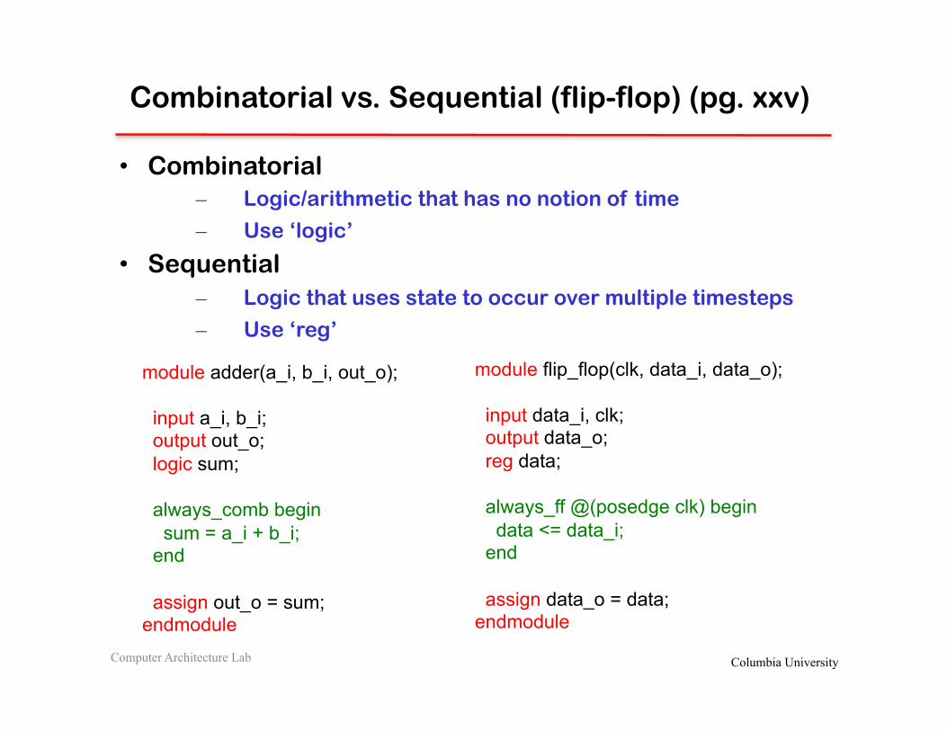
Combinatorial vs. Sequential (flip-flop) (pg. xxv)
• Combinatorial – Logic/arithmetic that has no notion of time
– Use ‘logic’
• Sequential – Logic that uses state to occur over multiple timesteps
– Use ‘reg’
Computer Architecture Lab
module adder(a_i, b_i, out_o); input a_i, b_i; output out_o; logic sum; always_comb begin sum = a_i + b_i; end assign out_o = sum; endmodule
module flip_flop(clk, data_i, data_o); input data_i, clk; output data_o; reg data; always_ff @(posedge clk) begin data <= data_i; end assign data_o = data; endmodule

Columbia University
Combinatorial vs. Sequential (latch) (pg. xxv)
• Combinatorial – Logic/arithmetic that has no notion of time
– Use ‘logic’
• Sequential – Logic that uses state to occur over multiple timesteps
– Use ‘reg’
Computer Architecture Lab
module adder(a_i, b_i, out_o); input a_i, b_i; output out_o; logic sum; always_comb begin sum = a_i + b_i; end assign out_o = sum; endmodule
module latch(clk, data_i, data_o); input data_i, clk; output data_o; reg data; always_latch begin if (clk) data <= data_i; end assign data_o = data; endmodule
Columbia University
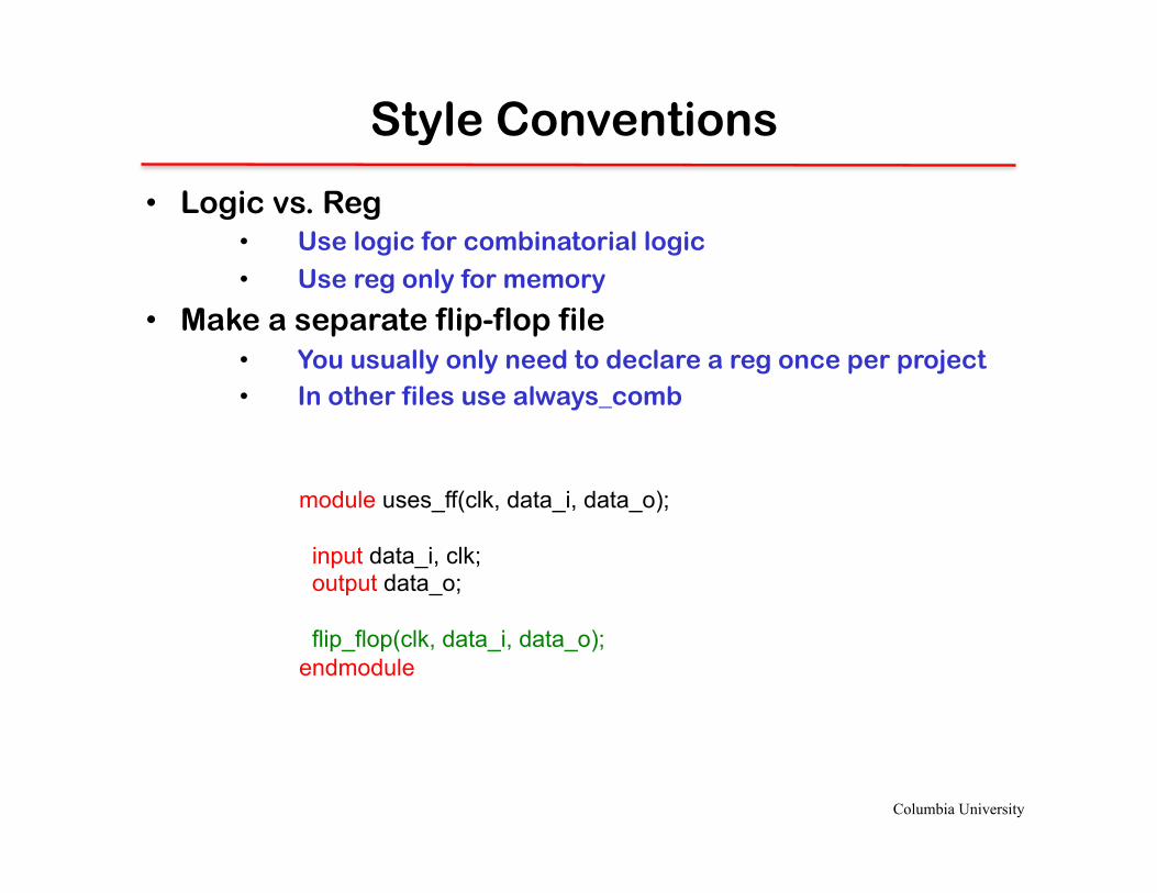
Style Conventions
• Logic vs. Reg • Use logic for combinatorial logic
• Use reg only for memory
• Make a separate flip-flop file • You usually only need to declare a reg once per project • In other files use always_comb
module uses_ff(clk, data_i, data_o); input data_i, clk; output data_o; flip_flop(clk, data_i, data_o); endmodule

Columbia University
Example: Simple MUX
• Exercise: Design a 2-to-1 multiplexer
module mux (data0_i, data1_i, select_i, data_o); // Your code endmodule

Columbia University
Example: Simple MUX
• In structural SystemVerilog
module mux (data0_i, data1_i, select_i, data_o); input data0_i, data1_i, select_i; output data_o; assign data_o = (select_i & data1_i) | (!select_i & data0_i); endmodule

Columbia University
Example: Simple MUX
• In behavioral SystemVerilog (with conditionals)
module mux (data0_i, data1_i, select_i, data_o); input data0_i, data1_i, select_i; output data_o; assign data_o = select_i ? data1_i : data0_i; endmodule
• If/Else statements are C-style – Only work inside of always blocks

Columbia University
Example: Simple MUX
• Using an always_comb block and case statement
module mux (data0_i, data1_i, select_i, data_o); input data0_i, data1_i, select_i; logic data; output data_o; always_comb begin case(select_i) '0: data = data0_i; '1: data = data1_i; endcase end assign data_o = data; endmodule
Columbia University
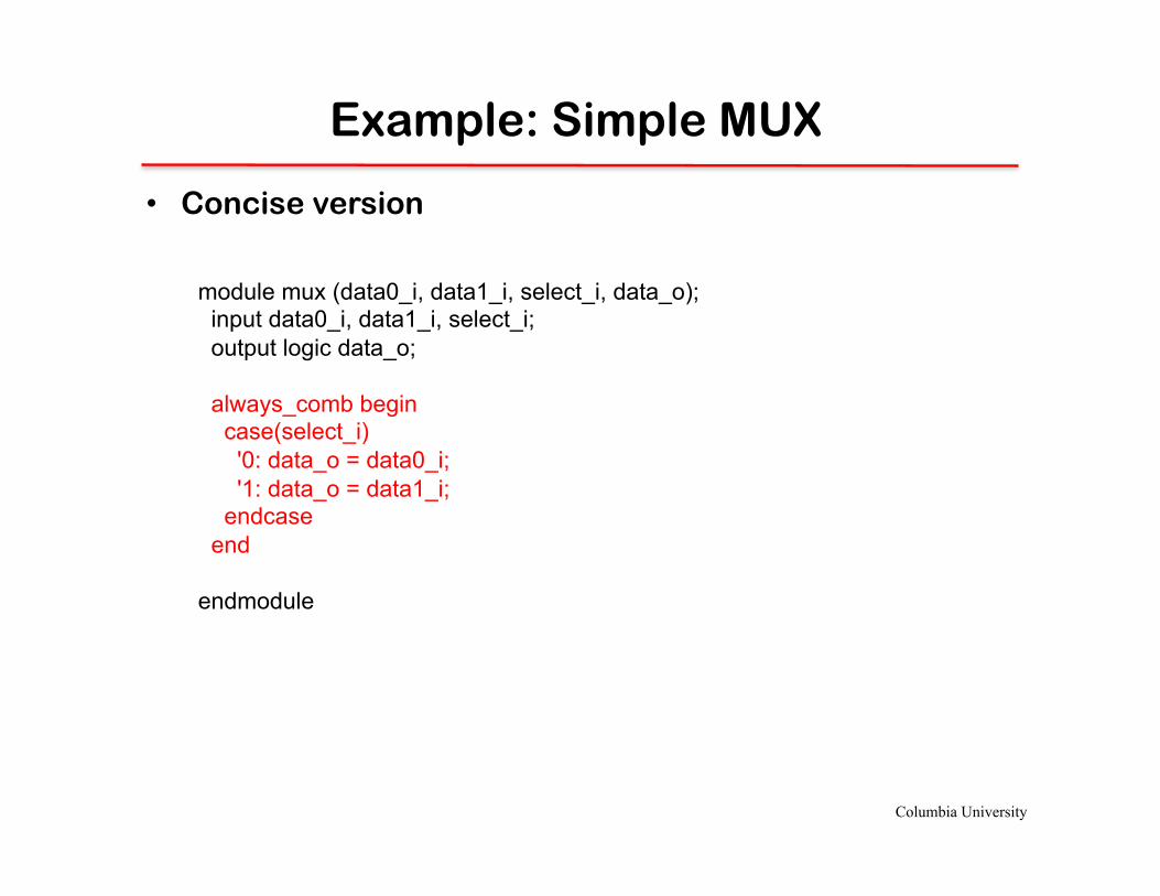
Example: Simple MUX
• Concise version
module mux (data0_i, data1_i, select_i, data_o); input data0_i, data1_i, select_i; output logic data_o; always_comb begin case(select_i) '0: data_o = data0_i; '1: data_o = data1_i; endcase end endmodule

Columbia University
Basic Compilation
• Log on a Columbia (CLIC) machine
• Set up environment (can use ~/.bashrc)
• Compile a module called MODULE_NAME
• This compiles a binary executable for simulation • Synthesis will be discussed later in the course
Source /sim/synopsys64/env_castl64.sh
vcs -sverilog MODULE_NAME.sv -o EXECUTABLE_NAME
ssh –X [email protected]

Columbia University
To The Handout
• What are the basic data types in SystemVerilog?
Computer Architecture Lab
input, output, wire, reg, logic, module.
• What is the key difference between assignment in SystemVerilog and assignment in a procedural language (like C)?
SystemVerilog assignments are continuous and occur in parallel.
• What is the difference between sequential logic and combinatorial logic?
Sequential logic occurs over multiple clock cycles in a synchronized fashion. Combinatorial logic is a single logical function.
Columbia University
Questions

Columbia University
Language Basics Outline
• Basic Types and Style • SystemVerilog Primitives
• Basic Data Types
• Assign and Always
• Building Larger Components • Parameters and Instantiation
• Conditional Statements
• Advanced Data Types
• Advanced Example

Columbia University
Module Instantiation (pg. 224)
• Instantiating a module • All inputs and outputs must be defined • Abstraction: analogous to a constructor in Java or C++
• Example • A four bit ripple-carry adder from 4 separate full-adders (FA) • The module we’re instancing is a user-defined type
module fourbitadder ( input [3 : 0] a, input [3 : 0] b, output c4, output [3 : 0] s, ); wire c0, c1, c2, c3; assign c0 = 1’b0; FA bit0 (a[0], b[0], c0, c1, s[0]); FA bit1 (a[1], b[1], c1, c2, s[1]); FA bit2 (a[2], b[2], c2, c3, s[2]); FA bit3 (a[3], b[3], c3, c4, s[3]); endmodule

Columbia University
Module Instantiation (pg. 224)
• The . Operator • Allows for reordering of arguments • A REQUIRED stylistic choice
• Example • Same four bit ripple-carry adder from 4 separate full-adders (FA)
module ( input [3 : 0] a, input [3 : 0] b, output c4, output [3 : 0] s, ); wire c0, c1, c2, c3; assign c0 = 1’b0; FA bit0 (.a(a[0]), .b(b[0]), .cin(c0), .cout(c1), .s(s[0])); FA bit1 (.a(a[1]), .b(b[1]), .cin(c1), .cout(c2), .s(s[1])); FA bit2 (.a(a[2]), .b(b[2]), .cin(c2), .cout(c3), .s(s[2])); FA bit3 (.a(a[3]), .b(b[3]), .cin(c3), .cout(c4), .s(s[3])); endmodule
Columbia University
Module Instantiation (pg. 224)
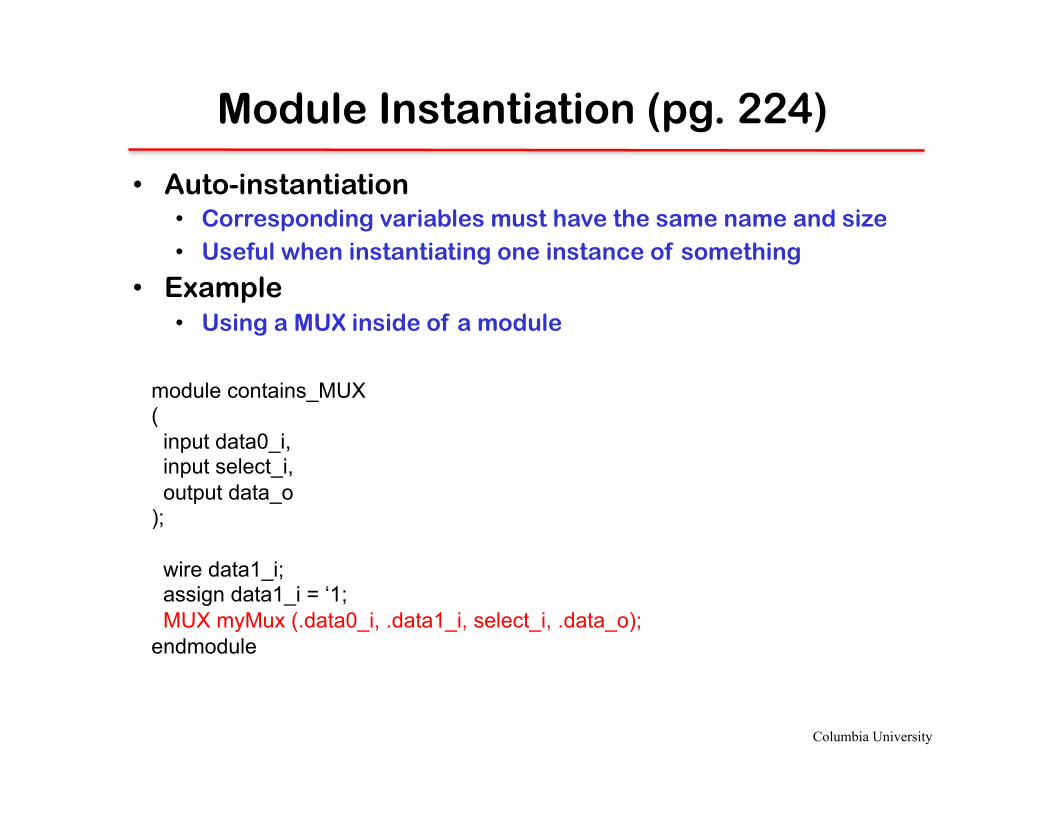
• Auto-instantiation • Corresponding variables must have the same name and size • Useful when instantiating one instance of something
• Example • Using a MUX inside of a module
module contains_MUX ( input data0_i, input select_i, output data_o ); wire data1_i; assign data1_i = ‘1; MUX myMux (.data0_i, .data1_i, select_i, .data_o); endmodule

Columbia University
Module Instantiation (pg. 224)
• Can pass literals
• Can pass arguments in any order
module contains_MUX ( input data0_i, input select_i, output data_o ); MUX myMux (.data1_i(‘1), .data0_i, .data_o, .select_i); endmodule

Columbia University
Parameters and Style
• Sets a value when the module is instanced • Equivalent to a constructor argument
module FF #(parameter WIDTH = 1) ( input clk, input [WIDTH – 1 : 0] data_i, output [WIDTH – 1 : 0] data_o ); reg [WIDTH – 1: 0] data; always_ff @(posedge clk) begin data <= data_i; end assign data_o = data; endmodule

Columbia University
Parameters and Style
• Sets a value when the module is instanced • Equivalent to a constructor argument
module register ( input clk, input [31 : 0] data_i, output [31 : 0] data_o ); FF #(.WIDTH(32)) ff32 (clk, data_i, data_o); endmodule
module FF #(parameter WIDTH = 1) ( input clk, input [WIDTH – 1 : 0] data_i, output [WIDTH – 1 : 0] data_o ); reg [WIDTH – 1: 0] data; always_ff @(posedge clk) begin data <= data_i; end assign data_o = data; endmodule

Columbia University
Conditional Statements (pg. 195)
module priorityEncoder ( input [7:0] data_i; output logic [2:0] data_o; ); always_comb begin if (data_i[0]) data_o = ‘0; else if (data_i[1]) data_o = 3'b001; else if (data_i[2]) data_o = 3'b010; else if (data_i[3]) data_o = 3'b011; else if (data_i[4]) data_o = 3'b100; else if (data_i[5]) data_o = 3'b101; else if (data_i[6]) data_o = 3'b110; else if (data_i[7]) data_o = 3'b111; else data_o = ‘x; end endmodule
• Usually implies a multiplexer • Syntactic sugar • Can always be done equivalently with structural Verilog
• Combinatorial always block • Changes whenever the input changes • The logic here does not create memory
Columbia University
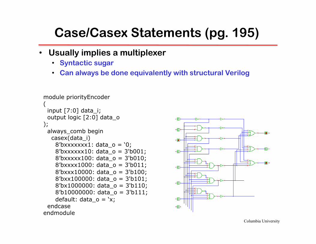
Case/Casex Statements (pg. 195)
• Usually implies a multiplexer • Syntactic sugar • Can always be done equivalently with structural Verilog
module priorityEncoder ( input [7:0] data_i; output logic [2:0] data_o ); always_comb begin casex(data_i) 8’bxxxxxxx1: data_o = ‘0; 8’bxxxxxx10: data_o = 3'b001; 8’bxxxxx100: data_o = 3'b010; 8’bxxxx1000: data_o = 3'b011; 8’bxxx10000: data_o = 3'b100; 8’bxx100000: data_o = 3'b101; 8’bx1000000: data_o = 3'b110; 8’b10000000: data_o = 3'b111; default: data_o = ‘x; endcase endmodule
Columbia University
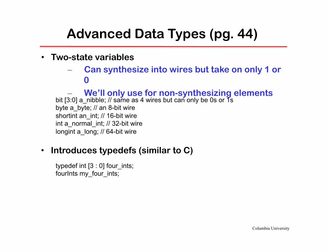
Advanced Data Types (pg. 44)
• Two-state variables – Can synthesize into wires but take on only 1 or
0
– We’ll only use for non-synthesizing elements bit [3:0] a_nibble; // same as 4 wires but can only be 0s or 1s byte a_byte; // an 8-bit wire shortint an_int; // 16-bit wire int a_normal_int; // 32-bit wire longint a_long; // 64-bit wire
• Introduces typedefs (similar to C)
typedef int [3 : 0] four_ints; fourInts my_four_ints;

Columbia University
Advanced Data Types: Arrays and Parameters (pg. 113)
• Basic arrays are similar to C reg [255 : 0] my_registers; // 256 storage bits reg [255 : 0] my_registers [31 : 0]; // 256 storage ints
• Parameters allow variable sizes for both dimensions parameter STORAGE_SIZE = 256; parameter INT_SIZE = 32; reg [STORAGE_SIZE – 1 : 0] my_registers; // 256 storage bits reg [STORAGE_SIZE – 1 : 0] my_registers [INT_SIZE – 1 : 0]; // 256 storage ints
• Associative arrays typedef reg [ADDRESS_WIDTH – 1 : 0] address; reg [DATA_SIZE – 1 : 0] memory [address];

Columbia University
Advanced Data Types: Structs (pg. 97)
• Essentially the same as in C
struct { bit sign; bit [10:0] exponent; bit [51:0] mantissa; } float;
• Can be used in array types, other structs, or typedefs • “packed” signifies adjacency typedef struct packed { bit sign; bit [10:0] exponent; bit [51:0] mantissa; } float; typedef float [255:0] float_array; float_array my_float_array;
Columbia University
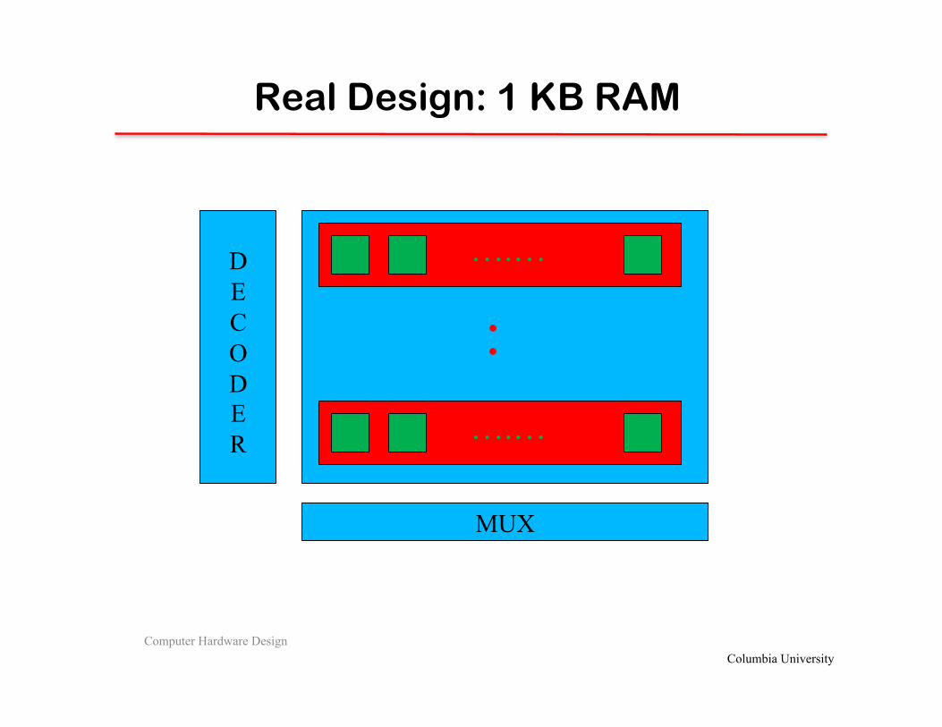
Real Design: 1 KB RAM
Computer Hardware Design
:
D E C O D E R
MUX
….…
….…
Columbia University
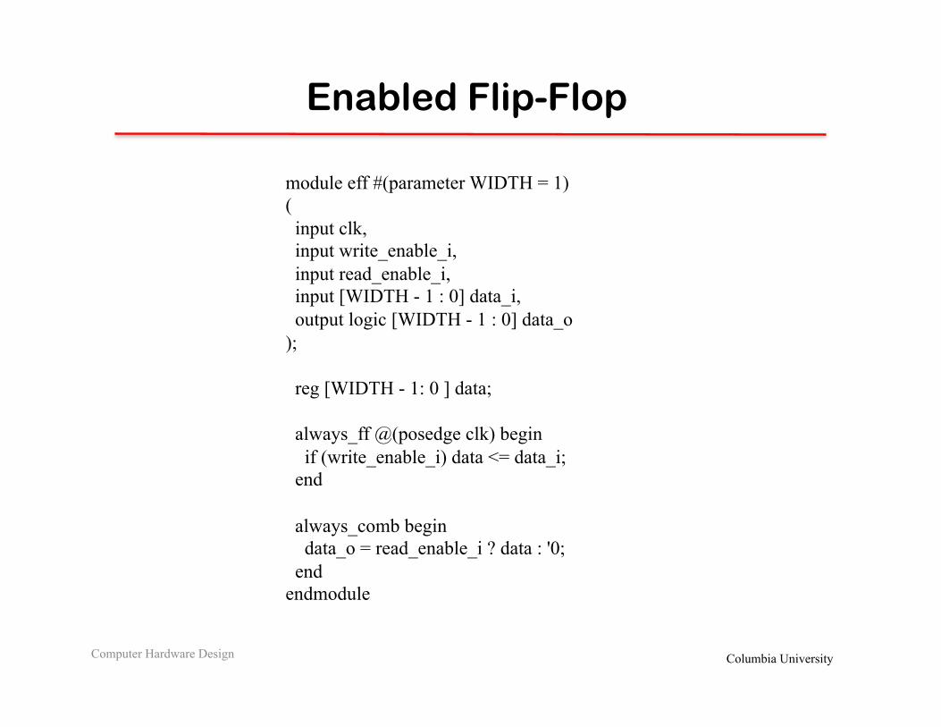
Enabled Flip-Flop
Computer Hardware Design
module eff #(parameter WIDTH = 1) ( input clk, input write_enable_i, input read_enable_i, input [WIDTH - 1 : 0] data_i, output logic [WIDTH - 1 : 0] data_o ); reg [WIDTH - 1: 0 ] data; always_ff @(posedge clk) begin if (write_enable_i) data <= data_i; end always_comb begin data_o = read_enable_i ? data : '0; end endmodule

Columbia University
Real Design: 1 KB RAM
Computer Hardware Design
:
D E C O D E R
MUX
….…
….…
Columbia University
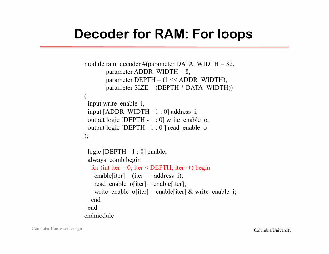
Decoder for RAM: For loops
Computer Hardware Design
module ram_decoder #(parameter DATA_WIDTH = 32, parameter ADDR_WIDTH = 8, parameter DEPTH = (1 << ADDR_WIDTH), parameter SIZE = (DEPTH * DATA_WIDTH)) ( input write_enable_i, input [ADDR_WIDTH - 1 : 0] address_i, output logic [DEPTH - 1 : 0] write_enable_o, output logic [DEPTH - 1 : 0 ] read_enable_o ); logic [DEPTH - 1 : 0] enable; always_comb begin for (int iter = 0; iter < DEPTH; iter++) begin enable[iter] = (iter == address_i); read_enable_o[iter] = enable[iter]; write_enable_o[iter] = enable[iter] & write_enable_i; end end endmodule

Columbia University
Real Design: 1 KB RAM
Computer Hardware Design
:
D E C O D E R
MUX
….…
….…

Columbia University
MUX for RAM: For loops
Computer Hardware Design
module ram_mux #(parameter DATA_WIDTH = 32, parameter ADDR_WIDTH = 8, parameter DEPTH = (1 << ADDR_WIDTH), parameter SIZE = (DEPTH * DATA_WIDTH)) ( input [SIZE - 1 : 0] data_i, output logic [DATA_WIDTH - 1 : 0] data_o ); always_comb begin for(int bit_in_word = 0; bit_in_word < DATA_WIDTH; bit_in_word++) begin data_o[bit_in_word] = '0; for(int bit_location = bit_in_word; bit_location < SIZE; bit_location += DATA_WIDTH) begin if (data_i[bit_location]) data_o[bit_in_word] = '1; end end end endmodule

Columbia University
Real Design: 1 KB RAM
Computer Hardware Design
:
D E C O D E R
MUX
….…
….…
Columbia University
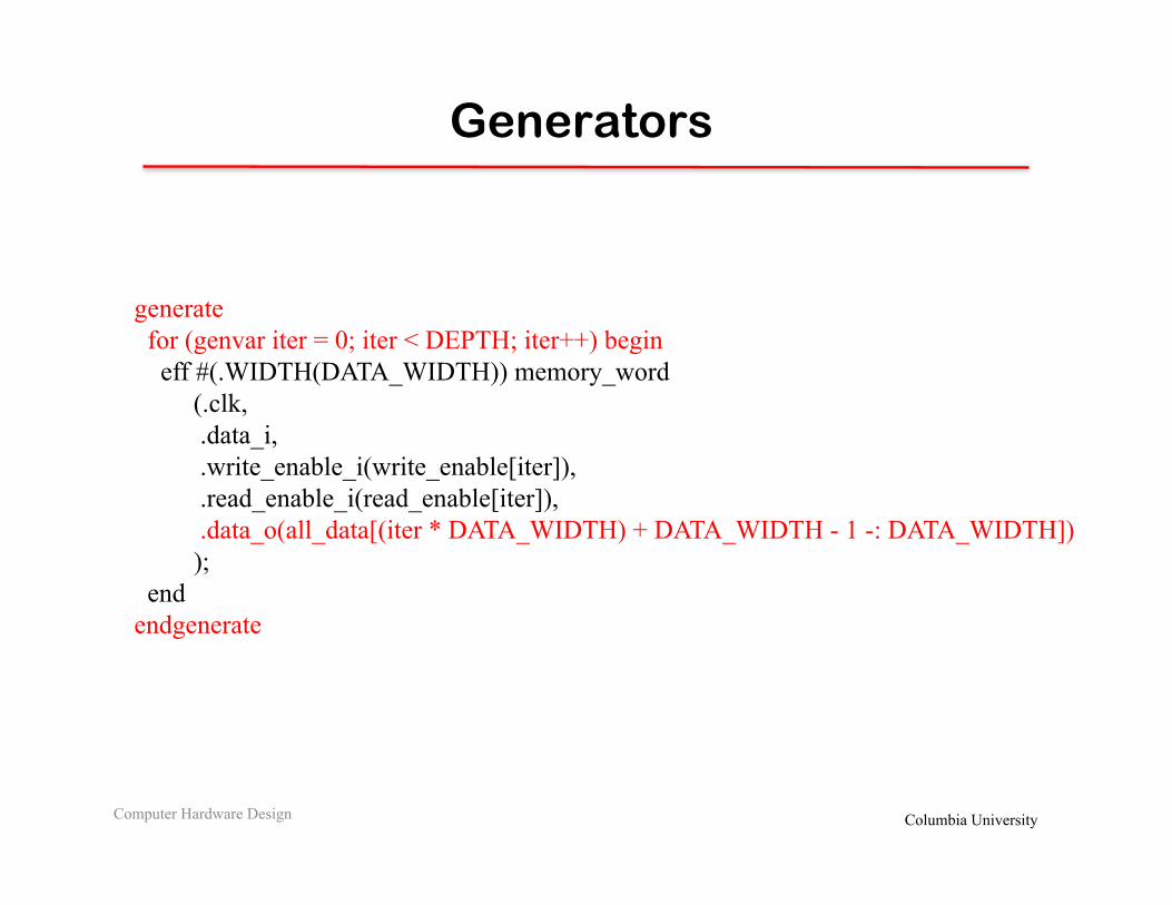
Generators
Computer Hardware Design
generate for (genvar iter = 0; iter < DEPTH; iter++) begin eff #(.WIDTH(DATA_WIDTH)) memory_word (.clk, .data_i, .write_enable_i(write_enable[iter]), .read_enable_i(read_enable[iter]), .data_o(all_data[(iter * DATA_WIDTH) + DATA_WIDTH - 1 -: DATA_WIDTH]) ); end endgenerate
Columbia University
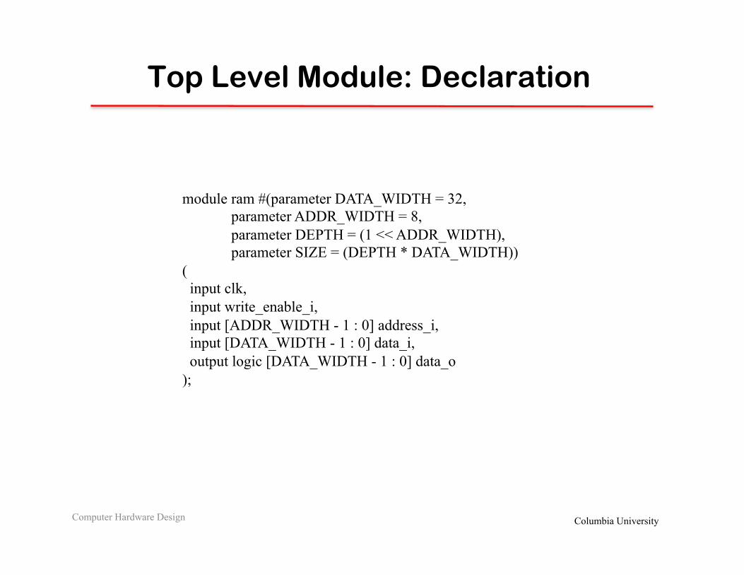
Top Level Module: Declaration
Computer Hardware Design
module ram #(parameter DATA_WIDTH = 32, parameter ADDR_WIDTH = 8, parameter DEPTH = (1 << ADDR_WIDTH), parameter SIZE = (DEPTH * DATA_WIDTH)) ( input clk, input write_enable_i, input [ADDR_WIDTH - 1 : 0] address_i, input [DATA_WIDTH - 1 : 0] data_i, output logic [DATA_WIDTH - 1 : 0] data_o );

Columbia University
Top Level Module: Body
Computer Hardware Design
// MUX wire [SIZE - 1 : 0] all_data; ram_mux mux (.data_i(all_data), .data_o); // Decoder wire [DEPTH - 1 : 0] read_enable; wire [DEPTH - 1 : 0] write_enable; ram_decoder decoder (.write_enable_i, .read_enable_o(read_enable), .write_enable_o(write_enable)); // Memory generate for (genvar iter = 0; iter < DEPTH; iter++) begin eff #(.WIDTH(DATA_WIDTH)) memory_word (.clk, .data_i, .write_enable_i(write_enable[iter]), .read_enable_i(read_enable[iter]), .data_o(all_data[(iter * DATA_WIDTH) + DATA_WIDTH - 1 -: DATA_WIDTH]) ); end endgenerate endmodule

Columbia University
Questions

Columbia University
Appendix: Inout
• Inout refers to a wire for tri-state logic – Also called a bidirectional pin
inout bidirectional;
• Tri-state wires can carry 0, 1, or z – When the value is z, it functions as an input wire – When the value is 0 or 1, it's an output wire
assign bidirectional = outputEnable ? input : z ;

Columbia University
System Verilog: Synthesizeable Set
Computer Hardware Design
Datatypes and Literals • Logic (4 state) • Typedef (user defined types) • Enumerations • Structures • Literals
Operators • . , .* Operator • Basic logic operations
Processes • assign statements • always_comb, always_ff
Interfaces • Generic Interface • Interface ports • Interface modports • Parameterized Interfaces
Disallowed SET • # delays • Initialization • No tasks and functions • Auto increment, decrement • Statically unknown bounds
For loop, Generate (with caution)
Simha
Acknowledgement: The following slides were inspired by materials in the Synopsys Design Tutorials

Columbia University
Typedef/Struct Example
Computer Hardware Design

Columbia University
Interfaces
Computer Hardware Design
(c) Synopsys

Columbia University
Simple Design Skeleton
Computer Hardware Design

Columbia University
Interface definition
Computer Hardware Design

Columbia University
Passing Interface as a Port
Computer Hardware Design

Columbia University
Interface Modports
Computer Hardware Design

Columbia University
Interface Modports (2)
Computer Hardware Design

Columbia University
Ports
Computer Hardware Design
Columbia University
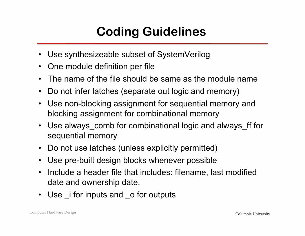
Coding Guidelines
• Use synthesizeable subset of SystemVerilog • One module definition per file • The name of the file should be same as the module name • Do not infer latches (separate out logic and memory) • Use non-blocking assignment for sequential memory and
blocking assignment for combinational memory • Use always_comb for combinational logic and always_ff for
sequential memory • Do not use latches (unless explicitly permitted) • Use pre-built design blocks whenever possible • Include a header file that includes: filename, last modified
date and ownership date. • Use _i for inputs and _o for outputs
Computer Hardware Design

Columbia University
Homework I
Computer Hardware Design
CAM
read 1
read_index 5
write 1
write_index 5
write_data 32
search 1
search_data 32
read_valid1
read_value32
search_valid1
search_index5
Inputs and Outputs must be clearly marked along with bit widths Also customary to provide the same in a tabular form
Columbia University
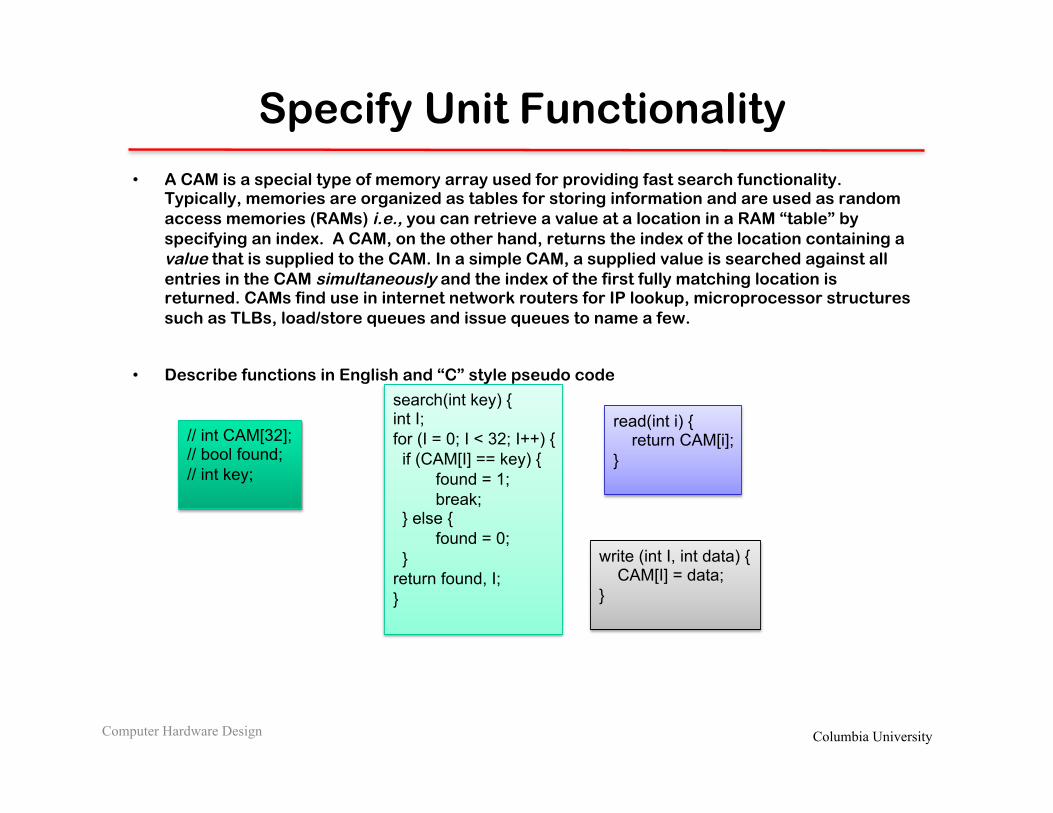
Specify Unit Functionality
• A CAM is a special type of memory array used for providing fast search functionality. Typically, memories are organized as tables for storing information and are used as random access memories (RAMs) i.e., you can retrieve a value at a location in a RAM “table” by specifying an index. A CAM, on the other hand, returns the index of the location containing a value that is supplied to the CAM. In a simple CAM, a supplied value is searched against all entries in the CAM simultaneously and the index of the first fully matching location is returned. CAMs find use in internet network routers for IP lookup, microprocessor structures such as TLBs, load/store queues and issue queues to name a few.
• Describe functions in English and “C” style pseudo code
Computer Hardware Design
search(int key) { int I; for (I = 0; I < 32; I++) { if (CAM[I] == key) { found = 1; break; } else { found = 0; } return found, I; }
read(int i) { return CAM[i]; }
write (int I, int data) { CAM[I] = data; }
// int CAM[32]; // bool found; // int key;

Columbia University
Hints
(Try design partitioning, and block diagrams before next lectures)
Computer Hardware Design

Columbia University
What “parts” do you have to build the CAM?
Computer Hardware Design
Flip-flop
Step1: We need a memory element to hold the values We know how to write to FF, read from a FF
Step 2: Enhance Flip Flop to check if the stored bit is same as searched bit
Match Logic
Flip-flop
CAM Cell
Step 3: We are searching for words not bits, so create a line from the cell
Match Logic
Flip-flop
Match Logic
Flip-flop
Match Logic
Flip-flop
Match Logic
Flip-flop
32
Step 4: We need multiple words, so stack Cam lines
Match Logic
Flip-flop
Match Logic
Flip-flop
Match Logic
Flip-flop
Match Logic
Flip-flop
Match Logic
Flip-flop
Match Logic
Flip-flop
Match Logic
Flip-flop
Match Logic
Flip-flop
Match Logic
Flip-flop
Match Logic
Flip-flop
Match Logic
Flip-flop
Match Logic
Flip-flop
Match Logic
Flip-flop
Match Logic
Flip-flop
Match Logic
Flip-flop
Match Logic
Flip-flop
Match Logic
Flip-flop
Match Logic
Flip-flop
Match Logic
Flip-flop
Match Logic
Flip-flop
Match Logic
Flip-flop
Match Logic
Flip-flop
Match Logic
Flip-flop
Match Logic
Flip-flop

Columbia University
CAM contd.,
Computer Hardware Design
Step 5: Need ability to read/write to a particular entry in CAM
Match Logic
Flip-flop
Match Logic
Flip-flop
Match Logic
Flip-flop
Match Logic
Flip-flop
Match Logic
Flip-flop
Match Logic
Flip-flop
Match Logic
Flip-flop
Match Logic
Flip-flop
Match Logic
Flip-flop
Match Logic
Flip-flop
Match Logic
Flip-flop
Match Logic
Flip-flop
Match Logic
Flip-flop
Match Logic
Flip-flop
Match Logic
Flip-flop
Match Logic
Flip-flop
Match Logic
Flip-flop
Match Logic
Flip-flop
Match Logic
Flip-flop
Match Logic
Flip-flop
Match Logic
Flip-flop
Match Logic
Flip-flop
Match Logic
Flip-flop
Match Logic
Flip-flop
Decoder
Line to read/write
32
Multiplexer
Read output
32
Read/Write Index
Step 6: Need ability to select first matching entry through the CAM
Match Logic
Flip-flop
Match Logic
Flip-flop
Match Logic
Flip-flop
Match Logic
Flip-flop
Match Logic
Flip-flop
Match Logic
Flip-flop
Match Logic
Flip-flop
Match Logic
Flip-flop
Match Logic
Flip-flop
Match Logic
Flip-flop
Match Logic
Flip-flop
Match Logic
Flip-flop
Match Logic
Flip-flop
Match Logic
Flip-flop
Match Logic
Flip-flop
Match Logic
Flip-flop
Match Logic
Flip-flop
Match Logic
Flip-flop
Match Logic
Flip-flop
Match Logic
Flip-flop
Match Logic
Flip-flop
Match Logic
Flip-flop
Match Logic
Flip-flop
Match Logic
Flip-flop
Decoder
32
Multiplexer
Read output
32 Priority
Encoder
32
Related Documents