SystemVerilog 3.1a Language Reference Manual Accellera’s Extensions to Verilog ® Abstract: a set of extensions to the IEEE 1364-2001 Verilog Hardware Description Language to aid in the creation and verification of abstract architectural level models

Welcome message from author
This document is posted to help you gain knowledge. Please leave a comment to let me know what you think about it! Share it to your friends and learn new things together.
Transcript
SystemVerilog 3.1aLanguage Reference Manual
Accellera’s Extensions to Verilog®
Abstract: a set of extensions to the IEEE 1364-2001 Verilog Hardware Description Language to aidin the creation and verification of abstract architectural level models


Copyright © 2002, 2003, 2004 by Accellera Organization, Inc.1370 Trancas Street #163Napa, CA 94558Phone: (707) 251-9977Fax: (707) 251-9877
All rights reserved. No part of this document may be reproduced or distributed in any medium what-soever to any third parties without prior written consent of Accellera Organization, Inc.
SystemVerilog 3.1a (5/13/04)
SystemVerilog 3.1aLanguage Reference Manual
Accellera’s Extensions to Verilog®
Abstract: a set of extensions to the IEEE 1364-2001 Verilog Hardware Description Language to aidin the creation and verification of abstract architectural level models

AccelleraSystemVerilog 3.1a Extensions to Verilog-2001
Verilog is a registered trademark of Cadence Design Systems, San Jose, CA
ii Copyright 2004 Accellera. All rights reserved .

AccelleraExtensions to Verilog-2001 SystemVerilog 3.1a
STATEMENT OF USE OF ACCELLERA STANDARDS
Accellera Standards documents are developed within Accellera and the Technical Committees of AccelleraOrganization, Inc. Accellera develops its standards through a consensus development process, approved by itsmembers and board of directors, which brings together volunteers representing varied viewpoints and intereststo achieve the final product. Volunteers are not necessarily members of Accellera and serve without compensa-tion. While Accellera administers the process and establishes rules to promote fairness in the consensus devel-opment process, Accellera does not independently evaluate, test, or verify the accuracy of any of theinformation contained in its standards.
Use of an Accellera Standard is wholly voluntary. Accellera disclaims liability for any personal injury, prop-erty or other damage, of any nature whatsoever, whether special, indirect, consequential, or compensatory,directly or indirectly resulting from the publication, use of, or reliance upon this, or any other Accellera Stan-dard document.
Accellera does not warrant or represent the accuracy or content of the material contained herein, and expresslydisclaims any express or implied warranty, including any implied warranty of merchantability or suitability fora specific purpose, or that the use of the material contained herein is free from patent infringement. AccelleraStandards documents are supplied “AS IS”.
The existence of an Accellera Standard does not imply that there are no other ways to produce, test, measure,purchase, market, or provide other goods and services related to the scope of an Accellera Standard. Further-more, the viewpoint expressed at the time a standard is approved and issued is subject to change due to devel-opments in the state of the art and comments received from users of the standard. Every Accellera Standard issubjected to review periodically for revision and update. Users are cautioned to check to determine that theyhave the latest edition of any Accellera Standard.
In publishing and making this document available, Accellera is not suggesting or rendering professional orother services for, or on behalf of, any person or entity. Nor is Accellera undertaking to perform any duty owedby any other person or entity to another. Any person utilizing this, and any other Accellera Standards docu-ment, should rely upon the advice of a competent professional in determining the exercise of reasonable care inany given circumstances.
Interpretations: Occasionally questions may arise regarding the meaning of portions of standards as they relateto specific applications. When the need for interpretations is brought to the attention of Accellera, Accellerawill initiate action to prepare appropriate responses. Since Accellera Standards represent a consensus of con-cerned interests, it is important to ensure that any interpretation has also received the concurrence of a balanceof interests. For this reason, Accellera and the members of its Technical Committees are not able to provide aninstant response to interpretation requests except in those cases where the matter has previously received for-mal consideration.
Comments for revision of Accellera Standards are welcome from any interested party, regardless of member-ship affiliation with Accellera. Suggestions for changes in documents should be in the form of a proposedchange of text, together with appropriate supporting comments. Comments on standards and requests for inter-pretations should be addressed to:
Accellera Organization1370 Trancas Street #163Napa, CA 94558USA
Copyright 2004 Accellera. All rights reserved. iii

AccelleraSystemVerilog 3.1a Extensions to Verilog-2001
Accellera is the sole entity that may authorize the use of Accellera-owned certification marks and/or trade-marks to indicate compliance with the materials set forth herein.
Authorization to photocopy portions of any individual standard for internal or personal use must be granted byAccellera Organization, Inc., provided that permission is obtained from and any required fee is paid to Accel-lera. To arrange for authorization please contact Lynn Horobin, Accellera, 1370 Trancas Street #163, Napa,CA 94558, phone (707) 251-9977, e-mail [email protected]. Permission to photocopy portions of any indi-vidual standard for educational classroom use can also be obtained from Accellera.
Note: Attention is called to the possibility that implementation of this standard may require use of subjectmatter covered by patent rights. By publication of this standard, no position is taken with respect to theexistence or validity of any patent rights in connection therewith. Accellera shall not be responsible foridentifying patents for which a license may be required by an Accellera standard or for conducting inquir-ies into the legal validity or scope of those patents that are brought to its attention.
iv Copyright 2004 Accellera. All rights reserved .
AccelleraExtensions to Verilog-2001 SystemVerilog 3.1a
Acknowledgements
This SystemVerilog Language Reference Manual was developed by experts from many different fields, includ-ing design and verification engineers, Electronic Design Automation (EDA) companies, EDA vendors, andmembers of the IEEE 1364 Verilog standard working group.
The SystemVerilog Language Reference Manual (LRM) was specified by the Accellera SystemVerilog com-mittee. Four subcommittees worked on various aspects of the SystemVerilog 3.1 specification:
— The Basic/Design Committee (SV-BC) worked on errata and extensions to the design features of System-Verilog 3.1.
— The Enhancement Committee (SV-EC) worked on errata and extensions to the testbench features of Sys-temVerilog 3.1.
— The Assertions Committee (SV-AC) worked on errata and extensions to the assertion features of System-Verilog 3.1.
— The C Application Programming Interface (API) Committee (SV-CC) worked on errata and extensions tothe Direct Programming Interface (DPI), the assertions and coverage APIs and the VPI features of System-Verilog 3.1.
The committee chairs were:
Vassilios Gerousis, SystemVerilog 3.1 and 3.1a Committee General Chair
Basic/Design CommitteeJohny Srouji, SystemVerilog 3.1 and 3.1a ChairKaren Pieper, SystemVerilog 3.1 and 3.1a Co-Chair
Enhancement CommitteeDavid Smith, SystemVerilog 3.1 and 3.1a ChairStefen Boyd, SystemVerilog 3.1 Co-ChairNeil Korpusik, SystemVerilog 3.1a Co-Chair
Assertions CommitteeFaisal Haque, SystemVerilog 3.1 and 3.1a ChairSteve Meier, SystemVerilog 3.1 Co-ChairArif Samad, SystemVerilog 3.1a Co-Chair
C API CommitteeSwapnajit Mittra, SystemVerilog 3.1 and 3.1a ChairGhassan Khoory, SystemVerilog 3.1 and 3.1a Co-Chair
Stuart Sutherland, SystemVerilog 3.1 and 3.1a Language Reference Manual Editor
Stefen Boyd, SystemVerilog 3.1 BNF Annex. Editor
Brad Pierce, SystemVerilog 3.1a BNF Annex Editor
Copyright 2004 Accellera. All rights reserved. v

AccelleraSystemVerilog 3.1a Extensions to Verilog-2001
Committee members included (listed alphabetically by last name)
* indicates this person was also an active member of the IEEE 1364 Verilog Standard Working Group+ indicates this person was actively involved in SystemVerilog 3.1++ indicates this person was actively involved in SystemVerilog 3.1a+++ indicates this person was actively involved in SystemVerilog 3.1 and 3.1a
SystemVerilog 3.1/3.1aBasic/Design Committee
SystemVerilog 3.1/3.1a Enhancement Committee
SystemVerilog 3.1/3.1aAssertions Committee
SystemVerilog 3.1/3.1aC API Committee
Kevin Cameron+Cliff Cummings*+++Dan Jacobi+++Jay Lawrence+++Mark Hartoog++Peter Flake++Matt Maidment+++Francoise Martinolle*+++Rishiyur Nikhil++Karen Pieper*+++Brad Pierce+++David Rich+++Steven Sharp*+Johny Srouji+++Gord Vreugdenhil*+Doug Warmke++
Stefen Boyd*+Dennis Brophy+++Michael Burns+++Kevin Cameron+Cliff Cummings*+++Peter Flake+Jeff Freedman+Neil Korpusik+++Jay Lawrence+++Francoise Martinolle*+Don Mills+Mehdi Mohtashemi+++Phil Moorby+Karen Pieper*+Brad Pierce+++Dave Rich++Ray Ryan++Arturo Salz+++David Smith+++Stuart Sutherland*+++
Roy Armoni+++Surrendra Dudani+++Cindy Eisner+Harry Foster+Faisal Haque+++John Havlicek+++Richard Ho+Adam Krolnik*+++David Lacey+Joseph Lu+++Erich Marschner+Steve Meier+Hillel Miller++Prakash Narain+Koushik Roy++Arif Samad++Andrew Seawright+Bassam Tabbara+++
John Amouroux+++Kevin Cameron+++Ralph Duncan++Charles Dawson++João Geada+++Ghassan Khoory+++Andrzej Litwiniuk+++Avinash Mani++Francoise Martinole*+++Swapnajit Mittra+++Michael Rohleder+++John Stickley+++Stuart Swan+++Bassam Tabbara+++Kurt Takara+Doug Warmke+++
vi Copyright 2004 Accellera. All rights reserved .
AccelleraExtensions to Verilog-2001 SystemVerilog 3.1a
Table of Contents
Section 1 Introduction to SystemVerilog ...................................................................................................... 1
Section 2 Literal Values.................................................................................................................................. 42.1 Introduction (informative) ...............................................................................................................42.2 Literal value syntax..........................................................................................................................42.3 Integer and logic literals ..................................................................................................................42.4 Real literals ......................................................................................................................................52.5 Time literals .....................................................................................................................................52.6 String literals....................................................................................................................................52.7 Array literals ....................................................................................................................................62.8 Structure literals ...............................................................................................................................6
Section 3 Data Types....................................................................................................................................... 83.1 Introduction (informative) ...............................................................................................................83.2 Data type syntax...............................................................................................................................93.3 Integer data types ...........................................................................................................................103.4 Real and shortreal data types .........................................................................................................113.5 Void data type ................................................................................................................................113.6 chandle data type ...........................................................................................................................113.7 String data type ..............................................................................................................................123.8 Event data type...............................................................................................................................163.9 User-defined types .........................................................................................................................163.10 Enumerations .................................................................................................................................173.11 Structures and unions.....................................................................................................................223.12 Class...............................................................................................................................................263.13 Singular and aggregate types .........................................................................................................273.14 Casting ...........................................................................................................................................273.15 $cast dynamic casting ....................................................................................................................283.16 Bit-stream casting ..........................................................................................................................29
Section 4 Arrays ............................................................................................................................................ 324.1 Introduction (informative) .............................................................................................................324.2 Packed and unpacked arrays ..........................................................................................................324.3 Multiple dimensions ......................................................................................................................334.4 Indexing and slicing of arrays........................................................................................................344.5 Array querying functions ...............................................................................................................354.6 Dynamic arrays ..............................................................................................................................354.7 Array assignment ...........................................................................................................................374.8 Arrays as arguments.......................................................................................................................384.9 Associative arrays ..........................................................................................................................394.10 Associative array methods .............................................................................................................414.11 Associative array assignment.........................................................................................................444.12 Associative array arguments ..........................................................................................................444.13 Associative array literals................................................................................................................444.14 Queues ...........................................................................................................................................454.15 Array manipulation methods .........................................................................................................47
Section 5 Data Declarations ......................................................................................................................... 525.1 Introduction (informative) .............................................................................................................525.2 Data declaration syntax..................................................................................................................525.3 Constants........................................................................................................................................52
Copyright 2004 Accellera. All rights reserved. vii

AccelleraSystemVerilog 3.1a Extensions to Verilog-2001
5.4 Variables ........................................................................................................................................535.5 Scope and lifetime .........................................................................................................................545.6 Nets, regs, and logic.......................................................................................................................555.7 Signal aliasing................................................................................................................................565.8 Type compatibility .........................................................................................................................58
Section 6 Attributes....................................................................................................................................... 616.1 Introduction (informative) .............................................................................................................616.2 Default attribute type .....................................................................................................................61
Section 7 Operators and Expressions.......................................................................................................... 627.1 Introduction (informative) .............................................................................................................627.2 Operator syntax..............................................................................................................................627.3 Assignment operators ....................................................................................................................627.4 Operations on logic and bit types ..................................................................................................637.5 Wild equality and wild inequality..................................................................................................637.6 Real operators ................................................................................................................................647.7 Size.................................................................................................................................................647.8 Sign ................................................................................................................................................647.9 Operator precedence and associativity ..........................................................................................647.10 Built-in methods ............................................................................................................................657.11 Static Prefixes ................................................................................................................................667.12 Concatenation ................................................................................................................................677.13 Unpacked array expressions ..........................................................................................................677.14 Structure expressions .....................................................................................................................687.15 Tagged union expressions and member access..............................................................................707.16 Aggregate expressions ...................................................................................................................717.17 Operator overloading .....................................................................................................................727.18 Streaming operators (pack / unpack) .............................................................................................737.19 Conditional operator ......................................................................................................................777.20 Set membership..............................................................................................................................77
Section 8 Procedural Statements and Control Flow.................................................................................. 798.1 Introduction (informative) .............................................................................................................798.2 Statements ......................................................................................................................................798.3 Blocking and nonblocking assignments ........................................................................................808.4 Selection statements.......................................................................................................................818.5 Loop statements .............................................................................................................................878.6 Jump statements .............................................................................................................................898.7 Final blocks....................................................................................................................................898.8 Named blocks and statement labels ...............................................................................................908.9 Disable ...........................................................................................................................................908.10 Event control..................................................................................................................................918.11 Level-sensitive sequence controls .................................................................................................938.12 Procedural assign and deassign removal .......................................................................................94
Section 9 Processes........................................................................................................................................ 959.1 Introduction (informative) .............................................................................................................959.2 Combinational logic.......................................................................................................................959.3 Latched logic..................................................................................................................................969.4 Sequential logic..............................................................................................................................969.5 Continuous assignments ................................................................................................................969.6 fork...join........................................................................................................................................979.7 Process execution threads ..............................................................................................................98
viii Copyright 2004 Accellera. All rights reserved .

AccelleraExtensions to Verilog-2001 SystemVerilog 3.1a
9.8 Process control ...............................................................................................................................989.9 Fine-grain process control ...........................................................................................................100
Section 10 Tasks and Functions................................................................................................................... 10210.1 Introduction (informative) ...........................................................................................................10210.2 Tasks ............................................................................................................................................10310.3 Functions......................................................................................................................................10410.4 Task and function argument passing ...........................................................................................10610.5 Import and export functions.........................................................................................................109
Section 11 Classes.......................................................................................................................................... 11111.1 Introduction (informative) ...........................................................................................................11111.2 Syntax ..........................................................................................................................................11211.3 Overview......................................................................................................................................11311.4 Objects (class instance)................................................................................................................11311.5 Object properties..........................................................................................................................11411.6 Object methods ............................................................................................................................11411.7 Constructors .................................................................................................................................11511.8 Static class properties...................................................................................................................11611.9 Static methods..............................................................................................................................11611.10 This ..............................................................................................................................................11611.11 Assignment, re-naming and copying ...........................................................................................11711.12 Inheritance and subclasses ...........................................................................................................11811.13 Overridden members....................................................................................................................11911.14 Super ............................................................................................................................................11911.15 Casting .........................................................................................................................................12011.16 Chaining constructors ..................................................................................................................12011.17 Data hiding and encapsulation.....................................................................................................12111.18 Constant class properties .............................................................................................................12111.19 Abstract classes and virtual methods ...........................................................................................12211.20 Polymorphism: dynamic method lookup.....................................................................................12311.21 Class scope resolution operator :: ................................................................................................12311.22 Out of block declarations .............................................................................................................12411.23 Parameterized classes ..................................................................................................................12511.24 Typedef class ...............................................................................................................................12611.25 Classes and structures ..................................................................................................................12611.26 Memory management ..................................................................................................................127
Section 12 Random Constraints .................................................................................................................. 12812.1 Introduction (informative) ...........................................................................................................12812.2 Overview......................................................................................................................................12812.3 Random variables ........................................................................................................................13112.4 Constraint blocks .........................................................................................................................13212.5 Randomization methods ..............................................................................................................14512.6 In-line constraints — randomize() with.......................................................................................14712.7 Disabling random variables with rand_mode() ...........................................................................14812.8 Controlling constraints with constraint_mode() ..........................................................................14912.9 Dynamic constraint modification.................................................................................................15012.10 In-line random variable control ...................................................................................................15012.11 Randomization of scope variables — std::randomize()...............................................................15112.12 Random number system functions and methods .........................................................................15312.13 Random stability ..........................................................................................................................15412.14 Manually seeding randomize .......................................................................................................15612.15 Random weighted case — randcase ............................................................................................157
Copyright 2004 Accellera. All rights reserved. ix
AccelleraSystemVerilog 3.1a Extensions to Verilog-2001
12.16 Random sequence generation — randsequence...........................................................................158
Section 13 Interprocess Synchronization and Communication................................................................ 16613.1 Introduction (informative) ...........................................................................................................16613.2 Semaphores ..................................................................................................................................16613.3 Mailboxes.....................................................................................................................................16713.4 Parameterized mailboxes .............................................................................................................17013.5 Event ............................................................................................................................................17113.6 Event sequencing: wait_order() ...................................................................................................17213.7 Event variables.............................................................................................................................173
Section 14 Scheduling Semantics................................................................................................................. 17614.1 Execution of a hardware model and its verification environment ...............................................17614.2 Event simulation ..........................................................................................................................17614.3 The stratified event scheduler ......................................................................................................17614.4 The PLI callback control points...................................................................................................180
Section 15 Clocking Blocks .......................................................................................................................... 18115.1 Introduction (informative) ...........................................................................................................18115.2 Clocking block declaration ..........................................................................................................18115.3 Input and output skews ................................................................................................................18315.4 Hierarchical expressions ..............................................................................................................18415.5 Signals in multiple clocking blocks .............................................................................................18515.6 Clocking block scope and lifetime...............................................................................................18515.7 Multiple clocking blocks example ...............................................................................................18515.8 Interfaces and clocking blocks.....................................................................................................18615.9 Clocking block events..................................................................................................................18715.10 Cycle delay: ## ............................................................................................................................18715.11 Default clocking...........................................................................................................................18815.12 Input sampling .............................................................................................................................18915.13 Synchronous events .....................................................................................................................18915.14 Synchronous drives......................................................................................................................190
Section 16 Program Block ............................................................................................................................ 19316.1 Introduction (informative) ...........................................................................................................19316.2 The program construct .................................................................................................................19316.3 Multiple programs........................................................................................................................19516.4 Eliminating testbench races .........................................................................................................19516.5 Blocking tasks in cycle/event mode.............................................................................................19616.6 Program control tasks ..................................................................................................................196
Section 17 Assertions ................................................................................................................................... 19817.1 Introduction (informative) ...........................................................................................................19817.2 Immediate assertions....................................................................................................................19817.3 Concurrent assertions overview...................................................................................................20017.4 Boolean expressions ....................................................................................................................20117.5 Sequences.....................................................................................................................................20317.6 Declaring sequences ....................................................................................................................20617.7 Sequence operations ....................................................................................................................20817.8 Manipulating data in a sequence..................................................................................................22417.9 Calling subroutines on match of a sequence................................................................................22817.10 System functions..........................................................................................................................22917.11 Declaring properties.....................................................................................................................22917.12 Multiple clock support .................................................................................................................240
x Copyright 2004 Accellera. All rights reserved .

AccelleraExtensions to Verilog-2001 SystemVerilog 3.1a
17.13 Concurrent assertions...................................................................................................................24617.14 Clock resolution...........................................................................................................................25217.15 Binding properties to scopes or instances....................................................................................25817.16 The expect statement ...................................................................................................................259
Section 18 Hierarchy..................................................................................................................................... 26118.1 Introduction (informative) ...........................................................................................................26118.2 Packages.......................................................................................................................................26118.3 Compilation unit support .............................................................................................................26518.4 Top-level instance........................................................................................................................26618.5 Module declarations.....................................................................................................................26718.6 Nested modules............................................................................................................................26718.7 Extern modules ............................................................................................................................26918.8 Port declarations ..........................................................................................................................27018.9 List of port expressions................................................................................................................27118.10 Time unit and precision ...............................................................................................................27118.11 Module instances .........................................................................................................................27218.12 Port connection rules ...................................................................................................................27618.13 Name spaces ................................................................................................................................27718.14 Hierarchical names ......................................................................................................................278
Section 19 Interfaces ..................................................................................................................................... 27919.1 Introduction (informative) ...........................................................................................................27919.2 Interface syntax............................................................................................................................28019.3 Ports in interfaces.........................................................................................................................28419.4 Modports ......................................................................................................................................28519.5 Interfaces and specify blocks .......................................................................................................29119.6 Tasks and functions in interfaces.................................................................................................29119.7 Parameterized interfaces ..............................................................................................................29719.8 Virtual interfaces..........................................................................................................................29919.9 Access to interface objects...........................................................................................................303
Section 20 Coverage...................................................................................................................................... 30520.1 Introduction (informative) ...........................................................................................................30520.2 Defining the coverage model: covergroup...................................................................................30620.3 Using covergroup in classes ........................................................................................................30820.4 Defining coverage points .............................................................................................................30920.5 Defining cross coverage...............................................................................................................31520.6 Specifying coverage options ........................................................................................................31920.7 Predefined coverage methods ......................................................................................................32420.8 Predefined coverage system tasks and functions .........................................................................32420.9 Organization of option and type_option members ......................................................................324
Section 21 Parameters .................................................................................................................................. 32621.1 Introduction (informative) ...........................................................................................................32621.2 Parameter declaration syntax .......................................................................................................327
Section 22 Configuration Libraries............................................................................................................. 33022.1 Introduction (informative) ...........................................................................................................33022.2 Libraries .......................................................................................................................................330
Section 23 System Tasks and System Functions ........................................................................................ 33123.1 Introduction (informative) ...........................................................................................................33123.2 Elaboration-time typeof function.................................................................................................331
Copyright 2004 Accellera. All rights reserved. xi

AccelleraSystemVerilog 3.1a Extensions to Verilog-2001
23.3 Typename function ......................................................................................................................33123.4 Expression size system function ..................................................................................................33223.5 Range system function.................................................................................................................33323.6 Shortreal conversions...................................................................................................................33323.7 Array querying system functions .................................................................................................33423.8 Assertion severity system tasks ...................................................................................................33523.9 Assertion control system tasks.....................................................................................................33623.10 Assertion system functions ..........................................................................................................33623.11 Random number system functions...............................................................................................33723.12 Program control ...........................................................................................................................33723.13 Coverage system functions ..........................................................................................................33723.14 Enhancements to Verilog-2001 system tasks ..............................................................................33723.15 $readmemb and $readmemh........................................................................................................33823.16 $writememb and $writememh .....................................................................................................33823.17 File format considerations for multi-dimensional unpacked arrays ............................................33923.18 System task arguments for multi-dimensional unpacked arrays .................................................340
Section 24 VCD Data .................................................................................................................................... 342
Section 25 Compiler Directives.................................................................................................................... 34325.1 Introduction (informative) ...........................................................................................................34325.2 ‘define macros..............................................................................................................................34325.3 `include ........................................................................................................................................344
Section 26 Features under consideration for removal from SystemVerilog ........................................... 34526.1 Introduction (informative) ...........................................................................................................34526.2 Defparam statements....................................................................................................................34526.3 Procedural assign and deassign statements..................................................................................345
Section 27 Direct Programming Interface (DPI) ....................................................................................... 34727.1 Overview......................................................................................................................................34727.2 Two layers of the DPI..................................................................................................................34827.3 Global name space of imported and exported functions..............................................................34927.4 Imported tasks and functions .......................................................................................................34927.5 Calling imported functions ..........................................................................................................35527.6 Exported functions .......................................................................................................................35627.7 Exported tasks..............................................................................................................................35727.8 Disabling DPI tasks and functions...............................................................................................357
Section 28 SystemVerilog Assertion API .................................................................................................... 35928.1 Requirements ...............................................................................................................................35928.2 Extensions to VPI enumerations..................................................................................................35928.3 Static information ........................................................................................................................36028.4 Dynamic information ...................................................................................................................36328.5 Control functions .........................................................................................................................366
Section 29 SystemVerilog Coverage API .................................................................................................... 36829.1 Requirements ...............................................................................................................................36829.2 SystemVerilog real-time coverage access ...................................................................................36929.3 FSM recognition ..........................................................................................................................37429.4 VPI coverage extensions..............................................................................................................377
Section 30 SystemVerilog Data Read API .................................................................................................. 38130.1 Introduction (informative) ...........................................................................................................381
xii Copyright 2004 Accellera. All rights reserved .

AccelleraExtensions to Verilog-2001 SystemVerilog 3.1a
30.2 Requirements ...............................................................................................................................38130.3 Extensions to VPI enumerations..................................................................................................38230.4 VPI object type additions.............................................................................................................38330.5 Object model diagrams ................................................................................................................38530.6 Usage extensions to VPI routines ................................................................................................38730.7 VPI routines added in SystemVerilog .........................................................................................38830.8 Reading data ................................................................................................................................38930.9 Optionally unloading the data......................................................................................................39930.10 Reading data from multiple databases and/or different read library providers ...........................39930.11 VPI routines extended in SystemVerilog.....................................................................................40230.12 VPI routines added in SystemVerilog .........................................................................................403
Section 31 SystemVerilog VPI Object Model............................................................................................. 40731.1 Introduction (informative) ...........................................................................................................40731.2 Instance .......................................................................................................................................40931.3 Interface ......................................................................................................................................41031.4 Program........................................................................................................................................41031.5 Module (supersedes IEEE 1364-2001 26.6.1) ............................................................................41131.6 Modport ......................................................................................................................................41231.7 Interface tf decl ............................................................................................................................41231.8 Ports (supersedes IEEE 1364-2001 26.6.5) .................................................................................41331.9 Ref Obj.........................................................................................................................................41431.10 Variables (supersedes IEEE 1364-2001 section 26.6.8) .............................................................41631.11 Var Select (supersedes IEEE 1364-2001 26.6.8).........................................................................41831.12 Typespec ......................................................................................................................................41931.13 Variable Drivers and Loads (supersedes IEEE 1364-2001 26.6.23) ...........................................42131.14 Instance Arrays (supersedes IEEE 1364-2001 26.6.2) ................................................................42131.15 Scope (supersedes IEEE 1364-2001 26.6.3) ...............................................................................42231.16 IO Declaration (supersedes IEEE 1364-2001 26.6.4) .................................................................42331.17 Clocking Block ...........................................................................................................................42431.18 Class Object Definition................................................................................................................42531.19 Constraint, constraint ordering, distribution, ...............................................................................42631.20 Constraint expression...................................................................................................................42731.21 Class Variables ...........................................................................................................................42831.23 Named Events (supersedes IEEE 1364-2001 26.6.11) ................................................................43031.24 Task, Function Declaration (supersedes IEEE 1364-2001 26.6.18)............................................43131.25 Alias Statement ...........................................................................................................................43231.26 Frames (supersedes IEEE 1364-2001 26.6.20)............................................................................43331.27 Threads.........................................................................................................................................43431.28 tf call (supersedes IEEE 1364-2001 26.6.19) ..............................................................................43531.29 Module path, path term (supersedes IEEE 1364-2001 26.6.15) .................................................43631.30 Concurrent assertions ..................................................................................................................43731.31 Property Decl ..............................................................................................................................43731.32 Property Specification .................................................................................................................43831.33 Multiclock Sequence Expression ................................................................................................43931.34 Sequence Declaration .................................................................................................................44031.35 Sequence Expression ..................................................................................................................44131.36 Attribute (supersedes IEEE 1364-2001 26.6.42) ........................................................................44231.37 Atomic Statement (supersedes IEEE 1364-2001 26.6.27) .........................................................44331.38 If, if else, return, case, do while (supersedes IEEE 1364-2001 26.6.35, 26.6.36).......................44431.39 waits, disables, expect, foreach (supersedes IEEE 1364 26.6.38) ...............................................44531.40 Simple expressions (supersedes IEEE 1364-2001 26.6.25) ........................................................44631.41 Expressions (supersedes IEEE 1364-2001 26.6.26) ....................................................................44731.42 Event control (supersedes IEEE 1364-2001 26.6.30)..................................................................448
Copyright 2004 Accellera. All rights reserved. xiii
AccelleraSystemVerilog 3.1a Extensions to Verilog-2001
31.43 Event stmt (supersedes IEEE 1364-2001 26.6.27) .....................................................................44831.44 Process (supersedes IEEE 1364-2001 26.6.27) ..........................................................................44931.45 Assignment (supersedes IEEE 1364-2001 26.6.28) ...................................................................449
Annex A Formal Syntax.............................................................................................................................. 451
Annex B Keywords...................................................................................................................................... 488
Annex C Std Package ................................................................................................................................. 490
Annex D Linked Lists................................................................................................................................. 492
Annex E DPI C-layer .................................................................................................................................. 498
Annex F Include files .................................................................................................................................. 523
Annex G Inclusion of Foreign Language Code ......................................................................................... 529
Annex H Formal Semantics of Concurrent Assertions ............................................................................ 533
Annex I sv_vpi_user.h................................................................................................................................ 544
Annex J Glossary ........................................................................................................................................ 553
Annex K Bibliography................................................................................................................................. 555
Index 557
xiv Copyright 2004 Accellera. All rights reserved .

AccelleraExtensions to Verilog-2001 SystemVerilog 3.1a
Section 1Introduction to SystemVerilog
This document specifies the Accellera extensions for a higher level of abstraction for modeling and verifica-tion with the Verilog Hardware Description Language. These additions extend Verilog into the systems spaceand the verification space. SystemVerilog is built on top of the work of the IEEE Verilog 2001 committee.
Throughout this document:
— “Verilog” or “Verilog-2001” refers to the IEEE Std. 1364-2001 standard for the Verilog Hardware Descrip-tion Language
— “SystemVerilog” refers to the Accellera extensions to the Verilog-2001 standard.
This document numbers the generations of Verilog as follows:
— “Verilog 1.0” is the IEEE Std. 1364-1995 Verilog standard, which is also called Verilog-1995
— “Verilog 2.0” is the IEEE Std. 1364-2001 Verilog standard, commonly called Verilog-2001; this genera-tion of Verilog contains the first significant enhancements to Verilog since its release to the public in 1990
— “SystemVerilog 3.x” is Verilog-2001 plus an extensive set of high-level abstraction extensions, as definedin this document
— SystemVerilog 3.0, approved as an Accellera standard in June 2002, includes enhancements primarily directed at high-level architectural modeling
— SystemVerilog 3.1, approved as an Accellera standard in May 2003, includes enhancements primarily directed at advanced verification and C language integration
— SystemVerilog 3.1a, approved as an Accellera standard in April 2004, includes corrections and clarifi-cations to the SystemVerilog 3.1 manual, as well as some additional enhancements to Verilog such as VCD and PLI specifications for SystemVerilog constructs.
The Accellera initiative to extend Verilog is an ongoing effort under the direction of the Accellera HDL+ Tech-nical Subcommittee. This committee will continue to define additional enhancements to Verilog beyond Sys-temVerilog 3.1a.
SystemVerilog is built on top of Verilog 2001. SystemVerilog improves the productivity, readability, and reus-ability of Verilog based code. The language enhancements in SystemVerilog provide more concise hardwaredescriptions, while still providing an easy route with existing tools into current hardware implementationflows. The enhancements also provide extensive support for directed and constrained-random testbench devel-opment, coverage driven verification, and assertion based verification.
SystemVerilog adds extended and new constructs to Verilog-2001, including:
— Extensions to data types for better encapsulation and compactness of code and for tighter specification
— C data types: int, typedef, struct, union, enum
— other data types: bounded queues, logic (0, 1, X, Z) and bit (0, 1), tagged unions for safety
— dynamic data types: string, classes, dynamic queues, dynamic arrays, associative arrays including auto-matic memory management freeing users from de-allocation issues
— dynamic casting and bit-stream casting
— Automatic/static specification on a per variable instance basis
— Extended operators for concise description
— Wild equality and inequality
— built-in methods to extend the language
Copyright 2004 Accellera. All rights reserved. 1

AccelleraSystemVerilog 3.1a Extensions to Verilog-2001
— operator overloading
— streaming operators
— set membership
— Extended procedural statements
— pattern matching on selection statements for use with tagged unions
— enhanced loop statements plus the foreach statement
— C like jump statements: return, break, continue
— final blocks that executes at the end of simulation (inverse of initial)
— extended event control and sequence events
— Enhanced process control
— Extensions to always blocks to include synthesis consistent simulation semantics
— Extensions to fork…join to model pipelines and for enhanced process control
— Fine-grain process control
— Enhanced tasks and functions
— C like void functions
— pass by reference
— default arguments
— pass by name
— optional arguments
— import/export functions for DPI (Direct Programming Interface)
— Classes: Object-Oriented mechanism that provides abstraction, encapsulation, and safe pointer capabilities
— Automated testbench support with random constraints
— Interprocess communication synchronization
— semaphores
— mailboxes
— event extensions, event variables, and event sequencing
— Clarification and extension of the scheduling semantics
— Cycle-Based Functionality: Clocking blocks and cycle-based attributes that help reduce development, easemaintainability, and promote reusability:
— cycle-based signal drives and samples
— synchronous samples
— race-free program context
— Assertion mechanism for verifying design intent and functional coverage intent.
— property and sequence declarations
— assertions and Coverage statements with action blocks
— Extended hierarchy support
2 Copyright 2004 Accellera. All rights reserved .
AccelleraExtensions to Verilog-2001 SystemVerilog 3.1a
— packages for declaration encapsulation with import for controlled access
— compilation-unit scope nested modules and extern modules for separate compilation support
— extension of port declarations to support interfaces, events, and variables.
— $root to provide unambiguous access using hierarchical references
— Interfaces to encapsulate communication and facilitate “Communication Oriented” design
— Functional coverage
— Direct Programming Interface (DPI) for clean, efficient interoperation with other languages (C provided)
— Assertion API
— Coverage API
— Data Read API
— VPI extensions for SystemVerilog constructs
— Concurrent assertion formal semantics
Copyright 2004 Accellera. All rights reserved. 3
AccelleraSystemVerilog 3.1a Extensions to Verilog-2001
Section 2Literal Values
2.1 Introduction (informative)
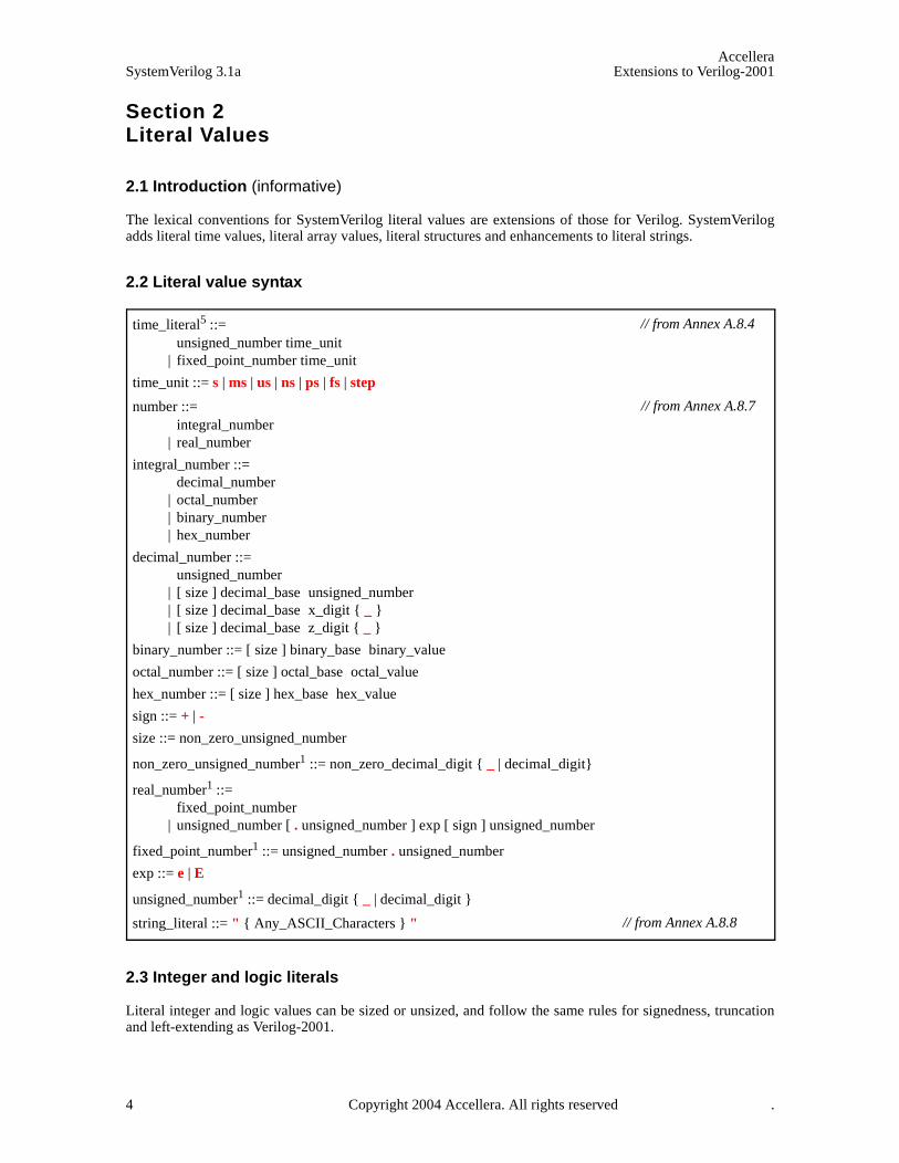
The lexical conventions for SystemVerilog literal values are extensions of those for Verilog. SystemVerilogadds literal time values, literal array values, literal structures and enhancements to literal strings.
2.2 Literal value syntax
2.3 Integer and logic literals
Literal integer and logic values can be sized or unsized, and follow the same rules for signedness, truncationand left-extending as Verilog-2001.
time_literal5 ::= unsigned_number time_unit
| fixed_point_number time_unit
time_unit ::= s | ms | us | ns | ps | fs | step
number ::= integral_number
| real_number
integral_number ::= decimal_number
| octal_number | binary_number | hex_number
decimal_number ::= unsigned_number
| [ size ] decimal_base unsigned_number | [ size ] decimal_base x_digit { _ } | [ size ] decimal_base z_digit { _ }
binary_number ::= [ size ] binary_base binary_value
octal_number ::= [ size ] octal_base octal_value
hex_number ::= [ size ] hex_base hex_value
sign ::= + | -
size ::= non_zero_unsigned_number
non_zero_unsigned_number1 ::= non_zero_decimal_digit { _ | decimal_digit}
real_number1 ::= fixed_point_number
| unsigned_number [ . unsigned_number ] exp [ sign ] unsigned_number
fixed_point_number1 ::= unsigned_number . unsigned_number
exp ::= e | E
unsigned_number1 ::= decimal_digit { _ | decimal_digit }
string_literal ::= " { Any_ASCII_Characters } "
// from Annex A.8.4
// from Annex A.8.7
// from Annex A.8.8
4 Copyright 2004 Accellera. All rights reserved .
AccelleraExtensions to Verilog-2001 SystemVerilog 3.1a
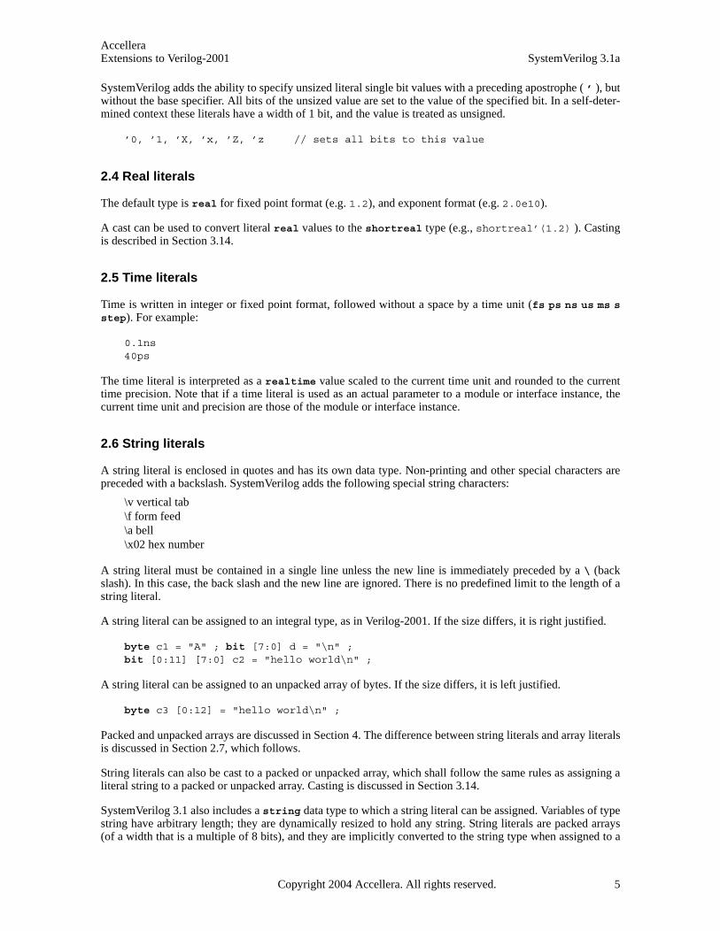
SystemVerilog adds the ability to specify unsized literal single bit values with a preceding apostrophe ( ’ ), butwithout the base specifier. All bits of the unsized value are set to the value of the specified bit. In a self-deter-mined context these literals have a width of 1 bit, and the value is treated as unsigned.
’0, ’1, ’X, ’x, ’Z, ’z // sets all bits to this value
2.4 Real literals
The default type is real for fixed point format (e.g. 1.2), and exponent format (e.g. 2.0e10).
A cast can be used to convert literal real values to the shortreal type (e.g., shortreal’(1.2) ). Castingis described in Section 3.14.
2.5 Time literals
Time is written in integer or fixed point format, followed without a space by a time unit (fs ps ns us ms sstep). For example:
0.1ns40ps
The time literal is interpreted as a realtime value scaled to the current time unit and rounded to the currenttime precision. Note that if a time literal is used as an actual parameter to a module or interface instance, thecurrent time unit and precision are those of the module or interface instance.
2.6 String literals
A string literal is enclosed in quotes and has its own data type. Non-printing and other special characters arepreceded with a backslash. SystemVerilog adds the following special string characters:
\v vertical tab\f form feed \a bell\x02 hex number
A string literal must be contained in a single line unless the new line is immediately preceded by a \ (backslash). In this case, the back slash and the new line are ignored. There is no predefined limit to the length of astring literal.
A string literal can be assigned to an integral type, as in Verilog-2001. If the size differs, it is right justified.
byte c1 = "A" ; bit [7:0] d = "\n" ;bit [0:11] [7:0] c2 = "hello world\n" ;
A string literal can be assigned to an unpacked array of bytes. If the size differs, it is left justified.
byte c3 [0:12] = "hello world\n" ;
Packed and unpacked arrays are discussed in Section 4. The difference between string literals and array literalsis discussed in Section 2.7, which follows.
String literals can also be cast to a packed or unpacked array, which shall follow the same rules as assigning aliteral string to a packed or unpacked array. Casting is discussed in Section 3.14.
SystemVerilog 3.1 also includes a string data type to which a string literal can be assigned. Variables of typestring have arbitrary length; they are dynamically resized to hold any string. String literals are packed arrays(of a width that is a multiple of 8 bits), and they are implicitly converted to the string type when assigned to a
Copyright 2004 Accellera. All rights reserved. 5
AccelleraSystemVerilog 3.1a Extensions to Verilog-2001
string type or used in an expression involving string type operands (see Section 3.7).
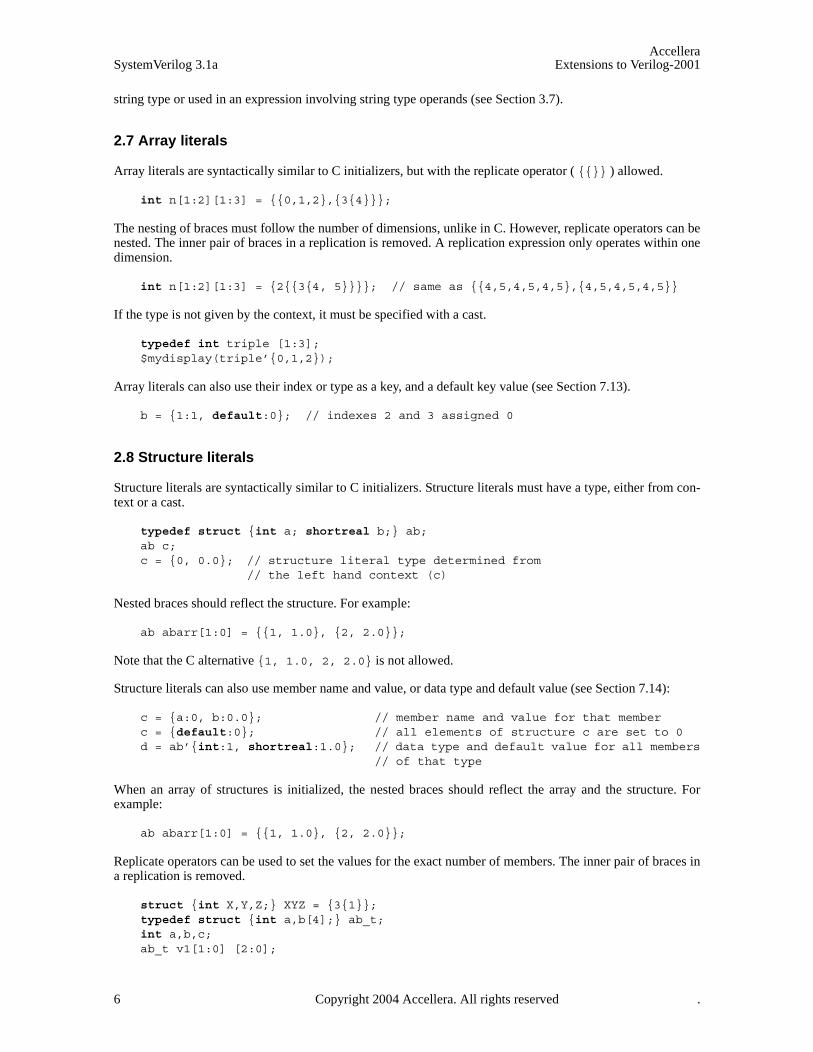
2.7 Array literals
Array literals are syntactically similar to C initializers, but with the replicate operator ( {{}} ) allowed.
int n[1:2][1:3] = {{0,1,2},{3{4}}};
The nesting of braces must follow the number of dimensions, unlike in C. However, replicate operators can benested. The inner pair of braces in a replication is removed. A replication expression only operates within onedimension.
int n[1:2][1:3] = {2{{3{4, 5}}}}; // same as {{4,5,4,5,4,5},{4,5,4,5,4,5}}
If the type is not given by the context, it must be specified with a cast.
typedef int triple [1:3]; $mydisplay(triple’{0,1,2});
Array literals can also use their index or type as a key, and a default key value (see Section 7.13).
b = {1:1, default:0}; // indexes 2 and 3 assigned 0
2.8 Structure literals
Structure literals are syntactically similar to C initializers. Structure literals must have a type, either from con-text or a cast.
typedef struct {int a; shortreal b;} ab; ab c; c = {0, 0.0}; // structure literal type determined from
// the left hand context (c)
Nested braces should reflect the structure. For example:
ab abarr[1:0] = {{1, 1.0}, {2, 2.0}};
Note that the C alternative {1, 1.0, 2, 2.0} is not allowed.
Structure literals can also use member name and value, or data type and default value (see Section 7.14):
c = {a:0, b:0.0}; // member name and value for that memberc = {default:0}; // all elements of structure c are set to 0d = ab’{int:1, shortreal:1.0}; // data type and default value for all members
// of that type
When an array of structures is initialized, the nested braces should reflect the array and the structure. Forexample:
ab abarr[1:0] = {{1, 1.0}, {2, 2.0}};
Replicate operators can be used to set the values for the exact number of members. The inner pair of braces ina replication is removed.
struct {int X,Y,Z;} XYZ = {3{1}};typedef struct {int a,b[4];} ab_t;int a,b,c;ab_t v1[1:0] [2:0];
6 Copyright 2004 Accellera. All rights reserved .

AccelleraExtensions to Verilog-2001 SystemVerilog 3.1a
v1 = {2{{3{a,{2{b,c}}}}}};
/* expands to {{3{{a,{2{b,c}}}}}, {3{{a,{2{b,c}}}}}} */
/* expands to {{{a,{2{b,c}}},{a,{2{b,c}}},{a,{2{b,c}}}},{{a,{2{b,c}}},{a,{2{b,c}}},{a,{2{b,c}}} } } */
/* expands to {{{a,{b,c,b,c}},{a,{b,c,b,c}},{a,{b,c,b,c}}},{{a,{b,c,b,c}},{a,{b,c,b,c}},{a,{b,c,b,c}}}} */
Copyright 2004 Accellera. All rights reserved. 7
AccelleraSystemVerilog 3.1a Extensions to Verilog-2001
Section 3Data Types
3.1 Introduction (informative)
To provide for clear translation to and from C, SystemVerilog supports the C built-in types, with the meaninggiven by the implementation C compiler. However, to avoid the duplication of int and long without causingconfusion, in SystemVerilog, int is 32 bits and longint is 64 bits. The C float type is called shortreal inSystemVerilog, so that it is not be confused with the Verilog-2001 real type.
Verilog-2001 has net data types, which can have 0, 1, X or Z, plus 7 strengths, giving 120 values. It also hasvariable data types such as reg, which have 4 values 0, 1, X, Z. These are not just different data types, they areused differently. SystemVerilog adds another 4-value data type, called logic (see Sections 3.3.2 and 5.6).
SystemVerilog adds string, chandle and class data types, and enhances the Verilog event type.
Verilog-2001 provides arbitrary fixed length arithmetic using reg data types. The reg type can have bits at Xor Z, however, and so are less efficient than an array of bits, because the operator evaluation must check for Xand Z, and twice as much data must be stored. SystemVerilog adds a bit type which can only have bits with 0or 1 values. See Section 3.3.2 on 2-state data types.
Automatic type conversions from a smaller number of bits to a larger number of bits involve zero extensions ifunsigned or sign extensions if signed, and do not cause warning messages. Automatic truncation from a largernumber of bits to a smaller number does cause a warning message. Automatic conversions between logic andbit do not cause warning messages. To convert a logic value to a bit, 1 converts to 1, anything else to 0.
User defined types are introduced by typedef and must be defined before they are used. Data types can alsobe parameters to modules or interfaces, making them like class templates in object-oriented programming. Oneroutine can be written to reverse the order of elements in any array, which is impossible in C and in Verilog.
Structures and unions are complicated in C, because the tags have a separate name space. SystemVerilog fol-lows the C syntax, but without the optional structure tags.
See also Section 4 on arrays.
8 Copyright 2004 Accellera. All rights reserved .

AccelleraExtensions to Verilog-2001 SystemVerilog 3.1a
3.2 Data type syntax
Syntax 3-1—data types (excerpt from Annex A)
data_type ::= integer_vector_type [ signing ] { packed_dimension }
| integer_atom_type [ signing ] | non_integer_type | struct_union [ packed [ signing ] ] { struct_union_member { struct_union_member } }
{ packed_dimension }13 | enum [ enum_base_type ] { enum_name_declaration { , enum_name_declaration } } | string | chandle | virtual [ interface ] interface_identifier | [ class_scope | package_scope ] type_identifier { packed_dimension } | class_type | event | ps_covergroup_identifier
enum_base_type ::= integer_atom_type [ signing ]
| integer_vector_type [ signing ] [ packed_dimension ]
| type_identifier [ packed_dimension ]24
enum_name_declaration ::= enum_identifier [ [ integral_number [ : integral_number ] ] ] [ = constant_expression ]
class_scope ::= class_type ::
class_type ::= ps_class_identifier [ parameter_value_assignment ]
{ :: class_identifier [ parameter_value_assignment ] }
integer_type ::= integer_vector_type | integer_atom_type
integer_atom_type ::= byte | shortint | int | longint | integer | time
integer_vector_type ::= bit | logic | reg
non_integer_type ::= shortreal | real | realtime
net_type ::= supply0 | supply1 | tri | triand | trior | tri0 | tri1 | wire | wand | wor
signing ::= signed | unsigned
simple_type ::= integer_type | non_integer_type | ps_type_identifier
struct_union_member27 ::= { attribute_instance } data_type_or_void list_of_variable_identifiers ;
data_type_or_void ::= data_type | void
struct_union ::= struct | union [ tagged ]
variable_decl_assignment ::= variable_identifier variable_dimension [ = expression ]
| dynamic_array_variable_identifier [ ] [ = dynamic_array_new ] | class_variable_identifier [ = class_new ]
| [ covergroup_variable_identifier ] = new [ ( list_of_arguments ) ]16
// from Annex A.2.2.1
// from Annex A.2.4
Copyright 2004 Accellera. All rights reserved. 9

AccelleraSystemVerilog 3.1a Extensions to Verilog-2001
3.3 Integer data types
SystemVerilog offers several integer data types, representing a hybrid of both Verilog and C data types:
3.3.1 Integral types
The term integral is used throughout this document to refer to the data types that can represent a single basicinteger data type, packed array, packed struct, packed union, enum, or time.
3.3.2 2-state (two-value) and 4-state (four-value) data types
Types that can have unknown and high-impedance values are called 4-state types. These are logic, reg,integer and time. The other types do not have unknown values and are called 2-state types, for example bitand int.
The difference between int and integer is that int is 2-state logic and integer is 4-state logic. 4-state val-ues have additional bits that encode the X and Z states. 2-state data types can simulate faster, take less memory,and are preferred in some design styles.
3.3.3 Signed and unsigned data types
Integer types use integer arithmetic and can be signed or unsigned. This affects the meaning of certain opera-tors such as ‘<’, etc.
int unsigned ui;int signed si;
The data types byte, shortint, int, integer and longint default to signed. The data types bit, regand logic default to unsigned, as do arrays of these types.
Note that the signed keyword is part of Verilog-2001. The unsigned keyword is a reserved keyword in Ver-ilog-2001, but is not utilized.
See also Section 7, on operators and expressions.
Table 3-1: Integer data types
shortint 2-state SystemVerilog data type, 16 bit signed integer
int 2-state SystemVerilog data type, 32 bit signed integer
longint 2-state SystemVerilog data type, 64 bit signed integer
byte 2-state SystemVerilog data type, 8 bit signed integer or ASCII character
bit 2-state SystemVerilog data type, user-defined vector size
logic 4-state SystemVerilog data type, user-defined vector size
reg 4-state Verilog-2001 data type, user-defined vector size
integer 4-state Verilog-2001 data type, 32 bit signed integer
time 4-state Verilog-2001 data type, 64-bit unsigned integer
10 Copyright 2004 Accellera. All rights reserved .
AccelleraExtensions to Verilog-2001 SystemVerilog 3.1a
3.4 Real and shortreal data types
The real1 data type is from Verilog-2001, and is the same as a C double. The shortreal data type is a Sys-temVerilog data type, and is the same as a C float.
3.5 Void data type
The void data type represents non-existent data. This type can be specified as the return type of functions,indicating no return value. This type can also be used for members of tagged unions (see Section 3.11).
3.6 chandle data type
The chandle data type represents storage for pointers passed using the DPI Direct Programming Interface(see Section 27). The size of this type is platform dependent, but shall be at least large enough to hold a pointeron the machine in which the tool is running.
The syntax to declare a handle is as follows:
chandle variable_name ;
where variable_name is a valid identifier. Chandles shall always be initialized to the value null, which has avalue of 0 on the C side. Chandles are very restricted in their usage, with the only legal uses being as follows:
— Only the following operators are valid on chandle variables:
— Equality (==), inequality (!=) with another chandle or with null
— Case equality (===), case inequality (!==) with another chandle or with null (same semantics as == and !=)
— Can be tested for a boolean value that shall be 0 if the chandle is null and 1 otherwise
— Only the following assignments can be made to a chandle
— Assignment from another chandle
— Assignment to null
— Chandles can be inserted into associative arrays (refer to Section 4.9), but the relative ordering of any twoentries in such an associative array can vary, even between successive runs of the same tool
— Chandles can be used within a class
— Chandles can be passed as arguments to functions or tasks
— Chandles can be returned from functions
The use of chandles is restricted as follows:
— Ports shall not have the chandle data type
— Chandles shall not be assigned to variables of any other type
— Chandles shall not be used:
— In any expression other than as permitted above
— As ports
— In sensitivity lists or event expressions
1 The real and shortreal types are represented as described by IEEE 754-1985, an IEEE standard for floating point numbers (See [K1] in Annex K).
Copyright 2004 Accellera. All rights reserved. 11
AccelleraSystemVerilog 3.1a Extensions to Verilog-2001
— In continuous assignments
— In unions
— In packed types
3.7 String data type
SystemVerilog includes a string data type, which is a variable size, dynamically allocated array of bytes.SystemVerilog also includes a number of special methods to work with strings.
Verilog supports string literals, but only at the lexical level. In Verilog, string literals behave like packed arraysof a width that is a multiple of 8 bits. A string literal assigned to a packed array of an integral variable of a dif-ferent size is either truncated to the size of the variable or padded with zeroes to the left as necessary.
In SystemVerilog string literals behave exactly the same as in Verilog However, SystemVerilog also supportsthe string data type to which a string literal can be assigned. When using the string data type instead of anintegral variable, strings can be of arbitrary length and no truncation occurs. Literal strings are implicitly con-verted to the string type when assigned to a string type or used in an expression involving string typeoperands.
Variables of type string can be indexed from 0 to N-1 (the last element of the array), and they can take on thespecial value “”, which is the empty string. Reading an element of a string yields a byte.
The syntax to declare a string is:
string variable_name [= initial_value];
where variable_name is a valid identifier and the optional initial_value can be a string literal or the value “”for an empty string. For example:
string myName = "John Smith";
If an initial value is not specified in the declaration, the variable is initialized to “”, the empty string.
SystemVerilog provides a set of operators that can be used to manipulate combinations of string variables andstring literals. The basic operators defined on the string data type are listed in Table 3-2.
A string literal can be assigned to a string or an integral type. If their size differs the literal is right justifiedand either truncated on the left or zero filled on the left, as necessary. For example:
byte c = "A"; // assign to c "A"bit [10:0] a = "\x41"; // assigns to a ‘b000_0100_0001bit [1:4][7:0] h = "hello" ; // assigns to h "ello"
A string, string literal, or packed array can be assigned to a string variable. The string variable shallgrow or shrink to accommodate the packed array. If the size (in bits) of the packed array is not a multiple of 8,then the packed array is zero filled on the left.
For example:
string s1 = "hello"; // sets s1 to "hello"bit [11:0] b = 12’ha41; string s2 = b; // sets s2 to ’h0a41
As a second example:
reg [15:0] r;integer i = 1;
12 Copyright 2004 Accellera. All rights reserved .
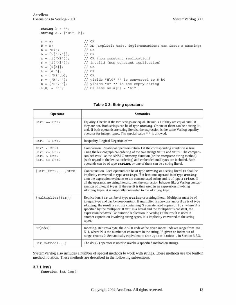
AccelleraExtensions to Verilog-2001 SystemVerilog 3.1a
string b = ""; string a = {"Hi", b};
r = a; // OKb = r; // OK (implicit cast, implementations can issue a warning) b = "Hi"; // OKb = {5{"Hi"}}; // OKa = {i{"Hi"}}; // OK (non constant replication)r = {i{"Hi"}}; // invalid (non constant replication)a = {i{b}}; // OKa = {a,b}; // OKa = {"Hi",b}; // OKr = {"H",""}; // yields "H\0" "" is converted to 8’b0 b = {"H",""}; // yields "H" "" is the empty string a[0] = "h"; // OK same as a[0] = "hi" )
SystemVerilog also includes a number of special methods to work with strings. These methods use the built-inmethod notation. These methods are described in the following subsections.
3.7.1 len()function int len()
Table 3-2: String operators
Operator Semantics
Str1 == Str2 Equality. Checks if the two strings are equal. Result is 1 if they are equal and 0 if they are not. Both strings can be of type string. Or one of them can be a string lit-eral. If both operands are string literals, the expression is the same Verilog equality operator for integer types. The special value " " is allowed.
Str1 != Str2 Inequality. Logical Negation of ==
Str1 < Str2Str1 <= Str2Str1 > Str2Str1 >= Str2
Comparison. Relational operators return 1 if the corresponding condition is true using the lexicographical ordering of the two strings Str1 and Str2. The compari-son behaves like the ANSI C strcmp function (or the compare string method) (with regard to the lexical ordering) and embedded null bytes are included. Both operands can be of type string, or one of them can be a string literal.
{Str1,Str2,...,Strn} Concatenation. Each operand can be of type string or a string literal (it shall be implicitly converted to type string). If at least one operand is of type string, then the expression evaluates to the concatenated string and is of type string. If all the operands are string literals, then the expression behaves like a Verilog concat-enation of integral types; if the result is then used in an expression involving string types, it is implicitly converted to the string type.
{multiplier{Str}} Replication. Str can be of type string or a string literal. Multiplier must be of integral type and can be non-constant. If multiplier is non-constant or Str is of type string, the result is a string containing N concatenated copies of Str, where N is specified by the multiplier. If Str is a literal and the multiplier is constant, the expression behaves like numeric replication in Verilog (if the result is used in another expression involving string types, it is implicitly converted to the string type).
Str[index] Indexing. Returns a byte, the ASCII code at the given index. Indexes range from 0 to N-1, where N is the number of characters in the string. If given an index out of range, returns 0. Semantically equivalent to Str.getc(index), in Section 3.7.3.
Str.method(...) The dot (.) operator is used to invoke a specified method on strings.
Copyright 2004 Accellera. All rights reserved. 13

AccelleraSystemVerilog 3.1a Extensions to Verilog-2001
— str.len() returns the length of the string, i.e., the number of characters in the string (excluding any ter-minating character).
— If str is "", then str.len() returns 0.
3.7.2 putc()task putc(int i, string s)task putc(int i, byte c)
— str.putc(i, c) replaces the ith character in str with the given integral value.
— str.putc(i, s) replaces the ith character in str with the first character in s.
— s can be any expression that can be assigned to a string.
— putc does not change the size of str: If i < 0 or i >= str.len(), then str is unchanged.
Note: str.putc(j, x) is semantically equivalent to str[j] = x.
3.7.3 getc()function int getc(int i)
— str.getc(i) returns the ASCII code of the ith character in str.
— If i < 0 or i >= str.len(), then str.getc(i) returns 0.
Note: x = str.getc(j) is semantically equivalent to x = str[j].
3.7.4 toupper()function string toupper()
— str.toupper() returns a string with characters in str converted to uppercase.
— str is unchanged.
3.7.5 tolower()function string tolower()
— str.tolower() returns a string with characters in str converted to lowercase.
— str is unchanged.
3.7.6 compare()function int compare(string s)
— str.compare(s) compares str and s, as in the ANSI C strcmp function (with regard to lexical order-ing and return value), and embedded null bytes are included.
See the relational string operators in Section 3.7, Table 3-2.
3.7.7 icompare()function int icompare(string s)
— str.icompare(s) compares str and s, like the ANSI C strcmp function (with regard to lexical order-ing and return value), but the comparison is case insensitive and embedded null bytes are included.
3.7.8 substr()function string substr(int i, int j)
— str.substr(i, j) returns a new string that is a substring formed by characters in position i through jof str.
14 Copyright 2004 Accellera. All rights reserved .

AccelleraExtensions to Verilog-2001 SystemVerilog 3.1a
— If i < 0, j < i, or j >= str.len(), substr() returns " " (the empty string).
3.7.9 atoi(), atohex(), atooct(), atobin()function integer atoi()function integer atohex()function integer atooct()function integer atobin()
— str.atoi() returns the integer corresponding to the ASCII decimal representation in str. For example:
str = "123";int i = str.atoi(); // assigns 123 to i.
The conversion scans all leading digits and underscore characters ( _ ) and stops as soon as it encountersany other character, or the end of the string. Returns zero if no digits were encountered. It does not parsethe full syntax for integer literals (sign, size, tick, base).
— atohex interprets the string as hexadecimal.
— atooct interprets the string as octal.
— atobin interprets the string as binary.
3.7.10 atoreal()function real atoreal()
— str.atoreal() returns the real number corresponding to the ASCII decimal representation in str.
The conversion parses Verilog syntax for real constants. The scan stops as soon as it encounters any char-acter that does not conform to this syntax, or the end of the string. Returns zero if no digits were encoun-tered.
3.7.11 itoa()task itoa(integer i)
— str.itoa(i) stores the ASCII decimal representation of i into str (inverse of atoi).
3.7.12 hextoa() task hextoa(integer i)
— str.hextoa(i) stores the ASCII hexadecimal representation of i into str (inverse of atohex).
3.7.13 octtoa()task octtoa(integer i)
— str.octtoa(i) stores the ASCII octal representation of i into str (inverse of atooct).
3.7.14 bintoa()task bintoa(integer i)
— str.bintoa(i) stores the ASCII binary representation of i into str (inverse of atobin).
3.7.15 realtoa()task realtoa(real r)
— str.realtoa(r) stores the ASCII real representation of i into str (inverse of atoreal).
Copyright 2004 Accellera. All rights reserved. 15
AccelleraSystemVerilog 3.1a Extensions to Verilog-2001
3.8 Event data type
The event data type is an enhancement over Verilog named events. SystemVerilog events provide a handle toa synchronization object. Like Verilog, event variables can be explicitly triggered and waited for. Furthermore,SystemVerilog events have a persistent triggered state that lasts for the duration of the entire time step. In addi-tion, an event variable can be assigned another event variable or the special value null. When assignedanother event variable, both event variables refer to the same synchronization object. When assigned null, theassociation between the synchronization object and the event variable is broken. Events can be passed as argu-ments to tasks.
The syntax to declare an event is:
event variable_name [= initial_value];
Where variable_name is a valid identifier and the optional initial_value can be another event variable or thespecial value null.
If an initial value is not specified then the variable is initialized to a new synchronization object.
If the event is assigned null, the event becomes nonblocking, as if it were permanently triggered.
Examples:
event done; // declare a new event called doneevent done_too = done; // declare done_too as alias to doneevent empty = null; // event variable with no synchronization object
Event operations and semantics are discussed in detail in Section 13.5.
3.9 User-defined types
Syntax 3-2—user-defined types (excerpt from Annex A)
The user can define a new type using typedef, as in C.
typedef int intP;
This can then be instantiated as:
intP a, b;
A type can be used before it is defined, provided it is first identified as a type by an empty typedef:
typedef foo;foo f = 1;typedef int foo;
Note that this does not apply to enumeration values, which must be defined before they are used.
User defined type identifiers have the same scoping rules as data identifiers, except that hierarchical referenceto type identifiers shall not be allowed. References to type identifiers defined within an interface through portsare allowed provided they are locally re-defined before being used.
type_declaration ::= typedef data_type type_identifier variable_dimension ;
| typedef interface_instance_identifier . type_identifier type_identifer ; | typedef [ enum | struct | union | class ] type_identifier ;
// from Annex A.2.1.3
16 Copyright 2004 Accellera. All rights reserved .
AccelleraExtensions to Verilog-2001 SystemVerilog 3.1a
interface intf_i;
typedef int data_t;endinterface module sub(intf_i p)
typedef p.data_t my_data_t;my_data_t data;
// type of ’data’ will be int when connected to interface aboveendmodule
User-defined type names must be used for complex data types in casting (see Section 3.14, below), which onlyallows simple type names, and as type parameter values when unpacked array types are used.
Sometimes a user defined type needs to be declared before the contents of the type has been defined. This is ofuse with user defined types derived from enum, struct, union, and class. For an example, seeSection 11.24. Support for this is provided by the following forms for typedef:
typedef enum type_declaration_identifier;typedef struct type_declaration_identifier;typedef union type_declaration_identifier;typedef class type_declaration_identifier;typedef type_declaration_identifier;
Note that, while this is useful for coupled definitions of classes as shown in Section 11.24, it cannot be used forcoupled definitions of structures, since structures are statically declared and there is no support for pointers tostructures.
The last form shows that the type of the user defined type does not have to be defined in the forward declara-tion.
A typedef inside a generate shall not define the actual type of a forward definition that exists outside thescope of the forward definition.
3.10 Enumerations
Syntax 3-3—enumerated types (excerpt from Annex A)
An enumerated type declares a set of integral named constants. Enumerated data types provide the capabilityto abstractly declare strongly typed variables without either a data type or data value(s) and later add therequired data type and value(s) for designs that require more definition. Enumerated data types also can be eas-ily referenced or displayed using the enumerated names as opposed to the enumerated values.
In the absence of a data type declaration, the default data type shall be int. Any other data type used with enu-merated types shall require an explicit data type declaration.
data_type ::= ...
| enum [ enum_base_type ] { enum_name_declaration { , enum_name_declaration } }
enum_base_type ::= integer_atom_type [ signing ]
| integer_vector_type [ signing ] [ packed_dimension ]
| type_identifier [ packed_dimension ]24
enum_name_declaration ::= enum_identifier [ [ integral_number [ : integral_number ] ] ] [ = constant_expression ]
// from Annex A.2.2.1
Copyright 2004 Accellera. All rights reserved. 17

AccelleraSystemVerilog 3.1a Extensions to Verilog-2001
An enumerated type defines a set of named values. In the following example, light1 and light2 are definedto be variables of the anonymous (unnamed) enumerated int type that includes the three members: red, yel-low and green.
enum {red, yellow, green} light1, light2; // anonymous int type
An enumerated name with x or z assignments assigned to an enum with no explicit data type or an explicit 2-state declaration shall be a syntax error.
// Syntax error: IDLE=2’b00, XX=2’bx <ERROR>, S1=2’b01, S2=2’b10 enum {IDLE, XX=’x, S1=2’b01, S2=2’b10} state, next;
An enum declaration of a 4-state type, such as integer, that includes one or more names with x or z assignmentsshall be permitted.
// Correct: IDLE=0, XX=’x, S1=1, S2=2 enum integer {IDLE, XX=’x, S1=’b01, S2=’b10} state, next;
An unassigned enumerated name that follows an enum name with x or z assignments shall be a syntax error.
// Syntax error: IDLE=2’b00, XX=2’bx, S1=??, S2=??enum integer {IDLE, XX=’x, S1, S2} state, next;
The values can be cast to integer types, and increment from an initial value of 0. This can be overridden.
enum {bronze=3, silver, gold} medal; // silver=4, gold=5
The values can be set for some of the names and not set for other names. The optional value of an enum namedconstant is an elaboration time constant expression (see Section 5.3) and can include references to parameters,local parameters, genvars, other enum named constants, and constant functions of these. Hierarchical namesand const variables are not allowed. A name without a value is automatically assigned an increment of thevalue of the previous name.
// c is automatically assigned the increment-value of 8enum {a=3, b=7, c} alphabet;
If an automatically incremented value is assigned elsewhere in the same enumeration, this shall be a syntaxerror.
// Syntax error: c and d are both assigned 8enum {a=0, b=7, c, d=8} alphabet;
If the first name is not assigned a value, it is given the initial value of 0.
// a=0, b=7, c=8enum {a, b=7, c} alphabet;
Any enumeration encoding value that is outside the representable range of the enum shall be an error. If any ofthe enum members are defined with a different sized constant, this shall be a syntax error.
// Correct declaration - bronze and gold are unsizedenum bit [3:0] {bronze='h3, silver, gold='h5} medal4;
// Correct declaration - bronze and gold sizes are redundantenum bit [3:0] {bronze=4'h3, silver, gold=4'h5} medal4;
// Error in the bronze and gold member declarationsenum bit [3:0] {bronze=5'h13, silver, gold=3'h5} medal4;
18 Copyright 2004 Accellera. All rights reserved .
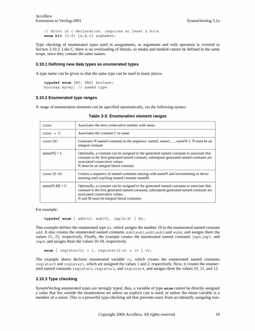
AccelleraExtensions to Verilog-2001 SystemVerilog 3.1a
// Error in c declaration, requires at least 2 bitsenum bit [0:0] {a,b,c} alphabet;
Type checking of enumerated types used in assignments, as arguments and with operators is covered inSection 3.10.3. Like C, there is no overloading of literals, so medal and medal4 cannot be defined in the samescope, since they contain the same names.
3.10.1 Defining new data types as enumerated types
A type name can be given so that the same type can be used in many places.
typedef enum {NO, YES} boolean;boolean myvar; // named type
3.10.2 Enumerated type ranges
A range of enumeration elements can be specified automatically, via the following syntax:
For example:
typedef enum { add=10, sub[5], jmp[6:8] } E1;
This example defines the enumerated type E1, which assigns the number 10 to the enumerated named constantadd. It also creates the enumerated named constants sub0,sub1,sub2,sub3,and sub4, and assigns them thevalues 11...15, respectively. Finally, the example creates the enumerated named constants jmp6,jmp7, andjmp8, and assigns them the values 16-18, respectively.
enum { register[2] = 1, register[2:4] = 10 } vr;
The example above declares enumerated variable vr, which creates the enumerated named constantsregister0 and register1, which are assigned the values 1 and 2, respectively. Next, it creates the enumer-ated named constants register2, register3, and register4, and assigns them the values 10, 11, and 12.
3.10.3 Type checking
SystemVerilog enumerated types are strongly typed, thus, a variable of type enum cannot be directly assigneda value that lies outside the enumeration set unless an explicit cast is used, or unless the enum variable is amember of a union. This is a powerful type-checking aid that prevents users from accidentally assigning non-
Table 3-3: Enumeration element ranges
name Associates the next consecutive number with name.
name = C Associates the constant C to name
name[N] Generates N named constants in the sequence: name0, name1, ..., nameN-1. N must be an integral constant
name[N] = C Optionally, a constant can be assigned to the generated named constants to associate that constant to the first generated named constant; subsequent generated named constants are associated consecutive values.N must be an integral literal constant.
name[N:M] Creates a sequence of named constants starting with nameN and incrementing or decre-menting until reaching named constant nameM.
name[N:M] = C Optionally, a constant can be assigned to the generated named constants to associate that constant to the first generated named constants; subsequent generated named constants are associated consecutive values.N and M must be integral literal constants.
Copyright 2004 Accellera. All rights reserved. 19
AccelleraSystemVerilog 3.1a Extensions to Verilog-2001
existent values to variables of an enumerate type. This restriction only applies to an enumeration that is explic-itly declared as a type. The enumeration values can still be used as constants in expressions, and the results canbe assigned to any variable of a compatible integral type.
Both the enumeration names and their integer values must be unique. The values can be set to any integral con-stant value, or auto-incremented from an initial value of 0. It is an error to set two values to the same name, orto set a value to the same auto-incremented value.
Enumerated variables are type-checked in assignments, arguments, and relational operators. Enumerated vari-ables are auto-cast into integral values, but, assignment of arbitrary expressions to an enumerated variablerequires an explicit cast.
For example:
typedef enum { red, green, blue, yellow, white, black } Colors;
This operation assigns a unique number to each of the color identifiers, and creates the new data type Colors.This type can then be used to create variables of that type.
Colors c;c = green;c = 1; // Invalid assignmentif ( 1 == c ) // OK. c is auto-cast to integer
In the example above, the value green is assigned to the variable c of type Colors. The second assignment isinvalid because of the strict typing rules enforced by enumerated types.
Casting can be used to perform an assignment of a different data type, or an out of range value, to an enumer-ated type. Casting is discussed in Sections 3.10.4, 3.14 and 3.15.
The result of any operation on an enumeration variable after the variable has been assigned an out of rangevalue shall be undefined.
3.10.4 Enumerated types in numerical expressions
Elements of enumerated type variables can be used in numerical expressions. The value used in the expressionis the numerical value associated with the enumerated value. For example:
typedef enum { red, green, blue, yellow, white, black } Colors;
Colors col;integer a, b;
a = blue * 3;col = yellow;b = col + green;
From the previous declaration, blue has the numerical value 2. This example assigns a the value of 6 (2*3),and it assigns b a value of 4 (3+1).
An enum variable or identifier used as part of an expression is automatically cast to the base type of the enumdeclaration (either explicitly or using int as the default). An assignment to an enum variable from an expres-sion other than the same type shall require a cast. Casting to an enum type shall cause a conversion of theexpression to its base type without checking the validity of the value (unless a dynamic cast is used asdescribed in Section 3.15).
typedef enum {Red, Green, Blue} Colors; typedef enum {Mo,Tu,We,Th,Fr,Sa,Su} Week; Colors C;
20 Copyright 2004 Accellera. All rights reserved .
AccelleraExtensions to Verilog-2001 SystemVerilog 3.1a
Week W; int I;
C = Colors’(C+1); // C is converted to an integer, then added to// one, then converted back to a Colors type
C = C + 1; C++; C+=2; C = I; // Illegal because they would all be // assignments of expressions without a cast
C = Colors’(Su); // Legal; puts an out of range value into C
I = C + W; // Legal; C and W are automatically cast to int
SystemVerilog includes a set of specialized methods to enable iterating over the values of enumerated types.
3.10.4.1 first()
The prototype for the first() method is:
function enum first();
The first() method returns the value of the first member of the enumeration.
3.10.4.2 last()
The prototype for the last() method is:
function enum last();
The last() method returns the value of the last member of the enumeration.
3.10.4.3 next()
The prototype for the next() method is:
function enum next( int unsigned N = 1 );
The next() method returns the Nth next enumeration value (default is the next one) starting from the currentvalue of the given variable. A wrap to the start of the enumeration occurs when the end of the enumeration isreached. If the given value is not a member of the enumeration, the next() method returns the first member.
3.10.4.4 prev()
The prototype for the prev() method is:
function enum prev( int unsigned N = 1 );
The prev() method returns the Nth previous enumeration value (default is the previous one) starting from thecurrent value of the given variable. A wrap to the end of the enumeration occurs when the start of the enumer-ation is reached. If the given value is not a member of the enumeration, the prev() method returns the lastmember.
3.10.4.5 num()
The prototype for the num() method is:
function int num();
The num() method returns the number of elements in the given enumeration.
Copyright 2004 Accellera. All rights reserved. 21

AccelleraSystemVerilog 3.1a Extensions to Verilog-2001
3.10.4.6 name()
The prototype for the name() method is:
function string name();
The name() method returns the string representation of the given enumeration value. If the given value is nota member of the enumeration, the name() method returns the empty string.
3.10.4.7 Using enumerated type methods
The following code fragment shows how to display the name and value of all the members of an enumeration.
typedef enum { red, green, blue, yellow } Colors;Colors c = c.first;forever begin
$display( "%s : %d\n", c.name, c );if( c == c.last ) break;c = c.next;
end
3.11 Structures and unions
Syntax 3-4—Structures and unions (excerpt from Annex A)
Structure and union declarations follow the C syntax, but without the optional structure tags before the ‘{‘.
struct { bit [7:0] opcode; bit [23:0] addr; }IR; // anonymous structure // defines variable IR
IR.opcode = 1; // set field in IR.
Some additional examples of declaring structure and unions are:
typedef struct { bit [7:0] opcode; bit [23:0] addr;
} instruction; // named structure typeinstruction IR; // define variable
typedef union { int i; shortreal f; } num; // named union typenum n; n.f = 0.0; // set n in floating point format
typedef struct { bit isfloat;
data_type ::= ...
| struct_union [ packed [ signing ] ] { struct_union_member { struct_union_member } }
{ packed_dimension }13
struct_union_member27 ::= { attribute_instance } data_type_or_void list_of_variable_identifiers ;
data_type_or_void ::= data_type | void
struct_union ::= struct | union [ tagged ]
// from Annex A.2.2.1
22 Copyright 2004 Accellera. All rights reserved .

AccelleraExtensions to Verilog-2001 SystemVerilog 3.1a
union { int i; shortreal f; } n; // anonymous type } tagged_st; // named structure
tagged_st a[9:0]; // array of structures
A structure can be assigned as a whole, and passed to or from a function or task as a whole.
Section 2.8 discusses assigning initial values to a structure.
A packed structure consists of bit fields, which are packed together in memory without gaps. This means thatthey are easily converted to and from bit vectors. An unpacked structure has an implementation-dependentpacking, normally matching the C compiler.
Like a packed array, a packed structure can be used as a whole with arithmetic and logical operators. The firstmember specified is the most significant and subsequent members follow in decreasing significance. Thestructures are declared using the packed keyword, which can be followed by the signed or unsigned key-words, according to the desired arithmetic behavior. The default is unsigned:
struct packed signed { int a; shortint b; byte c; bit [7:0] d;
} pack1; // signed, 2-state
struct packed unsigned {time a; integer b; logic [31:0] c;
} pack2; // unsigned, 4-state
If any data type within a packed structure is 4-state, the whole structure is treated as 4-state. Any 2-state mem-bers are converted as if cast. One or more bits of a packed structure can be selected as if it were a packed array,assuming an [n-1:0] numbering:
pack1 [15:8] // c
Non-integer data types, such as real and shortreal, are not allowed in packed structures or unions. Nor areunpacked arrays.
A packed structure can be used with a typedef.
typedef struct packed { // default unsigned bit [3:0] GFC; bit [7:0] VPI; bit [11:0] VCI; bit CLP; bit [3:0] PT ; bit [7:0] HEC; bit [47:0] [7:0] Payload; bit [2:0] filler;
} s_atmcell;
A packed union shall contain members that must be packed structures, or packed arrays or integer data typesall of the same size (in contrast to an unpacked union, where the members can be different sizes). This ensuresthat you can read back a union member that was written as another member. A packed union can also be usedas a whole with arithmetic and logical operators, and its behavior is determined by the signed or unsigned key-word, the latter being the default. If a packed union contains a 2-state member and a 4-state member, the entireunion is 4 state. There is an implicit conversion from 4-state to 2-state when reading and from 2-state to 4-state
Copyright 2004 Accellera. All rights reserved. 23

AccelleraSystemVerilog 3.1a Extensions to Verilog-2001
when writing the 2-state member.
For example, a union can be accessible with different access widths:
typedef union packed { // default unsigned s_atmcell acell; bit [423:0] bit_slice; bit [52:0][7:0] byte_slice;
} u_atmcell;
u_atmcell u1;byte b; bit [3:0] nib;b = u1.bit_slice[415:408]; // same as b = u1.byte_slice[51];nib = u1.bit_slice [423:420]; // same as nib = u1.acell.GFC;
Note that writing one member and reading another is independent of the byte ordering of the machine, unlike anormal union of normal structures, which are C-compatible and have members in ascending address order.
The signing of unpacked structures is not allowed. The following declaration would be considered illegal:
typedef struct signed {int f1 ;logic f2 ;
} sIllegalSignedUnpackedStructType; // illegal declaration
The qualifier tagged in a union declares it as a tagged union, which is a type-checked union. An ordinary(untagged) union can be updated using a value of one member type and read as a value of another membertype, which is a potential type loophole. A tagged union stores both the member value and a tag, i.e., additionalbits representing the current member name. The tag and value can only be updated together consistently, usinga statically type-checked tagged union expression (Section 7.15). The member value can only be read with atype that is consistent with the current tag value (i.e., member name). Thus, it is impossible to store a value ofone type and (mis)interpret the bits as another type.
In addition to type safety, the use of member names as tags also makes code simpler and smaller than code thathas to track unions with explicit tags. Tagged unions can also be used with pattern matching (Section 8.4),which improves readability even further.
In tagged unions, members can be declared with type void, when all the information is in the tag itself, as inthe following example of an integer together with a valid bit:
typedef union tagged {void Invalid;int Valid;
} VInt;
A value of VInt type is either Invalid and contains nothing, or is Valid and contains an int. Section 7.15describes how to construct values of this type, and also describes how it is impossible to read an integer out ofa VInt value that currently has the Invalid tag.
Example:
typedef union tagged {struct {
bit [4:0] reg1, reg2, regd;} Add;union tagged {
bit [9:0] JmpU;struct {
bit [1:0] cc;
24 Copyright 2004 Accellera. All rights reserved .

AccelleraExtensions to Verilog-2001 SystemVerilog 3.1a
bit [9:0] addr;} JmpC;
} Jmp;} Instr;
A value of Instr type is either an Add instruction, in which case it contains three 5-bit register fields, or it is aJmp instruction. In the latter case, it is either an unconditional jump, in which case it contains a 10-bit destina-tion address, or it is a conditional jump, in which case it contains a 2-bit condition-code register field and a 10-bit destination address. Section 7.15 describes how to construct values of Instr type, and describes how, inorder to read the cc field, for example, the instruction must have opcode Jmp and sub-opcode JmpC.
When the packed qualifier is used on a tagged union, all the members must have packed types, but they do nothave to be of the same size. The (standard) representation for a packed tagged union is the following.
— The size is always equal to the number of bits needed to represent the tag plus the maximum of the sizes ofthe members.
— The size of the tag is the minimum number of bits needed to code for all the member names (e.g., 5 to 8members would need 3 tag bits).
— The tag bits are always left-justified (i.e., towards the most-significant bits).
— For each member, the member bits are always right-justified (i.e., towards the least significant bits).
— The bits between the tag bits and the member bits are undefined. In the extreme case of a void member,only the tag is significant and all the remaining bits are undefined.
The representation scheme is applied recursively to any nested tagged unions.
Example: If the VInt type definition had the packed qualifier, Invalid and Valid values will have the fol-lowing layouts, respectively:
321
0 x x x x x x x ... ... ... x x x x x x x x x
321
1 ... an int value ...
tag is 0 for Invalid, 1 for Valid
Copyright 2004 Accellera. All rights reserved. 25
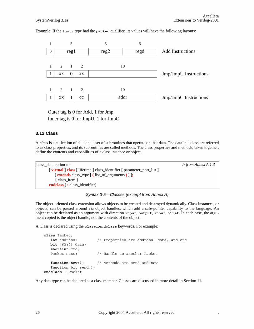
AccelleraSystemVerilog 3.1a Extensions to Verilog-2001
Example: If the Instr type had the packed qualifier, its values will have the following layouts:
3.12 Class
A class is a collection of data and a set of subroutines that operate on that data. The data in a class are referredto as class properties, and its subroutines are called methods. The class properties and methods, taken together,define the contents and capabilities of a class instance or object.
Syntax 3-5—Classes (excerpt from Annex A)
The object-oriented class extension allows objects to be created and destroyed dynamically. Class instances, orobjects, can be passed around via object handles, which add a safe-pointer capability to the language. Anobject can be declared as an argument with direction input, output, inout, or ref. In each case, the argu-ment copied is the object handle, not the contents of the object.
A Class is declared using the class...endclass keywords. For example:
class Packet; int address; // Properties are address, data, and crcbit [63:0] data;shortint crc;Packet next; // Handle to another Packet
function new(); // Methods are send and newfunction bit send();
endclass : Packet
Any data type can be declared as a class member. Classes are discussed in more detail in Section 11.
11
1 0
10
Add Instructions
51
0 reg1
5 5
reg2 regd
2 2
xx xx Jmp/JmpU Instructions
11
1 1
10
addr
2 2
xx cc Jmp/JmpC Instructions
Outer tag is 0 for Add, 1 for JmpInner tag is 0 for JmpU, 1 for JmpC
class_declaration ::= [ virtual ] class [ lifetime ] class_identifier [ parameter_port_list ]
[ extends class_type [ ( list_of_arguments ) ] ]; { class_item }
endclass [ : class_identifier]
// from Annex A.1.3
26 Copyright 2004 Accellera. All rights reserved .
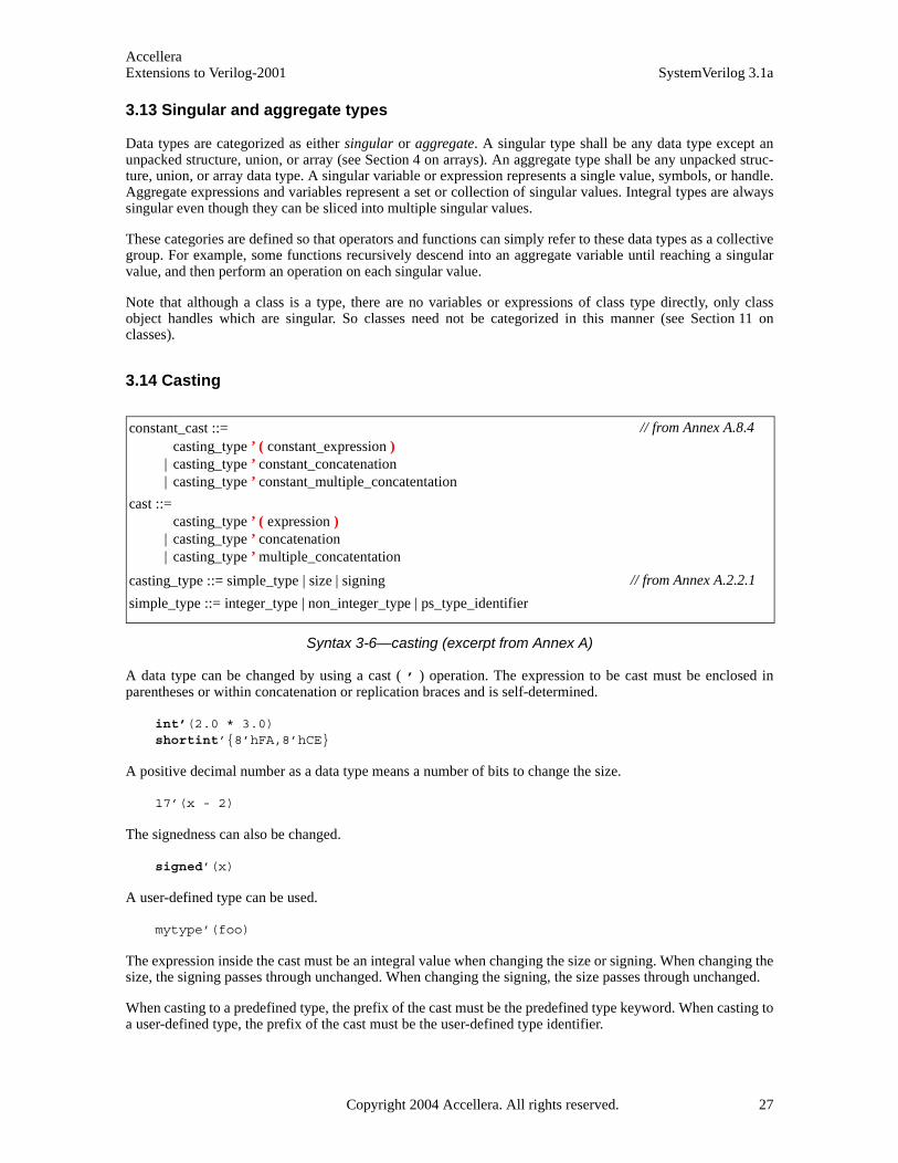
AccelleraExtensions to Verilog-2001 SystemVerilog 3.1a
3.13 Singular and aggregate types
Data types are categorized as either singular or aggregate. A singular type shall be any data type except anunpacked structure, union, or array (see Section 4 on arrays). An aggregate type shall be any unpacked struc-ture, union, or array data type. A singular variable or expression represents a single value, symbols, or handle.Aggregate expressions and variables represent a set or collection of singular values. Integral types are alwayssingular even though they can be sliced into multiple singular values.
These categories are defined so that operators and functions can simply refer to these data types as a collectivegroup. For example, some functions recursively descend into an aggregate variable until reaching a singularvalue, and then perform an operation on each singular value.
Note that although a class is a type, there are no variables or expressions of class type directly, only classobject handles which are singular. So classes need not be categorized in this manner (see Section 11 onclasses).
3.14 Casting
Syntax 3-6—casting (excerpt from Annex A)
A data type can be changed by using a cast ( ’ ) operation. The expression to be cast must be enclosed inparentheses or within concatenation or replication braces and is self-determined.
int’(2.0 * 3.0)shortint’{8’hFA,8’hCE}
A positive decimal number as a data type means a number of bits to change the size.
17’(x - 2)
The signedness can also be changed.
signed’(x)
A user-defined type can be used.
mytype’(foo)
The expression inside the cast must be an integral value when changing the size or signing. When changing thesize, the signing passes through unchanged. When changing the signing, the size passes through unchanged.
When casting to a predefined type, the prefix of the cast must be the predefined type keyword. When casting toa user-defined type, the prefix of the cast must be the user-defined type identifier.
constant_cast ::= casting_type ’ ( constant_expression )
| casting_type ’ constant_concatenation | casting_type ’ constant_multiple_concatentation
cast ::= casting_type ’ ( expression )
| casting_type ’ concatenation | casting_type ’ multiple_concatentation
casting_type ::= simple_type | size | signing
simple_type ::= integer_type | non_integer_type | ps_type_identifier
// from Annex A.8.4
// from Annex A.2.2.1
Copyright 2004 Accellera. All rights reserved. 27
AccelleraSystemVerilog 3.1a Extensions to Verilog-2001
When a shortreal is converted to an int or to 32 bits, its value is rounded, as in Verilog. Therefore, the con-version can lose information. To convert a shortreal to its underlying bit representation without a loss ofinformation, use $shortrealtobits as defined in Section 23.6. To convert from the bit representation of ashortreal value into a shortreal, use $bitstoshortreal as defined in Section 23.6.
Structures can be converted to bits preserving the bit pattern, which means they can be converted back to thesame value without any loss of information. When unpacked data is converted to the packed representation,the order of the data in the packed representation is such that the first field in the structure occupies the mostsignificant bits. The effect is the same as a concatenation of the data items (struct fields or array elements) inorder. The type of the elements in an unpacked structure or array must be valid for a packed representation inorder to be cast to any other type, whether packed or unpacked.
An explicit cast between packed types is not required since they are treated as integral values, but a cast can beused by tools to perform stronger type checking.
The following example demonstrates how the $bits attribute is used to obtain the size of a structure in bits(the $bits system function is discussed in Section 23.4), which facilitates conversion of the structure into apacked array:
typedef struct { bit isfloat; union { int i; shortreal f; } n; // anonymous type
} tagged_st; // named structure
typedef bit [$bits(tagged_st) - 1 : 0] tagbits; // tagged_st defined above
tagged_st a [7:0]; // unpacked array of structures
tagbits t = tagbits’(a[3]); // convert structure to array of bitsa[4] = tagged_st’(t); // convert array of bits back to structure
Note that the bit data type loses X values. If these are to be preserved, the logic type should be used instead.
The size of a union in bits is the size of its largest member. The size of a logic in bits is 1.
For compatibility, the Verilog functions $itor, $rtoi, $bitstoreal, $realtobits, $signed,$unsigned can also be used.
3.15 $cast dynamic casting
SystemVerilog provides the $cast system task to assign values to variables that might not ordinarily be validbecause of differing data type. $cast can be called as either a task or a function.
The syntax for $cast is:
function int $cast( singular dest_var, singular source_exp );
or
task $cast( singular dest_var, singular source_exp );
The dest_var is the variable to which the assignment is made.
The source_exp is the expression that is to be assigned to the destination variable.
Use of $cast as either a task or a function determines how invalid assignments are handled.
When called as a task, $cast attempts to assign the source expression to the destination variable. If the assign-ment is invalid, a runtime error occurs and the destination variable is left unchanged.
28 Copyright 2004 Accellera. All rights reserved .
AccelleraExtensions to Verilog-2001 SystemVerilog 3.1a
When called as a function, $cast attempts to assign the source expression to the destination variable, andreturns 1 if the cast is legal. If the cast fails, the function does not make the assignment and returns 0. Whencalled as a function, no runtime error occurs, and the destination variable is left unchanged.
It’s important to note that $cast performs a run-time check. No type checking is done by the compiler, exceptto check that the destination variable and source expression are singulars.
For example:
typedef enum { red, green, blue, yellow, white, black } Colors;Colors col;$cast( col, 2 + 3 );
This example assigns the expression (5 => black) to the enumerated type. Without $cast, or the staticcompile-time cast described below, this type of assignment is illegal.
The following example shows how to use the $cast to check if an assignment will succeed:
if ( ! $cast( col, 2 + 8 ) ) // 10: invalid cast$display( "Error in cast" );
Alternatively, the preceding examples can be cast using a static SystemVerilog cast operation: For example:
col = Colors’(2 + 3);
However, this is a compile-time cast, i.e, a coercion that always succeeds at run-time, and does not provide forerror checking or warn if the expression lies outside the enumeration values.
Allowing both types of casts gives full control to the user. If users know that it is safe to assign certain expres-sions to an enumerated variable, the faster static compile-time cast can be used. If users need to check if theexpression lies within the enumeration values, it is not necessary to write a lengthy switch statement manually,the compiler automatically provides that functionality via the $cast function. By allowing both types of casts,users can control the time/safety trade-offs.
Note: $cast is similar to the dynamic_cast function available in C++, but, $cast allows users to check ifthe operation will succeed, whereas dynamic_cast always raises a C++ exception.
3.16 Bit-stream casting
Type casting can also be applied to unpacked arrays and structs. It is thus possible to convert freely betweenbit-stream types using explicit casts. Types that can be packed into a stream of bits are called bit-stream types.A bit-stream type is a type consisting of the following:
— Any integral, packed, or string type
— Unpacked arrays, structures, or classes of the above types
— Dynamically-sized arrays (dynamic, associative, or queues) of any of the above types
This definition is recursive, so that, for example, a structure containing a queue of int is a bit-stream type.
Assuming A is of bit-stream type source_t and B is of bit-stream type dest_t, it is legal to convert A into Bby an explicit cast:
B = dest_t’(A);
The conversion from A of type source_t to B of type dest_t proceeds in two steps:
1) Conversion from source_t to a generic packed value containing the same number of bits as source_t.If source_t contains any 4-state data, the entire packed value is 4-state; otherwise, it is 2-state.
Copyright 2004 Accellera. All rights reserved. 29
AccelleraSystemVerilog 3.1a Extensions to Verilog-2001
2) Conversion from the generic packed value to dest_t. If the generic packed value is a 4-state type andparts of dest_t designate 2-state types then those parts in dest_t are assigned as if cast to a 2-state.
When a dynamic array, queue, or string is converted to the packed representation, the item at index 0 occupiesthe most significant bits. When an associative array is converted to the packed representation, items are packedin index-sorted order with the first indexed element occupying the most significant bits.
Both source_t and dest_t can include one or more dynamically sized data in any position (for example, astructure containing a dynamic array followed by a queue of bytes). If the source type, source_t, includesdynamically-sized variables, they are all included in the bit-stream. If the destination type, dest_t, includesunbounded dynamically-sized types, the conversion process is greedy: compute the size of the source_t,subtract the size of the fixed-size data items in the destination, and then adjust the size of the first dynamicallysized item in the destination to the remaining size; any remaining dynamically-sized items are left empty.
For the purposes of a bit-stream cast, a string is considered a dynamic array of bytes.
Regardless of whether the destination type contains only fixed-size items or dynamically-sized items, data isextracted into the destination in left-to-right order. It is thus legal to fill a dynamically-sized item with dataextracted from the middle of the packed representation.
If both source_t and dest_t are fixed sized unpacked types of different sizes then a cast generates a com-pile-time error. If source_t or dest_t contain dynamically-sized types then a difference in their sizes willgenerate an error either at compile time or run time, as soon as it is possible to determine the size mismatch.For example:
// Illegal conversion from 24-bit struct to int (32 bits) - compile time errorstruct {bit[7:0] a; shortint b;} a; int b = int’(a);
// Illegal conversion from 20-bit struct to int (32 bits) - run time error struct {bit a[$]; shortint b;} a = {{1,2,3,4}, 67}; int b = int’(a);
// Illegal conversion from int (32 bits) to struct dest_t (25 or 33 bits), // compile time error typedef struct {byte a[$]; bit b;} dest_t; int a;dest_t b = dest_t’(a);
Bit-stream casting can be used to convert between different aggregate types, such as two structure types, or astructure and an array or queue type. This conversion can be useful to model packet data transmission overserial communication streams. For example, the code below uses bit-stream casting to model a control packettransfer over a data stream:
typedef struct {shortint address;reg [3:0] code;byte command [2];
} Control;
typedef bit Bits [36:1];
Control p;Bits stream[$];
p = ... // initialize control packetstream = {stream, Bits’(p)} // append packet to unpacked queue of bits
Control q;
30 Copyright 2004 Accellera. All rights reserved .
AccelleraExtensions to Verilog-2001 SystemVerilog 3.1a
q = Control’(stream[0]); // convert stream back to a Control packetstream = stream[1:$]; // remove packet from stream
The following example uses bit-stream casting to model a data packet transfer over a byte stream:
typedef struct {byte length; shortint address; byte payload[];byte chksum;
} Packet;
The above type defines a generic data packet in which the size of the payload field is stored in the length field.Below is a function that randomly initializes the packet and computes the checksum.
function Packet genPkt();Packet p;
void’( randomize( p.address, p.length, p.payload )with { p.length > 1 && p.payload.size == p.length } );
p.chksum = p.payload.xor(); return p;
endfunction
The byte stream is modeled using a queue, and a bit-stream cast is used to send the packet over the stream.
typedef byte channel_type[$];channel_type channel;channel = {channel, channel_type’(genPkt())};
And the code to receive the packet:
Packet p;int size;
size = channel[0] + 4;p = Packet’( channel[0 : size - 1] ); // convert stream to Packetchannel = channel[ size, $ ]; // remove packet data from stream
Copyright 2004 Accellera. All rights reserved. 31

AccelleraSystemVerilog 3.1a Extensions to Verilog-2001
Section 4Arrays
4.1 Introduction (informative)
An array is a collection of variables, all of the same type, and accessed using the same name plus one or moreindices.
In C, arrays are indexed from 0 by integers, or converted to pointers. Although the whole array can be initial-ized, each element must be read or written separately in procedural statements.
In Verilog-2001, arrays are indexed from left-bound to right-bound. If they are vectors, they can be assigned asa single unit, but not if they are arrays. Verilog-2001 allows multiple dimensions.
In Verilog-2001, all data types can be declared as arrays. The reg, wire and all other net types can also have avector width declared. A dimension declared before the object name is referred to as the “vector width” dimen-sion. The dimensions declared after the object name are referred to as the “array” dimensions.
reg [7:0] r1 [1:256]; // [7:0] is the vector width, [1:256] is the array size
SystemVerilog uses the term “packed array” to refer to the dimensions declared before the object name (whatVerilog-2001 refers to as the vector width). The term “unpacked array” is used to refer to the dimensionsdeclared after the object name.
bit [7:0] c1; // packed array real u [7:0]; // unpacked array
SystemVerilog enhances packed arrays by allowing multiple dimensions. SystemVerilog adds the ability toprocedurally change the size of one of the dimensions of an unpacked array. Fixed-size unpacked arrays can bemulti-dimensional and have fixed storage allocated for all the elements of the array. Each dimension of anunpacked array can be declared as having a fixed or un-fixed size. A dynamic array allocates storage for ele-ments at runtime along with option of changing the size of one of its dimensions. An associative array allo-cates storage for elements individually as they are written. Associative arrays can be indexed using arbitrarydata types. A queue type of array grows or shrinks to accommodate the number elements written to the array atruntime.
4.2 Packed and unpacked arrays
A packed array is a mechanism for subdividing a vector into subfields which can be conveniently accessed asarray elements. Consequently, a packed array is guaranteed to be represented as a contiguous set of bits. Anunpacked array may or may not be so represented. A packed array differs from an unpacked array in that, whena packed array appears as a primary, it is treated as a single vector.
If a packed array is declared as signed, then the array viewed as a single vector shall be signed. The individualelements of the array are unsigned unless they are of a named type declared as signed. A part-select of apacked array shall be unsigned.
Packed arrays allow arbitrary length integer types, so a 48 bit integer can be made up of 48 bits. These integerscan then be used for 48 bit arithmetic. The maximum size of a packed array can be limited, but shall be at least65536 (216) bits.
Packed arrays can only be made of the single bit types (bit, logic, reg, wire, and the other net types) andrecursively other packed arrays and packed structures.
Integer types with predefined widths cannot have packed array dimensions declared. These types are: byte,shortint, int, longint, and integer. An integer type with a predefined width can be treated as a singledimension packed array. The packed dimensions of these integer types shall be numbered down to 0, such that
32 Copyright 2004 Accellera. All rights reserved .
AccelleraExtensions to Verilog-2001 SystemVerilog 3.1a
the right-most index is 0.
byte c2; // same as bit [7:0] c2; integer i1; // same as logic signed [31:0] i1;
Unpacked arrays can be made of any type. SystemVerilog enhances fixed-size unpacked arrays in that in addi-tion to all other variable types, unpacked arrays can also be made of object handles (see Section 11.4) andevents (see Section 13.5).
SystemVerilog accepts a single number, as an alternative to a range, to specify the size of an unpacked array,like C. That is, [size] becomes the same as [0:size-1]. For example:
int Array[8][32]; is the same as: int Array[0:7][0:31];
The following operations can be performed on all arrays, packed or unpacked. The examples provided withthese rules assume that A and B are arrays of the same shape and type.
— Reading and writing the array, e.g., A = B
— Reading and writing a slice of the array, e.g., A[i:j] = B[i:j]
— Reading and writing a variable slice of the array, e.g., A[x+:c] = B[y+:c]
— Reading and writing an element of the array, e.g., A[i] = B[i]
— Equality operations on the array or slice of the array, e.g. A==B, A[i:j] != B[i:j]
The following operations can be performed on packed arrays, but not on unpacked arrays. The examples pro-vided with these rules assume that A is an array.
— Assignment from an integer, e.g., A = 8’b11111111;
— Treatment as an integer in an expression, e.g., (A + 3)
If an unpacked array is declared as signed, then this applies to the individual elements of the array, since thewhole array cannot be viewed as a single vector.
When assigning to an unpacked array, the source and target must be arrays with the same number of unpackeddimensions, and the length of each dimension must be the same. Assignment to an unpacked array is done byassigning each element of the source unpacked array to the corresponding element of the target unpackedarray. Note that an element of an unpacked array can be a packed array.
For the purposes of assignment, a packed array is treated as a vector. Any vector expression can be assigned toany packed array. The packed array bounds of the target packed array do not affect the assignment. A packedarray cannot be directly assigned to an unpacked array without an explicit cast.
4.3 Multiple dimensions
Like Verilog memories, the dimensions following the type set the packed size. The dimensions following theinstance set the unpacked size.
bit [3:0] [7:0] joe [1:10]; // 10 entries of 4 bytes (packed into 32 bits)
can be used as follows:
joe[9] = joe[8] + 1; // 4 byte addjoe[7][3:2] = joe[6][1:0]; // 2 byte copy
Note that the dimensions declared following the type and before the name ([3:0][7:0] in the preceding dec-laration) vary more rapidly than the dimensions following the name ([1:10] in the preceding declaration).When used, the first dimensions ([3:0]) follow the second dimensions ([1:10]).
Copyright 2004 Accellera. All rights reserved. 33
AccelleraSystemVerilog 3.1a Extensions to Verilog-2001
In a list of dimensions, the right-most one varies most rapidly, as in C. However a packed dimension variesmore rapidly than an unpacked one.
bit [1:10] foo1 [1:5]; // 1 to 10 varies most rapidly; compatible withVerilog-2001 arrays
bit foo2 [1:5] [1:10]; // 1 to 10 varies most rapidly, compatible with C
bit [1:5] [1:10] foo3; // 1 to 10 varies most rapidly
bit [1:5] [1:6] foo4 [1:7] [1:8]; // 1 to 6 varies most rapidly, followed by1 to 5, then 1 to 8 and then 1 to 7
Multiple packed dimensions can also be defined in stages with typedef.
typedef bit [1:5] bsix; bsix [1:10] foo5; // 1 to 5 varies most rapidly
Multiple unpacked dimensions can also be defined in stages with typedef.
typedef bsix mem_type [0:3]; // array of four ’bsix’ elementsmem_type bar [0:7]; // array of eight ’mem_type’ elements
When the array is used with a smaller number of dimensions, these have to be the slowest varying ones.
bit [9:0] foo6; foo6 = foo1[2]; // a 10 bit quantity.
As in Verilog-2001, a comma-separated list of array declarations can be made. All arrays in the list shall havethe same data type and the same packed array dimensions.
bit [7:0] [31:0] foo7 [1:5] [1:10], foo8 [0:255]; // two arrays declared
If an index expression is out of the address bounds or if any bit in the address is X or Z, then the index shall beinvalid. The result of reading from an array with an invalid index shall return the default uninitialized value forthe array element type. Writing to an array with an invalid index shall perform no operation. Implementationscan generate a warning if an invalid index occurs for a read or write operation of an array.
4.4 Indexing and slicing of arrays
An expression can select part of a packed array, or any integer type, which is assumed to be numbered down to0.
SystemVerilog uses the term “part select” to refer to a selection of one or more contiguous bits of a singledimension packed array. This is consistent with the usage of the term “part select” in Verilog.
reg [63:0] data; reg [7:0] byte2;byte2 = data[23:16]; // an 8-bit part select from data
SystemVerilog uses the term “slice” to refer to a selection of one or more contiguous elements of an array. Ver-ilog only permits a single element of an array to be selected, and does not have a term for this selection.
An single element of a packed or unpacked array can be selected using an indexed name.
bit [3:0] [7:0] j; // j is a packed array byte k;k = j[2]; // select a single 8-bit element from j
34 Copyright 2004 Accellera. All rights reserved .

AccelleraExtensions to Verilog-2001 SystemVerilog 3.1a
One or more contiguous elements can be selected using a slice name. A slice name of a packed array is apacked array. A slice name of an unpacked array is an unpacked array.
bit busA [7:0] [31:0] ; // unpacked array of 8 32-bit vectorsint busB [1:0]; // unpacked array of 2 integers busB = busA[7:6]; // select a slice from busA
The size of the part select or slice must be constant, but the position can be variable. The syntax of Verilog-2001 is used.
int i = bitvec[j +: k]; // k must be constant.int a[x:y], b[y:z], e; a = {b[c -: d], e}; // d must be constant
Slices of an array can only apply to one dimension, but other dimensions can have single index values in anexpression.
4.5 Array querying functions
SystemVerilog provides new system functions to return information about an array. These are: $left,$right, $low, $high, $increment, $size, and $dimensions. These functions are described inSection 23.7.
4.6 Dynamic arrays
A dynamic array is one dimension of an unpacked array whose size can be set or changed at runtime. Thespace for a dynamic array doesn’t exist until the array is explicitly created at runtime.
The syntax to declare a dynamic array is:
data_type array_name [];
where data_type is the data type of the array elements. Dynamic arrays support the same types as fixed-sizearrays.
For example:
bit [3:0] nibble[]; // Dynamic array of 4-bit vectorsinteger mem[]; // Dynamic array of integers
The new[] operator is used to set or change the size of the array.
The size() built-in method returns the current size of the array.
The delete() built-in method clears all the elements yielding an empty array (zero size).
4.6.1 new[]
The built-in function new allocates the storage and initializes the newly allocated array elements either to theirdefault initial value or to the values provided by the optional argument.
The prototype of the new function is:
Copyright 2004 Accellera. All rights reserved. 35
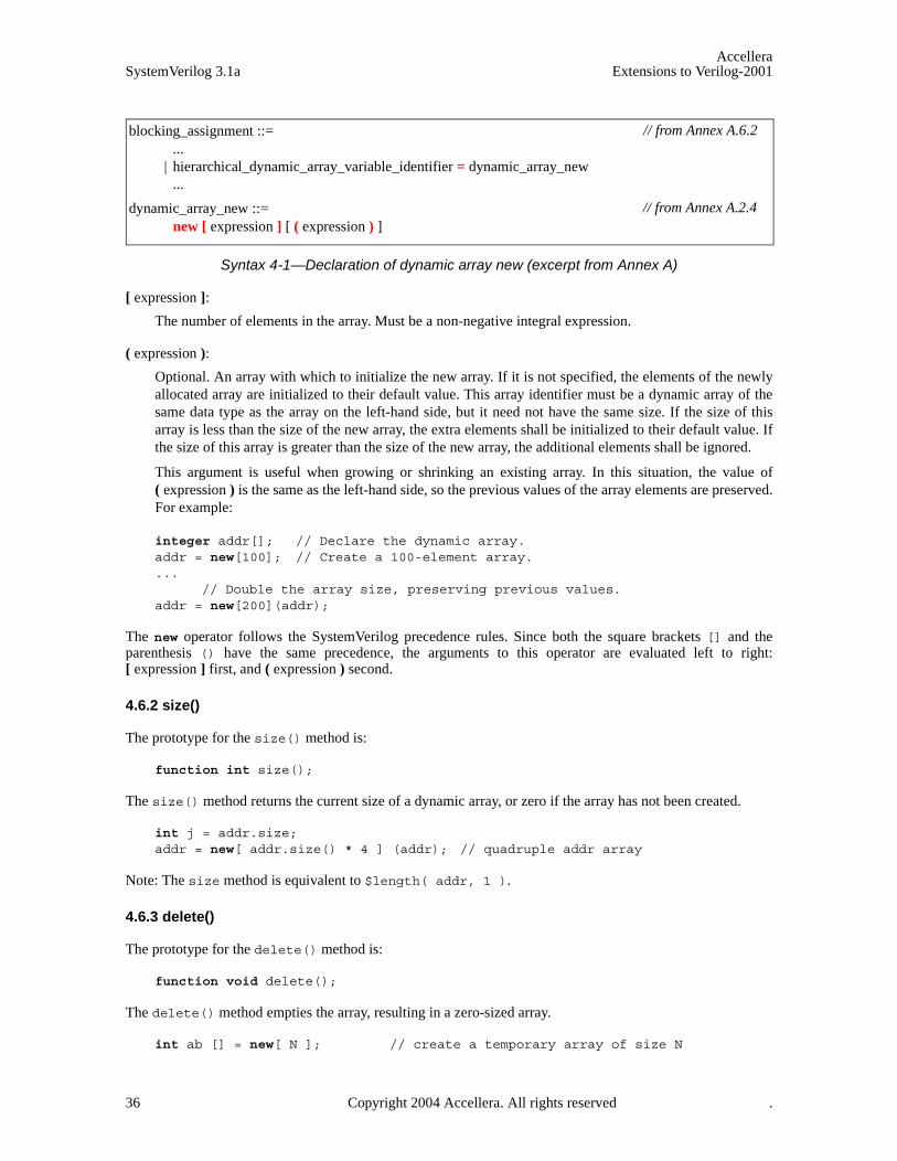
AccelleraSystemVerilog 3.1a Extensions to Verilog-2001
Syntax 4-1—Declaration of dynamic array new (excerpt from Annex A)
[ expression ]:
The number of elements in the array. Must be a non-negative integral expression.
( expression ):
Optional. An array with which to initialize the new array. If it is not specified, the elements of the newlyallocated array are initialized to their default value. This array identifier must be a dynamic array of thesame data type as the array on the left-hand side, but it need not have the same size. If the size of thisarray is less than the size of the new array, the extra elements shall be initialized to their default value. Ifthe size of this array is greater than the size of the new array, the additional elements shall be ignored.
This argument is useful when growing or shrinking an existing array. In this situation, the value of( expression ) is the same as the left-hand side, so the previous values of the array elements are preserved.For example:
integer addr[]; // Declare the dynamic array.addr = new[100]; // Create a 100-element array....
// Double the array size, preserving previous values.addr = new[200](addr);
The new operator follows the SystemVerilog precedence rules. Since both the square brackets [] and theparenthesis () have the same precedence, the arguments to this operator are evaluated left to right:[ expression ] first, and ( expression ) second.
4.6.2 size()
The prototype for the size() method is:
function int size();
The size() method returns the current size of a dynamic array, or zero if the array has not been created.
int j = addr.size;addr = new[ addr.size() * 4 ] (addr); // quadruple addr array
Note: The size method is equivalent to $length( addr, 1 ).
4.6.3 delete()
The prototype for the delete() method is:
function void delete();
The delete() method empties the array, resulting in a zero-sized array.
int ab [] = new[ N ]; // create a temporary array of size N
blocking_assignment ::= ...
| hierarchical_dynamic_array_variable_identifier = dynamic_array_new ...
dynamic_array_new ::= new [ expression ] [ ( expression ) ]
// from Annex A.6.2
// from Annex A.2.4
36 Copyright 2004 Accellera. All rights reserved .

AccelleraExtensions to Verilog-2001 SystemVerilog 3.1a
// use abab.delete; // delete the array contents$display( "%d", ab.size ); // prints 0
4.7 Array assignment
Assigning to a fixed-size unpacked array requires that the source and the target both be arrays with the samenumber of unpacked dimensions, and the length of each dimension be the same. Assignment is done by assign-ing each element of the source array to the corresponding element of the target array, which requires that thesource and target arrays be of compatible types. Compatible types are types that are assignment compati-ble.Assigning fixed-size unpacked arrays of unequal size to one another shall result in a type check error.
int A[10:1]; // fixed-size array of 10 elementsint B[0:9]; // fixed-size array of 10 elementsint C[24:1]; // fixed-size array of 24 elements
A = B; // ok. Compatible type and same sizeA = C; // type check error: different sizes
An array of wires can be assigned to an array of variables having the same number of unpacked dimensionsand the same length for each of those dimensions, and vice-versa.
wire [31:0] W [9:0]; assign W = A; initial #10 B = W;
A dynamic array can be assigned to a one-dimensional fixed-size array of a compatible type, if the size of thedynamic array is the same as the length of the fixed-size array dimension. Unlike assigning with a fixed-sizearray, this operation requires a run-time check that can result in an error.
int A[100:1]; // fixed-size array of 100 elementsint B[] = new[100]; // dynamic array of 100 elementsint C[] = new[8]; // dynamic array of 8 elements
A = B; // OK. Compatible type and same sizeA = C; // type check error: different sizes
A dynamic array or a one-dimensional fixed-size array can be assigned to a dynamic array of a compatibletype. In this case, the assignment creates a new dynamic array with a size equal to the length of the fixed-sizearray. For example:
int A[100:1]; // fixed-size array of 100 elementsint B[]; // empty dynamic arrayint C[] = new[8]; // dynamic array of size 8
B = A; // ok. B has 100 elementsB = C; // ok. B has 8 elements
The last statement above is equivalent to:
B = new[ C.size ] (C);
Similarly, the source of an assignment can be a complex expression involving array slices or concatenations.For example:
string d[1:5] = { "a", "b", "c", "d", "e" };string p[];p = { d[1:3], "hello", d[4:5] };
Copyright 2004 Accellera. All rights reserved. 37

AccelleraSystemVerilog 3.1a Extensions to Verilog-2001
The preceding example creates the dynamic array p with contents: “a”, “b”, “c”, “hello”, “d”, “e”.
4.8 Arrays as arguments
Arrays can be passed as arguments to tasks or functions. The rules that govern array argument passing by valueare the same as for array assignment (see Section 10.4). When an array argument is passed by value, a copy ofthe array is passed to the called task or function. This is true for all array types: fixed-size, dynamic, or associa-tive.
Note that unsized dimensions can occur in dynamic arrays and in formal arguments of import DPI functions. Ifone dimension of a formal is unsized, then any size of the corresponding dimension of an actual is accepted.
For example, the declaration:
task fun(int a[3:1][3:1]);
declares task fun that takes one argument, a two dimensional array with each dimension of size three. A call tofun must pass a two dimensional array and with the same dimension size 3 for all the dimensions. For exam-ple, given the above description for fun, consider the following actuals:
int b[3:1][3:1]; // OK: same type, dimension, and size
int b[1:3][0:2]; // OK: same type, dimension, & size (different ranges)
reg b[3:1][3:1]; // OK: assignment compatible type
event b[3:1][3:1]; // error: incompatible type
int b[3:1]; // error: incompatible number of dimensions
int b[3:1][4:1]; // error: incompatible size (3 vs. 4)
A subroutine that accepts a one-dimensional fixed-size array can also be passed a dynamic array of a compati-ble type of the same size.
For example, the declaration:
task bar( string arr[4:1] );
declares a task that accepts one argument, an array of 4 strings. This task can accept the following actual argu-ments:
string b[4:1]; // OK: same type and sizestring b[5:2]; // OK: same type and size (different range)string b[] = new[4]; // OK: same type and size, requires run-time check
A subroutine that accepts a dynamic array can be passed a dynamic array of a compatible type or a one-dimen-sional fixed-size array of a compatible type
For example, the declaration:
task foo( string arr[] );
declares a task that accepts one argument, a dynamic array of strings. This task can accept any one-dimen-sional array of strings or any dynamic array of strings.
An import DPI function that accepts a one-dimensional array can be passed a dynamic array of a compatibletype and of any size if formal is unsized, and of the same size if formal is sized. However, a dynamic array can-not be passed as an argument if formal is an unsized output.
38 Copyright 2004 Accellera. All rights reserved .
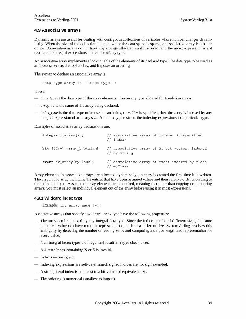
AccelleraExtensions to Verilog-2001 SystemVerilog 3.1a
4.9 Associative arrays
Dynamic arrays are useful for dealing with contiguous collections of variables whose number changes dynam-ically. When the size of the collection is unknown or the data space is sparse, an associative array is a betteroption. Associative arrays do not have any storage allocated until it is used, and the index expression is notrestricted to integral expressions, but can be of any type.
An associative array implements a lookup table of the elements of its declared type. The data type to be used asan index serves as the lookup key, and imposes an ordering.
The syntax to declare an associative array is:
data_type array_id [ index_type ];
where:
— data_type is the data type of the array elements. Can be any type allowed for fixed-size arrays.
— array_id is the name of the array being declared.
— index_type is the data-type to be used as an index, or *. If * is specified, then the array is indexed by anyintegral expression of arbitrary size. An index type restricts the indexing expressions to a particular type.
Examples of associative array declarations are:
integer i_array[*]; // associative array of integer (unspecified// index)
bit [20:0] array_b[string]; // associative array of 21-bit vector, indexed // by string
event ev_array[myClass]; // associative array of event indexed by class// myClass
Array elements in associative arrays are allocated dynamically; an entry is created the first time it is written.The associative array maintains the entries that have been assigned values and their relative order according tothe index data type. Associative array elements are unpacked, meaning that other than copying or comparingarrays, you must select an individual element out of the array before using it in most expressions.
4.9.1 Wildcard index type
Example: int array_name [*];
Associative arrays that specify a wildcard index type have the following properties:
— The array can be indexed by any integral data type. Since the indices can be of different sizes, the samenumerical value can have multiple representations, each of a different size. SystemVerilog resolves thisambiguity by detecting the number of leading zeros and computing a unique length and representation forevery value.
— Non-integral index types are illegal and result in a type check error.
— A 4-state Index containing X or Z is invalid.
— Indices are unsigned.
— Indexing expressions are self-determined; signed indices are not sign extended.
— A string literal index is auto-cast to a bit-vector of equivalent size.
— The ordering is numerical (smallest to largest).
Copyright 2004 Accellera. All rights reserved. 39

AccelleraSystemVerilog 3.1a Extensions to Verilog-2001
4.9.2 String index
Example: int array_name [ string ];
Associative arrays that specify a string index have the following properties:
— Indices can be strings or string literals of any length. Other types are illegal and shall result in a type checkerror.
— An empty string “” index is valid.
— The ordering is lexicographical (lesser to greater).
4.9.3 Class index
Example: int array_name [ some_Class ];
Associative arrays that specify a class index have the following properties:
— Indices can be objects of that particular type or derived from that type. Any other type is illegal and shallresult in a type check error.
— A null index is valid.
— The ordering is deterministic but arbitrary.
4.9.4 Integer (or int) index
Example: int array_name [ integer ];
Associative arrays that specify an integer index have the following properties:
— Indices can be any integral expression.
— Indices are signed.
— A 4-state index containing X or Z is invalid.
— Indices smaller than integer are sign extended to 32 bits.
— Indices larger than integer are truncated to 32 bits.
— The ordering is signed numerical.
4.9.5 Signed packed array
Example: typedef bit signed [4:1] Nibble; int array_name [ Nibble ];
Associative arrays that specify a signed packed array index have the following properties:
— Indices can be any integral expression.
— Indices are signed.
— Indices smaller than the size of the index type are sign extended.
— Indices larger than the size of the index type are truncated to the size of the index type.
— The ordering is signed numerical.
4.9.6 Unsigned packed array or packed struct
Example: typedef bit [4:1] Nibble; int array_name [ Nibble ];
40 Copyright 2004 Accellera. All rights reserved .
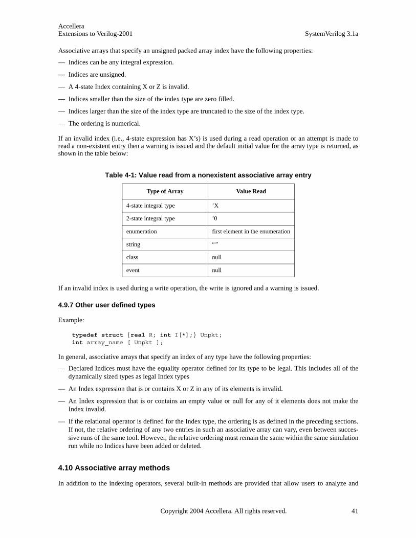
AccelleraExtensions to Verilog-2001 SystemVerilog 3.1a
Associative arrays that specify an unsigned packed array index have the following properties:
— Indices can be any integral expression.
— Indices are unsigned.
— A 4-state Index containing X or Z is invalid.
— Indices smaller than the size of the index type are zero filled.
— Indices larger than the size of the index type are truncated to the size of the index type.
— The ordering is numerical.
If an invalid index (i.e., 4-state expression has X’s) is used during a read operation or an attempt is made toread a non-existent entry then a warning is issued and the default initial value for the array type is returned, asshown in the table below:
If an invalid index is used during a write operation, the write is ignored and a warning is issued.
4.9.7 Other user defined types
Example:
typedef struct {real R; int I[*];} Unpkt;int array_name [ Unpkt ];
In general, associative arrays that specify an index of any type have the following properties:
— Declared Indices must have the equality operator defined for its type to be legal. This includes all of thedynamically sized types as legal Index types
— An Index expression that is or contains X or Z in any of its elements is invalid.
— An Index expression that is or contains an empty value or null for any of it elements does not make theIndex invalid.
— If the relational operator is defined for the Index type, the ordering is as defined in the preceding sections.If not, the relative ordering of any two entries in such an associative array can vary, even between succes-sive runs of the same tool. However, the relative ordering must remain the same within the same simulationrun while no Indices have been added or deleted.
4.10 Associative array methods
In addition to the indexing operators, several built-in methods are provided that allow users to analyze and
Table 4-1: Value read from a nonexistent associative array entry
Type of Array Value Read
4-state integral type ’X
2-state integral type ’0
enumeration first element in the enumeration
string “”
class null
event null
Copyright 2004 Accellera. All rights reserved. 41
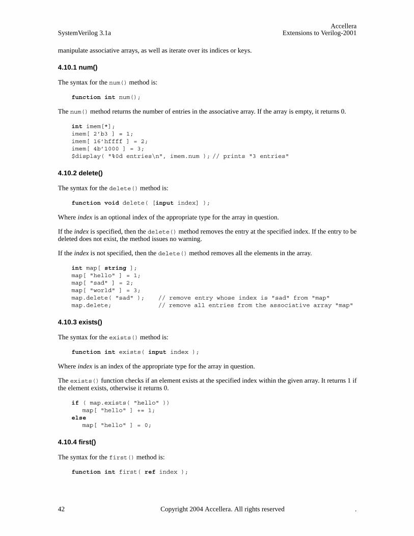
AccelleraSystemVerilog 3.1a Extensions to Verilog-2001
manipulate associative arrays, as well as iterate over its indices or keys.
4.10.1 num()
The syntax for the num() method is:
function int num();
The num() method returns the number of entries in the associative array. If the array is empty, it returns 0.
int imem[*];imem[ 2’b3 ] = 1;imem[ 16’hffff ] = 2;imem[ 4b’1000 ] = 3;$display( "%0d entries\n", imem.num ); // prints "3 entries"
4.10.2 delete()
The syntax for the delete() method is:
function void delete( [input index] );
Where index is an optional index of the appropriate type for the array in question.
If the index is specified, then the delete() method removes the entry at the specified index. If the entry to bedeleted does not exist, the method issues no warning.
If the index is not specified, then the delete() method removes all the elements in the array.
int map[ string ];map[ "hello" ] = 1;map[ "sad" ] = 2;map[ "world" ] = 3;map.delete( "sad" ); // remove entry whose index is "sad" from "map"map.delete; // remove all entries from the associative array "map"
4.10.3 exists()
The syntax for the exists() method is:
function int exists( input index );
Where index is an index of the appropriate type for the array in question.
The exists() function checks if an element exists at the specified index within the given array. It returns 1 ifthe element exists, otherwise it returns 0.
if ( map.exists( "hello" ))map[ "hello" ] += 1;
else map[ "hello" ] = 0;
4.10.4 first()
The syntax for the first() method is:
function int first( ref index );
42 Copyright 2004 Accellera. All rights reserved .
AccelleraExtensions to Verilog-2001 SystemVerilog 3.1a
Where index is an index of the appropriate type for the array in question.
The first() method assigns to the given index variable the value of the first (smallest) index in the associa-tive array. It returns 0 if the array is empty, and 1 otherwise.
string s;if ( map.first( s ) )
$display( "First entry is : map[ %s ] = %0d\n", s, map[s] );
4.10.5 last()
The syntax for the last() method is:
function int last( ref index );
Where index is an index of the appropriate type for the array in question.
The last() method assigns to the given index variable the value of the last (largest) index in the associativearray. It returns 0 if the array is empty, and 1 otherwise.
string s;if ( map.last( s ) )
$display( "Last entry is : map[ %s ] = %0d\n", s, map[s] );
4.10.6 next()
The syntax for the next() method is:
function int next( ref index );
Where index is an index of the appropriate type for the array in question.
The next() method finds the entry whose index is greater than the given index. If there is a next entry, theindex variable is assigned the index of the next entry, and the function returns 1. Otherwise, index isunchanged, and the function returns 0.
string s;if ( map.first( s ) )
do $display( "%s : %d\n", s, map[ s ] );
while ( map.next( s ) );
4.10.7 prev()
The syntax for the prev() method is:
function int prev( ref index );
Where index is an index of the appropriate type for the array in question.
The prev() function finds the entry whose index is smaller than the given index. If there is a previous entry,the index variable is assigned the index of the previous entry, and the function returns 1. Otherwise, the indexis unchanged, and the function returns 0.
string s;if ( map.last( s ) )
do $display( "%s : %d\n", s, map[ s ] );
Copyright 2004 Accellera. All rights reserved. 43

AccelleraSystemVerilog 3.1a Extensions to Verilog-2001
while ( map.prev( s ) );
If the argument passed to any of the four associative array traversal methods first, last, next, and prev issmaller than the size of the corresponding index, then the function returns –1 and shall copy only as much dataas can fit into the argument. For example:
string aa[*];byte ix;int status;aa[ 1000 ] = "a";status = aa.first( ix );
// status is –1// ix is 232 (least significant 8 bits of 1000)
4.11 Associative array assignment
Associative arrays can be assigned only to another associative array of a compatible type and with the sameindex type. Other types of arrays cannot be assigned to an associative array, nor can associative arrays beassigned to other types of arrays, whether fixed-size or dynamic.
Assigning an associative array to another associative array causes the target array to be cleared of any existingentries, and then each entry in the source array is copied into the target array.
4.12 Associative array arguments
Associative arrays can be passed as arguments only to associative arrays of a compatible type and with thesame index type. Other types of arrays, whether fixed-size or dynamic, cannot be passed to subroutines thataccept an associative array as an argument. Likewise, associative arrays cannot be passed to subroutines thataccept other types of arrays.
Passing an associative array by value causes a local copy of the associative array to be created.
4.13 Associative array literals
Associative array literals use the {index:value} syntax with an optional default index. Like all other arrays,an associative array can be written one entry at a time, or the whole array contents can be replaced using anarray literal.
Syntax 4-2—Associative array literal syntax (excerpt from Annex A)
For example:
// an associative array of strings indexed by 2-state integers,// default is "foo".string words [int] = {default: "foo"};
concatenation ::= ...
| { array_member_label : expression { , array_member_label : expression } }
array_member_label ::= default
| type_identifier | constant_expression
// from Annex A.8.1
44 Copyright 2004 Accellera. All rights reserved .

AccelleraExtensions to Verilog-2001 SystemVerilog 3.1a
// an associative array of 4-state integers indexed by strings, default is –1.integer table [string] = {"Peter":20, "Paul":22, "Mary":23, default:-1 };
If a default value is specified, then reading a non-existent element shall yield the specified default value. Oth-erwise, the default initial value is as described in Table 4-1 shall be returned.
4.14 Queues
A queue is a variable-size, ordered collection of homogeneous elements. A queue supports constant timeaccess to all its elements as well as constant time insertion and removal at the beginning or the end of thequeue. Each element in a queue is identified by an ordinal number that represents its position within the queue,with 0 representing the first, and $ representing the last. A queue is analogous to a one-dimensional unpackedarray that grows and shrinks automatically. Thus, like arrays, queues can be manipulated using the indexing,concatenation, slicing operator syntax, and equality operators.
Queues are declared using the same syntax as unpacked arrays, but specifying $ as the array size. The maxi-mum size of a queue can be limited by specifying its optional right bound (last index).
Syntax 4-3—Declaration of queue dimension (excerpt from Annex A)
constant_expression must evaluate to a positive integer value.
For example:
byte q1[$]; // A queue of bytesstring names[$] = { "Bob" }; // A queue of strings with one elementinteger Q[$] = { 3, 2, 7 }; // An initialized queue of integersbit q2[$:255]; // A queue whose maximum size is 256 bits
The empty array literal {} is used to denote an empty queue. If an initial value is not provided in the declara-tion, the queue variable is initialized to the empty queue.
4.14.1 Queue Operators
Queues support the same operations that can be performed on unpacked arrays, and using the same operatorsand rules except as defined below:
int q[$] = { 2, 4, 8 };int p[$];int e, pos;
e = q[0]; // read the first (left-most) iteme = q[$]; // read the last (right-most) itemq[0] = e; // write the first itemp = q; // read and write entire queue (copy)
q = { q, 6 }; // insert ’6’ at the end (append 6)q = { e, q }; // insert ’e’ at the beginning (prepend e)
q = q[1:$]; // delete the first (left-most) item
variable_dimension12 ::= { sized_or_unsized_dimension }
| associative_dimension | queue_dimension
queue_dimension ::= [ $ [ : constant_expression ] ]
// from Annex A.2.5
Copyright 2004 Accellera. All rights reserved. 45

AccelleraSystemVerilog 3.1a Extensions to Verilog-2001
q = q[0:$-1]; // delete the last (right-most) itemq = q[1:$-1]; // delete the first and last items
q = {}; // clear the queue (delete all items)
q = { q[0:pos-1], e, q[pos,$] }; // insert ’e’ at position posq = { q[0:pos], e, q[pos+1,$] }; // insert ’e’ after position pos
Unlike arrays, the empty queue, {}, is a valid queue and the result of some queue operations. The followingrules govern queue operators:
— Q[ a : b ] yields a queue with b - a + 1 elements.
— If a > b then Q[a:b] yields the empty queue {}.
— Q[ n : n ] yields a queue with one item, the one at position n. Thus, Q[ n : n ] === { Q[n] }.
— If n lies outside Q’s range (n < 0 or n > $) then Q[n:n] yields the empty queue {}.
— If either a or b are 4-state expressions containing X or Z values, it yields the empty queue {}.
— Q[ a : b ] where a < 0 is the same as Q[ 0 : b ].
— Q[ a : b ] where b > $ is the same as Q[ a : $ ].
— An invalid index value (i.e., a 4-state expression with X’s or Z’s, or a value that lies outside 0...$) shallcause a read operation (e = Q[n]) to return the default initial value for the type of queue item (asdescribed in Table 4-1).
— An invalid index (i.e., a 4-state expression with X's or Z's, or a value that lies outside 0...$+1) shall cause awrite operation to be ignored and a run-time warning to be issued. Note that writing to Q[$+1] is legal.
— A queue declared with a right bound [$:N] shall be limited to the indexes 0 through N (its maximum sizewill be N+1). An index that lies outside these limits shall be invalid, therefore, a write operation past theend of the queue shall be ignored and issue a warning. The warning can be issued at either compile time orrun time, as soon as it is possible to determine that the index lies outside the queue limit.
NOTE: Queues and dynamic arrays have the same assignment and argument passing semantics.
4.14.2 Queue methods
In addition to the array operators, queues provide several built-in methods.
4.14.2.1 size()
The prototype for the size() method is:
function int size();
The size() method returns the number of items in the queue. If the queue is empty, it returns 0.
for ( int j = 0; j < q.size; j++ ) $display( q[j] );
4.14.2.2 insert()
The prototype of the insert() method is:
function void insert(int index, queue_type item);
The insert() method inserts the given item at the specified index position.
— Q.insert(i, e) is equivalent to: Q = {Q[0:i-1], e, Q[i,$]}
46 Copyright 2004 Accellera. All rights reserved .

AccelleraExtensions to Verilog-2001 SystemVerilog 3.1a
4.14.2.3 delete()
The prototype of the delete() method is:
function void delete(int index);
The delete() method deletes the item at the specified index position.
— Q.delete(i) is equivalent to: Q = {Q[0:i-1], Q[i+1,$]}
4.14.2.4 pop_front()
The prototype of the pop_front() method is:
function queue_type pop_front();
The pop_front() method removes and returns the first element of the queue.
— e = Q.pop_front() is equivalent to: e = Q[0]; Q = Q[1,$]
4.14.2.5 pop_back()
The prototype of the pop_back() method is:
function queue_type pop_back();
The pop_back() method removes and returns the last element of the queue.
— e = Q.pop_back() is equivalent to: e = Q[$]; Q = Q[0,$-1]
4.14.2.6 push_front()
The prototype of the push_front() method is:
function void push_front(queue_type item);
The push_front() method inserts the given element at the front of the queue.
— Q.push_front(e) is equivalent to: Q = {e, Q}
4.14.2.7 push_back()
The prototype of the push_back() method is:
function void push_back(queue_type item);
The push_back() method inserts the given element at the end of the queue.
— Q.push_back(e) is equivalent to: Q = {Q, e}
4.15 Array manipulation methods
SystemVerilog provides several built-in methods to facilitate array searching, ordering, and reduction.
The general syntax to call these array methods is:
Copyright 2004 Accellera. All rights reserved. 47
AccelleraSystemVerilog 3.1a Extensions to Verilog-2001
Syntax 4-4—array method call syntax (not in Annex A)
The optional with clause accepts an expression enclosed in parenthesis. In contrast, the with clause used bythe randomize method (see Section 12.6) accepts a set of constraints enclosed in braces.
4.15.1 Array Locator Methods
Array locator methods operate on any unpacked array, including queues, but their return type is a queue. Theselocator methods allow searching an array for elements (or their indexes) that satisfy a given expression. Arraylocator methods traverse the array in an unspecified order. The optional with expression should not includeany side effects; if it does, the results are unpredictable.
The prototype of these methods is:
function array_type [$] locator_method (array_type iterator = item);// same type as the array
or
function int_or_index_type [$] index_locator_method(array_type iterator = item);// index type
Index locator methods return a queue of int for all arrays except associative arrays, which return a queue ofthe same type as the associative index type.
If no elements satisfy the given expression or the array is empty (in the case of a queue or dynamic array) thenan empty queue is returned, otherwise these methods return a queue containing all items that satisfy the expres-sion. Index locator methods return a queue with the indexes of all items that satisfy the expression. Theoptional expression specified by the with clause must evaluate to a boolean value.
Locator methods iterate over the array elements, which are then used to evaluate the expression specified bythe with clause. The iterator argument optionally specifies the name of the variable used by the with expres-sion to designate the element of the array at each iteration. If it is not specified, the name item is used bydefault. The scope for the iterator name is the with expression.
The following locator methods are supported (the with clause is mandatory) :
— find() returns all the elements satisfying the given expression
— find_index() returns the indexes of all the elements satisfying the given expression
— find_first() returns the first element satisfying the given expression
— find_first_index() returns the index of the first element satisfying the given expression
— find_last() returns the last element satisfying the given expression
— find_last_index() returns the index of the last element satisfying the given expression
For the following locator methods the with clause (and its expression) can be omitted if the relational opera-tors (<, >, ==) are defined for the element type of the given array. If a with clause is specified, the relationaloperators (<, >, ==) must be defined for the type of the expression.
— min() returns the element with the minimum value or whose expression evaluates to a minimum
— max() returns the element with the maximum value or whose expression evaluates to a maximum
array_method_call ::= expression . array_method_name { attribute_instance } [ ( list_of_arguments ) ]
[ with ( expression ) ]
// not in Annex A
48 Copyright 2004 Accellera. All rights reserved .
AccelleraExtensions to Verilog-2001 SystemVerilog 3.1a
— unique() returns all elements with unique values or whose expression is unique
— unique_index() returns the indexes of all elements with unique values or whose expression is unique
Examples:
string SA[10], qs[$];int IA[*], qi[$];
// Find all items greater than 5qi = IA.find( x ) with ( x > 5 );
// Find indexes of all items equal to 3qi = IA.find_index with ( item == 3 );
// Find first item equal to Bobqs = SA.find_first with ( item == "Bob" );
// Find last item equal to Henryqs = SA.find_last( y ) with ( y == "Henry" );
// Find index of last item greater than Zqi = SA.find_last_index( s ) with ( s > "Z" );
// Find smallest itemqi = IA.min;
// Find string with largest numerical valueqs = SA.max with ( item.atoi );
// Find all unique strings elementsqs = SA.unique;
// Find all unique strings in lower-caseqs = SA.unique( s ) with ( s.tolower );
4.15.2 Array ordering methods
Array ordering methods can reorder the elements of one-dimensional arrays or queues.
The general prototype for the ordering methods is:
function void ordering_method ( array_type iterator = item )
The following ordering methods are supported:
— reverse() reverses all the elements of the array (packed or unpacked). Specifying a with clause shall bea compiler error.
— sort() sorts the unpacked array in ascending order, optionally using the expression in the with clause.The with clause (and its expression) is optional when the relational operators are defined for the array ele-ment type.
— rsort() sorts the unpacked array in descending order, optionally using the expression in the with clause.The with clause (and its expression) is optional when the relational operators are defined for the array ele-ment type.
— shuffle() randomizes the order of the elements in the array. Specifying a with clause shall be a com-piler error.
Copyright 2004 Accellera. All rights reserved. 49
AccelleraSystemVerilog 3.1a Extensions to Verilog-2001
Examples:
string s[] = { "hello", "sad", "world" };s.reverse; // s becomes { "world", "sad", "hello" };
logic [4:1] b = 4’bXZ01;b.reverse; // b becomes 4’b10ZX
int q[$] = { 4, 5, 3, 1 };q.sort; // q becomes { 1, 3, 4, 5 }
struct { byte red, green, blue } c [512];c.sort with ( item.red ); // sort c using the red field onlyc.sort( x ) with ( x.blue << 8 + x.green ); // sort by blue then green
4.15.3 Array reduction methods
Array reduction methods can be applied to any unpacked array to reduce the array to a single value. Theexpression within the optional with clause can be used to specify the item to use in the reduction.
The prototype for these methods is:
function expression_or_array_type reduction_method (array_type iterator = item)
The method returns a single value of the same type as the array element type or, if specified, the type of theexpression in the with clause. The with clause can be omitted if the corresponding arithmetic or booleanreduction operation is defined for the array element type. If a with clause is specified, the corresponding arith-metic or boolean reduction operation must be defined for the type of the expression.
The following reduction methods are supported:
— sum() returns the sum of all the array elements, or if a with clause is specified, returns the sum of the val-ues yielded by evaluating the expression for each array element.
— product() returns the product of all the array elements, or if a with clause is specified, returns the prod-uct of the values yielded by evaluating the expression for each array element.
— and() returns the bit-wise AND ( & ) of all the array elements, or if a with clause is specified, returns thebit-wise AND of the values yielded by evaluating the expression for each array element
— or() returns the bit-wise OR ( | ) of all the array elements, or if a with clause is specified, returns the bit-wise OR of the values yielded by evaluating the expression for each array element
— xor() returns the logical XOR ( ^ ) of all the array elements, or if a with clause is specified, returns theXOR of the values yielded by evaluating the expression for each array element
Examples:
byte b[] = { 1, 2, 3, 4 };int y;
y = b.sum ; // y becomes 10 => 1 + 2 + 3 + 4y = b.product ; // y becomes 24 => 1 * 2 * 3 * 4y = b.xor with ( item + 4 ); // y becomes 12 => 5 ^ 6 ^ 7 ^ 8
4.15.4 Iterator index querying
The expressions used by array manipulation methods sometimes need the actual array indexes at each itera-tion, not just the array element. The index method of an iterator returns the index value of the specified dimen-sion. The prototype of the index method is:
50 Copyright 2004 Accellera. All rights reserved .

AccelleraExtensions to Verilog-2001 SystemVerilog 3.1a
function int_or_index_type index ( int dimension = 1 )
The array dimensions are numbered as defined in Section 23.7: The slowest varying is dimension 1. Succes-sively faster varying dimensions have sequentially higher dimension numbers. If the dimension is not speci-fied, the first dimension is used by default
The return type of the index method is an int for all array iterator items except associative arrays, whichreturns an index of the same type as the associative index type.
For example:
int arr[]int mem[9:0][9:0], mem2[9:0][9:0];int q[$];...
// find all items equal to their position (index)q = arr.find with ( item == item.index ); // find all items in mem that are greater than corresponding item in mem2q = mem.find( x ) with ( x > mem2[x.index(1)][x.index(2)] );
Copyright 2004 Accellera. All rights reserved. 51
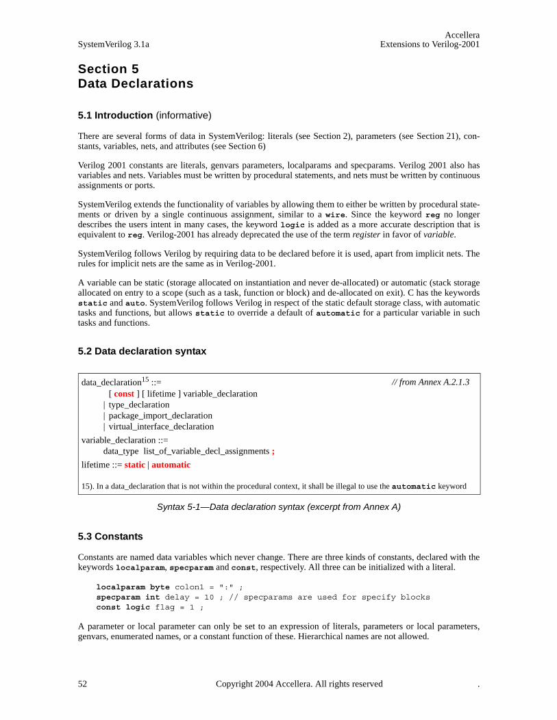
AccelleraSystemVerilog 3.1a Extensions to Verilog-2001
Section 5Data Declarations
5.1 Introduction (informative)
There are several forms of data in SystemVerilog: literals (see Section 2), parameters (see Section 21), con-stants, variables, nets, and attributes (see Section 6)
Verilog 2001 constants are literals, genvars parameters, localparams and specparams. Verilog 2001 also hasvariables and nets. Variables must be written by procedural statements, and nets must be written by continuousassignments or ports.
SystemVerilog extends the functionality of variables by allowing them to either be written by procedural state-ments or driven by a single continuous assignment, similar to a wire. Since the keyword reg no longerdescribes the users intent in many cases, the keyword logic is added as a more accurate description that isequivalent to reg. Verilog-2001 has already deprecated the use of the term register in favor of variable.
SystemVerilog follows Verilog by requiring data to be declared before it is used, apart from implicit nets. Therules for implicit nets are the same as in Verilog-2001.
A variable can be static (storage allocated on instantiation and never de-allocated) or automatic (stack storageallocated on entry to a scope (such as a task, function or block) and de-allocated on exit). C has the keywordsstatic and auto. SystemVerilog follows Verilog in respect of the static default storage class, with automatictasks and functions, but allows static to override a default of automatic for a particular variable in suchtasks and functions.
5.2 Data declaration syntax
Syntax 5-1—Data declaration syntax (excerpt from Annex A)
5.3 Constants
Constants are named data variables which never change. There are three kinds of constants, declared with thekeywords localparam, specparam and const, respectively. All three can be initialized with a literal.
localparam byte colon1 = ":" ;specparam int delay = 10 ; // specparams are used for specify blocksconst logic flag = 1 ;
A parameter or local parameter can only be set to an expression of literals, parameters or local parameters,genvars, enumerated names, or a constant function of these. Hierarchical names are not allowed.
data_declaration15 ::= [ const ] [ lifetime ] variable_declaration
| type_declaration | package_import_declaration | virtual_interface_declaration
variable_declaration ::= data_type list_of_variable_decl_assignments ;
lifetime ::= static | automatic
15). In a data_declaration that is not within the procedural context, it shall be illegal to use the automatic keyword
// from Annex A.2.1.3
52 Copyright 2004 Accellera. All rights reserved .
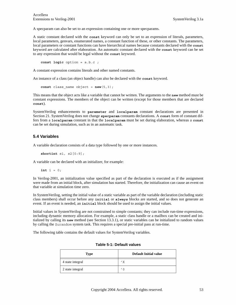
AccelleraExtensions to Verilog-2001 SystemVerilog 3.1a
A specparam can also be set to an expression containing one or more specparams.
A static constant declared with the const keyword can only be set to an expression of literals, parameters,local parameters, genvars, enumerated names, a constant function of these, or other constants. The parameters,local parameters or constant functions can have hierarchical names because constants declared with the constkeyword are calculated after elaboration. An automatic constant declared with the const keyword can be setto any expression that would be legal without the const keyword.
const logic option = a.b.c ;
A constant expression contains literals and other named constants.
An instance of a class (an object handle) can also be declared with the const keyword.
const class_name object = new(5,3);
This means that the object acts like a variable that cannot be written. The arguments to the new method must beconstant expressions. The members of the object can be written (except for those members that are declaredconst).
SystemVerilog enhancements to parameter and localparam constant declarations are presented inSection 21. SystemVerilog does not change specparam constants declarations. A const form of constant dif-fers from a localparam constant in that the localparam must be set during elaboration, whereas a constcan be set during simulation, such as in an automatic task.
5.4 Variables
A variable declaration consists of a data type followed by one or more instances.
shortint s1, s2[0:9];
A variable can be declared with an initializer, for example:
int i = 0;
In Verilog-2001, an initialization value specified as part of the declaration is executed as if the assignmentwere made from an initial block, after simulation has started. Therefore, the initialization can cause an event onthat variable at simulation time zero.
In SystemVerilog, setting the initial value of a static variable as part of the variable declaration (including staticclass members) shall occur before any initial or always blocks are started, and so does not generate anevent. If an event is needed, an initial block should be used to assign the initial values.
Initial values in SystemVerilog are not constrained to simple constants; they can include run-time expressions,including dynamic memory allocation. For example, a static class handle or a mailbox can be created and ini-tialized by calling its new method (see Section 13.3.1), or static variables can be initialized to random valuesby calling the $urandom system task. This requires a special pre-initial pass at run-time.
The following table contains the default values for SystemVerilog variables.
Table 5-1: Default values
Type Default Initial value
4 state integral ’X
2 state integral ’0
Copyright 2004 Accellera. All rights reserved. 53

AccelleraSystemVerilog 3.1a Extensions to Verilog-2001
5.5 Scope and lifetime
Any data declared outside a module, interface, task, or function, is global in scope (can be used anywhere afterits declaration) and has a static lifetime (exists for the whole elaboration and simulation time).
SystemVerilog data declared inside a module or interface but outside a task, process or function is local inscope and static in lifetime (exists for the lifetime of the module or interface). This is roughly equivalent to Cstatic data declared outside a function, which is local to a file.
Data declared in an automatic task, function or block has the lifetime of the call or activation and a local scope.This is roughly equivalent to a C automatic variable.
Data declared in a static task, function or block defaults to a static lifetime and a local scope.
Note that in SystemVerilog, data can be declared in unnamed blocks as well as in named blocks. This data isvisible to the unnamed block and any nested blocks below it. Hierarchical references cannot be used to accessthis data by name.
Verilog-2001 allows tasks and functions to be declared as automatic, making all storage within the task orfunction automatic. SystemVerilog allows specific data within a static task or function to be explicitly declaredas automatic. Data declared as automatic has the lifetime of the call or block, and is initialized on each entryto the call or block. The lifetime of a fork…join, fork…join_any, or fork…join_none block shallencompass the execution of all processes spawned by the block. The lifetime of a scope enclosing anyfork…join block includes the lifetime of the fork…join block.
SystemVerilog also allows data to be explicitly declared as static. Data declared to be static in an auto-matic task, function or block has a static lifetime and a scope local to the block. This is like C static datadeclared within a function.
module msl;int st0; // staticinitial begin
int st1; //staticstatic int st2; //static automatic int auto1; //automatic
end task automatic t1();
int auto2; //automaticstatic int st3; //staticautomatic int auto3; //automatic
endtask endmodule
real, shortreal 0.0
Enumeration First value in the enumeration
string "" (empty string)
event New event
class null
chandle (Opaque handle) null
Table 5-1: Default values
Type Default Initial value
54 Copyright 2004 Accellera. All rights reserved .

AccelleraExtensions to Verilog-2001 SystemVerilog 3.1a
SystemVerilog adds an optional qualifier to specify the default lifetime of all variables declared in task, func-tion or block defined within a module, interface or program (see Section 16). The lifetime qualifier is auto-matic or static. The default lifetime is static.
program automatic test ;int i; // not within a procedural block - statictask foo( int a ); // arguments and variables in foo are automatic
...endtask
endmodule
Class methods and declared for loop variables are by default automatic, regardless of the lifetime attribute ofthe scope in which they are declared. Classes are discussed in Section 11.
Note that automatic or dynamic variables cannot be written with nonblocking or continuous assignments.Automatic variables and dynamic constructs—objects handles, dynamic arrays, associative arrays, strings, andevent variables—shall be limited to the procedural context.
See also Section 10 on tasks and functions.
5.6 Nets, regs, and logic
Verilog-2001 states that a net can be written by one or more continuous assignments, primitive outputs orthrough module ports. The resultant value of multiple drivers is determined by the resolution function of thenet type. A net cannot be procedurally assigned. If a net on one side of a port is driven by a variable on theother side, a continuous assignment is implied. A force statement can override the value of a net. Whenreleased, it returns to resolved value.
Verilog-2001 also states that one or more procedural statements can write to variables, including proceduralcontinuous assignments. The last write determines the value. A variable cannot be continuously assigned. Theforce statement overrides the procedural assign statement, which in turn overrides the normal assignments. Avariable cannot be written through a port; it must go through an implicit continuous assignment to a net.
In SystemVerilog, all variables can now be written either by one continuous assignment, or by one or moreprocedural statements, including procedural continuous assignments. It shall be an error to have multiple con-tinuous assignments or a mixture of procedural and continuous assignments writing to any term in the expan-sion of a written longest static prefix of a logic variable (See Section 9.2.1 for the definition of the expansionof a longest static prefix) . All data types can write through a port.
SystemVerilog variables can be packed or unpacked aggregates of other types. Multiple assignments made toindependent elements of a variable are examined individually. An assignment where the left-hand-side con-tains a slice is treated as a single assignment to the entire slice. It shall be an error to have a packed structure orarray type written with a mixture of procedural and continuous assignments. Thus, an unpacked structure orarray can have one element assigned procedurally, and another element assigned continuously. And, each ele-ment of a packed structure or array can each have a single continuous assignment. For example, assume thefollowing structure declaration:
struct {bit [7:0] A;bit [7:0] B;byte C;
} abc;
The following statements are legal assignments to struct abc:
assign abc.C = sel ? 8’hBE : 8’hEF;
not (abc.A[0],abc.B[0]),
Copyright 2004 Accellera. All rights reserved. 55
AccelleraSystemVerilog 3.1a Extensions to Verilog-2001
(abc.A[1],abc.B[1]),(abc.A[2],abc.B[2]),(abc.A[3],abc.B[3]);
always @(posedge clk) abc.B <= abc.B + 1;
The following additional statements are illegal assignments to struct abc:
// Multiple continuous assignments to abc.Cassign abc.C = sel ? 8’hDE : 8’hED;
// Mixing continuous and procedural assignments to abc.Aalways @(posedge clk) abc.A[7:4] <= !abc.B[7:4];
For the purposes of the preceding rule, a declared variable initialization or a procedural continuous assignmentis considered a procedural assignment. A force statement is neither a continuous or procedural assignment. Arelease statement shall not change the variable until there is another procedural assignment, or shall sched-ule a re-evaluation of the continuous assignment driving it. A single force or release statement shall not beapplied to a whole or part of a variable that is being assigned by a mixture of continuous and proceduralassignments.
A continuous assignment is implied when a variable is connected to an input port declaration. This makesassignments to a variable declared as an input port illegal. A continuous assignment is implied when a variableis connected to the output port of an instance. This makes procedural or continuous assignments to a variableconnected to the output port of an instance illegal.
SystemVerilog variables cannot be connected to either side of an inout port. SystemVerilog introduces the con-cept of shared variables across ports with the ref port type. See Section 18.12 (port connections) for moreinformation about ports and port connection rules.
The compiler can issue a warning if a continuous assignment could drive strengths other then St0, St1, StX,or HiZ to a variable. In any case, SystemVerilog applies automatic type conversion to the assignment, and thestrength is lost.
Note that a SystemVerilog variable cannot have an implicit continuous assignment as part of its declaration,the way a net can. An assignment as part of the logic declaration is a variable initialization, not a continuousassignment. For example:
wire w = vara & varb; // continuous assignment
logic v = consta & constb; // initial procedural assignment
logic vw; // no initial assignmentassign vw = vara & varb; // continuous assignment to a logic
real circ;assign circ = 2.0 * PI * R; // continuous assignment to a real
5.7 Signal aliasing
The Verilog assign statement is a unidirectional assignment and can incorporate a delay and strength change.To model a bidirectional short-circuit connection it is necessary to use the alias statement. The members ofan alias list are signals whose bits share the same physical nets. The example below implements a byte orderswapping between bus A and bus B.
module byte_swap (inout wire [31:0] A, inout wire [31:0] B); alias {A[7:0],A[15:8],A[23:16],A[31:24]} = B;
endmodule
56 Copyright 2004 Accellera. All rights reserved .
AccelleraExtensions to Verilog-2001 SystemVerilog 3.1a
This example strips out the least and most significant bytes from a four byte bus:
module byte_rip (inout wire [31:0] W, inout wire [7:0] LSB, MSB); alias W[7:0] = LSB; alias W[31:24] = MSB;
endmodule
The bit overlay rules are the same as those for a packed union with the same member types: each member shallbe the same size, and connectivity is independent of the simulation host. The nets connected with an aliasstatement must be type compatible, that is, they have to be of the same net type. For example, it is illegal toconnect a wand net to a wor net with an alias statement. This is a stricter rule than applied to nets joining atports because the scope of an alias is limited and such connections are more likely to be a design error. Vari-ables and hierarchical references cannot be used in alias statements. Any violation of these rules shall beconsidered a fatal error.
The same nets can appear in multiple alias statements. The effects are cumulative. The following two exam-ples are equivalent. In either case, low12[11:4] and high12[7:0] share the same wires.
module overlap(inout wire [15:0] bus16, inout wire [11:0] low12, high12); alias bus16[11:0] = low12; alias bus16[15:4] = high12;
endmodule
module overlap(inout wire [15:0] bus16, inout wire [11:0] low12, high12); alias bus16 = {high12, low12[3:0]}; alias high12[7:0] = low12[11:4];
endmodule
To avoid errors in specification, it is not allowed to specify an alias from an individual signal to itself, or tospecify a given alias more than once. The following version of the code above would be illegal since the topfour and bottom four bits are the same in both statements:
alias bus16 = {high12[11:8], low12}; alias bus16 = {high12, low12[3:0]};
This alternative is also illegal because the bits of bus16 are being aliased to itself:
alias bus16 = {high12, bus16[3:0]} = {bus16[15:12], low12};
Alias statements can appear anywhere module instance statements can appear. If an identifier that has not beendeclared as a data type appears in an alias statement, then an implicit net is assumed, following the same rulesas implicit nets for a module instance. The following example uses alias along with the automatic namebinding to connect pins on cells from different libraries to create a standard macro:
module lib1_dff(Reset, Clk, Data, Q, Q_Bar); ...
endmodule
module lib2_dff(reset, clock, data, a, qbar); ...
endmodule
module lib3_dff(RST, CLK, D, Q, Q_); ...
endmodule
macromodule my_dff(rst, clk, d, q, q_bar); // wrapper cell input rst, clk, d; output q, q_bar;
Copyright 2004 Accellera. All rights reserved. 57
AccelleraSystemVerilog 3.1a Extensions to Verilog-2001
alias rst = Reset = reset = RST; alias clk = Clk = clock = CLK; alias d = data = D; alias q = Q; alias Q_ = q_bar = Q_Bar = qbar; ‘LIB_DFF my_dff (.*); // LIB_DFF is any of lib1_dff, lib2_dff or lib3_dff
endmodule
Using a net in an alias statement does not modify its syntactic behavior in other statements. Aliasing is per-formed at elaboration time and cannot be undone.
5.8 Type compatibility
Some SystemVerilog constructs and operations require a certain level of type compatibility for their operandsto be legal. There are four levels of type compatibility, formally defined here: Equivalent, Assignment Com-patible, Cast Compatible, and Non-Equivalent.
Note that there is no category for identical types defined here because there is no construct in the SystemVer-ilog language that requires it. For example, as defined below, int can be interchanged with bit signed[0:31] wherever it is syntactically legal to do so. Users can define their own level of type identity by usingthe $typename system function (see Section 23.3, Typename function), or through use of the PLI.
5.8.1 Equivalent Types
Two data types shall be defined as equivalent data types using the following inductive definition. If the twodata types are not defined equivalent using the following definition, then they shall be defined to be non-equiv-alent.
1) Any built-in type is equivalent to every other occurrence of itself, in every scope.
2) A simple typedef or type parameter override that renames a built-in or user defined type is equivalent tothat built-in or user defined type within the scope of the type identifier.
typedef bit node; // ’bit’ and ’node’ are equivalent typestypedef type1 type2; // ’type1’ and ’type2’ are equivalent types
3) An anonymous enum, struct, or union type is equivalent to itself among variables declared within the samedeclaration statement and no other types.
struct {int A; int B;} AB1, AB2; // AB1, AB2 have equivalent typesstruct {int A; int B;} AB3; // AB3 is not type equivalent to AB1
4) A typedef for an enum, unpacked struct, or unpacked union, or a class is equivalent to itself and variablesdeclared using that type within the scope of the type identifier.
typedef struct {int A; int B;} AB_t;AB_t AB1; AB_t AB2; // AB1 and AB2 have equivalent types
typedef struct {int A; int B;} otherAB_t;otherAB_t AB3; // AB3 is not type equivalent to AB1 or AB2
5) Packed arrays, packed structures, and built-in integral types are equivalent if they contain the same numberof total bits, are either all 2-state or all 4-state, and are either all signed or all unsigned. Note that if any bitof a packed structure or union is 4-state, the entire structure or union is considered 4-state.
typedef bit signed [7:0]BYTE; // equivalent to the byte typetypedef struct packed signed {bit[3:0] a, b;} uint8; // equivalent to the byte type
58 Copyright 2004 Accellera. All rights reserved .

AccelleraExtensions to Verilog-2001 SystemVerilog 3.1a
6) Unpacked array types are equivalent by having equivalent element types and identical shape. Shape isdefined as the number of dimensions and the number of elements in each dimension, not the actual rangeof the dimension.
bit [9:0] A[0:5];bit [1:10] B[6]; typedef bit [10:1] uint10;uint10 C[6:1]; // A, B and C have equivalent typestypedef int anint[0:0]; // anint is not type equivalent to int
7) Explicitly adding signed or unsigned modifiers to a type that does not change its default signing, does notcreate a non-equivalent type. Otherwise, the signing must match to have equivalence
typedef bit unsigned ubit; // type equivalent to bit
8) A typedef for an enum, unpacked struct, or unpacked union, or a class type declared in a package is alwaysequivalent to itself, regardless of the scope where the type is imported.
The scope of a type identifier includes the hierarchical instance scope. This means that each instance with userdefined types declared inside the instance creates a unique type. To have type equivalence among multipleinstances of the same module, interface, or program, a type must be declared at higher level in the compilationunit scope than the declaration of the module, interface or program, or imported from a package.
The following example is assumed to be within one compilation unit, although the package declaration neednot be in the same unit:
package p1;typedef struct {int A;} t_1;
endpackage
typedef struct {int A;} t_2;
module sub();import p1:t_1;parameter type t_3 = int;parameter type t_4 = int;typedef struct {int A;} t_5;t_1 v1; t_2 v2; t_3 v3; t_4 v4; t_5 v5;
endmodule
module top();typedef struct {int A;} t_6;sub #(.t_3(t_6)) s1 ();sub #(.t_3(t_6)) s2 ();
initial begin s1.v1 = s2.v1; // legal - both types from package p1 (rule 8)s1.v2 = s2.v2; // legal - both types from $unit (rule 4)s1.v3 = s2.v3; // legal - both types from top (rule 2)s1.v4 = s2.v4; // legal - both types are int (rule 1)s1.v5 = s2.v5; // illegal - types from s1 and s2 (rule 4)
end endmodule
5.8.2 Assignment Compatible
All equivalent types, and all non-equivalent types that have implicit casting rules defined between them areassignment compatible types. For example, all integral types are assignment compatible. Conversion betweenassignment compatible types can involve loss of data by truncation or rounding.
Copyright 2004 Accellera. All rights reserved. 59
AccelleraSystemVerilog 3.1a Extensions to Verilog-2001
Compatibility can be in one direction only. For example, an enum can be converted to an integral type withouta cast, but not in the other way around. Implicit casting rules are defined in Section 3 Data Types, andSection 7 Operators and Expressions.
5.8.3 Cast Compatible
All assignment compatible types, plus all non-equivalent types that have defined explicit casting rules are castcompatible types. For example, an integral type requires a cast to be assigned to an enum.
Explicit casting rules are defined in Section 3 Data Types.
5.8.4 Type Incompatible
These are all the remaining non-equivalent types that have no defined implicit or explicit casting rules. Classhandles and chandles are type incompatible with all other types.
60 Copyright 2004 Accellera. All rights reserved .
AccelleraExtensions to Verilog-2001 SystemVerilog 3.1a
Copyright 2004 Accellera. All rights reserved. 61
Section 6Attributes
6.1 Introduction (informative)
With Verilog-2001, users can add named attributes (properties) to Verilog objects, such as modules, instances,wires, etc. Attributes can also be specified on the extended SystemVerilog constructs and are included as partof the BNF (see Annex A). SystemVerilog also defines a default data type for attributes.
6.2 Default attribute type
The default type of an attribute with no value is bit, with a value of 1. Otherwise, the attribute takes the typeof the expression.
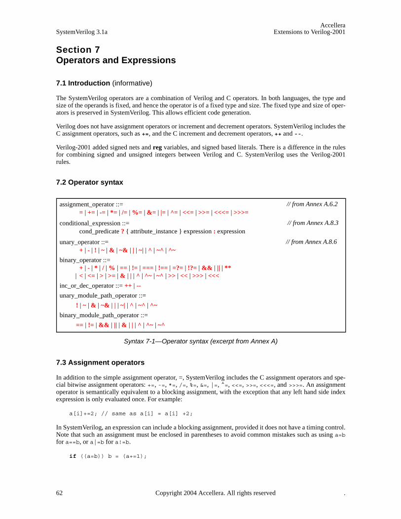
AccelleraSystemVerilog 3.1a Extensions to Verilog-2001
Section 7Operators and Expressions
7.1 Introduction (informative)
The SystemVerilog operators are a combination of Verilog and C operators. In both languages, the type andsize of the operands is fixed, and hence the operator is of a fixed type and size. The fixed type and size of oper-ators is preserved in SystemVerilog. This allows efficient code generation.
Verilog does not have assignment operators or increment and decrement operators. SystemVerilog includes theC assignment operators, such as +=, and the C increment and decrement operators, ++ and --.
Verilog-2001 added signed nets and reg variables, and signed based literals. There is a difference in the rulesfor combining signed and unsigned integers between Verilog and C. SystemVerilog uses the Verilog-2001rules.
7.2 Operator syntax
Syntax 7-1—Operator syntax (excerpt from Annex A)
7.3 Assignment operators
In addition to the simple assignment operator, =, SystemVerilog includes the C assignment operators and spe-cial bitwise assignment operators: +=, -=, *=, /=, %=, &=, |=, ^=, <<=, >>=, <<<=, and >>>=. An assignmentoperator is semantically equivalent to a blocking assignment, with the exception that any left hand side indexexpression is only evaluated once. For example:
a[i]+=2; // same as a[i] = a[i] +2;
In SystemVerilog, an expression can include a blocking assignment, provided it does not have a timing control.Note that such an assignment must be enclosed in parentheses to avoid common mistakes such as using a=bfor a==b, or a|=b for a!=b.
if ((a=b)) b = (a+=1);
assignment_operator ::= = | += | -= | *= | /= | %= | &= | |= | ^= | <<= | >>= | <<<= | >>>=
conditional_expression ::= cond_predicate ? { attribute_instance } expression : expression
unary_operator ::= + | - | ! | ~ | & | ~& | | | ~| | ^ | ~^ | ^~
binary_operator ::= + | - | * | / | % | == | != | === | !== | =?= | !?= | && | || | **
| < | <= | > | >= | & | | | ^ | ^~ | ~^ | >> | << | >>> | <<<
inc_or_dec_operator ::= ++ | --
unary_module_path_operator ::=
! | ~ | & | ~& | | | ~| | ^ | ~^ | ^~
binary_module_path_operator ::=
== | != | && | || | & | | | ^ | ^~ | ~^
// from Annex A.6.2
// from Annex A.8.3
// from Annex A.8.6
62 Copyright 2004 Accellera. All rights reserved .

AccelleraExtensions to Verilog-2001 SystemVerilog 3.1a
a = (b = (c = 5));
The semantics of such an assignment expression are those of a function which evaluates the right hand side,casts the right hand side to the left hand data type, stacks it, updates the left hand side and returns the stackedvalue. The type returned is the type of the left hand side data type. If the left hand side is a concatenation, thetype returned shall be an unsigned integral value whose bit length is the sum of the length of its operands.
It shall be illegal to include an assignment operator in an event expression, in an expression within a proce-dural continuous assignment, or in an expression that is not within a procedural statement.
SystemVerilog includes the C increment and decrement assignment operators ++i, --i, i++ and i--. Thesedo not need parentheses when used in expressions. These increment and decrement assignment operatorsbehave as blocking assignments.
The ordering of assignment operations relative to any other operation within an expression is undefined. Animplementation can warn whenever a variable is both written and read-or-written within an integral expressionor in other contexts where an implementation cannot guarantee order of evaluation. In the following example:
i = 10; j = i++ + (i = i - 1);
After execution, the value of j can be 18, 19, or 20 depending upon the relative ordering of the increment andthe assignment statements.
7.4 Operations on logic and bit types
When a binary operator has one operand of type bit and another of type logic, the result is of type logic. Ifone operand is of type int and the other of type integer, the result is of type integer.
The operators != and == return an X if either operand contains an X or a Z, as in Verilog-2001. This is con-verted to a 0 if the result is converted to type bit, e.g. in an if statement.
The unary reduction operators (& ~& | ~| ^ ~^) can be applied to any integer expression (including packedarrays). The operators shall return a single value of type logic if the packed type is four valued, and of typebit if the packed type is two valued.
int i;bit b = &i;integer j;logic c = &j;
7.5 Wild equality and wild inequality
SystemVerilog 3.1 introduces the wild-card comparison operators, as described below.
The wild equality operator (=?=) and inequality operator (!?=) treat X and Z values in a given bit position as awildcard. A wildcard bit matches any bit value (0, 1,Z, or X) in the value of the expression being comparedagainst it.
Table 7-1: Wild equality and wild inequality operators
Operator Usage Description
=?= a =?= b a equals b, X and Z values act as wild cards
!?= a !?= b a not equal b, X and Z values act as wild cards
Copyright 2004 Accellera. All rights reserved. 63
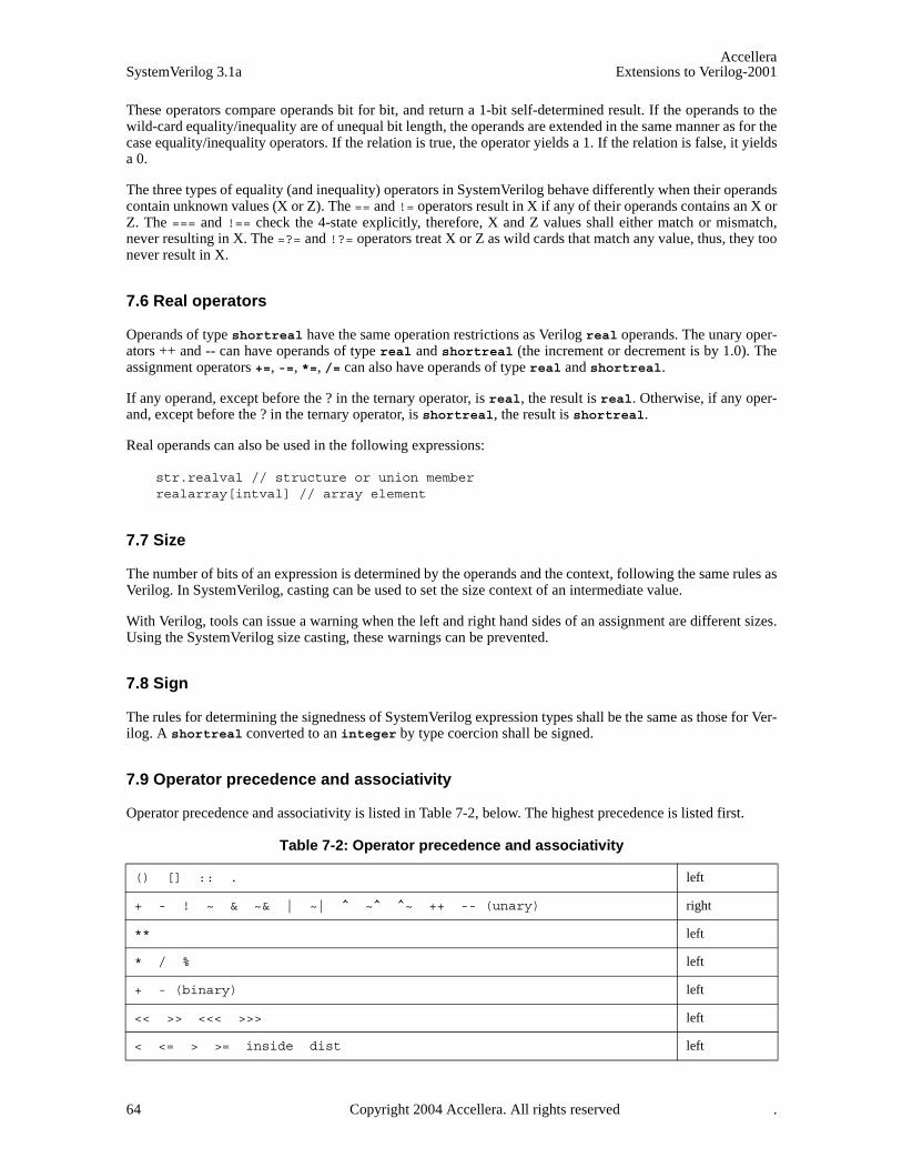
AccelleraSystemVerilog 3.1a Extensions to Verilog-2001
These operators compare operands bit for bit, and return a 1-bit self-determined result. If the operands to thewild-card equality/inequality are of unequal bit length, the operands are extended in the same manner as for thecase equality/inequality operators. If the relation is true, the operator yields a 1. If the relation is false, it yieldsa 0.
The three types of equality (and inequality) operators in SystemVerilog behave differently when their operandscontain unknown values (X or Z). The == and != operators result in X if any of their operands contains an X orZ. The === and !== check the 4-state explicitly, therefore, X and Z values shall either match or mismatch,never resulting in X. The =?= and !?= operators treat X or Z as wild cards that match any value, thus, they toonever result in X.
7.6 Real operators
Operands of type shortreal have the same operation restrictions as Verilog real operands. The unary oper-ators ++ and -- can have operands of type real and shortreal (the increment or decrement is by 1.0). Theassignment operators +=, -=, *=, /= can also have operands of type real and shortreal.
If any operand, except before the ? in the ternary operator, is real, the result is real. Otherwise, if any oper-and, except before the ? in the ternary operator, is shortreal, the result is shortreal.
Real operands can also be used in the following expressions:
str.realval // structure or union memberrealarray[intval] // array element
7.7 Size
The number of bits of an expression is determined by the operands and the context, following the same rules asVerilog. In SystemVerilog, casting can be used to set the size context of an intermediate value.
With Verilog, tools can issue a warning when the left and right hand sides of an assignment are different sizes.Using the SystemVerilog size casting, these warnings can be prevented.
7.8 Sign
The rules for determining the signedness of SystemVerilog expression types shall be the same as those for Ver-ilog. A shortreal converted to an integer by type coercion shall be signed.
7.9 Operator precedence and associativity
Operator precedence and associativity is listed in Table 7-2, below. The highest precedence is listed first.
Table 7-2: Operator precedence and associativity
() [] :: . left
+ - ! ~ & ~& | ~| ^ ~^ ^~ ++ -- (unary) right
** left
* / % left
+ - (binary) left
<< >> <<< >>> left
< <= > >= inside dist left
64 Copyright 2004 Accellera. All rights reserved .
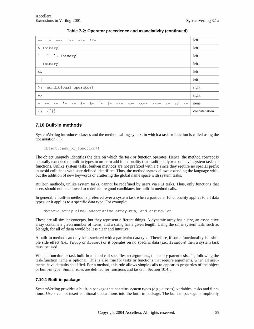
AccelleraExtensions to Verilog-2001 SystemVerilog 3.1a
7.10 Built-in methods
SystemVerilog introduces classes and the method calling syntax, in which a task or function is called using thedot notation (.):
object.task_or_function()
The object uniquely identifies the data on which the task or function operates. Hence, the method concept isnaturally extended to built-in types in order to add functionality that traditionally was done via system tasks orfunctions. Unlike system tasks, built-in methods are not prefixed with a $ since they require no special prefixto avoid collisions with user-defined identifiers. Thus, the method syntax allows extending the language with-out the addition of new keywords or cluttering the global name space with system tasks.
Built-in methods, unlike system tasks, cannot be redefined by users via PLI tasks. Thus, only functions thatusers should not be allowed to redefine are good candidates for built-in method calls.
In general, a built-in method is preferred over a system task when a particular functionality applies to all datatypes, or it applies to a specific data type. For example:
dynamic_array.size, associative_array.num, and string.len
These are all similar concepts, but they represent different things. A dynamic array has a size, an associativearray contains a given number of items, and a string has a given length. Using the same system task, such as$length, for all of them would be less clear and intuitive.
A built-in method can only be associated with a particular data type. Therefore, if some functionality is a sim-ple side effect (i.e., $stop or $reset) or it operates on no specific data (i.e., $random) then a system taskmust be used.
When a function or task built-in method call specifies no arguments, the empty parenthesis, (), following thetask/function name is optional. This is also true for tasks or functions that require arguments, when all argu-ments have defaults specified. For a method, this rule allows simple calls to appear as properties of the objector built-in type. Similar rules are defined for functions and tasks in Section 10.4.5.
7.10.1 Built-in package
SystemVerilog provides a built-in package that contains system types (e.g., classes), variables, tasks and func-tions. Users cannot insert additional declarations into the built-in package. The built-in package is implicitly
== != === !== =?= !?= left
& (binary) left
^ ~^ ^~ (binary) left
| (binary) left
&& left
|| left
?: (conditional operator) right
–> right
= += -= *= /= %= &= ^= |= <<= >>= <<<= >>>= := :/ <= none
{} {{}} concatenation
Table 7-2: Operator precedence and associativity (continued)
Copyright 2004 Accellera. All rights reserved. 65
AccelleraSystemVerilog 3.1a Extensions to Verilog-2001
wildcard imported into the compilation-unit scope of every compilation unit (see Section 18.3). Thus, declara-tions in the built-in package are directly available in any other scope (like system tasks and functions) unlessthey are redefined by user code.
The package name std followed by the scope resolution operator :: can be used to unambiguously accessnames in the built-in package. For example:
std::sys_task(); // unambiguously call the system provided sys_task
Unlike system tasks and functions, tasks and functions in the built-in package need not be prefixed with a $ toavoid collisions with user-defined identifiers. This mechanism allows functional extensions to the language ina backward compatible manner, without the addition of new keywords or polluting local name spaces.
7.11 Static Prefixes
Informally, the “longest static prefix” of a select is the longest part of the select for which an analysis tool hasknown values following elaboration. This concept is used when describing implicit sensitivity lists (see Sec-tion 9.2) and when describing error conditions for drivers of logic ports (see Section 5.6). The remainder ofthis section defines what constitutes the “longest static prefix” of a select.
A field select is defined as a hierarchical name where the right-hand side of the last “.” hierarchy separatoridentifies a field of a variable whose type is a struct or union declaration. The field select prefix is definedto be the left-hand side of final “.” hierarchy separator in a field select.
An indexing select is a single indexing operation. The indexing select prefix is either an identifier or, in thecase of a multidimensional select, another indexing select. Array selects, bit selects, part selects, and indexedpart selects are examples of indexing selects.
The definition of a static prefix is recursive and is defined as follows:
1) an identifier is a static prefix
2) a field select is a static prefix if the field select prefix is a static prefix
3) an indexing select is a static prefix if the indexing select prefix is a static prefix and the select expression isa constant expression.
The definition of the longest static prefix is defined as follows:
1) an identifier that is not the field select prefix or indexing select prefix of an expression that is a static prefix
2) a field select that is not the field select prefix or indexing select prefix of an expression that is a staticprefix
3) an indexing select that is not the field select prefix or indexing select prefix of an expression that is a staticprefix.
Examples:
localparam p = 7; reg [7:0] m [5:1][5:1]; integer i;
m[1][i] // longest static prefix is m[1]
built_in_data_type ::= [ std:: ] data_type_identifier
built_in_function_call ::= [ std:: ] built_in_identifier
// not in Annex A
// not in Annex A
66 Copyright 2004 Accellera. All rights reserved .

AccelleraExtensions to Verilog-2001 SystemVerilog 3.1a
m[p][1] // longest static prefix is m[p][1]
m[i][1] // longest static prefix is m
7.12 Concatenation
Braces ( { } ) are used to show concatenation, as in Verilog. The concatenation is treated as a packed vector ofbits. It can be used on the left hand side of an assignment or in an expression.
logic log1, log2, log3;{log1, log2, log3} = 3’b111;{log1, log2, log3} = {1’b1, 1’b1, 1’b1}; // same effect as 3’b111
Software tools can generate a warning if the concatenation width on one side of an assignment is different thanthe expression on the other side. The following examples can give warning of size mismatch:
bit [1:0] packedbits = {32’b1,32’b1}; // right hand side is 64 bitsint i = {1’b1, 1’b1}; //right hand side is 2 bits
Refer to Sections 2.7 and 2.8 for information on initializing arrays and structures .
SystemVerilog enhances the concatenation operation to allow concatenation of variables of type string. In gen-eral, if any of the operands is of type string, the concatenation is treated as a string, and all other argumentsare implicitly converted to the string type (as described in Section 3.7). String concatenation is not allowedon the left hand side of an assignment, only as an expression.
string hello = "hello";string s;s = { hello, " ", "world" };$display( "%s\n", s ); // displays 'hello world's = { s, " and goodbye" };$display( "%s\n", s ); // displays 'hello world and goodbye'
The replication operator (also called a multiple concatenation) form of braces can also be used with variablesof type string. In the case of string replication, a non-constant multiplier is allowed.
int n = 3;string s = {n { "boo " }};$display( "%s\n", s ); // displays 'boo boo boo '
Note that unlike bit concatenation, the result of a string concatenation or replication is not truncated. Instead,the destination variable (of type string) is resized to accommodate the resulting string.
7.13 Unpacked array expressions
Braces are also used for expressions to assign to unpacked arrays. Unlike in C, the expressions must match ele-ment for element, and the braces must match the array dimensions. Each expression item shall be evaluated inthe context of an assignment to the type of the corresponding element in the array. This means that the follow-ing examples do not give size warnings, unlike the similar assignments above:
bit unpackedbits [1:0] = {1,1}; // no size warning as bit can be set to 1int unpackedints [1:0] = {1'b1, 1'b1}; // no size warning as int can be
// set to 1'b1
The syntax of multiple concatenations can be used for unpacked array expressions as well. Each replicationrepresents a single dimension.
Copyright 2004 Accellera. All rights reserved. 67
AccelleraSystemVerilog 3.1a Extensions to Verilog-2001
unpackedbits = {2 {y}} ; // same as {y, y}int n[1:2][1:3] = {2{{3{y}}}}; // same as {{y,y,y},{y,y,y}}
SystemVerilog determines the context of the braces when used in the context of an assignment. If used in thecontext of an assignment to an unpacked array, the braces represent an unpacked array literal or expression.Outside the context of an assignment on the right hand side, an explicit cast must be used with the braces todistinguish it from a concatenation.
Note an aggregate expression cannot be used as the target of an assignment. The following is considered ille-gal:
logic [2:0] a [1:0];logic [2:0] b ,c;
always {b,c} = a; // illegal assignment the braces are not determined to be// an unpacked array expression
It can sometimes be useful to set array elements to a value without having to keep track of how many membersthere are. This can be done with the default keyword:
initial unpackedints = {default:2}; // sets elements to 2
For more arrays of structures, it is useful to specify one or more matching type keys, as illustrated under struc-ture expressions, below.
struct {int a; time b;} abkey[1:0];abkey = {{a:1, b:2ns}, {int:5, time:$time}};
When the braces include a type, or default key, the braces shall not be interpreted as a concatenation for bothpacked and unpacked array types.
The rules for unpacked array matching are as follows:
— An index:value specifies an explicit value for a keyed element index. The value is evaluated in the contextof an assignment to the indexed element and shall be castable to its type. It shall be an error to specify thesame index more than once in a single array expression.
— For type:value, if the element or sub array type of the unpacked array is equivalent to this type, theneach element or sub array shall be set to the value. The value must be castable to the array element or subarray type. Otherwise, if the unpacked array is multidimensional, then there is a recursive descent into eachsub array of the array using the rules in this section and the type and default keys. Otherwise, if theunpacked array is an array of structures, there is a recursive descent into each element of the array using therules for structure expressions and the type and default keys. If more than one type matches the same ele-ment, the last value shall be used.
— For default:value, this key specifies the default value to use for each element of an unpacked array thathas not been covered by the earlier rules in this section. The value is evaluated in the context of eachassignment to an element covered by the default and must be castable to the array element type.
Every element shall be covered by one of these rules.
If the type key, default key, or replication operator is used on an expression with side effects, the number oftimes that expression evaluates is undefined.
7.14 Structure expressions
A structure expression (packed or unpacked) can be built from member expressions using braces and commas,with the members in declaration order. Replicate operators can be used to set the values for the exact number
68 Copyright 2004 Accellera. All rights reserved .

AccelleraExtensions to Verilog-2001 SystemVerilog 3.1a
of members. Each member expression shall be evaluated in the context of an assignment to the type of the cor-responding member in the structure. It can also be built with the names of the members
module mod1;
typedef struct {int x;int y;
} st;
st s1;int k = 1;
initial begin #1 s1 = {1, 2+k}; // by position#1 $display( s1.x, s1.y);#1 s1 = {x:2, y:3+k); // by name#1 $display( s1);#1 $finish;
end endmodule
It can sometimes be useful to set structure members to a value without having to keep track of how manymembers there are, or what the names are. This can be done with the default keyword:
initial s1 = {default:2}; // sets x and y to 2
The {member:value} or {data_type: default_value} syntax can also be used:
ab abkey[1:0] = {{a:1, b:1.0}, {int:2, shortreal:2.0}};
Note that the default keyword applies to members in nested structures or elements in unpacked arrays instructures. In fact, it descends the nesting to a built-in type or a packed array of them.
struct {int A;struct {
int B, C;} BC1, BC2;
}
ABC = {A:1, BC1:{B:2, C:3}, BC2:{B:4,C:5}};DEF = {default:10};
To deal with the problem of members of different types, a type can be used as the key. This overrides thedefault for members of that type:
typedef struct {logic [7:0] a;bit b;bit signed [31:0] c; string s;
} sa;
sa s2;initial s2 = {int:1, default:0, string:""}; // set all to 0 except the
// array of bits to 1 and// string to ""
Copyright 2004 Accellera. All rights reserved. 69

AccelleraSystemVerilog 3.1a Extensions to Verilog-2001
Similarly, an individual member can be set to override the general default and the type default:
initial #10 s1 = {default:’1, s : ""}; // set all to 1 except s to ""
SystemVerilog determines the context of the braces when used in the context of an assignment. If used in thecontext of an assignment to an unpacked structure, the braces represent an unpacked structure literal or expres-sion. Outside the context of an assignment to an aggregate type, an explicit cast must be used with the braces todistinguish it from a concatenation. When the braces include a label, type, or default key, the braces shall notbe interpreted as a concatenation for both packed and unpacked structure types.
The matching rules are as follows:
— A member:value: specifies an explicit value for a named member of the structure. The named membermust be at the top level of the structure—a member with the same name in some level of substructure shallnot be set. The value must be castable to the member type and is evaluated in the context of an assignmentto the named member, otherwise an error is generated.
— The type:value specifies an explicit value for a field in the structure which is equivalent to the type andhas not been set by a field name key above. If the same type key is mentioned more than once, the lastvalue is used. The value is evaluated in the context of an assignment to the matching type.
— The default:value applies to members that are not matched by either member name or type key and arenot either structures or unpacked arrays. The value is evaluated in the context of each assignment to amember by the default and must be castable to the member type, otherwise an error is generated. Forunmatched structure members, the type and default specifiers are applied recursively according to the rulesin this section to each member of the substructure. For unmatched unpacked array members, the type anddefault keys are applied to the array according to the rules for unpacked arrays.
Every member must be covered by one of these rules.
If the type key, default key, or replication operator is used on an expression with side effects, the number oftimes that expression evaluates is undefined.
7.15 Tagged union expressions and member access
Syntax 7-2—Tagged union syntax (excerpt from Annex A)
A tagged union expression (packed or unpacked) is expressed using the keyword tagged followed by a taggedunion member identifier, followed by an expression representing the corresponding member value. For voidmembers the member value expression is omitted.
Example:
typedef union tagged {void Invalid;int Valid;
} VInt;
VInt vi1, vi2;
expression ::= ...
| tagged_union_expression
tagged_union_expression ::= tagged member_identifier [ expression ]
// from Annex A.8.3
70 Copyright 2004 Accellera. All rights reserved .
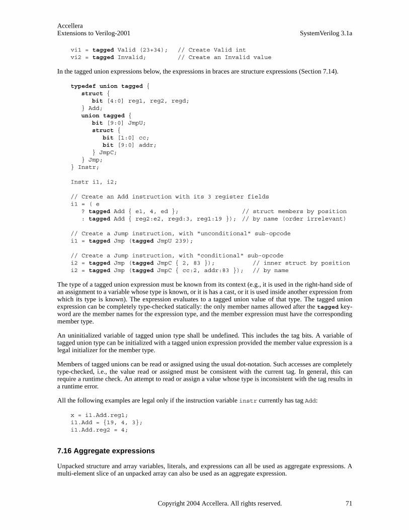
AccelleraExtensions to Verilog-2001 SystemVerilog 3.1a
vi1 = tagged Valid (23+34); // Create Valid intvi2 = tagged Invalid; // Create an Invalid value
In the tagged union expressions below, the expressions in braces are structure expressions (Section 7.14).
typedef union tagged {struct {
bit [4:0] reg1, reg2, regd;} Add;union tagged {
bit [9:0] JmpU;struct {
bit [1:0] cc; bit [9:0] addr;
} JmpC;} Jmp;
} Instr;
Instr i1, i2;
// Create an Add instruction with its 3 register fieldsi1 = ( e
? tagged Add { e1, 4, ed }; // struct members by position: tagged Add { reg2:e2, regd:3, reg1:19 }); // by name (order irrelevant)
// Create a Jump instruction, with "unconditional" sub-opcodei1 = tagged Jmp (tagged JmpU 239);
// Create a Jump instruction, with "conditional" sub-opcodei2 = tagged Jmp (tagged JmpC { 2, 83 }); // inner struct by positioni2 = tagged Jmp (tagged JmpC { cc:2, addr:83 }); // by name
The type of a tagged union expression must be known from its context (e.g., it is used in the right-hand side ofan assignment to a variable whose type is known, or it is has a cast, or it is used inside another expression fromwhich its type is known). The expression evaluates to a tagged union value of that type. The tagged unionexpression can be completely type-checked statically: the only member names allowed after the tagged key-word are the member names for the expression type, and the member expression must have the correspondingmember type.
An uninitialized variable of tagged union type shall be undefined. This includes the tag bits. A variable oftagged union type can be initialized with a tagged union expression provided the member value expression is alegal initializer for the member type.
Members of tagged unions can be read or assigned using the usual dot-notation. Such accesses are completelytype-checked, i.e., the value read or assigned must be consistent with the current tag. In general, this canrequire a runtime check. An attempt to read or assign a value whose type is inconsistent with the tag results ina runtime error.
All the following examples are legal only if the instruction variable instr currently has tag Add:
x = i1.Add.reg1;i1.Add = {19, 4, 3};i1.Add.reg2 = 4;
7.16 Aggregate expressions
Unpacked structure and array variables, literals, and expressions can all be used as aggregate expressions. Amulti-element slice of an unpacked array can also be used as an aggregate expression.
Copyright 2004 Accellera. All rights reserved. 71
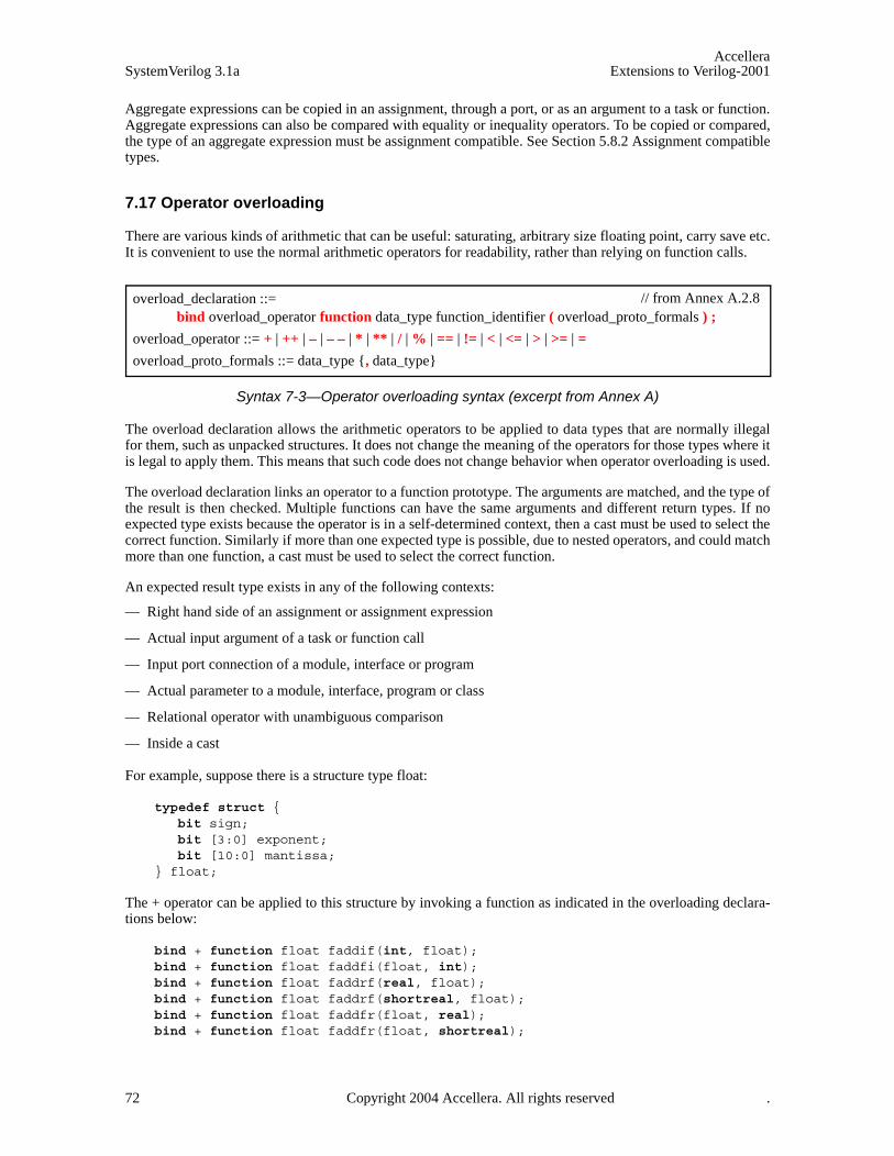
AccelleraSystemVerilog 3.1a Extensions to Verilog-2001
Aggregate expressions can be copied in an assignment, through a port, or as an argument to a task or function.Aggregate expressions can also be compared with equality or inequality operators. To be copied or compared,the type of an aggregate expression must be assignment compatible. See Section 5.8.2 Assignment compatibletypes.
7.17 Operator overloading
There are various kinds of arithmetic that can be useful: saturating, arbitrary size floating point, carry save etc.It is convenient to use the normal arithmetic operators for readability, rather than relying on function calls.
Syntax 7-3—Operator overloading syntax (excerpt from Annex A)
The overload declaration allows the arithmetic operators to be applied to data types that are normally illegalfor them, such as unpacked structures. It does not change the meaning of the operators for those types where itis legal to apply them. This means that such code does not change behavior when operator overloading is used.
The overload declaration links an operator to a function prototype. The arguments are matched, and the type ofthe result is then checked. Multiple functions can have the same arguments and different return types. If noexpected type exists because the operator is in a self-determined context, then a cast must be used to select thecorrect function. Similarly if more than one expected type is possible, due to nested operators, and could matchmore than one function, a cast must be used to select the correct function.
An expected result type exists in any of the following contexts:
— Right hand side of an assignment or assignment expression
— Actual input argument of a task or function call
— Input port connection of a module, interface or program
— Actual parameter to a module, interface, program or class
— Relational operator with unambiguous comparison
— Inside a cast
For example, suppose there is a structure type float:
typedef struct {bit sign;bit [3:0] exponent;bit [10:0] mantissa;
} float;
The + operator can be applied to this structure by invoking a function as indicated in the overloading declara-tions below:
bind + function float faddif(int, float); bind + function float faddfi(float, int);bind + function float faddrf(real, float);bind + function float faddrf(shortreal, float);bind + function float faddfr(float, real);bind + function float faddfr(float, shortreal);
overload_declaration ::= bind overload_operator function data_type function_identifier ( overload_proto_formals ) ;
overload_operator ::= + | ++ | – | – – | * | ** | / | % | == | != | < | <= | > | >= | =
overload_proto_formals ::= data_type {, data_type}
// from Annex A.2.8
72 Copyright 2004 Accellera. All rights reserved .

AccelleraExtensions to Verilog-2001 SystemVerilog 3.1a
bind + function float faddff(float, float);bind + function float fcopyf(float); // unary +bind + function float fcopyi(int); // unary +bind + function float fcopyr(real); // unary +bind + function float fcopyr(shortreal); // unary +
float A, B, C, D;assign A = B + C; //equivalent to A = faddff(B, C);assign D = A + 1.0; //equivalent to A = faddfr(A, 1.0);
The overloading declaration links the + operator to each function prototype according to the equivalent argu-ment types in the overloaded expression, which normally must match exactly. The exception is if the actualargument is an integral type and there is only one prototype with a corresponding integral argument, the actualis implicitly cast to the type in the prototype.
Note that the function prototype does not need to match the actual function declaration exactly. If it does not,then the normal implicit casting rules apply when calling the function. For example the fcopyi function canbe defined with an int argument:
function float fcopyi (int i);float o;o.sign = i[31];o.exponent = 0;o.mantissa = 0;…return o;
endfunction
Overloading the assignment operator also serves to overload implicit assignments or casting. Here these areusing the same functions as the unary +.
bind = function float fcopyi(int); // cast int to floatbind = function float fcopyr(real); // cast real to floatbind = function float fcopyr(shortreal); // cast shortreal to float
The operators that can be overloaded are the arithmetic operators, the relational operators and assignment.Note that the assignment operator from a float to a float cannot be overloaded here because it is already legal.Similarly, equality and inequality between floats cannot be overloaded.
No format can be assumed for 0 or 1, so the user cannot rely on subtraction to give equality, or on addition togive increment. Similarly no format can be assumed for positive or negative, so comparison must be explicitlycoded.
An assignment operator such as += is automatically built from both the + and = operators successively, wherethe = has its normal meaning. For example
float A, B;bind + function float faddff(float, float);always @(posedge clock) A += B; // equivalent to A = A + B
The scope and visibility of the overload declaration follows the same search rules as a data declaration. Theoverload declaration must be defined before use in a scope which is visible. The function bound by the over-load declaration uses the same scope search rules as a function enable from the scope where the operator isinvoked.
7.18 Streaming operators (pack / unpack)
The bit-stream casting described in Section 3.16 is most useful when the conversion operation can be easily
Copyright 2004 Accellera. All rights reserved. 73

AccelleraSystemVerilog 3.1a Extensions to Verilog-2001
expressed using only a type cast, and the specific ordering of the bit-stream is not important. Sometimes, how-ever, a stream that matches a particular machine organization is required. The streaming operators performpacking of bit-stream types (see Section 3.16) into a sequence of bits in a user-specified order. When used inthe left-hand-side, the streaming operators perform the reverse operation, unpack a stream of bits into one ormore variables. If the data being packed contains any 4-state types, the result of a pack operation is a 4-statestream; otherwise, the result of a pack is a 2-state stream. Unpacking a 4-state stream into a 2-state type is doneby a cast to a 2-state variable, and vice-versa.
The syntax of the bit-stream concatenation is:
Syntax 7-4—streaming concatenation syntax (excerpt from Annex A)
The stream-operator determines the order in which data is streamed: >> causes data to be streamed in left-to-right order, while << causes data to be streamed in right-to-left order. If a slice-size is specified then the data tobe streamed is first broken up into slices with the specified number of bits, and then the slices are streamed inthe specified order. If a slice-size is not specified, the default is 1 (or bit). If, as a result of slicing, the last sliceis less than the slice width then no padding is added.
For example:
int j = { "A", "B", "C", "D" };{ >> {j}} // generates stream "A" "B" "C" "D"{ << byte {j}} // generates stream "D" "C" "B" "A" (little endian){ << 16 {j}} // generates stream "C" "D" "A" "B"{ << { 8’b0011_0101 }} // generates stream ’b1010_1100 (bit reverse){ << 4 { 6’b11_0101 }} // generates stream ’b0101_11{ >> 4 { 6’b11_0101 }} // generates stream ’b1101_01 (same){ << 2 { { << { 4’b1101 }} }} // generates stream ’b1110
The streaming operators operate directly on integral types and streams. When applied to unpacked aggregatetypes, such as unpacked arrays, unpacked structures, or classes, they recursively traverse the data in depth-firstorder until reaching an integral type. A multi-dimensional packed array is thus treated as a single integral type,whereas an unpacked array of packed items causes each packed item to be streamed individually. The stream-ing operators can only process bit-stream types; any other types shall generate an error.
The result of the pack operation can be assigned directly to any bit-stream type variable. If the left-hand siderepresents a fixed-size variable and the stream is larger than the variable, an error will be generated. If the vari-able is larger than the stream, the stream is left-justified and zero-filled on the right. If the left-hand side repre-sents a dynamic-size variable, such as a queue or dynamic array, the variable is resized to accommodate theentire stream. If after resizing, the variable is larger than the stream, the stream is left-justified and zero-filledon the right. The stream is not an integral value; to participate in an expression, a cast is required.
streaming_expression ::= { stream_operator [ slice_size ] stream_concatenation }
stream_operator ::= >> | <<
slice_size ::= ps_type_identifier | constant_expression
stream_concatenation ::= { stream_expression { , stream_expression } }
stream_expression ::= expression [ with [ array_range_expression ] ]
array_range_expression ::= expression
| expression : expression | expression +: expression | expression -: expression
primary ::= ...
| streaming_expression
// from Annex A.8.1
74 Copyright 2004 Accellera. All rights reserved .
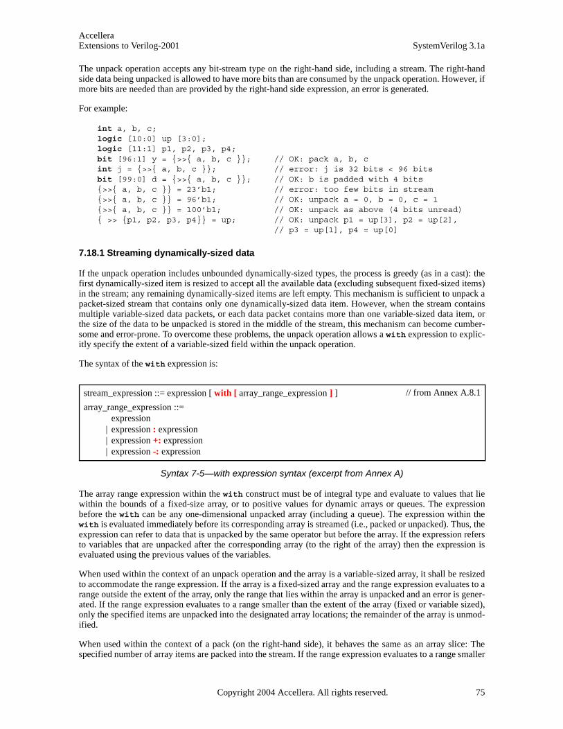
AccelleraExtensions to Verilog-2001 SystemVerilog 3.1a
The unpack operation accepts any bit-stream type on the right-hand side, including a stream. The right-handside data being unpacked is allowed to have more bits than are consumed by the unpack operation. However, ifmore bits are needed than are provided by the right-hand side expression, an error is generated.
For example:
int a, b, c;logic [10:0] up [3:0]; logic [11:1] p1, p2, p3, p4;bit [96:1] y = {>>{ a, b, c }}; // OK: pack a, b, cint j = {>>{ a, b, c }}; // error: j is 32 bits < 96 bitsbit [99:0] d = {>>{ a, b, c }}; // OK: b is padded with 4 bits{>>{ a, b, c }} = 23’b1; // error: too few bits in stream{>>{ a, b, c }} = 96’b1; // OK: unpack a = 0, b = 0, c = 1{>>{ a, b, c }} = 100’b1; // OK: unpack as above (4 bits unread){ >> {p1, p2, p3, p4}} = up; // OK: unpack p1 = up[3], p2 = up[2],
// p3 = up[1], p4 = up[0]
7.18.1 Streaming dynamically-sized data
If the unpack operation includes unbounded dynamically-sized types, the process is greedy (as in a cast): thefirst dynamically-sized item is resized to accept all the available data (excluding subsequent fixed-sized items)in the stream; any remaining dynamically-sized items are left empty. This mechanism is sufficient to unpack apacket-sized stream that contains only one dynamically-sized data item. However, when the stream containsmultiple variable-sized data packets, or each data packet contains more than one variable-sized data item, orthe size of the data to be unpacked is stored in the middle of the stream, this mechanism can become cumber-some and error-prone. To overcome these problems, the unpack operation allows a with expression to explic-itly specify the extent of a variable-sized field within the unpack operation.
The syntax of the with expression is:
Syntax 7-5—with expression syntax (excerpt from Annex A)
The array range expression within the with construct must be of integral type and evaluate to values that liewithin the bounds of a fixed-size array, or to positive values for dynamic arrays or queues. The expressionbefore the with can be any one-dimensional unpacked array (including a queue). The expression within thewith is evaluated immediately before its corresponding array is streamed (i.e., packed or unpacked). Thus, theexpression can refer to data that is unpacked by the same operator but before the array. If the expression refersto variables that are unpacked after the corresponding array (to the right of the array) then the expression isevaluated using the previous values of the variables.
When used within the context of an unpack operation and the array is a variable-sized array, it shall be resizedto accommodate the range expression. If the array is a fixed-sized array and the range expression evaluates to arange outside the extent of the array, only the range that lies within the array is unpacked and an error is gener-ated. If the range expression evaluates to a range smaller than the extent of the array (fixed or variable sized),only the specified items are unpacked into the designated array locations; the remainder of the array is unmod-ified.
When used within the context of a pack (on the right-hand side), it behaves the same as an array slice: Thespecified number of array items are packed into the stream. If the range expression evaluates to a range smaller
stream_expression ::= expression [ with [ array_range_expression ] ]
array_range_expression ::= expression
| expression : expression | expression +: expression | expression -: expression
// from Annex A.8.1
Copyright 2004 Accellera. All rights reserved. 75
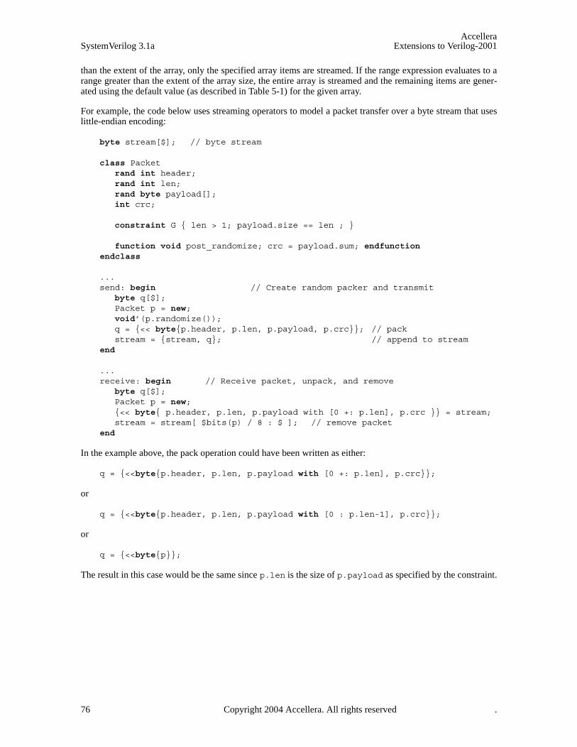
AccelleraSystemVerilog 3.1a Extensions to Verilog-2001
than the extent of the array, only the specified array items are streamed. If the range expression evaluates to arange greater than the extent of the array size, the entire array is streamed and the remaining items are gener-ated using the default value (as described in Table 5-1) for the given array.
For example, the code below uses streaming operators to model a packet transfer over a byte stream that useslittle-endian encoding:
byte stream[$]; // byte stream
class Packetrand int header;rand int len;rand byte payload[];int crc;
constraint G { len > 1; payload.size == len ; }
function void post_randomize; crc = payload.sum; endfunction endclass
... send: begin // Create random packer and transmit
byte q[$];Packet p = new;void’(p.randomize());q = {<< byte{p.header, p.len, p.payload, p.crc}}; // packstream = {stream, q}; // append to stream
end
... receive: begin // Receive packet, unpack, and remove
byte q[$];Packet p = new;{<< byte{ p.header, p.len, p.payload with [0 +: p.len], p.crc }} = stream;stream = stream[ $bits(p) / 8 : $ ]; // remove packet
end
In the example above, the pack operation could have been written as either:
q = {<<byte{p.header, p.len, p.payload with [0 +: p.len], p.crc}};
or
q = {<<byte{p.header, p.len, p.payload with [0 : p.len-1], p.crc}};
or
q = {<<byte{p}};
The result in this case would be the same since p.len is the size of p.payload as specified by the constraint.
76 Copyright 2004 Accellera. All rights reserved .
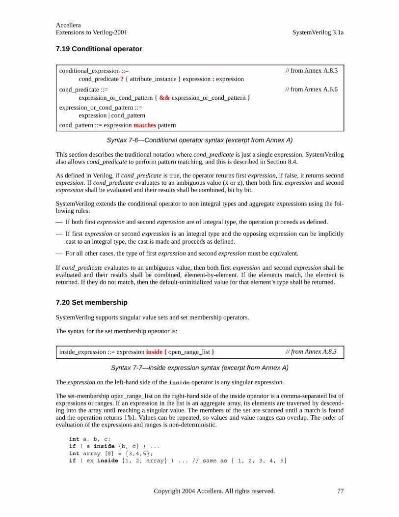
AccelleraExtensions to Verilog-2001 SystemVerilog 3.1a
7.19 Conditional operator
Syntax 7-6—Conditional operator syntax (excerpt from Annex A)
This section describes the traditional notation where cond_predicate is just a single expression. SystemVerilogalso allows cond_predicate to perform pattern matching, and this is described in Section 8.4.
As defined in Verilog, if cond_predicate is true, the operator returns first expression, if false, it returns secondexpression. If cond_predicate evaluates to an ambiguous value (x or z), then both first expression and secondexpression shall be evaluated and their results shall be combined, bit by bit.
SystemVerilog extends the conditional operator to non integral types and aggregate expressions using the fol-lowing rules:
— If both first expression and second expression are of integral type, the operation proceeds as defined.
— If first expression or second expression is an integral type and the opposing expression can be implicitlycast to an integral type, the cast is made and proceeds as defined.
— For all other cases, the type of first expression and second expression must be equivalent.
If cond_predicate evaluates to an ambiguous value, then both first expression and second expression shall beevaluated and their results shall be combined, element-by-element. If the elements match, the element isreturned. If they do not match, then the default-uninitialized value for that element’s type shall be returned.
7.20 Set membership
SystemVerilog supports singular value sets and set membership operators.
The syntax for the set membership operator is:
Syntax 7-7—inside expression syntax (excerpt from Annex A)
The expression on the left-hand side of the inside operator is any singular expression.
The set-membership open_range_list on the right-hand side of the inside operator is a comma-separated list ofexpressions or ranges. If an expression in the list is an aggregate array, its elements are traversed by descend-ing into the array until reaching a singular value. The members of the set are scanned until a match is foundand the operation returns 1’b1. Values can be repeated, so values and value ranges can overlap. The order ofevaluation of the expressions and ranges is non-deterministic.
int a, b, c;if ( a inside {b, c} ) ...int array [$] = {3,4,5};if ( ex inside {1, 2, array} ) ... // same as { 1, 2, 3, 4, 5}
conditional_expression ::= cond_predicate ? { attribute_instance } expression : expression
cond_predicate ::= expression_or_cond_pattern { && expression_or_cond_pattern }
expression_or_cond_pattern ::= expression | cond_pattern
cond_pattern ::= expression matches pattern
// from Annex A.8.3
// from Annex A.6.6
inside_expression ::= expression inside { open_range_list } // from Annex A.8.3
Copyright 2004 Accellera. All rights reserved. 77
AccelleraSystemVerilog 3.1a Extensions to Verilog-2001
The inside operator uses the equality ( == ) operator on non-integral expressions to perform the comparison.If no match is found, the inside operator returns 1’b0. Integral expressions also use the equality operator,except that a z inside a value in the set is treated as a don’t care and that bit position shall not be considered.Note that unlike comparisons performed by the casez statement, z values in the expression on the left-handside are not treated as a don't-care; the don't-care is unidirectional.
logic [2:0] val;while ( val inside {3’b1?1} ) ... // matches 3’b101, 3’b111, 3’b1x1, 3’b1z1
If no match is found, but some of the comparisons result in x, the inside operator shall return 1'bx. The returnvalue is effectively the or reduction of all the comparisons in the set with the expression on the left-hand side.
wire r;assign r=3’bz11 inside {3’b1?1, 3’b011}; // r = 1’bx
A range can be specified with a low and high bound enclosed by square braces [ ], and separated by a colon (: ), as in [low_bound:high_bound]. A bound specified by $ shall represent the lowest or highest value forthe type of the expression on the left-hand side. A match is found if the expression on the left-hand side isinclusively within the range. When specifying a range, the expressions must be of a singular type for with therelation operators ( <=, >= ) are defined. If the bound to the left of the colon is greater than the bound to theright, the range is empty and contains no values.
For example:
bit ba = a inside { [16:23], [32:47] };string I;if (I inside {["a rock":"hard place"]}) ...
// I between "a rock" and a "hard place"
78 Copyright 2004 Accellera. All rights reserved .
AccelleraExtensions to Verilog-2001 SystemVerilog 3.1a
Section 8Procedural Statements and Control Flow
8.1 Introduction (informative)
Procedural statements are introduced by the following:
initial // enable this statement at the beginning of simulation and execute it only once
final // do this statement once at the end of simulation
always, always_comb, always_latch, always_ff // loop forever (see Section 9 on processes)
task // do these statements whenever the task is called
function // do these statements whenever the function is called and return a value
SystemVerilog has the following types of control flow within a process
— Selection, loops and jumps
— Task and function calls
— Sequential and parallel blocks
— Timing control
Verilog procedural statements are in initial or always blocks, tasks or functions. SystemVerilog adds afinal block that executes at the end of simulation.
Verilog includes most of the statement types of C, except for do...while, break, continue and goto. Ver-ilog has the repeat statement which C does not, and the disable. The use of the Verilog disable to carryout the functionality of break and continue requires the user to invent block names, and introduces the opportu-nity for error.
SystemVerilog adds C-like break, continue and return functionality, which do not require the use of blocknames.
Loops with a test at the end are sometimes useful to save duplication of the loop body. SystemVerilog adds aC-like do...while loop for this capability.
Verilog provides two overlapping methods for procedurally adding and removing drivers for variables: theforce/release statements and the assign/deassign statements. The force/release statements can alsobe used to add or remove drivers for nets in addition to variables. A force statement targeting a variable that iscurrently the target of an assign shall override that assign; however, once the force is released, the assign’seffect again shall be visible.
The keyword assign is much more commonly used for the somewhat similar, yet quite different purpose ofdefining permanent drivers of values to nets.
SystemVerilog final blocks execute in an arbitrary but deterministic sequential order. This is possiblebecause final blocks are limited to the legal set of statements allowed for functions. SystemVerilog does notspecify the ordering, but implementations should define rules that preserve the ordering between runs. Thishelps keep the output log file stable since final blocks are mainly used for displaying statistics.
8.2 Statements
The syntax for procedural statements is:
Copyright 2004 Accellera. All rights reserved. 79
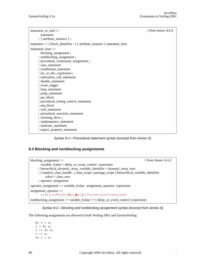
AccelleraSystemVerilog 3.1a Extensions to Verilog-2001
Syntax 8-1—Procedural statement syntax (excerpt from Annex A)
8.3 Blocking and nonblocking assignments
Syntax 8-2—blocking and nonblocking assignment syntax (excerpt from Annex A)
The following assignments are allowed in both Verilog-2001 and SystemVerilog:
#1 r = a;r = #1 a;r <= #1 a;r <= a;@c r = a;
statement_or_null ::= statement
| { attribute_instance } ;
statement ::= [ block_identifier : ] { attribute_instance } statement_item
statement_item ::= blocking_assignment ;
| nonblocking_assignment ; | procedural_continuous_assignment ; | case_statement | conditional_statement | inc_or_dec_expression ; | subroutine_call_statement | disable_statement | event_trigger | loop_statement | jump_statement | par_block | procedural_timing_control_statement | seq_block | wait_statement | procedural_assertion_statement | clocking_drive ; | randsequence_statement | randcase_statement | expect_property_statement
// from Annex A.6.4
blocking_assignment ::= variable_lvalue = delay_or_event_control expression
| hierarchical_dynamic_array_variable_identifier = dynamic_array_new | [ implicit_class_handle . | class_scope | package_scope ] hierarchical_variable_identifier
select = class_new | operator_assignment
operator_assignment ::= variable_lvalue assignment_operator expression
assignment_operator ::= = | += | -= | *= | /= | %= | &= | |= | ^= | <<= | >>= | <<<= | >>>=
nonblocking_assignment ::= variable_lvalue <= [ delay_or_event_control ] expression
// from Annex A.6.2
80 Copyright 2004 Accellera. All rights reserved .
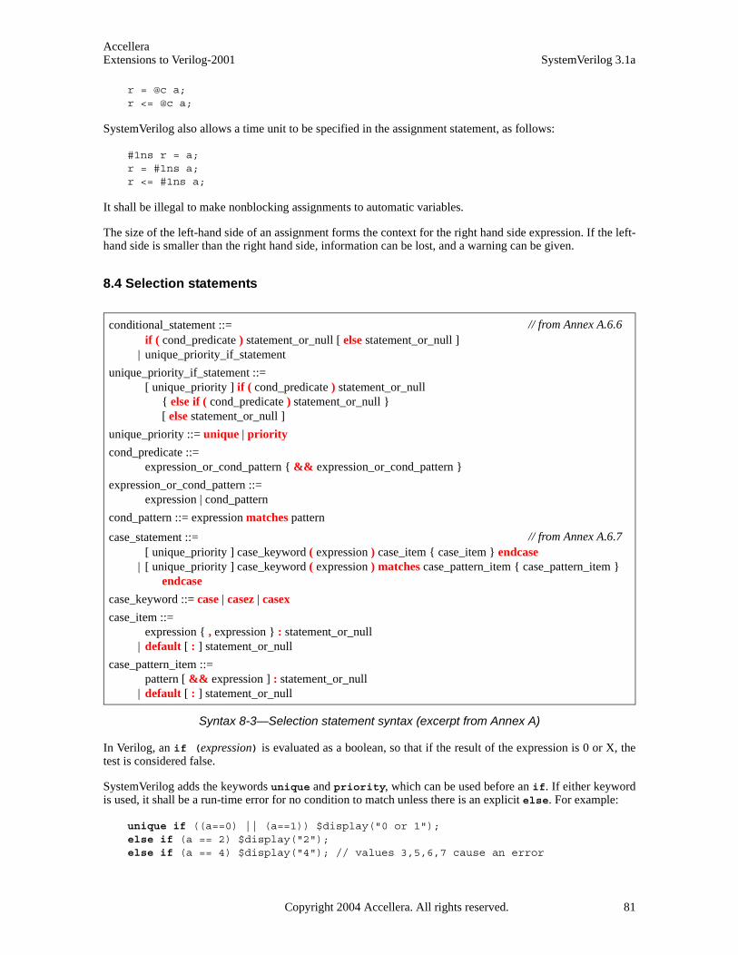
AccelleraExtensions to Verilog-2001 SystemVerilog 3.1a
r = @c a;r <= @c a;
SystemVerilog also allows a time unit to be specified in the assignment statement, as follows:
#1ns r = a;r = #1ns a;r <= #1ns a;
It shall be illegal to make nonblocking assignments to automatic variables.
The size of the left-hand side of an assignment forms the context for the right hand side expression. If the left-hand side is smaller than the right hand side, information can be lost, and a warning can be given.
8.4 Selection statements
Syntax 8-3—Selection statement syntax (excerpt from Annex A)
In Verilog, an if (expression) is evaluated as a boolean, so that if the result of the expression is 0 or X, thetest is considered false.
SystemVerilog adds the keywords unique and priority, which can be used before an if. If either keywordis used, it shall be a run-time error for no condition to match unless there is an explicit else. For example:
unique if ((a==0) || (a==1)) $display("0 or 1");else if (a == 2) $display("2");else if (a == 4) $display("4"); // values 3,5,6,7 cause an error
conditional_statement ::= if ( cond_predicate ) statement_or_null [ else statement_or_null ]
| unique_priority_if_statement
unique_priority_if_statement ::= [ unique_priority ] if ( cond_predicate ) statement_or_null
{ else if ( cond_predicate ) statement_or_null } [ else statement_or_null ]
unique_priority ::= unique | priority
cond_predicate ::= expression_or_cond_pattern { && expression_or_cond_pattern }
expression_or_cond_pattern ::= expression | cond_pattern
cond_pattern ::= expression matches pattern
case_statement ::= [ unique_priority ] case_keyword ( expression ) case_item { case_item } endcase
| [ unique_priority ] case_keyword ( expression ) matches case_pattern_item { case_pattern_item }endcase
case_keyword ::= case | casez | casex
case_item ::= expression { , expression } : statement_or_null
| default [ : ] statement_or_null
case_pattern_item ::= pattern [ && expression ] : statement_or_null
| default [ : ] statement_or_null
// from Annex A.6.6
// from Annex A.6.7
Copyright 2004 Accellera. All rights reserved. 81
AccelleraSystemVerilog 3.1a Extensions to Verilog-2001
priority if (a[2:1]==0) $display("0 or 1");else if (a[2] == 0) $display("2 or 3");else $display("4 to 7"); //covers all other possible values, so no error
A unique if indicates that there should not be any overlap in a series of if...else...if conditions, i.e. theyshould be mutually exclusive, allowing the expressions to be evaluated in parallel. A software tool shall issuean error if it determines that more than one condition is, or can be, true. A software tool shall also issue anerror if it determines that no condition is true, or it is possible that no condition is true, and the final if doesnot have a corresponding else.
A priority if indicates that a series of if...else...if conditions shall be evaluated in the order listed. Inthe preceding example, if the variable a had a value of 0, it would satisfy both the first and second conditions,requiring priority logic. A software tool shall also issue an error if it determines that no condition is true, or itis possible that no condition is true, and the final if does not have a corresponding else.
The unique and priority keywords apply to the entire series of if...else...if conditions. In the precedingexamples it would have been illegal to insert either keyword after any of the occurrences of else. To nestanother if statement within such a series of conditions, a begin...end block should be used.
In Verilog, there are three types of case statements, introduced by case, casez and casex. With SystemVer-ilog, each of these can be qualified by priority or unique. A priority case shall act on the first matchonly. A unique case shall check for overlapping case items, allowing the case items to be evaluated in paral-lel. A unique case shall issue a warning message if more than one case item matches the case expression. Ifthe case is qualified as priority or unique, the simulator shall issue a warning message if no case itemmatches. These warnings can be issued at either compile time or run time, as soon as it is possible to determinethe illegal condition.
Note: by specifying unique or priority, it is not necessary to code a default case to trap unexpected casevalues. For example:
bit [2:0] a;unique case(a) // values 3,5,6,7 cause a run-time warning
0,1: $display("0 or 1");2: $display("2");4: $display("4");
endcase
priority casez(a) // values 4,5,6,7 cause a run-time warning 3’b00?: $display("0 or 1");3’b0??: $display("2 or 3");
endcase
8.4.1 Pattern matching
Pattern matching provides a visual and succinct notation to compare a value against structures, tagged unionsand constants, and to access their members. SystemVerilog adds pattern matching capability to case and ifstatements, and to conditional expressions. Before describing pattern matching in those contexts, we firstdescribe the general concepts.
A pattern is a nesting of tagged union and structure expressions with identifiers, constant expressions, and thewildcard pattern “.*” at the leaves. For tagged union patterns, the identifier following the tagged keyword is aunion member name. For void members the nested member pattern is omitted.
82 Copyright 2004 Accellera. All rights reserved .

AccelleraExtensions to Verilog-2001 SystemVerilog 3.1a
Syntax 8-4—pattern syntax (excerpt from Annex A)
A pattern always occurs in a context of known type because it is matched against an expression of known type.Recursively, its nested patterns also have known type. A constant expression pattern must be of integral type.Thus a pattern can always be statically type-checked.
Each pattern introduces a new scope; the extent of this scope is described separately below for case statements,if statements and conditional expressions. Each pattern identifier is implicitly declared as a new variablewithin the pattern’s scope, with the unique type that it must have based on its position in the pattern. Patternidentifiers must be unique in the pattern, i.e., the same identifier cannot be used in more than one position in asingle pattern.
In pattern-matching, the value V of an expression is always matched against a pattern. Note that static type-checking ensures that V and the pattern have the same type. The result of a pattern match is:
— A 1-bit determined value: 0 (false, or fail) or 1 (true, or succeed). The result cannot be x or z even if thevalue and pattern contain such bits.
— If the match succeeds, the pattern identifiers are bound to the corresponding members from V, using ordi-nary procedural assignment.
Each pattern is matched using the following simple recursive rule:
— An identifier pattern always succeeds (matches any value), and the identifier is bound to that value (usingordinary procedural assignment).
— The wildcard pattern “.*” always succeeds.
— A constant expression pattern succeeds if V is equal to its value.
— A tagged union pattern succeeds if the value has the same tag and, recursively, if the nested patternmatches the member value of the tagged union.
— A structure pattern succeeds if, recursively, each of the nested member patterns matches the correspondingmember values in V. In structure patterns with named members, the textual order of members does not mat-ter, and members can be omitted. Omitted members are ignored.
Conceptually, if the value V is seen as a flattened vector of bits, the pattern specifies which bits to match, withwhat values they should be matched and, if the match is successful, which bits to extract and bind to the patternidentifiers. Matching can be insensitive to x and z values, as described in the individual constructs below.
8.4.1.1 Pattern matching in case statements
In a pattern-matching case statement, the expression in parentheses is followed by the keyword matches, andthe statement contains a series of “case_pattern_items”. The left-hand side of a case item, before the “:”, con-sists of a pattern and, optionally, the operator && followed by a boolean “filter” expression. The right-handside of a case item is a statement. Each pattern introduces a new scope, in which its pattern identifiers areimplicitly declared; this scope extends to the optional filter expression and the statement in the right-hand sideof the same case item. Thus different case items can reuse pattern identifiers.
All the patterns are completely statically type-checked. The expression being tested in the pattern-matching
pattern ::= variable_identifier
| .* | . constant_expression | tagged member_identifier [ pattern ] | { pattern { , pattern } } | { member_identifier : pattern { , member_identifier : pattern } }
// from Annex A.6.7.1
Copyright 2004 Accellera. All rights reserved. 83
AccelleraSystemVerilog 3.1a Extensions to Verilog-2001
case statement must have a known type, which is the same as the type of the pattern in each case item.
The expression in parentheses in a pattern-matching case statement shall be evaluated exactly once. Its value Vshall be matched against the left-hand sides of the case items, one at a time, in the exact order given, ignoringthe default case item if any. During this linear search, if a case item is selected, its statement is executed andthe linear search is terminated. If no case item is selected, and a default case item is given, then its statement isexecuted. If no case item is selected and no default case item is given, no statement is executed.
For a case item to be selected, the value V must match the pattern (and the pattern identifiers are assigned thecorresponding member values in V ) and then the boolean filter expression must evaluate to true (a determinedvalue other than 0).
Example:
typedef union tagged {void Invalid;int Valid;
} VInt;...VInt v;...case (v) matches
tagged Invalid : $display ("v is Invalid");tagged Valid n : $display ("v is Valid with value %d", n);
endcase
In the case statement, if v currently has the Invalid tag, the first pattern is matched. Otherwise, it must havethe Valid tag, and the second pattern is matched. The identifier n is bound to the value of the Valid member,and this value is displayed. It is impossible to access the integer member value (n) when the tag is Invalid.
Example:
typedef union tagged {struct {
bit [4:0] reg1, reg2, regd;} Add;union tagged {
bit [9:0] JmpU;struct {
bit [1:0] cc; bit [9:0] addr;
} JmpC;} Jmp;
} Instr;...Instr instr;...case (instr) matches
tagged Add {r1,r2,rd} && (rd != 0): rf[rd] = rf[r1] + rf[r2];tagged Jmp j : case (j) matches
tagged JmpU a : pc = pc + a;tagged JmpC {c,a}: if (rf[c]) pc = a;
endcase endcase
If instr holds an Add instruction, the first pattern is matched, and the identifiers r1, r2 and rd are bound tothe three register fields in the nested structure value. The right-hand side statement executes the instruction onthe register file rf. It is impossible to access these register fields if the tag is Jmp. If instr holds a Jmpinstruction, the second pattern is matched, and the identifier j is bound to the nested tagged union value. The
84 Copyright 2004 Accellera. All rights reserved .

AccelleraExtensions to Verilog-2001 SystemVerilog 3.1a
inner case statement, in turn, matches this value against JmpU and JmpC patterns, and so on.
Example (same as previous example, but using wildcard and constant patterns to eliminate the rd = 0 case; insome processors, register 0 is a special "discard" register):
case (instr) matches tagged Add {.*,.*, . 0} : ; // no optagged Add {r1,r2, rd} : rf[rd] = rf[r1] + rf[r2];tagged Jmp j : case (j) matches
tagged JmpU a : pc = pc + a;tagged JmpC {c,a} : if (rf[c]) pc = a;
endcase endcase
Example (same as previous example, but note that the first inner case statement involves only structures andconstants but no tagged unions):
case (instr) matches tagged Add s: case (s) matches
{.*,.*, . 0} : ; // no op{r1,r2, rd} : rf[rd] = rf[r1] + rf[r2];
endcase tagged Jmp j: case (j) matches
tagged JmpU a : pc = pc + a;tagged JmpC {c,a} : if (rf[c]) pc = a;
endcase endcase
Example (same as previous example, but using nested tagged union patterns):
case (instr) matches tagged Add {r1,r2,rd} && (rd != 0) : rf[rd] = rf[r1] + rf[r2];tagged Jmp (tagged JmpU a) : pc = pc + a;tagged Jmp (tagged JmpC {c,a}) : if (rf[c]) pc = a;
endcase
Example (same as previous example, with named structure components):
case (instr) matches tagged Add {reg2:r2,regd:rd,reg1:r1} && (rd != 0): rf[rd] = rf[r1] + rf[r2];tagged Jmp (tagged JmpU a) : pc = pc + a;tagged Jmp (tagged JmpC {addr:a,cc:c}) : if (rf[c]) pc = a;
endcase
As usual, the casez and casex keywords can be used instead of case, with the same semantics. In otherwords, during pattern matching, wherever two bits are compared (whether they are tag bits or members), thecasez form ignores z bits, and the casex form ignores both z and x bits.
The priority and unique qualifiers play their usual role. priority implies that some case item must beselected. unique also implies that exactly one case item will be selected, so that they can be evaluated in par-allel.
8.4.1.2 Pattern matching in if statements
The predicate in an if statement can be a series of clauses separated with the && operator. Each clause iseither an expression (used as a boolean filter), or has the form expression matches pattern. The clauses repre-sent a sequential conjunction from left to right, i.e., if any clause fails the remaining clauses are not evaluated,and all of them must succeed for the predicate to be true. Boolean expression clauses are evaluated as usual.Each pattern introduces a new scope, in which its pattern identifiers are implicitly declared; this scope extendsto the remaining clauses in the predicate and to the corresponding “true” arm of the if statement.
Copyright 2004 Accellera. All rights reserved. 85

AccelleraSystemVerilog 3.1a Extensions to Verilog-2001
In each e matches p clause, e and p must have the same known statically known type. The value of e ismatched against the pattern p as described above.
Even though the pattern matching clauses always return a defined 1-bit result, the overall result can be ambig-uous because of the boolean filter expressions in the predicate. The standard semantics of if statements hold,i.e., the first statement is executed if and only if the result is a determined value other than 0.
Example:
if (e matches (tagged Jmp (tagged JmpC {cc:c,addr:a})))... // c and a can be used here
else ...
Example (same as previous example, illustrating a sequence of two pattern-matches with identifiers bound inthe first pattern used in the second pattern).
if (e matches (tagged Jmp j),j matches (tagged JmpC {cc:c,addr:a}))... // c and a can be used here
else ...
Example (same as first example, but adding a boolean expression to the sequence of clauses). The ideaexpressed is: “if e is a conditional jump instruction and the condition register is not equal to zero ...”.
if (e matches (tagged Jmp (tagged JmpC {cc:c,addr:a}))&& (rf[c] != 0))... // c and a can be used here
else ...
The priority and unique qualifiers play their usual role for if statements even if they use pattern match-ing.
8.4.1.3 Pattern matching in conditional expressions
A conditional expression (e1 ? e2 : e3) can also use pattern matching, i.e., the predicate e1 can be asequence of expressions and “expression matches pattern” clauses separated with the && operator, just likethe predicate of an if statement. The clauses represent a sequential conjunction from left to right, i.e., if anyclause fails the remaining clauses are not evaluated, and all of them must succeed for the predicate to be true.Boolean expression clauses are evaluated as usual. Each pattern introduces a new scope, in which its patternidentifiers are implicitly declared; this scope extends to the remaining clauses in the predicate and to the conse-quent expression e2.
As described in the previous section, e1 can evaluate to true, false or an ambiguous value. The semantics ofthe overall conditional expression are described in Section 7.18, based on these three possible outcomes fore1.
86 Copyright 2004 Accellera. All rights reserved .
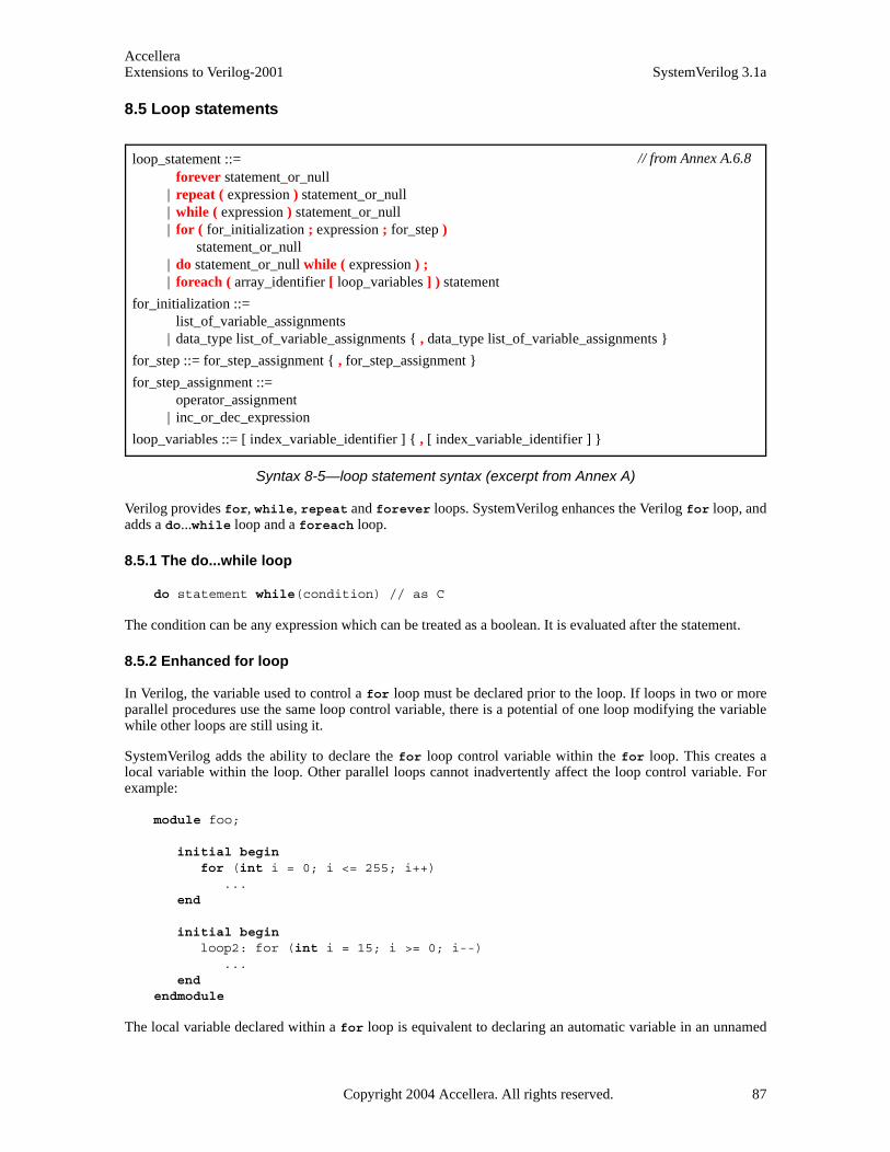
AccelleraExtensions to Verilog-2001 SystemVerilog 3.1a
8.5 Loop statements
Syntax 8-5—loop statement syntax (excerpt from Annex A)
Verilog provides for, while, repeat and forever loops. SystemVerilog enhances the Verilog for loop, andadds a do...while loop and a foreach loop.
8.5.1 The do...while loop
do statement while(condition) // as C
The condition can be any expression which can be treated as a boolean. It is evaluated after the statement.
8.5.2 Enhanced for loop
In Verilog, the variable used to control a for loop must be declared prior to the loop. If loops in two or moreparallel procedures use the same loop control variable, there is a potential of one loop modifying the variablewhile other loops are still using it.
SystemVerilog adds the ability to declare the for loop control variable within the for loop. This creates alocal variable within the loop. Other parallel loops cannot inadvertently affect the loop control variable. Forexample:
module foo;
initial begin for (int i = 0; i <= 255; i++)
...end
initial begin loop2: for (int i = 15; i >= 0; i--)
...end
endmodule
The local variable declared within a for loop is equivalent to declaring an automatic variable in an unnamed
loop_statement ::= forever statement_or_null
| repeat ( expression ) statement_or_null | while ( expression ) statement_or_null | for ( for_initialization ; expression ; for_step )
statement_or_null | do statement_or_null while ( expression ) ; | foreach ( array_identifier [ loop_variables ] ) statement
for_initialization ::= list_of_variable_assignments
| data_type list_of_variable_assignments { , data_type list_of_variable_assignments }
for_step ::= for_step_assignment { , for_step_assignment }
for_step_assignment ::= operator_assignment
| inc_or_dec_expression
loop_variables ::= [ index_variable_identifier ] { , [ index_variable_identifier ] }
// from Annex A.6.8
Copyright 2004 Accellera. All rights reserved. 87

AccelleraSystemVerilog 3.1a Extensions to Verilog-2001
block.
Verilog only permits a single initial statement and a single step assignment within a for loop. SystemVerilogallows the initial declaration or assignment statement to be one or more comma-separated statements. The stepassignment can also be one or more comma-separated assignment statements.
for ( int count = 0; count < 3; count++ )value = value +((a[count]) * (count+1));
for ( int count = 0, done = 0, int j = 0; j * count < 125; j++ )$display("Value j = %d\n", j );
8.5.3 The foreach loop
The foreach construct specifies iteration over the elements of an array. Its argument is an identifier that des-ignates any type of array (fixed-size, dynamic, or associative) followed by a list of loop variables enclosed insquare brackets. Each loop variable corresponds to one of the dimensions of the array. The foreach constructis similar to a repeat loop that uses the array bounds to specify the repeat count instead of an expression.
Examples:
string words [2] = { "hello", "world" };int prod [1:8] [1:3];
foreach( words [ j ] )$display( j , words[j] ); // print each index and value
foreach( prod[ k, m ] )prod[k][m] = k * m; // initialize
The number of loop variables must match the number of dimensions of the array variable. Empty loop vari-ables can be used to indicate no iteration over that dimension of the array, and contiguous empty loop variablestowards the end can be omitted. Loop variables are automatic, read-only, and their scope is local to the loop.The type of each loop variable is implicitly declared to be consistent with the type of array index. It shall be anerror for any loop variable to have the same identifier as the array.
The mapping of loop variables to array indexes is determined by the dimension cardinality, as described inSection 23.7. The foreach arranges for higher cardinality indexes to change more rapidly.
// 1 2 3 3 4 1 2 -> Dimension numbersint A [2][3][4]; bit [3:0][2:1] B [5:1][4];
foreach( A [ i, j, k ] ) ...foreach( B [ q, r, , s ] ) ...
The first foreach causes i to iterate from 0 to 1, j from 0 to 2, and k from 0 to 3. The second foreach causesq to iterate from 5 to 1, r from 0 to 3, and s from 2 to 1 (iteration over the 3rd index is skipped).
Multiple loop variables correspond to nested loops that iterate over the given indexes. The nesting of the loopsis determined by the dimension cardinality; outer loops correspond to lower cardinality indexes. In the firstexample above, the outermost loop iterates over i and the innermost loop iterates over k.
When loop variables are used in expressions other than as indexes to the designated array, they are auto-castinto a type consistent with the type of index. For fixed-size and dynamic arrays the auto-cast type is int. Forassociative arrays indexed by a specific index type, the auto-cast type is the same as the index type. For asso-ciative arrays indexed by a wildcard index (*), the auto-cast type is unsigned longint. To use differenttypes, an explicit cast can be used.
88 Copyright 2004 Accellera. All rights reserved .
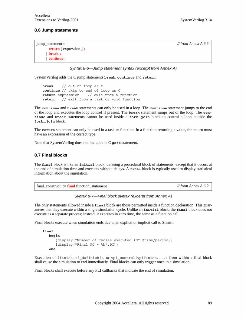
AccelleraExtensions to Verilog-2001 SystemVerilog 3.1a
8.6 Jump statements
Syntax 8-6—Jump statement syntax (excerpt from Annex A)
SystemVerilog adds the C jump statements break, continue and return.
break // out of loop as Ccontinue // skip to end of loop as Creturn expression // exit from a functionreturn // exit from a task or void function
The continue and break statements can only be used in a loop. The continue statement jumps to the endof the loop and executes the loop control if present. The break statement jumps out of the loop. The con-tinue and break statements cannot be used inside a fork...join block to control a loop outside thefork...join block.
The return statement can only be used in a task or function. In a function returning a value, the return musthave an expression of the correct type.
Note that SystemVerilog does not include the C goto statement.
8.7 Final blocks
The final block is like an initial block, defining a procedural block of statements, except that it occurs atthe end of simulation time and executes without delays. A final block is typically used to display statisticalinformation about the simulation.
Syntax 8-7—Final block syntax (excerpt from Annex A)
The only statements allowed inside a final block are those permitted inside a function declaration. This guar-antees that they execute within a single simulation cycle. Unlike an initial block, the final block does notexecute as a separate process; instead, it executes in zero time, the same as a function call.
Final blocks execute when simulation ends due to an explicit or implicit call to $finish.
final begin
$display("Number of cycles executed %d",$time/period);$display("Final PC = %h",PC);
end
Execution of $finish, tf_dofinish(), or vpi_control(vpiFinish,...) from within a final blockshall cause the simulation to end immediately. Final blocks can only trigger once in a simulation.
Final blocks shall execute before any PLI callbacks that indicate the end of simulation.
jump_statement ::= return [ expression ] ;
| break ; | continue ;
// from Annex A.6.5
final_construct ::= final function_statement // from Annex A.6.2
Copyright 2004 Accellera. All rights reserved. 89

AccelleraSystemVerilog 3.1a Extensions to Verilog-2001
8.8 Named blocks and statement labels
Syntax 8-8—Blocks and labels syntax (excerpt from Annex A)
Verilog allows a begin...end, fork...join, fork...join_any or fork...join_none statement block to benamed. A named block is used to identify the entire statement block. A named block creates a new hierarchyscope. The block name is specified after the begin or fork keyword, preceded by a colon. For example:
begin : blockA // Verilog-2001 named block...
end
SystemVerilog allows a matching block name to be specified after the block end, join, join_any orjoin_none keyword, preceded by a colon. This can help document which end or join, join_any orjoin_none is associated with which begin or fork when there are nested blocks. A name at the end of theblock is not required. It shall be an error if the name at the end is different than the block name at the begin-ning.
begin: blockB // block name after the begin or fork...
end: blockB
SystemVerilog allows a label to be specified before any statement, as in C. A statement label is used to identifya single statement. The label name is specified before the statement, followed by a colon.
labelA: statement
A begin...end, fork...join, fork...join_any or fork...join_none block is considered a statement, andcan have a statement label before the block.
labelB: fork // label before the begin or fork...
join : labelB
It shall be illegal to have both a label before a begin or fork and a block name after the begin or fork. Alabel cannot appear before the end, join, join_any or join_none, as these keywords do not form a state-ment.
A statement with a label can be disabled using a disable statement. Disabling a statement shall have thesame behavior as disabling a named block.
See Section 9.6 for additional discussion on fork...join, fork...join_any or fork...join_none.
8.9 Disable
SystemVerilog has break and continue to break out of or continue the execution of loops. The Verilog-2001disable can also be used to break out of or continue a loop, but is more awkward than using break or con-
seq_block ::= begin [ : block_identifier ] { block_item_declaration } { statement_or_null } end [ : block_identifier ]
par_block ::= fork [ : block_identifier ] { block_item_declaration } { statement_or_null } join_keyword [ : block_identifier ]
join_keyword ::= join | join_any | join_none
// from Annex A.6.3
90 Copyright 2004 Accellera. All rights reserved .
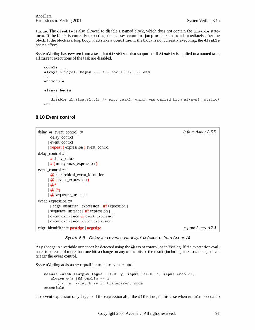
AccelleraExtensions to Verilog-2001 SystemVerilog 3.1a
tinue. The disable is also allowed to disable a named block, which does not contain the disable state-ment. If the block is currently executing, this causes control to jump to the statement immediately after theblock. If the block is a loop body, it acts like a continue. If the block is not currently executing, the disablehas no effect.
SystemVerilog has return from a task, but disable is also supported. If disable is applied to a named task,all current executions of the task are disabled.
module ...always always1: begin ... t1: task1( ); ... end ...endmodule
always begin ...disable u1.always1.t1; // exit task1, which was called from always1 (static)
end
8.10 Event control
Syntax 8-9—Delay and event control syntax (excerpt from Annex A)
Any change in a variable or net can be detected using the @ event control, as in Verilog. If the expression eval-uates to a result of more than one bit, a change on any of the bits of the result (including an x to z change) shalltrigger the event control.
SystemVerilog adds an iff qualifier to the @ event control.
module latch (output logic [31:0] y, input [31:0] a, input enable);always @(a iff enable == 1)
y <= a; //latch is in transparent modeendmodule
The event expression only triggers if the expression after the iff is true, in this case when enable is equal to
delay_or_event_control ::= delay_control
| event_control | repeat ( expression ) event_control
delay_control ::= # delay_value
| # ( mintypmax_expression )
event_control ::= @ hierarchical_event_identifier
| @ ( event_expression ) | @* | @ (*) | @ sequence_instance
event_expression ::= [ edge_identifier ] expression [ iff expression ]
| sequence_instance [ iff expression ] | event_expression or event_expression | event_expression , event_expression
edge_identifier ::= posedge | negedge
// from Annex A.6.5
// from Annex A.7.4
Copyright 2004 Accellera. All rights reserved. 91

AccelleraSystemVerilog 3.1a Extensions to Verilog-2001
1. Note that such an expression is evaluated when a changes, and not when enable changes. Also note thatiff has precedence over or. This can be made clearer by the use of parentheses.
If a variable is not of a 4-state type, then posedge and negedge refer to transitions from 0 and to 0, respec-tively.
If the expression denotes a clocking-block input or inout (see Section 15), the event control operator usesthe synchronous values, that is, the values sampled by the clocking event. The expression can also denote aclocking-block name (with no edge qualifier) to be triggered by the clocking event.
A variable used with the event control can be any one of the integral data types (see Section 3.3.1) or string.The variable can be either a simple variable or a ref argument (variable passed by reference); it can be a mem-ber of an array, associative-array, or object (class instance) of the aforementioned types.
Event expressions must return singular values. Aggregate types can be used in an expression provided theexpression reduces to a singular value. The object members or aggregate elements can be any type as long asthe result of the expression is a singular value.
If the event expression is a reference to a simple object handle or chandle variable, an event is created when awrite to that variable is not equal to its previous value.
Non-virtual methods of an object and built-in methods or system functions for an aggregate type are allowed inevent control expressions as long as the type of the return value is singular and the method is defined as a func-tion, not a task.
Changing the value of object data members, aggregate elements, or the size of a dynamically sized array refer-enced by a method or function shall cause the event expression to be re-evaluated. An implementation cancause the event expression to be re-evaluated when changing the value or size even if the members are not ref-erenced by the method or function.
real AOR[]; // dynamic array of realsbyte stream[$]; // queue of bytesinitial wait(AOR.size() > 0) ....; // waits for array to be allocatedinitial wait($bits(stream) > 60)...; // waits for total number of bits
// in stream greater than 60
Packet p = new; // Packet 1Packet q = new; // Packet 2initial fork
@(p.status); // Wait for status in Packet 1 to change@ q; // Wait for a change to handle q# 10 q = p; // triggers @q.// @(p.status) now waits for status in Packet 2 to change,// if not already different from Packet 1
join
8.10.1 Sequence events
A sequence instance can be used in event expressions to control the execution of procedural statements basedon the successful match of the sequence. This allows the endpoint of a named sequence to trigger multipleactions in other processes. Syntax 17-2 and 17-4 describe the syntax for declaring named sequences andsequence instances. A sequence instance can be used directly in an event expression, as shown in Syntax 8-9.
When a sequence instance is specified in an event expression, the process executing the event control shallblock until the specified sequence reaches its end-point. A sequence reaches its end point whenever there is amatch for the entire sequence. A process resumes execution following the Observe region in which the endpoint is detected.
An example of using a sequence as an event control is shown below.
92 Copyright 2004 Accellera. All rights reserved .

AccelleraExtensions to Verilog-2001 SystemVerilog 3.1a
sequence abc;@(posedge clk) a ##1 b ##1 c;endsequence
program test;initial begin
@ abc $display( "Saw a-b-c" );L1 : ...
end endprogram
In the example above, when the named sequence abc reaches its end point, the initial block in the programblock test is unblocked, which then displays the string ‘Saw a-b-c’ and continues execution with the statementlabeled L1. In this case, the end of the sequence acts as the trigger to unblock the event.
A sequence used in an event control is instantiated (as if by an assert property statement); the event control isused to synchronize to the end of the sequence, regardless of its start-time. Arguments to these sequences shallbe static; automatic variables used as sequence arguments shall result in an error.
8.11 Level-sensitive sequence controls
The execution of procedural code can be delayed until a sequence termination status is true. This is accom-plished using the level-sensitive wait statement in conjunction with the built-in method that returns the cur-rent end status of a named sequence: triggered.
The triggered sequence method evaluates to true if the given sequence has reached its end point at that particu-lar point in time (in the current time-step), and false otherwise. The triggered status of a sequence is set duringthe Observe region and persists through the remainder of the time-step (i.e., until simulation time advances).
For example:sequence abc;
@(posedge clk) a ##1 b ##1 c;endsequence
sequence de;@(negedge clk) d ##[2:5] e;
endsequence
program check;initial begin
wait( abc.triggered || de.triggered );if( abc.triggered )
$display( "abc succeeded" );if( de.triggered )
$display( "de succeeded" );L2 : ...
end endprogram
In the above example, the initial block in program check waits for the end point (success) of eithersequence abc or sequence de. When either condition evaluates to true the wait statement unblocks the pro-cess, which displays the sequences that caused the process to unblock and then continues to execute the state-ment labeled L2.
Copyright 2004 Accellera. All rights reserved. 93

AccelleraSystemVerilog 3.1a Extensions to Verilog-2001
8.12 Procedural assign and deassign removal
SystemVerilog currently supports the procedural assign and deassign statements. However, these state-ments might be removed from future versions of the language. See Section 26.3.
94 Copyright 2004 Accellera. All rights reserved .

AccelleraExtensions to Verilog-2001 SystemVerilog 3.1a
Section 9Processes
9.1 Introduction (informative) Verilog-2001 has always and initial blocks which define static processes.
In an always block which is used to model combinational logic, forgetting an else leads to an unintendedlatch. To avoid this mistake, SystemVerilog adds specialized always_comb and always_latch blocks,which indicate design intent to simulation, synthesis and formal verification tools. SystemVerilog also adds analways_ff block to indicate sequential logic.
In systems modeling, one of the key limitations of Verilog is the inability to create processes dynamically, ashappens in an operating system. Verilog has the fork...join construct, but this still imposes a static limit.
SystemVerilog has both static processes, introduced by always, initial or fork, and dynamic processes,introduced by built-in fork...join_any and fork...join_none.
SystemVerilog creates a thread of execution for each initial or always block, for each parallel statement ina fork...join block and for each dynamic process. Each continuous assignment can also be considered itsown thread.
SystemVerilog 3.1 adds dynamic processes by enhancing the fork...join construct in a way that is more nat-ural to Verilog users. SystemVerilog 3.1 also introduces dynamic process control constructs that can terminateor wait for processes using their dynamic, parent-child relationship. These are wait fork and disable fork.
9.2 Combinational logic
SystemVerilog provides a special always_comb procedure for modeling combinational logic behavior. Forexample:
always_comb a = b & c;
always_comb d <= #1ns b & c;
The always_comb procedure provides functionality that is different than a normal always procedure:
— There is an inferred sensitivity list that includes the expressions defined in Section 9.2.1.
— The variables written on the left-hand side of assignments shall not be written to by any other process.
— The procedure is automatically triggered once at time zero, after all initial and always blocks havebeen started, so that the outputs of the procedure are consistent with the inputs.
The SystemVerilog always_comb procedure differs from the Verilog-2001 always @* in the following ways:
— always_comb automatically executes once at time zero, whereas always @* waits until a change occurson a signal in the inferred sensitivity list.
— always_comb is sensitive to changes within the contents of a function, whereas always @* is only sensi-tive to changes to the arguments of a function.
— Variables on the left-hand side of assignments within an always_comb procedure, including variablesfrom the contents of a called function, shall not be written to by any other processes, whereas always @*permits multiple processes to write to the same variable.
Copyright 2004 Accellera. All rights reserved. 95

AccelleraSystemVerilog 3.1a Extensions to Verilog-2001
— Statements in an always_comb shall not include those that block, have blocking timing or event controls,or fork...join statements.
Software tools can perform additional checks to warn if the behavior within an always_comb procedure doesnot represent combinational logic, such as if latched behavior can be inferred.
9.2.1 Implicit always_comb sensitivities
The expansion of longest static prefix “P” is defined to be:
a) P itself if the P is not a memory or indexing select or if P is a legal word or bit select.
b) if P is a memory or indexing select, the expansion is every possible legal memory word select with astatic prefix that matches P.
The implicit sensitivity list of an always_comb includes the expansions of the longest static prefix of eachvariable or select expression that is read within the block or within any function called within the block withthe following exceptions:
1) any expansion of a variable declared within the block or within any function called within the block.
2) any expression that is also written within the block or within any function called within the block.
9.3 Latched logic
SystemVerilog also provides a special always_latch procedure for modeling latched logic behavior. Forexample:
always_latch if(ck) q <= d;
The always_latch procedure determines its sensitivity and executes identically to the always_comb proce-dure. Software tools can perform additional checks to warn if the behavior within an always_latch proce-dure does not represent latched logic.
9.4 Sequential logic
The SystemVerilog always_ff procedure can be used to model synthesizable sequential logic behavior. Forexample:
always_ff @(posedge clock iff reset == 0 or posedge reset) begin r1 <= reset ? 0 : r2 + 1;...
end
The always_ff block imposes the restriction that it contains one and only one event control and no blockingtiming controls. Variables on the left-hand side of assignments within an always_ff procedure, including vari-ables from the contents of a called function, shall not be written to by any other process. Software tools canperform additional checks to warn if the behavior within an always_ff procedure does not represent sequen-tial logic.
9.5 Continuous assignments
In Verilog, continuous assignments can only drive nets, and not variables.
SystemVerilog removes this restriction, and permits continuous assignments to drive nets any type of variable.
96 Copyright 2004 Accellera. All rights reserved .
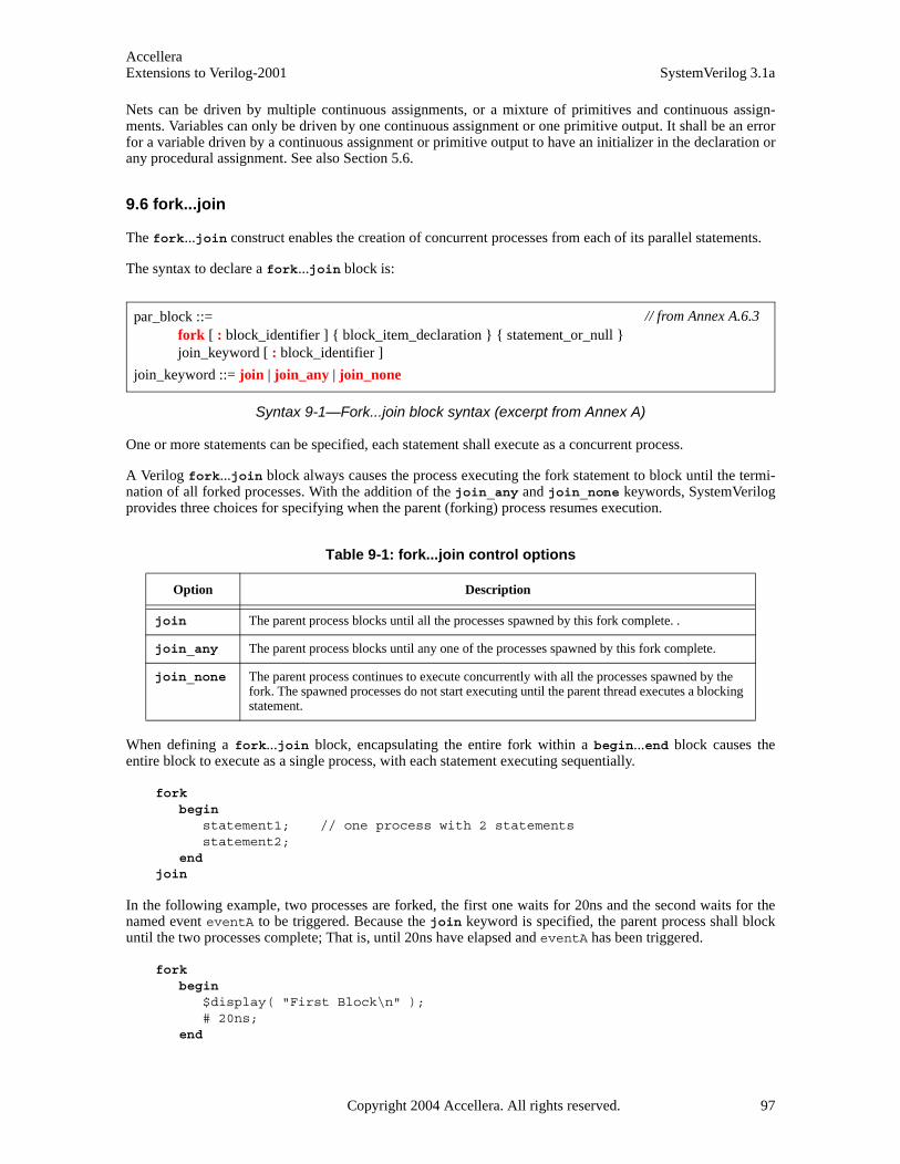
AccelleraExtensions to Verilog-2001 SystemVerilog 3.1a
Nets can be driven by multiple continuous assignments, or a mixture of primitives and continuous assign-ments. Variables can only be driven by one continuous assignment or one primitive output. It shall be an errorfor a variable driven by a continuous assignment or primitive output to have an initializer in the declaration orany procedural assignment. See also Section 5.6.
9.6 fork...join
The fork...join construct enables the creation of concurrent processes from each of its parallel statements.
The syntax to declare a fork...join block is:
Syntax 9-1—Fork...join block syntax (excerpt from Annex A)
One or more statements can be specified, each statement shall execute as a concurrent process.
A Verilog fork...join block always causes the process executing the fork statement to block until the termi-nation of all forked processes. With the addition of the join_any and join_none keywords, SystemVerilogprovides three choices for specifying when the parent (forking) process resumes execution.
When defining a fork...join block, encapsulating the entire fork within a begin...end block causes theentire block to execute as a single process, with each statement executing sequentially.
fork begin
statement1; // one process with 2 statementsstatement2;
end join
In the following example, two processes are forked, the first one waits for 20ns and the second waits for thenamed event eventA to be triggered. Because the join keyword is specified, the parent process shall blockuntil the two processes complete; That is, until 20ns have elapsed and eventA has been triggered.
fork begin
$display( "First Block\n" );# 20ns;
end
Table 9-1: fork...join control options
Option Description
join The parent process blocks until all the processes spawned by this fork complete. .
join_any The parent process blocks until any one of the processes spawned by this fork complete.
join_none The parent process continues to execute concurrently with all the processes spawned by the fork. The spawned processes do not start executing until the parent thread executes a blocking statement.
par_block ::= fork [ : block_identifier ] { block_item_declaration } { statement_or_null } join_keyword [ : block_identifier ]
join_keyword ::= join | join_any | join_none
// from Annex A.6.3
Copyright 2004 Accellera. All rights reserved. 97

AccelleraSystemVerilog 3.1a Extensions to Verilog-2001
begin $display( "Second Block\n" );@eventA;
end join
A return statement within the context of a fork...join statement is illegal and shall result in a compilationerror. For example:
task wait_20;fork
# 20;return ; // Illegal: cannot return; task lives in another process
join_none endtask
Automatic variables declared in the scope of the fork…join block shall be initialized to the initializationvalue whenever execution enters their scope, and before any processes are spawned. These variables are usefulin processes spawned by looping constructs to store unique, per-iteration data. For example:
initial for( int j = 1; j <= 3; ++j )
fork automatic int k = j; // local copy, k, for each value of j #k $write( "%0d", k ); begin
automatic int m = j; // the value of m is undetermined ...
end join_none
The example above generates the output 123.
9.7 Process execution threads
SystemVerilog creates a thread of execution for:
— Each initial block
— Each always block
— Each parallel statement in a fork...join (or join_any or join_none) statement group
— Each dynamic process
Each continuous assignment can also be considered its own thread.
9.8 Process control
SystemVerilog provides constructs that allow one process to terminate or wait for the completion of other pro-cesses. The wait fork construct waits for the completion of processes. The disable fork construct stopsthe execution of processes.
9.8.1 Wait fork
The wait fork statement is used to ensure that all child processes (processes created by the calling process)have completed their execution.
98 Copyright 2004 Accellera. All rights reserved .

AccelleraExtensions to Verilog-2001 SystemVerilog 3.1a
The syntax for wait fork is:
wait fork ; // from Annex A.6.5
Specifying wait fork causes the calling process to block until all its sub-processes have completed.
Verilog terminates a simulation run when there is no further activity of any kind. SystemVerilog adds the abil-ity to automatically terminate the simulation when all its program blocks finish executing (i.e, they reach theend of their execute block), regardless of the status of any child processes (see Section 16.6). The wait forkstatement allows a program block to wait for the completion of all its concurrent threads before exiting.
In the following example, in the task do_test, the first two processes are spawned and the task blocks until oneof the two processes completes (either exec1, or exec2). Next, two more processes are spawned in the back-ground. The wait fork statement shall ensure that the task do_test waits for all four spawned processes tocomplete before returning to its caller.
task do_test;fork
exec1();exec2();
join_any fork
exec3();exec4();
join_none wait fork; // block until exec1 ... exec4 complete
endtask
9.8.2 Disable fork
The disable fork statement terminates all active descendants (sub-processes) of the calling process.
The syntax for disable fork is:
disable fork ; // from Annex A.6.5
The disable fork statement terminates all descendants of the calling process, as well as the descendants ofthe process’ descendants, that is, if any of the child processes have descendants of their own, the disablefork statement shall terminate them as well.
In the example below, the task get_first spawns three versions of a task that wait for a particular device (1,7, or 13). The task wait_device waits for a particular device to become ready and then returns the device’saddress. When the first device becomes available, the get_first task shall resume execution and proceed tokill the outstanding wait_device processes.
task get_first( output int adr );fork
wait_device( 1, adr );wait_device( 7, adr );wait_device( 13, adr );
join_any disable fork;
endtask
Verilog supports the disable construct, which terminate a process when applied to the named block beingexecuted by the process. The disable fork statement differs from disable in that disable fork considersthe dynamic parent-child relationship of the processes, whereas disable uses the static, syntactical informa-tion of the disabled block. Thus, disable shall end all processes executing a particular block, whether theprocesses were forked by the calling thread or not, while disable fork shall end only those processes that
Copyright 2004 Accellera. All rights reserved. 99

AccelleraSystemVerilog 3.1a Extensions to Verilog-2001
were spawned by the calling thread.
9.9 Fine-grain process control
A process is a built-in class that allows one process to access and control another process once it has started.Users can declare variables of type process and safely pass them through tasks or incorporate them into otherobjects. The prototype for the process class is:
class process;enum state { FINISHED, RUNNING, WAITING, SUSPENDED, KILLED };
static function process self();function state status();task kill();task await();task suspend();task resume();
endclass
Objects of type process are created internally when processes are spawned. Users cannot create objects of typeprocess; attempts to call new shall not create a new process, and instead result in an error. The process classcannot be extended. Attempts to extend it shall result in a compilation error. Objects of type process areunique; they become available for reuse once the underlying process terminates and all references to the objectare discarded.
The self() function returns a handle to the current process, that is, a handle to the process making the call.
The status() function returns the process status, as defined by the state enumeration:
— FINISHED Process terminated normally.
— RUNNING Process is currently running (not in a blocking statement).
— WAITING Process is waiting in a blocking statement.
— SUSPENDED Process is stopped awaiting a resume.
— KILLED Process was forcibly killed (via kill or disable).
The kill() task terminates the given process and all its sub-processes, that is, processes spawned using forkstatements by the process being killed. If the process to be terminated is not blocked waiting on some othercondition, such as an event, wait expression, or a delay then the process shall be terminated at some unspeci-fied time in the current time step.
The await() task allows one process to wait for the completion of another process. It shall be an error to callthis task on the current process, i.e., a process cannot wait for its own completion.
The suspend() task allows a process to suspend either its own execution or that of another process. If theprocess to be suspended is not blocked waiting on some other condition, such as an event, wait expression, ora delay then the process shall be suspended at some unspecified time in the current time step. Calling thismethod more than once, on the same (suspended) process, has no effect.
The resume() task restarts a previously suspended process. Calling resume on a process that was suspendedwhile blocked on another condition shall re-sensitize the process to the event expression, or wait for the waitcondition to become true, or for the delay to expire. If the wait condition is now true or the original delay hastranspired, the process is scheduled onto the Active or Reactive region, so as to continue its execution in thecurrent time step. Calling resume on a process that suspends itself causes the process to continue to execute atthe statement following the call to suspend.
The example below starts an arbitrary number of processes, as specified by the task argument N. Next, the task
100 Copyright 2004 Accellera. All rights reserved .
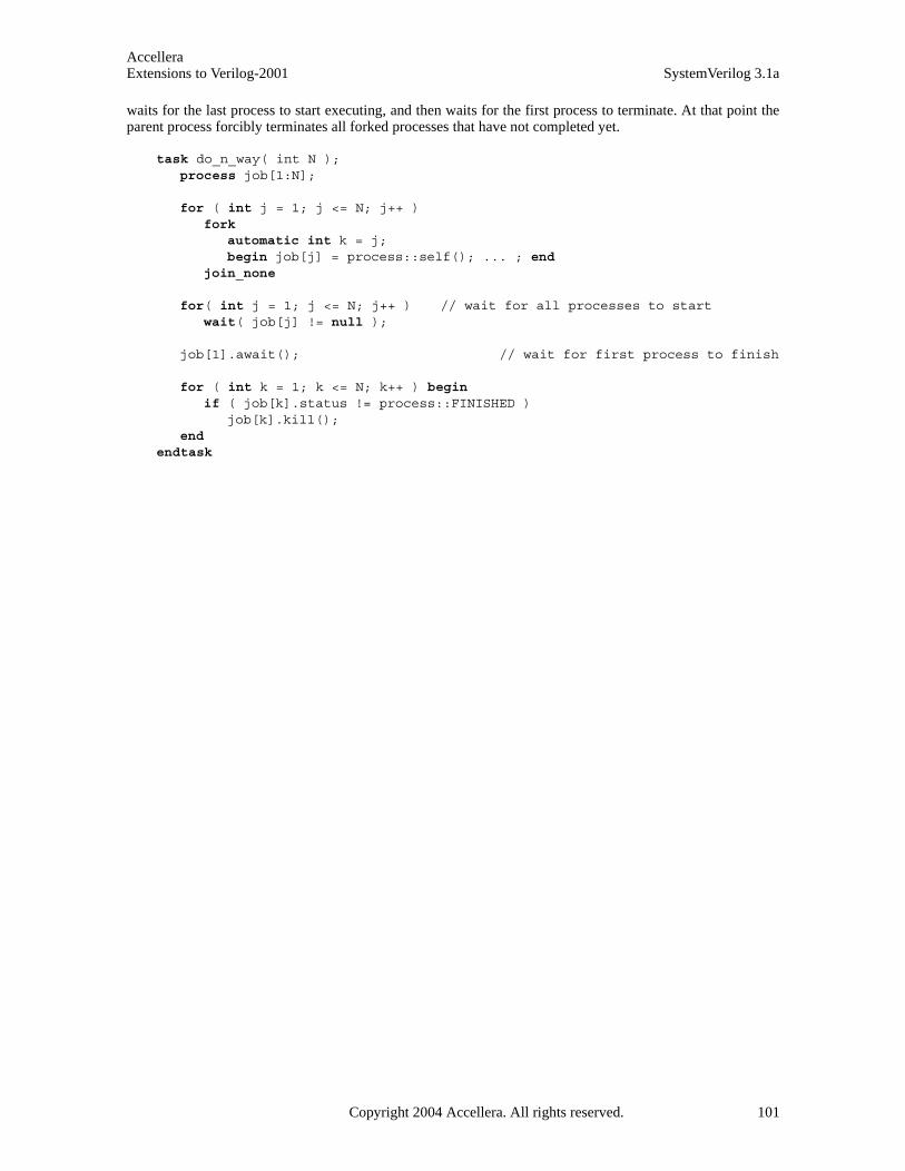
AccelleraExtensions to Verilog-2001 SystemVerilog 3.1a
waits for the last process to start executing, and then waits for the first process to terminate. At that point theparent process forcibly terminates all forked processes that have not completed yet.
task do_n_way( int N );process job[1:N];
for ( int j = 1; j <= N; j++ )fork
automatic int k = j; begin job[j] = process::self(); ... ; end
join_none
for( int j = 1; j <= N; j++ ) // wait for all processes to startwait( job[j] != null );
job[1].await(); // wait for first process to finish
for ( int k = 1; k <= N; k++ ) begin if ( job[k].status != process::FINISHED )
job[k].kill();end
endtask
Copyright 2004 Accellera. All rights reserved. 101
AccelleraSystemVerilog 3.1a Extensions to Verilog-2001
Section 10Tasks and Functions
10.1 Introduction (informative)
Verilog-2001 has static and automatic tasks and functions. Static tasks and functions share the same storagespace for all calls to the tasks or function within a module instance. Automatic tasks and function allocateunique, stacked storage for each instance.
SystemVerilog adds the ability to declare automatic variables within static tasks and functions, and static vari-ables within automatic tasks and functions.
SystemVerilog also adds:
— More capabilities for declaring task and function ports
— Function output and inout ports
— Void functions
— Multiple statements in a task or function without requiring a begin...end or fork...join block
— Returning from a task or function before reaching the end of the task or function
— Passing arguments by reference instead of by value
— Passing argument values by name instead of by position
— Default argument values
— Importing and exporting functions through the Direct Programming Interface (DPI)
102 Copyright 2004 Accellera. All rights reserved .
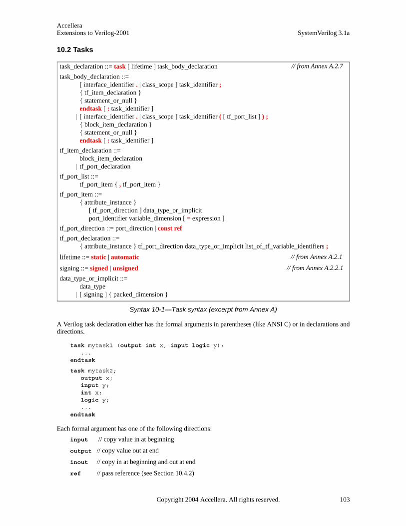
AccelleraExtensions to Verilog-2001 SystemVerilog 3.1a
10.2 Tasks
Syntax 10-1—Task syntax (excerpt from Annex A)
A Verilog task declaration either has the formal arguments in parentheses (like ANSI C) or in declarations anddirections.
task mytask1 (output int x, input logic y);...
endtask
task mytask2;output x;input y;int x;logic y;...
endtask
Each formal argument has one of the following directions:
input // copy value in at beginning
output // copy value out at end
inout // copy in at beginning and out at end
ref // pass reference (see Section 10.4.2)
task_declaration ::= task [ lifetime ] task_body_declaration
task_body_declaration ::= [ interface_identifier . | class_scope ] task_identifier ; { tf_item_declaration } { statement_or_null } endtask [ : task_identifier ]
| [ interface_identifier . | class_scope ] task_identifier ( [ tf_port_list ] ) ; { block_item_declaration } { statement_or_null } endtask [ : task_identifier ]
tf_item_declaration ::= block_item_declaration
| tf_port_declaration
tf_port_list ::= tf_port_item { , tf_port_item }
tf_port_item ::= { attribute_instance }
[ tf_port_direction ] data_type_or_implicit port_identifier variable_dimension [ = expression ]
tf_port_direction ::= port_direction | const ref
tf_port_declaration ::= { attribute_instance } tf_port_direction data_type_or_implicit list_of_tf_variable_identifiers ;
lifetime ::= static | automatic
signing ::= signed | unsigned
data_type_or_implicit ::= data_type
| [ signing ] { packed_dimension }
// from Annex A.2.7
// from Annex A.2.1
// from Annex A.2.2.1
Copyright 2004 Accellera. All rights reserved. 103

AccelleraSystemVerilog 3.1a Extensions to Verilog-2001
With SystemVerilog, there is a default direction of input if no direction has been specified. Once a directionis given, subsequent formals default to the same direction. In the following example, the formal arguments aand b default to inputs, and u and v are both outputs.
task mytask3(a, b, output logic [15:0] u, v);...
endtask
Each formal argument also has a data type which can be explicitly declared or can inherit a default type. Thetask argument default type in SystemVerilog is logic.
SystemVerilog allows an array to be specified as a formal argument to a task. For example:
// the resultant declaration of b is input [3:0][7:0] b[3:0] task mytask4(input [3:0][7:0] a, b[3:0], output [3:0][7:0] y[1:0]);
...endtask
Verilog-2001 allows tasks to be declared as automatic, so that all formal arguments and local variables arestored on the stack. SystemVerilog extends this capability by allowing specific formal arguments and localvariables to be declared as automatic within a static task, or by declaring specific formal arguments and localvariables as static within an automatic task.
With SystemVerilog, multiple statements can be written between the task declaration and endtask, whichmeans that the begin .... end can be omitted. If begin .... end is omitted, statements are executed sequen-tially, the same as if they were enclosed in a begin .... end group. It shall also be legal to have no statements atall.
In Verilog, a task exits when the endtask is reached. With SystemVerilog, the return statement can be used toexit the task before the endtask keyword.
10.3 Functions
Syntax 10-2—Function syntax (excerpt from Annex A)
function_data_type ::= data_type | void
function_data_type_or_implicit ::= function_data_type
| [ signing ] { packed_dimension }
function_declaration ::= function [ lifetime ] function_body_declaration
function_body_declaration ::= function_data_type_or_implicit
[ interface_identifier . | class_scope ] function_identifier ; { tf_item_declaration } { function_statement_or_null } endfunction [ : function_identifier ]
| function_data_type_or_implicit [ interface_identifier . | class_scope ] function_identifier ( [ tf_port_list ] ) ;
{ block_item_declaration } { function_statement_or_null } endfunction [ : function_identifier ]
lifetime ::= static | automatic
signing ::= signed | unsigned
// from Annex A.2.6
// from Annex A.2.1.3
// from Annex A.2.2.1
104 Copyright 2004 Accellera. All rights reserved .
AccelleraExtensions to Verilog-2001 SystemVerilog 3.1a
A Verilog function declaration either has the formal arguments in parentheses (like ANSI C) or in declarationsand directions:
function logic [15:0] myfunc1(int x, int y);...
endfunction
function logic [15:0] myfunc2;input int x;input int y;...
endfunction
SystemVerilog extends Verilog functions to allow the same formal arguments as tasks. Function argumentdirections are:
input // copy value in at beginning
output // copy value out at end
inout // copy in at beginning and out at end
ref // pass reference (see Section 10.4.2)
Function declarations default to the formal direction input if no direction has been specified. Once a directionis given, subsequent formals default to the same direction. In the following example, the formal arguments aand b default to inputs, and u and v are both outputs:
function logic [15:0] myfunc3(int a, int b, output logic [15:0] u, v);...
endfunction
Each formal argument has a data type which can be explicitly declared or can inherit a default type. Thedefault type in SystemVerilog is logic, which is compatible with Verilog. SystemVerilog allows an array tobe specified as a formal argument to a function, for example:
function [3:0][7:0] myfunc4(input [3:0][7:0] a, b[3:0]);...
endfunction
It shall be illegal to call a function with output, inout or ref arguments in an event expression, in an expres-sion within a procedural continuous assignment, or in an expression that is not within a procedural statement.However, a const ref function argument shall be legal in this context (see section 10.4.2).
SystemVerilog allows multiple statements to be written between the function header and endfunction,which means that the begin...end can be omitted. If the begin...end is omitted, statements are executedsequentially, as if they were enclosed in a begin...end group. It is also legal to have no statements at all, inwhich case the function returns the current value of the implicit variable that has the same name as the func-tion.
10.3.1 Return values and void functions
In Verilog, functions must return values. The return value is specified by assigning a value to the name of thefunction.
function [15:0] myfunc1 (input [7:0] x,y); myfunc1 = x * y - 1; //return value is assigned to function name
endfunction
SystemVerilog allows functions to be declared as type void, which do not have a return value. For non-voidfunctions, a value can be returned by assigning the function name to a value, as in Verilog, or by using return
Copyright 2004 Accellera. All rights reserved. 105
AccelleraSystemVerilog 3.1a Extensions to Verilog-2001
with a value. The return statement shall override any value assigned to the function name. When the returnstatement is used, non-void functions must specify an expression with the return.
function [15:0] myfunc2 (input [7:0] x,y); return x * y - 1; //return value is specified using return statement
endfunction
In SystemVerilog, a function return can be a structure or union. In this case, a hierarchical name used inside thefunction and beginning with the function name is interpreted as a member of the return value. If the functionname is used outside the function, the name indicates the scope of the whole function. If the function name isused within a hierarchical name, it also indicates the scope of the whole function.
Function calls are expressions unless of type void, which are statements:
a = b + myfunc1(c, d); //call myfunc1 (defined above) as an expression
myprint(a); //call myprint (defined below) as a statement
function void myprint (int a); ...
endfunction
10.3.2 Discarding function return values
In Verilog-2001, values returned by functions must be assigned or used in an expression. Calling a function asif it has no return value can result in a warning message. SystemVerilog allows using the void data type to dis-card a function’s return value, which is done by casting the function to the void type:
void’(some_function());
10.4 Task and function argument passing
SystemVerilog provides two means for passing arguments to functions and tasks: by value and by reference.Arguments can also be passed by name as well as by position. Task and function arguments can also be givendefault values, allowing the call to the task or function to not pass arguments.
10.4.1 Pass by value
Pass by value is the default mechanism for passing arguments to subroutines, it is also the only one providedby Verilog-2001. This argument passing mechanism works by copying each argument into the subroutine area.If the subroutine is automatic, then the subroutine retains a local copy of the arguments in its stack. If the argu-ments are changed within the subroutine, the changes are not visible outside the subroutine. When the argu-ments are large, it can be undesirable to copy the arguments. Also, programs sometimes need to share acommon piece of data that is not declared global.
For example, calling the function bellow copies 1000 bytes each time the call is made.
function int crc( byte packet [1000:1] );for( int j= 1; j <= 1000; j++ ) begin
crc ^= packet[j];end
endfunction
10.4.2 Pass by reference
Arguments passed by reference are not copied into the subroutine area, rather, a reference to the original argu-ment is passed to the subroutine. The subroutine can then access the argument data via the reference. Argu-
106 Copyright 2004 Accellera. All rights reserved .
AccelleraExtensions to Verilog-2001 SystemVerilog 3.1a
ments passed by reference must be matched with equivalent data types. See Section 5.8.1, Equivalent types.No casting shall be permitted. To indicate argument passing by reference, the argument declaration is precededby the ref keyword. The general syntax is:
subroutine( ref type argument );
For example, the example above can be written as:
function int crc( ref byte packet [1000:1] );for( int j= 1; j <= 1000; j++ ) begin
crc ^= packet[j];end
endfunction
Note that in the example, no change other than addition of the ref keyword is needed. The compiler knowsthat packet is now addressed via a reference, but users do not need to make these references explicit either inthe callee or at the point of the call. That is, the call to either version of the crc function remains the same:
byte packet1[1000:1];int k = crc( packet1 ); // pass by value or by reference: call is the same
When the argument is passed by reference, both the caller and the subroutine share the same representation ofthe argument, so any changes made to the argument either within the caller or the subroutine shall be visible toeach other. The semantics of assignments to variables passed by reference is that changes are seen outside thesubroutine immediately (before the subroutine returns). Only variables, not nets, can be passed by reference.
Arguments passed by reference must match exactly, no promotion, conversion, or auto-casting is possiblewhen passing arguments by reference. In particular, array arguments must match their type and all dimensionsexactly. Fixed-size arrays cannot be mixed with dynamic arrays and vice-versa.
Passing an argument by reference is a unique argument passing qualifier, different from input, output, orinout. Combining ref with any other directional qualifier shall be illegal. For example, the following decla-ration results in a compiler error:
task incr( ref input int a ); // incorrect: ref cannot be qualified
A ref argument is similar to an inout argument except that an inout argument is copied twice: once fromthe actual into the argument when the subroutine is called and once from the argument into the actual when thesubroutine returns. Passing object handles are no exception and have similar semantics when passed as ref orinout arguments, thus, a ref of an object handle allows changes to the object handle (for example assigninga new object) in addition to modification of the contents of the object.
To protect arguments passed by reference from being modified by a subroutine, the const qualifier can beused together with ref to indicate that the argument, although passed by reference, is a read-only variable.
task show ( const ref byte [] data );for ( int j = 0; j < data.size ; j++ )
$display( data[j] ); // data can be read but not writtenendtask
When the formal argument is declared as a const ref, the subroutine cannot alter the variable, and an attemptto do so shall generate a compiler error.
10.4.3 Default argument values
To handle common cases or allow for unused arguments, SystemVerilog allows a subroutine declaration tospecify a default value for each singular argument.
The syntax to declare a default argument in a subroutine is:
Copyright 2004 Accellera. All rights reserved. 107

AccelleraSystemVerilog 3.1a Extensions to Verilog-2001
subroutine( [ direction ] [ type ] argument = default_value );
The optional direction can be either input, inout, or ref (output ports can not specify defaults).
The default_value is an expression. The expression is evaluated in the scope of the caller each time the subrou-tine is called. The elements of the expression must be visible at the scope of subroutine and, if used, at thescope of the caller. If the default_value is not used, the expression is not evaluated and need not be visible atthe scope of the caller. Note that default values are only allowed with the ANSI style declaration.
When the subroutine is called, arguments with default values can be omitted from the call and the compilershall insert their corresponding values. Unspecified (or empty) arguments can be used as placeholders fordefault arguments, allowing the use of non-consecutive default arguments. If an unspecified argument is usedfor an argument that does not have a default value, a compiler error shall be issued.
task read(int j = 0, int k, int data = 1 );...endtask;
This example declares a task read() with two default arguments, j and data. The task can then be calledusing various default arguments:
read( , 5 ); // is equivalent to read( 0, 5, 1 );read( 2, 5 ); // is equivalent to read( 2, 5, 1 );read( , 5, ); // is equivalent to read( 0, 5, 1 );read( , 5, 7 ); // is equivalent to read( 0, 5, 7 );read( 1, 5, 2 ); // is equivalent to read( 1, 5, 2 );read( ); // error; k has no default value
10.4.4 Argument passing by name
SystemVerilog allows arguments to tasks and functions to be passed by name as well as by position. Thisallows specifying non-consecutive default arguments and easily specifying the argument to be passed at thecall. For example:
function int fun( int j = 1, string s = "no" );...
endfunction
The fun function can be called as follows:
fun( .j(2), .s("yes") ); // fun( 2, "yes" );fun( .s("yes") ); // fun( 1, "yes" );fun( , "yes" ); // fun( 1, "yes" );fun( .j(2) ); // fun( 2, "no" );fun( .s("yes"), .j(2) ); // fun( 2 , "yes" ); fun( .s(), .j() ); // fun( 1 , "no" );fun( 2 ); // fun( 2, "no" );fun( ); // fun( 1, "no" );
If the arguments have default values, they are treated like parameters to module instances. If the arguments donot have a default, then they must be given or the compiler shall issue an error.
If both positional and named arguments are specified in a single subroutine call, then all the positional argu-ments must come before the named arguments. Then, using the same example as above:
fun( .s("yes"), 2 ); // illegalfun( 2, .s("yes") ); // OK
108 Copyright 2004 Accellera. All rights reserved .

AccelleraExtensions to Verilog-2001 SystemVerilog 3.1a
10.4.5 Optional argument list
When a task or function specifies no arguments, the empty parenthesis, (), following the task/function nameshall be optional. This is also true for tasks or functions that require arguments, when all arguments havedefaults specified.
10.5 Import and export functions
The syntax for the import and export of functions is:
Syntax 10-3—Import and export syntax (excerpt from Annex A)
In both import and export, c_identifier is the name of the foreign function (import/export),function_identifier is the SystemVerilog name for the same function. If c_identifier is not explicitly given, itshall be the same as the SystemVerilog function function_identifier. An error shall be generated if and only ifthe c_identifier has characters that are not valid in a C function identifier.
Several SystemVerilog functions can be mapped to the same foreign function by supplying the samec_identifier for several fnames. Note that all these SystemVerilog functions must have identical argumenttypes, as defined in the next paragraph.
For any given c_identifier, all declarations, regardless of scope, must have exactly the same function signature.The function signature includes the return type, the number, order, direction and types of each and every argu-ment. Each type includes dimensions and bounds of any arrays/array dimensions. For import declarations,arguments can be open arrays. Open arrays are defined in Section 27.4.6.1. The signature also includes thepure/context qualifiers that can be associated with an import definition.
Only one import or export declaration of a given function_identifier shall be permitted in any given scope.More specifically, for an import, the import must be the sole declaration of function_identifier in the givenscope. For an export, the function must be declared in the scope where the export occurs and there must beonly one export of that function_identifier in that scope.
For exported functions, the exported function must be declared in the same scope that contains the export"DPI" declaration. Only SystemVerilog functions can be exported (specifically, this excludes exporting a classmethod)
Note that import "DPI" functions declared this way can be invoked by hierarchical reference the same as anynormal SystemVerilog function. Declaring a SystemVerilog function to be exported does not change thesemantics or behavior of this function from the SystemVerilog perspective (i.e. there is no effect in SystemVer-ilog usage other than making this exported function also accessible to C callers).
Only non-void functions with no output or inout arguments can be specified as pure. Functions specifiedas pure in their corresponding SystemVerilog external declarations shall have no side effects; their results needto depend solely on the values of their input arguments. Calls to such functions can be removed by SystemVer-ilog compiler optimizations or replaced with the values previously computed for the same values of the inputarguments.
Specifically, a pure function is assumed to not directly or indirectly (i.e., by calling other functions):
dpi_import_export ::= import "DPI" [ dpi_function_import_property ] [ c_identifier = ] dpi_function_proto ;
| import "DPI" [ dpi_task_import_property ] [ c_identifier = ] dpi_task_proto ; | export "DPI" [ c_identifier = ] function function_identifier ; | export "DPI" [ c_identifier = ] task task_identifier ;
dpi_import_property ::= context | pure
dpi_function_proto8,9 ::= function_prototype
// from Annex A.2.6
Copyright 2004 Accellera. All rights reserved. 109
AccelleraSystemVerilog 3.1a Extensions to Verilog-2001
— Perform any file operations
— Read or write anything in the broadest possible meaning, including I/O, environment variables, objectsfrom the operating system, or from the program or other processes, shared memory, sockets, etc.
— Access any persistent data, like global or static variables.
If a pure function does not obey the above restrictions, SystemVerilog compiler optimizations can lead tounexpected behavior, due to eliminated calls or incorrect results being used.
An unqualified imported function can have side effects but cannot read or modify any SystemVerilog signalsother than those provided through its arguments. Unqualified imports shall not be permitted to invoke exportedSystemVerilog functions.
Imported functions with the context qualifier can invoke exported SystemVerilog functions, can read orwrite to SystemVerilog signals other than those passed through their arguments, either through the use of otherinterfaces or as a side effect of invoking exported SystemVerilog functions. Context functions shall alwaysimplicitly be supplied a scope representing the fully qualified instance name within which the import declara-tion was present (i.e. an import function always runs in the instance in which the import declaration occurred).This is the same semantics as SystemVerilog functions, which also run in the scope they are defined, ratherthan in the scope of the caller.
Import context functions can have side effects and can use other SystemVerilog interfaces (including but notlimited to VPI). However, note that declaring an import context function does not automatically make anyother simulator interface available. For VPI access (or any other interface access) to be possible, the appropri-ate implementation-defined mechanism must still be used to enable these interface(s). Note also that DPI callsdo not automatically create or provide any handles or any special environment that might be needed by thoseother interfaces. It shall be the user’s responsibility to create, manage or otherwise manipulate the requiredhandles/environment(s) needed by the other interfaces. The svGetScopeName() and related functions existto provide a name based linkage from DPI to other interfaces. Exported functions can only be invoked if thecurrent DPI context refers to an instance in which the named function is defined.
To access functions defined in any other scope the foreign code shall have to change DPI context appropri-ately. Attempting to invoke an exported SystemVerilog function from a scope in which it is not directly visibleshall result in a runtime error. How such errors are handled shall be implementation dependent. If an importedfunction needs to invoke an exported function that is not visible from the current scope, it needs to change, viasvSetScope, the current scope to a scope that does have visibility to the exported function. This is conceptuallyequivalent to making a hierarchically qualified function call in SystemVerilog. The current SystemVerilog con-text shall be preserved across a call to an exported function, even if current context has been modified by anapplication. Note that context is not defined for non-context imports and attempting to use any functionalitydepending on context from non-context imports can lead to unpredictable behavior.
110 Copyright 2004 Accellera. All rights reserved .
AccelleraExtensions to Verilog-2001 SystemVerilog 3.1a
Section 11Classes
11.1 Introduction (informative)
SystemVerilog introduces an object-oriented class data abstraction. Classes allow objects to be dynamicallycreated, deleted, assigned, and accessed via object handles. Object handles provide a safe pointer-like mecha-nism to the language. Classes offer inheritance and abstract type modeling, which brings the advantages of Cfunction pointers with none of the type-safety problems, thus, bringing true polymorphism into Verilog.
Copyright 2004 Accellera. All rights reserved. 111

AccelleraSystemVerilog 3.1a Extensions to Verilog-2001
11.2 Syntax
Syntax 11-1—Class syntax (excerpt from Annex A)
class_declaration ::= [ virtual ] class [ lifetime ] class_identifier [ parameter_port_list ]
[ extends class_type [ ( list_of_arguments ) ] ]; { class_item }
endclass [ : class_identifier]
class_item ::= { attribute_instance } class_property
| { attribute_instance } class_method | { attribute_instance } class_constraint | { attribute_instance } type_declaration | { attribute_instance } class_declaration
| { attribute_instance } timeunits_declaration18
class_property ::= { property_qualifier } data_declaration
| const { class_item_qualifier } data_type const_identifier [ = constant_expression ] ;
class_method ::= { method_qualifier } task_declaration
| { method_qualifier } function_declaration | extern { method_qualifier } method_prototype ; | { method_qualifier } class_constructor_declaration | extern { method_qualifier } class_constructor_prototype
class_constructor_prototype ::= function new ( [ tf_port_list ] ) ;
class_constraint ::= constraint_prototype
| constraint_declaration
class_item_qualifier7 ::= static
| protected | local
property_qualifier7 ::= rand
| randc | class_item_qualifier
method_qualifier7 ::= virtual
| class_item_qualifier
method_prototype ::= task_prototype ;
| function_prototype ;
class_constructor_declaration ::= function [ class_scope ] new [ ( [ tf_port_list ] ) ] ;
{ block_item_declaration } [ super . new [ ( list_of_arguments ) ] ; ] { function_statement_or_null }
endfunction [ : new ]
// from Annex A.1.3
// from Annex A.1.8
112 Copyright 2004 Accellera. All rights reserved .
AccelleraExtensions to Verilog-2001 SystemVerilog 3.1a
11.3 Overview
A class is a type that includes data and subroutines (functions and tasks) that operate on that data. A class’sdata is referred to as class properties, and its subroutines are called methods, both are members of the class.The class properties and methods, taken together, define the contents and capabilities of some kind of object.
For example, a packet might be an object. It might have a command field, an address, a sequence number, atime stamp, and a packet payload. In addition, there are various things than can be done with a packet: initial-ize the packet, set the command, read the packet’s status, or check the sequence number. Each Packet is differ-ent, but as a class, packets have certain intrinsic properties that can be captured in a definition.
class Packet ; //data or class properties bit [3:0] command; bit [40:0] address;bit [4:0] master_id;integer time_requested;integer time_issued;integer status;
// initialization function new();
command = IDLE;address = 41’b0;master_id = 5’bx;
endfunction
// methods // public access entry points task clean();
command = 0; address = 0; master_id = 5’bx; endtask
task issue_request( int delay );// send request to bus
endtask
function integer current_status();current_status = status;
endfunction endclass
A common convention is to capitalize the first letter of the class name, so that it is easy to recognize class dec-larations.
11.4 Objects (class instance)
A class defines a data type. An object is an instance of that class. An object is used by first declaring a variableof that class type (that holds an object handle) and then creating an object of that class (using the new function)and assigning it to the variable.
Packet p; // declare a variable of class Packet p = new; // initialize variable to a new allocated object of the class Packet
The variable p is said to hold an object handle to an object of class Packet.
Uninitialized object handles are set by default to the special value null. An uninitialized object can bedetected by comparing its handle with null.
Copyright 2004 Accellera. All rights reserved. 113
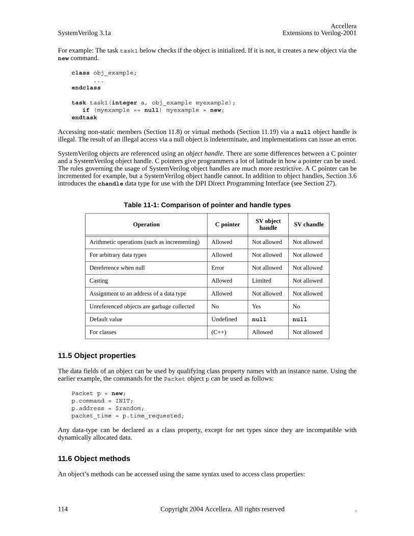
AccelleraSystemVerilog 3.1a Extensions to Verilog-2001
For example: The task task1 below checks if the object is initialized. If it is not, it creates a new object via thenew command.
class obj_example;...
endclass
task task1(integer a, obj_example myexample);if (myexample == null) myexample = new;
endtask
Accessing non-static members (Section 11.8) or virtual methods (Section 11.19) via a null object handle isillegal. The result of an illegal access via a null object is indeterminate, and implementations can issue an error.
SystemVerilog objects are referenced using an object handle. There are some differences between a C pointerand a SystemVerilog object handle. C pointers give programmers a lot of latitude in how a pointer can be used.The rules governing the usage of SystemVerilog object handles are much more restrictive. A C pointer can beincremented for example, but a SystemVerilog object handle cannot. In addition to object handles, Section 3.6introduces the chandle data type for use with the DPI Direct Programming Interface (see Section 27).
11.5 Object properties
The data fields of an object can be used by qualifying class property names with an instance name. Using theearlier example, the commands for the Packet object p can be used as follows:
Packet p = new;p.command = INIT;p.address = $random;packet_time = p.time_requested;
Any data-type can be declared as a class property, except for net types since they are incompatible withdynamically allocated data.
11.6 Object methods
An object’s methods can be accessed using the same syntax used to access class properties:
Table 11-1: Comparison of pointer and handle types
Operation C pointer SV object handle SV chandle
Arithmetic operations (such as incrementing) Allowed Not allowed Not allowed
For arbitrary data types Allowed Not allowed Not allowed
Dereference when null Error Not allowed Not allowed
Casting Allowed Limited Not allowed
Assignment to an address of a data type Allowed Not allowed Not allowed
Unreferenced objects are garbage collected No Yes No
Default value Undefined null null
For classes (C++) Allowed Not allowed
114 Copyright 2004 Accellera. All rights reserved .

AccelleraExtensions to Verilog-2001 SystemVerilog 3.1a
Packet p = new;status = p.current_status();
Note that the assignment to status is not:
status = current_status(p);
The focus in object-oriented programming is the object, in this case the packet, not the function call. Also,objects are self-contained, with their own methods for manipulating their own properties. So the object doesn’thave to be passed as an argument to current_status(). A class’ properties are freely and broadly availableto the methods of the class, but each method only accesses the properties associated with its object, i.e., itsinstance.
11.7 Constructors
SystemVerilog does not require the complex memory allocation and deallocation of C++. Construction of anobject is straightforward and garbage collection, as in Java, is implicit and automatic. There can be no memoryleaks or other subtle behavior that is so often the bane of C++ programmers.
SystemVerilog provides a mechanism for initializing an instance at the time the object is created. When anobject is created, for example
Packet p = new;
The system executes the new function associated with the class:
class Packet;integer command;
function new();command = IDLE;
endfunction endclass
Note that new is now being used in two very different contexts with very different semantics. The variable dec-laration creates an object of class Packet. In the course of creating this instance, the new function is invoked,in which any specialized initialization required can be done. The new function is also called the class construc-tor.
The new operation is defined as a function with no return type, and like any other function, it must be non-blocking. Even though new does not specify a return type, the left-hand side of the assignment determines thereturn type.
Class properties that include an initializer in their declaration are initialized before the execution of the user-defined class constructor. Thus, initializer values can be overridden by the class constructor.
Every class has a default (built-in) new method. The default constructor first calls its parent class constructor(super.new() as described in Section 11.14) and then proceeds to initialize each member of the current objectto its default (or uninitialized value).
It is also possible to pass arguments to the constructor, which allows run-time customization of an object:
Packet p = new(STARTUP, $random, $time);
where the new initialization task in Packet might now look like:
function new(int cmd = IDLE, bit[12:0] adrs = 0, int cmd_time );command = cmd;address = adrs;
Copyright 2004 Accellera. All rights reserved. 115
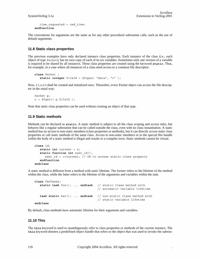
AccelleraSystemVerilog 3.1a Extensions to Verilog-2001
time_requested = cmd_time;endfunction
The conventions for arguments are the same as for any other procedural subroutine calls, such as the use ofdefault arguments.
11.8 Static class properties
The previous examples have only declared instance class properties. Each instance of the class (i.e., eachobject of type Packet), has its own copy of each of its six variables. Sometimes only one version of a variableis required to be shared by all instances. These class properties are created using the keyword static. Thus,for example, in a case where all instances of a class need access to a common file descriptor:
class Packet ;static integer fileId = $fopen( "data", "r" );
Now, fileID shall be created and initialized once. Thereafter, every Packet object can access the file descrip-tor in the usual way:
Packet p;c = $fgetc( p.fileID );
Note that static class properties can be used without creating an object of that type.
11.9 Static methods
Methods can be declared as static. A static method is subject to all the class scoping and access rules, butbehaves like a regular subroutine that can be called outside the class, even with no class instantiation. A staticmethod has no access to non-static members (class properties or methods), but it can directly access static classproperties or call static methods of the same class. Access to non-static members or to the special this handlewithin the body of a static method is illegal and results in a compiler error. Static methods cannot be virtual.
class id;static int current = 0;static function int next_id();
next_id = ++current; // OK to access static class propertyendfunction
endclass
A static method is different from a method with static lifetime. The former refers to the lifetime of the methodwithin the class, while the latter refers to the lifetime of the arguments and variables within the task.
class TwoTasks;static task foo(); ... endtask // static class method with
// automatic variable lifetime
task static bar(); ... endtask // non-static class method with// static variable lifetime
endclass
By default, class methods have automatic lifetime for their arguments and variables.
11.10 This
The this keyword is used to unambiguously refer to class properties or methods of the current instance. Thethis keyword denotes a predefined object handle that refers to the object that was used to invoke the subrou-
116 Copyright 2004 Accellera. All rights reserved .
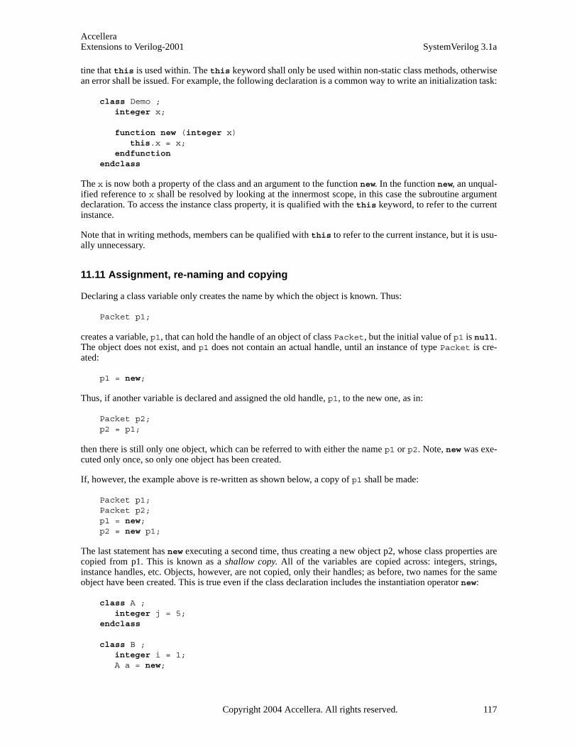
AccelleraExtensions to Verilog-2001 SystemVerilog 3.1a
tine that this is used within. The this keyword shall only be used within non-static class methods, otherwisean error shall be issued. For example, the following declaration is a common way to write an initialization task:
class Demo ;integer x;
function new (integer x) this.x = x;
endfunction endclass
The x is now both a property of the class and an argument to the function new. In the function new, an unqual-ified reference to x shall be resolved by looking at the innermost scope, in this case the subroutine argumentdeclaration. To access the instance class property, it is qualified with the this keyword, to refer to the currentinstance.
Note that in writing methods, members can be qualified with this to refer to the current instance, but it is usu-ally unnecessary.
11.11 Assignment, re-naming and copying
Declaring a class variable only creates the name by which the object is known. Thus:
Packet p1;
creates a variable, p1, that can hold the handle of an object of class Packet, but the initial value of p1 is null.The object does not exist, and p1 does not contain an actual handle, until an instance of type Packet is cre-ated:
p1 = new;
Thus, if another variable is declared and assigned the old handle, p1, to the new one, as in:
Packet p2;p2 = p1;
then there is still only one object, which can be referred to with either the name p1 or p2. Note, new was exe-cuted only once, so only one object has been created.
If, however, the example above is re-written as shown below, a copy of p1 shall be made:
Packet p1;Packet p2;p1 = new;p2 = new p1;
The last statement has new executing a second time, thus creating a new object p2, whose class properties arecopied from p1. This is known as a shallow copy. All of the variables are copied across: integers, strings,instance handles, etc. Objects, however, are not copied, only their handles; as before, two names for the sameobject have been created. This is true even if the class declaration includes the instantiation operator new:
class A ;integer j = 5;
endclass
class B ;integer i = 1;A a = new;
Copyright 2004 Accellera. All rights reserved. 117

AccelleraSystemVerilog 3.1a Extensions to Verilog-2001
endclass
function integer test;B b1 = new; // Create an object of class BB b2 = new b1; // Create an object that is a copy of b1b2.i = 10; // i is changed in b2, but not in b1b2.a.j = 50; // change a.j, shared by both b1 and b2test = b1.i; // test is set to 1 (b1.i has not changed)test = b1.a.j; // test is set to 50 (a.j has changed)
endfunction
Several things are noteworthy. First, class properties and instantiated objects can be initialized directly in aclass declaration. Second, the shallow copy does not copy objects. Third, instance qualifications can bechained as needed to reach into objects or to reach through objects:
b1.a.j // reaches into a, which is a property of b1p.next.next.next.val // chain through a sequence of handles to get to val
To do a full (deep) copy, where everything (including nested objects) are copied, custom code is typicallyneeded. For example:
Packet p1 = new;Packet p2 = new;p2.copy(p1);
where copy(Packet p) is a custom method written to copy the object specified as its argument into itsinstance.
11.12 Inheritance and subclasses
The previous sections defined a class called Packet. This class can be extended so that the packets can bechained together into a list. One solution would be to create a new class called LinkedPacket that contains avariable of type Packet called packet_c.
To refer to a class property of Packet, the variable packet_c needs to be referenced.
class LinkedPacket;Packet packet_c;LinkedPacket next;
function LinkedPacket get_next();get_next = next;
endfunction endclass
Since LinkedPacket is a specialization of Packet, a more elegant solution is to extend the class creating anew subclass that inherits the members of the parent class. Thus, for example:
class LinkedPacket extends Packet;LinkedPacket next;
function LinkedPacket get_next();get_next = next;
endfunction endclass
Now, all of the methods and class properties of Packet are part of LinkedPacket—as if they were defined inLinkedPacket—and LinkedPacket has additional class properties and methods.
118 Copyright 2004 Accellera. All rights reserved .

AccelleraExtensions to Verilog-2001 SystemVerilog 3.1a
The parent’s methods can also be overridden, changing their definitions.
The mechanism provided by SystemVerilog is called Single-Inheritance, that is, each class is derived from asingle parent class.
11.13 Overridden members
Subclass objects are also legal representative objects of their parent classes. For example, every Linked-Packet object is a perfectly legal Packet object.
The handle of a LinkedPacket object can be assigned to a Packet variable:
LinkedPacket lp = new;Packet p = lp;
In this case, references to p access the methods and class properties of the Packet class. So, for example, ifclass properties and methods in LinkedPacket are overridden, these overridden members referred to throughp get the original members in the Packet class. From p, new and all overridden members in LinkedPacketare now hidden.
class Packet;integer i = 1;function integer get();
get = i;endfunction
endclass
class LinkedPacket extends Packet;integer i = 2;function integer get();
get = -i;endfunction
endclass
LinkedPacket lp = new;Packet p = lp;j = p.i; // j = 1, not 2j = p.get(); // j = 1, not -1 or –2
To call the overridden method via a parent class object (p in the example), the method needs to be declaredvirtual (see Section 11.19).
11.14 Super
The super keyword is used from within a derived class to refer to members of the parent class. It is necessaryto use super to access members of a parent class when those members are overridden by the derived class.
class Packet; //parent classinteger value;function integer delay();
delay = value * value;endfunction
endclass
class LinkedPacket extends Packet; //derived classinteger value;
Copyright 2004 Accellera. All rights reserved. 119

AccelleraSystemVerilog 3.1a Extensions to Verilog-2001
function integer delay();delay = super.delay()+ value * super.value;
endfunction endclass
The member can be a member declared a level up or be inherited by the class one level up. There is no way toreach higher (for example, super.super.count is not allowed).
Subclasses (or derived classes) are classes that are extensions of the current class. Whereas superclasses (par-ent classes or base classes) are classes that the current class is extended from, beginning with the original baseclass.
When using the super within new, super.new shall be the first statement executed in the constructor. This isbecause the superclass must be initialized before the current class and if the user code doesn’t provide an ini-tialization, the compiler shall insert a call to super.new automatically.
11.15 Casting
It is always legal to assign a subclass variable to a variable of a class higher in the inheritance tree. It is neverlegal to directly assign a superclass variable to a variable of one of its subclasses. However, it is legal to assigna superclass handle to a subclass variable if the superclass handle refers to an object of the given subclass.
To check if the assignment is legal, the dynamic cast function $cast() is used (see Section 3.15).
The syntax for $cast() is:
task $cast( singular dest_handle, singular source_handle );
or
function int $cast( singular dest_handle, singular source_handle );
When used with object handles, $cast() checks the hierarchy tree (super and subclasses) of thesource_expr to see if it contains the class of dest_handle. If it does, $cast() does the assignment. Other-wise the error handling is as described in Section 3.15.
11.16 Chaining constructors
When a subclass is instantiated, the class method new() is invoked. The first action new() takes, before anycode defined in the function is evaluated, is to invoke the new() method of its superclass, and so on up theinheritance hierarchy. Thus, all the constructors are called, in the proper order, beginning with the root baseclass and ending with the current class.
If the initialization method of the superclass requires arguments, there are two choices. To always supply thesame arguments, or to use the super keyword. If the arguments are always the same, then they can be speci-fied at the time the class is extended:
class EtherPacket extends Packet(5);
This passes 5 to the new routine associated with Packet.
A more general approach is to use the super keyword, to call the superclass constructor:
function new();super.new(5);
endfunction
To use this approach, super.new(…) must be the first executable statement in the function new.
120 Copyright 2004 Accellera. All rights reserved .
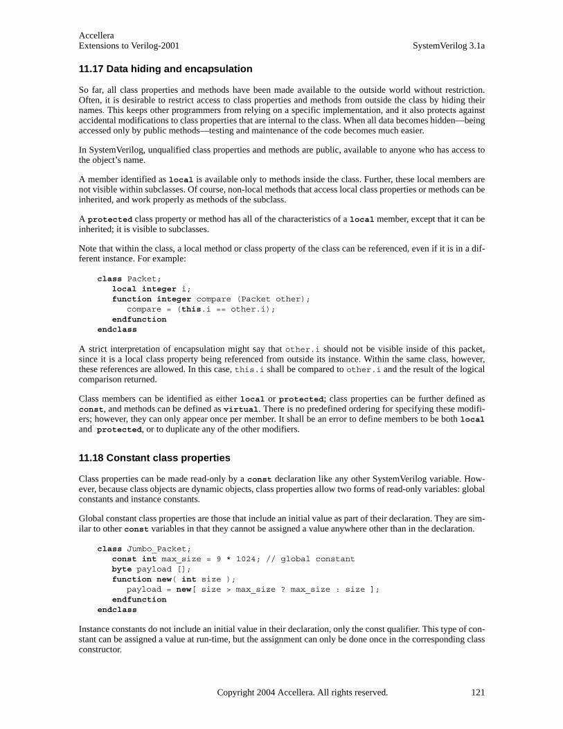
AccelleraExtensions to Verilog-2001 SystemVerilog 3.1a
11.17 Data hiding and encapsulation
So far, all class properties and methods have been made available to the outside world without restriction.Often, it is desirable to restrict access to class properties and methods from outside the class by hiding theirnames. This keeps other programmers from relying on a specific implementation, and it also protects againstaccidental modifications to class properties that are internal to the class. When all data becomes hidden—beingaccessed only by public methods—testing and maintenance of the code becomes much easier.
In SystemVerilog, unqualified class properties and methods are public, available to anyone who has access tothe object’s name.
A member identified as local is available only to methods inside the class. Further, these local members arenot visible within subclasses. Of course, non-local methods that access local class properties or methods can beinherited, and work properly as methods of the subclass.
A protected class property or method has all of the characteristics of a local member, except that it can beinherited; it is visible to subclasses.
Note that within the class, a local method or class property of the class can be referenced, even if it is in a dif-ferent instance. For example:
class Packet;local integer i;function integer compare (Packet other);
compare = (this.i == other.i);endfunction
endclass
A strict interpretation of encapsulation might say that other.i should not be visible inside of this packet,since it is a local class property being referenced from outside its instance. Within the same class, however,these references are allowed. In this case, this.i shall be compared to other.i and the result of the logicalcomparison returned.
Class members can be identified as either local or protected; class properties can be further defined asconst, and methods can be defined as virtual. There is no predefined ordering for specifying these modifi-ers; however, they can only appear once per member. It shall be an error to define members to be both localand protected, or to duplicate any of the other modifiers.
11.18 Constant class properties
Class properties can be made read-only by a const declaration like any other SystemVerilog variable. How-ever, because class objects are dynamic objects, class properties allow two forms of read-only variables: globalconstants and instance constants.
Global constant class properties are those that include an initial value as part of their declaration. They are sim-ilar to other const variables in that they cannot be assigned a value anywhere other than in the declaration.
class Jumbo_Packet;const int max_size = 9 * 1024; // global constantbyte payload [];function new( int size );
payload = new[ size > max_size ? max_size : size ];endfunction
endclass
Instance constants do not include an initial value in their declaration, only the const qualifier. This type of con-stant can be assigned a value at run-time, but the assignment can only be done once in the corresponding classconstructor.
Copyright 2004 Accellera. All rights reserved. 121
AccelleraSystemVerilog 3.1a Extensions to Verilog-2001
class Big_Packet;const int size; // instance constantbyte payload [];function new();
size = $random % 4096; //one assignment in new -> okpayload = new[ size ];
endfunction endclass
Typically, global constants are also declared static since they are the same for all instances of the class.However, an instance constant cannot be declared static, since that would disallow all assignments in theconstructor.
11.19 Abstract classes and virtual methods
A set of classes can be created that can be viewed as all being derived from a common base class. For example,a common base class of type BasePacket that sets out the structure of packets but is incomplete would neverbe instantiated. From this base class, though, a number of useful subclasses could be derived, such as Ethernetpackets, token ring packets, GPSS packets, satellite packets. Each of these packets might look very similar, allneeding the same set of methods, but they could vary significantly in terms of their internal details.
A base class sets out the prototype for the subclasses. Since the base class is not intended to be instantiated, itcan be made abstract by specifying the class to be virtual:
virtual class BasePacket;
Abstract classes can also have virtual methods. Virtual methods are a basic polymorphic construct. A virtualmethod overrides a method in all the base classes, whereas a normal method only overrides a method in thatclass and its descendants. One way to view this is that there is only one implementation of a virtual method perclass hierarchy, and it is always the one in the latest derived class. Virtual methods provide prototypes for sub-routines, all of the information generally found on the first line of a method declaration: the encapsulation cri-teria, the type and number of arguments, and the return type if it is needed. Later, when subclasses overridevirtual methods, they must follow the prototype exactly. Thus, all versions of the virtual method look identicalin all subclasses:
virtual class BasePacket;virtual function integer send(bit[31:0] data);endfunction
endclass
class EtherPacket extends BasePacket;function integer send(bit[31:0] data);
// body of the function...
endfunction endclass
EtherPacket is now a class that can be instantiated. In general, if an abstract class has any virtual methods, allof the methods must be overridden (and provided with a method body) for the subclass to be instantiated. Ifany virtual methods have no implementation, the subclass needs to be abstract.
An abstract class can contain methods for which there is only a prototype and no implementation (i.e., anincomplete class). An abstract class cannot be instantiated, it can only be derived. Methods of normal classescan also be declared virtual. In this case, the method must have a body. If the method does have a body, thenthe class can be instantiated, as can its subclasses.
122 Copyright 2004 Accellera. All rights reserved .
AccelleraExtensions to Verilog-2001 SystemVerilog 3.1a
11.20 Polymorphism: dynamic method lookup
Polymorphism allows the use of a variable in the superclass to hold subclass objects, and to reference themethods of those subclasses directly from the superclass variable. As an example, assume the base class for thePacket objects, BasePacket defines, as virtual functions, all of the public methods that are to be generallyused by its subclasses, methods such as send, receive, print, etc. Even though BasePacket is abstract, it canstill be used to declare a variable:
BasePacket packets[100];
Now, instances of various packet objects can be created, and put into the array:
EtherPacket ep = new; // extends BasePacket TokenPacket tp = new; // extends BasePacket GPSSPacket gp = new; // extends EtherPacket packets[0] = ep;packets[1] = tp;packets[2] = gp;
If the data types were, for example, integers, bits and strings, all of these types could not be stored into a singlearray, but with polymorphism, it can be done. In this example, since the methods were declared as virtual,the appropriate subclass methods can be accessed from the superclass variable, even though the compilerdidn’t know—at compile time—what was going to be loaded into it.
For example, packets[1]:
packets[1].send();
shall invoke the send method associated with the TokenPacket class. At run-time, the system correctly bindsthe method from the appropriate class.
This is a typical example of polymorphism at work, providing capabilities that are far more powerful than whatis found in a non-object-oriented framework.
11.21 Class scope resolution operator ::
The class scope operator :: is used to specify an identifier defined within the scope of a class. It has the fol-lowing form:
class_identifier :: { class_identifier :: } identifier
Identifiers on the left side of the scope-resolution operator (::) can be class names or package names (seeSection 18.2).
Because classes and other scopes can have the same identifiers, the scope resolution operator uniquely identi-fies a member of a particular class. In addition, to disambiguating class scope identifiers, the :: operator alsoallows access to static members (class properties and methods) from outside the class, as well as access to pub-lic or protected elements of a superclasses from within the derived classes.
class Base;typedef enum {bin,oct,dec,hex} radix;static task print( radix r, integer n ); ... endtask
endclass ...Base b = new;int bin = 123;b.print( Base::bin, bin ); // Base::bin and bin are differentBase::print( Base::hex, 66 );
Copyright 2004 Accellera. All rights reserved. 123

AccelleraSystemVerilog 3.1a Extensions to Verilog-2001
In SystemVerilog, the class scope operator applies to all static elements of a class: static class properties, staticmethods, typedefs, enumerations, structures, unions, and nested class declarations. Class-scope resolvedexpressions can be read (in expressions), written (in assignments or subroutines calls) or triggered off (in eventexpressions). They can also be used as the name of a type or a method call.
Like modules, classes are scopes and can nest. Nesting allows hiding of local names and local allocation ofresources. This is often desirable when a new type is needed as part of the implementation of a class. Declaringtypes within a class helps prevent name collisions, and cluttering the outer scope with symbols that are usedonly by that class. Type declarations nested inside a class scope are public and can be accessed outside theclass.
class StringList;class Node; // Nested class for a node in a linked list.
string name;Node link;
endclass endclass
class StringTree;class Node; // Nested class for a node in a binary tree.
string name;Node left, right;
endclass endclass // StringList::Node is different from StringTree::Node
The scope resolution operator enables:
— Access to static public members (methods and class properties) from outside the class hierarchy.
— Access to public or protected class members of a superclass from within the derived classes.
— Access to type declarations and enumeration named constants declared inside the class from outside theclass hierarchy or from within derived classes.
11.22 Out of block declarations
It is convenient to be able to move method definitions out of the body of the class declaration. This is done intwo steps. Declare, within the class body, the method prototypes—whether it is a function or task, any qualifi-ers (local, protected or virtual), and the full argument specification plus the extern qualifier. Theextern qualifier indicates that the body of the method (its implementation) is to be found outside the declara-tion. Then, outside the class declaration, declare the full method—like the prototype but without the qualifi-ers—and, to tie the method back to its class, qualify the method name with the class name and a pair of colons:
class Packet;Packet next;function Packet get_next();// single line
get_next = next;endfunction
// out-of-body (extern) declarationextern protected virtual function int send(int value);
endclass
function int Packet::send(int value);// dropped protected virtual, added Packet::// body of method
...endfunction
124 Copyright 2004 Accellera. All rights reserved .
AccelleraExtensions to Verilog-2001 SystemVerilog 3.1a
The out of block method declaration must match the prototype declaration exactly; the only syntactical differ-ence is that the method name is preceded by the class name and scope operator (::).
Out of block declarations must be declared in the same scope as the class declaration.
11.23 Parameterized classes
It is often useful to define a generic class whose objects can be instantiated to have different array sizes or datatypes. This avoids writing similar code for each size or type, and allows a single specification to be used forobjects that are fundamentally different, and (like a templated class in C++) not interchangeable.
The normal Verilog parameter mechanism is used to parameterize a class:
class vector #(int size = 1);bit [size-1:0] a;
endclass
Instances of this class can then be instantiated like modules or interfaces:
vector #(10) vten; // object with vector of size 10vector #(.size(2)) vtwo; // object with vector of size 2typedef vector#(4) Vfour; // Class with vector of size 4
This feature is particularly useful when using types as parameters:
class stack #(type T = int);local T items[];task push( T a ); ... endtask task pop( ref T a ); ... endtask
endclass
The above class defines a generic stack class that can be instantiated with any arbitrary type:
stack is; // default: a stack of int’sstack#(bit[1:10]) bs; // a stack of 10-bit vectorstack#(real) rs; // a stack of real numbers
Any type can be supplied as a parameter, including a user-defined type such as a class or struct.
The combination of a generic class and the actual parameter values is called a specialization (or variant). Eachspecialization of a class has a separate set of static member variables (this is consistent with C++ templatedclasses). To share static member variables among several class specializations, they must be placed in a non-parameterized base class.
class vector #(int size = 1);bit [size-1:0] a;static int count = 0;function void disp_count();
$display( "count: %d of size %d", count, size );endfunction
endclass
The variable count in the example above can only be accessed by the corresponding disp_count method.Each specialization of the class vector has its own unique copy of count.
To avoid having to repeat the specialization either in the declaration or to create parameters of that type, atypedef should be used:
typedef vector#(4) Vfour;
Copyright 2004 Accellera. All rights reserved. 125

AccelleraSystemVerilog 3.1a Extensions to Verilog-2001
typedef stack#(Vfour) Stack4;Stack4 s1, s2; // declare objects of type Stack4
A parameterized class can extend another parameterized class. For example:
class C #(type T = bit); ... endclass // base class class D1 #(type P = real) extends C; // T is bit (the default) class D2 #(type P = real) extends C #(integer); // T is integer class D3 #(type P = real) extends C #(P); // T is P
Class D1 extends the base class C using the base class’s default type (bit) parameter. Class D2 extends the baseclass C using an integer parameter. Class D3 extends the base class C using the parameterized type (P) withwhich the extended class is parameterized.
11.24 Typedef class
Sometimes a class variable needs to be declared before the class itself has been declared. For example, if twoclasses each need a handle to the other. When, in the course of processing the declaration for the first class, thecompiler encounters the reference to the second class, that reference is undefined and the compiler flags it asan error.
This is resolved using typedef to provide a forward declaration for the second class:
typedef class C2; // C2 is declared to be of type classclass C1;
C2 c;endclass class C2;
C1 c;endclass
In this example, C2 is declared to be of type class, a fact that is re-enforced later in the source code. Note thatthe class construct always creates a type, and does not require a typedef declaration for that purpose (as intypedef class …). This is consistent with common C++ use.
Note that the class keyword in the statement typedef class C2; is not necessary, and is used only fordocumentation purposes. The statement typedef C2; is equivalent and shall work the same way.
11.25 Classes and structures
SystemVerilog adds the object-oriented class construct. On the surface, it might appear that class andstruct provide equivalent functionality, and only one of them is needed. However, that is not true; class dif-fers from struct in four fundamental ways:
1) SystemVerilog struct are strictly static objects; they are created either in a static memory location(global or module scope) or on the stack of an automatic task. Conversely, SystemVerilog objects (i.e.,class instances) are exclusively dynamic, their declaration doesn’t create the object; that is done by callingnew.
2) SystemVerilog structs are type compatible so long as their bit sizes are the same, thus copying structs ofdifferent composition but equal sizes is allowed. In contrast, SystemVerilog objects are strictly strongly-typed. Copying an object of one type onto an object of another is not allowed.
3) SystemVerilog objects are implemented using handles, thereby providing C-like pointer functionality. But,SystemVerilog disallows casting handles onto other data types, thus, unlike C, SystemVerilog handles areguaranteed to be safe.
126 Copyright 2004 Accellera. All rights reserved .
AccelleraExtensions to Verilog-2001 SystemVerilog 3.1a
4) SystemVerilog objects form the basis of an Object-Oriented data abstraction that provides truepolymorphism. Class inheritance, abstract classes, and dynamic casting are powerful mechanisms that goway beyond the mere encapsulation mechanism provided by structs.
11.26 Memory management
Memory for objects, strings, and dynamic and associative arrays is allocated dynamically. When objects arecreated, SystemVerilog allocates more memory. When an object is no longer needed, SystemVerilog automati-cally reclaims the memory, making it available for re-use. The automatic memory management system is anintegral part of SystemVerilog. Without automatic memory management, SystemVerilog’s multi-threaded, re-entrant environment creates many opportunities for users to run into problems. A manual memory manage-ment system, such as the one provided by C’s malloc and free, would not be sufficient.
For example, consider the following example:
myClass obj = new;fork
task1( obj );task2( obj );
join_none
In this example, the main process (the one that forks off the two tasks) does not know when the two processesmight be done using the object obj. Similarly, neither task1 nor task2 knows when any of the other two pro-cesses will no longer be using the object obj. It is evident from this simple example that no single process hasenough information to determine when it is safe to free the object. The only two options available to the userare (1) play it safe and never reclaim the object, or (2) add some form of reference count that can be used todetermine when it might be safe to reclaim the object. Adopting the first option can cause the system toquickly run out of memory. The second option places a large burden on users, who, in addition to managingtheir testbench, must also manage the memory using less than ideal schemes. To avoid these shortcomings,SystemVerilog manages all dynamic memory automatically. Users do not need to worry about dangling refer-ences, premature deallocation, or memory leaks. The system shall automatically reclaim any object that is nolonger being used. In the example above, all that users do is assign null to the handle obj when they nolonger need it. Similarly, when an object goes out of scope the system implicitly assigns null to the object.
Copyright 2004 Accellera. All rights reserved. 127
AccelleraSystemVerilog 3.1a Extensions to Verilog-2001
Section 12Random Constraints
12.1 Introduction (informative)
Constraint-driven test generation allows users to automatically generate tests for functional verification. Ran-dom testing can be more effective than a traditional, directed testing approach. By specifying constraints, onecan easily create tests that can find hard-to-reach corner cases. SystemVerilog allows users to specify con-straints in a compact, declarative way. The constraints are then processed by a solver that generates randomvalues that meet the constraints.
The random constraints are typically specified on top of an object oriented data abstraction.that models thedata to be randomized as objects that contain random variables and user-defined constraints. The constraintsdetermine the legal values that can be assigned to the random variables. Objects are ideal for representing com-plex aggregate data types and protocols such as Ethernet packets.
Section 12.2 provides an overview of object-based randomization and constraint programming. The rest of thissection provides detailed information on random variables, constraint blocks, and the mechanisms used tomanipulate them.
12.2 Overview
This section introduces the basic concepts and uses for generating random stimulus within objects. SystemVer-ilog uses an object-oriented method for assigning random values to the member variables of an object, subjectto user-defined constraints. For example:
class Bus;rand bit[15:0] addr;rand bit[31:0] data;
constraint word_align {addr[1:0] == 2’b0;}endclass
The Bus class models a simplified bus with two random variables: addr and data, representing the addressand data values on a bus. The word_align constraint declares that the random values for addr must be suchthat addr is word-aligned (the low-order 2 bits are 0).
The randomize() method is called to generate new random values for a bus object:
Bus bus = new;
repeat (50) begin if ( bus.randomize() == 1 )
$display ("addr = %16h data = %h\n", bus.addr, bus.data);else
$display ("Randomization failed.\n");end
Calling randomize() causes new values to be selected for all of the random variables in an object such thatall of the constraints are true (satisfied). In the program test above, a bus object is created and then randomized50 times. The result of each randomization is checked for success. If the randomization succeeds, the new ran-dom values for addr and data are printed; if the randomization fails, an error message is printed. In thisexample, only the addr value is constrained, while the data value is unconstrained. Unconstrained variablesare assigned any value in their declared range.
Constraint programming is a powerful method that lets users build generic, reusable objects that can later be
128 Copyright 2004 Accellera. All rights reserved .

AccelleraExtensions to Verilog-2001 SystemVerilog 3.1a
extended or constrained to perform specific functions. The approach differs from both traditional proceduraland object-oriented programming, as illustrated in this example that extends the Bus class:
typedef enum {low, mid, high} AddrType;
class MyBus extends Bus;rand AddrType atype;constraint addr_range{
(atype == low ) -> addr inside { [0 : 15] };(atype == mid ) -> addr inside { [16 : 127]};(atype == high) -> addr inside {[128 : 255]};
}endclass
The MyBus class inherits all of the random variables and constraints of the Bus class, and adds a random vari-able called atype that is used to control the address range using another constraint. The addr_range con-straint uses implication to select one of three range constraints depending on the random value of atype.When a MyBus object is randomized, values for addr, data, and atype are computed such that all of the con-straints are satisfied. Using inheritance to build layered constraint systems enables the development of general-purpose models that can be constrained to perform application-specific functions.
Objects can be further constrained using the randomize() with construct, which declares additional con-straints in-line with the call to randomize():
task exercise_bus (MyBus bus);int res;
// EXAMPLE 1: restrict to low addresses res = bus.randomize() with {atype == low;};
// EXAMPLE 2: restrict to address between 10 and 20res = bus.randomize() with {10 <= addr && addr <= 20;};
// EXAMPLE 3: restrict data values to powers-of-twores = bus.randomize() with {data & (data - 1) == 0;};
endtask
This example illustrates several important properties of constraints:
— Constraints can be any SystemVerilog expression with variables and constants of integral type (bit, reg,logic, integer, enum, packed struct, etc.).
— The constraint solver must be able to handle a wide spectrum of equations, such as algebraic factoring,complex boolean expressions, and mixed integer and bit expressions. In the example above, the power-of-two constraint was expressed arithmetically. It could have also been defined with expressions using a shiftoperator. For example, 1 << n, where n is a 5-bit random variable.
— If a solution exists, the constraint solver must find it. The solver can fail only when the problem is over-constrained and there is no combination of random values that satisfy the constraints.
— Constraints interact bidirectionally. In this example, the value chosen for addr depends on atype and howit is constrained, and the value chosen for atype depends on addr and how it is constrained. All expres-sion operators are treated bidirectionally, including the implication operator (->).
— Constraints support only 2-state values. 4-state values (X or Z) or 4-state operators (e.g., ===, !== ) areillegal and shall result in an error.
Sometimes it is desirable to disable constraints on random variables. For example, to deliberately generate anillegal address (non-word aligned):
Copyright 2004 Accellera. All rights reserved. 129

AccelleraSystemVerilog 3.1a Extensions to Verilog-2001
task exercise_illegal(MyBus bus, int cycles);int res;
// Disable word alignment constraint.bus.word_align.constraint_mode(0);
repeat (cycles) begin
// CASE 1: restrict to small addresses.res = bus.randomize() with {addr[0] || addr[1];};
...end
// Re-enable word alignment constraintbus.word_align.constraint_mode(1);
endtask
The constraint_mode() method can be used to enable or disable any named constraint block in an object.In this example, the word-alignment constraint is disabled, and the object is then randomized with additionalconstraints forcing the low-order address bits to be non-zero (and thus unaligned).
The ability to enable or disable constraints allows users to design constraint hierarchies. In these hierarchies,the lowest level constraints can represent physical limits grouped by common properties into named constraintblocks, which can be independently enabled or disabled.
Similarly, the rand_mode() method can be used to enable or disable any random variable. When a randomvariable is disabled, it behaves in exactly the same way as other nonrandom variables.
Occasionally, it is desirable to perform operations immediately before or after randomization. That is accom-plished via two built-in methods, pre_randomize() and post_randomize(), which are automaticallycalled before and after randomization. These methods can be overridden with the desired functionality:
class XYPair;rand integer x, y;
endclass
class MyXYPair extends XYPair function void pre_randomize();
super.pre_randomize(); $display("Before randomize x=%0d, y=%0d", x, y);
endfunction
function void post_randomize();super.post_randomize();$display("After randomize x=%0d, y=%0d", x, y);
endfunction endclass
By default, pre_randomize() and post_randomize() call their overridden parent class methods. Whenpre_randomize() or post_randomize() are overridden, care must be taken to invoke the parent class’methods, unless the class is a base class (has no parent class), otherwise the base class methods shall not becalled.
The random stimulus generation capabilities and the object-oriented constraint-based verification methodol-ogy enable users to quickly develop tests that cover complex functionality and better assure design correctness.
130 Copyright 2004 Accellera. All rights reserved .

AccelleraExtensions to Verilog-2001 SystemVerilog 3.1a
12.3 Random variables
Class variables can be declared random using the rand and randc type-modifier keywords.
The syntax to declare a random variable in a class is:
Syntax 12-1—Random variable declaration syntax (excerpt from Annex A)
— The solver can randomize singular variables of any integral type.
— Arrays can be declared rand or randc, in which case all of their member elements are treated as rand orrandc.
— Dynamic and associative arrays can be declared rand or randc. All of the elements in the array are ran-domized, overwriting any previous data. If the array elements are object handles, all of the array elementsmust be non-null. Individual array elements can be constrained, in which case the index expression must bea literal constant.
— The size of a dynamic array declared as rand or randc can also be constrained. In that case, the array shallbe resized according to the size constraint, and then all the array elements shall be randomized. The arraysize constraint is declared using the size method. For example,
rand bit [7:0] len;rand integer data[];constraint db { data.size == len; }
The variable len is declared to be 8 bits wide. The randomizer computes a random value for the len vari-able in the 8-bit range of 0 to 255, and then randomizes the first len elements of the data array.
If a dynamic array’s size is not constrained then randomize() randomizes all the elements in the array.
— An object handle can be declared rand in which case all of that object’s variables and constraints aresolved concurrently with the variables and constraints of the object that contains the handle. Objects cannotbe declared randc.
12.3.1 rand modifier
Variables declared with the rand keyword are standard random variables. Their values are uniformly distrib-uted over their range. For example:
rand bit [7:0] y;
This is an 8-bit unsigned integer with a range of 0 to 255. If unconstrained, this variable shall be assigned anyvalue in the range 0 to 255 with equal probability. In this example, the probability of the same value repeatingon successive calls to randomize is 1/256.
12.3.2 randc modifier
Variables declared with the randc keyword are random-cyclic variables that cycle through all the values in arandom permutation of their declared range. Random-cyclic variables can only be of type bit or enumeratedtypes, and can be limited to a maximum size.
class_property ::= { property_qualifier } data_declaration
property_qualifier7 ::= rand
| randc
// from Annex A.1.8
Copyright 2004 Accellera. All rights reserved. 131
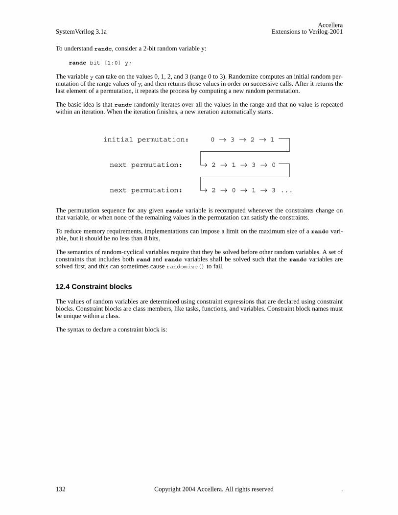
AccelleraSystemVerilog 3.1a Extensions to Verilog-2001
To understand randc, consider a 2-bit random variable y:
randc bit [1:0] y;
The variable y can take on the values 0, 1, 2, and 3 (range 0 to 3). Randomize computes an initial random per-mutation of the range values of y, and then returns those values in order on successive calls. After it returns thelast element of a permutation, it repeats the process by computing a new random permutation.
The basic idea is that randc randomly iterates over all the values in the range and that no value is repeatedwithin an iteration. When the iteration finishes, a new iteration automatically starts.
The permutation sequence for any given randc variable is recomputed whenever the constraints change onthat variable, or when none of the remaining values in the permutation can satisfy the constraints.
To reduce memory requirements, implementations can impose a limit on the maximum size of a randc vari-able, but it should be no less than 8 bits.
The semantics of random-cyclical variables require that they be solved before other random variables. A set ofconstraints that includes both rand and randc variables shall be solved such that the randc variables aresolved first, and this can sometimes cause randomize() to fail.
12.4 Constraint blocks
The values of random variables are determined using constraint expressions that are declared using constraintblocks. Constraint blocks are class members, like tasks, functions, and variables. Constraint block names mustbe unique within a class.
The syntax to declare a constraint block is:
initial permutation: 0 → 3 → 2 → 1
next permutation: → 2 → 1 → 3 → 0
next permutation: → 2 → 0 → 1 → 3 ...
132 Copyright 2004 Accellera. All rights reserved .
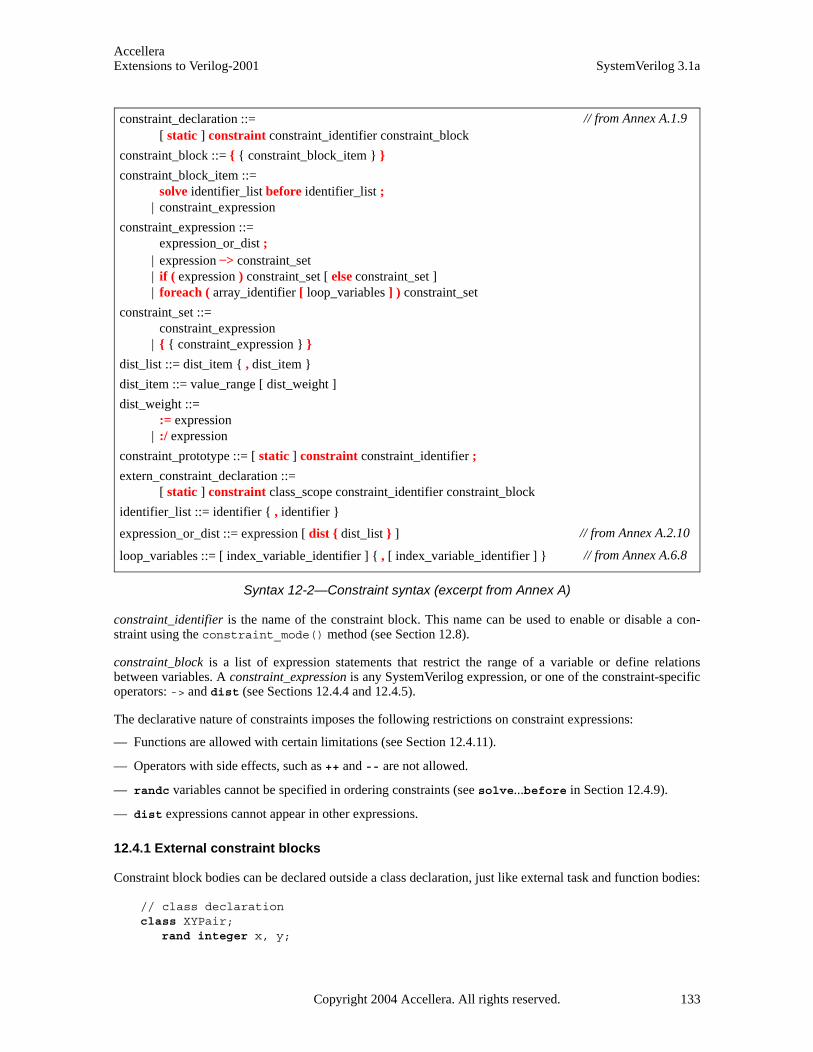
AccelleraExtensions to Verilog-2001 SystemVerilog 3.1a
Syntax 12-2—Constraint syntax (excerpt from Annex A)
constraint_identifier is the name of the constraint block. This name can be used to enable or disable a con-straint using the constraint_mode() method (see Section 12.8).
constraint_block is a list of expression statements that restrict the range of a variable or define relationsbetween variables. A constraint_expression is any SystemVerilog expression, or one of the constraint-specificoperators: -> and dist (see Sections 12.4.4 and 12.4.5).
The declarative nature of constraints imposes the following restrictions on constraint expressions:
— Functions are allowed with certain limitations (see Section 12.4.11).
— Operators with side effects, such as ++ and -- are not allowed.
— randc variables cannot be specified in ordering constraints (see solve...before in Section 12.4.9).
— dist expressions cannot appear in other expressions.
12.4.1 External constraint blocks
Constraint block bodies can be declared outside a class declaration, just like external task and function bodies:
// class declarationclass XYPair;
rand integer x, y;
constraint_declaration ::= [ static ] constraint constraint_identifier constraint_block
constraint_block ::= { { constraint_block_item } }
constraint_block_item ::= solve identifier_list before identifier_list ;
| constraint_expression
constraint_expression ::= expression_or_dist ;
| expression –> constraint_set | if ( expression ) constraint_set [ else constraint_set ] | foreach ( array_identifier [ loop_variables ] ) constraint_set
constraint_set ::= constraint_expression
| { { constraint_expression } }
dist_list ::= dist_item { , dist_item }
dist_item ::= value_range [ dist_weight ]
dist_weight ::= := expression
| :/ expression
constraint_prototype ::= [ static ] constraint constraint_identifier ;
extern_constraint_declaration ::= [ static ] constraint class_scope constraint_identifier constraint_block
identifier_list ::= identifier { , identifier }
expression_or_dist ::= expression [ dist { dist_list } ]
loop_variables ::= [ index_variable_identifier ] { , [ index_variable_identifier ] }
// from Annex A.1.9
// from Annex A.2.10
// from Annex A.6.8
Copyright 2004 Accellera. All rights reserved. 133

AccelleraSystemVerilog 3.1a Extensions to Verilog-2001
constraint c;endclass
// external constraint body declarationconstraint XYPair::c { x < y; }
12.4.2 Inheritance
Constraints follow the same general rules for inheritance as class variables, tasks, and functions:
— A constraint in a derived class that uses the same name as a constraint in its parent classes overrides thebase class constraints. For example:
class A;rand integer x;constraint c { x < 0; }
endclass
class B extends A;constraint c { x > 0; }
endclass
An instance of class A constrains x to be less than zero whereas an instance of class B constrains x to begreater than zero. The extended class B overrides the definition of constraint c. In this sense, constraintsare treated the same as virtual functions, so casting an instance of B to an A does not change the constraintset.
— The randomize() task is virtual. Accordingly, it treats the class constraints in a virtual manner. When anamed constraint is redefined in an extended class, the previous definition is overridden.
12.4.3 Set membership
Constraints support integer value sets and the set membership operator (as defined in Section 7.20).
Absent any other constraints, all values (either single values or value ranges), have an equal probability ofbeing chosen by the inside operator.
The negated form of the inside operator denotes that expression lies outside the set: !(expressioninside { set }).
For example:
rand integer x, y, z;constraint c1 {x inside {3, 5, [9:15], [24:32], [y:2*y], z};}
rand integer a, b, c;constraint c2 {a inside {b, c};}
integer fives[0:3] = { 5, 10, 15, 20 }; rand integer v;constraint c3 { v inside fives; }
It is important to note that the inside operator is bidirectional, thus, the second example above is equivalentto a == b || a == c.
12.4.4 Distribution
In addition to set membership, constraints support sets of weighted values called distributions. Distributions
134 Copyright 2004 Accellera. All rights reserved .
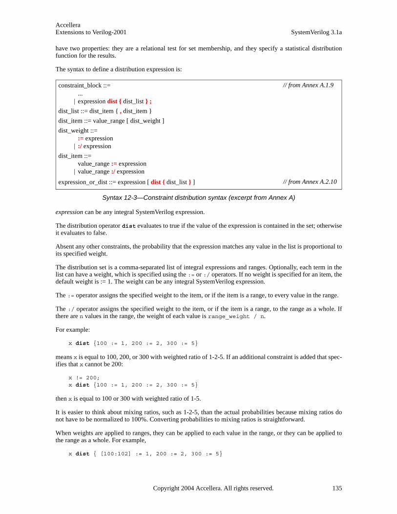
AccelleraExtensions to Verilog-2001 SystemVerilog 3.1a
have two properties: they are a relational test for set membership, and they specify a statistical distributionfunction for the results.
The syntax to define a distribution expression is:
Syntax 12-3—Constraint distribution syntax (excerpt from Annex A)
expression can be any integral SystemVerilog expression.
The distribution operator dist evaluates to true if the value of the expression is contained in the set; otherwiseit evaluates to false.
Absent any other constraints, the probability that the expression matches any value in the list is proportional toits specified weight.
The distribution set is a comma-separated list of integral expressions and ranges. Optionally, each term in thelist can have a weight, which is specified using the := or :/ operators. If no weight is specified for an item, thedefault weight is := 1. The weight can be any integral SystemVerilog expression.
The := operator assigns the specified weight to the item, or if the item is a range, to every value in the range.
The :/ operator assigns the specified weight to the item, or if the item is a range, to the range as a whole. Ifthere are n values in the range, the weight of each value is range_weight / n.
For example:
x dist {100 := 1, 200 := 2, 300 := 5}
means x is equal to 100, 200, or 300 with weighted ratio of 1-2-5. If an additional constraint is added that spec-ifies that x cannot be 200:
x != 200;x dist {100 := 1, 200 := 2, 300 := 5}
then x is equal to 100 or 300 with weighted ratio of 1-5.
It is easier to think about mixing ratios, such as 1-2-5, than the actual probabilities because mixing ratios donot have to be normalized to 100%. Converting probabilities to mixing ratios is straightforward.
When weights are applied to ranges, they can be applied to each value in the range, or they can be applied tothe range as a whole. For example,
x dist { [100:102] := 1, 200 := 2, 300 := 5}
constraint_block ::= ...
| expression dist { dist_list } ;
dist_list ::= dist_item { , dist_item }
dist_item ::= value_range [ dist_weight ]
dist_weight ::= := expression
| :/ expression
dist_item ::= value_range := expression
| value_range :/ expression
expression_or_dist ::= expression [ dist { dist_list } ]
// from Annex A.1.9
// from Annex A.2.10
Copyright 2004 Accellera. All rights reserved. 135
AccelleraSystemVerilog 3.1a Extensions to Verilog-2001
means x is equal to 100, 101, 102, 200, or 300 with a weighted ratio of 1-1-1-2-5.
x dist { [100:102] :/ 1, 200 := 2, 300 := 5}
means x is equal to one of 100, 101, 102, 200, or 300 with a weighted ratio of 1/3-1/3-1/3-2-5.
In general, distributions guarantee two properties: set membership and monotonic weighting, which meansthat increasing a weight increases the likelihood of choosing those values.
Limitations:
— A dist operation shall not be applied to randc variables.
— A dist expression requires that expression contain at least one rand variable.
12.4.5 Implication
Constraints provide two constructs for declaring conditional (predicated) relations: implication and if...else.
The implication operator ( –> ) can be used to declare an expression that implies a constraint.
The syntax to define an implication constraint is:
Syntax 12-4—Constraint implication syntax (excerpt from Annex A)
The expression can be any integral SystemVerilog expression.
The boolean equivalent of the implication operator a -> b is (!a || b). This states that if the expression istrue, then random numbers generated are constrained by the constraint (or constraint set). Otherwise the ran-dom numbers generated are unconstrained.
The constraint_set represents any valid constraint or an unnamed constraint set. If the expression is true, all ofthe constraints in the constraint set must also be satisfied.
For example:
mode == small -> len < 10;mode == large -> len > 100;
In this example, the value of mode implies that the value of len shall be constrained to less than 10 (mode ==small), greater than 100 (mode == large), or unconstrained (mode != small and mode != large).
In the following example:
bit [3:0] a, b;constraint c { (a == 0) -> (b == 1); }
Both a and b are 4 bits, so there are 256 combinations of a and b. Constraint c says that a == 0 implies thatb == 1, thereby eliminating 15 combinations: {0,0}, {0,2}, … {0,15}. Therefore, the probability that a == 0is thus 1/(256-15) or 1/241.
12.4.6 if...else constraints
if...else style constraints are also supported.
constraint_expression ::= ...
| expression –> constraint_set
// from Annex A.1.9
136 Copyright 2004 Accellera. All rights reserved .

AccelleraExtensions to Verilog-2001 SystemVerilog 3.1a
The syntax to define an if...else constraint is:
Syntax 12-5—if...else constraint syntax (excerpt from Annex A)
expression can be any integral SystemVerilog expression.
constraint_set represents any valid constraint or an unnamed constraint block. If the expression is true, all ofthe constraints in the first constraint or constraint set must be satisfied, otherwise all of the constraints in theoptional else constraint or constraint-block must be satisfied. Constraint sets can be used to group multipleconstraints.
If...else style constraint declarations are equivalent to implications:
if (mode == small)len < 10;
else if (mode == large)len > 100;
is equivalent to
mode == small -> len < 10 ;mode == large -> len > 100 ;
In this example, the value of mode implies that the value of len is less than 10, greater than 100, or uncon-strained.
Just like implication, if...else style constraints are bidirectional. In the declaration above, the value of modeconstrains the value of len, and the value of len constrains the value of mode.
Because the else part of an if...else style constraint declaration is optional, there can be confusion when anelse is omitted from a nested if sequence. This is resolved by always associating the else with the closestprevious if that lacks an else. In the example below, the else goes with the inner if, as shown by indenta-tion:
if (mode != large)if (mode == small)
len < 10;else // the else applies to preceding if
len > 100;
12.4.7 Iterative Constraints
Iterative constraints allow arrayed variables to be constrained in a parameterized manner using loop variablesand indexing expressions.
The syntax to define an iterative constraint is:
Syntax 12-6—foreach iterative constraint syntax (excerpt from Annex A)
constraint_expression ::= ...
| if ( expression ) constraint_set [ else constraint_set ]
// from Annex A.1.9
constraint_expression ::= ...
| foreach ( array_identifier [ loop_variables ] ) constraint_set
loop_variables ::= [ index_variable_identifier ] { , [ index_variable_identifier ] }
// from Annex A.1.9
// from Annex A.6.8
Copyright 2004 Accellera. All rights reserved. 137
AccelleraSystemVerilog 3.1a Extensions to Verilog-2001
The foreach construct specifies iteration over the elements of an array. Its argument is an identifier that des-ignates any type of array (fixed-size, dynamic, associative, or queue) followed by a list of loop variablesenclosed in square brackets. Each loop variable corresponds to one of the dimensions of the array.
For example:
class C;rand byte A[] ;
constraint C1 { foreach ( A [ i ] ) A[i] inside {2,4,8,16}; }constraint C2 { foreach ( A [ j ] ) A[j] > 2 * j; }
endclass
C1 constrains each element of the array A to be in the set [2,4,8,16]. C2 constrains each element of the array Ato be greater than twice its index.
The number of loop variables must not exceed the number of dimensions of the array variable. The scope ofeach loop variable is the foreach constraint construct, including its constraint_set. The type of each loop vari-able is implicitly declared to be consistent with the type of array index. An empty loop variable indicates noiteration over that dimension of the array. As with default arguments, a list of commas at the end can be omit-ted, thus, foreach( arr [ j ] ) is a shorthand for foreach( arr [ j, , , , ] ). It shall be an errorfor any loop variable to have the same identifier as the array.
The mapping of loop variables to array indexes is determined by the dimension cardinality, as described inSection 23.7.
// 1 2 3 3 4 1 2 -> Dimension numbersint A [2][3][4]; bit [3:0][2:1] B [5:1][4];
foreach( A [ i, j, k ] ) ...foreach( B [ q, r, , s ] ) ...
The first foreach causes i to iterate from 0 to 1, j from 0 to 2, and k from 0 to 3. The second foreachcauses q to iterate from 5 to 1, r from 0 to 3, and s from 2 to 1.
Iterative constraints can include predicates. For example:
class C;rand int A[] ;
constraint c1 { arr.size inside {[1:10]}; }constraint c2 { foreach ( A[ k ] ) (k < A.size - 1) -> A[k + 1] > A[k]; }
endclass
The first constraint, c1, constrains the size of the array A to be between 1 and 10. The second constraint, c2,constrains each array value to be greater than the preceding one, i.e., an array sorted in ascending order.
Within a foreach, predicate expressions involving only constants, state variables, object handle comparisons,loop variables, or the size of the array being iterated behave as guards against the creation of constraints, andnot as logical relations. For example, the implication in constraint c2 above involves only a loop variable andthe size of the array being iterated, thus, it allows the creation of a constraint only when k < A.size() - 1,which in this case prevents an out-of-bounds access in the constraint. Guards are described in more detail inSection 12.4.12.
Index expressions can include loop variables, constants, and state variables. Invalid or out or bound arrayindexes are not automatically eliminated; users must explicitly exclude these indexes using predicates.
The size method of a dynamic or associative array can be used to constrain the size of the array (see constraintc1 above). If an array is constrained by both size constraints and iterative constraints, the size constraints are
138 Copyright 2004 Accellera. All rights reserved .
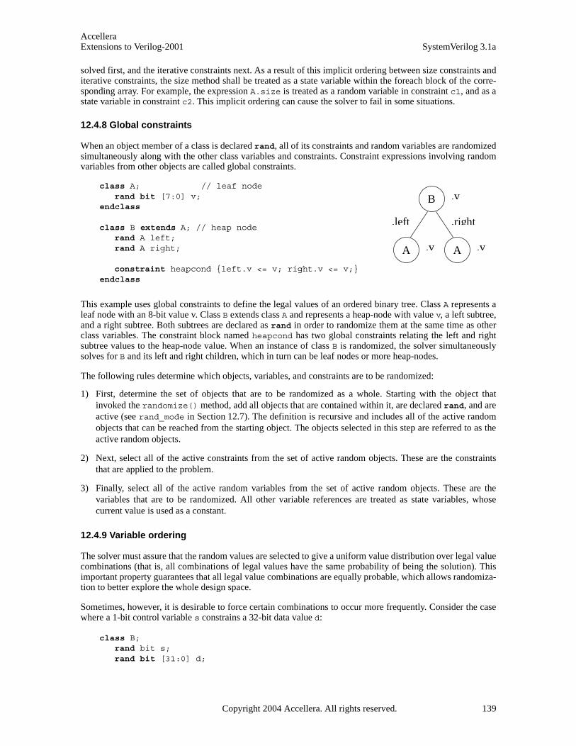
AccelleraExtensions to Verilog-2001 SystemVerilog 3.1a
solved first, and the iterative constraints next. As a result of this implicit ordering between size constraints anditerative constraints, the size method shall be treated as a state variable within the foreach block of the corre-sponding array. For example, the expression A.size is treated as a random variable in constraint c1, and as astate variable in constraint c2. This implicit ordering can cause the solver to fail in some situations.
12.4.8 Global constraints
When an object member of a class is declared rand, all of its constraints and random variables are randomizedsimultaneously along with the other class variables and constraints. Constraint expressions involving randomvariables from other objects are called global constraints.
This example uses global constraints to define the legal values of an ordered binary tree. Class A represents aleaf node with an 8-bit value v. Class B extends class A and represents a heap-node with value v, a left subtree,and a right subtree. Both subtrees are declared as rand in order to randomize them at the same time as otherclass variables. The constraint block named heapcond has two global constraints relating the left and rightsubtree values to the heap-node value. When an instance of class B is randomized, the solver simultaneouslysolves for B and its left and right children, which in turn can be leaf nodes or more heap-nodes.
The following rules determine which objects, variables, and constraints are to be randomized:
1) First, determine the set of objects that are to be randomized as a whole. Starting with the object thatinvoked the randomize() method, add all objects that are contained within it, are declared rand, and areactive (see rand_mode in Section 12.7). The definition is recursive and includes all of the active randomobjects that can be reached from the starting object. The objects selected in this step are referred to as theactive random objects.
2) Next, select all of the active constraints from the set of active random objects. These are the constraintsthat are applied to the problem.
3) Finally, select all of the active random variables from the set of active random objects. These are thevariables that are to be randomized. All other variable references are treated as state variables, whosecurrent value is used as a constant.
12.4.9 Variable ordering
The solver must assure that the random values are selected to give a uniform value distribution over legal valuecombinations (that is, all combinations of legal values have the same probability of being the solution). Thisimportant property guarantees that all legal value combinations are equally probable, which allows randomiza-tion to better explore the whole design space.
Sometimes, however, it is desirable to force certain combinations to occur more frequently. Consider the casewhere a 1-bit control variable s constrains a 32-bit data value d:
class B;rand bit s;rand bit [31:0] d;
class A; // leaf node rand bit [7:0] v;
endclass
class B extends A; // heap noderand A left;rand A right;
constraint heapcond {left.v <= v; right.v <= v;}endclass
.left .right
.v
.v .v
B
A A
Copyright 2004 Accellera. All rights reserved. 139

AccelleraSystemVerilog 3.1a Extensions to Verilog-2001
constraint c { s -> d == 0; }endclass
The constraint c says “s implies d equals zero”. Although this reads as if s determines d, in fact s and d aredetermined together. There are 233 possible combinations of {s,d}, but s is only true for {1,0}. Thus, theprobability that s is true is 1/233, which is practically zero.
The constraints provide a mechanism for ordering variables so that s can be chosen independently of d. Thismechanism defines a partial ordering on the evaluation of variables, and is specified using the solve keyword.
class B;rand bit s;rand bit [31:0] d;constraint c { s -> d == 0; }constraint order { solve s before d; }
endclass
In this case, the order constraint instructs the solver to solve for s before solving for d. The effect is that s isnow chosen true with 50% probability, and then d is chosen subject to the value of s. Accordingly, d == 0shall occur 50% of the time, and d != 0 shall occur for the other 50%.
Variable ordering can be used to force selected corner cases to occur more frequently than they would other-wise. However, a “solve...before ...” constraint does not change the solution space, and so cannot cause thesolver to fail.
The syntax to define variable order in a constraint block is:
Syntax 12-7—Solve...before constraint ordering syntax (excerpt from Annex A)
solve and before each take a comma-separated list of integral variables or array elements.
The following restrictions apply to variable ordering:
— Only random variables are allowed, that is, they must be rand.
— randc variables are not allowed. randc variables are always solved before any other.
— The variables must be integral values.
— A constraint block can contain both regular value constraints and ordering constraints.
— There must be no circular dependencies in the ordering, such as “solve a before b” combined with “solve bbefore a”.
— Variables that are not explicitly ordered shall be solved with the last set of ordered variables. These valuesare deferred until as late as possible to assure a good distribution of values.
— Variables can be solved in an order that is not consistent with the ordering constraints, provided that theoutcome is the same. An example situation where this might occur is:
x == 0;x < y;solve y before x;
In this case, since x has only one possible assignment (0), x can be solved for before y. The constraintsolver can use this flexibility to speed up the solving process.
constraint_block_item ::= solve identifier_list before identifier_list ;
| constraint_expression
// from Annex A.1.9
140 Copyright 2004 Accellera. All rights reserved .
AccelleraExtensions to Verilog-2001 SystemVerilog 3.1a
12.4.10 Static constraint blocks
A constraint block can be defined as static by including the static keyword in its definition.
The syntax to declare a static constraint block is:
Syntax 12-8—Static constraint syntax (excerpt from Annex A)
If a constraint block is declared as static, then calls to constraint_mode() shall affect all instances of thespecified constraint in all objects. Thus, if a static constraint is set to OFF, it is off for all instances of that par-ticular class.
12.4.11 Functions in Constraints
Some properties are unwieldy or impossible to express in a single expression. For example, the natural way tocompute the number of 1’s in a packed array uses a loop:
function int count_ones ( bit [9:0] w );for( count_ones = 0; w != 0; w = w >> 1 )
count_ones += w & 1’b1;endfunction
Such a function could be used to constrain other random variables to the number of 1 bits:
constraint C1 { length == count_ones( v ) ; }
Without the ability to call a function, this constraint requires the loop to be unrolled and expressed as a sum ofthe individual bits:
constraint C2 {
length == ((v>>9)&1) + ((v>>8)&1) + ((v>>7)&1) + ((v>>6)&1) + ((v>>5)&1) +((v>>4)&1) + ((v>>3)&1) + ((v>>2)&1) + ((v>>1)&1) + ((v>>0)&1);
}
Unlike the count_ones function, more complex properties, which require temporary state or unbounded loops,may be impossible to convert into a single expression. The ability to call functions, thus, enhances the expres-sive power of the constraint language and reduces the likelihood of errors. Note that the two constraints aboveare not completely equivalent; C2 is bidirectional (length can constrain v and vice-versa), whereas C1 is not.
To handle these common cases, SystemVerilog allows constraint expressions to include function calls, but itimposes certain semantic restrictions.
— Functions that appear in constraint expressions cannot contain output or ref arguments (const ref areallowed).
— Functions that appear in constraint expressions should be automatic (or preserve no state information) andhave no side effects.
— Functions that appear in constraints cannot modify the constraints, for example, calling rand_mode orconstraint_mode methods.
— Functions shall be called before constraints are solved, and their return values shall be treated as state vari-ables.
constraint_declaration ::= [ static ] constraint constraint_identifier constraint_block
// from Annex A.1.9
Copyright 2004 Accellera. All rights reserved. 141

AccelleraSystemVerilog 3.1a Extensions to Verilog-2001
— Random variables used as function arguments shall establish an implicit variable ordering or priority. Con-straints that include only variables with higher priority are solved before other, lower priority, constraints.Random variables solved as part of a higher priority set of constraints become state variables to the remain-ing set of constraints. For example:
class B;rand int x, y;constraint C { x <= F(y); } constraint D { y inside { 2, 4, 8 } ; }
endclass
Forces y to be solved before x. Thus, constraint D is solved separately before constraint C, which uses thevalues of y and F(y) as state variables. Note that the behavior for variable ordering implied by functionarguments differs from the behavior for ordering specified using the “solve...before...” constraint;function argument variable ordering subdivides the solution space thereby changing it. Since constraintson higher-priority variables are solved without considering lower-priority constraints at all this subdivi-sion can cause the overall constraints to fail. Within each prioritized set of constraints, cyclical (randc)variables are solved first.
— Circular dependencies created by the implicit variable ordering shall result in an error.
— Function calls in active constraints are executed an unspecified number of times (at least once), in anunspecified order.
12.4.12 Constraint guards
Constraint guards are predicate expressions that function as guards against the creation of constraints, and notas logical relations to be satisfied by the solver. These predicate expressions are evaluated before the con-straints are solved, and are characterized by involving only the following items:
— constants
— state variables
— object handle comparisons (comparisons between two handles or a handle and the constant null)
In addition to the above, iterative constraints (see Section 12.4.7) also consider loop variables and the size ofthe array being iterated as state variables.
Treating these predicate expressions as constraint guards prevents the solver from generating evaluation errors,thereby failing on some seemingly correct constraints. This enables users to write constraints that avoid errorsdue to nonexistent object handles or array indices out of bounds. For example, the sort constraint of the singly-linked list, SList, shown below is intended to assign a random sequence of numbers that is sorted in ascend-ing order. However, the constraint expression will fail on the last element when next.n results in an evalua-tion error due to a non-existent handle.
class SList;rand int n;rand Slist next;
constraint sort { n < next.n; }endclass
The error condition above can be avoided by writing a predicate expression to guard against that condition:
constraint sort { if( next != null ) n < next.n; }
In the sort constraint above, the if prevents the creation of a constraint when next == null, which in thiscase avoids accessing a non-existent object. Both implication ( –>) and if…else can be used as guards.
142 Copyright 2004 Accellera. All rights reserved .

AccelleraExtensions to Verilog-2001 SystemVerilog 3.1a
Guard expressions can themselves include subexpressions that result in evaluation errors (e.g., null refer-ences), and they are also guarded from generating errors. This logical sifting is accomplished by evaluatingpredicate subexpressions using the following 4-state representation:
— 0 FALSE Subexpression evaluates to FALSE
— 1 TRUE Subexpression evaluates to TRUE
— E ERROR Subexpression causes an evaluation error
— R RANDOM Expression includes random variables and cannot be evaluated
Every subexpression within a predicate expression is evaluated to yield one of the above four values. The sub-expressions are evaluated in an arbitrary order, and the result of that evaluation plus the logical operationdefine the outcome in the alternate 4-state representation. A conjunction ( && ), disjunction ( || ), or negation( ! ) of subexpressions can include some (perhaps all) guard subexpressions. The following rules specify theresulting value for the guard:
— Conjunction ( && ): If any one of the subexpressions evaluates to FALSE, then the guard evaluates toFALSE. Otherwise, if any one subexpression evaluates to ERROR, then the guard evaluates to ERROR,else the guard evaluates to TRUE.
— If the guard evaluates to FALSE then the constraint is eliminated.
— If the guard evaluates to TRUE then a (possibly conditional) constraint is generated.
— If the guard evaluates to ERROR then an error is generated and randomize fails.
— Disjunction ( || ): If any one of the subexpressions evaluates to TRUE, then the guard evaluates to TRUE.Otherwise, if any one subexpression evaluates to ERROR, then the guard evaluates to ERROR, else theguard evaluates to FALSE.
— If the guard evaluates to FALSE then a (possibly conditional) constraint is generated.
— If the guard evaluates to TRUE then an unconditional constraint is generated.
— If the guard evaluates to ERROR then an error is generated and randomize fails.
— Negation ( ! ): If the subexpression evaluates to ERROR, then the guard evaluates to ERROR. Otherwise,if the subexpression evaluates to TRUE or FALSE then the guard evaluates to FALSE or TRUE, respec-tively.
These rules are codified by the following truth tables:
These above rules are applied recursively until all subexpressions are evaluated. The final value of the evalu-ated predicate expression determines the outcome as follows:
— If the result is TRUE then an unconditional constraint is generated.
— If the result is FALSE then the constraint is eliminated, and can generate no error.
— If the result is ERROR then an unconditional error is generated and the constraint fails.
&& 0 1 E R
0 0 0 0 0
1 0 1 E R
E 0 E E E
R 0 R E R
|| 0 1 E R
0 0 1 E R
1 1 1 1 1
E E 1 E E
R R 1 E R
!
0 1
1 0
E E
R R
Conjunction Disjunction Negation
Copyright 2004 Accellera. All rights reserved. 143

AccelleraSystemVerilog 3.1a Extensions to Verilog-2001
— If the final result of the evaluation is RANDOM then a conditional constraint is generated.
When final value is RANDOM a traversal of the predicate expression tree is needed to collect all conditionalguards that evaluate to RANDOM. When the final value is ERROR, a subsequent traversal of the expressiontree is not required, allowing implementations to issue only one error.
Example 1:
class D;int x;
endclass
class C; rand int x, y; D a, b; constraint c1 { (x < y || a.x > b.x || a.x == 5 ) -> x+y == 10; }
endclass
In the example above, the predicate subexpressions are (x < y), (a.x > b.x), and (a.x == 5), which areall connected by disjunction. Some possible cases are:
— Case 1: a is non-null, b is null, a.x is 5.
Since (a.x==5) is true, the fact that b.x generates an error does not result in an error.
The unconditional constraint (x+y == 10) is generated.
— Case 2: a is null
This always results in error, irrespective of the other conditions.
— Case 3: a is non-null, b is non-null, a.x is 10, b.x is 20.
All the guard subexpressions evaluate to FALSE.
The conditional constraint (x<y) -> (x+y == 10) is generated.
Example 2:
class D; int x;
endclass
class C; rand int x, y; D a, b; constraint c1 { (x < y && a.x > b.x && a.x == 5 ) -> x+y == 10; }
endclass
In the example above, the predicate subexpressions are (x < y), (a.x > b.x), and (a.x == 5), which are all con-nected by conjunction. Some possible cases are:
— Case 1: a is non-null, b is null, a.x is 6.
Since (a.x==5) is false, the fact that b.x generates an error does not result in an error.
The constraint is eliminated.
— Case 2: a is null
This always results in error, irrespective of the other conditions.
— Case 3: a is non-null, b is non-null, a.x is 5, b.x is 2.
All the guard subexpressions evaluate to TRUE, producing constraint (x<y) -> (x+y == 10).
144 Copyright 2004 Accellera. All rights reserved .

AccelleraExtensions to Verilog-2001 SystemVerilog 3.1a
Example 3:
class D; int x;
endclass
class C; rand int x, y; D a, b; constraint c1 { (x < y && (a.x > b.x || a.x ==5)) -> x+y == 10; }
endclass
In the example above, the predicate subexpressions are (x < y) and (a.x > b.x || a.x == 5), which isconnected by disjunction. Some possible cases are:
— Case 1: a is non-null, b is null, a.x is 5.
The guard expression evaluates to (ERROR || a.x==5), which evaluates to (ERROR || TRUE).
The guard subexpression evaluates to TRUE.
The conditional constraint (x<y) -> (x+y == 10) is generated.
— Case 2: a is non-null, b is null, a.x is 8.
The guard expression evaluates to (ERROR || FALSE), and generates an error.
— Case 3: a is null
This always results in error, irrespective of the other conditions.
— Case 4: a is non-null, b is non-null, a.x is 5, b.x is 2.
All the guard subexpressions evaluate to TRUE.
The conditional constraint (x<y) -> (x+y == 10) is generated.
12.5 Randomization methods
12.5.1 randomize()
Variables in an object are randomized using the randomize() class method. Every class has a built-in ran-domize() virtual method, declared as:
virtual function int randomize();
The randomize() method is a virtual function that generates random values for all the active random vari-ables in the object, subject to the active constraints.
The randomize() method returns 1 if it successfully sets all the random variables and objects to valid values,otherwise it returns 0.
Example:
class SimpleSum;rand bit [7:0] x, y, z;constraint c {z == x + y;}
endclass
This class definition declares three random variables, x, y, and z. Calling the randomize() method shall ran-domize an instance of class SimpleSum:
Copyright 2004 Accellera. All rights reserved. 145
AccelleraSystemVerilog 3.1a Extensions to Verilog-2001
SimpleSum p = new;int success = p.randomize();if (success == 1 ) ...
Checking the return status can be necessary because the actual value of state variables or addition of con-straints in derived classes can render seemingly simple constraints unsatisfiable.
12.5.2 pre_randomize() and post_randomize()
Every class contains built-in pre_randomize() and post_randomize() functions, that are automaticallycalled by randomize() before and after computing new random values.
The built-in definition for pre_randomize() is:
function void pre_randomize;if (super) super.pre_randomize(); // test super to see if the
// object handle exists // Optional programming before randomization goes here
endfunction
The built-in definition for post_randomize() is:
function void post_randomize;if (super) super.post_randomize(); // test super to see if the
// object handle exists // Optional programming after randomization goes here
endfunction
When obj.randomize() is invoked, it first invokes pre_randomize() on obj and also all of its randomobject members that are enabled. pre_randomize() then calls super.pre_randomize(). After the newrandom values are computed and assigned, randomize() invokes post_randomize() on obj and also allof its random object members that are enabled. post_randomize() then calls super.post_randomize().
Users can override the pre_randomize() in any class to perform initialization and set pre-conditions beforethe object is randomized.
Users can override the post_randomize() in any class to perform cleanup, print diagnostics, and checkpost-conditions after the object is randomized.
If these methods are overridden, they must call their associated parent class methods, otherwise their pre- andpost-randomization processing steps shall be skipped.
The pre_randomize() and post_randomize() methods are not virtual. However, because they are auto-matically called by the randomize() method, which is virtual, they appear to behave as virtual methods.
12.5.3 Randomization methods notes
— Random variables declared as static are shared by all instances of the class in which they are declared.Each time the randomize() method is called, the variable is changed in every class instance.
— If randomize() fails, the constraints are infeasible and the random variables retain their previous values.
— If randomize() fails, post_randomize() is not called.
— The randomize() method is built-in and cannot be overridden.
— The randomize() method implements object random stability. An object can be seeded by calling itssrandom() method (see Section 12.12.3).
— The built-in methods pre_randomize() and post_randomize() are functions and cannot block.
146 Copyright 2004 Accellera. All rights reserved .

AccelleraExtensions to Verilog-2001 SystemVerilog 3.1a
12.6 In-line constraints — randomize() with
By using the randomize()...with construct, users can declare in-line constraints at the point where the ran-domize() method is called. These additional constraints are applied along with the object constraints.
The syntax for randomize()...with is:
Syntax 12-9—In-line constraint syntax (not in Annex A)
class_variable_identifier is the name of an instantiated object.
The unnamed constraint_block contains additional in-line constraints to be applied along with the object con-straints declared in the class.
For example:
class SimpleSumrand bit [7:0] x, y, z;constraint c {z == x + y;}
endclass
task InlineConstraintDemo(SimpleSum p);int success;success = p.randomize() with {x < y;};
endtask
This is the same example used before, however, randomize()...with is used to introduce an additional con-straint that x < y.
The randomize()...with construct can be used anywhere an expression can appear. The constraint block fol-lowing with can define all of the same constraint types and forms as would otherwise be declared in a class.
The randomize()...with constraint block can also reference local variables and task and function arguments,eliminating the need for mirroring a local state as member variables in the object class. The scope for variablenames in a constraint block, from inner to outer, is: randomize()...with object class, automatic and localvariables, task and function arguments, class variables, variables in the enclosing scope. The random-ize()...with class is brought into scope at the innermost nesting level.
In the example below, the randomize()...with class is Foo.
class Foo;rand integer x;
endclass
class Bar;integer x;integer y;
task doit(Foo f, integer x, integer z);int result;result = f.randomize() with {x < y + z;};
endtask endclass
inline_constraint _declaration ::= class_variable_identifier . randomize [ ( [ variable_identifier_list | null ] ) ]
with constraint_block
// not in Annex A
Copyright 2004 Accellera. All rights reserved. 147
AccelleraSystemVerilog 3.1a Extensions to Verilog-2001
In the f.randomize() with constraint block, x is a member of class Foo, and hides the x in class Bar. It alsohides the x argument in the doit() task. y is a member of Bar. z is a local argument.
12.7 Disabling random variables with rand_mode()
The rand_mode() method can be used to control whether a random variable is active or inactive. When a ran-dom variable is inactive, it is treated the same as if it had not been declared rand or randc. Inactive variablesare not randomized by the randomize() method, and their values are treated as state variables by the solver.All random variables are initially active.
The syntax for the rand_mode() method is:
task object[.random_variable]::rand_mode( bit on_off );
or
function int object.random_variable::rand_mode();
object is any expression that yields the object handle in which the random variable is defined.
random_variable is the name of the random variable to which the operation is applied. If it is not specified(only allowed when called as a task), the action is applied to all random variables within the specified object.
When called as a task, the argument to the rand_mode method determines the operation to be performed:
For unpacked array variables, random_variable can specify individual elements using the correspondingindex. Omitting the index results in all the elements of the array being affected by the call.
For unpacked structure variables, random_variable can specify individual members using the correspond-ing member. Omitting the member results in all the members of the structure being affected by the call.
If the random variable is an object handle, only the mode of the variable is changed, not the mode of randomvariables within that object (see global constraints in Section 12.4.8).
A compiler error shall be issued if the specified variable does not exist within the class hierarchy or it existsbut is not declared as rand or randc.
When called as a function, rand_mode() returns the current active state of the specified random variable. Itreturns 1 if the variable is active (ON), and 0 if the variable is inactive (OFF).
The function form of rand_mode() only accepts singular variables, thus, if the specified variable is anunpacked array, a single element must be selected via its index.
Example:
class Packet;rand integer source_value, dest_value;... other declarations
Table 12-1: rand_mode argument
Value Meaning Description
0 OFF Sets the specified variables to inactive so that they are not ran-domized on subsequent calls to the randomize() method.
1 ON Sets the specified variables to active so that they are randomized on subsequent calls to the randomize() method.
148 Copyright 2004 Accellera. All rights reserved .

AccelleraExtensions to Verilog-2001 SystemVerilog 3.1a
endclass
int ret;Packet packet_a = new;// Turn off all variables in objectpacket_a.rand_mode(0);
// ... other code// Enable source_valuepacket_a.source_value.rand_mode(1);
ret = packet_a.dest_value.rand_mode();
This example first disables all random variables in the object packet_a, and then enables only thesource_value variable. Finally, it sets the ret variable to the active status of variable dest_value.
The rand_mode() method is built-in and cannot be overridden.
12.8 Controlling constraints with constraint_mode()
The constraint_mode() method can be used to control whether a constraint is active or inactive. When aconstraint is inactive, it is not considered by the randomize() method. All constraints are initially active.
The syntax for the constraint_mode() method is:
task object[.constraint_identifier]::constraint_mode( bit on_off );
or
function int object.constraint_identifier::constraint_mode();
object is any expression that yields the object handle in which the constraint is defined.
constraint_identifier is the name of the constraint block to which the operation is applied. The constraint namecan be the name of any constraint block in the class hierarchy. If no constraint name is specified (only allowedwhen called as a task), the operation is applied to all constraints within the specified object.
When called as a task, the argument to the constraint_mode task method determines the operation to beperformed:
A compiler error shall be issued if the specified constraint block does not exist within the class hierarchy.
When called as a function, constraint_mode() returns the current active state of the specified constraintblock. It returns 1 if the constraint is active (ON), and 0 if the constraint is inactive (OFF).
Example:
Table 12-2: constraint_mode argument
Value Meaning Description
0 OFF Sets the specified constraint block to inactive so that it is not enforced by subsequent calls to the randomize() method.
1 ON Sets the specified constraint block to active so that it is considered on subsequent calls to the randomize() method.
Copyright 2004 Accellera. All rights reserved. 149

AccelleraSystemVerilog 3.1a Extensions to Verilog-2001
class Packet;rand integer source_value;constraint filter1 { source_value > 2 * m; }
endclass
function integer toggle_rand( Packet p );if ( p.filter1.constraint_mode() )
p.filter1.constraint_mode(0);else
p.filter1.constraint_mode(1);
toggle_rand = p.randomize();endfunction
In this example, the toggle_rand function first checks the current active state of the constraint filter1 in thespecified Packet object p. If the constraint is active, the function deactivates it; if it is inactive, the functionactivates it. Finally, the function calls the randomize method to generate a new random value for variablesource_value.
The constraint_mode() method is built-in and cannot be overridden.
12.9 Dynamic constraint modification
There are several ways to dynamically modify randomization constraints:
— Implication and if...else style constraints allow declaration of predicated constraints.
— Constraint blocks can be made active or inactive using the constraint_mode() built-in method. Ini-tially, all constraint blocks are active. Inactive constraints are ignored by the randomize() function.
— Random variables can be made active or inactive using the rand_mode() built-in method. Initially, allrand and randc variables are active. Inactive variables are ignored by the randomize() function.
— The weights in a dist constraint can be changed, affecting the probability that particular values in the setare chosen.
12.10 In-line random variable control
The randomize() method can be used to temporarily control the set of random and state variables within aclass instance or object. When the randomize method is called with no arguments, it behaves as described inthe previous sections, that is, it assigns new values to all random variables in an object—those declared asrand or randc—such that all of the constraints are satisfied. When randomize is called with arguments, thosearguments designate the complete set of random variables within that object; all other variables in the objectare considered state variables. For example, consider the following class and calls to randomize:
class CA;rand byte x, y;byte v, w;
constraint c1 { x < v && y > w );endclass
CA a = new;
a.randomize(); // random variables: x, y state variables: v, w a.randomize( x ); // random variables: x state variables: y, v, wa.randomize( v, w ); // random variables: v, w state variables: x, ya.randomize( w, x ); // random variables: w, x state variables: y, v
150 Copyright 2004 Accellera. All rights reserved .
AccelleraExtensions to Verilog-2001 SystemVerilog 3.1a
This mechanism controls the set of active random variables for the duration of the call to randomize, which isconceptually equivalent to making a set of calls to the rand_mode() method to disable or enable the corre-sponding random variables. Calling randomize() with arguments allows changing the random mode of anyclass property, even those not declared as rand or randc. This mechanism, however, does not affect the cycli-cal random mode; it cannot change a non-random variable into a cyclical random variable (randc), and cannotchange a cyclical random variable into a non-cyclical random variables (change from randc to rand).
The scope of the arguments to the randomize method is the object class. Arguments are limited to the names ofproperties of the calling object; expressions are not allowed. The random mode of local class members canonly be changed when the call to randomize has access to those properties, that is, within the scope of the classin which the local members are declared.
12.10.1 In-line constraint checker
Normally, calling the randomize method of a class that has no random variables causes the method to behaveas a checker, that is, it assigns no random values, and only returns a status: one if all constraints are satisfiedand zero otherwise. The in-line random variable control mechanism can also be used to force the randomize()method to behave as a checker.
The randomize method accepts the special argument null to indicate no random variables for the duration ofthe call. That is, all class members behave as state variables. This causes the randomize method to behave as achecker instead of a generator. A checker evaluates all constraints and simply returns one if all constraints aresatisfied, and zero otherwise. For example, if class CA defined above executes the following call:
success = a.randomize( null ); // no random variables
Then the solver considers all variables as state variables and only checks whether the constraint is satisfied,namely, that the relation (x < v && y > w) is true using the current values of x, y, v, and w.
12.11 Randomization of scope variables — std::randomize()
The built-in class randomize method operates exclusively on class member variables. Using classes to modelthe data to be randomized is a powerful mechanism that enables the creation of generic, reusable objects con-taining random variables and constraints that can be later extended, inherited, constrained, overridden,enabled, disabled, merged with or separated from other objects. The ease with which classes and their associ-ated random variables and constraints can be manipulated make classes an ideal vehicle for describing andmanipulating random data and constraints. However, some less-demanding problems that do not require thefull flexibility of classes, can use a simpler mechanism to randomize data that does not belong to a class. Thescope randomize function, std::randomize(), enables users to randomize data in the current scope, withoutthe need to define a class or instantiate a class object.
The syntax of the scope randomize function is:
Syntax 12-10—scope randomize function syntax (not in Annex A)
The scope randomize function behaves exactly the same as a class randomize method, except that it operateson the variables of the current scope instead of class member variables. Arguments to this function specify thevariables that are to be assigned random values, i.e., the random variables.
For example:
module stim;bit [15:0] addr;bit [31:0] data;
scope_randomize ::= [ std:: ] randomize ( [ variable_identifier_list ] ) [ with constraint_block ]
// not in Annex A
Copyright 2004 Accellera. All rights reserved. 151

AccelleraSystemVerilog 3.1a Extensions to Verilog-2001
function bit gen_stim();bit success, rd_wr;
success = randomize( addr, data, rd_wr ); // call std::randomize return rd_wr ;
endfunction
...endmodule
The function gen_stim calls std::randomize() with three variables as arguments: addr, data, andrd_wr. Thus, std::randomize() assigns new random variables to those variables that are visible in thescope of the gen_stim function. Note that addr and data have module scope, whereas rd_wr has scopelocal to the function. The above example can also be written using a class:
class stimc;rand bit [15:0] addr;rand bit [31:0] data;rand bit rd_wr;
endclass
function bit gen_stim( stimc p );bit success;success = p.randomize();addr = p.addr;data = p.data;return p.rd_wr;
endfunction
However, for this simple application, the scope randomize function leads to a straightforward implementation.
The scope randomize function returns 1 if it successfully sets all the random variables to valid values, other-wise it returns 0. If the scope randomize function is called with no arguments then it behaves as a checker, andsimply returns status.
12.11.1 Adding constraints to scope variables - std::randomize() with
The std::randomize() with form of the scope randomize function allows users to specify random con-straints to be applied to the local scope variables. When specifying constraints, the arguments to the scope ran-domize function become random variables, all other variables are considered state variables.
task stimulus( int length );int a, b, c, success;
success = std::randomize( a, b, c ) with { a < b ; a + b < length };...success = std::randomize( a, b ) with { b - a > length };...
endtask
The task stimulus above calls std::randomize twice resulting in two sets of random values for its localvariables a, b, and c. In the first call variables a and b are constrained such that variable a is less than b, andtheir sum is less than the task argument length, which is designated as a state variable. In the second call, vari-ables a and b are constrained such that their difference is greater than state variable length.
152 Copyright 2004 Accellera. All rights reserved .
AccelleraExtensions to Verilog-2001 SystemVerilog 3.1a
12.12 Random number system functions and methods
12.12.1 $urandom
The system function $urandom provides a mechanism for generating pseudorandom numbers. The functionreturns a new 32-bit random number each time it is called. The number shall be unsigned.
The syntax for $urandom is:
function int unsigned $urandom [ (int seed ) ] ;
The seed is an optional argument that determines the sequence of random numbers generated. The seed can beany integral expression. The random number generator shall generate the same sequence of random numbersevery time the same seed is used.
The random number generator is deterministic. Each time the program executes, it cycles through the samerandom sequence. This sequence can be made nondeterministic by seeding the $urandom function with anextrinsic random variable, such as the time of day.
For example:
bit [64:1] addr;
$urandom( 254 ); // Initialize the generatoraddr = {$urandom, $urandom }; // 64-bit random numbernumber = $urandom & 15; // 4-bit random number
The $urandom function is similar to the $random system function, with two exceptions. $urandom returnsunsigned numbers and is automatically thread stable (see Section 12.13.2).
12.12.2 $urandom_range()
The $urandom_range() function returns an unsigned integer within a specified range.
The syntax for $urandom_range() is:
function int unsigned $urandom_range( int unsigned maxval,int unsigned minval = 0 );
The function shall return an unsigned integer in the range maxval ... minval.
Example: val = $urandom_range(7,0);
If minval is omitted, the function shall return a value in the range maxval ... 0.
Example: val = $urandom_range(7);
If maxval is less than minval, the arguments are automatically reversed so that the first argument is largerthan the second argument.
Example: val = $urandom_range(0,7);
All of the three previous examples produce a value in the range of 0 to 7, inclusive.
$urandom_range() is automatically thread stable (see Section 12.13.2).
12.12.3 srandom()
The s srandom() method allows manually seeding the Random Number Generator (RNG) of objects orthreads. The RNG of a process can be seeded using the srandom() method of the process (see Section 9.9).
Copyright 2004 Accellera. All rights reserved. 153
AccelleraSystemVerilog 3.1a Extensions to Verilog-2001
The prototype of the srandom() method is:
function void srandom( int seed );
The srandom() method initializes an object’s random number generator using the value of the given seed.
12.12.4 get_randstate()
The get_randstate() method retrieves the current state an object’s Random Number Generator (RNG).The state of the RNG associated with a process is retrieved using the get_randstate() method of the pro-cess (see Section 9.9).
The prototype of the get_randstate() method is:
function string get_randstate();
The get_randstate() method returns a copy of the internal state of the RNG associated with the givenobject.
The RNG state is a string of unspecified length and format. The length and contents of the string are imple-mentation dependent.
12.12.5 set_randstate()
The set_randstate() method sets the state of an object’s Random Number Generator (RNG). The state ofthe RNG associated with a process is set using the set_randstate() method of the process (seeSection 9.9).
The prototype of the set_randstate() method is:
function void set_randstate( string state );
The set_randstate() method copies the given state into the internal state of an object's RNG.
The RNG state is a string of unspecified length and format. Calling set_randstate() with a string valuethat was not obtained from get_randstate()—or from a different implementation ofget_randstate()—is undefined.
12.13 Random stability
The Random Number Generator (RNG) is localized to threads and objects. Because the sequence of randomvalues returned by a thread or object is independent of the RNG in other threads or objects, this property iscalled random stability. Random stability applies to:
— The system randomization calls, $urandom() and $urandom_range().
— The object and process random seeding method, srandom().
— The object randomization method, randomize().
Testbenches with this feature exhibit more stable RNG behavior in the face of small changes to the user code.Additionally, it enables more precise control over the generation of random values by manually seedingthreads and objects.
12.13.1 Random stability properties
Random stability encompasses the following properties:
— Thread stability
154 Copyright 2004 Accellera. All rights reserved .
AccelleraExtensions to Verilog-2001 SystemVerilog 3.1a
Each thread has an independent RNG for all randomization system calls invoked from that thread. Whena new thread is created, its RNG is seeded with the next random value from its parent thread. This prop-erty is called hierarchical seeding.
Program and thread stability is guaranteed as long as thread creation and random number generation isdone in the same order as before. When adding new threads to an existing test, they can be added at theend of a code block in order to maintain random number stability of previously created work.
— Object stability
Each class instance (object) has an independent RNG for all randomization methods in the class. When anobject is created using new, its RNG is seeded with the next random value from the thread that creates theobject.
Object stability is guaranteed as long as object and thread creation, as well as random number generation,are done in the same order as before. In order to maintain random number stability, new objects, threadsand random numbers can be created after existing objects are created.
— Manual seeding
All RNG’s can be manually seeded. Combined with hierarchical seeding, this facility allows users todefine the operation of a subsystem (hierarchy subtree) completely with a single seed at the root thread ofthe system.
12.13.2 Thread stability
Random values returned from the $urandom system call are independent of thread execution order. For exam-ple:
integer x, y, z;fork //set a seed at the start of a thread
begin process::self.srandom(100); x = $urandom; end //set a seed during a thread
begin y = $urandom; process::self.srandom(200); end // draw 2 values from the thread RNG
begin z = $urandom + $urandom ; end join
The above program fragment illustrates several properties:
— Thread locality. The values returned for x, y and z are independent of the order of thread execution. This isan important property because it allows development of subsystems that are independent, controllable, andpredictable.
— Hierarchical seeding. When a thread is created, its random state is initialized using the next random valuefrom the parent thread as a seed. The three forked threads are all seeded from the parent thread.
Each thread is seeded with a unique value, determined solely by its parent. The root of a thread execution sub-tree determines the random seeding of its children. This allows entire subtrees to be moved, and preserves theirbehavior by manually seeding their root thread.
12.13.3 Object stability
The randomize() method built into every class exhibits object stability. This is the property that calls torandomize() in one instance are independent of calls to randomize() in other instances, and independentof calls to other randomize functions.
For example:
class Foo;
Copyright 2004 Accellera. All rights reserved. 155

AccelleraSystemVerilog 3.1a Extensions to Verilog-2001
rand integer x;endclass
class Bar;rand integer y;
endclass
initial begin Foo foo = new();Bar bar = new();integer z;void’(foo.randomize());// z = $random;void’(bar.randomize());
end
— The values returned for foo.x and bar.y are independent of each other.
— The calls to randomize() are independent of the $random system call. If one uncomments the line z =$random above, there is no change in the values assigned to foo.x and bar.y.
— Each instance has a unique source of random values that can be seeded independently. That random seed istaken from the parent thread when the instance is created.
— Objects can be seeded at any time using the srandom() method.
class Foo;function new (integer seed);
//set a new seed for this instancethis.srandom(seed);
endfunction endclass
Once an object is created there is no guarantee that the creating thread can change the object’s random statebefore another thread accesses the object. Therefore, it is best that objects self-seed within their new methodrather than externally.
An object’s seed can be set from any thread. However, a thread’s seed can only be set from within the threaditself.
12.14 Manually seeding randomize
Each object maintains its own internal random number generator, which is used exclusively by its random-ize() method. This allows objects to be randomized independent of each other and of calls to other systemrandomization functions. When an object is created, its random number generator (RNG) is seeded using thenext value from the RNG of the thread that creates the object. This process is called hierarchical object seed-ing.
Sometimes it is desirable to manually seed an object’s RNG using the srandom() method. This can be doneeither in a class method, or external to the class definition:
An example of seeding the RNG internally, as a class method is:
class Packet;rand bit[15:0] header;...function new (int seed);
this.srandom(seed);
156 Copyright 2004 Accellera. All rights reserved .
AccelleraExtensions to Verilog-2001 SystemVerilog 3.1a
...endfunction
endclass
An example of seeding the RNG externally is:
Packet p = new(200); // Create p with seed 200.p.srandom(300); // Re-seed p with seed 300.
Calling srandom() in an object’s new() function, assures the object’s RNG is set with the new seed beforeany class member values are randomized.
12.15 Random weighted case — randcase
Syntax 12-11—randcase syntax (excerpt from Annex A)
The keyword randcase introduces a case statement that randomly selects one of its branches. The randcaseitem expressions are non-negative integral values that constitute the branch weights. An item’s weight dividedby the sum of all weights gives the probability of taking that branch. For example:
randcase 3 : x = 1;1 : x = 2;4 : x = 3;
endcase
The sum of all weights is 8, so the probability of taking the first branch is 0.375, the probability of taking thesecond is 0.125, and the probability of taking the third is 0.5.
If a branch specifies a zero weight then that branch is not taken. If all randcase items specify zero weights thenno branch is taken and a warning can be issued.
The randcase weights can be arbitrary expressions, not just constants. For example:
byte a, b;
randcase a + b : x = 1;a - b : x = 2;a ^ ~b : x = 3;12’b800 : x = 4;
endcase
The precision of each weight expression is self-determined. The sum of the weights is computed using stan-dard addition semantics (maximum precision of all weights), where each summand is unsigned. Each weightexpression is evaluated at most once (implementations can cache identical expressions) in an unspecifiedorder. In the example above, the first three weight expressions are computed using 8-bit precision, the fourthexpression is computed using 12-bit precision; the resulting weights are added as unsigned values using 12-bitprecision. The weight selection then uses unsigned 12-bit comparison.
statement_item ::= ...
| randcase_statement
randcase_statement ::= randcase randcase_item { randcase_item } endcase
randcase_item ::= expression : statement_or_null
// from Annex A.6.4
// from Annex A.6.7
Copyright 2004 Accellera. All rights reserved. 157
AccelleraSystemVerilog 3.1a Extensions to Verilog-2001
Each call to randcase retrieves one random number in the range zero to the sum of the weights. The weightsare then selected in declaration order: smaller random numbers correspond to the first (top) weight statements.
Randcase statements exhibit thread stability. The random numbers are obtained from $urandom_range(),thus, random values drawn are independent of thread execution order. This can result in multiple calls to$urandom_range() to handle greater than 32 bits.
12.16 Random sequence generation — randsequence
Parser generators, such as yacc, use a Backus-Naur Form (BNF) or similar notation to describe the grammar ofthe language to be parsed. The grammar is thus used to generate a program that is able to check if a stream oftokens represents a syntactically correct utterance in that language. SystemVerilog’s sequence generatorreverses this process. It uses the grammar to randomly create a correct utterance (i.e., a stream of tokens) of thelanguage described by the grammar. The random sequence generator is useful for randomly generating struc-tured sequences of stimulus such as instructions or network traffic patterns.
The sequence generator uses a set of rules and productions within a randsequence block. The syntax of therandsequence block is:
Syntax 12-12—randsequence syntax (excerpt from Annex A)
A randsequence grammar is composed of one or more productions. Each production contains a name and alist of production items. Production items are further classified into terminals and nonterminals. Nonterminalsare defined in terms of terminals and other nonterminals. A terminal is an indivisible item that needs no furtherdefinition than its associated code block. Ultimately, every nonterminal is decomposed into its terminals. A
statement_item ::= ...
| randsequence_statement
randsequence_statement ::= randsequence ( [ production_ identifier ] ) production { production }
endsequence
production ::= [ function_data_type ] production_name [ ( tf_port_list ) ] : rs_rule { | rs_rule } ;
rs_rule ::= rs_production_list [ := expression [ rs_code_block ] ]
rs_production_list ::= rs_prod { rs_prod }
| rand join [ ( expression ) ] production_item production_item { production_item }
rs_code_block ::= { { data_declaration } { statement_or_null } }
rs_prod ::= production_item
| rs_code_block | rs_if_else | rs_repeat | rs_case
production_item ::= production_identifier [ ( list_of_arguments ) ]
rs_if_else ::= if ( expression ) production_item [ else production_item ]
rs_repeat ::= repeat ( expression ) production_item
rs_case ::= case ( expression ) rs_case_item { rs_case_item } endcase
rs_case_item ::= expression { , expression } : production_item
| default [ : ] production_item
// from Annex A.6.4
// from Annex A.6.12
158 Copyright 2004 Accellera. All rights reserved .
AccelleraExtensions to Verilog-2001 SystemVerilog 3.1a
production list contains a succession of production items, indicating that the items must be streamed insequence. A single production can contain multiple production lists separated by the | symbol. Production listsseparated by a | imply a set of choices, which the generator will make at random.
A simple example illustrates the basic concepts:
randsequence( main )main : first second done ;first : add | dec ;second : pop | push ;done : { $display("done"); } ;add : { $display("add"); } ;dec : { $display("dec"); } ;pop : { $display("pop"); } ;push : { $display("push"); } ;
endsequence
The production main is defined in terms of three nonterminals: first, second, and done. When main ischosen, it generates the sequence, first, second, and done. When first is generated, it is decomposed intoits productions, which specifies a random choice between add and dec. Similarly, the second production spec-ifies a choice between pop and push. All other productions are terminals; they are completely specified bytheir code block, which in the example displays the production name. Thus, the grammar leads to the follow-ing possible outcomes:
add pop doneadd push donedec pop donedec push done
When the randsequence statement is executed, it generates a grammar-driven stream of random productions.As each production is generated, the side effects of executing its associated code blocks produce the desiredstimulus. In addition to the basic grammar, the sequence generator provides for random weights, interleavingand other control mechanisms. Although the randsequence statement does not intrinsically create a loop, arecursive production will cause looping.
The randsequence statement creates an automatic scope. All production identifiers are local to the scope. Inaddition, each code block within the randsequence block creates an anonymous automatic scope. Hierarchi-cal references to the variables declared within the code blocks are not allowed. To declare a static variable, thestatic prefix must be used. The randsequence keyword can be followed by an optional production name(inside the parenthesis) that designates the name of the top-level production. If unspecified, the first productionbecomes the top-level production.
12.16.1 Random production weights
The probability that a production list is generated can be changed by assigning weights to production lists. Theprobability that a particular production list is generated is proportional to its specified weight.
The := operator assigns the weight specified by the expression to its production list. Weight expression mustevaluate to integral non-negative values. A weight is only meaningful when assigned to alternative produc-tions, that is, production list separated by a |. Weight expressions are evaluated when their enclosing produc-tion is selected, thus allowing weights to change dynamically. For example, the first production of theprevious example can be re-written as:
first : add := 3
production ::= [ function_data_type ] production_name [ ( tf_port_list ) ] : rs_rule { | rs_rule } ;
rs_rule ::= rs_production_list [ := expression [ rs_code_block ] ]
Copyright 2004 Accellera. All rights reserved. 159
AccelleraSystemVerilog 3.1a Extensions to Verilog-2001
| dec := 2;
This defines the production first in terms of two weighted production lists add and dec. The production addwill be generated with 60% probability and the production dec will be generated with 40% probability.
If no weight is specified, a production shall use a weight of 1. If only some weights are specified, the unspeci-fied weights shall use a weight of 1.
12.16.2 If...else production statements
A production can be made conditionally by means of an if...else production statement. The syntax of theif...else production statement is:
The expression can be any expression that evaluates to a boolean value. If the expression evaluates to true, theproduction following the expression is generated, otherwise the production following the optional else state-ment is generated. For example:
randsequence()...PP_PO : if ( depth < 2 ) PUSH else POP ;PUSH : { ++depth; do_push(); };POP : { --depth; do_pop(); };
endsequence
This example defines the production PP_OP. If the variable depth is less than 2 then production PUSH is gener-ated, otherwise production POP is generated. The variable depth is updated by the code blocks of both thePUSH and POP productions.
12.16.3 Case production statements
A production can be selected from a set of alternatives using a case production statement. The syntax of thecase production statement is:
The case production statement is analogous to the procedural case statement except as noted below. The caseexpression is evaluated, and its value is compared against the value of each case-item expression, which areevaluated and compared in the order in which they are given. The production generated is the one associatedwith the first case-item expression matching the case expression. If no matching case-item expression is foundthen the production associated with the optional default item is generated, or nothing if there no default item.Multiple default statements in one case production statement shall be illegal. Case-item expressions separatedby commas allow multiple expressions to share the production. For example:
randsequence()SELECT : case ( device & 7 )
0 : NETWORK1, 2 : DISKdefault : MEMORY
endcase ;...
rs_if_else ::= if ( expression ) production_item [ else production_item ]
rs_case ::= case ( expression ) rs_case_item { rs_case_item } endcase
rs_case_item ::= expression { , expression } : production_item
| default [ : ] production_item
160 Copyright 2004 Accellera. All rights reserved .
AccelleraExtensions to Verilog-2001 SystemVerilog 3.1a
endsequence
This example defines the production SELECT with a case statement. The case expression (device & 7) isevaluated and compared against the two case-item expressions. If the expression matches 0, the productionNETWORK is generated, and if it matches 1 or 2 the production DISK is generated. Otherwise the productionMEMORY is generated.
12.16.4 Repeat production statements
The repeat production statement is used to iterate over a production a specified number of times. The syntaxof the repeat production statement is:
The repeat expression must evaluate to a non-negative integral value. That value specifies the number oftimes that the corresponding production is generated. For example:
randsequence()...PUSH_OPER : repeat( $urandom_range( 2, 6 ) ) PUSH ;PUSH : ...
endsequence
In this example the PUSH_OPER production specifies that the PUSH production be repeated a random number oftimes (between 2 and 6) depending on by the value returned by $urandom_range().
The repeat production statement itself cannot be terminated prematurely. A break statement will terminatethe entire randsequence block (see Section 12.16.6).
12.16.5 Interleaving productions — rand join
The rand join production control is used to randomly interleave two or more production sequences whilemaintaining the relative order of each sequence. The syntax of the rand join production control is:
For example:
randsequence( TOP )TOP : rand join S1 S2 ;S1 : A B ;S2 : C D ;
endsequence
The generator will randomly produce the following sequences:
A B C DA C B DA C D BC D A BC A B DC A D B
The optional expression following the rand join keywords must be a real number in the range 0.0 to 1.0. The
rs_repeat ::= repeat ( expression ) production_item
rs_production_list ::= rs_prod { rs_prod }
| rand join [ ( expression ) ] production_item production_item { production_item }
Copyright 2004 Accellera. All rights reserved. 161
AccelleraSystemVerilog 3.1a Extensions to Verilog-2001
value of this expression represents the degree to which the length of the sequences to be interleaved affects theprobability of selecting a sequence. A sequence’s length is the number of productions not yet interleaved at agiven time. If the expression is 0.0, the shortest sequences are given higher priority. If the expression is 1.0, thelongest sequences are given priority. For instance, using the previous example:
TOP : rand join (0.0) S1 S2 ;
Gives higher priority to the sequences: A B C D C D A B
TOP : rand join (1.0) S1 S2 ;
Gives higher priority to the sequences: A C B D A C D B C A B D C A D B
If unspecified, the generator used the default value of 0.5, which does not prioritize any sequence length.
At each step, the generator interleaves nonterminal symbols to depth of one.
12.16.6 Aborting productions — break and return
Two procedural statements can be used to terminate a production prematurely: break and return. These twostatements can appear in any code block; they differ in what they consider the scope from which to exit.
The break statement terminates the sequence generation. When a break statement is executed from within aproduction code block, it forces a jump out of the randsequence block. For example:
randsequence()WRITE : SETUP DATA ;SETUP : { if( fifo_length >= max_length ) break; } COMMAND ;DATA : ...
endsequence next_statement : ...
When the example above executes the break statement within the SETUP production, the COMMAND productionis not generated, and execution continues on the line labeled next_statement. Use of the break statementwithin a loop statement behaves as defined in Section 8.6. Thus, the break statement terminates the smallestenclosing looping statement, otherwise the randsequence block.
The return statement aborts the generation of the current production. When a return statement is executedfrom within a production code block, the current production is aborted. Sequence generation continues withthe next production following the aborted production. For example:
randsequence()TOP : P1 P2 ;P1 : A B C ;P2 : A { if( flag == 1 ) return; } B C ;A : { $display( "A" ); } ;B : { if( flag == 2 ) return; $display( "B" ); } ;C : { $display( "C" ); } ;
endsequence
Depending on the value of variable flag, the example above displays the following:flag == 0 ==> A B C A B Cflag == 1 ==> A B C Aflag == 2 ==> A C A C
When flag == 1, production P2 is aborted in the middle, after generating A. When flag == 2, productionB is aborted twice (once as part of P1 and once as part of P2), but each time, generation continues with the nextproduction, C.
162 Copyright 2004 Accellera. All rights reserved .

AccelleraExtensions to Verilog-2001 SystemVerilog 3.1a
12.16.7 Value passing between productions
Data can be passed down to a production about to be generated, and generated productions can return data tothe nonterminals that triggered their generation. Passing data to a production is similar to a task call, and usesthe same syntax. Returning data from a production requires that a type be declared for the production, whichuses syntax similar to a function declaration.
Productions that accept data include a formal argument list. The syntax for declaring the arguments to a pro-duction is similar to a task prototype; the syntax for passing data to the production is the same as a task call.
For example, the first example above could be written as:
randsequence( main )main : first second gen ;first : add | dec ;second : pop | push ;add : gen("add") ;dec : gen("dec") ;pop : gen("pop") ;push : gen("push") ;gen( string s = "done" ) : { $display( s }; } ;
endsequence
In this example, the production gen accepts a string argument whose default is "done". Five other produc-tions generate this production, each with a different argument (the one in main uses the default).
A production creates a scope, which encompasses all its rules and code blocks. Thus, arguments passed downto a production are available throughout the production.
Productions that return data require a type declaration. The optional return type precedes the production. Pro-ductions that do not specify a return type shall assume a void return type.
A value is returned from a production by using the return with an expression. When the return statement isused with a production that returns a value, it must specify an expression of the correct type, just like non-voidfunctions. The return statement assigns the given expression to the corresponding production. The returnvalue can be read in the code blocks of the production that triggered the generation of the production returninga value. Within these code blocks, return values are accessed using the production name plus an optionalindexing expression. Within each production, a variable of the same name is implicitly declared for each pro-duction that returns a value.
If the same production appears multiple times then a one-dimensional array that starts at 1 is implicitlydeclared. For example:
randsequence( bin_op )void bin_op : value operator value // void type is optional
{ $display( "%s %b %b", operator, value[1], value[2] ); };
bit [7:0] value : { return $urandom } ;string operator : add := 5 { return "+" ; }
| dec := 2 { return "-" ; }| mult := 1 { return "*" ; }
;endsequence
In the example above, the operator and value productions return a string and an 8-bit value, respectively. The
production ::= [ function_data_type ] production_name [ ( tf_port_list ) ] : rs_rule { | rs_rule } ;
production_item ::= production_identifier [ ( list_of_arguments ) ]
Copyright 2004 Accellera. All rights reserved. 163

AccelleraSystemVerilog 3.1a Extensions to Verilog-2001
production bin_op includes these two value-returning productions. Therefore, the code block associated withproduction bin_op has access to the following implicit variable declarations:
bit [7:0] value [1:2];string operator;
Accessing these implicit variables yields the values returned from the corresponding productions. When exe-cuted, the example above displays a simple three-item random sequence: an operator followed by two 8-bitvalues. The operators +, -, and *are chosen with a distribution of 5/8, 2/8, and 1/8, respectively.
Only the return values of productions already generated (i.e., to the left of the code block accessing them) canbe retrieved. Attempting to read the return value of a production that has not been generated results in an unde-fined value. For example:
X : A {int y = B;} B ; // invalid use of BX : A {int y = A[2];} B A ; // invalid use of A[2]X : A {int y = A;} B {int j = A + B;} ; // valid
The sequences produced by randsequence can be driven directly into a system, as a side effect of productiongeneration, or the entire sequence can be generated for future processing. For example, the following functiongenerates and returns a queue of random numbers in the range given by its arguments. The first and last queueitem correspond to the lower and upper bounds, respectively. Also, the size of the queue is randomly selectedbased on the production weights.
function int[$] GenQueue(int low, int high);int[$] q;
randsequence()TOP : BOUND(low) LIST BOUND(high) ;LIST : LIST ITEM:= 8 { q = { q, ITEM }; }
| ITEM := 2 { q = { q, ITEM }; };
int ITEM : { return $urandom_range( low, high ); } ;
BOUND(int b) : { q = { q, b }; } ;endsequence GenQueue = q;
endfunction
When the randsequence in function GenQueue executes, it generates the TOP production, which causesthree productions to be generated: BOUND with argument low, LIST, and BOUND with argument high. TheBOUND production simply appends its argument to the queue. The LIST production consists of a weightedLIST ITEM production and an ITEM production. The LIST ITEM production is generated with 80% probabil-ity, which causes the LIST production to be generated recursively, thereby postponing the generation of theITEM production. The selection between LIST ITEM and ITEM is repeated until the ITEM production isselected, which terminates the LIST production. Each time the ITEM production is generated, it produces arandom number in the indicated range, which is later appended to the queue.
The following example uses a randsequence block to produce random traffic for a DSL packet network.
class DSL; ... endclass // class that creates valid DSL packets
randsequence (STREAM)STREAM : GAP DATA := 80
| DATA := 20 ;
DATA : PACKET(0) := 94 { transmit( PACKET ); }| PACKET(1) := 6 { transmit( PACKET ); } ;
164 Copyright 2004 Accellera. All rights reserved .
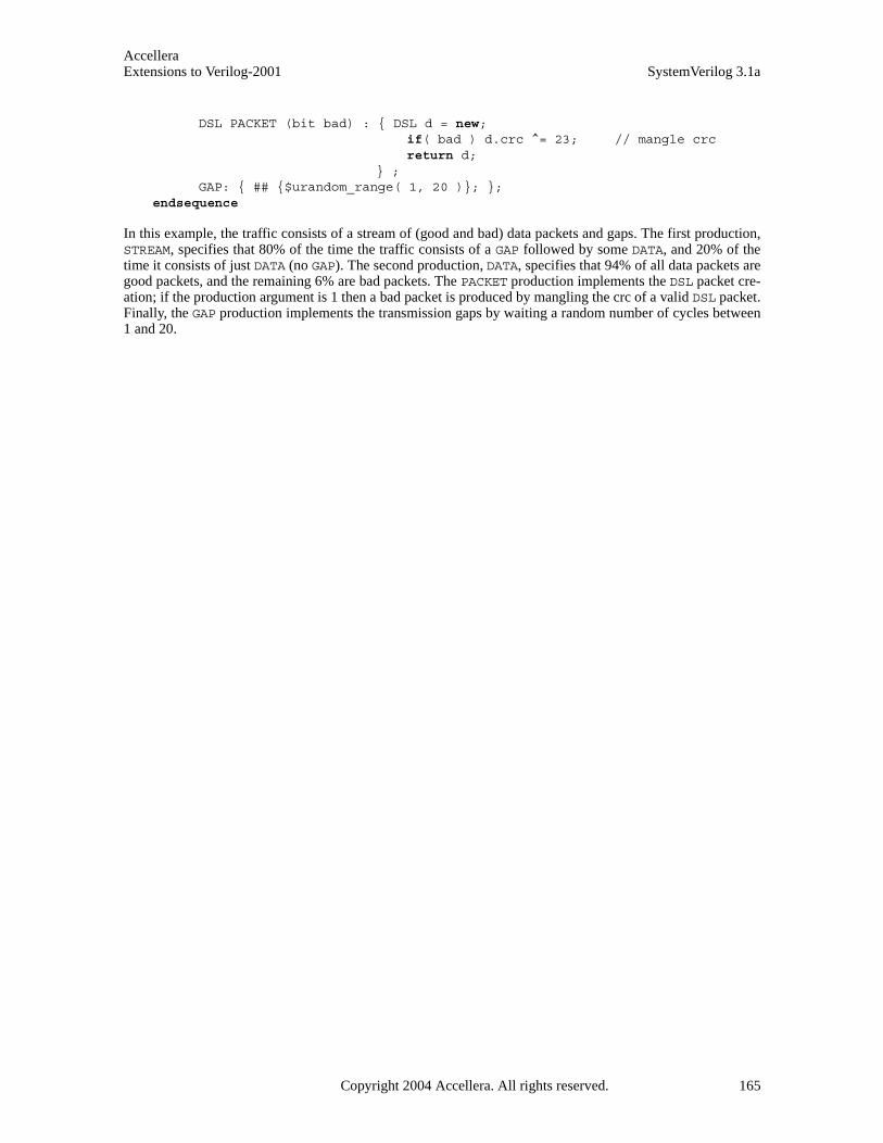
AccelleraExtensions to Verilog-2001 SystemVerilog 3.1a
DSL PACKET (bit bad) : { DSL d = new;if( bad ) d.crc ^= 23; // mangle crcreturn d;
} ;GAP: { ## {$urandom_range( 1, 20 )}; };
endsequence
In this example, the traffic consists of a stream of (good and bad) data packets and gaps. The first production,STREAM, specifies that 80% of the time the traffic consists of a GAP followed by some DATA, and 20% of thetime it consists of just DATA (no GAP). The second production, DATA, specifies that 94% of all data packets aregood packets, and the remaining 6% are bad packets. The PACKET production implements the DSL packet cre-ation; if the production argument is 1 then a bad packet is produced by mangling the crc of a valid DSL packet.Finally, the GAP production implements the transmission gaps by waiting a random number of cycles between1 and 20.
Copyright 2004 Accellera. All rights reserved. 165

AccelleraSystemVerilog 3.1a Extensions to Verilog-2001
Section 13Interprocess Synchronization and Communication
13.1 Introduction (informative)
High-level and easy-to-use synchronization and communication mechanism are essential to control the kindsof interactions that occur between dynamic processes used to model a complex system or a highly reactivetestbench. Verilog provides basic synchronization mechanisms (i.e., -> and @), but they are all limited tostatic objects and are adequate for synchronization at the hardware level, but fall short of the needs of a highlydynamic, reactive testbench. At the system level, an essential limitation of Verilog is its inability to createdynamic events and communication channels, which match the capability to create dynamic processes.
SystemVerilog adds a powerful and easy-to-use set of synchronization and communication mechanisms, all ofwhich can be created and reclaimed dynamically. SystemVerilog adds a semaphore built-in class, which canbe used for synchronization and mutual exclusion to shared resources, and a mailbox built-in class that can beused as a communication channel between processes. SystemVerilog also enhances Verilog’s named eventdata type to satisfy many of the system-level synchronization requirements.
Semaphores and mailboxes are built-in types, nonetheless, they are classes, and can be used as base classes forderiving additional higher level classes. These built-in classes reside in the built-in std package (see Section7.10.1), thus, they can be re-defined by user code in any other scope.
13.2 Semaphores
Conceptually, a semaphore is a bucket. When a semaphore is allocated, a bucket that contains a fixed numberof keys is created. Processes using semaphores must first procure a key from the bucket before they can con-tinue to execute. If a specific process requires a key, only a fixed number of occurrences of that process can bein progress simultaneously. All others must wait until a sufficient number of keys is returned to the bucket.Semaphores are typically used for mutual exclusion, access control to shared resources, and for basic synchro-nization.
An example of creating a semaphore is:
semaphore smTx;
Semaphore is a built-in class that provides the following methods:
— Create a semaphore with a specified number of keys: new()
— Obtain one or more keys from the bucket: get()
— Return one or more keys into the bucket: put()
— Try to obtain one or more keys without blocking: try_get()
13.2.1 new()
Semaphores are created with the new() method.
The prototype for semaphore new() is:
function new(int keyCount = 0 );
The KeyCount specifies the number of keys initially allocated to the semaphore bucket. The number of keys inthe bucket can increase beyond KeyCount when more keys are put into the semaphore than are removed. Thedefault value for KeyCount is 0.
The new() function returns the semaphore handle, or null if the semaphore cannot be created.
166 Copyright 2004 Accellera. All rights reserved .
AccelleraExtensions to Verilog-2001 SystemVerilog 3.1a
13.2.2 put()
The semaphore put() method is used to return keys to a semaphore.
The prototype for put() is:
task put(int keyCount = 1);
keyCount specifies the number of keys being returned to the semaphore. The default is 1.
When the semaphore.put() task is called, the specified number of keys are returned to the semaphore. If aprocess has been suspended waiting for a key, that process shall execute if enough keys have been returned.
13.2.3 get()
The semaphore get() method is used to procure a specified number of keys from a semaphore.
The prototype for get() is:
task get(int keyCount = 1);
keyCount specifies the required number of keys to obtain from the semaphore. The default is 1.
If the specified number of keys are available, the method returns and execution continues. If the specifiednumber of key are not available, the process blocks until the keys become available.
The semaphore waiting queue is First-In First-Out (FIFO). This does not guarantee the order in which pro-cesses arrive at the queue, only that their arrival order shall be preserved by the semaphore.
13.2.4 try_get()
The semaphore try_get() method is used to procure a specified number of keys from a semaphore, but with-out blocking.
The prototype for try_get() is:
function int try_get(int keyCount = 1);
keyCount specifies the required number of keys to obtain from the semaphore. The default is 1.
If the specified number of keys are available, the method returns 1 and execution continues. If the specifiednumber of key are not available, the method returns 0.
13.3 Mailboxes
A mailbox is a communication mechanism that allows messages to be exchanged between processes. Data canbe sent to a mailbox by one process and retrieved by another.
Conceptually, mailboxes behave like real mailboxes. When a letter is delivered and put into the mailbox, onecan retrieve the letter (and any data stored within). However, if the letter has not been delivered when onechecks the mailbox, one must choose whether to wait for the letter or retrieve the letter on subsequent trips tothe mailbox. Similarly, SystemVerilog’s mailboxes provide processes to transfer and retrieve data in a con-trolled manner. Mailboxes are created as having either a bounded or unbounded queue size. A bounded mail-box becomes full when it contains the bounded number of messages. A process that attempts to place amessage into a full mailbox shall be suspended until enough room becomes available in the mailbox queue.Unbounded mailboxes never suspend a thread in a send operation.
An example of creating a mailbox is:
Copyright 2004 Accellera. All rights reserved. 167
AccelleraSystemVerilog 3.1a Extensions to Verilog-2001
mailbox mbxRcv;
Mailbox is a built-in class that provides the following methods:
— Create a mailbox: new()
— Place a message in a mailbox: put()
— Try to place a message in a mailbox without blocking: try_put()
— Retrieve a message from a mailbox: get() or peek()
— Try to retrieve a message from a mailbox without blocking: try_get() or try_peek()
— Retrieve the number of messages in the mailbox: num()
13.3.1 new()
Mailboxes are created with the new() method.
The prototype for mailbox new() is:
function new(int bound = 0);
The new() function returns the mailbox handle, or null if the mailboxes cannot be created. If the boundargument is zero then the mailbox is unbounded (the default) and a put() operation shall never block. Ifbound is non-zero, it represents the size of the mailbox queue.
The bound must be positive. Negative bounds are illegal and can result in indeterminate behavior, but imple-mentations can issue a warning.
13.3.2 num()
The number of messages in a mailbox can be obtained via the num() method.
The prototype for num() is:
function int num();
The num() method returns the number of messages currently in the mailbox.
The returned value should be used with care, since it is valid only until the next get() or put() is executedon the mailbox. These mailbox operations can be from different processes than the one executing the num()method. Therefore, the validity of the returned value shall depend on the time that the other methods start andfinish.
13.3.3 put()
The put() method places a message in a mailbox.
The prototype for put() is:
task put( singular message);
The message is any singular expression, including object handles.
The put() method stores a message in the mailbox in strict FIFO order. If the mailbox was created with abounded queue the process shall be suspended until there is enough room in the queue.
168 Copyright 2004 Accellera. All rights reserved .

AccelleraExtensions to Verilog-2001 SystemVerilog 3.1a
13.3.4 try_put()
The try_put() method attempts to place a message in a mailbox.
The prototype for try_put() is:
function int try_put( singular message);
The message is any singular expression, including object handles.
The try_put() method stores a message in the mailbox in strict FIFO order. This method is meaningful onlyfor bounded mailboxes. If the mailbox is not full then the specified message is placed in the mailbox and thefunction returns 1. If the mailbox is full, the method returns 0.
13.3.5 get()
The get() method retrieves a message from a mailbox.
The prototype for get() is:
task get( ref singular message );
The message can be any singular expression, and it must be a valid left-hand side expression.
The get() method retrieves one message from the mailbox, that is, removes one message from the mailboxqueue. If the mailbox is empty then the current process blocks until a message is placed in the mailbox. If thereis a type mismatch between the message variable and the message in the mailbox, a runtime error is generated.
Non-parameterized mailboxes are type-less, that is, a single mailbox can send and receive different types ofdata. Thus, in addition to the data being sent (i.e., the message queue), a mailbox implementation must main-tain the message data type placed by put(). This is required in order to enable the runtime type checking.
The mailbox waiting queue is FIFO. This does not guarantee the order in which processes arrive at the queue,only that their arrival order shall be preserved by the mailbox.
13.3.6 try_get()
The try_get() method attempts to retrieves a message from a mailbox without blocking.
The prototype for try_get() is:
function int try_get( ref singular message );
The message can be any singular expression, and it must be a valid left-hand side expression.
The try_get() method tries to retrieve one message from the mailbox. If the mailbox is empty, then themethod returns 0. If there is a type mismatch between the message variable and the message in the mailbox,the method returns –1. If a message is available and the message type matches the type of the message vari-able, the message is retrieved and the method returns 1.
13.3.7 peek()
The peek() method copies a message from a mailbox without removing the message from the queue.
The prototype for peek() is:
task peek( ref singular message );
The message can be any singular expression, and it must be a valid left-hand side expression.
Copyright 2004 Accellera. All rights reserved. 169

AccelleraSystemVerilog 3.1a Extensions to Verilog-2001
The peek() method copies one message from the mailbox without removing the message from the mailboxqueue. If the mailbox is empty then the current process blocks until a message is placed in the mailbox. If thereis a type mismatch between the message variable and the message in the mailbox, a runtime error is generated.
Note that calling peek() can cause one message to unblock more than one process. As long as a messageremains in the mailbox queue, any process blocked in either a peek() or get() operation shall becomeunblocked.
13.3.8 try_peek()
The try_peek() method attempts to copy a message from a mailbox without blocking.
The prototype for try_peek() is:
function int try_peek( ref singular message );
The message can be any singular expression, and it must be a valid left-hand side expression.
The try_peek() method tries to copy one message from the mailbox without removing the message from themailbox queue. If the mailbox is empty, then the method returns 0. If there is a type mismatch between themessage variable and the message in the mailbox, the method returns –1. If a message is available and the mes-sage type matches, the type of the message variable, the message is copied and the method returns 1.
13.4 Parameterized mailboxes
The default mailbox is type-less, that is, a single mailbox can send and receive any type of data. This is a verypowerful mechanism that, unfortunately, can also result in run-time errors due to type mismatches between amessage and the type of the variable used to retrieve the message. Frequently, a mailbox is used to transfer aparticular message type, and, in that case, it is useful to detect type mismatches at compile time.
Parameterized mailboxes use the same parameter mechanism as parameterized classes (see Section 11.23),modules, and interfaces:
mailbox #(type = dynamic_type)
Where dynamic_type represents a special type that enables run-time type-checking (the default).
A parameterized mailbox of a specific type is declared by specifying the type:
typedef mailbox #(string) s_mbox;
s_mbox sm = new;string s;
sm.put( "hello" );...sm.get( s ); // s <- "hello"
Parameterized mailboxes provide all the same standard methods as dynamic mailboxes: num(), new(),get(), peek(), put(), try_get(), try_peek(), try_put().
The only difference between a generic (dynamic) mailbox and a parameterized mailbox is that for a parameter-ized mailbox, the compiler ensures that the put, try_put, peek, try_peek, get and try_get methods arecompatible with the mailbox type, so that all type mismatches are caught by the compiler and not at run-time.
170 Copyright 2004 Accellera. All rights reserved .
AccelleraExtensions to Verilog-2001 SystemVerilog 3.1a
13.5 Event
In Verilog, named events are static objects that can be triggered via the -> operator, and processes can wait foran event to be triggered via the @ operator. SystemVerilog events support the same basic operations, butenhance Verilog events in several ways. The most salient enhancement is that the triggered state of Verilognamed events has no duration, whereas in SystemVerilog this state persists throughout the time-step in whichthe event triggered. Also, SystemVerilog events act as handles to synchronization queues, thus, they can bepassed as arguments to tasks, and they can be assigned to one another or compared.
Existing Verilog event operations (@ and ->) are backward compatible and continue to work the same waywhen used in the static Verilog context. The additional functionality described below works with all events ineither the static or dynamic context.
A SystemVerilog event provides a handle to an underlying synchronization object. When a process waits for anevent to be triggered, the process is put on a queue maintained within the synchronization object. Processescan wait for a SystemVerilog event to be triggered either via the @ operator, or by using the wait() constructto examine their triggered state. Events are triggered using the -> or the ->> operator.
Syntax 13-1—Event trigger syntax (excerpt from Annex A)
The syntax to declare named events is discussed in Section 3.8.
13.5.1 Triggering an event
Named events are triggered via the -> operator.
Triggering an event unblocks all processes currently waiting on that event. When triggered, named eventsbehave like a one-shot, that is, the trigger state itself is not observable, only its effect. This is similar to the wayin which an edge can trigger a flip-flop but the state of the edge cannot be ascertained, i.e., if (posedgeclock) is illegal.
13.5.2 Nonblocking event trigger
Nonblocking events are triggered using the ->> operator.
The effect of the ->> operator is that the statement executes without blocking and it creates a nonblockingassign update event in the time in which the delay control expires, or the event-control occurs. The effect ofthis update event shall be to trigger the referenced event in the nonblocking assignment region of the simula-tion cycle.
13.5.3 Waiting for an event
The basic mechanism to wait for an event to be triggered is via the event control operator, @.
@ hierarchical_event_identifier;
The @ operator blocks the calling process until the given event is triggered.
For a trigger to unblock a process waiting on an event, the waiting process must execute the @ statement beforethe triggering process executes the trigger operator, ->. If the trigger executes first, then the waiting processremains blocked.
event_trigger ::= -> hierarchical_event_identifier ;
| ->> [ delay_or_event_control ] hierarchical_event_identifier ;
// from Annex A.6.5
Copyright 2004 Accellera. All rights reserved. 171
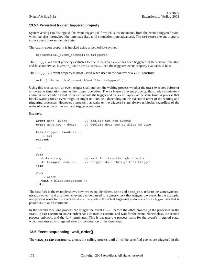
AccelleraSystemVerilog 3.1a Extensions to Verilog-2001
13.5.4 Persistent trigger: triggered property
SystemVerilog can distinguish the event trigger itself, which is instantaneous, from the event’s triggered state,which persists throughout the time-step (i.e., until simulation time advances). The triggered event propertyallows users to examine this state.
The triggered property is invoked using a method-like syntax:
hierarchical_event_identifier.triggered
The triggered event property evaluates to true if the given event has been triggered in the current time-stepand false otherwise. If event_identifier is null, then the triggered event property evaluates to false.
The triggered event property is most useful when used in the context of a wait construct:
wait ( hierarchical_event_identifier.triggered )
Using this mechanism, an event trigger shall unblock the waiting process whether the wait executes before orat the same simulation time as the trigger operation. The triggered event property, thus, helps eliminate acommon race condition that occurs when both the trigger and the wait happen at the same time. A process thatblocks waiting for an event might or might not unblock, depending on the execution order of the waiting andtriggering processes. However, a process that waits on the triggered state always unblocks, regardless of theorder of execution of the wait and trigger operations.
Example:
event done, blast; // declare two new eventsevent done_too = done; // declare done_too as alias to done
task trigger( event ev );-> ev;
endtask
...
fork @ done_too; // wait for done through done_too#1 trigger( done ); // trigger done through task trigger
join
fork -> blast;wait ( blast.triggered );
join
The first fork in the example shows how two event identifiers, done and done_too, refer to the same synchro-nization object, and also how an event can be passed to a generic task that triggers the event. In the example,one process waits for the event via done_too, while the actual triggering is done via the trigger task that ispassed done as an argument.
In the second fork, one process can trigger the event blast before the other process (if the processes in thefork…join execute in source order) has a chance to execute, and wait for the event. Nonetheless, the secondprocess unblocks and the fork terminates. This is because the process waits for the event’s triggered state,which remains in its triggered state for the duration of the time-step.
13.6 Event sequencing: wait_order()
The wait_order construct suspends the calling process until all of the specified events are triggered in the
172 Copyright 2004 Accellera. All rights reserved .

AccelleraExtensions to Verilog-2001 SystemVerilog 3.1a
given order (left to right) or any of the un-triggered events are triggered out of order and thus causes the oper-ation to fail.
The syntax for the wait_order construct is:
Syntax 13-2—wait_order event sequencing syntax (excerpt from Annex A)
For wait_order to succeed, at any point in the sequence, the subsequent events—which must all be un-trig-gered at this point, or the sequence would have already failed—must be triggered in the prescribed order. Pre-ceding events are not limited to occur only once. That is, once an event occurs in the prescribed order, it can betriggered again without causing the construct to fail.
Only the first event in the list can wait for the persistent triggered property.
The action taken when the construct fails depends on whether or not the optional phrase else statement (thefail statement) is specified. If it is specified, then the given statement is executed upon failure of the construct.If the fail statement is not specified, a failure generates a run-time error.
For example:
wait_order( a, b, c);
suspends the current process until events a, b, and c trigger in the order a –> b –> c. If the events trigger outof order, a run-time error is generated.
Example:
wait_order( a, b, c ) else $display( "Error: events out of order" );
In this example, the fail statement specifies that upon failure of the construct, a user message be displayed, butwithout an error being generated.
Example:
bit success;wait_order( a, b, c ) success = 1; else success = 0;
In this example, the completion status is stored in the variable success, without an error being generated.
13.7 Event variables
An event is a unique data type with several important properties. Unlike Verilog, SystemVerilog events can beassigned to one another. When one event is assigned to another the synchronization queue of the source eventis shared by both the source and the destination event. In this sense, events act as full fledged variables and notmerely as labels.
13.7.1 Merging events
When one event variable is assigned to another, the two become merged. Thus, executing -> on either event
wait_statement ::= ... | wait_order ( hierarchical_identifier [ , hierarchical_identifier ] ) action_block
action_block ::= statement _or_null
| [ statement ] else statement
// from Annex A.6.5
Copyright 2004 Accellera. All rights reserved. 173
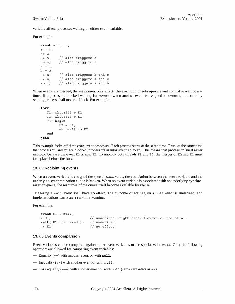
AccelleraSystemVerilog 3.1a Extensions to Verilog-2001
variable affects processes waiting on either event variable.
For example:
event a, b, c;a = b;-> c;-> a; // also triggers b-> b; // also triggers aa = c;b = a;-> a; // also triggers b and c-> b; // also triggers a and c-> c; // also triggers a and b
When events are merged, the assignment only affects the execution of subsequent event control or wait opera-tions. If a process is blocked waiting for event1 when another event is assigned to event1, the currentlywaiting process shall never unblock. For example:
fork T1: while(1) @ E2;T2: while(1) @ E1;T3: begin
E2 = E1;while(1) -> E2;
end join
This example forks off three concurrent processes. Each process starts at the same time. Thus, at the same timethat process T1 and T2 are blocked, process T3 assigns event E1 to E2. This means that process T1 shall neverunblock, because the event E2 is now E1. To unblock both threads T1 and T2, the merger of E2 and E1 musttake place before the fork.
13.7.2 Reclaiming events
When an event variable is assigned the special null value, the association between the event variable and theunderlying synchronization queue is broken. When no event variable is associated with an underlying synchro-nization queue, the resources of the queue itself become available for re-use.
Triggering a null event shall have no effect. The outcome of waiting on a null event is undefined, andimplementations can issue a run-time warning.
For example:
event E1 = null;@ E1; // undefined: might block forever or not at all wait( E1.triggered ); // undefined-> E1; // no effect
13.7.3 Events comparison
Event variables can be compared against other event variables or the special value null. Only the followingoperators are allowed for comparing event variables:
— Equality (==) with another event or with null.
— Inequality (!=) with another event or with null.
— Case equality (===) with another event or with null (same semantics as ==).
174 Copyright 2004 Accellera. All rights reserved .

AccelleraExtensions to Verilog-2001 SystemVerilog 3.1a
— Case inequality (!==) with another event or with null (same semantics as !=).
— Test for a boolean value that shall be 0 if the event is null and 1 otherwise.
Example:
event E1, E2;if ( E1 ) // same as if ( E1 != null )
E1 = E2;if ( E1 == E2 )
$display( "E1 and E2 are the same event" );
Copyright 2004 Accellera. All rights reserved. 175
AccelleraSystemVerilog 3.1a Extensions to Verilog-2001
Section 14Scheduling Semantics
14.1 Execution of a hardware model and its verification environment
The balance of the sections of this standard describes the behavior of each of the elements of the language.This section gives an overview of the interactions between these elements, especially with respect to the sched-uling and execution of events. Although SystemVerilog is not limited to simulation, the semantics of the lan-guage are defined for event directed simulation, and other uses of the hardware description language areabstracted from this base definition.
14.2 Event simulation
The SystemVerilog language is defined in terms of a discrete event execution model. The discrete event simu-lation is described in more detail in this section to provide a context to describe the meaning and valid interpre-tation of SystemVerilog constructs. These resulting definitions provide the standard SystemVerilog referencealgorithm for simulation, which all compliant simulators shall implement. Note that there is a great deal ofchoice in the definitions that follow, and differences in some details of execution are to be expected betweendifferent simulators. In addition, SystemVerilog simulators are free to use different algorithms than thosedescribed in this section, provided the user-visible effect is consistent with the reference algorithm.
A SystemVerilog description consists of connected threads of execution or processes. Processes are objectsthat can be evaluated, that can have state, and that can respond to changes on their inputs to produce outputs.Processes are concurrently scheduled elements, such as initial blocks. Example of processes include, butare not limited to, primitives, initial, always, always_comb, always_latch, and always_ff proce-dural blocks, continuous assignments, asynchronous tasks, and procedural assignment statements.
Every change in state of a net or variable in the system description being simulated is considered an updateevent.
Processes are sensitive to update events. When an update event is executed, all the processes that are sensitiveto that event are considered for evaluation in an arbitrary order. The evaluation of a process is also an event,known as an evaluation event.
Evaluation events also include PLI callbacks, which are points in the execution model where user-definedexternal routines can be called from the simulation kernel.
In addition to events, another key aspect of a simulator is time. The term simulation time is used to refer to thetime value maintained by the simulator to model the actual time it would take for the system description beingsimulated. The term time is used interchangeably with simulation time in this section.
To fully support clear and predictable interactions, a single time slot is divided into multiple regions whereevents can be scheduled that provide for an ordering of particular types of execution. This allows propertiesand checkers to sample data when the design under test is in a stable state. Property expressions can be safelyevaluated, and testbenches can react to both properties and checkers with zero delay, all in a predictable man-ner. This same mechanism also allows for non-zero delays in the design, clock propagation, and/or stimulusand response code to be mixed freely and consistently with cycle accurate descriptions.
14.3 The stratified event scheduler
A compliant SystemVerilog simulator must maintain some form of data structure that allows events to bedynamically scheduled, executed and removed as the simulator advances through time. The data structure isnormally implemented as a time ordered set of linked lists, which are divided and subdivided in a well definedmanner.
The first division is by time. Every event has one and only one simulation execution time, which at any given
176 Copyright 2004 Accellera. All rights reserved .

AccelleraExtensions to Verilog-2001 SystemVerilog 3.1a
point during simulation can be the current time or some future time. All scheduled events at a specific timedefine a time slot. Simulation proceeds by executing and removing all events in the current simulation timeslot before moving on to the next non-empty time slot, in time order. This procedure guarantees that the simu-lator never goes backwards in time.
A time slot is divided into a set of ordered regions:
1) Preponed
2) Pre-active
3) Active
4) Inactive
5) Pre-NBA
6) NBA
7) Post-NBA
8) Observed
9) Post-observed
10) Reactive
11) Postponed
The purpose of dividing a time slot into these ordered regions is to provide predictable interactions betweenthe design and testbench code.
Except for the Observed and Reactive regions and the Post-observed PLI region, these regions essentiallyencompass the Verilog 1364-2001 standard reference model for simulation, with exactly the same level ofdeterminism. This means that legacy Verilog code shall continue to run correctly without modification withinthe new mechanism. The Postponed region is where the monitoring of signals, and other similar events, takesplace. No new value changes are allowed to happen in the time slot once the Postponed region is reached.
The Observed and Reactive regions are new in the SystemVerilog 3.1 standard, and events are only scheduledinto these new regions from new language constructs.
The Observed region is for the evaluation of the property expressions when they are triggered. A criterion forthis determinism is that the property evaluations must only occur once in any clock triggering time slot. Duringthe property evaluation, pass/fail code shall be scheduled in the Reactive region of the current time slot.
The sampling time of sampled data for property expressions is controlled in the clocking block. The new#1step sampling delay provides the ability to sample data immediately before entering the current time slot,and is a preferred construct over other equivalent constructs because it allows the 1step time delay to beparameterized. This #1step construct is a conceptual mechanism that provides a method for defining whensampling takes place, and does not require that an event be created in this previous time slot. Conceptually this#1step sampling is identical to taking the data samples in the Preponed region of the current time slot.
Code specified in the program block, and pass/fail code from property expressions, are scheduled in the Reac-tive region.
The Pre-active, Pre-NBA, and Post-NBA are new in the SystemVerilog 3.1 standard but support existing PLIcallbacks. The Post-observed region is new in the SystemVerilog 3.1 standard and has been added for PLI sup-port.
The Pre-active region is specifically for a PLI callback control point that allows for user code to read and writevalues and create events before events in the Active region are evaluated (see Section 14.4).
Copyright 2004 Accellera. All rights reserved. 177

AccelleraSystemVerilog 3.1a Extensions to Verilog-2001
The Pre-NBA region is specifically for a PLI callback control point that allows for user code to read and writevalues and create events before the events in the NBA region are evaluated (see Section 14.4).
The Post-NBA region is specifically for a PLI callback control point that allows for user code to read and writevalues and create events after the events in the NBA region are evaluated (see Section 14.4).
The Post-observed region is specifically for a PLI callback control point that allows for user code to read val-ues after properties are evaluated (in Observed or earlier region).
The flow of execution of the event regions is specified in Figure 14-1.
Figure 14-1 — The SystemVerilog flow of time slots and event regions
The Active, Inactive, Pre-NBA, NBA, Post-NBA, Observed, Post-observed and Reactive regions are known asthe iterative regions.
The Preponed region is specifically for a PLI callback control point that allows for user code to access data atthe current time slot before any net or variable has changed state.
time slot from previous
time slot preponed
pre-active
active
inactive
pre-NBA Legend:
NBA
region post-NBA
PLI Region
observed
post-observed
reactive
to next
time slot
postponed
178 Copyright 2004 Accellera. All rights reserved .

AccelleraExtensions to Verilog-2001 SystemVerilog 3.1a
The Active region holds current events being evaluated and can be processed in any order.
The Inactive region holds the events to be evaluated after all the active events are processed.
An explicit #0 delay requires that the process be suspended and an event scheduled into the Inactive region ofthe current time slot so that the process can be resumed in the next inactive to active iteration.
A nonblocking assignment creates an event in the NBA region, scheduled for current or a later simulationtime.
The Postponed region is specifically for a PLI callback control point that allows for user code to be suspendeduntil after all the Active, Inactive and NBA regions have completed. Within this region, it is illegal to writevalues to any net or variable, or to schedule an event in any previous region within the current time slot.
14.3.1 The SystemVerilog simulation reference algorithmexecute_simulation {
T = 0;initialize the values of all nets and variables;schedule all initialization events into time 0 slot;while (some time slot is non-empty) {
move to the next future non-empty time slot and set T;execute_time_slot (T);
}}
execute_time_slot {execute_region (preponed);while (some iterative region is non-empty) {
execute_region (active);scan iterative regions in order {
if (region is non-empty) {move events in region to the active region;break from scan loop;
}}
}execute_region (postponed);
}
execute_region {while (region is non-empty) {
E = any event from region;remove E from the region;if (E is an update event) {
update the modified object;evaluate processes sensitive to the object and possibly schedule
further events for execution;} else { /* E is an evaluation event */
evaluate the process associated with the event and possiblyschedule further events for execution;
}}
}
The Iterative regions and their order are: Active, Inactive, Pre-NBA, NBA, Post-NBA, Observed, Post-observed and Reactive.
Copyright 2004 Accellera. All rights reserved. 179

AccelleraSystemVerilog 3.1a Extensions to Verilog-2001
14.4 The PLI callback control points
There are two kinds of PLI callbacks, those that are executed immediately when some specific activity occurs,and those that are explicitly registered as a one-shot evaluation event.
It is possible to explicitly schedule a PLI callback event in any region. Thus, an explicit PLI callback registra-tion is identified by a tuple: (time, region).
The following list provides the mapping from the various current PLI callbacks
Table 14-3: PLI Callbacks
Callback Identification
tf_synchronize (time, Pre-NBA)
tf_isynchronize (time, Pre-NBA)
tf_rosynchronize (time, Postponed)
tf_irosynchronize (time, Postponed)
cbReadWriteSynch (time, Post-NBA)
cbAtStartOfSimTime (time, Pre-active)
cbReadOnlySynch (time, Postponed)
cbNBASynch (time, Pre-NBA)
cbAtEndOfSimTime (time, Postponed)
cbNextSimTime (time, Pre-active)
cbAfterDelay (time, Pre-active)
180 Copyright 2004 Accellera. All rights reserved .
AccelleraExtensions to Verilog-2001 SystemVerilog 3.1a
Section 15Clocking Blocks
15.1 Introduction (informative)
In Verilog, the communication between blocks is specified using module ports. SystemVerilog adds the inter-face, a key construct that encapsulates the communication between blocks, thereby enabling users to easilychange the level of abstraction at which the inter-module communication is to be modeled.
An interface can specify the signals or nets through which a testbench communicates with a device under test.However, an interface does not explicitly specify any timing disciplines, synchronization requirements, orclocking paradigms.
SystemVerilog adds the clocking block that identifies clock signals, and captures the timing and synchroni-zation requirements of the blocks being modeled. A clocking block assembles signals that are synchronous to aparticular clock, and makes their timing explicit. The clocking block is a key element in a cycle-based method-ology, which enables users to write testbenches at a higher level of abstraction. Rather than focusing on signalsand transitions in time, the test can be defined in terms of cycles and transactions. Depending on the environ-ment, a testbench can contain one or more clocking blocks, each containing its own clock plus an arbitrarynumber of signals.
The clocking block separates the timing and synchronization details from the structural, functional, and proce-dural elements of a testbench. Thus, the timing for sampling and driving clocking block signals is implicit andrelative to the clocking-block’s clock. This enables a set of key operations to be written very succinctly, with-out explicitly using clocks or specifying timing. These operations are:
— Synchronous events
— Input sampling
— Synchronous drives
15.2 Clocking block declaration
The syntax for the clocking block is:
Copyright 2004 Accellera. All rights reserved. 181
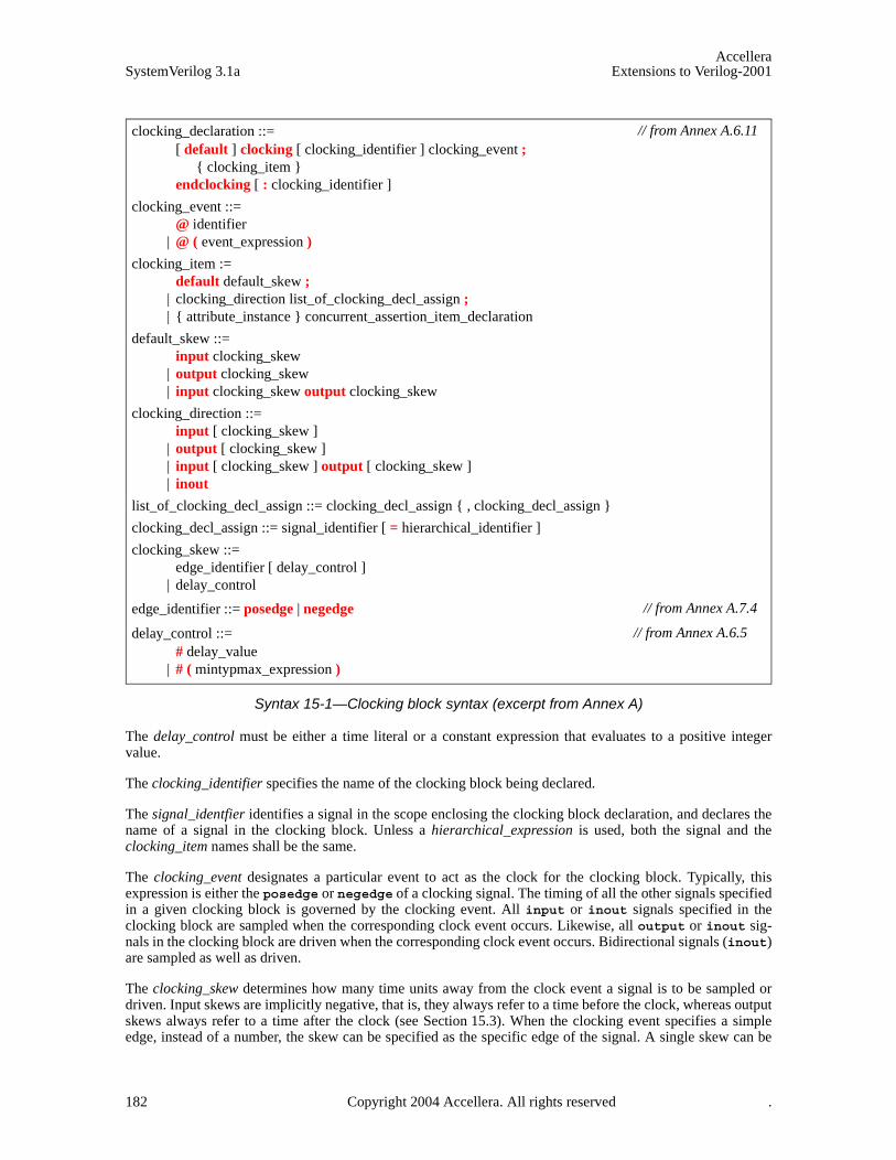
AccelleraSystemVerilog 3.1a Extensions to Verilog-2001
Syntax 15-1—Clocking block syntax (excerpt from Annex A)
The delay_control must be either a time literal or a constant expression that evaluates to a positive integervalue.
The clocking_identifier specifies the name of the clocking block being declared.
The signal_identfier identifies a signal in the scope enclosing the clocking block declaration, and declares thename of a signal in the clocking block. Unless a hierarchical_expression is used, both the signal and theclocking_item names shall be the same.
The clocking_event designates a particular event to act as the clock for the clocking block. Typically, thisexpression is either the posedge or negedge of a clocking signal. The timing of all the other signals specifiedin a given clocking block is governed by the clocking event. All input or inout signals specified in theclocking block are sampled when the corresponding clock event occurs. Likewise, all output or inout sig-nals in the clocking block are driven when the corresponding clock event occurs. Bidirectional signals (inout)are sampled as well as driven.
The clocking_skew determines how many time units away from the clock event a signal is to be sampled ordriven. Input skews are implicitly negative, that is, they always refer to a time before the clock, whereas outputskews always refer to a time after the clock (see Section 15.3). When the clocking event specifies a simpleedge, instead of a number, the skew can be specified as the specific edge of the signal. A single skew can be
clocking_declaration ::= [ default ] clocking [ clocking_identifier ] clocking_event ;
{ clocking_item } endclocking [ : clocking_identifier ]
clocking_event ::= @ identifier
| @ ( event_expression )
clocking_item := default default_skew ;
| clocking_direction list_of_clocking_decl_assign ; | { attribute_instance } concurrent_assertion_item_declaration
default_skew ::= input clocking_skew
| output clocking_skew | input clocking_skew output clocking_skew
clocking_direction ::= input [ clocking_skew ]
| output [ clocking_skew ] | input [ clocking_skew ] output [ clocking_skew ] | inout
list_of_clocking_decl_assign ::= clocking_decl_assign { , clocking_decl_assign }
clocking_decl_assign ::= signal_identifier [ = hierarchical_identifier ]
clocking_skew ::= edge_identifier [ delay_control ]
| delay_control
edge_identifier ::= posedge | negedge
delay_control ::= # delay_value
| # ( mintypmax_expression )
// from Annex A.6.11
// from Annex A.7.4
// from Annex A.6.5
182 Copyright 2004 Accellera. All rights reserved .
AccelleraExtensions to Verilog-2001 SystemVerilog 3.1a
specified for the entire block by using a default clocking item.
clocking ck1 @(posedge clk); default input #1step output negedge; // legal // outputs driven on the negedge clkinput ... ;output ... ;
endclocking
clocking ck2 @(clk); // no edge specified!default input #1step output negedge; // legalinput ... ;output ... ;
endclocking
The hierarchical_identifier specifies that, instead of a local port, the signal to be associated with the clockingblock is specified by its hierarchical name (cross-module reference).
Example:
clocking bus @(posedge clock1);default input #10ns output #2ns; input data, ready, enable = top.mem1.enable;output negedge ack;input #1step addr;
endclocking
In the above example, the first line declares a clocking block called bus that is to be clocked on the positiveedge of the signal clock1. The second line specifies that by default all signals in the clocking block shall usea 10ns input skew and a 2ns output skew. The next line adds three input signals to the clocking block: data,ready, and enable; the last signal refers to the hierarchical signal top.mem1.enable. The fourth line addsthe signal ack to the clocking block, and overrides the default output skew so that ack is driven on the nega-tive edge of the clock. The last line adds the signal addr and overrides the default input skew so that addr issampled one step before the positive edge of the clock.
Unless otherwise specified, the default input skew is 1step and the default output skew is 0. A step is aspecial time unit whose value is defined in Section 18.10. A 1step input skew allows input signals to sampletheir steady-state values in the time step immediately before the clock event (i.e., in the preceding Postponedregion). Unlike other time units, which represent physical units, a step cannot be used to set or modify eitherthe precision or the timeunit.
15.3 Input and output skews
Input (or inout) signals are sampled at the designated clock event. If an input skew is specified then the signalis sampled at skew time units before the clock event. Similarly, output (or inout) signals are driven skew simu-lation time units after the corresponding clock event. Figure 15-1 shows the basic sample/drive timing for apositive edge clock.
Copyright 2004 Accellera. All rights reserved. 183
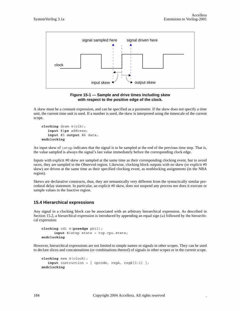
AccelleraSystemVerilog 3.1a Extensions to Verilog-2001
Figure 15-1 — Sample and drive times including skewwith respect to the positive edge of the clock.
A skew must be a constant expression, and can be specified as a parameter. If the skew does not specify a timeunit, the current time unit is used. If a number is used, the skew is interpreted using the timescale of the currentscope.
clocking dram @(clk);input #1ps address;input #5 output #6 data;
endclocking
An input skew of 1step indicates that the signal is to be sampled at the end of the previous time step. That is,the value sampled is always the signal’s last value immediately before the corresponding clock edge.
Inputs with explicit #0 skew are sampled at the same time as their corresponding clocking event, but to avoidraces, they are sampled in the Observed region. Likewise, clocking block outputs with no skew (or explicit #0skew) are driven at the same time as their specified clocking event, as nonblocking assignments (in the NBAregion).
Skews are declarative constructs, thus, they are semantically very different from the syntactically similar pro-cedural delay statement. In particular, an explicit #0 skew, does not suspend any process nor does it execute orsample values in the Inactive region.
15.4 Hierarchical expressions
Any signal in a clocking block can be associated with an arbitrary hierarchical expression. As described inSection 15.2, a hierarchical expression is introduced by appending an equal sign (=) followed by the hierarchi-cal expression:
clocking cd1 @(posedge phi1);input #1step state = top.cpu.state;
endclocking
However, hierarchical expressions are not limited to simple names or signals in other scopes. They can be usedto declare slices and concatenations (or combinations thereof) of signals in other scopes or in the current scope.
clocking mem @(clock);input instruction = { opcode, regA, regB[3:1] };
endclocking
output skewinput skew
clock
signal sampled here signal driven here
184 Copyright 2004 Accellera. All rights reserved .

AccelleraExtensions to Verilog-2001 SystemVerilog 3.1a
15.5 Signals in multiple clocking blocks
The same signals—clock, inputs, inouts, or outputs—can appear in more than one clocking block. Clockingblocks that use the same clock (or clocking expression) shall share the same synchronization event, in the samemanner as several latches can be controlled by the same clock. Input semantics are described in Section 15.12,and output semantics are described in Section 15.14.
15.6 Clocking block scope and lifetime
A clocking block is both a declaration and an instance of that declaration. A separate instantiation step is notnecessary. Instead, one copy is created for each instance of the block containing the declaration (like an alwaysblock). Once declared, the clocking signals are available via the clocking block name and the dot (.) operator:
dom.sig // signal sig in clocking dom
Clocking blocks cannot be nested. They cannot be declared inside functions, tasks, packages, or outside alldeclarations in a compilation unit. Clocking blocks can only be declared inside a module, interface or program(see Section 16).
Clocking blocks have static lifetime and scope local to their enclosing module, interface or program.
15.7 Multiple clocking blocks example
In this example, a simple test program includes two clocking blocks. The program construct used in this exam-ple is discussed in Section 16.
program test( input phi1, input [15:0] data, output logic write,input phi2, inout [8:1] cmd, input enable
);reg [8:1] cmd_reg;
clocking cd1 @(posedge phi1);input data;output write;input state = top.cpu.state;
endclocking
clocking cd2 @(posedge phi2);input #2 output #4ps cmd;input enable;
endclocking
initial begin // program begins here
...// user can access cd1.data , cd2.cmd , etc…
end assign cmd = enable ? cmd_reg: 'x;
endprogram
The test program can be instantiated and connected to a device under test (cpu and mem).
module top;logic phi1, phi2;wire [8:1] cmd; // cannot be logic (two bidirectional drivers)logic [15:0] data;
Copyright 2004 Accellera. All rights reserved. 185

AccelleraSystemVerilog 3.1a Extensions to Verilog-2001
test main( phi1, data, write, phi2, cmd, enable );cpu cpu1( phi1, data, write );mem mem1( phi2, cmd, enable );
endmodule
15.8 Interfaces and clocking blocks
A clocking encapsulates a set of signals that share a common clock, therefore, specifying a clocking blockusing a SystemVerilog interface can significantly reduce the amount of code needed to connect the test-bench. Furthermore, since the signal directions in the clocking block within the testbench are with respect tothe testbench, and not the design under test, a modport declaration can appropriately describe either direction.A testbench program can be contained within a program and its ports can be interfaces that correspond to thesignals declared in each clocking block. The interface’s wires shall have the same direction as specified in theclocking block when viewed from the testbench side (i.e., modport test), and reversed when viewed fromthe device under test (i.e., modport dut).
For example, the previous example could be re-written using interfaces as follows:
interface bus_A (input clk);logic [15:0] data;logic write;modport test (input data, output write);modport dut (output data, input write);
endinterface
interface bus_B (input clk);logic [8:1] cmd;logic enable;modport test (input enable);modport dut (output enable);
endinterface
program test( bus_A.test a, bus_B.test b );
clocking cd1 @(posedge a.clk);input a.data;output a.write;inout state = top.cpu.state;
endclocking
clocking cd2 @(posedge b.clk);input #2 output #4ps b.cmd;input b.enable;
endclocking
initial begin // program begins here...// user can access cd1.a.data , cd2.b.cmd , etc…
end endprogram
The test module can be instantiated and connected as before:
module top;logic phi1, phi2;
186 Copyright 2004 Accellera. All rights reserved .

AccelleraExtensions to Verilog-2001 SystemVerilog 3.1a
bus_A a(phi1);bus_B b(phi2);
test main( a, b );cpu cpu1( a );mem mem1( b );
endmodule
Alternatively, in the program test above, the clocking block can be written using both interfaces and hierarchi-cal expressions as:
clocking cd1 @(posedge a.clk);input data = a.data;output write = a.write;inout state = top.cpu.state;
endclocking
clocking cd2 @(posedge b.clk);input #2 output #4ps cmd = b.cmd;input enable = b.enable;
endclocking
This would allow using the shorter names (cd1.data, cd2.cmd, …) instead of the longer interface syntax(cd1.a.data, cd2.b.cmd,…).
15.9 Clocking block events
The clocking event of a clocking block is available directly by using the clocking block name, regardless of theactual clocking event used to declare the clocking block.
For example.
clocking dram @(posedge phi1);inout data;output negedge #1 address;
endclocking
The clocking event of the dram clocking block can be used to wait for that particular event:
@( dram );
The above statement is equivalent to @(posedge phi1).
15.10 Cycle delay: ##
The ## operator can be used to delay execution by a specified number of clocking events, or clock cycles.
The syntax for the cycle delay statement is:
Copyright 2004 Accellera. All rights reserved. 187

AccelleraSystemVerilog 3.1a Extensions to Verilog-2001
Syntax 15-2—Cycle delay syntax (excerpt from Annex A)
The expression can be any SystemVerilog expression that evaluates to a positive integer value.
What constitutes a cycle is determined by the default clocking in effect (see Section 15.11). If no default clock-ing has been specified for the current module, interface, or program then the compiler shall issue an error.
Example:
## 5; // wait 5 cycles (clocking events) using the default clocking
## (j + 1); // wait j+1 cycles (clocking events) using the default clocking
15.11 Default clocking
One clocking can be specified as the default for all cycle delay operations within a given module, inter-face, or program.
The syntax for the default cycle specification statement is:
Syntax 15-3—Default clocking syntax (excerpt from Annex A)
The clocking_identifier must be the name of a clocking block.
Only one default clocking can be specified in a program, module, or interface. Specifying a default clockingmore than once in the same program or module shall result in a compiler error.
A default clocking is valid only within the scope containing the default clocking specification. This scopeincludes the module, interface, or program that contains the declaration as well as any nested modules or inter-faces. It does not include instantiated modules or interfaces.
Example 1. Declaring a clocking as the default:
program test( input bit clk, input reg [15:0] data ); default clocking bus @(posedge clk);
procedural_timing_control_statement ::= procedural_timing_control statement_or_null
procedural_timing_control ::= ...
| cycle_delay
cycle_delay ::= ## integral_number
| ## identifier | ## ( expression )
// from Annex A.6.5
// from Annex A.6.11
module_or_generate_item_declaration ::= ...
| default clocking clocking_identifier ;
clocking_declaration ::= [ default ] clocking [ clocking_identifier ] clocking_event ;
{ clocking_item } endclocking [ : clocking_identifier ]
// from Annex A.1.5
// from Annex A.6.11
188 Copyright 2004 Accellera. All rights reserved .
AccelleraExtensions to Verilog-2001 SystemVerilog 3.1a
inout data;endclocking
initial begin ## 5;if ( bus.data == 10 )
## 1;else
...end
endprogram
Example 2. Assigning an existing clocking to be the default:
module processor ... clocking busA @(posedge clk1); ... endclocking clocking busB @(negedge clk2); ... endclocking module cpu( interface y );
default clocking busA ;initial begin
## 5; // use busA => (posedge clk1)...
end endmodule
endmodule
15.12 Input sampling
All clocking block inputs (input or inout) are sampled at the corresponding clocking event. If the input skew isnot an explicit #0, then the value sampled corresponds to the signal value at the Postponed region of the timestep skew time-units prior to the clocking event (see Figure 15-1 in Section 15.3). If the input skew is anexplicit #0, then the value sampled corresponds to the signal value in the Observed region.
Samples happen immediately (the calling process does not block). When a signal appears in an expression, it isreplaced by the signal’s sampled value, that is, the value that was sampled at the last sampling point.
When the same signal is an input to multiple clocking blocks, the semantics are straightforward; each clockingblock samples the corresponding signal with its own clocking event.
15.13 Synchronous events
Explicit synchronization is done via the event control operator, @, which allows a process to wait for a particu-lar signal value change, or a clocking event (see Section 15.9).
The syntax for the synchronization operator is given in Section 8.10.
The expression used with the event control can denote clocking block input (input or inout), or a slicethereof. Slices can include dynamic indices, which are evaluated once, when the @ expression executes.
These are some example synchronization statements:
— Wait for the next change of signal ack_1 of clocking block ram_bus
@(ram_bus.ack_l);
— Wait for the next clocking event in clocking block ram_bus
Copyright 2004 Accellera. All rights reserved. 189
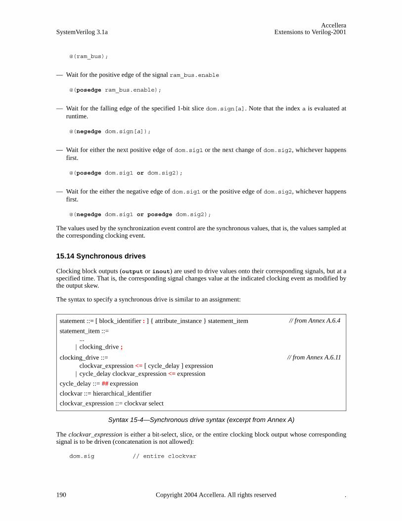
AccelleraSystemVerilog 3.1a Extensions to Verilog-2001
@(ram_bus);
— Wait for the positive edge of the signal ram_bus.enable
@(posedge ram_bus.enable);
— Wait for the falling edge of the specified 1-bit slice dom.sign[a]. Note that the index a is evaluated atruntime.
@(negedge dom.sign[a]);
— Wait for either the next positive edge of dom.sig1 or the next change of dom.sig2, whichever happensfirst.
@(posedge dom.sig1 or dom.sig2);
— Wait for the either the negative edge of dom.sig1 or the positive edge of dom.sig2, whichever happensfirst.
@(negedge dom.sig1 or posedge dom.sig2);
The values used by the synchronization event control are the synchronous values, that is, the values sampled atthe corresponding clocking event.
15.14 Synchronous drives
Clocking block outputs (output or inout) are used to drive values onto their corresponding signals, but at aspecified time. That is, the corresponding signal changes value at the indicated clocking event as modified bythe output skew.
The syntax to specify a synchronous drive is similar to an assignment:
Syntax 15-4—Synchronous drive syntax (excerpt from Annex A)
The clockvar_expression is either a bit-select, slice, or the entire clocking block output whose correspondingsignal is to be driven (concatenation is not allowed):
dom.sig // entire clockvar
statement ::= [ block_identifier : ] { attribute_instance } statement_item
statement_item ::= ...
| clocking_drive ;
clocking_drive ::= clockvar_expression <= [ cycle_delay ] expression
| cycle_delay clockvar_expression <= expression
cycle_delay ::= ## expression
clockvar ::= hierarchical_identifier
clockvar_expression ::= clockvar select
// from Annex A.6.4
// from Annex A.6.11
190 Copyright 2004 Accellera. All rights reserved .
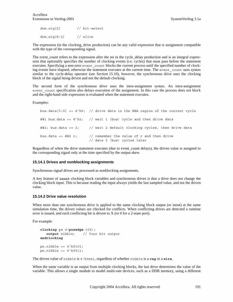
AccelleraExtensions to Verilog-2001 SystemVerilog 3.1a
dom.sig[2] // bit-select
dom.sig[8:2] // slice
The expression (in the clocking_drive production) can be any valid expression that is assignment compatiblewith the type of the corresponding signal.
The event_count refers to the expression after the ## in the cycle_delay production and is an integral expres-sion that optionally specifies the number of clocking events (i.e. cycles) that must pass before the statementexecutes. Specifying a non-zero event_count blocks the current process until the specified number of clock-ing events have elapsed, otherwise the statement executes at the current time. The event_count uses syntaxsimilar to the cycle-delay operator (see Section 15.10), however, the synchronous drive uses the clockingblock of the signal being driven and not the default clocking.
The second form of the synchronous drive uses the intra-assignment syntax. An intra-assignmentevent_count specification also delays execution of the assignment. In this case the process does not blockand the right-hand side expression is evaluated when the statement executes.
Examples:
bus.data[3:0] <= 4’h5; // drive data in the NBA region of the current cycle
##1 bus.data <= 8’hz; // wait 1 (bus) cycle and then drive data
##2; bus.data <= 2; // wait 2 default clocking cycles, then drive data
bus.data <= ##2 r; // remember the value of r and then drive // data 2 (bus) cycles later
Regardless of when the drive statement executes (due to event_count delays), the driven value is assigned tothe corresponding signal only at the time specified by the output skew.
15.14.1 Drives and nonblocking assignments
Synchronous signal drives are processed as nonblocking assignments.
A key feature of inout clocking block variables and synchronous drives is that a drive does not change theclocking block input. This is because reading the input always yields the last sampled value, and not the drivenvalue.
15.14.2 Drive value resolution
When more than one synchronous drive is applied to the same clocking block output (or inout) at the samesimulation time, the driven values are checked for conflicts. When conflicting drives are detected a runtimeerror is issued, and each conflicting bit is driven to X (or 0 for a 2-state port).
For example:
clocking pe @(posedge clk);output nibble; // four bit output
endclocking
pe.nibble <= 4’b0101;pe.nibble <= 4’b0011;
The driven value of nibble is 4’b0xx1, regardless of whether nibble is a reg or a wire.
When the same variable is an output from multiple clocking blocks, the last drive determines the value of thevariable. This allows a single module to model multi-rate devices, such as a DDR memory, using a different
Copyright 2004 Accellera. All rights reserved. 191

AccelleraSystemVerilog 3.1a Extensions to Verilog-2001
clocking block to model each active edge. For example:
reg j;
clocking pe @(posedge clk);output j;
endclocking
clocking ne @(negedge clk);output j;
endclocking
The variable j is an output to two clocking blocks using different clocking events (posedge vs. negedge).When driven, the variable j shall take on the value most recently assigned by either clocking block.
Clocking block outputs driving a net (i.e. through different ports) cause the net to be driven to its resolved sig-nal value. When a clocking block output corresponds to a wire, a driver for that wire is created that is updatedas if by a continuous assignment from a register inside the clocking block that is updated as a nonblockingassignment.
192 Copyright 2004 Accellera. All rights reserved .
AccelleraExtensions to Verilog-2001 SystemVerilog 3.1a
Section 16Program Block
16.1 Introduction (informative)
The module is the basic building block in Verilog. Modules can contain hierarchies of other modules, wires,task and function declarations, and procedural statements within always and initial blocks. This constructworks extremely well for the description of hardware. However, for the testbench, the emphasis is not in thehardware-level details such as wires, structural hierarchy, and interconnects, but in modeling the completeenvironment in which a design is verified. A lot of effort is spent getting the environment properly initializedand synchronized, avoiding races between the design and the testbench, automating the generation of inputstimuli, and reusing existing models and other infrastructure.
The program block serves three basic purposes:
1) It provides an entry point to the execution of testbenches.
2) It creates a scope that encapsulates program-wide data.
3) It provides a syntactic context that specifies scheduling in the Reactive region.
The program construct serves as a clear separator between design and testbench, and, more importantly, itspecifies specialized execution semantics in the Reactive region for all elements declared within the program.Together with clocking blocks, the program construct provides for race-free interaction between the design andthe testbench, and enables cycle and transaction level abstractions.
The abstraction and modeling constructs of SystemVerilog simplify the creation and maintenance of test-benches. The ability to instantiate and individually connect each program instance enables their use as general-ized models.
16.2 The program construct
A typical program contains type and data declarations, subroutines, connections to the design, and one or moreprocedural code streams. The connection between design and testbench uses the same interconnect mechanismas used by SystemVerilog to specify port connections, including interfaces. The syntax for the program blockis:
Copyright 2004 Accellera. All rights reserved. 193
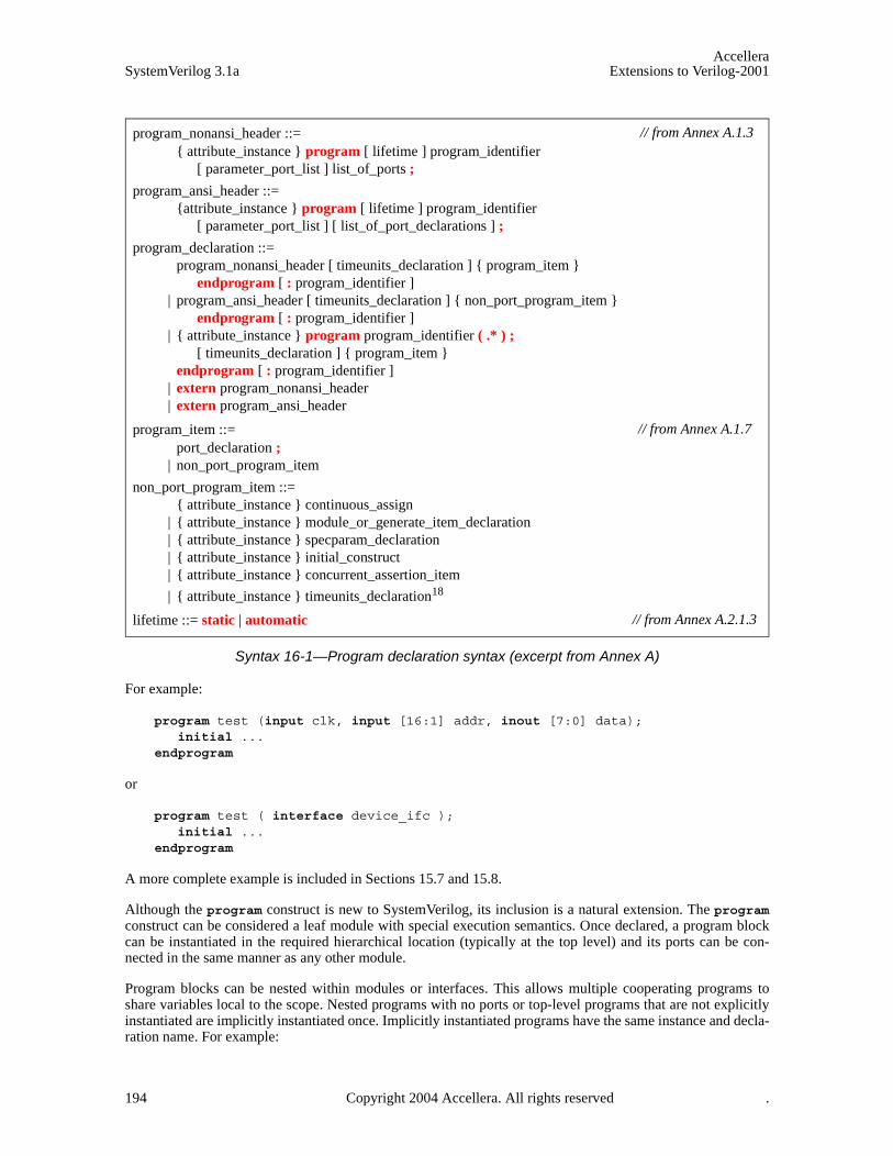
AccelleraSystemVerilog 3.1a Extensions to Verilog-2001
Syntax 16-1—Program declaration syntax (excerpt from Annex A)
For example:
program test (input clk, input [16:1] addr, inout [7:0] data);initial ...
endprogram
or
program test ( interface device_ifc );initial ...
endprogram
A more complete example is included in Sections 15.7 and 15.8.
Although the program construct is new to SystemVerilog, its inclusion is a natural extension. The programconstruct can be considered a leaf module with special execution semantics. Once declared, a program blockcan be instantiated in the required hierarchical location (typically at the top level) and its ports can be con-nected in the same manner as any other module.
Program blocks can be nested within modules or interfaces. This allows multiple cooperating programs toshare variables local to the scope. Nested programs with no ports or top-level programs that are not explicitlyinstantiated are implicitly instantiated once. Implicitly instantiated programs have the same instance and decla-ration name. For example:
program_nonansi_header ::= { attribute_instance } program [ lifetime ] program_identifier
[ parameter_port_list ] list_of_ports ;
program_ansi_header ::= {attribute_instance } program [ lifetime ] program_identifier
[ parameter_port_list ] [ list_of_port_declarations ] ;
program_declaration ::= program_nonansi_header [ timeunits_declaration ] { program_item }
endprogram [ : program_identifier ] | program_ansi_header [ timeunits_declaration ] { non_port_program_item }
endprogram [ : program_identifier ] | { attribute_instance } program program_identifier ( .* ) ;
[ timeunits_declaration ] { program_item } endprogram [ : program_identifier ]
| extern program_nonansi_header | extern program_ansi_header
program_item ::= port_declaration ;
| non_port_program_item
non_port_program_item ::= { attribute_instance } continuous_assign
| { attribute_instance } module_or_generate_item_declaration | { attribute_instance } specparam_declaration | { attribute_instance } initial_construct | { attribute_instance } concurrent_assertion_item
| { attribute_instance } timeunits_declaration18
lifetime ::= static | automatic
// from Annex A.1.3
// from Annex A.1.7
// from Annex A.2.1.3
194 Copyright 2004 Accellera. All rights reserved .

AccelleraExtensions to Verilog-2001 SystemVerilog 3.1a
module test(...)int shared; // variable shared by programs p1 and p1
program p1;...
endprogram
program p2;...
endprogram // p1 and p2 are implicitly instantiated once in module test
endmodule
A program block can contain one or more initial blocks. It cannot contain always blocks, UDPs, modules,interfaces, or other programs.
Type and data declarations within the program are local to the program scope and have static lifetime. Programvariables can only be assigned using blocking assignments. Non-program variables can only be assigned usingnonblocking assignments. Using nonblocking assignments with program variables or blocking assignmentswith design (non-program) variables shall be an error. References to program variables from outside any pro-gram block shall be an error.
16.3 Multiple programs
It is allowed to have any arbitrary number of program definitions or instances. The programs can be fully inde-pendent (without inter-program communication), or cooperative. The degree of communication can be con-trolled by choosing to share data using nested blocks, packages, or hierarchical references, or making the dataprivate by declaring it inside the corresponding program block.
16.4 Eliminating testbench races
There are two major sources of non-determinism in Verilog. The first one is that active events are processed inan arbitrary order. The second one is that statements without time-control constructs in behavioral blocks donot execute as one event. However, from the testbench perspective, these effects are all unimportant details.The primary task of a testbench is to generate valid input stimulus for the design under test, and to verify thatthe device operates correctly. Furthermore, testbenches that use cycle abstractions are only concerned with thestable or steady state of the system for both checking the current outputs and for computing stimuli for the nextcycle. Formal tools also work in this fashion.
Statements within a program block that are sensitive to changes (e.g., update events) in design signals(declared in modules, not program blocks) are scheduled in the Reactive region. Consider a program block thatcontains the statement @(clk) S1; where clk is a design signal in some module. Every transition of signalclk will cause the statement S1 to be scheduled into the Reactive region. Likewise, initial blocks within pro-gram blocks are scheduled in the Reactive region; in contrast, initial blocks in modules are scheduled in theActive region. In addition, design signals driven from within the program must be assigned using nonblockingassignments and are updated in the NBA region. Thus, even signals driven with no delay are propagated intothe design as one event. With this behavior, correct cycle semantics can be modeled without races; therebymaking program-based testbenches compatible with clocked assertions and formal tools.
Since the program schedules events in the Reactive region, the clocking block construct is very useful to auto-matically sample the steady-state values of previous time steps or clock cycles. Programs that read design val-ues exclusively through clocking blocks with #0 input skews are insensitive to read-write races. It is importantto note that simply sampling input signals (or setting non-zero skews on clocking block inputs) does not elimi-nate the potential for races. Proper input sampling only addresses a single clocking block. With multipleclocks, the arbitrary order in which overlapping or simultaneous clocks are processed is still a potential sourcefor races. The program construct addresses this issue by scheduling its execution in the Reactive region, after
Copyright 2004 Accellera. All rights reserved. 195
AccelleraSystemVerilog 3.1a Extensions to Verilog-2001
all design events have been processed, including clocks driven by nonblocking assignments.
16.4.1 Zero-skew clocking block races
When a clocking block sets both input and output skews to #0 (see Section 15.3) then its inputs are sampled(in the observed region) at the same time as its outputs are driven (in the NBA region). This type of explicit #0delay processing is a common source of non-determinism that can result in races. Nonetheless, even in thiscase, the program minimizes races by means of two mechanisms. First, by constraining program statements tobe scheduled in the Reactive region, after all explicit #0 delay transitions have propagated through the designand the system has reached a quasi steady state. Second, by requiring design variables or nets to be modifiedonly via nonblocking assignments. These two mechanisms reduce the likelihood of a race; nonetheless, a raceis still possible when skews are set to explicit #0 .
16.5 Blocking tasks in cycle/event mode
Calling program tasks or functions from within design modules is illegal and shall result in an error. This isbecause the design must not be aware of the testbench. Programs are allowed to call tasks or functions in otherprograms or within design modules. Functions within design modules can be called from a program, andrequire no special handling. However, blocking tasks (a task that does not execute in 0 simulation time) withindesign modules that are called from a program do require explicit synchronization upon return from the task.That is, when blocking tasks return to the program code, the program block execution is automatically post-poned until the Reactive region. The copy out of the parameters happens when the task returns.
Calling blocking tasks in design modules from within programs requires careful consideration. Expressionsevaluated by the task before blocking on the first timing control shall use the values after they have beenupdated by nonblocking assignments. In contrast, if the task is called from a module at the start of the time step(before nonblocking assignments are processed) then those same expressions shall use the values before theyhave been updated by nonblocking assignments.
module ...task T;
S1: a = b; // might execute before or after the Observe region#5;S2: b <= 1’b1; // always executes before the Observe region
endtask endmodule
If task T, above, is called from within a module, then the statement S1 can execute immediately when theActive region is processed, before variable b is updated by a nonblocking assignment. If the same task is calledfrom within a program, then the statement S1 shall execute when the Reactive region is processed, after vari-able b might have been updated by nonblocking assignments. Statement S2 always executes immediately afterthe delay expires; it does not wait for the Reactive region even though it was originally called from the pro-gram block.
16.6 Program control tasks
In addition to the normal simulation control tasks ($stop and $finish), a program can use the $exit controltask.
16.6.1 $exit()
Each program can be explicitly exited by calling the $exit system task. When all programs exit (implicitly orexplicitly), the simulation finishes and an implicit call to $finish is made.
The syntax for the $exit system task is:
task $exit();
196 Copyright 2004 Accellera. All rights reserved .
AccelleraExtensions to Verilog-2001 SystemVerilog 3.1a
When all initial blocks in a program finish (i.e., they execute their last statement), the program implicitlycalls $exit. Calling $exit causes all processes spawned by the current program to be terminated.
Copyright 2004 Accellera. All rights reserved. 197
AccelleraSystemVerilog 3.1a Extensions to Verilog-2001
Section 17 Assertions
17.1 Introduction (informative)
SystemVerilog adds features to specify assertions of a system. An assertion specifies a behavior of the system.Assertions are primarily used to validate the behavior of a design. In addition, assertions can be used to pro-vide functional coverage and generate input stimulus for validation.
There are two kinds of assertions: concurrent and immediate.
— Immediate assertions follow simulation event semantics for their execution and are executed like a state-ment in a procedural block. Immediate assertions are primarily intended to be used with simulation.
— Concurrent assertions are based on clock semantics and use sampled values of variables. One of the goalsof SystemVerilog assertions is to provide a common semantic meaning for assertions so that they can beused to drive various design and verification tools. Many tools, such as formal verification tools, evaluatecircuit descriptions using cycle-based semantics, which typically relies on a clock signal or signals to drivethe evaluation of the circuit. Any timing or event behavior between clock edges is abstracted away. Con-current assertions incorporate these clock semantics. While this approach generally simplifies the evalua-tion of a circuit description, there are a number of scenarios under which this cycle-based evaluationprovides different behavior from the standard event-based evaluation of SystemVerilog.
This section describes both types of assertions.
17.2 Immediate assertions
The immediate assertion statement is a test of an expression performed when the statement is executed in theprocedural code. The expression is non-temporal and is interpreted the same way as an expression in the con-dition of a procedural if statement. That is, if the expression evaluates to X, Z or 0, then it is interpreted asbeing false and the assertion is said to fail. Otherwise, the expression is interpreted as being true and the asser-tion is said to pass.
The immediate assert statement is a statement_item and can be specified anywhere a procedural statement isspecified.
Syntax 17-1—Immediate assertion syntax (excerpt from Annex A)
The action_block specifies what actions are taken upon success or failure of the assertion. The statement asso-ciated with the success of the assert statement is the first statement. It is called the pass statement and is exe-cuted if the expression evaluates to true. The pass statement can, for example, record the number of successesfor a coverage log, but can be omitted altogether. If the pass statement is omitted, then no user-specified actionis taken when the assert expression is true. The statement associated with else is called a fail statement and isexecuted if the expression evaluates to false. The else statement can also be omitted. The action block is exe-cuted immediately after the evaluation of the assert expression.
procedural_assertion_statement ::= ... | immediate_assert_statement
immediate_assert_statement ::= assert ( expression ) action_block
action_block ::= statement _or_null
| [ statement ] else statement
// from Annex A.6.10
// from Annex A.6.3
198 Copyright 2004 Accellera. All rights reserved .

AccelleraExtensions to Verilog-2001 SystemVerilog 3.1a
The optional statement label (identifier and colon) creates a named block around the assertion statement (orany other SystemVerilog statement) and can be displayed using the %m format specification.
assert_foo : assert(foo) $display("%m passed"); else $display("%m failed");
Note: The assertion control system tasks are described in Section 23.9.
Since the assertion is a statement that something must be true, the failure of an assertion shall have a severityassociated with it. By default, the severity of an assertion failure is error. Other severity levels can be specifiedby including one of the following severity system tasks in the fail statement:
— $fatal is a run-time fatal.
— $error is a run-time error.
— $warning is a run-time warning, which can be suppressed in a tool-specific manner.
— $info indicates that the assertion failure carries no specific severity.
The syntax for these system tasks is shown in Section 23.8.
If an assertion fails and no else clause is specified, the tool shall, by default, call $error, unless a tool-spe-cific option, such as a command-line option, is enabled to suppress the failure.
All of these severity system tasks shall print a tool-specific message indicating the severity of the failure, andspecific information about the specific failure, which shall include the following information:
— The file name and line number of the assertion statement.
— The hierarchical name of the assertion, if it is labeled, or the scope of the assertion if it is not labeled.
For simulation tools, these tasks shall also include the simulation run-time at which the severity system task iscalled.
Each system task can also include additional user-specified information using the same format as the Verilog$display.
If more than one of these system tasks is included in the else clause, then each shall be executed as specified.
If the severity system task is executed at a time other than when the assertion fails, the actual failure time of theassertion can be recorded and displayed programmatically. For example:
time t;
always @(posedge clk)if (state == REQ)
assert (req1 || req2)else begin
t = $time;#5 $error("assert failed at time %0t",t);
end
If the assertion fails at time 10, the error message shall be printed at time 15, but the user-defined string printedshall be “assert failed at time 10”.
The display of messages of warning and info types can be controlled by a tool-specific option, such as a com-mand-line option.
Since the fail statement, like the pass statement, is any legal SystemVerilog procedural statement, it can also beused to signal a failure to another part of the testbench.
assert (myfunc(a,b)) count1 = count + 1; else ->event1;
Copyright 2004 Accellera. All rights reserved. 199
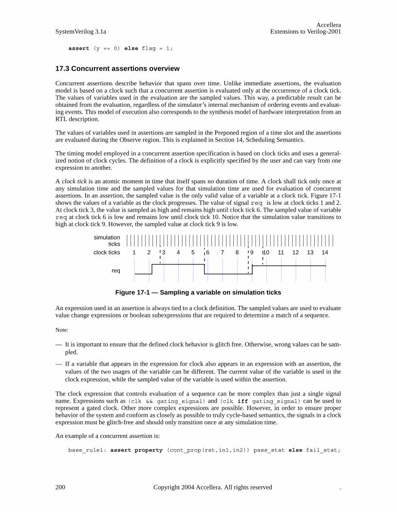
AccelleraSystemVerilog 3.1a Extensions to Verilog-2001
assert (y == 0) else flag = 1;
17.3 Concurrent assertions overview
Concurrent assertions describe behavior that spans over time. Unlike immediate assertions, the evaluationmodel is based on a clock such that a concurrent assertion is evaluated only at the occurrence of a clock tick.The values of variables used in the evaluation are the sampled values. This way, a predictable result can beobtained from the evaluation, regardless of the simulator’s internal mechanism of ordering events and evaluat-ing events. This model of execution also corresponds to the synthesis model of hardware interpretation from anRTL description.
The values of variables used in assertions are sampled in the Preponed region of a time slot and the assertionsare evaluated during the Observe region. This is explained in Section 14, Scheduling Semantics.
The timing model employed in a concurrent assertion specification is based on clock ticks and uses a general-ized notion of clock cycles. The definition of a clock is explicitly specified by the user and can vary from oneexpression to another.
A clock tick is an atomic moment in time that itself spans no duration of time. A clock shall tick only once atany simulation time and the sampled values for that simulation time are used for evaluation of concurrentassertions. In an assertion, the sampled value is the only valid value of a variable at a clock tick. Figure 17-1shows the values of a variable as the clock progresses. The value of signal req is low at clock ticks 1 and 2.At clock tick 3, the value is sampled as high and remains high until clock tick 6. The sampled value of variablereq at clock tick 6 is low and remains low until clock tick 10. Notice that the simulation value transitions tohigh at clock tick 9. However, the sampled value at clock tick 9 is low.
Figure 17-1 — Sampling a variable on simulation ticks
An expression used in an assertion is always tied to a clock definition. The sampled values are used to evaluatevalue change expressions or boolean subexpressions that are required to determine a match of a sequence.
Note:
— It is important to ensure that the defined clock behavior is glitch free. Otherwise, wrong values can be sam-pled.
— If a variable that appears in the expression for clock also appears in an expression with an assertion, thevalues of the two usages of the variable can be different. The current value of the variable is used in theclock expression, while the sampled value of the variable is used within the assertion.
The clock expression that controls evaluation of a sequence can be more complex than just a single signalname. Expressions such as (clk && gating_signal) and (clk iff gating_signal) can be used torepresent a gated clock. Other more complex expressions are possible. However, in order to ensure properbehavior of the system and conform as closely as possible to truly cycle-based semantics, the signals in a clockexpression must be glitch-free and should only transition once at any simulation time.
An example of a concurrent assertion is:
base_rule1: assert property (cont_prop(rst,in1,in2)) pass_stat else fail_stat;
1 2 3 4 5 6 7 8 9 10 11 12 13 14clock ticks
req
simulationticks
200 Copyright 2004 Accellera. All rights reserved .
AccelleraExtensions to Verilog-2001 SystemVerilog 3.1a
The keyword property distinguishes a concurrent assertion from an immediate assertion. The syntax of con-current assertions is discussed in 17.13.
17.4 Boolean expressions
The expressions used in sequences are evaluated over sampled values of the variables that appear in theexpressions. The outcome of the evaluation of an expression is boolean and is interpreted the same way as anexpression is interpreted in the condition of a procedural if statement. That is, if the expression evaluates to X,Z, or 0, then it is interpreted as being false. Otherwise, it is true.
There are certain restrictions on the expressions that can appear in concurrent assertions. The restrictions onoperand types, variables, and operators are specified in the following sections.
Expressions are allowed to include function calls, but certain semantic restrictions are imposed.
— Functions that appear in expressions cannot contain output or ref arguments (const ref are allowed).
— Functions should be automatic (or preserve no state information) and have no side effects.
17.4.1 Operand types
The following types are not allowed:
— non-integer types (shortreal, real and realtime)
— string
— event
— chandle
— class
— associative arrays
— dynamic arrays
Fixed size arrays, packed or unpacked, can be used as a whole or as part selects or as indexed bit or partselects. The indices can be constants, parameters, or variables.
The following example shows some possible forms of comparison of members of structures and unions:
typedef int [4] array;typedef struct { int a, b, c,d } record;union { record r; array a; } p, q;
The following comparisons are legal in expressions:
p.a == q.a
and
p.r == q.r
The following example provides further illustration of the use of arrays in expressions.
logic [7:0] arrayA [0:15], arrayB[0:15];
The following comparisons are legal:
arrayA == arrayB;
Copyright 2004 Accellera. All rights reserved. 201

AccelleraSystemVerilog 3.1a Extensions to Verilog-2001
arrayA != arrayB;arrayA[i] >= arrayB[j]; arrayB[i][j+:2] == arrayA[k][m-:2];(arrayA[i] & (~arrayB[j])) == 0;
17.4.2 Variables
The variables that can appear in expressions must be static design variables or function calls returning valuesof types described in Section 17.4.1. Static variables declared in programs, interfaces or clocking blocks canalso be accessed. If a reference is to a static variable declared in a task, that variable is sampled as any othervariable, independent of calls to the task.
17.4.3 Operators
All operators that are valid for the types described in Section 17.4.1 are allowed with the exception of assign-ment operators and increment and decrement operators. SystemVerilog includes the C assignment operators,such as +=, and the C increment and decrement operators, ++ and --. These operators cannot be used in expres-sions that appear in assertions. This restriction prevents side effects.
202 Copyright 2004 Accellera. All rights reserved .

AccelleraExtensions to Verilog-2001 SystemVerilog 3.1a
17.5 Sequences
Syntax 17-2—Sequence syntax (excerpt from Annex A)
sequence_expr ::= cycle_delay_range sequence_expr { cycle_delay_range sequence_expr }
| sequence_expr cycle_delay_range sequence_expr { cycle_delay_range sequence_expr }| expression_or_dist [ boolean_abbrev ] | ( expression_or_dist {, sequence_match_item } ) [ boolean_abbrev ] | sequence_instance [ sequence_abbrev ] | ( sequence_expr {, sequence_match_item } ) [ sequence_abbrev ] | sequence_expr and sequence_expr | sequence_expr intersect sequence_expr | sequence_expr or sequence_expr | first_match ( sequence_expr {, sequence_match_item} ) | expression_or_dist throughout sequence_expr | sequence_expr within sequence_expr | clocking_event sequence_expr
cycle_delay_range ::= ## integral_number
| ## identifier | ## ( constant_expression ) | ## [ cycle_delay_const_range_expression ]
sequence_match_item ::= operator_assignment
| inc_or_dec_expression | subroutine_call
sequence_instance ::= ps_sequence_identifier [ ( [ actual_arg_list ] ) ]
actual_arg_list ::= actual_arg_expr { , actual_arg_expr }
| . formal_identifier ( actual_arg_expr ) { , . formal_identifier ( actual_arg_expr ) }
actual_arg_expr ::= event_expression
| $
boolean_abbrev ::= consecutive_repetition
| non_consecutive_repetition| goto_repetition
sequence_abbrev ::= consecutive_repetition
consecutive_repetition ::= [* const_or_range_expression ]
non_consecutive_repetition ::= [= const_or_range_expression ]
goto_repetition ::= [-> const_or_range_expression ]
const_or_range_expression ::= constant_expression
| cycle_delay_const_range_expression
cycle_delay_const_range_expression ::= constant_expression : constant_expression
| constant_expression : $
expression_or_dist ::= expression [ dist { dist_list } ]
// from Annex A.2.10
Copyright 2004 Accellera. All rights reserved. 203

AccelleraSystemVerilog 3.1a Extensions to Verilog-2001
Properties are often constructed out of sequential behaviors. The sequence feature provides the capability tobuild and manipulate sequential behaviors. The simplest sequential behaviors are linear. A linear sequence is afinite list of SystemVerilog boolean expressions in a linear order of increasing time. The linear sequence is saidto match along a finite interval of consecutive clock ticks provided the first boolean expression evaluates totrue at the first clock tick, the second boolean expression evaluates to true at the second clock tick, and soforth, up to and including the last boolean expression evaluating to true at the last clock tick. A single booleanexpression is an example of a simple linear sequence, and it matches at a single clock tick provided the bool-ean expression evaluates to true at that clock tick.
More complex sequential behaviors are described by SystemVerilog sequences. A sequence is a regularexpression over the SystemVerilog boolean expressions that concisely specifies a set of zero, finitely many, orinfinitely many linear sequences. If at least one of the linear sequences from this set matches along a finiteinterval of consecutive clock ticks, then the sequence is said to match along that interval.
A property may involve checking of one or more sequential behaviors beginning at various times. Anattempted evaluation of a sequence is a search for a match of the sequence beginning at a particular clock tick.To determine whether such a match exists, appropriate boolean expressions are evaluated beginning at the par-ticular clock tick and continuing at each successive clock tick until either a match is found or it is deduced thatno match can exist.
Sequences can be composed by concatenation, analogous to a concatenation of lists. The concatenation speci-fies a delay, using ##, from the end of the first sequence until the beginning of the second sequence.
The following is the syntax for sequence concatenation.
Syntax 17-3—Sequence concatenation syntax (excerpt from Annex A)
In this syntax:
— constant_expression is computed at compile time and must result in an integer value.
— constant_expression can only be 0 or greater.
— The $ token is used to indicate the end of simulation. For formal verification tools, $ is used to indicate afinite, unbounded, range.
— When a range is specified with two expressions, the second expression must be greater or equal to the firstexpression.
The context in which a sequence occurs determines when the sequence is evaluated. The first expression in asequence is checked at the first occurrence of the clock tick at or after the expression that triggered evaluationof the sequence. Each successive element (if any) in the sequence is checked at the next subsequent occurrenceof the clock.
A ## followed by a number or range specifies the delay from the current clock tick to the beginning of the
sequence_expr ::= cycle_delay_range sequence_expr { cycle_delay_range sequence_expr }
| sequence_expr cycle_delay_range sequence_expr { cycle_delay_range sequence_expr }...
cycle_delay_range ::= ## integral_number
| ## identifier | ## ( constant_expression ) | ## [ cycle_delay_const_range_expression ]
cycle_delay_const_range_expression ::= constant_expression : constant_expression
| constant_expression : $
// from Annex A.2.10
204 Copyright 2004 Accellera. All rights reserved .
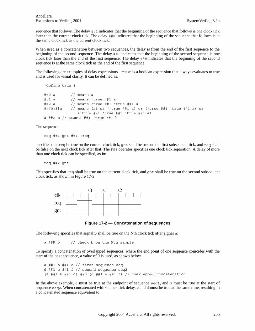
AccelleraExtensions to Verilog-2001 SystemVerilog 3.1a
sequence that follows. The delay ##1 indicates that the beginning of the sequence that follows is one clock ticklater than the current clock tick. The delay ##0 indicates that the beginning of the sequence that follows is atthe same clock tick as the current clock tick.
When used as a concatenation between two sequences, the delay is from the end of the first sequence to thebeginning of the second sequence. The delay ##1 indicates that the beginning of the second sequence is oneclock tick later than the end of the first sequence. The delay ##0 indicates that the beginning of the secondsequence is at the same clock tick as the end of the first sequence.
The following are examples of delay expressions. ‘true is a boolean expression that always evaluates to trueand is used for visual clarity. It can be defined as:
‘define true 1
##0 a // means a##1 a // means ‘true ##1 a ##2 a // means ‘true ##1 ‘true ##1 a##[0:3]a // means (a) or (‘true ##1 a) or (‘true ##1 ‘true ##1 a) or
(‘true ##1 ‘true ##1 ‘true ##1 a)a ##2 b // means a ##1 ‘true ##1 b
The sequence:
req ##1 gnt ##1 !req
specifies that req be true on the current clock tick, gnt shall be true on the first subsequent tick, and req shallbe false on the next clock tick after that. The ##1 operator specifies one clock tick separation. A delay of morethan one clock tick can be specified, as in:
req ##2 gnt
This specifies that req shall be true on the current clock tick, and gnt shall be true on the second subsequentclock tick, as shown in Figure 17-2.
Figure 17-2 — Concatenation of sequences
The following specifies that signal b shall be true on the Nth clock tick after signal a:
a ##N b // check b on the Nth sample
To specify a concatenation of overlapped sequences, where the end point of one sequence coincides with thestart of the next sequence, a value of 0 is used, as shown below.
a ##1 b ##1 c // first sequence seq1d ##1 e ##1 f // second sequence seq2(a ##1 b ##1 c) ##0 (d ##1 e ##1 f) // overlapped concatenation
In the above example, c must be true at the endpoint of sequence seq1, and d must be true at the start ofsequence seq2. When concatenated with 0 clock tick delay, c and d must be true at the same time, resulting ina concatenated sequence equivalent to:
clk
req
gnt
s0 s1 s2
Copyright 2004 Accellera. All rights reserved. 205

AccelleraSystemVerilog 3.1a Extensions to Verilog-2001
a ##1 b ##1 c&&d ##1 e ##1 f
It should be noted that no other form of overlapping between the sequences can be expressed using the concat-enation operation.
In cases where the delay can be any value in a range, a time window can be specified as follows:
req ##[4:32] gnt
In the above case, signal req must be true at the current clock tick, and signal gnt must be true at some clocktick between the 4th and the 32nd clock tick after the current clock tick.
The time window can extend to a finite, but unbounded, range by using $ as in the example below.
req ##[4:$] gnt
A sequence can be unconditionally extended by concatenation with ‘true.
a ##1 b ##1 c ##3 ‘true
After satisfying signal c, the sequence length is extended by 3 clock ticks. Such adjustments in the length ofsequences can be required when complex sequences are constructed by combining simpler sequences.
17.6 Declaring sequences
A sequence can be declared in
— a module
— an interface
— a program
— a clocking block
— a package
— a compilation-unit scope
Sequences are declared using the following syntax.:
206 Copyright 2004 Accellera. All rights reserved .

AccelleraExtensions to Verilog-2001 SystemVerilog 3.1a
Syntax 17-4—Declaring sequence syntax (excerpt from Annex A)
The clocking_event specifies the clock for the sequence.
A sequence is declared with optional formal arguments. When a sequence is instantiated, actual arguments canbe passed to the sequence. The sequence gets expanded with the actual arguments by replacing the formalarguments with the actual arguments. Semantic checks are performed to ensure that the expanded sequencewith the actual arguments is legal.
An actual argument can replace an:
— identifier
— expression
— event control expression
— upper range as $
Note that variables used in a sequence that are not formal arguments to the sequence are resolved according tothe scoping rules from the scope in which the sequence is declared.
sequence s1;@(posedge clk) a ##1 b ##1 c;
endsequence sequence s2;
@(posedge clk) d ##1 e ##1 f;endsequence sequence s3;
@(negedge clk) g ##1 h ##1 i;endsequence
In this example, sequences s1 and s2 are evaluated on successive posedge events of clk. The sequence s3 isevaluated on successive negedge events of clk.
Another example of sequence declaration, which includes arguments is shown below:
concurrent_assertion_item_declaration ::= ... | sequence_declaration
sequence_declaration ::= sequence sequence_identifier [ ( [ list_of_formals ] ) ] ;
{ assertion_variable_declaration } sequence_expr ;
endsequence [ : sequence_identifier ]
sequence_instance ::= ps_sequence_identifier [ ( [ actual_arg_list ] ) ]
actual_arg_list ::= actual_arg_expr { , actual_arg_expr }
| . formal_identifier ( actual_arg_expr ) { , . formal_identifier ( actual_arg_expr ) }
actual_arg_expr ::= event_expression
| $
assertion_variable_declaration ::= data_type list_of_variable_identifiers ;
// from Annex A.2.10
Copyright 2004 Accellera. All rights reserved. 207
AccelleraSystemVerilog 3.1a Extensions to Verilog-2001
sequence s20_1(data,en);(!frame && (data==data_bus)) ##1 (c_be[0:3] == en);
endsequence
Sequence s20_1 does not specify a clock. In this case, a clock would be inherited from some external source,such as a property or an assert statement. A sequence can be referred to by its name. A hierarchical namecan be used, consistent with the SystemVerilog naming conventions. A sequence can be referenced in a prop-erty, an assert statement, or a cover statement.
To use a named sequence as a subsequence of another sequence, simply reference its name. The evaluation ofa sequence that references a named sequence is performed in the same way as if the named sequence was con-tained as a lexical part of the referencing sequence, with the formal arguments of the named sequence replacedby the actual ones and the remaining variables in the named sequence resolved according to the scope of thedeclaration of the named sequence. An example is shown below:
sequence s;a ##1 b ##1 c;
endsequence sequence rule;
@(posedge sysclk)trans ##1 start_trans ##1 s ##1 end_trans;
endsequence
Sequence rule in the preceding example is equivalent to:
sequence rule;@(posedge sysclk) trans ##1 start_trans ##1 a ##1 b ##1 c ##1 end_trans ;
endsequence
Any form of syntactic cyclic dependency of the sequence names is disallowed. The example below illustratesan illegal dependency of s1 on s2 and s2 on s1, because it creates a cyclic dependency.
sequence s1;@(posedge sysclk) (x ##1 s2);
endsequence sequence s2;
@(posedge sysclk) (y ##1 s1);endsequence
17.7 Sequence operations
17.7.1 Operator precedence
Operator precedence and associativity are listed in Table 17-1, below. The highest precedence is listed first.
Table 17-1: Operator precedence and associativity
SystemVerilog expression operators Associativity
[* ] [= ] [-> ] ----
## left
throughout right
within left
208 Copyright 2004 Accellera. All rights reserved .
AccelleraExtensions to Verilog-2001 SystemVerilog 3.1a
17.7.2 Repetition in sequences
Following is the syntax for sequence repetition.
Syntax 17-5—Sequence repetition syntax (excerpt from Annex A)
The number of iterations of a repetition can either be specified by exact count or be required to fall within afinite range. If specified by exact count, then the number of iterations is defined by a non-negative integer con-stant expression. If required to fall within a finite range, then the minimum number of iterations is defined by anon-negative integer constant expression and the maximum number of iterations is either defined by a non-negative integer constant expression or is $, indicating a finite, but unbounded maximum.
If both the minimum and maximum numbers of iterations are defined by non-negative integer constant expres-sions, then the minimum number must be less than or equal to the maximum number.
Three kinds of repetition are provided:
— consecutive repetition ( [* ): Consecutive repetition specifies finitely many iterative matches of the oper-and sequence, with a delay of one clock tick from the end of one match to the beginning of the next. Theoverall repetition sequence matches at the end of the last iterative match of the operand.
— goto repetition ( [-> ): Goto repetition specifies finitely many iterative matches of the operand booleanexpression, with a delay of one or more clock ticks from one match of the operand to the next successive
intersect left
and left
or left
Table 17-1: Operator precedence and associativity
sequence_expr ::= ...| expression_or_dist [ boolean_abbrev ] | ( expression_or_dist {, sequence_match_item } ) [ boolean_abbrev ] | sequence_instance [ sequence_abbrev ] | ( sequence_expr {, sequence_match_item} ) [ sequence_abbrev ] ...
boolean_abbrev ::= consecutive_repetition
| non_consecutive_repetition| goto_repetition
sequence_abbrev ::= consecutive_repetition
consecutive_repetition ::= [* const_or_range_expression ]
non_consecutive_repetition ::= [= const_or_range_expression ]
goto_repetition ::= [-> const_or_range_expression ]
const_or_range_expression ::= constant_expression
| cycle_delay_const_range_expression
cycle_delay_const_range_expression ::= constant_expression : constant_expression
| constant_expression : $
// from Annex A.2.10
Copyright 2004 Accellera. All rights reserved. 209

AccelleraSystemVerilog 3.1a Extensions to Verilog-2001
match and no match of the operand strictly in between. The overall repetition sequence matches at the lastiterative match of the operand.
— non-consecutive repetition ( [= ): Non-consecutive repetition specifies finitely many iterative matches ofthe operand boolean expression, with a delay of one or more clock ticks from one match of the operand tothe next successive match and no match of the operand strictly in between. The overall repetition sequencematches at or after the last iterative match of the operand, but before any later match of the operand.
The effect of consecutive repetition of a subsequence within a sequence can be achieved by explicitly iteratingthe subsequence, as:
a ##1 b ##1 b ##1 b ##1 c
Using the consecutive repetition operator [*3], which indicates 3 iterations, this sequential behavior is speci-fied more succinctly:
a ##1 b [*3] ##1 c
A consecutive repetition specifies that the operand sequence must match a specified number of times. The con-secutive repetition operator [*N] specifies that the operand sequence must match N times in succession. Forexample:
a [*3] means a ##1 a ##1 a
Using 0 as the repetition number, an empty sequence results, as:
a [*0]
An empty sequence is one that does not match over any positive number of clocks. The following rules applyfor concatenating sequences with empty sequences. An empty sequence is denoted as empty and a sequence isdenoted as seq.
— (empty ##0 seq) does not result in a match
— (seq ##0 empty) does not result in a match
— (empty ##n seq), where n is greater than 0, is equivalent to (##(n-1) seq)
— (seq ##n empty), where n is greater than 0, is equivalent to (seq ##(n-1) 'true)
For example,
b ##1 ( a[*0] ##0 c)
produces no match of the sequence.
b ##1 a[*0:1] ##2 c
is equivalent to
(b ##2 c) or (b ##1 a ##2 c)
The syntax allows combination of a delay and repetition in the same sequence. The following are bothallowed:
‘true ##3 (a [*3]) // means ‘true ##1 ‘true ##1 ‘true ##1 a ##1 a ##1 a (‘true ##2 a) [*3] // means (‘true ##2 a) ##1 (‘true ##2 a) ##1
// (‘true ##2 a), which in turn means ‘true ##1 ‘true ##1// a ##1 ‘true ##1 ‘true ##1 a ##1 ‘true ##1 ‘true ##1 a
A sequence can be repeated as follows:
210 Copyright 2004 Accellera. All rights reserved .
AccelleraExtensions to Verilog-2001 SystemVerilog 3.1a
(a ##2 b) [*5]
This is the same as:
(a ##2 b ##1 a ##2 b ##1 a ##2 b ##1 a ##2 b ##1 a ##2 b)
A repetition with a range of min minimum and max maximum number of iterations can be expressed with theconsecutive repetition operator [* min:max].
As an example,
(a ##2 b)[*1:5]
is equivalent to
(a ##2 b)or (a ##2 b ##1 a ##2 b) or (a ##2 b ##1 a ##2 b ##1 a ##2 b) or (a ##2 b ##1 a ##2 b ##1 a ##2 b ##1 a ##2 b)or (a ##2 b ##1 a ##2 b ##1 a ##2 b ##1 a ##2 b ##1 a ##2 b)
Similarly,
(a[*0:3] ##1 b ##1 c)
is equivalent to
(b ##1 c) or (a ##1 b ##1 c) or (a ##1 a ##1 b ##1 c) or (a ##1 a ##1 a ##1 b ##1 c)
To specify a finite, but unbounded, number of iterations, the dollar sign ( $ ) is used. For example, the repeti-tion:
a ##1 b [*1:$] ##1 c
matches over an interval of three or more consecutive clock ticks if a is true on the first clock tick, c is true onthe last clock tick, and b is true at every clock tick strictly in between the first and the last.
Specifying the number of iterations of a repetition by exact count is equivalent to specifying a range in whichthe minimum number of repetitions is equal to the maximum number of repetitions. In other words, seq[*n]is equivalent to seq[*n:n].
The goto repetition (non-consecutive exact repetition) takes a boolean expression rather than a sequence asoperand. It specifies the iterative matching of the boolean expression at clock ticks that are not necessarily con-secutive and ends at the last iterative match. For example,
a ##1 b [->2:10] ##1 c
matches over an interval of consecutive clock ticks provided a is true on the first clock tick, c is true on the lastclock tick, b is true on the penultimate clock tick, and, including the penultimate, there are at least 2 and atmost 10 not-necessarily-consecutive clock ticks strictly in between the first and last on which b is true. Thissequence is equivalent to:
a ##1 ((!b[*0:$] ##1 b) [*2:10]) ##1 c
The non-consecutive repetition is like the goto repetition except that a match does not have to end at the lastiterative match of the operand boolean expression. The use of non-consecutive repetition instead of goto repe-
Copyright 2004 Accellera. All rights reserved. 211

AccelleraSystemVerilog 3.1a Extensions to Verilog-2001
tition allows the match to be extended by arbitrarily many clock ticks provided the boolean expression is falseon all of the extra clock ticks. For example,
a ##1 b [=2:10] ##1 c
matches over an interval of consecutive clock ticks provided a is true on the first clock tick, c is true on the lastclock tick, and there are at least 2 and at most 10 not-necessarily-consecutive clock ticks strictly in between thefirst and last on which b is true. This sequence is equivalent to:
a ##1 ((!b [*0:$] ##1 b) [*2:10]) ##1 !b[*0:$] ##1 c
17.7.3 Sampled value functions
This section describes the system functions available for accessing sampled values of an expression. Thesefunctions include the capability to access current sampled value, access sampled value in the past, or detectchanges in sampled value of an expression. Sampling of an expression is explained in Section 17.3. The fol-lowing functions are provided.
$sampled(expression [, clocking_event])
$rose( expression [, clocking_event])
$fell( expression [, clocking_event])
$stable( expression [, clocking_event])
$past( expression1 [, number_of_ticks] [, expression2] [, clocking_event])
The use of these functions is not limited to assertion features; they can be used as expressions in proceduralcode as well. The clocking event, although optional as an explicit argument to the functions, is required fortheir semantics. The clocking event is used to sample the value of the argument expression.
The clocking event must be explicitly specified as an argument, or inferred from the code where it is used. Thefollowing rules are used to infer the clocking event:
— if used in an assertion, the appropriate clocking event from the assertion is used.
— if used in an action block of a singly-clocked assertion, the clock of the assertion is used.
— if used in a procedural block, the inferred clock, if any, for the procedural code (Section 17.13.5) is used.
Otherwise, default clocking (Section 15.11) is used.
When these functions are used in an assertion, the clocking event argument of the functions, if specified, shallbe identical to the clocking event of the expression in the assertion. In the case of multi-clock assertion, theappropriate clocking event for the expression where the function is used, is applied to the function.
Function $sampled returns the sampled value of the expression with respect to the last occurrence of theclocking event. When $sampled is invoked prior to the occurrence of the first clocking event, the value of Xis returned. The use of $sampled in assertions, although allowed, is redundant, as the result of the function isidentical to the sampled value of the expression itself used in the assertion.
Three functions are provided to detect changes in sampled values: $rose, $fell and $stable.
A value change function detects the change in the sampled value of an expression. The clocking event is usedto obtain the sampled value of the argument expression at a clock tick prior to the current simulation time unit.Here, the current simulation time unit refers to the simulation time unit in which the function is evaluated. Thissampled value is compared against the value of the expression determined at the prepone time of the currentsimulation time unit. The result of a value change expression is true or false and can be used as a booleanexpression.
212 Copyright 2004 Accellera. All rights reserved .

AccelleraExtensions to Verilog-2001 SystemVerilog 3.1a
$rose returns true if the least significant bit of the expression changed to 1. Otherwise, it returns false.
$fell returns true if the least significant bit of the expression changed to 0. Otherwise, it returns false.
$stable returns true if the value of the expression did not change. Otherwise, it returns false.
When these functions are called at or before the first clock tick of the clocking event, the results are computedby comparing the current sampled value of the expression to X.
Figure 17-3 illustrates two examples of value changes:
— Value change expression e1 is defined as $rose(req)
— Value change expression e2 is defined as $fell(ack)
Figure 17-3 — Value change expressions
The clock ticks used for sampling the variables are derived from the clock for the property, which is differentfrom the simulation ticks. Assume, for now, that this clock is defined elsewhere. At clock tick 3, e1 occursbecause the value of req at clock tick 2 was low and at clock tick 3, the value is high. Similarly, e2 occurs atclock tick 6 because the value of ack was sampled as high at clock tick 5 and sampled as low at clock tick 6.
The example below illustrates the use of $rose in SystemVerilog code outside assertions.
always @(posedge clk)reg1 <= a & $rose(b);
In this example, the clocking event (posedge clk) is applied to $rose. $rose is true whenever the sampledvalue of b changed to 1 from its sampled value at the previous tick of the clocking event.
In addition to accessing value changes, the past values can be accessed with the $past function. The follow-ing three optional arguments are provided:
expression2 is used as a gating expression for the clocking event
number_of_ticks specifies the number of clock ticks in the past
clocking_event specifies the clocking event for sampling expression1
expression1 and expression2 can be any expression allowed in assertions.
number_of_ticks must be one or greater. If number_of_ticks is not specified, then it defaults to 1. $pastreturns the sampled value of the expression that was present number_of_ticks prior to the time of evaluation of$past. A clock tick is based on clocking_event. If the specified clock tick in the past is before the start of sim-ulation, the returned value from the $past function is a value of X.
1 2 3 4 5 6 7 8 9 10 11 12 13 14clock ticks
req
ack
e1
simulation
e2
ticks
Copyright 2004 Accellera. All rights reserved. 213

AccelleraSystemVerilog 3.1a Extensions to Verilog-2001
The optional argument clocking_event specifies the clock for the function. The rules governing the usage ofclocking_event are same as those described for the value change function.
When intermediate optional arguments between two arguments are not needed, a comma must be placed foreach omitted argument. For example,
$past(in1, , enable);
Here, a comma is specified to omit number_of_ticks. The default of one is used for the empty number_of_ticksargument. Note that a comma for the omitted clocking_event argument is not needed, as it does not fall withinthe specified arguments.
$past can be used in any System Verilog expression. An example is shown below.
always @(posedge clk)reg1 <= a & $past(b);
In this example, the clocking event (posedge clk) is applied to $past. $past is evaluated in the currentoccurrence of (posedge clk), and returns the value of b sampled at the previous occurrence of (posedgeclk).
When expression2 is specified, the sampling of expression1 is performed based on its clock gated withexpression2. For example,
always @(posedge clk)if (enable) q <= d;
always @(posedge clk)assert (done |=> (out == $past(q, 2,enable)) ;
In this example, the sampling of q for evaluating $past is based on the clocking expression
posedge clk iff enable
17.7.4 AND operation
The binary operator and is used when both operands are expected to match, but the end times of the operandsequences can be different.
Syntax 17-6—and operator syntax (excerpt from Annex A)
The two operands of and are sequences. The requirement for the match of the and operation is that both theoperands must match. The operand sequences start at the same time. When one of the operand sequencesmatches, it waits for the other to match. The end time of the composite sequence is the end time of the operandsequence that completes last.
When te1 and te2 are sequences, then the composite sequence:
te1 and te2
— Matches if te1 and te2 match.
— The end time is the end time of either te1 or te2, whichever matches last.
sequence_expr ::= ...| sequence_expr and sequence_expr
// from Annex A.2.10
214 Copyright 2004 Accellera. All rights reserved .

AccelleraExtensions to Verilog-2001 SystemVerilog 3.1a
The following example is a sequence with operator and, where the two operands are sequences.
(te1 ##2 te2) and (te3 ##2 te4 ##2 te5)
Figure 17-4 — ANDing (and) two sequences
The operation as illustrated in Figure 17-4 shows the evaluation attempt at clock tick 8. Here, the two operandsequences are (te1 ##2 te2) and (te3 ##2 te4 ##2 te5). The first operand sequence requires that firstte1 evaluates to true followed by te2 two clock ticks later. The second sequence requires that first te3 evalu-ates to true followed by te4 two clock ticks later, followed by te5 two clock ticks later.
This attempt results in a match since both operand sequences match. The end times of matches for the individ-ual sequences are clock ticks 10 and 12. The end time for the composite sequence is the later of the two endtimes, so a match is recognized for the composite sequence at clock tick 12.
In the following example, the first operand sequence has a concatenation operator with range from 1 to 5:
(te1 ##[1:5] te2) and (te3 ##2 te4 ##2 te5)
The first operand sequence requires that te1 evaluate to true and that te2 evaluate to true 1, 2, 3, 4, or 5 clockticks later. The second operand sequence is the same as in the previous example. To consider all possibilities ofa match of the composite sequence, the following steps can be taken:
1) Five threads of evaluation are started for the five possible linear sequences associated with the firstsequence operand.
2) The second operand sequence has only one associated linear sequence, so only one thread of evaluation isstarted for it.
3) Figure 17-5 shows the evaluation attempt beginning at clock tick 8. All five linear sequences for the firstoperand sequence match, as shown in a time window, so there are five matches of the first operandsequence, ending at clock ticks 9, 10, 11, 12 and 13 respectively. The second operand sequence matches atclock tick 12.
1 2 3 4 5 6 7 8 9 10 11 12 13 14clk
te1
te2
te3
te1 ##2 te2
te3 ##2 te4 ##2 te5
te4
te5
(te1 ##2 te2) and(te3 ##2 te4 ##2 te5)
Copyright 2004 Accellera. All rights reserved. 215
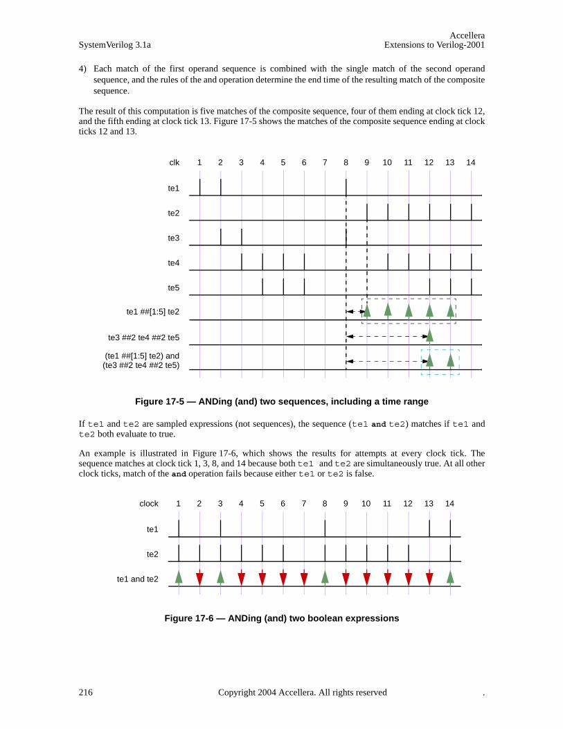
AccelleraSystemVerilog 3.1a Extensions to Verilog-2001
4) Each match of the first operand sequence is combined with the single match of the second operandsequence, and the rules of the and operation determine the end time of the resulting match of the compositesequence.
The result of this computation is five matches of the composite sequence, four of them ending at clock tick 12,and the fifth ending at clock tick 13. Figure 17-5 shows the matches of the composite sequence ending at clockticks 12 and 13.
Figure 17-5 — ANDing (and) two sequences, including a time range
If te1 and te2 are sampled expressions (not sequences), the sequence (te1 and te2) matches if te1 andte2 both evaluate to true.
An example is illustrated in Figure 17-6, which shows the results for attempts at every clock tick. Thesequence matches at clock tick 1, 3, 8, and 14 because both te1 and te2 are simultaneously true. At all otherclock ticks, match of the and operation fails because either te1 or te2 is false.
Figure 17-6 — ANDing (and) two boolean expressions
1 2 3 4 5 6 7 8 9 10 11 12 13 14clk
te1
te2
te3
te1 ##[1:5] te2
te3 ##2 te4 ##2 te5
te4
te5
(te1 ##[1:5] te2) and(te3 ##2 te4 ##2 te5)
1 2 3 4 5 6 7 8 9 10 11 12 13 14clock
te1
te2
te1 and te2
216 Copyright 2004 Accellera. All rights reserved .

AccelleraExtensions to Verilog-2001 SystemVerilog 3.1a
17.7.5 Intersection (AND with length restriction)
The binary operator intersect is used when both operand sequences are expected to match, and the endtimes of the operand sequences must be the same.
Syntax 17-7—intersect operator syntax (excerpt from Annex A)
The two operands of intersect are sequences. The requirements for match of the intersect operation are:
— Both the operands must match.
— The lengths of the two matches of the operand sequences must be the same.
The additional requirement on the length of the sequences is the basic difference between and and intersect.
An attempted evaluation of an intersect sequence can result in multiple matches. The results of such anattempt can be computed as follows.
— Matches of the first and second operands that are of the same length are paired. Each such pair results in amatch of the composite sequence, with length and endpoint equal to the shared length and endpoint of thepaired matches of the operand sequences.
— If no such pair is found, then there is no match of the composite sequence.
Figure 17-7 is similar to Figure 17-5, except that and is replaced by intersect. In this case, unlike in Figure17-5, there is only a single match at clock tick 12.
sequence_expr ::= ...| sequence_expr intersect sequence_expr
// from Annex A.2.10
1 2 3 4 5 6 7 8 9 10 11 12 13 14clk
te1
te2
te3
te1 ##[1:5] te2
te3 ##2 te4 ##2 te5
te4
te5
(te1 ##[1:5] te2) intersect(te3 ##2 te4 ##2 te5)
Figure 17-7 — Intersecting two sequences
Copyright 2004 Accellera. All rights reserved. 217

AccelleraSystemVerilog 3.1a Extensions to Verilog-2001
17.7.6 OR operation
The operator or is used when at least one of the two operand sequences is expected to match.
Syntax 17-8—or operator syntax (excerpt from Annex A)
The two operands of or are sequences.
If the operands te1 and te2 are expressions, then
te1 or te2
matches at any clock tick on which at least one of te1 and te2 evaluates to true.
Figure 17-8 illustrates an or operation for which the operands te1 and te2 are expressions. The compositesequence does not match at clock ticks 7 and 13 because te1 and te2 are both false at those times. At all otherclock ticks, the composite sequence matches, as at least one of the two operands evaluates to true.
Figure 17-8 — ORing (or) Two Sequences
When te1 and te2 are sequences, then the sequence
te1 or te2
matches if at least one of the two operand sequences te1 and te2 matches. Each match of either te1 or te2constitutes a match of the composite sequence, and its end time as a match of the composite sequence is thesame as its end time as a match of te1 or of te2. In other words, the set of matches of te1 or te2 is theunion of the set of matches of te1 with the set of matches of te2.
The following example shows a sequence with operator or where the two operands are sequences. Figure 17-9illustrates this example.
(te1 ##2 te2) or (te3 ##2 te4 ##2 te5)
sequence_expr ::= ...| sequence_expr or sequence_expr
// from Annex A.2.10
1 2 3 4 5 6 7 8 9 10 11 12 13 14clock
te1
te2
te1 or te2
218 Copyright 2004 Accellera. All rights reserved .

AccelleraExtensions to Verilog-2001 SystemVerilog 3.1a
Figure 17-9 — ORing (or) two sequences
Here, the two operand sequences are: (te1 ##2 te2) and (te3 ##2 te4 ##2 te5). The first sequencerequires that te1 first evaluates to true, followed by te2 two clock ticks later. The second sequence requiresthat te3 evaluates to true, followed by te4 two clock ticks later, followed by te5 two clock ticks later. InFigure 17-9, the evaluation attempt for clock tick 8 is shown. The first sequence matches at clock tick 10 andthe second sequence matches at clock tick 12. So, two matches for the composite sequence are recognized.
In the following example, the first operand sequence has a concatenation operator with range from 1 to 5
(te1 ##[1:5] te2) or (te3 ##2 te4 ##2 te5)
The first operand sequence requires that te1 evaluate to true and that te2 evaluate to true 1, 2, 3, 4, or 5 clockticks later. The second operand sequence requires that te3 evaluate to true, that te4 evaluate to true 2 clockticks later, and that te5 evaluate to true another 2 clock ticks later. The composite sequence matches at anyclock tick on which at least one of the operand sequences matches. As shown in Figure 17-10, for the attemptat clock tick 8, the first operand sequence matches at clock ticks 9, 10, 11, 12, and 13, while the second oper-and matches at clock tick 12. The composite sequence therefore has one match at each of clock ticks 9, 10, 11,and 13 and has two matches at clock tick 12.
1 2 3 4 5 6 7 8 9 10 11 12 13 14clk
te1
te2
te3
te1 ##2 te2
te3 ##2 te4 ##2 te5
te4
te5
(te1 ##2 te2) or(te3 ##2 te4 ##2 te5)
Copyright 2004 Accellera. All rights reserved. 219

AccelleraSystemVerilog 3.1a Extensions to Verilog-2001
Figure 17-10 — ORing (or) two sequences, including a time range
17.7.7 first_match operation
The first_match operator matches only the first of possibly multiple matches for an evaluation attempt ofits operand sequence. This allows all subsequent matches to be discarded from consideration. In particular,when a sequence is a subsequence of a larger sequence, then applying the first_match operator has signifi-cant effect on the evaluation of the enclosing sequence.
Syntax 17-9—first_match operator syntax (excerpt from Annex A)
An evaluation attempt of first_match (seq) results in an evaluation attempt for the operand seq beginning atthe same clock tick. If the evaluation attempt for seq produces no match, then the evaluation attempt forfirst_match (seq) produces no match. Otherwise, the match of seq with earliest ending clock tick is a matchof first_match (seq). If there are multiple matches of seq with the same ending clock tick as the earliest one,then all those matches are matches of first_match (seq).
The example below shows a variable delay specification.
sequence t1;te1 ## [2:5] te2;
endsequence sequence ts1;
first_match(te1 ## [2:5] te2);endsequence
Here, te1 and te2 are expressions. Each attempt of sequence t1 can result in matches for up to four of the fol-lowing sequences:
1 2 3 4 5 6 7 8 9 10 11 12 13 14clk
te1
te2
te3
te1 ##[1:5] te2
te3 ##2 te4 ##2 te5
te4
te5
(te1 ##[1:5] te2) or(te3 ##2 te4 ##2 te5)
sequence_expr ::= ...| first_match ( sequence_expr {, sequence_match_item} )
// from Annex A.2.10
220 Copyright 2004 Accellera. All rights reserved .

AccelleraExtensions to Verilog-2001 SystemVerilog 3.1a
te1 ##2 te2 te1 ##3 te2 te1 ##4 te2 te1 ##5 te2
However, sequence ts1 can result in a match for only one of the above four sequences. Whichever match ofthe above four sequences ends first is a match of sequence ts1.
As another example:
sequence t2;(a ##[2:3] b) or (c ##[1:2] d);
endsequence sequence ts2;
first_match(t2);endsequence
Each attempt of sequence t2 can result in matches for up to four of the following sequences:
a ##2 ba ##3 bc ##1 dc ##2 d
Sequence ts2 matches only the earliest ending match of these sequences. If a, b, c, and d are expressions,then it is possible to have matches ending at the same time for both.
a ##2 bc ##2 d
If both of these sequences match and (c ##1 d) does not match, then evaluation of ts2 results in these twomatches.
Sequence match items can be attached to the operand sequence of the first_match operator. The sequencematch items are placed within the same set of parentheses that encloses the operand. Thus, for example, thelocal variable assignment x = e can be attached to the first match of seq via
first_match(seq, x = e)
which is equivalent to
first_match((seq, x = e))
See Sections 17.8 and 17.9 for discussion of sequence match items.
17.7.8 Conditions over sequences
Sequences often occur under the assumptions of some conditions for correct behavior. A logical conditionmust hold true, for instance, while processing a transaction. Also, occurrence of certain values is prohibitedwhile processing a transaction. Such situations can be expressed directly using the following construct:
Syntax 17-10—throughout construct syntax (excerpt from Annex A)
sequence_expr ::= ...| expression_or_dist throughout sequence_expr
// from Annex A.2.10
Copyright 2004 Accellera. All rights reserved. 221

AccelleraSystemVerilog 3.1a Extensions to Verilog-2001
The construct exp throughout seq is an abbreviation for:
(exp) [*0:$] intersect seq
The composite sequence, exp throughout seq, matches along a finite interval of consecutive clock ticksprovided seq matches along the interval and exp evaluates to true at each clock tick of the interval.
The following example is illustrated in Figure 17-11.
sequence burst_rule1;@(posedge mclk)
$fell(burst_mode) ##0 (!burst_mode) throughout (##2 ((trdy==0)&&(irdy==0)) [*7]);
endsequence
Figure 17-11 — Match with throughout restriction fails
Figure 17-12 illustrates the evaluation attempt for sequence burst_rule1 beginning at clock tick 2. Sincesignal burst_mode is high at clock tick 1 and low at clock tick 2, $fell(burst_mode) is true at clock tick2. To complete the match of burst_rule1, the value of burst_mode is required to be low throughout amatch of the subsequence (##2 ((trdy==0)&&(irdy==0)) [*7]) beginning at clock tick 2. This subse-quence matches from clock tick 2 to clock tick 10. However, at clock tick 9 burst_mode becomes high,thereby failing to match according to the rules for throughout.
If signal burst_mode were instead to remain low through at least clock tick 10, then there would be a matchof burst_rule1 from clock tick 2 to clock tick 10, as shown in Figure 17-12.
1 2 3 4 5 6 7 8 9 10 11 12 13 14mclk
burst_mode
burst_rule1
irdy
trdy
(trdy==0) &&1 2 3 4 5 6 7(irdy==0)
1 2 3 4 5 6 7 8 9 10 11 12 13 14mclk
burst_mode
burst_rule1
irdy
trdy
(trdy==0) &&1 2 3 4 5 6 7 (irdy==0)
222 Copyright 2004 Accellera. All rights reserved .
AccelleraExtensions to Verilog-2001 SystemVerilog 3.1a
Figure 17-12 — Match with throughout restriction succeeds
17.7.9 Sequence contained within another sequence
The containment of a sequence within another sequence is expressed as follows:
Syntax 17-11—within construct syntax (excerpt from Annex A)
The construct seq1 within seq2 is an abbreviation for:
(1[*0:$] ##1 seq1 ##1 1[*0:$]) intersect seq2
The composite sequence seq1 within seq2 matches along a finite interval of consecutive clock ticks pro-vided seq2 matches along the interval and seq1 matches along some sub-interval of consecutive clock ticks.That is, the matches of seq1 and seq2 must satisfy the following:
— The start point of the match of seq1 must be no earlier than the start point of the match of seq2.
— The end point of the match of seq1 must be no later than the end point of the match of seq2.
For example, the sequence
!trdy[*7] within (($fell irdy) ##1 !irdy[*8])
matches from clock tick 3 to clock tick 11 on the trace shown in Figure 17-12.
17.7.10 Detecting and using endpoint of a sequence
There are two ways in which a complex sequence can be decomposed into simpler subsequences.
One is to instantiate a named sequence by referencing its name. Evaluation of such a reference requires thenamed sequence to match starting from the clock tick at which the reference is reached during the evaluationof the enclosing sequence. For example:
sequence s;a ##1 b ##1 c;
endsequence sequence rule;
@(posedge sysclk)trans ##1 start_trans ##1 s ##1 end_trans;
endsequence
Sequence s is evaluated beginning one tick after the evaluation of start_trans in the sequence rule.
Another way to use a sequence is to detect its end point in another sequence. The end point of a sequence isreached whenever the ending clock tick of a match of the sequence is reached, regardless of the starting clocktick of the match. The reaching of the end point can be tested in any sequence by using the method ended.
The syntax of the ended method is:
sequence_instance.ended
ended is a method on a sequence. The result of its operation is true or false. When method ended is evaluatedin an expression, it tests whether its operand sequence has reached its end point at that particular point in time.
sequence_expr ::= ...| sequence_expr within sequence_expr
// from Annex A.2.10
Copyright 2004 Accellera. All rights reserved. 223
AccelleraSystemVerilog 3.1a Extensions to Verilog-2001
The result of ended does not depend upon the starting point of the match of its operand sequence. An exampleis shown below:
sequence e1;@(posedge sysclk) $rose(ready) ##1 proc1 ##1 proc2 ;
endsequence sequence rule;
@(posedge sysclk) reset ##1 inst ##1 e1.ended ##1 branch_back;endsequence
In this example, sequence e1 must match one clock tick after inst. If the method ended is replaced with aninstance of sequence e1, a match of e1 must start one clock tick after inst. Notice that method ended onlytests for the end point of e1, and has no bearing on the starting point of e1. ended can be used on sequencesthat have formal arguments. For example with the declarations
sequence e2(a,b,c);@(posedge sysclk) $rose(a) ##1 b ##1 c;
endsequence sequence rule2;
@(posedge sysclk) reset ##1 inst ##1 e2(ready,proc1,proc2).ended ##1 branch_back;
endsequence
rule2 is equivalent to rule2a below:
sequence e2_instantiated;e2(ready,proc1,proc2);
endsequence sequence rule2a;
@(posedge sysclk) reset ##1 inst ##1 e2_instantiated.ended ##1 branch_back;endsequence
There are additional restrictions on passing local variables into an instance of a sequence to which ended isapplied. See Section 17.8.
17.8 Manipulating data in a sequence
The use of a static SystemVerilog variable implies that only one copy exists. If data values need to be checkedin pipelined designs, then for each quantum of data entering the pipeline, a separate variable can be used tostore the predicted output of the pipeline for later comparison when the result actually exits the pipe. This stor-age can be built by using an array of variables arranged in a shift register to mimic the data propagatingthrough the pipeline. However, in more complex situations where the latency of the pipe is variable and out oforder, this construction could become very complex and error prone. Therefore, variables are needed that arelocal to and are used within a particular transaction check that can span an arbitrary interval of time and canoverlap with other transaction checks. Such a variable must thus be dynamically created when needed withinan instance of a sequence and removed when the end of the sequence is reached.
The dynamic creation of a variable and its assignment is achieved by using the local variable declaration in asequence or property declaration and making an assignment in the sequence.
Syntax 17-12—variable assignment syntax (excerpt from Annex A)
sequence_expr ::= ...
| ( expression_or_dist {, sequence_match_item } ) [ boolean_abbrev ] | ( sequence_expr {, sequence_match_item} ) [ sequence_abbrev ]
...
// from Annex A.2.10
224 Copyright 2004 Accellera. All rights reserved .

AccelleraExtensions to Verilog-2001 SystemVerilog 3.1a
The type of variable is explicitly specified. The variable can be assigned at the end point of any syntactic sub-sequence by placing the subsequence, comma separated from the sampling assignment, in parentheses. Forexample, if in
a ##1 b[->1] ##1 c[*2]
it is desired to assign x = e at the match of b[->1], the sequence can be rewritten as
a ##1 (b[->1], x = e) ##1 c[*2]
The local variable can be reassigned later in the sequence, as in
a ##1 (b[->1], x = e) ##1 (c[*2], x = x + 1)
For every attempt, a new copy of the variable is created for the sequence. The variable value can be tested likeany other SystemVerilog variable.
Hierarchical references to a local variable are not allowed.
As an example of local variable usage, assume a pipeline that has a fixed latency of 5 clock cycles. The dataenters the pipe on pipe_in when valid_in is true, and the value computed by the pipeline appears 5 clockcycles later on the signal pipe_out1. The data as transformed by the pipe is predicted by a function that incre-ments the data. The following property verifies this behavior:
property e;int x;(valid_in,(x = pipe_in)) |-> ##5 (pipe_out1 == (x+1));
endproperty
Property e is evaluated as :
1) When valid_in is true, x is assigned the value of pipe_in. If five cycles later, pipe_out1 is equal tox+1, then property e is true. Otherwise, property e is false.
2) When is valid_in false, property e evaluates to true.
Variables can be used in sequences or properties.
sequence data_check;int x;a ##1 !a, x = data_in ##1 !b[*0:$] ##1 b && (data_out == x);
endsequence property data_check_p
int x;a ##1 !a, x = data_in |=> !b[*0:$] ##1 b && (data_out == x);
endproperty
Local variables can be written on repeated sequences and accomplish accumulation of values.
sequence rep_v;int x;‘true,x = 0 ##0(!a [* 0:$] ##1 a, x = x+data)[*4] ##1 b ##1 c && (data_out == x);
endsequence
The local variables declared in one sequence are not visible in the sequence where it gets instantiated. Anexample below illustrates an illegal access to local variable v1 of sequence sub_seq1 in sequence seq1.
sequence sub_seq1;int v1;
Copyright 2004 Accellera. All rights reserved. 225

AccelleraSystemVerilog 3.1a Extensions to Verilog-2001
a ##1 !a, v1 = data_in ##1 !b[*0:$] ##1 b && (data_out == v1);endsequence sequence seq1;
c ##1 sub_seq1 ##1 (do1 == v1); // error since v1 is not visibleendsequence
To access a local variable of a subsequence, a local variable must be declared and passed to the instantiatedsubsequence through an argument. An example below illustrates this usage.
sequence sub_seq2(lv);a ##1 !a, lv = data_in ##1 !b[*0:$] ##1 b && (data_out == lv);
endsequence sequence seq2;
int v1;c ##1 sub_seq2(v1) ##1 (do1 == v1); // v1 is now bound to lv
endsequence
Local variables can be passed into an instance of a named sequence to which ended is applied and accessed ina similar manner. For example
sequence seq2a; int v1; c ##1 sub_seq2(v1).ended ##1 (do1 == v1); // v1 is now bound to lv
endsequence
There are additional restrictions when passing local variables into an instance of a named sequence to whichended is applied:
1) Local variables can be passed in only as entire actual arguments, not as proper subexpressions of actualarguments.
2) In the declaration of the named sequence, the formal argument to which the local variable is bound mustnot be referenced before it is assigned.
The second restriction is met by sub_seq2 because the assignment lv = data_in occurs before the referenceto lv in data_out == lv.
If a local variable is assigned before being passed into an instance of a named sequence to which ended isapplied, then the restrictions prevent this assigned value from being visible within the named sequence. Therestrictions are important because the use of ended means that there is no guaranteed relationship between thepoint in time at which the local variable is assigned outside the named sequence and the beginning of thematch of the instance.
A local variable that is passed in as actual argument to an instance of a named sequence to which ended isapplied will flow out of the application of ended to that instance provided both of the following conditions aremet:
1) The local variable flows out of the end of the named sequence instance, as defined by the local variableflow rules for sequences. (See below and Annex H.)
2) The application of ended to this instance is a maximal boolean expression. In other words, the applicationof ended cannot have negation or any other expression operator applied to it.
Both conditions are satisfied by sub_seq2 and seq2a. Thus, in seq2a the value in v1 in the comparison do1== v1 is the value assigned to lv in sub_seq2 by the assignment lv = data_in. However, in
sequence seq2b; int v1; c ##1 !sub_seq2(v1).ended ##1 (do1 == v1); // v1 unassigned endsequence
the second condition is violated because of the negation applied to sub_seq2(v1).ended. Therefore, v1
226 Copyright 2004 Accellera. All rights reserved .
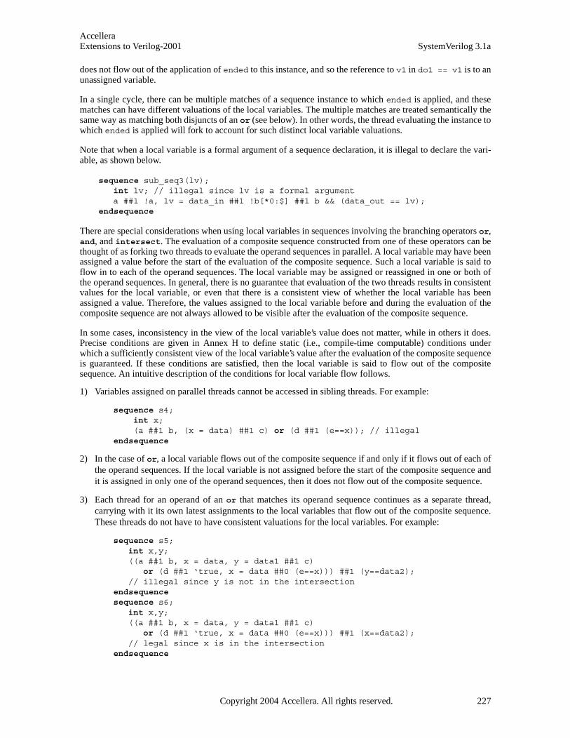
AccelleraExtensions to Verilog-2001 SystemVerilog 3.1a
does not flow out of the application of ended to this instance, and so the reference to v1 in do1 == v1 is to anunassigned variable.
In a single cycle, there can be multiple matches of a sequence instance to which ended is applied, and thesematches can have different valuations of the local variables. The multiple matches are treated semantically thesame way as matching both disjuncts of an or (see below). In other words, the thread evaluating the instance towhich ended is applied will fork to account for such distinct local variable valuations.
Note that when a local variable is a formal argument of a sequence declaration, it is illegal to declare the vari-able, as shown below.
sequence sub_seq3(lv);int lv; // illegal since lv is a formal argumenta ##1 !a, lv = data_in ##1 !b[*0:$] ##1 b && (data_out == lv);
endsequence
There are special considerations when using local variables in sequences involving the branching operators or,and, and intersect. The evaluation of a composite sequence constructed from one of these operators can bethought of as forking two threads to evaluate the operand sequences in parallel. A local variable may have beenassigned a value before the start of the evaluation of the composite sequence. Such a local variable is said toflow in to each of the operand sequences. The local variable may be assigned or reassigned in one or both ofthe operand sequences. In general, there is no guarantee that evaluation of the two threads results in consistentvalues for the local variable, or even that there is a consistent view of whether the local variable has beenassigned a value. Therefore, the values assigned to the local variable before and during the evaluation of thecomposite sequence are not always allowed to be visible after the evaluation of the composite sequence.
In some cases, inconsistency in the view of the local variable’s value does not matter, while in others it does.Precise conditions are given in Annex H to define static (i.e., compile-time computable) conditions underwhich a sufficiently consistent view of the local variable’s value after the evaluation of the composite sequenceis guaranteed. If these conditions are satisfied, then the local variable is said to flow out of the compositesequence. An intuitive description of the conditions for local variable flow follows.
1) Variables assigned on parallel threads cannot be accessed in sibling threads. For example:
sequence s4; int x; (a ##1 b, (x = data) ##1 c) or (d ##1 (e==x)); // illegal
endsequence
2) In the case of or, a local variable flows out of the composite sequence if and only if it flows out of each ofthe operand sequences. If the local variable is not assigned before the start of the composite sequence andit is assigned in only one of the operand sequences, then it does not flow out of the composite sequence.
3) Each thread for an operand of an or that matches its operand sequence continues as a separate thread,carrying with it its own latest assignments to the local variables that flow out of the composite sequence.These threads do not have to have consistent valuations for the local variables. For example:
sequence s5;int x,y;((a ##1 b, x = data, y = data1 ##1 c)
or (d ##1 ‘true, x = data ##0 (e==x))) ##1 (y==data2);// illegal since y is not in the intersection
endsequence sequence s6;
int x,y;((a ##1 b, x = data, y = data1 ##1 c)
or (d ##1 ‘true, x = data ##0 (e==x))) ##1 (x==data2);// legal since x is in the intersection
endsequence
Copyright 2004 Accellera. All rights reserved. 227
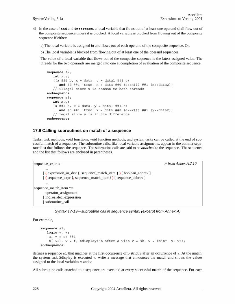
AccelleraSystemVerilog 3.1a Extensions to Verilog-2001
4) In the case of and and intersect, a local variable that flows out of at least one operand shall flow out ofthe composite sequence unless it is blocked. A local variable is blocked from flowing out of the compositesequence if either:
a) The local variable is assigned in and flows out of each operand of the composite sequence. Or,
b) The local variable is blocked from flowing out of at least one of the operand sequences.
The value of a local variable that flows out of the composite sequence is the latest assigned value. Thethreads for the two operands are merged into one at completion of evaluation of the composite sequence.
sequence s7;int x,y;((a ##1 b, x = data, y = data1 ##1 c)
and (d ##1 ‘true, x = data ##0 (e==x))) ##1 (x==data2);// illegal since x is common to both threads
endsequence sequence s8;
int x,y;(a ##1 b, x = data, y = data1 ##1 c)
and (d ##1 ‘true, x = data ##0 (e==x))) ##1 (y==data2);// legal since y is in the difference
endsequence
17.9 Calling subroutines on match of a sequence
Tasks, task methods, void functions, void function methods, and system tasks can be called at the end of suc-cessful match of a sequence. The subroutine calls, like local variable assignments, appear in the comma-sepa-rated list that follows the sequence. The subroutine calls are said to be attached to the sequence. The sequenceand the list that follows are enclosed in parentheses.
Syntax 17-13—subroutine call in sequence syntax (excerpt from Annex A)
For example,
sequence s1;logic v, w;(a, v = e) ##1 (b[->1], w = f, $display("b after a with v = %h, w = %h\n", v, w));
endsequence
defines a sequence s1 that matches at the first occurrence of b strictly after an occurrence of a. At the match,the system task $display is executed to write a message that announces the match and shows the valuesassigned to the local variables v and w.
All subroutine calls attached to a sequence are executed at every successful match of the sequence. For each
sequence_expr ::= ...
| ( expression_or_dist {, sequence_match_item } ) [ boolean_abbrev ] | ( sequence_expr {, sequence_match_item} ) [ sequence_abbrev ]
...
sequence_match_item ::= operator_assignment
| inc_or_dec_expression | subroutine_call
// from Annex A.2.10
228 Copyright 2004 Accellera. All rights reserved .
AccelleraExtensions to Verilog-2001 SystemVerilog 3.1a
successful match, the attached calls are executed in the order they appear in the list. The subroutines are sched-uled in the Reactive region, like an action block.
Each argument of a subroutine call attached to a sequence must either be passed by value as an input or bepassed by reference (either ref or const ref; see Section 10.4.2). Actual argument expressions that arepassed by value use sampled values of the underlying variables and are consistent with the variable valuesused to evaluate the sequence match.
Local variables can be passed into subroutine calls attached to a sequence. Any local variable that flows out ofthe sequence or that is assigned in the list following the sequence, but before the subroutine call, can be used inan actual argument expression for the call. If a local variable appears in an actual argument expression, thenthat argument must be passed by value.
17.10 System functions
Assertions are commonly used to evaluate certain specific characteristics of a design implementation, such aswhether a particular signal is “one-hot”. The following system functions are included to facilitate such com-mon assertion functionality:
— $onehot (<expression>) returns true if only one bit of the expression is high.
— $onehot0(<expression>) returns true if at most one bit of the expression is high.
— $isunknown (<expression>) returns true if any bit of the expression is X or Z. This is equivalent to^<expression> === ’bx.
All of the above system functions have a return type of bit. A return value of 1’b1 indicates true, and a returnvalue of 1’b0 indicates false.
Another useful function provided for the boolean expression is $countones, to count the number of 1s in a bitvector expression.
$countones ( expression)
An X and Z value of a bit is not counted towards the number of ones.
17.11 Declaring properties
A property defines a behavior of the design. A property can be used for verification as an assumption, achecker, or a coverage specification. In order to use the behavior for verification, an assert, assume orcover statement must be used. A property declaration by itself does not produce any result.
A property can be declared in
— a module
— an interface a program
— a clocking block
— a package
— a compilation-unit scope
To declare a property, the property construct is used as shown below:
Copyright 2004 Accellera. All rights reserved. 229
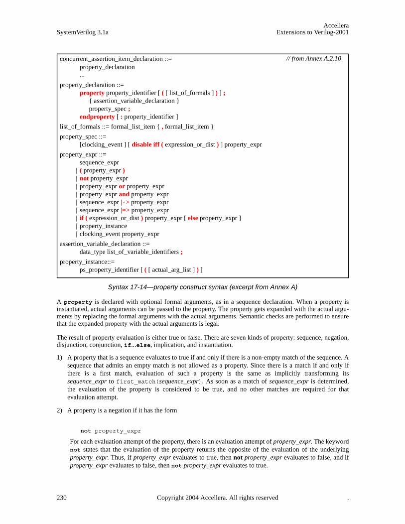
AccelleraSystemVerilog 3.1a Extensions to Verilog-2001
Syntax 17-14—property construct syntax (excerpt from Annex A)
A property is declared with optional formal arguments, as in a sequence declaration. When a property isinstantiated, actual arguments can be passed to the property. The property gets expanded with the actual argu-ments by replacing the formal arguments with the actual arguments. Semantic checks are performed to ensurethat the expanded property with the actual arguments is legal.
The result of property evaluation is either true or false. There are seven kinds of property: sequence, negation,disjunction, conjunction, if...else, implication, and instantiation.
1) A property that is a sequence evaluates to true if and only if there is a non-empty match of the sequence. Asequence that admits an empty match is not allowed as a property. Since there is a match if and only ifthere is a first match, evaluation of such a property is the same as implicitly transforming itssequence_expr to first_match(sequence_expr). As soon as a match of sequence_expr is determined,the evaluation of the property is considered to be true, and no other matches are required for thatevaluation attempt.
2) A property is a negation if it has the form
not property_expr
For each evaluation attempt of the property, there is an evaluation attempt of property_expr. The keywordnot states that the evaluation of the property returns the opposite of the evaluation of the underlyingproperty_expr. Thus, if property_expr evaluates to true, then not property_expr evaluates to false, and ifproperty_expr evaluates to false, then not property_expr evaluates to true.
concurrent_assertion_item_declaration ::= property_declaration ...
property_declaration ::= property property_identifier [ ( [ list_of_formals ] ) ] ;
{ assertion_variable_declaration } property_spec ;
endproperty [ : property_identifier ]
list_of_formals ::= formal_list_item { , formal_list_item }
property_spec ::= [clocking_event ] [ disable iff ( expression_or_dist ) ] property_expr
property_expr ::= sequence_expr
| ( property_expr ) | not property_expr | property_expr or property_expr | property_expr and property_expr | sequence_expr |-> property_expr | sequence_expr |=> property_expr | if ( expression_or_dist ) property_expr [ else property_expr ] | property_instance | clocking_event property_expr
assertion_variable_declaration ::= data_type list_of_variable_identifiers ;
property_instance::= ps_property_identifier [ ( [ actual_arg_list ] ) ]
// from Annex A.2.10
230 Copyright 2004 Accellera. All rights reserved .

AccelleraExtensions to Verilog-2001 SystemVerilog 3.1a
3) A property is a disjunction if it has the form
property_expr1 or property_expr2
The property evaluates to true if and only if at least one of property_expr1 and property_expr2 evaluatesto true.
4) A property is a conjunction if it has the form
property_expr1 and property_expr2
The property evaluates to true if and only if both property_expr1 and property_expr2 evaluate to true.
5) A property is an if...else if it has either the form
if (expression_or_dist) property_expr1
or the form
if (expression_or_dist) property_expr1 else property_expr2
A property of the first form evaluates to true if and only if either expression_or_dist evaluates to false orproperty_expr1 evaluates to true. A property of the second form evaluates to true if and only if eitherexpression_or_dist evaluates to true and property_expr1 evaluates to true or expression_or_dist evaluatesto false and property_expr2 evaluates to true.
6) A property is an implication if it has either the form
sequence_expr |-> property_expr
or the form
sequence_expr |=> property_expr
The meaning of implications is discussed in 17.11.1.
7) An instance of a named property can be used as a property_expr or property_spec. In general, the instanceis legal provided the body property_spec of the named property can be substituted in place of the instance,with actual arguments substituted for formal arguments, and result in a legal property_expr orproperty_spec, ignoring local variable declarations. Thus, for example, if an instance of a named propertyis used as a property_expr operand for any property-building operator, then the named property must nothave a disable iff clause. Similarly, clock events in a named property must conform to the rules ofmultiple clock support when the property is instantiated in a property_expr or property_spec that alsoinvolves other clock events.
The following table lists the property operators from highest to lowest precedence and shows the associativityof the non-unary operators.
Table 17-2: Property operator precedence and associativity
SystemVerilog property operators Associativity
not ----
and left
or left
if...else right
|-> |=> right
Copyright 2004 Accellera. All rights reserved. 231
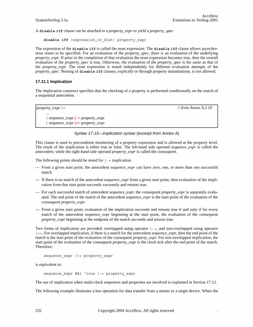
AccelleraSystemVerilog 3.1a Extensions to Verilog-2001
A disable iff clause can be attached to a property_expr to yield a property_spec
disable iff (expression_or_dist) property_expr
The expression of the disable iff is called the reset expression. The disable iff clause allows asynchro-nous resets to be specified. For an evaluation of the property_spec, there is an evaluation of the underlyingproperty_expr. If prior to the completion of that evaluation the reset expression becomes true, then the overallevaluation of the property_spec is true. Otherwise, the evaluation of the property_spec is the same as that ofthe property_expr. The reset expression is tested independently for different evaluation attempts of theproperty_spec. Nesting of disable iff clauses, explicitly or through property instantiations, is not allowed.
17.11.1 Implication
The implication construct specifies that the checking of a property is performed conditionally on the match ofa sequential antecedent.
Syntax 17-15—implication syntax (excerpt from Annex A)
This clause is used to precondition monitoring of a property expression and is allowed at the property level.The result of the implication is either true or false. The left-hand side operand sequence_expr is called theantecedent, while the right-hand side operand property_expr is called the consequent.
The following points should be noted for |-> implication:
— From a given start point, the antecedent sequence_expr can have zero, one, or more than one successfulmatch.
— If there is no match of the antecedent sequence_expr from a given start point, then evaluation of the impli-cation from that start point succeeds vacuously and returns true.
— For each successful match of antecedent sequence_expr, the consequent property_expr is separately evalu-ated. The end point of the match of the antecedent sequence_expr is the start point of the evaluation of theconsequent property_expr.
— From a given start point, evaluation of the implication succeeds and returns true if and only if for everymatch of the antecedent sequence_expr beginning at the start point, the evaluation of the consequentproperty_expr beginning at the endpoint of the match succeeds and returns true.
Two forms of implication are provided: overlapped using operator |->, and non-overlapped using operator|=>. For overlapped implication, if there is a match for the antecedent sequence_expr, then the end point of thematch is the start point of the evaluation of the consequent property_expr. For non-overlapped implication, thestart point of the evaluation of the consequent property_expr is the clock tick after the end point of the match.Therefore:
sequence_expr |=> property_expr
is equivalent to:
sequence_expr ##1 ‘true |-> property_expr
The use of implication when multi-clock sequences and properties are involved is explained in Section 17.12.
The following example illustrates a bus operation for data transfer from a master to a target device. When the
property_expr ::= ... | sequence_expr |-> property_expr | sequence_expr |=> property_expr
// from Annex A.2.10
232 Copyright 2004 Accellera. All rights reserved .

AccelleraExtensions to Verilog-2001 SystemVerilog 3.1a
bus enters a data transfer phase, multiple data phases can occur to transfer a block of data. During the datatransfer phase, a data phase completes on any rising clock edge on which irdy is asserted and either trdy orstop is asserted. Note that an asserted signal here implies a value of low. The end of a data phase can beexpressed as:
property data_end;@(posedge mclk) data_phase |-> ((irdy==0) && ($fell(trdy) || $fell(stop))) ;
endproperty
Each time a data phase is true, a match for data_phase is recognized. The attempt at clock tick 6 is illustratedin Figure 17-13. The values shown for the signals are the sampled values with respect to the clock. At clocktick 6, data_end is true because stop gets asserted while irdy is asserted.
Figure 17-13 — Conditional sequence matching
In another example, data_end_exp is used to ensure that frame is de-asserted (value high) within 2 clockticks after data_end_exp occurs. Further, it is also required that irdy is de-asserted (value high) one clocktick after frame is de-asserted.
A property written to express this condition is shown below.
‘define data_end_exp (data_phase && ((irdy==0)&&($fell(trdy)||$fell(stop)))) property data_end_rule1;
@(posedge mclk) ‘data_end_exp |-> ##[1:2] $rose(frame) ##1 $rose(irdy);
endproperty
property data_end_rule1 first evaluates data_end_exp at every clock tick to test if its value is true. If thevalue is false, then that particular attempt to evaluate data_end_rule1 is considered true. Otherwise, the fol-lowing sequence is evaluated. The sequence:
##[1:2] $rose(frame) ##1 $rose(irdy)
specifies looking for the rising edge of frame within two clock ticks in the future. After frame toggles high,irdy must also toggle high after one clock tick. This is illustrated in Figure 17-14 for the evaluation attempt atclock tick 6. ‘data_end_exp is acknowledged at clock tick 6. Next, frame toggles high at clock tick 7. Sincethis falls within the timing constraint imposed by [1:2], it satisfies the sequence and continues to evaluatefurther. At clock tick 8, irdy is evaluated. Signal irdy transitions to high at clock tick 8, matching thesequence specification completely for the attempt that began at clock tick 6.
1 2 3 4 5 6 7 8 9 10 11 12 13 14mclk
data_phase
data_end
irdy
trdy (high)
stop
Copyright 2004 Accellera. All rights reserved. 233
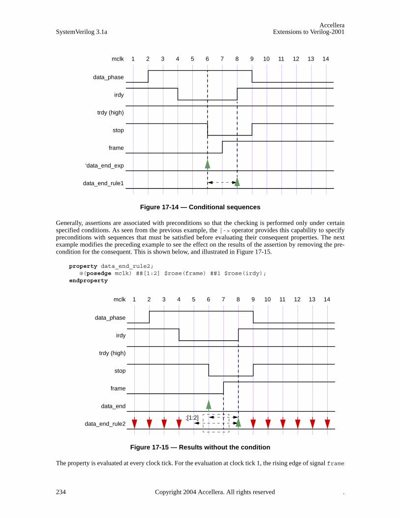
AccelleraSystemVerilog 3.1a Extensions to Verilog-2001
Figure 17-14 — Conditional sequences
Generally, assertions are associated with preconditions so that the checking is performed only under certainspecified conditions. As seen from the previous example, the |-> operator provides this capability to specifypreconditions with sequences that must be satisfied before evaluating their consequent properties. The nextexample modifies the preceding example to see the effect on the results of the assertion by removing the pre-condition for the consequent. This is shown below, and illustrated in Figure 17-15.
property data_end_rule2;@(posedge mclk) ##[1:2] $rose(frame) ##1 $rose(irdy);
endproperty
Figure 17-15 — Results without the condition
The property is evaluated at every clock tick. For the evaluation at clock tick 1, the rising edge of signal frame
1 2 3 4 5 6 7 8 9 10 11 12 13 14mclk
data_phase
‘data_end_exp
irdy
trdy (high)
stop
frame
data_end_rule1
1 2 3 4 5 6 7 8 9 10 11 12 13 14mclk
data_phase
data_end
irdy
trdy (high)
stop
frame
data_end_rule2;[1:2]
234 Copyright 2004 Accellera. All rights reserved .

AccelleraExtensions to Verilog-2001 SystemVerilog 3.1a
does not occur at clock tick 1 or 2, so the property fails at clock tick 1. Similarly, there is a failure at clock ticks2, 3, and 4. For attempts starting at clock ticks 5 and 6, the rising edge of signal frame at clock tick 7 allowschecking further. At clock tick 8, the sequences complete according to the specification, resulting in a matchfor attempts starting at 5 and 6. All later attempts to match the sequence fail because $rose(frame) doesnot occur again.
Figure 17-15 shows that removing the precondition of checking ‘data_end_exp from the assertion causesfailures that are not relevant to the verification objective. It is important from the validation standpoint todetermine these preconditions and use them to filter out inappropriate or extraneous situations.
An example of implication where the antecedent is a sequence follows: (a ##1 b ##1 c) |-> (d ##1 e)
If the sequence (a ##1 b ##1 c) matches, then the sequence (d ##1 e) must also match. On the otherhand, if the sequence (a ##1 b ##1 c) does not match, then the result is true.
Another example of implication is:
property p16;(write_en & data_valid) ##0 (write_en && (retire_address[0:4]==addr)) [*2] |-> ##[3:8] write_en && !data_valid &&(write_address[0:4]==addr);
endproperty
This property can be coded alternatively as a nested implication:
property p16_nested;(write_en & data_valid) |->
(write_en && (retire_address[0:4]==addr)) [*2] |-> ##[3:8] write_en && !data_valid && (write_address[0:4]==addr);
endproperty
Multi-clock sequence implication is explained in Section 17.12.
17.11.2 Property examples
The following examples illustrate the property forms.
property rule1;@(posedge clk) a |-> b ##1 c ##1 d;
endproperty property rule2;
@(clkev) disable iff (foo) a |-> not(b ##1 c ##1 d);endproperty
Property rule2 negates the sequence (b ##1 c ##1 d) in the consequent of the implication.clkev specifies the clock for the property.
property rule3;@(posedge clk) a[*2] |-> ((##[1:3] c) or (d |=> e));
endproperty
Property rule3 says that if a holds and a also held last cycle, then either c must hold at some point 1 to threecycles after the current cycle, or, if d holds in the current cycle, then e must hold one cycle later.
property rule4;@(posedge clk) a[*2] |-> ((##[1:3] c) and (d |=> e));
endproperty
Copyright 2004 Accellera. All rights reserved. 235
AccelleraSystemVerilog 3.1a Extensions to Verilog-2001
Property rule4 says that if a holds and a also held last cycle, then c must hold at some point 1 to three cyclesafter the current cycle, and if d holds in the current cycle, then e must hold one cycle later.
property rule5;@(posedge clk) a ##1 (b || c)[->1] |->
if (b) (##1 d |-> e)
else // cf ;
endproperty
Property rule5 has a followed by the first match of either b or c as its antecedent. The consequent usesif...else to split cases on which of b or c is matched first.
property rule6(x,y);##1 x |-> y;
endproperty property rule5a;
@(posedge clk) a ##1 (b || c)[->1] |->
if (b) rule6(d,e)
else // cf ;
endproperty
Property rule5a is equivalent to rule5, but it uses an instance of rule6 as a property expression.
A property can optionally specify an event control for the clock. The clock derivation and resolution rules aredescribed in Section 17.14.
A named property can be instantiated by referencing its name. A hierarchical name can be used, consistentwith the SystemVerilog naming conventions. Like sequence declarations, variables used within a property thatare not formal arguments to the property are resolved hierarchically from the scope in which the property isdeclared.
Properties that use more than one clock are described in Section 17.12
17.11.3 Recursive properties
SystemVerilog allows recursive properties. A named property is recursive if its declaration involves an instan-tiation of itself. Recursion provides a flexible framework for coding properties to serve as ongoing assump-tions, checkers, or coverage monitors.
For example,
property prop_always(p);p and (1’b1 |=> prop_always(p));
endproperty
is a recursive property that says that the formal argument property p must hold at every cycle. This example isuseful if the ongoing requirement that property p hold applies after a complicated triggering condition encodedin sequence s:
property p1(s,p);s |=> prop_always(p);
endproperty
236 Copyright 2004 Accellera. All rights reserved .

AccelleraExtensions to Verilog-2001 SystemVerilog 3.1a
As another example, the recursive property
property prop_weak_until(p,q);q or (p and (1’b1 |=> prop_weak_until(p,q)));
endproperty
says that formal argument property p must hold at every cycle up to but not including the first cycle at whichformal argument property q holds. Formal argument property q is not required ever to hold, though. Thisexample is useful if p must hold at every cycle after a complicated triggering condition encoded in sequence s,but the requirement on p is lifted by q:
property p2(s,p,q);s |=> prop_weak_until(p,q);
endproperty
More generally, several properties can be mutually recursive. For example
property check_phase1;s1 |-> (phase1_prop and (1’b1 |=> check_phase2));
endproperty property check_phase2;
s2 |-> (phase2_prop and (1’b1 |=> check_phase1));endproperty
There are three restrictions on recursive property declarations.
RESTRICTION 1: The negation operator not cannot be applied to any property expression that instantiates arecursive property. In particular, the negation of a recursive property cannot be asserted or used in defininganother property.
Here are examples of illegal property declarations that violate Restriction 1:
property illegal_recursion_1(p);not prop_always(not p);
endproperty
property illegal_recursion_2(p);p and (1’b1 |=> not illegal_recursion_2(p));
endproperty
RESTRICTION 2: The operator disable iff cannot be used in the declaration of a recursive property. Thisrestriction is consistent with the restriction that disable iff cannot be nested.
Here is an example of an illegal property declaration that violates Restriction 2:
property illegal_recursion_3(p);disable iff (b)p and (1’b1 |=> illegal_recursion_3(p));
endproperty
The intent of illegal_recursion_3 can be written legally as
property legal_3(p);disable iff (b) prop_always(p);
endproperty
since legal_3 is not a recursive property.
RESTRICTION 3: If p is a recursive property, then, in the declaration of p, every instance of p must occur
Copyright 2004 Accellera. All rights reserved. 237
AccelleraSystemVerilog 3.1a Extensions to Verilog-2001
after a positive advance in time. In the case of mutually recursive properties, all recursive instances must occurafter positive advances in time.
Here is an example of an illegal property declaration that violates Restriction 3:
property illegal_recursion_4(p);p and (1’b1 |-> illegal_recursion_4(p));
endproperty
If this form were legal, the recursion would be stuck in time, checking p over and over again at the same cycle.
Recursive properties can represent complicated requirements, such as those associated with varying numbersof data beats, out-of-order completions, retries, etc. Here is an example of using a recursive property to checkcomplicated conditions of this kind.
EXAMPLE: Suppose that write data must be checked according to the following conditions:
— Acknowledgment of a write request is indicated by the signal write_request together withwrite_request_ack. When a write request is acknowledged, it gets a 4-bit tag, indicated by signalwrite_reqest_ack_tag. The tag is used to distinguish data beats for multiple write transactions inflight at the same time.
— It is understood that distinct write transactions in flight at the same time must be given distinct tags. Forsimplicity, this condition is not a part of what is checked in this example.
— Each write transaction can have between 1 and 16 data beats, and each data beat is 8 bits. There is a modelof the expected write data that is available at acknowledgment of a write request. The model is a 128-bitvector. The most significant group of 8 bits represents the expected data for the first beat, the next group of8 bits represents the expected data for the second beat (if there is a second beat), and so forth.
— Data transfer for a write transaction occurs after acknowledgment of the write request and, barring retry,ends with the last data beat. The data beats for a single write transaction occur in order.
— A data beat is indicated by the data_valid signal together with the signal data_valid_tag to deter-mine the relevant write transaction. The signal data is valid with data_valid and carries the data for thatbeat. The data for each beat must be correct according to the model of the expected write data.
— The last data beat is indicated by signal last_data_valid together with data_valid anddata_valid_tag. For simplicity, this example does not represent the number of data beats and does notcheck that last_data_valid is signaled at the correct beat.
— At any time after acknowledgement of the write request, but not later than the cycle after the last data beat,a write transaction can be forced to retry. Retry is indicated by the signal retry together with signalretry_tag to identify the relevant write transaction. If a write transaction is forced to retry, then its cur-rent data transfer is aborted and the entire data transfer must be repeated. The transaction does not re-request and its tag does not change.
— There is no limit on the number of times a write transaction can be forced to retry.
— A write transaction completes the cycle after the last data beat provided it is not forced to retry in thatcycle.
Here is code to check these conditions:
property check_write;
logic [0:127] expected_data; // local variable to sample model datalogic [3:0] tag; // local variable to sample tag
disable iff (reset)(
238 Copyright 2004 Accellera. All rights reserved .
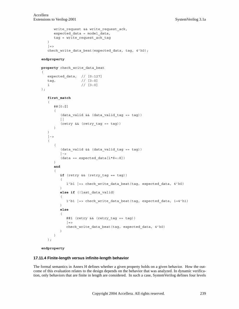
AccelleraExtensions to Verilog-2001 SystemVerilog 3.1a
write_request && write_request_ack, expected_data = model_data,tag = write_request_ack_tag
)|=> check_write_data_beat(expected_data, tag, 4’h0);
endproperty property check_write_data_beat(
expected_data, // [0:127] tag, // [3:0] i // [3:0]
);
first_match (
##[0:$](
(data_valid && (data_valid_tag == tag))||(retry && (retry_tag == tag))
))|->(
((data_valid && (data_valid_tag == tag)) |-> (data == expected_data[i*8+:8])
)and (
if (retry && (retry_tag == tag))(
1’b1 |=> check_write_data_beat(tag, expected_data, 4’h0))else if (!last_data_valid)(
1’b1 |=> check_write_data_beat(tag, expected_data, i+4’h1))else (
##1 (retry && (retry_tag == tag))|=>check_write_data_beat(tag, expected_data, 4’h0)
))
);
endproperty
17.11.4 Finite-length versus infinite-length behavior
The formal semantics in Annex H defines whether a given property holds on a given behavior. How the out-come of this evaluation relates to the design depends on the behavior that was analyzed. In dynamic verifica-tion, only behaviors that are finite in length are considered. In such a case, SystemVerilog defines four levels
Copyright 2004 Accellera. All rights reserved. 239

AccelleraSystemVerilog 3.1a Extensions to Verilog-2001
of satisfaction of a property:
Holds strongly:
— no bad states have been seen
— all future obligations have been met
— the property will hold on any extension of the path
Holds (but does not hold strongly):
— no bad states have been seen
— all future obligations have been met
— the property may or may not hold on a given extension of the path
Pending:
— no bad states have been seen
— future obligations have not been met
— the property may or may not hold on a given extension of the path
Fails:
— a bad state has been seen
— future obligations may or may not have been met
— the property will not hold on any extension of the path
17.11.5 Non-degeneracy
It is possible to define sequences that can never be matched. For example:
(1’b1) intersect(1’b1 ##1 1’b1)
It is also possible to define sequences that admit only empty matches. For example:
1’b1[*0]
A sequence that admits no match or that admits only empty matches is called degenerate. A sequence thatadmits at least one non-empty match is called non-degenerate. A more precise definition of non-degeneracy isgiven in Annex H.
The following restrictions apply:
1) Any sequence that is used as a property must be non-degenerate and must not admit any empty match.
2) Any sequence that is used as the antecedent of an overlapping implication (|->) must be non-degenerate.
3) Any sequence that is used as the antecedent of a non-overlapping implication (|=>) must admit at least onematch. Such a sequence can admit only empty matches.
The reason for these restrictions is that the use of degenerate sequences the forbidden ways results in counter-intuitive property semantics, especially when the property is combined with a disable iff clause.
17.12 Multiple clock support
Multiple clock sequences and properties can be specified using the following syntax.
240 Copyright 2004 Accellera. All rights reserved .
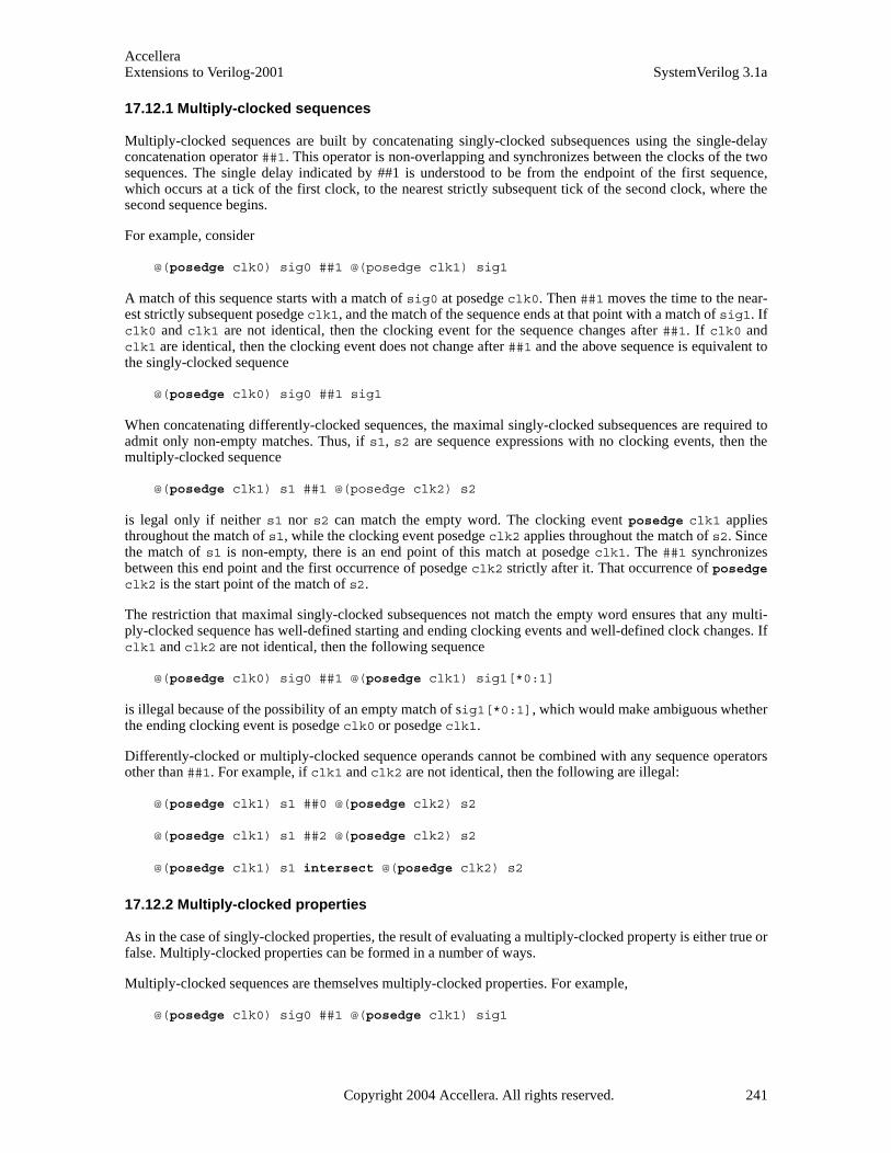
AccelleraExtensions to Verilog-2001 SystemVerilog 3.1a
17.12.1 Multiply-clocked sequences
Multiply-clocked sequences are built by concatenating singly-clocked subsequences using the single-delayconcatenation operator ##1. This operator is non-overlapping and synchronizes between the clocks of the twosequences. The single delay indicated by ##1 is understood to be from the endpoint of the first sequence,which occurs at a tick of the first clock, to the nearest strictly subsequent tick of the second clock, where thesecond sequence begins.
For example, consider
@(posedge clk0) sig0 ##1 @(posedge clk1) sig1
A match of this sequence starts with a match of sig0 at posedge clk0. Then ##1 moves the time to the near-est strictly subsequent posedge clk1, and the match of the sequence ends at that point with a match of sig1. Ifclk0 and clk1 are not identical, then the clocking event for the sequence changes after ##1. If clk0 andclk1 are identical, then the clocking event does not change after ##1 and the above sequence is equivalent tothe singly-clocked sequence
@(posedge clk0) sig0 ##1 sig1
When concatenating differently-clocked sequences, the maximal singly-clocked subsequences are required toadmit only non-empty matches. Thus, if s1, s2 are sequence expressions with no clocking events, then themultiply-clocked sequence
@(posedge clk1) s1 ##1 @(posedge clk2) s2
is legal only if neither s1 nor s2 can match the empty word. The clocking event posedge clk1 appliesthroughout the match of s1, while the clocking event posedge clk2 applies throughout the match of s2. Sincethe match of s1 is non-empty, there is an end point of this match at posedge clk1. The ##1 synchronizesbetween this end point and the first occurrence of posedge clk2 strictly after it. That occurrence of posedgeclk2 is the start point of the match of s2.
The restriction that maximal singly-clocked subsequences not match the empty word ensures that any multi-ply-clocked sequence has well-defined starting and ending clocking events and well-defined clock changes. Ifclk1 and clk2 are not identical, then the following sequence
@(posedge clk0) sig0 ##1 @(posedge clk1) sig1[*0:1]
is illegal because of the possibility of an empty match of sig1[*0:1], which would make ambiguous whetherthe ending clocking event is posedge clk0 or posedge clk1.
Differently-clocked or multiply-clocked sequence operands cannot be combined with any sequence operatorsother than ##1. For example, if clk1 and clk2 are not identical, then the following are illegal:
@(posedge clk1) s1 ##0 @(posedge clk2) s2
@(posedge clk1) s1 ##2 @(posedge clk2) s2
@(posedge clk1) s1 intersect @(posedge clk2) s2
17.12.2 Multiply-clocked properties
As in the case of singly-clocked properties, the result of evaluating a multiply-clocked property is either true orfalse. Multiply-clocked properties can be formed in a number of ways.
Multiply-clocked sequences are themselves multiply-clocked properties. For example,
@(posedge clk0) sig0 ##1 @(posedge clk1) sig1
Copyright 2004 Accellera. All rights reserved. 241

AccelleraSystemVerilog 3.1a Extensions to Verilog-2001
is a multiply-clocked property. If a multiply-clocked sequence is evaluated as a property starting at some point,the evaluation returns true if and only if there is a match of the multiply-clocked sequence beginning at thatpoint.
The boolean property operators (not, and, or) can be used freely to combine singly- and multiply-clockedproperties. The meanings of the boolean property operators are the usual ones, just as in the case of singly-clocked properties. For example,
(@(posedge clk0) sig0) and (@(posedge clk1) sig1)
is a multiply-clocked property, but it is not a multiply-clocked sequence. This property evaluates to true at apoint if and only if the two sequences
@(posedge clk0) sig0
and
@(posedge clk1) sig1
both have matches beginning at the point.
The non-overlapping implication operator |=> can be used freely to create a multiply-clocked property from anantecedent sequence and a consequent property that are differently- or multiply-clocked. The meaning of mul-tiply-clocked non-overlapping implication is similar to that of singly-clocked non-overlapping implication.For example, if s0, s1 are sequences with no clocking event, then in
@(posedge clk0) s0 |=> @(posedge clk1) s1
|=> synchronizes between posedge clk0 and posedge clk1. Starting at the point at which the implication isbeing evaluated, for each match of s0 clocked by clk0, time is advanced from the end point of the match tothe nearest strictly future occurrence of posedge clk1, and from that point there must exist a match of s1clocked by clk1.
The non-overlapping implication operator |=> can synchronize between the ending clock event of its anteced-ent and several leading clock events for subproperties of its consequent. For example, in
@(posedge clk0) s0 |=> (@(posedge clk1) s1) and (@(posedge clk2) s2)
|=> synchronizes between posedge clk0 and both posedge clk1 and posedge clk2.
Since synchronization between distinct clocks always requires strict advance of time, the two property build-ing operators that require special care with multiple clocks are the overlapping implication |-> and if/if...else.
Since |-> overlaps the end of its antecedent with the beginning of its consequent, the clock for the end of theantecedent must be the same as the clock for the beginning of the consequent. For example, if clk0 and clk1are not identical and s0, s1, s2 are sequences with no clocking events, then
@(posedge clk0) s0 |-> @(posedge clk1) s1 ##1 @(posedge clk2) s2
is illegal, but
@(posedge clk0) s0 |-> @(posedge clk0) s1 ##1 @(posedge clk2) s2
is legal.
The if/if...else operators overlap the test of the boolean condition with the beginning of the if clause prop-erty and, if present, the else clause property. Therefore, whenever using if or if...else, the if and elseclause properties must begin on the same clock as the test of the boolean condition. For example, if clk0 andclk1 are not identical and s0, s1, s2 are sequences with no clocking events, then
242 Copyright 2004 Accellera. All rights reserved .
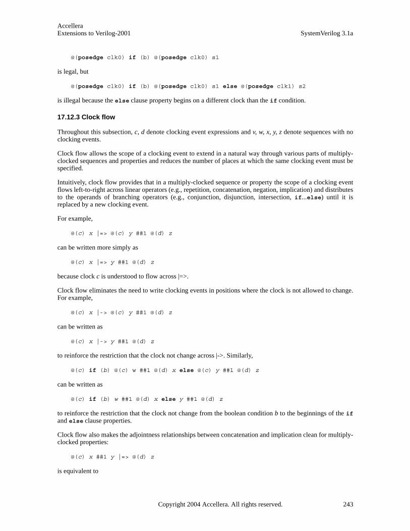
AccelleraExtensions to Verilog-2001 SystemVerilog 3.1a
@(posedge clk0) if (b) @(posedge clk0) s1
is legal, but
@(posedge clk0) if (b) @(posedge clk0) s1 else @(posedge clk1) s2
is illegal because the else clause property begins on a different clock than the if condition.
17.12.3 Clock flow
Throughout this subsection, c, d denote clocking event expressions and v, w, x, y, z denote sequences with noclocking events.
Clock flow allows the scope of a clocking event to extend in a natural way through various parts of multiply-clocked sequences and properties and reduces the number of places at which the same clocking event must bespecified.
Intuitively, clock flow provides that in a multiply-clocked sequence or property the scope of a clocking eventflows left-to-right across linear operators (e.g., repetition, concatenation, negation, implication) and distributesto the operands of branching operators (e.g., conjunction, disjunction, intersection, if...else) until it isreplaced by a new clocking event.
For example,
@(c) x |=> @(c) y ##1 @(d) z
can be written more simply as
@(c) x |=> y ##1 @(d) z
because clock c is understood to flow across |=>.
Clock flow eliminates the need to write clocking events in positions where the clock is not allowed to change.For example,
@(c) x |-> @(c) y ##1 @(d) z
can be written as
@(c) x |-> y ##1 @(d) z
to reinforce the restriction that the clock not change across |->. Similarly,
@(c) if (b) @(c) w ##1 @(d) x else @(c) y ##1 @(d) z
can be written as
@(c) if (b) w ##1 @(d) x else y ##1 @(d) z
to reinforce the restriction that the clock not change from the boolean condition b to the beginnings of the ifand else clause properties.
Clock flow also makes the adjointness relationships between concatenation and implication clean for multiply-clocked properties:
@(c) x ##1 y |=> @(d) z
is equivalent to
Copyright 2004 Accellera. All rights reserved. 243

AccelleraSystemVerilog 3.1a Extensions to Verilog-2001
@(c) x |=> y |=> @(d) z
and
@(c) x ##0 y |=> @(d) z
is equivalent to
@(c) x |-> y |=> @(d) z
The scope of a clocking event flows into parenthesized subexpressions and, if the subexpression is a sequence,also flows left-to-right across the parenthesized subexpression. However, the scope of a clocking event doesnot flow out of enclosing parentheses.
For example, in
@(c) w ##1 (x ##1 @(d) y) |=> z
w, x, z are clocked at c and y is clocked at d. Clock c flows across ##1, across the parenthesized subsequence (x##1 @(d) y), and across |=>. Clock c also flows into the parenthesized subsequence, but it does not flowthrough @(d). Clock d does not flow out of its enclosing parentheses.
As another example, in
@(c) v |=> (w ##1 @(d) x) and (y ##1 z)
v, w, y, z are clocked at c and x is clocked at d. Clock c flows across |=>, distributes to both operands of the and(which is a property conjunction due to the multiple clocking), and flows into each of the parenthesized subex-pressions. Within (w ##1 @(d) x), c flows across ##1 but does not flow through @(d). Clock d does not flowout of its enclosing parentheses. Within (y ##1 z), c flows across ##1.
Similarly, the scope of a clocking event flows into an instance of a named sequence or property, and, if theinstance is a sequence, also flows left-to-right across the instance. However, a clocking event in the declarationof a sequence or property does not flow out of an instance of that sequence or property.
Note that juxtaposing two clocking events nullifies the first of them:
@(d) @(c) x
is equivalent to @(c) x
because the flow of clock d is immediately overridden by clock c.
17.12.4 Examples
The following are examples of multiple-clock specifications:
sequence s1;@(posedge clk1) a ##1 b; // single clock sequence
endsequence sequence s2;
@(posedge clk2) c ##1 d; // single clock sequenceendsequence
1) multiple-clock sequence
sequence mult_s;@(posedge clk) a ##1 @(posedge clk1) s1 ##1 @(posedge clk2) s2;
244 Copyright 2004 Accellera. All rights reserved .
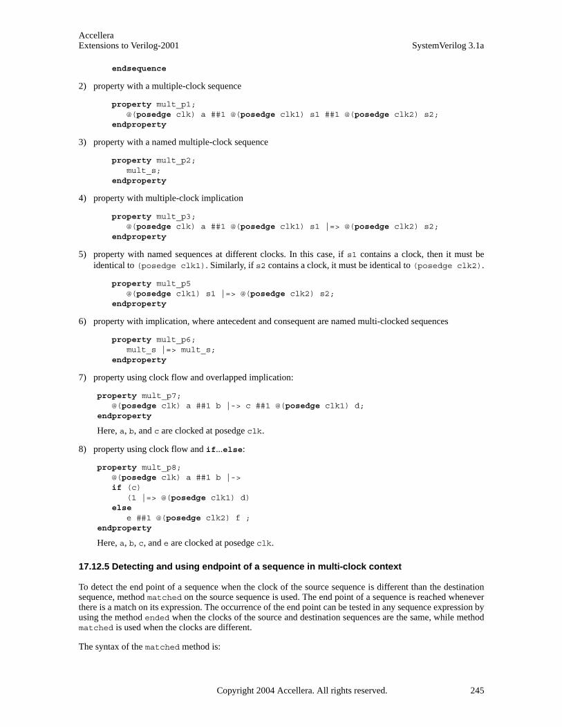
AccelleraExtensions to Verilog-2001 SystemVerilog 3.1a
endsequence
2) property with a multiple-clock sequence
property mult_p1;@(posedge clk) a ##1 @(posedge clk1) s1 ##1 @(posedge clk2) s2;
endproperty
3) property with a named multiple-clock sequence
property mult_p2;mult_s;
endproperty
4) property with multiple-clock implication
property mult_p3;@(posedge clk) a ##1 @(posedge clk1) s1 |=> @(posedge clk2) s2;
endproperty
5) property with named sequences at different clocks. In this case, if s1 contains a clock, then it must beidentical to (posedge clk1). Similarly, if s2 contains a clock, it must be identical to (posedge clk2).
property mult_p5@(posedge clk1) s1 |=> @(posedge clk2) s2;
endproperty
6) property with implication, where antecedent and consequent are named multi-clocked sequences
property mult_p6;mult_s |=> mult_s;
endproperty
7) property using clock flow and overlapped implication:
property mult_p7;@(posedge clk) a ##1 b |-> c ##1 @(posedge clk1) d;
endproperty
Here, a, b, and c are clocked at posedge clk.
8) property using clock flow and if...else:
property mult_p8;@(posedge clk) a ##1 b |-> if (c)
(1 |=> @(posedge clk1) d)else
e ##1 @(posedge clk2) f ;endproperty
Here, a, b, c, and e are clocked at posedge clk.
17.12.5 Detecting and using endpoint of a sequence in multi-clock context
To detect the end point of a sequence when the clock of the source sequence is different than the destinationsequence, method matched on the source sequence is used. The end point of a sequence is reached wheneverthere is a match on its expression. The occurrence of the end point can be tested in any sequence expression byusing the method ended when the clocks of the source and destination sequences are the same, while methodmatched is used when the clocks are different.
The syntax of the matched method is:
Copyright 2004 Accellera. All rights reserved. 245

AccelleraSystemVerilog 3.1a Extensions to Verilog-2001
sequence_instance.matched
matched is a method on a sequence which return true or false. Unlike ended, matched uses synchronizationbetween the two clocks, by storing the result of the source sequence match until the arrival of the first destina-tion clock tick after the match. When method matched is applied, it tests whether the source sequence hasreached the end point at that particular point in time. The result of matched does not depend upon the startingpoint of the source sequence.
Like ended, matched can be used on sequences that have formal arguments.
An example is shown below:
sequence e1(a,b,c); @(posedge clk) $rose(a) ##1 b ##1 c ;
endsequence sequence e2;
@(posedge sysclk) reset ##1 inst ##1 e1(ready,proc1,proc2).matched [->1] ##1 branch_back;
endsequence
In this example, source sequence e1 is evaluated at clock clk, while the destination sequence e2 is evaluatedat clock sysclk. In e2, the end point of the instance e1(ready,proc1,proc2) is tested to occur sometimeafter the occurrence of inst. Notice that method matched only tests for the end point ofe1(ready,proc1,proc2) and has no bearing on the starting point of e1(ready,proc1,proc2).
Local variables can be passed into an instance of a named sequence to which matched is applied. The samerestrictions apply as in the case of ended. Values of local variables sampled in an instance of a namedsequence to which matched is applied will flow out under the same conditions as for ended. SeeSection 17.8.
As with ended, a sequence instance to which matched is applied can have multiple matches in a single cycleof the destination sequence clock. The multiple matches are treated semantically the same way as matchingboth disjuncts of an or. In other words, the thread evaluating the destination sequence will fork to account forsuch distinct local variable valuations.
17.13 Concurrent assertions
A property on its own is never evaluated for checking an expression. It must be used within a verificationstatement for this to occur. A verification statement states the verification function to be performed on theproperty. The statement can be one of the following:
— assert to specify the property as a checker to ensure that the property holds for the design
— assume to specify the property as an assumption for the environment
— cover to monitor the property evaluation for coverage
A concurrent assertion statement can be specified in:
— an always block or initial block as a statement, wherever these blocks can appear
— a module
— an interface
— a program
246 Copyright 2004 Accellera. All rights reserved .

AccelleraExtensions to Verilog-2001 SystemVerilog 3.1a
Syntax 17-16—Concurrent assert construct syntax (excerpt from Annex A)
The assert, assume or cover statements can be referenced by their optional name. A hierarchical name canbe used consistent with the SystemVerilog naming conventions. When a name is not provided, a tool shallassign a name to the statement for the purpose of reporting. Assertion control system tasks are described inSection 23.9.
17.13.1 assert statement
The assert statement is used to enforce a property as a checker. When the property for the assert state-ment is evaluated to be true, the pass statements of the action block are executed. Otherwise, the fail state-ments of the action_block are executed. For example,
property abc(a,b,c);disable iff (a==2) not @clk (b ##1 c);
endproperty env_prop: assert property (abc(rst,in1,in2)) pass_stat else fail_stat;
When no action is needed, a null statement (i.e.;) is specified. If no statement is specified for else, then$error is used as the statement when the assertion fails.
The action_block shall not include any concurrent assert, assume, or cover statement. The action_block,however, can contain immediate assertion statements.
Note: The pass and fail statements are executed in the Reactive region. The regions of execution are explainedin the scheduling semantics section, Section 14.
17.13.2 assume statement
The purpose of the assume statement is to allow properties to be considered as assumptions for formal analy-sis as well as for dynamic simulation tools. When a property is assumed, the tools constrain the environment sothat the property holds.
For formal analysis, there is no obligation to verify that the assumed properties hold. An assumed property canbe considered as a hypothesis to prove the asserted properties.
For simulation, the environment must be constrained such that the properties that are assumed shall hold. Likean assert property, an assumed property must be checked and reported if it fails to hold. There is no require-
procedural_assertion_statement ::= concurrent_assertion_statement
| immediate_assert_statement
concurrent_assertion_item ::= [ block_identifier : ] concurrent_assertion_statement
concurrent_assertion_statement ::= assert_property_statement
| assume_property_statement | cover_property_statement
assert_property_statement::= assert property ( property_spec ) action_block
assume_property_statement::= assume property ( property_spec ) ;
cover_property_statement::= cover property ( property_spec ) statement_or_null
// from Annex A.6.10
// from Annex A.2.10
Copyright 2004 Accellera. All rights reserved. 247

AccelleraSystemVerilog 3.1a Extensions to Verilog-2001
ment on the tools to report successes of the assumed properties.
Additionally, for random simulation, biasing on the inputs provides a way to make random choices. An expres-sion can be associated with biasing as shown below
expression dist { dist_list } ; // from Annex A.1.9
Distribution sets and the dist operator are explained in Section 12.4.4.
The biasing feature is only useful when properties are considered as assumptions to drive random simulation.When a property with biasing is used in an assertion or coverage, the dist operator is equivalent to inside oper-ator, and the weight specification is ignored. For example,
a1:assume property @(posedge clk) req dist {0:=40, 1:=60} ;property proto
@(posedge clk) req |-> req[*1:$] ##0 ack;endproperty
This is equivalent to:
a1_assertion:assert property req inside {0, 1} ;property proto_assertion
@(posedge clk) req |-> req[*1:$] ##0 ack;endproperty
In the above example, signal req is specified with distribution in assumption a1, and is converted to an equiv-alent assertion a1_assertion.
It should be noted that the properties that are assumed must hold in the same way with or without biasing.When using an assume statement for random simulation, the biasing simply provides a means to select valuesof free variables, according to the specified weights, when there is a choice of selection at a particular time.
Consider an example specifying a simple synchronous request - acknowledge protocol, where variable reqcan be raised at any time and must stay asserted until ack is asserted. In the next clock cycle both req and ackmust be de-asserted.
Properties governing req are:
property pr1;@(posedge clk) !reset_n |-> !req; //when reset_n is asserted (0),keep req 0
endproperty property pr2;
@(posedge clk) ack |=> !req; // one cycle after ack, req must be de-assertedendproperty property pr3;
@(posedge clk) req |-> req[*1:$] ##0 ack; // hold req asserted until// and including ack asserted
endproperty
Properties governing ack are:
property pa1;@(posedge clk) !reset_n || !req |-> !ack;
endproperty property pa2;
@(posedge clk) ack |=> !ack;endproperty
When verifying the behavior of a protocol controller which has to respond to requests on req, assertions
248 Copyright 2004 Accellera. All rights reserved .
AccelleraExtensions to Verilog-2001 SystemVerilog 3.1a
assert_req1 and assert_req2 should be proven while assuming that statements a1, assume_ack1,assume_ack2 and assume_ack3 hold at all times.
a1:assume property @(posedge clk) req dist {0:=40, 1:=60} ; assume_ack1:assume property (pr1);assume_ack2:assume property (pr2);assume_ack3:assume property (pr3);
assert_req1:assert property (pa1)else $display("\n ack asserted while req is still de-asserted");
assert_req2:assert property (pa2)else $display("\n ack is extended over more than one cycle");
Note that assume does not provide an action block, as the actions for an assumption serve no purpose.
17.13.3 cover statement
To monitor sequences and other behavioral aspects of the design for coverage, the same syntax is used with thecover statement. The tools can gather information about the evaluation and report the results at the end ofsimulation. When the property for the cover statement is successful, the pass statements can specify a cover-age function, such as monitoring all paths for a sequence. The pass statement shall not include any concurrentassert, assume or cover statement.
Coverage results are divided into two: coverage for properties, coverage for sequences.
For sequence coverage, the statement appears as:
cover property ( sequence_expr ) statement_or_null
The results of coverage statement for a property shall contain:
— Number of times attempted
— Number of times succeeded
— Number of times failed
— Number of times succeeded because of vacuity
In addition, statement_or_null is executed every time a property succeeds.
Vacuity rules are applied only when implication operator is used. A property succeeds non-vacuously only ifthe consequent of the implication contributes to the success.
Results of coverage for a sequence shall include:
— Number of times attempted
— Number of times matched (each attempt can generate multiple matches)
In addition, statement_or_null gets executed for every match. If there are multiple matches at the same time,the statement gets executed multiple times, one for each match.
17.13.4 Using concurrent assertion statements outside of procedural code
A concurrent assertion statement can be used outside of a procedural context. It can be used within a module,an interface, or a program. A concurrent assertion statement is an assert, an assume, or a cover statement.Such a concurrent assertion statement uses the always semantics.
The following two forms are equivalent:
Copyright 2004 Accellera. All rights reserved. 249
AccelleraSystemVerilog 3.1a Extensions to Verilog-2001
assert property ( property_spec ) action_block
always assert property ( property_spec ) action_block ;
Similarly, the following two forms are equivalent:
cover property ( property_spec ) statement_or_null
always cover property ( property_spec ) statement_or_null
For example:
module top(input bit clk);logic a,b,c;property rule3;
@(posedge clk) a |-> b ##1 c;endproperty a1: assert property (rule3);...
endmodule
rule3 is a property declared in module top. The assert statement a1 starts checking the property from thebeginning to the end of simulation. The property is always checked. Similarly,
module top(input bit clk);logic a,b,c;sequence seq3;
@(posedge clk) b ##1 c;endsequence c1: cover property (seq3); ...
endmodule
The cover statement c1 starts coverage of the sequence seq3 from beginning to the end of simulation. Thesequence is always monitored for coverage.
17.13.5 Embedding concurrent assertions in procedural code
A concurrent assertion statement can also be embedded in a procedural block. For example:
property rule;a ##1 b ##1 c;
endproperty
always @(posedge clk) begin <statements> assert property (rule);
end
If the statement appears in an always block, the property is always monitored. If the statement appears in aninitial block, then the monitoring is performed only on the first clock tick.
Two inferences are made from the procedural context: clock from the event control of an always block, andthe enabling conditions.
A clock is inferred if the statement is placed in an always or initial block with an event control abiding bythe following rules:
250 Copyright 2004 Accellera. All rights reserved .

AccelleraExtensions to Verilog-2001 SystemVerilog 3.1a
— The clock to be inferred must be placed as the first term of the event control as an edge specifier (posedgeexpression or negedge expression).
— The variables in expression must not be used anywhere in the always or initial block.
For example:
property r1;q != d;
endproperty always @(posedge mclk) begin
q <= d1;r1_p: assert property (r1);
end
The above property can be checked by writing statement r1_p outside the always block, and declaring theproperty with the clock as:
property r1;@(posedge mclk)q != d;
endproperty always @(posedge mclk) begin
q <= d1;end r1p: assert property (r1);
If the clock is explicitly specified with a property, then it must be identical to the inferred clock, as shownbelow:
property r2;@(posedge mclk)(q != d);
endproperty always @(posedge mclk) begin
q <= d1;r2_p: assert property (r2);
end
In the above example, (posedge mclk) is the clock for property r2.
Another inference made from the context is the enabling condition for a property. Such derivation takes placewhen a property is placed in an if...else block or a case block. The enabling condition assumed from thecontext is used as the antecedent of the property.
property r3;@(posedge mclk)(q != d);
endproperty always @(posedge mclk) begin
if (a) begin q <= d1;r3_p: assert property (r3);
end end
The above example is equivalent to:
property r3;@(posedge mclk)a |-> (q != d);
endproperty r3_p: assert property (r3);
Copyright 2004 Accellera. All rights reserved. 251
AccelleraSystemVerilog 3.1a Extensions to Verilog-2001
always @(posedge mclk) begin if (a) begin
q <= d1; end end
Similarly, the enabling condition is also inferred from case statements.
property r4;@(posedge mclk)(q != d);
endproperty always @(posedge mclk) begin
case (a) 1: begin q <= d1;
r4p: assert property (r4);end
default: q1 <= d1;endcase
end
The above example is equivalent to:
property r4;@(posedge mclk)(a==1) |-> (q != d);
endproperty r4_p: assert property (r4);always @(posedge mclk) begin
case (a) 1: begin q <= d1;
end default: q1 <= d1;
endcase end
The enabling condition is inferred from procedural code inside an always or initial block, with the follow-ing restrictions:
1) There must not be a preceding statement with a timing control.
2) A preceding statement shall not invoke a task call which contains a timing control on any statement.
3) The concurrent assertion statement shall not be placed in a looping statement, immediately, or in anynested scope of the looping statement.
17.14 Clock resolution
There are a number of ways to specify a clock for a property:
— sequence instance with a clock, for example
sequence s2; @(posedge clk) a ##2 b; endsequence property p2; not s2; endpropertyassert property (p2);
— property, for example:
property p3; @(posedge clk) not (a ##2 b); endproperty assert property (p3);
252 Copyright 2004 Accellera. All rights reserved .
AccelleraExtensions to Verilog-2001 SystemVerilog 3.1a
— contextually inferred clock from a procedural block, for example:
always @(posedge clk) assert property (not (a ##2 b));
— clocking block, for example:
clocking master_clk @(posedge clk); property p3; not (a ##2 b); endproperty
endclocking assert property (master_clk.p3);
— default clock, for example:
default clocking master_clk ; // master clock as defined above property p4; (a ##2 b); endproperty assert property (p4);
For a multi-clocked assertion, the clocks are explicitly specified. No default clock or inferred clock is used. Inaddition, multi-clocked properties are not allowed to be defined within a clocking block.
A multi-clocked property assert statement must not be embedded in procedural code where a clock is inferred.For example, following forms are not allowed.
always @(clk) assert property (mult_clock_prop);// illegal initial @(clk) assert property (mult_clock_prop);// illegal
The rules for an assertion with one clock are discussed in the following paragraphs.
The clock for an assertion statement is determined in the decreasing order of priority:
1) Explicitly specified clock for the assertion.
2) Inferred clock from the context of the code when embedded.
3) Default clock, if specified.
A concurrent assertion statement must resolve to a clock. Otherwise, the statement is considered illegal.
Sequences and properties specified in clocking blocks resolve the clock by the following rules:
1) Event control of the clocking block specifies the clock.
2) No explicit event control is allowed in any property or sequence declaration.
3) If a named sequence that is defined outside the clocking block is used , its clock, if specified, must beidentical to the clocking block’s clock.
4) Multi-clock properties are not allowed.
Resolution of clock for a sequence declaration assumes that only one explicit event control can be specified.Also, the named sequences used in the sequence declaration can, but do not need to, contain event control intheir definitions.
sequence s;//sequence composed of two named subsequences @(posedge s_clk) e ##1 s1 ##1 s2 ##1 f;
endsequence sequence s1;
@(posedge clk1) a ##1 b; // single clock sequenceendsequence sequence s2;
Copyright 2004 Accellera. All rights reserved. 253
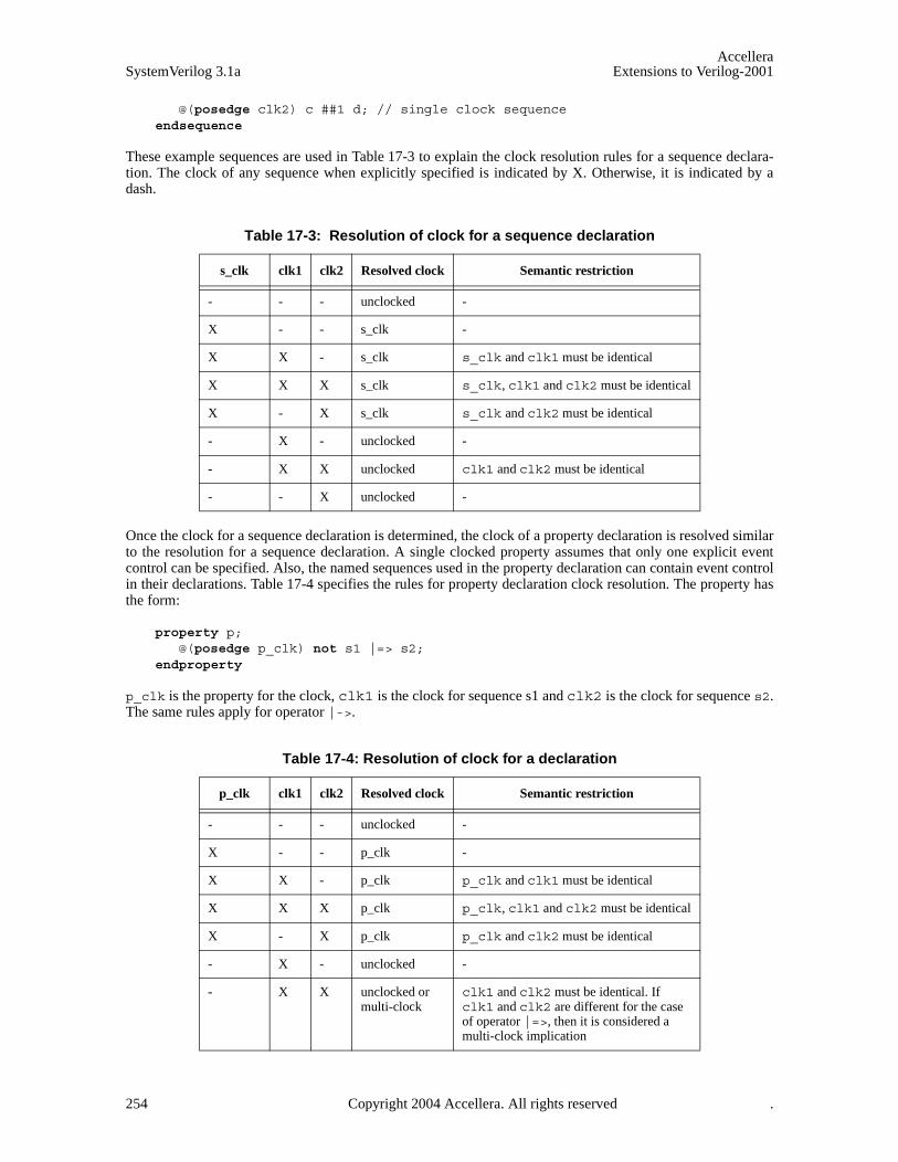
AccelleraSystemVerilog 3.1a Extensions to Verilog-2001
@(posedge clk2) c ##1 d; // single clock sequenceendsequence
These example sequences are used in Table 17-3 to explain the clock resolution rules for a sequence declara-tion. The clock of any sequence when explicitly specified is indicated by X. Otherwise, it is indicated by adash.
Once the clock for a sequence declaration is determined, the clock of a property declaration is resolved similarto the resolution for a sequence declaration. A single clocked property assumes that only one explicit eventcontrol can be specified. Also, the named sequences used in the property declaration can contain event controlin their declarations. Table 17-4 specifies the rules for property declaration clock resolution. The property hasthe form:
property p;@(posedge p_clk) not s1 |=> s2;
endproperty
p_clk is the property for the clock, clk1 is the clock for sequence s1 and clk2 is the clock for sequence s2.The same rules apply for operator |->.
Table 17-3: Resolution of clock for a sequence declaration
s_clk clk1 clk2 Resolved clock Semantic restriction
- - - unclocked -
X - - s_clk -
X X - s_clk s_clk and clk1 must be identical
X X X s_clk s_clk, clk1 and clk2 must be identical
X - X s_clk s_clk and clk2 must be identical
- X - unclocked -
- X X unclocked clk1 and clk2 must be identical
- - X unclocked -
Table 17-4: Resolution of clock for a declaration
p_clk clk1 clk2 Resolved clock Semantic restriction
- - - unclocked -
X - - p_clk -
X X - p_clk p_clk and clk1 must be identical
X X X p_clk p_clk, clk1 and clk2 must be identical
X - X p_clk p_clk and clk2 must be identical
- X - unclocked -
- X X unclocked or multi-clock
clk1 and clk2 must be identical. If clk1 and clk2 are different for the case of operator |=>, then it is considered a multi-clock implication
254 Copyright 2004 Accellera. All rights reserved .

AccelleraExtensions to Verilog-2001 SystemVerilog 3.1a
Resolution of clock for an assert statement is based on the following assumptions:
— assert can appear in an always block, initial block or outside procedural context
— clock is inferred from an always or initial block
— default clock can be specified using default clocking block
Table 17-5 specifies the rules for clock resolution when assert appears in an always or initial block, wherei_clk is the inferred clock from an always or initial block, d_clk is the default clock, and p_clk is theproperty clock.
When the assert statement is outside any procedural block, there is no inferred clock. The rules for clock res-olution are specified in Table 17-6.
17.14.1 Clock resolution in multiply-clocked properties
Throughout this subsection, s, s1, s2 denote sequences without clocking events; p, p1, p2 denote propertieswithout clocking events; m, m1, m2 denote multiply-clocked sequences, q, q1, q2 denote multiply-clocked
- - X unclocked -
Table 17-5: Resolution of clock in an always or initial block
i_clk d_clk p_clk Resolved clock Semantic restriction
- - - unclocked Error. An assertion must have a clock
X - - i_clk -
- X - d_clk
- - X p_clk
X - X i_clk i_clk and p_clk must be identical
X X - i_clk -
- X X p_clk
- - X p_clk -
Table 17-6: Resolution of clock outside a procedural block
d_clk p_clk Resolved clock Semantic restriction
– – unclocked Error. An assertion must have a clock
X - d_clk
– X p_clk
X X p_clk
Table 17-4: Resolution of clock for a declaration
p_clk clk1 clk2 Resolved clock Semantic restriction
Copyright 2004 Accellera. All rights reserved. 255
AccelleraSystemVerilog 3.1a Extensions to Verilog-2001
properties; and c, c1, c2 denote non-identical clocking event expressions.
Due to clock flow, juxtaposition of two clocks nullifies the first. This and the nesting of clocking events withinother property building operators mean that there are subtleties in the general interpretation of the restrictionsabout where the clock can change in multiply-clocked properties. For example,
@(c) s |-> @(c) (p and @(c1) p1)
appears legal because the antecedent is clocked by c and the consequent begins syntactically with the clockingevent @(c). However, the consequent sequence is equivalent to
(@(c) p) and (@(c1) p1)
and |-> cannot synchronize between clock c from the antecedent and clock c1 from the second conjunct of theconsequent. Similarly,
@(c) s |-> @(c1) (@(c) p)
appears illegal due to the apparent clock change from c to c1 across |->. However, it is legal, although arguablymisleading in style, because the consequent property is equivalent to @(c) p.
This subsection gives a more precise treatment of the restrictions on multiply-clocked use of |-> and if/if...else than the intuitive discussion in Section 17.12. The present treatment depends on the notion of the setof semantic leading clocks for a multiply-clocked sequence or property.
Some sequences and properties have no explicit leading clock event. Their initial clocking event is inheritedfrom an outer clocking event according to the flow of clocking event scope. In this case, the semantic leadingclock is said to be inherited. For example, in the property
@(c) s |=> p and @(c1) p1
the semantic leading clock of the subproperty p is inherited since the initial clock of p is the clock that flowsacross |=>.
A multiply-clocked sequence has a unique semantic leading clock, defined inductively as follows.
— The semantic leading clock of s is inherited.
— The semantic leading clock of @(c) s is c.
— If inherited is the semantic leading clock of m, then the semantic leading clock of @(c) m is c. Otherwise,the semantic leading clock of @(c) m is equal to the semantic leading clock of m.
— The semantic leading clock of (m) is equal to the semantic leading clock of m.
— The semantic leading clock of m1 ## m2 is equal to the semantic leading clock of m1.
The set of semantic leading clocks of a multiply-clocked property is defined inductively as follows.
— The set of semantic leading clocks of m is {c}, where c is the unique semantic leading clock of m.
— The set of semantic leading clocks of p is {inherited}.
— If inherited is an element of the set of semantic leading clocks of q, then the set of semantic leading clocksof @(c) q is obtained from the set of semantic leading clocks of q by replacing inherited by c. Otherwise,the set of semantic leading clocks of @(c) q is equal to the set of semantic leading clocks of q.
— The set of semantic leading clocks of (q) is equal to the set of semantic leading clocks of q.
— The set of semantic leading clocks of not q is equal to the set of semantic leading clocks of q.
— The set of semantic leading clocks of q1 and q2 is the union of the set of semantic leading clocks of q1 withthe set of semantic leading clocks of q2.
256 Copyright 2004 Accellera. All rights reserved .
AccelleraExtensions to Verilog-2001 SystemVerilog 3.1a
— The set of semantic leading clocks of q1 or q2 is the union of the set of semantic leading clocks of q1 withthe set of semantic leading clocks of q2.
— The set of semantic leading clocks of m |-> p is equal to the set of semantic leading clocks of m.
— The set of semantic leading clocks of m |=> p is equal to the set of semantic leading clocks of m.
— The set of semantic leading clocks of if (b) q is {inherited}.
— The set of semantic leading clocks of if (b) q1 else q2 is {inherited}.
— The set of semantic leading clocks of a property instance is equal to the set of semantic leading clocks ofthe multiply-clocked property obtained from the body of its declaration by substituting in actual argu-ments.
For example, the multiply-clocked sequence
@(c1) s1 ## @(c2) s2
has c1 as its unique semantic leading clock, while the multiply-clocked property
not (p1 and (@(c2) p2)
has {inherited, c2} as its set of semantic leading clocks.
In the presence of an incoming outer clock, the inherited semantic leading clock is always understood to referto the incoming outer clock. On the other hand, if a property has only explicit semantic leading clocks, then theincoming outer clock has no effect on the clocking of the property since the explicit clock events replace theincoming outer clock. Therefore, the clocking of a property q in the presence of incoming outer clock c isequivalent to the clocking of the property @(c) q.
The rules for using multiply-clocked overlapping implication and if/if...else in the presence of an incomingouter clock can now be stated more precisely.
1) Multiply-clocked overlapping implication.
Let c be the incoming outer clock. Then the clocking of m |-> q is equivalent to the clocking of@(c) m |-> q
In the presence of the incoming outer clock, m has a well-defined ending clock, and there is a well-defined clock that flows across |->. The multiply-clocked overlapped implication m |-> q is legal forincoming clock c if and only if the following two conditions are met:
a) Every explicit semantic leading clock of q is identical to the ending clock of m.
b) If inherited is a semantic leading clock of q, then the ending clock of m is equal to the clock that flowsacross |->.
For example
@(c) s |-> p1 or @(c2) p2
is not legal because the ending clock of the antecedent is c, while the consequent has c2 as an explicitsemantic leading clock.
Also,
@(c) s ## (@(c1) s1) |-> p
is not legal because the set of semantic leading clocks of p is {inherited}, the ending clock of the anteced-ent is c1, and the clock that flows across |-> and is inherited by p is c.
On the other hand,
Copyright 2004 Accellera. All rights reserved. 257

AccelleraSystemVerilog 3.1a Extensions to Verilog-2001
@(c) s |-> p1 or @(c) p2
and
@(c) s ## @(c1) s1 |-> p1 or @(c1) p2
are both legal.
2) Multiply-clocked if/if...else
Let c be the incoming outer clock. Then the clocking of if (b) q1 [ else q2 ] is equivalent to the clockingof
@(c) if (b) q1 [ else q2 ]
The boolean condition b is clocked by c, so the multiply-clocked if/if...else if (b) q1 [ else q2 ] islegal for incoming clock c if and only if the following condition is met:
— Every explicit semantic leading clock of q1 [ or q2 ] is identical to c.
For example,
@(c) if (b) p1 else @(c) p2
is legal, but
@(c) if (b) @(c) (p1 and @(c2) p2)
is not.
17.15 Binding properties to scopes or instances
To facilitate verification separate from the design, it is possible to specify properties and bind them to specificmodules or instances. The following are the goals of providing this feature:
— It allows verification engineers to verify with minimum changes to the design code/files.
— It allows a convenient mechanism to attach verification IP to a module or an instance.
— No semantic changes to the assertions are introduced due to this feature. It is equivalent to writing proper-ties external to a module, using hierarchical path names.
With this feature, a user can bind a module, interface, or program instance to a module or a module instance.
The syntax of the bind construct is:
Syntax 17-17—bind construct syntax (excerpt from Annex A)
The bind directive can be specified in
— a module
— an interface
— a compilation-unit scope
bind_directive ::= bind hierarchical_identifier constant_select bind_instantiation ;
bind_instantiation ::= program_instantiation
| module_instantiation | interface_instantiation
// from Annex A.1.5
258 Copyright 2004 Accellera. All rights reserved .

AccelleraExtensions to Verilog-2001 SystemVerilog 3.1a
A program block contains non-design code (either testbench or properties) and executes in the Reactive region,as explained in Section 16.
Example of binding a program instance to a module:
bind cpu fpu_props fpu_rules_1(a,b,c);
Where:
— cpu is the name of module.
— fpu_props is the name of the program containing properties.
— fpu_rules_1 is the program instance name.
— Ports (a, b,c) get bound to signals (a,b,c) of module cpu.
— Every instance of cpu gets the properties.
Example of binding a program instance to a specific instance of a module:
bind cpu1 fpu_props fpu_rules_1(a,b,c);
By binding a program to a module or an instance, the program becomes part of the bound object. The names ofassertion-related declarations can be referenced using the SystemVerilog hierarchical naming conventions.
Binding of a module instance or an interface instance works the same way as described for programs above.
interface range (input clk,enable, input int minval,expr);property crange_en;
@(posedge clk) enable |-> (minval <= expr); endproperty
range_chk: assert property (crange_en);endinteface
bind cr_unit range r1(c_clk,c_en,v_low,(in1&&in2));
In this example, interface range is instantiated in the module cr_unit. Effectively, every instance of modulecr_unit shall contain the interface instance r1.
17.16 The expect statement
The expect statement is a procedural blocking statement that allows waiting on a property evaluation. Thesyntax of the expect statement accepts a named property or a property declaration, and is given below.
Syntax 17-18—expect statement syntax (excerpt from Annex A)
The expect statement accepts the same syntax used to assert a property. An expect statement causes the exe-cuting process to block until the given property succeeds or fails. The statement following the expect isscheduled to execute after processing the Observe region in which the property completes its evaluation. Whenthe property succeeds or fails the process unblocks, and the property stops being evaluated (i.e., no propertyevaluation is started until that expect statement is executed again).
When executed, the expect statement starts a single thread of evaluation for the given property on the subse-quent clocking event, that is, the first evaluation shall take place on the next clocking event. If the propertyfails at its clocking event, the optional else clause of the action block is executed. If the property succeeds the
expect_property_statement ::= expect ( property_spec ) action_block
// from Annex A.2.10
Copyright 2004 Accellera. All rights reserved. 259
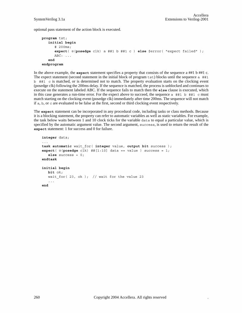
AccelleraSystemVerilog 3.1a Extensions to Verilog-2001
optional pass statement of the action block is executed.
program tst;initial begin
# 200ms;expect( @(posedge clk) a ##1 b ##1 c ) else $error( "expect failed" );ABC: ...
end endprogram
In the above example, the expect statement specifies a property that consists of the sequence a ##1 b ##1 c.The expect statement (second statement in the initial block of program tst) blocks until the sequence a ##1b ##1 c is matched, or is determined not to match. The property evaluation starts on the clocking event(posedge clk) following the 200ms delay. If the sequence is matched, the process is unblocked and continues toexecute on the statement labeled ABC. If the sequence fails to match then the else clause is executed, whichin this case generates a run-time error. For the expect above to succeed, the sequence a ##1 b ##1 c mustmatch starting on the clocking event (posedge clk) immediately after time 200ms. The sequence will not matchif a, b, or c are evaluated to be false at the first, second or third clocking event respectively.
The expect statement can be incorporated in any procedural code, including tasks or class methods. Becauseit is a blocking statement, the property can refer to automatic variables as well as static variables. For example,the task below waits between 1 and 10 clock ticks for the variable data to equal a particular value, which isspecified by the automatic argument value. The second argument, success, is used to return the result of theexpect statement: 1 for success and 0 for failure.
integer data;...task automatic wait_for( integer value, output bit success );expect( @(posedge clk) ##[1:10] data == value ) success = 1;
else success = 0;endtask
initial begin bit ok;wait_for( 23, ok ); // wait for the value 23...
end
260 Copyright 2004 Accellera. All rights reserved .
AccelleraExtensions to Verilog-2001 SystemVerilog 3.1a
Section 18Hierarchy
18.1 Introduction (informative)
Verilog has a simple organization. All data, functions and tasks are in modules except for system tasks andfunctions, which are global, and can be defined in the PLI. A Verilog module can contain instances of othermodules. Any uninstantiated module is at the top level. This does not apply to libraries, which therefore have adifferent status and a different procedure for analyzing them. A hierarchical name can be used to specify anynamed object from anywhere in the instance hierarchy. The module hierarchy is often arbitrary and a lot ofeffort is spent in maintaining port lists.
In Verilog, only net, reg, integer and time data types can be passed through module ports.
SystemVerilog adds many enhancements for representing design hierarchy:
— Packages containing declarations such as data, types, classes, tasks and functions
— Separate compilation support
— A compilation-unit scope visible only within a compilation unit
— Nested module declarations, to aid in representing self-contained models and libraries
— Relaxed rules on port declarations
— Simplified named port connections, using .name
— Implicit port connections, using .*
— Time unit and time precision specifications bound to modules
— A concept of interfaces to bundle connections between modules (presented in Section 19)
An important enhancement in SystemVerilog is the ability to pass any data type through module ports, includ-ing nets, and all variable types including reals, arrays, and structures.
18.2 Packages
SystemVerilog packages provide an additional mechanism for sharing parameters, data, type, task, function,sequence, and property declarations amongst multiple SystemVerilog modules, interfaces and programs. Pack-ages are explicitly named scopes appearing at the outermost level of the source text (at the same level as top-level modules and primitives). Types, variables, tasks, functions, sequences, and properties may be declaredwithin a package. Such declarations may be referenced within modules, macromodules, interfaces, programs,and other packages by either import or fully resolved name.
Copyright 2004 Accellera. All rights reserved. 261
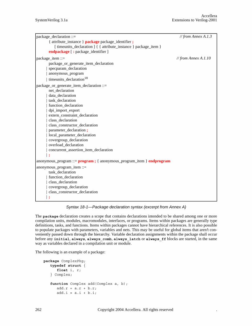
AccelleraSystemVerilog 3.1a Extensions to Verilog-2001
Syntax 18-1—Package declaration syntax (excerpt from Annex A)
The package declaration creates a scope that contains declarations intended to be shared among one or morecompilation units, modules, macromodules, interfaces, or programs. Items within packages are generally typedefinitions, tasks, and functions. Items within packages cannot have hierarchical references. It is also possibleto populate packages with parameters, variables and nets. This may be useful for global items that aren’t con-veniently passed down through the hierarchy. Variable declaration assignments within the package shall occurbefore any initial, always, always_comb, always_latch or always_ff blocks are started, in the sameway as variables declared in a compilation unit or module.
The following is an example of a package:
package ComplexPkg;typedef struct {
float i, r;} Complex;
function Complex add(Complex a, b);add.r = a.r + b.r;add.i = a.i + b.i;
package_declaration ::= { attribute_instance } package package_identifier ;
[ timeunits_declaration ] { { attribute_instance } package_item } endpackage [ : package_identifier ]
package_item ::= package_or_generate_item_declaration
| specparam_declaration | anonymous_program
| timeunits_declaration18
package_or_generate_item_declaration ::= net_declaration
| data_declaration | task_declaration | function_declaration | dpi_import_export | extern_constraint_declaration | class_declaration | class_constructor_declaration | parameter_declaration ; | local_parameter_declaration | covergroup_declaration | overload_declaration | concurrent_assertion_item_declaration | ;
anonymous_program ::= program ; { anonymous_program_item } endprogram
anonymous_program_item ::= task_declaration
| function_declaration | class_declaration | covergroup_declaration | class_constructor_declaration | ;
// from Annex A.1.3
// from Annex A.1.10
262 Copyright 2004 Accellera. All rights reserved .

AccelleraExtensions to Verilog-2001 SystemVerilog 3.1a
endfunction
function Complex mul(Complex a, b);mul.r = (a.r * b.r) - (a.i * b.i);mul.i = (a.r * b.i) + (a.i * b.r);
endfunction endpackage : ComplexPkg
18.2.1 Referencing data in packages
Packages must exist in order for the items they define to be recognized by the scopes in which they areimported.
One way to use declarations made in a package is to reference them using the scope resolution operator “::”.
ComplexPkg::Complex cout = ComplexPkg::mul(a, b);
An alternate method for utilizing package declarations is via the import statement.
Syntax 18-2—Package import syntax (excerpt from Annex A)
The import statement provides direct visibility of identifiers within packages. It allows identifiers declaredwithin packages to be visible within the current scope without a package name qualifier. Two forms of theimport statement are provided: explicit import, and wildcard import. Explicit import allows control over pre-cisely which symbols are imported:
import ComplexPkg::Complex;import ComplexPkg::add;
An explicit import shall be illegal if the imported identifier is declared in the same scope or explicitly importedfrom another package. Importing an identifier from the same package multiple times is allowed.
A wildcard import allows all identifiers declared within a package to be imported provided the identifier is nototherwise defined in the importing scope:
import ComplexPkg::*;
A wildcard import makes each identifier within the package a candidate for import. Each such identifier isimported only when it is referenced in the importing scope and it is neither declared nor explicitly importedinto the scope. Similarly, a wildcard import of an identifier is overridden by a subsequent declaration of thesame identifier in the same scope. If the same identifier is wildcard imported into a scope from two differentpackages, the identifier shall be undefined within that scope and result in an error if the identifier is used.
18.2.2 Search order Rules
Table 18-1 describes the search order rules for the declarations imported from a package. For the purposes ofthe discussion below, consider the following package declarations:
data_declaration ::= ...
| package_import_declaration
package_import_declaration ::= import package_import_item { , package_import_item } ;
package_import_item ::= package_identifier :: identifier
| package_identifier :: *
// from Annex A.2.1.3
Copyright 2004 Accellera. All rights reserved. 263

AccelleraSystemVerilog 3.1a Extensions to Verilog-2001
package p;typedef enum { FALSE, TRUE } BOOL;const BOOL c = FALSE;
endpackage
package q;const int c = 0;
endpackage
When using a wildcard import, a reference to an undefined identifier that is declared within the package causesthat identifier to be imported into the local scope. However, an error results if the same identifier is laterdeclared or explicitly imported. This is shown in the following example:
Table 18-1: Scoping Rules for Package Importation
Example Description
Scope containing a
local declaration of c
Scope not containing a
local declaration of c
Scope containing a
declaration of c imported using
import q::c
Scope containing a
declaration of c imported as import q::*
u = p::c;y = p::TRUE;
A qualified package identi-fier is visible in any scope (with-out the need for an import clause).
OK
Direct reference to c refers to the locally declared c.
p::c refers to the c in package p.
OK
Direct reference to c is illegal since it is unde-fined.
p::c refers to the c in package p.
OK
Direct reference to c refers to the c imported from q.
p::c refers to the c in package p.
OK
Direct reference to c refers to the c imported from q.
p::c refers to the c in package p.
import p::*; . . .
y = FALSE;
All declarations inside package p become poten-tially directly visible in the importing scope:– c – BOOL – FALSE – TRUE
OK
Direct reference to c refers to the locally declared c.
Direct reference to other identifi-ers (e.g., FALSE) refer to those implicitly imported from package p.
OK
Direct reference to c refers to the c imported from package p.
OK
Direct reference to c refers to the c imported from package q.
OK / ERROR
c is undefined in the importing scope. Thus, a direct reference to c is illegal and results in an error.
The import clause is other-wise allowed.
import p::c; . . .
if( ! c ) ...
The imported identifiers become directly visible in the importing scope:– c
ERROR
‘‘
OK
Direct reference to c refers to the c imported from package p.
ERROR
It shall be illegal to import an identifier defined in the importing scope.
OK / ERROR
The import of p::c makes any prior reference to c illegal.
Otherwise, direct reference to c refers to the c imported from package p.
264 Copyright 2004 Accellera. All rights reserved .

AccelleraExtensions to Verilog-2001 SystemVerilog 3.1a
module foo;import q::*;wire a = c; // This statement forces the import of q::c;import p::c; // The conflict with q::c and p::c creates an error.
endmodule
18.3 Compilation unit support
SystemVerilog supports separate compilation using compiled units. The following terms and definitions areprovided:
— compilation unit: a collection of one or more SystemVerilog source files compiled together
— compilation-unit scope: a scope that is local to the compilation unit. It contains all declarations that lie out-side of any other scope
— $unit: the name used to explicitly access the identifiers in the compilation-unit scope
The exact mechanism for defining which files constitute a compilation unit is tool specific. Tools shall providea mechanism to specify the files that make up a compilation unit. Two extreme cases are:
1) All files make a single compilation unit (in which case the declarations in the compilation-unit scope areaccessible anywhere within the design)
2) Each file is a separate compilation unit (in which case the declarations in each compilation-unit scope areaccessible only within its corresponding file)
The contents of files included using one or more ‘include directives become part of the compilation unit ofthe file they are included within.
If there is a declaration that is incomplete at the end of a file, then the compilation unit including that file willextend through each successive file until there are no incomplete declarations at the end of the group of files.
The default is that each file is a separate compilation unit.
A tool must also provide a mechanism (such as a command line switch) that specifies that all of the files com-piled together are a single compilation unit.
There are other possible mappings of files to compilation units and the mechanism for defining them are toolspecific and may not be portable.
The compilation-unit scope can contain any item that can be defined within a package. These items are in thecompilation-unit scope name space.
The following items are visible in all compilation units: modules, macromodules, primitives, programs, inter-faces, and packages. Items defined in the compilation-unit scope cannot be accessed by name from outside thecompilation unit. Access to the items in a compilation-unit scope can be accessed using the PLI, which mustprovide an iterator to traverse all the compilation units.
In Verilog, compiler directives once seen by a tool apply to all forthcoming source text. This behavior shall besupported within a separately compiled unit; however, compiler directives from one separately compiled unitshall not affect other compilation units. This may result in a difference of behavior between compiling theunits separately or as a single compilation unit containing the entire source.
When an identifier is referenced within a scope, SystemVerilog follows the Verilog name search rules:
— First, the nested scope is searched (1364-2001 12.6) (including nested module declarations), including anyidentifiers made available through package import declarations
Copyright 2004 Accellera. All rights reserved. 265
AccelleraSystemVerilog 3.1a Extensions to Verilog-2001
— Next, the compilation-unit scope is searched (including any identifiers made available through packageimport declarations
— Finally, the instance hierarchy is searched (1364-2001 12.5)
$unit is the name of the scope that encompasses a compilation unit. Its purpose is to allow the unambiguousreference to declarations at the outermost level of a compilation unit (i.e., those in the compilation-unit scope).This is done via the same scope resolution operator used to access package items.
For example:
bit b;task foo;
int b;b = 5 + $unit::b; // $unit::b is the one outside
endtask
The compilation-unit scope allows users to easily share declarations (e.g., types) across the unit of compila-tion, but without having to declare a package from which the declarations are subsequently imported. Thus, thecompilation-unit scope is similar to an implicitly defined anonymous package. Because it has no name, thecompilation-unit scope cannot be used with an import statement, and the identifiers declared within the scopeare not accessible via hierarchical references. Within a particular compilation unit, however, the special name$unit can be used to explicitly access the declarations of its compilation-unit scope.
18.4 Top-level instance
The name $root is added to unambiguously refer to a top level instance, or to an instance path starting fromthe root of the instantiation tree. $root is the root of the instantiation tree.
For example:
$root.A.B // item B within top instance A$root.A.B.C // item C within instance B within instance A
$root allows explicit access to the top of the instantiation tree. This is useful to disambiguate a local path(which takes precedence) from the rooted path. In Verilog, a hierarchical path is ambiguous. For example,A.B.C can mean the local A.B.C or the top-level A.B.C (assuming there is an instance A that contains aninstance B at both the top level and in the current module). Verilog addresses that ambiguity by giving priorityto the local scope, thereby preventing access to the top level path. $root allows explicit access to the top levelin those cases in which the name of the top level module is insufficient to uniquely identify the path.
266 Copyright 2004 Accellera. All rights reserved .

AccelleraExtensions to Verilog-2001 SystemVerilog 3.1a
18.5 Module declarations
Syntax 18-3—Module declaration syntax (excerpt from Annex A)
In Verilog, a module must be declared apart from other modules, and can only be instantiated within anothermodule. A module declaration can appear after it is instantiated in the source text.
SystemVerilog adds the capability to nest module declarations.
module m1(...); ... endmodule
module m2(...); ... endmodule
module m3(...);
m1 i1(...); // instantiates the local m1 declared belowm2 i4(...); // instantiates m2 - no local declarationmodule m1(...); ... endmodule // nested module declaration,
// m1 module name is in m3’s name space endmodule
18.6 Nested modules
A module can be declared within another module. The outer name space is visible to the inner module, so thatany name declared there can be used, unless hidden by a local name, provided the module is declared andinstantiated in the same scope.
One purpose of nesting modules is to show the logical partitioning of a module without using ports. Namesthat are global are in the outermost scope, and names that are only used locally can be limited to local modules.
module_declaration ::= module_nonansi_header [ timeunits_declaration ] { module_item }
endmodule [ : module_identifier ] | module_ansi_header [ timeunits_declaration ] { non_port_module_item }
endmodule [ : module_identifier ] | { attribute_instance } module_keyword [ lifetime ] module_identifier ( .* ) ;
[ timeunits_declaration ] { module_item } endmodule [ : module_identifier ] | extern module_nonansi_header | extern module_ansi_header
module_nonansi_header ::= { attribute_instance } module_keyword [ lifetime ] module_identifier [ parameter_port_list ]
list_of_ports ;
module_ansi_header ::= { attribute_instance } module_keyword [ lifetime ] module_identifier [ parameter_port_list ]
[ list_of_port_declarations ] ;
module_keyword ::= module | macromodule
timeunits_declaration ::= timeunit time_literal ;
| timeprecision time_literal ; | timeunit time_literal ;
timeprecision time_literal ; | timeprecision time_literal ;
timeunit time_literal ;
// from Annex A.1.3
Copyright 2004 Accellera. All rights reserved. 267

AccelleraSystemVerilog 3.1a Extensions to Verilog-2001
// This example shows a D-type flip-flop made of NAND gatesmodule dff_flat(input d, ck, pr, clr, output q, nq);wire q1, nq1, q2, nq2;
nand g1b (nq1, d, clr, q1); nand g1a (q1, ck, nq2, nq1);
nand g2b (nq2, ck, clr, q2); nand g2a (q2, nq1, pr, nq2);
nand g3a (q, nq2, clr, nq); nand g3b (nq, q1, pr, q);endmodule
// This example shows how the flip-flop can be structured into 3 RS latches.module dff_nested(input d, ck, pr, clr, output q, nq);wire q1, nq1, nq2;
module ff1; nand g1b (nq1, d, clr, q1); nand g1a (q1, ck, nq2, nq1); endmodule ff1 i1();
module ff2; wire q2; // This wire can be encapsulated in ff2 nand g2b (nq2, ck, clr, q2); nand g2a (q2, nq1, pr, nq2); endmodule ff2 i2();
module ff3; nand g3a (q, nq2, clr, nq); nand g3b (nq, q1, pr, q); endmodule ff3 i3();endmodule
The nested module declarations can also be used to create a library of modules that is local to part of a design.
module part1(....);module and2(input a, b, output z);....endmodule module or2(input a, b, output z);....endmodule ....and2 u1(....), u2(....), u3(....);.....
endmodule
This allows the same module name, e.g. and2, to occur in different parts of the design and represent differentmodules. Note that an alternative way of handling this problem is to use configurations.
Nested modules with no ports that are not explicitly instantiated shall be implicitly instantiated once with aninstance name identical to the module name. Otherwise, if they have ports and are not explicitly instantiated,
268 Copyright 2004 Accellera. All rights reserved .

AccelleraExtensions to Verilog-2001 SystemVerilog 3.1a
they are ignored.
18.7 Extern modules
To support separate compilation, extern declarations of a module can be used to declare the ports on a modulewithout defining the module itself. An extern module declaration consists of the keyword extern followed bythe module name and the list of ports for the module. Both list of ports syntax (possibly with parameters), andoriginal Verilog style port declarations can be used. Note that the potential existence of defparams precludesthe checking of the port connection information prior to elaboration time even for list of ports style declara-tions.
The following example demonstrates the usage of extern module declarations.
extern module m (a,b,c,d);extern module a #(parameter size= 8, parameter type TP = logic [7:0])
(input [size:0] a, output TP b);
module top ();wire [8:0] a;logic [7:0] b;
m m (.*);a a (.*);
endmodule
Modules m and a are then assumed to be instantiated as:
module top ();m m (a,b,c,d);a a (a,b);
endmodule
If an extern declaration exists for a module, it is possible to use .* as the ports of the module. This usageshall be equivalent to placing the ports (and possibly parameters) of the extern declaration on the module.
For example,
extern module m (a,b,c,d);extern module a #(parameter size = 8, parameter type TP = logic [7:0])
(input [size:0] a, output TP b);
module m (.*);input a,b,c;output d;
endmodule
module a (.*);...
endmodule
is equivalent to writing:
module m (a,b,c,d); input a,b,c; output d;
endmodule
module a #(parameter size = 8, parameter type TP = logic [7:0])
Copyright 2004 Accellera. All rights reserved. 269

AccelleraSystemVerilog 3.1a Extensions to Verilog-2001
(input [size:0] a, output TP b); ...
endmodule
Extern module declarations can appear at any level of the instantiation hierarchy, but are visible only withinthe level of hierarchy in which they are declared. It shall be an error for the module definition to not exactlymatch the extern module declaration.
18.8 Port declarations
Syntax 18-4—Port declaration syntax (excerpt from Annex A)
With SystemVerilog, a port can be a declaration of a net, an interface, an event, or a variable of any type,including an array, a structure or a union.
typedef struct { bit isfloat; union { int i; shortreal f; } n;
} tagged_st; // named structure
module mh1 (input int in1, input shortreal in2, output tagged_st out);...
endmodule
For the first port, if neither a type nor a direction is specified, then it shall be assumed to be a member of a portlist, and any port direction or type declarations must be declared after the port list. This is compatible with theVerilog-1995 syntax. If the first port type but no direction is specified, then the port direction shall default toinout. If the first port direction but no type is specified, then the port type shall default to wire. This defaulttype can be changed using the ‘default_nettype compiler directive, as in Verilog.
// Any declarations must follow the port list, because first port does not // have either a direction or type specified; Port directions default to inout module mh4(x, y);
wire x;tri0 y;...
endmodule
For subsequent ports in the port list, if the type and direction are omitted, then both are inherited from the pre-
inout_declaration ::= inout port_type list_of_port_identifiers
input_declaration ::=input port_type list_of_port_identifiers
| input data_type list_of_variable_identifiers
output_declaration ::= output port_type list_of_port_identifiers
| output data_type list_of_variable_port_identifiers
interface_port_declaration ::= interface_identifier list_of_interface_identifiers
| interface_identifier . modport_identifier list_of_interface_identifiers
ref_declaration ::= ref data_type list_of_port_identifiers
port_type ::= [ net_type_or_trireg ] [ signing ] { packed_dimension }
// from Annex A.2.1.2
// from Annex A.2.2.1
270 Copyright 2004 Accellera. All rights reserved .
AccelleraExtensions to Verilog-2001 SystemVerilog 3.1a
vious port. If only the direction is omitted, then it is inherited from the previous port. If only the type is omit-ted, it shall default to wire. This default type can be changed using the ‘default_nettype compilerdirective, as in Verilog.
// second port inherits its direction and type from previous port module mh3 (input byte a, b);
...endmodule
Generic interface ports cannot be declared using the Verilog-1995 list of ports style. Generic interface portscan only be declared by using a list of port declaration style.
module cpuMod(interface d, interface j);...
endmodule
18.9 List of port expressions
Verilog 1364-2001 created a list_of_port_declarations alternate style which minimized the duplication of dataused to specify the ports of a module. SystemVerilog adds an explicitly named port declaration to that style,allowing elements of arrays and structures, concatenations of elements, or aggregate expressions of elementsdeclared in a module, interface or program to be specified on the port list.
Like explicitly named ports in a module port declaration, port identifiers exist in their own namespace for eachport list. When port item is just a simple port identifier, that identifier is used as both a reference to an interfaceitem and a port identifier. Once a port identifier has been defined, there shall not be another port definition withthis same name.
For example:
module mymod (output .P1(r[3:0]),output .P2(r[7:4]),ref .Y(x), input bit R );
logic [7:0] r;int x;...
endmodule
The self-determined type of the port expression becomes the type for the port. If the port expression is to be anaggregate expression, then a cast must be used since self-determined aggregate expressions are not allowed.The port expression must resolve to a legal expression for type of module port (See section 18.12—Port con-nection rules). The port expression is optional because ports can be defined that do not connect to anythinginternal to the port.
18.10 Time unit and precision
SystemVerilog has a time unit and precision declaration which has the equivalent functionality of the ‘times-cale compiler directives in Verilog-2001. Use of these declarations removes the file order dependencies prob-lems with compiler directives. The time unit and precision can be declared by the timeunit andtimeprecision keywords, respectively, and set to a time literal which must be a power of 10 units. Forexample:
timeunit 100ps;timeprecision 10fs;
Copyright 2004 Accellera. All rights reserved. 271
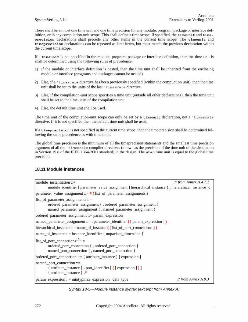
AccelleraSystemVerilog 3.1a Extensions to Verilog-2001
There shall be at most one time unit and one time precision for any module, program, package or interface def-inition, or in any compilation-unit scope. This shall define a time scope. If specified, the timeunit and time-precision declarations shall precede any other items in the current time scope. The timeunit andtimeprecision declarations can be repeated as later items, but must match the previous declaration withinthe current time scope.
If a timeunit is not specified in the module, program, package or interface definition, then the time unit isshall be determined using the following rules of precedence:
1) If the module or interface definition is nested, then the time unit shall be inherited from the enclosingmodule or interface (programs and packages cannot be nested).
2) Else, if a ‘timescale directive has been previously specified (within the compilation unit), then the timeunit shall be set to the units of the last ‘timescale directive.
3) Else, if the compilation-unit scope specifies a time unit (outside all other declarations), then the time unitshall be set to the time units of the compilation unit.
4) Else, the default time unit shall be used.
The time unit of the compilation-unit scope can only be set by a timeunit declaration, not a ‘timescaledirective. If it is not specified then the default time unit shall be used.
If a timeprecision is not specified in the current time scope, then the time precision shall be determined fol-lowing the same precedence as with time units.
The global time precision is the minimum of all the timeprecision statements and the smallest time precisionargument of all the `timescale compiler directives (known as the precision of the time unit of the simulationin Section 19.8 of the IEEE 1364-2001 standard) in the design. The step time unit is equal to the global timeprecision.
18.11 Module instances
Syntax 18-5—Module instance syntax (excerpt from Annex A)
module_instantiation ::= module_identifier [ parameter_value_assignment ] hierarchical_instance { , hierarchical_instance };
parameter_value_assignment ::= # ( list_of_parameter_assignments )
list_of_parameter_assignments ::= ordered_parameter_assignment { , ordered_parameter_assignment }
| named_parameter_assignment { , named_parameter_assignment }
ordered_parameter_assignment ::= param_expression
named_parameter_assignment ::= . parameter_identifier ( [ param_expression ] )
hierarchical_instance ::= name_of_instance ( [ list_of_port_connections ] )
name_of_instance ::= instance_identifier { unpacked_dimension }
list_of_port_connections17 ::= ordered_port_connection { , ordered_port_connection }
| named_port_connection { , named_port_connection }
ordered_port_connection ::= { attribute_instance } [ expression ]
named_port_connection ::= { attribute_instance } . port_identifier [ ( [ expression ] ) ]
| { attribute_instance } .*
param_expression ::= mintypmax_expression | data_type
// from Annex A.4.1.1
// from Annex A.8.3
272 Copyright 2004 Accellera. All rights reserved .

AccelleraExtensions to Verilog-2001 SystemVerilog 3.1a
A module can be used (instantiated) in two ways, hierarchical or top level. Hierarchical instantiation allowsmore than one instance of the same type. The module name can be a module previously declared or onedeclared later. Actual parameters can be named or ordered. Port connections can be named, ordered or implic-itly connected. They can be nets, variables, or other kinds of interfaces, events, or expressions. See below forthe connection rules.
Consider an ALU accumulator (alu_accum) example module that includes instantiations of an ALU module,an accumulator register (accum) module and a sign-extension (xtend) module. The module headers for thethree instantiated modules are shown in the following example code.
module alu (output reg [7:0] alu_out,output reg zero,input [7:0] ain, bin,input [2:0] opcode);// RTL code for the alu module
endmodule
module accum (output reg [7:0] dataout,input [7:0] datain,input clk, rst_n);// RTL code for the accumulator module
endmodule
module xtend (output reg [7:0] dout,input din,input clk, rst_n);// RTL code for the sign-extension module
endmodule
18.11.1 Instantiation using positional port connections
Verilog has always permitted instantiation of modules using positional port connections, as shown in thealu_accum1 module example, below.
module alu_accum1 (output [15:0] dataout,input [7:0] ain, bin,input [2:0] opcode,input clk, rst_n);wire [7:0] alu_out;
alu alu (alu_out, , ain, bin, opcode);accum accum (dataout[7:0], alu_out, clk, rst_n);xtend xtend (dataout[15:8], alu_out[7], clk, rst_n);
endmodule
As long as the connecting variables are ordered correctly and are the same size as the instance-ports that theyare connected to, there shall be no warnings and the simulation shall work as expected.
18.11.2 Instantiation using named port connections
Verilog has always permitted instantiation of modules using named port connections as shown in thealu_accum2 module example.
module alu_accum2 (
Copyright 2004 Accellera. All rights reserved. 273
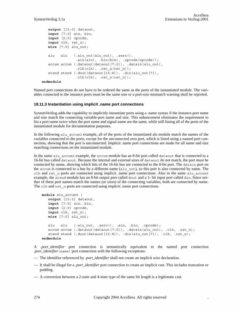
AccelleraSystemVerilog 3.1a Extensions to Verilog-2001
output [15:0] dataout,input [7:0] ain, bin,input [2:0] opcode,input clk, rst_n);wire [7:0] alu_out;
alu alu (.alu_out(alu_out), .zero(), .ain(ain), .bin(bin), .opcode(opcode));
accum accum (.dataout(dataout[7:0]), .datain(alu_out), .clk(clk), .rst_n(rst_n));
xtend xtend (.dout(dataout[15:8]), .din(alu_out[7]), .clk(clk), .rst_n(rst_n));
endmodule
Named port connections do not have to be ordered the same as the ports of the instantiated module. The vari-ables connected to the instance ports must be the same size or a port-size mismatch warning shall be reported.
18.11.3 Instantiation using implicit .name port connections
SystemVerilog adds the capability to implicitly instantiate ports using a .name syntax if the instance-port nameand size match the connecting variable-port name and size. This enhancement eliminates the requirement tolist a port name twice when the port name and signal name are the same, while still listing all of the ports of theinstantiated module for documentation purposes.
In the following alu_accum3 example, all of the ports of the instantiated alu module match the names of thevariables connected to the ports, except for the unconnected zero port, which is listed using a named port con-nection, showing that the port is unconnected. Implicit .name port connections are made for all name and sizematching connections on the instantiated module.
In the same alu_accum3 example, the accum module has an 8-bit port called dataout that is connected to a16-bit bus called dataout. Because the internal and external sizes of dataout do not match, the port must beconnected by name, showing which bits of the 16-bit bus are connected to the 8-bit port. The datain port onthe accum is connected to a bus by a different name (alu_out), so this port is also connected by name. Theclk and rst_n ports are connected using implicit .name port connections. Also in the same alu_accum3example, the xtend module has an 8-bit output port called dout and a 1- bit input port called din. Since nei-ther of these port names match the names (or sizes) of the connecting variables, both are connected by name.The clk and rst_n ports are connected using implicit .name port connections.
module alu_accum3 (output [15:0] dataout,input [7:0] ain, bin,input [2:0] opcode,input clk, rst_n);wire [7:0] alu_out;
alu alu (.alu_out, .zero(), .ain, .bin, .opcode);accum accum (.dataout(dataout[7:0]), .datain(alu_out), .clk, .rst_n);xtend xtend (.dout(dataout[15:8]), .din(alu_out[7]), .clk, .rst_n);
endmodule
A .port_identifier port connection is semantically equivalent to the named port connection.port_identifier(name) port connection with the following exceptions:
— The identifier referenced by .port_identifier shall not create an implicit wire declaration.
— It shall be illegal for a .port_identifier port connection to create an implicit cast. This includes truncation orpadding.
— A conversion between a 2-state and 4-state type of the same bit length is a legitimate cast.
274 Copyright 2004 Accellera. All rights reserved .

AccelleraExtensions to Verilog-2001 SystemVerilog 3.1a
— A port connection between a net type and a variable type of the same bit length is a legitimate cast.
— It shall be an error if a .port_identifier port connection between two dissimilar net types would generate awarning message as required by the Verilog-2001 standard.
18.11.4 Instantiation using implicit .* port connections
SystemVerilog adds the capability to implicitly instantiate ports using a .* syntax for all ports where theinstance-port name and size match the connecting variable-port name and size. This enhancement eliminatesthe requirement to list any port where the name and size of the connecting variable match the name and size ofthe instance port. This implicit port connection style is used to indicate that all port names and sizes match theconnections where emphasis is placed only on the exception ports. The implicit .* port connection syntax cangreatly facilitate rapid block-level testbench generation where all of the testbench variables are chosen tomatch the instantiated module port names and sizes.
In the following alu_accum4 example, all of the ports of the instantiated alu module match the names of thevariables connected to the ports, except for the unconnected zero port, which is listed using a named port con-nection, showing that the port is unconnected. The implicit .* port connection syntax connects all other portson the instantiated module.
In the same alu_accum4 example, the accum module has an 8-bit port called dataout that is connected to a16-bit bus called dataout. Because the internal and external sizes of dataout do not match, the port must beconnected by name, showing which bits of the 16-bit bus are connected to the 8-bit port. The datain port onthe accum is connected to a bus by a different name (alu_out), so this port is also connected by name. Theclk and rst_n ports are connected using implicit .* port connections. Also in the same alu_accum4 exam-ple, the xtend module has an 8-bit output port called dout and a 1- bit input port called din. Since neither ofthese port names match the names (or sizes) of the connecting variables, both are connected by name. The clkand rst_n ports are connected using implicit .* port connections.
module alu_accum4 (output [15:0] dataout,input [7:0] ain, bin,input [2:0] opcode,input clk, rst_n);wire [7:0] alu_out;
alu alu (.*, .zero());accum accum (.*, .dataout(dataout[7:0]), .datain(alu_out));xtend xtend (.*, .dout(dataout[15:8]), .din(alu_out[7]));
endmodule
An implicit .* port connection is semantically equivalent to a default .name port connection for every portdeclared in the instantiated module. A named port connection can be mixed with a .* connection to overridethe port connection to a different expression or to leave the port unconnected.
When the implicit .* port connection is mixed in the same instantiation with named port connections, theimplicit .* port connection token can be placed anywhere in the port list. The .* token can only appear atmost once in the port list.
Modules can be instantiated into the same parent module using any combination of legal positional, named,implicit .name connected and implicit .* connected instances as shown in alu_accum5 example.
module alu_accum5 (output [15:0] dataout,input [7:0] ain, bin,input [2:0] opcode,input clk, rst_n);wire [7:0] alu_out;
Copyright 2004 Accellera. All rights reserved. 275
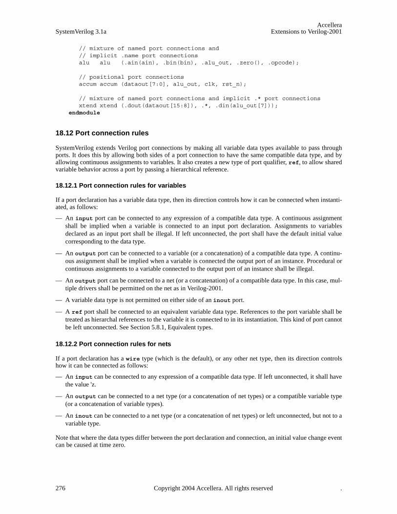
AccelleraSystemVerilog 3.1a Extensions to Verilog-2001
// mixture of named port connections and// implicit .name port connectionsalu alu (.ain(ain), .bin(bin), .alu_out, .zero(), .opcode);
// positional port connectionsaccum accum (dataout[7:0], alu_out, clk, rst_n);
// mixture of named port connections and implicit .* port connectionsxtend xtend (.dout(dataout[15:8]), .*, .din(alu_out[7]));
endmodule
18.12 Port connection rules
SystemVerilog extends Verilog port connections by making all variable data types available to pass throughports. It does this by allowing both sides of a port connection to have the same compatible data type, and byallowing continuous assignments to variables. It also creates a new type of port qualifier, ref, to allow sharedvariable behavior across a port by passing a hierarchical reference.
18.12.1 Port connection rules for variables
If a port declaration has a variable data type, then its direction controls how it can be connected when instanti-ated, as follows:
— An input port can be connected to any expression of a compatible data type. A continuous assignmentshall be implied when a variable is connected to an input port declaration. Assignments to variablesdeclared as an input port shall be illegal. If left unconnected, the port shall have the default initial valuecorresponding to the data type.
— An output port can be connected to a variable (or a concatenation) of a compatible data type. A continu-ous assignment shall be implied when a variable is connected the output port of an instance. Procedural orcontinuous assignments to a variable connected to the output port of an instance shall be illegal.
— An output port can be connected to a net (or a concatenation) of a compatible data type. In this case, mul-tiple drivers shall be permitted on the net as in Verilog-2001.
— A variable data type is not permitted on either side of an inout port.
— A ref port shall be connected to an equivalent variable data type. References to the port variable shall betreated as hierarchal references to the variable it is connected to in its instantiation. This kind of port cannotbe left unconnected. See Section 5.8.1, Equivalent types.
18.12.2 Port connection rules for nets
If a port declaration has a wire type (which is the default), or any other net type, then its direction controlshow it can be connected as follows:
— An input can be connected to any expression of a compatible data type. If left unconnected, it shall havethe value 'z.
— An output can be connected to a net type (or a concatenation of net types) or a compatible variable type(or a concatenation of variable types).
— An inout can be connected to a net type (or a concatenation of net types) or left unconnected, but not to avariable type.
Note that where the data types differ between the port declaration and connection, an initial value change eventcan be caused at time zero.
276 Copyright 2004 Accellera. All rights reserved .

AccelleraExtensions to Verilog-2001 SystemVerilog 3.1a
18.12.3 Port connection rules for interfaces
A port declaration can be a generic interface or named interface type. An interface port instance must alwaysbe connected to an interface instance or a higher-level interface port. An interface port cannot be left uncon-nected.
If a port declaration has a generic interface type, then it can be connected to an interface instance of any type.If a port declaration has a named interface type, then it must be connected to an interface instance of the iden-tical type.
18.12.4 Compatible port types
The same rules for assignment compatibility are used for compatible port types for ports declared as an inputor an output variable, or for output ports connected to variables. SystemVerilog does not change any of theother port connection compatibility rules
18.12.5 Unpacked array ports and arrays of instances
For an unpacked array port, the port and the array connected to the port must have the same number ofunpacked dimensions, and each dimension of the port must have the same size as the corresponding dimensionof the array being connected.
If the size and type of the port connection match the size and type of a single instance port, the connection shallbe made to each instance in an array of instances.
If the port connection is an unpacked array, the unpacked array dimensions of each port connection shall becompared with the dimensions of the instance array. If they match exactly in size, each element of the port con-nection shall be matched to the port left index to left index, right index to right index. If they do not match itshall be considered an error.
If the port connection is a packed array, each instance shall get a part-select of the port connection, startingwith all right-hand indices to match the right most part-select, and iterating through the right most dimensionfirst. Too many or too few bits to connect all the instances shall be considered an error.
18.13 Name spaces
SystemVerilog has eight name spaces for identifiers, two are global (definitions name space and package namespace), two are global to the compilation unit (compilation unit name space and text macro name space) andfour are local. The eight name spaces are described as follows:
1) The definitions name space unifies all the non-nested module, macromodule, primitive, program, andinterface identifiers defined outside of all other declarations. Once a name is used to define a module,macromodule, primitive, program, or interface within one compilation unit the name shall not be usedagain (in any compilation unit) to declare another non-nested module, macromodule, primitive, program,or interface outside of all other declarations. This is compatible with the definitions name space as definedin IEEE 1364-2001.
2) The package name space unifies all the package identifiers defined among all compilation units. Once aname is used to define a package within one compilation unit the name shall not be used again to declareanother package within any compilation unit.
3) The compilation-unit scope name space exists outside the module, macromodule, interface,package, program, and primitive constructs. It unifies the definitions of the functions, tasks,parameters, named events, net declarations, variable declarations and user defined types within thecompilation-unit scope.
Copyright 2004 Accellera. All rights reserved. 277
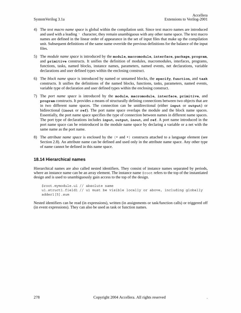
AccelleraSystemVerilog 3.1a Extensions to Verilog-2001
4) The text macro name space is global within the compilation unit. Since text macro names are introducedand used with a leading ‘ character, they remain unambiguous with any other name space. The text macronames are defined in the linear order of appearance in the set of input files that make up the compilationunit. Subsequent definitions of the same name override the previous definitions for the balance of the inputfiles.
5) The module name space is introduced by the module, macromodule, interface, package, program,and primitive constructs. It unifies the definition of modules, macromodules, interfaces, programs,functions, tasks, named blocks, instance names, parameters, named events, net declarations, variabledeclarations and user defined types within the enclosing construct.
6) The block name space is introduced by named or unnamed blocks, the specify, function, and taskconstructs. It unifies the definitions of the named blocks, functions, tasks, parameters, named events,variable type of declaration and user defined types within the enclosing construct.
7) The port name space is introduced by the module, macromodule, interface, primitive, andprogram constructs. It provides a means of structurally defining connections between two objects that arein two different name spaces. The connection can be unidirectional (either input or output) orbidirectional (inout or ref). The port name space overlaps the module and the block name spaces.Essentially, the port name space specifies the type of connection between names in different name spaces.The port type of declarations includes input, output, inout, and ref. A port name introduced in theport name space can be reintroduced in the module name space by declaring a variable or a net with thesame name as the port name.
8) The attribute name space is enclosed by the (* and *) constructs attached to a language element (seeSection 2.8). An attribute name can be defined and used only in the attribute name space. Any other typeof name cannot be defined in this name space.
18.14 Hierarchical names
Hierarchical names are also called nested identifiers. They consist of instance names separated by periods,where an instance name can be an array element. The instance name $root refers to the top of the instantiateddesign and is used to unambiguously gain access to the top of the design.
$root.mymodule.u1 // absolute nameu1.struct1.field1 // u1 must be visible locally or above, including globallyadder1[5].sum
Nested identifiers can be read (in expressions), written (in assignments or task/function calls) or triggered off(in event expressions). They can also be used as task or function names.
278 Copyright 2004 Accellera. All rights reserved .
AccelleraExtensions to Verilog-2001 SystemVerilog 3.1a
Section 19Interfaces
19.1 Introduction (informative)
The communication between blocks of a digital system is a critical area that can affect everything from ease ofRTL coding, to hardware-software partitioning to performance analysis to bus implementation choices andprotocol checking. The interface construct in SystemVerilog was specifically created to encapsulate the com-munication between blocks, allowing a smooth migration from abstract system-level design through succes-sive refinement down to lower-level register-transfer and structural views of the design. By encapsulating thecommunication between blocks, the interface construct also facilitates design re-use. The inclusion of interfacecapabilities is one of the major advantages of SystemVerilog.
At its lowest level, an interface is a named bundle of nets or variables. The interface is instantiated in a designand can be accessed through a port as a single item, and the component nets or variables referenced whereneeded. A significant proportion of a Verilog design often consists of port lists and port connection lists, whichare just repetitions of names. The ability to replace a group of names by a single name can significantly reducethe size of a description and improve its maintainability.
Additional power of the interface comes from its ability to encapsulate functionality as well as connectivity,making an interface, at its highest level, more like a class template. An interface can have parameters, con-stants, variables, functions and tasks. The types of elements in an interface can be declared, or the types can bepassed in as parameters. The member variables and functions are referenced relative to the instance name ofthe interface as instance.member. Thus, modules that are connected via an interface can simply call the task/function members of that interface to drive the communication. With the functionality thus encapsulated in theinterface, and isolated from the module, the abstraction level and/or granularity of the communication protocolcan be easily changed by replacing the interface with a different interface containing the same members butimplemented at a different level of abstraction. The modules connected via the interface don’t need to changeat all.
To provide direction information for module ports and to control the use of tasks and functions within particu-lar modules, the modport construct is provided. As the name indicates, the directions are those seen from themodule.
In addition to task/function methods, an interface can also contain processes (i.e. initial or always blocks)and continuous assignments, which are useful for system-level modeling and testbench applications. Thisallows the interface to include, for example, its own protocol checker that automatically verifies that all mod-ules connected via the interface conform to the specified protocol. Other applications, such as functional cov-erage recording and reporting, protocol checking and assertions can also be built into the interface.
The methods can be abstract, i.e. defined in one module and called in another, using the export and import con-structs. This could be coded using hierarchical path names, but this would impede re-use because the nameswould be design-specific. A better way is to declare the task and function names in the interface, and to uselocal hierarchical names from the interface instance for both definition and call. Broadcast communication ismodeled by forkjoin tasks, which can be defined in more than one module and executed concurrently.
Copyright 2004 Accellera. All rights reserved. 279

AccelleraSystemVerilog 3.1a Extensions to Verilog-2001
19.2 Interface syntax
Syntax 19-1—Interface syntax (excerpt from Annex A)
The interface construct provides a new hierarchical structure. It can contain smaller interfaces and can bepassed through ports.
The aim of interfaces is to encapsulate communication. At the lower level, this means bundling variables andwires in interfaces, and can impose access restrictions with port directions in modports. The modules can be
interface_declaration ::= interface_nonansi_header [ timeunits_declaration ] { interface_item }
endinterface [ : interface_identifier ] | interface_ansi_header [ timeunits_declaration ] { non_port_interface_item }
endinterface [ : interface_identifier ] | { attribute_instance } interface interface_identifier ( .* ) ;
[ timeunits_declaration ] { interface_item } endinterface [ : interface_identifier ]
| extern interface_nonansi_header | extern interface_ansi_header
interface_nonansi_header ::= { attribute_instance } interface [ lifetime ] interface_identifier
[ parameter_port_list ] list_of_ports ;
interface_ansi_header ::= {attribute_instance } interface [ lifetime ] interface_identifier
[ parameter_port_list ] [ list_of_port_declarations ] ;
modport_declaration ::= modport modport_item { , modport_item } ;
modport_item ::= modport_identifier ( modport_ports_declaration { , modport_ports_declaration } )
modport_ports_declaration ::={ attribute_instance } modport_simple_ports_declaration
| { attribute_instance } modport_hierarchical_ports_declaration | { attribute_instance } modport_tf_ports_declaration | { attribute_instance } modport_clocking_declaration
modport_clocking_declaration ::= clocking clocking_identifier
modport_simple_ports_declaration ::= port_direction modport_simple_port { , modport_simple_port }
modport_simple_port ::= port_identifier
| . port_identifier ( [ expression ] )
modport_hierarchical_ports_declaration ::= interface_instance_identifier [ [ constant_expression ] ] . modport_identifier
modport_tf_ports_declaration ::= import_export modport_tf_port { , modport_tf_port }
modport_tf_port ::= method_prototype
| tf_identifier
import_export ::= import | export
interface_instantiation ::= interface_identifier [ parameter_value_assignment ]
hierarchical_instance { , hierarchical_instance } ;
// from Annex A.1.3
// from Annex A.2.9
// from Annex A.4.1.2
280 Copyright 2004 Accellera. All rights reserved .
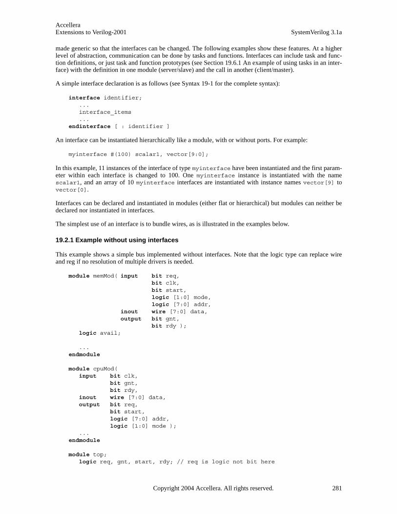
AccelleraExtensions to Verilog-2001 SystemVerilog 3.1a
made generic so that the interfaces can be changed. The following examples show these features. At a higherlevel of abstraction, communication can be done by tasks and functions. Interfaces can include task and func-tion definitions, or just task and function prototypes (see Section 19.6.1 An example of using tasks in an inter-face) with the definition in one module (server/slave) and the call in another (client/master).
A simple interface declaration is as follows (see Syntax 19-1 for the complete syntax):
interface identifier;...interface_items ...
endinterface [ : identifier ]
An interface can be instantiated hierarchically like a module, with or without ports. For example:
myinterface #(100) scalar1, vector[9:0];
In this example, 11 instances of the interface of type myinterface have been instantiated and the first param-eter within each interface is changed to 100. One myinterface instance is instantiated with the namescalar1, and an array of 10 myinterface interfaces are instantiated with instance names vector[9] tovector[0].
Interfaces can be declared and instantiated in modules (either flat or hierarchical) but modules can neither bedeclared nor instantiated in interfaces.
The simplest use of an interface is to bundle wires, as is illustrated in the examples below.
19.2.1 Example without using interfaces
This example shows a simple bus implemented without interfaces. Note that the logic type can replace wireand reg if no resolution of multiple drivers is needed.
module memMod( input bit req,bit clk,bit start,logic [1:0] mode,logic [7:0] addr,
inout wire [7:0] data,output bit gnt,
bit rdy );logic avail;
...endmodule
module cpuMod(input bit clk,
bit gnt,bit rdy,
inout wire [7:0] data,output bit req,
bit start,logic [7:0] addr,logic [1:0] mode );
...endmodule
module top;logic req, gnt, start, rdy; // req is logic not bit here
Copyright 2004 Accellera. All rights reserved. 281

AccelleraSystemVerilog 3.1a Extensions to Verilog-2001
logic clk = 0;logic [1:0] mode;logic [7:0] addr;wire [7:0] data;
memMod mem(req, clk, start, mode, addr, data, gnt, rdy);cpuMod cpu(clk, gnt, rdy, data, req, start, addr, mode);
endmodule
19.2.2 Interface example using a named bundle
The simplest form of a SystemVerilog interface is a bundled collection of variables or nets. When an interfaceis referenced as a port, the variables and nets in it are assumed to have ref and inout access, respectively.The following interface example shows the basic syntax for defining, instantiating and connecting an interface.Usage of the SystemVerilog interface capability can significantly reduce the amount of code required to modelport connections.
interface simple_bus; // Define the interfacelogic req, gnt;logic [7:0] addr, data;logic [1:0] mode; logic start, rdy;
endinterface: simple_bus
module memMod(simple_bus a, // Access the simple_bus interface input bit clk);
logic avail;// When memMod is instantiated in module top, a.req is the req// signal in the sb_intf instance of the ’simple_bus’ interfacealways @(posedge clk) a.gnt <= a.req & avail;
endmodule
module cpuMod(simple_bus b, input bit clk);...
endmodule
module top;logic clk = 0;
simple_bus sb_intf(); // Instantiate the interface
memMod mem(sb_intf, clk); // Connect the interface to the module instancecpuMod cpu(.b(sb_intf), .clk(clk)); // Either by position or by name
endmodule
In the preceding example, if the same identifier, sb_intf, had been used to name the simple_bus interfacein the memMod and cpuMod module headers, then implicit port declarations also could have been used toinstantiate the memMod and cpuMod modules into the top module, as shown below.
module memMod (simple_bus sb_intf, input bit clk);...
endmodule
module cpuMod (simple_bus sb_intf, input bit clk);...
endmodule
282 Copyright 2004 Accellera. All rights reserved .
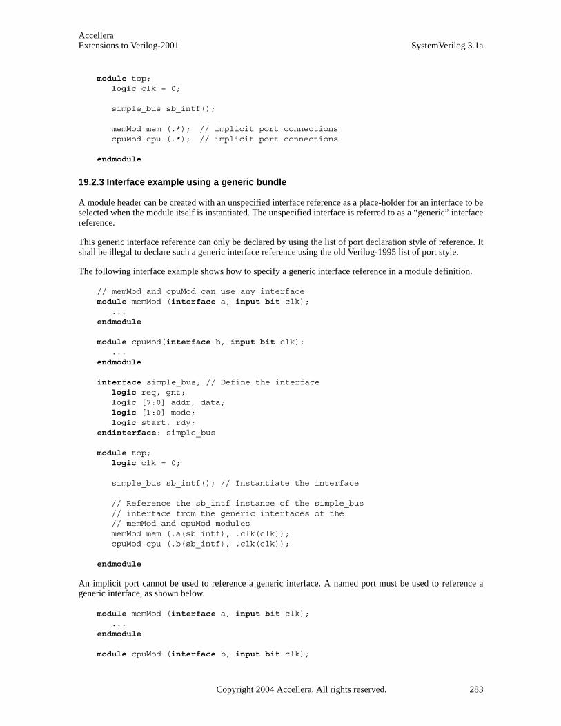
AccelleraExtensions to Verilog-2001 SystemVerilog 3.1a
module top;logic clk = 0;
simple_bus sb_intf();
memMod mem (.*); // implicit port connectionscpuMod cpu (.*); // implicit port connections
endmodule
19.2.3 Interface example using a generic bundle
A module header can be created with an unspecified interface reference as a place-holder for an interface to beselected when the module itself is instantiated. The unspecified interface is referred to as a “generic” interfacereference.
This generic interface reference can only be declared by using the list of port declaration style of reference. Itshall be illegal to declare such a generic interface reference using the old Verilog-1995 list of port style.
The following interface example shows how to specify a generic interface reference in a module definition.
// memMod and cpuMod can use any interfacemodule memMod (interface a, input bit clk);
...endmodule
module cpuMod(interface b, input bit clk);...
endmodule
interface simple_bus; // Define the interfacelogic req, gnt;logic [7:0] addr, data;logic [1:0] mode; logic start, rdy;
endinterface: simple_bus
module top;logic clk = 0;
simple_bus sb_intf(); // Instantiate the interface
// Reference the sb_intf instance of the simple_bus// interface from the generic interfaces of the// memMod and cpuMod modulesmemMod mem (.a(sb_intf), .clk(clk));cpuMod cpu (.b(sb_intf), .clk(clk));
endmodule
An implicit port cannot be used to reference a generic interface. A named port must be used to reference ageneric interface, as shown below.
module memMod (interface a, input bit clk);...
endmodule
module cpuMod (interface b, input bit clk);
Copyright 2004 Accellera. All rights reserved. 283
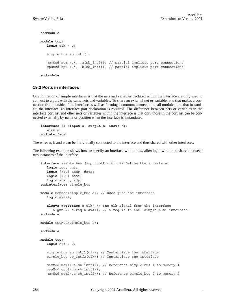
AccelleraSystemVerilog 3.1a Extensions to Verilog-2001
... endmodule
module top;logic clk = 0;
simple_bus sb_intf();
memMod mem (.*, .a(sb_intf)); // partial implicit port connectionscpuMod cpu (.*, .b(sb_intf)); // partial implicit port connections
endmodule
19.3 Ports in interfaces
One limitation of simple interfaces is that the nets and variables declared within the interface are only used toconnect to a port with the same nets and variables. To share an external net or variable, one that makes a con-nection from outside of the interface as well as forming a common connection to all module ports that instanti-ate the interface, an interface port declaration is required. The difference between nets or variables in theinterface port list and other nets or variables within the interface is that only those in the port list can be con-nected externally by name or position when the interface is instantiated.
interface i1 (input a, output b, inout c);wire d;
endinterface
The wires a, b and c can be individually connected to the interface and thus shared with other interfaces.
The following example shows how to specify an interface with inputs, allowing a wire to be shared betweentwo instances of the interface.
interface simple_bus (input bit clk); // Define the interfacelogic req, gnt;logic [7:0] addr, data;logic [1:0] mode; logic start, rdy;
endinterface: simple_bus
module memMod(simple_bus a); // Uses just the interfacelogic avail;
always @(posedge a.clk) // the clk signal from the interfacea.gnt <= a.req & avail; // a.req is in the ’simple_bus’ interface
endmodule
module cpuMod(simple_bus b);...
endmodule
module top;logic clk = 0;
simple_bus sb_intf1(clk); // Instantiate the interfacesimple_bus sb_intf2(clk); // Instantiate the interface
memMod mem1(.a(sb_intf1)); // Reference simple_bus 1 to memory 1cpuMod cpu1(.b(sb_intf1));memMod mem2(.a(sb_intf2)); // Reference simple_bus 2 to memory 2
284 Copyright 2004 Accellera. All rights reserved .

AccelleraExtensions to Verilog-2001 SystemVerilog 3.1a
cpuMod cpu2(.b(sb_intf2));
endmodule
Note: Because the instantiated interface names do not match the interface names used in the memMod andcpuMod modules, implicit port connections cannot be used for this example.
19.4 Modports
To restrict interface access within a module, there are modport lists with directions declared within the inter-face. The keyword modport indicates that the directions are declared as if inside the module.
interface i2;wire a, b, c, d;modport master (input a, b, output c, d);modport slave (output a, b, input c, d);
endinterface
In this example, the modport list name (master or slave) can be specified in the module header, where theinterface name selects an interface and the modport name selects the appropriate directional information forthe interface signals accessed in the module header.
module m (i2.master i);...
endmodule
module s (i2.slave i);...
endmodule
module top;i2 i();
m u1(.i(i));s u2(.i(i));
endmodule
The syntax of interface_name.modport_name reference_name gives a local name for a hierarchicalreference. Note that this can be generalized to any interface with a given modport name by writing inter-face.modport_name reference_name.
The modport list name (master or slave) can also be specified in the port connection with the module instance,where the modport name is hierarchical from the interface instance.
module m (i2 i);...
endmodule
module s (i2 i);...
endmodule
module top;i2 i();
m u1(.i(i.master));s u2(.i(i.slave));
endmodule
Copyright 2004 Accellera. All rights reserved. 285
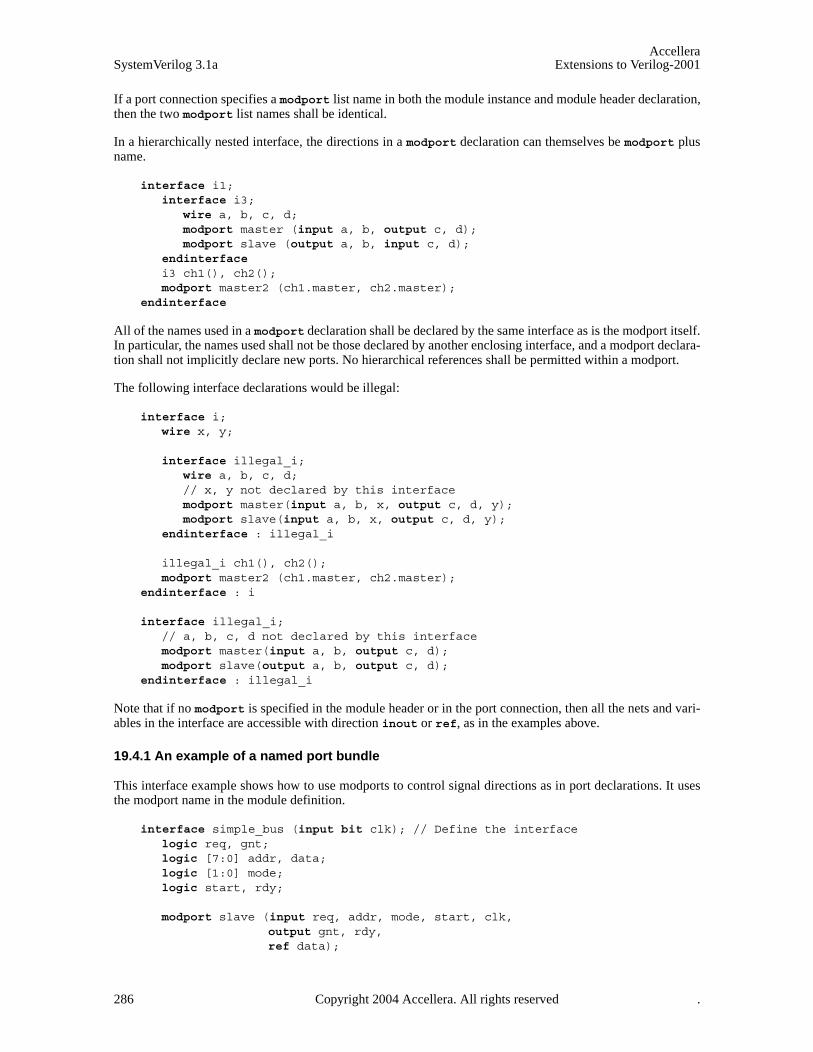
AccelleraSystemVerilog 3.1a Extensions to Verilog-2001
If a port connection specifies a modport list name in both the module instance and module header declaration,then the two modport list names shall be identical.
In a hierarchically nested interface, the directions in a modport declaration can themselves be modport plusname.
interface i1;interface i3;
wire a, b, c, d;modport master (input a, b, output c, d);modport slave (output a, b, input c, d);
endinterface i3 ch1(), ch2();modport master2 (ch1.master, ch2.master);
endinterface
All of the names used in a modport declaration shall be declared by the same interface as is the modport itself.In particular, the names used shall not be those declared by another enclosing interface, and a modport declara-tion shall not implicitly declare new ports. No hierarchical references shall be permitted within a modport.
The following interface declarations would be illegal:
interface i; wire x, y;
interface illegal_i; wire a, b, c, d; // x, y not declared by this interface modport master(input a, b, x, output c, d, y); modport slave(input a, b, x, output c, d, y);
endinterface : illegal_i
illegal_i ch1(), ch2(); modport master2 (ch1.master, ch2.master);
endinterface : i
interface illegal_i; // a, b, c, d not declared by this interface modport master(input a, b, output c, d); modport slave(output a, b, output c, d);
endinterface : illegal_i
Note that if no modport is specified in the module header or in the port connection, then all the nets and vari-ables in the interface are accessible with direction inout or ref, as in the examples above.
19.4.1 An example of a named port bundle
This interface example shows how to use modports to control signal directions as in port declarations. It usesthe modport name in the module definition.
interface simple_bus (input bit clk); // Define the interfacelogic req, gnt;logic [7:0] addr, data;logic [1:0] mode; logic start, rdy;
modport slave (input req, addr, mode, start, clk,output gnt, rdy,ref data);
286 Copyright 2004 Accellera. All rights reserved .

AccelleraExtensions to Verilog-2001 SystemVerilog 3.1a
modport master(input gnt, rdy, clk,output req, addr, mode, start,ref data);
endinterface: simple_bus
module memMod (simple_bus.slave a); // interface name and modport namelogic avail;
always @(posedge a.clk) // the clk signal from the interfacea.gnt <= a.req & avail; // the gnt and req signal in the interface
endmodule
module cpuMod (simple_bus.master b);...
endmodule
module top;logic clk = 0;
simple_bus sb_intf(clk); // Instantiate the interface
initial repeat(10) #10 clk++;
memMod mem(.a(sb_intf)); // Connect the interface to the module instancecpuMod cpu(.b(sb_intf));
endmodule
19.4.2 An example of connecting a port bundle
This interface example shows how to use modports to restrict interface signal access and control their direc-tion. It uses the modport name in the module instantiation.
interface simple_bus (input bit clk); // Define the interfacelogic req, gnt;logic [7:0] addr, data;logic [1:0] mode; logic start, rdy;
modport slave (input req, addr, mode, start, clk,output gnt, rdy,ref data);
modport master(input gnt, rdy, clk,output req, addr, mode, start,ref data);
endinterface: simple_bus
module memMod(simple_bus a); // Uses just the interface namelogic avail;
always @(posedge a.clk) // the clk signal from the interfacea.gnt <= a.req & avail; // the gnt and req signal in the interface
endmodule
Copyright 2004 Accellera. All rights reserved. 287
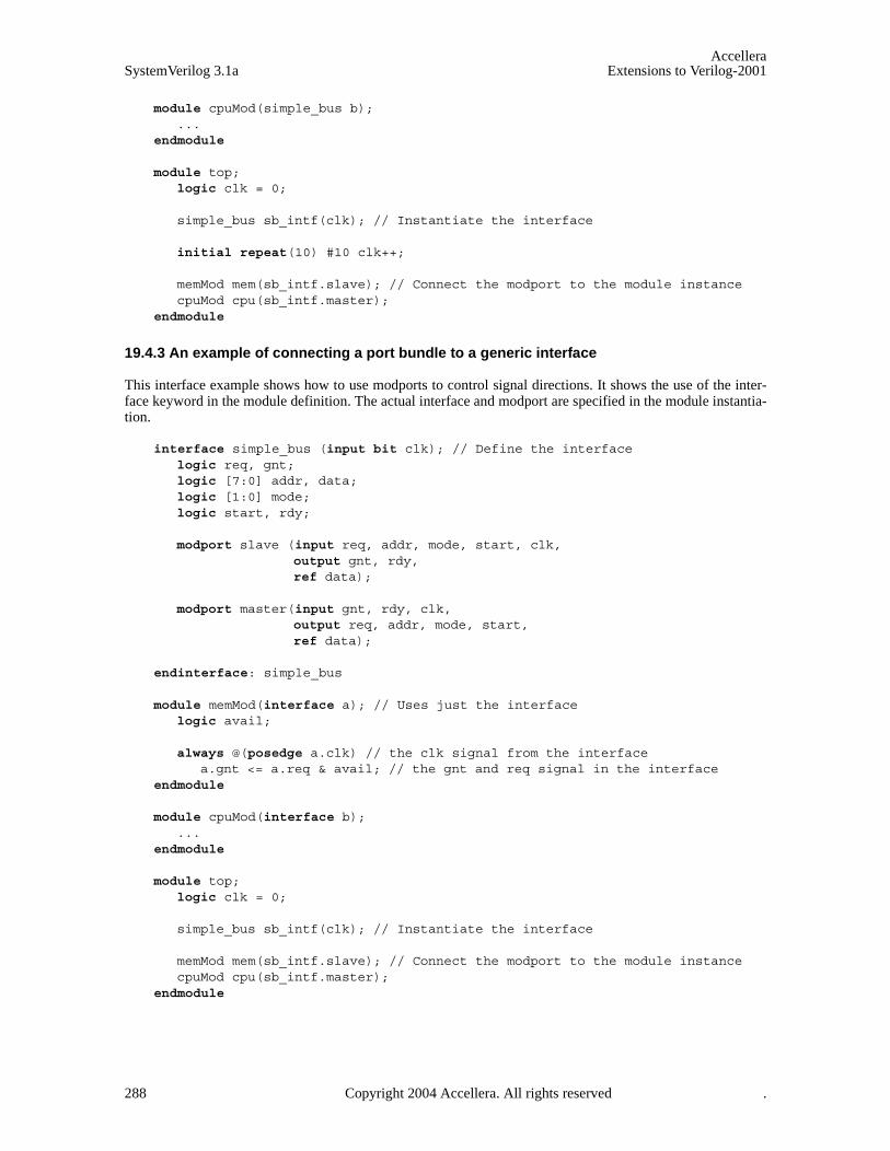
AccelleraSystemVerilog 3.1a Extensions to Verilog-2001
module cpuMod(simple_bus b);...
endmodule
module top;logic clk = 0;
simple_bus sb_intf(clk); // Instantiate the interface
initial repeat(10) #10 clk++;
memMod mem(sb_intf.slave); // Connect the modport to the module instancecpuMod cpu(sb_intf.master);
endmodule
19.4.3 An example of connecting a port bundle to a generic interface
This interface example shows how to use modports to control signal directions. It shows the use of the inter-face keyword in the module definition. The actual interface and modport are specified in the module instantia-tion.
interface simple_bus (input bit clk); // Define the interfacelogic req, gnt;logic [7:0] addr, data;logic [1:0] mode; logic start, rdy;
modport slave (input req, addr, mode, start, clk,output gnt, rdy,ref data);
modport master(input gnt, rdy, clk,output req, addr, mode, start,ref data);
endinterface: simple_bus
module memMod(interface a); // Uses just the interfacelogic avail;
always @(posedge a.clk) // the clk signal from the interfacea.gnt <= a.req & avail; // the gnt and req signal in the interface
endmodule
module cpuMod(interface b);...
endmodule
module top;logic clk = 0;
simple_bus sb_intf(clk); // Instantiate the interface
memMod mem(sb_intf.slave); // Connect the modport to the module instancecpuMod cpu(sb_intf.master);
endmodule
288 Copyright 2004 Accellera. All rights reserved .

AccelleraExtensions to Verilog-2001 SystemVerilog 3.1a
19.4.4 Modport expressions
A modport expression allows elements of arrays and structures, concatenations of elements, aggregate expres-sions of elements declared in an interface to be included in a modport list. This modport expression is explic-itly named with a port identifier, visible only through the modport connection.
Like explicitly named ports in a module port declaration, port identifiers exist in their own namespace for eachmodport list. When modport item is just a simple port identifier, that identifier is used as both a reference to aninterface item and a port identifier. Once a port identifier has been defined, there shall not be another port def-inition with this same name.
For example:
interface I;logic [7:0] r;const int x=1;bit R;modport A (output .P(r[3:0]), input .Q(x), R);modport B (output .P(r[7:4]), input .Q(2), R);
endinterface
module M ( interface i);,initial i.P = i.Q;
endmodule
module top;I i1;M u1 (i1.A);M u2 (i1.B);initial #1 $display("%b", i1.r); // displays 00010010
endmodule
The self-determined type of the port expression becomes the type for the port. If the port expression is to be anaggregate expression, then a cast must be used since self-determined aggregate expressions are not allowed.The port expression must resolve to a legal expression for type of module port (See section 18.12—Port con-nection rules). In the example above, the Q port could not be an output or inout because the port expression is aconstant. The port expression is optional because ports can be defined that do not connect to anything internalto the port.
19.4.5 Clocking blocks and modports
The modport construct can also be used to specify the direction of clocking blocks declared within an inter-face. As with other modport declarations, the directions of the clocking block are those seen from the modulein which the interface becomes a port. The syntax for this is shown below.
Syntax 19-2—modport clocking declaration syntax (excerpt from Annex A)
modport_declaration ::= modport modport_item { , modport_item } ;
modport_item ::= modport_identifier ( modport_ports_declaration { , modport_ports_declaration } )
modport_ports_declaration ::={ attribute_instance } modport_simple_ports_declaration
| { attribute_instance } modport_hierarchical_ports_declaration | { attribute_instance } modport_tf_ports_declaration | { attribute_instance } modport_clocking_declaration
modport_clocking_declaration ::= clocking clocking_identifier
// from Annex A.2.9
Copyright 2004 Accellera. All rights reserved. 289
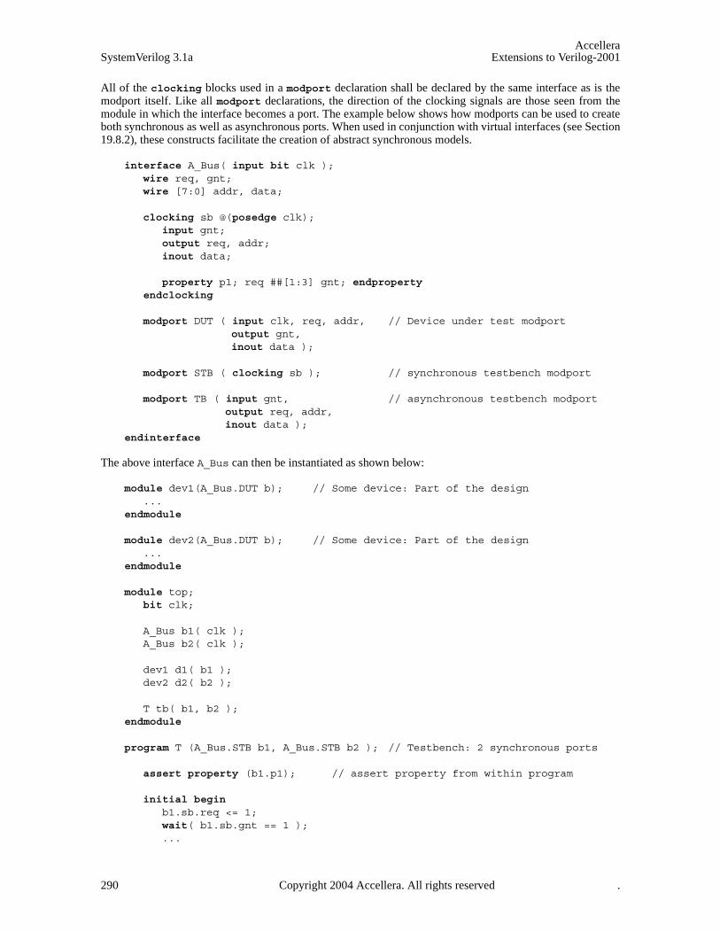
AccelleraSystemVerilog 3.1a Extensions to Verilog-2001
All of the clocking blocks used in a modport declaration shall be declared by the same interface as is themodport itself. Like all modport declarations, the direction of the clocking signals are those seen from themodule in which the interface becomes a port. The example below shows how modports can be used to createboth synchronous as well as asynchronous ports. When used in conjunction with virtual interfaces (see Section19.8.2), these constructs facilitate the creation of abstract synchronous models.
interface A_Bus( input bit clk );wire req, gnt;wire [7:0] addr, data;
clocking sb @(posedge clk); input gnt;output req, addr;inout data;
property p1; req ##[1:3] gnt; endproperty endclocking
modport DUT ( input clk, req, addr, // Device under test modportoutput gnt,inout data );
modport STB ( clocking sb ); // synchronous testbench modport
modport TB ( input gnt, // asynchronous testbench modportoutput req, addr, inout data );
endinterface
The above interface A_Bus can then be instantiated as shown below:
module dev1(A_Bus.DUT b); // Some device: Part of the design...
endmodule
module dev2(A_Bus.DUT b); // Some device: Part of the design...
endmodule
module top;bit clk;
A_Bus b1( clk );A_Bus b2( clk );
dev1 d1( b1 );dev2 d2( b2 );
T tb( b1, b2 );endmodule
program T (A_Bus.STB b1, A_Bus.STB b2 ); // Testbench: 2 synchronous ports
assert property (b1.p1); // assert property from within program
initial begin b1.sb.req <= 1;wait( b1.sb.gnt == 1 );...
290 Copyright 2004 Accellera. All rights reserved .

AccelleraExtensions to Verilog-2001 SystemVerilog 3.1a
b1.sb.req <= 0;b2.sb.req <= 1;wait( b2.sb.gnt == 1 );...b2.sb.req <= 0;
end endprogram
The example above shows the program block using the synchronous interface designated by the clocking-modport of interface ports b1 and b2. In addition to the procedural drives and samples of the clocking blocksignals, the program asserts the property p1 of one of its interfaces b1.
19.5 Interfaces and specify blocks
The specify block is used to describe various paths across a module and perform timing checks to ensure thatevents occurring at the module inputs satisfy the timing constraints of the device described by the module. Themodule paths are from module input ports to output ports and the timing checks are relative to the moduleinputs. The specify block refers to these ports as terminal descriptor. Module inout ports can function aseither an input or output terminal. When one of the port instances is an interface, each signal in the interfacebecomes an available terminal, with the default direction as defined for an interface, or as restricted by a mod-port. A ref port cannot be used as a terminal in a specify block.
The following shows an example of using interfaces together with a specify block:
interface itf;logic c,q,d;modport flop (input c,d, output q);
endinterface
module dtype (itf.flop ch);always_ff @(posedge ch.c) ch.q <= ch.d;
specify ( posedge ch.c => (ch.q+:ch.d)) = (5,6);$setup( ch.d, posedge ch.c, 1 );
endspecify endmodule
19.6 Tasks and functions in interfaces
Tasks and functions can be defined within an interface, or they can be defined within one or more of the mod-ules connected. This allows a more abstract level of modeling. For example “read” and “write” can be definedas tasks, without reference to any wires, and the master module can merely call these tasks. In a modportthese tasks are declared as import tasks.
If a module is connected to a modport containing an exported task or function, and the module does not definethat task or function, then an elaboration error shall occur. Similarly if the modport contains an exported taskor function prototype, and the task or function defined in the module does not exactly match that prototype,then an elaboration error shall occur.
If the tasks or functions are defined in a module, using a hierarchical name, they must also be declared asextern in the interface, or as export in a modport.
Tasks (not functions) can be defined in a module that is instantiated twice, e.g. two memories driven from thesame CPU. Such multiple task definitions are allowed by a forkjoin extern declaration in the interface.
Copyright 2004 Accellera. All rights reserved. 291

AccelleraSystemVerilog 3.1a Extensions to Verilog-2001
19.6.1 An example of using tasks in an interface interface simple_bus (input bit clk); // Define the interface
logic req, gnt;logic [7:0] addr, data;logic [1:0] mode; logic start, rdy;
task masterRead(input logic [7:0] raddr); // masterRead method// ...
endtask: masterRead
task slaveRead; // slaveRead method// ...
endtask: slaveRead
endinterface: simple_bus
module memMod(interface a); // Uses any interfacelogic avail;
always @(posedge a.clk) // the clk signal from the interfacea.gnt <= a.req & avail // the gnt and req signals in the interface
always @(a.start)a.slaveRead;
endmodule
module cpuMod(interface b);enum {read, write} instr;logic [7:0] raddr;
always @(posedge b.clk)if (instr == read)
b.masterRead(raddr); // call the Interface method...
endmodule
module top;logic clk = 0;
simple_bus sb_intf(clk); // Instantiate the interface
memMod mem(sb_intf); cpuMod cpu(sb_intf);
endmodule
A function prototype specifies the types and directions of the arguments and the return value of a functionwhich is defined elsewhere. Similarly, a task prototype specifies the types and directions of the arguments of atask which is defined elsewhere. In a modport, the import and export constructs can either use task or functionprototypes or use just the identifiers. The only exception is when a modport is used to import a function or taskfrom another module, in which case a full prototype shall be used.
The number and types of arguments in a prototype must match the argument types in the function or task dec-laration. The rules for type equivalency are described in Section 5.8.1, Equivalent types.
19.6.2 An example of using tasks in modports
This interface example shows how to use modports to control signal directions and task access in a full read/
292 Copyright 2004 Accellera. All rights reserved .

AccelleraExtensions to Verilog-2001 SystemVerilog 3.1a
write interface.
interface simple_bus (input bit clk); // Define the interfacelogic req, gnt;logic [7:0] addr, data;logic [1:0] mode; logic start, rdy;
modport slave (input req, addr, mode, start, clk,output gnt, rdy,ref data,import task slaveRead(),
task slaveWrite()); // import into module that uses the modport
modport master(input gnt, rdy, clk,output req, addr, mode, start,ref data,import masterRead,
masterWrite);// import into module that uses the modport
task masterRead(input logic [7:0] raddr); // masterRead method// ...
endtask
task slaveRead; // slaveRead method// ...
endtask
task masterWrite(input logic [7:0] waddr);//...
endtask
task slaveWrite;//...
endtask
endinterface: simple_bus
module memMod(interface a); // Uses just the interfacelogic avail;
always @(posedge a.clk) // the clk signal from the interfacea.gnt <= a.req & avail; // the gnt and req signals in the interface
always @(a.start)if (a.mode[0] == 1’b0)
a.slaveRead;else
a.slaveWrite;endmodule
module cpuMod(interface b);enum {read, write} instr = $rand();logic [7:0] raddr = $rand();
always @(posedge b.clk)if (instr == read)
Copyright 2004 Accellera. All rights reserved. 293
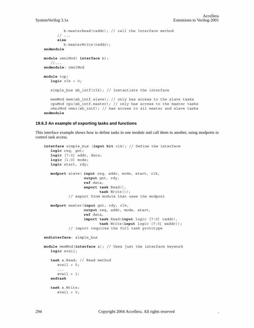
AccelleraSystemVerilog 3.1a Extensions to Verilog-2001
b.masterRead(raddr); // call the Interface method// ...else
b.masterWrite(raddr);endmodule
module omniMod( interface b);//...
endmodule: omniMod
module top;logic clk = 0;
simple_bus sb_intf(clk); // Instantiate the interface
memMod mem(sb_intf.slave); // only has access to the slave taskscpuMod cpu(sb_intf.master); // only has access to the master tasksomniMod omni(sb_intf); // has access to all master and slave tasks
endmodule
19.6.3 An example of exporting tasks and functions
This interface example shows how to define tasks in one module and call them in another, using modports tocontrol task access.
interface simple_bus (input bit clk); // Define the interfacelogic req, gnt;logic [7:0] addr, data;logic [1:0] mode; logic start, rdy;
modport slave( input req, addr, mode, start, clk,output gnt, rdy,ref data,export task Read(),
task Write()); // export from module that uses the modport
modport master(input gnt, rdy, clk,output req, addr, mode, start,ref data,import task Read(input logic [7:0] raddr),
task Write(input logic [7:0] waddr)); // import requires the full task prototype
endinterface: simple_bus
module memMod(interface a); // Uses just the interface keywordlogic avail;
task a.Read; // Read methodavail = 0;...avail = 1;
endtask
task a.Write;avail = 0;
294 Copyright 2004 Accellera. All rights reserved .

AccelleraExtensions to Verilog-2001 SystemVerilog 3.1a
...avail = 1;
endtask endmodule
module cpuMod(interface b);enum {read, write} instr;logic [7:0] raddr;
always @(posedge b.clk)if (instr == read)
b.Read(raddr); // call the slave method via the interface...
else b.Write(raddr);
endmodule
module top;logic clk = 0;
simple_bus sb_intf(clk); // Instantiate the interface
memMod mem(sb_intf.slave); // exports the Read and Write taskscpuMod cpu(sb_intf.master); // imports the Read and Write tasks
endmodule
19.6.4 An example of multiple task exports
It is normally an error for more than one module to export the same task name. However, several instances ofthe same modport type can be connected to an interface, such as memory modules in the previous example. Sothat these can still export their read and write tasks, the tasks must be declared in the interface using theextern forkjoin keywords.
The call to extern forkjoin task countslaves( ); in the example below behaves as:
fork top.mem1.a.countslaves;top.mem2.a.countslaves;
join
For a read task, only one module should actively respond to the task call, e.g. the one containing the appropri-ate address. The tasks in the other modules should return with no effect. Only then should the active task writeto the result variables.
Note multiple export of functions is not allowed, because they must always write to the result.
The effect of a disable on an extern forkjoin task is as follows:
— If the task is referenced via the interface instance, all task calls shall be disabled.
— If the task is referenced via the module instance, only the task call to that module instance shall be dis-abled.
— If an interface contains an extern forkjoin task, and no module connected to that interface defines the task,then any call to that task shall report a run-time error and return immediately with no effect.
This interface example shows how to define tasks in more than one module and call them in another usingextern forkjoin. The multiple task export mechanism can also be used to count the instances of a particularmodport that are connected to each interface instance.
Copyright 2004 Accellera. All rights reserved. 295
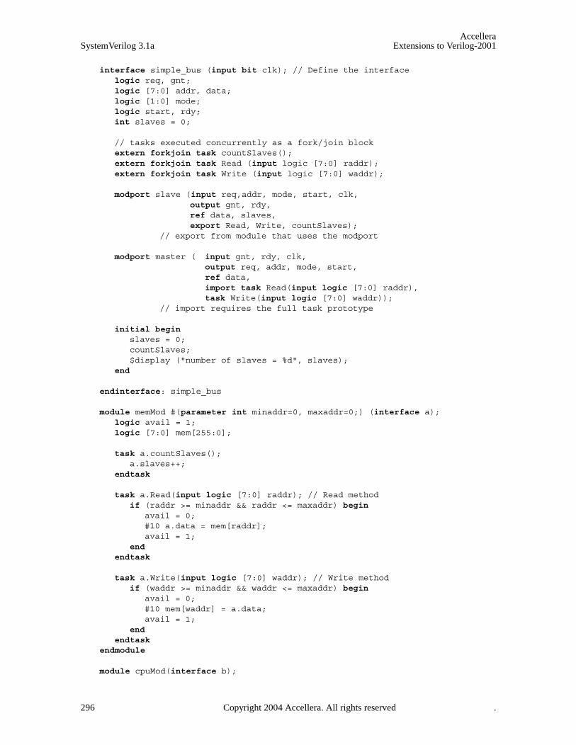
AccelleraSystemVerilog 3.1a Extensions to Verilog-2001
interface simple_bus (input bit clk); // Define the interfacelogic req, gnt;logic [7:0] addr, data;logic [1:0] mode;logic start, rdy;int slaves = 0;
// tasks executed concurrently as a fork/join blockextern forkjoin task countSlaves();extern forkjoin task Read (input logic [7:0] raddr);extern forkjoin task Write (input logic [7:0] waddr);
modport slave (input req,addr, mode, start, clk,output gnt, rdy,ref data, slaves,export Read, Write, countSlaves);
// export from module that uses the modport
modport master ( input gnt, rdy, clk,output req, addr, mode, start,ref data,import task Read(input logic [7:0] raddr),task Write(input logic [7:0] waddr));
// import requires the full task prototype
initial begin slaves = 0;countSlaves;$display ("number of slaves = %d", slaves);
end
endinterface: simple_bus
module memMod #(parameter int minaddr=0, maxaddr=0;) (interface a);logic avail = 1;logic [7:0] mem[255:0];
task a.countSlaves();a.slaves++;
endtask
task a.Read(input logic [7:0] raddr); // Read methodif (raddr >= minaddr && raddr <= maxaddr) begin
avail = 0;#10 a.data = mem[raddr];avail = 1;
end endtask
task a.Write(input logic [7:0] waddr); // Write methodif (waddr >= minaddr && waddr <= maxaddr) begin
avail = 0;#10 mem[waddr] = a.data;avail = 1;
end endtask
endmodule
module cpuMod(interface b);
296 Copyright 2004 Accellera. All rights reserved .

AccelleraExtensions to Verilog-2001 SystemVerilog 3.1a
typedef enum {read, write} instr;instr inst;logic [7:0] raddr;integer seed;
always @(posedge b.clk) begin inst = instr’($dist_uniform(seed, 0, 1));raddr = $dist_uniform(seed, 0, 3);if (inst == read) begin
$display("%t begin read %h @ %h", $time, b.data, raddr);callr:b.Read(raddr);$display("%t end read %h @ %h", $time, b.data, raddr);
end else begin
$display("%t begin write %h @ %h", $time, b.data, raddr);b.data = raddr;callw:b.Write(raddr);$display("%t end write %h @ %h", $time, b.data, raddr);
end end
endmodule
module top;logic clk = 0;
function void interrupt();disable mem1.a.Read; // task via module instancedisable sb_intf.Write; // task via interface instanceif (mem1.avail == 0) $display ("mem1 was interrupted");if (mem2.avail == 0) $display ("mem2 was interrupted");
endfunction
always #5 clk++;
initial begin #28 interrupt();#10 interrupt();#100 $finish;
end
simple_bus sb_intf(clk);
memMod #(0, 127) mem1(sb_intf.slave);memMod #(128, 255) mem2(sb_intf.slave);cpuMod cpu(sb_intf.master);
endmodule
19.7 Parameterized interfaces
Interface definitions can take advantage of parameters and parameter redefinition, in the same manner as mod-ule definitions. This example shows how to use parameters in interface definitions.
interface simple_bus #(AWIDTH = 8, DWIDTH = 8) (input bit clk); // Define the interface
logic req, gnt;logic [AWIDTH-1:0] addr;logic [DWIDTH-1:0] data;logic [1:0] mode;
Copyright 2004 Accellera. All rights reserved. 297

AccelleraSystemVerilog 3.1a Extensions to Verilog-2001
logic start, rdy;
modport slave( input req, addr, mode, start, clk,output gnt, rdy,ref data,import task slaveRead(),
task slaveWrite()); // import into module that uses the modport
modport master(input gnt, rdy, clk,output req, addr, mode, start,ref data,import task masterRead(input logic [AWIDTH-1:0] raddr),
task masterWrite(input logic [AWIDTH-1:0] waddr));// import requires the full task prototype
task masterRead(input logic [AWIDTH-1:0] raddr); // masterRead method...
endtask
task slaveRead; // slaveRead method...
endtask
task masterWrite(input logic [AWIDTH-1:0] waddr);...
endtask
task slaveWrite;...
endtask
endinterface: simple_bus
module memMod(interface a); // Uses just the interface keywordlogic avail;
always @(posedge a.clk) // the clk signal from the interfacea.gnt <= a.req & avail; //the gnt and req signals in the interface
always @(a.start)if (a.mode[0] == 1’b0)
a.slaveRead;else
a.slaveWrite;endmodule
module cpuMod(interface b);enum {read, write} instr;logic [7:0] raddr;
always @(posedge b.clk)if (instr == read)
b.masterRead(raddr); // call the Interface method// ...
else b.masterWrite(raddr);
endmodule
298 Copyright 2004 Accellera. All rights reserved .
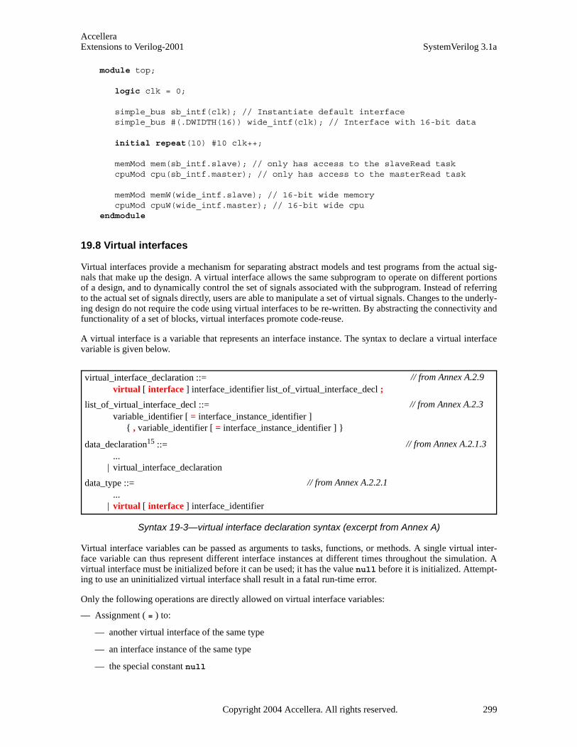
AccelleraExtensions to Verilog-2001 SystemVerilog 3.1a
module top;
logic clk = 0;
simple_bus sb_intf(clk); // Instantiate default interfacesimple_bus #(.DWIDTH(16)) wide_intf(clk); // Interface with 16-bit data
initial repeat(10) #10 clk++;
memMod mem(sb_intf.slave); // only has access to the slaveRead taskcpuMod cpu(sb_intf.master); // only has access to the masterRead task
memMod memW(wide_intf.slave); // 16-bit wide memorycpuMod cpuW(wide_intf.master); // 16-bit wide cpu
endmodule
19.8 Virtual interfaces
Virtual interfaces provide a mechanism for separating abstract models and test programs from the actual sig-nals that make up the design. A virtual interface allows the same subprogram to operate on different portionsof a design, and to dynamically control the set of signals associated with the subprogram. Instead of referringto the actual set of signals directly, users are able to manipulate a set of virtual signals. Changes to the underly-ing design do not require the code using virtual interfaces to be re-written. By abstracting the connectivity andfunctionality of a set of blocks, virtual interfaces promote code-reuse.
A virtual interface is a variable that represents an interface instance. The syntax to declare a virtual interfacevariable is given below.
Syntax 19-3—virtual interface declaration syntax (excerpt from Annex A)
Virtual interface variables can be passed as arguments to tasks, functions, or methods. A single virtual inter-face variable can thus represent different interface instances at different times throughout the simulation. Avirtual interface must be initialized before it can be used; it has the value null before it is initialized. Attempt-ing to use an uninitialized virtual interface shall result in a fatal run-time error.
Only the following operations are directly allowed on virtual interface variables:
— Assignment ( = ) to:
— another virtual interface of the same type
— an interface instance of the same type
— the special constant null
virtual_interface_declaration ::= virtual [ interface ] interface_identifier list_of_virtual_interface_decl ;
list_of_virtual_interface_decl ::= variable_identifier [ = interface_instance_identifier ]
{ , variable_identifier [ = interface_instance_identifier ] }
data_declaration15 ::= ...
| virtual_interface_declaration
data_type ::= ...
| virtual [ interface ] interface_identifier
// from Annex A.2.9
// from Annex A.2.3
// from Annex A.2.1.3
// from Annex A.2.2.1
Copyright 2004 Accellera. All rights reserved. 299

AccelleraSystemVerilog 3.1a Extensions to Verilog-2001
— Equality ( == ) and inequality ( != ) with:
— another virtual interface of the same type
— an interface instance of the same type
— the special constant null
Virtual interfaces shall not be used as ports, interface items, or as members of unions.
Once a virtual interface has been initialized, all the components of the underlying interface instance aredirectly available to the virtual interface via the dot notation. These components can only be used in proceduralstatements; they cannot be used in continuous assignments or sensitivity lists. In order for a net to be driven viaa virtual interface, the interface itself must provide a procedural means to do so. This can be accomplishedeither via a clocking block or by including a driver that is updated by a continuous assignment from a variablewithin the interface.
Virtual interfaces can be declared as class properties, which can be initialized procedurally or by an argumentto new(). This allows the same virtual interface to be used in different classes. The following example showshow the same transactor class can be used to interact with various different devices.
interface SBus; // A Simple bus interfacelogic req, grant;logic [7:0] addr, data;
endinterface
class SBusTransctor; // SBus transactor classvirtual SBus bus; // virtual interface of type Sbus
function new( virtual SBus s );bus = s; // initialize the virtual interface
endfunction
task request(); // request the busbus.req <= 1’b1;
endtask
task wait_for_bus(); // wait for the bus to be granted@(posedge bus.grant);
endtask endclass
module devA( Sbus s ) ... endmodule // devices that use SBusmodule devB( Sbus s ) ... endmodule
module top;
SBus s[1:4] (); // instantiate 4 interfaces
devA a1( s[1] ); // instantiate 4 devicesdevB b1( s[2] );devA a2( s[3] );devB b2( s[4] );
initial begin SbusTransactor t[1:4]; // create 4 bus-transactors and bind
t[1] = new( s[1] );t[2] = new( s[2] );
300 Copyright 2004 Accellera. All rights reserved .

AccelleraExtensions to Verilog-2001 SystemVerilog 3.1a
t[3] = new( s[3] );t[4] = new( s[4] );// test t[1:4]
end endmodule
In the preceding example, the transaction class SbusTransctor is a simple reusable component. It is writtenwithout any global or hierarchical references, and is unaware of the particular device with which it will inter-act. Nevertheless, the class can interact with any number of devices (4 in the example) that adhere to the inter-face’s protocol.
19.8.1 Virtual interfaces and clocking blocks
Clocking blocks and interfaces can be combined to represent the interconnect between synchronous blocks.Moreover, because clocking blocks provide a procedural mechanism to assign values to both nets and vari-ables, they are ideally suited to be used by virtual interfaces. For example:
interface SyncBus( input bit clk );wire a, b, c;
clocking sb @(posedge clk); input a;output b;inout c;
endclocking
endinterface
typedef virtual SyncBus VI; // A virtual interface type
task do_it( VI v ); // handles any SyncBus via clocking sbif( v.sb.a == 1 )
v.sb.b <= 0;else
v.sb.c <= ##1 1;endtask
In the preceding example, interface SyncBus includes a clocking block, which is used by task do_it to ensuresynchronous access to the interface’s signals: a, b, and c. Note that changes to the storage type of the interfacesignals (from net to variable and vice-versa) requires no changes to the task. The interfaces can be instantiatedas shown below.
module top;bit clk;
SyncBus b1( clk );SyncBus b2( clk );
initial begin VI v[2] = { b1, b2 };
repeat( 20 )do_it( v[ $urandom_range( 0, 1 ) ] );
end endmodule
The top module above shows how a virtual interface can be used to randomly select among a set of interfacesto be manipulated, in this case by the do_it task.
Copyright 2004 Accellera. All rights reserved. 301

AccelleraSystemVerilog 3.1a Extensions to Verilog-2001
19.8.2 Virtual interfaces modports and clocking blocks
As shown in the example above, once a virtual interface is declared, its clocking block can be referenced usingdot-notation. However, this only works for interfaces with no modports. Typically, a device under test and itstestbench exhibit modport direction. This common case can be handled by including the clocking in the corre-sponding modport as described in Section 19.4.5.
The example below shows how modports used in conjunction with virtual interfaces facilitate the creation ofabstract synchronous models.
interface A_Bus( input bit clk );wire req, gnt;wire [7:0] addr, data;
clocking sb @(posedge clk); input gnt;output req, addr;inout data;
property p1; req ##[1:3] gnt; endproperty endclocking
modport DUT ( input clk, req, addr, // Device under test modportoutput gnt,inout data );
modport STB ( clocking sb ); // synchronous testbench modport
modport TB ( input gnt, // asynchronous testbench modportoutput req, addr, inout data );
endinterface
The above interface A_Bus can then be instantiated as shown below:
module dev1(A_Bus.DUT b); // Some device: Part of the design...
endmodule
module dev2(A_Bus.DUT b); // Some device: Part of the design...
endmodule
program T (A_Bus.STB b1, A_Bus.STB b2 ); // Testbench: 2 synchronous ports...
endprogram
module top;bit clk;
A_Bus b1( clk );A_Bus b2( clk );
dev1 d1( b1 );dev2 d2( b2 );
T tb( b1, b2 );endmodule
302 Copyright 2004 Accellera. All rights reserved .

AccelleraExtensions to Verilog-2001 SystemVerilog 3.1a
And, within the testbench program, the virtual interface can refer directly to the clocking block.
program T (A_Bus.STB b1, A_Bus.STB b2 ); // Testbench: 2 synchronous ports
typedef virtual A_Bus.STB SYNCTB;
task request( SYNCTB s );s.sb.req <= 1;
endtask
task wait_grant( SYNCTB s );wait( s.sb.gnt == 1 );
endtask
task drive(SYNCTB s, logic [7:0] adr, data );if( s.sb.gnt == 0 ) begin
request(s); // acquire bus if neededwait_grant(s);
end s.sb.addr = adr;s.sb.data = data;repeat(2) @s.sb;s.sb.req = 0; //release bus
endtask
assert property (b1.p1); // assert property from within program
initial begin drive( b1, $random, $random );drive( b2, $random, $random );
end endprogram
The example above shows how the clocking block is referenced via the virtual interface by the tasks within theprogram block.
19.9 Access to interface objects
Access to all objects declared in an interface is always available by hierarchical reference, regardless ofwhether or not the interface is connected through a port. When an interface is connected with a modport ineither the module header or port connection, access by port reference is limited to only those objects listed inthe modport, for only those types of objects legal to be listed in modports (nets, variables, tasks, and functions)All objects are still visible by hierarchical reference. For example:
interface ebus_i;integer I; // reference to I not allowed through modport mptypedef enum {Y,N} choice;choice Q;parameter True = 1;modport mp(input Q);
endinterface
module Top;ebus_i ebus;sub s1(ebus.mod);
endmodule
module sub(interface.mp i);
Copyright 2004 Accellera. All rights reserved. 303
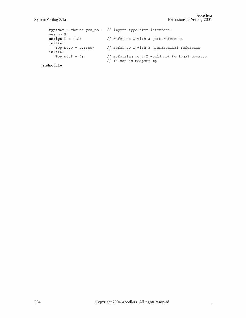
AccelleraSystemVerilog 3.1a Extensions to Verilog-2001
typedef i.choice yes_no; // import type from interfaceyes_no P;assign P = i.Q; // refer to Q with a port referenceinitial
Top.s1.Q = i.True; // refer to Q with a hierarchical referenceinitial
Top.s1.I = 0; // referring to i.I would not be legal because // is not in modport mp
endmodule
304 Copyright 2004 Accellera. All rights reserved .
AccelleraExtensions to Verilog-2001 SystemVerilog 3.1a
Section 20Coverage
20.1 Introduction (informative)
Functional verification comprises a large portion of the resources required to design and validate a complexsystem. Often, the validation must be comprehensive without redundant effort. To minimize wasted effort,coverage is used as a guide for directing verification resources by identifying tested and untested portions ofthe design.
Coverage is defined as the percentage of verification objectives that have been met. It is used as a metric forevaluating the progress of a verification project in order to reduce the number of simulation cycles spent inverifying a design
Broadly speaking, there are two types of coverage metrics. Those that can be automatically extracted from thedesign code, such as code coverage, and those that are user-specified in order to tie the verification environ-ment to the design intent or functionality. This latter form is referred to as Functional Coverage, and is thetopic of this section.
Functional coverage is a user-defined metric that measures how much of the design specification, as enumer-ated by features in the test plan, has been exercised. It can be used to measure whether interesting scenarios,corner cases, specification invariants, or other applicable design conditions—captured as features of the testplan—have been observed, validated and tested.
The key aspects of functional coverage are:
— It is user-specified, and is not automatically inferred from the design
— It is based on the design specification (i.e., its intent) and is thus independent of the actual design code orits structure.
Since it is fully specified by the user, functional coverage requires more up front effort (someone has to writethe coverage model). Functional coverage also requires a more structured approach to verification. Althoughfunctional coverage can shorten the overall verification effort and yield higher quality designs, these shortcom-ings can impede its adoption.
The SystemVerilog functional coverage extensions address these shortcomings by providing language con-structs for easy specification of functional coverage models. This specification can be efficiently executed bythe SystemVerilog simulation engine, thus, enabling coverage data manipulation and analysis tools that speedup the development of high quality tests. The improved set of tests can exercise more corner cases and requiredscenarios, without redundant work.
The SystemVerilog functional coverage constructs enable:
— Coverage of variables and expressions, as well as cross coverage between them.
— Automatic as well as user-defined coverage bins.
— Associate bins with sets of values, transitions, or cross products.
— Filtering conditions at multiple levels.
— Events and sequences to automatically trigger coverage sampling.
— Procedural activation and query of coverage.
— Optional directives to control and regulate coverage.
Copyright 2004 Accellera. All rights reserved. 305

AccelleraSystemVerilog 3.1a Extensions to Verilog-2001
20.2 Defining the coverage model: covergroup
The covergroup construct encapsulates the specification of a coverage model. Each covergroup specificationcan include the following components:
— A clocking event that synchronizes the sampling of coverage points
— A set of coverage points
— Cross coverage between coverage points
— Optional formal arguments
— Coverage options
The covergroup construct is a user-defined type. The type definition is written once, and multiple instancesof that type can be created in different contexts. Similar to a class, once defined, a covergroup instance canbe created via the new() operator. A covergroup can be defined in a module, program, interface, or class.
Syntax 20-1—Covergroup syntax (excerpt from Annex A)
The identifier associated with the covergroup declaration defines the name of the coverage model. Using thisname, an arbitrary number of coverage model instances can be created. For example:
covergroup_declaration ::= covergroup covergroup_identifier [ ( [ tf_port_list ] ) ] [ coverage_event ] ;
{ coverage_spec_or_option ; } endgroup [ : covergroup_identifier ]
coverage_spec_or_option ::= {attribute_instance} coverage_spec
| {attribute_instance} coverage_option ;
coverage_option ::= option.member_identifier = expression
| type_option.member_identifier = expression
coverage_spec ::= cover_point
| cover_cross
coverage_event ::= clocking_event
| @@( block_event_expression )
block_event_expression :: = block_event_expression or block_event_expression
| begin hierarchical_btf_identifier | end hierarchical_btf_identifier
hierarchical_btf_identifier :: = hierarchical_tf_identifier
| hierarchical_block_identifier | hierarchical _identifier [ class_scope ] method_identifier
variable_decl_assignment ::= ...
| [ covergroup_variable_identifier ] = new [ ( list_of_arguments ) ]16
16. It shall be legal to omit the covergroup_variable_identifer from a covergroup instantiation only if this implicit instan-tiation is within a class that has no other instantiation of the covergroup.
// from Annex A.2.11
// from Annex A.2.4
306 Copyright 2004 Accellera. All rights reserved .
AccelleraExtensions to Verilog-2001 SystemVerilog 3.1a
covergroup cg; ... endgroup cg cg_inst = new;
The above example defines a covergroup named cg. An instance of cg is declared as cg_inst and createdusing the new operator.
A covergroup can specify an optional list of arguments. When the covergroup specifies a list of formalarguments, its instances must provide to the new operator all the actual arguments that are not defaulted.Actual arguments are evaluated when the new operator is executed. A ref argument allows a different variableto be sampled by each instance of a covergroup. Input arguments will not track value of their arguments;they will use the value passed to the new operator.
If a clocking event is specified, it defines the event at which coverage points are sampled. If the clocking eventis omitted, users must procedurally trigger the coverage sampling. This is done via the built-in sample()method (see Section 20.7). Optionally, the strobe option can be used to modify the sampling behavior. Whenthe strobe option is not set (the default), a coverage point is sampled the instant the clocking event takes place,as if the process triggering the event were to call the built-in sample() method. If the clocking event occursmultiple times in a time step, the coverage point will also be sampled multiple times. The strobe option (seeSection 20.6.1) can be used to specify that coverage points are sampled in the postponed region, thereby filter-ing multiple clocking events so that only one sample per time slot is taken.
As an alternative to a clocking event, a coverage group accepts a block event expression to indicate that thecoverage sample is to be triggered by the start or the end of execution of a given named block, task, function,or class method. Block event expressions that specify the begin keyword followed by a hierarchical identifierdenoting a named block, task, function, or class method shall be triggered immediately before the correspond-ing block, task, function, or method begins executing its first statement. Block event expressions that specifythe end keyword followed by a hierarchical identifier denoting a named block, task, function, or class methodshall be triggered immediately after the corresponding block, task, function, or method executes its last state-ment. Block event expressions that specify the end of execution shall not be triggered if the block, task, func-tion, or method is disabled.
A covergroup can contain one or more coverage points. A coverage point can be a variable or an expression.Each coverage point includes a set of bins associated with its sampled values or its value-transitions. The binscan be explicitly defined by the user or automatically created by the tool. Coverage points are discussed indetail in Section 20.4.
enum { red, green, blue } color;
covergroup g1 @(posedge clk);c: coverpoint color;
endgroup
The above example defines coverage group g1 with a single coverage point associated with variable color. Thevalue of the variable color is sampled at the indicated clocking event: the positive edge of signal clk. Since thecoverage point does not explicitly define any bins, the tool automatically creates 3 bins, one for each possiblevalue of the enumerated type. Automatic bins are described in Section 20.4.2.
A coverage group can also specify cross coverage between two or more coverage points or variables. Anycombination of more than two variables or previously declared coverage points is allowed. For example:
enum { red, green, blue } color;bit [3:0] pixel_adr, pixel_offset, pixel_hue;
covergroup g2 @(posedge clk);Hue: coverpoint pixel_hue;Offset: coverpoint pixel_offset;
AxC: cross color, pixel_adr; // cross 2 variables (implicitly declared// coverpoints)
Copyright 2004 Accellera. All rights reserved. 307
AccelleraSystemVerilog 3.1a Extensions to Verilog-2001
all: cross color, Hue, Offset; // cross 1 variable and 2 coverpointsendgroup
The example above creates coverage group g2 that includes 2 coverage points and two cross coverage items.Explicit coverage points labeled Offset and Hue are defined for variables pixel_offset and pixel_hue.SystemVerilog implicitly declares coverage points for variables color and pixel_adr in order to track theircross coverage. Implicitly declared cover points are described in Section 20.5.
A coverage group can also specify one or more options to control and regulate how coverage data is structuredand collected. Coverage options can be specified for the coverage group as a whole, or for specific itemswithin the coverage group, that is, any of its coverage points or crosses. In general, a coverage option specifiedat the covergroup level applies to all of its items unless overridden by them. Coverage options are describedin Section 20.6.
20.3 Using covergroup in classes
By embedding a coverage group within a class definition, the covergroup provides a simple way to cover asubset of the class properties. This integration of coverage with classes provides an intuitive and expressivemechanism for defining the coverage model associated with a class. For example,
In class xyz, defined below, members m_x and m_y are covered using an embedded covergroup:
class xyz;bit [3:0] m_x;int m_y;bit m_z;
covergroup cov1 @m_z; // embedded covergroup coverpoint m_x;coverpoint m_y;
endgroup
function new(); cov1 = new; endfunctionendclass
In this example, data members m_x and m_y of class xyz are sampled on every change of data member m_z.
When a covergroup is defined within a class, and no explicit variables of that covergroup are declared inthe class then a variable with the same name as the coverage group is implicitly declared, e.g, in the aboveexample, a variable cov1 (of the embedded coverage group) is implicitly declared. Whether the coveragegroup variable is implicitly or explicitly declared, each class contains exactly one variable of each embeddedcoverage group. Each embedded coverage group thus becomes part of the class, tightly binding the class prop-erties to the coverage definition. Declaring multiple variables of the same embedded coverage group shallresult in a compiler error.
An embedded covergroup can define a coverage model for protected and local class properties without anychanges to the class data encapsulation. Class members can become coverage points or can be used in othercoverage constructs, such as conditional guards or option initialization.
A class can have more than one covergroup. The following example shows two cover groups in class MC.
class MC;logic [3:0] m_x;local logic m_z;bit m_e;covergroup cv1 @(posedge clk); coverpoint m_x; endgroupcovergroup cv2 @m_e ; coverpoint m_z; endgroup
endclass
308 Copyright 2004 Accellera. All rights reserved .

AccelleraExtensions to Verilog-2001 SystemVerilog 3.1a
In covergroup cv1, public class member variable m_x is sampled at every positive edge of signal clk. Localclass member m_z is covered by another covergroup cv2. Each coverage groups is sampled by a differentclocking event.
An embedded coverage group must be explicitly instantiated in the new method. If it is not, then the coveragegroup is not created and no data will be sampled.
Below is an example of an embedded coverage_group that does not have any passed-in arguments, and usesexplicit instantiation to synchronize with another object:
class Helper; int m_ev;endclass
class MyClass;Helper m_obj;int m_a;covergroup Cov @(m_obj.m_ev);
coverpoint m_a;endgroup
function new();m_obj = new;
Cov = new; // Create embedded covergroup after creating m_objendfunction
endclass
In this example, covergroup Cov is embedded within class MyClass, which contains an object of typeHelper class, called m_obj. The clocking event for the embedded coverage group refers to data memberm_ev of m_obj. Because the coverage group Cov uses m_obj, m_obj must be instantiated before Cov. There-fore, the coverage group Cov is instantiated after instantiating m_obj in the class constructor. As shown above,the instantiation of an embedded coverage group is done by assigning the result of the new operator to the cov-erage group identifier.
The following example shows how arguments passed in to an embedded coverage group can be used to set acoverage option of the coverage group.
class C1;bit [7:0] x;
covergroup cv (int arg) @(posedge clk);option.at_least = arg;
coverpoint x;endgroup
function new(int p1);cv = new(p1);
endfunction endclass
initial begin C1 obj = new(4);
end
20.4 Defining coverage points
A covergroup can contain one or more coverage points. A coverage point can be an integral variable or an
Copyright 2004 Accellera. All rights reserved. 309

AccelleraSystemVerilog 3.1a Extensions to Verilog-2001
integral expression. Each coverage point includes a set of bins associated with its sampled values or its value-transitions. The bins can be explicitly defined by the user or automatically created by SystemVerilog. The syn-tax for specifying coverage points is given below.
Syntax 20-2—coverpoint syntax (excerpt from Annex A)
A coverage point creates a hierarchical scope, and can be optionally labeled. If the label is specified then itdesignates the name of the coverage point. This name can be used to add this coverage point to a cross cover-age specification, or to access the methods of the coverage point. If the label is omitted and the coverage pointis associated with a single variable then the variable name becomes the name of the coverage point. Otherwise,an implementation can generate a name for the coverage point only for the purposes of coverage reporting, thatis, generated names cannot be used within the language.
A coverage point can sample the values that correspond to a particular scheduling region (see Section 14) byspecifying a clocking block signal. Thus, a coverage point that denotes a clocking block signal will sample thevalues made available by the clocking block. If the clocking block specifies a skew of #1step, the coveragepoint will sample the signal values from the Preponed region. If the clocking block specifies a skew of #0, thecoverage point will sample the signal values from the Observe region.
The expression within the iff construct specifies an optional condition that disables coverage for that coverpoint. If the guard expression evaluates to false at a sampling point, the coverage point is ignored. For exam-ple:
covergroup g4;coverpoint s0 iff(!reset);
endgroup
In the preceding example, cover point s0 is covered only if the value reset is false.
A coverage-point bin associates a name and a count with a set of values or a sequence of value transitions. Ifthe bin designates a set of values, the count is incremented every time the coverage point matches one of thevalues in the set. If the bin designates a sequence of value transitions, the count is incremented every time thecoverage point matches the entire sequence of value transitions.
The bins for a coverage point can be automatically created by SystemVerilog or explicitly defined using thebins construct to name each bin. If the bins are not explicitly defined, they are automatically created by Sys-temVerilog. The number of automatically created bins can be controlled using the auto_bin_max coverageoption. Coverage options are described in Section 20.6.
cover_point ::= [ cover_point_identifer : ] coverpoint expression [ iff ( expression ) ] bins_or_empty
bins_or_empty ::= { {attribute_instance} { bins_or_options ; } }
| ;
bins_or_options ::= coverage_option
| [ wildcard ] bins_keyword bin_identifier [ [ [ expression ] ] ] = { range_list } [ iff ( expression ) ] | [ wildcard] bins_keyword bin_identifier [ [ ] ] = trans_list [ iff ( expression ) ] | bins_keyword bin_identifier [ [ [ expression ] ] ] = default [ iff ( expression ) ] | bins_keyword bin_identifier = default sequence [ iff ( expression ) ]
bins_keyword::= bins | illegal_bins | ignore_bins
range_list ::= value_range { , value_range }
value_range ::= expression
| [ expression : expression ]
// from Annex A.2.11
// from Annex A.8.3
310 Copyright 2004 Accellera. All rights reserved .
AccelleraExtensions to Verilog-2001 SystemVerilog 3.1a
The bins construct allows creating a separate bin for each value in the given range-list, or a single bin for theentire range of values. To create a separate bin for each value (an array of bins) the square brackets, [], mustfollow the bin name. To create a fixed number of bins for a set of values, a number can be specified inside thesquare brackets. The range_list used to specify the set of values associated with a bin shall be constant expres-sions, instance constants (for classes only) or non-ref arguments to the coverage group.
If a fixed number of bins is specified, and that number is smaller than the number of values in the bin then thepossible bin values are uniformly distributed among the specified bins. If the number of values is not divisibleby the number of bins then the last bin will include the remaining items. For example:
bins fixed [3] = {1:10};
The 11 possible values are distributed as follows: <1,2,3>, <4,5,6>, <7,8,9,10>. If the number of bins exceedsthe number of values then some of the bins will be empty.
The expression within the iff construct at the end of a bin definition provides a per-bin guard condition. If theexpression is false at a sampling point, the count for the bin is not incremented.
The default specification defines a bin that is associated with none of the defined value bins. The defaultbin catches the values of the coverage point that do not lie within any of the defined bins. However, the cover-age calculation for a coverage point shall not take into account the coverage captured by the default bin. Thedefault is useful for catching unplanned or invalid values. The default sequence form can be used to catchall transitions (or sequences) that do not lie within any of the defined transition bins (see Section 20.4.1). Thedefault sequence specification does not accept multiple transition bins (the [] notation is not allowed).
bit [9:0] v_a;
covergroup cg @(posedge clk);
coverpoint v_a{
bins a = { [0:63],65 };bins b[] = { [127:150],[148:191] }; // note overlapping valuesbins c[] = { 200,201,202 };bins d = { [1000:$] }; bins others[] = default;
}endgroup
In the example above, the first bins construct associates bin a with the values of variable v_a between 0 and63, and the value 65. The second bins construct creates a set of 65 bins b[127], b[128],...b[191]. Like-wise, the third bins construct creates 3 bins: c[200], c[201], and c[202]. The fourth bins construct asso-ciates bin d with the values between 1000 and 1023 ($ represents the maximum value of v_a). Every value thatdoes not match bins a, b[], c[], or d[] is added into its own distinct bin.
A default or default sequence bin specification cannot be explicitly ignored (see Section 20.4.4). It shallbe an error for bins designated as ignore_bins to also specify a default or default sequence.
Generic coverage groups can be written by passing their traits as arguments to the constructor. For example:
covergroup gc (ref int ra, int low, int high ) @(posedge clk);
coverpoint ra // sample variable passed by reference{
bins good = { [low : high] };bins bad[] = default;
}endgroup
Copyright 2004 Accellera. All rights reserved. 311

AccelleraSystemVerilog 3.1a Extensions to Verilog-2001
...int va, vb;
cg c1 = new( va, 0, 50 ); // cover variable va in the range 0 to 50cg c2 = new( vb, 120, 600 ); // cover variable vb in the range 120 to 600
The example above defines a coverage group, gc, in which the signal to be sampled as well as the extent of thecoverage bins are specified as arguments. Later, two instances of the coverage group are created; each instancesamples a different signal and covers a different range of values.
20.4.1 Specifying bins for transitions
The syntax for specifying transition bins accepts a subset of the sequence syntax described in Section 17:
Syntax 20-3—Transition bin syntax (excerpt from Annex A)
A trans_list specifies one or more sets of ordered value transitions of the coverage point. A single value transi-tion is thus specified as:
value1 => value2
It represents the value of coverage point at two successive sample points, that is, value1 followed by value2at the next sample point.
A sequence of transitions is represented as:
value1 => value3 => value4 => value5
In this case, value1 is followed by value3, followed by value4 and followed by value5. A sequence canbe of any arbitrary length.
A set of transitions can be specified as:
range_list1 => range_list2
bins_or_options ::= ...
| [ wildcard ] bins_keyword bin_identifier [ [ [ expression ] ] ] = { range_list } [ iff ( expression ) ] | [ wildcard] bins_keyword bin_identifier [ [ ] ] = trans_list [ iff ( expression ) ]
...
bins_keyword::= bins | illegal_bins | ignore_bins
range_list ::= value_range { , value_range }
trans_list ::= ( trans_set ) { , ( trans_set ) }
trans_set ::= trans_range_list => trans_range_list { => trans_range_list }
trans_range_list ::= trans_item
| trans_item [ [* repeat_range ] ] | trans_item [ [–> repeat_range ] ] | trans_item [ [= repeat_range ] ]
trans_item ::= range_list
repeat_range ::= expression
| expression : expression
// from Annex A.2.11
312 Copyright 2004 Accellera. All rights reserved .
AccelleraExtensions to Verilog-2001 SystemVerilog 3.1a
This specification expands to transitions between each value in range_list1 and each value inrange_list2. For example,
1,5 => 6, 7
specifies the following four transitions:
1=>6, 1=>7, 5=>6, 5=>7
Consecutive repetitions of transitions are specified using (see Annex H):
trans_item [* repeat_range ]
Here, trans_item is repeated for repeat_range times. For example,
3 [* 5]
is the same as
3=>3=>3=>3=>3
An example of a range of repetition is:
3 [* 3:5]
is the same as
3=>3=>3, 3=>3=>3=>3, 3=>3=>3=>3=>3
The repetition with non-consecutive occurrence of a value is specified using: trans_item [-> repeat_range ].Here, the occurrence of a value is specified with an arbitrary number of sample points where the value does notoccur. For example,
3 [-> 3]
is the same as
...3=>...=>3...=>3
where the dots (...) represent any transition that does not contain the value 3.
Non-consecutive repetition is where a sequence of transitions continues until the next transition. For example,
3 [= 2]
is same as the transitions below excluding the last transition.
3=>...=>3...=>3
A trans_list specifies one or more sets of ordered value transitions of the coverage point. If the sequence ofvalue transitions of the coverage point matches any complete sequence in the trans_list, the coverage count ofthe corresponding bin is incremented. For example:
bit [4:1] v_a;
covergroup cg @(posedge clk);
coverpoint v_a{
bins sa = (4 => 5 => 6), ([7:9],10=>11,12);
Copyright 2004 Accellera. All rights reserved. 313
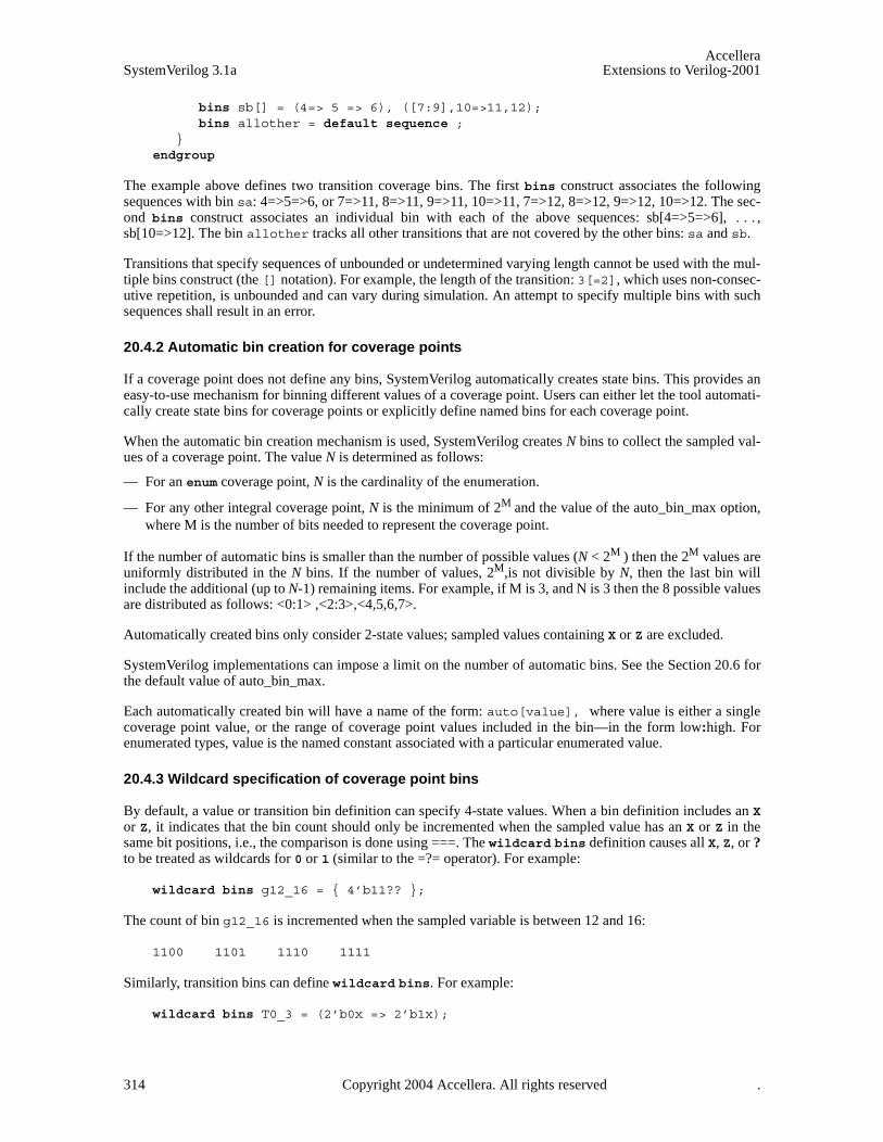
AccelleraSystemVerilog 3.1a Extensions to Verilog-2001
bins sb[] = (4=> 5 => 6), ([7:9],10=>11,12);bins allother = default sequence ;
}endgroup
The example above defines two transition coverage bins. The first bins construct associates the followingsequences with bin sa: 4=>5=>6, or 7=>11, 8=>11, 9=>11, 10=>11, 7=>12, 8=>12, 9=>12, 10=>12. The sec-ond bins construct associates an individual bin with each of the above sequences: sb[4=>5=>6], ...,sb[10=>12]. The bin allother tracks all other transitions that are not covered by the other bins: sa and sb.
Transitions that specify sequences of unbounded or undetermined varying length cannot be used with the mul-tiple bins construct (the [] notation). For example, the length of the transition: 3[=2], which uses non-consec-utive repetition, is unbounded and can vary during simulation. An attempt to specify multiple bins with suchsequences shall result in an error.
20.4.2 Automatic bin creation for coverage points
If a coverage point does not define any bins, SystemVerilog automatically creates state bins. This provides aneasy-to-use mechanism for binning different values of a coverage point. Users can either let the tool automati-cally create state bins for coverage points or explicitly define named bins for each coverage point.
When the automatic bin creation mechanism is used, SystemVerilog creates N bins to collect the sampled val-ues of a coverage point. The value N is determined as follows:
— For an enum coverage point, N is the cardinality of the enumeration.
— For any other integral coverage point, N is the minimum of 2M and the value of the auto_bin_max option,where M is the number of bits needed to represent the coverage point.
If the number of automatic bins is smaller than the number of possible values (N < 2M ) then the 2M values areuniformly distributed in the N bins. If the number of values, 2M,is not divisible by N, then the last bin willinclude the additional (up to N-1) remaining items. For example, if M is 3, and N is 3 then the 8 possible valuesare distributed as follows: <0:1> ,<2:3>,<4,5,6,7>.
Automatically created bins only consider 2-state values; sampled values containing X or Z are excluded.
SystemVerilog implementations can impose a limit on the number of automatic bins. See the Section 20.6 forthe default value of auto_bin_max.
Each automatically created bin will have a name of the form: auto[value], where value is either a singlecoverage point value, or the range of coverage point values included in the bin—in the form low:high. Forenumerated types, value is the named constant associated with a particular enumerated value.
20.4.3 Wildcard specification of coverage point bins
By default, a value or transition bin definition can specify 4-state values. When a bin definition includes an Xor Z, it indicates that the bin count should only be incremented when the sampled value has an X or Z in thesame bit positions, i.e., the comparison is done using ===. The wildcard bins definition causes all X, Z, or ?to be treated as wildcards for 0 or 1 (similar to the =?= operator). For example:
wildcard bins g12_16 = { 4’b11?? };
The count of bin g12_16 is incremented when the sampled variable is between 12 and 16:
1100 1101 1110 1111
Similarly, transition bins can define wildcard bins. For example:
wildcard bins T0_3 = (2’b0x => 2’b1x);
314 Copyright 2004 Accellera. All rights reserved .

AccelleraExtensions to Verilog-2001 SystemVerilog 3.1a
The count of transition bin T0_3 is incremented for the following transitions (as if by (0,1=>2,3)):
00 => 10 00 => 11 01 => 10 01 => 11
A wildcard bin definition only consider 2-state values; sampled values containing X or Z are excluded. Thus,the range of values covered by a wildcard bin is established by replacing every wildcard digit by 0 to computethe low bound and 1 to compute the high bound.
20.4.4 Excluding coverage point values or transitions
A set of values or transitions associated with a coverage-point can be explicitly excluded from coverage byspecifying them as ignore_bins. For example:
covergroup cg23;coverpoint a{
ignore_bins ignore_vals = {7,8};ignore_bins ignore_trans = (1=>3=>5);
}endgroup
All values or transitions associated with ignored bins are excluded from coverage. Ignored values or transitionsare excluded even if they are also included in another bin.
20.4.5 Specifying Illegal coverage point values or transitions
A set of values or transitions associated with a coverage-point can be marked as illegal by specifying them asillegal_bins. For example:
covergroup cg3;coverpoint b{
illegal_bins bad_vals = {1,2,3};illegal_bins bad_trans = (4=>5=>6);
}endgroup
All values or transitions associated with illegal bins are excluded from coverage. If they occur, a run-time erroris issued. Illegal bins take precedence over any other bins, that is, they will result in a run-time error even ifthey are also included in another bin.
20.5 Defining cross coverage
A coverage group can specify cross coverage between two or more coverage points or variables. Cross cover-age is specified using the cross construct. When a variable V is part of a cross coverage, SystemVerilogimplicitly creates a coverage point for the variable, as if it had been created by the statement coverpoint V;.Thus, a cross involves only coverage points. Expressions cannot be used directly in a cross; a coverage pointmust be explicitly defined first.
The syntax for specifying cross coverage is given below.
Copyright 2004 Accellera. All rights reserved. 315

AccelleraSystemVerilog 3.1a Extensions to Verilog-2001
Syntax 20-4—Cross coverage syntax (excerpt from Annex A)
The label for a cross declaration provides an optional name. The label also creates a hierarchical scope for thebins defined within the cross.
The expression within the optional iff provides a conditional guard for the cross coverage. If at any samplepoint, the condition evaluates to false, the cross coverage is ignored. The expression within the optional iffconstruct at the end of a cross bin definition provides a per-bin guard condition. If the expression is false, thecross bin is ignored.
Cross coverage of a set of N coverage points is defined as the coverage of all combinations of all bins associ-ated with the N coverage points, that is, the Cartesian product of the N sets of coverage-point bins. For exam-ple:
bit [3:0] a, b;
covergroup cov @(posedge clk);aXb : cross a, b;
endgroup
The coverage group cov in the example above specifies the cross coverage of two 4-bit variables, a and b. Sys-temVerilog implicitly creates a coverage point for each variable. Each coverage point has 16 bins, namelyauto[0]...auto[15]. The cross of a and b (labeled aXb), therefore, has 256 cross products, and each crossproduct is a bin of aXb.
Cross coverage between expressions previously defined as coverage points is also allowed. For example:
cover_cross ::= [cover_point_identifer : ] cross list_of_coverpoints [ iff ( expression ) ] select_bins_or_empty
list_of_coverpoints ::= cross_item , cross_item { , cross_item }
cross_item ::= cover_point_identifier
| variable_identifier
select_bins_or_empty ::= { { bins_selections_or_option ; } }
| ;
bins_selection_or_option ::= { attribute_instance } coverage_option
| { attribute_instance } bins_selection
bins_selection ::= bins_keyword bin_identifier = select_expression [ iff ( expression ) ]
select_expression ::= select_condition
| ! select_condition | select_expression && select_expression | select_expression || select_expression | ( select_expression )
select_condition ::= binsof ( bins_expression ) [ intersect { open_range_list } ]
bins_expression ::= variable_identifier
| cover_point_identifier [ . bins_identifier ]
open_range_list ::= open_value_range { , open_value_range }
open_value_range ::= value_range21
// from Annex A.2.11
316 Copyright 2004 Accellera. All rights reserved .

AccelleraExtensions to Verilog-2001 SystemVerilog 3.1a
bit [3:0] a, b, c;
covergroup cov2 @(posedge clk);BC: coverpoint b+c;aXb : cross a, BC;
endgroup
The coverage group cov2 has the same number of cross products as the previous example, but in this case, oneof the coverage points is the expression b+c, which is labeled BC.
bit [31:0] a_var;bit [3:0] b_var;
covergroup cov3 @(posedge clk);A: coverpoint a_var { bins yy[] = { [0:9] }; }CC: cross b_var, A;
endgroup
The coverage group cov3 crosses variable b_var with coverage point A (labeled CC). Variable b_var auto-matically creates 16 bins (auto[0]...auto[15]). Coverage point A explicitly creates 10 binsyy[0]...yy[9]. The cross of two coverage points creates 16 * 10 = 160 cross product bins, namely the pairsshown below:
<auto[0], yy[0]><auto[0], yy[1]>...<auto[0], yy[9]><auto[1], yy[0]>...<auto[15], yy[9]>
Cross coverage is allowed only between coverage points defined within the same coverage group. Coveragepoints defined in a coverage group other than the one enclosing the cross cannot participate in a cross.Attempts to cross items from different coverage groups shall result in a compiler error.
In addition to specifying the coverage points that are crossed, SystemVerilog includes a powerful set of opera-tors that allow defining cross coverage bins. Cross coverage bins can be specified in order to group together aset of cross products. A cross-coverage bin associates a name and a count with a set of cross products. Thecount of the bin is incremented every time any of the cross products match, i.e., every coverage point in thecross matches its corresponding bin in the cross product.
User-defined bins for cross coverage are defined using bins select-expressions. The syntax for defining thesebin selection expressions is given in Syntax 20-4.
The binsof construct yields the bins of its expression, which can be either a coverage point (explicitlydefined or implicitly defined for a single variable) or a coverage-point bin. The resulting bins can be furtherselected by including (or excluding) only the bins whose associated values intersect a desired set of values.The desired set of values can be specified using a comma-separated list of open_value_range as shown in Syn-tax 20-4. For example, the following select expression:
binsof( x ) intersect { y }
denotes the bins of coverage point x whose values intersect the range given by y. Its negated form:
! binsof( x ) intersect { y }
denotes the bins of coverage point x whose values do not intersect the range given by y.
Copyright 2004 Accellera. All rights reserved. 317
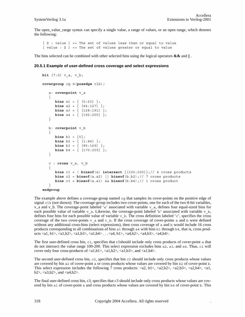
AccelleraSystemVerilog 3.1a Extensions to Verilog-2001
The open_value_range syntax can specify a single value, a range of values, or an open range, which denotesthe following:
[ $ : value ] => The set of values less than or equal to value[ value : $ ] => The set of values greater or equal to value
The bins selected can be combined with other selected bins using the logical operators && and || .
20.5.1 Example of user-defined cross coverage and select expressions
bit [7:0] v_a, v_b;
covergroup cg @(posedge clk);
a: coverpoint v_a{
bins a1 = { [0:63] };bins a2 = { [64:127] };bins a3 = { [128:191] };bins a4 = { [192:255] };
}
b: coverpoint v_b{
bins b1 = {0};bins b2 = { [1:84] };bins b3 = { [85:169] };bins b4 = { [170:255] };
}
c : cross v_a, v_b{
bins c1 = ! binsof(a) intersect {[100:200]};// 4 cross productsbins c2 = binsof(a.a2) || binsof(b.b2);// 7 cross productsbins c3 = binsof(a.a1) && binsof(b.b4);// 1 cross product
}endgroup
The example above defines a coverage-group named cg that samples its cover-points on the positive edge ofsignal clk (not shown). The coverage-group includes two cover-points, one for each of the two 8-bit variables,v_a and v_b. The coverage-point labeled ‘a’ associated with variable v_a, defines four equal-sized bins foreach possible value of variable v_a. Likewise, the coverage-point labeled ‘b’ associated with variable v_b,defines four bins for each possible value of variable v_b. The cross definition labeled ‘c’, specifies the crosscoverage of the two cover-points v_a and v_b. If the cross coverage of cover-points a and b were definedwithout any additional cross-bins (select expressions), then cross coverage of a and b would include 16 crossproducts corresponding to all combinations of bins a1 through a4 with bins b1 through b4, that is, cross prod-ucts <a1, b1>, <a1,b2>, <a1,b3>, <a1,b4>...<a4, b1>, <a4,b2>, <a4,b3>, <a4,b4>.
The first user-defined cross bin, c1, specifies that c1should include only cross products of cover-point a thatdo not intersect the value range 100-200. This select expression excludes bins a2, a3, and a4. Thus, c1 willcover only four cross-products of <a1,b1>, <a1,b2>, <a1,b3>, and <a1,b4>.
The second user-defined cross bin, c2, specifies that bin c2 should include only cross products whose valuesare covered by bin a2 of cover-point a or cross products whose values are covered by bin b2 of cover-point b.This select expression includes the following 7 cross products: <a2, b1>, <a2,b2>, <a2,b3>, <a2,b4>, <a1,b2>, <a3,b2>, and <a4,b2>.
The final user-defined cross bin, c3, specifies that c3 should include only cross products whose values are cov-ered by bin a1 of cover-point a and cross products whose values are covered by bin b4 of cover-point b. This
318 Copyright 2004 Accellera. All rights reserved .
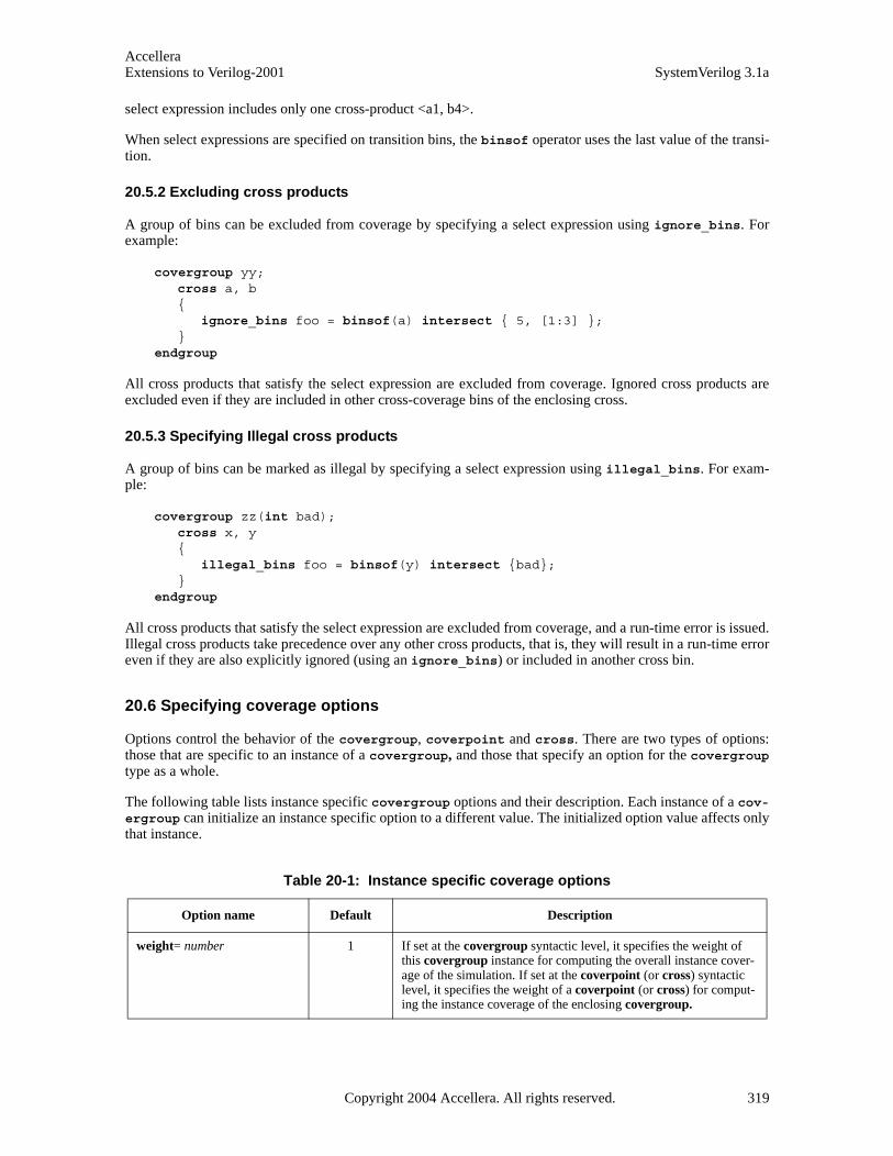
AccelleraExtensions to Verilog-2001 SystemVerilog 3.1a
select expression includes only one cross-product <a1, b4>.
When select expressions are specified on transition bins, the binsof operator uses the last value of the transi-tion.
20.5.2 Excluding cross products
A group of bins can be excluded from coverage by specifying a select expression using ignore_bins. Forexample:
covergroup yy;cross a, b{
ignore_bins foo = binsof(a) intersect { 5, [1:3] };}
endgroup
All cross products that satisfy the select expression are excluded from coverage. Ignored cross products areexcluded even if they are included in other cross-coverage bins of the enclosing cross.
20.5.3 Specifying Illegal cross products
A group of bins can be marked as illegal by specifying a select expression using illegal_bins. For exam-ple:
covergroup zz(int bad);cross x, y{
illegal_bins foo = binsof(y) intersect {bad};}
endgroup
All cross products that satisfy the select expression are excluded from coverage, and a run-time error is issued.Illegal cross products take precedence over any other cross products, that is, they will result in a run-time erroreven if they are also explicitly ignored (using an ignore_bins) or included in another cross bin.
20.6 Specifying coverage options
Options control the behavior of the covergroup, coverpoint and cross. There are two types of options:those that are specific to an instance of a covergroup, and those that specify an option for the covergrouptype as a whole.
The following table lists instance specific covergroup options and their description. Each instance of a cov-ergroup can initialize an instance specific option to a different value. The initialized option value affects onlythat instance.
Table 20-1: Instance specific coverage options
Option name Default Description
weight= number 1 If set at the covergroup syntactic level, it specifies the weight of this covergroup instance for computing the overall instance cover-age of the simulation. If set at the coverpoint (or cross) syntactic level, it specifies the weight of a coverpoint (or cross) for comput-ing the instance coverage of the enclosing covergroup.
Copyright 2004 Accellera. All rights reserved. 319
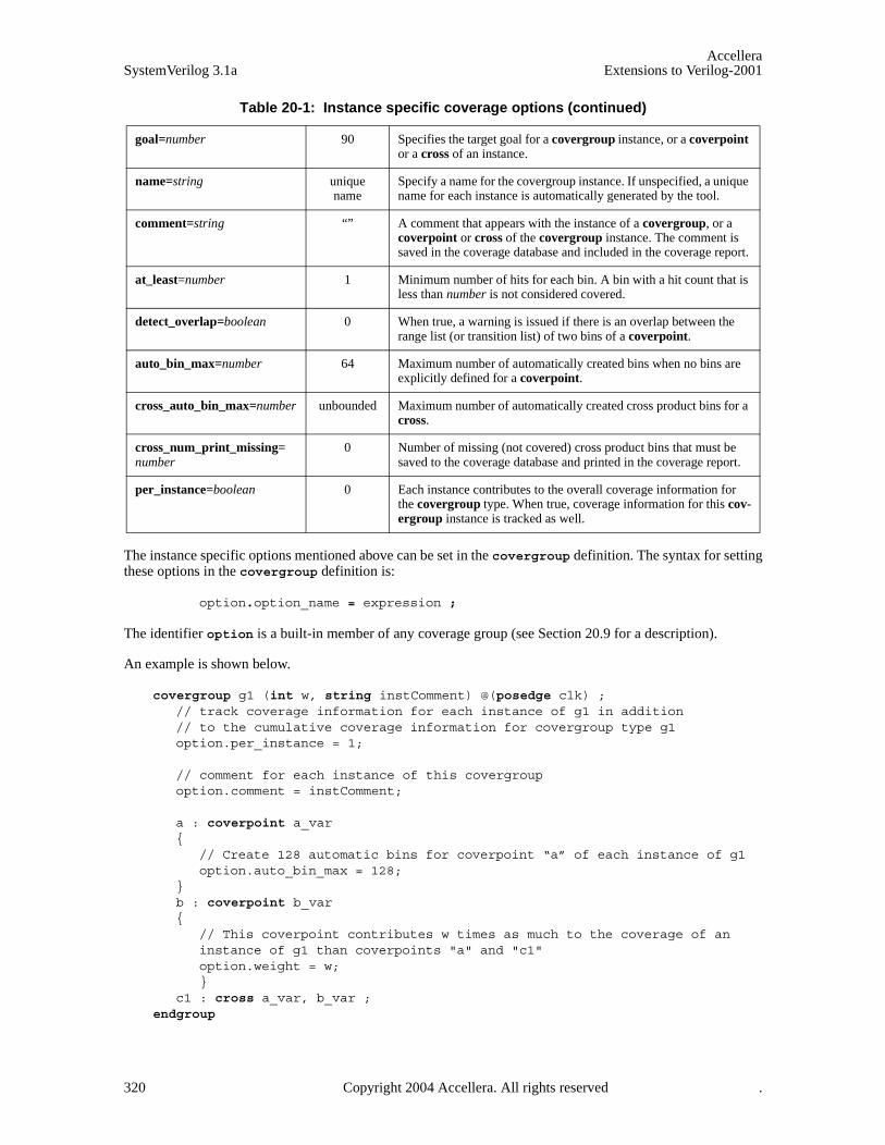
AccelleraSystemVerilog 3.1a Extensions to Verilog-2001
The instance specific options mentioned above can be set in the covergroup definition. The syntax for settingthese options in the covergroup definition is:
option.option_name = expression ;
The identifier option is a built-in member of any coverage group (see Section 20.9 for a description).
An example is shown below.
covergroup g1 (int w, string instComment) @(posedge clk) ;// track coverage information for each instance of g1 in addition // to the cumulative coverage information for covergroup type g1option.per_instance = 1;
// comment for each instance of this covergroupoption.comment = instComment;
a : coverpoint a_var {
// Create 128 automatic bins for coverpoint “a” of each instance of g1option.auto_bin_max = 128;
}b : coverpoint b_var {
// This coverpoint contributes w times as much to the coverage of aninstance of g1 than coverpoints "a" and "c1"option.weight = w;
}c1 : cross a_var, b_var ;
endgroup
goal=number 90 Specifies the target goal for a covergroup instance, or a coverpoint or a cross of an instance.
name=string unique name
Specify a name for the covergroup instance. If unspecified, a unique name for each instance is automatically generated by the tool.
comment=string “” A comment that appears with the instance of a covergroup, or a coverpoint or cross of the covergroup instance. The comment is saved in the coverage database and included in the coverage report.
at_least=number 1 Minimum number of hits for each bin. A bin with a hit count that is less than number is not considered covered.
detect_overlap=boolean 0 When true, a warning is issued if there is an overlap between the range list (or transition list) of two bins of a coverpoint.
auto_bin_max=number 64 Maximum number of automatically created bins when no bins are explicitly defined for a coverpoint.
cross_auto_bin_max=number unbounded Maximum number of automatically created cross product bins for a cross.
cross_num_print_missing=number
0 Number of missing (not covered) cross product bins that must be saved to the coverage database and printed in the coverage report.
per_instance=boolean 0 Each instance contributes to the overall coverage information for the covergroup type. When true, coverage information for this cov-ergroup instance is tracked as well.
Table 20-1: Instance specific coverage options (continued)
320 Copyright 2004 Accellera. All rights reserved .
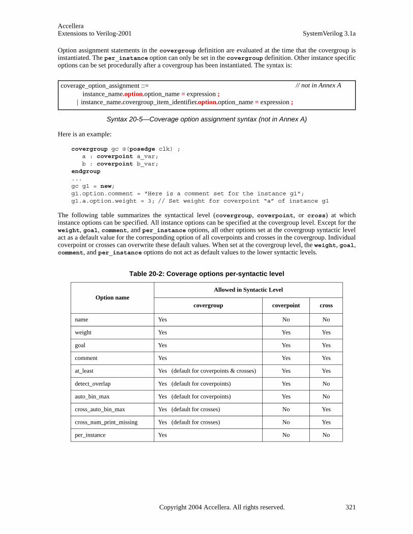
AccelleraExtensions to Verilog-2001 SystemVerilog 3.1a
Option assignment statements in the covergroup definition are evaluated at the time that the covergroup isinstantiated. The per_instance option can only be set in the covergroup definition. Other instance specificoptions can be set procedurally after a covergroup has been instantiated. The syntax is:
Syntax 20-5—Coverage option assignment syntax (not in Annex A)
Here is an example:
covergroup gc @(posedge clk) ;a : coverpoint a_var;b : coverpoint b_var;
endgroup ...gc g1 = new;g1.option.comment = "Here is a comment set for the instance g1";g1.a.option.weight = 3; // Set weight for coverpoint “a” of instance g1
The following table summarizes the syntactical level (covergroup, coverpoint, or cross) at whichinstance options can be specified. All instance options can be specified at the covergroup level. Except for theweight, goal, comment, and per_instance options, all other options set at the covergroup syntactic levelact as a default value for the corresponding option of all coverpoints and crosses in the covergroup. Individualcoverpoint or crosses can overwrite these default values. When set at the covergroup level, the weight, goal,comment, and per_instance options do not act as default values to the lower syntactic levels.
Table 20-2: Coverage options per-syntactic level
Option nameAllowed in Syntactic Level
covergroup coverpoint cross
name Yes No No
weight Yes Yes Yes
goal Yes Yes Yes
comment Yes Yes Yes
at_least Yes (default for coverpoints & crosses) Yes Yes
detect_overlap Yes (default for coverpoints) Yes No
auto_bin_max Yes (default for coverpoints) Yes No
cross_auto_bin_max Yes (default for crosses) No Yes
cross_num_print_missing Yes (default for crosses) No Yes
per_instance Yes No No
coverage_option_assignment ::= instance_name.option.option_name = expression ;
| instance_name.covergroup_item_identifier.option.option_name = expression ;
// not in Annex A
Copyright 2004 Accellera. All rights reserved. 321

AccelleraSystemVerilog 3.1a Extensions to Verilog-2001
20.6.1 Covergroup Type Options
The following table lists options that describe a particular feature (or property) of the covergroup type as awhole. They are analogous to static data members of classes.
The covergroup type options mentioned above can be set in the covergroup definition. The syntax for set-ting these options in the covergroup definition is:
type_option.option_name = expression ;
The identifier type_option is a built-in member of any coverage group (see Section 20.9 for a description).
Different instances of a covergroup cannot assign different values to type options. This is syntactically disal-lowed, since these options can only be initialized via constant expressions. Here is an example:
covergroup g1 (int w, string instComment) @(posedge clk) ; // track coverage information for each instance of g1 in addition // to the cumulative coverage information for covergroup type g1option.per_instance = 1;
type_option.comment = "Coverage model for features foo and bar";
type_option.strobe = 1; // sample at the end of the time slot
// comment for each instance of this covergroupoption.comment = instComment;
a : coverpoint a_var{
// Use weight 2 to compute the coverage of each instanceoption.weight = 2;// Use weight 3 to compute the cumulative (type) coverage for g1type_option.weight = 3;// NOTE: type_option.weight = w would cause syntax error.
}b : coverpoint b_var {
Table 20-3: Coverage group type (static) options
Option name Default Description
weight=constant_number 1 If set at the covergroup syntactic level, it specifies the weight of this covergroup for computing the overall cumulative (or type) coverage of the saved database. If set at the coverpoint (or cross) syntactic level, it specifies the weight of a coverpoint (or cross) for computing the cumulative (or type) coverage of the enclosing covergroup.
goal=constant_number 90 Specifies the target goal for a covergroup type, or a coverpoint or cross of a covergroup type.
comment=string_literal “” A comment that appears with the covergroup type, or a coverpoint or cross of the covergroup type. The comment is saved in the coverage database and included in the coverage report.
strobe=constant_number 0 If set to 1, all samples happen at the end of the time slot, like the $strobe system task.
322 Copyright 2004 Accellera. All rights reserved .

AccelleraExtensions to Verilog-2001 SystemVerilog 3.1a
// Use weight w to compute the coverage of each instanceoption.weight = w;// Use weight 5 to compute the cumulative (type) coverage of g1type_option.weight = 5;
}endgroup
In the above example the coverage for each instance of g1 is computed as:
(((instance coverage of “a”) * 2) + ((instance coverage of “b”) * w)) / ( 2 + w)
On the other hand the coverage for covergroup type “g1” is computed as:
( ((overall type coverage of “a”) * 3) + ((overall type coverage of “b”) * 5) ) / (3 + 5).
Type options can be set procedurally at any time during simulation. The syntax is:
Syntax 20-6—Coverage type option assignment syntax (not in Annex A)
Here is an example:
covergroup gc @(posedge clk) ;a : coverpoint a_var;b : coverpoint b_var;
endgroup ...gc::type_option.comment = "Here is a comment for covergroup g1";
// Set the weight for coverpoint "a" of covergroup g1gc::a::type_option.weight = 3;gc g1 = new;
The following table summarizes the syntactical level (covergroup, coverpoint, or cross) in which typeoptions can be specified. When set at the covergroup level, the type options do not act as defaults for lowersyntactic levels.
Table 20-4: Coverage type-options
Option nameAllowed Syntactic Level
covergroup coverpoint cross
weight Yes Yes Yes
goal Yes Yes Yes
comment Yes Yes Yes
strobe Yes No No
coverage_type_option_assignment ::= covergroup_name::type_option.option_name = expression ;
| covergroup_name::covergroup_item_identifier::type_option.option_name = expression ;
// not in Annex A
Copyright 2004 Accellera. All rights reserved. 323
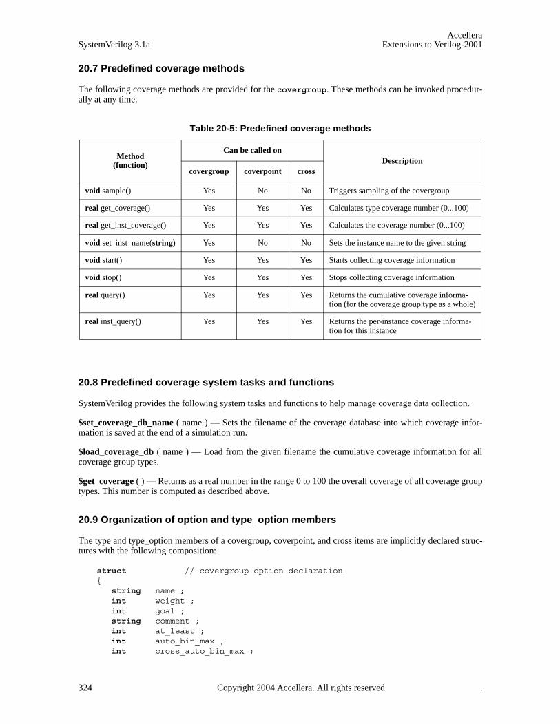
AccelleraSystemVerilog 3.1a Extensions to Verilog-2001
20.7 Predefined coverage methods
The following coverage methods are provided for the covergroup. These methods can be invoked procedur-ally at any time.
20.8 Predefined coverage system tasks and functions
SystemVerilog provides the following system tasks and functions to help manage coverage data collection.
$set_coverage_db_name ( name ) — Sets the filename of the coverage database into which coverage infor-mation is saved at the end of a simulation run.
$load_coverage_db ( name ) — Load from the given filename the cumulative coverage information for allcoverage group types.
$get_coverage ( ) — Returns as a real number in the range 0 to 100 the overall coverage of all coverage grouptypes. This number is computed as described above.
20.9 Organization of option and type_option members
The type and type_option members of a covergroup, coverpoint, and cross items are implicitly declared struc-tures with the following composition:
struct // covergroup option declaration{
string name ;int weight ;int goal ;string comment ;int at_least ;int auto_bin_max ;int cross_auto_bin_max ;
Table 20-5: Predefined coverage methods
Method(function)
Can be called onDescription
covergroup coverpoint cross
void sample() Yes No No Triggers sampling of the covergroup
real get_coverage() Yes Yes Yes Calculates type coverage number (0...100)
real get_inst_coverage() Yes Yes Yes Calculates the coverage number (0...100)
void set_inst_name(string) Yes No No Sets the instance name to the given string
void start() Yes Yes Yes Starts collecting coverage information
void stop() Yes Yes Yes Stops collecting coverage information
real query() Yes Yes Yes Returns the cumulative coverage informa-tion (for the coverage group type as a whole)
real inst_query() Yes Yes Yes Returns the per-instance coverage informa-tion for this instance
324 Copyright 2004 Accellera. All rights reserved .
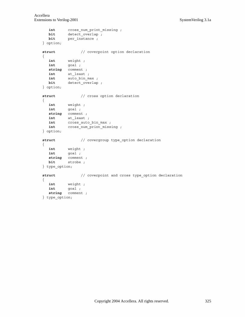
AccelleraExtensions to Verilog-2001 SystemVerilog 3.1a
int cross_num_print_missing ;bit detect_overlap ;bit per_instance ;
} option;
struct // coverpoint option declaration{
int weight ;int goal ;string comment ;int at_least ;int auto_bin_max ;bit detect_overlap ;
} option;
struct // cross option declaration{
int weight ;int goal ;string comment ;int at_least ;int cross_auto_bin_max ;int cross_num_print_missing ;
} option;
struct // covergroup type_option declaration{
int weight ;int goal ;string comment ;bit strobe ;
} type_option;
struct // coverpoint and cross type_option declaration{
int weight ;int goal ;string comment ;
} type_option;
Copyright 2004 Accellera. All rights reserved. 325
AccelleraSystemVerilog 3.1a Extensions to Verilog-2001
Section 21Parameters
21.1 Introduction (informative)
Verilog-2001 provides three constructs for defining compile time constants: the parameter, localparam andspecparam statements.
The language provides four methods for setting the value of parameter constants in a design. Each parametermust be assigned a default value when declared. The default value of a parameter of an instantiated module canbe overridden in each instance of the module using one of the following:
— Implicit in-line parameter redefinition (e.g. foo #(value, value) u1 (...); )
— Explicit in-line parameter redefinition (e.g. foo #(.name(value), .name(value)) u1 (...); )
— defparam statements, using hierarchical path names to redefine each parameter
21.1.1 Defparam removal
The defparam statement might be removed from future versions of the language. See Section 26.2.
326 Copyright 2004 Accellera. All rights reserved .
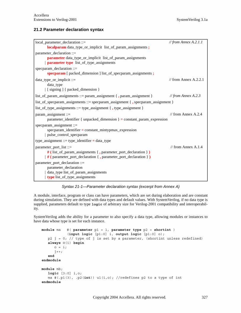
AccelleraExtensions to Verilog-2001 SystemVerilog 3.1a
21.2 Parameter declaration syntax
Syntax 21-1—Parameter declaration syntax (excerpt from Annex A)
A module, interface, program or class can have parameters, which are set during elaboration and are constantduring simulation. They are defined with data types and default values. With SystemVerilog, if no data type issupplied, parameters default to type logic of arbitrary size for Verilog-2001 compatibility and interoperabil-ity.
SystemVerilog adds the ability for a parameter to also specify a data type, allowing modules or instances tohave data whose type is set for each instance.
module ma #( parameter p1 = 1, parameter type p2 = shortint )(input logic [p1:0] i, output logic [p1:0] o);
p2 j = 0; // type of j is set by a parameter, (shortint unless redefined) always @(i) begin
o = i; j++;
end endmodule
module mb;logic [3:0] i,o;ma #(.p1(3), .p2(int)) u1(i,o); //redefines p2 to a type of int
endmodule
local_parameter_declaration ::= localparam data_type_or_implicit list_of_param_assignments ;
parameter_declaration ::= parameter data_type_or_implicit list_of_param_assignments
| parameter type list_of_type_assignments
specparam_declaration ::= specparam [ packed_dimension ] list_of_specparam_assignments ;
data_type_or_implicit ::= data_type
| [ signing ] { packed_dimension }
list_of_param_assignments ::= param_assignment { , param_assignment }
list_of_specparam_assignments ::= specparam_assignment { , specparam_assignment }
list_of_type_assignments ::= type_assignment { , type_assignment }
param_assignment ::= parameter_identifier { unpacked_dimension } = constant_param_expression
specparam_assignment ::= specparam_identifier = constant_mintypmax_expression
| pulse_control_specparam
type_assignment ::= type_identifier = data_type
parameter_port_list ::= # ( list_of_param_assignments { , parameter_port_declaration } )
| # ( parameter_port_declaration { , parameter_port_declaration } )
parameter_port_declaration ::=parameter_declaration
| data_type list_of_param_assignments | type list_of_type_assignments
// from Annex A.2.1.1
// from Annex A.2.2.1
// from Annex A.2.3
// from Annex A.2.4
// from Annex A.1.4
Copyright 2004 Accellera. All rights reserved. 327

AccelleraSystemVerilog 3.1a Extensions to Verilog-2001
SystemVerilog adds the ability for local parameters to be declared in a generate block. Local parameters canalso be declared in a package or in a compilation unit scope. In these contexts, the parameter keyword canbe used as a synonym for the localparam keyword.
$ can be assigned to parameters of integer types. A parameter to which $ is assigned shall only be used wher-ever $ can be specified as a literal constant.
For example, $ represents unbounded range specification, where the upper index can be any integer.
parameter r2 = $;property inq1(r1,r2);
@(posedge clk) a ##[r1:r2] b ##1 c |=> d;endproperty assert inq1(3);
To support whether a constant is $, a system function is provided to test whether a constant is a $. The syntaxof the system function is
$isunbounded(const_expression);
$isunbounded returns true if const_expression is unbounded. Typically, $isunbounded would be used as acondition in the generate statement.
The example below illustrates the benefit of using $ in writing properties concisely where the range is parame-terized. The checker in the example ensures that a bus driven by signal en remains 0, i.e, quiet for the specifiedminimum (min_quiet) and maximum (max_quiet) quiet time.
Note that function $isunbounded is used for checking the validity of the actual arguments.
interface quiet_time_checker #(parameter min_quiet = 0,parameter max_quiet = 0)(input logic clk, reset_n, [1:0]en);
generate if ( max_quiet == 0) begin
property quiet_time;@(posedge clk) reset_n |-> ($countones(en) == 1);
endproperty a1: assert property (quiet_time);
end else begin
property quiet_time;@(posedge clk)
(reset_n && ($past(en) != 0) && en == 0)|->(en == 0)[*min_quiet:max_quiet]
##1 ($countones(en) == 1);endproperty a1: assert property (quiet_time);
end if ((min_quiet == 0) && ($isunbounded(max_quiet))
$display(warning_msg);endgenerate
endinterface
quiet_time_checker #(0, 0) quiet_never (clk,1,enables);quiet_time_checker #(2, 4) quiet_in_window (clk,1,enables);quiet_time_checker #(0, $) quiet_any (clk,1,enables);
328 Copyright 2004 Accellera. All rights reserved .
AccelleraExtensions to Verilog-2001 SystemVerilog 3.1a
Another example below illustrates that by testing for $, a property can be configured according to the require-ments. When parameter max_cks is unbounded, it is not required to test for expr to become false.
interface width_checker #(parameter min_cks = 1, parameter max_cks = 1)(input logic clk, reset_n, expr);
generate begin if ($isunbounded(max_cks)) begin
property width;@(posedge clk)
(reset_n && $rose(expr)) |-> (expr [* min_cks]);endproperty a2: assert property (width);
end else begin
property assert_width_p;@(posedge clk)
(reset_n && $rose(expr)) |-> (expr[* min_cks:max_cks])##1 (!expr);
endproperty a2: assert property (width);
end endgenerate
endinterface
width_checker #(3, $) max_width_unspecified (clk,1,enables);width_checker #(2, 4) width_specified (clk,1,enables);
SystemVerilog also adds the ability to omit the parameter keyword in a parameter port list.
class vector #(size = 1);logic [size-1:0] v;
endclass
typedef vector#(16) word;
interface simple_bus #(AWIDTH = 64, type T = word) (input bit clk) ;endinterface
In a list of parameters, a parameter can depend on earlier parameters. In the following declaration, the defaultvalue of the second parameter depends on the value of the first parameter. The third parameter is a type, andthe fourth parameter is a value of that type.
module mc # (int N = 5, M = N*16, type T = int, T x = 0) ( ... );...endmodule
Copyright 2004 Accellera. All rights reserved. 329

AccelleraSystemVerilog 3.1a Extensions to Verilog-2001
330 Copyright 2004 Accellera. All rights reserved .
Section 22Configuration Libraries
22.1 Introduction (informative)
Verilog-2001 provides the ability to specify design configurations, which specify the binding information ofmodule instances to specific Verilog HDL source code. Configurations utilize libraries. A library is a collec-tion of modules, primitives and other configurations. Separate library map files specify the source code loca-tion for the cells contained within the libraries. The names of the library map files is typically specified asinvocation options to simulators or other software tools reading in Verilog source code.
SystemVerilog adds support for interfaces to Verilog configurations.
22.2 Libraries
A library is a named collection of cells. A cell is a module, macromodule, primitive, interface, program, pack-age, or configuration. A configuration is a specification of which source files bind to each instance in thedesign.
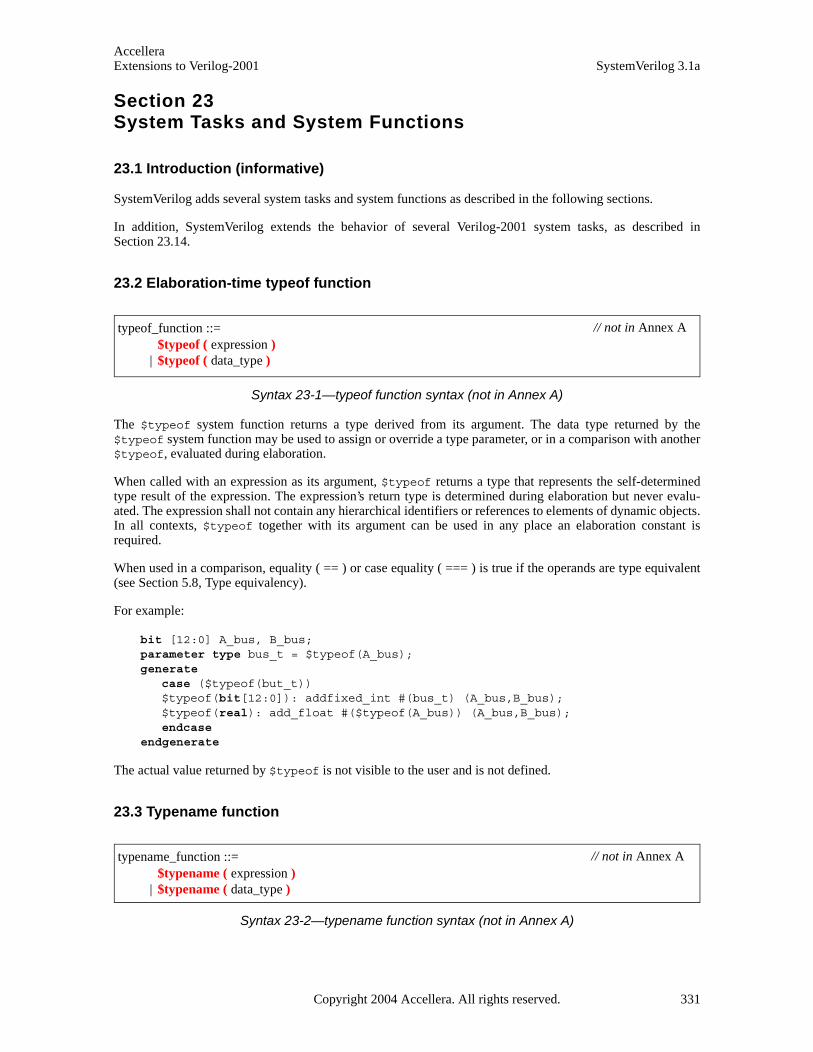
AccelleraExtensions to Verilog-2001 SystemVerilog 3.1a
Section 23System Tasks and System Functions
23.1 Introduction (informative)
SystemVerilog adds several system tasks and system functions as described in the following sections.
In addition, SystemVerilog extends the behavior of several Verilog-2001 system tasks, as described inSection 23.14.
23.2 Elaboration-time typeof function
Syntax 23-1—typeof function syntax (not in Annex A)
The $typeof system function returns a type derived from its argument. The data type returned by the$typeof system function may be used to assign or override a type parameter, or in a comparison with another$typeof, evaluated during elaboration.
When called with an expression as its argument, $typeof returns a type that represents the self-determinedtype result of the expression. The expression’s return type is determined during elaboration but never evalu-ated. The expression shall not contain any hierarchical identifiers or references to elements of dynamic objects.In all contexts, $typeof together with its argument can be used in any place an elaboration constant isrequired.
When used in a comparison, equality ( == ) or case equality ( === ) is true if the operands are type equivalent(see Section 5.8, Type equivalency).
For example:
bit [12:0] A_bus, B_bus;parameter type bus_t = $typeof(A_bus);generate
case ($typeof(but_t))$typeof(bit[12:0]): addfixed_int #(bus_t) (A_bus,B_bus);$typeof(real): add_float #($typeof(A_bus)) (A_bus,B_bus);endcase
endgenerate
The actual value returned by $typeof is not visible to the user and is not defined.
23.3 Typename function
Syntax 23-2—typename function syntax (not in Annex A)
typeof_function ::= $typeof ( expression )
| $typeof ( data_type )
// not in Annex A
typename_function ::= $typename ( expression )
| $typename ( data_type )
// not in Annex A
Copyright 2004 Accellera. All rights reserved. 331

AccelleraSystemVerilog 3.1a Extensions to Verilog-2001
The $typename system function returns a string that represents the resolved type of its argument.
The return string is constructed in the following steps:
1) A typedef that creates an equivalent type is resolved back to built-in or user defined types.
2) The default signing is removed, even if present explicitly in the source
3) System generated names are created for anonymous structs, unions and enums.
4) A ‘$’ is used as the placeholder for the name of an anonymous unpacked array.
5) Actual encoded values are appended with numeration named constants.
6) User defined type names are prefixed with their defining package or scope namespace.
7) Array ranges are represented as unsized decimal numbers.
8) Whitespace in the source is removed and a single space is added to separate identifiers and keywords fromeach other.
This process is similar to the way that type equality is computed, except that array ranges and built-in equiva-lent types are not normalized in the generated string. Thus $typename can be used in string comparisons forstricter type-checking of arrays than $typeof.
When called with an expression as its argument, $typename returns a string that represents the self-deter-mined type result of the expression. The expression's return type is determined during elaboration but neverevaluated. When used as an elaboration time constant, the expression shall not contain any hierarchical identi-fiers or references to elements of dynamic objects.
// source code // $typename would returntypedef bit node; // "bit"node signed [2:0] X; // "bit signed[2:0]"int signed Y; // "int"package A;
enum {A,B,C=99} X; // "enum{A=32’d0,B=32’d1,C=’32bX}A::e$1"typedef bit [9:1’b1] word // "A::bit[9:1]"
endpackage : Aimport A:.*;module top;
typedef struct {node A,B;} AB_t;AB_t AB[10]; // "struct{bit A;bit B;}top.AB_t$[0:9]"...
endmodule
23.4 Expression size system function
Syntax 23-3—Size function syntax (not in Annex A)
The $bits system function returns the number of bits required to hold an expression as a bit stream. SeeSection 3.16, Bit-stream casting for a definition of legal types. A 4 state value counts as one bit. Given the dec-laration:
logic [31:0] foo;
size_function ::= $bits ( expression )
| $bits ( type_identifier )
// not in Annex A
332 Copyright 2004 Accellera. All rights reserved .
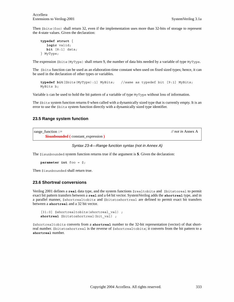
AccelleraExtensions to Verilog-2001 SystemVerilog 3.1a
Then $bits(foo) shall return 32, even if the implementation uses more than 32-bits of storage to representthe 4-state values. Given the declaration:
typedef struct {logic valid;bit [8:1] data;
} MyType;
The expression $bits(MyType) shall return 9, the number of data bits needed by a variable of type MyType.
The $bits function can be used as an elaboration-time constant when used on fixed sized types; hence, it canbe used in the declaration of other types or variables.
typedef bit[$bits(MyType):1] MyBits; //same as typedef bit [9:1] MyBits;MyBits b;
Variable b can be used to hold the bit pattern of a variable of type MyType without loss of information.
The $bits system function returns 0 when called with a dynamically sized type that is currently empty. It is anerror to use the $bits system function directly with a dynamically sized type identifier.
23.5 Range system function
Syntax 23-4—Range function syntax (not in Annex A)
The $isunbounded system function returns true if the argument is $. Given the declaration:
parameter int foo = $;
Then $isunbounded shall return true.
23.6 Shortreal conversions
Verilog 2001 defines a real data type, and the system functions $realtobits and $bitstoreal to permitexact bit pattern transfers between a real and a 64 bit vector. SystemVerilog adds the shortreal type, and ina parallel manner, $shortrealtobits and $bitstoshortreal are defined to permit exact bit transfersbetween a shortreal and a 32 bit vector.
[31:0] $shortrealtobits(shortreal_val) ; shortreal $bitstoshortreal(bit_val) ;
$shortrealtobits converts from a shortreal number to the 32-bit representation (vector) of that short-real number. $bitstoshortreal is the reverse of $shortrealtobits; it converts from the bit pattern to ashortreal number.
range_function ::= $isunbounded ( constant_expression )
// not in Annex A
Copyright 2004 Accellera. All rights reserved. 333

AccelleraSystemVerilog 3.1a Extensions to Verilog-2001
23.7 Array querying system functions
Syntax 23-5—Array querying function syntax (not in Annex A)
SystemVerilog provides system functions to return information about a particular dimension of an array vari-able or type. The return type is integer, and the default for the optional dimension expression is 1. The arraydimension can specify any fixed sized index (packed or unpacked), or any dynamically sized index (dynamic,associative, or queue).
— $left shall return the left bound (msb) of the dimension
— $right shall return the right bound (lsb) of the dimension
— $low shall return the minimum of $left and $right of the dimension
— $high shall return the maximum of $left and $right of the dimension
— $increment shall return 1 if $left is greater than or equal to $right, and -1 if $left is less than$right
— $size shall return the number of elements in the dimension, which is equivalent to $high - $low + 1
— $dimensions shall return the number of dimensions in the array, or 0 for a singular object
The dimensions of an array shall be numbered as follows: The slowest varying dimension (packed orunpacked) is dimension 1. Successively faster varying dimensions have sequentially higher dimension num-bers. Intermediate type definitions are expanded first before numbering the dimensions.
For example:
// Dimension numbers// 3 4 1 2reg [3:0][2:1] n [1:5][2:8];typedef reg [3:0][2:1] packed_reg;packed_reg n[1:5][2:8]; // same dimensions as in the lines above
For a fixed sized integer type (integer, shortint, longint, and byte), dimension 1 is pre-defined. For aninteger N declared without a range specifier, its bounds are assumed to be [$bits(N)-1:0].
If an out-of-range dimension is specified, these functions shall return a ’x.
When used on a dynamic array or queue dimension, these functions return information about the current stateof the array. If the dimension is currently empty, these functions shall return a ’x. It is an error to use thesefunctions directly on a dynamically sized type identifier.
array_query_function ::= array_dimension_function ( array_identifier , dimension_expression )
| array_dimension_function ( type_identifier [ , dimension_expression ] ) | $dimensions ( array_identifier ) | $dimensions ( type_identifier )
array_dimension_function ::= $left
| $right | $low | $high | $increment | $size
dimension_expression ::= expression
// not in Annex A
334 Copyright 2004 Accellera. All rights reserved .
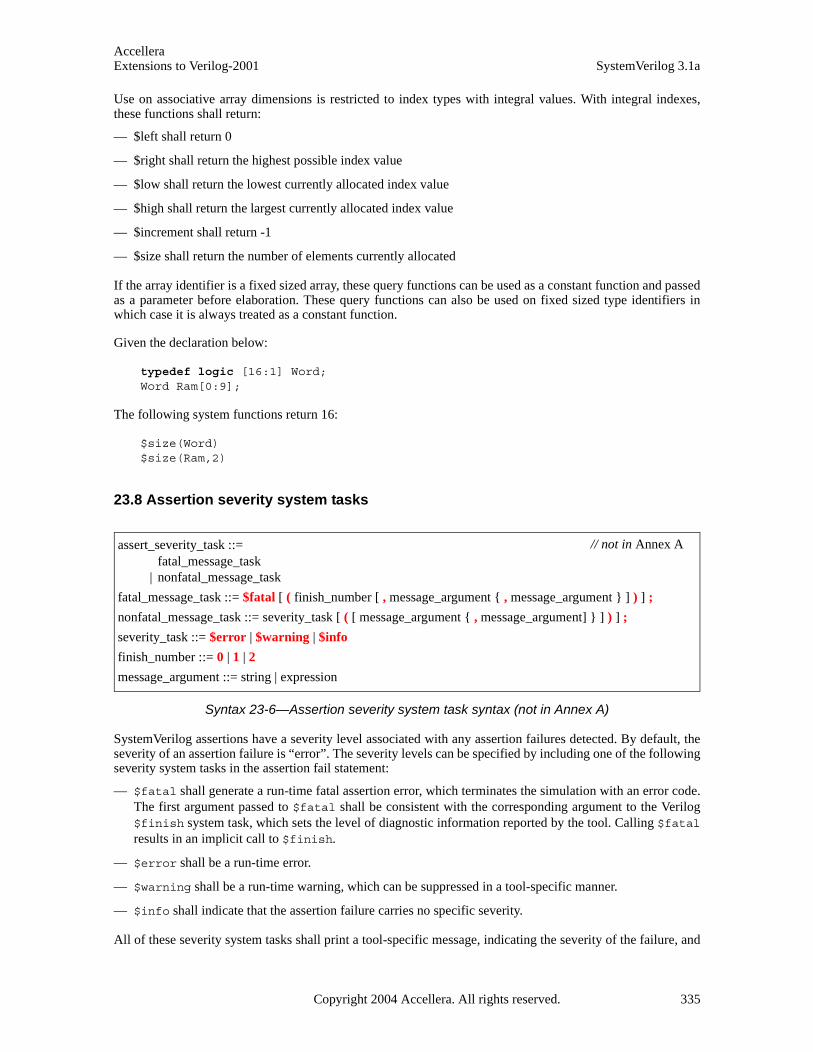
AccelleraExtensions to Verilog-2001 SystemVerilog 3.1a
Use on associative array dimensions is restricted to index types with integral values. With integral indexes,these functions shall return:
— $left shall return 0
— $right shall return the highest possible index value
— $low shall return the lowest currently allocated index value
— $high shall return the largest currently allocated index value
— $increment shall return -1
— $size shall return the number of elements currently allocated
If the array identifier is a fixed sized array, these query functions can be used as a constant function and passedas a parameter before elaboration. These query functions can also be used on fixed sized type identifiers inwhich case it is always treated as a constant function.
Given the declaration below:
typedef logic [16:1] Word;Word Ram[0:9];
The following system functions return 16:
$size(Word)$size(Ram,2)
23.8 Assertion severity system tasks
Syntax 23-6—Assertion severity system task syntax (not in Annex A)
SystemVerilog assertions have a severity level associated with any assertion failures detected. By default, theseverity of an assertion failure is “error”. The severity levels can be specified by including one of the followingseverity system tasks in the assertion fail statement:
— $fatal shall generate a run-time fatal assertion error, which terminates the simulation with an error code.The first argument passed to $fatal shall be consistent with the corresponding argument to the Verilog$finish system task, which sets the level of diagnostic information reported by the tool. Calling $fatalresults in an implicit call to $finish.
— $error shall be a run-time error.
— $warning shall be a run-time warning, which can be suppressed in a tool-specific manner.
— $info shall indicate that the assertion failure carries no specific severity.
All of these severity system tasks shall print a tool-specific message, indicating the severity of the failure, and
assert_severity_task ::= fatal_message_task
| nonfatal_message_task
fatal_message_task ::= $fatal [ ( finish_number [ , message_argument { , message_argument } ] ) ] ;
nonfatal_message_task ::= severity_task [ ( [ message_argument { , message_argument] } ] ) ] ;
severity_task ::= $error | $warning | $info
finish_number ::= 0 | 1 | 2
message_argument ::= string | expression
// not in Annex A
Copyright 2004 Accellera. All rights reserved. 335
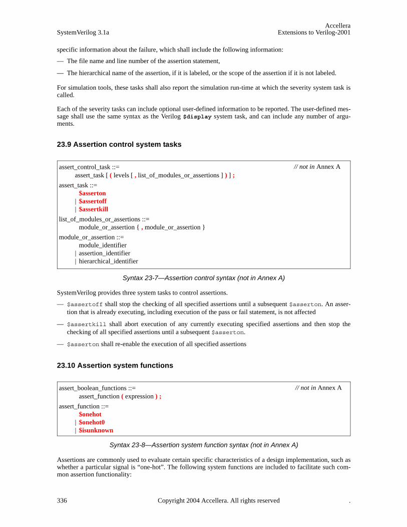
AccelleraSystemVerilog 3.1a Extensions to Verilog-2001
specific information about the failure, which shall include the following information:
— The file name and line number of the assertion statement,
— The hierarchical name of the assertion, if it is labeled, or the scope of the assertion if it is not labeled.
For simulation tools, these tasks shall also report the simulation run-time at which the severity system task iscalled.
Each of the severity tasks can include optional user-defined information to be reported. The user-defined mes-sage shall use the same syntax as the Verilog $display system task, and can include any number of argu-ments.
23.9 Assertion control system tasks
Syntax 23-7—Assertion control syntax (not in Annex A)
SystemVerilog provides three system tasks to control assertions.
— $assertoff shall stop the checking of all specified assertions until a subsequent $asserton. An asser-tion that is already executing, including execution of the pass or fail statement, is not affected
— $assertkill shall abort execution of any currently executing specified assertions and then stop thechecking of all specified assertions until a subsequent $asserton.
— $asserton shall re-enable the execution of all specified assertions
23.10 Assertion system functions
Syntax 23-8—Assertion system function syntax (not in Annex A)
Assertions are commonly used to evaluate certain specific characteristics of a design implementation, such aswhether a particular signal is “one-hot”. The following system functions are included to facilitate such com-mon assertion functionality:
assert_control_task ::= assert_task [ ( levels [ , list_of_modules_or_assertions ] ) ] ;
assert_task ::=$asserton
| $assertoff | $assertkill
list_of_modules_or_assertions ::=module_or_assertion { , module_or_assertion }
module_or_assertion ::= module_identifier
| assertion_identifier| hierarchical_identifier
// not in Annex A
assert_boolean_functions ::= assert_function ( expression ) ;
assert_function ::=$onehot
| $onehot0 | $isunknown
// not in Annex A
336 Copyright 2004 Accellera. All rights reserved .
AccelleraExtensions to Verilog-2001 SystemVerilog 3.1a
— $onehot returns true if one and only one bit of expression is high.
— $onehot0 returns true if at most one bit of expression is high.
— $isunknown returns true if any bit of the expression is X or Z. This is equivalent to^expression === ’bx.
All of the above system functions shall have a return type of bit. A return value of 1’b1 shall indicate true,and a return value of 1’b0 shall indicate false.
A function is provided to return sampled value of an expression.
$sampled ( expression [, clocking_event] )
Three functions are provided for assertions to detect changes in values between two adjacent clock ticks.
$rose ( expression [, clocking_event] )
$fell ( expression [, clocking_event] )
$stable ( expression [, clocking_event] )
The past values can be accessed with the $past function.
$past ( expression [, number_of_ticks] [, expression2] [, clocking_event] )
$sampled, $rose, $fell, $stable and $past are discussed in Section 17.7.3.
The number of 1s in a bit vector expression can be determined with the $countones function.
$countones ( expression )
$countones is discussed in Section 17.10.
23.11 Random number system functions
To supplement the Verilog $random system function, SystemVerilog provides three special system functionsfor generating pseudorandom numbers, $urandom, $urandom_range and $srandom. These system func-tions are presented in Section 12.12.
23.12 Program control
In addition to the normal simulation control tasks ($stop and $finish), a program can use the $exit controltask. When all programs exit, the simulation finishes and an implicit call to $finish is made. The usage of$exit is presented in Section 16.6 on program blocks.
23.13 Coverage system functions
SystemVerilog has several built-in system functions for obtaining test coverage information:$coverage_control, $coverage_get_max, $coverage_get, $coverage_merge and$coverage_save. The coverage system functions are described in Section 29.2.
23.14 Enhancements to Verilog-2001 system tasks
SystemVerilog adds system tasks and system functions as described in the following sections. In addition, Sys-temVerilog extends the behavior of the following:
Copyright 2004 Accellera. All rights reserved. 337
AccelleraSystemVerilog 3.1a Extensions to Verilog-2001
— %u and %z format specifiers:
— For packed data, %u and %z are defined to operate as though the operation were applied to the equiva-lent vector.
— For unpacked struct data, %u and %z are defined to apply as though the operation were performed on each member in declaration order.
— For unpacked union data, %u and %z are defined to apply as though the operation were performed on the first member in declaration order.
— %u and %z are not defined on unpacked arrays.
— The count of data items read by a %u or %z for an aggregate type is always either 1 or 0; the individual members are not counted separately.
— $fread
$fread has two variants—a register variant and a set of three memory variants.
The register variant,
$fread(myreg, fd);
— is defined to be the one applied for all packed data.
— For unpacked struct data, $fread is defined to apply as though the operation were performed on each member in declaration order.
— For unpacked union data, $fread is defined to apply as though the operation were performed on the first member in declaration order.
— For unpacked arrays, the original definition applies except that unpacked struct or union elements are read as described above.
23.15 $readmemb and $readmemh
23.15.1 Reading packed data
$readmemb and $readmemh are extended to unpacked arrays of packed data, associative arrays of packeddata, and dynamic arrays of packed data. In such cases, the system tasks treat each packed element as the vec-tor equivalent and perform the normal operation.
When working with associative arrays, indexes must be of integral types.
23.15.2 Reading 2-state types
$readmemb and $readmemh are extended to packed data of 2-state type, such as int or enumerated types. For2-state integer types, reading proceeds the same as for conventional Verilog reg types (e.g. integer), with theexception that X or Z data is converted to 0. For enumerated types, the file data represents the ordinal value ofthe enumerated type. (See Section 3.10) If an enumeration ordinal is out of range for a given type, then an errorshall be issued and no further reading shall take place.
23.16 $writememb and $writememh
SystemVerilog introduces system tasks $writememb and $writememh:
338 Copyright 2004 Accellera. All rights reserved .
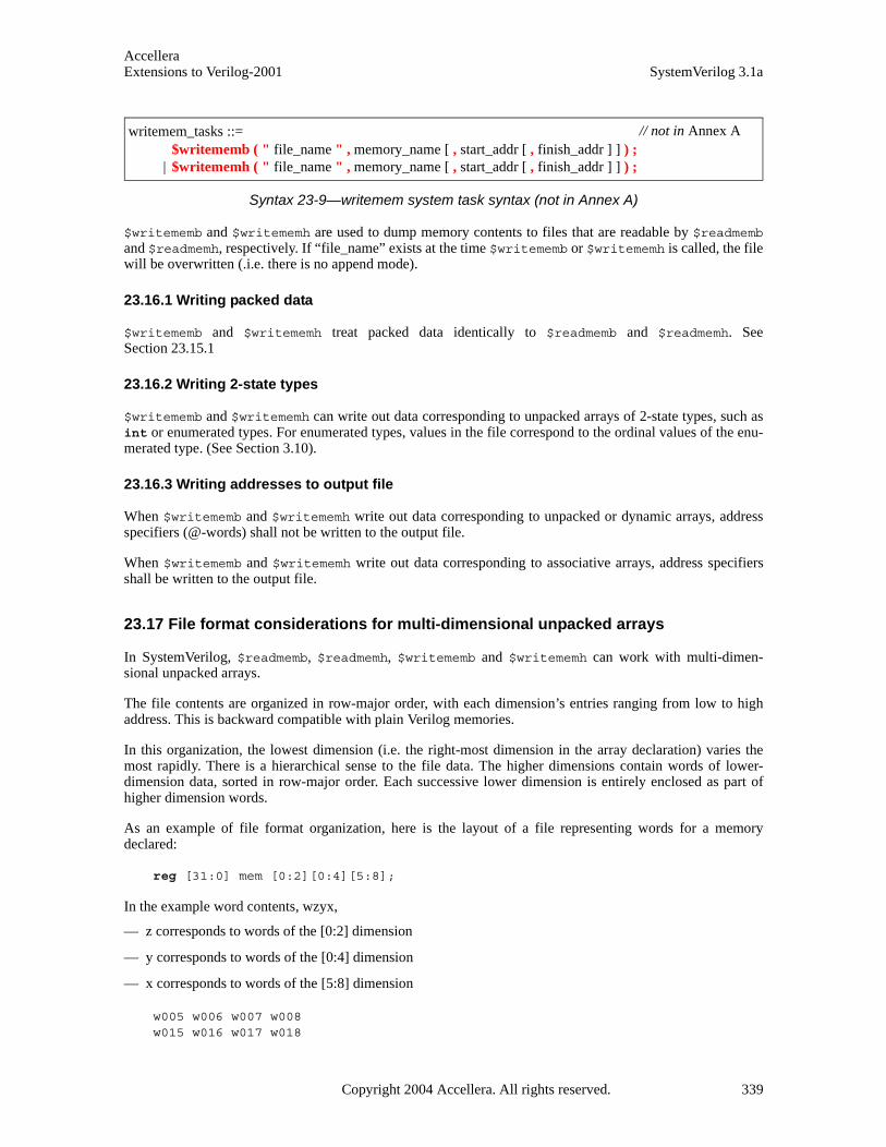
AccelleraExtensions to Verilog-2001 SystemVerilog 3.1a
Syntax 23-9—writemem system task syntax (not in Annex A)
$writememb and $writememh are used to dump memory contents to files that are readable by $readmemband $readmemh, respectively. If “file_name” exists at the time $writememb or $writememh is called, the filewill be overwritten (.i.e. there is no append mode).
23.16.1 Writing packed data
$writememb and $writememh treat packed data identically to $readmemb and $readmemh. SeeSection 23.15.1
23.16.2 Writing 2-state types
$writememb and $writememh can write out data corresponding to unpacked arrays of 2-state types, such asint or enumerated types. For enumerated types, values in the file correspond to the ordinal values of the enu-merated type. (See Section 3.10).
23.16.3 Writing addresses to output file
When $writememb and $writememh write out data corresponding to unpacked or dynamic arrays, addressspecifiers (@-words) shall not be written to the output file.
When $writememb and $writememh write out data corresponding to associative arrays, address specifiersshall be written to the output file.
23.17 File format considerations for multi-dimensional unpacked arrays
In SystemVerilog, $readmemb, $readmemh, $writememb and $writememh can work with multi-dimen-sional unpacked arrays.
The file contents are organized in row-major order, with each dimension’s entries ranging from low to highaddress. This is backward compatible with plain Verilog memories.
In this organization, the lowest dimension (i.e. the right-most dimension in the array declaration) varies themost rapidly. There is a hierarchical sense to the file data. The higher dimensions contain words of lower-dimension data, sorted in row-major order. Each successive lower dimension is entirely enclosed as part ofhigher dimension words.
As an example of file format organization, here is the layout of a file representing words for a memorydeclared:
reg [31:0] mem [0:2][0:4][5:8];
In the example word contents, wzyx,
— z corresponds to words of the [0:2] dimension
— y corresponds to words of the [0:4] dimension
— x corresponds to words of the [5:8] dimension
w005 w006 w007 w008w015 w016 w017 w018
writemem_tasks ::= $writememb ( " file_name " , memory_name [ , start_addr [ , finish_addr ] ] ) ;
| $writememh ( " file_name " , memory_name [ , start_addr [ , finish_addr ] ] ) ;
// not in Annex A
Copyright 2004 Accellera. All rights reserved. 339
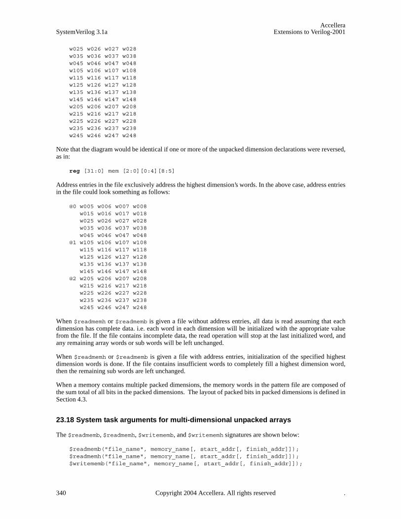
AccelleraSystemVerilog 3.1a Extensions to Verilog-2001
w025 w026 w027 w028w035 w036 w037 w038w045 w046 w047 w048w105 w106 w107 w108w115 w116 w117 w118w125 w126 w127 w128w135 w136 w137 w138w145 w146 w147 w148w205 w206 w207 w208w215 w216 w217 w218w225 w226 w227 w228w235 w236 w237 w238w245 w246 w247 w248
Note that the diagram would be identical if one or more of the unpacked dimension declarations were reversed,as in:
reg [31:0] mem [2:0][0:4][8:5]
Address entries in the file exclusively address the highest dimension’s words. In the above case, address entriesin the file could look something as follows:
@0 w005 w006 w007 w008w015 w016 w017 w018w025 w026 w027 w028w035 w036 w037 w038w045 w046 w047 w048
@1 w105 w106 w107 w108w115 w116 w117 w118w125 w126 w127 w128w135 w136 w137 w138w145 w146 w147 w148
@2 w205 w206 w207 w208w215 w216 w217 w218w225 w226 w227 w228w235 w236 w237 w238w245 w246 w247 w248
When $readmemh or $readmemb is given a file without address entries, all data is read assuming that eachdimension has complete data. i.e. each word in each dimension will be initialized with the appropriate valuefrom the file. If the file contains incomplete data, the read operation will stop at the last initialized word, andany remaining array words or sub words will be left unchanged.
When $readmemh or $readmemb is given a file with address entries, initialization of the specified highestdimension words is done. If the file contains insufficient words to completely fill a highest dimension word,then the remaining sub words are left unchanged.
When a memory contains multiple packed dimensions, the memory words in the pattern file are composed ofthe sum total of all bits in the packed dimensions. The layout of packed bits in packed dimensions is defined inSection 4.3.
23.18 System task arguments for multi-dimensional unpacked arrays
The $readmemb, $readmemh, $writememb, and $writememh signatures are shown below:
$readmemb("file_name", memory_name[, start_addr[, finish_addr]]);$readmemh("file_name", memory_name[, start_addr[, finish_addr]]);$writememb("file_name", memory_name[, start_addr[, finish_addr]]);
340 Copyright 2004 Accellera. All rights reserved .

AccelleraExtensions to Verilog-2001 SystemVerilog 3.1a
$writememh("file_name", memory_name[, start_addr[, finish_addr]]);
memory_name can be an unpacked array, or a partially indexed multi-dimensional unpacked array thatresolves to a lesser-dimensioned unpacked array.
Higher order dimensions must be specified with an index, rather than a complete or partial dimension range.The lowest dimension (i.e. the right-most specified dimension in the identifier) can be specified with slice syn-tax. See Section 4.4 for details on legal array indexing in SystemVerilog.
The start_addr and finish_addr arguments apply to the addresses of the unpacked array selected bymemory_name. This address range represents the highest dimension of data in the file_name.
When slice syntax is used in the memory_name argument, any start_addr and finish_addr arguments must fallwithin the bounds of the slice’s range.
The direction of the highest dimension’s file entries is given by the relative magnitudes of start_addr andfinish_addr, as is the case in 1364-2001.
Copyright 2004 Accellera. All rights reserved. 341
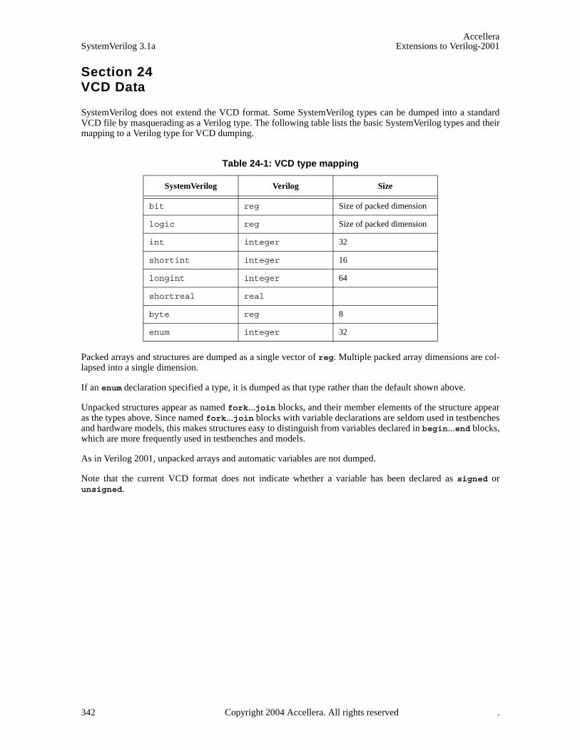
AccelleraSystemVerilog 3.1a Extensions to Verilog-2001
342 Copyright 2004 Accellera. All rights reserved .
Section 24VCD Data
SystemVerilog does not extend the VCD format. Some SystemVerilog types can be dumped into a standardVCD file by masquerading as a Verilog type. The following table lists the basic SystemVerilog types and theirmapping to a Verilog type for VCD dumping.
Packed arrays and structures are dumped as a single vector of reg. Multiple packed array dimensions are col-lapsed into a single dimension.
If an enum declaration specified a type, it is dumped as that type rather than the default shown above.
Unpacked structures appear as named fork...join blocks, and their member elements of the structure appearas the types above. Since named fork...join blocks with variable declarations are seldom used in testbenchesand hardware models, this makes structures easy to distinguish from variables declared in begin...end blocks,which are more frequently used in testbenches and models.
As in Verilog 2001, unpacked arrays and automatic variables are not dumped.
Note that the current VCD format does not indicate whether a variable has been declared as signed orunsigned.
Table 24-1: VCD type mapping
SystemVerilog Verilog Size
bit reg Size of packed dimension
logic reg Size of packed dimension
int integer 32
shortint integer 16
longint integer 64
shortreal real
byte reg 8
enum integer 32

AccelleraExtensions to Verilog-2001 SystemVerilog 3.1a
Section 25Compiler Directives
25.1 Introduction (informative)
Verilog provides the ‘define text substitution macro compiler directive. A macro can contain arguments,whose values can be set for each instance of the macro. For example:
‘define NAND(dval) nand #(dval)
‘NAND(3) i1 (y, a, b); //‘NAND(3) macro substitutes with: nand #(3)
‘NAND(3:4:5) i2 (o, c, d); //‘NAND(3:4:5) macro substitutes with: nand #(3:4:5)
SystemVerilog enhances the capabilities of the ‘define compiler directive to support the construction ofstring literals and identifiers.
Verilog provides the `include file inclusion compiler directive. SystemVerilog enhances the capabilities tosupport standard include specification, and enhances the `include directive to accept a file name constructedwith a macro.
25.2 ‘define macros
In Verilog, the ‘define macro text can include a backslash ( \ ) at the end of a line to show continuation onthe next line.
In SystemVerilog, the macro text can also include `", `\`" and ``.
An `" overrides the usual lexical meaning of ", and indicates that the expansion should include an actual quo-tation mark. This allows string literals to be constructed from macro arguments.
A `\`" indicates that the expansion should include the escape sequence \", e.g.
`define msg(x,y) `"x: `\`"y`\`"`"
This expands:
$display(`msg(left side,right side));
to:
$display("left side: \"right side\"");
A `` delimits lexical tokens without introducing white space, allowing identifiers to be constructed from argu-ments, e.g.
`define foo(f) f``_suffix
This expands:
‘foo(bar)
to:
bar_suffix
Copyright 2004 Accellera. All rights reserved. 343

AccelleraSystemVerilog 3.1a Extensions to Verilog-2001
The ‘include directive can be followed by a macro, instead of a literal string:
‘define home(filename) ‘"/home/foo/filename‘" ‘include ‘home(myfile)
25.3 ‘include
The syntax of the ‘include compiler directive is:
include_compiler_directive ::= ‘include "filename" | ‘include <filename>
When the filename is an absolute path, only that filename is included and only the double quote form ofthe ‘include can be used.
When the double quote ("filename") version is used, the behavior of ‘include is unchanged from IEEEStd. 1364-2001.
When the angle bracket (<filename>) notation is used, then only the vendor defined location containing filesdefined by the language standard is searched. Relative path names given inside the < > are interpreted relativeto the vendor-defined location in all cases.
344 Copyright 2004 Accellera. All rights reserved .
AccelleraExtensions to Verilog-2001 SystemVerilog 3.1a
Section 26Features under consideration for removal from SystemVerilog
26.1 Introduction (informative)
Certain Verilog language features can be simulation inefficient, easily abused, and the source of design prob-lems. These features are being considered for removal from the SystemVerilog language, if there is an alternatemethod for these features.
The Verilog language features that have been identified in this standard as ones which can be removed fromVerilog are defparam and procedural assign/deassign.
26.2 Defparam statements
The SystemVerilog committee has determined, based on the solicitation of input from tool implementers andtools users, that the defparam method of specifying the value of a parameter can be a source of design errors,and can be an impediment to tool implementation. The defparam statement does not provide a capability thatcannot be done by another method, which avoids these problems. Therefore, the committee has placed thedefparam statement on a deprecation list. This means is that a future revision of the Verilog standard mightnot require support for this feature. This current standard still requires tools to support the defparam state-ment. However, users are strongly encouraged to migrate their code to use one of the alternate methods ofparameter redefinition.
Prior to the acceptance of the Verilog-2001 Standard, it was common practice to change one or more parame-ters of instantiated modules using a separate defparam statement. Defparam statements can be a source of toolcomplexity and design problems.
A defparam statement can precede the instance to be modified, can follow the instance to be modified, can beat the end of the file that contains the instance to be modified, can be in a separate file from the instance to bemodified, can modify parameters hierarchically that in turn must again be passed to other defparam state-ments to modify, and can modify the same parameter from two different defparam statements (with unde-fined results). Due to the many ways that a defparam can modify parameters, a Verilog compiler cannotinsure the final parameter values for an instance until after all of the design files are compiled.
Prior to Verilog-2001, the only other method available to change the values of parameters on instantiated mod-ules was to use implicit in-line parameter redefinition. This method uses #(parameter_value) as part of themodule instantiation. Implicit in-line parameter redefinition syntax requires that all parameters up to andincluding the parameter to be changed must be placed in the correct order, and must be assigned values.
Verilog-2001 introduced explicit in-line parameter redefinition, in the form #(.parameter_name(value)),as part of the module instantiation. This method gives the capability to pass parameters by name in the instan-tiation, which supplies all of the necessary parameter information to the model in the instantiation itself.
The practice of using defparam statements is highly discouraged. Engineers are encouraged to take advantageof the Verilog-2001 explicit in-line parameter redefinition capability.
See Section 21 for more details on parameters.
26.3 Procedural assign and deassign statements
The SystemVerilog committee has determined, based on the solicitation of input from tool implementers andtools users, that the procedural assign and deassign statements can be a source of design errors, and can bean impediment to tool implementation. The procedural assign/deassign statements do not provide a capa-bility that cannot be done by another method, which avoids these problems. Therefore, the committee hasplaced the procedural assign/deassign statements on a deprecation list. This means that a future revision ofthe Verilog standard might not require support for theses statements. This current standard still requires tools to
Copyright 2004 Accellera. All rights reserved. 345

AccelleraSystemVerilog 3.1a Extensions to Verilog-2001
support the procedural assign/deassign statements. However, users are strongly encouraged to migratetheir code to use one of the alternate methods of procedural or continuous assignments.
Verilog has two forms of the assign statement:
— Continuous assignments, placed outside of any procedures
— Procedural continuous assignments, placed within a procedure
Continuous assignment statements are a separate process that are active throughout simulation. The continuousassignment statement accurately represents combinational logic at an RTL level of modeling, and is frequentlyused.
Procedural continuous assignment statements become active when the assign statement is executed in theprocedure. The process can be de-activated using a deassign statement. The procedural assign/deassignstatements are seldom needed to model hardware behavior. In the unusual circumstances where the behavior ofprocedural continuous assignments are required, the same behavior can be modeled using the procedural forceand release statements.
The fact that the assign statement to be used both outside and inside a procedure can cause confusion anderrors in Verilog models. The practice of using the assign and deassign statements inside of proceduralblocks is highly discouraged.
346 Copyright 2004 Accellera. All rights reserved .
AccelleraExtensions to Verilog-2001 SystemVerilog 3.1a
Section 27Direct Programming Interface (DPI)
This chapter highlights the Direct Programming Interface and provides a detailed description of the System-Verilog layer of the interface. The C layer is defined in Annex E.
27.1 Overview
Direct Programming Interface (DPI) is an interface between SystemVerilog and a foreign programming lan-guage. It consists of two separate layers: the SystemVerilog layer and a foreign language layer. Both sides ofDPI are fully isolated. Which programming language is actually used as the foreign language is transparentand irrelevant for the SystemVerilog side of this interface. Neither the SystemVerilog compiler nor the foreignlanguage compiler is required to analyze the source code in the other’s language. Different programming lan-guages can be used and supported with the same intact SystemVerilog layer. For now, however, SystemVerilog3.1 defines a foreign language layer only for the C programming language. See Annex E for more details.
The motivation for this interface is two-fold. The methodological requirement is that the interface should allowa heterogeneous system to be built (a design or a testbench) in which some components can be written in a lan-guage (or more languages) other than SystemVerilog, hereinafter called the foreign language. On the otherhand, there is also a practical need for an easy and efficient way to connect existing code, usually written in Cor C++, without the knowledge and the overhead of PLI or VPI.
DPI follows the principle of a black box: the specification and the implementation of a component is clearlyseparated and the actual implementation is transparent to the rest of the system. Therefore, the actual program-ming language of the implementation is also transparent, though this standard defines only C linkage seman-tics. The separation between SystemVerilog code and the foreign language is based on using functions as thenatural encapsulation unit in SystemVerilog. By and large, any function can be treated as a black box andimplemented either in SystemVerilog or in the foreign language in a transparent way, without changing itscalls.
27.1.1 Tasks and functions
DPI allows direct inter-language function calls between the languages on either side of the interface. Specifi-cally, functions implemented in a foreign language can be called from SystemVerilog; such functions arereferred to as imported functions. SystemVerilog functions that are to be called from a foreign code shall bespecified in export declarations (see Section 27.6 for more details). DPI allows for passing SystemVerilog databetween the two domains through function arguments and results. There is no intrinsic overhead in this inter-face.
It is also possible to perform task enables across the language boundary. Foreign code can call SystemVerilogtasks, and native Verilog code can call imported tasks. An imported task has the same semantics as a nativeVerilog task: It never returns a value, and it can block and consume simulation time.
All functions used in DPI are assumed to complete their execution instantly and consume 0 (zero) simulationtime, just as normal SystemVerilog functions. DPI provides no means of synchronization other than by dataexchange and explicit transfer of control.
Every imported task and function needs to be declared. A declaration of an imported task or function isreferred to as an import declaration. Import declarations are very similar to SystemVerilog task and functiondeclarations. Import declarations can occur anywhere where SystemVerilog task and function definitions arepermitted. An import declaration is considered to be a definition of a SystemVerilog task or function with aforeign language implementation. The same foreign task or function can be used to implement multiple Sys-temVerilog tasks and functions (this can be a useful way of providing differing default argument values for thesame basic task or function), but a given SystemVerilog name can only be defined once per scope. Importedtask and functions can have zero or more formal input, output, and inout arguments. Imported tasksalways return a void value, and thus can only be used in statement context. Imported functions can return aresult or be defined as void functions.
Copyright 2004 Accellera. All rights reserved. 347
AccelleraSystemVerilog 3.1a Extensions to Verilog-2001
DPI is based entirely upon SystemVerilog constructs. The usage of imported functions is identical as for nativeSystemVerilog functions. With few exceptions imported functions and native functions are mutuallyexchangeable. Calls of imported functions are indistinguishable from calls of SystemVerilog functions. Thisfacilitates ease-of-use and minimizes the learning curve. Similar interchangeable semantics exist betweennative SystemVerilog tasks and imported tasks.
27.1.2 Data types
SystemVerilog data types are the sole data types that can cross the boundary between SystemVerilog and a for-eign language in either direction (i.e., when an imported function is called from SystemVerilog code or anexported SystemVerilog function is called from a foreign code). It is not possible to import the data types ordirectly use the type syntax from another language. A rich subset of SystemVerilog data types is allowed forformal arguments of import and export functions, although with some restrictions and with some notationalextensions. Function result types are restricted to small values, however (see Section 27.4.5).
Formal arguments of an imported function can be specified as open arrays. A formal argument is an open arraywhen a range of one or more of its dimensions, packed or unpacked, is unspecified. An open array is like amulti-dimensional dynamic array formal in both packed and unpacked dimensions, and is thus denoted usingthe same syntax as dynamic arrays, using [] to denote an open dimension. This is solely a relaxation of theargument-matching rules. An actual argument shall match the formal one regardless of the range(s) for its cor-responding dimension(s), which facilitates writing generalized code that can handle SystemVerilog arrays ofdifferent sizes. See Section 27.4.6.1.
27.1.2.1 Data representation
DPI does not add any constraints on how SystemVerilog-specific data types are actually implemented. Optimalrepresentation can be platform dependent. The layout of 2- or 4-state packed structures and arrays is imple-mentation- and platform-dependent.
The implementation (representation and layout) of 4-state values, structures, and arrays is irrelevant for Sys-temVerilog semantics, and can only impact the foreign side of the interface.
27.2 Two layers of the DPI
DPI consists of two separate layers: the SystemVerilog layer and a foreign language layer. The SystemVeriloglayer does not depend on which programming language is actually used as the foreign language. Although dif-ferent programming languages can be supported and used with the intact SystemVerilog layer, SystemVerilog3.1 defines a foreign language layer only for the C programming language. Nevertheless, SystemVerilog codeshall look identical and its semantics shall be unchanged for any foreign language layer. Different foreign lan-guages can require that the SystemVerilog implementation shall use the appropriate function call protocol,argument passing and linking mechanisms. This shall be, however, transparent to SystemVerilog users. Sys-temVerilog 3.1 requires only that its implementation shall support C protocols and linkage.
27.2.1 DPI SystemVerilog layer
The SystemVerilog side of DPI does not depend on the foreign programming language. In particular, the actualfunction call protocol and argument passing mechanisms used in the foreign language are transparent and irrel-evant to SystemVerilog. SystemVerilog code shall look identical regardless of what code the foreign side of theinterface is using. The semantics of the SystemVerilog side of the interface is independent from the foreignside of the interface.
This chapter does not constitute a complete interface specification. It only describes the functionality, seman-tics and syntax of the SystemVerilog layer of the interface. The other half of the interface, the foreign languagelayer, defines the actual argument passing mechanism and the methods to access (read/write) formal argumentsfrom the foreign code. See Annex E for more details.
348 Copyright 2004 Accellera. All rights reserved .
AccelleraExtensions to Verilog-2001 SystemVerilog 3.1a
27.2.2 DPI foreign language layer
The foreign language layer of the interface (which is transparent to SystemVerilog) shall specify how actualarguments are passed, how they can be accessed from the foreign code, how SystemVerilog-specific data types(such as logic and packed) are represented, and how to translate them to and from some predefined C-liketypes.
The data types allowed for formal arguments and results of imported functions or exported functions are gen-erally SystemVerilog types (with some restrictions and with notational extensions for open arrays). The user isresponsible for specifying in their foreign code the native types equivalent to the SystemVerilog types used inimported declarations or export declarations. Software tools, like a SystemVerilog compiler, can facilitate themapping of SystemVerilog types onto foreign native types by generating the appropriate function headers.
The SystemVerilog compiler or simulator shall generate and/or use the function call protocol and argumentpassing mechanisms required for the intended foreign language layer. The same SystemVerilog code (com-piled accordingly) shall be usable with different foreign language layers, regardless of the data access methodassumed in a specific layer. Annex F defines DPI foreign language layer for the C programming language.
27.3 Global name space of imported and exported functions
Every task or function imported to SystemVerilog must eventually resolve to a global symbol. Similarly, everytask or function exported from SystemVerilog defines a global symbol. Thus the tasks and functions importedto and exported from SystemVerilog have their own global name space of linkage names, different from com-pilation-unit scope name space. Global names of imported and exported tasks and functions must be unique(no overloading is allowed ) and shall follow C conventions for naming; specifically, such names must startwith a letter or underscore, and can be followed by alphanumeric characters or underscores. Exported andimported tasks and functions, however, can be declared with local SystemVerilog names. Import and exportdeclarations allow users to specify a global name for a function in addition to its declared name. Should a glo-bal name clash with a SystemVerilog keyword or a reserved name, it shall take the form of an escaped identi-fier. The leading backslash ( \ ) character and the trailing white space shall be stripped off by theSystemVerilog tool to create the linkage identifier. Note that after this stripping, the linkage identifier soformed must comply with the normal rules for C identifier construction. If a global name is not explicitlygiven, it shall be the same as the SystemVerilog task or function name. For example:
export "DPI" foo_plus = function \foo+ ; // "foo+" exported as "foo_plus"export "DPI" function foo; // "foo" exported under its own nameimport "DPI" init_1 = function void \init[1] (); // "init_1" is a linkage nameimport "DPI" \begin = function void \init[2] (); // "begin" is a linkage name
The same global task or function can be referred to in multiple import declarations in different scopes or/andwith different SystemVerilog names, see Section 27.4.4.
Multiple export declarations are allowed with the same c_identifier, explicit or implicit, as long as they are indifferent scopes and have the same type signature (as defined in Section 27.4.4 for imported tasks and func-tions). Multiple export declarations with the same c_identifier in the same scope are forbidden.
27.4 Imported tasks and functions
The usage of imported functions is similar as for native SystemVerilog functions.
27.4.1 Required properties of imported tasks and functions — semantic constraints
This section defines the semantic constraints imposed on imported tasks or functions. Some semantic restric-tions are shared by all imported tasks or functions. Other restrictions depend on whether the special propertiespure (see Section 27.4.2) or context (see Section 27.4.3) are specified for an imported task or function. ASystemVerilog compiler is not able to verify that those restrictions are observed and if those restrictions are notsatisfied, the effects of such imported task or function calls can be unpredictable.
Copyright 2004 Accellera. All rights reserved. 349

AccelleraSystemVerilog 3.1a Extensions to Verilog-2001
27.4.1.1 Instant completion of imported functions
Imported functions shall complete their execution instantly and consume zero-simulation time, similarly tonative functions.
Note that imported tasks can consume time, similar to native SystemVerilog tasks.
27.4.1.2 input, output and inout arguments
Imported functions can have input, output and inout arguments. The formal input arguments shall not bemodified. If such arguments are changed within a function, the changes shall not be visible outside the func-tion; the actual arguments shall not be changed.
The imported function shall not assume anything about the initial values of formal output arguments. The ini-tial values of output arguments are undetermined and implementation-dependent.
The imported function can access the initial value of a formal inout argument. Changes that the importedfunction makes to a formal inout argument shall be visible outside the function.
27.4.1.3 Special properties pure and context
Special properties can be specified for an imported task or function: as pure or as context (see alsoSection 27.4.2 or 27.4.3 ).
A function whose result depends solely on the values of its input arguments and with no side effects can bespecified as pure. This can usually allow for more optimizations and thus can result in improved simulationperformance. Section 27.4.2 details the rules that must be obeyed by pure functions. An imported task cannever be declared pure.
An imported task or function that is intended to call exported tasks or functions or to access SystemVerilogdata objects other then its actual arguments (e.g. via VPI or PLI calls) must be specified as context. Calls ofcontext tasks and functions are specially instrumented and can impair SystemVerilog compiler optimizations;therefore simulation performance can decrease if the context property is specified when not necessary. Atask or function not specified as context shall not read or write any data objects from SystemVerilog otherthen its actual arguments. For tasks or functions not specified as context, the effects of calling PLI, VPI, orexported SystemVerilog tasks or functions can be unpredictable and can lead to unexpected behavior; suchcalls can even crash. Section 27.4.3 details the restrictions that must be obeyed by non-context tasks or func-tions.
If neither the pure nor the context attribute is used on an imported task or function, the task or function shallnot access SystemVerilog data objects, however it can perform side-effects such as writing to a file or manipu-lating a global variable.
27.4.1.4 Memory management
The memory spaces owned and allocated by the foreign code and SystemVerilog code are disjoined. Each sideis responsible for its own allocated memory. Specifically, an imported function shall not free the memory allo-cated by SystemVerilog code (or the SystemVerilog compiler) nor expect SystemVerilog code to free the mem-ory allocated by the foreign code (or the foreign compiler). This does not exclude scenarios where foreign codeallocates a block of memory, then passes a handle (i.e., a pointer) to that block to SystemVerilog code, which inturn calls an imported function (e.g. C standard function free) which directly or indirectly frees that block.
NOTE—In this last scenario, a block of memory is allocated and freed in the foreign code, even when the standard func-tions malloc and free are called directly from SystemVerilog code.
27.4.1.5 Reentrancy of imported tasks
Since imported tasks can block (consume time), it is possible for an imported task’s C code to be simultaneously active inmultiple execution threads. Standard reentrancy considerations must be made by the C programmer. Some examples of
350 Copyright 2004 Accellera. All rights reserved .

AccelleraExtensions to Verilog-2001 SystemVerilog 3.1a
such considerations include safe use of static variables, and ensuring that only thread-safe C standard library calls (MTsafe) are used.
27.4.1.6 C++ exceptions
It is possible to implement DPI imported tasks and functions using C++, as long as C linkage conventions areobserved at the language boundary. If C++ is used, exceptions must not propagate out of any imported task orfunction. Undefined behavior will result if an exception crosses the language boundary from C++ into System-Verilog.
27.4.2 Pure functions
A pure function call can be safely eliminated if its result is not needed or if the previous result for the samevalues of input arguments is available somehow and can be reused without needing to recalculate. Only non-void functions with no output or inout arguments can be specified as pure. Functions specified as pureshall have no side effects whatsoever; their results need to depend solely on the values of their input argu-ments. Calls to such functions can be removed by SystemVerilog compiler optimizations or replaced with thevalues previously computed for the same values of the input arguments.
Specifically, a pure function is assumed not to directly or indirectly (i.e., by calling other functions):
— perform any file operations
— read or write anything in the broadest possible meaning, includes i/o, environment variables, objects fromthe operating system or from the program or other processes, shared memory, sockets, etc.
— access any persistent data, like global or static variables.
If a pure function does not obey the above restrictions, SystemVerilog compiler optimizations can lead tounexpected behavior, due to eliminated calls or incorrect results being used.
27.4.3 Context tasks and functions
Some DPI imported tasks or functions require that the context of their call is known. It takes special instru-mentation of their call instances to provide such context; for example, an internal variable referring to the “cur-rent instance” might need to be set. To avoid any unnecessary overhead, imported task or function calls inSystemVerilog code are not instrumented unless the imported task or function is specified as context.
All DPI exported tasks or functions require that the context of their call is known. This occurs since System-Verilog task or function declarations always occur in instantiable scopes, hence allowing a multiplicity ofunique task or function instances.
For the sake of simulation performance, an imported task or function call shall not block SystemVerilog com-piler optimizations. An imported task or function not specified as context shall not access any data objectsfrom SystemVerilog other than its actual arguments. Only the actual arguments can be affected (read or writ-ten) by its call. Therefore, a call of a non-context task or function is not a barrier for optimizations. A contextimported task or function, however, can access (read or write) any SystemVerilog data objects by calling PLI/VPI, or by calling an export task or function. Therefore, a call to a context task or function is a barrier for Sys-temVerilog compiler optimizations.
Only calls of context imported tasks or functions are properly instrumented and cause conservative optimiza-tions; therefore, only those tasks or functions can safely call all tasks or functions from other APIs, includingPLI and VPI functions or exported SystemVerilog tasks or functions. For imported tasks or functions not spec-ified as context, the effects of calling PLI or VPI functions or SystemVerilog tasks or functions can be unpre-dictable and such calls can crash if the callee requires a context that has not been properly set. However notethat declaring an import context task or function does not automatically make any other simulator interfaceautomatically available. For VPI access (or any other interface access) to be possible, the appropriate imple-mentation defined mechanism must still be used to enable these interface(s). Note also that DPI calls do notautomatically create or provide any handles or any special environment that can be needed by those otherinterfaces. It is the user’s responsibility to create, manage or otherwise manipulate the required handles/envi-
Copyright 2004 Accellera. All rights reserved. 351
AccelleraSystemVerilog 3.1a Extensions to Verilog-2001
ronment(s) needed by the other interfaces.
Context imported tasks or functions are always implicitly supplied a scope representing the fully qualifiedinstance name within which the import declaration was present. This scope defines which exported System-Verilog tasks or functions can be called directly from the imported task or function; only tasks or functionsdefined and exported from the same scope as the import can be called directly. To call any other exported Sys-temVerilog tasks or functions, the imported task or function shall first have to modify its current scope, inessence performing the foreign language equivalent of a SystemVerilog hierarchical task or function call.
Special DPI utility functions exist that allow imported task or functions to retrieve and operate on their scope.See Annex E for more details.
27.4.4 Import declarations
Each imported task or function shall be declared. Such declaration are referred to as import declarations. Thesyntax of an import declaration is similar to the syntax of SystemVerilog task or function prototypes (seeSection 10.5).
Imported tasks or functions are similar to SystemVerilog tasks or functions. Imported tasks or functions canhave zero or more formal input, output, and inout arguments. Imported functions can return a result or bedefined as void functions. Imported tasks never return a result, and thus are always declared in foreign code asvoid functions.
Syntax 27-1—DPI import declaration syntax (excerpt from Annex A)
An import declaration specifies the task or function name, function result type, and types and directions of for-mal arguments. It can also provide optional default values for formal arguments. Formal argument names areoptional unless argument passing by name is needed. An import declaration can also specify an optional taskor function property. Imported functions can have the properties context or pure; imported tasks can havethe property context.
Note that an import declaration is equivalent to defining a task or function of that name in the SystemVerilogscope in which the import declaration occurs, and thus multiple imports of the same task or function name intothe same scope are forbidden. Note that this declaration scope is particularly important in the case of importedcontext tasks or functions, see Section 27.4.3; for non-context imported tasks or functions the declarationscope has no other implications other than defining the visibility of the task or function.
dpi_import_export ::= import "DPI" [ dpi_function_import_property ] [ c_identifier = ] dpi_function_proto ;
| import "DPI" [ dpi_task_import_property ] [ c_identifier = ] dpi_task_proto ; | export "DPI" [ c_identifier = ] function function_identifier ; | export "DPI" [ c_identifier = ] task task_identifier ;
dpi_function_import_property ::= context | pure
dpi_task_import_property ::= context
dpi_function_proto8,9 ::= function_prototype
dpi_task_proto9 ::= task_prototype
function_prototype ::= function function_data_type function_identifier ( [ tf_port_list ] )
task_prototype ::= task task_identifier ( [ tf_port_list ] )
NOTES:
8) dpi_function_proto return types are restricted to small values, as per 27.4.5.
9) Formals of dpi_function_proto and dpi_task_proto cannot use pass by reference mode and class types cannot bepassed at all; for the complete set of restrictions see 27.4.6.
// from Annex A.2.6
// from Annex A.2.7
// from Annex A.10
352 Copyright 2004 Accellera. All rights reserved .

AccelleraExtensions to Verilog-2001 SystemVerilog 3.1a
c_identifier provides the linkage name for this task or function in the foreign language. If not provided, thisdefaults to the same identifier as the SystemVerilog task or function name. In either case, this linkage namemust conform to C identifier syntax. An error shall occur if the c_identifier, either directly or indirectly, doesnot conform to these rules.
For any given c_identifier (whether explicitly defined with c_identifier=, or automatically determined from thetask or function name), all declarations, regardless of scope, must have exactly the same type signature. Thesignature includes the return type and the number, order, direction and types of each and every argument. Typeincludes dimensions and bounds of any arrays or array dimensions. Signature also includes the pure/contextqualifiers that can be associated with an extern definition.
Note that multiple declarations of the same imported or exported task or function in different scopes can varyargument names and default values, provided the type compatibility constraints are met.
A formal argument name is required to separate the packed and the unpacked dimensions of an array.
The qualifier ref cannot be used in import declarations. The actual implementation of argument passingdepends solely on the foreign language layer and its implementation and shall be transparent to the SystemVer-ilog side of the interface.
The following are examples of external declarations.
import "DPI" function void myInit();
// from standard math library import "DPI" pure function real sin(real);
// from standard C library: memory managementimport "DPI" function chandle malloc(int size); // standard C functionimport "DPI" function void free(chandle ptr); // standard C function
// abstract data structure: queueimport "DPI" function chandle newQueue(input string name_of_queue);
// Note the following import uses the same foreign function for// implementation as the prior import, but has different SystemVerilog name// and provides a default value for the argument.import "DPI" newQueue=function chandle newAnonQueue(input string s=null);import "DPI" function chandle newElem(bit [15:0]);import "DPI" function void enqueue(chandle queue, chandle elem);import "DPI" function chandle dequeue(chandle queue);
// miscellaneaimport "DPI" function bit [15:0] getStimulus();import "DPI” context function void processTransaction(chandle elem,
output logic [64:1] arr [0:63]);import "DPI" task checkResults(input string s, bit [511:0] packet);
27.4.5 Function result
Function result types are restricted to small values. The following SystemVerilog data types are allowed forimported function results:
— void, byte, shortint, int, longint, real, shortreal, chandle, and string
— packed bit arrays up to 32 bits and all types that are eventually equivalent to packed bit arrays up to 32 bits
— scalar values of type bit and logic
The same restrictions apply for the result types of exported functions.
Copyright 2004 Accellera. All rights reserved. 353
AccelleraSystemVerilog 3.1a Extensions to Verilog-2001
27.4.6 Types of formal arguments
A rich subset of SystemVerilog data types is allowed for formal arguments of import and export tasks or func-tions. Generally, C compatible types, packed types and user defined types built of types from these two catego-ries can be used for formal arguments of DPI tasks or functions. The set of permitted types is definedinductively.
The following SystemVerilog types are the only permitted types for formal arguments of import and exporttasks or functions:
— void, byte, shortint, int, longint, real, shortreal, chandle, and string
— scalar values of type bit and logic
— packed one dimensional arrays of type bit and logic
Note however, that every packed type, whatever is its structure, is eventually equivalent to a packed onedimensional array. Therefore practically all packed types are supported, although their internal structure(individual fields of structs, multiple dimensions of arrays) shall be transparent and irrelevant.
— enumeration types interpreted as the type associated with that enumeration
— types constructed from the supported types with the help of the constructs:
— struct
— unpacked array
— typedef
The following caveats apply for the types permitted in DPI:
— Enumerated data types are not supported directly. Instead, an enumerated data type is interpreted as thetype associated with that enumerated type.
— SystemVerilog does not specify the actual memory representation of packed structures or any arrays,packed or unpacked. Unpacked structures have an implementation-dependent packing, normally matchingthe C compiler.
— The actual memory representation of SystemVerilog data types is transparent for SystemVerilog semanticsand irrelevant for SystemVerilog code. It can be relevant for the foreign language code on the other side ofthe interface, however; a particular representation of the SystemVerilog data types can be assumed. Thisshall not restrict the types of formal arguments of imported tasks or functions, with the exception ofunpacked arrays. SystemVerilog implementation can restrict which SystemVerilog unpacked arrays arepassed as actual arguments for a formal argument which is a sized array, although they can be alwayspassed for an unsized (i.e., open) array. Therefore, the correctness of an actual argument might be imple-mentation-dependent. Nevertheless, an open array provides an implementation-independent solution.
27.4.6.1 Open arrays
The size of the packed dimension, the unpacked dimension, or both dimensions can remain unspecified; suchcases are referred to as open arrays (or unsized arrays). Open arrays allow the use of generic code to handledifferent sizes.
Formal arguments of imported functions can be specified as open arrays. (Exported SystemVerilog functionscannot have formal arguments specified as open arrays.) A formal argument is an open array when a range ofone or more of its dimensions is unspecified (denoted by using square brackets ([])). This is solely a relax-ation of the argument-matching rules. An actual argument shall match the formal one regardless of the range(s)for its corresponding dimension(s), which facilitates writing generalized code that can handle SystemVerilogarrays of different sizes.
Although the packed part of an array can have an arbitrary number of dimensions, in the case of open arrays
354 Copyright 2004 Accellera. All rights reserved .

AccelleraExtensions to Verilog-2001 SystemVerilog 3.1a
only a single dimension is allowed for the packed part. This is not very restrictive, however, since any packedtype is eventually equivalent to one-dimensional packed array. The number of unpacked dimensions is notrestricted.
If a formal argument is specified as an open array with a range of its packed or one or more of its unpackeddimensions unspecified, then the actual argument shall match the formal one—regardless of its dimensionsand sizes of its linearized packed or unpacked dimensions corresponding to an unspecified range of the formalargument, respectively.
Here are examples of types of formal arguments (empty square brackets [] denote open array):
logic bit [8:1] bit[] bit [7:0] array8x10 [1:10] // array8x10 is a formal arg name logic [31:0] array32xN [] // array32xN is a formal arg name logic [] arrayNx3 [3:1] // arrayNx3 is a formal arg name bit [] arrayNxN [] // arrayNxN is a formal arg name
Example of complete import declarations:
import "DPI" function void foo(input logic [127:0]);import "DPI" function void boo(logic [127:0] i []); // open array of 128-bit
The following example shows the use of open arrays for different sizes of actual arguments:
typedef struct {int i; ... } MyType;
import "DPI" function void foo(input MyType i [][]);/* 2-dimensional unsized unpacked array of MyType */
MyType a_10x5 [11:20][6:2]; MyType a_64x8 [64:1][-1:-8];
foo(a_10x5); foo(a_64x8);
27.5 Calling imported functions
The usage of imported functions is identical as for native SystemVerilog functions., hence the usage and syn-tax for calling imported functions is identical as for native SystemVerilog functions. Specifically, argumentswith default values can be omitted from the call; arguments can be passed by name, if all formal arguments arenamed.
27.5.1 Argument passing
Argument passing for imported functions is ruled by the WYSIWYG principle: What You Specify Is What YouGet, see Section 27.5.1.1. The evaluation order of formal arguments follows general SystemVerilog rules.
Argument compatibility and coercion rules are the same as for native SystemVerilog functions. If a coercion isneeded, a temporary variable is created and passed as the actual argument. For input and inout arguments,the temporary variable is initialized with the value of actual argument with the appropriate coercion; for out-put or inout arguments, the value of the temporary variable is assigned to the actual argument with theappropriate conversion. The assignments between a temporary and the actual argument follow general System-Verilog rules for assignments and automatic coercion.
On the SystemVerilog side of the interface, the values of actual arguments for formal input arguments ofimported functions shall not be affected by the callee; the initial values of formal output arguments of imported
Copyright 2004 Accellera. All rights reserved. 355
AccelleraSystemVerilog 3.1a Extensions to Verilog-2001
functions are unspecified (and can be implementation-dependent), and the necessary coercions, if any, areapplied as for assignments. imported functions shall not modify the values of their input arguments.
For the SystemVerilog side of the interface, the semantics of arguments passing is as if input arguments arepassed by copy-in, output arguments are passed by copy-out, and inout arguments were passed by copy-in,copy-out. The terms copy-in and copy-out do not impose the actual implementation; they refer only to “hypo-thetical assignment”.
The actual implementation of argument passing is transparent to the SystemVerilog side of the interface. Inparticular, it is transparent to SystemVerilog whether an argument is actually passed by value or by reference.The actual argument passing mechanism is defined in the foreign language layer. See Annex E for moredetails.
27.5.1.1 “What You Specify Is What You Get” principle
The principle “What You Specify Is What You Get” guarantees the types of formal arguments of importedfunctions — an actual argument is guaranteed to be of the type specified for the formal argument, with theexception of open arrays (for which unspecified ranges are statically unknown). Formal arguments, other thanopen arrays, are fully defined by import declaration; they shall have ranges of packed or unpacked arraysexactly as specified in the import declaration. Only the declaration site of the imported function is relevant forsuch formal arguments.
Another way to state this is that no compiler (either C or SystemVerilog) can make argument coercionsbetween a caller’s declared formal and the callee’s declared formals. this is because the callee’s formal argu-ments are declared in a different language than the caller’s formal arguments; hence here is no visible relation-ship between the two sets of formals. Users are expected to understand all argument relationships and provideproperly matched types on both sides of the interface.
Formal arguments defined as open arrays have the size and ranges of the corresponding actual arguments, i.e.,have the ranges of packed or unpacked arrays exactly as that of the actual argument. The unsized ranges ofopen arrays are determined at a call site; the rest of type information is specified at the import declaration.
So, if a formal argument is declared as bit [15:8] b [], then it is the import declaration which specifies theformal argument is an unpacked array of packed bit array with bounds 15 to 8, while the actual argument usedat a particular call site defines the bounds for the unpacked part for that call.
27.5.2 Value changes for output and inout arguments
The SystemVerilog simulator is responsible for handling value changes for output and inout arguments.Such changes shall be detected and handled after control returns from imported functions to SystemVerilogcode.
For output and inout arguments, the value propagation (i.e., value change events) happens as if an actualargument was assigned a formal argument immediately after control returns from imported functions. If thereis more than one argument, the order of such assignments and the related value change propagation followsgeneral SystemVerilog rules.
27.6 Exported functions
DPI allows calling SystemVerilog functions from another language. However, such functions must adhere tothe same restrictions on argument types and results as are imposed on imported functions. It is an error toexport a function that does not satisfy such constraints.
SystemVerilog functions that can be called from foreign code need to be specified in export declarations.Export declarations are allowed to occur only in the scope in which the function being exported is defined.Only one export declaration per function is allowed in a given scope.
Note that class member functions cannot be exported, but all other SystemVerilog functions can be exported.
356 Copyright 2004 Accellera. All rights reserved .
AccelleraExtensions to Verilog-2001 SystemVerilog 3.1a
Similar to import declarations, export declarations can define an optional c_identifier to be used in the for-eign language when calling an exported function.
Syntax 27-2—DPI export declaration syntax (excerpt from Annex A)
c_identifier is optional here. It defaults to function_identifier. For rules describing c_identifier, seeSection 27.3. Note that all export functions are always context functions. No two functions in the same Sys-temVerilog scope can be exported with the same explicit or implicit c_identifier. The export declaration andthe definition of the corresponding SystemVerilog function can occur in any order. Only one export declarationis permitted per SystemVerilog function.
27.7 Exported tasks
SystemVerilog allows tasks to be called from a foreign language, similar to functions. Such tasks are termed“exported tasks”.
All aspects of exported functions described above in Section 27.6 apply to exported tasks. This includes legaldeclaration scopes as well as usage of the optional c_identifier.
It is never legal to call an exported task from within an imported function. These semantics are identical tonative SystemVerilog semantics, in which it is illegal for a function to perform a task enable.
It is legal for an imported task to call an exported task only if the imported task is declared with the contextproperty. Section 27.4.3 (Context tasks and functions) for more details.
One difference between exported tasks and exported functions is that SystemVerilog tasks do not have returnvalue types. The return value of an exported task is an int value which indicates if a disable is active or not onthe current execution thread.
Similarly, imported tasks return an int value which is used to indicate that the imported task has acknowledgeda disable. See Section 27.8 for more detail on disables in DPI.
27.8 Disabling DPI tasks and functions
It is possible for a disable statement to disable a block that is currently executing a mixed language callchain. When a DPI import task or function is disabled, the C code is required to follow a simple disable proto-col. The protocol gives the C code the opportunity to perform any necessary resource cleanup, such as closingopen file handles, closing open VPI handles, or freeing heap memory.
An imported task or function is said to be in the disabled state when a disable statement somewhere in thedesign targets either it or a parent for disabling. Note that the only way for an imported task or function to enterthe disabled state is immediately after the return of a call to an exported task or function. An important aspectof the protocol is that disabled import tasks and functions must programmatically acknowledge that they havebeen disabled. A task or function can determine that it is in the disabled state by calling the API functionsvIsDisabledState().
The protocol is composed of the following items:
1) When an exported task returns due to a disable, it must return a value of 1. Otherwise it must return 0.
2) When an imported task returns due to a disable, it must return a value of 1. Otherwise it must return 0.
3) Before an imported function returns due to a disable, it must call the API functionsvAckDisabledState().
dpi_import_export ::= | export "DPI" [ c_identifier = ] function function_identifier ;
// from Annex A.2.6
Copyright 2004 Accellera. All rights reserved. 357
AccelleraSystemVerilog 3.1a Extensions to Verilog-2001
4) Once an imported task or function enters the disabled state, it is illegal for the current function invocationto make any further calls to exported tasks or functions.
Items 2, 3, and 4 are mandatory behavior for imported DPI tasks and functions. It is the responsibility of theDPI programmer to correctly implement the behavior.
Item 1 is guaranteed by SystemVerilog simulators. In addition, simulators must implement checks to ensurethat items 2, 3, and 4 are correctly followed by imported tasks and functions. If any protocol item is not cor-rectly followed, a fatal simulation error is issued.
Note that if an exported task itself is the target of a disable, its parent imported task is not considered to be inthe disabled state when the exported task returns. In such cases the exported task shall return value 0, and callsto svIsDisabledState() shall return 0 as well.
When a DPI imported task or function returns due to a disable, the values of its output and inout parametersare undefined. Similarly, function return values are undefined when an imported function returns due to a dis-able. C programmers can return values from disabled functions, and C programmers can write values into thelocations of output and inout parameters of imported tasks or functions. However, SystemVerilog simula-tors are not obligated to propagate any such values to the calling SystemVerilog code if a disable is in effect.
358 Copyright 2004 Accellera. All rights reserved .

AccelleraExtensions to Verilog-2001 SystemVerilog 3.1a
Section 28SystemVerilog Assertion API
This chapter defines the Assertion Application Programming Interface (API) in SystemVerilog.
28.1 Requirements
SystemVerilog provides assertion capabilities to enable:
— a user’s C code to react to assertion events.
— third-party assertion “waveform” dumping tools to be written.
— third-party assertion coverage tools to be written.
— third-party assertion debug tools to be written.
28.1.1 Naming conventions
All elements added by this interface shall conform to the Verilog Procedural Interface (VPI) interface namingconventions.
— All names are prefixed by vpi.
— All type names shall start with vpi, followed by initially capitalized words with no separators, e.g., vpiAssertCheck.
— All callback names shall start with cb, followed by initially capitalized words with no separators, e.g., cbAssertionStart.
— All function names shall start with vpi_, followed by all lowercase words separated by underscores (_), e.g., vpi_get_assert_info().
28.2 Extensions to VPI enumerations
These extensions shall be appended to the contents of the vpi_user.h file, described in IEEE Std. 1364-2001, Annex G. The numbers in the range 700 - 799 are reserved for the assertion portion of the VPI.
28.2.1 Object types
This section lists the object type VPI calls. The VPI reserved range for these calls is 700 - 729.#define vpiAssertion 700 /* assertion */
28.2.2 Object properties
This section lists the object property VPI calls. The VPI reserved range for these calls is 700 - 729.
/* Assertion types */
#define vpiSequenceType 701#define vpiAssertType 702#define vpiCoverType 703#define vpiPropertyType 704#define vpiImmediateAssertType705
Copyright 2004 Accellera. All rights reserved. 359

AccelleraSystemVerilog 3.1a Extensions to Verilog-2001
28.2.3 Callbacks
This section lists the system callbacks. The VPI reserved range for these calls is 700 - 719.
1) Assertion
#define cbAssertionStart 700#define cbAssertionSuccess 701#define cbAssertionFailure 702#define cbAssertionStepSuccess 703#define cbAssertionStepFailure 704#define cbAssertionDisable 705#define cbAssertionEnable 706#define cbAssertionReset 707#define cbAssertionKill 708
2) “Assertion system”
#define cbAssertionSysInitialized709#define cbAssertionSysStart 710#define cbAssertionSysStop 711#define cbAssertionSysEnd 712#define cbAssertionSysReset 713
28.2.4 Control constants
This section lists the system control constant callbacks. The VPI reserved range for these calls is 730 - 759.
1) Assertion
#define vpiAssertionDisable 730#define vpiAssertionEnable 731#define vpiAssertionReset 732#define vpiAssertionKill 733#define vpiAssertionEnableStep 734#define vpiAssertionDisableStep 735
2) Assertion stepping
#define vpiAssertionClockSteps 736
3) “Assertion system”
#define vpiAssertionSysStart 737#define vpiAssertionSysStop 738#define vpiAssertionSysEnd 739#define vpiAssertionSysReset 740
28.3 Static information
This section defines how to obtain assertion handles and other static assertion information.
28.3.1 Obtaining assertion handles
SystemVerilog extends the VPI module iterator model (i.e., the instance) to encompass assertions, as shown inFigure 28-1.
The following steps highlight how to obtain the assertion handles for named assertions.
360 Copyright 2004 Accellera. All rights reserved .
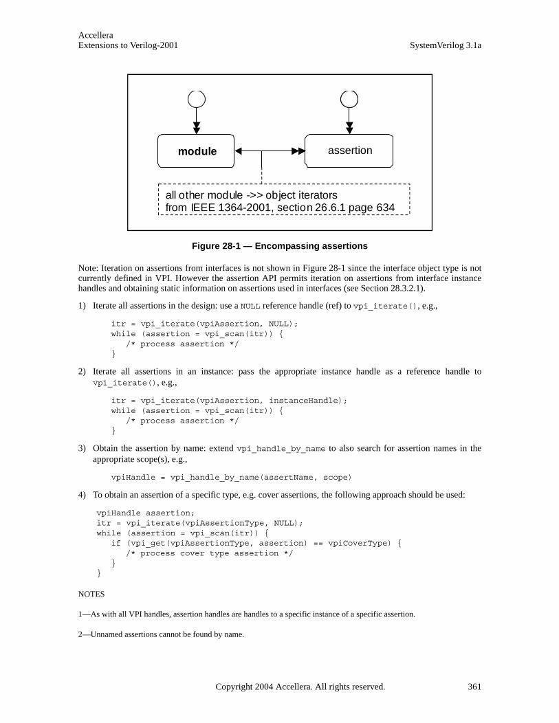
AccelleraExtensions to Verilog-2001 SystemVerilog 3.1a
Figure 28-1 — Encompassing assertions
Note: Iteration on assertions from interfaces is not shown in Figure 28-1 since the interface object type is notcurrently defined in VPI. However the assertion API permits iteration on assertions from interface instancehandles and obtaining static information on assertions used in interfaces (see Section 28.3.2.1).
1) Iterate all assertions in the design: use a NULL reference handle (ref) to vpi_iterate(), e.g.,
itr = vpi_iterate(vpiAssertion, NULL); while (assertion = vpi_scan(itr)) { /* process assertion */ }
2) Iterate all assertions in an instance: pass the appropriate instance handle as a reference handle tovpi_iterate(), e.g.,
itr = vpi_iterate(vpiAssertion, instanceHandle); while (assertion = vpi_scan(itr)) { /* process assertion */ }
3) Obtain the assertion by name: extend vpi_handle_by_name to also search for assertion names in theappropriate scope(s), e.g.,
vpiHandle = vpi_handle_by_name(assertName, scope)
4) To obtain an assertion of a specific type, e.g. cover assertions, the following approach should be used:
vpiHandle assertion; itr = vpi_iterate(vpiAssertionType, NULL); while (assertion = vpi_scan(itr)) {
if (vpi_get(vpiAssertionType, assertion) == vpiCoverType) {/* process cover type assertion */
}}
NOTES
1—As with all VPI handles, assertion handles are handles to a specific instance of a specific assertion.
2—Unnamed assertions cannot be found by name.
module property
all other module ->> object iterators from IEEE 1364-2001, section 26.6.1 page 634
assertion
Copyright 2004 Accellera. All rights reserved. 361
AccelleraSystemVerilog 3.1a Extensions to Verilog-2001
28.3.2 Obtaining static assertion information
The following information about an assertion is considered to be static.
— Assertion name
— Instance in which the assertion occurs
— Module definition containing the assertion
— Assertion type
1) Sequence
2) Assert
3) Cover
4) Property
5) ImmediateAssert
— Assertion source information: the file, line, and column where the assertion is defined.
— Assertion clocking block/expression
28.3.2.1 Using vpi_get_assertion_info
Static information can be obtained directly from an assertion handle by using vpi_get_assertion_info(),as shown below.
typedef struct t_vpi_source_info {PLI_BYTE8 *fileName;PLI_INT32 startLine;PLI_INT32 startColumn;PLI_INT32 endLine;PLI_INT32 endColumn;
} s_vpi_source_info, *p_vpi_source_info;typedef struct t_vpi_assertion_info {
PLI_BYTE8 *assertName; /* name of assertion */vpiHandle instance; /* instance containing assertion */PLI_BYTE8 defname; /* name of module/interface containing assertion */vpiHandle clock; /* clocking expression */PLI_INT32 assertionType; /* vpiSequenceType, vpiAssertType, vpiCoverType,
*//* vpiPropertyType, vpiImmediateAssertType */
s_vpi_source_info sourceInfo;} s_vpi_assertion_info, *p_vpi_assertion_info;PLI_INT32 vpi_get_assertion_info (assert_handle, p_vpi_assertion_info);
This call obtains all the static information associated with an assertion.
The inputs are a valid handle to an assertion and a pointer to an existing s_vpi_assertion_info data struc-ture. On success, the function returns TRUE and the s_vpi_assertion_info data structure is filled in asappropriate. On failure, the function returns FALSE and the contents of the assertion data structure are unpre-dictable.
Assertions can occur in modules and interfaces: for assertions defined in modules, the instance field in thes_vpi_assertion_info structure shall contain the handle to the appropriate module or interface instance.Note that VPI does not currently define the information model for interfaces and therefore the interfaceinstance handle shall be implementation dependent. The clock field of that structure contains a handle to theevent expression representing the clock for the assertion, as determined by Section 17.14.
362 Copyright 2004 Accellera. All rights reserved .
AccelleraExtensions to Verilog-2001 SystemVerilog 3.1a
NOTE: a single call returns all the information for efficiency reasons.
28.3.2.2 Extending vpi_get() and vpi_get_str()
In addition to vpi_get_assertion_info, the following existing VPI functions are also extended:
vpi_get(), vpi_get_str()
vpi_get() can be used to query the following VPI property from a handle to an assertion:
vpiAssertionDirective
returns one of vpiSequenceType, vpiAssertType, vpiCoverType, vpiPropertyType, vpiImme-diateAssertType.
vpiLineNo
returns the line number where the assertion is declared.
vpi_get_str() can be used to obtain the following VPI properties from an assertion handle:
vpiFileName
returns the filename of the source file where the assertion was declared.
vpiName
returns the name of the assertion.
vpiFullName
returns the fully qualified name of the assertion.
28.4 Dynamic information
This section defines how to place assertion system and assertion callbacks.
28.4.1 Placing assertion system callbacks
Use vpi_register_cb(), setting the cb_rtn element to the function to be invoked and the reason elementof the s_cb_data structure to one of the following values, to place an assertion system callback.
cbAssertionSysInitialized occurs after the system has initialized. No assertion-specific actions can be performed until this callbackcompletes. The assertion system can initialize before cbStartOfSimulation does or afterwards.
cbAssertionSysStart the assertion system has become active and starts processing assertion attempts. This always occur aftercbAssertionSysInitialized. By default, the assertion system is “started” on simulation startup, butthe user can delay this by using assertion system control actions.
cbAssertionSysStop
the assertion system has been temporarily suspended. While stopped no assertion attempts are processedand no assertion-related callbacks occur. The assertion system can be stopped and resumed an arbitrarynumber of times during a single simulation run.
cbAssertionSysEnd occurs when all assertions have completed and no new attempts shall start. Once this callback occurs nomore assertion-related callbacks shall occur and assertion-related actions shall have no further effect. Thistypically occurs after the end of simulation.
cbAssertionSysReset
occurs when the assertion system is reset, e.g., due to a system control action.
The callback routine invoked follows the normal VPI callback prototype and is passed an s_cb_data contain-ing the callback reason and any user data provided to the vpi_register_cb() call.
Copyright 2004 Accellera. All rights reserved. 363

AccelleraSystemVerilog 3.1a Extensions to Verilog-2001
28.4.2 Placing assertions callbacks
Use vpi_register_assertion_cb() to place an assertion callback; the prototype is:
/* typedef for vpi_register_assertion_cb callback function */ typedef PLI_INT32 (vpi_assertion_callback_func)(
PLI_INT32 reason, /* callback reason */p_vpi_time cb_time, /* callback time */vpiHandle assertion, /* handle to assertion */p_vpi_attempt_info info, /* attempt related information */PLI_BYTE8 *user_data /* user data entered upon registration */
);
vpiHandle vpi_register_assertion_cb(vpiHandle assertion, /* handle to assertion */PLI_INT32 reason, /* reason for which callbacks needed */vpi_assertion_callback_func *cb_rtn, PLI_BYTE8 *user_data /* user data to be supplied to cb */
);typedef struct t_vpi_assertion_step_info {
PLI_INT32 matched_expression_count;vpiHandle *matched_exprs; /* array of expressions */p_vpi_source_info *exprs_source_info; /* array of source info */PLI_INT32 stateFrom, stateTo;/* identify transition */
} s_vpi_assertion_step_info, *p_vpi_assertion_step_info;typedef struct t_vpi_attempt_info {
union {vpiHandle failExpr;p_vpi_assertion_step_info step;
} detail;s_vpi_time attemptStartTime; /* Time attempt triggered */
} s_vpi_attempt_info, *p_vpi_attempt_info;
where reason is any of the following.
cbAssertionStart
an assertion attempt has started. For most assertions one attempt starts each and every clock tick.
cbAssertionSuccess
when an assertion attempt reaches a success state.
cbAssertionFailure
when an assertion attempt fails to reach a success state.
cbAssertionStepSuccessprogress one step an attempt. By default, step callbacks are not enabled on any assertions; they areenabled on a per-assertion/per-attempt basis (see Section 28.5.2), rather than on a per-assertion basis.
cbAssertionStepFailure
failure to progress by one step along an attempt. By default, step callbacks are not enabled on any asser-tions; they are enabled on a per-assertion/per-attempt basis (see Section 28.5.2), rather than on a per-assertion basis.
cbAssertionDisable
whenever the assertion is disabled (e.g., as a result of a control action).
cbAssertionEnable
whenever the assertion is enabled.
cbAssertionReset
whenever the assertion is reset.
364 Copyright 2004 Accellera. All rights reserved .
AccelleraExtensions to Verilog-2001 SystemVerilog 3.1a
cbAssertionKill
when an attempt is killed (e.g., as a result of a control action).
These callbacks are specific to a given assertion; placing such a callback on one assertion does not cause thecallback to trigger on an event occurring on a different assertion. If the callback is successfully placed, a han-dle to the callback is returned. This handle can be used to remove the callback via vpi_remove_cb(). If therewere errors on placing the callback, a NULL handle is returned. As with all other calls, invoking this functionwith invalid arguments has unpredictable effects.
Once the callback is placed, the user-supplied function shall be called each time the specified event occurs onthe given assertion. The callback shall continue to be called whenever the event occurs until the callback isremoved.
The callback function shall be supplied the following arguments:
1) the reason for the callback
2) a pointer to the time of the callback
3) the handle for the assertion
4) a pointer to an attempt information structure
5) a reference to the user data supplied when the callback was registered.
The t_vpi_attempt_info attempt information structure contains details relevant to the specific event thatoccurred.
— On disable, enable, reset and kill callbacks, the returned p_vpi_attempt_info info pointer is NULL and no attempt information is available.
— On start and success callbacks, only the attemptStartTime field is valid.
— On a cbAssertionFailure callback, the attemptStartTime and detail.failExpr fields are valid.
— On a step callback, the attemptStartTime and detail.step fields are valid.
On a step callback, the detail describes the set of expressions matched in satisfying a step along the asser-tion, along with the corresponding source references. In addition, the step also identifies the source and desti-nation “states” needed to uniquely identify the path being taken through the assertion. State ids are justintegers, with 0 identifying the origin state, 1 identifying an accepting state, and any other number represent-ing some intermediate point in the assertion. It is possible for the number of expressions in a step to be 0(zero), which represents an unconditional transition. In the case of a failing transition, the information pro-vided is just as that for a successful one, but the last expression in the array represents the expression where thetransition failed.
NOTES
1—In a failing transition, there shall always be at least one element in the expression array.
2—Placing a step callback results in the same callback function being invoked for both success and failure steps.
3—The content of the cb_time field depends on the reason identified by the reason field, as follows:
— cbAssertionStart — cb_time is the time when the assertion attempt has been started.
— cbAssertionSuccess, cbAssertionFailure — cb_time is the time when the assertion suc-ceeded/failed.
Copyright 2004 Accellera. All rights reserved. 365
AccelleraSystemVerilog 3.1a Extensions to Verilog-2001
— cbAssertionStepSuccess, cbAssertionStepFailure — cb_time is the time when the asser-tion attempt step succeeded/failed.
— cbAssertionDisable, cbAssertionEnable, cbAssertionReset, cbAssertionKill — cb_time is the time when the assertion attempt was disabled/enabled/reset/killed.
4—In contrast to cb_time, the content of attemptStartTime is always the start time of the actual attempt of anassertion. It can be used as an unique ID that distinguishes the attempts of any given assertion.
28.5 Control functions
This section defines how to obtain assertion system control and assertion control information.
28.5.1 Assertion system control
Use vpi_control(), with one of the following operators and no other arguments, to obtain assertion systemcontrol information.
Usage example: vpi_control(vpiAssertionSysReset)
vpiAssertionSysReset
discards all attempts in progress for all assertions and restore the entire assertion system to its initial state.Any pre-existing vpiAssertionStepSuccess and vpiAssertionStepFailure callbacks shall beremoved; all other assertion callbacks shall remain.
Usage example: vpi_control(vpiAssertionSysStop)
vpiAssertionSysStop
considers all attempts in progress as unterminated and disable any further assertions from being started.This control has no effect on pre-existing assertion callbacks.
Usage example: vpi_control(vpiAssertionSysStart)
vpiAssertionSysStart
restarts the assertion system after it was stopped (e.g., due to vpiAssertionSysStop). Once started,attempts shall resume on all assertions. This control has no effect on prior assertion callbacks.
Usage example: vpi_control(vpiAssertionSysEnd)
vpiAssertionSysEnd
discard all attempts in progress and disables any further assertions from starting. All assertion callbackscurrently installed shall be removed. Note that once this control is issued, no further assertion relatedactions shall be permitted.
28.5.2 Assertion control
Use vpi_control(), with one of the following operators, to obtain assertion control information.
— For the following operators, the second argument shall be a valid assertion handle.
Usage example: vpi_control(vpiAssertionReset, assertionHandle)
vpiAssertionReset
discards all current attempts in progress for this assertion and resets this assertion to its initial state.
Usage example: vpi_control(vpiAssertionDisable, assertionHandle)
vpiAssertionDisable
disables the starting of any new attempts for this assertion. This has no effect on any existing attempts. orif the assertion already disabled. By default, all assertions are enabled.
366 Copyright 2004 Accellera. All rights reserved .

AccelleraExtensions to Verilog-2001 SystemVerilog 3.1a
Usage example: vpi_control(vpiAssertionEnable, assertionHandle)
vpiAssertionEnable
enables starting new attempts for this assertion. This has no effect if assertion already enabled or on anyexisting attempts.
— For the following operators, the second argument shall be a valid assertion handle and the third argumentshall be an attempt start-time (as a pointer to a correctly initialized s_vpi_time structure).
Usage example: vpi_control(vpiAssertionKill, assertionHandle, attemptStartTime)
vpiAssertionKill
discards the given attempts, but leaves the assertion enabled and does not reset any state used by thisassertion (e.g., past() sampling).
Usage example: vpi_control(vpiAssertionDisableStep, assertionHandle,attemptStartTime)
vpiAssertionDisableStep
disables step callbacks for this assertion. This has no effect if stepping not enabled or it is already dis-abled.
— For the following operator, the second argument shall be a valid assertion handle, the third argument shallbe an attempt start-time (as a pointer to a correctly initialized s_vpi_time structure) and the fourth argu-ment shall be a step control constant.
Usage example: vpi_control(vpiAssertionEnableStep, assertionHandle,attemptStartTime, vpiAssertionClockSteps)
vpiAssertionEnableStep
enables step callbacks to occur for this assertion attempt. By default, stepping is disabled for all asser-tions. This call has no effect if stepping is already enabled for this assertion and attempt, other than possi-bly changing the stepping mode for the attempt if the attempt has not occurred yet. The stepping mode ofany particular attempt cannot be modified after the assertion attempt in question has started.
NOTE—In this release, the only step control constant available is vpiAssertionClockSteps, indicating callbackson a per assertion/clock-tick basis. The assertion clock is the event expression supplied as the clocking expression to theassertion declaration. The assertion shall “advance” whenever this event occurs and, when stepping is enabled, such eventsshall also cause step callbacks to occur.
Copyright 2004 Accellera. All rights reserved. 367

AccelleraSystemVerilog 3.1a Extensions to Verilog-2001
Section 29SystemVerilog Coverage API
29.1 Requirements
This chapter defines the Coverage Application Programming Interface (API) in SystemVerilog.
29.1.1 SystemVerilog API
The following criteria are used within this API.
1) This API shall be similar for all coveragesThere are a wide number of coverage types available, with possibly different sets offered by differentvendors. Maintaining a common interface across all the different types enhances portability and ease ofuse.
2) At a minimum, the following types of coverage shall be supported:
a) statement coverage
b) toggle coverage
c) fsm coverage
i) fsm states
ii) fsm transitions
c) assertion coverage
3) Coverage APIs shall be extensible in a transparent manner, i.e., adding a new coverage type shall not breakany existing coverage usage.
4) This API shall provide means to obtain coverage information from specific sub-hierarchies of the designwithout requiring the user to enumerate all instances in those hierarchies.
29.1.2 Naming conventions
All elements added by this interface shall conform to the Verilog Procedural Interface (VPI) interface namingconventions.
— All names are prefixed by vpi.
— All type names shall start with vpi, followed by initially capitalized words with no separators, e.g., vpiCoverageStmt.
— All callback names shall start with cb, followed by initially capitalized words with no separators, e.g.,cbAssertionStart.
— All function names shall start with vpi_, followed by all lowercase words separated by underscores (_),e.g., vpi_control().
29.1.3 Nomenclature
The following terms are used in this standard.
Statement coverage — whether a statement has been executed or not, where statement is anything definedas a statement in the LRM. Covered means it executed at least once. Some implementations also permit
368 Copyright 2004 Accellera. All rights reserved .
AccelleraExtensions to Verilog-2001 SystemVerilog 3.1a
querying the execution count. The granularity of statement coverage can be per-statement or per-state-ment block (however defined).
FSM coverage — the number of states in a finite state machine (FSM) that this simulation reached. Thisstandard does not require FSM automatic extraction, but a standard mechanism to force specific extrac-tion is available via pragmas.
Toggle coverage — for each bit of every signal (wire and register), whether that bit has both a 0 value anda 1 value. Full coverage means both are seen; otherwise, some implementations can query for partialcoverage. Some implementations also permit querying the toggle count of each bit.
Assertion coverage — for each assertion, whether it has had at least one success. Implementations permitquerying for further details, such as attempt counts, success counts, failure counts and failure coverage.
These terms define the “primitives” for each coverage type. Over instances or blocks, the coverage number ismerely the sum of all contained primitives in that instance or block.
29.2 SystemVerilog real-time coverage access
This section describes the mechanisms in SystemVerilog through which SystemVerilog code can query andcontrol coverage information. Coverage information is provided to SystemVerilog by means of a number ofbuilt-in system functions (described in Section 29.2.2) using a number of predefined constants (described inSection 29.2.1) to describe the types of coverage and the control actions to be performed.
29.2.1 Predefined coverage constants in SystemVerilog
The following predefined ‘defines represent basic real-time coverage capabilities accessible directly fromSystemVerilog.
— Coverage control
‘define SV_COV_START 0‘define SV_COV_STOP 1‘define SV_COV_RESET 2‘define SV_COV_CHECK 3
— Scope definition (hierarchy traversal/accumulation type)
‘define SV_COV_MODULE 10‘define SV_COV_HIER 11
— Coverage type identification
‘define SV_COV_ASSERTION 20‘define SV_COV_FSM_STATE 21‘define SV_COV_STATEMENT 22‘define SV_COV_TOGGLE 23
— Status results
‘define SV_COV_OVERFLOW -2‘define SV_COV_ERROR -1‘define SV_COV_NOCOV 0‘define SV_COV_OK 1‘define SV_COV_PARTIAL 2
Copyright 2004 Accellera. All rights reserved. 369
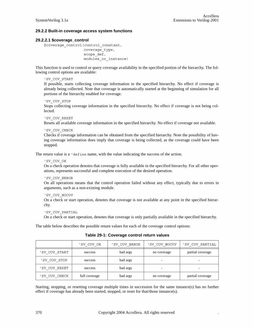
AccelleraSystemVerilog 3.1a Extensions to Verilog-2001
29.2.2 Built-in coverage access system functions
29.2.2.1 $coverage_control$coverage_control(control_constant,
coverage_type,scope_def,modules_or_instance)
This function is used to control or query coverage availability in the specified portion of the hierarchy. The fol-lowing control options are available:
‘SV_COV_START If possible, starts collecting coverage information in the specified hierarchy. No effect if coverage isalready being collected. Note that coverage is automatically started at the beginning of simulation for allportions of the hierarchy enabled for coverage.
‘SV_COV_STOP Stops collecting coverage information in the specified hierarchy. No effect if coverage is not being col-lected.
‘SV_COV_RESET Resets all available coverage information in the specified hierarchy. No effect if coverage not available.
‘SV_COV_CHECK Checks if coverage information can be obtained from the specified hierarchy. Note the possibility of hav-ing coverage information does imply that coverage is being collected, as the coverage could have beenstopped.
The return value is a ‘define name, with the value indicating the success of the action.
‘SV_COV_OK
On a check operation denotes that coverage is fully available in the specified hierarchy. For all other oper-ations, represents successful and complete execution of the desired operation.
‘SV_COV_ERROR
On all operations means that the control operation failed without any effect, typically due to errors inarguments, such as a non-existing module.
‘SV_COV_NOCOV
On a check or start operation, denotes that coverage is not available at any point in the specified hierar-chy.
‘SV_COV_PARTIAL
On a check or start operation, denotes that coverage is only partially available in the specified hierarchy.
The table below describes the possible return values for each of the coverage control options:
Starting, stopping, or resetting coverage multiple times in succession for the same instance(s) has no furthereffect if coverage has already been started, stopped, or reset for that/those instance(s).
Table 29-1: Coverage control return values
‘SV_COV_OK ‘SV_COV_ERROR ‘SV_COV_NOCOV ‘SV_COV_PARTIAL
‘SV_COV_START success bad args no coverage partial coverage
‘SV_COV_STOP success bad args - -
‘SV_COV_RESET success bad args - -
‘SV_COV_CHECK full coverage bad args no coverage partial coverage
370 Copyright 2004 Accellera. All rights reserved .

AccelleraExtensions to Verilog-2001 SystemVerilog 3.1a
The hierarchy(ies) being controlled or queried are specified as follows.
‘SV_MODULE_COV, "unique module def name"
provides coverage of all instances of the given module (the unique module name is a string), excludingany child instances in the instances of the given module. The module definition name can use specialnotation to describe nested module definitions.
‘SV_COV_HIER, "module name"
provides coverage of all instances of the given module, including all the hierarchy below.
‘SV_MODULE_COV, instance_name
provides coverage of the one named instance. The instance is specified as a normal Verilog hierarchicalpath.
‘SV_COV_HIER, instance_name
provides coverage of the named instance, plus all the hierarchy below it.
All the permutations are summarized in Table 29-2.
NOTE—Definition names are represented as strings, whereas instance names are referenced by hierarchical paths. A hier-archical path need not include any . if the path refers to an instance in the current context (i.e., normal Verilog hierarchicalpath rules apply).
Table 29-2: Instance coverage permutations
Control/query “Definition name” instance.name
‘SV_COV_MODULE The sum of coverage for all instances of the named module, excluding any hierarchy below those instances.
Coverage for just the named instance, excluding any hierar-chy in instances below that instance.
‘SV_COV_HIER The sum of coverage for all instances of the named module, including all coverage for all hierarchy below those instances.
Coverage for the named instance and any hierarchy below it.
Copyright 2004 Accellera. All rights reserved. 371

AccelleraSystemVerilog 3.1a Extensions to Verilog-2001
Example 29-1 — Hierarchical instance example
If coverage is enabled on all instances shown in Example 29-1 —, then:
$coverage_control(‘SV_COV_CHECK, ‘SV_COV_TOGGLE, ‘SV_COV_HIER, $root)
checks all instances to verify they have coverage and, in this case, returns ‘SV_COV_OK.
$coverage_control(‘SV_COV_RESET, ‘SV_COV_TOGGLE, ‘SV_COV_MODULE, "DUT")
resets coverage collection on both instances of the DUT, specifically, $root.tb.unit1 and$root.tb.unit2, but leaves coverage unaffected in all other instances.
$coverage_control(‘SV_COV_RESET, ‘SV_COV_TOGGLE, ‘SV_COV_MODULE,
$root.tb.unit1)
resets coverage of only the instance $root.tb.unit1, leaving all other instances unaffected.
$coverage_control(‘SV_COV_STOP, ‘SV_COV_TOGGLE, ‘SV_COV_HIER,
$root.tb.unit1)
resets coverage of the instance $root.tb.unit1 and also reset coverage for all instances below it, spe-cifically $root.tb.unit1.comp and $root.tb.unit1.ctrl.
$coverage_control(‘SV_COV_START, ‘SV_COV_TOGGLE, ‘SV_COV_HIER, "DUT")
starts coverage on all instances of the module DUT and of all hierarchy(ies) below those instances. In this
module componentinstance comp
module controlinstance ctrl
module DUTinstance unit1
module componentinstance comp
module controlinstance ctrl
module DUTinstance unit2
module TestBenchinstance tb
module BusWatcherinstance watch
$root
372 Copyright 2004 Accellera. All rights reserved .
AccelleraExtensions to Verilog-2001 SystemVerilog 3.1a
design, coverage is started for the instances $root.tb.unit1, $root.tb.unit1.comp,$root.tb.unit1.ctrl, $root.tb.unit2, $root.tb.unit2.comp, and $root.tb.unit2.ctrl.
29.2.2.2 $coverage_get_max$coverage_get_max(coverage_type, scope_def, modules_or_instance)
This function obtains the value representing 100% coverage for the specified coverage type over the specifiedportion of the hierarchy. This value shall remain constant across the duration of the simulation.
NOTE—This value is proportional to the design size and structure, so it also needs to be constant through multiple inde-pendent simulations and compilations of the same design, assuming any compilation options do not modify the coveragesupport or design structure.
The return value is an integer, with the following meanings.
-2 (‘SV_COV_OVERFLOW) the value exceeds a number that can be represented as an integer.
-1 (‘SV_COV_ERROR) an error occurred (typically due to using incorrect arguments).
0 (‘SV_COV_NOCOV) no coverage is available for that coverage type on that/those hierarchy(ies).
+pos_num the maximum coverage number (where pos_num > 0), which is the sum of all coverable items of thattype over the given hierarchy(ies).
The scope of this function is specified as per $coverage_control (see Section 29.2.2.1).
29.2.2.3 $coverage_get$coverage_get(coverage_type, scope_def, modules_or_instance)
This function obtains the current coverage value for the given coverage type over the given portion of the hier-archy. This number can be converted to a coverage percentage by use of the equation:
The return value follows the same pattern as $coverage_get_max (see Section 29.2.2.2), but with pos_numrepresenting the current coverage level, i.e., the number of the coverable items that have been covered in this/these hierarchy(ies).
The scope of this function is specified as per $coverage_control (see Section 29.2.2.1).
The return value is an integer, with the following meanings.
-2 (‘SV_COV_OVERFLOW) the value exceeds a number that can be represented as an integer.
-1 (‘SV_COV_ERROR) an error occurred (typically due to using incorrect arguments).
0 (‘SV_COV_NOCOV) no coverage is available for that coverage type on that/those hierarchy(ies).
+pos_num the maximum coverage number (where pos_num > 0), which is the sum of all coverable items of thattype over the given hierarchy(ies).
100*max()__cov
()_cov%cov
geterage
geterageerage =
Copyright 2004 Accellera. All rights reserved. 373

AccelleraSystemVerilog 3.1a Extensions to Verilog-2001
29.2.2.4 $coverage_merge
$coverage_merge(coverage_type, "name")
This function loads and merges coverage data for the specified coverage into the simulator. name is an arbi-trary string used by the tool, in an implementation-specific way, to locate the appropriate coverage database,i.e., tools are allowed to store coverage files any place they want with any extension they want as long as theuser can retrieve the information by asking for a specific saved name from that coverage database. If namedoes not exist or does not correspond to a coverage database from the same design, an error shall occur. If anerror occurs during loading, the coverage numbers generated by this simulation might not be meaningful.
The return values from this function are:
‘SV_COV_OK
the coverage data has been found and merged.
‘SV_COV_NOCOV
the coverage data has been found, but did not contain the coverage type requested.
‘SV_COV_ERROR
the coverage data was not found or it did not correspond to this design, or another error.
29.2.2.5 $coverage_save
$coverage_save(coverage_type, "name")
This function saves the current state of coverage to the tool’s coverage database and associates it with thegiven name. This name will be mapped in an implementation-specific way into some file or set of files in thecoverage database. Data saved to the database shall be retrieved later by using $coverage_merge and sup-plying the same name. Saving coverage shall not have any effect on the state of coverage in this simulation.
The return values from this function are:
‘SV_COV_OK
the coverage data was successfully saved.
‘SV_COV_NOCOV
no such coverage is available in this design (nothing was saved).
‘SV_COV_ERROR
some error occurred during the save. If an error occurs, the tool shall automatically remove the coveragedatabase entry for name to preserve the coverage database integrity. It is not an error to overwrite a previ-ously existing name.
NOTES
1—The coverage database format is implementation-dependent.
2—Mapping of names to actual directories/files is implementation-dependent. There is no requirement that a coveragename map to any specific set of files or directories.
29.3 FSM recognition
Coverage tools need to have automatic recognition of many of the common FSM coding idioms in Verilog/SystemVerilog. This standard does not attempt to describe or require any specific automatic FSM recognitionmechanisms. However, the standard does prescribe a means by which non-automatic FSM extraction occurs.The presence of any of these standard FSM description additions shall override the tool’s default extractionmechanism.
Identification of an FSM consists of identifying the following items:
374 Copyright 2004 Accellera. All rights reserved .
AccelleraExtensions to Verilog-2001 SystemVerilog 3.1a
1) the state register (or expression)
2) the next state register (this is optional)
3) the legal states.
29.3.1 Specifying the signal that holds the current state
Use the following pragma to identify the vector signal that holds the current state of the FSM:
/* tool state_vector signal_name */
where tool and state_vector are required keywords. This pragma needs to be specified inside the moduledefinition where the signal is declared.
Another pragma is also required, to specify an enumeration name for the FSM. This enumeration name is alsospecified for the next state and any possible states, associating them with each other as part of the same FSM.There are two ways to do this:
— Use the same pragma:
/* tool state_vector signal_name enum enumeration_name */
— Use a separate pragma in the signal’s declaration:
/* tool state_vector signal_name */reg [7:0] /* tool enum enumeration_name */ signal_name;
In either case, enum is a required keyword; if using a separate pragma, tool is also a required keyword and thepragma needs to be specified immediately after the bit-range of the signal.
29.3.2 Specifying the part-select that holds the current state
A part-select of a vector signal can be used to hold the current state of the FSM. When a coverage tool displaysor reports FSM coverage data, it names the FSM after the signal that holds the current state. If a part-selectholds the current state in the user’s FSM, the user needs to also specify a name for the FSM for the coveragetool to use. The FSM name is not the same as the enumeration name.
Specify the part-select by using the following pragma:
/* tool state_vector signal_name[n:n] FSM_name enum enumeration_name */
29.3.3 Specifying the concatenation that holds the current state
Like specifying a part-select, a concatenation of signals can be specified to hold the current state (when includ-ing an FSM name and an enumeration name):
/* tool state_vector {signal_name , signal_name, ...} FSM_name enumenumeration_name */
The concatenation is composed of all the signals specified. Bit-selects or part-selects of signals cannot be usedin the concatenation.
29.3.4 Specifying the signal that holds the next state
The signal that holds the next state of the FSM can also be specified with the pragma that specifies the enumer-ation name:
reg [7:0] /* tool enum enumeration_name */
Copyright 2004 Accellera. All rights reserved. 375
AccelleraSystemVerilog 3.1a Extensions to Verilog-2001
signal_name
This pragma can be omitted if, and only if, the FSM does not have a signal for the next state.
29.3.5 Specifying the current and next state signals in the same declaration
The tool assumes the first signal following the pragma holds the current state and the next signal holds the nextstate when a pragma is used for specifying the enumeration name in a declaration of multiple signals, e.g.,
/* tool state_vector cs */reg [1:0] /* tool enum myFSM */ cs, ns, nonstate;
In this example, the tool assumes signal cs holds the current state and signal ns holds the next state. It assumesnothing about signal nonstate.
29.3.6 Specifying the possible states of the FSM
The possible states of the FSM can also be specified with a pragma that includes the enumeration name:
parameter /* tool enum enumeration_name */S0 = 0,s1 = 1,s2 = 2,s3 = 3;
Put this pragma immediately after the keyword parameter, unless a bit-width for the parameters is used, inwhich case, specify the pragma immediately after the bit-width:
parameter [1:0] /* tool enum enumeration_name */S0 = 0,s1 = 1,s2 = 2,s3 = 3;
29.3.7 Pragmas in one-line comments
These pragmas work in both block comments, between the /* and */ character strings, and one-line com-ments, following the // character string, e.g.,
parameter [1:0] // tool enum enumeration_nameS0 = 0,s1 = 1,s2 = 2,s3 = 3;
376 Copyright 2004 Accellera. All rights reserved .
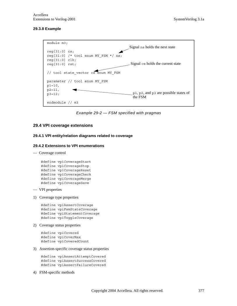
AccelleraExtensions to Verilog-2001 SystemVerilog 3.1a
29.3.8 Example
Example 29-2 — FSM specified with pragmas
29.4 VPI coverage extensions
29.4.1 VPI entity/relation diagrams related to coverage
29.4.2 Extensions to VPI enumerations
— Coverage control
#define vpiCoverageStart#define vpiCoverageStop#define vpiCoverageReset#define vpiCoverageCheck#define vpiCoverageMerge#define vpiCoverageSave
— VPI properties
1) Coverage type properties
#define vpiAssertCoverage#define vpiFsmStateCoverage#define vpiStatementCoverage#define vpiToggleCoverage
2) Coverage status properties
#define vpiCovered#define vpiCoverMax#define vpiCoveredCount
3) Assertion-specific coverage status properties
#define vpiAssertAttemptCovered#define vpiAssertSuccessCovered#define vpiAssertFailureCovered
4) FSM-specific methods
module m3;
reg[31:0] cs;reg[31:0] /* tool enum MY_FSM */ ns;reg[31:0] clk;reg[31:0] rst;
// tool state_vector cs enum MY_FSM
parameter // tool enum MY_FSMp1=10,p2=11,p3=12;
endmodule // m3
Signal ns holds the next state
Signal cs holds the current state
p1, p2, and p3 are possible states ofthe FSM
Copyright 2004 Accellera. All rights reserved. 377
AccelleraSystemVerilog 3.1a Extensions to Verilog-2001
#define vpiFsmStates #define vpiFsmStateExpression
— FSM handle types (vpi types)
#define vpiFsm#define vpiFsmHandle
29.4.3 Obtaining coverage information
To obtain coverage information, the vpi_get() function is extended with additional VPI properties that canbe obtained from existing handles:
vpi_get(<coverageType>, instance_handle)
Returns the number of covered items of the given coverage type in the given instance. Coverage type is one ofthe coverage type properties described in Section 29.4.2. For example, given coverage type vpiStatement-Coverage, this call would return the number of covered statements in the instance pointed byinstance_handle.
vpi_get(vpiCovered, assertion_handle)vpi_get(vpiCovered, statement_handle)vpi_get(vpiCovered, signal_handle)vpi_get(vpiCovered, fsm_handle)vpi_get(vpiCovered, fsm_state_handle)
Returns whether the item referenced by the handle has been covered. For handles that can contain multiplecoverable entities, such as statement, fsm and signal handles, the return value indicates how many of the enti-ties have been covered.
— For assertion handle, the coverable entities are assertions
— For statement handle, the entities are statements
— For signal handle, the entities are individual signal bits
— For fsm handle, the entities are fsm states
For assertions, vpiCovered implies that the assertion has been attempted, has succeeded at least once and hasnever failed. More detailed coverage information can be obtained for assertions by the following queries:
vpi_get(vpiAssertAttemptCovered, assertion_handle)
Returns the number of times the assertion has been attempted.
vpi_get(vpiAssertSuccessCovered, assertion_handle)
Returns the number of times the assertion has succeeded non-vacuously or, if assertion handle corresponds to acover sequence, the number of times the sequence has been matched. Refer to Section 17.11.1 and 17.13 forthe definition of vacuity.
vpi_get(vpiAssertVacuousSuccessCovered, assertion_handle)
Returns the number of times the assertion has succeeded vacuously. Refer to Section 17.11.1 and 17.13 for thedefinition of vacuity.
vpi_get(vpiAssertFailureCovered, assertion_handle)
Returns the number of times the assertion has failed. For any assertion, the number of attempts that have notyet reached any conclusion (success or failure) can be derived from the formula:
378 Copyright 2004 Accellera. All rights reserved .
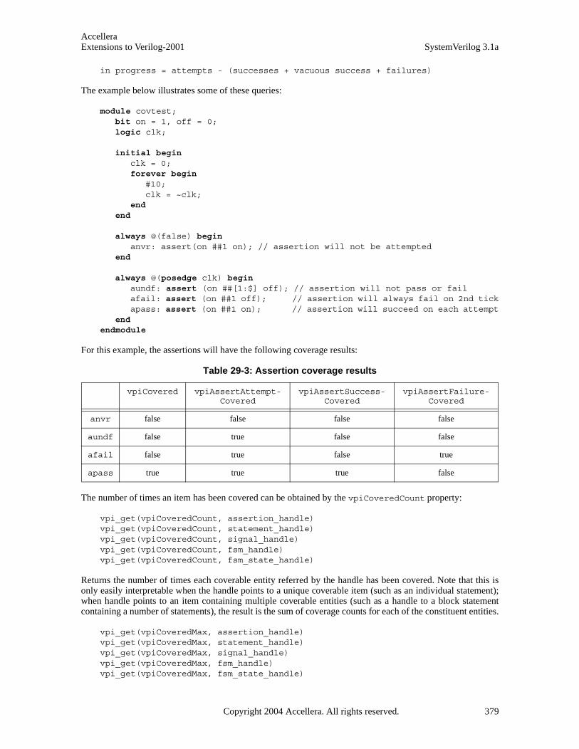
AccelleraExtensions to Verilog-2001 SystemVerilog 3.1a
in progress = attempts - (successes + vacuous success + failures)
The example below illustrates some of these queries:
module covtest;bit on = 1, off = 0;logic clk;
initial begin clk = 0;forever begin
#10;clk = ~clk;
end end
always @(false) begin anvr: assert(on ##1 on); // assertion will not be attempted
end
always @(posedge clk) begin aundf: assert (on ##[1:$] off); // assertion will not pass or failafail: assert (on ##1 off); // assertion will always fail on 2nd tickapass: assert (on ##1 on); // assertion will succeed on each attempt
end endmodule
For this example, the assertions will have the following coverage results:
The number of times an item has been covered can be obtained by the vpiCoveredCount property:
vpi_get(vpiCoveredCount, assertion_handle)vpi_get(vpiCoveredCount, statement_handle)vpi_get(vpiCoveredCount, signal_handle)vpi_get(vpiCoveredCount, fsm_handle)vpi_get(vpiCoveredCount, fsm_state_handle)
Returns the number of times each coverable entity referred by the handle has been covered. Note that this isonly easily interpretable when the handle points to a unique coverable item (such as an individual statement);when handle points to an item containing multiple coverable entities (such as a handle to a block statementcontaining a number of statements), the result is the sum of coverage counts for each of the constituent entities.
vpi_get(vpiCoveredMax, assertion_handle)vpi_get(vpiCoveredMax, statement_handle)vpi_get(vpiCoveredMax, signal_handle)vpi_get(vpiCoveredMax, fsm_handle)vpi_get(vpiCoveredMax, fsm_state_handle)
Table 29-3: Assertion coverage results
vpiCovered vpiAssertAttempt-Covered
vpiAssertSuccess-Covered
vpiAssertFailure-Covered
anvr false false false false
aundf false true false false
afail false true false true
apass true true true false
Copyright 2004 Accellera. All rights reserved. 379
AccelleraSystemVerilog 3.1a Extensions to Verilog-2001
Returns the number of coverable entities pointed by the handle. Note that this shall always return 1 (one) whenapplied to an assertion or FSM state handle.
vpi_iterate(vpiFsm, instance-handle)
Returns an iterator to all FSMs in an instance.
vpi_handle(vpiFsmStateExpression, fsm-handle)
Returns the handle to the signal or expression encoding the FSM state.
vpi_iterate(vpiFsmStates, fsm-handle)
Returns an iterator to all states of an FSM.
vpi_get_value(fsm_state_handle, state-handle)
Returns the value of an FSM state.
29.4.4 Controlling coveragevpi_control(<coverageControl>, <coverageType>, instance_handle)vpi_control(<coverageControl>, <coverageType>, assertion_handle)
Controls the collection of coverage on the given instance or assertion. Note that statement, toggle and FSMcoverage are not individually controllable (i.e., they are controllable only at the instance level and not on a perstatement/signal/FSM basis). The semantics and behavior are as per the $coverage_control system func-tion (see Section 29.2.2.1). coverageControl is one vpiCoverageStart, vpiCoverageStop, vpiCover-ageReset or vpiCoverageCheck, as defined in Section 29.4.2. coverageType is any one of the VPIcoverage type properties (Section 29.4.2)
vpi_control(<coverageControl>, <coverageType>, name)
This saves or merges coverage into the current simulation. The semantics and behavior are specified as per theequivalent system functions $coverage_merge (see Section 29.2.2.4) and $coverage_save (seeSection 29.2.2.5). coverageControl is one of vpiCoverageMerge or vpiCoverageSave, defined inSection 29.4.2.
380 Copyright 2004 Accellera. All rights reserved .

AccelleraExtensions to Verilog-2001 SystemVerilog 3.1a
Section 30SystemVerilog Data Read API
30.1 Introduction (informative)
This chapter extends the SystemVerilog VPI with read facilities so that the Verilog Procedural Interface (VPI)acts as an Application Programming Interface (API) for data access and tool interaction irrespective ofwhether the data is in memory or a persistent form such as a database, and also irrespective of the tool the useris interacting with.
SystemVerilog is both a design and verification language consequently its VPI has a wealth of design and ver-ification data access mechanisms. This makes the VPI an ideal vehicle for tool integration in order to replacearcane, inefficient, and error-prone file-based data exchanges with a new mechanism for tool to tool, and userto tool interface. Moreover, a single access API eases the interoperability investments for vendors and usersalike. Reducing interoperability barriers allows vendors to focus on tool implementation. Users, on the otherhand, are able to create integrated design flows from a multitude of best-in-class offerings spanning the realmsof design and verification such as simulators, debuggers, formal, coverage or test bench tools.
30.2 Requirements
SystemVerilog adds several design and verification constructs including:
— C data types such as int, struct, union, and enum.
— Advanced built-in data types such as string.
— User defined data types and corresponding methods.
— Data types and facilities that enhance the creation and functionality of testbenches.
The access API shall be implemented by all tools as a minimal set for a standard means for user-tool or tool-tool interaction that involves SystemVerilog object data querying (reading). In other words, there is no need fora simulator to be running for this API to be in effect; it is a set of API routines that can be used for any interac-tion for example between a user and a waveform tool to read the data stored in its database. This usage flow isshown in the figure below.
Figure 30-2 — Data read VPI usage model
The focus in the API is the user view of access. While the API does provide varied facilities to give the userthe ability to effectively architect his or her application, it does not address the tool level efficiency concernssuch as time-based incremental load of the data, and/or predicting or learning the user access. It is left up toimplementers to make this as easy and seamless as possible on the user. To make this easy on tools, the APIprovides an initialization routine where the user specifies access type and design scope. The user should be pri-
SystemVerilog
Waveform Database
VPI
Read
User
Application
VPI
Read
Copyright 2004 Accellera. All rights reserved. 381
AccelleraSystemVerilog 3.1a Extensions to Verilog-2001
marily concerned with the API specified here, and efficiency issues are dealt with behind the scenes.
30.3 Extensions to VPI enumerations
These extensions shall be appended to the contents of the vpi_user.h file, described in IEEE Std. 1364-2001, Annex G. The numbers in the range 800 - 899 are reserved for the read data access portion of the VPI.
30.3.1 Object types
All objects in VPI have a vpiType. This API adds a new object type for data traversal, and two other objectstypes for object collection and traverse object collection.
/* vpiHandle type for the data traverse object */#define vpiTrvsObj 800 /* use in vpi_handle() */#define vpiCollection 810 /* Collection of VPI handles */#define vpiObjCollection 811 /* Collection of traversable
design objs */#define vpiTrvsCollection 812 /* Collection of vpiTrvsObj’s */
The other object types that this API references, for example to get a value at a specific time, are all the validtypes in the VPI that can be used as arguments in the VPI routines for logic and strength value processing suchas vpi_get_value(<object_handle>, <value_pointer>). These types include:
— Constants
— Nets and net arrays
— Regs and reg arrays
— Variables
— Memory
— Parameters
— Primitives
— Assertions
In other words, any limitation in vpiType of vpi_get_value() shall also be reflected in this data accessAPI.
30.3.2 Object properties
This section lists the object property VPI calls.
30.3.2.1 Static info
/* Check *//* use in vpi_get() */#define vpiIsLoaded 820 /* is loaded */#define vpiHasDataVC 821 /* has at least one VC
at some point in time in the database */
#define vpiHasVC 822 /* has VC at specific time */
#define vpiHasNoValue 823 /* has no value atspecific time */
#define vpiBelong 824 /* belong to extension */
382 Copyright 2004 Accellera. All rights reserved .
AccelleraExtensions to Verilog-2001 SystemVerilog 3.1a
/* Access */#define vpiAccessLimitedInteractive 830 /* interactive */ #define vpiAccessInteractive 831 /* interactive: history */#define vpiAccessPostProcess 832 /* database */
/* Member of a collection */#define vpiMember 840 /* use in vpi_iterate() *//* Iteration on instances for loaded */#define vpiDataLoaded 850 /* use in vpi_iterate() */
30.3.2.2 Dynamic info
30.3.2.2.1 Control constants
/* Control Traverse: use in vpi_goto() for a vpiTrvsObj type */#define vpiMinTime 860 /* min time */#define vpiMaxTime 864 /* max time */#define vpiPrevVC 868#define vpiNextVC 870#define vpiTime 874 /* time jump */
These properties can also be used in vpi_get_time() to enhance the access efficiency. The routinevpi_get_time() with a traverse handle argument is extended with the additional ability to get the min, max,previous VC, and next VC times of the traverse handle; not just the current time of the handle. These samecontrol constants can then be used for both access and for moving the traverse handle where the context (get orgo to) can distinguish the intent.
30.3.3 System callbacks
The access API adds no new system callbacks. The reader routines (methods) can be called whenever the userapplication has control and wishes to access data.
30.4 VPI object type additions
30.4.1 Traverse object
To access the value changes of an object over time, the notion of a Value Change (VC) traverse handle isadded. A value change traverse object is used to traverse and access value changes not just for the currentvalue (as calling vpi_get_time() or vpi_get_value() on the object handle would) but for any point intime: past, present, or future. To create a value change traverse handle the routine vpi_handle() is calledwith a vpiTrvsObj vpiType:
vpiHandle object_handle; /* design object */vpiHandle trvsHndl = vpi_handle(/*vpiType*/vpiTrvsObj,
/*vpiHandle*/ object_handle);
A traverse object exists from the time it is created until its handle is released. It is the application’s responsibil-ity to keep a handle to the created traverse object, and to release it when it is no longer needed.
30.4.2 VPI collection
In order to read data efficiently, it can be necessary to specify a group of objects. For example, when traversingdata a user might wish to specify a list of objects to be marked as targets of data traversal. To do this groupingrequires the notion of a collection. A collection represents a user-defined collection of VPI handles. The col-lection is an ordered list of VPI handles. The vpiType of a collection handle can be vpiCollection, vpi-ObjCollection, or vpiTrvsCollection:
Copyright 2004 Accellera. All rights reserved. 383
AccelleraSystemVerilog 3.1a Extensions to Verilog-2001
— A collection of type vpiCollection is a general collection of VPI handles of objects of any type.
— The collection object of type vpiObjCollection represents a collection of VPI traversable objects in the design.
— A vpiTrvsCollection is a collection of traverse objects of type vpiTrvsObj.
The usage here in the read API is of either:
— Collections of traversable design objects: Used for example in vpi_handle() to create traverse han-dles for the collection. A collection of traversable design objects is of type vpiObjCollection (the elements can be any object type in the design except traverse objects of type vpiTrvsObj).
— Collections of data traverse objects: Used for example in vpi_goto() to move the traverse handles of all the objects in the collection (all are of type vpiTrvsObj). A collection of traverse objects is a vpiTrvsCollection.
The collection contains a set of member VPI objects and can take on an arbitrary size. The collection can becreated at any time and existing objects can be added to it. The reader implementation can perform a typecheck on the items being added to the collection and generate an error if the item added does not belong to theallowed vpiType.
The purpose of a collection is to group design objects and permit operating on each element with a single oper-ation applied to the whole collection group. vpi_iterate(vpiMember, <collection_handle>) is usedto create a member iterator. vpi_scan() can then be used to scan the iterator for the elements of the collec-tion.
A collection object is created with vpi_create(). The first call provides NULL handles to the collectionobject and the object to be added. Following calls, which can be performed at any time, provide the collectionhandle and a handle to the object for addition. The return argument is a handle to the collection object.
For example:
vpiHandle designCollection;vpiHandle designObj;vpiHandle trvsCollection;vpiHandle trvsObj;/* Create a collection of design objects */designCollection = vpi_create(vpiObjCollection, NULL, NULL);/* Add design object designObj into it */designCollection = vpi_create(vpiObjCollection, designCollection, designObj);
/* Create a collection of traverse objects*/trvsCollection = vpi_create(vpiTrvsCollection, NULL, NULL);/* Add traverse object trvsObj into it */trvsCollection = vpi_create(vpiTrvsCollection, trvsCollection, trvsObj);
Sometimes it is necessary to filter a collection and extract a set of handles which meet, or do not meet, a spe-cific criterion for a given collection. The function vpi_filter() can be used for this purpose in the form of:
vpiHandle colFilterHdl = vpi_filter((vpiHandle) colHdl, (PLI_INT32)filterType, (PLI_INT32) flag);
The first argument of vpi_filter(), colHdl, shall be the collection on which to apply the filter operation.The second argument, filterType can be any vpiType or VPI boolean property. This argument is the criterionused for filtering the collection members. The third argument, flag, is a boolean value. If set to TRUE,vpi_filter() shall return a collection of handles which match the criterion indicated by filterType, if set toFALSE, vpi_filter() shall return a collection of handles which do not match the criterion indicated by fil-terType. The original collection passed as a first argument remains unchanged.
384 Copyright 2004 Accellera. All rights reserved .

AccelleraExtensions to Verilog-2001 SystemVerilog 3.1a
A collection object exists from the time it is created until its handle is released. It is the application’s responsi-bility to keep a handle to the created collection, and to release it when it is no longer needed.
30.4.2.1 Operations on collections
A traverse collection can be obtained (i.e. created) from a design collection using vpi_handle(). The callwould take on the form of:
vpiHandle objCollection;/* Obtain a traverse collection from the object collection */vpi_handle(vpiTrvsCollection, objCollection);
The usage of this capability is discussed in Section 30.8.7.
Another optional method is defined, which is used in the case the user wishes to directly control the data load,for loading data of objects in a collection: vpi_load(). This operation loads all the objects in the collection.It is equivalent to performing a vpi_load() on every single handle of the object elements in the collection.
A traversal method is also defined on collections of traverse handles; i.e. collections of type vpiTrvsCol-lection. The method is vpi_goto().
30.5 Object model diagrams
A traverse object of type vpiTrvsObj is related to its parent object; it is a means to access the value data ofsaid object. An object can have several traverse objects each pointing and moving in a different way along thevalue data horizon. This is shown graphically in the model diagram below. The traversable class is a represen-tational grouping consisting of any object that:
— Has a name
— Can take on a value accessible with vpi_get_value(), the value must be variable over time (i.e. necessitates creation of a traverse object to access the value over time).
The class includes nets, net arrays, regs, reg arrays, variables, memory, primitive, primitive arrays, concurrentassertions, and parameters. It also includes part selects of all the design object types that can have part selects.
Copyright 2004 Accellera. All rights reserved. 385

AccelleraSystemVerilog 3.1a Extensions to Verilog-2001
Figure 30-3 — Model diagram of traverse object
A collection object of type vpiObjCollection groups together a set of design objects Obj (of any type). Atraverse collection object of type vpiTrvsCollection groups together a set of traverse objects trvsObj oftype vpiTrvsObj.
net array
trvs obj
-> name str: vpiName
->time: trvs time
-> value
vpiParent
nets
traversable
primitive array
primitive
reg array
regs
str: vpiFullName
variables
memory
concurrent assertions
-> trvs loaded bool: vpiIsLoaded
instances
vpiDataLoaded
max time, min time, next VC, prev VCvpi_get_time()
parameter
bool: vpiHasDataVC
vpi_goto()next VC, prev VCmax time, min time,
-> control: trvs time
bool: vpiHasNoValue
-> Is in extensionbool: vpiBelong
-> has value change
vpi_get_value()
bool: vpiHasVC
386 Copyright 2004 Accellera. All rights reserved .
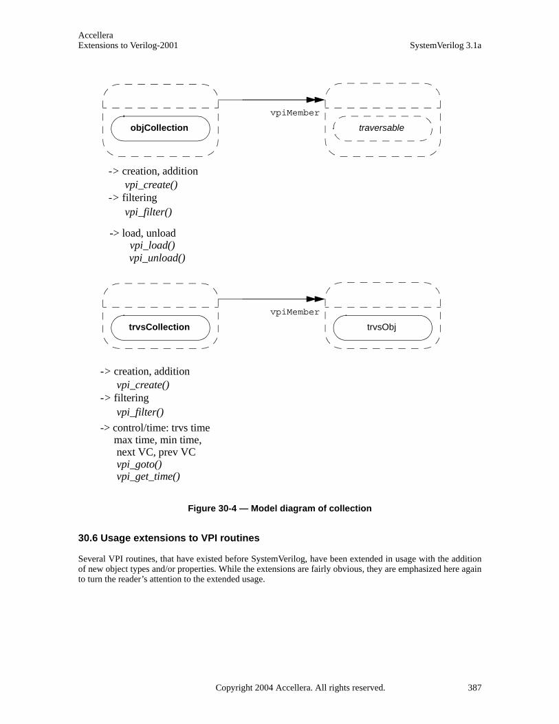
AccelleraExtensions to Verilog-2001 SystemVerilog 3.1a
Figure 30-4 — Model diagram of collection
30.6 Usage extensions to VPI routines
Several VPI routines, that have existed before SystemVerilog, have been extended in usage with the additionof new object types and/or properties. While the extensions are fairly obvious, they are emphasized here againto turn the reader’s attention to the extended usage.
objCollection traversable
vpiMember
-> creation, addition vpi_create()-> filtering vpi_filter()
trvsCollection trvsObj
vpiMember
-> control/time: trvs time max time, min time, next VC, prev VC vpi_goto()
-> creation, addition vpi_create()-> filtering vpi_filter()
-> load, unload vpi_load() vpi_unload()
vpi_get_time()
Copyright 2004 Accellera. All rights reserved. 387

AccelleraSystemVerilog 3.1a Extensions to Verilog-2001
Table 30-1: Usage extensions to Verilog 2001 VPI routines
30.7 VPI routines added in SystemVerilog
This section lists all the VPI routines added in SystemVerilog.
To Use New Usage
Get tool’s reader version vpi_get_vlog_info() Reader version information
Create an iterator for the loaded objects (using vpi_iterate(vpiData-Loaded, <instance>)).Create an iterator for (object or traverse) collections using vpi_iterate(vpiMember, <collection>).
vpi_iterate() Add iteration types vpiData-Loaded and vpiMember. Extended with collection handle to create a col-lection member element iterator.
Obtain a traverse (collection) handle from an object (collection) handle
vpi_handle() Add new types vpiTrvsObj and vpiTrvsCollection.Extended with collection handle (of traversable objects) to create a traverse collection from an object col-lection.
Obtain a property. vpi_get() Extended with the new check proper-ties: vpiIsLoaded , vpiHas-DataVC, vpiHasVC, vpiHasNoValue, andvpiBelong.
Get a value. vpi_get_value() Use traverse handle as argument to get value where handle points.
Get time traverse (collection) handle points at.
vpi_get_time() Use traverse (collection) handle as argument to get current time where handle points. Also, get the traverse handle min, max, previous VC time, or next VC time.
Free traverse handleFree (traverse) collection handle.
vpi_free_object() Use traverse handle as argumentUse (traverse) collection handle as argument.
388 Copyright 2004 Accellera. All rights reserved .

AccelleraExtensions to Verilog-2001 SystemVerilog 3.1a
Table 30-2: VPI routines
Table 30-3: Reader VPI routines
30.8 Reading data
Reading data is performed in 3 steps:
1) A design object must be selected for traverse access from a database (or from memory).
2) Indicate the intent to access data. This is typically done by a vpi_load_init() call as a hint from theuser to the tool on which areas of the design are going to be accessed. The tool shall then load the data inan invisible fashion to the user (for example, either right after the call, or at traverse handle creation, orusage). Alternatively, if the user wishes he can (also) choose to add a specific vpi_load() call (this canbe done at any point in time) to load, or force the load of, a specific object or collection of objects. This can
To Use
For the reader extension, initialize read interface by loading the appropriate reader extension library (simulator, waveform, or other tool). All VPI rou-tines defined by the reader extension library shall be called by indirection through the returned pointer; only built-in VPI routines can be called directly.
vpi_load_extension()
To Use
Perform any tool cleanup. Close database (if opened in vpiAccessPostProcess or vpiAccess-Interactive mode).
vpi_close()
Create a new handle: used to- create an object (traverse) collection- Add a (traverse) object to an existing collection.
vpi_create()
Filter a collection and extract a set of handles which meet, or do not meet, a specific criterion for a given collection.
vpi_filter()
Move traverse (collection) to min, max, or specific time. Return a new traverse (collection) handle con-taining all the objects that have a VC at that time.
vpi_goto()
Load data (for a single design object or a collection) onto memory if the user wishes to exercise this level of data load control.
vpi_load()
Initialize load access. vpi_load_init()
Unload data (for a single design object or a collec-tion) from memory if the user wishes to exercise this level of data load control.
vpi_unload()
Copyright 2004 Accellera. All rights reserved. 389
AccelleraSystemVerilog 3.1a Extensions to Verilog-2001
be done either instead of, or in addition to, the objects in the scope or collection specified invpi_load_init()). vpi_unload() can be used by the user to force the tool to unload specific objects.It should be noted that traverse handle creation shall fail for unloaded objects or collections.
3) Once an object is selected, and marked for load, a traverse object handle can be created and used totraverse the design objects’ stored data.
4) At this point the object is available for reading. The traverse object permits the data value traversal andaccess.
30.8.1 VPI read initialization and load access initialization
Selecting an object is done in 3 steps:
1) The first step is to initialize the read access with a call to vpi_load_extension() to load the readerextension and set:
a) Name of the reader library to be used specified as a character string. This is either a full pathname tothis library or the single filename (without path information) of this library, assuming a vendor specificway of defining the location of such a library. The latter method is more portable and thereforerecommended. Neither the full pathname, nor the single filename shall include an extension, the nameof the library must be unique and the appropriate extension for the actual platform should be providedby the application loading this library More details are in Section 30.10.
b) Name of the database holding the stored data or flush database in case of vpiAccessPostProcess orvpiAccessInteractive respectively; a NULL can be used in case ofvpiAccessLimitedInteractive. This is the logical name of a database, not the name of a file inthe file system. It is implementation dependent whether there is any relationship to an actual on-diskobject and the provided name. See access mode below for more details on the access modes.
c) Access mode: The following VPI properties set the mode of access
— vpiAccessLimitedInteractive: Means that the access shall be done for the data stored in the tool memory (e.g. simulator), the history (or future) that the tool stores is implementation dependent. If the tool does not store the requested info then the querying routines shall return a fail. The database name argument to vpi_load_extension() in this mode shall be ignored (even if not NULL).
— vpiAccessInteractive: Means that the access shall be done interactively. The tool shall then use the database specified as a “flush” area for its data. This mode is very similar to the vpiAccessLim-itedInteractive with the additional requirement that all the past history (before current time) shall be stored (for the specified scope/collection, see the access scope/collection description of vpi_load_init().
— vpiAccessPostProcess: Means that the access shall be done through the specified database. All data queries shall return the data stored in the specified database. Data history depends on what is stored in the database, and can be nothing (i.e. no data).
vpi_load_extension() can be called multiple times for different reader interface libraries (coming fromdifferent tools), database specification, and/or read access. A call with vpiAccessInteractive means thatthe user is querying the data stored inside the simulator database and uses the VPI routines supported by thesimulator. A call with vpiAccessPostProcess means that the user is accessing the data stored in the data-base and uses the VPI services provided by the waveform tool. The application, if accessing several databasesand/or using multiple read API libraries, can use the routine vpi_get(vpiBelong, <vpiHandle>) tocheck whether a handle belongs to that database. The call is performed as follows:
reader_extension_ptr->vpi_get(vpiBelong, <vpiHandle>);
where reader_extension_ptr is the reader library pointer returned by the call to
390 Copyright 2004 Accellera. All rights reserved .
AccelleraExtensions to Verilog-2001 SystemVerilog 3.1a
vpi_load_extension(). TRUE is returned if the passed handle belongs to that extension, and FALSE other-wise. If the application uses the built-in library (i.e. the one provided by the tool it is running under), there is noneed to use indirection to call the VPI routines; they can be called directly. An initial call must however bemade to set the access mode, specify the database, and check for error indicated by a NULL return.
vpi_close() shall be called in case of:
— vpiAcessLimitedInteractive to perform any tool cleanup. The validity of VPI handles after this call is left up to the particular reader implementation.
— vpiAccessPostProcess or vpiAccessInteractive mode to perform any tool cleanup and close the opened database. Handles obtained before the call to vpi_close() are no longer valid after this call.
Multiple databases, possibly in different access modes (for example a simulator database opened in vpi-AccessInteractive and a database opened in vpiAccessPostProcess, or two different databasesopened in vpiAccessPostProcess) can be accessed at the same time. Section 30.10 shows an example ofhow to access multiple databases from multiple read interfaces simultaneously.
2) Next step is to specify the elements that shall be accessed. This is accomplished by callingvpi_load_init() and specifying a scope and/or an item collection. At least one of the two (scope orcollection) needs to be specified. If both are specified then the union of all the object elements forms theentire set of objects the user can access.
— Access scope: The specified scope handle, and nesting mode govern the scope that access returns. Data queries outside this scope (and its sub-scopes as governed by the nesting mode) shall return a fail in the access routines unless the object belongs to access collection described below. It can be used either in a complementary or in an exclusive fashion to access collection. NULL is to be passed to the collection when access scope is used in an exclusive fashion.
— Access collection: The specified collection stores the traverse object handles to be loaded. It can be used either in a complementary or in an exclusive fashion to access scope. NULL is to be passed to the scope when access collection is used in an exclusive fashion.
vpi_load_init() enables access to the objects stored in the database and can be called multiple times. Theload access specification of a call remains valid until the next call is executed. This routine serves to initializethe tool load access and provides an entry point for the tool to perform data access optimizations.
30.8.2 Object selection for traverse access
In order to select an object for access, the user must first obtain the object handle. This can be done using theVPI routines (that are supported in the tool being used) for traversing the HDL hierarchy and obtaining anobject handle based on the type of object relationship to another (top) handle.
Any tool that implements this read API (e.g. waveform tool) shall implement at least a basic subset of thedesign navigation VPI routines that shall include vpi_handle_by_name() to permit the user to get a vpi-Handle from an object name. It is left up to tool implementation to support additional design navigation rela-tionships. Therefore, if the application wishes to access similar elements from one database to another, it shalluse the name of the object, and then call vpi_handle_by_name(), to get the object handle from the relevantdatabase. This level of indirection is always safe to do when switching the database query context, and shall beguaranteed to work.
It should be noted that an object’s vpiHandle depends on the access mode specified invpi_load_extension() and the database accessed (identified by the returned extension pointer, see Section30.10). A handle obtained through a post process access mode (vpiAccessPostProcess) from a waveformtool for example is not interchangeable in general with a handle obtained through interactive access mode(vpiAccessLimitedInteractive or vpiAccessInteractive) from a simulator. Also handles obtainedthrough post process access mode of different databases are not interchangeable. This is because objects, theirdata, and relationships in a stored database could be quite different from those in the simulation model, and
Copyright 2004 Accellera. All rights reserved. 391
AccelleraSystemVerilog 3.1a Extensions to Verilog-2001
those in other databases.
30.8.3 Optionally loading objects
As mentioned earlier, vpi_load_init() allows the tool implementing the reader to load objects in a fashionthat is invisible to the user. Optionally, if the user chooses to do their own loading at some point in time, thenonce the object handle is obtained they can use the VPI data load routine vpi_load() with the object’s vpi-Handle to load the data for the specific object onto memory. Alternatively, for efficiency considerations,vpi_load() can be called with a design object collection handle of type vpiObjCollection. The collectionmust have already been created with vpi_create() and the (additional) selected object handles added to theload collection using vpi_create() with the created collection list passed as argument. The object(s) data isnot accessible as of yet to the user’s read queries; a traverse handle must still be created. This is presented inSection 30.8.4.
Note that loading the object means loading the object from a database into memory, or marking it for active useif it is already in the memory hierarchy. Object loading is the portion that tool implementers need to look at forefficiency considerations. Reading the data of an object, if loaded in memory, is a simple consequence of theload initialization (vpi_load_init()) and/or vpi_load() optionally called by the user. The API does notspecify here any memory hierarchy or caching strategy that governs the access (load or read) speed. It is left upto tool implementation to choose the appropriate scheme. It is recommended that this happens in a fashioninvisible to the user without requiring additional routine calls.
The API here provides the tool with the chance to prepare itself for data load and access with thevpi_load_init(). With this call, the tool can examine what objects the user wishes to access before theactual read access is made. The API also provides the user the ability to force loads and unloads but it is rec-ommended to leave this to the tool unless there is a need for the user application to influence this aspect.
30.8.3.1 Iterating the design for the loaded objects
The user shall be allowed to optionally iterate for the loaded objects in a specific instantiation scope usingvpi_iterate(). This shall be accomplished by calling vpi_iterate() with the appropriate reference han-dle, and using the property vpiDataLoaded. This is shown below.
a) Iterate all data read loaded objects in the design: use a NULL reference handle (ref_h) tovpi_iterate(), e.g.,
itr = vpi_iterate(vpiDataLoaded, /* ref_h */ NULL);while (loadedObj = vpi_scan(itr)) {/* process loadedObj */}
b) Iterate all data read loaded objects in an instance: pass the appropriate instance handle as a referencehandle to vpi_iterate(), e.g.,
itr = vpi_iterate(vpiDataLoaded, /* ref_h */ instanceHandle);while (loadedObj = vpi_scan(itr)) {/* process loadedObj */}
30.8.3.2 Iterating the object collection for its member objects
The user shall be allowed to iterate for the design objects in a design collection using vpi_iterate() andvpi_scan(). This shall be accomplished by creating an iterator for the members of the collection and thenuse vpi_scan() on the iterator handle e.g.
vpiHandle var_handle; /* some object */vpiHandle varCollection;/* object collection */vpiHandle Var; /* object handle */vpiHandle itr; /* iterator handle */
392 Copyright 2004 Accellera. All rights reserved .
AccelleraExtensions to Verilog-2001 SystemVerilog 3.1a
/* Create object collection */varCollection = vpi_create(vpiObjCollection, NULL, NULL);/* Add elements to the object collection */varCollection = vpi_create(vpiObjCollection, varCollection, var_handle);
/* Iterating a collection for its elements */ itr = vpi_iterate(vpiMember, varCollection);/* create iterator*/while (Var = vpi_scan(itr)) { /* scan iterator *//* process Var */}
30.8.4 Reading an object
The sections above have outlined:
— How to select an object for access, in other words, marking this object as a target for access. This is where the design navigation VPI is used.
— How to call vpi_load_init() as a hint on the areas to be accessed, and/or optionally load an object into memory after obtaining a handle and then either loading objects individually or as a group using the object collection.
— How to optionally iterate the design scope and the object collection to find the loaded objects if needed.
In this section reading data is discussed. Reading an object’s data means obtaining its value changes. VPI,before this extension, had allowed a user to query a value at a specific point in time—namely the current time,and its access does not require the extra step of giving a load hint or actually loading the object data. This stepis added here because VPI is extended with a temporal access component: The user can ask about all the valuesin time (regardless of whether that value is available to a particular tool, or found in memory or a database, themechanism is provided) since accessing this value horizon involves a larger memory expense, and possibly aconsiderable access time. Let’s see now how to access and traverse this value timeline of an object.
To access the value changes of an object over time, a traverse object is used, as introduced earlier in Section30.4.1. Several VPI routines are also added to traverse the value changes (using this new handle) back andforth. This mechanism is very different from the “iteration” notion of VPI that returns objects related to a givenobject, the traversal here can walk or jump back and forth on the value change timeline of an object. To createa value change traverse handle the routine vpi_handle() must be called in the following manner:
vpiHandle trvsHndl = vpi_handle(vpiTrvsObj, object_handle);
Note that the user (or tool) application can create more than one value change traverse handle for the sameobject, thus providing different views of the value changes. Each value change traverse handle shall have ameans to have an internal index, which is used to point to its “current” time and value change of the place itpoints. In fact, the value change traversal can be done by increasing or decreasing this internal index. What thisindex is, and how its function is performed is left up to tools’ implementation; It is only used as a concept forexplanation here.
Once created the traverse handle can point anywhere along the timeline; its initial location is left for toolimplementation. However, if the traverse object has no value changes the handle shall point to the minimumtime (of the trace), so that calls to vpi_get_time() can return a valid time. It is up to the user to call an initialvpi_goto() to move to the desired initial pointing location.
30.8.4.1 Traversing value changes of objects
After getting a traverse vpiHandle, the application can do a forward or backward walk or jump traversal byusing vpi_goto() on a vpiTrvsObj object type with the new traverse properties.
Here is a sample code segment for the complete process from handle creation to traversal.
p_vpi_extension reader_p; /* Pointer to VPI reader extension structure */
Copyright 2004 Accellera. All rights reserved. 393

AccelleraSystemVerilog 3.1a Extensions to Verilog-2001
vpiHandle instanceHandle; /* Some scope object is inside */vpiHandle var_handle; /* Object handle */vpiHandle vc_trvs_hdl; /* Traverse handle */vpiHandle itr;p_vpi_value value_p; /* Value storage */p_vpi_time time_p; /* Time storage */PLI_INT32 code; /* return code */.../* Initialize the read interface: Access data from memory *//* NOTE: Use built-in VPI (e.g. that of simulator application is running
under) */reader_p = vpi_load_extension(NULL, NULL, vpiAccessLimitedInteractive);
if (reader_p == NULL) ... ; /* Not successful */
/* Initialize the load: Access data from simulator) memory, for scope instanceHandle and its subscopes *//* NOTE: Call marks access for all the objects in the scope */vpi_load_init(NULL, instanceHandle, 0);
itr = vpi_iterate(vpiVariables, instanceHandle);while (var_handle = vpi_scan(itr)) {/* Demo how to force the load, this part can be skipped in general */
if (vpi_get(vpiIsLoaded, var_handle) == 0) { /* not loaded*//* Load data: object-based load, one by one */if (!vpi_load(var_handle)); /* Data not found ! */
break;}
/*-- End of Demo how to force the load, this part can be skipped in general *//* Create a traverse handle for read queries */vc_trvs_hdl = vpi_handle(vpiTrvsObj, var_handle);/* Go to minimum time */vc_trvs_hdl = vpi_goto(vpiMinTime, vc_trvs_hdl, NULL, NULL);/* Get info at the min time */time_p->type = vpiSimTime;vpi_get_time(vc_trvs_hdl, time_p); /* Minimum time */vpi_printf(...);vpi_get_value(vc_trvs_hdl, value_p); /* Value */vpi_printf(...);if (vpi_get(vpiHasDataVC, vc_trvs_hdl)) { /* Have any VCs ? */
for (;;) { /* All the elements in time */vc_trvs_hdl = vpi_goto(vpiNextVC, vc_trvs_hdl, NULL, &code);if (!code) {
/* failure (e.g. already at MaxTime or no more VCs) */break; /* cannot go further */
}/* Get Max time: Set bits of s_vpi_time type field *//* time_p->type = vpiMaxTime & vpiSimTime; *//* vpi_get_time(vc_trvs_hdl, time_p); */time_p->type = vpiSimTime;vpi_get_time(vc_trvs_hdl, time_p); /* Time of VC */vpi_get_value(vc_trvs_hdl, value_p); /* VC data */
}}
}/* free handles */vpi_free_object(...);
394 Copyright 2004 Accellera. All rights reserved .

AccelleraExtensions to Verilog-2001 SystemVerilog 3.1a
The code segment above declares an interactive access scheme, where only a limited history of values is pro-vided by the tool (e.g. simulator). It then creates a Value Change (VC) traverse handle associated with anobject whose handle is represented by var_handle but only after vpi_load_init() is called. It then createsa traverse handle, vc_trvs_hdl. With this traverse handle, it first calls vpi_goto() to move to the minimumtime where the value has changed. It moves the handle (internal index) to that time by calling vpi_goto()with a vpiMinTime argument. It then repeatedly calls vpi_goto() with a vpiNextVC to move the internalindex forward repeatedly until there is no value change left. vpi_get_time() gets the actual time where thisVC is, and data is obtained by vpi_get_value(). The application can also choose to call vpi_goto() witha time_p argument to automatically get the VC time instead of calling vpi_get_time() separately to getthis information.
The traverse and collection handles can be freed when they are no longer needed using vpi_free_object().
30.8.4.2 Jump Behavior
Jump behavior refers to the behavior of vpi_goto() with a vpiTime control constant, vpiTrvsObj type,and a jump time argument. The user specifies a time to which he or she would like the traverse handle to jump,but the specified time might or might not have value changes. In that case, the traverse handle shall point to thelatest VC equal to or less than the time requested.
In the example below, the whole simulation run is from time 10 to time 65, and a variable has value changes attime 10, 15 and 50. If a value change traverse handle is associated with this variable and a jump to a differenttime is attempted, the result shall be determined as follows:
— Jump to 12; traverse handle return time is 10.
— Jump to 15; traverse handle return time is 15.
— Jump to 65; traverse handle return time is 50.
— Jump to 30; traverse handle return time is 15.
— Jump to 0; traverse handle return time is 10.
— Jump to 50; traverse handle return time is 50.
If the jump time has a value change, then the internal index of the traverse handle shall point to that time.Therefore, the return time is exactly the same as the jump time.
If the jump time does not have a value change, and if the jump time is not less than the minimum time of thewhole trace2 run, then the return time is aligned backward. If the jump time is less than the minimum time,then the return time shall be the minimum time. In case the object has hold value semantics between the VCssuch as static variables, then the return of vpi_goto() (with a specified time argument to jump to) is a newhandle pointing to that time to indicate success. In case the time is greater than the trace maximum time, orwhen an automatic object or an assertion or any other object that does not hold its value between the VCs thenthe return code should indicate failure (and the backward time alignment is still performed). In other words thetime returned by the traverse object shall never exceed the trace maximum; the maximum point in the trace isnot marked as a VC unless there is truly a value change at that point in time (see the example in this subsec-tion).
30.8.4.3 Dump off regions
When accessing a database, it is likely that there are gaps along the value time-line where possibly the datarecording (e.g. dumping from simulator) was turned off. In this case the starting point of that interval shall bemarked as a VC if the object had a stored value before that time. vpi_goto(), whether used to jump to thattime or using next VC or previous VC traversal from a point before or after respectively, shall stop at that VC.Calling vpi_get_value() on the traverse object pointing to that VC shall have no effect on the value argu-
2 The word trace can be replaced by “simulation”; trace is used here for generality since a dump file can be generated by several tools.
Copyright 2004 Accellera. All rights reserved. 395
AccelleraSystemVerilog 3.1a Extensions to Verilog-2001
ment passed; the time argument shall be filled with the time at that VC. vpi_get() can be called in the form:vpi_get(vpiHasNoValue, <traverse handle>) to return TRUE if the traverse handle has no value (i.e.pointing to the start of a dump off region) and FALSE otherwise.
There is, of course, another VC (from no recorded value to an actual recorded value) at the end of the dump offinterval, if the end exists i.e. there is additional dumping performed and data for this object exists before theend of the trace. There are no VCs in between the two marking the beginning and end (if they exist); a move tothe next VC from the start point leads to the end point.
30.8.5 Sample code using object (and traverse) collectionsp_vpi_extension reader; /* Pointer to reader VPI library */vpiHandle scope; /* Some scope being looked at */vpiHandle var_handle; /* Object handle */vpiHandle some_net; /* Handle of some net */vpiHandle some_reg; /* Handle of some reg */vpiHandle vc_trvs_hdl1; /* Traverse handle */vpiHandle vc_trvs_hdl2; /* Traverse handle */vpiHandle itr; /* Iterator */vpiHandle objCollection; /* Object collection */vpiHandle trvsCollection; /* Traverse collection */
PLI_BYTE8 *data = “my_database”;/* database */p_vpi_time time_p; /* time */PLI_INT32 code; /* Return code */
/* Initialize the read interface: Post process mode, read from a database *//* NOTE: Uses “toolX” library */reader_p = vpi_load_extension(“toolX”, data, vpiAccessPostProcess);
if (reader_p == NULL) ... ; /* Not successful */
/* Get the scope using its name */scope = reader_p->vpi_handle_by_name(“top.m1.s1”, NULL);/* Create object collection */objCollection = reader_p->vpi_create(vpiObjCollection, NULL, NULL);
/* Add data to collection: All the nets in scope *//* ASSUMPTION: (waveform) tool “toolX” supports this navigation
relationship */itr = reader_p->vpi_iterate(vpiNet, scope);while (var_handle = reader_p->vpi_scan(itr)) {
objCollection = reader_p->vpi_create(vpiObjCollection, objCollection,var_handle);
}/* Add data to collection: All the regs in scope *//* ASSUMPTION: (waveform) tool supports this navigation relationship */itr = reader_p->vpi_iterate(vpiReg, scope);while (var_handle = reader_p->vpi_scan(itr)) {
objCollection = reader_p->vpi_create(vpiObjCollection, objCollection,var_handle);
}
/* Initialize the load: focus only on the signals in the object collection: objCollection */reader_p->vpi_load_init(objCollection, NULL, 0);
/* Demo scanning the object collection */itr = reader_p->vpi_iterate(vpiMember, objCollection);
396 Copyright 2004 Accellera. All rights reserved .
AccelleraExtensions to Verilog-2001 SystemVerilog 3.1a
while (var_handle = reader_p->vpi_scan(itr)) {...
}
/* Application code here */some_net = ...;time_p = ...;some_reg = ...;....vc_trvs_hdl1 = reader_p->vpi_handle(vpiTrvsObj, some_net);vc_trvs_hdl2 = reader_p->vpi_handle(vpiTrvsObj, some_reg);vc_trvs_hdl1 = reader_p->vpi_goto(vpiTime, vc_trvs_hdl1, time_p, &code);vc_trvs_hdl2 = reader_p->vpi_goto(vpiTime, vc_trvs_hdl2, time_p, &code);/* Data querying and processing here */....
/* free handles*/reader_p->vpi_free_object(...);
/* close database */reader_p->vpi_close(0, vpiAccessPostProcess, data);
The code segment above initializes the read interface for post process read access from database data. It thencreates an object collection objCollection then adds to it all the objects in scope of type vpiNet andvpiReg (assuming this type of navigation is allowed in the tool). Load access is initialized and set to theobjects listed in objCollection. objCollection can be iterated using vpi_iterate() to create the itera-tor and then using vpi_scan() to scan it assuming here that the waveform tool provides this navigation. Theapplication code is then free to obtain traverse handles for the objects, and perform its querying and data pro-cessing as it desires.
The code segment below shows a simple code segment that mimics the function of a $dumpvars call to accessdata of all the regs in a specific scope and its subscopes and process the data.
p_vpi_extension reader_p; /* Reader library pointer */vpiHandle big_scope; /* Some scope being looked at */vpiHandle obj_handle; /* Object handle */vpiHandle obj_trvs_hdl; /* Traverse handle */vpiHandle signal_iterator; /* Iterator for signals */p_vpi_time time_p; /* time */
/* Initialize the read interface: Access data from simulator *//* NOTE: Use built-in VPI (e.g. that of simulator application is running
under */reader_p = vpi_load_extension(NULL, NULL, vpiAccessLimitedInteractive);
if (reader_p == NULL) ... ; /* Not successful */
/* Initialize the load access: data from (simulator) memory, for scopebig_scope and its subscopes */
/* NOTE: Call marks load access */vpi_load_init(NULL, big_scope, 0);
/* Application code here *//* Obtain handle for all the regs in scope */signal_iterator = vpi_iterate(vpiReg, big_scope);
/* Data querying and processing here */while ( (obj_handle = vpi_scan(signal_iterator)) != NULL ) {
Copyright 2004 Accellera. All rights reserved. 397

AccelleraSystemVerilog 3.1a Extensions to Verilog-2001
assert(vpi_get(vpiType, obj_handle) == vpiReg);/* Create a traverse handle for read queries */obj_trvs_hdl = vpi_handle(vpiTrvsObj, obj_handle);time_p = ...; /* some time */obj_trvs_hdl = vpi_goto(vpiTime, obj_trvs_hdl, time_p, &code);/* Get info at time */vpi_get_value(obj_trvs_hdl, value_p); /* Value */vpi_printf(“....”);
}/* free handles*/vpi_free_object(...);
30.8.6 Object-based traversal
Object based traversal can be performed by creating a traverse handle for the object and then moving it backand forth to the next or previous Value Change (VC) or by performing jumps in time. A traverse object handlefor any object in the design can be obtained by calling vpi_handle() with a vpiTrvsObj type, and an objectvpiHandle. This is the method described in Section 30.8.4, and used in all the code examples thus far.
Using this method, the traversal would be object-based because the individual object traverse handles are cre-ated, and then the application can query the (value, time) pairs for each VC. This method works well when thedesign is being navigated and there is a need to access the (stored) data of any individual object.
30.8.7 Time-ordered traversal
Alternatively, a user might wish to do a time-ordered traversal i.e. a time-based examination of values of sev-eral objects. This can be done by using a collection. The first step is to create a traverse collection of typevpiTrvsCollection of the objects to be traversed from the design object collection of type vpiObjCol-lection using vpi_handle() with a vpiTrvsCollection type and collection handle argument.vpi_goto() can then be called on the traverse collection to move to next or previous or do jump in time forthe collection as a whole. A move to next (previous) VC means move to the next (previous) earliest VC amongthe objects in the collection; any traverse handle that does not have any VC is ignored; on return its new handlepoints to the same place as its old. A jump to a specific time aligns the new returned handles of all the objectsin the collection (as if this had been done object by object, but here it is done in one-shot for all elements).
It is possible to loop in time by incrementing the time, and doing a jump to those time increments. This isshown in the following code snippet.
vpiHandle objCollection = ...;vpiHandle trvsCollection;p_vpi_time time_p;PLI_INT32 code;
/* Obtain (create) traverse collection from object collection */trvsCollection = vpi_handle(vpiTrvsCollection, objCollection);/* Loop in time: increments of 100 units */for (i = 0; i < 1000; i = i + 100) {
time_p = ...;/* Go to point in time */trvsCollection = vpi_goto(vpiTime, trvsCollection, time_p, &code);...
}
Alternatively, the user might wish to get a new collection returned of all the objects that have a value change atthe given time the traverse collection was moved to. In this case vpi_filter() follows the call tovpi_goto(). The latter returns a new collection with all the new traverse objects, whether they have a VC ornot. vpi_filter() allows us to filter the members that have a VC at that time. This is shown in the codesnippet that follows.
398 Copyright 2004 Accellera. All rights reserved .
AccelleraExtensions to Verilog-2001 SystemVerilog 3.1a
...vpiHandle rettrvsCollection; /* Collection for all the objects */vpiHandle vctrvsCollection; /* collection for the objects with VC */vpiHandle itr; /* collection member iterator */.../* Go to earliest next VC in the collection */for (;;) { /* for all collection VCs in time */
rettrvsCollection = vpi_goto(vpiNextVC, trvsCollection, NULL, &code);if (!code) {
/* failure (e.g. already at MaxTime or no more VCs) */break; /* cannot go further */
}vctrvsCollection = vpi_filter(rettrvsCollection, vpiHasVC, 1);/* create iterator then scan the VC collection */itr = vpi_iterate(vpiMember, vctrvsCollection);while (vc_trvs1_hdl = vpi_scan(itr)) {
/* Element has a VC */vpi_get_value(vc_trvs1_hdl, value_p); /* VC data *//* Do something at this VC point */...
}...
}
30.9 Optionally unloading the data
The implementation tool should handle unloading the unused data in a fashion invisible to the user. Managingthe data caching and memory hierarchy is left to tool implementation but it should be noted that failure tounload can affect the tool performance and capacity.
The user can optionally choose to call vpi_unload() to unload the data from (active) memory if the userapplication is done with accessing the data.
Calling vpi_unload() before releasing (freeing) traverse (collection) handles that are manipulating the datausing vpi_free_object() is not recommended practice by users; the behavior of traversal using existinghandles is not defined here. It is left up to tool implementation to decide how best to handle this. Tools shall,however, prevent creation of new traverse handles, after the call to vpi_unload(), by returning the appropri-ate fail codes in the respective creation routines.
30.10 Reading data from multiple databases and/or different read library providers
The VPI routine vpi_load_extension() is used to load VPI extensions. Such extensions include readerlibraries from such tools as waveform viewers. vpi_load_extension() shall return a pointer to a functionpointer structure with the following definition.
typedef struct {void *user_data; /* Attach user data here if needed *//* Below this point user application MUST NOT modify any values */size_t struct_size; /* Must be set to sizeof(s_vpi_extension) */long struct_version; /* Set to 1 for SystemVerilog 3.1a */PLI_BYTE8 *extension_version;PLI_BYTE8 *extension_name;/* One function pointer for each of the defined VPI routines:
- Each function pointer has to have the correct prototype */...PLI_INT32 (*vpi_chk_error)(error_info_p);
Copyright 2004 Accellera. All rights reserved. 399

AccelleraSystemVerilog 3.1a Extensions to Verilog-2001
...PLI_INT32 (*vpi_vprintf)(PLI_BYTE8 *format, ...);...
} s_vpi_extension, *p_vpi_extension;
Subsequent versions of the s_vpi_extension structure shall only extend it by adding members at the end;previously existing entries must not be changed, removed, or re-ordered in order to preserve backward com-patability. The struct_size entry allows users to perform basic sanity checks (e.g. before type casting), andthe struct_version permits keeping track and checking the version of the s_vpi_extension structure.The structure also has a user_data field to give users a way to attach data to a particular load of an extensionif they wish to do so.
The structure shall have an entry for every VPI routine; the order and synopsis of these entries within the struc-ture shall exactly match the order and synopsis of function definitions in Chapter 27 of the Verilog Standard,IEEE Std 1364-2001. After those entries the SystemVerilog VPI routine additions for assertionsvpi_get_assertion_info() and then vpi_register_assertion_cb() shall be added in that order.Then all new reader routines defined in Table 30-3 shall be added in exactly the order noted in the table. If aparticular extension does not support a specific VPI routine, then it shall still have an entry (with the correctprototype), and a dummy body that shall always have a return (consistent with the VPI prototype) to signifyfailure (i.e. NULL or FALSE ). The routine call must also raise the appropriate VPI error, which can be checkedby vpi_chk_error(), and/or automatically generate an error message in a manner consistent with the spe-cific VPI routine.
If tool providers want to add their own implementation extensions, those extensions must only have the effectof making the s_vpi_extension structure larger and any non-standard content must occur after all the stan-dard fields. This permits applications to use the pointer to the extended structure as if it was ap_vpi_extension pointer, yet still allow the applications to go beyond and access or call tool-specific fieldsor routines in the extended structure. For example, a tool extended s_vpi_extension could be:
typedef struct {/* inline a copy of s_vpi_extension *//* begin */void *user_data;.../* end *//* “toolZ” extension with one additional routine */int (*toolZfunc)(int);
} s_toolZ_extension, *p_toolZ_extension;
An example of use of the above extended structure is as follows:
p_vpi_extension h;p_toolZ_extension hZ;
h = vpi_load_extension(“toolZ”, <args>);if ( h && (h->struct_size >= sizeof(s_toolZ_extension))
&& !(strcmp(h->extension_version, “...”) && !strcmp(h->extension_name, “toolZ”) ) {
hZ = (p_toolZ_extension) h;/* Can now use hZ to access all the VPI routines, including toolZ’s
‘toolZfunc’ */...
}
The SystemVerilog tool the user application is running under is responsible for loading the appropriate exten-sion, i.e. the reader API library in the case of the read API. The extension name is used for this purpose, fol-lowing a specific policy, for example, this extension name can be the name of the library to be loaded. Oncethe reader API library is loaded all VPI function calls that wish to use the implementation in the library shall beperformed using the returned p_vpi_extension pointer as an indirection to call the function pointers speci-
400 Copyright 2004 Accellera. All rights reserved .

AccelleraExtensions to Verilog-2001 SystemVerilog 3.1a
fied in s_vpi_extension or the extended vendor specific structure as described above. Note that, as statedearlier, in the case the application is using the built-in routine implementation (i.e. the ones provided by thetool (e.g. simulator) it is running under) then the de-reference through the pointer is not necessary.
Multiple databases can be opened for read simultaneously by the application. After avpi_load_extension() call, a top scope handle can be created for that database to be used later to deriveany other handles for objects in that database. An example of multiple database access is shown below. In theexample, scope1 and scope2 are the top scope handles used to point into database1 and database2respectively and perform the processing (comparing data in the two databases for example).
p_vpi_extension reader_pX; /* Pointer to reader libraryfunction struct */p_vpi_extension reader_pY; /* Pointer to reader libraryfunction struct */vpiHandle scope1, scope2; /* Some scope being looked at */vpiHandle var_handle; /* Object handle */vpiHandle some_net; /* Handle of some net */vpiHandle some_reg; /* Handle of some reg */vpiHandle vc_trvs_hdl1; /* Traverse handle */vpiHandle vc_trvs_hdl2; /* Traverse handle */vpiHandle itr; /* Iterator */vpiHandle objCollection1, objCollection2; /* Object collection */vpiHandle trvsCollection1, trvsCollection2; /* Traverse collection */p_vpi_time time_p; /* time */
PLI_BYTE8 *data1 = “database1”;PLI_BYTE8 *data2 = “database2”;
/* Initialize the read interface: Post process mode, read from a database *//* NOTE: Use library from “toolX” */reader_pX = vpi_load_extension(“toolX”, data1, vpiAccessPostProcess);/* Get the scope using its name *//* NOTE: scope handle comes from database: data1 */scope1 = reader_pX->vpi_handle_by_name(“top.m1.s1”, NULL);
/* Initialize the read interface: Post process mode, read from a database *//* NOTE: Use library from “toolY” */reader_pY = vpi_load_extension(“toolY”, data2, vpiAccessPostProcess);/* Get the scope using its name *//* NOTE: scope handle comes from database: data2 */scope2 = reader_pY->vpi_handle_by_name(“top.m1.s1”, NULL);
/* Create object collections */objCollection1 = reader_pX->vpi_create(vpiObjCollection, NULL, NULL);objCollection2 = reader_pY->vpi_create(vpiObjCollection, NULL, NULL);
/* Add data to collection1: All the nets in scope1, data comes from database1 */
/* ASSUMPTION: (waveform) tool supports this navigation relationship */itr = reader_pX->vpi_iterate(vpiNet, scope1);while (var_handle = reader_pX->vpi_scan(itr)) {
objCollection1 = reader_pX->vpi_create(vpiObjCollection, objCollection1,var_handle);
}
/* Add data to collection2: All the nets in scope2,data comes from database2 */
/* ASSUMPTION: (waveform) tool supports this navigation relationship */itr = reader_pY->vpi_iterate(vpiNet, scope2);while (var_handle = reader_pY->vpi_scan(itr)) {
objCollection2 = reader_pY->vpi_create(vpiObjCollection, objCollection2,
Copyright 2004 Accellera. All rights reserved. 401
AccelleraSystemVerilog 3.1a Extensions to Verilog-2001
var_handle);}
/* Initialize the load: focus only on the signals in the object collection: objCollection */reader_pX->vpi_load_init(objCollection1, NULL, 0);reader_pY->vpi_load_init(objCollection2, NULL, 0);
/* Demo: Scan the object collection */itr = reader_pX->vpi_iterate(vpiMember, objCollection1);while (var_handle = reader_pX->vpi_scan(itr)) {
...}itr = reader_pY->vpi_iterate(vpiMember, objCollection2);while (var_handle = reader_pY->vpi_scan(itr)) {
...}
/* Application code here: Access Objects from database1 or database2 */some_net = ...;time_p = ...;some_reg = ...;..../* Data querying and processing here */....
/* free handles*/reader_pX->vpi_free_object(...);reader_pY->vpi_free_object(...);
/* close databases */reader_pX->vpi_close(0, vpiAccessPostProcess, data1);reader_pY->vpi_close(0, vpiAccessPostProcess, data2);
30.11 VPI routines extended in SystemVerilog
Table 30-1 lists the usage extensions. They are repeated here the additional extended usage with traverse (col-lection) handles of vpi_get_time() for clarity.
vpi_get_time()
Synopsis: Retrieve the time of the object or collection of objects traverse handle.Syntax: vpi_get_time(vpiHandle obj, p_vpi_time time_p) Returns: PLI_INT32, 1 for success, 0 for fail.Arguments:
vpiHandle obj: Handle to a traverse object of type vpiTrvsObj or a traverse collection of type vpiTrvsCollection.p_vpi_time time_p: Pointer to a structure containing the returned time information. There areseveral cases to consider:
PLI_INT32 type = ...; /* vpiScaledRealTime, vpiSimTime, or vpiSuppressTime */(time_p == type): Get the time of traverse object or collection. In case of collectionreturn time only if all the members have the same time, otherwise time_p is not modified.(time_p == vpiMinTime & type): Gets the minimum time of traverse object or
collection.(time_p == vpiMaxTime & type): Gets the maximum time of traverse object or
402 Copyright 2004 Accellera. All rights reserved .
AccelleraExtensions to Verilog-2001 SystemVerilog 3.1a
collection.(time_p == vpiNextVC & type): Gets the time where traverse handle points next.Returns failure if traverse object or collection has no next VC and time_p is not modified. Inthe case of a collection, it returns success when any traverse object in the collection has a nextVC, time_p is updated with the smallest next VC time.(time_p == vpiPrevVC & type): Gets the time where traverse handle previouslypoints. Returns failure if traverse object or collection has no previous VC and time_p is notmodified. In the case of a collection, it returns success when any traverse object in thecollection has a previous VC, time_p is updated with the largest previous VC time.
Related routines: None.
30.12 VPI routines added in SystemVerilog
This section describes the additional VPI routines in detail.
vpi_load_extension()
Synopsis: Load specified VPI extension. The general form of this function allows for later extensions.For the reader-specific form, initialize the reader with access mode, and specify the database if used.Syntax: vpi_load_extension(PLI_BYTE8 *extension_name, ...) in its general form
vpi_load_extension( PLI_BYTE8 *extension_name, PLI_BYTE8 *name,
vpiType mode, ...) for the reader extensionReturns: PLI_INT32, 1 for success, 0 for fail.Arguments:
PLI_BYTE8 *extension_name: Extension name of the extension library to be loaded. In the case of the reader, this is the reader VPI library (with the supported navigation VPI routines).
...: Contains all the additional arguments. For the reader extension these are:PLI_BYTE8 *name: Database.vpiType mode:
vpiAccessLimitedInteractive: Access data in tool memory, with limited history. The tool shall at least have the current time value, no history is required.vpiAccessInteractive: Access data interactively. Tool shall keep value history up to the current time.vpiAccessPostProcess: Access data stored in specified database.
...: Additional arguments if required by specific reader extensions.Related routines: None.
30.12.1 VPI reader routines
vpi_close()
Synopsis: Close the database if open.Syntax: vpi_close(PLI_INT32 tool, vpiType prop, PLI_BYTE8* name)Returns: PLI_INT32, 1 for success, 0 for fail.Arguments:
PLI_INT32 tool: 0 for the reader.vpiType prop:
vpiAccessPostProcess: Access data stored in specified database.vpiAccessInteractive: Access data interactively, database is the flush area. Tool shallkeep value history up to the current time.
PLI_BYTE8* name: Name of the database. This can be the logical name of a database or theactual name of the data file depending on the tool implementation.
Related routines: None.
Copyright 2004 Accellera. All rights reserved. 403
AccelleraSystemVerilog 3.1a Extensions to Verilog-2001
vpi_load_init()
Synopsis: Initialize the load access to scope and/or collection of objects.Syntax: vpi_load_init(vpiHandle objCollection, vpiHandle scope, PLI_INT32 level)Returns: PLI_INT32, 1 for success, 0 for fail.Arguments:
vpiHandle objCollection: Object collection of type vpiObjCollection, a collectionof design objects.vpiHandle scope: Scope of the load.PLI_INT32 level: If 0 then enables read access to scope and all its subscopes, 1 means just thescope.
Related routines: None.
vpi_load()
Synopsis: Load the data of the given object into memory for data access and traversal if object is anobject handle; load the whole collection (i.e. set of objects) if passed handle is an object collection of typevpiObjCollection.Syntax: vpi_load(vpiHandle h)Returns: PLI_INT32, 1 for success of loading (all) object(s) (in collection), 0 for fail of loading (any) object (incollection).Arguments:
vpiHandle h: Handle to a design object (of any valid type) or object collection of type vpiObjCollection.
Related routines: None
vpi_unload()
Synopsis: Unload the given object data from (active) memory if object is an object handle, unload thewhole collection if passed object is a collection of type vpiObjCollection. See Section 30.9 for adescription of data unloading.Syntax: vpi_unload(vpiHandle h)Returns: PLI_INT32, 1 for success, 0 for fail.Arguments:
vpiHandle h: Handle to an object or collection (of type vpiObjCollection).Related routines: None.
vpi_create()
Synopsis: Create or add to an object or traverse collection.Syntax: vpi_create(vpiType prop, vpiHandle h, vpiHandle obj)Returns: vpiHandle of type vpiObjCollection for success, NULL for fail.Arguments:
vpiType prop: vpiObjCollection: Create (or add to) object (vpiObjCollection) or traverse (vpiTrvsCollection) collection.
vpiHandle h: Handle to a (object) traverse collection of type (vpiObjCollection)vpiTrvsCollection, NULL for first call (creation)vpiHandle obj: Handle of object to add, NULL if for first time creation of collection.
Related routines: None.
vpi_goto()
Synopsis: Try to move to min, max or specified time. A new traverse (collection) handle is returnedpointing to the specified time. If the traverse handle (members of collection) has a VC at that time thenthe returned handle (members of returned collection) is updated to point to the specified time, otherwise itis not updated. If the passed handle has no VC (for collection this means no VC for any object) a fail isindicated, otherwise a success is indicated. In case of a jump to a specified time, and there is no valuechange at the specified time, then the value change traverse index of the returned (new) handle (member
404 Copyright 2004 Accellera. All rights reserved .

AccelleraExtensions to Verilog-2001 SystemVerilog 3.1a
of returned collection) is aligned based on the jump behavior defined in Section 30.8.4.2, and its time(and the time pointer argument if passed and is non-NULL) shall be updated based on the aligned traversepoint. In the case of vpiNextVC or vpiPrevVC, the time argument, if passed and is non-NULL (otherwiseit is ignored and not updated), is updated if there is a VC (for collection this means a VC for any object) tothe new time, otherwise the value is not updated.Syntax: vpi_goto(vpiType prop, vpiHandle obj, p_vpi_time time_p, PLI_INT32
*ret_code)
Returns: vpiHandle of type vpitrvsObj (vpiObjCollection).Arguments:
vpiType prop: vpiMinTime: Goto the minimum time of traverse collection handle.vpiMaxTime: Goto the maximum time of traverse collection handle.vpiTime: Jump to the time specified in time_p.vpiNextVC: Goto the (time of) next VC.vpiPrevVC: Goto the (time of) previous VC.
vpiHandle obj: Handle to a traverse object (collection) of type vpiTrvsObj (vpiTrvsCollection)p_vpi_time time_p: Pointer to a structure containing time information. Used only if prop isof type vpiTime, otherwise it is ignored.PLI_INT32 *ret_code:Pointer to a return code indicator. It is 1 for success and 0 for fail.
Related routines: None.
vpi_filter()
Synopsis: Filter a general collection, a traversable object collection, or traverse collection according to aspecific criterion. Return a collection of the handles that meet the criterion. Original collection is notchanged.Syntax: vpi_filter(vpiHandle h, PLI_INT32 ft, PLI_INT32 flag)Returns: vpiHandle of type vpiObjCollection for success, NULL for fail.Arguments:
vpiHandle h: Handle to a collection of type vpiCollection, vpiObjCollection orvpiTrvsCollection
PLI_INT32 ft: Filter criterion, any vpiType or a VPI boolean property.PLI_INT32 flag: Flag to indicate whether to match criterion (if set to TRUE), or not (if set to
FALSE).Related routines: None.
Copyright 2004 Accellera. All rights reserved. 405

AccelleraSystemVerilog 3.1a Extensions to Verilog-2001
406 Copyright 2004 Accellera. All rights reserved .
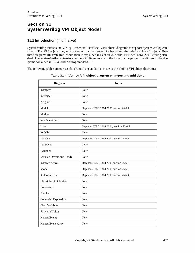
AccelleraExtensions to Verilog-2001 SystemVerilog 3.1a
Section 31SystemVerilog VPI Object Model
31.1 Introduction (informative)
SystemVerilog extends the Verilog Procedural Interface (VPI) object diagrams to support SystemVerilog con-structs. The VPI object diagrams document the properties of objects and the relationships of objects. Howthese diagrams illustrate this information is explained in Section 26 of the IEEE Std. 1364-2001 Verilog stan-dard. The SystemVerilog extensions to the VPI diagrams are in the form of changes to or additions to the dia-grams contained in 1364-2001 Verilog standard.
The following table summarizes the changes and additions made to the Verilog VPI object diagrams:
Table 31-4: Verilog VPI object diagram changes and additions
Diagram Notes
Instances New
Interface New
Program New
Module Replaces IEEE 1364.2001 section 26.6.1
Modport New
Interface tf decl New
Ports Replaces IEEE 1364.2001, section 26.6.5
Ref Obj New
Variable Replaces IEEE 1364.2001 section 26.6.8
Var select New
Typespec New
Variable Drivers and Loads New
Instance Arrays Replaces IEEE 1364.2001 section 26.6.2
Scope Replaces IEEE 1364.2001 section 26.6.3
IO Declaration Replaces IEEE 1364.2001 section 26.6.4
Class Object Definition New
Constraint New
Dist Item New
Constraint Expression New
Class Variables New
Structure/Union New
Named Events New
Named Event Array New
Copyright 2004 Accellera. All rights reserved. 407

AccelleraSystemVerilog 3.1a Extensions to Verilog-2001
Task, Function Declaration Replaces IEEE 1364.2001 section 26.6.18
Alias Statement New
Frames Replaces IEEE 1364.2001 section 26.6.20
Threads New
Concurrent Assertions New
Disable Condition New
Clocking Event New
Property Declaration New
Property Specification New
Property Expression New
Multiclock Sequence Expression New
Sequence Declaration New
Sequence Expression New
Instances New
Atomic Statement New
if, if-else Replaces IEEE 1364-2001 section 26.6.35
case Replaces IEEE 1364-2001 section 26.6.36
return New
do while New
waits Replaces wait in IEEE 1364-2001 section 26.6.32
disables Replaces IEEE 1364-2001 section 26.6 38
expect New
foreach New
Table 31-4: Verilog VPI object diagram changes and additions (continued)
Diagram Notes
408 Copyright 2004 Accellera. All rights reserved .

AccelleraExtensions to Verilog-2001 SystemVerilog 3.1a
31.2 Instance
-> array memberbool: vpiArray
-> cellbool: vpiCellInstance
-> default net typeint: vpiDefNetType
-> definition locationint: vpiDefLineNostr: vpiDefFile
-> definition namestr: vpiDefName
-> delay modeint: vpiDefDelayMode
-> namestr: vpiNamestr: vpiFullName
-> protectedbool: vpiProtected
-> timeprecisionint: vpiTimePrecision
-> timeunitint: vpiTimeUnit
-> unconnected driveint: vpiUnconnDrive
-> Configurationstr: vpiLibrarystr: vpiCellstr: vpiConfig
->default lifetime bool: vpiAutomatic
-> topbool: vpiTop
compile unitbool: vpiUnit
vpiInternalScope
interface
task func
interface
scope
net
variables
net array
array var
named event
named event array
process
parameter
def param
param assign
module
expr vpiIndex
program
instanceinstance array
program
interface array
clocking block
clocking block
concurrent assertions
package
typespec
vpiMemory
reg array
program array
spec param
instance items
vpiTypedef
vpiDefaultClocking
reg
Copyright 2004 Accellera. All rights reserved. 409

AccelleraSystemVerilog 3.1a Extensions to Verilog-2001
NOTES
1) Top-level instances shall be accessed using vpi_iterate() with a NULL reference object.
1) Passing a NULL handle to vpi_get() with types vpiTimePrecision or vpiTimeUnit shall return the smallest time precision of all instances in the design.
2) If an instance is an element within an array, the vpiIndex transition is used to access the index within thearray. If the instance is not part of an array, this transition shall return NULL.
3) Compilation units are represented as packages that have a vpiUnit property set to TRUE. Such implicitlydeclared packages shall have implementation dependent names.
31.3 Interface
31.4 Program
cont assigninterface
mod port
vpiInstance
NOTE
All interfaces are instances and all relations and properties in the Instances diagram also apply.
mod path
interface tf decl
cont assignprogramvpiInstance
NOTE
All programs are instances and all relations and properties in the Instances diagram also apply.
410 Copyright 2004 Accellera. All rights reserved .

AccelleraExtensions to Verilog-2001 SystemVerilog 3.1a
31.5 Module (supersedes IEEE 1364-2001 26.6.1)
-> top modulebool: vpiTopModule
vpiInternalScope
interface
task func
port
scope
net
variables
net array
array var
named event
named event array
process
module
cont assign
module array
primitive
primitive array
tchk
mod path
spec param
parameter
def param
io decl
param assign
program
program array
interface array
alias stmt
clocking block
concurrent assertions
module
NOTES
1) vpiModule will return a module if the object isinside a module instance, otherwise NULL;
2) vpiInstance will always return the immediateinstance (package, module, program or interface)in which the object is instantiated
3) vpiMemory will return array variable objectsrather than vpiMemory objects. The IEEE 1364committee is currently making a similar update tothe Verilog VPI (refer to note 3 in IEEE 1364-2001, section 26.6.9)
vpiMemory
reg
reg array
Copyright 2004 Accellera. All rights reserved. 411

AccelleraSystemVerilog 3.1a Extensions to Verilog-2001
31.6 Modport
31.7 Interface tf decl
-> namestr: vpiName
modportinterface io decl
-> access typeint: vpiAccessType
vipForkJoinvpiExtern
interface tf decl
task
function
NOTE
vpiIterate(vpiTaskFunc) can return more than one task/function declaration for modport tasks/func-tions with an access type of vpiForkJoin, because the task or function can be imported from multiplemodule instances.
412 Copyright 2004 Accellera. All rights reserved .
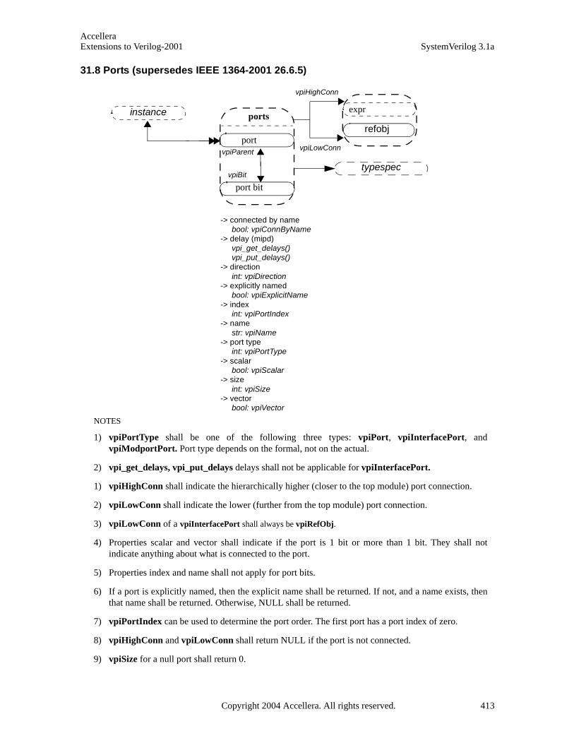
AccelleraExtensions to Verilog-2001 SystemVerilog 3.1a
31.8 Ports (supersedes IEEE 1364-2001 26.6.5)
-> connected by namebool: vpiConnByName
-> delay (mipd)vpi_get_delays()vpi_put_delays()
-> directionint: vpiDirection
-> explicitly namedbool: vpiExplicitName
-> indexint: vpiPortIndex
-> namestr: vpiName
-> port typeint: vpiPortType
-> scalarbool: vpiScalar
-> sizeint: vpiSize
-> vectorbool: vpiVector
NOTES
1) vpiPortType shall be one of the following three types: vpiPort, vpiInterfacePort, andvpiModportPort. Port type depends on the formal, not on the actual.
2) vpi_get_delays, vpi_put_delays delays shall not be applicable for vpiInterfacePort.
1) vpiHighConn shall indicate the hierarchically higher (closer to the top module) port connection.
2) vpiLowConn shall indicate the lower (further from the top module) port connection.
3) vpiLowConn of a vpiInterfacePort shall always be vpiRefObj.
4) Properties scalar and vector shall indicate if the port is 1 bit or more than 1 bit. They shall notindicate anything about what is connected to the port.
5) Properties index and name shall not apply for port bits.
6) If a port is explicitly named, then the explicit name shall be returned. If not, and a name exists, thenthat name shall be returned. Otherwise, NULL shall be returned.
7) vpiPortIndex can be used to determine the port order. The first port has a port index of zero.
8) vpiHighConn and vpiLowConn shall return NULL if the port is not connected.
9) vpiSize for a null port shall return 0.
ports
port
port bit
vpiHighConn
vpiLowConnvpiParent
vpiBit
instance
refobj
expr
typespec
Copyright 2004 Accellera. All rights reserved. 413

AccelleraSystemVerilog 3.1a Extensions to Verilog-2001
31.9 Ref Obj
31.9.1 Examples
These objects are newly defined objects needed for supporting the full connectivity through ports where theports are vpiInterface or vpiModport or any object inside modport or interface.
RefObjs are dummy objects and they always have a handle to the original object.
interface simple ()
logic req, gnt;modport slave (input req, output gnt);modport master (input gnt, output req);}module top()
interface simple i;
child1 i1(i);child2 i2(i.master);endmodule
ref obj
-> namestr: vpiNamestr: vpiFullName
named event
modport
interface
nets
reg
variable
scope
ref obj
vpiLowConn vpiHighConn
vpiPortInstports ports
interface array
event array
vpiActual
vpiParent
414 Copyright 2004 Accellera. All rights reserved .
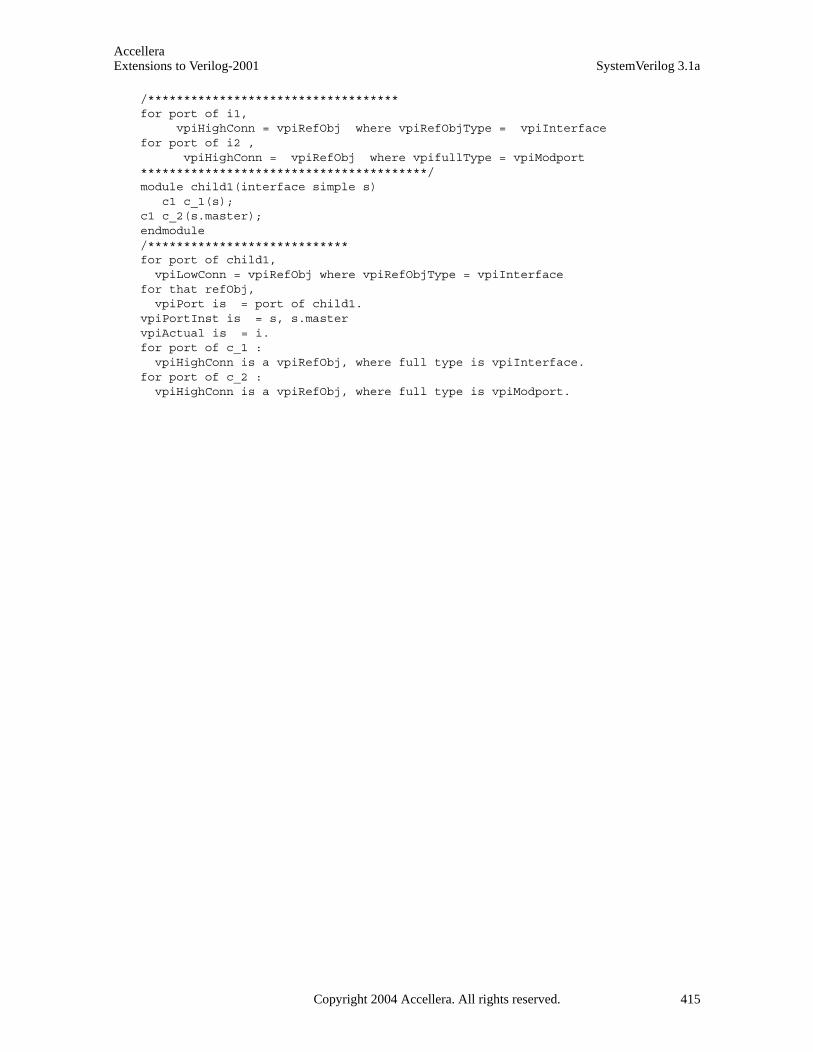
AccelleraExtensions to Verilog-2001 SystemVerilog 3.1a
/***********************************for port of i1, vpiHighConn = vpiRefObj where vpiRefObjType = vpiInterfacefor port of i2 , vpiHighConn = vpiRefObj where vpifullType = vpiModport****************************************/module child1(interface simple s) c1 c_1(s);c1 c_2(s.master);endmodule/****************************for port of child1, vpiLowConn = vpiRefObj where vpiRefObjType = vpiInterfacefor that refObj, vpiPort is = port of child1.vpiPortInst is = s, s.mastervpiActual is = i. for port of c_1 : vpiHighConn is a vpiRefObj, where full type is vpiInterface.for port of c_2 : vpiHighConn is a vpiRefObj, where full type is vpiModport.
Copyright 2004 Accellera. All rights reserved. 415
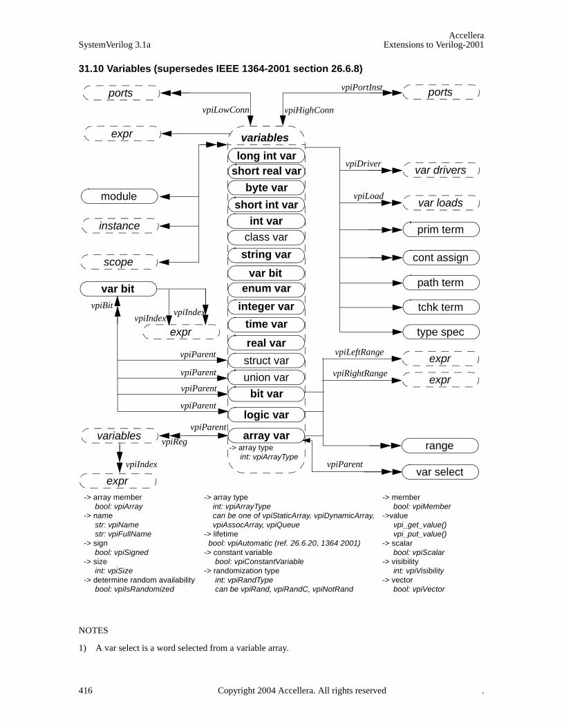
AccelleraSystemVerilog 3.1a Extensions to Verilog-2001
31.10 Variables (supersedes IEEE 1364-2001 section 26.6.8)
NOTES
1) A var select is a word selected from a variable array.
long int var
real var
logic var
short real var
int varshort int var
byte var
array var
time var
var bit
integer var
string var
struct var
union var
enum var
variables
class var
bit var
vpiLowConn vpiHighConn
vpiPortInst
vpiLoad
vpiDriver
vpiLeftRange
vpiRightRange
vpiParent
vpiReg
vpiIndex
vpiParent
vpiParent
vpiBit
vpiParent
vpiParent
vpiParent
var bit
range
ports
prim term
module
instance
scope cont assign
path term
tchk term
type spec
var select
var drivers
var loads
ports
expr
expr
variables
-> array memberbool: vpiArray
-> namestr: vpiNamestr: vpiFullName
-> signbool: vpiSigned
-> sizeint: vpiSize
-> determine random availabilitybool: vpiIsRandomized
-> array type int: vpiArrayType can be one of vpiStaticArray, vpiDynamicArray,
vpiAssocArray, vpiQueue-> lifetime bool: vpiAutomatic (ref. 26.6.20, 1364 2001)-> constant variable
bool: vpiConstantVariable-> randomization type
int: vpiRandTypecan be vpiRand, vpiRandC, vpiNotRand
-> memberbool: vpiMember
->valuevpi_get_value()vpi_put_value()
-> scalarbool: vpiScalar
-> visibilityint: vpiVisibility
-> vectorbool: vpiVector
-> array typeint: vpiArrayType
exprvpiIndex
expr
expr
vpiIndex
416 Copyright 2004 Accellera. All rights reserved .
AccelleraExtensions to Verilog-2001 SystemVerilog 3.1a
2) The boolean property vpiArray shall be TRUE if the variable handle references an array of variables, andFALSE otherwise. If the variable is an array, iterate on vpiVarSelect to obtain handles to each variable inthe array.
3) To obtain the members of a union and structure, see the relations in Section 31.21
4) The range relation is valid only when vpiArray is true. When applied to array vars this relation returnsonly unpacked ranges. When applied to logic and bit variables, it returns only the packed ranges.
5) vpi_handle (vpiIndex, var_select_handle) shall return the index of a var select in a 1-dimensional array.vpi_iterate (vpiIndex, var_select_handle) shall return the set of indices for a var select in amultidimensional array, starting with the index for the var select and working outward
6) vpiLeftRange and vpiRightRange shall only apply if vpiMultiArray is not true, i.e. if the array is notmulti-dimensional.
7) A variable handle of type vpiArrayVar represents an unpacked array. The range iterator for array varsreturns only the unpacked ranges for the array.
8) If the variable has an initialization expression, the expression can be obtained from vpi_handle(vpiExpr,var_handle)
9) vpiSize for a variable array shall return the number of variables in the array. For non-array variables, itshall return the size of the variable in bits. For unpacked structures and unions the size returned indicatesthe number of fields in the structure or union.
10) vpiSize for a var select shall return the number of bits in the var select. This applies only for packed varselect.
11) Variables whose boolean property vpiArray is TRUE do not have a value property.
12) vpiBit iterator applies only for logic, bit, packed struct, and packed union variables.
13) vpi_handle(vpiIndex, var_bit_handle) shall return the bit index for the variable bit.vpi_iterate(vpiIndex, var_bit_handle) shall return the set of indices for a multidimensional variable bitselect, starting with the index for the bit and working outwards
14) cbSizeChange will be applicable only for dynamic and associative arrays. If both value and size change,the size change callback will be invoked first. This callback fires after size change occurs and before anyvalue changes for that variable. The value in the callback is new size of the array.
15) The property vpiRandType, returns the current randomization type for the variable, which can be one ofvpiRand, vpiRandC, and vpiNotRand.
16) vpiIsRandomized is a property to determine whether a random variable is currently active forrandomization.
17) When the vpiMember property is true, it indicates that the variable is a member of a parent struct or unionvariable. See also relations in Section 31.21
18) If a variable is an element of an array, the vpiIndex iterator will return the indexing expressions that selectthat specific variable out of the array.
19) Note that:logic var == regvar bit var == reg bitarray var == reg array
20) The properties vpiScalar and vpiVector are applicable only to packed struct vars, packed union vars,bit vars and logic vars. These properties return false for all other objects.
Copyright 2004 Accellera. All rights reserved. 417
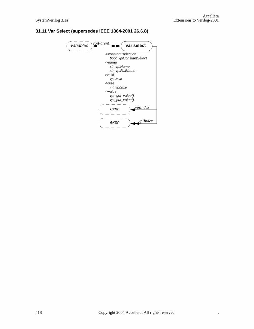
AccelleraSystemVerilog 3.1a Extensions to Verilog-2001
31.11 Var Select (supersedes IEEE 1364-2001 26.6.8)
var select
expr
expr vpiIndex
vpiIndex
->constant selectionbool: vpiConstantSelect
->namestr: vpiNamestr: vpiFullName
>validvpiValid
->sizeint: vpiSize
->valuevpi_get_value()vpi_put_value()
variables vpiParent
418 Copyright 2004 Accellera. All rights reserved .
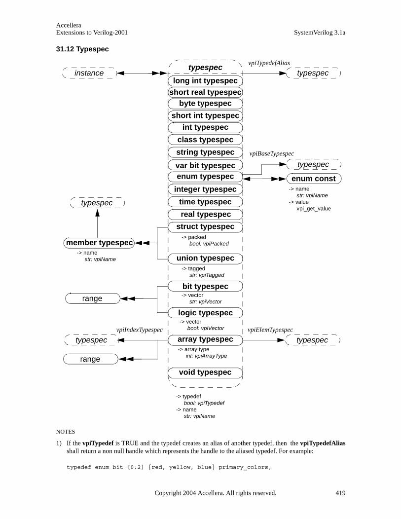
AccelleraExtensions to Verilog-2001 SystemVerilog 3.1a
31.12 Typespec
NOTES
1) If the vpiTypedef is TRUE and the typedef creates an alias of another typedef, then the vpiTypedefAliasshall return a non null handle which represents the handle to the aliased typedef. For example:
typedef enum bit [0:2] {red, yellow, blue} primary_colors;
long int typespec
real typespec
logic typespec
short real typespec
int typespecshort int typespec
byte typespec
array typespec
time typespec
var bit typespec
integer typespec
string typespec
struct typespec
union typespec
enum typespec
typespec
class typespec
bit typespec
vpiBaseTypespec
vpiTypedefAlias
vpiElemTypespec
member typespec
range
enum const
instance
typespec
typespec
typespec
typespec
void typespec
range
-> namestr: vpiName
-> typedefbool: vpiTypedef
-> namestr: vpiName
-> vectorbool: vpiVector
-> vectorstr: vpiVector
-> taggedstr: vpiTagged
-> packedbool: vpiPacked
-> array typeint: vpiArrayType
-> namestr: vpiName
-> valuevpi_get_value
typespecvpiIndexTypespec
Copyright 2004 Accellera. All rights reserved. 419

AccelleraSystemVerilog 3.1a Extensions to Verilog-2001
typdef primary_colors colors;
If “h1” is a handle to the typespec colors, its vpiType shall return a vpiEnumTypespec, the vpiTypedefproperty shall be true, the vpiName property shall return “colors”, the vpiTypedefAlias shall return ahandle “h2” to the typespec “primary_colors” of vpiType vpiEnumTypespec. The vpiTypedefproperty shall be false for h2 and its vpiTypedefAlias shall return null.
2) vpiIndexTypespec relation is present only on associative arrays and returns the type that is used as the keyinto the associative array.
3) If the type of a type is vpiStruct or vpiUnion, then you can iterate over numbers to obtain the structure ofthe user-defined type. For each member the typespec relation from the member will detail its type.
4) The name of a typedef may be the empty string if the typedef is representing the type of a typedef fielddefined inline rather than via a typedef. For example:
typedef struct {
struct
int a;
}B
} C;
5) The typedef C has vpiTypedefType vpiStruct, a single field named B with vpiTypedefType vpiStruct.Obtaining the typedef of field B, you will obtain a typedef with no name and a single field, named "a" withvpiTypedefType of vpiInt.
6) If a type is defined as an alias of another type, it inherits the vpiType of this other type. For example:
typedef time my_time;
my_time t;
The vpiTypespec of the variable named “t” shall return a handle h1 to the typespec “my_time” whosevpiType shall be a vpiTimeTypespec. The vpiTypedefAlias applied to handle h1 shall return a typespechandle h2 to the predefined type “time”.
420 Copyright 2004 Accellera. All rights reserved .
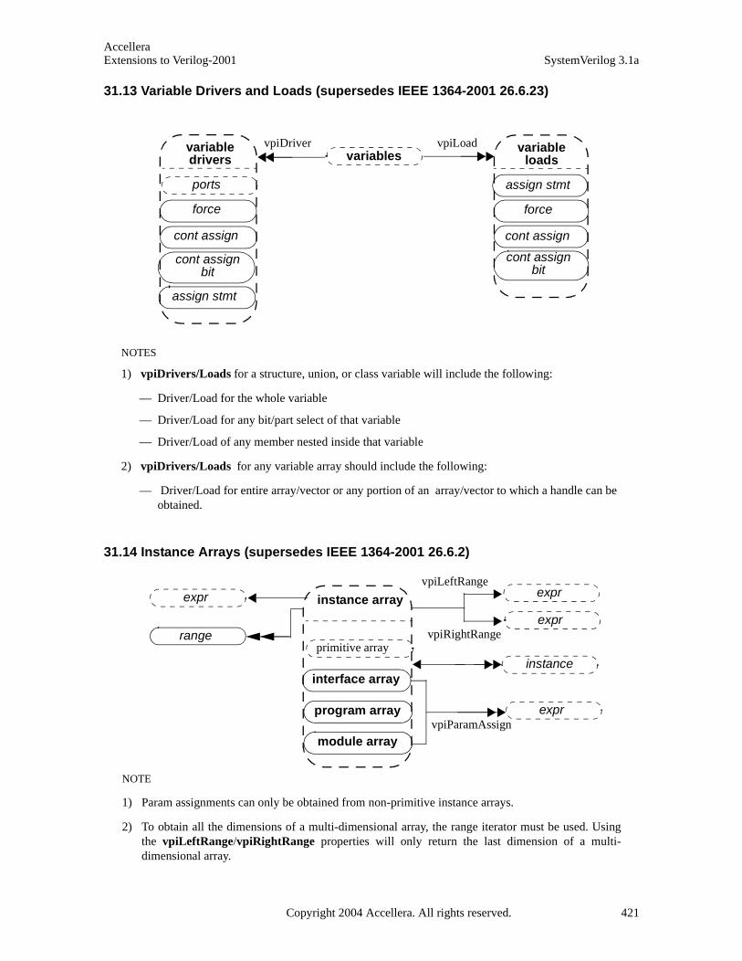
AccelleraExtensions to Verilog-2001 SystemVerilog 3.1a
31.13 Variable Drivers and Loads (supersedes IEEE 1364-2001 26.6.23)
31.14 Instance Arrays (supersedes IEEE 1364-2001 26.6.2)
variable loads
assign stmt
force
cont assign
variable drivers
ports
force
cont assign
cont assign bit
assign stmt
cont assign bit
variablesvpiDriver vpiLoad
NOTES
1) vpiDrivers/Loads for a structure, union, or class variable will include the following:
— Driver/Load for the whole variable
— Driver/Load for any bit/part select of that variable
— Driver/Load of any member nested inside that variable
2) vpiDrivers/Loads for any variable array should include the following:
— Driver/Load for entire array/vector or any portion of an array/vector to which a handle can be obtained.
instance array
program array
primitive array
module array
expr
expr
expr exprvpiLeftRange
vpiRightRange
vpiParamAssign
instanceinterface array
NOTE
1) Param assignments can only be obtained from non-primitive instance arrays.
2) To obtain all the dimensions of a multi-dimensional array, the range iterator must be used. Usingthe vpiLeftRange/vpiRightRange properties will only return the last dimension of a multi-dimensional array.
range
Copyright 2004 Accellera. All rights reserved. 421
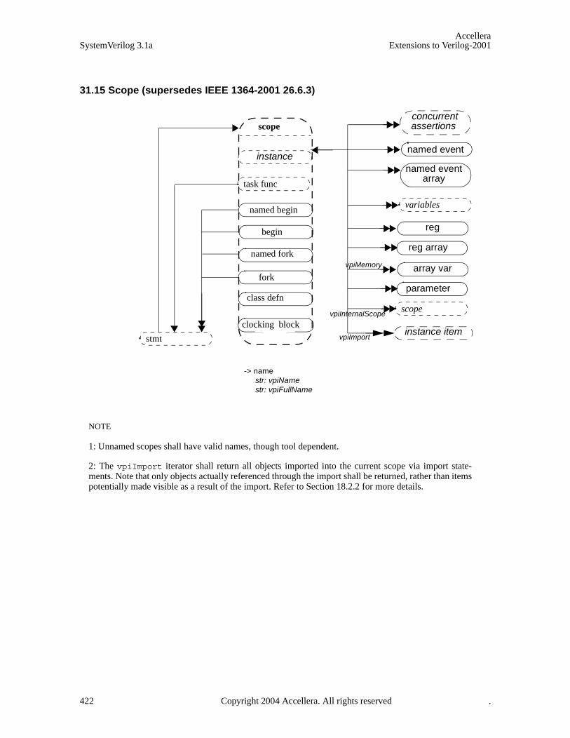
AccelleraSystemVerilog 3.1a Extensions to Verilog-2001
31.15 Scope (supersedes IEEE 1364-2001 26.6.3)
scope
class defn
task func
named begin
named fork
named event array
named event
vpiInternalScope
reg
reg array
array var
parameter
variables
scope
-> namestr: vpiNamestr: vpiFullName
stmt
instance
begin
fork
concurrent assertions
NOTE
1: Unnamed scopes shall have valid names, though tool dependent.
2: The vpiImport iterator shall return all objects imported into the current scope via import state-ments. Note that only objects actually referenced through the import shall be returned, rather than itemspotentially made visible as a result of the import. Refer to Section 18.2.2 for more details.
instance itemvpiImport
clocking block
vpiMemory
422 Copyright 2004 Accellera. All rights reserved .

AccelleraExtensions to Verilog-2001 SystemVerilog 3.1a
31.16 IO Declaration (supersedes IEEE 1364-2001 26.6.4)
NOTE
vpiDirection returns vpiRef for pass by ref ports.
io decludp defn
task func
expr
expr
reg
net
variable-> directionint: vpiDirection
-> namestr: vpiName
-> scalarbool: vpiScalar
-> signbool: vpiSigned
-> sizeint: vpiSize
-> vectorbool: vpiVector
-> arraybool: vpiArray
vpiExpr
vpiLeftRange
vpiRightRange
range
instance
typespec
tf decl
clocking block
Copyright 2004 Accellera. All rights reserved. 423
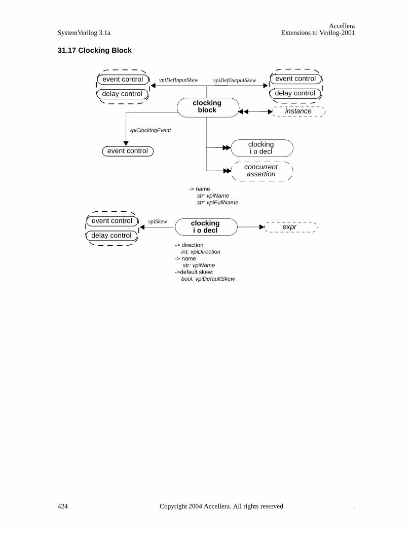
AccelleraSystemVerilog 3.1a Extensions to Verilog-2001
31.17 Clocking Block
vpiClockingEvent
event control
clocking block
clockingi o decl
vpiDefInputSkew vpiDefOutputSkew
clockingi o decl
vpiSkew
-> namestr: vpiNamestr: vpiFullName
instance
event control
delay control
event control
delay control
event control
delay control
expr
-> direction int: vpiDirection-> name str: vpiName->default skew: bool: vpiDefaultSkew
concurrentassertion
424 Copyright 2004 Accellera. All rights reserved .

AccelleraExtensions to Verilog-2001 SystemVerilog 3.1a
31.18 Class Object Definition
class defn
variable
constraint
extends
vpiDerivedClasses
> namestr: vpiName
> virtualbool: vpiVirtual
-> user defined
bool: vpiUserDefined-> lifetime
bool: vpiAutomatic
vpiMethods
NOTE
1) ClassDefn handle is a new concept. It does not correspond to any vpiUserDefined (class object) inthe design. Rather it represents the actual type definition of a class.
1) Should not call vpi_get_value/vpi_put_value on the non-static variables obtained from the classdefinition handle.
1) Iterator to constraints returns only normal constraints and not inline constraints.
1) To get constraints inherited from base classes, you will need to traverse the extend relation toobtain the base class.
1) The vpiDerivedClasses iterator returns all the classes derived from the given class.
1) The relation to vpiExtend exists whenever a one class is derived from another class (ref Section11.12). The relation from extend to classDefn provides the base class. The iterators from extend toparam assign and arguments provide the parameters and arguments used in constructor chaining(ref Section 11.16 and 11.23)
scope
parameter
task func
param assign
expr
vpiArgument
class defn
instances
Copyright 2004 Accellera. All rights reserved. 425
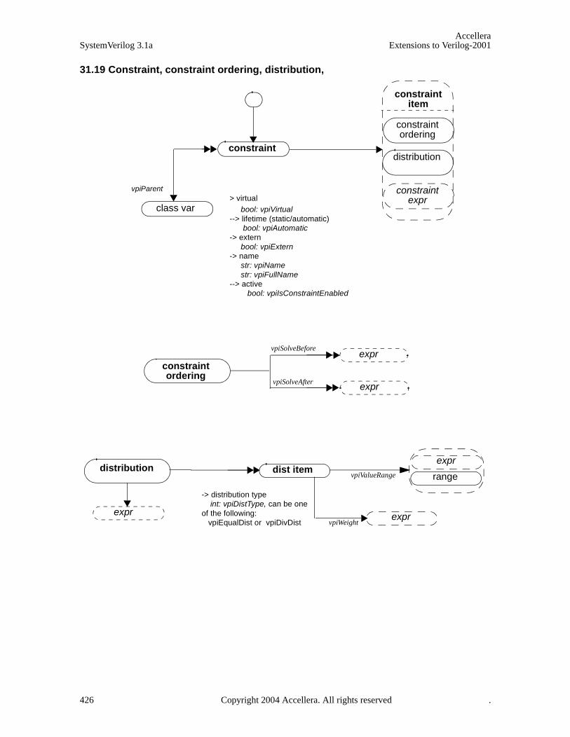
AccelleraSystemVerilog 3.1a Extensions to Verilog-2001
31.19 Constraint, constraint ordering, distribution,
vpiParent
constraint
class var > virtual
bool: vpiVirtual --> lifetime (static/automatic)
bool: vpiAutomatic-> extern
bool: vpiExtern-> name
str: vpiNamestr: vpiFullName
--> active bool: vpiIsConstraintEnabled
constraint ordering
distribution
constraint expr
constraint ordering
vpiSolveBefore
vpiSolveAfter
distribution dist item
expr
expr
expr
constraint item
range
exprvpiWeight
exprvpiValueRange
-> distribution type int: vpiDistType, can be one of the following: vpiEqualDist or vpiDivDist
426 Copyright 2004 Accellera. All rights reserved .

AccelleraExtensions to Verilog-2001 SystemVerilog 3.1a
31.20 Constraint expression
constraint expr
implication
constr if
constr if else
expr
vpiCondition
constraint expr
expr
constraint exprvpiElseConst
expr
Copyright 2004 Accellera. All rights reserved. 427

AccelleraSystemVerilog 3.1a Extensions to Verilog-2001
31.21 Class Variables
class var class defn
-> Class typeint: vpiClassTypecan be one of
vpiUserDefinedClass, vpiMailboxClass, vpiSemaphoreClass -> access type
int: vpiAccessTypecan be one of vpiPublicAccvpiProtectedAcc, vpiLocalAcc
frame
exprvpiMessages
NOTES
1) vpiWaiting/Process iterator on mailbox/semaphores will show the processes waiting on the object:
— Waiting process means either frame or task/function handle.
2) vpiMessage iterator shall return all the messages in a mailbox.
3) vpiClassDefn returns the ClassDefn which was used to create the handle. vpiActualDefn returnsthe ClassDefn that handle object points to when the query is made. The difference can be seen inthe example below:class Packet...endclass : Packet
class LinkedPacket extends Packet...endclass : LinkedPacket
LinkedPacket l = new;Packet p = l;
In this example, the vpiClassDefn of variable "p" is Packet, but the vpiActualDefn is"LinkedPacket".
4) vpiClassDefn/vpiActualDefn both shall return NULL for built-in classes.
variables
vpiWaitingProcesses
class defnvpiActualDefn
428 Copyright 2004 Accellera. All rights reserved .
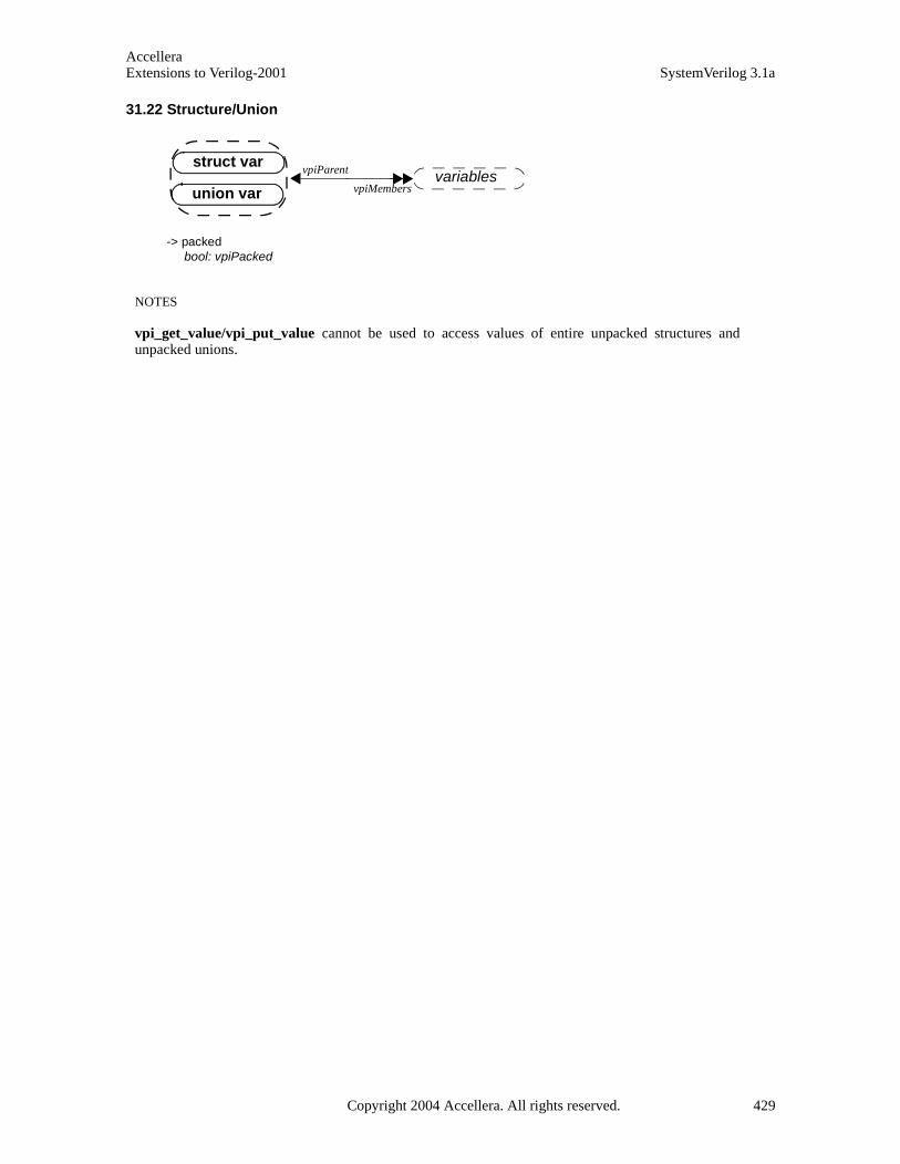
AccelleraExtensions to Verilog-2001 SystemVerilog 3.1a
31.22 Structure/Union
variables
-> packedbool: vpiPacked
NOTES
vpi_get_value/vpi_put_value cannot be used to access values of entire unpacked structures andunpacked unions.
struct var
union var
vpiParent
vpiMembers
Copyright 2004 Accellera. All rights reserved. 429

AccelleraSystemVerilog 3.1a Extensions to Verilog-2001
31.23 Named Events (supersedes IEEE 1364-2001 26.6.11)
named event
vpiWaitingProcesses
frame
NOTE
The new iterator (vpiWaitingProcesses) returns all waiting processes, identified by their frame, for thatnamed event.
scope
-> array memberbool: vpiArray
-> namestr: vpiNamestr: vpiFullName
-> valuevpi_put_value()
-> automaticbool: vpiAutomatic
named event array
vpiIndex
named event
-> namestr: vpiNamestr: vpiFullName
-> automaticbool: vpiAutomatic
NOTE
vpi_iterate(vpiIndex, named_event_handle) shall return the set of indices for a named event withinan array, starting with the index for the named event and working outward. If the named event is notpart of an array, a NULL shall be returned.
expr
range
instance
instance vpiParent
430 Copyright 2004 Accellera. All rights reserved .
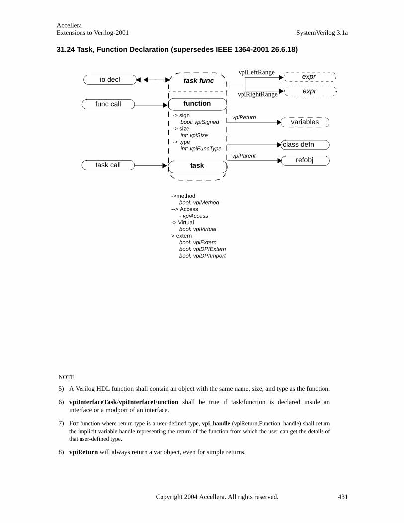
AccelleraExtensions to Verilog-2001 SystemVerilog 3.1a
31.24 Task, Function Declaration (supersedes IEEE 1364-2001 26.6.18)
task func
function
task
expr
exprvpiLeftRange
vpiRightRange
func call
task call
io decl
-> signbool: vpiSigned
-> sizeint: vpiSize
-> typeint: vpiFuncType
class defn
NOTE
5) A Verilog HDL function shall contain an object with the same name, size, and type as the function.
6) vpiInterfaceTask/vpiInterfaceFunction shall be true if task/function is declared inside aninterface or a modport of an interface.
7) For function where return type is a user-defined type, vpi_handle (vpiReturn,Function_handle) shall returnthe implicit variable handle representing the return of the function from which the user can get the details ofthat user-defined type.
8) vpiReturn will always return a var object, even for simple returns.
->methodbool: vpiMethod
--> Access- vpiAccess
-> Virtualbool: vpiVirtual
> externbool: vpiExternbool: vpiDPIExtern bool: vpiDPIImport
vpiParentrefobj
vpiReturnvariables
Copyright 2004 Accellera. All rights reserved. 431
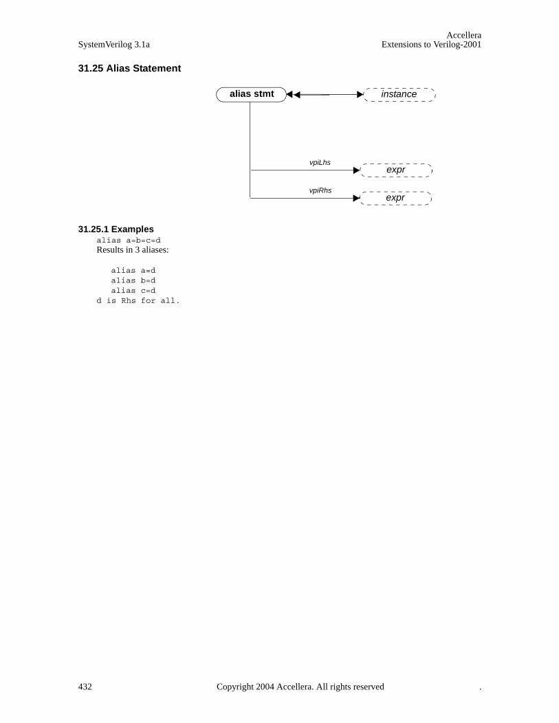
AccelleraSystemVerilog 3.1a Extensions to Verilog-2001
31.25 Alias Statement
31.25.1 Examplesalias a=b=c=dResults in 3 aliases:
alias a=dalias b=dalias c=d
d is Rhs for all.
alias stmt
vpiLhs
vpiRhs
instance
expr
expr
432 Copyright 2004 Accellera. All rights reserved .
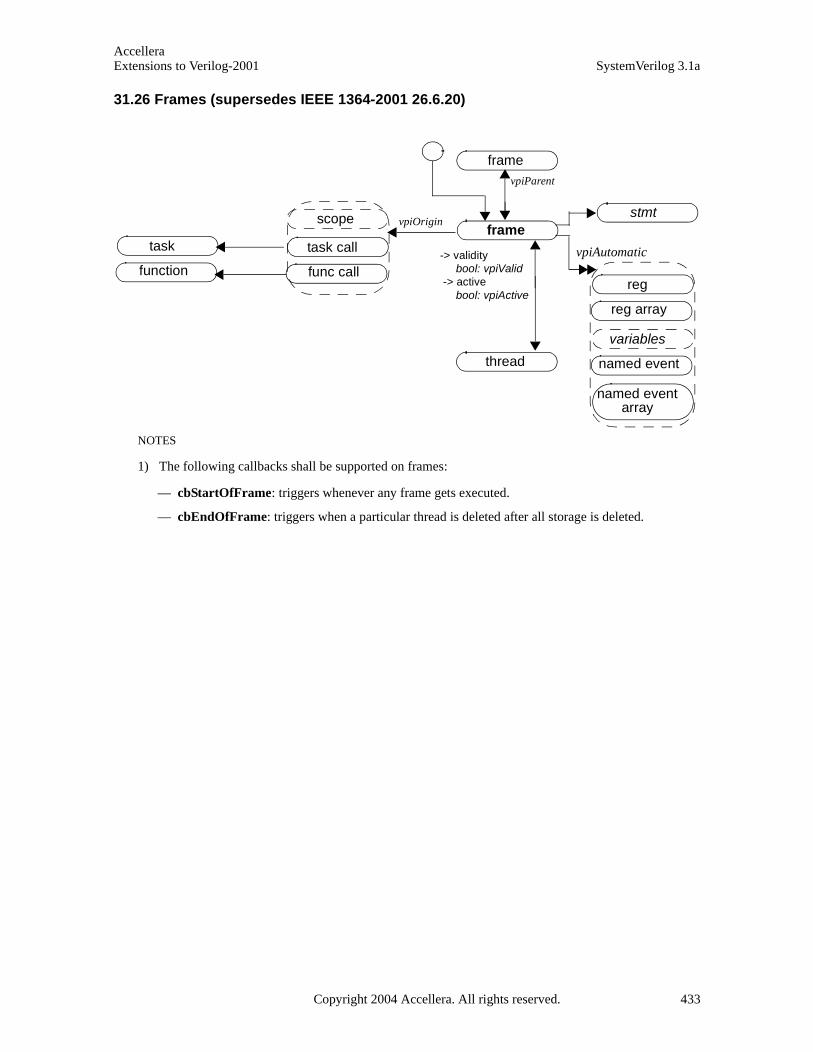
AccelleraExtensions to Verilog-2001 SystemVerilog 3.1a
31.26 Frames (supersedes IEEE 1364-2001 26.6.20)
stmt
function
taskframe
framevpiParent
thread
reg array
reg
vpiOrigin
func call
task call
named event
variables
named event array
-> validitybool: vpiValid
-> activebool: vpiActive
scope
NOTES
1) The following callbacks shall be supported on frames:
— cbStartOfFrame: triggers whenever any frame gets executed.
— cbEndOfFrame: triggers when a particular thread is deleted after all storage is deleted.
vpiAutomatic
Copyright 2004 Accellera. All rights reserved. 433
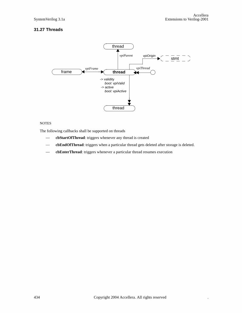
AccelleraSystemVerilog 3.1a Extensions to Verilog-2001
31.27 Threads
thread
thread
vpiParent
thread
vpiFrameframe
vpiThread
NOTES
The following callbacks shall be supported on threads
— cbStartOfThread: triggers whenever any thread is created
— cbEndOfThread: triggers when a particular thread gets deleted after storage is deleted.
— cbEnterThread: triggers whenever a particular thread resumes execution
-> validitybool: vpiValid
-> activebool: vpiActive
vpiOriginstmt
434 Copyright 2004 Accellera. All rights reserved .
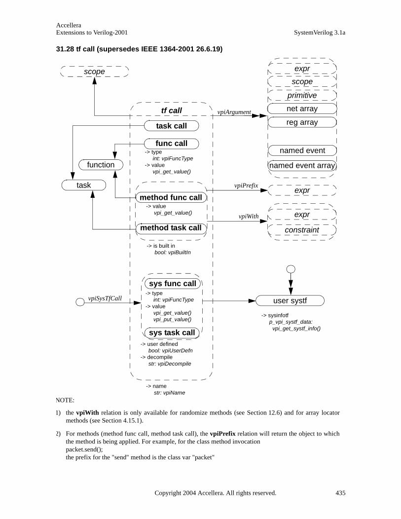
AccelleraExtensions to Verilog-2001 SystemVerilog 3.1a
31.28 tf call (supersedes IEEE 1364-2001 26.6.19)
task call
func call
sys func call
method task call
tf call
sys task call
vpiArgument
user systf
expr
scope
primitive
method func call
-> namestr: vpiName
-> user definedbool: vpiUserDefn
-> decompilestr: vpiDecompile
-> typeint: vpiFuncType
-> valuevpi_get_value()vpi_put_value()
-> typeint: vpiFuncType
-> valuevpi_get_value()
-> is built inbool: vpiBuiltIn
-> valuevpi_get_value()
net array
reg array
-> sysinfotf p_vpi_systf_data: vpi_get_systf_info()
named event array
expr
expr
constraint
vpiPrefix
vpiWith
named event
vpiSysTfCall
task
function
scope
NOTE:
1) the vpiWith relation is only available for randomize methods (see Section 12.6) and for array locatormethods (see Section 4.15.1).
2) For methods (method func call, method task call), the vpiPrefix relation will return the object to whichthe method is being applied. For example, for the class method invocationpacket.send();the prefix for the "send" method is the class var "packet"
Copyright 2004 Accellera. All rights reserved. 435
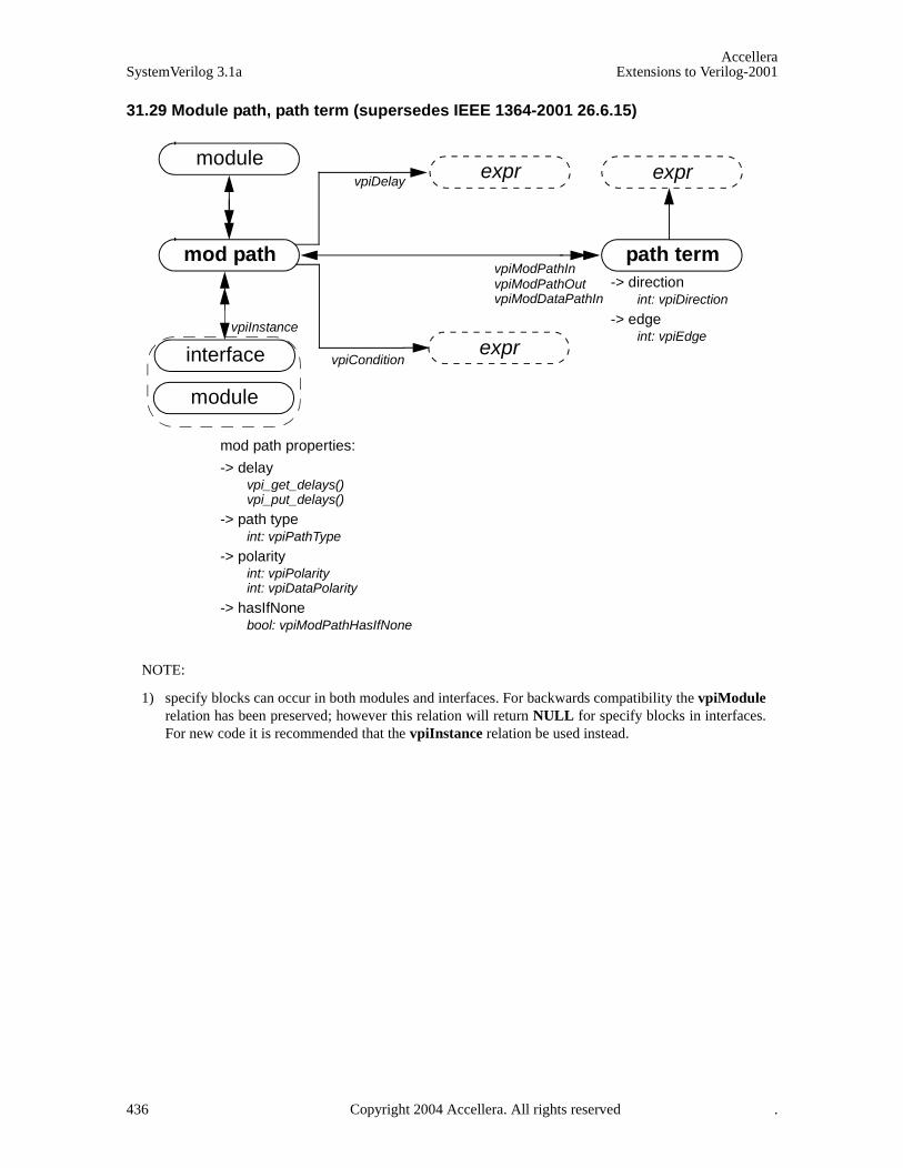
AccelleraSystemVerilog 3.1a Extensions to Verilog-2001
31.29 Module path, path term (supersedes IEEE 1364-2001 26.6.15)
path termvpiModPathInvpiModPathOut
moduleexpr
expr
vpiModDataPathIn
mod path
exprvpiDelay
mod path properties:
-> delayvpi_get_delays()vpi_put_delays()
-> path typeint: vpiPathType
-> polarityint: vpiPolarityint: vpiDataPolarity
-> hasIfNonebool: vpiModPathHasIfNone
-> directionint: vpiDirection
-> edgeint: vpiEdge
vpiConditioninterface
vpiInstance
module
NOTE:
1) specify blocks can occur in both modules and interfaces. For backwards compatibility the vpiModulerelation has been preserved; however this relation will return NULL for specify blocks in interfaces.For new code it is recommended that the vpiInstance relation be used instead.
436 Copyright 2004 Accellera. All rights reserved .

AccelleraExtensions to Verilog-2001 SystemVerilog 3.1a
31.30 Concurrent assertions
31.31 Property Decl
concurrent assertions
assert property
cover property
expr
expr
property inst
property spec
definition locationstr: vpiDefFile
int: vpiDefLineNo
block identifier
str: vpiName
str: vpiFullName
is clock inferred
bool:vpiIsClockInferred
stmt
stmt
vpiElseStmt
vpiProperty
NOTE
Clocking event is always the actual clocking event on which the assertion is being evaluated, regardlessof whether this is explicit or implicit (inferred)
vpiClockingEvent
assume property
vpiDisableCondition
property decl property inst
name
str: vpiName
str: vpiFullName
definition locationstr: vpiDefFile
int: vpiDefLineNo
property spec
identifier
Copyright 2004 Accellera. All rights reserved. 437

AccelleraSystemVerilog 3.1a Extensions to Verilog-2001
31.32 Property Specification
property spec
definition locationint: vpiDefLineNostr: vpiDefFileexpr
property expr
variables
property expr
sequence expr
vpiOperand
NOTES:1. within the context of a property expr, vpiOpType can be any one of vpiNotOp, vpiImplyOp,
vpiDelayedImplyOp, vpiAndOp, vpiOrOp, vpiIfOp, vpiIfElseOpOperands to these operations will be provided in the same order as show in the BNF.
multiclock sequence expr
NOTE
Variables are declarations of property variables. You cannot get the value of these variables.
expr
vpiClockingEvent
property expr
vpiDisableCondition
operation
property inst
-> operation type int: vpiOpType
clocked property
expr
property expr
vpiClockingEvent
438 Copyright 2004 Accellera. All rights reserved .
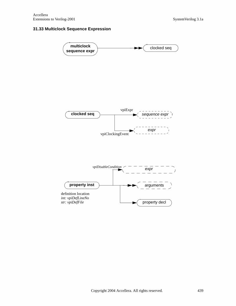
AccelleraExtensions to Verilog-2001 SystemVerilog 3.1a
31.33 Multiclock Sequence Expression
multiclock sequence expr
clocked seq
sequence expr
property inst arguments
property decl
definition locationint: vpiDefLineNostr: vpiDefFile
clocked seq
exprvpiClockingEvent
exprvpiDisableCondition
vpiExpr
Copyright 2004 Accellera. All rights reserved. 439
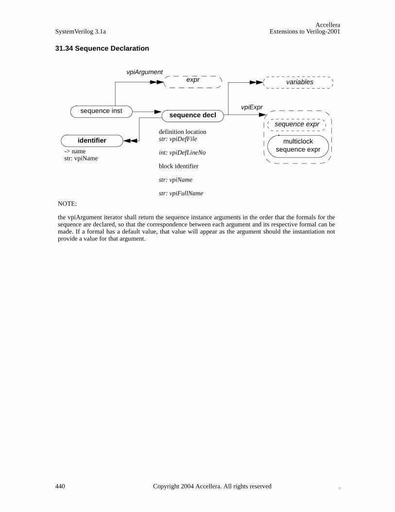
AccelleraSystemVerilog 3.1a Extensions to Verilog-2001
31.34 Sequence Declaration
sequence declsequence inst
identifierdefinition locationstr: vpiDefFile
int: vpiDefLineNo
block identifier
str: vpiName
str: vpiFullName
sequence expr
multiclock sequence expr
variables
-> name str: vpiName
exprvpiArgument
NOTE:
the vpiArgument iterator shall return the sequence instance arguments in the order that the formals for thesequence are declared, so that the correspondence between each argument and its respective formal can bemade. If a formal has a default value, that value will appear as the argument should the instantiation notprovide a value for that argument.
vpiExpr
440 Copyright 2004 Accellera. All rights reserved .

AccelleraExtensions to Verilog-2001 SystemVerilog 3.1a
31.35 Sequence Expression
sequence expr
sequence exproperation
sequence inst
operation type
int: vpiOpType
vpiOperand
sequence expr
expr assignment
sequence decl
Notes:2. Within a sequence expression, vpiOpType can be any one of vpiAndOp, vpiIntersectOp, vpiOr,
vpiFirstMatchOp, vpiThroughoutOp, vpiWithinOp, vpiUnaryCycleDelayOp, vpiCycleDelayOp, vpiRepeatOp, vpiConsecutiveRepeatOp or vpiGotoRepeatOp.
3. For operations, the operands are provided in the same order as the operands appear in BNF, with the following exceptions:vpiUnaryCycleDelayOp: arguments will be: sequence, left range, right range. Right range will only be given if different than left range.vpiCycleDelayOp: argument will be: LHS sequence, rhs sequence, left range, right range. Right range will only be provided if different than left range.all the repeat operators: the first argument will be the sequence being repeated, the next argument will be the left repeat bound, followed by the right repeat bound. The right repeat bound will only be provided if different than left repeat bound.
and, intersect, or, first_match, throughout, within, ##, [*], [=], [->]
immediate assert
stmt
stmt
vpiElseStmt
expr
distribution
tf callvpiMatchItem
vpiExpr
exprvpiArgument
Copyright 2004 Accellera. All rights reserved. 441
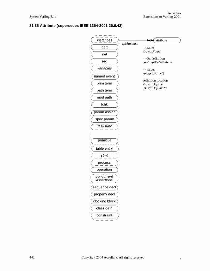
AccelleraSystemVerilog 3.1a Extensions to Verilog-2001
31.36 Attribute (supersedes IEEE 1364-2001 26.6.42)
attributeinstances
port
net
reg
variables
named event
prim term
path term
mod path
tchk
param assign
spec param
task func
primitive
table entry
stmt
process
operation
concurrent assertions
sequence decl
property decl
clocking block
class defn
constraint
-> namestr: vpiName
-> On definitionbool: vpiDefAttribute
-> value:vpi_get_value()
definition locationstr: vpiDefFileint: vpiDefLineNo
vpiAttribute
442 Copyright 2004 Accellera. All rights reserved .

AccelleraExtensions to Verilog-2001 SystemVerilog 3.1a
31.37 Atomic Statement (supersedes IEEE 1364-2001 26.6.27)
if
disables
release
if else
waits
repeat
while
deassign
delay control
event stmt
for
tf call
forever
event control
atomic stmt
case
force
assignment
-> labelstr: vpiName
do while
assign stmt
expect
foreach
return
break
continue
The vpiName property provides the statement label if one was given, otherwise the name is NULL.
immediate assert
Copyright 2004 Accellera. All rights reserved. 443

AccelleraSystemVerilog 3.1a Extensions to Verilog-2001
31.38 If, if else, return, case, do while (supersedes IEEE 1364-2001 26.6.35, 26.6.36)
if
if else
-> qualifierint: vpiQualifer
vpiCondition
vpiElseStmt
expr
stmt
stmt
case
case item
-> typeint: vpiCaseType
-> qualifierint: vpiQualifier
expr
stmt
expr
pattern
expr
pattern
any pattern
tagged pattern
struct pattern
typespec
pattern
return stmt exprvpiCondition
do whilevpiCondition
expr
stmt
-> namestr: vpiName
vpiExpr
444 Copyright 2004 Accellera. All rights reserved .
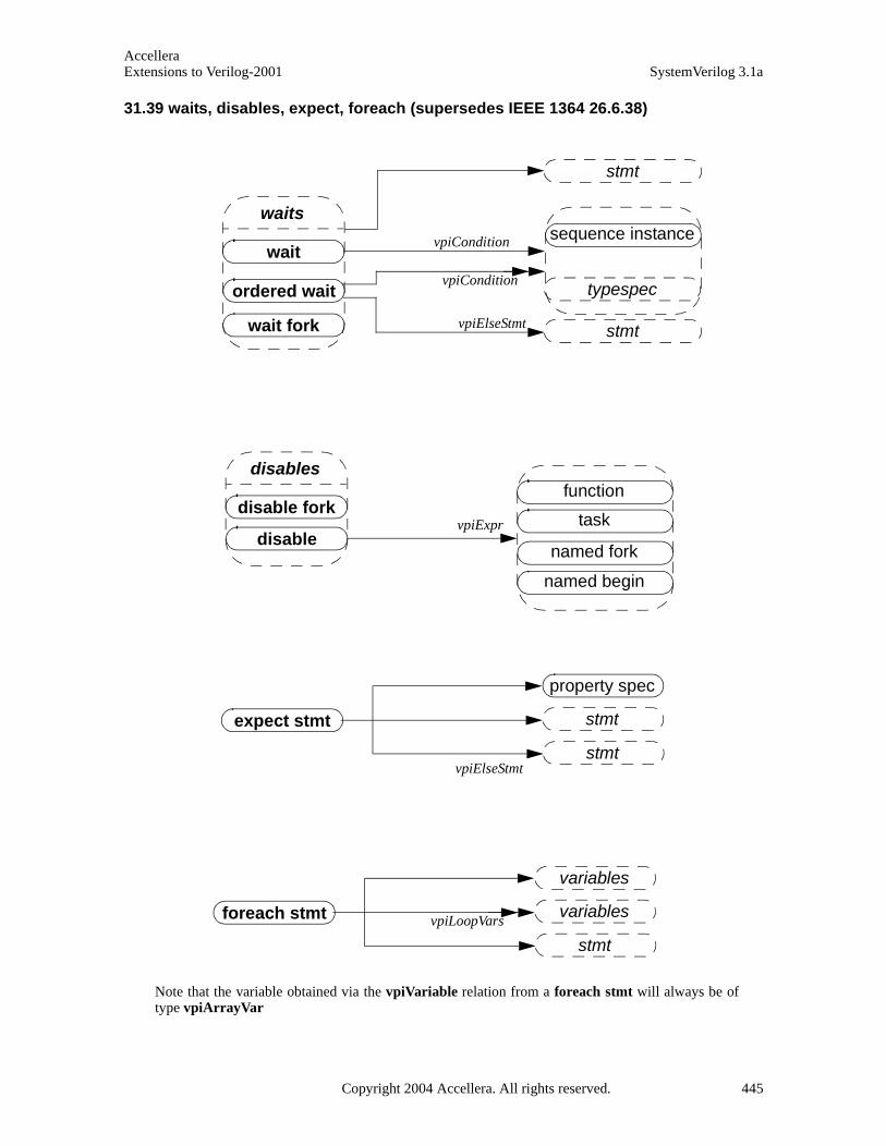
AccelleraExtensions to Verilog-2001 SystemVerilog 3.1a
31.39 waits, disables, expect, foreach (supersedes IEEE 1364 26.6.38)
waits
wait
wait fork
ordered wait typespec
sequence instance
stmt
vpiCondition
stmt
vpiElseStmt
disables
disable fork
disabletaskvpiExpr
function
named fork
named begin
vpiCondition
expect stmt
vpiElseStmt
property spec
stmt
stmt
foreach stmt vpiLoopVars
variables
variables
stmt
Note that the variable obtained via the vpiVariable relation from a foreach stmt will always be oftype vpiArrayVar
Copyright 2004 Accellera. All rights reserved. 445

AccelleraSystemVerilog 3.1a Extensions to Verilog-2001
31.40 Simple expressions (supersedes IEEE 1364-2001 26.6.25)
simple expr
variables
expr
nets
regs
memory word
var select
vpiUse prim term
stmt
ports
path term
delay term
cont assign
vpiIndex
parameter
specparam
bit select
time var
integer var
parameter
specparam
var select
memory word
vpiIParent-> name
str: vpiNamestr: vpiFullName
-> constant selectbool: vpiConstantSelect
tchk term
cont assign bit
ref obj
446 Copyright 2004 Accellera. All rights reserved .

AccelleraExtensions to Verilog-2001 SystemVerilog 3.1a
31.41 Expressions (supersedes IEEE 1364-2001 26.6.26)
expr
operation
constant
simple expr
part-select
vpiParent
vpiOperand
func call
sys func call
expr
expr
vpiLeftRange
vpiRightRange
expr
-> constant selectionbool: vpiConstantSelect
-> decompilestr: vpiDecompile
-> sizeint: vpiSize
-> valuevpi_get_value()
-> operation typeint: vpiOpType
-> constant typeint: vpiConstType
typespec
range
sequence inst
pattern
NOTES:
1) For an operator whose type is vpiMultiConcat, the first operand shall be the multiplier expression. The remainingoperands shall be the expressions within the concatenation.
2) The property vpiDecompile will return a string with a functionally equivalent expression to the original expressionwithin the HDL. Parenthesis shall be added only to preserve precedence. Each operand and operator shall be separated bya single space character. No additional white space shall be added due to parenthesis.
3) New vpiOpTypes: vpiInsideOp, vpiMatchOp, vpiCastOp, vpiPreIncOp, vpiPostIncOp, vpiPreDecOp, vpiPostDecOp,vpiIffOp, vpiCycleDelayOp. The cast operation is represented as a unary operation, with its sole argument being theexpression being cast, and the typespec of the cast expression being the type to which the argument is being cast.
4) New vpiConstType: vpiNullConst, vpiOneStepConst, vpiUnboundedConst. The constant vpiUnboundedConst repre-sents the $ value used in assertion ranges.
5) The one to one relation to typespec must always be available for vpiCastOp operations and for simple expressions. Forother expressions it is implementation dependent whether there is any associated typespec.
6) Variable slices are represented by part-selects whose parent simple expression is an array variable.
method func call
Copyright 2004 Accellera. All rights reserved. 447
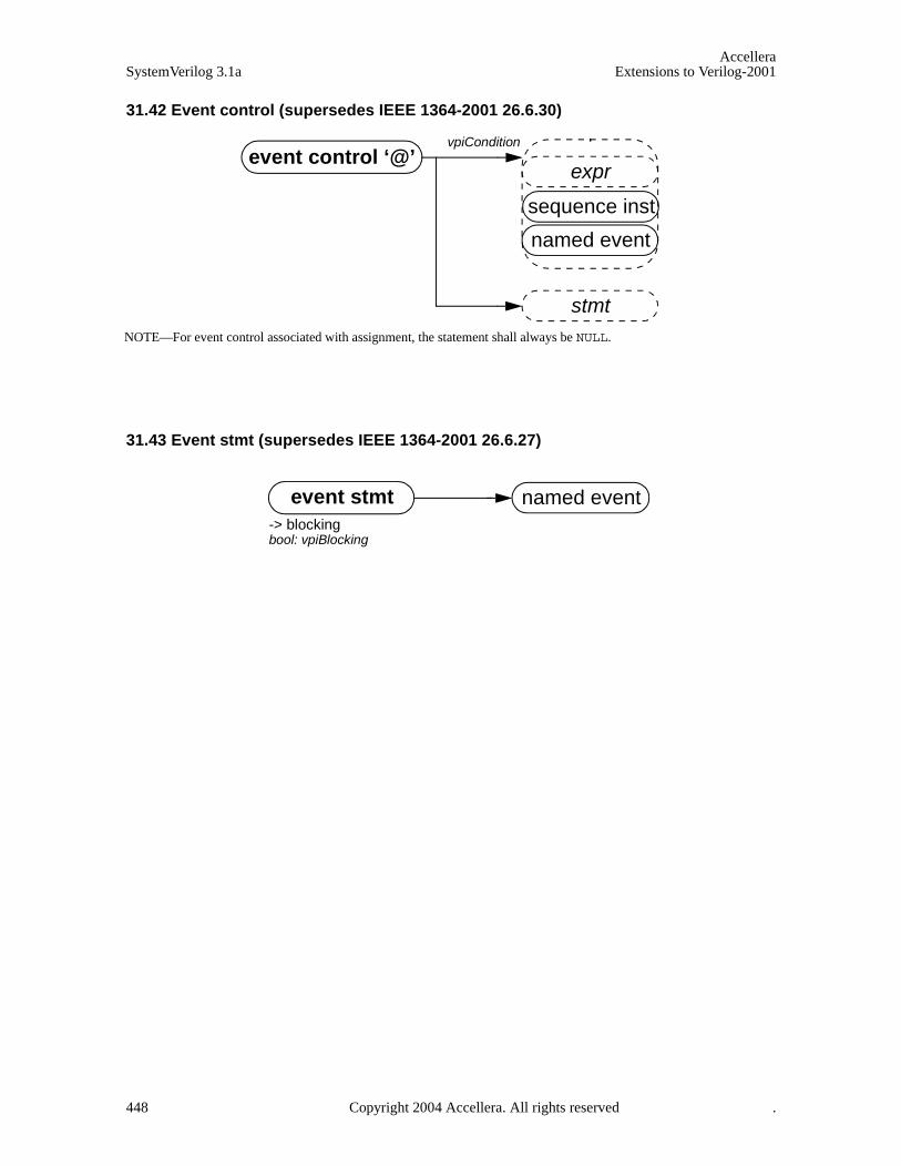
AccelleraSystemVerilog 3.1a Extensions to Verilog-2001
31.42 Event control (supersedes IEEE 1364-2001 26.6.30)
31.43 Event stmt (supersedes IEEE 1364-2001 26.6.27)
vpiCondition
expr
stmt
event control ‘@’
named event
NOTE—For event control associated with assignment, the statement shall always be NULL.
sequence inst
event stmt named event-> blockingbool: vpiBlocking
448 Copyright 2004 Accellera. All rights reserved .

AccelleraExtensions to Verilog-2001 SystemVerilog 3.1a
31.44 Process (supersedes IEEE 1364-2001 26.6.27)
31.45 Assignment (supersedes IEEE 1364-2001 26.6.28)
NOTE: vpiOpType will return vpiAssignmentOp for normal non-blocking ’=’ assignments, and the operatorcombined with the assignment for the operators described in section 7.3.
For example, the assignment
a[i] += 2;
will return vpiAddOp for the vpiOpType property.
module
initial
process
final
block
stmt
atomic stmt
scope
always-> always typeint: vpiAlwaysType
NOTE- vpiAlwaysType can be one of: vpiAlwaysComb, vpiAlwaysFF, vpiAlwaysLatch
assignmentvpiRhs
expr
vpiLhsexpr
delay control
event control
repeat control-> operator
int: vpiOpType
-> blockingbool: vpiBlocking
Copyright 2004 Accellera. All rights reserved. 449

AccelleraSystemVerilog 3.1a Extensions to Verilog-2001
450 Copyright 2004 Accellera. All rights reserved .
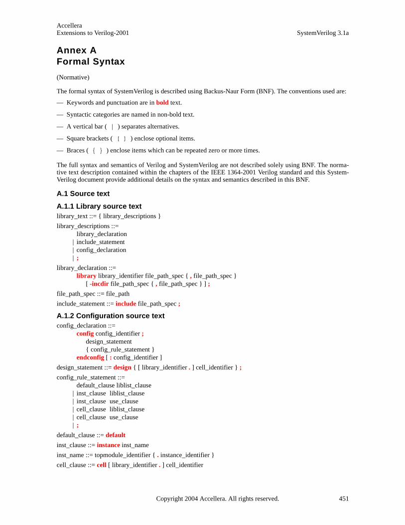
AccelleraExtensions to Verilog-2001 SystemVerilog 3.1a
Annex AFormal Syntax
(Normative)
The formal syntax of SystemVerilog is described using Backus-Naur Form (BNF). The conventions used are:
— Keywords and punctuation are in bold text.
— Syntactic categories are named in non-bold text.
— A vertical bar ( | ) separates alternatives.
— Square brackets ( [ ] ) enclose optional items.
— Braces ( { } ) enclose items which can be repeated zero or more times.
The full syntax and semantics of Verilog and SystemVerilog are not described solely using BNF. The norma-tive text description contained within the chapters of the IEEE 1364-2001 Verilog standard and this System-Verilog document provide additional details on the syntax and semantics described in this BNF.
A.1 Source text
A.1.1 Library source text library_text ::= { library_descriptions }
library_descriptions ::= library_declaration
| include_statement | config_declaration | ;
library_declaration ::= library library_identifier file_path_spec { , file_path_spec }
[ -incdir file_path_spec { , file_path_spec } ] ;
file_path_spec ::= file_path
include_statement ::= include file_path_spec ;
A.1.2 Configuration source text config_declaration ::=
config config_identifier ; design_statement { config_rule_statement }
endconfig [ : config_identifier ]
design_statement ::= design { [ library_identifier . ] cell_identifier } ;
config_rule_statement ::= default_clause liblist_clause
| inst_clause liblist_clause | inst_clause use_clause | cell_clause liblist_clause | cell_clause use_clause | ;
default_clause ::= default
inst_clause ::= instance inst_name
inst_name ::= topmodule_identifier { . instance_identifier }
cell_clause ::= cell [ library_identifier . ] cell_identifier
Copyright 2004 Accellera. All rights reserved. 451

AccelleraSystemVerilog 3.1a Extensions to Verilog-2001
liblist_clause ::= liblist {library_identifier}
use_clause ::= use [ library_identifier . ] cell_identifier [ : config ]
A.1.3 Module and primitive source text source_text ::= [ timeunits_declaration ] { description }
description ::= module_declaration
| udp_declaration | interface_declaration | program_declaration | package_declaration | { attribute_instance } package_item | { attribute_instance } bind_directive
module_nonansi_header ::= { attribute_instance } module_keyword [ lifetime ] module_identifier [ parameter_port_list ]
list_of_ports ;
module_ansi_header ::= { attribute_instance } module_keyword [ lifetime ] module_identifier [ parameter_port_list ]
[ list_of_port_declarations ] ;
module_declaration ::= module_nonansi_header [ timeunits_declaration ] { module_item }
endmodule [ : module_identifier ] | module_ansi_header [ timeunits_declaration ] { non_port_module_item }
endmodule [ : module_identifier ] | { attribute_instance } module_keyword [ lifetime ] module_identifier ( .* ) ;
[ timeunits_declaration ] { module_item } endmodule [ : module_identifier ] | extern module_nonansi_header | extern module_ansi_header
module_keyword ::= module | macromodule
interface_nonansi_header ::= { attribute_instance } interface [ lifetime ] interface_identifier
[ parameter_port_list ] list_of_ports ;
interface_ansi_header ::= {attribute_instance } interface [ lifetime ] interface_identifier
[ parameter_port_list ] [ list_of_port_declarations ] ;
interface_declaration ::= interface_nonansi_header [ timeunits_declaration ] { interface_item }
endinterface [ : interface_identifier ] | interface_ansi_header [ timeunits_declaration ] { non_port_interface_item }
endinterface [ : interface_identifier ] | { attribute_instance } interface interface_identifier ( .* ) ;
[ timeunits_declaration ] { interface_item } endinterface [ : interface_identifier ]
| extern interface_nonansi_header | extern interface_ansi_header
program_nonansi_header ::= { attribute_instance } program [ lifetime ] program_identifier
[ parameter_port_list ] list_of_ports ;
program_ansi_header ::= {attribute_instance } program [ lifetime ] program_identifier
[ parameter_port_list ] [ list_of_port_declarations ] ;
452 Copyright 2004 Accellera. All rights reserved .
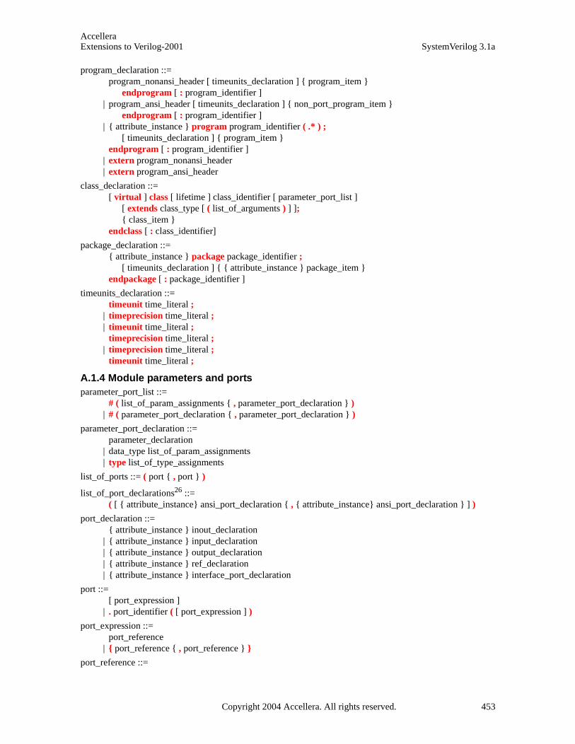
AccelleraExtensions to Verilog-2001 SystemVerilog 3.1a
program_declaration ::= program_nonansi_header [ timeunits_declaration ] { program_item }
endprogram [ : program_identifier ] | program_ansi_header [ timeunits_declaration ] { non_port_program_item }
endprogram [ : program_identifier ] | { attribute_instance } program program_identifier ( .* ) ;
[ timeunits_declaration ] { program_item } endprogram [ : program_identifier ]
| extern program_nonansi_header | extern program_ansi_header
class_declaration ::= [ virtual ] class [ lifetime ] class_identifier [ parameter_port_list ]
[ extends class_type [ ( list_of_arguments ) ] ]; { class_item }
endclass [ : class_identifier]
package_declaration ::= { attribute_instance } package package_identifier ;
[ timeunits_declaration ] { { attribute_instance } package_item } endpackage [ : package_identifier ]
timeunits_declaration ::= timeunit time_literal ;
| timeprecision time_literal ; | timeunit time_literal ;
timeprecision time_literal ; | timeprecision time_literal ;
timeunit time_literal ;
A.1.4 Module parameters and ports parameter_port_list ::=
# ( list_of_param_assignments { , parameter_port_declaration } ) | # ( parameter_port_declaration { , parameter_port_declaration } )
parameter_port_declaration ::= parameter_declaration
| data_type list_of_param_assignments | type list_of_type_assignments
list_of_ports ::= ( port { , port } )
list_of_port_declarations26 ::= ( [ { attribute_instance} ansi_port_declaration { , { attribute_instance} ansi_port_declaration } ] )
port_declaration ::= { attribute_instance } inout_declaration
| { attribute_instance } input_declaration | { attribute_instance } output_declaration | { attribute_instance } ref_declaration | { attribute_instance } interface_port_declaration
port ::= [ port_expression ]
| . port_identifier ( [ port_expression ] )
port_expression ::= port_reference
| { port_reference { , port_reference } }
port_reference ::=
Copyright 2004 Accellera. All rights reserved. 453

AccelleraSystemVerilog 3.1a Extensions to Verilog-2001
port_identifier constant_select
port_direction ::= input | output | inout | ref
net_port_header ::= [ port_direction ] port_type
variable_port_header ::= [ port_direction ] data_type
interface_port_header ::= interface_identifier [ . modport_identifier ]
| interface [ . modport_identifier ]
ansi_port_declaration ::= [ net_port_header | interface_port_header ] port_identifier { unpacked_dimension }
| [ variable_port_header ] port_identifier variable_dimension [ = constant_expression ] | [ net_port_header | variable_port_header ] . port_identifier ( [ expression ] )
A.1.5 Module items module_common_item ::=
module_or_generate_item_declaration | interface_instantiation | program_instantiation | concurrent_assertion_item | bind_directive | continuous_assign | net_alias | initial_construct | final_construct | always_construct
module_item ::= port_declaration ;
| non_port_module_item
module_or_generate_item ::= { attribute_instance } parameter_override
| { attribute_instance } gate_instantiation | { attribute_instance } udp_instantiation | { attribute_instance } module_instantiation | { attribute_instance } module_common_item
module_or_generate_item_declaration ::= package_or_generate_item_declaration
| genvar_declaration | clocking_declaration | default clocking clocking_identifier ;
non_port_module_item ::= generated_module_instantiation
| module_or_generate_item | specify_block | { attribute_instance } specparam_declaration | program_declaration | module_declaration
| timeunits_declaration18
parameter_override ::= defparam list_of_defparam_assignments ;
bind_directive ::= bind hierarchical_identifier constant_select bind_instantiation ;
bind_instantiation ::= program_instantiation
| module_instantiation
454 Copyright 2004 Accellera. All rights reserved .
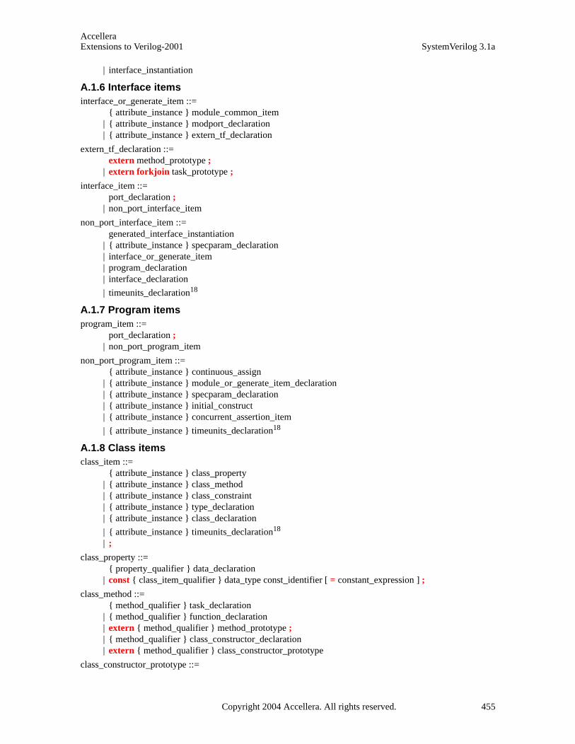
AccelleraExtensions to Verilog-2001 SystemVerilog 3.1a
| interface_instantiation
A.1.6 Interface items interface_or_generate_item ::=
{ attribute_instance } module_common_item | { attribute_instance } modport_declaration | { attribute_instance } extern_tf_declaration
extern_tf_declaration ::= extern method_prototype ;
| extern forkjoin task_prototype ;
interface_item ::= port_declaration ;
| non_port_interface_item
non_port_interface_item ::= generated_interface_instantiation
| { attribute_instance } specparam_declaration | interface_or_generate_item | program_declaration | interface_declaration
| timeunits_declaration18
A.1.7 Program items program_item ::=
port_declaration ; | non_port_program_item
non_port_program_item ::= { attribute_instance } continuous_assign
| { attribute_instance } module_or_generate_item_declaration | { attribute_instance } specparam_declaration | { attribute_instance } initial_construct | { attribute_instance } concurrent_assertion_item
| { attribute_instance } timeunits_declaration18
A.1.8 Class items class_item ::=
{ attribute_instance } class_property | { attribute_instance } class_method | { attribute_instance } class_constraint | { attribute_instance } type_declaration | { attribute_instance } class_declaration
| { attribute_instance } timeunits_declaration18 | ;
class_property ::= { property_qualifier } data_declaration
| const { class_item_qualifier } data_type const_identifier [ = constant_expression ] ;
class_method ::= { method_qualifier } task_declaration
| { method_qualifier } function_declaration | extern { method_qualifier } method_prototype ; | { method_qualifier } class_constructor_declaration | extern { method_qualifier } class_constructor_prototype
class_constructor_prototype ::=
Copyright 2004 Accellera. All rights reserved. 455
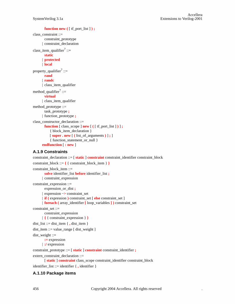
AccelleraSystemVerilog 3.1a Extensions to Verilog-2001
function new ( [ tf_port_list ] ) ;
class_constraint ::= constraint_prototype
| constraint_declaration
class_item_qualifier7 ::= static
| protected | local
property_qualifier7 ::= rand
| randc | class_item_qualifier
method_qualifier7 ::= virtual
| class_item_qualifier
method_prototype ::= task_prototype ;
| function_prototype ;
class_constructor_declaration ::= function [ class_scope ] new [ ( [ tf_port_list ] ) ] ;
{ block_item_declaration } [ super . new [ ( list_of_arguments ) ] ; ] { function_statement_or_null }
endfunction [ : new ]
A.1.9 Constraints constraint_declaration ::= [ static ] constraint constraint_identifier constraint_block
constraint_block ::= { { constraint_block_item } }
constraint_block_item ::= solve identifier_list before identifier_list ;
| constraint_expression
constraint_expression ::= expression_or_dist ;
| expression –> constraint_set | if ( expression ) constraint_set [ else constraint_set ] | foreach ( array_identifier [ loop_variables ] ) constraint_set
constraint_set ::= constraint_expression
| { { constraint_expression } }
dist_list ::= dist_item { , dist_item }
dist_item ::= value_range [ dist_weight ]
dist_weight ::= := expression
| :/ expression
constraint_prototype ::= [ static ] constraint constraint_identifier ;
extern_constraint_declaration ::= [ static ] constraint class_scope constraint_identifier constraint_block
identifier_list ::= identifier { , identifier }
A.1.10 Package items
456 Copyright 2004 Accellera. All rights reserved .

AccelleraExtensions to Verilog-2001 SystemVerilog 3.1a
package_item ::= package_or_generate_item_declaration
| specparam_declaration | anonymous_program
| timeunits_declaration18
package_or_generate_item_declaration ::= net_declaration
| data_declaration | task_declaration | function_declaration | dpi_import_export | extern_constraint_declaration | class_declaration | class_constructor_declaration | parameter_declaration ; | local_parameter_declaration | covergroup_declaration | overload_declaration | concurrent_assertion_item_declaration | ;
anonymous_program ::= program ; { anonymous_program_item } endprogram
anonymous_program_item ::= task_declaration
| function_declaration | class_declaration | covergroup_declaration | class_constructor_declaration | ;
A.2 Declarations
A.2.1 Declaration types
A.2.1.1 Module parameter declarations
local_parameter_declaration ::= localparam data_type_or_implicit list_of_param_assignments ;
parameter_declaration ::= parameter data_type_or_implicit list_of_param_assignments
| parameter type list_of_type_assignments
specparam_declaration ::= specparam [ packed_dimension ] list_of_specparam_assignments ;
A.2.1.2 Port declarations
inout_declaration ::= inout port_type list_of_port_identifiers
input_declaration ::=input port_type list_of_port_identifiers
| input data_type list_of_variable_identifiers
output_declaration ::= output port_type list_of_port_identifiers
| output data_type list_of_variable_port_identifiers
interface_port_declaration ::=
Copyright 2004 Accellera. All rights reserved. 457
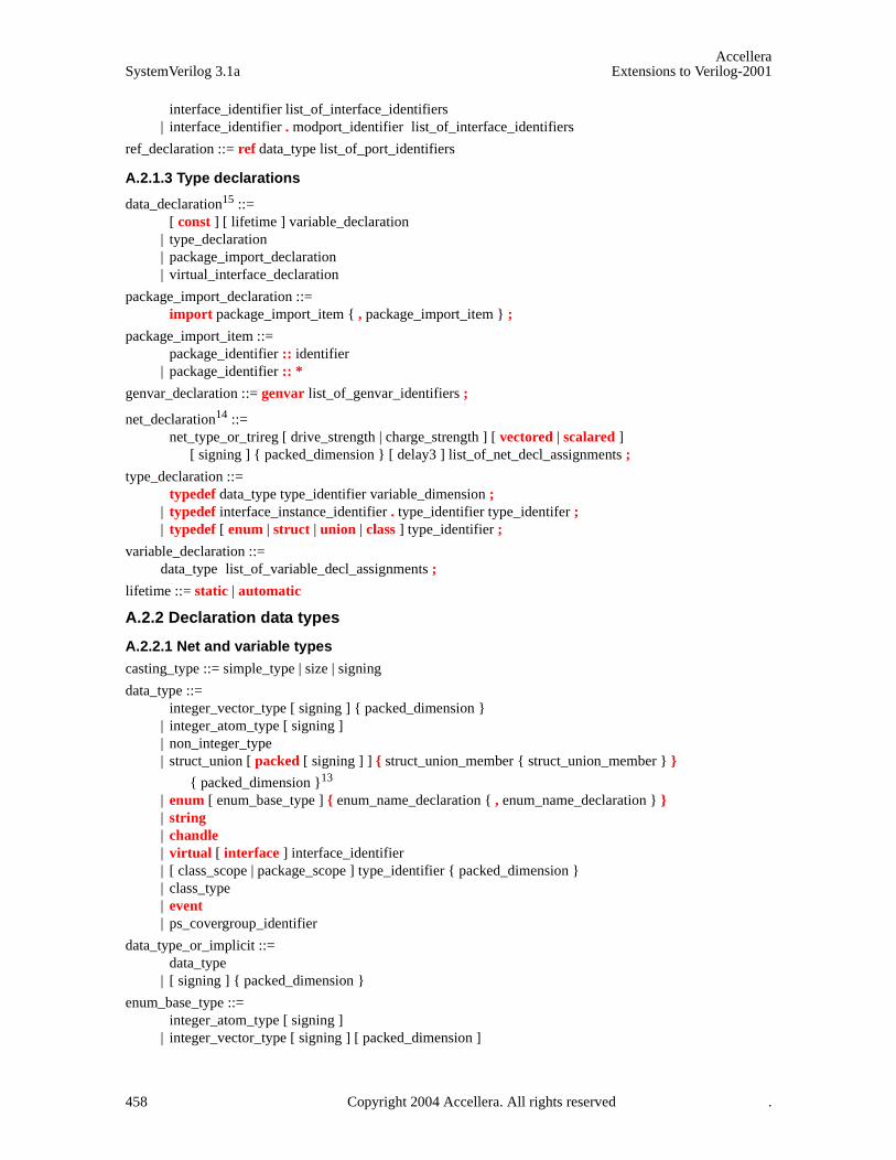
AccelleraSystemVerilog 3.1a Extensions to Verilog-2001
interface_identifier list_of_interface_identifiers | interface_identifier . modport_identifier list_of_interface_identifiers
ref_declaration ::= ref data_type list_of_port_identifiers
A.2.1.3 Type declarations
data_declaration15 ::= [ const ] [ lifetime ] variable_declaration
| type_declaration | package_import_declaration | virtual_interface_declaration
package_import_declaration ::= import package_import_item { , package_import_item } ;
package_import_item ::= package_identifier :: identifier
| package_identifier :: *
genvar_declaration ::= genvar list_of_genvar_identifiers ;
net_declaration14 ::= net_type_or_trireg [ drive_strength | charge_strength ] [ vectored | scalared ]
[ signing ] { packed_dimension } [ delay3 ] list_of_net_decl_assignments ;
type_declaration ::= typedef data_type type_identifier variable_dimension ;
| typedef interface_instance_identifier . type_identifier type_identifer ; | typedef [ enum | struct | union | class ] type_identifier ;
variable_declaration ::= data_type list_of_variable_decl_assignments ;
lifetime ::= static | automatic
A.2.2 Declaration data types
A.2.2.1 Net and variable types
casting_type ::= simple_type | size | signing
data_type ::= integer_vector_type [ signing ] { packed_dimension }
| integer_atom_type [ signing ] | non_integer_type | struct_union [ packed [ signing ] ] { struct_union_member { struct_union_member } }
{ packed_dimension }13 | enum [ enum_base_type ] { enum_name_declaration { , enum_name_declaration } } | string | chandle | virtual [ interface ] interface_identifier | [ class_scope | package_scope ] type_identifier { packed_dimension } | class_type | event | ps_covergroup_identifier
data_type_or_implicit ::= data_type
| [ signing ] { packed_dimension }
enum_base_type ::= integer_atom_type [ signing ]
| integer_vector_type [ signing ] [ packed_dimension ]
458 Copyright 2004 Accellera. All rights reserved .
AccelleraExtensions to Verilog-2001 SystemVerilog 3.1a
| type_identifier [ packed_dimension ]24
enum_name_declaration ::= enum_identifier [ [ integral_number [ : integral_number ] ] ] [ = constant_expression ]
class_scope ::= class_type ::
class_type ::= ps_class_identifier [ parameter_value_assignment ]
{ :: class_identifier [ parameter_value_assignment ] }
integer_type ::= integer_vector_type | integer_atom_type
integer_atom_type ::= byte | shortint | int | longint | integer | time
integer_vector_type ::= bit | logic | reg
non_integer_type ::= shortreal | real | realtime
net_type ::= supply0 | supply1 | tri | triand | trior | tri0 | tri1 | wire | wand | wor
port_type ::= [ net_type_or_trireg ] [ signing ] { packed_dimension }
net_type_or_trireg ::= net_type | trireg
signing ::= signed | unsigned
simple_type ::= integer_type | non_integer_type | ps_type_identifier
struct_union_member27 ::= { attribute_instance } data_type_or_void list_of_variable_identifiers ;
data_type_or_void ::= data_type | void
struct_union ::= struct | union [ tagged ]
A.2.2.2 Strengths
drive_strength ::= ( strength0 , strength1 )
| ( strength1 , strength0 ) | ( strength0 , highz1 ) | ( strength1 , highz0 ) | ( highz0 , strength1 ) | ( highz1 , strength0 )
strength0 ::= supply0 | strong0 | pull0 | weak0
strength1 ::= supply1 | strong1 | pull1 | weak1
charge_strength ::= ( small ) | ( medium ) | ( large )
A.2.2.3 Delays
delay3 ::= # delay_value | # ( mintypmax_expression [ , mintypmax_expression [ , mintypmax_expression ] ] )
delay2 ::= # delay_value | # ( mintypmax_expression [ , mintypmax_expression ] )
delay_value ::= unsigned_number
| real_number | ps_identifier | time_literal
A.2.3 Declaration lists list_of_defparam_assignments ::= defparam_assignment { , defparam_assignment }
list_of_genvar_identifiers ::= genvar_identifier { , genvar_identifier }
list_of_interface_identifiers ::= interface_identifier { unpacked_dimension } { , interface_identifier { unpacked_dimension } }
Copyright 2004 Accellera. All rights reserved. 459
AccelleraSystemVerilog 3.1a Extensions to Verilog-2001
list_of_net_decl_assignments ::= net_decl_assignment { , net_decl_assignment }
list_of_net_identifiers ::= net_identifier { unpacked_dimension } { , net_identifier { unpacked_dimension } }
list_of_param_assignments ::= param_assignment { , param_assignment }
list_of_port_identifiers ::= port_identifier { unpacked_dimension } { , port_identifier { unpacked_dimension } }
list_of_udp_port_identifiers ::= port_identifier { , port_identifier }
list_of_specparam_assignments ::= specparam_assignment { , specparam_assignment }
list_of_tf_variable_identifiers ::= port_identifier variable_dimension [ = expression ] { , port_identifier variable_dimension [ = expression ] }
list_of_type_assignments ::= type_assignment { , type_assignment }
list_of_variable_decl_assignments ::= variable_decl_assignment { , variable_decl_assignment }
list_of_variable_identifiers ::= variable_identifier variable_dimension { , variable_identifier variable_dimension }
list_of_variable_port_identifiers ::= port_identifier variable_dimension [ = constant_expression ] { , port_identifier variable_dimension [ = constant_expression ] }
list_of_virtual_interface_decl ::= variable_identifier [ = interface_instance_identifier ]
{ , variable_identifier [ = interface_instance_identifier ] }
A.2.4 Declaration assignments defparam_assignment ::= hierarchical_parameter_identifier = constant_mintypmax_expression
net_decl_assignment ::= net_identifier { unpacked_dimension } [ = expression ]
param_assignment ::= parameter_identifier { unpacked_dimension } = constant_param_expression
specparam_assignment ::= specparam_identifier = constant_mintypmax_expression
| pulse_control_specparam
type_assignment ::= type_identifier = data_type
pulse_control_specparam ::= PATHPULSE$ = ( reject_limit_value [ , error_limit_value ] ) ;
| PATHPULSE$specify_input_terminal_descriptor$specify_output_terminal_descriptor = ( reject_limit_value [ , error_limit_value ] ) ;
error_limit_value ::= limit_value
reject_limit_value ::= limit_value
limit_value ::= constant_mintypmax_expression
variable_decl_assignment ::= variable_identifier variable_dimension [ = expression ]
| dynamic_array_variable_identifier [ ] [ = dynamic_array_new ] | class_variable_identifier [ = class_new ]
| [ covergroup_variable_identifier ] = new [ ( list_of_arguments ) ]16
class_new20 ::= new [ ( list_of_arguments ) | expression ]
dynamic_array_new ::= new [ expression ] [ ( expression ) ]
A.2.5 Declaration ranges unpacked_dimension ::= [ constant_range ]
| [ constant_expression ]
packed_dimension11 ::= [ constant_range ]
460 Copyright 2004 Accellera. All rights reserved .
AccelleraExtensions to Verilog-2001 SystemVerilog 3.1a
| unsized_dimension
associative_dimension ::= [ data_type ]
| [ * ]
variable_dimension12 ::= { sized_or_unsized_dimension }
| associative_dimension | queue_dimension
queue_dimension ::= [ $ [ : constant_expression ] ]
unsized_dimension11 ::= [ ]
sized_or_unsized_dimension ::= unpacked_dimension | unsized_dimension
A.2.6 Function declarations function_data_type ::= data_type | void
function_data_type_or_implicit ::= function_data_type
| [ signing ] { packed_dimension }
function_declaration ::= function [ lifetime ] function_body_declaration
function_body_declaration ::= function_data_type_or_implicit
[ interface_identifier . | class_scope ] function_identifier ; { tf_item_declaration } { function_statement_or_null } endfunction [ : function_identifier ]
| function_data_type_or_implicit [ interface_identifier . | class_scope ] function_identifier ( [ tf_port_list ] ) ;
{ block_item_declaration } { function_statement_or_null } endfunction [ : function_identifier ]
function_prototype ::= function function_data_type function_identifier ( [ tf_port_list ] )
dpi_import_export ::= import "DPI" [ dpi_function_import_property ] [ c_identifier = ] dpi_function_proto ;
| import "DPI" [ dpi_task_import_property ] [ c_identifier = ] dpi_task_proto ; | export "DPI" [ c_identifier = ] function function_identifier ; | export "DPI" [ c_identifier = ] task task_identifier ;
dpi_function_import_property ::= context | pure
dpi_task_import_property ::= context
dpi_function_proto8,9 ::= function_prototype
dpi_task_proto9 ::= task_prototype
A.2.7 Task declarations task_declaration ::= task [ lifetime ] task_body_declaration
task_body_declaration ::= [ interface_identifier . | class_scope ] task_identifier ; { tf_item_declaration } { statement_or_null } endtask [ : task_identifier ]
| [ interface_identifier . | class_scope ] task_identifier ( [ tf_port_list ] ) ; { block_item_declaration } { statement_or_null }
Copyright 2004 Accellera. All rights reserved. 461
AccelleraSystemVerilog 3.1a Extensions to Verilog-2001
endtask [ : task_identifier ]
tf_item_declaration ::= block_item_declaration
| tf_port_declaration
tf_port_list ::= tf_port_item { , tf_port_item }
tf_port_item ::= { attribute_instance }
[ tf_port_direction ] data_type_or_implicit port_identifier variable_dimension [ = expression ]
tf_port_direction ::= port_direction | const ref
tf_port_declaration ::= { attribute_instance } tf_port_direction data_type_or_implicit list_of_tf_variable_identifiers ;
task_prototype ::= task task_identifier ( [ tf_port_list ] )
A.2.8 Block item declarations block_item_declaration ::=
{ attribute_instance } data_declaration | { attribute_instance } local_parameter_declaration | { attribute_instance } parameter_declaration ; | { attribute_instance } overload_declaration
overload_declaration ::= bind overload_operator function data_type function_identifier ( overload_proto_formals ) ;
overload_operator ::= + | ++ | – | – – | * | ** | / | % | == | != | < | <= | > | >= | =
overload_proto_formals ::= data_type {, data_type}
A.2.9 Interface declarations virtual_interface_declaration ::=
virtual [ interface ] interface_identifier list_of_virtual_interface_decl ;
modport_declaration ::= modport modport_item { , modport_item } ;
modport_item ::= modport_identifier ( modport_ports_declaration { , modport_ports_declaration } )
modport_ports_declaration ::={ attribute_instance } modport_simple_ports_declaration
| { attribute_instance } modport_hierarchical_ports_declaration | { attribute_instance } modport_tf_ports_declaration | { attribute_instance } modport_clocking_declaration
modport_clocking_declaration ::= clocking clocking_identifier
modport_simple_ports_declaration ::= port_direction modport_simple_port { , modport_simple_port }
modport_simple_port ::= port_identifier
| . port_identifier ( [ expression ] )
modport_hierarchical_ports_declaration ::= interface_instance_identifier [ [ constant_expression ] ] . modport_identifier
modport_tf_ports_declaration ::= import_export modport_tf_port { , modport_tf_port }
modport_tf_port ::= method_prototype
| tf_identifier
462 Copyright 2004 Accellera. All rights reserved .
AccelleraExtensions to Verilog-2001 SystemVerilog 3.1a
import_export ::= import | export
A.2.10 Assertion declarations concurrent_assertion_item ::= [ block_identifier : ] concurrent_assertion_statement
concurrent_assertion_statement ::= assert_property_statement
| assume_property_statement | cover_property_statement
assert_property_statement::= assert property ( property_spec ) action_block
assume_property_statement::= assume property ( property_spec ) ;
cover_property_statement::= cover property ( property_spec ) statement_or_null
expect_property_statement ::= expect ( property_spec ) action_block
property_instance ::= ps_property_identifier [ ( [ actual_arg_list ] ) ]
concurrent_assertion_item_declaration ::= property_declaration
| sequence_declaration
property_declaration ::= property property_identifier [ ( [ list_of_formals ] ) ] ;
{ assertion_variable_declaration } property_spec ;
endproperty [ : property_identifier ]
property_spec ::= [clocking_event ] [ disable iff ( expression_or_dist ) ] property_expr
property_expr ::= sequence_expr
| ( property_expr ) | not property_expr | property_expr or property_expr | property_expr and property_expr | sequence_expr |-> property_expr | sequence_expr |=> property_expr | if ( expression_or_dist ) property_expr [ else property_expr ] | property_instance | clocking_event property_expr
sequence_declaration ::= sequence sequence_identifier [ ( [ list_of_formals ] ) ] ;
{ assertion_variable_declaration } sequence_expr ;
endsequence [ : sequence_identifier ]
sequence_expr ::= cycle_delay_range sequence_expr { cycle_delay_range sequence_expr }
| sequence_expr cycle_delay_range sequence_expr { cycle_delay_range sequence_expr }| expression_or_dist [ boolean_abbrev ] | ( expression_or_dist {, sequence_match_item } ) [ boolean_abbrev ] | sequence_instance [ sequence_abbrev ] | ( sequence_expr {, sequence_match_item } ) [ sequence_abbrev ]
Copyright 2004 Accellera. All rights reserved. 463
AccelleraSystemVerilog 3.1a Extensions to Verilog-2001
| sequence_expr and sequence_expr | sequence_expr intersect sequence_expr | sequence_expr or sequence_expr | first_match ( sequence_expr {, sequence_match_item} ) | expression_or_dist throughout sequence_expr | sequence_expr within sequence_expr | clocking_event sequence_expr
cycle_delay_range ::= ## integral_number
| ## identifier | ## ( constant_expression ) | ## [ cycle_delay_const_range_expression ]
sequence_method_call ::= sequence_instance . method_identifier
sequence_match_item ::= operator_assignment
| inc_or_dec_expression | subroutine_call
sequence_instance ::= ps_sequence_identifier [ ( [ actual_arg_list ] ) ]
formal_list_item ::= formal_identifier [ = actual_arg_expr ]
list_of_formals ::= formal_list_item { , formal_list_item }
actual_arg_list ::= actual_arg_expr { , actual_arg_expr }
| . formal_identifier ( actual_arg_expr ) { , . formal_identifier ( actual_arg_expr ) }
actual_arg_expr ::= event_expression
| $
boolean_abbrev ::= consecutive_repetition
| non_consecutive_repetition| goto_repetition
sequence_abbrev ::= consecutive_repetition
consecutive_repetition ::= [* const_or_range_expression ]
non_consecutive_repetition ::= [= const_or_range_expression ]
goto_repetition ::= [-> const_or_range_expression ]
const_or_range_expression ::= constant_expression
| cycle_delay_const_range_expression
cycle_delay_const_range_expression ::= constant_expression : constant_expression
| constant_expression : $
expression_or_dist ::= expression [ dist { dist_list } ]
assertion_variable_declaration ::= data_type list_of_variable_identifiers ;
A.2.11 Covergroup declarations covergroup_declaration ::=
covergroup covergroup_identifier [ ( [ tf_port_list ] ) ] [ coverage_event ] ;
464 Copyright 2004 Accellera. All rights reserved .

AccelleraExtensions to Verilog-2001 SystemVerilog 3.1a
{ coverage_spec_or_option ; } endgroup [ : covergroup_identifier ]
coverage_spec_or_option ::= {attribute_instance} coverage_spec
| {attribute_instance} coverage_option ;
coverage_option ::= option.member_identifier = expression
| type_option.member_identifier = expression
coverage_spec ::= cover_point
| cover_cross
coverage_event ::= clocking_event
| @@( block_event_expression )
block_event_expression :: = block_event_expression or block_event_expression
| begin hierarchical_btf_identifier | end hierarchical_btf_identifier
hierarchical_btf_identifier :: = hierarchical_tf_identifier
| hierarchical_block_identifier | hierarchical _identifier [ class_scope ] method_identifier
cover_point ::= [ cover_point_identifer : ] coverpoint expression [ iff ( expression ) ] bins_or_empty
bins_or_empty ::= { {attribute_instance} { bins_or_options ; } }
| ;
bins_or_options ::= coverage_option
| [ wildcard ] bins_keyword bin_identifier [ [ [ expression ] ] ] = { range_list } [ iff ( expression ) ] | [ wildcard] bins_keyword bin_identifier [ [ ] ] = trans_list [ iff ( expression ) ] | bins_keyword bin_identifier [ [ [ expression ] ] ] = default [ iff ( expression ) ] | bins_keyword bin_identifier = default sequence [ iff ( expression ) ]
bins_keyword::= bins | illegal_bins | ignore_bins
range_list ::= value_range { , value_range }
trans_list ::= ( trans_set ) { , ( trans_set ) }
trans_set ::= trans_range_list => trans_range_list { => trans_range_list }
trans_range_list ::= trans_item
| trans_item [ [* repeat_range ] ] | trans_item [ [–> repeat_range ] ] | trans_item [ [= repeat_range ] ]
trans_item ::= range_list
repeat_range ::= expression
| expression : expression
cover_cross ::= [cover_point_identifer : ] cross list_of_coverpoints [ iff ( expression ) ] select_bins_or_empty
list_of_coverpoints ::= cross_item , cross_item { , cross_item }
cross_item ::= cover_point_identifier
Copyright 2004 Accellera. All rights reserved. 465
AccelleraSystemVerilog 3.1a Extensions to Verilog-2001
| variable_identifier
select_bins_or_empty ::= { { bins_selections_or_option ; } }
| ;
bins_selection_or_option ::= { attribute_instance } coverage_option
| { attribute_instance } bins_selection
bins_selection ::= bins_keyword bin_identifier = select_expression [ iff ( expression ) ]
select_expression ::= select_condition
| ! select_condition | select_expression && select_expression | select_expression || select_expression | ( select_expression )
select_condition ::= binsof ( bins_expression ) [ intersect { open_range_list } ]
bins_expression ::= variable_identifier
| cover_point_identifier [ . bins_identifier ]
open_range_list ::= open_value_range { , open_value_range }
open_value_range ::= value_range21
A.3 Primitive instances
A.3.1 Primitive instantiation and instances gate_instantiation ::=
cmos_switchtype [delay3] cmos_switch_instance { , cmos_switch_instance } ; | enable_gatetype [drive_strength] [delay3] enable_gate_instance { , enable_gate_instance } ; | mos_switchtype [delay3] mos_switch_instance { , mos_switch_instance } ; | n_input_gatetype [drive_strength] [delay2] n_input_gate_instance { , n_input_gate_instance } ; | n_output_gatetype [drive_strength] [delay2] n_output_gate_instance
{ , n_output_gate_instance } ; | pass_en_switchtype [delay2] pass_enable_switch_instance { , pass_enable_switch_instance } ; | pass_switchtype pass_switch_instance { , pass_switch_instance } ; | pulldown [pulldown_strength] pull_gate_instance { , pull_gate_instance } ; | pullup [pullup_strength] pull_gate_instance { , pull_gate_instance } ;
cmos_switch_instance ::= [ name_of_instance ] ( output_terminal , input_terminal , ncontrol_terminal , pcontrol_terminal )
enable_gate_instance ::= [ name_of_instance ] ( output_terminal , input_terminal , enable_terminal )
mos_switch_instance ::= [ name_of_instance ] ( output_terminal , input_terminal , enable_terminal )
n_input_gate_instance ::= [ name_of_instance ] ( output_terminal , input_terminal { , input_terminal } )
n_output_gate_instance ::= [ name_of_instance ] ( output_terminal { , output_terminal } , input_terminal )
pass_switch_instance ::= [ name_of_instance ] ( inout_terminal , inout_terminal )
pass_enable_switch_instance ::= [ name_of_instance ] ( inout_terminal , inout_terminal , enable_terminal )
pull_gate_instance ::= [ name_of_instance ] ( output_terminal )
A.3.2 Primitive strengths pulldown_strength ::=
( strength0 , strength1 )
466 Copyright 2004 Accellera. All rights reserved .

AccelleraExtensions to Verilog-2001 SystemVerilog 3.1a
| ( strength1 , strength0 ) | ( strength0 )
pullup_strength ::= ( strength0 , strength1 )
| ( strength1 , strength0 ) | ( strength1 )
A.3.3 Primitive terminals enable_terminal ::= expression
inout_terminal ::= net_lvalue
input_terminal ::= expression
ncontrol_terminal ::= expression
output_terminal ::= net_lvalue
pcontrol_terminal ::= expression
A.3.4 Primitive gate and switch types cmos_switchtype ::= cmos | rcmos
enable_gatetype ::= bufif0 | bufif1 | notif0 | notif1
mos_switchtype ::= nmos | pmos | rnmos | rpmos
n_input_gatetype ::= and | nand | or | nor | xor | xnor
n_output_gatetype ::= buf | not
pass_en_switchtype ::= tranif0 | tranif1 | rtranif1 | rtranif0
pass_switchtype ::= tran | rtran
A.4 Module, interface and generated instantiation
A.4.1 Instantiation
A.4.1.1 Module instantiation
module_instantiation ::= module_identifier [ parameter_value_assignment ] hierarchical_instance { , hierarchical_instance } ;
parameter_value_assignment ::= # ( list_of_parameter_assignments )
list_of_parameter_assignments ::= ordered_parameter_assignment { , ordered_parameter_assignment }
| named_parameter_assignment { , named_parameter_assignment }
ordered_parameter_assignment ::= param_expression
named_parameter_assignment ::= . parameter_identifier ( [ param_expression ] )
hierarchical_instance ::= name_of_instance ( [ list_of_port_connections ] )
name_of_instance ::= instance_identifier { unpacked_dimension }
list_of_port_connections17 ::= ordered_port_connection { , ordered_port_connection }
| named_port_connection { , named_port_connection }
ordered_port_connection ::= { attribute_instance } [ expression ]
named_port_connection ::= { attribute_instance } . port_identifier [ ( [ expression ] ) ]
| { attribute_instance } .*
A.4.1.2 Interface instantiation
interface_instantiation ::=
Copyright 2004 Accellera. All rights reserved. 467
AccelleraSystemVerilog 3.1a Extensions to Verilog-2001
interface_identifier [ parameter_value_assignment ] hierarchical_instance { , hierarchical_instance } ;
A.4.1.3 Program instantiation
program_instantiation ::= program_identifier [ parameter_value_assignment ] hierarchical_instance { , hierarchical_instance } ;
A.4.2 Generated instantiation
A.4.2.1 Generated module instantiation
generated_module_instantiation ::= generate { generate_module_item } endgenerate
generate_module_item ::= generate_module_conditional_statement
| generate_module_case_statement | generate_module_loop_statement | [ generate_block_identifier : ] generate_module_block | module_or_generate_item
generate_module_conditional_statement ::= if ( constant_expression ) generate_module_item [ else generate_module_item ]
generate_module_case_statement ::= case ( constant_expression ) genvar_module_case_item { genvar_module_case_item }endcase
genvar_module_case_item ::= constant_expression { , constant_expression } : generate_module_item
| default [ : ] generate_module_item
generate_module_loop_statement ::= for ( genvar_decl_assignment ; constant_expression ; genvar_assignment )
generate_module_named_block
genvar_assignment ::= genvar_identifier assignment_operator constant_expression
| inc_or_dec_operator genvar_identifier | genvar_identifier inc_or_dec_operator
genvar_decl_assignment ::= [ genvar ] genvar_identifier = constant_expression
generate_module_named_block ::= begin : generate_block_identifier { generate_module_item } end [ : generate_block_identifier ]
| generate_block_identifier : generate_module_block
generate_module_block ::= begin [ : generate_block_identifier ] { generate_module_item } end [ : generate_block_identifier ]
A.4.2.2 Generated interface instantiation
generated_interface_instantiation ::= generate { generate_interface_item } endgenerate
generate_interface_item ::= generate_interface_conditional_statement
| generate_interface_case_statement | generate_interface_loop_statement | [ generate_block_identifier : ] generate_interface_block | interface_or_generate_item
generate_interface_conditional_statement ::= if ( constant_expression ) generate_interface_item [ else generate_interface_item ]
generate_interface_case_statement ::= case ( constant_expression ) genvar_interface_case_item { genvar_interface_case_item } endcase
genvar_interface_case_item ::=
468 Copyright 2004 Accellera. All rights reserved .

AccelleraExtensions to Verilog-2001 SystemVerilog 3.1a
constant_expression { , constant_expression } : generate_interface_item | default [ : ] generate_interface_item
generate_interface_loop_statement ::= for ( genvar_decl_assignment ; constant_expression ; genvar_assignment )
generate_interface_named_block
generate_interface_named_block ::= begin : generate_block_identifier { generate_interface_item } end [ : generate_block_identifier ]
| generate_block_identifier : generate_interface_block
generate_interface_block ::= begin [ : generate_block_identifier ] { generate_interface_item } end [ : generate_block_identifier ]
A.5 UDP declaration and instantiation
A.5.1 UDP declaration udp_nonansi_declaration ::=
{ attribute_instance } primitive udp_identifier ( udp_port_list ) ;
udp_ansi_declaration ::= { attribute_instance } primitive udp_identifier ( udp_declaration_port_list ) ;
udp_declaration ::= udp_nonansi_declaration udp_port_declaration { udp_port_declaration }
udp_body endprimitive [ : udp_identifier ]
| udp_ansi_declaration udp_body
endprimitive [ : udp_identifier ] | extern udp_nonansi_declaration | extern udp_ansi_declaration | { attribute_instance } primitive udp_identifier ( .* ) ;
{ udp_port_declaration }udp_body
endprimitive [ : udp_identifier ]
A.5.2 UDP ports udp_port_list ::= output_port_identifier , input_port_identifier { , input_port_identifier }
udp_declaration_port_list ::= udp_output_declaration , udp_input_declaration { , udp_input_declaration }
udp_port_declaration ::= udp_output_declaration ;
| udp_input_declaration ; | udp_reg_declaration ;
udp_output_declaration ::= { attribute_instance } output port_identifier
| { attribute_instance } output reg port_identifier [ = constant_expression ]
udp_input_declaration ::= { attribute_instance } input list_of_udp_port_identifiers
udp_reg_declaration ::= { attribute_instance } reg variable_identifier
A.5.3 UDP body udp_body ::= combinational_body | sequential_body
combinational_body ::= table combinational_entry { combinational_entry } endtable
combinational_entry ::= level_input_list : output_symbol ;
Copyright 2004 Accellera. All rights reserved. 469

AccelleraSystemVerilog 3.1a Extensions to Verilog-2001
sequential_body ::= [ udp_initial_statement ] table sequential_entry { sequential_entry } endtable
udp_initial_statement ::= initial output_port_identifier = init_val ;
init_val ::= 1’b0 | 1’b1 | 1’bx | 1’bX | 1’B0 | 1’B1 | 1’Bx | 1’BX | 1 | 0
sequential_entry ::= seq_input_list : current_state : next_state ;
seq_input_list ::= level_input_list | edge_input_list
level_input_list ::= level_symbol { level_symbol }
edge_input_list ::= { level_symbol } edge_indicator { level_symbol }
edge_indicator ::= ( level_symbol level_symbol ) | edge_symbol
current_state ::= level_symbol
next_state ::= output_symbol | -
output_symbol ::= 0 | 1 | x | X
level_symbol ::= 0 | 1 | x | X | ? | b | B
edge_symbol ::= r | R | f | F | p | P | n | N | *
A.5.4 UDP instantiation udp_instantiation ::= udp_identifier [ drive_strength ] [ delay2 ] udp_instance { , udp_instance } ;
udp_instance ::= [ name_of_instance ] ( output_terminal , input_terminal { , input_terminal } )
A.6 Behavioral statements
A.6.1 Continuous assignment and net alias statements continuous_assign ::=
assign [ drive_strength ] [ delay3 ] list_of_net_assignments ; | assign [ delay_control ] list_of_variable_assignments ;
list_of_net_assignments ::= net_assignment { , net_assignment }
list_of_variable_assignments ::= variable_assignment { , variable_assignment }
net_alias ::= alias net_lvalue = net_lvalue { = net_lvalue } ;
net_assignment ::= net_lvalue = expression
A.6.2 Procedural blocks and assignments initial_construct ::= initial statement_or_null
always_construct ::= always_keyword statement
always_keyword ::= always | always_comb | always_latch | always_ff
blocking_assignment ::= variable_lvalue = delay_or_event_control expression
| hierarchical_dynamic_array_variable_identifier = dynamic_array_new | [ implicit_class_handle . | class_scope | package_scope ] hierarchical_variable_identifier
select = class_new | operator_assignment
operator_assignment ::= variable_lvalue assignment_operator expression
assignment_operator ::= = | += | -= | *= | /= | %= | &= | |= | ^= | <<= | >>= | <<<= | >>>=
nonblocking_assignment ::= variable_lvalue <= [ delay_or_event_control ] expression
procedural_continuous_assignment ::= assign variable_assignment
| deassign variable_lvalue | force variable_assignment | force net_assignment | release variable_lvalue
470 Copyright 2004 Accellera. All rights reserved .

AccelleraExtensions to Verilog-2001 SystemVerilog 3.1a
| release net_lvalue
variable_assignment ::= variable_lvalue = expression
A.6.3 Parallel and sequential blocks action_block ::=
statement_or_null | [ statement ] else statement_or_null
seq_block ::= begin [ : block_identifier ] { block_item_declaration } { statement_or_null } end [ : block_identifier ]
par_block ::= fork [ : block_identifier ] { block_item_declaration } { statement_or_null } join_keyword [ : block_identifier ]
join_keyword ::= join | join_any | join_none
A.6.4 Statements statement_or_null ::=
statement | { attribute_instance } ;
statement ::= [ block_identifier : ] { attribute_instance } statement_item
statement_item ::= blocking_assignment ;
| nonblocking_assignment ; | procedural_continuous_assignment ; | case_statement | conditional_statement | inc_or_dec_expression ; | subroutine_call_statement | disable_statement | event_trigger | loop_statement | jump_statement | par_block | procedural_timing_control_statement | seq_block | wait_statement | procedural_assertion_statement | clocking_drive ; | randsequence_statement | randcase_statement | expect_property_statement
function_statement ::= statement
function_statement_or_null ::= function_statement
| { attribute_instance } ;
variable_identifier_list ::= variable_identifier { , variable_identifier }
A.6.5 Timing control statements procedural_timing_control_statement ::=
procedural_timing_control statement_or_null
delay_or_event_control ::= delay_control
Copyright 2004 Accellera. All rights reserved. 471
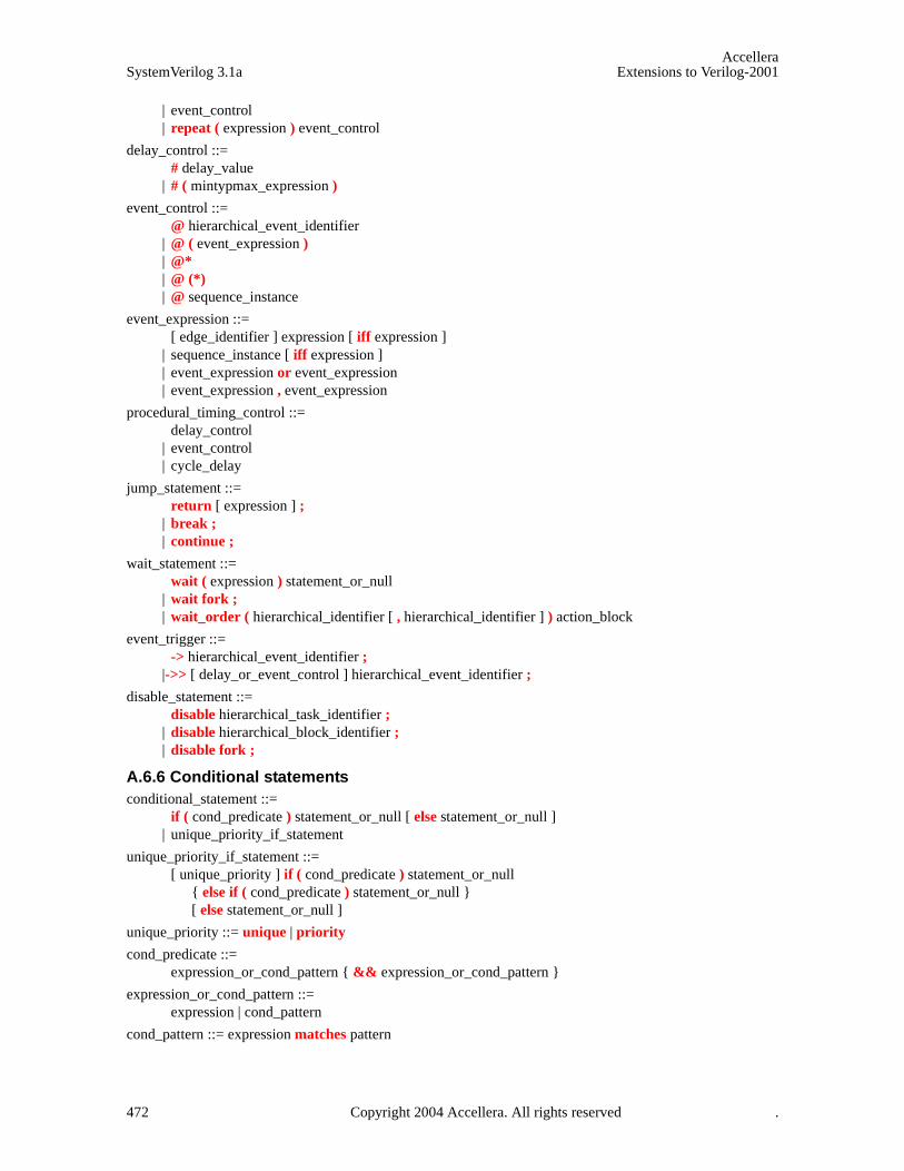
AccelleraSystemVerilog 3.1a Extensions to Verilog-2001
| event_control | repeat ( expression ) event_control
delay_control ::= # delay_value
| # ( mintypmax_expression )
event_control ::= @ hierarchical_event_identifier
| @ ( event_expression ) | @* | @ (*) | @ sequence_instance
event_expression ::= [ edge_identifier ] expression [ iff expression ]
| sequence_instance [ iff expression ] | event_expression or event_expression | event_expression , event_expression
procedural_timing_control ::= delay_control
| event_control| cycle_delay
jump_statement ::= return [ expression ] ;
| break ; | continue ;
wait_statement ::= wait ( expression ) statement_or_null
| wait fork ; | wait_order ( hierarchical_identifier [ , hierarchical_identifier ] ) action_block
event_trigger ::= -> hierarchical_event_identifier ;
|->> [ delay_or_event_control ] hierarchical_event_identifier ;
disable_statement ::= disable hierarchical_task_identifier ;
| disable hierarchical_block_identifier ; | disable fork ;
A.6.6 Conditional statements conditional_statement ::=
if ( cond_predicate ) statement_or_null [ else statement_or_null ] | unique_priority_if_statement
unique_priority_if_statement ::= [ unique_priority ] if ( cond_predicate ) statement_or_null
{ else if ( cond_predicate ) statement_or_null } [ else statement_or_null ]
unique_priority ::= unique | priority
cond_predicate ::= expression_or_cond_pattern { && expression_or_cond_pattern }
expression_or_cond_pattern ::= expression | cond_pattern
cond_pattern ::= expression matches pattern
472 Copyright 2004 Accellera. All rights reserved .
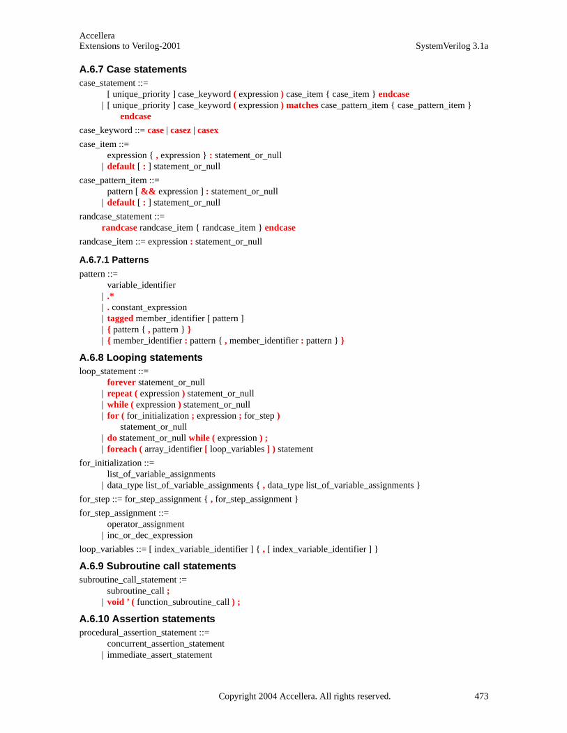
AccelleraExtensions to Verilog-2001 SystemVerilog 3.1a
A.6.7 Case statements case_statement ::=
[ unique_priority ] case_keyword ( expression ) case_item { case_item } endcase | [ unique_priority ] case_keyword ( expression ) matches case_pattern_item { case_pattern_item }
endcase
case_keyword ::= case | casez | casex
case_item ::= expression { , expression } : statement_or_null
| default [ : ] statement_or_null
case_pattern_item ::= pattern [ && expression ] : statement_or_null
| default [ : ] statement_or_null
randcase_statement ::= randcase randcase_item { randcase_item } endcase
randcase_item ::= expression : statement_or_null
A.6.7.1 Patterns
pattern ::= variable_identifier
| .* | . constant_expression | tagged member_identifier [ pattern ] | { pattern { , pattern } } | { member_identifier : pattern { , member_identifier : pattern } }
A.6.8 Looping statements loop_statement ::=
forever statement_or_null | repeat ( expression ) statement_or_null | while ( expression ) statement_or_null | for ( for_initialization ; expression ; for_step )
statement_or_null | do statement_or_null while ( expression ) ; | foreach ( array_identifier [ loop_variables ] ) statement
for_initialization ::= list_of_variable_assignments
| data_type list_of_variable_assignments { , data_type list_of_variable_assignments }
for_step ::= for_step_assignment { , for_step_assignment }
for_step_assignment ::= operator_assignment
| inc_or_dec_expression
loop_variables ::= [ index_variable_identifier ] { , [ index_variable_identifier ] }
A.6.9 Subroutine call statements subroutine_call_statement :=
subroutine_call ; | void ’ ( function_subroutine_call ) ;
A.6.10 Assertion statementsprocedural_assertion_statement ::=
concurrent_assertion_statement | immediate_assert_statement
Copyright 2004 Accellera. All rights reserved. 473
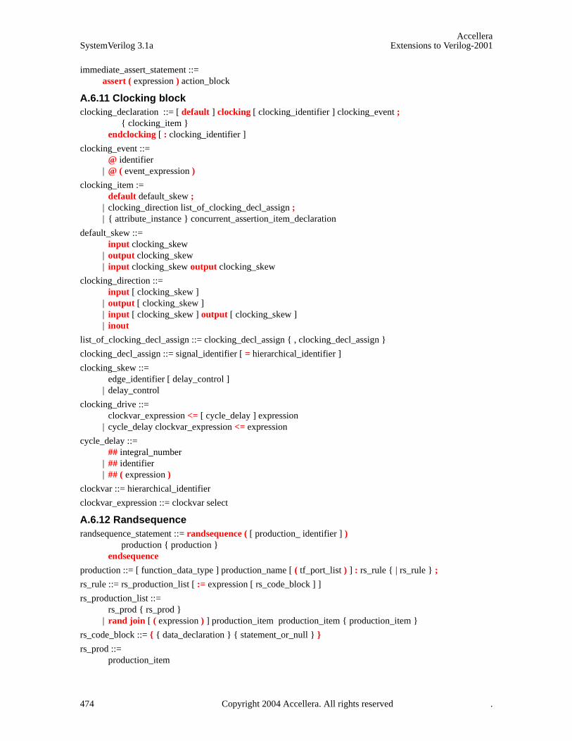
AccelleraSystemVerilog 3.1a Extensions to Verilog-2001
immediate_assert_statement ::= assert ( expression ) action_block
A.6.11 Clocking block clocking_declaration ::= [ default ] clocking [ clocking_identifier ] clocking_event ;
{ clocking_item } endclocking [ : clocking_identifier ]
clocking_event ::= @ identifier
| @ ( event_expression )
clocking_item := default default_skew ;
| clocking_direction list_of_clocking_decl_assign ; | { attribute_instance } concurrent_assertion_item_declaration
default_skew ::= input clocking_skew
| output clocking_skew | input clocking_skew output clocking_skew
clocking_direction ::= input [ clocking_skew ]
| output [ clocking_skew ] | input [ clocking_skew ] output [ clocking_skew ] | inout
list_of_clocking_decl_assign ::= clocking_decl_assign { , clocking_decl_assign }
clocking_decl_assign ::= signal_identifier [ = hierarchical_identifier ]
clocking_skew ::= edge_identifier [ delay_control ]
| delay_control
clocking_drive ::= clockvar_expression <= [ cycle_delay ] expression
| cycle_delay clockvar_expression <= expression
cycle_delay ::= ## integral_number
| ## identifier | ## ( expression )
clockvar ::= hierarchical_identifier
clockvar_expression ::= clockvar select
A.6.12 Randsequence randsequence_statement ::= randsequence ( [ production_ identifier ] )
production { production } endsequence
production ::= [ function_data_type ] production_name [ ( tf_port_list ) ] : rs_rule { | rs_rule } ;
rs_rule ::= rs_production_list [ := expression [ rs_code_block ] ]
rs_production_list ::= rs_prod { rs_prod }
| rand join [ ( expression ) ] production_item production_item { production_item }
rs_code_block ::= { { data_declaration } { statement_or_null } }
rs_prod ::= production_item
474 Copyright 2004 Accellera. All rights reserved .
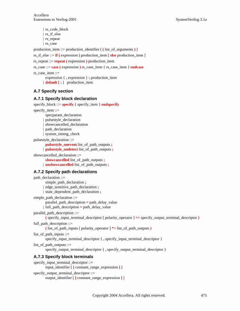
AccelleraExtensions to Verilog-2001 SystemVerilog 3.1a
| rs_code_block | rs_if_else | rs_repeat | rs_case
production_item ::= production_identifier [ ( list_of_arguments ) ]
rs_if_else ::= if ( expression ) production_item [ else production_item ]
rs_repeat ::= repeat ( expression ) production_item
rs_case ::= case ( expression ) rs_case_item { rs_case_item } endcase
rs_case_item ::= expression { , expression } : production_item
| default [ : ] production_item
A.7 Specify section
A.7.1 Specify block declaration specify_block ::= specify { specify_item } endspecify
specify_item ::= specparam_declaration
| pulsestyle_declaration | showcancelled_declaration | path_declaration | system_timing_check
pulsestyle_declaration ::= pulsestyle_onevent list_of_path_outputs ;
| pulsestyle_ondetect list_of_path_outputs ;
showcancelled_declaration ::= showcancelled list_of_path_outputs ;
| noshowcancelled list_of_path_outputs ;
A.7.2 Specify path declarations path_declaration ::=
simple_path_declaration ; | edge_sensitive_path_declaration ; | state_dependent_path_declaration ;
simple_path_declaration ::= parallel_path_description = path_delay_value
| full_path_description = path_delay_value
parallel_path_description ::= ( specify_input_terminal_descriptor [ polarity_operator ] => specify_output_terminal_descriptor )
full_path_description ::= ( list_of_path_inputs [ polarity_operator ] *> list_of_path_outputs )
list_of_path_inputs ::= specify_input_terminal_descriptor { , specify_input_terminal_descriptor }
list_of_path_outputs ::= specify_output_terminal_descriptor { , specify_output_terminal_descriptor }
A.7.3 Specify block terminals specify_input_terminal_descriptor ::=
input_identifier [ [ constant_range_expression ] ]
specify_output_terminal_descriptor ::= output_identifier [ [ constant_range_expression ] ]
Copyright 2004 Accellera. All rights reserved. 475
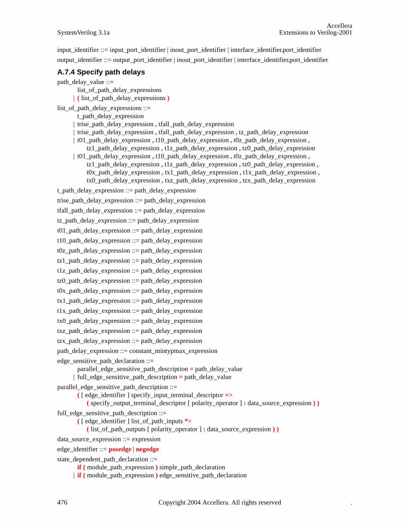
AccelleraSystemVerilog 3.1a Extensions to Verilog-2001
input_identifier ::= input_port_identifier | inout_port_identifier | interface_identifier.port_identifier
output_identifier ::= output_port_identifier | inout_port_identifier | interface_identifier.port_identifier
A.7.4 Specify path delays path_delay_value ::=
list_of_path_delay_expressions | ( list_of_path_delay_expressions )
list_of_path_delay_expressions ::= t_path_delay_expression
| trise_path_delay_expression , tfall_path_delay_expression | trise_path_delay_expression , tfall_path_delay_expression , tz_path_delay_expression | t01_path_delay_expression , t10_path_delay_expression , t0z_path_delay_expression ,
tz1_path_delay_expression , t1z_path_delay_expression , tz0_path_delay_expression | t01_path_delay_expression , t10_path_delay_expression , t0z_path_delay_expression ,
tz1_path_delay_expression , t1z_path_delay_expression , tz0_path_delay_expression , t0x_path_delay_expression , tx1_path_delay_expression , t1x_path_delay_expression , tx0_path_delay_expression , txz_path_delay_expression , tzx_path_delay_expression
t_path_delay_expression ::= path_delay_expression
trise_path_delay_expression ::= path_delay_expression
tfall_path_delay_expression ::= path_delay_expression
tz_path_delay_expression ::= path_delay_expression
t01_path_delay_expression ::= path_delay_expression
t10_path_delay_expression ::= path_delay_expression
t0z_path_delay_expression ::= path_delay_expression
tz1_path_delay_expression ::= path_delay_expression
t1z_path_delay_expression ::= path_delay_expression
tz0_path_delay_expression ::= path_delay_expression
t0x_path_delay_expression ::= path_delay_expression
tx1_path_delay_expression ::= path_delay_expression
t1x_path_delay_expression ::= path_delay_expression
tx0_path_delay_expression ::= path_delay_expression
txz_path_delay_expression ::= path_delay_expression
tzx_path_delay_expression ::= path_delay_expression
path_delay_expression ::= constant_mintypmax_expression
edge_sensitive_path_declaration ::= parallel_edge_sensitive_path_description = path_delay_value
| full_edge_sensitive_path_description = path_delay_value
parallel_edge_sensitive_path_description ::= ( [ edge_identifier ] specify_input_terminal_descriptor =>
( specify_output_terminal_descriptor [ polarity_operator ] : data_source_expression ) )
full_edge_sensitive_path_description ::= ( [ edge_identifier ] list_of_path_inputs *>
( list_of_path_outputs [ polarity_operator ] : data_source_expression ) )
data_source_expression ::= expression
edge_identifier ::= posedge | negedge
state_dependent_path_declaration ::= if ( module_path_expression ) simple_path_declaration
| if ( module_path_expression ) edge_sensitive_path_declaration
476 Copyright 2004 Accellera. All rights reserved .

AccelleraExtensions to Verilog-2001 SystemVerilog 3.1a
| ifnone simple_path_declaration
polarity_operator ::= + | -
A.7.5 System timing checks
A.7.5.1 System timing check commands
system_timing_check ::= $setup_timing_check
| $hold_timing_check | $setuphold_timing_check | $recovery_timing_check | $removal_timing_check | $recrem_timing_check | $skew_timing_check | $timeskew_timing_check | $fullskew_timing_check | $period_timing_check | $width_timing_check | $nochange_timing_check
$setup_timing_check ::= $setup ( data_event , reference_event , timing_check_limit [ , [ notifier ] ] ) ;
$hold_timing_check ::= $hold ( reference_event , data_event , timing_check_limit [ , [ notifier ] ] ) ;
$setuphold_timing_check ::= $setuphold ( reference_event , data_event , timing_check_limit , timing_check_limit
[ , [ notifier ] [ , [ stamptime_condition ] [ , [ checktime_condition ] [ , [ delayed_reference ] [ , [ delayed_data ] ] ] ] ] ] ) ;
$recovery_timing_check ::= $recovery ( reference_event , data_event , timing_check_limit [ , [ notifier ] ] ) ;
$removal_timing_check ::= $removal ( reference_event , data_event , timing_check_limit [ , [ notifier ] ] ) ;
$recrem_timing_check ::= $recrem ( reference_event , data_event , timing_check_limit , timing_check_limit
[ , [ notifier ] [ , [ stamptime_condition ] [ , [ checktime_condition ] [ , [ delayed_reference ] [ , [ delayed_data ] ] ] ] ] ] ) ;
$skew_timing_check ::= $skew ( reference_event , data_event , timing_check_limit [ , [ notifier ] ] ) ;
$timeskew_timing_check ::= $timeskew ( reference_event , data_event , timing_check_limit
[ , [ notifier ] [ , [ event_based_flag ] [ , [ remain_active_flag ] ] ] ] ) ;
$fullskew_timing_check ::= $fullskew ( reference_event , data_event , timing_check_limit , timing_check_limit
[ , [ notifier ] [ , [ event_based_flag ] [ , [ remain_active_flag ] ] ] ] ) ;
$period_timing_check ::= $period ( controlled_reference_event , timing_check_limit [ , [ notifier ] ] ) ;
$width_timing_check ::= $width ( controlled_reference_event , timing_check_limit , threshold [ , [ notifier ] ] ) ;
$nochange_timing_check ::= $nochange ( reference_event , data_event , start_edge_offset ,
end_edge_offset [ , [ notifier ] ] ) ;
Copyright 2004 Accellera. All rights reserved. 477
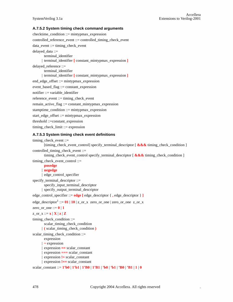
AccelleraSystemVerilog 3.1a Extensions to Verilog-2001
A.7.5.2 System timing check command arguments
checktime_condition ::= mintypmax_expression
controlled_reference_event ::= controlled_timing_check_event
data_event ::= timing_check_event
delayed_data ::= terminal_identifier
| terminal_identifier [ constant_mintypmax_expression ]
delayed_reference ::= terminal_identifier
| terminal_identifier [ constant_mintypmax_expression ]
end_edge_offset ::= mintypmax_expression
event_based_flag ::= constant_expression
notifier ::= variable_identifier
reference_event ::= timing_check_event
remain_active_flag ::= constant_mintypmax_expression
stamptime_condition ::= mintypmax_expression
start_edge_offset ::= mintypmax_expression
threshold ::=constant_expression
timing_check_limit ::= expression
A.7.5.3 System timing check event definitions
timing_check_event ::= [timing_check_event_control] specify_terminal_descriptor [ &&& timing_check_condition ]
controlled_timing_check_event ::= timing_check_event_control specify_terminal_descriptor [ &&& timing_check_condition ]
timing_check_event_control ::= posedge
| negedge | edge_control_specifier
specify_terminal_descriptor ::= specify_input_terminal_descriptor
| specify_output_terminal_descriptor
edge_control_specifier ::= edge [ edge_descriptor { , edge_descriptor } ]
edge_descriptor1 ::= 01 | 10 | z_or_x zero_or_one | zero_or_one z_or_x
zero_or_one ::= 0 | 1
z_or_x ::= x | X | z | Z
timing_check_condition ::= scalar_timing_check_condition
| ( scalar_timing_check_condition )
scalar_timing_check_condition ::= expression
| ~ expression | expression == scalar_constant | expression === scalar_constant | expression != scalar_constant | expression !== scalar_constant
scalar_constant ::= 1’b0 | 1’b1 | 1’B0 | 1’B1 | ’b0 | ’b1 | ’B0 | ’B1 | 1 | 0
478 Copyright 2004 Accellera. All rights reserved .

AccelleraExtensions to Verilog-2001 SystemVerilog 3.1a
A.8 Expressions
A.8.1 Concatenations concatenation ::=
{ expression { , expression } } | { struct_member_label : expression { , struct_member_label : expression } } | { array_member_label : expression { , array_member_label : expression } }
constant_concatenation ::= { constant_expression { , constant_expression } }
| { struct_member_label : constant_expression { , struct_member_label : constant_expression } } | { array_member_label : constant_expression { , array_member_label : constant_expression } }
struct_member_label ::= default
| type_identifier | variable_identifier
array_member_label ::= default
| type_identifier | constant_expression
constant_multiple_concatenation ::= { constant_expression constant_concatenation }
module_path_concatenation ::= { module_path_expression { , module_path_expression } }
module_path_multiple_concatenation ::= { constant_expression module_path_concatenation }
multiple_concatenation ::= { expression concatenation }19
streaming_expression ::= { stream_operator [ slice_size ] stream_concatenation }
stream_operator ::= >> | <<
slice_size ::= ps_type_identifier | constant_expression
stream_concatenation ::= { stream_expression { , stream_expression } }
stream_expression ::= expression [ with [ array_range_expression ] ]
array_range_expression ::= expression
| expression : expression | expression +: expression | expression -: expression
empty_queue22 ::= { }
A.8.2 Subroutine calls
constant_function_call ::= function_subroutine_call25
tf_call ::= ps_or_hierarchical_tf_identifier { attribute_instance } [ ( list_of_arguments ) ]
system_tf_call ::= system_tf_identifier [ ( list_of_arguments ) ]
subroutine_call ::= tf_call
| system_tf_call | method_call | randomize_call
function_subroutine_call ::= subroutine_call
list_of_arguments ::= [ expression ] { , [ expression ] } { , . identifier ( [ expression ] ) }
| . identifier ( [ expression ] ) { , . identifier ( [ expression ] ) }
Copyright 2004 Accellera. All rights reserved. 479

AccelleraSystemVerilog 3.1a Extensions to Verilog-2001
method_call ::= method_call_root . method_call_body
method_call_body ::= method_identifier { attribute_instance } [ ( list_of_arguments ) ]
| built_in_method_call
built_in_method_call ::= array_manipulation_call
| randomize_call
array_manipulation_call ::= array_method_name { attribute_instance }
[ ( list_of_arguments ) ] [ with ( expression ) ]
randomize_call ::= randomize { attribute_instance }
[ ( [ variable_identifier_list | null ] ) ] [ with constraint_block ]
method_call_root ::= expression | implicit_class_handle
array_method_name ::= method_identifier | unique | and | or | xor
A.8.3 Expressions inc_or_dec_expression ::=
inc_or_dec_operator { attribute_instance } variable_lvalue | variable_lvalue { attribute_instance } inc_or_dec_operator
conditional_expression ::= cond_predicate ? { attribute_instance } expression : expression
constant_expression ::= constant_primary
| unary_operator { attribute_instance } constant_primary | constant_expression binary_operator { attribute_instance } constant_expression | constant_expression ? { attribute_instance } constant_expression : constant_expression
constant_mintypmax_expression ::= constant_expression
| constant_expression : constant_expression : constant_expression
constant_param_expression ::= constant_mintypmax_expression | data_type | $
param_expression ::= mintypmax_expression | data_type
constant_range_expression ::= constant_expression
| constant_part_select_range
constant_part_select_range ::= constant_range
| constant_indexed_range
constant_range ::= constant_expression : constant_expression
constant_indexed_range ::= constant_expression +: constant_expression
| constant_expression -: constant_expression
expression ::= primary
| unary_operator { attribute_instance } primary | inc_or_dec_expression | ( operator_assignment )
480 Copyright 2004 Accellera. All rights reserved .

AccelleraExtensions to Verilog-2001 SystemVerilog 3.1a
| expression binary_operator { attribute_instance } expression | conditional_expression | inside_expression | tagged_union_expression
tagged_union_expression ::= tagged member_identifier [ expression ]
inside_expression ::= expression inside { open_range_list }
value_range ::= expression
| [ expression : expression ]
mintypmax_expression ::= expression
| expression : expression : expression
module_path_conditional_expression ::= module_path_expression ? { attribute_instance } module_path_expression : module_path_expression
module_path_expression ::= module_path_primary
| unary_module_path_operator { attribute_instance } module_path_primary | module_path_expression binary_module_path_operator { attribute_instance }
module_path_expression | module_path_conditional_expression
module_path_mintypmax_expression ::= module_path_expression
| module_path_expression : module_path_expression : module_path_expression
range_expression ::= expression | part_select_range
part_select_range ::= constant_range | indexed_range
indexed_range ::= expression +: constant_expression
| expression -: constant_expression
A.8.4 Primaries constant_primary ::=
primary_literal | ps_parameter_identifier | ps_specparam_identifier | genvar_identifier | [ package_scope | class_scope ] enum_identifier | constant_concatentation | constant_multiple_concatenation | constant_function_call | ( constant_mintypmax_expression ) | constant_cast
module_path_primary ::= number
| identifier | module_path_concatenation | module_path_multiple_concatenation | function_subroutine_call | ( module_path_mintypmax_expression )
primary ::= primary_literal
Copyright 2004 Accellera. All rights reserved. 481
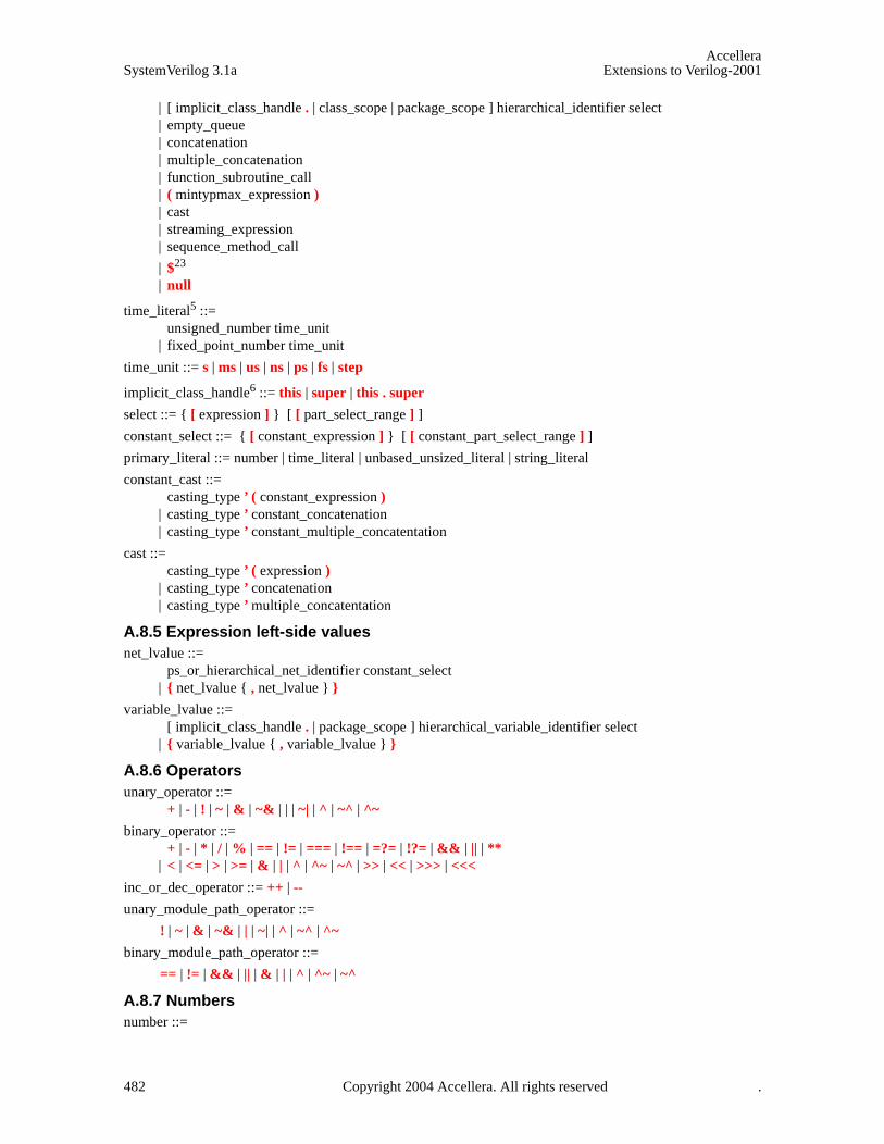
AccelleraSystemVerilog 3.1a Extensions to Verilog-2001
| [ implicit_class_handle . | class_scope | package_scope ] hierarchical_identifier select | empty_queue | concatenation | multiple_concatenation | function_subroutine_call | ( mintypmax_expression ) | cast | streaming_expression | sequence_method_call
| $23 | null
time_literal5 ::= unsigned_number time_unit
| fixed_point_number time_unit
time_unit ::= s | ms | us | ns | ps | fs | step
implicit_class_handle6 ::= this | super | this . super
select ::= { [ expression ] } [ [ part_select_range ] ]
constant_select ::= { [ constant_expression ] } [ [ constant_part_select_range ] ]
primary_literal ::= number | time_literal | unbased_unsized_literal | string_literal
constant_cast ::= casting_type ’ ( constant_expression )
| casting_type ’ constant_concatenation | casting_type ’ constant_multiple_concatentation
cast ::= casting_type ’ ( expression )
| casting_type ’ concatenation | casting_type ’ multiple_concatentation
A.8.5 Expression left-side values net_lvalue ::=
ps_or_hierarchical_net_identifier constant_select | { net_lvalue { , net_lvalue } }
variable_lvalue ::= [ implicit_class_handle . | package_scope ] hierarchical_variable_identifier select
| { variable_lvalue { , variable_lvalue } }
A.8.6 Operators unary_operator ::=
+ | - | ! | ~ | & | ~& | | | ~| | ^ | ~^ | ^~
binary_operator ::= + | - | * | / | % | == | != | === | !== | =?= | !?= | && | || | **
| < | <= | > | >= | & | | | ^ | ^~ | ~^ | >> | << | >>> | <<<
inc_or_dec_operator ::= ++ | --
unary_module_path_operator ::=
! | ~ | & | ~& | | | ~| | ^ | ~^ | ^~
binary_module_path_operator ::=
== | != | && | || | & | | | ^ | ^~ | ~^
A.8.7 Numbers number ::=
482 Copyright 2004 Accellera. All rights reserved .
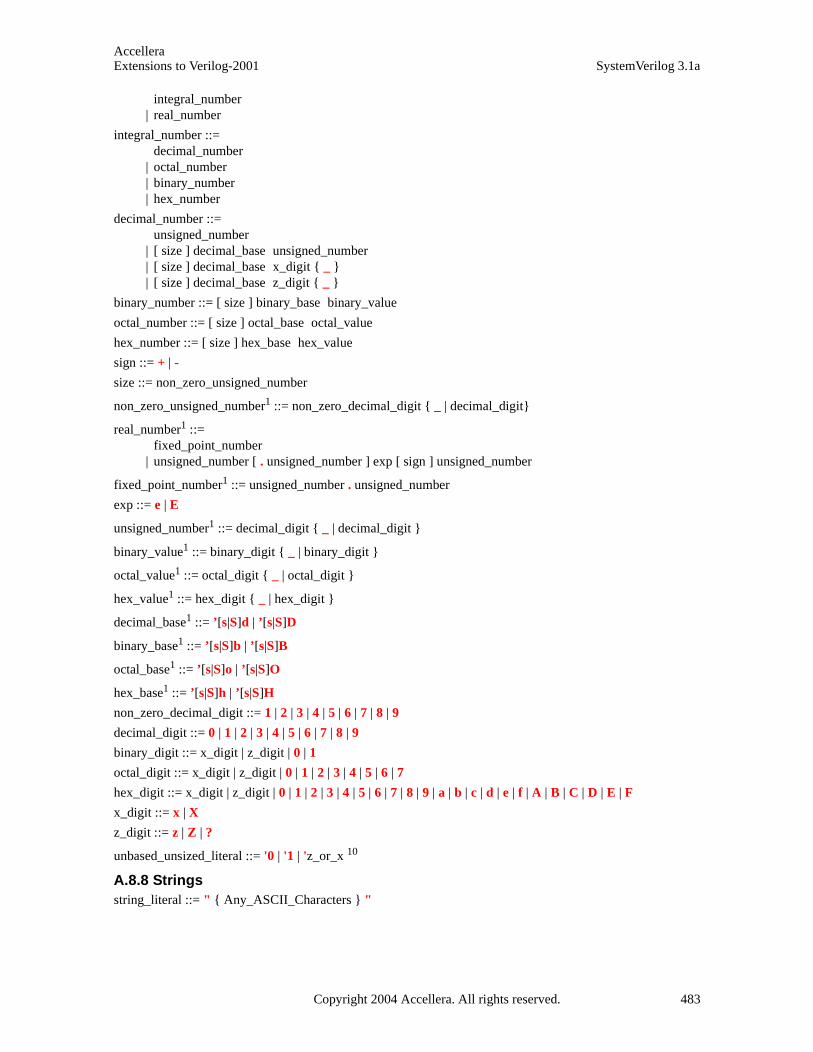
AccelleraExtensions to Verilog-2001 SystemVerilog 3.1a
integral_number | real_number
integral_number ::= decimal_number
| octal_number | binary_number | hex_number
decimal_number ::= unsigned_number
| [ size ] decimal_base unsigned_number | [ size ] decimal_base x_digit { _ } | [ size ] decimal_base z_digit { _ }
binary_number ::= [ size ] binary_base binary_value
octal_number ::= [ size ] octal_base octal_value
hex_number ::= [ size ] hex_base hex_value
sign ::= + | -
size ::= non_zero_unsigned_number
non_zero_unsigned_number1 ::= non_zero_decimal_digit { _ | decimal_digit}
real_number1 ::= fixed_point_number
| unsigned_number [ . unsigned_number ] exp [ sign ] unsigned_number
fixed_point_number1 ::= unsigned_number . unsigned_number
exp ::= e | E
unsigned_number1 ::= decimal_digit { _ | decimal_digit }
binary_value1 ::= binary_digit { _ | binary_digit }
octal_value1 ::= octal_digit { _ | octal_digit }
hex_value1 ::= hex_digit { _ | hex_digit }
decimal_base1 ::= ’[s|S]d | ’[s|S]D
binary_base1 ::= ’[s|S]b | ’[s|S]B
octal_base1 ::= ’[s|S]o | ’[s|S]O
hex_base1 ::= ’[s|S]h | ’[s|S]H
non_zero_decimal_digit ::= 1 | 2 | 3 | 4 | 5 | 6 | 7 | 8 | 9
decimal_digit ::= 0 | 1 | 2 | 3 | 4 | 5 | 6 | 7 | 8 | 9
binary_digit ::= x_digit | z_digit | 0 | 1
octal_digit ::= x_digit | z_digit | 0 | 1 | 2 | 3 | 4 | 5 | 6 | 7
hex_digit ::= x_digit | z_digit | 0 | 1 | 2 | 3 | 4 | 5 | 6 | 7 | 8 | 9 | a | b | c | d | e | f | A | B | C | D | E | F
x_digit ::= x | X
z_digit ::= z | Z | ?
unbased_unsized_literal ::= '0 | '1 | 'z_or_x 10
A.8.8 Strings string_literal ::= " { Any_ASCII_Characters } "
Copyright 2004 Accellera. All rights reserved. 483
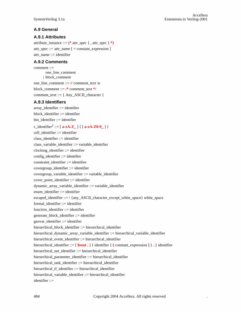
AccelleraSystemVerilog 3.1a Extensions to Verilog-2001
A.9 General
A.9.1 Attributes attribute_instance ::= (* attr_spec { , attr_spec } *)
attr_spec ::= attr_name [ = constant_expression ]
attr_name ::= identifier
A.9.2 Comments comment ::=
one_line_comment | block_comment
one_line_comment ::= // comment_text \n
block_comment ::= /* comment_text */
comment_text ::= { Any_ASCII_character }
A.9.3 Identifiers array_identifier ::= identifier
block_identifier ::= identifier
bin_identifier ::= identifier
c_identifier2 ::= [ a-zA-Z_ ] { [ a-zA-Z0-9_ ] }
cell_identifier ::= identifier
class_identifier ::= identifier
class_variable_identifier ::= variable_identifier
clocking_identifier ::= identifier
config_identifier ::= identifier
constraint_identifier ::= identifier
covergroup_identifier ::= identifier
covergroup_variable_identifier ::= variable_identifier
cover_point_identifier ::= identifier
dynamic_array_variable_identifier ::= variable_identifier
enum_identifier ::= identifier
escaped_identifier ::= \ {any_ASCII_character_except_white_space} white_space
formal_identifier ::= identifier
function_identifier ::= identifier
generate_block_identifier ::= identifier
genvar_identifier ::= identifier
hierarchical_block_identifier ::= hierarchical_identifier
hierarchical_dynamic_array_variable_identifier ::= hierarchical_variable_identifier
hierarchical_event_identifier ::= hierarchical_identifier
hierarchical_identifier ::= [ $root . ] { identifier { [ constant_expression ] } . } identifier
hierarchical_net_identifier ::= hierarchical_identifier
hierarchical_parameter_identifier ::= hierarchical_identifier
hierarchical_task_identifier ::= hierarchical_identifier
hierarchical_tf_identifier ::= hierarchical_identifier
hierarchical_variable_identifier ::= hierarchical_identifier
identifier ::=
484 Copyright 2004 Accellera. All rights reserved .

AccelleraExtensions to Verilog-2001 SystemVerilog 3.1a
simple_identifier | escaped_identifier
index_variable_identifier ::= identifier
interface_identifier ::= identifier
interface_instance_identifier ::= identifier
inout_port_identifier ::= identifier
input_port_identifier ::= identifier
instance_identifier ::= identifier
library_identifier ::= identifier
member_identifier ::= identifier
method_identifier ::= identifier
modport_identifier ::= identifier
module_identifier ::= identifier
net_identifier ::= identifier
output_port_identifier ::= identifier
package_identifier ::= identifier
package_scope ::= package_identifier ::
| $unit ::
parameter_identifier ::= identifier
port_identifier ::= identifier
program_identifier ::= identifier
property_identifier ::= identifier
ps_class_identifier ::= [ package_scope ] class_identifier
ps_covergroup_identifier ::= [ package_scope ] covergroup_identifier
ps_identifier ::= [ package_scope ] identifier
ps_or_hierarchical_net_identifier ::= [ package_scope ] net_identifier | hierarchical_net_identifier
ps_or_hierarchical_tf_identifier ::= [ package_scope ] tf_identifier | hierarchical_tf_identifier
ps_parameter_identifier ::= [ package_scope ] parameter_identifier
ps_property_identifier ::= [ package_scope ] property_identifier
ps_sequence_identifier ::= [ package_scope ] sequence_identifier
ps_specparam_identifier ::= [ package_scope ] specparam_identifier
ps_type_identifier ::= [ package_scope ] type_identifier
sequence_identifier ::= identifier
signal_identifier ::= identifier
simple_identifier2 ::= [ a-zA-Z_ ] { [ a-zA-Z0-9_$ ] }
specparam_identifier ::= identifier
system_tf_identifier3 ::= $[ a-zA-Z0-9_$ ]{ [ a-zA-Z0-9_$ ] }
task_identifier ::= identifier
tf_identifier ::= identifier
terminal_identifier ::= identifier
topmodule_identifier ::= identifier
type_identifier ::= identifier
Copyright 2004 Accellera. All rights reserved. 485
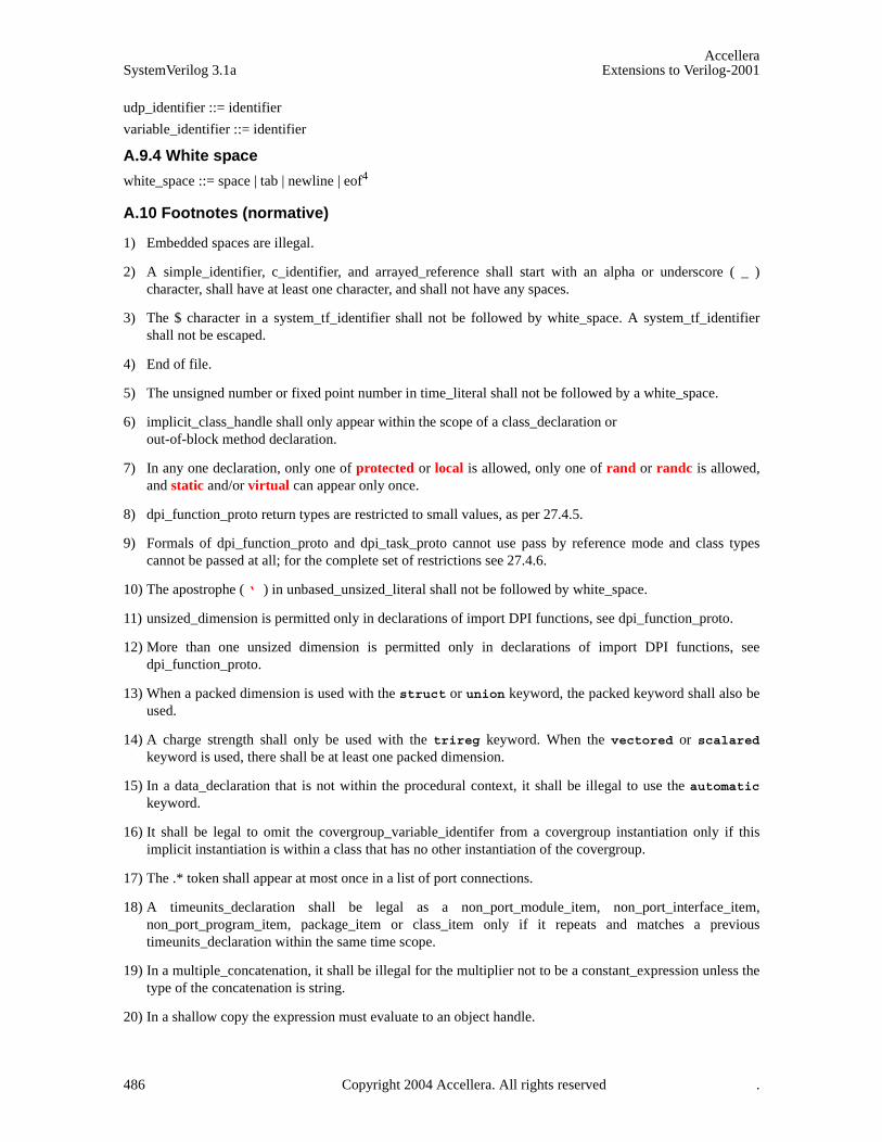
AccelleraSystemVerilog 3.1a Extensions to Verilog-2001
udp_identifier ::= identifier
variable_identifier ::= identifier
A.9.4 White space
white_space ::= space | tab | newline | eof4
A.10 Footnotes (normative)
1) Embedded spaces are illegal.
2) A simple_identifier, c_identifier, and arrayed_reference shall start with an alpha or underscore ( _ )character, shall have at least one character, and shall not have any spaces.
3) The $ character in a system_tf_identifier shall not be followed by white_space. A system_tf_identifiershall not be escaped.
4) End of file.
5) The unsigned number or fixed point number in time_literal shall not be followed by a white_space.
6) implicit_class_handle shall only appear within the scope of a class_declaration orout-of-block method declaration.
7) In any one declaration, only one of protected or local is allowed, only one of rand or randc is allowed,and static and/or virtual can appear only once.
8) dpi_function_proto return types are restricted to small values, as per 27.4.5.
9) Formals of dpi_function_proto and dpi_task_proto cannot use pass by reference mode and class typescannot be passed at all; for the complete set of restrictions see 27.4.6.
10) The apostrophe ( ‘ ) in unbased_unsized_literal shall not be followed by white_space.
11) unsized_dimension is permitted only in declarations of import DPI functions, see dpi_function_proto.
12) More than one unsized dimension is permitted only in declarations of import DPI functions, seedpi_function_proto.
13) When a packed dimension is used with the struct or union keyword, the packed keyword shall also beused.
14) A charge strength shall only be used with the trireg keyword. When the vectored or scalaredkeyword is used, there shall be at least one packed dimension.
15) In a data_declaration that is not within the procedural context, it shall be illegal to use the automatickeyword.
16) It shall be legal to omit the covergroup_variable_identifer from a covergroup instantiation only if thisimplicit instantiation is within a class that has no other instantiation of the covergroup.
17) The .* token shall appear at most once in a list of port connections.
18) A timeunits_declaration shall be legal as a non_port_module_item, non_port_interface_item,non_port_program_item, package_item or class_item only if it repeats and matches a previoustimeunits_declaration within the same time scope.
19) In a multiple_concatenation, it shall be illegal for the multiplier not to be a constant_expression unless thetype of the concatenation is string.
20) In a shallow copy the expression must evaluate to an object handle.
486 Copyright 2004 Accellera. All rights reserved .

AccelleraExtensions to Verilog-2001 SystemVerilog 3.1a
21) It shall be legal to use the $ primary in an open_value_range of the form [ expression : $ ] or [ $ : expression ].
22) { } shall only be legal in the context of a queue.
23) The $ primary shall be legal only in a select for a queue variable or in an open_value_range.
24) A type_identifier shall be legal as an enum_base_type if it denotes an integer_atom_type, with which anadditional packed dimension is not permitted, or an integer_vector_type.
25) In a constant_function_call, all arguments shall be constant_expressions.
26) The list_of_port_declarations syntax is explained in Section 18.8, which also imposes various semanticrestrictions, e.g., a ref port must be of a variable type and an inout port must not be. It shall be illegal toinitialize a port that is not a variable output port.
27) It shall be legal to declare a void struct_union_member only within tagged unions.
Copyright 2004 Accellera. All rights reserved. 487
AccelleraSystemVerilog 3.1a Extensions to Verilog-2001
Annex BKeywords
SystemVerilog reserves the keywords listed in Table .
Legend:
— † keywords added to the IEEE 1364 Verilog-2001 standard as part of SystemVerilog 3.0
— ‡ keywords added to the IEEE 1364 Verilog-2001 standard as part of SystemVerilog 3.1
— * keywords added to the IEEE 1364 Verilog-2001 standard as part of SystemVerilog 3.1a
488 Copyright 2004 Accellera. All rights reserved .

AccelleraExtensions to Verilog-2001 SystemVerilog 3.1a
Table B-1: Reserved keywords
Note: The keyword var is reserved for future extensions.
alias‡ alwaysalways_comb† always_ff† always_latch† andassert† assignassume* automaticbefore‡ beginbind‡ bins* binsof* bit† break† bufbufif0bufif1byte† casecasexcasezcellchandle‡ class‡ clocking‡ cmosconfigconst† constraint‡ context‡ continue† cover‡ covergroup* coverpoint* cross* deassigndefaultdefparamdesigndisabledist‡ do† edgeelseendendcaseendclass‡ endclocking‡ endconfigendfunctionendgenerateendgroup* endinterface†
endmoduleendpackage* endprimitiveendprogram‡ endproperty‡ endspecifyendsequence‡ endtableendtaskenum† eventexpect* export† extends‡ extern† final‡ first_match‡ forforceforeach* foreverforkforkjoin† functiongenerategenvarhighz0highz1ififf† ifnoneignore_bins* illegal_bins* import† incdirincludeinitialinoutinputinside‡ instanceint† integerinterface† intersect‡ joinjoin_any‡ join_none‡ largeliblistlibrarylocal‡ localparamlogic† longint† macromodule
matches* mediummodport† modulenandnegedgenew‡ nmosnornoshowcancellednotnotif0notif1null‡ oroutputpackage* packed† parameterpmosposedgeprimitivepriority† program‡ property‡ protected‡ pull0pull1pulldownpulluppulsestyle_oneventpulsestyle_ondetectpure‡ rand‡ randc‡ randcase* randsequence* rcmosrealrealtimeref‡ regreleaserepeatreturn† rnmosrpmosrtranrtranif0rtranif1scalaredsequence‡ shortint† shortreal† showcancelledsigned
smallsolve‡ specifyspecparamstatic† string‡ strong0strong1struct† super‡ supply0supply1tabletagged* taskthis‡ throughout‡ timetimeprecision† timeunit† trantranif0tranif1tritri0tri1triandtriortriregtype† typedef† union† unique† unsignedusevar‡ vectoredvirtual‡ void† waitwait_order‡ wandweak0weak1whilewildcard* wirewith‡ within‡ worxnorxor
Copyright 2004 Accellera. All rights reserved. 489

AccelleraSystemVerilog 3.1a Extensions to Verilog-2001
Annex C Std Package
(Informative)
The standard package contains system types (see Section 7.10.1). The following types are provided by the stdbuilt-in package. The descriptions of the semantics of these types are defined in the indicated sections.
C.1 Semaphore
The semaphore class is described in Section 13.2 and its prototype is:
class semaphore;function new(int keyCount = 0);task put(int keyCount = 1);task get(int keyCount = 1);function int try_get(int keyCount = 1);
endclass
C.2 Mailbox
The mailbox class is described in Section 13.3 and its prototype is:
Note: dynamic_singular_type below represents a special type that enables run-time type-checking.
class mailbox #(type T = dynamic_singular_type) ;function new(int bound = 0);function int num();task put( T message);function int try_put( T message);task get( ref T message );function int try_get( ref T message );task peek( ref T message );function int try_peek( ref T message );
endclass
C.3 Randomize
The randomize function is described in Section 12.11 and its prototype is:
function int randomize( ... );
The syntax for the randomize function is:
randomize( variable_identifier {, variable_identifier } ) [ with constraint_block ];
C.4 Process
The process class is described in Section 9.9 and its prototype is:
class process;enum state { FINISHED, RUNNING, WAITING, SUSPENDED, KILLED };
static function process self();function state status();task kill();task await();
490 Copyright 2004 Accellera. All rights reserved .

AccelleraExtensions to Verilog-2001 SystemVerilog 3.1a
task suspend();task resume();
endclass
Copyright 2004 Accellera. All rights reserved. 491
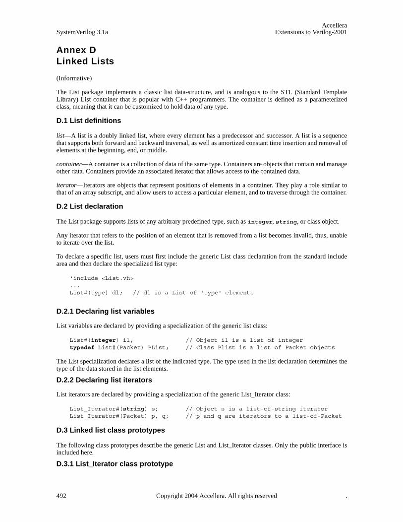
AccelleraSystemVerilog 3.1a Extensions to Verilog-2001
Annex D Linked Lists
(Informative)
The List package implements a classic list data-structure, and is analogous to the STL (Standard TemplateLibrary) List container that is popular with C++ programmers. The container is defined as a parameterizedclass, meaning that it can be customized to hold data of any type.
D.1 List definitions
list—A list is a doubly linked list, where every element has a predecessor and successor. A list is a sequencethat supports both forward and backward traversal, as well as amortized constant time insertion and removal ofelements at the beginning, end, or middle.
container—A container is a collection of data of the same type. Containers are objects that contain and manageother data. Containers provide an associated iterator that allows access to the contained data.
iterator—Iterators are objects that represent positions of elements in a container. They play a role similar tothat of an array subscript, and allow users to access a particular element, and to traverse through the container.
D.2 List declaration
The List package supports lists of any arbitrary predefined type, such as integer, string, or class object.
Any iterator that refers to the position of an element that is removed from a list becomes invalid, thus, unableto iterate over the list.
To declare a specific list, users must first include the generic List class declaration from the standard includearea and then declare the specialized list type:
‘include <List.vh>...List#(type) dl; // dl is a List of 'type' elements
D.2.1 Declaring list variables
List variables are declared by providing a specialization of the generic list class:
List#(integer) il; // Object il is a list of integertypedef List#(Packet) PList; // Class Plist is a list of Packet objects
The List specialization declares a list of the indicated type. The type used in the list declaration determines thetype of the data stored in the list elements.
D.2.2 Declaring list iterators
List iterators are declared by providing a specialization of the generic List_Iterator class:
List_Iterator#(string) s; // Object s is a list-of-string iterator List_Iterator#(Packet) p, q; // p and q are iterators to a list-of-Packet
D.3 Linked list class prototypes
The following class prototypes describe the generic List and List_Iterator classes. Only the public interface isincluded here.
D.3.1 List_Iterator class prototype
492 Copyright 2004 Accellera. All rights reserved .

AccelleraExtensions to Verilog-2001 SystemVerilog 3.1a
class List_Iterator#(parameter type T); extern function void next();extern function void prev();extern function int neq( List_Iterator#(T) iter );extern function int eq( List_Iterator#(T) iter );extern function T data();
endclass
D.3.2 List class prototype
class List#(parameter type T); extern function new();extern function int size();extern function int empty();extern function void push_front( T value );extern function void push_back( T value );extern function T front();extern function T back();extern function void pop_front();extern function void pop_back();extern function List_Iterator#(T) start();extern function List_Iterator#(T) finish();extern function void insert( List_Iterator#(T) position, T value );extern function void insert_range( List_Iterator#(T) position,
first, last );extern function void erase( List_Iterator#(T) position );extern function void erase_range( List_Iterator#(T) first, last );extern function void set( List_Iterator#(T) first, last );extern function void swap( List#(T) lst );extern function void clear();extern function void purge();
endclass
D.4 List_Iterator methods
The List_Iterator class provides methods to iterate over the elements of lists. These methods are describedbelow.
D.4.1 next()
function void next();
next changes the iterator so that it refers to the next element in the list.
D.4.2 prev()
function void prev();
prev changes the iterator so that it refers to the previous element in the list.
D.4.3 eq()
function int eq( List_Iterator#(T) iter );
eq compares two iterators, and returns 1 if both iterators refer to the same list element. Otherwise, it returns 0.
if( i1.eq(i2) ) $display("both iterators refer to the same element");
Copyright 2004 Accellera. All rights reserved. 493
AccelleraSystemVerilog 3.1a Extensions to Verilog-2001
D.4.4 neq()
function int neq( List_Iterator#(T) iter );
neq is the negation of eq(); it compares two iterators, and returns 0 if both iterators refer to the same list ele-ment. Otherwise, it returns 1.
D.4.5 data()
function T data();
data returns the data stored in the element at the given iterator location.
D.5 List methods
The List class provides methods to query the size of the list, obtain iterators to the head or tail of the list,retrieve the data stored in the list, and methods to add, remove, and reorder the elements of the list.
D.5.1 size()
function int size();
size returns the number of elements stored in the list.
while ( list1.size > 0 ) begin // loop while still elements in the list...
end
D.5.2 empty()
function int empty();
empty returns 1 if the number elements stored in the list is zero, 0 otherwise.
if ( list1.empty )$display( "list is empty" );
D.5.3 push_front()
function void push_front( T value );
push_front inserts the specified value at the front of the list.
List#(int) numbers;numbers.push_front(10);numbers.push_front(5); // numbers contains { 5 , 10 }
D.5.4 push_back()
function void push_back( T value );
push_back inserts the specified value at the end of the list.
List#(string) names;names.push_back("Donald");names.push_back("Mickey"); // names contains { "Donald", "Mickey" }
494 Copyright 2004 Accellera. All rights reserved .
AccelleraExtensions to Verilog-2001 SystemVerilog 3.1a
D.5.5 front()
function T front();
front returns the data stored in the first element of the list (valid only if the list is not empty).
D.5.6 back()
function T back();
back returns the data stored in the last element of the list (valid only if the list is not empty).
List#(int) numbers;numbers.push_front(3);numbers.push_front(2);numbers.push_front(1);$display( numbers.front, numbers.back ); // displays 1 3
D.5.7 pop_front()
function void pop_front();
pop_front removes the first element of the list. If the list is empty, this method is illegal and can generate anerror.
D.5.8 pop_back()
function void pop_back();
pop_back removes the last element of the list. If the list is empty, this method is illegal and can generate anerror.
while ( lp.size > 1 ) begin // remove all but the center element from// an odd-sized list lp
lp.pop_front();lp.pop_back();
end
D.5.9 start()
function List_Iterator#(T) start();
start returns an iterator to the position of the first element in the list.
D.5.10 finish()
function List_Iterator#(T) finish();
finish returns an iterator to a position just past the last element in the list. The last element in the last can beaccessed using finish.prev.
List#(int) lst; // display contents of list lst in position orderfor ( List_Iterator#(int) p = lst.start; p.neq(lst.finish); p.next )
$display( p.data );
D.5.11 insert()
function void insert( List_Iterator#(T) position, T value );
Copyright 2004 Accellera. All rights reserved. 495
AccelleraSystemVerilog 3.1a Extensions to Verilog-2001
insert inserts the given data (value) into the list at the position specified by the iterator (before the ele-ment, if any, that was previously at the iterator’s position). If the iterator is not a valid position within the list,then this operation is illegal and can generate an error.
function void add_sort( List#(byte) L, byte value ); for ( List_Iterator#(byte) p = L.start; p.neq(L.finish) ; p.next )
if ( p.data > value ) begin lst.insert( p, value ); // Add to sorted list (ascending order)
return;end
endfunction
D.5.12 insert_range()
function void insert_range( List_Iterator#(T) position, first, last );
insert_range inserts the elements contained in the list range specified by the iterators first and last at thespecified list position (before the element, if any, that was previously at the position iterator). All the elementsfrom first up to, but not including, last are inserted into the list. If the last iterator refers to an element beforethe first iterator, the range wraps around the end of the list. The range iterators can specify a range either inanother list or in the same list as being inserted.
If the position iterator is not a valid position within the list, or if the range iterators are invalid (i.e., they referto different lists or to invalid positions), then this operation is illegal and can generate an error.
D.5.13 erase()
function void erase( List_Iterator#(T) position );
erase removes form the list the element at the specified position. After erase() returns, the position iteratorbecomes invalid.
list1.erase( list1.start ); // same as pop_front
If the position iterator is not a valid position within the list, this operation is illegal and can generate an error.
D.5.14 erase_range()
function void erase_range( List_Iterator#(T) first, last );
erase_range removes from a list the range of elements specified by the first and last iterators. This operationremoves elements from the first iterator’s position up to, but not including, the last iterator’s position. If thelast iterator refers to an element before the first iterator, the range wraps around the end of the list.
list1.erase_range( list1.start, list1.finish ); // Remove all elements from// list1
If the range iterators are invalid (i.e., they refer to different lists or to invalid positions), then this operation isillegal and can generate an error.
D.5.15 set()
function void set( List_Iterator#(T) first, last );
set assigns to the list object the elements that lie in the range specified by the first and last iterators. After thismethod returns, the modified list shall have a size equal to the range specified by first and last. This methodcopies the data from the first iterator’s position up to, but not including, the last iterator’s position. If the lastiterator refers to an element before the first iterator, the range wraps around the end of the list.
list2.set( list1.start, list2.finish ); // list2 is a copy of list1
496 Copyright 2004 Accellera. All rights reserved .

AccelleraExtensions to Verilog-2001 SystemVerilog 3.1a
If the range iterators are invalid (i.e., they refer to different lists or to invalid positions), then this operation isillegal and can generate an error.
D.5.16 swap()
function void swap( List#(T) lst );
swap exchanges the contents of two equal-size lists.
list1.swap( list2 ); // swap the contents of list1 to list2 and vice-versa
Swapping a list with itself has no effect. If the lists are of different sizes, this method can issue a warning.
D.5.17 clear()
function void clear();
clear removes all the elements from a list, but not the list itself (i.e., the list header itself).
list1.clear(); // list1 becomes empty
D.5.18 purge()
function void purge();
purge removes all the list elements (as in clear) and the list itself. This accomplishes the same effect as assign-ing null to the list. A purged list must be re-created using new before it can be used again.
list1.purge(); // same as list1 = null
Copyright 2004 Accellera. All rights reserved. 497
AccelleraSystemVerilog 3.1a Extensions to Verilog-2001
Annex EDPI C-layer
E.1 Overview
The SystemVerilog Direct Programming Interface (DPI) allows direct inter-language function calls betweenSystemVerilog and any foreign programming language with a C function call protocol and linking model:
— Functions implemented in C and given import declarations in SystemVerilog can be called from System-Verilog; such functions are referred to as imported functions.
— Functions implemented in SystemVerilog and specified in export declarations can be called from C; suchfunctions are referred to as exported functions.
— Tasks implemented in SystemVerilog and specified in export declarations can be called from C; such func-tions are referred to as exported tasks.
— Functions implemented in C which can be called from SystemVerilog, and can in turn call exported tasks,are referred to as imported tasks.
The SystemVerilog DPI supports only SystemVerilog data types, which are the sole data types that can crossthe boundary between SystemVerilog and a foreign language in either direction. On the other hand, the datatypes used in C code shall be C types; hence, the duality of types.
A value that is passed through the Direct Programming Interface is specified in SystemVerilog code as a valueof SystemVerilog type, while the same value shall be specified in C code as a value of C type. Therefore, a pairof matching type definitions is required to pass a value through DPI: the SystemVerilog definition and the Cdefinition.
It is the user’s responsibility to provide these matching definitions. A tool (such as a SystemVerilog compiler)can facilitate this by generating C type definitions for the SystemVerilog definitions used in DPI for importedand exported functions.
Some SystemVerilog types are directly compatible with C types; defining a matching C type for them isstraightforward. There are, however, SystemVerilog-specific types, namely packed types (arrays, structures,and unions), 2-state or 4-state, which have no natural correspondence in C. DPI does not require any particularrepresentation of such types and does not impose any restrictions on SystemVerilog implementations. Thisallows implementers to choose the layout and representation of packed types that best suits their simulationperformance.
While not specifying the actual representation of packed types, this C-layer interface defines a canonical repre-sentation of packed 2-state and 4-state arrays. This canonical representation is actually based on legacy VerilogProgramming Language Interface’s (PLI’s) avalue/bvalue representation of 4-state vectors. Library functionsprovide the translation between the representation used in a simulator and the canonical representation ofpacked arrays. There are also functions for bit selects and limited part selects for packed arrays, which do notrequire the use of the canonical representation.
Formal arguments in SystemVerilog can be specified as open arrays solely in import declarations; exportedSystemVerilog functions cannot have formal arguments specified as open arrays. A formal argument is anopen array when a range of one or more of its dimensions is unspecified (denoted in SystemVerilog by usingempty square brackets ([])). This corresponds to a relaxation of the DPI argument-matching rules(Section 27.5.1). An actual argument shall match the corresponding formal argument regardless of the range(s)for its corresponding dimension(s), which facilitates writing generalized C code that can handle SystemVerilogarrays of different sizes.
The C-layer of DPI basically uses normalized ranges. Normalized ranges mean [n-1:0] indexing for thepacked part (packed arrays are restricted to one dimension) and [0:n-1] indexing for a dimension in theunpacked part of an array. Normalized ranges are used for the canonical representation of packed arrays in Cand for System Verilog arrays passed as actual arguments to C, with the exception of actual arguments for open
498 Copyright 2004 Accellera. All rights reserved .

AccelleraExtensions to Verilog-2001 SystemVerilog 3.1a
arrays. The elements of an open array can be accessed in C by using the same range of indices as defined inSystem Verilog for the actual argument for that open array and the same indexing as in SystemVerilog.
Function arguments are generally passed by some form of reference or by value. All formal arguments, exceptopen arrays, are passed by direct reference or value, and, therefore, are directly accessible in C code. Onlysmall values of SystemVerilog input arguments (see Annex E.7.7) are passed by value. Formal argumentsdeclared in SystemVerilog as open arrays are passed by a handle (type svOpenArrayHandle) and are accessi-ble via library functions. Array-querying functions are provided for open arrays.
Depending on the data types used for imported or exported functions, either binary level or C-source levelcompatibility is granted. Binary level is granted for all data types that do not mix SystemVerilog packed andunpacked types and for open arrays which can have both packed and unpacked parts. If a data type that mixesSystemVerilog packed and unpacked types is used, then the C code needs to be re-compiled using the imple-mentation-dependent definitions provided by the vendor.
The C-layer of the Direct Programming Interface provides two include files. The main include file, svdpi.h,is implementation-independent and defines the canonical representation, all basic types, and all interface func-tions. The second include file, svdpi_src.h, defines only the actual representation of packed arrays and,hence, its contents are implementation-dependent. Applications that do not need to include this file are binary-level compatible.
E.2 Naming conventionsAll names introduced by this interface shall conform to the following conventions.
— All names defined in this interface are prefixed with sv or SV_.
— Function and type names start with sv, followed by initially capitalized words with no separators, e.g.,svBitPackedArrRef.
— Names of symbolic constants start with sv_, e.g., sv_x.
— Names of macro definitions start with SV_, followed by all upper-case words separated by a underscore(_), e.g., SV_CANONICAL_SIZE.
E.3 Portability
Depending on the data types used for imported or exported tasks or functions, the C code can be binary-levelor source-level compatible. Applications that do not use SystemVerilog packed types are always binary com-patible. Applications that don’t mix SystemVerilog packed and unpacked types in the same data type can bewritten to guarantee binary compatibility. Open arrays with both packed and unpacked parts are also binarycompatible.
The values of SystemVerilog packed types can be accessed via interface tasks or functions using the canonicalrepresentation of 2-state and 4-state packed arrays, or directly through pointers using the implementation rep-resentation. The former mode assures binary level compatibility; the latter one allows for tool-specific, perfor-mance-oriented tuning of an application, though it also requires recompiling with the implementation-dependent definitions provided by the vendor and shipped with the simulator.
E.3.1 Binary compatibility
Binary compatibility means an application compiled for a given platform shall work with every SystemVerilogsimulator on that platform.
E.3.2 Source-level compatibility
Source-level compatibility means an application needs to be re-compiled for each SystemVerilog simulator andimplementation-specific definitions shall be required for the compilation.
E.4 Include files
The C-layer of the Direct Programming Interface defines two include files corresponding to these two levels of
Copyright 2004 Accellera. All rights reserved. 499
AccelleraSystemVerilog 3.1a Extensions to Verilog-2001
compatibility: svdpi.h and svdpi_src.h.
Binary compatibility of an application depends on the data types of the values passed through the interface. Ifall corresponding type definitions can be written in C without the need to include the svdpi_src.h file, thenan application is binary compatible. If the svdpi_src.h file is required, then the application is not binarycompatible and needs to be recompiled for each simulator of choice.
Applications that pass solely C-compatible data types or standalone packed arrays (both 2-state and 4-state)require only the svdpi.h file and, therefore, are binary compatible with all simulators. Applications that usecomplex data types which are constructed of both SystemVerilog packed arrays and C-compatible types alsorequire the svdpi_src.h file and, therefore, are not binary compatible with all simulators. They are source-level compatible, however. If an application is tuned for a particular vendor-specific representation of packedarrays and therefore needs vendor specific include files, then such an application is not source-level compati-ble.
E.4.1 svdpi.h include file
Applications which use the Direct Programming Interface with C code usually need this main include file. Theinclude file svdpi.h defines the types for canonical representation of 2-state (bit) and 4-state (logic) val-ues and passing references to SystemVerilog data objects. The file also provides function headers and defines anumber of helper macros and constants.
This document fully defines the svdpi.h file. The content of svdpi.h does not depend on any particularimplementation or platform; all simulators shall use the same file. For more details on svdpi.h, seeAnnex E.9.1.
Applications which only use svdpi.h shall be binary-compatible with all SystemVerilog simulators.
E.4.2 svdpi_src.h include file
This is an auxiliary include file. svdpi_src.h defines data structures for implementation-specific representa-tion of 2-state and 4-state SystemVerilog packed arrays. The interface specifies the contents of this file, i.e.,what symbols are defined. The actual definitions of those symbols, however, are implementation-specific andshall be provided by vendors.
Applications that require the svdpi_src.h file are only source-level compatible, i.e., they need to be com-piled with the version of svdpi_src.h provided for a particular implementation of SystemVerilog. If, how-ever, an application makes use of the details of the implementation-specific representation of packed arraysand thus it requires vendor specific include files, then such an application is not source-level compatible.
E.5 Semantic constraints
Note that the constraints expressed here merely restate those expressed in Section 27.4.1.
Formal and actual arguments of both imported tasks or functions and exported tasks or functions are bound bythe principle “What You Specify Is What You Get.” This principle is binding both for the caller and for thecallee, in C code and in SystemVerilog code. For the callee, it guarantees the actual arguments are as specifiedfor the formal ones. For the caller, it means the function call arguments shall conform with the types of the for-mal arguments, which might require type-coercion on the caller side.
Another way to state this is that no compiler (either C or SystemVerilog) can make argument coercionsbetween a caller’s declared formals and the callee’s declared the formals. This is because the callee’s formalarguments are declared in a different language than the caller’s formal arguments; hence there is no visiblerelationship between the two sets of formals. Users are expected to understand all argument relationships andprovide properly matched types on both sides of the interface (see Annex E.6.2).
In SystemVerilog code, the compiler can change the formal arguments of a native SystemVerilog task or func-tion and modify its code accordingly, because of optimizations, compiler pragmas, or command line switches.The situation is different for imported tasks and functions. A SystemVerilog compiler cannot modify the Ccode, perform any coercions, or make any changes whatsoever to the formal arguments of an imported task or
500 Copyright 2004 Accellera. All rights reserved .
AccelleraExtensions to Verilog-2001 SystemVerilog 3.1a
function.
A SystemVerilog compiler shall provide any necessary coercions for the actual arguments of every importedtask and function call. For example, a SystemVerilog compiler might truncate or extend bits of a packed arrayif the widths of the actual and formal arguments are different. Similarly, a C compiler can provide coercion forC types based on the relationship of the arguments in the exported task’s and function’s C prototype (formals)and the exported task’s and function’s C call site (actuals). However, a C compiler cannot provide such coer-cion for SystemVerilog types.
Thus, in each case of an inter-language function call, either C to SystemVerilog or SystemVerilog to C, thecompilers expect but cannot enforce that the types on either side are compatible. It is therefore the user’sresponsibility to ensure that the imported/exported function types exactly match the types of the correspondingtasks or functions in the foreign language.
E.5.1 Types of formal arguments
The principle “What You Specify Is What You Get” guarantees the types of formal arguments of importedfunctions — an actual argument is guaranteed to be of the type specified for the formal argument, with theexception of open arrays (for which unspecified ranges are statically unknown). Formal arguments, other thanopen arrays, are fully defined by imported declaration; they shall have ranges of packed or unpacked arraysexactly as specified in the imported declaration. Only the SystemVerilog declaration site of the imported func-tion is relevant for such formal arguments.
Formal arguments defined as open arrays have the size and ranges of the actual argument, i.e., have the rangesof packed or unpacked arrays exactly as that of the actual argument. The unsized ranges of open arrays aredetermined at a call site; the rest of the type information is specified at the import declaration. See alsoAnnex E.6.1.
So, if a formal argument is declared as bit [15:8] b [], then it is the import declaration which specifies theformal argument is an unpacked array of packed bit array with bounds 15 to 8, while the actual argument usedat a particular call site defines the bounds for the unpacked part for that call.
E.5.2 input arguments
Formal arguments specified in SystemVerilog as input must not be modified by the foreign language code.See also Section 27.4.1.2.
E.5.3 output arguments
The initial values of formal arguments specified in SystemVerilog as output are undetermined and implemen-tation-dependent. See also Section 27.4.1.2.
E.5.4 Value changes for output and inout arguments
The SystemVerilog simulator is responsible for handling value changes for output and inout arguments.Such changes shall be detected and handled after the control returns from C code to SystemVerilog code.
E.5.5 context and non-context tasks and functions
Also refer to Section 27.4.3.
Some DPI imported tasks or functions or other interface functions called from them require that the context oftheir call be known. It takes special instrumentation of their call instances to provide such context; for exam-ple, a variable referring to the “current instance” might need to be set. To avoid any unnecessary overhead,imported tasks and function calls in SystemVerilog code are not instrumented unless the imported tasks orfunction is specified as context in its SystemVerilog import declaration.
All DPI export tasks and functions require that the context of their call is known. This occurs since SystemVer-ilog task and function declarations always occur in instantiable scopes, hence allowing a multiplicity of uniquetask and function instances in the simulator’s elaborated database. Thus, there is no such thing as a non-contextexport task or function.
Copyright 2004 Accellera. All rights reserved. 501
AccelleraSystemVerilog 3.1a Extensions to Verilog-2001
For the sake of simulation performance, a non-context imported task or function call shall not block System-Verilog compiler optimizations. An imported task or function not specified as context shall not access any dataobjects from SystemVerilog other then its actual arguments. Only the actual arguments can be affected (read orwritten) by its call. Therefore, a call of non-context imported task or function is not a barrier for optimizations.A context imported task or function, however, can access (read or write) any SystemVerilog data objects bycalling PLI/VPI, nor by calling an embedded export task or function. Therefore, a call to a context task orfunction is a barrier for SystemVerilog compiler optimizations.
Only the calls of context imported tasks and functions are properly instrumented and cause conservative opti-mizations; therefore, only those tasks and functions can safely call all functions from other APIs, includingPLI and VPI functions or exported SystemVerilog functions. For imported task or functions not specified ascontext, the effects of calling PLI, VPI, or SystemVerilog functions can be unpredictable and such calls cancrash if the callee requires a context that has not been properly set.
Special DPI utility functions exist that allow imported task and functions to retrieve and operate on their con-text. For example, the C implementation of an imported task or function can use svGetScope() to retrieve ansvScope corresponding to the instance scope of its corresponding SystemVerilog import declaration. SeeAnnex E.8 for more details.
E.5.6 pure functions
See also Section 27.4.2.
Only non-void functions with no output or inout arguments can be specified as pure. Functions specifiedas pure in their corresponding SystemVerilog import declarations shall have no side effects; their results needto depend solely on the values of their input arguments. Calls to such functions can be removed by SystemVer-ilog compiler optimizations or replaced with the values previously computed for the same values of the inputarguments.
Specifically, a pure function is assumed not to directly or indirectly (i.e., by calling other functions):
— perform any file operations
— read or write anything in the broadest possible meaning, includes i/o, environment variables, objects fromthe operating system or from the program or other processes, shared memory, sockets, etc.
— access any persistent data, like global or static variables.
If a pure function does not obey the above restrictions, SystemVerilog compiler optimizations can lead tounexpected behavior, due to eliminated calls or incorrect results being used.
E.5.7 Memory management
See also Section 27.4.1.4.
The memory spaces owned and allocated by C code and SystemVerilog code are disjoined. Each side isresponsible for its own allocated memory. Specifically, C code shall not free the memory allocated by System-Verilog code (or the SystemVerilog compiler) nor expect SystemVerilog code to free the memory allocated byC code (or the C compiler). This does not exclude scenarios in which C code allocates a block of memory, thenpasses a handle (i.e., a pointer) to that block to SystemVerilog code, which in turn calls a C function thatdirectly (if it is the standard function free) or indirectly frees that block.
NOTE—In this last scenario, a block of memory is allocated and freed in C code, even when the standard functions malloc and free are called directly from SystemVerilog code.
E.6 Data types
This section defines the data types of the C-layer of the Direct Programming Interface.
E.6.1 Limitations
502 Copyright 2004 Accellera. All rights reserved .
AccelleraExtensions to Verilog-2001 SystemVerilog 3.1a
Packed arrays can have an arbitrary number of dimensions; though they are eventually always equivalent to aone-dimensional packed array and treated as such. If the packed part of an array in the type of a formal argu-ment in SystemVerilog is specified as multi-dimensional, the SystemVerilog compiler linearizes it. Althoughthe original ranges are generally preserved for open arrays, if the actual argument has a multidimensionalpacked part of the array, it shall be normalized into an equivalent one-dimensional packed array.
NOTE—The actual argument can have both packed and unpacked parts of an array; either can be multidimensional.
E.6.2 Duality of types: SystemVerilog types vs. C types
A value that crosses the Direct Programming Interface is specified in SystemVerilog code as a value of Sys-temVerilog type, while the same value shall be specified in C code as a value of C type. Therefore, each datatype that is passed through the Direct Programming Interface requires two matching type definitions: the Sys-temVerilog definition and C definition.
The user needs to provide such matching definitions. Specifically, for each SystemVerilog type used in theimport declarations or export declarations in SystemVerilog code, the user shall provide the equivalent typedefinition in C reflecting the argument passing mode for the particular type of SystemVerilog value and thedirection (input, output, or inout) of the formal SystemVerilog argument. For values passed by reference,a generic pointer void * can be used (conveniently typedefed in svdpi.h or svdpi_src.h) withoutknowing the actual representation of the value.
E.6.3 Data representation
DPI imposes the following additional restrictions on the representation of SystemVerilog data types.
— SystemVerilog types that are not packed and that do not contained packed elements have C compatible rep-resentation.
— Basic integer and real data types are represented as defined in Annex E.6.4.
— Enumeration types are represented as the types associated with them. Enumerated names are not availableon C side of interface.
— Representation of packed types is implementation-dependent.
— Unpacked arrays embedded in a structure have C compatible layout regardless of the type of elements.Similarly, standalone arrays passed as actuals to a sized formal argument have C compatible representa-tion.
— Standalone array passed as an actual to an open array formal
— if the element type is scalar or packed then the representation is implementation dependent
— otherwise the representation is C compatible. Therefore an element of an array shall have the same rep-resentation as an individual value of the same type. Hence, an array’s elements can be accessed from C code via normal C array indexing similarly to doing so for individual values.
— The natural order of elements for each dimension in the layout of an unpacked array shall be used, i.e., ele-ments with lower indices go first. For SystemVerilog range [L:R], the element with SystemVerilog indexmin(L,R) has the C index 0 and the element with SystemVerilog index max(L,R) has the C indexabs(L-R).
NOTE—This does not actually impose any restrictions on how unpacked arrays are implemented; it only says an array thatdoes not satisfy this condition shall not be passed as an actual argument for a formal argument which is a sized array; it canbe passed, however, for a formal argument which is an unsized (i.e., open) array. Therefore, the correctness of an actualargument might be implementation-dependent. Nevertheless, an open array provides an implementation-independent solu-tion; this seems to be a reasonable trade-off.
E.6.4 Basic types
Table E-1 defines the mapping between the basic SystemVerilog data types and the corresponding C types.
Copyright 2004 Accellera. All rights reserved. 503

AccelleraSystemVerilog 3.1a Extensions to Verilog-2001
†Encodings for bit and logic are given in file svdpi.h. Refer to Annex E.9.1.1.
The DPI interface also supports the SystemVerilog and C unsigned integer data types that correspond to themappings Table E-1 shows for their signed equivalents.
Note that input mode arguments of type byte unsigned and shortint unsigned are not equivalent tobit[7:0] or bit[15:0], respectively, since the former are passed as C types unsigned char andunsigned short and the latter are passed as C unsigned int (i.e., svBitVec32). A similar lack of equiva-lence applies to passing such parameters by reference for output and inout modes.
The representation of SystemVerilog-specific data types like packed bit and logic arrays is implementation-dependent and generally transparent to the user. Nevertheless, for the sake of performance, applications can betuned for a specific implementation and make use of the actual representation used by that implementation;such applications shall not be binary compatible, however.
E.6.5 Normalized ranges
Packed arrays are treated as one-dimensional; the unpacked part of an array can have an arbitrary number ofdimensions. Normalized ranges mean [n-1:0] indexing for the packed part and [0:n-1] indexing for adimension of the unpacked part of an array. Normalized ranges are used for accessing all arguments but openarrays. The canonical representation of packed arrays also uses normalized ranges.
E.6.6 Mapping between SystemVerilog ranges and normalized ranges
The SystemVerilog ranges for a formal argument specified as an open array are those of the actual argumentfor a particular call. Open arrays are accessible, however, by using their original ranges and the same indexingas in the SystemVerilog code.
For all other types of arguments, i.e., all arguments but open arrays, the SystemVerilog ranges are defined inthe corresponding SystemVerilog import or export declaration. Normalized ranges are used for accessing sucharguments in C code. The mapping between SystemVerilog ranges and normalized ranges is defined as fol-lows.
1) If a packed part of an array has more than one dimension, it is linearized as specified by the equivalence ofpacked types (see Section 4.2).
Table E-1: Mapping data types
SystemVerilog type C type
byte char
shortint short int
int int
longint long long
real double
shortreal float
chandle void*
string char*
bit† unsigned char
logic† unsigned char
504 Copyright 2004 Accellera. All rights reserved .
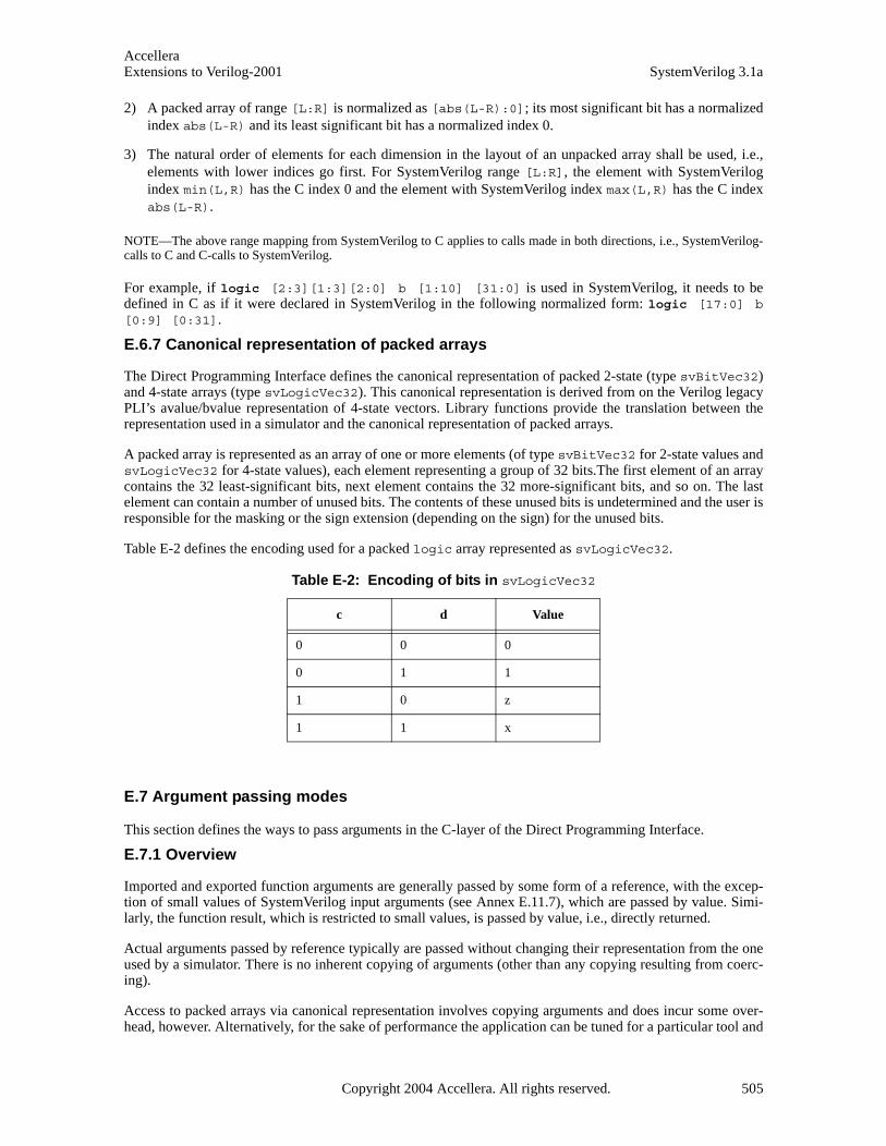
AccelleraExtensions to Verilog-2001 SystemVerilog 3.1a
2) A packed array of range [L:R] is normalized as [abs(L-R):0]; its most significant bit has a normalizedindex abs(L-R) and its least significant bit has a normalized index 0.
3) The natural order of elements for each dimension in the layout of an unpacked array shall be used, i.e.,elements with lower indices go first. For SystemVerilog range [L:R], the element with SystemVerilogindex min(L,R) has the C index 0 and the element with SystemVerilog index max(L,R) has the C indexabs(L-R).
NOTE—The above range mapping from SystemVerilog to C applies to calls made in both directions, i.e., SystemVerilog-calls to C and C-calls to SystemVerilog.
For example, if logic [2:3][1:3][2:0] b [1:10] [31:0] is used in SystemVerilog, it needs to bedefined in C as if it were declared in SystemVerilog in the following normalized form: logic [17:0] b[0:9] [0:31].
E.6.7 Canonical representation of packed arrays
The Direct Programming Interface defines the canonical representation of packed 2-state (type svBitVec32)and 4-state arrays (type svLogicVec32). This canonical representation is derived from on the Verilog legacyPLI’s avalue/bvalue representation of 4-state vectors. Library functions provide the translation between therepresentation used in a simulator and the canonical representation of packed arrays.
A packed array is represented as an array of one or more elements (of type svBitVec32 for 2-state values andsvLogicVec32 for 4-state values), each element representing a group of 32 bits.The first element of an arraycontains the 32 least-significant bits, next element contains the 32 more-significant bits, and so on. The lastelement can contain a number of unused bits. The contents of these unused bits is undetermined and the user isresponsible for the masking or the sign extension (depending on the sign) for the unused bits.
Table E-2 defines the encoding used for a packed logic array represented as svLogicVec32.
E.7 Argument passing modes
This section defines the ways to pass arguments in the C-layer of the Direct Programming Interface.
E.7.1 Overview
Imported and exported function arguments are generally passed by some form of a reference, with the excep-tion of small values of SystemVerilog input arguments (see Annex E.11.7), which are passed by value. Simi-larly, the function result, which is restricted to small values, is passed by value, i.e., directly returned.
Actual arguments passed by reference typically are passed without changing their representation from the oneused by a simulator. There is no inherent copying of arguments (other than any copying resulting from coerc-ing).
Access to packed arrays via canonical representation involves copying arguments and does incur some over-head, however. Alternatively, for the sake of performance the application can be tuned for a particular tool and
Table E-2: Encoding of bits in svLogicVec32
c d Value
0 0 0
0 1 1
1 0 z
1 1 x
Copyright 2004 Accellera. All rights reserved. 505
AccelleraSystemVerilog 3.1a Extensions to Verilog-2001
access the packed arrays directly through pointers using implementation representation, which could compro-mise binary and/or source compatibility. Data can be, however, moved around (copied, stored, retrieved) with-out using canonical representation while preserving binary or source level compatibility at the same time. Thisis possible by using pointers and size of data and when the detailed knowledge of the data representation is notrequired.
NOTE—This provides some degree of flexibility and allows the user to control the trade-off of performance vs. portability.
Formal arguments, except open arrays, are passed by direct reference or value, and, therefore, are directlyaccessible in C code. Formal arguments declared in SystemVerilog as open arrays are passed by a handle (typesvOpenArrayHandle) and are accessible via library functions.
E.7.2 Calling SystemVerilog tasks and functions from C
There is no difference in argument passing between calls from SystemVerilog to C and calls from C to System-Verilog. Tasks and functions exported from SystemVerilog cannot have open arrays as arguments. Apart fromthis restriction, the same types of formal arguments can be declared in SystemVerilog for exported tasks andfunctions and imported tasks and functions. A task or function exported from SystemVerilog shall have thesame function header in C as would an imported function with the same function result type and same formalargument list. In the case of arguments passed by reference, an actual argument to SystemVerilog task andfunction called from C shall be allocated using the same layout of data as SystemVerilog uses for that type ofargument; the caller is responsible for the allocation. It can be done while preserving the binary compatibility,see Annex E.11.5 and Annex E.11.11.
Calling a SystemVerilog task from C is the same as calling a SystemVerilog function from C with the excep-tion that the return type of an exported task is an int value which has a special meaning related to disable state-ments. Please see Section 27.8 for details on disable processing by DPI imported tasks and functions.
E.7.3 Argument passing by value
Only small values of formal input arguments (see Annex E.11.7) are passed by value. Function results are alsodirectly passed by value. The user needs to provide the C-type equivalent to the SystemVerilog type of a for-mal argument if an argument is passed by value.
E.7.4 Argument passing by reference
For arguments passed by reference, their original simulator-defined representation shall be used and a refer-ence (a pointer) to the actual data object is passed. The actual argument is usually allocated by a caller. Thecaller can also pass a reference to an object already allocated somewhere else, for example, its own formalargument passed by reference.
If an argument of type T is passed by reference, the formal argument shall be of type T*. However, packedarrays can also be passed using generic pointers void* (typedefed accordingly to svBitPackedArrRef orsvLogicPackedArrRef).
E.7.5 Allocating actual arguments for SystemVerilog-specific types
This is relevant only for calling exported SystemVerilog functions from C code. The caller is responsible forallocating any actual arguments that are passed by reference.
Static allocation requires knowledge of the relevant data type. If such a type involves SystemVerilog packedarrays, their actual representation needs to be known to C code; thus, the file svdpi_src.h needs to beincluded, which makes the C code implementation-dependent and not binary compatible.
Sometimes binary compatibility can be achieved by using dynamic allocation functions. The functionssvSizeOfLogicPackedArr() and svSizeOfBitPackedArr() provide the size of the actual representa-tion of a packed array, which can be used for the dynamic allocation of an actual argument without compro-mising the portability (see Annex E.11.11). Such a technique does not work if a packed array is a part ofanother type.
E.7.6 Argument passing by handle—open arrays
506 Copyright 2004 Accellera. All rights reserved .
AccelleraExtensions to Verilog-2001 SystemVerilog 3.1a
Arguments specified as open (unsized) arrays are always passed by a handle, regardless of direction of the Sys-temVerilog formal argument, and are accessible via library functions. The actual implementation of a handle issimulator-specific and transparent to the user. A handle is represented by the generic pointer void * (type-defed to svOpenArrayHandle). Arguments passed by handle shall always have a const qualifier, becausethe user shall not modify the contents of a handle.
E.7.7 input arguments
input arguments of imported functions implemented in C shall always have a const qualifier.
input arguments, with the exception of open arrays, are passed by value or by reference, depending on thesize. ‘Small’ values of formal input arguments are passed by value. The following data types are consideredsmall:
— byte, shortint, int, longint, real, shortreal
— chandle, string
— bit (i.e., 2-state) packed arrays up to 32 bits (canonical representation shall be used, like for a functionresult; thus a small packed bit array shall be represented as const svBitVec32)
input arguments of other types are passed by reference.
If an input argument is a packed bit array passed by value, its value shall be represented using the canonicalrepresentation svBitVec32. If the size is smaller than 32 bits, the most significant bits are unused and theircontents are undetermined. The user is responsible for the masking or the sign extension, depending on thesign, for the unused bits.
E.7.8 inout and output arguments
inout and output arguments, with the exception of open arrays, are always passed by reference. Specifically,packed arrays are passed, accordingly, as svBitPackedArrRef or svLogicPackedArrRef. The same rulesabout unused bits apply as in Annex E.11.7.
E.7.9 Function result
Types of a function result are restricted to the following SystemVerilog data types (see Table E-1 for the corre-sponding C type):
— byte, shortint, int, longint, real, shortreal, chandle, string
— packed bit arrays up to 32 bits
— scalar values of type bit and logic
Encodings for bit and logic are given in file svdpi.h. Refer to Annex E.9.1.1.
If the function result type is a packed bit array, the returned value shall be represented using the canonicalrepresentation svBitVec32. If a packed bit array is smaller than 32 bits, the most significant bits are unusedand their contents are undetermined.
E.8 Context tasks and functions
Some DPI imported tasks and functions require that the context of their call is known. For example, those callscan be associated with instances of C models that have a one-to-one correspondence with instances of System-Verilog modules that are making the calls. Alternatively, a DPI imported task or function might need to accessor modify simulator data structures using PLI or VPI calls, or by making a call back into SystemVerilog via anexport task or function. Context knowledge is required for such calls to function properly. It can take specialinstrumentation of their call to provide such context.
To avoid any unnecessary overhead, imported task and function calls in SystemVerilog code are not instru-mented unless the imported task or function is specified as context in its SystemVerilog import declaration. Asmall set of DPI utility functions are available to assist programmers when working with context tasks or func-
Copyright 2004 Accellera. All rights reserved. 507

AccelleraSystemVerilog 3.1a Extensions to Verilog-2001
tions (see Annex E.8.3). If those utility functions are used with any non-context function, a system error shallresult.
E.8.1 Overview of DPI and VPI context
Both DPI task and functions and VPI/PLI functions might need to understand their context. However, themeaning of the term is different for the two categories of task and functions.
DPI imported tasks and functions are essentially proxies for native SystemVerilog tasks and functions. NativeSystemVerilog tasks and functions always operate in the scope of their declaration site. For example, a nativeSystemVerilog function f() can be declared in a module m which is instantiated as top.i1_m. Thetop.i1_m instance of f() can be called via hierarchical reference from code in a distant design region.Function f() is said to execute in the context (aka. instantiated scope) of top.i1_m, since it has unqualifiedvisibility only for variables local to that specific instance of m. Function f() does not have unqualified visibil-ity for any variables in the calling code’s scope.
DPI imported tasks and functions follow the same model as native SystemVerilog tasks and functions. Theyexecute in the context of their surrounding declarative scope, rather than the context of their call sites. Thistype of context is termed DPI context.
This is in contrast to VPI and PLI functions. Such functions execute in a context associated with their call sites.The VPI/PLI programming model relies on C code’s ability to retrieve a context handle associated with theassociated system task’s call site, and then work with the context handle to glean information about arguments,items in the call site’s surrounding declarative scope, etc. This type of context is termed VPI context.
Note that all DPI export tasks and functions require that the context of their call is known. This occurs sinceSystemVerilog task and function declarations always occur in instantiable scopes, hence giving rise to a multi-plicity of associated task or function instances in the simulator’s database. Thus, there is no such thing as anon-context export tasks or function. All export task and function calls must have their execution scope speci-fied in advance by use of a context-setting API function.
E.8.2 Context of imported and export tasks and functions
DPI imported and export tasks and functions can be declared anywhere a normal SystemVerilog task or func-tion can be declared. Specifically, this means that they can be declared in module, program, interface, orgenerate declarative scope.
A context imported task or function executes in the context of the instantiated scope surrounding its declara-tion. This means that such tasks and functions can see other variables in that scope without qualification. Asexplained in Annex E.8.1, this should not be confused with the context of the task’s or function’s call site,which can actually be anywhere in the SystemVerilog design hierarchy. The context of an imported or exportedtask or function corresponds to the fully qualified name of the task or function, minus the task or functionname itself.
Note that context is transitive through imported and export context tasks and functions declared in the samescope. That is, if an imported task or function is running in a certain context, and if it in turn calls an exportedtask or function that is available in the same context, the exported task or function can be called without anyuse of svSetScope(). For example, consider a SystemVerilog call to a native function f(), which in turn calls anative function g(). Now replace the native function f() with an equivalent imported context C function,f’(). The system shall behave identically regardless if f() or f’() is in the call chain above g(). g() hasthe proper execution context in both cases.
E.8.3 Working with DPI context tasks and functions in C code
DPI defines a small set of functions to help programmers work with DPI context tasks and functions. The termscope is used in the task or function names for consistency with other SystemVerilog terminology. The termsscope and context are equivalent for DPI tasks and functions.
There are functions that allow the user to retrieve and manipulate the current operational scope. It is an error touse these functions with any C code that is not executing under a call to a DPI context imported task or func-tion.
508 Copyright 2004 Accellera. All rights reserved .
AccelleraExtensions to Verilog-2001 SystemVerilog 3.1a
There are also functions that provide users with the power to set data specific to C models into the SystemVer-ilog simulator for later retrieval. These are the “put” and “get” user data functions, which are similar to facili-ties provided in VPI and PLI.
The put and get user data functions are flexible and allow for a number of use models. Users might wish toshare user data across multiple context imported functions defined in the same SV scope. Users might wish tohave unique data storage on a per function basis. Shared or unique data storage is controllable by a user-defined key.
To achieve shared data storage, a related set of context imported tasks and functions should all use the sameuserKey. To achieve unique data storage, a context import task or function should use a unique key. Note that itis a requirement on the user that such a key be truly unique from all other keys that could possibly be used byC code. This includes completely unknown C code that could be running in the same simulation. It is sug-gested that taking addresses of static C symbols (such as a function pointer, or address of some static C data)always be done for user key generation. Generating keys based on arbitrary integers is not a safe practice.
Note that it is never possible to share user data storage across different contexts. For example, if a Verilogmodule m declares a context imported task or function f, and m is instantiated more than once in the System-Verilog design, then f shall execute under different values of svScope. No such executing instances of f canshare user data with each other, at least not using the system-provided user data storage area accessible viasvPutUserData().
A user wanting to share a data area across multiple contexts must do so by allocating the common data area,then storing the pointer to it individually for each of the contexts in question via multiple calls to svPutUser-Data(). This is because, although a common user key can be used, the data must be associated with the indi-vidual scopes (denoted by svScope) of those contexts.
/* Functions for working with DPI context functions */
/* Retrieve the active instance scope currently associated with the executing* imported function.* Unless a prior call to svSetScope has occurred, this is the scope of the* function’s declaration site, not call site.* The return value is undefined if this function is invoked from a non-context* imported function.*/
svScope svGetScope();
/* Set context for subsequent export function execution.* This function must be called before calling an export function, unless* the export function is called while executing an extern function. In that* case the export function shall inherit the scope of the surrounding extern* function. This is known as the “default scope”.* The return is the previous active scope (as per svGetScope)*/
svScope svSetScope(const svScope scope);
/* Gets the fully qualified name of a scope handle */const char* svGetNameFromScope(const svScope);
/* Retrieve svScope to instance scope of an arbitrary function declaration.* (can be either module, program, interface, or generate scope)* The return value shall be NULL for unrecognized scope names.*/
svScope svGetScopeFromName(const char* scopeName);
/* Store an arbitrary user data pointer for later retrieval by svGetUserData()* The userKey is generated by the user. It must be guaranteed by the user to* be unique from all other userKey’s for all unique data storage requirements
Copyright 2004 Accellera. All rights reserved. 509

AccelleraSystemVerilog 3.1a Extensions to Verilog-2001
* It is recommended that the address of static functions or variables in the* user’s C code be used as the userKey.* It is illegal to pass in NULL values for either the scope or userData* arguments. It is also an error to call svPutUserData() with an invalid* svScope. This function returns -1 for all error cases, 0 upon success. It is* suggested that userData values of 0 (NULL) not be used as otherwise it can* be impossible to discern error status returns when calling svGetUserData()*/
int svPutUserData(const svScope scope, void *userKey, void* userData);
/* Retrieve an arbitrary user data pointer that was previously * stored by a call to svPutUserData(). See the comment above * svPutUserData() for an explanation of userKey, as well as * restrictions on NULL and illegal svScope and userKey values. * This function returns NULL for all error cases, and a non-Null* user data pointer upon success. * This function also returns NULL in the event that a prior call
* to svPutUserData() was never made.*/
void* svGetUserData(const svScope scope, void* userKey);
/* Returns the file and line number in the SV code from which the extern call* was made. If this information available, returns TRUE and updates fileName * and lineNumber to the appropriate values. Behavior is unpredictable if* fileName or lineNumber are not appropriate pointers. If this information is * not available return FALSE and contents of fileName and lineNumber not* modified. Whether this information is available or not is implementation* specific. Note that the string provided (if any) is owned by the SV* implementation and is valid only until the next call to any SV function.* Applications must not modify this string or free it*/
int svGetCallerInfo(char **fileName, int *lineNumber);
E.8.4 Example 1 — Using DPI context functions
SV Side:// Declare an imported context sensitive C function with cname "MyCFunc"import "DPI" context MyCFunc = function integer MapID(int portID);
C Side:// Define the function and model class on the C++ side:class MyCModel {private:
int locallyMapped(int portID); // Does something interesting...public:
// ConstructorMyCModel(const char* instancePath) {
svScope svScope = svGetScopeByName(instancePath);
// Associate "this" with the corresponding SystemVerilog scope// for fast retrieval during runtime.svPutUserData(svScope, (void*) MyCFunc, this);
}
friend int MyCFunc(int portID);};
// Implementation of imported context function callable in SV
510 Copyright 2004 Accellera. All rights reserved .
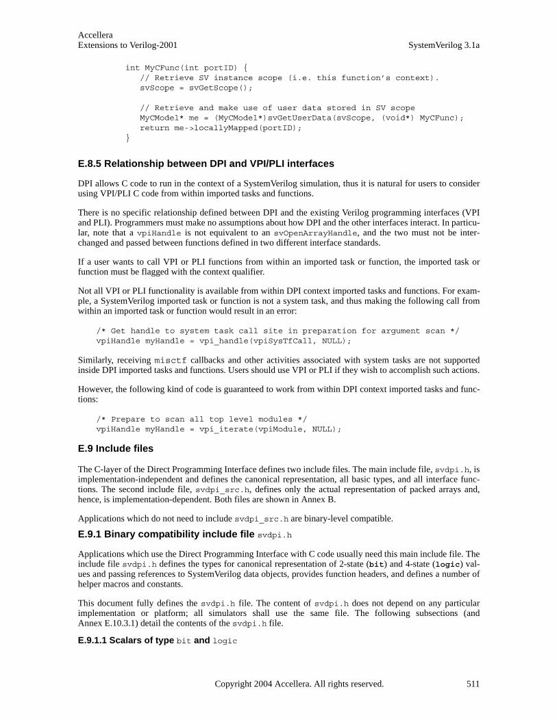
AccelleraExtensions to Verilog-2001 SystemVerilog 3.1a
int MyCFunc(int portID) {// Retrieve SV instance scope (i.e. this function’s context).svScope = svGetScope();
// Retrieve and make use of user data stored in SV scopeMyCModel* me = (MyCModel*)svGetUserData(svScope, (void*) MyCFunc);return me->locallyMapped(portID);
}
E.8.5 Relationship between DPI and VPI/PLI interfaces
DPI allows C code to run in the context of a SystemVerilog simulation, thus it is natural for users to considerusing VPI/PLI C code from within imported tasks and functions.
There is no specific relationship defined between DPI and the existing Verilog programming interfaces (VPIand PLI). Programmers must make no assumptions about how DPI and the other interfaces interact. In particu-lar, note that a vpiHandle is not equivalent to an svOpenArrayHandle, and the two must not be inter-changed and passed between functions defined in two different interface standards.
If a user wants to call VPI or PLI functions from within an imported task or function, the imported task orfunction must be flagged with the context qualifier.
Not all VPI or PLI functionality is available from within DPI context imported tasks and functions. For exam-ple, a SystemVerilog imported task or function is not a system task, and thus making the following call fromwithin an imported task or function would result in an error:
/* Get handle to system task call site in preparation for argument scan */vpiHandle myHandle = vpi_handle(vpiSysTfCall, NULL);
Similarly, receiving misctf callbacks and other activities associated with system tasks are not supportedinside DPI imported tasks and functions. Users should use VPI or PLI if they wish to accomplish such actions.
However, the following kind of code is guaranteed to work from within DPI context imported tasks and func-tions:
/* Prepare to scan all top level modules */vpiHandle myHandle = vpi_iterate(vpiModule, NULL);
E.9 Include files
The C-layer of the Direct Programming Interface defines two include files. The main include file, svdpi.h, isimplementation-independent and defines the canonical representation, all basic types, and all interface func-tions. The second include file, svdpi_src.h, defines only the actual representation of packed arrays and,hence, is implementation-dependent. Both files are shown in Annex B.
Applications which do not need to include svdpi_src.h are binary-level compatible.
E.9.1 Binary compatibility include file svdpi.h
Applications which use the Direct Programming Interface with C code usually need this main include file. Theinclude file svdpi.h defines the types for canonical representation of 2-state (bit) and 4-state (logic) val-ues and passing references to SystemVerilog data objects, provides function headers, and defines a number ofhelper macros and constants.
This document fully defines the svdpi.h file. The content of svdpi.h does not depend on any particularimplementation or platform; all simulators shall use the same file. The following subsections (andAnnex E.10.3.1) detail the contents of the svdpi.h file.
E.9.1.1 Scalars of type bit and logic
Copyright 2004 Accellera. All rights reserved. 511
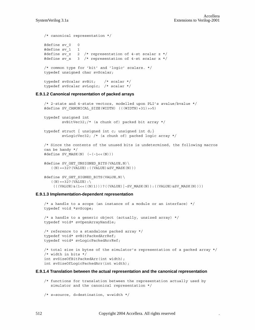
AccelleraSystemVerilog 3.1a Extensions to Verilog-2001
/* canonical representation */
#define sv_0 0 #define sv_1 1 #define sv_z 2 /* representation of 4-st scalar z */ #define sv_x 3 /* representation of 4-st scalar x */
/* common type for ’bit’ and ’logic’ scalars. */ typedef unsigned char svScalar;
typedef svScalar svBit; /* scalar */ typedef svScalar svLogic; /* scalar */
E.9.1.2 Canonical representation of packed arrays
/* 2-state and 4-state vectors, modelled upon PLI’s avalue/bvalue */ #define SV_CANONICAL_SIZE(WIDTH) (((WIDTH)+31)>>5)
typedef unsigned int svBitVec32;/* (a chunk of) packed bit array */
typedef struct { unsigned int c; unsigned int d;}svLogicVec32; /* (a chunk of) packed logic array */
/* Since the contents of the unused bits is undetermined, the following macros can be handy */ #define SV_MASK(N) (~(-1<<(N)))
#define SV_GET_UNSIGNED_BITS(VALUE,N)\((N)==32?(VALUE):((VALUE)&SV_MASK(N)))
#define SV_GET_SIGNED_BITS(VALUE,N)\((N)==32?(VALUE):\ (((VALUE)&(1<<((N)1)))?((VALUE)|~SV_MASK(N)):((VALUE)&SV_MASK(N))))
E.9.1.3 Implementation-dependent representation
/* a handle to a scope (an instance of a module or an interface) */typedef void *svScope;
/* a handle to a generic object (actually, unsized array) */ typedef void* svOpenArrayHandle;
/* reference to a standalone packed array */ typedef void* svBitPackedArrRef; typedef void* svLogicPackedArrRef;
/* total size in bytes of the simulator’s representation of a packed array */ /* width in bits */ int svSizeOfBitPackedArr(int width);int svSizeOfLogicPackedArr(int width);
E.9.1.4 Translation between the actual representation and the canonical representation
/* functions for translation between the representation actually used bysimulator and the canonical representation */
/* s=source, d=destination, w=width */
512 Copyright 2004 Accellera. All rights reserved .
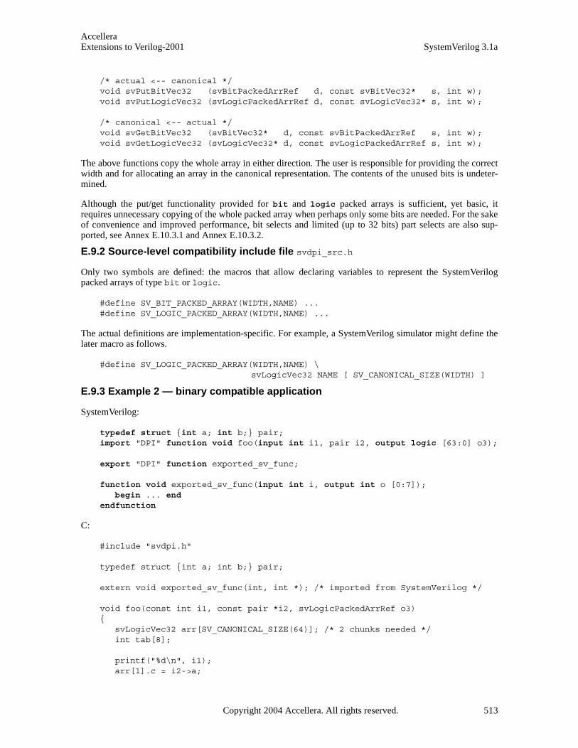
AccelleraExtensions to Verilog-2001 SystemVerilog 3.1a
/* actual <-- canonical */ void svPutBitVec32 (svBitPackedArrRef d, const svBitVec32* s, int w); void svPutLogicVec32 (svLogicPackedArrRef d, const svLogicVec32* s, int w);
/* canonical <-- actual */ void svGetBitVec32 (svBitVec32* d, const svBitPackedArrRef s, int w); void svGetLogicVec32 (svLogicVec32* d, const svLogicPackedArrRef s, int w);
The above functions copy the whole array in either direction. The user is responsible for providing the correctwidth and for allocating an array in the canonical representation. The contents of the unused bits is undeter-mined.
Although the put/get functionality provided for bit and logic packed arrays is sufficient, yet basic, itrequires unnecessary copying of the whole packed array when perhaps only some bits are needed. For the sakeof convenience and improved performance, bit selects and limited (up to 32 bits) part selects are also sup-ported, see Annex E.10.3.1 and Annex E.10.3.2.
E.9.2 Source-level compatibility include file svdpi_src.h
Only two symbols are defined: the macros that allow declaring variables to represent the SystemVerilogpacked arrays of type bit or logic.
#define SV_BIT_PACKED_ARRAY(WIDTH,NAME) ... #define SV_LOGIC_PACKED_ARRAY(WIDTH,NAME) ...
The actual definitions are implementation-specific. For example, a SystemVerilog simulator might define thelater macro as follows.
#define SV_LOGIC_PACKED_ARRAY(WIDTH,NAME) \ svLogicVec32 NAME [ SV_CANONICAL_SIZE(WIDTH) ]
E.9.3 Example 2 — binary compatible application
SystemVerilog:
typedef struct {int a; int b;} pair; import "DPI" function void foo(input int i1, pair i2, output logic [63:0] o3);
export "DPI" function exported_sv_func;
function void exported_sv_func(input int i, output int o [0:7]); begin ... end
endfunction
C:
#include "svdpi.h"
typedef struct {int a; int b;} pair;
extern void exported_sv_func(int, int *); /* imported from SystemVerilog */
void foo(const int i1, const pair *i2, svLogicPackedArrRef o3) {
svLogicVec32 arr[SV_CANONICAL_SIZE(64)]; /* 2 chunks needed */int tab[8];
printf("%d\n", i1);arr[1].c = i2->a;
Copyright 2004 Accellera. All rights reserved. 513
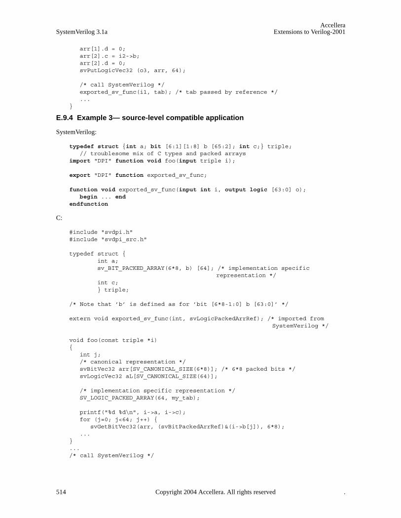
AccelleraSystemVerilog 3.1a Extensions to Verilog-2001
arr[1].d = 0;arr[2].c = i2->b;arr[2].d = 0;svPutLogicVec32 (o3, arr, 64);
/* call SystemVerilog */ exported_sv_func(i1, tab); /* tab passed by reference */ ...
}
E.9.4 Example 3— source-level compatible application
SystemVerilog:
typedef struct {int a; bit [6:1][1:8] b [65:2]; int c;} triple; // troublesome mix of C types and packed arrays
import "DPI" function void foo(input triple i);
export "DPI" function exported_sv_func;
function void exported_sv_func(input int i, output logic [63:0] o); begin ... end
endfunction
C:
#include "svdpi.h" #include "svdpi_src.h"
typedef struct { int a; sv_BIT_PACKED_ARRAY(6*8, b) [64]; /* implementation specific
representation */ int c; } triple;
/* Note that ’b’ is defined as for ’bit [6*8-1:0] b [63:0]’ */
extern void exported_sv_func(int, svLogicPackedArrRef); /* imported fromSystemVerilog */
void foo(const triple *i) {
int j;/* canonical representation */ svBitVec32 arr[SV_CANONICAL_SIZE(6*8)]; /* 6*8 packed bits */ svLogicVec32 aL[SV_CANONICAL_SIZE(64)];
/* implementation specific representation */SV_LOGIC_PACKED_ARRAY(64, my_tab);
printf("%d %d\n", i->a, i->c);for (j=0; j<64; j++) {
svGetBitVec32(arr, (svBitPackedArrRef)&(i->b[j]), 6*8); ...
} ... /* call SystemVerilog */
514 Copyright 2004 Accellera. All rights reserved .

AccelleraExtensions to Verilog-2001 SystemVerilog 3.1a
exported_sv_func(2, (svLogicPackedArrRef)&my_tab); /* by reference */ svGetLogicVec32(aL, (svLogicPackedArrRef)&my_tab, 64); ... }
NOTE—a, b, and c are directly accessed as fields in a structure. In the case of b, which represents unpacked array ofpacked arrays, the individual element is accessed via the library function svGetBitVec32(), by passing its address tothe function.
E.10 Arrays
Normalized ranges are used for accessing SystemVerilog arrays, with the exception of formal arguments spec-ified as open arrays.
E.10.1 Multidimensional arrays
Packed arrays shall be one-dimensional. Unpacked arrays can have an arbitrary number of dimensions.
E.10.2 Direct access to unpacked arrays
Unpacked arrays, with the exception of formal arguments specified as open arrays, shall have the same layoutas used by a C compiler; they are accessed using C indexing (see Annex E.6.6).
E.10.3 Access to packed arrays via canonical representation
Packed arrays are accessible via canonical representation; this C-layer interface provides functions for movingdata between implementation representation and canonical representation (any necessary conversion is per-formed on-the-fly (see Annex E.9.1.3)), and for bit selects and limited (up to 32-bit) part selects. (Bit selectsdo not involve any canonical representation.)
E.10.3.1 Bit selects
This subsection defines the bit selects portion of the svdpi.h file (see Annex E.9.1 for more details).
/* Packed arrays are assumed to be indexed n-1:0,where 0 is the index of least significant bit */
/* functions for bit select */
/* s=source, i=bit-index */svBit svGetSelectBit(const svBitPackedArrRef s, int i); svLogic svGetSelectLogic(const svLogicPackedArrRef s, int i);
/* d=destination, i=bit-index, s=scalar */void svPutSelectBit(svBitPackedArrRef d, int i, svBit s); void svPutSelectLogic(svLogicPackedArrRef d, int i, svLogic s);
E.10.3.2 Part selects
Limited (up to 32-bit) part selects are supported. A part select is a slice of a packed array of types bit orlogic. Array slices are not supported for unpacked arrays. Additionally, 64-bit wide part select can be read asa single value of type unsigned long long.
Functions for part selects only allow access (read/write) to a narrow subrange of up to 32 bits. A canonical rep-resentation shall be used for such narrow vectors. If the specified range of part select is not fully containedwithin the normalized range of an array, the behavior is undetermined.
For the convenience, bit type part selects are returned as a function result. In addition to a general function fornarrow part selects (<= 32-bits), there are two specialized functions for 32 and 64 bits.
/** functions for part select *
Copyright 2004 Accellera. All rights reserved. 515

AccelleraSystemVerilog 3.1a Extensions to Verilog-2001
* a narrow (<=32 bits) part select is copied between * the implementation representation and a single chunk of * canonical representation * Normalized ranges and indexing [n-1:0] are used for both arrays:* the array in the implementation representation and the canonical array.* * s=source, d=destination, i=starting bit index, w=width * like for variable part selects; limitations: w <= 32 ** In part select operations, the data is copied to or from the * canonical representation part (’chunk’) designated by range [w-1:0]* and the implementation representation part designated by range [w+i-1:i].*/
NOTE—For the sake of symmetry, a canonical representation (i.e., an array) is used both for bit and logic, although asimpler int can be used for bit-part selects (<= 32-bits):
/* canonical <-- actual */void svGetPartSelectBit(svBitVec32* d, const svBitPackedArrRef s, int i,
int w);svBitVec32 svGetBits(const svBitPackedArrRef s, int i, int w);svBitVec32 svGet32Bits(const svBitPackedArrRef s, int i); // 32-bitsunsigned long long svGet64Bits(const svBitPackedArrRef s, int i); // 64-bitsvoid svGetPartSelectLogic(svLogicVec32* d, const svLogicPackedArrRef s, int i,
int w);
/* actual <-- canonical */void svPutPartSelectBit(svBitPackedArrRef d, const svBitVec32 s, int i,
int w); void svPutPartSelectLogic(svLogicPackedArrRef d, const svLogicVec32 s, int i,
int w);
E.11 Open arrays
Formal arguments specified as open arrays allows passing actual arguments of different sizes (i.e., differentrange and/or different number of elements), which facilitates writing more general C code that can handle Sys-temVerilog arrays of different sizes. The elements of an open array can be accessed in C by using the samerange of indices and the same indexing as in SystemVerilog. Plus, inquiries about the dimensions and the orig-inal boundaries of SystemVerilog actual arguments are supported for open arrays.
NOTE—Both packed and unpacked array dimensions can be unsized.
All formal arguments declared in SystemVerilog as open arrays are passed by handle (type svOpenArray-Handle), regardless of the direction of a SystemVerilog formal argument. Such arguments are accessible viainterface functions.
E.11.1 Actual ranges
The formal arguments defined as open arrays have the size and ranges of the actual argument, as determinedon a per-call basis. The programmer shall always have a choice whether to specify a formal argument as asized array or as an open (unsized) array.
In the former case, all indices are normalized on the C side (i.e., 0 and up) and the programmer needs to knowthe size of an array and be capable of determining how the ranges of the actual argument map onto C-styleranges (see Annex E.6.6).
Tip: programmers can decide to use [n:0]name[0:k] style ranges in SystemVerilog.
In the later case, i.e., an open array, individual elements of a packed array are accessible via interface func-
516 Copyright 2004 Accellera. All rights reserved .

AccelleraExtensions to Verilog-2001 SystemVerilog 3.1a
tions, which facilitate the SystemVerilog-style of indexing with the original boundaries of the actual argument.
If a formal argument is specified as a sized array, then it shall be passed by reference, with no overhead, and isdirectly accessible as a normalized array. If a formal argument is specified as an open (unsized) array, then itshall be passed by handle, with some overhead, and is mostly indirectly accessible, again with some overhead,although it retains the original argument boundaries.
NOTE—This provides some degree of flexibility and allows the programmer to control the trade-off of performance vs.convenience.
The following example shows the use of sized vs. unsized arrays in SystemVerilog code.
// both unpacked arrays are 64 by 8 elements, packed 16-bit eachlogic [15: 0] a_64x8 [63:0][7:0];logic [31:16] b_64x8 [64:1][-1:-8];
import "DPI" function void foo(input logic [] i [][]);// 2-dimensional unsized unpacked array of unsized packed logic
import "DPI" function void boo(input logic [31:16] i [64:1][-1:-8]); // 2-dimensional sized unpacked array of sized packed logic
foo(a_64x8); foo(b_64x8); // C code can use original ranges [31:16][64:1][-1:-8] boo(b_64x8); // C code must use normalized ranges [15:0][0:63][0:7]
E.11.2 Array querying functions
These functions are modelled upon the SystemVerilog array querying functions and use the same semantics(see Section 23.7).
If the dimension is 0, then the query refers to the packed part (which is one-dimensional) of an array, anddimensions > 0 refer to the unpacked part of an array.
/* h= handle to open array, d=dimension */ int svLeft(const svOpenArrayHandle h, int d); int svRight(const svOpenArrayHandle h, int d); int svLow(const svOpenArrayHandle h, int d); int svHigh(const svOpenArrayHandle h, int d); int svIncrement(const svOpenArrayHandle h, int d); int svLength(const svOpenArrayHandle h, int d); int svDimensions(const svOpenArrayHandle h);
E.11.3 Access functions
Similarly to sized arrays, there are functions for copying data between the simulator representation and thecanonical representation and to obtain the actual address of SystemVerilog data object or of an individual ele-ment of an unpacked array. This information might be useful for simulator-specific tuning of the application.
Depending on the type of an element of an unpacked array, different access methods shall be used when work-ing with elements.
— Packed arrays ( bit or logic) are accessed via copying to or from the canonical representation.
— Scalars (1-bit value of type bit or logic) are accessed (read or written) directly.
— Other types of values (e.g., structures) are accessed via generic pointers; a library function calculates anaddress and the user needs to provide the appropriate casting.
Copyright 2004 Accellera. All rights reserved. 517
AccelleraSystemVerilog 3.1a Extensions to Verilog-2001
— Scalars and packed arrays are accessible via pointers only if the implementation supports this functionality(per array), e.g., one array can be represented in a form that allows such access, while another array mightuse a compacted representation which renders this functionality unfeasible (both occurring within the samesimulator).
SystemVerilog allows arbitrary dimensions and, hence, an arbitrary number of indices. To facilitate this, vari-able argument list functions shall be used. For the sake of performance, specialized versions of all indexingfunctions are provided for 1, 2, or 3 indices.
E.11.4 Access to the actual representation
The following functions provide an actual address of the whole array or of its individual elements. These func-tions shall be used for accessing elements of arrays of types compatible with C. These functions are also usefulfor vendors, because they provide access to the actual representation for all types of arrays.
If the actual layout of the SystemVerilog array passed as an argument for an open unpacked array is differentthan the C layout, then it is not possible to access such an array as a whole; therefore, the address and size ofsuch an array shall be undefined (zero (0), to be exact). Nonetheless, the addresses of individual elements of anarray shall be always supported.
NOTE—No specific representation of an array is assumed here; hence, all functions use a generic pointer void *.
/* a pointer to the actual representation of the whole array of any type */ /* NULL if not in C layout */ void *svGetArrayPtr(const svOpenArrayHandle);
int svSizeOfArray(const svOpenArrayHandle); /* total size in bytes or 0 if notin C layout */
/* Return a pointer to an element of the array or NULL if index outside the range or null pointer */
void *svGetArrElemPtr(const svOpenArrayHandle, int indx1, ...);
/* specialized versions for 1-, 2- and 3-dimensional arrays: */ void *svGetArrElemPtr1(const svOpenArrayHandle, int indx1); void *svGetArrElemPtr2(const svOpenArrayHandle, int indx1, int indx2); void *svGetArrElemPtr3(const svOpenArrayHandle, int indx1, int indx2,
int indx3);
Access to an individual array element via pointer makes sense only if the representation of such an element isthe same as it would be for an individual value of the same type. Representation of array elements of typescalar or packed value is implementation-dependent; the above functions shall return NULL if the representa-tion of the array elements differs from the representation of individual values of the same type.
E.11.5 Access to elements via canonical representation
This group of functions is meant for accessing elements which are packed arrays (bit or logic).
The following functions copy a single vector from a canonical representation to an element of an open array orother way round. The element of an array is identified by indices, bound by the ranges of the actual argument,i.e., the original SystemVerilog ranges are used for indexing.
/* functions for translation between simulator and canonical representations*//* s=source, d=destination *//* actual <-- canonical */ void svPutBitArrElemVec32 (const svOpenArrayHandle d, const svBitVec32* s,
int indx1, ...);
518 Copyright 2004 Accellera. All rights reserved .

AccelleraExtensions to Verilog-2001 SystemVerilog 3.1a
void svPutBitArrElem1Vec32(const svOpenArrayHandle d, const svBitVec32* s,int indx1);
void svPutBitArrElem2Vec32(const svOpenArrayHandle d, const svBitVec32* s,int indx1, int indx2);
void svPutBitArrElem3Vec32(const svOpenArrayHandle d, const svBitVec32* s,int indx1, int indx2, int indx3);
void svPutLogicArrElemVec32 (const svOpenArrayHandle d, const svLogicVec32* s,int indx1, ...);
void svPutLogicArrElem1Vec32(const svOpenArrayHandle d, const svLogicVec32* s,int indx1);
void svPutLogicArrElem2Vec32(const svOpenArrayHandle d, const svLogicVec32* s,int indx1, int indx2);
void svPutLogicArrElem3Vec32(const svOpenArrayHandle d, const svLogicVec32* s,int indx1, int indx2, int indx3);
/* canonical <-- actual */ void svGetBitArrElemVec32 (svBitVec32* d, const svOpenArrayHandle s,
int indx1, ...); void svGetBitArrElem1Vec32(svBitVec32* d, const svOpenArrayHandle s,
int indx1); void svGetBitArrElem2Vec32(svBitVec32* d, const svOpenArrayHandle s,
int indx1, int indx2);void svGetBitArrElem3Vec32(svBitVec32* d, const svOpenArrayHandle s,
int indx1, int indx2, int indx3);
void svGetLogicArrElemVec32 (svLogicVec32* d, const svOpenArrayHandle s, int indx1, ...);
void svGetLogicArrElem1Vec32(svLogicVec32* d, const svOpenArrayHandle s, int indx1);
void svGetLogicArrElem2Vec32(svLogicVec32* d, const svOpenArrayHandle s, int indx1, int indx2);
void svGetLogicArrElem3Vec32(svLogicVec32* d, const svOpenArrayHandle s, int indx1, int indx2, int indx3);
The above functions copy the whole packed array in either direction. The user is responsible for allocating anarray in the canonical representation.
E.11.6 Access to scalar elements (bit and logic)
Another group of functions is needed for scalars (i.e., when an element of an array is a simple scalar, bit, orlogic):
svBit svGetBitArrElem (const svOpenArrayHandle s, int indx1, ...); svBit svGetBitArrElem1(const svOpenArrayHandle s, int indx1); svBit svGetBitArrElem2(const svOpenArrayHandle s, int indx1, int indx2); svBit svGetBitArrElem3(const svOpenArrayHandle s, int indx1, int indx2,
int indx3);
svLogic svGetLogicArrElem (const svOpenArrayHandle s, int indx1, ...); svLogic svGetLogicArrElem1(const svOpenArrayHandle s, int indx1); svLogic svGetLogicArrElem2(const svOpenArrayHandle s, int indx1, int indx2); svLogic svGetLogicArrElem3(const svOpenArrayHandle s, int indx1, int indx2,
int indx3);
void svPutLogicArrElem (const svOpenArrayHandle d, svLogic value, int indx1,...);
void svPutLogicArrElem1(const svOpenArrayHandle d, svLogic value, int indx1); void svPutLogicArrElem2(const svOpenArrayHandle d, svLogic value, int indx1,
Copyright 2004 Accellera. All rights reserved. 519

AccelleraSystemVerilog 3.1a Extensions to Verilog-2001
int indx2); void svPutLogicArrElem3(const svOpenArrayHandle d, svLogic value, int indx1,
int indx2, int indx3);
void svPutBitArrElem (const svOpenArrayHandle d, svBit value, int indx1, ...); void svPutBitArrElem1(const svOpenArrayHandle d, svBit value, int indx1); void svPutBitArrElem2(const svOpenArrayHandle d, svBit value, int indx1,
int indx2); void svPutBitArrElem3(const svOpenArrayHandle d, svBit value, int indx1,
int indx2, int indx3);
E.11.7 Access to array elements of other types
If an array’s elements are of a type compatible with C, there is no need to use canonical representation. In suchsituations, the elements are accessed via pointers, i.e., the actual address of an element shall be computed firstand then used to access the desired element.
E.11.8 Example 4— two-dimensional open array
SystemVerilog:
typedef struct {int i; ... } MyType;
import "DPI" function void foo(input MyType i [][]); /* 2-dimensional unsizedunpacked array of MyType */
MyType a_10x5 [11:20][6:2]; MyType a_64x8 [64:1][-1:-8];
foo(a_10x5); foo(a_64x8);
C:
#include "svdpi.h"
typedef struct {int i; ... } MyType;
void foo(const svOpenArrayHandle h){
MyType my_value;int i, j;int lo1 = svLow(h, 1);int hi1 = svHigh(h, 1);int lo2 = svLow(h, 2);int hi2 = svHigh(h, 2);
for (i = lo1; i <= hi1; i++) { for (j = lo2; j <= hi2; j++) {
my_value = *(MyType *)svGetArrElemPtr2(h, i, j);... *(MyType *)svGetArrElemPtr2(h, i, j) = my_value;...
} ...}
}
520 Copyright 2004 Accellera. All rights reserved .

AccelleraExtensions to Verilog-2001 SystemVerilog 3.1a
E.11.9 Example 5 — open array
SystemVerilog:
typedef struct { ... } MyType;
import "DPI" function void foo(input MyType i [], output MyType o []);
MyType source [11:20];MyType target [11:20];
foo(source, target);
C:
#include "svdpi.h"
typedef struct ... } MyType;
void foo(const svOpenArrayHandle hin, const svOpenArrayHandle hout){
int count = svLength(hin, 1);MyType *s = (MyType *)svGetArrayPtr(hin);MyType *d = (MyType *)svGetArrayPtr(hout);
if (s && d) { /* both arrays have C layout */
/* an efficient solution using pointer arithmetic */while (count--)
*d++ = *s++;
/* even more efficient:memcpy(d, s, svSizeOfArray(hin));
*/
} else { /* less efficient yet implementation independent */
int i = svLow(hin, 1);int j = svLow(hout, 1);while (i <= svHigh(hin, 1)) {
*(MyType *)svGetArrElemPtr1(hout, j++) = *(MyType *)svGetArrElemPtr1(hin, i++);
}
}
}
E.11.10 Example 6 — access to packed arrays
SystemVerilog:
import "DPI" function void foo(input logic [127:0]);import "DPI" function void boo(input logic [127:0] i []); // open array of
// 128-bit
C:
#include "svdpi.h"
Copyright 2004 Accellera. All rights reserved. 521
AccelleraSystemVerilog 3.1a Extensions to Verilog-2001
/* one 128-bit packed vector */void foo(const svLogicPackedArrRef packed_vec_128_bit){
svLogicVec32 arr[SV_CANONICAL_SIZE(128)]; /* canonical representation */
svGetLogicVec32(arr, packed_vec_128_bit, 128);...
}
/* open array of 128-bit packed vectors */void boo(const svOpenArrayHandle h){
int i;svLogicVec32 arr[SV_CANONICAL_SIZE(128)]; /* canonical representation */
for (i = svLow(h, 1); i <= svHigh(h, 1); i++) {
svLogicPackedArrRef ptr = (svLogicPackedArrRef)svGetArrElemPtr1(h, i); /* user need not know the vendor representation! */
svGetLogicVec32(arr, ptr, 128); ...
}...
}
E.11.11 Example 7 — binary compatible calls of exported functions
This example demonstrates the source compatibility include file svdpi_src.h is not needed if a C functiondynamically allocates the data structure for simulator representation of a packed array to be passed to anexported SystemVerilog function.
SystemVerilog:
export "DPI" function myfunc; ... function void myfunc (output logic [31:0] r); ... ...
C:
#include "svdpi.h" extern void myfunc (svLogicPackedArrRef r); /* exported from SV */
/* output logic packed 32-bits */ ... svLogicVec32 my_r[SV_CANONICAL_SIZE(32)]; /* my array, canonical representation */
/* allocate memory for logic packed 32-bits in simulator’s representation */ svLogicPackedArrRef r =
(svLogicPackedArrRef)malloc(svSizeOfLogicPackedArr(32)); myfunc(r); /* canonical <-- actual */ svGetLogicVec32(my_r, r, 32); /* shall use only the canonical representation from now on */ free(r); /* don’t need any more */ ...
522 Copyright 2004 Accellera. All rights reserved .

AccelleraExtensions to Verilog-2001 SystemVerilog 3.1a
Annex FInclude files
This annex shows the contents of the svdpi.h and svdpi_src.h include files.
F.1 Binary-level compatibility include file svdpi.h
/* canonical representation */
#define sv_0 0 #define sv_1 1 #define sv_z 2 /* representation of 4-st scalar z */ #define sv_x 3 /* representation of 4-st scalar x */
/* common type for ’bit’ and ’logic’ scalars. */ typedef unsigned char svScalar;
typedef svScalar svBit; /* scalar */ typedef svScalar svLogic; /* scalar */
/* Canonical representation of packed arrays *//* 2-state and 4-state vectors, modelled upon PLI’s avalue/bvalue */ #define SV_CANONICAL_SIZE(WIDTH) (((WIDTH)+31)>>5)
typedef unsigned int svBitVec32; /* (a chunk of) packed bit array */
typedef struct { unsigned int c; unsigned int d;}svLogicVec32; /* (a chunk of) packed logic array */
/* Since the contents of the unused bits is undetermined, the following macros canbe handy */
#define SV_MASK(N) (~(-1<<(N)))
#define SV_GET_UNSIGNED_BITS(VALUE,N)\((N)==32?(VALUE):((VALUE)&SV_MASK(N)))
#define SV_GET_SIGNED_BITS(VALUE,N)\((N)==32?(VALUE):\ (((VALUE)&(1<<((N)1)))?((VALUE)|~SV_MASK(N)):((VALUE)&SV_MASK(N))))
/* implementation-dependent representation */
/* a handle to a scope (an instance of a module or interface) */typedef void* svScope;
/* a handle to a generic object (actually, unsized array) */ typedef void* svOpenArrayHandle;
/* reference to a standalone packed array */ typedef void* svBitPackedArrRef; typedef void* svLogicPackedArrRef;
/* total size in bytes of the simulator’s representation of a packed array */ /* width in bits */ int svSizeOfBitPackedArr(int width);int svSizeOfLogicPackedArr(int width);
Copyright 2004 Accellera. All rights reserved. 523
AccelleraSystemVerilog 3.1a Extensions to Verilog-2001
/* Translation between the actual representation and canonical representation */
/* functions for translation between the representation actually used bysimulator and the canonical representation */
/* s=source, d=destination, w=width */
/* actual <-- canonical */ void svPutBitVec32 (svBitPackedArrRef d, const svBitVec32* s, int w); void svPutLogicVec32 (svLogicPackedArrRef d, const svLogicVec32* s, int w);
/* canonical <-- actual */ void svGetBitVec32 (svBitVec32* d, const svBitPackedArrRef s, int w); void svGetLogicVec32 (svLogicVec32* d, const svLogicPackedArrRef s, int w);
/* Bit selects */
/* Packed arrays are assumed to be indexed n-1:0,where 0 is the index of least significant bit */
/* functions for bit select */
/* s=source, i=bit-index */svBit svGetSelectBit(const svBitPackedArrRef s, int i); svLogic svGetSelectLogic(const svLogicPackedArrRef s, int i);
/* d=destination, i=bit-index, s=scalar */void svPutSelectBit(svBitPackedArrRef d, int i, svBit s); void svPutSelectLogic(svLogicPackedArrRef d, int i, svLogic s);
/** functions for part select * * a narrow (<=32 bits) part select is copied between * the implementation representation and a single chunk of * canonical representation * Normalized ranges and indexing [n-1:0] are used for both arrays:* the array in the implementation representation and the canonical array.* * s=source, d=destination, i=starting bit index, w=width * like for variable part selects; limitations: w <= 32 ** In part select operations, the data is copied to or from the * canonical representation part (’chunk’) designated by range [w-1:0]* and the implementation representation part designated by range [w+i-1:i].*/
/* canonical <-- actual */void svGetPartSelectBit(svBitVec32* d, const svBitPackedArrRef s, int i,
int w);svBitVec32 svGetBits(const svBitPackedArrRef s, int i, int w);svBitVec32 svGet32Bits(const svBitPackedArrRef s, int i); // 32-bitsunsigned long long svGet64Bits(const svBitPackedArrRef s, int i); // 64-bitsvoid svGetPartSelectLogic(svLogicVec32* d, const svLogicPackedArrRef s, int i,
int w);
/* actual <-- canonical */void svPutPartSelectBit(svBitPackedArrRef d, const svBitVec32 s, int i, int w);void svPutPartSelectLogic(svLogicPackedArrRef d, const svLogicVec32 s, int i,
524 Copyright 2004 Accellera. All rights reserved .
AccelleraExtensions to Verilog-2001 SystemVerilog 3.1a
int w);
/* Array querying functions */ /* These functions are modelled upon the SystemVerilog array querying functions
and use the same semantics*/ /* If the dimension is 0, then the query refers to the packed part (which is one-
dimensional) of an array, and dimensions > 0 refer to the unpacked part of anarray.*/
/* h= handle to open array, d=dimension */ int svLeft(const svOpenArrayHandle h, int d); int svRight(const svOpenArrayHandle h, int d); int svLow(const svOpenArrayHandle h, int d); int svHigh(const svOpenArrayHandle h, int d); int svIncrement(const svOpenArrayHandle h, int d); int svLength(const svOpenArrayHandle h, int d); int svDimensions(const svOpenArrayHandle h);
/* a pointer to the actual representation of the whole array of any type */ /* NULL if not in C layout */ void *svGetArrayPtr(const svOpenArrayHandle);
int svSizeOfArray(const svOpenArrayHandle); /* total size in bytes or 0 if not in C layout */
/* Return a pointer to an element of the array or NULL if index outside the range or null pointer */
void *svGetArrElemPtr(const svOpenArrayHandle, int indx1, ...);
/* specialized versions for 1-, 2- and 3-dimensional arrays: */ void *svGetArrElemPtr1(const svOpenArrayHandle, int indx1); void *svGetArrElemPtr2(const svOpenArrayHandle, int indx1, int indx2); void *svGetArrElemPtr3(const svOpenArrayHandle, int indx1, int indx2, int indx3);
/* Functions for translation between simulator and canonical representations*//* These functions copy the whole packed array in either direction. The user is responsible for allocating an array in the canonical representation. */ /* s=source, d=destination *//* actual <-- canonical */ void svPutBitArrElemVec32 (const svOpenArrayHandle d, const svBitVec32* s,
int indx1, ...); void svPutBitArrElem1Vec32(const svOpenArrayHandle d, const svBitVec32* s,
int indx1); void svPutBitArrElem2Vec32(const svOpenArrayHandle d, const svBitVec32* s,
int indx1, int indx2); void svPutBitArrElem3Vec32(const svOpenArrayHandle d, const svBitVec32* s,
int indx1, int indx2, int indx3);
void svPutLogicArrElemVec32 (const svOpenArrayHandle d, const svLogicVec32* s, int indx1, ...);
void svPutLogicArrElem1Vec32(const svOpenArrayHandle d, const svLogicVec32* s,int indx1);
void svPutLogicArrElem2Vec32(const svOpenArrayHandle d, const svLogicVec32* s, int indx1, int indx2);
void svPutLogicArrElem3Vec32(const svOpenArrayHandle d, const svLogicVec32* s, int indx1, int indx2, int indx3);
/* canonical <-- actual */
Copyright 2004 Accellera. All rights reserved. 525

AccelleraSystemVerilog 3.1a Extensions to Verilog-2001
void svGetBitArrElemVec32 (svBitVec32* d, const svOpenArrayHandle s,int indx1, ...);
void svGetBitArrElem1Vec32(svBitVec32* d, const svOpenArrayHandle s, int indx1);
void svGetBitArrElem2Vec32(svBitVec32* d, const svOpenArrayHandle s, int indx1,int indx2);
void svGetBitArrElem3Vec32(svBitVec32* d, const svOpenArrayHandle s, int indx1, int indx2, int indx3);
void svGetLogicArrElemVec32 (svLogicVec32* d, const svOpenArrayHandle s,int indx1, ...);
void svGetLogicArrElem1Vec32(svLogicVec32* d, const svOpenArrayHandle s,int indx1);
void svGetLogicArrElem2Vec32(svLogicVec32* d, const svOpenArrayHandle s,int indx1, int indx2);
void svGetLogicArrElem3Vec32(svLogicVec32* d, const svOpenArrayHandle s, int indx1, int indx2, int indx3);
svBit svGetBitArrElem (const svOpenArrayHandle s, int indx1, ...); svBit svGetBitArrElem1(const svOpenArrayHandle s, int indx1); svBit svGetBitArrElem2(const svOpenArrayHandle s, int indx1, int indx2); svBit svGetBitArrElem3(const svOpenArrayHandle s, int indx1, int indx2,
int indx3);
svLogic svGetLogicArrElem (const svOpenArrayHandle s, int indx1, ...); svLogic svGetLogicArrElem1(const svOpenArrayHandle s, int indx1); svLogic svGetLogicArrElem2(const svOpenArrayHandle s, int indx1, int indx2); svLogic svGetLogicArrElem3(const svOpenArrayHandle s, int indx1, int indx2,
int indx3);
void svPutLogicArrElem (const svOpenArrayHandle d, svLogic value, int indx1, ...); void svPutLogicArrElem1(const svOpenArrayHandle d, svLogic value, int indx1); void svPutLogicArrElem2(const svOpenArrayHandle d, svLogic value, int indx1,
int indx2); void svPutLogicArrElem3(const svOpenArrayHandle d, svLogic value, int indx1,
int indx2, int indx3);
void svPutBitArrElem (const svOpenArrayHandle d, svBit value, int indx1, ...); void svPutBitArrElem1(const svOpenArrayHandle d, svBit value, int indx1); void svPutBitArrElem2(const svOpenArrayHandle d, svBit value, int indx1,
int indx2); void svPutBitArrElem3(const svOpenArrayHandle d, svBit value, int indx1,
int indx2, int indx3);
/* Functions for working with DPI context functions */
/* Retrieve the active instance scope currently associated with the executingimported function.Unless a prior call to svSetScope has occurred, this is the scope of thefunction’s declaration site, not call site.Returns NULL if called from C code that is *not* an imported function. */
svScope svGetScope();
/* Set context for subsequent export function execution.This function must be called before calling an export function, unlessthe export function is called while executing an extern function. In thatcase the export function shall inherit the scope of the surrounding externfunction. This is known as the "default scope".
526 Copyright 2004 Accellera. All rights reserved .
AccelleraExtensions to Verilog-2001 SystemVerilog 3.1a
The return is the previous active scope (as per svGetScope) */svScope svSetScope(const svScope scope);
/* Gets the fully qualified name of a scope handle */const char* svGetNameFromScope(const svScope);
/* Retrieve svScope to instance scope of an arbitrary function declaration.* (can be either module, program, interface, or generate scope)* The return value shall be NULL for unrecognized scope names.*/
svScope svGetScopeFromName(const char* scopeName);
/* Store an arbitrary user data pointer for later retrieval by svGetUserData()* The userKey is generated by the user. It must be guaranteed by the user to* be unique from all other userKey’s for all unique data storage requirements* It is recommended that the address of static functions or variables in the* user’s C code be used as the userKey.* It is illegal to pass in NULL values for either the scope or userData* arguments. It is also an error to call svPutUserData() with an invalid* svScope. This function returns -1 for all error cases, 0 upon success. It is* suggested that userData values of 0 (NULL) not be used as otherwise it can* be impossible to discern error status returns when calling svGetUserData()*/
int svPutUserData(const svScope scope, void *userKey, void* userData);
/* Retrieve an arbitrary user data pointer that was previously* stored by a call to svPutUserData(). See the comment above* svPutUserData() for an explanation of userKey, as well as* restrictions on NULL and illegal svScope and userKey values.* This function returns NULL for all error cases, 0 upon success.* This function also returns NULL in the event that a prior call* to svPutUserData() was never made.*/
void* svGetUserData(const svScope scope, void* userKey);
/* Returns the file and line number in the SV code from which the extern call* was made. If this information available, returns TRUE and updates fileName* and lineNumber to the appropriate values. Behavior is unpredictable if* fileName or lineNumber are not appropriate pointers. If this information is* not available return FALSE and contents of fileName and lineNumber not* modified. Whether this information is available or not is implementation* specific. Note that the string provided (if any) is owned by the SV* implementation and is valid only until the next call to any SV function.* Applications must not modify this string or free it*/
int svGetCallerInfo(char **fileName, int *lineNumber);
/* * Returns 1 if the current execution thread is in the disabled state. * Disable protocol must be adhered to if in the disabled state. */int svIsDisabledState();
/* * Imported functions call this API function during disable processing to* acknowledge that they are correctly participating in the DPI disable protocol.* This function must be called before returning from an imported function that is* in the disabled state.
Copyright 2004 Accellera. All rights reserved. 527

AccelleraSystemVerilog 3.1a Extensions to Verilog-2001
*/void svAckDisabledState();
F.2 Source-level compatibility include file svdpi_src.h
/* macros for declaring variables to represent the SystemVerilog *//* packed arrays of type bit or logic *//* WIDTH= number of bits,NAME = name of a declared field/variable */#define SV_BIT_PACKED_ARRAY(WIDTH,NAME)/* actual definition goes here */#define SV_LOGIC_PACKED_ARRAY(WIDTH,NAME)/* actual definition goes here */
528 Copyright 2004 Accellera. All rights reserved .
AccelleraExtensions to Verilog-2001 SystemVerilog 3.1a
Annex GInclusion of Foreign Language Code
This annex describes common guidelines for the inclusion of Foreign Language Code into a SystemVerilogapplication. This intention of these guidelines is to enable the redistribution of C binaries in shared objectform.
Foreign Language Code is functionality that is included into SystemVerilog using the DPI Interface. As aresult, all statements of this annex apply only to code included using this interface; code included by usingother interfaces (e.g., PLI or VPI) is outside the scope of this document. Due to the nature of the DPI Interface,most Foreign Language Code is usually be created from C or C++ source code, although nothing precludes thecreation of appropriate object code from other languages. This annex adheres to this rule, it’s content is inde-pendent from the actual language used.
In general, Foreign Language Code is provided in the form of object code compiled for the actual platform.The capability to include Foreign Language Code in object-code form shall be supported by all simulators asspecified here. Overview
This annex defines how to:
— specify the location of the corresponding files within the file system
— specify the files to be loaded (in case of object code) or
— provide the object code (as a shared library or archive)
Although this annex defines guidelines for a common inclusion methodology, it requires multiple implementa-tions (usually two) of the corresponding facilities. This takes into account that multiple users can have differ-ent viewpoints and different requirements on the inclusion of Foreign Language Code.
— A vendor that wants to provide his IP in form of Foreign Language Code often requires a self-containedmethod for the integration, which still permits an integration by a third party. This use-case is often cov-ered by a bootstrap file approach.
— A project team that specifies a common, standard set of Foreign Language code, might change the codedepending on technology, selected cells, back-annotation data, and other items. This-use case is often cov-ered by a set of tool switches, although it might also use the bootstrap file approach.
— An user might want to switch between selections or provide additional code. This-use case is covered byproviding a set of tool switches to define the corresponding information, although it might also use thebootstrap file approach.
NOTE—This annex defines a set of switch names to be used for a particular functionality. This is of informative nature;the actual naming of switches is not part of this standard. It might further not be possible to use certain character configura-tions in all operating systems or shells. Therefore any switch name defined within this document is a recommendation howto name a switch, but not a requirement of the language.
G.1 Location independence
All pathnames specified within this annex are intended to be location-independent, which is accomplished byusing the switch -sv_root. It can receive a single directory pathname as the value, which is then prepended toany relative pathname that has been specified. In absence of this switch, or when processing relative filenamesbefore any -sv_root specification, the current working directory of the user shall be used as the defaultvalue.
G.2 Object code inclusion
Compiled object code is required for cases where the compilation and linking of source code is fully handledby the user; thus, the created object code only need be loaded to integrate the Foreign Language Code into aSystemVerilog application. All SystemVerilog applications shall support the integration of Foreign Language
Copyright 2004 Accellera. All rights reserved. 529

AccelleraSystemVerilog 3.1a Extensions to Verilog-2001
Code in object code form. Figure 7-1depicts the inclusion of object code and its relations to the various stepsinvolved in this integration process.
.
Figure 7-1 — Inclusion of object code into a SystemVerilog application
Compiled object code can be specified by one of the following two methods:
1) by an entry in a bootstrap file; see Annex G.2.1 for more details on this file and its content. Its locationshall be specified with one instance of the switch -sv_liblist pathname. This switch can be usedmultiple times to define the usage of multiple bootstrap files.
2) by specifying the file with one instance of the switch -sv_lib pathname_without_extension(i.e., the filename shall be specified without the platform specific extension). The SystemVerilogapplication is responsible for appending the appropriate extension for the actual platform. This switch canbe used multiple times to define multiple libraries holding object code.
Both methods shall be provided and made available concurrently, to permit any mixture of their usage. Everylocation can be an absolute pathname or a relative pathname, where the value of the switch -sv_root is usedto identify an appropriate prefix for relative pathnames (see Annex G.1 for more details on forming path-names).
The following conditions also apply.
— The compiled object code itself shall be provided in form of a shared library having the appropriate exten-sion for the actual platform.
NOTE—Shared libraries use, for example, .so for Solaris and .sl for HP-UX; other operating systems might use differ-ent extensions. In any case, the SystemVerilog application needs to identify the appropriate extension.
— The provider of the compiled code is responsible for any external references specified within these objects.Appropriate data needs to be provided to resolve all open dependencies with the correct information.
— The provider of the compiled code shall avoid interferences with other software and ensure the appropriatesoftware version is taken (e.g., in cases where two versions of the same library are referenced). Similarproblems can arise when there are dependencies on the expected runtime environment in the compiledobject code (e.g., in cases where C++ global objects or static initializers are used).
— The SystemVerilog application need only load object code within a shared library that is referenced by theSystemVerilog code or by registration functions; loading of additional functions included within a sharedlibrary can interfere with other parts.
In case of multiple occurrences of the same file (files having the same pathname or which can easily be identi-fied as being identical; e.g., by comparing the inodes of the files to detect cases where links are used to referthe same file), the above order also identifies the precedence of loading; a file located by method 1) shall over-ride files specified by method 2).
Load
SystemVerilog
applicationObjectcode
Sourcecode
Compile
Object codeinclusion
Link
Performed by the user
530 Copyright 2004 Accellera. All rights reserved .

AccelleraExtensions to Verilog-2001 SystemVerilog 3.1a
All compiled object code need to be loaded in the specification order similarly to the above scheme; first thecontent of the bootstrap file is processed starting with the first line, then the set of -sv_lib switches is pro-cessed in order of their occurrence. Any library shall only be loaded once.
G.2.1 Bootstrap file
The object code bootstrap file has the following syntax.
1) The first line contains the string #!SV_LIBRARIES.
2) An arbitrary amount of entries follow, one entry per line, where every entry holds exactly one librarylocation. Each entry consists only of the pathname_without_extension of the object code file tobe loaded and can be surrounded by an arbitrary number of blanks; at least one blank shall precede theentry in the line. The value pathname_without_extension is equivalent to the value of the switch-sv_lib.
3) Any amount of comment lines can be interspersed between the entry lines; a comment line starts with thecharacter # after an arbitrary (including zero) amount of blanks and is terminated with a newline.
G.2.2 Examples
1) If the pathname root has been set by the switch -sv_root to /home/user and the following object filesneed to be included:
/home/user/myclibs/lib1.so/home/user/myclibs/lib3.so/home/user/proj1/clibs/lib4.so/home/user/proj3/clibs/lib2.so
then use either of the methods in Example 7-1. Both methods are equivalent.
Example 7-1 — Using a simple bootstrap file or a switch list
2) If the current working directory is /home/user, using the series of switches shown in Example 7-2 (leftcolumn) result in loading the following files (right column).
Example 7-2 — Using a combination of -sv_lib and -sv_root switches
...-sv_lib myclibs/lib1-sv_lib myclibs/lib3-sv_lib proj1/clibs/lib4-sv_lib proj3/clibs/lib2...
Bootstrap file method Switch list method
#!SV_LIBRARIES myclibs/lib1 myclibs/lib3proj1/clibs/lib4
proj3/clibs/lib2
Switches Files
-sv_lib svLibrary1-sv_lib svLibrary2-sv_root /home/project2/shared_code-sv_lib svLibrary3-sv_root /home/project3/code-sv_lib svLibrary4
/home/user/svLibrary1.so/home/user/svLibrary2.so
/home/project2/shared_code/svLibrary3.so
/home/project3/code/svLibrary4.so
Copyright 2004 Accellera. All rights reserved. 531
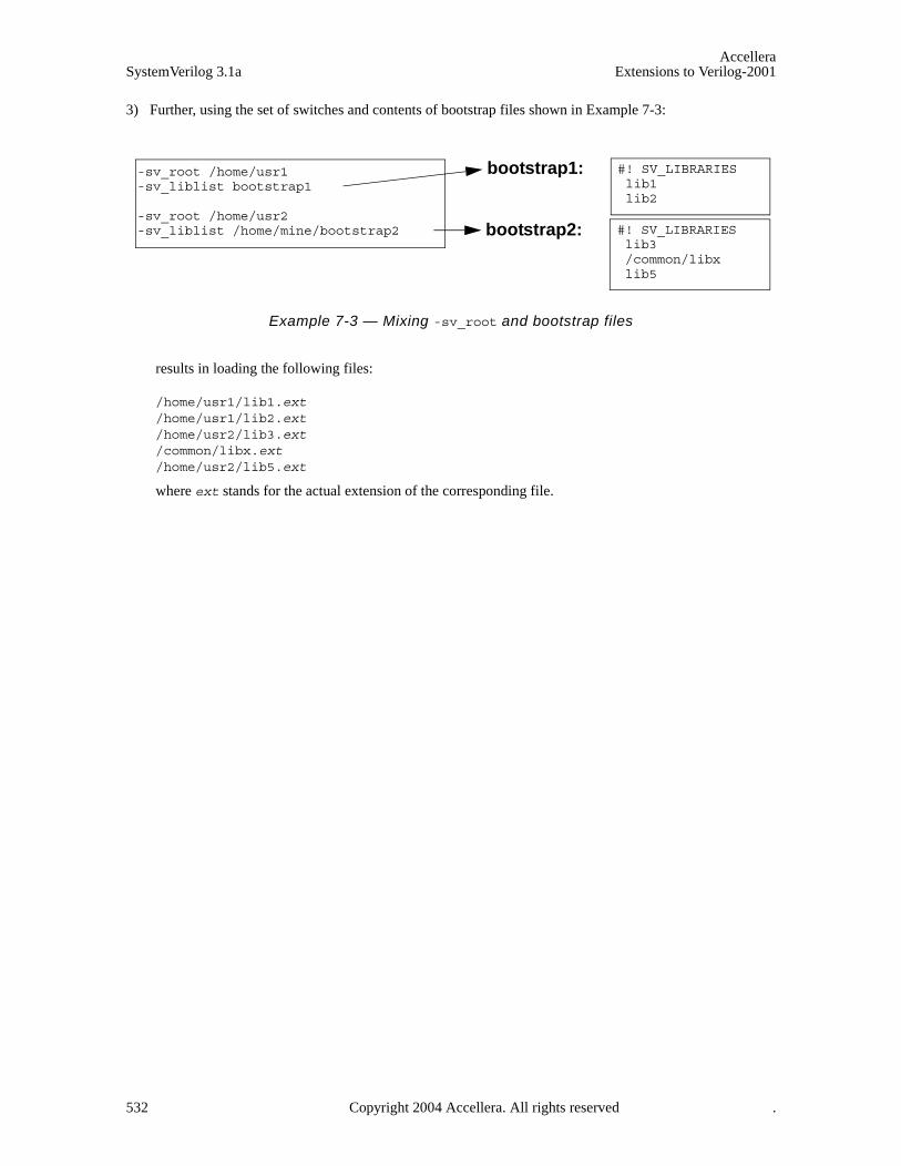
AccelleraSystemVerilog 3.1a Extensions to Verilog-2001
3) Further, using the set of switches and contents of bootstrap files shown in Example 7-3:
Example 7-3 — Mixing -sv_root and bootstrap files
results in loading the following files:
/home/usr1/lib1.ext/home/usr1/lib2.ext/home/usr2/lib3.ext/common/libx.ext/home/usr2/lib5.ext
where ext stands for the actual extension of the corresponding file.
#! SV_LIBRARIES lib1 lib2
#! SV_LIBRARIES lib3 /common/libx lib5
bootstrap1:
bootstrap2:
-sv_root /home/usr1-sv_liblist bootstrap1
-sv_root /home/usr2-sv_liblist /home/mine/bootstrap2
532 Copyright 2004 Accellera. All rights reserved .
AccelleraExtensions to Verilog-2001 SystemVerilog 3.1a
Annex HFormal Semantics of Concurrent Assertions
H.1 Introduction
This appendix presents a formal semantics for SystemVerilog concurrent assertions. Immediate assertions andcoverage statements are not discussed here. Throughout this appendix, “assertion” is used to mean “concurrentassertion”. The semantics is defined by a relation that determines when a finite or infinite word (i.e., trace) sat-isfies an assertion. Intuitively, such a word represents a sequence of valuations of SystemVerilog variablessampled at the finest relevant granularity of time (e.g., at the granularity of simulator cycles). The process bywhich such words are produced is closely related to the SystemVerilog scheduling semantics and is not definedhere. In this appendix, words are assumed to be sequences of elements, each element being either a set ofatomic propositions or one of two special symbols used as placeholders when extending finite words. Theatomic propositions are not further defined. The meaning of satisfaction of a SystemVerilog boolean expres-sion by a set of atomic propositions is assumed to be understood.
The semantics is based on an abstract syntax for SystemVerilog assertions. There are several advantages tousing the abstract syntax rather than the full SystemVerilog Assertions BNF.
1) The abstract syntax facilitates separation of derived operators from basic operators. The satisfactionrelation is defined explicitly only for assertions built from basic operators.
2) The abstract syntax avoids reliance on operator precedence, associativity, and auxiliary rules for resolvingsyntactic and semantic ambiguities.
3) The abstract syntax simplifies the assertion language by eliminating some features that tend to encumberthe definition of the formal semantics.
a) The abstract syntax eliminates local variable declarations. The semantics of local variables is writtenwith implicit types.
b) The abstract syntax eliminates instantiation of sequences and properties. The semantics of an assertionwith an instance of a sequence or non-recursive property is the same as the semantics of a relatedassertion obtained by replacing the sequence or non-recursive property instance with an explicitlywritten sequence or property. The explicit sequence or property is obtained from the body of theassociated declaration by substituting actual arguments for formal arguments. A separate sectiondefines the semantics of instances of recursive properties in terms of the semantics of instances of non-recursive properties.
c) The abstract syntax does not allow implicit clocks. Clocking event controls must be applied explicitlyin the abstract syntax.
d) The abstract syntax does not allow explicit procedural enabling conditions for assertions. Proceduralenabling conditions are utilized in the semantics definition (see Subsection 3.3.1), but the method forextracting such conditions is not defined in this appendix.
4) The abstract syntax eliminates the distinction between property_expr and property_spec from the fullBNF. Without the distinction, disable iff is a general, nestable property-building operator, while in thefull BNF disable iff can be attached only at the top level of a property. Semantically, there is no needfor this restriction on the placement of disable iff. The abstract syntax thus eliminates an unnecessarysemantic layer while maintaining the simple inductive form for the definition of the semantics ofproperties. As a result, semantics are given for some properties that do not correspond to forms from thefull BNF, but this does not degrade the definitions for the properties that do correspond to forms from thefull BNF.
In order to use this appendix to determine the semantics of a SystemVerilog assertion, the assertion must firstbe transformed into an enabling condition together with an assertion in the abstract syntax. For assertions that
Copyright 2004 Accellera. All rights reserved. 533
AccelleraSystemVerilog 3.1a Extensions to Verilog-2001
do not involve recursive properties, this transformation involves eliminating sequence and non-recursive prop-erty instances by substitution, eliminating local variable declarations, introducing parentheses, determining theenabling condition, determining implicit or inferred clocking event controls, and eliminating redundant clock-ing event controls. For example, the following SystemVerilog assertion
sequence s(x,y); x ##1 y; endsequencesequence t(z); @(c) z[*1:2] ##1 B; endsequencealways @(c) if (b) assert property (s(A,B) |=> t(A));
is transformed into the enabling condition “b” together with the assertion
always @(c) assert property ((A ##1 B) |=> (A[*1:2] ##1 B))
in the abstract syntax.
If the SystemVerilog assertion involves instances of recursive properties, then the transformation replacesthese instances with placeholder functions of the actual arguments. The semantics of an instance of a recursiveproperty is defined in terms of associated non-recursive properties in Section H.5. Once the semantics of therecursive property instances are understood, the placeholder functions are treated as properties with thesesemantics. Then the ordinary definitions can be applied to the transformed assertion in the abstract syntaxtogether with placeholder functions.
H.2 Abstract Syntax
H.2.1 Abstract grammars
In the following abstract grammars, b denotes a boolean expression, v denotes a local variable name, and edenotes an expression.
The abstract grammar for unclocked sequences is R
R ::= b // "boolean expression" form| ( 1, v = e ) // "local variable sampling" form| ( R ) // "parenthesis" form| ( R ##1 R ) // "concatenation" form| ( R ##0 R ) // "fusion" form| ( R or R ) // "or" form| ( R intersect R ) // "intersect" form| first_match ( R ) // "first match" form| R [ *0 ] // "null repetition" form| R [ *1:$ ] // "unbounded repetition" form
The abstract grammar for clocked sequences isS ::= @(b) R // "clock" form
| ( S ) // "parenthesized" form | ( S ## S ) // "concatenation" form
The abstract grammar for unclocked properties isP ::= R // "sequence" form
| ( P ) // "parenthesis" form| not P // "negation" form| ( P or P ) // "or" form| ( P and P ) // "and" form| ( R |-> P ) // "implication" form| disable iff ( b ) P // "reset" form
Each instance of R in this production must be a non-degenerate unclocked sequence. In the “sequence” form, Rmust not be tightly satisfied by the empty word. See H.3.2 and H.3.5 for the definitions of non-degeneracy andtight satisfaction.
534 Copyright 2004 Accellera. All rights reserved .
AccelleraExtensions to Verilog-2001 SystemVerilog 3.1a
The abstract grammar for clocked properties isQ ::= @( b ) P // "clock" form
| S // "sequence" form| ( Q ) // "parenthesis" form| not Q // "negation" form| ( Q or Q ) // "or" form| ( Q and Q ) // "and" form| ( S |-> Q ) // "implication" form| disable iff ( b ) Q // "reset" form
Each instance of S in this production must be a non-degenerate clocked sequence. In the “sequence” form, Smust not be tightly satisfied by the empty word. See H.3.2 and H.3.5 for the definitions of non-degeneracy andtight satisfaction.
The abstract grammar for assertions isA ::= always assert property Q // "always" form
| always @( b ) assert property P // "always with clock" form| initial assert property Q // "initial" form| initial @( b ) assert property P // "initial with clock" form
H.2.2 Notations
Throughout the sequel, the following notational conventions will be used: b, c denote boolean expressions; vdenotes a local variable name; e denotes an expression; R, R1, R2 denote unclocked sequences; S, S1, S2 denoteclocked sequences; P, P1, P2 denote unclocked properties; Q denotes a clocked property; A denotes an asser-tion; i, j, k, m, n denote non-negative integer constants.
H.2.3 Derived forms
Internal parentheses are omitted in compositions of the (associative) operators ##1 and or.
H.2.3.1 Derived non-overlapping implication operator
• ( R1 |=> P ) (( R1 ##1 1 ) |-> P ) .
• ( S1 |=> Q ) ((S1 ##1 @(1) 1 ) |-> Q ) .
H.2.3.2 Derived consecutive repetition operators
• Let m > 0. R [*m] ( R ##1 R ##1 ... ##1 R ) // m copies of R .
• R [*0:$] ( R [*0] or R [*1:$] ) .
• Let m < n. R [*m:n] ( R [*m] or R [*m +1] or ... or R [*n]) .
• Let m > 1. R [*m:$] ( R [*m – 1] ##1 R [*1:$]) .
H.2.3.3 Derived delay and concatenation operators
Let m < n.
• ( ##[m:n] R ) (1[*m:n] ##1 R ) .
• ( ##[m:$] R ) (1[*m:$] ##1 R ) .
• ( ##m R ) (1[*m] ##1 R ) .
• Let m > 0. ( R1 ##[m:n] R2 ) ( R1 ##1 1[*m – 1:n – 1] ##1 R2 ) .
Copyright 2004 Accellera. All rights reserved. 535
AccelleraSystemVerilog 3.1a Extensions to Verilog-2001
• Let m > 0. ( R1 ##[m:$] R2 ) ( R1 ##1 1[*m – 1:$] ##1 R2 ) .
• Let m > 1. ( R1 ##m R2 ) ( R1 ##1 1[*m – 1] ##1 R2 ) .
• ( R1 ##[0:0] R2 ) ( R1 ##0 R2 ) .
• Let n > 0. ( R1 ##[0:n] R2 ) (( R1 ##0 R2 ) or ( R1 ##[1:n] R2 )) .
• ( R1 ##[0:$] R2 ) (( R1 ##0 R2 ) or ( R1 ##[1:$] R2 )) .
H.2.3.4 Derived non-consecutive repetition operators
Let m < n.
• b [->m:n] ( !b [*0:$] ##1 b )[*m:n] .
• b [->m:$] ( !b [*0:$] ##1 b )[*m:$] .
• b [->m] ( !b [*0:$] ##1 b)[*m] .
• b [=m:n] ( b [->m:n] ##1 !b [*0:$] ) .
• b [=m:$] ( b [->m:$] ##1 !b [*0:$] ) .
• b [=m] ( b [->m] ##1 !b [*0:$] ) .
H.2.3.5 Other derived operators
• ( R1 and R2 )((( R1 ##1 1[*0:$]) intersect R2 ) or ( R1 intersect ( R2 ##1 1[*0:$]))) .
• ( R1 within R2 ) ((1[*0:$] ##1 R1 ##1 1[*0:$]) intersect R2 ) .
• ( b throughout R ) (( b [*0:$]) intersect R ) .
• ( R, v = e ) ( R ##0 ( 1, v = e )) .
• ( R, v1 = e1,... ,vk = ek) (( R, v1 = e1) ##0 ( 1, v2 = e2 ,... , vk = ek )) for k > 1
• ( if ( b ) P ) ( b |-> P )
• ( if ( b ) P1 else P2 ) ( ( b |-> P1 ) and ( !b |-> P2 ) )
H.3 Semantics
Let P be the set of atomic propositions.
The semantics of assertions and properties is defined via a relation of satisfaction by empty, finite, and infinitewords over the alphabet Σ = 2P U {T, ⊥}. Such a word is an empty, finite, or infinite sequence of elements of Σ.The number of elements in the sequence is called the length of the word, and the length of word w is denoted|w|. Note that |w| is either a non-negative integer or infinity.
The sequence elements of a word are called its letters and are assumed to be indexed consecutively beginningat zero. If |w| > 0, then the first letter of w is denoted w0; if |w| > 1, then the second letter of w is denoted w1; andso forth. w i.. denotes the word obtained from w by deleting its first i letters. If i < |w|, then w i.. = w iw i+1.... Ifi > |w|, then w i.. is empty.
If i < j, then w i, j denotes the finite word obtained from w by deleting its first i letters and also deleting all lettersafter its ( j + 1)st. If i < j < |w|, then w i, j = w iw i+1...w j.
If w is a word over Σ, define w to be the word obtained from w by interchanging T with ⊥. More precisely,
536 Copyright 2004 Accellera. All rights reserved .
AccelleraExtensions to Verilog-2001 SystemVerilog 3.1a
w i = T if w i = ⊥ ; w i = ⊥ if w i = T; and w i = w i if w i is an element in 2P.
The semantics of clocked sequences and properties is defined in terms of the semantics of unclockedsequences and properties. See the subsection on rewrite rules for clocks below.
It is assumed that the satisfaction relation ζ b is defined for elements ζ in 2P and boolean expressions b. Forany boolean expression b, define
T b and ⊥ b .
H.3.1 Rewrite rules for clocks
The semantics of clocked sequences and properties is defined in terms of the semantics of unclockedsequences and properties. The following rewrite rules define the transformation of a clocked sequence or prop-erty into an unclocked version that is equivalent for the purposes of defining the satisfaction relation. In thistransformation, it is required that the conditions in event controls not be dependent upon any local variables.
• @(c) b ( !c [*0:$] ##1 c & b ) .
• @(c)( 1, v = e ) ( @(c) 1 ##0 ( 1, v = e )) .
• @(c)( P ) ( @(c) P ).
• @(c)( R1 ##1 R2 ) ( @(c) R1 ##1 @(c) R2 ) .
• @(c)( R1 ##0 R2 ) ( @(c) R1 ##0 @(c) R2 ) .
• @(c)( R1 or R2 ) ( @(c) R1 or @(c) R2 ) .
• @(c)( R1 intersect R2 ) ( @(c) R1 intersect @(c) R2 ) .
• @(c) first_match ( R ) first_match ( @(c) R ) .
• @(c) R [*0] ( @(c) R )[*0] .
• @(c) R [*1:$] ( @(c) R )[*1:$] .
• @(c) disable iff ( b ) P disable iff ( b ) @(c) P .
• @(c) not P not @(c) P.
• @(c) ( R |-> P ) ( @(c) R |-> @(c) P ) .
• @(c) ( P1 or P2 ) ( @(c) P1 or @(c) P2 ).
• @(c) ( P1 and P2 ) ( @(c) P1 and @(c) P2 ).
H.3.2 Tight satisfaction without local variables
Tight satisfaction is denoted by . For unclocked sequences without local variables, tight satisfaction isdefined as follows. w, x, y, z denote finite words over Σ.
• w b iff |w| = 1 and w0 b .
• w ( R ) iff w R .
• w ( R1 ##1 R2 ) iff there exist x, y such that w = xy and x R1 and y R2 .
• w ( R1 ##0 R2 ) iff there exist x, y, z such that w = xyz and |y| = 1, and xy R1 and yz R2 .
• w ( R1 or R2 ) iff either w R1 or w R2 .
• w ( R1 intersect R2 ) iff both w R1 and w R2 .
Copyright 2004 Accellera. All rights reserved. 537

AccelleraSystemVerilog 3.1a Extensions to Verilog-2001
• w first_match ( R ) iff both
— w R and
— if there exist x, y such that w = xy and x R, then y is empty.
• w R [*0] iff |w| = 0.
• w R [*1:$] iff there exist words w1, w2,..., wj ( j > 1) such that w = w1w2...wj and for every i such that 1 < i < j, wi R .
If S is a clocked sequence, then w S iff w S’, where S’ is the unclocked sequence that results from S byapplying the rewrite rules.
An unclocked sequence R is non-degenerate iff there exists a non-empty finite word w over Σ such that w R. A clocked sequence S is non-degenerate iff the unclocked sequence S’ that results from S by applyingthe rewrite rules is non-degenerate.
H.3.3 Satisfaction without local variables
H.3.3.1 Neutral satisfaction
w denotes a non-empty finite or infinite word over Σ. Assume that all properties, sequences, and unclockedproperty fragments do not involve local variables.
Neutral satisfaction of assertions:
For the definition of neutral satisfaction of assertions, b denotes the boolean expression representing theenabling condition for the assertion. Intuitively, b is derived from the conditions in the context of a proceduralassertion, while b is “1” for a declarative assertion.
• w, b always @(c) assert property P iff for every 0 < i < |w| such that w i c and w i b, w i.. @(c) P.
• w, b always assert property Q iff for every 0 < i < |w|, if w i b then w i.. Q .
• w, b initial @(c) assert property P iff for every 0 < i < |w| such that w 0, i !c [*0:$] ##1 c andw i b, w i.. @(c) P .
• w, b initial assert property Q iff (if w 0 b then w Q ) .
Neutral satisfaction of properties:
• w ( P ) iff w P.
• w Q iff w Q’, where Q’ is the unclocked property that results from Q by applying the rewrite rules.
• w disable iff (b) P iff either w P or there exists 0 < k < |w| such that w k b and w 0, k–1 Tω P. Here, w 0, –1 denotes the empty word.
• w not P iff w P.
• w R iff there exists 0 < j < |w| such that w 0, j R .
• w ( R |-> P ) iff for every 0 < j < |w| such that w 0, j R, w j.. P .
• w ( P1 or P2 ) iff w P1 or w P2.
• w ( P1 and P2 ) iff w P1 and w P2.
Remark: Since w is non-empty, it can be proved that w not b iff w !b.
^
538 Copyright 2004 Accellera. All rights reserved .

AccelleraExtensions to Verilog-2001 SystemVerilog 3.1a
H.3.3.2 Weak and strong satisfaction by finite words
This subsection defines weak and strong satisfaction, denoted – and + (respectively) of an assertion A bya finite (possibly empty) word w over Σ. These relations are defined in terms of the relation of neutral satisfac-tion by infinite words as follows:
• w – A iff w Tω A.
• w + A iff w⊥ω A.
A tool checking for satisfaction of A by the finite word w should return:
• “holds strongly” if w + A.
• “fails” if w A.
• “holds (but does not hold strongly)” if w A and w + A.
• “pending” if w - A and w A.
H.3.4 Local variable flow
This subsection defines inductively how local variable names flow through unclocked sequences. Below, “U”denotes set union, “ ” denotes set intersection, “–” denotes set difference, and “{}” denotes the empty set.
The function “sample” takes a sequence as input and returns a set of local variable names as output. Intuitively,this function returns the set of local variable names that are sampled (i.e., assigned) in the sequence.
The function “block” takes a sequence as input and returns a set of local variable names as output. Intuitively,this function returns the set of local variable names that are blocked from flowing out of the sequence.
The function “flow” takes a set X of local variable names and a sequence as input and returns a set of local vari-able names as output. Intuitively, this function returns the set of local variable names that flow out of thesequence given the set X of local variable names that flow into the sequence.
The function “sample” is defined by
• sample (b) = {} .
• sample (( 1, v = e )) = {v} .
• sample (( R )) = sample (R) .
• sample (( R1 ##1 R2 )) = sample (R1) U sample (R2) .
• sample (( R1 ##0 R2 )) = sample (R1) U sample (R2) .
• sample (( R1 or R2 )) = sample (R1) U sample (R2) .
• sample (( R1 intersect R2 )) = sample (R1) U sample (R2) .
• sample (first_match ( R )) = sample (R) .
• sample (R [*0]) = {} .
• sample (R [*1:$]) = sample (R) .
The function “block” is defined by
• block (b) = {} .
• block (( 1, v = e )) = {} .
• block (( R )) = block (R) .
U
Copyright 2004 Accellera. All rights reserved. 539
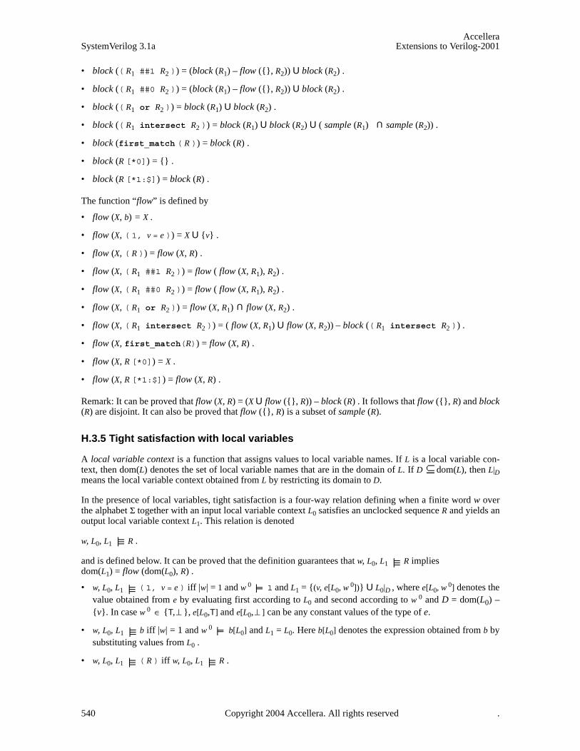
AccelleraSystemVerilog 3.1a Extensions to Verilog-2001
• block (( R1 ##1 R2 )) = (block (R1) – flow ({}, R2)) U block (R2) .
• block (( R1 ##0 R2 )) = (block (R1) – flow ({}, R2)) U block (R2) .
• block (( R1 or R2 )) = block (R1) U block (R2) .
• block (( R1 intersect R2 )) = block (R1) U block (R2) U ( sample (R1) sample (R2)) .
• block (first_match ( R )) = block (R) .
• block (R [*0]) = {} .
• block (R [*1:$]) = block (R) .
The function “flow” is defined by
• flow (X, b) = X .
• flow (X, ( 1, v = e )) = X U {v} .
• flow (X, ( R )) = flow (X, R) .
• flow (X, ( R1 ##1 R2 )) = flow ( flow (X, R1), R2) .
• flow (X, ( R1 ##0 R2 )) = flow ( flow (X, R1), R2) .
• flow (X, ( R1 or R2 )) = flow (X, R1) flow (X, R2) .
• flow (X, ( R1 intersect R2 )) = ( flow (X, R1) U flow (X, R2)) – block (( R1 intersect R2 )) .
• flow (X, first_match(R)) = flow (X, R) .
• flow (X, R [*0]) = X .
• flow (X, R [*1:$]) = flow (X, R) .
Remark: It can be proved that flow (X, R) = (X U flow ({}, R)) – block (R) . It follows that flow ({}, R) and block(R) are disjoint. It can also be proved that flow ({}, R) is a subset of sample (R).
H.3.5 Tight satisfaction with local variables
A local variable context is a function that assigns values to local variable names. If L is a local variable con-text, then dom(L) denotes the set of local variable names that are in the domain of L. If D dom(L), then L|Dmeans the local variable context obtained from L by restricting its domain to D.
In the presence of local variables, tight satisfaction is a four-way relation defining when a finite word w overthe alphabet Σ together with an input local variable context L0 satisfies an unclocked sequence R and yields anoutput local variable context L1. This relation is denoted
w, L0, L1 R .
and is defined below. It can be proved that the definition guarantees that w, L0, L1 R implies dom(L1) = flow (dom(L0), R) .
• w, L0, L1 ( 1, v = e ) iff |w| = 1 and w 0 1 and L1 = {(v, e[L0, w 0])} U L0|D , where e[L0, w 0] denotes thevalue obtained from e by evaluating first according to L0 and second according to w 0 and D = dom(L0) –{v}. In case w 0 {T, }, e[L0,T] and e[L0, ] can be any constant values of the type of e.
• w, L0, L1 b iff |w| = 1 and w 0 b[L0] and L1 = L0. Here b[L0] denotes the expression obtained from b bysubstituting values from L0 .
• w, L0, L1 ( R ) iff w, L0, L1 R .
U
U
∈ ⊥ ⊥
540 Copyright 2004 Accellera. All rights reserved .

AccelleraExtensions to Verilog-2001 SystemVerilog 3.1a
• w, L0, L1 ( R1 ##1 R2 ) iff there exist x, y, L’ such that w = xy and x, L0, L’ R1 and y, L’, L1 R2 .
• w, L0, L1 ( R1 ##0 R2 ) iff there exist x, y, z, L’ such that w = xyz and |y| = 1, and xy, L0, L’ R1 and yz, L’, L1 R2 .
• w, L0, L1 ( R1 or R2 ) iff there exists L’ such that both of the following hold:
— either w, L0, L’ R1 or w, L0, L’ R2, and
— L1 = L’ |D, where D = flow (dom(L0), ( R1 or R2 )) .
• w, L0, L1 ( R1 intersect R2 ) iff there exist L’, L" such thatw, L0, L’ R1 and w, L0, L" R2 and L1 = L’ |D’ U L" |D’’ , where
D’ = flow (dom(L0), R1) – (block (( R1 intersect R2 )) U sample (R2)) D’’ = flow (dom(L0), R2) – (block (( R1 intersect R2 )) U sample (R1))
Remark: It can be proved that if w, L0, L’ R1 and w, L0, L" R2 , then L’ |D’ U L" |D’’ is a function.
• w, L0, L1 first_match ( R ) iff both
— w, L0, L1 R and
— if there exist x, y, L’ such that w = xy and x, L0, L’ R, then y is empty.
• w, L0, L1 R [*0] iff |w| = 0 and L1 = L0.
• w, L0, L1 R [*1:$] iff there exist L(0) = L0, w1, L(1), w2, L(2),..., wj, L( j) = L1 ( j > 1) such that w = w1w2...wj
and for every i such that 1 < i < j, wi, L(i –1), L(i) R .
If S is a clocked sequence, then w, L0, L1 S iff w, L0, L1 S’, where S’ is the unclocked sequence that resultsfrom S by applying the rewrite rules.
An unclocked sequence R is non-degenerate iff there exist a non-empty finite word w over Σ and local variablecontexts L0, L1 such that w, L0, L1 R. A clocked sequence S is non-degenerate iff the unclocked sequence S’that results from S by applying the rewrite rules is non-degenerate.
H.3.6 Satisfaction with local variables
H.3.6.1 Neutral satisfaction
w denotes a non-empty finite or infinite word over Σ. L0, L1 denote local variable contexts.
The rules defining neutral satisfaction of an assertion are identical to those without local variables, but with theunderstanding that the underlying properties can have local variables.
Neutral satisfaction of properties:
• w Q iff w, {} Q.
• w, L0 Q iff w, L0 Q’, where Q’ is the unclocked property that results from Q by applying the rewriterules.
• w, L0 disable iff (b) P iff either w, L0 P or there exists 0 < k < |w| such thatw k b[L0] and w 0, k–1Tω, L0 P. Here, w 0, –1 denotes the empty word.
• w, L0 not P iff w, L0 P .
• w, L0 R iff there exist 0 < j < |w| and L1 such that w 0, j, L0, L1 R .
• w, L0 ( R |-> P ) iff for every 0 < j < |w| and L1 such that w 0, j, L0, L1 R, w j.., L1 P .
Copyright 2004 Accellera. All rights reserved. 541
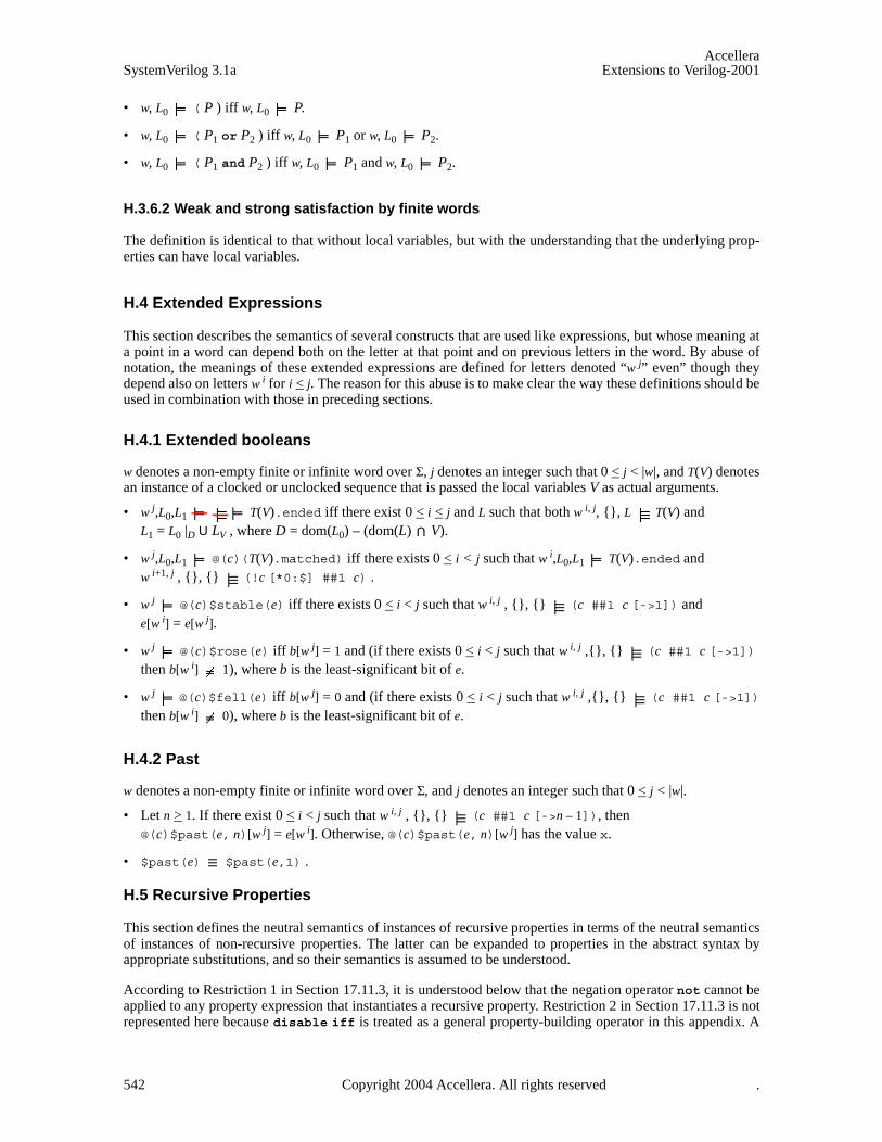
AccelleraSystemVerilog 3.1a Extensions to Verilog-2001
• w, L0 ( P ) iff w, L0 P.
• w, L0 ( P1 or P2 ) iff w, L0 P1 or w, L0 P2.
• w, L0 ( P1 and P2 ) iff w, L0 P1 and w, L0 P2.
H.3.6.2 Weak and strong satisfaction by finite words
The definition is identical to that without local variables, but with the understanding that the underlying prop-erties can have local variables.
H.4 Extended Expressions
This section describes the semantics of several constructs that are used like expressions, but whose meaning ata point in a word can depend both on the letter at that point and on previous letters in the word. By abuse ofnotation, the meanings of these extended expressions are defined for letters denoted “w j” even” though theydepend also on letters w i for i < j. The reason for this abuse is to make clear the way these definitions should beused in combination with those in preceding sections.
H.4.1 Extended booleans
w denotes a non-empty finite or infinite word over Σ, j denotes an integer such that 0 < j < |w|, and T(V) denotesan instance of a clocked or unclocked sequence that is passed the local variables V as actual arguments.
• w j,L0,L1 T(V).ended iff there exist 0 < i < j and L such that both w i, j, {}, L T(V) andL1 = L0 |D U LV , where D = dom(L0) – (dom(L) V).
• w j,L0,L1 @(c)(T(V).matched) iff there exists 0 < i < j such that w i,L0,L1 T(V).ended and
w i+1, j , {}, {} (!c [*0:$] ##1 c) .
• w j @(c)$stable(e) iff there exists 0 < i < j such that w i, j , {}, {} (c ##1 c [->1]) and
e[w i] = e[w j].
• w j @(c)$rose(e) iff b[w j] = 1 and (if there exists 0 < i < j such that w i, j ,{}, {} (c ##1 c [->1]) then b[w i] 1), where b is the least-significant bit of e.
• w j @(c)$fell(e) iff b[w j] = 0 and (if there exists 0 < i < j such that w i, j ,{}, {} (c ##1 c [->1])
then b[w i] 0), where b is the least-significant bit of e.
H.4.2 Past
w denotes a non-empty finite or infinite word over Σ, and j denotes an integer such that 0 < j < |w|.
• Let n > 1. If there exist 0 < i < j such that w i, j , {}, {} (c ##1 c [->n – 1]), then @(c)$past(e, n)[w j] = e[w i]. Otherwise, @(c)$past(e, n)[w j] has the value x.
• $past(e) $past(e,1) .
H.5 Recursive Properties
This section defines the neutral semantics of instances of recursive properties in terms of the neutral semanticsof instances of non-recursive properties. The latter can be expanded to properties in the abstract syntax byappropriate substitutions, and so their semantics is assumed to be understood.
According to Restriction 1 in Section 17.11.3, it is understood below that the negation operator not cannot beapplied to any property expression that instantiates a recursive property. Restriction 2 in Section 17.11.3 is notrepresented here because disable iff is treated as a general property-building operator in this appendix. A
U
542 Copyright 2004 Accellera. All rights reserved .
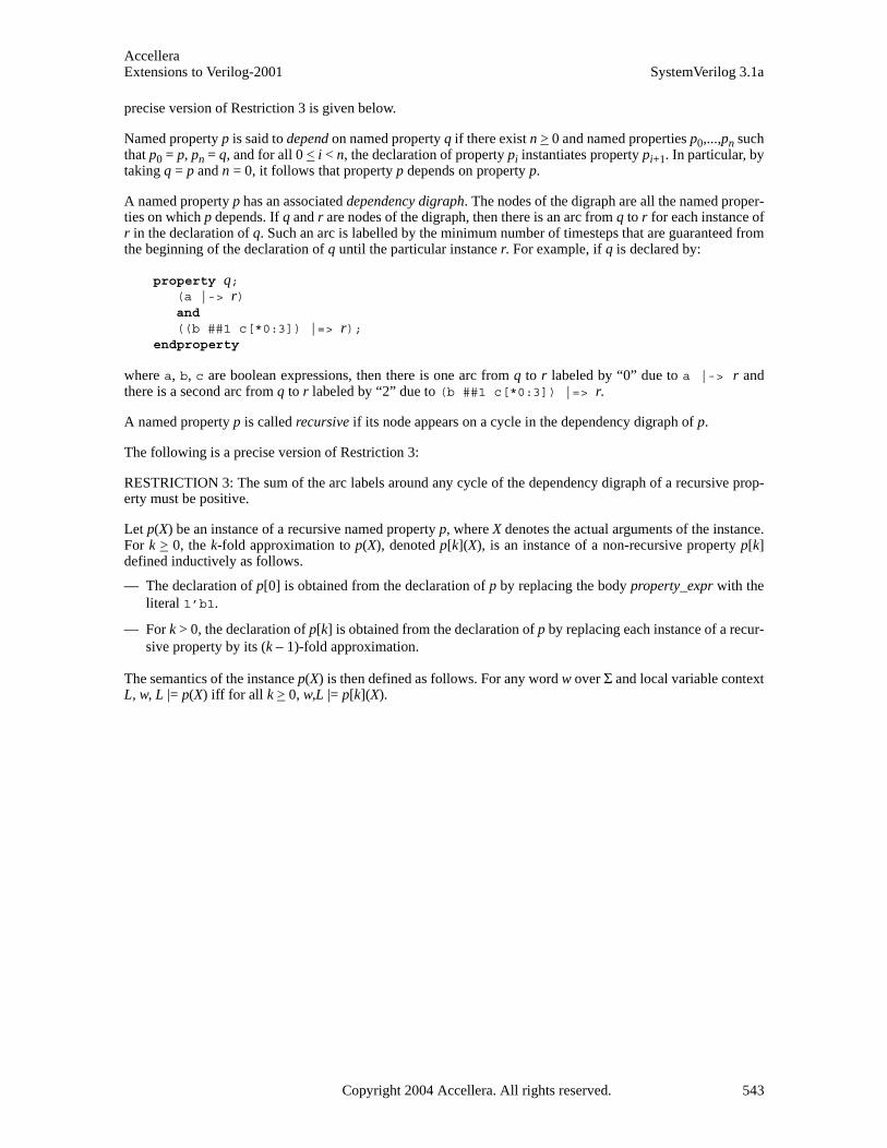
AccelleraExtensions to Verilog-2001 SystemVerilog 3.1a
precise version of Restriction 3 is given below.
Named property p is said to depend on named property q if there exist n > 0 and named properties p0,...,pn suchthat p0 = p, pn = q, and for all 0 < i < n, the declaration of property pi instantiates property pi+1. In particular, bytaking q = p and n = 0, it follows that property p depends on property p.
A named property p has an associated dependency digraph. The nodes of the digraph are all the named proper-ties on which p depends. If q and r are nodes of the digraph, then there is an arc from q to r for each instance ofr in the declaration of q. Such an arc is labelled by the minimum number of timesteps that are guaranteed fromthe beginning of the declaration of q until the particular instance r. For example, if q is declared by:
property q;(a |-> r)and ((b ##1 c[*0:3]) |=> r);
endproperty
where a, b, c are boolean expressions, then there is one arc from q to r labeled by “0” due to a |-> r andthere is a second arc from q to r labeled by “2” due to (b ##1 c[*0:3]) |=> r.
A named property p is called recursive if its node appears on a cycle in the dependency digraph of p.
The following is a precise version of Restriction 3:
RESTRICTION 3: The sum of the arc labels around any cycle of the dependency digraph of a recursive prop-erty must be positive.
Let p(X) be an instance of a recursive named property p, where X denotes the actual arguments of the instance.For k > 0, the k-fold approximation to p(X), denoted p[k](X), is an instance of a non-recursive property p[k]defined inductively as follows.
— The declaration of p[0] is obtained from the declaration of p by replacing the body property_expr with theliteral 1’b1.
— For k > 0, the declaration of p[k] is obtained from the declaration of p by replacing each instance of a recur-sive property by its (k – 1)-fold approximation.
The semantics of the instance p(X) is then defined as follows. For any word w over Σ and local variable contextL, w, L |= p(X) iff for all k > 0, w,L |= p[k](X).
Copyright 2004 Accellera. All rights reserved. 543

AccelleraSystemVerilog 3.1a Extensions to Verilog-2001
Annex Isv_vpi_user.h
(normative)
sv_vpi_user.h
/*************************************************************************** * sv_vpi_user.h * * Accellera SystemVerilog VPI extensions. * * This file contains the constant definitions, structure definitions, and * routine declarations used by the Verilog PLI procedural interface VPI * access routines. * **************************************************************************/
/*************************************************************************** * NOTE: The constant values 600 through 999 are reserved for use in this * sv_vpi_user.h file. The range 800 through 899 is reserved for the reader * VPI **************************************************************************/
#ifndef SV_VPI_USER_H#define SV_VPI_USER_H
#include <vpi_user.h>
#ifdef __cplusplusextern "C" {#endif}
/****************************** OBJECT TYPES ******************************/#define vpiPackage 600#define vpiInterface 601#define vpiProgram 602#define vpiInterfaceArray 603#define vpiProgramArray 604#define vpiTypespec 605#define vpiModport 606#define vpiInterfaceTfDecl 607#define vpiRefObj 608#define vpiVarBitVar vpiRegBit#define vpiLongIntVar 609#define vpiShortIntVar 610#define vpiIntVar 611#define vpiShortRealVar 612#define vpiByteVar 613#define vpiClassVar 614#define vpiStringVar 615#define vpiEnumVar 616#define vpiStructVar 617#define vpiUnionVar 618#define vpiBitVar 619#define vpiLogicVar vpiRegVar #define vpiArrayVar vpiRegArray
544 Copyright 2004 Accellera. All rights reserved .

AccelleraExtensions to Verilog-2001 SystemVerilog 3.1a
#define vpiLongIntTypespec 620#define vpiShortRealTypespec 621#define vpiByteTypespec 622#define vpiShortIntTypespec 623#define vpiIntTypespec 624#define vpiClassTypespec 625#define vpiStringTypespec 626#define vpiVarBitTypespec 627#define vpiEnumTypespec 628#define vpiEnumConst 629#define vpiIntegerTypespec 630#define vpiTimeTypespec 631#define vpiRealTypespec 632#define vpiStructTypespec 633#define vpiUnionTypespec 634#define vpiBitTypespec 635#define vpiLogicTypespec 636#define vpiArrayTypespec 637#define vpiVoidTypespec 638#define vpiMemberTypespec 639#define vpiClockingBlock 640#define vpiClockingIODecl 641#define vpiClassDefn 642#define vpiConstraint 643#define vpiConstraintOrdering 644
#define vpiDistItem 645#define vpiAliasStmt 646#define vpiThread 647#define vpiMethodFuncCall 648#define vpiMethodTaskCall 649#define vpiAssertProperty 650#define vpiAssumeProperty 651#define vpiCoverProperty 652#define vpiDisableCondition 653#define vpiClockingEvent 654#define vpiPropertyDecl 655#define vpiPropertySpec 656#define vpiPropertyExpr 657#define vpiMulticlockSequenceExpr 658#define vpiClockedSeq 659#define vpiPropertyInst 660#define vpiSequenceDecl 661#define vpiSequenceSpec 662#define vpiActualArgExpr 663#define vpiSequenceInst 664#define vpiImmediateAssert 665#define vpiReturn 666#define vpiAnyPattern 667#define vpiTaggedPattern 668#define vpiStructPattern 669#define vpiDoWhile 670#define vpiOrderedWait 671#define vpiWaitFork 672#define vpiDisableFork 673#define vpiExpectStmt 674#define vpiForeachStmt 675#define vpiFinal 676
Copyright 2004 Accellera. All rights reserved. 545
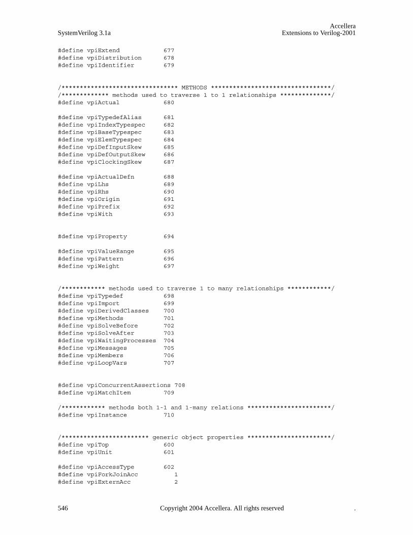
AccelleraSystemVerilog 3.1a Extensions to Verilog-2001
#define vpiExtend 677#define vpiDistribution 678#define vpiIdentifier 679
/******************************** METHODS *********************************//************* methods used to traverse 1 to 1 relationships **************/#define vpiActual 680
#define vpiTypedefAlias 681#define vpiIndexTypespec 682#define vpiBaseTypespec 683#define vpiElemTypespec 684#define vpiDefInputSkew 685#define vpiDefOutputSkew 686#define vpiClockingSkew 687
#define vpiActualDefn 688#define vpiLhs 689#define vpiRhs 690#define vpiOrigin 691#define vpiPrefix 692#define vpiWith 693
#define vpiProperty 694
#define vpiValueRange 695#define vpiPattern 696#define vpiWeight 697
/************ methods used to traverse 1 to many relationships ************/#define vpiTypedef 698#define vpiImport 699#define vpiDerivedClasses 700#define vpiMethods 701#define vpiSolveBefore 702#define vpiSolveAfter 703#define vpiWaitingProcesses 704#define vpiMessages 705#define vpiMembers 706#define vpiLoopVars 707
#define vpiConcurrentAssertions 708#define vpiMatchItem 709
/************ methods both 1-1 and 1-many relations ***********************/#define vpiInstance 710
/************************ generic object properties ***********************/#define vpiTop 600#define vpiUnit 601
#define vpiAccessType 602#define vpiForkJoinAcc 1#define vpiExternAcc 2
546 Copyright 2004 Accellera. All rights reserved .
AccelleraExtensions to Verilog-2001 SystemVerilog 3.1a
#define vpiDPIExternAcc 3#define vpiDPIImportAcc 4
#define vpiArrayType 603#define vpiStaticArray 1#define vpiDynamicArray 2#define vpiAssocArray 3#define vpiQueueArray 4
#define vpiIsRandomized 604
#define vpiRandType 605#define vpiNotRand 1#define vpiRand 2#define vpiRandC 3
#define vpiConstantVariable 606#define vpiMember 607
#define vpiVisibility 608#define vpiPublicVis 1#define vpiProtectedVis 2#define vpiLocalVis 3
#define vpiPacked 609#define vpiTagged 610#define vpiRef 611#define vpiDefaultSkew 612#define vpiVirtual 613#define vpiUserDefined 614#define vpiIsConstraintEnabled 615
#define vpiClassType 616#define vpiMailboxClass 1#define vpiSemaphoreClass 2#define vpiUserDefineClass 3
#define vpiMethod 617#define vpiValid 618#define vpiActive 619#define vpiIsClockInferred 620
#define vpiQualifier 621#define vpiUniqueQualifier 1#define vpiPriorityQualifier 2#define vpiTaggedQualifier 3
#define vpiNullConst 622#define vpiOneStepConst 623
#define vpiAlwaysType 624#define vpiAlwaysComb 1#define vpiAlwaysFF 2#define vpiAlwaysLatch 3
#define vpiDistType 625#define vpiEqualDist 1 /* constraint equal distribution */#define vpiDivDist 2 /* constraint divided distribution */
Copyright 2004 Accellera. All rights reserved. 547
AccelleraSystemVerilog 3.1a Extensions to Verilog-2001
/******************************** Operators *******************************/
#define vpiImplyOp 50 /* -> implication operator */#define vpiNonOverlapImplyOp 51 /* |=> non-overlapped implication */#define vpiOverlapImplyOp 52 /* |-> overlapped implication operator */#define vpiUnaryCycleDelayOp 53 /* binary cycle delay (##) operator */#define vpiCycleDelayOp 54 /* binary cycle delay (##) operator */#define vpiIntersectOp 55 /* intersection operator */#define vpiFirstMatchOp 56 /* first_match operator */#define vpiThroughoutOp 57 /* throught operator */#define vpiWithinOp 58 /* within operator */#define vpiRepeatOp 59 /* [=] non-consecutive repetition */#define vpiConsecutiveRepeatOp 60 /* [*] consecutive repetition */#define vpiGotoRepeatOp 61 /* [->] goto repetition */
#define vpiPostIncOp 62 /* ++ post-increment */#define vpiPreIncOp 63 /* ++ pre-increment */#define vpiPostDecOp 64 /* -- post-decrement */#define vpiPreDecOp 65 /* -- pre-decrement */
#define vpiMatchOp 66 /* match() operator */#define vpiCastOp 67 /* type‘() operator */#define vpiIffOp 68 /* iff operator */#define vpiWildEqOp 69 /* =?= operator */#define vpiWildNeqOp 70 /* !?= operator */
#define vpiStreamLROp 71 /* left-to-right streaming {>>} operator */#define vpiStreamRLOp 72 /* right-to-left streaming {<<} operator */
#define vpiMatchedOp 73 /* the .matched sequence operation */#define vpiEndedOp 74 /* the .ended sequence operation */
/************************** STRUCTURE DEFINITIONS *************************/
/***************************** structure *****************************/
/**************************** CALLBACK REASONS ****************************/#define cbStartOfThread 600 /* callback on thread creation */#define cbEndOfThread 601 /* callback on thread termination */#define cbEnterThread 602 /* callback on re-entering thread */#define cbStartOfFrame 603 /* callback on frame creation */#define cbEndOfFrame 604 /* callback on frame exit */#define cbTypeChange 605 /* callback on variable type/size change */
/************************* FUNCTION DECLARATIONS **************************/
/**************************************************************************//**************************************************************************/
/*************************** Coverage VPI *********************************/
/* coverage control */#define vpiCoverageStart 711#define vpiCoverageStop 712#define vpiCoverageReset 713#define vpiCoverageCheck 714#define vpiCoverageMerge 715#define vpiCoverageSave 716
548 Copyright 2004 Accellera. All rights reserved .

AccelleraExtensions to Verilog-2001 SystemVerilog 3.1a
/* coverage type properties */#define vpiAssertCoverage 717#define vpiFsmStateCoverage 718#define vpiStatementCoverage 719#define vpiToggleCoverage 720/* Coverage status properties */#define vpiCovered 721#define vpiCoverMax 722#define vpiCoveredCount 723/* Assertion-specific coverage status properties */#define vpiAssertAttemptCovered 724#define vpiAssertSuccessCovered 725#define vpiAssertFailureCovered 726/* FSM-specific coverage status properties */#define vpiFsmStates 727#define vpiFsmStateExpression 728/* FSM handle types */ #define vpiFsm 729#define vpiFsmHandle 730
/***************************************************************************//***************************************************************************/
/***************************** Assertion VPI *******************************/
/* assertion types */#define vpiSequenceType 731#define vpiAssertType 732#define vpiCoverType 733#define vpiPropertyType 734#define vpiImmediateAssertType 735
/* assertion callback types */#define cbAssertionStart 606#define cbAssertionSuccess 607#define cbAssertionFailure 608#define cbAssertionStepSuccess 609#define cbAssertionStepFailure 610#define cbAssertionDisable 611#define cbAssertionEnable 612#define cbAssertionReset 613#define cbAssertionKill 614#define cbAssertionSysInitialized 615#define cbAssertionSysStart 616#define cbAssertionSysStop 617#define cbAssertionSysEnd 618#define cbAssertionSysReset 619
/* Assertion control constants */#define vpiAssertionDisable 620#define vpiAssertionEnable 621#define vpiAssertionReset 622#define vpiAssertionKill 623#define vpiAssertionEnableStep 624#define vpiAssertionDisableStep 625#define vpiAssertionClockSteps 626#define vpiAssertionSysStart 627#define vpiAssertionSysStop 628#define vpiAssertionSysEnd 629
Copyright 2004 Accellera. All rights reserved. 549

AccelleraSystemVerilog 3.1a Extensions to Verilog-2001
#define vpiAssertionSysReset 630
/* Assertion related structs and types */typedef struct t_vpi_source_info { PLI_BYTE8 *fileName; PLI_INT32 startLine; PLI_INT32 startColumn; PLI_INT32 endLine; PLI_INT32 endColumn;} s_vpi_source_info, *p_vpi_source_info;
typedef struct t_vpi_assertion_info { PLI_BYTE8 *assertName; /* name of assertion */ vpiHandle instance; /* instance containing assertion */ PLI_BYTE8 defname; /* name of module/interface containing the assertion */ vpiHandle clock; /* clocking expression */ PLI_INT32 assertionType; /* vpiSequenceType, vpiAssertType, vpiCoverType, vpiPropertyType, vpiImmediateAssertType */ s_vpi_source_info sourceInfo;} s_vpi_assertion_info, *p_vpi_assertion_info;
typedef struct t_vpi_assertion_step_info { PLI_INT32 matched_expression_count; vpiHandle *matched_exprs; /* array of expressions */ p_vpi_source_info *exprs_source_info; /* array of source info */ PLI_INT32 stateFrom, stateTo; /* identify transition */} s_vpi_assertion_step_info, *p_vpi_assertion_step_info;
typedef struct t_vpi_attempt_info { union { vpiHandle failExpr; p_vpi_assertion_step_info step; } detail; s_vpi_time attemptStartTime; /* Time attempt triggered */} s_vpi_attempt_info, *p_vpi_attempt_info;
/* typedef for vpi_register_assertion_cb callback function */typedef PLI_INT32 (vpi_assertion_callback_func)( PLI_INT32 reason, /* callback reason */ p_vpi_time cb_time, /* callback time */ vpiHandle assertion, /* handle to assertion */ p_vpi_attempt_info info, /* attempt related information */ PLI_BYTE8 *user_data /* user data entered upon registration */ );
/* assertion specific VPI functions */PLI_INT32 vpi_get_assertion_info (assert_handle, p_vpi_assertion_info);
vpiHandle vpi_register_assertion_cb( vpiHandle assertion, /* handle to assertion */ PLI_INT32 reason, /* reason for which callbacks needed */ vpi_assertion_callback_func *cb_rtn, PLI_BYTE8 *user_data /* user data to be supplied to cb */ );
550 Copyright 2004 Accellera. All rights reserved .
AccelleraExtensions to Verilog-2001 SystemVerilog 3.1a
/***************************************************************************//***************************************************************************/
/*************** Reader VPI ***********************//* reader VPI has been assigned the numeric range 800-899 */
/********** Reader types ***********/#define vpiTrvsObj 800 /* Data traverse object */#define vpiCollection 810 /* Collection of VPI handle */#define vpiObjCollection 811 /* Collection of traversable design objs */#define vpiTrvsCollection 812 /* Collection of vpiTrvsObjs */
/********* Reader methods *********/
/* Check */#define vpiIsLoaded 820 /* Object data is loaded check */#define vpiHasDataVC 821 /* Traverse object has at least one VC * at some point in time in the * database check */#define vpiHasVC 822 /* Has VC at specific time check */ #define vpiHasNoValue 823 /* Has no value at specific time check */#define vpiBelong 824 /* Belongs to extension check */
/* Access */#define vpiAccessLimitedInteractive 830 /* Interactive access */#define vpiAccessInteractive 831 /* interactive with history access */#define vpiAccessPostProcess 832 /* Database access *//* Member of a collection */#define vpiMember 840 /* Member of a collection *//* Iteration on instances for loaded */#define vpiDataLoaded 850 /* Use in vpi_iterate() */
/* Control Traverse/Check Time */#define vpiMinTime 860 /* Min time */#define vpiMaxTime 864 /* Max time */#define vpiPrevVC 868 /* Previous Value Change (VC) */#define vpiNextVC 870 /* Next Value Change (VC) */#define vpiTime 874 /* Time jump */
/********** routines **********/
/* general form of the vpi extension loading function is: * PLI_INT32 vpi_load_extension PROTO_PARAMS((PLI_BYTE8 *extension_name, ...)) */ /********** Reader routines **********//* load extension form for the reader extension */PLI_INT32 vpi_load_extension PROTO_PARAMS((PLI_BYTE8 *extension_name, PLI_BYTE8 *name, vpiType mode, ...)) PLI_INT32 vpi_close PROTO_PARAMS((PLI_INT32 tool, vpiType prop, PLI_BYTE8* name));
PLI_INT32 vpi_load_init PROTO_PARAMS((vpiHandle objCollection, vpiHandle scope, PLI_INT32 level));
Copyright 2004 Accellera. All rights reserved. 551

AccelleraSystemVerilog 3.1a Extensions to Verilog-2001
PLI_INT32 vpi_load PROTO_PARAMS((vpiHandle h));
PLI_INT32 vpi_unload PROTO_PARAMS((vpiHandle h));
vpiHandle vpi_create PROTO_PARAMS((vpiType prop, vpiHandle h, vpiHandle obj));
vpiHandle vpi_goto PROTO_PARAMS((vpiType prop, vpiHandle obj, p_vpi_time time_p, PLI_INT32 *ret_code));
vpiHandle vpi_filter PROTO_PARAMS((vpiHandle h, PLI_INT32 ft, PLI_INT32 flag));
#ifdef __cplusplus}#endif
#endif
552 Copyright 2004 Accellera. All rights reserved .
AccelleraExtensions to Verilog-2001 SystemVerilog 3.1a
Annex JGlossary
(Informative)
Aggregate — An aggregate expression, variable or type represents a set or collection of singular values. Anaggregate type is any unpacked structure, unpacked union, or unpacked array data type. Aggregates may becopied or compared as a whole, but not typically used in an expression as a whole.
Assertion — An assertion is a statement that a certain property must be true. For example, that a read_requestmust always be followed by a read_grant within 2 clock cycles. Assertions allow for automated checking thatthe specified property is true, and can generate automatic error messages if the property is not true. SystemVer-ilog provides special assertion constructs, which are discussed in Section 17.
Bit-stream — A bit-stream type or variables is any type that can be represented as a serial stream of bits. Toqualify as a bit-stream type, each and every bit of the type must be individually addressable. This means that abit-stream type can be any type that does not include a handle, chandle, real, shortreal, or event.
Canonical representation — A data representation format established by convention into which and fromwhich translations can be made with specialized representations.
Constant — There are two types of constants in SystemVerilog. Parameters and local parameters are elabora-tion constants. Their values are calculated before elaboration is complete. Elaboration constants can be used toset the range of array types. The other form of constant is a run-time constant. These are variables that can onlybe set in an initialization expression using the const qualifier.
Context imported task — A DPI imported task declared with the 'context' property that is capable of callingexported tasks or functions and capable of accessing System Verilog objects via VPI or PLI calls.
Disable protocol — A set of conventions for setting, checking and handling disable status.
DPI — Direct Programming Interface. This is an interface between SystemVerilog and foreign programminglanguages permitting direct function calls from SystemVerilog to foreign code and from foreign code to Sys-temVerilog. It has been designed to have low inherent overhead and permit direct exchange of data betweenSystemVerilog and foreign code.
Dynamic — A dynamic type or variable is one that can be resized or re-allocated at runtime. Dynamic typesinclude those that contain dynamic arrays, associative arrays, queues, or class handles.
Elaboration — Elaboration is the process of binding together the components that make up a design. Thesecomponents can include module instances, primitive instances, interfaces, and the top-level of the design hier-archy.
Enumerated type — Enumerated data types provide the capability to declare a variable which can have oneof a set of named values. The numerical equivalents of these values can be specified. Enumerated types can beeasily referenced or displayed using the enumerated names, as opposed to the enumerated values. Section 3.10discusses enumerated types.
Exported task — A System Verilog task that is declared in an export declaration and can be enabled from animported task.
Imported task — A DPI foreign code subprogram that can call exported tasks and can directly or indirectlyconsume simulation time.
Interface — An interface encapsulates the communication between blocks of a design, allowing a smoothmigration from abstract system-level design through successive refinement down to lower-level register-trans-fer and structural views of the design. By encapsulating the communication between blocks, the interface con-struct also facilitates design re-use. The inclusion of interface capabilities is one of the major advantages ofSystemVerilog. Interfaces are covered in Section 19.
Copyright 2004 Accellera. All rights reserved. 553
AccelleraSystemVerilog 3.1a Extensions to Verilog-2001
Integral — An integral expression, variable or type is used to represent integral, or integer value They mayalso be called vectored values. .Integrals may be signed or unsigned, sliced into smaller integral values, or con-catenated into larger values.
LRM — LRM is an abbreviation for Language Reference Manual. “SystemVerilog LRM” refers to this docu-ment. “Verilog LRM” refers to the IEEE manual “1364-2001 IEEE Standard for Verilog Hardware DescriptionLanguage 2001”. See Annex K for information about this manual.
Open array — A DPI array formal argument for which the packed or unpacked dimension size (or both) is notspecified and for which interface routines describe the size of corresponding actual arguments at runtime.
Packed array — Packed array refers to an array where the dimensions are declared before an object name.Packed arrays can have any number of dimensions. A one-dimensional packed array is the same as a vectorwidth declaration in Verilog. Packed arrays provide a mechanism for subdividing a vector into subfields,which can be conveniently accessed as array elements. A packed array differs from an unpacked array, in thatthe whole array is treated as a single vector for arithmetic operations. Packed arrays are discussed in detail inSection 4.
Process — A process is a thread of one or more programming statements which can be executed indepen-dently of other programming statements. Each initial procedure, always procedure and continuous assignmentstatement in Verilog is a separate process. These are static processes. That is, each time the process starts run-ning, there is an end to the process. SystemVerilog adds specialized always procedures, which are also staticprocesses, and dynamic processes. When dynamic processes are started, they can run without ending. Pro-cesses are presented in Section 9.
Signal — A signal is an informal term, usually meaning either a variable or net. The context where it is usedmay imply further restrictions on allowed types.
Singular — A singular expression, variable or type represents a single value, symbol, or handle. A singulartype is any type except an unpacked structure, unpacked union, or unpacked array data type.
SystemVerilog — SystemVerilog refers to the Accellera standard for a set of abstract modeling and verifica-tion extensions to the IEEE 1364-2001 Verilog standard. The many features of the SystemVerilog standard arepresented in this document.
Unpacked array — Unpacked array refers to an array where the dimensions are declared after an objectname. Unpacked arrays are the same as arrays in Verilog, and can have any number of dimensions. Anunpacked array differs from a packed array, in that the whole array cannot be used for arithmetic operations.Each element must be treated separately. Unpacked arrays are discussed in Section 4.
Verilog — Verilog refers to the IEEE 1364-2001 Verilog Hardware Description Language (HDL), commonlycalled Verilog-2001. This language is documented in the IEEE manual “1364-2001 IEEE Standard for VerilogHardware Description Language 2001”. See Annex K for information about this manual.
VPI — Verilog Procedural Interface. The 3rd generation Verilog Programming Language Interface (PLI), pro-viding object-oriented access to Verilog behavioral, structural, assertion and coverage objects.
554 Copyright 2004 Accellera. All rights reserved .

AccelleraExtensions to Verilog-2001 SystemVerilog 3.1a
Annex KBibliography
(Informative)
[K1] IEEE Std. 754-1985, IEEE Standard for Binary Floating-Point Arithmetic 1985. ISBN 1-5593-7653-8.IEEE Product No. SH10116-TBR.
[K2] IEEE Std. 1364-1995, IEEE Standard Hardware Description Language Based on the Verilog¨ HardwareDescription Language 1995. ISBN 0-7381-3065-6. IEEE Product No. WE94418-TBR.
[K3] IEEE Std. 1364-2001, IEEE Standard for Verilog Hardware Description Language 2001. ISBN 0-7381-2827-9. IEEE Product No. SH94921-TBR.
Copyright 2004 Accellera. All rights reserved. 555

AccelleraSystemVerilog 3.1a Extensions to Verilog-2001
556 Copyright 2004 Accellera. All rights reserved .

AccelleraExtensions to Verilog-2001 SystemVerilog 3.1a
Index
Symbols!?= wild inequality operator 63## expression operator 208#1step 177$, as unbounded range 328–329, 333$assertkill 336$assertoff 336$asserton 336$bits 28, 332$bitstoshortreal 28$cast 28$cast() 120$countones 229$coverage_control 372$coverage_merge 374, 380$coverage_save 374, 380$dimensions 35, 334$error 199, 335$exit 196$fatal 199, 335$fell 212$get_coverage 324$high 35, 334$increment 35, 334$info 199, 335$isunbounded 333$isunknown 229, 337$left 35, 334$load_coverage_db 324$low 35, 334$onehot 229, 337$onehot0 229, 337$past 212$readmemb 338, 340$readmemh 338, 340$right 35, 334$root 266, 278$rose 212$sampled 212$set_coverage_db_name 324$shortrealtobits 28$size 35, 334$stable 212$typename 332$typeof 331$unit 265$urandom 153$urandom_range 153$warning 199, 335$writememb 338, 340$writememh 338, 340
Copyright 2004 Acc
%= assignment operator 62&= assignment operator 62* expression operator 208*= assignment operator 62, 64*= expression operator 208*-> expression operator 208+= assignment operator 62, 64.* port connections 275.name port connections 274/= assignment operator 62, 64:: scope resolution operator 66, 123, 152:= weight operator 159<<<= assignment operator 62<<= assignment operator 62-= assignment operator 62, 64=?= wild equality operator 63-> 136>>= assignment operator 62>>>= assignment operator 62?: conditional operator 77[* consecutive repetition operator 209[= non-consecutive repetition operator 210–211[-> goto repetition operator 209, 211\ line continuation 343\a bell 5\f form feed 5\v vertical tab 5\x02 hex number 5^= assignment operator 62‘ ‘ double back tick 343‘cast operator 27‘define 343‘SV_COV_CHECK 370‘SV_COV_ERROR 370‘SV_COV_HIER 371‘SV_COV_NOCOV 370‘SV_COV_OK 370‘SV_COV_PARTIAL 370‘SV_COV_RESET 370‘SV_COV_START 370‘SV_COV_STOP 370‘SV_MODULE_COV 371|= assignment operator 62|=> implication operator 231–232|-> implication operator 231–235
Numerics2-state types 104-state types 10
Aaccess
built-in packages 66class data hiding 121
ellera. All rights reserved .557
AccelleraSystemVerilog 3.1a Extensions to Verilog-2001
class members 114class methods 114class parent members 119compilation unit items 265coverage 369coverage access functions 370data read API 381data read API, collection 391data read API, data 389data read API, mode 390data read API, scope 391DPI access to data structure 110, 350–351interfaces 285package items 266tagged union members 70, 82top of hierarchy tree 266
active region 177aggregate expressions 71aggregate types 27alias 56always @* 95always_comb 95–96always_ff 95–96always_latch 95–96and 209, 214and() 50anding sequences 214array literals 6array locator methods 48
find() 48find_first() 48find_first_index() 48find_index() 48find_last() 48find_last_index() 48max() 48min() 48unique() 49unique_index() 49
array ordering methodsreverse() 49rsort() 49shuffle() 49sort() 49
array part selects 34array querying functions 35, 334array reduction methods
and() 50or() 50product() 50sum() 50xor() 50
array slices 34arrays 32
558 Copyright 2004 Acc
assert 198, 247assertion API 359–367assertion attempt 364–365assertion callbacks
constants 360system 363
assertion controlconstants 360functions 366stepping 360system 360
assertion handle 360, 363assertion information
dynamic 363static 362
assertion object property 359assertion object type 359assertion step 360assertion step, callback 365assertion system functions 336assertion system tasks 335–336assertions 198–229, 553assertions callbacks
placing 364assign 79, 94, 345assignment compatible types 59assignment operators 62associative array methods
delete() 42exists() 42first() 42last() 43next() 43num() 42prev() 43
associative arrays 39–45assume 247atobin() 15atohex() 15atoi() 15atooct() 15atoreal() 15attributes 61auto_bin_max 310automatic 52, 54–55, 102automatic tasks 104await() 100
Bback() 495before 133bell 5bind 72–73, 258bins 310–315
ellera. All rights reserved.
AccelleraExtensions to Verilog-2001 SystemVerilog 3.1a
binsof 317, 319bintoa() 15bit 8, 10bit-stream casting 29block name 90blocking assignments 80boolean expression 204break 79, 89–90, 162built-in methods 65built-in package 65, 490byte 10
CC++ exceptions 351callbacks, assertions 360case 160case statements, pattern matching 83cast compatible types 60casting 27–28casting, bit-stream 29cbAssertion... 360, 363–365chandle 8, 11, 114check 199class 26, 111–127class scope operator, see scope resolution operatorclear() 497clock tick 200clocking blocks 290, 302close database 389collection 382–383, 387combinational logic 95compare() 14compilation unit 265–266concatenation 67concurrent assertions 200, 385conditional operator rules 77configurations 330consecutive repetition 209const 52, 121constants 52constraint blocks 132constraint_mode() 130, 149context 110, 349–351continue 79, 89–90continuous assignment 96cover 247, 249coverage 305–325coverage API 368–380coverage options 319coverage, VPI 377covergroup 306–325coverpoint 315, 319cross 315–316, 319
Copyright 2004 Acc
Ddata access 381data declarations 52data query routines 390data querying 381data traversal 382data type compatibility 58data type equivalence 58data types 8data() 494database 381, 389–391deassign 79, 94, 345debuggers 381decrement operator 62defparam 326, 345delete() 36, 42, 47design navigation VPI routines 391Direct Programming Interface (DPI) 347–357disable 91, 357disable fork 95, 99disable iff 533dist 133, 135distribution 135do...while loop 79, 87double 11DPI exports
functions 351, 356, 498, 506tasks 351, 357, 498
DPI importsargument data types 354, 501–502argument modes 350argument passing 355, 505arrays 515blocking 347, 350–351C++ exceptions 351context 350–351, 501, 507declaration 352disabling 357include files 499, 511memory management 350, 502open arrays 354, 506, 516packed arrays 505portability 499pure 350, 502ranges 504reentrancy 350return values
functions 347, 352–353, 507tasks 347
scope 352semantic constraints 349, 500simulation time 347tasks and functions 109, 347, 349
ellera. All rights reserved .559
AccelleraSystemVerilog 3.1a Extensions to Verilog-2001
void return value 347dynamic array methods
delete() 36size() 36
dynamic arrays 35dynamic processes 95
Eefficiency 392elaboration 553empty() 494encapsulation 121enum 18enumerated type methods
first() 21last() 21name() 22next() 21num() 21prev() 21
enumerated types 17, 553eq() 493equivalent data types 58erase() 496erase_range() 496exists() 42expect 259export 109, 291, 351, 356, 498extends 120extern 124, 291, 295
Ffilter 384, 389final 79, 89find() 48find_first() 48find_first_index() 48find_index() 48find_last() 48find_last_index() 48finish() 495FINISHED process status 100first() 21, 42first_match 220float 11flush database 390for loops 87force 79foreach 138fork...join 97fork…join_any 54fork…join_none 54forkjoin 279, 291, 295form feed 5
560 Copyright 2004 Acc
front() 495functions
arg passing by name 108declaration syntax 105default arguments 107exporting 109, 291, 351, 356, 498, 506importing 109, 291, 352in interfaces 291void 105
Ggarbage collection 115get_randstate() 154getc() 14goto 89goto repetition operator 209, 211
Hhandle 114hextoa() 15hierarchical names 278
Iicompare() 14if statements, pattern matching 85if...else 136, 160iff 91, 200, 310, 316ignore_bins 315, 319illegal_bins 315, 319immediate assertions 198implication 136, 231–232, 234–235import 109, 291, 352inactive region 177increment operator 62inheritance 118, 134initialize load access 389initialize read interface 389insert() 46, 495insert_range() 496int 8, 10integer 10integer literals 4integral 10interactive access 391, 395interface 279–304, 553interfaces, restricting access 285interfaces, virtual 299–304interleaving 161interoperability 381intersect 209, 217, 317introduction to SystemVerilog 1iterative constraints 137iterators, assertions 361itoa() 15
ellera. All rights reserved.
AccelleraExtensions to Verilog-2001 SystemVerilog 3.1a
Jjoin_any 95, 97join_none 95, 97
Kkill() 100KILLED process status 100
Llabels 90last() 21, 43latched logic 96len() 13libraries 330library map files 330linked lists 492–497list methods
back() 495clear() 497data() 494empty() 494eq() 493erase() 496erase_range() 496finish() 495front() 495insert() 495insert_range() 496neq() 494next() 493pop_back() 495pop_front() 495prev() 493purge() 497push_back() 494push_front() 494set() 496size() 494start() 495swap() 497
literal values 4load access initialization 389–390load data 381, 385, 389local 121localparam 326logic 8, 10longest static prefix 66longint 8, 10LRM 554
Mmailbox 490matched 245matches 83–86max() 48
Copyright 2004 Acc
memory management 127methods 114
and() 50atobin() 15atohex() 15atoi() 15atooct() 15atoreal() 15await() 100back() 495bintoa() 15clear() 497compare() 14constraint_mode() 130, 149data() 494delete() 36, 42, 47empty() 494eq() 493erase() 496erase_range() 496exists() 42find() 48find_first() 48find_first_index() 48find_index() 48find_last() 48find_last_index() 48finish() 495first() 21, 42front() 495get_randstate() 154getc() 14hextoa() 15icompare() 14insert() 46, 495insert_range() 496itoa() 15kill() 100last() 21, 43len() 13max() 48min() 48name() 22neq() 494new() 35next() 21, 43, 493num() 21, 42octtoa() 15or() 50pop_back() 47, 495pop_front() 47, 495post_randomize() 130, 146pre_randomize() 130, 146prev() 21, 43, 493
ellera. All rights reserved .561
AccelleraSystemVerilog 3.1a Extensions to Verilog-2001
process() 490product() 50purge() 497push_back() 47, 494push_front() 47, 494putc() 14rand_mode() 130, 148randomize() 128, 145, 490realtoa() 15resume() 100reverse() 49rsort() 49self() 100set() 496set_randstate() 154shuffle() 49sie() 494size() 36, 46sort() 49start() 495status() 100substr() 14sum() 50suspend() 100swap() 497tolower() 14toupper() 14unique() 49unique_index() 49xor() 50
methods, built-in 65min() 48model diagram 385–387modport 279, 285modport expressions 289module instantiation 273–275multiple databases 390multiple dimension arrays 33
Nname() 22named blocks 90named port connections 274NBA region 177neq() 494nested identifiers 278nested modules 267new 115next() 21, 43, 493nonblocking assignments 80non-consecutive repetition 210–211null 11, 16, 127num() 21, 42
562 Copyright 2004 Acc
Oobject handle 113–114object-oriented 111observed region 177octtoa() 15operator associativity 64operator overloading 72operator precedence 64, 208operators, streaming 73–76or 209, 218or() 50oring sequences 218overview of SystemVerilog 1
Ppack 73packages 261–264packages, built-in 65packed 23–25packed arrays 32–34, 63, 554parameter 125, 326–329parameter type 327part selects 34pattern matching 82–86PLI callbacks 180pointer 114polymorphism 123pop_back() 47, 495pop_front() 47, 495port connections, .* 275port connections, .name 274port declarations 270port expressions 271post_randomize() 130, 146post-NBA region 177post-observed region 177postponed region 177pre_randomize() 130, 146pre-active region 177precedence 64pre-NBA region 177preponed region 177prev() 21, 43, 493priority 81process 554process control 98, 100process execution threads 98process methods
await() 100kill() 100resume() 100self() 100status() 100suspend() 100
ellera. All rights reserved.
AccelleraExtensions to Verilog-2001 SystemVerilog 3.1a
process() 490processes 100product() 50program block 193–197property 201, 229protected 121pure 109, 349–350purge() 497push_back() 47, 494push_front() 47, 494putc() 14
Qquery routines 390queue methods
delete() 47insert() 46pop_back() 47pop_front() 47push_back() 47push_front() 47size() 46
queues 45–47
Rrand 131rand join 161rand_mode() 130, 148randc 131randcase 157random constraints 128–157random distribution 135random implication 136Random Number Generator (RNG) 154randomization methods 154
constraint_mode() 130, 149post_randomize() 130, 146pre_randomize() 130, 146rand_mode() 130, 148randomize() 128, 145, 490set_randstate() 154
randomize() 128, 145, 490randomize()...with 147randsequence 158–165range system function 333reactive region 177read API 390reader implementation 384reader interface libraries 390reader routines 383real 5, 8, 11real literals 5real, operations on 64realtoa() 15
Copyright 2004 Acc
recursive properties 542reentrancy, DPI 350ref 107reg 8, 10regions
active 177inactive 177NBA 177observed 177post-NBA 177post-observed 177postponed 177pre-active 177pre-NBA 177preponed 177reactive 177
release 79repeat 161repetition 209repetition, consecutive 209repetition, goto 209, 211repetition, non-consecutive 210–211resolution operator, see scope resolution operatorresume() 100return 79, 89, 91, 104–105, 162reverse() 49RNG (Random Number Generator) 154rsort() 49RUNNING process status 100
Ss_vpi_assertion_info 362s_vpi_assertion_step_info 364s_vpi_attempt_info 364s_vpi_extension 400s_vpi_source_info 362scheduling semantics 176–180scope resolution operator ( :: ) 66, 123self() 100semaphore 490sequence 204, 206sequence expression 204sequential logic 96set() 496set_randstate() 154sets 77shortint 10shortreal 5, 8, 11shortreal, operations on 64shuffle() 49signed types 10singular types 27size() 36, 46, 494slices 34
ellera. All rights reserved .563
AccelleraSystemVerilog 3.1a Extensions to Verilog-2001
solve...before 133, 140sort() 49sparse arrays, see associative arraysspecify block 291specparam 326start() 495statement labels 90static 52–55, 102, 116static processes 95static tasks 104static, longest static prefix 66status() 100std 66, 151, 166, 490–491step 5, 177, 183, 272stratified event scheduler 176streaming operators 73–76string 12–15string literals 5string methods
atobin() 15atohex() 15atoi() 15atooct() 15atoreal() 15bintoa() 15compare() 14getc() 14hextoa() 15icompare() 14itoa() 15len() 13octtoa() 15putc() 14realtoa() 15substr() 14tolower() 14toupper() 14
strobe 307struct 22structure literals 6structures 22structures, packed 23subclasses 118substr() 14sum() 50super 119suspend() 100SUSPENDED process status 100swap() 497SystemVerilog, overview 1SystemVerilog,version numbers 1
Tt_vpi_assertion_info 362
564 Copyright 2004 Acc
t_vpi_assertion_step_info 364t_vpi_attempt_info 364t_vpi_source_info 362tagged 24–25, 70–71, 82tasks
arg pass by name 108automatic 104declaring 103default arguments 107exporting 351, 357, 498in interfaces 291static 104
this 116threads 98throughout 208time 10time literals 5time unit 5tolower() 14top level 266toupper() 14traverse data 382traverse object 383type 327type compatibility 58typedef 8, 16, 126typename function 331typeof function 331
Uunbounded range 328–329union 22unions 22unions, packed 23, 25unions, tagged 24–25, 70–71unique 81unique() 49unique_index() 49unload data 389unpack 73unpacked arrays 32–34, 554unsigned types 10unsized literals 5user-defined types 16
Vvalue change 383variable initialization 53VCD 342vertical tab 5virtual 121–122, 299–304void
data type 9, 11DPI tasks and functions 347, 352
ellera. All rights reserved.

AccelleraExtensions to Verilog-2001 SystemVerilog 3.1a
function return cast 106functions 105, 228pattern matching 82structures and unions 22tagged union 24–25, 70
VPI assertion constantsvpiAssertion 359vpiAssertionClockSteps 360, 367vpiAssertionDirective 363vpiAssertionDisable 360, 366vpiAssertionDisableStep 360, 367vpiAssertionEnable 360, 367vpiAssertionEnableStep 360, 367vpiAssertionKill 360, 367vpiAssertionReset 360, 366vpiAssertionSysEnd 360, 366vpiAssertionSysReset 360, 366vpiAssertionSysStart 360, 366vpiAssertionSysStop 360, 366vpiAssertType 359, 363vpiCoverType 359, 363vpiImmediateAssertType 359, 363vpiPropertyType 359, 363vpiSequenceType 359, 363
VPI callbackscbAssertionDisable 360, 364, 366cbAssertionEnable 360, 364, 366cbAssertionFailure 360, 364–365cbAssertionKill 360, 365–366cbAssertionReset 360, 364, 366cbAssertionStart 360, 364–365cbAssertionStepFailure 360, 364, 366cbAssertionStepSuccess 360, 364, 366cbAssertionSuccess 360, 364–365cbAssertionSysEnd 360, 363cbAssertionSysInitialized 360, 363cbAssertionSysReset 360, 363cbAssertionSysStart 360, 363cbAssertionSysStop 360, 363cbEndOfFrame 433cbEndOfThread 434cbEnterThread 434cbSizeChange 417cbStartOfFrame 433cbStartOfThread 434
VPI Collections 383VPI constants
vpiAccess 431vpiAccessInteractive 383, 389–391vpiAccessLimitedInteractive 383, 390–391vpiAccessPostProcess 383, 390vpiAccessType 428vpiActualDefn 428vpiAddOp 449
Copyright 2004 Acc
vpiAlwaysComb 449vpiAlwaysFF 449vpiAlwaysLatch 449vpiAlwaysType 449vpiAndOp 438, 441vpiArrayType 416vpiAssignmentOp 449vpiAssocArray 416vpiAutomatic 426vpiBaseTypespec 419vpiBelong 382, 386, 388, 390vpiBuiltIn 435vpiCastOp 447vpiClassDefn 428vpiClockingEvent 424, 437–438vpiCollection 382–383vpiCondition 427vpiConsecutiveRepeatOp 441vpiConstantVariable 416vpiConstType 447vpiCycleDelayOp 441, 447vpiDataLoaded 383, 386, 388, 392vpiDefaultSkew 424vpiDefInputSkew 424vpiDefOutputSkew 424vpiDelayedImplyOp 438vpiDerivedClasses 425vpiDisableCondition 437–438vpiDistType 426vpiDivDist 426vpiDPIExtern 431vpiDPIImport 431vpiDynamicArray 416vpiElemTypespec 419vpiElseConst 427vpiElseStmt 437, 441vpiEnumTypespec 420vpiEqualDist 426vpiExtend 425vpiExtern 426, 431vpiFirstMatchOp 441vpiForkJoin 412vpiGotoRepeatOp 441vpiHasDataVC 382, 386, 388vpiHasNoValue 382, 386, 388, 396vpiHasVC 382, 386, 388vpiIfElseOp 438vpiIffOp 447vpiIfOp 438vpiImplyOp 438vpiImport 422vpiIndexTypespec 419–420vpiInsideOp 447vpiInterfaceFunction 431
ellera. All rights reserved .565
AccelleraSystemVerilog 3.1a Extensions to Verilog-2001
vpiInterfacePort 413vpiInterfaceTask 431vpiIntersectOp 441vpiIsClockInferred 437vpiIsConstantEnabled 426vpiIsConstraintEnabled 426vpiIsLoaded 386, 388vpiIsRandomized 416–417vpiLocalAcc 428vpiMailboxClass 428vpiMatchItem 441vpiMatchOp 447vpiMaxTime 383, 405vpiMember 384, 388, 416–417vpiMembers 429vpiMessage 428vpiMessages 428vpiMethod 431vpiMethods 425vpiMinTime 383, 405vpiModportPort 413vpiNextVC 383, 405vpiNotOp 438vpiNotRand 416–417vpiNullConst 447vpiObjCollection 382–383, 386, 392–393,
398, 404–405vpiOneStepConst 447vpiOpType 449vpiOpTypes 447vpiOr 441vpiOrigin 434vpiOrOp 438vpiPacked 429vpiPort 413vpiPortType 413vpiPostDecOp 447vpiPostIncOp 447vpiPreDecOp 447vpiPrefix 435vpiPreIncOp 447vpiPrevVC 383, 405vpiProcess 428vpiProperty 437vpiProtectedAcc 428vpiPublicAcc 428vpiQualifer 444vpiQualifier 444vpiQueue 416vpiRand 416–417vpiRandC 416–417vpiRandType 416–417vpiRef 423vpiRefObj 413
566 Copyright 2004 Acc
vpiRepeatOp 441vpiReturn 431vpiSemaphoreClass 428vpiSolveAfter 426vpiSolveBefore 426vpiStaticArray 416vpiStruct 420vpiThread 434vpiThroughoutOp 441vpiTime 383, 405vpiTimeTypespec 420vpiTrvsCollection 382–386, 388, 398, 402,
404–405vpiTrvsObj 382–386, 388, 393, 395, 398,
402, 405vpitrvsObj 405vpiTypedef 420vpiTypedefAlias 419–420vpiTypespec 420vpiUnaryCycleDelayOp 441vpiUnboundedConst 447vpiUnion 420vpiUnit 410vpiUserDefined 425vpiUserDefinedClass 428vpiValueRange 426vpiVirtual 425–426, 431vpiVisibility 416vpiWaiting 428vpiWaitingProcesses 428, 430vpiWeight 426vpiWith 435vpiWithinOp 441
VPI coverage constantsvpiAssertAttemptCovered 377–378vpiAssertCoverage 377vpiAssertFailureCovered 377–378vpiAssertSuccessCovered 377–378vpiAssertVacuousSuccessCovered 378vpiCoverageCheck 377vpiCoverageMerge 377, 380vpiCoverageReset 377vpiCoverageSave 377, 380vpiCoverageStart 377vpiCoverageStop 377vpiCovered 377–378vpiCoveredCount 377, 379vpiCoveredMax 379vpiCoverMax 377vpiFsm 378, 380vpiFsmHandle 378vpiFsmStateCoverage 377vpiFsmStateExpression 378, 380vpiFsmStates 378, 380
ellera. All rights reserved.
AccelleraExtensions to Verilog-2001 SystemVerilog 3.1a
vpiStatementCoverage 377vpiToggleCoverage 377
VPI object diagrams 407–449VPI objects
alias stmt 432always 449any pattern 444array typespec 419array var 416assert property 437assign stmt 421, 443assignment 443, 449assume property 437atomic stmt 443begin 422bit typespec 419bit var 416break 443byte typespec 419byte var 416case 443–444case item 444class defn 425class typespec 419class var 428clocked property 438clocked seq 439clocking block 424clocking io decl 424concurrent assertions 437constant 446–447constr if 427constr if else 427constraint 426constraint expr 427constraint item 426constraint ordering 426cont assign 421cont assign bit 421continue 443cover property 437deassign 443delay control 443disable 445disable fork 445disables 443, 445dist item 426distribution 426do while 443–444else 444enum const 419enum typespec 419enum var 416event control 443, 448
Copyright 2004 Acc
event stmt 443, 448expect 443expect stmt 445expr 446–447extends 425final 449for 443force 421, 443foreach 443foreach stmt 445forever 443fork 422frame 433func call 435function 431identifier 440if 443–444if else 443immediate assert 441, 443implication 427initial 449instance 409instance array 421instance items 409int typespec 419int var 416integer typespec 419integer var 416interface 410interface array 421interface tf decl 412io decl 423logic typespec 419logic var 416long int typespec 419long int var 416member typespec 419method func call 435method task call 435mod path 436modport 412module 411module array 421multiclock sequence expr 439named begin 422named event 430named event array 430named fork 422operation 438, 441, 446–447ordered wait 445package 409part select 446–447path term 436pattern 444
ellera. All rights reserved .567

AccelleraSystemVerilog 3.1a Extensions to Verilog-2001
ports 413, 421process 449program 410program array 421property decl 437property expr 438property inst 439property spec 438real typespec 419real var 416ref obj 414release 443repeat 443return 443return stmt 444scope 422sequence decl 440sequence expr 441sequence inst 441short int typespec 419short int var 416short real typespec 419short real var 416string typespec 419string var 416struct pattern 444struct typespec 419struct var 429sys func call 435sys task call 435tagged pattern 444task 431task call 435task func 431tf call 435, 443thread 434time typespec 419time var 416traversable 386trvs obj 386typespec 419union typespec 419union var 429var bit 416var bit typespec 419var select 418variable drivers 421variable loads 421variables 416, 421void typespec 419vpiMember 429wait 445wait fork 445waits 443, 445
568 Copyright 2004 Acc
while 443VPI read initialization 390vpi_close() 389, 403vpi_control() 366, 380vpi_create() 389, 392–393, 404vpi_filter() 384, 389, 398, 405vpi_free_object() 388vpi_get() 363, 382, 388, 390vpi_get_assertion_info() 362vpi_get_str() 363vpi_get_time() 383, 388, 393, 395, 402vpi_get_value() 382–383, 385, 388vpi_get_vlog_info() 388vpi_goto() 389, 393, 395, 404vpi_handle() 388vpi_handle_by_name() 391vpi_iterate() 388vpi_load() 385, 389, 392, 404vpi_load_extension() 389, 391, 399–401, 403vpi_load_init() 389, 391–393, 404vpi_register_assertion_cb() 364vpi_register_cb() 363vpi_unload() 389, 399, 404
Wwait fork 95, 98WAITING process status 100waveform tool 381, 390while 79, 87wildcard 314wild-card operators 63with 48, 50, 147within 208
Xxor() 50
ellera. All rights reserved.


Related Documents