Citation: Zhang, Z.; Zhang, T.; Zhang, H.; Yang, J.; Cao, Y.; Jiang, Y.; Tian, D. Modeling, Kinematic Characteristics Analysis and Experimental Testing of an Elliptical Rotor Scraper Pump. Machines 2022, 10, 78. https://doi.org/10.3390/ machines10020078 Academic Editor: Antonio J. Marques Cardoso Received: 27 December 2021 Accepted: 21 January 2022 Published: 23 January 2022 Publisher’s Note: MDPI stays neutral with regard to jurisdictional claims in published maps and institutional affil- iations. Copyright: © 2022 by the authors. Licensee MDPI, Basel, Switzerland. This article is an open access article distributed under the terms and conditions of the Creative Commons Attribution (CC BY) license (https:// creativecommons.org/licenses/by/ 4.0/). machines Article Modeling, Kinematic Characteristics Analysis and Experimental Testing of an Elliptical Rotor Scraper Pump Zhen Zhang 1,2 , Tiezhu Zhang 1,2 , Hongxin Zhang 1,2, *, Jian Yang 1,2 , Yang Cao 1,2 , Yong Jiang 1,2 and Dong Tian 1,2 1 College of Mechanical and Electrical Engineering, Qingdao University, Qingdao 266071, China; [email protected] (Z.Z.); [email protected] (T.Z.); [email protected] (J.Y.); [email protected] (Y.C.); [email protected] (Y.J.); [email protected] (D.T.) 2 Power Integration and Energy Storage Systems Engineering Technology Center (Qingdao), Qingdao 266071, China * Correspondence: [email protected]; Tel.: +86-135-7386-5229 Abstract: Against the backdrop of the rapid burgeoning of international energy engineering, the efficient utilization of energy is a paramount factor. The key idea in this paper is to propose an elliptical rotor scraper pump (ERSP) in order to address the imperfections and defects of traditional volume pumps, such as their labyrinthine design, low volume utilization efficiency and undesirable sealing performance. The ERSP can dramatically achieve the aims of ameliorating pump structure and improving energy efficiency. One of the Roots pump's rotors or the vane pump's shifting blade is replaced by a swing scraper in the ERSP. It is worth noting that a small swing range is a high-priority feature of the scraper; the scraper not only serves the purpose of dividing the pump cavity and self-sealing the unit but also reduces the noise level when working. A vital function of ERSP is the efficient conversion of mechanical energy into fluid pressure energy by changing the volume. Simultaneously, based on theoretical analysis, the mathematical model of the ERSP is established, and its kinematic characteristics are investigated, using ADAMS to verify the kinematic rationality of the ERSP. Ultimately, the research group manufactured a prototype of the pump, based on the previous simulation results and calculations, and experiments verified the feasibility of the pump. The design and research of the ERSP have essential reference significance for the development of fluid energy machinery technology. Keywords: pumps; kinematic characteristics; structural innovation; ADAMS; prototype testing 1. Introduction 1.1. Research Motivation As an essential fluid power device, the pump is a component that uses mechanical energy to raise fluid pressure [1,2]. It is extensively used in machinery, hydraulics, auto- mobiles, and other applications. The pump has long performed an irreplaceable role in human manufacturing and life. Nevertheless, the structure has also changed greatly due to the work requirements of different pumps in various fields. More and more types of pumps, designed by various research teams and companies, are currently used in different industries [3]. However, at present, most pump designs have numerous issues, such as a complex structure, not being compact enough, a low displacement rate per unit volume, lack of reliable self-sealing, assembly difficulties, and so on [4]. As such, proposing a new pump that can solve the above problems is critical and has important significance and potential. 1.2. Literature Review The rational utilization and conversion of energy is the focus of energy engineer- ing [5–8], including the world's mainstream pumps, gear pumps, Roots pumps, centrifugal pumps, blade pumps, etc. The working principle of most of these pumps is to change Machines 2022, 10, 78. https://doi.org/10.3390/machines10020078 https://www.mdpi.com/journal/machines

Welcome message from author
This document is posted to help you gain knowledge. Please leave a comment to let me know what you think about it! Share it to your friends and learn new things together.
Transcript
�����������������
Citation: Zhang, Z.; Zhang, T.;
Zhang, H.; Yang, J.; Cao, Y.; Jiang, Y.;
Tian, D. Modeling, Kinematic
Characteristics Analysis and
Experimental Testing of an Elliptical
Rotor Scraper Pump. Machines 2022,
10, 78. https://doi.org/10.3390/
machines10020078
Academic Editor: Antonio J. Marques
Cardoso
Received: 27 December 2021
Accepted: 21 January 2022
Published: 23 January 2022
Publisher’s Note: MDPI stays neutral
with regard to jurisdictional claims in
published maps and institutional affil-
iations.
Copyright: © 2022 by the authors.
Licensee MDPI, Basel, Switzerland.
This article is an open access article
distributed under the terms and
conditions of the Creative Commons
Attribution (CC BY) license (https://
creativecommons.org/licenses/by/
4.0/).
machines
Article
Modeling, Kinematic Characteristics Analysis andExperimental Testing of an Elliptical Rotor Scraper PumpZhen Zhang 1,2, Tiezhu Zhang 1,2, Hongxin Zhang 1,2,*, Jian Yang 1,2, Yang Cao 1,2, Yong Jiang 1,2 and Dong Tian 1,2
1 College of Mechanical and Electrical Engineering, Qingdao University, Qingdao 266071, China;[email protected] (Z.Z.); [email protected] (T.Z.); [email protected] (J.Y.);[email protected] (Y.C.); [email protected] (Y.J.); [email protected] (D.T.)
2 Power Integration and Energy Storage Systems Engineering Technology Center (Qingdao),Qingdao 266071, China
* Correspondence: [email protected]; Tel.: +86-135-7386-5229
Abstract: Against the backdrop of the rapid burgeoning of international energy engineering, theefficient utilization of energy is a paramount factor. The key idea in this paper is to propose anelliptical rotor scraper pump (ERSP) in order to address the imperfections and defects of traditionalvolume pumps, such as their labyrinthine design, low volume utilization efficiency and undesirablesealing performance. The ERSP can dramatically achieve the aims of ameliorating pump structureand improving energy efficiency. One of the Roots pump's rotors or the vane pump's shifting blade isreplaced by a swing scraper in the ERSP. It is worth noting that a small swing range is a high-priorityfeature of the scraper; the scraper not only serves the purpose of dividing the pump cavity andself-sealing the unit but also reduces the noise level when working. A vital function of ERSP isthe efficient conversion of mechanical energy into fluid pressure energy by changing the volume.Simultaneously, based on theoretical analysis, the mathematical model of the ERSP is established,and its kinematic characteristics are investigated, using ADAMS to verify the kinematic rationalityof the ERSP. Ultimately, the research group manufactured a prototype of the pump, based on theprevious simulation results and calculations, and experiments verified the feasibility of the pump.The design and research of the ERSP have essential reference significance for the development offluid energy machinery technology.
Keywords: pumps; kinematic characteristics; structural innovation; ADAMS; prototype testing
1. Introduction1.1. Research Motivation
As an essential fluid power device, the pump is a component that uses mechanicalenergy to raise fluid pressure [1,2]. It is extensively used in machinery, hydraulics, auto-mobiles, and other applications. The pump has long performed an irreplaceable role inhuman manufacturing and life. Nevertheless, the structure has also changed greatly dueto the work requirements of different pumps in various fields. More and more types ofpumps, designed by various research teams and companies, are currently used in differentindustries [3]. However, at present, most pump designs have numerous issues, such as acomplex structure, not being compact enough, a low displacement rate per unit volume,lack of reliable self-sealing, assembly difficulties, and so on [4]. As such, proposing anew pump that can solve the above problems is critical and has important significanceand potential.
1.2. Literature Review
The rational utilization and conversion of energy is the focus of energy engineer-ing [5–8], including the world's mainstream pumps, gear pumps, Roots pumps, centrifugalpumps, blade pumps, etc. The working principle of most of these pumps is to change
Machines 2022, 10, 78. https://doi.org/10.3390/machines10020078 https://www.mdpi.com/journal/machines
Machines 2022, 10, 78 2 of 15
the fluid volume to achieve fluid pressure [9]. Existing pumps, nevertheless, also havenumerous problems and shortcomings that affect the pump's applicability. During theoperation of a Roots pump, the meshing of the internal rotor is periodic, which reducesthe flow field stability [10]. The surface shape of the Roots pump rotor is complex, whichbrings considerable difficulties in manufacture and installation. Chen et al. adopted an evo-lutionary structural optimization method to optimize the rotor design of the Roots pump,and the safety and stability of the optimized structure were significantly improved [11].When a gear pump is functioning, the essence of its gear rotor engagement is collisioncontact, which cannot avoid vibration and other problems, resulting in a certain degree ofleakage [12]. In addition, low efficiency, loud noise in working, and ease of wear are thegear pump’s shortcomings. Wang et al. found effective measures to control gear pumpnoise and relieve trapped oil when analyzing external gear pump vibration and evaluatingpump body design optimization [13]. When a blade pump is functioning, it has highrequirements regarding the pressure on both sides of the blade and faces the problemsof a short working life and small flow [14]. The rotating speed range of a blade pump isrigorous, and the cleaning degree of the fluid has a high requirement, so the blade pump isat a disadvantage in its scope of application [15]. Yang et al. adopted a new transition curveafter considerable testing, which dramatically reduced the noise problem of traditionalvane pumps [16].
Numerous researchers and teams have conducted much exploration and analysis ofthe structural innovation of pumps. Due to the differing working requirements of pumps indifferent fields, the traditional pump structure is unable to meet all these needs. Zhang et al.used AMESim to model and simulate a new design of variable oil pump. Subsequently, theredundant forces in the mechanical structure were analyzed using ADAMS and improve-ment directions were proposed [17]. Li et al. proposed a new type of hydraulic pumpingunit. This new pump achieves continuous pumping, improves the pumping rate, and offersremarkable energy-saving performance within a symmetrical structure [18]. Hsieh et al.invented a new elliptical curve that can be used as a reference for pump or rotary fluidmachinery design [19]. Shim et al. developed a new type of volumetric rotary pump thatoffers lower vibration, less power loss and a higher flow rate compared with traditionalpumps and is suitable for high-viscosity fluids [20]. Choi et al. proposed an improvementdirection for centrifugal pumps, based on the performance analysis of an ultra-low specificspeed centrifugal pump, and verified its application value [21]. Cheng et al. analyzedthe influence of various factors on pump efficiency, in view of the low efficiency of tradi-tional oil pumps, and then developed a small-displacement oil pump. Their experimentproved that their oil pump offers good energy-saving ability and efficiency [22]. In orderto improve the volumetric efficiency of the axial piston pump, Zhang et al. proposed anovel stacked-roller 2D piston pump [23]. Guan et al. designed a new spherical pump andcarried out kinematic modeling. The spherical pump has many advantages and can beused in many applications [24]. Saputra et al. has developed a pump powered by solarcells that dramatically reduces the cost of domestic pumping needs [25].
Most of the above studies improve upon the original pumps, and their research resultshave not solved all existing problems. A new kind of elliptical rotor scraper pump (ERSP)is presented in this paper. The ERSP uses a swing scraper instead of a moving blade torealize pressure for self-sealing, forming a novel fluid pump without a valve, increasingwork efficiency.
Kinematics research is one of the indispensable steps in investigating and developinga mechanical device. Only when a product meets the requirements of kinematics canit continue to be developed. Sun et al. conducted a kinematic simulation of a pointingmechanism, based on ADAMS, and verified the correctness of kinematic analysis [26]. Yuanet al. proposed a single-stage horizontal self-priming pump system. They conducted akinematics simulation analysis on its modeling, laying a foundation for the next prototype’sproduction and testing [27]. Battarra et al. carried out a kinematic analysis of a vane CAMring mechanism for a balanced vane pump. Through parametric analysis, the influence
Machines 2022, 10, 78 3 of 15
of different design parameters on the kinematics of the blade CAM ring mechanism wasdetermined [28].
Based on the preceding research and profound consideration of the application and op-timization of previous pumps, the ERSP offers tremendous research value. The explorationof this paper is of great significance to the development of the ERSP and has reference valueto the improvement of fluid power machinery technology.
1.3. Challenges and Problems
Considerably more work will need to be completed to improve the structural inno-vation and technical capability of conventional positive displacement pumps. Firstly, inrecent years, most of the treatises published on pump design innovation and analysis didnot fully consider the feasibility of the structure. At the same time, there are not manyresearch teams that are in a position to build prototypes. Secondly, pump research andexploration entail a wide range of aspects, requiring researchers to have engineering designexperience. In the current research, the simulation processes are all dependent on relatedsoftware; as a result, there are specific errors and hysteresis. Finally, the pump is not adevice that plays a solo role; the improvement and progress of related technology still needthe joint efforts of enterprises and research teams involved in the field.
1.4. Contributions of This Work
The major contributions of this paper are as follows:
• This paper proposes a new type of elliptical rotor scraper pump (ERSP) to realize thecontinuous output of high-pressure fluid.
• The ERSP's structure adopts a swing scraper to divide the pump cavity. This arrange-ment subverts the design concept of the traditional pump structure.
• Through mathematical modeling, parameter setting and kinematic simulation analysis,the workability of the ERSP is preliminarily verified.
• Based on the current research, the research team developed a prototype to verify thefeasibility of the ERSP through practical experiments.
1.5. Organization of the Paper
The other chapters of this paper are as follows. Section 2 introduces the structureand working principle of the ERSP. In Section 3, the mathematical model of the pump isestablished, and related parameters are set up. The kinematic characteristic of the ERSP isanalyzed in Section 4, which includes steady-state analysis and followability analysis. InSection 5, a prototype based on R&D is tested. Section 6 summarizes the content of thispaper and gives future prospects and suggestions for future work.
2. Structure and Working Principle2.1. Pump Structure
The structure of the ERSP is demonstrated in Figure 1, detailing the components thatenable the conversion of fluids from low pressure to high pressure. The swing scraperdivides the pump cavity into high-pressure and low-pressure cavities, so the ERSP canrealize a high-efficiency output by fluid pressure self-sealing. The rotor in the pump followsan elliptical line, which enhances the volume utilization rate and makes it easier to keep thescraper close to the rotor. A compact internal structure and the uncomplicated replacementof parts are the core characteristics of the novel pump. Compared with a traditional pump,the novel pump technology has excellent inheritance characteristics. The ERSP’s productionprocess is simple and offers good application value in the future.

Machines 2022, 10, 78 4 of 15Machines 2022, 10, x FOR PEER REVIEW 4 of 16
Figure 1. The structure of the ERSP.
The main components of the ERSP are an elliptical rotor, rotor spindle, swing scraper, scraper big end, scraper shaft, torsion spring, location pin, deep groove ball bearing, bearing sleeve, bearing shaft, fluid inlet, fluid outlet, pedestal, pump body, flange, and double-lip seals. Part of the detailed structure is illustrated in Figure 2.
Figure 2. Detail of the pump part of the structure.
The pump body and the end cap are fixed by bolts and positioning pins. Large gaps should be avoided between the contact surfaces of each part to reduce internal fluid leakage. The rotor shaft does not move with respect to the elliptical rotor. This design is convenient for casting and also solves the problems of vibration and poor sealing caused by traditional key matching. The swing scraper big end is in close contact with the surface of the rotor, and elliptical lines are applied to the rotor design to achieve synchronous and
Figure 1. The structure of the ERSP.
The main components of the ERSP are an elliptical rotor, rotor spindle, swing scraper,scraper big end, scraper shaft, torsion spring, location pin, deep groove ball bearing, bearingsleeve, bearing shaft, fluid inlet, fluid outlet, pedestal, pump body, flange, and double-lipseals. Part of the detailed structure is illustrated in Figure 2.
Machines 2022, 10, x FOR PEER REVIEW 4 of 16
Figure 1. The structure of the ERSP.
The main components of the ERSP are an elliptical rotor, rotor spindle, swing scraper, scraper big end, scraper shaft, torsion spring, location pin, deep groove ball bearing, bearing sleeve, bearing shaft, fluid inlet, fluid outlet, pedestal, pump body, flange, and double-lip seals. Part of the detailed structure is illustrated in Figure 2.
Figure 2. Detail of the pump part of the structure.
The pump body and the end cap are fixed by bolts and positioning pins. Large gaps should be avoided between the contact surfaces of each part to reduce internal fluid leakage. The rotor shaft does not move with respect to the elliptical rotor. This design is convenient for casting and also solves the problems of vibration and poor sealing caused by traditional key matching. The swing scraper big end is in close contact with the surface of the rotor, and elliptical lines are applied to the rotor design to achieve synchronous and
Figure 2. Detail of the pump part of the structure.
The pump body and the end cap are fixed by bolts and positioning pins. Large gapsshould be avoided between the contact surfaces of each part to reduce internal fluid leakage.The rotor shaft does not move with respect to the elliptical rotor. This design is convenientfor casting and also solves the problems of vibration and poor sealing caused by traditionalkey matching. The swing scraper big end is in close contact with the surface of the rotor, andelliptical lines are applied to the rotor design to achieve synchronous and stable rotation
Machines 2022, 10, 78 5 of 15
of the scraper when the elliptical rotor rotates. The swing scraper big end bearing shaftis supported in a deep-groove ball bearing and bearing sleeve; the purpose is to achieverolling friction between the rotor and scraper, reducing the impact and loss caused bysliding friction. One end of the torsion spring is fixed onto the scraper shaft, the otherend is fixed onto the outer flange. The role of the torsion spring is to provide extra torqueto keep the swing scraper in contact with the elliptical rotor. There are shoulders on thescraper shaft and the rotor shaft to avoid contact wearing of the bearing outer ring. Theclearance between the swing scraper, elliptical rotor and end face can be adjusted by settinga flange. A double-lipped sealing ring is arranged at the flange of the rotor shaft to ensure agood seal in the ERSP unit. The ERSP offers a compact structure, low installation difficultyand good sealing performance. This design of synchronous rotation of rotor and scraperis very uncommon in existing fluid pump research, so it has excellent research value anddevelopment prospects.
2.2. Working Principles of the ERSP Pump
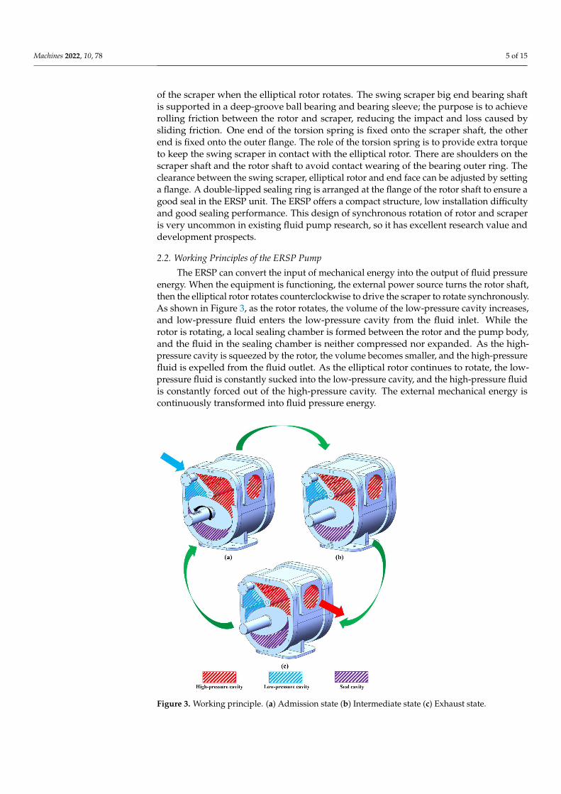
The ERSP can convert the input of mechanical energy into the output of fluid pressureenergy. When the equipment is functioning, the external power source turns the rotor shaft,then the elliptical rotor rotates counterclockwise to drive the scraper to rotate synchronously.As shown in Figure 3, as the rotor rotates, the volume of the low-pressure cavity increases,and low-pressure fluid enters the low-pressure cavity from the fluid inlet. While therotor is rotating, a local sealing chamber is formed between the rotor and the pump body,and the fluid in the sealing chamber is neither compressed nor expanded. As the high-pressure cavity is squeezed by the rotor, the volume becomes smaller, and the high-pressurefluid is expelled from the fluid outlet. As the elliptical rotor continues to rotate, the low-pressure fluid is constantly sucked into the low-pressure cavity, and the high-pressure fluidis constantly forced out of the high-pressure cavity. The external mechanical energy iscontinuously transformed into fluid pressure energy.
Machines 2022, 10, x FOR PEER REVIEW 5 of 16
stable rotation of the scraper when the elliptical rotor rotates. The swing scraper big end bearing shaft is supported in a deep-groove ball bearing and bearing sleeve; the purpose is to achieve rolling friction between the rotor and scraper, reducing the impact and loss caused by sliding friction. One end of the torsion spring is fixed onto the scraper shaft, the other end is fixed onto the outer flange. The role of the torsion spring is to provide extra torque to keep the swing scraper in contact with the elliptical rotor. There are shoulders on the scraper shaft and the rotor shaft to avoid contact wearing of the bearing outer ring. The clearance between the swing scraper, elliptical rotor and end face can be adjusted by setting a flange. A double-lipped sealing ring is arranged at the flange of the rotor shaft to ensure a good seal in the ERSP unit. The ERSP offers a compact structure, low installation difficulty and good sealing performance. This design of synchronous rotation of rotor and scraper is very uncommon in existing fluid pump research, so it has excellent research value and development prospects.
2.2. Working Principles of the ERSP Pump The ERSP can convert the input of mechanical energy into the output of fluid
pressure energy. When the equipment is functioning, the external power source turns the rotor shaft, then the elliptical rotor rotates counterclockwise to drive the scraper to rotate synchronously. As shown in Figure 3, as the rotor rotates, the volume of the low-pressure cavity increases, and low-pressure fluid enters the low-pressure cavity from the fluid inlet. While the rotor is rotating, a local sealing chamber is formed between the rotor and the pump body, and the fluid in the sealing chamber is neither compressed nor expanded. As the high-pressure cavity is squeezed by the rotor, the volume becomes smaller, and the high-pressure fluid is expelled from the fluid outlet. As the elliptical rotor continues to rotate, the low-pressure fluid is constantly sucked into the low-pressure cavity, and the high-pressure fluid is constantly forced out of the high-pressure cavity. The external mechanical energy is continuously transformed into fluid pressure energy.
Figure 3. Working principle. (a) Admission state (b) Intermediate state (c) Exhaust state Figure 3. Working principle. (a) Admission state (b) Intermediate state (c) Exhaust state.
Machines 2022, 10, 78 6 of 15
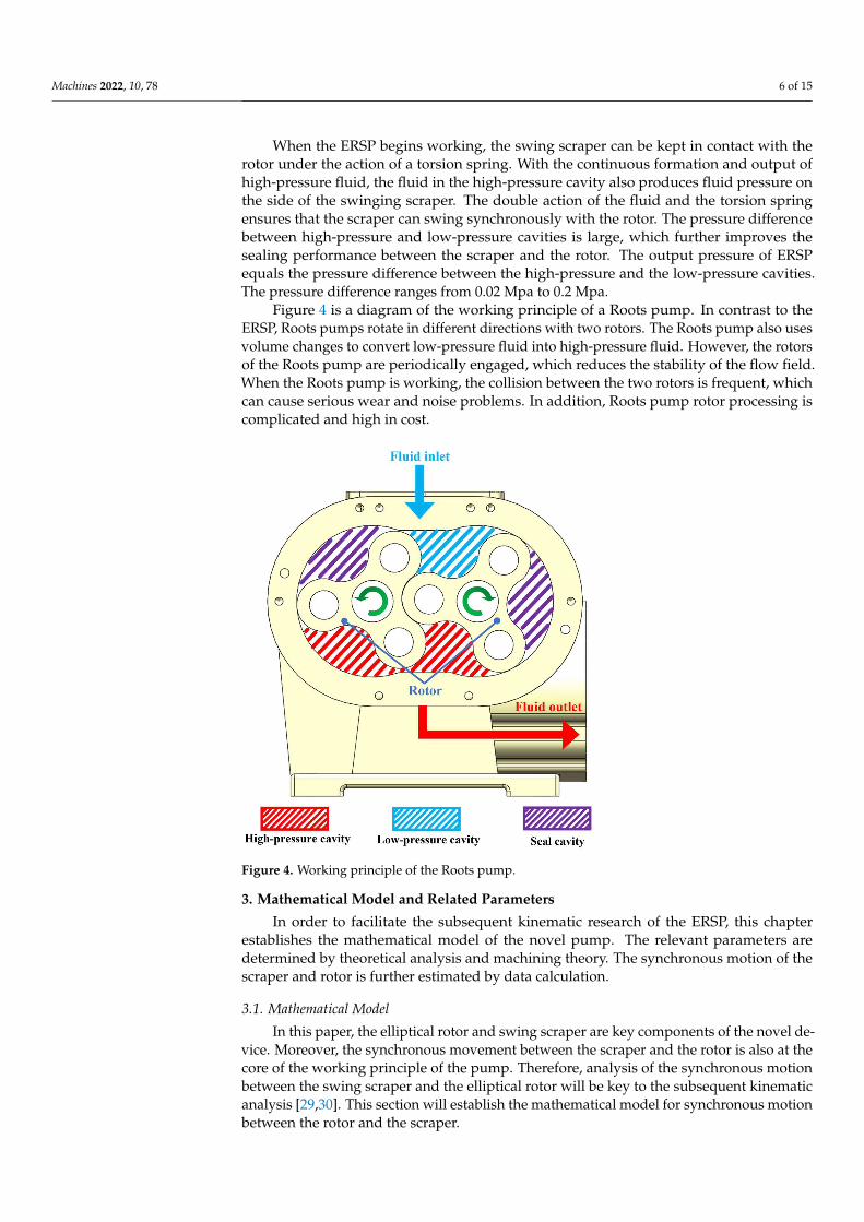
When the ERSP begins working, the swing scraper can be kept in contact with therotor under the action of a torsion spring. With the continuous formation and output ofhigh-pressure fluid, the fluid in the high-pressure cavity also produces fluid pressure onthe side of the swinging scraper. The double action of the fluid and the torsion springensures that the scraper can swing synchronously with the rotor. The pressure differencebetween high-pressure and low-pressure cavities is large, which further improves thesealing performance between the scraper and the rotor. The output pressure of ERSPequals the pressure difference between the high-pressure and the low-pressure cavities.The pressure difference ranges from 0.02 Mpa to 0.2 Mpa.
Figure 4 is a diagram of the working principle of a Roots pump. In contrast to theERSP, Roots pumps rotate in different directions with two rotors. The Roots pump also usesvolume changes to convert low-pressure fluid into high-pressure fluid. However, the rotorsof the Roots pump are periodically engaged, which reduces the stability of the flow field.When the Roots pump is working, the collision between the two rotors is frequent, whichcan cause serious wear and noise problems. In addition, Roots pump rotor processing iscomplicated and high in cost.
Machines 2022, 10, x FOR PEER REVIEW 6 of 16
When the ERSP begins working, the swing scraper can be kept in contact with the rotor under the action of a torsion spring. With the continuous formation and output of high-pressure fluid, the fluid in the high-pressure cavity also produces fluid pressure on the side of the swinging scraper. The double action of the fluid and the torsion spring ensures that the scraper can swing synchronously with the rotor. The pressure difference between high-pressure and low-pressure cavities is large, which further improves the sealing performance between the scraper and the rotor. The output pressure of ERSP equals the pressure difference between the high-pressure and the low-pressure cavities. The pressure difference ranges from 0.02 Mpa to 0.2 Mpa.
Figure 4 is a diagram of the working principle of a Roots pump. In contrast to the ERSP, Roots pumps rotate in different directions with two rotors. The Roots pump also uses volume changes to convert low-pressure fluid into high-pressure fluid. However, the rotors of the Roots pump are periodically engaged, which reduces the stability of the flow field. When the Roots pump is working, the collision between the two rotors is frequent, which can cause serious wear and noise problems. In addition, Roots pump rotor processing is complicated and high in cost.
Figure 4. Working principle of the Roots pump.
3. .Mathematical Model and Related Parameters In order to facilitate the subsequent kinematic research of the ERSP, this chapter
establishes the mathematical model of the novel pump. The relevant parameters are determined by theoretical analysis and machining theory. The synchronous motion of the scraper and rotor is further estimated by data calculation.
3.1. Mathematical Model In this paper, the elliptical rotor and swing scraper are key components of the novel
device. Moreover, the synchronous movement between the scraper and the rotor is also at the core of the working principle of the pump. Therefore, analysis of the synchronous motion between the swing scraper and the elliptical rotor will be key to the subsequent
Figure 4. Working principle of the Roots pump.
3. Mathematical Model and Related Parameters
In order to facilitate the subsequent kinematic research of the ERSP, this chapterestablishes the mathematical model of the novel pump. The relevant parameters aredetermined by theoretical analysis and machining theory. The synchronous motion of thescraper and rotor is further estimated by data calculation.
3.1. Mathematical Model
In this paper, the elliptical rotor and swing scraper are key components of the novel de-vice. Moreover, the synchronous movement between the scraper and the rotor is also at thecore of the working principle of the pump. Therefore, analysis of the synchronous motionbetween the swing scraper and the elliptical rotor will be key to the subsequent kinematicanalysis [29,30]. This section will establish the mathematical model for synchronous motionbetween the rotor and the scraper.
Machines 2022, 10, 78 7 of 15
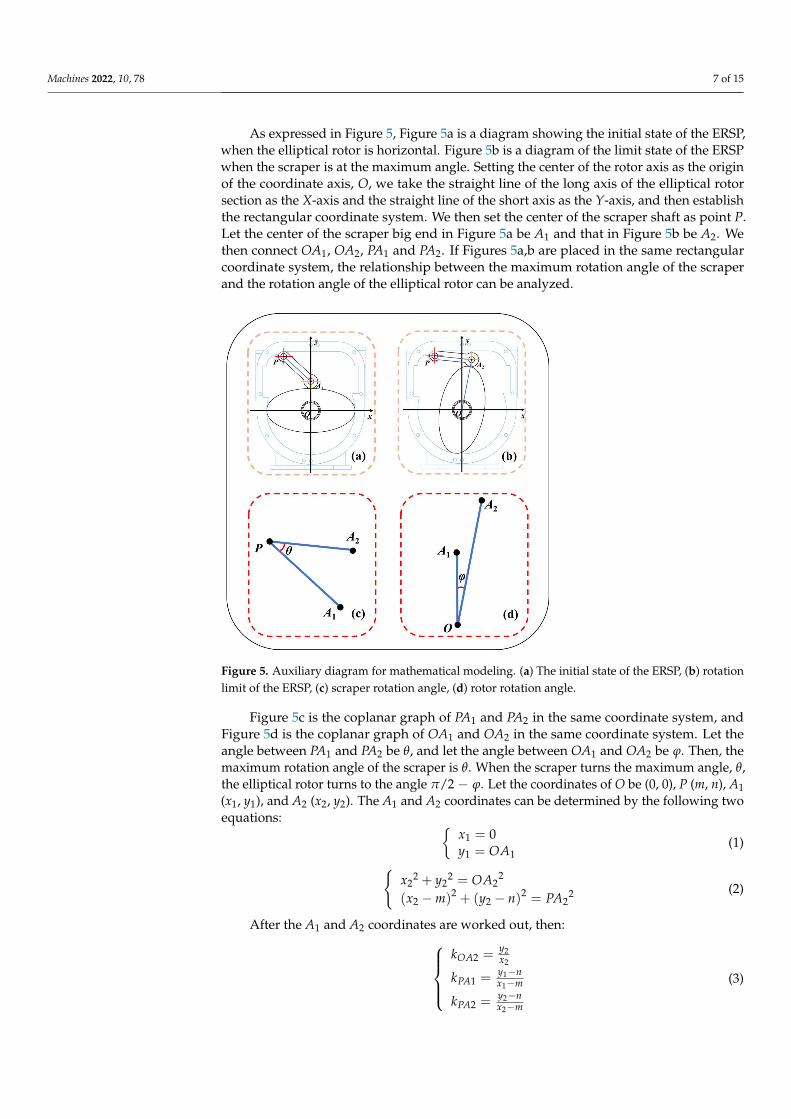
As expressed in Figure 5, Figure 5a is a diagram showing the initial state of the ERSP,when the elliptical rotor is horizontal. Figure 5b is a diagram of the limit state of the ERSPwhen the scraper is at the maximum angle. Setting the center of the rotor axis as the originof the coordinate axis, O, we take the straight line of the long axis of the elliptical rotorsection as the X-axis and the straight line of the short axis as the Y-axis, and then establishthe rectangular coordinate system. We then set the center of the scraper shaft as point P.Let the center of the scraper big end in Figure 5a be A1 and that in Figure 5b be A2. Wethen connect OA1, OA2, PA1 and PA2. If Figures 5a,b are placed in the same rectangularcoordinate system, the relationship between the maximum rotation angle of the scraperand the rotation angle of the elliptical rotor can be analyzed.
Machines 2022, 10, x FOR PEER REVIEW 7 of 16
kinematic analysis [29,30]. This section will establish the mathematical model for synchronous motion between the rotor and the scraper.
As expressed in Figure 5, Figure 5a is a diagram showing the initial state of the ERSP, when the elliptical rotor is horizontal. Figure 5b is a diagram of the limit state of the ERSP when the scraper is at the maximum angle. Setting the center of the rotor axis as the origin of the coordinate axis, O, we take the straight line of the long axis of the elliptical rotor section as the X-axis and the straight line of the short axis as the Y-axis, and then establish the rectangular coordinate system. We then set the center of the scraper shaft as point P. Let the center of the scraper big end in Figure 5a be A1 and that in Figure 5b be A2. We then connect OA1, OA2, PA1 and PA2. If Figure 5a and Figure 5b are placed in the same rectangular coordinate system, the relationship between the maximum rotation angle of the scraper and the rotation angle of the elliptical rotor can be analyzed.
Figure 5. Auxiliary diagram for mathematical modeling. (a) The initial state of the ERSP, (b) rotation limit of the ERSP, (c) scraper rotation angle, (d) rotor rotation angle.
Figure 5c is the coplanar graph of PA1 and PA2 in the same coordinate system, and Figure 5d is the coplanar graph of OA1 and OA2 in the same coordinate system. Let the angle between PA1 and PA2 be θ, and let the angle between OA1 and OA2 be φ. Then, the maximum rotation angle of the scraper is θ. When the scraper turns the maximum angle, θ, the elliptical rotor turns to the angle π/2 − φ. Let the coordinates of O be (0, 0), P (m, n), A1 (x1, y1), and A2 (x2, y2). The A1 and A2 coordinates can be determined by the following two equations:
1
1 1
0x
y OA
(1)
22 22 2 2
2 2 22 2 2
x y OA
x m y n PA
(2)
After the A1 and A2 coordinates are worked out, then:
Figure 5. Auxiliary diagram for mathematical modeling. (a) The initial state of the ERSP, (b) rotationlimit of the ERSP, (c) scraper rotation angle, (d) rotor rotation angle.
Figure 5c is the coplanar graph of PA1 and PA2 in the same coordinate system, andFigure 5d is the coplanar graph of OA1 and OA2 in the same coordinate system. Let theangle between PA1 and PA2 be θ, and let the angle between OA1 and OA2 be ϕ. Then, themaximum rotation angle of the scraper is θ. When the scraper turns the maximum angle, θ,the elliptical rotor turns to the angle π/2 − ϕ. Let the coordinates of O be (0, 0), P (m, n), A1(x1, y1), and A2 (x2, y2). The A1 and A2 coordinates can be determined by the following twoequations: {
x1 = 0y1 = OA1
(1){x2
2 + y22 = OA2
2
(x2 −m)2 + (y2 − n)2 = PA22 (2)
After the A1 and A2 coordinates are worked out, then:kOA2 = y2
x2
kPA1 = y1−nx1−m
kPA2 = y2−nx2−m
(3)
Machines 2022, 10, 78 8 of 15
where kOA2, kPA1 and kPA2 are the slopes of OA2, PA1 and PA2, respectively.
tan α =|k1 − k2|
1 + k1 · k2(4)
The above formula is the tangent formula of the rectangular coordinate system. Here,k1 and k2 are the slopes of two intersecting lines, and α is the included angle of the twolines. Using the tangent formula, we can establish the following relationship: θ = arctan |kPA1 − kPA2|
1 + kPA1·kPA2
ϕ = arctan 1kOA2
(5)
During the operation of the ERSP, the external power drives the rotor shaft to rotate.The rotor speed n (r/min) can be regarded as a constant value, except for the suddenincrease of speed caused by external speed regulation. Therefore, there exists the followingrelationship between the angle β (deg) and the speed n (r/min) of the rotor in a certaintime frame of ∆t (s):
β = 6 · n · ∆t (6)
3.2. Basic Parameter Setting
Reasonable parameter setting is significant in mechanical research. In this section, thebasic parameters of the ERSP are set up, based on current machining theory and traditionalpumps. The swing scraper and elliptical rotor are made from aluminum alloy. Other basicparameters are indicated in Table 1.
Table 1. Basic parameters of the ERSP.
Parameters Value
Long axis of elliptical line 228 mmShort axis of elliptical line 114 mm
Length of the PA1 95.1804 mmThickness of swing scraper 228 mmThickness of elliptical rotor 228 mm
Diameter of scraper big end section circle 36 mmElliptical rotor speed (n) 300 r/minTorsion spring stiffness 0.0565 N·m/deg
According to the design of the ERSP and the setting of basic parameters, the mathe-matical model in Section 3.1 can be substituted in real numbers. The angle of θ is about36.723◦, and the angle of ϕ is about 10.750◦. When the swing scraper turns at the maximumangle of 36.723◦, the rotor turns to 79.250◦.
4. Kinematic Characteristics Analysis
Theoretical analysis and mathematical modeling were carried out, as outlined in theabove chapters, and this chapter uses ADAMS to analyze the kinematic characteristics ofthe ERSP. ADAMS, or the automatic dynamic analysis of mechanical systems, can simulatethe statics, kinematics and dynamics of mechanical systems. ADAMS simulations can beused to predict mechanical system performance, motion range, collision detection, peakload and calculate the input load of finite elements. This paper mainly uses the kinematicsanalysis function of ADAMS.
In this chapter, kinematic characteristics are analyzed from two aspects. Firstly, whenthe rotor speed and pressure difference are fixed and the scraper big end is always closeto the rotor, the kinematic characteristics are analyzed. This aspect is called steady-stateanalysis. Secondly, the parameters are changed to observe the kinematic characteristics ofthe swing scraper follow-through. This aspect is called followability analysis.

Machines 2022, 10, 78 9 of 15
4.1. Steady-State Analysis
In the steady-state analysis, we selected the rotating speed, n, of the elliptical rotor as300 r/min, and the pressure difference between high-pressure and low-pressure cavities istaken as 0.5 atmospheric pressure (about 0.05 MPa). This section takes the horizontal stateof the elliptical rotor as the initial state for the simulation and selects the first three periodsof the pump to research.
Figure 6 shows the rotation angle curve of the swing scraper, as obtained by thesimulation. It is obvious from Figure 6 that when the ERSP completes a cycle, the swingscraper swings up and down twice. Through the analysis of the simulation data, it isknown that the maximum angle of swing scraper rotation is 36.765◦. The angle obtained bythe simulation is approximately equal to the maximum angle of 36.723◦, as derived by themathematical model in Section 3. When the rotation angle of the swing scraper reaches themaximum angle for the first time, the time elapsed is 0.044 s.
Machines 2022, 10, x FOR PEER REVIEW 9 of 16
the ERSP. ADAMS, or the automatic dynamic analysis of mechanical systems, can simulate the statics, kinematics and dynamics of mechanical systems. ADAMS simulations can be used to predict mechanical system performance, motion range, collision detection, peak load and calculate the input load of finite elements. This paper mainly uses the kinematics analysis function of ADAMS.
In this chapter, kinematic characteristics are analyzed from two aspects. Firstly, when the rotor speed and pressure difference are fixed and the scraper big end is always close to the rotor, the kinematic characteristics are analyzed. This aspect is called steady-state analysis. Secondly, the parameters are changed to observe the kinematic characteristics of the swing scraper follow-through. This aspect is called followability analysis.
4.1. .Steady-State Analysis In the steady-state analysis, we selected the rotating speed, n, of the elliptical rotor as
300 r/min, and the pressure difference between high-pressure and low-pressure cavities is taken as 0.5 atmospheric pressure (about 0.05 MPa). This section takes the horizontal state of the elliptical rotor as the initial state for the simulation and selects the first three periods of the pump to research.
Figure 6 shows the rotation angle curve of the swing scraper, as obtained by the simulation. It is obvious from Figure 6 that when the ERSP completes a cycle, the swing scraper swings up and down twice. Through the analysis of the simulation data, it is known that the maximum angle of swing scraper rotation is 36.765°. The angle obtained by the simulation is approximately equal to the maximum angle of 36.723°, as derived by the mathematical model in Section 3. When the rotation angle of the swing scraper reaches the maximum angle for the first time, the time elapsed is 0.044s.
Figure 6. The curve of the rotation angle of the swing scraper.
Figure 7 shows the curve of the rotation angle of the elliptic rotor, as obtained by the simulation. It is obvious from the figure that when the ERSP completes a cycle, the elliptical rotor rotates once. According to the rotation angle of the swing scraper and elliptical rotor, when the scraper turns the maximum angle of 36.765° for the first time, the scraper turns 79.200°. The rotor rotation angle obtained by the simulation is approximately equal to 79.250°, as derived from the mathematical model in Section 3. A comparison between the simulation and theoretical model is given in Table 2.
Figure 6. The curve of the rotation angle of the swing scraper.
Figure 7 shows the curve of the rotation angle of the elliptic rotor, as obtained by thesimulation. It is obvious from the figure that when the ERSP completes a cycle, the ellipticalrotor rotates once. According to the rotation angle of the swing scraper and elliptical rotor,when the scraper turns the maximum angle of 36.765◦ for the first time, the scraper turns79.200◦. The rotor rotation angle obtained by the simulation is approximately equal to79.250◦, as derived from the mathematical model in Section 3. A comparison between thesimulation and theoretical model is given in Table 2.
Machines 2022, 10, x FOR PEER REVIEW 10 of 16
Figure 7. The curve of the rotation angle of the rotor.
Table 2. Comparison between the simulation and theoretical model.
Parameters Theoretical calculation value Simulation value Maximum angle of scraper (θ) 36.723° 36.765° Angle of elliptical rotor (π/2 −
φ) 79.250° 79.250°
Figure 8 depicts the comparison between the rotation angle of the elliptical rotor and the swing scraper. The angled contrast more clearly reflects the ERSP’s working principle. The maximum rotation angle of the swing scraper is slight, which can effectively reduce both noise and impact.
Figure 8. Comparison of the rotation angles.
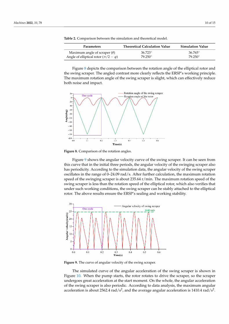
Figure 9 shows the angular velocity curve of the swing scraper. It can be seen from this curve that in the initial three periods, the angular velocity of the swinging scraper also has periodicity. According to the simulation data, the angular velocity of the swing scraper oscillates in the range of 0–24.09 rad/s. After further calculation, the maximum rotation speed of the swinging scraper is about 235.64 r/min. The maximum rotation speed of the swing scraper is less than the rotation speed of the elliptical rotor, which also veri-fies that under such working conditions, the swing scraper can be stably attached to the elliptical rotor. The above results ensure the ERSP’s sealing and working stability.
Figure 7. The curve of the rotation angle of the rotor.
Machines 2022, 10, 78 10 of 15
Table 2. Comparison between the simulation and theoretical model.
Parameters Theoretical Calculation Value Simulation Value
Maximum angle of scraper (θ) 36.723◦ 36.765◦
Angle of elliptical rotor (π/2 − ϕ) 79.250◦ 79.250◦
Figure 8 depicts the comparison between the rotation angle of the elliptical rotor andthe swing scraper. The angled contrast more clearly reflects the ERSP’s working principle.The maximum rotation angle of the swing scraper is slight, which can effectively reduceboth noise and impact.
Machines 2022, 10, x FOR PEER REVIEW 10 of 16
Figure 7. The curve of the rotation angle of the rotor.
Table 2. Comparison between the simulation and theoretical model.
Parameters Theoretical calculation value Simulation value Maximum angle of scraper (θ) 36.723° 36.765° Angle of elliptical rotor (π/2 −
φ) 79.250° 79.250°
Figure 8 depicts the comparison between the rotation angle of the elliptical rotor and the swing scraper. The angled contrast more clearly reflects the ERSP’s working principle. The maximum rotation angle of the swing scraper is slight, which can effectively reduce both noise and impact.
Figure 8. Comparison of the rotation angles.
Figure 9 shows the angular velocity curve of the swing scraper. It can be seen from this curve that in the initial three periods, the angular velocity of the swinging scraper also has periodicity. According to the simulation data, the angular velocity of the swing scraper oscillates in the range of 0–24.09 rad/s. After further calculation, the maximum rotation speed of the swinging scraper is about 235.64 r/min. The maximum rotation speed of the swing scraper is less than the rotation speed of the elliptical rotor, which also veri-fies that under such working conditions, the swing scraper can be stably attached to the elliptical rotor. The above results ensure the ERSP’s sealing and working stability.
Figure 8. Comparison of the rotation angles.
Figure 9 shows the angular velocity curve of the swing scraper. It can be seen fromthis curve that in the initial three periods, the angular velocity of the swinging scraper alsohas periodicity. According to the simulation data, the angular velocity of the swing scraperoscillates in the range of 0–24.09 rad/s. After further calculation, the maximum rotationspeed of the swinging scraper is about 235.64 r/min. The maximum rotation speed of theswing scraper is less than the rotation speed of the elliptical rotor, which also verifies thatunder such working conditions, the swing scraper can be stably attached to the ellipticalrotor. The above results ensure the ERSP’s sealing and working stability.
Machines 2022, 10, x FOR PEER REVIEW 11 of 16
Figure 9. The curve of angular velocity of the swing scraper.
The simulated curve of the angular acceleration of the swing scraper is shown in Figure 10. When the pump starts, the rotor rotates to drive the scraper, so the scraper undergoes great acceleration at the start moment. On the whole, the angular acceleration of the swing scraper is also periodic. According to data analysis, the maximum angular acceleration is about 2562.4 rad/s2, and the average angular acceleration is 1410.4 rad/s2.
Figure 10. The curve of angular acceleration of the swing scraper.
Figure 11 describes the curve of torsion spring deformation established by the simulation. In terms of parameter settings, the pre-torsion of the torsion spring has been set at 15° in this paper. Through data analysis, the maximum deformation of the torsion spring is about 51.760°. Figure 12 shows the torque curve of the torsion spring. Through data analysis, the pre-tightening torque of the torsion spring is set at 830.4 N·mm, and the maximum torque is 2939.7 N·mm. In summary, the torsion spring plays the role of providing torque for auxiliary sealing in the working process of the ERSP. Due to the low torque provided, the efficiency of the ERSP is not reduced during operation.
Figure 11. The curve of deformation of the torsion spring.
Figure 9. The curve of angular velocity of the swing scraper.
The simulated curve of the angular acceleration of the swing scraper is shown inFigure 10. When the pump starts, the rotor rotates to drive the scraper, so the scraperundergoes great acceleration at the start moment. On the whole, the angular accelerationof the swing scraper is also periodic. According to data analysis, the maximum angularacceleration is about 2562.4 rad/s2, and the average angular acceleration is 1410.4 rad/s2.

Machines 2022, 10, 78 11 of 15
Machines 2022, 10, x FOR PEER REVIEW 11 of 16
Figure 9. The curve of angular velocity of the swing scraper.
The simulated curve of the angular acceleration of the swing scraper is shown in Figure 10. When the pump starts, the rotor rotates to drive the scraper, so the scraper undergoes great acceleration at the start moment. On the whole, the angular acceleration of the swing scraper is also periodic. According to data analysis, the maximum angular acceleration is about 2562.4 rad/s2, and the average angular acceleration is 1410.4 rad/s2.
Figure 10. The curve of angular acceleration of the swing scraper.
Figure 11 describes the curve of torsion spring deformation established by the simulation. In terms of parameter settings, the pre-torsion of the torsion spring has been set at 15° in this paper. Through data analysis, the maximum deformation of the torsion spring is about 51.760°. Figure 12 shows the torque curve of the torsion spring. Through data analysis, the pre-tightening torque of the torsion spring is set at 830.4 N·mm, and the maximum torque is 2939.7 N·mm. In summary, the torsion spring plays the role of providing torque for auxiliary sealing in the working process of the ERSP. Due to the low torque provided, the efficiency of the ERSP is not reduced during operation.
Figure 11. The curve of deformation of the torsion spring.
Figure 10. The curve of angular acceleration of the swing scraper.
Figure 11 describes the curve of torsion spring deformation established by the sim-ulation. In terms of parameter settings, the pre-torsion of the torsion spring has beenset at 15◦ in this paper. Through data analysis, the maximum deformation of the torsionspring is about 51.760◦. Figure 12 shows the torque curve of the torsion spring. Throughdata analysis, the pre-tightening torque of the torsion spring is set at 830.4 N·mm, andthe maximum torque is 2939.7 N·mm. In summary, the torsion spring plays the role ofproviding torque for auxiliary sealing in the working process of the ERSP. Due to the lowtorque provided, the efficiency of the ERSP is not reduced during operation.
Machines 2022, 10, x FOR PEER REVIEW 11 of 16
Figure 9. The curve of angular velocity of the swing scraper.
The simulated curve of the angular acceleration of the swing scraper is shown in Figure 10. When the pump starts, the rotor rotates to drive the scraper, so the scraper undergoes great acceleration at the start moment. On the whole, the angular acceleration of the swing scraper is also periodic. According to data analysis, the maximum angular acceleration is about 2562.4 rad/s2, and the average angular acceleration is 1410.4 rad/s2.
Figure 10. The curve of angular acceleration of the swing scraper.
Figure 11 describes the curve of torsion spring deformation established by the simulation. In terms of parameter settings, the pre-torsion of the torsion spring has been set at 15° in this paper. Through data analysis, the maximum deformation of the torsion spring is about 51.760°. Figure 12 shows the torque curve of the torsion spring. Through data analysis, the pre-tightening torque of the torsion spring is set at 830.4 N·mm, and the maximum torque is 2939.7 N·mm. In summary, the torsion spring plays the role of providing torque for auxiliary sealing in the working process of the ERSP. Due to the low torque provided, the efficiency of the ERSP is not reduced during operation.
Figure 11. The curve of deformation of the torsion spring. Figure 11. The curve of deformation of the torsion spring.
Machines 2022, 10, x FOR PEER REVIEW 12 of 16
Figure 12. The curve of the torque of the torsion spring.
Figure 13 shows the contact force curve between the elliptical rotor and the swing scraper, as obtained by the simulation. The instantaneous direction of the contact force should be perpendicular to the elliptical tangent of the contact point. Through data analysis, the maximum contact force is set at about 1201.2 N.
Figure 13. The curve of contact force.
4.2..4.2. .Followability Analysis In the ordinary operation of the ERSP, it is necessary to ensure that the swing scraper
big end is always close to the elliptical rotor. Therefore, it is essential to analyze and study the following ability of the swing scraper relative to the elliptical rotor. In engineering practice, in order to make the scraper adapt faster to the rotor speed, we can increase the reverse torque of the swing scraper by adjusting the stiffness of the torsion spring. In addition, the pressure difference between high-pressure and low-pressure cavities is also variable under different working conditions. Therefore, when the above parameters are changed, the maximum speed of the rotor in the normal operation of the ERSP will also change. Figure 14 displays the followability analysis of the surface figure. Figure 14 clearly shows the maximum rotor speed that can make the swing scraper follow the rotor well under different torsion spring stiffness settings and various pressure differences between the high-pressure and low-pressure cavities. In the study, the torsion spring stiffness range is 56.5 N·mm/deg–615.85 N·mm/deg, and the pressure difference is 0.02 MPa–0.2 MPa. The simulation results show that the greater the stiffness of the torsion spring or the pressure difference, the better the following performance of the ERSP. The relevant matching data, obtained from the followability analysis in this section, is of great significance to follow-up research and the prototype testing of the novel pump.
Figure 12. The curve of the torque of the torsion spring.
Figure 13 shows the contact force curve between the elliptical rotor and the swingscraper, as obtained by the simulation. The instantaneous direction of the contact forceshould be perpendicular to the elliptical tangent of the contact point. Through data analysis,the maximum contact force is set at about 1201.2 N.

Machines 2022, 10, 78 12 of 15
Machines 2022, 10, x FOR PEER REVIEW 12 of 16
Figure 12. The curve of the torque of the torsion spring.
Figure 13 shows the contact force curve between the elliptical rotor and the swing scraper, as obtained by the simulation. The instantaneous direction of the contact force should be perpendicular to the elliptical tangent of the contact point. Through data analysis, the maximum contact force is set at about 1201.2 N.
Figure 13. The curve of contact force.
4.2..4.2. .Followability Analysis In the ordinary operation of the ERSP, it is necessary to ensure that the swing scraper
big end is always close to the elliptical rotor. Therefore, it is essential to analyze and study the following ability of the swing scraper relative to the elliptical rotor. In engineering practice, in order to make the scraper adapt faster to the rotor speed, we can increase the reverse torque of the swing scraper by adjusting the stiffness of the torsion spring. In addition, the pressure difference between high-pressure and low-pressure cavities is also variable under different working conditions. Therefore, when the above parameters are changed, the maximum speed of the rotor in the normal operation of the ERSP will also change. Figure 14 displays the followability analysis of the surface figure. Figure 14 clearly shows the maximum rotor speed that can make the swing scraper follow the rotor well under different torsion spring stiffness settings and various pressure differences between the high-pressure and low-pressure cavities. In the study, the torsion spring stiffness range is 56.5 N·mm/deg–615.85 N·mm/deg, and the pressure difference is 0.02 MPa–0.2 MPa. The simulation results show that the greater the stiffness of the torsion spring or the pressure difference, the better the following performance of the ERSP. The relevant matching data, obtained from the followability analysis in this section, is of great significance to follow-up research and the prototype testing of the novel pump.
Figure 13. The curve of contact force.
4.2. Followability Analysis
In the ordinary operation of the ERSP, it is necessary to ensure that the swing scraperbig end is always close to the elliptical rotor. Therefore, it is essential to analyze and studythe following ability of the swing scraper relative to the elliptical rotor. In engineeringpractice, in order to make the scraper adapt faster to the rotor speed, we can increase thereverse torque of the swing scraper by adjusting the stiffness of the torsion spring. Inaddition, the pressure difference between high-pressure and low-pressure cavities is alsovariable under different working conditions. Therefore, when the above parameters arechanged, the maximum speed of the rotor in the normal operation of the ERSP will alsochange. Figure 14 displays the followability analysis of the surface figure. Figure 14 clearlyshows the maximum rotor speed that can make the swing scraper follow the rotor wellunder different torsion spring stiffness settings and various pressure differences betweenthe high-pressure and low-pressure cavities. In the study, the torsion spring stiffness rangeis 56.5 N·mm/deg–615.85 N·mm/deg, and the pressure difference is 0.02 MPa–0.2 MPa.The simulation results show that the greater the stiffness of the torsion spring or the pressuredifference, the better the following performance of the ERSP. The relevant matching data,obtained from the followability analysis in this section, is of great significance to follow-upresearch and the prototype testing of the novel pump.
Machines 2022, 10, x FOR PEER REVIEW 13 of 16
Figure 14. Result of the followability analysis.
5. .Development of Principle Prototype This research group has carried out an in-depth analysis of the ERSP in terms of
theoretical analysis, model building and characteristics research. Building on existing research, a principle prototype pump has been successfully developed. The relevant R&D process is shown in Figure 15. The rotor shaft of the prototype is connected to an AC motor, and the motor is set to output at a constant speed to establish the synchronous movement of the elliptical rotor and the swing scraper. The prototype test proves that when the motor speed is set at 300 r/min, 450 r/min and 600 r/min, respectively, the swing scraper has acceptable following performance and can meet the working requirements.
Figure 14. Result of the followability analysis.

Machines 2022, 10, 78 13 of 15
5. Development of Principle Prototype
This research group has carried out an in-depth analysis of the ERSP in terms oftheoretical analysis, model building and characteristics research. Building on existingresearch, a principle prototype pump has been successfully developed. The relevant R&Dprocess is shown in Figure 15. The rotor shaft of the prototype is connected to an AC motor,and the motor is set to output at a constant speed to establish the synchronous movementof the elliptical rotor and the swing scraper. The prototype test proves that when the motorspeed is set at 300 r/min, 450 r/min and 600 r/min, respectively, the swing scraper hasacceptable following performance and can meet the working requirements.
Machines 2022, 10, x FOR PEER REVIEW 14 of 16
Figure 15. R&D process.
6. .Conclusion and Prospects It is indisputable that the elliptical rotor scraper pump (ERSP) is presented herein for
the first time and its kinematic characteristics have been studied in this paper. The novel pump adopts a swinging scraper instead of the blade and rotor used in a traditional positive displacement pump. By changing the pump cavity volume, the ERSP can convert mechanical energy into fluid pressure energy. The ERSP surmounts the problems of poor sealing performance and the low volume utilization effectivity of traditional positive displacement pumps, and can more comfortably meet the requirements of various fluid pressure outputs. The mathematical model was established through theoretical analysis in the above chapters, and the ERSP’s kinematics characteristics were anatomized via ADAMS.
Steady-state analysis and followability analysis are the fundamental components of the analysis of kinematic characteristics. In the steady-state analysis, rotor speed and the pressure difference between high-pressure and low-pressure cavities were taken as fixed values. Through kinematic simulation, the rotation angle and contact force curves were output, which fully verify the kinematic feasibility of the ERSP. In the followability analysis, the maximum rotor speed was set using different rotor speeds and the pressure difference between high-pressure and low-pressure cavities was obtained via simulation. The followability analysis is of great significance to subsequent engineering practice.
It is worth mentioning that the ERSP breaks the traditional concept of positive displacement pump design. The ERSP offers certain advantages in terms of installation layout and sealing and has broad development prospects in the future. In the long run, this study has momentous reference significance for the improvement and development of fluid machinery and engineering.
Author Contributions: Conceptualization, T.Z. and H.Z.; methodology, Z.Z. and H.Z.; software, Z.Z. and J.Y.; validation, Z.Z., Y.C. and J.Y.; formal analysis, Y.J. and D.T.; investigation, Z.Z.; re-sources, T.Z. and H.Z.; data curation, Z.Z., Y.C. and J.Y.; writing—original draft preparation, Z.Z.; writing—review and editing, Z.Z. and J.Y.; visualization, Z.Z.; supervision, Z.Z. and J.Y.; project administration, T.Z. and H.Z.; funding acquisition, H.Z.
Figure 15. R&D process.
6. Conclusions and Prospects
It is indisputable that the elliptical rotor scraper pump (ERSP) is presented hereinfor the first time and its kinematic characteristics have been studied in this paper. Thenovel pump adopts a swinging scraper instead of the blade and rotor used in a traditionalpositive displacement pump. By changing the pump cavity volume, the ERSP can convertmechanical energy into fluid pressure energy. The ERSP surmounts the problems of poorsealing performance and the low volume utilization effectivity of traditional positivedisplacement pumps, and can more comfortably meet the requirements of various fluidpressure outputs. The mathematical model was established through theoretical analysis inthe above chapters, and the ERSP’s kinematics characteristics were anatomized via ADAMS.
Steady-state analysis and followability analysis are the fundamental components ofthe analysis of kinematic characteristics. In the steady-state analysis, rotor speed andthe pressure difference between high-pressure and low-pressure cavities were taken asfixed values. Through kinematic simulation, the rotation angle and contact force curveswere output, which fully verify the kinematic feasibility of the ERSP. In the followabilityanalysis, the maximum rotor speed was set using different rotor speeds and the pressuredifference between high-pressure and low-pressure cavities was obtained via simulation.The followability analysis is of great significance to subsequent engineering practice.
It is worth mentioning that the ERSP breaks the traditional concept of positive dis-placement pump design. The ERSP offers certain advantages in terms of installation layoutand sealing and has broad development prospects in the future. In the long run, this

Machines 2022, 10, 78 14 of 15
study has momentous reference significance for the improvement and development offluid machinery and engineering.
Author Contributions: Conceptualization, T.Z. and H.Z.; methodology, Z.Z. and H.Z.; software, Z.Z.and J.Y.; validation, Z.Z., Y.C. and J.Y.; formal analysis, Y.J. and D.T.; investigation, Z.Z.; resources, T.Z.and H.Z.; data curation, Z.Z., Y.C. and J.Y.; writing—original draft preparation, Z.Z.; writing—reviewand editing, Z.Z. and J.Y.; visualization, Z.Z.; supervision, Z.Z. and J.Y.; project administration, T.Z.and H.Z.; funding acquisition, H.Z. All authors have read and agreed to the published version of themanuscript.
Funding: This research was funded by the National Natural Science Foundation of China, grantnumber 52075278, and the Municipal Livelihood Science and Technology Project of Qingdao, grantnumber 19-6-1-92-nsh.
Data Availability Statement: Not applicable.
Conflicts of Interest: The authors declare no conflict of interest.
References1. Liu, L. Development and Application of Soil Coupled Heat Pump; AIP Publishing LLC: Melville, NY, USA, 2017.2. Alawadhi, K.; Alzuwayer, B.; Mohammad, T.A.; Buhemdi, M.H. Design and Optimization of a Centrifugal Pump for Slurry
Transport Using the Response Surface Method. Machines 2021, 9, 60. [CrossRef]3. Li, L.; Wang, X.; Pu, Q.; Liu, S. Advancement of electroosmotic pump in microflow analysis: A review. Anal. Chim. Acta 2019,
1060, 1–16. [CrossRef] [PubMed]4. Li, H.; Liu, J.; Li, K.; Liu, Y. A review of recent studies on piezoelectric pumps and their applications. Mech. Syst. Signal Processing
2021, 151, 107393. [CrossRef]5. Miao, L.; Zhang, Y.; Tong, C.; Guo, Q.; Zhang, J.; Yildirim, T. Optimized Energy-Storage Method Based on Deep-Learning
Adaptive-Dynamic Programming. J. Energy Eng. 2020, 146, 04020011. [CrossRef]6. Hong, J.; Wang, Z.; Yao, Y. Fault prognosis of battery system based on accurate voltage abnormity prognosis using long short-term
memory neural networks. Appl. Energy 2019, 251, 113381. [CrossRef]7. Hong, J.; Wang, Z.; Chen, W.; Wang, L.; Lin, P.; Qu, C. Online accurate state of health estimation for battery systems on real-world
electric vehicles with variable driving conditions considered. J. Clean. Prod. 2021, 294, 125814. [CrossRef]8. Hong, J.; Wang, Z.; Ma, F.; Yang, J.; Xu, X.; Qu, C.; Zhang, J.; Shan, T.; Hou, Y.; Zhou, Y. Thermal Runaway Prognosis of Battery
Systems Using the Modified Multi-Scale Entropy in Real-World Electric Vehicles. IEEE Trans. Transp. Electrif. 2021, 7, 2269–2278.[CrossRef]
9. Parlak, Z.; Kemerli, M.; Engin, T.; Ko, Y. Design of a mini double-discharge centrifugal pump under multiphase flow by CFD andexperimental verification. J. Appl. Fluid Mech. 2018, 11, 1437–1448. [CrossRef]
10. Maqsood, M.; Usman, A.; Bodla, M.F.; Ali, J. Evaluation of performance parameters of indigenously developed roots pumpingsystem. IOP Conf. Ser. Mater. Sci. Eng. 2016, 146, 012047. [CrossRef]
11. Chen, X.M.; Lai, X.D.; Zhang, X.; Zhou, X. Evolutionary Topology Optimization Design of Rotary Lobe of Roots Vacuum Pumps.Adv. Mater. Res. 2013, 798–799, 365–368. [CrossRef]
12. Szwemin, P.; Fiebig, W. The Influence of Radial and Axial Gaps on Volumetric Efficiency of External Gear Pumps. Energies 2021,14, 4468. [CrossRef]
13. Wang, H.; Du, S.S. External Gear Pump Model and Simulation. Appl. Mech. Mater. 2011, 127, 228–232. [CrossRef]14. Bai, J.J.; Xu, M.M. Research Status and Development Trend of Vane Pump. Appl. Mech. Mater. 2014, 556, 1143–1146. [CrossRef]15. Korkmaz, E.; Glcü, M.; Kurbanolu, C. Effects of blade discharge angle, blade number and splitter blade length on deep well pump
performance. J. Appl. Fluid Mech. 2017, 10, 529–540. [CrossRef]16. Yang, L.F. Structure Optimization Design of Vane Steering Pump. Appl. Mech. Mater. 2014, 496, 904–907. [CrossRef]17. Zhang, W.; Wang, B.; Zhang, Y.; Peng, L.; Liu, M.; Lv, Y. Research on modelling and simulation of a new variable displacement oil
pump. J. Eng. 2019, 2019, 350–354. [CrossRef]18. Li, Z.; Song, J.; Huang, Y.; Li, Y.; Chen, J. Design and analysis for a new energy-saving hydraulic pumping unit. Proc. Inst. Mech.
Eng. Part C J. Mech. Eng. Sci. 2017, 232, 2119–2131. [CrossRef]19. Hsieh, C.-F. A new curve for application to the rotor profile of rotary lobe pumps. Mech. Mach. Theory 2015, 87, 70–81. [CrossRef]20. Shim, S.-B.; Park, Y.-J.; Nam, J.-S.; Kim, S.-C.; Kim, J.-M.; Kim, K.-U. Development of a rotary clap mechanism for positive-
displacement rotary pumps: Experimental verification and optimization. Int. J. Precis. Eng. Manuf. 2017, 18, 587–597. [CrossRef]21. Choi, Y.-D.; Kurokawa, J.; Matsui, J. Performance and Internal Flow Characteristics of a Very Low Specific Speed Centrifugal
Pump. J. Fluids Eng. 2006, 128, 341. [CrossRef]22. Cheng, T.; Jiang, M. Design and Efficiency Analysis of Small Displacement Pump. IOP Conf. Ser. Earth Environ. Sci. 2020, 461,
012052. [CrossRef]

Machines 2022, 10, 78 15 of 15
23. Zhang, C.; Ruan, J.; Xing, T.; Li, S.; Meng, B.; Ding, C. Research on the Volumetric Efficiency of a Novel Stacked Roller 2D PistonPump. Machines 2021, 9, 128. [CrossRef]
24. Guan, D.; Wu, J.H.; Jing, L.; Hilton, H.H.; Lu, K. Kinematic modeling, analysis and test on a quiet spherical pump. J. Sound Vib.2016, 383, 146–155. [CrossRef]
25. Saputra, O.A.; Syaifudin, M. Design, analysis, and application of solar cell to drive water pump. Int. Conf. Sci. Appl. Sci. 2019,2202, 020113.
26. Sun, J.; Shao, L.; Fu, L.; Han, X.; Li, S. Kinematic analysis and optimal design of a novel parallel pointing mechanism. Aerosp. Sci.Technol. 2020, 104, 105931. [CrossRef]
27. Zhang, Y.; Jiang, J.; Zhang, L.; Wei, Q. Single Stage Horizontal Self-Priming Pump System Assembly and Kinematics Simulation.In Proceedings of the 2015 Seventh International Conference on Advanced Communication and Networking (ACN), KotaKinabalu, Malaysia, 8–11 July 2015.
28. Battarra, M.; Blum, A.; Mucchi, E. Kinematics of a balanced vane pump with circular tip vanes. Mech. Mach. Theory 2019, 137,355–373. [CrossRef]
29. Chen, R.; Rao, Y.; Yue, H.; Ai, Y.; Zhang, X.; Zhang, L.; Zheng, J. Numerical Simulation of Bed Combustion in Biomass-BriquetteBoiler. J. Energy Eng. 2020, 146, 04020031. [CrossRef]
30. Shcherba, V.; Shalay, V.; Nosov, E.; Pavlyuchenko, E.; Tegzhanov, A.-K. Development and Research of Crosshead-Free PistonHybrid Power Machine. Machines 2021, 9, 32. [CrossRef]
Related Documents