Coatings 2015, 5, 709-723; doi:10.3390/coatings5040709 coatings ISSN 2079-6412 www.mdpi.com/journal/coatings Article Tailoring a High Temperature Corrosion Resistant FeNiCrAl for Oxy-Combustion Application by Thermal Spray Coating and HIP Jarkko Metsäjoki 1, *, Maria Oksa 1 , Satu Tuurna 2 , Juha Lagerbom 2 , Jouko Virta 1 , Sanni Yli-Olli 1 and Tomi Suhonen 1 1 VTT Technical Research Centre of Finland Ltd., Espoo 02044, Finland; E-Mails: [email protected] (M.O.); [email protected] (J.V.); [email protected] (S.Y.-O.); [email protected] (T.S.) 2 VTT Technical Research Centre of Finland Ltd., Tampere 33101, Finland; E-Mails: [email protected] (S.T.); [email protected] (J.L.) * Author to whom correspondence should be addressed; E-Mail: [email protected]; Tel.: +358-40-7377-643. Academic Editor: Alessandro Lavacchi Received: 18 September 2015 / Accepted: 13 October 2015 / Published: 16 October 2015 Abstract: Oxy-fuel combustion combined with CCS (carbon capture and storage) aims to decrease CO2 emissions in energy production using fossil fuels. Oxygen firing changes power plant boiler conditions compared to conventional firing. Higher material temperatures and harsher and more variable environmental conditions cause new degradation processes that are inadequately understood at the moment. In this study, an Fe-Ni-Cr-Al alloy was developed based on thermodynamic simulations. The chosen composition was manufactured as powder by gas atomization. The powder was sieved into two fractions: The finer was used to produce thermal spray coatings by high velocity oxy-fuel (HVOF) and the coarser to manufacture bulk specimens by hot isostatic pressing (HIP). The high temperature corrosion properties of the manufactured FeNiCrAl coating and bulk material were tested in laboratory conditions simulating oxy-combustion. The manufacturing methods and the results of high temperature corrosion performance are presented. The corrosion performance of the coating was on average between the bulk steel references Sanicro 25 and TP347HFG. OPEN ACCESS

Welcome message from author
This document is posted to help you gain knowledge. Please leave a comment to let me know what you think about it! Share it to your friends and learn new things together.
Transcript

Coatings 2015, 5, 709-723; doi:10.3390/coatings5040709
coatings ISSN 2079-6412
www.mdpi.com/journal/coatings
Article
Tailoring a High Temperature Corrosion Resistant FeNiCrAl
for Oxy-Combustion Application by Thermal Spray Coating
and HIP
Jarkko Metsäjoki 1,*, Maria Oksa 1, Satu Tuurna 2, Juha Lagerbom 2, Jouko Virta 1,
Sanni Yli-Olli 1 and Tomi Suhonen 1
1 VTT Technical Research Centre of Finland Ltd., Espoo 02044, Finland;
E-Mails: [email protected] (M.O.); [email protected] (J.V.); [email protected] (S.Y.-O.);
[email protected] (T.S.) 2 VTT Technical Research Centre of Finland Ltd., Tampere 33101, Finland;
E-Mails: [email protected] (S.T.); [email protected] (J.L.)
* Author to whom correspondence should be addressed; E-Mail: [email protected];
Tel.: +358-40-7377-643.
Academic Editor: Alessandro Lavacchi
Received: 18 September 2015 / Accepted: 13 October 2015 / Published: 16 October 2015
Abstract: Oxy-fuel combustion combined with CCS (carbon capture and storage) aims to
decrease CO2 emissions in energy production using fossil fuels. Oxygen firing changes
power plant boiler conditions compared to conventional firing. Higher material temperatures
and harsher and more variable environmental conditions cause new degradation processes
that are inadequately understood at the moment. In this study, an Fe-Ni-Cr-Al alloy was
developed based on thermodynamic simulations. The chosen composition was manufactured
as powder by gas atomization. The powder was sieved into two fractions: The finer was used
to produce thermal spray coatings by high velocity oxy-fuel (HVOF) and the coarser to
manufacture bulk specimens by hot isostatic pressing (HIP). The high temperature corrosion
properties of the manufactured FeNiCrAl coating and bulk material were tested in laboratory
conditions simulating oxy-combustion. The manufacturing methods and the results of high
temperature corrosion performance are presented. The corrosion performance of the coating
was on average between the bulk steel references Sanicro 25 and TP347HFG.
OPEN ACCESS

Coatings 2015, 5 710
Keywords: oxy-fuel combustion; powder metallurgy; thermal spray coating; HIP; high
temperature; corrosion testing
1. Introduction
The energy sector is the largest CO2 emitter globally [1]. One concept to reduce the CO2 emissions
originating from the use of fossil fuels in power generation is carbon capture and storage (CCS) [2,3].
Integrated oxy-combustion is considered as one of the most promising technologies to facilitate CO2
capture, because it can be built as a retrofit solution for existing boilers [4]. The oxy-fuel process uses
oxygen or oxygen-enriched air to reduce nitrogen in the flue gas and hence increase the CO2 content to
facilitate more efficient capture.
Oxy-fuel combustion can be expected to differ from combustion in air by modified distribution of
fireside temperatures, much reduced NOx emissions, increased levels of fireside CO2 and H2O with small
amounts of O2, Ar, N2, and some impurities like SO2 and Cl [5]. Due to recycling of flue gas in oxy-fired
combustion compared to air firing, there is an increased risk of corrosive species enrichment in the flue
gas environment [6,7]. These changes in the combustion gas chemistry will also affect the chemistry and
formation of deposits. This may increase corrosion of the boiler components that are in contact with the
combustion and flue gas environment [8–10]. Coatings are a promising approach to improve corrosion
resistance because existing validated structural steels can be used as base material. Coatings can be
tailored by composition and structure to give the best surface protection for selected conditions.
Several steels and alloys have been tested in air- and oxy-fuel combustion conditions [11–15].
These include low alloy steels (13CrMo44), ferritic steels (T91, T/P92), austenitic steels (1.4910,
Super 304H, TP347HFG, 310N, Sanicro 25 and HR3C), and nickel base alloys (IN617 and IN740).
Gagliano et al. [11] tested several candidate materials both in laboratory and field tests in advanced
ultra-supercritical conditions. They discovered that a material’s resistance to coal ash corrosion is
primarily dependent on the chromium content. Alloys containing chromium more than 22 wt % generally
exhibited satisfactory corrosion resistance in laboratory tests. The field study showed that materials
containing roughly 25 wt % chromium exhibited satisfactory resistance, regardless of the fireside
corrosion mechanism. Hussain et al. [14] exposed nickel-based thermal spray coatings to corrosion
testing simulating fireside corrosion in coal and biomass co-combustion at 650 °C. The best performing
coating in the study was NiCr coating with 46 wt % of chromium.
In future power plants, oxy-combustion may cause serious corrosion problems to boiler components.
Besides testing present available materials, development of new protective materials is essential.
Iron-based high chromium content coatings with aluminium addition offer a promising and readily
applied solution [16], but require further development and research. This paper presents the development
of a new Fe-based alloy from thermodynamical calculations to laboratory testing under simulating
oxy-combustion. The Fe-based alloy was tested as a coating manufactured by high velocity oxy-fuel
(HVOF) thermal spray process and in a hot isostatic pressed (HIP) bulk form.

Coatings 2015, 5 711
2. Experimental Section
The material tailoring for oxy-combustion conditions began with composition selection by
thermodynamic calculation. Iron was chosen as the base material, because it is inexpensive, and cost
effective material solutions are valued. The thermodynamic calculations were made with the
FactSage 6.3 program using the FSsteel database and a custom-compiled database for the environment
and deposit. Based on the calculations (Figure 1), Fe-30Ni-14.5Cr-3.5Al, the red dotted line in the
Figure 1, was chosen as the material composition. The phase diagram (Figure 1) shows that at temperatures
over 675 °C the structure should be fully austenitic (FCC_A1) with fully soluble alloying elements.
The material might have some problems with the formation of a brittle σ-phase under temperature of
675 °C. Additionally Al3Ni6 precipitates can form under 675 °C.
Figure 1. Phase diagram of the designed FeNiCrAl alloy. Selected material composition is
marked with a dotted line. FCC_A1 = austenitic and FCC_A2 = ferritic.
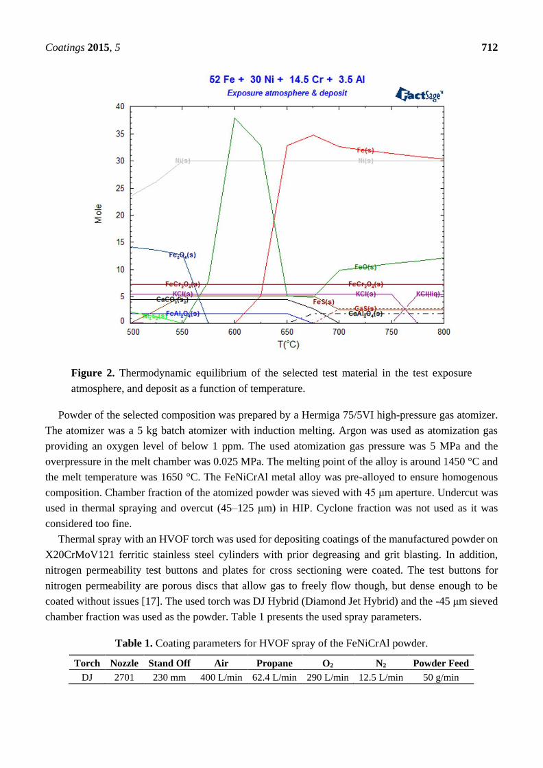
Thermodynamic equilibrium calculations were made with a surplus amount of exposure gases
(44% CO2-30% H2O-0.6% SO2-0.2% HCl-N2) and deposit (CaSO4-0.55 wt % KCl). The results are
shown in Figure 2, where it can be seen that at 650 °C, the equilibrium favors solid FeCr2O4 formation
along with smaller amounts of FeO, FeS and FeAl2O4 on top of Fe and Ni, which have high stabilities
according to the calculation. The salt and gas would react to form solid CaCO3. Moving to 720 °C solid
FeO is increasingly preferred while solid FeS is not. Solid CaAl2O4 should be formed instead of FeAl2O4
and solid CaS instead of CaCO3.
Coatings 2015, 5 712
Figure 2. Thermodynamic equilibrium of the selected test material in the test exposure
atmosphere, and deposit as a function of temperature.
Powder of the selected composition was prepared by a Hermiga 75/5VI high-pressure gas atomizer.
The atomizer was a 5 kg batch atomizer with induction melting. Argon was used as atomization gas
providing an oxygen level of below 1 ppm. The used atomization gas pressure was 5 MPa and the
overpressure in the melt chamber was 0.025 MPa. The melting point of the alloy is around 1450 °C and
the melt temperature was 1650 °C. The FeNiCrAl metal alloy was pre-alloyed to ensure homogenous
composition. Chamber fraction of the atomized powder was sieved with 45 μm aperture. Undercut was
used in thermal spraying and overcut (45–125 μm) in HIP. Cyclone fraction was not used as it was
considered too fine.
Thermal spray with an HVOF torch was used for depositing coatings of the manufactured powder on
X20CrMoV121 ferritic stainless steel cylinders with prior degreasing and grit blasting. In addition,
nitrogen permeability test buttons and plates for cross sectioning were coated. The test buttons for
nitrogen permeability are porous discs that allow gas to freely flow though, but dense enough to be
coated without issues [17]. The used torch was DJ Hybrid (Diamond Jet Hybrid) and the -45 μm sieved
chamber fraction was used as the powder. Table 1 presents the used spray parameters.
Table 1. Coating parameters for HVOF spray of the FeNiCrAl powder.
Torch Nozzle Stand Off Air Propane O2 N2 Powder Feed
DJ 2701 230 mm 400 L/min 62.4 L/min 290 L/min 12.5 L/min 50 g/min
Coatings 2015, 5 713
Hot isostatic pressing was performed using an Asea Mini Hipper QUINTUS Hot Isostatic Press type
QIH-9. The overcut of the chamber fraction of the gas atomized powder was packed in an AISI 316L
HIP capsule of Ø27/30 mm × 100 mm using mechanical pressing. The evacuation of the capsule was
24 h at room temperature down to a pressure level of 10−5 mbar. Used HIP parameters were
1150 °C/3 h/1000 bar.
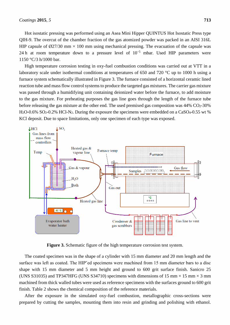
High temperature corrosion testing in oxy-fuel combustion conditions was carried out at VTT in a
laboratory scale under isothermal conditions at temperatures of 650 and 720 °C up to 1000 h using a
furnace system schematically illustrated in Figure 3. The furnace consisted of a horizontal ceramic lined
reaction tube and mass flow control systems to produce the targeted gas mixtures. The carrier gas mixture
was passed through a humidifying unit containing deionized water before the furnace, to add moisture
to the gas mixture. For preheating purposes the gas line goes through the length of the furnace tube
before releasing the gas mixture at the other end. The used premixed gas composition was 44% CO2-30%
H2O-0.6% SO2-0.2% HCl-N2. During the exposure the specimens were embedded on a CaSO4-0.55 wt %
KCl deposit. Due to space limitations, only one specimen of each type was exposed.
Figure 3. Schematic figure of the high temperature corrosion test system.
The coated specimen was in the shape of a cylinder with 15 mm diameter and 20 mm length and the
surface was left as coated. The HIP’ed specimens were machined from 15 mm diameter bars to a disc
shape with 15 mm diameter and 5 mm height and ground to 600 grit surface finish. Sanicro 25
(UNS S31035) and TP347HFG (UNS S34710) specimens with dimensions of 15 mm × 15 mm × 3 mm
machined from thick walled tubes were used as reference specimens with the surfaces ground to 600 grit
finish. Table 2 shows the chemical composition of the reference materials.
After the exposure in the simulated oxy-fuel combustion, metallographic cross-sections were
prepared by cutting the samples, mounting them into resin and grinding and polishing with ethanol.
Coatings 2015, 5 714
Characterization was performed with an optical microscope and a FEI XL30 ESEM scanning electron
microscope (SEM) equipped with a Thermo Fisher Scientific UltraDry energy dispersive X-ray detector
(EDX). X-ray Diffraction (XRD) was performed on corrosion products of the coatings after exposure in
the highest temperature. The aim of the materials performance assessment was to characterize the
morphologies produced during the exposure testing and to determine the extent of metal damage caused
to each specimen during the exposure.
Table 2. Chemical composition of bulk materials Sanicro 25 and TP347HFG by optical
emission spectroscopy (OES).
Alloy Cr Ni Mo Nb Fe Other
TP347HFG 18.3 11.7 0.23 0.92 bal. 1.64 Mn, 0.33 Cu, 0.4 Si, 0.07 C
Sanicro 25 22.3 24.9 – 0.5 bal. 3.4 W, 1.5 Co, 2.9 Cu, 0.2 Si, 0.3 Mn, 0.24 N, 0.06C
3. Results
3.1. Powder Manufacturing and Consolidation
Particle sizes of the manufactured powder were measured using Malvern Mastersizer 3000.
The -45 μm sieved powder had D10 15.1, D50 27.4 and D90 45.3 μm values and the 45–125 μm sieved
powder had D10 34.7, D50 61.3 and D90 105 μm values. The coarser powder contained some fine
particles below 45 μm although sieved with 45 μm sieve. This was because of clogging of the sieve and
perhaps too short a sieving time.
SEM images of the powders are presented in Figures 4 and 5. They show some small satellite particles
stuck on the surface of larger particles, but the amount of the satellites was so small that it was considered
not to affect thermal spraying or HIP. Large magnification images (Figures 4b and 5b) show grain
structures. The grain structure is larger in large particles than in small particles due to faster cooling rate
of the small particles. The grain structure cannot be detected on particles of less than 10 μm in diameter.
EDX analysis of the composition of the powder is presented in Table 3.
An optical micrograph of the resulting microstructure of the HIP’ed alloy is presented in Figure 6.
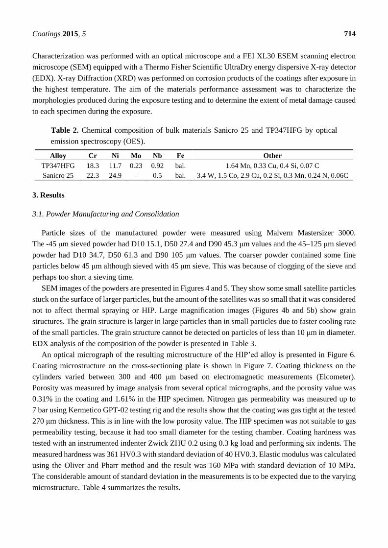
Coating microstructure on the cross-sectioning plate is shown in Figure 7. Coating thickness on the
cylinders varied between 300 and 400 μm based on electromagnetic measurements (Elcometer).
Porosity was measured by image analysis from several optical micrographs, and the porosity value was
0.31% in the coating and 1.61% in the HIP specimen. Nitrogen gas permeability was measured up to
7 bar using Kermetico GPT-02 testing rig and the results show that the coating was gas tight at the tested
270 μm thickness. This is in line with the low porosity value. The HIP specimen was not suitable to gas
permeability testing, because it had too small diameter for the testing chamber. Coating hardness was
tested with an instrumented indenter Zwick ZHU 0.2 using 0.3 kg load and performing six indents. The
measured hardness was 361 HV0.3 with standard deviation of 40 HV0.3. Elastic modulus was calculated
using the Oliver and Pharr method and the result was 160 MPa with standard deviation of 10 MPa.
The considerable amount of standard deviation in the measurements is to be expected due to the varying
microstructure. Table 4 summarizes the results.

Coatings 2015, 5 715
Figure 4. SEM images of gas atomized FeNiCrAl powder sieved below 45 μm, magnifications
with micron bars. (a) 100 μm; (b) 5 μm.
Figure 5. SEM images of gas atomized FeNiCrAl powder sieved 45–125 μm, magnifications
with micron bars. (a) 100 μm; (b) 5 μm.
Table 3. EDX analysis of the FeNiCrAl powder in wt % and calculated difference in %.
Fe Ni Cr Al
Target Bal 30.0 14.5 3.5
EDX analysis Bal 24.8 13.5 3.5
Difference (%) – −17.3 −6.9 0.0
Figure 6. Microstructure of the HIP’ed FeNiCrAl alloy before testing.
Coatings 2015, 5 716
Figure 7. Optical micrograph of a cross-section of HVOF DJ Hybrid sprayed FeNiCrAl
coating before testing.
Table 4. Indentation results for the HVOF thermal spray coating.
Coating Method Hardness (HV0.3) STDEV E (Mpa) STDEV n
DJ Hybrid 361 40 160 10 6
3.2. Exposure at 650 °C
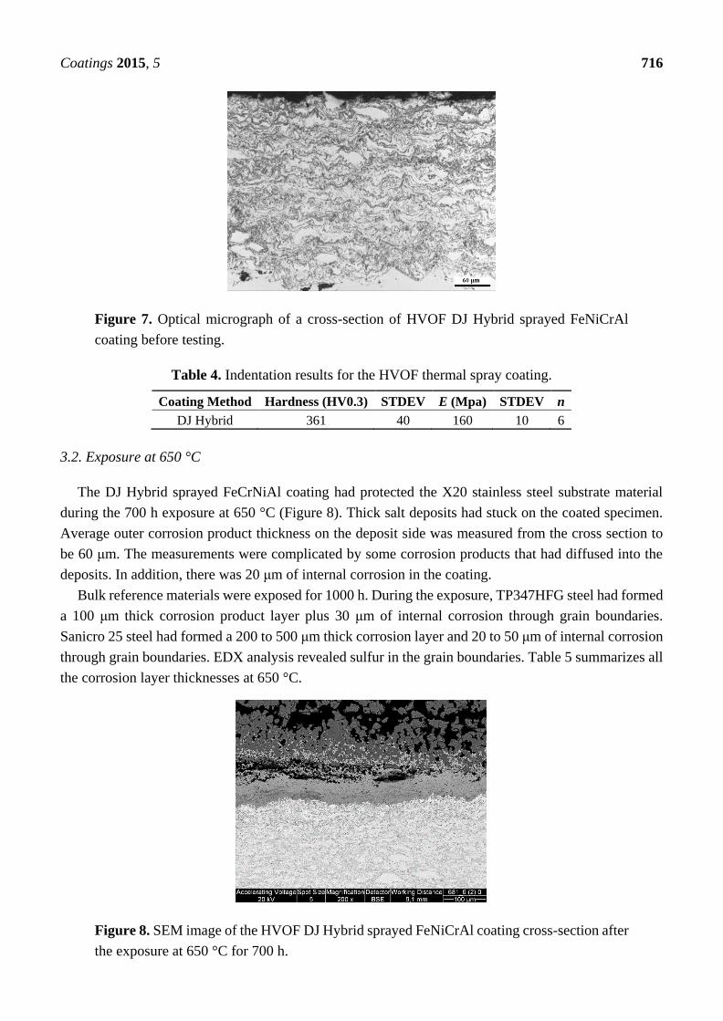
The DJ Hybrid sprayed FeCrNiAl coating had protected the X20 stainless steel substrate material
during the 700 h exposure at 650 °C (Figure 8). Thick salt deposits had stuck on the coated specimen.
Average outer corrosion product thickness on the deposit side was measured from the cross section to
be 60 μm. The measurements were complicated by some corrosion products that had diffused into the
deposits. In addition, there was 20 μm of internal corrosion in the coating.
Bulk reference materials were exposed for 1000 h. During the exposure, TP347HFG steel had formed
a 100 μm thick corrosion product layer plus 30 μm of internal corrosion through grain boundaries.
Sanicro 25 steel had formed a 200 to 500 μm thick corrosion layer and 20 to 50 μm of internal corrosion
through grain boundaries. EDX analysis revealed sulfur in the grain boundaries. Table 5 summarizes all
the corrosion layer thicknesses at 650 °C.
Figure 8. SEM image of the HVOF DJ Hybrid sprayed FeNiCrAl coating cross-section after
the exposure at 650 °C for 700 h.
Coatings 2015, 5 717
Table 5. Corrosion layer thicknesses in μm at 650 °C. HIP sample was not exposed at this
temperature. The HVOF coating was exposed for 700 h while the others were exposed for
1000 h.
Layer HVOF (DJ) TP347HFG Sanicro 25
Outer layer(s) 60 100 200–500
Internal 20 30 20–50
3.3. Exposure at 720 °C
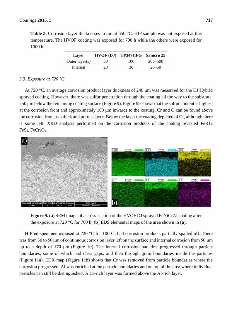
At 720 °C, an average corrosion product layer thickness of 240 μm was measured for the DJ Hybrid
sprayed coating. However, there was sulfur penetration through the coating all the way to the substrate,
250 μm below the remaining coating surface (Figure 9). Figure 9b shows that the sulfur content is highest
at the corrosion front and approximately 100 μm inwards to the coating. Cr and O can be found above
the corrosion front as a thick and porous layer. Below the layer the coating depleted of Cr, although there
is some left. XRD analysis performed on the corrosion products of the coating revealed Fe2O3,
FeS2, FeCr2O4.
Figure 9. (a) SEM image of a cross-section of the HVOF DJ sprayed FeNiCrAl coating after
the exposure at 720 °C for 700 h; (b) EDS elemental maps of the area shown in (a).
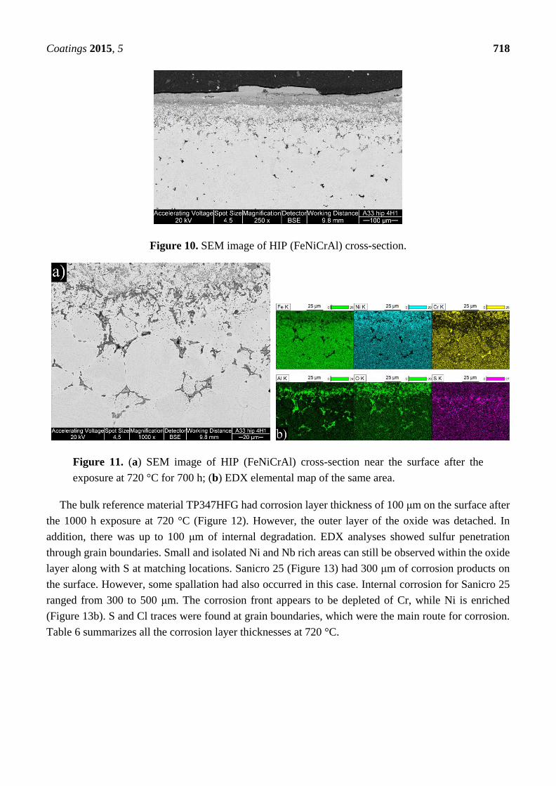
HIP’ed specimen exposed at 720 °C for 1000 h had corrosion products partially spalled off. There
was from 30 to 50 μm of continuous corrosion layer left on the surface and internal corrosion from 50 μm
up to a depth of 170 μm (Figure 10). The internal corrosion had first progressed through particle
boundaries, some of which had clear gaps, and then through grain boundaries inside the particles
(Figure 11a). EDX map (Figure 11b) shows that Cr was removed from particle boundaries where the
corrosion progressed. Al was enriched at the particle boundaries and on top of the area where individual
particles can still be distinguished. A Cr-rich layer was formed above the Al-rich layer.
Coatings 2015, 5 718
Figure 10. SEM image of HIP (FeNiCrAl) cross-section.
Figure 11. (a) SEM image of HIP (FeNiCrAl) cross-section near the surface after the
exposure at 720 °C for 700 h; (b) EDX elemental map of the same area.
The bulk reference material TP347HFG had corrosion layer thickness of 100 μm on the surface after
the 1000 h exposure at 720 °C (Figure 12). However, the outer layer of the oxide was detached. In
addition, there was up to 100 μm of internal degradation. EDX analyses showed sulfur penetration
through grain boundaries. Small and isolated Ni and Nb rich areas can still be observed within the oxide
layer along with S at matching locations. Sanicro 25 (Figure 13) had 300 μm of corrosion products on
the surface. However, some spallation had also occurred in this case. Internal corrosion for Sanicro 25
ranged from 300 to 500 μm. The corrosion front appears to be depleted of Cr, while Ni is enriched
(Figure 13b). S and Cl traces were found at grain boundaries, which were the main route for corrosion.
Table 6 summarizes all the corrosion layer thicknesses at 720 °C.

Coatings 2015, 5 719
Figure 12. (a) SEM image of TP347HFG steel cross-section near the surface after the
exposure at 720 °C for 1000 h; (b) EDX elemental map of the corrosion front at a
higher magnification.
Figure 13. (a) SEM image of Sanicro 25 steel cross-section near the surface after the
exposure at 720 °C for 1000 h; (b) EDX elemental map of the same area.
Table 6. Corrosion layer thicknesses in μm at 720 °C. Some of the external corrosion layers
had spalled off, indicated by the “+” signs. The HVOF coating was exposed for 700 h while
the others were exposed for 1000 h.
Layer HVOF (DJ) HIP TP347HFG Sanicro 25
Outer layer(s) 240 50+ 100+ 300+
Internal 250 50–170 100 300–500

Coatings 2015, 5 720
4. Discussion
As expected, the results showed that a higher temperature yielded higher amounts of corrosion.
The corrosion mechanism appeared to be the same in both temperatures: sulfidation, possibly preceded
by chlorine corrosion. The formation of such types of corrosion products cause by chlorine corrosion
have also been reported by Oksa et al. [17]. Alkali chlorides in deposits may cause accelerated corrosion
well below the melting point of KCl [18]. Gases containing HCl for example, can influence the corrosion
caused by other mechanisms, such as sulfidation, by breaking down the protective oxides and allowing
corrosive species to reach the metal surface [18]. Similar results have been reported by Haanappel et al. [19],
who found that HCl in an oxidizing-sulfidizing environment increased the corrosion rate significantly and
made the scales thick, porous and non-protective, comparable to the results of this study.
The manufactured FeNiCrAl composition was both thermal sprayed and HIP’ed so that the effect of
microstructure to the performance could be seen. The structure of the DJ Hybrid coating showed some
large splats, which were nicely deformed, and some completely oxidized small particles. The coating
could have been improved by using a tighter powder fraction, either by removing the smallest particles
and using current spray parameters, or by removing the largest particles and using cooler spray
parameters. The over-oxidized lamellae boundaries in the coating could have contained porosity or might
have micro-cracked under thermal stress and therefore allow faster diffusion of corrosive species into
the coating and enabled diffusion of coating element outward, as Ni and Fe were found diffused deep
into the deposits. Having small lamellas lead to an increased amount of lamellae boundaries and hence
higher diffusion when the boundaries act as diffusion paths. Aluminum did not effectively block the
lamellae boundaries, and XRD results showed that the predicted phases did not form. This was likely
due to the composition mismatch between the calculated and manufactured powder. Based on the EDX
results of Table 3, there is room for optimization in the powder manufacturing, because the actual
composition had 17% less Ni and 7% less Cr than planned. Al content was exactly as planned.
Unfortunately, the HIP’ed specimen had large porosity between the particles, making it more difficult
to compare with the other specimens as intended. However, the larger particles do show how the
corrosive species diffused inside the particles through grain boundaries. The same was observed on a
smaller scale in the coatings.
The exposure tests were conducted on single specimens, so the approach is guiding rather than
statistical. TP347HFG performed well at 650 °C by having the second thinnest corrosion products
(100 + 30 μm), being only slightly behind the HVOF coating, which would have had 86 + 29 μm if we
assume linear growth from 700 h exposure to 1000 h. At 720 °C the oxide had spalled, but based on the
amount of internal corrosion, the material could be the best performer of the experiment. The reference
material Sanicro 25 had disastrous performance at both temperatures, even though it contained more Cr
(22.5 vs. 18 wt %) and Ni (25 vs. 11 wt %) than the TP347HFG. Selective corrosion of Cr has been
observed to increase in Cl containing atmospheres when Cr content increases [20]. However, the Cr
difference of TP347HFG and Sanicro 25 is quite small compared to the performance difference.
Therefore, the very poor performance of Sanicro 25 steel was more likely related to its Cu content.
When present in deposits, copper has been found to increase corrosion rates significantly in chlorine
containing conditions by catalyzing the formation of elemental chlorine from HCl [21,22]. Because
chemical composition of Sanicro 25 with higher Cr and Ni content would suggest that the material had
Coatings 2015, 5 721
better corrosion resistance than TP347HFG, we suggest that copper has probably had an influence on
the high corrosion rate as an alloying element. Together with preferential removal of Cr at the corrosion
front, copper may have reacted with chlorine and contributed to the very high corrosion rate of
Sanicro 25. As a reference, TP347HFG and SAN25 have been tested in air- and oxy-firing conditions by
Holcomb et al. [13]. The corrosion rates varied from 0–25 nm/h at 550 °C to 210–615 nm/h at corrosion
peak temperature of about 700 °C, when chlorine was not present in the deposit.
5. Conclusions
This study presented material development from thermodynamic calculations of suitable composition
to performance in a simulated oxy-fuel combustion environment. In between, there were steps for
creating the desired composition in the form of a powder, and using two different consolidation methods
to produce coating or bulk material from the powder. HVOF (DJ) coating had better performance than
the reference materials at 650 °C. However, at 720 °C there was significant amount of sulfur penetration
throughout the coating. The HIP’ed structure was hard to compare due to its porosity. Overall the best
material in these experiments was the TP347HFG steel. In light of these results, the execution of the
development chain has room for improvement and further research is required.
Acknowledgments
The authors would like to thank VTT Technical Research Centre of Finland Ltd. for the
financial support.
Author Contributions
Maria Oksa and Satu Tuurna designed the research. Juha Lagerbom, Jouko Virta and Tomi Suhonen
performed and designed the experimental work. Sanni Yli-Olli performed the thermodynamic
calculation. Jarkko Metsäjok performed the SEM analysis and authored the manuscript, and Maria Oksa,
Satu Tuurna, Juha Lagerbom and Jouko Virta co-authored the work.
Conflicts of Interest
The authors declare no conflict of interest.
References
1. International Energy Agency. World Energy Outlook Special Report 2015: Energy and Climate
Change; International Energy Agency: Paris, France, 2015; Available online: http://www.iea.org/
publications/freepublications/publication/WEO2015SpecialReportonEnergyandClimateChange.pdf
(accessed on 3 September 2015).
2. Zheng, L. Oxy-Fuel Combustion for Power Generation and Carbon Dioxide (CO2) Capture;
Woodhead Publishing: Cambridge, UK, 2011; p. 374.
3. Bordenet, B. Influence of novel cycle concepts on the high-temperature corrosion of power plants.
Mater. Corros. 2008, 59, 361–366.

Coatings 2015, 5 722
4. Scheffknecht, G.; Al-Makhadmeh, L.; Schnell, U.; Maier, J. Oxy-fuel coal combustion—A review
of the current state-of-the-art. Int. J. Greenh. Gas Control 2011, 5, S16–S35.
5. Kranzmann, A.; Neddemeyer, T.; Ruhl, A.S.; Huenert, D.; Bettge, D.; Oder, G.; Saliwan-Neumann, R.
The challenge in understanding the corrosion mechanisms under oxyfuel combustion conditions.
Int. J. Greenh. Gas Control 2011, 5, S168–S178.
6. Stein-Brzozowska, G.; Maier, J.; Scheffknecht, G. Impact of the oxy-fuel combustion on the
corrosion behaviour of advanced austenitic superheater materials. Energy Procedia 2011, 4,
2035–2042.
7. Pint, B.A.; Thomson, J.K. Effect of oxy-firing on corrosion rates at 600–650 °C. Mater. Corros.
2014, 65, 132–140.
8. Covino, B.S., Jr.; Matthes, S.A.; Bullard, S.J. Effect of Oxyfuel Combustion on Superheater
Corrosion. In Proceedings of the NACE CORROSION 2008 Conference & Expo, New Orleans,
LA, USA, 16–19 March 2008; p. 8456.
9. Montgomery, M.; Bjurman, M.; Hjørnhede, A.; Rombrecht, H.B.; Lisk, A.; Krautz, H.J. High
temperature corrosion investigation in an oxyfuel combustion test rig. Mater. Corros. 2015, 66,
257–269.
10. Yu, D.; Morris, W.J.; Erickson, R.; Wendt, J.O.L.; Fry, A.; Senior, C.L. Ash and deposit formation
from oxy-coal combustion in a 100 kW test furnace. Int. J. Greenh. Gas Control 2011, 5, S159–S167.
11. Gagliano, M.S.; Hack, H.; Stanko, G. Update on the fireside corrosion resistance of proposed
advanced ultrasupercritical superheater and reheater materials: Laboratory and field test results.
In Proceedings of the Clearwater Coal Conference 34th International Technical Conference on Coal
Utilization & Fuel Systems, Clearwater, FL, USA, 31 May–4 June 2009.
12. Syed, A.U.; Simms, N.J.; Oakey, J.E. Fireside corrosion of superheaters: Effects of air and
oxy-firing of coal and biomass. Fuel 2012, 101, 62–73.
13. Holcomb, G.R.; McGhee, B.F.; Fry, A.T.; Simms, N.J.; Davis, K. Boiler corrosion and monitoring.
Mater. High Temp. 2013, 30, 271–286.
14. Hussain, T.; Syed, A.Y.; Simms, N.J. Trends in fireside corrosion damage to superheaters in air and
oxy-firing of coal/biomass. Fuel 2013, 113, 787–797.
15. Huczkowski, P.; Olszewski, T.; Schiek, M.; Lutz, B.; Holcomb, G.R.; Shemet, V.; Nowak, W.;
Meier, G.H.; Singheiser, L.; Quadakkers, W.J. Effect of SO2 on oxidation of metallic materials in
CO2/H2O-rich gases relevant to oxyfuel environments. Mater. Corros. 2014, 65, 121–131.
16. Bellucci, A.; Bellini, S.; Pileggi, R.; Stocchi, D.; Tuurna, S. Effect of Al Enrichment by Pack
Cementation of FeCr Coatings Deposited by HVOF. J. Therm. Spray Technol. 2015, 24, 244–251.
17. Oksa, M.; Metsäjoki, J.; Kärki, J. Thermal spray coatings for high-temperature corrosion protection
in biomass co-fired boilers. J. Therm. Spray Technol. 2015, 24, 194–205.
18. Nielsen, H.P.; Frandsen, F.J.; Dam-Johansen, K.; Baxter, L.L. The implications of chlorine-associated
corrosion on the operation of biomass-fired boilers. Prog. Energy Combust. Sci. 2000, 26, 283–298.
19. Haanappel, V.A.C.; Haanappel, N.W.J.; Fransen, T.; van Corbach, H.D.; Gellings, P.J. Corrosion
Kinetics of Low- and High-Alloy Steels in Chlorine-Containing Gas Atmospheres. Corrosion 1992,
48, 812–821.
20. Montgomery, M.; Karlsson, A. In-situ corrosion investigation at Masnedø CHP plant—A straw-fired
power plant. Mater. Corros. 1999, 50, 579–584.

Coatings 2015, 5 723
21. Galetz, M.C.; Bauer, J.T.; Schutze, M.; Noguchi, M.; Takatoh, C.; Cho, H. The Influence of Copper
in Ash Deposits on the Corrosion of Boiler Tube Alloys for Waste-to-Energy Plants. Mater. Corros.
2012, 63, 1–8.
22. Oksa, M.; Tuurna, S.; Varis, T. Increased lifetime for biomass and waste to energy power plant
boilers with HVOF coatings—High temperature corrosion testing under chlorine-containing molten
salt. J. Therm. Spray Technol. 2013, 22, 783–796.
© 2015 by the authors; licensee MDPI, Basel, Switzerland. This article is an open access article
distributed under the terms and conditions of the Creative Commons Attribution license
(http://creativecommons.org/licenses/by/4.0/).
Related Documents