Citation: Mahmood, S.; Iqbal, A.; Rafi-ud-Din; Wadood, A.; Mateen, A.; Amin, M.; Yahia, I.S.; Zahran, H.Y. Influence of Homogenizing Methodology on Mechanical and Tribological Performance of Powder Metallurgy Processed Titanium Composites Reinforced by Graphene Nanoplatelets. Molecules 2022, 27, 2666. https://doi.org/10.3390/ molecules27092666 Academic Editor: Chiara Ingrosso Received: 23 March 2022 Accepted: 18 April 2022 Published: 21 April 2022 Publisher’s Note: MDPI stays neutral with regard to jurisdictional claims in published maps and institutional affil- iations. Copyright: © 2022 by the authors. Licensee MDPI, Basel, Switzerland. This article is an open access article distributed under the terms and conditions of the Creative Commons Attribution (CC BY) license (https:// creativecommons.org/licenses/by/ 4.0/). molecules Article Influence of Homogenizing Methodology on Mechanical and Tribological Performance of Powder Metallurgy Processed Titanium Composites Reinforced by Graphene Nanoplatelets Sultan Mahmood 1 , Amjad Iqbal 2,3, * , Rafi-ud-Din 4 , Abdul Wadood 1 , Abdul Mateen 5 , Muhammad Amin 6 , Ibrahim S. Yahia 7,8,9 and Heba Y. Zahran 7,8,9 1 Department of Materials Science and Engineering, Institute of Space Technology, Islamabad 44000, Pakistan; [email protected] (S.M.); [email protected] (A.W.) 2 Department of Advance Materials and Technologies, Faculty of Materials Engineering, Silesian University of Technology, 44-100 Gliwice, Poland 3 CEMMPRE—Centre for Mechanical Engineering Materials and Processes, Department of Mechanical Engineering, University of Coimbra, Rua Luı’s Reis Santos, 3030-788 Coimbra, Portugal 4 Materials Division, Pakistan Institute of Nuclear Science and Technology, Islamabad 45650, Pakistan; rafi[email protected] 5 Department of Materials Science and Engineering, Pak-Austria Fachhochschule Institute of Applied Sciences and Technology, Haripur 22621, Pakistan; [email protected] 6 Department of Energy System Engineering Seoul, Seoul National University, Seoul 08826, Korea; [email protected] 7 Laboratory of Nano-Smart Materials for Science and Technology (LNSMST), Department of Physics, Faculty of Science, King Khalid University, P.O. Box 9004, Abha 61413, Saudi Arabia; [email protected] (I.S.Y.); [email protected] (H.Y.Z.) 8 Research Center for Advanced Materials Science (RCAMS), King Khalid University, P.O. Box 9004, Abha 61413, Saudi Arabia 9 Nanoscience Laboratory for Environmental and Biomedical Applications (NLEBA), Semiconductor Lab., Metallurgical Lab.1, Department of Physics, Faculty of Education, Ain Shams University, Roxy, Cairo 11757, Egypt * Correspondence: [email protected] Abstract: In the present work, 0.25 wt%GNP-Ti composites were prepared through powder met- allurgy route by adopting three types of mixing modes to investigate the extent of mixing on the mechanical and tribological properties. Dry ball milling, wet ball milling, and rotator mixing were independently employed to homogenize the composite constituents. Three types of composite pow- ders obtained were subsequently sintered into composite pellets by cold compaction followed by vacuum sintering. Morphological investigation of composite powders performed by SEM revealed better homogenization of GNPs in Ti matrix for dry ball milled composite powder, whereas wet ball milled and rotator mixed composite powders showed aggregation and bundling of GNPs. Micro Vickers hardness of composites produced via dry ball milling is 4.56% and 15.7% higher than wet ball milled and rotator mixed samples, respectively. Wear test performed by pin-on-disk tribometer showed higher wear loss for wet ball milled and rotator mixed composites in comparison to dry ball milled. Keywords: titanium; graphene nanoplatelets; titanium matrix composites; morphology; mechanical properties; tribological properties 1. Introduction Metal matrix composites (MMCs) have been regarded as an essential class of engineer- ing materials due to their better thermal and mechanical performance [1,2]. Conventionally, titanium and its alloys seem to be a better choice for automotive, aerospace, and bio-medical applications owing to the medium density, moderate mechanical strength, good corrosion Molecules 2022, 27, 2666. https://doi.org/10.3390/molecules27092666 https://www.mdpi.com/journal/molecules

Welcome message from author
This document is posted to help you gain knowledge. Please leave a comment to let me know what you think about it! Share it to your friends and learn new things together.
Transcript
Citation: Mahmood, S.; Iqbal, A.;
Rafi-ud-Din; Wadood, A.; Mateen, A.;
Amin, M.; Yahia, I.S.; Zahran, H.Y.
Influence of Homogenizing
Methodology on Mechanical and
Tribological Performance of Powder
Metallurgy Processed Titanium
Composites Reinforced by Graphene
Nanoplatelets. Molecules 2022, 27,
2666. https://doi.org/10.3390/
molecules27092666
Academic Editor: Chiara Ingrosso
Received: 23 March 2022
Accepted: 18 April 2022
Published: 21 April 2022
Publisher’s Note: MDPI stays neutral
with regard to jurisdictional claims in
published maps and institutional affil-
iations.
Copyright: © 2022 by the authors.
Licensee MDPI, Basel, Switzerland.
This article is an open access article
distributed under the terms and
conditions of the Creative Commons
Attribution (CC BY) license (https://
creativecommons.org/licenses/by/
4.0/).
molecules
Article
Influence of Homogenizing Methodology on Mechanical andTribological Performance of Powder Metallurgy ProcessedTitanium Composites Reinforced by Graphene NanoplateletsSultan Mahmood 1 , Amjad Iqbal 2,3,* , Rafi-ud-Din 4, Abdul Wadood 1, Abdul Mateen 5, Muhammad Amin 6,Ibrahim S. Yahia 7,8,9 and Heba Y. Zahran 7,8,9
1 Department of Materials Science and Engineering, Institute of Space Technology, Islamabad 44000, Pakistan;[email protected] (S.M.); [email protected] (A.W.)
2 Department of Advance Materials and Technologies, Faculty of Materials Engineering, Silesian University ofTechnology, 44-100 Gliwice, Poland
3 CEMMPRE—Centre for Mechanical Engineering Materials and Processes, Department of MechanicalEngineering, University of Coimbra, Rua Luı’s Reis Santos, 3030-788 Coimbra, Portugal
4 Materials Division, Pakistan Institute of Nuclear Science and Technology, Islamabad 45650, Pakistan;[email protected]
5 Department of Materials Science and Engineering, Pak-Austria Fachhochschule Institute of Applied Sciencesand Technology, Haripur 22621, Pakistan; [email protected]
6 Department of Energy System Engineering Seoul, Seoul National University, Seoul 08826, Korea;[email protected]
7 Laboratory of Nano-Smart Materials for Science and Technology (LNSMST), Department of Physics,Faculty of Science, King Khalid University, P.O. Box 9004, Abha 61413, Saudi Arabia;[email protected] (I.S.Y.); [email protected] (H.Y.Z.)
8 Research Center for Advanced Materials Science (RCAMS), King Khalid University, P.O. Box 9004,Abha 61413, Saudi Arabia
9 Nanoscience Laboratory for Environmental and Biomedical Applications (NLEBA), Semiconductor Lab.,Metallurgical Lab.1, Department of Physics, Faculty of Education, Ain Shams University, Roxy,Cairo 11757, Egypt
* Correspondence: [email protected]
Abstract: In the present work, 0.25 wt%GNP-Ti composites were prepared through powder met-allurgy route by adopting three types of mixing modes to investigate the extent of mixing on themechanical and tribological properties. Dry ball milling, wet ball milling, and rotator mixing wereindependently employed to homogenize the composite constituents. Three types of composite pow-ders obtained were subsequently sintered into composite pellets by cold compaction followed byvacuum sintering. Morphological investigation of composite powders performed by SEM revealedbetter homogenization of GNPs in Ti matrix for dry ball milled composite powder, whereas wet ballmilled and rotator mixed composite powders showed aggregation and bundling of GNPs. MicroVickers hardness of composites produced via dry ball milling is 4.56% and 15.7% higher than wetball milled and rotator mixed samples, respectively. Wear test performed by pin-on-disk tribometershowed higher wear loss for wet ball milled and rotator mixed composites in comparison to dryball milled.
Keywords: titanium; graphene nanoplatelets; titanium matrix composites; morphology; mechanicalproperties; tribological properties
1. Introduction
Metal matrix composites (MMCs) have been regarded as an essential class of engineer-ing materials due to their better thermal and mechanical performance [1,2]. Conventionally,titanium and its alloys seem to be a better choice for automotive, aerospace, and bio-medicalapplications owing to the medium density, moderate mechanical strength, good corrosion
Molecules 2022, 27, 2666. https://doi.org/10.3390/molecules27092666 https://www.mdpi.com/journal/molecules

Molecules 2022, 27, 2666 2 of 18
and oxidation resistance, better fracture toughness, and biocompatibility. However, theiruse in many applications is limited because of poor wear resistance and lower electri-cal and thermal properties [3,4]. Poor tribological performance of titanium, for example,inferior fretting behavior and lower wear resistance, are chiefly due to its low thermalconductivity and less plastic shearing resistance [5]. In addition, many structural andengineering applications require a higher degree of mechanical strength. To overcomesuch deficiencies in titanium, numerous reinforcement materials have been incorporated todevelop titanium matrix composites (TMCs) [6]. Various ceramic reinforcements have beenreported in the literature to improve the strength and wear resistance of Ti and its alloys.Shufeng et al. investigated the synergic effect of in situ synthesized TiC-TiB reinforcementson microstructure and mechanical properties of TMCs and observed a 1.7 times increase intensile strength accompanying a 12.5% decline in ductility for 13.6 vol% reinforcement [7].Ti/TiC nanocomposites were synthesized by Gu et al., who found optimum content of TiCas 12.5 wt% to achieve a 2 times increase in microhardness and considerably low coefficientof friction (COF) and wear rate [8]. Wang et al. achieved 3.5 times higher compressivestrength at the expense of a 20% decline in strain to failure for in situ synthesized nano-metric TiC-Ti composites compared to un-reinforced Ti [9]. Al2O3-Ti nanocomposites wereproduced by Zarghani et al. through friction stir processing and noticed 1.5 times enhance-ment in compressive yield strength for 3.9 vol% Al2O3-Ti in comparison to as receivedTi [10]. Huang et al. obtained 1.36 times increase in tensile strength for 5 vol%TiB nanowiresreinforced Ti-6Al-4V composites compared to that of un-reinforced alloy [11]. Pan et al.developed in situ formed TiC-Ti composites and showed 62% higher nano-indentationhardness and 30% lower COF than pure Ti [12]. Recently, Jin et al. found a 68.6% increasein hardness and 32.6% improvement in wear resistance of TiB2-Ti composites producedby selective laser melting [13]. However, reported enhancement in mechanical strengthand wear resistance is achieved at the cost of lightweight, toughness, thermal, and electri-cal properties because ceramics have higher densities, low fracture toughness, and poorthermal and electrical conductivity than titanium [14].
In view of the above, lightweight reinforcement materials having high strength, tough-ness, and electrical and thermal conductivity are indispensable in realizing the goal ofproducing titanium composites for aerospace, automotive, and bio-medical applications.In this perspective, carbonaceous materials, for example, carbon fiber (CF), nano-diamond(ND), carbon nanotubes (CNTs), and graphene nanoplatelets (GNPs), emerged as anideal choice thanks to their superior chemical and physical characteristics [15,16]. Nano-diamonds reinforcement (0.35 wt%) in the Ti matrix resulted in a 71.5% reduction in wearrate, as investigated by Saba et al. [17]. CNTs due to the high aspect ratio, high strength,and self-lubrication properties appear to be a promising reinforcement for TMCs [18].Research conducted by Kuzumaki et al. demonstrated a 5.5 times improvement in hard-ness of Ti through 0.8 vol% CNTs reinforcement [19]. Kondoh et al. achieved a 1.2 and1.5 times increase in tensile and yield strength, respectively, for 0.35 wt% CNT-Ti compositeswithout much reduction in the ductility [20]. Moreover, 3 wt% CNT-Ti composites wereproduced by Xue et al., wherein they confirmed good compressive strengthat elevatedtemperature when subjected to higher strain [21]. Wang et al. reported 61% compressivestrength enhancement for 0.4 wt% CNT-Ti composites [22]. Munir et al. researched onthe powder metallurgy processing of CNT-Ti composite and investigated the influenceof processing parameters and CNTs content on microstructural, mechanical, and wearproperties. Increase in compressive strength by 1.5 times and wear reduction by a factor of3.4 were reported for 0.5 wt% CNT-Ti composites [23–25]. However, among carbonaceousreinforcement materials, graphene has led the race, because it is gifted with low density(1.8 g/cm3), high strength (125 GPa), high elastic modulus (1.1 TPa), very good electricalconductivity (2 × 10⁸/ohm/m), remarkable thermal conductivity (5 × 10³ W/m/K), veryhigh specific surface (2630 m2/g), and outstanding self-lubrication behavior [26]. Grapheneis basically a two-dimensional single atomic layer of SP2 hybridized carbon atoms arrangedin a honeycomb lattice with a bond length of 0.142 nm. Its extraordinary self-lubrication is
Molecules 2022, 27, 2666 3 of 18
due to easy sliding on the densely packed surface [27]. However, the synthesis of perfectsingle layer graphene with ideal properties is not practicable [28]. Therefore, multilayergraphene with more than 10 layers, termed as graphene nanoplatelets (GNPs), retainingmost of the single layer properties has been proved to be a more suitable reinforcementchoice for composites applications [29].
Therefore keeping in mind the aim to develop lightweight, tough, and wear resistantcomposites, a systematic literature survey regarding GNPs-Ti composites has been carriedout which shows that research in this area is in the initial stage. Prior works synthesized theGNPs-Ti composites through the powder metallurgy (PM) route and explored some signifi-cant aspects. Yang et al. produced graphene platelets (GPs) reinforced titanium compositevia ball milling, cold compaction, and microwave sintering. They reported an 8% increasein thermal conductivity for 0.4 wt% GP, while the maximum compressive strength wasrecorded at 0.3 wt% GPs [30]. Song et al. synthesized TMCs reinforced by multilayergraphene (MLGs) through solution ball milling and spark plasma sintering (SPS) andfound an optimum content of 0.5 wt% MLGs for improvement in microscopic mechanicalproperties and scratch resistance of TMCs, but properties declined at 1.5 wt% MLGs. [31].Cao et al. achieved a 12%, 20%, and 15% increase in tensile strength, yield strength, andelastic modulus, respectively, for 0.5 wt% graphene nanoflakes (GNFs) reinforced Ti-6Al-4Vcomposites fabricated via blending, wet mixing, hot isostatic pressing (HIP), and isothermalforging. Notably, enhancement in mechanical properties was registered without the loss ofductility [32]. Gurbuz et al. developed 0.15, 0.30, 0.45, and 0.60 wt% GNPs-Ti compositesby blending, ball milling, cold compaction, and vacuum sintering. Optimized sinteringconditions were noticed at 1100 ◦C, 120 min for 0.15 wt% GNPs-Ti composites, displaying a86% increase in hardness [33]. Mu et al. have explored the influence of GNPs contents andits dispersion on the mechanical performance of TMCs, in addition to the role of secondaryprocessing such as hot rolling on mechanical properties of GNP-Ti composite, producedthrough wet ball milling and spark plasma sintering. Tensile strength and yield strengthwere enhanced to 24% and 27%, respectively, for 0.4 wt% GNPs, whereas for 0.8 wt%GNPs-Ti composite system, the nanoindentation test showed a 96% hardness increase inthe direction perpendicular to hot rolling [34,35]. Guo et al. used ball milling and SPSto fabricate Ti-6Al-4V matrix composites reinforced by Ni-P coated GNFs with varyingcontent from 0.25 to 1.5 wt%. They observed a uniform distribution of GNFs and reporteda 1.6 times increase in compressive yield stress for 0.5 wt% GNFs while maintaining 34.2%ductility [36].
Despite some very encouraging outcomes, the field is still open to explore the fullperspective of graphene reinforced titanium matrix composites for their effective use inaerospace, automotive, and bio-medical sectors. Processing of these composites posessome big challenges. Since the first and crucial step in PM is the homogenous mixing ofcomposite constituents to attain optimum property attributes in sintered composite [37],the primary target in developing GNPs-Ti composites is to overcome the challenge ofGNPs aggregation in the titanium matrix because GNPs dispersion in metal matrices iseven more difficult than CNTs, due to the very high specific surface area of graphene [38].Therefore, ample homogenization of GNPs-Ti composites powders before consolidation isthe most vital process phase. Earlier works focused on PM processing by employing onetype of homogenizing approach. Keeping in view the applications demand of TMCs suchas landing gear and turbine engine parts for aircraft and bone and dental implants [39,40],there is a need to explore and compare various homogenizing techniques and optimize thebest suitable method to reach the targeted attributes, for example, enhanced mechanicaland tribological characteristics. To the authors’ best knowledge, no comprehensive studyon the investigation of homogenizing methodology’s influence on the mechanical andtribological performance of GNPs-Ti composites has been published so far.
The main purpose of this research is to produce GNPs-Ti composites with a higherlevel of mechanical and tribological performance suitable for the longer and proficientfunctioning of aerospace and bio-medical components. Therefore, this work is primarily
Molecules 2022, 27, 2666 4 of 18
designed to develop 0.25 wt% GNP-Ti composites through PM processing by adopting threedifferent homogenizing approaches: dry ball milling, wet ball milling, and rotator mixing.The influence of homogenizing methodologies on morphological variations of compositepowders and its connection with the mechanical strength and tribological properties ofdeveloped composites have been investigated.
2. Experimental Part2.1. Materials
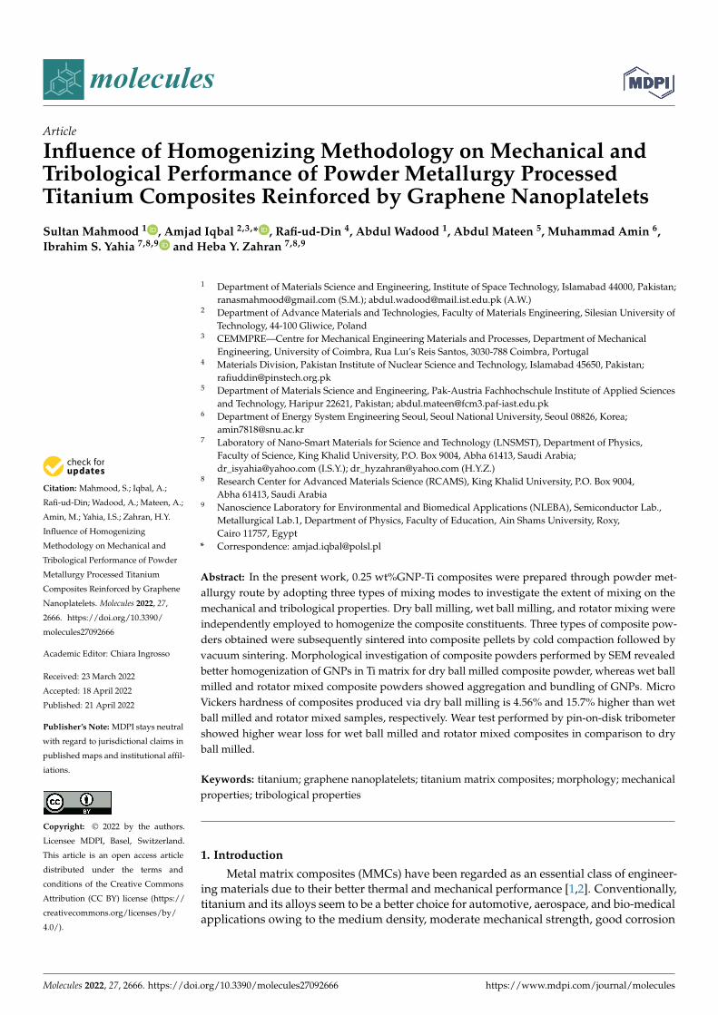
Matrix material used in this research is commercially pure titanium powder, having amean particle size of 28.8 µm and bulk shape morphology as evident in Figure 1a,b. Thechemical composition of as received Ti powder is presented in Table 1. For reinforcement,GNPs having an average thickness of 5–25 nm and a length of 1–20 µm are used. Themorphology of GNPs is shown in Figure 1c. Both raw materials were purchased fromGuangzhou Jiechuang, Co., Ltd. (Guangzhou, Guangdong, China).
Molecules 2022, 27, x FOR PEER REVIEW 4 of 19
functioning of aerospace and bio-medical components. Therefore, this work is primarily designed to develop 0.25 wt% GNP-Ti composites through PM processing by adopting three different homogenizing approaches: dry ball milling, wet ball milling, and rotator mixing. The influence of homogenizing methodologies on morphological variations of composite powders and its connection with the mechanical strength and tribological properties of developed composites have been investigated.
2. Experimental Part 2.1. Materials
Matrix material used in this research is commercially pure titanium powder, having a mean particle size of 28.8 µm and bulk shape morphology as evident in Figure 1a,b. The chemical composition of as received Ti powder is presented in Table 1. For reinforcement, GNPs having an average thickness of 5–25 nm and a length of 1–20 µm are used. The morphology of GNPs is shown in Figure 1c. Both raw materials were purchased from Guangzhou Jiechuang, Co., Ltd. (Guangzhou, Guangdong, China).
Figure 1. Stating materials: (a) particle size analysis of Ti powder; SEM micrographs showing mor-phology of (b) Ti powder and (c) GNPs.
Table 1. Chemical composition of as received Titanium powder.
Element Concentration (%) Fe Al Ti
0.036 0.021 99.943
2.2. Processing The solid-state powder metallurgy route is adopted to produce 0.25 wt% GNP-Ti
composite samples. In the first step, GNPs are homogenized in Ti powder through three different mixing techniques to obtain three types of composite powders. In the second stage, composite powders are cold pressed followed by vacuum sintering to obtain three types of sample batches. Samples preparation through this route is described in subse-quent sections, and processing parameters are summarized in Table 2.
Figure 1. Stating materials: (a) particle size analysis of Ti powder; SEM micrographs showingmorphology of (b) Ti powder and (c) GNPs.
Table 1. Chemical composition of as received Titanium powder.
Element Concentration (%)
Fe Al Ti
0.036 0.021 99.943
2.2. Processing
The solid-state powder metallurgy route is adopted to produce 0.25 wt% GNP-Ticomposite samples. In the first step, GNPs are homogenized in Ti powder through threedifferent mixing techniques to obtain three types of composite powders. In the secondstage, composite powders are cold pressed followed by vacuum sintering to obtain threetypes of sample batches. Samples preparation through this route is described in subsequentsections, and processing parameters are summarized in Table 2.
2.2.1. Dry Ball Milling
In this technique, 0.25 wt% GNP-Ti composite powder is obtained through ball millingin dry form by employing a planetary ball mill (PM 4, Retsch, Germany). Besides compositeconstituents, 0.3 wt% stearic acid (SA) is added as a process control agent (PCA). Thefunction of PCA during mechanical alloying is to avoid cold welding and accelerate thefracturing of powder particles [41]. GNPs and Ti powders in weighed quantity are put intoa steel vial (500 mL, ID = 100 mm) together with the tungsten carbide balls as a millingmedia. Balls of dissimilar sizes (5 mm and 10 mm diameter) are used to bring in morecollisions and promote fracturing over cold welding [42]. Ball to powder ratio (BPR) is set
Molecules 2022, 27, 2666 5 of 18
at 6:1. Ball milling is performed at 225 rpm for 3 h in dry argon atmosphere to preventoxidation of freshly produced surfaces [43].
Table 2. Processing parameters for 0.25 wt% GNP-Ti composites.
Sample Batch
Composite Constituents Mixing Consolidation
Method Medium ChargeRatio Speed Time Compaction
PressureSintering
TemperatureSintering
TimeHeating andCooling Rate
SinteringEnvironment
1 Dryball milling
Tungstencarbide balls
Balls topowderratio 6:1
225 rpm 3 h
400 MPa 1100 ◦C 2 h 10 ◦C/min 10−3 vacuum2 Wetball milling
Tungstencarbide balls
Balls topowderratio 6:1
225 rpm 3 h
3 Rotator mixing Stainlesssteel blade
Volumefilled 1/3 300 rpm 3 h
2.2.2. Wet Ball Milling
In wet ball milling, initially, GNPs slurry is prepared by dispersing GNPs in methanolat a ratio of 1 mg/1 mL, via 30 min ultrasonication in a water bath at 60 ◦C. Secondly, Tipowder slurry is produced by mixing it in methanol at the proportion of 1 g/2 mL byultrasonication for 30 min in the water bath at 60 ◦C. In the third step, two slurries aremixed thoroughly by a 30 min magnetic stirring to obtain the composite slurry. Then,composite slurry is charged into a steel vial (500 mL, ID = 100 mm) along with millingmedia of tungsten carbide balls of 5 mm and 10 mm in diameter. Ball to powder ratio (BPR)is 6:1 and wet ball milling is conducted at 225 rpm for 3 h. Finally, ball milled slurry isdried completely at 100 ◦C in the oven.
2.2.3. Rotator Mixing
To prepare 0.25 wt% GNP-Ti GNPs composite powder via rotator mixing, first GNPsand Ti powder slurries are prepared as in Section 2.2.2. Then, a rotator mixer with thestainless-steel blade is employed to mix these two slurries at 300 rpm for 3 h. After that,composite slurry prepared is fully dried in the oven at 100 ◦C.
2.2.4. Consolidation
GNP-Ti composite powders (0.25 wt%) prepared via three mixing methods are con-solidated by uniaxial cold compaction and subsequent vacuum sintering. In the first step,composite powders are charged in a steel die with an inner cavity diameter of 19 mmand cold pressed at 400 MPa using a hydraulic press (15-Ton, STENHFJ). Zinc stearate isincorporated to act as a die lubricant [44]. Successively, pressed compacts termed as greenpellets are sintered in a vacuum furnace (Energyen, Korea) at 1100 ◦C for 2 h at a heatingand cooling rate of 10 ◦C/min under 10−3 Pa vacuum.
2.3. Characterization
Particle size analysis of as received Ti powder is performed by the laser diffraction par-ticle size analyzer (Mastersizer 3000E, Malvern Instruments, Malvern, UK). The morphol-ogy of Ti powder and GNPs is examined by field emission scanning electron microscope(FE-SEM MIRA-III, TESCON, Kohoutovice, Czech Republic) in the secondary electronimaging mode at an accelerating voltage of 20 KV. The purity of Ti powder is analyzed byinductively coupled plasma-optical emission spectroscopy (ICP-OES). This technique ispreferred because its detection limits are in the parts per billion (ppb) to parts per million(ppm) range and can analyze trace impurities in metal and alloys. Further, chemical andionization interferences relatively do not occur in ICP-OES, which gives highly accurateresults. Principles of operation, samples detail, and analyzing procedures can be foundelsewhere [45,46].
Morphological modifications induced in 0.25 wt% GNP-Ti composite powders byhomogenizing methods are investigated by FE-SEM in secondary electron imaging mode
Molecules 2022, 27, 2666 6 of 18
at an accelerating voltage of 20 KV. Raman spectroscopy (Horiba HR 800 UV) is used toinvestigate the quality of as received graphene and its structural integrity in composites.A HE-NE laser of 633 nm wavelength is used at a numerical aperture of 50× lens with600 g/mm grating. Raman scattering is performed at six different points of each samplewith a scattering range of 200–3500 cm−1. The crystal structure of raw materials and phasecomposition of composites are analyzed by X-ray diffraction (XRD) technique, using RigakuX-ray diffractometer with Cu Kα radiation over 2θ scanning range of 20–80◦.
The green density of cold compacted pellets is calculated by the geometrical method,while the sintered density of composite pellets is determined by the Archimedes principleusing a densimeter (AU-900S, Dong Guan Hong Tuo Instrument Company, Guangdong,China) having an accuracy of 10−3 g. Samples for hardness measurement are prepared bya series of grinding and polishing steps to attain a 1 µm finish. Polished specimens areultrasonically cleaned in ethanol for 30 min and dried in an oven. Hardness measurement isperformed by a Vickers micro-hardness tester (Karl Frank, Wurzburg, Germany) equippedwith a pyramid diamond indenter at a load of 980.7 mN for 15 s. As 100% dense compositematerial fabrication is not possible through the described PM route. Therefore, hardnessreading may vary to some extent at different locations of the same sample due to thepresence of porosity [47,48]. Because of this, 6 readings were recorded at various points ofthe sample, and an average was taken.
Tribological properties of composites are studied by performing the wear test onpin-on-disk tribometer (MT-Spain). Specimens in round shape (18 mm diameter, 6 mmthickness) are prepared through grinding up to 2000 grit finish. Before testing, eachspecimen is ultrasonically cleaned in ethanol for 30 min, dried in the oven, and weighedcarefully using an electronic weighing balance having accuracy up to 4 decimal places. Thespecimen is fixed at a rotating disk while diamond pin is employed as the counter body.Wear tests are run at 10 N load, 3 mm track radius, 100 rpm, 190 m sliding distance, in thedry state at 25 ◦C and 55%RH. As a result of the wear test, wear tracks are produced at thesample surface, and the removed material or wear debris is collected. The sample is cleaned,dried, and weighed again to record the wear mass loss. The wear rate is determined asper ASTM G-99. The coefficient of friction (COF) is plotted from machine data up tothe sliding distance at which the constant COF value is reached. The wear behavior orwear mechanisms involved are studied by examining the worn surfaces pattern and weardebris morphology through FE-SEM in secondary electron imaging mode at an acceleratingvoltage of 20 KV. Energy dispersive x-ray analysis (EDX) of worn surfaces and collectedwear debris has been performed by FE-SEM.
3. Results and Discussion3.1. Morphological Evolution of Composite Powders
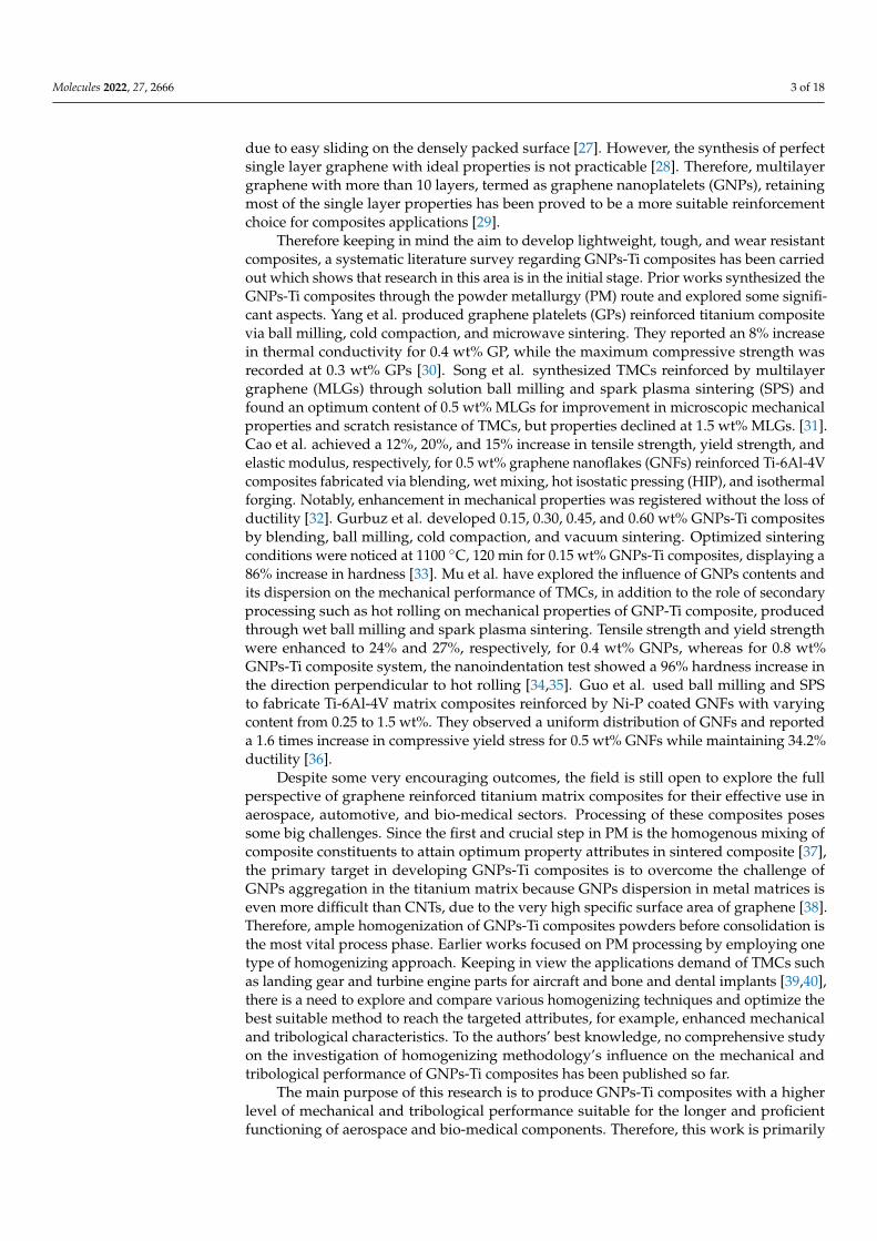
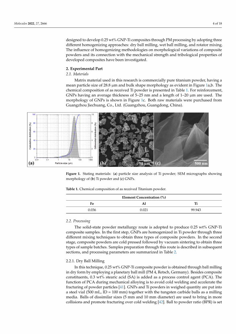
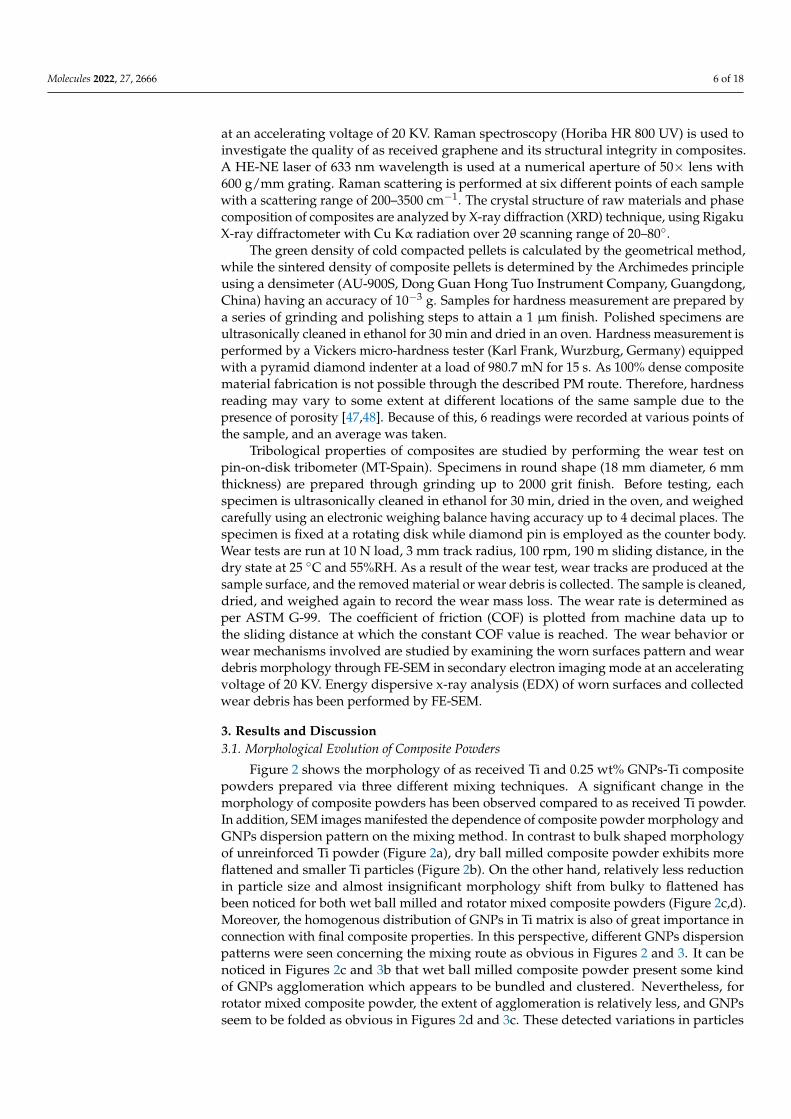
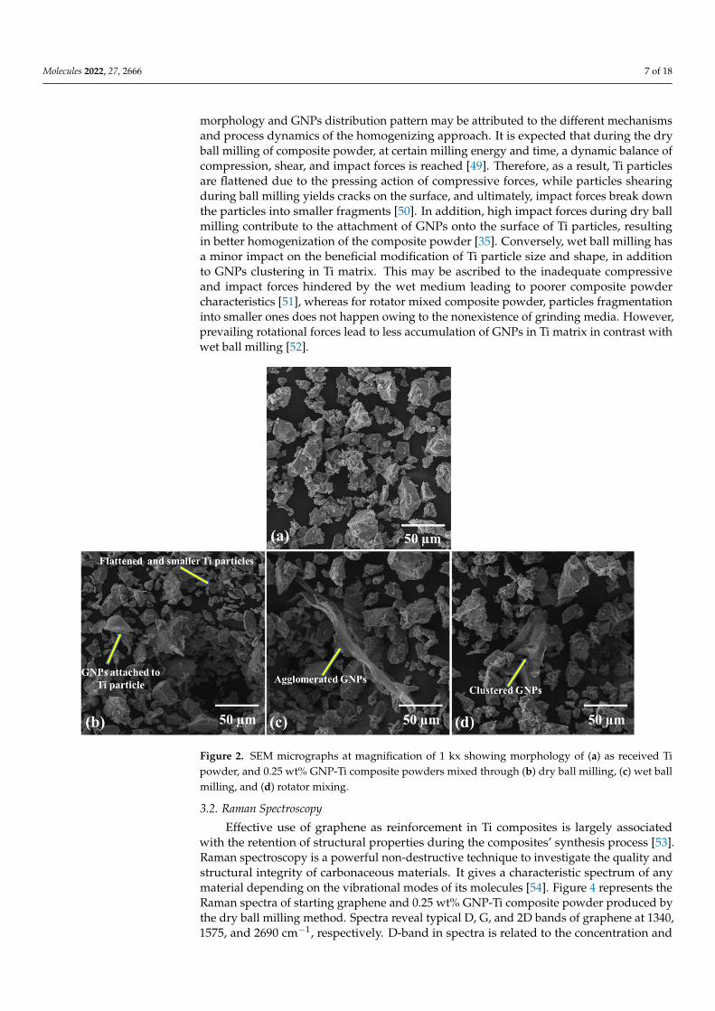
Figure 2 shows the morphology of as received Ti and 0.25 wt% GNPs-Ti compositepowders prepared via three different mixing techniques. A significant change in themorphology of composite powders has been observed compared to as received Ti powder.In addition, SEM images manifested the dependence of composite powder morphology andGNPs dispersion pattern on the mixing method. In contrast to bulk shaped morphologyof unreinforced Ti powder (Figure 2a), dry ball milled composite powder exhibits moreflattened and smaller Ti particles (Figure 2b). On the other hand, relatively less reductionin particle size and almost insignificant morphology shift from bulky to flattened hasbeen noticed for both wet ball milled and rotator mixed composite powders (Figure 2c,d).Moreover, the homogenous distribution of GNPs in Ti matrix is also of great importance inconnection with final composite properties. In this perspective, different GNPs dispersionpatterns were seen concerning the mixing route as obvious in Figures 2 and 3. It can benoticed in Figures 2c and 3b that wet ball milled composite powder present some kindof GNPs agglomeration which appears to be bundled and clustered. Nevertheless, forrotator mixed composite powder, the extent of agglomeration is relatively less, and GNPsseem to be folded as obvious in Figures 2d and 3c. These detected variations in particles
Molecules 2022, 27, 2666 7 of 18
morphology and GNPs distribution pattern may be attributed to the different mechanismsand process dynamics of the homogenizing approach. It is expected that during the dryball milling of composite powder, at certain milling energy and time, a dynamic balance ofcompression, shear, and impact forces is reached [49]. Therefore, as a result, Ti particlesare flattened due to the pressing action of compressive forces, while particles shearingduring ball milling yields cracks on the surface, and ultimately, impact forces break downthe particles into smaller fragments [50]. In addition, high impact forces during dry ballmilling contribute to the attachment of GNPs onto the surface of Ti particles, resultingin better homogenization of the composite powder [35]. Conversely, wet ball milling hasa minor impact on the beneficial modification of Ti particle size and shape, in additionto GNPs clustering in Ti matrix. This may be ascribed to the inadequate compressiveand impact forces hindered by the wet medium leading to poorer composite powdercharacteristics [51], whereas for rotator mixed composite powder, particles fragmentationinto smaller ones does not happen owing to the nonexistence of grinding media. However,prevailing rotational forces lead to less accumulation of GNPs in Ti matrix in contrast withwet ball milling [52].
Molecules 2022, 27, x FOR PEER REVIEW 8 of 19
Figure 2. SEM micrographs at magnification of 1 kx showing morphology of (a) as received Ti pow-der, and 0.25 wt% GNP-Ti composite powders mixed through (b) dry ball milling, (c) wet ball mill-ing, and (d) rotator mixing.
Figure 3. Higher magnification SEM micrographs showing morphology of 0.25 wt% GNP-Ti com-posite powders mixed through (a) dry ball milling (at magnification of 25 kx), (b) wet ball milling (at magnification of 10 kx), and (c) rotator mixing (at magnification of 10 kx).
3.2. Raman Spectroscopy Effective use of graphene as reinforcement in Ti composites is largely associated with
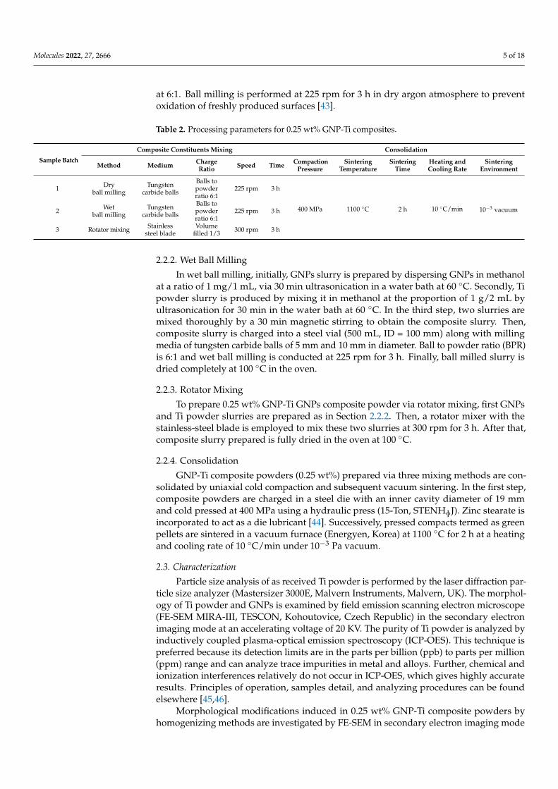
the retention of structural properties during the composites’ synthesis process [53]. Ra-man spectroscopy is a powerful non-destructive technique to investigate the quality and structural integrity of carbonaceous materials. It gives a characteristic spectrum of any material depending on the vibrational modes of its molecules [54]. Figure 4 represents the Raman spectra of starting graphene and 0.25 wt% GNP-Ti composite powder produced by the dry ball milling method. Spectra reveal typical D, G, and 2D bands of graphene at 1340, 1575, and 2690 cm−1, respectively. D-band in spectra is related to the concentration
Figure 2. SEM micrographs at magnification of 1 kx showing morphology of (a) as received Tipowder, and 0.25 wt% GNP-Ti composite powders mixed through (b) dry ball milling, (c) wet ballmilling, and (d) rotator mixing.
3.2. Raman Spectroscopy
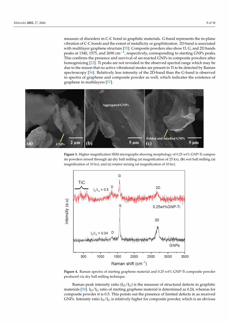
Effective use of graphene as reinforcement in Ti composites is largely associatedwith the retention of structural properties during the composites’ synthesis process [53].Raman spectroscopy is a powerful non-destructive technique to investigate the quality andstructural integrity of carbonaceous materials. It gives a characteristic spectrum of anymaterial depending on the vibrational modes of its molecules [54]. Figure 4 represents theRaman spectra of starting graphene and 0.25 wt% GNP-Ti composite powder produced bythe dry ball milling method. Spectra reveal typical D, G, and 2D bands of graphene at 1340,1575, and 2690 cm−1, respectively. D-band in spectra is related to the concentration and
Molecules 2022, 27, 2666 8 of 18
measure of disorders in C-C bond in graphitic materials. G-band represents the in-planevibration of C-C bonds and the extent of metallicity or graphitization. 2D-band is associatedwith multilayer graphene structure [55]. Composite powders also show D, G, and 2D bandspeaks at 1340, 1575, and 2690 cm−1, respectively, corresponding to starting GNPs peaks.This confirms the presence and survival of un-reacted GNPs in composite powders afterhomogenizing [23]. Ti peaks are not revealed in the observed spectral range which may bedue to the reason that no active vibrational modes are present in Ti to be detected by Ramanspectroscopy [56]. Relatively less intensity of the 2D-band than the G-band is observedin spectra of graphene and composite powder as well, which indicates the existence ofgraphene in multilayers [57].
Molecules 2022, 27, x FOR PEER REVIEW 8 of 19
Figure 2. SEM micrographs at magnification of 1 kx showing morphology of (a) as received Ti pow-der, and 0.25 wt% GNP-Ti composite powders mixed through (b) dry ball milling, (c) wet ball mill-ing, and (d) rotator mixing.
Figure 3. Higher magnification SEM micrographs showing morphology of 0.25 wt% GNP-Ti com-posite powders mixed through (a) dry ball milling (at magnification of 25 kx), (b) wet ball milling (at magnification of 10 kx), and (c) rotator mixing (at magnification of 10 kx).
3.2. Raman Spectroscopy Effective use of graphene as reinforcement in Ti composites is largely associated with
the retention of structural properties during the composites’ synthesis process [53]. Ra-man spectroscopy is a powerful non-destructive technique to investigate the quality and structural integrity of carbonaceous materials. It gives a characteristic spectrum of any material depending on the vibrational modes of its molecules [54]. Figure 4 represents the Raman spectra of starting graphene and 0.25 wt% GNP-Ti composite powder produced by the dry ball milling method. Spectra reveal typical D, G, and 2D bands of graphene at 1340, 1575, and 2690 cm−1, respectively. D-band in spectra is related to the concentration
Figure 3. Higher magnification SEM micrographs showing morphology of 0.25 wt% GNP-Ti compos-ite powders mixed through (a) dry ball milling (at magnification of 25 kx), (b) wet ball milling (atmagnification of 10 kx), and (c) rotator mixing (at magnification of 10 kx).
Molecules 2022, 27, x FOR PEER REVIEW 9 of 19
and measure of disorders in C-C bond in graphitic materials. G-band represents the in-plane vibration of C-C bonds and the extent of metallicity or graphitization. 2D-band is associated with multilayer graphene structure [55]. Composite powders also show D, G, and 2D bands peaks at 1340, 1575, and 2690 cm−1, respectively, corresponding to starting GNPs peaks. This confirms the presence and survival of un-reacted GNPs in composite powders after homogenizing [23]. Ti peaks are not revealed in the observed spectral range which may be due to the reason that no active vibrational modes are present in Ti to be detected by Raman spectroscopy [56]. Relatively less intensity of the 2D-band than the G-band is observed in spectra of graphene and composite powder as well, which indicates the existence of graphene in multilayers [57].
Raman peak intensity ratio (ID/IG) is the measure of structural defects in graphitic materials [58]. ID/IG ratio of starting graphene material is determined as 0.24, whereas for composite powder it is 0.5. This points out the presence of limited defects in as received GNPs. Intensity ratio ID/IG is relatively higher for composite powder, which is an obvious indication of induced structural defects in GNPs present in composite powder due to the homogenization process [53]. Further analysis of Raman spectra of 0.25 wt% GNP-Ti com-posite powders shows peaks at 260, 418, and 605 cm−1. These peaks indicate the formation of interfacial compound TiC during milling. This observation is further supported by a relatively higher spectrum background in composite powder than as received GNPs, which is also ascribed to the TiC formation due to harsh ball milling conditions. Similar findings have been reported in earlier works [23,57].
Figure 4. Raman spectra of starting graphene material and 0.25 wt% GNP-Ti composite powder produced via dry ball milling technique.
3.3. XRD Analysis XRD patterns of as received graphene nanoplatelets, pure titanium, and 0.25 wt%
GNP-Ti composites are presented in Figure 5. XRD peaks shown in Figure 5a are charac-teristic of graphene confirming its quality [59,60], whereas pure Ti and 0.25 wt% GNP-Ti composites exhibited elemental Ti peaks having hexagonal close packed (hcp) structure, as evident in Figure 5b. Ti Peaks are indexed as (001), (002), (101), (102), (110), (103), (112),
Figure 4. Raman spectra of starting graphene material and 0.25 wt% GNP-Ti composite powderproduced via dry ball milling technique.
Raman peak intensity ratio (ID/IG) is the measure of structural defects in graphiticmaterials [58]. ID/IG ratio of starting graphene material is determined as 0.24, whereas forcomposite powder it is 0.5. This points out the presence of limited defects in as receivedGNPs. Intensity ratio ID/IG is relatively higher for composite powder, which is an obvious
Molecules 2022, 27, 2666 9 of 18
indication of induced structural defects in GNPs present in composite powder due tothe homogenization process [53]. Further analysis of Raman spectra of 0.25 wt% GNP-Ti composite powders shows peaks at 260, 418, and 605 cm−1. These peaks indicatethe formation of interfacial compound TiC during milling. This observation is furthersupported by a relatively higher spectrum background in composite powder than asreceived GNPs, which is also ascribed to the TiC formation due to harsh ball millingconditions. Similar findings have been reported in earlier works [23,57].
3.3. XRD Analysis
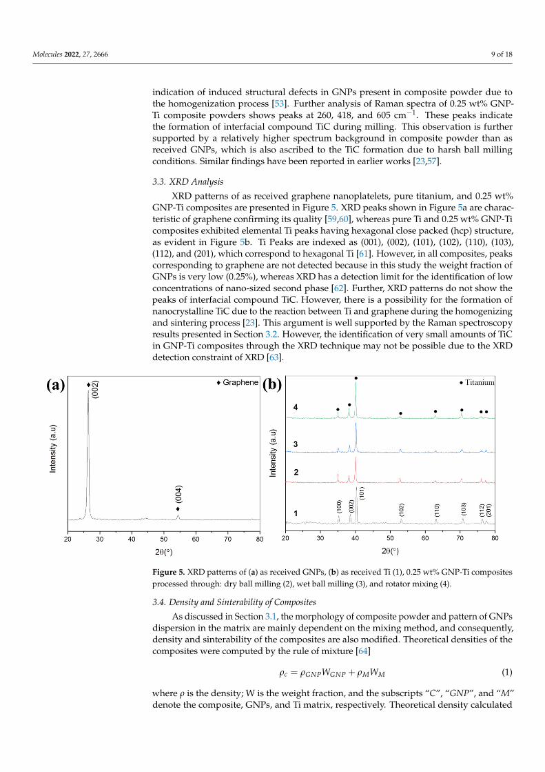
XRD patterns of as received graphene nanoplatelets, pure titanium, and 0.25 wt%GNP-Ti composites are presented in Figure 5. XRD peaks shown in Figure 5a are charac-teristic of graphene confirming its quality [59,60], whereas pure Ti and 0.25 wt% GNP-Ticomposites exhibited elemental Ti peaks having hexagonal close packed (hcp) structure,as evident in Figure 5b. Ti Peaks are indexed as (001), (002), (101), (102), (110), (103),(112), and (201), which correspond to hexagonal Ti [61]. However, in all composites, peakscorresponding to graphene are not detected because in this study the weight fraction ofGNPs is very low (0.25%), whereas XRD has a detection limit for the identification of lowconcentrations of nano-sized second phase [62]. Further, XRD patterns do not show thepeaks of interfacial compound TiC. However, there is a possibility for the formation ofnanocrystalline TiC due to the reaction between Ti and graphene during the homogenizingand sintering process [23]. This argument is well supported by the Raman spectroscopyresults presented in Section 3.2. However, the identification of very small amounts of TiCin GNP-Ti composites through the XRD technique may not be possible due to the XRDdetection constraint of XRD [63].
Molecules 2022, 27, x FOR PEER REVIEW 10 of 19
and (201), which correspond to hexagonal Ti [61]. However, in all composites, peaks cor-responding to graphene are not detected because in this study the weight fraction of GNPs is very low (0.25%), whereas XRD has a detection limit for the identification of low con-centrations of nano-sized second phase [62]. Further, XRD patterns do not show the peaks of interfacial compound TiC. However, there is a possibility for the formation of nano-crystalline TiC due to the reaction between Ti and graphene during the homogenizing and sintering process [23]. This argument is well supported by the Raman spectroscopy results presented in Section 3.2. However, the identification of very small amounts of TiC in GNP-Ti composites through the XRD technique may not be possible due to the XRD detection constraint of XRD [63].
Figure 5. XRD patterns of (a) as received GNPs, (b) as received Ti (1), 0.25 wt% GNP-Ti composites processed through: dry ball milling (2), wet ball milling (3), and rotator mixing (4).
3.4. Density and Sinterability of Composites As discussed in Section 3.1, the morphology of composite powder and pattern of
GNPs dispersion in the matrix are mainly dependent on the mixing method, and conse-quently, density and sinterability of the composites are also modified. Theoretical densi-ties of the composites were computed by the rule of mixture [64] 𝜌 𝜌 𝑊 𝜌 𝑊 (1)
where ρ is the density; W is the weight fraction, and the subscripts “C”, “GNP”, and “M” denote the composite, GNPs, and Ti matrix, respectively. Theoretical density calculated from the above equation and experimentally measured green and sintered densities are put into the below equation to compute the sinterability (Ø) of composites.
Ø = ρs − ρg/ρth − ρg (2)
where ρs, ρg and ρth are the sintered, green, and theoretical densities, respectively. Results are shown in Table 3. This suggests that the composite samples processed through dry ball milling display the highest green and sintered density, whereas those processed through wet ball milling display the lowest. Sinterability of composite powder compact depends upon particle size, shape, particle size distribution, and homogenous mixing of composite constituents in addition to sintering conditions [47]. Therefore, dependency of sinterability upon the mixing approach may be linked to the morphology evolution of Ti particles and GNPs dispersion style in the matrix. It is quite evident from Figure 2 that composite powder mixed via dry ball milling presented flattened morphology and a rea-sonable fraction of smaller particles as well. Moreover, GNPs adherence to Ti particles
Figure 5. XRD patterns of (a) as received GNPs, (b) as received Ti (1), 0.25 wt% GNP-Ti compositesprocessed through: dry ball milling (2), wet ball milling (3), and rotator mixing (4).
3.4. Density and Sinterability of Composites
As discussed in Section 3.1, the morphology of composite powder and pattern of GNPsdispersion in the matrix are mainly dependent on the mixing method, and consequently,density and sinterability of the composites are also modified. Theoretical densities of thecomposites were computed by the rule of mixture [64]
ρc = ρGNPWGNP + ρMWM (1)
where ρ is the density; W is the weight fraction, and the subscripts “C”, “GNP”, and “M”denote the composite, GNPs, and Ti matrix, respectively. Theoretical density calculated
Molecules 2022, 27, 2666 10 of 18
from the above equation and experimentally measured green and sintered densities are putinto the below equation to compute the sinterability (Ø) of composites.
Ø = ρs − ρg/ρth − ρg (2)
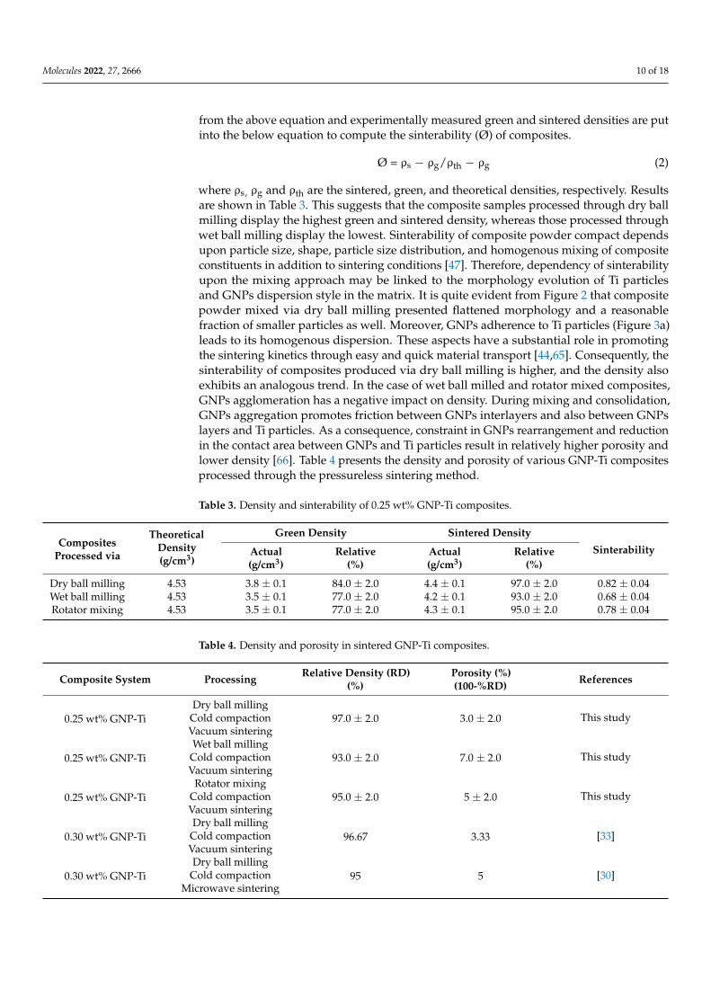
where ρs, ρg and ρth are the sintered, green, and theoretical densities, respectively. Resultsare shown in Table 3. This suggests that the composite samples processed through dry ballmilling display the highest green and sintered density, whereas those processed throughwet ball milling display the lowest. Sinterability of composite powder compact dependsupon particle size, shape, particle size distribution, and homogenous mixing of compositeconstituents in addition to sintering conditions [47]. Therefore, dependency of sinterabilityupon the mixing approach may be linked to the morphology evolution of Ti particlesand GNPs dispersion style in the matrix. It is quite evident from Figure 2 that compositepowder mixed via dry ball milling presented flattened morphology and a reasonablefraction of smaller particles as well. Moreover, GNPs adherence to Ti particles (Figure 3a)leads to its homogenous dispersion. These aspects have a substantial role in promotingthe sintering kinetics through easy and quick material transport [44,65]. Consequently, thesinterability of composites produced via dry ball milling is higher, and the density alsoexhibits an analogous trend. In the case of wet ball milled and rotator mixed composites,GNPs agglomeration has a negative impact on density. During mixing and consolidation,GNPs aggregation promotes friction between GNPs interlayers and also between GNPslayers and Ti particles. As a consequence, constraint in GNPs rearrangement and reductionin the contact area between GNPs and Ti particles result in relatively higher porosity andlower density [66]. Table 4 presents the density and porosity of various GNP-Ti compositesprocessed through the pressureless sintering method.
Table 3. Density and sinterability of 0.25 wt% GNP-Ti composites.
CompositesProcessed via
TheoreticalDensity(g/cm3)
Green Density Sintered Density
SinterabilityActual(g/cm3)
Relative(%)
Actual(g/cm3)
Relative(%)
Dry ball milling 4.53 3.8 ± 0.1 84.0 ± 2.0 4.4 ± 0.1 97.0 ± 2.0 0.82 ± 0.04Wet ball milling 4.53 3.5 ± 0.1 77.0 ± 2.0 4.2 ± 0.1 93.0 ± 2.0 0.68 ± 0.04Rotator mixing 4.53 3.5 ± 0.1 77.0 ± 2.0 4.3 ± 0.1 95.0 ± 2.0 0.78 ± 0.04
Table 4. Density and porosity in sintered GNP-Ti composites.
Composite System Processing Relative Density (RD)(%)
Porosity (%)(100-%RD) References
0.25 wt% GNP-TiDry ball milling
97.0 ± 2.0 3.0 ± 2.0 This studyCold compactionVacuum sintering
0.25 wt% GNP-TiWet ball milling
93.0 ± 2.0 7.0 ± 2.0 This studyCold compactionVacuum sintering
0.25 wt% GNP-TiRotator mixing
95.0 ± 2.0 5 ± 2.0 This studyCold compactionVacuum sintering
0.30 wt% GNP-TiDry ball milling
96.67 3.33 [33]Cold compactionVacuum sintering
0.30 wt% GNP-TiDry ball milling
95 5 [30]Cold compactionMicrowave sintering
Molecules 2022, 27, 2666 11 of 18
3.5. Mechanical Strength of Composites
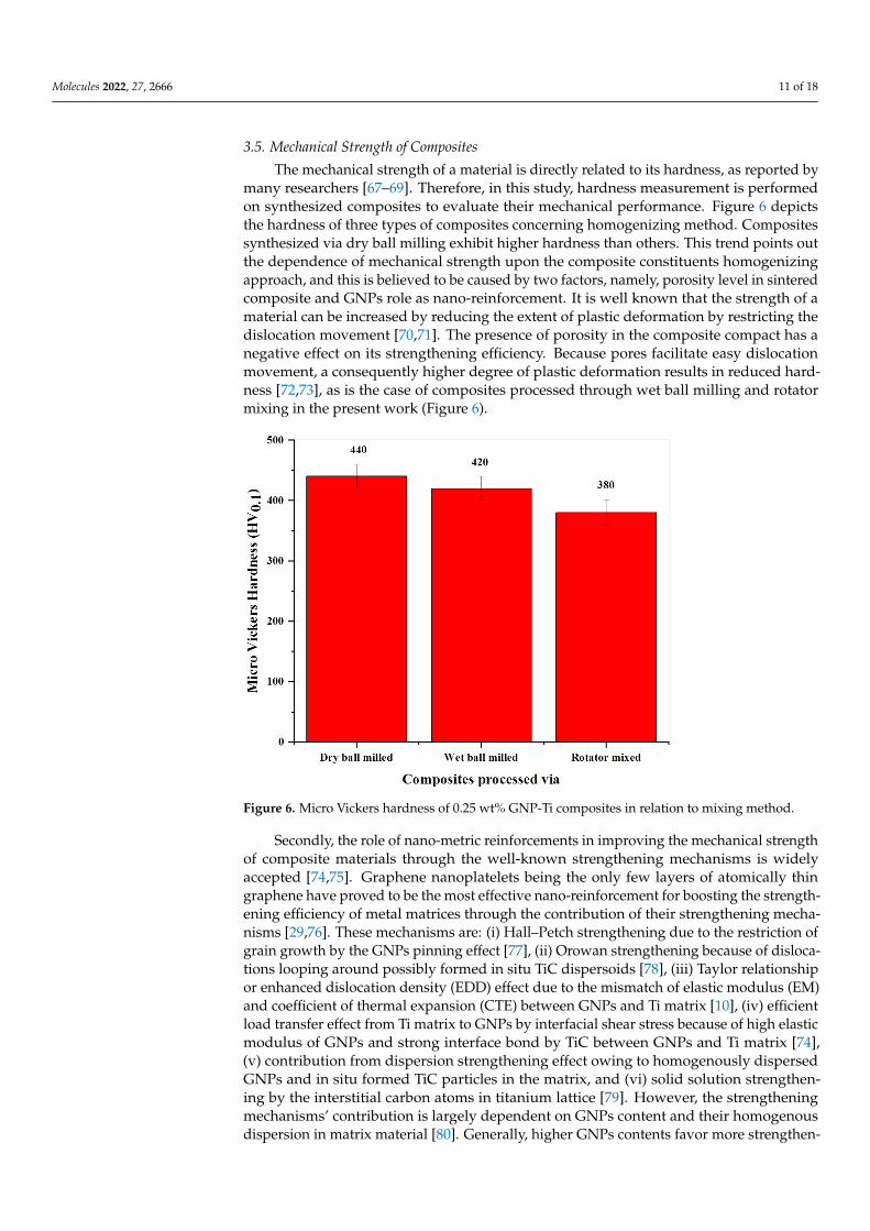
The mechanical strength of a material is directly related to its hardness, as reported bymany researchers [67–69]. Therefore, in this study, hardness measurement is performedon synthesized composites to evaluate their mechanical performance. Figure 6 depictsthe hardness of three types of composites concerning homogenizing method. Compositessynthesized via dry ball milling exhibit higher hardness than others. This trend points outthe dependence of mechanical strength upon the composite constituents homogenizingapproach, and this is believed to be caused by two factors, namely, porosity level in sinteredcomposite and GNPs role as nano-reinforcement. It is well known that the strength of amaterial can be increased by reducing the extent of plastic deformation by restricting thedislocation movement [70,71]. The presence of porosity in the composite compact has anegative effect on its strengthening efficiency. Because pores facilitate easy dislocationmovement, a consequently higher degree of plastic deformation results in reduced hard-ness [72,73], as is the case of composites processed through wet ball milling and rotatormixing in the present work (Figure 6).
Molecules 2022, 27, x FOR PEER REVIEW 13 of 19
Figure 6. Micro Vickers hardness of 0.25 wt% GNP-Ti composites in relation to mixing method.
Table 5. Hardness of GNP-Ti composites.
Composite System Processing Hardness References
0.25 wt% GNP-Ti Dry ball milling
440 ± 20 HV0.1 This study Cold compaction Vacuum sintering
0.25 wt% GNP-Ti Wet ball milling
420 ± 20 HV0.1 This study Cold compaction Vacuum sintering
0.25 wt% GNP-Ti Rotator mixing
380 ± 20 HV0.1 This study Cold compaction Vacuum sintering
0.30 wt% GNP-Ti Dry ball milling
519 ± 35 HV0.5 [33] Cold compaction Vacuum sintering
0.30 wt% GNP-Ti Dry ball milling 435 ± 28 HV1 [57] Spark plasma sintering
3.6. Tribological Performance Table 6 presents the results of tribological testing performed on composite samples,
in relation to coefficient of friction (COF) and wear rate. It is inferred from the results that composites processed via dry ball milling present relatively less wear loss than wet ball milled and rotator mixed ones, so they exhibit reduced wear rate and coefficient of fric-tion. As discussed in Section 3.5, the strength of composites is directly related to the degree of sinterability and homogenous GNPs dispersion in the matrix. The hardness of a mate-rial is linked to its wear properties in some way [81]. Consequently, for composites pro-duced via dry balling, the extent of plastic deformation will be lower, thereby producing less abrasion, which results in reduced wear loss and consequently lower COF value as evident in Figure 7. On the other hand, a somewhat higher porosity level and GNPs clus-tering in the Ti matrix promote plastic deformation, thus producing more wear debris, so
Figure 6. Micro Vickers hardness of 0.25 wt% GNP-Ti composites in relation to mixing method.
Secondly, the role of nano-metric reinforcements in improving the mechanical strengthof composite materials through the well-known strengthening mechanisms is widelyaccepted [74,75]. Graphene nanoplatelets being the only few layers of atomically thingraphene have proved to be the most effective nano-reinforcement for boosting the strength-ening efficiency of metal matrices through the contribution of their strengthening mecha-nisms [29,76]. These mechanisms are: (i) Hall–Petch strengthening due to the restriction ofgrain growth by the GNPs pinning effect [77], (ii) Orowan strengthening because of disloca-tions looping around possibly formed in situ TiC dispersoids [78], (iii) Taylor relationshipor enhanced dislocation density (EDD) effect due to the mismatch of elastic modulus (EM)and coefficient of thermal expansion (CTE) between GNPs and Ti matrix [10], (iv) efficientload transfer effect from Ti matrix to GNPs by interfacial shear stress because of high elasticmodulus of GNPs and strong interface bond by TiC between GNPs and Ti matrix [74],(v) contribution from dispersion strengthening effect owing to homogenously dispersedGNPs and in situ formed TiC particles in the matrix, and (vi) solid solution strengthen-ing by the interstitial carbon atoms in titanium lattice [79]. However, the strengtheningmechanisms’ contribution is largely dependent on GNPs content and their homogenousdispersion in matrix material [80]. Generally, higher GNPs contents favor more strengthen-
Molecules 2022, 27, 2666 12 of 18
ing efficiency. However, it has been reported that strength declines beyond 0.5 wt% GNPsdue to their agglomeration and clustering [31].
It is worth mentioning here that the results obtained in this study are in close agreementwith the above argument and prior works, as evident in Table 5. Correlating the hardnessresults with the morphological evolution study of composite powders, it is obvious thatgood adherence of GNPs onto the Ti particle surface favors uniform dispersion in thedry ball milled sample (Figure 2b), so the sintered composite displays higher hardness.In contrast, apparent GNPs aggregation and bundling have been observed in wet ballmilled and rotator mixed composite powders, respectively (Figure 2c,d), and hence theyexhibit relatively less hardness. In view of above, the dry ball milling approach has showngood potential to adequately homogenize the 0.25 wt% GNP-Ti composite constituents andachieve good mechanical strength in the final composite.
Table 5. Hardness of GNP-Ti composites.
Composite System Processing Hardness References
0.25 wt% GNP-TiDry ball milling
440 ± 20 HV0.1 This studyCold compactionVacuum sintering
0.25 wt% GNP-TiWet ball milling
420 ± 20 HV0.1 This studyCold compactionVacuum sintering
0.25 wt% GNP-TiRotator mixing
380 ± 20 HV0.1 This studyCold compactionVacuum sintering
0.30 wt% GNP-TiDry ball milling
519 ± 35 HV0.5 [33]Cold compactionVacuum sintering
0.30 wt% GNP-TiDry ball milling 435 ± 28 HV1 [57]Spark plasma sintering
3.6. Tribological Performance
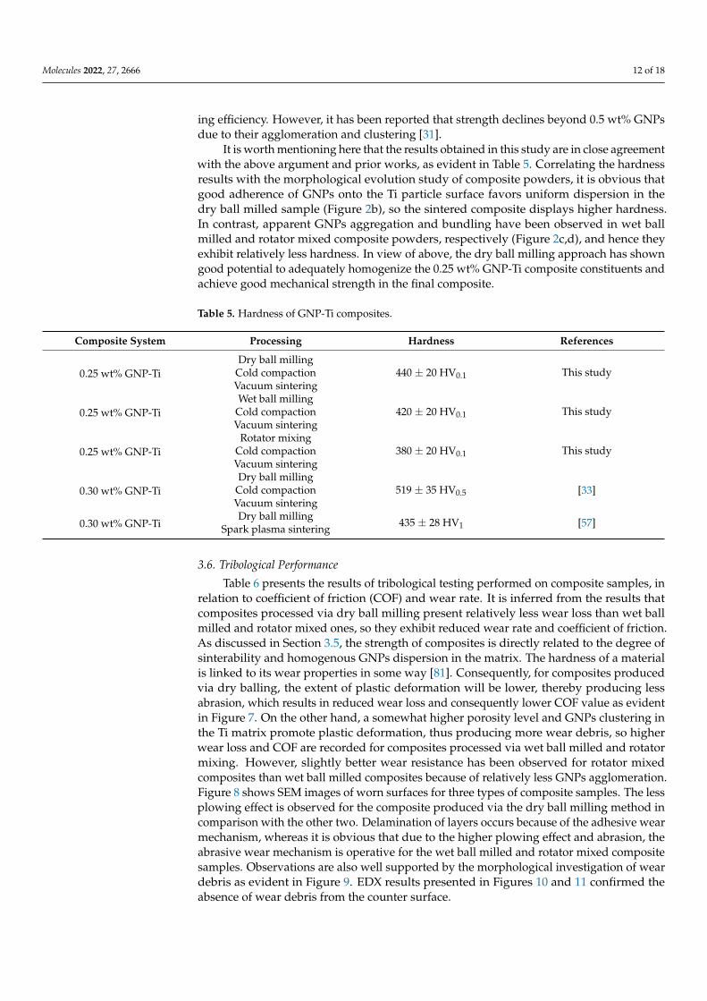
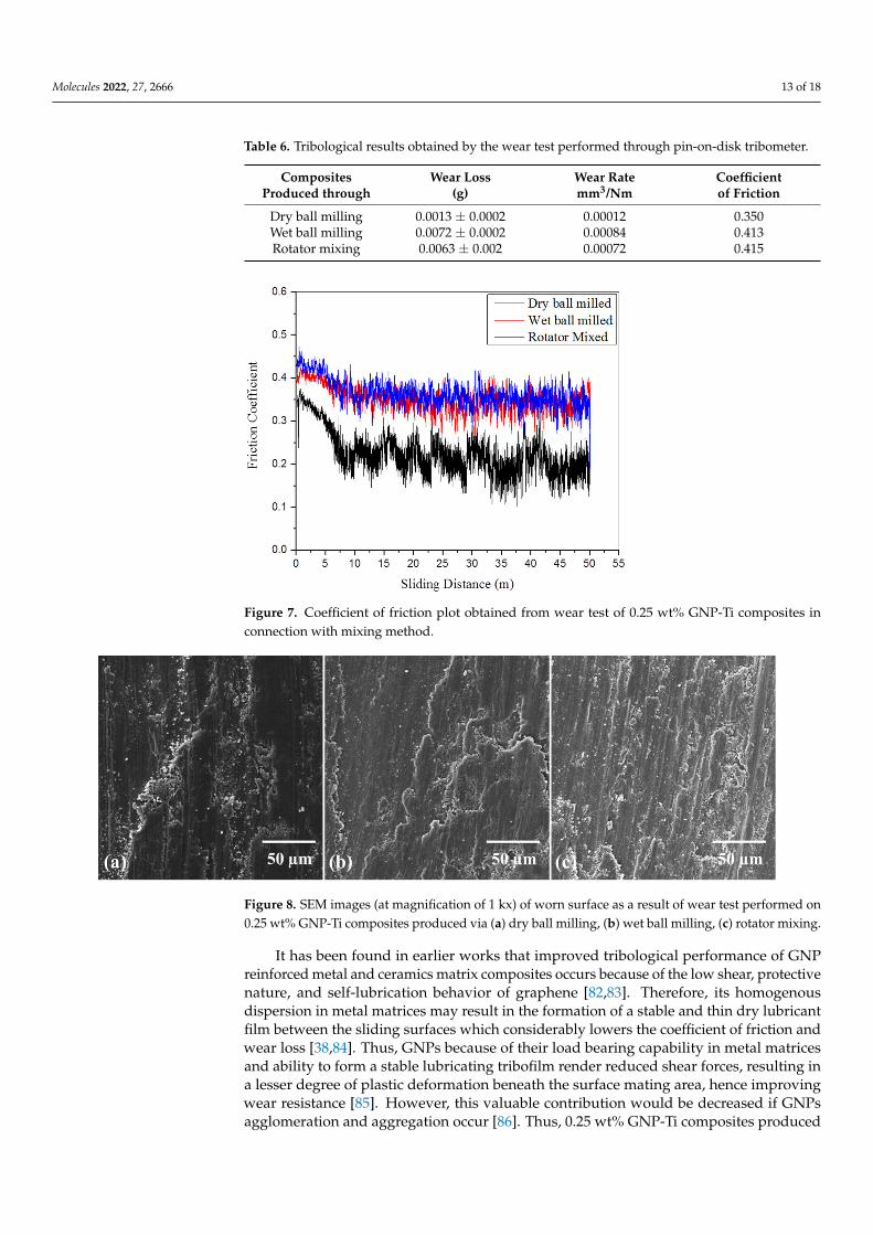
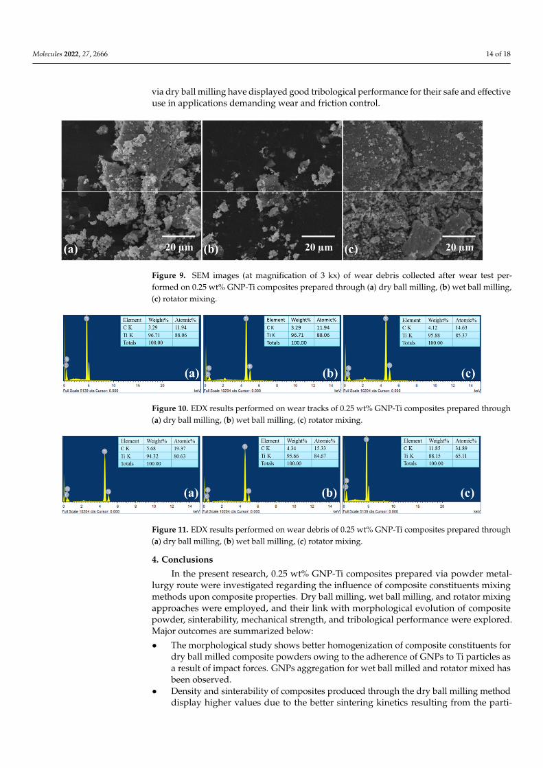
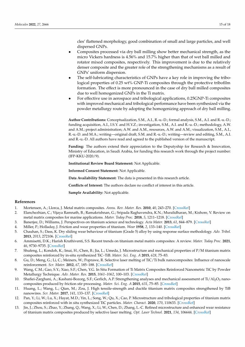
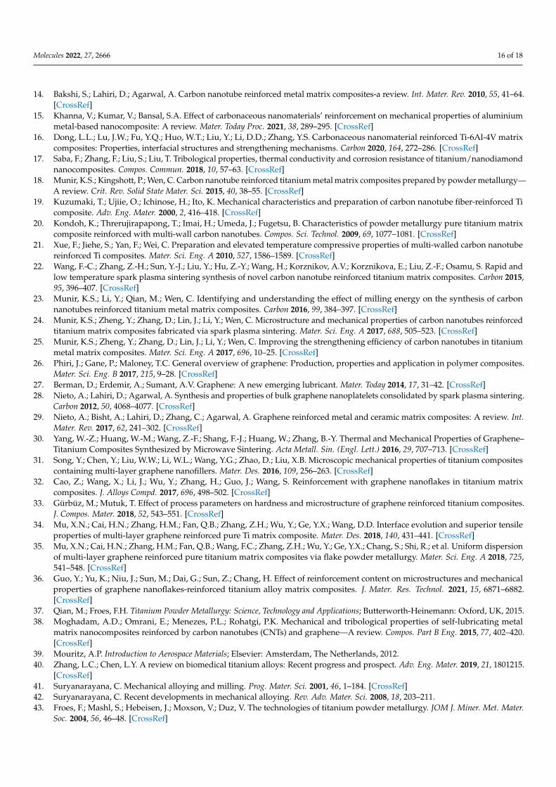
Table 6 presents the results of tribological testing performed on composite samples, inrelation to coefficient of friction (COF) and wear rate. It is inferred from the results thatcomposites processed via dry ball milling present relatively less wear loss than wet ballmilled and rotator mixed ones, so they exhibit reduced wear rate and coefficient of friction.As discussed in Section 3.5, the strength of composites is directly related to the degree ofsinterability and homogenous GNPs dispersion in the matrix. The hardness of a materialis linked to its wear properties in some way [81]. Consequently, for composites producedvia dry balling, the extent of plastic deformation will be lower, thereby producing lessabrasion, which results in reduced wear loss and consequently lower COF value as evidentin Figure 7. On the other hand, a somewhat higher porosity level and GNPs clustering inthe Ti matrix promote plastic deformation, thus producing more wear debris, so higherwear loss and COF are recorded for composites processed via wet ball milled and rotatormixing. However, slightly better wear resistance has been observed for rotator mixedcomposites than wet ball milled composites because of relatively less GNPs agglomeration.Figure 8 shows SEM images of worn surfaces for three types of composite samples. The lessplowing effect is observed for the composite produced via the dry ball milling method incomparison with the other two. Delamination of layers occurs because of the adhesive wearmechanism, whereas it is obvious that due to the higher plowing effect and abrasion, theabrasive wear mechanism is operative for the wet ball milled and rotator mixed compositesamples. Observations are also well supported by the morphological investigation of weardebris as evident in Figure 9. EDX results presented in Figures 10 and 11 confirmed theabsence of wear debris from the counter surface.
Molecules 2022, 27, 2666 13 of 18
Table 6. Tribological results obtained by the wear test performed through pin-on-disk tribometer.
CompositesProduced through
Wear Loss(g)
Wear Ratemm3/Nm
Coefficientof Friction
Dry ball milling 0.0013 ± 0.0002 0.00012 0.350Wet ball milling 0.0072 ± 0.0002 0.00084 0.413Rotator mixing 0.0063 ± 0.002 0.00072 0.415
Molecules 2022, 27, x FOR PEER REVIEW 14 of 19
higher wear loss and COF are recorded for composites processed via wet ball milled and rotator mixing. However, slightly better wear resistance has been observed for rotator mixed composites than wet ball milled composites because of relatively less GNPs ag-glomeration. Figure 8 shows SEM images of worn surfaces for three types of composite samples. The less plowing effect is observed for the composite produced via the dry ball milling method in comparison with the other two. Delamination of layers occurs because of the adhesive wear mechanism, whereas it is obvious that due to the higher plowing effect and abrasion, the abrasive wear mechanism is operative for the wet ball milled and rotator mixed composite samples. Observations are also well supported by the morpho-logical investigation of wear debris as evident in Figure 9. EDX results presented in Fig-ures 10 and 11 confirmed the absence of wear debris from the counter surface.
It has been found in earlier works that improved tribological performance of GNP reinforced metal and ceramics matrix composites occurs because of the low shear, protec-tive nature, and self-lubrication behavior of graphene [82,83]. Therefore, its homogenous dispersion in metal matrices may result in the formation of a stable and thin dry lubricant film between the sliding surfaces which considerably lowers the coefficient of friction and wear loss [38,84]. Thus, GNPs because of their load bearing capability in metal matrices and ability to form a stable lubricating tribofilm render reduced shear forces, resulting in a lesser degree of plastic deformation beneath the surface mating area, hence improving wear resistance [85]. However, this valuable contribution would be decreased if GNPs agglomeration and aggregation occur [86]. Thus, 0.25 wt% GNP-Ti composites produced via dry ball milling have displayed good tribological performance for their safe and effec-tive use in applications demanding wear and friction control.
Table 6. Tribological results obtained by the wear test performed through pin-on-disk tribometer.
Composites Produced through
Wear Loss (g)
Wear Rate mm3/Nm
Coefficient of Friction
Dry ball milling 0.0013 ± 0.0002 0.00012 0.350 Wet ball milling 0.0072 ± 0.0002 0.00084 0.413 Rotator mixing 0.0063 ± 0.002 0.00072 0.415
Figure 7. Coefficient of friction plot obtained from wear test of 0.25 wt% GNP-Ti composites in con-nection with mixing method.
Figure 7. Coefficient of friction plot obtained from wear test of 0.25 wt% GNP-Ti composites inconnection with mixing method.
Molecules 2022, 27, x FOR PEER REVIEW 15 of 19
Figure 8. SEM images (at magnification of 1 kx) of worn surface as a result of wear test performed on 0.25 wt% GNP-Ti composites produced via (a) dry ball milling, (b) wet ball milling, (c) rotator mixing.
Figure 9. SEM images (at magnification of 3 kx) of wear debris collected after wear test performed on 0.25 wt% GNP-Ti composites prepared through (a) dry ball milling, (b) wet ball milling, (c) rota-tor mixing.
Figure 10. EDX results performed on wear tracks of 0.25 wt% GNP-Ti composites prepared through (a) dry ball milling, (b) wet ball milling, (c) rotator mixing.
Figure 11. EDX results performed on wear debris of 0.25 wt% GNP-Ti composites prepared through (a) dry ball milling, (b) wet ball milling, (c) rotator mixing.
Figure 8. SEM images (at magnification of 1 kx) of worn surface as a result of wear test performed on0.25 wt% GNP-Ti composites produced via (a) dry ball milling, (b) wet ball milling, (c) rotator mixing.
It has been found in earlier works that improved tribological performance of GNPreinforced metal and ceramics matrix composites occurs because of the low shear, protectivenature, and self-lubrication behavior of graphene [82,83]. Therefore, its homogenousdispersion in metal matrices may result in the formation of a stable and thin dry lubricantfilm between the sliding surfaces which considerably lowers the coefficient of friction andwear loss [38,84]. Thus, GNPs because of their load bearing capability in metal matricesand ability to form a stable lubricating tribofilm render reduced shear forces, resulting ina lesser degree of plastic deformation beneath the surface mating area, hence improvingwear resistance [85]. However, this valuable contribution would be decreased if GNPsagglomeration and aggregation occur [86]. Thus, 0.25 wt% GNP-Ti composites produced
Molecules 2022, 27, 2666 14 of 18
via dry ball milling have displayed good tribological performance for their safe and effectiveuse in applications demanding wear and friction control.
Molecules 2022, 27, x FOR PEER REVIEW 15 of 19
Figure 8. SEM images (at magnification of 1 kx) of worn surface as a result of wear test performed on 0.25 wt% GNP-Ti composites produced via (a) dry ball milling, (b) wet ball milling, (c) rotator mixing.
Figure 9. SEM images (at magnification of 3 kx) of wear debris collected after wear test performed on 0.25 wt% GNP-Ti composites prepared through (a) dry ball milling, (b) wet ball milling, (c) rota-tor mixing.
Figure 10. EDX results performed on wear tracks of 0.25 wt% GNP-Ti composites prepared through (a) dry ball milling, (b) wet ball milling, (c) rotator mixing.
Figure 11. EDX results performed on wear debris of 0.25 wt% GNP-Ti composites prepared through (a) dry ball milling, (b) wet ball milling, (c) rotator mixing.
Figure 9. SEM images (at magnification of 3 kx) of wear debris collected after wear test per-formed on 0.25 wt% GNP-Ti composites prepared through (a) dry ball milling, (b) wet ball milling,(c) rotator mixing.
Molecules 2022, 27, x FOR PEER REVIEW 15 of 19
Figure 8. SEM images (at magnification of 1 kx) of worn surface as a result of wear test performed on 0.25 wt% GNP-Ti composites produced via (a) dry ball milling, (b) wet ball milling, (c) rotator mixing.
Figure 9. SEM images (at magnification of 3 kx) of wear debris collected after wear test performed on 0.25 wt% GNP-Ti composites prepared through (a) dry ball milling, (b) wet ball milling, (c) rota-tor mixing.
Figure 10. EDX results performed on wear tracks of 0.25 wt% GNP-Ti composites prepared through (a) dry ball milling, (b) wet ball milling, (c) rotator mixing.
Figure 11. EDX results performed on wear debris of 0.25 wt% GNP-Ti composites prepared through (a) dry ball milling, (b) wet ball milling, (c) rotator mixing.
Figure 10. EDX results performed on wear tracks of 0.25 wt% GNP-Ti composites prepared through(a) dry ball milling, (b) wet ball milling, (c) rotator mixing.
Molecules 2022, 27, x FOR PEER REVIEW 15 of 19
Figure 8. SEM images (at magnification of 1 kx) of worn surface as a result of wear test performed on 0.25 wt% GNP-Ti composites produced via (a) dry ball milling, (b) wet ball milling, (c) rotator mixing.
Figure 9. SEM images (at magnification of 3 kx) of wear debris collected after wear test performed on 0.25 wt% GNP-Ti composites prepared through (a) dry ball milling, (b) wet ball milling, (c) rota-tor mixing.
Figure 10. EDX results performed on wear tracks of 0.25 wt% GNP-Ti composites prepared through (a) dry ball milling, (b) wet ball milling, (c) rotator mixing.
Figure 11. EDX results performed on wear debris of 0.25 wt% GNP-Ti composites prepared through (a) dry ball milling, (b) wet ball milling, (c) rotator mixing.
Figure 11. EDX results performed on wear debris of 0.25 wt% GNP-Ti composites prepared through(a) dry ball milling, (b) wet ball milling, (c) rotator mixing.
4. Conclusions
In the present research, 0.25 wt% GNP-Ti composites prepared via powder metal-lurgy route were investigated regarding the influence of composite constituents mixingmethods upon composite properties. Dry ball milling, wet ball milling, and rotator mixingapproaches were employed, and their link with morphological evolution of compositepowder, sinterability, mechanical strength, and tribological performance were explored.Major outcomes are summarized below:
• The morphological study shows better homogenization of composite constituents fordry ball milled composite powders owing to the adherence of GNPs to Ti particles asa result of impact forces. GNPs aggregation for wet ball milled and rotator mixed hasbeen observed.
• Density and sinterability of composites produced through the dry ball milling methoddisplay higher values due to the better sintering kinetics resulting from the parti-
Molecules 2022, 27, 2666 15 of 18
cles’ flattened morphology, good combination of small and large particles, and welldispersed GNPs.
• Composites processed via dry ball milling show better mechanical strength, as themicro Vickers hardness is 4.56% and 15.7% higher than that of wet ball milled androtator mixed composites, respectively. This improvement is due to the relativelydenser composite and the greater role of the strengthening mechanisms as a result ofGNPs’ uniform dispersion.
• The self-lubricating characteristics of GNPs have a key role in improving the tribo-logical properties of 0.25 wt% GNP-Ti composites through the protective tribofilmformation. The effect is more pronounced in the case of dry ball milled compositesdue to well homogenized GNPs in the Ti matrix.
• For effective use in aerospace and tribological applications, 0.25GNP-Ti compositeswith improved mechanical and tribological performance have been synthesized via thepowder metallurgy route by adopting the homogenizing approach of dry ball milling.
Author Contributions: Conceptualization, S.M., A.I., R.-u.-D.; formal analysis, S.M., A.I. and R.-u.-D.;funding acquisition, A.I., I.S.Y. and H.Y.Z.; investigation, S.M., A.I. and R.-u.-D.; methodology, A.W.and A.M.; project administration; A.W. and A.M., resources, A.W. and A.M.; visualization, S.M., A.I.,R.-u.-D. and M.A.; writing—original draft, S.M. and R.-u.-D.; writing—review and editing, S.M., A.I.and R.-u.-D. All authors have read and agreed to the published version of the manuscript.
Funding: The authors extend their appreciation to the Deputyship for Research & Innovation,Ministry of Education, in Saudi Arabia, for funding this research work through the project number:(IFP-KKU-2020/9).
Institutional Review Board Statement: Not Applicable.
Informed Consent Statement: Not Applicable.
Data Availability Statement: The data is presented in this research article.
Conflicts of Interest: The authors declare no conflict of interest in this article.
Sample Availability: Not applicable.
References1. Mortensen, A.; Llorca, J. Metal matrix composites. Annu. Rev. Mater. Res. 2010, 40, 243–270. [CrossRef]2. Elanchezhian, C.; Vijaya Ramnath, B.; Ramakrishnan, G.; Sripada Raghavendra, K.N.; Muralidharan, M.; Kishore, V. Review on
metal matrix composites for marine applications. Mater. Today Proc. 2018, 5, 1211–1218. [CrossRef]3. Banerjee, D.; Williams, J. Perspectives on titanium science and technology. Acta Mater. 2013, 61, 844–879. [CrossRef]4. Miller, P.; Holladay, J. Friction and wear properties of titanium. Wear 1958, 2, 133–140. [CrossRef]5. Chauhan, S.; Dass, K. Dry sliding wear behaviour of titanium (Grade 5) alloy by using response surface methodology. Adv. Tribol.
2013, 2013, 272106. [CrossRef]6. Ammisetti, D.K.; Harish Kruthiventi, S.S. Recent trends on titanium metal matrix composites: A review. Mater. Today Proc. 2021,
46, 9730–9735. [CrossRef]7. Shufeng, L.; Kondoh, K.; Imai, H.; Chen, B.; Jia, L.; Umeda, J. Microstructure and mechanical properties of P/M titanium matrix
composites reinforced by in-situ synthesized TiC–TiB. Mater. Sci. Eng. A 2015, 628, 75–83.8. Gu, D.; Meng, G.; Li, C.; Meiners, W.; Poprawe, R. Selective laser melting of TiC/Ti bulk nanocomposites: Influence of nanoscale
reinforcement. Scr. Mater. 2012, 67, 185–188. [CrossRef]9. Wang, C.M.; Gao, S.Y.; Xiao, S.F.; Chen, Y.G. In Situ Formation of Ti Matrix Composites Reinforced Nanometric TiC by Powder
Metallurgy Technique. Adv. Mater. Res. 2015, 1061–1062, 100–103. [CrossRef]10. Shafiei-Zarghani, A.; Kashani-Bozorg, S.F.; Gerlich, A.P. Strengthening analyses and mechanical assessment of Ti/Al2O3 nano-
composites produced by friction stir processing. Mater. Sci. Eng. A 2015, 631, 75–85. [CrossRef]11. Huang, L.; Wang, L.; Qian, M.; Zou, J. High tensile-strength and ductile titanium matrix composites strengthened by TiB
nanowires. Scr. Mater. 2017, 141, 133–137. [CrossRef]12. Pan, Y.; Li, W.; Lu, X.; Hayat, M.D.; Yin, L.; Song, W.; Qu, X.; Cao, P. Microstructure and tribological properties of titanium matrix
composites reinforced with in situ synthesized TiC particles. Mater. Charact. 2020, 170, 110633. [CrossRef]13. Jin, J.; Zhou, S.; Zhao, Y.; Zhang, Q.; Wang, X.; Li, W.; Chen, D.; Zhang, L.-C. Refined microstructure and enhanced wear resistance
of titanium matrix composites produced by selective laser melting. Opt. Laser Technol. 2021, 134, 106644. [CrossRef]
Molecules 2022, 27, 2666 16 of 18
14. Bakshi, S.; Lahiri, D.; Agarwal, A. Carbon nanotube reinforced metal matrix composites-a review. Int. Mater. Rev. 2010, 55, 41–64.[CrossRef]
15. Khanna, V.; Kumar, V.; Bansal, S.A. Effect of carbonaceous nanomaterials’ reinforcement on mechanical properties of aluminiummetal-based nanocomposite: A review. Mater. Today Proc. 2021, 38, 289–295. [CrossRef]
16. Dong, L.L.; Lu, J.W.; Fu, Y.Q.; Huo, W.T.; Liu, Y.; Li, D.D.; Zhang, Y.S. Carbonaceous nanomaterial reinforced Ti-6Al-4V matrixcomposites: Properties, interfacial structures and strengthening mechanisms. Carbon 2020, 164, 272–286. [CrossRef]
17. Saba, F.; Zhang, F.; Liu, S.; Liu, T. Tribological properties, thermal conductivity and corrosion resistance of titanium/nanodiamondnanocomposites. Compos. Commun. 2018, 10, 57–63. [CrossRef]
18. Munir, K.S.; Kingshott, P.; Wen, C. Carbon nanotube reinforced titanium metal matrix composites prepared by powder metallurgy—A review. Crit. Rev. Solid State Mater. Sci. 2015, 40, 38–55. [CrossRef]
19. Kuzumaki, T.; Ujiie, O.; Ichinose, H.; Ito, K. Mechanical characteristics and preparation of carbon nanotube fiber-reinforced Ticomposite. Adv. Eng. Mater. 2000, 2, 416–418. [CrossRef]
20. Kondoh, K.; Threrujirapapong, T.; Imai, H.; Umeda, J.; Fugetsu, B. Characteristics of powder metallurgy pure titanium matrixcomposite reinforced with multi-wall carbon nanotubes. Compos. Sci. Technol. 2009, 69, 1077–1081. [CrossRef]
21. Xue, F.; Jiehe, S.; Yan, F.; Wei, C. Preparation and elevated temperature compressive properties of multi-walled carbon nanotubereinforced Ti composites. Mater. Sci. Eng. A 2010, 527, 1586–1589. [CrossRef]
22. Wang, F.-C.; Zhang, Z.-H.; Sun, Y.-J.; Liu, Y.; Hu, Z.-Y.; Wang, H.; Korznikov, A.V.; Korznikova, E.; Liu, Z.-F.; Osamu, S. Rapid andlow temperature spark plasma sintering synthesis of novel carbon nanotube reinforced titanium matrix composites. Carbon 2015,95, 396–407. [CrossRef]
23. Munir, K.S.; Li, Y.; Qian, M.; Wen, C. Identifying and understanding the effect of milling energy on the synthesis of carbonnanotubes reinforced titanium metal matrix composites. Carbon 2016, 99, 384–397. [CrossRef]
24. Munir, K.S.; Zheng, Y.; Zhang, D.; Lin, J.; Li, Y.; Wen, C. Microstructure and mechanical properties of carbon nanotubes reinforcedtitanium matrix composites fabricated via spark plasma sintering. Mater. Sci. Eng. A 2017, 688, 505–523. [CrossRef]
25. Munir, K.S.; Zheng, Y.; Zhang, D.; Lin, J.; Li, Y.; Wen, C. Improving the strengthening efficiency of carbon nanotubes in titaniummetal matrix composites. Mater. Sci. Eng. A 2017, 696, 10–25. [CrossRef]
26. Phiri, J.; Gane, P.; Maloney, T.C. General overview of graphene: Production, properties and application in polymer composites.Mater. Sci. Eng. B 2017, 215, 9–28. [CrossRef]
27. Berman, D.; Erdemir, A.; Sumant, A.V. Graphene: A new emerging lubricant. Mater. Today 2014, 17, 31–42. [CrossRef]28. Nieto, A.; Lahiri, D.; Agarwal, A. Synthesis and properties of bulk graphene nanoplatelets consolidated by spark plasma sintering.
Carbon 2012, 50, 4068–4077. [CrossRef]29. Nieto, A.; Bisht, A.; Lahiri, D.; Zhang, C.; Agarwal, A. Graphene reinforced metal and ceramic matrix composites: A review. Int.
Mater. Rev. 2017, 62, 241–302. [CrossRef]30. Yang, W.-Z.; Huang, W.-M.; Wang, Z.-F.; Shang, F.-J.; Huang, W.; Zhang, B.-Y. Thermal and Mechanical Properties of Graphene–
Titanium Composites Synthesized by Microwave Sintering. Acta Metall. Sin. (Engl. Lett.) 2016, 29, 707–713. [CrossRef]31. Song, Y.; Chen, Y.; Liu, W.W.; Li, W.L.; Wang, Y.G.; Zhao, D.; Liu, X.B. Microscopic mechanical properties of titanium composites
containing multi-layer graphene nanofillers. Mater. Des. 2016, 109, 256–263. [CrossRef]32. Cao, Z.; Wang, X.; Li, J.; Wu, Y.; Zhang, H.; Guo, J.; Wang, S. Reinforcement with graphene nanoflakes in titanium matrix
composites. J. Alloys Compd. 2017, 696, 498–502. [CrossRef]33. Gürbüz, M.; Mutuk, T. Effect of process parameters on hardness and microstructure of graphene reinforced titanium composites.
J. Compos. Mater. 2018, 52, 543–551. [CrossRef]34. Mu, X.N.; Cai, H.N.; Zhang, H.M.; Fan, Q.B.; Zhang, Z.H.; Wu, Y.; Ge, Y.X.; Wang, D.D. Interface evolution and superior tensile
properties of multi-layer graphene reinforced pure Ti matrix composite. Mater. Des. 2018, 140, 431–441. [CrossRef]35. Mu, X.N.; Cai, H.N.; Zhang, H.M.; Fan, Q.B.; Wang, F.C.; Zhang, Z.H.; Wu, Y.; Ge, Y.X.; Chang, S.; Shi, R.; et al. Uniform dispersion
of multi-layer graphene reinforced pure titanium matrix composites via flake powder metallurgy. Mater. Sci. Eng. A 2018, 725,541–548. [CrossRef]
36. Guo, Y.; Yu, K.; Niu, J.; Sun, M.; Dai, G.; Sun, Z.; Chang, H. Effect of reinforcement content on microstructures and mechanicalproperties of graphene nanoflakes-reinforced titanium alloy matrix composites. J. Mater. Res. Technol. 2021, 15, 6871–6882.[CrossRef]
37. Qian, M.; Froes, F.H. Titanium Powder Metallurgy: Science, Technology and Applications; Butterworth-Heinemann: Oxford, UK, 2015.38. Moghadam, A.D.; Omrani, E.; Menezes, P.L.; Rohatgi, P.K. Mechanical and tribological properties of self-lubricating metal
matrix nanocomposites reinforced by carbon nanotubes (CNTs) and graphene—A review. Compos. Part B Eng. 2015, 77, 402–420.[CrossRef]
39. Mouritz, A.P. Introduction to Aerospace Materials; Elsevier: Amsterdam, The Netherlands, 2012.40. Zhang, L.C.; Chen, L.Y. A review on biomedical titanium alloys: Recent progress and prospect. Adv. Eng. Mater. 2019, 21, 1801215.
[CrossRef]41. Suryanarayana, C. Mechanical alloying and milling. Prog. Mater. Sci. 2001, 46, 1–184. [CrossRef]42. Suryanarayana, C. Recent developments in mechanical alloying. Rev. Adv. Mater. Sci. 2008, 18, 203–211.43. Froes, F.; Mashl, S.; Hebeisen, J.; Moxson, V.; Duz, V. The technologies of titanium powder metallurgy. JOM J. Miner. Met. Mater.
Soc. 2004, 56, 46–48. [CrossRef]
Molecules 2022, 27, 2666 17 of 18
44. Evans, C.A.; Brundle, C.R.; Wilson, S. Encyclopedia of Materials Characterization; Reed Publishing: New York, NY, USA, 1992.45. Committee, H. ASM Handbook, Vol. 10: Materials Characterization, 3rd ed.; ASM International: Almere, The Netherlands, 1992.46. Watts, J.F. Encyclopedia of Materials Characterization; Brundle, C.R., Evans, C.A., Jr., Wilson, S., Eds.; Butterworth-Heinemann:
Stoneham, MA, USA, 1992; Elsevier: Amsterdam, The Netherlands, 1993; ISBN 0-7506-9168-9.47. Kang, S.-J.L. 1—SINTERING PROCESSES. In Sintering; Kang, S.-J.L., Ed.; Butterworth-Heinemann: Oxford, UK, 2005; pp. 3–8.
[CrossRef]48. Froes, F.; Eylon, D.; Eichelman, G.; Burte, H. Developments in titanium powder metallurgy. JOM 1980, 32, 47–54. [CrossRef]49. Al-Sherbini, A.-S.; Bakr, M.; Ghoneim, I.; Saad, M. Exfoliation of graphene sheets via high energy wet milling of graphite in
2-ethylhexanol and kerosene. J. Adv. Res. 2017, 8, 209–215. [CrossRef] [PubMed]50. Stobinski, L.; Lesiak, B.; Malolepszy, A.; Mazurkiewicz, M.; Mierzwa, B.; Zemek, J.; Jiricek, P.; Bieloshapka, I. Graphene oxide and
reduced graphene oxide studied by the XRD, TEM and electron spectroscopy methods. J. Electron Spectrosc. Relat. Phenom. 2014,195, 145–154. [CrossRef]
51. Munir, K.S.; Qian, M.; Li, Y.; Oldfield, D.T.; Kingshott, P.; Zhu, D.M.; Wen, C. Quantitative Analyses of MWCNT-Ti PowderMixtures using Raman Spectroscopy: The Influence of Milling Parameters on Nanostructural Evolution. Adv. Eng. Mater. 2015,17, 1660–1669. [CrossRef]
52. Pérez-Bustamante, R.; Bolaños-Morales, D.; Bonilla-Martínez, J.; Estrada-Guel, I.; Martínez-Sánchez, R. Microstructural andhardness behavior of graphene-nanoplatelets/aluminum composites synthesized by mechanical alloying. J. Alloys Compd. 2014,615, S578–S582. [CrossRef]
53. Jia, H.; Zhang, Z.; Qi, Z.; Liu, G.; Bian, X. Formation of nanocrystalline TiC from titanium and different carbon sources bymechanical alloying. J. Alloys Compd. 2009, 472, 97–103. [CrossRef]
54. Suryanarayana, C.; Ivanov, E.; Boldyrev, V. The science and technology of mechanical alloying. Mater. Sci. Eng. A 2001, 304,151–158. [CrossRef]
55. Ali, A.-A.; Baumli, P.; Mucsi, G. Mechanical Alloying and Milling; University of Miskolc: Miskolc, Hungaria, 2015.56. Eisen, W.B. Advances in Powder Metallurgy and Particulate Materials; Metal Powder Industries Federation: Princeton, USA, 2001.57. Bose, A. Advances in Particulate Materials; Elsevier: Amsterdam, The Netherlands, 2013.58. Larkin, P.J. Chapter 1—Introduction: Infrared and Raman Spectroscopy. In Infrared and Raman Spectroscopy, 2nd ed.; Larkin, P.J.,
Ed.; Elsevier: Amsterdam, The Netherlands, 2018; pp. 1–5. [CrossRef]59. Mu, X.N.; Zhang, H.M.; Cai, H.N.; Fan, Q.B.; Zhang, Z.H.; Wu, Y.; Fu, Z.J.; Yu, D.H. Microstructure evolution and superior tensile
properties of low content graphene nanoplatelets reinforced pure Ti matrix composites. Mater. Sci. Eng. A 2017, 687, 164–174.[CrossRef]
60. Hulman, M. 15—Raman spectroscopy of graphene. In Graphene, 2nd ed.; Skakalova, V., Kaiser, A.B., Eds.; Woodhead Publishing:Cambridge, UK, 2021; pp. 381–411. [CrossRef]
61. Lohse, B.; Calka, A.; Wexler, D. Raman spectroscopy as a tool to study TiC formation during controlled ball milling. J. Appl. Phys.2005, 97, 114912. [CrossRef]
62. Liu, J.; Wu, M.; Yang, Y.; Yang, G.; Yan, H.; Jiang, K. Preparation and mechanical performance of graphene platelet reinforcedtitanium nanocomposites for high temperature applications. J. Alloys Compd. 2018, 765, 1111–1118. [CrossRef]
63. Jiang, J.; Pachter, R.; Mehmood, F.; Islam, A.E.; Maruyama, B.; Boeckl, J.J. A Raman spectroscopy signature for characterizingdefective single-layer graphene: Defect-induced I(D)/I(D’) intensity ratio by theoretical analysis. Carbon 2015, 90, 53–62.[CrossRef]
64. Chawla, K.K. Metal matrix composites. In Composite Materials; Springer: Berlin/Heidelberg, Germany, 2012; pp. 197–248.65. Angelo, P.; Subramanian, R. Powder Metallurgy: Science, Technology and Applications; Prentice Hall Of India Private Limited: Delhi,
India, 2008.66. Rahimian, M.; Ehsani, N.; Parvin, N.; reza Baharvandi, H. The effect of particle size, sintering temperature and sintering time on
the properties of Al–Al2O3 composites, made by powder metallurgy. J. Mater. Processing Technol. 2009, 209, 5387–5393. [CrossRef]67. Khodabakhshi, F.; Gerlich, A.P. On the correlation between indentation hardness and tensile strength in friction stir processed
materials. Mater. Sci. Eng. A 2020, 789, 139682. [CrossRef]68. Mahmoud Ali, M.; Omran, A.N.M.; Abd-El-Hakeem Mohamed, M. Prediction the correlations between hardness and tensile
properties of aluminium-silicon alloys produced by various modifiers and grain refineries using regression analysis and anartificial neural network model. Eng. Sci. Technol. Int. J. 2021, 24, 105–111. [CrossRef]
69. Dehuri, B.; Soumya Pradhan, S. Correlations between hardness and tensile strength of cracked aluminium plates repaired withcomposite patches. Mater. Today Proc. 2020, 21, 1335–1339. [CrossRef]
70. Hansen, N.; Barlow, C.Y. 17—Plastic Deformation of Metals and Alloys. In Physical Metallurgy, 5th ed.; Laughlin, D.E., Hono, K.,Eds.; Elsevier: Oxford, UK, 2014; pp. 1681–1764. [CrossRef]
71. Gupta, A.; Khatirkar, R.; Singh, J. A review of microstructure and texture evolution during plastic deformation and heat treatmentof β-Ti alloys. J. Alloys Compd. 2022, 899, 163242. [CrossRef]
72. Bidulský, R.; Bidulská, J.; Grande, M.A. Effect of high-temperature sintering and severe plastic deformation on the porositydistribution. High Temp. Mater. Processes 2009, 28, 337–342. [CrossRef]
73. Roberts, J.; Ueda, Y. Influence of Porosity on Deformation and Fracture of UO2. J. Am. Ceram. Soc. 1972, 55, 117–124. [CrossRef]74. Casati, R.; Vedani, M. Metal matrix composites reinforced by nano-particles—A review. Metals 2014, 4, 65–83. [CrossRef]
Molecules 2022, 27, 2666 18 of 18
75. Molina-Aldareguia, J.M.; Elizalde, M.R. Metal Matrix Composites reinforced with nano-size reinforcements. Compos. Sci. Technol.2010, 70, 2227. [CrossRef]
76. Hu, Z.; Tong, G.; Lin, D.; Chen, C.; Guo, H.; Xu, J.; Zhou, L. Graphene-reinforced metal matrix nanocomposites—A review. Mater.Sci. Technol. 2016, 32, 930–953. [CrossRef]
77. Sanaty-Zadeh, A. Comparison between current models for the strength of particulate-reinforced metal matrix nanocompositeswith emphasis on consideration of Hall–Petch effect. Mater. Sci. Eng. A 2012, 531, 112–118. [CrossRef]
78. Zhang, Z.; Chen, D.L. Contribution of Orowan strengthening effect in particulate-reinforced metal matrix nanocomposites. Mater.Sci. Eng. A 2008, 483–484, 148–152. [CrossRef]
79. Li, S.; Sun, B.; Imai, H.; Mimoto, T.; Kondoh, K. Powder metallurgy titanium metal matrix composites reinforced with carbonnanotubes and graphite. Compos. Part A Appl. Sci. Manuf. 2013, 48, 57–66. [CrossRef]
80. Mu, X.N.; Cai, H.N.; Zhang, H.M.; Fan, Q.B.; Wang, F.C.; Zhang, Z.H.; Ge, Y.X.; Shi, R.; Wu, Y.; Wang, Z.; et al. Uniformdispersion and interface analysis of nickel coated graphene nanoflakes/ pure titanium matrix composites. Carbon 2018, 137,146–155. [CrossRef]
81. Fang, L.; Zhou, Q.; Li, Y. An explanation of the relation between wear and material hardness in three-body abrasion. Wear 1991,151, 313–321. [CrossRef]
82. Zhang, Y.; Chromik, R.R. Tribology of self-lubricating metal matrix composites. In Self-Lubricating Composites; Springer:Berlin/Heidelberg, Germany, 2022; pp. 31–71.
83. Xu, Z.; Shi, X.; Zhai, W.; Yao, J.; Song, S.; Zhang, Q. Preparation and tribological properties of TiAl matrix composites reinforcedby multilayer graphene. Carbon 2014, 67, 168–177. [CrossRef]
84. Tabandeh-Khorshid, M.; Omrani, E.; Menezes, P.L.; Rohatgi, P.K. Tribological performance of self-lubricating aluminum matrixnanocomposites: Role of graphene nanoplatelets. Eng. Sci. Technol. Int. J. 2016, 19, 463–469. [CrossRef]
85. Rohatgi, P.K.; Tabandeh-Khorshid, M.; Omrani, E.; Lovell, M.R.; Menezes, P.L. Tribology of metal matrix composites. In Tribologyfor Scientists and Engineers; Springer: Berlin/Heidelberg, Germany, 2013; pp. 233–268.
86. Tabandeh-Khorshid, M.; Kumar, A.; Omrani, E.; Kim, C.; Rohatgi, P. Synthesis, characterization, and properties of graphenereinforced metal-matrix nanocomposites. Compos. Part B Eng. 2020, 183, 107664. [CrossRef]
Related Documents