Citation: Bouazizi, M.; Ye, C.; Ohtsuki, T. Low-Resolution Infrared Array Sensor for Counting and Localizing People Indoors: When Low End Technology Meets Cutting Edge Deep Learning Techniques. Information 2022, 13, 132. https:// doi.org/10.3390/info13030132 Academic Editor: Randa Herzallah Received: 30 January 2022 Accepted: 1 March 2022 Published: 4 March 2022 Publisher’s Note: MDPI stays neutral with regard to jurisdictional claims in published maps and institutional affil- iations. Copyright: © 2022 by the authors. Licensee MDPI, Basel, Switzerland. This article is an open access article distributed under the terms and conditions of the Creative Commons Attribution (CC BY) license (https:// creativecommons.org/licenses/by/ 4.0/). information Article Low-Resolution Infrared Array Sensor for Counting and Localizing People Indoors: When Low End Technology Meets Cutting Edge Deep Learning Techniques Mondher Bouazizi * , Chen Ye † and Tomoaki Ohtsuki Faculty of Science and Technology, Keio University, Yokohama 223-8522, Japan; [email protected] (C.Y.); [email protected] (T.O.) * Correspondence: [email protected] † Current address: Center for Frontier Medical Engineering, Chiba University, Chiba 263-8522, Japan. Abstract: In this paper, we propose a method that uses low-resolution infrared (IR) array sensors to identify the presence and location of people indoors. In the first step, we introduce a method that uses 32 × 24 pixels IR array sensors and relies on deep learning to detect the presence and location of up to three people with an accuracy reaching 97.84%. The approach detects the presence of a single person with an accuracy equal to 100%. In the second step, we use lower end IR array sensors with even lower resolution (16 × 12 and 8 × 6) to perform the same tasks. We invoke super resolution and denoising techniques to faithfully upscale the low-resolution images into higher resolution ones. We then perform classification tasks and identify the number of people and their locations. Our experiments show that it is possible to detect up to three people and a single person with accuracy equal to 94.90 and 99.85%, respectively, when using frames of size 16 × 12. For frames of size 8 × 6, the accuracy reaches 86.79 and 97.59%, respectively. Compared to a much complex network (i.e., RetinaNet), our method presents an improvement of over 8% in detection. Keywords: counting; deep learning; healthcare; indoor localization; IR array sensor; machine learning 1. Introduction With the advances in the field of medicine and healthcare [1,2], a trend has been observed in almost all countries: societies are becoming older, and the ratio of people over 65 years old is becoming higher [3–5]. For instance, the median ages in Japan, France and Germany are 47.3, 41 and 47.1 years, respectively. Nevertheless, people over 65 in in these countries represent 28.40, 20.75 and 21.69% of their respective total populations (https: //www.worldometers.info/demographics/. Accessed 12 January 2022). This increase in terms of median age and percentage of elderly people makes it necessary to find a way to continuously monitor these people, in particular, ones living alone [6]. This is because they are more vulnerable and subject to severe accidents that might occur and that need immediate intervention to help them. Chances of these people facing such severe accidents such as falling are quite high. The World Health Organization [7] reported that between 28 and 35% of elderly people fall at least once every year. Some of these falls are very harmful and might even be lethal. Therefore, it is fair to affirm that monitoring elderly people living alone is one of the biggest concerns in the field of healthcare. The technological advances and the “revolution” of Internet of Things (IoT) are very promising to automate a great part of this monitoring process. They would allow to build autonomous systems that allow for immediate detection of accidents. Such systems would monitor a variety of aspects related to patients including monitoring vital signals (e.g., pulse, heartbeat and respiration rates, etc.) [8,9], the detection of activities [10,11], in particular, the detection of fall activities [12], etc. Information 2022, 13, 132. https://doi.org/10.3390/info13030132 https://www.mdpi.com/journal/information

Welcome message from author
This document is posted to help you gain knowledge. Please leave a comment to let me know what you think about it! Share it to your friends and learn new things together.
Transcript
Citation: Bouazizi, M.; Ye, C.;
Ohtsuki, T. Low-Resolution Infrared
Array Sensor for Counting and
Localizing People Indoors: When
Low End Technology Meets Cutting
Edge Deep Learning Techniques.
Information 2022, 13, 132. https://
doi.org/10.3390/info13030132
Academic Editor: Randa Herzallah
Received: 30 January 2022
Accepted: 1 March 2022
Published: 4 March 2022
Publisher’s Note: MDPI stays neutral
with regard to jurisdictional claims in
published maps and institutional affil-
iations.
Copyright: © 2022 by the authors.
Licensee MDPI, Basel, Switzerland.
This article is an open access article
distributed under the terms and
conditions of the Creative Commons
Attribution (CC BY) license (https://
creativecommons.org/licenses/by/
4.0/).
information
Article
Low-Resolution Infrared Array Sensor for Counting andLocalizing People Indoors: When Low End Technology MeetsCutting Edge Deep Learning TechniquesMondher Bouazizi * , Chen Ye † and Tomoaki Ohtsuki
Faculty of Science and Technology, Keio University, Yokohama 223-8522, Japan; [email protected] (C.Y.);[email protected] (T.O.)* Correspondence: [email protected]† Current address: Center for Frontier Medical Engineering, Chiba University, Chiba 263-8522, Japan.
Abstract: In this paper, we propose a method that uses low-resolution infrared (IR) array sensorsto identify the presence and location of people indoors. In the first step, we introduce a methodthat uses 32 × 24 pixels IR array sensors and relies on deep learning to detect the presence andlocation of up to three people with an accuracy reaching 97.84%. The approach detects the presenceof a single person with an accuracy equal to 100%. In the second step, we use lower end IR arraysensors with even lower resolution (16 × 12 and 8 × 6) to perform the same tasks. We invoke superresolution and denoising techniques to faithfully upscale the low-resolution images into higherresolution ones. We then perform classification tasks and identify the number of people and theirlocations. Our experiments show that it is possible to detect up to three people and a single personwith accuracy equal to 94.90 and 99.85%, respectively, when using frames of size 16 × 12. For framesof size 8 × 6, the accuracy reaches 86.79 and 97.59%, respectively. Compared to a much complexnetwork (i.e., RetinaNet), our method presents an improvement of over 8% in detection.
Keywords: counting; deep learning; healthcare; indoor localization; IR array sensor; machine learning
1. Introduction
With the advances in the field of medicine and healthcare [1,2], a trend has beenobserved in almost all countries: societies are becoming older, and the ratio of people over65 years old is becoming higher [3–5]. For instance, the median ages in Japan, France andGermany are 47.3, 41 and 47.1 years, respectively. Nevertheless, people over 65 in in thesecountries represent 28.40, 20.75 and 21.69% of their respective total populations (https://www.worldometers.info/demographics/. Accessed 12 January 2022). This increase interms of median age and percentage of elderly people makes it necessary to find a wayto continuously monitor these people, in particular, ones living alone [6]. This is becausethey are more vulnerable and subject to severe accidents that might occur and that needimmediate intervention to help them. Chances of these people facing such severe accidentssuch as falling are quite high. The World Health Organization [7] reported that between 28and 35% of elderly people fall at least once every year. Some of these falls are very harmfuland might even be lethal. Therefore, it is fair to affirm that monitoring elderly peopleliving alone is one of the biggest concerns in the field of healthcare. The technologicaladvances and the “revolution” of Internet of Things (IoT) are very promising to automatea great part of this monitoring process. They would allow to build autonomous systemsthat allow for immediate detection of accidents. Such systems would monitor a variety ofaspects related to patients including monitoring vital signals (e.g., pulse, heartbeat andrespiration rates, etc.) [8,9], the detection of activities [10,11], in particular, the detection offall activities [12], etc.
Information 2022, 13, 132. https://doi.org/10.3390/info13030132 https://www.mdpi.com/journal/information
Information 2022, 13, 132 2 of 32
A key step toward building such a system is the identification of the presence of theperson under monitoring and determining their location at any moment. This is because,in most of the state-of-the-art works, monitoring vital signs or detecting activities performedby a person assume their location is well-identified. This, among others, has made indoorlocalization a hot topic of research in the last few decades [13–16]. Indoor localization refersto the process of locating people (or other objects) inside buildings where more commonlocalization systems cannot be used or lack precision. The techniques proposed to performindoor localization depend on a multitude of factors. These include the nature of thesubject to localize (i.e., detecting a human, an electronic device or any other object, etc.),the number of dimensions (i.e., in 2D or 3D) and/or the level of precision required, etc.
Localization of electronic equipment (e.g., smart phones, smart watches, etc.) hasattracted most of the attention in the research community [13,17]. It has also been on theeasier side of things with the number of sensors, transmitters and receivers these devicesare usually equipped with. However, asking the elderly person to carry such devices all thetime might not be very desirable as it poses an extra burden for them. Lightweight devicessuch as smart watches and wearable sensors in general might be less of a burden giventheir light weight [18]. However, they require the person to carry them around and notforget to wear them all the time. They also require people to make sure the data are beingcollected accurately all the time.
On the other side of things, non-wearable devices are much more convenient andpractical as no requirement is imposed on the elderly person. The devices can be attachedto a non-limited source of power and collect the measurements continuously. However,they do have their own limitations as well. Devices such as cameras, for instance, haveissues related to privacy and might not be desirable to be installed indoors. Others suchas radars [19] have issues related to coverage. However, one of the wireless sensors thathas been explored more recently is the low-resolution wireless infrared (IR) array sensor.IR array sensors come with different characteristics and different costs. IR array sensorscapture the heat emitted by any heat source (such as the human body) and map it into a low-resolution matrix which can be seen as an image. It has conventionally been agreed on thatsuch sensors with a low resolution are not privacy invasive [12]. These properties of thistype of sensor, alongside with their relatively low cost, have attracted several researchers,in academia and in industry, to use these sensors for indoor activities.
In this paper, we introduce an approach that uses wide angle low-resolution IR sensorsto count and identify the location of people in a given room. In the first step, we use asensor whose resolution is equal to 32 × 24 pixels. The frames captured by the sensorare classified using deep learning (DL) image classification techniques. For this sake, wepropose a convolutional neural network (CNN) architecture that performs very well, whencompared to classic CNN architectures such as ResNet [20] and VGG16 [21] while runningmuch faster. The approach reaches an accuracy of detection equal to 97% for up to threepeople in the scene and 100% for single person detection. In the second part of this paper,we propose an approach that uses another DL technique referred to in the literature as superresolution. We use frames of size 16 × 12 and 8 × 6 pixels and apply the super resolutiontechnique to upscale them up to 32 × 24 pixels. We then use the same models we havetrained in the first step to run a classification task on the generated images to identify thenumber of people in a room and locate them. The results obtained show that it is possibleto use lower resolution frames (in particular, ones with a resolution equal to 16 × 12) toidentify the number and location of people in a room, with not much worse performance.
The contribution of this paper can be summarized as follows:
• We propose a deep learning-based method for counting and localizing people indoorsthat can run on low-end devices (a Raspberry Pi) in real time.
• We employed super resolution techniques on low-end sensors as well (i.e., sensorswith resolutions equal to 16× 12 and 8× 6) to perform the same tasks with comparableresults to images of size 32 × 24.
Information 2022, 13, 132 3 of 32
• We built a working device running the proposed approach for practical usage and foractual comparison of the proposed approach with existing ones.
The remainder of this paper goes as follows: In Section 2, we introduce some of thework present in the literature that addressed the topics discussed in this paper. In Section 3,we describe our motivations for this work and some of the challenges we tackle. InSection 4, we introduce our proposed framework, as well as the experiment specifications.In Section 5, we describe in details our framework, in particular the model architectures forSuper Resolution and Classification. In Section 6, we show and discuss the results. Finally,in Section 8, we conclude this work and give directions for possible future work.
2. Related Work2.1. Sensors for Healthcare
Activity detection for healthcare and monitoring of elderly people has been the subjectof several research works over the last few decades. Indoor localization, fall detectionand activity recognition, in particular, have been among the hottest topics of researchin this field. Several approaches rely on wearable devices to collect information directlyrelated to the body movement of the monitored person. Atallahet al. [18] investigatedthe idea of using accelerometers to detect the activities of a given person. They discussedwhere the accelerometer should be placed and what features are extracted to identifythe activity. Their work was, in some way, an extension to previous similar works suchas [22–24]. Wearable devices have also been used for fall detection [25,26] and indoorlocalization [27,28]. WhereNet (http://www.wherenet.com/. Accessed 7 November 2021)is a commercial product that uses RFID to identify people (and objects as well); however,it obviously works at very short distances and requires the detected objects to have RFIDcomponents carried. It is worth mentioning that most of these systems require, in additionto the wearable device itself (which is not necessarily dedicated; a smartphone, for example,can do the job), another device to be installed in the room.
2.2. Indoor Localization
With regard to our current paper, indoor localization, in particular, has been an activetopic of research. Several works have been proposed in the literature to perform thistask. However, most of the focus was given to indoor localization as an extension to theglobal localization using systems such as Global Positioning System (GPS) to continuethe localization inside buildings [29–32]. Such techniques detect the location of devicesequipped with mobile, WiFi or Bluetooth emitters and receivers. In short, techniques ofindoor localization fall generally into 5 categories:
• Triangulation: Approaches falling into this category, such as [33], are characterized byshort coverages and not so good accuracy. They require, in general, direct line of sightand their accuracy deteriorates very quickly with signal multi-pathing.
• Trilateration: Approaches falling into this category, such as [34], share the same overallcharacteristics of triangulation techniques in terms of accuracy and coverage. Theyrequire some a priori knowledge for them to work efficiently.
• Fingerprinting: These techniques [35,36] rely on learning the fingerprints of the differ-ent areas of the monitored scene offline and use this knowledge to later on detect thelocation of objects by comparing the fingerprints. This is obviously the least accurateand most environment dependent approach.
• Proximity Detection: These techniques, such as [37], as their name suggests, simplydetect whether two devices are close to each other. They can be used with multipleindoor fixed devices to tell the approximate location of an object. Obviously, theysuffer from the very small coverage and low precision.
• Dead Reckoning: These techniques use estimations based on last known measure-ments to approximate the current location. These techniques suffer mostly from thecumulative error given that the further in time we are, the least likely we have realinformation (regarding the speed and position) collected.
Information 2022, 13, 132 4 of 32
Localization for activity detection for healthcare and monitoring of elderly peoplepresents a different track for both research and industry, as they do not usually rely onaccurate mobile devices. In the literature, fewer approaches dealt with this task as theconstraints are more severe. These work data from decades ago are still viable: In [27,28],some approaches that rely on wearable devices for indoor localization are shown. Followingare a summary of some of the recent works that have been proposed in the literature forindoor localization.
In [38], the authors proposed a method that relies on an emitting device whose signalsare collected to identify its location. They extract features related to the time difference ofarrival (TDOA), frequency difference of arrival (FDOA), angle of arrival (AOA) and/orreceived signal strength (RSS) from received signals by receiving devices to locate theemitter within the region of interest. They employed a three-stage framework and trainedtheir model to minimize the Root Mean Squared Error (RMSE) between the actual locationof the emitter and that estimated. Their work, despite presenting good performance(i.e., RMSE equal to 0.6241 m in their simulation), requires the subject (elderly person)to be equipped with the emitting device all the time, which defies the idea of device-free localization. Nonetheless, such a solution is computationally expensive and requirespowerful devices to run it.
In [39], Wang et al. exploited the received signal strength indicator which is collectedat the Radio Frequency Identification (RFID) readers and used maximum likelihood es-timation along with its Cramer–Rao lower bound for the estimation of the locations ofactive RFID tags. They used an extended Kalman filter (EKF) to implement and evaluatetheir system. Their approach reaches an average error between 0.5 and 2.0 m for differentconditions. Again, this approach requires the monitored person to be carrying the activeRFID tags and a set of RFID readers for an accurate localization to take place.
In [40], Salman et al. proposed a solution they called LoCATE (which stands for theLocalization of health Center Assets Through an IoT Environment), which allows trackingpatients and medical staff in near real time. In their work, they used Raspberry Pis Zero asedge nodes and used WiFi signals to identify the locations of users with reference to a setof WiFi hotspots. By roughly estimating the distance to each of the hotspots based on theRSS, they locate the edge nodes. In their work, they showed that distance calculation frompacket signal strength is consistent but not always accurate with error reaching, in somecases, over 20%. Nonetheless, their work requires the data to be collected and sent over theinternet to a server to perform the computation due to the high computation cost required.In addition, despite being qualified as “real-time”, in their work, the authors needed tocollect data over a few minutes.
In [41], Nguyen et al. proposed an architecture for real-time tracking of people andequipment using Bluetooth Low Energy (BLE) and iBeacons in hospitals. In their work,they collect the RSS from the BLE-enabled devices carried by users or attached to theequipment. They then analyzed the RSS to estimate the actual location of users/devices.Their experiments show that it is possible to reach an average localization error less than 0.7m. However, in their work, they made some assumptions that are not necessarily realistic(e.g., fixed height of the devices). In addition, this work also requires equipping the subjectwith BLE devices, defying the concept of “device-free” localization.
In [42,43], Anastasiou et al. and Pitoglou et al. proposed an end-to-end solution forvarious healthcare-related data collection and aggregation, including localization. Theirwork, however, has not addressed the localization task in depth, and no results have beenshown to evaluate the efficiency of their proposal. Nonetheless, the task of aggregation ofdata is performed remotely, making the solution more prone to security issues.
An interesting work was also introduced by [44] to address the issue of sensor failureor corruption. In their work, they proposed using virtual sensor data (i.e., augmented data)to replace missing or corrupted data with reference to previously correct ones. They haveshown through simulations that it is indeed possible to keep good performance of detectioneven in the case where missing or corrupted sensors are present.
Information 2022, 13, 132 5 of 32
In the context of device-free sensing, very few solutions have been proposed. A fewdirections include the use of ambient WiFi signals and the reflections caused by the bodyof a given subject to estimate their position, similar to [45–47]. However, this directioncurrently presents various challenges and difficulties, and the works presented focus moreon activity detection as the idea behind it focuses more on the movement of the subjectsrather than their positions.
In [48], the authors proposed an activity detection approach using 2D Lidar. Theirapproach, in addition to the detection of the activity, accurately locates the subjects in theroom where the experiments are conducted. However, despite being a device-free solution,due to the nature of 2D Lidars, their approach requires direct Line-of-Sight (LoS) for theidentification. Nonetheless, in their work, they only conducted the experiments when asingle subject is present. Further experiments are required to validate their approach incases where more than a single person is present.
In a previous work of ours [49], we used IR array sensor alongside machine learningtechniques to identify people indoors. In the current work, we iterate further on the ideaand run further experiments. We propose a more robust technique for detection, even usingmuch lower resolution sensors.
2.3. Object Detection
In computer vision, the task of detecting instances of objects inside an image andattributing descriptive labels to them is referred to as “object detection.” Object detectionhas been a hot research topic over the last few decades. Object detection is one of thecomputer vision tasks that has benefited the most with the revolutionary advances in deeplearning. From a hardware perspective, new generations of powerful Graphical ProcessingUnits (GPUs) have allowed for a faster processing of data which released the potentialsof neural network and allowed research works such as those of Krizhevsky et al. [50] andZeiler and Fergus [51]. Over the last few years, a few neural network architectures haveshown great potential in object detection. In the current work, we limit our comparisonof our proposed approach to RetinaNet [52]; several works have been proposed in recentyears. These include, but are not limited to, the following:
• Faster R-CNN [53]: Faster R-CNN is the second major revision to R-CNN [54]. RCNNalgorithm proposes a bunch of boxes in the image and checks if any of these boxescontain any object. RCNN uses selective search to extract these boxes from an image(these boxes are called regions).
• YoloV3 [55]: Yolo stands for “You Only Look Once”. YoloV3 is the newest and mostoptimized version of the YOLO architecture proposed in [56]. Most of the other works,which perform the object classification at a different region with different sizes andscales of a single image, and every region with a high classification probability score isconsidered as a potential detection. Yolo’s novelty comes from the fact that they applya single network on the whole image. The network does the division into regions andthe prediction of the objects.
• Single Shot MultiBox Detector (SSD) [57]: SSD follows the same philosophy of Yolo. Ittakes only one shot to detect multiple objects present in an image using multibox. SSDis composed of two sub-networks put in cascade: a classification network used forfeature extraction (backbone) and a set of extra convolutional layers whose objectiveis to detect the bounding boxes and attribute the confidence scores. VGG-16 [21] isused as a classification backbone for SSD. Six extra convolutional layers are added toVGG-16.
• RetinaNet [52]: RetinaNet [52] is a one stage object detection model that uses theconcept of focal loss to address a common problem known in object detection whichis the object/background imbalance. RetinaNet identifies regions in the image thatcontain objects and performs the classification of the objects. Afterward, a regressiontask is performed to squeeze/extend the bounding boxes to the objects.

Information 2022, 13, 132 6 of 32
Overall, these architectures have shown impressive results in the literature. Whilemost of them are originally trained on the ImageNet data set [58], they can be re-trained andfine-tuned to perform the classification of other kinds of image data, even artificial ones.
Being used for comparison with our approach, later, we will describe in more detail theidea behind RetinaNet and what makes it much more powerful than other network architectures.
3. Motivations and Challenges3.1. Motivations
As stated in Section 2, most of the existing work related to the detection of peopleindoors relies heavily on portable devices and sensors that transmit/receive data andsignals to perform the detection. Such devices could present a burden to the elderly people,and improper usage or misuse of such devices could lead to wrong interpretation. Forinstance, if a person leaves behind the device they are supposed to carry, not only doestheir location become unknown but wrong conclusions such as “fake” position or thedetection of a wrong fall could present crucial false alarms. Nonetheless, keeping thedevices fully functional and charged might be beyond the capacity of the elderly person.Another issue that needs to be addressed by many of the existing solutions is that the rawdata are transmitted to remote severs for the data to be processed, inducing a potentialsecurity and privacy issue. Device-free solutions are much scarcer, and the few onespresent [46,48] have major limitations related to coverage and performance. In the currentwork, our goal is to address these issues by employing a device-free solution for countingand locating elderly people using a low-cost IR array sensor. The approach can also runlocally on low-end devices.
3.2. Scope
The current work is part of a bigger project aiming to build a fully working system tomonitor senior people living alone. It is also an extension for our work published in [49].Our choice to use low-resolution IR array sensors comes from the fact that these sensorshave several advantages when compared to others: not only do they not reveal privateinformation even when data are leaked but they also work under multiple conditions suchas total darkness.
As stated above, the use of sensors with relatively high resolution (i.e., 32 × 24 pixels)has given very good results as we will demonstrate later on in this paper. However,the relatively high cost of these sensors might be a limiting factor that makes their adoptionof mass deployment impractical. A better option would be to use lower resolution sensorsavailable at much lower cost, given that they perform as well, or at least with comparableperformance. However, our earlier experiments with such sensors have shown that it is hardto identify accurately the number of people in a room and their location with high accuracy.
That being said, with the advances in the field of deep learning, new techniques haveemerged that made it possible to enhance images even when the original quality is poor.This led us to believe that using such techniques could be useful to achieve our current goal:using low-resolution sensors to provide results similar to those of high resolution ones.
Therefore, in the current work, we aim to perform the following tasks:
1. Train a model to classify 32 × 24 pixel images to detect the number and location ofpeople in a room.
2. Train a super resolution model to reconstruct high-resolution thermal images fromlower resolution ones. The input to this model is images of the size 8× 6 or 16× 12 andthe output would be images of the same size as ones used initially (i.e., 32 × 24 pixels).
3. Fine tune the model previously trained to perform the classification task on thenew data.
3.3. Challenges
As stated previously, the main challenges present come from the fact that the framesgenerated from the sensor are very low resolution. These frames are usually very irrelevant
Information 2022, 13, 132 7 of 32
and unclear to extract useful information from them, in particular, with the amount of noisegenerated within every frame.
Nevertheless, several scenarios are hard to classify to begin with, even for much higherresolution frames: cases where two people are very close to each other, or when someone islaying on the ground, etc. For the first case, the classifier tends to report the two people asa single person; and for the second, it tends to report a single person as two people.
In addition, external sources of heat such as electronic devices or, more importantly, thepresence of big windows introducing the sun light to the scene highly affects the detection,in particular, when the sensor resolution is low and each pixel collects data for a larger area.
Some other inescapable challenges include the inherent properties of the sensorsand requirements in terms of coverage: IR array sensors require the direct line of sightbetween them and the target. Any obstacle that interrupts this property would result inthis target not being detected. Obviously, if several sensors are installed, this issue couldbe minimized.
The latter being out of the scope of this paper, we tackle the former challenges andshow how we addressed them.
4. System Description and Experiment Specifications4.1. Equipment
IR array sensors have been attracting more and more attention over the past few yearsin several fields including indoor sensing and healthcare. However, very few are availablefor a reasonable and competitive price allowing their deployment in large quantities. Theseinclude the following:
• Panasonic Grid-EYE sensor (https://industrial.panasonic.com/jp/products/pt/grid-eye. Accessed 29 January 2022): This sensor is among the cheapest ones available inmarket. This sensor, however, has two main drawbacks: (1) it has very narrower angle(i.e., 36.5◦ × 36.5◦) and (2) offers only a resolution equal to 8 × 8 pixels. The limitedcoverage makes its usage in practice require dense deployment to cover a single room.Nevertheless, such a sensor does not offer high enough resolution to train a superresolution network for our approach to run properly. That said, this sensor couldbenefit from our proposed method itself after training. In other words, after the superresolution network is already trained, it can be applied directly to data collected bythis sensor to increase their resolution.
• Heimann sensors (https://www.heimannsensor.com/. Accessed 29 January 2022):These sensors come in a wide variety of resolutions and levels of noise, Field of View(FOV). Namely, their resolution starts from 8 × 8 and increases to 120 × 84 pixels. Themain drawback of these sensors is their much higher cost. Nonetheless, these sensorsrequire using their own evaluation kits (which come at a high price as well) making asolution based on them much more expensive.
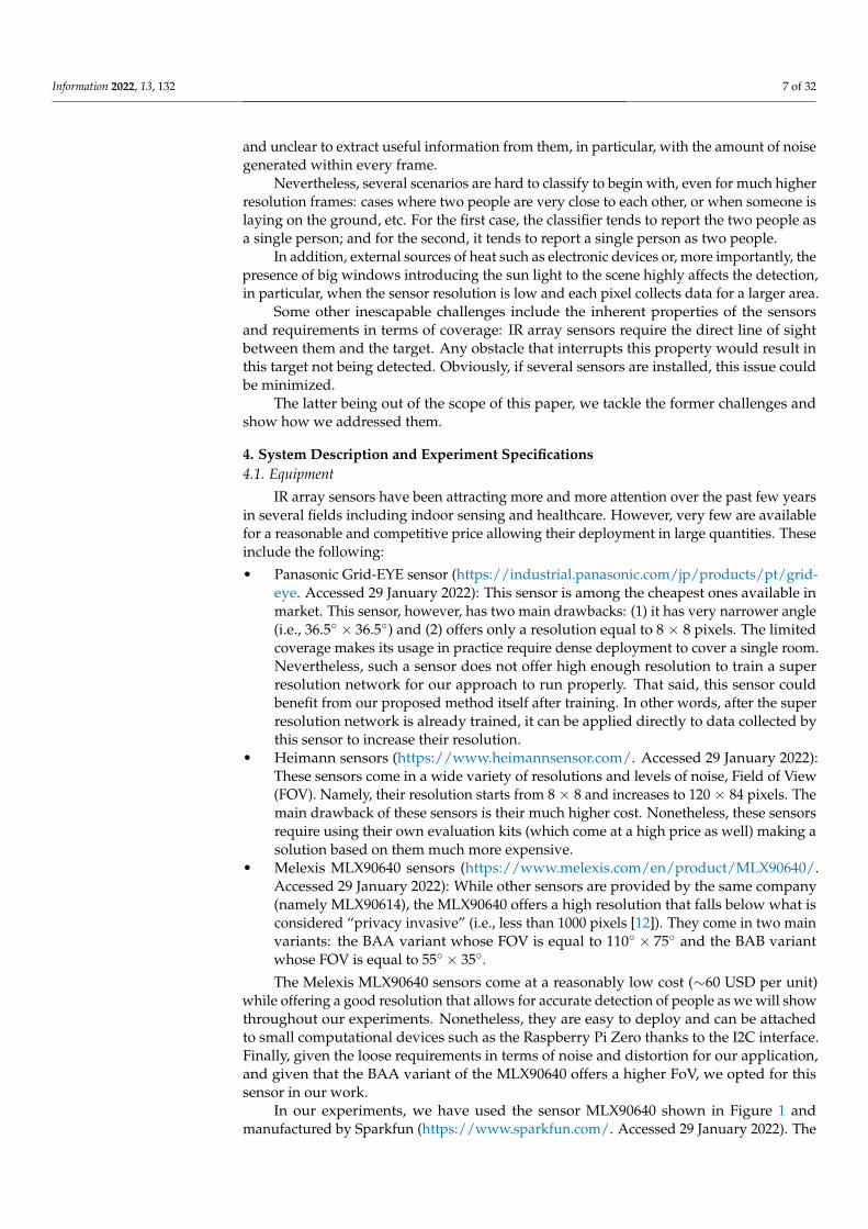
• Melexis MLX90640 sensors (https://www.melexis.com/en/product/MLX90640/.Accessed 29 January 2022): While other sensors are provided by the same company(namely MLX90614), the MLX90640 offers a high resolution that falls below what isconsidered “privacy invasive” (i.e., less than 1000 pixels [12]). They come in two mainvariants: the BAA variant whose FOV is equal to 110◦ × 75◦ and the BAB variantwhose FOV is equal to 55◦ × 35◦.
The Melexis MLX90640 sensors come at a reasonably low cost (∼60 USD per unit)while offering a good resolution that allows for accurate detection of people as we will showthroughout our experiments. Nonetheless, they are easy to deploy and can be attachedto small computational devices such as the Raspberry Pi Zero thanks to the I2C interface.Finally, given the loose requirements in terms of noise and distortion for our application,and given that the BAA variant of the MLX90640 offers a higher FoV, we opted for thissensor in our work.
In our experiments, we have used the sensor MLX90640 shown in Figure 1 andmanufactured by Sparkfun (https://www.sparkfun.com/. Accessed 29 January 2022). The
Information 2022, 13, 132 8 of 32
specifications of this sensor are given in Table 1. The sensor allows the extraction of framesof different sizes and at different rates. For the first round of experiments, the data arecollected at the highest resolution (32 × 24), and the frames are downsampled to 16 × 12and 8 × 6. These images (original images + downsampled ones) are used to train our superresolution neural network. Data are then collected at lower resolution and used to performthe classification.
Figure 1. The IR array sensor used for our experiments.
Table 1. Specifications of the IR array sensor used for our experiments.
IR Senor Model MLX90640
Voltage 3.3 V
Temperature range −40 ∼ 85 ◦C
Resolution 32 × 24 − 16 × 12 − 8 × 6 pixels
Recording rate 1, 2, 4, 8, 16, 32 and 64 fps
Coverage 110◦ × 75◦
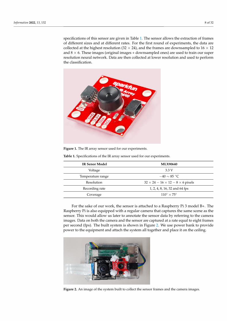
For the sake of our work, the sensor is attached to a Raspberry Pi 3 model B+. TheRaspberry Pi is also equipped with a regular camera that captures the same scene as thesensor. This would allow us later to annotate the sensor data by referring to the cameraimages. Data on both the camera and the sensor are captured at a rate equal to eight framesper second (fps). The built system is shown in Figure 2. We use power bank to providepower to the equipment and attach the system all together and place it on the ceiling.
Figure 2. An image of the system built to collect the sensor frames and the camera images.
Information 2022, 13, 132 9 of 32
4.2. Environment
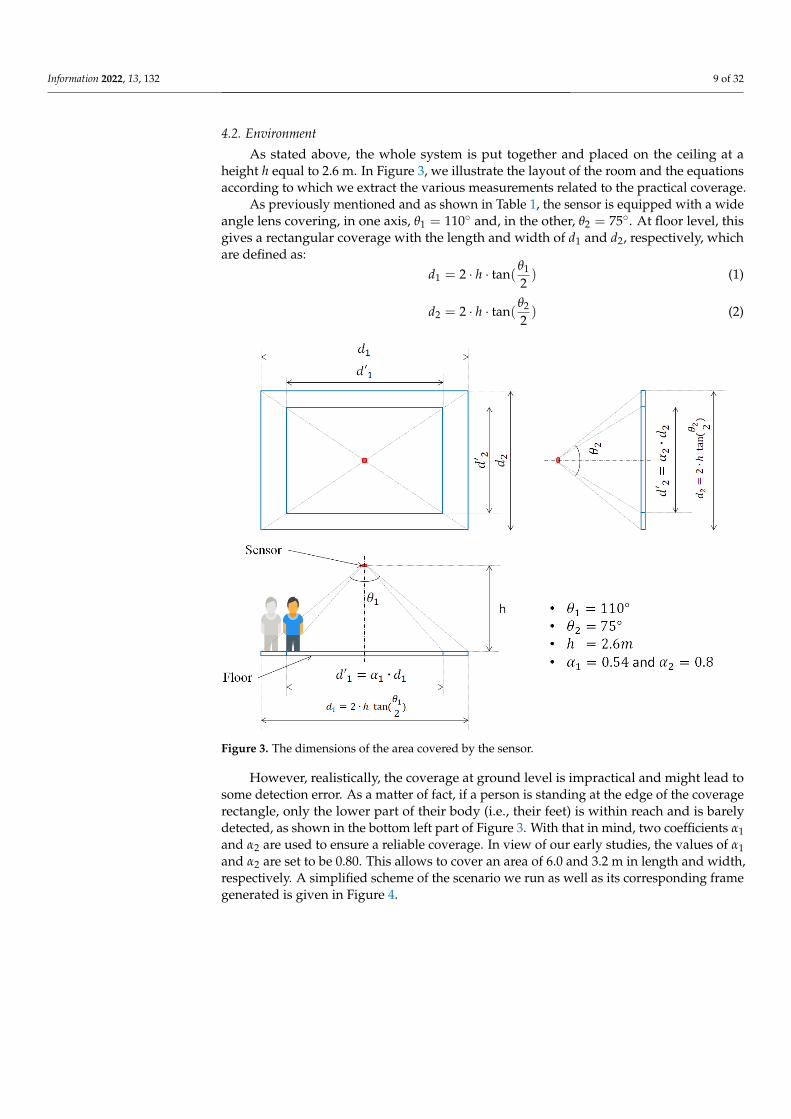
As stated above, the whole system is put together and placed on the ceiling at aheight h equal to 2.6 m. In Figure 3, we illustrate the layout of the room and the equationsaccording to which we extract the various measurements related to the practical coverage.
As previously mentioned and as shown in Table 1, the sensor is equipped with a wideangle lens covering, in one axis, θ1 = 110◦ and, in the other, θ2 = 75◦. At floor level, thisgives a rectangular coverage with the length and width of d1 and d2, respectively, whichare defined as:
d1 = 2 · h · tan(θ1
2) (1)
d2 = 2 · h · tan(θ2
2) (2)
Figure 3. The dimensions of the area covered by the sensor.
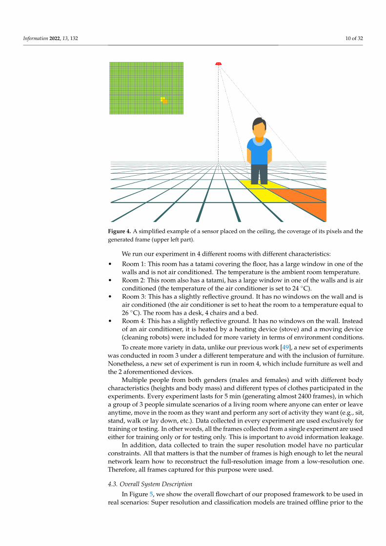
However, realistically, the coverage at ground level is impractical and might lead tosome detection error. As a matter of fact, if a person is standing at the edge of the coveragerectangle, only the lower part of their body (i.e., their feet) is within reach and is barelydetected, as shown in the bottom left part of Figure 3. With that in mind, two coefficients α1and α2 are used to ensure a reliable coverage. In view of our early studies, the values of α1and α2 are set to be 0.80. This allows to cover an area of 6.0 and 3.2 m in length and width,respectively. A simplified scheme of the scenario we run as well as its corresponding framegenerated is given in Figure 4.
Information 2022, 13, 132 10 of 32
Figure 4. A simplified example of a sensor placed on the ceiling, the coverage of its pixels and thegenerated frame (upper left part).
We run our experiment in 4 different rooms with different characteristics:
• Room 1: This room has a tatami covering the floor, has a large window in one of thewalls and is not air conditioned. The temperature is the ambient room temperature.
• Room 2: This room also has a tatami, has a large window in one of the walls and is airconditioned (the temperature of the air conditioner is set to 24 ◦C).
• Room 3: This has a slightly reflective ground. It has no windows on the wall and isair conditioned (the air conditioner is set to heat the room to a temperature equal to26 ◦C). The room has a desk, 4 chairs and a bed.
• Room 4: This has a slightly reflective ground. It has no windows on the wall. Insteadof an air conditioner, it is heated by a heating device (stove) and a moving device(cleaning robots) were included for more variety in terms of environment conditions.
To create more variety in data, unlike our previous work [49], a new set of experimentswas conducted in room 3 under a different temperature and with the inclusion of furniture.Nonetheless, a new set of experiment is run in room 4, which include furniture as well andthe 2 aforementioned devices.
Multiple people from both genders (males and females) and with different bodycharacteristics (heights and body mass) and different types of clothes participated in theexperiments. Every experiment lasts for 5 min (generating almost 2400 frames), in whicha group of 3 people simulate scenarios of a living room where anyone can enter or leaveanytime, move in the room as they want and perform any sort of activity they want (e.g., sit,stand, walk or lay down, etc.). Data collected in every experiment are used exclusively fortraining or testing. In other words, all the frames collected from a single experiment are usedeither for training only or for testing only. This is important to avoid information leakage.
In addition, data collected to train the super resolution model have no particularconstraints. All that matters is that the number of frames is high enough to let the neuralnetwork learn how to reconstruct the full-resolution image from a low-resolution one.Therefore, all frames captured for this purpose were used.
4.3. Overall System Description
In Figure 5, we show the overall flowchart of our proposed framework to be used inreal scenarios: Super resolution and classification models are trained offline prior to the
Information 2022, 13, 132 11 of 32
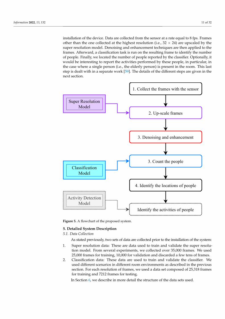
installation of the device. Data are collected from the sensor at a rate equal to 8 fps. Framesother than the one collected at the highest resolution (i.e., 32 × 24) are upscaled by thesuper resolution model. Denoising and enhancement techniques are then applied to theframes. Afterward, a classification task is run on the resulting frame to identify the numberof people. Finally, we located the number of people reported by the classifier. Optionally, itwould be interesting to report the activities performed by these people, in particular, inthe case where a single person (i.e., the elderly person) is present in the room. This laststep is dealt with in a separate work [59]. The details of the different steps are given in thenext section.
Super ResolutionModel
ClassificationModel
1. Collect the frames with the sensor
2. Up-scale frames
3. Count the people
4. Identify the locations of people
Identify the activities of people
Activity DetectionModel
3. Denoising and enhancement
Figure 5. A flowchart of the proposed system.
5. Detailed System Description5.1. Data Collection
As stated previously, two sets of data are collected prior to the installation of the system:
1. Super resolution data: These are data used to train and validate the super resolu-tion model. From several experiments, we collected over 35,000 frames. We used25,000 frames for training, 10,000 for validation and discarded a few tens of frames.
2. Classification data: These data are used to train and validate the classifier. Weused different scenarios in different room environments as described in the previoussection. For each resolution of frames, we used a data set composed of 25,318 framesfor training and 7212 frames for testing.
In Section 6, we describe in more detail the structure of the data sets used.
Information 2022, 13, 132 12 of 32
5.2. Super Resolution and Frame Upscaling
This step consists of two parts: offline training and online inference. The latter partconsists of simply applying the model generated offline to upscale the images collectedfrom the sensor after its deployment. Therefore, we focus here on how the model is builtand on the architecture of the neural network used.
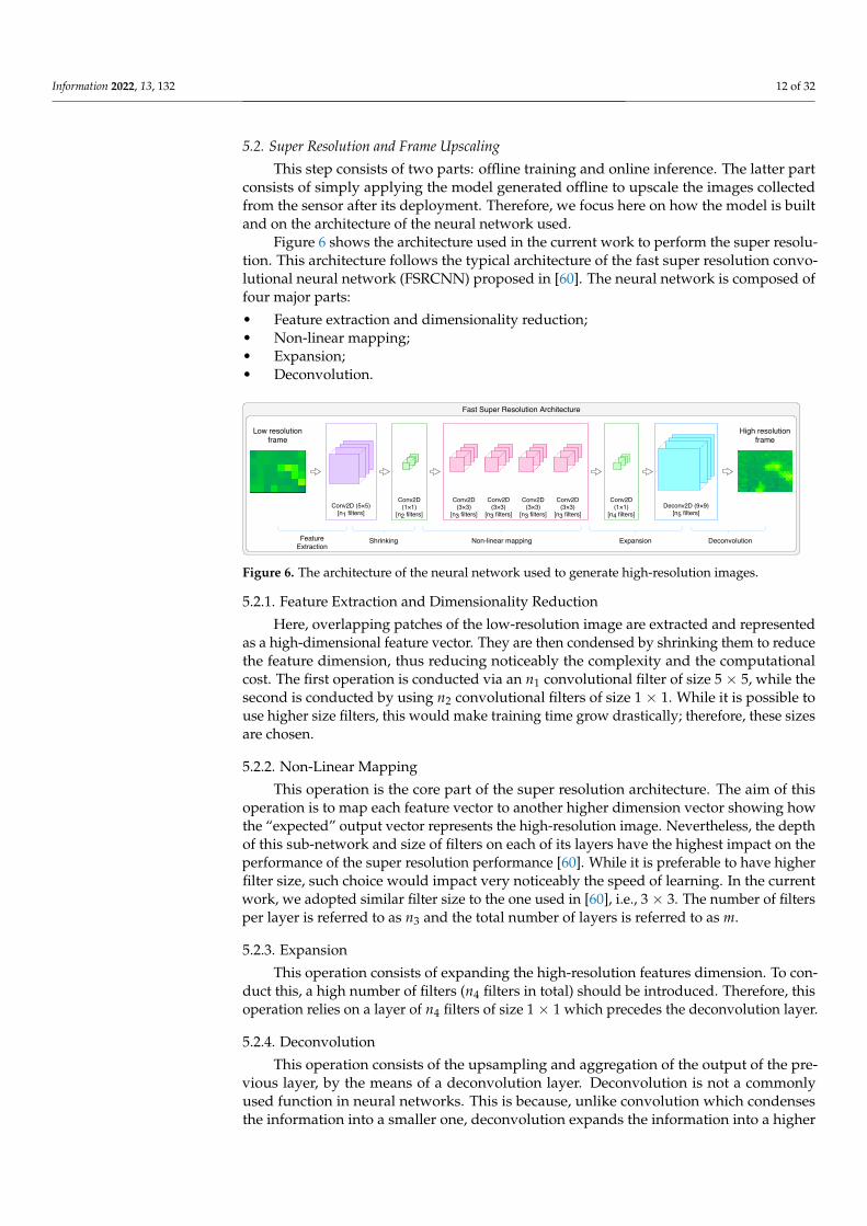
Figure 6 shows the architecture used in the current work to perform the super resolu-tion. This architecture follows the typical architecture of the fast super resolution convo-lutional neural network (FSRCNN) proposed in [60]. The neural network is composed offour major parts:
• Feature extraction and dimensionality reduction;• Non-linear mapping;• Expansion;• Deconvolution.
Conv2D(1×1)
[n2 filters]
Conv2D(3×3)
[n3 filters]
Conv2D(3×3)
[n3 filters]
Conv2D(3×3)
[n3 filters]
Conv2D(3×3)
[n3 filters]Deconv2D (9×9)
[n5 filters]
Conv2D(1×1)
[n4 filters]Conv2D (5×5)
[n1 filters]
FeatureExtraction
Non-linear mapping Expansion DeconvolutionShrinking
Fast Super Resolution Architecture
Low resolutionframe
High resolutionframe
Figure 6. The architecture of the neural network used to generate high-resolution images.
5.2.1. Feature Extraction and Dimensionality Reduction
Here, overlapping patches of the low-resolution image are extracted and representedas a high-dimensional feature vector. They are then condensed by shrinking them to reducethe feature dimension, thus reducing noticeably the complexity and the computationalcost. The first operation is conducted via an n1 convolutional filter of size 5 × 5, while thesecond is conducted by using n2 convolutional filters of size 1 × 1. While it is possible touse higher size filters, this would make training time grow drastically; therefore, these sizesare chosen.
5.2.2. Non-Linear Mapping
This operation is the core part of the super resolution architecture. The aim of thisoperation is to map each feature vector to another higher dimension vector showing howthe “expected” output vector represents the high-resolution image. Nevertheless, the depthof this sub-network and size of filters on each of its layers have the highest impact on theperformance of the super resolution performance [60]. While it is preferable to have higherfilter size, such choice would impact very noticeably the speed of learning. In the currentwork, we adopted similar filter size to the one used in [60], i.e., 3 × 3. The number of filtersper layer is referred to as n3 and the total number of layers is referred to as m.
5.2.3. Expansion
This operation consists of expanding the high-resolution features dimension. To con-duct this, a high number of filters (n4 filters in total) should be introduced. Therefore, thisoperation relies on a layer of n4 filters of size 1 × 1 which precedes the deconvolution layer.
5.2.4. Deconvolution
This operation consists of the upsampling and aggregation of the output of the pre-vious layer, by the means of a deconvolution layer. Deconvolution is not a commonlyused function in neural networks. This is because, unlike convolution which condensesthe information into a smaller one, deconvolution expands the information into a higher
Information 2022, 13, 132 13 of 32
dimension. More accurately, this depends on the size of the stride, as a stride of size 1with padding would give information of the same size; however, for a stride of size k,the condensed information will have a size 1/k. Inversely, a deconvolution with a strideenlarges the input information, and with an accurate choice, the output image can be thesize we want.
5.2.5. Activations and Parameters
Unlike the commonly used Rectified Linear Unit (ReLU) activation function,reference [60] proposed to use Parametric ReLU (PReLU) for better learning. PReLUdiffers from conventional ReLU in the way that the threshold for the activation is decided.While ReLU uses 0 as a threshold, meaning that all negative values are mapped to zero,PReLU has this threshold as a parameter learned through training. This is important notonly to have better training but also later on to estimate the complexity of the architecture.
In our current work, we used the following parameters for the number of filters perlayer and number of non-linear mapping layers:
n1 = n4 = 56n2 = 16n3 = 12 and m = 4n5 = 1
(3)
That being the case, the overall architecture of the super resolution network is givenin Table 2.
Table 2. The architecture of the neural network used for super resolution.
Layer Type Number of Filters Filter Size
Conv 2D 56 5 × 5
Conv 2D 16 1 × 1
Conv 2D 12 3 × 3
Conv 2D 12 3 × 3
Conv 2D 12 3 × 3
Conv 2D 12 3 × 3
Conv 2D 56 1 × 1
DeConv 2D 1 9 × 9
To estimate the complexity of our neural network, we use its total number of param-eters as an indicator. We have a set of convolutions, a single deconvolution. To that weadd the number of PReLU parameters. To recall, every convolutional layer is followed byPReLU layers.
The total number of parameters P of a given convolutional layer c is given by:
P(c) = (m · n · p) + 1) · k (4)
where m and n are the width and height of each filter (3× 3 in our case), p is the number ofchannels and k is the number of filters in the layer.
The total number of parameters P of a given PReLU layer a is given by:
P(a) = h · w · k (5)
where h and w are the height and width of the input image, respectively, and k is again thenumber of filters.
Information 2022, 13, 132 14 of 32
That being the case, the overall number of parameters in the network is 21,745 for thecase where the input images are 8 × 6 and 47,089 for the case where the input images are16 × 12.
5.3. Denoising and Enhancement
Before proceeding with counting the number of people, we opt for another step tofurther enhance the quality of the generated frames. Denoising is a well-established andexplored topic in the field of computer vision and imaging in general. For the sake ofsimplicity, and keeping in mind the hardware limitations, in this work, we opted forthree techniques to denoise the frames generated by the IR sensor.
5.3.1. Averaging over N Consecutive Frames
This method is quite straightforward: Given that the sensor collects the data at arelatively high frame rate (8 FPS), we assume that consecutive frames have little to nochange with regard to the main objects/people present, unless they move at a high speed.The noise, on the other hand, changes from a frame to the next. To reduce its effect, givenN consecutive frames (in practice, we use N = 2), we average the values of pixels of twoconsecutive frames into one.
5.3.2. Aggressive Denoising
This method is referred to as aggressive as it suppresses a noticeable amount ofinformation from the frame. It works on a simple principle: Frames are considered as heatmatrices (raw data before transforming them into images). Adjacent pixels which are closeto one another in temperature are all adjusted to their average temperature’s 0.5◦ upperbound. This results in a much less noisy frame, even though part of the information is lostas previously stated.
5.3.3. Non-Local Means Denoising (NLMD)
The NLMD [61] method is based on a straightforward principle and works on imagesas images rather than heat matrix: replacing a pixel’s color with an average of the colors ofsimilar pixels. However, the pixels that are most similar to a particular pixel have no needto be near close to it at all. Thus, it is permissible to scan a large section of the picture insearch of all pixels that closely match the pixel to be denoised. Obviously, this technique ismore expensive in terms of computation, yet it is still considered as cost effective.
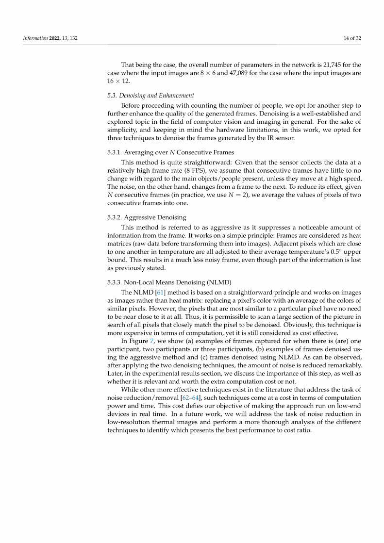
In Figure 7, we show (a) examples of frames captured for when there is (are) oneparticipant, two participants or three participants, (b) examples of frames denoised us-ing the aggressive method and (c) frames denoised using NLMD. As can be observed,after applying the two denoising techniques, the amount of noise is reduced remarkably.Later, in the experimental results section, we discuss the importance of this step, as well aswhether it is relevant and worth the extra computation cost or not.
While other more effective techniques exist in the literature that address the task ofnoise reduction/removal [62–64], such techniques come at a cost in terms of computationpower and time. This cost defies our objective of making the approach run on low-enddevices in real time. In a future work, we will address the task of noise reduction inlow-resolution thermal images and perform a more thorough analysis of the differenttechniques to identify which presents the best performance to cost ratio.
Information 2022, 13, 132 15 of 32
1 p
arti
cipan
t2 p
arti
cipan
ts3 p
arti
cipan
ts
(a) (b) (c)
Figure 7. Examples of frames denoised using different techniques. (a) Original Frames, (b) Frames“aggressively” denoised, (c) Frames denoised using NLMD.
5.4. Counting People
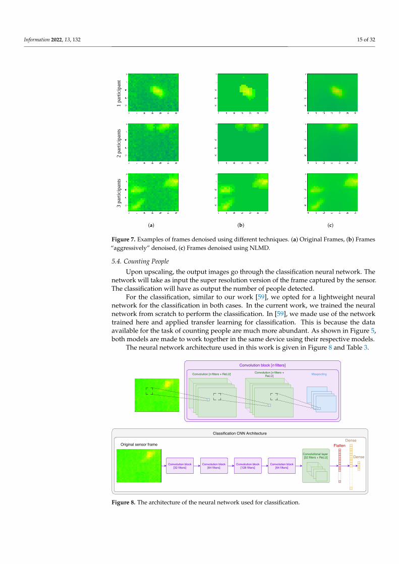
Upon upscaling, the output images go through the classification neural network. Thenetwork will take as input the super resolution version of the frame captured by the sensor.The classification will have as output the number of people detected.
For the classification, similar to our work [59], we opted for a lightweight neuralnetwork for the classification in both cases. In the current work, we trained the neuralnetwork from scratch to perform the classification. In [59], we made use of the networktrained here and applied transfer learning for classification. This is because the dataavailable for the task of counting people are much more abundant. As shown in Figure 5,both models are made to work together in the same device using their respective models.
The neural network architecture used in this work is given in Figure 8 and Table 3.
Convolution [n filters + ReLU] Convolution [n filters +ReLU] Maxpooling
Convolution block [n filters]
Convolution block[32 filters]
Convolution block[64 filters]
Convolution block[128 filters]
Convolution block[64 filters]
Convolutional layer [32 filters + ReLU]
Classification CNN Architecture
Dense
Dense
FlattenOriginal sensor frame
Figure 8. The architecture of the neural network used for classification.
Information 2022, 13, 132 16 of 32
The upper part of Figure 8 shows the structure of a convolutional block: such a blockhas two convolutional layers with a ReLU activation, followed by a Max pooling layer. Eachconvolutional layer consists of a set of n filters of size 3× 3, whose weights are initializedrandomly and learned over training. In addition, we added padding to the edges of theframes to prevent the sizes of the generated images (except when performing Max pooling)from decreasing.
Table 3. The architecture of the neural network used for classification.
Layer Type Number of Filters FC Neurons
Conv 2D 32 -
Conv 2D 32 -
Max pooling 2D - -
Conv 2D 64 -
Conv 2D 64 -
Max pooling 2D - -
Conv 2D 128 -
Conv 2D 128 -
Max pooling 2D - -
Conv 2D 64 -
Conv 2D 64 -
Max pooling 2D - -
Conv 2D 32 -
Flatten - -
Dense - 64
Dense - 4
The lower part of Figure 8 shows the overall architecture of our proposed model: itconsists of four convolution blocks followed by a flattening layer and two dense layers.The last dense layer is obviously one responsible for determining the class. Therefore, alllayers have ReLU activations except for the last dense layer whose activation is a Softmax.Moreover, we used a drop out equal to 0.6 after each Max pooling layer.
Again, the number of parameters is used as a measure of the complexity of the network.In addition to Equations (4) and (5), we use the following equation to calculate the totalnumber of parameters P of a given dense layer d:
P(d) = (s · t) + 1 (6)
where s is the size of the dense layer (the number of neurons) and t is the number of neuronsin the previous layer.
The total number of parameters of the classification neural network is about 410 Kparameters. To put that into perspective, a network architecture such as ResNet34 [20]has a total number of parameters that is about 21 M and VGG16 [21] has a total numberof parameters that is about 138 M. In case we want to run everything locally on a devicesuch as the Raspberry Pi, equipped with a Movedius Neural Stick (https://software.intel.com/en-us/movidius-ncs. Accessed 7 November 2021), simpler architectures such as ourswould not consume much computational resources and would run in real time with aframe rate equal to eight.
As stated above, it is important to keep in mind that our objective is to run the modelson a low-end device. Therefore, having light neural network architecture is one of theconstraints we have set when designing it. With that in mind, the number of layers and
Information 2022, 13, 132 17 of 32
filters per layer have been set to the smallest number possible. Nonetheless, given thatthe characteristics of hardware (in general) work more efficiently when memory chunksstored in powers of two are passed, the batch size and other parameters were set to be assuch. This is a common practice in the community and explained in reference [65]. Wehave tried using different network architectures with more (respectively, less) layers. In theformer case (i.e., using deeper networks), there is no noticeable gain in the classificationperformance that justifies the extra computation cost. In the latter case, using shallowernetworks does indeed affect the performance: the classification accuracy drops significantlyand cases when a person is laying on the ground or people are very close to each otherwould result in misclassification.
To summarize, despite being simplistic, the proposed architecture provides verygood classification results. In addition, due to its simplicity, once trained, it can run theclassification fast enough even on a low computational device such as the Raspberry Piitself. The classification objective is to count the number of people. In our experiments, at agiven time, the room could have zero, one, two or three people. Therefore, four classes arepresent in total.
5.5. Identification of the Location of People
This step uses the same method we previously used in [49]. The previous step outputsthe number of people present in the room, which we refer to as N. After identifying N, weuse a method referred to, in the computer vision world, as Canny’s edge detection [66].Canny’s edge detection approach is widely employed in computer vision to identify edgesof objects in images. The approach relies on the difference in color between the adjacentpixels. The detailed description of the approach is given in [66]. In our work, using [66],we aim to find the top N hottest spots in the sensor image. We briefly summarize the stepstaken by this method to detect edges in an image:
1. Noise Reduction: To facilitate the detection, the first step, as its name implies, is toreduce the image noise. The way this is performed is by using a Gaussian filter tosmoothen the frame.
2. Find the intensity gradient: After reducing the noise, the intensity gradient of colors inthe image are derived. To achieve this goal, a Sobel kernel filter [67] is applied on thehorizontal and vertical directions. This would allow us to obtain the correspondingrespective derivatives Gx and Gy, which, in return, are used to obtain the gradientand orientation of pixels:
G =√
G2x + G2
y (7)
θ = tan−1(Gy
Gx) (8)
3. Suppression of non-maximums: Edges are, by definition, local maximums. Hence,non-local maximum pixels (obviously in the direction of the gradients measured inthe previous step) are discarded. Nevertheless, during this step, fake maximums (i.e.,pixels whose gradient is equal to 0, but they are not actual maximums) are identifiedand discarded.
4. Double thresholds and hysteresis thresholding: While in the previous step, non-edge pixels are set to 0, edges have different intensities. This step suppresses—ifnecessary—weak edges (i.e., edges that do not separate two objects or an object fromits background). Obviously, the definition of a weak edge implies a subjective decision.This is achieved thanks to two parameters that need to be taken into account: anupper threshold and a lower one.
One thing to retain is that these last two parameters (thresholds) can drastically changethe level of details captured and by how much the values of the neighboring pixels shoulddiffer for an edge to be detected. The approach can be made more or less sensitive to “color”
Information 2022, 13, 132 18 of 32
nuances by tweaking these thresholds. Consequently, detected edges can reflect sharper orsmaller changes in temperature.
Given the nature of our images (i.e., 32× 24 pixel frames reflecting heat emitted byobjects in the room), we set default values for these thresholds so that they detect the Nhottest spots correctly, most of the time. This implies that in some cases they do not workcorrectly. Therefore, these values are dynamically adjusted if the number of hot spotsdetected is different from N (it is increased if the detected number is different from N andvice versa). We then identify the centroids of areas found and consider them to be theapproximate locations of the people present in the room.
5.6. Activity Detection
In a separate work of ours [59], we used the same equipment to run another clas-sification task whose goal is to detect the activity performed by a person present in theroom. While this is out of the scope of the current paper, it might be worth mentioning thatthe accuracy of activity detection reported for seven different types of activities reachedover 97%.
6. Experimental Results6.1. Data Sets
To evaluate the performance (i.e., accuracy of detection, precision and recall) of theapproach that relies on super resolution for identifying and counting people, we use a dataset identical in size for all resolutions that we experimented with: 8 × 6-size, 16 × 12-sizeand 32 × 24-size frames. The structure of the data set is given in Table 4.
Table 4. Data sets used: the number of frames with N people present in them, N ∈ {0, 1, 2, 3}.
Number of People 0 1 2 3
Training set 5129 6583 7348 6258
Test set 1298 1546 2810 1558
6.2. High-Resolution Classification Results6.2.1. Training Set Cross-Validation
To measure the correctness of classification, we use four Key Performance Indicators(KPIs), which are the TP rate, precision, recall and the F1-score. In a first step, we perform a5-fold cross-validation on the training set. The training set is split into five subsets. In eachfold, three of the subsets are used to train a model, one is used for validation and one isused for evaluation.
Since different techniques of denoising have been used in our work, we first report theoverall classification KPIs averaged over all the folds using each technique, as well as thatfor the original frames. We use the following terminology for the following methods ofdenoising of the frames:
• The method where frames captured with size 32 × 24 with no denoising is referred toas (M32×24);
• The method where frames captured with size 32 × 24 are denoised by averaging overtwo consecutive frames is referred to as (M32×24E−a);
• The method where frames captured with size 32 × 24 are denoised by the aggressivedenoising method is referred to as (M32×24E−d1);
• The method where frames captured with size 32 × 24 denoised by the NLMDmethod [61] is referred to as (M32×24E−d2).
In Table 5, we show the overall the reported performance.
Information 2022, 13, 132 19 of 32
Table 5. The classification TP rate, precision, recall and F1-score of the high-resolution frames duringcross-validation for different denoising techniques.
TP Rate Precision Recall F-Measure
(M32×24) 97.48% 97.46% 97.48% 97.47%
(M32×24E−a) 97.51% 97.50% 97.51% 97.51%
(M32×24E−d1) 97.82% 97.84% 97.82% 97.83%
(M32×24E−d2) 97.84% 97.88% 97.84% 97.86%
Since the use of NLMD [61] has given the highest KPIs, we focus on this techniqueand report in Table 6 the classification results on each of the individual folds, as well as theweighted average of them for the method (M32×24E−d2).
Table 6. The classification TP rate, precision, recall and F1-score of the high-resolution framesduring cross-validation.
TP Rate Precision Recall F-Measure
Fold 1 97.85% 97.87% 97.85% 97.86%
Fold 2 98.01% 98.05% 98.01% 98.03%
Fold 3 98.14% 98.14% 98.14% 98.14%
Fold 4 98.08% 98.09% 98.08% 98.08%
Fold 5 97.11% 97.25% 97.11% 97.18%
Average 97.84% 97.88% 97.84% 97.86%
6.2.2. Evaluation on the Test Set
Here, we use the entire training to train and validate one more model and use thetrained model on unseen data. After training our model, we run the classification onour test set. The results of classification are given in Table 7, and the confusion matrixof classification is given in Table 8. Similar to cross-validation, the evaluation here isperformed using the best-performing denoising technique (i.e., the NLMD method [61]).
Table 7. The classification TP rate, precision, recall and F1-score of the high-resolution frames on thetest set.
TP Rate Precision Recall F-Measure
Class 0 100% 100% 100% 100%
Class 1 99.29% 98.27% 99.29% 98.78%
Class 2 98.33% 95.80% 98.33% 97.05%
Class 3 92.94% 98.64% 92.94% 95.70%
Overall 97.67% 97.70% 97.67% 97.66%
Table 8. The classification confusion matrix of the high-resolution frames on the test set.
Class Classified as
0 1 2 3
Class 0 1298 0 0 0
Class 1 0 1535 11 0
Class 2 0 27 2763 20
Class 3 0 0 110 1448
Information 2022, 13, 132 20 of 32
The overall accuracy obtained reaches over 97.67%, with a precision and recall of theclass 0 (class 0 represents the case where no person is present in the room) equal to 100%.This means that it is possible to confirm, at any given moment, whether or not there issomeone in the room. This is of utmost importance, given that one of our goals, at the endof the day, is to monitor the person when they are in the room. Being able to identify theirpresence when true should be certain with 100% confidence.
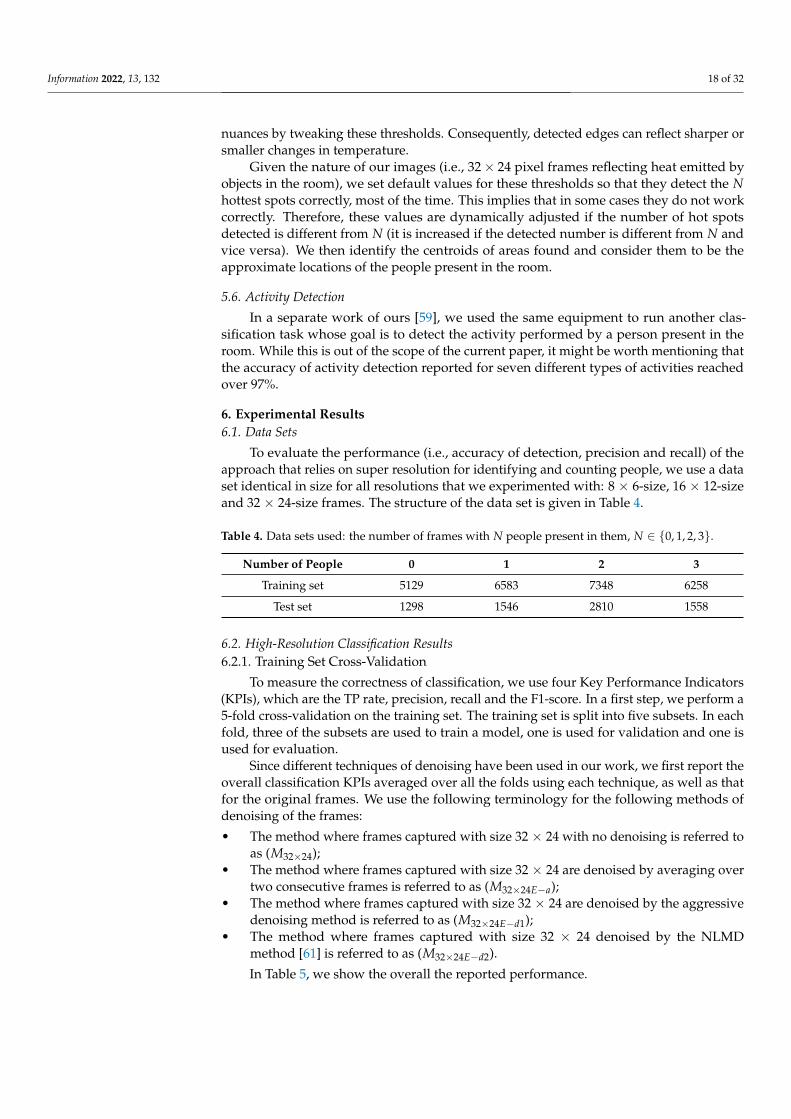
Location-wise, it is hard to confirm the level of precision of detection due to the factthat different pixels of the generated sensor image cover different area sizes due to the angledifference. In addition, due to the distortion in the image captured by the camera, the exactlocation cannot be confirmed at a very precise level. Nevertheless, we rely on the centroidsof the generated areas to determine the location of users. This makes the exact location notvery accurate. Our empirical measurements show that the margin of inaccuracy is about0.3 m. With that in mind, it is fair to affirm that the location identification reaches 100%accuracy for the correctly classified instances and for the precision level mentioned (i.e.,0.3 m). In other words, for the frames where we were able to correctly identify the numberof people present, the objects detected as the participants, using the Canny’s method foredge detection, correspond indeed to them. In Figure 9, we show an example of someinstances correctly classified and whose location are correctly identified.
Figure 9. Examples of the same instant as captured by the camera (left), the sensor (middle) andprocessed sensor frames to identify the location of detected people (right).
6.3. Low-Resolution Classification Results6.3.1. Super Resolution: How to Evaluate the Performance
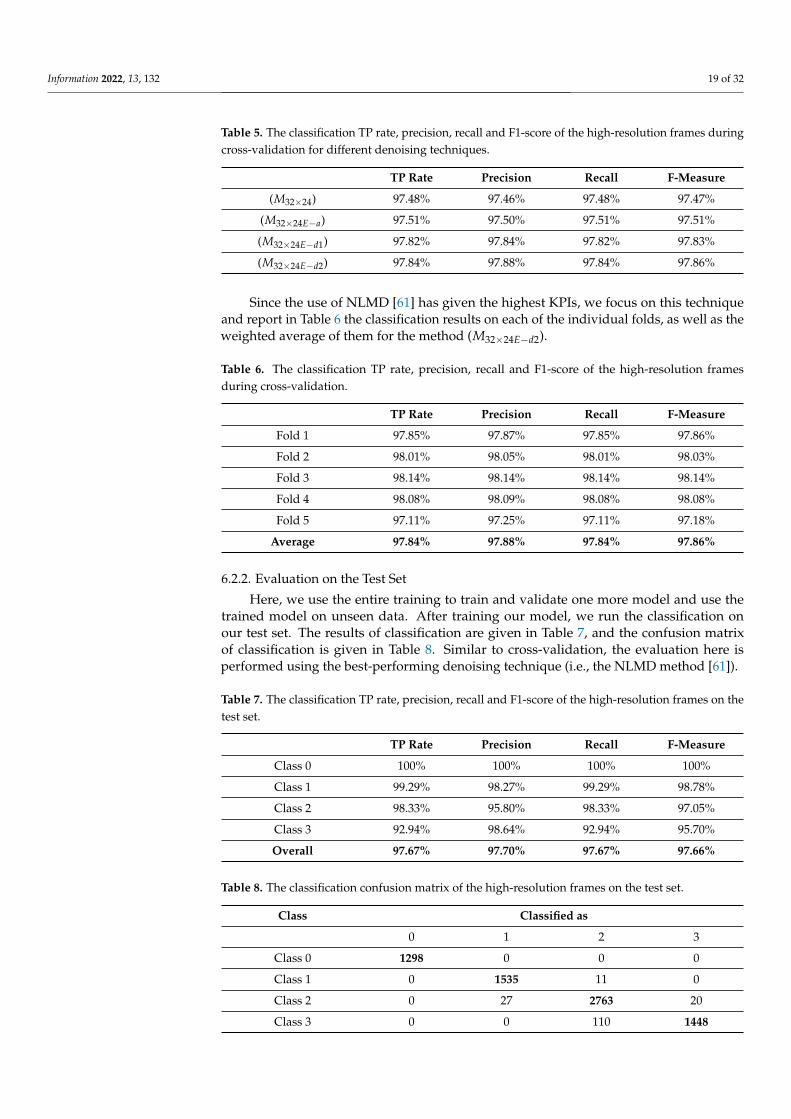
In Figure 10, we show an example of two consecutive frames collected with size32 × 24. The frames show the existance of three people in the room. As we can observe,in the regions of low temperatures, the amount of noise present is very high, leading toa grid effect: nearby pixels have a trend to oscillate so that each pixel has values that arehigher/lower than the neighboring ones and pixels change from being higher to beinglower than its neighbors in consecutive frames.
Information 2022, 13, 132 21 of 32
Figure 10. An example of two consecutive frames to show the amount of noise present in them.The total number of people present in the room is 3. However, other than the hotspots whichcorrespond to these people, the other pixels’ values (colors) fluctuate remarkably.
Given that the amount of such noise in the frames captured by the sensor is high, wedid not evaluate the performance of the super resolution approach using the conventionalmetrics of evaluation of super resolution (e.g., entropy). We relied, instead, on the actualclassification that takes place when we count people. In other words, if the classificationaccuracy is improved compared to the original low-resolution images, we conclude thatthe super resolution approach is good and has contributed to enhancing the performanceof our classifier.
In addition, to observe the effect of minimizing the noise, we have added an evaluationof frames generated using the different techniques described previously in Section 5.3. Intotal, we evaluate the classification performance of the following methods of capturingthe frames:
• The method where frames captured with size 32 × 24 are used as they are is referredto as (M32×24);
• The method where frames captured with size 32 × 24 are denoised by the NLMDmethod [61] is referred to as (M32×24E−d2);
• The method where frames captured with size 16 × 12 are used as they are is referredto as (M16×12);
• The method where frames captured with size 16 × 12 are upscaled with the superresolution technique to 32 × 24 is referred to as (M16×12SR);
• The method where frames captured with size 16 × 12 are upscaled with the superresolution technique to 32 × 24 and denoised by averaging over two consecutiveframes is referred to as (M16×12E−a);
• The method where frames captured with size 16 × 12 are upscaled with the superresolution technique to 32 × 24 and denoised by the aggressive denoising method isreferred to as (M16×12SR−E−d1);
• The method where frames captured with size 16 × 12 are upscaled with the superresolution technique to 32 × 24 and denoised by the NLMD method [61] is referred toas (M16×12SR−E−d2);
• The method where frames captured with size 8 × 6 are used as they are is referred toas (M8×6);
• The method where frames captured with size 8 × 6 are upscaled with the superresolution technique to 32 × 24 is referred to as (M8×6SR);
• The method where frames captured with size 8 × 6 are upscaled with the superresolution technique to 32 × 24 and denoised by averaging over two consecutiveframes is referred to as (M8×6E−a);
• The method where frames captured with size 8 × 6 are upscaled with the superresolution technique to 32 × 24 and denoised by the aggressive denoising method isreferred to as (M8×6SR−E−d1);
Information 2022, 13, 132 22 of 32
• The method where frames captured with size 8 × 6 are upscaled with the superresolution technique to 32 × 24 and denoised by the NLMD method [61] is referred toas (M8×6SR−E−d2).
6.3.2. Classification Results
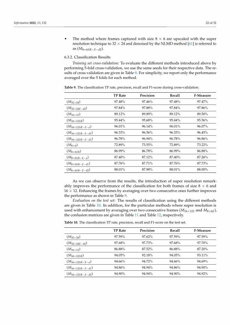
Training set cross-validation: To evaluate the different methods introduced above byperforming 5-fold cross-validation, we use the same seeds for their respective data. The re-sults of cross validation are given in Table 9. For simplicity, we report only the performanceaveraged over the 5 folds for each method.
Table 9. The classification TP rate, precision, recall and F1-score during cross-validation.
TP Rate Precision Recall F-Measure
(M32×24) 97.48% 97.46% 97.48% 97.47%
(M32×24E−d2) 97.84% 97.88% 97.84% 97.86%
(M16×12) 89.12% 89.89% 89.12% 89.50%
(M16×12SR) 95.44% 95.68% 95.44% 95.56%
(M16×12SR−E−a) 96.01% 96.14% 96.01% 96.07%
(M16×12SR−E−d1) 96.33% 96.56% 96.33% 96.45%
(M16×12SR−E−d1) 96.78% 96.94% 96.78% 96.86%
(M8×6) 72.89% 73.55% 72.89% 73.22%
(M8×6SR) 86.99% 86.78% 86.99% 86.88%
(M8×6SR−E−a) 87.40% 87.12% 87.40% 87.26%
(M8×6SR−E−d1) 87.76% 87.71% 87.76% 87.73%
(M8×6SR−E−d2) 88.01% 87.98% 88.01% 88.00%
As we can observe from the results, the introduction of super resolution remark-ably improves the performance of the classification for both frames of size 8 × 6 and16 × 12. Enhancing the frames by averaging over two consecutive ones further improvesthe performance as shown in Table 9.
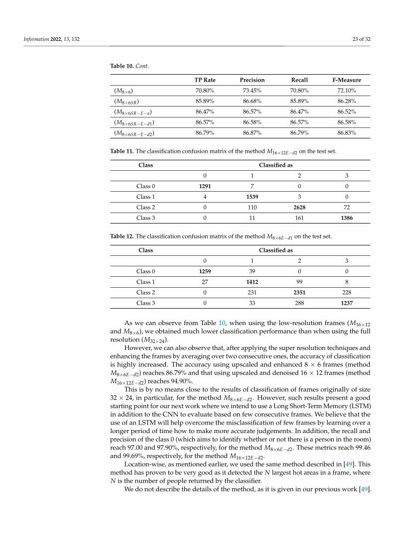
Evaluation on the test set: The results of classification using the different methodsare given in Table 10. In addition, for the particular methods where super resolution isused with enhancement by averaging over two consecutive frames (M16×12E and M8×6E),the confusion matrices are given in Table 11 and Table 12, respectively.
Table 10. The classification TP rate, precision, recall and F1-score on the test set.
TP Rate Precision Recall F-Measure
(M32×24) 97.59% 97.62% 97.59% 97.59%
(M32×24E−d2) 97.68% 97.73% 97.68% 97.70%
(M16×12) 86.88% 87.52% 86.88% 87.20%
(M16×12SR) 94.05% 92.18% 94.05% 93.11%
(M16×12SR−E−a) 94.66% 94.72% 94.66% 94.69%
(M16×12SR−E−d1) 94.86% 94.94% 94.86% 94.90%
(M16×12SR−E−d2) 94.90% 94.94% 94.90% 94.92%
Information 2022, 13, 132 23 of 32
Table 10. Cont.
TP Rate Precision Recall F-Measure
(M8×6) 70.80% 73.45% 70.80% 72.10%
(M8×6SR) 85.89% 86.68% 85.89% 86.28%
(M8×6SR−E−a) 86.47% 86.57% 86.47% 86.52%
(M8×6SR−E−d1) 86.57% 86.58% 86.57% 86.58%
(M8×6SR−E−d2) 86.79% 86.87% 86.79% 86.83%
Table 11. The classification confusion matrix of the method M16×12E−d2 on the test set.
Class Classified as
0 1 2 3
Class 0 1291 7 0 0
Class 1 4 1539 3 0
Class 2 0 110 2628 72
Class 3 0 11 161 1386
Table 12. The classification confusion matrix of the method M8×6E−d1 on the test set.
Class Classified as
0 1 2 3
Class 0 1259 39 0 0
Class 1 27 1412 99 8
Class 2 0 231 2351 228
Class 3 0 33 288 1237
As we can observe from Table 10, when using the low-resolution frames (M16×12and M8×6), we obtained much lower classification performance than when using the fullresolution (M32×24).
However, we can also observe that, after applying the super resolution techniques andenhancing the frames by averaging over two consecutive ones, the accuracy of classificationis highly increased. The accuracy using upscaled and enhanced 8 × 6 frames (methodM8×6E−d2) reaches 86.79% and that using upscaled and denoised 16 × 12 frames (methodM16×12E−d2) reaches 94.90%.
This is by no means close to the results of classification of frames originally of size32 × 24, in particular, for the method M8×6E−d2. However, such results present a goodstarting point for our next work where we intend to use a Long Short-Term Memory (LSTM)in addition to the CNN to evaluate based on few consecutive frames. We believe that theuse of an LSTM will help overcome the misclassification of few frames by learning over alonger period of time how to make more accurate judgements. In addition, the recall andprecision of the class 0 (which aims to identify whether or not there is a person in the room)reach 97.00 and 97.90%, respectively, for the method M8×6E−d2. These metrics reach 99.46and 99.69%, respectively, for the method M16×12E−d2.
Location-wise, as mentioned earlier, we used the same method described in [49]. Thismethod has proven to be very good as it detected the N largest hot areas in a frame, whereN is the number of people returned by the classifier.
We do not describe the details of the method, as it is given in our previous work [49].
Information 2022, 13, 132 24 of 32
6.4. Discussion
In the previous sub-sections, we have shown how it is possible to provide goodclassification accuracy when employing super resolution techniques. The results returnedby the classification of upscaled and denoised frames are comparable to those of high-resolution ones. In particular, when using the original sensor frames of size 16 × 12,the detection accuracy difference is less than 2%. That being said, despite reaching goodperformance, the current method has lower classification performance than that of higherresolution frame. We believe that it is possible to remedy this problem by using an LSTMneural network built on top of the CNN (i.e., uses the output of the CNN). Here, we suggestto use several consecutive frames. By observing over multiple frames the people present,it would be possible to detect more accurately their number and identify more accuratelytheir location. In other words, even if individual frames can have wrong detections hereand there, when using consecutive frames, such error could be minimized.
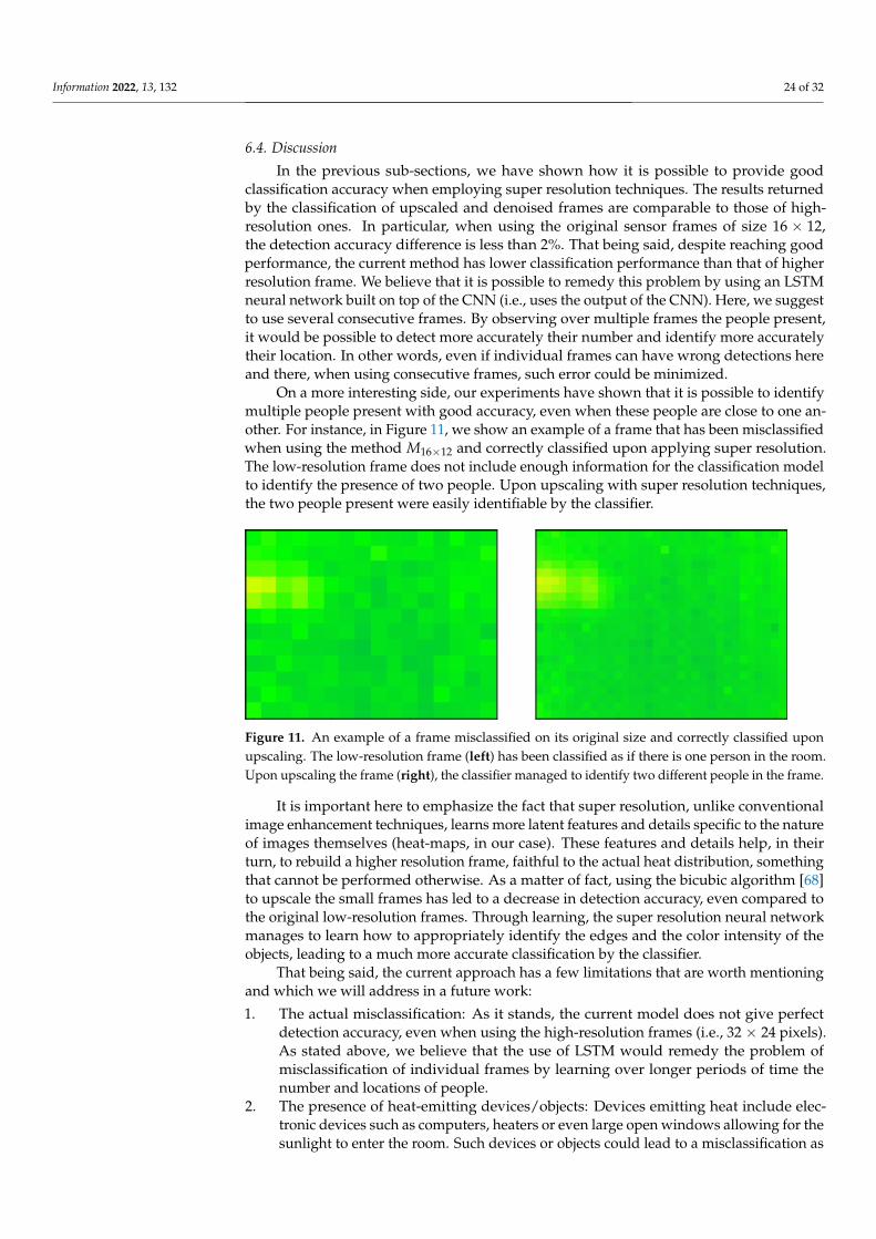
On a more interesting side, our experiments have shown that it is possible to identifymultiple people present with good accuracy, even when these people are close to one an-other. For instance, in Figure 11, we show an example of a frame that has been misclassifiedwhen using the method M16×12 and correctly classified upon applying super resolution.The low-resolution frame does not include enough information for the classification modelto identify the presence of two people. Upon upscaling with super resolution techniques,the two people present were easily identifiable by the classifier.
Figure 11. An example of a frame misclassified on its original size and correctly classified uponupscaling. The low-resolution frame (left) has been classified as if there is one person in the room.Upon upscaling the frame (right), the classifier managed to identify two different people in the frame.
It is important here to emphasize the fact that super resolution, unlike conventionalimage enhancement techniques, learns more latent features and details specific to the natureof images themselves (heat-maps, in our case). These features and details help, in theirturn, to rebuild a higher resolution frame, faithful to the actual heat distribution, somethingthat cannot be performed otherwise. As a matter of fact, using the bicubic algorithm [68]to upscale the small frames has led to a decrease in detection accuracy, even compared tothe original low-resolution frames. Through learning, the super resolution neural networkmanages to learn how to appropriately identify the edges and the color intensity of theobjects, leading to a much more accurate classification by the classifier.
That being said, the current approach has a few limitations that are worth mentioningand which we will address in a future work:
1. The actual misclassification: As it stands, the current model does not give perfectdetection accuracy, even when using the high-resolution frames (i.e., 32 × 24 pixels).As stated above, we believe that the use of LSTM would remedy the problem ofmisclassification of individual frames by learning over longer periods of time thenumber and locations of people.
2. The presence of heat-emitting devices/objects: Devices emitting heat include elec-tronic devices such as computers, heaters or even large open windows allowing for thesunlight to enter the room. Such devices or objects could lead to a misclassification as
Information 2022, 13, 132 25 of 32
their heat might be confused with that emitted by a human body. This problem can bealso addressed by exploiting the time component. Unlike the first issue we mentionedabout the use of few consecutive frames, learning here requires the observation overmuch longer periods of time that can go to hours to learn the overall behavior of thenon-human heat emitters in the room.
3. The residual heat in furniture (e.g., a bed or a sofa) after a person spends a long timeon it: After leaving their bed/seat, the heat absorbed by the piece of furniture will beemitted, leading to a wrong identification of the person. This heat, despite dissipatingafter a while, is not to be confused by the heat emitted by the person themself. Thiscould be addressed by learning this particular behavior and taking it into accountwhen making the classification decision.
4. The presence of obstacles: The presence of obstacles is an inherent problem with objectdetection systems that rely on direct line of sight between the sensor and the object tobe detected. This problem can partially be addressed by design choices as for where toplace the sensor or by using multiple sensors that cover the entire area of monitoring.
In a future work, we will be mainly focusing on the three first limitations. We willmake use of short- and long-term residual information to identify which constitutes a realrepresentation of a human and which does not. We will also address the problem of thedetection of actions of each person individually by isolating their representation usingobject identification techniques and applying the activity detection technique we proposein [59] to identify their activity.
7. Proposed Approach against State-of-the-Art Object Detection
In this section, we describe in more detail the idea behind RetinaNet [52] and whatmakes it much more powerful than other object detection neural network architectures. Wethen compare the results of our proposed method to RetinaNet [52] in terms of classificationand detection accuracy but, more importantly, in execution time, as our proposed methodaims to run the detection on low-end devices with very limited computational power.
Besides RetinaNet, we compare our approach against a Dense Neural Network (DNN),composed of:
• A flattening layer to transform the input image into a uni-dimensional vector.• A total of 4 fully-connected dense layers having, respectively, 512, 256, 128, 64 neurons,
whose activation is set to ReLU.• A fully-connected layer with a Softmax activation responsible for determining the class.
The same technique we proposed for localization is used here after the classification.
7.1. RetinaNet
The RetinaNet [52] model architecture is shown in Figure 12. The architecture iscomposed of three main components:
1. The backbone: The backbone calculates the feature maps at different scales. This isusually a typical convolutional network that is responsible for computing the featuremap over the input image. In our work, we opted for the conventional ResNet34architecture [20] as a backbone for RetinaNet. It has two parts:
• The bottom-up pathway: here, the backbone network calculates the feature mapsat different scales.
• The top-down pathway: the top-down pathway upsamples the spatially coarsefeature map. Lateral connections merge the top-down layers and bottom-uplayers whose size are the same.
2. The classification subnet: This subnet predicts the probability of an object of a givenclass being present in each anchor box.
3. Anchor regression subnet: Upon identifying objects, this network offsets the boundingboxes from the anchor boxes for the objects.
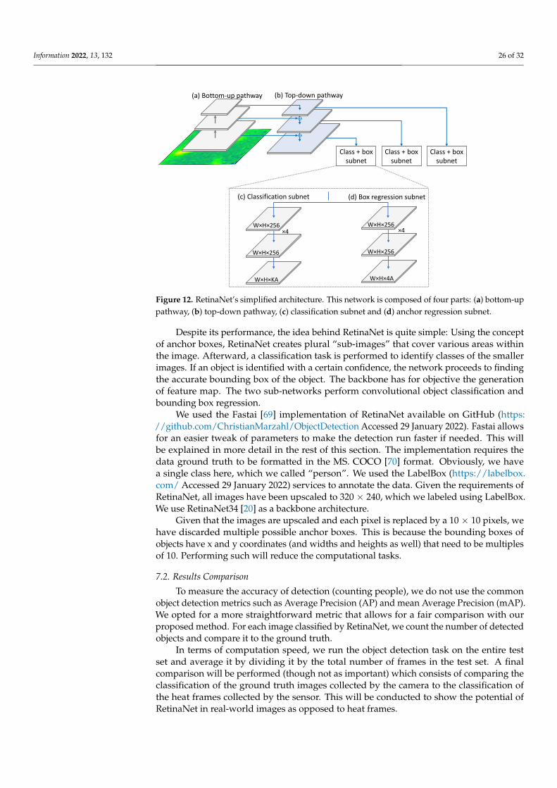
Information 2022, 13, 132 26 of 32
Class + box subnet
(c) Classification subnet
(a) Bottom-up pathway
W×H×256
W×H×256
W×H×KA
×4 ×4W×H×256
W×H×256
W×H×4A
(b) Top-down pathway
(d) Box regression subnet
Class + box subnet
Class + box subnet
Figure 12. RetinaNet’s simplified architecture. This network is composed of four parts: (a) bottom-uppathway, (b) top-down pathway, (c) classification subnet and (d) anchor regression subnet.
Despite its performance, the idea behind RetinaNet is quite simple: Using the conceptof anchor boxes, RetinaNet creates plural “sub-images” that cover various areas withinthe image. Afterward, a classification task is performed to identify classes of the smallerimages. If an object is identified with a certain confidence, the network proceeds to findingthe accurate bounding box of the object. The backbone has for objective the generationof feature map. The two sub-networks perform convolutional object classification andbounding box regression.
We used the Fastai [69] implementation of RetinaNet available on GitHub (https://github.com/ChristianMarzahl/ObjectDetection Accessed 29 January 2022). Fastai allowsfor an easier tweak of parameters to make the detection run faster if needed. This willbe explained in more detail in the rest of this section. The implementation requires thedata ground truth to be formatted in the MS. COCO [70] format. Obviously, we havea single class here, which we called “person”. We used the LabelBox (https://labelbox.com/ Accessed 29 January 2022) services to annotate the data. Given the requirements ofRetinaNet, all images have been upscaled to 320 × 240, which we labeled using LabelBox.We use RetinaNet34 [20] as a backbone architecture.
Given that the images are upscaled and each pixel is replaced by a 10 × 10 pixels, wehave discarded multiple possible anchor boxes. This is because the bounding boxes ofobjects have x and y coordinates (and widths and heights as well) that need to be multiplesof 10. Performing such will reduce the computational tasks.
7.2. Results Comparison
To measure the accuracy of detection (counting people), we do not use the commonobject detection metrics such as Average Precision (AP) and mean Average Precision (mAP).We opted for a more straightforward metric that allows for a fair comparison with ourproposed method. For each image classified by RetinaNet, we count the number of detectedobjects and compare it to the ground truth.
In terms of computation speed, we run the object detection task on the entire testset and average it by dividing it by the total number of frames in the test set. A finalcomparison will be performed (though not as important) which consists of comparing theclassification of the ground truth images collected by the camera to the classification ofthe heat frames collected by the sensor. This will be conducted to show the potential ofRetinaNet in real-world images as opposed to heat frames.
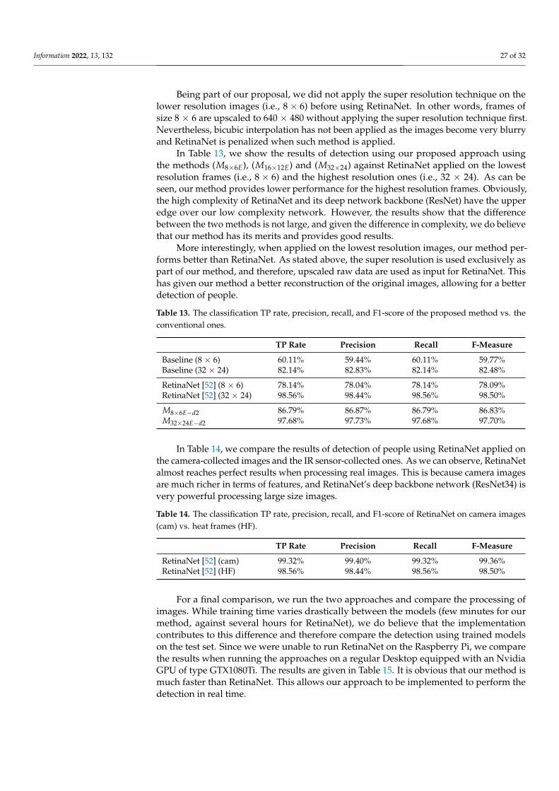
Information 2022, 13, 132 27 of 32
Being part of our proposal, we did not apply the super resolution technique on thelower resolution images (i.e., 8× 6) before using RetinaNet. In other words, frames ofsize 8 × 6 are upscaled to 640 × 480 without applying the super resolution technique first.Nevertheless, bicubic interpolation has not been applied as the images become very blurryand RetinaNet is penalized when such method is applied.
In Table 13, we show the results of detection using our proposed approach usingthe methods (M8×6E), (M16×12E) and (M32×24) against RetinaNet applied on the lowestresolution frames (i.e., 8× 6) and the highest resolution ones (i.e., 32 × 24). As can beseen, our method provides lower performance for the highest resolution frames. Obviously,the high complexity of RetinaNet and its deep network backbone (ResNet) have the upperedge over our low complexity network. However, the results show that the differencebetween the two methods is not large, and given the difference in complexity, we do believethat our method has its merits and provides good results.
More interestingly, when applied on the lowest resolution images, our method per-forms better than RetinaNet. As stated above, the super resolution is used exclusively aspart of our method, and therefore, upscaled raw data are used as input for RetinaNet. Thishas given our method a better reconstruction of the original images, allowing for a betterdetection of people.
Table 13. The classification TP rate, precision, recall, and F1-score of the proposed method vs. theconventional ones.
TP Rate Precision Recall F-Measure
Baseline (8 × 6) 60.11% 59.44% 60.11% 59.77%Baseline (32 × 24) 82.14% 82.83% 82.14% 82.48%
RetinaNet [52] (8 × 6) 78.14% 78.04% 78.14% 78.09%RetinaNet [52] (32 × 24) 98.56% 98.44% 98.56% 98.50%
M8×6E−d2 86.79% 86.87% 86.79% 86.83%M32×24E−d2 97.68% 97.73% 97.68% 97.70%
In Table 14, we compare the results of detection of people using RetinaNet applied onthe camera-collected images and the IR sensor-collected ones. As we can observe, RetinaNetalmost reaches perfect results when processing real images. This is because camera imagesare much richer in terms of features, and RetinaNet’s deep backbone network (ResNet34) isvery powerful processing large size images.
Table 14. The classification TP rate, precision, recall, and F1-score of RetinaNet on camera images(cam) vs. heat frames (HF).
TP Rate Precision Recall F-Measure
RetinaNet [52] (cam) 99.32% 99.40% 99.32% 99.36%RetinaNet [52] (HF) 98.56% 98.44% 98.56% 98.50%
For a final comparison, we run the two approaches and compare the processing ofimages. While training time varies drastically between the models (few minutes for ourmethod, against several hours for RetinaNet), we do believe that the implementationcontributes to this difference and therefore compare the detection using trained modelson the test set. Since we were unable to run RetinaNet on the Raspberry Pi, we comparethe results when running the approaches on a regular Desktop equipped with an NvidiaGPU of type GTX1080Ti. The results are given in Table 15. It is obvious that our method ismuch faster than RetinaNet. This allows our approach to be implemented to perform thedetection in real time.
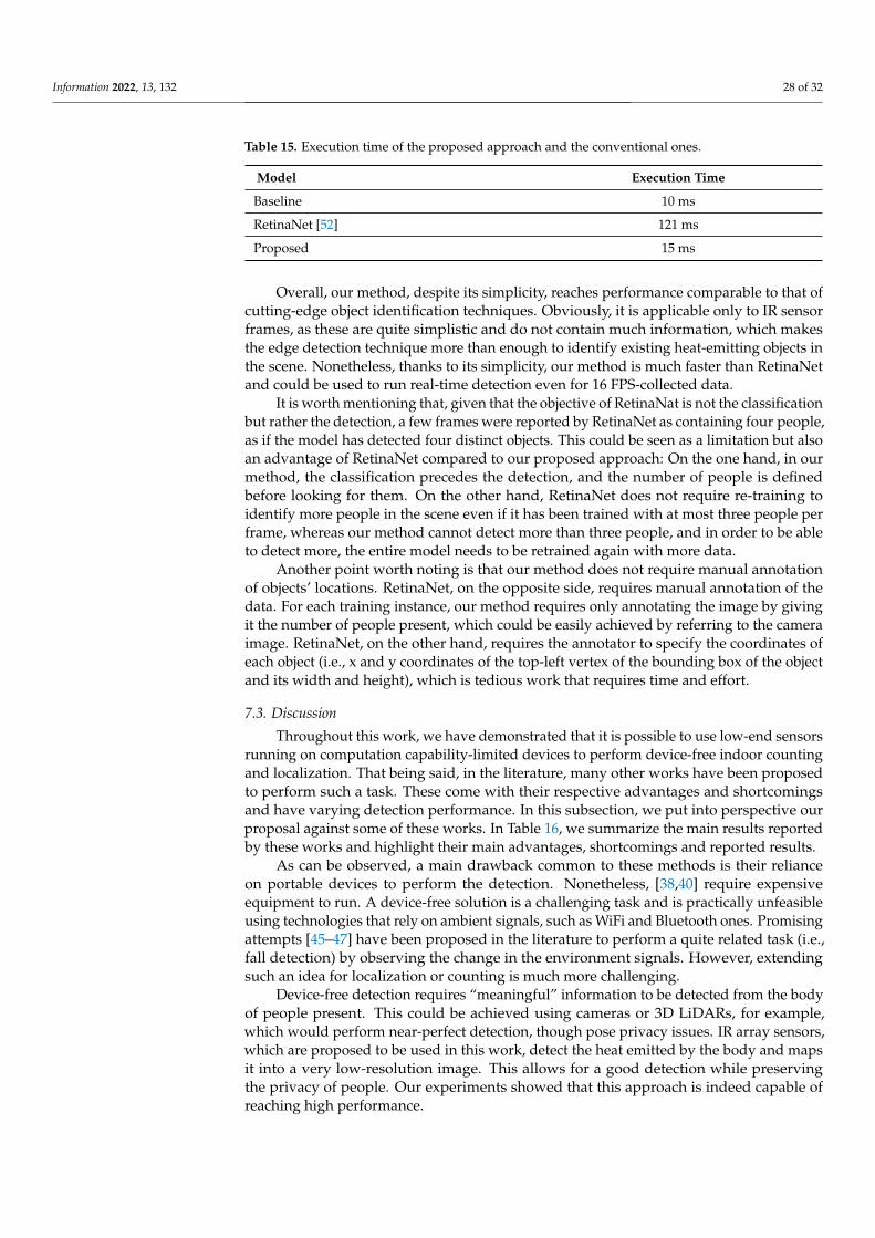
Information 2022, 13, 132 28 of 32
Table 15. Execution time of the proposed approach and the conventional ones.
Model Execution Time
Baseline 10 ms
RetinaNet [52] 121 ms
Proposed 15 ms
Overall, our method, despite its simplicity, reaches performance comparable to that ofcutting-edge object identification techniques. Obviously, it is applicable only to IR sensorframes, as these are quite simplistic and do not contain much information, which makesthe edge detection technique more than enough to identify existing heat-emitting objects inthe scene. Nonetheless, thanks to its simplicity, our method is much faster than RetinaNetand could be used to run real-time detection even for 16 FPS-collected data.
It is worth mentioning that, given that the objective of RetinaNat is not the classificationbut rather the detection, a few frames were reported by RetinaNet as containing four people,as if the model has detected four distinct objects. This could be seen as a limitation but alsoan advantage of RetinaNet compared to our proposed approach: On the one hand, in ourmethod, the classification precedes the detection, and the number of people is definedbefore looking for them. On the other hand, RetinaNet does not require re-training toidentify more people in the scene even if it has been trained with at most three people perframe, whereas our method cannot detect more than three people, and in order to be ableto detect more, the entire model needs to be retrained again with more data.
Another point worth noting is that our method does not require manual annotationof objects’ locations. RetinaNet, on the opposite side, requires manual annotation of thedata. For each training instance, our method requires only annotating the image by givingit the number of people present, which could be easily achieved by referring to the cameraimage. RetinaNet, on the other hand, requires the annotator to specify the coordinates ofeach object (i.e., x and y coordinates of the top-left vertex of the bounding box of the objectand its width and height), which is tedious work that requires time and effort.
7.3. Discussion
Throughout this work, we have demonstrated that it is possible to use low-end sensorsrunning on computation capability-limited devices to perform device-free indoor countingand localization. That being said, in the literature, many other works have been proposedto perform such a task. These come with their respective advantages and shortcomingsand have varying detection performance. In this subsection, we put into perspective ourproposal against some of these works. In Table 16, we summarize the main results reportedby these works and highlight their main advantages, shortcomings and reported results.
As can be observed, a main drawback common to these methods is their relianceon portable devices to perform the detection. Nonetheless, [38,40] require expensiveequipment to run. A device-free solution is a challenging task and is practically unfeasibleusing technologies that rely on ambient signals, such as WiFi and Bluetooth ones. Promisingattempts [45–47] have been proposed in the literature to perform a quite related task (i.e.,fall detection) by observing the change in the environment signals. However, extendingsuch an idea for localization or counting is much more challenging.
Device-free detection requires “meaningful” information to be detected from the bodyof people present. This could be achieved using cameras or 3D LiDARs, for example,which would perform near-perfect detection, though pose privacy issues. IR array sensors,which are proposed to be used in this work, detect the heat emitted by the body and mapsit into a very low-resolution image. This allows for a good detection while preservingthe privacy of people. Our experiments showed that this approach is indeed capable ofreaching high performance.
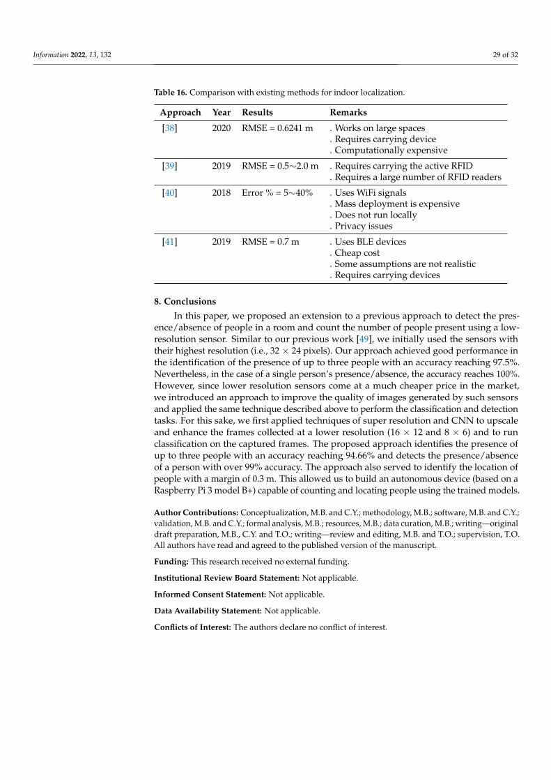
Information 2022, 13, 132 29 of 32
Table 16. Comparison with existing methods for indoor localization.
Approach Year Results Remarks
[38] 2020 RMSE = 0.6241 m . Works on large spaces. Requires carrying device. Computationally expensive
[39] 2019 RMSE = 0.5∼2.0 m . Requires carrying the active RFID. Requires a large number of RFID readers
[40] 2018 Error % = 5∼40% . Uses WiFi signals. Mass deployment is expensive. Does not run locally. Privacy issues
[41] 2019 RMSE = 0.7 m . Uses BLE devices. Cheap cost. Some assumptions are not realistic. Requires carrying devices
8. Conclusions
In this paper, we proposed an extension to a previous approach to detect the pres-ence/absence of people in a room and count the number of people present using a low-resolution sensor. Similar to our previous work [49], we initially used the sensors withtheir highest resolution (i.e., 32 × 24 pixels). Our approach achieved good performance inthe identification of the presence of up to three people with an accuracy reaching 97.5%.Nevertheless, in the case of a single person’s presence/absence, the accuracy reaches 100%.However, since lower resolution sensors come at a much cheaper price in the market,we introduced an approach to improve the quality of images generated by such sensorsand applied the same technique described above to perform the classification and detectiontasks. For this sake, we first applied techniques of super resolution and CNN to upscaleand enhance the frames collected at a lower resolution (16 × 12 and 8 × 6) and to runclassification on the captured frames. The proposed approach identifies the presence ofup to three people with an accuracy reaching 94.66% and detects the presence/absenceof a person with over 99% accuracy. The approach also served to identify the location ofpeople with a margin of 0.3 m. This allowed us to build an autonomous device (based on aRaspberry Pi 3 model B+) capable of counting and locating people using the trained models.
Author Contributions: Conceptualization, M.B. and C.Y.; methodology, M.B.; software, M.B. and C.Y.;validation, M.B. and C.Y.; formal analysis, M.B.; resources, M.B.; data curation, M.B.; writing—originaldraft preparation, M.B., C.Y. and T.O.; writing—review and editing, M.B. and T.O.; supervision, T.O.All authors have read and agreed to the published version of the manuscript.
Funding: This research received no external funding.
Institutional Review Board Statement: Not applicable.
Informed Consent Statement: Not applicable.
Data Availability Statement: Not applicable.
Conflicts of Interest: The authors declare no conflict of interest.

Information 2022, 13, 132 30 of 32
AbbreviationsThe following abbreviations are used in this manuscript:
CNN Convolutional Neural NetworkDL Deep LearningFPS Frames Per SecondFPRCNN Fast Super Resolution Convolutional Neural NetworkGPS Global Positioning SystemIR InfraredKPI Key Performance IndicatorNLMD Non-Local Means DenoisingPReLU Parametric Rectified Linear UnitSSD Single Shot MultiBox DetectorTP True Positives
References1. Ketu, S.; Mishra, P.K. Internet of Healthcare Things: A contemporary survey. J. Netw. Comput. Appl. 2021, 192, 103179. [CrossRef]2. Perera, M.S.; Halgamuge, M.N.; Samarakody, R.; Mohammad, A. Internet of things in healthcare: A survey of telemedicine
systems used for elderly people. In IoT in Healthcare and Ambient Assisted Living; Springer: Berlin/Heidelberg, Germany,2021; pp. 69–88.
3. Yang, S.; Wang, D.; Li, W.; Wang, C.; Yang, X.; Lo, K. Decoupling of Elderly Healthcare Demand and Expenditure in China.Healthcare 2021, 9, 1346. [CrossRef] [PubMed]
4. Hamiduzzaman, M.; De Bellis, A.; Abigail, W.; Kalaitzidis, E.; Harrington, A. The world is not mine–barriers to healthcare accessfor Bangladeshi rural elderly women. J. Cross-Cult. Gerontol. 2021, 36, 69–89. [CrossRef] [PubMed]
5. Yotsuyanagi, H.; Kurosaki, M.; Yatsuhashi, H.; Lee, I.H.; Ng, A.; Brooks-Rooney, C.; Nguyen, M.H. Characteristics and healthcarecosts in the aging hepatitis B population of Japan: A nationwide real-world analysis. Dig. Dis. 2022, 40, 68–77. [CrossRef]
6. Qian, K.; Zhang, Z.; Yamamoto, Y.; Schuller, B.W. Artificial intelligence internet of things for the elderly: From assisted living tohealth-care monitoring. IEEE Signal Process. Mag. 2021, 38, 78–88. [CrossRef]
7. World Health Organization. WHO Global Report on Falls Prevention in Older Age. Available online: https://www.who.int/ageing/publications/Falls_prevention7March.pdf (accessed on 29 January 2022).
8. Wang, J.; Zhai, S. Heart Rate Detection with Multi-Use Capacitive Touch Sensors. U.S. Patent 10,299,729, 28 May 2019.9. Rosales, L.; Skubic, M.; Heise, D.; Devaney, M.J.; Schaumburg, M. Heartbeat detection from a hydraulic bed sensor using a
clustering approach. In Proceedings of the 2012 Annual International Conference of the IEEE Engineering in Medicine andBiology Society, San Diego, CA, USA, 28 August–1 September 2012; pp. 2383–2387.
10. Luo, F.; Poslad, S.; Bodanese, E. Temporal convolutional networks for multiperson activity recognition using a 2-d lidar. IEEEInternet Things J. 2020, 7, 7432–7442. [CrossRef]
11. Ma, Z.; Bigham, J.; Poslad, S.; Wu, B.; Zhang, X.; Bodanese, E. Device-free, activity during daily life, recognition using a low-costlidar. In Proceedings of the 2018 IEEE Global Communications Conference (GLOBECOM), Abu Dhabi, UAE, 9–13 December2018; pp. 1–6.
12. Mashiyama, S.; Hong, J.; Ohtsuki, T. A fall detection system using low resolution infrared array sensor. In Proceedings of the2014 IEEE 25th Annual International Symposium on Personal, Indoor, and Mobile Radio Communication (PIMRC), WashingtonDC, USA, 2–5 September 2014; pp. 2109–2113.
13. Mao, G.; Fidan, B.; Anderson, B.D. Wireless sensor network localization techniques. Comput. Netw. 2007, 51, 2529–2553.[CrossRef]
14. Sen, S.; Radunovic, B.; Choudhury, R.R.; Minka, T. You Are Facing the Mona Lisa: Spot Localization Using PHY Layer Information.In Proceedings of the 10th International Conference on Mobile Systems, Applications, and Services, Lake District, UK, 25–29 June2012; Association for Computing Machinery: New York, NY, USA, 2012; pp. 183–196.
15. Lim, H.; Kung, L.C.; Hou, J.C.; Luo, H. Zero-Configuration, Robust Indoor Localization: Theory and Experimentation. InProceedings of the IEEE INFOCOM 2006. 25TH IEEE International Conference on Computer Communications, Barcelona, Spain,23–29 April 2006; pp. 1–12.
16. Nandakumar, R.; Chintalapudi, K.K.; Padmanabhan, V.N. Centaur: Locating devices in an office environment. In Proceedingsof the 18th Annual International Conference on Mobile Computing and Networking, Istanbul, Turkey, 22–26 August 2012;pp. 281–292.
17. Mobark, M.; Chuprat, S.; Mantoro, T. Improving the accuracy of complex activities recognition using accelerometer-embeddedmobile phone classifiers. In Proceedings of the 2017 Second International Conference on Informatics and Computing (ICIC),Jayapura, Indonesia, 1–3 November 2017; pp. 1–5.
18. Atallah, L.; Lo, B.; King, R.; Yang, G.Z. Sensor placement for activity detection using wearable accelerometers. In Proceedings ofthe 2010 International Conference on Body Sensor Networks, Biopolis, Singapore, 7–9 June 2010; pp. 24–29.

Information 2022, 13, 132 31 of 32
19. Zhang, D.; Xia, F.; Yang, Z.; Yao, L.; Zhao, W. Localization technologies for indoor human tracking. In Proceedings of the 2010 5thInternational Conference on Future Information Technology, Busan, Korea, 21–23 May 2010; pp. 1–6.
20. He, K.; Zhang, X.; Ren, S.; Sun, J. Deep residual learning for image recognition. In Proceedings of the IEEE Conference onComputer Vision and Pattern Recognition, Las Vegas, NV, USA, 27–30 June 2016; pp. 770–778.
21. Simonyan, K.; Zisserman, A. Very deep convolutional networks for large-scale image recognition. arXiv 2014, arXiv:1409.1556.22. Mathie, M.; Coster, A.; Lovell, N.; Celler, B. Detection of daily physical activities using a triaxial accelerometer. Med. Biol. Eng.
Comput. 2003, 41, 296–301. [CrossRef]23. Bao, L.; Intille, S.S. Activity recognition from user-annotated acceleration data. In International Conference on Pervasive Computing;
Springer: Berlin/Heidelberg, Germany, 2004; pp. 1–17.24. Lo, B.; Atallah, L.; Aziz, O.; El ElHew, M.; Darzi, A.; Yang, G.Z. Real-time pervasive monitoring for postoperative care. In
Proceedings of the 4th International Workshop on Wearable and Implantable Body Sensor Networks (BSN 2007), Aachen,Germany, 26–28 March 2007; Springer: Berlin/Heidelberg, Germany, 2007; pp. 122–127.
25. Cornacchia, M.; Ozcan, K.; Zheng, Y.; Velipasalar, S. A survey on activity detection and classification using wearable sensors.IEEE Sens. J. 2016, 17, 386–403. [CrossRef]
26. Liu, T.; Guo, X.; Wang, G. Elderly-falling detection using distributed direction-sensitive pyroelectric infrared sensor arrays.Multidimens. Syst. Signal Process. 2012, 23, 451–467. [CrossRef]
27. Want, R.; Hopper, A.; Falcao, V.; Gibbons, J. The active badge location system. ACM Trans. Inf. Syst. (TOIS) 1992, 10, 91–102.[CrossRef]
28. LLC, M. Firefly Motion Tracking System User’s Guide. Available online: http://www.gesturecentral.com/firefly/FireflyUserGuide.pdf (accessed on 29 January 2021).
29. Hou, X.; Arslan, T. Monte Carlo localization algorithm for indoor positioning using Bluetooth low energy devices. In Proceedingsof the 2017 International Conference on Localization and GNSS (ICL-GNSS), Nottingham, UK, 27–29 June 2017; pp. 1–6.
30. Radoi, I.E.; Cirimpei, D.; Radu, V. Localization systems repository: A platform for open-source localization systems anddatasets. In Proceedings of the 2019 International Conference on Indoor Positioning and Indoor Navigation (IPIN), Pisa, Italy,30 September–3 October 2019; pp. 1–8.
31. Dinh-Van, N.; Nashashibi, F.; Thanh-Huong, N.; Castelli, E. Indoor Intelligent Vehicle localization using WiFi received signalstrength indicator. In Proceedings of the 2017 IEEE MTT-S International Conference on Microwaves for Intelligent Mobility(ICMIM), Aichi, Japan, 19–21 March 2017; pp. 33–36.
32. Zhu, J.Y.; Xu, J.; Zheng, A.X.; He, J.; Wu, C.; Li, V.O. Wifi fingerprinting indoor localization system based on spatio-temporal (S-T)metrics. In Proceedings of the 2014 International Conference on Indoor Positioning and Indoor Navigation (IPIN), Busan, Korea,27–30 October 2014; pp. 611–614.
33. Kabir, A.L.; Saha, R.; Khan, M.A.; Sohul, M.M. Locating Mobile Station Using Joint TOA/AOA. In Proceedings of the 4thInternational Conference on Ubiquitous Information Technologies & Applications, Jeju, Korea, 15–17 December 2021; pp. 1–6.
34. Kul, G.; Özyer, T.; Tavli, B. IEEE 802.11 WLAN based real time indoor positioning: Literature survey and experimentalinvestigations. Procedia Comput. Sci. 2014, 34, 157–164. [CrossRef]
35. Yang, Z.; Wu, C.; Liu, Y. Locating in fingerprint space: Wireless indoor localization with little human intervention. In Proceedingsof the 18th Annual International Conference on Mobile Computing and Networking, Istanbul, Turkey, 22–26 August 2012;pp. 269–280.
36. Wang, X.; Gao, L.; Mao, S.; Pandey, S. CSI-based fingerprinting for indoor localization: A deep learning approach. IEEE Trans.Veh. Technol. 2016, 66, 763–776. [CrossRef]
37. Brida, P.; Duha, J.; Krasnovsky, M. On the accuracy of weighted proximity based localization in wireless sensor networks. InPersonal Wireless Communications; Springer: Berlin/Heidelberg, Germany, 2007; pp. 423–432.
38. Hassanhosseini, S.; Taban, M.R.; Abouei, J.; Mohammadi, A. Improving performance of indoor localization using compressivesensing and normal hedge algorithm. Turk. J. Electr. Eng. Comput. Sci. 2020, 28, 2143–2157. [CrossRef]
39. Wang, J.; Dhanapal, R.K.; Ramakrishnan, P.; Balasingam, B.; Souza, T.; Maev, R. Active RFID Based Indoor Localization. InProceedings of the 2019 22th International Conference on Information Fusion (FUSION), Ottawa, ON, Canada, 2–5 July 2019;pp. 1–7.
40. Salman, A.; El-Tawab, S.; Yorio, Z.; Hilal, A. Indoor Localization Using 802.11 WiFi and IoT Edge Nodes. In Proceedings of the2018 IEEE Global Conference on Internet of Things (GCIoT), Alexandria, Egypt, 5–7 December 2018; pp. 1–5.
41. Nguyen, Q.H.; Johnson, P.; Nguyen, T.T.; Randles, M. A novel architecture using iBeacons for localization and tracking of peoplewithin healthcare environment. In Proceedings of the 2019 Global IoT Summit (GIoTS), Aarhus, Denmark, 17–21 June 2019;pp. 1–6.
42. Anastasiou, A.; Pitoglou, S.; Androutsou, T.; Kostalas, E.; Matsopoulos, G.; Koutsouris, D. MODELHealth: An InnovativeSoftware Platform for Machine Learning in Healthcare Leveraging Indoor Localization Services. In Proceedings of the 2019 20thIEEE International Conference on Mobile Data Management (MDM), Hong Kong, China, 13 June 2019; pp. 443–446.
43. Pitoglou, S.; Anastasiou, A.; Androutsou, T.; Giannouli, D.; Kostalas, E.; Matsopoulos, G.; Koutsouris, D. MODELHealth:Facilitating Machine Learning on Big Health Data Networks. In Proceedings of the 2019 41st Annual International Conference ofthe IEEE Engineering in Medicine and Biology Society (EMBC), Berlin, Germany, 23–27 July 2019; pp. 2174–2177.

Information 2022, 13, 132 32 of 32
44. Pedrollo, G.; Konzen, A.A.; de Morais, W.O.; Pignaton de Freitas, E. Using Smart Virtual-Sensor Nodes to Improve the Robustnessof Indoor Localization Systems. Sensors 2021, 21, 3912. [CrossRef]
45. Nakamura, T.; Bouazizi, M.; Yamamoto, K.; Ohtsuki, T. Wi-Fi-CSI-based Fall Detection by Spectrogram Analysis with CNN. InProceedings of the GLOBECOM 2020—2020 IEEE Global Communications Conference, Taipei, Taiwan, 7–11 December 2020;pp. 1–6.
46. Keenan, R.M.; Tran, L.N. Fall Detection using Wi-Fi Signals and Threshold-Based Activity Segmentation. In Proceedings ofthe 2020 IEEE 31st Annual International Symposium on Personal, Indoor and Mobile Radio Communications, London, UK, 31August–3 September 2020; pp. 1–6.
47. Wang, Y.; Yang, S.; Li, F.; Wu, Y.; Wang, Y. FallViewer: A Fine-Grained Indoor Fall Detection System With Ubiquitous Wi-FiDevices. IEEE Int. Things J. 2021, 8, 12455–12466. [CrossRef]
48. Bouazizi, M.; Ye, C.; Ohtsuki, T. 2D LIDAR-Based Approach for Activity Identification and Fall Detection. IEEE Int. Things J.2021, 1. [CrossRef]
49. Bouazizi, M.; Ohtsuki, T. An Infrared Array Sensor-Based Method for Localizing and Counting People for Health Care andMonitoring. In Proceedings of the 2020 42nd Annual International Conference of the IEEE Engineering in Medicine & BiologySociety (EMBC), Montreal, Canada, 20–24 July 2020; pp. 4151–4155.
50. Krizhevsky, A.; Sutskever, I.; Hinton, G.E. Imagenet classification with deep convolutional neural networks. Adv. Neural Inf.Process. Syst. 2012, 25, 1097–1105. [CrossRef]
51. Zeiler, M.D.; Fergus, R. Visualizing and understanding convolutional networks. In European Conference on Computer Vision;Springer: Berlin/Heidelberg, Germany, 2014; pp. 818–833.
52. Lin, T.Y.; Goyal, P.; Girshick, R.; He, K.; Dollár, P. Focal loss for dense object detection. In Proceedings of the IEEE InternationalConference on Computer Vision, Venice, Italy, 22–29 October 2017; pp. 2980–2988.
53. Ren, S.; He, K.; Girshick, R.; Sun, J. Faster r-cnn: Towards real-time object detection with region proposal networks. Adv. NeuralInf. Process. Syst. 2015, 28, 91–99. [CrossRef]
54. Girshick, R.; Donahue, J.; Darrell, T.; Malik, J. Rich feature hierarchies for accurate object detection and semantic segmentation.In Proceedings of the IEEE Conference on Computer Vision and Pattern Recognition (CVPR), Columbus, OH, USA, 23–28 June2014; pp. 580–587.
55. Farhadi, A.; Redmon, J. Yolov3: An incremental improvement. In Computer Vision and Pattern Recognition; Springer:Berlin/Heidelberg, Germany, 2018; Volume 1804.
56. Redmon, J.; Divvala, S.; Girshick, R.; Farhadi, A. You Only Look Once: Unified, Real-Time Object Detection. In Proceedings ofthe 2016 IEEE Conference on Computer Vision and Pattern Recognition (CVPR), Las Vegas, NV, USA, 27–30 June 2016; IEEEComputer Society: Los Alamitos, CA, USA, 2016; pp. 779–788.
57. Liu, W.; Anguelov, D.; Erhan, D.; Szegedy, C.; Reed, S.; Fu, C.Y.; Berg, A.C. SSD: Single Shot MultiBox Detector. In ComputerVision—ECCV 2016; Leibe, B., Matas, J., Sebe, N., Welling, M., Eds.; Springer International Publishing: Cham, Switzerland, 2016;pp. 21–37.
58. Deng, J.; Dong, W.; Socher, R.; Li, L.J.; Li, K.; Fei-Fei, L. ImageNet: A large-scale hierarchical image database. In Proceedings ofthe 2009 IEEE Conference on Computer Vision and Pattern Recognition, Miami, FL, USA, 20–25 June 2009; pp. 248–255.
59. Muthukumar, K.; Bouazizi, M.; Ohtsuki, T. A Novel Hybrid Deep Learning Model for Activity Detection Using Wide-AngleLow-Resolution Infrared Array Sensor. IEEE Access 2021, 9, 82563–82576. [CrossRef]
60. Dong, C.; Loy, C.C.; Tang, X. Accelerating the super-resolution convolutional neural network. In European Conference on ComputerVision; Springer: Berlin/Heidelberg, Germany, 2016; pp. 391–407.
61. Buades, A.; Coll, B.; Morel, J.M. Non-Local Means Denoising. Image Process. Line 2011, 1, 208–212. [CrossRef]62. Jain, P.; Tyagi, V. A survey of edge-preserving image denoising methods. Inf. Syst. Front. 2016, 18, 159–170. [CrossRef]63. Diwakar, M.; Kumar, M. A review on CT image noise and its denoising. Biomed. Signal Process. Control 2018, 42, 73–88. [CrossRef]64. Fan, L.; Zhang, F.; Fan, H.; Zhang, C. Brief review of image denoising techniques. Vis. Comput. Ind. Biomed. Art 2019, 2, 1–12.
[CrossRef] [PubMed]65. Ponnuru, R.; Pookalangara, A.K.; Nidamarty, R.K.; Jain, R.K. CIFAR-10 Classification Using Intel® Optimization for TensorFlow*.
Available online: https://www.intel.com/content/www/us/en/developer/articles/technical/cifar-10-classification-using-optimization-for-tensorflow.html (accessed on 29 January 2022).
66. Canny, J. A computational approach to edge detection. IEEE Trans. Pattern Anal. Mach. Intell. 1986, 6, 679–698. [CrossRef]67. Sobel, I.; Feldman, G. An Isotropic 3 × 3 Image Gradient Operator. Presentation at Stanford AI Project. Available online:
https://www.researchgate.net/publication/285159837_A_33_isotropic_gradient_operator_for_image_processing (accessed on29 January 2022).
68. Keys, R. Cubic convolution interpolation for digital image processing. IEEE Trans. Acoust. Speech Signal Process. 1981,29, 1153–1160. [CrossRef]
69. Howard, J.; Gugger, S. Fastai: A layered API for deep learning. Information 2020, 11, 108. [CrossRef]70. Lin, T.Y.; Maire, M.; Belongie, S.; Hays, J.; Perona, P.; Ramanan, D.; Dollár, P.; Zitnick, C.L. Microsoft coco: Common objects in
context. In European Conference on Computer Vision; Springer: Berlin/Heidelberg, Germany, 2014; pp. 740–755.
Related Documents