IJREAT International Journal of Research in Engineering & Advanced Technology, Volume 3, Issue 4, Aug-Sept, 2015 ISSN: 2320 – 8791 (Impact Factor: 2.317) www.ijreat.org www.ijreat.org Published by: PIONEER RESEARCH & DEVELOPMENT GROUP (www.prdg.org) 10 Improvement Of Voltage Stability In WECS Using Of Two Mass Drive Train And PWM Converter Kajal Kushwah 1 , C.S. Sharma 2 1 M.E. (EMD), Department Of EE, Samrat Ashok Technological Institute (SATI), Vidisha, Madhya Pradesh, India 2 Associate Professer, Department Of EE, Samrat Ashok Technological Institute (SATI), Vidisha, Madhya Pradesh, India Abstract This paper deals with the wind power generation using asynchronous generator (PMSG) Feeding 3ø load at grid side and its problem associated with it. In WECS comprising PMSG, capacitor bank, diode rectifier, dc link, 3ø pulse width modulation inverter ,LC filter,3ø load feeding the grid .3ø ac-dc-ac converter ,wind turbine, PMSG , Two mass drive train is modelled in this paper using MATLAB/SIMULINK . voltage stability analysis has been done and also get the maximum power from wind ,variable speed wind energy conversion system should be established. The many variables, which influence harmonics and resonance in wind power plants, will described with respect to analysis methods, mitigations, avoidance. The entire system has been modelled and simulated using power system block set in MALAB to obtain the result. Keyword –WECS, Two Mass Drive Train, PMSG, Ac-Dc-Ac Converter 1. INTRODUCTION Wind energy is one of the fastest growing renewable energies in the world. The generation of wind power is clean and non-polluting; it does not produce any by products harmful to the environment. Nowadays, modelling and simulation is the basic tool for analysis, such as optimization, project, design and control. Wind energy conversion systems are very different in nature from Conventional generators and therefore dynamic studies must be addressed in order to integrated wind power into the power system. differential heating of earth and surface by the sun causes the movement of air masses on the surfaces of the earth i.e. the wind W.E.C.S. convert the K.E. of wind into electrically or other forms of energy. Wind power generation has experienced a tremendous growth in past decade and has been recognised as an environmentally friendly and economically completive means of electric power generate. In fig.1 shown a layout of such a WECS . The prime mover employed is generally a wind turbine and the variable speed generator is use a PMSG on account of its simplicity, ruggedness, low cost and ease of implementation .The erratic nature of wind speed , the generator acts as a source of variable voltage and frequency. Directly interfacing this PMSG to the grid give rise to the following problem like the voltage fluctuation, inability of the generator to extract and feed power to grid at speeds below the synchronous speed and the added tendency to act as a motor, generation of sub harmonics or harmonics associated with the pulsating torque characteristic of wind driving the PMSG. The configuration of the interface employed is generally a rectifier-inverter system connected through a DC link.

Welcome message from author
This document is posted to help you gain knowledge. Please leave a comment to let me know what you think about it! Share it to your friends and learn new things together.
Transcript

IJREAT International Journal of Research in Engineering & Advanced Technology, Volume 3, Issue 4, Aug-Sept, 2015 ISSN: 2320 – 8791 (Impact Factor: 2.317)
www.ijreat.org
www.ijreat.org Published by: PIONEER RESEARCH & DEVELOPMENT GROUP (www.prdg.org) 10
Improvement Of Voltage Stability In WECS Using Of
Two Mass Drive Train And PWM Converter
Kajal Kushwah1, C.S. Sharma2
1M.E. (EMD), Department Of EE, Samrat Ashok Technological Institute (SATI),
Vidisha, Madhya Pradesh, India
2Associate Professer, Department Of EE, Samrat Ashok Technological Institute (SATI),
Vidisha, Madhya Pradesh, India
Abstract
This paper deals with the wind power
generation using asynchronous generator
(PMSG) Feeding 3ø load at grid side and its
problem associated with it. In WECS
comprising PMSG, capacitor bank, diode
rectifier, dc link, 3ø pulse width modulation
inverter ,LC filter,3ø load feeding the grid .3ø
ac-dc-ac converter ,wind turbine, PMSG , Two
mass drive train is modelled in this paper using
MATLAB/SIMULINK . voltage stability
analysis has been done and also get the
maximum power from wind ,variable speed
wind energy conversion system should be
established. The many variables, which
influence harmonics and resonance in wind
power plants, will described with respect to
analysis methods, mitigations, avoidance. The
entire system has been modelled and simulated
using power system block set in MALAB to
obtain the result.
Keyword –WECS, Two Mass Drive Train, PMSG,
Ac-Dc-Ac Converter
1. INTRODUCTION
Wind energy is one of the fastest growing
renewable energies in the world. The generation of
wind power is clean and non-polluting; it does not
produce any by products harmful to the
environment. Nowadays, modelling and
simulation is the basic tool for analysis, such as
optimization, project, design and control. Wind
energy conversion systems are very different in
nature from Conventional generators and therefore
dynamic studies must be addressed in order to
integrated wind power into the power system.
differential heating of earth and surface by the sun
causes the movement of air masses on the surfaces
of the earth i.e. the wind W.E.C.S. convert the
K.E. of wind into electrically or other forms of
energy. Wind power generation has experienced a
tremendous growth in past decade and has been
recognised as an environmentally friendly and
economically completive means of electric power
generate. In fig.1 shown a layout of such a WECS
. The prime mover employed is generally a wind
turbine and the variable speed generator is use a
PMSG on account of its simplicity, ruggedness,
low cost and ease of implementation .The erratic
nature of wind speed , the generator acts as a
source of variable voltage and frequency. Directly
interfacing this PMSG to the grid give rise to the
following problem like the voltage fluctuation,
inability of the generator to extract and feed power
to grid at speeds below the synchronous speed and
the added tendency to act as a motor, generation of
sub harmonics or harmonics associated with the
pulsating torque characteristic of wind driving the
PMSG. The configuration of the interface
employed is generally a rectifier-inverter system
connected through a DC link.

IJREAT International Journal of Research in Engineering & Advanced Technology, Volume 3, Issue 4, Aug-Sept, 2015 ISSN: 2320 – 8791 (Impact Factor: 2.317)
www.ijreat.org
www.ijreat.org Published by: PIONEER RESEARCH & DEVELOPMENT GROUP (www.prdg.org) 11
Fig.1 generalized block diagram of wind energy
conversion system
WECS produce electricity by using the power of
wind to drive an electrical generator. The
conversion of the kinetic energy of the incoming
air stream into the electrical energy takes place in
two steps: the extraction device, i.e., the wind
turbine rotor captures the wind power movement
by means of aerodynamically designed blades, and
converts it into rotating mechanical energy, which
drives the generator rotor. The electrical generator
then converts this rotating mechanical power into
electrical power. A gear box may be used to match
the rotational speed of the wind turbine rotor
with one that is appropriate for the generator.
The electrical power is then transferred to the grid
through a transformer. The connection of the wind
turbine to the grid is possible at different levels of
voltage, with a common level being 450-500 V.
Power electronics converters can also be used for
enhanced power extraction and variable speed
operation of the wind turbine.
2. PROPOSEDSYSTEM CONFIGURATION
Figure 4-1 illustrates the topology of a typical
power converter of ( a s y n c h r o n o u s
g e n e r a t o r ) PMSG for grid connection
with a 3-phase diode bridge voltage source
converter (VSC). At the generator side, the 3-Ph
diode rectifier circuit consists of six diodes, a dc
link capacitor and at the grid side, the full bridge
inverter is possessed of 6 (MO SFE T) IGBTs.
For this type of converter, the current from the
wind turbine generator can only flow toward to
the grid, i.e. one way power flows from the
generator to the grid. AC power from the
p e r ma n e n t m a g n e t s yn c h r o n o u s
generator is converted into DC power through
the rectifier diode bridge, and then inverted to AC
for grid connection by means of the full IGBT
inverter bridge.
Fig.2.1 layout of PMSG based on WECS
This configuration decouples the wind turbine
generator from the grid by the diode bridge. The
VSC controller stabilises the voltage Vdc of the
DC link using the capacitor between the rectifier
diode-based bridge and the full IGBT inverter
bridge. Because most wind turbines work at start
up with a large drag especially for a large scale
wind turbine, the wind turbine generator requires
high torque to drive it. The popular solution for
this problem is either to design a wind turbine
with low start up wind speed or to provide an
additional driver component.
2.1 Wind Turbine Model
Fig.2.2 Diagram of wind turbine
The wind turbine model consisting of
aerodynamic, drive train .electrical generator
The wind turbine extracts a portion of wind power
(Pwind) from the swept area of the rotor disc and
converts it into mechanical power (Pm) as
determined below
Pm � 1 � 2Cpα, β�ρA (2.1)
PM
SG
rect
ifier
Prime
mover
inv
erte
r
gr
id
wind Rotor
aerody
namic
Drive
train
Gener
ator

IJREAT International Journal of Research in Engineering & Advanced Technology, Volume 3, Issue 4, Aug-Sept, 2015 ISSN: 2320 – 8791 (Impact Factor: 2.317)
www.ijreat.org
www.ijreat.org Published by: PIONEER RESEARCH & DEVELOPMENT GROUP (www.prdg.org) 12
Tw � Pwind/ωm (2.2)
Tw � �1/2Cpα, β�ρAv3�/ωm (2.3)
Where
Pm= mechanical power extracted from turbine
Tw=mechanical torque extracted from turbine rotor
A=rotor area or covered area=� � ���
v= velocity of the wind [m/s]
ρ=air density [kg/m3]
CP= performance coefficient
α =tip speed ratio
rotor blade pitch angle[rad.]
Rotor Torque Tw � �1/2πCpα, β�ρR2v3�/ωm
1 � � � � !"#.#%&' (
#.#)* "&) (2.4)
is the free wind speed (m/s). The power
coefficient (CP €0. 0.593) can be maximized for
a given wind speed by optimally adjusting the
values of tip speed ratio and the blade pitch
angle using data supplied by the manufacturer.
In this thesis, through the optimal choice of CP
for a given wind speed, Pm and ω m (rotor
mechanical speed) are assumed to be known and
are used as inputs to the synchronous generator.
Introduction to variable-speed wind turbine with
PMSG
Fig.2.3Cp-α characteristics curve
2.2 MODELLING OF THE PMSG
The generator can be magnetised electrically or
by permanent magnets. Two types of
synchronous generators have often been used in
the wind turbine industry: (1) the wound rotor
synchronous generator (WRSG) and (2) the
permanent magnet synchronous generator (PMSG.
The synchronous generator with a suitable number
of poles can be used for direct-drive applications
without any gearbox. PMSGs do not require
external excitation current, meaning less losses,
improved efficiency and more compact size.
This is the topology studied in this paper.
Parameters of electrical generators are often
specified in terms of per unit. Calculations
are simplified because quantities expressed as
per unit are the same regardless of the voltage
level. Similar types of apparatus will have
impedances, voltage drops and losses that are the
same when expressed as a per-unit fraction of the
equipment rating, even if the unit size varies
widely. Although the use of p.u. values may at
first sight seem a rather indirect method of
expression there are several reasons for using a
per-unit system.
• the use of the constant √3 is rduced in three-
phase calculations.
• per unit quantities are the same on either side of a generator, independent of voltage level.
• by normalizing quantities to a common base, both hand and automation calculations are simplified.
PARAMETER Value Unit
Nominal power 8.5e3 W
Wind speed 12 m/s
Base rotational speed 1 -
No. of poles 6 -
Frequency 50 Hz
Voltage constant 500 V
Moment of inertia 0.002 Kg.m2
TABLE3.1 PMSG WIND TIRBINE PARAMETER
IJREAT International Journal of Research in Engineering & Advanced Technology, Volume 3, Issue 4, Aug-Sept, 2015 ISSN: 2320 – 8791 (Impact Factor: 2.317)
www.ijreat.org
www.ijreat.org Published by: PIONEER RESEARCH & DEVELOPMENT GROUP (www.prdg.org) 13
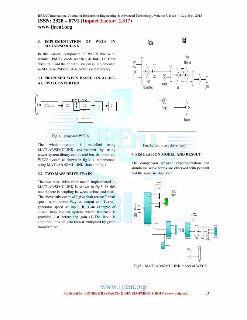
3. IMPLEMENTATION OF WECS IN
MATAB/SIMULINK
In this various component of WECS like wind
turbine, PMSG, diode rectifier, dc link , LC filter
drive train and their control system is implemented
in MATLAB/SIMULINK power system library.
3.1 PROPOSED WECS BASED ON AC-DC-
AC PWM CONVERTER
DC LINK
α>90°
Fig.3.1 proposed WECS
The whole system is modelled using
MATLAB/SIMULINK environment by using
power system library and its tool box the proposed
WECS system as shown in fig.3 is implemented
using MATLAB /SIMULINK shown in fig.4.
3.2 TWO MASS DRIVE TRAIN
The two mass drive train model implemented in
MATLAB/SIMULINK is shown in fig.5. In this
model there is coupling between turbine and shaft.
The above subsystem will give shaft torque T-shaft
(pu) , wind power Wwt as output and Twt(pu),
generator speed as input. It is an example of
closed loop control system where feedback is
provided just before the gain (1).The input is
amplified through gain then it multiplied by given
transfer func.
Fig.3.2 two mass drive train
4. SIMULATION MODEL AND RESULT
The comparison between experimentation and
simulation wave forms are observed with per unit
and the same are displayed.
Fig5.1 MATLAB/SIMULINK model of WECS
Lc
Fil
ter
Look- up table
PRIME
MOVER,.PMSG
Diode
Rectifir
er
Pwm
Inverte
r
Gri
d
IJREAT International Journal of Research in Engineering & Advanced Technology, Volume 3, Issue 4, Aug-Sept, 2015 ISSN: 2320 – 8791 (Impact Factor: 2.317)
www.ijreat.org
www.ijreat.org Published by: PIONEER RESEARCH & DEVELOPMENT GROUP (www.prdg.org) 14
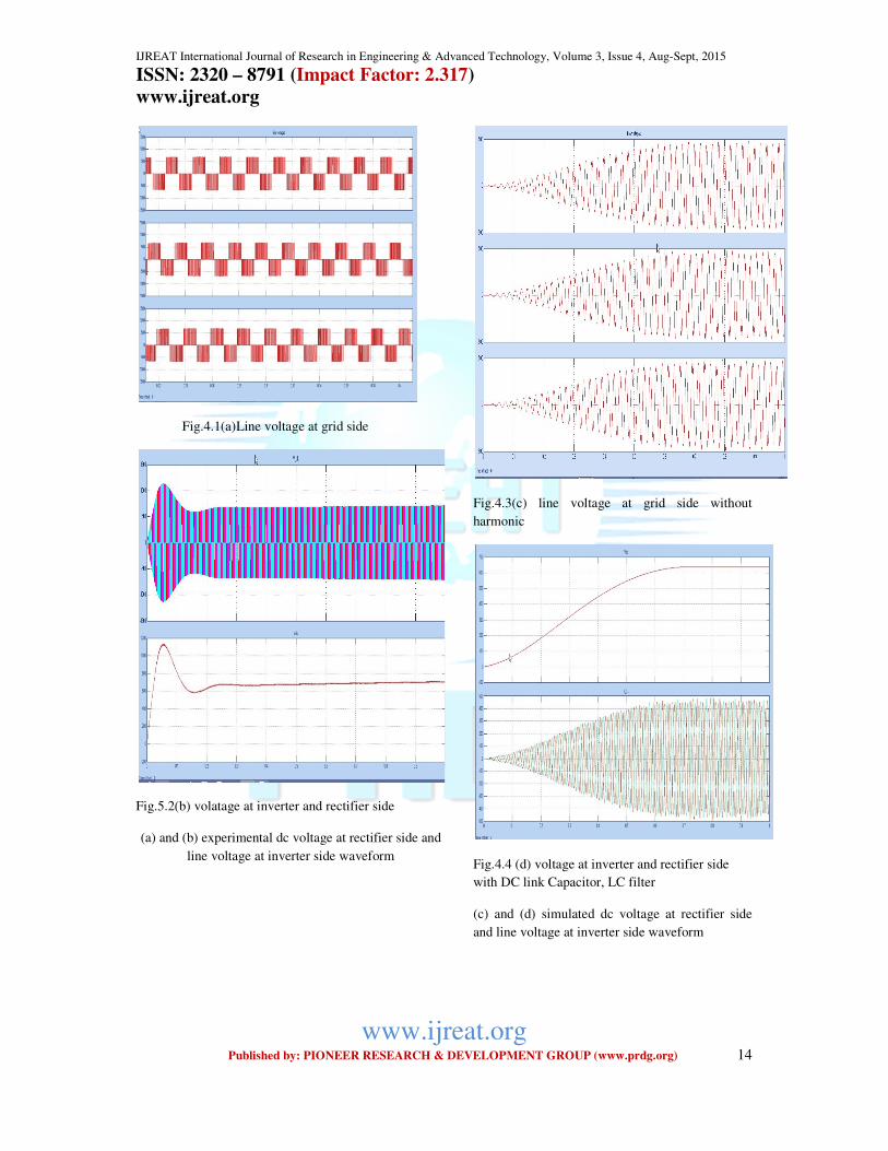
Fig.4.1(a)Line voltage at grid side
Fig.5.2(b) volatage at inverter and rectifier side
(a) and (b) experimental dc voltage at rectifier side and
line voltage at inverter side waveform
Fig.4.3(c) line voltage at grid side without
harmonic
Fig.4.4 (d) voltage at inverter and rectifier side
with DC link Capacitor, LC filter
(c) and (d) simulated dc voltage at rectifier side
and line voltage at inverter side waveform

IJREAT International Journal of Research in Engineering & Advanced Technology, Volume 3, Issue 4, Aug-Sept, 2015 ISSN: 2320 – 8791 (Impact Factor: 2.317)
www.ijreat.org
www.ijreat.org Published by: PIONEER RESEARCH & DEVELOPMENT GROUP (www.prdg.org) 15
Fig .4.5 FFT analysis
5. CONCLUSION
In this paper, a variable speed wind energy
conversion system (WECS) has been developed
using MATLAB/SIMULINK. Mathematical
model of various components of the WECS like
wind turbine, two mass drive train, PMSG
generator, and AC-DC-AC converter along with
their controls has been discussed and developed.
The energy extracted from wind is transferred
from the generator to the dc-link by the generator-
side rectifier and then to the utility by the grid side
inverter. The capacitor bank is effectively avoided
input displacement factor is zero and draws no
reactive power. The dc-link capacitor provides
decoupling between the generator-side and grid-
side converter, a thereby offers separate control
flexibilities for the power converters .The
developed model and its control was simulated in
MATLAB/SIMULINK and tested/validated for
different conditions i.e. constant and variable wind
speed, different faults like three phase to ground
etc.
References
1. N.Rakeh, A.Nitya, and Gautham Ram , “Modelling and simulation of the wind energy electric conversion system to extract the maximum power from the
wind using matlab”International conference onMagnetics,Machine & Drive (AICERA-2014 iCMMD)978-4799-5202-1/14$31.00©2014 IEEE
2. M.Bradt, B. Badrazadeh,E. Camm, D.Mueller,J.Schoene,T.Siebert, T.Smith,M.Starke,R.Walling, “Harmonics and Rasonance Issues In Wind Power Plants” IEEE PES wind plant collector system design working group.
3. R. M. Hilloowala, A. M. Sharaf, and M.
Lodge, “ energy conversion schemes and electric power supply quality,” European Wind Energy Conference, Madrid, 1990.
4. N. Mohan, and A. Riaz, “Wind driven capacitor excited inductiongenerators for residential electric heating,” IEEE PES Winter Meeting
5. Hou-Tsan Lee, Li-Chen Fu, and Hsin-Sain Huang, “Sensorless speed tracking of induction motor with unknown torque based on maximum power transfer,” IEEE Transactions on Industrial Electronics, Vol.49, No:4, pp.911-924, 2002.
6. Hadi Saddat, power system analysis 3rd edition .
7. F. G. R. de Campos, WSP and A. A, Penteado Junior, WISP, “Wind Energy Generation Simulation with Asynchronous Generator connected toENERSUL Distribution System” 2004 IEEUPES Transmission & Distribution Conference & Exposition: Latin America.
8. Dr. P.S.Bimbhra “Power electronics books”
9. Gopal K. Dubey “fundamentals of
electrical drives 2nd edition”
10. MATLAB/SIMULINK/Sim Power System, online.http://mathworks.com
Related Documents


![52407115 Voltage Stability[1]](https://static.cupdf.com/doc/110x72/577d225a1a28ab4e1e97265d/52407115-voltage-stability1.jpg)

