Citation: Tariq, H.; Rashid, M.; Javed, A.; Riaz, M.A.; Sinki, M.; Zia, M.Y.I. Implementation of Omni-D Tele-Presence Robot Using Kalman Filter and Tricon Ultrasonic Sensors. Sensors 2022, 22, 3948. https://doi.org/10.3390/s22103948 Academic Editors: David Scaradozzi and Sašo Blažiˇ c Received: 8 April 2022 Accepted: 18 May 2022 Published: 23 May 2022 Publisher’s Note: MDPI stays neutral with regard to jurisdictional claims in published maps and institutional affil- iations. Copyright: © 2022 by the authors. Licensee MDPI, Basel, Switzerland. This article is an open access article distributed under the terms and conditions of the Creative Commons Attribution (CC BY) license (https:// creativecommons.org/licenses/by/ 4.0/). sensors Article Implementation of Omni-D Tele-Presence Robot Using Kalman Filter and Tricon Ultrasonic Sensors Hassan Tariq 1 , Muhammad Rashid 2 , Asfa Javed 1 , Muhammad Aaqib Riaz 1 , Mohammed Sinky 2 and Muhammad Yousuf Irfan Zia 3, * 1 Department of Electrical Engineering, School of Engineering, University of Management and Technology (UMT), Lahore 54770, Pakistan; [email protected] (H.T.); [email protected] (A.J.); [email protected] (M.A.R.) 2 Department of Computer Engineering, Umm Al-Qura University, Makkah 21955, Saudi Arabia; [email protected] (M.R.); [email protected] (M.S.) 3 Telecommunications Engineering School, University of Malaga, 29010 Malaga, Spain * Correspondence: [email protected] Abstract: The tele-presence robot is designed to set forth an economic solution to facilitate day- to-day normal activities in almost every field. There are several solutions to design tele-presence robots, e.g., Skype and team viewer, but it is pretty inappropriate to use Skype and extra hardware. Therefore, in this article, we have presented a robust implementation of the tele-presence robot. Our proposed omnidirectional tele-presence robot consists of (i) Tricon ultrasonic sensors, (ii) Kalman filter implementation and control, and (iii) integration of our developed WebRTC-based application with the omnidirectional tele-presence robot for video transmission. We present a new algorithm to encounter the sensor noise with the least number of sensors for the estimation of Kalman filter. We have simulated the complete model of robot in Simulink and Matlab for the tough paths and critical hurdles. The robot successfully prevents the collision and reaches the destination. The mean errors for the estimation of position and velocity are 5.77% and 2.04%. To achieve efficient and reliable video transmission, the quality factors such as resolution, encoding, average delay and throughput are resolved using the WebRTC along with the integration of the communication protocols. To protect the data transmission, we have implemented the SSL protocol and installed it on the server. We tested three different cases of video resolutions (i.e., 320 × 280, 820 × 460 and 900 × 590) for the performance evaluation of the video transmission. For the highest resolution, our TPR takes 3.5 ms for the encoding, and the average delay is 2.70 ms with 900 × 590 pixels. Keywords: omnidirectional robot; tele-presence robot; Kalman filter; Tricon ultrasonic sensors 1. Introduction In this modern era, robots dominate the top horizon of different branches of embedded systems. For example, in medical-related applications, the increasing number of people results in increasing difficulties for the operators (or physicians) to monitor and serve the severe patients. Thus, a virtual presence is a good alternative to aid patients in scenarios where face-to-face communication is not possible [1,2]. Video chats are very popular, but tele-presence gives the immense feeling of virtual presence from a distance, which enables the best power for decisions and resolves the complexity of the monitoring and daily routine work. With the increased population, the percentage of the population of elderly people is also increasing in the world. The World Health Organization (WHO) raises this concern that the population of people 60 years and above age is predicted to rise between 2000 and 2050. This means it will grow from 605 million to 2 billion and it will double from 11 to 22% [3]. The increase in total population and aged population has created economic, cultural and social challenges in the families, individuals, societies and the community globally. Sensors 2022, 22, 3948. https://doi.org/10.3390/s22103948 https://www.mdpi.com/journal/sensors

Welcome message from author
This document is posted to help you gain knowledge. Please leave a comment to let me know what you think about it! Share it to your friends and learn new things together.
Transcript
Citation: Tariq, H.; Rashid, M.; Javed,
A.; Riaz, M.A.; Sinki, M.; Zia, M.Y.I.
Implementation of Omni-D
Tele-Presence Robot Using Kalman
Filter and Tricon Ultrasonic Sensors.
Sensors 2022, 22, 3948.
https://doi.org/10.3390/s22103948
Academic Editors: David Scaradozzi
and Sašo Blažic
Received: 8 April 2022
Accepted: 18 May 2022
Published: 23 May 2022
Publisher’s Note: MDPI stays neutral
with regard to jurisdictional claims in
published maps and institutional affil-
iations.
Copyright: © 2022 by the authors.
Licensee MDPI, Basel, Switzerland.
This article is an open access article
distributed under the terms and
conditions of the Creative Commons
Attribution (CC BY) license (https://
creativecommons.org/licenses/by/
4.0/).
sensors
Article
Implementation of Omni-D Tele-Presence Robot Using KalmanFilter and Tricon Ultrasonic Sensors
Hassan Tariq 1 , Muhammad Rashid 2 , Asfa Javed 1 , Muhammad Aaqib Riaz 1 , Mohammed Sinky 2
and Muhammad Yousuf Irfan Zia 3,*
1 Department of Electrical Engineering, School of Engineering, University of Management andTechnology (UMT), Lahore 54770, Pakistan; [email protected] (H.T.); [email protected] (A.J.);[email protected] (M.A.R.)
2 Department of Computer Engineering, Umm Al-Qura University, Makkah 21955, Saudi Arabia;[email protected] (M.R.); [email protected] (M.S.)
3 Telecommunications Engineering School, University of Malaga, 29010 Malaga, Spain* Correspondence: [email protected]
Abstract: The tele-presence robot is designed to set forth an economic solution to facilitate day-to-day normal activities in almost every field. There are several solutions to design tele-presencerobots, e.g., Skype and team viewer, but it is pretty inappropriate to use Skype and extra hardware.Therefore, in this article, we have presented a robust implementation of the tele-presence robot.Our proposed omnidirectional tele-presence robot consists of (i) Tricon ultrasonic sensors, (ii) Kalmanfilter implementation and control, and (iii) integration of our developed WebRTC-based applicationwith the omnidirectional tele-presence robot for video transmission. We present a new algorithmto encounter the sensor noise with the least number of sensors for the estimation of Kalman filter.We have simulated the complete model of robot in Simulink and Matlab for the tough paths andcritical hurdles. The robot successfully prevents the collision and reaches the destination. Themean errors for the estimation of position and velocity are 5.77% and 2.04%. To achieve efficientand reliable video transmission, the quality factors such as resolution, encoding, average delayand throughput are resolved using the WebRTC along with the integration of the communicationprotocols. To protect the data transmission, we have implemented the SSL protocol and installedit on the server. We tested three different cases of video resolutions (i.e., 320× 280, 820× 460 and900× 590) for the performance evaluation of the video transmission. For the highest resolution, ourTPR takes 3.5 ms for the encoding, and the average delay is 2.70 ms with 900 × 590 pixels.
Keywords: omnidirectional robot; tele-presence robot; Kalman filter; Tricon ultrasonic sensors
1. Introduction
In this modern era, robots dominate the top horizon of different branches of embeddedsystems. For example, in medical-related applications, the increasing number of peopleresults in increasing difficulties for the operators (or physicians) to monitor and serve thesevere patients. Thus, a virtual presence is a good alternative to aid patients in scenarioswhere face-to-face communication is not possible [1,2]. Video chats are very popular,but tele-presence gives the immense feeling of virtual presence from a distance, whichenables the best power for decisions and resolves the complexity of the monitoring anddaily routine work. With the increased population, the percentage of the population ofelderly people is also increasing in the world. The World Health Organization (WHO)raises this concern that the population of people 60 years and above age is predicted torise between 2000 and 2050. This means it will grow from 605 million to 2 billion and itwill double from 11 to 22% [3]. The increase in total population and aged population hascreated economic, cultural and social challenges in the families, individuals, societies andthe community globally.
Sensors 2022, 22, 3948. https://doi.org/10.3390/s22103948 https://www.mdpi.com/journal/sensors
Sensors 2022, 22, 3948 2 of 19
To address the aforementioned issues, an attractive alternative is the use of a tele-presence robot. A tele-presence robot (TPR) is a holonomic remote-controlled, wheeleddevice that has wireless internet connectivity. Typically, the robot uses a tablet to providevideo and audio capabilities. Moreover, the TPR contains the cameras, which allow theuser(s) to enter a live conference, video chat, monitoring, etc. [4]. The TPR enables the people(or) groups of people to communicate with each other through the internet anywhere inthe world. One of the solutions is to exploit the Internet protocols and the Skype cross-platforms for the design and development of tele-presence [5,6]. The solutions based onSkype have achieved some degrees of success in utilizing the software and hardwaredevelopment. Nevertheless, the processing and handling time is high, as it exploits third-party plugins. In [7], a wheelchair-using tele-presence robot system is introduced foroutdoor applications to support handicaps. Their system uses cellular data and dependson the Skype and Mac book mini. Their findings demonstrate that the use of combinedhardware and software is not feasible for some applications. Additionally, the interfacingand synchronization of hardware and software result in further issues. Another method fortele-presence wheelchairs equipped with multiple cameras is proposed in [8] with an aid toprovide effective assistance for the elderly and people with disabilities.
Another method is to use open-source APIs and integrate them into the system. We-bRTC is the recent example that provides a free hand to modify, integrate and use in theirway. This influences the user’s experience and the overall quality of the video calls. Theuse of WebRTC also offers numerous benefits for the service providers, i.e., ease of use, costreduction, security, fast time to market, and simplified device integration. Moreover, withWebRTC, users can enjoy real-time communication services which are outside the tradi-tional fixed and mobile device context [9]. Along with the video transmission, the control ofthe mobile robot is also an important step during the design and implementation of a tele-presence robot. Motivated by [7], the authors propose a video communication frameworkto improve the performance of a tele-presence wheelchair system further. Their mechanicalframework is utilizing a non-holonomic robotic model which requires steering while turn-ing the robot’s direction. Another method is to exploit the holonomic model, which canmove from one point to another and can turn on a single point [10].
1.1. Motivation
The complete design consists of video transmission and control of the mobile robot.The implementation of webRTC is evolving with time and it still needs a performanceimprovement. Keeping this view, performance parameters, i.e., the average delay andthroughput, require careful consideration during the implementation of a tele-presencerobot. For different applications, the features discovered by researchers are increasing dayby day. Some identical parameters include efficient and robust control with the highestpossible degree of stability. Additionally, the control methodology, video quality, serversecurity and efficiency are important parameters to characterize the TPR [11]. On the otherhand, the collision-proof feature helps to secure from the damage. To improve the control,a state prediction and estimation mechanism should be integrated along with a collision-proof feature. Many applications require TPR such as monitoring in the medical field,conference meetings, invigilation, etc. Therefore, the medical-related applications are onthe top to serve the betterment of humanity [12–15]. The TPR is also employed in theshopping malls for entertainment [16]. According to [17], the TPR is (also) well-suitedfor numerous applications in the COVID-19 pandemic where relatives and doctors canvirtually meet the patients. Therefore, based on the scenario presented above, there is areal need to design and implement the tele-presence robot for medical-related applications.This is precisely the motivation for our work. In this paper, we propose a complete designof the robot that offers robustness in the video transmission as well as control of the mobilerobot. The tele-presence robot consists of omnidirectional kinematics and exploits webRTCfor video transmission. We propose a Tricon ultrasonic sensor algorithm to integrate aKalman filter for the velocity and location estimation.
Sensors 2022, 22, 3948 3 of 19
1.2. Related Work and Challenges
We classify the existing tele-presence based robot systems according to their utilizedapplications. Some tele-presence robots for educational activities are presented in [18–20].Research practices describing the wheelchairs based on tele-presence robot systems areshown in [7,8]. Examples of some additional tele-presence robot systems are describedin [10,21–28]. More insight details to these research practices are given below.
Tele-presence robots for educational activities [18–20]: Some interesting tele-presencerobots are presented in [18,19] for teaching activities to facilitate the elderly instructors.This presents enough understanding to the students when they see the live activity on thescreen. Moreover, this gives the concept of distance learning to improve the literacy rate,but the problem is that it must be under omnidirectional control because it will be used ineducational institutes. An omnidirectional control determines the ability of the movementof TPR in any direction instantaneously from any starting position. In [20], a tele-presencerobot for tutoring is presented to facilitate the students in the educational institutes. Therobot contains a collision system to prevent damage to hardware. This includes a largescreen and remote control of the movement for the lectures.
Wheelchairs based on tele-presence robot systems [7,8]: In [7], a wheelchair-using atele-presence robot system is introduced for outdoor applications to support handicaps.Their system uses cellular data and depends on Skype and the mac book mini. Theirfindings demonstrate that the use of combined hardware and software is not feasiblefor some applications. Additionally, the interfacing and synchronization of hardwareand software result in further issues. Similar to [7], a new method for tele-presencewheelchairs equipped with multiple cameras is proposed in [8] with an aid to provideeffective assistance for the elderly and people with disabilities.
Some additional tele-presence robot systems [10,21–28]: In [21], a tele-presence robotis used as a medical doctor, which contains several beneficial features such as temperaturepulse rate, etc. Additionally, a TPR is used to serve the patients in sequence to one anotherbased on the instructions provided by the physician. An Arduino-based microcontrollerunit (we termed MCU) is employed to provide instructions to the robot. The MCU isslow for processing when it has to receive the packets from the internet, which reducesits efficiency and eventually increases the command execution and propagation time.In [22], an assisted driving concept is introduced that typically provides collision avoidance.Moreover, their design avoids unnecessary movements that would lead to a collision.A virtual platform of an underwater manipulator mounted on a submersible vehicle ispresented in [23]. They used a three-dimensional simulator “Webots” for teleoperationthrough a replica master arm.
A simple obstacle avoidance method is proposed in [24] for tele-presence robots toassist aged people living in remote areas. Their approach is appropriate for manuallyoperated robot systems. More precisely, when an opening is not found, the robot stopsand an operator is responsible for moving the robot by a remote operation to search foran opening. A low-cost telepresence robot with mechanical control of omni-wheels ispresented in [10]. This provides them access to a wide range of directions. Their solutionoffers two different modes where the robot operates in a normal or autonomous mode. Theauthors in [25] designed a robot to include new expressive features such as Light-EmittingDiodes (LED), a robotic arm and some basic control functions to support disabled persons.
The maldistribution problem of physicians is resolved in [26] by using tele-presencerobot systems. They noted that one limitation of the medical tele-presence robots systemis the lack of medical features. Based on this observation, they developed a tele-presencesystem that includes a tele-presence robot (named, Akibot) integrated with medical devicessuch as an otoscope, stethoscope, and ultrasound probe. In [27], a novel method ofstate estimation using delayed sensor measurements of a TPR for real-time navigation ispresented. An Augmented State Extended Kalman Filter (AS-EKF) is proposed to estimatethe position of the robot. They tested their proposed algorithm in a real environment.They show improvements of an average of more than 34% as compared to traditional EKF.
Sensors 2022, 22, 3948 4 of 19
Interesting work is described in [28] where a tele-presence robot is utilized to estimate thesafety of the drivers and pedestrians.
Although numerous designs have been proposed to tackle the transmission, moni-toring and control of TPR [7,8,10,18–28], these implementations have certain limitations.The user always controls TPR from remote locations that result in issues either for thetransmission or control of TPR. In most cases, the existing tele-presence robot systemsare proposed without considering the collision characteristics [7,10,19,21,22,24,26,28]. Theaverage transmission delay could cause a collision with an object. Therefore, a collisionprevention system should be considered during the design of the TPR. Robust controlis also needed in remote areas to control the TPR where it faces steering in congestedsites. Thus, the robust control of the omnidirectional implementation is an additionalconcern that affects the performance/efficiency of the robot. Therefore, a robust design andimplementation to cope with the aforementioned issues is an open research problem.
1.3. Novelty and Contributions
The originality of this paper is the robust control of the omnidirectional movement ofTPR and the integration of Web Real-Time Communication (WebRTC) with the DynamicDomain Name System (DDNS) server for the efficient transmission of videos. The contri-butions to this work are as follows:
• We have presented a tele-presence robot to offer the efficient video transmissions byusing a WebRTC. The corresponding details are given in Section 3.3.
• Designing of an online portal using a hypertext markup language (HTML) that can beaccessed from anywhere in the world. Then, the integration of our designed portalwith the proposed tele-presence robot is an additional contribution.
• Performance evaluation of the WebRTC for three different video resolutions, i.e.,320× 280, 820× 460, and 900× 590 pixels.
• We have proposed a Tricon sensor algorithm for the Kalman Filter to improve therobustness of the collision avoidance.
• Simulation of the TPR with Kalman filter for the crucial paths/hurdles to estimate theparameters, i.e., velocity and position.
• Hardware implementation, testing of the TPR in real environment and performancecomparison with simulated results.
The remainder of this paper is organized as follows: The mathematical structure ofomnidirectional, DC motor and Kalman filter is presented in Section 2. Our proposeddesign of an omnidirectional tele-presence robot is described in Section 3. The simulationresults are given in Section 4. The hardware implementations and testing of our proposedtele-presence robot is presented in Section 5. Finally, Section 6 concludes the paper.
2. Preliminaries
The fundamental mathematical models associated with TPR are as follows: (i) modelingof omnidirectional wheels and (ii) dynamical modeling of DC motor. The corresponding detailsfor these two models are further described in Section 2.1 and Section 2.2, respectively.
2.1. Modeling of Omnidirectional Wheels
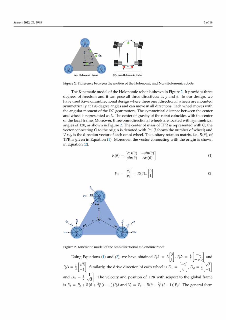
The kinematic model of TPR includes two types of robots: (i) Holonomic and (ii)Non-Holonomic. The prior can move in any direction at any angle while the formercan not move instantly in any direction. Moreover, the Non-Holonomic robots requiresome turning radius (steering angle) and time to turn in a specific direction. This typeof robot needs parallel motion to turn in any direction. For example, car tires will moveparallel to turn right or left. Therefore, Figure 1 shows the clear difference between theHolonomic and Non-Holonimic robots. It is important to note that we have used threewheels in the omnidirectional Holonomic system to obtain the rotation of the robot withzero turning radius.
Sensors 2022, 22, 3948 5 of 19
x X
Y
Ф1
Ф2
x X
Y
Ф1
Ф2
V
V
V
x X
Y
Ф1
Ф2
V
V
V
V
BWRBWL
MRFMLF
MRBMLB
V
V
(a). Holonomic Robot (b). Non-Holonomic Robot
Ф3
Figure 1. Difference between the motion of the Holonomic and Non-Holonomic robots.
The Kinematic model of the Holonomic robot is shown in Figure 2. It provides threedegrees of freedom and it can pose all three directives: x, y and θ. In our design, wehave used Kiwi omnidirectional design where three omnidirectional wheels are mountedsymmetrically at 120-degree angles and can move in all directions. Each wheel moves withthe angular moment of the DC gear motors. The symmetrical distance between the centerand wheel is represented as L. The center of gravity of the robot coincides with the centerof the local frame. Moreover, three omnidirectional wheels are located with symmetricalangles of 120, as shown in Figure 2. The center of mass of TPR is represented with O, thevector connecting O to the origin is denoted with Poi (i shows the number of wheel) andVix, y is the direction vector of each omni wheel. The unitary rotation matrix, i.e., R(θ), ofTPR is given in Equation (1). Moreover, the vector connecting with the origin is shownin Equation (2).
R(θ) =[
cos(θ) −sin(θ)sin(θ) cos(θ)
](1)
Poi =[
xiyi
]= R(θ)L
[01
](2)
x
X
Y
ϴ
V1
V2y
V2x V3x
V3y
Ф1
Ф2 Ф3
Po1
D1
Figure 2. Kinematic model of the omnidirectional Holonomic robot.
Using Equations (1) and (2), we have obtained Po1 = L[
01
], Po2 = L
2
[−1−√
3
]and
Po3 = L2
[√3−1
]. Similarly, the drive direction of each wheel is D1 =
[−10
], D2 = 1
2
[√3−1
]and D3 = 1
2
[1√3
]. The velocity and position of TPR with respect to the global frame
is Ri = Po + R(θ + 2π3 (i − 1))Poi and Vi = Po + R(θ + 2π
3 (i − 1))Poi. The general form
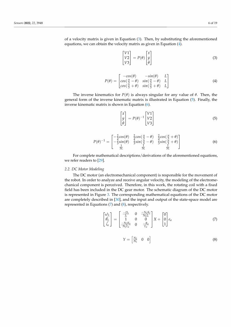
Sensors 2022, 22, 3948 6 of 19
of a velocity matrix is given in Equation (3). Then, by substituting the aforementionedequations, we can obtain the velocity matrix as given in Equation (4).V1
V2V3
= P(θ)
xyθ
(3)
P(θ) =
−cos(θ) −sin(θ) Lcos(π
3 − θ) sin(π3 − θ) L
cos(π3 + θ) sin(π
3 + θ) L
(4)
The inverse kinematics for P(θ) is always singular for any value of θ. Then, thegeneral form of the inverse kinematic matrix is illustrated in Equation (5). Finally, theinverse kinematic matrix is shown in Equation (6).x
yθ
= P(θ)−1
V1V2V3
(5)
P(θ)−1 =
− 23 cos(θ) 2
3 cos(π3 − θ) 2
3 cos(π3 + θ)
− 23 sin(θ) 2
3 sin(π3 − θ) 2
3 sin(π3 + θ)
13L
13L
13L
(6)
For complete mathematical descriptions/derivations of the aforementioned equations,we refer readers to [29].
2.2. DC Motor Modeling
The DC motor (an electromechanical component) is responsible for the movement ofthe robot. In order to analyze and receive angular velocity, the modeling of the electrome-chanical component is perceived. Therefore, in this work, the rotating coil with a fixedfield has been included in the DC gear motor. The schematic diagram of the DC motoris represented in Figure 3. The corresponding mathematical equations of the DC motorare completely described in [30], and the input and output of the state-space model arerepresented in Equations (7) and (8), respectively.ωL
θLia
=
−De
Je0 −N1Kt
N2 Je1 0 0
−N2KbN1La
0 −RaLa
X +
001
ea (7)
Y =[
N2N1
0 0]
(8)
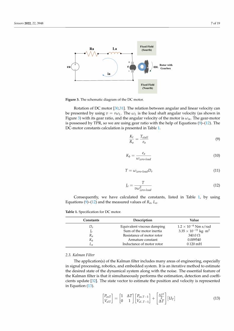
Sensors 2022, 22, 3948 7 of 19
ea
ia
Ra La
+
-
e J Rotor with
Gearbox ωL
Fixed Field
(Sourth)
Fixed Field
(Nourth)
Figure 3. The schematic diagram of the DC motor.
Rotation of DC motor [30,31]. The relation between angular and linear velocity canbe presented by using v = rωL. The ωL is the load shaft angular velocity (as shown inFigure 3) with its gear ratio, and the angular velocity of the motor is ωm. The gear-motoris possessed by TPR, so we are using gear ratio with the help of Equations (9)–(12). TheDC-motor constants calculation is presented in Table 1.
Kt
Ra=
Tstallea
(9)
Kb =ea
ωzero-load(10)
T = ωzero-loadDe (11)
Je =T
vω2zero-load
(12)
Consequently, we have calculated the constants, listed in Table 1, by usingEquations (9)–(12) and the measured values of Ra, La.
Table 1. Specification for DC motor.
Constants Description Value
De Equivalent viscous damping 1.2 × 10⁻⁶ Nm s/radJe Sum of the motor inertia 3.35 × 10⁻¹¹ kg·m2
Ra Resistance of motor rotor 340.0 ΩKb Armature constant 0.009540La Inductance of motor rotor 0.120 mH
2.3. Kalman Filter
The application(s) of the Kalman filter includes many areas of engineering, especiallyin signal processing, robotics, and embedded system. It is an iterative method to estimatethe desired state of the dynamical system along with the noise. The essential feature ofthe Kalman filter is that it simultaneously performs the estimation, detection and coeffi-cients update [32]. The state vector to estimate the position and velocity is representedin Equation (13). [
PosTVelT
]=
[1 ∆T0 1
][Pos.T−1Vel..T−1
]+
[∆T2
2∆T
][UT]
(13)
Sensors 2022, 22, 3948 8 of 19
In Equation (13), PosT, VelT and UT present the current position, velocity and accelerationof the TPR. For Equation (13), the prediction equation for Kalman filter is XT = AXT−1 + BUT.The prediction for the current stage is based on the previous data. This predicts the coming stagealong with the update and is performed with the incoming data from the used ultrasonic sensor.
The output of the Kalman filter in terms of the position is ZT =[1 0
][PosTVelT
], ZT = CXT.
Two terms, i.e., XT, and XT, are the estimated and predicted state vectors. Using the precedingequations, an updated TPR formulation is constructed in Equation (14).
XT = XT + K(ZT − ZT) (14)
We will obtain the input from the sensors represented as Z in the update equationwhere ZT is the estimated sensor measurements. In Equation (14), the Kalman gain ismultiplied with the correction term. The gain of the Kalman filter is given in Equation (15).The compelete mathematical model is given in [33]. Equations (16) and (17) represent theprediction and covariance matrices.
K = PTCTS−1 (15)
where
PT =COV(XT − XT)
1− KTCT − KC + KSKT (16)
S = CPTCT + COV(SensorNoise) (17)
3. Proposed Design of Omnidirectional Tele-Presence Robot
The complete design of our proposed omnidirectional tele-presence robot consists of (i)Tricon ultrasonic sensors, (ii) Kalman filter implementation and control and (iii) integrationof our developed WebRTC-based application with the omnidirectional tele-presence robotfor video transmission. The corresponding details for these blocks of our TPR design aregiven in Sections 3.1–3.3.
3.1. Our Proposed Algorithm for Tricon Ultrasonic Sensors
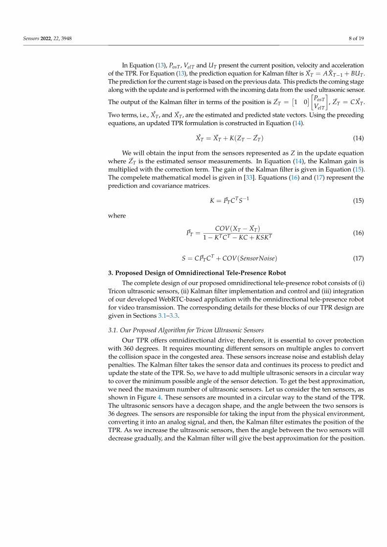
Our TPR offers omnidirectional drive; therefore, it is essential to cover protectionwith 360 degrees. It requires mounting different sensors on multiple angles to convertthe collision space in the congested area. These sensors increase noise and establish delaypenalties. The Kalman filter takes the sensor data and continues its process to predict andupdate the state of the TPR. So, we have to add multiple ultrasonic sensors in a circular wayto cover the minimum possible angle of the sensor detection. To get the best approximation,we need the maximum number of ultrasonic sensors. Let us consider the ten sensors, asshown in Figure 4. These sensors are mounted in a circular way to the stand of the TPR.The ultrasonic sensors have a decagon shape, and the angle between the two sensors is36 degrees. The sensors are responsible for taking the input from the physical environment,converting it into an analog signal, and then, the Kalman filter estimates the position of theTPR. As we increase the ultrasonic sensors, then the angle between the two sensors willdecrease gradually, and the Kalman filter will give the best approximation for the position.
Sensors 2022, 22, 3948 9 of 19
- Ultrasonic
Sensors
- TP Stand/ RodUltrasonic Sensors data fed to the
Kalman Filter
Figure 4. Ten ultrasonic sensors mounted in a circular order.
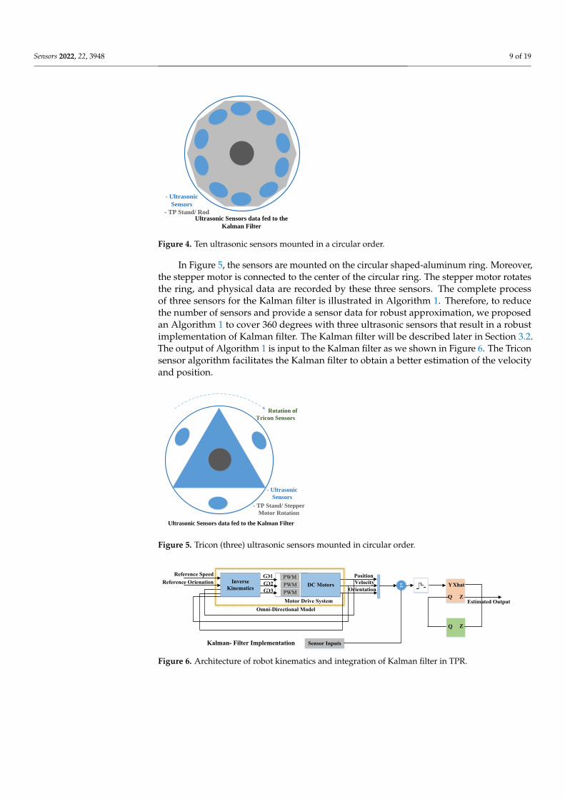
In Figure 5, the sensors are mounted on the circular shaped-aluminum ring. Moreover,the stepper motor is connected to the center of the circular ring. The stepper motor rotatesthe ring, and physical data are recorded by these three sensors. The complete processof three sensors for the Kalman filter is illustrated in Algorithm 1. Therefore, to reducethe number of sensors and provide a sensor data for robust approximation, we proposedan Algorithm 1 to cover 360 degrees with three ultrasonic sensors that result in a robustimplementation of Kalman filter. The Kalman filter will be described later in Section 3.2.The output of Algorithm 1 is input to the Kalman filter as we shown in Figure 6. The Triconsensor algorithm facilitates the Kalman filter to obtain a better estimation of the velocityand position.
- Ultrasonic
Sensors
- TP Stand/ Stepper
Motor Rotation
Ultrasonic Sensors data fed to the Kalman Filter
Rotation of
Tricon Sensors
Figure 5. Tricon (three) ultrasonic sensors mounted in circular order.
Inverse
KinematicsDC Motors
Ѡ1
Sensor Inputs
Motor Drive System
Omni-Directional Model
Reference Speed
Reference Orienation
Position
Velocity
OrientationΣ Y
Q
Xhat
Z
Q Z
Estimated Output
Kalman- Filter Implementation
PWM
PWM
PWM
Ѡ2
Ѡ3
Figure 6. Architecture of robot kinematics and integration of Kalman filter in TPR.
Sensors 2022, 22, 3948 10 of 19
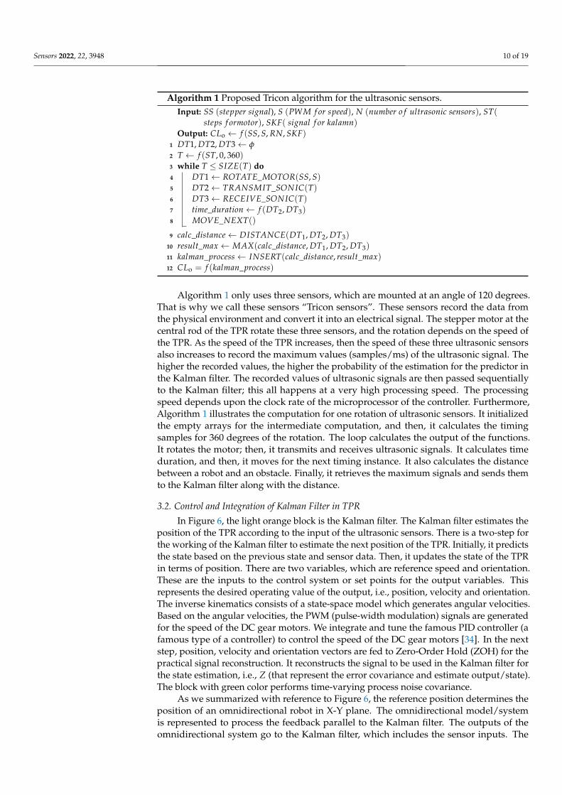
Algorithm 1 Proposed Tricon algorithm for the ultrasonic sensors.Input: SS (stepper signal), S (PWM f or speed), N (number o f ultrasonic sensors), ST(
steps f ormotor), SKF( signal f or kalamn)Output: CLo ← f (SS, S, RN, SKF)
1 DT1, DT2, DT3← φ
2 T ← f (ST, 0, 360)3 while T ≤ SIZE(T) do4 DT1← ROTATE_MOTOR(SS, S)5 DT2← TRANSMIT_SONIC(T)6 DT3← RECEIVE_SONIC(T)7 time_duration← f (DT2, DT3)8 MOVE_NEXT()
9 calc_distance← DISTANCE(DT1, DT2, DT3)10 result_max ← MAX(calc_distance, DT1, DT2, DT3)11 kalman_process← INSERT(calc_distance, result_max)12 CLo = f (kalman_process)
Algorithm 1 only uses three sensors, which are mounted at an angle of 120 degrees.That is why we call these sensors “Tricon sensors”. These sensors record the data fromthe physical environment and convert it into an electrical signal. The stepper motor at thecentral rod of the TPR rotate these three sensors, and the rotation depends on the speed ofthe TPR. As the speed of the TPR increases, then the speed of these three ultrasonic sensorsalso increases to record the maximum values (samples/ms) of the ultrasonic signal. Thehigher the recorded values, the higher the probability of the estimation for the predictor inthe Kalman filter. The recorded values of ultrasonic signals are then passed sequentiallyto the Kalman filter; this all happens at a very high processing speed. The processingspeed depends upon the clock rate of the microprocessor of the controller. Furthermore,Algorithm 1 illustrates the computation for one rotation of ultrasonic sensors. It initializedthe empty arrays for the intermediate computation, and then, it calculates the timingsamples for 360 degrees of the rotation. The loop calculates the output of the functions.It rotates the motor; then, it transmits and receives ultrasonic signals. It calculates timeduration, and then, it moves for the next timing instance. It also calculates the distancebetween a robot and an obstacle. Finally, it retrieves the maximum signals and sends themto the Kalman filter along with the distance.
3.2. Control and Integration of Kalman Filter in TPR
In Figure 6, the light orange block is the Kalman filter. The Kalman filter estimates theposition of the TPR according to the input of the ultrasonic sensors. There is a two-step forthe working of the Kalman filter to estimate the next position of the TPR. Initially, it predictsthe state based on the previous state and sensor data. Then, it updates the state of the TPRin terms of position. There are two variables, which are reference speed and orientation.These are the inputs to the control system or set points for the output variables. Thisrepresents the desired operating value of the output, i.e., position, velocity and orientation.The inverse kinematics consists of a state-space model which generates angular velocities.Based on the angular velocities, the PWM (pulse-width modulation) signals are generatedfor the speed of the DC gear motors. We integrate and tune the famous PID controller (afamous type of a controller) to control the speed of the DC gear motors [34]. In the nextstep, position, velocity and orientation vectors are fed to Zero-Order Hold (ZOH) for thepractical signal reconstruction. It reconstructs the signal to be used in the Kalman filter forthe state estimation, i.e., Z (that represent the error covariance and estimate output/state).The block with green color performs time-varying process noise covariance.
As we summarized with reference to Figure 6, the reference position determines theposition of an omnidirectional robot in X-Y plane. The omnidirectional model/systemis represented to process the feedback parallel to the Kalman filter. The outputs of theomnidirectional system go to the Kalman filter, which includes the sensor inputs. The
Sensors 2022, 22, 3948 11 of 19
predictor estimates the next state whose output is Xhat (estimated vectors, i.e., position,velocity and orientation), and then, the updater modifies the state, whose output is Z. ThePID controller is used for the smooth drive and control of gear motor [35]. In this way, thesystem keeps on working.
3.3. Webrtc Integration in the Tele-Presence Robot (TPR)
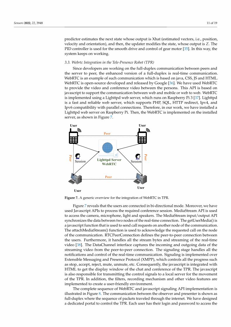
Since developers are working on the full-duplex communication between peers andthe server to peer, the enhanced version of a full-duplex is real-time communication.WebRTC is an example of such communication which is based on java, CSS, JS and HTML.WebRTC is open-source developed and released by Google [36]. We have used WebRTCto provide the video and conference video between the persons. This API is based onjavascript to support the communication between web and mobile or web to web. WebRTCis implemented using a Lighttpd web server, which runs on Raspberry Pi 3 [37]. Lighttpdis a fast and reliable web server, which supports PHP, SQL, HTTP redirect, Ipv4, andIpv6 compatibility with parallel connections. Therefore, in our work, we have installed aLighttpd web server on Raspberry Pi. Then, the WebRTC is implemented on the installedserver, as shown in Figure 7.
Peer
Lighttpd Server
WebRTC
Peer
Pee
r
Pee
r
User User
User
Session
User
Session
Figure 7. A generic overview for the integration of WebRTC in TPR.
Figure 7 reveals that the users are connected in bi-directional mode. Moreover, we haveused Javascript APIs to process the required conference session. MediaStream API is usedto access the camera, microphone, light and speakers. The MediaStream input/output APIsynchronizes the data between two nodes of the real-time connection. The getUserMedia() isa javascript function that is used to send call requests on another node of the communication.The attachMediaStream() function is used to acknowledge the requested call on the nodeof the communication. RTCPeerConnection defines the peer-to-peer connection betweenthe users. Furthermore, it handles all the stream bytes and streaming of the real-timevideo [38]. The DataChannel interface captures the incoming and outgoing data of thestreaming video from the peer-to-peer connection. The signaling stage handles all thenotifications and control of the real-time communication. Signaling is implemented overExtensible Messaging and Presence Protocol (XMPP), which controls all the progress suchas stop, accept, reject, mute, unmute, etc. Consequently, the javascript is integrated withHTML to get the display window of the chat and conference of the TPR. The javascriptis also responsible for transmitting the control signals to a local server for the movementof the TPR. In addition, the filters, recording mechanism and other video features areimplemented to create a user-friendly environment.
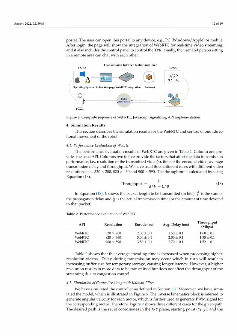
The complete sequence of WebRTC and javascript signaling API implementation isillustrated in Figure 8. The communication between the observer and presenter is shown asfull-duplex where the sequence of packets traveled through the internet. We have designeda dedicated portal to control the TPR. Each user has their login and password to access the
Sensors 2022, 22, 3948 12 of 19
portal. The user can open this portal to any device, e.g., PC (Windows/Apple) or mobile.After login, the page will show the integration of WebRTC for real-time video streaming,and it also includes the control panel to control the TPR. Finally, the user and person sittingin a remote area can chat with each other.
Operating System
Person
Robot Webpage WebRTC integration Internet
TX/RX TX/RXTransmission between Robot and User
TELE
PRESENCE
Figure 8. Complete sequence of WebRTC, Javascript signalizing API implementation.
4. Simulation Results
This section describes the simulation results for the WebRTC and control of omnidirec-tional movement of the robot.
4.1. Performance Evaluation of Webrtc
The performance evaluation results of WebRTC are given in Table 2. Column one pro-vides the used API. Columns two to five provide the factors that affect the data transmissionperformance, i.e., resolution of the transmitted video(s), time of the encoded video, averagetransmission delay and throughput. We have used three different cases with different videoresolutions, i.e., 320× 280, 820× 460 and 900× 590. The throughput is calculated by usingEquation (18).
Throughput =L
d/V + L/B(18)
In Equation (18), L shows the packet length to be transmitted (in bits), dV is the sum of
the propagation delay and LB is the actual transmission time (or the amount of time devoted
to that packet).
Table 2. Performance evaluation of WebRTC.
API Resolution Encode (ms) Avg. Delay (ms) Throughput(Mbps)
WebRTC 320 × 280 2.00± 0.1 1.50± 0.1 1.60± 0.1WebRTC 820 × 460 3.00± 0.1 2.00± 0.1 1.55± 0.1WebRTC 900 × 590 3.50± 0.1 2.70± 0.1 1.52± 0.1
Table 2 shows that the average encoding time is increased when processing higher-resolution videos. Delay during transmission may occur which in turn will result inincreasing buffer size for temporary storage, causing longer latency. However, a higherresolution results in more data to be transmitted but does not affect the throughput of thestreaming due to congestion control.
4.2. Simulation of Controller along with Kalman Filter
We have simulated the controller as defined in Section 3.2. Moreover, we have simu-lated the model, which is illustrated in Figure 6. The inverse kinematics block is inferred togenerate angular velocity for each motor, which is further used to generate PWM signal forthe corresponding motor. Therefore, Figure 9 shows three different cases for the given path.The desired path is the set of coordinates in the X-Y plane, starting point (x1, y1) and the
Sensors 2022, 22, 3948 13 of 19
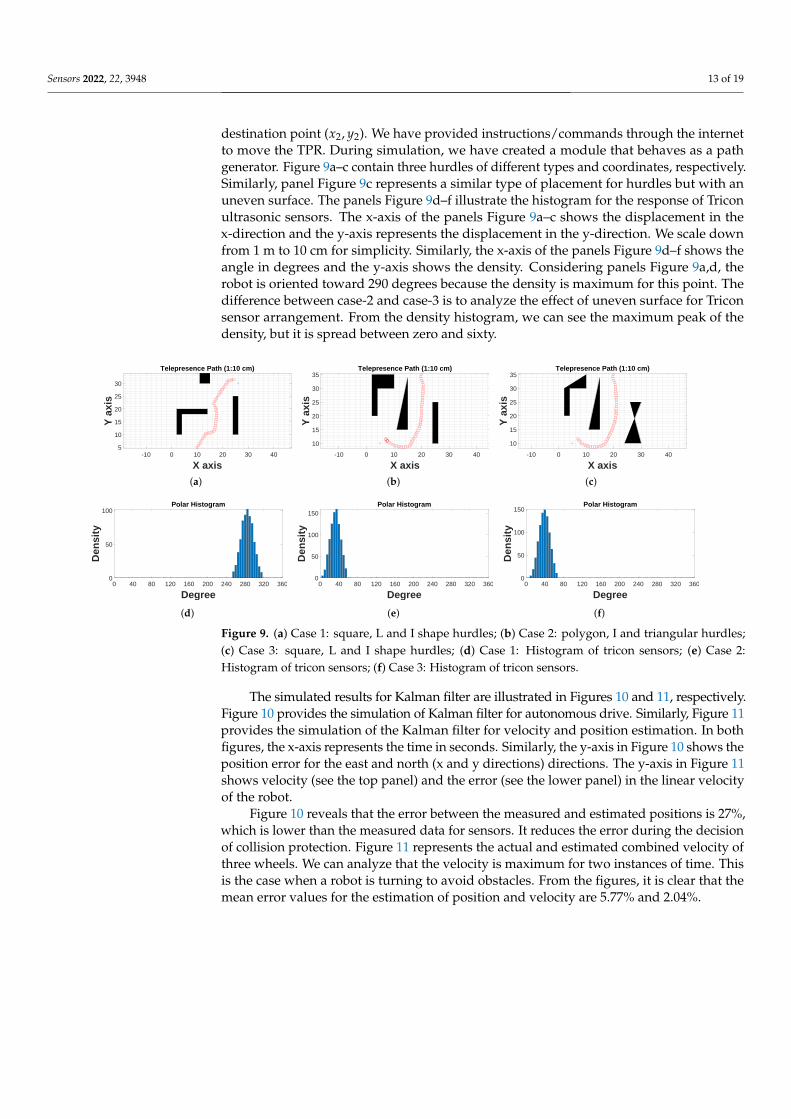
destination point (x2, y2). We have provided instructions/commands through the internetto move the TPR. During simulation, we have created a module that behaves as a pathgenerator. Figure 9a–c contain three hurdles of different types and coordinates, respectively.Similarly, panel Figure 9c represents a similar type of placement for hurdles but with anuneven surface. The panels Figure 9d–f illustrate the histogram for the response of Triconultrasonic sensors. The x-axis of the panels Figure 9a–c shows the displacement in thex-direction and the y-axis represents the displacement in the y-direction. We scale downfrom 1 m to 10 cm for simplicity. Similarly, the x-axis of the panels Figure 9d–f shows theangle in degrees and the y-axis shows the density. Considering panels Figure 9a,d, therobot is oriented toward 290 degrees because the density is maximum for this point. Thedifference between case-2 and case-3 is to analyze the effect of uneven surface for Triconsensor arrangement. From the density histogram, we can see the maximum peak of thedensity, but it is spread between zero and sixty.
-10 0 10 20 30 40
X axis
5
10
15
20
25
30
Y a
xis
Telepresence Path (1:10 cm)
(a)
-10 0 10 20 30 40
X axis
10
15
20
25
30
35
Y a
xis
Telepresence Path (1:10 cm)
(b)
-10 0 10 20 30 40
X axis
10
15
20
25
30
35
Y a
xis
Telepresence Path (1:10 cm)
(c)
Polar Histogram
0 40 80 120 160 200 240 280 320 360
Degree
0
50
100
Den
sity
(d)
Polar Histogram
0 40 80 120 160 200 240 280 320 360
Degree
0
50
100
150
Den
sity
(e)
Polar Histogram
0 40 80 120 160 200 240 280 320 360
Degree
0
50
100
150D
ensi
ty
(f)
Figure 9. (a) Case 1: square, L and I shape hurdles; (b) Case 2: polygon, I and triangular hurdles;(c) Case 3: square, L and I shape hurdles; (d) Case 1: Histogram of tricon sensors; (e) Case 2:Histogram of tricon sensors; (f) Case 3: Histogram of tricon sensors.
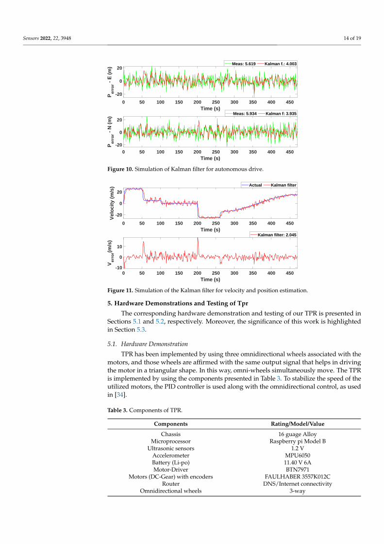
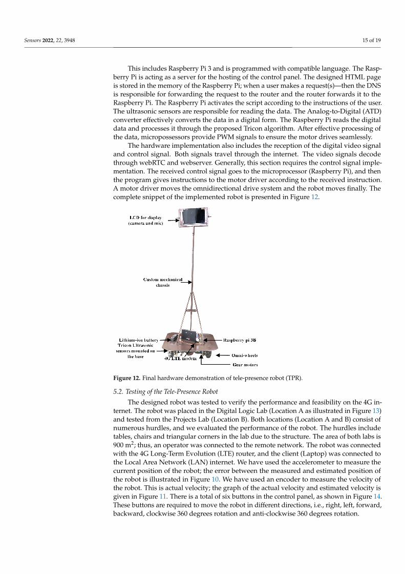
The simulated results for Kalman filter are illustrated in Figures 10 and 11, respectively.Figure 10 provides the simulation of Kalman filter for autonomous drive. Similarly, Figure 11provides the simulation of the Kalman filter for velocity and position estimation. In bothfigures, the x-axis represents the time in seconds. Similarly, the y-axis in Figure 10 shows theposition error for the east and north (x and y directions) directions. The y-axis in Figure 11shows velocity (see the top panel) and the error (see the lower panel) in the linear velocityof the robot.
Figure 10 reveals that the error between the measured and estimated positions is 27%,which is lower than the measured data for sensors. It reduces the error during the decisionof collision protection. Figure 11 represents the actual and estimated combined velocity ofthree wheels. We can analyze that the velocity is maximum for two instances of time. Thisis the case when a robot is turning to avoid obstacles. From the figures, it is clear that themean error values for the estimation of position and velocity are 5.77% and 2.04%.
Sensors 2022, 22, 3948 14 of 19
0 50 100 150 200 250 300 350 400 450Time (s)
-20
0
20
Per
ror -
E (
m)
Meas: 5.619 Kalman f.: 4.003
0 50 100 150 200 250 300 350 400 450Time (s)
-20
0
20
Per
ror -
N (
m) Meas: 5.934 Kalman f: 3.935
Figure 10. Simulation of Kalman filter for autonomous drive.
0 50 100 150 200 250 300 350 400 450Time (s)
-20
0
20
Vel
oci
ty (
m/s
) Actual Kalman filter
0 50 100 150 200 250 300 350 400 450Time (s)
-10
0
10
Ver
ror(m
/s)
Kalman filter: 2.045
Figure 11. Simulation of the Kalman filter for velocity and position estimation.
5. Hardware Demonstrations and Testing of Tpr
The corresponding hardware demonstration and testing of our TPR is presented inSections 5.1 and 5.2, respectively. Moreover, the significance of this work is highlightedin Section 5.3.
5.1. Hardware Demonstration
TPR has been implemented by using three omnidirectional wheels associated with themotors, and those wheels are affirmed with the same output signal that helps in drivingthe motor in a triangular shape. In this way, omni-wheels simultaneously move. The TPRis implemented by using the components presented in Table 3. To stabilize the speed of theutilized motors, the PID controller is used along with the omnidirectional control, as usedin [34].
Table 3. Components of TPR.
Components Rating/Model/Value
Chassis 16 guage AlloyMicroprocessor Raspberry pi Model B
Ultrasonic sensors 1.2 VAccelerometer MPU6050Battery (Li-po) 11.40 V 6AMotor-Driver BTN7971
Motors (DC-Gear) with encoders FAULHABER 3557K012CRouter DNS/Internet connectivity
Omnidirectional wheels 3-way
Sensors 2022, 22, 3948 15 of 19
This includes Raspberry Pi 3 and is programmed with compatible language. The Rasp-berry Pi is acting as a server for the hosting of the control panel. The designed HTML pageis stored in the memory of the Raspberry Pi; when a user makes a request(s)—then the DNSis responsible for forwarding the request to the router and the router forwards it to theRaspberry Pi. The Raspberry Pi activates the script according to the instructions of the user.The ultrasonic sensors are responsible for reading the data. The Analog-to-Digital (ATD)converter effectively converts the data in a digital form. The Raspberry Pi reads the digitaldata and processes it through the proposed Tricon algorithm. After effective processing ofthe data, micropossessors provide PWM signals to ensure the motor drives seamlessly.
The hardware implementation also includes the reception of the digital video signaland control signal. Both signals travel through the internet. The video signals decodethrough webRTC and webserver. Generally, this section requires the control signal imple-mentation. The received control signal goes to the microprocessor (Raspberry Pi), and thenthe program gives instructions to the motor driver according to the received instruction.A motor driver moves the omnidirectional drive system and the robot moves finally. Thecomplete snippet of the implemented robot is presented in Figure 12.
Figure 12. Final hardware demonstration of tele-presence robot (TPR).
5.2. Testing of the Tele-Presence Robot
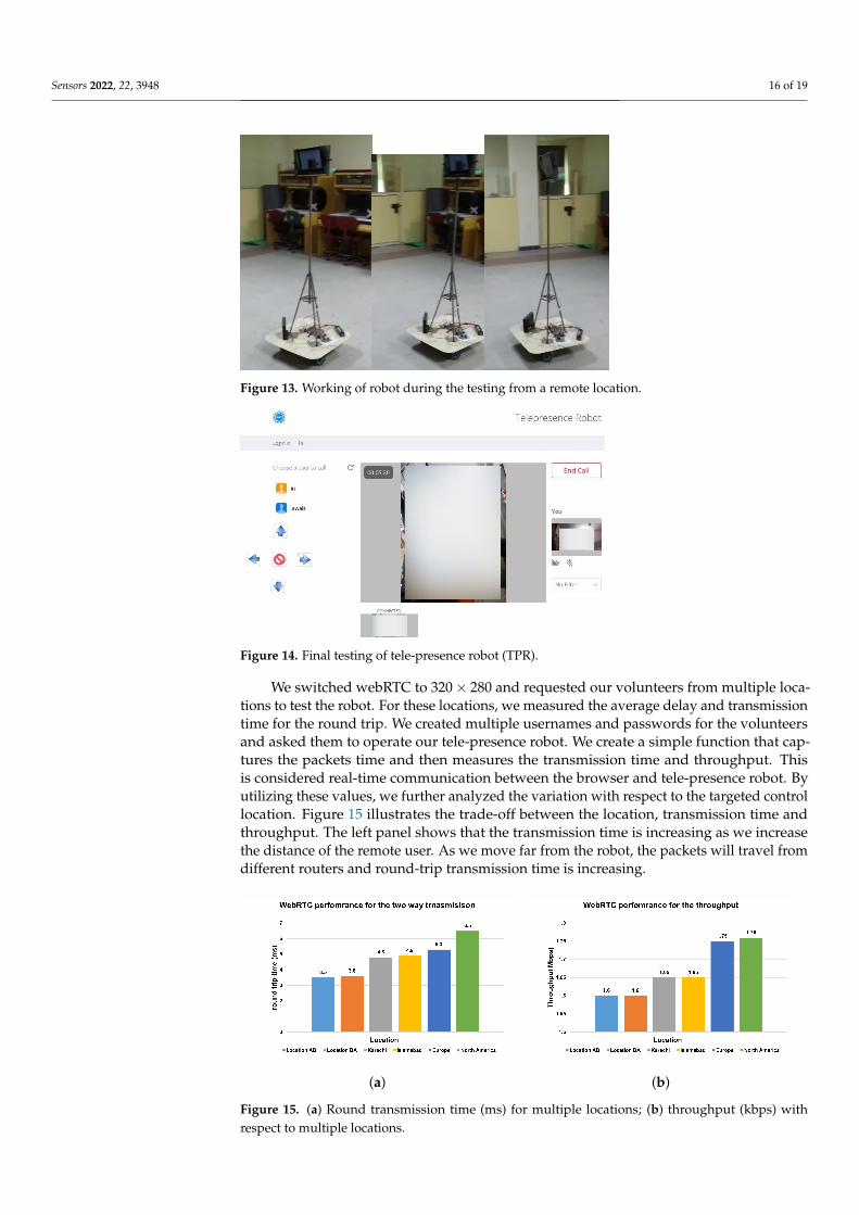
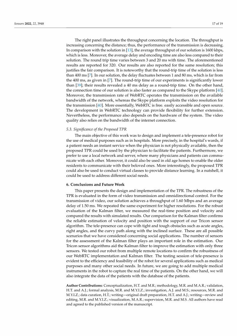
The designed robot was tested to verify the performance and feasibility on the 4G in-ternet. The robot was placed in the Digital Logic Lab (Location A as illustrated in Figure 13)and tested from the Projects Lab (Location B). Both locations (Location A and B) consist ofnumerous hurdles, and we evaluated the performance of the robot. The hurdles includetables, chairs and triangular corners in the lab due to the structure. The area of both labs is900 m2; thus, an operator was connected to the remote network. The robot was connectedwith the 4G Long-Term Evolution (LTE) router, and the client (Laptop) was connected tothe Local Area Network (LAN) internet. We have used the accelerometer to measure thecurrent position of the robot; the error between the measured and estimated position ofthe robot is illustrated in Figure 10. We have used an encoder to measure the velocity ofthe robot. This is actual velocity; the graph of the actual velocity and estimated velocity isgiven in Figure 11. There is a total of six buttons in the control panel, as shown in Figure 14.These buttons are required to move the robot in different directions, i.e., right, left, forward,backward, clockwise 360 degrees rotation and anti-clockwise 360 degrees rotation.
Sensors 2022, 22, 3948 16 of 19
Figure 13. Working of robot during the testing from a remote location.
Figure 14. Final testing of tele-presence robot (TPR).
We switched webRTC to 320× 280 and requested our volunteers from multiple loca-tions to test the robot. For these locations, we measured the average delay and transmissiontime for the round trip. We created multiple usernames and passwords for the volunteersand asked them to operate our tele-presence robot. We create a simple function that cap-tures the packets time and then measures the transmission time and throughput. Thisis considered real-time communication between the browser and tele-presence robot. Byutilizing these values, we further analyzed the variation with respect to the targeted controllocation. Figure 15 illustrates the trade-off between the location, transmission time andthroughput. The left panel shows that the transmission time is increasing as we increasethe distance of the remote user. As we move far from the robot, the packets will travel fromdifferent routers and round-trip transmission time is increasing.
(a) (b)
Figure 15. (a) Round transmission time (ms) for multiple locations; (b) throughput (kbps) withrespect to multiple locations.
Sensors 2022, 22, 3948 17 of 19
The right panel illustrates the throughput concerning the location. The throughput isincreasing concerning the distance; thus, the performance of the transmission is decreasing.In comparison with the solution in [13], the average throughput of our solution is 1600 kbps,which is less. Moreover, the average delay and encoding time are also less compared to theirsolution. The round trip time varies between 3 and 20 ms with time. The aforementionedresults are reported for 320. Our results are also reported for the same resolution; thisjustifies the fair comparison. It is noteworthy that the round-trip time of the solution is lessthan 400 ms [7]. In our solution, the delay fluctuates between 1 and 80 ms, which is far fromthe 400 ms, as given in [7]. The round-trip time of our experiments is significantly lowerthan [39]; their results revealed a 40 ms delay as a round-trip time. On the other hand,the connection time of our solution is also faster as compared to the Skype platform [40].Moreover, the transmission rate of WebRTC operates the transmission on the availablebandwidth of the network, whereas the Skype platform exploits the video resolution forthe transmission [40]. More essentially, WebRTC is free. easily accessible and open source.The development in WebRTC technology can provide flexibility for further extension.Nevertheless, the performance also depends on the hardware of the system. The videoquality also relies on the bandwidth of the internet connection.
5.3. Significance of the Proposed TPR
The main objective of this work was to design and implement a tele-presence robot forthe use of medical purposes such as in hospitals. More precisely, in the hospital’s wards, ifa patient needs an instant service when the physician is not physically available, then theproposed TPR could be used by the physician to facilitate the patients. Furthermore, weprefer to use a local network and server, where many physicians and patients can commu-nicate with each other. Moreover, it could also be used in old age homes to enable the olderresidents to communicate with their beloved ones. More interestingly, the proposed TPRcould also be used to conduct virtual classes to provide distance learning. In a nutshell, itcould be used to address different social needs.
6. Conclusions and Future Work
This paper presents the design and implementation of the TPR. The robustness of theTPR is evaluated in the form of video transmission and omnidirectional control. For thetransmission of video, our solution achieves a throughput of 1.60 Mbps and an averagedelay of 1.50 ms. We repeated the same experiment for higher resolutions. For the robustevaluation of the Kalman filter, we measured the real-time position and velocity andcompared the results with simulated results. Our comparison for the Kalman filter confirmsthe reliable estimation of velocity and position with the support of our Tricon sensoralgorithm. The tele-presence can cope with tight and tough obstacles such as acute angles,right angles, and the curvy path along with the inclined surface. These are all possiblescenarios that we have considered concerning social applications. The number of sensorsfor the assessment of the Kalman filter plays an important role in the estimation. OurTricon sensor algorithms aid the Kalman filter to improve the estimation with only threesensors. We tested our robot from multiple remote locations to confirm the robustness ofour WebRTC implementation and Kalman filter. The testing session of tele-presence isevident to the efficiency and feasibility of the robot for several applications such as medicalpurposes and many other social needs. In future, we are going to add multiple medicalinstruments in the robot to capture the real time of the patients. On the other hand, we willalso integrate the data of the patients with the database of the patients.
Author Contributions: Conceptualization, H.T. and M.R.; methodology, M.R. and M.A.R.; validation,H.T. and A.J.; formal analysis, M.R. and M.Y.I.Z.; investigation, A.J. and M.S.; resources, M.R. andM.Y.I.Z.; data curation, H.T.; writing—original draft preparation, H.T. and A.J.; writing—review andediting, M.R. and M.Y.I.Z.; visualization, M.A.R.; supervision, M.R. and M.S. All authors have readand agreed to the published version of the manuscript.
Sensors 2022, 22, 3948 18 of 19
Funding: The authors would like to thank the Deanship of Scientific Research at Umm Al-QuraUniversity for supporting this work by Grant Code: (22UQU4320199DSR02).
Institutional Review Board Statement: Not applicable.
Informed Consent Statement: Not applicable.
Data Availability Statement: Not applicable.
Conflicts of Interest: The authors declare no conflict of interest.
References1. Choi, J.J.; Kwak, S.S. Can you feel me?: How embodiment levels of telepresence systems affect presence. In Proceedings of the
2016 25th IEEE International Symposium on Robot and Human Interactive Communication (RO-MAN), New York, NY, USA,26–31 August 2016; pp. 606–611. [CrossRef]
2. Rangel, R.; Romero, L.; Garcia, M. Paynal, a low cost telepresence robot. In Proceedings of the 2015 IEEE International AutumnMeeting on Power, Electronics and Computing (ROPEC), Ixtapa, Mexico, 4–6 November 2015; pp. 1–4. [CrossRef]
3. World Health Organization. Ageing and Future Population; WHO: Geneva, Switzerland, 2021.4. Adalgeirsson, S.O.; Breazeal, C. MeBot: A robotic platform for socially embodied telepresence. In Proceedings of the 2010 5th
ACM/IEEE International Conference on Human-Robot Interaction (HRI), Osaka, Japan, 2–5 March 2010; pp. 15–22. [CrossRef]5. Ha, V.K.L.; Nguyen, T.N.; Nguyen, H.T. Real-time transmission of panoramic images for a telepresence wheelchair. In Proceedings
of the 2015 37th Annual International Conference of the IEEE Engineering in Medicine and Biology Society (EMBC), Milan, Italy,25–29 August 2015; pp. 3565–3568. [CrossRef]
6. Schneider, D. A DIY Telepresence Robot. IEEE Spectrum, 30 September 2022. Avasilable online: https://spectrum.ieee.org/a-diy-telepresence-robot (accessed on 2 February 2022).
7. Ha, V.K.L.; Nguyen, T.N.; Nguyen, H.T. A telepresence wheelchair using cellular network infrastructure in outdoor environments.In Proceedings of the 2016 38th Annual International Conference of the IEEE Engineering in Medicine and Biology Society(EMBC), Orlando, FL, USA, 16–20 August 2016; pp. 5352–5355. [CrossRef]
8. Ha, V.K.L.; Nguyen, T.N.; Nguyen, H.T. Real-time video streaming with multi-camera for a telepresence wheelchair. In Proceed-ings of the 2016 14th International Conference on Control, Automation, Robotics and Vision (ICARCV), Phuket, Thailand, 13–15November 2016; pp. 1–5. [CrossRef]
9. GSM Association, Version 1.0; WebRTC to Complement IP Communication Services; GSMA: London, UK, 2021.10. Mishra, R.; Ajmera, Y.; Mishra, N.; Javed, A. Ego-Centric framework for a three-wheel omni-drive Telepresence robot. In Proceed-
ings of the 2019 IEEE International Conference on Advanced Robotics and its Social Impacts (ARSO), Beijing, China, 31 October–2November 2019; pp. 281–286. [CrossRef]
11. Husic, J.B.; Barakovic, S.; Veispahic, A. What factors influence the quality of experience for WebRTC video calls? In Proceedingsof the 2017 40th International Convention on Information and Communication Technology, Electronics and Microelectronics(MIPRO), Opatija, Croatia, 22–26 May 2017; pp. 428–433. [CrossRef]
12. Sarder, M.R.; Ahmed, F.; Shakhar, B.A. Design and implementation of a lightweight telepresence robot for medical assistance. InProceedings of the 2017 International Conference on Electrical, Computer and Communication Engineering (ECCE), Cox’s Bazar,Bangladesh, 16–18 February 2017; pp. 779–783. [CrossRef]
13. Ha, V.K.L.; Chai, R.; Nguyen, H.T. Real-time WebRTC-based design for a telepresence wheelchair. In Proceedings of the 2017 39thAnnual International Conference of the IEEE Engineering in Medicine and Biology Society (EMBC), Jeju, Korea, 11–15 July 2017;pp. 2676–2679. [CrossRef]
14. Jitheesh, P.; Keeramkot, F.; Athira, P.C.; Madeena, S.; ; Arunvinodh, C. Telepresence Robot Doctor. In Proceedings of the 2016Online International Conference on Green Engineering and Technologies (IC-GET), Coimbatore, India, 19–20 November 2016;pp. 1–4. [CrossRef]
15. Borvorntanajanya, K.; Thiuthipsakul, P.; Chalongwongse, S.; Moonjaita, C.; Suthakorn, J. Development of differential suspensionwheeled system for telepresence robot in rural hospital area. In Proceedings of the 2016 IEEE International Conference onRobotics and Biomimetics (ROBIO), Qingdao, China, 3–7 December 2016; pp. 1046–1051. [CrossRef]
16. Nguyen, V.A.; Lu, J.; Zhao, S.; Vu, D.T.; Yang, H.; Jones, D.L.; Do, M.N. ITEM: Immersive Telepresence for Entertainment andMeetings – A Practical Approach. IEEE J. Sel. Top. Signal Process. 2015, 9, 546–561. [CrossRef]
17. Isabet, B.; Pino, M.; Lewis, M.; Benveniste, S.; Rigaud, A.S. Social Telepresence Robots: A Narrative Review of ExperimentsInvolving Older Adults before and during the COVID-19 Pandemic. Int. J. Environ. Res. Public Health 2021, 18, 3597. [CrossRef]
18. Okamura, E.; Tanaka, F. A pilot study about remote teaching by elderly people to children over a two-way telepresence robotsystem. In Proceedings of the 2016 11th ACM/IEEE International Conference on Human-Robot Interaction (HRI), Christchurch,New Zealand, 7–10 March 2016; pp. 489–490. [CrossRef]
19. Shin, K.W.C.; Han, J. Children’s perceptions of and interactions with a telepresence robot. In Proceedings of the 201611th ACM/IEEE International Conference on Human-Robot Interaction (HRI), Christchurch, New Zealand, 7–10 March 2016;pp. 521–522. [CrossRef]
Sensors 2022, 22, 3948 19 of 19
20. Kwon, O.H.; Koo, S.Y.; Kim, Y.G.; Kwon, D.S. Telepresence robot system for English tutoring. In Proceedings of the 2010 IEEEWorkshop on Advanced Robotics and its Social Impacts, Seoul, Korea, 26–28 October 2010; pp. 152–155. [CrossRef]
21. Budiharto, W.; Suhartono, D. Intelligent service robot with voice recognition and telepresence capabilities. In Proceedings of the2015 SAI Intelligent Systems Conference (IntelliSys), London, UK, 10–11 November 2015; pp. 301–304. [CrossRef]
22. Macharet, D.G.; Florencio, D.A. A collaborative control system for telepresence robots. In Proceedings of the 2012 IEEE/RSJInternational Conference on Intelligent Robots and Systems, Vilamoura-Algarve, Portugal, 7–12 October 2012; pp. 5105–5111.[CrossRef]
23. Zhang, J.; Li, W.; Yu, J.; Zhang, Q.; Cui, S.; Li, Y.; Li, S.; Chen, G. Development of a Virtual Platform for Telepresence Control of anUnderwater Manipulator Mounted on a Submersible Vehicle. IEEE Trans. Ind. Electron. 2017, 64, 1716–1727. [CrossRef]
24. Tanaka, R.; Kurabe, K.; Kihal, M.E.; Ichimi, M.; Tatsuno, K. Improvement on an obstacle avoidance in telepresence robot. InProceedings of the 2015 IEEE/SICE International Symposium on System Integration (SII), Nagoya, Japan, 11–13 December 2015;pp. 634–639. [CrossRef]
25. Fitter, N.T.; Joung, Y.; Demeter, M.; Hu, Z.; Mataric, M.J. Design and Evaluation of Expressive Turn-Taking Hardware fora Telepresence Robot. In Proceedings of the 2019 28th IEEE International Conference on Robot and Human InteractiveCommunication (RO-MAN), New Delhi, India, 14–18 October 2019; pp. 1–8. [CrossRef]
26. Boll, S. Multimedia at CHI: Telepresence at Work for Remote Conference Participation. IEEE Multimed. 2017, 24, 5–9. [CrossRef]27. Das, B.; Dobie, G.; Pierce, S.G. AS-EKF: A Delay Aware State Estimation Technique for Telepresence Robot Navigation.
In Proceedings of the 2019 Third IEEE International Conference on Robotic Computing (IRC), Naples, Italy, 25–27 February 2019;pp. 624–629. [CrossRef]
28. Arroyo, D.; Tanaka, F. A Time-based Strategy for the Transition of Control in Telepresence Robots. In Proceedings of the 201827th IEEE International Symposium on Robot and Human Interactive Communication (RO-MAN), Taian, China, 27–31 August2018; pp. 342–347. [CrossRef]
29. Li, W.; Yang, C.; Jiang, Y.; Liu, X.; Su, C.Y. Motion Planning for Omnidirectional Wheeled Mobile Robot by Potential Field Method.J. Adv. Transp. 2017, 2017, 4961383. [CrossRef]
30. Nise, N.S. Control System Engineering; Wiley: Hoboken, NJ, USA, 2004.31. Tariq, H.; Rashid, M.; Hafeez, M.A.; Alotaibi, S.S.; Sinky, M.H. A Hybrid Linear Quadratic Regulator Controller for Unmanned
Free-Swimming Submersible. Appl. Sci. 2021, 11, 9131 [CrossRef]32. Korotaj, B.; Novoselnik, B.; Baotic, M. Kalman Filter Based Sensor Fusion for Omnidirectional Mechatronic System. In Proceedings
of the 2021 International Conference on Electrical Drives Power Electronics (EDPE), Dubrovnik, Croatia, 22–24 September 2021;pp. 183–188. [CrossRef]
33. Li, Q.; Li, R.; Ji, K.; Dai, W. Kalman Filter and Its Application. In Proceedings of the 2015 8th International Conference onIntelligent Networks and Intelligent Systems (ICINIS), Tianjin, China, 1–3 November 2015; pp. 74–77. [CrossRef]
34. Batayneh, W.; AbuRmaileh, Y. Decentralized Motion Control for Omnidirectional Wheelchair Tracking Error Elimination UsingPD-Fuzzy-P and GA-PID Controllers. Sensors 2020, 20, 3525. [CrossRef] [PubMed]
35. Shijin, C.S.; Udayakumar, K. Speed control of wheeled mobile robots using PID with dynamic and kinematic modelling. InProceedings of the 2017 International Conference on Innovations in Information, Embedded and Communication Systems(ICIIECS), Coimbatore, India, 17–18 March 2017; pp. 1–7. [CrossRef]
36. WebRTC. WebRTC API. 2021. Available online: https://developer.mozilla.org/en-US/docs/Web/API/WebRTC_API (accessedon 7 February 2022).
37. Lighttpd. Lighttpd Web Server; 1.4.64; Lighttpd: New York, NY, USA, 2021. Available online: https://www.lighttpd.net/ (accessedon 6 December 2021).
38. Sredojev, B.; Samardzija, D.; Posarac, D. WebRTC technology overview and signaling solution design and implementation.In Proceedings of the 2015 38th International Convention on Information and Communication Technology, Electronics andMicroelectronics (MIPRO), Opatija, Croatia, 25–29 May 2015; pp. 1006–1009. [CrossRef]
39. Denojean-Mairet, M.; Tan, Q.; Pivot, F.; Ally, M. A Ubiquitous Computing Platform—Affordable Telepresence Robot Designand Applications. In Proceedings of the 2014 IEEE 17th International Conference on Computational Science and Engineering,Washington, DC, USA, 19–21 December 2014; pp. 793–798. [CrossRef]
40. Corke, P.; Findlater, K.; Murphy, E. Skype: A communications framework for robotics. In Proceedings of the 2012 AustralasianConference on Robotics and Automation, Wellington, New Zealand, 3–5 December 2012.
Related Documents