Eberspacher Hydronic B4WSC Technical Overview Document and Instructions
Aug 20, 2015
Welcome message from author
This document is posted to help you gain knowledge. Please leave a comment to let me know what you think about it! Share it to your friends and learn new things together.
Transcript
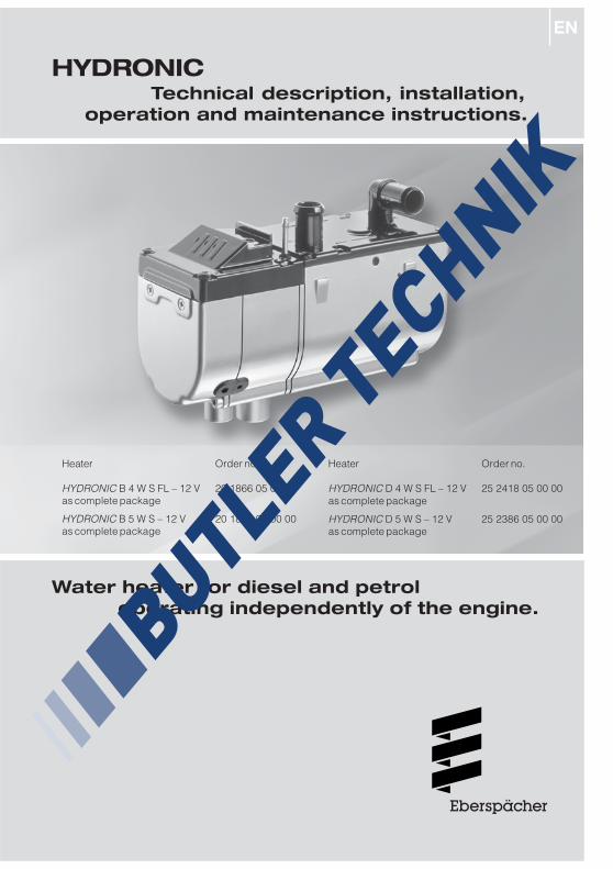
Heater Order no.
HYDRONIC B 4 W S FL – 12 V 20 1866 05 00 00as complete package
HYDRONIC B 5 W S – 12 V 20 1862 05 00 00as complete package
Heater Order no.
HYDRONIC D 4 W S FL – 12 V 25 2418 05 00 00as complete package
HYDRONIC D 5 W S – 12 V 25 2386 05 00 00as complete package
HYDRONICTechnical description, installation,
operation and maintenance instructions.
Water heater for diesel and petroloperating independently of the engine.
2
8
7
6
5
4
3
2
1
Introduction1
Contents
Chapter Title Contents Page
Introduction • Contents ................................................................................................ 2• Concept of this manual ......................................................................... 3• Special text structure, presentation and picture symbols ..................... 4• Important information before starting work ............................................ 4• Statutory regulations ......................................................................... 5, 6• Safety instructions for installation and operation ................................. 7• Accident prevention .............................................................................. 7
Product information • Scope of supply petrol / diesel heaters ............................................. 8, 9• Technical data petrol heaters ........................................................ 10, 11• Technical data diesel heaters ........................................................ 12, 13• Main dimensions .................................................................................. 14
Installation • Installation and location ...................................................................... 15• Possible installation positions ............................................................. 16• Mounting and fastening ....................................................................... 17• Nameplate ........................................................................................... 18• Connection to the cooling water circuit ....................................... 19 – 22• Exhaust system ................................................................................... 23• Combustion air system ........................................................................ 24• Fuel supply petrol / diesel heaters ............................................. 25 – 29
Operation and • Operating instructions / important information for operation ............... 30function • Initial commissioning ........................................................................... 30
• Description of functions ...................................................................... 30• Control and safety devices ................................................................. 31
Electrical system • Heater wiring ........................................................................................ 32• Parts list for heater circuit diagram ..................................................... 32• Heater circuit diagram ........................................................................ 33• Parts lists for control units circuit diagrams ...................................... 34• Control units circuit diagrams ...................................................... 35 – 40
Troubleshooting • In case of faults, please check the following points ........................... 41Maintenance • Troubleshooting ................................................................................... 41Service • Maintenance instructions .................................................................... 41
• Service ................................................................................................ 41
Environment • Certification ......................................................................................... 42• Disposal ............................................................................................... 42• EU Declaration of Conformity ............................................................... 42
Lists • List of key words ........................................................................... 43, 44• List of abbreviations ............................................................................ 44

3
Introduction1
Concept of this manual
This manual aims to support the service companyinstalling the heater and to provide the user with allimportant information about the heater.The manual has been divided into 8 chapters to makeit easier to find the corresponding information quickly.
IntroductionHere you will find important introductoryinformation about installation of the heaterand about the structure of the manual.
Product informationHere you will find information about the scopeof supply, the technical data and thedimensions of the heater.
InstallationHere you will find important information andinstructions referring to installation of theheater.
Operation and functionHere you will find information about theoperation and function of the heater.
Electric systemHere you will find information about theelectronic system and electronic componentsof the heater.
Troubleshooting / maintenance / serviceThis section contains information on possiblefaults and malfunctions, troubleshooting,maintenance and the service hotline.
EnvironmentHere you will find information about certificationand disposal of the heater together with the EUDeclaration of Conformity.
ListsHere you will find the key word list andabbreviations list.
2
3
4 8
7
6
51

4
Special text structure, presentation andpicture symbols
This manual uses special text structures and picturesymbols to emphasise different contents.Please refer to the examples below for thecorresponding meanings and associated actions.
Special structure and presentations
A dot (•) indicates a list which is started by aheading. If an indented dash (–) follows a dot, this listis subordinate to the dot.
Picture symbols
Regulation!This picture symbol with the remark “Regulation”refers to a statutory regulation. Failure to comply withthis regulation results in expiry of the type permit forthe heater and preclusion of any guarantee andliability claims on J. Eberspächer GmbH & Co. KG andits associated companies.
Danger!This picture symbol with the remark “Danger!” refersto the risk of a fatal danger to life and limb. Undercertain circumstances, failure to comply with theseinstructions can result in severe or life-threateninginjuries.
Caution!This picture symbol with the remark “Caution!” refersto a dangerous situation for a person and / or theproduct.Failure to comply with these instructions can result ininjuries to people and/or damage to machinery.
These remarks contain application recommendationsand useful tips for installation of the heater.
Important information beforestarting work
Range of application of the heater
The water heater operating independently of an engineis intended for installation in the following vehicles,depending on its heating output:• Vehicles of all kinds• Construction machinery• Agricultural machinery• Boats, ships and yachts
Installation of the heater is not permitted in vehiclesused for the transport of dangerous goods as perADR.
Purpose of the heater(using the vehicle heat exchanger)
• Pre-heating, de-misting windows• Heating and keeping the following warm:
– Driver and working cabs– Freight compartments– Ship’s cabins– Passenger and crew compartments– Vehicle engines and units
On account of its functional purpose, the heater is notpermitted for the following applications:• Long-term continuous operation, e.g. for pre-heating
and heating of:– Residential rooms– Garages– Work huts, weekend homes and hunting huts– Houseboats, etc.
Caution!Safety instructions for application andproper purpose
• The heater must only be used and operated for therange of application stated by the manufacturer incompliance with the “Operating instructions”included with every heater.
Please note!
Please note!
Introduction1

5
Statutory regulations
The Federal Road Transport Directorate has issued an"EC type approval" and an "EMC type approval" for theheater for installation in motor vehicles and with thefollowing official type approval marks, noted on theheater name plate.
HYDRONIC EC- e1 00 0023
EMC- e1 031075
Regulation!Directive 2001 / 56 / EU of the European Parliamentand the Council
• Arrangement of the heater
– Parts of the structure and other components nearthe heater must be protected from excess heatexposure and possible contamination from fuel oroil.
– The heater must not pose a fire hazard even whenit overheats.This requirement is deemed to be fulfilled whenadequate clearance to all parts is observed duringinstallation, sufficient ventilation is provided andfire-proof materials or heat plates are used.
– The heater must not be located in the passengercompartment in vehicles of class M1, M2, M3 and N.A unit may however be used in a hermetically sealedhousing which also corresponds to the conditionsstated above.
– The factory nameplate or duplicate must be affixedso that it can still be easily read when the heateris installed in the vehicle.
– All appropriate precautions must be taken whenarranging the heater to minimise the risk of injuriesto persons or damage to other property.
• Fuel supply
– The fuel intake connection must not be located inthe passenger compartment and must be sealedwith a properly closing lid to prevent any fuel leaks.
– In heaters for liquid fuel where the heater fuel isseparate from the vehicle fuel, the type of fuel andintake connection must be clearly identified.
– A warning sign is to be fixed to the intakeconnection indicating that the heater must beswitched off before refuelling.
• Exhaust system
– The exhaust outlet must be arranged so as toprevent any penetration of exhaust fumes into thevehicle interior through the ventilation system,warm air intakes or open windows.
• Combustion air intake
– The air for the heater combustion chamber mustnot be sucked in from the passenger compartmentof the vehicle.
– The air intake must be arranged or protected insuch a way that it cannot be blocked by otherobjects.
• Operating status display
– A clearly visible operating display in the user’sfield of vision must indicate when the heater isswitched on and off.
Introduction1
6
Please note!
• Compliance with the statutory regulations, theadditional regulations and safety instructions isprerequisite for guarantee and liability claims.Failure to comply with the statutory regulations andsafety instructions and incorrect repairs even whenusing original spare parts make the guarantee nulland void and preclude any liability forJ. Eberspächer GmbH & Co. KG.
• Subsequent installation of this heater must complywith these installation instructions.
• The statutory regulations are binding and must alsobe observed in countries which do not have anyspecial regulations.
• When the heater is to be installed in vehicles notsubject to the German Ordinance for the Regis-tration of Motor Vehicles (StVZO), for exampleships, the specially valid regulations andinstallation instructions for these specialapplications must be observed.
• Installation of the heater in special vehicles mustcomply with the regulations applying to suchvehicles.
• Other installation requirements are contained in thecorresponding sections of this manual.
RegulationsAdditional regulations for certain vehiclesnamed in Directive 94 / 55 / EC (ADRFramework Directive)
ScopeThis appendix applies to vehicles for which the specialprovisions of Directive 94 / 55 / EC apply to combus-tion heaters and their installation.
Definition of terms usedFor the purposes of this appendix, the vehicle desi-gnations "EX / II", "EX / III", "AT", "FL" and "OX" accor-ding to Chapter 9.1 of Annex B of Directive 94 / 55 /EC are used.
Technical regulations
General provisions (EX / II, EX / III, AT, FL and OXvehicles)
Avoid heating and ignitionThe combustion heaters and their exhaust gas routingshall be designed, located, protected or covered soas to prevent any unacceptable risk of heating orignition of the load. This requirement shall be consi-dered as fulfilled if the fuel tank and the exhaustsystem of the appliance conform to provisions in3.1.1.1 and 3.1.1.2. Compliance with these regulati-ons shall be checked in the complete vehicle.
Fuel tanksFuel tanks for supplying the heater shall conform tothe following regulations:• In the event of any leakage, the fuel shall drain to
the ground without coming into contact with hotparts of the vehicle or the load;
• fuel tanks containing petrol shall be equipped withan effective flame trap at the filler opening or with aclosure enabling the opening to be kept hermetical-ly sealed.
Exhaust system and exhaust pipe layoutThe exhaust system as well as the exhaust pipes shalllaid out or protected to avoid any danger to the loadthrough heating or ignition. Parts of the exhaustsystem situated directly below the fuel tank (diesel)shall have a clearance of at least 100 mm or be pro-tected by a thermal shield.
Switching on the combustion heaterThe combustion heater may only be switched onmanually. Automatic switching on via a programmableswitch is not permitted.
EX / II and EX / III vehiclesCombustion heaters for gaseous fuels are not permit-ted.
FL vehiclesCombustion heaters must be able to be taken out ofservice/disabled at least by the methods described inthe following:
a)Switching off manually in the driver's cabinb)Switching off the vehicle's engine; in this case the
heater may be manually switched back on by thevehicle driver;
c)Starting up of a feed pump installed in the vehiclefor the dangerous goods carried.
Combustion heater after-runAfter-running of the switched off combustion heater ispermitted. In the cases named in the "FL vehicles"paragraph under letters b) and c) the supply of com-bustion air must be interrupted by suitable meansafter a maximum after-run period of 40 seconds. Onlycombustion heaters whose heat exchangers are veri-fiably not damaged by the reduced after-run period of40 seconds beyond their usual use period may beused.
Introduction1
7
Safety instructions for installationand operation
Danger!Risk of injury, fire and poisoning
• Disconnect the vehicle battery before starting anykind of work.
• Before working on the heater, switch the heater offand let all hot components cool down.
• The heater must not be operated in enclosed rooms,e.g. in the garage or multi-storey car park.
Caution!Safety instructions for installation and operation
• The heater must only be installed by a JE partnerauthorised by the manufacturer according to theinstructions in this manual and possibly according tospecial installation recommendations; the sameapplies to any repairs to be carried out in the caseor repairs or guarantee claims.
• Repairs by non-authorised third-parties or with notoriginal spare parts are dangerous and therefore notallowed. They result in expiry of the type permit ofthe heater; consequently, when installed in motorvehicles they can cause expiry of the vehicleoperating licence.
• The following measures are not allowed:– Changes to components relevant to the heater.– Use of third-party components not approved by
J. Eberspächer GmbH & Co. KG.– Nonconformities in installation or operation from
the statutory regulations, safety instructions orspecifications relevant to safe operation as statedin the installation instructions and operatinginstructions. This applies in particular to theelectrical wiring, fuel supply, combustion airsystem and exhaust system.
• Only original accessories and original spare partsmust be used during installation or repairs.
• Only original accessories and spare parts may beused for installation or repairs.
• Only the controls approved by Eberspächer may beused to operate the heater.The use of other controls can result in malfunctions.
• Before the heater is installed again in anothervehicle, rinse the heater parts carrying water withclear water.
• When carrying out electric welding on the vehicle,the plus pole cable at the battery should bedisconnected and placed at ground to protect thecontroller.
• The heater must not be operated where there is arisk of an accumulation of flammable vapours ordust, for example close to– fuel depot– coal depot– wood depot– grain depots etc.
• The heater must be switched off when refuelling.
• When the heater is mounted in a safety housingetc., the installation compartment of the heater isnot a stowage compartment and must be kept clear.In particular fuel canisters, oil cans, spray cans,gas cartridges, fire extinguishers, cleaning rags,items of clothing, paper etc. must not be stored ortransported on or next to the heater.
• Defect fuses must only be replaced by fuses withthe prescribed rating.
• If fuel leaks from the heater fuel system, arrangefor the damage to be repaired immediately by aJE service partner.
• When topping up the coolant, only use the coolantpermitted by the vehicle manufacturer, see thevehicle operating manual. Any blending withunpermitted coolant can cause damage to theengine and heater.
• After-running of the heater must not be interruptedprematurely e.g. by pressing the batterydisconnecting switch, apart from in the case of anemergency stop.
Accident prevention
General accident prevention regulations and thecorresponding workshop and operation safety
instructions are to be observed.
Introduction1

8
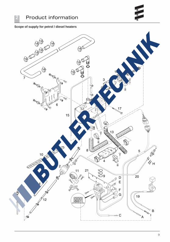
Scope of supply for petrol / diesel heaters
Quantity / Designation Order number
Petrol heaters1 HYDRONIC B 4 W S FL – 12 V 20 1866 05 00 00
as complete package*
1 HYDRONIC B 5 W S – 12 V 20 1862 05 00 00as complete package*
Diesel heaters1 HYDRONIC D 4 W S FL – 12 V 25 2418 05 00 00
as complete package*
1 HYDRONIC D 5 W S – 12 V 25 2386 05 00 00as complete package*
To be ordered separately:1 Control unit** –
* Complete package contains:1 Heater1 Universal installation kit
** Control units see price list / accessories catalogue
Parts list for the picture “Scope of supply petrol /diesel heaters”
Picture No. Designation
1 Heater2 Dosing pump3 Waterpump4 Exhaust silencer5 Cable tree, heater6 Heater bracket7 Water hose8 Flexible exhaust pipe9 Cable tape
10 Bracket of perforated tape11 Bracket, dosing pump12 Pipe, 4 x 113 Combustion air hose14 Hose, 3.5 x 315 Pipe, 4 x 1.2516 Bracket, water pump17 Screw M6 x 9718 Tank withdrawal device19 Cable harness blower20 Cable harness dosing pump21 Combined bracket
Lead harnesses
A Connection of control unitsB Vehicle blower controlC Positive supply connectionD Negative supply connectionE Connection to terminal 85 (1-pin, brown)F Connection to terminal 86 (1-pin, red/black)G Diagnosis query (1-pin, blue/white)H Spare connector and seal
(required if shortening lead)I Positive power supply connection - blower relay
• Parts without picture number are small parts andpacked in a bag.
• Please consult the additional parts catalogue ifany other parts are required for installation.
Product information2
Please note!
9
Scope of supply for petrol / diesel heaters
Product information2
10
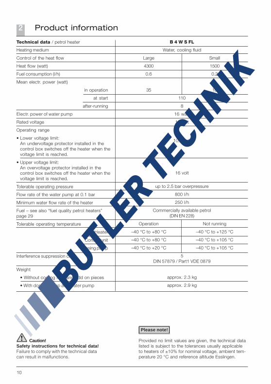
Caution!Safety instructions for technical data!Failure to comply with the technical datacan result in malfunctions.
B 4 W S FL
Water, cooling fluid
Large Small
4300 1500
0.6 0.2
35 10
110
8
16 watt
12 volt
10.2 volt
16 volt
up to 2.5 bar overpressure
800 l/h
250 l/h
Commercially available petrol(DIN EN 228)
Operation Not running
–40 °C to +80 °C –40 °C to +125 °C
–40 °C to +80 °C –40 °C to +105 °C
–40 °C to +20 °C –40 °C to +105 °C
5DIN 57879 / Part1 VDE 0879
approx. 2.3 kg
approx. 2.9 kg
Technical data / petrol heater
Heating medium
Control of the heat flow
Heat flow (watt)
Fuel consumption (l/h)
Mean electr. power (watt)
in operation
at start
after-running
Electr. power of water pump
Rated voltage
Operating range
• Lower voltage limit:An undervoltage protector installed in thecontrol box switches off the heater when thevoltage limit is reached.
• Upper voltage limit:An overvoltage protector installed in thecontrol box switches off the heater when thevoltage limit is reached.
Tolerable operating pressure
Flow rate of the water pump at 0.1 bar
Minimum water flow rate of the heater
Fuel – see also “fuel quality petrol heaters”page 29
Tolerable operating temperature
Heater
Control unit
Dosing pump
Interference suppression class
Weight
• Without cooling fluid and add on pieces
• With dosing pump and water pump
Please note!
Provided no limit values are given, the technical datalisted is subject to the tolerances usually applicableto heaters of ±10% for nominal voltage, ambient tem-perature 20 °C and reference altitude Esslingen.
Product information2

11
Caution!Safety instructions for technical data!Failure to comply with the technical datacan result in malfunctions.
Technical data / petrol heater
Heating medium
Control of the heat flow
Heat flow (watt)
Fuel consumption (l/h)
Mean electr. power (watt)
in operation
at start
after-running
Electr. power of water pump
Rated voltage
Operating range
• Lower voltage limit:An undervoltage protector installed in thecontrol box switches off the heater when thevoltage limit is reached.
• Upper voltage limit:An overvoltage protector installed in thecontrol box switches off the heater when thevoltage limit is reached.
Tolerable operating pressure
Flow rate of the water pump at 0.1 bar
Minimum water flow rate of the heater
Fuel – see also “fuel quality petrol heaters”page 29
Tolerable operating temperature
Heater
Control unit
Dosing pump
Interference suppression class
Weight
• Without cooling fluid and add on pieces
• With dosing pump and water pump
B 5 W S
Water, cooling fluid
Large Small
5000 1500
0.69 0.2
37 10
110
8
16 watt
12 volt
10.2 volt
16 volt
up to 2.5 bar overpressure
800 l/h
250 l/h
Commercially available petrol(DIN EN 228)
Operation Not running
–40 °C to +80 °C –40 °C to +125 °C
–40 °C to +80 °C –40 °C to +105 °C
–40 °C to +20 °C –40 °C to +105 °C
5DIN 57879 / Part1 VDE 0879
approx. 2.3 kg
approx. 2.9 kg
Please note!
Provided no limit values are given, the technical datalisted is subject to the tolerances usually applicableto heaters of ±10% for nominal voltage, ambient tem-perature 20 °C and reference altitude Esslingen.
Product information2

12
Caution!Safety instructions for technical data!Failure to comply with the technical datacan result in malfunctions.
D 4 W S FL
Water, cooling fluid
Large Small
4300 2400
0.53 0.27
35 10
110
8
16 watt
12 volt
10.2 volt
16 volt
up to 2.5 bar overpressure
800 l/h
250 l/h
Commercially available diesel(DIN EN 590)
Operation Not running
–40 °C to +80 °C –40 °C to +105 °C
–40 °C to +80 °C –40 °C to +105 °C
–40 °C to +20 °C –40 °C to +105 °C
5DIN 57879 / Part1 VDE 0879
approx. 2.3 kg
approx. 2.9 kg
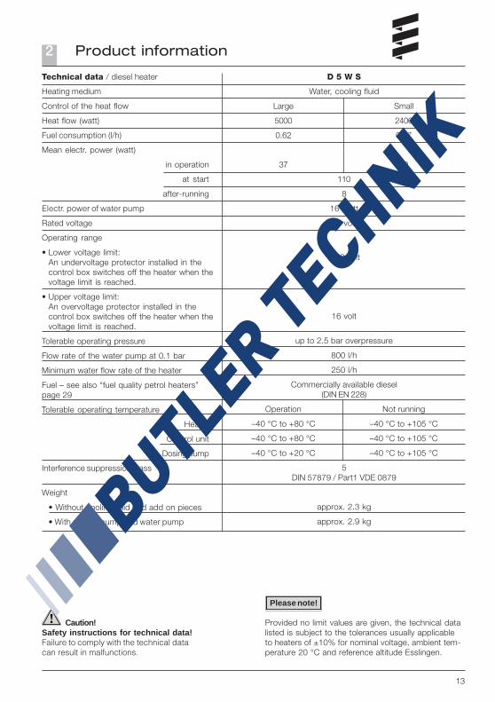
Technical data / diesel heater
Heating medium
Control of the heat flow
Heat flow (watt)
Fuel consumption (l/h)
Mean electr. power (watt)
in operation
at start
after-running
Electr. power of water pump
Rated voltage
Operating range
• Lower voltage limit:An undervoltage protector installed in thecontrol box switches off the heater when thevoltage limit is reached.
• Upper voltage limit:An overvoltage protector installed in thecontrol box switches off the heater when thevoltage limit is reached.
Tolerable operating pressure
Flow rate of the water pump at 0.1 bar
Minimum water flow rate of the heater
Fuel – see also “fuel quality petrol heaters”page 29
Tolerable operating temperature
Heater
Control unit
Dosing pump
Interference suppression class
Weight
• Without cooling fluid and add on pieces
• With dosing pump and water pump
Please note!
Provided no limit values are given, the technical datalisted is subject to the tolerances usually applicableto heaters of ±10% for nominal voltage, ambient tem-perature 20 °C and reference altitude Esslingen.
Product information2
13
Caution!Safety instructions for technical data!Failure to comply with the technical datacan result in malfunctions.
Technical data / diesel heater
Heating medium
Control of the heat flow
Heat flow (watt)
Fuel consumption (l/h)
Mean electr. power (watt)
in operation
at start
after-running
Electr. power of water pump
Rated voltage
Operating range
• Lower voltage limit:An undervoltage protector installed in thecontrol box switches off the heater when thevoltage limit is reached.
• Upper voltage limit:An overvoltage protector installed in thecontrol box switches off the heater when thevoltage limit is reached.
Tolerable operating pressure
Flow rate of the water pump at 0.1 bar
Minimum water flow rate of the heater
Fuel – see also “fuel quality petrol heaters”page 29
Tolerable operating temperature
Heater
Control unit
Dosing pump
Interference suppression class
Weight
• Without cooling fluid and add on pieces
• With dosing pump and water pump
D 5 W S
Water, cooling fluid
Large Small
5000 2400
0.62 0.27
37 10
110
8
16 watt
12 volt
10.2 volt
16 volt
up to 2.5 bar overpressure
800 l/h
250 l/h
Commercially available diesel(DIN EN 228)
Operation Not running
–40 °C to +80 °C –40 °C to +105 °C
–40 °C to +80 °C –40 °C to +105 °C
–40 °C to +20 °C –40 °C to +105 °C
5DIN 57879 / Part1 VDE 0879
approx. 2.3 kg
approx. 2.9 kg
Please note!
Provided no limit values are given, the technical datalisted is subject to the tolerances usually applicableto heaters of ±10% for nominal voltage, ambient tem-perature 20 °C and reference altitude Esslingen.
Product information2
14
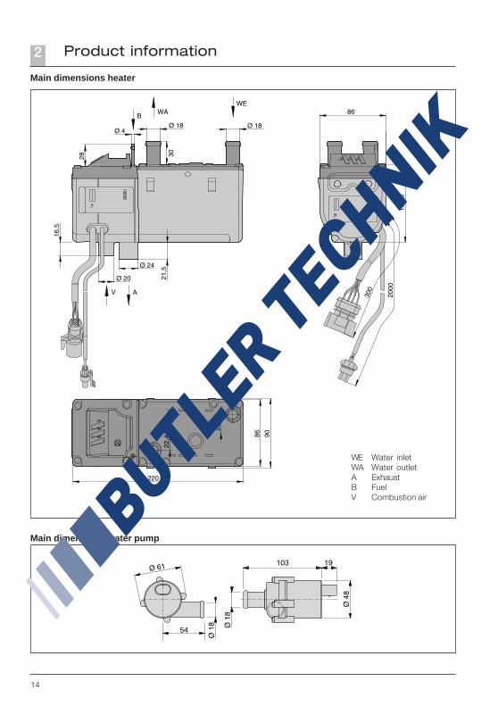
Main dimensions heater
Main dimensions water pump
Product information2
WE Water inletWA Water outletA ExhaustB FuelV Combustion air

15
Installation exampleheater in a delivery van
Installation location
The installation location for the heater is the enginecompartment. The heater must be mounted below themin. cooling water level (compensation tank, cooler,vehicle heat exchanger) for automatic venting of theheat exchanger of the heater and the water pump.
• The regulations and safety instructions to be obser-ved for this chapter are stated on page 4 – 7.
• The installation suggestions made in the installationinstructions are examples. Other installation locati-ons are possible if they correspond to the installati-on requirements stated in these installation instruc-tions.
• Other installation information (e.g. for boats andships) is available from the manufacturer on request.
• Please take note of the installation locations toge-ther with the operating and storage temperatures.
• Ensure an adequate distance from hot vehicle parts.
Installation3
1 Heater2 Water pump3 Exhaust pipe with exhaust silencer4 Combustion air intake silencer5 Fan relay6 Fuse bracket7 Control unit8 Dosing pump9 Rising pipe
Installation exampleheater in a car
Please note!
1 Heater2 Water pump3 Exhaust pipe with exhaust silencer4 Combustion air hose5 Fuse holder6 Fan relay7 Contol unit8 Dosing pump9 T-piece for fuel

16
Installation3
Possible installation positions
The heater should preferably be installed in the normalposition, horizontal with the exhaust connection downto the bottom.Depending on the installation conditions, the heatercan also be mounted in the permitted swivel range,see diagram.
When the heater is operating, the shown normal ormaximum installation positions can be varied brieflyby up to +15° in all directions. Such deviationscaused by the inclined position of the vehicle do notimpair the heater functions in any way.
Water pump in normal position withpermitted swivel range
The pressure connection must point 5° upwards,as shown in the diagram.
Heater in normal position withpermitted swivel range
Please note!
Swivel range from the normal positionup to max. 90° swivel upwards.
Swivel range from the normal position tomax. 90° swivel around the longitudinal axis.

17
Installation3
1 Heater2 Bracket clips3 Bracket holder
Mounting and fastening
Position the heater in the holding clips of the heaterbracket and fasten with fastening screw, M6 x 97(torque 60.5Nm). Mount the heater bracket in a suitableposition in the engine compartment, possibly usinganti-vibration pads if necessary.
Depending on the installation space available, theheater can be moved sideways in the bracket andscrewed in one of the two fastening threads.
Please note!
Please note!
4 Fastening screw5 Fastening thread
Mounting the angled water connection
The heater is supplied with a straight water connection.Depending on the installation conditions, it may benecessary to mount an angled water connection.• Unscrew the fastening screws on the cover and
remove the cover.• Press the straight water connection down.• Loosen the indented ring and remove the O-ring
seal.• Pull the water connection out of the cover.• Insert the angled water connection into the cover,
insert the new O-ring seal in the provided grooveand grease lightly.
• Mount the indented ring to the angled waterconnection, turn the water connection according tothe installation position and insert in the toothed rimof the cover.
• Screw the cover to the housing again using 4 screws,torque 4 Nm.
If the previous screw opening is covered by theangled water connection, the neighbouring screw holewill have to be used instead.
Please proceed as follows:• Cut a thread in the bore of the aluminium housing:
to do so, screw a tapping screw into the bore andunscrew it again.
• Place the cover on the housing and screw in all fourscrews – torque 4.5 Nm.
The thread must be cut before mounting the cover.
1 Fastening screws2 Straight connection3 Indented ring4 O-ring
5 Cover6 Angled connection7 Bore holes8 Heater
18
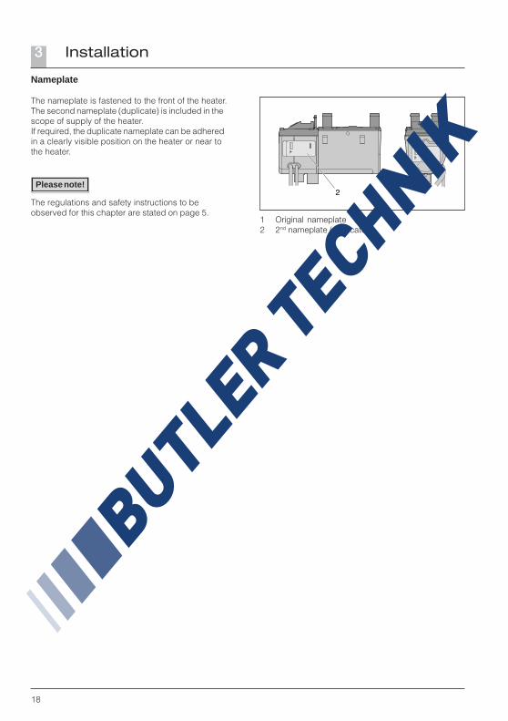
Nameplate
The nameplate is fastened to the front of the heater.The second nameplate (duplicate) is included in thescope of supply of the heater.If required, the duplicate nameplate can be adheredin a clearly visible position on the heater or near tothe heater.
The regulations and safety instructions to beobserved for this chapter are stated on page 5.
1 Original nameplate2 2nd nameplate (duplicate)
Please note!
Installation3

19
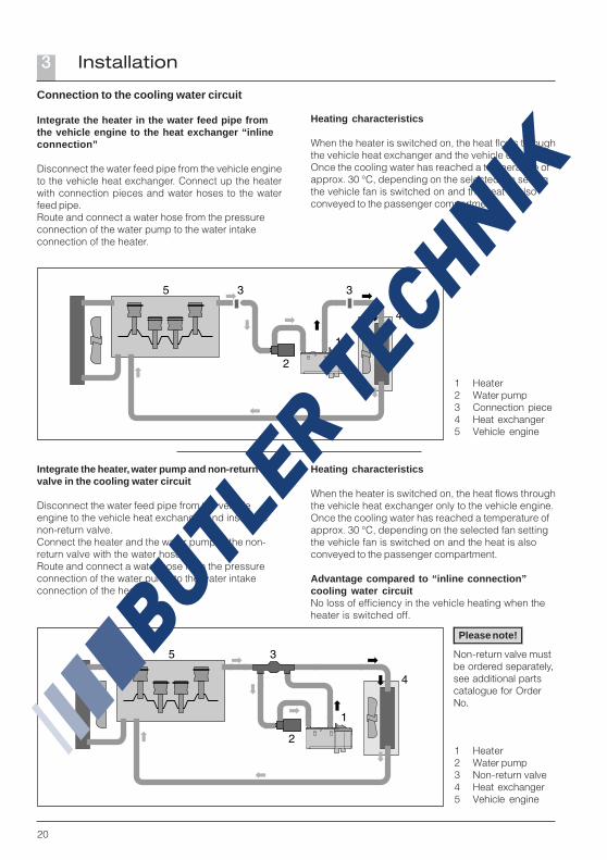
Connection to the cooling water circuit
The heater is connected to the cooling water circuitin the water feed pipe from the vehicle engine to theheat exchanger. There are four possible alternativeinstallations here.
The alternatives are described on pages 20 – 22.
Danger!Risk of injuries and burns!
It is possible for the coolant and components of thecoolant circuit to get very hot.
• Parts conveying water must be routed and fastenedin such a way that they pose no temperature risk toman, animals or material sensitive to temperaturefrom radiation / direct contact.
• Before working on the coolant circuit, switch theheater off and wait until all components have cooleddown completely, if necessary where safety gloves.
• When installing the heater and the water pump,please note the direction of flow of the coolantcircuit.
• Fill the heater and water hoses with coolant beforeconnecting to the coolant circuit.
• Route the water hoses without any kinks, and in arising position if possible.
• When routing the water pipes, observe a sufficientclearance to hot vehicle parts.
• Protect all water hoses / water pipes from chafingand from extreme temperatures.
• Secure all hose connections with hose clips(Tightening torque = 1.5 Nm).
• After the vehicle has been operating for 2 hours ortravelled 100 km, tighten the hose clips again.
• The minimum water flow rate is only guaranteed ifthe temperature difference of the heating mediumdoes not exceed 10 K between water inlet and wateroutlet during heating.
• Only overpressure valves with an opening pressureof min. 0.4 – max. 2 bar may be used in the coolantcircuit.
• The coolant liquid must contain at least 10 %antifreeze all year round as corrosion protection.
• The cooling liquid must contain sufficient antifreezefor low temperatures.
• Before commissioning the heater or after changingthe cooling liquid, the whole coolant circuit includingheater must be vented free of bubbles according tothe instructions issued by the vehicle manufacturer.
• Only top up with coolant approved by the vehiclemanufacturer.
Please note!
Installation3
20
Heating characteristics
When the heater is switched on, the heat flows throughthe vehicle heat exchanger and the vehicle engine.Once the cooling water has reached a temperature ofapprox. 30 °C, depending on the selected fan settingthe vehicle fan is switched on and the heat is alsoconveyed to the passenger compartment.
Connection to the cooling water circuit
Integrate the heater in the water feed pipe fromthe vehicle engine to the heat exchanger “inlineconnection”
Disconnect the water feed pipe from the vehicle engineto the vehicle heat exchanger. Connect up the heaterwith connection pieces and water hoses to the waterfeed pipe.Route and connect a water hose from the pressureconnection of the water pump to the water intakeconnection of the heater.
1 Heater2 Water pump3 Connection piece4 Heat exchanger5 Vehicle engine
Integrate the heater, water pump and non-returnvalve in the cooling water circuit
Disconnect the water feed pipe from the vehicleengine to the vehicle heat exchanger and insert thenon-return valve.Connect the heater and the water pump to the non-return valve with the water hoses.Route and connect a water hose from the pressureconnection of the water pump to the water intakeconnection of the heater.
Heating characteristics
When the heater is switched on, the heat flows throughthe vehicle heat exchanger only to the vehicle engine.Once the cooling water has reached a temperature ofapprox. 30 °C, depending on the selected fan settingthe vehicle fan is switched on and the heat is alsoconveyed to the passenger compartment.
Advantage compared to “inline connection”cooling water circuitNo loss of efficiency in the vehicle heating when theheater is switched off.
1 Heater2 Water pump3 Non-return valve4 Heat exchanger5 Vehicle engine
Please note!
Non-return valve mustbe ordered separately,see additional partscatalogue for OrderNo.
Installation3

21
Heating characteristics
Small coolant circuitFast heating of the passenger compartment. Initiallythe heat produced by the heater is only conveyed tothe heat exchanger up to a cooling water temperatureof approx. 70 °C. This heats the passengercompartment up quickly.Large cooling water circuitIf the cooling water temperature continues to increase,the thermostat slowly changes over to the large circuit(full change-over at approx. 75 °C). This heats thepassenger compartment up and also allows for enginepre-heating.
Connection to the cooling water circuit
Integrate the heater, water pump, non-return valve,thermostat and T-piece in the cooling water circuit.
Disconnect the water feed pipe from the vehicleengine to the vehicle heat exchanger and insertthe non-return valve.Disconnect the water return pipe from the heatexchanger to the vehicle engine and insert theT-piece.Connect the heater and the water pump to thethermostat, non-return valve and T-piece usingwater hoses, as shown in the diagram.
Thermostat functions
Cooling water temperature <70 °C – small coolantcircuit:Connection no. 1 – open to the heaterConnection no. 2 – open to the T-pieceConnection no. 3 – closed to the non-return valve
Cooling water temperature >75 °C – large coolantcircuit:Connection no. 1 – open (to the heater)Connection no. 2 – closed (to the T-piece)Connection no. 3 – open (to the non-return valve)
Integrate the thermostat into the water circuit withconnections (1), (2) and (3) as shown in the diagram.
The thermostat, non-return valve and T-piece must beordered separately, see additional parts catalogue forOrder No.
1 Heater2 Water pump3 Non-return valve4 Thermostat5 T-piece6 Heat exchanger7 Vehicle engine
Please note!
Please note!
1 Connection to the heater2 Connection to the T-piece3 Connection to the non-return valve
Installation3
22
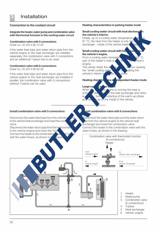
Connection to the coolant circuit
Integrate the heater, water pump and combination valvewith thermostat function in the cooling water circuit
Combination valve with 5 connectionsOrder no. 25 2014 80 72 00
If the water feed pipe and water return pipe from thevehicle engine to the heat exchanger are installedseparately, the combination valve with 5 connectionsand an additional T-piece has to be used.
Combination valve with 6 connectionsOrder no. 25 2014 80 62 00
If the water feed pipe and water return pipe from thevehicle engine to the heat exchanger are installed inparallel, the combination valve with 6 connections(without T-piece) can be used.
Install combination valve with 5 connections
Disconnect the water feed pipe from the vehicle engineto the vehicle heat exchanger and insert the combinationvalve.Disconnect the water return pipe from the heat exchangerto the vehicle engine and insert the T-piece.Connect the heater to the combination valve and T-piecewith the water hoses, as shown in the drawing.
Install combination valve with 6 connections
Disconnect the water feed pipe and the water returnpipe from the vehicle engine to the vehicle heatexchanger and insert the combination valve.Connect the heater to the combination valve with thewater hoses, as shown in the drawing.
1 Heater2 Water pump3 Combination valve
(5 connections)4 T-piece5 Heat exchanger6 Vehicle engine
Combination valve with thermostat function(6 connections)
Heater
fromvehicle engine
tovehicle engine
tovehicle heat exchanger
fromvehicle exchanger
Heating characteristics in parking heater mode
Small cooling water circuit with heat discharge inthe vehicle's interior.Initially, up to a cooling water temperature of approx67 °C, the heat from the heater is only fed to the heatexchanger - inside of the vehicle heats up fast.
Small cooling water circuit with heat discharge atthe vehicle's engine.From a cooling water temperature of around 67 °C,part of the heater's heat is also fed to the vehicle'sengine.This slowly heats the engine circuit, without causingthe "small cooling water circuit" for heating thevehicle's interior to rapidly cool down.
Heating characteristics in independent heater mode
Large cooling water circuitWhen the vehicle's engine is running the heat isuniformly distributed to the heat exchanger and vehic-le engine - further shortening of the warm-up phaseand heating up of the inside of the vehicle.
Installation3

23
Exhaust system
(Exhaust diagram see page 24)
Mounting the exhaust system
The scope of supply of the universal installation kitincludes a flexible exhaust pipe, inner Ø 24 mm,1000 mm long and an exhaust silencer.The flexible exhaust pipe can be shortened to 20 cmor lengthened to max. 2 m, depending on theinstallation conditions.Fasten the exhaust silencer to a suitable position inthe vehicle. Route the flexible exhaust pipe from theheater to the exhaust silencer and fasten with pipeclips. Use a pipe clip to fix a short exhaust pipe end(with end sleeve) to the exhaust silencer.
Caution!Safety instructions!The whole exhaust system gets very hot during andimmediately after the heater has been working in theheating mode. This is why the exhaust system mustbe routed according to these installation instructions.• The exhaust outlet must end in the open air.• The exhaust pipe must not protrude beyond the
lateral limits of the vehicle.• Install the exhaust pipe sloping slightly downwards.
If necessary, make a drain hole approx. Ø 5 mm atthe lowest point to drain off condensation.
• Important functional parts of the vehicle must not beimpaired (keep sufficient clearance).
• Mount the exhaust pipe with sufficient clearance toheat-sensitive parts. Pay particular attention to fuelpipes (plastic or metal), electrical cables and brakehoses etc.!
• Exhaust pipes must be fastened safely(recommended clearance of 50 cm) to avoid damagefrom vibrations.
• Route the exhaust system so that the emitted fumesare not sucked in with the combustion air.
• The mouth of the exhaust pipe must not get cloggedby dirt and snow.
• The mouth of the exhaust pipe must not point in thedirection of travel.
• Always fasten the exhaust silencer to the vehicle.
Danger!Risk of injuries and burns!Every type of combustion produces high temperaturesand toxic exhaust fumes. This is the reason why theexhaust system must be installed according to theseinstructions.• Do not perform any work on the exhaust system
while the heater is working.• Before working on the exhaust system, first switch
the heater off and wait until all parts have cooleddown completely, wear safety gloves if necessary.
• Do not inhale exhaust fumes.
• Comply with the regulations and safety instructionsfor this chapter on page 4 – 7.
• If a silencer is fitted, the exhaust end pipe must bemuch shorter than the flexible exhaust pipe betweenthe heater and the exhaust silencer.
Please note!
Installation3
24
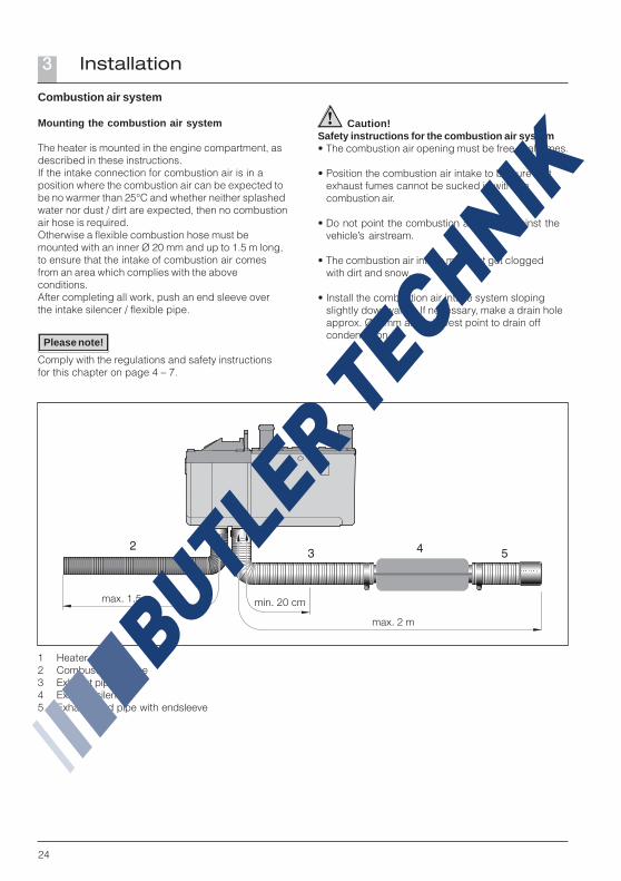
1 Heater2 Combustion air pipe3 Exhaust pipe4 Exhaust silencer5 Exhaust end pipe with endsleeve
Caution!Safety instructions for the combustion air system• The combustion air opening must be free at all times.
• Position the combustion air intake to be sure thatexhaust fumes cannot be sucked in with thecombustion air.
• Do not point the combustion air intake against thevehicle’s airstream.
• The combustion air intake must not get cloggedwith dirt and snow.
• Install the combustion air intake system slopingslightly downwards. If necessary, make a drain holeapprox. Ø 5 mm at the lowest point to drain offcondensation.
Combustion air system
Mounting the combustion air system
The heater is mounted in the engine compartment, asdescribed in these instructions.If the intake connection for combustion air is in aposition where the combustion air can be expected tobe no warmer than 25°C and whether neither splashedwater nor dust / dirt are expected, then no combustionair hose is required.Otherwise a flexible combustion hose must bemounted with an inner Ø 20 mm and up to 1.5 m long,to ensure that the intake of combustion air comesfrom an area which complies with the aboveconditions.After completing all work, push an end sleeve overthe intake silencer / flexible pipe.
Comply with the regulations and safety instructionsfor this chapter on page 4 – 7.
Please note!
max. 2 m
max. 1.5 m min. 20 cm
Installation3

25
Fuel supply
Mounting the dosing pump, routing the fuel pipesand mounting the fuel tank
The following safety instructions must be observedwhen mounting the dosing pump, routing the fuel pipesand mounting the fuel tank.Deviations from the instructions stated here are notallowed.Failure to comply can result in malfunctions.
Danger!Risk of fire, explosion, poisoning and injuries!
Caution when handling fuel.
• Switch off the vehicle engine and heater beforerefuelling and before working on the fuel supply.
• No naked lights when handling fuel.
• Do not smoke.
• Do not inhale fuel vapours.
• Avoid any contact with the skin.
Caution!Safety instructions for routing the fuel pipes!
• Only use a sharp knife to cut off fuel hoses andpipes. Interfaces must not be crushed and must befree of burrs.
• The fuel pipe from the dosing pump to the heatershould be routed at a continuous rise.
• Fuel pipes must be fastened safely to avoid anydamage and / or noise production from vibrations(recommended clearance of approx. 50 cm).
• Fuel pipes must be protected from any mechanicaldamage.
• Route the fuel pipes so that any distortion of thevehicle, engine movements etc. cannot have anylasting effect on the service life.
• Parts carrying fuel must be protected frominterfering heat.
• Never route or fasten the fuel pipes to the heater orvehicle exhaust system. When the systems cross,always ensure there is a sufficient heat clearance.If necessary, install heat deflection plates.
• Dripping or evaporating fuel must never be allowedto collect on hot parts or ignite on electric systems.
• When connecting fuel pipes with a fuel hose, alwaysmount the fuel pipes in a butt joint to prevent anybubbles from forming.
Safety instructions for fuel pipes and fuel tanksin buses and coaches
• In buses and coaches, fuel pipes and fuel tanksmust not be routed through the passengercompartment or driver’s cab.
• Fuel tanks in buses and coaches must bepositioned in such a way that the exits are not indirect danger from a possible fire.
Comply with the regulations and safety instructionsfor this chapter on page 4 – 7.
Please note!
1 Correct connection2 Incorrect connection – bubble formation
1 2
Installation3

26
Fuel feed point with T-piece from the fuel supply linefrom the tank fitting to the vehicle engine
1 Fuel feed pipe from tank connection – insertT-piece before the fuel pump in the fuel feed pipe.
2 Fuel return pipe to the tank connection3 Dosing pump4 T-piece5 Fuel pipe, 4 x 1 (di = Ø 2 mm)6 Fuel pipe, 4 x 1.25 (di = Ø 1.5 mm)7 Fuel hose, 3.5 x 3 (di = Ø 3.5 mm),
approx. 50 mm long8 To the engine, mechanical fuel or injection pump.
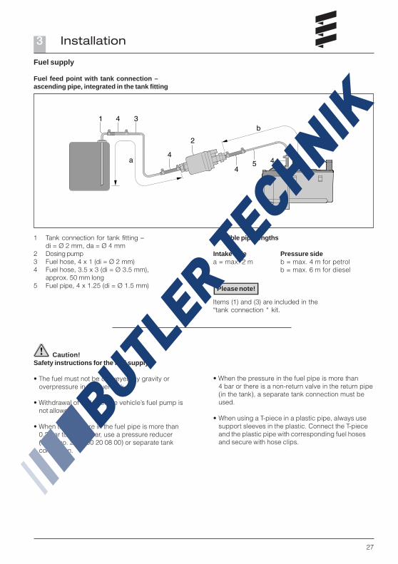
Possible pipe lengths
Intake side Pressure sidea = max. 2 m b = max. 4 m for petrol
b = max. 6 m for diesel
Fuel supply
Item (4) is not included in the scopeof supply “installation kit”.Order no. see extra parts catalogue.
Please note!
Installation position of the T-piece
Use the installation positions shown in the diagramwhen inserting a T-piece.
1 Direction of flow from the fuel tank2 Direction of flow to the vehicle engine
1 2
Installation3
27
Fuel feed point with tank connection –ascending pipe, integrated in the tank fitting
1 Tank connection for tank fitting –di = Ø 2 mm, da = Ø 4 mm
2 Dosing pump3 Fuel hose, 4 x 1 (di = Ø 2 mm)4 Fuel hose, 3.5 x 3 (di = Ø 3.5 mm),
approx. 50 mm long5 Fuel pipe, 4 x 1.25 (di = Ø 1.5 mm)
Items (1) and (3) are included in the“tank connection “ kit.
Fuel supply
Caution!Safety instructions for the fuel supply!
• The fuel must not be conveyed by gravity oroverpressure in the fuel tank.
• Withdrawal of fuel after the vehicle’s fuel pump isnot allowed.
• When the pressure in the fuel pipe is more than0.2 bar to max. 4 bar, use a pressure reducer(order no. 22 1000 20 08 00) or separate tankconnection.
• When the pressure in the fuel pipe is more than4 bar or there is a non-return valve in the return pipe(in the tank), a separate tank connection must beused.
• When using a T-piece in a plastic pipe, always usesupport sleeves in the plastic. Connect the T-pieceand the plastic pipe with corresponding fuel hosesand secure with hose clips.
Please note!
Possible pipe lengths
Intake side Pressure sidea = max. 2 m b = max. 4 m for petrol
b = max. 6 m for diesel
Installation3
28
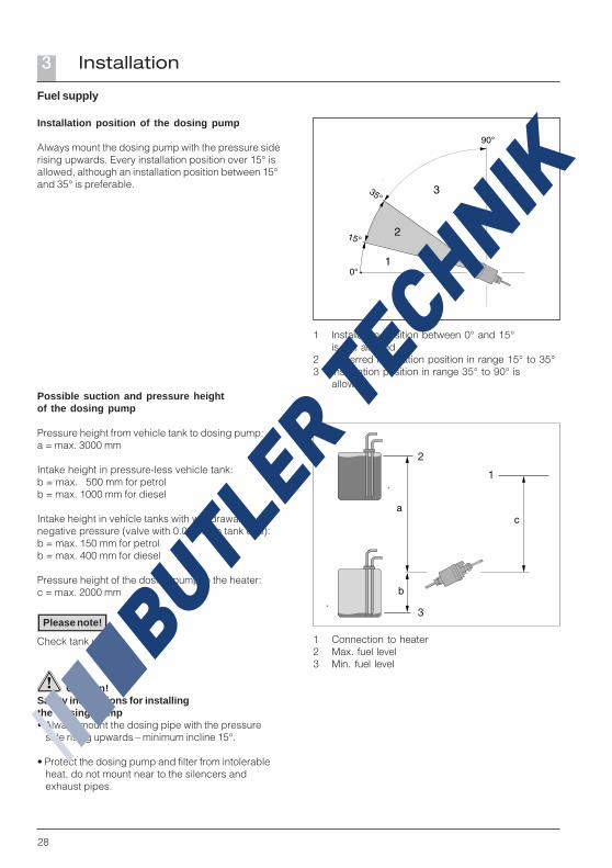
Possible suction and pressure heightof the dosing pump
Pressure height from vehicle tank to dosing pump:a = max. 3000 mm
Intake height in pressure-less vehicle tank:b = max. 500 mm for petrolb = max. 1000 mm for diesel
Intake height in vehicle tanks with withdrawal bynegative pressure (valve with 0.03 bar in tank cap):b = max. 150 mm for petrolb = max. 400 mm for diesel
Pressure height of the dosing pump to the heater:c = max. 2000 mm
Check tank venting. 1 Connection to heater2 Max. fuel level3 Min. fuel level
Fuel supply
Installation position of the dosing pump
Always mount the dosing pump with the pressure siderising upwards. Every installation position over 15° isallowed, although an installation position between 15°and 35° is preferable.
1 Installation position between 0° and 15°is not allowed
2 Preferred installation position in range 15° to 35°3 Installation position in range 35° to 90° is
allowed
Caution!Safety instructions for installingthe dosing pump• Always mount the dosing pipe with the pressure
side rising upwards – minimum incline 15°.
• Protect the dosing pump and filter from intolerableheat, do not mount near to the silencers andexhaust pipes.
Please note!
Installation3
29
Fuel supply
Fuel quality for petrol heaters
The heater can run on commercially available fuelas per DIN EN 228, as used in the vehicle tank.
Fuel quality for diesel heaters
The heater can run on commercially available fuelas per DIN EN 590, as used in the vehicle tank.
Fuel for special cases
In special cases (above 0 °C), the heater can alsorun on fuel oil EL or paraffin.
Fuel for low temperatures
Refineries and fuel service stations automaticallyadjust the fuel to normal winter temperatures (winterdiesel). This means that difficulties are only to beexpected for extreme drops in temperature, as alsoapply to the vehicle engine. Please also refer to thevehicle manual.
If the heater is run from a separate tank, pleasecomply with the following rules:For temperatures above 0 °C, any kind of diesel fuelas per DIN EN 590 can be used.
If no special diesel fuel is available for lowtemperatures, then paraffin or petrol should be mixedwith the fuel according to the following table:
Temperature Winterdiesel Addition 0 °C to –25 °C 100 % ––25 °C to –40 °C 150 %* 50 % paraffin
or petrol
* or 100 % special cold diesel fuel (Arctic diesel)
• Mixtures with used oil are not allowed!
• After refuelling with winter or cold diesel or the listedblends, the fuel pipes and the dosing pump must befilled with the new fuel by letting the heater run for15 mins.!
Operation with biodiesel (PME)
The heater is not certified for operation with biodiesel.
Please note!
Installation3

30
Operation and function4
Operating instructions
The heater is operated by a control element.Detailed operating instructions are enclosed with thecontrol unit.
The workshop / garage installing the heater will issueyou with the operating instructions.
Important instructions for operation
Safety checks before the startAfter a lengthy period of non-use (summer months)check that all parts fit securely (tighten screws wherenecessary).Check the fuel system visually for any leaks.
Before switching onBefore switching on or pre-programming the heater,adjust the heating control in the vehicle to “WARM”(maximum setting) and the fan to “slow” (low powerconsumption).In vehicles with automatic heating, adjust the heatingcontrol to “MAX” and open the heating vents beforeswitching the ignition off.
Pre-venting with change-over “heating / venting”Pre-venting with change-over “heating / venting”Pre-venting with change-over “heating / venting”Pre-venting with change-over “heating / venting”Pre-venting with change-over “heating / venting”Pre-venting means the possibility of starting thevehicle fan directly from the heater preselection timeror, even more convenient, from the radio remotecontrol, thus bypassing the heating mode, so that thepassenger compartment, which frequently heats upconsiderably in summer weather, can be ventilatedbriefly with fresh air (separate wiring).
Heating at high altitudesWhen using the heater at high altitudes, please note:• Heating at altitudes up to 1500 m:
– Unlimited heating possible.• Heating at altitudes over 1500 mm:
– Heating is possible for short periods at this altitude(e.g. driving over a mountain pass or taking abreak in a journey).
– in the event of a lengthy stay, e.g. wintercamping, it is necessary to adjust the fuel supplyto the altitude, please contact a JE partner forfurther information.
In diesel heaters, 12 volt, it is possible to install analtitude pump kit (Order No.: 24 0222 00 00 00),which allows the heater to be run at altitudes over1500 m and up to 2750 m, even during a lengthy stay.
Initial commissioning
The following points are to be checked by thecompany installing the heater during initialcommissioning.
• After installation of the heater, the coolant circuitand the whole fuel supply system must be ventedcarefully. Comply with the instructions issued by thevehicle manufacturer.
• Open the coolant circuit before the trial run (se thetemperature control to “WARM”).
• During the trial run of the heater, check all water andfuel connections for leaks and firm fitting.
• If the heater shows a fault during operation, findand eliminate the cause of the fault using adiagnosis unit.
Description of functions
Switching on (pre-heating mode)When switched on, the operating display in the con-trol unit lights up. The water pump starts up.After a specific program sequence the combustion airfan, glow plug and metering pump start up and initia-te combustion. Once a stable flame has formed, theglow plug switches off under time control.
Heating modeDepending on heating requirements, the heater isadjusted in the following stages:LARGE – SMALL – OFF (Pause).The temperature limits are permanently programmed inthe electronic controller.If the heating requirements in the “SMALL” stage areso small that the cooling water temperature reaches85 °C, the heater goes into the pause mode.The heater continues to run on for approx.120 seconds, then it switches off (Pause mode).The control lamp lights up and the water pumpcontinues to run, even in the pause mode.
To compensate for the low heating requirementscoming from the vehicle engine, the heater can beoperated as pre-heater or combined pre-heater andextra heater, depending on the settings (wiring seecircuit diagram).
Please note!
Please note!
Please note!

31
Operation and function4
Control and safety devices
The heater is equipped with the following control andsafety devices.
• If the heater does not ignite within 90 secondsafter starting the fuel pump, the start is repeated.If the heater still does not ignite after another90 seconds, the heater is switched off. After anunacceptable number of failed start attempts, thecontroller is locked.*
• f the flame goes off by itself during operation, theheater is restarted.If the heater does not ignite within 90 seconds afterthe fuel pump has started, or ignites and goes offagain within 15 minutes, the heater is switched off.This status can be remedied by briefly switching offand on again.
• In the case of overheating (e.g. lack of water, poorlyvented coolant circuit), the overheating sensortriggers, the fuel supply is interrupted and the heaterswitched off.Once the cause of overheating has been eliminated,the heater can be re-started by switching off and onagain (on condition that the heater has cooled downagain sufficiently, cooling water temperature<70 °C). After the heater has been switched offfor overheating an unacceptable number of times,the controller is locked.*
• The heater is switched off if the upper or lowervoltage limit is reached.
• The heater does not start up when the glow plug isdefect or when the electric lead to the dosing pumpis interrupted.
• The speed of the fan motor is monitored continuously.If the fan motor does not start up, if it is blocked or ifthe speed falls below 40 % of the nominal speed, theheater is switched off after 60 sec.
* The controller can be enabled again and the faultsread off:• using the module timer / timer EasyStart T• using the radio remote control TP5 / EasyStart R+For other controls:• by connecting up a diagnosis unit• using the customer service program
KD2000 / EDiTHFor operation and fault list, please refer to theenclosed operating instructions or the troubleshoo-ting and repair instructions for the heater.
Emergency shutdown – EMERGENCY OFFIf an emergency shutdown – EMERGENCY OFF –is necessary during operation, proceed as follows:• Switch the heater off with the control or• pull the fuse out or• disconnect the heater from the battery.
Please note!
Do not switch the heater off and on again more thantwice.
32
Electrical system5
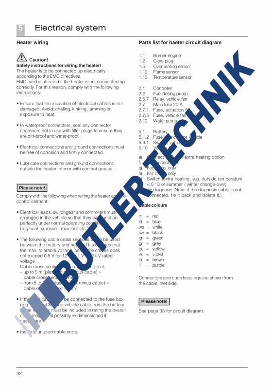
Heater wiring
Caution!Safety instructions for wiring the heater!The heater is to be connected up electricallyaccording to the EMC directives.EMC can be affected if the heater is not connected upcorrectly. For this reason, comply with the followinginstructions:
• Ensure that the insulation of electrical cables is notdamaged. Avoid: chafing, kinking, jamming orexposure to heat.
• In waterproof connectors, seal any connectorchambers not in use with filler plugs to ensure theyare dirt-proof and water-proof.
• Electrical connections and ground connections mustbe free of corrosion and firmly connected.
• Lubricate connections and ground connectionsoutside the heater interior with contact grease.
Comply with the following when wiring the heater and thecontrol element:
• Electrical leads, switchgear and controllers must bearranged in the vehicle so that they can functionperfectly under normal operating conditions(e.g.heat exposure, moisture etc.).
• The following cable cross sections are to be usedbetween the battery and heater. This ensures thatthe max. tolerable voltage loss in the cables doesnot exceed 0.5 V for 12 V or 1 V for 24 V ratedvoltage.Cable cross sections for a cable length of:– up to 5 m (plus cable + minus cable) = cable cross section 4 mm²– from 5 to 8 m (plus cable + minus cable) = cable cross section 6 mm²
• If the plus cable is to be connected to the fuse box(e.g. terminal 30), the vehicle cable from the batteryto the fuse box must be included in rating the overallcable length and possibly re-dimensioned ifnecessary.
• Insulate unused cable ends.
Parts list for haeter circuit diagram
1.1 Burner engine1.2 Glow plug1.5 Overheating sensor1.12 Flame sensor1.13 Temperature sensor
2.1 Controller2.2 Fuel dosing pump2.5.7 Relay, vehicle fan2.7 Main fuse 20 A2.7.1 Fuse, actuation 5A2.7.5 Fuse, vehicle fan 25 A2.12 Water pump
5.1 Battery5.1.2 Fuse block in the vehicle5.9.1 Switch, vehicle fan5.10 Vehicle fan
a) Connect to D+ for extra heating optionf) Disconnect lineg) For petrol onlyh) For diesel onlyk) Switch (extra heating, e.g. outside temperature
< 5 °C or summer / winter change-over)l) JE diagnosis (Note: if the diagnosis cable is not
connected, tie it back and isolate it.)
See page 33 for circuit diagram.
Connectors and bush housings are shown fromthe cable inlet side.
Please note!
Please note!
Cable colours
rt = redbl = bluews = whitesw = blackgn = greengr = greyge = yellowvi = violetbr = brownli = purple

33
Heater circuit diagram
Parts list page 32
Electrical system5
20 1861 00 96 01
34
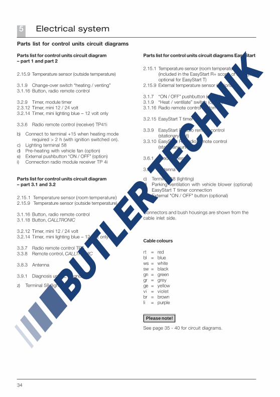
Cable colours
rt = redbl = bluews = whitesw = blackgn = greengr = greyge = yellowvi = violetbr = brownli = purple
Parts list for control units circuit diagram– part 3.1 and 3.2
2.15.1 Temperature sensor (room temperature)2.15.9 Temperature sensor (outside temperature)
3.1.16 Button, radio remote control3.1.18 Button, CALLTRONIC
3.2.12 Timer, mini 12 / 24 volt3.2.14 Timer, mini lighting blue – 12 volt only
3.3.7 Radio remote control TP53.3.8 Remote control, CALLTRONIC
3.8.3 Antenna
3.9.1 Diagnosis unit JE diagnosis
z) Terminal 58 (lighting)
Parts list for control units circuit diagrams
Parts list for control units circuit diagram– part 1 and part 2
2.15.9 Temperature sensor (outside temperature)
3.1.9 Change-over switch “heating / venting”3.1.16 Button, radio remote control
3.2.9 Timer, module timer2.3.12 Timer, mini 12 / 24 volt3.2.14 Timer, mini lighting blue – 12 volt only
3.3.6 Radio remote control (receiver) TP41i
b) Connect to terminal +15 when heating moderequired > 2 h (with ignition switched on).
c) Lighting terminal 58d) Pre-heating with vehicle fan (option)e) External pushbutton “ON / OFF” (option)i) Connection radio module receiver TP 4i
See page 35 - 40 for circuit diagrams.
Please note!
Parts list for control units circuit diagrams EasyStart
2.15.1 Temperature sensor (room temperature)(included in the EasyStart R+ scope of supply,optional for EasyStart T)
2.15.9 External temperature sensor (optional)
3.1.7 “ON / OFF” pushbutton (option)3.1.9 “Heat / ventilate” switch (option)3.1.16 Radio remote control button
3.2.15 EasyStart T timer
3.3.9 EasyStart R radio remote control(stationary unit)
3.3.10 EasyStart R+ radio remote control(stationary unit)
3.6.1 Lead harness
3.8.3 Antenna
c) Terminal 58 (lighting)d) Parking ventilation with vehicle blower (optional)e) EasyStart T timer connectiong) External "ON / OFF" button (optional)
Connectors and bush housings are shown from thecable inlet side.
Electrical system5
35
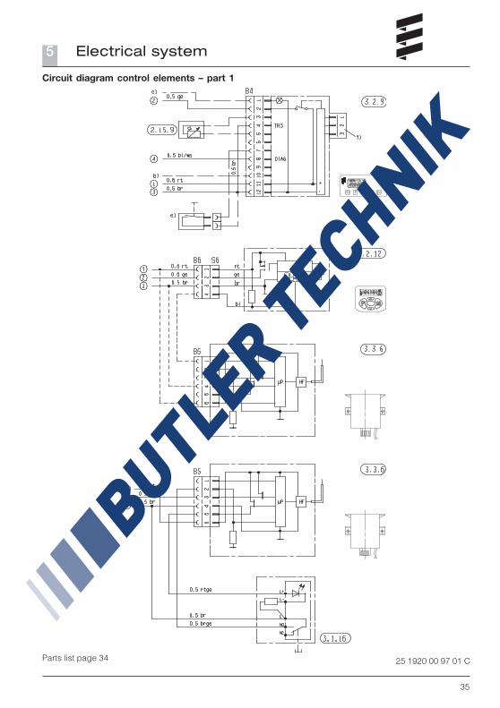
Circuit diagram control elements – part 1
Parts list page 34 25 1920 00 97 01 C
Electrical system5
36
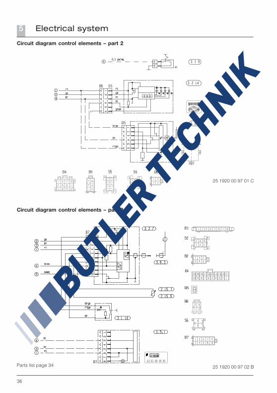
Circuit diagram control elements – part 2
Circuit diagram control elements – part 3.1
Parts list page 34 25 1920 00 97 02 B
25 1920 00 97 01 C
Electrical system5
37
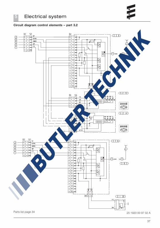
Circuit diagram control elements – part 3.2
Parts list page 34 25 1920 00 97 02 A
Electrical system5
38
Parts list page 34
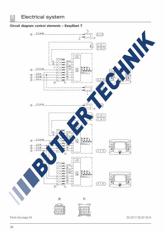
Circuit diagram control elements – EasyStart T
25 2217 00 97 03 A
Electrical system5
39
Parts list page 34
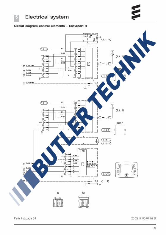
Circuit diagram control elements – EasyStart R
25 2217 00 97 02 B
Electrical system5
40
Electrical system5
Parts list page 34
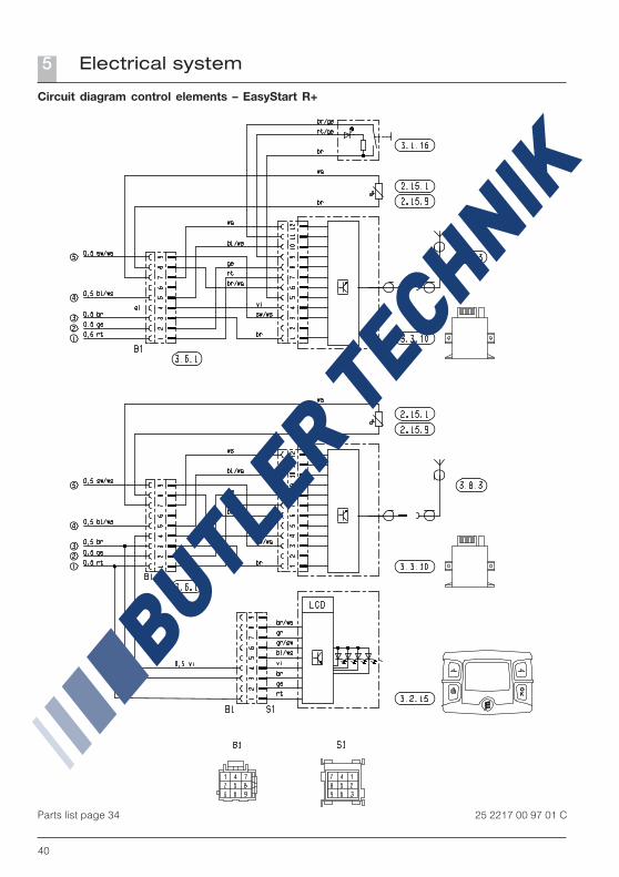
Circuit diagram control elements – EasyStart R+
25 2217 00 97 01 C

41
Troubleshooting / Maintenance / Service6
In case of faults, please check the followingpoints
• If the heater does not start after being switched on:– Switch the heater off and on again.
• If the heater still does not start, check whether:– There is fuel in the tank?– The fuses are OK?– The electrical cables, connections etc. are OK?– Anything is clogging the combustion air supply or exhaust system?
Troubleshooting
If the heater remains faulty even after these pointshave been checked, or another malfunction occursin your heater, please contact:
• For installation ex works, your contract workshop.
• For subsequent installation, the workshop whoinstalled your heater.
Please note that warranty claims can be become voidif the heater is changed by a third party or by thisinstallation of third party parts.
Maintenance instructions
• Switch the heater off once a month for about10 minutes, even outside the heating period.
• Before the heating period starts, the heater shouldundergo a trial run.If persistent extreme smoke develops, unusualburning noises or a clear fuel smell can be perceivedor if electric / electronic parts heat up, the heatermust be switched off and put out of service byremoving the fuse.In this case, the heater should not be started upagain until it has been checked by qualified staffwho have been trained on Eberspächer heaters.
• Check the openings of the combustion air supplyand exhaust system after longer standstill periods,clean if necessary!
Initial commissioning
The following points are to be checked by thecompany installing the heater during initialcommissioning.
• After installation of the heater, the coolant circuitand the whole fuel supply system must be ventedcarefully. Comply with the instructions issued by thevehicle manufacturer.
• Open the coolant circuit before the trial run (se thetemperature control to “OPEN”).
• During the trial run of the heater, check all water andfuel connections for leaks and firm fitting.
• If the heater shows a fault during operation, findand eliminate the cause of the fault using adiagnosis unit.
Service
If you have any technical queries or problemswith your pre-heater, dial the following servicephone number:
HotlinePhone. 0800 / 12 34 300
Fax hotlineFax 01805 / 26 26 24
Outside of Germany, please contact the respectivenational Eberspächer service agent.
Please note!

42
Environment7
EU Declaration of Conformity
With regard to the following products
Heater type HYDRONIC
we herewith confirm that it conforms with the primesafety requirements stipulated in the directives of theEU Council for harmonisation of the legal regulationsof the member states with regard to electromagneticcompatibility (89 / 336 / EEC).This declaration applies to all heaters producedaccording to the production drawings HYDRONICwhich are an integral part of this declaration.
The following standards/directives have been used toassess the product with regard to electromagneticcompatibility:• EN 50081 – 1 Basic form interference emission.• EN 50082 – 1 Basic form interference resistance.• 72 / 245 / EEC – Modification status 95 / 54 / EU
interference suppression in motor vehicles.
Certification
The high quality of Eberspächer’s products is the keyto our success.To guarantee this quality, we have organised all workprocesses in the company along the lines of qualitymanagement (QM).Even so, we still pursue a large number of activitiesfor continuous improvement of product quality in orderto keep pace with the similarly constantly growingrequirements made by our customers.All the steps necessary for quality assurance arestipulated in international standards.This quality is to be considered in a total sense.It affects products, procedures and customer/supplierrelationships.Officially approved public experts assess the systemand the corresponding certification company awardsa certificate.
Eberspächer has already qualified for the followingstandards:
Quality management as perDIN EN ISO 9001:2000 and ISO/TS 16949:1999
Environment management system as perDIN EN ISO 14001:1996
Disposal
Disposal of materialsOld devices, defect components and packagingmaterial can all be separated and sorted into pure-grade factions so that all parts can be disposed of asrequired in an environment-friendly manner or recycledwhere applicable.Electric motors, controllers and sensors (e.g.temperature sensors) are deemed to be “electronicscrap”.
Dismantling the heaterThe heater is dismantled according to the repairstages in the current troubleshooting / repairinstructions.
PackagingThe packaging of the heater can be kept in caseit has to be sent back.
43
Lists8
AAccident prevention ................................................... 7Altitude ..................................................................... 30Arrangement of the heater ......................................... 5
BBubble formation ...................................................... 25
CCable colours .................................................... 32, 34Cable harnesses ........................................................ 8Certification .............................................................. 42Circuit diagrams ................................................ 34 – 40Cooling water circuit ......................................... 19 – 22Combination valve .................................................... 22Combustion air system ............................................. 24Contents ..................................................................... 2Concept of this manual .............................................. 3Control in heating mode ............................................ 30Controls .................................................................... 31Connection to the coolant circuit ..................... 19 – 22
DDescription of functions ........................................... 30Declaration of conformity ......................................... 42Disposal .................................................................... 42Dosing pump ............................................................. 28
EElectrical system .............................................. 32 – 40Emergency shut-down .............................................. 31Emergency off .......................................................... 31Environment .............................................................. 42EU Declaration of Conformity .................................... 42Exhaust .................................................................... 23Exhaust system ............................................. 5, 23, 24
FFastening .................................................................. 17Faults ....................................................................... 41Forced shut-down ..................................................... 31Fuel .................................................................. 25 – 29Fuel quality ............................................................... 29Fuel supply .................................................. 5, 25 – 29
HHeating operation ..................................................... 30Heat flow .......................................................... 10 – 13Hotline ...................................................................... 41
IInformation ................................................................. 4Installation location .................................................. 15Installation positions ................................................ 16Instructions ........................................................... 6, 7Installation ........................................................ 15 – 29Introduction ................................................................ 2Initial commissioning ................................................ 30Interference suppression class ........................ 10 – 13
MMain dimensions ....................................................... 14Materials ................................................................... 42Maintenance ............................................................. 41
NNameplate ................................................................ 18
OOperation .................................................................. 30Operating instructions .............................................. 30
PPicture symbols .......................................................... 4Pipe length ......................................................... 26, 27Power consumption ........................................... 10 – 13Presentations ............................................................. 4Pressure side .................................................... 26, 27Purpose ...................................................................... 4
RRated voltage ................................................... 10 – 13Regulations ............................................................ 5, 6
SSafety devices .......................................................... 31Scope of supply ..................................................... 8, 9Special text structure ................................................. 4Statutory regulations ............................................. 5, 6Starting procedure .................................................... 30Suction height ........................................................... 28Switching on ............................................................. 30
List of key words A – Z
Keyword Page
List of key words A – Z
Keyword Page

44
Lists8
TTest symbol ................................................................ 5Text structure ............................................................. 4Technical data .................................................. 10 – 13Troubleshooting ........................................................ 41T-piece ...................................................................... 26
VVoltage ............................................................. 10 – 13Voltage limit ...................................................... 10 – 13
WWiring ....................................................................... 32
List of abbreviations
ADREuropean agreement about the international transportof dangerous goods on the road.
EC type approvalPermit awarded by the Federal Vehicle Office for theproduction of a heater for installation in motorisedvehicles.
EMC directiveElectromagnetic compatibility.
JE partnerJ. Eberspächer partner.
PMEBiodiesel as per DIN V 51606.
List of key words A – Z
Keyword Page


20 1
862
90 9
9 15
EN
06.2
007
Sub
ject
to c
hang
esP
rinte
d in
Ger
man
y©
J. E
bers
päch
er G
mbH
& C
o. K
G
www.eberspaecher.com
J. EberspächerGmbH & Co. KGEberspächerstr. 24D - 73730 EsslingenTelefon 0711 939 - 00Telefax 0711 939 - [email protected]

Related Documents