e For 01 LC Model: 2516880512V 2517670512V 2517740512V 2518300512V D1L-C INSTALLATION TROUBLESHOOTING & PARTS MANUAL 2516890524V 25 1768 05 24V 25 1775 05 24V 25 1831 05 24V MARCH 1995 http://www.hagerbv.com/catalogus/84-eberspacher-d1lc

Welcome message from author
This document is posted to help you gain knowledge. Please leave a comment to let me know what you think about it! Share it to your friends and learn new things together.
Transcript
--------.------------------~-----
e For 01 LC Model:
2516880512V 2517670512V 2517740512V 2518300512V
D1L-C
INSTALLATION
TROUBLESHOOTING
& PARTS MANUAL
2516890524V 25 1768 05 24V 25 1775 05 24V 25 1831 05 24V MARCH 1995
http://www.hagerbv.com/catalogus/84-eberspacher-d1lc
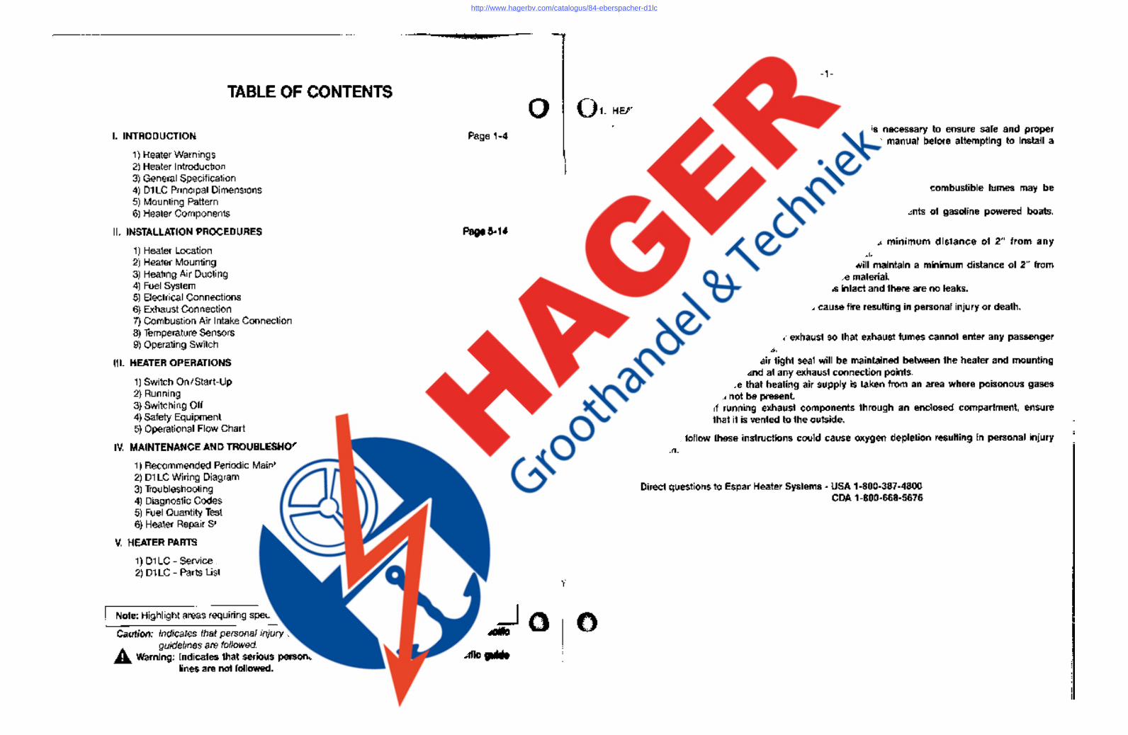
TABLE OF CONTENTS
I. INTRODUCTION
1) Heater Warnings 2) Heater Introduction 3) General Specification 4) D1 LC Principal Dimensions 5) Mounting Pattern 6) Heater Components
II. INSTALLATION PROCEDURES
1) Heater Location 2) Heater Mounting 3) Heating Air Ducting 4) Fuel System 5) Electrical Connections 6) Exhaust Connection 7) Combustion Air Intake Connection 8) Temperature Sensors 9) Operating Switch
III. HEATER OPERATIONS .
1) Switch On/Start-Up 2) Running 3) Switching Off 4) Safety Equipment 5) Operational Flow Chart
IV. MAINTENANCE AND
1) Recommended Periodic Maintenance 2) D1 LC Wiring Diagram 3) Troubleshooting 4) Diagnostic Codes 5) Fuel Quantity Test 6) Heater Repair Steps
V. HEATER PARTS SECTION
1) D1 LC - Service Parts Diagram 2) D1 LC - Parts List
SPECIAL NOTES
Note: Highlight areas requiring special attention or clarification.
Caution: Indicates that personal injury or damage to equipment guidelines are followed. A. Warning: Indicates that serious personal injury or death .l11I1i~
lines are not followed.
-1-
1. HEATER WARNINGS
Warning To Installer: Correct installation of this heater is necessary to ensure safe and proper operation. Read and understand this manual before attempting to install a heater. A. Warning -. Explosion Hazard
A Warning-
1. Heater must be turned off while re-fueling. 2. Do not install heater in enclosed areas where combustible fumes may be
present. 3. Do not install heaters in engine compartments of gasoline powered boats.
Fire Hazard 1. Install heater so it will maintain a minimum distance of 2" from any
flammable or heat sensitive material. 2. Install the exhaust system so it will maintain a minimum distance of 2" from
any flammable or heat sensitive material. 3. Ensure that the fuel system is intact and there are no leaks.
Failure to follow these instructions could cause fire resulting in personal injury or death.
A Warning - Asphyxiation Hazard 1. Route the heater exhaust so that exhaust fumes cannot enter any passenger
compartments. 2. Ensure an air tight seal will be maintained between the heater and mounting
surface and at any exhaust connection points. 3. Ensure that heating air supply is taken from an area where poisonous gases
will not be present. 4. If running exhaust components through an enclosed compartment, ensure
that it is vented to the outside.·
Failure to follow these instructions could cause oxygen depletion resulting in personal injury or death.
Direct questions to Espar Heater Systems - USA 1-800-387-4800 CDA 1-800-668-5676
http://www.hagerbv.com/catalogus/84-eberspacher-d1lc
- 2-
ESPAR-D1 LC AIR HEATER 2. INTRODUCTION
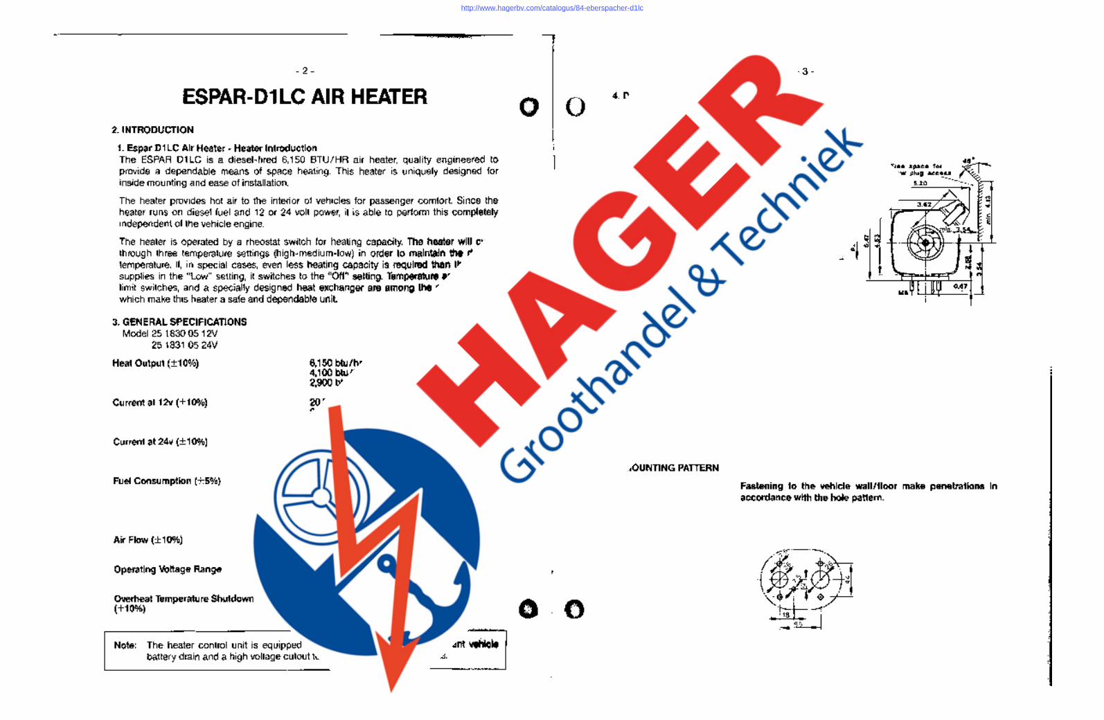
1. Espar D1 LC Air Heater - Heater Introduction The ESPAR D1LC is a diesel-fired 6,150 BTU/HR air heater, quality engineered to provide a dependable means of space heating. This heater is uniquely designed for inside mounting and ease of installation.
The heater provides hot air to the interior of vehicles for passenger comfort. ~in"". heater runs on diesel fuel and 12 or 24 volt power, it is able to perform independent of the vehicle engine.
The heater is operated by a rheostat switch for h"",tinln ciapSlclt~(.; through three temperature settings (high-medlum-Iowl temperature. If, in special cases, even less supplies in the "Low" setting, it switches tothe limit switches, and a specially de~)igrled hecifEll<clla6 which make this heater a safe anlcldepj~.nclal:ll~IJnjl;~'c:f
3. GENERAL SPECIFICATIONS Model 25 1830 05 12V
25 1831 05 24V
Heat Output (+10%)
Current at 12v (+10%)
Current at 24v (+10%)
Fuel Consumption (+5%)
Air Flow (+10%)
Operating Voltage Range
Overheat Temperature Shutdown (+10%)
High Med. Low
U.S. Gal/hr
. 06
.04
.03
54 cfm High 34 cfm Med/Low
10.5 to 15.0 vdc at 12 vdc 21.0 to 30.0 vdc at 24 vdc
240°F (116°C)
Note: The heater control unit is equipped with a low t() battery drain and a high voltage cutout to protect heater electrical parts.
4. D1 LC PRINCIPAL DIMENSIONS
.. .., N ...
U.17 with end cap
11.42
o
Combustion air Exhaust fO.n fO.lIlS
4.114 Fuel
5. MOUNTING PATTERN
- 3-
Fr •• apace for glow plug ace. sa --...
5.20 ,---"'"
Me
Fastening to the vehicle wall/floor make penetrations in accordance with the hole pattern .
(*~~~. <0 ~'-~t -I- ',\., . .,. \ N·
\~.::~~ .' . ,;I->-18
55
http://www.hagerbv.com/catalogus/84-eberspacher-d1lc
- 4-
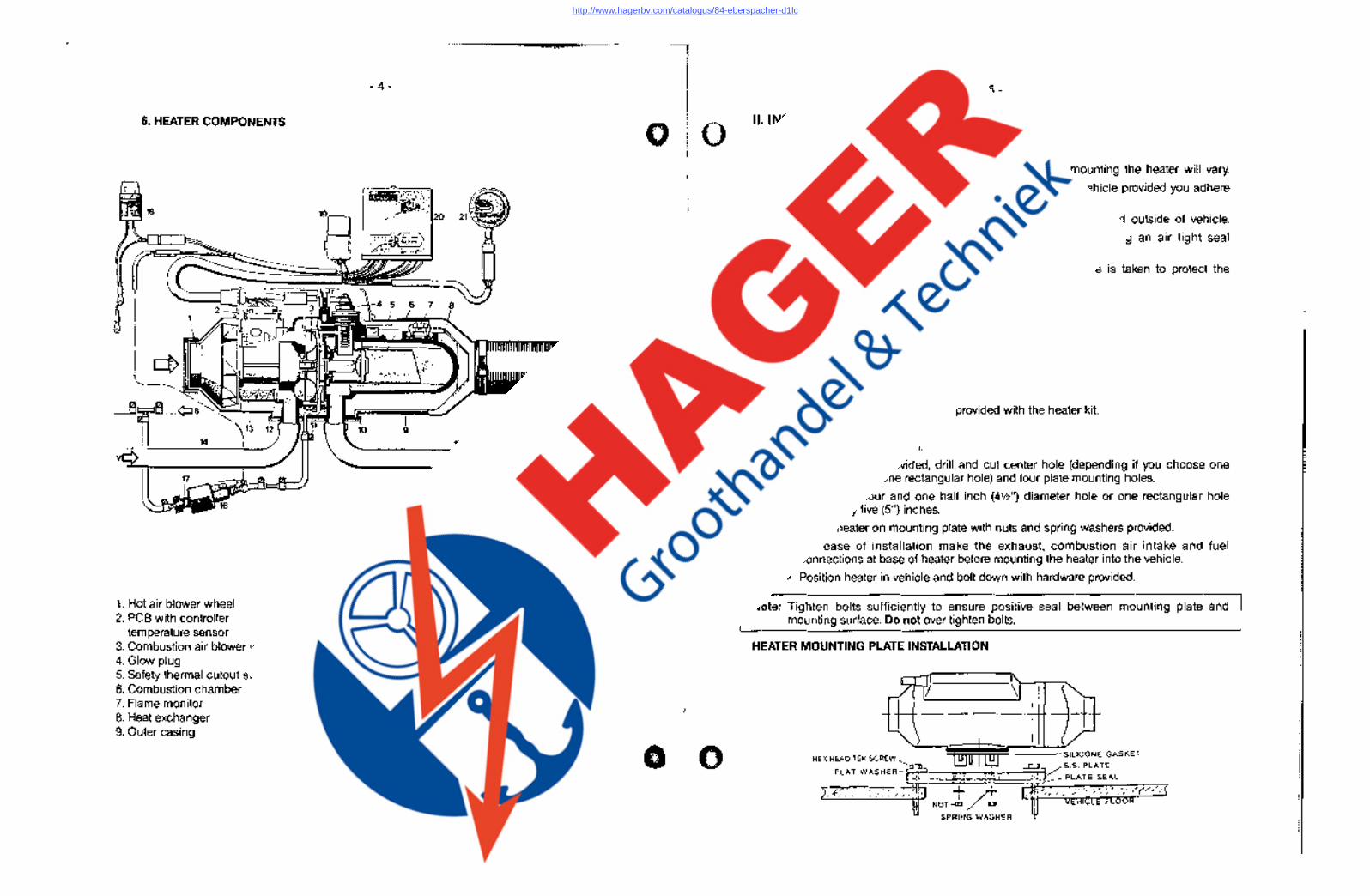
6. HEATER COMPONENTS
18
14
1. Hot air blower wheel 10. Flange seal 2. PCB with controller 11. Fuel line
temperature sensor 12. Series resistor for glow 3. Combustion air blower wheel plug (for 24V only) 4. Glow plug 5. Safety thermal cutout switch 6. Combustion chamber 7. Flame monitor 8. Heat exchanger 9. Outer casing
13. Blower motor 14. Combustion air intake line 15. Exhaust line 16. Fuel metering pump 17. Fuel strainer
F = fresh air V = Combustion air B = fuel W = IIV •. ",";.;
A i'i " ii '!
Ii II " ')
- 5 -
II. INSTALLATION PROCEDURES
1. Heater Location
Depending on the type of vehicle, the best location for mounting the heater will vary.
Basically, the heater may be mounted anywhere inside the vehicle provided you adhere to the following conditions:
A) Combustion air intake, exhaust and fuel inlet must be located outside of vehicle.
B) Heater must be mounted on flat horizontal surface providing an air tight seal between heater and vehicle.
C) Do not mount the heater outside the vehicle, unless care is taken to protect the heater from the weather.
When selecting the location, consider the following:
A) Combustion air and exhaust connections
B) Ducting
C) Fuel line connections
D) Electrical connections
2. Heater Mounting
A mounting plate and hardware are provided with the heater kit.
A) Heater
• Choose heater location.
• Using template provided, drill and cut center hole (depending if you choose one circular hole or one rectangular hole) and four plate mounting holes.
• Cut one (1) four and one half inch (4%") diameter hole or one rectangular hole four (4") by five (5") inches.
• Mount heater on mounting plate with nuts and spring washers provided.
• For ease of installation make the exhaust, combustion air intake and fuel connections at base of heater before mounting the heater into the vehicle.
• Position heater in vehicle and bolt down with hardware provided.
Note: Tighten bolts sufficiently to ensure positive seal between mounting plate and mounting surface. Do not over tighten bolts.
HEATER MOUNTING PLATE INSTALLATION
HEX HEAD TEK SCREW
FLAT WASHER-
-...L-=~~~~====S~ILlCONE GASKET . ' L':"':":"~' .:.. •. '-'.;...:...:....:..~:P NUT-G:. ~
SPRING WASHER
/S.S. PLATE
PLATE SEAL
http://www.hagerbv.com/catalogus/84-eberspacher-d1lc
- 6-
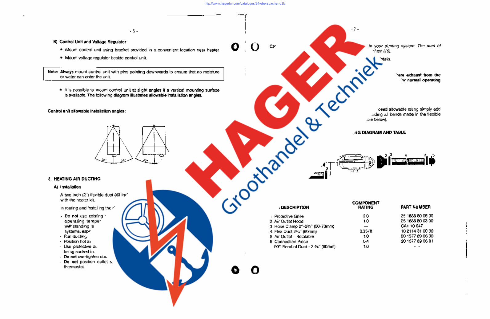
B) Control Unit and Voltage Regulator
• Mount control unit using bracket provided in a convenient location near heater.
• Mount voltage regulator beside control unit.
Note: Always mount control unit with pins pointing downwards to ensure that no moisture or water can enter the unit.
• It is possible to mount control unit at is available. The following diagram ilh.Jstrcltel)t:lII()IJIIt:lblc;lJO~tc
Control unit allowable installation angles:
3. HEATING AIR DUCTING
A) Installation
A two inch (2") flexible duct (40 inches long), with the heater kit.
In routing and installing the ducting the following criteria must
- Do not use existing vehicle ducting or outlets. They. may not be rated at Espar operating temperature standards. Ducts and outlets must be capable of withstanding a minimum of 300°F operating temperatures. Beware of vehicle systems, especially plastic ones.
- Run ducting with smooth bends. Avoid crushing duct. Position hot air outlet so that it cannot be obstructed. Use protective air intake grille on air inlet side of heater to prevent objects from being sucked in. Do not overtighten duct clamps. Do not position outlet so that it will blow hot air directly at nn"""t'lr ri,;if'i~~, thermostat.
--- ------------------------------------------,
- 7 -
Caution: Do not connect too many components it? your ducting system. The sum of component ratings may not exceed the value of ten (10).
*See the following ducting component rating for details.
Warning: Heating air inlet must be installed in an area where exhaust from the vehicle's engine or from the heater cannot enter under normal operating conditions.
B.) Ducting Component Rating
To make sure your ducting installation does not exceed allowable rating simply add component ratings of all components used including all bends made in the flexible duct. This sum should not exceed ten (Use table below).
COMPONENT RATING DIAGRAM AND TABLE
ITEM DESCRIPTION
1 Protective Grille 2 Air Outlet Hood 3 Hose Clamp 2"-2%" (50-70mm) 4 Flex Duct 23fa" (60mm) 5 Air Outlet - Rotatable 6 Connection Piece
90° Bend of Duct - 2 318" (60mm)
COMPONENT RATING
2.0 1.0
0.35/ft 1.0 0.4 1.0
PART NUMBER
251688800600 251688800300 CA110047 10211431 0000 201577 89 06 00 201577890601
II II "
ji
I
I
http://www.hagerbv.com/catalogus/84-eberspacher-d1lc
I"~: "
i',
i·1
!
'", !
.1 '[
- 8-
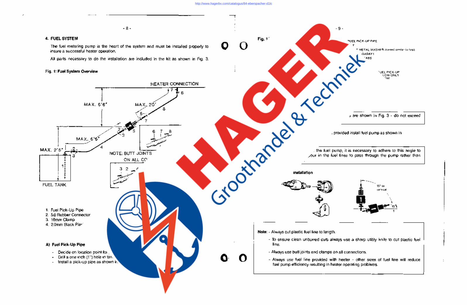
4. FUEL SYSTEM
The fuel metering pump is the heart of the system and must be installed properly to insure a successful heater operation.
All parts necessary to do the installation are included in the kit as shown in Fig. 3.
Fig. 1: Fuel System Overview
1 MAX. 6'6'
MAX 2 '6,1,2., __ " • .!:'""'~-J"
,.---~I-"""'" 3 I I I
1 : I I
• I I
FUEL TANK
1. Fuel Pick-Up Pipe 2. 5.0 Rubber Connector 3. 10mm Clamp 4. 2.0mm Black Plastic Fuel Line
A) Fuel Pick-Up Pipe
HEATER CONNECTION
NOTE: BUTT JOINTS AND CLAMPS
ON ALL CONNECTIONS
Jlr~ ~~ ~ - Right Wrong
5. Fuel Metering Pump 6.7mmClamp 7. 3.5mm Rubber Connector 8. 1.5mm White Plastic Fuel Line
- Decide on location point for pipe in tank (in a protected area). - Drill a one inch (1 ") hole in tank or blanking plate. - Install a pick-up pipe as shown in Fig. 3A.
- 9-
Fig. 1A: Fuel Pick-Up Pipe Installations FUEL PICK-UP PIPE
NUT SHEET METAL WASHER-(raised center to top)
RUBBER GASKET
~_;;;;;;;;::.......HOLDING TABS
FUEL TANK
B) Fuel Metering Pump
- Decide on location for fuel pump. - Must be in a protected area. - Near fuel tank.
ALLOW 4 IN. FROM FUEL PICK-UP TO TANK BOTTOM. ALLOW ONLY 1 INCH FOR FLAT BOTTOM TANKS.
Note: - The fuel metering pump maximum lengths are shown in Fig. 3 - do not exceed these limits.
_. Using the bracket and rubber mount provided install fuel pump as shown in Fig. lB.
Note: - The mounting angle of the fuel pump, it is necessary to adhere to this angle to allow any air or vapour in the fuel lines to pass through the pump rather than cause a blockage.
Fig. 1 B: Fuel Pump Installation
Note: - Always cut plastic fuel line to length.
~ I 15° to Iii vertical
D \1 _ -j:J.J-... r15°1 I -,~
-". \
- To ensure clean unburred cuts always use a sharp utility knife to cut plastic fuel line.
- Always use butt joints and clamps on all connections.
- Always use fuel line provided with heater - other sizes of fuel line will reduce fuel pump efficiency resulting in heater operating problems.
http://www.hagerbv.com/catalogus/84-eberspacher-d1lc
------- --- ------'----,-'-----~-------~
- 10-
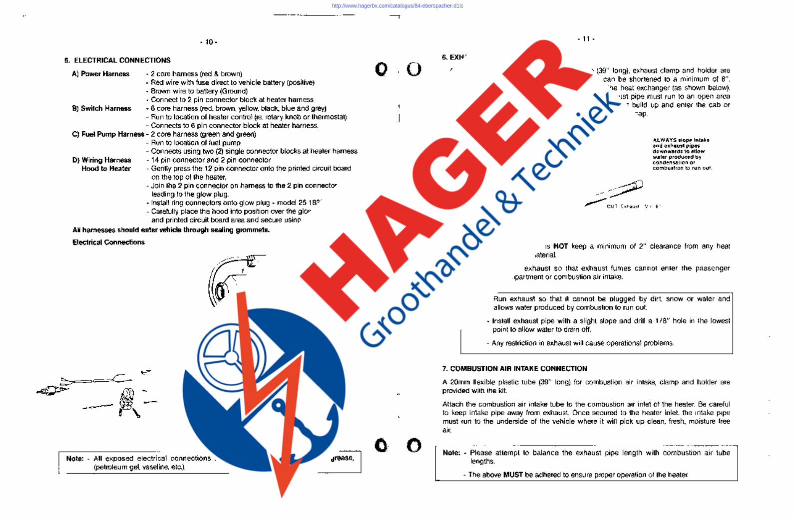
5. ELECTRICAL CONNECTIONS
A) Power Harness - 2 core harness (red & brown) - Red wire with fuse direct to vehicle battery (positive) - Brown wire to battery (Ground) - Connect to 2 pin connector block at heater harness
B) Switch Harness - 6 core harness (red, brown, yellow, black, blue and grey) - Run to location of heater control (ie. rotary knob or thermostat) - Connects to 6 pin connector block at heater harness.
C) Fuel Pump Harness - 2 core harness (green and green)
0) Wiring Harness Hood to Heater
- Run to location of fuel pump - Connects using two (2) single connector blocks at heater harness - 14 pin connector and 2 pin connector - Gently press the 12 pin connector onto the printed circuit board
on the top of the heater. - Join the 2 pin connector on harness to the 2 pin connector
leading to the glow plug. - Install ring connectors onto glow plug - model 251830 and 251831 - Carefully place the hood into position over the glow plug
and printed circuit board area and secure using a 6mm hex wrench. All harnesses should enter vehicle through sealing grommets.
Electrical Connections
J' c
-~-. jl, --{...,.Y
Note: - All exposed electrical connections should be coated with profeotilifgre8Se, (petroleum gel, vaseline, etc.). ' "'.'
•
•
- 11 -
6. EXHAUST CONNECTION
A 24mm flexible stainless steel exhaust pipe (39", long), exhaust clamp and holder are provided with the heater kit. The exhaust pipe can be shortened to a minimum of 8". Attach the exhaust pipe to the exhaust outlet of the heat exchanger (as shown below). Once secured to the heater exhaust outlet, the exhaust pipe must run to an open area to the rear or side of the vehicle so that fumes cannot build up and enter the cab or the combustion air inlet to the heater. Install protective end cap.
Caution: ALWAYS slope intake and exhaust pipes downwards to allow water produced by condensation or combustion to run out.
~~ ? ---" '''~ ~ CUT Exhaust Min,8"
CUT Min. 8'" Combustion Air
A WARNING: The exhaust is HOT keep a minimum of 2" clearance from any heat sensitive material.
A WARNING: Route exhaust so that exhaust fumes cannot enter the passenger compartment or combustion air intake.
Note: - Run exhaust so that it cannot be plugged by dirt, snow or water and allows water produced by combustion to run out.
- Install exhaust pipe with a slight slope and drill a 1/8" hole in the lowest point to allow water to drain off.
- Any restriction in exhaust will cause operational problems.
7. COMBUSTION AIR INTAKE CONNECTION
A 20mm flexible plastic tube (39" long) for combustion air intake, clamp and holder are provided with the kit. '
Attach the combustion air intake tube to the combustion air inlet of the heater. Be careful to keep intake pipe away from exhaust. Once secured to the heater inlet, the intake pipe must run to the underside of the vehicle where it will pick up clean, fresh, moisture free air.
Note: - Please attempt to balance the exhaust pipe length with combustion air tube lengths.
- The above MUST be adhered to ensure proper operation of the heater.
http://www.hagerbv.com/catalogus/84-eberspacher-d1lc
- 12 -
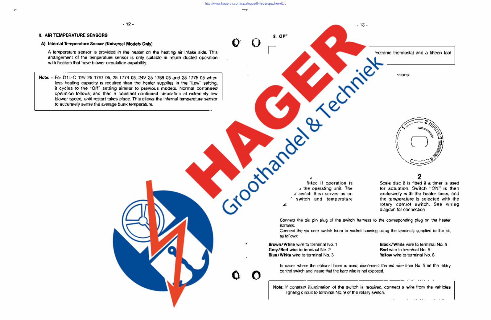
8. AIR TEMPERATURE SENSORS
A) Internal Temperature Sensor (Universal Models Only)
A temperature sensor is provided in the heater on the heating air intake side. This arrangement of the temperature sensor is only suitable in return ducted operation with heaters that have blower circulation capability.
Note: - For 01L-C 12V 25176705,25177405, 24V25 176805 and 25 1775 05 when less heating capacity is required than the heater supplies in the "Low" setting,· it cycles to the "Off" setting similar to previous models. Normal continued operation follows, and then a constant continued circulation at extremely low blower speed, until restart takes place. This allows the internal temperature sensor to accurately sense the average bunk temperature.
•..... '.8 ~>
- 13 -
9. OPERATING SWITCH
.
Note: The 01 LC truck kit is supplied with an electronic thermostat and a fifteen foot (15') switch harness.
The heater may be operated using one of the following switch options: - Rotary control switch with on / off control - Rotary control switch with timer for on/off control - Thermostat with built in on/off switch
A) Rotary Control Switch and Optional Heater Timer Two scales are supplied as follows:
1 Scale disc 1 is fitted if operation is exclusively with the operating unit. The rotary control switch then serves as an "ON/OFF" switch and temperature controller.
2 Scale disc 2 is fitted if a timer is used for actuation. Switch "ON" is then exclusively with the heater timer, and the temperature is selected with the rotary control switch. See wiring diagram for connection.
Connect the six pin plug of the switch harness to the corresponding plug on the heater harness. Connect the six core switch loom to socket housing using the terminals supplied in the kit, as follows:
Brown/White wire to terminal No.1 Grey/Red wire to terminal No.2 Blue/White wire to terminal No.3
Black/White wire to terminal NO.4 Red wire to terminal NO.5 Yellow wire to terminal No.6
In cases where the optional timer is used, disconnect the red wire from No. 5 on the rotary control switch and insure that the bare wire is not exposed.
Note: If constant illumination of the switch is required, connect a wire from the vehicles lighting circuit to terminal NO.9 of the rotary switch.
http://www.hagerbv.com/catalogus/84-eberspacher-d1lc
- 14-
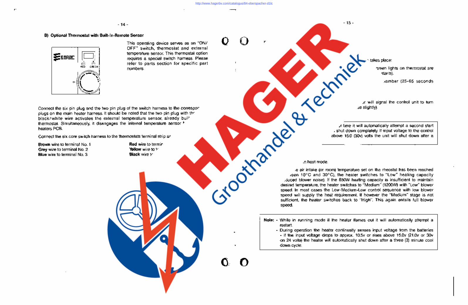
B) Optional Thermostat with Built-In-Remote Sensor
, 0
o 0 RED GREEN
0_'\
C> ~ •
~
This operating device serves as an "ON I OFF" switch, thermostat and external temperature sensor. This thermostat option requires a special switch harness. Please refer to parts section for specific part numbers.
Connect the six pin plug and the two pin plug of the switch harness to the corresponding plugs on the main heater harness. It should be noted that the two pin plug with the single blacklwhite wire activates the external temperature sensor, already built into the thermostat. Simultaneously, it disengages the internal temperature sensor built into the heaters PCB.
Connect the six core switch harness to the thermostats terminal strip as follows:
Brown wire to terminal No.1 Grey wire to terminal No.2 Blue wire to terminal No.3
Red wire to terminal No.5 Yellow wire to terminal No.6 Black wire to terminal No. T •
- 15 -
III. HEATER OPERATION
1. SWITCH ON I START UP Heater always starts in HIGH mode. Once switched on the following sequence of events takes place:
A) Green pilot light on rotary switch is on. Red and green lights on thermostat are "on" (Control unit does a systems check. Blower motor starts).
B) Glow plug begins to preheat the combustion chamber (25-65 seconds depending on the input voltage).
C) Fuel pump starts.
0) Once ignition takes place the flame sensor will signal the control unit to turn the glow plug off (motor speed will increase slightly).
E) Heater begins heating interior.
Note: - If the heater fails to start the first time it will automatically attempt a second start if unsuccessful the heater will shut down completely. If input voltage to the control unit is below 10.5 (21 v) or above 15.0 (30v) volts the unit will shut down after a 20 second delay.
2. RUNNING
A) Heater runs in heat mode.
B) Once the air intake (or room) temperature set on the rheostat has been reached (between 10°C and 30°C), the heater switches to "Low" heating capacity (reduced blower noise). If the 850W heating capacity is insufficient to maintain desired temperature, the heater switches to "Medium" (1200W) with "Low" blower speed. In most cases the Low-Medium-Low control sequence with low blower speed will supply the heat requirement. If however the "Medium" stage is not sufficient, the heater switches back to "High". This again entails full blower speed.
Note: - While in running mode if the heater flames out it will automatically attempt a restart.
- During operation the heater continually senses input voltage from the batteries - if the input voltage drops to approx. 10.5v or rises above 15.0v (21.0v or 30v on 24 volts) the heater will automatically shut down after a three (3) minute cool down cycle.
http://www.hagerbv.com/catalogus/84-eberspacher-d1lc
- 16 -
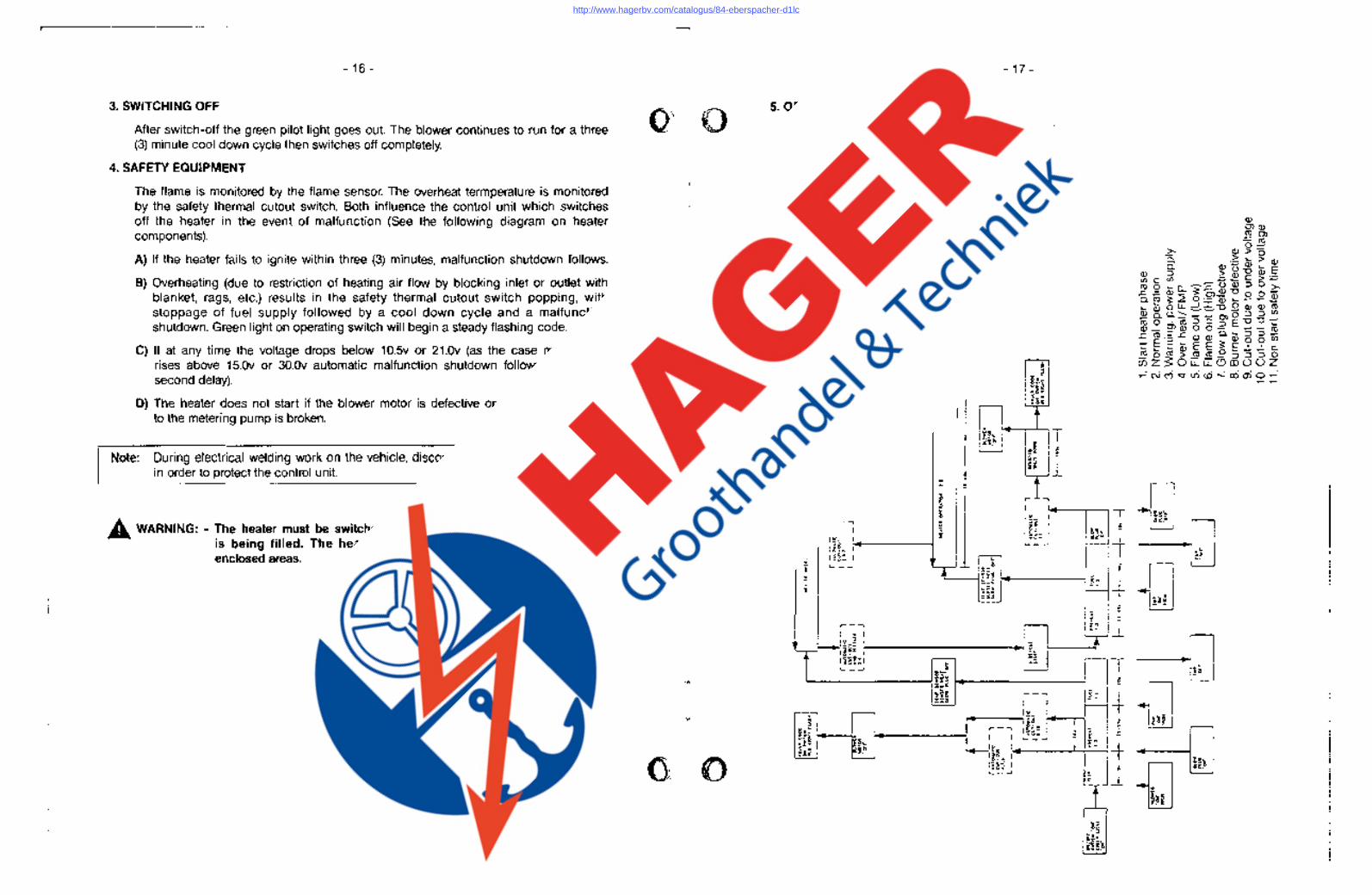
3. SWITCHING OFF
After switch-off the green pilot light goes out. The blower continues to run for a three (3) minute cool down cycle then switches off completely.
4. SAFETY EQUIPMENT
The flame is monitored by the flame sensor. The overheat termperature is monitored by the safety thermal cutout switch. Both influence the control unit which switches off the heater in the event of malfunction (See the following diagram on heater components).
A) If the heater fails to ignite within three (3) minutes, malfunction shutdown follows.
B) Overheating (due to restriction of heating air flow by blocking inlet or outlet with blanket, rags, etc.) results in the safety thermal cutout switch popping, with stoppage of fuel supply followed by a cool down cycle and a malfunction shutdown. Green light on operating switch will begin a steady flashing code.
C) If at any time the voltage drops below 10.5v or 21.0v (as the case may be), or rises above 15.0v or 30.0v automatic malfunction shutdown follows (after a 20 second delay).
D) The heater does not start if the blower motor is defective or the electrical cable to the metering pump is broken.
Note: During electrical welding work on the vehicle, disconnect the power to the heater, in order to protect the control unit.
A WARNING: - The heater must be switched off while any fuel tank on the vehicle is being filled. The heater must not be operated in garages or enclosed areas.
fit
- 17 -
5. OPERATIONAL FLOW CHART
r{] I Os' ~ .. gg t t3~ ." L[J . ~ ~ ~.
• , ~.: ~~g ~!r • ~
h~ I
-f-
i 5 • ::'1'
g~ !
nJ t I ~ gg 1.. + , i
t!~ - • I I
0< . ...i.. 2 : ~g~ : • ·0'. ~ I ~e: I r ~ . ~-~ I I i - J~_ I -. I
~ I~ ._ I~~: I , ~-~
;
il
http://www.hagerbv.com/catalogus/84-eberspacher-d1lc

-18 -
IV. MA
INT
EN
AN
CE
AN
D T
RO
UB
LES
HO
OT
ING
1. RE
CO
MM
EN
DE
D P
ER
IOD
IC M
AIN
TE
NA
NC
E
A)
Rem
ove the glo
w p
lug
and inspect for carbon build up. Clean o
r replace.
B)
Rem
ove the glo
w p
lug
screen and inspect for carbon build up. Clean or replace.
If cleaning is required, use brass brush (Espar part num
ber CA
O 05 003).
C)
Make sure vent h
ole
is open. Espar recom
mends the use of nondetergent 100%
volatile carburetor cleaner and an
air gun w
ill also help. Rem
ove loose carbon from
the glow plug cham
ber.
D)
Inspect the du
elin
g, the a
ir intake screen and air outlet for restriction or blockage.
E)
Inspect combustion air intake and exhaust for blockage.
F) R
un yo
ur heater a
nd
che
ck for p
rop
er operation d
urin
g
reg
ula
r Preventative
Maintenance throughout the year.
G)
Maintain yo
ur batteries and all
electrical connections in
go
od
condition. With
insufficient power the heater w
ill not start. Low and high voltage cutouts w
ill shut the heater dow
n automatically.
H) . U
se fuel suitable for the climate (see engine m
anufacturers recomm
endations). B
lending used engine oil with diesel fuel is not perm
itted.
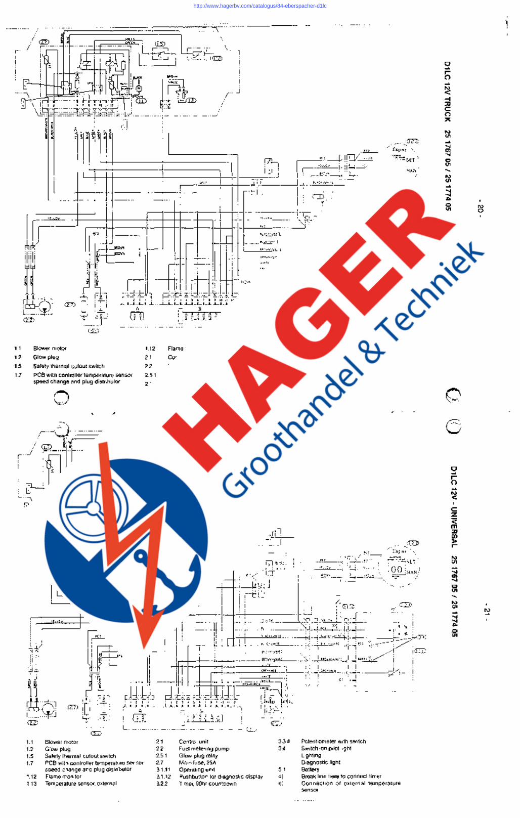
-19 -
2. D1 LC
WIR
ING
DIA
GR
AM
D1LC
-U
NIV
ER
SA
L (12V/24V
) 2
51
68
80
51
25
16
89
05
,-----------, _..J
(
,/ A
-----
(r-~g
e
i~d
'I I I I I
.~ ----------------,
~ /--~--z" ..
8)-
We
<
\
( ~ I!I ~I';\ '. W
!
0 i
I t+
----\.
I ,-
.
~.f:( l .. J:~-,-I)
~iir------------;\-~~~:::f:~I-::ll:-g!=~j '-_
__
_ ~---------_----
_ ;;:l':
~
g I
r ---
-----
----"l
L _
__
__
__
__
__
, •
':I I:
t [
2
, __________________ --__ --__ ~ 9--::=-:7:: r:::::=-: =:. =:: j ~ . tJi'
: :
-,
' .
, '
, '
'-_
__
__
__
__
__
__
__
__
__
__
__
__
~-
__
J
~ ~--------------------! '-----------------,
I
, , , , , , , , , , , , , , , , , , , , , , , , , , , ~ ~
e
, ~---
----------------
----~-~ r---+
+----I---'<
I -.i:~ ",R
L-1
tj tj
i L
L-L
__
__
_ J
§~ ~
.. it. e
<"
"'-::3
NjJ8
'j (
--::3
( --
.D>
b
~ '"
T"""
T"""'-
('\J
,-C\llO
r--':':C\i
NN
NN
C'i("
j("j
~
r:,,!C\jl!:!1
'-: ,-
or-T
""" T
""" T
"""
http://www.hagerbv.com/catalogus/84-eberspacher-d1lc
/
r .. -/ ~-··;t~ ~~~~~~~=~ . ~ ! .. ..., Ci3) \ i ,r'~ \ j ! = ,-m'-, I c_ .. "~ -i ~ :
, " 1
1.1
1.2
1.5
1.7
,- ' _'I _w '
• . ".. I
\\!o.=iI!"~' r::~~;~:!~'r>t!:'~:-'l';"~'J': 'i"1fu "lilt" ) u ~ t· :=:,-!.- .. - .. -. j.-~ / I " oj t; ~ Z 5 "! _ - .. ...!
> ~ • ~ ~ ~ ~ " .
111'11 1--= RCD ./ E '.
R!:D • spar "'-
: : ' .!CV ""'" :' ,=-:-" '.
,<c. I II . [J] .::::~ : !i~ ·"co" I ~SET \ -l!: r '1 r -i:<J l::::i ",0"" \ ~ MAN
1
CITJ .--i-'- . , ' .,,"W"'" '-. • . ! 1 ~lJ '- /
r-l-l '-"r 'l ~_L-. i II II ' ,
) : ! ' 0, / I , 0 CREEN 1 ,'mLDv' I "" ,
' "'-:;:"-', ,
=~~~~~Jf~~=~~~~~t==t~fta~f~~~":~:"~V;~~2 il'-'~ '"''W"''' I \ • _. . .. ~" !·~·1 ,eov",V"'" .eov",V"'" , .L.:",_.,= ..
,~"v : I:: I:
~~ 'EO
IR.ILIIN
tllOVI<!
~ }:ri r ~l
(UJ irh1 iIi
L.
BROIo'Il\VHI1( "i
"'Hire llN..l,J'e""""""' ____ _ (,RO\RrL I I
r~" "l , ,
L .. _ .... J <EEl tg-J
GIl
Blower motor
Glow plug
Safety thermal cutout switch
"'HI Ie
" ",DV"''''iR~ mr-J RlICL-llUb V~~";; "i' 4 •• ---- •• - •• ;- 9 9 10 II 1~2 I : . .. .. , • ,. -'-'-<- : ~.;,.-, •. ~ ...Li...L..-'-'-LLl. : L .. _ .. _ .. .J
i..'..J .. u.L C !j 'Ii II I I Uil 1 A "iI- 11 , i n~) '_ .. _ .. _ .. _ .. .J em L .. __ .. _ .. _ ..
LL . ..J
1.12 Flame monitor
Control unit
3.1.12 Pushbutton for diagnostic display
2.1 3.2.2 Timer, 99hr countdown
2.2 3.5 Thermostat
PCB with controiler temperature sensor 2.5.1
Fuel metering pump
Glow plug relay
Main fuse, 25A
5.1 Battery speed change and plug distributor 2.7
0
,r' .. ..- .. - .. - .. - .. - .. - .. - .. - .. - .. - .. - .. - .. ~
e) Connection of external temperature _ensor
6' .. ., ;' " : em P r .. J :-.. _ ... "
: i Ci3) r", tc;:j"
I 1\ ~z;~ \ ..... "] L .. _ .. ..J (ill) i
I I ' i i = : i ri-n~=±±~- I I. - : ' , , '
L
' .. = I .. ' . ,"" """\ I ", .. "",' ."'~
<ill)
!~->-;ii! L~ .. J / .. - .. -....~
Reo ," Espar '-"
r--.....!·""'-o --Lk!!tl/ VHIl( .!"-~~.... '. YellO" \ ( '1'12 I HllOV ~SET ': .eoV" :::,: \ OOM I LJI~ BROliN AN'
L.J ,"":~ / ......... ,,/
I ~
I = +=1 i=il It I -r== "" e)(,' /~ I I II p-rJlJ r-tl:J
r:QiJ? on : : -f ---:r'-l I \ "
TEllO.... TellO'" !'~ -, TellO" : '[(!'~ I 'I ,. d)I'" t
,--++-----t----t--t-t--+--tt-+,-++t----'''',-".,-------!'<!,., ! ~cp H \\ ! do'> ! • i \\\: 9LA(n .... HIIE i~ i 9l"CK\VHIf(ici~ i 7:=' t .,. I 3.4
r -+--ft-+-+-+-+-+-----""'''''-''''W''"'"''-'-,-----i-<: : BLU(\V"ITC : (: : Reo '1:0 , I" In I I In I" . : BROWIWKI TC '-.:: :, : • I G:IlD
I I BROVNWHIJ[ ~ ! _ ! 9RO .... NWH[f( ! (! _ ! GREeN ~ i i """ 1 I I I I· 1 :: GR[Y\R(il " 'GR(r\I!CO ".;" ____ -j¢_ I .",- c'''' . V"'" I I I I 1 I : " c), ,.. I
I I .. ov"'''~ II Li . ..i Li-L _____ J
'" ,..--
'''Ilk : I :: I : III I
H B~OVN
ROliN
:11Al L~J <EEl
(U)
.. ~
)~, ~
:--,...: .. I : I I I ..L. :t3J
d~::- .. ~ r:: ::-.:-:~=-::.;::.:-:.-::b r-J;~·t "~JI 1" , I 2 ) 4, 'I 2 1 ~ 5 6 , 8 9 10 II 12 • 8~ .. ill lQ.: r·.-----·L-I -L .-LLL....L.-'---I........L...L.1_....L.J---L~ I I, , I ,A C B .. : i {, ~)o "'" i'" ill i L .. _ .. _ .. :' ? ~ ~ 10 : aD
GIl L._ .. ____ .. _ .. _ .. _ _ .. _ .. _ .J <7D
1.1 Blower motor 2.1 Control unit 3.3.4 Potentiometer with switch
1.2 Glow plug 2.2 Fuel metering pump 3.4 Switch-on pilot light
1.5 Safety thermal cutout switch 2.5.1 Glow plug relay Lighting
1.7 PCB with controiler temperature sensor 2.7 Main fuse, 25A Diagnostic light speed change and plug distributor 3.1.11 Operating unit 5.1 Battery
1.12 Flame monitor 3.1.12 Pushbutton for diagnostic display d) Break line here to connect timer 1.13 Temperature sensor, external 3.2.2 Timer, 99hr countdown e) Connection of external temperature
sensor
c ... r-0 ... ~
< -I :c c: 0
" ~ CI1 ... " '" " C) CI1 ..... ~ CI1 ... " " "" C) CI1
O·l", \ -, ---' ',,- :t:§.J
c ... h ... ~ c: z <: m :c ~ r-
~ CI1 ... " '" " C) CI1 ..... ~ CI1 ... " " "" .0 CI1
I\) 0
I\) ...
http://www.hagerbv.com/catalogus/84-eberspacher-d1lc

/r"-"--:"'-"-"-"~"-"=' 1\ : em n
.. ...! r"-" ! .. '-,j" c f=l:=::::=:'::": ern r", !=.Siif!!j
i = ~J L .. _ .. -J(uE>
i I ~ , --: L..: "'" -- ! ." "\ I .. • .. "" i "o~
: \L'tfi~~~fV'"" ',~ mltl r
1.1 1.2 1.5 1.7
II -I jj mt j----::-"'j (ill)
r:=Afil L'~ .. "': .. J
I I I II " '"'' "" I II 3 f;pJ
I ~U
.. _ <IT<l 11(0 ./ '-. '" kl q! ,.. Esper',
mc" : ",, v"''' " =- '. ,eo", ! ' I!;-,- "ce'" I ~SET \ . t:::i '00"" \ lQQj hi AN J
'-, ..... Tn ;'
~ ,/
=1=tt==-W= e'( /~ 1:~ @Jl
""" ,------'---tI+-l _+-1 -+-1-+-111--+1 -HIl-+-I -HIl+-I --'l::,,---:CO" ~lSW: ~ :::""~t'~i: i-l~\\l I I .. ,'. , ... I
'" BLACKWIi!J( I""" 9LACK\VH)f( 1(1"-l 3.-1
I I . "" I eUX:\\,IHllt " 'aLU(WHII( • (' ,~(!) l/I-
I ii IloT-~ : BROVHWHtT( ::. :: • I@J) r--. 9ROVN ~k
I /I I BROVN\VHII( 1!-~ eR!JV~\VHIIC !.(!_~ : I:: I:
~~ W·I'OO"' II . . I
)1 v",,, I I I I I I . GR(Y\I1ED ' :'" 'GRCnI1ED '(:",' ~ "<IT( I I I I I I \,IT " , "'"'+--
1: ::1::: '"'""'''~"<''I c.i .. J c.i .. { ._ .. _ .. _"- ._ .. j
r-l- + -, ~.. . . .._. c·:-:"c--. ....,
t::J}::::LnCt-c;'D~b:nl'~ n~tJ~ I~l irh1 iIi . ,
L .. _.. ..J ~
rm
t3-J (ill
1.1 Blower motor 1.2 Glow plug
i !HIH H ~~I i L._ .. _ .. --1 : : ~ L .. _ .. __ .. _ .. _ .. _ .. _ .. _ .. _ .. _ .. _ .. --1 <TIl
1.13 2.1
Temperature sensor, external Control unit
3.3.4 3.4
1.2.1 Resistor for glow plug (24V only) Fuel metering pump Glow plug relay 1.5 Safety thermal cutout switch
Potentiometer with switch Switch-on pilot light Lighting Diagnostic light Battery 1.7 PCB with controller temperature sensor
speed change and plug distributor 1.12 Flame monitor
2.2 2.5.1 2.7 3.1.11 3.1.12 3.2.2
Mai n fuse, 25A Operating unit Pushbutton for diagnostic display Timer, 99hr countdown
5.1 d) e)
Break line here to connect timer Connection of external temperature sensor e
,,~ ~
\ ,.., 1- Z'~~~~~~-=J \ ..J/ ~- .. ij1 .. _ .. _. ..-._ .. , r~ ,'-'iIl \-"l ," , . ~ .
: i ! L~..J L .. _ .. .J@) i ! i = ! i ! i =~ I liT ":,,: i l ,L: "'"""' ::l&~f~ IJh r.J ", I n=f :""'~ . ~ .' "I-" .. - .1..L ,..'1- .. I OJ) /
·\Lbl-j::o::::-o::~y:~~?~~p=,~._ .. _ .. _. ::._ .. _ .. _ .. _ .. j " , ~ e _ , ~ ~ x Z
~ ~ ::l 1;; ., ~ ... :t ~ :I<l '#~1i!I~5I<lg
r;R i;' i lStJ
~~
l-..~=f==~t=============~================t==t=t::~,~,~:;,v~ni'~T~~~ C1]) r-+----1H--::""""':::-::'"~":.:".ti.::-, ;;, 21~ 2 i : _ . _____ -_. -:- --- --- ---
L------+-+t-------I---;=::=t--I--t---t-+-t--""='1'~, : I' _ BLACK i --""is' t I \ I 1\ LLJ r-1 <:l:rn ,. _ . :
-J.. " I I, 0 liED " rr;---' lit» : 0 0 ,--;:::::J~;::::=1====~=~~==:::;----t-tl-i-IIr=~~~+==~~~j,~~,± ;" , 1 RED OREEH I ,+---1H-t---"""",:u.OV"'--t' =~"";<. !I! . YELLD\I : .,.-,::: ____ , 'L~C~ II L -..~: • .J I y:; ........... ~ IL/ICK\'oo'Ii.Itt ~ 13..., '/;{ ,
RtD • i+-i 1\ ~ J' BRO ..... N '5 - r~
BRD .... N· 8I.lf.:\'oo'Ii.ITE I I, I BLU : "~ /" '~I "Ir :::~: """" ..1 i, "" L.. .. _ .. _ .. L .. '::O.·,.,=, ...
[ [[ [ H: v,'"~ ~ l''''~ -'"''''''~'-----~ r - ~.~ ,1 1 -~ r' -- --l . , '""1' .1. I • ,-,.1. --L.L..L..l...L..J-LLL.L...I-L ,t-- "I ! :' , ! 1.! ! . -A ... C ,81 H I i r"I":t'1j L .. _ .... J ~j i !HIH pH : :~: @ L .. _ .. _ .. _ .. _ .. _ .. _ .. _ .. _ .. _ .. _ .. _ .. --1 ill) L .. _ .. _ .. --1 ~
Blower motor Glow plug
BRO .... N
'"
Safety thermal cutout switch
Fuel metering pump Temperature sensor Current regulator Main fuse, 25A
1.12 2.1
PCB with controller temperature sensor speed change and plug distributor' Flame monitor Control unit
2.2 1.13 2.5.1 2.7 3.1.12 3.5 5.1
Pushbutton for diagnostic display Thermostat Battery
'.-.--.--..
c .... r-0 N .... < c: z <: m :EJ (f) l> r-
N C1I .... ..... Q) 0)
0 C1I ..... N C1I .... ..... ..... C1I 0 C1I
Qr.··: --_\@ ....•.
'-,"
c .... r-0 .... ~ .... :EJ c: 0
" 3: 0 c m r-N C1I .... 0) W 0 0 C1I
I\) I\)
I\) W
http://www.hagerbv.com/catalogus/84-eberspacher-d1lc
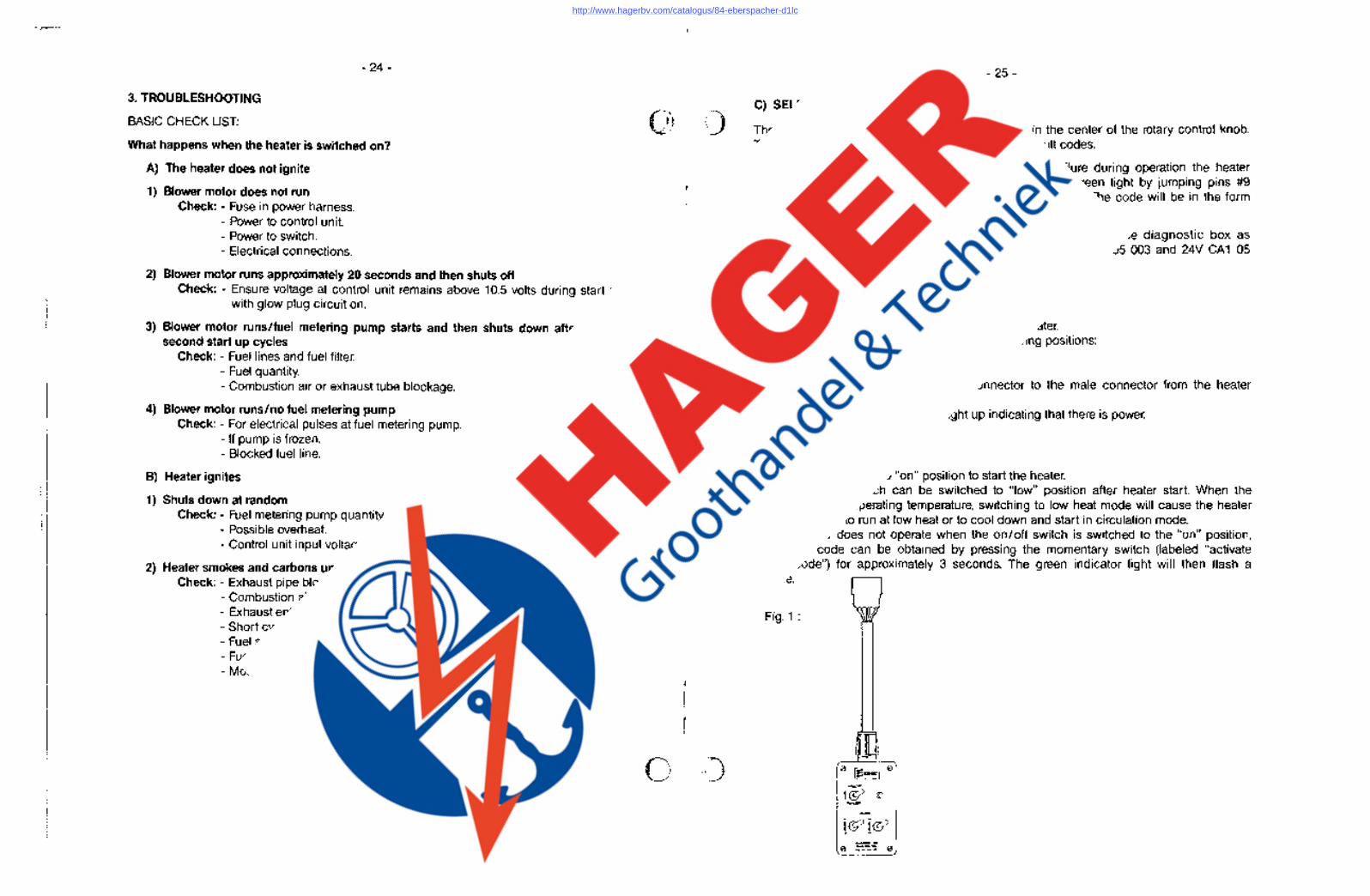
3. TROUBLESHOOTING
BASIC CHECK LIST:
- 24-
What happens when the heater is switched on?
A) The heater does not ignite
1) Blower motor does not run Check: - Fuse in power harness.
- Power to control unit - Power to switch. - Electrical connections.
2) Blower motor runs approximately 20 seconds and then shuts off Check: - Ensure voltage at control unit remains above 10.5 volts during start up
with glow plug circuit on.
3) Blower motor runslfuel metering pump starts and then shuts down after two 90 second start up cycles
Check: - Fuel lines and fuel filter. - Fuel quantity. - Combustion air or exhaust tube blockage.
4) Blower motor runs/no fuel metering pump Check: - For electrical pulses at fuel metering pump.
- If pump is frozen. - Blocked fuel line.
B) Heater ignites
1) Shuts down at random Check: - Fuel metering pump quantity.
- Possible overheat. - Control unit input Voltage.
2) Heater smokes and carbons up Check: - Exhaust pipe blocked.
- Combustion air intake blocked. - Exhaust entering combustion air intake pipe. - Short cycling, rapid on/off operation. - Fuel system. - Fuel metering pump quantity. - Motor rpm.
'-----. 1
•
- 25-
C) SELF DIAGNOSTIC
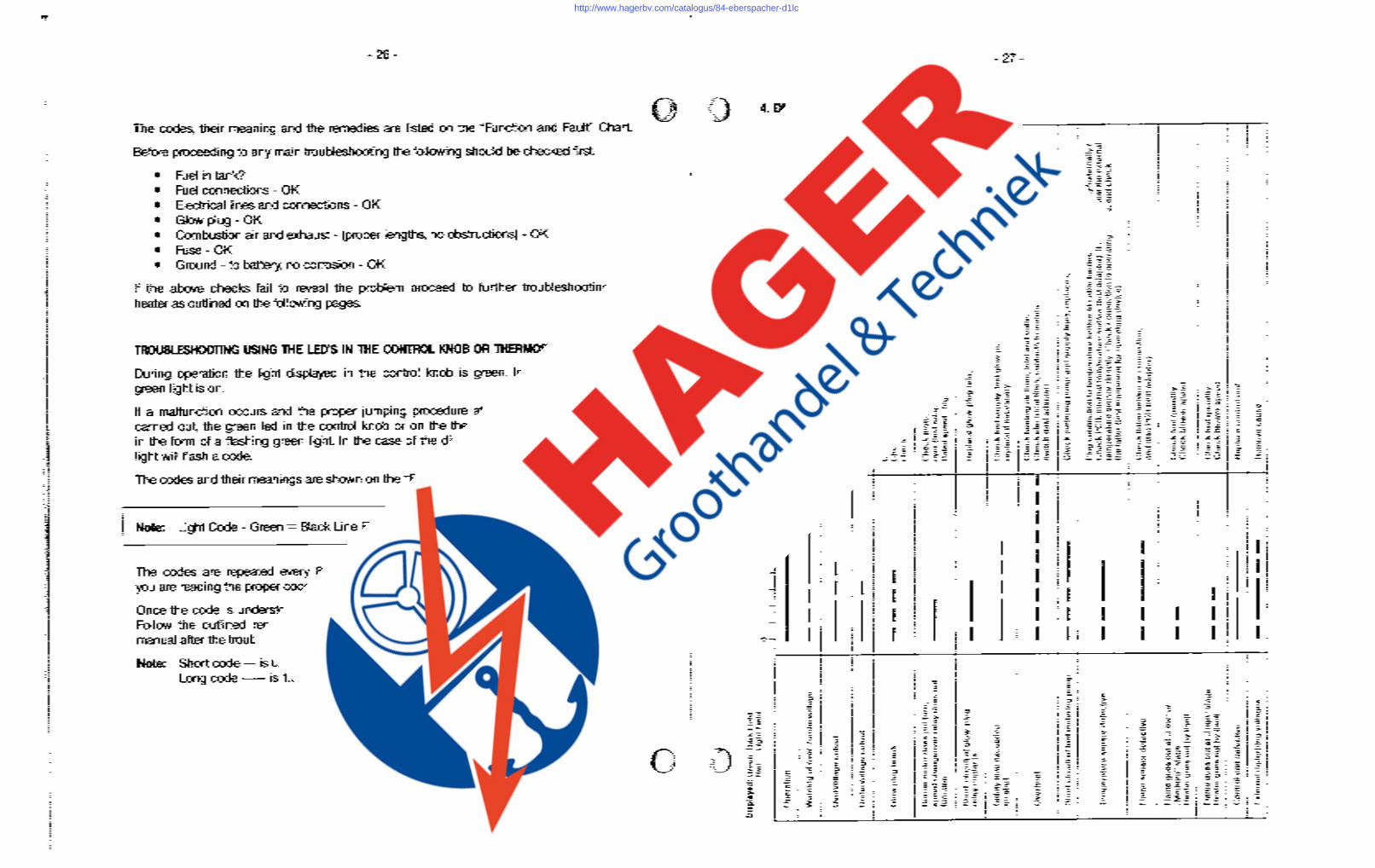
The D1 LC is equipped with a self diagnoses light in the center of the rotary control knob. The green light on the thermostat face will produce fault codes.
In the event of the component failure or a systems failure during operation the heater will shut down. A failure code can be produced at the green light by jumping pins #9 and #11 at the control box for one (1) to three (3) seconds. The code will be in the form of a flashing green light. Refer to wiring diagrams.
To assist the service technician to obtain heater fault code the diagnostic box as illustrated in figure 1) is available. Espar part number 12V CA1 05 003 and 24V CA1 05 004.
Set Up:
- Unplug six pin switch harness connector at the heater. - Ensure diagnostic box switches are in the following positions:
on / off switch in "off" position. high/low switch in "high" position.
- Plug female six pin diagnostic box connector to the male connector from the heater switch harness.
- Green indicator light should now light up indicating that there is power.
Operation:
- Switch on / off switch to "on" position to start the heater. - High/low heat switch can be switched to "low" position after heater start. When the
heater reaches operating temperature, switching to low heat mode will cause the heater to switch itself to run at low heat or to cool down and start in circulation mode.
- If the heater does not operate when the on/off switch is switched to the "on" position, the fault code can be obtained by pressing the momentary switch (labeled "activate fault code") for approximately 3 seconds. The green indicator light will then flash a code.
Fig. 1 : \Mjr
o ____ 0
,
!
http://www.hagerbv.com/catalogus/84-eberspacher-d1lc
~
y
Dis
pla
ved
: G
ree
n:
Da
rk F
ield
R
ed:
Ug
ht
Fie
ld
Op
era
tio
n
Wa
rnin
g 0
1 o
ve
r-/u
nd
erv
olla
ge
Ove
rvo
llag
e c
uto
ut
Un
de
rvo
llag
e c
uto
ut
Glo
w p
lug
bre
ak
Bu
rne
r m
oto
r d
oe
s n
ollu
rn,
z ~ r(J)
o :::
; :::
l 0
(O~
8 8
0.0
. (l
) (l
)
I ~.
-·0
"'
. ~W
. W
W
",
W(l
) '"
a
(l)
0 a
:::l
00
.
:::l
'"
0.
_.
'"
:::l
:i" (l
) -:::l
(l)(
O
:::l
_
(0
:::;
-:::;
spe
ed
ch
an
ge
ove
r re
lay
do
es n
ot
fun
ctio
n
Sh
ort
-cir
cu
it 0
1 g
low
-plu
g
rela
y co
nta
cls
.
Sa
fety
lim
e e
xce
ed
ed
n
o s
tart
Ove
rhe
at
Sh
ort
cir
cu
it o
f lu
el
me
teri
ng
pu
mp
Te
mp
era
ture
se
nso
r d
efe
ctiv
e
Fla
me
se
nso
r d
efe
ctiv
e
Fla
me
go
es o
ut
at
"Lo
w"
or
"Me
diu
m"
sta
ge
H
ea
ter
go
es
ou
l b
y i
tse
lf.
Fla
me
go
es
ou
t a
l "H
igh
" st
ag
e
He
ate
r g
oe
s o
ut
by i
tse
lf
Co
ntr
ol
un
il d
efe
ctiv
e
Exl
ern
al
dis
turb
ing
vo
lta
ge
s . ---
361
0 II
I _
:::l
:::l
-a
c 2
(l)
Ill<
_
-::
:;
n>
g. C
D i(
l)a
~
0 0
-co
.
:::;
_(l)
(l
) ::
: _
. _
:::l"
,
o (l
) c
0.
§ O-~o.
-(l)
(l)
(l
)"O
~
'"
III
'"
:::T
-. 6
' o
:""
0 g
.» 0
. ::J
=
"":
'I
(Co
m.
'"
0 (l
) (l
) 3
~
a _
~."O
0 0
0_
::
:l::
:l::
:;
. (l
) (l
)
o
:::l
_
-Ill
~
c (l
) ;::
;;
"2.
III
III
:::l
a 0
. (l
) _
3 :::
; (l
) (l
) :::
l :::
l -- "0:::;
o (l
)
a Cil
(l
) 3
o.(
l)
c 0
. C
il,<
'" a
III
0 ~ -
(l)
C
o 3
C
:::l
""0
S
' ::J
(l
) _
0.:
::;
(l)
:::l
a -::
:;
:::;
Ill
_. ~
"',..
'6;1
C
(l
)
III
a Cil
0
~
0.
al !Jl
0.
-·Il
l tB
Ci3 -:::;Cil (l
)"O
"O
(l)
a el.
"0
(l
) (l
) 0
. ~ a
(l)
o CiS
o.~
\D'<
O
J ~ :::l
0.
Yl ~ ~ o ~ -:::; Cil
(l) * ~ 8 0. !Jl S- (l) :::l '" C Cil
--- -- -
----
---
-
z ~ Co
(0 ;:r
()
~
(l) G)
$ :::l II CIl ~ " Co :::l
(l) " (ji. 0: 8
sees
.
--I
:::;
(l
) a o 0. !Jl III
:::l
0.
g.
(l) ::;.
3 al :::l 5·
(0 '" III Cil '" :::; ~ :::l o :::l
g.
(l) ~
:::l n. o·
:::l
III
:::l
0. ~
C -;,
()
:::;
II
I ;::l-
---------
---
-- ---
-- ---
---
_.
::J
(")
::::;:
: (0
II
I ::
r ....
. ..
."Q
) ...
.. :::
T ::::
::!.
::;;
(l)
(l)
3 _.
_
a. II
I =
0
-_
"""'
IcC
' iil3
S-:::l
'" -
a :::
T g,
g. ~.
II
I II
I (l
) g
a _,~
o -~
0 o
.lll
Cil
a
(l)
'"
(l)
a .
:!.:
:J
C
-
:::l
~
(O
(l)
'"
(0
0
. II
I ""
"'I
__
::J
8l:
::l0
. :::l--
:::;
:::;
::
:(l)
(l)
(0
::
:;a
"O
_o~
. :::
l 0
--"0
::J
a
(I)
--~
(l)
:::;
,,_
.
:::l
C
a 0
3 II
I 0
-"0
C
J)
,-"
(l)
0 :::
l o
"""'
li<O
-0
"0
g
.:::
lo
co g.
(')
o.(l)
ll
55""
'" C
(0
::
:; ~
:::J ~
CD
o 3
III
!e.o
.....
_
.
Cf)
..
...
a_
:::;
c-
EaC
D
~ '"
a
~ S-
0 _~:::l
:::;
-
(l)
ur 0 - -
~0C"
(l)
-0
(l)
-X
:::
l II
I '" ::
:;
_.
:::;
III
6.1l
l'"
o·a
0
-a
OC
D
o 0
. (l
) ~
(l)
:::l .. 'fi
lii .. .,
(0
0
Ci3 ~
(l)
_.
:::l
:::l
_(0
«5
.0
:::;
"0
-(l)
(i)
" a
o =:-
. :::
l 0 :::
l -:::; (l)
«5. ;:r
0.
iii·
"0
~ II
:::l -:::; (l) a o ~ o " :::l o 0-
iii·
(0 $ ? :;- g.
(l)
g.
(l) ~
3 o i -:::; (l)
-i ~
c m
,.... m
:J: o ~
Z
G) c en
Z
G) i!
m Fn c en z -i
:J:
m 8 z -i ~
,....
~
o m
o ::a i!
m
::a
3:
o it ""I ~
l>
G)
C
C
m
Ch
eck c
on
tro
ller,
cha
r.ge
ba
tte
ry.
:::;
:::
;; (l
) _
!!l.::
:; (l
) (l
) ~
III
III
'"
0-
o ~
S-(
l)
:i" a
(l
) ::
:;
o.(
l)
o a
:::l
@
:Til
t (l
) _
. --o S- o ::;;
Cil
_. <
:::
l (l
) (0
II
I "0
-II
I _
(0
:::;
(l)
(l)
Yl"
O o 0- ro 3 "0 o a [ S- 2'
~ -:::; (l
) ~ - o C
0- !Jl :::;
o ~
:::l
(0
-:::; (l)
Ch
eck
co
ntr
olle
r, i
f n
ece
ssa
ry l
est
ch
arg
er.
H
ea
ler
mu
st b
e c
on
ne
cte
d d
ire
clly t
o I
he
ba
tte
ry.
Ch
arg
e b
aU
ery
. ch
eck c
on
tro
lier,
• •
• •
• •
• ;!1
;!1
G);
!1()
G)m
0
",0
0(l)
C
(l)
3 ::;
; n.
_. ::J
I
0:"
0
:::!.
(")
::J
o.O
c_
ao
_
I se
,c:D
.l::
Jm
_ A
0
·(0
-
al :::
l
(l)Q
1..
o :::
J I
5'0
~
III
0 (l
) <:
!".
_. ~ '"
0
0- !!l.
ai
~
~
:::l o a o ~ g o·
:::l o A
...."
"Q
>
::J
III
:::l
'"
:::l
0.'
0. ~ :::;
II
I c !e.
'0
o al ~ (l)
:::l
tS
:::;
-'" :::l o o ~ ~ c n. o·
:::l
$..
o A
ao
o
A
:::l !. o :::l '" o A
G.h
eck
glo
w p
lug
, g
low
plu
g s
eri
es
resi
sto
r (f
or
24
V),
rep
Jace
. C
he
ck c
on
ne
cti
ng
lin
es
an
d c
on
ne
ctio
n,
ch
eck c
on
ne
cti
on
to
glo
w p
lug
re
lay.
~ Cil
"0 o i :i"
(0
S- III
:::l
'<
3 !l?
:::l - o C
0- !Jl :::;
o g.
:::
l (0
g.
(l) 0' ~ :i"
(0
'" :::;
o C
0: g a ::
:;
(l) a iB
0. - ~
Che
ck.
mo
tor
spe
ed
(te
st a
da
pte
r),
if n
ece
ssa
ry r
ep
lace
blo
we
r. C
he
ck s
pe
ed
ch
an
ge
-o
ver
(te
st a
da
pte
r),
if n
ece
ssa
ry r
ep
lace
PC
B.
Rat
ed s
peed
: h
igh
= 4
50
0 ±
10
% r
pm
, m
ed
ium
/lo
w ==
: 30
00
± 1
0(1/(1
rp
m
Re
pla
ce g
low
-plu
g r
ela
y
Ch
eck lu
el
sup
ply
, te
st g
low
plu
g (
inte
rru
pte
d c
oil,
ye
t so
oty
co
nn
ect
ion
),
rep
lace
if n
ece
ssa
ry.
Ch
eck h
ea
tin
g a
ir l
ine
s, i
nle
t a
nd
ou
tle
t fo
r cl
og
gin
g,
if n
ece
ssa
ry r
em
ove
clo
g.
Ch
eck e
lect
rica
l lin
es,
co
nta
cts
to
me
teri
ng
pu
mp
. C
he
ck s
ale
ty t
he
rma
l cu
tou
t sw
itch
(te
st a
da
pte
r).
Ch
eck m
ete
rin
g p
um
p a
nd
su
pp
ly li
ne
s, r
ep
lace
iI n
ece
ssa
ry.
Plu
g c
on
ne
cti
on
to
te
mp
era
ture
se
nso
r in
ca
ble
ha
rne
ss m
ad
e i
nte
rna
lly/e
xte
rna
lly?
C
he
ck P
CB
, in
tern
al t
em
pe
ratu
re s
en
sor
{le
st a
da
pte
r).
II n
ece
ssa
ry t
est
th
e e
xte
rna
l.
tem
pe
ratu
re s
en
sor
dir
ect
ly.
Ch
eck
co
nn
ecti
on
to
op
era
tin
g d
evi
ce,
an
d c
he
ck
Ihe
laU
er
(te
st e
qu
ipm
en
t lo
r o
pe
rati
ng
de
vice
):
Ch
eck f
lam
e s
en
sor
or
con
ne
ctio
n,
an
d a
lso
PC
B (
test
ad
ap
ter)
.
Ch
eck l
ue
l Q
ua
ntit
y C
he
ck b
tow
er
spe
ed
Ch
eck l
ue
l Qu
an
tity
C
he
ck b
low
er
spe
ed
Re
pla
ce ·
con
tro
l u
nit
Re
mo
ve c
au
se
--I
:::;
(l
) 8 0. JJl -:::; Q1.
~
3 al :::l
:::l
(0
III
:::l
0. -:::; (l) Cil 3 II
iJf
III Cil ~ o :::l -:::; (l) ~
:::l n. o·
:::l
III
:::l
0. ~
C -;,
()
:::;
II
I ~ ,.. ~ ~
! •
f' c ~ z ~ o 8 c rn
~
I\:)
--
J
http://www.hagerbv.com/catalogus/84-eberspacher-d1lc
- 28-
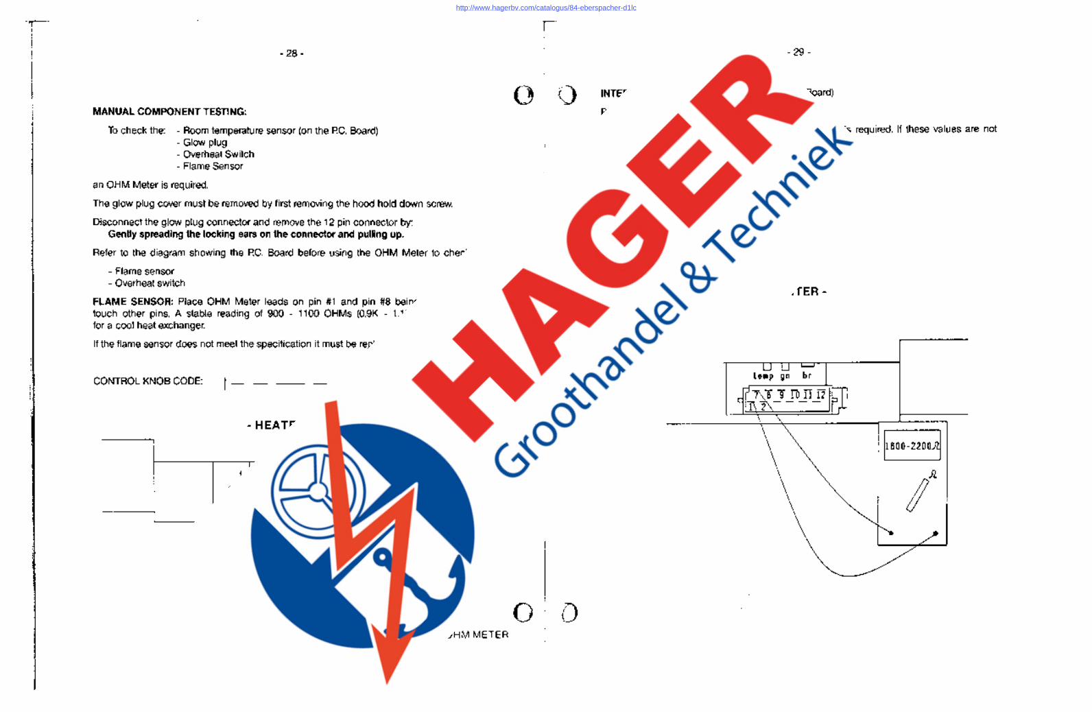
MANUAL COMPONENT TESTING:
To check the: - Room temperature sensor (on the P.C. Board) - Glow plug - Overheat Switch - Flame Sensor
an OHM Meter is required.
The glow plug cover must be removed by first removing the hood hold down screw.
Disconnect the glow plug connector and remove the 12 pin connector by: Gently spreading the locking ears on the connector and pulling up.
Refer to the diagram showing the P.C. Board before using the OHM Meter to check the:
- Flame sensor - Overheat switch
FLAME SENSOR: Place OHM Meter leads on pin #1 and pin #8 being careful NOT to touch other pins. A stable reading of 900 - 1100 OHMs (0.9K - 1.1 K) should be seen for a cool heat exchanger.
If the flame sensor does not meet the specification it must be replaced.
CONTROL KNOB CODE: 1--
- HEATER-
Flame Senser Test
OHM METER
-----------------------------------------,
- 29-
INTERNAL TEMPERATURE SENSOR: (on P.C. Board)
Place OHM Meter leads on pin #7 and pin #1.
A steady reading of 1800 - 2200 OHMs (1.8K - 2.2K) is required. If these values are not produced then the P.C. board must be replaced.
CONTROL KNOB CODE: 1--
- HEATER-
1800-2200.iI
http://www.hagerbv.com/catalogus/84-eberspacher-d1lc
- 30-
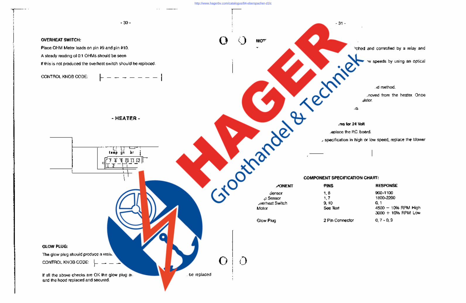
OVERHEAT SWITCH:
Place OHM Meter leads on pin #9 and pin #10.
A steady reading of 0.1 OHMs should be seen
If this is not produced the overheat switch should be replaced.
CONTROL KNOB CODE: ~-------I
- HEATER-
GLOW PLUG:
The glow plug should produce a resistance of 0.7 - 0.9 OHMs.
CONTROL KNOB CODE: ~ __ _
If all the above checks are OK the glow plug and the 12 pin connectors can be replaced and the hood replaced and secured.
-.'.;' ..•... ' ....• W
- 31 -
MOTOR TEST:
The heater is a two speed motor with speeds switched and controlled by a relay and a resistor on the P.C. board.
The blower motor can be checked for proper high and low speeds by using an optical or strobe tachometer.
High Speed Low Speed
4500 = 10% RPM 3000 = 10% RPM
If low speed cannot be obtained it can be checked using a second method.
The second method requires that the P.C. board be removed from the heater. Once removed a OHM Meter is used to check the low speed resistor.
Refer to the following diagram for the proper test points.
Values required for the resistor are:
3.71 - 4.1 ohms for 12 Volt OR 17.1 - 18.9 ohms for 24 Volt
If the resistor is not within specification, replace the P.C. board.
If the blower motor does not turn to specification in high or low speed, replace the blower motor.
CONTROL KNOB CODE: f-I--
COMPONENT SPECIFICATION CHART:
PCB COMPONENT
Flame Sensor Temp Sensor Overheat Switch Motor
Glow Plug
PINS
1,8 1,7 9, 10 See Text
2 Pin Connector
RESPONSE
900-1100 1800-2200 0, 1 4500 + 10% RPM High 3000 + 10% RPM Low
0,7 - 0, 9
http://www.hagerbv.com/catalogus/84-eberspacher-d1lc
- 32-
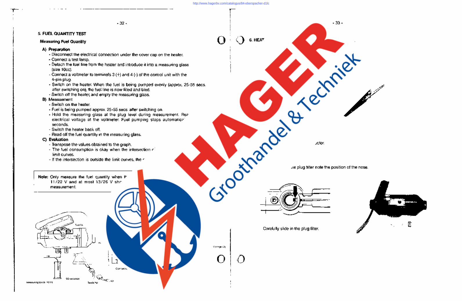
5. FUEL QUANTITY TEST
Measuring Fuel Quantity
A) Preparation - Disconnect the electrical connection under the cover cap on the heater. - Connect a test lamp. - Detach the fuel line from the heater and introduce it into a measuring glass
(size 10cc). - Connect a voltmeter to terminals 3 (+) and 4 (-) of the control unit with the
4-pin plug. - Switch on the heater. When the fuel is being pumped evenly (approx. 25-55 secs.
after switching on), the fuel line is now filled and bled. - Switch off the heater, and empty the measuring glass.
B) Measuement - Switch on the heater. - Fuel is being pumped approx. 25-55 secs. after switching on. - Hold the measuring glass at the plug level during measurement. Read off the
electrical voltage at the voltmeter. Fuel pumping stops automatically after 90 seconds.
- Switch the heater back off. - Read off the fuel quantity in the measuring glass.
C) Evaluation - Transpose the values obtained to the graph. - The fuel consumption is okay when the intersection of the two lines is within the
limit curves. - If the intersection is outside the limit curves, the metering pump must be replaced.
Note: Only measure the fuel quantity when the battery is sufficiently charged. At least 11/22 V and at most 13/26 V should be applied at the control unit during measurement.
"
li Measuring glass, lace
Control unit
:J
o 0
Jl11 Voltmeter
(
~-.
" '-, '
90 seconds ... Q ~;,;.
Testlamp
Connection of voltmeter to control unit
ml ---90 seconds
7
6
5
4
11 22
12 24
13 26 Voltage (V)
6. HEATER REPAIR STEPS
1. Removing/fitting the glow plug
2. Removinglfitting the plug filter
Removing the cap
Remove the glow plug connector. Unscrew the glow plug. Remove the plug filter.
- 33-
When refitting the plug filter note the position of the nose.
- ~I~ --@)DEti= ~~~------------
Carefully slide in the plug filter.
---------------------------------
http://www.hagerbv.com/catalogus/84-eberspacher-d1lc
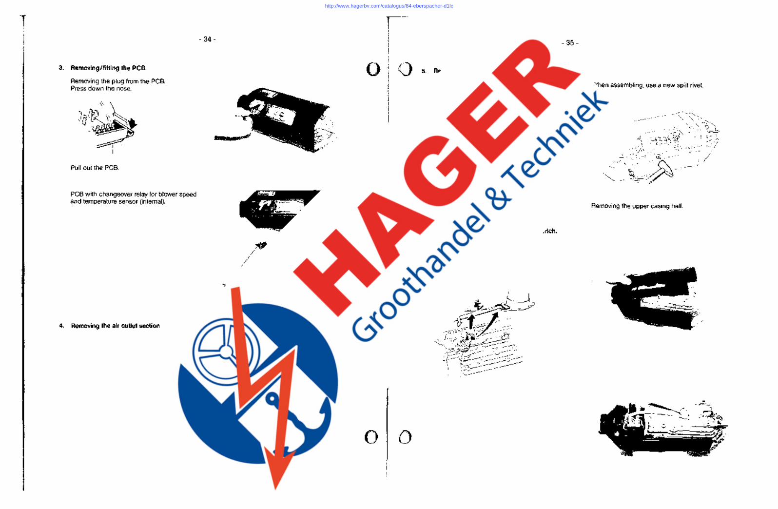
3. Removing/fitting the PCB.
Removing the plug from the PCB. Press down the nose.
Pull out the PCB.
PCB with changeover relay for blower speed and temperature sensor (internal).
4. Removing the air outlet section
- 34-
Temperature sensor for heating air (internal).
.,
•
5. Removinglfitting the upper casing half.
Remove split rivet knock pin through using a small drive, lever out rivet using a knife.
6. Removing the safety thermal cutout switch .
- 35-
When assembling, use a new split rivet.
Removing the upper casing half.
http://www.hagerbv.com/catalogus/84-eberspacher-d1lc
------------------------------------------------------
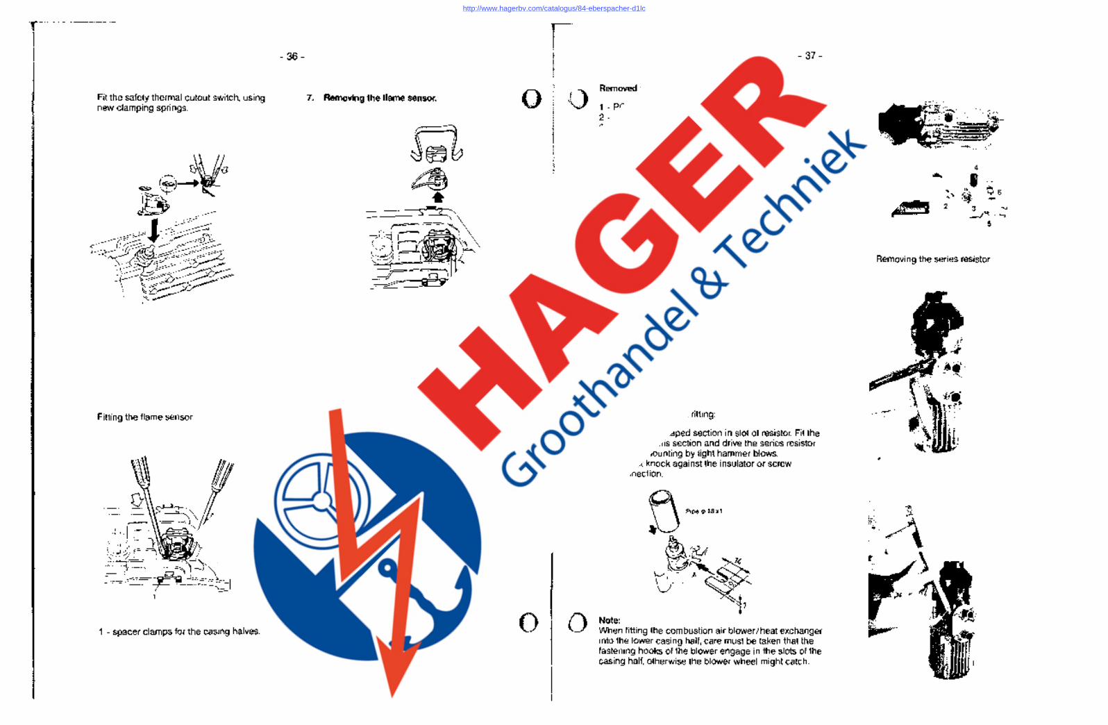
Fit the safety thermal cutout switch, using new clamping springs.
Fitting the flame sensor
1
1 - spacer clamps for the casing halves.
- 36-
7. Removing.the flame sensor. •
•
Removed parts
1 - PC.B 2 - safety thermal cutout switch 3 - glow plug 4 - plug filter 5 - flame sensor 6 - spacer clamps for casing halves
- 37-
8. Changing the series resistor for glow plugs in the 24 V heaters
Note on removal: The series resistor has been fitted with a clamping ring, there is no thread!
Please note when fitting:
Place fork-shaped section in slot of resistor. Fit the pipe over this section and drive the series resistor into its mounting by light hammer blows. Do not knock against the insulator or screw connection.
Note: When fitting the combustion air blower / heat exchanger into the lower casing half, care must be taken that the fastening hooks of the blower engage in the slots of the casing half, otherwise the blower wheel might catch.
1
, " ,4.~
2
Removing the series resistor
http://www.hagerbv.com/catalogus/84-eberspacher-d1lc
- 38-
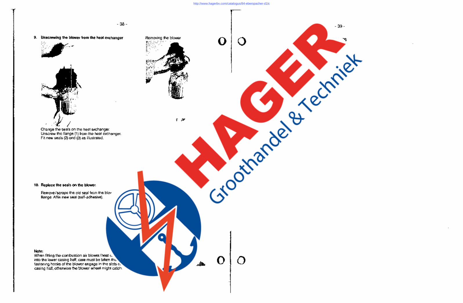
9. Unscrewing the blower from the heat exchanger
Change the seals on the heat exchanger. Unscrew the flange (1) from the heat exchanger. Fit new seals (2) and (3) as illustrated.
10. Replace the seals on the blower.
Remove/scrape the old seal from the blower flange. Affix new seal (self-adhesive).
Note: When fitting the combustion air blower/heat exchanger into the lower casing half, care must be taken that the fastening hooks of the blower engage in the slots of the casing half, otherwise the blower wheel might catch.
- 39-
Removing the blower NOTES
2 , •
http://www.hagerbv.com/catalogus/84-eberspacher-d1lc
- 40-
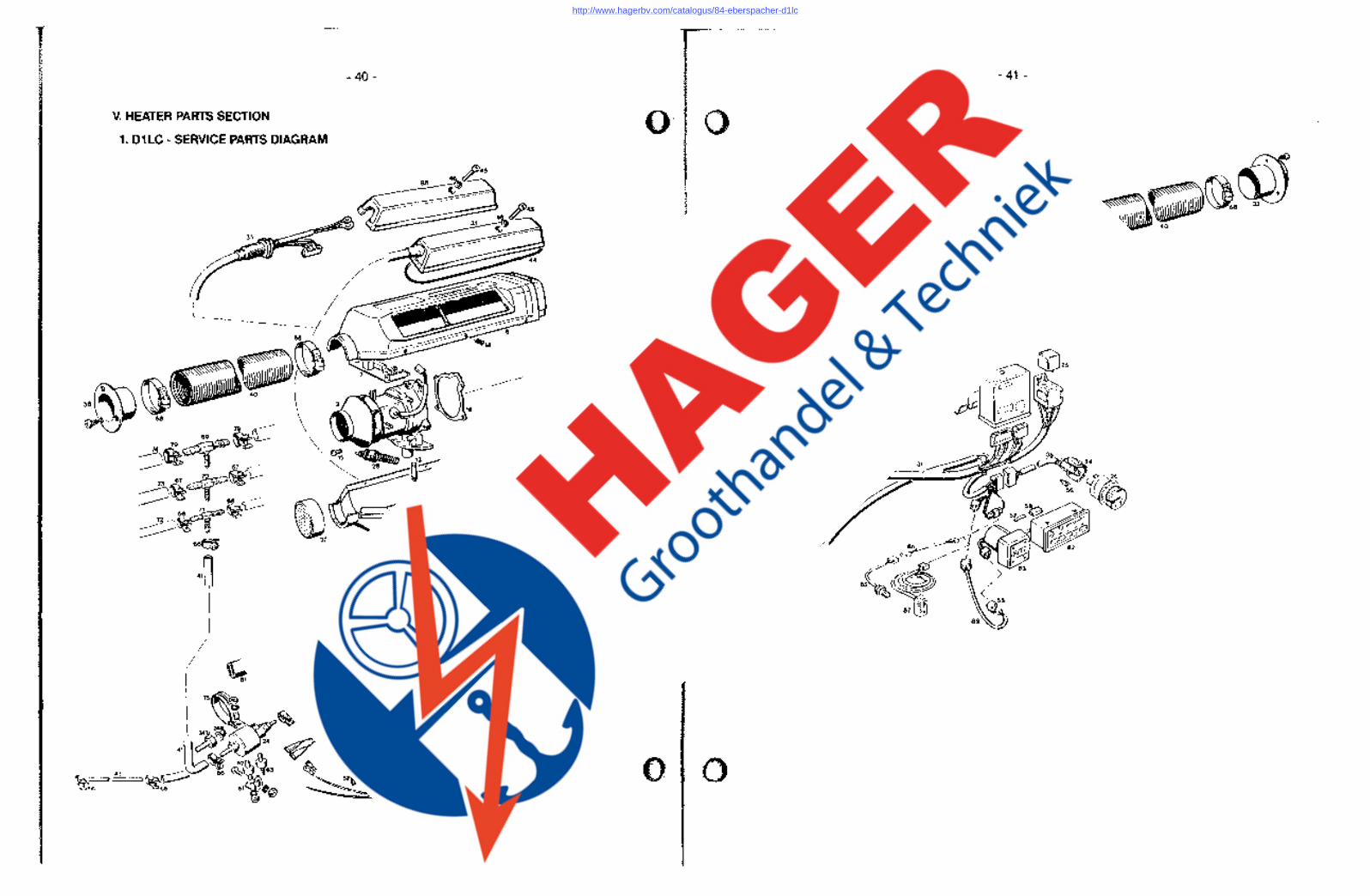
V. HEATER PARTS 1 SECTION
. D1 LC - SERVICE PARTS DIAGRAM
~~3~~_ ,,-~;:~" ~~. (,
~
I L...
- 41 -
-----
> 83
,//
http://www.hagerbv.com/catalogus/84-eberspacher-d1lc
- 42- - 43-251830/251831
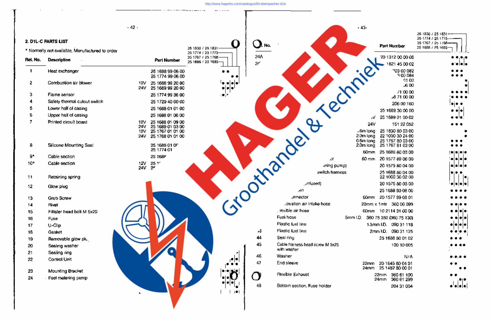
2. D1 L-C PARTS LIST 251774/251775 25 1767 / 25 1768=]1
~! 251830/251831
No. Description . Part Number 251688/251689, * Normally not available, Manufactured to order 251774/251
Ref. No. Description Part Number 251767/251 Pot-shaped strainer 201312000006 ••• • 251688/251 .
Hose connection 201621450002 ••• • 1 Heat exchanger 251688990600 Relay 12V 20300082 •••
251774990600 24V 20300084 • •• 2 Combustion air blower 12V 251688992000
Current regulator 12V 251830300100 • 24V 251689992000
24V 251769800600 • 3 Flame sensor 251774993600
Temperature control switch complete 12V 25176771 0000 ••• • 24V 25176871 0000 • •• •
4 Safety thermal cutout switch 25 1729 40 00 00 Ceramic holder 20600160 ••• 5 Lower half of casing 25168801 01 00 Resistor 24V 251689300000 ••• 6 Upper half of casing 25168801 0600 Protective plate 24V 25168901 0002 • •• 7 Printed circuit board 12V 25168801 0900 Double u-clip 24V 151 22052 24V 25168901 0300 •••
12V 25 1767 01 01 00 Cable harness 0.6m long 251830800300 • 24V 25 1768 01 01 00 2.0m long 221000302400 •
0.6m long 25 1767 80 03 00 ••• 8 Silicone Mounting Seal 25168801 0002 2.0m long 25176781 0300 •••
251774010002 Air outlet hood 60mm 251688800300 • •• • 9* Cable section 25168801 0700 Adjustable air outlet deflector 60mm 201577 89 06 00 • •• •
10* Cable section 12V 25168801 0400 Cable section (Fuel metering pump) 201579800400 24V 25168901 0200 • •• • Temperature control switch harness 251688800400 • ••
11 Retaining spring 251388010004 221000300200 • 251774010003 Power Cable (unfused) 201575800300
12 Glow plug 12V 25 1830 01 01 00 • •• • 24V 251831 01 01 00 Safety screen 251688800600 • • • •
13 Grub Screw 10610022 Hose connector 60mm 201577 89 06 01 • •• • 14 Rivet 131 31 051 Combustion air intake hose 20mm x 1mtr 36000099 • •• • 15 Fillister head bolt M 5x20 10310461 Flexible air hose 60mm 102114310000 • •• • 16 Fuse 17142080 Fuel hose 5mm I.D. 360 75 350 (360 75 130) • •• • 17 U-Clip 25168801 0003 Plastic fuel line 1.5mm 1.0. 09031118 • •• • 18 Gasket 25168801 00 06 Plastic fuel line 2mml.D. 09031 125 • •• • 19 Removable glow plug screen 251688060400 Seal ring 2516888001 02 • •• 20 Sealing washer 251688060003 Cable harness head screw M 5x25 10010005 • • •• 21 Sealing ring 251688060006
with washer
22 Control Unit 12V 251688500006 Washer N/A • •••
24V 251689500008 End sleeve 22mm 201645800401 •• 23 Mounting Bracket 251688650001
24mm 251482800001 •• 24 . Fuel metering pump 12V 251688450000
Flexible Exhaust 22mm 36061 100 •• 24mm 36061299 •• 24V 251689450000
12V 251830450000 Bottom section, Fuse holder 20431004 • • •• 24V 251831 450000
http://www.hagerbv.com/catalogus/84-eberspacher-d1lc
- 44-
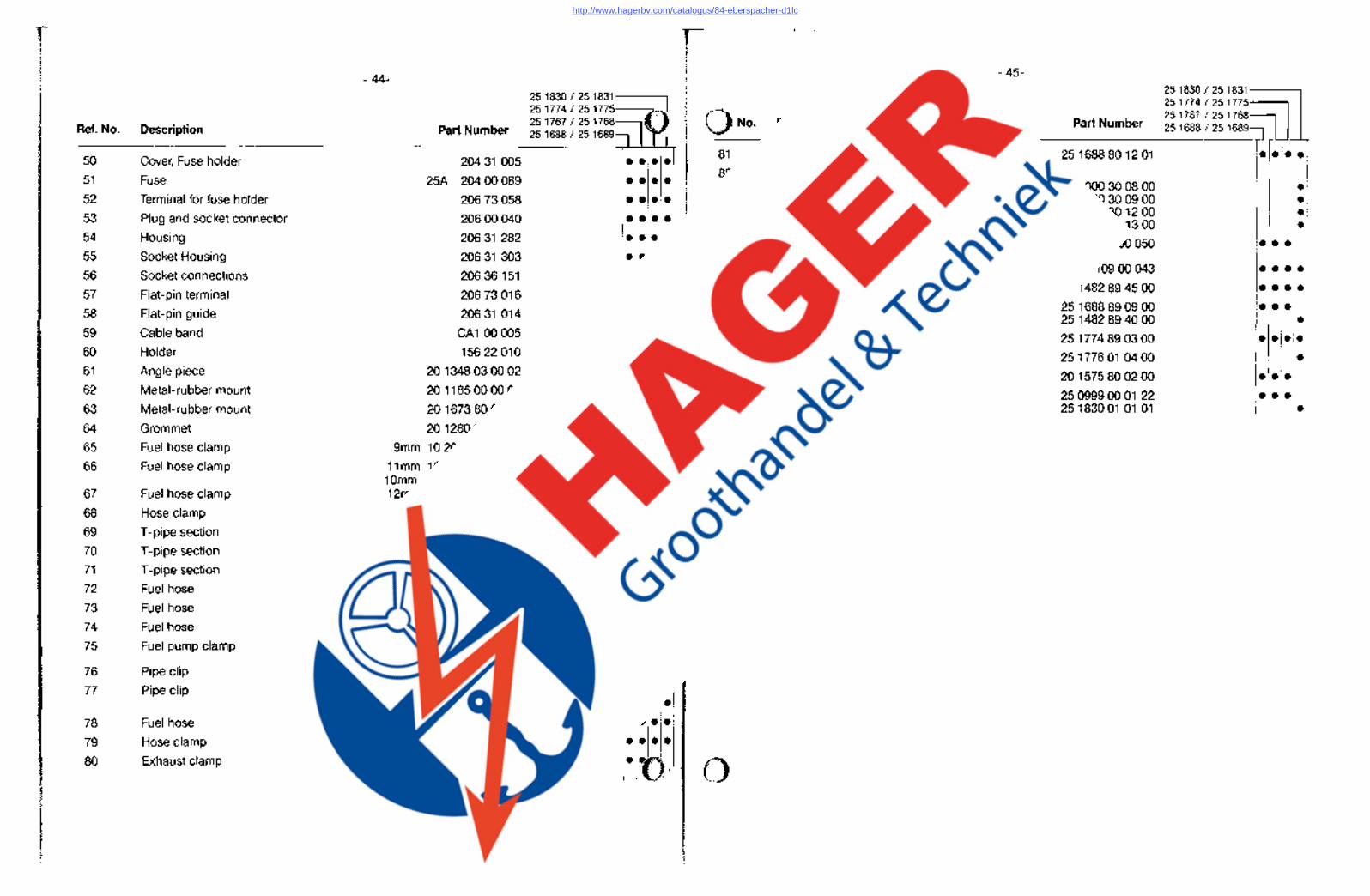
Ref. No. Description Part Number
50 Cover, Fuse holder 20431005
51 Fuse 25A 20400089
52 Terminal for fuse holder 20673058
53 Plug and socket connector 20600040
54 Housing 20631282
55 Socket Housing 20631303
56 Socket connections 20636151
57 Flat-pin terminal 20673016
58 Flat-pin guide 20631 014
59 Cable band CA1 00005
60 Holder 15622010
61 Angle piece 201348030002
62 Metal-rubber mount 201185000001
63 Metal-rubber mount 2016738001 01
64 Grommet 201280090103
65 Fuel hose clamp 9mm 102063009098
66 Fuel hose clamp 11mm 10206301 1098 10mm 10206301 0098
67 Fuel hose clamp 12mm 10206301 2098
68 Hose clamp CA110047
69 T -pipe section 26231153
70 T -pipe section 26231 152
71 T -pipe section 26231 151
72 Fuel hose 7.5mm 360 31 070
73 Fuel hose 9mm 360 31 095
74 Fuel hose 11 mm 360 31 096
75 Fuel pump clamp 15200144
76 Pipe clip 15200139
77 Pipe clip 25mm 15210048 28mm 15210051
78 Fuel hose 3.5mm 1.0. 36075300
79 Hose clamp 102064106025
80 Exhaust clamp 22mm 251688801200 24mm 15261102
251830/251831 251774/251 251767/251 251688/251
No. Description
81 End sleeve with crossbar
82 Heater timer Timer/thermostat
7 day timer
83 99 Hr. timer
Screw taptite M 5x10
Temperature sensor, external
Cable section
Temperature sensor, external
Cable cover
Switch harness
Sealing ring
- 45-
12V 24V 12V 24V
251830/251831 251774/251775
Part Number 25 1767 / 25 1768~ 251688/251689,
251688801201 • •• • 221000300800 • 221000300900 • 221000301200 • 221000301300 •
CA1 00050 ••• 10900043 ••• •
251482894500 • •• • 251688890900 • •• 251482894000 • 251774890300 • •• • 25177601 0400 • 201575800200 • •• 25 0999 00 01 22 • •• 25183001 01 01 •
http://www.hagerbv.com/catalogus/84-eberspacher-d1lc
Related Documents