J. Eberspächer GmbH & Co. KG Eberspächerstr. 24 D-73730 Esslingen Telephone (switchboard) (0711) 939-00 Facsimile (0711) 939-0500 www.eberspaecher.com 25 2435 95 20 81 02.2008 Subject to changes Printed in Germany © J. Eberspächer GmbH & Co. KG Troubleshooting and Repair Instructions The troubleshooting and repair instructions are applicable to the following unit versions only Heater Order no. HYDRONIC M8 Biodiesel 12 V 25 2470 05 00 00 24 V 25 2471 05 00 00 HYDRONIC M10 12 V 25 2434 05 00 00 24 V 25 2435 05 00 00 Heater Order no. HYDRONIC M12 12 V 25 2472 05 00 00 24 V 25 2473 05 00 00 Visit www.butlertechnik.com for more technical information and downloads. www.butlertechnik.com

Welcome message from author
This document is posted to help you gain knowledge. Please leave a comment to let me know what you think about it! Share it to your friends and learn new things together.
Transcript
J. EberspächerGmbH & Co. KGEberspächerstr. 24D-73730 Esslingen
Telephone (switchboard)(0711) 939-00Facsimile(0711) 939-0500
www.eberspaecher.com
25 2435 95 20 81 02.2008 Subject to changes Printed in Germany © J. Eberspächer GmbH & Co. KG
Troubleshooting and Repair Instructions
The troubleshooting and repair instructions are applicable to the following unit versions only
Heater Order no.
HYDRONIC M8 Biodiesel 12 V 25 2470 05 00 00 24 V 25 2471 05 00 00
HYDRONIC M10 12 V 25 2434 05 00 00 24 V 25 2435 05 00 00
Heater Order no.
HYDRONIC M12 12 V 25 2472 05 00 00 24 V 25 2473 05 00 00
Visit www.butlertechnik.com for more technical information and downloads.
www.butlertechnik.com
2
5
4
3
1
1 Introduction
This list of contents gives you precise information about the contents of the Troubleshooting and Repair Instructions.
If you are looking for a term, technical term or you would like an abbreviation explained, please use the relevant index at the end of the instructions, from page 54.
Introduction • Contents .................................................................................................. 2 – 3• Foreword ....................................................................................................... 4• Safety instructions for installation and repair ................................................... 4• Accident prevention ....................................................................................... 4• Special text structure, presentation and picture symbols ................................ 4
• Cutaway view ................................................................................................. 5• Description of functions .................................................................................. 6• Control and safety devices ............................................................................. 7• Forced ADR / ADR99 shutdown ..................................................................... 7• Emergency stop (EMERGENCY OFF) ............................................................. 7
• Technical data, heater ............................................................................ 8 – 10• Technical data, water pump ......................................................................... 11
• What to check first in case of faults .............................................................. 12• Locking the control box ................................................................................ 12• Cancel the control box lock .......................................................................... 12• Overview of testing equipment ..................................................................... 13• Fault diagnosis using the diagnostic unit ................................................ 14, 15• Fault diagnosis using the EDiTH diagnostics tool .......................................... 16• Fault diagnosis using the EasyStart R+ radio remote control and EasyStart T timer ................................................................................... 17• Fault code table ................................................................................... 18 – 20
Function
Product information
Troubleshooting
• Repair instructions ....................................................................................... 21• Always observe the following safety instructions before working on the heater 21• Special tool, AMP release tools .................................................................... 21• Assembly drawing ....................................................................................... 22• Component parts / Notes on various components ....................................... 23• Preparatory work for all repairs ..................................................................... 24• Repair step 1 Dismantle control box / blower unit and jacket ............................................. 24
– Remove overheating and temperature sensor ........................................... 24– Remove water pump connector ................................................................ 25– Remove side cover and jacket .................................................................. 25– Remove electric motor cover .................................................................... 25– Disconnect 14-pin connector at control box and release cables................ 26– Remove flame sensor ............................................................................... 27– Dismantle combustion chamber................................................................ 27
• Repair step 2 Assemble control box / blower unit and jacket ............................................. 28
– Install combustion chamber seal ............................................................... 28– Install grommet ......................................................................................... 28– Insert combustion chamber ...................................................................... 28– Install combustion chamber ...................................................................... 29– Lay sensor lead harness and leads for glow plugs .................................... 29– Install flame sensor ................................................................................... 30– Connect flame sensor lead harness and electric motor leads .................... 30– Connect the glow plug leads..................................................................... 31– Install electric motor cover ........................................................................ 32– Assemble control box / blower unit and jacket .......................................... 32– Lay water pump lead harness ................................................................... 33– Install overheating and temperature sensor ............................................... 33– Install impeller cover .................................................................................. 34
Repair instructions
2
Contents
Chapter Title Contents Page
Visit www.butlertechnik.com for more technical information and downloads.
www.butlertechnik.com
3
Introduction
Circuit diagrams
Service
6
7
Chapter Title Contents Page
Contents
• Repair step 3 ............................................................................................... 35– Remove / check glow plug ....................................................................... 35– Install glow plug ........................................................................................ 35– Clean ignition air drillhole ........................................................................... 35
• Repair step 4 ............................................................................................... 36– Remove spark plug socket lining............................................................... 36– Install spark plug socket lining ................................................................... 36
• Repair step 5 ............................................................................................... 37– Check overheating and temperature sensor .............................................. 37
• Repair step 6 ............................................................................................... 38– Check flame sensor .................................................................................. 38
• Repair step 7– Remove / attach water pump ................................................................... 39
• Measuring the fuel quantity........................................................................... 40
• Heater wiring ................................................................................................ 41• Notes on rewiring the 12-pin cable harness connector ................................. 41• Circuit diagram: HYDRONIC M-II – 12 volt / 24 volt ..................................... 42• Parts list: HYDRONIC M-II – 12 volt / 24 volt ............................................... 43• Circuit diagram: HYDRONIC M-II – ADR – 12 volt / 24 volt .......................... 44• Parts list: HYDRONIC M-II – ADR/ADR99 – 12 volt / 24 volt ........................ 45• Parts list: EasyStart R+ / R / T and EasyStart T – ADR control units ............. 46• Circuit diagram, EasyStart R+ control units .................................................. 47• Circuit diagram, EasyStart R+ control units .................................................. 48• Circuit diagram, EasyStart T control units ..................................................... 49• Circuit diagram, control units, EasyStart T – ADR ......................................... 50
• Certifications ................................................................................................ 51• Disposal ....................................................................................................... 51• EC Declaration of Conformity ....................................................................... 51• Representatives abroad ......................................................................... 52, 53• List of keywords ........................................................................................... 54• List of abbreviations ..................................................................................... 55
1
Repair instructions5
Visit www.butlertechnik.com for more technical information and downloads.
www.butlertechnik.com
4
Special text structure, presentation and picture symbolsSpecial text formats and picture symbols are used in these instructions to emphasise different situations and subjects. Please refer to the following examples for their meanings and appropriate action.
Special text formats and presentations• A dot (•) indicates a list, which is started by a heading.
– If an indented dash (–) follows a "dot", this list is a sub-section of the black dot.
Picture symbols
Danger!This information points out a potential serious or fatal danger. Ignoring this information can result in severe injuries.
Caution!This information points out a dangerous situation for a person and / or the product. Failure to comply with these instructions can result in injuries to people and / or damage to machinery.
Introduction1ForewordThese Troubleshooting and Repair Instructions are applicable to the heaters listed on the title page, to the exclusion of all li-ability claims.Depending on the version or revised status of the heater, there may be differences between it and these troubleshooting and repair instructions.The user must check this before carrying out the repair work and, if necessary, take the differences into account.
Caution!Safety instructions for installation and repair!
Improper installation or repair of Eberspächer heaters can cause a fire or result poisonous exhaust entering the inside of the vehicle. This can cause serious and even fatal risks.
The heater may only be installed according to the specifica-tions in the technical documents or repaired using original spare parts by authorised and trained persons.Installation and repairs by unauthorised and untrained per-sons, repairs using non-original spare parts and without the technical documents required for installation and repair are dangerous and therefore are not permitted.
A repair may only be carried out in connection with the re-spective unit-related technical description, installation instruc-tions, operating instructions and maintenance instructions. This document must be carefully read through before / during installation and repair and followed throughout. Particular attention is to be paid to the official regulations, the safety in-structions and the general information.
The relevant rules of sound engineering practice and any information provided by the vehicle manufacturer are to be observed during the installation and repair.Eberspächer does not accept any liability for defects and damage, which are due to installation or repair by unauthor-ised and untrained persons.Compliance with the official regulations and the safety instruc-tions is prerequisite for liability claims. Failure to comply with the official regulations and safety instructions leads to exclu-sion of any liability of the heater manufacturer.
Accident prevention
General accident prevention regulations and the correspond-ing workshop and operating safety instructions are to be observed.
Please note!
Visit www.butlertechnik.com for more technical information and downloads.
www.butlertechnik.com
5
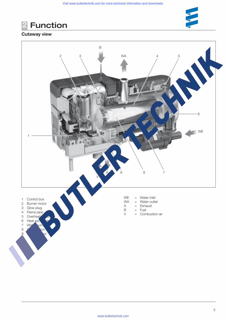
Function2Cutaway view
1 Control box2 Burner motor3 Glow plug4 Flame pipe5 Overheating sensor6 Heat exchanger7 Water pump8 Combustion chamber9 Flame sensor
WE = Water inletWA = Water outletA = Exhaust B = Fuel V = Combustion air
1
3
B
2 WA
WE
AV
9 8 7
54
6
Visit www.butlertechnik.com for more technical information and downloads.
www.butlertechnik.com
6
Function2Description of functions
Switching onOn being switched on, the switch-on check is displayed in the control unit (EasyStart R+ / EasyStart T). The heater starts with a pre-set program, whereby the water pump and the combustion air blower start up first.The metering pump starts pumping the fuel with a slight delay. The glow phase of the glow plugs starts at the same time as discharge of the combustion air.The glow plugs are switched off once a stable flame has formed in the combustion chamber.
Heating modeThe first time it is started up, the heater is run with the "POWER" stage until the water temperature exceeds the "POWER" / "HIGH" changeover threshold.HYDRONIC M8 / M10Then, depending on the heat requirement, the heater runs in the "HIGH – MEDIUM – LOW – OFF” stages only. If the heating requirement in the "LOW" stage is so small that the cooling water temperature reaches 85 °C, the heater switches from "LOW" to "OFF". HYDRONIC M12Then, depending on the heat requirement, the heater runs in the "HIGH – MEDIUM 1 / MEDIUM 2 / MEDIUM 3 – LOW – OFF” stages only. If the heating requirement in the "LOW" stage is so small that the cooling water temperature reaches 85 °C, the heater switches from "LOW" to "OFF". The after-run follows with additional after-glowing of the glow plugs (as when the heater is switched off). After the cooling water has cooled to approx. 70 °C the HYDRONIC M8 / M10 heater starts in "MEDIUM" stage, the HYDRONIC M12 heater in "MEDIUM 1" stage.If the cooling water temperature reaches approx. 55 °C the temperature sensor switches on the vehicle fan.
Switching offOn being switched off the heater starts the after-run of 180 sec. During the after-run, after 90 seconds the first glow plug is switched on for 45 seconds, then the second glow plug is switched on until the end of the after-run.
Temperature dropTemperature drop only becomes active while the vehicle is running and if the heater is switched on. The control stages are reached earlier; 58 °C instead of 68 °C and 45 °C instead of 63 °C. The heater's control action is adjusted to the lower heat requirement.The temperature drop is made possible by connecting the positive cable (D+) to connector S2, terminal C3, of the heater (see circuit diagrams, page 42 and 44).
Visit www.butlertechnik.com for more technical information and downloads.
www.butlertechnik.com
7
Function2Control and safety devices
The heater is equipped with the following control and safety devices.
• If the heater does not ignite within 74 seconds after the fuel starts to pump, the start is repeated.
If the heater still does not ignite after another 65 seconds of fuel being pumped, the heater is automatically shut down.
After an unacceptable number of failed start attempts, the control box is locked.*
• If the flame goes off by itself during operation, the heater is restarted.
If the heater does not ignite within 74 seconds after the fuel starts to pump again, the heater is automatically shut down.
The shutdown on faults can be cancelled by briefly switch-ing off and on again.
• In the case of overheating (e.g. water shortage, poorly ven-tilated cooling water circuit), the overheating sensor triggers, the fuel feed is interrupted and the heater is automatically shut down.
Once the cause of the overheating has been eliminated, the heater can be re-started by switching it off and on again (provided that the heater has cooled down sufficiently, cool-ing water temperature < 70 °C).
After the heater has been shut down due to overheating an unacceptable number of times, the control box is locked.*
* The lock can be cancelled and the faults read out:• with the EasyStart T timer• with the EasyStart R+ radio remote control.
In other control units• with the diagnostics unit• using the EDiTH diagnostics tool.
For operation and fault list, please refer to the enclosed operating instructions or these troubleshooting and repair instructions.
• If the lower or upper voltage limit is reached, the heater is automatically shut down.
• The heater does not start up if the electric cable to the metering pump is interrupted.
• If one of the two glow plugs is defective, the start sequence takes place with one glow plug only.
• The speed of the blower motor is continuously monitored. If the blower motor does not start up, if it is blocked or if the
speed differs by > 12.5 % of the desired speed, the heater is automatically shut down after 60 sec.
• The function of the water pump is continuously monitored.
Do not repeat the switching off / on routine more than twice.
Forced shutdown during ADR / ADR99 operation
In vehicles for the transport of dangerous goods (e.g. tanker trucks), the heater must be switched off before the truck drives into a danger area (refinery, petrol station, etc.) Failure to comply results in the heater automatically switching off if:• The vehicle engine is switched off.• An additional unit is started up (auxiliary drive for unloading
pump, etc.)• A vehicle door is opened (ADR99 regulation, only in France).This is followed by a short after-run of the blower for max. 40 seconds.
Emergency stop – EMERGENCY OFFIf an emergency stop – EMERGENCY OFF – is necessary during operation, complete the following:• Switch the heater off at the control element or• remove the fuse or• disconnect the heater from the battery.
Please note!
Visit www.butlertechnik.com for more technical information and downloads.
www.butlertechnik.com
8
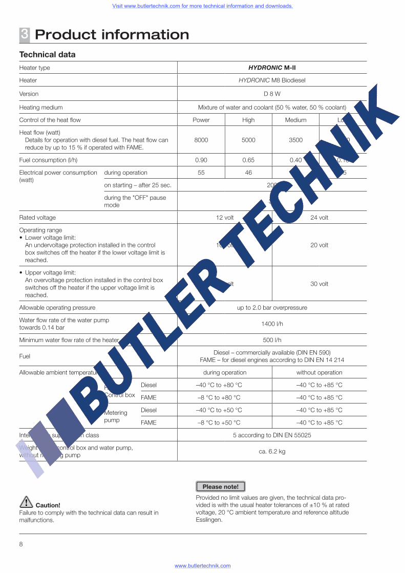
Product information3Technical data
Heater type HYDRONIC M-II
Heater HYDRONIC M8 Biodiesel
Version D 8 W
Heating medium Mixture of water and coolant (50 % water, 50 % coolant)
Control of the heat flow Power High Medium Low
Heat flow (watt) Details for operation with diesel fuel. The heat flow can
reduce by up to 15 % if operated with FAME.8000 5000 3500 1500
Fuel consumption (l/h) 0.90 0.65 0.40 0.18
Electrical power consumption (watt)
during operation 55 46 39 35
on starting – after 25 sec. 200
during the "OFF" pause mode
32
Rated voltage 12 volt 24 volt
Operating range• Lower voltage limit: An undervoltage protection installed in the control
box switches off the heater if the lower voltage limit is reached.
10 volt 20 volt
• Upper voltage limit: An overvoltage protection installed in the control box
switches off the heater if the upper voltage limit is reached.
15 volt 30 volt
Allowable operating pressure up to 2.0 bar overpressure
Water flow rate of the water pump towards 0.14 bar
1400 l/h
Minimum water flow rate of the heater 500 l/h
FuelDiesel – commercially available (DIN EN 590)
FAME – for diesel engines according to DIN EN 14 214
Allowable ambient temperature during operation without operation
Heater / Control box
Diesel –40 °C to +80 °C –40 °C to +85 °C
FAME –8 °C to +80 °C –40 °C to +85 °C
Metering pump
Diesel –40 °C to +50 °C –40 °C to +85 °C
FAME –8 °C to +50 °C –40 °C to +85 °C
Interference suppression class 5 according to DIN EN 55025
Weight – with control box and water pump, without metering pump
ca. 6.2 kg
Caution!Failure to comply with the technical data can result in malfunctions.
Provided no limit values are given, the technical data pro-vided is with the usual heater tolerances of ±10 % at rated voltage, 20 °C ambient temperature and reference altitude Esslingen.
Please note!
Visit www.butlertechnik.com for more technical information and downloads.
www.butlertechnik.com
9
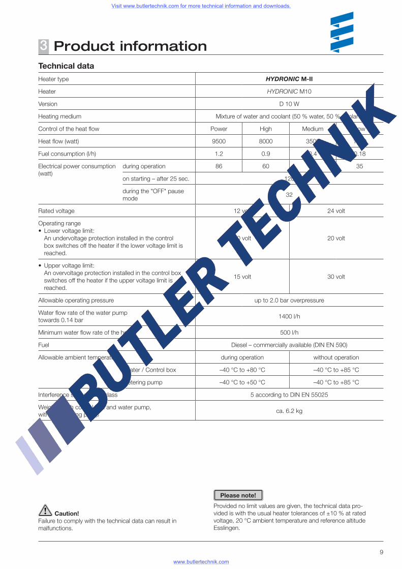
Product information3Technical data
Heater type HYDRONIC M-II
Heater HYDRONIC M10
Version D 10 W
Heating medium Mixture of water and coolant (50 % water, 50 % coolant)
Control of the heat flow Power High Medium Low
Heat flow (watt) 9500 8000 3500 1500
Fuel consumption (l/h) 1.2 0.9 0.4 0.18
Electrical power consumption (watt)
during operation 86 60 39 35
on starting – after 25 sec. 120
during the "OFF" pause mode
32
Rated voltage 12 volt 24 volt
Operating range• Lower voltage limit: An undervoltage protection installed in the control
box switches off the heater if the lower voltage limit is reached.
10 volt 20 volt
• Upper voltage limit: An overvoltage protection installed in the control box
switches off the heater if the upper voltage limit is reached.
15 volt 30 volt
Allowable operating pressure up to 2.0 bar overpressure
Water flow rate of the water pump towards 0.14 bar
1400 l/h
Minimum water flow rate of the heater 500 l/h
Fuel Diesel – commercially available (DIN EN 590)
Allowable ambient temperature during operation without operation
Heater / Control box –40 °C to +80 °C –40 °C to +85 °C
Metering pump –40 °C to +50 °C –40 °C to +85 °C
Interference suppression class 5 according to DIN EN 55025
Weight – with control box and water pump, without metering pump
ca. 6.2 kg
Caution!Failure to comply with the technical data can result in malfunctions.
Provided no limit values are given, the technical data pro-vided is with the usual heater tolerances of ±10 % at rated voltage, 20 °C ambient temperature and reference altitude Esslingen.
Please note!
Visit www.butlertechnik.com for more technical information and downloads.
www.butlertechnik.com
10
Product information3
Caution!Failure to comply with the technical data can result in malfunctions.
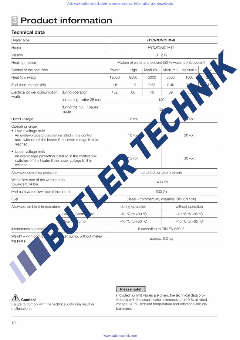
Technical data
Heater type HYDRONIC M-II
Heater HYDRONIC M12
Version D 12 W
Heating medium Mixture of water and coolant (50 % water, 50 % coolant)
Control of the heat flow Power High Medium 1 Medium 2 Medium 3 Low
Heat flow (watt) 12000 9500 5000 3500 1500 1200
Fuel consumption (l/h) 1.5 1.2 0.65 0.40 0.18 0.15
Electrical power consumption (watt)
during operation 132 86 46 39 35 34
on starting – after 25 sec. 120
during the "OFF" pause mode
32
Rated voltage 12 volt 24 volt
Operating range• Lower voltage limit: An undervoltage protection installed in the control
box switches off the heater if the lower voltage limit is reached.
10 volt 20 volt
• Upper voltage limit: An overvoltage protection installed in the control box
switches off the heater if the upper voltage limit is reached.
15 volt 30 volt
Allowable operating pressure up to 2.0 bar overpressure
Water flow rate of the water pump towards 0.14 bar
1400 l/h
Minimum water flow rate of the heater 500 l/h
Fuel Diesel – commercially available (DIN EN 590)
Allowable ambient temperature during operation without operation
Heater / Control box –40 °C to +80 °C –40 °C to +85 °C
Metering pump –40 °C to +50 °C –40 °C to +85 °C
Interference suppression class 5 according to DIN EN 55025
Weight – with control box and water pump, without meter-ing pump
approx. 6.2 kg
Provided no limit values are given, the technical data pro-vided is with the usual heater tolerances of ±10 % at rated voltage, 20 °C ambient temperature and reference altitude Esslingen.
Please note!
Visit www.butlertechnik.com for more technical information and downloads.
www.butlertechnik.com
11
Product information3
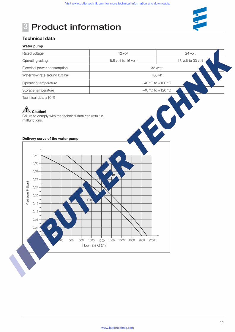
Delivery curve of the water pump
Caution!Failure to comply with the technical data can result in malfunctions.
Flow rate Q (l/h)
Pre
ssur
e P
(bar
)
Technical data
Water pump
Rated voltage 12 volt 24 volt
Operating voltage 8.5 volt to 16 volt 18 volt to 33 volt
Electrical power consumption 32 watt
Water flow rate around 0.3 bar 700 l/h
Operating temperature –40 °C to +100 °C
Storage temperature –40 °C to +120 °C
Technical data ±10 %
Visit www.butlertechnik.com for more technical information and downloads.
www.butlertechnik.com
12
Troubleshooting4What to check first in case of faults
• Check whether:– Fuel in the tank?– Fuel pipes leaking? (visual check)– Summer diesel still in the fuel pipe?– Heating lever (water valve) fully set to "HOT"?– Combustion air system or exhaust system damaged or
blocked?
• Electrical components:– Cables, connections damaged?– Contacts corroded?– Fuses defective?– Incorrect wiring? (short circuits, interrupted / broken)
• Check battery voltage– Battery voltage < 10 volt, the undervoltage protection of
the 12 volt heater has triggered.– Battery voltage < 20 volt, the undervoltage protection of
the 24 volt heater has triggered.
• Check voltage supply UBatt (Terminal 30) Disconnect the 12-pin connector (B2) and measure the
voltage applied at the control box / blower unit between chamber A3 (cable 2.52 rt) and chamber A2 (cable 2.52 br).
If it differs from the battery voltage, check the fuses, the supply cables, the negative connection and the positive support point on the battery for voltage drop (corrosion / interruption).
• Check switch-on signal (S+) If using the EasyStart R+, R and T control units. Disconnect the 12-pin connector (B2) at the control box /
blower unit and then use the control unit to switch on the heater.
Measure the applied voltage in the connector (B2) between chamber B4 (cable 0.752 bl/ws) and chamber A2 (cable 2.52 br). If no voltage is applied, then check the supply cable (cable 12 ge), the 5 A fuse (Item 2.7.1 in the circuit diagram) and the control unit.
In all other control units Disconnect the 12-pin connector (B2) at the control box /
blower unit and then press the button C on the control unit. Measure the applied voltage in the connector (B2) between
chamber C4 (cable 12 ge) and chamber A2 (cable 2.52 br). If no voltage is applied, then check the supply cable (cable 12 ge), the 5 A fuse (Item 2.7.1 in the circuit diagram) and the control unit.
Locking the control box
The control box is locked if the following faults occur:
• Too many attempted starts If the heater performs several failed starting attempts in suc-
cession – fault code 050 is displayed –> the control box is locked.
• Overheating If the heater overheats several times in succession – fault
code 015 is displayed –> the control box is locked.
Cancel the control box lock
Cancellation of the control box lock depends on the appropri-ate test equipment and is described on pages 14 to 17.
Visit www.butlertechnik.com for more technical information and downloads.
www.butlertechnik.com
13
Troubleshooting4Overview of the individual test equipment and control units
The electronic control box can store up to 5 faults, which can be read out and displayed. The following test equipment can be used to query the fault memory in the control box and if necessary to delete the locking of the control box:
Testing equipment Order No.:
• Diagnostic unit 22 1529 89 00 00 also required: Adapter cable 22 1000 33 44 00
• EDiTH diagnostics tool– ISO adapter 22 1524 89 00 00 also required: Adapter cable 22 1000 33 44 00
If the diagnostics cable is connected, the following control units can also be used to query the fault memory in the con-trol box and if necessary to delete the locking of the control box:
Control units Order No.:
• EasyStart T 22 1000 32 88 00
• EasyStart R+ 22 1000 32 80 00
If the fault memory cannot be read out, check the diagnostics cable is properly laid and is not damaged.
External diagnostics systemWith an external, vehicle-specific diagnostics system –> Consult the vehicle manufacturer.
Please note!
Visit www.butlertechnik.com for more technical information and downloads.
www.butlertechnik.com
14
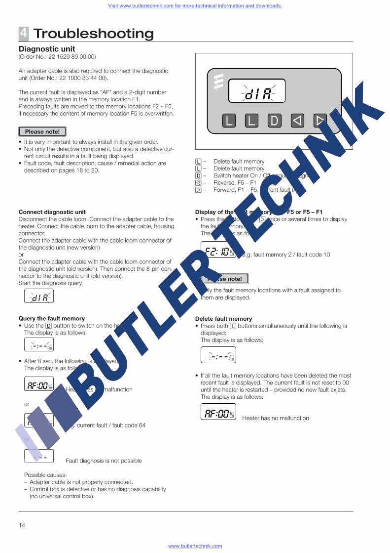
Diagnostic unit(Order No.: 22 1529 89 00 00)
An adapter cable is also required to connect the diagnostic unit (Order No.: 22 1000 33 44 00).
The current fault is displayed as "AF" and a 2-digit number and is always written in the memory location F1.Preceding faults are moved to the memory locations F2 – F5, if necessary the content of memory location F5 is overwritten.
• It is very important to always install in the given order.• Not only the defective component, but also a defective cur-
rent circuit results in a fault being displayed.• Fault code, fault description, cause / remedial action are
described on pages 18 to 20.
Connect diagnostic unitDisconnect the cable loom. Connect the adapter cable to the heater. Connect the cable loom to the adapter cable, housing connector.Connect the adapter cable with the cable loom connector of the diagnostic unit (new version)orConnect the adapter cable with the cable loom connector of the diagnostic unit (old version). Then connect the 8-pin con-nector to the diagnostic unit (old version). Start the diagnosis query.
Query the fault memory• Use the D button to switch on the heater. The display is as follows:
• After 8 sec. the following is displayed: The display is as follows:
Heater has no malfunction
or
e.g. current fault / fault code 64
or
Fault diagnosis is not possible
Possible causes:– Adapter cable is not properly connected.– Control box is defective or has no diagnosis capability
(no universal control box).
Troubleshooting4
Display of the fault memory F1 – F5 or F5 – F1• Press the button e or f once or several times to display
the fault memory. The display is as follows:
e.g. fault memory 2 / fault code 10
Only the fault memory locations with a fault assigned to them are displayed.
Delete fault memory• Press both l buttons simultaneously until the following is
displayed: The display is as follows:
• If all the fault memory locations have been deleted the most recent fault is displayed. The current fault is not reset to 00 until the heater is restarted – provided no new fault exists.
The display is as follows:
Heater has no malfunction
l – Delete fault memoryl – Delete fault memoryd – Switch heater On / Off, request diagnosise – Reverse, F5 – F1f – Forward, F1 – F5, current fault (AF)
Please note!
Please note!
Visit www.butlertechnik.com for more technical information and downloads.
www.butlertechnik.com
15
Troubleshooting4
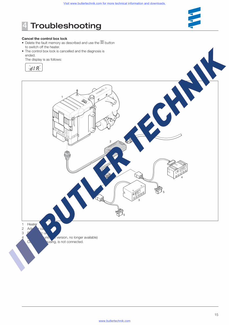
Cancel the control box lock• Delete the fault memory as described and use the d button
to switch off the heater.• The control box lock is cancelled and the diagnosis is
ended. The display is as follows:
1 Heater2 Adapter cable3 Diagnostic unit4 Diagnostic unit (old version, no longer available)5 Connector housing, is not connected.
Visit www.butlertechnik.com for more technical information and downloads.
www.butlertechnik.com
16
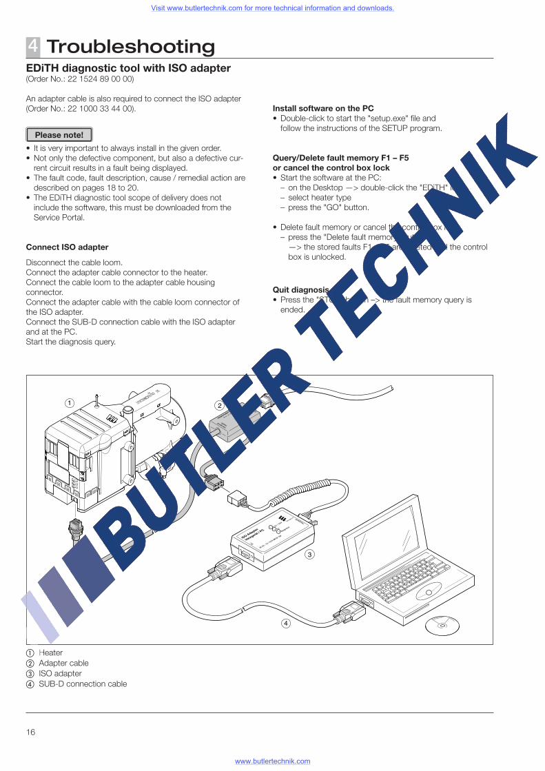
EDiTH diagnostic tool with ISO adapter(Order No.: 22 1524 89 00 00)
An adapter cable is also required to connect the ISO adapter (Order No.: 22 1000 33 44 00).
• It is very important to always install in the given order.• Not only the defective component, but also a defective cur-
rent circuit results in a fault being displayed.• The fault code, fault description, cause / remedial action are
described on pages 18 to 20.• The EDiTH diagnostic tool scope of delivery does not
include the software, this must be downloaded from the Service Portal.
Connect ISO adapter
Disconnect the cable loom.Connect the adapter cable connector to the heater.Connect the cable loom to the adapter cable housing connector.Connect the adapter cable with the cable loom connector of the ISO adapter.Connect the SUB-D connection cable with the ISO adapter and at the PC.Start the diagnosis query.
Troubleshooting4
� Heater� Adapter cable� ISO adapter� SUB-D connection cable
Install software on the PC• Double-click to start the "setup.exe" file and follow the instructions of the SETUP program.
Query/Delete fault memory F1 – F5 or cancel the control box lock• Start the software at the PC:
– on the Desktop —> double-click the "EDiTH" icon – select heater type– press the "GO" button.
• Delete fault memory or cancel the control box lock:– press the "Delete fault memory" button —> the stored faults F1 – F5 are deleted and the control
box is unlocked.
Quit diagnosis• Press the "STOP" button –> the fault memory query is
ended.
Please note!
Visit www.butlertechnik.com for more technical information and downloads.
www.butlertechnik.com
17
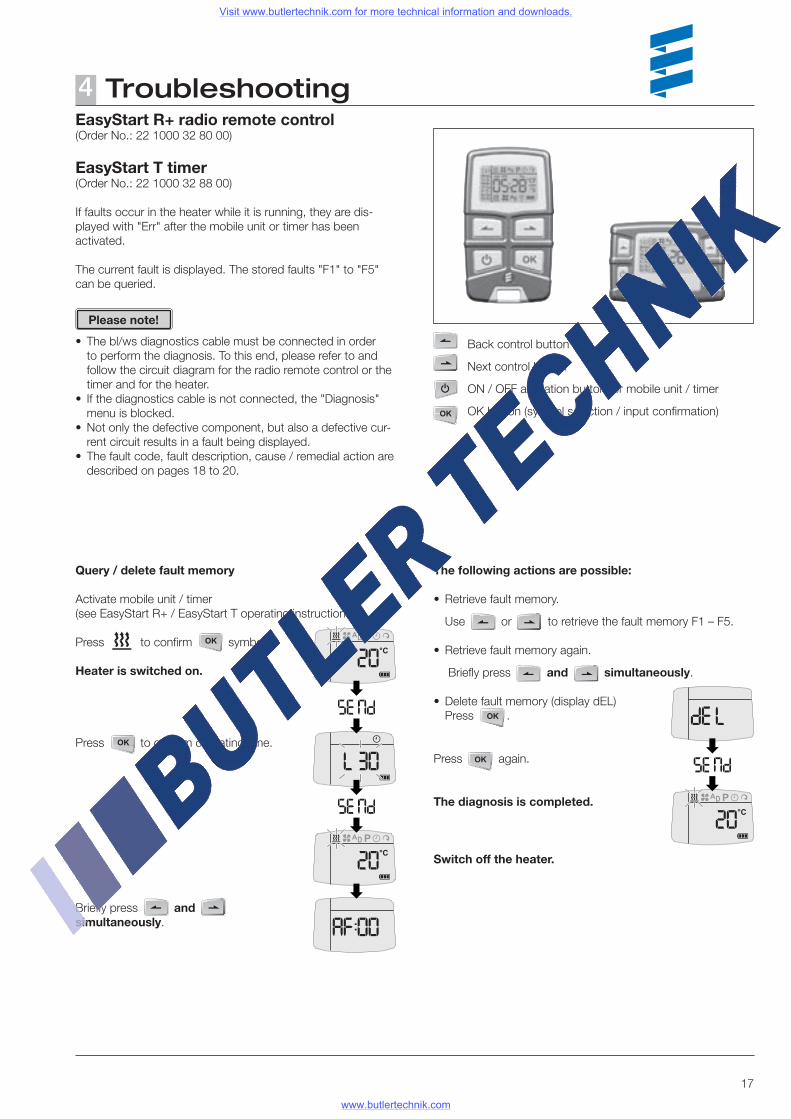
The following actions are possible:
• Retrieve fault memory.
Use or to retrieve the fault memory F1 – F5.
• Retrieve fault memory again.
Briefly press and simultaneously.
• Delete fault memory (display dEL) Press .
Press again.
The diagnosis is completed.
Switch off the heater.
Query / delete fault memory
Activate mobile unit / timer(see EasyStart R+ / EasyStart T operating instructions)
Press to confirm symbol.
Heater is switched on.
Press to confirm operating time.
Briefly press and simultaneously.
EasyStart R+ radio remote control (Order No.: 22 1000 32 80 00)
EasyStart T timer (Order No.: 22 1000 32 88 00)
If faults occur in the heater while it is running, they are dis-played with "Err" after the mobile unit or timer has been activated.
The current fault is displayed. The stored faults "F1" to "F5" can be queried.
• The bl/ws diagnostics cable must be connected in order to perform the diagnosis. To this end, please refer to and follow the circuit diagram for the radio remote control or the timer and for the heater.
• If the diagnostics cable is not connected, the "Diagnosis" menu is blocked.
• Not only the defective component, but also a defective cur-rent circuit results in a fault being displayed.
• The fault code, fault description, cause / remedial action are described on pages 18 to 20.
Back control button
Next control button
ON / OFF activation button for mobile unit / timer
OK button (symbol selection / input confirmation)
Troubleshooting4
Please note!
Visit www.butlertechnik.com for more technical information and downloads.
www.butlertechnik.com
18
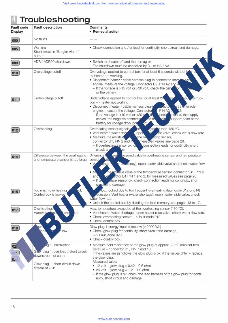
Troubleshooting4Fault codeDisplay
Fault description Comments• Remedial action
000 No faults — —
005 WarningShort circuit in "Burglar Alarm" output
• Check connection and / or lead for continuity, short circuit and damage.
009 ADR / ADR99 shutdown • Switch the heater off and then on again – The shutdown must be cancelled by D+ or HA / NA.
010 Overvoltage cutoff Overvoltage applied to control box for at least 6 seconds without interruption –> heater not working.• Disconnect heater / cable harness plug-in connector, start the vehicle
engine, measure the voltage. Connector B2, PIN A2 and A3:– If the voltage is >15 volt or >30 volt, check the generator regulator and /
or the battery.
011 Undervoltage cutoff Undervoltage applied to control box for at least 20 seconds without interrup-tion –> heater not working.• Disconnect heater / cable harness plug-in connector, start the vehicle
engine, measure the voltage. Connector B2, PIN A2 and A3:– If the voltage is <10 volt or <20 volt, then check the fuses, the supply
cables, the negative connections and the positive support point at the battery for voltage drop (corrosion).
012 Overheating Overheating sensor signals temperature greater than 120 °C.• Vent heater (water shortage), open heater slide valve, check water flow rate.• Measure the resistive value of the overheating sensor,
connector B1, PIN 2 and 4, for measured values see page 28.– If overheating sensor ok, check connection leads for continuity, short
circuit and damage.
014 Difference between the overheating and temperature sensor is too large
Difference between measured value in overheating sensor and temperature sensor greater than 70 K. • Vent heater (water deficiency), open heater slide valve and check water flow
rate.• Measure the resistive value of the temperature sensor, connector B1, PIN 2
and 4 or connector B1 PIN 1 and 2; for measured values see page 28.– If temperature sensor ok, check connection leads for continuity, short
circuit and damage.
015 Too much overheating detected,Control box is locked
Control box locked due to too frequent overheating (fault code 012 or 014) in succession. Vent heater (water shortage), open heater slide valve, check water flow rate. • Unlock the control box by deleting the fault memory, see pages 13 to 17.
017 Overheating, Hardware threshold exceeded
Max. temperature exceeded at the overheating sensor (180 °C).• Vent heater (water shortage), open heater slide valve, check water flow rate.• Check overheating sensor —> fault code 012.• Check control box.
019 Glow plug 1, Ignition energy too low
Glow plug 1 energy input is too low (< 2000 Ws)• Check glow plug for continuity, short circuit and damage —> Fault code 020.• Check control box.
020
021
022
Glow plug 1, interruption
Glow plug 1, overload / short circuit downstream of earth
Glow plug 1, short circuit down-stream of +Ub
• Measure cold resistance of the glow plug at approx. 20 °C ambient tem-perature – connector B1, PIN 7 and 10.
If the values are as follows the glow plug is ok, if the values differ – replace the glow plug.
Measured value:• 12 volt – glow plug = 0.42 – 0.6 ohm• 24 volt – glow plug = 1.2 – 1.9 ohm– If the glow plug is ok, check the lead harness of the glow plug for conti-
nuity, short circuit and damage.
Visit www.butlertechnik.com for more technical information and downloads.
www.butlertechnik.com
19
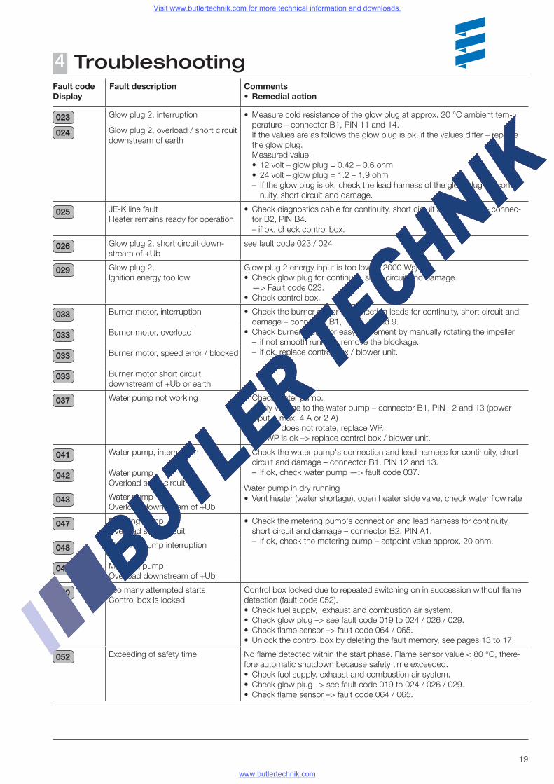
Troubleshooting4Fault codeDisplay
Fault description Comments• Remedial action
023
024
Glow plug 2, interruption
Glow plug 2, overload / short circuit downstream of earth
• Measure cold resistance of the glow plug at approx. 20 °C ambient tem-perature – connector B1, PIN 11 and 14.
If the values are as follows the glow plug is ok, if the values differ – replace the glow plug.
Measured value:• 12 volt – glow plug = 0.42 – 0.6 ohm• 24 volt – glow plug = 1.2 – 1.9 ohm– If the glow plug is ok, check the lead harness of the glow plug for conti-
nuity, short circuit and damage.
025 JE-K line faultHeater remains ready for operation
• Check diagnostics cable for continuity, short circuit and damage – connec-tor B2, PIN B4.– if ok, check control box.
026 Glow plug 2, short circuit down-stream of +Ub
see fault code 023 / 024
029 Glow plug 2, Ignition energy too low
Glow plug 2 energy input is too low (< 2000 Ws)• Check glow plug for continuity, short circuit and damage. —> Fault code 023.• Check control box.
033 Burner motor, interruption • Check the burner motor's connection leads for continuity, short circuit and damage – connector B1, PIN 3, 6 and 9.
• Check burner motor for easy movement by manually rotating the impeller– if not smooth running, remove the blockage.– if ok, replace control box / blower unit.
033 Burner motor, overload
033 Burner motor, speed error / blocked
033 Burner motor short circuitdownstream of +Ub or earth
037 Water pump not working • Check water pump. Apply voltage to the water pump – connector B1, PIN 12 and 13 (power
input = max. 4 A or 2 A)– If WP does not rotate, replace WP.– If WP is ok –> replace control box / blower unit.
041 Water pump, interruption • Check the water pump's connection and lead harness for continuity, short circuit and damage – connector B1, PIN 12 and 13.– If ok, check water pump —> fault code 037.
Water pump in dry running• Vent heater (water shortage), open heater slide valve, check water flow rate
042 Water pump Overload short circuit
043 Water pump Overload downstream of +Ub
047 Metering pump Overload short circuit
• Check the metering pump's connection and lead harness for continuity, short circuit and damage – connector B2, PIN A1.– If ok, check the metering pump – setpoint value approx. 20 ohm.
048 Metering pump interruption
048 Metering pump Overload downstream of +Ub
050 Too many attempted startsControl box is locked
Control box locked due to repeated switching on in succession without flame detection (fault code 052). • Check fuel supply, exhaust and combustion air system.• Check glow plug –> see fault code 019 to 024 / 026 / 029.• Check flame sensor –> fault code 064 / 065.• Unlock the control box by deleting the fault memory, see pages 13 to 17.
052 Exceeding of safety time No flame detected within the start phase. Flame sensor value < 80 °C, there-fore automatic shutdown because safety time exceeded.• Check fuel supply, exhaust and combustion air system.• Check glow plug –> see fault code 019 to 024 / 026 / 029.• Check flame sensor –> fault code 064 / 065.
Visit www.butlertechnik.com for more technical information and downloads.
www.butlertechnik.com
20
Troubleshooting4Fault codeDisplay
Fault description Comments• Remedial action
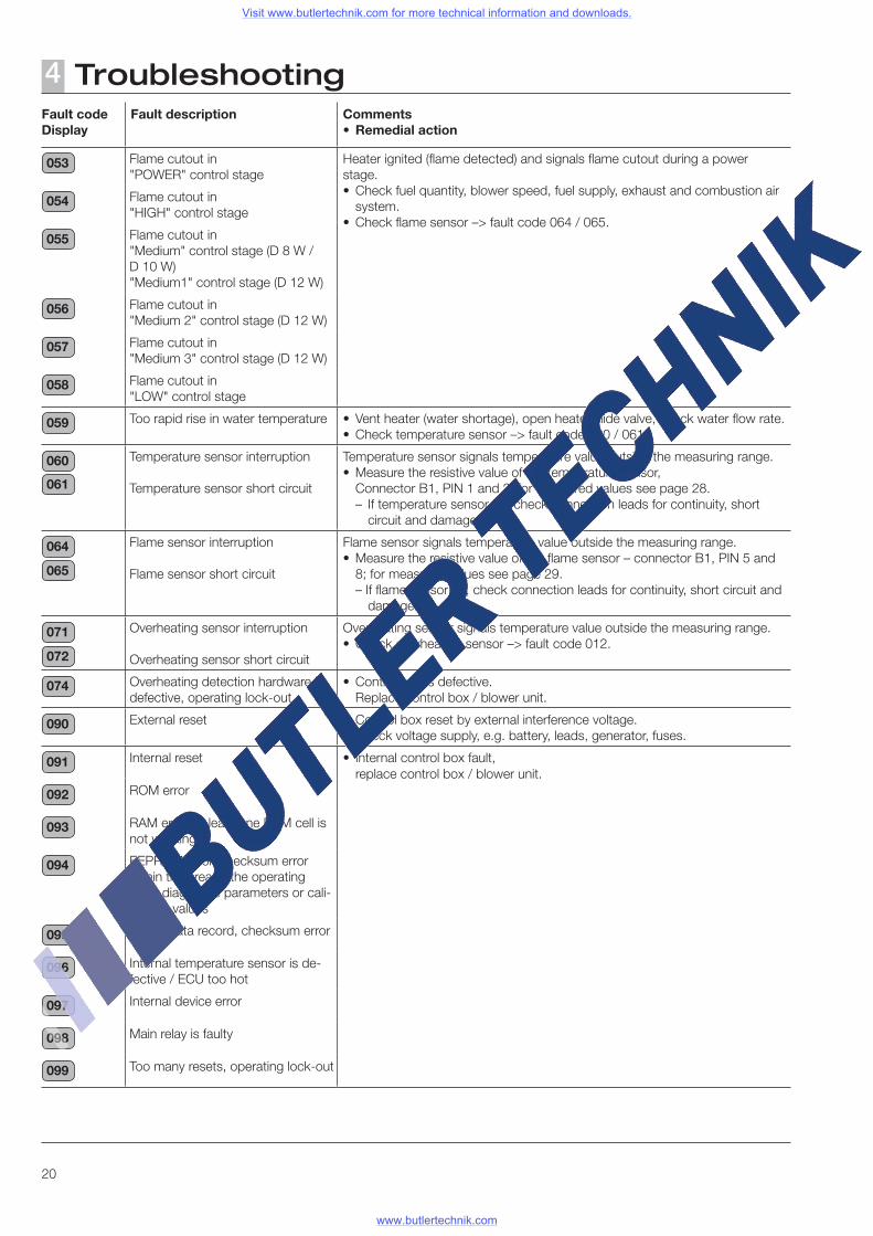
053 Flame cutout in "POWER" control stage
Heater ignited (flame detected) and signals flame cutout during a power stage.• Check fuel quantity, blower speed, fuel supply, exhaust and combustion air
system.• Check flame sensor –> fault code 064 / 065.
054 Flame cutout in "HIGH" control stage
055 Flame cutout in "Medium" control stage (D 8 W / D 10 W)"Medium1" control stage (D 12 W)
056 Flame cutout in "Medium 2" control stage (D 12 W)
057 Flame cutout in "Medium 3" control stage (D 12 W)
058 Flame cutout in "LOW" control stage
059 Too rapid rise in water temperature • Vent heater (water shortage), open heater slide valve, check water flow rate. • Check temperature sensor –> fault code 060 / 061
060
061
Temperature sensor interruption
Temperature sensor short circuit
Temperature sensor signals temperature value outside the measuring range.• Measure the resistive value of the temperature sensor, Connector B1, PIN 1 and 2; for measured values see page 28.
– If temperature sensor ok, check connection leads for continuity, short circuit and damage.
064
065
Flame sensor interruption
Flame sensor short circuit
Flame sensor signals temperature value outside the measuring range. • Measure the resistive value of the flame sensor – connector B1, PIN 5 and
8; for measured values see page 29.– If flame sensor ok, check connection leads for continuity, short circuit and
damage.
071
072
Overheating sensor interruption
Overheating sensor short circuit
Overheating sensor signals temperature value outside the measuring range.• Check overheating sensor –> fault code 012.
074 Overheating detection hardware is defective, operating lock-out
• Control box is defective. Replace control box / blower unit.
090 External reset • Control box reset by external interference voltage. Check voltage supply, e.g. battery, leads, generator, fuses.
091 Internal reset • Internal control box fault, replace control box / blower unit.
092 ROM error
093 RAM error, at least one RAM cell is not working
094 EEPROM error, checksum error within the area of the operating data, diagnostic parameters or cali-bration values
095 Invalid data record, checksum error
096 Internal temperature sensor is de-fective / ECU too hot
097 Internal device error
098 Main relay is faulty
099 Too many resets, operating lock-out
Visit www.butlertechnik.com for more technical information and downloads.
www.butlertechnik.com
21
Repair instructions5Repair instructions
The permitted repair work on the heater is described in the "Repair Instructions" chapter. The heater must be removed from the vehicle for the repair work to be carried out.
The heater is assembled in the reverse order, note and follow any additional instructions.
After completing all the work and installing the heater in the vehicle, perform a functional check on the heater.
Always observe the following safety instructions before working on the heater
Danger!Risk of injury, burns and poisoning!• Always switch off the heater beforehand and leave it to cool.• Disconnect the battery.• The heater must not be operated in closed rooms such as
garages or workshops. Exception: Exhaust suction available directly at the entry to the exhaust
pipe.
Caution!• The seals of dismantled components must be renewed.• During repair work, check all components for damage and if
necessary replace.• Check connector contacts, plug-in connections and cables
for corrosion and damage and if necessary repair.• Only ever use Eberspächer spare parts if replacements are
necessary.• After working on the coolant circuit the level of the coolant
must be checked and if necessary topped up according to the vehicle manufacturer's instructions.
The coolant circuit must then be vented.• Operation or the after running of the heater may only be
stopped in an emergency (see "EMERGENCY OFF" page 7) by interrupting the battery current (risk of heater overheating).
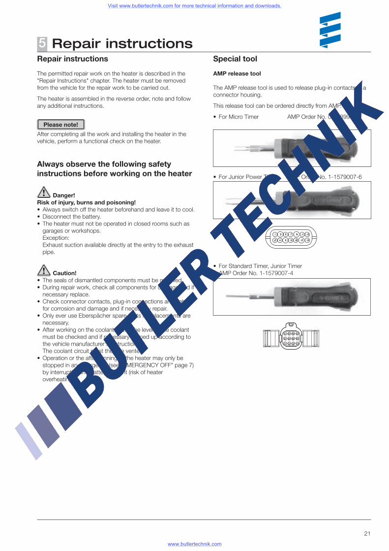
Special tool
AMP release tool
The AMP release tool is used to release plug-in contacts in a connector housing.
This release tool can be ordered directly from AMP.
• For Micro Timer AMP Order No. 0-0539960-1Please note!
• For Junior Power Timer AMP Order No. 1-1579007-6
• For Standard Timer, Junior Timer AMP Order No. 1-1579007-4
Visit www.butlertechnik.com for more technical information and downloads.
www.butlertechnik.com
22
Repair instructions5Assembly drawing
Visit www.butlertechnik.com for more technical information and downloads.
www.butlertechnik.com
23
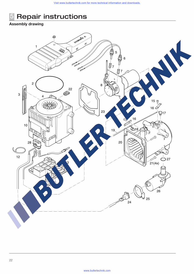
Repair instructions5Parts list
1 Impeller cover2 O-ring 117.07 x 3.533 Cover, side4 Impeller5 Glow plug 16 Glow plug 27 Spark plug socket lining8 Combustion chamber9 M5 x 16 TAPTITE / DIN 7500 TORX screw10 Control box / blower unit11 Flame sensor12 Cable tie13 Electric motor cover14 M5 x 16 TAPTITE / DIN 7500 TORX screw15 M4 x 12 TAPTITE / DIN 7985 TORX screw16 Compression spring17 Overheating sensor18 Temperature sensor19 Overheating / temperature sensor cable loom20 Jacket with heat exchanger21 M5 x 25 TAPTITE / DIN 7500 TORX screw22 Grommet23 Combustion chamber seal24 Water pump cable loom connector25 Hose clip26 Water pump27 O-ring 19.8 x 2.328 14-pin connector
Please note!
Notes on various components
• Control box / blower unit, Item 10 Control box / blower unit and electric motor cannot be
dismantled. If these components are defective the complete control box / blower unit must be replaced.
• Jacket with heat exchanger, Item 20 The jacket and heat exchanger cannot be dismantled. If
these components are defective the complete jacket with heat exchanger component must be replaced.
• O-ring, Item 2 The O-ring is included in the scope of supply of the ET part
"control box / blower unit". The O-ring is also available as a component part.
• Combustion chamber seal, Item 23 The combustion chamber seal is included in the scope of
supply of the following ET parts:– Jacket with heat exchanger (20)– Combustion chamber (8)– Glow plug (5) and (6)
The combustion chamber seal is also available as a compo-nent part.
Visit www.butlertechnik.com for more technical information and downloads.
www.butlertechnik.com
24
Repair instructions5
Repair step 1Dismantle control box / blower unit and jacket
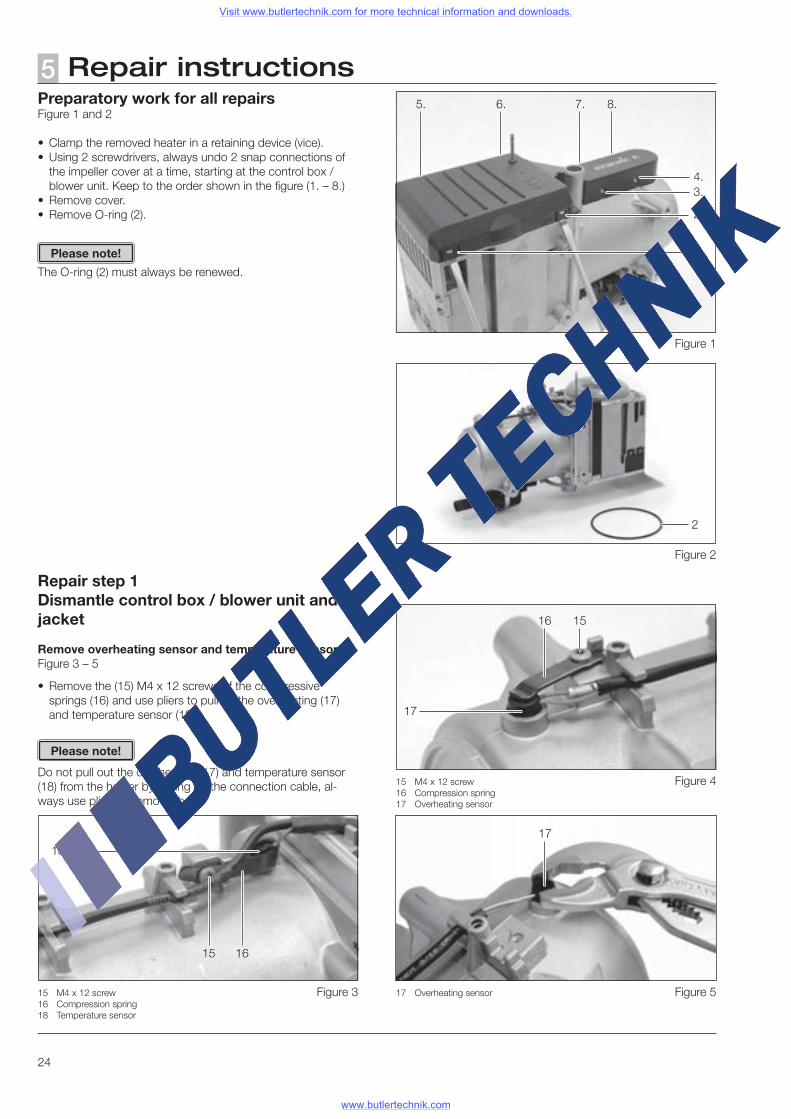
Remove overheating sensor and temperature sensorFigure 3 – 5
• Remove the (15) M4 x 12 screws of the compressive springs (16) and use pliers to pull off the overheating (17) and temperature sensor (18).
Do not pull out the overheating (17) and temperature sensor (18) from the holder by pulling on the connection cable, al-ways use pliers to remove them.
2 O-ring
2
17
16
18
16
15 M4 x 12 screw16 Compression spring17 Overheating sensor
15 M4 x 12 screw16 Compression spring18 Temperature sensor
15
15
Please note!
Preparatory work for all repairsFigure 1 and 2
• Clamp the removed heater in a retaining device (vice).• Using 2 screwdrivers, always undo 2 snap connections of
the impeller cover at a time, starting at the control box / blower unit. Keep to the order shown in the figure (1. – 8.)
• Remove cover.• Remove O-ring (2).
The O-ring (2) must always be renewed.
Please note!
Figure 1
17 Overheating sensor
17
1.
2.
3.4.
8.7.6.5.
Figure 2
Figure 4
Figure 5Figure 3
Visit www.butlertechnik.com for more technical information and downloads.
www.butlertechnik.com
25
Repair instructions5
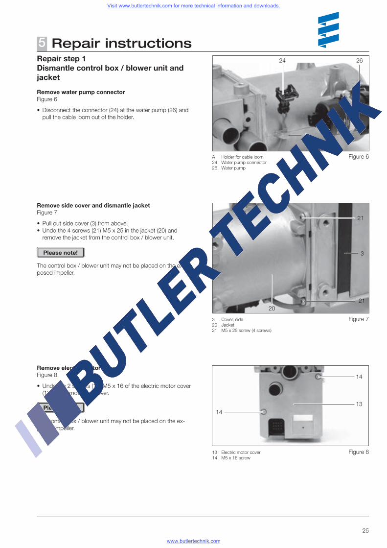
A Holder for cable loom24 Water pump connector26 Water pump
24 26
21
21
3 Cover, side20 Jacket21 M5 x 25 screw (4 screws)
13 Electric motor cover14 M5 x 16 screw
1413
14
20
Remove side cover and dismantle jacketFigure 7
• Pull out side cover (3) from above.• Undo the 4 screws (21) M5 x 25 in the jacket (20) and
remove the jacket from the control box / blower unit.
The control box / blower unit may not be placed on the ex-posed impeller.
Repair step 1Dismantle control box / blower unit and jacket
Remove water pump connectorFigure 6
• Disconnect the connector (24) at the water pump (26) and pull the cable loom out of the holder.
3
Remove electric motor coverFigure 8
• Undo the 2 screws (14) M5 x 16 of the electric motor cover (13) and remove the cover.
The control box / blower unit may not be placed on the ex-posed impeller.
Please note!
Please note!
A
Figure 6
Figure 7
Figure 8
Visit www.butlertechnik.com for more technical information and downloads.
www.butlertechnik.com
26
Repair instructions5Repair step 1Dismantle control box / blower unit and jacket
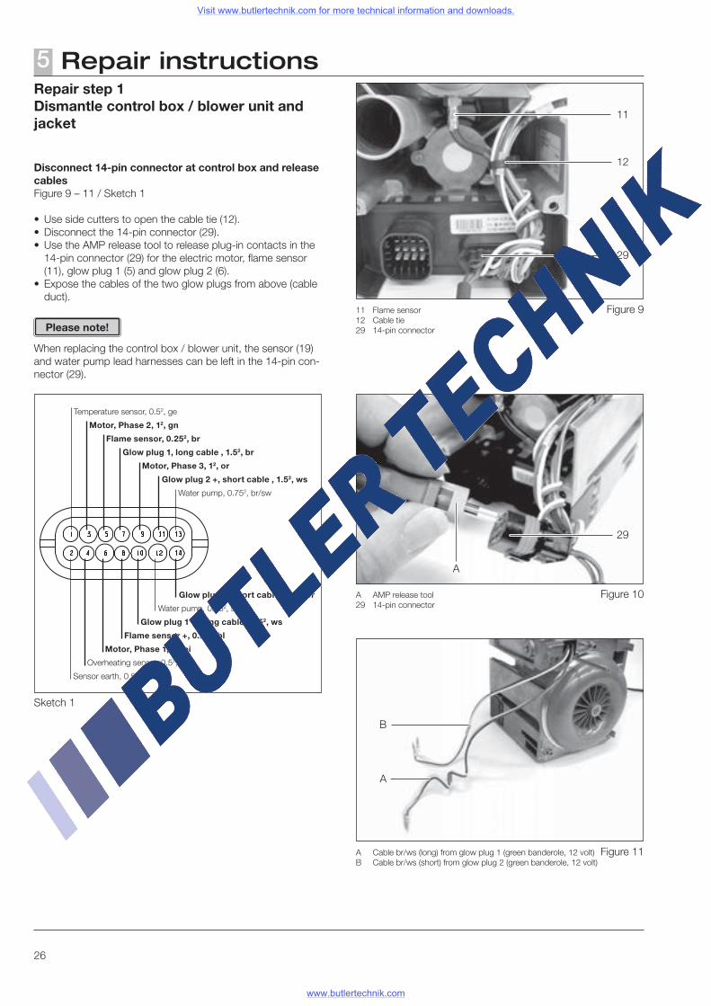
Disconnect 14-pin connector at control box and release cablesFigure 9 – 11 / Sketch 1
• Use side cutters to open the cable tie (12).• Disconnect the 14-pin connector (29).• Use the AMP release tool to release plug-in contacts in the
14-pin connector (29) for the electric motor, flame sensor (11), glow plug 1 (5) and glow plug 2 (6).
• Expose the cables of the two glow plugs from above (cable duct).
When replacing the control box / blower unit, the sensor (19) and water pump lead harnesses can be left in the 14-pin con-nector (29).
12
29
11
11 Flame sensor12 Cable tie29 14-pin connector
A AMP release tool29 14-pin connector
29
A
A
B
A Cable br/ws (long) from glow plug 1 (green banderole, 12 volt)B Cable br/ws (short) from glow plug 2 (green banderole, 12 volt)
Please note!
Sketch 1
Temperature sensor, 0.52, ge
Sensor earth, 0.52, bl/ws
Overheating sensor, 0.52, rt
Motor, Phase 1, 12, pi
Motor, Phase 2, 12, gn
Motor, Phase 3, 12, or
Flame sensor +, 0.252, bl
Flame sensor, 0.252, br
Glow plug 1, long cable , 1.52, br
Glow plug 1 +, long cable , 1.52, ws
Glow plug 2 +, short cable , 1.52, ws
Glow plug 2, short cable , 1.52, br
Water pump, 0.752, br/sw
Water pump, 0.752, sw/rt
Figure 9
Figure 10
Figure 11
Visit www.butlertechnik.com for more technical information and downloads.
www.butlertechnik.com
27
Repair instructions5
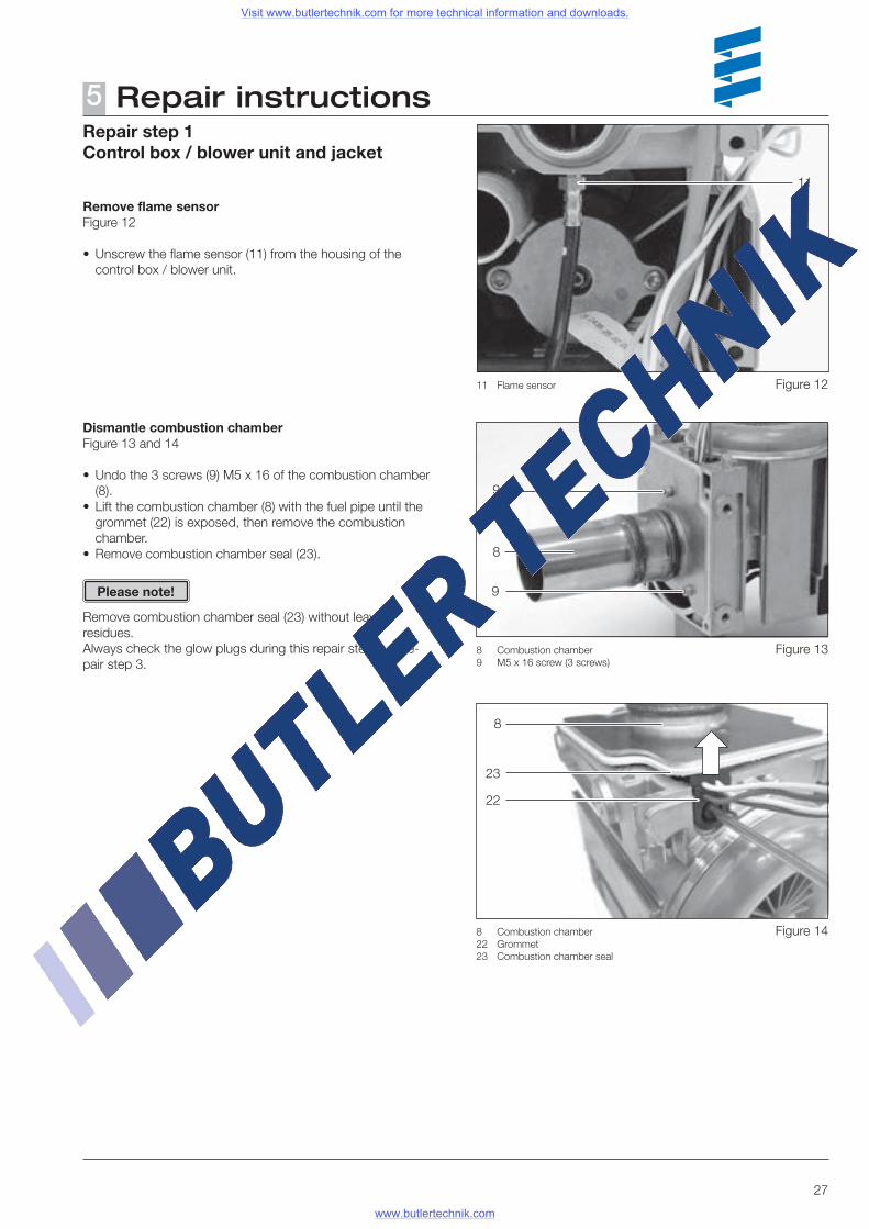
8 Combustion chamber9 M5 x 16 screw (3 screws)
9
9
8
Repair step 1Control box / blower unit and jacket
Remove flame sensorFigure 12
• Unscrew the flame sensor (11) from the housing of the control box / blower unit.
11
11 Flame sensor
Dismantle combustion chamberFigure 13 and 14
• Undo the 3 screws (9) M5 x 16 of the combustion chamber (8).
• Lift the combustion chamber (8) with the fuel pipe until the grommet (22) is exposed, then remove the combustion chamber.
• Remove combustion chamber seal (23).
Remove combustion chamber seal (23) without leaving residues.Always check the glow plugs during this repair step, see re-pair step 3.
Please note!
23
8
22
8 Combustion chamber22 Grommet23 Combustion chamber seal
Figure 12
Figure 13
Figure 14
Visit www.butlertechnik.com for more technical information and downloads.
www.butlertechnik.com
28
Repair instructions5Repair step 2Assemble control box / blower unit and jacket
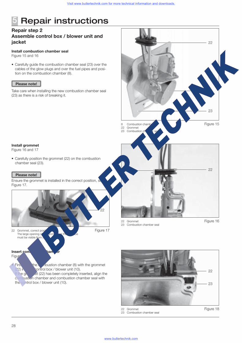
Install combustion chamber sealFigure 15 and 16
• Carefully guide the combustion chamber seal (23) over the cables of the glow plugs and over the fuel pipes and posi-tion on the combustion chamber (8).
Take care when installing the new combustion chamber seal (23) as there is a risk of breaking it.
Please note!
Install grommetFigure 16 and 17
• Carefully position the grommet (22) on the combustion chamber seal (23).
Ensure the grommet is installed in the correct position, see Figure 17.
Please note!
23
8
22
8 Combustion chamber22 Grommet23 Combustion chamber seal
23
22
22 Grommet23 Combustion chamber seal
Insert combustion chamberFigure 18
• First insert the combustion chamber (8) with the grommet (22) into the control box / blower unit (10).
If the grommet (22) has been completely inserted, align the combustion chamber and combustion chamber seal with the control box / blower unit (10).
23 22
22 Grommet23 Combustion chamber seal
22 Grommet, correct position The large opening of the grommet at the fuel tube
must be visible from above
22
Figure 15
Figure 16
Figure 18
Figure 17
Visit www.butlertechnik.com for more technical information and downloads.
www.butlertechnik.com
29
Repair instructions5Repair step 2Assemble the control box / blower unit and jacket
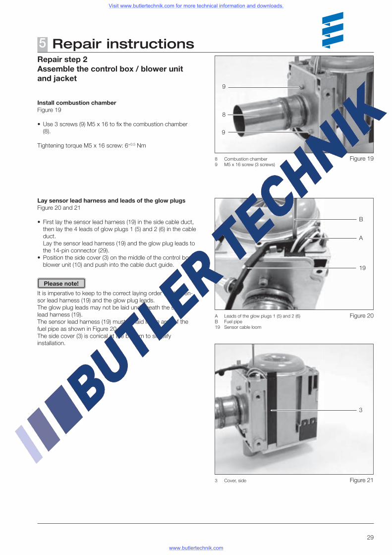
Install combustion chamberFigure 19
• Use 3 screws (9) M5 x 16 to fix the combustion chamber (8).
Tightening torque M5 x 16 screw: 6+0.5 Nm
8 Combustion chamber9 M5 x 16 screw (3 screws)
9
9
8
Lay sensor lead harness and leads of the glow plugsFigure 20 and 21
• First lay the sensor lead harness (19) in the side cable duct, then lay the 4 leads of glow plugs 1 (5) and 2 (6) in the cable duct.
Lay the sensor lead harness (19) and the glow plug leads to the 14-pin connector (29).
• Position the side cover (3) on the middle of the control box / blower unit (10) and push into the cable duct guide.
It is imperative to keep to the correct laying order for the sen-sor lead harness (19) and the glow plug leads.The glow plug leads may not be laid underneath the sensor lead harness (19).The sensor lead harness (19) must be laid in the area of the fuel pipe as shown in Figure 20.The side cover (3) is conical at the bottom to simplify installation.
B
A
19
A Leads of the glow plugs 1 (5) and 2 (6)B Fuel pipe19 Sensor cable loom
Please note!
3
3 Cover, side
Figure 19
Figure 20
Figure 21
Visit www.butlertechnik.com for more technical information and downloads.
www.butlertechnik.com
30
Repair instructions5Repair step 2Assemble the control box / blower unit and jacket
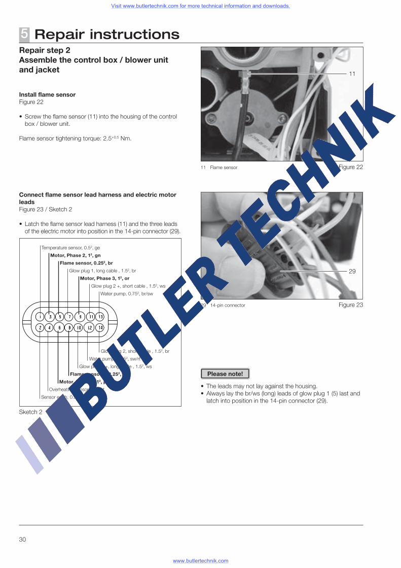
Install flame sensorFigure 22
• Screw the flame sensor (11) into the housing of the control box / blower unit.
Flame sensor tightening torque: 2.5+0.5 Nm.
Connect flame sensor lead harness and electric motor leadsFigure 23 / Sketch 2
• Latch the flame sensor lead harness (11) and the three leads of the electric motor into position in the 14-pin connector (29).
• The leads may not lay against the housing.• Always lay the br/ws (long) leads of glow plug 1 (5) last and
latch into position in the 14-pin connector (29).
Temperature sensor, 0.52, ge
Sensor earth, 0.52, bl/ws
Overheating sensor, 0.52, rt
Motor, Phase 1, 12, pi
Motor, Phase 2, 12, gn
Motor, Phase 3, 12, or
Flame sensor +, 0.252, bl
Flame sensor, 0.252, br
Glow plug 1, long cable , 1.52, br
Glow plug 1 +, long cable , 1.52, ws
Glow plug 2 +, short cable , 1.52, ws
Glow plug 2, short cable , 1.52, br
Water pump, 0.752, br/sw
Water pump, 0.752, sw/rt
Sketch 2
11
11 Flame sensor
29
29 14-pin connector
Please note!
Figure 22
Figure 23
Visit www.butlertechnik.com for more technical information and downloads.
www.butlertechnik.com
31
Repair instructions5
Temperature sensor, 0.52, ge
Sensor earth, 0.52, bl/ws
Overheating sensor, 0.52, rt
Motor, Phase 1, 12, pi
Motor, Phase 2, 12, gn
Motor, Phase 3, 12, or
Flame sensor +, 0.252, bl
Flame sensor, 0.252, br
Glow plug 1, long cable , 1.52, br
Glow plug 1 +, long cable , 1.52, ws
Glow plug 2 +, short cable , 1.52, ws
Glow plug 2, short cable , 1.52, br
Water pump, 0.752, br/sw
Water pump, 0.752, sw/rt
Sketch 3
Repair step 2Assemble control box / blower unit and jacket
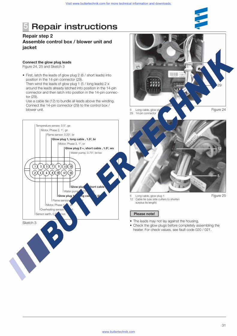
Connect the glow plug leadsFigure 24, 25 and Sketch 3
• First, latch the leads of glow plug 2 (6 / short leads) into position in the 14-pin connector (29).
Then wind the leads of glow plug 1 (5 / long leads) 2 x around the leads already latched into position in the 14-pin connector and then latch into position in the 14-pin connec-tor (29).
Use a cable tie (12) to bundle all leads above the winding. Connect the 14-pin connector (29) to the control box /
blower unit.
• The leads may not lay against the housing.• Check the glow plugs before completely assembling the
heater. For check values, see fault code 020 / 021.
5 Long cable, glow plug 129 14-pin connector
5 Long cable, glow plug 112 Cable tie (use side cutters to shorten
surplus tie length)
12
5
Please note!
5
29
Figure 25
Figure 24
Visit www.butlertechnik.com for more technical information and downloads.
www.butlertechnik.com
32
Repair instructions5Repair step 2Assemble control box / blower unit and jacket
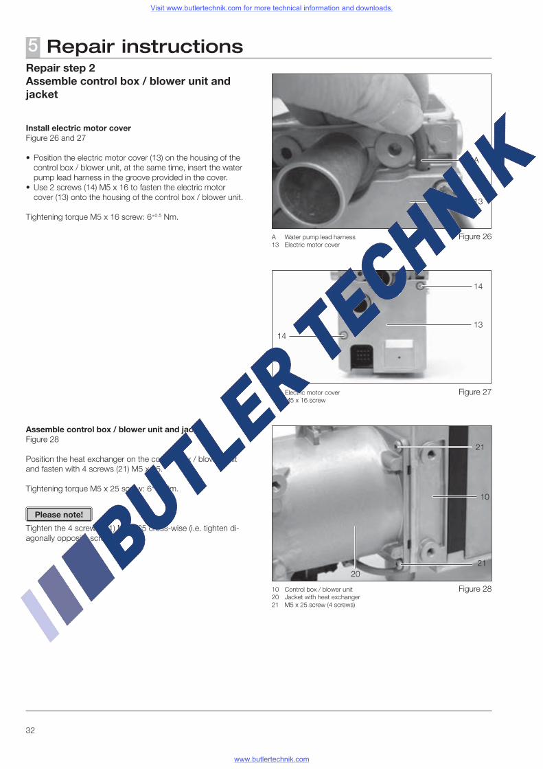
Install electric motor coverFigure 26 and 27
• Position the electric motor cover (13) on the housing of the control box / blower unit, at the same time, insert the water pump lead harness in the groove provided in the cover.
• Use 2 screws (14) M5 x 16 to fasten the electric motor cover (13) onto the housing of the control box / blower unit.
Tightening torque M5 x 16 screw: 6+0.5 Nm.
Assemble control box / blower unit and jacketFigure 28
Position the heat exchanger on the control box / blower unit and fasten with 4 screws (21) M5 x 25.
Tightening torque M5 x 25 screw: 6+0.5 Nm.
Tighten the 4 screws (21) M5 x 25 cross-wise (i.e. tighten di-agonally opposite screws).
13 Electric motor cover14 M5 x 16 screw
1413
14
A
13
A Water pump lead harness 13 Electric motor cover
21
21
10 Control box / blower unit20 Jacket with heat exchanger21 M5 x 25 screw (4 screws)
20
10
Please note!
Figure 26
Figure 27
Figure 28
Visit www.butlertechnik.com for more technical information and downloads.
www.butlertechnik.com
33
Repair instructions5Repair step 2Control box / blower unit and jacket
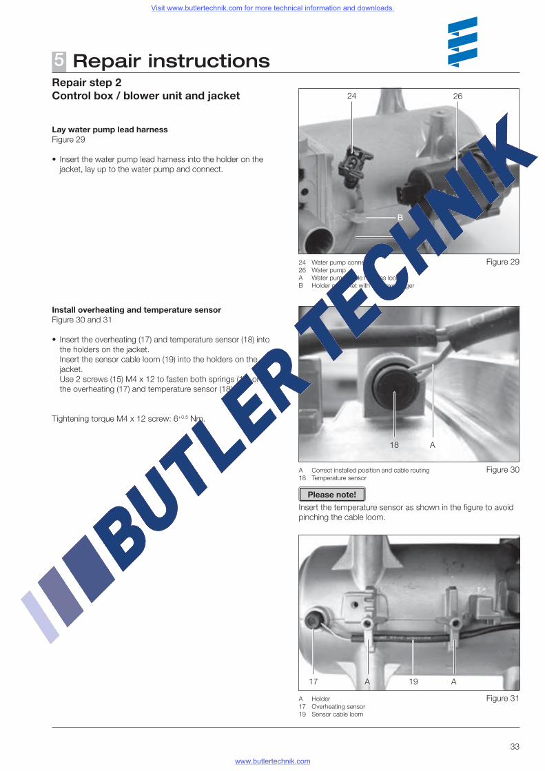
Lay water pump lead harnessFigure 29
• Insert the water pump lead harness into the holder on the jacket, lay up to the water pump and connect.
Install overheating and temperature sensorFigure 30 and 31
• Insert the overheating (17) and temperature sensor (18) into the holders on the jacket.
Insert the sensor cable loom (19) into the holders on the jacket.
Use 2 screws (15) M4 x 12 to fasten both springs (16) on the overheating (17) and temperature sensor (18).
Tightening torque M4 x 12 screw: 6+0.5 Nm.
Insert the temperature sensor as shown in the figure to avoid pinching the cable loom.
B
24 26
24 Water pump connector26 Water pumpA Water pump cable harness loomB Holder on jacket with heat exchanger
A
A Correct installed position and cable routing 18 Temperature sensor
A Holder17 Overheating sensor19 Sensor cable loom
A18
1917
Please note!
AA
Figure 29
Figure 30
Figure 31
Visit www.butlertechnik.com for more technical information and downloads.
www.butlertechnik.com
34
Repair instructions5Repair step 2Control box / blower unit and jacket
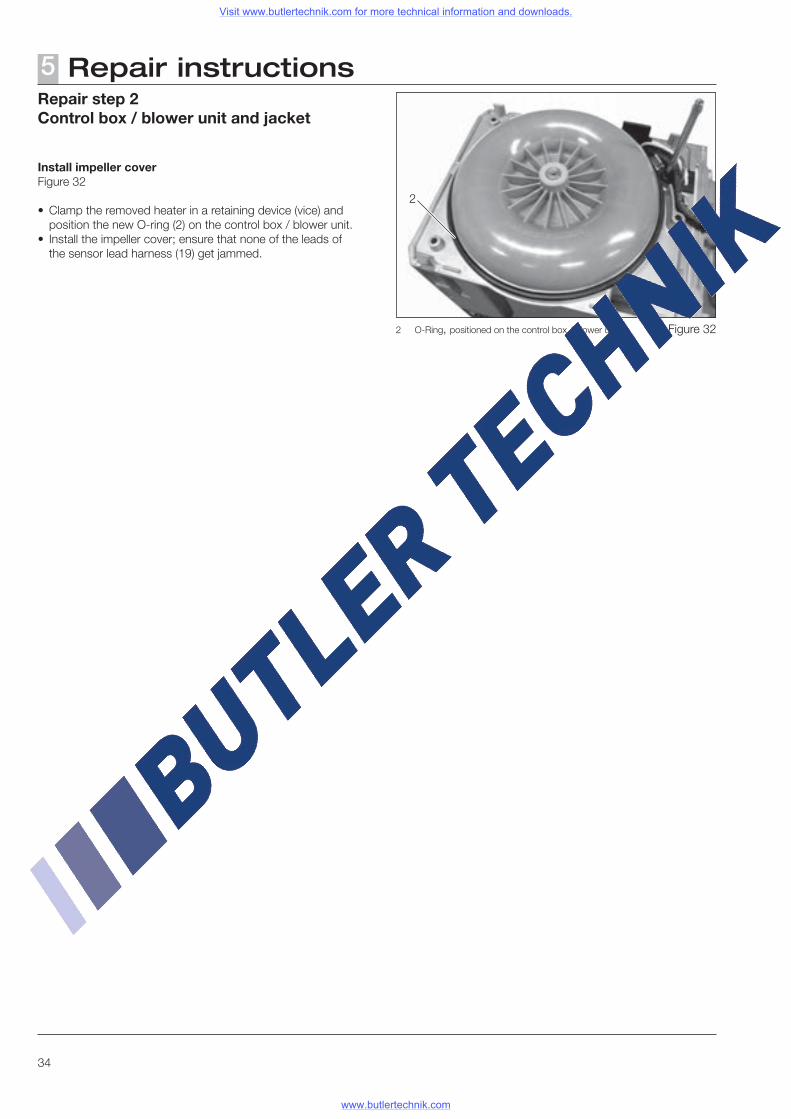
Install impeller coverFigure 32
• Clamp the removed heater in a retaining device (vice) and position the new O-ring (2) on the control box / blower unit.
• Install the impeller cover; ensure that none of the leads of the sensor lead harness (19) get jammed.
2
2 O-Ring, positioned on the control box / blower unit Figure 32
Visit www.butlertechnik.com for more technical information and downloads.
www.butlertechnik.com
35
Repair instructions5Repair step 3
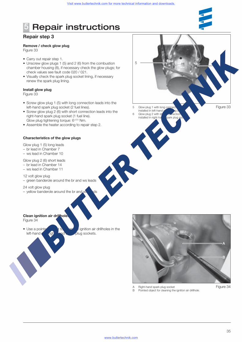
Remove / check glow plugFigure 33
• Carry out repair step 1.• Unscrew glow plugs 1 (5) and 2 (6) from the combustion
chamber housing (8), if necessary check the glow plugs; for check values see fault code 020 / 021.
• Visually check the spark plug socket lining, if necessary renew the spark plug lining.
Install glow plugFigure 33
• Screw glow plug 1 (5) with long connection leads into the left-hand spark plug socket (2 fuel lines).
• Screw glow plug 2 (6) with short connection leads into the right-hand spark plug socket (1 fuel line).
Glow plug tightening torque: 6+0.5 Nm.• Assemble the heater according to repair step 2.
Characteristics of the glow plugs
Glow plug 1 (5) long leads– br lead in Chamber 7– ws lead in Chamber 10
Glow plug 2 (6) short leads– br lead in Chamber 14– ws lead in Chamber 11
12 volt glow plug– green banderole around the br and ws leads
24 volt glow plug– yellow banderole around the br and ws leads
5 Glow plug 1 with long connection leads, installed in left-hand spark plug socket
6 Glow plug 2 with short connection leads, installed in right-hand spark plug socket
56
A
B
A Right-hand spark plug socketB Pointed object for cleaning the ignition air drillhole.
Clean ignition air drillholesFigure 34
• Use a pointed object to clean the ignition air drillholes in the left-hand and right-hand spark plug sockets.
Figure 33
Figure 34
Visit www.butlertechnik.com for more technical information and downloads.
www.butlertechnik.com
36
Repair instructions5Repair step 4
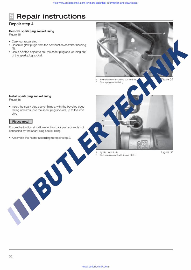
Remove spark plug socket liningFigure 35
• Carry out repair step 1.• Unscrew glow plugs from the combustion chamber housing
(8).• Use a pointed object to pull the spark plug socket lining out
of the spark plug socket.
Install spark plug socket liningFigure 36
• Insert the spark plug socket linings, with the bevelled edge facing upwards, into the spark plug sockets up to the limit stop.
Ensure the ignition air drillhole in the spark plug socket is notconcealed by the spark plug socket lining.
• Assemble the heater according to repair step 2.
A
B
A Pointed object for pulling out the lining7 Spark plug socket lining
A Ignition air drillholeB Spark plug socket with lining installed
A
7
Please note!
Figure 35
Figure 36
Visit www.butlertechnik.com for more technical information and downloads.
www.butlertechnik.com
37
Repair instructions5Repair step 5
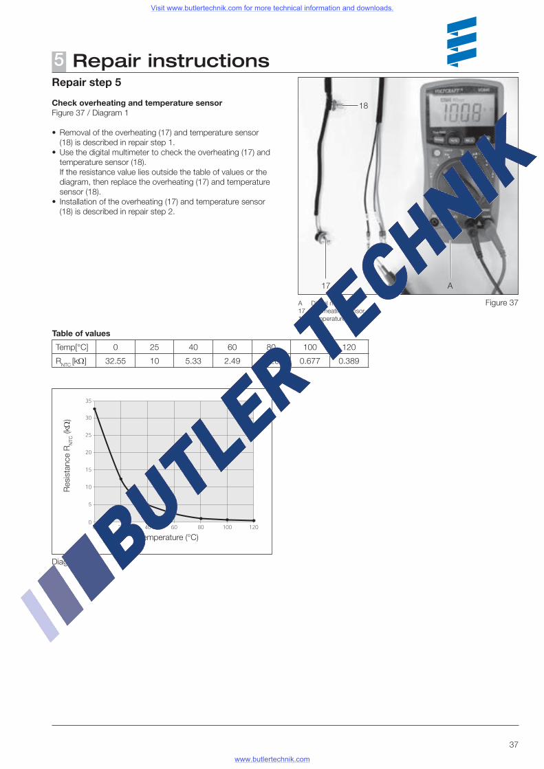
Check overheating and temperature sensorFigure 37 / Diagram 1
• Removal of the overheating (17) and temperature sensor (18) is described in repair step 1.
• Use the digital multimeter to check the overheating (17) and temperature sensor (18).
If the resistance value lies outside the table of values or the diagram, then replace the overheating (17) and temperature sensor (18).
• Installation of the overheating (17) and temperature sensor (18) is described in repair step 2.
Res
ista
nce
RN
TC (kΩ
)
Temperature (°C)
Table of values
Temp[°C] 0 25 40 60 80 100 120
RNTC [kΩ] 32.55 10 5.33 2.49 1.26 0.677 0.389
Diagram 1
18
17 A
A Digital multimeter17 Overheating sensor18 Temperature sensor
Figure 37
Visit www.butlertechnik.com for more technical information and downloads.
www.butlertechnik.com
38
Repair instructions5Repair step 6
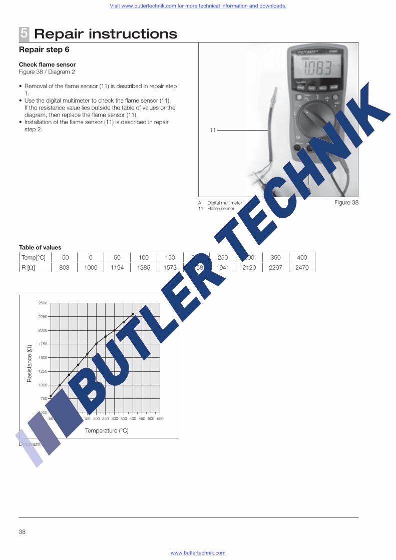
Check flame sensorFigure 38 / Diagram 2
• Removal of the flame sensor (11) is described in repair step 1.
• Use the digital multimeter to check the flame sensor (11). If the resistance value lies outside the table of values or the
diagram, then replace the flame sensor (11).• Installation of the flame sensor (11) is described in repair
step 2.
Temperature (°C)
Res
ista
nce
(Ω)
Table of values
Temp[°C] -50 0 50 100 150 200 250 300 350 400
R [Ω] 803 1000 1194 1385 1573 1758 1941 2120 2297 2470
Diagram 2
11
A
A Digital multimeter11 Flame sensor
Figure 38
Visit www.butlertechnik.com for more technical information and downloads.
www.butlertechnik.com
39
Repair step 7
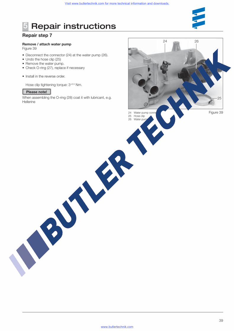
Remove / attach water pumpFigure 39
• Disconnect the connector (24) at the water pump (26).• Undo the hose clip (25)• Remove the water pump.• Check O-ring (27), replace if necessary
• Install in the reverse order.
Hose clip tightening torque: 3+0.5 Nm.
When assembling the O-ring (28) coat it with lubricant, e.g. Hellerine
Repair instructions5
Please note!
25
24 26
24 Water pump connector25 Hose clip26 Water pump
Figure 39
Visit www.butlertechnik.com for more technical information and downloads.
www.butlertechnik.com
40
Repair instructions5Measuring the fuel quantity
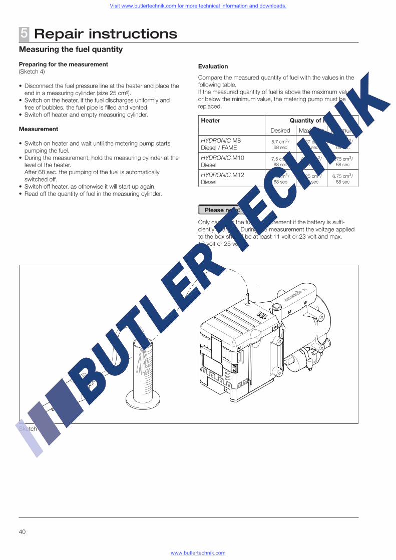
Preparing for the measurement (Sketch 4)
• Disconnect the fuel pressure line at the heater and place the end in a measuring cylinder (size 25 cm³).
• Switch on the heater, if the fuel discharges uniformly and free of bubbles, the fuel pipe is filled and vented.
• Switch off heater and empty measuring cylinder.
Measurement
• Switch on heater and wait until the metering pump starts pumping the fuel.
• During the measurement, hold the measuring cylinder at the level of the heater.
After 68 sec. the pumping of the fuel is automatically switched off.
• Switch off heater, as otherwise it will start up again.• Read off the quantity of fuel in the measuring cylinder.
Evaluation
Compare the measured quantity of fuel with the values in the following table.If the measured quantity of fuel is above the maximum value or below the minimum value, the metering pump must be replaced.
Heater Quantity of fuel
Desired Maximum Minimum
HYDRONIC M8 Diesel / FAME
5.7 cm3/ 68 sec
6.27 cm3/ 68 sec
5.13 cm3/ 68 sec
HYDRONIC M10Diesel
7.5 cm3/ 68 sec
8.25 cm3/ 68 sec
6.75 cm3/ 68 sec
HYDRONIC M12Diesel
7.5 cm3/ 68 sec
8.25 cm3/ 68 sec
6.75 cm3/ 68 sec
Only carry out the fuel measurement if the battery is suffi-ciently charged. During the measurement the voltage applied to the box should be at least 11 volt or 23 volt and max. 13 volt or 25 volt.
Please note!
Sketch 4
Visit www.butlertechnik.com for more technical information and downloads.
www.butlertechnik.com
41
Circuit diagram6Heater wiring
The heater is to be connected up electrically according to the EMC directives.
Caution!Safety instructions for wiring the heater!
EMC can be affected if the heater is not connected up cor-rectly. For this reason, comply with the following instructions:
• Ensure that the insulation of electrical cables is not dam-ages. Avoid:
chafing, kinking, jamming or exposure to heat.
• In waterproof connectors, seal any connector chambers not in use with filler plugs to ensure they are dirt-proof and water-proof.
• Electrical connections and ground connections must be free of corrosion and firmly connected.
• Lubricate connections and ground connections outside the heater interior with contact grease.
Comply with the following when wiring the heater and the control unit:
• Electrical leads, switch and control gear must be positioned in the vehicle so that they can function perfectly under normal operating conditions without impairment (e.g. due to heat exposure, moisture, etc.).
• The following cable cross sections are to be used between the battery and heater.
This ensures that the max. allowable voltage drop in the cables does not exceed 0.5 V for 12 V or 1 V for 24 V rated voltage.
Cable cross-sections for a cable length (plus cable + minus cable) of:– up to 5 m = cable cross-section 4 mm²– from 5 m up to 8 m = cable cross-section 6 mm²
• If the positive cable is to be connected to the fuse box (e.g. terminal 30), the vehicle's cable from the battery to the fuse box must also be included in the calculation for the total cable length and re-dimensioned if necessary.
• Insulate unused cable ends.
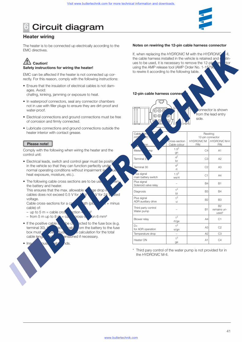
Notes on rewiring the 12-pin cable harness connector
If, when replacing the HYDRONIC M with the HYDRONIC M-II, the cable harness installed in the vehicle is retained and contin-ues to be used, it is necessary to remove the 12-pin connector using the AMP release tool (AMP Order No. 1-1579007-4) and to rewire it according to the following table.
12-pin cable harness connector
Cable harnessHYDRONIC M
Rewiring 12-pin connector
ConnectionCross-section Cable colour
HYDRONIC MPIN
HYDRONIC M-IIPIN
Metering pump 1.52
gnC4 A1
Terminal 31 42
brC3 A2
Terminal 30 42 rt
C2 A3
Plus signal main battery switch
1.52
ws/rtC1 A4
Plus signalSolenoid valve relay
– B4 B1
Diagnosis 12
blB3 B4
Plus signalADR auxiliary drive
12
viB2 B3
Third party controlWater pump
– B1 B2
remains un-used*
Blower relay 12
rt/geA4 C1
D+ for ADR operation
12
vi/gnA3 C2
Temperature drop – A2 C3
Heater ON 12
geA1 C4
* Third pary control of the water pump is not provided for in the HYDRONIC M-II.
Connector is shown from the lead entry side.
Please note!
Visit www.butlertechnik.com for more technical information and downloads.
www.butlertechnik.com
42
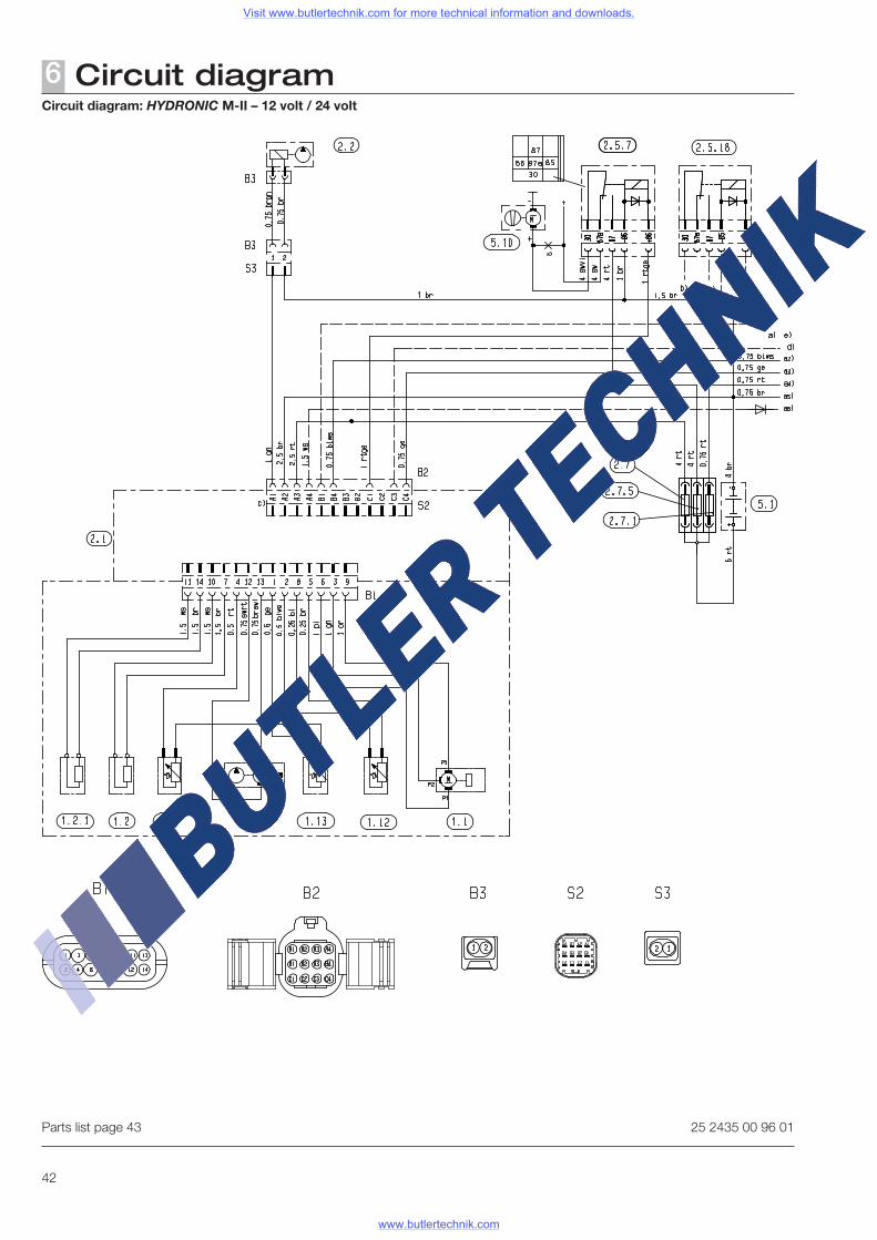
Circuit diagram6Circuit diagram: HYDRONIC M-II – 12 volt / 24 volt
Parts list page 43 25 2435 00 96 01
Visit www.butlertechnik.com for more technical information and downloads.
www.butlertechnik.com
43
Circuit diagram6
Cable colours
rt = redbl = bluews = whitesw = blackgn = greengr = greyge = yellowvi = violet
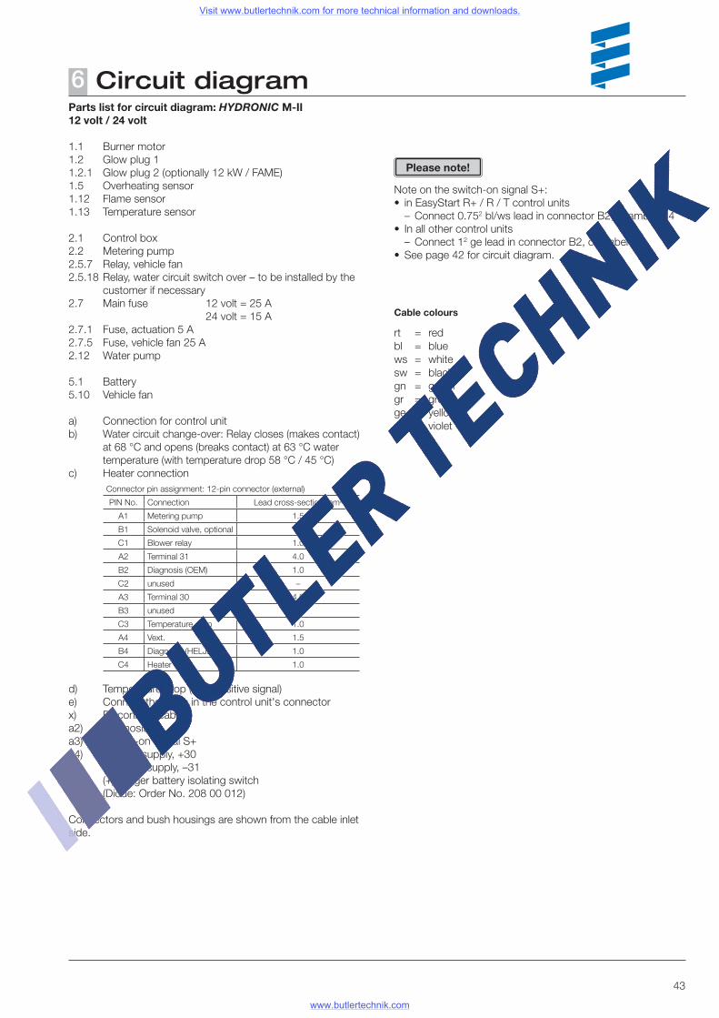
Parts list for circuit diagram: HYDRONIC M-II12 volt / 24 volt
1.1 Burner motor1.2 Glow plug 11.2.1 Glow plug 2 (optionally 12 kW / FAME)1.5 Overheating sensor1.12 Flame sensor1.13 Temperature sensor
2.1 Control box2.2 Metering pump2.5.7 Relay, vehicle fan2.5.18 Relay, water circuit switch over – to be installed by the
customer if necessary2.7 Main fuse 12 volt = 25 A 24 volt = 15 A2.7.1 Fuse, actuation 5 A2.7.5 Fuse, vehicle fan 25 A2.12 Water pump
5.1 Battery5.10 Vehicle fan
a) Connection for control unitb) Water circuit change-over: Relay closes (makes contact)
at 68 °C and opens (breaks contact) at 63 °C water temperature (with temperature drop 58 °C / 45 °C)
c) Heater connectionConnector pin assignment: 12-pin connector (external)
PIN No. Connection Lead cross-section mm2
A1 Metering pump 1.5
B1 Solenoid valve, optional 1.0
C1 Blower relay 1.0
A2 Terminal 31 4.0
B2 Diagnosis (OEM) 1.0
C2 unused –
A3 Terminal 30 4.0
B3 unused –
C3 Temperature drop 1.0
A4 Vext. 1.5
B4 Diagnosis (HELJED) 1.0
C4 Heater ON 1.0
d) Temperature drop (with positive signal)e) Connect the leads in the control unit's connectorx) Disconnect cablea2) Diagnosisa3) Switch-on signal S+a4) Positive supply, +30a5) Negative supply, –31a6) (+) Trigger battery isolating switch (Diode: Order No. 208 00 012)
Connectors and bush housings are shown from the cable inlet side.
Note on the switch-on signal S+:• in EasyStart R+ / R / T control units
– Connect 0.752 bl/ws lead in connector B2, chamber B4• In all other control units
– Connect 12 ge lead in connector B2, chamber B4• See page 42 for circuit diagram.
Please note!
Visit www.butlertechnik.com for more technical information and downloads.
www.butlertechnik.com

44
Circuit diagram6
Parts list page 45 25 2435 00 96 02
Circuit diagram: HYDRONIC M-II, 12 volt / 24 volt, ADR
Visit www.butlertechnik.com for more technical information and downloads.
www.butlertechnik.com
45
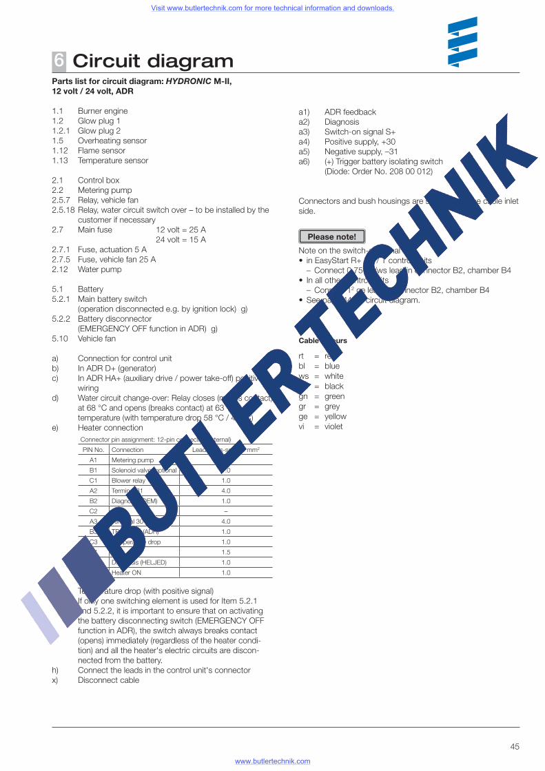
Circuit diagram6Parts list for circuit diagram: HYDRONIC M-II,12 volt / 24 volt, ADR
1.1 Burner engine1.2 Glow plug 11.2.1 Glow plug 21.5 Overheating sensor1.12 Flame sensor1.13 Temperature sensor
2.1 Control box2.2 Metering pump2.5.7 Relay, vehicle fan2.5.18 Relay, water circuit switch over – to be installed by the
customer if necessary2.7 Main fuse 12 volt = 25 A 24 volt = 15 A2.7.1 Fuse, actuation 5 A2.7.5 Fuse, vehicle fan 25 A2.12 Water pump
5.1 Battery5.2.1 Main battery switch (operation disconnected e.g. by ignition lock) g)5.2.2 Battery disconnector (EMERGENCY OFF function in ADR) g)5.10 Vehicle fan
a) Connection for control unitb) In ADR D+ (generator)c) In ADR HA+ (auxiliary drive / power take-off) positive
wiringd) Water circuit change-over: Relay closes (makes contact)
at 68 °C and opens (breaks contact) at 63 °C water temperature (with temperature drop 58 °C / 45 °C)
e) Heater connectionConnector pin assignment: 12-pin connector (external)
PIN No. Connection Lead cross-section mm2
A1 Metering pump 1.5
B1 Solenoid valve, optional 1.0
C1 Blower relay 1.0
A2 Terminal 31 4.0
B2 Diagnosis (OEM) 1.0
C2 D+ –
A3 Terminal 30 4.0
B3 TRS signal (ADR) 1.0
C3 Temperature drop 1.0
A4 Vext. 1.5
B4 Diagnosis (HELJED) 1.0
C4 Heater ON 1.0
f) Temperature drop (with positive signal)g) If only one switching element is used for Item 5.2.1
and 5.2.2, it is important to ensure that on activating the battery disconnecting switch (EMERGENCY OFF function in ADR), the switch always breaks contact (opens) immediately (regardless of the heater condi-tion) and all the heater's electric circuits are discon-nected from the battery.
h) Connect the leads in the control unit's connectorx) Disconnect cable
a1) ADR feedbacka2) Diagnosisa3) Switch-on signal S+a4) Positive supply, +30a5) Negative supply, –31a6) (+) Trigger battery isolating switch (Diode: Order No. 208 00 012)
Connectors and bush housings are shown from the cable inlet side.
Note on the switch-on signal S+:• in EasyStart R+ / R / T control units
– Connect 0.752 bl/ws lead in connector B2, chamber B4• In all other control units
– Connect 12 ge lead in connector B2, chamber B4• See page 44 for circuit diagram.
Please note!
Cable colours
rt = redbl = bluews = whitesw = blackgn = greengr = greyge = yellowvi = violet
Visit www.butlertechnik.com for more technical information and downloads.
www.butlertechnik.com
46
Parts list for circuit diagrams, control units:EasyStart R+ / R / T and EasyStart T – ADR
2.15.1 Temperature sensor (room temperature) (included in scope of supply for EasyStart R+, optional for EasyStart R and EasyStart T)2.15.9 Temperature sensor (outside temperature)
3.1.7 "ON / OFF" button3.1.16 Radio remote control button
3.2.15 EasyStart T timer
3.3.9 Radio remote control, EasyStart R (stationary unit)3.3.10 Radio remote control, EasyStart R+ (stationary unit)
3.6.1 Adapter cable
3.8.3 Antenna
c) Terminal 58 (lighting)e) Connection, EasyStart T timerg) External "ON / OFF" button (optional)x) ADR jumper
• Insulate unused cable ends.• Connectors and bush housings are shown from the cable
inlet side.
Cable colours
rt = redbl = bluews = whitesw = blackgn = greengr = greyge = yellowvi = violet
Circuit diagram6
Please note!
EasyStart R+ circuit diagram see page 47EasyStart R circuit diagram see page 48EasyStart T circuit diagram see page 49EasyStart T – ADR circuit diagram see page 50
Visit www.butlertechnik.com for more technical information and downloads.
www.butlertechnik.com
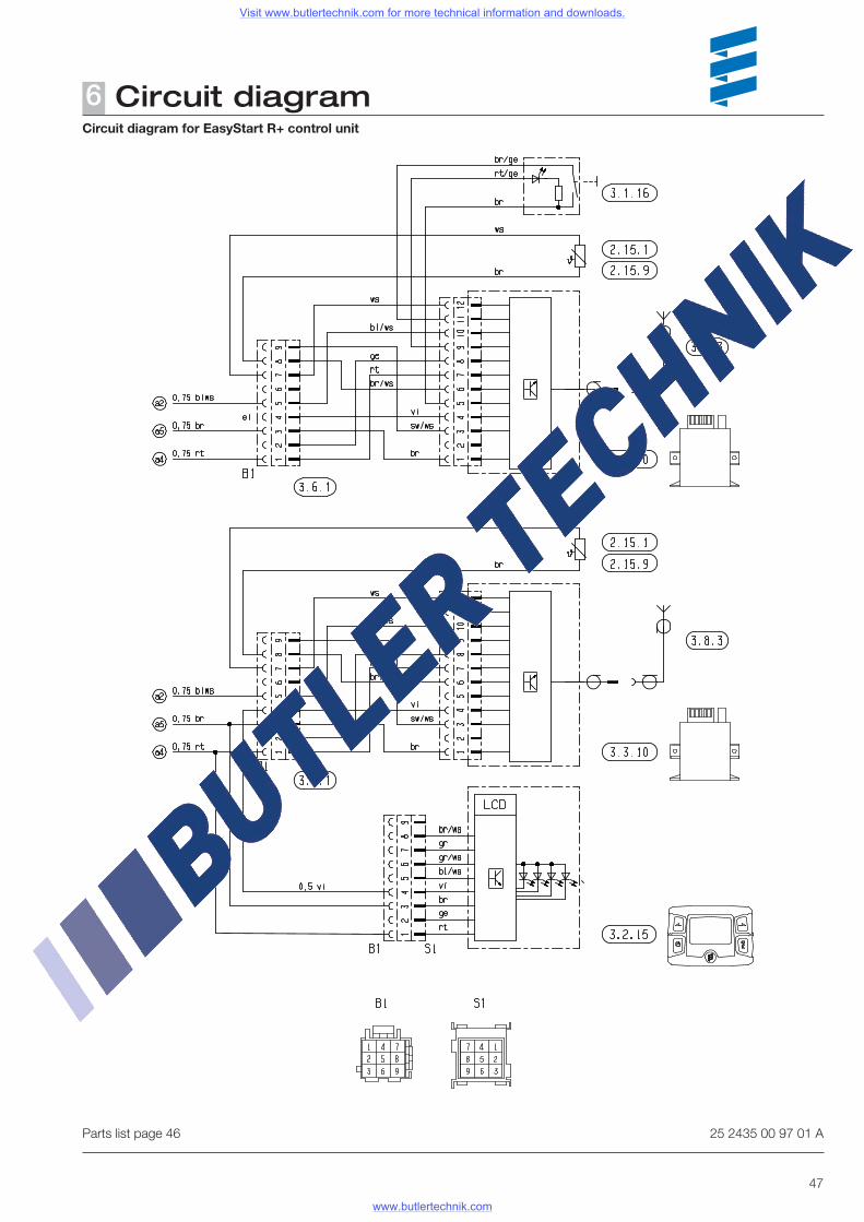
47
Parts list page 46
Circuit diagram for EasyStart R+ control unit
25 2435 00 97 01 A
Circuit diagram6
Visit www.butlertechnik.com for more technical information and downloads.
www.butlertechnik.com
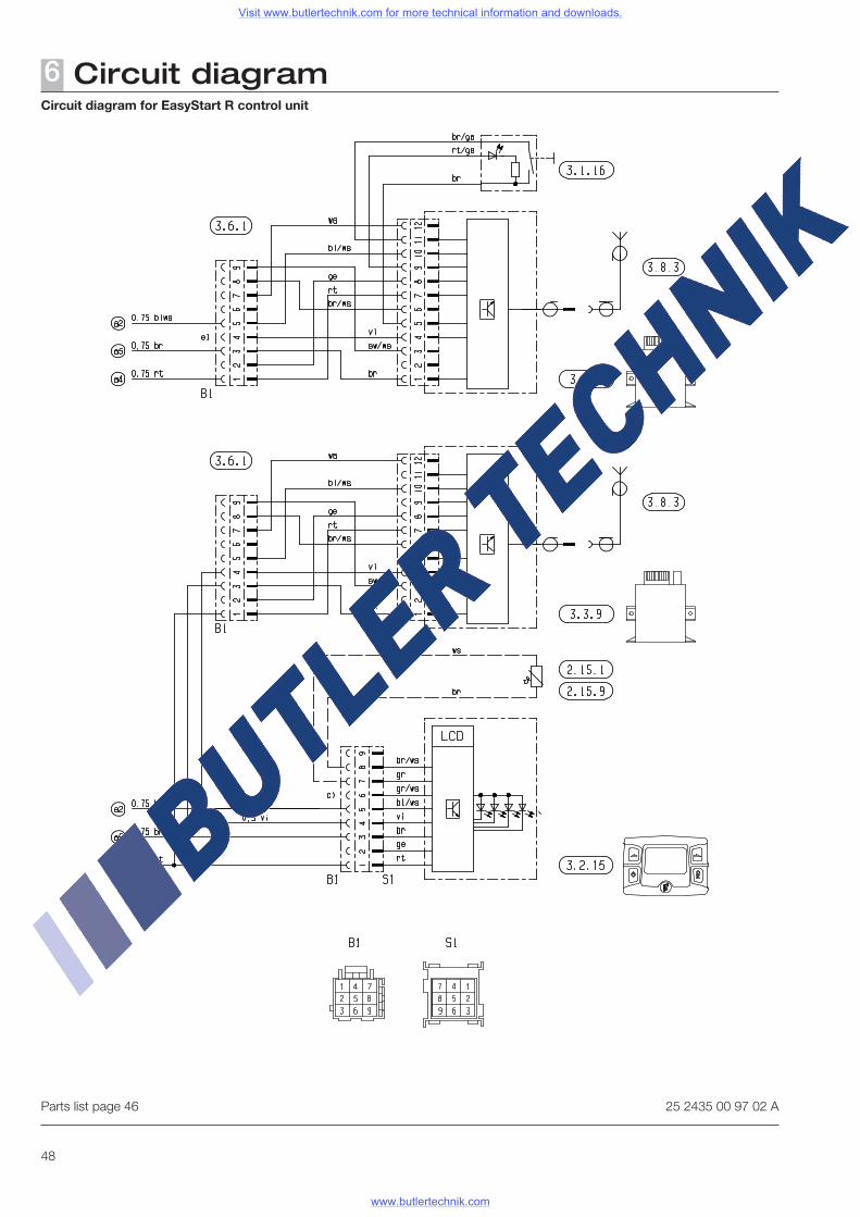
48
Parts list page 46
Circuit diagram for EasyStart R control unit
25 2435 00 97 02 A
Circuit diagram6
Visit www.butlertechnik.com for more technical information and downloads.
www.butlertechnik.com
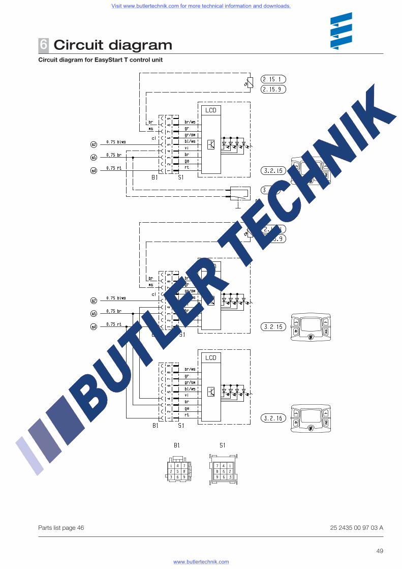
49
Parts list page 46
Circuit diagram for EasyStart T control unit
25 2435 00 97 03 A
Circuit diagram6
Visit www.butlertechnik.com for more technical information and downloads.
www.butlertechnik.com
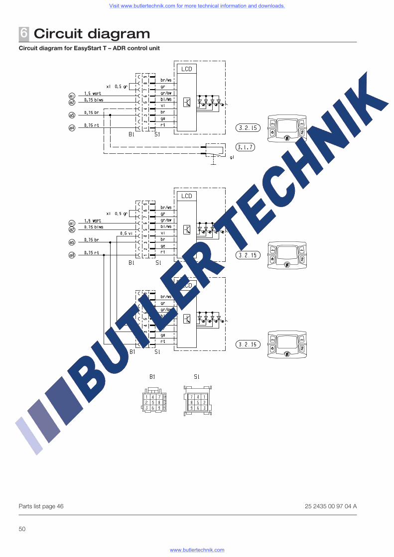
50
Circuit diagram6
Parts list page 46
Circuit diagram for EasyStart T – ADR control unit
25 2435 00 97 04 A
Visit www.butlertechnik.com for more technical information and downloads.
www.butlertechnik.com
51
Service7Certifications
The high quality of Eberspächer products is the key to our success. To guarantee this quality, we have organised all work proc-esses in the company along the lines of quality management (QM). Even so, we still pursue a large number of activities for continuous improvement of product quality in order to keep pace with the similarly constantly growing requirements made by our customers.All the steps necessary for quality assurance are stipulated in international standards. This quality is to be considered in a total sense.It affects products, procedures and customer / supplier relationships. Officially approved public experts assess the system and the corresponding certification company awards a certificate.
Eberspächer has already qualified for the following standards:
Quality management in accordance withDIN EN ISO 9001:2000 and ISO/TS 16949:1999
Environmental management system in accordance withDIN EN ISO 14001:1996
Disposal
Disposal of materialsOld devices, defect components and packaging material can all be separated and sorted into pure-grade factions so that all parts can be disposed of as required in an environment-friendly manner recycled where applicable. Electric motors, control boxes and sensors (e.g. temperature sensors) are deemed to be "electronic scrap".
Dismantling the heaterThe heater is dismantled according to the repair stages in the current troubleshooting / repair instructions.
PackagingThe packaging of the heater can be kept in case it has to be sent back.
EC Declaration of Conformity
With regard to the following products
Heater type HYDRONIC M-II
we herewith confirm that it conforms with the prime safety requirements stipulated in the directives of the EU Council for harmonisation of the legal regulations of the member states with regard to electromagnetic compatibility (89 / 336 / EEC).This declaration applies to all heaters produced according to the production drawings HYDRONIC M-II – which are an inte-gral part of this declaration.The following standards / directives have been used to assess the product with regard to electromagnetic compatibility:• EN 50081 – 1 Basic form interference emission• EN 50082 – 1 Basic form of interference immunity• 72 / 245 / EEC – Modification status 2005 / 83 / EC Interference suppression in motor vehicles.
Visit www.butlertechnik.com for more technical information and downloads.
www.butlertechnik.com
52
Service7Representatives abroad
ArgentinaChampion S. A.Av. Cordoba 2756 al 58RA - 1187 Buenos AiresTel. 0054 / 1 - 962 16 21Fax. 0054 / 1 - 962 16 27
for boat heaters /Trimer S. A.P.O. Box 1772Correo CentralRA - 1000 Buenos AiresTel. 0054 / 11 45 80 04 44Fax. 0054 / 11 45 80 04 40
Belgium and LuxembourgEberca bvbalResearch Park HaasrodeEsperantolaan 2B - 3001 Leuven HaasrodeTel. 0032 / 16 - 40 25 00Fax. 0032 / 16 - 40 05 15
Chilefür Bootsheizungenfor boat heaters /pour bateau chauffagesNauticentro Ltda.Tomas Moro 135Las Condes - SantiagoTel. 0056 / 2 - 201 49 66Fax. 0056 / 2 - 201 56 35
People‘s Republic of ChinaEberspaecher Automotive Technology (Beijing) Co., Ltd.B1-1 Xincheng Industrial ParkKechuang Street No. 2, BDABeijing 100023People‘s Republic of ChinaTel. 0086 10 6789 2686Fax. 0086 10 6789 2636
DenmarkEberspächer DanmarkLiterbuen 9DK - 2740 SkovlundeTel. 0045 / 44 - 85 30 30Fax. 0045 / 44 - 85 30 39Estland
EstoniaHesyco Group OÜLüli 1EE - 10112 TallinnTel. 00372 / 38 48 890/891Fax. 00372 / 38 48 892
FinlandWihuri Oy AutolaManttaalitie 9SF - 01510 Vantaa 51Tel. 0035 / 89 - 82 58 51Fax. 0035 / 89 - 82 58 52 07
FranceEberspächer S. A. S.Z.A.C. la Clé Saint Pierre3 rue Blaise PascalF - 78996 Elancourt CedexTel. 0033-1-30 68 54 54Fax. 0033-1-30 68 54 55
GreeceMARCONI HELLAS S. A.Souliou 2 – 4GR 143 43 N. Halkidona AthenTel. 0030 / 210 25 13 500Fax. 0030 / 210 25 28 854
Great BritainEberspächer UK Ltd.Headlands Business ParkSalisbury Road, Ringwood GB - Hampshire BH 243 PBTel. 0044 / 1425 - 48 01 51Fax. 0044 / 1425 - 48 01 52
ItalyEberspaecher S.r.l.Via del Canneto 45I - 25010 Borgosatollo (BS)Tel. 0039 / 030 25076-1Fax. 0039 / 030 2500307
JapanWhite House Co., Ltd.10-4 Obata-MiyanokoshiMoriyama-KuNagoya 463-0052 JPTel. 0081 / 5 27 76 38 11Fax. 0081 / 5 27 76 38 55
Canada Espar Products Inc.6099A Vipond DriveCDN MississaugaOntario L5T 2B2Tel. 001 / 905 6 70 09 60Fax. 001 / 905 6 70 07 28
KoreaHyundai Millate 2 Cha, A-405# 1303 Baek Seok-Dong, islan-dongkuKoyang-City Kyungki-DoTel. +82 (31) 932-34 11 / 12Fax. +82 (31) 932-34 16
LatviaTrans Baltic Trading CorporationMaskavas iela 449LV - 1063 RigaTel. 00371 / 7-26 63 23Fax. 00371 / 7-18 79 67
LithuaniaUAB LeopolisPaneriu 51LIT - 2055 VilniusTel. 0037-052-33 04 57Fax. 0037-052-13 35 37
Republic MoldaviaTC - IUSTINIAN140 Hinchesti Str., of.9MD - 2070 KishinevTel. 003732 / 727883, 738710Fax. 003732 / 727883
NetherlandsEberca B. V.Marconistraat 2NL - 3281 NB NumansdropTel. 0031 / 1866 - 2 19 55Fax. 0031 / 1866 - 2 18 18
NorwayEberspächer NorgeTrollåsveien 34N 1414 TrollåsenTel. 0047 / 66 82 30 50Fax. 0047 / 66 82 30 58
Visit www.butlertechnik.com for more technical information and downloads.
www.butlertechnik.com
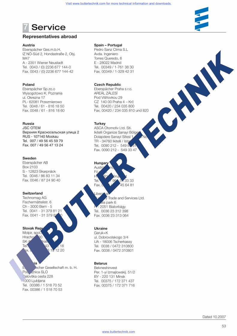
53
Service7Representatives abroad
Dated 10.2007
Austria Eberspächer Ges.m.b.H.IZ NÖ-Süd 2, Hondastraße 2, Obj. M47A - 2351 Wiener NeustadtTel. 0043 / (0) 2236 677 144-0 Fax. 0043 / (0) 2236 677 144-42
PolandEberspächer Sp.zo.o
Wysogotowo K. Poznania
ul. Okrezna 17
PL- 62081 Przezmierowo
Tel. 0048 / 61 - 816 18 50
Fax. 0048 / 61 - 816 18 60
RussiaJSC OTEMВерхняя Красносельская улица 2RUS - 107140 MoskauTel. 007 / 49 56 45 59 79Fax. 007 / 49 56 47 13 24
SwedenEberspächer ABBox 2103S - 12823 SkarpnäckTel. 0046 / 86 83 11 34Fax. 0046 / 87 24 90 40
SwitzerlandTechnomag AGFischermättelistr. 6Ch - 3000 Bern - 5Tel. 0041 - 31 379 81 21Fax. 0041 - 31 379 82 50
Slovak RepublicMolpir, spol.s.r.o.Hrachova 30SK-821 05 BratislawaTel. 00421 / 243 19 12 18Fax. 00421 / 243 19 12 20
SloveniaEberspaecher Gesellschaft m. b. H.Podružnica SLOCelovška cesta 2281000 LjubljanaTel. 00386 / 1 518 70 52Fax. 00386 / 1 518 70 53
Spain – PortugalPedro Sanz Clima S.L Avda. IngenieroTorres Queredo, 6E - 28022 MadridTel. 00349 / 1-761 38 30Fax. 00349 / 1-329 42 31
Czech RepublicEberspächer Praha s r.o.
AREÁL ZÁLESÍ
Pod Višňovkou 29
CZ 140 00 Praha 4 – Krč
Tel. 00420 / 234 035 800
Fax. 00420 / 234 035 810 und 820
TurkeyASCA Otomotiv Ltd. Sti.Ikitelli Organize Sanayi BölgesiDolapdere Sanayi Sitesi 1. Ada No. 38TR - 34760 Ikitelli / IstanbulTel. 0090 212 - 549 86 31Fax. 0090 212 - 549 33 47
HungaryAustropannon KFTFö ut 96H - 9081 GyörujbaratTel. 0036 / 96 - 54 33 33Fax. 0036 / 96 - 45 64 81
Liberatus Hungary Trade and Services Ltd.Roźalia park 6
H - 2051 Biatorbágy
Tel. 0036 23 312 398Fax. 0036 23 313 064
UkraineGeruk+Kul. Dobrovolskogo 3/4UA - 18006 TscherkassyTel. 0038 / 0472 310800Fax. 0038 / 0472 310801
BelarusBelvneshinvest Per. 1-yi Izmajlowskij. 51/2BY - 220 131 MinskTel. 00375 / 172 371 437Fax. 00375 / 172 371 716
Visit www.butlertechnik.com for more technical information and downloads.
www.butlertechnik.com
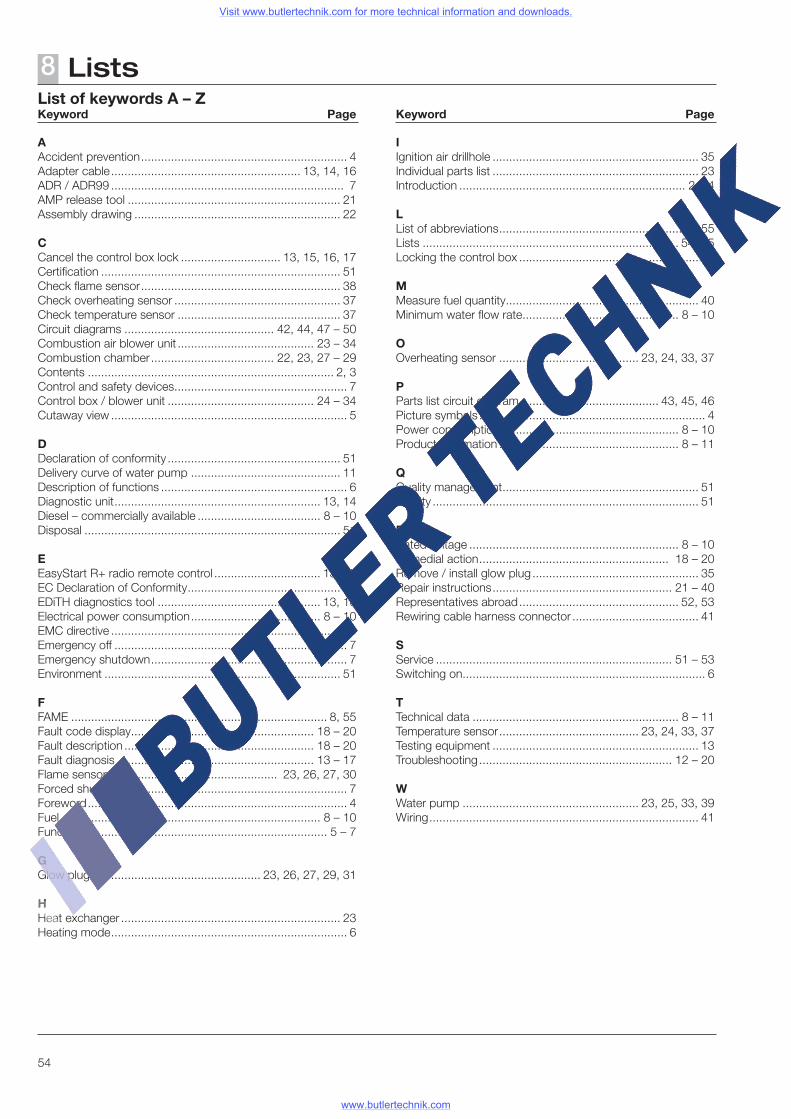
54
Lists8
AAccident prevention .............................................................. 4Adapter cable ......................................................... 13, 14, 16ADR / ADR99 ...................................................................... 7AMP release tool ................................................................ 21Assembly drawing .............................................................. 22
CCancel the control box lock .............................. 13, 15, 16, 17Certification ........................................................................ 51Check flame sensor ............................................................ 38Check overheating sensor .................................................. 37Check temperature sensor ................................................. 37Circuit diagrams ............................................. 42, 44, 47 – 50Combustion air blower unit ......................................... 23 – 34Combustion chamber ..................................... 22, 23, 27 – 29Contents .......................................................................... 2, 3Control and safety devices .................................................... 7Control box / blower unit ............................................ 24 – 34Cutaway view ....................................................................... 5
DDeclaration of conformity .................................................... 51Delivery curve of water pump ............................................. 11Description of functions ........................................................ 6Diagnostic unit .............................................................. 13, 14Diesel – commercially available ..................................... 8 – 10Disposal ............................................................................. 51
EEasyStart R+ radio remote control ................................ 13, 17EC Declaration of Conformity .............................................. 51EDiTH diagnostics tool ................................................. 13, 16Electrical power consumption ....................................... 8 – 10EMC directive ..................................................................... 55Emergency off ...................................................................... 7Emergency shutdown ........................................................... 7Environment ....................................................................... 51
FFAME ............................................................................. 8, 55Fault code display ....................................................... 18 – 20 Fault description ......................................................... 18 – 20Fault diagnosis ........................................................... 13 – 17Flame sensor ................................................... 23, 26, 27, 30Forced shutdown ................................................................. 7Foreword .............................................................................. 4Fuel .............................................................................. 8 – 10Function ......................................................................... 5 – 7
GGlow plug ................................................... 23, 26, 27, 29, 31
HHeat exchanger .................................................................. 23Heating mode ....................................................................... 6
IIgnition air drillhole .............................................................. 35Individual parts list .............................................................. 23Introduction .................................................................... 2 – 4
LList of abbreviations ............................................................ 55Lists ............................................................................. 54, 55Locking the control box ........................................................ 7
MMeasure fuel quantity .......................................................... 40Minimum water flow rate ............................................... 8 – 10
OOverheating sensor .......................................... 23, 24, 33, 37
PParts list circuit diagram .......................................... 43, 45, 46Picture symbols .................................................................... 4Power consumption ..................................................... 8 – 10Product information ...................................................... 8 – 11
QQuality management ........................................................... 51Quality ................................................................................ 51
RRated voltage ............................................................... 8 – 10Remedial action ......................................................... 18 – 20Remove / install glow plug .................................................. 35Repair instructions ...................................................... 21 – 40Representatives abroad ................................................ 52, 53Rewiring cable harness connector ...................................... 41
SService ....................................................................... 51 – 53Switching on ......................................................................... 6
TTechnical data .............................................................. 8 – 11Temperature sensor .......................................... 23, 24, 33, 37Testing equipment .............................................................. 13Troubleshooting .......................................................... 12 – 20
WWater pump ..................................................... 23, 25, 33, 39Wiring ................................................................................. 41
List of keywords A – ZKeyword Page Keyword Page
Visit www.butlertechnik.com for more technical information and downloads.
www.butlertechnik.com
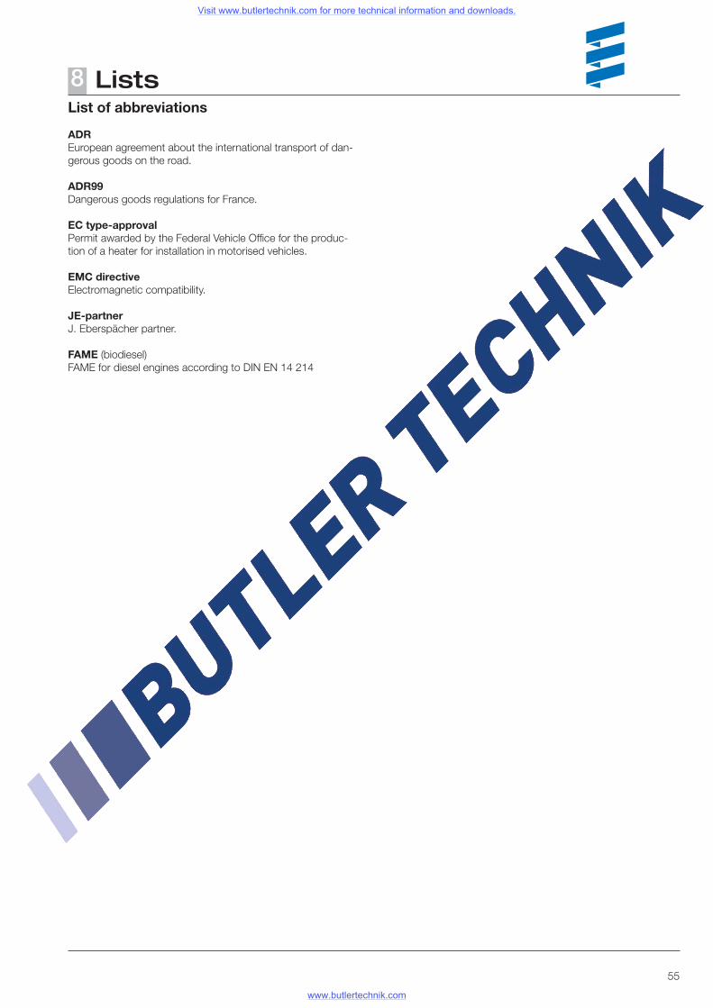
55
Lists8List of abbreviations
ADREuropean agreement about the international transport of dan-gerous goods on the road.
ADR99Dangerous goods regulations for France.
EC type-approvalPermit awarded by the Federal Vehicle Office for the produc-tion of a heater for installation in motorised vehicles.
EMC directiveElectromagnetic compatibility.
JE-partnerJ. Eberspächer partner.
FAME (biodiesel)FAME for diesel engines according to DIN EN 14 214
Visit www.butlertechnik.com for more technical information and downloads.
www.butlertechnik.com

Visit www.butlertechnik.com for more technical information and downloads.
www.butlertechnik.com
Related Documents