Marine catalogue — information, technology, tips. The compass heading is heat. Eberspächer marine heaters. Visit www.butlertechnik.com for more technical information and downloads. www.butlertechnik.com

Welcome message from author
This document is posted to help you gain knowledge. Please leave a comment to let me know what you think about it! Share it to your friends and learn new things together.
Transcript

J.EberspächerGmbH & Co. KGEberspächerstraße 24D-73730 EsslingenTelefon Hotline 0800 1 23 43 00Fax Hotline 01805 26 26 [email protected]
www.eberspaecher.com
Marine catalogue — information, technology, tips.
The compass heading is heat.Eberspächer marine heaters.
VHM/M
S12
/08Bech1.0Technicald
ata:+/-10
%Sub
ject
tomodification,
errors
possible.Printed
inGermany.Printed
onchlorine-freepap
er.
Visit www.butlertechnik.com for more technical information and downloads.
www.butlertechnik.com
2
The Eberspächer marine catalogue is inten-
ded to be used for supporting dockyard and
Eberspächer service partners when figuring
out which heater system to use and install,
as well as for giving the ship owner important
instructions for using the heater system. On
the next several pages, you will find informa-
tion on air and water heating units as well
as operating controls and accessories.
Visit www.butlertechnik.com for more technical information and downloads.
www.butlertechnik.com
3
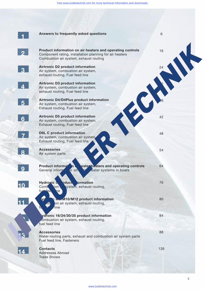
Answers to frequently asked questions
Product information on air heaters and operating controlsComponent rating, installation planning for air heatersCombustion air system, exhaust routing
Airtronic D2 product informationAir system, combustion air system,exhaust routing, Fuel feed line
Airtronic D3 product informationAir system, combustion air system,exhaust routing, Fuel feed line
Airtronic D4/D4Plus product informationAir system, combustion air system,Exhaust routing, Fuel feed line
Airtronic D5 product informationAir system, combustion air system,Exhaust routing, Fuel feed line
D8L C product informationAir system, combustion air system,Exhaust routing, Fuel feed line
AccessoriesAir system parts
Product information on water heaters and operating controlsGeneral information on water heater systems in boats
Hydronic 5 product informationCombustion air system, exhaust routing,fuel feed line
Hydronic M8/M10/M12 product informationCombustion air system, exhaust routing,fuel feed line
Hydronic 16/24/30/35 product informationCombustion air system, exhaust routing,fuel feed line
AccessoriesWater-routing parts, exhaust and combustion air system partsFuel feed line, Fasteners
ContactsAddresses AbroadTrade Shows
1
2
4
5
6
7
8
9
10
11
12
13
6
16
24
32
36
42
48
54
64
76
80
84
88
12614
3
Visit www.butlertechnik.com for more technical information and downloads.
www.butlertechnik.com
4
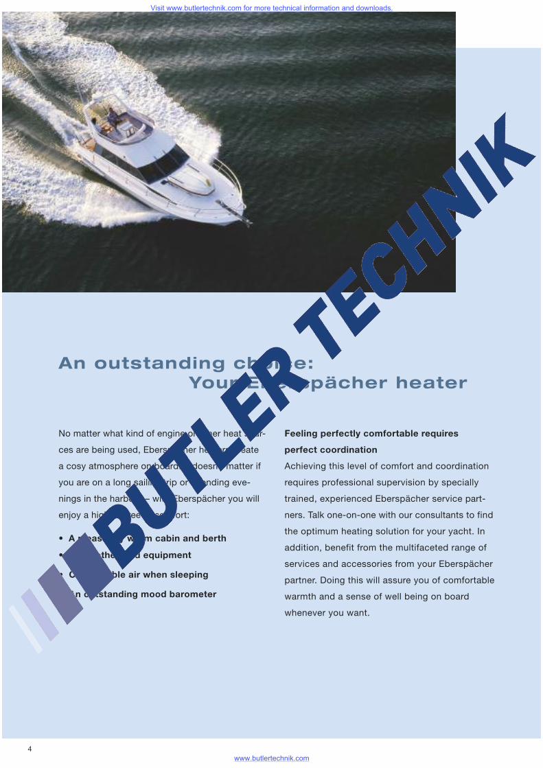
An outstanding choice:Your Eberspächer heater
• A pleasantly warm cabin and berth
• Dry clothes and equipment
• Comfortable air when sleeping
• An outstanding mood barometer
No matter what kind of engine or other heat sour-
ces are being used, Eberspächer heaters create
a cosy atmosphere on board. It doesn’t matter if
you are on a long sailing trip or spending eve-
nings in the harbour – with Eberspächer you will
enjoy a high degree of comfort:
Feeling perfectly comfortable requires
perfect coordination
Achieving this level of comfort and coordination
requires professional supervision by specially
trained, experienced Eberspächer service part-
ners. Talk one-on-one with our consultants to find
the optimum heating solution for your yacht. In
addition, benefit from the multifaceted range of
services and accessories from your Eberspächer
partner. Doing this will assure you of comfortable
warmth and a sense of well being on board
whenever you want.
Visit www.butlertechnik.com for more technical information and downloads.
www.butlertechnik.com
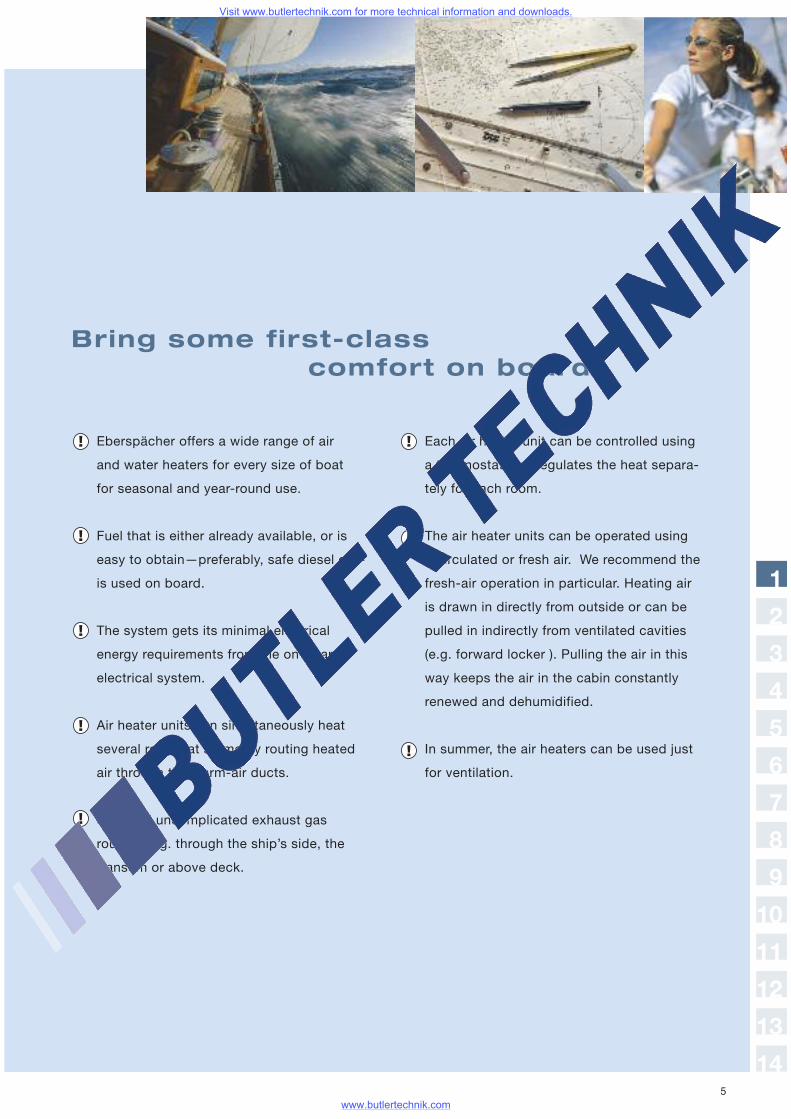
Bring some first-classcomfort on board!
Eberspächer offers a wide range of air
and water heaters for every size of boat
for seasonal and year-round use.
Fuel that is either already available, or is
easy to obtain—preferably, safe diesel oil—
is used on board.
The system gets its minimal electrical
energy requirements from the on-board
electrical system.
Air heater units can simultaneously heat
several rooms at a time by routing heated
air through the warm-air ducts.
Safe and uncomplicated exhaust gas
routing, e.g. through the ship’s side, the
transom or above deck.
Each air heater unit can be controlled using
a thermostat that regulates the heat separa-
tely for each room.
The air heater units can be operated using
recirculated or fresh air. We recommend the
fresh-air operation in particular. Heating air
is drawn in directly from outside or can be
pulled in indirectly from ventilated cavities
(e.g. forward locker ). Pulling the air in this
way keeps the air in the cabin constantly
renewed and dehumidified.
In summer, the air heaters can be used just
for ventilation.
1
2
3
4
5
6
7
8
9
10
11
12
13
145
Visit www.butlertechnik.com for more technical information and downloads.
www.butlertechnik.com
6
Answers to yourfrequently asked questions
What will I actually get for my money?
With an Eberspächer stationary heater, you
are getting a premium product that has been
painstakingly manufactured according to
the highest quality and safety standards.
Can I install the stationary heater myself?
The heater can only be installed by an authori-
zed Eberspächer partner. Otherwise, this consti-
tutes non-compliance with the instructions for
installation and the specific directions these
instructions include, and invalidates warranty
claims on the part of J. Eberspächer GmbH &
Co. KG and its partners. Complying with legal
guidelines and safety instructions is the prere-
quisite for warranty and liability claims.
Which system is right for me:
water or air?
That depends mainly on the amount of time you
will need the heat and how you use it. Air heaters
are recommended for retrofitting in boats be-
cause a specialist can easily install them and
they provide you with heat in a hurry. Air heaters
are recommended even in cabins where you
sleep because they use so little electricity and
you can preselect the temperature for the com-
partment. Water heaters are the overwhelming
choice preferred in shipyards for yacht design.
These heaters are integrated into the existing
water system and can be used to independently
heat water for tap water and for washing, any
heaters that are hooked up (central heating)
and to preheat the engine.
Visit www.butlertechnik.com for more technical information and downloads.
www.butlertechnik.com
We’ve listed a couple of basic criteria below to
help you decide. A diesel heater is usually
integrated in the design.
How big is the boat and which rooms
should be heated?
The general rule of thumb is: 120 – 200 watts
of heat is needed per cubic meter of space to be
heated (depending on where you are using it and
how long you need it). This means that you have
the following options with air heaters:
The small heater, the Airtronic D2, is the ideal
solution (depending on location) for sailboats up
to 8 meters long and motorboats up to 6 meters
long. If you need a heater that runs very quietly
on board because of where it is installed (e.g.
under a seat bench), then we recommend
installing the Airtronic D3.
The Airtronic D4 is used for sailing yachts up
to 12 meters long and for motorboats up to
10 meters long. 4000 watts of heat flow will
keep the saloon area and aft cabin warm at
the same time.
The Airtronic D5 and D8LC are available for
larger yachts; these heaters will meet any
heating needs you may have.
The only exceptions might be: your Eberspächer
specialist will have to determine on site which
heater you will need for working boats that have
to be heated under bitterly cold conditions.
Sailboats usually have less interior volume than
motorboats. The space to be heated has to be
calculated so that the wattage required per cubic
meter is used. The answer to this equation tells
you which heater you need. For example: Each
cubic meter requires 125 watts, therefore,
5000 watts are necessary for 40 m3. This means
you should choose the Airtronic D5. Water hea-
ters need to be chosen in a similar manner.
The total amount of heat from a heat exchanger
is usually listed. If you have installed a heat
exchanger for your cabin interior whose output
is greater than 9 kW, then you need a heater that
exceeds this capacity. In this case, you would
need the Hydronic M10.
Who will assist me in planning
my heater installation?
Our specialist service partners have been
specifically trained how to calculate heat
requirements and how to select the proper
heater(s).
1
2
3
4
5
6
7
8
9
10
11
12
13
14
Visit www.butlertechnik.com for more technical information and downloads.
www.butlertechnik.com
8
Operation
How do you operate the stationary heater?
Convenient controls are used to operate these
heaters. Mini-controllers are primarily used to
operate air heaters; timers or remote control
units are used for water heaters. Our Calltronic
remote control is especially convenient and
easy to use—just call in from your cell phone
or landline with tone dialling to activate your
heater—even at long distance (provided you
have network coverage).
How fast do the compartments heat up?
Pre-heating time depends on the outside air tem-
perature, the size of the boat and insulation. Thirty
minutes is usually enough to heat up a cabin.
How much fuel does a stationary
heater use?
Because they are very efficient, Eberspächer
stationary heaters are optimized for high fuel
economy. Average fuel consumption depends on
several factors, such as the heater, the outside
air temperature, your boat’s insulation and the
size of the compartments that have to be hea-
ted. For example, the Hydronic 5 water heater
uses only 0,62 l of diesel per hour at its highest
setting. But on the other hand, it uses just
0.27 l/h on its lowest setting. Our air heaters,
e.g. the Airtronic D4, only need 0.51 l/h at the
most to warm up your cabins. After that, it
only needs an average of 0.11 l/h.
Can I use gasoline as a fuel, too?
Using gasoline as an exception for gasoline-
fired air heaters in boats: Installing gasoline-
fired heaters is only allowed as an exception,
and then only if the respective local laws allow it.
One case might be in boats with gasoline engi-
nes where the heater can only get its fuel
through the fuel line or from the boat’s tank.
But in this situation, you absolutely must
comply with the following: The heater is
not allowed to be installed in the engine com-
partment. The heater is only allowed to be
installed in a well-ventilated space that is not
connected to the engine compartment or to the
tank compartment. And this space must be free
of any exhaust. The combustion air and the
Visit www.butlertechnik.com for more technical information and downloads.
www.butlertechnik.com
9
In addition, the diesel heater must get its fuel
from a separate diesel tank that meets code for
all the generally applicable, local regulations
regarding diesel tanks in boats.
Does a stationary heater need AC
mains power (230 V)?
No. The current needed to run the heater’s elec-
trical components is taken from the battery.
Heat is created by combusting the fuel.
heater air must be drawn in from outside
at a point you are absolutely sure is free from
any possible gasoline fumes and exhaust.
Can I install a diesel heater in a
gasoline-powered boat?
It is basically possible to install a diesel heater
in a gasoline-powered boat. In this instance, the
same rules apply as in the above-stated excep-
tion for gasoline-operated heaters.
1
2
3
4
5
6
7
8
9
10
11
12
13
14
Visit www.butlertechnik.com for more technical information and downloads.
www.butlertechnik.com
10
Does a stationary heater make noise?
Well, by their very nature of course all stationary
heaters make combustion noises when they
are operating. But they are so minimal that
our stationary heaters are approved for day
and night operation. For boat installation in
particular, if required, a wide range of measures
is available for minimizing noise.
Does running a stationary heater
create any fumes?
In extremely rare instances, the start-and-stop
phase may produce a minimal amount of fumes
or odours. This is just as normal as water vapour
occurring when the outside temperature is low.
Safety
Which regulations do I have to follow
when operating a heater?
Legal Regulations
Legal guidelines vary from region to region in
terms of governing the design, installation and
operation of heaters in boats. Before a heater is
installed, you must first check which laws must
be complied with as they pertain to the particular
area of operation on your boat. Various testing
organisations will check and monitor compliance
with the legal regulations.
Regional differences
Following are examples of regional laws and
regulations for heaters in boats.
• In Bavaria, Sweden and the UK (Great Britain
and Northern Ireland): gasoline-powered hea-
ters are not allowed as built-in components
in new-boat construction.
• Sweden: the combustion air must be pulled
in from outside the boat.
Visit www.butlertechnik.com for more technical information and downloads.
www.butlertechnik.com
CE certification
Since June 16, 1998, every newly manufactured
sports boat between 2.5m and 24m long—inclu-
ding its system components—has to meet the
CE identification requirements. For heater
installation, this means the following:
• That the heater is labelled with CE identification
• That the fuel supply in the engine compartment
must only be routed through metal or fire-
resistant hoses, in accordance with DIN
EN ISO 7850.
Heater permit
The following permits exist for heaters, and the ins-
pection certification appears on the nameplate
of the plant that manufactured the heater:
• CE certification with the CE identification label.
• A permit from the TÜV southern Germany for
the following heaters for operation on Bavarian
waters: (No identification on the factory name
plate) Airtronic D2, Airtronic D4
How long is the warranty on new heaters?
Eberspächer warrants all its products for
24 months.
Does a stationary heater need special
service?
No. Our products are maintenance-free. But,
just like an AC system, it should be switched
on briefly once a month. Ten minutes is enough.1
2
3
4
5
6
7
8
9
10
11
12
13
14
Visit www.butlertechnik.com for more technical information and downloads.
www.butlertechnik.com

12
Important installationand safety information
Using the heater
The heater may only be used and operated
for the specified purposes for which it is manu-
factured, and in accordance with the “Technical
Description” that accompanies each heater.
Risk of injury, fire and poisoning!
• The heater may only be operated with an
outlet hood installed.
• Disconnect the battery before starting any work.
• Before starting any work on the heater, turn the
heater off and let all hot components cool off.
• The heater may not be operated in any enclo-
sed areas, e.g. dockyard.
• Hot-air outlets that can be adjusted must al-
ways be aimed in such a way that any living
beings (people, animals) and any objects
(attached or unattached) that can be affected
by heat are not placed directly in the path
of hot air.
• The year the heater is first operated must
be marked on the factory nameplate.
• An air heater’s heat exchanger is a component
subjected to a high degree of stress, it has to
be replaced ten years after the heater was initi-
ally put into operation. In addition, the date of
installation must be entered on the “original
replacement part” label, which is included with
the heat exchanger. This label must then be
glued in place next to the manufacturer’s
nameplate.
• The heater may only be installed, or, in
cases of repair or warranty claims, repaired,
by a manufacturer-authorized Eberspächer
service partner, and this must be carried out
in accordance with the specifications listed in
this document and the Technical Description.
• Repairs carried out by a non-authorized
third party are hazardous and therefore not
permitted; if this does occur, the heater’s type
approval documentation and the one for the
boat will be rendered invalid.
• Only OEM accessories and replacement
parts are allowed to be used for carrying
out installation or repair work.
Visit www.butlertechnik.com for more technical information and downloads.
www.butlertechnik.com
13
The following actions are not permitted
• Changing or altering heater-related components.
• Use of non-OEM parts not approved by
Eberspächer GmbH & Co. KG.
• Deviations from legal, safety and/or function-
related guidelines during installation or opera-
tion, which are given in the installation and/or
operating instructions. This especially applies
to electrical wiring, the fuel supply, combustion
and exhaust air routing.
• Only those control devices approved by
Eberspächer GmbH & Co. KG may be used for
operating heaters. Using other control devices
can cause malfunctions.
• The heater may not be operated in any area
where inflammable vapours, fumes or dust
can form—e.g. near a fuel depot, coal yard,
lumberyard or granary, or similar.
• The space where the heater is installed must not
be a storage area and must remain clear, unless
it has been installed in a protective case, or similar.
1
2
3
4
5
6
7
8
9
10
11
12
13
14
Visit www.butlertechnik.com for more technical information and downloads.
www.butlertechnik.com
14
• In particular, reserve fuel canisters, oil cans,
spray cans, gas cartridges, fire extinguishers,
cleaning rags, articles of clothing, paper, etc.
must not be stored or transported on or
next to the heater.
• The heater must be turned off before refuelling.
• Defective fuses may only be replaced with
fuses bearing the specified fuse rating.
• If any fuel leaks out of the heater’s fuel
system (leakage), have any damage repaired
immediately at an Eberspächer service partner
(and do not operate the heater until it is repaired).
• The heater’s delayed off must not be cancel-
led prematurely, e.g. by actuating the battery
cut-off switch, except in an emergency.
Emergency cut-off — EMERGENCY/OFF
The following must be done in the event of
an emergency cut-off — EMERGENCY/OFF —
while operating the heater:
• Pull fuse or
• Disconnect the heater from the battery
(actuate the battery cut-off switch)
Performing an emergency cut-off might
damage the heater.
Accident Prevention
All general accident-prevention regulations
and the appropriate repair shop and industrial
safety instructions are to be followed.
Visit www.butlertechnik.com for more technical information and downloads.
www.butlertechnik.com
15
The environment
Certification
The high quality of Eberspächer products is
the key to our success. In order to ensure this
quality, we have organized all of the work proces-
ses in our company in terms of quality manage-
ment (QA). Nevertheless, we engage in
a wide range of activities in order to improve our
product quality, and in order to keep pace with
ever-increasing customer demands. The type of
guarantee of quality required is defined in inter-
national standards. This quality should be viewed
in a far-reaching sense because it applies to
products, work-production sequences and custo-
mer-supplier relationships. Officially approved
experts evaluate the system and the appropriate
certifying body awards the certificate.
Eberspächer has already qualified for the
following standards:
Quality management in accordance with
DIN EN ISO 9001:2000 and ISO/TS 16949:1999
Environmental management system
accordance with DIN EN ISO 14001:1996
Waste disposalmanagement
Disposing of materials
Old equipment, defective components
and packing material can be correctly sorted
separately, so that if necessary, all parts can
be disposed of in an environmentally friendly
manner, or taken for recycling. Electric motors,
control devices and sensors (e.g. temperature
sensors) qualify in this sense as “electrical-scrap.”
Dismantling the heater
Dismantling the heater is done in accordance
with the repair steps from current troubleshoo-
ting and the repair manual.
1
1
2
3
4
5
6
7
8
9
10
11
12
13
14
Visit www.butlertechnik.com for more technical information and downloads.
www.butlertechnik.com

16
The right air heater
for every need
Skippers are individualists—and every boat has its
own special quirks and characteristics that an
Eberspächer marine heater needs to cope with:
smaller boats require different solutions than
20-meter yachts. The question whether your boat is
a sailboat or a motorboat plays an important part, too.
And your selection from the Eberspächer line of pro-
ducts is just as great. With heater outputs of 850
to 8,000 W for spaces up to 70m3, you will definitely
find what you want. Stop by and talk it over with your
boating specialist. He will be glad to help you put
together your own installation quote.
Heat output (watts)
Diesel version
850 / 1,200 /
1,800 / 2,200
36 / 52 / 75 / 90
8 / 12 / 22 / 34
Technicaldata
Air throughput (m3/h)
0.10 / 0.15 / 0.23 / 0.28
310 x 115 x 122
Fuel consumption (l/h)
Electrical output opera-tion (watts)
Voltage (volts)
Dimensions L x W x H (mm)
AirtronicD2
12 / 24
900 / 1,600 /
2,200 / 3,000
52 / 80 / 100 / 130
7 / 10 / 16 / 24
0.11 / 0.20 / 0.28 / 0.38
376 x 140 x 150
AirtronicD3
12
Weight (kg) 2.7 4.5
900 / 2,000 /
3,000 / 4,000
55 / 95 / 130 / 160
7 / 13 / 24 / 40
0.11/ 0.25 / 0.38 / 0.51
376 x 140 x 150
AirtronicD4
12 / 24
4.5
900 / 2,000 /
3,000 / 4,000
45 / 86 / 120 / 160
7 / 16 / 30 / 55
0.11 / 0.25 / 0.38 / 0.51
376 x 140 x 150
AirtronicD4 Plus
12 / 24
4.5
Visit www.butlertechnik.com for more technical information and downloads.
www.butlertechnik.com
17
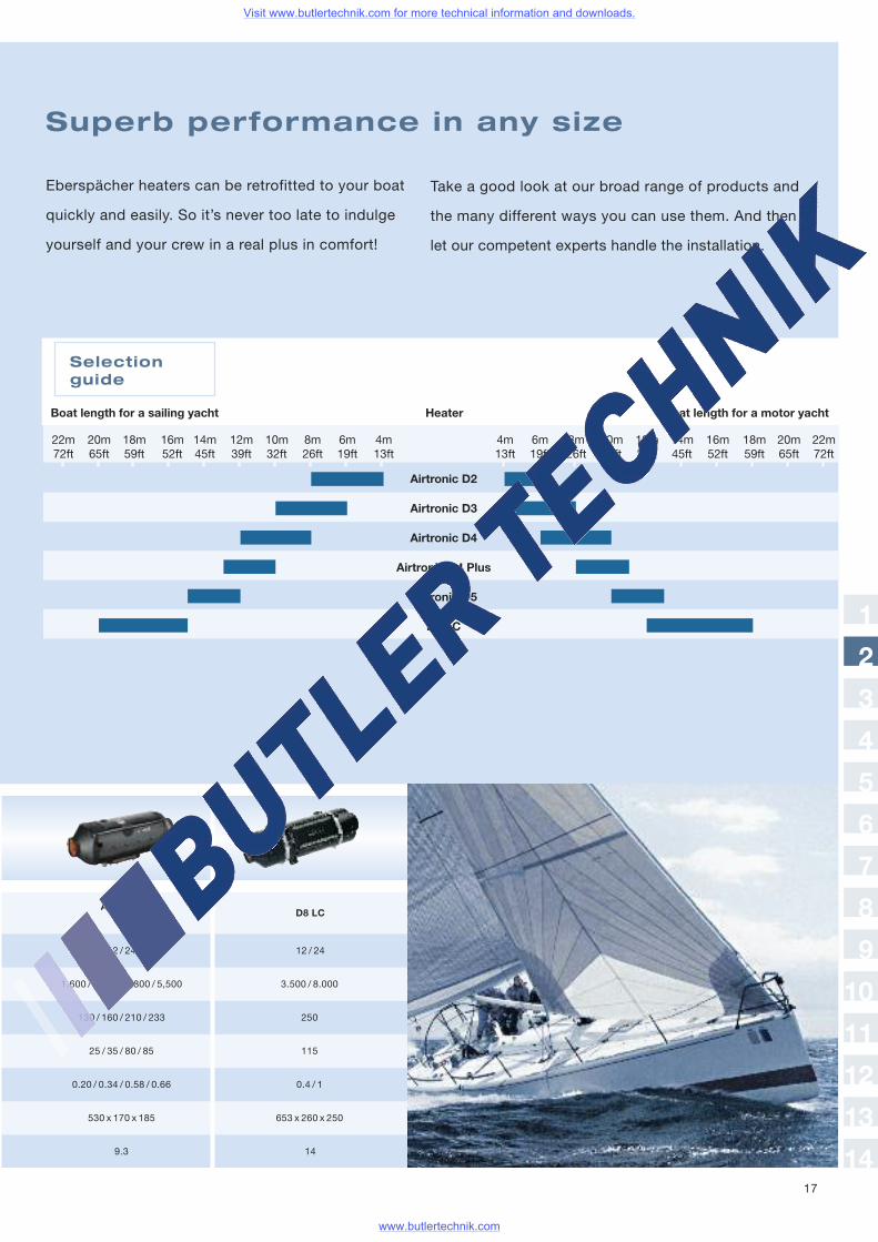
Eberspächer heaters can be retrofitted to your boat
quickly and easily. So it’s never too late to indulge
yourself and your crew in a real plus in comfort!
Superb performance in any size
Take a good look at our broad range of products and
the many different ways you can use them. And then
let our competent experts handle the installation.
Airtronic D2
Airtronic D3
Airtronic D4
Airtronic D4 Plus
Airtronic D5
D8 LC
Selectionguide
1,600 / 2,700 / 4,800 / 5,500
130 / 160 / 210 / 233
25 / 35 / 80 / 85
0.20 / 0.34 / 0.58 / 0.66
530 x 170 x 185
AirtronicD5
12 / 24
3.500 / 8.000
250
115
0.4 / 1
653 x 260 x 250
D8 LC
12 / 24
9.3 14
Boat length for a sailing yacht Heater Boat length for a motor yacht
22m 20m 18m 16m 14m 12m 10m 8m 6m 4m 4m 6m 8m 10m 12m 14m 16m 18m 20m 22m72ft 65ft 59ft 52ft 45ft 39ft 32ft 26ft 19ft 13ft 13ft 19ft 26ft 32ft 39ft 45ft 52ft 59ft 65ft 72ft
1
2
3
4
5
6
7
8
9
10
11
12
13
14
Visit www.butlertechnik.com for more technical information and downloads.
www.butlertechnik.com
18
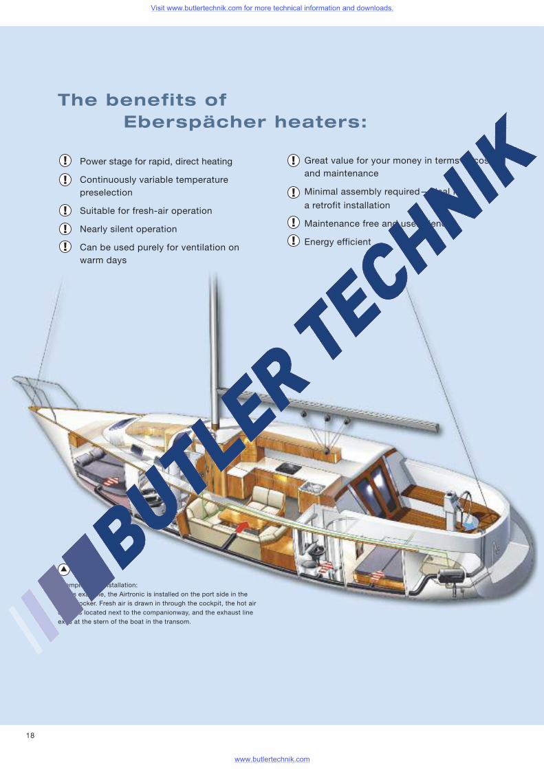
Example of an installation:In this example, the Airtronic is installed on the port side in theship’s locker. Fresh air is drawn in through the cockpit, the hot airoutlet is located next to the companionway, and the exhaust lineexits at the stern of the boat in the transom.
Great value for your money in terms of costand maintenance
Minimal assembly required—ideal for
a retrofit installation
Maintenance free and user friendly
Energy efficient
Power stage for rapid, direct heating
Continuously variable temperaturepreselection
Suitable for fresh-air operation
Nearly silent operation
Can be used purely for ventilation onwarm days
The benefits ofEberspächer heaters:
Visit www.butlertechnik.com for more technical information and downloads.
www.butlertechnik.com
19
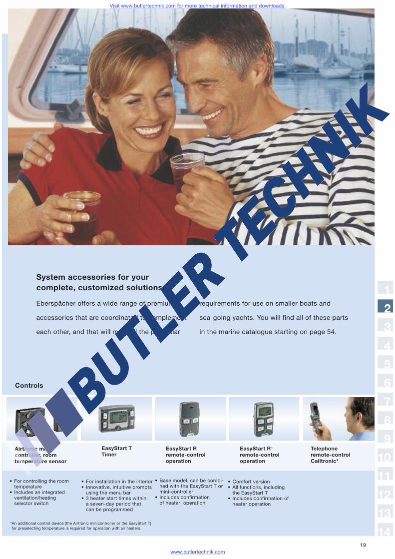
System accessories for yourcomplete, customized solutions:
Eberspächer offers a wide range of premium
accessories that are coordinated to complement
each other, and that will meet all the particular
requirements for use on smaller boats and
sea-going yachts. You will find all of these parts
in the marine catalogue starting on page 54.
*An additional control device (the Airtronic minicontroller or the EasyStart T)for preselecting temperature is required for operation with air heaters.
EasyStart TTimer
EasyStart Rremote-controloperation
Airtronic mini-controller, roomtemperature sensor
Telephoneremote-controlCalltronic*
EasyStart R+
remote-controloperation
• For controlling the roomtemperature
• Includes an integratedventilation/heatingselector switch
• For installation in the interior• Innovative, intuitive promptsusing the menu bar
• 3 heater start times withina seven-day period thatcan be programmed
• Base model, can be combi-ned with the EasyStart T ormini-controller
• Includes confirmationof heater operation
• Comfort version• All functions, includingthe EasyStart T
• Includes confirmation ofheater operation
Controls
1
2
3
4
5
6
7
8
9
10
11
12
13
14
Visit www.butlertechnik.com for more technical information and downloads.
www.butlertechnik.com
20
Hot air system and parts Component rating
General instructions on the heater air systemand the parts Component ratingParts for conducting heat can also be installed onthe heater. Each part has a parts Component rating,which reduces the heated air output. To give you theopportunity to check whether the installation you areplanning will not restrict hot air throughput improperly,we have defined an equipment Component rating forevery heater, and a part Component rating for all ofthe parts that carry hot air. Refer to the specificationsin the partsID tables:0 = No increase in temperature,− = No part Component rating.
The total of the part Component rating, of the partsconducting hot air that are connected to the unit can-not be greater than the heater Component rating,since otherwise the outlet temperature will be too highand will activate the overheating sensor. If the sum ofthe part Component rating is greater than the heater’sComponent rating, then selecting a larger diameter forthe parts hot air will reduce this total.
General rule of thumb:
Twice the cross-section, or two identical parts inparallel = 1/4 of the Component rating.
Example:
Hose ø 50,A = 19.6 cm2, Component rating 1.0
Hose ø 75,A = 44.2 cm2, Component rating 0.25
The Component rating for smooth, welded pipes ishalfthat for flexible pipes of the same diameter(i.e. twice the pipe length).
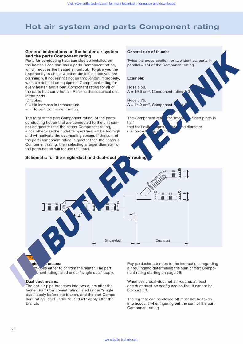
Single-duct
Single duct means:A duct goes either to or from the heater. The partComponent rating listed under “single duct” apply.
Dual duct means:The hot-air pipe branches into two ducts after theheater. Part Component rating listed under “singleduct” apply before the branch, and the part Compo-nent rating listed under “dual duct” apply after thebranch.
Pay particular attention to the instructions regardingair routingand determining the sum of part Compo-nent rating starting on page 26.
When using dual-duct hot air routing, at leastone duct must be configured so that it cannot beblocked off.
The leg that can be closed off must not be takeninto account when figuring out the sum of the partComponent rating.
Please note!
Schematic for the single-duct and dual-duct hot air routing
Visit www.butlertechnik.com for more technical information and downloads.
www.butlertechnik.com
21
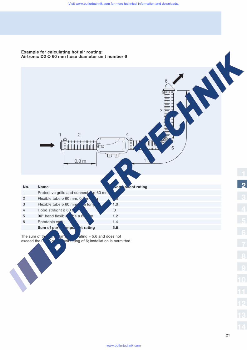
Example for calculating hot air routing:Airtronic D2 Ø 60 mm hose diameter unit number 6
No. Name Part Component rating
1 Protective grille and connector ø 60 mm 1.7
2 Flexible tube ø 60 mm, 0.3 m long 0.3
3 Flexible tube ø 60 mm, 1 m long 1,0
4 Hood straight ø 60 mm 0
5 90° bend flexible tube ø 60 mm 1.2
6 Rotatable vent 1.4
Sum of part Component rating 5.6
The sum of the part Component rating = 5.6 and does notexceed the unit Component rating of 6; installation is permitted
1
2
3
4
5
6
7
8
9
10
11
12
13
14
Visit www.butlertechnik.com for more technical information and downloads.
www.butlertechnik.com
22
Exhaust and com-bustion air
Fasteners
Electrical parts
Partscarrying fuel
Installation location
If installing the heater in the engine compartment,metal fuel lines or fire-retardant hoses (in accordancewith DIN EN ISO 7840) must be used.
When the boat heels, bilge water must not wash overthe heater unit.
Make sure that the connection to the boat’s hull is notrigid when installing the heater unit. This will preventtransmitting sound and vibration from the heater.
Insulating or flammable objects should be stored atleast one meter away from the heater unit.
Be sure to follow all specifications, especially the sa-fety instructions listed in the Technical Description inthis chapter. The Technical Description is includedwith every heater unit.
Please note!
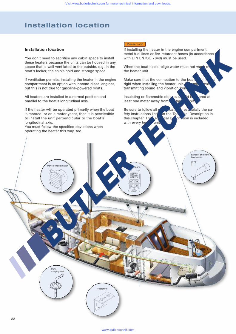
Installation location
You don’t need to sacrifice any cabin space to installthese heaters because the units can be housed in anyspace that is well ventilated to the outside, e.g. in theboat’s locker, the ship’s hold and storage space.
If ventilation permits, installing the heater in the enginecompartment is an option with inboard diesel engines,but this is not true for gasoline-powered boats.
All heaters are installed in a normal position andparallel to the boat’s longitudinal axis.
If the heater will be operated primarily when the boatis moored, or on a motor yacht, then it is permissibleto install the unit perpendicular to the boat’slongitudinal axis.You must follow the specified deviations whenoperating the heater this way, too.
Parts conducting air
Visit www.butlertechnik.com for more technical information and downloads.
www.butlertechnik.com
23
Combustion air system
Combustion air must be drawn from a well-ventilatedarea at atmospheric pressure (not from the cabin).
There are two options for routing the combustionair system:
If analogous regulations exist in Sweden, then thecombustion air must be drawn in from outside theboat.To draw air in this way, an additional plastic is availa-ble for the opening in the boat’s hull.The opening for drawing in combustion air must belocated where it will not pull in any exhaust (fromthe heater unit or the engine).The line from the heater unit must be laid so it runsdownward. A condensate opening must be connectedat the lowest point for routing that does not slope.The combustion air hose must be routed at theend as a gooseneck. This lets any water that getsin drain out again.If no pertinent regulations exist to the contrary, thecombustion air can also be drawn from a stowagearea or from the engine compartment.
• When drawing combustion air from the engine com-partment, make very sure that it is adequately venti-lated and that the atmospheric pressure does notchange while the engine is running (e.g. dueto the cooling fan running).
Exhaust gas routing
In sailboats, the exhaust gas routing is taken to thetransom, and in motorboats to the side hull. Theexhaust gas routing must be insulated so that thesurface temperature does not exceed 80° C.Routing the exhaust gas through a cabin can onlybe done through a pipe made of stainless steel.Outside the cabin, a flexible exhaust pipe ofdouble-layer stainless steel can be used.Preferably, the exhaust line should always be installedso that it always runs downward, so that condensateor surge water can drain away immediately.If a particular installation situation is awkward, aT-fitting that includes a condensate line can beused at the lowest point in the exhaust gas routing.The flexible exhaust pipe has to be routed at theend as a gooseneck so that any water gettingin can run out again.We highly recommend using a muffler to deaden thesound of the exhaust.
• When laying the exhaust lines, make absolutely surethat all of the connections are tightly sealed. Thegaskets in the boat hull’s opening must fit exactly.Make sure that no hot metal parts touch the boat’shull when the exhaust gas routing is being laid andthe opening in the boat hull is being installed. Mini-mum distance from the hull of 20 mm must absolu-tely be maintained with an insulatedexhaust line.
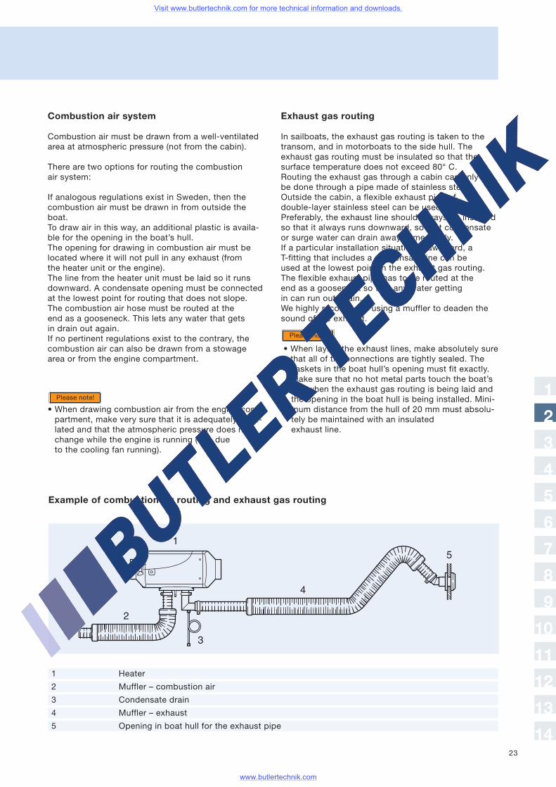
Example of combustion air routing and exhaust gas routing
Please note!
Please note!
1
2
3
4
5
6
7
8
9
10
11
12
13
14
1 Heater
2 Muffler – combustion air
3 Condensate drain
4 Muffler – exhaust
5 Opening in boat hull for the exhaust pipe
Visit www.butlertechnik.com for more technical information and downloads.
www.butlertechnik.com
24
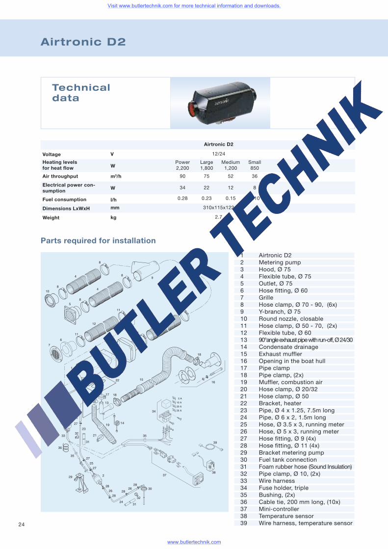
Airtronic D2
Parts required for installation
Technicaldata
Voltage
Air throughput
Heating levelsfor heat flow
Fuel consumption
Electrical power con-sumption
Weight
Dimensions LxWxH
Airtronic D2
12/24
Power Large Medium Small2,200 1,800 1,200 850
90 75 52 36
34 22 12 8
0.28 0.23 0.15 0.10
310x115x122
2.7
V
W
m3/h
W
l/h
mm
kg
1 Airtronic D22 Metering pump3 Hood, Ø 754 Flexible tube, Ø 755 Outlet, Ø 756 Hose fitting, Ø 607 Grille8 Hose clamp, Ø 70 - 90, (6x)9 Y-branch, Ø 7510 Round nozzle, closable11 Hose clamp, Ø 50 - 70, (2x)12 Flexible tube, Ø 6013 90°angleexhaustpipewithrun-off,Ø24/3014 Condensate drainage15 Exhaust muffler16 Opening in the boat hull17 Pipe clamp18 Pipe clamp, (2x)19 Muffler, combustion air20 Hose clamp, Ø 20/3221 Hose clamp, Ø 5022 Bracket, heater23 Pipe, Ø 4 x 1.25, 7.5m long24 Pipe, Ø 6 x 2, 1.5m long25 Hose, Ø 3.5 x 3, running meter26 Hose, Ø 5 x 3, running meter27 Hose fitting, Ø 9 (4x)28 Hose fitting, Ø 11 (4x)29 Bracket metering pump30 Fuel tank connection31 Foam rubber hose (Sound Insulation)32 Pipe clamp, Ø 10, (2x)33 Wire harness34 Fuse holder, triple35 Bushing, (2x)36 Cable tie, 200 mm long, (10x)37 Mini-controller38 Temperature sensor39 Wire harness, temperature sensor
Visit www.butlertechnik.com for more technical information and downloads.
www.butlertechnik.com
25
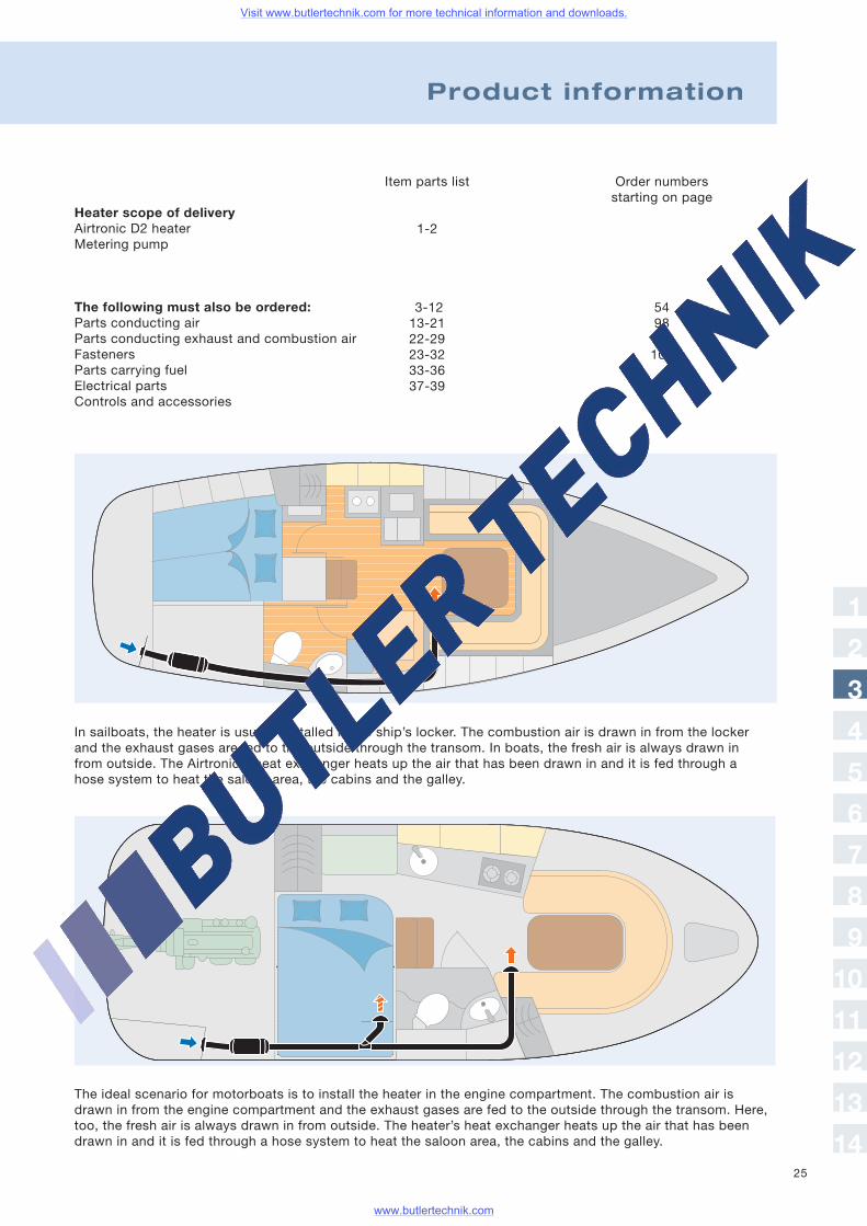
The ideal scenario for motorboats is to install the heater in the engine compartment. The combustion air isdrawn in from the engine compartment and the exhaust gases are fed to the outside through the transom. Here,too, the fresh air is always drawn in from outside. The heater’s heat exchanger heats up the air that has beendrawn in and it is fed through a hose system to heat the saloon area, the cabins and the galley.
In sailboats, the heater is usually installed in the ship’s locker. The combustion air is drawn in from the lockerand the exhaust gases are fed to the outside through the transom. In boats, the fresh air is always drawn infrom outside. The Airtronic's heat exchanger heats up the air that has been drawn in and it is fed through ahose system to heat the saloon area, the cabins and the galley.
Heater scope of deliveryAirtronic D2 heaterMetering pump
The following must also be ordered:Parts conducting airParts conducting exhaust and combustion airFastenersParts carrying fuelElectrical partsControls and accessories
Product information
Item parts list
1-2
3-1213-2122-2923-3233-3637-39
Order numbersstarting on page
5498114106
1
2
3
4
5
6
7
8
9
10
11
12
13
14
Visit www.butlertechnik.com for more technical information and downloads.
www.butlertechnik.com
26
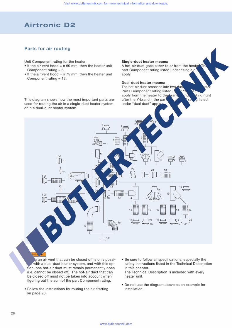
Single-duct heater means:A hot-air duct goes either to or from the heater. Thepart Component rating listed under “single duct”apply.
Dual-duct heater means:The hot-air duct branches into two ducts after the heater.Parts Component rating listed under “single duct”apply from the heater to the branch, and starting rightafter the Y-branch, the part Component rating listedunder “dual duct” apply.
Parts for air routing
Airtronic D2
Unit Component rating for the heater• If the air vent hood = ø 60 mm, then the heater unitComponent rating = 6.
• If the air vent hood = ø 75 mm, then the heater unitComponent rating = 12.
This diagram shows how the most important parts areused for routing the air in a single-duct heater systemor in a dual-duct heater system.
• Using an air vent that can be closed off is only possi-ble with a dual-duct heater system, and with this op-tion, one hot-air duct must remain permanently open(i.e. cannot be closed off). The hot-air duct that canbe closed off must not be taken into account whenfiguring out the sum of the part Component rating.
• Follow the instructions for routing the air startingon page 20.
Please note!
• Be sure to follow all specifications, especially thesafety instructions listed in the Technical Descriptionin this chapter.The Technical Description is included with everyheater unit.
• Do not use the diagram above as an example forinstallation.
Visit www.butlertechnik.com for more technical information and downloads.
www.butlertechnik.com
27
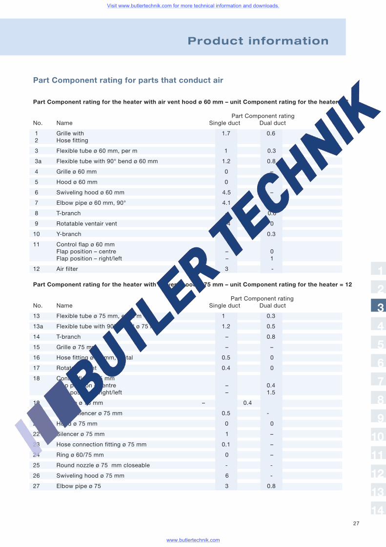
Part Component rating for parts that conduct air
Product information
Part Component rating
Part Component rating for the heater with air vent hood ø 60 mm – unit Component rating for the heater = 6
No. Name Single duct Dual duct
1 Grille with 1.7 0.62 Hose fitting
3 Flexible tube ø 60 mm, per m 1 0.3
3a Flexible tube with 90° bend ø 60 mm 1.2 0.8
4 Grille ø 60 mm 0 –
5 Hood ø 60 mm 0 –
6 Swiveling hood ø 60 mm 4.5 –
7 Elbow pipe ø 60 mm, 90° 4.1 0
8 T-branch – 0.6
9 Rotatable ventair vent 1.4 0
10 Y-branch – 0.3
11 Control flap ø 60 mmFlap position – centre – 0Flap position – right/left – 1
12 Air filter 3 -
Part Component rating for the heater with air vent hood ø 75 mm – unit Component rating for the heater = 12
Part Component ratingNo. Name Single duct Dual duct
13 Flexible tube ø 75 mm, each m 1 0.3
13a Flexible tube with 90°- bend ø 75 mm 1.2 0.5
14 T-branch – 0.8
15 Grille ø 75 mm – –
16 Hose fitting ø 75 mm, metal 0.5 0
17 Rotatable vent 0.4 0
18 Control flap ø 75 mmFlap position – centre – 0.4Flap position – right/left – 1.5
19 Y-piece ø 75 mm – 0.4
20 Intake silencer ø 75 mm 0.5 -
21 Hood ø 75 mm 0 0
22 Silencer ø 75 mm 1 –
23 Hose connection fitting ø 75 mm 0.1 –
24 Ring ø 60/75 mm 0 –
25 Round nozzle ø 75 mm closeable - -
26 Swiveling hood ø 75 mm 6 -
27 Elbow pipe ø 75 3 0.8
1
2
3
4
5
6
7
8
9
10
11
12
13
14
Visit www.butlertechnik.com for more technical information and downloads.
www.butlertechnik.com

28
Parts for routing combustion air
Parts for routing the exhaust
No. Name
1 Pipe clamp2 90°-angle exhaust pipe ø 24/30 mm3 90°-angle exhaust pipe ø 24/30 mm with drain4 Flexible spiral tube ø 30 mm5 Condensate drainage
No. Name
6 Exhaust insulation7 Connector ø 30 mm with drainage8 Exhaust muffler flexible9 Opening in the boat hull
No. Name
1 Hose clamp2 Silencer for front left3 Hose connecting pipe ø 25 mm
No. Name
4 Flexible tube ø 25 mm5 Boat hull opening for front left
Airtronic D2
Visit www.butlertechnik.com for more technical information and downloads.
www.butlertechnik.com
29
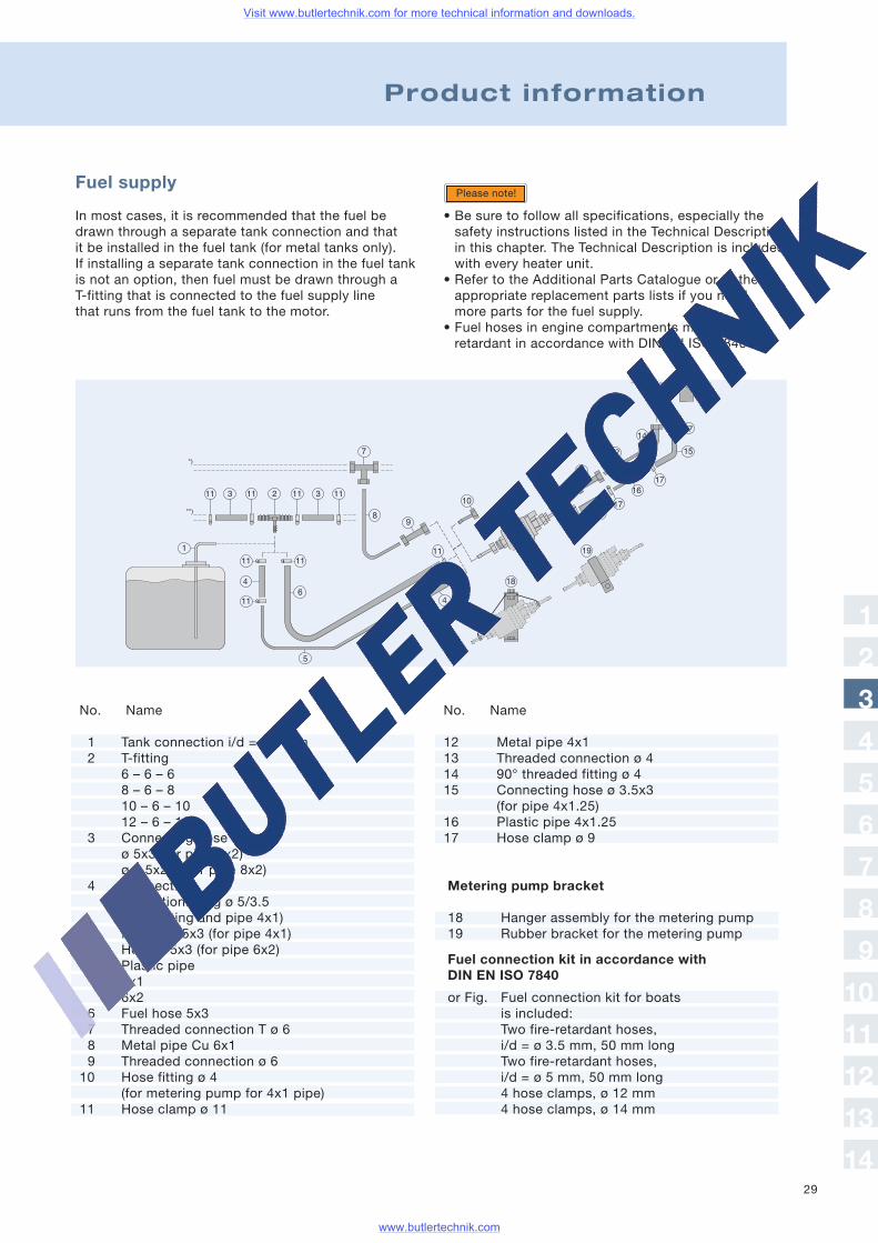
Fuel supply
In most cases, it is recommended that the fuel bedrawn through a separate tank connection and thatit be installed in the fuel tank (for metal tanks only).If installing a separate tank connection in the fuel tankis not an option, then fuel must be drawn through aT-fitting that is connected to the fuel supply linethat runs from the fuel tank to the motor.
• Be sure to follow all specifications, especially thesafety instructions listed in the Technical Descriptionin this chapter. The Technical Description is includedwith every heater unit.
• Refer to the Additional Parts Catalogue or to theappropriate replacement parts lists if you needmore parts for the fuel supply.
• Fuel hoses in engine compartments must be fire-retardant in accordance with DIN EN ISO 7840.
Please note!
No. Name
12 Metal pipe 4x113 Threaded connection ø 414 90° threaded fitting ø 415 Connecting hose ø 3.5x3
(for pipe 4x1.25)16 Plastic pipe 4x1.2517 Hose clamp ø 9
Metering pump bracket
18 Hanger assembly for the metering pump19 Rubber bracket for the metering pump
Fuel connection kit in accordance withDIN EN ISO 7840
or Fig. Fuel connection kit for boatsis included:Two fire-retardant hoses,i/d = ø 3.5 mm, 50 mm longTwo fire-retardant hoses,i/d = ø 5 mm, 50 mm long4 hose clamps, ø 12 mm4 hose clamps, ø 14 mm
Product information
No. Name
1 Tank connection i/d = ø 2 mm2 T-fitting
6 – 6 – 68 – 6 – 810 – 6 – 1012 – 6 – 12
3 Connecting hoseø 5x3 (for pipe 6x2)ø 7.5x2.5 (for pipe 8x2)
4 ConnectionReductionfitting ø 5/3.5(for T-fitting and pipe 4x1)Hose ø 3.5x3 (for pipe 4x1)Hose ø 5x3 (for pipe 6x2)
5 Plastic pipe4x16x2
6 Fuel hose 5x37 Threaded connection T ø 68 Metal pipe Cu 6x19 Threaded connection ø 610 Hose fitting ø 4
(for metering pump for 4x1 pipe)11 Hose clamp ø 11
1
2
3
4
5
6
7
8
9
10
11
12
13
14
Visit www.butlertechnik.com for more technical information and downloads.
www.butlertechnik.com
30
Airtronic D3
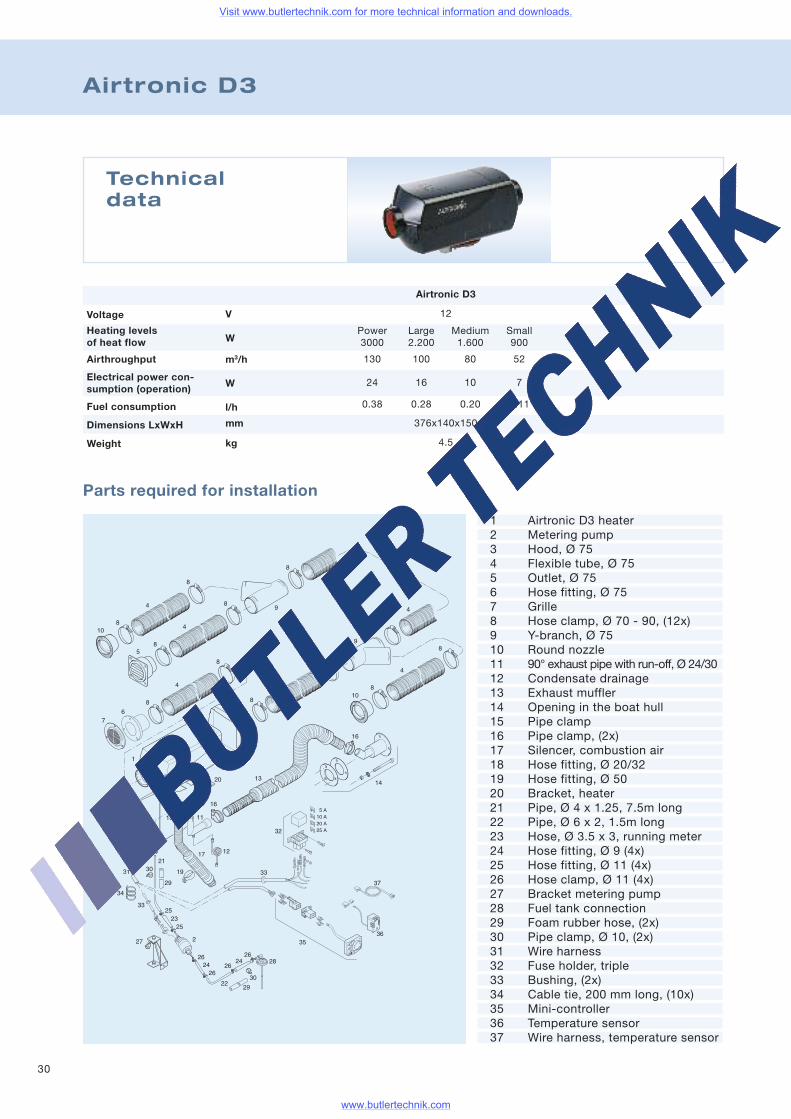
Technicaldata
Voltage
Airthroughput
Heating levelsof heat flow
Fuel consumption
Electrical power con-sumption (operation)
Weight
Dimensions LxWxH
Airtronic D3
12
Power Large Medium Small3000 2.200 1.600 900
130 100 80 52
24 16 10 7
0.38 0.28 0.20 0.11
376x140x150
4.5
V
W
m3/h
W
l/h
mm
kg
Parts required for installation
1 Airtronic D3 heater2 Metering pump3 Hood, Ø 754 Flexible tube, Ø 755 Outlet, Ø 756 Hose fitting, Ø 757 Grille8 Hose clamp, Ø 70 - 90, (12x)9 Y-branch, Ø 7510 Round nozzle11 90° exhaust pipe with run-off, Ø 24/3012 Condensate drainage13 Exhaust muffler14 Opening in the boat hull15 Pipe clamp16 Pipe clamp, (2x)17 Silencer, combustion air18 Hose fitting, Ø 20/3219 Hose fitting, Ø 5020 Bracket, heater21 Pipe, Ø 4 x 1.25, 7.5m long22 Pipe, Ø 6 x 2, 1.5m long23 Hose, Ø 3.5 x 3, running meter24 Hose fitting, Ø 9 (4x)25 Hose fitting, Ø 11 (4x)26 Hose clamp, Ø 11 (4x)27 Bracket metering pump28 Fuel tank connection29 Foam rubber hose, (2x)30 Pipe clamp, Ø 10, (2x)31 Wire harness32 Fuse holder, triple33 Bushing, (2x)34 Cable tie, 200 mm long, (10x)35 Mini-controller36 Temperature sensor37 Wire harness, temperature sensor
Visit www.butlertechnik.com for more technical information and downloads.
www.butlertechnik.com
31
Product information
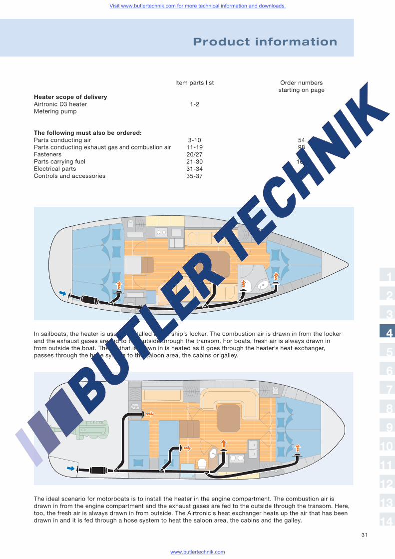
The ideal scenario for motorboats is to install the heater in the engine compartment. The combustion air isdrawn in from the engine compartment and the exhaust gases are fed to the outside through the transom. Here,too, the fresh air is always drawn in from outside. The Airtronic's heat exchanger heats up the air that has beendrawn in and it is fed through a hose system to heat the saloon area, the cabins and the galley.
In sailboats, the heater is usually installed in the ship’s locker. The combustion air is drawn in from the lockerand the exhaust gases are fed to the outside through the transom. For boats, fresh air is always drawn infrom outside the boat. The air that is drawn in is heated as it goes through the heater’s heat exchanger,passes through the hose system to the saloon area, the cabins or galley.
Heater scope of deliveryAirtronic D3 heaterMetering pump
The following must also be ordered:Parts conducting airParts conducting exhaust gas and combustion airFastenersParts carrying fuelElectrical partsControls and accessories
Item parts list
1-2
3-1011-1920/2721-3031-3435-37
Order numbersstarting on page
5498114106
1
2
3
4
5
6
7
8
9
10
11
12
13
14
Visit www.butlertechnik.com for more technical information and downloads.
www.butlertechnik.com
32
Airtronic D3
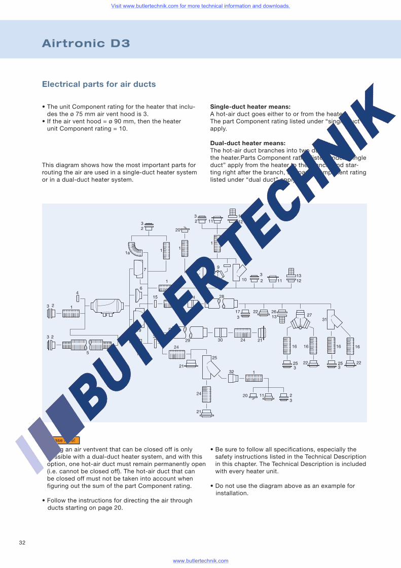
Single-duct heater means:A hot-air duct goes either to or from the heater.The part Component rating listed under “single duct”apply.
Dual-duct heater means:The hot-air duct branches into two ducts afterthe heater.Parts Component rating listed under “singleduct” apply from the heater to the branch, and star-ting right after the branch, the parts Component ratinglisted under “dual duct” apply.
• Using an air ventvent that can be closed off is onlypossible with a dual-duct heater system, and with thisoption, one hot-air duct must remain permanently open(i.e. cannot be closed off). The hot-air duct that canbe closed off must not be taken into account whenfiguring out the sum of the part Component rating.
• Follow the instructions for directing the air throughducts starting on page 20.
Please note!
Electrical parts for air ducts
• The unit Component rating for the heater that inclu-des the ø 75 mm air vent hood is 3.
• If the air vent hood = ø 90 mm, then the heaterunit Component rating = 10.
This diagram shows how the most important parts forrouting the air are used in a single-duct heater systemor in a dual-duct heater system.
• Be sure to follow all specifications, especially thesafety instructions listed in the Technical Descriptionin this chapter. The Technical Description is includedwith every heater unit.
• Do not use the diagram above as an example forinstallation.
Visit www.butlertechnik.com for more technical information and downloads.
www.butlertechnik.com
33
Product information
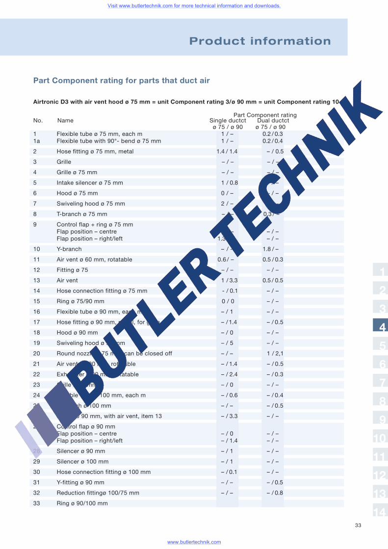
Part Component rating for parts that duct air
Airtronic D3 with air vent hood ø 75 mm = unit Component rating 3/ø 90 mm = unit Component rating 10
Part Component ratingNo. Name Single ductct Dual ductct
ø 75 / ø 90 ø 75 / ø 901 Flexible tube ø 75 mm, each m 1 / – 0.2 / 0.31a Flexible tube with 90°- bend ø 75 mm 1 / – 0.2 / 0.4
2 Hose fitting ø 75 mm, metal 1.4 / 1.4 – / 0.5
3 Grille – / – – / –
4 Grille ø 75 mm – / – – / –
5 Intake silencer ø 75 mm 1 / 0.8 – / –
6 Hood ø 75 mm 0 / – – / –
7 Swiveling hood ø 75 mm 2 / – – / –
8 T-branch ø 75 mm – / – 0,3 / –
9 Control flap + ring ø 75 mmFlap position – centre 0 / – – / –Flap position – right/left 1.3 / – – / –
10 Y-branch – / – 1.8 / –
11 Air vent ø 60 mm, rotatable 0.6 / – 0.5 / 0.3
12 Fitting ø 75 – / – – / –
13 Air vent 1 / 3.3 0.5 / 0.5
14 Hose connection fitting ø 75 mm - / 0.1 – / –
15 Ring ø 75/90 mm 0 / 0 – / –
16 Flexible tube ø 90 mm, each m – / 1 – / –
17 Hose fitting ø 90 mm, metal, for grille – /1.4 – / 0.5
18 Hood ø 90 mm – / 0 – / –
19 Swiveling hood ø 90 mm – / 5 – / –
20 Round nozzle ø 75 mm, can be closed off – / – 1 / 2,1
21 Air vent ø 100 mm, rotatable – / 1.4 – / 0.5
22 Exhauster ø 90 mm, rotatable – / 2.4 – / 0.3
23 Grille ø 90 mm – / 0 – / –
24 Flexible tube ø 100 mm, each m – / 0.6 – / 0.4
25 Y-branch ø 100 mm – / – – / 0.5
26 Fitting ø 90 mm, with air vent, item 13 – / 3.3 – / –
27 Control flap ø 90 mmFlap position – centre – / 0 – / –Flap position – right/left – / 1.4 – / –
28 Silencer ø 90 mm – / 1 – / –
29 Silencer ø 100 mm – / 1 – / –
30 Hose connection fitting ø 100 mm – / 0.1 – / –
31 Y-fitting ø 90 mm – / – – / 0.5
32 Reduction fittingø 100/75 mm – / – – / 0.8
33 Ring ø 90/100 mm
1
2
3
4
5
6
7
8
9
10
11
12
13
14
Visit www.butlertechnik.com for more technical information and downloads.
www.butlertechnik.com

34
Airtronic D3
Parts for ducting combustion air
Parts for routing the exhaust
No. Name
1 Pipe clamp2 90°-angle exhaust pipe ø 24/30 mm3 90°-angle exhaust pipe ø 24/30 mm with drain4 Flexible spiral tube ø 30 mm5 Condensate drainage
No. Name
6 Exhaust insulation7 Connector ø 30 mm with drainage8 Exhaust muffler flexible9 Opening in the boat hull
No. Name
1 Hose clamp2 Silencer for front left3 Hose connecting pipe ø 25 mm
No. Name
4 Flexible tube ø 25 mm5 Boat hull opening for front left
Visit www.butlertechnik.com for more technical information and downloads.
www.butlertechnik.com
35
Product information
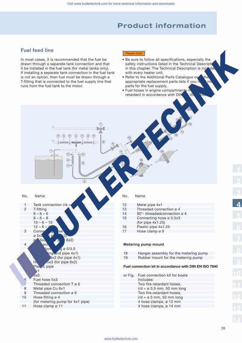
Fuel feed line
In most cases, it is recommended that the fuel bedrawn through a separate tank connection and thatit be installed in the fuel tank (for metal tanks only).If installing a separate tank connection in the fuel tankis not an option, then fuel must be drawn through aT-fitting that is connected to the fuel supply line thatruns from the fuel tank to the motor.
• Be sure to follow all specifications, especially thesafety instructions listed in the Technical Descriptionin this chapter. The Technical Description is includedwith every heater unit.
• Refer to the Additional Parts Catalogue or to theappropriate replacement parts lists if you need moreparts for the fuel supply.
• Fuel hoses in engine compartments must be fireretardant in accordance with DIN EN ISO 7840.
Please note!
No. Name
12 Metal pipe 4x113 Threaded connection ø 414 90°- threadedconnection ø 415 Connecting hose ø 3.5x3
(for pipe 4x1.25)16 Plastic pipe 4x1.2517 Hose clamp ø 9
Metering pump mount
18 Hanger assembly for the metering pump19 Rubber mount for the metering pump
Fuel connection kit in accordance with DIN EN ISO 7840
or Fig. Fuel connection kit for boatsincludes:Two fire-retardant hoses,i/d = ø 3.5 mm, 50 mm longTwo fire-retardant hoses,i/d = ø 5 mm, 50 mm long4 hose clamps, ø 12 mm4 hose clamps, ø 14 mm
No. Name
1 Tank connection i/d = ø 2 mm2 T-fitting
6 – 6 – 68 – 6 – 810 – 6 – 1012 – 6 – 12
3 Connecting hoseø 5x3 (for pipe 6x2)ø 7.5x2.5 (for pipe 8x2)
4 ConnectionReduction fitting ø 5/3.5(for T fitting and pipe 4x1)Hose ø 3.5x3 (for pipe 4x1)Hose ø 5x3 (for pipe 6x2)
5 Plastic pipe4x16x2
6 Fuel hose 5x37 Threaded connection T ø 68 Metal pipe Cu 6x19 Threaded connection ø 610 Hose fitting ø 4
(for metering pump for 4x1 pipe)11 Hose clamp ø 11
1
2
3
4
5
6
7
8
9
10
11
12
13
14
Visit www.butlertechnik.com for more technical information and downloads.
www.butlertechnik.com
3636
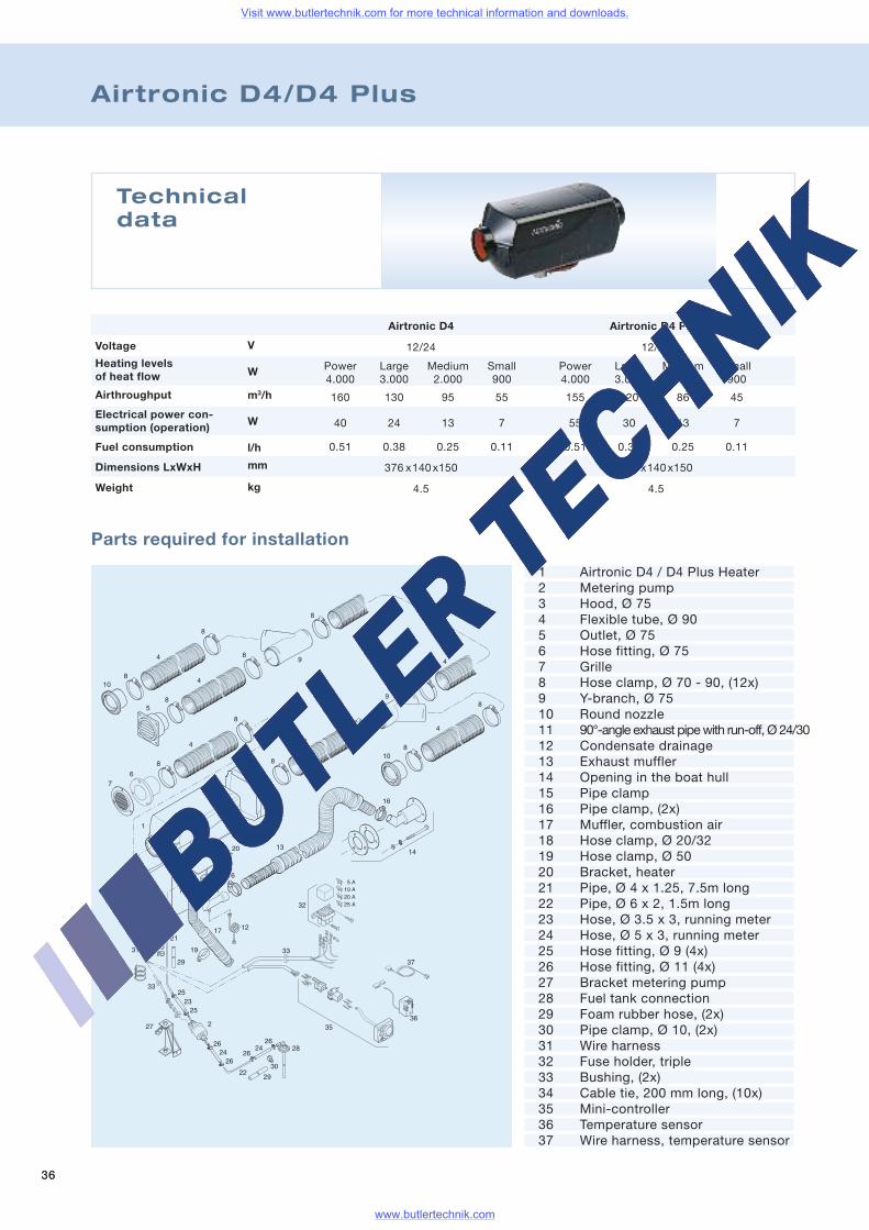
Airtronic D4/D4 Plus
Technicaldata
Voltage
Airthroughput
Heating levelsof heat flow
Fuel consumption
Electrical power con-sumption (operation)
Weight
Dimensions LxWxH
Airtronic D4
12/24
Power Large Medium Small4.000 3.000 2.000 900
160 130 95 55
40 24 13 7
0.51 0.38 0.25 0.11
376 x140x150
4.5
Airtronic D4 Plus
12/24
Power Large Medium Small4.000 3.000 2.000 900
155 120 86 45
55 30 13 7
0.51 0.38 0.25 0.11
376 x140x150
4.5
V
W
m3/h
W
l/h
mm
kg
Parts required for installation
1 Airtronic D4 / D4 Plus Heater2 Metering pump3 Hood, Ø 754 Flexible tube, Ø 905 Outlet, Ø 756 Hose fitting, Ø 757 Grille8 Hose clamp, Ø 70 - 90, (12x)9 Y-branch, Ø 7510 Round nozzle11 90°-angle exhaust pipewith run-off, Ø 24/3012 Condensate drainage13 Exhaust muffler14 Opening in the boat hull15 Pipe clamp16 Pipe clamp, (2x)17 Muffler, combustion air18 Hose clamp, Ø 20/3219 Hose clamp, Ø 5020 Bracket, heater21 Pipe, Ø 4 x 1.25, 7.5m long22 Pipe, Ø 6 x 2, 1.5m long23 Hose, Ø 3.5 x 3, running meter24 Hose, Ø 5 x 3, running meter25 Hose fitting, Ø 9 (4x)26 Hose fitting, Ø 11 (4x)27 Bracket metering pump28 Fuel tank connection29 Foam rubber hose, (2x)30 Pipe clamp, Ø 10, (2x)31 Wire harness32 Fuse holder, triple33 Bushing, (2x)34 Cable tie, 200 mm long, (10x)35 Mini-controller36 Temperature sensor37 Wire harness, temperature sensor
Visit www.butlertechnik.com for more technical information and downloads.
www.butlertechnik.com
3737
Product information
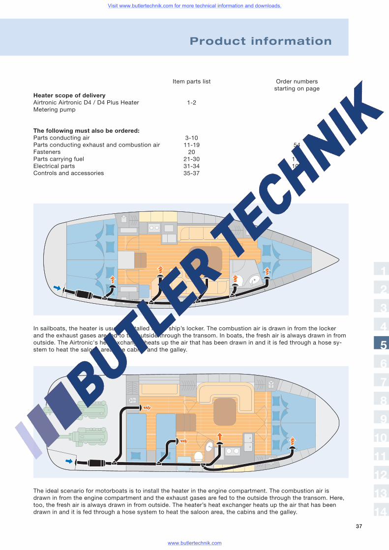
The ideal scenario for motorboats is to install the heater in the engine compartment. The combustion air isdrawn in from the engine compartment and the exhaust gases are fed to the outside through the transom. Here,too, the fresh air is always drawn in from outside. The heater’s heat exchanger heats up the air that has beendrawn in and it is fed through a hose system to heat the saloon area, the cabins and the galley.
In sailboats, the heater is usually installed in the ship’s locker. The combustion air is drawn in from the lockerand the exhaust gases are fed to the outside through the transom. In boats, the fresh air is always drawn in fromoutside. The Airtronic's heat exchanger heats up the air that has been drawn in and it is fed through a hose sy-stem to heat the saloon area, the cabins and the galley.
Heater scope of deliveryAirtronic Airtronic D4 / D4 Plus HeaterMetering pump
The following must also be ordered:Parts conducting airParts conducting exhaust and combustion airFastenersParts carrying fuelElectrical partsControls and accessories
Item parts list
1-2
3-1011-1920
21-3031-3435-37
Order numbersstarting on page
5498114106
1
2
3
4
5
6
7
8
9
10
11
12
13
14
Visit www.butlertechnik.com for more technical information and downloads.
www.butlertechnik.com
38
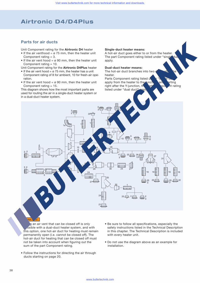
Airtronic D4/D4Plus
Single-duct heater means:A hot-air duct goes either to or from the heater.The part Component rating listed under “single duct”apply.
Dual-duct heater means:The hot-air duct branches into two ducts after theheater.Parts Component rating listed under “single duct”apply from the heater to the junction, and startingright after the Y-junction, the parts Component ratinglisted under “dual duct” apply.
Parts for air ducts
Unit Component rating for the Airtronic D4 heater• If the air venthood = ø 75 mm, then the heater unitComponent rating = 3.
• If the air vent hood = ø 90 mm, then the heater unitComponent rating = 10.
Unit Component rating for the Airtronic D4Plus heater• If the air vent hood = ø 75 mm, the heater has a unitComponent rating of 8 for ambient, 10 for fresh-air ope-ration.
• If the air vent hood = ø 90 mm, then the heater unitComponent rating = 15.
This diagram shows how the most important parts areused for routing the air in a single-duct heater system orin a dual-duct heater system.
• Using an air vent that can be closed off is onlypossible with a dual-duct heater system, and withthis option, one hot-air duct for heating must remainpermanently open (i.e. cannot be closed off). Thehot-air duct for heating that can be closed off mustnot be taken into account when figuring out thesum of the part Component rating.
• Follow the instructions for directing the air throughducts starting on page 20.
Please note!
• Be sure to follow all specifications, especially thesafety instructions listed in the Technical Descriptionin this chapter. The Technical Description is includedwith every heater unit.
• Do not use the diagram above as an example forinstallation.
Visit www.butlertechnik.com for more technical information and downloads.
www.butlertechnik.com
39
Product information
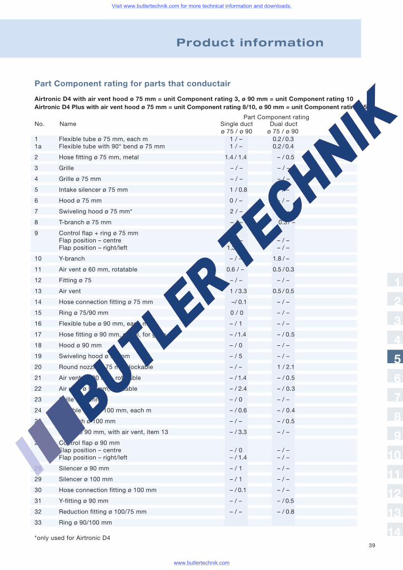
Part Component rating for parts that conductair
Airtronic D4 with air vent hood ø 75 mm = unit Component rating 3, ø 90 mm = unit Component rating 10Airtronic D4 Plus with air vent hood ø 75 mm = unit Component rating 8/10, ø 90 mm = unit Component rating 15
No. Name Single duct Dual ductø 75 / ø 90 ø 75 / ø 90
Part Component rating
1 Flexible tube ø 75 mm, each m 1 / – 0.2 / 0.31a Flexible tube with 90° bend ø 75 mm 1 / – 0.2 / 0.4
2 Hose fitting ø 75 mm, metal 1.4 / 1.4 – / 0.5
3 Grille – / – – / –
4 Grille ø 75 mm – / – – / –
5 Intake silencer ø 75 mm 1 / 0.8 – / –
6 Hood ø 75 mm 0 / – – / –
7 Swiveling hood ø 75 mm* 2 / – – / –
8 T-branch ø 75 mm – / – 0.3 / –
9 Control flap + ring ø 75 mmFlap position – centre 0 / – – / –Flap position – right/left 1.3 / – – / –
10 Y-branch – / – 1.8 / –
11 Air vent ø 60 mm, rotatable 0.6 / – 0.5 / 0.3
12 Fitting ø 75 – / – – / –
13 Air vent 1 / 3.3 0.5 / 0.5
14 Hose connection fitting ø 75 mm –/ 0.1 – / –
15 Ring ø 75/90 mm 0 / 0 – / –
16 Flexible tube ø 90 mm, each m – / 1 – / –
17 Hose fitting ø 90 mm, metal, for grille – /1.4 – / 0.5
18 Hood ø 90 mm – / 0 – / –
19 Swiveling hood ø 90 mm – / 5 – / –
20 Round nozzle ø 75 mm, lockable – / – 1 / 2.1
21 Air vent ø 100 mm, rotatable – / 1.4 – / 0.5
22 Air vent ø 90 mm, rotatable – / 2.4 – / 0.3
23 Grille ø 90 mm – / 0 – / –
24 Flexible tube ø 100 mm, each m – / 0.6 – / 0.4
25 Y-branch ø 100 mm – / – – / 0.5
26 Fitting ø 90 mm, with air vent, item 13 – / 3.3 – / –
27 Control flap ø 90 mmFlap position – centre – / 0 – / –Flap position – right/left – / 1.4 – / –
28 Silencer ø 90 mm – / 1 – / –
29 Silencer ø 100 mm – / 1 – / –
30 Hose connection fitting ø 100 mm – / 0.1 – / –
31 Y-fitting ø 90 mm – / – – / 0.5
32 Reduction fitting ø 100/75 mm – / – – / 0.8
33 Ring ø 90/100 mm
1
2
3
4
5
6
7
8
9
10
11
12
13
14*only used for Airtronic D4
Visit www.butlertechnik.com for more technical information and downloads.
www.butlertechnik.com
40
Airtronic D4/D4Plus
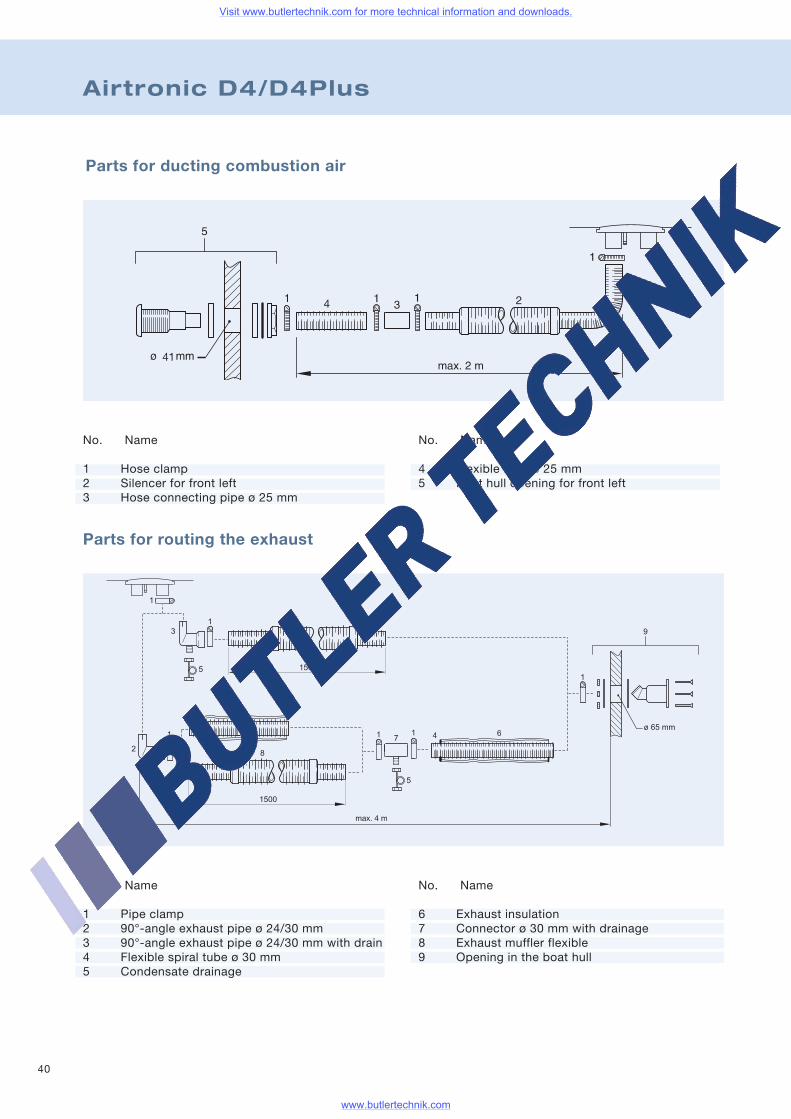
Parts for ducting combustion air
Parts for routing the exhaust
No. Name
1 Pipe clamp2 90°-angle exhaust pipe ø 24/30 mm3 90°-angle exhaust pipe ø 24/30 mm with drain4 Flexible spiral tube ø 30 mm5 Condensate drainage
No. Name
6 Exhaust insulation7 Connector ø 30 mm with drainage8 Exhaust muffler flexible9 Opening in the boat hull
No. Name
1 Hose clamp2 Silencer for front left3 Hose connecting pipe ø 25 mm
No. Name
4 Flexible tube ø 25 mm5 Boat hull opening for front left
Visit www.butlertechnik.com for more technical information and downloads.
www.butlertechnik.com
41
Product information
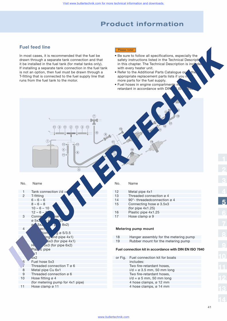
Fuel feed line
In most cases, it is recommended that the fuel bedrawn through a separate tank connection and thatit be installed in the fuel tank (for metal tanks only).If installing a separate tank connection in the fuel tankis not an option, then fuel must be drawn through aT-fitting that is connected to the fuel supply line thatruns from the fuel tank to the motor.
• Be sure to follow all specifications, especially thesafety instructions listed in the Technical Descriptionin this chapter. The Technical Description is includedwith every heater unit.
• Refer to the Additional Parts Catalogue or to theappropriate replacement parts lists if you needmore parts for the fuel supply.
• Fuel hoses in engine compartments must be fireretardant in accordance with DIN EN ISO 7840.
Please note!
No. Name
12 Metal pipe 4x113 Threaded connection ø 414 90°- threadedconnection ø 415 Connecting hose ø 3.5x3
(for pipe 4x1.25)16 Plastic pipe 4x1.2517 Hose clamp ø 9
Metering pump mount
18 Hanger assembly for the metering pump19 Rubber mount for the metering pump
Fuel connection kit in accordance with DIN EN ISO 7840
or Fig. Fuel connection kit for boatsincludes:Two fire-retardant hoses,i/d = ø 3.5 mm, 50 mm longTwo fire-retardant hoses,i/d = ø 5 mm, 50 mm long4 hose clamps, ø 12 mm4 hose clamps, ø 14 mm
No. Name
1 Tank connection i/d = ø 2 mm2 T-fitting
6 – 6 – 68 – 6 – 810 – 6 – 1012 – 6 – 12
3 Connecting hoseø 5x3 (for pipe 6x2)ø 7.5x2.5 (for pipe 8x2)
4 ConnectionReduction fitting ø 5/3.5(for T fitting and pipe 4x1)Hose ø 3.5x3 (for pipe 4x1)Hose ø 5x3 (for pipe 6x2)
5 Plastic pipe4x16x2
6 Fuel hose 5x37 Threaded connection T ø 68 Metal pipe Cu 6x19 Threaded connection ø 610 Hose fitting ø 4
(for metering pump for 4x1 pipe)11 Hose clamp ø 11
1
2
3
4
5
6
7
8
9
10
11
12
13
14
Visit www.butlertechnik.com for more technical information and downloads.
www.butlertechnik.com
42
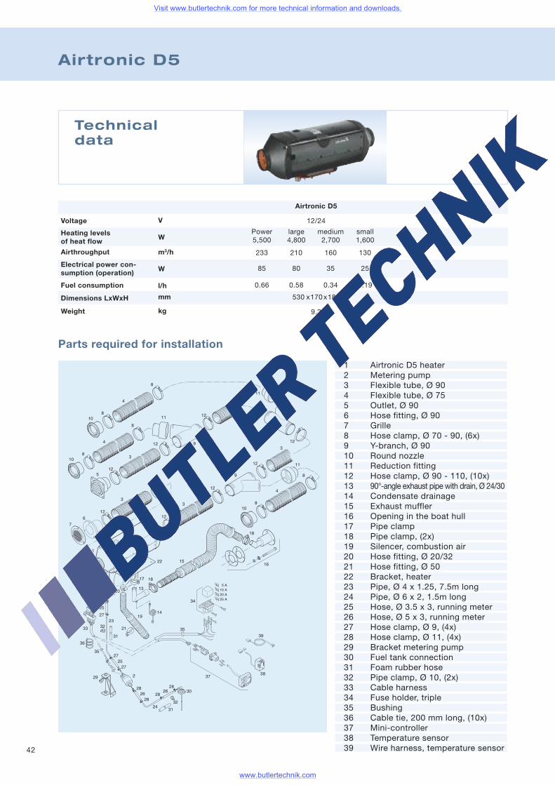
Airtronic D5
Technicaldata
Voltage
Airthroughput
Heating levelsof heat flow
Fuel consumption
Electrical power con-sumption (operation)
Weight
Dimensions LxWxH
Airtronic D5
12/24
Power large medium small5,500 4,800 2,700 1,600
233 210 160 130
85 80 35 25
0.66 0.58 0.34 0.19
530 x170x185
9.3
V
W
m3/h
W
l/h
mm
kg
Parts required for installation
1 Airtronic D5 heater2 Metering pump3 Flexible tube, Ø 904 Flexible tube, Ø 755 Outlet, Ø 906 Hose fitting, Ø 907 Grille8 Hose clamp, Ø 70 - 90, (6x)9 Y-branch, Ø 9010 Round nozzle11 Reduction fitting12 Hose clamp, Ø 90 - 110, (10x)13 90°-angle exhaust pipe with drain, Ø 24/3014 Condensate drainage15 Exhaust muffler16 Opening in the boat hull17 Pipe clamp18 Pipe clamp, (2x)19 Silencer, combustion air20 Hose fitting, Ø 20/3221 Hose fitting, Ø 5022 Bracket, heater23 Pipe, Ø 4 x 1.25, 7.5m long24 Pipe, Ø 6 x 2, 1.5m long25 Hose, Ø 3.5 x 3, running meter26 Hose, Ø 5 x 3, running meter27 Hose clamp, Ø 9, (4x)28 Hose clamp, Ø 11, (4x)29 Bracket metering pump30 Fuel tank connection31 Foam rubber hose32 Pipe clamp, Ø 10, (2x)33 Cable harness34 Fuse holder, triple35 Bushing36 Cable tie, 200 mm long, (10x)37 Mini-controller38 Temperature sensor39 Wire harness, temperature sensor
Visit www.butlertechnik.com for more technical information and downloads.
www.butlertechnik.com
43
Product information
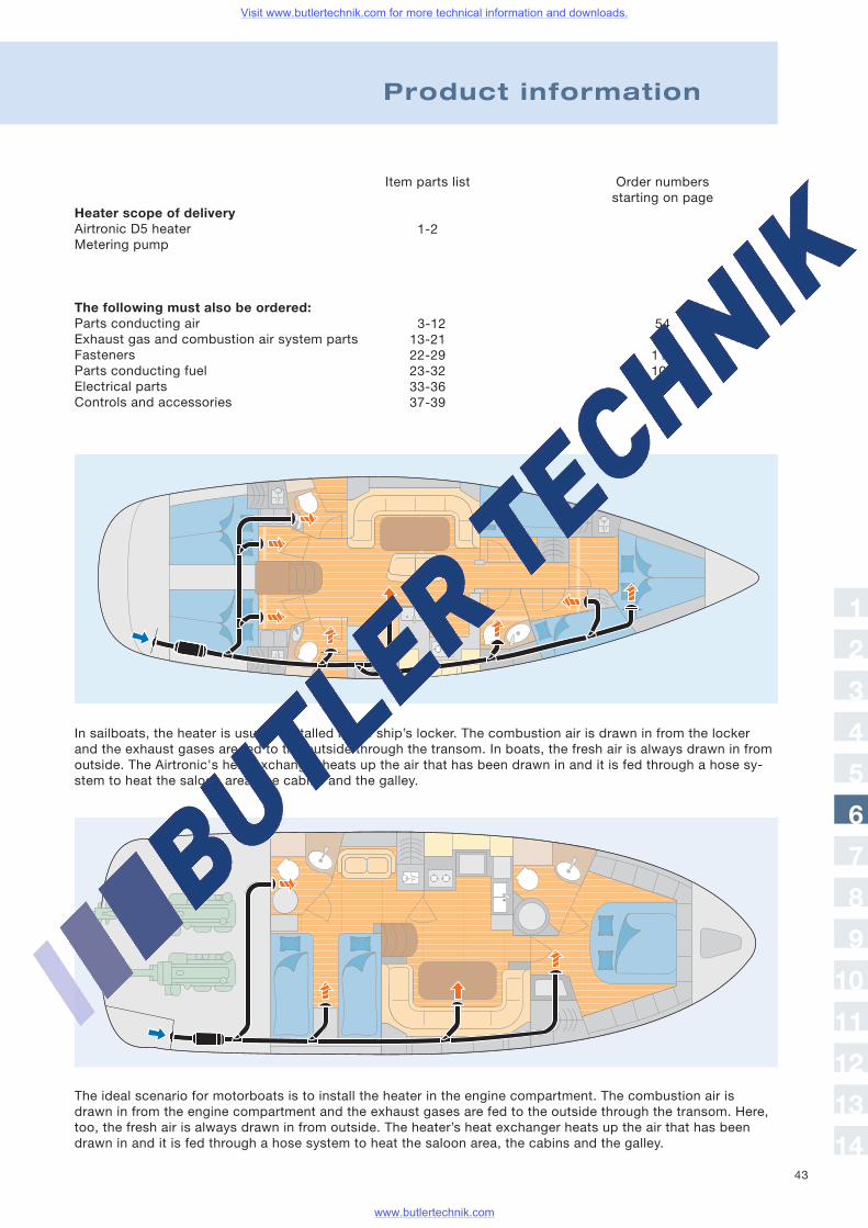
The ideal scenario for motorboats is to install the heater in the engine compartment. The combustion air isdrawn in from the engine compartment and the exhaust gases are fed to the outside through the transom. Here,too, the fresh air is always drawn in from outside. The heater’s heat exchanger heats up the air that has beendrawn in and it is fed through a hose system to heat the saloon area, the cabins and the galley.
In sailboats, the heater is usually installed in the ship’s locker. The combustion air is drawn in from the lockerand the exhaust gases are fed to the outside through the transom. In boats, the fresh air is always drawn in fromoutside. The Airtronic's heat exchanger heats up the air that has been drawn in and it is fed through a hose sy-stem to heat the saloon area, the cabins and the galley.
Heater scope of deliveryAirtronic D5 heaterMetering pump
The following must also be ordered:Parts conducting airExhaust gas and combustion air system partsFastenersParts conducting fuelElectrical partsControls and accessories
Item parts list
1-2
3-1213-2122-2923-3233-3637-39
Order numbersstarting on page
5498114106
1
2
3
4
5
6
7
8
9
10
11
12
13
14
Visit www.butlertechnik.com for more technical information and downloads.
www.butlertechnik.com
44
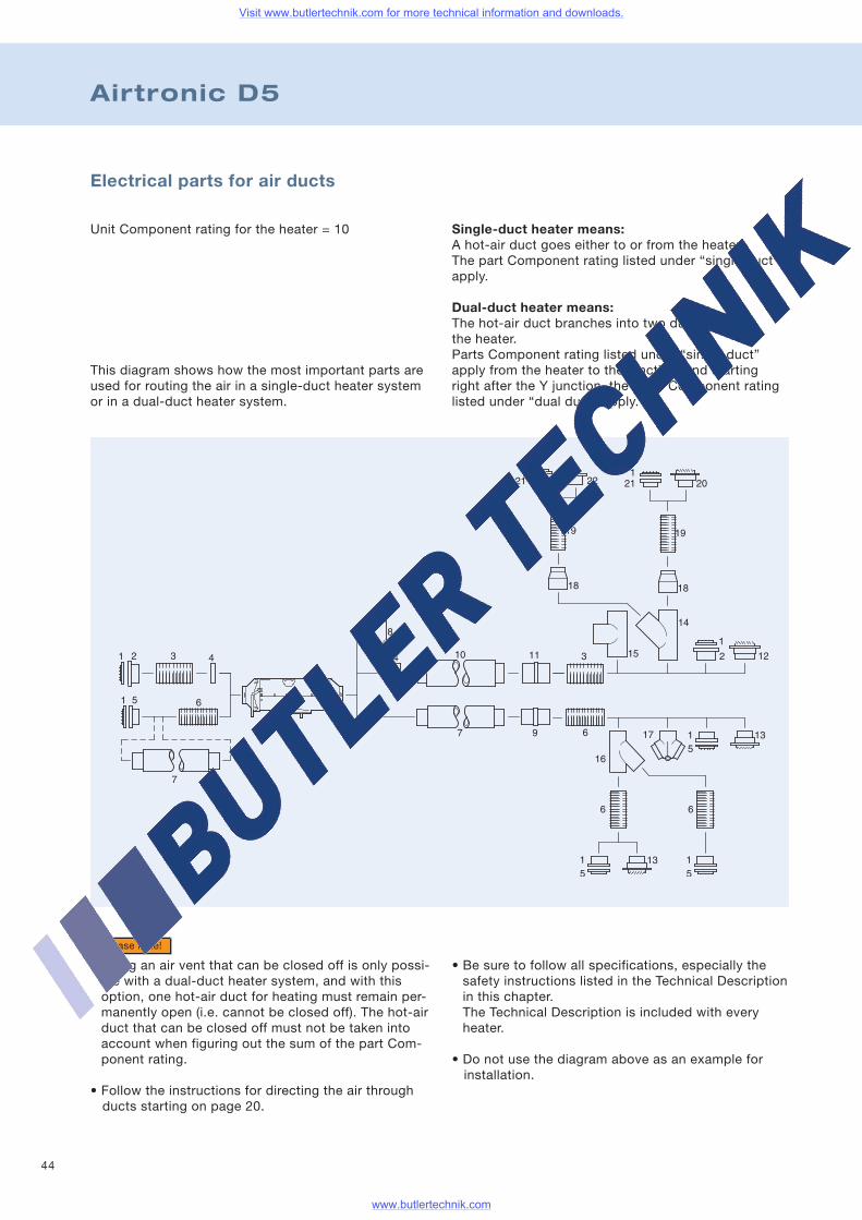
Single-duct heater means:A hot-air duct goes either to or from the heater.The part Component rating listed under “single duct”apply.
Dual-duct heater means:The hot-air duct branches into two ducts afterthe heater.Parts Component rating listed under “single duct”apply from the heater to the junction, and startingright after the Y junction, the parts Component ratinglisted under “dual duct” apply.
Electrical parts for air ducts
Unit Component rating for the heater = 10
This diagram shows how the most important parts areused for routing the air in a single-duct heater systemor in a dual-duct heater system.
Airtronic D5
• Using an air vent that can be closed off is only possi-ble with a dual-duct heater system, and with thisoption, one hot-air duct for heating must remain per-manently open (i.e. cannot be closed off). The hot-airduct that can be closed off must not be taken intoaccount when figuring out the sum of the part Com-ponent rating.
• Follow the instructions for directing the air throughducts starting on page 20.
Please note!
• Be sure to follow all specifications, especially thesafety instructions listed in the Technical Descriptionin this chapter.The Technical Description is included with everyheater.
• Do not use the diagram above as an example forinstallation.
Visit www.butlertechnik.com for more technical information and downloads.
www.butlertechnik.com
45
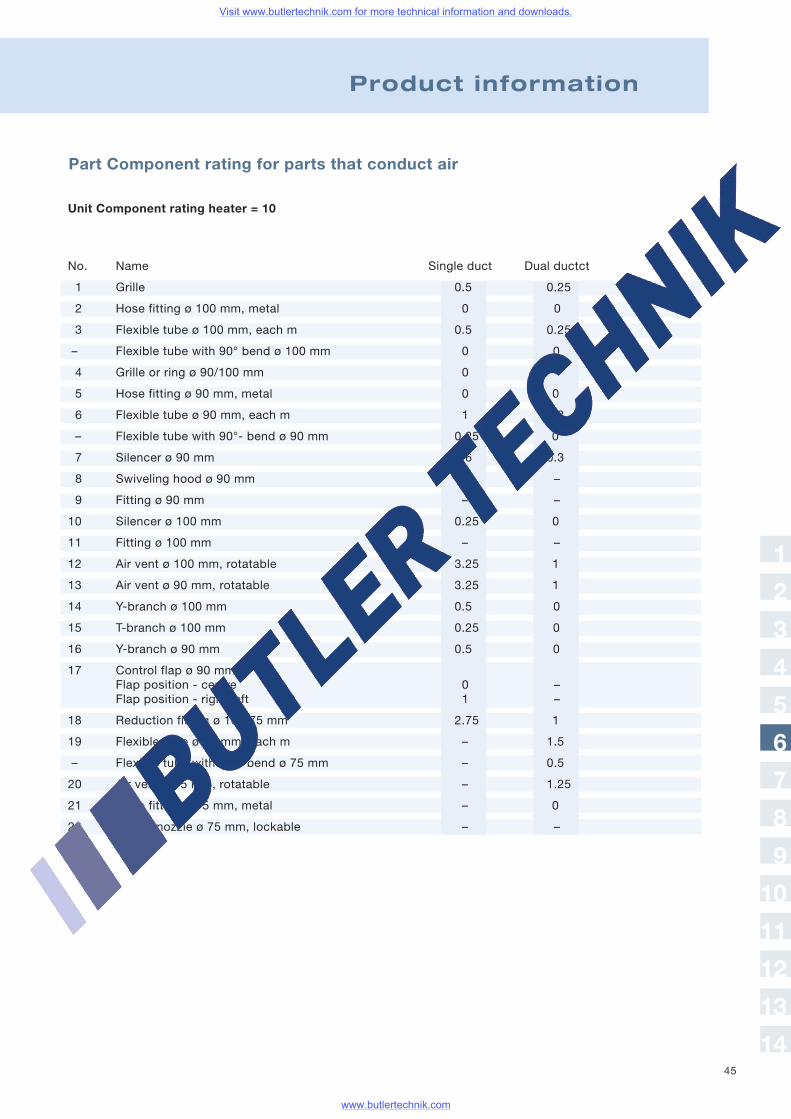
Part Component rating for parts that conduct air
Product information
Unit Component rating heater = 10
No. Name Single duct Dual ductct
1 Grille 0.5 0.25
2 Hose fitting ø 100 mm, metal 0 0
3 Flexible tube ø 100 mm, each m 0.5 0.25
– Flexible tube with 90° bend ø 100 mm 0 0
4 Grille or ring ø 90/100 mm 0 –
5 Hose fitting ø 90 mm, metal 0 0
6 Flexible tube ø 90 mm, each m 1 0.3
– Flexible tube with 90°- bend ø 90 mm 0.25 0
7 Silencer ø 90 mm 0,6 0.3
8 Swiveling hood ø 90 mm 1.5 –
9 Fitting ø 90 mm – –
10 Silencer ø 100 mm 0.25 0
11 Fitting ø 100 mm – –
12 Air vent ø 100 mm, rotatable 3.25 1
13 Air vent ø 90 mm, rotatable 3.25 1
14 Y-branch ø 100 mm 0.5 0
15 T-branch ø 100 mm 0.25 0
16 Y-branch ø 90 mm 0.5 0
17 Control flap ø 90 mmFlap position - centre 0 –Flap position - right/left 1 –
18 Reduction fitting ø 100/75 mm 2.75 1
19 Flexible tube ø 75 mm, each m – 1.5
– Flexible tube with 90°- bend ø 75 mm – 0.5
20 Air vent ø 75 mm, rotatable – 1.25
21 Hose fitting ø 75 mm, metal – 0
22 Round nozzle ø 75 mm, lockable – –
1
2
3
4
5
6
7
8
9
10
11
12
13
14
Visit www.butlertechnik.com for more technical information and downloads.
www.butlertechnik.com
46
Airtronic D5
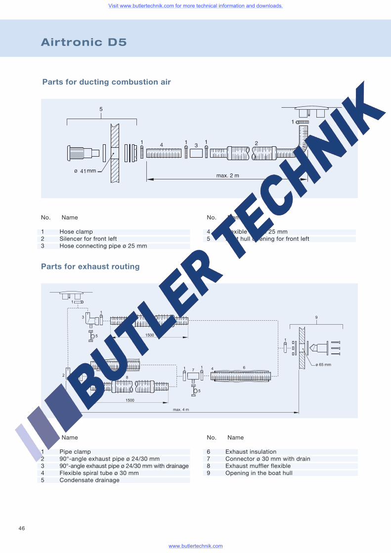
Parts for ducting combustion air
Parts for exhaust routing
No. Name
1 Pipe clamp2 90°-angle exhaust pipe ø 24/30 mm3 90°-angle exhaust pipe ø 24/30 mm with drainage4 Flexible spiral tube ø 30 mm5 Condensate drainage
No. Name
6 Exhaust insulation7 Connector ø 30 mm with drain8 Exhaust muffler flexible9 Opening in the boat hull
No. Name
1 Hose clamp2 Silencer for front left3 Hose connecting pipe ø 25 mm
No. Name
4 Flexible tube ø 25 mm5 Boat hull opening for front left
Visit www.butlertechnik.com for more technical information and downloads.
www.butlertechnik.com

47
Product information
Fuel feed line
In most cases, it is recommended that the fuel bedrawn through a separate tank connection and thatit be installed in the fuel tank (for metal tanks only).If installing a separate tank connection in the fuel tankis not an option, then fuel must be drawn through aT-fitting that is connected to the fuel supply line thatruns from the fuel tank to the motor.
• Be sure to follow all specifications, especially thesafety instructions listed in the Technical Descriptionin this chapter. The Technical Description is includedwith every heater unit.
• Refer to the Accessory Parts Catalogue or to theappropriate replacement parts lists if you need moreparts for the fuel supply.
• Fuel hoses in engine compartments must be fireretardant in accordance with DIN EN ISO 7840.
Please note!
No. Name
12 Metal pipe 4x113 Threaded connection ø 414 90°-angle threaded connection ø 415 Connecting hose ø 3.5x3
(for pipe 4x1.25)16 Plastic pipe 4x1.2517 Hose clamp ø 9
Metering pump mount
18 Fuel connection kit for boats is included:19 Rubber mount for the metering pump
Fuel connection kit in accordance with DIN EN ISO 7840
or Fig. Fuel connection kit for boatsis included:2 fire-retardant hoses,i/d = ø 3.5 mm, 50 mm long2 fire-retardant hoses,i/d = ø 5 mm, 50 mm long4 hose clamps, ø 12 mm4 hose clamps, ø 14 mm
No. Name
1 Tank connection i/d = ø 2 mm2 T-fitting
6 – 6 – 68 – 6 – 810 – 6 – 1012 – 6 – 12
3 Connecting hoseø 5x3 (for pipe 6x2)ø 7.5x2.5 (for pipe 8x2)
4 ConnectionReduction fitting ø 5/3.5(for T-fitting and pipe 4x1)Hose ø 3.5x3 (for pipe 4x1)Hose ø 5x3 (for pipe 6x2)
5 Plastic pipe4x16x2
6 Fuel hose 5x37 Threaded connection T ø 68 Metal pipe Cu 6x19 Threaded connection ø 610 Hose fitting ø 4
(for metering pump for 4x1 pipe)11 Hose clamp ø 11
1
2
3
4
5
6
7
8
9
10
11
12
13
14
Visit www.butlertechnik.com for more technical information and downloads.
www.butlertechnik.com
48
Air Heater D8LC
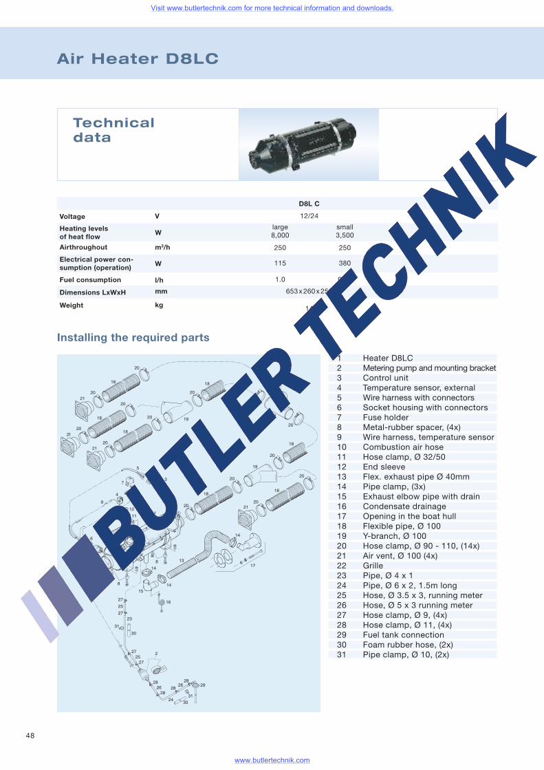
Technicaldata
D8L C
12/24
large small8,000 3,500
250 250
115 380
1.0 0.40
653x260x250
14
Voltage
Airthroughout
Heating levelsof heat flow
Fuel consumption
Electrical power con-sumption (operation)
Weight
Dimensions LxWxH
V
W
m3/h
W
l/h
mm
kg
Installing the required parts
1 Heater D8LC2 Metering pump and mounting bracket3 Control unit4 Temperature sensor, external5 Wire harness with connectors6 Socket housing with connectors7 Fuse holder8 Metal-rubber spacer, (4x)9 Wire harness, temperature sensor10 Combustion air hose11 Hose clamp, Ø 32/5012 End sleeve13 Flex. exhaust pipe Ø 40mm14 Pipe clamp, (3x)15 Exhaust elbow pipe with drain16 Condensate drainage17 Opening in the boat hull18 Flexible pipe, Ø 10019 Y-branch, Ø 10020 Hose clamp, Ø 90 - 110, (14x)21 Air vent, Ø 100 (4x)22 Grille23 Pipe, Ø 4 x 124 Pipe, Ø 6 x 2, 1.5m long25 Hose, Ø 3.5 x 3, running meter26 Hose, Ø 5 x 3 running meter27 Hose clamp, Ø 9, (4x)28 Hose clamp, Ø 11, (4x)29 Fuel tank connection30 Foam rubber hose, (2x)31 Pipe clamp, Ø 10, (2x)
Visit www.butlertechnik.com for more technical information and downloads.
www.butlertechnik.com
49
Product information
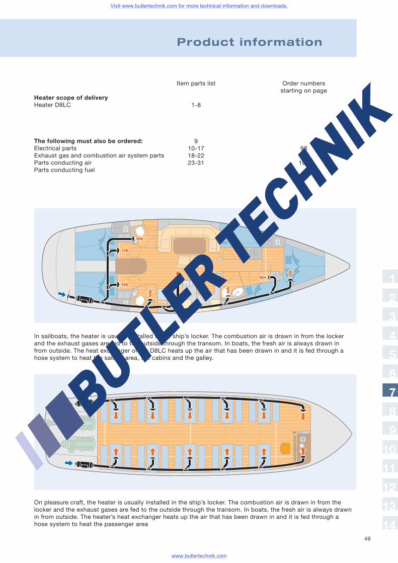
Heater scope of deliveryHeater D8LC
The following must also be ordered:Electrical partsExhaust gas and combustion air system partsParts conducting airParts conducting fuel
Item parts list
1-8
910-1718-2223-31
Order numbersstarting on page
9854106
On pleasure craft, the heater is usually installed in the ship’s locker. The combustion air is drawn in from thelocker and the exhaust gases are fed to the outside through the transom. In boats, the fresh air is always drawnin from outside. The heater’s heat exchanger heats up the air that has been drawn in and it is fed through ahose system to heat the passenger area
In sailboats, the heater is usually installed in the ship’s locker. The combustion air is drawn in from the lockerand the exhaust gases are fed to the outside through the transom. In boats, the fresh air is always drawn infrom outside. The heat exchanger of the D8LC heats up the air that has been drawn in and it is fed through ahose system to heat the saloon area, the cabins and the galley.
1
2
3
4
5
6
7
8
9
10
11
12
13
14
Visit www.butlertechnik.com for more technical information and downloads.
www.butlertechnik.com
50
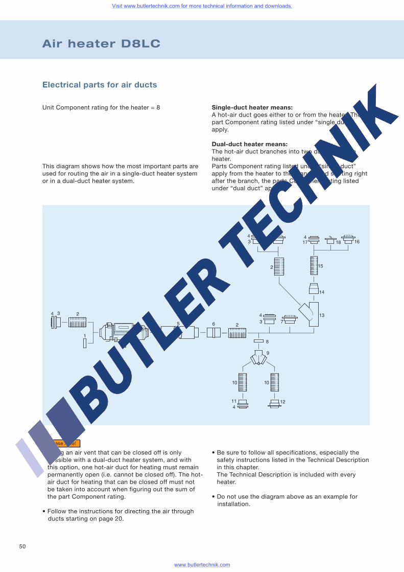
Air heater D8LC
Single-duct heater means:A hot-air duct goes either to or from the heater. Thepart Component rating listed under “single duct”apply.
Dual-duct heater means:The hot-air duct branches into two ducts after theheater.Parts Component rating listed under “single duct”apply from the heater to the branch, and starting rightafter the branch, the parts Component rating listedunder “dual duct” apply.
Electrical parts for air ducts
Unit Component rating for the heater = 8
This diagram shows how the most important parts areused for routing the air in a single-duct heater systemor in a dual-duct heater system.
• Using an air vent that can be closed off is onlypossible with a dual-duct heater system, and withthis option, one hot-air duct for heating must remainpermanently open (i.e. cannot be closed off). The hot-air duct for heating that can be closed off must notbe taken into account when figuring out the sum ofthe part Component rating.
• Follow the instructions for directing the air throughducts starting on page 20.
Please note!
• Be sure to follow all specifications, especially thesafety instructions listed in the Technical Descriptionin this chapter.The Technical Description is included with everyheater.
• Do not use the diagram above as an example forinstallation.
Visit www.butlertechnik.com for more technical information and downloads.
www.butlertechnik.com
51
Part Component rating for parts that direct air through ducts
Product information
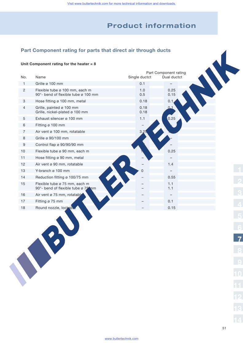
Unit Component rating for the heater = 8
Part Component ratingNo. Name Single ductct Dual ductct
1 Grille ø 100 mm 0.1 –
2 Flexible tube ø 100 mm, each m 1.0 0.2590°- bend of flexible tube ø 100 mm 0.5 0.15
3 Hose fitting ø 100 mm, metal 0.18 0.1
4 Grille, painted ø 100 mm 0.18 0.1Grille, nickel-plated ø 100 mm 0.18 0.1
5 Exhaust silencer ø 100 mm 1.1 0.25
6 Fitting ø 100 mm – –
7 Air vent ø 100 mm, rotatable 3.25 1.1
8 Grille ø 90/100 mm 0 –
9 Control flap ø 90/90/90 mm 2.4 –
10 Flexible tube ø 90 mm, each m 1 0.25
11 Hose fitting ø 90 mm, metal – –
12 Air vent ø 90 mm, rotatable – 1.4
13 Y-branch ø 100 mm 0 –
14 Reduction fitting ø 100/75 mm – 0.55
15 Flexible tube ø 75 mm, each m – 1.190°- bend of flexible tube ø 75 mm – 1.1
16 Air vent ø 75 mm, rotatable – –
17 Fitting ø 75 mm – 0.1
18 Round nozzle, lockable – 0.15
1
2
3
4
5
6
7
8
9
10
11
12
13
14
Visit www.butlertechnik.com for more technical information and downloads.
www.butlertechnik.com
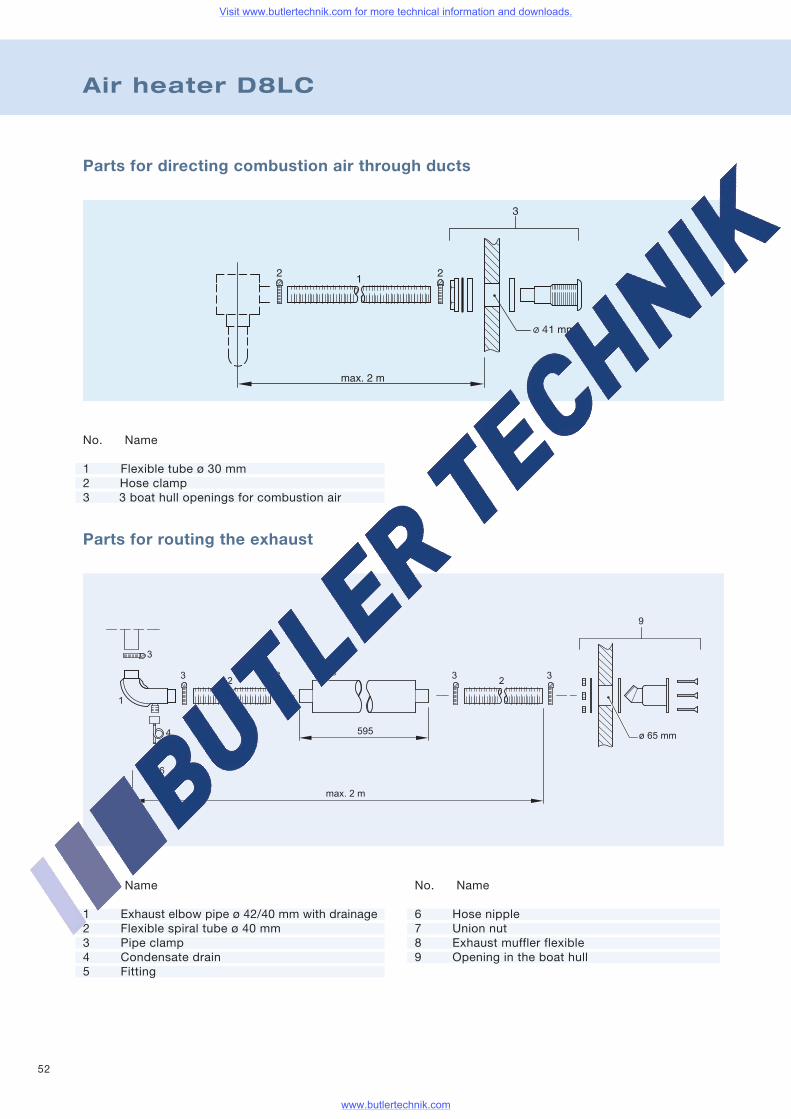
52
Air heater D8LC
Parts for directing combustion air through ducts
Parts for routing the exhaust
No. Name
1 Flexible tube ø 30 mm2 Hose clamp3 3 boat hull openings for combustion air
No. Name
1 Exhaust elbow pipe ø 42/40 mm with drainage2 Flexible spiral tube ø 40 mm3 Pipe clamp4 Condensate drain5 Fitting
No. Name
6 Hose nipple7 Union nut8 Exhaust muffler flexible9 Opening in the boat hull
Visit www.butlertechnik.com for more technical information and downloads.
www.butlertechnik.com
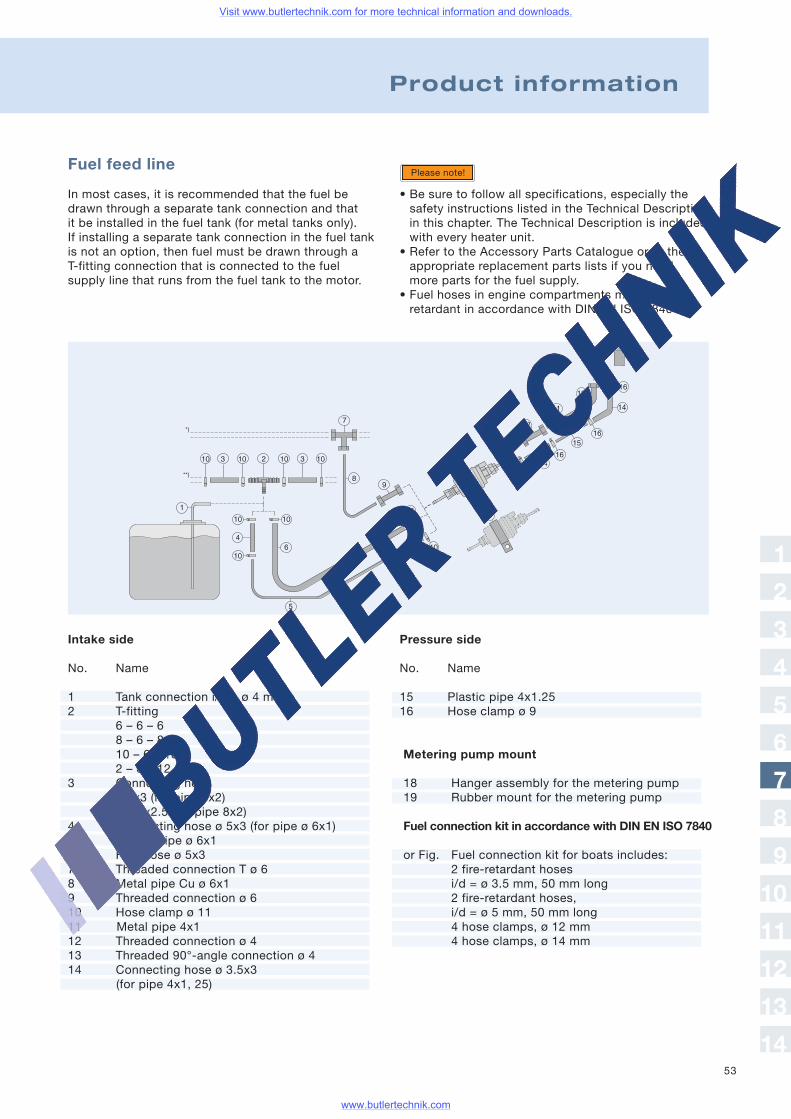
53
Product information
Fuel feed line
In most cases, it is recommended that the fuel bedrawn through a separate tank connection and thatit be installed in the fuel tank (for metal tanks only).If installing a separate tank connection in the fuel tankis not an option, then fuel must be drawn through aT-fitting connection that is connected to the fuelsupply line that runs from the fuel tank to the motor.
• Be sure to follow all specifications, especially thesafety instructions listed in the Technical Descriptionin this chapter. The Technical Description is includedwith every heater unit.
• Refer to the Accessory Parts Catalogue or to theappropriate replacement parts lists if you needmore parts for the fuel supply.
• Fuel hoses in engine compartments must be fire-retardant in accordance with DIN EN ISO 7840.
Please note!
Pressure side
No. Name
15 Plastic pipe 4x1.2516 Hose clamp ø 9
Metering pump mount
18 Hanger assembly for the metering pump19 Rubber mount for the metering pump
Fuel connection kit in accordance with DIN EN ISO 7840
or Fig. Fuel connection kit for boats includes:2 fire-retardant hosesi/d = ø 3.5 mm, 50 mm long2 fire-retardant hoses,i/d = ø 5 mm, 50 mm long4 hose clamps, ø 12 mm4 hose clamps, ø 14 mm
Intake side
No. Name
1 Tank connection i/d = ø 4 mm2 T-fitting
6 – 6 – 68 – 6 – 810 – 6 – 102 – 6 – 12
3 Connecting hoseø 5x3 (for pipe 6x2)ø 7.5x2.5 (for pipe 8x2)
4 Connecting hose ø 5x3 (for pipe ø 6x1)5 Plastic pipe ø 6x16 Fuel hose ø 5x37 Threaded connection T ø 68 Metal pipe Cu ø 6x19 Threaded connection ø 610 Hose clamp ø 1111 Metal pipe 4x112 Threaded connection ø 413 Threaded 90°-angle connection ø 414 Connecting hose ø 3.5x3
(for pipe 4x1, 25)
1
2
3
4
5
6
7
8
9
10
11
12
13
14
Visit www.butlertechnik.com for more technical information and downloads.
www.butlertechnik.com
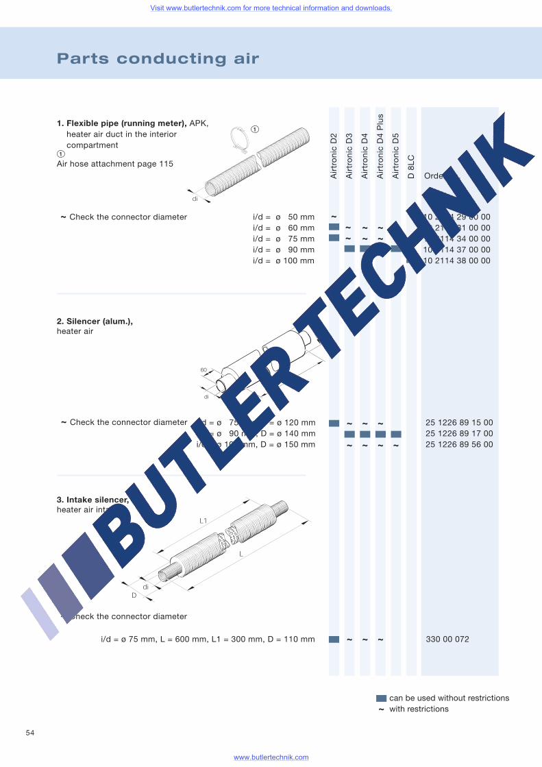
54
Parts conducting air
AirtronicD2
AirtronicD3
AirtronicD4
AirtronicD4Plus
AirtronicD5
D8LC
Order no.
Air hose attachment page 115
~ Check the connector diameter i/d = ø 50 mm 10 2114 29 00 00i/d = ø 60 mm 10 2114 31 00 00i/d = ø 75 mm 10 2114 34 00 00i/d = ø 90 mm 10 2114 37 00 00i/d = ø 100 mm 10 2114 38 00 00
~ ~~ ~ ~
i/d = ø 75 mm, D = ø 120 mm 25 1226 89 15 00i/d = ø 90 mm, D = ø 140 mm 25 1226 89 17 00i/d = ø 100 mm, D = ø 150 mm 25 1226 89 56 00
~ Check the connector diameter
~ Check the connector diameter
i/d = ø 75 mm, L = 600 mm, L1 = 300 mm, D = 110 mm 330 00 072
can be used without restrictionswith restrictions~
~~
~ ~ ~
~ ~ ~ ~
~ ~ ~
~
1. Flexible pipe (running meter), APK,heater air duct in the interiorcompartment
3. Intake silencer,heater air intake
2. Silencer (alum.),heater air
Visit www.butlertechnik.com for more technical information and downloads.
www.butlertechnik.com
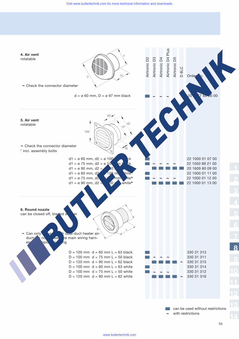
55
AirtronicD2
AirtronicD3
AirtronicD4
AirtronicD4Plus
AirtronicD5
D8LC
Order no.
~ Check the connector diameter
d = ø 60 mm, D = ø 97 mm black 20 1577 89 06 00
~ Check the connector diameter* incl. assembly bolts
d1 = ø 60 mm, d2 = ø 100 mm black 22 1000 01 07 00d1 = ø 75 mm, d2 = ø 100 mm black 22 1050 89 21 00d1 = ø 90 mm, d2 = ø 100 mm black 20 1609 80 09 00d1 = ø 60 mm, d2 = ø 100 mm white* 22 1000 01 11 00d1 = ø 75 mm, d2 = ø 100 mm white* 22 1000 01 12 00d1 = ø 90 mm, d2 = ø 100 mm white* 22 1000 01 13 00
~ Can only be used with dual-duct heater air-duct; do not exceed the main wiring harn-ess’s Component rating
can be used without restrictionswith restrictions~
~ ~ ~
~ ~ ~ ~
D = 100 mm d = 60 mm L = 63 black 330 31 313D = 100 mm d = 75 mm L = 50 black 330 31 311D = 120 mm d = 90 mm L = 62 black 330 31 315D = 100 mm d = 60 mm L = 63 white 330 31 314D = 100 mm d = 75 mm L = 50 white 330 31 312D = 120 mm d = 90 mm L = 62 white 330 31 316
~ ~ ~ ~
~
~~ ~ ~
~ ~ ~
1
2
3
4
5
6
7
8
9
10
11
12
13
14
4. Air ventrotatable
5. Air ventrotatable
6. Round nozzlecan be closed off, bladed shutter
Visit www.butlertechnik.com for more technical information and downloads.
www.butlertechnik.com
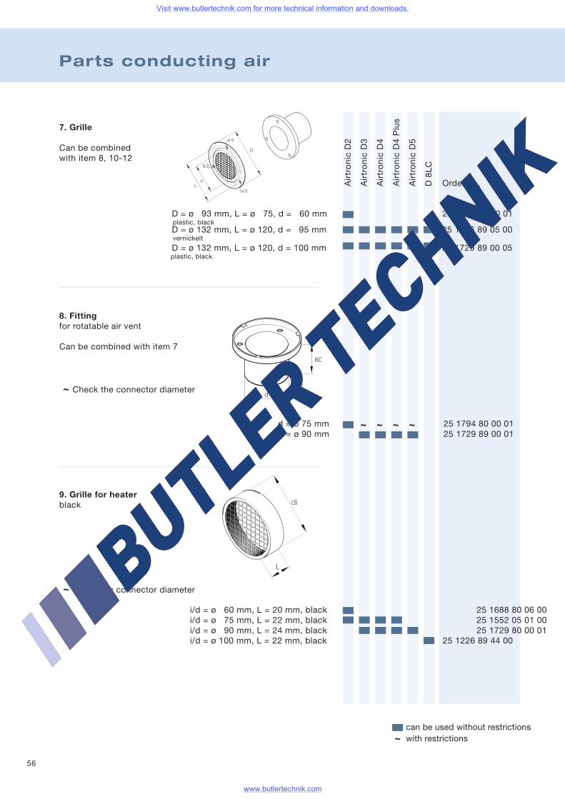
56
Parts conducting air
AirtronicD2
AirtronicD3
AirtronicD4
AirtronicD4Plus
AirtronicD5
D8LC
8. Fittingfor rotatable air vent
Can be combined with item 7
~ Check the connector diameter
9. Grille for heaterblack
~ Check the connector diameter
Order no.
i/d = ø 60 mm, L = 20 mm, black 25 1688 80 06 00i/d = ø 75 mm, L = 22 mm, black 25 1552 05 01 00i/d = ø 90 mm, L = 24 mm, black 25 1729 80 00 01i/d = ø 100 mm, L = 22 mm, black 25 1226 89 44 00
d = ø 75 mm 25 1794 80 00 01d = ø 90 mm 25 1729 89 00 01
7. Grille
Can be combinedwith item 8, 10-12
D = ø 93 mm, L = ø 75, d = 60 mm 22 1000 01 00 01plastic, blackD = ø 132 mm, L = ø 120, d = 95 mm 25 1226 89 05 00vernickelt
D = ø 132 mm, L = ø 120, d = 100 mm 25 1729 89 00 05plastic, black
~ ~ ~ ~
can be used without restrictionswith restrictions~
Visit www.butlertechnik.com for more technical information and downloads.
www.butlertechnik.com
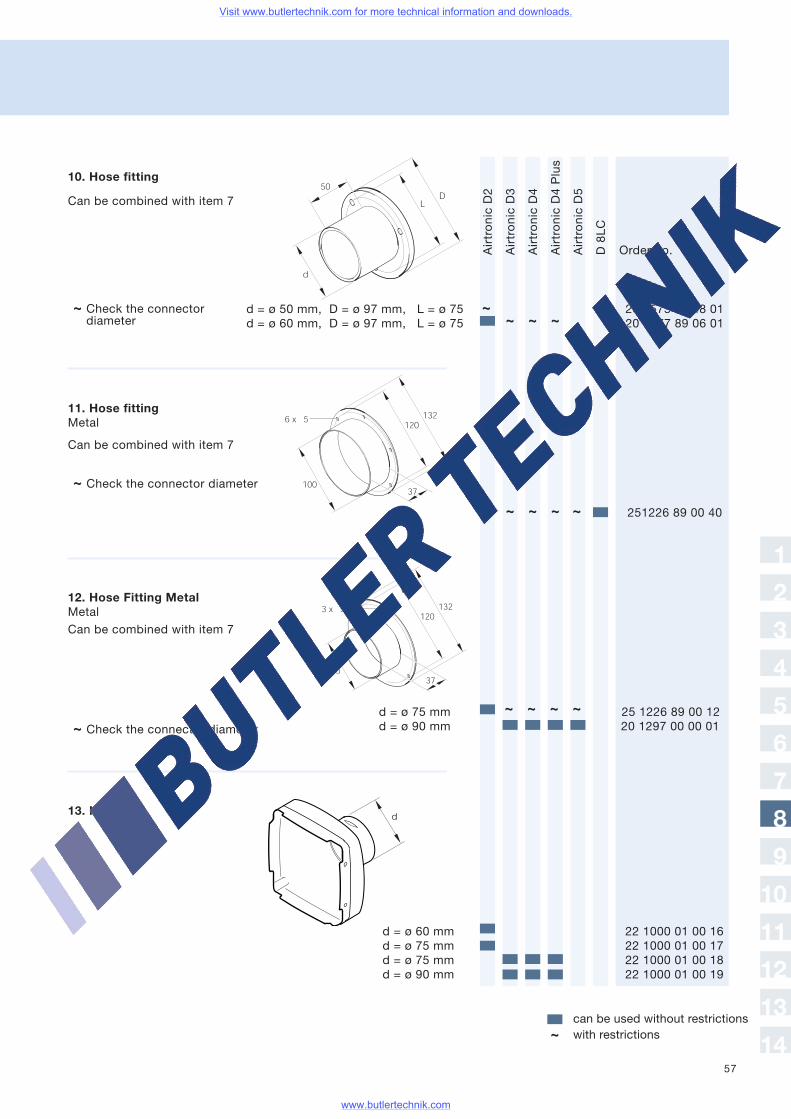
57
AirtronicD2
AirtronicD3
AirtronicD4
AirtronicD4Plus
AirtronicD5
D8LC
Order no.
10. Hose fitting
d = ø 50 mm, D = ø 97 mm, L = ø 75 20 1575 80 08 01d = ø 60 mm, D = ø 97 mm, L = ø 75 20 1577 89 06 01
~ Check the connectordiameter
11. Hose fittingMetal
Can be combined with item 7
~ Check the connector diameter
12. Hose Fitting MetalMetal
~ Check the connector diameter
d = ø 75 mm 25 1226 89 00 12d = ø 90 mm 20 1297 00 00 01
13. Hood
d = ø 60 mm 22 1000 01 00 16d = ø 75 mm 22 1000 01 00 17d = ø 75 mm 22 1000 01 00 18d = ø 90 mm 22 1000 01 00 19
Can be combined with item 7
Can be combined with item 7
251226 89 00 40
~ ~ ~
~~ ~ ~
~ ~ ~ ~
~
can be used without restrictionswith restrictions~
1
2
3
4
5
6
7
8
9
10
11
12
13
14
Visit www.butlertechnik.com for more technical information and downloads.
www.butlertechnik.com
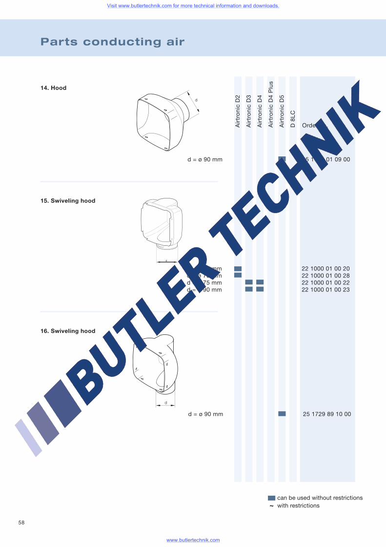
58
Parts conducting air
AirtronicD2
AirtronicD3
AirtronicD4
AirtronicD4Plus
AirtronicD5
D8LC
14. Hood
d = ø 90 mm 25 1729 01 09 00
16. Swiveling hood
d = ø 90 mm 25 1729 89 10 00
Order no.
15. Swiveling hood
d = ø 60 mm 22 1000 01 00 20d = ø 75 mm 22 1000 01 00 28d = ø 75 mm 22 1000 01 00 22d = ø 90 mm 22 1000 01 00 23
can be used without restrictionswith restrictions~
Visit www.butlertechnik.com for more technical information and downloads.
www.butlertechnik.com
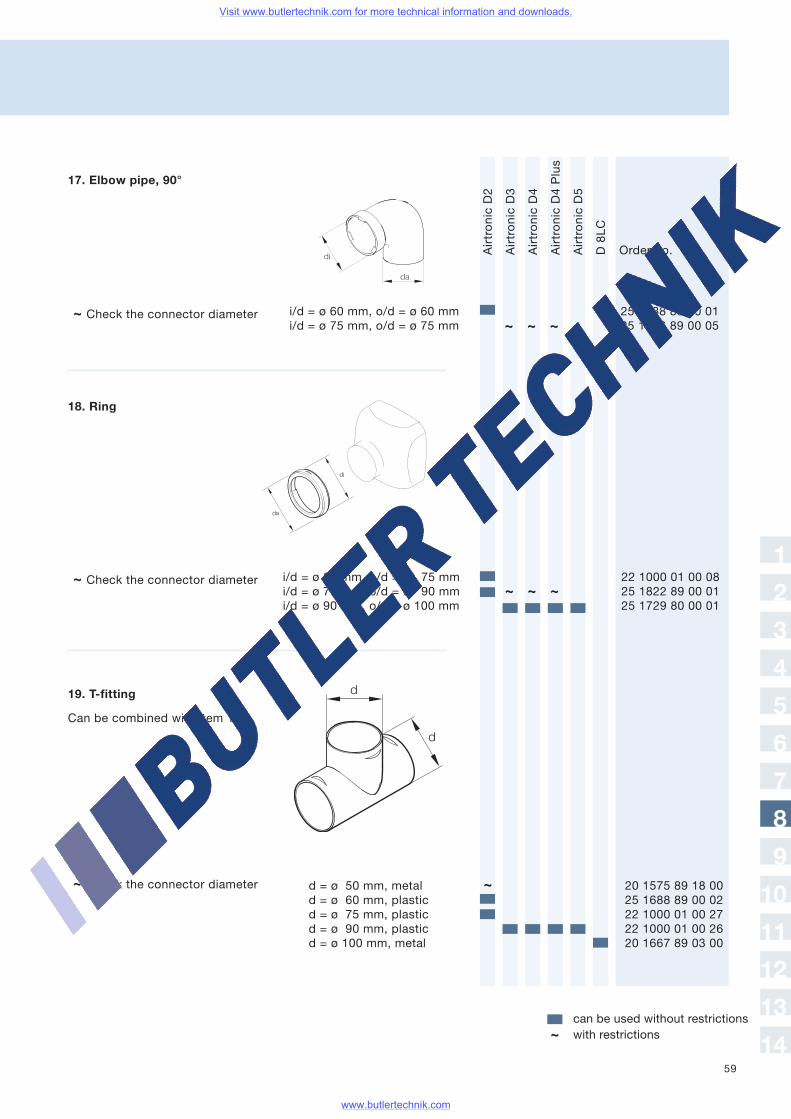
59
AirtronicD2
AirtronicD3
AirtronicD4
AirtronicD4Plus
AirtronicD5
D8LC
Order no.
17. Elbow pipe, 90°
i/d = ø 60 mm, o/d = ø 60 mm 25 1688 89 00 01i/d = ø 75 mm, o/d = ø 75 mm 25 1482 89 00 05
18. Ring
i/d = ø 60 mm, o/d = ø 75 mm 22 1000 01 00 08i/d = ø 75 mm, o/d = ø 90 mm 25 1822 89 00 01i/d = ø 90 mm, o/d = ø 100 mm 25 1729 80 00 01
~ Check the connector diameter
19. T-fitting
d = ø 50 mm, metal 20 1575 89 18 00d = ø 60 mm, plastic 25 1688 89 00 02d = ø 75 mm, plastic 22 1000 01 00 27d = ø 90 mm, plastic 22 1000 01 00 26d = ø 100 mm, metal 20 1667 89 03 00
~ Check the connector diameter
Can be combined with item 1
~ ~ ~
~ ~ ~
~
~ Check the connector diameter
can be used without restrictionswith restrictions~
1
2
3
4
5
6
7
8
9
10
11
12
13
14
Visit www.butlertechnik.com for more technical information and downloads.
www.butlertechnik.com
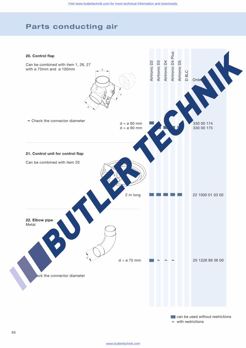
60
Parts conducting air
Order no.
20. Control flap
d
d
d
~ Check the connector diameter
21. Control unit for control flap
22. Elbow pipeMetal
AirtronicD2
AirtronicD3
AirtronicD4
AirtronicD4Plus
AirtronicD5
D8LC
Can be combined with item 1, 26, 27with ø 75mm and ø 100mm
Can be combined with item 20
d = ø 60 mm 330 00 174d = ø 90 mm 330 00 175
d = ø 75 mm 25 1226 89 36 00
2 m long 22 1000 01 03 00
can be used without restrictionswith restrictions~
~ Check the connector diameter
~ ~ ~
Visit www.butlertechnik.com for more technical information and downloads.
www.butlertechnik.com
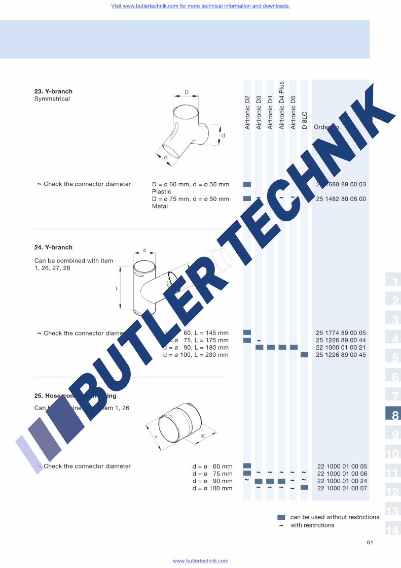
61
Order no.
23. Y-branchSymmetrical
D = ø 60 mm, d = ø 50 mm 25 1688 89 00 03PlasticD = ø 75 mm, d = ø 50 mm 25 1482 80 08 00Metal
~ Check the connector diameter
24. Y-branch
d = ø 60, L = 145 mm 25 1774 89 00 05d = ø 75, L = 175 mm 25 1226 89 00 44d = ø 90, L = 180 mm 22 1000 01 00 21d = ø 100, L = 230 mm 25 1226 89 00 45
~ Check the connector diameter
d = ø 60 mm 22 1000 01 00 05d = ø 75 mm 22 1000 01 00 06d = ø 90 mm 22 1000 01 00 24d = ø 100 mm 22 1000 01 00 07
25. Hose connection fitting
~ Check the connector diameter
Can be combined with item 1, 26
AirtronicD2
AirtronicD3
AirtronicD4
AirtronicD4Plus
AirtronicD5
D8LC
~ ~ ~ ~
~
~ ~ ~~
~ ~ ~
~~
~~~
Can be combined with item1, 26, 27, 28
can be used without restrictionswith restrictions~
1
2
3
4
5
6
7
8
9
10
11
12
13
14
Visit www.butlertechnik.com for more technical information and downloads.
www.butlertechnik.com
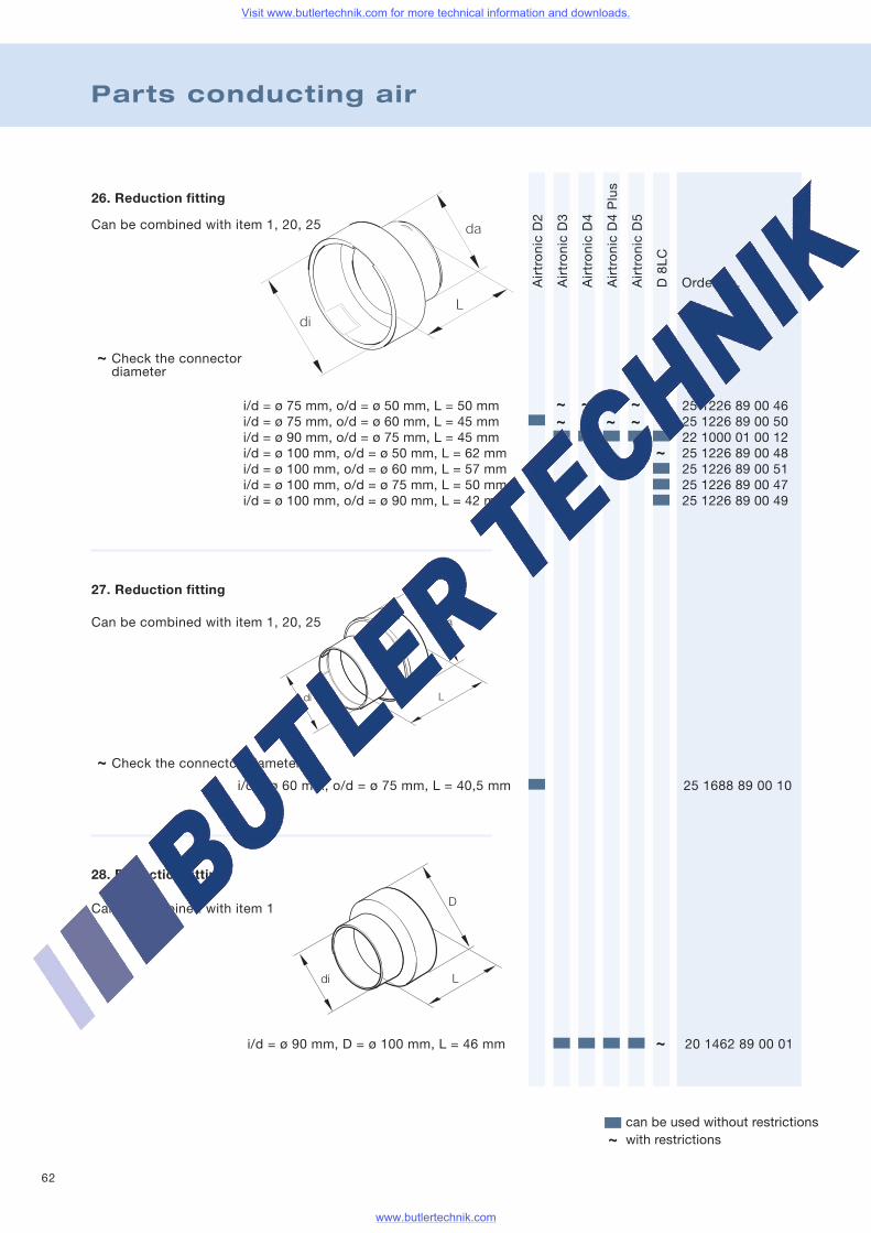
62
Parts conducting air
26. Reduction fitting
~ Check the connectordiameter
27. Reduction fitting
~ Check the connector diameter
Can be combined with item 1, 20, 25
Can be combined with item 1, 20, 25
i/d = ø 75 mm, o/d = ø 50 mm, L = 50 mm 25 1226 89 00 46i/d = ø 75 mm, o/d = ø 60 mm, L = 45 mm 25 1226 89 00 50i/d = ø 90 mm, o/d = ø 75 mm, L = 45 mm 22 1000 01 00 12i/d = ø 100 mm, o/d = ø 50 mm, L = 62 mm 25 1226 89 00 48i/d = ø 100 mm, o/d = ø 60 mm, L = 57 mm 25 1226 89 00 51i/d = ø 100 mm, o/d = ø 75 mm, L = 50 mm 25 1226 89 00 47i/d = ø 100 mm, o/d = ø 90 mm, L = 42 mm 25 1226 89 00 49
i/d = ø 60 mm, o/d = ø 75 mm, L = 40,5 mm 25 1688 89 00 10
i/d = ø 90 mm, D = ø 100 mm, L = 46 mm 20 1462 89 00 01
AirtronicD2
AirtronicD3
AirtronicD4
AirtronicD4Plus
AirtronicD5
D8LC
28. Reduction fitting
~~ ~ ~ ~
~ ~ ~
~
~
Can be combined with item 1
can be used without restrictionswith restrictions~
Order no.
Visit www.butlertechnik.com for more technical information and downloads.
www.butlertechnik.com
63
Notes
1
2
3
4
5
6
7
8
9
10
11
12
13
14
Visit www.butlertechnik.com for more technical information and downloads.
www.butlertechnik.com
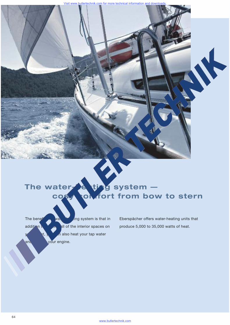
64
The water-heating system —cosy comfort from bow to stern
The benefit of a water-heating system is that in
addition to heating all of the interior spaces on
your yacht, you can also heat your tap water
and preheat your engine.
Eberspächer offers water-heating units that
produce 5,000 to 35,000 watts of heat.
Visit www.butlertechnik.com for more technical information and downloads.
www.butlertechnik.com
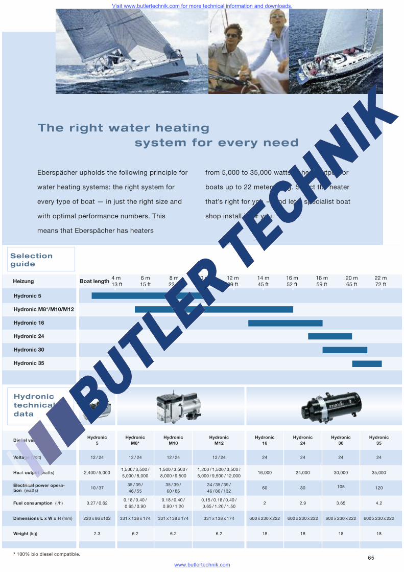
65
Heat output (watts)
Diesel version
2,400 / 5,000
10 / 37
0.27 / 0.62
Hydronictechnicaldata
Electrical power opera-tion (watts)
220 x 86 x102
2.3
Dimensions L x W x H (mm)
Fuel consumption (l/h)
Voltage (Volt)
Weight (kg)
Hydronic5
12 / 24
1,500 / 3,500 /
5,000 / 8,000
35 / 39 /
46 / 55
0.18 / 0.40 /
0.65 / 0.90
331 x 138 x 174
6.2
HydronicM8*
12 / 24
1,500 / 3,500 /
8,000 / 9,500
35 / 39 /
60 / 86
0.18 / 0.40 /
0.90 / 1.20
331 x 138 x 174
6.2
HydronicM10
12 / 24
16,000
60
2
600 x 230 x 222
18
Hydronic16
24
24,000
80
2.9
600 x 230 x 222
18
Hydronic24
24
30,000
105
3.65
600 x 230 x 222
18
Hydronic30
24
35,000
120
4.2
600 x 230 x 222
18
Hydronic35
24
1,200 / 1,500 / 3,500 /
5,000 / 9,500 / 12,000
34 / 35 / 39 /
46 / 86 / 132
0.15 / 0.18 / 0.40 /
0.65 / 1.20 / 1.50
331 x 138 x 174
6.2
HydronicM12
12 / 24
4 m 6 m 8 m 10 m 12 m 14 m 16 m 18 m 20 m 22 m13 ft 15 ft 22 ft 32 ft 39 ft 45 ft 52 ft 59 ft 65 ft 72 ft
Hydronic 5
Hydronic M8*/M10/M12
Hydronic 16
Hydronic 24
Hydronic 30
Hydronic 35
Selectionguide
* 100% bio diesel compatible.
The right water heatingsystem for every need
Eberspächer upholds the following principle for
water heating systems: the right system for
every type of boat — in just the right size and
with optimal performance numbers. This
means that Eberspächer has heaters
from 5,000 to 35,000 watts of heat output for
boats up to 22 meters long. Select the heater
that’s right for you — and let a specialist boat
shop install it for you.
Boat lengthHeizung
Visit www.butlertechnik.com for more technical information and downloads.
www.butlertechnik.com
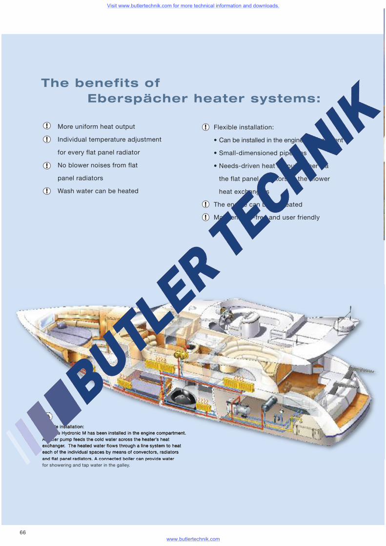
66
The benefits ofEberspächer heater systems:
More uniform heat output
Individual temperature adjustment
for every flat panel radiator
No blower noises from flat
panel radiators
Wash water can be heated
Flexible installation:
• Can be installed in the engine compartment
• Small-dimensioned pipelines
• Needs-driven heat output: either via
the flat panel radiators or the blower
heat exchangers
The engine can be preheated
Maintenance-free and user friendly
Sample installation:Here the Hydronic M has been installed in the engine compartment.A water pump feeds the cold water across the heater’s heatexchanger. The heated water flows through a line system to heateach of the individual spaces by means of convectors, radiatorsand flat panel radiators. A connected boiler can provide waterfor showering and tap water in the galley.
Visit www.butlertechnik.com for more technical information and downloads.
www.butlertechnik.com

67
1
2
3
4
5
6
7
8
9
10
11
12
13
14
Control devices
System accessories for yourcomplete, customised solutions:
Eberspächer offers a wide range of premium
accessories that are coordinated to complement
each other, and which will meet all the particular
requirements for use on smaller boats and
seaworthy yachts. You will find all of these parts
in the marine catalogue starting on page 88.
* Available for 12-volt heaters only.
EasyStart TTimer
EasyStart Rremote-controloperation
Telephoneremote-controlCalltronic*
EasyStart R+
remote-controloperation
• For assembly in aninterior space
• Innovative, intuitive menuprompts using the menu bar
• 3 heater start times that canbe programmed within aseven-day period
• Base model, can becombined with theEasyStart T or mini-controller
• Includes feedback onheater function
• Comfort version• Alle Funktionen derEasyStart T inklusive
• Includes feedback onheater function
• GSM module with voice chip• You can operate the stationaryheater by calling from your cellphone or from your landline(tone dial).
Visit www.butlertechnik.com for more technical information and downloads.
www.butlertechnik.com
68
General information on water heater systems in boats
Without a doubt, it’s a good thing for the skipper tooutfit his boat with a heater system. The more andlonger a boat is used, the more you need a waterheater system.
Benefits:
• Uniform heat output, infinitely variable control, lownoise level
• Can be combined with your existing water circulationas long as you have a two-circuit cooling system forthe engine. This allows the waste heat from theengine to be used for heating as well andconversely, for preheating the engine.
• Wash water can be heated.• Heat is transported through lines whose diameteris much smaller than air ducts.
• Just as much comfort as with central heating.
Disadvantages of heating with water:
• The heater takes up valuable space in the cabin.• Slow to heat up.• Low drying effect on the air in the compartment.• In certain situations, an additional blower heateris required for fresh-air operation.
The most convenient installation location
In most situations, water heaters are installed inthe engine compartment. This is where the heaterfor washing water is also located (the boiler).Mandatory safety devices (such as the pressure-equaliser tank, safety valve, manometer, float ventvalve, drain cock, and the tap cock for filling) canalso be housed here.
Before we get to the installation of a water heatersystem, we first have to go over a few fundamentalpoints:
• Heat requirements? This tells you the size of heateryou need.
• How will the heater, boiler, heating element and,if required, the drive motor be connected to thenetwork of pipes?
• Selecting and dimensioning the heating element.• Dimensioning the network of pipes. Will the waterpump’s capacity be adequate?
• Can the drive motor be integrated in the watercirculation system? (This is only possible witha dual-circuit cooling system)
In general, these points should be kept in mind.The answers to these questions, however, willdetermine how much time and expense you willneed to invest, depending on whether motorboats(up to approx. 12 m) or larger cruising yachtsneed to be heated. And why make it any morecomplicated than it needs to be?
Heat requirements
The most expensive things involved in determiningheating needs can be figured into the calculations:including the size of the rooms, the material in thewalls, the inside, outside and glass surfaces, andtaking into account where you like to go boatingand the length of the season.But that’s only worth it for large cruising yachts.It’s much simpler in most cases for motor boats.
The main factor is the length of the boat!
Since heaters do not come in infinite gradationsof heat output capacities, there is a limit as to whatyou can select from. You would have to select thenext larger heater in a borderline situation betweentwo heaters and be certain that you can effectivelycontrol the heat flow.
The following might serve as examples to applyto your own needs:
Sailing yachts and motor boats up to• Max. length of 10m – Hydronic D5W S• Max. length of 16m – Hydronic M
But heating needs should be calculated even moreprecisely for even larger yachts. This is a matterfor the heating expert!
The following heaters are available for you to selectfrom:• Hydronic 24 with 24000 watts• Hydronic 30 with 30000 watts• Hydronic 35 with 35000 watts
Visit www.butlertechnik.com for more technical information and downloads.
www.butlertechnik.com
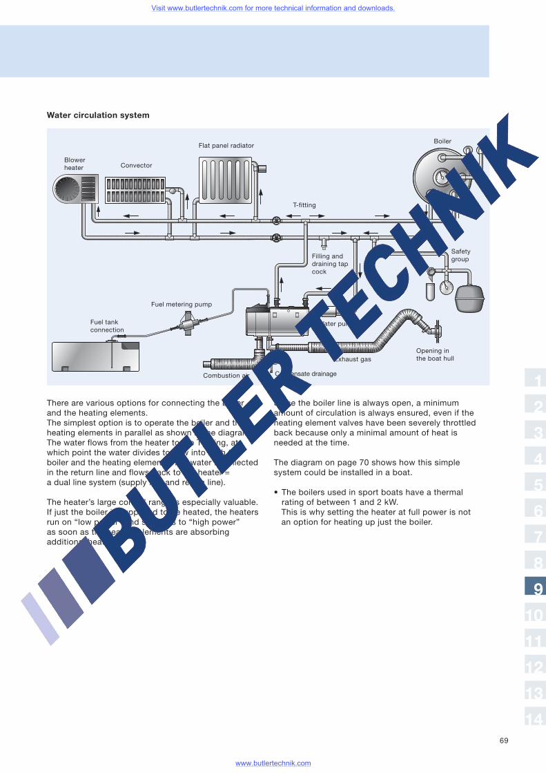
69
Water circulation system
There are various options for connecting the boilerand the heating elements.The simplest option is to operate the boiler and theheating elements in parallel as shown in the diagram.The water flows from the heater to the T-fitting, atwhich point the water divides to flow into both theboiler and the heating elements. The water is collectedin the return line and flows back to the heater =a dual line system (supply line and return line).
The heater’s large control range is especially valuable.If just the boiler is supposed to be heated, the heatersrun on “low power” and switches to “high power”as soon as the heating elements are absorbingadditional heat.
Since the boiler line is always open, a minimumamount of circulation is always ensured, even if theheating element valves have been severely throttledback because only a minimal amount of heat isneeded at the time.
The diagram on page 70 shows how this simplesystem could be installed in a boat.
• The boilers used in sport boats have a thermalrating of between 1 and 2 kW.This is why setting the heater at full power is notan option for heating up just the boiler.
Fuel metering pump
Flat panel radiator
ConvectorBlowerheater
Condensate drainage
Water pump
T-fitting
Boiler
Filling anddraining tapcock
Safetygroup
Exhaust gas
Fuel tankconnection
Combustion air
Opening inthe boat hull
1
2
3
4
5
6
7
8
9
10
11
12
13
14
Visit www.butlertechnik.com for more technical information and downloads.
www.butlertechnik.com
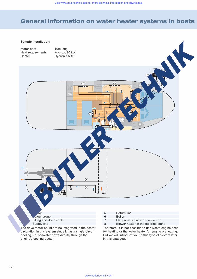
70
General information on water heater systems in boats
Sample installation:
Motor boat 10m longHeat requirements Approx. 10 kWHeater Hydronic M10
The drive motor could not be integrated in the heatercirculation in this system since it has a single-circuitcooling, i.e. seawater flows directly through theengine’s cooling ducts.
Therefore, it is not possible to use waste engine heatfor heating or the water heater for engine preheating.But we will introduce you to this type of system laterin this catalogue.
1 Heater2 Safety group3 Filling and drain cock4 Supply line
5 Return line6 Boiler7 Flat panel radiator or convector8 Blower heater in the steering stand
Visit www.butlertechnik.com for more technical information and downloads.
www.butlertechnik.com
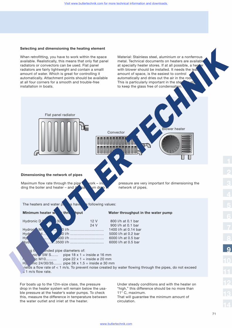
71
Selecting and dimensioning the heating element
When retrofitting, you have to work within the spaceavailable. Realistically, this means that only flat panelradiators or convectors can be used. Flat panelradiators are fairly lightweight and contain a smalllamount of water. Which is great for controlling itautomatically. Attachment points should be availableat all four corners for a smooth and trouble-freeinstallation in boats.
Material: Stainless steel, aluminium or a nonferrousmetal. Technical documents on heaters are availableat specialty heater stores. If at all possible, a heaterwith blower should be installed. It needs the leastamount of space, is the easiest to controlautomatically and dries out the air in the room.This is particularly important in the steering standto keep the glass free of condensation.
Dimensioning the network of pipes
Maximum flow rate through the pipe network – inclu-ding the boiler and heater – and its maximum drop in
For boats up to the 12m-size class, the pressuredrop in the heater system will remain below the usa-ble pressure at the heater’s water pumps. To checkthis, measure the difference in temperature betweenthe water outlet and inlet at the heater.
The heaters and water pumps have the following values:
Minimum heater water throughput Water throughput in the water pump
Hydronic D 5W S…..300 l/h 12 V 800 l/h at 0.1 bar24 V 900 l/h at 0.1 bar
Hydronic M10……… 500 l/h ………………………. 1400 l/h at 0.14 barHydronic 24………..2000 l/h ………………………. 5000 l/h at 0.2 barHydronic 30………..2600 l/h ………………………. 6000 l/h at 0.5 barHydronic 35………..3500 l/h ………………………. 6000 l/h at 0.5 bar
Using the intended pipe diameters of:Hydronic D 5W S…… pipe 18 x 1 = inside ø 16 mmHydronic M10……… pipe 22 x 1 = inside ø 20 mmHydronic 24/30/35……. pipe 38 x 1.5 = inside ø 30 mmyields a flow rate of < 1 m/s. To prevent noise created by water flowing through the pipes, do not exceeda 1 m/s flow rate.
pressure are very important for dimensioning thenetwork of pipes.
Under steady conditions and with the heater on“high,” this difference should be no more than11° C, maximum.That will guarantee the minimum amount ofcirculation.
Flat panel radiator
Blower heaterConvector
1
2
3
4
5
6
7
8
9
10
11
12
13
14
Visit www.butlertechnik.com for more technical information and downloads.
www.butlertechnik.com
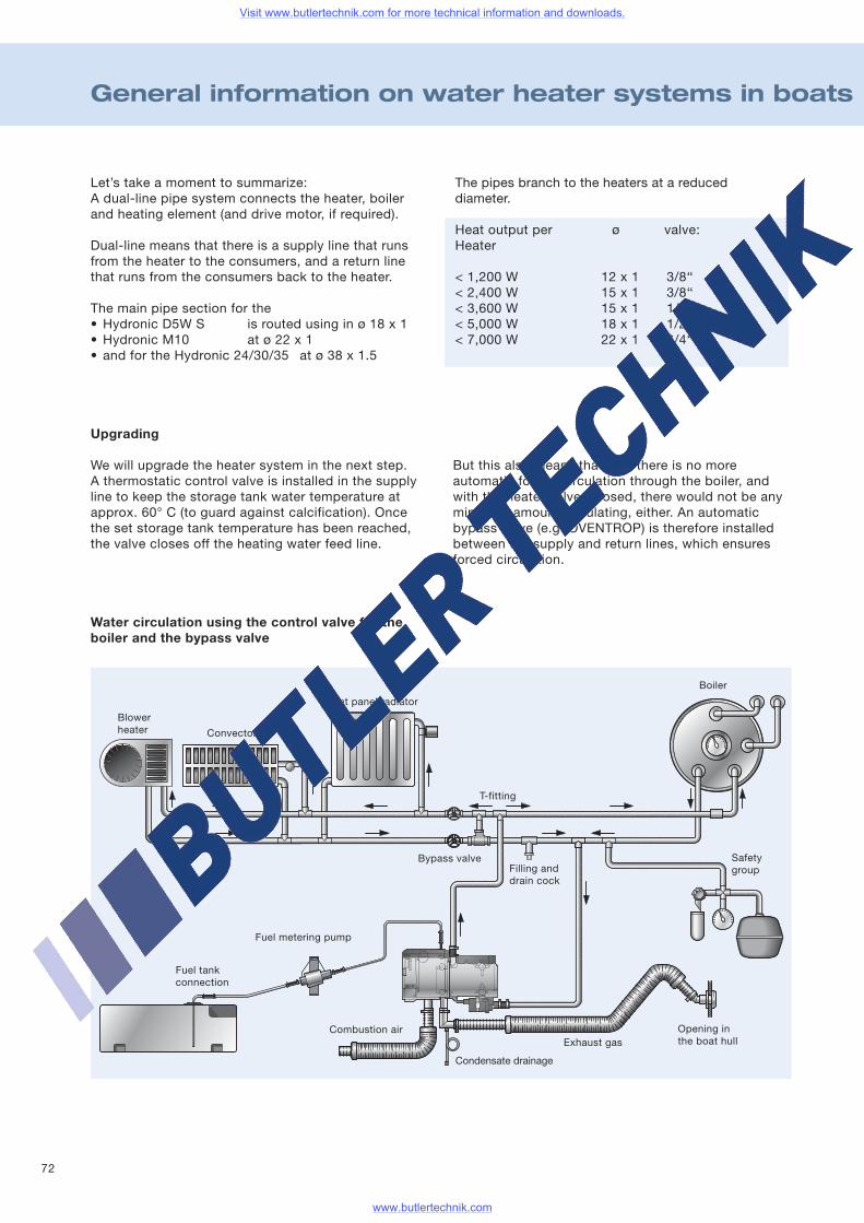
72
General information on water heater systems in boats
Let’s take a moment to summarize:A dual-line pipe system connects the heater, boilerand heating element (and drive motor, if required).
Dual-line means that there is a supply line that runsfrom the heater to the consumers, and a return linethat runs from the consumers back to the heater.
The main pipe section for the• Hydronic D5W S is routed using in ø 18 x 1• Hydronic M10 at ø 22 x 1• and for the Hydronic 24/30/35 at ø 38 x 1.5
The pipes branch to the heaters at a reduceddiameter.
Heat output per ø valve:Heater
< 1,200 W< 2,400 W< 3,600 W< 5,000 W< 7,000 W
12 x 115 x 115 x 118 x 122 x 1
3/8‘‘3/8‘‘1/2‘‘1/2‘‘3/4‘‘
Upgrading
We will upgrade the heater system in the next step.A thermostatic control valve is installed in the supplyline to keep the storage tank water temperature atapprox. 60° C (to guard against calcification). Oncethe set storage tank temperature has been reached,the valve closes off the heating water feed line.
But this also means that now there is no moreautomatic forced circulation through the boiler, andwith the heater valves closed, there would not be anyminimum amount circulating, either. An automaticbypass valve (e.g. OVENTROP) is therefore installedbetween the supply and return lines, which ensuresforced circulation.
Water circulation using the control valve for theboiler and the bypass valve
Fuel metering pump
Flat panel radiator
Convector
Blowerheater
Combustion air
T-fitting
Boiler
Safetygroup
Exhaust gas
Fuel tankconnection
Condensate drainage
Bypass valveFilling anddrain cock
Opening inthe boat hull
Visit www.butlertechnik.com for more technical information and downloads.
www.butlertechnik.com
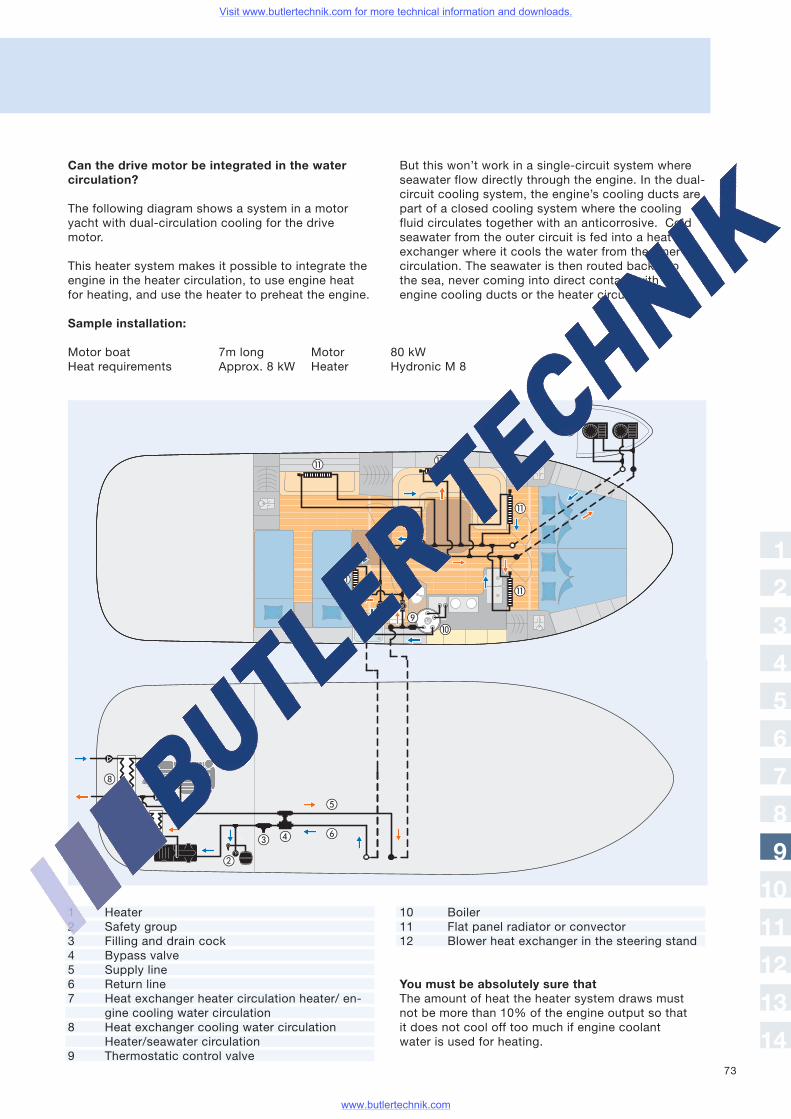
73
Can the drive motor be integrated in the watercirculation?
The following diagram shows a system in a motoryacht with dual-circulation cooling for the drivemotor.
This heater system makes it possible to integrate theengine in the heater circulation, to use engine heatfor heating, and use the heater to preheat the engine.
But this won’t work in a single-circuit system whereseawater flow directly through the engine. In the dual-circuit cooling system, the engine’s cooling ducts arepart of a closed cooling system where the coolingfluid circulates together with an anticorrosive. Coldseawater from the outer circuit is fed into a heatexchanger where it cools the water from the innercirculation. The seawater is then routed back intothe sea, never coming into direct contact with theengine cooling ducts or the heater circulation.
Sample installation:
Motor boat 7m long Motor 80 kWHeat requirements Approx. 8 kW Heater Hydronic M 8
1
2
3
4
5
6
7
8
9
10
11
12
13
14
1 Heater2 Safety group3 Filling and drain cock4 Bypass valve5 Supply line6 Return line7 Heat exchanger heater circulation heater/ en-
gine cooling water circulation8 Heat exchanger cooling water circulation
Heater/seawater circulation9 Thermostatic control valve
10 Boiler11 Flat panel radiator or convector12 Blower heat exchanger in the steering stand
You must be absolutely sure thatThe amount of heat the heater system draws mustnot be more than 10% of the engine output so thatit does not cool off too much if engine coolantwater is used for heating.
Visit www.butlertechnik.com for more technical information and downloads.
www.butlertechnik.com
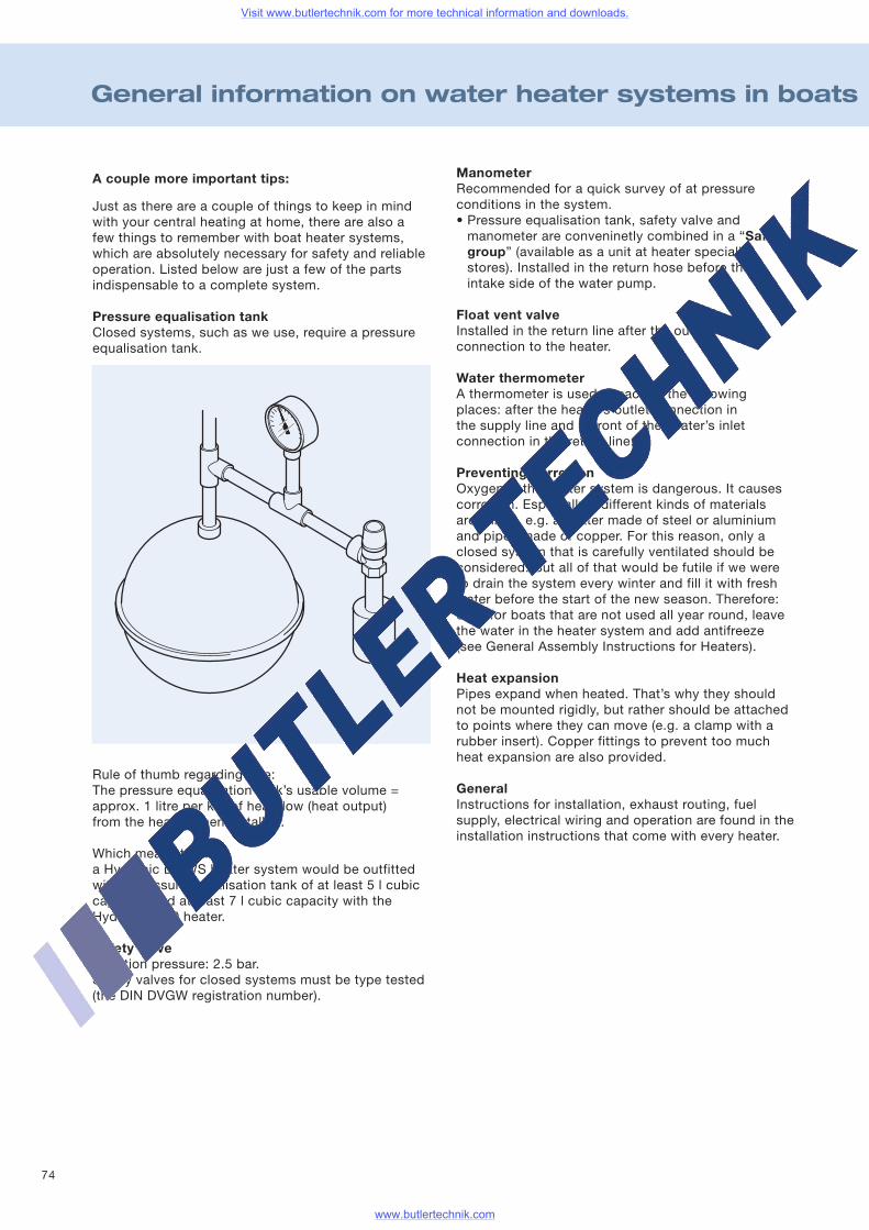
74
General information on water heater systems in boats
A couple more important tips:
Just as there are a couple of things to keep in mindwith your central heating at home, there are also afew things to remember with boat heater systems,which are absolutely necessary for safety and reliableoperation. Listed below are just a few of the partsindispensable to a complete system.
Pressure equalisation tankClosed systems, such as we use, require a pressureequalisation tank.
Rule of thumb regarding size:The pressure equalisation tank’s usable volume =approx. 1 litre per kW of heat flow (heat output)from the heater when installed.
Which means that:a Hydronic D 5WS heater system would be outfittedwith a pressure equalisation tank of at least 5 l cubiccapacity, and at least 7 l cubic capacity with theHydronic M10 heater.
Safety valveReaction pressure: 2.5 bar.Safety valves for closed systems must be type tested(the DIN DVGW registration number).
ManometerRecommended for a quick survey of at pressureconditions in the system.• Pressure equalisation tank, safety valve andmanometer are conveninetly combined in a “Safetygroup” (available as a unit at heater specialitystores). Installed in the return hose before theintake side of the water pump.
Float vent valveInstalled in the return line after the outletconnection to the heater.
Water thermometerA thermometer is used at each of the followingplaces: after the heater’s outlet connection inthe supply line and in front of the heater’s inletconnection in the return line.
Preventing corrosionOxygen in the heater system is dangerous. It causescorrosion. Especially if different kinds of materialsare joined, e.g. a heater made of steel or aluminiumand pipes made of copper. For this reason, only aclosed system that is carefully ventilated should beconsidered. But all of that would be futile if we wereto drain the system every winter and fill it with freshwater before the start of the new season. Therefore:even for boats that are not used all year round, leavethe water in the heater system and add antifreeze(see General Assembly Instructions for Heaters).
Heat expansionPipes expand when heated. That’s why they shouldnot be mounted rigidly, but rather should be attachedto points where they can move (e.g. a clamp with arubber insert). Copper fittings to prevent too muchheat expansion are also provided.
GeneralInstructions for installation, exhaust routing, fuelsupply, electrical wiring and operation are found in theinstallation instructions that come with every heater.
Visit www.butlertechnik.com for more technical information and downloads.
www.butlertechnik.com
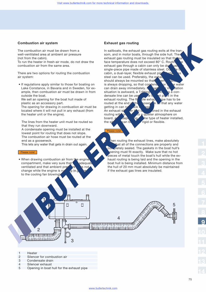
75
Combustion air system
The combustion air must be drawn from awell-ventilated area at ambient air pressure(not from the cabin).To run the heater in fresh-air mode, do not draw thecombustion air from the same area.
There are two options for routing the combustionair system:
• If regulations apply similar to those for boating onLake Constance, in Bavaria and in Sweden, for ex-ample, then combustion air must be drawn in fromoutside the boat.We sell an opening for the boat hull made ofplastic as an accessory part.The opening for drawing in combustion air must belocated where it will not pull in any exhaust (fromthe heater unit or the engine).
The lines from the heater unit must be routed sothat they run downward.A condensate opening must be installed at thelowest point for routing that does not slope.The combustion air hose must be routed at theend as a gooseneck.This lets any water that gets in drain out again.
• When drawing combustion air from the enginecompartment, make very sure that it is adequatelyventilated and that ambient pressure does notchange while the engine is running (e.g. dueto the cooling fan blowing).
Exhaust gas routing
In sailboats, the exhaust gas routing exits at the tran-som, and in motor boats, through the side hull. Theexhaust gas routing must be insulated so that the sur-face temperature does not exceed 80° C. Routing theexhaust gas through a cabin can only be done using asingle-piece pipe made of stainless steel. Outside thecabin, a dual-layer, flexible exhaust pipe of stainlesssteel can be used. Preferably, the exhaust gas lineshould always be mounted so that, when installed, itis always dropping, so that condensate or surge watercan drain away immediately. If a particular installationsituation is awkward, a T-fitting that includes a con-densate line can be used at the lowest point in theexhaust routing. The flexible exhaust pipe has to berouted at the end of the gooseneck so that any watergetting in can run back out again.An exhaust silencer that is positioned in the exhaustrouting will contribute to a quieter atmosphere onboard, and, depending on the type of heater installed,the silencer can be either rigid or flexible.
• When routing the exhaust lines, make absolutelysure that all of the connections are properly andcompletely sealed. The gaskets in the boat hull’sopening must fit exactly. Make sure that no hotpieces of metal touch the boat’s hull while the ex-haust routing is being laid and the opening in theboat hull is being installed. Minimum distance fromthe hull of 20 mm must absolutely be maintainedif the exhaust gas lines are insulated.
Please note!
Please note!
1
2
3
4
5
6
7
8
9
10
11
12
13
14
1 Heater2 Silencer for combustion air3 Condensate drain4 Silencer exhaust5 Opening in boat hull for the exhaust pipe
Visit www.butlertechnik.com for more technical information and downloads.
www.butlertechnik.com
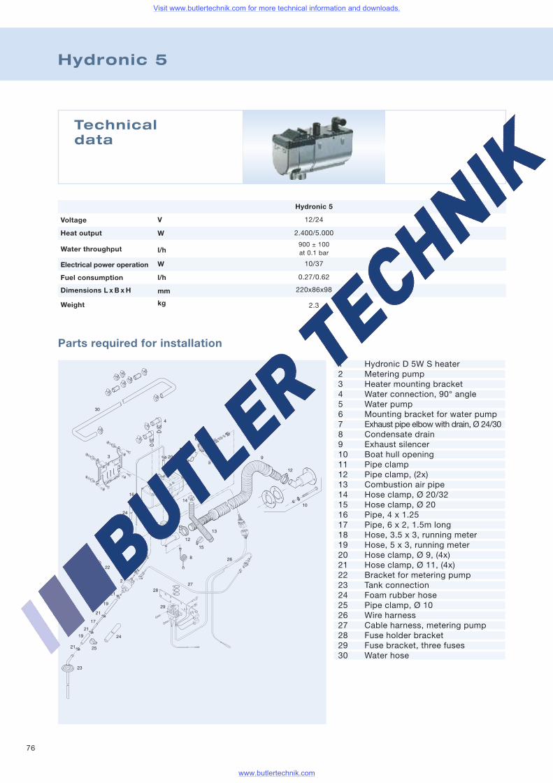
76
Hydronic 5
Parts required for installation
Technicaldata
Hydronic 5
12/24V
W
l/h
W
l/h
mm
kg
1 Hydronic D 5W S heater2 Metering pump3 Heater mounting bracket4 Water connection, 90° angle5 Water pump6 Mounting bracket for water pump7 Exhaust pipe elbowwith drain, Ø 24/308 Condensate drain9 Exhaust silencer10 Boat hull opening11 Pipe clamp12 Pipe clamp, (2x)13 Combustion air pipe14 Hose clamp, Ø 20/3215 Hose clamp, Ø 2016 Pipe, 4 x 1.2517 Pipe, 6 x 2, 1.5m long18 Hose, 3.5 x 3, running meter19 Hose, 5 x 3, running meter20 Hose clamp, Ø 9, (4x)21 Hose clamp, Ø 11, (4x)22 Bracket for metering pump23 Tank connection24 Foam rubber hose25 Pipe clamp, Ø 1026 Wire harness27 Cable harness, metering pump28 Fuse holder bracket29 Fuse bracket, three fuses30 Water hose
Voltage
Water throughput
Heat output
Fuel consumption
Electrical power operation
Dimensions L x B x H
Weight
2.400/5.000
900 ± 100at 0.1 bar
10/37
0.27/0.62
220x86x98
2.3
Visit www.butlertechnik.com for more technical information and downloads.
www.butlertechnik.com
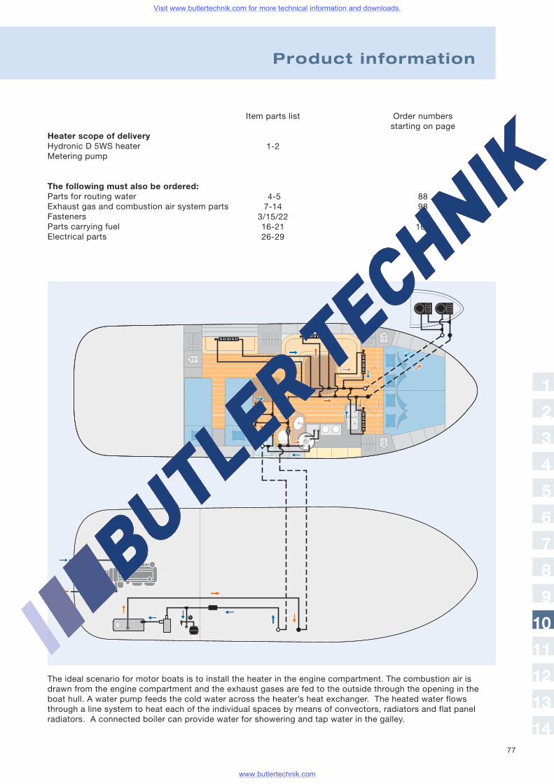
77
1
2
3
4
5
6
7
8
9
10
11
12
13
14
Heater scope of deliveryHydronic D 5WS heaterMetering pump
The following must also be ordered:Parts for routing waterExhaust gas and combustion air system partsFastenersParts carrying fuelElectrical parts
Product information
Item parts list
1-2
4-57-14
3/15/2216-2126-29
Order numbersstarting on page
8898114106
The ideal scenario for motor boats is to install the heater in the engine compartment. The combustion air isdrawn from the engine compartment and the exhaust gases are fed to the outside through the opening in theboat hull. A water pump feeds the cold water across the heater’s heat exchanger. The heated water flowsthrough a line system to heat each of the individual spaces by means of convectors, radiators and flat panelradiators. A connected boiler can provide water for showering and tap water in the galley.
Visit www.butlertechnik.com for more technical information and downloads.
www.butlertechnik.com
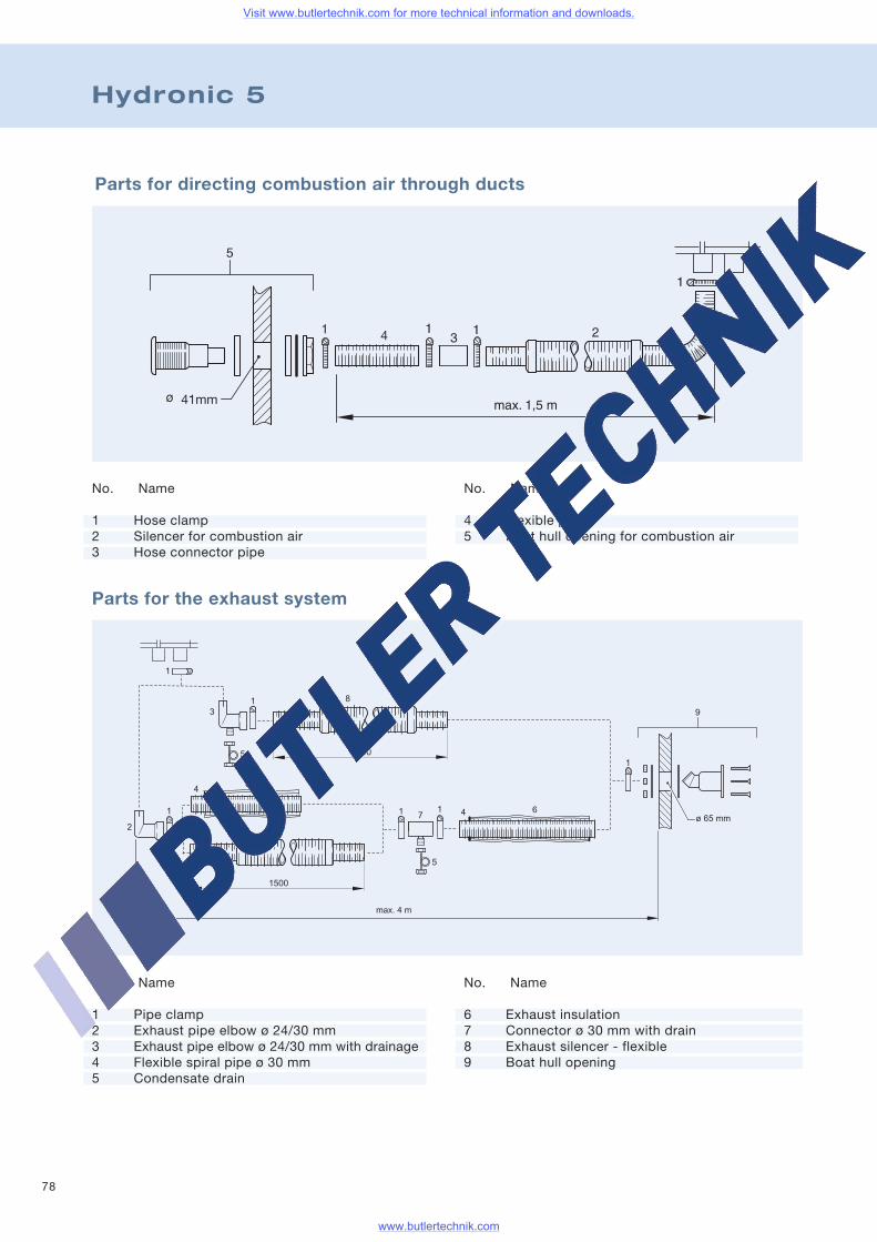
78
Hydronic 5
Parts for directing combustion air through ducts
Parts for the exhaust system
No. Name
1 Pipe clamp2 Exhaust pipe elbow ø 24/30 mm3 Exhaust pipe elbow ø 24/30 mm with drainage4 Flexible spiral pipe ø 30 mm5 Condensate drain
No. Name
6 Exhaust insulation7 Connector ø 30 mm with drain8 Exhaust silencer - flexible9 Boat hull opening
No. Name
1 Hose clamp2 Silencer for combustion air3 Hose connector pipe
No. Name
4 Flexible pipe5 Boat hull opening for combustion air
Visit www.butlertechnik.com for more technical information and downloads.
www.butlertechnik.com
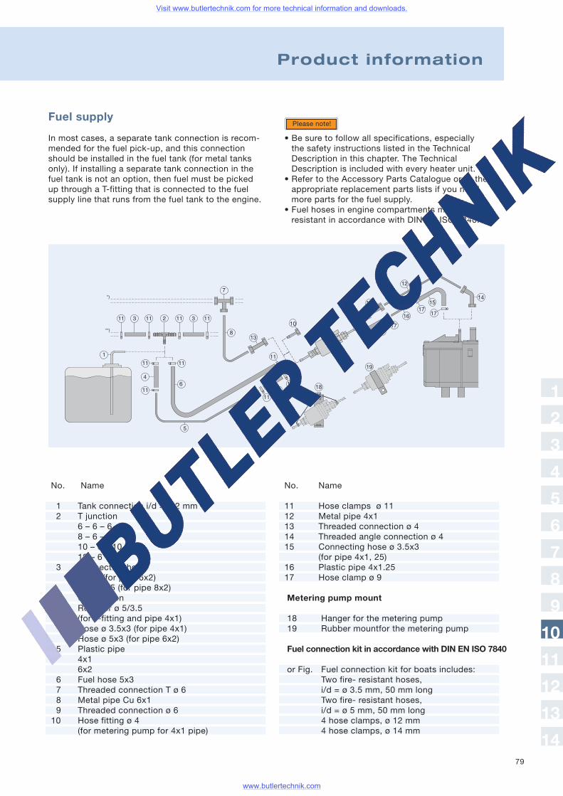
79
Fuel supply
In most cases, a separate tank connection is recom-mended for the fuel pick-up, and this connectionshould be installed in the fuel tank (for metal tanksonly). If installing a separate tank connection in thefuel tank is not an option, then fuel must be pickedup through a T-fitting that is connected to the fuelsupply line that runs from the fuel tank to the engine.
• Be sure to follow all specifications, especiallythe safety instructions listed in the TechnicalDescription in this chapter. The TechnicalDescription is included with every heater unit.
• Refer to the Accessory Parts Catalogue or to theappropriate replacement parts lists if you needmore parts for the fuel supply.
• Fuel hoses in engine compartments must be fire-resistant in accordance with DIN EN ISO 7840.
Please note!
No. Name
1 Tank connection i/d = ø 2 mm2 T junction
6 – 6 – 68 – 6 – 810 – 6 – 1012 – 6 – 12
3 Connecting hoseø 5x3 (for pipe 6x2)ø 7.5x2.5 (for pipe 8x2)
4 ConnectionReducer ø 5/3.5(for T-fitting and pipe 4x1)Hose ø 3.5x3 (for pipe 4x1)Hose ø 5x3 (for pipe 6x2)
5 Plastic pipe4x16x2
6 Fuel hose 5x37 Threaded connection T ø 68 Metal pipe Cu 6x19 Threaded connection ø 610 Hose fitting ø 4
(for metering pump for 4x1 pipe)
No. Name
11 Hose clamps ø 1112 Metal pipe 4x113 Threaded connection ø 414 Threaded angle connection ø 415 Connecting hose ø 3.5x3
(for pipe 4x1, 25)16 Plastic pipe 4x1.2517 Hose clamp ø 9
Product information
Metering pump mount
18 Hanger for the metering pump19 Rubber mountfor the metering pump
Fuel connection kit in accordance with DIN EN ISO 7840
or Fig. Fuel connection kit for boats includes:Two fire- resistant hoses,i/d = ø 3.5 mm, 50 mm longTwo fire- resistant hoses,i/d = ø 5 mm, 50 mm long4 hose clamps, ø 12 mm4 hose clamps, ø 14 mm
1
2
3
4
5
6
7
8
9
10
11
12
13
14
Visit www.butlertechnik.com for more technical information and downloads.
www.butlertechnik.com
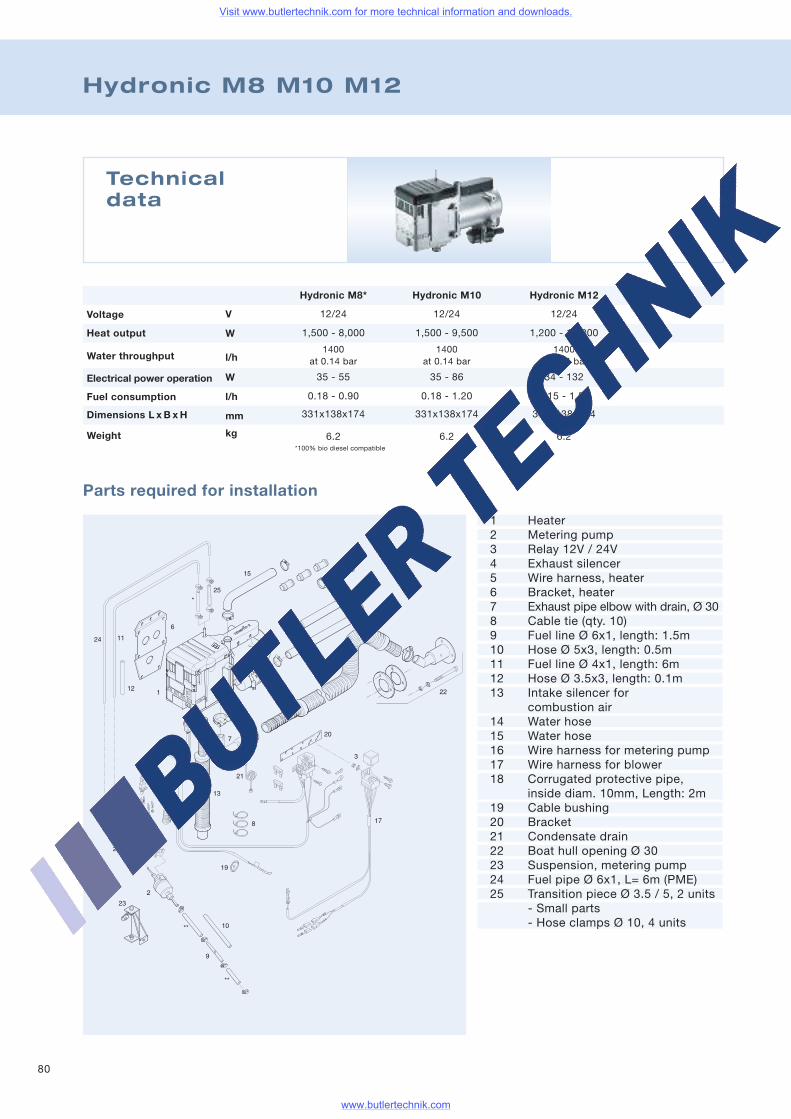
80
Hydronic M8 M10 M12
Parts required for installation
Technicaldata
1 Heater2 Metering pump3 Relay 12V / 24V4 Exhaust silencer5 Wire harness, heater6 Bracket, heater7 Exhaust pipe elbow with drain, Ø 308 Cable tie (qty. 10)9 Fuel line Ø 6x1, length: 1.5m10 Hose Ø 5x3, length: 0.5m11 Fuel line Ø 4x1, length: 6m12 Hose Ø 3.5x3, length: 0.1m13 Intake silencer for
combustion air14 Water hose15 Water hose16 Wire harness for metering pump17 Wire harness for blower18 Corrugated protective pipe,
inside diam. 10mm, Length: 2m19 Cable bushing20 Bracket21 Condensate drain22 Boat hull opening Ø 3023 Suspension, metering pump24 Fuel pipe Ø 6x1, L= 6m (PME)25 Transition piece Ø 3.5 / 5, 2 units
- Small parts- Hose clamps Ø 10, 4 units
Hydronic M8*
12/24V
W
l/h
W
l/h
mm
kg
Voltage
Water throughput
Heat output
Fuel consumption
Electrical power operation
Dimensions L x B x H
Weight
1,500 - 8,000
1400at 0.14 bar
35 - 55
0.18 - 0.90
331x138x174
6.2
Hydronic M10
12/24
1,500 - 9,500
1400at 0.14 bar
35 - 86
0.18 - 1.20
331x138x174
6.2
Hydronic M12
12/24
1,200 - 12,000
1400at 0.14 bar
34 - 132
0.15 - 1.50
331x138x174
6.2*100% bio diesel compatible
Visit www.butlertechnik.com for more technical information and downloads.
www.butlertechnik.com
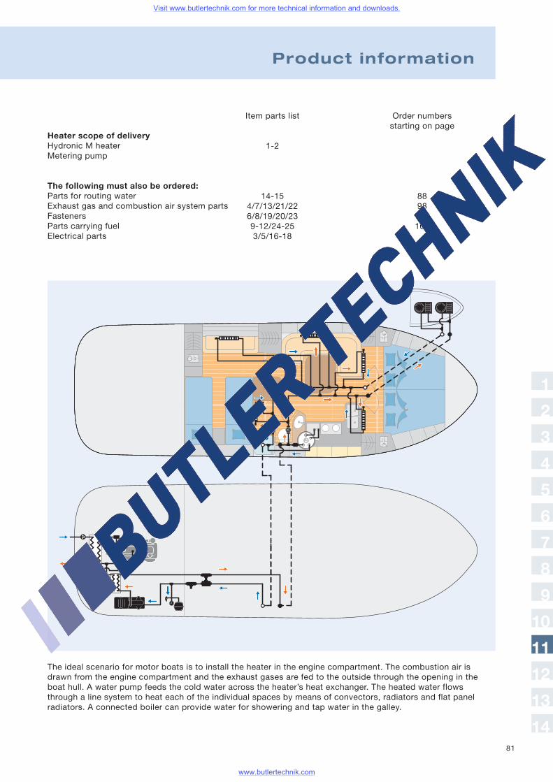
81
Heater scope of deliveryHydronic M heaterMetering pump
The following must also be ordered:Parts for routing waterExhaust gas and combustion air system partsFastenersParts carrying fuelElectrical parts
Product information
Item parts list
1-2
14-154/7/13/21/226/8/19/20/239-12/24-253/5/16-18
Order numbersstarting on page
8898114106
The ideal scenario for motor boats is to install the heater in the engine compartment. The combustion air isdrawn from the engine compartment and the exhaust gases are fed to the outside through the opening in theboat hull. A water pump feeds the cold water across the heater’s heat exchanger. The heated water flowsthrough a line system to heat each of the individual spaces by means of convectors, radiators and flat panelradiators. A connected boiler can provide water for showering and tap water in the galley.
1
2
3
4
5
6
7
8
9
10
11
12
13
14
Visit www.butlertechnik.com for more technical information and downloads.
www.butlertechnik.com
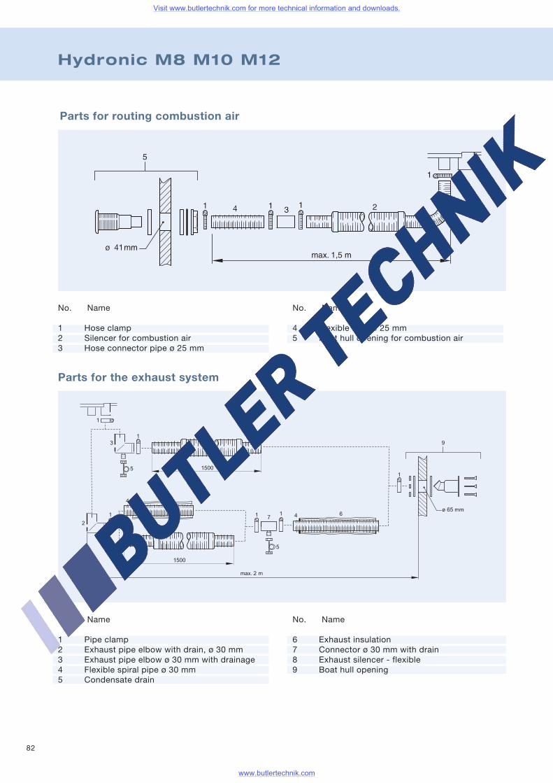
82
Hydronic M8 M10 M12
Parts for routing combustion air
Parts for the exhaust system
No. Name
1 Hose clamp2 Silencer for combustion air3 Hose connector pipe ø 25 mm
No. Name
4 Flexible tube ø 25 mm5 Boat hull opening for combustion air
No. Name
1 Pipe clamp2 Exhaust pipe elbow with drain, ø 30 mm3 Exhaust pipe elbow ø 30 mm with drainage4 Flexible spiral pipe ø 30 mm5 Condensate drain
No. Name
6 Exhaust insulation7 Connector ø 30 mm with drain8 Exhaust silencer - flexible9 Boat hull opening
Visit www.butlertechnik.com for more technical information and downloads.
www.butlertechnik.com

83
Fuel supply
In most cases, a separate tank connection is recom-mended for the fuel pick-up, and this connectionshould be installed in the fuel tank (for metal tanksonly). If installing a separate tank connection in thefuel tank is not an option, then fuel must be pickedup through a T-fitting that is connected to the fuelsupply line that runs from the fuel tank to the engine.
Please note!
No. Name
1 Tank connection i/d = ø 2 mm2 T junction
6 – 6 – 68 – 6 – 810 – 6 – 1012 – 6 – 12
3 Connecting hoseø 5x3 (for pipe 6x2)ø 7.5x2.5 (for pipe 8x2)
4 ConnectionReducer ø 5/3.5(for T-fitting and pipe 4x1)Hose ø 3.5x3 (for pipe 4x1)Hose ø 5x3 (for pipe 6x2)
5 Plastic pipe4x16x2
6 Fuel hose 5x37 Threaded connection T ø 68 Metal pipe Cu 6x19 Threaded connection ø 610 Hose fitting ø 4
(for metering pump for 4x1 pipe)
No. Name
11 Hose clamp ø 1112 Metal pipe 4x112 Metal pipe 4x113 Threaded connection ø 414 Threaded angle connection ø 415 Connecting hose ø 3.5x3 (for pipe 4x1. 25)16 Plastic pipe 4x1.2517 Hose clamp ø 9
Product information
Metering pump mount
18 Hanger for the metering pump19 Rubber mount for the metering pump
Fuel connection kit in accordance with DIN EN ISO 7840
or Fig. Fuel connection kit for boats includes:Two fire- resistant hoses,i/d = ø 3.5 mm, 50 mm longTwo fire- resistant hoses,i/d = ø 5 mm, 50 mm long4 hose clamps, ø 12 mm4 hose clamps, ø 14 mm
• Be sure to follow all specifications, especially thesafety instructions listed in the Technical Descriptionin this chapter. The Technical Description is includedwith every heater unit.
• Refer to the Accessory Parts Catalogue or to theappropriate replacement parts lists if you needmore parts for the fuel supply.
• Fuel hoses in engine compartments must be fire-resistant in accordance with DIN EN ISO 7840.
1
2
3
4
5
6
7
8
9
10
11
12
13
14
Visit www.butlertechnik.com for more technical information and downloads.
www.butlertechnik.com
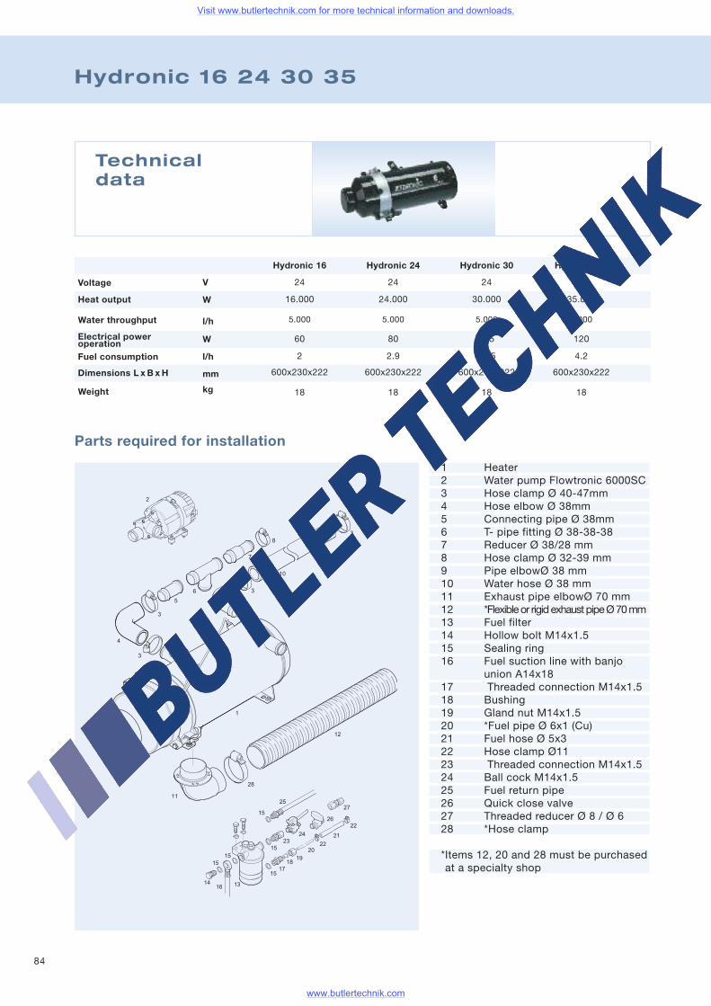
84
Hydronic 16 24 30 35
Parts required for installation
Technicaldata
1 Heater2 Water pump Flowtronic 6000SC3 Hose clamp Ø 40-47mm4 Hose elbow Ø 38mm5 Connecting pipe Ø 38mm6 T- pipe fitting Ø 38-38-387 Reducer Ø 38/28 mm8 Hose clamp Ø 32-39 mm9 Pipe elbowØ 38 mm10 Water hose Ø 38 mm11 Exhaust pipe elbowØ 70 mm12 *Flexibleor rigidexhaustpipeØ70mm13 Fuel filter14 Hollow bolt M14x1.515 Sealing ring16 Fuel suction line with banjo
union A14x1817 Threaded connection M14x1.518 Bushing19 Gland nut M14x1.520 *Fuel pipe Ø 6x1 (Cu)21 Fuel hose Ø 5x322 Hose clamp Ø1123 Threaded connection M14x1.524 Ball cock M14x1.525 Fuel return pipe26 Quick close valve27 Threaded reducer Ø 8 / Ø 628 *Hose clamp
*Items 12, 20 and 28 must be purchasedat a specialty shop
Hydronic 16
24V
W
l/h
W
l/h
mm
kg
Voltage
Water throughput
Heat output
Fuel consumption
Electrical poweroperation
Dimensions L x B x H
Weight
16.000
5.000
60
2
600x230x222
18
Hydronic 24
24
24.000
5.000
80
2.9
600x230x222
18
Hydronic 30
24
30.000
5.000
105
3.65
600x230x222
18
Hydronic 35
24
35.000
5.000
120
4.2
600x230x222
18
Visit www.butlertechnik.com for more technical information and downloads.
www.butlertechnik.com

85
1
2
3
4
5
6
7
8
9
10
11
12
13
14
Heater scope of deliveryHydronic heater 16 – 35
The following must also be ordered:Parts for routing waterExhaust gas and combustion air system partsFastenersParts carrying fuel
Product information
Item parts list
1-2
3-1011-1222
13-28
Order numbersstarting on page
8898114106
The ideal scenario for motor boats is to install the heater in the engine compartment. The combustion air isdrawn in from the engine compartment and the exhaust gases are fed to the outside through the opening inthe boat hull. A water pump feeds the cold water across the heater’s heat exchanger. The heated water flowsthrough a line system to heat each of the individual spaces by means of convectors, radiators and flat panelradiators. A connected boiler can provide water for showering and tap water in the galley. The engine canalso be integrated through a water/water heat exchanger. That gives you the option of heating the boat byusing heat from the engine during your boat trip, and of loading the boiler.
Visit www.butlertechnik.com for more technical information and downloads.
www.butlertechnik.com
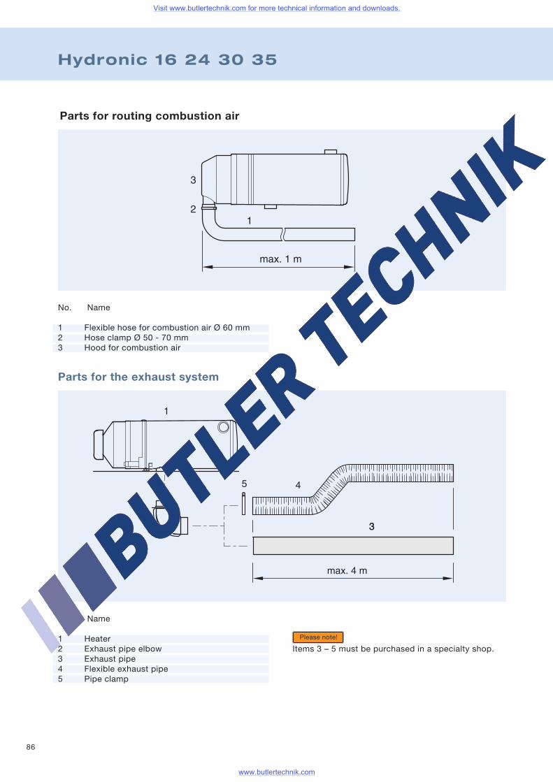
86
Hydronic 16 24 30 35
Parts for routing combustion air
Parts for the exhaust system
No. Name
1 Heater2 Exhaust pipe elbow3 Exhaust pipe4 Flexible exhaust pipe5 Pipe clamp
Items 3 – 5 must be purchased in a specialty shop.
No. Name
1 Flexible hose for combustion air Ø 60 mm2 Hose clamp Ø 50 - 70 mm3 Hood for combustion air
Please note!
Visit www.butlertechnik.com for more technical information and downloads.
www.butlertechnik.com
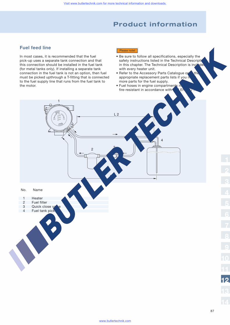
87
Fuel feed line
In most cases, it is recommended that the fuelpick-up uses a separate tank connection and thatthis connection should be installed in the fuel tank(for metal tanks only). If installing a separate tankconnection in the fuel tank is not an option, then fuelmust be picked upthrough a T-fitting that is connectedto the fuel supply line that runs from the fuel tank tothe motor.
Please note!
No. Name
1 Heater2 Fuel filter3 Quick close valve4 Fuel tank pick-up
Product information
• Be sure to follow all specifications, especially thesafety instructions listed in the Technical Descriptionin this chapter. The Technical Description is includedwith every heater unit.
• Refer to the Accessory Parts Catalogue or to theappropriate replacement parts lists if you needmore parts for the fuel supply.
• Fuel hoses in engine compartments must befire-resistant in accordance with DIN EN ISO 7840.
1
2
3
4
5
6
7
8
9
10
11
12
13
14
Visit www.butlertechnik.com for more technical information and downloads.
www.butlertechnik.com
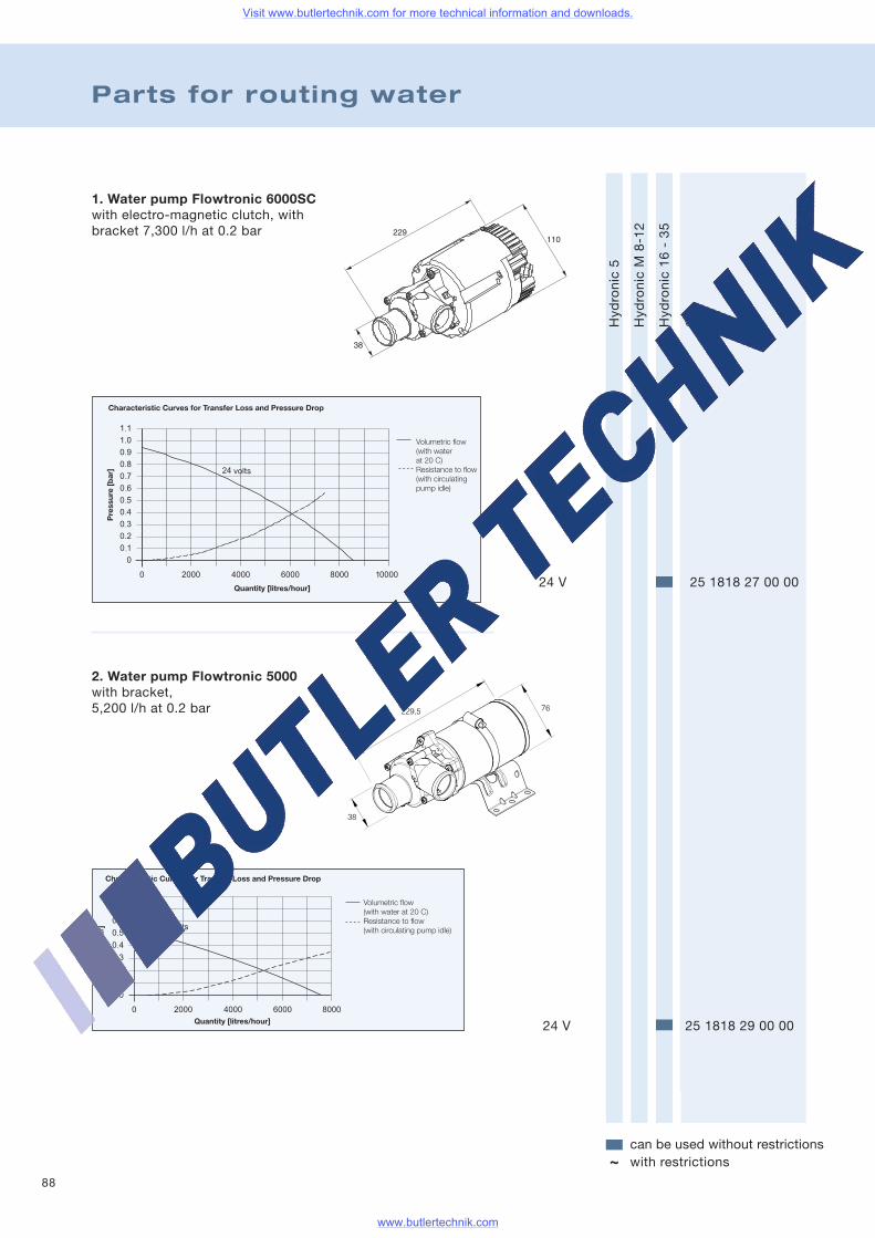
88
Parts for routing water
Hydronic5
HydronicM8-12
Hydronic16-35
Order no.
can be used without restrictionswith restrictions~
24 V 25 1818 27 00 00
.
.
.
.
.
.
.
.
.
.
.
Pre
ssur
e[b
ar]
2. Water pump Flowtronic 5000with bracket,5,200 l/h at 0.2 bar
24 V 25 1818 29 00 00
1. Water pump Flowtronic 6000SCwith electro-magnetic clutch, withbracket 7,300 l/h at 0.2 bar
Visit www.butlertechnik.com for more technical information and downloads.
www.butlertechnik.com
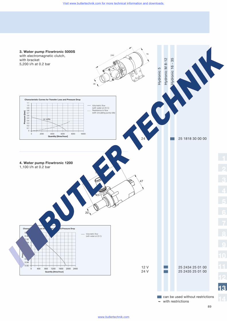
89
Hydronic5
HydronicM8-12
Hydronic16-35
Order no.
can be used without restrictionswith restrictions~
1
2
3
4
5
6
7
8
9
10
11
12
13
14
3. Water pump Flowtronic 5000Swith electromagnetic clutch,with bracket5,200 l/h at 0.2 bar
24 V 25 1818 30 00 00
4. Water pump Flowtronic 12001,100 l/h at 0.2 bar
12 V 25 2434 25 01 0024 V 25 2435 25 01 00
Visit www.butlertechnik.com for more technical information and downloads.
www.butlertechnik.com
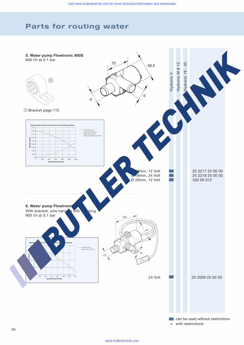
90
Parts for routing water
Hydronic5
HydronicM8-12
Hydronic16-35
can be used without restrictionswith restrictions~
Order no.
5. Water pump Flowtronic 800S800 l/h at 0.1 bar
Ø 18mm, 12 Volt 25 2217 25 00 00Ø 18mm, 24 Volt 25 2218 25 00 00Ø 20mm, 12 Volt 330 00 012
6. Water pump Flowtronic 900With bracket, wire harness 500 mm long900 l/h at 0.1 bar
24 Volt 25 2009 25 00 00
.
.
.
Bracket page 115
Visit www.butlertechnik.com for more technical information and downloads.
www.butlertechnik.com
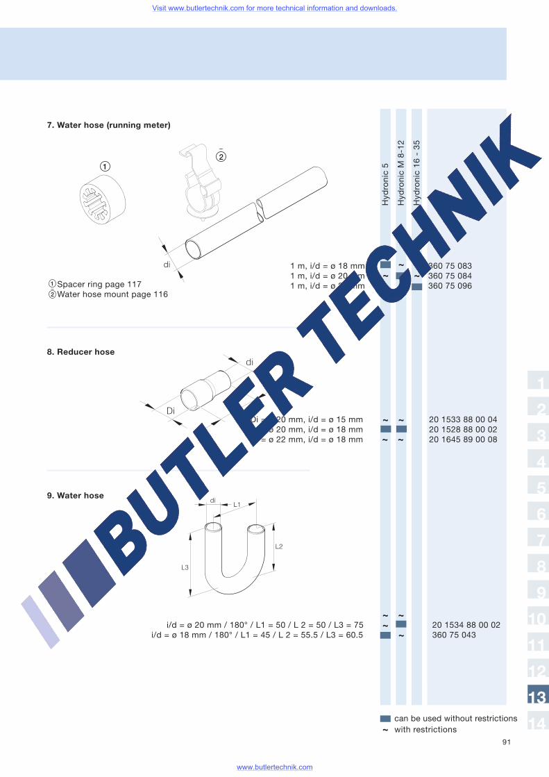
91
Hydronic5
HydronicM8-12
Hydronic16-35
Order no.
can be used without restrictionswith restrictions~
di
diL1
L2
L3
~~~
~ ~
~ ~
~ ~~
~
1
2
3
4
5
6
7
8
9
10
11
12
13
14
Spacer ring page 117Water hose mount page 116
7. Water hose (running meter)
8. Reducer hose
1 m, i/d = ø 18 mm 360 75 0831 m, i/d = ø 20 mm 360 75 0841 m, i/d = ø 38 mm 360 75 096
9. Water hose
i/d = ø 20 mm / 180° / L1 = 50 / L 2 = 50 / L3 = 75 20 1534 88 00 02i/d = ø 18 mm / 180° / L1 = 45 / L 2 = 55.5 / L3 = 60.5 360 75 043
Di = ø 20 mm, i/d = ø 15 mm 20 1533 88 00 04Di = ø 20 mm, i/d = ø 18 mm 20 1528 88 00 02Di = ø 22 mm, i/d = ø 18 mm 20 1645 89 00 08
Visit www.butlertechnik.com for more technical information and downloads.
www.butlertechnik.com
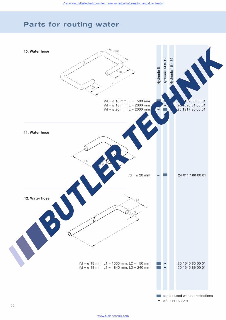
92
Parts for routing water
10. Water hose
11. Water hose
Hydronic5
HydronicM8-12
Hydronic16-35
Order no.
can be used without restrictionswith restrictions~
12. Water hose
i/d = ø 18 mm, L = 500 mm 24 0132 00 00 01i/d = ø 18 mm, L = 2000 mm 20 1690 81 00 01i/d = ø 20 mm, L = 2000 mm 25 1917 80 00 01
i/d = ø 20 mm 24 0117 80 00 01
i/d = ø 18 mm, L1 = 1000 mm, L2 = 50 mm 20 1645 80 00 01i/d = ø 18 mm, L1 = 840 mm, L2 = 240 mm 20 1645 89 00 01
~
~~
~
~~
Visit www.butlertechnik.com for more technical information and downloads.
www.butlertechnik.com
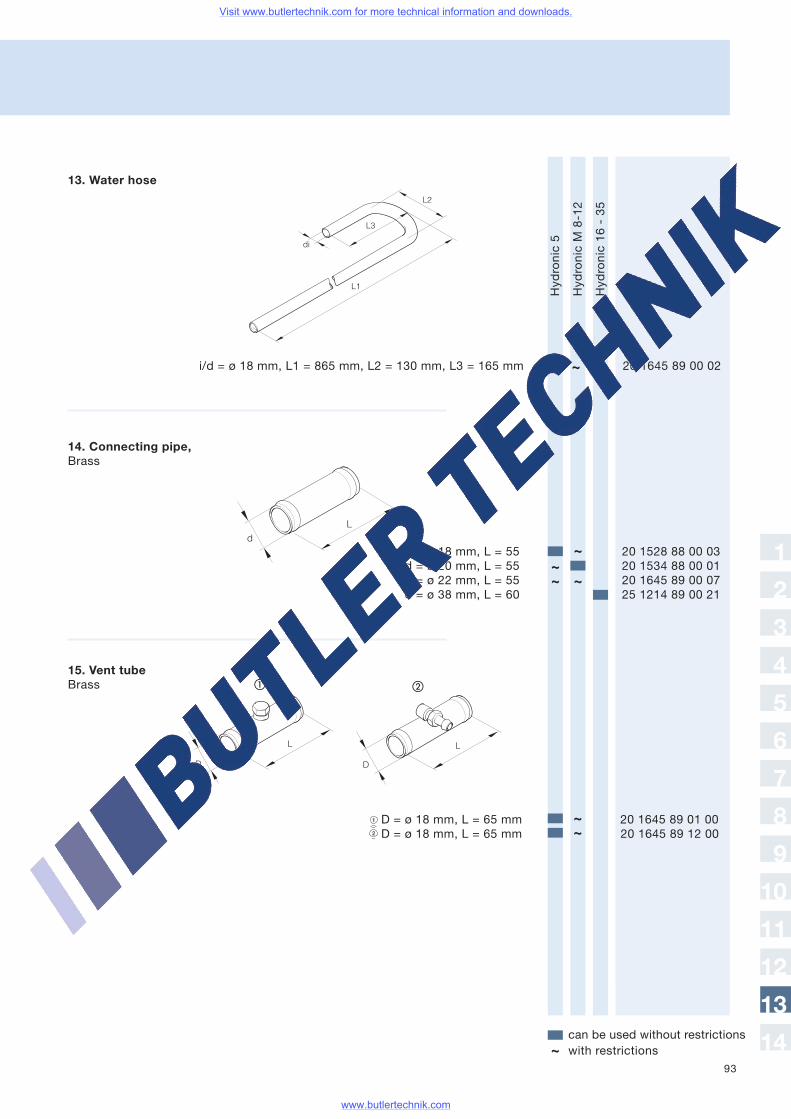
93
Hydronic5
HydronicM8-12
Hydronic16-35
Order no.
can be used without restrictionswith restrictions~
13. Water hose
14. Connecting pipe,Brass
15. Vent tubeBrass
D = ø 18 mm, L = 65 mm 20 1645 89 01 00D = ø 18 mm, L = 65 mm 20 1645 89 12 00
di
L2
L3
L1
dL
L
D D
L
ba
~
~~~ ~
~~
1
2
3
4
5
6
7
8
9
10
11
12
13
14
i/d = ø 18 mm, L1 = 865 mm, L2 = 130 mm, L3 = 165 mm 20 1645 89 00 02
d = ø 18 mm, L = 55 20 1528 88 00 03d = ø 20 mm, L = 55 20 1534 88 00 01d = ø 22 mm, L = 55 20 1645 89 00 07d = ø 38 mm, L = 60 25 1214 89 00 21
Visit www.butlertechnik.com for more technical information and downloads.
www.butlertechnik.com
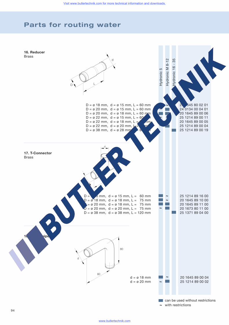
94
Parts for routing water
16. ReducerBrass
17. T-ConnectorBrass
18. Elbow pipe
d
80
80
Hydronic5
HydronicM8-12
Hydronic16-35
Order no.
can be used without restrictionswith restrictions~
D = ø 18 mm, d = ø 15 mm, L = 60 mm 20 1645 80 02 01D = ø 20 mm, d = ø 15 mm, L = 60 mm 24 0134 00 04 01D = ø 20 mm, d = ø 18 mm, L = 60 mm 20 1645 89 00 06D = ø 22 mm, d = ø 15 mm, L = 60 mm 25 1214 89 00 11D = ø 22 mm, d = ø 18 mm, L = 60 mm 20 1645 89 00 05D = ø 22 mm, d = ø 20 mm, L = 60 mm 25 1214 89 00 04D = ø 38 mm, d = ø 28 mm, L = 80 mm 25 1214 89 00 19
D = ø 18 mm, d = ø 15 mm, L = 60 mm 25 1214 89 16 00D = ø 18 mm, d = ø 18 mm, L = 75 mm 20 1645 89 10 00D = ø 20 mm, d = ø 18 mm, L = 75 mm 20 1645 89 11 00D = ø 20 mm, d = ø 20 mm, L = 75 mm 20 1673 80 11 00D = ø 38 mm, d = ø 38 mm, L = 120 mm 25 1371 89 04 00
d = ø 18 mm 20 1645 89 00 04d = ø 20 mm 25 1214 89 00 02
d
D L
d
D L
~~
~ ~~ ~~
~
~~
~~
Visit www.butlertechnik.com for more technical information and downloads.
www.butlertechnik.com
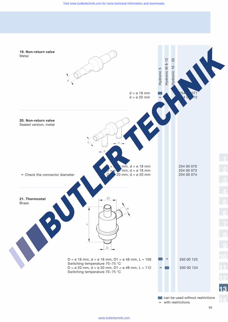
95
19. Non-return valveMetal
20. Non-return valveSealed version, metal
~ Check the connector diameter
Hydronic5
HydronicM8-12
Hydronic16-35
Order no.
can be used without restrictionswith restrictions~
d = ø 18 mm 254 00 071d = ø 20 mm 254 00 072
D = ø 18 mm, d = ø 18 mm 254 00 070D = ø 20 mm, d = ø 18 mm 254 00 073D = ø 20 mm, d = ø 20 mm 254 00 074
D
d
d
d
21. ThermostatBrass
D
d
L
D1
D = ø 18 mm, d = ø 18 mm, D1 = ø 48 mm, L = 109 330 00 123Switching temperature 70−75 °CD = ø 20 mm, d = ø 20 mm, D1 = ø 48 mm, L = 112 330 00 124Switching temperature 70−75 °C
~
~
~~
1
2
3
4
5
6
7
8
9
10
11
12
13
14
Visit www.butlertechnik.com for more technical information and downloads.
www.butlertechnik.com
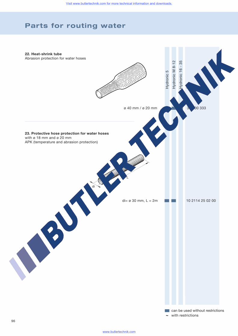
96
Parts for routing water
22. Heat-shrink tubeAbrasion protection for water hoses
Hydronic5
HydronicM8-12
Hydronic16-35
Order no.
can be used without restrictionswith restrictions~
ø 40 mm / ø 20 mm 360 00 333
23. Protective hose protection for water hoseswith ø 18 mm and ø 20 mmAPK (temperature and abrasion protection)
di= ø 30 mm, L = 2m 10 2114 25 02 00
Visit www.butlertechnik.com for more technical information and downloads.
www.butlertechnik.com
97
Notes
1
2
3
4
5
6
7
8
9
10
11
12
13
14
Visit www.butlertechnik.com for more technical information and downloads.
www.butlertechnik.com
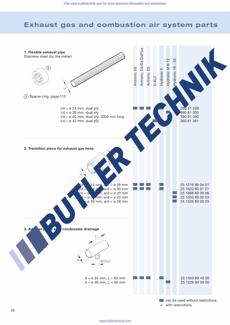
98
Exhaust gas and combustion air system parts
AirtronicD2
AirtronicD3/D4/D4Plus
AirtronicD5
D8LC
Hydronic5
HydronicM8-12
Hydronic16-35
Order no.
can be used without restrictionswith restrictions~
i/d = ø 24 mm, dual ply 360 61 299i/d = ø 30 mm, dual ply 360 61 300i/d = ø 40 mm, dual ply, 3000 mm long 360 61 380i/d = ø 42 mm, dual ply 360 61 381
i/d = ø 24 mm, a/d = ø 26 mm 25 1216 88 04 01i/d = ø 24 mm, a/d = ø 30 mm 25 1520 80 01 01i/d = ø 30 mm, a/d = ø 20 mm 25 1688 89 00 08i/d = ø 30 mm, a/d = ø 22 mm 22 1050 89 00 03i/d = ø 30 mm, a/d = ø 26 mm 25 1226 89 00 29
~
1. Flexible exhaust pipeStainless steel (by the meter)
Spacer ring, page 115
2. Transition piece for exhaust gas hose
3. Adapter piece with condensate drainage
d = ø 24 mm, L = 65 mm 22 1050 89 40 00d = ø 30 mm, L = 60 mm 25 1226 89 59 00
Visit www.butlertechnik.com for more technical information and downloads.
www.butlertechnik.com
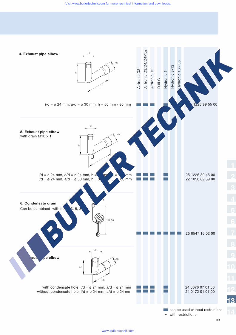
99
AirtronicD2
AirtronicD3/D4/D4Plus
AirtronicD5
D8LC
Hydronic5
Hydronic8-12
Hydronic16-35
Order no.
can be used without restrictionswith restrictions~
4. Exhaust pipe elbow
i/d = ø 24 mm, a/d = ø 30 mm, h = 50 mm / 80 mm 25 1226 89 55 00
di
da
L
h
5. Exhaust pipe elbowwith drain M10 x 1
i/d = ø 24 mm, a/d = ø 24 mm, h = 50 mm, L = 110 mm 25 1226 89 45 00i/d = ø 24 mm, a/d = ø 30 mm, h = 50 mm, L = 80 mm 22 1050 89 39 00
di
da
L
h
6. Condensate drain
25 8547 16 02 00
7. Exhaust pipe elbow
with condensate hole i/d = ø 24 mm, a/d = ø 24 mm 24 0076 07 01 00without condensate hole i/d = ø 24 mm, a/d = ø 24 mm 24 0172 01 01 00
Can be combined with items 3, 5, 8
1
2
3
4
5
6
7
8
9
10
11
12
13
14
Visit www.butlertechnik.com for more technical information and downloads.
www.butlertechnik.com
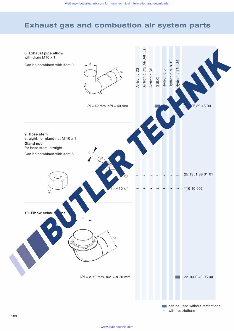
100
Exhaust gas and combustion air system parts
AirtronicD2
AirtronicD3/D4/D4Plus
AirtronicD5
D8LC
Hydronic5
HydronicM8-12
Hydronic16-35
Order no.
can be used without restrictionswith restrictions~
8. Exhaust pipe elbowwith drain M10 x 1
i/d = 42 mm, a/d = 40 mm 25 1226 89 46 00
i/d = ø 70 mm, a/d = ø 70 mm 22 1000 40 03 00
25 1351 88 01 01
M10 x 1 116 10 002
~ ~ ~ ~ ~ ~ ~
~ ~ ~ ~ ~ ~ ~
Can be combined with item 9
9. Hose stemstraight, for gland nut M 10 x 1Gland nutfor hose stem, straight
Can be combined with item 8
10. Elbow exhaust pipe
Visit www.butlertechnik.com for more technical information and downloads.
www.butlertechnik.com
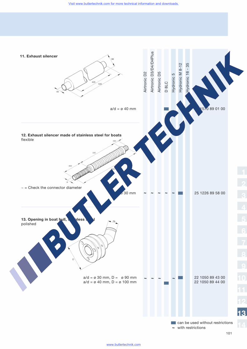
101
AirtronicD2
AirtronicD3/D4/D4Plus
AirtronicD5
D8LC
Hydronic5
HydronicM8-12
Hydronic16-35
Order no.
can be used without restrictionswith restrictions~
a/d = ø 40 mm 25 1570 89 01 00
i/d = ø 30 mm 25 1226 89 58 00~ = Check the connector diameter
a/d = ø 30 mm, D = ø 90 mm 22 1050 89 43 00a/d = ø 40 mm, D = ø 100 mm 22 1050 89 44 00
11. Exhaust silencer
~ ~ ~ ~ ~
~ ~ ~ ~
1
2
3
4
5
6
7
8
9
10
11
12
13
14
12. Exhaust silencer made of stainless steel for boatsflexible
13. Opening in boat hull, stainless steelpolished
Visit www.butlertechnik.com for more technical information and downloads.
www.butlertechnik.com
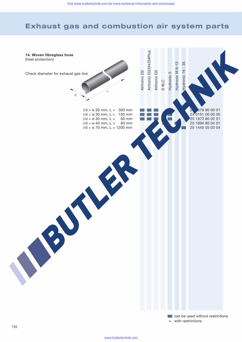
102
Exhaust gas and combustion air system parts
AirtronicD2
AirtronicD3/D4/D4Plus
AirtronicD5
D8LC
Hydronic5
HydronicM8-12
Hydronic16-35
Order no.
can be used without restrictionswith restrictions~
i/d = ø 30 mm, L = 300 mm 25 1676 80 00 01i/d = ø 30 mm, L = 150 mm 24 0151 00 00 05i/d = ø 30 mm, L = 60 mm 25 1973 80 02 01i/d = ø 40 mm, L = 60 mm 25 1894 80 04 01i/d = ø 70 mm, L = 1200 mm 25 1445 05 03 04
Ldi
14. Woven fibreglass hose(heat protection)
~
Check diameter for exhaust gas line
Visit www.butlertechnik.com for more technical information and downloads.
www.butlertechnik.com
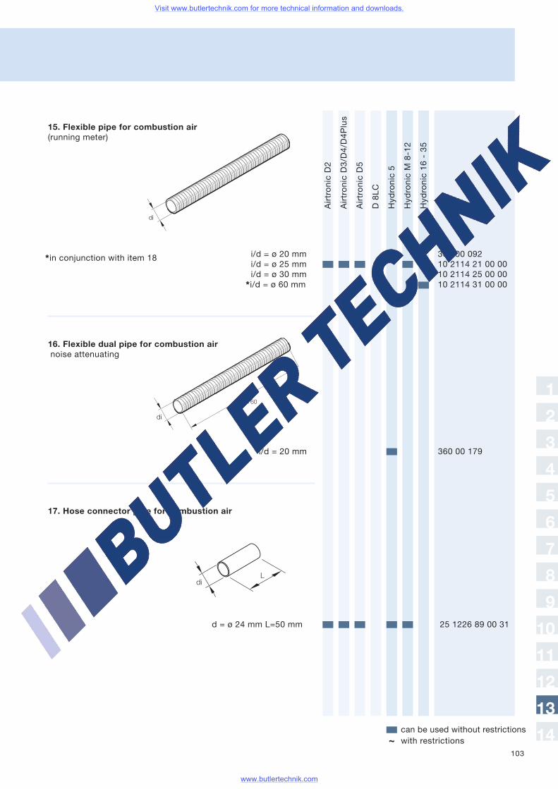
103
AirtronicD2
AirtronicD3/D4/D4Plus
AirtronicD5
D8LC
Hydronic5
HydronicM8-12
Hydronic16-35
Order no.
can be used without restrictionswith restrictions~
16. Flexible dual pipe for combustion airnoise attenuating
i/d = 20 mm 360 00 179
i/d = ø 20 mm 360 00 092i/d = ø 25 mm 10 2114 21 00 00i/d = ø 30 mm 10 2114 25 00 00
*i/d = ø 60 mm 10 2114 31 00 00
15. Flexible pipe for combustion air(running meter)
17. Hose connector pipe for combustion air
d = ø 24 mm L=50 mm 25 1226 89 00 31
*in conjunction with item 18
1
2
3
4
5
6
7
8
9
10
11
12
13
14
Visit www.butlertechnik.com for more technical information and downloads.
www.butlertechnik.com
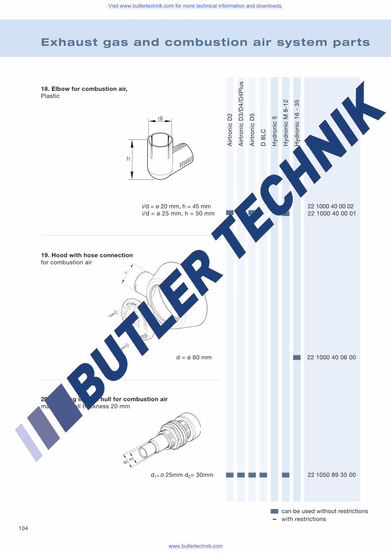
104
Exhaust gas and combustion air system parts
AirtronicD2
AirtronicD3/D4/D4Plus
AirtronicD5
D8LC
Hydronic5
HydronicM8-12
Hydronic16-35
Order no.
can be used without restrictionswith restrictions~
d = ø 60 mm 22 1000 40 06 00
d
18. Elbow for combustion air,Plastic
i/d = ø 20 mm, h = 45 mm 22 1000 40 00 02i/d = ø 25 mm, h = 50 mm 22 1000 40 00 01
d1= Ø 25mm d2= 30mm 22 1050 89 35 00
19. Hood with hose connectionfor combustion air
20. Opening in boat hull for combustion airmax. boat hull thickness 20 mm
Visit www.butlertechnik.com for more technical information and downloads.
www.butlertechnik.com
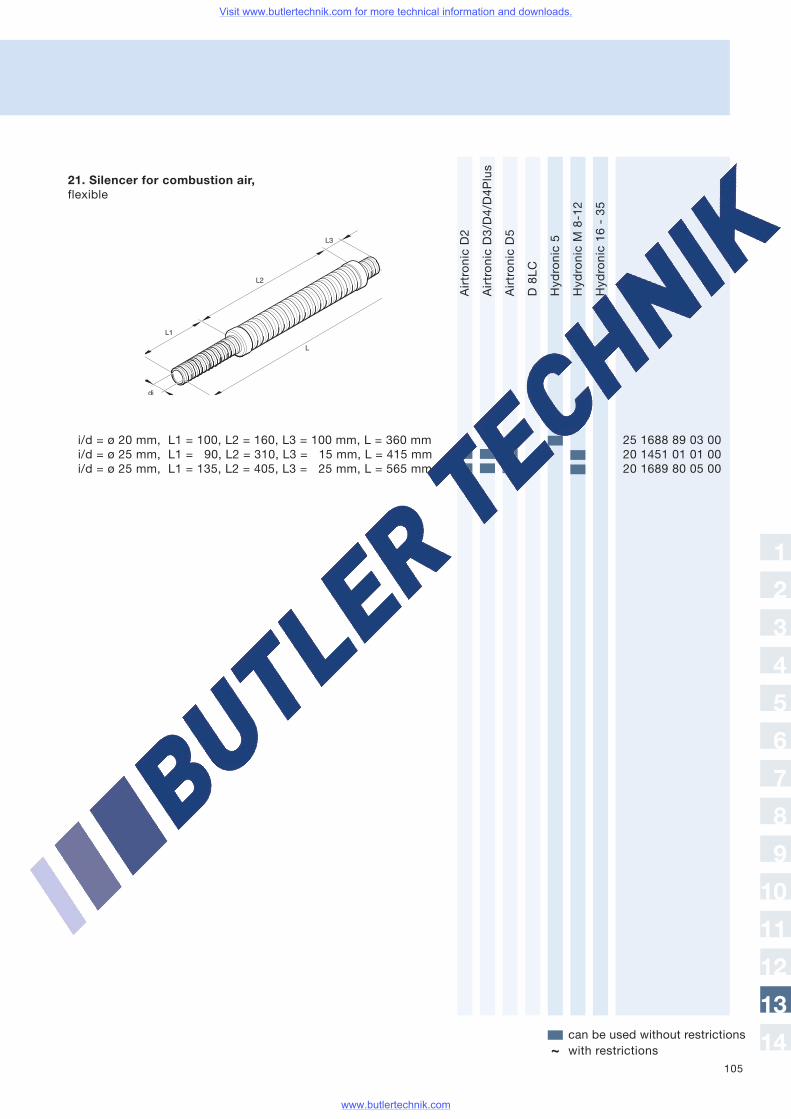
105
AirtronicD2
AirtronicD3/D4/D4Plus
AirtronicD5
D8LC
Hydronic5
HydronicM8-12
Hydronic16-35
Order no.
can be used without restrictionswith restrictions~
21. Silencer for combustion air,flexible
i/d = ø 20 mm, L1 = 100, L2 = 160, L3 = 100 mm, L = 360 mm 25 1688 89 03 00i/d = ø 25 mm, L1 = 90, L2 = 310, L3 = 15 mm, L = 415 mm 20 1451 01 01 00i/d = ø 25 mm, L1 = 135, L2 = 405, L3 = 25 mm, L = 565 mm 20 1689 80 05 00
1
2
3
4
5
6
7
8
9
10
11
12
13
14
Visit www.butlertechnik.com for more technical information and downloads.
www.butlertechnik.com
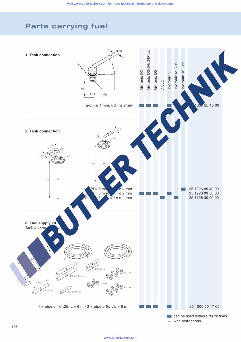
106
Parts carrying fuel
AirtronicD2
AirtronicD3/D4/D4Plus
AirtronicD5
D8LC
Hydronic5
HydronicM8-12
Hydronic16-35
Order no.
can be used without restrictionswith restrictions~
1. Tank connection
a/d = ø 4 mm, i/d = ø 2 mm 22 1000 20 15 00
2. Tank connection
a/d = 6 mm, i/d = ø 4 mm 25 1226 89 40 00a/d = 6 mm, i/d = ø 2 mm 25 1226 89 50 00a/d = 6 mm, i/d = ø 4 mm 25 1156 30 00 00
1 = pipe ø 4x1.25; L = 6 m / 2 = pipe ø 6x1; L = 6 m 22 1000 20 17 00
3. Fuel supply kitTank pick-up feed pipe
Visit www.butlertechnik.com for more technical information and downloads.
www.butlertechnik.com
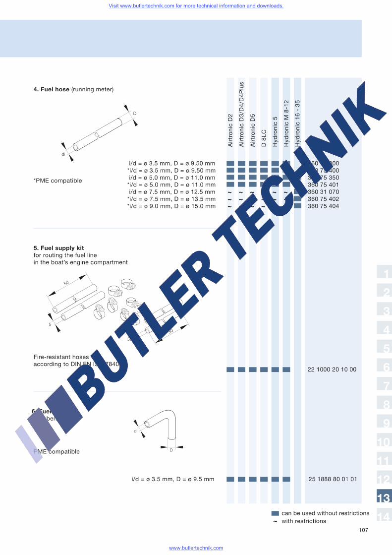
107
AirtronicD2
AirtronicD3/D4/D4Plus
AirtronicD5
D8LC
Hydronic5
HydronicM8-12
Hydronic16-35
Order no.
can be used without restrictionswith restrictions~
i/d = ø 3.5 mm, D = ø 9.50 mm 360 75 300*i/d = ø 3.5 mm, D = ø 9.50 mm 360 75 400i/d = ø 5.0 mm, D = ø 11.0 mm 360 75 350*i/d = ø 5.0 mm, D = ø 11.0 mm 360 75 401i/d = ø 7.5 mm, D = ø 12.5 mm 360 31 070*i/d = ø 7.5 mm, D = ø 13.5 mm 360 75 402*i/d = ø 9.0 mm, D = ø 15.0 mm 360 75 404
di
D
*PME compatible
22 1000 20 10 00
5
3,5
50
50
Fire-resistant hosesaccording to DIN EN ISO 7840
6. Fuel hose105° bend
i/d = ø 3.5 mm, D = ø 9.5 mm 25 1888 80 01 01
di
DPME compatible
~~ ~ ~ ~ ~ ~~ ~ ~ ~ ~ ~
~ ~ ~ ~ ~
1
2
3
4
5
6
7
8
9
10
11
12
13
14
4. Fuel hose (running meter)
5. Fuel supply kitfor routing the fuel linein the boat’s engine compartment
Visit www.butlertechnik.com for more technical information and downloads.
www.butlertechnik.com
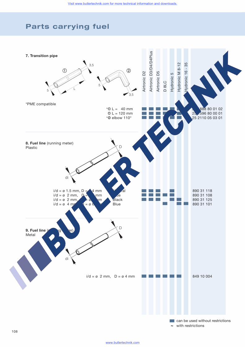
108
Parts carrying fuel
AirtronicD2
AirtronicD3/D4/D4Plus
AirtronicD5
D8LC
Hydronic5
HydronicM8-12
Hydronic16-35
Order no.
can be used without restrictionswith restrictions~
5
3,5
L5
3,5
ba
1
1
2
D
di
*
*
D
di
7. Transition pipe
*PME compatibleO L = 40 mm 25 1888 80 01 02O L = 120 mm 25 1596 80 00 01O elbow 110° 25 2110 05 03 01
8. Fuel line (running meter)Plastic
i/d = ø 1.5 mm, D = ø 4 mm Natural 890 31 118i/d = ø 2 mm, D = ø 4 mm Blue 890 31 108i/d = ø 2 mm, D = ø 6 mm Black 890 31 125i/d = ø 4 mm, D = ø 6 mm Blue 890 31 101
9. Fuel line (running meter)Metal
i/d = ø 2 mm, D = ø 4 mm 849 10 004
Visit www.butlertechnik.com for more technical information and downloads.
www.butlertechnik.com

109
AirtronicD2
AirtronicD3/D4/D4Plus
AirtronicD5
D8LC
Hydronic5
HydronicM8-12
Hydronic16-35
Order no.
can be used without restrictionswith restrictions~
di
D
355
da
1
2
3
4
5
6
7
8
9
10
11
12
13
14
10. Foam rubber hose (running meter) Fel pipeProtection to insulate against contact and noiser
11. Heat-protection hosefor fuel line, fibreglass-woven,laminated with aluminium
Also usable forelectrical conduction
i/d = ø 10 mm, D = 13 mm 360 00 183
i/d = ø 5 mm, D = ø 10 360 75 200
12. Reinforcement bushingBrass
Packaging unit – qty. 10
a/d = ø 4 mm for pipe 6x1 22 1000 20 01 00a/d = ø 6 mm for pipe 8x1 22 1000 20 02 00a/d = ø 8 mm for pipe 10x1 22 1000 20 03 00
Visit www.butlertechnik.com for more technical information and downloads.
www.butlertechnik.com
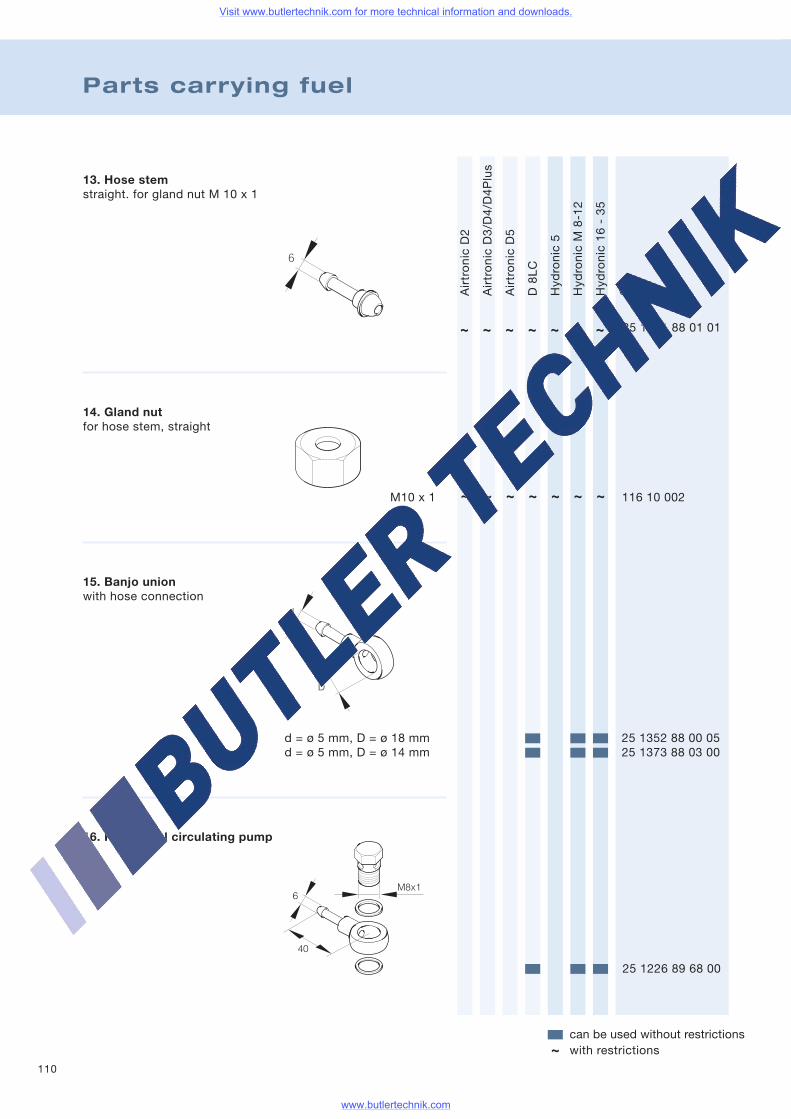
110
Parts carrying fuel
AirtronicD2
AirtronicD3/D4/D4Plus
AirtronicD5
D8LC
Hydronic5
HydronicM8-12
Hydronic16-35
Order no.
can be used without restrictionswith restrictions~
13. Hose stemstraight. for gland nut M 10 x 1
25 1351 88 01 01
M10 x 1 116 10 002
25 1226 89 68 00
15. Banjo unionwith hose connection
d
D
d = ø 5 mm, D = ø 18 mm 25 1352 88 00 05d = ø 5 mm, D = ø 14 mm 25 1373 88 03 00
40
6M8x1
~ ~ ~ ~ ~ ~ ~
~ ~ ~ ~ ~ ~ ~
16. Kit for fuel circulating pump
14. Gland nutfor hose stem, straight
Visit www.butlertechnik.com for more technical information and downloads.
www.butlertechnik.com
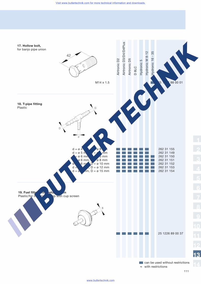
111
AirtronicD2
AirtronicD3/D4/D4Plus
AirtronicD5
D8LC
Hydronic5
HydronicM8-12
Hydronic16-35
Order no.
can be used without restrictionswith restrictions~
M14 x 1.5 25 1373 88 00 01
17. Hollow bolt,for banjo pipe union
d = ø 4 mm, D = ø 8 mm 262 31 155d = ø 5 mm, D = ø 5 mm 262 31 149d = ø 6 mm, D = ø 6 mm 262 31 150d = ø 6 mm, D = ø 8 mm 262 31 151d = ø 6 mm, D = ø 10 mm 262 31 152d = ø 6 mm, D = ø 12 mm 262 31 153d = ø 6 mm, D = ø 15 mm 262 31 154
D
D
d
18. T-pipe fittingPlastic
42
25 1226 89 00 37
6
1
2
3
4
5
6
7
8
9
10
11
12
13
14
19. Fuel filter with metal screenPlastic/for metering pump with cup screen
Visit www.butlertechnik.com for more technical information and downloads.
www.butlertechnik.com
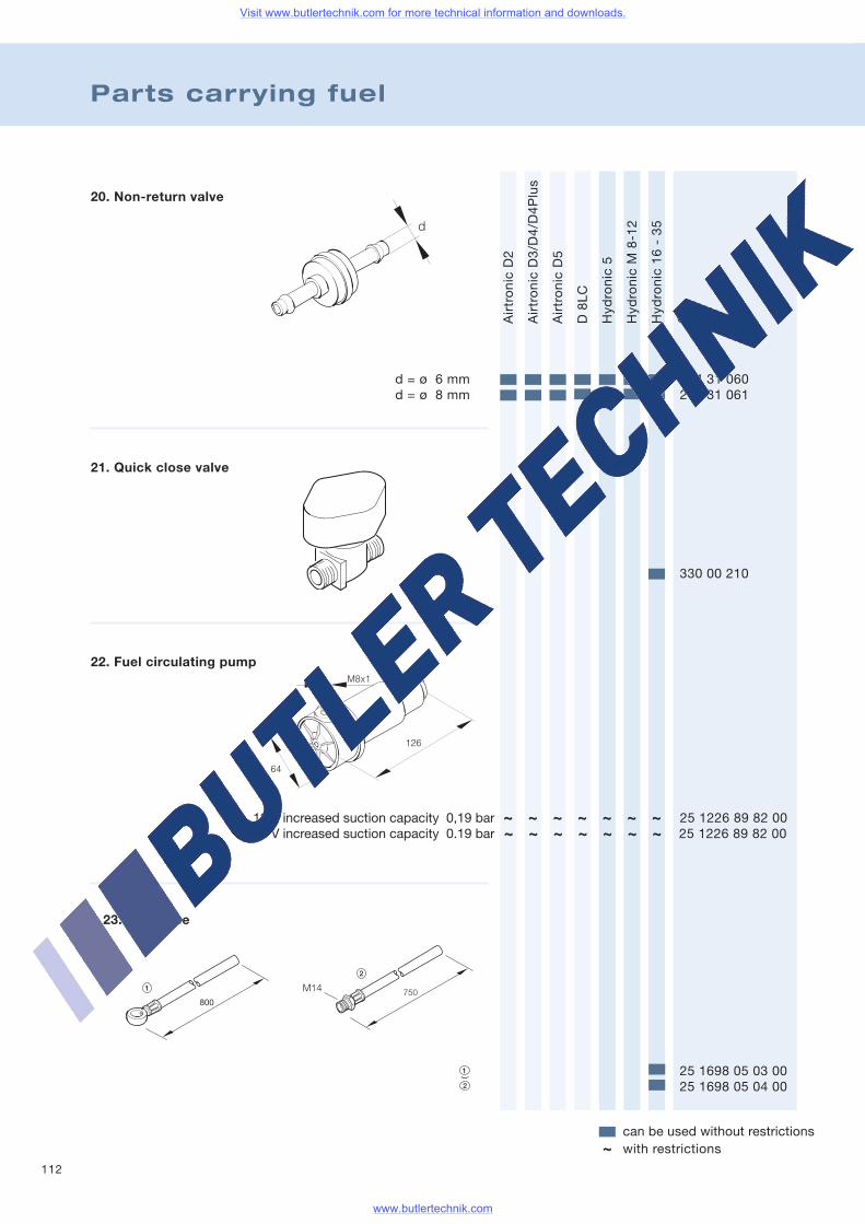
112
Parts carrying fuel
AirtronicD2
AirtronicD3/D4/D4Plus
AirtronicD5
D8LC
Hydronic5
HydronicM8-12
Hydronic16-35
Order no.
can be used without restrictionswith restrictions~
20. Non-return valve
d = ø 6 mm 244 31 060d = ø 8 mm 244 31 061
d
330 00 210
12 V increased suction capacity 0,19 bar 25 1226 89 82 0024 V increased suction capacity 0.19 bar 25 1226 89 82 00
M8x1
64
126
~ ~ ~ ~ ~ ~~~ ~ ~ ~ ~ ~ ~
23. Fuel hose
25 1698 05 03 0025 1698 05 04 00
21. Quick close valve
22. Fuel circulating pump
Visit www.butlertechnik.com for more technical information and downloads.
www.butlertechnik.com
113
Notes
Visit www.butlertechnik.com for more technical information and downloads.
www.butlertechnik.com
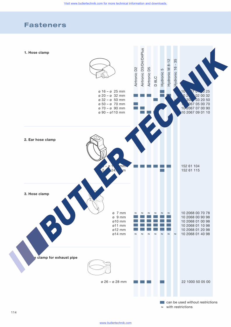
114
Fasteners
AirtronicD2
AirtronicD3/D4/D4Plus
AirtronicD5
D8LC
Hydronic5
HydronicM8-12
Hydronic16-35
Order no.
can be used without restrictionswith restrictions~
1. Hose clamp
ø 16 – ø 25 mm 10 2067 01 60 25ø 20 – ø 32 mm 10 2067 02 00 32ø 32 – ø 50 mm 10 2067 03 20 50ø 50 – ø 70 mm 10 2067 05 00 70ø 70 – ø 90 mm 10 2067 07 00 90ø 90 – ø110 mm 10 2067 09 01 10
2. Ear hose clamp
ø 9 – ø 10.5 mm 152 61 104ø 2 – ø 24.0 mm 152 61 115
3. Hose clamp
4. Pipe clamp for exhaust pipe
ø 26 – ø 28 mm 22 1000 50 05 00
~
~ ~ ~ ~ ~ ~
~ ~ ~ ~ ~ ~ ~
ø 7 mm 10 2068 00 70 78ø 9 mm 10 2068 00 90 98ø10 mm 10 2068 01 00 98ø11 mm 10 2068 01 10 98ø12 mm 10 2068 01 20 98ø14 mm 10 2068 01 40 98
Visit www.butlertechnik.com for more technical information and downloads.
www.butlertechnik.com
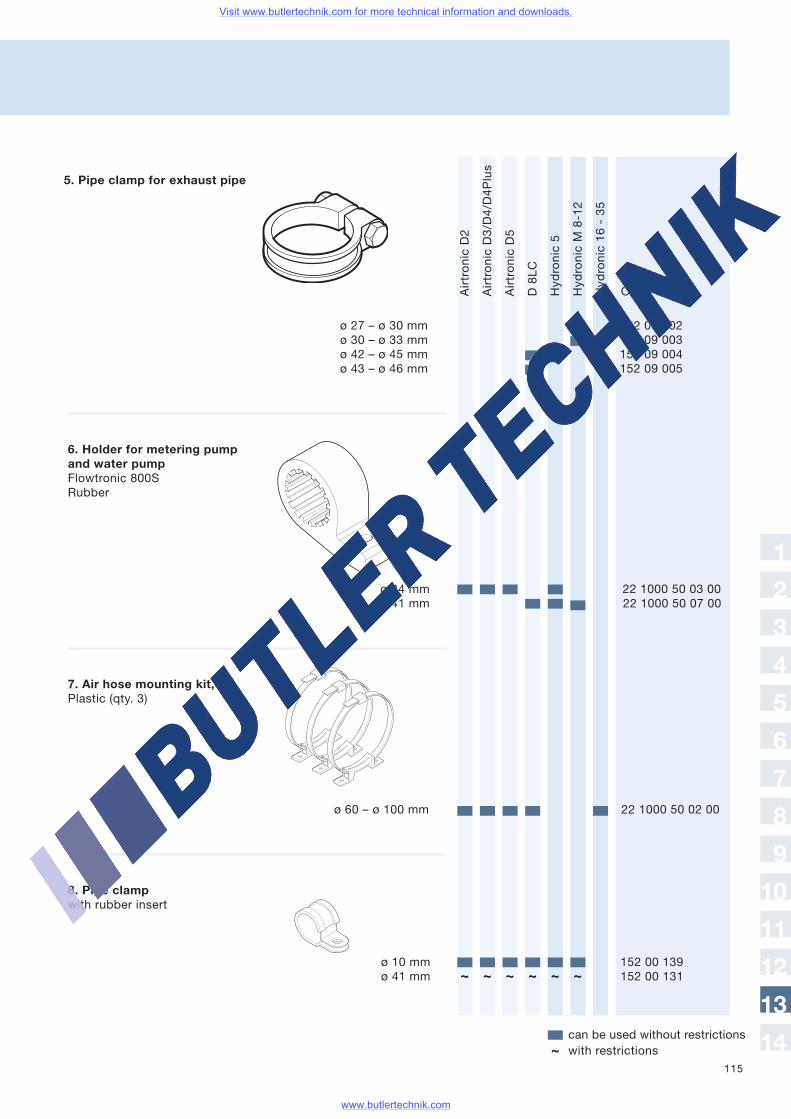
115
AirtronicD2
AirtronicD3/D4/D4Plus
AirtronicD5
D8LC
Hydronic5
HydronicM8-12
Hydronic16-35
Order no.
can be used without restrictionswith restrictions~
ø 27 – ø 30 mm 152 09 002ø 30 – ø 33 mm 152 09 003ø 42 – ø 45 mm 152 09 004ø 43 – ø 46 mm 152 09 005
8. Pipe clampwith rubber insert
ø 10 mm 152 00 139ø 41 mm 152 00 131~ ~ ~ ~ ~ ~
1
2
3
4
5
6
7
8
9
10
11
12
13
14
6. Holder for metering pumpand water pumpFlowtronic 800SRubber
ø 34 mm 22 1000 50 03 00ø 41 mm 22 1000 50 07 00
5. Pipe clamp for exhaust pipe
7. Air hose mounting kit,Plastic (qty. 3)
ø 60 – ø 100 mm 22 1000 50 02 00
Visit www.butlertechnik.com for more technical information and downloads.
www.butlertechnik.com
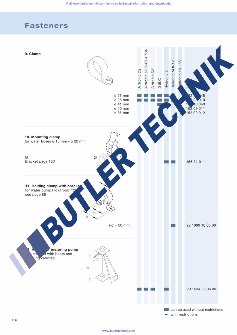
116
Fasteners
AirtronicD2
AirtronicD3/D4/D4Plus
AirtronicD5
D8LC
Hydronic5
HydronicM8-12
Hydronic16-35
Order no.
can be used without restrictionswith restrictions~
9. Clamp
ø 25 mm 152 10 048ø 28 mm 152 09 010ø 41 mm 152 10 040ø 50 mm 152 09 011ø 65 mm 152 09 012
156 31 011
i/d = 50 mm 22 1000 10 05 00
20 1634 80 06 00
70
1OO1
~~
10. Mounting clampfor water hoses ø 15 mm - ø 20 mm
Bracket page 120
11. Holding clamp with bracketfor water pump Flowtronic 1200see page 89
12. Holder for metering pumpcan be used with boats andcamping vehicles
Visit www.butlertechnik.com for more technical information and downloads.
www.butlertechnik.com
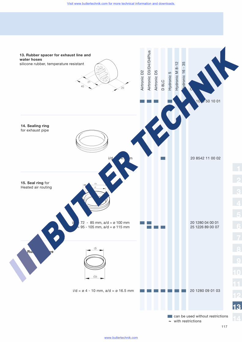
117
AirtronicD2
AirtronicD3/D4/D4Plus
AirtronicD5
D8LC
Hydronic5
HydronicM8-12
Hydronic16-35
Order no.
can be used without restrictionswith restrictions~
14. Sealing ringfor exhaust pipe
i/d = 72 - 85 mm, a/d = ø 100 mm 20 1280 04 00 01i/d = 95 - 105 mm, a/d = ø 115 mm 25 1226 89 00 07
15. Seal ring forHeated air routing
22 1000 50 10 01
i/d = ø 41 mm 20 8542 11 00 02
16. Rubber sleeve
i/d = ø 4 - 10 mm, a/d = ø 16.5 mm 20 1280 09 01 03
1
2
3
4
5
6
7
8
9
10
11
12
13
14
13. Rubber spacer for exhaust line andwater hosessilicone rubber, temperature resistant
Visit www.butlertechnik.com for more technical information and downloads.
www.butlertechnik.com
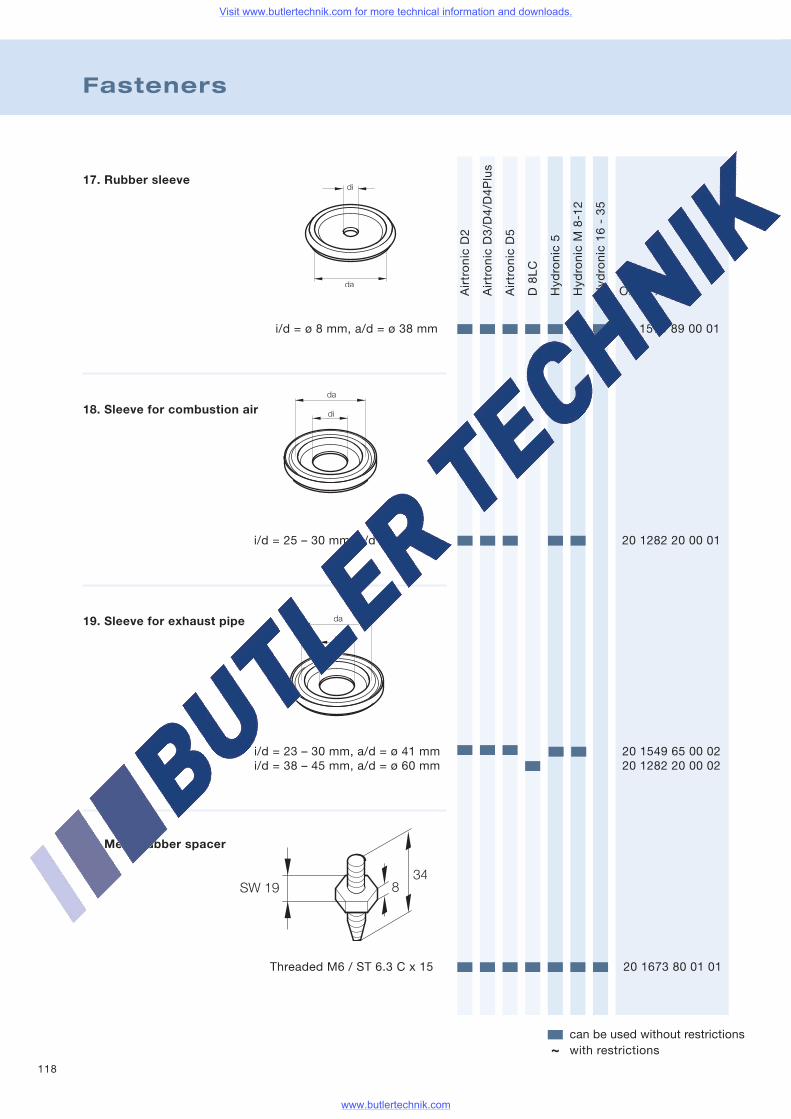
118
Fasteners
AirtronicD2
AirtronicD3/D4/D4Plus
AirtronicD5
D8LC
Hydronic5
HydronicM8-12
Hydronic16-35
Order no.
can be used without restrictionswith restrictions~
17. Rubber sleeve
i/d = ø 8 mm, a/d = ø 38 mm 20 1575 89 00 01
i/d = 25 – 30 mm, a/d = ø 41 mm 20 1282 20 00 01
19. Sleeve for exhaust pipe
i/d = 23 – 30 mm, a/d = ø 41 mm 20 1549 65 00 02i/d = 38 – 45 mm, a/d = ø 60 mm 20 1282 20 00 02
20. Metal rubber spacer
18. Sleeve for combustion air
Threaded M6 / ST 6.3 C x 15 20 1673 80 01 01
Visit www.butlertechnik.com for more technical information and downloads.
www.butlertechnik.com
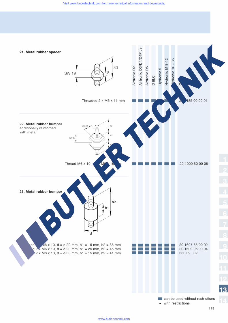
119
AirtronicD2
AirtronicD3/D4/D4Plus
AirtronicD5
D8LC
Hydronic5
HydronicM8-12
Hydronic16-35
Order no.
can be used without restrictionswith restrictions~
21. Metal rubber spacer
22. Metal rubber bumperadditionally reinforcedwith metal
Thread 2 x M6 x 10, d = ø 20 mm, h1 = 15 mm, h2 = 35 mm 20 1607 65 00 02Thread 2 x M6 x 10, d = ø 20 mm, h1 = 25 mm, h2 = 45 mm 20 1609 05 00 04Thread 2 x M8 x 13, d = ø 30 mm, h1 = 15 mm, h2 = 41 mm 330 09 002
Threaded 2 x M6 x 11 mm 20 1185 00 00 01
Thread M6 x 10 mm / M6 x 15 mm 22 1000 50 00 081
2
3
4
5
6
7
8
9
10
11
12
13
14
23. Metal rubber bumper
Visit www.butlertechnik.com for more technical information and downloads.
www.butlertechnik.com
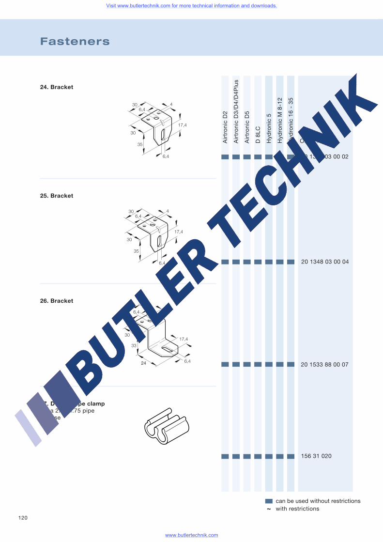
120
Fasteners
AirtronicD2
AirtronicD3/D4/D4Plus
AirtronicD5
D8LC
Hydronic5
HydronicM8-12
Hydronic16-35
Order no.
can be used without restrictionswith restrictions~
24. Bracket
20 1348 03 00 02
25. Bracket
20 1348 03 00 04
26. Bracket
20 1533 88 00 07
27. Double pipe clampfits a 2x ø 4.75 pipeor hose
156 31 020
Visit www.butlertechnik.com for more technical information and downloads.
www.butlertechnik.com
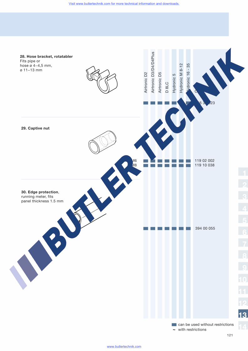
121
AirtronicD2
AirtronicD3/D4/D4Plus
AirtronicD5
D8LC
Hydronic5
HydronicM8-12
Hydronic16-35
Order no.
can be used without restrictionswith restrictions~
29. Captive nut
156 31 023
M6 119 02 002M8 119 10 038
394 00 055
1
2
3
4
5
6
7
8
9
10
11
12
13
14
28. Hose bracket, rotatablerFits pipe orhose ø 4−4,5 mm,ø 11−13 mm
30. Edge protection,running meter, fitspanel thickness 1.5 mm
Visit www.butlertechnik.com for more technical information and downloads.
www.butlertechnik.com
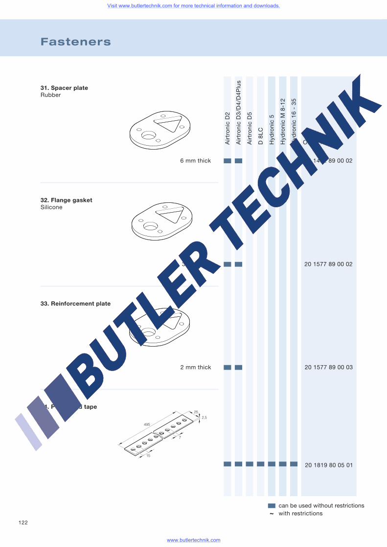
122
Fasteners
AirtronicD2
AirtronicD3/D4/D4Plus
AirtronicD5
D8LC
Hydronic5
HydronicM8-12
Hydronic16-35
Order no.
can be used without restrictionswith restrictions~
31. Spacer plateRubber
32. Flange gasketSilicone
3 mm thick 20 1577 89 00 02
33. Reinforcement plate
2 mm thick 20 1577 89 00 03
34. Perforated tape
495
2,5
25
15
7
20 1819 80 05 01
6 mm thick 25 1482 89 00 02
Visit www.butlertechnik.com for more technical information and downloads.
www.butlertechnik.com
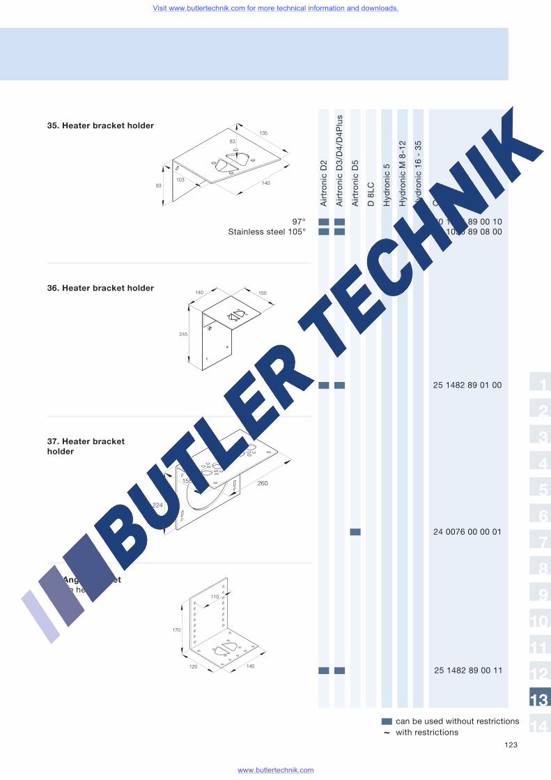
123
AirtronicD2
AirtronicD3/D4/D4Plus
AirtronicD5
D8LC
Hydronic5
HydronicM8-12
Hydronic16-35
Order no.
can be used without restrictionswith restrictions~
24 0076 00 00 01
37. Heater bracketholder
135
93103
83
140
25 1482 89 01 00
224
260155
120 140
110
170
25 1482 89 00 11
1
2
3
4
5
6
7
8
9
10
11
12
13
14
36. Heater bracket holder
35. Heater bracket holder
97° 20 1575 89 00 10Stainless steel 105° 22 1050 89 08 00
38. Angle bracketfor the heater
Visit www.butlertechnik.com for more technical information and downloads.
www.butlertechnik.com
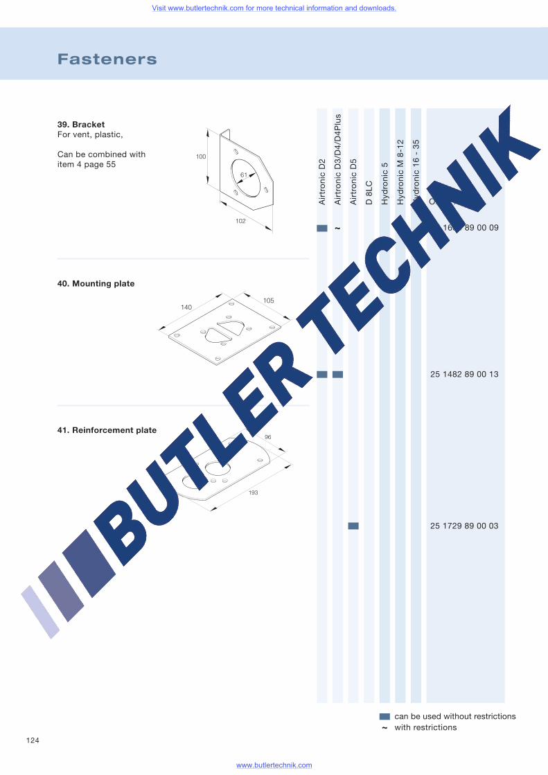
124
Fasteners
AirtronicD2
AirtronicD3/D4/D4Plus
AirtronicD5
D8LC
Hydronic5
HydronicM8-12
Hydronic16-35
Order no.
can be used without restrictionswith restrictions~
39. BracketFor vent, plastic,
Can be combined withitem 4 page 55
25 1688 89 00 09
40. Mounting plate
25 1482 89 00 13
105140
25 1729 89 00 03
96
193
100
102
61
~
41. Reinforcement plate
Visit www.butlertechnik.com for more technical information and downloads.
www.butlertechnik.com
125
Notes
Visit www.butlertechnik.com for more technical information and downloads.
www.butlertechnik.com
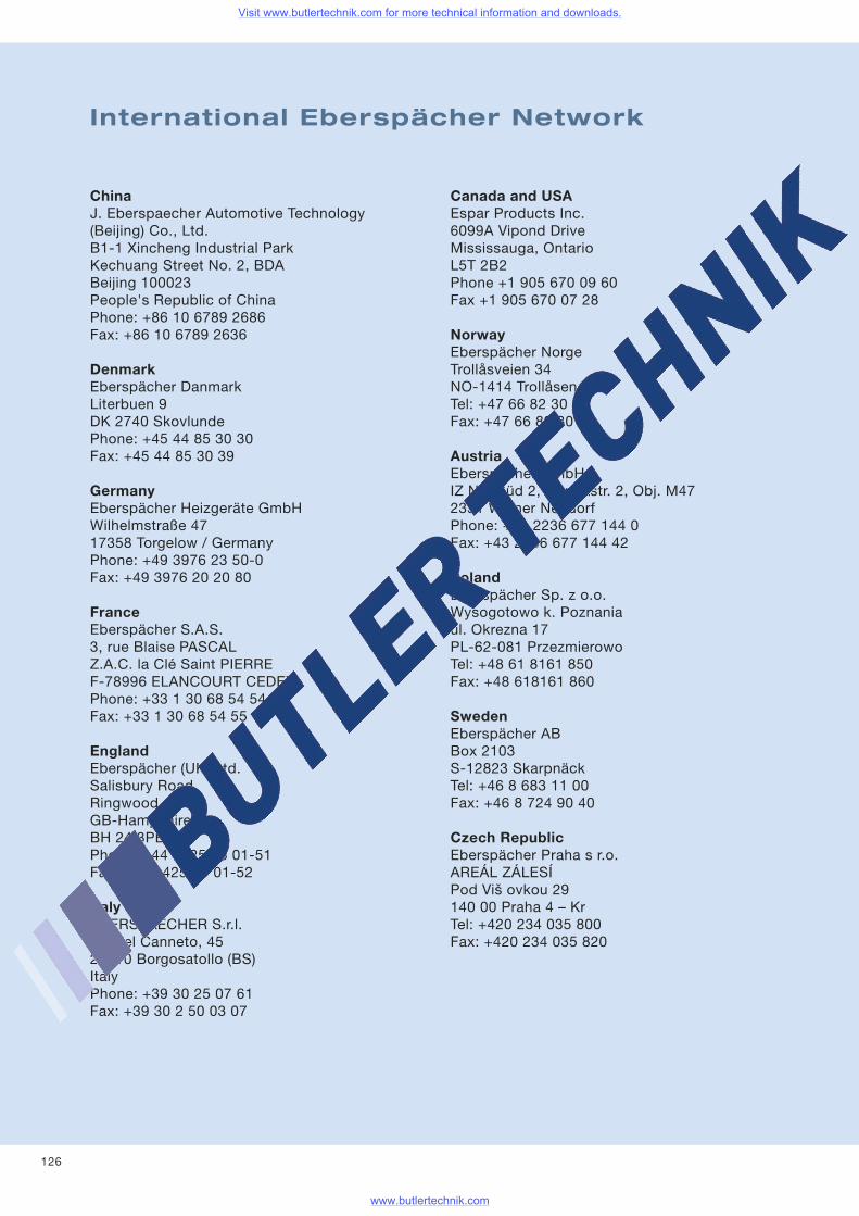
126
ChinaJ. Eberspaecher Automotive Technology(Beijing) Co., Ltd.B1-1 Xincheng Industrial ParkKechuang Street No. 2, BDABeijing 100023People's Republic of ChinaPhone: +86 10 6789 2686Fax: +86 10 6789 2636
DenmarkEberspächer DanmarkLiterbuen 9DK 2740 SkovlundePhone: +45 44 85 30 30Fax: +45 44 85 30 39
GermanyEberspächer Heizgeräte GmbHWilhelmstraße 4717358 Torgelow / GermanyPhone: +49 3976 23 50-0Fax: +49 3976 20 20 80
FranceEberspächer S.A.S.3, rue Blaise PASCALZ.A.C. la Clé Saint PIERREF-78996 ELANCOURT CEDEXPhone: +33 1 30 68 54 54Fax: +33 1 30 68 54 55
EnglandEberspächer (UK) Ltd.Salisbury RoadRingwoodGB-HampshireBH 24 3PBPhone: +44 1425 48 01-51Fax: +44 1425 48 01-52
ItalyEBERSPAECHER S.r.l.Via del Canneto, 4525010 Borgosatollo (BS)ItalyPhone: +39 30 25 07 61Fax: +39 30 2 50 03 07
Canada and USAEspar Products Inc.6099A Vipond DriveMississauga, OntarioL5T 2B2Phone +1 905 670 09 60Fax +1 905 670 07 28
NorwayEberspächer NorgeTrollåsveien 34NO-1414 TrollåsenTel: +47 66 82 30 50Fax: +47 66 82 30 58
AustriaEberspächer GmbHIZ NÖ-Süd 2, Hondastr. 2, Obj. M472351 Wiener NeudorfPhone: +43 2236 677 144 0Fax: +43 2236 677 144 42
PolandEberspächer Sp. z o.o.Wysogotowo k. Poznaniaul. Okrezna 17PL-62-081 PrzezmierowoTel: +48 61 8161 850Fax: +48 618161 860
SwedenEberspächer ABBox 2103S-12823 SkarpnäckTel: +46 8 683 11 00Fax: +46 8 724 90 40
Czech RepublicEberspächer Praha s r.o.AREÁL ZÁLESÍPod Viš ovkou 29140 00 Praha 4 – KrTel: +420 234 035 800Fax: +420 234 035 820
International Eberspächer Network
Visit www.butlertechnik.com for more technical information and downloads.
www.butlertechnik.com
127
1
2
3
4
5
6
7
8
9
10
11
12
13
14
ArgentinaTrimer SADel Arca 55San FernandoBuenos Aires - ArgentinaTel. 0054 (11) 45 80 04 44Fax 0054 (11) 45 80 04 40
Belgium and LuxembourgEberca B.V.B.A.Researchpark-HaasrodeEsperantolaan 2B-3001 Leuven-HaasrodeTel. 0032 / 16 40 25 00Fax 0032 / 16 40 05 15
ChileNauticentro Ltda.Tomás Moro 135 Las CondesSantiagoTel. 0056 (2) 201-49 66, 224-68 15, 212-09 14Fax 0056 (2) 201-56 35
EstoniaTaavi LindHesyco Group OÜLüli 1EE-10112 TallinnTel. 00372 / 3 84 88 90Fax 00372 / 3 84 88 92
FinlandManttaalitie 9SF-01530 Vantaa 51Tel. 00358 (20) 510-10Fax 00358 (20) 510-2207
GreeceMarconi Hellas S.A.Souliou Str. 2-4GR-14343 N.Halkidona – AthensTel. 0030 (210) 2 51 35 00Fax 0030 (210) 2 52 88 54
JapanWhite House Co., LTD.10-4 Obata-MiyanokosiMoriyama-KuNagoya 463-0052Tel. 0081 (52) 7 76 38 11Fax 0081 (52) 7 76 38 55
Croatia, Bosnia-HerzogovinaTermobil d.o.o.Kukuljanovo bbHR-51223 SkrljevoTel. 00385 (1) 2 75 08 34Fax 00385 (1) 2 75 08 36
LatviaTransBaltic Trading CorporationMaskavas iela 449LV-1063 RigaTel. 00371 (7)26 63 23Fax 00371 (7)18 79 67
LithuaniaUAB LeopolisPaneriu 51LIT-2055 VilniusTel. 0037 (052) 33 04 57Fax 0037 (052) 13 35 37
MoldaviaTC-IUSTINIAN S.R.L., I.M.140 Hinchesti Str. of.92070 KishinevTel. 00373 (22) 73 87 10Fax 00373 (22) 72 78 83
New ZealandDometic New Zealand Ltd26 Cashew StreetGrenada North, WellingtonTel.: + 64 4 232 3898Fax: + 64 4 232 3878
The NetherlandsEberca B.V.Marconistraat 2NL-3281 NB NumansdorpTel. 0031 (1866) 2 19 55Fax. 0031 (1866) 2 18 18
RomaniaCEFIN Romania S.R.L.Str. Italia Nr. 1-7com. ChiajnaRO-Jud. Ilfov 077040Tel. +40 74 184 10 33Fax +40 74 184 12 22
Visit www.butlertechnik.com for more technical information and downloads.
www.butlertechnik.com
128
RomaniaTermoportSos. Bucuresti nr. 314 (DS601)RO-077055 Ciorogarla, IlfovTel. +40 21 314 35 55Fax +40 21 314 35 65
RomaniaFOMCO SRLRâtul Morii 1295RO-547530 Sângeorgiu de MuresTel./Fax +40 265 318008 /+40 744 396653+40 726 194558+40 788 473099
RussiaCompany OTEMul. Verchnaya Krasnoseljskaya, 2RUS - 107140 MoskauTel. 007 (495) 6 45 59 79Fax 007 (495) 6 47 13 24
SwitzerlandTechnomag AGSternenfeldstraße 17CH-4127 BirsfeldenTel. 0041 / 6 13 78 91 51Fax 0041 / 6 13 73 35 90
Sloveniaüber Eberspächer ÖsterreichEberspaecher Gesellschaft m.b.H.Podružnica SLOCelovška cesta 2281000 LjubljanaTel. ++386 1 518 70 52Fax: ++386 1 518 70 53
Spain & PortugalPedro Sanz Clima S.L.Av. Ingeniero Torres Quevedo, 6E-28022 MadridTel. 0034 (91) 7 61 38 30Fax 0034 (9
South KoreaE-Con Enterprise IncSeoul Branch Office4F, Yeok San Bldg. # 43-1, Samsung DongKangnam-Gu, Seoul 135-091South KoreaTel. 0082 02 558 8826Fax 0082 02 552 8788
TurkeyACSA Otomotiv San. Tic. Ltd.Organize Sanayi SitesiDolapdere Koop. 1 Ada No:38TR-34760 Ikitelli-IstanbulTel. 0090 (212) 5 49 86 31 + 5 49 73 14Fax 0090 (212) 5 49 33 47
UkraineGeruk & Kuliza Dobrovolskogo 3/4UA-18006 TscherkassyTel. 0038 (0472) 710-800 / 710-801 / 711-056Fax 0038 (0472) 710-800
HungaryAustropannon KFTFö ut 96H-9081 GyörujbaratTel. 0036 (96) 54 33 33Fax 0036 (96) 45 64 81
BelorussiaBelvneshinvestPer. 1-yj Izmajlowskij 51/2BY-220 131 MinskTel.+Fax 00375 (172) 62 40 75
Visit www.butlertechnik.com for more technical information and downloads.
www.butlertechnik.com

129
Trade Shows and Exhibitions
Welcome!
You can also ask questions at the following boattrade shows, see products “live” and get yourown impressions. We are looking forward tomeeting you.
Boot in Düsseldorf
Hanseboot in Hamburg
Salon Nautique in Paris (France)
Grand Pavois in La Rochelle (France)
Mets in Amsterdam (The Netherlands)
1
2
3
4
5
6
7
8
9
10
11
12
13
14
Visit www.butlertechnik.com for more technical information and downloads.
www.butlertechnik.com
130
Notes
Visit www.butlertechnik.com for more technical information and downloads.
www.butlertechnik.com
131
Notes
Visit www.butlertechnik.com for more technical information and downloads.
www.butlertechnik.com

J.EberspächerGmbH & Co. KGEberspächerstraße 24D-73730 EsslingenTelefon Hotline 0800 1 23 43 00Fax Hotline 01805 26 26 [email protected]
www.eberspaecher.com
Marine catalogue — information, technology, tips.
The compass heading is heat.Eberspächer marine heaters.
VHM/M
S12
/08Bech1.0Technicald
ata:+/-10
%Sub
ject
tomodification,
errors
possible.Printed
inGermany.Printed
onchlorine-freepap
er.
Visit www.butlertechnik.com for more technical information and downloads.
www.butlertechnik.com
Related Documents