www.socomec.co.in SOLUTIONS FOR CONTROL & POWER 2011 - 2012 General Catalogue

Welcome message from author
This document is posted to help you gain knowledge. Please leave a comment to let me know what you think about it! Share it to your friends and learn new things together.
Transcript

www.socomec.co.in
SOLUTIONS FOR CONTROL & POWER 2011 - 2012
General Catalogue
2 General Catalogue 2011-2012 SOCOMEC
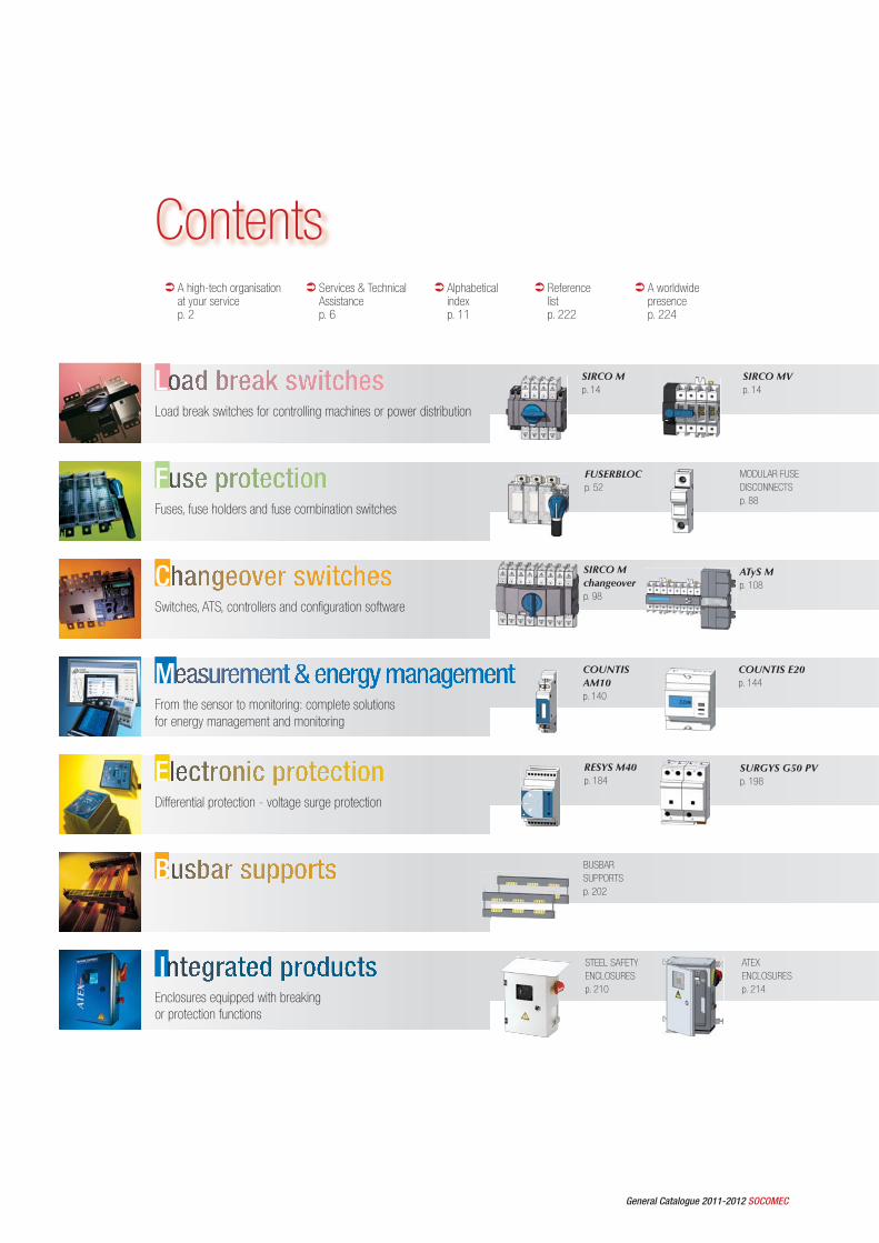
ContentsA high-tech organisation at your servicep. 2
Services & Technical Assistancep. 6
Alphabeticalindexp. 11
Referencelistp. 222
A worldwide presencep. 224
SIRCO Mp. 14
SIRCO MVp. 14
FFuses, fuse holders and fuse combination switches
CSwitches, ATS, controllers and configuration software
MFrom the sensor to monitoring: complete solutions for energy management and monitoring
EDifferential protection - voltage surge protection
B
IEnclosures equipped with breaking or protection functions
LLoad break switches for controlling machines or power distribution
ATyS Mp. 108
COUNTIS AM10p. 140
BUSBARSUPPORTSp. 202
STEEL SAFETY ENCLOSURESp. 210
ATEX ENCLOSURESp. 214
RESYS M40p. 184
COUNTIS E20p. 144
FUSERBLOCp. 52
SURGYS G50 PVp. 198
MODULAR FUSE DISCONNECTSp. 88
SIRCO M changeoverp. 98
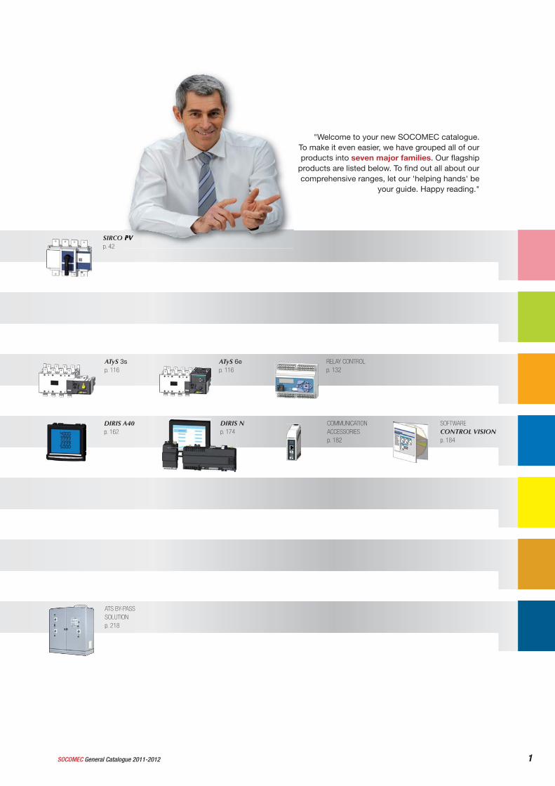
1SOCOMEC General Catalogue 2011-2012
ATyS 3sp. 116
ATyS 6ep. 116
RELAY CONTROLp. 132
COMMUNICATION ACCESSORIESp. 182
SOFTWARECONTROL VISIONp. 184
SIRCO PVp. 42
"Welcome to your new SOCOMEC catalogue. To make it even easier, we have grouped all of our products into seven major families. Our flagship
products are listed below. To find out all about our comprehensive ranges, let our 'helping hands' be
your guide. Happy reading."
DIRIS A40p. 162
DIRIS Np. 174
ATS BY-PASS SOLUTIONp. 218

2 General Catalogue 2011-2012 SOCOMEC
A high-tech organization at your service
The company on your doorstep
We are wholly committed to providing you with the best response to your needs. This is why our commercial network is fully integrated and has a perfect understanding of your industrial situation. And depending on the case, each of the departments involved in your project will work directly with you.With SOCOMEC, you will always fi nd the specialist contact you need right on your doorstep.
The right product for you
We offer you the widest and most varied range of switching and protection systems available: thanks to wide-ranging adaptation of standard references, our product families cover an extensive scope of applications.And since we use modular design as our basis, and offer a complete set of easy-to-fi t accessories, you can benefi t from numerous additional functions, at the best possible price.
Continuous innovation
Technological foresight is a sixth sense possessed by each of our departments. And thanks to our many technological partnerships, we are constantly enriching our expertise.Therefore, it is no surprise that our extensive R&D resources allow us to bring your expectations to life every day.Our innovations benefi t your performance.
"JANUS de l’industrie"
The range of Type-S handles was awarded the "JANUS de l’industrie" industrial design prize. Awarded by the French design institute, with the backing of the Ministry of Foreign Trade, this prestigious label
recognised a range that has been very popular with our customers.
Meeting deadlines
Thanks to the real-time management of orders and deliveries that we carry out in close collaboration with our transporters, you can count on us to honour our commitments to the full.
Direct and friendly contact
Another area in which SOCOMEC lays claim to a personal "style":Personal commitment to you, openness and friendliness, solidarity within a shared project, desire to give a response which meets your needs; these convictions guide every man and woman in our teams.
Integrated production with shorter lead-times
As an independent manufacturer, SOCOMEC is in charge of all its strategic skills areas and offers the best progression in terms of fl exibility.Thanks to our integrated production and industrial organisation into autonomous cells, you can benefi t from impeccable manufacturing quality and perfectly controlled deadlines.
Your Guarantee of Satisfaction
An integrated ASEFA-LOVAG approved laboratory, numerous homologations and certifi cations testifying that our devices comply with international standards, quality recognised and proven on a daily basis, universality and adaptability to your specifi c confi guration, this is what we offer to ensure your satisfaction.
SIT
E 47
6 A
SIT
E 04
1 A
CO
RP
O 1
75A
SIT
E 14
9 A
3SOCOMEC General Catalogue 2011-2012
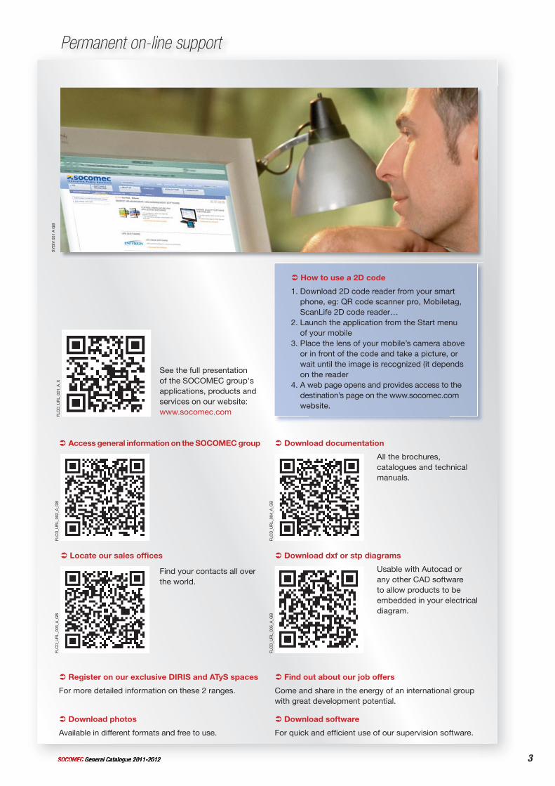
Permanent on-line supportS
YD
IV 0
51 A
GB
FLC
D_U
RL_
001_
A_X
See the full presentation of the SOCOMEC group's applications, products and services on our website: www.socomec.com
FLC
D_U
RL_
003_
A_G
B
Locate our sales offi ces
Find your contacts all over the world.
FLC
D_U
RL_
005_
A_G
B
Usable with Autocad or any other CAD software to allow products to be embedded in your electrical diagram.
Download dxf or stp diagrams
FLC
D_U
RL_
004_
A_G
B
All the brochures, catalogues and technical manuals.
Download documentation
FLC
D_U
RL_
002_
A_G
B
Access general information on the SOCOMEC group
For quick and effi cient use of our supervision software.
Download softwareDownload photos
Available in different formats and free to use.
Come and share in the energy of an international group with great development potential.
Find out about our job offers
For more detailed information on these 2 ranges.
Register on our exclusive DIRIS and ATyS spaces
1. Download 2D code reader from your smart phone, eg: QR code scanner pro, Mobiletag, ScanLife 2D code reader…
2. Launch the application from the Start menu of your mobile
3. Place the lens of your mobile’s camera above or in front of the code and take a picture, or wait until the image is recognized (it depends on the reader
4. A web page opens and provides access to the destination’s page on the www.socomec.com website.
How to use a 2D code
4 General Catalogue 2011-2012 SOCOMEC
Adapted services
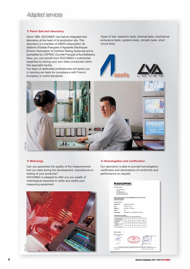
Pierre Siat test laboratory
Since 1965, SOCOMEC has had an integrated test laboratory at the heart of its production site. This laboratory is a member of ASEFA (Association de Stations d’Essais Française d’Appareils Électriques [French Association of Certifi ed Testing Systems]) and is accredited by COFRAC (Comité Français d'Accréditation).Now, you can benefi t from SOCOMEC's substantial expertise by having your own tests conducted within this specialist facility.Our team of dedicated professionals will assist you in carrying out tests for compliance with French, European or world standards.
Types of test: dielectric tests, thermal tests, mechanical endurance tests, systems tests, climatic tests, short circuit tests.
Metrology
Can you guarantee the quality of the measurements that you take during the development, manufacture or testing of your products?SOCOMEC is pleased to offer you our wealth of metrological expertise to verify and certify your measuring equipment.
Homologation and certifi cation
Our laboratory is able to provide homologation certifi cates and declarations of conformity and performance on request.
CO
RP
O 1
63A
AP
PLI
079
A
5SOCOMEC General Catalogue 2011-2012
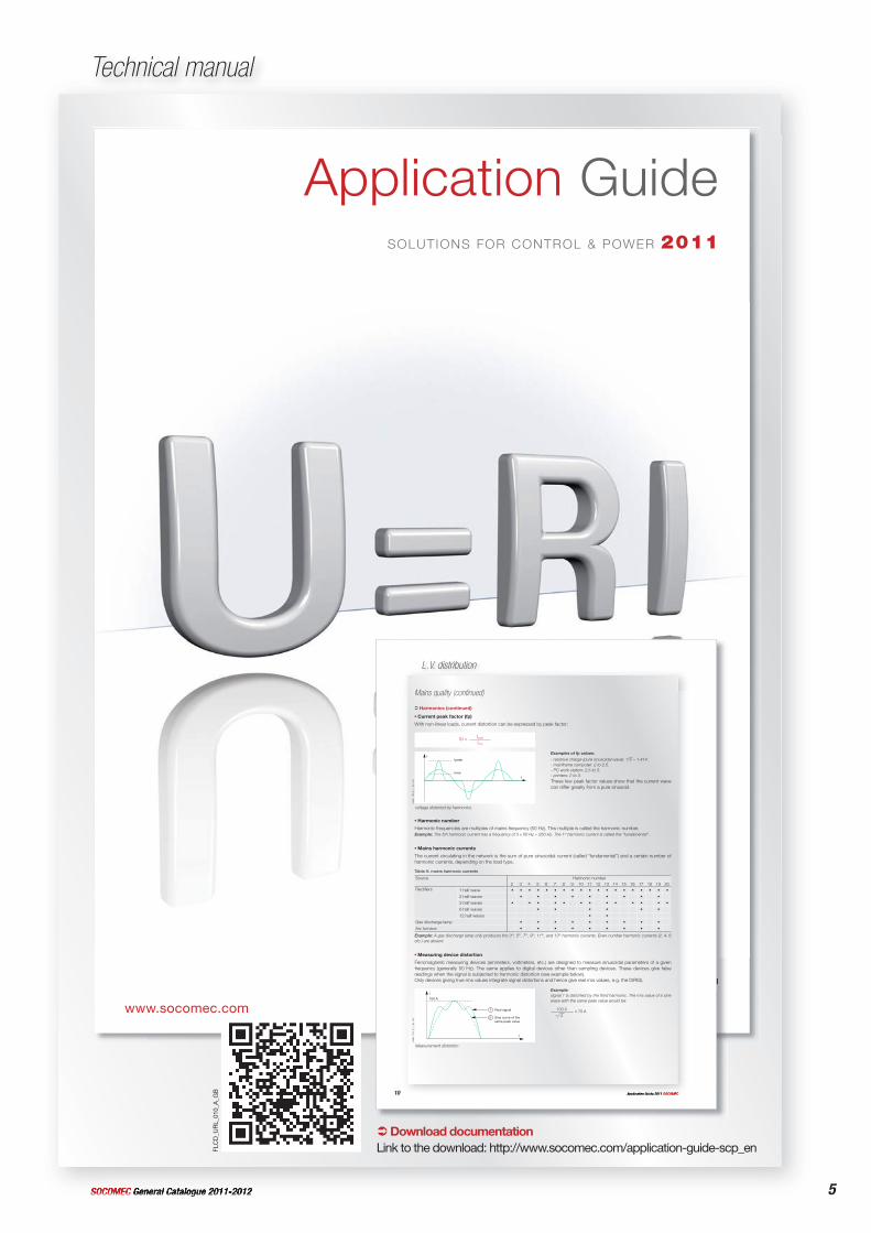
Technical manual
Application GuideSOLUTIONS FOR CONTROL & POWER 2011
www.socomec.com
10 Application Guide 2011 SOCOMEC
L.V. distribution
Mains quality (continued)
Harmonics (continued)
Example:signal 1 is distorted by the third harmonic. The rms value of a sine wave with the same peak value would be:
100 A = 70 A2
Current peak factor (fp)
With non-linear loads, current distortion can be expressed by peak factor:
fp = Ipeak
Irms
Examples of fp values:
- resistive charge (pure sinusoidal wave): 2 = 1.414.- mainframe computer: 2 to 2.5.- PC work station: 2.5 to 3.- printers: 2 to 3.These few peak factor values show that the current wave can differ greatly from a pure sinusoid.
voltage distorted by harmonics
cate
c_10
3_b_
1_gb
_cat
I
t
I peak
I rms
Harmonic number
Harmonic frequencies are multiples of mains frequency (50 Hz). This multiple is called the harmonic number.Example: The 5th harmonic current has a frequency of 5 x 50 Hz = 250 Hz. The 1st harmonic current is called the “fundamental”.
Mains harmonic currents
The current circulating in the network is the sum of pure sinusoidal current (called “fundamental”) and a certain number of harmonic currents, depending on the load type.
Table A: mains harmonic currents
Source Harmonic number2 3 4 5 6 7 8 9 10 11 12 13 14 15 16 17 18 19 20
Rectifi ers 1 half wave • • • • • • • • • • • • • • • • • • •
2 half waves • • • • • • • • •
3 half waves • • • • • • • • • • • • •
6 half waves • • • • • •
12 half waves • •
Gas discharge lamp • • • • • • • • •
Arc furnace • • • • • • • • •
Example: A gas discharge lamp only produces the 3rd, 5th, 7th, 9th, 11th, and 13th harmonic currents. Even-number harmonic currents (2. 4. 6 etc.) are absent.
Measuring device distortion
Ferromagnetic measuring devices (ammeters, voltmeters, etc.) are designed to measure sinusoidal parameters of a given frequency (generally 50 Hz). The same applies to digital devices other than sampling devices. These devices give false readings when the signal is subjected to harmonic distortion (see example below).Only devices giving true rms values integrate signal distortions and hence give real rms values, e.g. the DIRIS).
Measurement distortion
cate
c_10
4_b_
1_gb
_cat
I
t
100 A
1
2
Real signal
Sine curve of the same peak value
Download documentationLink to the download: http://www.socomec.com/application-guide-scp_enFL
CD
_UR
L_01
0_A
_GB
6 General Catalogue 2011-2012 SOCOMEC
Service & Technical Assistance: Your peace of mind assured
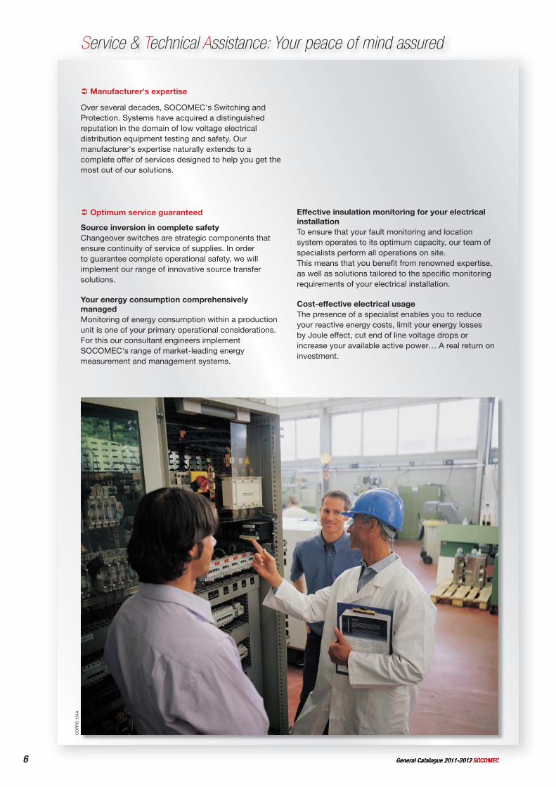
Manufacturer's expertise
Over several decades, SOCOMEC's Switching and Protection. Systems have acquired a distinguished reputation in the domain of low voltage electrical distribution equipment testing and safety. Our manufacturer's expertise naturally extends to a complete offer of services designed to help you get the most out of our solutions.
Optimum service guaranteed
Source inversion in complete safetyChangeover switches are strategic components that ensure continuity of service of supplies. In order to guarantee complete operational safety, we will implement our range of innovative source transfer solutions.
Your energy consumption comprehensively managedMonitoring of energy consumption within a production unit is one of your primary operational considerations. For this our consultant engineers implement SOCOMEC's range of market-leading energy measurement and management systems.
Effective insulation monitoring for your electrical installationTo ensure that your fault monitoring and location system operates to its optimum capacity, our team of specialists perform all operations on site.This means that you benefi t from renowned expertise, as well as solutions tailored to the specifi c monitoring requirements of your electrical installation.
Cost-effective electrical usageThe presence of a specialist enables you to reduce your reactive energy costs, limit your energy losses by Joule effect, cut end of line voltage drops or increase your available active power… A real return on investment.
CO
RP
O 1
54A

7SOCOMEC General Catalogue 2011-2012
The security of a fully committed partner
Specially adapted skillsOur service team is formed of specialists in our fi elds, with hands-on experience and well-acquainted with the maintenance of industrial electrical systems. You get the benefi ts from a dual skills base: technical expertise relating to the products that have been installed and practical knowledge of your usage needs.
Reassuringly close at handOur geographical coverage means that we are close to every user, ensuring we can respond to any request and guarantee comprehensive assistance, from technical diagnostics before repair to implementing solutions specifi cally adapted to your installations.
Constantly attentive to your needsTrue to our principles, we favour direct and friendly contact. Our repairs are targeted responses to one, single problem: your own. Our engineers are attentive to your needs to bring you the most appropriate technical support and advice so you can plan your investments with confi dence.
Adapted services
CommissioningInstallation of your equipment is carried out by a specialist, and is totally compatible with and adapted to your use.
Engineering your installationA broad range of features tailored to respond to the particular requirements and limitations of your electrical installation, and to help you deal with specifi c operational demands.
TrainingYou will receive training, specially adapted to your needs, in order to familiarise you with our equipment and enable you to use it to your best advantage.
MaintenanceA wide range of preventive or corrective maintenance options designed to suit your installation and its environment, and to ensure continuity of service of your electrical networks.
Engineering your projectFrom initial studies to operating your system, our team will guide you, ensuring full commitment.
Do not hesitate to contact our Socomec sales offi ce to discuss a service package tailored to your requirements.
CO
RP
O 1
55A
CO
RP
O 1
64A
8 General Catalogue 2011-2012 SOCOMEC
Equipment for healthcare buildings
The provision of electricity in healthcare buildings presents particular challenges: the availability of reliable electrical power is an absolute imperative driven by the need to guarantee the quality of patient care and the obligation to ensure their safety.
This requirement is now coupled with the need to improve the energy effi ciency of premises for sustainable management of installations.
SIT
E 33
6 A
SIT
E 31
0 A
NH
C 0
3-20
08
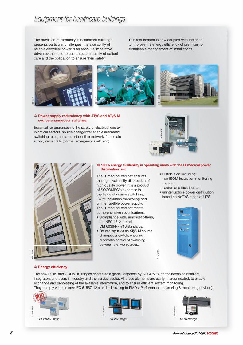
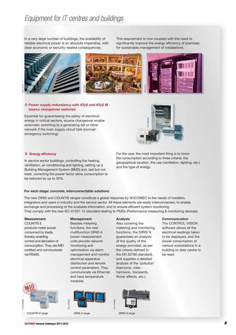
Power supply redundancy with ATyS and ATyS M source changeover switches
Essential for guaranteeing the safety of electrical energy in critical sectors, source changeover enable automatic switching to a generator set or other network if the main supply circuit fails (normal/emergency switching).
134
A R
AN
GE
Energy efficiency
The new DIRIS and COUNTIS ranges constitute a global response by SOCOMEC to the needs of installers, integrators and users in industry and the service sector. All these elements are easily interconnected, to enable exchange and processing of the available information, and to ensure effi cient system monitoring. They comply with the new IEC 61557-12 standard relating to PMDs (Performance measuring & monitoring devices).
132
A R
AN
GE
DIRIS A range
124
A R
AN
GE
DIRIS N range
The IT medical cabinet ensures the high availability distribution of high quality power. It is a product of SOCOMEC's expertise in the fi elds of source switching, ISOM insulation monitoring and uninterruptible power supply.The IT medical cabinet meets comprehensive specifi cations:• Compliance with, amongst others,
the NFC 15-211 and CEI 60364-7-710 standards.
• Double input via an ATyS M source changeover switch, ensuring automatic control of switching between the two sources.
• Distribution including:- an ISOM insulation monitoring
system- automatic fault locator.
• uninterruptible power distribution based on NeTYS range of UPS.
AP
PLI
243
A
AP
PLI
243
A
100% energy availability in operating areas with the IT medical power distribution unit
117
B R
AN
GE
COUNTIS E range
9SOCOMEC General Catalogue 2011-2012
Equipment for IT centres and buildings
In a very large number of buildings, the availability of reliable electrical power is an absolute imperative, with clear economic or security-related consequences.
This requirement is now coupled with the need to signifi cantly improve the energy effi ciency of premises for sustainable management of installations.
SIT
E 13
1 A
SIT
E 46
6 A
SIT
E 37
4 A
Energy effi ciency
In service sector buildings, controlling the heating, ventilation, air conditioning and lighting, setting up a Building Management System (BMS) and, last but not least, correcting the power factor allow consumption to be reduced by up to 30%.
For the user, the most important thing is to know the consumption according to three criteria: the geographical location, the use (ventilation, lighting, etc.) and the type of energy.
MeasurementCOUNTIS Eproducts meter power consumed by loads, thereby enabling control and allocation of consumption. They are MID certified and communicate via RS485.
ManagementBesides metering functions, the new multifunction DIRIS A power measurement units provide network monitoring and optimisation via alarm management and monitor electrical apparatus distribution and remote control parameters. They communicate via Ethernet and have temperature modules.
AnalysisAlso covering the metering and monitoring functions, the DIRIS N guarantees an analysis of the quality of the energy provided, as per the criteria defi ned in the EN 50160 standard, and supplies a detailed analysis of the ‘pollution’ (harmonic, inter-harmonic, transients, fl icker effects, etc.).
CommunicationThe CONTROL VISION software allows all the electrical readings taken to be displayed, and the power consumption of various workstations in a building or data centre to be read.
For each stage: concrete, interconnectable solutions
The new DIRIS and COUNTIS ranges constitute a global response by SOCOMEC to the needs of installers, integrators and users in industry and the service sector. All these elements are easily interconnected, to enable exchange and processing of the available information, and to ensure effi cient system monitoring. They comply with the new IEC 61557-12 standard relating to PMDs (Performance measuring & monitoring devices).
117
B R
AN
GE
132
A R
AN
GE
124
A R
AN
GE
COUNTIS E range DIRIS A range DIRIS N range
Power supply redundancy with ATyS and ATyS M source changeover switches
Essential for guaranteeing the safety of electrical energy in critical sectors, source changeover enable automatic switching to a generating set or other network if the main supply circuit fails (normal/emergency switching).
134
A R
AN
GE
10 General Catalogue 2011-2012 SOCOMEC
Equipment for Photovoltaic applications
Our expertise in the world of controlling and protecting electrical installations has quite naturally been expressed in both standard solutions and those adapted to photovoltaic applications. Whatever the type of architecture, we can offer breaking and
protection systems adapted to each application from 2kWc to tens of MWc. Our modular designs ensure installation is exceptionally easy, providing a wide range of functionalities.
Main applications
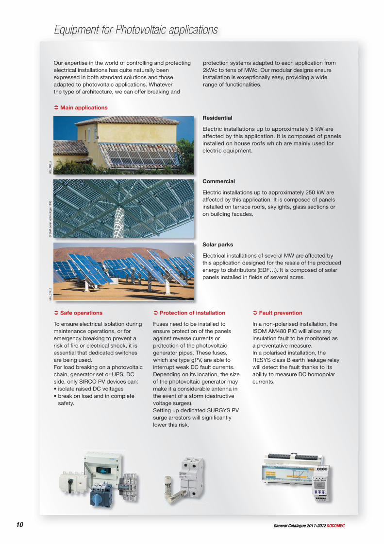
Residential
Electric installations up to approximately 5 kW are affected by this application. It is composed of panels installed on house roofs which are mainly used for electric equipment.
site
_408
_asi
te_3
17_a
Solar parks
Electrical installations of several MW are affected by this application designed for the resale of the produced energy to distributors (EDF…). It is composed of solar panels installed in fields of several acres.
© S
MA
sol
ar te
chno
logi
e 11
35
Commercial
Electric installations up to approximately 250 kW are affected by this application. It is composed of panels installed on terrace roofs, skylights, glass sections or on building facades.
Safe operations
To ensure electrical isolation during maintenance operations, or for emergency breaking to prevent a risk of fi re or electrical shock, it is essential that dedicated switches are being used.For load breaking on a photovoltaic chain, generator set or UPS, DC side, only SIRCO PV devices can:• isolate raised DC voltages• break on load and in complete
safety.
Protection of installation
Fuses need to be installed to ensure protection of the panels against reverse currents or protection of the photovoltaic generator pipes. These fuses, which are type gPV, are able to interrupt weak DC fault currents.Depending on its location, the size of the photovoltaic generator may make it a considerable antenna in the event of a storm (destructive voltage surges).Setting up dedicated SURGYS PV surge arrestors will signifi cantly lower this risk.
Fault prevention
In a non-polarised installation, the ISOM AM480 PIC will allow any insulation fault to be monitored as a preventative measure.In a polarised installation, the RESYS class B earth leakage relay will detect the fault thanks to its ability to measure DC homopolar currents.
11SOCOMEC General Catalogue 2011-2012
Alphabetical index
AATEX enclosures ___________________________________ 216
ATS BY-PASS _____________________________________ 104
ATS By-Pass solution _______________________________ 218
ATyS _____________________________________________ 116
ATyS C30 / ATyS C40 ______________________________ 132
ATyS M ___________________________________________ 108
BBILLING APPLICATION software _____________________ 188
Busbar supports ___________________________________ 200
CChangeover switches ________________________________ 94
Changeover switches SIRCO M _______________________ 98
Changeover switches SIRCO VM1 ____________________ 100
Communication accessories _________________________ 182
Connecting the RS485 link ___________________________ 182
CONTROL VISION software __________________________ 184
COUNTIS AM10 ___________________________________ 140
COUNTIS Ci _______________________________________ 152
COUNTIS E10 / E11 / E12 ___________________________ 142
COUNTIS E20 / E21 ________________________________ 144
COUNTIS E30 / E31 / E32 / E33 / E34 _________________ 146
COUNTIS E40 / E41 / E42 / E43 / E44 _________________ 148
COUNTIS E50 / E53 ________________________________ 150
Customised solutions - Integrated products ____________ 224
DDifferential protection _______________________________ 191
DIRIS A10 _________________________________________ 154
DIRIS A20 _________________________________________ 158
DIRIS A40 / A41 ___________________________________ 162
DIRIS A60 _________________________________________ 168
DIRIS N300 / N600 _________________________________ 174
EElectronic protection ________________________________ 190
Energy management, measurement and analysis ________ 134
FFuse protection _____________________________________ 48
FUSERBLOC _______________________________________ 52
IIntegrated products _________________________________ 208
LLoad break switches _________________________________ 12
PPV fuses ___________________________________________ 90
RRESYS M20 _______________________________________ 192
RESYS M40 _______________________________________ 194
RESYS P40 _______________________________________ 196
RM PV _____________________________________________ 88
SSafety enclosures __________________________________ 210
SB C 10 __________________________________________ 202
SB C 20 __________________________________________ 204
SB C 30 __________________________________________ 206
SIRCO M and MV ___________________________________ 14
SIRCO M PV _______________________________________ 28
SIRCO MV PV ______________________________________ 36
SIRCO PV __________________________________________ 42
SURGYS® G50-PV _________________________________ 198
UUsing the ethernet network __________________________ 183
Using the telephone network _________________________ 183
VVoltage surge protection _____________________________ 191
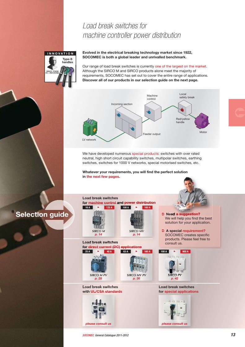
12 SOCOMECGeneral Catalogue 2011-2012
Load break switches
13General Catalogue 2011-2012SOCOMEC
Load break switchesfor direct current (DC) applications
Load break switches with UL/CSA standards
Evolved in the electrical breaking technology market since 1922, SOCOMEC is both a global leader and unrivalled benchmark.
Our range of load break switches is currently one of the largest on the market.Although the SIRCO M and SIRCO products alone meet the majority of requirements, SOCOMEC has set out to cover the entire range of applications. Discover all of our products in our selection guide on the next page.
We have developed numerous special products: switches with over rated neutral, high short circuit capability switches, multipolar switches, earthing switches, switches for 1000 V networks, special motorised switches, etc.
Whatever your requirements, you will find the perfect solution in the next few pages.
Load break switches for machine controller power distribution
Load break switches for machine control and power distribution
IO
IO
IO
IO
Need a suggestion? We will help you fi nd the best solution for your application.
A special requirement?SOCOMEC creates specifi c products. Please feel free to consult us.
I N N O V A T I O N
Type-S handles
Selection guide
SIRCO MV p. 14
100 A 160 A
SIRCO M p. 14
16 A 125 A
SIRCO M PVp. 28
25 A 40 A
SIRCO MV PV p. 36
63 A 160 A
SIRCO PV p. 42
100 A 800 A
please consult us
please consult us
Load break switches for special applications
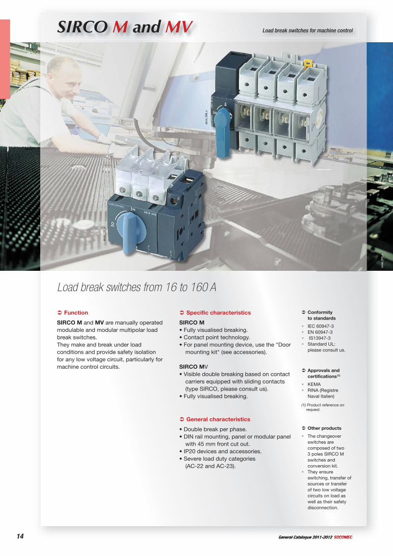
14 General Catalogue 2011-2012 SOCOMEC
corp
o_20
7_a
SIRCO M and MV Load break switches for machine control
Load break switches from 16 to 160 A
sirc
m_1
32_a
sirc
m_0
99_a
Function
SIRCO M and MV are manually operated modulable and modular multipolar load break switches.They make and break under load conditions and provide safety isolation for any low voltage circuit, particularly for machine control circuits.
Conformityto standards
IEC 60947-3EN 60947-3 IS13947-3Standard UL: please consult us.
••••
Approvals and certifications (1)
KEMARINA (Registre Naval Italien)
(1) Product reference on request.
••
General characteristics
• Double break per phase.• DIN rail mounting, panel or modular panel
with 45 mm front cut out.• IP20 devices and accessories.• Severe load duty categories
(AC-22 and AC-23).
Specific characteristics
SIRCO M• Fully visualised breaking.• Contact point technology.• For panel mounting device, use the "Door
mounting kit" (see accessories).
SIRCO MV• Visible double breaking based on contact
carriers equipped with sliding contacts (type SIRCO, please consult us).
• Fully visualised breaking.
Other products
The changeover switches are composed of two 3 poles SIRCO M switches and conversion kit.They ensure switching, transfer of sources or transfer of two low voltage circuits on load as well as their safety disconnection.
•
•
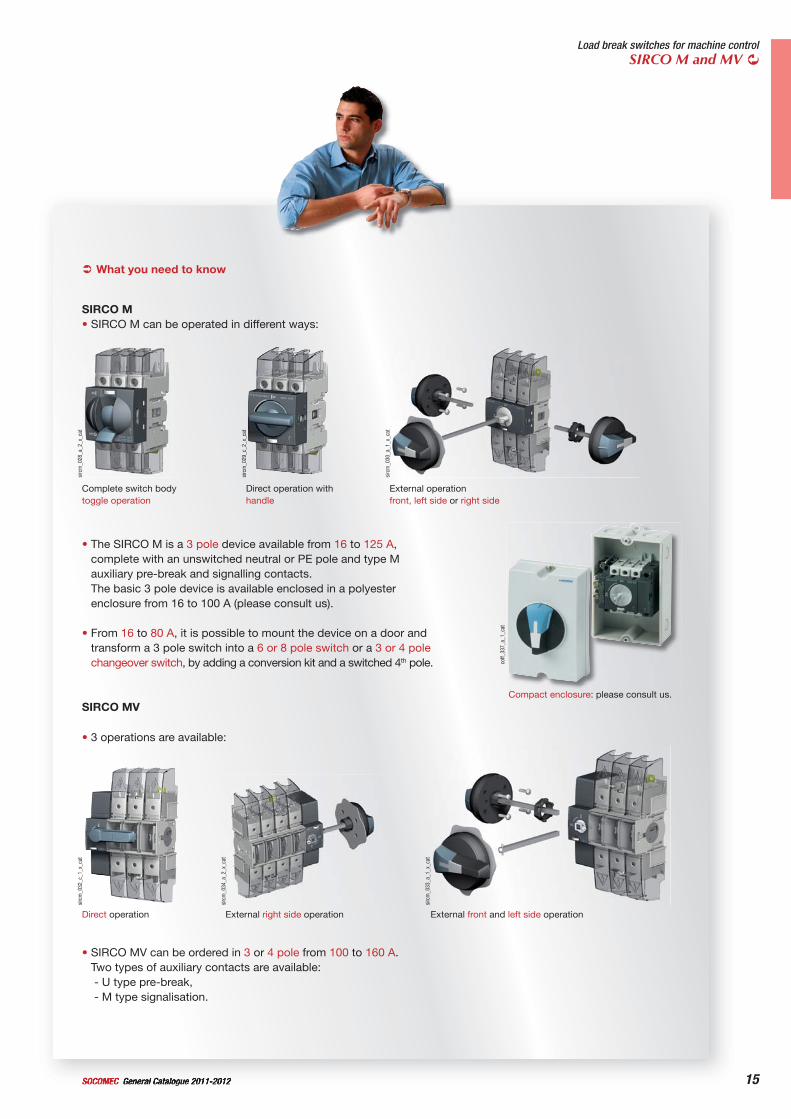
15General Catalogue 2011-2012SOCOMEC
Load break switches for machine controlSIRCO M and MV
sirc
m_0
32_c
_1_x
_cat
Direct operation
sirc
m_0
34_a
_2_x
_cat
External right side operation
sirc
m_0
33_a
_1_x
_cat
External front and left side operation
• 3 operations are available:
• SIRCO MV can be ordered in 3 or 4 pole from 100 to 160 A.Two types of auxiliary contacts are available:- U type pre-break,- M type signalisation.
What you need to know
sirc
m_0
29_c
_2_x
_cat
Direct operation with handle
SIRCO M• SIRCO M can be operated in different ways:
sirc
m_0
30_a
_1_x
_cat
External operationfront, left side or right side
• The SIRCO M is a 3 pole device available from 16 to 125 A,complete with an unswitched neutral or PE pole and type M auxiliary pre-break and signalling contacts. The basic 3 pole device is available enclosed in a polyester enclosure from 16 to 100 A (please consult us).
• From 16 to 80 A, it is possible to mount the device on a door and transform a 3 pole switch into a 6 or 8 pole switch or a 3 or 4 pole changeover switch, by adding a conversion kit and a switched 4th pole.
SIRCO MV
sirc
m_0
28_a
_2_x
_cat
Complete switch body toggle operation
coff_
337_
a_1_
cat
Compact enclosure: please consult us.
16 General Catalogue 2011-2012 SOCOMEC16
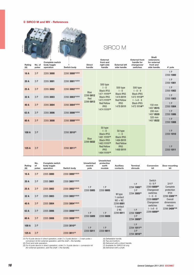
SIRCO M and MV - References
sirc
m_1
32_a SIRCO M
Rating(A)
No. of poles
Complete switch body toggle operation Switch body
Direct handle
External front and right side
handleExternal left side handle
External front handle for
changeoverswitches
Shaftextensionsfor external
front and side handle 4e pole
16 A 3 P 2205 3000 2200 3000(1)(2)(3)
Blue2299 5012
Red2299 5013
S00 type I - 0
Black IP551471 1111(4)
Black IP651473 1111(4)
Red/Yellow IP65
1474 1111(4)
S00 type I - 0
Black IP65147A 5111 Red/Yellow
IP65147B 5111
S00 type I - 0 - II
Black IP651473 1113(4)
I - I+II - II Black IP65
1473 1114(4) 150 mm1407 0515 200 mm
1407 0520 320 mm
1407 0532
1 P2200 1000
20 A 3 P 2205 3001 2200 3001(1)(2)(3) 1 P2200 1001
25 A 3 P 2205 3002 2200 3002(1)(2)(3) 1 P2200 1002
32 A 3 P 2205 3003 2200 3003(1)(2)(3) 1 P2200 1003
40 A 3 P 2205 3004 2200 3004(1)(2)(3) 1 P2200 1004
63 A 3 P 2205 3006 2200 3006(1)(2)(3) 1 P2200 1006
80 A 3 P 2205 3008 2200 3008(1)(2)(3) 1 P2200 1008
100 A 3 P 2200 3010(2)
Blue2299 5032
S0 typeI - 0
Black IP551481 1111(4)
Black IP651483 1111(4)
Red/Yellow IP65
1484 1111(4)
S0 typeI - 0
Black IP65148A 5111 Red/Yellow
IP65148B 5111
1 P2200 1010
125 A 3 P 2200 3011(2) 1 P2200 1011
(1) For 8 pole device in direct operation, order 2 x 3 pole device + 2 main poles + conversion kit (for external operation, add the shaft + the handle).
(2) Front and side operation.(3) For 6-pole device in direct operation, order 2 x 3-pole device + conversion kit
(for external operation, add the shaft + the handle).
(4) Defeatable handle.(5) Top and bottom.(6) Delivered with a direct handle.(7) Available for SIRCO M only.(8) Delivered with a shaft.
Rating(A)
No.ofpoles
Complete switch body toggle operation Switch body
Unswitchedneutral
pole
Unswitchedprotective
earthmodule
Auxiliarycontacts
Terminal shrouds
Conversionkit
Door mounting kit
16 A 3 P 2205 3000 2200 3000(1)(2)(3)
1 P2200 5005
1 P2200 9005
M type1 contact NO + NC
2299 0001 1 contact
2 NC2299 0011
1 P2294 1005(5)
3 P2294 3005(5)
Switch6 / 8 P
2269 6009(6)
Changeover switches I - 0 - II
2209 6009(6)
Changeover switches I - I+II - II
2299 6009(6)
3/4 P Completeprotection
IP2X2299 3309(7)(8)
Overalldimensions
reduce2299 3409(7)(8)
20 A 3 P 2205 3001 2200 3001(1)(2)(3)
25 A 3 P 2205 3002 2200 3002(1)(2)(3)
32 A 3 P 2205 3003 2200 3003(1)(2)(3)
40 A 3 P 2205 3004 2200 3004(1)(2)(3)
63 A 3 P 2205 3006 2200 3006(1)(2)(3)
1 P2200 5009
1 P2200 9009
1 P2294 1009(5)
3 P2294 3009(5)80 A 3 P 2205 3008 2200 3008(1)(2)(3)
100 A 3 P 2200 3010(2)
1 P2200 5011
1 P2200 9011
1 P2294 1011(5)
3 P2294 3016(5)125 A 3 P 2200 3011(2)
sirc
m_1
33_a
17General Catalogue 2011-2012SOCOMEC 17
Load break switches for machine controlSIRCO M and MV
sirc
m_0
99_a
Direct operation handle
sirc
m_0
71_b
_1_x
_cat
M00 handle
sirc
m_0
41_a
_1_x
_cat
M01 handle
sirc
m_0
42_b
_1_x
_cat
M0 handle
SIRCO MV
Rating(A)
No. of poles Switch body
Direct handle
External front handle
External right side handle
External left side handle
Shaftextensionsfor external
front and side
Auxiliarysignal
contact
Auxiliarycontacts for pre-break
Terminal shrouds
Voltage sensing and
power supply kit
100 A
3 P 2200 3110
Blue2299 5042(1)
Blue2299 5022
S0 typeI - 0
Black IP551491 0111(2)
Black IP651493 0111(2)
I - 0 Red/Yellow
IP651494 0111(2)
S1 type OI - 0
Black IP551411 2111(2)
Red/Yellow IP65
1414 2111(2)
S0 typeI - 0
Black IP551491 0111(2)
Red/Yellow IP65
1494 0111(2)
S1 type I - 0
Black IP551415 2111 Red/Yellow
IP651418 2111
S0 typeI - 0
Black IP65149A 9111 Red/Yellow
IP65149B 9111
S1 type I - 0
Black IP65141A 2111 Red/Yellow
IP65141B 2111
S0 type 150 mm
1409 0615200 mm
1409 0620320 mm
1409 0632
S1 type 200 mm
1401 0620320 mm
1401 0632400 mm
1401 0640
M type1 contact NO + NC
2299 00011 contact
2 NC2299 0011
U typeNC contact3999 0701
1 contact NO3999 0702
3 P2294 3016(3)
4 P2294 4016(3)
2 pieces1399 4006
4 P 2200 4110
125 A
3 P 2200 3012
4 P 2200 4012
160 A
3 P 2200 3016
4 P 2200 4016
(1) Standard.(2) Defeatable handle.(3) Top and bottom.
Accessories
acce
s_26
8_a
M0b handle
For SIRCO MRating (A) Handle colour Handle Reference16 … 80 Blue M00 type 2299 501216 … 80 Red M00 type 2299 5013100 ... 125 Blue M01 type 2299 5032
For SIRCO MVRating (A) Handle colour Handle Reference100 ... 160 Blue M0B type 2299 5042(1)
100 ... 160 Blue M0 type 2299 5022(1) Standard.
18 General Catalogue 2011-2012 SOCOMEC18
SIRCO M and MV - Accessories (continued)
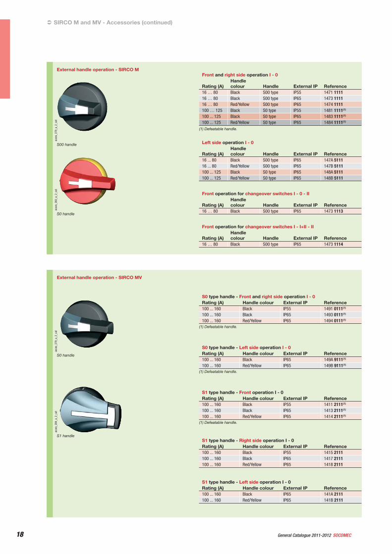
External handle operation - SIRCO M
acce
s_27
8_a_
2_ca
t
S00 handle
acce
s_26
3_a_
2_ca
t
S0 handle
Front and right side operation I - 0
Rating (A)Handlecolour Handle External IP Reference
16 … 80 Black S00 type IP55 1471 111116 … 80 Black S00 type IP65 1473 111116 … 80 Red/Yellow S00 type IP65 1474 1111100 … 125 Black S0 type IP55 1481 1111(1)
100 ... 125 Black S0 type IP65 1483 1111(1)
100 ... 125 Red/Yellow S0 type IP65 1484 1111(1)
(1) Defeatable handle.
Left side operation I - 0
Rating (A)Handlecolour Handle External IP Reference
16 ... 80 Black S00 type IP65 147A 511116 ... 80 Red/Yellow S00 type IP65 147B 5111100 ... 125 Black S0 type IP65 148A 5111100 ... 125 Red/Yellow S0 type IP65 148B 5111
Front operation for changeover switches I - 0 - II
Rating (A)Handlecolour Handle External IP Reference
16 … 80 Black S00 type IP65 1473 1113
Front operation for changeover switches I - I+II - II
Rating (A)Handlecolour Handle External IP Reference
16 … 80 Black S00 type IP65 1473 1114
acce
s_28
4_a_
2_ca
t
S1 handle
acce
s_27
9_a_
2_ca
t
S0 handle
External handle operation - SIRCO MV
S0 type handle - Front and right side operation I - 0Rating (A) Handle colour External IP Reference100 ... 160 Black IP55 1491 0111(1)
100 ... 160 Black IP65 1493 0111(1)
100 ... 160 Red/Yellow IP65 1494 0111(1)
(1) Defeatable handle.
S0 type handle - Left side operation I - 0Rating (A) Handle colour External IP Reference100 ... 160 Black IP65 149A 9111(1)
100 ... 160 Red/Yellow IP65 149B 9111(1)
(1) Defeatable handle.
S1 type handle - Front operation I - 0Rating (A) Handle colour External IP Reference100 ... 160 Black IP55 1411 2111(1)
100 ... 160 Black IP65 1413 2111(1)
100 ... 160 Red/Yellow IP65 1414 2111(1)
(1) Defeatable handle.
S1 type handle - Right side operation I - 0Rating (A) Handle colour External IP Reference100 ... 160 Black IP55 1415 2111100 ... 160 Black IP65 1417 2111100 ... 160 Red/Yellow IP65 1418 2111
S1 type handle - Left side operation I - 0Rating (A) Handle colour External IP Reference100 ... 160 Black IP65 141A 2111100 ... 160 Red/Yellow IP65 141B 2111
19General Catalogue 2011-2012SOCOMEC 19
Load break switches for machine controlSIRCO M and MV
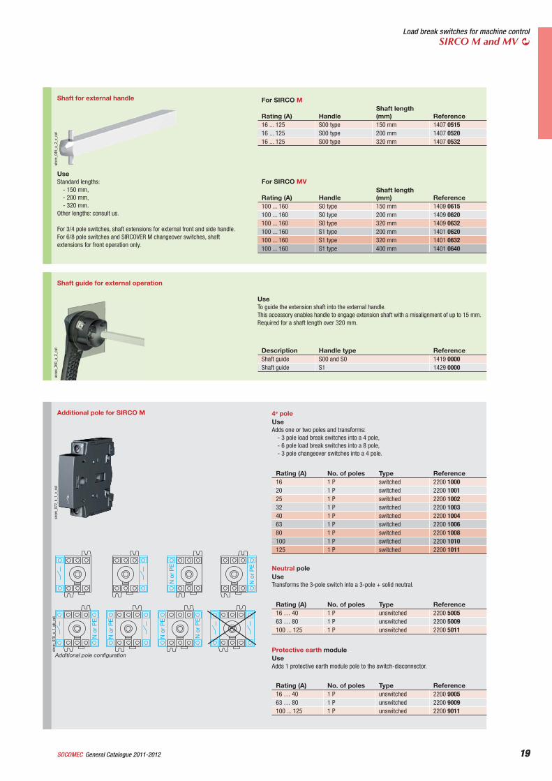
Shaft for external handle
sirc
m_0
45_a
_2_x
_cat
UseStandard lengths:
- 150 mm,- 200 mm,- 320 mm.
Other lengths: consult us.
For 3/4 pole switches, shaft extensions for external front and side handle.For 6/8 pole switches and SIRCOVER M changeover switches, shaft extensions for front operation only.
For SIRCO M
Rating (A) HandleShaft length (mm) Reference
16 ... 125 S00 type 150 mm 1407 051516 ... 125 S00 type 200 mm 1407 052016 ... 125 S00 type 320 mm 1407 0532
For SIRCO MV
Rating (A) HandleShaft length (mm) Reference
100 ... 160 S0 type 150 mm 1409 0615100 ... 160 S0 type 200 mm 1409 0620100 ... 160 S0 type 320 mm 1409 0632100 ... 160 S1 type 200 mm 1401 0620100 ... 160 S1 type 320 mm 1401 0632100 ... 160 S1 type 400 mm 1401 0640
Protective earth moduleUseAdds 1 protective earth module pole to the switch-disconnector.
Rating (A) No. of poles Type Reference16 … 40 1 P unswitched 2200 900563 … 80 1 P unswitched 2200 9009100 ... 125 1 P unswitched 2200 9011
Neutral poleUseTransforms the 3-pole switch into a 3-pole + solid neutral.
Rating (A) No. of poles Type Reference16 … 40 1 P unswitched 2200 500563 … 80 1 P unswitched 2200 5009100 ... 125 1 P unswitched 2200 5011
4e poleUseAdds one or two poles and transforms:
- 3 pole load break switches into a 4 pole,- 6 pole load break switches into a 8 pole,- 3 pole changeover switches into a 4 pole.
Rating (A) No. of poles Type Reference16 1 P switched 2200 100020 1 P switched 2200 100125 1 P switched 2200 100232 1 P switched 2200 100340 1 P switched 2200 100463 1 P switched 2200 100680 1 P switched 2200 1008100 1 P switched 2200 1010125 1 P switched 2200 1011
Additional pole for SIRCO M
sirc
m_0
72_b
_1_x
_cat
N o
r P
E
N o
r P
E
N o
r P
E
N o
r P
E
N o
r P
E
N o
r P
E
sirc
m_0
78_a
_1_g
b_ca
t
Additional pole configuration
Shaft guide for external operation
acce
s_26
0_a_
2_ca
t
UseTo guide the extension shaft into the external handle.This accessory enables handle to engage extension shaft with a misalignment of up to 15 mm.Required for a shaft length over 320 mm.
Description Handle type ReferenceShaft guide S00 and S0 1419 0000Shaft guide S1 1429 0000
20 General Catalogue 2011-2012 SOCOMEC20
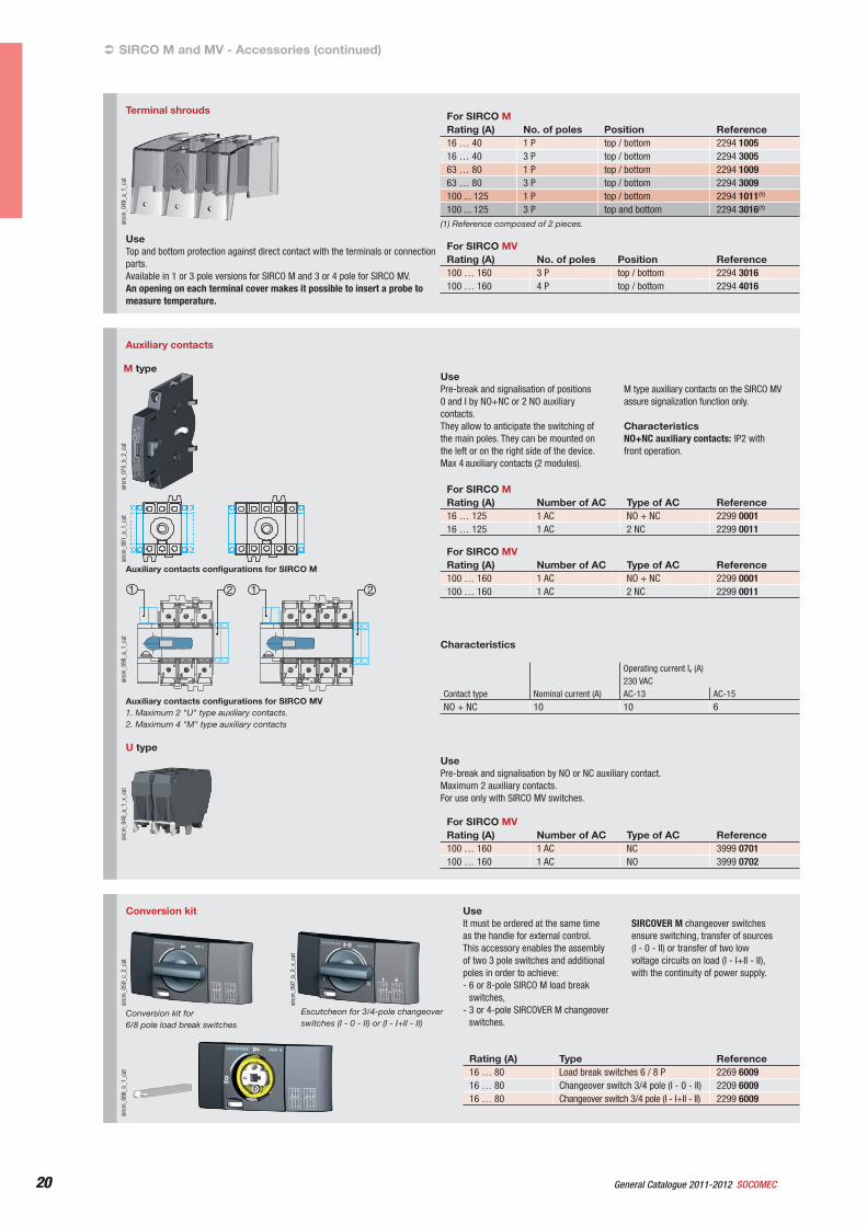
sirc
m_0
97_b
_2_x
_cat
Escutcheon for 3/4-pole changeover switches (I - 0 - II) or (I - I+II - II)
sirc
m_0
86_b
_1_c
atsi
rcm
_050
_c_2
_cat
Conversion kit for 6/8 pole load break switches
Conversion kit UseIt must be ordered at the same time as the handle for external control.This accessory enables the assembly of two 3 pole switches and additional poles in order to achieve:- 6 or 8-pole SIRCO M load break
switches,- 3 or 4-pole SIRCOVER M changeover
switches.
SIRCOVER M changeover switches ensure switching, transfer of sources (I - 0 - II) or transfer of two low voltage circuits on load (I - I+II - II), with the continuity of power supply.
Rating (A) Type Reference16 … 80 Load break switches 6 / 8 P 2269 600916 … 80 Changeover switch 3/4 pole (I - 0 - II) 2209 600916 … 80 Changeover switch 3/4 pole (I - I+II - II) 2299 6009
Terminal shroudssi
rcm
_049
_a_1
_cat
UseTop and bottom protection against direct contact with the terminals or connection parts.Available in 1 or 3 pole versions for SIRCO M and 3 or 4 pole for SIRCO MV.An opening on each terminal cover makes it possible to insert a probe to measure temperature.
For SIRCO MRating (A) No. of poles Position Reference16 … 40 1 P top / bottom 2294 100516 … 40 3 P top / bottom 2294 300563 … 80 1 P top / bottom 2294 100963 … 80 3 P top / bottom 2294 3009100 ... 125 1 P top / bottom 2294 1011(1)
100 ... 125 3 P top and bottom 2294 3016(1)
For SIRCO MVRating (A) No. of poles Position Reference100 … 160 3 P top / bottom 2294 3016100 … 160 4 P top / bottom 2294 4016
(1) Reference composed of 2 pieces.
SIRCO M and MV - Accessories (continued)
Auxiliary contacts
sirc
m_0
75_b
_2_c
at
UsePre-break and signalisation of positions 0 and I by NO+NC or 2 NO auxiliary contacts.They allow to anticipate the switching of the main poles. They can be mounted on the left or on the right side of the device.Max 4 auxiliary contacts (2 modules).
M type auxiliary contacts on the SIRCO MV assure signalization function only.
CharacteristicsNO+NC auxiliary contacts: IP2 with front operation.
For SIRCO MRating (A) Number of AC Type of AC Reference16 … 125 1 AC NO + NC 2299 000116 … 125 1 AC 2 NC 2299 0011
For SIRCO MVRating (A) Number of AC Type of AC Reference100 … 160 1 AC NO + NC 2299 0001100 … 160 1 AC 2 NC 2299 0011
Characteristics
Contact type Nominal current (A)
Operating current Ie (A)230 VACAC-13 AC-15
NO + NC 10 10 6
U type
sirc
m_0
48_a
_1_x
_cat
UsePre-break and signalisation by NO or NC auxiliary contact. Maximum 2 auxiliary contacts.For use only with SIRCO MV switches.
For SIRCO MVRating (A) Number of AC Type of AC Reference100 … 160 1 AC NC 3999 0701100 … 160 1 AC NO 3999 0702
sirc
m_0
81_a
_1_c
at
Auxiliary contacts configurations for SIRCO M
21 1 2
sirc
m_0
98_a
_1_c
at
Auxiliary contacts configurations for SIRCO MV1. Maximum 2 "U" type auxiliary contacts.2. Maximum 4 "M" type auxiliary contacts
M type
21General Catalogue 2011-2012SOCOMEC 21
Load break switches for machine controlSIRCO M and MV
sirc
m_0
51_b
_2_c
at
For SIRCO M
Rating (A)No. of poles Description Reference
16 … 80 3/4 P Complete protection IP2X 2299 330916 … 80 3/4 P Overall dimensions reduce 2299 3409
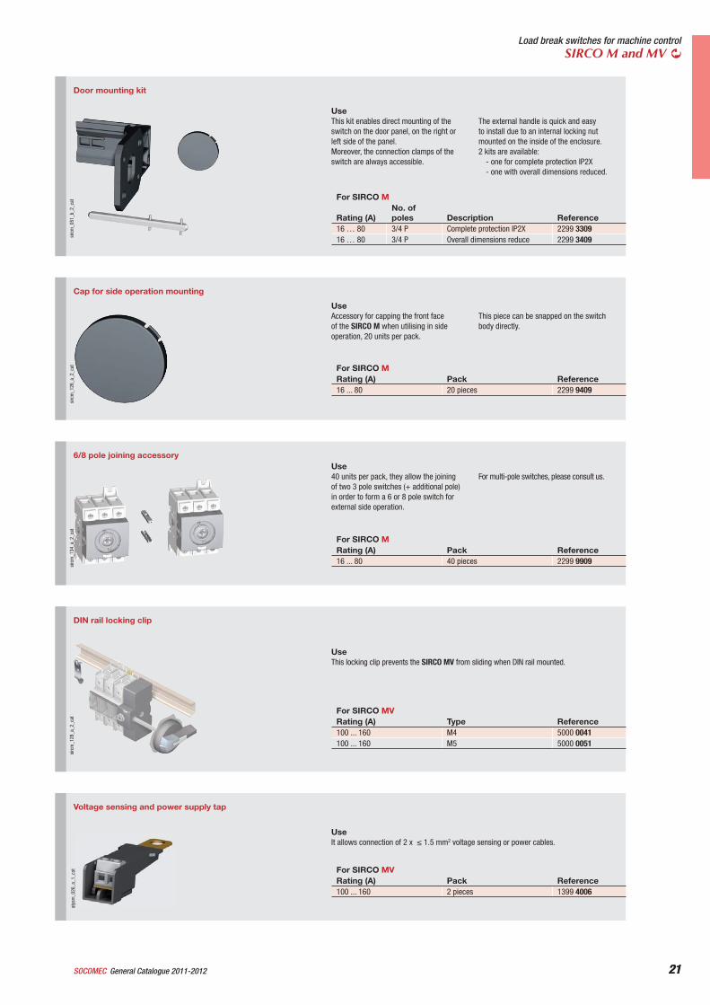
Door mounting kit
UseThis kit enables direct mounting of the switch on the door panel, on the right or left side of the panel.Moreover, the connection clamps of the switch are always accessible.
The external handle is quick and easy to install due to an internal locking nut mounted on the inside of the enclosure.2 kits are available:
- one for complete protection IP2X- one with overall dimensions reduced.
Cap for side operation mounting
sirc
m_1
26_a
_2_c
at
UseAccessory for capping the front face of the SIRCO M when utilising in side operation, 20 units per pack.
This piece can be snapped on the switch body directly.
For SIRCO MRating (A) Pack Reference16 ... 80 20 pieces 2299 9409
6/8 pole joining accessory
sirc
m_1
34_a
_2_c
at
Use40 units per pack, they allow the joining of two 3 pole switches (+ additional pole) in order to form a 6 or 8 pole switch for external side operation.
For multi-pole switches, please consult us.
For SIRCO MRating (A) Pack Reference16 ... 80 40 pieces 2299 9909
DIN rail locking clip
sirc
m_1
28_a
_2_c
at
UseThis locking clip prevents the SIRCO MV from sliding when DIN rail mounted.
For SIRCO MVRating (A) Type Reference100 ... 160 M4 5000 0041100 ... 160 M5 5000 0051
Voltage sensing and power supply tap
UseIt allows connection of 2 x 1.5 mm2 voltage sensing or power cables.
For SIRCO MVRating (A) Pack Reference100 ... 160 2 pieces 1399 4006
atys
m_0
26_a
_1_c
at
22 General Catalogue 2011-2012 SOCOMEC22
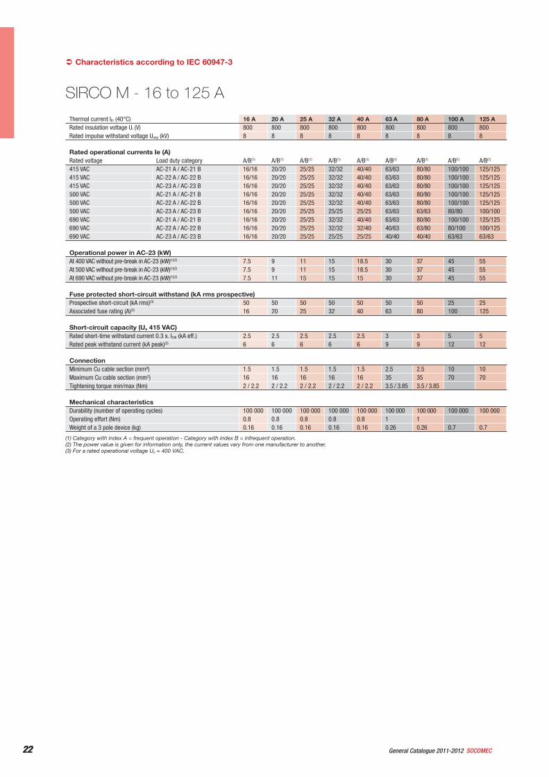
Thermal current Ith (40°C) 16 A 20 A 25 A 32 A 40 A 63 A 80 A 100 A 125 ARated insulation voltage Ui (V) 800 800 800 800 800 800 800 800 800Rated impulse withstand voltage Uimp (kV) 8 8 8 8 8 8 8 8 8
Rated operational currents Ie (A)Rated voltage Load duty category A/B(1) A/B(1) A/B(1) A/B(1) A/B(1) A/B(1) A/B(1) A/B(1) A/B(1)
415 VAC AC-21 A / AC-21 B 16/16 20/20 25/25 32/32 40/40 63/63 80/80 100/100 125/125415 VAC AC-22 A / AC-22 B 16/16 20/20 25/25 32/32 40/40 63/63 80/80 100/100 125/125415 VAC AC-23 A / AC-23 B 16/16 20/20 25/25 32/32 40/40 63/63 80/80 100/100 125/125500 VAC AC-21 A / AC-21 B 16/16 20/20 25/25 32/32 40/40 63/63 80/80 100/100 125/125500 VAC AC-22 A / AC-22 B 16/16 20/20 25/25 32/32 40/40 63/63 80/80 100/100 125/125500 VAC AC-23 A / AC-23 B 16/16 20/20 25/25 25/25 25/25 63/63 63/63 80/80 100/100690 VAC AC-21 A / AC-21 B 16/16 20/20 25/25 32/32 40/40 63/63 80/80 100/100 125/125690 VAC AC-22 A / AC-22 B 16/16 20/20 25/25 32/32 32/40 40/63 63/80 80/100 100/125690 VAC AC-23 A / AC-23 B 16/16 20/20 25/25 25/25 25/25 40/40 40/40 63/63 63/63
Operational power in AC-23 (kW)At 400 VAC without pre-break in AC-23 (kW)(1)(2) 7.5 9 11 15 18.5 30 37 45 55At 500 VAC without pre-break in AC-23 (kW)(1)(2) 7.5 9 11 15 18.5 30 37 45 55At 690 VAC without pre-break in AC-23 (kW)(1)(2) 7.5 11 15 15 15 30 37 45 55
Fuse protected short-circuit withstand (kA rms prospective)Prospective short-circuit (kA rms)(3) 50 50 50 50 50 50 50 25 25Associated fuse rating (A)(3) 16 20 25 32 40 63 80 100 125
Short-circuit capacity (Ue 415 VAC)Rated short-time withstand current 0.3 s. ICW (kA eff.) 2.5 2.5 2.5 2.5 2.5 3 3 5 5Rated peak withstand current (kA peak)(3) 6 6 6 6 6 9 9 12 12
ConnectionMinimum Cu cable section (mm²) 1.5 1.5 1.5 1.5 1.5 2.5 2.5 10 10Maximum Cu cable section (mm2) 16 16 16 16 16 35 35 70 70Tightening torque min/max (Nm) 2 / 2.2 2 / 2.2 2 / 2.2 2 / 2.2 2 / 2.2 3.5 / 3.85 3.5 / 3.85
Mechanical characteristicsDurability (number of operating cycles) 100 000 100 000 100 000 100 000 100 000 100 000 100 000 100 000 100 000Operating effort (Nm) 0.8 0.8 0.8 0.8 0.8 1 1Weight of a 3 pole device (kg) 0.16 0.16 0.16 0.16 0.16 0.26 0.26 0.7 0.7
Characteristics according to IEC 60947-3
(1) Category with index A = frequent operation - Category with index B = infrequent operation.(2) The power value is given for information only, the current values vary from one manufacturer to another.(3) For a rated operational voltage Ue = 400 VAC.
SIRCO M - 16 to 125 A
23General Catalogue 2011-2012SOCOMEC 23
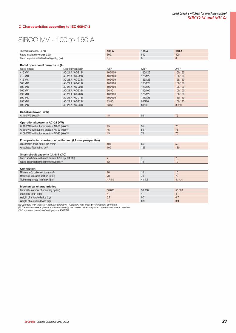
Load break switches for machine controlSIRCO M and MV
Thermal current Ith (40°C) 100 A 125 A 160 ARated insulation voltage Ui (V) 800 800 800Rated impulse withstand voltage Uimp (kV) 8 8 8
Rated operational currents Ie (A)Rated voltage Load duty category A/B(1) A/B(1) A/B(1)
415 VAC AC-21 A / AC-21 B 100/100 125/125 160/160415 VAC AC-22 A / AC-22 B 100/100 125/125 160/160415 VAC AC-23 A / AC-23 B 100/100 125/125 125/160500 VAC AC-21 A / AC-21 B 100/100 125/125 160/160500 VAC AC-22 A / AC-22 B 100/100 125/125 125/160500 VAC AC-23 A / AC-23 B 80/80 100/100 100/100690 VAC AC-20 A / AC-20 B 100/100 125/125 160/160690 VAC AC-21 A / AC-21 B 100/100 125/125 160/160690 VAC AC-22 A / AC-22 B 63/80 80/100 100/125690 VAC AC-23 A / AC-23 B 63/63 80/80 80/80
Reactive power (kvar)At 400 VAC (kvar)(2) 45 55 75
Operational power in AC-23 (kW)At 400 VAC without pre-break in AC-23 (kW)(1)(2) 45 55 75At 500 VAC without pre-break in AC-23 (kW)(1)(2) 45 55 75At 690 VAC without pre-break in AC-23 (kW)(1)(2) 45 75 75
Fuse protected short-circuit withstand (kA rms prospective)Prospective short-circuit (kA rms)(3) 100 65 50Associated fuse rating (A)(3) 100 125 160
Short-circuit capacity (Ue 415 VAC)Rated short-time withstand current 0.3 s. ICW (kA eff.) 7 7 7Rated peak withstand current (kA peak)(3) 12 12 12
ConnectionMinimum Cu cable section (mm²) 10 10 10Maximum Cu cable section (mm2) 70 70 70Tightening torque min/max (Nm) 4 / 4.4 4 / 4.4 4 / 4.4
Mechanical characteristicsDurability (number of operating cycles) 50 000 50 000 50 000Operating effort (Nm) 4 4 4Weight of a 3 pole device (kg) 0.7 0.7 0.7Weight of a 4 pole device (kg) 0.9 0.9 0.9
Characteristics according to IEC 60947-3
(1) Category with index A = frequent operation - Category with index B = infrequent operation.(2) The power value is given for information only, the current values vary from one manufacturer to another.(3) For a rated operational voltage Ue = 400 VAC.
SIRCO MV - 100 to 160 A
24 General Catalogue 2011-2012 SOCOMEC24
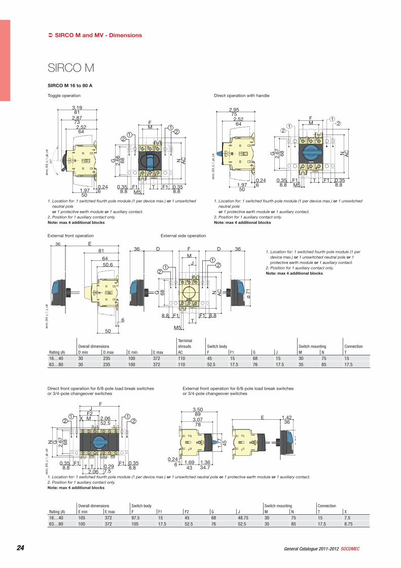
SIRCO M 16 to 80 A
Toggle operation
2.68
F
TM5
M
NG AC
3.19
2.52
61.97
2.87
F1 0.35F10.35
21 2
168
50
0.248.88.8
81
73
64
sirc
m_0
52_b
_1_g
b_ca
t
1. Location for: 1 switched fourth pole module (1 per device max.) or 1 unswitched neutral pole or 1 protective earth module or 1 auxiliary contact.
2. Position for 1 auxiliary contact only.Note: max 4 additional blocks
Direct operation with handle
2.67
F
TM5
M
NG AC
2.52
0.241.97
2.95
F1F10.35
21 2
175
64
650
68
8.88.80.35si
rcm
_053
_b_1
_gb_
cat
1. Location for: 1 switched fourth pole module (1 per device max.) or 1 unswitched neutral pole or 1 protective earth module or 1 auxiliary contact.
2. Position for 1 auxiliary contact only.Note: max 4 additional blocks
External front operation External side operation
J
68
36 D F
TM5
M36D
NG AC
E36
81
64
6
50
50.6
F18.8 F1 8.8
ø 71
21 2
1
sirc
m_0
54_c
_1_x
_cat
1. Location for: 1 switched fourth pole module (1 per device max.) or 1 unswitched neutral pole or 1 protective earth module or 1 auxiliary contact.
2. Position for 1 auxiliary contact only.Note: max 4 additional blocks
Rating (A)Overall dimensions
Terminal shrouds Switch body Switch mounting Connection
D min D max E min E max AC F F1 G J M N T16…40 30 235 100 372 110 45 15 68 15 30 75 1563…80 30 235 100 372 110 52.5 17.5 76 17.5 35 85 17.5
SIRCO M and MV - Dimensions
Direct front operation for 6/8-pole load break switches or 3/4-pole changeover switches
External front operation for 6/8-pole load break switches or 3/4-pole changeover switches
1.42E
1.77
3.07
1.361.690.24
3.50
279
X
N G2.
67
T T 0.292.06
MF2
2.06
FJ
F1F10.35
21
21 89
78
43 34.76
36
45
52.5
68
8.8 8.87.5
0.35
sirc
m_0
55_c
_1_g
b_ca
t
1. Location for: 1 switched fourth pole module (1 per device max.) or 1 unswitched neutral pole or 1 protective earth module or 1 auxiliary contact.2. Position for 1 auxiliary contact only.Note: max 4 additional blocks
Rating (A)Overall dimensions Switch body Switch mounting ConnectionE min E max F F1 F2 G J M N T X
16…40 105 372 97.5 15 45 68 48.75 30 75 15 7.563…80 105 372 105 17.5 52.5 76 52.5 35 85 17.5 8.75
SIRCO M
25General Catalogue 2011-2012SOCOMEC 25
Load break switches for machine controlSIRCO M and MV
Direct operation with handle
75
64
0.246
124.
6
131.
4
26
78
8 8 8 826 26 26
2.95
2.52
2 09
49.0
5
0.35 0.351.021.02 1.02
51.7
3
1.02
3.07
21
21
sirc
m_0
56_c
_1_g
b_ca
t
1. Location for: 1 switched fourth pole module (1 per device max.) or 1 unswitched neutral pole or 1 protective earth module or 1 auxiliary contact.
2. Position for 1 auxiliary contact only.Note: max 4 additional blocks
SIRCO M 100 to 125 A
External front operation External side operation
37100 min.372 max.
8164
53
6
50.613
37
124.
6
131.
418
9
2678 37
8.8 8.826 26 26M5
88ø 71
30 min.201 max.
30 min.201 max.
2
12
1
sirc
m_0
57_b
_1_x
_cat
1. Location for: 1 switched fourth pole module (1 per device max.) or 1 unswitched neutral pole or 1 protective earth module or 1 auxiliary contact.
2. Position for 1 auxiliary contact only.Note: max 4 additional blocks
SIRCO MV
Direct front operation External front operation
37
110 min.357 max.A B
88ø 71
8,8
76 13561
653
64
26
124,
6
131,
418
9
M5
35 26109
8,8
1
1
69,929,5
44
70
C D2 2
sirc
m_0
58_c
_1_x
_cat
A. 3 poleB. 4 pole
C. S0 type handleD. S1 type handle
1. Maximum 4 "M" type auxiliary contacts2. Maximum 2 "U" type auxiliary contacts
SIRCO MV 100 to 160 A
External side operation
69,950,6
536
13530 min.
300 max. 3783
10926 57
26
189
131,
4
124,
6
M5
B CA
88ø 71
8,88,8
E
1
D F
1
69,944
70
22
sirc
m_0
59_c
_1_x
_cat
A. Right side operationB. 3 poleC. 4 pole
D. S0 type handleE. Left side operationF. S1 type handle
1. Maximum 4 "M" type auxiliary contacts2. Maximum 2 "U" type auxiliary contacts
26 General Catalogue 2011-2012 SOCOMEC26
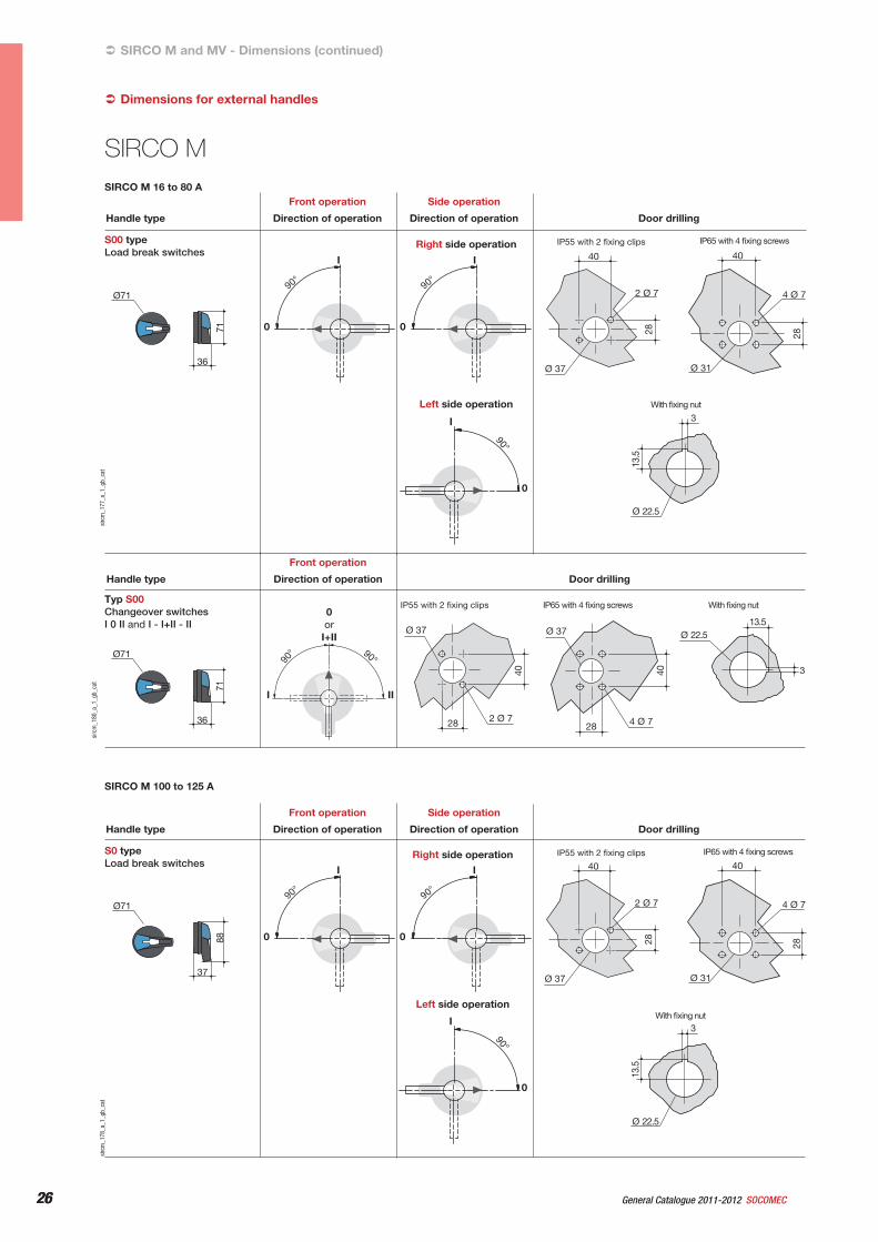
SIRCO M and MV - Dimensions (continued)
13.5
Ø 22.5
3
0
I
90°
0
I
90°
I
0
90°
40
4 Ø 7
Ø 31
28
40
2 Ø 7
Ø 37
28
Right side operation
Left side operation
Ø71
36
71
With fixing nut
IP55 with 2 fixing clips IP65 with 4 fixing screwsS00 typeLoad break switches
Direction of operation Direction of operation Door drillingHandle type
Front operation Side operation
sirc
m_1
77_a
_1_g
b_ca
t
SIRCO M 16 to 80 A
Dimensions for external handles
SIRCO M
13.5Ø 22.5
3
Typ S00Changeover switchesI 0 II and I - I+II - II
0or
I+II
I II
90° 90°
40
28
40
2 Ø 7
Ø 37
28
Ø 37
4 Ø 7
Ø71
36
71
With fixing nutIP55 with 2 fixing clips IP65 with 4 fixing screws
Direction of operation Door drillingHandle type
Front operation
sirc
m_1
80_a
_1_g
b_ca
t
13.5
Ø 22.5
3
Ø71
37
88 0
I
90°
0
I
90°
I
0
90°
40
4 Ø 7
Ø 31
28
40
2 Ø 7
Ø 37
28
Right side operation
Left side operationWith fixing nut
IP55 with 2 fixing clips IP65 with 4 fixing screwsS0 typeLoad break switches
Direction of operation Direction of operation Door drillingHandle type
Front operation Side operation
sirc
m_1
78_a
_1_g
b_ca
t
SIRCO M 100 to 125 A
27General Catalogue 2011-2012SOCOMEC 27
Load break switches for machine controlSIRCO M and MV
13.5
Ø 22.5
3
Ø71
37
88 0
I
90°
0
I
90°
I
I
90°
40
4 Ø 7
Ø 31
28
40
2 Ø 7
Ø 37
28
Right side operation
Left side operation
90°
I
0
90°
I
0
90°
I
0
Ø78
44
70
40
4 Ø 7
Ø 31
28
40
2 Ø 7
Ø 37
28
Right side operation
Left side operationWith fixing nut
IP55 with 2 fixing clips IP65 with 4 fixing screwsS1 typeLoad break switches
IP55 with 2 fixing clips IP65 with 4 fixing screwsS0 typeLoad break switches
Direction of operation Direction of operation Door drillingHandle type
Front operation Side operation
sirc
m_1
79_a
_1_g
b_ca
t
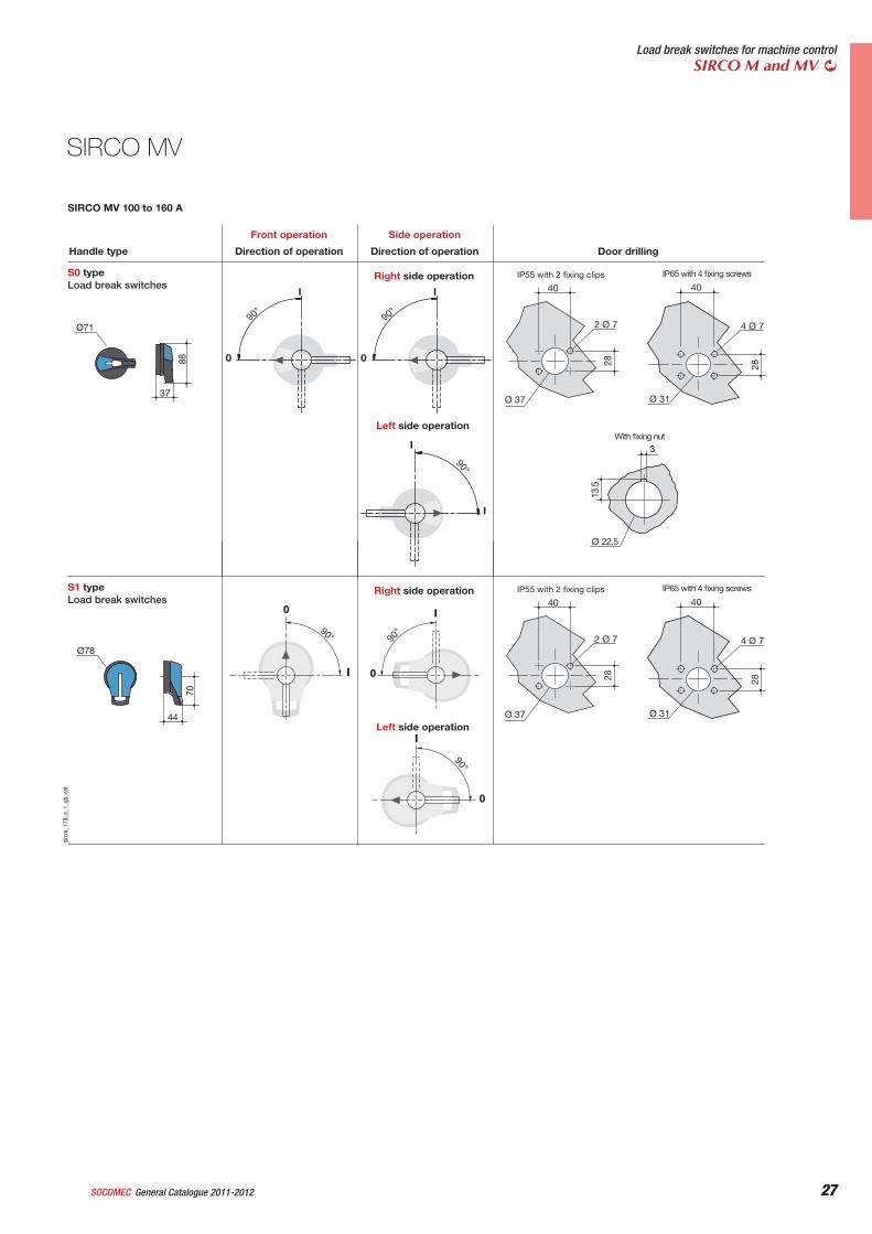
SIRCO MV 100 to 160 A
SIRCO MV
28 General Catalogue 2011-2012 SOCOMEC
© S
MA
sola
r tec
hnol
ogie
681
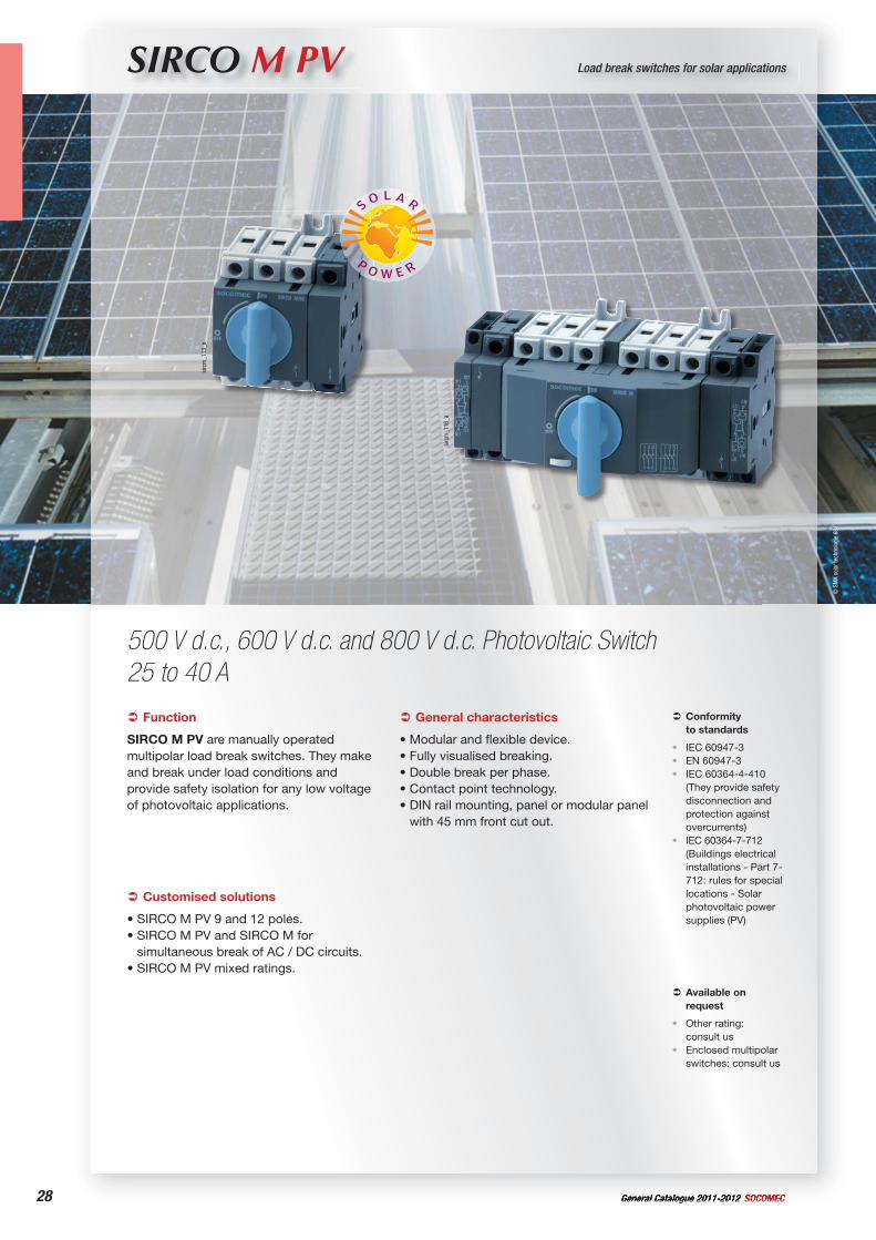
SIRCO M PV Load break switches for solar applications
500 V d.c., 600 V d.c. and 800 V d.c. Photovoltaic Switch 25 to 40 A
Function
SIRCO M PV are manually operated multipolar load break switches. They make and break under load conditions and provide safety isolation for any low voltage of photovoltaic applications.
Conformityto standards
IEC 60947-3EN 60947-3IEC 60364-4-410 (They provide safety disconnection and protection against overcurrents)IEC 60364-7-712 (Buildings electrical installations - Part 7-712: rules for special locations - Solar photovoltaic power supplies (PV)
•••
•
General characteristics
• Modular and flexible device.• Fully visualised breaking. • Double break per phase.• Contact point technology.• DIN rail mounting, panel or modular panel
with 45 mm front cut out.
Customised solutions
• SIRCO M PV 9 and 12 poles.• SIRCO M PV and SIRCO M for
simultaneous break of AC / DC circuits.• SIRCO M PV mixed ratings.
Available on request
Other rating: consult usEnclosed multipolar switches: consult us
•
•
sirc
m_1
13_a
sirc
m_1
16_a
29General Catalogue 2011-2012SOCOMEC
Load break switches for solar applicationsSIRCO M PV
coff_
337_
a_1_
cat
sirc
m_0
29_c
sirc
m_1
38_a
sirc
m_1
40_a
_1_c
at
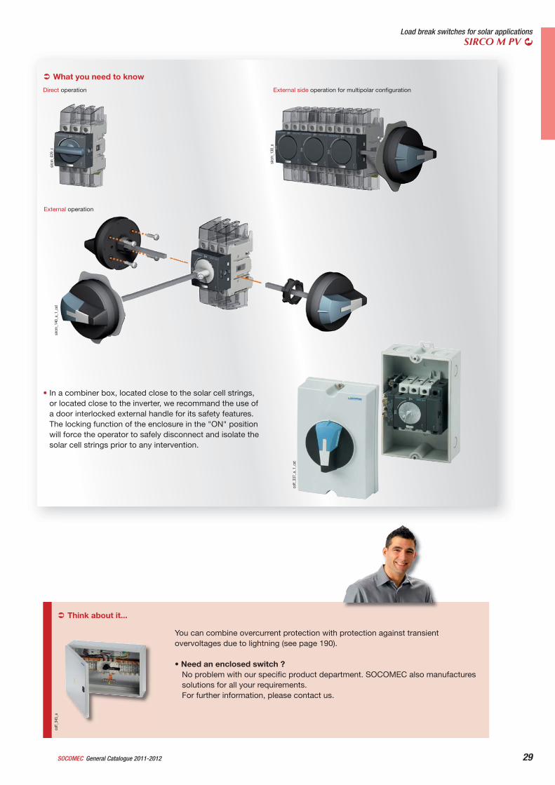
What you need to know
Direct operation External side operation for multipolar configuration
External operation
• In a combiner box, located close to the solar cell strings, or located close to the inverter, we recommand the use of a door interlocked external handle for its safety features. The locking function of the enclosure in the "ON" position will force the operator to safely disconnect and isolate the solar cell strings prior to any intervention.
Think about it...
You can combine overcurrent protection with protection against transient overvoltages due to lightning (see page 190).
• Need an enclosed switch ?No problem with our specific product department. SOCOMEC also manufacturessolutions for all your requirements.For further information, please contact us.
coff_
343_
a
30 General Catalogue 2011-2012 SOCOMEC30
SIRCO M PV
References
Accessories
sirc
m_0
71_a
M00 handle
Direct operation handle
For SIRCO M PV - 4 polesRating (A) Handle colour Handle Reference32 ... 40 Blue M00 type 2299 5012(1)(2)
32 ... 40 Red M00 type 2299 5013(2)
(1) Direct handle supplied as standard for 6 and 8 pole equipment.(2) For 4 pole switches
UseDirect handle for SIRCO M PV 4 poles 500 V d.c.
External operation handle
sirc
m_0
43_a
_1_x
_cat
S00 handle
UseThe door interlocked external operation handle includes a padlockable handle, a conversion kit and must be combined with a shaft extension.In a combiner box, located close to the solar cell strings, or located close to the inverter, we recommand the use of a door interlocked external handle for its safety features.
ExampleThe locking function of the enclosure in the "ON" position will force the operator to safely disconnect and isolate the solar cell strings prior to any intervention. Opening the door when the switch is on "ON" position is possible by defeating the interlocking function with the use of a tool (authorized persons only).The interlocking function is restored when the door is re-closed.
Front and right side operation I - 0Rating (A) Handle colour Handle External IP Reference25 ... 40 Black S00 type IP55 1471 1111(1)
25 ... 40 Black S00 type IP65 1473 1111(1)
25 ... 40 Red/Yellow S00 type IP65 1474 1111(1)
Left side operation I - 0Rating (A) Handle colour Handle External IP Reference25 ... 40 Black S00 type IP65 147A 511125 ... 40 Red/Yellow S00 type IP65 147B 5111
(1) Defeatable handle.
Shaft for external handle
sirc
m_0
45_a
_2_x
_cat
UseStandard lengths:
- 150 mm,- 200 mm,- 320 mm.
Other lengths: consult us.
For 3/4 pole switches: shaft extensions for externalfront and side handle.For 6/8 pole front operated switches: shaftextensions for external front handle only.For 6/8 pole side operated switches: shaft extensionsfor external side handle only.
For SIRCO M PVRating (A) Shaft length (mm) Reference25 ... 40 150 mm 1407 051525 ... 40 200 mm 1407 052025 ... 40 320 mm 1407 0532
Voltage (V d.c.) Rating (A)
No. of poles Switch body
Direct handle
External front and right side
handleExternal left side handle
Shaft for external front
and side operation
Auxiliarycontacts
Door mounting kit
50032 A 4 P 22PV 4004
Blue2299 5012(1)
Red2299 5013(1)
Type S00 Black IP55
1471 1111(2)
Type S00 Black IP65
1473 1111(2)
Type S00 Red/yellow
IP651474 1111(2)
Type S00 Black IP65147A 5111 Type S00 Red/yellow
IP65147B 5111
150 mm1407 0515 200 mm
1407 0520 320 mm
1407 0532
M type 1 contact NO + NC
2299 0001 M type
1 contact 2 NC
2299 0011
Overalldimensions
reduce2299 3409(1)(3)
Complete protection
IP2X2299 3309(1)(3)
40 A 4 P 22PV 4008
60025 A 6 P 22PV 6004(4)
40 A 6 P 22PV 6008(4)
80025 A 8 P 22PV 8004(4)
40 A 8 P 22PV 8008(4)
(1) For 4 pole switches(2) Defeatable handle.(3) Supplied with a shaft.(4) Direct handle supplied as standard.
31General Catalogue 2011-2012SOCOMEC 31
Load break switches for solar applicationsSIRCO M PV
Terminal shrouds
sirc
m_0
49_a
_1_c
at
UseTop and bottom protection against direct contact withthe terminals or connection parts. 2 units per pack.1 or 3 pole are available.AdvantagePerforations enabling remote thermographicinspection without dismantling.
For fitting a complete device4 poles: please order one reference of 3 pole and one reference of 1 pole terminal shrouds.6 poles: please order 2 references of 3 pole terminal shrouds.8 poles: please order 2 references of each terminal shrouds (1 pole and 3 poles).
M type auxiliary contacts
sirc
m_0
75_b
_2_c
at
sirc
m_0
81_a
_1_c
at
Auxiliary contacts configurations for SIRCO MPV
UsePre-break and signalisation of positions 0 and I by NO+NC or 2 NO auxiliary contacts.They allow to anticipate the switching of the main poles. They can be mounted on the left or on the right side of the device.Max 4 auxiliary contacts (2 blocks).
CharacteristicsNO+NC auxiliary contacts: IP2 with front operation.
Cap for side operation mounting
sirc
m_1
26_a
_2_c
at
UseAccessory for capping the front face of the SIRCO M PV when utilising in door mounting or side operation, 20 units per pack.This piece can be snapped on the switch body directly.
Door mounting kit
sirc
m_0
51_b
_2_c
at
UseThis kit enables direct mounting of the SIRCO M PV 4 poles switch, on the door front panel, on the right or left side panels.Moreover, the connection clamps of the switch are always accessible.The external handle is quick and easy to install due to an internal locking nut mounted on the inside of the enclosure.
2 kits are available:- one for complete protection IP2X,- one with overall dimensions reduced.
Kit with reduced overall dimensions.
For SIRCO M PVRating (A) No. of poles Position Reference25 ... 32 1 P top and bottom 2294 100525 ... 32 3 P top and bottom 2294 300540 1 P top and bottom 2294 100940 3 P top and bottom 2294 3009
For SIRCO M PVRating (A) Number of AC Type of AC Reference25 ... 40 1 AC NO + NC 2299 000125 ... 40 1 AC 2 NC 2299 0011
For SIRCO M PV
Rating (A)No. of poles Description Reference
25 ... 40 3/4 P Overall dimensions reduce 2299 3409(1)(2)
25 ... 40 3/4 P Complete protection IP2X 2299 3309(1)
(1) Delivered with a shaft.(2) Standard.
For SIRCO M PVRating (A) Pack Reference25 ... 40 20 pieces 2299 9409
32 General Catalogue 2011-2012 SOCOMEC32
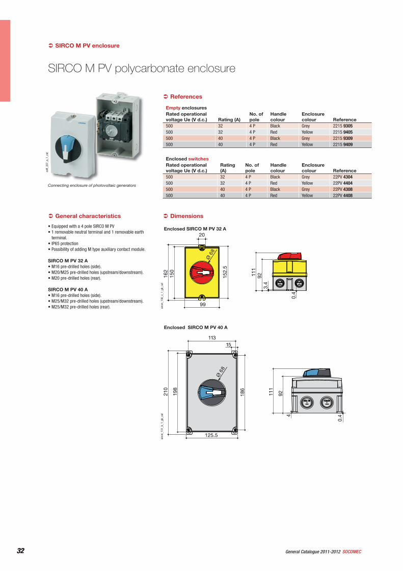
SIRCO M PV polycarbonate enclosure
coff_
337_
a_1_
cat
Connecting enclosure of photovoltaic generators
3.4
0.4
92111
152.
5
162
150
20
Ø 6
8
99
sirc
m_1
30_c
_1_g
b_ca
t
186
198
4
0.4
92111
210
15113
125.5
Ø 6
8
sirc
m_1
31_b
_1_g
b_ca
t
General characteristics
• Equipped with a 4 pole SIRCO M PV• 1 removable neutral terminal and 1 removable earth
terminal.• IP65 protection• Possibility of adding M type auxiliary contact module.
SIRCO M PV 32 A• M16 pre-drilled holes (side).• M20/M25 pre-drilled holes (upstream/downstream).• M20 pre-drilled holes (rear).
SIRCO M PV 40 A• M16 pre-drilled holes (side).• M25/M32 pre-drilled holes (upstream/downstream).• M25/M32 pre-drilled holes (rear).
References
SIRCO M PV enclosure
Dimensions
Empty enclosuresRated operational voltage Ue (V d.c.) Rating (A)
No. of pole
Handlecolour
Enclosure colour Reference
500 32 4 P Black Grey 2215 9305500 32 4 P Red Yellow 2215 9405500 40 4 P Black Grey 2215 9309500 40 4 P Red Yellow 2215 9409
Enclosed switchesRated operational voltage Ue (V d.c.)
Rating(A)
No. of pole
Handlecolour
Enclosure colour Reference
500 32 4 P Black Grey 22PV 4304500 32 4 P Red Yellow 22PV 4404500 40 4 P Black Grey 22PV 4308500 40 4 P Red Yellow 22PV 4408
Enclosed SIRCO M PV 32 A
Enclosed SIRCO M PV 40 A
33General Catalogue 2011-2012SOCOMEC 33
Load break switches for solar applicationsSIRCO M PV
Characteristics according to IEC 60947-3
SIRCO M PV 25 to 40 A
Dimensions for external handles13
.5
Ø 22.5
3
0
I
90°
0
I
90°
I
0
90°
40
4 Ø 7
Ø 31
28
40
2 Ø 7
Ø 37
28
Right side operation
Left side operation
Ø71
36
71
With fixing nut
IP55 with 2 fixing clips IP65 with 4 fixing screwsS00 typeLoad break switches
Direction of operation Direction of operation Door drillingHandle type
Front operation Side operation
sirc
m_1
77_a
_1_g
b_ca
t
SIRCO M PV 25 to 40 A
Rated current I (A) 25 A 32 A 40 ARated insulation voltage Ui (V) 800 800 800Rated impulse withstand voltage Uimp (kV) 8 8 8
Rated operational currents Ie (A)
Rated voltage No. of poles Number of pole in series per polarity (A) (A) (A)500 V d.c. 4 P 2 P + and 2 P - 32 40600 V d.c. 6 P 3 P + and 3 P - 25 40800 V d.c. 8 P 4 P + and 4 P - 25 40
Short-circuit capacityRated short-time withstand current 0.3 s. ICW (kA eff)(1) 2.5 2.5 3Rated peak withstand current (kA peak)(1) 6 6 9
ConnectionMinimum Cu cable section (mm2) 1.5 1.5 2.5Maximum Cu cable section (mm2) 16 16 35Tightening torque min/max (Nm) 2 / 2.5 2 / 2.2 3.5 / 3.85
Mechanical characteristicsDurability (number of operating cycles) 100 000 100 000 100 000Operating effort (Nm) 0.8 0.8 1Weight of 4 p (kg) 0.225 0.225 0.350Weight of 6 P (kg) 0.405 0.405 0.585Weight of 8 P (kg) 0.510 0.510 0.755
(1) For a rated operational voltage Ue = 400 V a.c.
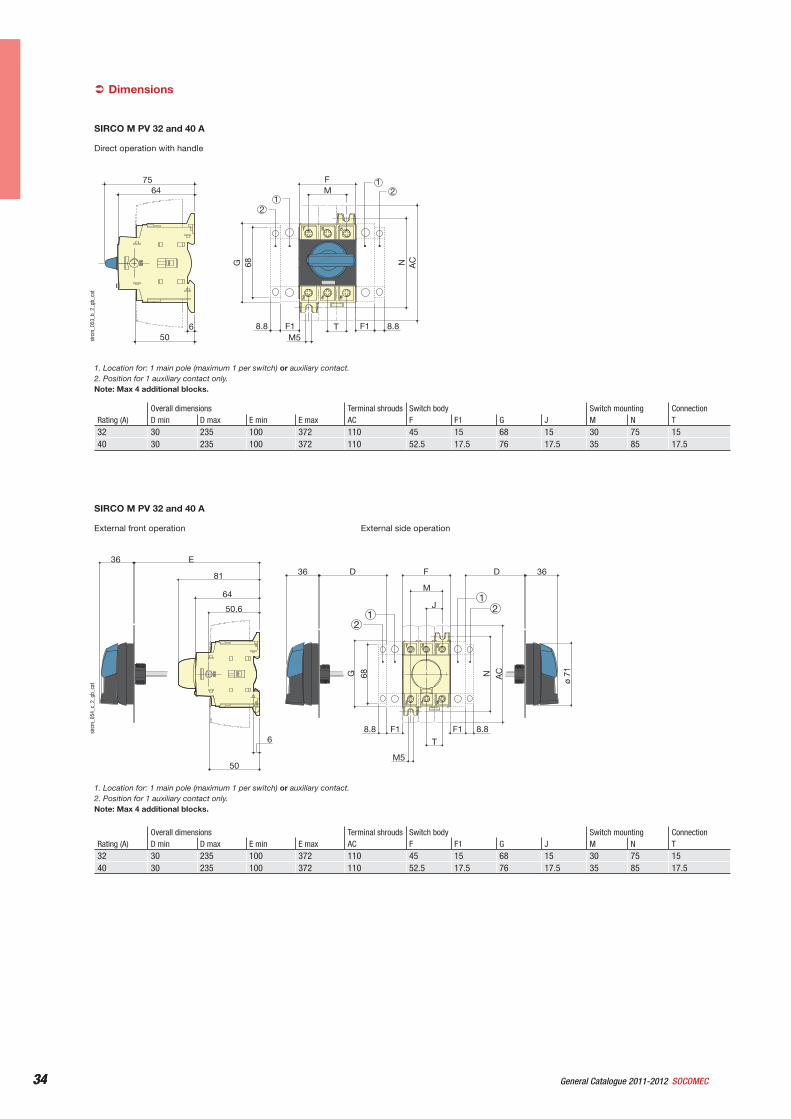
34 General Catalogue 2011-2012 SOCOMEC34
Direct operation with handle
68
F
TM5
M
NG AC
64
650
75
F1 8.8F18.8
2
21
1
sirc
m_0
53_b
_2_g
b_ca
t
1. Location for: 1 main pole (maximum 1 per switch) or auxiliary contact.2. Position for 1 auxiliary contact only.Note: Max 4 additional blocks.
SIRCO M PV 32 and 40 A
External front operation External side operation
J
68
36 D F
T
M5
M
36D
NG AC
E36
81
64
6
50
50.6
F18.8 F1 8.8
ø 71
2
21
1
sirc
m_0
54_c
_2_g
b_ca
t
1. Location for: 1 main pole (maximum 1 per switch) or auxiliary contact.2. Position for 1 auxiliary contact only.Note: Max 4 additional blocks.
SIRCO M PV 32 and 40 A
Dimensions
Rating (A)Overall dimensions Terminal shrouds Switch body Switch mounting ConnectionD min D max E min E max AC F F1 G J M N T
32 30 235 100 372 110 45 15 68 15 30 75 1540 30 235 100 372 110 52.5 17.5 76 17.5 35 85 17.5
Rating (A)Overall dimensions Terminal shrouds Switch body Switch mounting ConnectionD min D max E min E max AC F F1 G J M N T
32 30 235 100 372 110 45 15 68 15 30 75 1540 30 235 100 372 110 52.5 17.5 76 17.5 35 85 17.5
35General Catalogue 2011-2012SOCOMEC 35
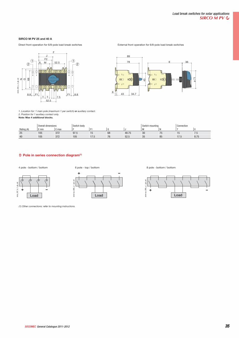
Load break switches for solar applicationsSIRCO M PV
Direct front operation for 6/8-pole load break switches External front operation for 6/8-pole load break switches
36E
45
78
34.7436
89
ø 71
X
N G 68
T T 7.552.5
MF2
52.5
FJ
F1 8.8F18.8
2 21 1
sirc
m_0
55_c
_2_g
b_ca
t
1. Location for: 1 main pole (maximum 1 per switch) or auxiliary contact.2. Position for 1 auxiliary contact only.Note: Max 4 additional blocks.
SIRCO M PV 25 and 40 A
Pole in series connection diagram(1)
-+Loadsi
rcm
-pv_
009_
a_1_
gb_c
at
8 pole - bottom / bottom
-+
Load
6 pole - top / bottom
sirc
m-p
v_00
8_a_
1_gb
_cat
Load
-+
sirc
o_30
7_b_
1_gb
_cat
4 pole - bottom / bottom
(1) Other connections: refer to mounting instructions.
Rating (A)Overall dimensions Switch body Switch mounting ConnectionE min E max F F1 G J M N T X
25 105 372 97.5 15 68 48.75 30 75 15 7.540 105 372 105 17.5 76 52.5 35 85 17.5 8.75
36 General Catalogue 2011-2012 SOCOMEC
SMA_Solar_Technology_720
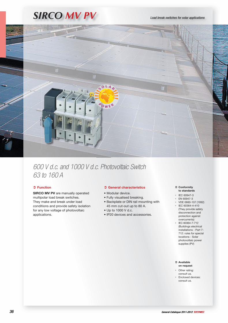
SIRCO MV PV Load break switches for solar applications
600 V d.c. and 1000 V d.c. Photovoltaic Switch63 to 160 A
sircm_099_a
Function
SIRCO MV PV are manually operated multipolar load break switches.They make and break under load conditions and provide safety isolation for any low voltage of photovoltaic applications.
Conformityto standards
IEC 60947-3EN 60947-3VDE 0660-107 (1992)IEC 60364-4-410 (They provide safety disconnection and protection against overcurrents)IEC 60364-7-712 (Buildings electrical installations - Part 7-712: rules for special locations - Solar photovoltaic power supplies (PV)
••••
•
General characteristics
• Modular device.• Fully visualised breaking.• Backplate or DIN rail mounting with
45 mm cut-out up to 80 A.• Up to 1000 V d.c.• IP20 devices and accessories.
Available on request
Other rating: consult us.Enclosed devices: consult us.
•
•
37General Catalogue 2011-2012SOCOMEC 37
Load break switches for solar applicationsSIRCO MV PV
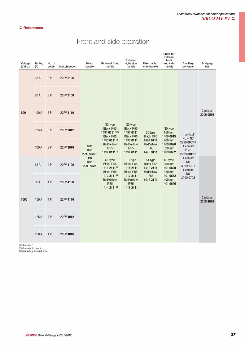
References
Front and side operation
Voltage (V d.c.)
Rating(A)
No. of poles Switch body
Direct handle
External front handle
External right side
handleExternal left side handle
Shaft for external
front and side handle
Auxiliarycontacts
Bridgingbar
600
63 A 3 P 22PV 3106
M0b Blue
2299 5042(1)
M0 Blue
2299 5022
S0 type Black IP55
1491 0111(1)(2)
Black IP651493 0111(2)
Red/Yellow IP65
1494 0111(2)
S1 type Black IP55
1411 2111(2)
Black IP651413 2111(2)
Red/Yellow IP65
1414 2111(2)
S0 type Black IP551491 0111 Black IP651493 0111 Red/Yellow
IP651494 0111
S1 type Black IP551415 2111 Black IP651417 2111 Red/Yellow
IP651418 2111
S0 type Black IP65149A 9111 Red/Yellow
IP65149B 9111
S1 type Black IP65141A 2111 Red/Yellow
IP65141B 2111
S0 type150 mm
1409 0615 200 mm
1409 0620 320 mm
1409 0632
S1 type 200 mm
1401 0620 320 mm
1401 0632 400 mm
1401 0640
1 contact NO + NC
2299 0001(3)
1 contact 2 NC
2299 0011(3)
1 contactNC
3999 0701 1 contact
NO3999 0702
2 pieces2209 0016
80 A 3 P 22PV 3108
100 A 3 P 22PV 3110
125 A 3 P 22PV 3012
160 A 3 P 22PV 3016
1000
63 A 4 P 22PV 4106
2 pieces2209 2016
80 A 4 P 22PV 4108
100 A 4 P 22PV 4110
125 A 4 P 22PV 4012
160 A 4 P 22PV 4016
(1) Standard.(2) Defeatable handle.(3) Signalling contact only.
38 General Catalogue 2011-2012 SOCOMEC38
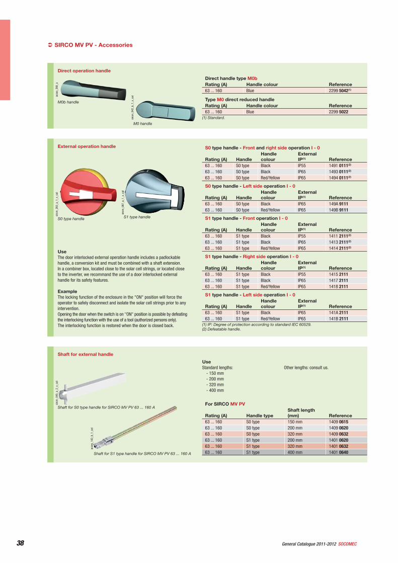
Shaft for external handle
acce
s_14
3_b_
1_ca
t
Shaft for S1 type handle for SIRCO MV PV 63 ... 160 A
sirc
m_0
45_a
_2_x
_cat
Shaft for S0 type handle for SIRCO MV PV 63 ... 160 A
UseStandard lengths:
- 150 mm- 200 mm- 320 mm- 400 mm
Other lengths: consult us.
For SIRCO MV PV
Rating (A) Handle typeShaft length (mm) Reference
63 ... 160 S0 type 150 mm 1409 061563 ... 160 S0 type 200 mm 1409 062063 ... 160 S0 type 320 mm 1409 063263 ... 160 S1 type 200 mm 1401 062063 ... 160 S1 type 320 mm 1401 063263 ... 160 S1 type 400 mm 1401 0640
External operation handle
sirc
m_2
63_a
_1_x
_cat
S0 type handle
sirc
m_0
87_a
_1_x
_cat
S1 type handle
UseThe door interlocked external operation handle includes a padlockable handle, a conversion kit and must be combined with a shaft extension. In a combiner box, located close to the solar cell strings, or located close to the inverter, we recommand the use of a door interlocked external handle for its safety features.
ExampleThe locking function of the enclosure in the "ON" position will force the operator to safely disconnect and isolate the solar cell strings prior to any intervention.Opening the door when the switch is on "ON" position is possible by defeating the interlocking function with the use of a tool (authorized persons only).The interlocking function is restored when the door is closed back.
S0 type handle - Front and right side operation I - 0
Rating (A) HandleHandlecolour
External IP(1) Reference
63 ... 160 S0 type Black IP55 1491 0111(2)
63 ... 160 S0 type Black IP65 1493 0111(2)
63 ... 160 S0 type Red/Yellow IP65 1494 0111(2)
(1) IP: Degree of protection according to standard IEC 60529.(2) Defeatable handle.
S0 type handle - Left side operation I - 0
Rating (A) HandleHandlecolour
External IP(1) Reference
63 ... 160 S0 type Black IP65 149A 911163 ... 160 S0 type Red/Yellow IP65 149B 9111
S1 type handle - Front operation I - 0
Rating (A) HandleHandlecolour
External IP(1) Reference
63 ... 160 S1 type Black IP55 1411 2111(2)
63 ... 160 S1 type Black IP65 1413 2111(2)
63 ... 160 S1 type Red/Yellow IP65 1414 2111(2)
S1 type handle - Right side operation I - 0
Rating (A) HandleHandlecolour
External IP(1) Reference
63 ... 160 S1 type Black IP55 1415 211163 ... 160 S1 type Black IP65 1417 211163 ... 160 S1 type Red/Yellow IP65 1418 2111
S1 type handle - Left side operation I - 0
Rating (A) HandleHandlecolour
External IP(1) Reference
63 ... 160 S1 type Black IP65 141A 211163 ... 160 S1 type Red/Yellow IP65 141B 2111
SIRCO MV PV - Accessories
Direct operation handle
acce
s_26
8_a
M0b handle
sirc
m_0
42_b
_1_x
_cat
M0 handle
Direct handle type M0bRating (A) Handle colour Reference63 ... 160 Blue 2299 5042(1)
Type M0 direct reduced handleRating (A) Handle colour Reference63 ... 160 Blue 2299 5022
(1) Standard.
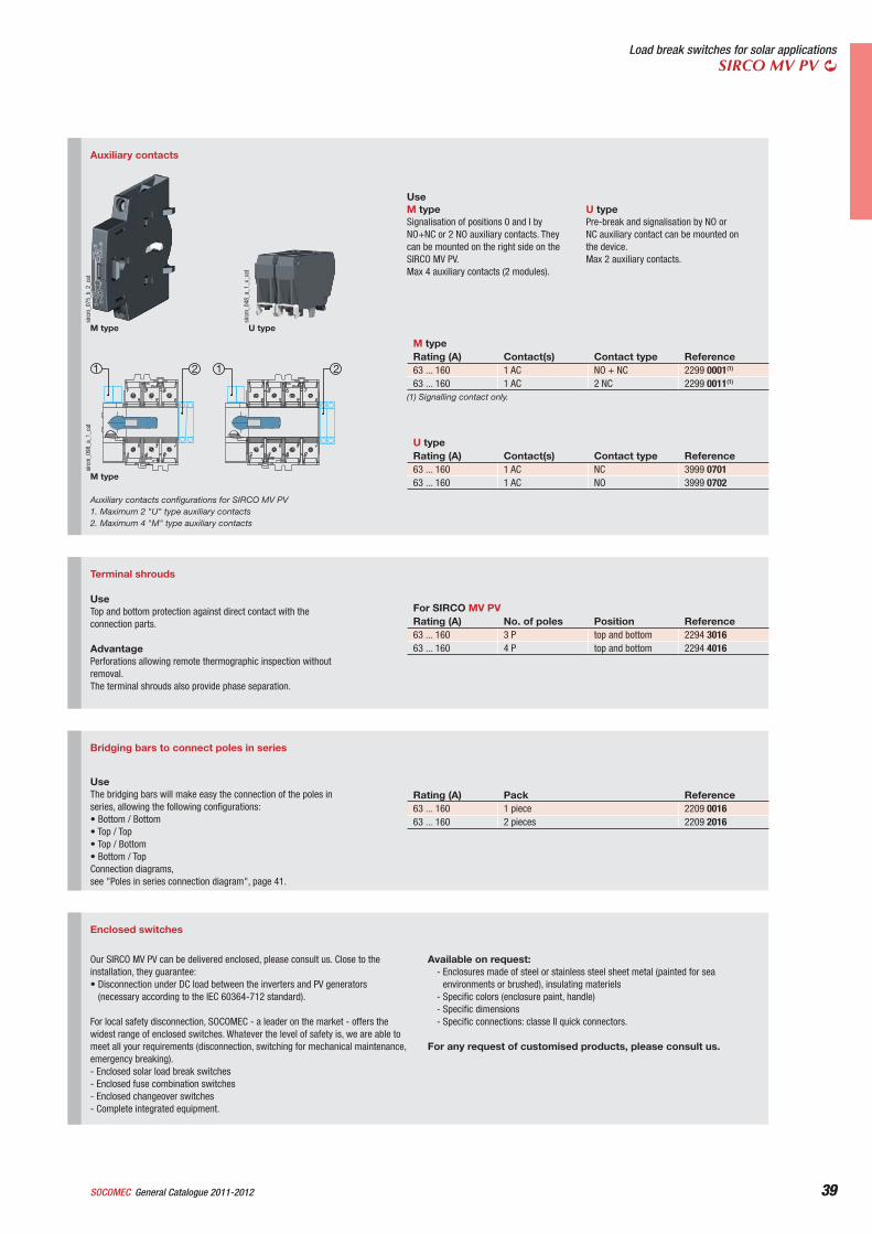
39General Catalogue 2011-2012SOCOMEC 39
Load break switches for solar applicationsSIRCO MV PV
Bridging bars to connect poles in series
UseThe bridging bars will make easy the connection of the poles in series, allowing the following configurations:• Bottom / Bottom• Top / Top• Top / Bottom• Bottom / TopConnection diagrams, see "Poles in series connection diagram", page 41.
Rating (A) Pack Reference63 ... 160 1 piece 2209 001663 ... 160 2 pieces 2209 2016
Enclosed switches
Our SIRCO MV PV can be delivered enclosed, please consult us. Close to the installation, they guarantee:• Disconnection under DC load between the inverters and PV generators
(necessary according to the IEC 60364-712 standard).
For local safety disconnection, SOCOMEC - a leader on the market - offers the widest range of enclosed switches. Whatever the level of safety is, we are able to meet all your requirements (disconnection, switching for mechanical maintenance, emergency breaking).- Enclosed solar load break switches- Enclosed fuse combination switches- Enclosed changeover switches- Complete integrated equipment.
Available on request:- Enclosures made of steel or stainless steel sheet metal (painted for sea
environments or brushed), insulating materiels- Specific colors (enclosure paint, handle)- Specific dimensions- Specific connections: classe II quick connectors.
For any request of customised products, please consult us.
Terminal shrouds
UseTop and bottom protection against direct contact with the connection parts.
AdvantagePerforations allowing remote thermographic inspection without removal.The terminal shrouds also provide phase separation.
For SIRCO MV PVRating (A) No. of poles Position Reference63 ... 160 3 P top and bottom 2294 301663 ... 160 4 P top and bottom 2294 4016
Auxiliary contacts
sirc
m_0
75_b
_2_c
at
M type
21 1 2
sirc
m_0
98_a
_1_c
at
M type
Auxiliary contacts configurations for SIRCO MV PV1. Maximum 2 "U" type auxiliary contacts2. Maximum 4 "M" type auxiliary contacts
sirc
m_0
48_a
_1_x
_cat
U type
UseM typeSignalisation of positions 0 and I by NO+NC or 2 NO auxiliary contacts. They can be mounted on the right side on the SIRCO MV PV. Max 4 auxiliary contacts (2 modules).
U typePre-break and signalisation by NO or NC auxiliary contact can be mounted on the device. Max 2 auxiliary contacts.
M typeRating (A) Contact(s) Contact type Reference63 ... 160 1 AC NO + NC 2299 0001(1)
63 ... 160 1 AC 2 NC 2299 0011(1)
(1) Signalling contact only.
U typeRating (A) Contact(s) Contact type Reference63 ... 160 1 AC NC 3999 070163 ... 160 1 AC NO 3999 0702
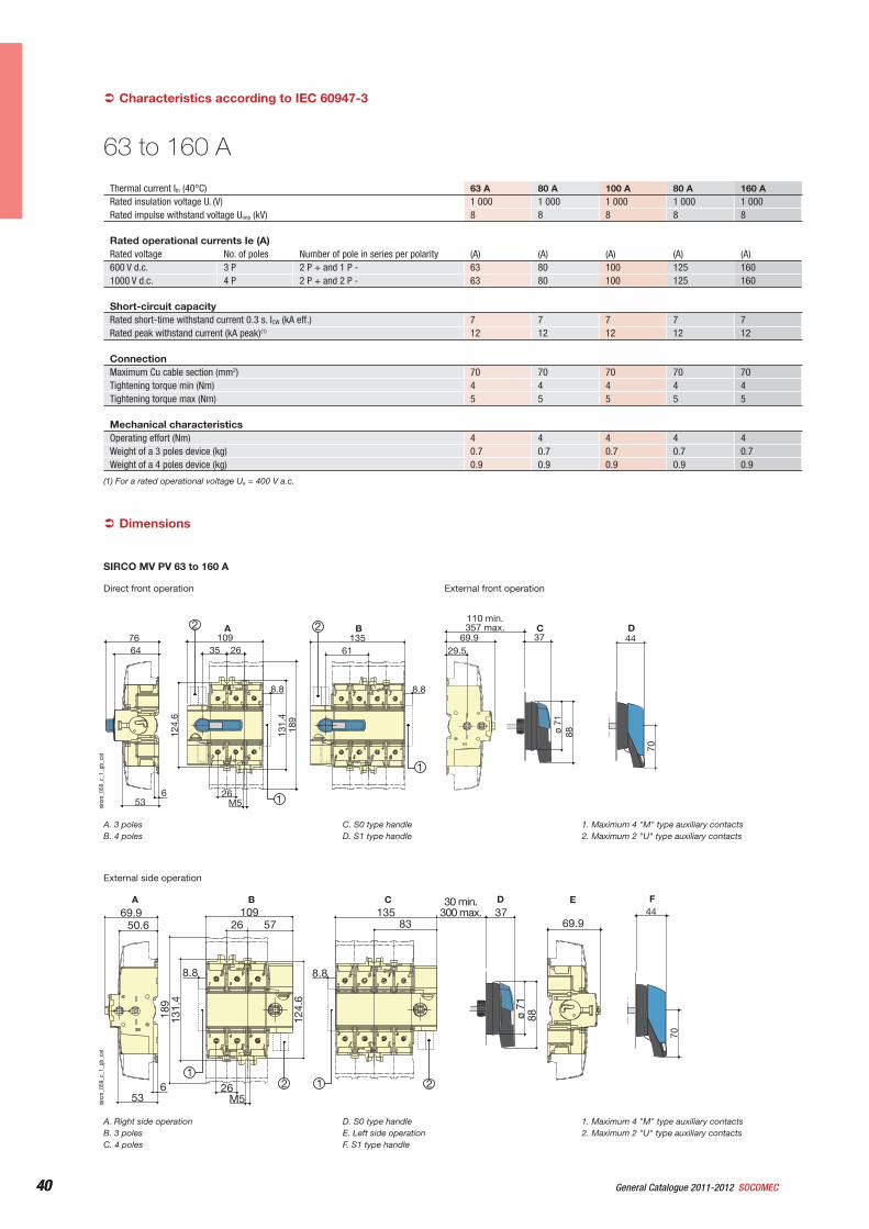
40 General Catalogue 2011-2012 SOCOMEC40
Direct front operation External front operation
37
110 min.357 max.A B
88ø 71
8.8
76 13561
653
64
26
124.
6
131.
418
9
M5
35 26109
8.8
1
1
69.929.5
4470
C D2 2
sirc
m_0
58_c
_1_g
b_ca
t
A. 3 polesB. 4 poles
C. S0 type handleD. S1 type handle
1. Maximum 4 "M" type auxiliary contacts2. Maximum 2 "U" type auxiliary contacts
SIRCO MV PV 63 to 160 A
External side operation
69.950.6
536
13530 min.
300 max. 3783
10926 57
26
189
131.
4
124.
6
M5
B CA
88ø 71
8.88.8
E
1
D F
1
69.944
70
22
sirc
m_0
59_c
_1_g
b_ca
t
A. Right side operationB. 3 polesC. 4 poles
D. S0 type handleE. Left side operationF. S1 type handle
1. Maximum 4 "M" type auxiliary contacts2. Maximum 2 "U" type auxiliary contacts
Dimensions
Thermal current Ith (40°C) 63 A 80 A 100 A 80 A 160 ARated insulation voltage Ui (V) 1 000 1 000 1 000 1 000 1 000Rated impulse withstand voltage Uimp (kV) 8 8 8 8 8
Rated operational currents Ie (A)Rated voltage No. of poles Number of pole in series per polarity (A) (A) (A) (A) (A)600 V d.c. 3 P 2 P + and 1 P - 63 80 100 125 1601000 V d.c. 4 P 2 P + and 2 P - 63 80 100 125 160
Short-circuit capacityRated short-time withstand current 0.3 s. ICW (kA eff.) 7 7 7 7 7Rated peak withstand current (kA peak)(1) 12 12 12 12 12
ConnectionMaximum Cu cable section (mm2) 70 70 70 70 70Tightening torque min (Nm) 4 4 4 4 4Tightening torque max (Nm) 5 5 5 5 5
Mechanical characteristicsOperating effort (Nm) 4 4 4 4 4Weight of a 3 poles device (kg) 0.7 0.7 0.7 0.7 0.7Weight of a 4 poles device (kg) 0.9 0.9 0.9 0.9 0.9
Characteristics according to IEC 60947-3
(1) For a rated operational voltage Ue = 400 V a.c.
63 to 160 A
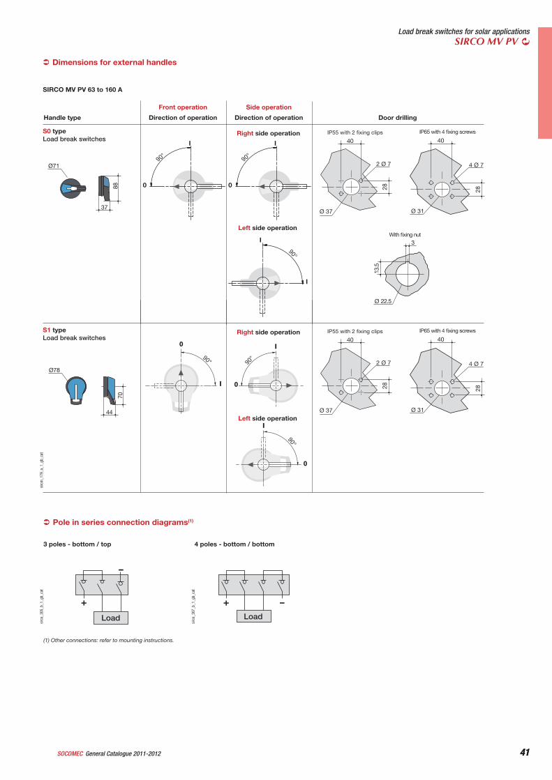
41General Catalogue 2011-2012SOCOMEC 41
Load break switches for solar applicationsSIRCO MV PV
Dimensions for external handles
Pole in series connection diagrams(1)
-
+
Load
sirc
o_30
5_b_
1_gb
_cat
3 poles - bottom / top
Load
-+
sirc
o_30
7_b_
1_gb
_cat
4 poles - bottom / bottom
13.5
Ø 22.5
3
Ø71
37
88 0
I
90°
0
I
90°
I
I
90°
40
4 Ø 7
Ø 31
28
40
2 Ø 7
Ø 37
28
Right side operation
Left side operation
90°
I
0
90°
I
0
90°
I
0
Ø78
44
70
40
4 Ø 7
Ø 31
28
40
2 Ø 7
Ø 37
28
Right side operation
Left side operationWith fixing nut
IP55 with 2 fixing clips IP65 with 4 fixing screwsS1 typeLoad break switches
IP55 with 2 fixing clips IP65 with 4 fixing screwsS0 typeLoad break switches
Direction of operation Direction of operation Door drillingHandle type
Front operation Side operation
sirc
m_1
79_a
_1_g
b_ca
t
SIRCO MV PV 63 to 160 A
(1) Other connections: refer to mounting instructions.
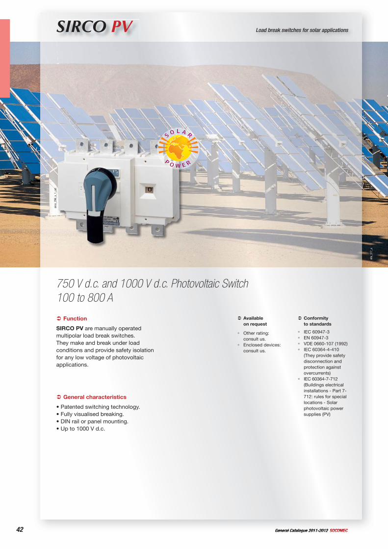
42 General Catalogue 2011-2012 SOCOMEC
site
_317
_a
SIRCO PV Load break switches for solar applications
750 V d.c. and 1000 V d.c. Photovoltaic Switch100 to 800 A
sirc
o_29
6_a_
1_ca
t
Function
SIRCO PV are manually operated multipolar load break switches.They make and break under load conditions and provide safety isolation for any low voltage of photovoltaic applications.
Conformityto standards
IEC 60947-3EN 60947-3VDE 0660-107 (1992)IEC 60364-4-410 (They provide safety disconnection and protection against overcurrents)IEC 60364-7-712 (Buildings electrical installations - Part 7-712: rules for special locations - Solar photovoltaic power supplies (PV)
••••
•
General characteristics
• Patented switching technology.• Fully visualised breaking.• DIN rail or panel mounting.• Up to 1000 V d.c.
Available on request
Other rating: consult us.Enclosed devices: consult us.
•
•
43General Catalogue 2011-2012SOCOMEC 43
Load break switches for solar applicationsSIRCO PV
Direct handle
acce
s_11
4_a_
1_ca
t
Direct handle
Rating (A) Handle colour Reference(1)
100 … 800 Black 2699 5052(2)
100 … 800 Red 2699 5053(1) IP: Degree of protection according to standard IEC 60529.(2) Standard.
Accessories
Front operation
acce
s_15
0_a_
3_ca
t
S2 type handle
External handle
UseThe door interlocked external operation handle includes a padlockable handle, a conversion kit and must be combined with a shaft extension.In a combiner box, located close to the solar cell strings, or located close to the inverter, we recommande to use a door interlocked external handle for its safety features.
ExampleThe locking function of the enclosure in the "ON" position will force the operator to safely disconnect and isolate the solar cell strings prior to any intervention. Opening the door when the switch is on "ON" position is possible by defeating the interlocking function using a tool (authorized persons only).The interlocking function is restored when the door is closed back.
Front operationRating (A) Handle Handle colour External IP(1) Reference100 … 800 S2 type Black IP55 1421 2111(2)
100 ... 800 S2 type Black IP65 1423 2111100 … 800 S2 type Red IP65 1424 2111
(1) IP: Degree of protection according to standard IEC60529 standard.(2) Standard.
References
Shaft guide for external operation
acce
s_26
0_a_
2_ca
t
Description Reference(1)
Shaft guide 1429 0000(1) IP: Degree of protection according to standard IEC 60529.
UseTo guide the shaft extension into the external handle.This accessory enables handle to engage extension shaft with a misalignment of up to 15 mm.Required for a shaft lenght over 320 mm.
Voltage (V d.c.) Rating (A)No. of poles Switch body Direct handle
External handle
Shaft for external handle
Auxiliarycontacts Bridging bars
750
100 A
3 P
26PV 3010
Black2699 5052(1)
Red2699 5053
Type S2 Black IP55
1421 2111(1)
Type S2 Black IP651423 2111 Type S2 Red IP65
1424 2111
200 mm1400 1020 320 mm
1400 1032(1)
500 mm1400 1050
1st contact NO/NC
2699 0031 2nd contact
NO/NC2699 0032
2609 0025
125 A 26PV 3012
160 A 26PV 3016
200 A 26PV 3020
250 A 26PV 3025
315 A 26PV 3031
400 A 26PV 30402609 2050
500 A 26PV 3050
630 A 26PV 30632609 0080
800 A 26PV 3080
1000
100 A
4 P
26PV 4010
2609 2025
125 A 26PV 4012
160 A 26PV 4016
200 A 26PV 4020
250 A 26PV 4025
315 A 26PV 4031
400 A 26PV 40402609 4050
500 A 26PV 4050
630 A 26PV 40632609 2080
800 A 26PV 4080
(1) Standard.
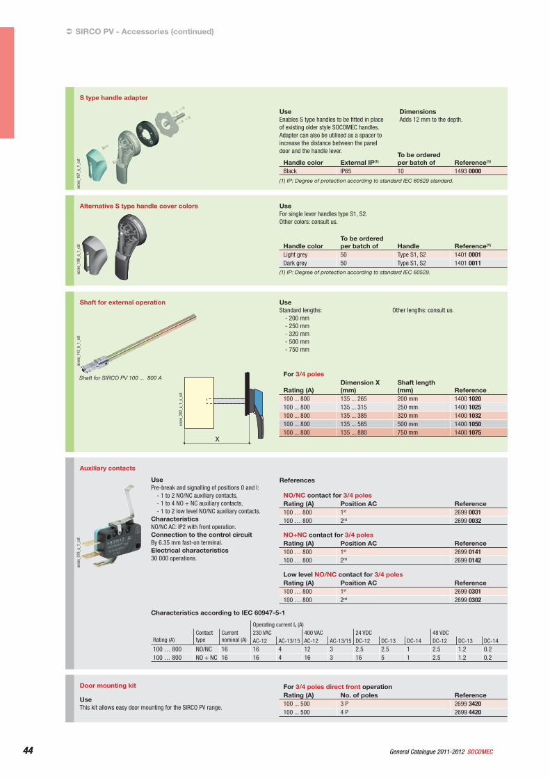
44 General Catalogue 2011-2012 SOCOMEC44
S type handle adapter
acce
s_18
7_a_
1_ca
t
UseEnables S type handles to be fitted in place of existing older style SOCOMEC handles. Adapter can also be utilised as a spacer to increase the distance between the panel door and the handle lever.
DimensionsAdds 12 mm to the depth.
Handle color External IP(1)To be ordered per batch of Reference(1)
Black IP65 10 1493 0000(1) IP: Degree of protection according to standard IEC 60529 standard.
Alternative S type handle cover colors
acce
s_19
8_a_
1_ca
t
UseFor single lever handles type S1, S2.Other colors: consult us.
Handle colorTo be ordered per batch of Handle Reference(1)
Light grey 50 Type S1, S2 1401 0001Dark grey 50 Type S1, S2 1401 0011
(1) IP: Degree of protection according to standard IEC 60529.
SIRCO PV - Accessories (continued)
Shaft for external operation
X
acce
s_20
2_a_
1_x_
cat
acce
s_14
3_b_
1_ca
t
Shaft for SIRCO PV 100 ... 800 A
UseStandard lengths:
- 200 mm- 250 mm- 320 mm- 500 mm- 750 mm
Other lengths: consult us.
For 3/4 poles
Rating (A)Dimension X (mm)
Shaft length (mm) Reference
100 ... 800 135 ... 265 200 mm 1400 1020100 ... 800 135 ... 315 250 mm 1400 1025100 ... 800 135 ... 385 320 mm 1400 1032100 ... 800 135 ... 565 500 mm 1400 1050100 ... 800 135 ... 880 750 mm 1400 1075
acce
s_07
6_a_
1_ca
t
Auxiliary contacts
UsePre-break and signalling of positions 0 and I:
- 1 to 2 NO/NC auxiliary contacts,- 1 to 4 NO + NC auxiliary contacts,- 1 to 2 low level NO/NC auxiliary contacts.
CharacteristicsNO/NC AC: IP2 with front operation.Connection to the control circuitBy 6.35 mm fast-on terminal.Electrical characteristics30 000 operations.
Characteristics according to IEC 60947-5-1
Operating current Ie (A)
Rating (A)Contacttype
Currentnominal (A)
230 VAC 400 VAC 24 VDC 48 VDCAC-12 AC-13/15 AC-12 AC-13/15 DC-12 DC-13 DC-14 DC-12 DC-13 DC-14
100 … 800 NO/NC 16 16 4 12 3 2.5 2.5 1 2.5 1.2 0.2100 … 800 NO + NC 16 16 4 16 3 16 5 1 2.5 1.2 0.2
References
NO/NC contact for 3/4 polesRating (A) Position AC Reference100 … 800 1st 2699 0031100 … 800 2nd 2699 0032
NO+NC contact for 3/4 polesRating (A) Position AC Reference100 … 800 1st 2699 0141100 … 800 2nd 2699 0142
Low level NO/NC contact for 3/4 polesRating (A) Position AC Reference100 … 800 1st 2699 0301100 … 800 2nd 2699 0302
Door mounting kit
UseThis kit allows easy door mounting for the SIRCO PV range.
For 3/4 poles direct front operationRating (A) No. of poles Reference100 ... 500 3 P 2699 3420100 ... 500 4 P 2699 4420
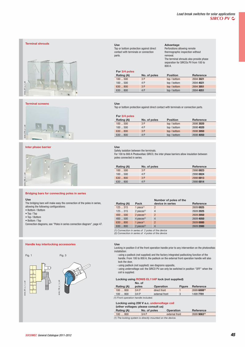
45General Catalogue 2011-2012SOCOMEC 45
Load break switches for solar applicationsSIRCO PV
Terminal shrouds
acce
s_07
7_a_
1_ca
t
UseTop or bottom protection against direct contact with terminals or connection parts.
AdvantagePerforations allowing remote thermographic inspection without removal.The terminal shrouds also provide phase separation for SIRCOs PV from 100 to 800 A.
For 3/4 polesRating (A) No. of poles Position Reference100 ... 500 3 P top / bottom 2694 3021100 ... 500 4 P top / bottom 2694 4021630 ... 800 3 P top / bottom 2694 3051630 ... 800 4 P top / bottom 2694 4051
acce
s_07
9_a_
1_ca
t
UseTop or bottom protection against direct contact with terminals or connection parts.
Terminal screens
For 3/4 polesRating (A) No. of poles Position Reference100 ... 500 3 P top / bottom 2698 3020100 ... 500 4 P top / bottom 2698 4020630 ... 800 3 P top / bottom 2698 3050630 ... 800 4 P top / bottom 2698 4050
Inter phase barrier
acce
s_03
6_a_
1_ca
t
UseSafety isolation between the terminals.For 100 to 800 A Photovoltaic SIRCO, the inter phase barriers allow insulation between poles connected in series.
Rating (A) No. of poles Reference100 ... 500 3 P 2998 0023100 ... 500 4 P 2998 0024630 ... 800 3 P 2998 0013630 ... 800 4 P 2998 0014
acce
s_15
8_a_
1_x_
cat
Fig. 3
acce
s_00
1_a_
1_x_
cat
Fig. 1
Handle key interlocking accessories UseLocking in position 0 of the front operation handle prior to any intervention on the photovoltaic installation:
- using a padlock (not supplied) and the factory integrated padlocking function of the handle. From 100 to 800 A, the padlock on the external front operation handle will also lock the door,
- using padlock (not supplied): see diagrams opposite,- using undervoltage coil: the SIRCO PV can only be switched in position "OFF" when the coil is supplied.
Locking using RONIS EL11AP lock (not supplied)
Rating (A)No. of poles Operation Figure Reference
100 … 800 3/4 P direct front 1 2699 6008(1)
100 … 800 3/4 P external front 3 1499 7701(1) Front operation handle included.
Locking using 230 V a.c. undervoltage coil(other voltages: please consult us)Rating (A) No. of poles Operation Reference100 … 800 3/4 P external front 2699 9063(1)
(1) The locking system is directly mounted on the device.
Bridging bars for connecting poles in series
UseThe bridging bars will make easy the connection of the poles in series, allowing the following configurations:• Bottom / Bottom• Top / Top• Top / Bottom• Bottom / TopConnection diagrams, see "Poles in series connection diagram", page 47.
Rating (A) PackNumber of poles of the device in series Reference
125 ... 315 1 piece(1) 2 2609 0025125 ... 315 2 pieces(2) 4 2609 2025400 ... 500 2 pieces(1) 2 2609 2050400 ... 500 4 pieces(2) 4 2609 4050630 ... 800 1 piece(1) 2 2609 0080630 ... 800 2 pieces(2) 4 2609 2080
(1) Connection in series of 2 poles of the device(2) Connection in series of 4 poles of the device
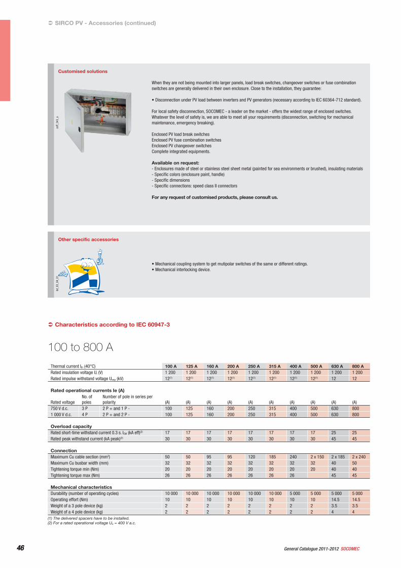
46 General Catalogue 2011-2012 SOCOMEC46
Customised solutions
coff_
343_
a
When they are not being mounted into larger panels, load break switches, changeover switches or fuse combination switches are generally delivered in their own enclosure. Close to the installation, they guarantee:
• Disconnection under PV load between inverters and PV generators (necessary according to IEC 60364-712 standard).
For local safety disconnection, SOCOMEC - a leader on the market - offers the widest range of enclosed switches. Whatever the level of safety is, we are able to meet all your requirements (disconnection, switching for mechanical maintenance, emergency breaking).
Enclosed PV load break switchesEnclosed PV fuse combination switchesEnclosed PV changeover switchesComplete integrated equipments.
Available on request:- Enclosures made of steel or stainless steel sheet metal (painted for sea environments or brushed), insulating materials- Specific colors (enclosure paint, handle)- Specific dimensions- Specific connections: speed class II connectors
For any request of customised products, please consult us.
Other specific accessories
bd_0
3_04
_01
• Mechanical coupling system to get mutipolar switches of the same or different ratings.• Mechanical interlocking device.
SIRCO PV - Accessories (continued)
Thermal current Ith (40°C) 100 A 125 A 160 A 200 A 250 A 315 A 400 A 500 A 630 A 800 ARated insulation voltage Ui (V) 1 200 1 200 1 200 1 200 1 200 1 200 1 200 1 200 1 200 1 200Rated impulse withstand voltage Uimp (kV) 12(1) 12(1) 12(1) 12(1) 12(1) 12(1) 12(1) 12(1) 12 12
Rated operational currents Ie (A)
Rated voltageNo. of poles
Number of pole in series per polarity (A) (A) (A) (A) (A) (A) (A) (A) (A) (A)
750 V d.c. 3 P 2 P + and 1 P - 100 125 160 200 250 315 400 500 630 8001 000 V d.c. 4 P 2 P + and 2 P - 100 125 160 200 250 315 400 500 630 800
Overload capacityRated short-time withstand current 0.3 s. ICW (kA eff)(2) 17 17 17 17 17 17 17 17 25 25Rated peak withstand current (kA peak)(2) 30 30 30 30 30 30 30 30 45 45
ConnectionMaximum Cu cable section (mm2) 50 50 95 95 120 185 240 2 x 150 2 x 185 2 x 240Maximum Cu busbar width (mm) 32 32 32 32 32 32 32 32 40 50Tightening torque min (Nm) 20 20 20 20 20 20 20 20 40 40Tightening torque max (Nm) 26 26 26 26 26 26 26 45 45
Mechanical characteristicsDurability (number of operating cycles) 10 000 10 000 10 000 10 000 10 000 10 000 5 000 5 000 5 000 5 000Operating effort (Nm) 10 10 10 10 10 10 10 10 14.5 14.5Weight of a 3 pole device (kg) 2 2 2 2 2 2 2 2 3.5 3.5Weight of a 4 pole device (kg) 2 2 2 2 2 2 2 2 4 4
Characteristics according to IEC 60947-3
(1) The delivered spacers have to be installed.(2) For a rated operational voltage Ue = 400 V a.c.
100 to 800 A
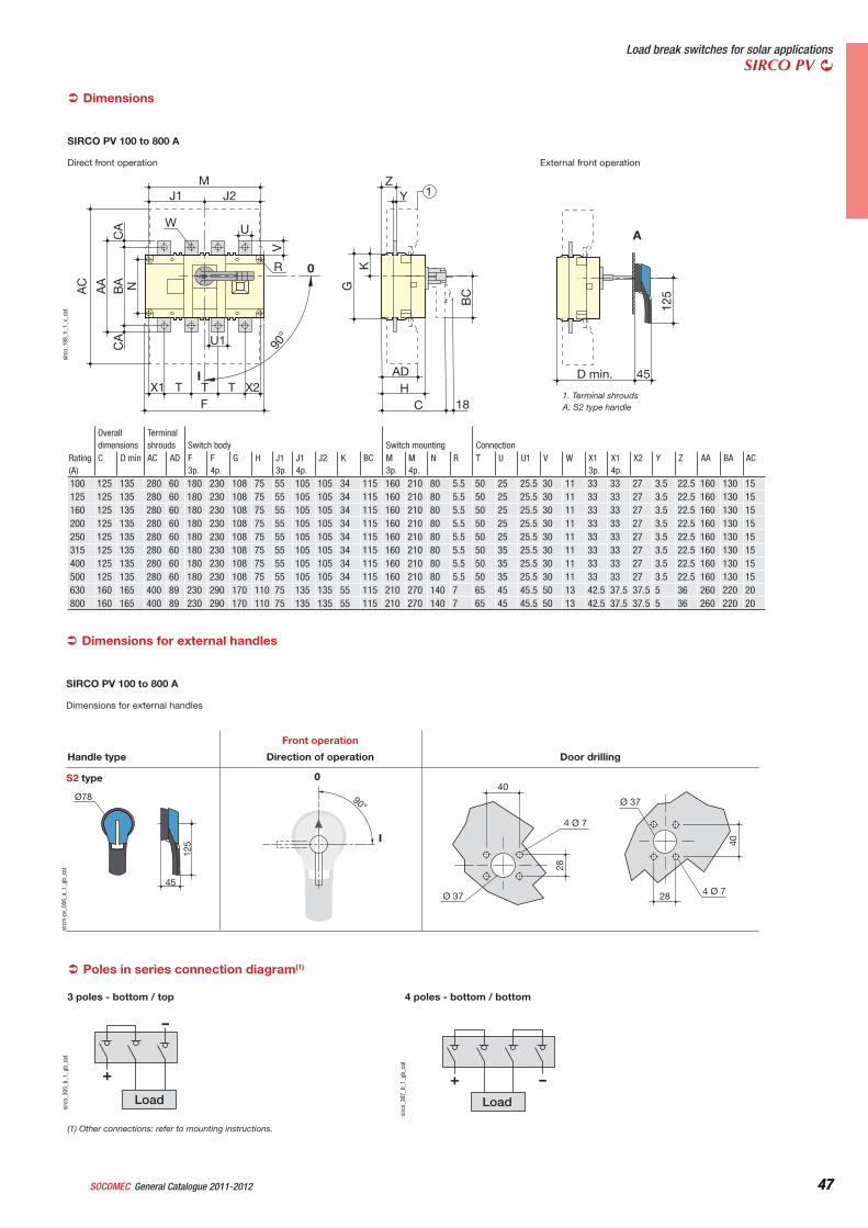
47General Catalogue 2011-2012SOCOMEC 47
Load break switches for solar applicationsSIRCO PV
Direct front operation External front operation
1
18
ZY
C
D min. 45H
ADX2X1 T
R
UW
J1 J2M
F
U1
TT
KGAC
AA
BA N
CA
CA
V
BC
125
I
090
°
A
sirc
o_19
8_h_
1_x_
cat
1. Terminal shroudsA. S2 type handle
Rating (A)
Overalldimensions
Terminal shrouds Switch body Switch mounting Connection
C D min AC AD F 3p.
F4p.
G H J1 3p.
J14p.
J2 K BC M 3p.
M4p.
N R T U U1 V W X1 3p.
X14p.
X2 Y Z AA BA AC
100 125 135 280 60 180 230 108 75 55 105 105 34 115 160 210 80 5.5 50 25 25.5 30 11 33 33 27 3.5 22.5 160 130 15125 125 135 280 60 180 230 108 75 55 105 105 34 115 160 210 80 5.5 50 25 25.5 30 11 33 33 27 3.5 22.5 160 130 15160 125 135 280 60 180 230 108 75 55 105 105 34 115 160 210 80 5.5 50 25 25.5 30 11 33 33 27 3.5 22.5 160 130 15200 125 135 280 60 180 230 108 75 55 105 105 34 115 160 210 80 5.5 50 25 25.5 30 11 33 33 27 3.5 22.5 160 130 15250 125 135 280 60 180 230 108 75 55 105 105 34 115 160 210 80 5.5 50 25 25.5 30 11 33 33 27 3.5 22.5 160 130 15315 125 135 280 60 180 230 108 75 55 105 105 34 115 160 210 80 5.5 50 35 25.5 30 11 33 33 27 3.5 22.5 160 130 15400 125 135 280 60 180 230 108 75 55 105 105 34 115 160 210 80 5.5 50 35 25.5 30 11 33 33 27 3.5 22.5 160 130 15500 125 135 280 60 180 230 108 75 55 105 105 34 115 160 210 80 5.5 50 35 25.5 30 11 33 33 27 3.5 22.5 160 130 15630 160 165 400 89 230 290 170 110 75 135 135 55 115 210 270 140 7 65 45 45.5 50 13 42.5 37.5 37.5 5 36 260 220 20800 160 165 400 89 230 290 170 110 75 135 135 55 115 210 270 140 7 65 45 45.5 50 13 42.5 37.5 37.5 5 36 260 220 20
SIRCO PV 100 to 800 A
Dimensions for external handles
Dimensions for external handles
Ø78
45
125
90°
I
0
40
28
Ø 37
4 Ø 7
40
28
Ø 37
4 Ø 7
Direction of operation Door drillingHandle type
Front operation
S2 type
sirc
m-p
v_00
6_a_
1_gb
_cat
SIRCO PV 100 to 800 A
Poles in series connection diagram(1)
-
+
Load
sirc
o_30
5_b_
1_gb
_cat
3 poles - bottom / top
Dimensions
Load
-+
sirc
o_30
7_b_
1_gb
_cat
4 poles - bottom / bottom
(1) Other connections: refer to mounting instructions.
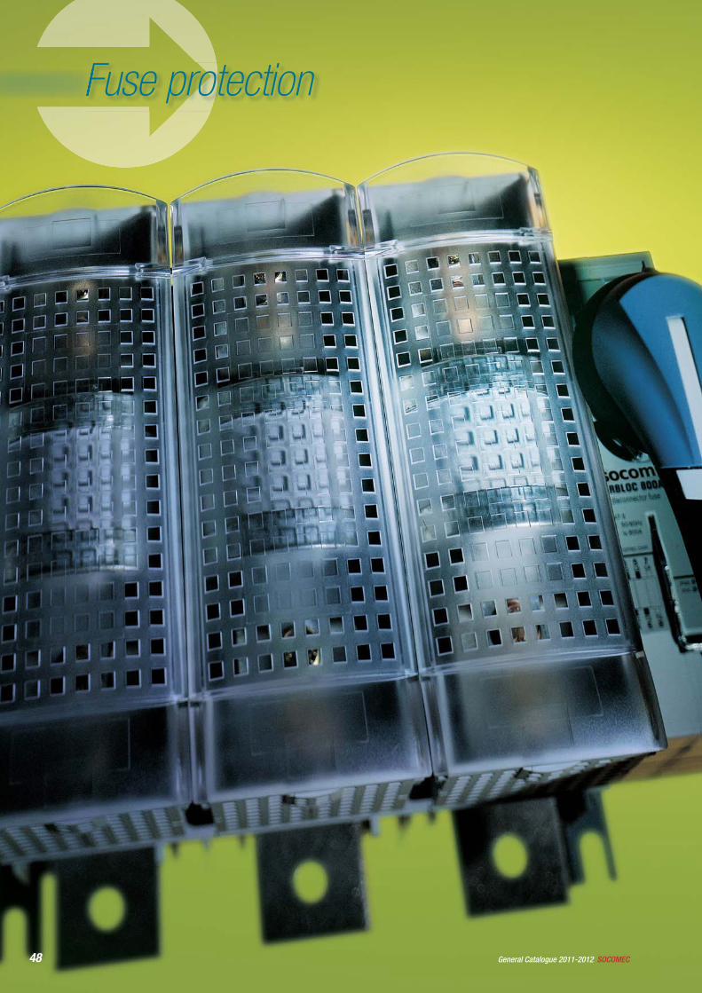
48 SOCOMECGeneral Catalogue 2011-2012
Fuse protection
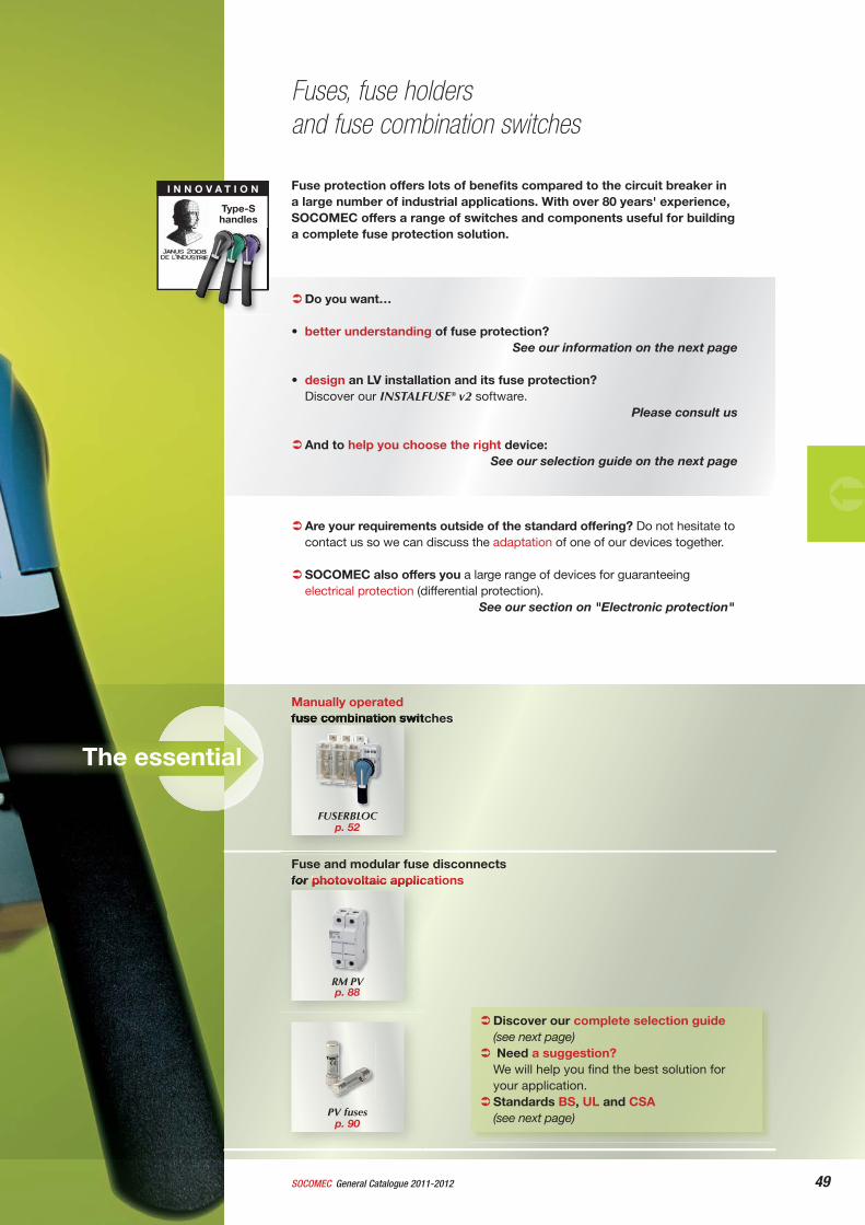
49General Catalogue 2011-2012SOCOMEC
Fuse protection offers lots of benefi ts compared to the circuit breaker in a large number of industrial applications. With over 80 years' experience, SOCOMEC offers a range of switches and components useful for building a complete fuse protection solution.
Do you want…
• better understanding of fuse protection?See our information on the next page
• design an LV installation and its fuse protection?Discover our INSTALFUSE® v2 software.
Please consult us
And to help you choose the right device: See our selection guide on the next page
Are your requirements outside of the standard offering? Do not hesitate to contact us so we can discuss the adaptation of one of our devices together.
SOCOMEC also offers you a large range of devices for guaranteeing electrical protection (differential protection).
See our section on "Electronic protection"
Fuses, fuse holdersand fuse combination switches
Manually operatedfuse combination switches
Discover our complete selection guide (see next page) Need a suggestion? We will help you fi nd the best solution for your application. Standards BS, UL and CSA(see next page)
FUSERBLOC p. 52
I N N O V A T I O N
Type-S handles
The essential
Fuse and modular fuse disconnects for photovoltaic applications
PV fuses p. 90
RM PV p. 88
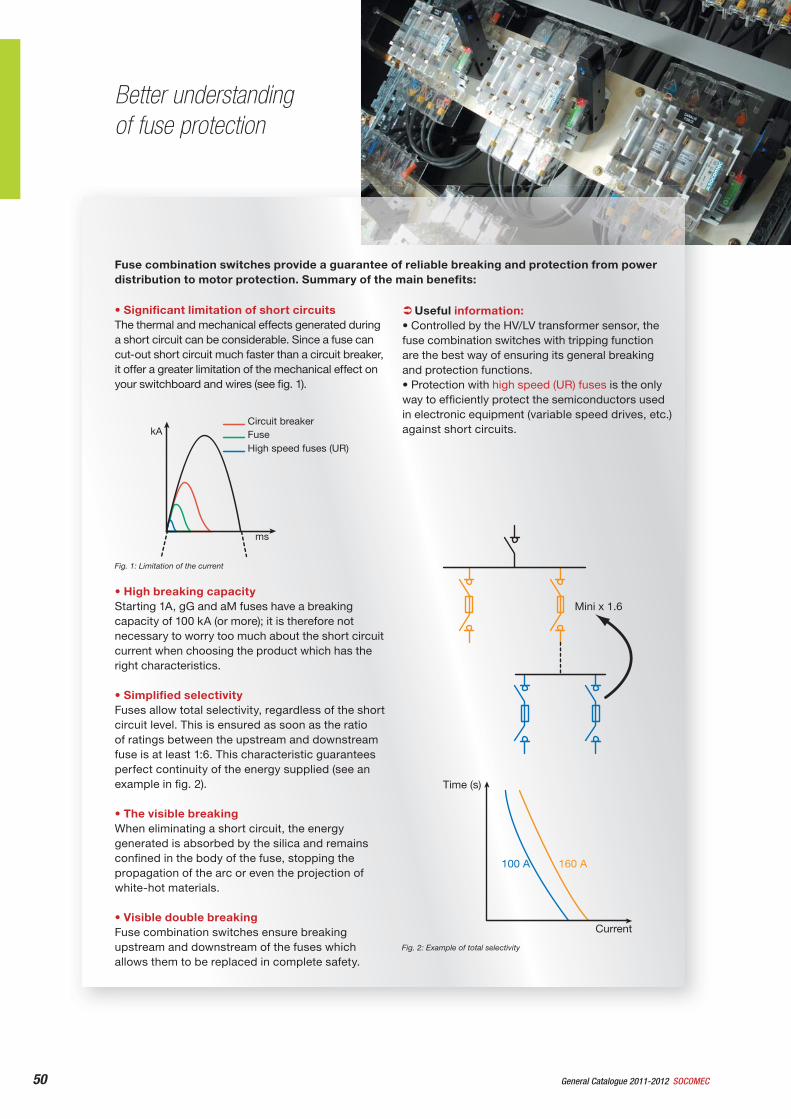
50 SOCOMECGeneral Catalogue 2011-2012
Fuse combination switches provide a guarantee of reliable breaking and protection from power distribution to motor protection. Summary of the main benefi ts:
Better understanding of fuse protection
Mini x 1.6
160 A100 A
Time (s)
Current
Fig. 2: Example of total selectivity
• Signifi cant limitation of short circuits The thermal and mechanical effects generated during a short circuit can be considerable. Since a fuse can cut-out short circuit much faster than a circuit breaker, it offer a greater limitation of the mechanical effect on your switchboard and wires (see fi g. 1).
• High breaking capacity Starting 1A, gG and aM fuses have a breaking capacity of 100 kA (or more); it is therefore not necessary to worry too much about the short circuit current when choosing the product which has the right characteristics.
• Simplifi ed selectivity Fuses allow total selectivity, regardless of the short circuit level. This is ensured as soon as the ratio of ratings between the upstream and downstream fuse is at least 1:6. This characteristic guarantees perfect continuity of the energy supplied (see an example in fi g. 2).
• The visible breaking When eliminating a short circuit, the energy generated is absorbed by the silica and remains confi ned in the body of the fuse, stopping the propagation of the arc or even the projection of white-hot materials.
• Visible double breaking Fuse combination switches ensure breaking upstream and downstream of the fuses which allows them to be replaced in complete safety.
Useful information:• Controlled by the HV/LV transformer sensor, the fuse combination switches with tripping function are the best way of ensuring its general breaking and protection functions.• Protection with high speed (UR) fuses is the only way to effi ciently protect the semiconductors used in electronic equipment (variable speed drives, etc.) against short circuits.kA
ms
Circuit breaker
High speed fuses (UR)Fuse
Fig. 1: Limitation of the current
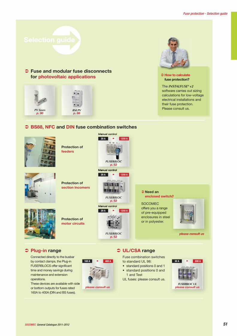
51General Catalogue 2011-2012SOCOMEC
Fuse protection - Selection guide
Selection guide
The INSTALFUSE® v2software carries out sizing calculations for low-voltage electrical installations and their fuse protection. Please consult us.
How to calculate fuse protection?
SOCOMECoffers you a range of pre-equipped enclosures in steel or in polyester.
please consult us
Need an enclosed switch?
Protection of feeders
Protection of section incomers
BS88, NFC and DIN fuse combination switches
Protection of motor circuits
Manual control
Manual control
FUSERBLOC p. 52
20 A 1250 A
Manual control
FUSERBLOC p. 52
20 A 1250 A
FUSERBLOC p. 52
20 A 1250 A
UL/CSA rangeFuse combination switchesto standard UL 98: • standard positions 0 and 1• standard positions 0 and
1 and TestUL fuses: please consult us.
30 A 800 A
Plug-in rangeConnected directly to the busbar by contact clamps, the Plug-in FUSERBLOCS offer significant time and money savings during maintenance and extension operations. These devices are available with side or bottom outputs for fuses rated 160A to 400A (DIN and BS fuses).
please consult us
160 A 400 A
FUSERBLOC ULplease consult us
Fuse and modular fuse disconnects for photovoltaic applications
PV fuses p. 90
RM PV p. 88
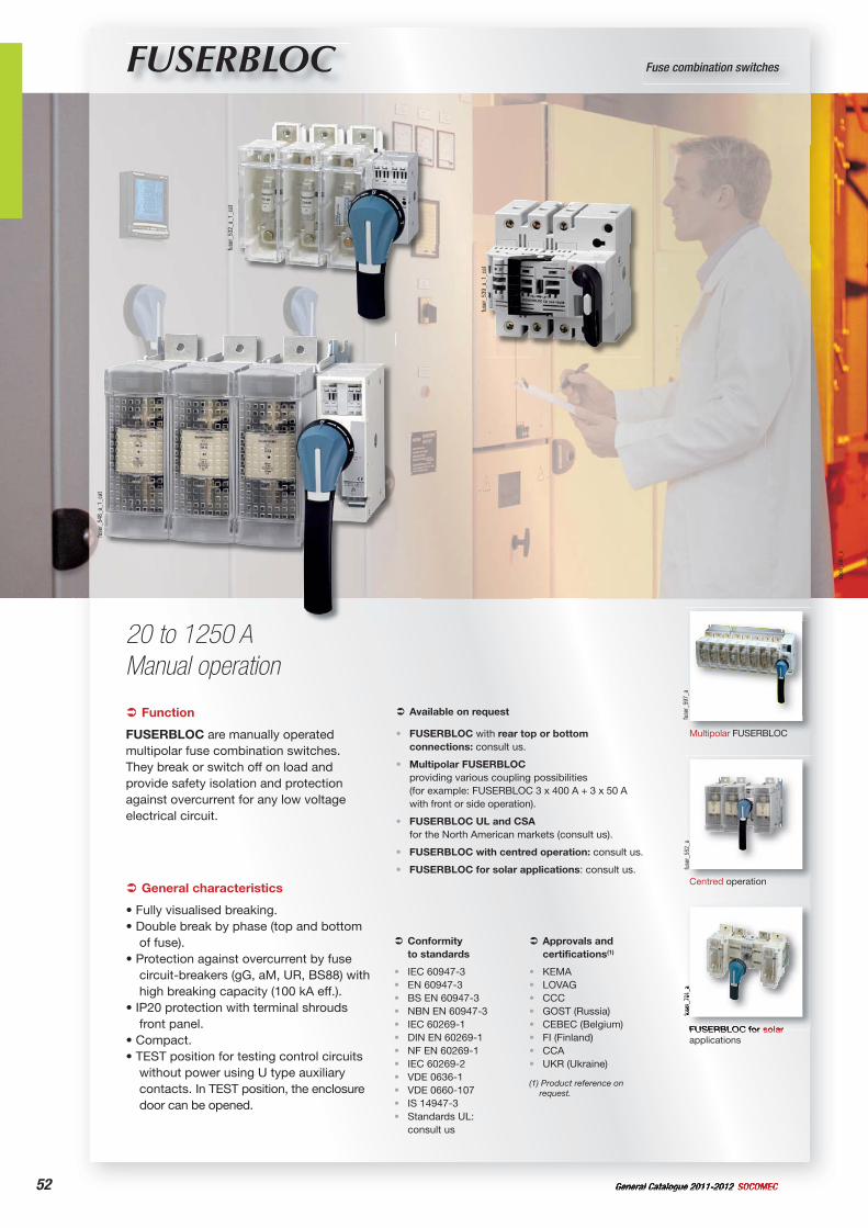
52 General Catalogue 2011-2012 SOCOMEC
appl
i_08
0_c
FUSERBLOC Fuse combination switches
20 to 1250 AManual operation
fuse
r_53
9_a_
1_ca
t
fuse
r_53
2_a_
1_ca
t
fuse
r_54
8_a_
1_ca
t
Function
FUSERBLOC are manually operated multipolar fuse combination switches.They break or switch off on load and provide safety isolation and protection against overcurrent for any low voltage electrical circuit.
Conformityto standards
IEC 60947-3EN 60947-3BS EN 60947-3NBN EN 60947-3IEC 60269-1DIN EN 60269-1NF EN 60269-1IEC 60269-2VDE 0636-1VDE 0660-107IS 14947-3Standards UL: consult us
••••••••••••
Approvals and certifications(1)
KEMALOVAGCCCGOST (Russia)CEBEC (Belgium)FI (Finland)CCAUKR (Ukraine)
(1) Product reference on request.
••••••••
General characteristics
• Fully visualised breaking.• Double break by phase (top and bottom
of fuse).• Protection against overcurrent by fuse
circuit-breakers (gG, aM, UR, BS88) with high breaking capacity (100 kA eff.).
• IP20 protection with terminal shrouds front panel.
• Compact.• TEST position for testing control circuits
without power using U type auxiliary contacts. In TEST position, the enclosure door can be opened.
Available on request
FUSERBLOC with rear top or bottom connections: consult us.
Multipolar FUSERBLOCproviding various coupling possibilities (for example: FUSERBLOC 3 x 400 A + 3 x 50 A with front or side operation).
FUSERBLOC UL and CSAfor the North American markets (consult us).
FUSERBLOC with centred operation: consult us.
FUSERBLOC for solar applications: consult us.
•
•
•
•
• fuse
r_55
2_a
Centred operation
FUSERBLOC for solarapplications
fuse
r_70
1_a
fuse
r_59
7_a
Multipolar FUSERBLOC
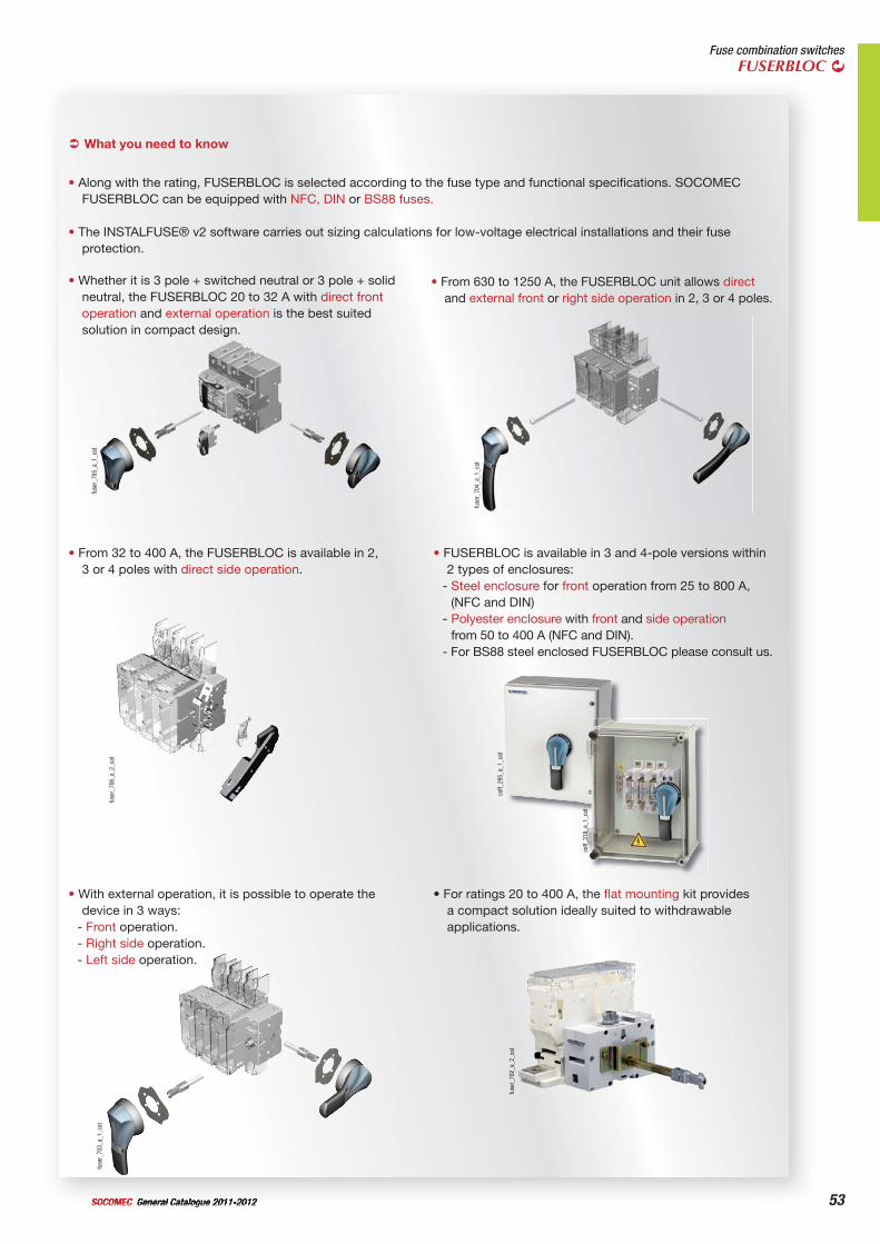
53General Catalogue 2011-2012SOCOMEC
Fuse combination switchesFUSERBLOC
What you need to know
• Along with the rating, FUSERBLOC is selected according to the fuse type and functional specifications. SOCOMEC FUSERBLOC can be equipped with NFC, DIN or BS88 fuses.
• The INSTALFUSE® v2 software carries out sizing calculations for low-voltage electrical installations and their fuse protection.
• Whether it is 3 pole + switched neutral or 3 pole + solid neutral, the FUSERBLOC 20 to 32 A with direct front operation and external operation is the best suited solution in compact design.
• From 630 to 1250 A, the FUSERBLOC unit allows directand external front or right side operation in 2, 3 or 4 poles.
• From 32 to 400 A, the FUSERBLOC is available in 2, 3 or 4 poles with direct side operation.
• FUSERBLOC is available in 3 and 4-pole versions within 2 types of enclosures:
- Steel enclosure for front operation from 25 to 800 A, (NFC and DIN)
- Polyester enclosure with front and side operationfrom 50 to 400 A (NFC and DIN).
- For BS88 steel enclosed FUSERBLOC please consult us.
• With external operation, it is possible to operate the device in 3 ways:
- Front operation.- Right side operation.- Left side operation.
• For ratings 20 to 400 A, the flat mounting kit provides a compact solution ideally suited to withdrawable applications.
fuse
r_70
2_a_
2_ca
t
fuse
r_70
3_a_
1_ca
t
coff_
319_
a_1_
cat
coff_
295_
a_1_
cat
fuse
r_70
6_a_
2_ca
t
fuse
r_70
4_a_
1_ca
t
fuse
r_70
5_a_
1_ca
t
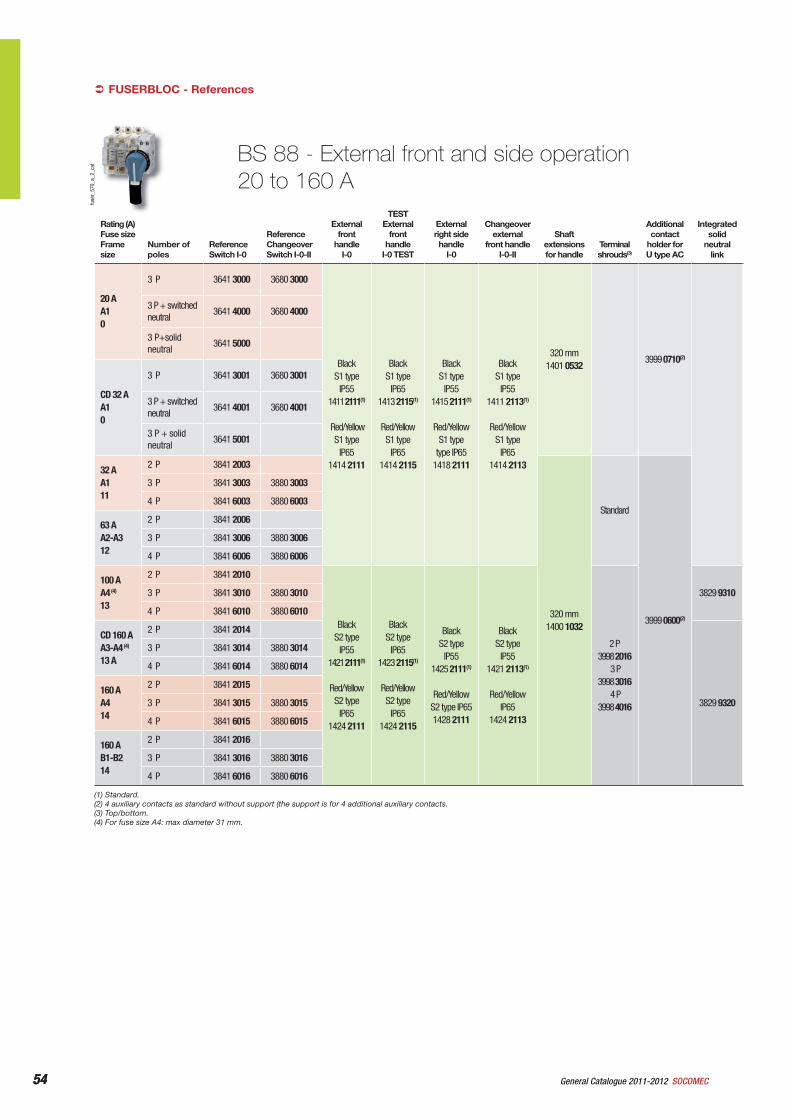
54 General Catalogue 2011-2012 SOCOMEC54
BS 88 - External front and side operation20 to 160 A
Rating (A)Fuse sizeFrame size
Number of poles
ReferenceSwitch I-0
ReferenceChangeoverSwitch I-0-II
External front
handle I-0
TEST External
front handle
I-0 TEST
External right side handle
I-0
Changeover external
front handleI-0-II
Shaft extensions for handle
Terminal shrouds(3)
Additional contact
holder for U type AC
Integrated solid
neutral link
20 AA10
3 P 3641 3000 3680 3000
Black S1 type
IP551411 2111(1)
Red/Yellow S1 type
IP651414 2111
Black S1 type
IP651413 2115(1)
Red/Yellow S1 type
IP651414 2115
Black S1 type
IP551415 2111(1)
Red/Yellow S1 type
type IP651418 2111
BlackS1 type
IP551411 2113(1)
Red/Yellow S1 type
IP651414 2113
320 mm1401 0532
3999 0710(2)
3 P + switched neutral
3641 4000 3680 4000
3 P+solid neutral
3641 5000
CD 32 AA10
3 P 3641 3001 3680 3001
3 P + switched neutral
3641 4001 3680 4001
3 P + solid neutral
3641 5001
32 AA111
2 P 3841 2003
320 mm1400 1032
Standard
3999 0600(2)
3 P 3841 3003 3880 3003
4 P 3841 6003 3880 6003
63 AA2-A312
2 P 3841 2006
3 P 3841 3006 3880 3006
4 P 3841 6006 3880 6006
100 AA4 (4)
13
2 P 3841 2010
Black S2 type
IP551421 2111(1)
Red/Yellow S2 type
IP651424 2111
Black S2 type
IP651423 2115(1)
Red/Yellow S2 type
IP651424 2115
Black S2 type
IP551425 2111(1)
Red/Yellow S2 type IP651428 2111
Black S2 type
IP551421 2113(1)
Red/Yellow IP65
1424 2113
2 P3998 2016
3 P3998 3016
4 P3998 4016
3829 9310 3 P 3841 3010 3880 3010
4 P 3841 6010 3880 6010
CD 160 AA3-A4 (4)
13 A
2 P 3841 2014
3829 9320
3 P 3841 3014 3880 3014
4 P 3841 6014 3880 6014
160 AA414
2 P 3841 2015
3 P 3841 3015 3880 3015
4 P 3841 6015 3880 6015
160 AB1-B214
2 P 3841 2016
3 P 3841 3016 3880 3016
4 P 3841 6016 3880 6016
(1) Standard.(2) 4 auxiliary contacts as standard without support (the support is for 4 additional auxiliary contacts.(3) Top/bottom.(4) For fuse size A4: max diameter 31 mm.
FUSERBLOC - Referencesfu
ser_
570_
a_2_
cat
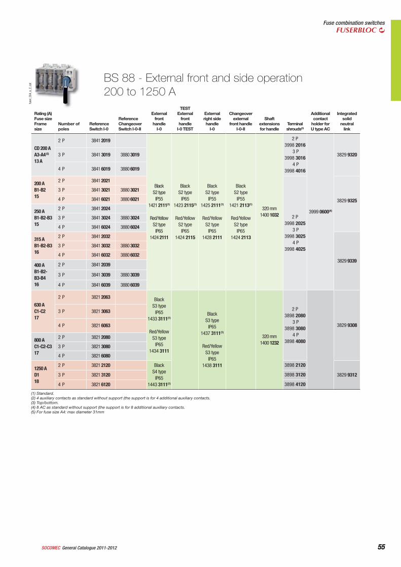
55General Catalogue 2011-2012SOCOMEC 55
Fuse combination switchesFUSERBLOC
Rating (A)Fuse sizeFrame size
Number of poles
ReferenceSwitch I-0
ReferenceChangeoverSwitch I-0-II
External front
handle I-0
TEST External
front handle
I-0 TEST
External right side handle
I-0
Changeover external
front handleI-0-II
Shaft extensions for handle
Terminal shrouds(3)
Additional contact
holder for U type AC
Integrated solid
neutral link
CD 200 AA3-A4 (5)
13 A
2 P 3841 2019
Black S2 type
IP551421 2111(1)
Red/Yellow S2 type
IP651424 2111
Black S2 type
IP651423 2115(1)
Red/Yellow S2 type
IP651424 2115
Black S2 type
IP551425 2111(1)
Red/Yellow S2 type
IP651428 2111
Black S2 type
IP551421 2113(1)
Red/Yellow S2 type
IP651424 2113
320 mm 1400 1032
2 P3998 2016
3 P3998 3016
4 P3998 4016
3999 0600(4)
3829 9320 3 P 3841 3019 3880 3019
4 P 3841 6019 3880 6019
200 AB1-B215
2 P 3841 2021
2 P3998 2025
3 P3998 3025
4 P3998 4025
3829 9325
3 P 3841 3021 3880 3021
4 P 3841 6021 3880 6021
250 AB1-B2-B315
2 P 3841 2024
3 P 3841 3024 3880 3024
4 P 3841 6024 3880 6024
315 AB1-B2-B316
2 P 3841 2032
3829 9339
3 P 3841 3032 3880 3032
4 P 3841 6032 3880 6032
400 AB1-B2-B3-B416
2 P 3841 2039
3 P 3841 3039 3880 3039
4 P 3841 6039 3880 6039
630 AC1-C217
2 P 3821 2063 Black S3 type
IP651433 3111(1)
Red/Yellow S3 type
IP651434 3111
Black S3 type
IP651437 3111(1)
Red/Yellow S3 type
IP651438 3111
320 mm 1400 1232
2 P3898 2080
3 P 3898 3080
4 P3898 4080
3829 9308
3 P 3821 3063
4 P 3821 6063
800 AC1-C2-C317
2 P 3821 2080
3 P 3821 3080
4 P 3821 6080
1250 AD118
2 P 3821 2120 Black S4 type
IP651443 3111(1)
3898 2120
3829 9312 3 P 3821 3120 3898 3120
4 P 3821 6120 3898 4120
(1) Standard.(2) 4 auxiliary contacts as standard without support (the support is for 4 additional auxiliary contacts.(3) Top/bottom.(4) 8 AC as standard without support (the support is for 8 additional auxiliary contacts.(5) For fuse size A4: max diameter 31mm
BS 88 - External front and side operation200 to 1250 A
fuse
r_55
4_a_
2_ca
t
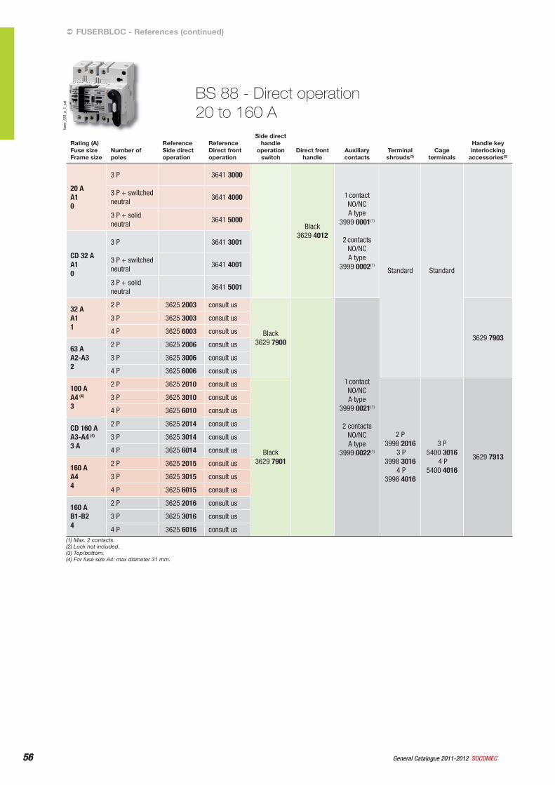
56 General Catalogue 2011-2012 SOCOMEC56
Rating (A)Fuse sizeFrame size
Number of poles
ReferenceSide direct operation
ReferenceDirect front operation
Side direct handle
operationswitch
Direct front handle
Auxiliarycontacts
Terminal shrouds(3)
Cageterminals
Handle key interlocking
accessories(2)
20 AA10
3 P 3641 3000
Black3629 4012
1 contactNO/NCA type
3999 0001(1)
2 contactsNO/NCA type
3999 0002(1)
Standard Standard
3 P + switched neutral
3641 4000
3 P + solid neutral
3641 5000
CD 32 AA10
3 P 3641 3001
3 P + switched neutral
3641 4001
3 P + solid neutral
3641 5001
32 AA11
2 P 3625 2003 consult us
Black3629 7900
1 contactNO/NCA type
3999 0021(1)
2 contacts NO/NCA type
3999 0022(1)
3629 7903
3 P 3625 3003 consult us
4 P 3625 6003 consult us
63 AA2-A32
2 P 3625 2006 consult us
3 P 3625 3006 consult us
4 P 3625 6006 consult us
100 AA4 (4)
3
2 P 3625 2010 consult us
Black3629 7901
2 P3998 2016
3 P3998 3016
4 P3998 4016
3 P5400 3016
4 P5400 4016
3629 7913
3 P 3625 3010 consult us
4 P 3625 6010 consult us
CD 160 AA3-A4 (4)
3 A
2 P 3625 2014 consult us
3 P 3625 3014 consult us
4 P 3625 6014 consult us
160 AA44
2 P 3625 2015 consult us
3 P 3625 3015 consult us
4 P 3625 6015 consult us
160 AB1-B24
2 P 3625 2016 consult us
3 P 3625 3016 consult us
4 P 3625 6016 consult us
BS 88 - Direct operation20 to 160 A
(1) Max. 2 contacts.(2) Lock not included.(3) Top/bottom.(4) For fuse size A4: max diameter 31 mm.
FUSERBLOC - References (continued)
fuse
r_53
9_a_
1_ca
t
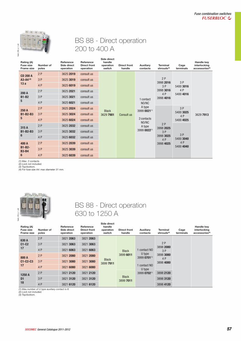
57General Catalogue 2011-2012SOCOMEC 57
Fuse combination switchesFUSERBLOC
Rating (A)Fuse sizeFrame size
Number of poles
ReferenceSide direct operation
ReferenceDirect front operation
Side direct handle
operationswitch
Direct front handle
Auxiliarycontacts
Terminal shrouds(3)
Cageterminals
Handle key interlocking
accessories(2)
CD 200 AA3-A4 (4)
13 a
2 P 3625 2019 consult us
Black3629 7901 Consult us
1 contactNO/NCA type
3999 0021(1)
2 contactsNO/NCA type
3999 0022(1)
2 P3998 2016
3 P3998 3016
4 P3998 4016
3 P5400 3016
4 P5400 4016
3629 7913
3 P 3625 3019 consult us
4 P 3625 6019 consult us
200 AB1-B25
2 P 3625 2021 consult us
3 P 3625 3021 consult us
4 P 3625 6021 consult us
250 AB1-B2-B35
2 P 3625 2024 consult us
2 P3998 2025
3 P3998 3025
4 P3998 4025
3 P5400 3025
4 P5400 4025
3 P 3625 3024 consult us
4 P 3625 6024 consult us
315 AB1-B2-B36
2 P 3625 2032 consult us
3 P5400 3040
4 P5400 4040
3 P 3625 3032 consult us
4 P 3625 6032 consult us
400 AB1-B2-B3-B46
2 P 3625 2039 consult us
3 P 3625 3039 consult us
4 P 3625 6039 consult us
(1) Max. 2 contacts.(2) Lock not included.(3) Top/bottom.(4) For fuse size A4: max diameter 31 mm.
Rating (A)Fuse sizeFrame size
Number of poles
ReferenceSide direct operation
ReferenceDirect front operation
Side direct handle
operationswitch
Direct front handle
Auxiliarycontacts
Terminal shrouds(3)
Cageterminals
Handle key interlocking
accessories(2)
630 AC1-C217
2 P 3821 2063 3821 2063
Black3899 7911
Black3899 6011
1 contact NOU type
3999 0701(1)
1 contact NO U type
3999 0702(1)
2 P3898 2080
3 P3898 3080
4 P3898 4080
3 P 3821 3063 3821 3063
4 P 3821 6063 3821 6063
800 AC1-C2-C317
2 P 3821 2080 3821 2080
3 P 3821 3080 3821 3080
4 P 3821 6080 3821 6080
1250 AD118
2 P 3821 2120 3821 2120Black
3899 7011
3898 2120
3 P 3821 3120 3821 3120 3898 3120
4 P 3821 6120 3821 6120 3898 4120
BS 88 - Direct operation200 to 400 A
fuse
r_23
0_a_
1_ca
tfu
ser_
416_
a_1_
cat
BS 88 - Direct operation630 to 1250 A
(1) Max.number of U type auxiliary contact is 8.(2) Lock not included.(3) Top/bottom.
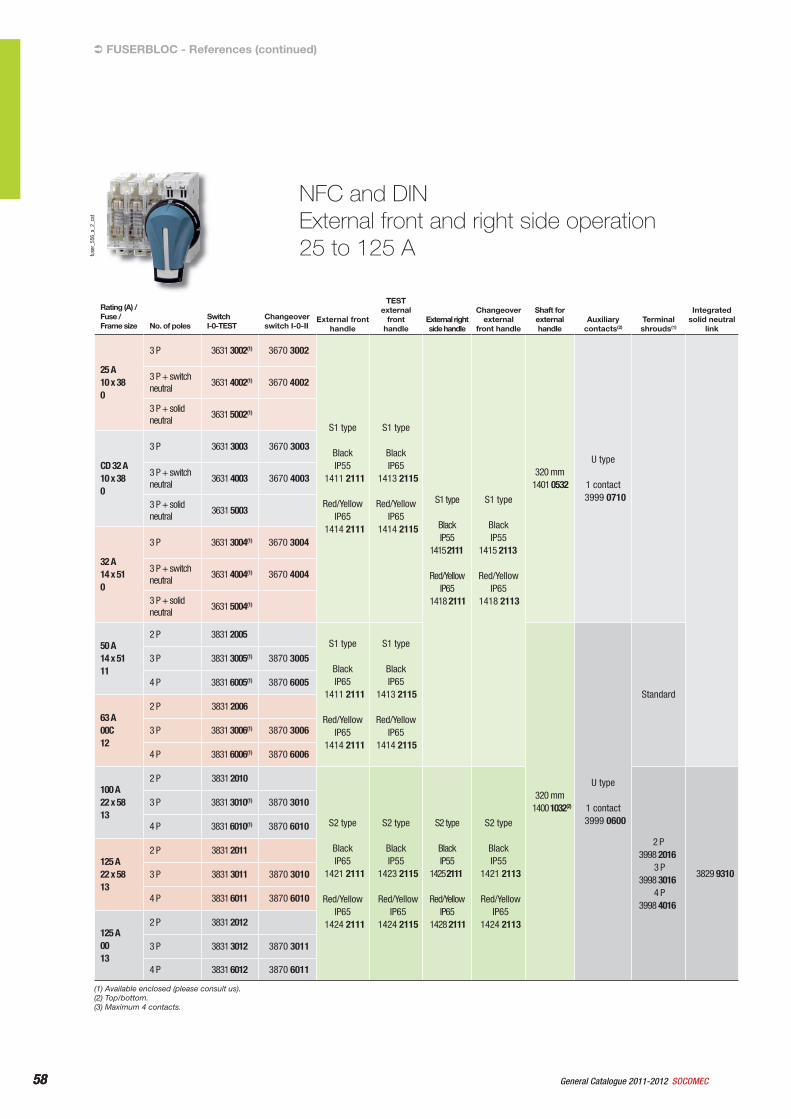
58 General Catalogue 2011-2012 SOCOMEC58
NFC and DINExternal front and right side operation25 to 125 A
FUSERBLOC - References (continued)
Rating (A) /Fuse /Frame size No. of poles
Switch I-0-TEST
Changeover switch I-0-II
External front handle
TEST external
fronthandle
External right side handle
Changeover external
front handle
Shaft for external handle
Auxiliarycontacts(2)
Terminal shrouds(1)
Integratedsolid neutral
link
25 A10 x 380
3 P 3631 3002(1) 3670 3002
S1 type
Black IP55
1411 2111
Red/Yellow IP65
1414 2111
S1 type
Black IP65
1413 2115
Red/Yellow IP65
1414 2115
S1 type
Black IP55
1415 2111
Red/YellowIP65
1418 2111
S1 type
Black IP55
1415 2113
Red/YellowIP65
1418 2113
320 mm1401 0532
U type
1 contact3999 0710
3 P + switch neutral
3631 4002(1) 3670 4002
3 P + solid neutral
3631 5002(1)
CD 32 A10 x 380
3 P 3631 3003 3670 3003
3 P + switch neutral
3631 4003 3670 4003
3 P + solid neutral
3631 5003
32 A14 x 510
3 P 3631 3004(1) 3670 3004
3 P + switch neutral
3631 4004(1) 3670 4004
3 P + solid neutral
3631 5004(1)
50 A14 x 5111
2 P 3831 2005 S1 type
Black IP65
1411 2111
Red/Yellow IP65
1414 2111
S1 type
Black IP65
1413 2115
Red/Yellow IP65
1414 2115
320 mm1400 1032(2)
U type
1 contact3999 0600
Standard
3 P 3831 3005(1) 3870 3005
4 P 3831 6005(1) 3870 6005
63 A00C12
2 P 3831 2006
3 P 3831 3006(1) 3870 3006
4 P 3831 6006(1) 3870 6006
100 A22 x 5813
2 P 3831 2010
S2 type
Black IP65
1421 2111
Red/Yellow IP65
1424 2111
S2 type
Black IP55
1423 2115
Red/YellowIP65
1424 2115
S2 type
Black IP55
1425 2111
Red/Yellow IP65
1428 2111
S2 type
Black IP55
1421 2113
Red/YellowIP65
1424 2113
2 P3998 2016
3 P3998 3016
4 P3998 4016
3829 9310
3 P 3831 3010(1) 3870 3010
4 P 3831 6010(1) 3870 6010
125 A22 x 5813
2 P 3831 2011
3 P 3831 3011 3870 3010
4 P 3831 6011 3870 6010
125 A0013
2 P 3831 2012
3 P 3831 3012 3870 3011
4 P 3831 6012 3870 6011
(1) Available enclosed (please consult us).(2) Top/bottom.(3) Maximum 4 contacts.
fuse
r_55
6_a_
2_ca
t

59General Catalogue 2011-2012SOCOMEC 59
Fuse combination switchesFUSERBLOC
fuse
r_54
8_a_
1_ca
t
NFC and DINExternal front and right side operation160 to 1250 A
Rating (A) /Fuse /Frame size
No. of poles Switch I-0
Changeover switch I-0-II
External front handle
TEST external
fronthandle
External right side handle
Changeover external front
handle
Shaft for external handle
Auxiliary contacts
Terminalshrouds(2)
Integrated solid neutral link
160 A0013
2 P 3831 2015
Type S2
Black IP55
1421 2111
Red/Yellow IP65
1424 2111
Type S2
Black IP65
1423 2115
Red/YellowIP65
1424 2115
Type S2
Black IP55
1425 2111
Red/Yellow IP65
1428 2111
Type S2
Black IP55
1425 2113
Red/Yellow IP65
1428 2113
320 mm1400 1032
U type
1 contact3999 0600(3)
2 P3998 2016
3 P3998 3016
4 P3998 4016
3829 9320
3 P 3831 3015 3870 3015
4 P 3831 6015 3870 6015
160 A014
2 P 3831 2016
3 P 3831 3016(1) 3870 3016
4 P 3831 6016(1) 3870 6016
250 A115
2 P 3831 2024
U type
1 contact3999 0600(4)
2 P3998 2025
3 P3998 3025
4 P3998 4025
3829 93253 P 3831 3024(1) 3870 3024
4 P 3831 6024(1) 3870 6024
400 A216
2 P 3831 2039
3829 93393 P 3831 3039(1) 3870 3039
4 P 3831 6039(1) 3870 6039
630 A317
2 P 3811 2063 Type S3
Black IP65
1433 3111
Red/Yellow IP65
1434 3111
Type S3
Black IP65
1437 3111
Red/Yellow IP65
1438 3111
320 mm1400 1232
2 P3898 2080
3 P3898 3080
4 P3898 4080
3829 9308
3 P 3811 3063(1)
4 P 3811 6063(1)
800 A317
2 P 3811 2080
3 P 3811 3080
4 P 3811 6080
800 A418
2 P 3811 2081 Type S4
Black IP65
1443 3111
Red/Yellow IP65
1444 3111
2 P3898 2120
3 P3898 3120
4 P3898 4120
3829 9312
3 P 3811 3081
4 P 3811 6081
1250 A418
2 P 3811 2120
3 P 3811 3120
4 P 3811 6120
(1) Available enclosed (please consult us).(2) Top/bottom.(3) Maximum 4 contacts.(4) Maximum 8 contacts.
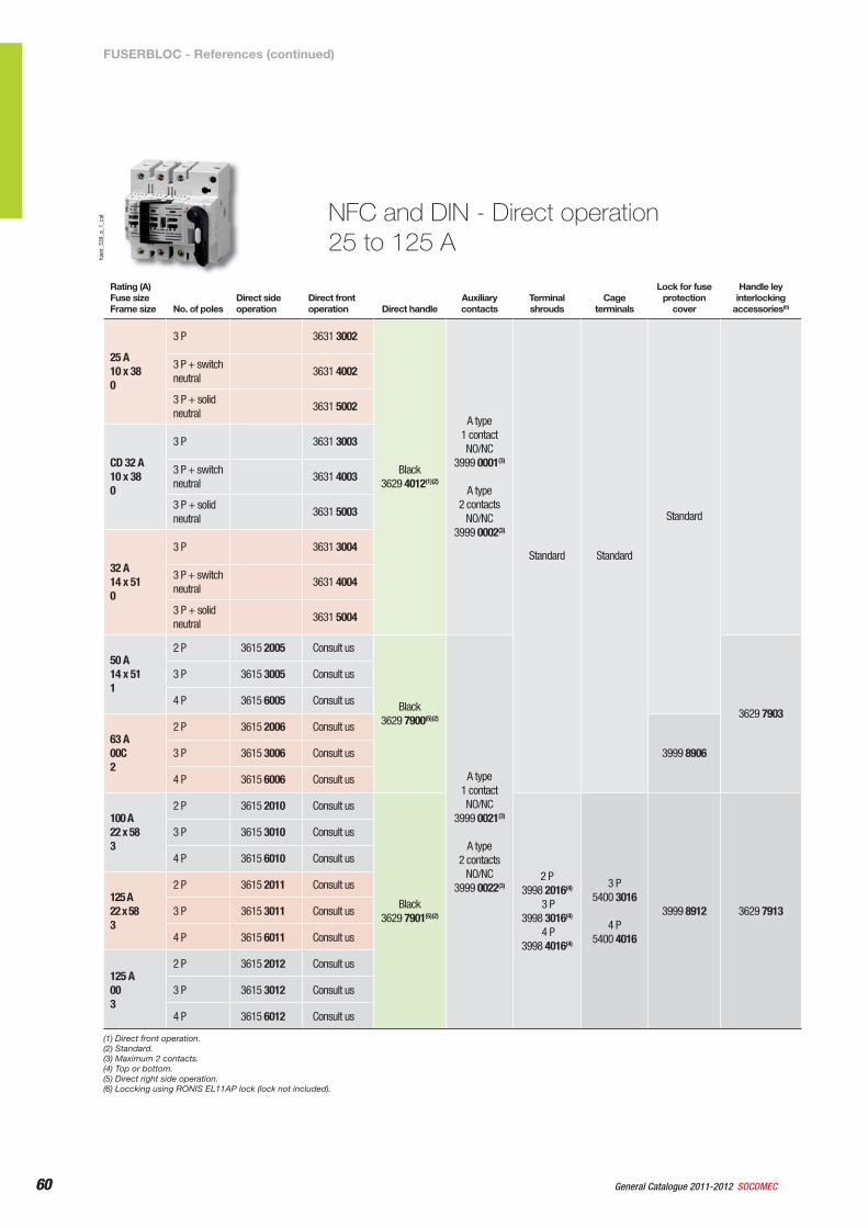
60 General Catalogue 2011-2012 SOCOMEC60
NFC and DIN - Direct operation25 to 125 A
fuse
r_53
9_a_
1_ca
t
Rating (A)Fuse sizeFrame size No. of poles
Direct side operation
Direct front operation Direct handle
Auxiliary contacts
Terminal shrouds
Cage terminals
Lock for fuse protection
cover
Handle ley interlocking
accessories(6)
25 A10 x 380
3 P 3631 3002
Black3629 4012(1)(2)
A type 1 contact NO/NC
3999 0001(3)
A type 2 contacts
NO/NC3999 0002(3)
Standard Standard
Standard
3 P + switch neutral
3631 4002
3 P + solid neutral
3631 5002
CD 32 A10 x 380
3 P 3631 3003
3 P + switch neutral
3631 4003
3 P + solid neutral
3631 5003
32 A14 x 510
3 P 3631 3004
3 P + switch neutral
3631 4004
3 P + solid neutral
3631 5004
50 A14 x 511
2 P 3615 2005 Consult us
Black3629 7900(5)(2)
A type 1 contact NO/NC
3999 0021(3)
A type 2 contacts
NO/NC3999 0022(3)
3629 7903
3 P 3615 3005 Consult us
4 P 3615 6005 Consult us
63 A00C2
2 P 3615 2006 Consult us
3999 89063 P 3615 3006 Consult us
4 P 3615 6006 Consult us
100 A22 x 583
2 P 3615 2010 Consult us
Black3629 7901(5)(2)
2 P3998 2016(4)
3 P3998 3016(4)
4 P3998 4016(4)
3 P5400 3016
4 P5400 4016
3999 8912 3629 7913
3 P 3615 3010 Consult us
4 P 3615 6010 Consult us
125 A22 x 583
2 P 3615 2011 Consult us
3 P 3615 3011 Consult us
4 P 3615 6011 Consult us
125 A003
2 P 3615 2012 Consult us
3 P 3615 3012 Consult us
4 P 3615 6012 Consult us
(1) Direct front operation.(2) Standard.(3) Maximum 2 contacts.(4) Top or bottom.(5) Direct right side operation.(6) Loccking using RONIS EL11AP lock (lock not included).
FUSERBLOC - References (continued)
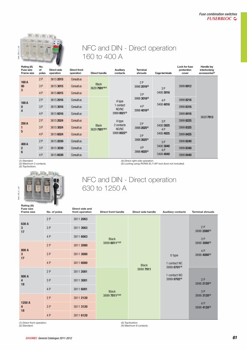
61General Catalogue 2011-2012SOCOMEC 61
Fuse combination switchesFUSERBLOC
NFC and DIN - Direct operation160 to 400 Afu
ser_
230_
a_1_
cat
Rating (A)Fuse sizeFrame size
No. of poles
Direct side operation
Direct front operation Direct handle
Auxiliary contacts
Terminal shrouds Cage terminals
Lock for fuse protection
cover
Handle ley interlocking
accessories(5)
160 A003
2 P 3615 2015 Consult us
Black3629 7901(4)(1)
A type 1 contact NO/NC
3999 0021(2)
A type 2 contacts
NO/NC3999 0022(2)
2 P3998 2016(3)
3 P3998 3016(3)
4 P3998 4016(3)
3 P5400 3016
4 P5400 4016
3999 8912
3629 7913
3 P 3615 3015 Consult us
4 P 3615 6015 Consult us
160 A04
2 P 3615 2016 Consult us
Black3629 7901(4)(1)
3999 8216
3 P 3615 3016 Consult us 3999 8316
4 P 3615 6016 Consult us 3999 8416
250 A15
2 P 3615 2024 Consult us2 P
3998 2025(3)
3 P3998 3025(3)
4 P3998 4025(3)
3 P5400 3025
4 P5400 4025
3999 8225
3 P 3615 3024 Consult us 3999 8325
4 P 3615 6024 Consult us 3999 8425
400 A26
2 P 3615 2039 Consult us 3 P5400 3040
4 P5400 4040
3999 8240
3 P 3615 3039 Consult us 3999 8340
4 P 3615 6039 Consult us 3999 8440
NFC and DIN - Direct operation630 to 1250 A
fuse
r_41
6_a_
1_ca
t
Rating (A)Fuse sizeFrame size No. of poles
Direct side and front operation Direct front handle Direct side handle Auxiliary contacts Terminal shrouds
630 A317
2 P 3811 2063
Black3899 6011(1)(2)
Black3899 7911
U type
1 contact NC3999 0701(4)
1 contact NO3999 0702(4)
2 P3898 2080(3)
3 P3898 3080(3)
4 P3898 4080(3)
3 P 3811 3063
4 P 3811 6063
800 A317
2 P 3811 2080
3 P 3811 3080
4 P 3811 6080
800 A418
2 P 3811 2081
Black3899 7011(1)(2)
2 P3898 2120(3)
3 P3898 3120(3)
4 P3898 4120(3)
3 P 3811 3081
4 P 3811 6081
1250 A418
2 P 3811 2120
3 P 3811 3120
4 P 3811 6120
(1) Direct front operation.(2) Standard.
(3) Top/bottom.(4) Maximum 8 contacts.
(1) Standard.(2) Maximum 2 contacts.(3) Top/bottom.
(4) Direct right side operation.(5) Locking using RONIS EL11AP lock (lock not included).
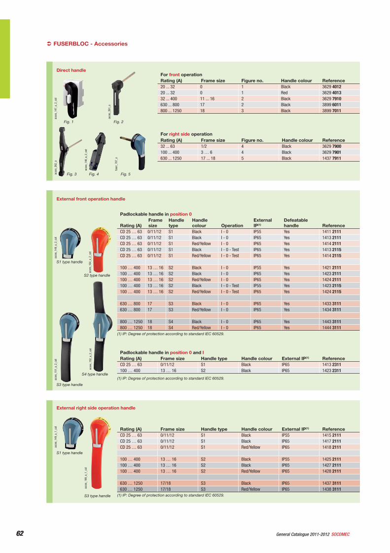
62 General Catalogue 2011-2012 SOCOMEC62
External right side operation handle
acce
s_16
6_a_
1_ca
t
S3 type handle
acce
s_14
9_a_
1_ca
t
S1 type handle
Rating (A) Frame size Handle type Handle colour External IP(1) ReferenceCD 25 … 63 0/11/12 S1 Black IP55 1415 2111CD 25 … 63 0/11/12 S1 Black IP65 1417 2111CD 25 … 63 0/11/12 S1 Red/Yellow IP65 1418 2111
100 … 400 13 … 16 S2 Black IP55 1425 2111100 … 400 13 … 16 S2 Black IP65 1427 2111100 … 400 13 … 16 S2 Red/Yellow IP65 1428 2111
630 … 1250 17/18 S3 Black IP65 1437 3111630 … 1250 17/18 S3 Red/Yellow IP65 1438 3111
(1) IP: Degree of protection according to standard IEC 60529.
FUSERBLOC - Accessories
External front operation handle
acce
s_15
2_a_
2_ca
t
S4 type handle
acce
s_15
1_a_
2_ca
t
S3 type handle
acce
s_16
4_a_
2_ca
t
S2 type handle
acce
s_14
9_a_
2_ca
t
S1 type handle
Padlockable handle in position 0
Rating (A)Framesize
Handletype
Handlecolour Operation
External IP(1)
Defeatablehandle Reference
CD 25 … 63 0/11/12 S1 Black I - 0 IP55 Yes 1411 2111CD 25 … 63 0/11/12 S1 Black I - 0 IP65 Yes 1413 2111CD 25 … 63 0/11/12 S1 Red/Yellow I - 0 IP65 Yes 1414 2111CD 25 … 63 0/11/12 S1 Black I - 0 - Test IP65 Yes 1413 2115CD 25 … 63 0/11/12 S1 Red/Yellow I - 0 - Test IP65 Yes 1414 2115
100 … 400 13 … 16 S2 Black I - 0 IP55 Yes 1421 2111100 … 400 13 … 16 S2 Black I - 0 IP65 Yes 1423 2111100 … 400 13 … 16 S2 Red/Yellow I - 0 IP65 Yes 1424 2111100 … 400 13 … 16 S2 Black I - 0 - Test IP55 Yes 1423 2115100 … 400 13 … 16 S2 Red/Yellow I - 0 - Test IP65 Yes 1424 2115
630 … 800 17 S3 Black I - 0 IP65 Yes 1433 3111630 … 800 17 S3 Red/Yellow I - 0 IP65 Yes 1434 3111
800 … 1250 18 S4 Black I - 0 IP65 Yes 1443 3111800 … 1250 18 S4 Red/Yellow I - 0 IP65 Yes 1444 3111
(1) IP: Degree of protection according to standard IEC 60529.
Padlockable handle in position 0 and IRating (A) Frame size Handle type Handle colour External IP(1) ReferenceCD 25 … 63 0/11/12 S1 Black IP65 1413 2311100 … 400 13 … 16 S2 Black IP65 1423 2311
(1) IP: Degree of protection according to standard IEC 60529.
Direct handle
acce
s_26
1_a
acce
s_14
7_a_
2_ca
t
For front operationRating (A) Frame size Figure no. Handle colour Reference20 ... 32 0 1 Black 3629 401220 ... 32 0 1 Red 3629 401332 ... 400 11 ... 16 2 Black 3629 7910630 ... 800 17 2 Black 3899 6011800 ... 1250 18 3 Black 3899 7011
For right side operationRating (A) Frame size Figure no. Handle colour Reference32 ... 63 1/2 4 Black 3629 7900100 ... 400 3 … 6 4 Black 3629 7901630 ... 1250 17 ... 18 5 Black 1437 7911
acce
s_26
2_a
acce
s_14
8_a_
2_ca
t
fuse
r_70
7_a
Fig. 1 Fig. 2
Fig. 3 Fig. 4 Fig. 5
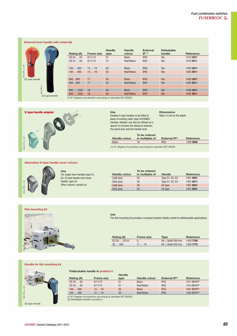
63General Catalogue 2011-2012SOCOMEC 63
Fuse combination switchesFUSERBLOC
acce
s_23
6_a_
1_ca
t
S2 type handle
acce
s_23
5_a
S3 type handle
External front handle with metal tab
Rating (A) Frame sizeHandletype
Handlecolour
External IP (1)
Defeatablehandle Reference
CD 25 … 63 0/11/12 S1 Black IP65 Yes 141D 2911CD 25 … 63 0/11/12 S1 Red/Yellow IP65 Yes 141E 2911
100 … 400 13 … 16 S2 Black IP65 Yes 142D 2911100 … 400 13 … 16 S2 Red/Yellow IP65 Yes 142E 2911
600…800 17 S3 Black IP65 Yes 143D 3911600…800 17 S3 Red/Yellow IP65 Yes 143E 3911
800 … 1250 18 S4 Black IP65 Yes 144D 3911800 … 1250 18 S4 Red/Yellow IP65 Yes 144E 3911
(1) IP: Degree of protection according to standard IEC 60529.
S type handle adapter
acce
s_18
7_a_
1_ca
t
UseEnables S type handles to be fitted in place of existing older style SOCOMEC handles. Adapter can also be utilised as a spacer to increase the distance between the panel door and the handle lever.
DimensionsAdds 12 mm to the depth.
Handle colourTo be orderedin multiples of External IP(1) Reference
Black 10 IP65 1493 0000
(1) IP: Degree of protection according to standard IEC 60529.
Alternative S-type handle cover colours
acce
s_19
8_a_
1_ca
t
UseFor single lever handles type S1, S2, S3 and double arms lever handle, type S4.Other colours: consult us.
Handle colourTo be orderedin multiples of Handle Reference
Light grey 50 Type S1, S2, S3 1401 0001Dark grey 50 Type S1, S2, S3 1401 0011Light grey 50 S4 type 1401 0031Dark grey 50 S4 type 1401 0041
Flat mounting kit
fuse
r_53
5_a_
1_ca
t
UseThe flat mounting kit provides a compact solution ideally suited to withdrawable applications.
Rating (A) Frame size Type ReferenceCD 20 … CD 32 0 Kit + Shaft 200 mm 1429 770932 … 400 11 … 16 Kit + Shaft 200 mm 1429 7710
Handle for flat mounting kit
fuse
r_53
6_a_
1_ca
t
S2 type handle.
Padlockable handle in position 0
Rating (A) Frame sizeHandletype Handle colour External IP(1) Reference
CD 20 … 63 0/11/12 S1 Black IP55 1411 2111(2)
CD 20 … 63 0/11/12 S1 Red/Yellow IP65 1414 2111(2)
100 … 400 13 … 16 S2 Black IP55 1421 2111(2)
100 … 400 13 … 16 S2 Red/Yellow IP65 1424 2111(2)
(1) IP: Degree of protection according to standard IEC 60529.(2) Defeatable handle in position I.
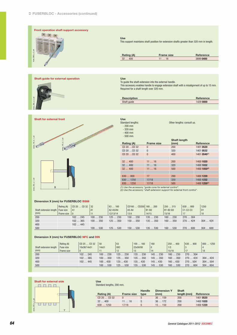
64 General Catalogue 2011-2012 SOCOMEC64
Shaft guide for external operation
acce
s_26
0_a_
2_ca
t
UseTo guide the shaft extension into the external handle.This accessory enables handle to engage extension shaft with a misalignment of up to 15 mm.Required for a shaft length over 320 mm.
Description ReferenceShaft guide 1429 0000
FUSERBLOC - Accessories (continued)
Shaft for external front
X
acce
s_20
2_a_
1_ca
t
acce
s_14
3_b_
1_ca
t
acce
s_14
5_b_
1_ca
t
UseStandard lengths:
- 200 mm- 320 mm- 400 mm- 500 mm.
Other lengths: consult us.
Rating (A) Frame sizeShaft length (mm) Reference
CD 20 …CD 32 0 200 1401 0520CD 20 …CD 32 0 320 1401 0532CD 20 …CD 32 0 400 1401 0540(1)
32 … 400 11 … 16 200 1400 102032 … 400 11 … 16 320 1400 103232 … 400 11 … 16 500 1400 1050(2)
630 … 800 17 200 1400 1220630 … 1250 17/18 320 1400 1232630 … 1250 17/18 500 1400 1250(1)
(1) Use the accessory "guide cone for external control".(2) Use the accessory "shaft extension support for external front control".
Dimension X (mm) for FUSERBLOC NFC and DIN
Rating (A) CD 25 … CD 32 50 63 100 … 160 160 250 … 400 630 … 800 800 … 1250Shaft extension length (mm)
Fuse size 10x38/14x51 14x51 00C 22x58/00 0 1/2 3 4Frame size 0 11 12 13 14 15/16 17 18
200 102 … 245 100 … 230 125 … 230 135 … 230 145 … 230 160 … 230 270 … 304320 102 … 365 100 … 350 125 … 350 135 … 350 145 … 350 160 … 350 270 … 424 304 ... 424400 102 … 445 100 ... 430 125 ... 430 135 ... 430 145 ... 430 160 ... 430 270 ... 504 304 ... 504500 100 … 530 125 … 530 135 … 530 145 … 530 160 … 530 270 … 604 304 ... 604
Dimension X (mm) for FUSERBLOC BS88
Rating (A) CD 20 … CD 32 32 63 … 160 CD160 … CD200 160 … 200 250 … 315 630 … 800 1250Shaft extension length (mm)
Fuse size A1 A1 A2-A3/A4 A3-A4 B1-B2 B1-B2-B3 C1-C2-C3 D1Frame size 0 11 12/13/14 13 A 14/15 15/16 17 18
200 102 … 245 100 … 230 125 … 230 150 … 230 135 … 230 160 … 230 270 … 304320 102 … 365 100 … 350 125 … 350 150 … 350 135 … 350 160 … 350 270 … 424 304 … 424400 102 … 445500 100 … 530 125 … 530 150 … 530 135 … 530 160 … 530 270 … 600 304 … 600
Shaft for external side
Yacce
s_20
3_a_
1_ca
t
UseStandard lengths, 200 mm.
Rating (A) Frame sizeHandletype
Dimension Y (mm)
Shaftlength (mm) Reference
CD 20 … CD 32 0 S 36 … 159 200 1401 052032 … 400 11 … 16 S 36 … 172 200 1400 1020630 … 1250 17/18 S 15 … 150 200 1400 1220
Front operation shaft support accessoryfu
ser_
698_
a_2_
cat
UseThis support maintains shaft position for extension shafts greater than 320 mm in length.
Rating (A) Frame size Reference32 … 400 11 … 16 3899 0400
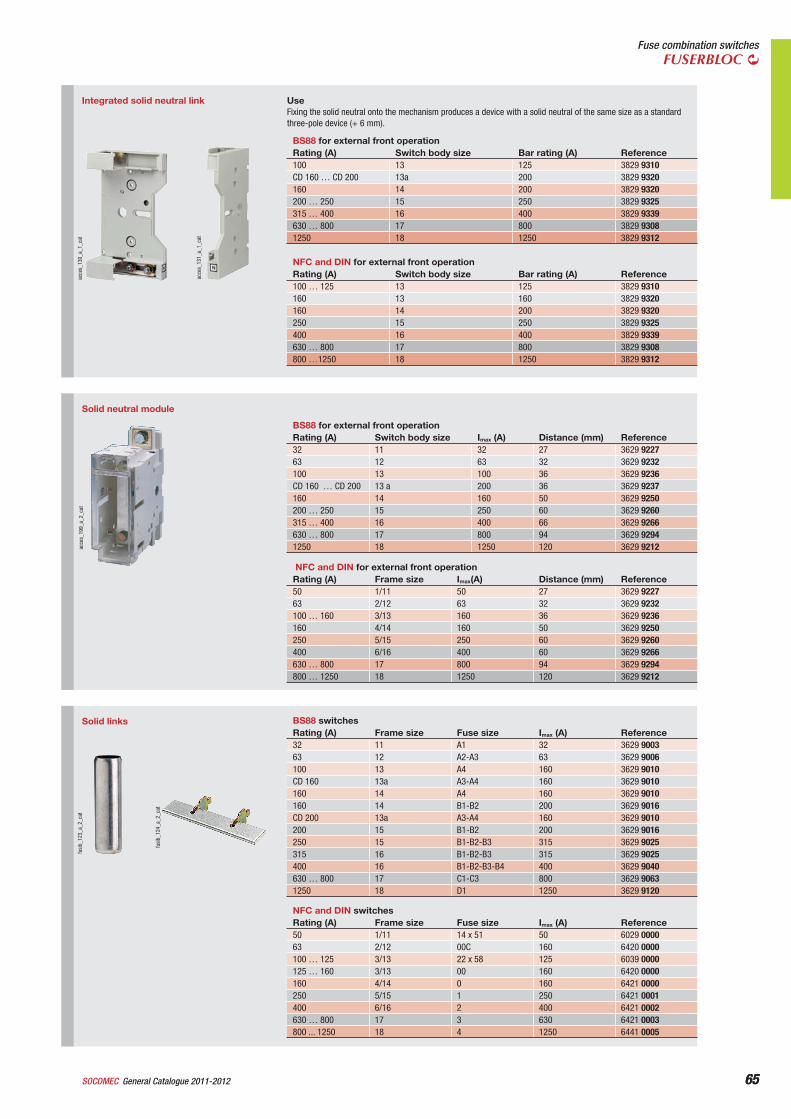
65General Catalogue 2011-2012SOCOMEC 65
Fuse combination switchesFUSERBLOC
Integrated solid neutral link
acce
s_13
1_a_
1_ca
t
acce
s_13
0_a_
1_ca
t
UseFixing the solid neutral onto the mechanism produces a device with a solid neutral of the same size as a standard three-pole device (+ 6 mm).
NFC and DIN for external front operationRating (A) Switch body size Bar rating (A) Reference100 … 125 13 125 3829 9310160 13 160 3829 9320160 14 200 3829 9320250 15 250 3829 9325400 16 400 3829 9339630 … 800 17 800 3829 9308800 …1250 18 1250 3829 9312
BS88 for external front operationRating (A) Switch body size Bar rating (A) Reference100 13 125 3829 9310CD 160 … CD 200 13a 200 3829 9320160 14 200 3829 9320200 … 250 15 250 3829 9325315 … 400 16 400 3829 9339630 … 800 17 800 3829 93081250 18 1250 3829 9312
Solid neutral module
acce
s_19
9_a_
2_ca
t
NFC and DIN for external front operationRating (A) Frame size Imax(A) Distance (mm) Reference50 1/11 50 27 3629 922763 2/12 63 32 3629 9232100 … 160 3/13 160 36 3629 9236160 4/14 160 50 3629 9250250 5/15 250 60 3629 9260400 6/16 400 60 3629 9266630 … 800 17 800 94 3629 9294800 … 1250 18 1250 120 3629 9212
BS88 for external front operationRating (A) Switch body size Imax (A) Distance (mm) Reference32 11 32 27 3629 922763 12 63 32 3629 9232100 13 100 36 3629 9236CD 160 … CD 200 13 a 200 36 3629 9237160 14 160 50 3629 9250200 … 250 15 250 60 3629 9260315 … 400 16 400 66 3629 9266630 … 800 17 800 94 3629 92941250 18 1250 120 3629 9212
Solid links
fusi
b_12
4_a_
2_ca
t
fusi
b_12
3_a_
2_ca
t
NFC and DIN switchesRating (A) Frame size Fuse size Imax (A) Reference50 1/11 14 x 51 50 6029 000063 2/12 00C 160 6420 0000100 … 125 3/13 22 x 58 125 6039 0000125 … 160 3/13 00 160 6420 0000160 4/14 0 160 6421 0000250 5/15 1 250 6421 0001400 6/16 2 400 6421 0002630 … 800 17 3 630 6421 0003800 ... 1250 18 4 1250 6441 0005
BS88 switchesRating (A) Frame size Fuse size Imax (A) Reference32 11 A1 32 3629 900363 12 A2-A3 63 3629 9006100 13 A4 160 3629 9010CD 160 13a A3-A4 160 3629 9010160 14 A4 160 3629 9010160 14 B1-B2 200 3629 9016CD 200 13a A3-A4 160 3629 9010200 15 B1-B2 200 3629 9016250 15 B1-B2-B3 315 3629 9025315 16 B1-B2-B3 315 3629 9025400 16 B1-B2-B3-B4 400 3629 9040630 … 800 17 C1-C3 800 3629 90631250 18 D1 1250 3629 9120
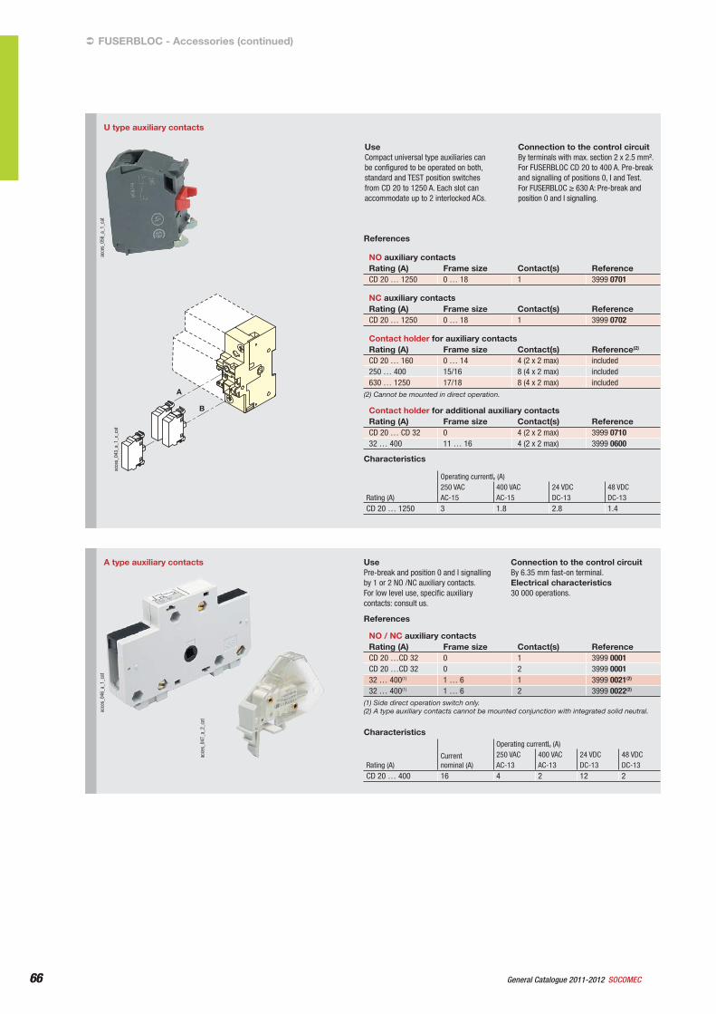
66 General Catalogue 2011-2012 SOCOMEC66
U type auxiliary contacts
A
B
acce
s_05
6_a_
1_ca
t
acce
s_04
3_a_
1_x_
cat
UseCompact universal type auxiliaries can be configured to be operated on both, standard and TEST position switches from CD 20 to 1250 A. Each slot can accommodate up to 2 interlocked ACs.
Connection to the control circuitBy terminals with max. section 2 x 2.5 mm².For FUSERBLOC CD 20 to 400 A. Pre-break and signalling of positions 0, I and Test.For FUSERBLOC 630 A: Pre-break and position 0 and I signalling.
References
NO auxiliary contactsRating (A) Frame size Contact(s) ReferenceCD 20 … 1250 0 … 18 1 3999 0701
NC auxiliary contactsRating (A) Frame size Contact(s) ReferenceCD 20 … 1250 0 … 18 1 3999 0702
Contact holder for auxiliary contactsRating (A) Frame size Contact(s) Reference(2)
CD 20 … 160 0 … 14 4 (2 x 2 max) included250 … 400 15/16 8 (4 x 2 max) included630 … 1250 17/18 8 (4 x 2 max) included
(2) Cannot be mounted in direct operation.
Contact holder for additional auxiliary contactsRating (A) Frame size Contact(s) ReferenceCD 20 … CD 32 0 4 (2 x 2 max) 3999 071032 … 400 11 … 16 4 (2 x 2 max) 3999 0600
Characteristics
Operating currentIe (A)250 VAC 400 VAC 24 VDC 48 VDC
Rating (A) AC-15 AC-15 DC-13 DC-13CD 20 … 1250 3 1.8 2.8 1.4
A type auxiliary contacts
acce
s_04
6_a_
1_ca
t
acce
s_04
7_a_
2_ca
t
UsePre-break and position 0 and I signalling by 1 or 2 NO /NC auxiliary contacts.For low level use, specific auxiliary contacts: consult us.
Connection to the control circuitBy 6.35 mm fast-on terminal.Electrical characteristics30 000 operations.
References
NO / NC auxiliary contactsRating (A) Frame size Contact(s) ReferenceCD 20 …CD 32 0 1 3999 0001CD 20 …CD 32 0 2 3999 000132 … 400(1) 1 … 6 1 3999 0021(2)
32 … 400(1) 1 … 6 2 3999 0022(2)
(1) Side direct operation switch only.(2) A type auxiliary contacts cannot be mounted conjunction with integrated solid neutral.
Characteristics
Rating (A)Currentnominal (A)
Operating currentIe (A)250 VAC 400 VAC 24 VDC 48 VDCAC-13 AC-13 DC-13 DC-13
CD 20 … 400 16 4 2 12 2
FUSERBLOC - Accessories (continued)
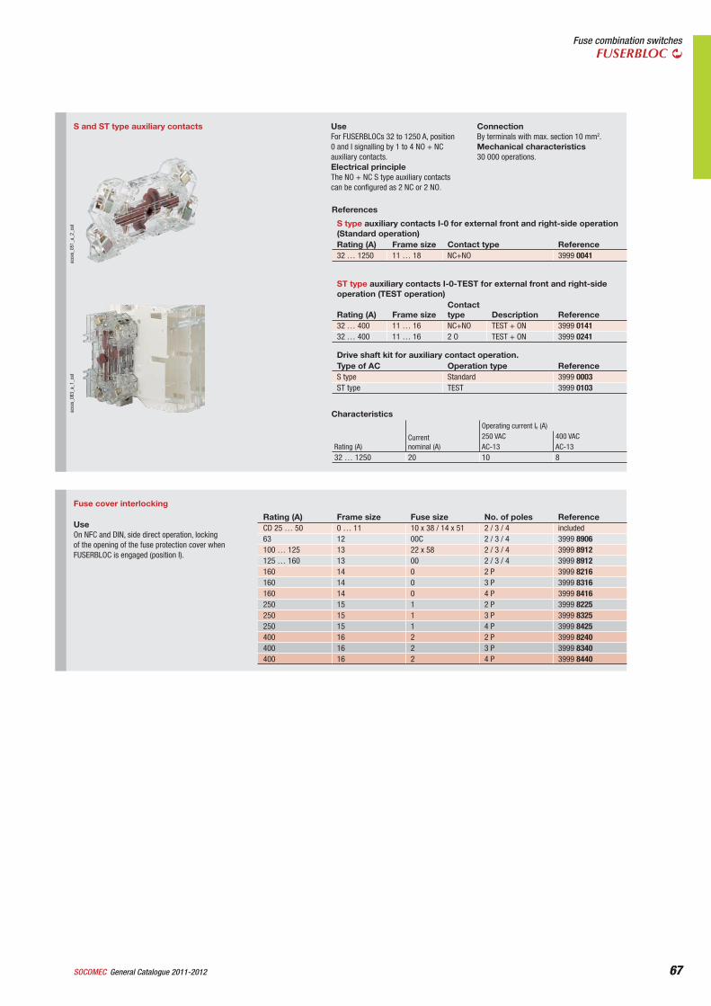
67General Catalogue 2011-2012SOCOMEC 67
Fuse combination switchesFUSERBLOC
S and ST type auxiliary contacts
acce
s_05
1_a_
2_ca
tac
ces_
083_
a_1_
cat
UseFor FUSERBLOCs 32 to 1250 A, position 0 and I signalling by 1 to 4 NO + NC auxiliary contacts.Electrical principleThe NO + NC S type auxiliary contacts can be configured as 2 NC or 2 NO.
ConnectionBy terminals with max. section 10 mm2.Mechanical characteristics30 000 operations.
References
S type auxiliary contacts I-0 for external front and right-side operation (Standard operation)Rating (A) Frame size Contact type Reference32 … 1250 11 … 18 NC+NO 3999 0041
ST type auxiliary contacts I-0-TEST for external front and right-side operation (TEST operation)
Rating (A) Frame sizeContacttype Description Reference
32 … 400 11 … 16 NC+NO TEST + ON 3999 014132 … 400 11 … 16 2 O TEST + ON 3999 0241
Drive shaft kit for auxiliary contact operation.Type of AC Operation type ReferenceS type Standard 3999 0003ST type TEST 3999 0103
Characteristics
Rating (A)Currentnominal (A)
Operating current Ie (A)250 VAC 400 VACAC-13 AC-13
32 … 1250 20 10 8
Fuse cover interlocking
UseOn NFC and DIN, side direct operation, locking of the opening of the fuse protection cover when FUSERBLOC is engaged (position I).
Rating (A) Frame size Fuse size No. of poles ReferenceCD 25 … 50 0 … 11 10 x 38 / 14 x 51 2 / 3 / 4 included63 12 00C 2 / 3 / 4 3999 8906100 … 125 13 22 x 58 2 / 3 / 4 3999 8912125 … 160 13 00 2 / 3 / 4 3999 8912160 14 0 2 P 3999 8216160 14 0 3 P 3999 8316160 14 0 4 P 3999 8416250 15 1 2 P 3999 8225250 15 1 3 P 3999 8325250 15 1 4 P 3999 8425400 16 2 2 P 3999 8240400 16 2 3 P 3999 8340400 16 2 4 P 3999 8440
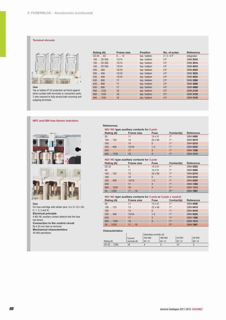
68 General Catalogue 2011-2012 SOCOMEC68
NFC and DIN fuse blowm indication
fuse
r_31
2_a_
1_ca
tfu
ser_
311_
a_1_
cat
UseFor fuse cartridge with striker (size 14 x 51 22 x 58; 0; 1; 2; 3 and 4).Electrical principleA NO/ NC auxiliary contact detects that the fuse has blown.Connection to the control circuitBy 6.35 mm fast-on terminal.Mechanical characteristics30 000 operations.
ReferencesNO/ NC type auxiliary contacts for 2 poleRating (A) Frame size Fuse Contact(s) Reference50 11 14 x 51 1st 3994 0405100 … 125 13 22 x 58 1st 3994 0210160 14 0 1st 3994 0216250 … 400 15/16 1-2 1st 3994 0225630 17 3 1st 3894 1206800 … 1250 18 4 1st 3894 1212
NO/ NC type auxiliary contacts for 3 poleRating (A) Frame size Fuse Contact(s) ReferenceCD 32 0 14 x 51 1st 3994 030350 11 14 x 51 1st 3994 0405100 … 125 13 22 x 58 1st 3994 0310160 14 0 1st 3994 0316250 … 400 15/16 1-2 1st 3994 0325630 17 3 1st 3894 1306800 … 1250 18 4 1st 3894 131250 … 1250 11 … 18 2nd 3994 1901
NO/ NC type auxiliary contacts for 4 pole or 3 pole + neutralRating (A) Frame size Fuse Contact(s) Reference50 11 14 x 51 1st 3994 0405100 … 125 13 22 x 58 1st 3994 0410160 14 0 1st 3994 0416250 … 400 15/16 1-2 1st 3994 0425630 17 3 1st 3894 1406800 … 1250 18 4 1st 3894 141250 … 1250 11 … 18 2nd 3994 1901
Characteristics
Rating (A)Currentnominal (A)
Operating currentIe (A)250 VAC 400 VAC 24 VDC 48 VDCAC-13 AC-13 DC-13 DC-13
CD 32 ... 1250 16 4 3 12 2
FUSERBLOC - Accessories (continued)
Terminal shrouds
fuse
r_31
4_a_
1_ca
t
UseTop or bottom IP 20 protection (at front) against direct contact with terminals or connection parts.2 sets required to fully shroud both incoming and outgoing terminals.
Rating (A) Frame size Position No. of poles ReferenceCD 20 … 63 0 … 12 top / bottom 2 / 3 / 4 P integrated100 … CD 200 13/14 top / bottom 2 P 3998 2016100 … CD 200 13/14 top / bottom 3 P 3998 3016100 … CD 200 13/14 top / bottom 4 P 3998 4016200 … 400 15/16 top / bottom 2 P 3998 2025200 … 400 15/16 top / bottom 3 P 3998 3025200 … 400 15/16 top / bottom 4 P 3998 4025630 … 800 17 top / bottom 2 P 3898 2080630 … 800 17 top / bottom 3 P 3898 3080630 … 800 17 top / bottom 4 P 3898 4080800 … 1250 18 top / bottom 2 P 3898 2120800 … 1250 18 top / bottom 3 P 3898 3120800 … 1250 18 top / bottom 4 P 3898 4120
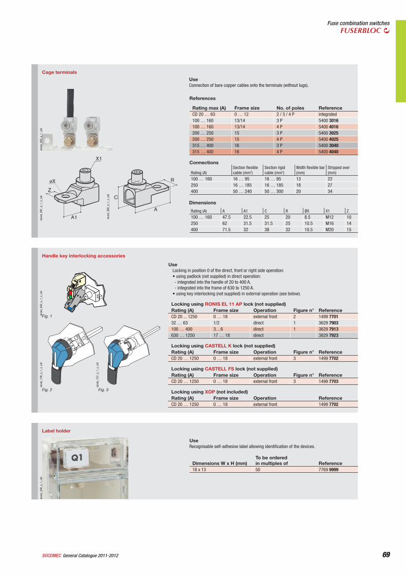
69General Catalogue 2011-2012SOCOMEC 69
Fuse combination switchesFUSERBLOC
Label holder
acce
s_04
4_a_
1_ca
t
UseRecognisable self-adhesive label allowing identification of the devices.
Dimensions W x H (mm)To be orderedin multiples of Reference
18 x 13 50 7769 9999
Handle key interlocking accessories
acce
s_15
7_a_
1_x_
cat
Fig. 3
acce
s_15
8_a_
1_x_
cat
Fig. 2
acce
s_04
2_a_
1_x_
cat
Fig. 1
UseLocking in position 0 of the direct, front or right side operation:• using padlock (not supplied) in direct operation:- integrated into the handle of 20 to 400 A,- integrated into the frame of 630 to 1250 A.
• using key interlocking (not supplied) in external operation (see below).
Locking using RONIS EL 11 AP lock (not supplied)Rating (A) Frame size Operation Figure n° ReferenceCD 20 ... 1250 0 … 18 external front 2 1499 770132 … 63 1/2 direct 1 3629 7903100 … 400 3…6 direct 1 3629 7913630 … 1250 17 … 18 direct 3829 7923
Locking using CASTELL K lock (not supplied)Rating (A) Frame size Operation Figure n° ReferenceCD 20 … 1250 0 … 18 external front 3 1499 7702
Locking using CASTELL FS lock (not supplied)Rating (A) Frame size Operation Figure n° ReferenceCD 20 … 1250 0 … 18 external front 3 1499 7703
Locking using XOP (not included)Rating (A) Frame size Operation ReferenceCD 20 … 1250 0 … 18 external front 1499 7702
Cage terminals
A1
X1
øX
ZC
A
R
acce
s_09
2_a_
1_x_
cat
acce
s_09
1_a_
1_x_
cat
acce
s_05
3_a_
1_ca
t
UseConnection of bare copper cables onto the terminals (without lugs).
References
Rating max (A) Frame size No. of poles ReferenceCD 20 … 63 0 … 12 2 / 3 / 4 P integrated100 … 160 13/14 3 P 5400 3016100 … 160 13/14 4 P 5400 4016200 … 250 15 3 P 5400 3025200 … 250 15 4 P 5400 4025315 … 400 16 3 P 5400 3040315 … 400 16 4 P 5400 4040
Connections
Rating (A)Section flexible cable (mm2)
Section rigid cable (mm2)
Width flexible bar (mm)
Stripped over (mm)
100 … 160 16 … 95 16 … 95 13 22250 16 … 185 16 … 185 18 27400 50 … 240 50 … 300 20 34
Dimensions
Rating (A) A A1 C R ØX X1 Z100 … 160 47.5 22.5 25 20 8.5 M12 10250 62 31.5 31.5 25 10.5 M16 14400 71.5 32 38 32 10.5 M20 15
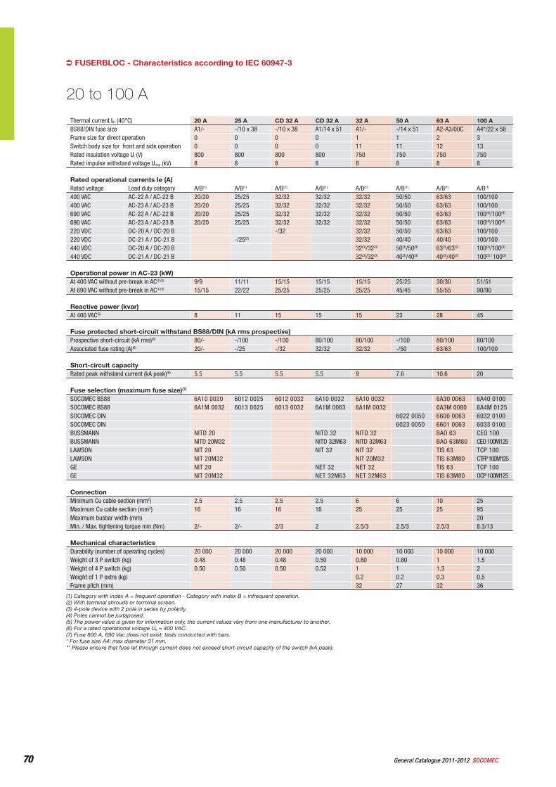
70 General Catalogue 2011-2012 SOCOMEC70
FUSERBLOC - Characteristics according to IEC 60947-3
Thermal current Ith (40°C) 20 A 25 A CD 32 A CD 32 A 32 A 50 A 63 A 100 ABS88/DIN fuse size A1/- -/10 x 38 -/10 x 38 A1/14 x 51 A1/- -/14 x 51 A2-A3/00C A4*/22 x 58Frame size for direct operation 0 0 0 0 1 1 2 3Switch body size for front and side operation 0 0 0 0 11 11 12 13Rated insulation voltage Ui (V) 800 800 800 800 750 750 750 750Rated impulse withstand voltage Uimp (kV) 8 8 8 8 8 8 8 8
Rated operational currents Ie (A) Rated voltage Load duty category A/B(1) A/B(1) A/B(1) A/B(1) A/B(1) A/B(1) A/B(1) A/B(1)
400 VAC AC-22 A / AC-22 B 20/20 25/25 32/32 32/32 32/32 50/50 63/63 100/100400 VAC AC-23 A / AC-23 B 20/20 25/25 32/32 32/32 32/32 50/50 63/63 100/100690 VAC AC-22 A / AC-22 B 20/20 25/25 32/32 32/32 32/32 50/50 63/63 100(4)/100(4)
690 VAC AC-23 A / AC-23 B 20/20 25/25 32/32 32/32 32/32 50/50 63/63 100(4)/100(4)
220 VDC DC-20 A / DC-20 B -/32 32/32 50/50 63/63 100/100220 VDC DC-21 A / DC-21 B -/25(2) 32/32 40/40 40/40 100/100440 VDC DC-20 A / DC-20 B 32(3)/32(3) 50(3)/50(3) 63(3)/63(3) 100(3)/100(3)
440 VDC DC-21 A / DC-21 B 32(3)/32(3) 40(3)/40(3) 40(3)/40(3) 100(3) / 100(3)
Operational power in AC-23 (kW) At 400 VAC without pre-break in AC(1)(5) 9/9 11/11 15/15 15/15 15/15 25/25 30/30 51/51At 690 VAC without pre-break in AC(1)(5) 15/15 22/22 25/25 25/25 25/25 45/45 55/55 90/90
Reactive power (kvar) At 400 VAC(5) 8 11 15 15 15 23 28 45
Fuse protected short-circuit withstand BS88/DIN (kA rms prospective)Prospective short-circuit (kA rms)(6) 80/- -/100 -/100 80/100 80/100 -/100 80/100 80/100Associated fuse rating (A)(6) 20/- -/25 -/32 32/32 32/32 -/50 63/63 100/100
Short-circuit capacityRated peak withstand current (kA peak)(6) 5.5 5.5 5.5 5.5 9 7.6 10.6 20
Fuse selection (maximum fuse size)(7)
SOCOMEC BS88 6A10 0020 6012 0025 6012 0032 6A10 0032 6A10 0032 6A30 0063 6A40 0100SOCOMEC BS88 6A1M 0032 6013 0025 6013 0032 6A1M 0063 6A1M 0032 6A3M 0080 6A4M 0125SOCOMEC DIN 6022 0050 6600 0063 6032 0100SOCOMEC DIN 6023 0050 6601 0063 6033 0100BUSSMANN NITD 20 NITD 32 NITD 32 BAO 63 CEO 100BUSSMANN NITD 20M32 NITD 32M63 NITD 32M63 BAO 63M80 CEO 100M125LAWSON NIT 20 NIT 32 NIT 32 TIS 63 TCP 100LAWSON NIT 20M32 NIT 20M32 TIS 63M80 CTFP 100M125GE NIT 20 NET 32 NET 32 TIS 63 TCP 100GE NIT 20M32 NET 32M63 NET 32M63 TIS 63M80 OCP 100M125
ConnectionMinimum Cu cable section (mm2) 2.5 2.5 2.5 2.5 6 6 10 25Maximum Cu cable section (mm2) 16 16 16 16 25 25 25 95Maximum busbar width (mm) 20Min. / Max. tightening torque min (Nm) 2/- 2/- 2/3 2 2.5/3 2.5/3 2.5/3 8.3/13
Mechanical characteristicsDurability (number of operating cycles) 20 000 20 000 20 000 20 000 10 000 10 000 10 000 10 000Weight of 3 P switch (kg) 0.48 0.48 0.48 0.50 0.80 0.80 1 1.5Weight of 4 P switch (kg) 0.50 0.50 0.50 0.52 1 1 1.3 2Weight of 1 P extra (kg) 0.2 0.2 0.3 0.5Frame pitch (mm) 32 27 32 36
20 to 100 A
(1) Category with index A = frequent operation - Category with index B = infrequent operation.(2) With terminal shrouds or terminal screen.(3) 4-pole device with 2 pole in series by polarity.(4) Poles cannot be juxtaposed.(5) The power value is given for information only, the current values vary from one manufacturer to another.(6) For a rated operational voltage Ue = 400 VAC.(7) Fuse 800 A, 690 Vac does not exist, tests conducted with bars.* For fuse size A4: max diameter 31 mm.** Please ensure that fuse let through current does not exceed short-circuit capacity of the switch (kA peak).
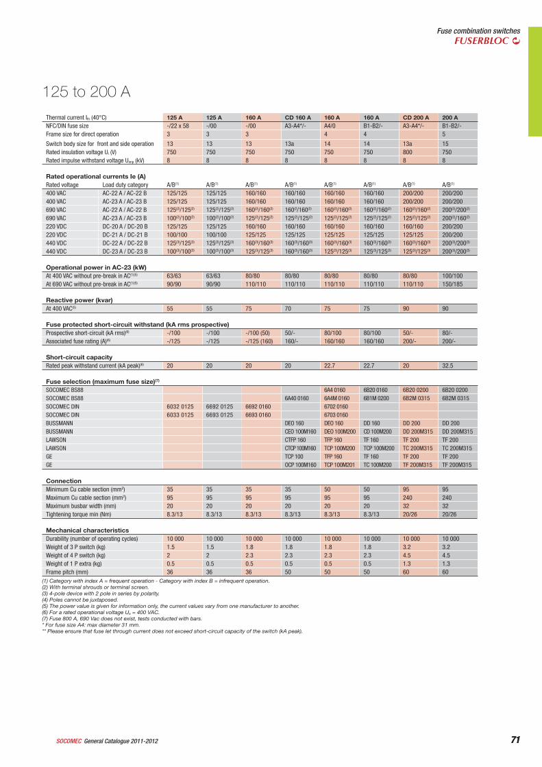
71General Catalogue 2011-2012SOCOMEC 71
Fuse combination switchesFUSERBLOC
Thermal current Ith (40°C) 125 A 125 A 160 A CD 160 A 160 A 160 A CD 200 A 200 ANFC/DIN fuse size -/22 x 58 -/00 -/00 A3-A4*/- A4/0 B1-B2/- A3-A4*/- B1-B2/-Frame size for direct operation 3 3 3 4 4 5
Switch body size for front and side operation 13 13 13 13a 14 14 13a 15Rated insulation voltage Ui (V) 750 750 750 750 750 750 800 750Rated impulse withstand voltage Uimp (kV) 8 8 8 8 8 8 8 8
Rated operational currents Ie (A)Rated voltage Load duty category A/B(1) A/B(1) A/B(1) A/B(1) A/B(1) A/B(1) A/B(1) A/B(1)
400 VAC AC-22 A / AC-22 B 125/125 125/125 160/160 160/160 160/160 160/160 200/200 200/200400 VAC AC-23 A / AC-23 B 125/125 125/125 160/160 160/160 160/160 160/160 200/200 200/200690 VAC AC-22 A / AC-22 B 125(2)/125(2) 125(2)/125(2) 160(2)/160(2) 160(2/160(2) 160(2)/160(2) 160(2)/160(2) 160(2)/160(2) 200(2)/200(2)
690 VAC AC-23 A / AC-23 B 100(2)/100(2) 100(2)/100(2) 125(2)/125(2) 125(2)/125(2) 125(2)/125(2) 125(2)/125(2) 125(2)/125(2) 200(2)/160(2)
220 VDC DC-20 A / DC-20 B 125/125 125/125 160/160 160/160 160/160 160/160 160/160 200/200220 VDC DC-21 A / DC-21 B 100/100 100/100 125/125 125/125 125/125 125/125 125/125 200/200440 VDC DC-22 A / DC-22 B 125(3)/125(3) 125(3)/125(3) 160(3)/160(3) 160(3)/160(3) 160(3)/160(3) 160(3)/160(3) 160(3)/160(3) 200(3)/200(3)
440 VDC DC-23 A / DC-23 B 100(3)/100(3) 100(3)/100(3) 125(3)/125(3) 160(3)/160(3) 125(3)/125(3) 125(3)/125(3) 125(3)/125(3) 200(3)/200(3)
Operational power in AC-23 (kW) At 400 VAC without pre-break in AC(1)(5) 63/63 63/63 80/80 80/80 80/80 80/80 80/80 100/100At 690 VAC without pre-break in AC(1)(5) 90/90 90/90 110/110 110/110 110/110 110/110 110/110 150/185
Reactive power (kvar) At 400 VAC(5) 55 55 75 70 75 75 90 90
Fuse protected short-circuit withstand (kA rms prospective)Prospective short-circuit (kA rms)(6) -/100 -/100 -/100 (50) 50/- 80/100 80/100 50/- 80/-Associated fuse rating (A)(6) -/125 -/125 -/125 (160) 160/- 160/160 160/160 200/- 200/-
Short-circuit capacityRated peak withstand current (kA peak)(6) 20 20 20 20 22.7 22.7 20 32.5
Fuse selection (maximum fuse size)(7)
SOCOMEC BS88 6A4 0160 6B20 0160 6B20 0200 6B20 0200SOCOMEC BS88 6A40 0160 6A4M 0160 6B1M 0200 6B2M 0315 6B2M 0315SOCOMEC DIN 6032 0125 6692 0125 6692 0160 6702 0160SOCOMEC DIN 6033 0125 6693 0125 6693 0160 6703 0160BUSSMANN DEO 160 DEO 160 DD 160 DD 200 DD 200BUSSMANN CEO 100M160 DEO 100M200 CD 100M200 DD 200M315 DD 200M315LAWSON CTFP 160 TFP 160 TF 160 TF 200 TF 200LAWSON CTCP 100M160 TCP 100M200 TCP 100M200 TC 200M315 TC 200M315GE TCP 100 TFP 160 TF 160 TF 200 TF 200GE OCP 100M160 TCP 100M201 TC 100M200 TF 200M315 TF 200M315
ConnectionMinimum Cu cable section (mm2) 35 35 35 35 50 50 95 95Maximum Cu cable section (mm2) 95 95 95 95 95 95 240 240Maximum busbar width (mm) 20 20 20 20 20 20 32 32Tightening torque min (Nm) 8.3/13 8.3/13 8.3/13 8.3/13 8.3/13 8.3/13 20/26 20/26
Mechanical characteristicsDurability (number of operating cycles) 10 000 10 000 10 000 10 000 10 000 10 000 10 000 10 000Weight of 3 P switch (kg) 1.5 1.5 1.8 1.8 1.8 1.8 3.2 3.2Weight of 4 P switch (kg) 2 2 2.3 2.3 2.3 2.3 4.5 4.5Weight of 1 P extra (kg) 0.5 0.5 0.5 0.5 0.5 0.5 1.3 1.3Frame pitch (mm) 36 36 36 50 50 50 60 60
125 to 200 A
(1) Category with index A = frequent operation - Category with index B = infrequent operation.(2) With terminal shrouds or terminal screen.(3) 4-pole device with 2 pole in series by polarity.(4) Poles cannot be juxtaposed.(5) The power value is given for information only, the current values vary from one manufacturer to another.(6) For a rated operational voltage Ue = 400 VAC.(7) Fuse 800 A, 690 Vac does not exist, tests conducted with bars.* For fuse size A4: max diameter 31 mm.** Please ensure that fuse let through current does not exceed short-circuit capacity of the switch (kA peak).
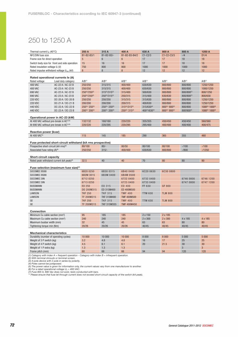
72 General Catalogue 2011-2012 SOCOMEC72
Thermal current Ith (40°C) 250 A 315 A 400 A 630 A 800 A 800 A 1250 ANFC/DIN fuse size B1-B2-B3/1 B1-B2-B3/- B1-B2-B3-B4/2 C1-C2/3 C1-C2-C3/3 -/4 D1/4Frame size for direct operation 5 6 6 17 17 18 18
Switch body size for front and side operation 15 16 16 17 17 18 18Rated insulation voltage Ui (V) 750 800 800 1000 1000 1000 1000Rated impulse withstand voltage Uimp (kV) 8 8 8 12 12 12 12
Rated operational currents Ie (A)Rated voltage Load duty category A/B(1) A/B(1) A/B(1) A/B(1) A/B(1) A/B(1) A/B(1)
400 VAC AC-22 A / AC-22 B 250/250 315/315 400/400 630/630 800/800 800/800 1250/1250400 VAC AC-23 A / AC-23 B 250/250 315/315 400/400 630/630 800/800 800/800 1000/1250690 VAC AC-22 A / AC-22 B 250(2)/250(2) 315(2)/315(2) 315/400 500/630 800/800 800/800(7) 800/1250690 VAC AC-23 A / AC-23 B 250(2)/250(2) 250(2)/315(2) 250/315 315/400 630/630 800/800(7) 800/630220 VDC DC-20 A / DC-20 B 250/250 250/250 315/315 315/630 800/800 800/800 1250/1250220 VDC DC-21 A / DC-21 B 200/200 200/200 200/315 400/630 800/800 800/800 1250/1250440 VDC DC-22 A / DC-22 B 250(3) / 250(3) 250(3) / 250(3) 315(4)/315(4) 315/630(4) 800(3) / 800(3) 800/800 1000(3) / 1000(3)
440 VDC DC-23 A / DC-23 B 200(3) / 200(3) 200(3) / 200(3) 250(4) / 315(4) 400(4)/630(4) 800(3) / 800(3) 800/800(3) 1000(3) / 1000(3)
Operational power in AC-23 (kW) At 400 VAC without pre-break in AC(1)(5) 132/132 160/160 220/220 355/355 450/450 450/450 560/560At 690 VAC without pre-break in AC(1)(5) 220/220 220/295 220/295 295/400 400/400 400/400 400/475
Reactive power (kvar) At 400 VAC(5) 115 145 185 290 365 355 460
Fuse protected short-circuit withstand (kA rms prospective)Prospective short-circuit (kA rms)(6) 80/100 80/- 80/50 80/100 80/100 -/100 -/100Associated fuse rating (A)(6) 250/250 315/- 400/400 630/630 800/800 -/800 -/1250
Short-circuit capacityRated peak withstand current (kA peak)(6) 32.5 40 40 70 80 80 90
Fuse selection (maximum fuse size)(7)
SOCOMEC BS88 6B20 0250 6B30 0315 6B40 0400 6C20 0630 6C30 0800SOCOMEC BS88 6B2M 3015 6B3M 0400 6B4M 0500SOCOMEC DIN 6712 0250 6722 0400 6732 0400 6746 0800 6746 1200SOCOMEC DIN 6713 0250 6723 0400 6733 0400 6747 0800 6747 1200BUSSMANN ED 250 ED 315 ED 400 FF 630 GF 800BUSSMANN DD 200M315 ED 315M400 ED 400M500LAWSON TKF 250 TKF 315 TMF 400 TTM 630 TLM 800LAWSON TF 200M315 TKF 315M400 TMF 400M500GE TKF 250 TKF 315 TMF 400 TTM 630 TLM 800GE TF 200M315 TKF 315M355 TMF 400M450
ConnectionMinimum Cu cable section (mm2) 95 185 185 2 x 150 2 x 185Maximum Cu cable section (mm2) 240 240 240 2 x 300 2 x 300 4 x 185 4 x 185Maximum busbar width (mm) 32 45 45 63 63 80 80Tightening torque min (Nm) 20/26 20/26 20/26 40/45 40/45 40/45 40/45
Mechanical characteristicsDurability (number of operating cycles) 10 000 10 000 10 000 8 000 8 000 5 000 5 000Weight of 3 P switch (kg) 3.2 4.8 4.8 16 17 25 25Weight of 4 P switch (kg) 4.5 6.1 6.1 20 21.5 30 30Weight of 1 P extra (kg) 1.3 1.3 1.3 3 3Frame pitch (mm) 60 66 66 94 94 120 120
250 to 1250 A
(1) Category with index A = frequent operation - Category with index B = infrequent operation.(2) With terminal shrouds or terminal screen.(3) 4-pole device with 2 pole in series by polarity.(4) Poles cannot be juxtaposed.(5) The power value is given for information only, the current values vary from one manufacturer to another.(6) For a rated operational voltage Ue = 400 VAC.(7) Fuse 800 A, 690 Vac does not exist, tests conducted with bars.** Please ensure that fuse let through current does not exceed short-circuit capacity of the switch (kA peak).
FUSERBLOC - Characteristics according to IEC 60947-3 (continued)
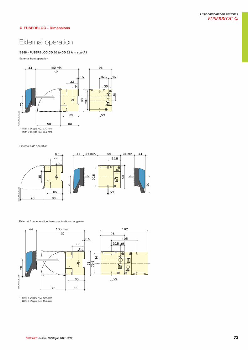
73General Catalogue 2011-2012SOCOMEC 73
Fuse combination switchesFUSERBLOC
FUSERBLOC - Dimensions
External front operation
5.265
8398
14
98 79.5
96
35
102 min.
6.5
1944
37.5 15
144
70vf
user
_292
_d_1
_x_c
at
1. With 1 U type AC: 130 mmWith 2 U type AC: 155 mm.
BS88 - FUSERBLOC CD 20 to CD 32 A in size A1
External side operation
8398
96
5.2
9879.5
36 min.44
52.5
36 min. 446.5
1944
65
45
7070
fuse
r_29
5_c_
1_x_
cat
External front operation fuse combination changeover
5.2
14
98 79.5
192
37.5 15
96
105
65
8398
105 min.44
6.5
1944
1
70fu
ser_
440_
b_1_
x_ca
t
1. With 1 U type AC: 130 mmWith 2 U type AC: 155 mm.
External operation
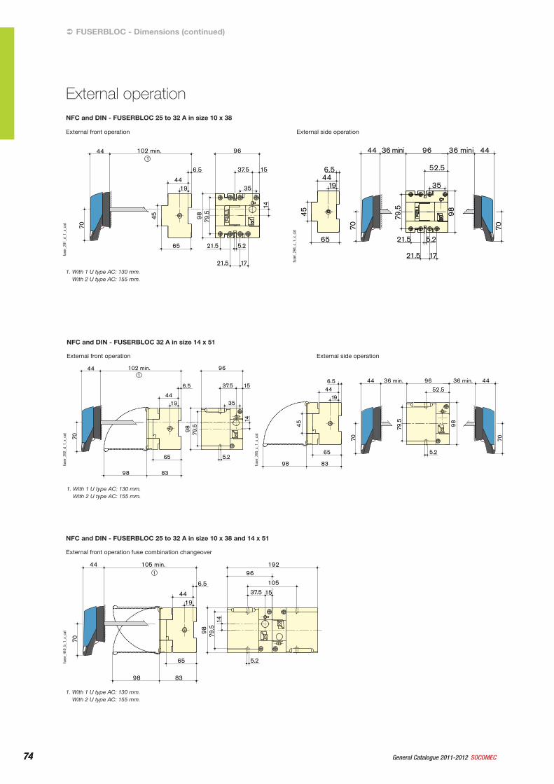
74 General Catalogue 2011-2012 SOCOMEC74
External side operation
96
1721.5
5.2
35
9879.5
21.5
36 mini44
52.5
36 mini 44
6.5
1944
65
45
7070
fuse
r_29
4_c_
1_x_
cat
External front operation
5.265
8398
14
98 79.5
96
35
102 min.
6.5
1944
37.5 15
144
70
fuse
r_29
2_d_
1_x_
cat
1. With 1 U type AC: 130 mm.With 2 U type AC: 155 mm.
NFC and DIN - FUSERBLOC 32 A in size 14 x 51
96
1721.5
5.2
35
98 79.5
21.5
102 min.
6.5
1944
65
45
14
37.5 15
144
70
fuse
r_29
1_d_
1_x_
cat
1. With 1 U type AC: 130 mm.With 2 U type AC: 155 mm.
NFC and DIN - FUSERBLOC 25 to 32 A in size 10 x 38
External side operation
8398
96
5.29879
.5
36 min.44
52.5
36 min. 446.5
1944
65
45
7070
External front operation
FUSERBLOC - Dimensions (continued)
External operation
fuse
r_29
5_c_
1_x_
cat
External front operation fuse combination changeover
5.2
14
98 79.5
192
37.5 15
96
105
65
8398
105 min.44
6.5
1944
1
70
fuse
r_44
0_b_
1_x_
cat
1. With 1 U type AC: 130 mm.With 2 U type AC: 155 mm.
NFC and DIN - FUSERBLOC 25 to 32 A in size 10 x 38 and 14 x 51
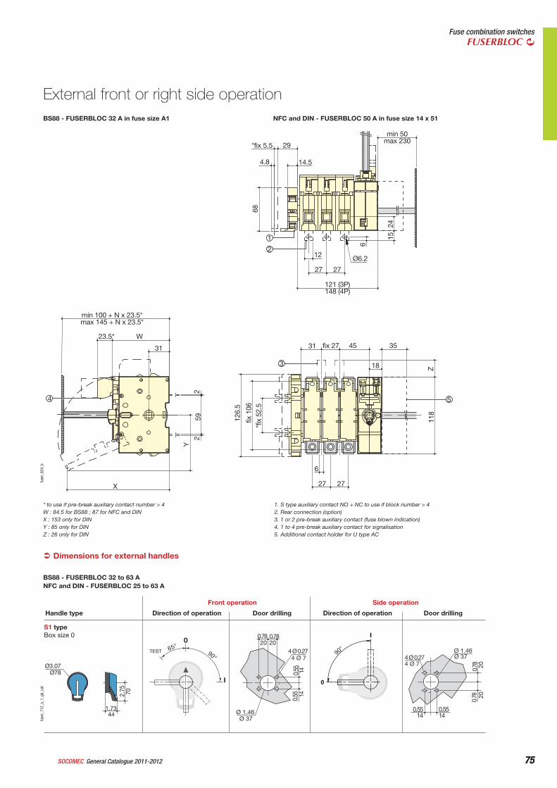
75General Catalogue 2011-2012SOCOMEC 75
Fuse combination switchesFUSERBLOC
Dimensions for external handles
S1 typeBox size 0
0
I
90°
0.78
4 Ø 0.27
0.55
Ø 1.46
Ø3.07
1.73
2.75
65°TEST 90°
I
0
Direction of operationHandle type
Front operation
Door drilling Direction of operation
Side operation
Door drilling
Ø78
70
44Ø 37
1414
4 Ø 7
2020
4 Ø 7Ø 37
2020
140.5514
0.78
Ø 1.46
0.55
0.55
4 Ø 0.27
0.780.78
fuse
r_71
2_a_
1_gb
_cat
BS88 - FUSERBLOC 32 to 63 ANFC and DIN - FUSERBLOC 25 to 63 A
68
6
Z11
8
*fix
52.
5 fix
106
126.
5
2 2
59
Y
2415
*fix 5.5 29
14.5
min 50 max 230
12
27 27
Ø6.2
31
min 100 + N x 23.5* max 145 + N x 23.5*
23.5* W
31
X
fix 27 45 35
18
6
27 27
4.8
3
54
1
2
121 (3P) 148 (4P)
fuse
r_62
4_b
BS88 - FUSERBLOC 32 A in fuse size A1 NFC and DIN - FUSERBLOC 50 A in fuse size 14 x 51
External front or right side operation
* to use if pre-break auxiliary contact number > 4W : 84.5 for BS88 ; 87 for NFC and DINX : 153 only for DINY : 85 only for DINZ : 26 only for DIN
1. S type auxiliary contact NO + NC to use if block number > 42. Rear connection (option)3. 1 or 2 pre-break auxiliary contact (fuse blown indication)4. 1 to 4 pre-break auxiliary contact for signalisation5. Additional contact holder for U type AC
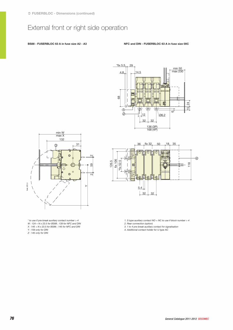
76 General Catalogue 2011-2012 SOCOMEC76
BS88 - FUSERBLOC 63 A in fuse size A2 - A3 NFC and DIN - FUSERBLOC 63 A in fuse size 00C
68
6
1511
8
*fix
52.
5 fix
106
126.
5
Y
259
2
24
*fix 5.5
4.8 14.5min 50
max 230
12
32 32
136 (3P) 168 (4P)
36
min Wmax X
132
fix 32 50 18 35
5.4
32 32
Ø6.2
29
3
12
31
4
fuse
r_62
5_b
FUSERBLOC - Dimensions (continued)
External front or right side operation
* to use if pre-break auxiliary contact number > 4W : 124 + N x 23.5 for BS88 ; 139 for NFC and DINX : 145 + N x 23.5 for BS88 ; 145 for NFC and DINY : 159 only for DINZ : 145 only for DIN
1. S type auxiliary contact NO + NC to use if block number > 42. Rear connection (option)3. 1 to 4 pre-break auxiliary contact for signalisation4. Additional contact holder for U type AC
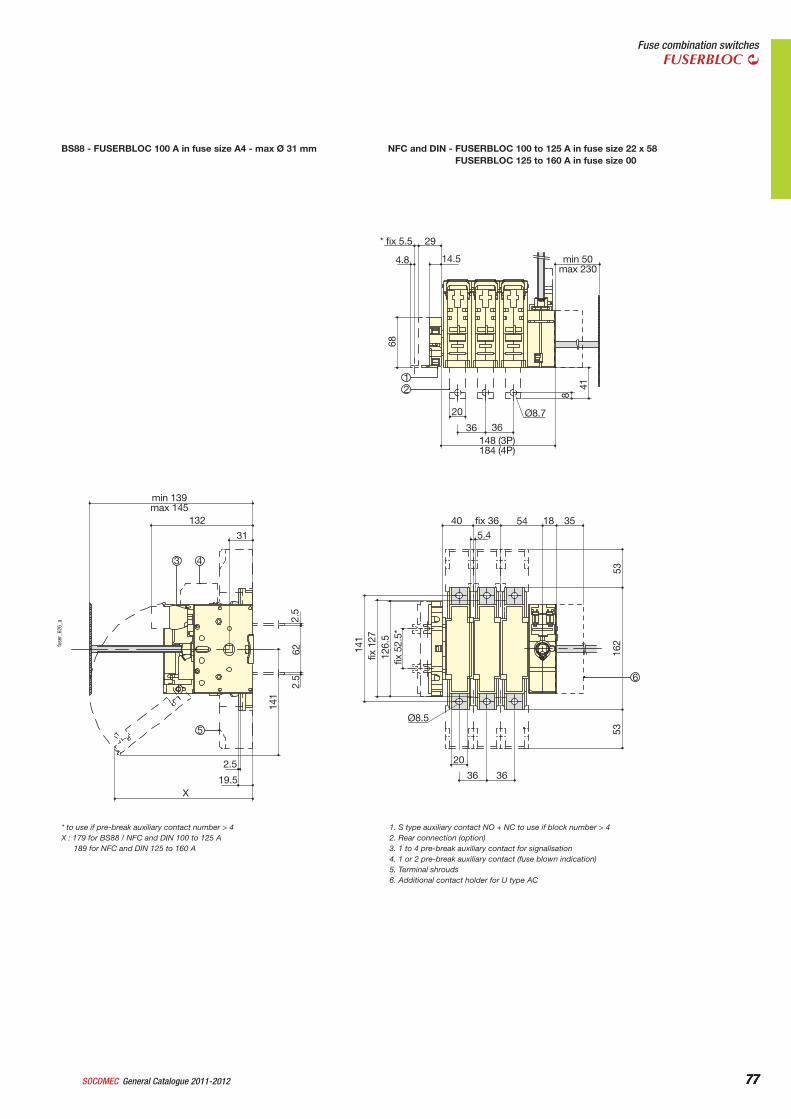
77General Catalogue 2011-2012SOCOMEC 77
Fuse combination switchesFUSERBLOC
BS88 - FUSERBLOC 100 A in fuse size A4 - max Ø 31 mm NFC and DIN - FUSERBLOC 100 to 125 A in fuse size 22 x 58FUSERBLOC 125 to 160 A in fuse size 00
* fix 5.5
20
36 36Ø8.7
148 (3P)184 (4P)
40 fix 36 545.4
20
36 36
Ø8.5
2.5
19.5X
31
132
min 139max 145
18 35
8
5353
fix 5
2.5*
126.
5fix
127
141
2.5
622.
5
141
162
41
68
4.8 14.5 min 50max 230
29
3 4
12
5
6
fuse
r_62
6_a
* to use if pre-break auxiliary contact number > 4X : 179 for BS88 / NFC and DIN 100 to 125 A
189 for NFC and DIN 125 to 160 A
1. S type auxiliary contact NO + NC to use if block number > 42. Rear connection (option)3. 1 to 4 pre-break auxiliary contact for signalisation4. 1 or 2 pre-break auxiliary contact (fuse blown indication)5. Terminal shrouds6. Additional contact holder for U type AC
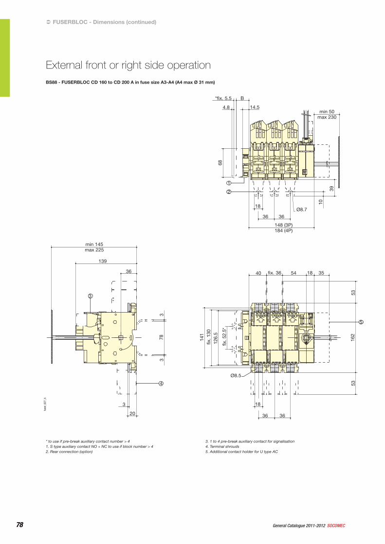
78 General Catalogue 2011-2012 SOCOMEC78
BS88 - FUSERBLOC CD 160 to CD 200 A in fuse size A3-A4 (A4 max Ø 31 mm)
*fix. 5.5 B
4.8 14.5min 50
max 230
18
40
Ø8.5
min 145 max 225
139
36
3
20
18
36 36
fix. 36 54 18 35
36 36
Ø8.7
148 (3P) 184 (4P)
68
10
5353
162
141
33
78
fix. 1
30
126.
5
fix. 5
2.5*
39
3
1
2
5
4
fuse
r_62
7_b
FUSERBLOC - Dimensions (continued)
External front or right side operation
* to use if pre-break auxiliary contact number > 41. S type auxiliary contact NO + NC to use if block number > 42. Rear connection (option)
3. 1 to 4 pre-break auxiliary contact for signalisation4. Terminal shrouds5. Additional contact holder for U type AC
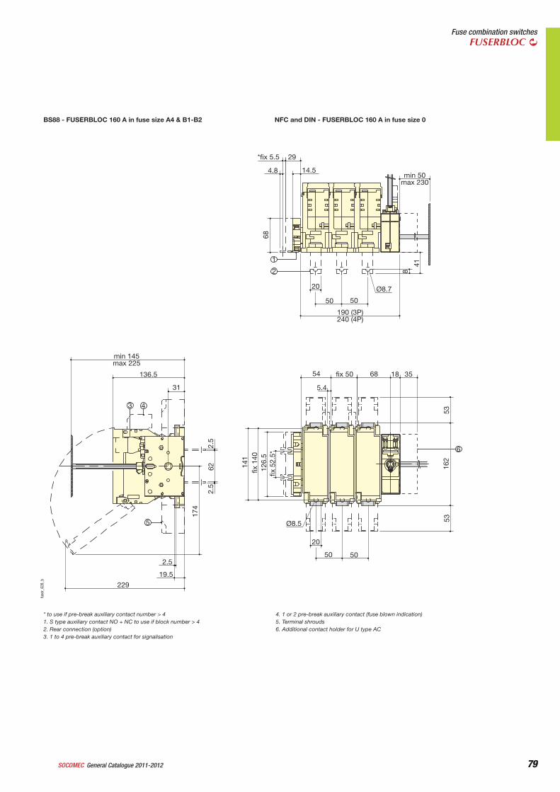
79General Catalogue 2011-2012SOCOMEC 79
Fuse combination switchesFUSERBLOC
BS88 - FUSERBLOC 160 A in fuse size A4 & B1-B2 NFC and DIN - FUSERBLOC 160 A in fuse size 0
*fix 5.5 29
4.8 14.5min 50
max 230
20
50
54
min 145 max 225
136.5
31
2.5
19.5
229
5.4
Ø8.5
20
50 50
fix 50 68 18 35
50
Ø8.7
41
8
5316
2
fix 5
2.5*
12
6.5
fix 1
40
141
2.5
62
174
2.5
53
68
3 4
1
2
6
5
190 (3P) 240 (4P)
fuse
r_62
8_b
* to use if pre-break auxiliary contact number > 41. S type auxiliary contact NO + NC to use if block number > 42. Rear connection (option)3. 1 to 4 pre-break auxiliary contact for signalisation
4. 1 or 2 pre-break auxiliary contact (fuse blown indication)5. Terminal shrouds6. Additional contact holder for U type AC
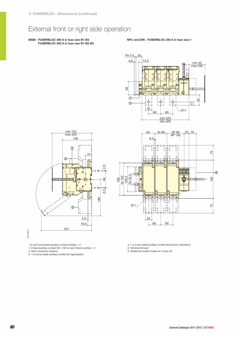
80 General Catalogue 2011-2012 SOCOMEC80
BS88 - FUSERBLOC 200 A in fuse size B1-B2FUSERBLOC 250 A in fuse size B1-B2-B3
NFC and DIN - FUSERBLOC 250 A in fuse size 1
*fix 5.5
32
17
52
7519
5
*fix
52.
5 12
6.5
fix 1
62
166
2.5
84
185
2.5
75
68
60
64
6.4
25 35
Ø11
32
60 60
fix 60 3P 86 4P 146
min 154 max 225
146
31
2.5
19.5
251
60Ø11
29
4.8 14.5min 50
max 230
4
1
2
5
3
234 (3P) 294 (4P)
6
fuse
r_62
9_b
FUSERBLOC - Dimensions (continued)
External front or right side operation
* to use if pre-break auxiliary contact number > 41. S type auxiliary contact NO + NC to use if block number > 42. Rear connection (option)3. 1 to 8 pre-break auxiliary contact for signalisation
4. 1 or 2 pre-break auxiliary contact (fuse blown indication)5. Terminal shrouds6. Additional contact holder for U type AC
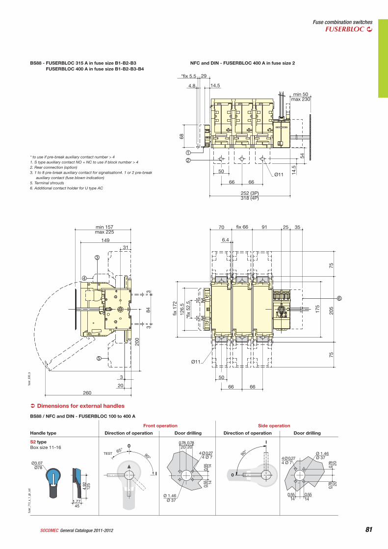
81General Catalogue 2011-2012SOCOMEC 81
Fuse combination switchesFUSERBLOC
BS88 - FUSERBLOC 315 A in fuse size B1-B2-B3FUSERBLOC 400 A in fuse size B1-B2-B3-B4
NFC and DIN - FUSERBLOC 400 A in fuse size 2
*fix 5.5 29
50
66 66
Ø11
252 (3P) 318 (4P)
70min 157 max 225
149
31
3
20
260
6.4
Ø11
50
66 66
fix 66 91 25 35
14.5
7520
5
175
*fix
52.
5 12
6.5
fix 1
72
384
200
3
75
54
68
4.8 14.5
min 50 max 230
4
1
2
6
3
5
fuse
r_63
0_b
* to use if pre-break auxiliary contact number > 41. S type auxiliary contact NO + NC to use if block number > 42. Rear connection (option)3. 1 to 8 pre-break auxiliary contact for signalisation4. 1 or 2 pre-break
auxiliary contact (fuse blown indication)5. Terminal shrouds6. Additional contact holder for U type AC
Dimensions for external handles
S2 typeBox size 11-16
4 Ø 7
0
I
90°65° 20 20
Ø 37
TEST 90°
I
0
Ø78
1.77
4.92
Direction of operationHandle type
Front operation
Door drilling Direction of operation
Side operation
Door drilling
Ø3.07
0.78 0.78
1414
0.55
0.55
Ø 1.46
4 Ø 0.27
0.78
4 Ø 0.27
0.55
Ø 1.46
4 Ø 7Ø 37
2020
140.5514
0.78
45
125
BS88 / NFC and DIN - FUSERBLOC 100 to 400 A
fuse
r_71
3_a_
1_gb
_cat
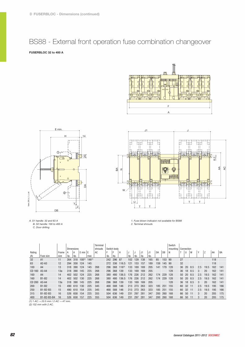
82 General Catalogue 2011-2012 SOCOMEC82
FUSERBLOC 32 to 400 A
F
A
J1
14H
E min. J
TT
T T
U
W
YZ
DB
8.2
NBA
DA
20
AA
AC
1
2
28
404Ø7
ØD
0
90
90
I
Ø78
44
70
Ø78
45
125
A B
C
II
fuse
r_63
4_d_
1_x_
cat
FUSERBLOC - Dimensions (continued)
BS88 - External front operation fuse combination changeover
A. S1 handle: 32 and 63 AB. S2 handle: 100 to 400 AC. Door drilling
1. Fuse blown indicaion not available for BS882. Terminal shrouds
Rating (A) Fuse size
Frame size
DimensionsTerminal shrouds Switch body
Switchmounting Connection
A3p.
A4p.
E min E max
AC F 3p.
F4p.
H J 3p.
J4p.
J13p.
J14p.
DA DB N T U W Y Z AA BA
32 A1 11 264 318 100(1) 146(1) 242 296 87 102 129 138 165 85 153 90 27 11863 A2-A3 12 294 358 124 145 272 336 116.5 121 153 157 189 159 145 90 32 118100 A4 13 318 390 124 145 268 296 368 116(2) 133 169 169 205 141 179 128 36 20 8.5 2.5 19.5 162 141CD 160 A3-A4 13a 318 390 145 225 268 296 368 139 133 169 169 205 128 36 18 8.5 3 20 162 141160 A4 14 402 502 124 225 268 380 480 136.5 176 226 212 262 174 229 128 50 20 8.5 2.5 19.5 162 141160 B1-B2 14 402 502 130 225 268 380 480 136.5 176 226 212 262 174 229 128 50 20 8.5 2.5 19.5 162 141CD 200 A3-A4 13a 318 390 145 225 268 296 368 139 133 169 169 205 128 36 18 8.5 3 20 162 141200 B1-B2 15 490 610 130 225 345 468 588 146 213 273 263 323 185 251 155 60 32 11 2.5 19.5 195 166250 B1-B2-B3 15 490 610 154 225 345 468 588 146 213 273 263 323 185 251 155 60 32 11 2.5 19.5 195 166315 B1-B2-B3 16 526 658 154 225 355 504 636 149 231 297 281 347 200 260 168 66 50 11 3 20 205 175400 B1-B2-B3-B4 16 526 658 157 225 355 504 636 149 231 297 281 347 200 260 168 66 50 11 3 20 205 175
(1) 1 AC: + 23.5 mm / 2 AC: + 47 mm.(2) 132 mm with 2 AC.
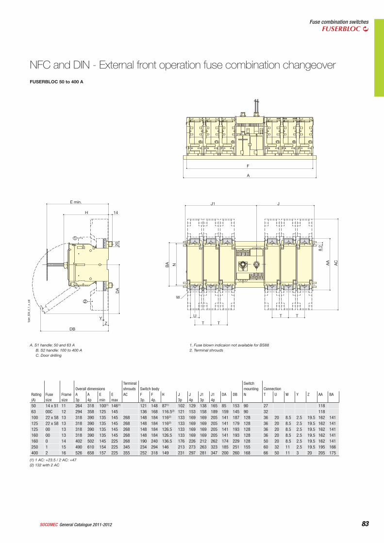
83General Catalogue 2011-2012SOCOMEC 83
Fuse combination switchesFUSERBLOC
FUSERBLOC 50 to 400 A
F
A
J1
14H
E min. J
TT
T T
U
W
YZ
DB
8.2
NBA
DA
20
AA
AC
1
2
28
404Ø7
ØD
0
90
90
I
Ø78
44
70
Ø78
4512
5
A B
C
II
fuse
r_63
4_d_
1_x_
cat
NFC and DIN - External front operation fuse combination changeover
A. S1 handle: 50 and 63 AB. S2 handle: 100 to 400 AC. Door drilling
1. Fuse blown indicaion not available for BS882. Terminal shrouds
Rating(A)
Fusesize
Frame size
Overall dimensionsTerminal shrouds Switch body
Switchmounting Connection
A3p
A4p
Emin
Emax
AC F 3p.
F4p.
H J3p
J4p
J13p
J14p
DA DB N T U W Y Z AA BA
50 14 x 51 11 264 318 100(1) 146(1) 121 148 87(1) 102 129 138 165 85 153 90 27 11863 00C 12 294 358 125 145 136 168 116.5(2) 121 153 158 189 159 145 90 32 118100 22 x 58 13 318 390 135 145 268 148 184 116(2) 133 169 169 205 141 187 128 36 20 8.5 2.5 19.5 162 141125 22 x 58 13 318 390 135 145 268 148 184 116(2) 133 169 169 205 141 179 128 36 20 8.5 2.5 19.5 162 141125 00 13 318 390 135 145 268 148 184 126.5 133 169 169 205 141 193 128 36 20 8.5 2.5 19.5 162 141160 00 13 318 390 135 145 268 148 184 126.5 133 169 169 205 141 193 128 36 20 8.5 2.5 19.5 162 141160 0 14 402 502 145 225 268 190 240 136.5 176 226 212 262 174 229 128 50 20 8.5 2.5 19.5 162 141250 1 15 490 610 154 225 345 234 294 146 213 273 263 323 185 251 155 60 32 11 2.5 19.5 195 166400 2 16 526 658 157 225 355 252 318 149 231 297 281 347 200 260 168 66 50 11 3 20 205 175
(1) 1 AC: +23.5 / 2 AC: +47(2) 132 with 2 AC
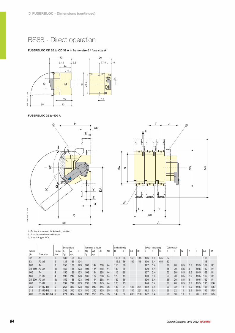
84 General Catalogue 2011-2012 SOCOMEC84
FUSERBLOC CD 20 to CD 32 A in frame size 0 / fuse size A1
FUSERBLOC - Dimensions (continued)
BS88 - Direct operation
5.265
8398
14
98 79.5
96
6.591.5
112
19
4437.5 15
45
fuse
r_14
8_c_
1_x_
cat
FUSERBLOC 32 to 400 A
C
31
Z
U T
AB
W
A
Y
H
R
NBA
DA
AA
AC
T JAD
S
DB
70°
2
1
3
fuse
r_06
4_b_
1_x_
cat
1. Protection screen lockable in position I2. 1 or 2 fuse blown indication.3. 1 or 2 A type ACs
Rating (A) Fuse size
Frame size
Dimensions Terminal shrouds Switch body Switch mounting ConnectionA3p.
A4p.
C AB 3p
AB4p
AC AD H J DA DB N R S T U W Y Z AA BA
32 A1 1 133 165 134 116.5 36 159 145 106 5.4 6.5 27 11863 A2-A3 2 133 165 134 116.5 36 159 145 106 5.4 6.5 32 118100 A4 3 150 186 173 108 144 268 44 116 38 127 5.4 36 20 8.5 2.5 19.5 162 141CD 160 A3-A4 3a 152 188 173 108 144 268 44 139 38 130 5.4 36 20 8.5 3 19.5 162 141160 A4 4 150 186 173 108 144 268 44 116 38 127 5.4 50 20 8.5 2.5 19.5 162 141160 B1-B2 4 192 242 173 136 172 268 44 123 45 140 5.4 50 20 8.5 2.5 19.5 162 141CD 200 A3-A4 3a 152 188 173 108 144 268 44 139 38 130 5.4 36 20 8.5 3 19.5 162 141200 B1-B2 5 192 242 173 136 172 345 44 123 45 140 5.4 60 20 8.5 2.5 19.5 195 166250 B1-B2-B3 5 253 313 173 180 240 345 65 146 81 185 251 162 6.4 60 32 11 2.5 19.5 195 166315 B1-B2-B3 6 253 313 173 180 240 355 65 146 81 185 251 162 6.4 66 32 11 2.5 19.5 195 175400 B1-B2-B3-B4 6 271 337 173 192 258 355 65 149 86 200 260 172 6.4 66 50 11 3 20 205 175
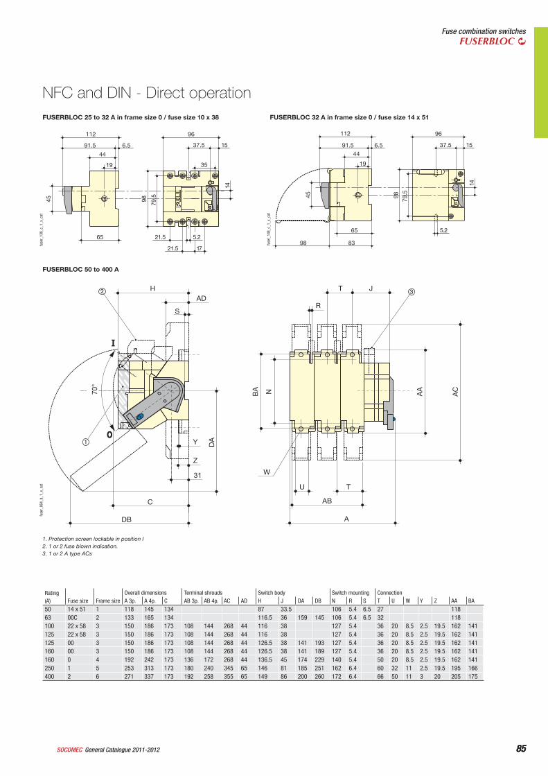
85General Catalogue 2011-2012SOCOMEC 85
Fuse combination switchesFUSERBLOC
FUSERBLOC 25 to 32 A in frame size 0 / fuse size 10 x 38
NFC and DIN - Direct operation
FUSERBLOC 50 to 400 A
C
31
Z
U T
AB
W
A
Y
H
R
NBA
DA
AA
AC
T JAD
S
DB
70°
2
1
3
fuse
r_06
4_b_
1_x_
cat
1. Protection screen lockable in position I2. 1 or 2 fuse blown indication.3. 1 or 2 A type ACs
96
1721.5
5.2
35
98 79.5
21.5
112
6.591.5
19
44
65
45
14
37.5 15
fuse
r_13
8_c_
1_x_
cat
5.265
8398
14
98 79.5
96
6.591.5
112
19
4437.5 15
45
fuse
r_14
8_c_
1_x_
cat
FUSERBLOC 32 A in frame size 0 / fuse size 14 x 51
Rating (A) Fuse size Frame size
Overall dimensions Terminal shrouds Switch body Switch mounting ConnectionA 3p. A 4p. C AB 3p. AB 4p. AC AD H J DA DB N R S T U W Y Z AA BA
50 14 x 51 1 118 145 134 87 33.5 106 5.4 6.5 27 11863 00C 2 133 165 134 116.5 36 159 145 106 5.4 6.5 32 118100 22 x 58 3 150 186 173 108 144 268 44 116 38 127 5.4 36 20 8.5 2.5 19.5 162 141125 22 x 58 3 150 186 173 108 144 268 44 116 38 127 5.4 36 20 8.5 2.5 19.5 162 141125 00 3 150 186 173 108 144 268 44 126.5 38 141 193 127 5.4 36 20 8.5 2.5 19.5 162 141160 00 3 150 186 173 108 144 268 44 126.5 38 141 189 127 5.4 36 20 8.5 2.5 19.5 162 141160 0 4 192 242 173 136 172 268 44 136.5 45 174 229 140 5.4 50 20 8.5 2.5 19.5 162 141250 1 5 253 313 173 180 240 345 65 146 81 185 251 162 6.4 60 32 11 2.5 19.5 195 166400 2 6 271 337 173 192 258 355 65 149 86 200 260 172 6.4 66 50 11 3 20 205 175
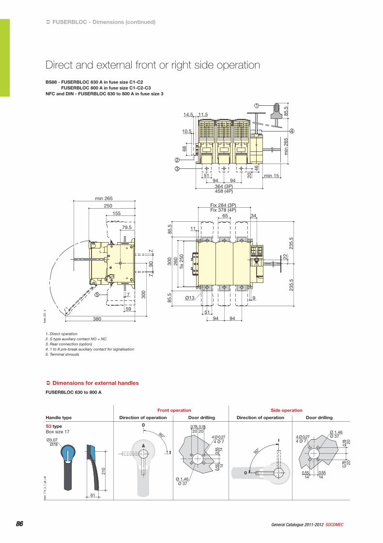
86 General Catalogue 2011-2012 SOCOMEC86
BS88 - FUSERBLOC 630 A in fuse size C1-C2FUSERBLOC 800 A in fuse size C1-C2-C3
NFC and DIN - FUSERBLOC 630 to 800 A in fuse size 3
FUSERBLOC - Dimensions (continued)
Direct and external front or right side operation
250
155
79.5
7
59
380
min 265
Ø13
11
Fix 284 (3P) Fix 378 (4P)
65 34
51
9
94 94
11.5
94 94 min 15
364 (3P) 458 (4P)
51
14.5
10.5
fix 2
50
2223
5.5
235.
5
260
300
85.5
85.5
77
300
90
68
2046
min
265
85
.5 1
3
2
5
4
fuse
r_63
1_b
1. Direct operation2. S type auxiliary contact NO + NC3. Rear connection (option)4. 1 to 8 pre-break auxiliary contact for signalisation5. Terminal shrouds
Dimensions for external handles
S3 typeBox size 17
0
I
90°
61
210
90°
I
0
Direction of operationHandle type
Front operation
Door drilling Direction of operation
Side operation
Door drilling
Ø3.07Ø78
Ø 37
1414
4 Ø 7
2020
Ø 1.46
0.55
0.55
4 Ø 0.27
0.780.78
0.78
4 Ø 0.27
0.55
Ø 1.46
4 Ø 7Ø 37
2020
140.5514
0.78
fuse
r_71
4_a_
1_gb
_cat
FUSERBLOC 630 to 800 A
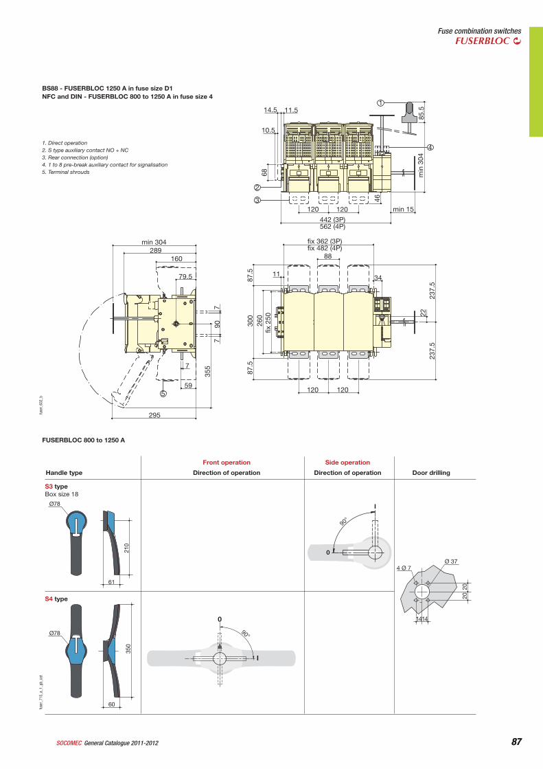
87General Catalogue 2011-2012SOCOMEC 87
Fuse combination switchesFUSERBLOC
BS88 - FUSERBLOC 1250 A in fuse size D1NFC and DIN - FUSERBLOC 800 to 1250 A in fuse size 4
min 304 289
160
fix 362 (3P) fix 482 (4P)
14.5
10.5
11.5
120 120
442 (3P) 562 (4P)
min 15
88
11 34
120 120
79.5
7
59
295
355
7
87.5
min
304
85
.5
68
46
300
260
fix 2
50 22
237.
523
7.5
87.5
907
3
4
2
1
5
fuse
r_63
2_b
1. Direct operation2. S type auxiliary contact NO + NC3. Rear connection (option)4. 1 to 8 pre-break auxiliary contact for signalisation5. Terminal shrouds
Ø78
61
210
S3 typeBox size 18
Direction of operationHandle type
Front operation
Direction of operation
Side operation
Door drilling
0
I
90°
2020
4 Ø 7
1414
Ø 37
S4 type
60
350
Ø78 90°
I
0
fuse
r_71
5_a_
1_gb
_cat
FUSERBLOC 800 to 1250 A
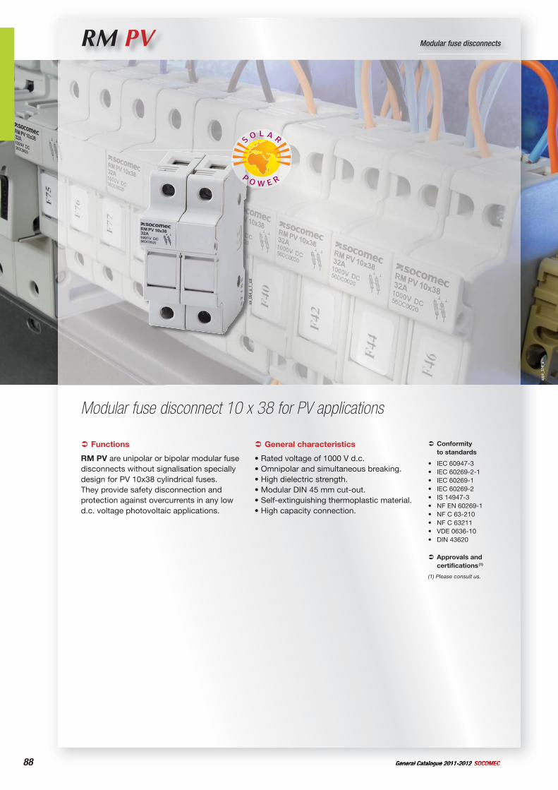
General Catalogue 2011-2012 SOCOMEC88
RM PV Modular fuse disconnects
Modular fuse disconnect 10 x 38 for PV applications
Functions
RM PV are unipolar or bipolar modular fuse disconnects without signalisation specially design for PV 10x38 cylindrical fuses. They provide safety disconnection and protection against overcurrents in any low d.c. voltage photovoltaic applications.
Conformityto standards
IEC 60947-3IEC 60269-2-1IEC 60269-1IEC 60269-2IS 14947-3NF EN 60269-1NF C 63-210NF C 63211VDE 0636-10DIN 43620
••••••••••
Approvals and certifications (1)
(1) Please consult us.
General characteristics
• Rated voltage of 1000 V d.c.• Omnipolar and simultaneous breaking.• High dielectric strength.• Modular DIN 45 mm cut-out.• Self-extinguishing thermoplastic material.• High capacity connection.
rm_0
54_a
_1_c
at
appl
i_37
4_a
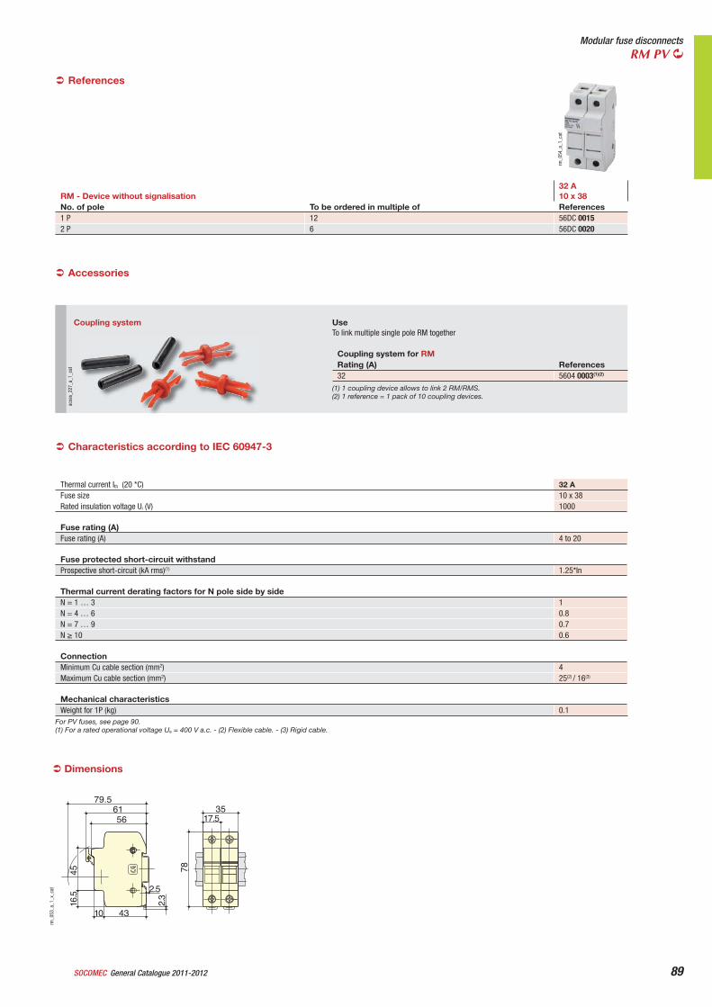
General Catalogue 2011-2012SOCOMEC 89
Modular fuse disconnectsRM PV
References
RM - Device without signalisation32 A10 x 38
No. of pole To be ordered in multiple of References1 P 12 56DC 00152 P 6 56DC 0020
rm_0
54_a
_1_c
at
Coupling system UseTo link multiple single pole RM together
Coupling system for RMRating (A) References32 5604 0003(1)(2)
(1) 1 coupling device allows to link 2 RM/RMS.(2) 1 reference = 1 pack of 10 coupling devices.
acce
s_22
7_a_
1_ca
t
Accessories
Thermal current Ith (20 *C) 32 AFuse size 10 x 38Rated insulation voltage Ui (V) 1000
Fuse rating (A)Fuse rating (A) 4 to 20
Fuse protected short-circuit withstandProspective short-circuit (kA rms)(1) 1.25*In
Thermal current derating factors for N pole side by sideN = 1 … 3 1N = 4 … 6 0.8N = 7 … 9 0.7N 10 0.6
ConnectionMinimum Cu cable section (mm2) 4Maximum Cu cable section (mm2) 25(2) / 16(3)
Mechanical characteristicsWeight for 1P (kg) 0.1
Characteristics according to IEC 60947-3
For PV fuses, see page 90.(1) For a rated operational voltage Ue = 400 V a.c. - (2) Flexible cable. - (3) Rigid cable.
79.56156
4516.5
10 43
2.5
2.3
3517.5
78
rm_0
53_a
_1_x
_cat
Dimensions
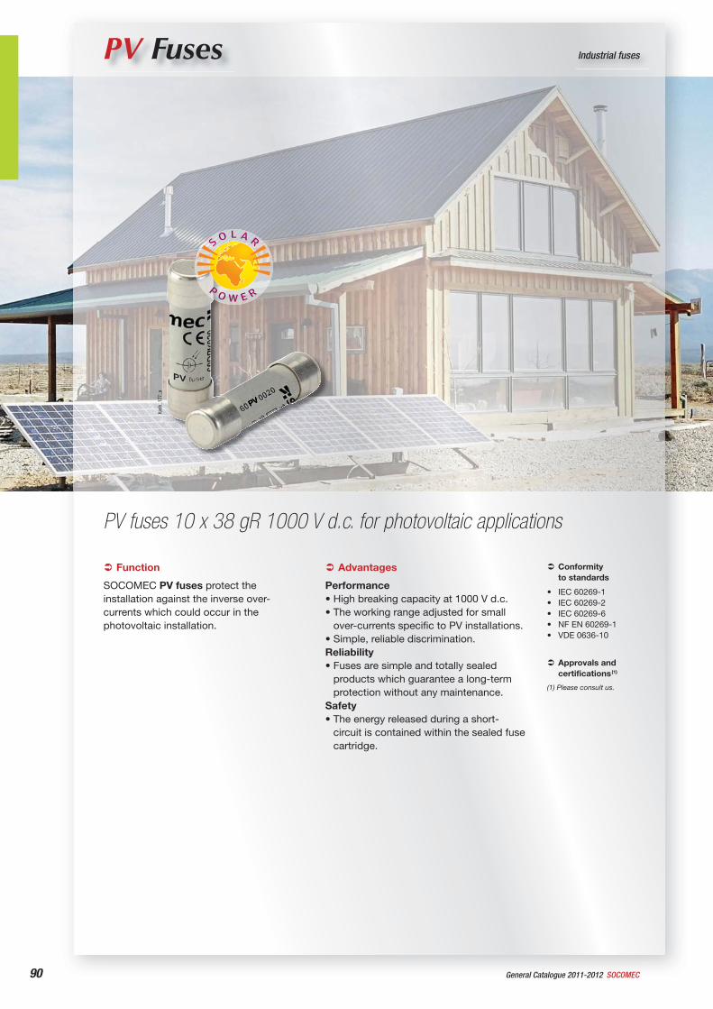
90 General Catalogue 2011-2012 SOCOMEC
PV Fuses Industrial fuses
PV fuses 10 x 38 gR 1000 V d.c. for photovoltaic applications
Function
SOCOMEC PV fuses protect the installation against the inverse over-currents which could occur in the photovoltaic installation.
Conformityto standards
IEC 60269-1IEC 60269-2IEC 60269-6NF EN 60269-1VDE 0636-10
•••••
Approvals and certifications (1)
(1) Please consult us.
Advantages
Performance• High breaking capacity at 1000 V d.c.• The working range adjusted for small
over-currents specific to PV installations.• Simple, reliable discrimination.Reliability• Fuses are simple and totally sealed
products which guarantee a long-term protection without any maintenance.
Safety• The energy released during a short-
circuit is contained within the sealed fuse cartridge.
appl
i_28
2_a
fusi
b_17
7_a

91
Industrial fusesFusibles PV
General Catalogue 2011-2012SOCOMEC
What you need to know
Used Characteristics• ISC : short circuit current of the PV string • ISC MAX : short circuit current of the PV string related to maximum sunlight
density• IRM : maximum admitted reverse current• In : fuse rating or fuse rated current (at 25°C in a RM disconnect switch)• Nc : number of PV strings in parallel connection• Ue : maximum fuse rated voltage• UOC MAX : maximum open circuit voltage in the lowest temperature conditions
When to protectA PV string requires an over current protection when its own maximum admissible reverse current characteristic (Irm) is less than the current generated by the rest of the installation (current generated by the “Nc-1” other strings). The protection is obligatory if Nc 1+ (IRM / ISC)
How to protect The overload protection is to be applied at each of the two polarities, regardless of whether the d.c. installation is earthed or not.
How to choose the fuse protection
VoltageUe > UOC MAX
In the absence of complementary information use UOC MAX =1.2 UOC.
Fuse rating determinationDetermination of the Fuse Rated Current consists of choosing a protection capable of:• supporting without fusing the normal overload current during the periods of
maximum sunlight density at the ambient temperature of the enclosure in which the fuse is installed
In > ISC MAX
In the absence of complementary information use ISC MAX = 1.4 ISC
• melting and reliably clearing the fault before the PV modules are damaged by the reverse current
In < IRM
man
ne_4
90_a
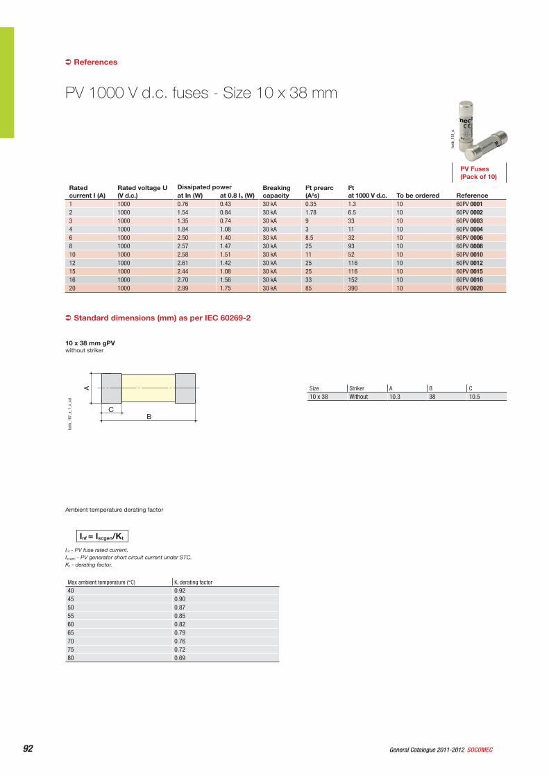
92 General Catalogue 2011-2012 SOCOMEC
PV 1000 V d.c. fuses - Size 10 x 38 mm
References
without striker
Standard dimensions (mm) as per IEC 60269-2
Size Striker A B C10 x 38 Without 10.3 38 10.5
BC
A
fusi
b_16
7_a_
1_x_
cat
10 x 38 mm gPV
fusi
b_16
8_a
PV Fuses (Pack of 10)
Ratedcurrent I (A)
Rated voltage U (V d.c.)
Dissipated power Breaking capacity
I2t prearc (A2s)
I2tat 1000 V d.c. To be ordered Referenceat In (W) at 0.8 In (W)
1 1000 0.76 0.43 30 kA 0.35 1.3 10 60PV 00012 1000 1.54 0.84 30 kA 1.78 6.5 10 60PV 00023 1000 1.35 0.74 30 kA 9 33 10 60PV 00034 1000 1.84 1.08 30 kA 3 11 10 60PV 00046 1000 2.50 1.40 30 kA 8.5 32 10 60PV 00068 1000 2.57 1.47 30 kA 25 93 10 60PV 000810 1000 2.58 1.51 30 kA 11 52 10 60PV 001012 1000 2.61 1.42 30 kA 25 116 10 60PV 001215 1000 2.44 1.08 30 kA 25 116 10 60PV 001516 1000 2.70 1.56 30 kA 33 152 10 60PV 001620 1000 2.99 1.75 30 kA 85 390 10 60PV 0020
Max ambient temperature (°C) Kt derating factor40 0.9245 0.9050 0.8755 0.8560 0.8265 0.7970 0.7675 0.7280 0.69
Inf = Iscgen/Kt
Inf - PV fuse rated current.Iscgen - PV generator short circuit current under STC.Kt - derating factor.
Ambient temperature derating factor
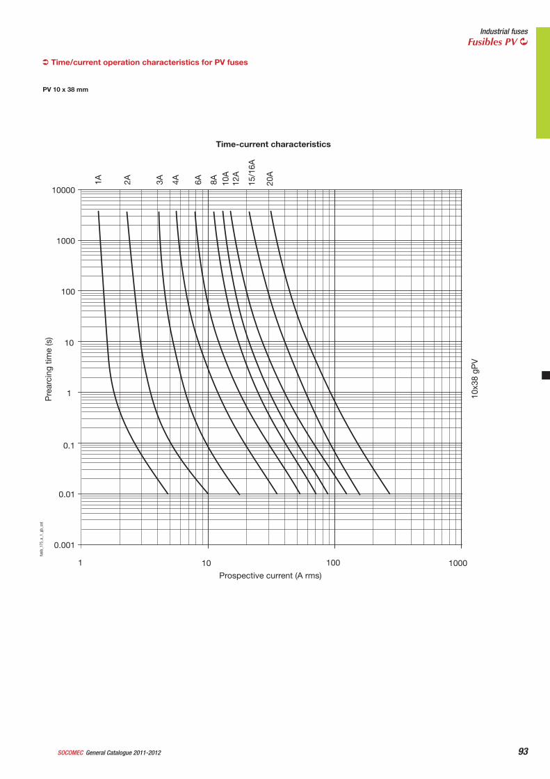
93
Industrial fusesFusibles PV
General Catalogue 2011-2012SOCOMEC
PV 10 x 38 mm
Time/current operation characteristics for PV fuses
1A 2A 3A 4A 6A 8A 10A
12A
15/1
6A
20A
10000
1000
100
10
1
0.1
0.01
0.001
1 10 100 1000
10x3
8 gP
V
Pre
arci
ng ti
me
(s)
Prospective current (A rms)
Time-current characteristics
fusi
b_17
5_a_
1_gb
_cat
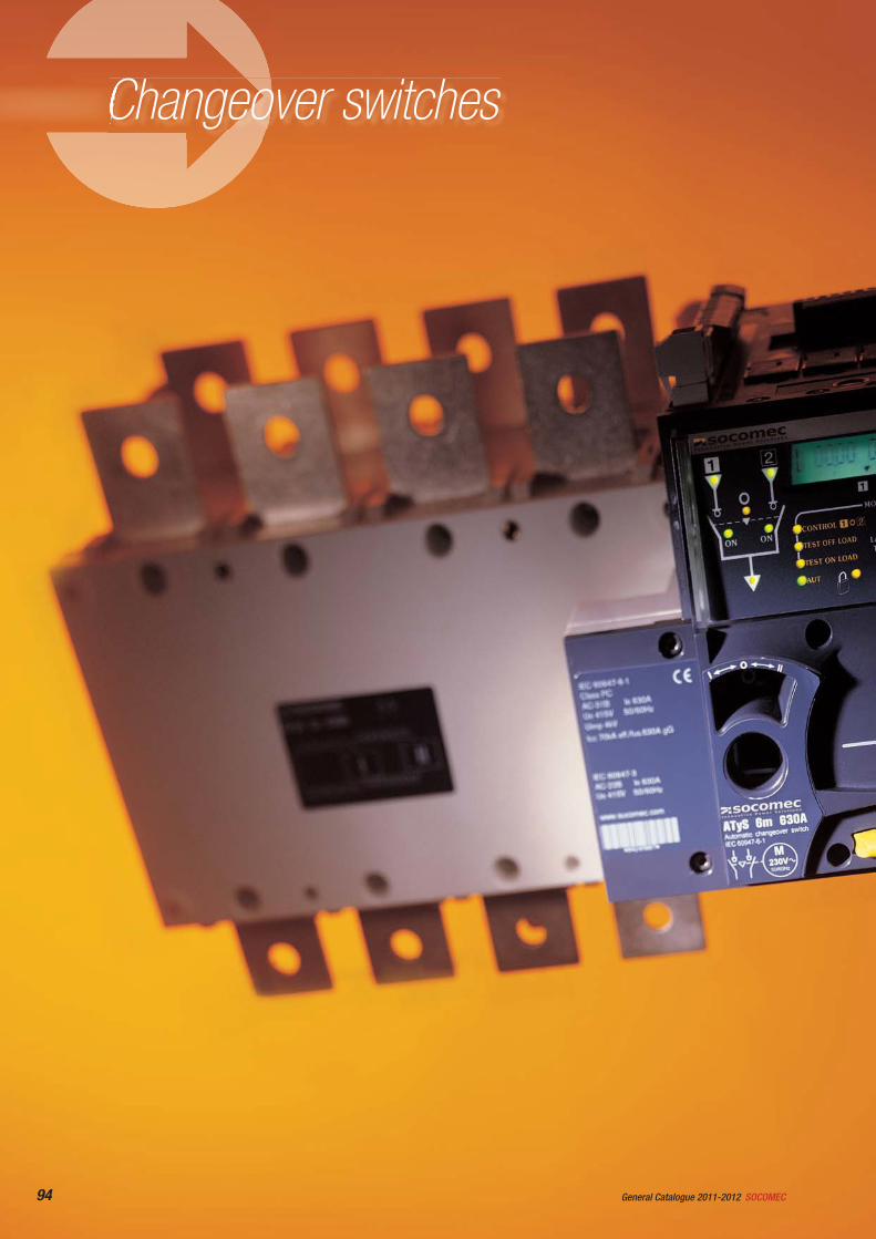
94 SOCOMECGeneral Catalogue 2011-2012
Changeover switches
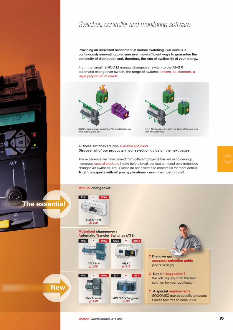
95General Catalogue 2011-2012SOCOMEC
Discover ourcomplete selection guide (see next page)
Need a suggestion? We will help you fi nd the best solution for your application.
A special requirement?SOCOMEC makes specifi c products.Please feel free to consult us.
Switches, controller and monitoring software
The essential
Providing an unrivalled benchmark in source switching, SOCOMEC is continuously innovating to ensure ever more effi cient ways to guarantee the continuity of distribution and, therefore, the rate of availability of your energy.
From the ‘small’ SIRCO M manual changeover switch to the ATyS 6 automatic changeover switch, the range of switches covers, as standard, a large proportion of needs.
All these switches are also available enclosed.Discover all of our products in our selection guide on the next pages.
The experience we have gained from different projects has led us to develop numerous special products (make before break contact or mixed pole motorised changeover switches, etc). Please do not hesitate to contact us for more details. Trust the experts with all your applications - even the most critical!
Manual changeover
SIRCO VM1 p. 100
63 A 125 A
Motorised changeover /Automatic Transfer Switches (ATS)
ATyS M 6 p. 108
ATyS 3 p. 116
40 A 160 A 125 A 3200 A
40 A 160 A
ATyS M monop. 108
New
40 A 160 A
SIRCO M changeover p. 98
ATyS M changeover switch for Normal/Backup use with a generating set
ATyS M changeover switch for Normal/Backup use with two networks
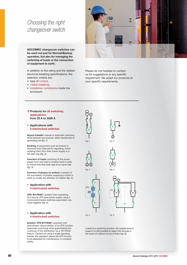
96 SOCOMECGeneral Catalogue 2011-2012
SOCOMEC changeover switches can be used not just for Normal/Backup operation, but also for managing the switching of loads or the connection of equipment to earth.
In addition to the rating and the related electrical breaking specifi cations, the selection criteria are:• type of control,• visible breaking,• installation constraints inside the
enclosure.
Choosing the right changeover switch
Products for all switching applicationsfrom 25 A to 3200 A
• Applications with 2 interlocked switches
Source transfer: manual or automatic switching (ATS) between two sources, either transformer or generating set (fi g. 1).
Earthing of equipment such as motors or electrical lines reserved for signalling, whilst isolating them from their power supply in a fail-safe way (fi g. 2).
Inversion of loads: switching of the power supply from one load to another load in order to ensure that they both age at an equal rate (fi g. 3).
Inversion of phases on motors: inversion of the succession of phases supplying a motor in order to modify the direction of rotation (fi g. 4).
• Application with 3 interlocked switches
UPS 'BY-PASS': isolation then bypassing of a secure UPS type power supply using 3 interlocked breaker switches assembled very close together (fi g. 5).
• Application with 4 interlocked switches
Solution ‘ATS BY-PASS': upstream and downstream disconnection of an ATS function (automatic switching) while guaranteeing the continuity of the distribution via a 'BY-PASS' branch. Carried out using a single operating handle, this operation allows the ATS function to be separated for maintenance, in complete safety.
Linked to a switching function, the bypass branch means it is still possible to select the sources in the event of a failure of one of them (fi g. 6).
Please do not hesitate to contact us for suggestions or any specifi c requirement: We adapt our products to your specifi c requirements.
Fig. 6
Fig.1 Fig. 2
Fig. 3 Fig. 4
Fig. 5
UPS
ATS
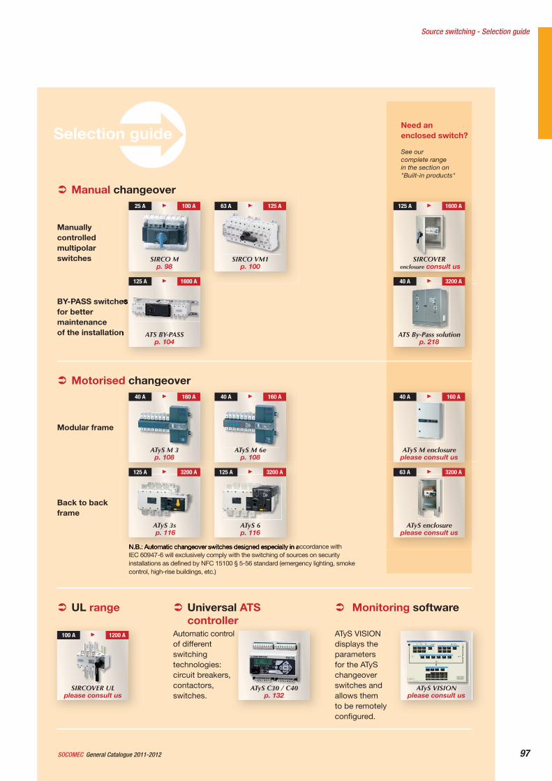
Need an enclosed switch?
See our complete range in the section on "Built-in products"
97General Catalogue 2011-2012SOCOMEC
Selection guide
Source switching - Selection guide
Manual changeover
BY-PASS switches for better maintenanceof the installation
Manuallycontrolled multipolarswitches SIRCO VM1
p. 100
63 A 125 A
SIRCO M p. 98
25 A 100 A
ATS BY-PASSp. 104
125 A 1600 A
ATS By-Pass solutionp. 218
40 A 3200 A
SIRCOVERenclosure consult us
125 A 1600 A
Motorised changeover
N.B.: Automatic changeover switches designed especially in accordance with IEC 60947-6 will exclusively comply with the switching of sources on security installations as defined by NFC 15100 § 5-56 standard (emergency lighting, smoke control, high-rise buildings, etc.)
Back to back frame
Modular frame
ATyS M 3p. 108
40 A 160 A 40 A 160 A
ATyS M 6ep. 108
ATyS 6p. 116
125 A 3200 A
ATyS 3s p. 116
125 A 3200 A
ATyS enclosureplease consult us
63 A 3200 A
ATyS M enclosureplease consult us
40 A 160 A
Monitoring software
ATyS VISION please consult us
ATyS VISION displays the parametersfor the ATyS changeoverswitches and allows them to be remotely configured.
Universal ATS controller
ATyS C30 / C40p. 132
Automatic control of different switchingtechnologies:circuit breakers, contactors,switches.
UL range
SIRCOVER ULplease consult us
100 A 1200 A
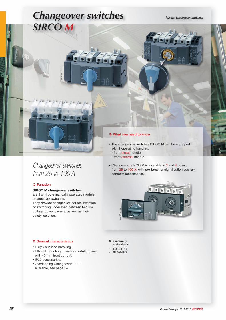
98 General Catalogue 2011-2012 SOCOMEC
appl
i_18
5_a
Changeover switches SIRCO M
Manual changeover switches
Changeover switches from 25 to 100 A
sirc
m_1
24_a
sirc
m_1
73_a
_1_c
at
sirc
m_1
23_a
sirc
m_1
21_a
Function
SIRCO M changeover switches are 3 or 4 pole manually operated modular changeover switches.They provide changeover, source inversion or switching under load between two low voltage power circuits, as well as their safety isolation.
Conformityto standards
IEC 60947-3EN 60947-3
••
General characteristics
• Fully visualised breaking.• DIN rail mounting, panel or modular panel
with 45 mm front cut out.• IP20 accessories.• Overlapping Changeover I-I+II-II
available, see page 14.
What you need to know
• The changeover switches SIRCO M can be equipped with 2 operating handles:- front direct handle- front external handle.
• Changeover SIRCO M is available in 3 and 4 poles, from 25 to 100 A, with pre-break or signalisation auxiliary contacts (accessories).
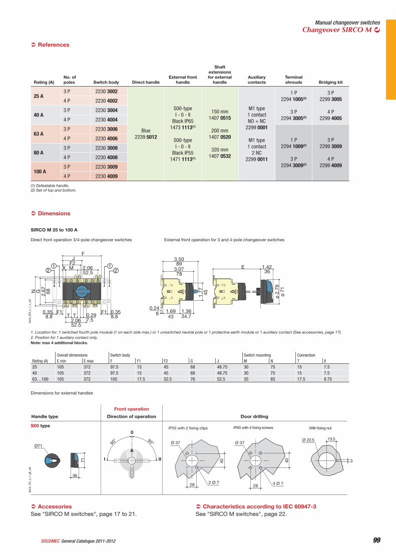
99General Catalogue 2011-2012SOCOMEC 99
Manual changeover switchesChangeover SIRCO M
Rating (A)No. of poles Switch body Direct handle
External front handle
Shaftextensionsfor external
handleAuxiliarycontacts
Terminal shrouds Bridging kit
25 A3 P 2230 3002
Blue2239 5012
S00-typeI - 0 - II
Black IP651473 1113(1)
S00-typeI - 0 - II
Black IP551471 1113(1)
150 mm1407 0515
200 mm1407 0520
320 mm1407 0532
M1 type1 contactNO + NC
2299 0001
M1 type1 contact
2 NC2299 0011
1 P2294 1005(2)
3 P2294 3005(2)
3 P2299 3005
4 P2299 4005
4 P 2230 4002
40 A3 P 2230 3004
4 P 2230 4004
63 A3 P 2230 3006
1 P2294 1009(2)
3 P2294 3009(2)
3 P2299 3009
4 P2299 4009
4 P 2230 4006
80 A3 P 2230 3008
4 P 2230 4008
100 A3 P 2230 3009
4 P 2230 4009
References
Direct front operation 3/4-pole changeover switches External front operation for 3 and 4-pole changeover switches
1.42E
1.77
3.07
1.361.690.24
3.50
ø 2.
79
X
N G2.
67
T T 0.292.06
MF2
2.06
FJ
F1F10.35
21
21 89
78
43 34.76
36
ø 7145
52.5
68
8.8
52.5
8.87.5
0.35
sirc
m_0
55_c
_1_x
_cat
1. Location for: 1 switched fourth pole module (1 on each side max.) or 1 unswitched neutral pole or 1 protective earth module or 1 auxiliary contact (See accessories, page 17).2. Position for 1 auxiliary contact only.Note: max 4 additional blocks.
Rating (A)Overall dimensions Switch body Switch mounting ConnectionE min E max F F1 F2 G J M N T X
25 105 372 97.5 15 45 68 48.75 30 75 15 7.540 105 372 97.5 15 45 68 48.75 30 75 15 7.563…100 105 372 105 17.5 52.5 76 52.5 35 85 17.5 8.75
SIRCO M 25 to 100 A
Dimensions for external handles
13.5Ø 22.5
3
With fixing nutIP55 with 2 fixing clips IP65 with 4 fixing screws
Direction of operation
Front operation
Door drillingHandle type
S00 type0
I II
90° 90°
40
28
40
2 Ø 7
Ø 37
28
Ø 37
4 Ø 7
Ø71
36
71
sirc
m_1
81_a
_1_g
b_ca
t
Dimensions
AccessoriesSee "SIRCO M switches", page 17 to 21.
Characteristics according to IEC 60947-3See "SIRCO M switches", page 22.
(1) Defeatable handle.(2) Set of top and bottom.
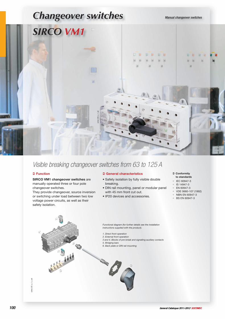
100 General Catalogue 2011-2012 SOCOMEC
Changeover switches
SIRCO VM1
Manual changeover switches
Visible breaking changeover switches from 63 to 125 A
com
ut_0
21_a
_1_x
_cat
Functional diagram (for further details see the installation instructions supplied with the product).
1. Direct front operation2. External front operation3 and 4. Blocks of pre-break and signalling auxiliary contacts5. Bridging bars6. Back plate or DIN rail mounting
com
ut_0
04_a
_1_c
at
Function
SIRCO VM1 changeover switches are manually operated three or four pole changeover switches.They provide changeover, source inversion or switching under load between two low voltage power circuits, as well as their safety isolation.
Conformityto standards
IEC 60947-3IS 14947-3EN 60947-3VDE 0660-107 (1992) NBN EN 60947-3BS EN 60947-3
••••••
General characteristics
• Safety isolation by fully visible double breaking.
• DIN rail mounting, panel or modular panel with 45 mm front cut out.
• IP20 devices and accessories.
appl
i_30
9_a
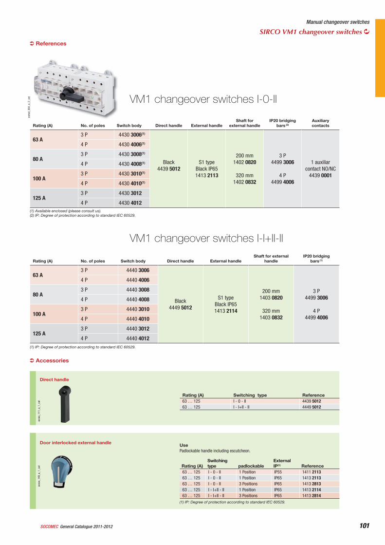
101General Catalogue 2011-2012SOCOMEC 101
Manual changeover switches
SIRCO VM1 changeover switches
VM1 changeover switches I-0-II
Rating (A) No. of poles Switch body Direct handle External handleShaft for
external handleIP20 bridging
bars (2)Auxiliarycontacts
63 A3 P 4430 3006(1)
Black4439 5012
S1 typeBlack IP651413 2113
200 mm1402 0820
320 mm1402 0832
3 P4499 3006
4 P4499 4006
1 auxiliar contact NO/NC
4439 0001
4 P 4430 4006(1)
80 A3 P 4430 3008(1)
4 P 4430 4008(1)
100 A3 P 4430 3010(1)
4 P 4430 4010(1)
125 A3 P 4430 3012
4 P 4430 4012
com
ut_0
04_a
_2_c
at
VM1 changeover switches I-I+II-II
Rating (A) No. of poles Switch body Direct handle External handleShaft for external
handleIP20 bridging
bars (1)
63 A3 P 4440 3006
Black4449 5012
S1 typeBlack IP651413 2114
200 mm1403 0820
320 mm1403 0832
3 P4499 3006
4 P4499 4006
4 P 4440 4006
80 A3 P 4440 3008
4 P 4440 4008
100 A3 P 4440 3010
4 P 4440 4010
125 A3 P 4440 3012
4 P 4440 4012
References
(1) IP: Degree of protection according to standard IEC 60529.
(1) Available enclosed (please consult us).(2) IP: Degree of protection according to standard IEC 60529.
Accessories
Direct handle
acce
s_11
1_a_
1_ca
t
Rating (A) Switching type Reference63 … 125 I - 0 - II 4439 501263 … 125 I - I+II - II 4449 5012
Door interlocked external handle
acce
s_14
9_a_
1_ca
t
UsePadlockable handle including escutcheon.
Rating (A) Switching type padlockable
External IP(1) Reference
63 … 125 I - 0 - II 1 Position IP55 1411 211363 … 125 I - 0 - II 1 Position IP65 1413 211363 … 125 I - 0 - II 3 Positions IP65 1413 281363 … 125 I - I+II - II 1 Position IP65 1413 211463 … 125 I - I+II - II 3 Positions IP65 1413 2814
(1) IP: Degree of protection according to standard IEC 60529.
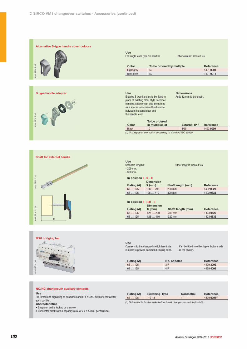
102 General Catalogue 2011-2012 SOCOMEC102
SIRCO VM1 changeover switches - Accessories (continued)
IP20 bridging bar
com
ut_0
05_a
_1_c
at
UseConnects to the standard switch terminals in order to provide common bridging point.
Can be fitted to either top or bottom side of the switch.
Rating (A) No. of poles Reference63 … 125 3 P 4499 300663 … 125 4 P 4499 4006
NO/NC changeover auxiliary contacts
UsePre-break and signalling of positions I and II: 1 NO/NC auxiliary contact for each position.Characteristics• Snaps on and is locked by a screw.• Connector block with a capacity max. of 2 x 1.5 mm2 per terminal.
Rating (A) Switching type Contact(s) Reference63 … 125 I - 0 - II 1 4439 0001(1)
(1) Not available for the make before break changeover switch (I-I+II-II).
Shaft for external handle
acce
s_14
6_b_
1_ca
t
Xacce
s_20
2_a_
1_x_
cat
UseStandard lengths: - 200 mm,- 320 mm.
Other lengths: Consult us.
In position I - 0 - II
Rating (A) DimensionX (mm) Shaft length (mm) Reference
63 … 125 128 … 290 200 mm 1402 082063 … 125 128 … 410 320 mm 1402 0832
In position I - I+II - II
Rating (A) DimensionX (mm) Shaft length (mm) Reference
63 … 125 128 … 290 200 mm 1403 082063 … 125 128 … 410 320 mm 1403 0832
Alternative S-type handle cover colours
acce
s_19
8_a_
1_ca
t
UseFor single lever type S1 handles. Other colours: Consult us.
Color To be ordered by multiple ReferenceLight grey 50 1401 0001Dark grey 50 1401 0011
S type handle adapter
acce
s_18
7_a_
1_ca
t
UseEnables S type handles to be fitted in place of existing older style Socomec handles. Adapter can also be utilised as a spacer to increase the distance between the panel door and the handle lever.
DimensionsAdds 12 mm to the depth.
ColorTo be orderedin multiples of External IP(1) Reference
Black 10 IP65 1493 0000(1) IP: Degree of protection according to standard IEC 60529.
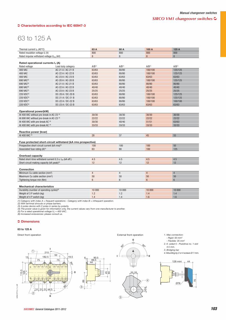
103General Catalogue 2011-2012SOCOMEC 103
Manual changeover switches
SIRCO VM1 changeover switches
Characteristics according to IEC 60947-3
Thermal current Ith (40°C) 63 A 80 A 100 A 125 ARated insulation voltage Ui (V) 800 800 800 800Rated impulse withstand voltage Uimp (kV) 8 8 8 8
Rated operational currents Ie (A) Rated voltage Load duty category A/B(1) A/B(1) A/B(1) A/B(1)
400 VAC AC-21 A / AC-21 B 63/63 80/80 100/100 125/125400 VAC AC-22 A / AC-22 B 63/63 80/80 100/100 125/125400 VAC AC-23 A / AC-23 B 63/63 63/63 63/63 63/63690 VAC(2) AC-20 A / AC-20 B 63/63 80/80 100/100 125/125690 VAC(2) AC-21 A / AC-21 B 63/63 80/80 80/80 80/80690 VAC(2) AC-22 A / AC-22 B 40/40 40/40 40/40 40/40690 VAC(2) AC-23 A / AC-23 B 25/25 25/25 25/25 25/25220 VDC(3) DC-20 A / DC-20 B 63/63 80/80 100/100 125/125220 VDC(3) DC-21 A / DC-21 B 63/63 80/80 100/100 125/125220 VDC(3) DC-22 A / DC-22 B 63/63 80/80 100/100 100/100220 VDC(3) DC-23 A / DC-23 B 63/63 63/63 63/63 63/63
Operational power(kW) At 400 VAC without pre-break in AC-23 (4) 30/30 30/30 30/30 30/30At 690 VAC without pre-break in AC-23 (4) 22/22 22/22 22/22 22/22At 400 VAC with pre-break AC (4) 30/30 40/40 51/51 63/63At 400 VAC with pre-break AC (4) 33/33 33/33 33/33 33/33
Reactive power (kvar) At 400 VAC (4) 28 37 45 55
Fuse protected short-circuit withstand (kA rms prospective)Prospective short-circuit current (kA rms)(5) 100 100 100 50Associated fuse rating (A)(5) 63 80 100 125
Overload capacityRated short-time withstand current 0.3 s. ICW (kA eff.) 4.5 4.5 4.5 4.5Short-circuit making capacity (kA peak)(5) 12 12 12 12
ConnectionMinimum Cu cable section (mm2) 4 4 4 4Maximum Cu cable section (mm2) 50 50 50 50Tightening torque min (Nm) 6 6 6 6
Mechanical characteristicsDurability (number of operating cycles)(6) 10 000 10 000 10 000 10 000Weight of 3 P switch (kg) 1.2 1.2 1.4 1.4Weight of 4 P switch (kg) 1.4 1.4 1.6 1.6
63 to 125 A
(1) Category with index A = frequent operations - Category with index B = infrequent operation.(2) With terminal shrouds or phase barriers.(3) 4-poles device with 2 poles in series by polarity.(4) The power value is given for information only, the current values vary from one manufacturer to another.(5) For a rated operational voltage Ue = 400 VAC.(6) Increased endurances: please consult us.
Direct front operation External front operation
I
II
0
13 182.5
21552
105
115.
5
75
= =
19.5
21 21 21 44.5
75
2
128 mini
9445
90.569.5
44
89
6
1
4
5
3
44
70
90° 90°
90°
90°
1414
20 20
I II
0
Ø78
com
ut_0
13_e
_1_x
_cat
1. Max connection:- Rigid: 50 mm2,
- Flexible: 35 mm2
2. 6 -sided 5 - Pozidrive no. 1 slot 4.5 mm.
3. Bridging bar4. Mounting by 2 or 4 screws Ø 7 mm.
63 to 125 A
Dimensions
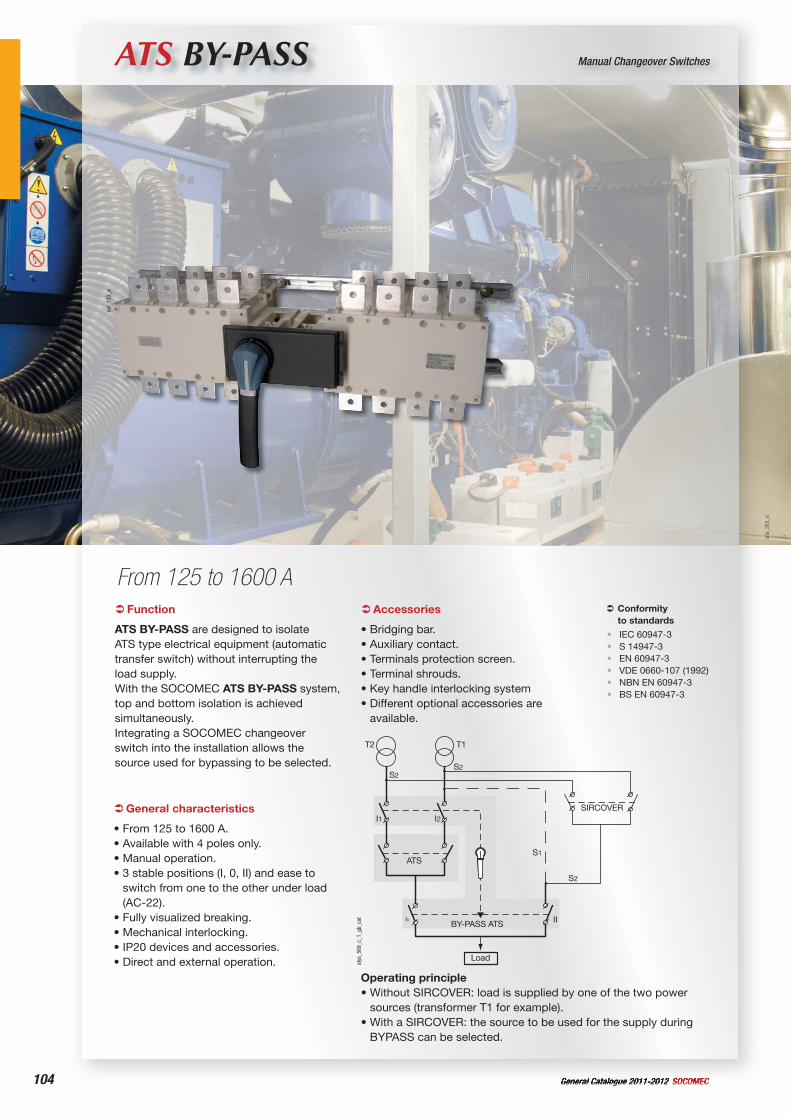
104 General Catalogue 2011-2012 SOCOMEC
ATS BY-PASS Manual Changeover Switches
From 125 to 1600 A
Operating principle• Without SIRCOVER: load is supplied by one of the two power
sources (transformer T1 for example).• With a SIRCOVER: the source to be used for the supply during
BYPASS can be selected.
I3BY-PASS ATS
SIRCOVER
Load
ATS
I1 I2
S2S2
S2
S1
T2 T1
II
atys
_569
_c_1
_gb_
cat
Function
ATS BY-PASS are designed to isolate ATS type electrical equipment (automatic transfer switch) without interrupting the load supply. With the SOCOMEC ATS BY-PASS system, top and bottom isolation is achieved simultaneously.Integrating a SOCOMEC changeover switch into the installation allows the source used for bypassing to be selected.
Conformityto standards
IEC 60947-3S 14947-3EN 60947-3VDE 0660-107 (1992) NBN EN 60947-3BS EN 60947-3
••••••
General characteristics
• From 125 to 1600 A.• Available with 4 poles only.• Manual operation.• 3 stable positions (I, 0, II) and ease to
switch from one to the other under load (AC-22).
• Fully visualized breaking.• Mechanical interlocking.• IP20 devices and accessories.• Direct and external operation.
Accessories
• Bridging bar.• Auxiliary contact.• Terminals protection screen.• Terminal shrouds.• Key handle interlocking system• Different optional accessories are
available.
svr_
133_
a
site
_363
_a
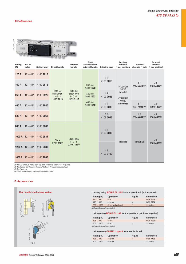
105General Catalogue 2011-2012SOCOMEC 105
Manual Changeover Switches
ATS BY-PASS
Rating(A)
No. of poles Switch body Direct handle
External handle
Shaft extensions for
external handle Bridging bars
Auxiliarycontacts
(1 per position)Terminal
shrouds (1 set)
Terminal screens
(1 per position)
125 A 12 + 4 P 4100 9813
Type S3 Black IP65
I - O - II1433 3113
Type S3 Black IP65
I - O - II1433 3113
200 mm1401 1520
320 mm1401 1532
400 mm1401 1540
1 P4109 0019
1st contact NO/NF
included
2nd contact NO/NC
4109 0021
4 P 2694 4014(1)(2)
4 P1509 4012(3)160 A 12 + 4 P 4100 9816
250 A 12 + 4 P 4100 9825 1 P4109 0025
400 A 12 + 4 P 4100 9840 1 P4109 0039
4 P 2694 4021(1)(2)
4 P1509 4025(3)
630 A 12 + 4 P 4100 9863 1 P4109 0063
4 P2694 4051(1)(2)
4 P1509 4063(3)
800 A 12 + 4 P 4100 9880
Black2799 7062
Black IP65I - 0 - II
2799 7147(4)
1 P4109 0080
included consult us 4 P1509 4080(3)
1000 A 12 + 4 P 4100 9881
1250 A 12 + 4 P 4100 9882 1 P
4109 0160 1600 A 12 + 4 P 4100 9886
(1) To fully shroud front, rear, top and bottom 8 references required.(2) To shroud front switch top and bottom 4 references required.(3) Top/bottom.(4) Shaft extension for external handle included.
svr_
134_
a_1_
x_ca
t
Accessories
Key handle interlocking system
acce
s_00
1_a_
1_x_
cat
Locking using RONIS EL11AP lock in position 0 (not included)
Rating (A) Operation Figure Reference125 ... 630 direct 1 4109 1006 (1)
125 ... 630 external 3 1499 7701800 ... 1600 direct and external 2 consult us
acce
s_13
2_a_
1_x_
cat
acce
s_15
8_a_
1_x_
cat
Fig.1 Fig. 2
Fig. 3
Locking using RONIS EL11AP lock in positions I, 0, II (not supplied)
Rating (A) Operation Figure Reference125 ... 630 direct 1 4109 1002(1)
800 ... 1600 direct 2 consult us(1) Specific handle included.
(1) Specific handle included.
Locking using CASTELL type K lock (not included)
Rating (A) Operation Figure Reference125 ... 630 external 3 1499 7702800 ... 1600 external consult us
References
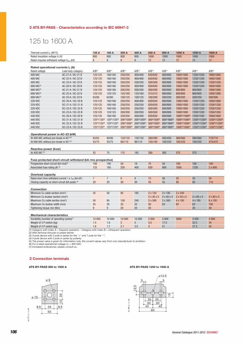
106 General Catalogue 2011-2012 SOCOMEC106
Thermal current Ith (40°C) 125 A 160 A 250 A 400 A 630 A 800 A 1000 A 1250 A 1600 ARated insulation voltage Ui (V) 800 800 800 800 1000 1000 1000 1000 1000Rated impulse withstand voltage Uimp (kV) 8 8 8 8 12 12 12 12 12
Rated operational currents Ie (A) Rated voltage Load duty category A/B(1) A/B(1) A/B(1) A/B(1) A/B(1) A/B(1) A/B(1) A/B(1) A/B(1)
400 VAC AC-21 A / AC-21 B 125/125 160/160 250/250 400/400 630/630 800/800 1000/1000 1250/1250 1600/1600400 VAC AC-22 A / AC-22 B 125/125 160/160 250/250 400/400 630/630 800/800 1000/1000 1250/1250 1600/1600400 VAC AC-23 A / AC-23 B 125/125 160/160 250/250 250/250 500/500 800/800 1000/1000 1250/1250 1250/1250690 VAC(2) AC-20 A / AC-20 B 125/125 160/160 250/250 400/400 630/630 800/800 1000/1000 1250/1250 1600/1600690 VAC(2) AC-21 A / AC-21 B 125/125 160/160 200/250 200/250 500/500 800/800 800/800 800/800 1000/1000690 VAC(2) AC-22 A / AC-22 B 125/125 125/125 125/160 125/160 315/315 800/800 800/800 800/800 1000/1000690 VAC(2) AC-23 A / AC-23 B 63/80 63/80 100/125 100/125 160/200 200/250 200/250 200/250 500/500220 VDC DC-20 A / DC-20 B 125/125 160/160 250/250 400/400 630/630 800/800 1000/1000 1250/1250 1600/1600220 VDC DC-21 A / DC-21 B 125/125 160/160 250/250 250/250 630/630 800/800 1000/1000 1250/1250 1250/1250220 VDC DC-22 A / DC-22 B 125/125 160/160 250/250 250/250 500/500 800/800 1000/1000 1250/1250 1250/1250220 VDC DC-23 A / DC-23 B 125/125 125/125 200/200 200/200 500/500 800/800 1000/1000 1250/1250 1250/1250440 VDC DC-20 A / DC-20 B 125/125 160/160 250/250 400/400 630/630 800/800 1000(4)/1000(4) 1250/1250 1600/1600440 VDC DC-21 A / DC-21 B 125(3)/125(3) 125(3) /125(3) 200(3)/200(3) 200(3)/200(3) 500(3)/500(3) 800(4)/800(4) 1000(4)/1000(4) 1250(4)/1250(4) 1250(4)/1250(4)
440 VDC DC-22 A / DC-22 B 125(3)/125(3) 125(3)/125(3) 200(3)/200(3) 200(3)/200(3) 500(3)/500(3) 800(4)/800(4) 1000(4)/1000(4) 1250(4)/1250(4) 1250(4)/1250(4)
440 VDC DC-23 A / DC-23 B 125(4)/125(4) 125(4)/125(4) 200(4)/200(4) 200(4)/200(4) 500(4)/500(4) 800(4)/800(4) 1000(4)/1000(4) 1250(4)/1250(4) 1250(4)/1250(4)
Operational power in AC-23 (kW) At 400 VAC without pre-break in AC(1)(5) 63/63 80/80 132/132 132/132 280/280 450/450 560/560 560/560 710/710At 690 VAC without pre-break in AC(1)(5) 55/75 55/75 90/110 90/110 150/185 185/220 185/220 185/220 475/475
Reactive power (kvar) At 400 VAC (5) 55 75 115 185 290 365 575 575
Fuse protected short-circuit withstand (kA rms prospective)Prospective short-circuit (kA rms)(6) 100 100 50 18 70 50 100 100 100Associated fuse rating (A) (6) 125 160 250 400 630 800 1000 1250 2 x 800
Overload capacityRated short-time withstand current 1 s. ICW (kA eff.) 7 7 9 9 13 26 35 35 50Closing capacity on short-circuit (kA peak) (6) 20 20 30 30 45 55 80 80 110
ConnectionMinimum Cu cable section (mm2) 35 50 95 185 2 x 150 2 x 185 2 x 240Minimum Cu busbar section (mm2) 2 x 30 x 5 2 x 40 x 5 2 x 50 x 5 2 x 60 x 5 2 x 80 x 5Maximum Cu cable section (mm2) 50 95 150 240 2 x 300 2 x 300 4 x 185 4 x 185 6 x 185Maximum Cu busbar width (mm) 25 25 32 32 50 63 63 63 100Tightening torque min (Nm) 9 9 20 20 20 20 40
Mechanical characteristicsDurability (number of operating cycles)(7) 10 000 10 000 10 000 10 000 5 000 3 000 3000 3 000 4 000Weight of 3 P switch (kg) 1.5 1.6 2 3 3,5 17.5 22.5 34Weight of 4 P switch (kg) 1.6 1.7 2.1 3.5 4 21 27.5 42
125 to 1600 A
(1) Category with index A = frequent operation - Category with index B = infrequent operation.(2) With terminal shrouds or phase barrier.(3) 3-pole device with 2 pole in series for the "+" and 1 pole for the "-".(4) 4-pole device with 2 pole in series by polarity.(5) The power value is given for information only, the current values vary from one manufacturer to another.v(6) For a rated operational voltage Ue = 400 VAC.(7) Increased endurances: please consult us.
ATS BY-PASS - Characteristics according to IEC 60947-3
15
5 5
12.5
25 253030
454590
ø12.5
svr_
098_
a_1_
x_ca
t
ATS BY-PASS 1250 to 1600 A
33 8.58.5
50
3310
ø 9
ø 15
svr_
077_
a_1_
x_ca
t
ATS BY-PASS 800 to 1000 A
Connection terminals
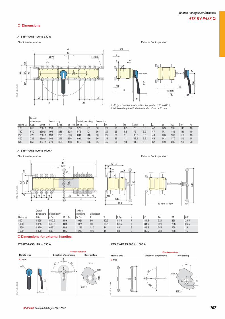
107General Catalogue 2011-2012SOCOMEC 107
Manual Changeover Switches
ATS BY-PASS
Direct front operation External front operation
Rating (A)
Overalldimensions Switch body Switch mounting ConnectionA 8p. E min H J 8p. J1 8p. M 8p. N T U V W X 8p. Y Z Z1 AA BA AC
125 610 260±1 193 238 338 576 101 36 20 25 8.5 76 3.5 47 143 135 115 10160 610 260±1 193 238 338 576 101 36 20 25 8.5 76 3.5 47 143 135 115 10250 725 260±1 193 295 396 691 116 50 25 30 11 83.5 3.5 49 143 160 130 10400 725 260±1 193 295 396 691 116 50 35 35 11 83.5 3.5 49 143 170 140 15630 850 337±1 270 358 458 816 176 65 45 50 13 91.5 5 62 199 235 220 20
AA
BA N
CA
CA
Ø W
U
II I
A
M
6 Ø 8.5
X XT T T T T T
J J1
25
61
H
E min.
1
Z1
Y Y
210
Z
V
H
19
210
61
A
atys
_617
_c_1
_x_c
at
ATS BY-PASS 125 to 630 A
Dimensions
A. S3 type handle for external front operation: 125 to 630 A.1. Minimum length with shaft extension: E min + 50 mm.
Direct front operation External front operation
Rating (A)
Overalldimensions Switch body
Switchmounting Connection
A 8p. J 8p. J1 8p. M 8p. T V X 8p. Y Z AA BA AC800 1 055 510.5 189 1 021 80 60.5 81.5 7 84.5 321 268 26.51000 1 055 510.5 189 1 021 80 60.5 81.5 7 84.5 321 268 26.51250 1 320 643 195 1 286 120 44 88 8 85.5 288 258 151600 1 320 643 195 1 286 120 44 88 8 85.5 288 258 15
A
V
M 271.5Z
Y
19
110
344
425
380
Y
AA
BA
250
CA
CA
324==
90
JJT T TJ1
545
T XX TT
E min. = 460
atys
_742
_b_1
_x_c
at
ATS BY-PASS 800 to 1600 A
Dimensions for external handles
S3 type
90° 90°
4 Ø 7
1414
20 20
(1)Ø D
I II
0
Ø78
61
210
Direction of operationHandle type
Front operation
Door drilling
svr_
144_
a_1_
gb_c
at
ATS BY-PASS 125 to 630 A
V type
90°
Ø 31
50
50
4 Ø 6.5
I
545
90°
II
0
Direction of operationHandle type
Front operation
Door drilling
svr_
145_
a_1_
gb_c
at
ATS BY-PASS 800 to 1600 A
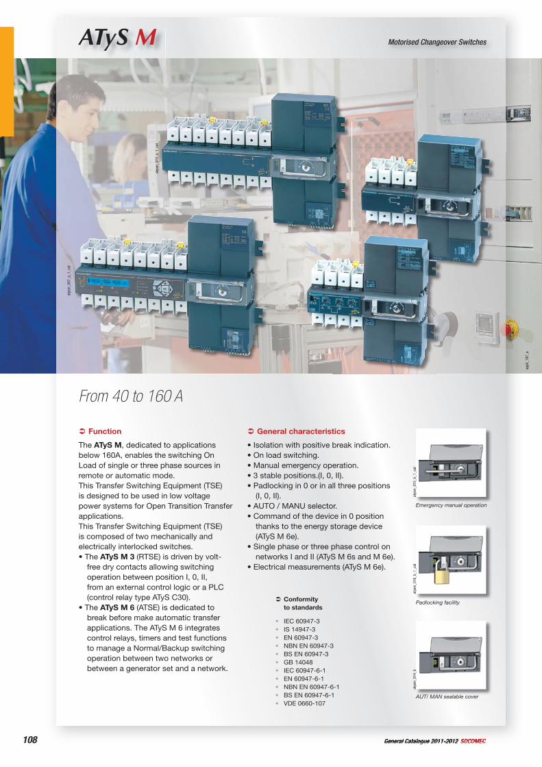
108 General Catalogue 2011-2012 SOCOMEC
ATyS M Motorised Changeover Switches
From 40 to 160 A
atys
m_0
13_a
_1_c
at
atys
m_0
07_a
_1_c
at
atys
m_0
14_b
AUT/ MAN sealable cover
atys
m_0
15_b
_1_c
at
Emergency manual operation
atys
m_0
16_b
_1_c
at
Padlocking facility
Function
The ATyS M, dedicated to applications below 160A, enables the switching On Load of single or three phase sources in remote or automatic mode.This Transfer Switching Equipment (TSE) is designed to be used in low voltage power systems for Open Transition Transfer applications.This Transfer Switching Equipment (TSE) is composed of two mechanically and electrically interlocked switches.• The ATyS M 3 (RTSE) is driven by volt-
free dry contacts allowing switching operation between position I, 0, II, from an external control logic or a PLC (control relay type ATyS C30).
• The ATyS M 6 (ATSE) is dedicated to break before make automatic transfer applications. The ATyS M 6 integrates control relays, timers and test functions to manage a Normal/Backup switching operation between two networks or between a generator set and a network.
Conformityto standards
IEC 60947-3IS 14947-3EN 60947-3NBN EN 60947-3BS EN 60947-3GB 14048IEC 60947-6-1EN 60947-6-1NBN EN 60947-6-1BS EN 60947-6-1VDE 0660-107
•••••••••••
General characteristics
• Isolation with positive break indication.• On load switching.• Manual emergency operation.• 3 stable positions.(I, 0, II).• Padlocking in 0 or in all three positions
(I, 0, II).• AUTO / MANU selector.• Command of the device in 0 position
thanks to the energy storage device (ATyS M 6e).
• Single phase or three phase control on networks I and II (ATyS M 6s and M 6e).
• Electrical measurements (ATyS M 6e).
appl
i_18
7_a
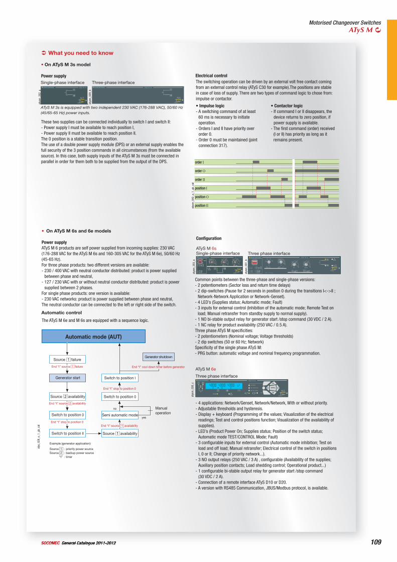
109General Catalogue 2011-2012SOCOMEC
Motorised Changeover SwitchesATyS M
What you need to know
• On ATyS M 3s model
Power supply Electrical control
order I
order O
order II
position I
position O
position IIatys
m_0
42_a
_1_g
b_ca
t
Common points between the three-phase and single-phase versions: - 2 potentiometers (Sector loss and return time delays) - 2 dip-switches (Pause for 2 seconds in position 0 during the transitions I<->II ;
Network-Network Application or Network-Genset).- 4 LED’s (Supplies status; Automatic mode; Fault)- 3 inputs for external control (Inhibition of the automatic mode; Remote Test on
load; Manual retransfer from standby supply to normal supply).- 1 NO bi-stable output relay for generator start /stop command (30 VDC / 2 A).- 1 NC relay for product availability (250 VAC / 0.5 A).Three phase ATyS M specificities: - 2 potentiometers (Nominal voltage; Voltage thresholds) - 2 dip switches (50 or 60 Hz; Network)Specificity of the single phase ATyS M: - PRG button: automatic voltage and nominal frequency programmation.
- 4 applications: Network/Genset, Network/Network, With or without priority.- Adjustable thresholds and hysteresis.- Display + keyboard (Programming of the values; Visualization of the electrical
readings; Test and control positions function; Visualization of the availability of supplies).
- LED’s (Product Power On; Supplies status; Position of the switch status; Automatic mode TEST/CONTROL Mode; Fault)
- 3 configurable inputs for external control (Automatic mode inhibition; Test on load and off load; Manual retransfer; Electrical control of the switch in positions I, 0 or II; Change of priority network...).
- 3 NO output relays (250 VAC / 3 A) , configurable (Availability of the supplies; Auxiliary position contacts; Load shedding control; Operational product...)
- 1 configurable bi-stable output relay for generator start /stop command (30 VDC / 2 A).
- Connection of a remote interface ATyS D10 or D20.- A version with RS485 Communication, JBUS/Modbus protocol, is available.
ATyS M 6e
• Impulse logic- A switching command of at least
60 ms is necessary to initiate operation.
- Orders I and II have priority over order 0.
- Order 0 must be maintained (joint connection 317).
• Contactor logic- If command I or II disappears, the
device returns to zero position, if power supply is available.
- The first command (order) received (I or II) has priority as long as it remains present.
• On ATyS M 6s and 6e models
Power supplyATyS M 6 products are self power supplied from incoming supplies: 230 VAC (176-288 VAC for the ATyS M 6s and 160-305 VAC for the ATyS M 6e), 50/60 Hz (45-65 Hz).For three phase products: two different versions are available: - 230 / 400 VAC with neutral conductor distributed: product is power supplied
between phase and neutral,- 127 / 230 VAC with or without neutral conductor distributed: product is power
supplied between 2 phases.For single phase products: one version is available: - 230 VAC networks: product is power supplied between phase and neutral,The neutral conductor can be connected to the left or right side of the switch.
These two supplies can be connected individually to switch I and switch II: - Power supply I must be available to reach position I,- Power supply II must be available to reach position II.The 0 position is a stable transition position.The use of a double power supply module (DPS) or an external supply enables the full security of the 3 position commands in all circumstances (from the available source). In this case, both supply inputs of the ATyS M 3s must be connected in parallel in order for them both to be supplied from the output of the DPS.
Source failure
Automatic mode (AUT)
End “t” source 1 failure
Source availability
Generator shutdown
Semi automatic mode
Source availability
End “t” source 2 availability
End “t” stop to position 0End “t” source 1 availability
End “t” stop to position 0
End “t” cool down timer before generator
no
yes
Source 1 : priority power sourceSource 2 : backup power source “t” : timer
2
1
1
Example (generator application):
Switch to position 0
Switch to position II
Switch to position I
Switch to position 0
Manualoperation
Generator start
atys
_028
_e_1
_gb_
cat
The ATyS M 6e and M 6s are equipped with a sequence logic.
Automatic control
atys
m_0
29_b
Three-phase interface
atys
m_0
30_c
Three phase interface
Three phase interface
atys
m_0
31_b
The switching operation can be driven by an external volt free contact coming from an external control relay (ATyS C30 for example).The positions are stable in case of loss of supply. There are two types of command logic to chose from: impulse or contactor.
atys
m_2
02_a
ATyS M 3s is equipped with two independent 230 VAC (176-288 VAC), 50/60 Hz (45/65-65 Hz) power inputs.
Single-phase interface
atys
m_2
03_a
Configuration
ATyS M 6sSingle-phase interface
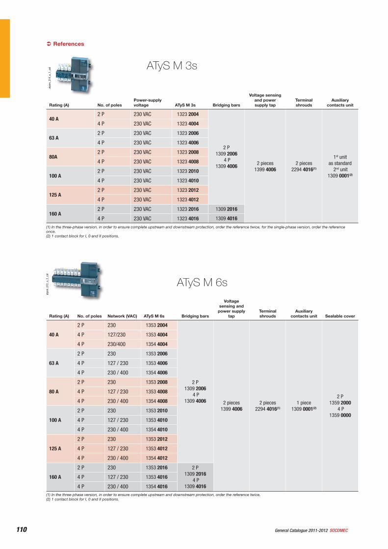
110 General Catalogue 2011-2012 SOCOMEC110
Referencesat
ysm
_012
_a_2
_cat
ATyS M 3s
ATyS M 6s
atys
m_2
14_a
_1_c
at
Rating (A) No. of polesPower-supply voltage ATyS M 3s Bridging bars
Voltage sensing and power supply tap
Terminal shrouds
Auxiliarycontacts unit
40 A2 P 230 VAC 1323 2004
2 P1309 2006
4 P1309 4006 2 pieces
1399 4006 2 pieces
2294 4016(1)
1st unitas standard
2nd unit1309 0001(2)
4 P 230 VAC 1323 4004
63 A2 P 230 VAC 1323 2006
4 P 230 VAC 1323 4006
80A2 P 230 VAC 1323 2008
4 P 230 VAC 1323 4008
100 A2 P 230 VAC 1323 2010
4 P 230 VAC 1323 4010
125 A2 P 230 VAC 1323 2012
4 P 230 VAC 1323 4012
160 A2 P 230 VAC 1323 2016 1309 2016
4 P 230 VAC 1323 4016 1309 4016
(1) In the three-phase version, in order to ensure complete upstream and downstream protection, order the reference twice, for the single-phase version, order the reference once.(2) 1 contact block for I, 0 and II positions.
Rating (A) No. of poles Network (VAC) ATyS M 6s Bridging bars
Voltage sensing and
power supply tap
Terminal shrouds
Auxiliarycontacts unit Sealable cover
40 A
2 P 230 1353 2004
2 P1309 2006
4 P1309 4006 2 pieces
1399 4006 2 pieces
2294 4016(1)1 piece
1309 0001(2)
2 P1359 2000
4 P1359 0000
4 P 127/230 1353 4004
4 P 230/400 1354 4004
63 A
2 P 230 1353 2006
4 P 127 / 230 1353 4006
4 P 230 / 400 1354 4006
80 A
2 P 230 1353 2008
4 P 127 / 230 1353 4008
4 P 230 / 400 1354 4008
100 A
2 P 230 1353 2010
4 P 127 / 230 1353 4010
4 P 230 / 400 1354 4010
125 A
2 P 230 1353 2012
4 P 127 / 230 1353 4012
4 P 230 / 400 1354 4012
160 A
2 P 230 1353 2016 2 P1309 2016
4 P1309 4016
4 P 127 / 230 1353 4016
4 P 230 / 400 1354 4016(1) In the three-phase version, in order to ensure complete upstream and downstream protection, order the reference twice.(2) 1 contact block for I, 0 and II positions.
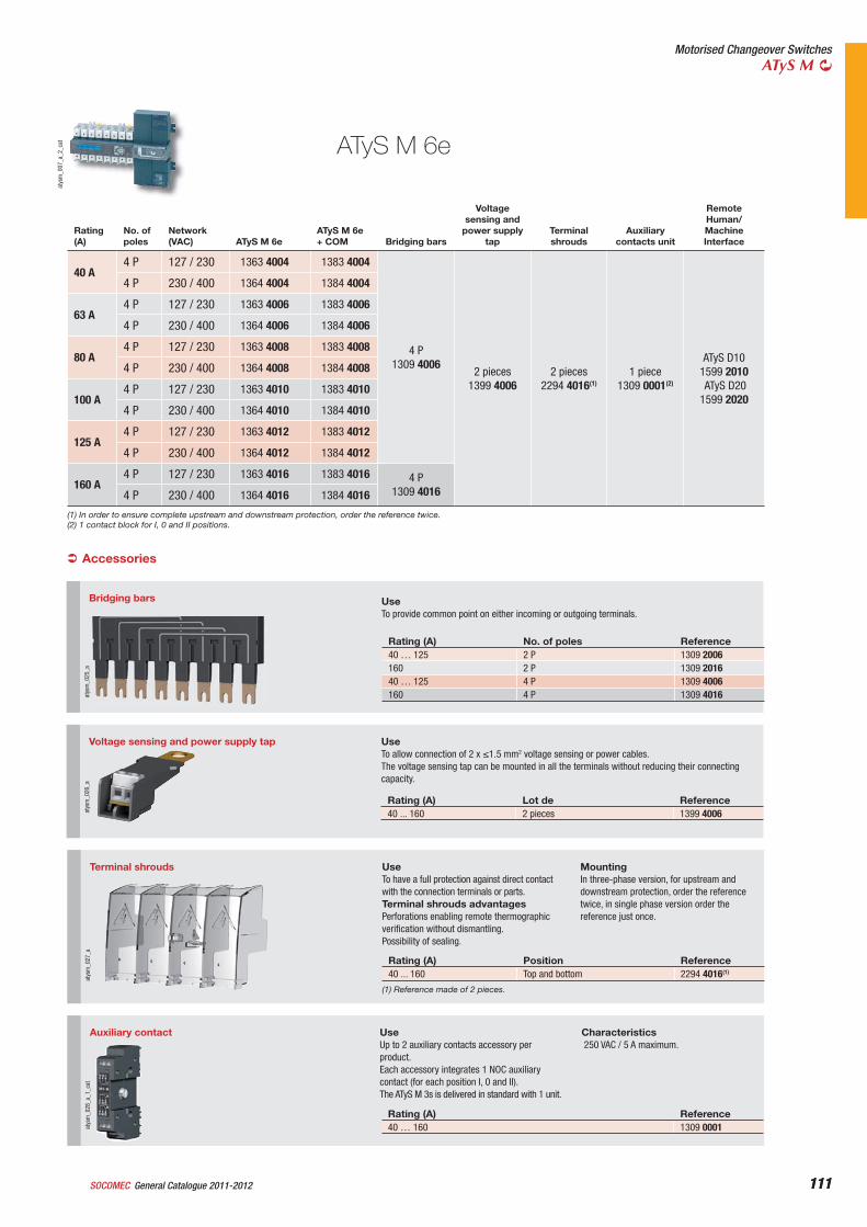
111General Catalogue 2011-2012SOCOMEC 111
Motorised Changeover SwitchesATyS M
atys
m_0
07_a
_2_c
at
Bridging bars
atys
m_0
25_a
UseTo provide common point on either incoming or outgoing terminals.
Rating (A) No. of poles Reference40 … 125 2 P 1309 2006160 2 P 1309 201640 … 125 4 P 1309 4006160 4 P 1309 4016
Accessories
Voltage sensing and power supply tap
atys
m_0
26_a
UseTo allow connection of 2 x 1.5 mm2 voltage sensing or power cables.The voltage sensing tap can be mounted in all the terminals without reducing their connecting capacity.
Rating (A) Lot de Reference40 ... 160 2 pieces 1399 4006
ATyS M 6e
Rating(A)
No. of poles
Network(VAC) ATyS M 6e
ATyS M 6e + COM Bridging bars
Voltage sensing and
power supply tap
Terminal shrouds
Auxiliarycontacts unit
RemoteHuman/MachineInterface
40 A4 P 127 / 230 1363 4004 1383 4004
4 P1309 4006
2 pieces1399 4006
2 pieces2294 4016(1)
1 piece1309 0001(2)
ATyS D101599 2010 ATyS D201599 2020
4 P 230 / 400 1364 4004 1384 4004
63 A4 P 127 / 230 1363 4006 1383 4006
4 P 230 / 400 1364 4006 1384 4006
80 A4 P 127 / 230 1363 4008 1383 4008
4 P 230 / 400 1364 4008 1384 4008
100 A4 P 127 / 230 1363 4010 1383 4010
4 P 230 / 400 1364 4010 1384 4010
125 A4 P 127 / 230 1363 4012 1383 4012
4 P 230 / 400 1364 4012 1384 4012
160 A4 P 127 / 230 1363 4016 1383 4016 4 P
1309 4016 4 P 230 / 400 1364 4016 1384 4016
Auxiliary contact
atys
m_0
28_a
_1_c
at
UseUp to 2 auxiliary contacts accessory per product.Each accessory integrates 1 NOC auxiliary contact (for each position I, 0 and II).The ATyS M 3s is delivered in standard with 1 unit.
Characteristics 250 VAC / 5 A maximum.
Rating (A) Reference40 … 160 1309 0001
Terminal shrouds
atys
m_0
27_a
UseTo have a full protection against direct contact with the connection terminals or parts.Terminal shrouds advantagesPerforations enabling remote thermographic verification without dismantling.Possibility of sealing.
MountingIn three-phase version, for upstream and downstream protection, order the reference twice, in single phase version order the reference just once.
Rating (A) Position Reference40 ... 160 Top and bottom 2294 4016(1)
(1) Reference made of 2 pieces.
(1) In order to ensure complete upstream and downstream protection, order the reference twice.(2) 1 contact block for I, 0 and II positions.
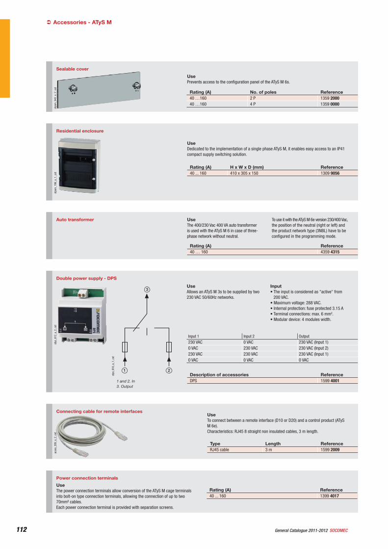
112 General Catalogue 2011-2012 SOCOMEC112
Accessories - ATyS M
Sealable cover
atys
m_0
43_a
_2_c
at
UsePrevents access to the configuration panel of the ATyS M 6s.
Rating (A) No. of poles Reference40 …160 2 P 1359 200040 …160 4 P 1359 0000
Connecting cable for remote interfaces
Type Length ReferenceRJ45 cable 3 m 1599 2009
acce
s_20
9_a_
2_ca
t
UseTo connect between a remote interface (D10 or D20) and a control product (ATyS M 6e).Characteristics: RJ45 8 straight non insulated cables, 3 m length.
Residential enclosure
atys
m_1
96_a
_1_c
at
UseDedicated to the implementation of a single phase ATyS M, it enables easy access to an IP41 compact supply switching solution.
Rating (A) H x W x D (mm) Reference40 ... 160 410 x 305 x 150 1309 9056
Auto transformer UseThe 400/230 Vac 400 VA auto transformer is used with the ATyS M 6 in case of three-phase network without neutral.
To use it with the ATyS M 6e version 230/400 Vac, the position of the neutral (right or left) and the product network type (3NBL) have to be configured in the programming mode.
Rating (A) Reference40 … 160 4359 4315
Power connection terminals
UseThe power connection terminals allow conversion of the ATyS M cage terminals into bolt-on type connection terminals, allowing the connection of up to two 70mm² cables. Each power connection terminal is provided with separation screens.
Rating (A) Reference40 ... 160 1399 4017
Double power supply - DPS
atys
_612
_a_2
_cat
3
21
atys
_616
_a_1
_cat
1 and 2. In3. Output
UseAllows an ATyS M 3s to be supplied by two 230 VAC 50/60Hz networks.
Input• The input is considered as "active" from
200 VAC.• Maximum voltage: 288 VAC.• Internal protection: fuse protected 3.15 A• Terminal connections: max. 6 mm2.• Modular device: 4 modules width.
Description of accessories ReferenceDPS 1599 4001
Input 1 Input 2 Output230 VAC 0 VAC 230 VAC (Input 1)0 VAC 230 VAC 230 VAC (Input 2)230 VAC 230 VAC 230 VAC (Input 1)0 VAC 0 VAC 0 VAC
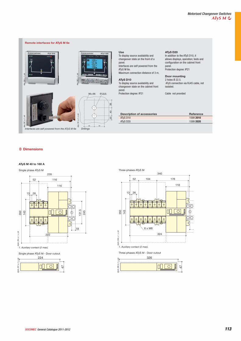
113General Catalogue 2011-2012SOCOMEC 113
Motorised Changeover SwitchesATyS M
Remote interfaces for ATyS M 6e
atys
_564
_c_1
_cat
atys
_565
_c_1
_cat
atys
_597
_a_1
_cat
Interfaces are self powered from the ATyS M 6e
Ø 22.5
4036
20
= =
96 x 96
atys
_161
_a_1
_x_c
at
Drillings
UseTo display source availability and changeover state on the front of a panel.Interfaces are self powered from the ATyS M 6e.Maximum connection distance of 3 m.
ATyS D10To display source availability and changeover state on the cabinet front panel. Protection degree: IP21
ATyS D20In addition to the ATyS D10, it allows displays, operation; tests and configuration on the cabinet front panel.Protection degree: IP21
Door mounting2 holes Ø 22.5. ATyS connection via RJ45 cable, not isolated.
Cable not provided
Description of accessories ReferenceATyS D10 1599 2010ATyS D20 1599 2020
Dimensions
Single phase ATyS M
1
235
11652
222
116
245
131.
5
143
350
2613
18
atys
m_2
04_a
_1_x
_cat
1. Auxiliary contact (2 max).
ATyS M 40 to 160 A
Single phase ATyS M - Door cutout
224
47
atys
m_2
07_a
_1_x
_cat
Three-phases ATyS M
1
340
17610452
324
116
143
350
2613
6 x M6
atys
m_0
34_a
_1_x
_cat
1. Auxiliary contact (2 max).
Three-phases ATyS M - Door cutout
326
47
atys
m_0
08_b
_1_x
_cat
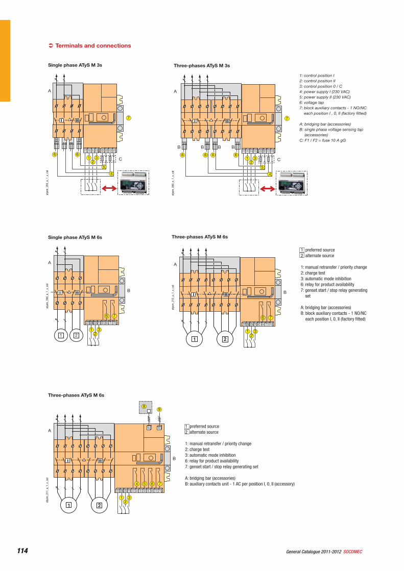
114 General Catalogue 2011-2012 SOCOMEC114
atys
m_2
12_a
_1_x
_cat
Three-phases ATyS M 6s
A
1 2
B
210209208207 74736463
312
76
atys
m_2
06_a
_1_x
_cat
Single phase ATyS M 6s
1 preferred source2 alternate source
1: manual retransfer / priority change2: charge test3: automatic mode inhibition6: relay for product availability7: genset start / stop relay generating
set
A: bridging bar (accessories) B: block auxiliary contacts - 1 NO/NC
each position I, 0, II (factory fitted)
1 preferred source2 alternate source
1: manual retransfer / priority change2: charge test3: automatic mode inhibition6: relay for product availability7: genset start / stop relay generating set
A: bridging bar (accessories) B: auxiliary contacts unit - 1 AC per position I, 0, II (accessory)
Three-phases ATyS M 6s
A
B
210209208207 54534443
312
54
74736463
76
RJ
8
1 2
RS
9
atys
m_2
11_a
_1_x
_cat
Terminals and connections
A
1 2
B
210209208207 74736463
312
76
101102201202313314315317
A
BB
3
4
6 6
21 C
7
5
atys
m_2
05_a
_1_x
_cat
Single phase ATyS M 3s
101102201202313314315317
A
BBBB
3
5
4
6 6 6 6
21 C
7
atys
m_0
40_e
_1_x
_cat
1: control position I2: control position II3: control position 0 / C4: power supply I (230 VAC) 5: power supply II (230 VAC) 6: voltage tap7: block auxiliary contacts - 1 NO/NC
each position I , 0, II (factory fitted)
A: bridging bar (accessories) B: single phase voltage sensing tap
(accessories)C: F1 / F2 = fuse 10 A gG
Three-phases ATyS M 3s
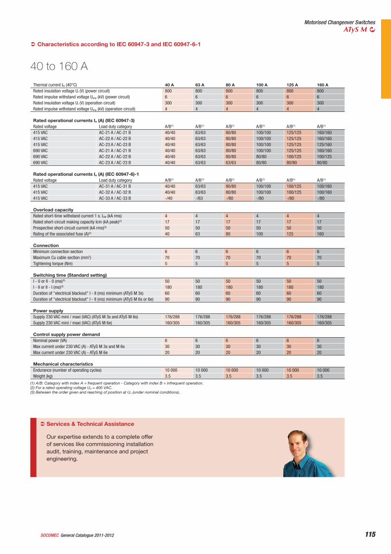
115General Catalogue 2011-2012SOCOMEC 115
Motorised Changeover SwitchesATyS M
40 to 160 A
Thermal current Ith (40°C) 40 A 63 A 80 A 100 A 125 A 160 ARated insulation voltage Ui (V) (power circuit) 800 800 800 800 800 800Rated impulse withstand voltage Uimp (kV) (power circuit) 6 6 6 6 6 6Rated insulation voltage Ui (V) (operation circuit) 300 300 300 300 300 300Rated impulse withstand voltage Uimp (kV) (operation circuit) 4 4 4 4 4 4
Rated operational currents Ie (A) (IEC 60947-3)Rated voltage Load duty category A/B(1) A/B(1) A/B(1) A/B(1) A/B(1) A/B(1)
415 VAC AC-21 A / AC-21 B 40/40 63/63 80/80 100/100 125/125 160/160415 VAC AC-22 A / AC-22 B 40/40 63/63 80/80 100/100 125/125 160/160415 VAC AC-23 A / AC-23 B 40/40 63/63 80/80 100/100 125/125 125/160690 VAC AC-21 A / AC-21 B 40/40 63/63 80/80 100/100 125/125 160/160690 VAC AC-22 A / AC-22 B 40/40 63/63 80/80 80/80 100/125 100/125690 VAC AC-23 A / AC-23 B 40/40 63/63 63/63 80/80 80/80 80/80
Rated operational currents Ie (A) (IEC 60947-6)-1Rated voltage Load duty category A/B(1) A/B(1) A/B(1) A/B(1) A/B(1) A/B(1)
415 VAC AC-31 A / AC-31 B 40/40 63/63 80/80 100/100 100/125 100/160415 VAC AC-32 A / AC-32 B 40/40 63/63 80/80 100/100 100/125 100/160415 VAC AC-33 A / AC-33 B -/40 -/63 -/80 -/80 -/80 -/80
Overload capacityRated short-time withstand current 1 s. ICW (kA rms) 4 4 4 4 4 4Rated short-circuit making capacity Icm (kA peak)(2) 17 17 17 17 17 17Prospective short-circuit current (kA rms)(2) 50 50 50 50 50 50Rating of the associated fuse (A)(2) 40 63 80 100 125 160
ConnectionMinimum connection section 6 6 6 6 6 6Maximum Cu cable section (mm2) 70 70 70 70 70 70Tightening torque (Nm) 5 5 5 5 5 5
Switching time (Standard setting)I - 0 or II - 0 (ms)(3) 50 50 50 50 50 50I - II or II - I (ms)(3) 180 180 180 180 180 180Duration of "electrical blackout" I - II (ms) minimum (ATyS M 3s) 60 60 60 60 60 60Duration of "electrical blackout" I - II (ms) minimum (ATyS M 6s or 6e) 90 90 90 90 90 90
Power supplySupply 230 VAC mini / maxi (VAC) (ATyS M 3s and ATyS M 6s) 176/288 176/288 176/288 176/288 176/288 176/288Supply 230 VAC mini / maxi (VAC) (ATyS M 6e) 160/305 160/305 160/305 160/305 160/305 160/305
Control supply power demandNominal power (VA) 6 6 6 6 6 6Max current under 230 VAC (A) - ATyS M 3s and M 6s 30 30 30 30 30 30Max current under 230 VAC (A) - ATyS M 6e 20 20 20 20 20 20
Mechanical characteristicsEndurance (number of operating cycles) 10 000 10 000 10 000 10 000 10 000 10 000Weight (kg) 3.5 3.5 3.5 3.5 3.5 3.5
Characteristics according to IEC 60947-3 and IEC 60947-6-1
(1) A/B: Category with index A = frequent operation - Category with index B = infrequent operation.(2) For a rated operating voltage Ue = 400 VAC.(3) Between the order given and reaching of position at Un (under nominal conditions).
Services & Technical Assistance
Our expertise extends to a complete offer of services like commissioning installation audit, training, maintenance and project engineering.
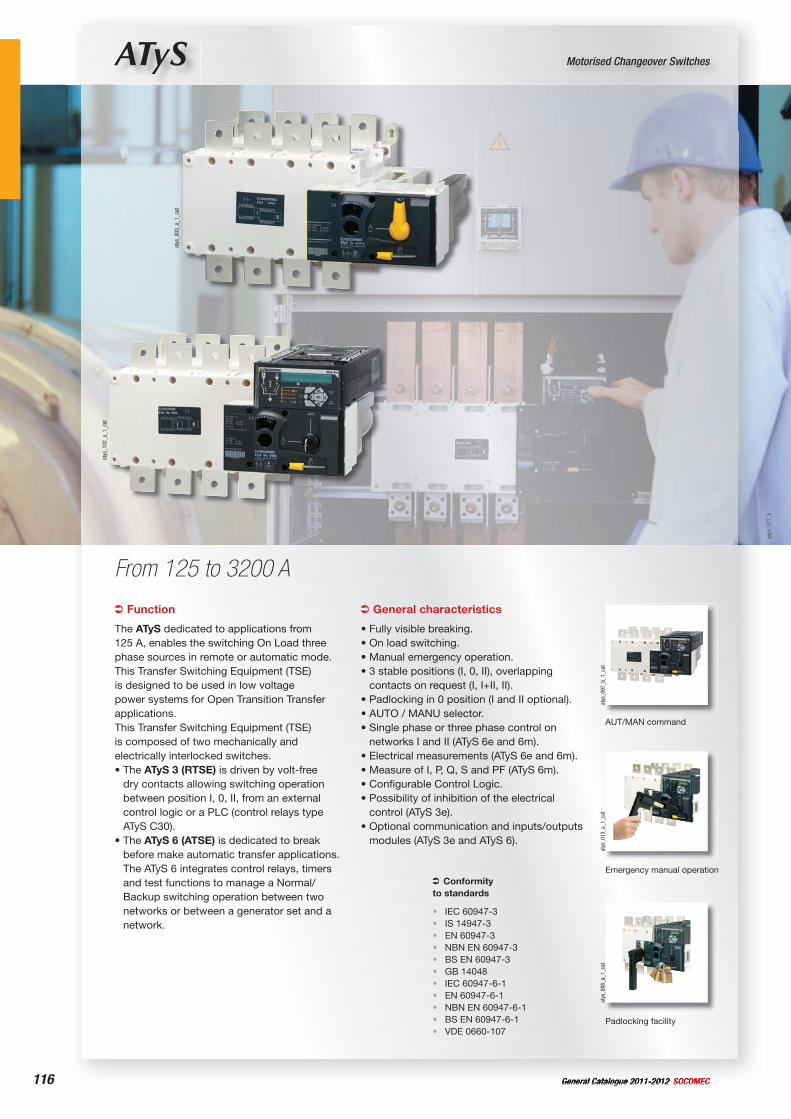
116 General Catalogue 2011-2012 SOCOMEC
ATyS Motorised Changeover Switches
From 125 to 3200 A
Function
The ATyS dedicated to applications from 125 A, enables the switching On Load three phase sources in remote or automatic mode.This Transfer Switching Equipment (TSE) is designed to be used in low voltage power systems for Open Transition Transfer applications.This Transfer Switching Equipment (TSE) is composed of two mechanically and electrically interlocked switches.• The ATyS 3 (RTSE) is driven by volt-free
dry contacts allowing switching operation between position I, 0, II, from an external control logic or a PLC (control relays type ATyS C30).
• The ATyS 6 (ATSE) is dedicated to break before make automatic transfer applications. The ATyS 6 integrates control relays, timers and test functions to manage a Normal/Backup switching operation between two networks or between a generator set and a network.
Conformityto standards
IEC 60947-3IS 14947-3 EN 60947-3NBN EN 60947-3BS EN 60947-3GB 14048IEC 60947-6-1EN 60947-6-1NBN EN 60947-6-1BS EN 60947-6-1VDE 0660-107
•••••••••••
General characteristics
• Fully visible breaking.• On load switching.• Manual emergency operation.• 3 stable positions (I, 0, II), overlapping
contacts on request (I, I+II, II).• Padlocking in 0 position (I and II optional).• AUTO / MANU selector.• Single phase or three phase control on
networks I and II (ATyS 6e and 6m).• Electrical measurements (ATyS 6e and 6m).• Measure of I, P, Q, S and PF (ATyS 6m).• Configurable Control Logic.• Possibility of inhibition of the electrical
control (ATyS 3e).• Optional communication and inputs/outputs
modules (ATyS 3e and ATyS 6).
atys
_003
_a_1
_cat
atys
_102
_a_1
_cat
atys
_097
_b_1
_cat
AUT/MAN command
atys
_013
_a_1
_cat
Emergency manual operation
atys
_008
_a_1
_cat
Padlocking facility
appl
i_07
7_b
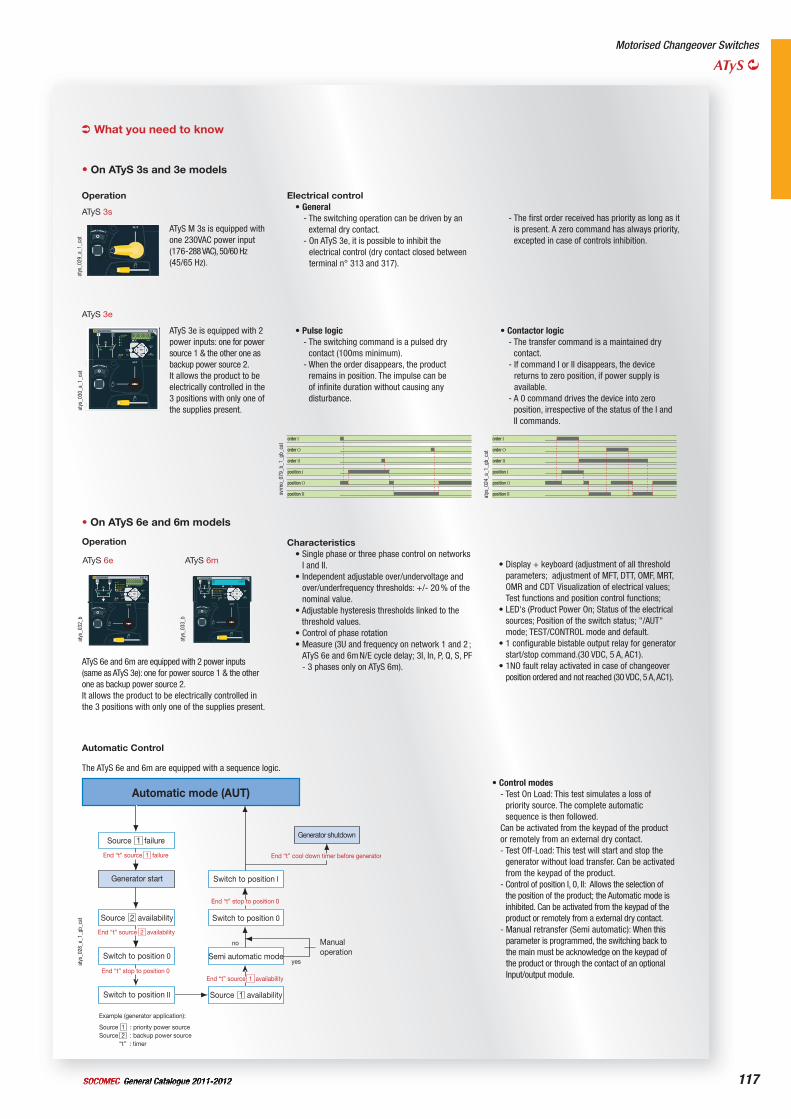
117General Catalogue 2011-2012SOCOMEC
Motorised Changeover Switches
ATyS
What you need to know
atys
_030
_a_1
_cat
ATyS 3e
ATyS 3e is equipped with 2 power inputs: one for power source 1 & the other one as backup power source 2.It allows the product to be electrically controlled in the 3 positions with only one of the supplies present.
order I
order O
order II
position I
position O
position IIsvrm
o_07
9_b_
1_gb
_cat
• Pulse logic- The switching command is a pulsed dry
contact (100ms minimum).- When the order disappears, the product
remains in position. The impulse can be of infinite duration without causing any disturbance.
order I
order O
order II
position I
position O
position IIatys
_024
_a_1
_gb_
cat
• Contactor logic- The transfer command is a maintained dry
contact.- If command I or II disappears, the device
returns to zero position, if power supply is available.
- A 0 command drives the device into zero position, irrespective of the status of the I and II commands.
Source failure
Automatic mode (AUT)
End “t” source 1 failure
Source availability
Generator shutdown
Semi automatic mode
Source availability
End “t” source 2 availability
End “t” stop to position 0End “t” source 1 availability
End “t” stop to position 0
End “t” cool down timer before generator
no
yes
Source 1 : priority power sourceSource 2 : backup power source “t” : timer
2
1
1
Example (generator application):
Switch to position 0
Switch to position II
Switch to position I
Switch to position 0
Manualoperation
Generator start
atys
_028
_e_1
_gb_
cat
• Control modes- Test On Load: This test simulates a loss of
priority source. The complete automatic sequence is then followed.
Can be activated from the keypad of the product or remotely from an external dry contact.- Test Off-Load: This test will start and stop the
generator without load transfer. Can be activated from the keypad of the product.
- Control of position I, 0, II: Allows the selection of the position of the product; the Automatic mode is inhibited. Can be activated from the keypad of the product or remotely from a external dry contact.
- Manual retransfer (Semi automatic): When this parameter is programmed, the switching back to the main must be acknowledge on the keypad of the product or through the contact of an optional Input/output module.
Automatic Control
The ATyS 6e and 6m are equipped with a sequence logic.
• On ATyS 6e and 6m models
atys
_032
_b
ATyS 6e
ATyS 6e and 6m are equipped with 2 power inputs (same as ATyS 3e): one for power source 1 & the other one as backup power source 2.It allows the product to be electrically controlled in the 3 positions with only one of the supplies present.
atys
_033
_b
ATyS 6m
Characteristics• Single phase or three phase control on networks
I and II.• Independent adjustable over/undervoltage and
over/underfrequency thresholds: +/- 20 % of the nominal value.
• Adjustable hysteresis thresholds linked to the threshold values.
• Control of phase rotation• Measure (3U and frequency on network 1 and 2 ;
ATyS 6e and 6m N/E cycle delay; 3I, In, P, Q, S, PF - 3 phases only on ATyS 6m).
• Display + keyboard (adjustment of all threshold parameters; adjustment of MFT, DTT, OMF, MRT, OMR and CDT Visualization of electrical values; Test functions and position control functions;
• LED's (Product Power On; Status of the electrical sources; Position of the switch status; "/AUT" mode; TEST/CONTROL mode and default.
• 1 configurable bistable output relay for generator start/stop command.(30 VDC, 5 A, AC1).
• 1NO fault relay activated in case of changeover position ordered and not reached (30 VDC, 5 A, AC1).
Operation
• On ATyS 3s and 3e models
atys
_029
_a_1
_cat
ATyS 3s
ATyS M 3s is equipped with one 230VAC power input (176-288 VAC), 50/60 Hz (45/65 Hz).
Electrical control• General
- The switching operation can be driven by an external dry contact.
- On ATyS 3e, it is possible to inhibit the electrical control (dry contact closed between terminal n° 313 and 317).
Operation
- The first order received has priority as long as it is present. A zero command has always priority, excepted in case of controls inhibition.
General Catalogue 2011-2012 SOCOMEC118
ATyS 3
Rating(A)
No. of poles ATyS 3s ATyS 3e
Bridgingbars
Terminal shrouds
Terminal screens
Optionalmodules
Auxiliarycontacts
Voltage transformer 400/230 VAC
125 A 4 P 1523 4012SL(1) 1533 4012SL
standard
4 P2694 4014(3)(4)
4 P1509 4012(5)
RS485MODBUS
1599 2000(6)
2 inputs / 2 outputs
1599 2001(6)
ATyS 3s1599 1002(7)
ATyS 3e1599 0002(7)
1599 4063
160 A 4 P 1523 4016SL(1) 1533 4016SL
250 A 4 P 1523 4025SL(1) 1533 4025SL
4 P2694 4021(3)(4)
4 P1509 4025(5)
400 A 4 P 1523 4040SL(1) 1533 4040SL
630 A 4 P 1523 4063SL(1) 1533 4063SL 2694 4051(3)(4) 1509 4063(5)
800 A 4 P 1523 4080SL(1) 1533 4080SL
4 P1509 4080(5) ATyS 3s
1599 1032(7)
ATyS 3e1599 0032(7) 1599 4120
1000 A 4 P 1523 4100SL(1) 1533 4100SL
1250 A 4 P 1523 4120(1) 1533 4120 4109 4120
1600 A 4 P 1523 4160(1) 1533 4160
4109 4160 4 P1509 4160(5)
1800 A 4 P 1523 4180 ATyS 3s1599 1032(7)
2000 A 4 P 1533 4200
(2) 4 P1509 4200(5) included 1599 4200 2500 A 4 P 1533 4250
3200 A 4 P 1533 4320
atys
_003
_a_1
_cat
ATyS - References
(1) Available enclosed (please consult us).(2) See page 122 and 123.(3) To shroud front switch top and bottom 2 references required.(4) To fully shroud front, rear, top and bottom 4 references required.(5) To shroud the front switch top and bottom, 1 reference is required.(6) On ATyS 3e only.(7) Factory fitted.
General Catalogue 2011-2012SOCOMEC 119
Motorised Changeover Switches
ATyS
Rating(A)
No. of poles ATyS 3s ATyS 3e
DC power supply
Padlockablehandle
Key handle interlocking
system
Doorprotective surround
Mountingspacers
DPS - Dual power supply
125 A 4 P 1523 4012SL(1) 1533 4012SL
12 VDC/230 VAC1599 5012
24 VDC/230 VAC1599 5112
1599 0003(2) 1509 1006(2)
ATyS 3s1529 0012
ATyS 3e1539 0012
1509 0001
1599 4001(3)
160 A 4 P 1523 4016SL(1) 1533 4016SL
250 A 4 P 1523 4025SL(1) 1533 4025SL
400 A 4 P 1523 4040SL(1) 1533 4040SL
630 A 4 P 1523 4063SL(1) 1533 4063SL
800 A 4 P 1523 4080SL(1) 1533 4080SL
1599 0004(2) 1509 1004(2)
ATyS 3s1529 0080
ATyS 3e1539 0080
1000 A 4 P 1523 4100SL(1) 1533 4100SL
1250 A 4 P 1523 4120(1) 1533 4120
1600 A 4 P 1523 4160(1) 1533 4160
1800 A 4 P 1523 4180 ATyS 3s1529 0080
2000 A 4 P 1533 4200
ATyS 3e1539 0080 2500 A 4 P 1533 4250
3200 A 4 P 1533 4320
(1) Available enclosed (please consult us).(2) Factory fitted.(3) On ATyS 3e only.
ATyS 3 (continued)
General Catalogue 2011-2012 SOCOMEC120
ATyS 6
ATyS - References (continued)
Rating(A)
No. of poles ATyS 6e ATyS 6m
Bridgingbars
Voltage sensing kit
Terminal shrouds
Terminal screens
Optionalmodules
Humaninterface/ Offset Machine
RJ45connecting
cable
125 A 4 P 1563 4012SLVR(1) 1573 4012SLVR
standard
standardwith neutral on right(3)
4 P2694 4014(4)(5)
4 P1509 4012(6)
RS485MODBUS
1599 2000
2 inputs/2 outputs
1599 2001
ATyS D101599 2010 ATyS D201599 2020
1599 2009
160 A 4 P 1563 4016SLVR(1) 1573 4016SLVR
250 A 4 P 1563 4025SLVR(1) 1573 4025SLVR
4 P2694 4021(4)(5)
4 P1509 4025(6)
400 A 4 P 1563 4040SLVR(1) 1573 4040SLVR
630 A 4 P 1563 4063SLVR(1) 1573 4063SLVR2694 3051(4)(5) 1509 3063(6)
2694 4051(4)(5) 1509 4063(6)
800 A 4 P 1563 4080SLVR(1) 1573 4080SLVR
4 P1509 4080(6)1000 A 4 P 1563 4100SLVR(1) 1573 4100SLVR
1250 A 4 P 1563 4120VR(1) 1573 4120VR 4109 4120
1600 A 4 P 1563 4160VR(1) 1573 4160VR 4109 41601509 3160(6)
1509 4160(6)
2000 A 4 P 1563 4200VR 1573 4200VR
(2) 4 P1509 4200(6)2500 A 4 P 1563 4250VR 1573 4250VR
3200 A 4 P 1563 4320VR 1573 4320VR
(1) Available enclosed (please consult us).(2) See page 122 and 123.(3) For neutral on the left see page 124.(4) To shroud front switch top and bottom 2 references required.(5) To fully shroud front, rear, top and bottom 4 references required.(6) To shroud front switch top and bottom 1 references required.
atys
_102
_a_1
_cat
General Catalogue 2011-2012SOCOMEC 121
Motorised Changeover Switches
ATyS
Rating(A)
No. of poles ATyS 6e ATyS 6m
Auxiliarycontacts
Voltage transformer 400/230 VAC
DC power supply
Padlockablehandle
Key handle interlocking
system
Doorprotective surround
Mountingspacers
125 A 4 P 1563 4012SLVR(1) 1573 4012SLVR
1599 0002(2) 1599 4063
12 VDC /230 VAC
1599 5012 24 VDC /230 VAC
1599 5112
1599 0003(2) 1509 1006(2) 1539 0012 1509 0001
160 A 4 P 1563 4016SLVR(1) 1573 4016SLVR
250 A 4 P 1563 4025SLVR(1) 1573 4025SLVR
400 A 4 P 1563 4040SLVR(1) 1573 4040SLVR
630 A 4 P 1563 4063SLVR(1) 1573 4063SLVR
800 A 4 P 1563 4080SLVR(1) 1573 4080SLVR
1599 0032(2) 1599 4120
1599 0004(2) 1509 1004(2) 1539 0080
1000 A 4 P 1563 4100SLVR(1) 1573 4100SLVR
1250 A 4 P 1563 4120VR(1) 1573 4120VR
1600 A 4 P 1563 4160VR(1) 1573 4160VR
2000 A 4 P 1563 4200VR 1573 4200VR
included 1599 4200 2500 A 4 P 1563 4250VR 1573 4250VR
3200 A 4 P 1563 4320VR 1573 4320VR
(1) Available enclosed (please consult us).(2) Factory fitted.
ATyS 6 (continued)
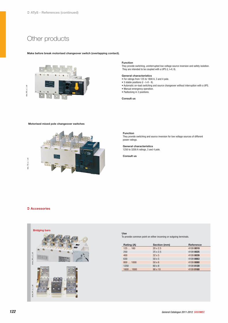
General Catalogue 2011-2012 SOCOMEC122
ATyS - References (continued)
Motorised mixed pole changeover switches
Make before break motorised changeover switch (overlapping contact).
atys
_003
_a_1
_cat
FunctionThey provide switching, uninterrupted low voltage source inversion and safety isolation. They are intended to be coupled with a UPS (I, I+II, II).
General characteristics• For ratings from 125 to 1800 A, 3 and 4 pole.• 3 stable positions (I - I+II - II).• Automatic on-load switching and source changeover without interruption with a UPS.• Manual emergency operation.• Padlocking in 3 positions.
Consult us
atys
_725
_a_1
_cat
FunctionThey provide switching and source inversion for low voltage sources of different power ratings.
General characteristics 1250 to 3200 A ratings, 3 and 4 pole.
Consult us
Other products
Bridging bars
acce
s_20
5_a_
2_ca
tac
ces_
041_
a_1_
cat
UseTo provide common point on either incoming or outgoing terminals.
Rating (A) Section (mm) Reference125 … 160 20 x 2.5 4109 0019250 25 x 2.5 4109 0025400 32 x 5 4109 0039630 50 x 5 4109 0063800 … 1000 50 x 6 4109 00801250 60 x 8 4109 01201600 ... 1800 90 x 10 4109 0160
Accessories
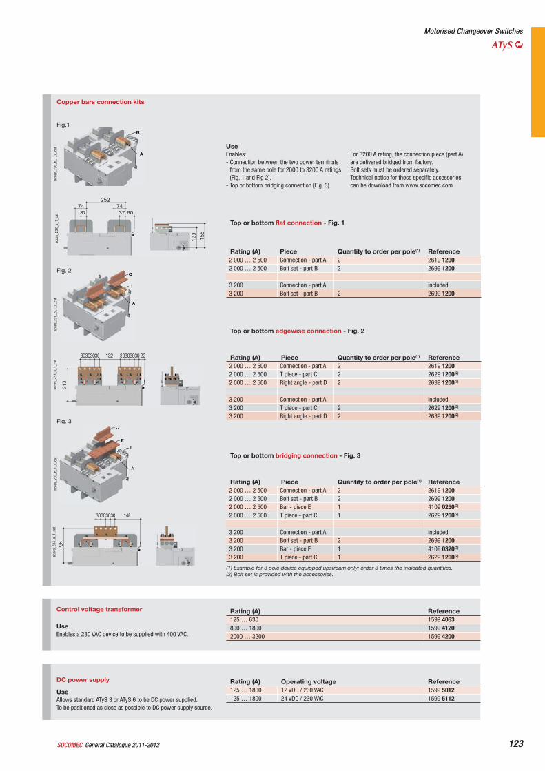
General Catalogue 2011-2012SOCOMEC 123
Motorised Changeover Switches
ATyS
DC power supply
UseAllows standard ATyS 3 or ATyS 6 to be DC power supplied.To be positioned as close as possible to DC power supply source.
Rating (A) Operating voltage Reference125 … 1800 12 VDC / 230 VAC 1599 5012125 … 1800 24 VDC / 230 VAC 1599 5112
Control voltage transformer
UseEnables a 230 VAC device to be supplied with 400 VAC.
Rating (A) Reference125 … 630 1599 4063800 … 1800 1599 41202000 … 3200 1599 4200
Copper bars connection kits
UseEnables: - Connection between the two power terminals
from the same pole for 2000 to 3200 A ratings (Fig. 1 and Fig 2).
- Top or bottom bridging connection (Fig. 3).
For 3200 A rating, the connection piece (part A) are delivered bridged from factory.Bolt sets must be ordered separately.Technical notice for these specific accessories can be download from www.socomec.com
Top or bottom flat connection - Fig. 1
Rating (A) Piece Quantity to order per pole(1) Reference2 000 … 2 500 Connection - part A 2 2619 12002 000 … 2 500 Bolt set - part B 2 2699 1200
3 200 Connection - part A included3 200 Bolt set - part B 2 2699 1200
Top or bottom edgewise connection - Fig. 2
Rating (A) Piece Quantity to order per pole(1) Reference2 000 … 2 500 Connection - part A 2 2619 12002 000 … 2 500 T piece - part C 2 2629 1200(2)
2 000 … 2 500 Right angle - part D 2 2639 1200(2)
3 200 Connection - part A included3 200 T piece - part C 2 2629 1200(2)
3 200 Right angle - part D 2 2639 1200(2)
Top or bottom bridging connection - Fig. 3
Rating (A) Piece Quantity to order per pole(1) Reference2 000 … 2 500 Connection - part A 2 2619 12002 000 … 2 500 Bolt set - part B 2 2699 12002 000 … 2 500 Bar - piece E 1 4109 0250(2)
2 000 … 2 500 T piece - part C 1 2629 1200(2)
3 200 Connection - part A included3 200 Bolt set - part B 2 2699 12003 200 Bar - piece E 1 4109 0320(2)
3 200 T piece - part C 1 2629 1200(2)
(1) Example for 3 pole device equipped upstream only: order 3 times the indicated quantities.(2) Bolt set is provided with the accessories.
acce
s_22
6_b_
1_x_
cat
2527437
7437 60
129
155
acce
s_23
2_a_
1_ca
t
Fig.1
30303030 132 30303030 22
210
acce
s_22
8_b_
1_x_
cat
acce
s_23
3_a_
1_ca
t
Fig. 2
A
B
acce
s_23
0_b_
1_x_
cat
30303030 148
225
acce
s_23
4_a_
1_ca
t
Fig. 3
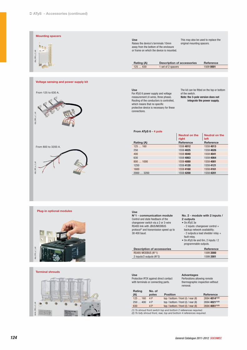
General Catalogue 2011-2012 SOCOMEC124
ATyS - Accessories (continued)
Terminal shrouds
acce
s_20
6_a_
2_ca
t
UseProtection IP2X against direct contact with terminals or connecting parts.
AdvantagesPerforations allowing remote thermographic inspection without removal.
Rating(A)
No. of poles Position Reference
125 … 160 4 P top / bottom / front (I) / rear (II) 2694 4014(1)(2)
250 … 400 4 P top / bottom / front (I) / rear (II) 2694 4021(1)(2)
630 4 P top / bottom / front (I) / rear (II) 2694 4051(1)(2)
(1) To shroud front switch top and bottom 2 references required.(2) To fully shroud front, rear, top and bottom 4 references required.
Voltage sensing and power supply kit
atys
_606
_a_1
_cat
From 125 to 630 A.
atys
_603
_a_2
_cat
From 800 to 3200 A.
UseFor ATyS 6 power supply and voltage measurement (4 wires, three phase).Routing of the conductors is controlled, which means that no specific protective device is necessary for these connections.
The kit can be fitted on the top or bottom of the switch.Note: the 3-pole version does not
integrate the power supply.
From ATyS 6 - 4 poleNeutral on the right
Neutral on the left
Rating (A) Reference Reference125 … 160 1559 4012 1559 4013250 1559 4025 1559 4026400 1559 4040 1559 4041630 1559 4063 1559 4064800 … 1000 1559 4080 1559 40811250 1559 4120 1559 41211600 1559 4160 1559 41612000 … 3200 1559 4200 1559 4201
Plug-in optional modules
atys
_016
_a_1
_cat
UseN°1 - communication moduleControl and state feedback of the changeover switch via a 2 or 3-wire RS485 link with JBUS/MODBUS protocol® and transmission speed up to 38 400 baud.
No. 2 - module with 2 inputs / 2 outputs• On ATyS 3e
- 2 inputs: changeover control + backup network availability; - 2 outputs:a load shedder relay + fault relay.
• On ATyS 6e and 6m, 2 inputs / 2 programmable outputs.
Description of accessories ReferenceRS485 MODBUS (N°1) 1599 20002 inputs/2 outputs (N°2) 1599 2001
Mounting spacersat
ys_0
09_a
_2_c
at
UseRaises the device's terminals 10mm away from the bottom of the enclosure or frame on which the device is mounted.
This may also be used to replace the original mounting spacers.
Rating (A) Description of accessories Reference125 … 630 1 set of 2 spacers 1509 0001
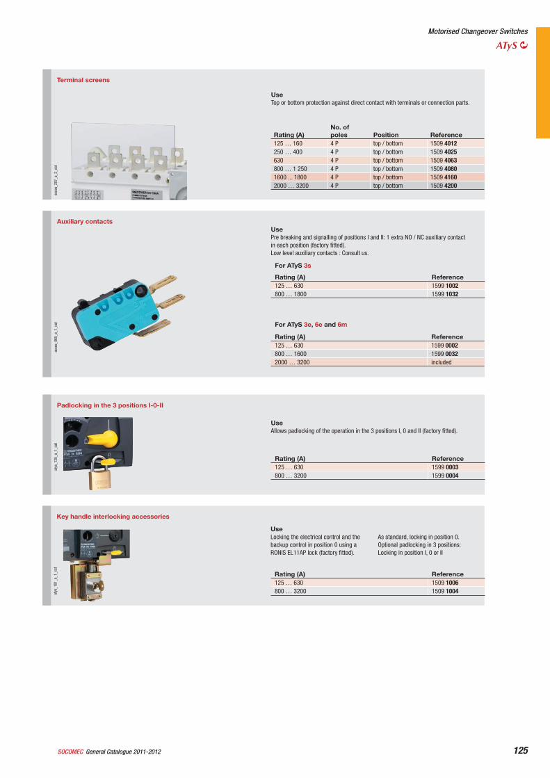
General Catalogue 2011-2012SOCOMEC 125
Terminal screens
acce
s_20
7_a_
2_ca
t
UseTop or bottom protection against direct contact with terminals or connection parts.
Rating (A) No. of poles Position Reference
125 … 160 4 P top / bottom 1509 4012250 … 400 4 P top / bottom 1509 4025630 4 P top / bottom 1509 4063800 … 1 250 4 P top / bottom 1509 40801600 ... 1800 4 P top / bottom 1509 41602000 … 3200 4 P top / bottom 1509 4200
Auxiliary contacts
acce
s_06
5_a_
1_ca
t
UsePre breaking and signalling of positions I and II: 1 extra NO / NC auxiliary contact in each position (factory fitted).Low level auxiliary contacts : Consult us.
For ATyS 3s
Rating (A) Reference125 … 630 1599 1002800 … 1800 1599 1032
For ATyS 3e, 6e and 6m
Rating (A) Reference125 … 630 1599 0002800 … 1600 1599 00322000 … 3200 included
Motorised Changeover Switches
ATyS
Padlocking in the 3 positions I-0-II
atys
_125
_a_1
_cat
UseAllows padlocking of the operation in the 3 positions I, 0 and II (factory fitted).
Rating (A) Reference125 … 630 1599 0003800 … 3200 1599 0004
Key handle interlocking accessories
atys
_101
_a_1
_cat
UseLocking the electrical control and the backup control in position 0 using a RONIS EL11AP lock (factory fitted).
As standard, locking in position 0.Optional padlocking in 3 positions: Locking in position I, 0 or II
Rating (A) Reference125 … 630 1509 1006800 … 3200 1509 1004
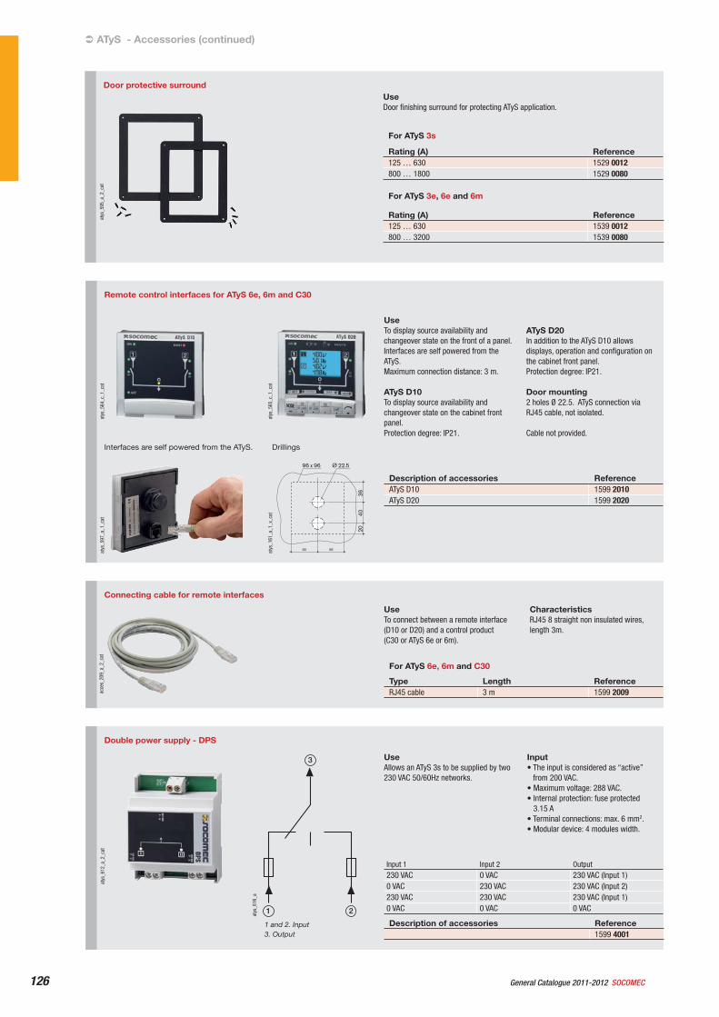
General Catalogue 2011-2012 SOCOMEC126
Connecting cable for remote interfaces
acce
s_20
9_a_
2_ca
t
UseTo connect between a remote interface (D10 or D20) and a control product (C30 or ATyS 6e or 6m).
CharacteristicsRJ45 8 straight non insulated wires, length 3m.
For ATyS 6e, 6m and C30
Type Length ReferenceRJ45 cable 3 m 1599 2009
ATyS - Accessories (continued)
Double power supply - DPS
atys
_612
_a_2
_cat
3
21atys
_616
_a
1 and 2. Input3. Output
UseAllows an ATyS 3s to be supplied by two 230 VAC 50/60Hz networks.
Input• The input is considered as “active”
from 200 VAC.• Maximum voltage: 288 VAC.• Internal protection: fuse protected
3.15 A• Terminal connections: max. 6 mm2.• Modular device: 4 modules width.
Input 1 Input 2 Output230 VAC 0 VAC 230 VAC (Input 1) 0 VAC 230 VAC 230 VAC (Input 2) 230 VAC 230 VAC 230 VAC (Input 1) 0 VAC 0 VAC 0 VAC
Description of accessories Reference1599 4001
Remote control interfaces for ATyS 6e, 6m and C30
atys
_564
_c_1
_cat
atys
_565
_c_1
_cat
atys
_597
_a_1
_cat
Interfaces are self powered from the ATyS.
Ø 22.5
4036
20
= =
96 x 96
atys
_161
_a_1
_x_c
at
Drillings
UseTo display source availability and changeover state on the front of a panel.Interfaces are self powered from the ATyS.Maximum connection distance: 3 m.
ATyS D10To display source availability and changeover state on the cabinet front panel. Protection degree: IP21.
ATyS D20In addition to the ATyS D10 allows displays, operation and configuration on the cabinet front panel.Protection degree: IP21.
Door mounting2 holes Ø 22.5. ATyS connection via RJ45 cable, not isolated.
Cable not provided.
Description of accessories ReferenceATyS D10 1599 2010ATyS D20 1599 2020
Door protective surround
atys
_595
_a_2
_cat
UseDoor finishing surround for protecting ATyS application.
For ATyS 3s
Rating (A) Reference125 … 630 1529 0012800 … 1800 1529 0080
For ATyS 3e, 6e and 6m
Rating (A) Reference125 … 630 1539 0012800 … 3200 1539 0080
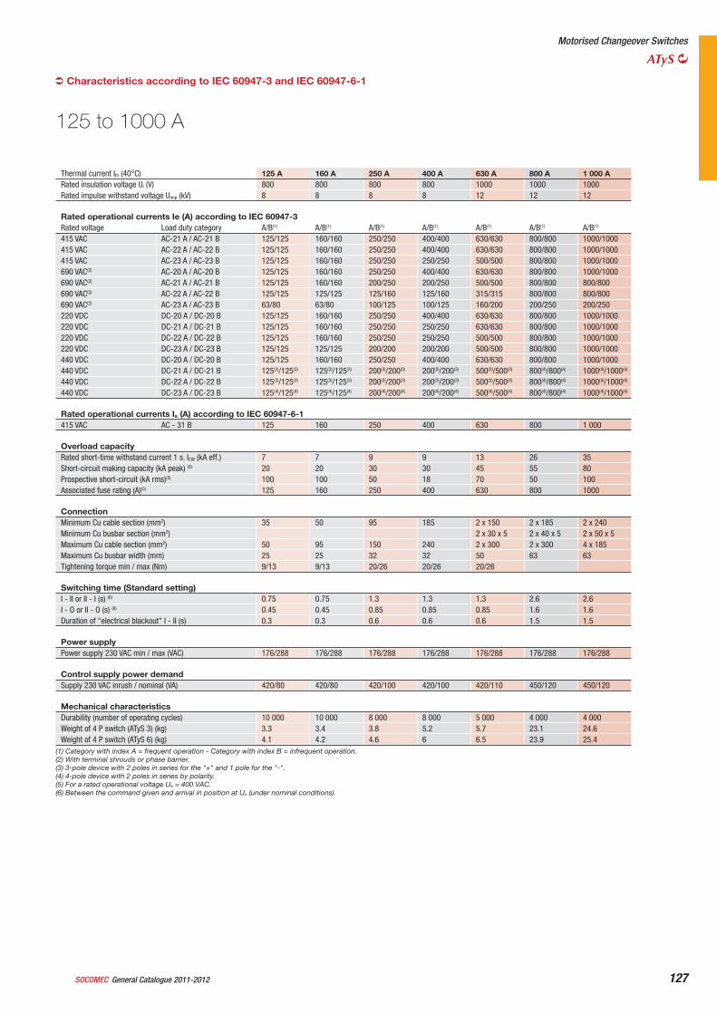
General Catalogue 2011-2012SOCOMEC 127
Motorised Changeover Switches
ATyS
Thermal current Ith (40°C) 125 A 160 A 250 A 400 A 630 A 800 A 1 000 ARated insulation voltage Ui (V) 800 800 800 800 1000 1000 1000Rated impulse withstand voltage Uimp (kV) 8 8 8 8 12 12 12
Rated operational currents Ie (A) according to IEC 60947-3Rated voltage Load duty category A/B(1) A/B(1) A/B(1) A/B(1) A/B(1) A/B(1) A/B(1)
415 VAC AC-21 A / AC-21 B 125/125 160/160 250/250 400/400 630/630 800/800 1000/1000415 VAC AC-22 A / AC-22 B 125/125 160/160 250/250 400/400 630/630 800/800 1000/1000415 VAC AC-23 A / AC-23 B 125/125 160/160 250/250 250/250 500/500 800/800 1000/1000690 VAC(2) AC-20 A / AC-20 B 125/125 160/160 250/250 400/400 630/630 800/800 1000/1000690 VAC(2) AC-21 A / AC-21 B 125/125 160/160 200/250 200/250 500/500 800/800 800/800690 VAC(2) AC-22 A / AC-22 B 125/125 125/125 125/160 125/160 315/315 800/800 800/800690 VAC(2) AC-23 A / AC-23 B 63/80 63/80 100/125 100/125 160/200 200/250 200/250220 VDC DC-20 A / DC-20 B 125/125 160/160 250/250 400/400 630/630 800/800 1000/1000220 VDC DC-21 A / DC-21 B 125/125 160/160 250/250 250/250 630/630 800/800 1000/1000220 VDC DC-22 A / DC-22 B 125/125 160/160 250/250 250/250 500/500 800/800 1000/1000220 VDC DC-23 A / DC-23 B 125/125 125/125 200/200 200/200 500/500 800/800 1000/1000440 VDC DC-20 A / DC-20 B 125/125 160/160 250/250 400/400 630/630 800/800 1000/1000440 VDC DC-21 A / DC-21 B 125(3)/125(3) 125(3)/125(3) 200(3)/200(3) 200(3)/200(3) 500(3)/500(3) 800(4)/800(4) 1000(4)/1000(4)
440 VDC DC-22 A / DC-22 B 125(3)/125(3) 125(3)/125(3) 200(3)/200(3) 200(3)/200(3) 500(3)/500(3) 800(4)/800(4) 1000(4)/1000(4)
440 VDC DC-23 A / DC-23 B 125(4)/125(4) 125(4)/125(4) 200(4)/200(4) 200(4)/200(4) 500(4)/500(4) 800(4)/800(4) 1000(4)/1000(4)
Rated operational currents Ie (A) according to IEC 60947-6-1415 VAC AC - 31 B 125 160 250 400 630 800 1 000
Overload capacityRated short-time withstand current 1 s. ICW (kA eff.) 7 7 9 9 13 26 35Short-circuit making capacity (kA peak) (5) 20 20 30 30 45 55 80Prospective short-circuit (kA rms)(5) 100 100 50 18 70 50 100Associated fuse rating (A)(5) 125 160 250 400 630 800 1000
ConnectionMinimum Cu cable section (mm2) 35 50 95 185 2 x 150 2 x 185 2 x 240Minimum Cu busbar section (mm2) 2 x 30 x 5 2 x 40 x 5 2 x 50 x 5Maximum Cu cable section (mm2) 50 95 150 240 2 x 300 2 x 300 4 x 185Maximum Cu busbar width (mm) 25 25 32 32 50 63 63Tightening torque min / max (Nm) 9/13 9/13 20/26 20/26 20/26
Switching time (Standard setting) I - II or II - I (s) (6) 0.75 0.75 1.3 1.3 1.3 2.6 2.6I - O or II - O (s) (6) 0.45 0.45 0.85 0.85 0.85 1.6 1.6Duration of "electrical blackout" I - II (s) 0.3 0.3 0.6 0.6 0.6 1.5 1.5
Power supplyPower supply 230 VAC min / max (VAC) 176/288 176/288 176/288 176/288 176/288 176/288 176/288
Control supply power demandSupply 230 VAC inrush / nominal (VA) 420/80 420/80 420/100 420/100 420/110 450/120 450/120
Mechanical characteristicsDurability (number of operating cycles) 10 000 10 000 8 000 8 000 5 000 4 000 4 000Weight of 4 P switch (ATyS 3) (kg) 3.3 3.4 3.8 5.2 5.7 23.1 24.6Weight of 4 P switch (ATyS 6) (kg) 4.1 4.2 4.6 6 6.5 23.9 25.4
125 to 1000 A
(1) Category with index A = frequent operation - Category with index B = infrequent operation.(2) With terminal shrouds or phase barrier.(3) 3-pole device with 2 poles in series for the "+" and 1 pole for the "-".(4) 4-pole device with 2 poles in series by polarity.(5) For a rated operational voltage Ue = 400 VAC.(6) Between the command given and arrival in position at Un (under nominal conditions).
Characteristics according to IEC 60947-3 and IEC 60947-6-1
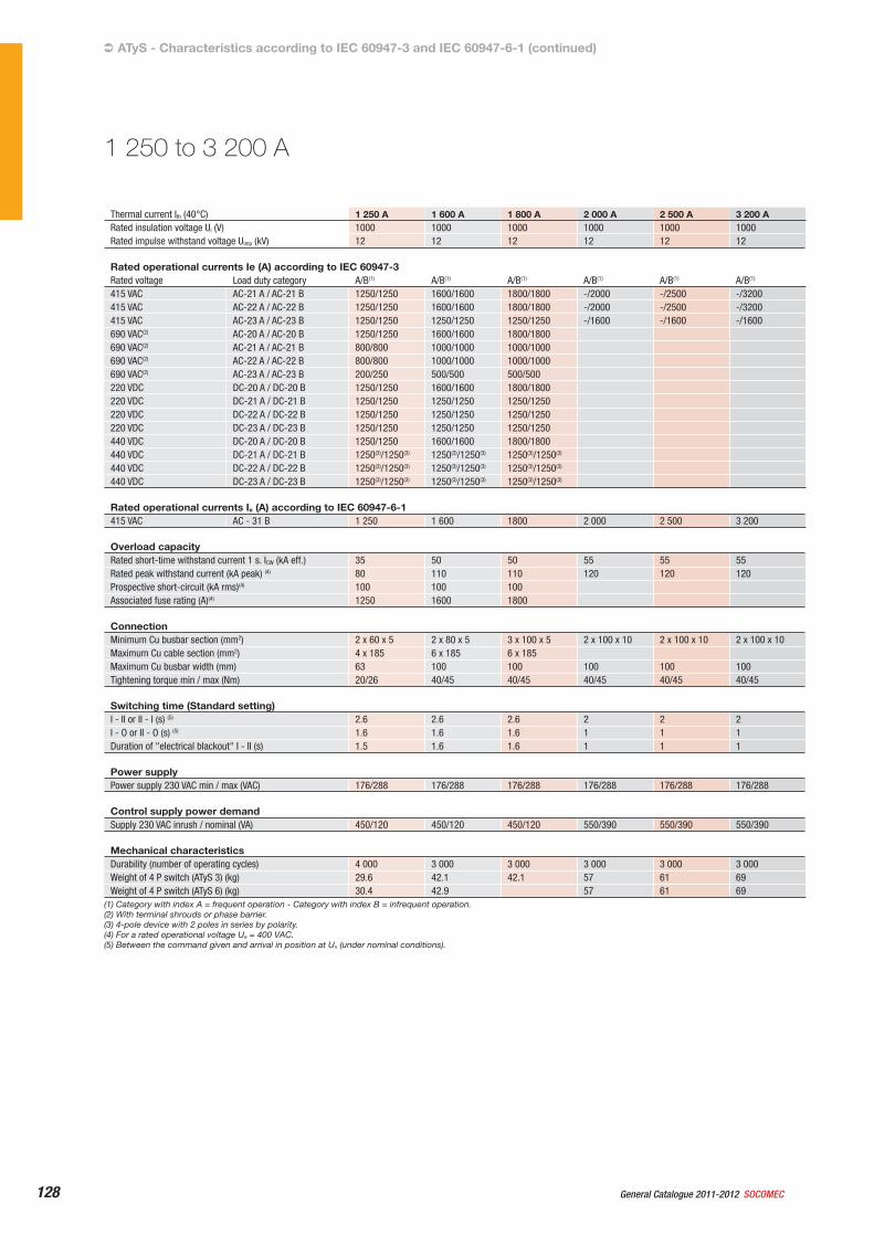
General Catalogue 2011-2012 SOCOMEC128
Thermal current Ith (40°C) 1 250 A 1 600 A 1 800 A 2 000 A 2 500 A 3 200 ARated insulation voltage Ui (V) 1000 1000 1000 1000 1000 1000Rated impulse withstand voltage Uimp (kV) 12 12 12 12 12 12
Rated operational currents Ie (A) according to IEC 60947-3Rated voltage Load duty category A/B(1) A/B(1) A/B(1) A/B(1) A/B(1) A/B(1)
415 VAC AC-21 A / AC-21 B 1250/1250 1600/1600 1800/1800 -/2000 -/2500 -/3200415 VAC AC-22 A / AC-22 B 1250/1250 1600/1600 1800/1800 -/2000 -/2500 -/3200415 VAC AC-23 A / AC-23 B 1250/1250 1250/1250 1250/1250 -/1600 -/1600 -/1600690 VAC(2) AC-20 A / AC-20 B 1250/1250 1600/1600 1800/1800690 VAC(2) AC-21 A / AC-21 B 800/800 1000/1000 1000/1000690 VAC(2) AC-22 A / AC-22 B 800/800 1000/1000 1000/1000690 VAC(2) AC-23 A / AC-23 B 200/250 500/500 500/500220 VDC DC-20 A / DC-20 B 1250/1250 1600/1600 1800/1800220 VDC DC-21 A / DC-21 B 1250/1250 1250/1250 1250/1250220 VDC DC-22 A / DC-22 B 1250/1250 1250/1250 1250/1250220 VDC DC-23 A / DC-23 B 1250/1250 1250/1250 1250/1250440 VDC DC-20 A / DC-20 B 1250/1250 1600/1600 1800/1800440 VDC DC-21 A / DC-21 B 1250(3)/1250(3) 1250(3)/1250(3) 1250(3)/1250(3)
440 VDC DC-22 A / DC-22 B 1250(3)/1250(3) 1250(3)/1250(3) 1250(3)/1250(3)
440 VDC DC-23 A / DC-23 B 1250(3)/1250(3) 1250(3)/1250(3) 1250(3)/1250(3)
Rated operational currents Ie (A) according to IEC 60947-6-1415 VAC AC - 31 B 1 250 1 600 1800 2 000 2 500 3 200
Overload capacityRated short-time withstand current 1 s. ICW (kA eff.) 35 50 50 55 55 55Rated peak withstand current (kA peak) (4) 80 110 110 120 120 120Prospective short-circuit (kA rms)(4) 100 100 100Associated fuse rating (A)(4) 1250 1600 1800
ConnectionMinimum Cu busbar section (mm2) 2 x 60 x 5 2 x 80 x 5 3 x 100 x 5 2 x 100 x 10 2 x 100 x 10 2 x 100 x 10Maximum Cu cable section (mm2) 4 x 185 6 x 185 6 x 185Maximum Cu busbar width (mm) 63 100 100 100 100 100Tightening torque min / max (Nm) 20/26 40/45 40/45 40/45 40/45 40/45
Switching time (Standard setting) I - II or II - I (s) (5) 2.6 2.6 2.6 2 2 2I - O or II - O (s) (5) 1.6 1.6 1.6 1 1 1Duration of "electrical blackout" I - II (s) 1.5 1.6 1.6 1 1 1
Power supplyPower supply 230 VAC min / max (VAC) 176/288 176/288 176/288 176/288 176/288 176/288
Control supply power demandSupply 230 VAC inrush / nominal (VA) 450/120 450/120 450/120 550/390 550/390 550/390
Mechanical characteristicsDurability (number of operating cycles) 4 000 3 000 3 000 3 000 3 000 3 000Weight of 4 P switch (ATyS 3) (kg) 29.6 42.1 42.1 57 61 69Weight of 4 P switch (ATyS 6) (kg) 30.4 42.9 57 61 69
(1) Category with index A = frequent operation - Category with index B = infrequent operation.(2) With terminal shrouds or phase barrier.(3) 4-pole device with 2 poles in series by polarity.(4) For a rated operational voltage Ue = 400 VAC.(5) Between the command given and arrival in position at Un (under nominal conditions).
1 250 to 3 200 A
ATyS - Characteristics according to IEC 60947-3 and IEC 60947-6-1 (continued)
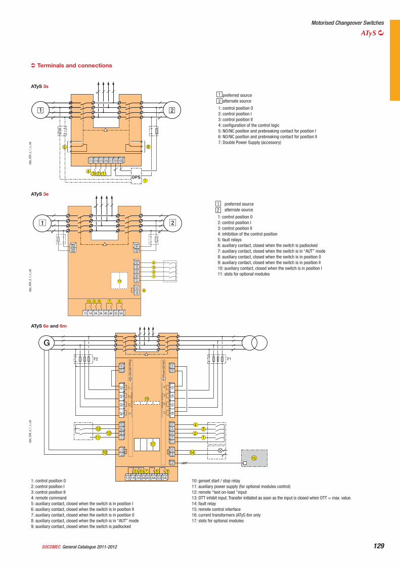
General Catalogue 2011-2012SOCOMEC 129
Motorised Changeover Switches
ATyS
Terminals and connections
73210
209208
207206
205204
203202
20174
Pow
er 2
30 V
AC
2Pow
er 230 VAC
13
5 6 7 8 9
1211
4
16
32
1
1
13 14 24 34 43 44 53 54
101
102
103
104
105
106
313
314
315
316
317
6364
RJ
Volta
ge s
ensin
gL1
L2L3
N
Volta
ge s
ensin
gL1
L2L3
N
G
17
10 1415
F2 F1
atys
_026
_d_1
_x_c
at
1: control position 02: control position I3: control position II4: remote command5: auxiliary contact, closed when the switch is in position I6: auxiliary contact, closed when the switch is in position II7: auxiliary contact, closed when the switch is in position 08: auxiliary contact, closed when the switch is in “AUT” mode9: auxiliary contact, closed when the switch is padlocked
10: genset start / stop relay11: auxiliary power supply (for optional modules control)12: remote “test on-load ”input13: DTT inhibit input. Transfer initiated as soon as the input is closed when DTT = max. value. 14: fault relay15: remote control interface16: current transformers (ATyS 6m only17: slots for optional modules
ATyS 6e and 6m
5 6
4 3 2 1
313 314 315 316 317
1 2
101 102
DPS7
atys
_025
_e_1
_x_c
at
preferred source alternate source
1: control position 02: control position I3: control position II4: configuration of the control logic5: NO/NC position and prebreaking contact for position I6: NO/NC position and prebreaking contact for position II7: Double Power Supply (accessory)
ATyS 3s
1
2
13 14 24 34 43 44 53 54
6463
102
2022
01 101
3173
1631
531
331
4
1 2
4321
11
5
10 9 8 7 6
atys
_094
_d_1
_x_c
at
preferred source alternate source
1: control position 02: control position I3: control position II4: inhibition of the control position5: fault relays6: auxiliary contact, closed when the switch is padlocked7: auxiliary contact, closed when the switch is in “AUT” mode8: auxiliary contact, closed when the switch is in position 09: auxiliary contact, closed when the switch is in position II10: auxiliary contact, closed when the switch is in position I11: slots for optional modules
ATyS 3e
12
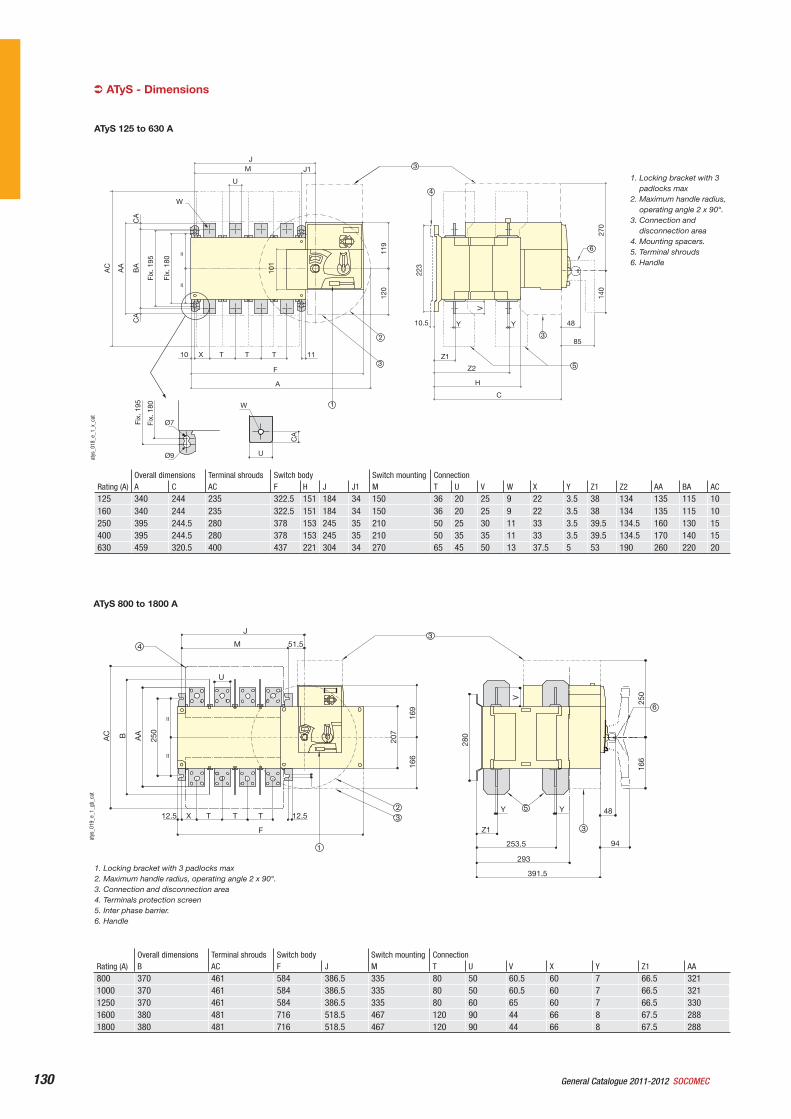
General Catalogue 2011-2012 SOCOMEC130
Rating (A) Overall dimensions Terminal shrouds Switch body Switch mounting ConnectionB AC F J M T U V X Y Z1 AA
800 370 461 584 386.5 335 80 50 60.5 60 7 66.5 3211000 370 461 584 386.5 335 80 50 60.5 60 7 66.5 3211250 370 461 584 386.5 335 80 60 65 60 7 66.5 3301600 380 481 716 518.5 467 120 90 44 66 8 67.5 2881800 380 481 716 518.5 467 120 90 44 66 8 67.5 288
F
12.5
=
207
169
166
280
250
166
V
=
250
AA
12.5
391.5
293
253.5
Z1
Y Y 48
94
X
M 51.5
J
T T T
1
3
BAC
23
34
5
6
U
atys
_019
_e_1
_gb_
cat
1. Locking bracket with 3 padlocks max2. Maximum handle radius, operating angle 2 x 90°.3. Connection and disconnection area4. Terminals protection screen5. Inter phase barrier.6. Handle
ATyS 800 to 1800 A
ATyS - Dimensions
Rating (A) Overall dimensions Terminal shrouds Switch body Switch mounting ConnectionA C AC F H J J1 M T U V W X Y Z1 Z2 AA BA AC
125 340 244 235 322.5 151 184 34 150 36 20 25 9 22 3.5 38 134 135 115 10160 340 244 235 322.5 151 184 34 150 36 20 25 9 22 3.5 38 134 135 115 10250 395 244.5 280 378 153 245 35 210 50 25 30 11 33 3.5 39.5 134.5 160 130 15400 395 244.5 280 378 153 245 35 210 50 35 35 11 33 3.5 39.5 134.5 170 140 15630 459 320.5 400 437 221 304 34 270 65 45 50 13 37.5 5 53 190 260 220 20
10
W
U
MJ
J1
X T T T 11
C
H
Z2
Z1
10.5 Y Y
85
48
F
A12
0
140
270
V
223
119
=
Fix.
180
Fix.
195
BA
CA
CA
AA
AC
101
=
Ø7
Ø9
Fix.
180
Fix.
195 1
32
3
3
4
5
6
CA
W
U
atys
_018
_e_1
_x_c
at
1. Locking bracket with 3 padlocks max
2. Maximum handle radius, operating angle 2 x 90°.
3. Connection and disconnection area
4. Mounting spacers.5. Terminal shrouds6. Handle
ATyS 125 to 630 A
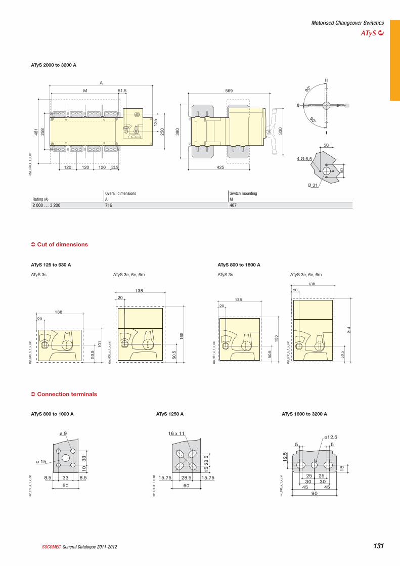
General Catalogue 2011-2012SOCOMEC 131
Rating (A) Overall dimensions Switch mountingA M
2 000 … 3 200 716 467
M 51.5
53.5120120120
A
250
258
461
569
425
380
125
330
90°90°
Ø 31
50
50
4 Ø 6,5
II
I
0
atys
_678
_b_1
_x_c
at
ATyS 2000 to 3200 A
Motorised Changeover Switches
ATyS
ATyS 3s
50.5
20
138
101
atys
_649
_a_1
_x_c
at
ATyS 125 to 630 A
ATyS 3e, 6e, 6m
50.5
20
138
165
atys
_650
_a_1
_x_c
at
ATyS 3e, 6e, 6m
33 8.58.5
50
3310
ø 9
ø 15
svr_
077_
a_1_
x_ca
t
ATyS 800 to 1000 A
16 x 11
60
28.5 15.7515.75
28.5
15
svr_
078_
b_1_
x_ca
t
ATyS 1250 A
15
5 5
12.5
25 253030
454590
ø12.5
svr_
098_
a_1_
x_ca
t
ATyS 1600 to 3200 A
50.5
20
138
214
atys
_652
_a_1
_x_c
at
ATyS 3s50
.5
20
138
150
atys
_651
_a_1
_x_c
at
ATyS 800 to 1800 A
Cut of dimensions
Connection terminals
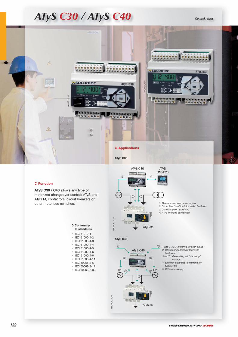
132 General Catalogue 2011-2012 SOCOMEC
ATyS C30 / ATyS C40 Control relays
Applications
ATyS C30
1. Measurement and power supply2. Control and position information feedback3. Generating set “start/stop”4. ATyS interface connection
21
3 4
ATyS 3s
ATyS C30 ATySD10/D20
atys
_149
_e_1
_x_c
at
ATyS C40
1 and 1'. U+F metering for each group2. Control and position information
feedback3 and 3'. Generating set "start/stop"
control4. External "start/stop" command for
basic cycle5. DC power supply
2
1 1’
3 3’
4
G1 G2
ATyS 3s
5
ATyS C40
atys
_566
_b_1
_x_c
at
Function
ATyS C30 / C40 allows any type of motorized changeover control: ATyS and ATyS M, contactors, circuit breakers or other motorised switches.
Conformityto standards
IEC 61010-1IEC 61000-4-2IEC 61000-4-3IEC 61000-4-4IEC 61000-4-5IEC 61000-4-6IEC 61000-4-8IEC 61000-4-11IEC 60068-2-6IEC 60068-2-11IEC 60068-2-30
•••••••••••
atys
_448
_b_1
_cat
atys
_599
_b_1
_cat
appl
i_07
8_c
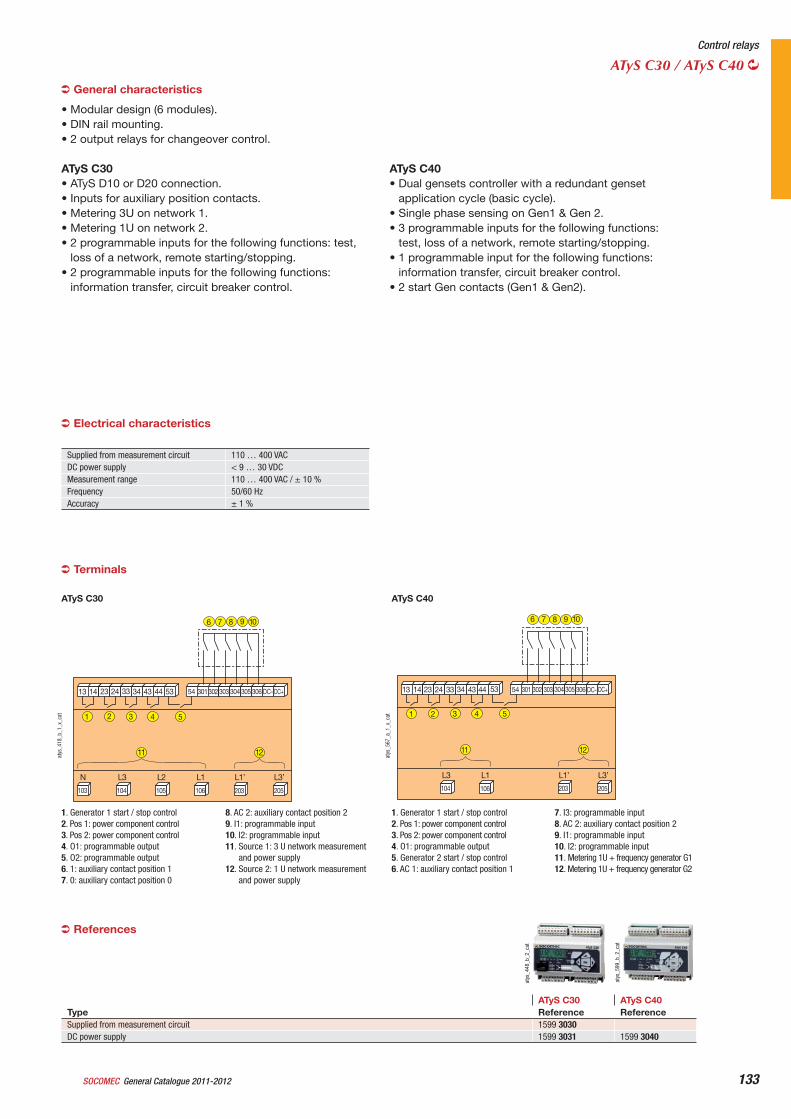
General Catalogue 2011-2012SOCOMEC 133
Control relays
ATyS C30 / ATyS C40
Terminals
13 14 23 24 33 34 43 44 53 54 301302 303 304 305 306 DC- DC+
205203106105104103
L3’L1’L1L2L3N
4 5
6 7 8 9 10
11 12
321
atys
_418
_b_1
_x_c
at
1. Generator 1 start / stop control2. Pos 1: power component control3. Pos 2: power component control4. O1: programmable output5. O2: programmable output6. 1: auxiliary contact position 17. 0: auxiliary contact position 0
8. AC 2: auxiliary contact position 29. I1: programmable input10. I2: programmable input11. Source 1: 3 U network measurement
and power supply12. Source 2: 1 U network measurement
and power supply
ATyS C30
13 14 23 24 33 34 43 44 53 54 301 302 303 304 305 306 DC- DC+
205203106104
L3’L1’L1L3
4 5
6 7 8 9 10
11 12
321
atys
_567
_a_1
_x_c
at
1. Generator 1 start / stop control2. Pos 1: power component control3. Pos 2: power component control4. O1: programmable output5. Generator 2 start / stop control6. AC 1: auxiliary contact position 1
7. I3: programmable input8. AC 2: auxiliary contact position 29. I1: programmable input10. I2: programmable input11. Metering 1U + frequency generator G112. Metering 1U + frequency generator G2
ATyS C40
General characteristics
• Modular design (6 modules).• DIN rail mounting.• 2 output relays for changeover control.
ATyS C30• ATyS D10 or D20 connection.• Inputs for auxiliary position contacts.• Metering 3U on network 1.• Metering 1U on network 2.• 2 programmable inputs for the following functions: test,
loss of a network, remote starting/stopping.• 2 programmable inputs for the following functions:
information transfer, circuit breaker control.
ATyS C40• Dual gensets controller with a redundant genset
application cycle (basic cycle).• Single phase sensing on Gen1 & Gen 2.• 3 programmable inputs for the following functions:
test, loss of a network, remote starting/stopping.• 1 programmable input for the following functions:
information transfer, circuit breaker control.• 2 start Gen contacts (Gen1 & Gen2).
ATyS C30 ATyS C40Type Reference ReferenceSupplied from measurement circuit 1599 3030DC power supply 1599 3031 1599 3040
atys
_448
_b_2
_cat
atys
_599
_b_2
_cat
Supplied from measurement circuit 110 … 400 VACDC power supply < 9 … 30 VDCMeasurement range 110 … 400 VAC / ± 10 %Frequency 50/60 HzAccuracy ± 1 %
Electrical characteristics
References
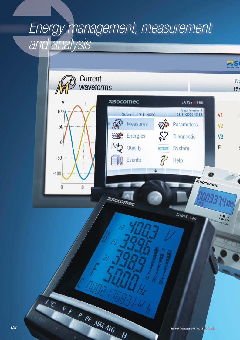
134 SOCOMECGeneral Catalogue 2011-2012
Energy management, measurement and analysis
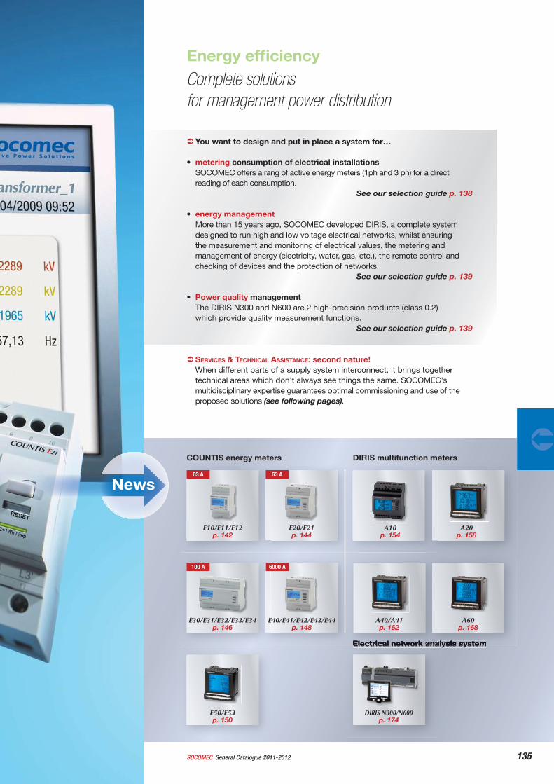
Energy effi ciency
135General Catalogue 2011-2012SOCOMEC
You want to design and put in place a system for…
• metering consumption of electrical installationsSOCOMEC offers a rang of active energy meters (1ph and 3 ph) for a direct reading of each consumption.
See our selection guide p. 138
• energy managementMore than 15 years ago, SOCOMEC developed DIRIS, a complete system designed to run high and low voltage electrical networks, whilst ensuring the measurement and monitoring of electrical values, the metering and management of energy (electricity, water, gas, etc.), the remote control and checking of devices and the protection of networks. See our selection guide p. 139
• Power quality managementThe DIRIS N300 and N600 are 2 high-precision products (class 0.2)which provide quality measurement functions. See our selection guide p. 139
SERVICES & TECHNICAL ASSISTANCE: second nature! When different parts of a supply system interconnect, it brings together technical areas which don't always see things the same. SOCOMEC's multidisciplinary expertise guarantees optimal commissioning and use of the proposed solutions (see following pages).
DIRIS multifunction metersCOUNTIS energy meters
Electrical network analysis system
Complete solutions for management power distribution
A40/A41p. 162
DIRIS N300/N600p. 174
E10/E11/E12 p. 142
63 A
E20/E21 p. 144
63 A
A60p. 168
E30/E31/E32/E33/E34p. 146
100 A 6000 A
E40/E41/E42/E43/E44 p. 148
E50/E53 p. 150
A10 p. 154
A20 p. 158
News
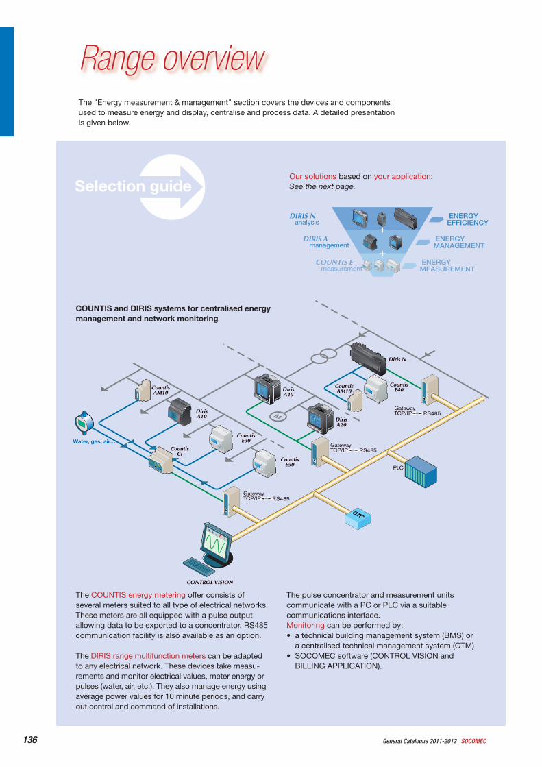
136 General Catalogue 2011-2012 SOCOMEC
CountisE50
Water, gas, air… Countis
E30
CountisCi
CountisAM10
DirisA10 Diris
A20
DirisA40
CountisE40
CountisAM10
Diris N
PLC
CONTROL VISION
GatewayTCP/IP RS485
GatewayTCP/IP RS485
GatewayTCP/IP RS485 M
GTCGTC
The "Energy measurement & management" section covers the devices and components used to measure energy and display, centralise and process data. A detailed presentation is given below.
Range overview
COUNTIS and DIRIS systems for centralised energy management and network monitoring
The pulse concentrator and measurement units communicate with a PC or PLC via a suitable communications interface.Monitoring can be performed by:• a technical building management system (BMS) or
a centralised technical management system (CTM)• SOCOMEC software (CONTROL VISION and
BILLING APPLICATION).
The COUNTIS energy metering offer consists of several meters suited to all type of electrical networks. These meters are all equipped with a pulse output allowing data to be exported to a concentrator, RS485 communication facility is also available as an option.
The DIRIS range multifunction meters can be adapted to any electrical network. These devices take measu-rements and monitor electrical values, meter energy or pulses (water, air, etc.). They also manage energy using average power values for 10 minute periods, and carry out control and command of installations.
Our solutions based on your application:See the next page.Selection guide
ENERGYMEASUREMENT
ENERGYMANAGEMENT
ENERGYEFFICIENCY
COUNTIS E
DIRIS A
DIRIS N
measurement
management
analysis
+
+
DIRISD600
5/TEST
4OK PROG
I V F P PF E
DIRIS A20
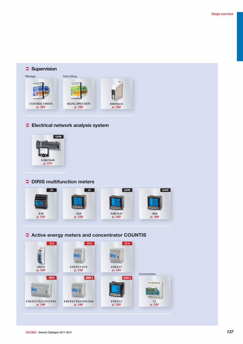
137General Catalogue 2011-2012SOCOMEC
Range overview
DIRIS multifunction meters
A10p. 154
LV
A40/A41p. 162
LV/HV
A20p. 158
LV
A60p. 168
LV/HV
Electrical network analysis system
N300/N600p. 174
LV/HV
SupervisionManage
Interfacesp. 182
BILLING APPLICATIONp. 188
Sub-billing
CONTROL VISIONp. 184
Active energy meters and concentrator COUNTIS
Cip. 152
E50/E53 p. 150
E30/E31/E32/E33/E34p. 146
100 A
E40/E41/E42/E43/E44 p. 148
6000 A
32 A
AM10p. 140
E20/E21 p. 144
63 A
E10/E11/E12 p. 142
63 A
6000 AConcentrator
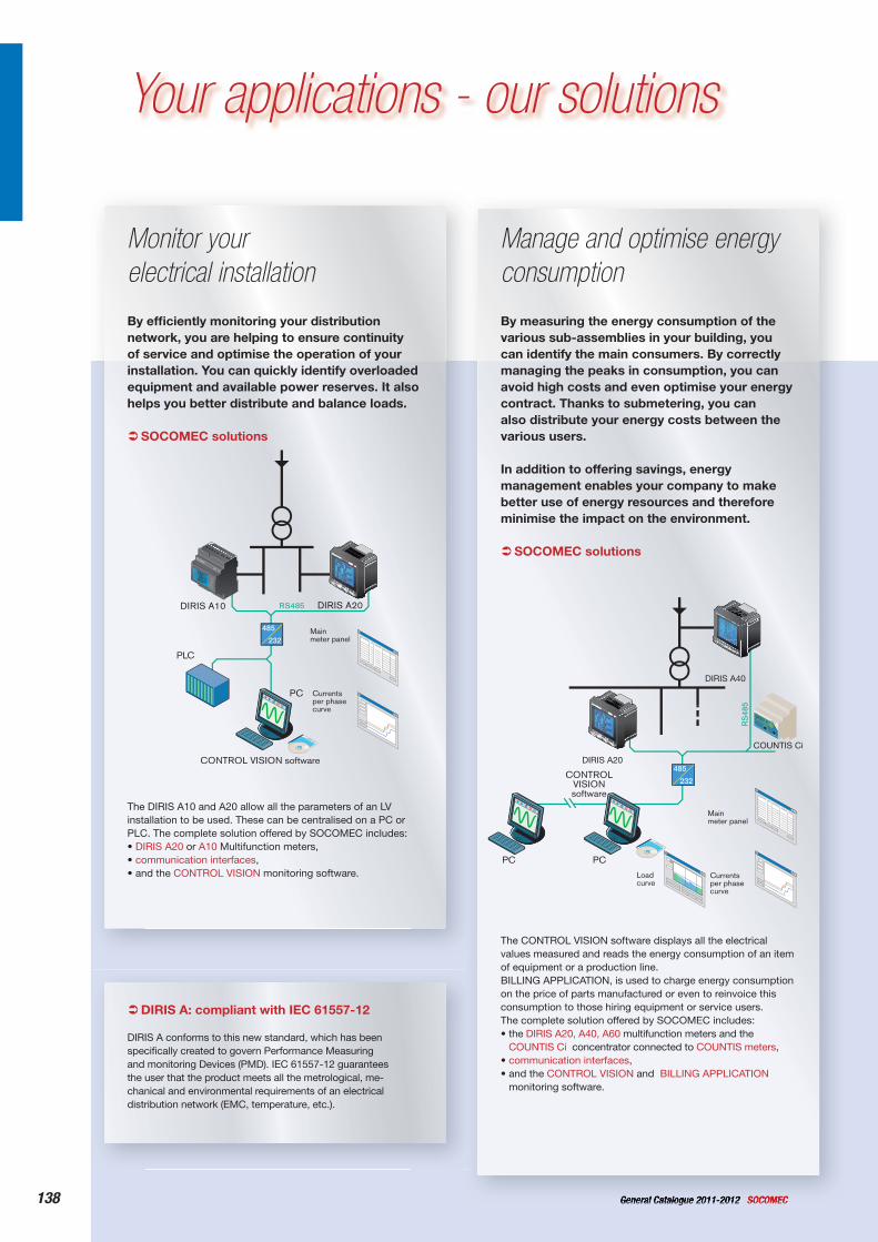
138 General Catalogue 2011-2012 SOCOMEC
Your applications - our solutions
By effi ciently monitoring your distribution network, you are helping to ensure continuity of service and optimise the operation of your installation. You can quickly identify overloaded equipment and available power reserves. It also helps you better distribute and balance loads.
SOCOMEC solutions
The DIRIS A10 and A20 allow all the parameters of an LV installation to be used. These can be centralised on a PC or PLC. The complete solution offered by SOCOMEC includes:• DIRIS A20 or A10 Multifunction meters,• communication interfaces,• and the CONTROL VISION monitoring software.
Monitor your electrical installation
485
232
PLC
CONTROL VISION software
Mainmeter panel
Currentsper phasecurve
PC
RS485 DIRIS A20DIRIS A10
By measuring the energy consumption of the various sub-assemblies in your building, you can identify the main consumers. By correctly managing the peaks in consumption, you can avoid high costs and even optimise your energy contract. Thanks to submetering, you can also distribute your energy costs between the various users.
In addition to offering savings, energy management enables your company to make better use of energy resources and therefore minimise the impact on the environment.
SOCOMEC solutions
The CONTROL VISION software displays all the electrical values measured and reads the energy consumption of an item of equipment or a production line.BILLING APPLICATION, is used to charge energy consumption on the price of parts manufactured or even to reinvoice this consumption to those hiring equipment or service users.The complete solution offered by SOCOMEC includes:• the DIRIS A20, A40, A60 multifunction meters and the
COUNTIS Ci concentrator connected to COUNTIS meters,• communication interfaces,• and the CONTROL VISION and BILLING APPLICATION
monitoring software.
Manage and optimise energy consumption
485
232
RS
485
PCPC
CONTROLVISIONsoftware
Mainmeter panel
Currentsper phase curve
Loadcurve
DIRIS A40
DIRIS A20
COUNTIS Ci
DIRIS A: compliant with IEC 61557-12
DIRIS A conforms to this new standard, which has beenspecifi cally created to govern Performance Measuring and monitoring Devices (PMD). IEC 61557-12 guarantees the user that the product meets all the metrological, me-chanical and environmental requirements of an electrical distribution network (EMC, temperature, etc.).
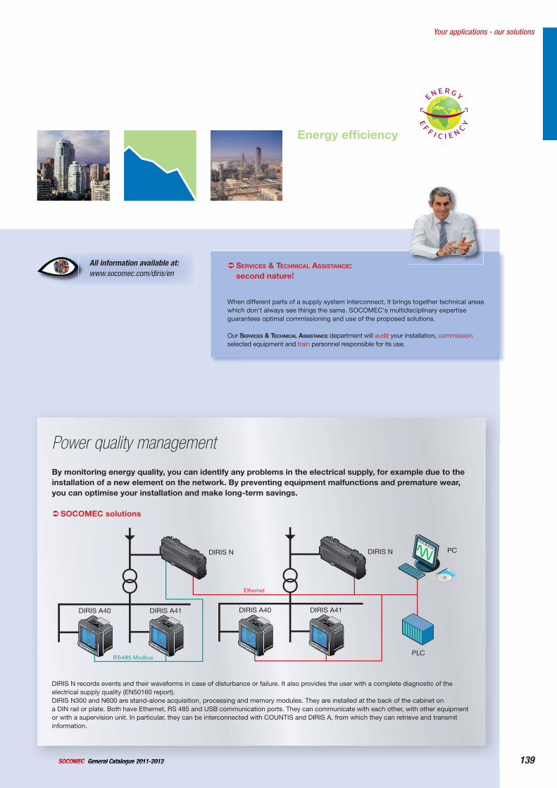
139General Catalogue 2011-2012SOCOMEC
All information available at:www.socomec.com/diris/en
Your applications - our solutions
Energy effi ciency
Energy bill
SERVICES & TECHNICAL ASSISTANCE:second nature!
When different parts of a supply system interconnect, it brings together technical areas which don't always see things the same. SOCOMEC's multidisciplinary expertise guarantees optimal commissioning and use of the proposed solutions.
Our SERVICES & TECHNICAL ASSISTANCE department will audit your installation, commissionselected equipment and train personnel responsible for its use.
By monitoring energy quality, you can identify any problems in the electrical supply, for example due to the installation of a new element on the network. By preventing equipment malfunctions and premature wear, you can optimise your installation and make long-term savings.
SOCOMEC solutions
DIRIS N records events and their waveforms in case of disturbance or failure. It also provides the user with a complete diagnostic of the electrical supply quality (EN50160 report).DIRIS N300 and N600 are stand-alone acquisition, processing and memory modules. They are installed at the back of the cabinet ona DIN rail or plate. Both have Ethernet, RS 485 and USB communication ports. They can communicate with each other, with other equipmentor with a supervision unit. In particular, they can be interconnected with COUNTIS and DIRIS A, from which they can retrieve and transmit information.
Power quality management
PCDIRIS N
DIRIS A40 DIRIS A41
Ethernet
PLCRS485 Modbus
DIRIS N
DIRIS A40 DIRIS A41
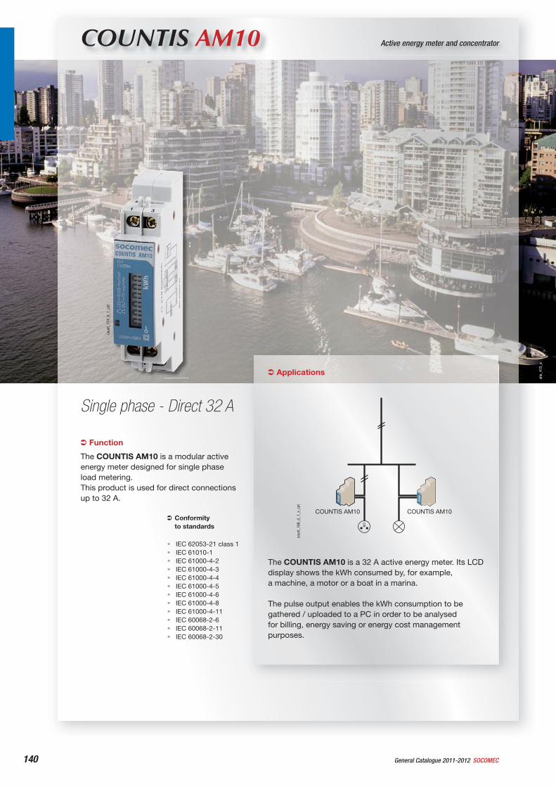
140 General Catalogue 2011-2012 SOCOMEC
COUNTIS AM10 Active energy meter and concentrator
Single phase - Direct 32 A
Function
The COUNTIS AM10 is a modular active energy meter designed for single phase load metering.This product is used for direct connections up to 32 A.
Conformityto standards
IEC 62053-21 class 1IEC 61010-1IEC 61000-4-2IEC 61000-4-3IEC 61000-4-4IEC 61000-4-5IEC 61000-4-6IEC 61000-4-8IEC 61000-4-11IEC 60068-2-6IEC 60068-2-11IEC 60068-2-30
••••••••••••
Applications
The COUNTIS AM10 is a 32 A active energy meter. Its LCD display shows the kWh consumed by, for example, a machine, a motor or a boat in a marina.
The pulse output enables the kWh consumption to be gathered / uploaded to a PC in order to be analysed for billing, energy saving or energy cost management purposes.
COUNTIS AM10COUNTIS AM10
coun
t_16
6_d_
1_x_
cat
coun
t_17
4_b_
1_ca
t
site
_415
_a
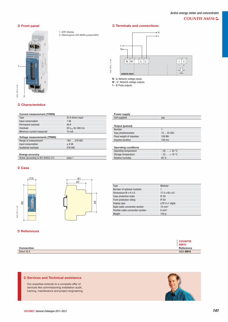
General Catalogue 2011-2012SOCOMEC 141
Active energy meter and concentrator
COUNTIS AM10
Case
Type ModularNumber of optional modules 1Dimensions W x H x D 17.5 x 85 x 61Case protection index IP 20Front protection rating IP 50Display type LCD 5+1 digitsRigid cable connection section 10 mm2
Flexible cable connection section 6 mm2
Weight 150 g
4761
45
17.5
85
coun
t_16
7_a_
x_ca
t
Terminals and connections
N N' L L'
LN
NL
1 3
kWhCOUNTIS AM10
+-
coun
t_16
8_b_
1_x_
cat
N - L: Network voltage inputs.N' - L': Network voltage outputs.1 - 3: Pulse outputs.
2
1
coun
t_17
4x_b
_2_c
at
1. kWh display.2. Metrological LED (6000 pulses/kWh)
COUNTISAM10
Connection ReferenceDirect 32 A 4850 AM10
References
Front panel
Current measurement (TRMS) Type 32 A direct inputInput consumption 1 VAPermanent overload 40 AOverload 20 Imax for 500 msMinimum current measured 15 mA
Voltage measurements (TRMS) Range of measurement 184 … 276 VACInput consumption 8 VASustained overload 276 VAC
Energy accuracy Active (according to IEC 62053-21) class 1
Power supply Self supplied yes
Output (pulsed) Number 1Type phototransistor 10 ... 35 VDCFixed weight of impulses 100 WhImpulse duration 100 ms
Operating conditions Operating temperature - 20 … + 45 °CStorage temperature - 25 … + 70 °CRelative humidity 85 %
Characteristics
Services and Technical assistance
Our expertise extends to a complete offer of services like commissioning installation audit, training, maintenance and project engineering.
142 General Catalogue 2011-2012 SOCOMEC
site
_544
_a
COUNTIS E10 / E11 / E12 Active energy meter and concentrator
Single phase - Direct 63 A
Function
The COUNTIS E1x is an active electrical energy meter designed for single phase load metering. It is used for direct connections up to 63 A.
Conformityto standards
IEC 62053-21 class 1IEC 62053-31IEC 62053-11EN 50470-1EN 50470-3
•••••
Applications
The COUNTIS E10 displays the total energy consumed and allows remote access through pulse output.Metering over specific period can be managed though a partial counter.
The COUNTIS E11 is a double tariff meter meant for dual tariff invoicing. For each tariff a partial counter is available.
The COUNTIS E12 features MID certification.MID certified meters feature:- Extra thefts protection : meter can not be
reset, sealed casing. - Extra accuracy : MID specifications on
accuracy according to temperature, humidity, and other external factors are extended.
coun
t_17
8_b_
1_ca
t
NEW
143General Catalogue 2011-2012SOCOMEC 143
Active energy meter and concentratorCOUNTIS E10 / E11 / E12
Connection
+ -
T1/2 L’L NCOUNTIS E10/E11/E12
NL’L
4 6 8 10 1 3 2
coun
t_18
1_b_
1_x_
cat
Case
Type ModularNumber of optional modules 3Dimensions W x H x D 54 x 90 x 62.5 mmCase protection index IP 20Front protection rating IP 51Display type Backlit LCD displayRigid cable connection section 1.5 to 16 mm2
Flexible cable connection section 1 to 16 mm2
Weight 170 g
C=1Wh/imp230VAC 50/60Hz 0.5-10(63)A
COUNTIS E10
RESET
63A
Error Partial
54 4562.5
90 45
coun
t_19
0_b_
1_x_
cat
1
2
34
coun
t_17
8x_b
_1_c
at
1. LCD display.2. Navigation key.3. Reset key.4. Metrological LED.
Front panel
References
COUNTIS E10 COUNTIS E11 COUNTIS E12Type Reference Reference Reference63 A direct 4850 300063 A direct - Dual tariff 4850 300163 A direct - Dual tariff and MID 4850 3002
Certification MIDThe Measuring Instruments Directive (MID) authorises the use of MID Countis in applications for which sub-billing of the electrical energy consumed is necessary (apartments, commercial units, etc.). It guarantees each user that meters meets a high level of accuracy, quality design and manufacturing through a 3rd party verification.
Voltage measurementRange of measurement 230 ... 400 V +/- 20 %Consumption (VA) 0.5 VA max.Sustained overload 280 V phase-neutral
Energy accuracyActive (according to IEC 62053-21) Class 1
Power supplySelf supplied YesFrequency 50/60 Hz
Output (pulsed)Type of optocoupler IEC 62053-31 Class A (20 ... 30 VDC)Number 1Fixed weight of impulses 100 WhImpulse duration 100 ms
Operating conditionsOperating temperature -10 to 55 °CStorage temperature -20 to 70 °CRelative humidity 85 %
Electrical characteristics
(1) I(min) 0.5 * Itr(2) The accuracy class is guaranteed between Itr et Imax.(3) I(ref) = I(b) (base current) = 10 * I(tr) for direct connection COUNTIS.
Current measurement
Type Single phase - Direct 63 AInput consumption 0.8 VA max.Startup current (Ist) 40 mAMinimum current (Imin) 0.5 A(1)
Transition current (Itr) 1 A(2)
Reference current (Iref) 10 A(3)
Permanent overload (Imax) 63 AShort-time over-current 1890 A max for 10 ms
144 General Catalogue 2011-2012 SOCOMEC
site
_063
_a
COUNTIS E20 / E21 Active energy meter and concentrator
3-phase - 63 A direct
Function
The COUNTIS E2x is an active electrical energy meter designed for three-phase networks. It is used for direct connections up to 63 A.
Conformityto standards
IEC 62053-21 class 1•
Applications
The COUNTIS E20 displays the total energy consumed and allows remote access through pulse output.Metering over specific period can be managed though a partial counter.
The COUNTIS E21 is a double tariff meter meant for dual tariff invoicing. For each tariff a partial counter is available.
coun
t_17
7_b_
1_ca
t
NEW
145General Catalogue 2011-2012SOCOMEC 145
Active energy meter and concentratorCOUNTIS E20 / E21
Case
Type ModularNumber of optional modules 4Dimensions W x H x D 72 x 90 x 62.5 mmCase protection index IP20Front protection rating IP51Display type Backlit LCD displayRigid cable connection section 1.5 to 16 mm2
Flexible cable connection section 1 to 16 mm2
Weight 245 g
C=1Wh / imp3X230(400)VAC 50/60Hz 0.5-10(63)A
63A
RESET
COUNTIS E20
Error Partial
72 4562.5
90 45
coun
t_19
1_b_
1_x_
cat
Electrical characteristics
Connection
L3
NL1’L2’L3’
L1
+ -
L1’L1 L2 L3L2’ L3’NCOUNTIS E20
L2
2 4 6 1 3 5 7 9 11
coun
t_18
2_a_
1_x_
cat
L1’L2’L3’
L1L2L3
+ -
T1/2 L1’L1 L2 L3L2’ L3’NCOUNTIS E21
N
2 4 6 8 10 1 3 5 7 9 11
coun
t_18
3_a_
1_x_
cat
1
234
coun
t_17
7x_b
_1_c
at
1. LCD display.2. Navigation key.3. Reset key.4. Metrological LED.
Front panel
References
COUNTIS E20 COUNTIS E21Type Reference Reference63 A direct - 3-phase 4850 300363 A direct - 3-phase - Dual tariff 4850 3004
Voltage measurementRange of measurement 230 ... 400 V +/- 20 %Consumption (VA) 2 VA max.Sustained overload 280 V phase-neutral / 480 V phase-phase
Energy accuracyActive (according to IEC 62053-21) Class 1
Power supplySelf supplied YesFrequency 50/60 Hz
Output (pulsed)Number 1Type of optocoupler IEC 62053-31 Class A (20 ... 30 VDC)Fixed weight of impulses 100 WhImpulse duration 100 ms
Operating conditionsOperating temperature -10 to 55 °CStorage temperature -20 to 70 °CRelative humidity 85 %
(1) I(min) 0.5 * Itr(2) The accuracy class is guaranteed between Itr et Imax.(3) I(ref) = I(b) (base current) = 10 * I(tr) for direct connection COUNTIS.
Current measurement
Type 63 A direct - 3-phaseInput consumption 0.8 VA max. per phaseStartup current (Ist) 40 mAMinimum current (Imin) 0.5 A(1)
Transition current (Itr) 1 A(2)
Reference current (Iref) 10 A(3)
Permanent overload (Imax) 63 AShort-time over-current 1890 A max for 10 ms
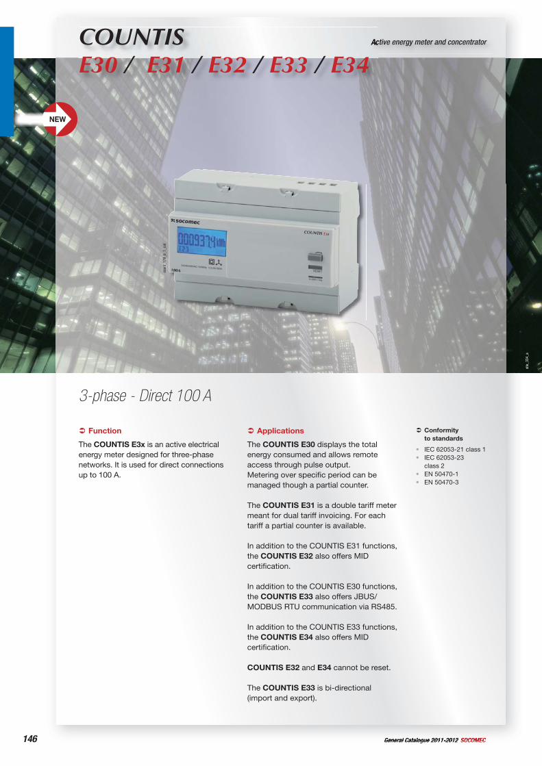
146 General Catalogue 2011-2012 SOCOMEC
site
_334
_a
Active energy meter and concentrator
3-phase - Direct 100 A
Function
The COUNTIS E3x is an active electrical energy meter designed for three-phase networks. It is used for direct connections up to 100 A.
Conformityto standards
IEC 62053-21 class 1IEC 62053-23class 2EN 50470-1EN 50470-3
••
••
Applications
The COUNTIS E30 displays the total energy consumed and allows remote access through pulse output.Metering over specific period can be managed though a partial counter.
The COUNTIS E31 is a double tariff meter meant for dual tariff invoicing. For each tariff a partial counter is available.
In addition to the COUNTIS E31 functions, the COUNTIS E32 also offers MID certification.
In addition to the COUNTIS E30 functions, the COUNTIS E33 also offers JBUS/MODBUS RTU communication via RS485.
In addition to the COUNTIS E33 functions, the COUNTIS E34 also offers MID certification.
COUNTIS E32 and E34 cannot be reset.
The COUNTIS E33 is bi-directional (import and export).
COUNTIS E30 / E31 / E32 / E33 / E34
coun
t_17
9_b_
1_ca
t
NEW
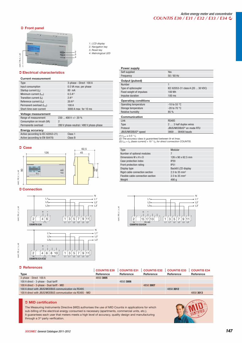
147General Catalogue 2011-2012SOCOMEC 147
Active energy meter and concentratorCOUNTIS E30 / E31 / E32 / E33 / E34
CaseType ModularNumber of optional modules 7Dimensions W x H x D 126 x 90 x 62.5 mmCase protection index IP20Front protection rating IP51Display type Backlit LCD displayRigid cable connection section 2.5 to 35 mm2
Flexible cable connection section 2.5 to 35 mm2
Weight 490 g
C=2Wh / imp3X230(400)VAC 50/60Hz 0.5-20(100)A
RESET
100A
COUNTIS E30
Error Partial
126 4562,5
90 45
coun
t_19
2_b_
1_x_
cat
Connection
L3
NL1’L2’L3’
L1
+ -
L1’L1 L2 L3L2’ L3’N
2 4 6 1 3 5 7 9 11
COUNTIS E30
L2L1’L2’L3’
L1L2L3
+ -
RS 485 L1’L1 L2 L3L2’ L3’NCOUNTIS E33/E34
N
15 1 3 5 7 9 112 1317
L1’L2’L3’
L1L2L3
+ -
T1/2 L1’L1 L2 L3L2’ L3’NCOUNTIS E31/E32
N
1 3 5 7 9 112 4 6 8 10
coun
t_18
5_a_
1_x_
cat
coun
t_18
8_b_
1_x_
cat
coun
t_18
4_a_
1_x_
cat
1. LCD display2. Navigation key3. Reset key4. Metrological LED
1
234
coun
t_17
9x_b
_1_c
at
Front panel
ReferencesCOUNTIS E30 COUNTIS E31 COUNTIS E32 COUNTIS E33 COUNTIS E34
Type Reference Reference Reference Reference Reference3-phase - Direct 100 A 4850 3005100 A direct - 3-phase - Dual tariff 4850 3006100 A direct - 3-phase - Dual tariff - MID 4850 3007100 A direct with JBUS/MODBUS communication via RS485 4850 3012100 A direct with JBUS/MODBUS communication via RS485 - MID 4850 3013
Electrical characteristics
Voltage measurementRange of measurement 230 ... 400 V +/- 20 %Consumption on inrush (VA) 2Permanente overload 280 V phase-neutral / 480 V phase-phase
Energy accuracyActive (according to IEC 62053-21) Class 1Active (according to EN 50470) Class B
Power supplySelf supplied YesFrequency 50 / 60 Hz
Output (pulsed)Number 1Type of optocoupler IEC 62053-31 class A (20 ... 30 VDC)Fixed weight of impulses 100 WhImpulse duration 100 ms
Operating conditionsOperating temperature -10 to 55 °CStorage temperature -20 to 70 °CRelative humidity 85 %
CommunicationLink RS485Type 2 … 3 half duplex wiresProtocol JBUS/MODBUS® en mode RTUJBUS/MODBUS® speed 3800 … 38400 bauds
MID certificationThe Measuring Instruments Directive (MID) authorises the use of MID Countis in applications for which sub-billing of the electrical energy consumed is necessary (apartments, commercial units, etc.). It guarantees each user that meters meets a high level of accuracy, quality design and manufacturing through a 3rd party verification.
(1) I(min) 0.5 * Itr(2) The accuracy class is guaranteed between Itr et Imax.(3) I(ref) = I(b) (base current) = 10 * I(tr) for direct connection COUNTIS.
Current measurement
Type 3-phase - Direct 100 AInput consumption 0.5 VA max. per phaseStartup current (Ist) 80 mAMinimum current (Imin) 0.5 A(1)
Transition current (Itr) 2 A(2)
Reference current (Iref) 20 A(3)
Permanent overload (Imax) 100 AShort-time over-current 3000 A max for 10 ms
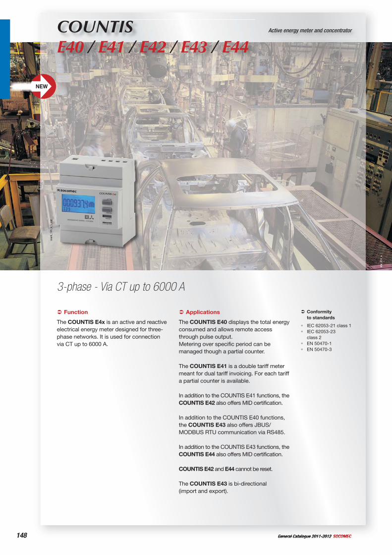
148 General Catalogue 2011-2012 SOCOMEC
site
_014
_a
COUNTIS E40 / E41 / E42 / E43 / E44
Active energy meter and concentrator
3-phase - Via CT up to 6000 A
Function
The COUNTIS E4x is an active and reactive electrical energy meter designed for three-phase networks. It is used for connection via CT up to 6000 A.
Conformityto standards
IEC 62053-21 class 1IEC 62053-23class 2EN 50470-1EN 50470-3
••
••
Applications
The COUNTIS E40 displays the total energy consumed and allows remote access through pulse output.Metering over specific period can be managed though a partial counter.
The COUNTIS E41 is a double tariff meter meant for dual tariff invoicing. For each tariff a partial counter is available.
In addition to the COUNTIS E41 functions, the COUNTIS E42 also offers MID certification.
In addition to the COUNTIS E40 functions, the COUNTIS E43 also offers JBUS/MODBUS RTU communication via RS485.
In addition to the COUNTIS E43 functions, the COUNTIS E44 also offers MID certification.
COUNTIS E42 and E44 cannot be reset.
The COUNTIS E43 is bi-directional (import and export).
coun
t_19
5_a_
1_ca
t
NEW
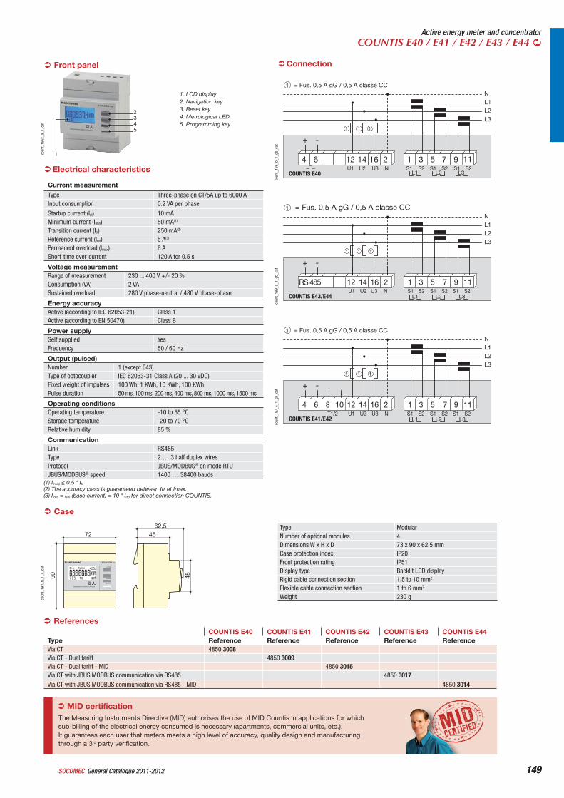
149General Catalogue 2011-2012SOCOMEC 149
Active energy meter and concentratorCOUNTIS E40 / E41 / E42 / E43 / E44
Case
Type ModularNumber of optional modules 4Dimensions W x H x D 73 x 90 x 62.5 mmCase protection index IP20Front protection rating IP51Display type Backlit LCD displayRigid cable connection section 1.5 to 10 mm2
Flexible cable connection section 1 to 6 mm2
Weight 230 g
3X230(400)VAC 50/60Hz 0.05-5(6)A
RESET
PROG
C=0.1Wh/imp
COUNTIS E40
Error Partial
72 4562,5
90 45
coun
t_19
3_b_
1_x_
cat
Connection
NL1L2L3
+ -
3
L1
1 5
L3L2
97 1112RS 485 1614 2
COUNTIS E43/E44S2S1 S1 S1S2 S2U1 U3U2 N
= Fus. 0,5 A gG / 0,5 A classe CC
1 1 1
1
coun
t_18
9_d_
1_gb
_cat
NL1L2L3
+ -
3
L1
1 5
L3L2
97 111210864 1614 2S2S1 S1 S1S2 S2U1T1/2 U3U2 N
COUNTIS E41/E42
= Fus. 0,5 A gG / 0,5 A classe CC
1 1 1
1
coun
t_18
7_c_
1_gb
_cat
NL1L2L3
+ -
S21 3 5S1 S1
L3L2L1S1S2 S2U1 U3U2 N
COUNTIS E40
4 6 12 14 16 2 7 9 11
1 1 1
= Fus. 0,5 A gG / 0,5 A classe CC1
coun
t_18
6_b_
1_gb
_cat
1. LCD display2. Navigation key3. Reset key4. Metrological LED5. Programming key
coun
t_19
5x_a
_1_c
at
Front panel
1
2345
(1) I(min) 0.5 * Itr(2) The accuracy class is guaranteed between Itr et Imax.(3) I(ref) = I(b) (base current) = 10 * I(tr) for direct connection COUNTIS.
ReferencesCOUNTIS E40 COUNTIS E41 COUNTIS E42 COUNTIS E43 COUNTIS E44
Type Reference Reference Reference Reference ReferenceVia CT 4850 3008Via CT - Dual tariff 4850 3009Via CT - Dual tariff - MID 4850 3015Via CT with JBUS MODBUS communication via RS485 4850 3017Via CT with JBUS MODBUS communication via RS485 - MID 4850 3014
CommunicationLink RS485Type 2 … 3 half duplex wiresProtocol JBUS/MODBUS® en mode RTUJBUS/MODBUS® speed 1400 … 38400 bauds
Voltage measurementRange of measurement 230 ... 400 V +/- 20 %Consumption (VA) 2 VASustained overload 280 V phase-neutral / 480 V phase-phase
Energy accuracyActive (according to IEC 62053-21) Class 1Active (according to EN 50470) Class B
Power supplySelf supplied YesFrequency 50 / 60 Hz
Output (pulsed)Number 1 (except E43)Type of optocoupler IEC 62053-31 Class A (20 ... 30 VDC)Fixed weight of impulses 100 Wh, 1 KWh, 10 KWh, 100 KWhPulse duration 50 ms, 100 ms, 200 ms, 400 ms, 800 ms, 1000 ms, 1500 ms
Operating conditionsOperating temperature -10 to 55 °CStorage temperature -20 to 70 °CRelative humidity 85 %
Electrical characteristics
MID certificationThe Measuring Instruments Directive (MID) authorises the use of MID Countis in applications for which sub-billing of the electrical energy consumed is necessary (apartments, commercial units, etc.). It guarantees each user that meters meets a high level of accuracy, quality design and manufacturing through a 3rd party verification.
Current measurement
Type Three-phase on CT/5A up to 6000 AInput consumption 0.2 VA per phase
Startup current (Ist) 10 mAMinimum current (Imin) 50 mA(1)
Transition current (Itr) 250 mA(2)
Reference current (Iref) 5 A(3)
Permanent overload (Imax) 6 AShort-time over-current 120 A for 0.5 s
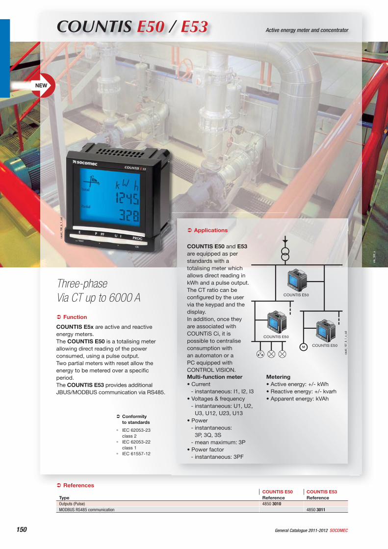
150 General Catalogue 2011-2012 SOCOMEC
site
_300
_a
COUNTIS E50 / E53 Active energy meter and concentrator
Three-phaseVia CT up to 6000 A
coun
t_19
6_b_
1_ca
t
Function
COUNTIS E5x are active and reactive energy meters.The COUNTIS E50 is a totalising meter allowing direct reading of the power consumed, using a pulse output.Two partial meters with reset allow the energy to be metered over a specific period.The COUNTIS E53 provides additional JBUS/MODBUS communication via RS485.
Conformityto standards
IEC 62053-23class 2IEC 62053-22class 1IEC 61557-12
•
•
•
Applications
COUNTIS E50 and E53are equipped as per standards with a totalising meter which allows direct reading in kWh and a pulse output.The CT ratio can be configured by the user via the keypad and the display.In addition, once they are associated with COUNTiS Ci, it is possible to centralise consumption with an automaton or a PC equipped with CONTROL VISION.
COUNTIS E50
COUNTIS E50
COUNTIS E50
COUNTIS E 50
COUNTIS E 50
COUNTIS E 50
ReferencesCOUNTIS E50 COUNTIS E53
Type Reference ReferenceOutputs (Pulse) 4850 3010MODBUS RS485 communication 4850 3011
Multi-function meter• Current
- instantaneous: I1, I2, I3• Voltages & frequency
- instantaneous: U1, U2, U3, U12, U23, U13
• Power- instantaneous:
3P, 3Q, 3S- mean maximum: 3P
• Power factor- instantaneous: 3PF
Metering• Active energy: +/- kWh• Reactive energy: +/- kvarh• Apparent energy: kVAh
coun
t_19
7_b_
1_x_
cat
NEW
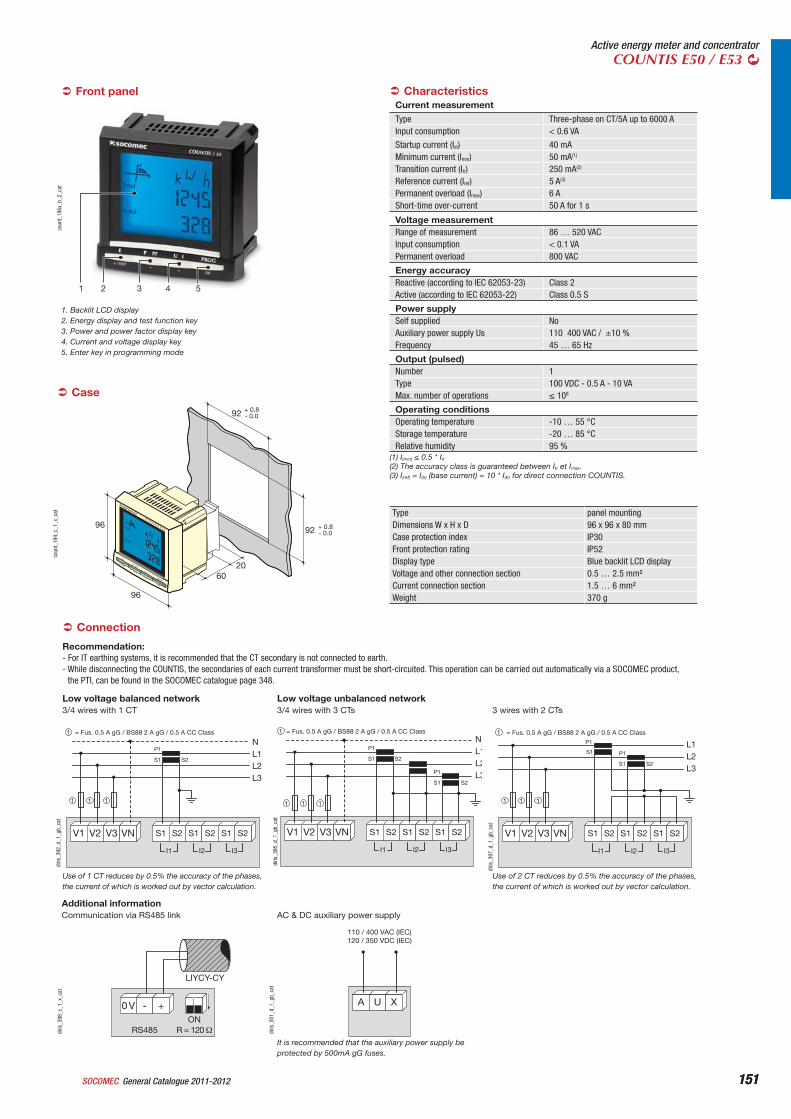
151General Catalogue 2011-2012SOCOMEC 151
Active energy meter and concentratorCOUNTIS E50 / E53
54321
coun
t_19
6x_b
_2_c
at
1. Backlit LCD display2. Energy display and test function key3. Power and power factor display key4. Current and voltage display key5. Enter key in programming mode
Front panel
Case
Type panel mountingDimensions W x H x D 96 x 96 x 80 mmCase protection index IP30Front protection rating IP52Display type Blue backlit LCD displayVoltage and other connection section 0.5 … 2.5 mm²Current connection section 1.5 … 6 mm²Weight 370 g
96
96
6020
92 + 0.8- 0.0
92 + 0.8- 0.0
COUNTIS E53
coun
t_19
4_c_
1_x_
cat
Voltage measurementRange of measurement 86 … 520 VACInput consumption < 0.1 VAPermanent overload 800 VAC
Energy accuracyReactive (according to IEC 62053-23) Class 2Active (according to IEC 62053-22) Class 0.5 S
Power supplySelf supplied NoAuxiliary power supply Us 110 400 VAC / ±10 %Frequency 45 … 65 Hz
Output (pulsed)Number 1Type 100 VDC - 0.5 A - 10 VAMax. number of operations 108
Operating conditionsOperating temperature -10 … 55 °CStorage temperature -20 … 85 °CRelative humidity 95 %
Characteristics
Connection
Recommendation:- For IT earthing systems, it is recommended that the CT secondary is not connected to earth.- While disconnecting the COUNTIS, the secondaries of each current transformer must be short-circuited. This operation can be carried out automatically via a SOCOMEC product,
the PTI, can be found in the SOCOMEC catalogue page 348.
diris
_392
_d_1
_gb_
cat
Use of 1 CT reduces by 0.5% the accuracy of the phases, the current of which is worked out by vector calculation.
3/4 wires with 1 CTLow voltage balanced network
V1 V2 V3 VN
S2
P1
S1
NL1L2L3
I3I2I1
S2S1 S2S1 S2S1
= Fus. 0.5 A gG / BS88 2 A gG / 0.5 A CC Class1
1 1 1
Low voltage unbalanced network
NL1L2L3
S2
S2
P1
S1
P1
S1
V1 V2 V3 VN
I3I2I1
S2S1 S2S1 S2S1
= Fus. 0.5 A gG / BS88 2 A gG / 0.5 A CC Class1
1 1 1
diris
_395
_d_1
_gb_
cat
3/4 wires with 3 CTs
L1L2L3
S2
P1
S1
P1
S1
V1 V2 V3 VN
I3I2I1
S2S1 S2S1 S2S1
= Fus. 0.5 A gG / BS88 2 A gG / 0.5 A CC Class1
1 1 1
diris
_397
_d_1
_gb_
cat
Use of 2 CT reduces by 0.5% the accuracy of the phases, the current of which is worked out by vector calculation.
3 wires with 2 CTs
Additional information
RS485
0 V - +ON
LIYCY-CY
diris
_398
_c_1
_x_c
at
Communication via RS485 link
A U X
110 / 400 VAC (IEC)120 / 350 VDC (IEC)
diris
_501
_d_1
_gb_
cat
It is recommended that the auxiliary power supply be protected by 500mA gG fuses.
AC & DC auxiliary power supply
(1) I(min) 0.5 * Itr(2) The accuracy class is guaranteed between Itr et Imax.(3) I(ref) = I(b) (base current) = 10 * I(tr) for direct connection COUNTIS.
Current measurement
Type Three-phase on CT/5A up to 6000 AInput consumption < 0.6 VA
Startup current (Ist) 40 mAMinimum current (Imin) 50 mA(1)
Transition current (Itr) 250 mA(2)
Reference current (Iref) 5 A(3)
Permanent overload (Imax) 6 AShort-time over-current 50 A for 1 s
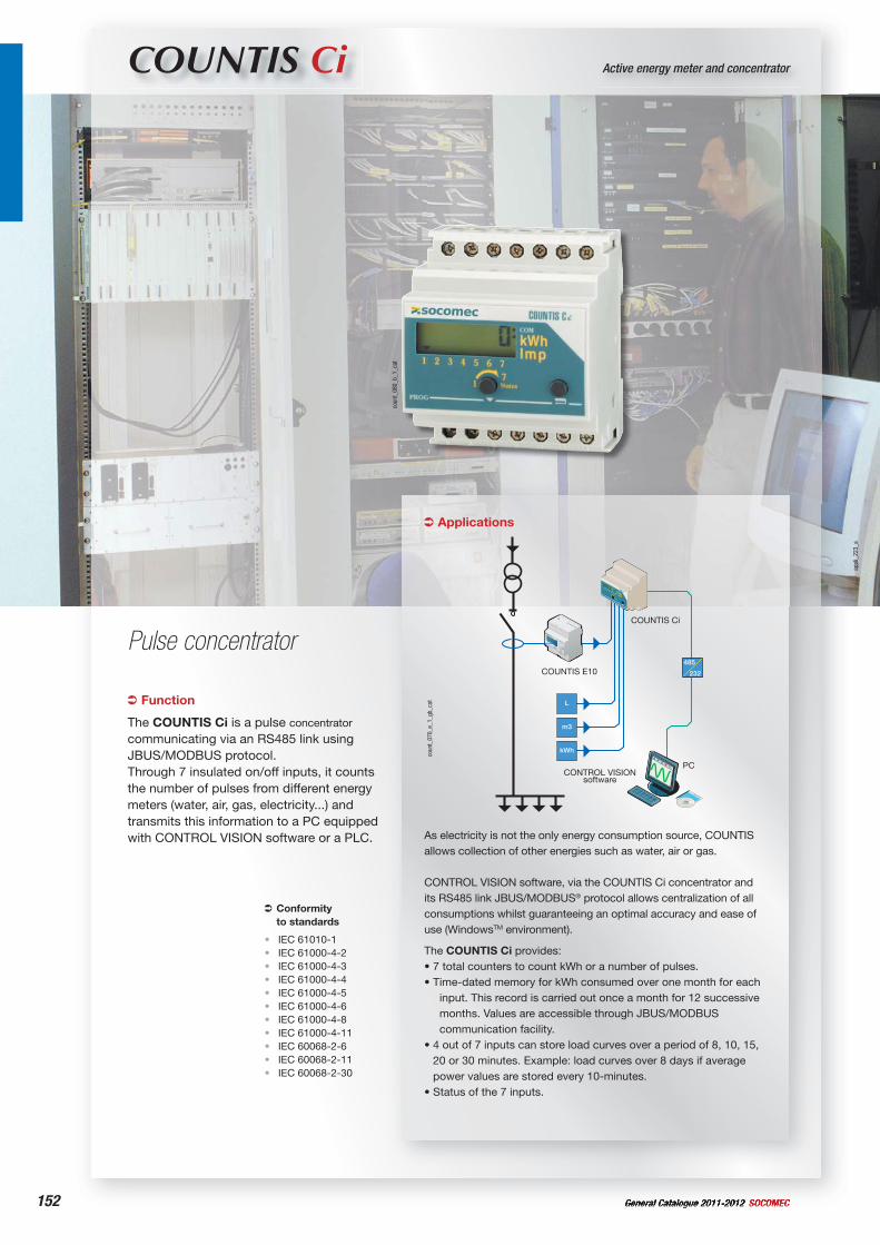
152 General Catalogue 2011-2012 SOCOMEC
appl
i_22
3_a
COUNTIS Ci Active energy meter and concentrator
Pulse concentrator
Applications
As electricity is not the only energy consumption source, COUNTIS allows collection of other energies such as water, air or gas.
CONTROL VISION software, via the COUNTIS Ci concentrator and its RS485 link JBUS/MODBUS® protocol allows centralization of all consumptions whilst guaranteeing an optimal accuracy and ease of use (WindowsTM environment).
The COUNTIS Ci provides:• 7 total counters to count kWh or a number of pulses.• Time-dated memory for kWh consumed over one month for each
input. This record is carried out once a month for 12 successive months. Values are accessible through JBUS/MODBUS communication facility.
• 4 out of 7 inputs can store load curves over a period of 8, 10, 15, 20 or 30 minutes. Example: load curves over 8 days if average power values are stored every 10-minutes.
• Status of the 7 inputs.
485
232
L
m3
kWh
CONTROL VISIONsoftware
COUNTIS E10
COUNTIS Ci
PC
coun
t_07
0_e_
1_gb
_catFunction
The COUNTIS Ci is a pulse concentrator
communicating via an RS485 link using JBUS/MODBUS protocol. Through 7 insulated on/off inputs, it counts the number of pulses from different energy meters (water, air, gas, electricity...) and transmits this information to a PC equipped with CONTROL VISION software or a PLC.
Conformityto standards
IEC 61010-1IEC 61000-4-2IEC 61000-4-3IEC 61000-4-4IEC 61000-4-5IEC 61000-4-6IEC 61000-4-8IEC 61000-4-11IEC 60068-2-6IEC 60068-2-11IEC 60068-2-30
•••••••••••
coun
t_08
0_b_
1_ca
t
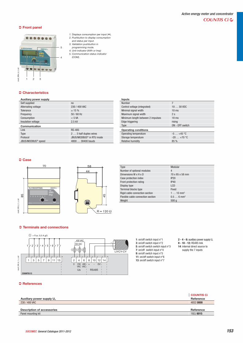
General Catalogue 2011-2012SOCOMEC 153
Active energy meter and concentrator
COUNTIS Ci
Terminals and connections
1
COUNTIS Ci
7 9 11 13 2 4 6 8 10 12 14531
2 3 4 5 6 7
LIYCY-CY
230 VAC
400 VAC
RS485Us
0V+
+
-
-230VAC
400VAC
0
= Fus. 0,5 A gG1
1 1 1
coun
t_03
0_b_
1_x_
cat
1: on/off switch input n°13: on/off switch input n°25: on/off switch switch input n°37: on/off switch input n°49: on/off switch input n°511: on/off switch input n°613: on/off switch input n°7
2 - 4 - 6: auxiliary power supply Us
8 - 10 - 12: RS485 link14: internal direct source to
supply the 7 inputs
COUNTIS CiAuxiliary power supply Us Reference230 / 400 VAC 4852 0000
Description of accessories ReferencePanel mounting kit 192J 8015
3
4
5
21
coun
t_08
0x_b
_4_c
at
1. Displays consumption per input ( ).2. Pushbutton to display consumption
and status per input.3. Validation pushbutton in
programming mode.4. Unit indicator (kWh or Imp)5. Communication status indicator
(COM).
Auxiliary power supply Self supplied noAlternating voltage 230 / 400 VACTolerance ± 15 %Frequency 50 / 60 HzConsumption < 5 VAInsulation voltage 2.5 kV
CommunicationLink RS-485Type 2 … 3 half duplex wiresProtocol JBUS/MODBUS® in RTU modeJBUS/MODBUS® speed 4800 … 38400 bauds
InputsNumber 7Control voltage (integrated) 10 … 30 VDCMinimal signal width 10 msMaximum signal width 2 sMinimum length between 2 impulses 18 msEdge triggering risingType ON - OFF switch
Operating conditions Operating temperature -5 … +45 °CStorage temperature -20 … +70 °CRelative humidity 85 %
Characteristics
Case
Type ModularNumber of optional modules 4Dimensions W x H x D 70 x 85 x 58 mmCase protection index IP20Front protection rating IP40Display type LCDTerminal blocks type FixedRigid cable connection section 1 … 10 mm2
Flexible cable connection section 0.5 … 6 mm2
Weight 500 g
70
85
44
58
45
coun
t_03
8_d_
1_x_
cat
References
Front panel
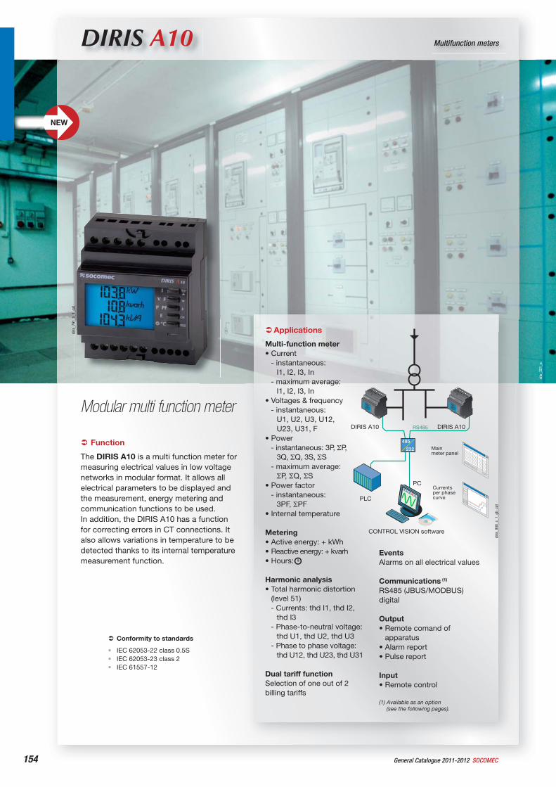
site
_321
_a
154 General Catalogue 2011-2012 SOCOMEC
DIRIS A10 Multifunction meters
Modular multi function meter
Function
The DIRIS A10 is a multi function meter for measuring electrical values in low voltage networks in modular format. It allows all electrical parameters to be displayed and the measurement, energy metering and communication functions to be used.In addition, the DIRIS A10 has a function for correcting errors in CT connections. It also allows variations in temperature to be detected thanks to its internal temperature measurement function.
Conformity to standards
IEC 62053-22 class 0.5SIEC 62053-23 class 2IEC 61557-12
•••
Applications
Multi-function meter• Current
- instantaneous: I1, I2, I3, In
- maximum average: I1, I2, I3, In
• Voltages & frequency- instantaneous:
U1, U2, U3, U12, U23, U31, F
• Power- instantaneous: 3P, P,
3Q, Q, 3S, S- maximum average:
P, Q, S• Power factor
- instantaneous: 3PF, PF
• Internal temperature
Metering• Active energy: + kWh• Reactive energy: + kvarh• Hours:
Harmonic analysis• Total harmonic distortion
(level 51)- Currents: thd I1, thd I2,
thd I3- Phase-to-neutral voltage:
thd U1, thd U2, thd U3- Phase to phase voltage:
thd U12, thd U23, thd U31
Dual tariff functionSelection of one out of 2 billing tariffs
EventsAlarms on all electrical values
Communications (1)
RS485 (JBUS/MODBUS) digital
Output• Remote comand of
apparatus• Alarm report• Pulse report
Input• Remote control
(1) Available as an option (see the following pages).
485
232
PC
DIRIS A10 DIRIS A10
CONTROL VISION software
PLC
RS485
Mainmeter panel
Currentsper phasecurve
diris
_808
_c_1
_gb_
cat
diris
_791
_b_1
_cat
NEW
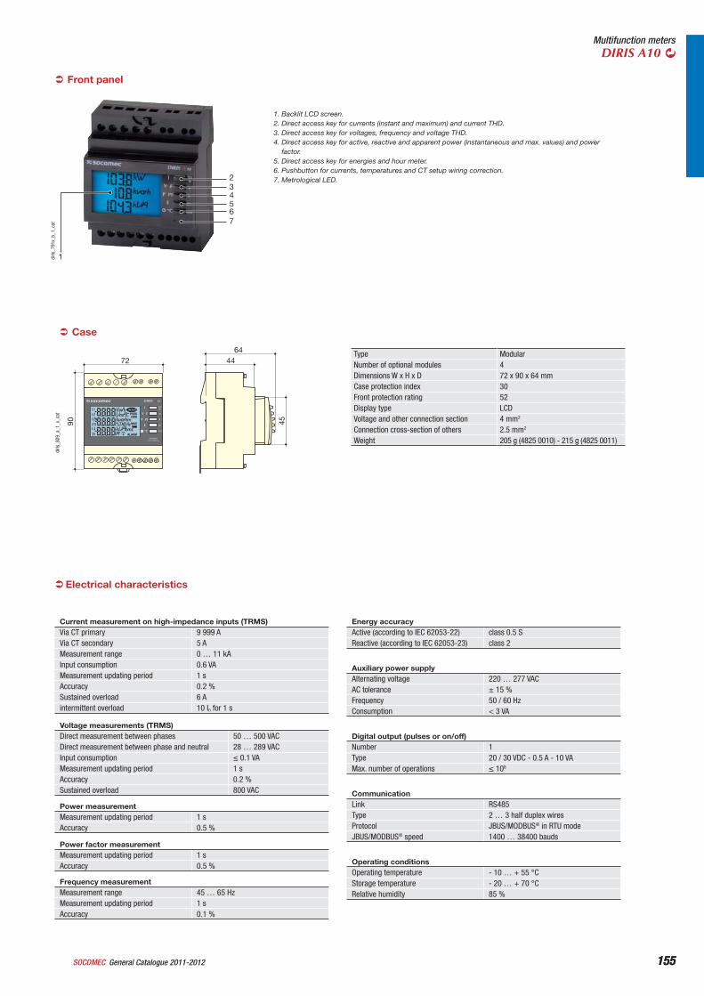
155General Catalogue 2011-2012SOCOMEC 155
Multifunction metersDIRIS A10
1
234567
diris
_791
x_b_
1_ca
t
1. Backlit LCD screen.2. Direct access key for currents (instant and maximum) and current THD.3. Direct access key for voltages, frequency and voltage THD.4. Direct access key for active, reactive and apparent power (instantaneous and max. values) and power
factor.5. Direct access key for energies and hour meter.6. Pushbutton for currents, temperatures and CT setup wiring correction.7. Metrological LED.
Front panel
Case
Type ModularNumber of optional modules 4Dimensions W x H x D 72 x 90 x 64 mmCase protection index 30Front protection rating 52Display type LCDVoltage and other connection section 4 mm2
Connection cross-section of others 2.5 mm2
Weight 205 g (4825 0010) - 215 g (4825 0011)PROG
TEST
OK
DIRIS A10
P PF
I
E
C=0,1Wh/imp
°C
V F
72
90 45
4464
diris
_809
_a_1
_x_c
at
Current measurement on high-impedance inputs (TRMS)Via CT primary 9 999 AVia CT secondary 5 AMeasurement range 0 … 11 kAInput consumption 0.6 VAMeasurement updating period 1 sAccuracy 0.2 %Sustained overload 6 Aintermittent overload 10 In for 1 s
Voltage measurements (TRMS)Direct measurement between phases 50 … 500 VACDirect measurement between phase and neutral 28 … 289 VACInput consumption 0.1 VAMeasurement updating period 1 sAccuracy 0.2 %Sustained overload 800 VAC
Power measurementMeasurement updating period 1 sAccuracy 0.5 %
Power factor measurementMeasurement updating period 1 sAccuracy 0.5 %
Frequency measurementMeasurement range 45 … 65 HzMeasurement updating period 1 sAccuracy 0.1 %
Energy accuracyActive (according to IEC 62053-22) class 0.5 SReactive (according to IEC 62053-23) class 2
Auxiliary power supplyAlternating voltage 220 … 277 VACAC tolerance ± 15 %Frequency 50 / 60 HzConsumption < 3 VA
Digital output (pulses or on/off)Number 1Type 20 / 30 VDC - 0.5 A - 10 VAMax. number of operations 108
CommunicationLink RS485Type 2 … 3 half duplex wiresProtocol JBUS/MODBUS® in RTU modeJBUS/MODBUS® speed 1400 … 38400 bauds
Operating conditionsOperating temperature - 10 … + 55 °CStorage temperature - 20 … + 70 °CRelative humidity 85 %
Electrical characteristics
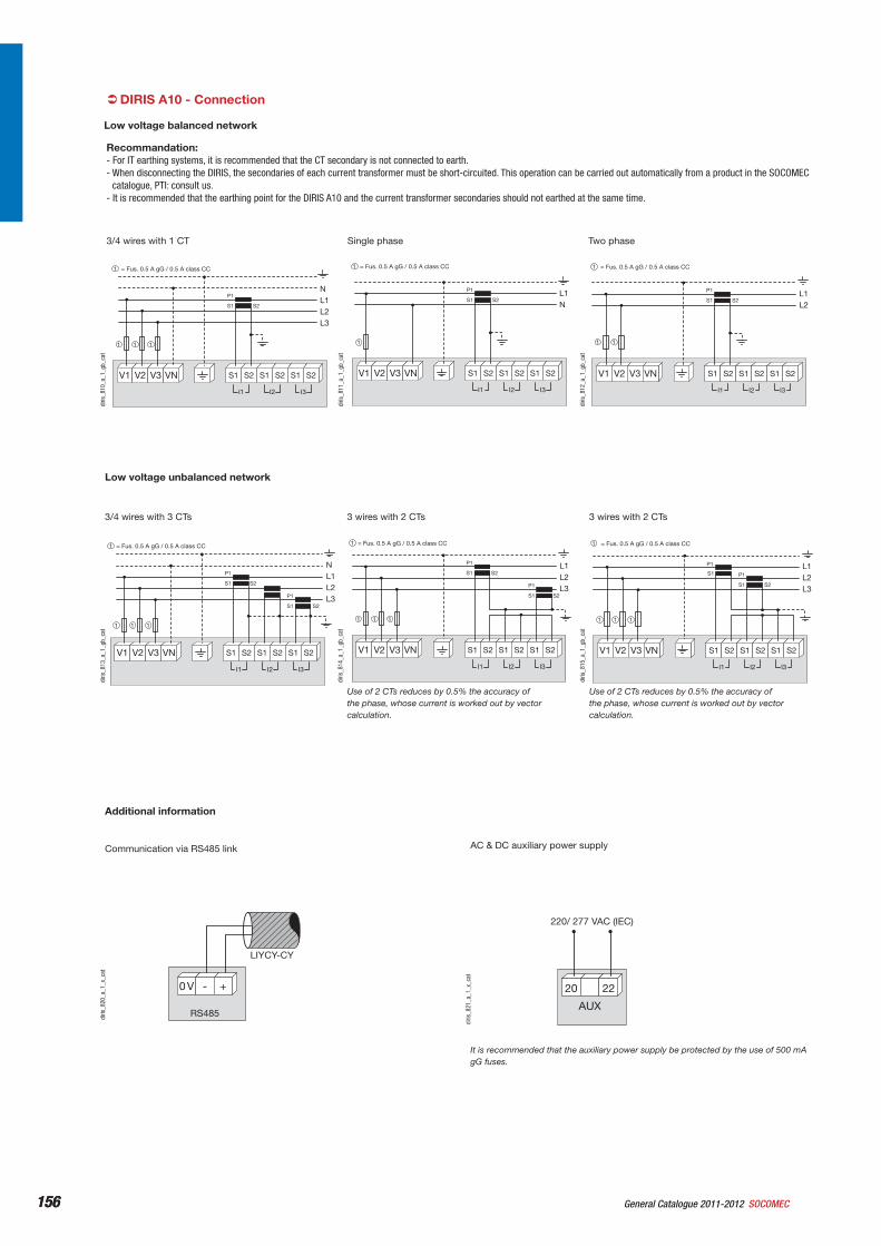
156 General Catalogue 2011-2012 SOCOMEC156
DIRIS A10 - Connection
Recommandation:- For IT earthing systems, it is recommended that the CT secondary is not connected to earth.- When disconnecting the DIRIS, the secondaries of each current transformer must be short-circuited. This operation can be carried out automatically from a product in the SOCOMEC
catalogue, PTI: consult us.- It is recommended that the earthing point for the DIRIS A10 and the current transformer secondaries should not earthed at the same time.
V1 V2 V3 VN
S2
P1
S1
NL1L2L3
I3I2I1
S2S1 S2S1 S2S1
= Fus. 0.5 A gG / 0.5 A class CC1
1 1 1
diris
_810
_a_1
_gb_
cat
3/4 wires with 1 CT
V1 V2 V3 VN
S2
P1
S1L1N
I3I2I1
S2S1 S2S1 S2S1
= Fus. 0.5 A gG / 0.5 A class CC1
1di
ris_8
11_a
_1_g
b_ca
t
Single phase
V1 V2 V3 VN
S2
P1
S1L1L2
I3I2I1
S2S1 S2S1 S2S1
= Fus. 0.5 A gG / 0.5 A class CC1
1 1
diris
_812
_a_1
_gb_
cat
Two phase
Additional information
RS485
0 V - +
LIYCY-CY
diris
_820
_a_1
_x_c
at
Communication via RS485 link
AUX
220/ 277 VAC (IEC)
20 22
diris
_821
_a_1
_x_c
at
It is recommended that the auxiliary power supply be protected by the use of 500 mA gG fuses.
AC & DC auxiliary power supply
Low voltage unbalanced network
NL1L2L3
S2
S2
P1
S1
P1
S1
V1 V2 V3 VN
I3I2I1
S2S1 S2S1 S2S1
= Fus. 0.5 A gG / 0.5 A class CC1
1 1 1
diris
_813
_a_1
_gb_
cat
3/4 wires with 3 CTs
L1L2L3
S2
S2
P1
S1
P1
S1
V1 V2 V3 VN
I3I2I1
S2S1 S2S1 S2S1
= Fus. 0.5 A gG / 0.5 A class CC1
1 1 1
diris
_814
_a_1
_gb_
cat
Use of 2 CTs reduces by 0.5% the accuracy of the phase, whose current is worked out by vector calculation.
3 wires with 2 CTs
L1L2L3
S2
P1
S1
P1
S1
V1 V2 V3 VN
I3I2I1
S2S1 S2S1 S2S1
= Fus. 0.5 A gG / 0.5 A class CC1
1 1 1
diris
_815
_a_1
_gb_
cat
Use of 2 CTs reduces by 0.5% the accuracy of the phase, whose current is worked out by vector calculation.
3 wires with 2 CTs
Low voltage balanced network
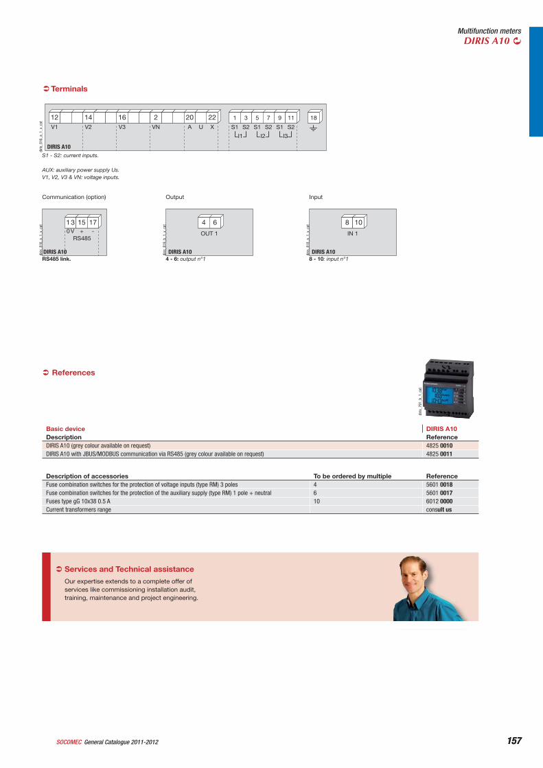
157General Catalogue 2011-2012SOCOMEC 157
Multifunction metersDIRIS A10
Terminals
DIRIS A10
20 2216 212 14
I3I2I1
31 75 119
A U XV3 VNV1 V2 S2S1 S2S1 S2S1
18
diris
_816
_a_1
_x_c
at
S1 - S2: current inputs.
AUX: auxiliary power supply Us.V1, V2, V3 & VN: voltage inputs.
1 3 15 170 V + -
RS485
DIRIS A10diris
_816
_a_1
_x_c
at
RS485 link.
Communication (option)
4 6
DIRIS A10
OUT 1
diris
_819
_b_1
_x_c
at
4 - 6: output n°1
Output
References
Basic device DIRIS A10Description ReferenceDIRIS A10 (grey colour available on request) 4825 0010DIRIS A10 with JBUS/MODBUS communication via RS485 (grey colour available on request) 4825 0011
diris
_791
_b_1
_cat
8 10
DIRIS A10
IN 1
diris
_818
_a_1
_x_c
at
8 - 10: input n°1
Input
Description of accessories To be ordered by multiple ReferenceFuse combination switches for the protection of voltage inputs (type RM) 3 poles 4 5601 0018Fuse combination switches for the protection of the auxiliary supply (type RM) 1 pole + neutral 6 5601 0017Fuses type gG 10x38 0.5 A 10 6012 0000Current transformers range consult us
Services and Technical assistance
Our expertise extends to a complete offer of services like commissioning installation audit, training, maintenance and project engineering.
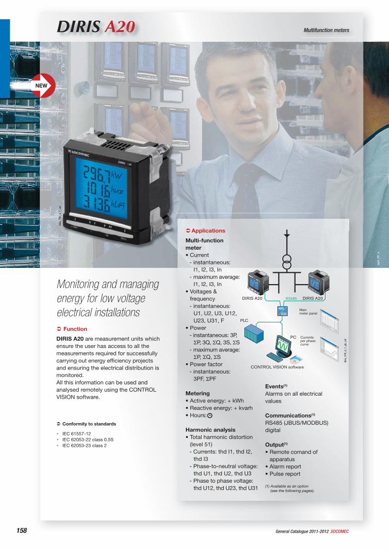
appl
i_38
7_a
158 General Catalogue 2011-2012 SOCOMEC
DIRIS A20 Multifunction meters
Monitoring and managing energy for low voltage electrical installations
diris
_750
_a_1
_cat
Function
DIRIS A20 are measurement units which ensure the user has access to all the measurements required for successfully carrying out energy efficiency projects and ensuring the electrical distribution is monitored.All this information can be used and analysed remotely using the CONTROL VISION software.
Conformity to standards
IEC 61557-12IEC 62053-22 class 0.5SIEC 62053-23 class 2
•••
Applications
Multi-functionmeter• Current
- instantaneous: I1, I2, I3, In
- maximum average: I1, I2, I3, In
• Voltages & frequency- instantaneous:
U1, U2, U3, U12, U23, U31, F
• Power- instantaneous: 3P,
P, 3Q, Q, 3S, S- maximum average:
P, Q, S• Power factor
- instantaneous: 3PF, PF
Metering• Active energy: + kWh• Reactive energy: + kvarh• Hours:
Harmonic analysis• Total harmonic distortion
(level 51)- Currents: thd I1, thd I2,
thd I3- Phase-to-neutral voltage:
thd U1, thd U2, thd U3- Phase to phase voltage:
thd U12, thd U23, thd U31
Events(1)
Alarms on all electrical values
Communications(1)
RS485 (JBUS/MODBUS) digital
Output(1)
• Remote comand of apparatus
• Alarm report• Pulse report
(1) Available as an option (see the following pages).
485
232
PLC
CONTROL VISION software
Mainmeter panel
Currentsper phasecurve
PC
RS485DIRIS A20 DIRIS A20
diris
_576
_d_1
_gb_
cat
NEW
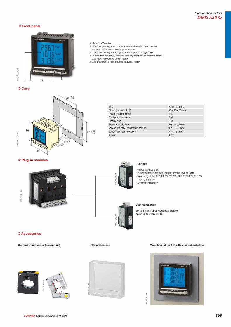
159General Catalogue 2011-2012SOCOMEC 159
Multifunction metersDIRIS A20
54321diris
_743
x_a_
2_ca
t
1. Backlit LCD screen.2. Direct access key for currents (instantaneous and max. values),
current THD and set up wiring correction.3. Direct access key for voltages, frequency and voltage THD.4. Pushbutton for active, reactive, and apparent power (instantaneous
and max. values) and power factor.5. Direct access key for energies and hour meter.
Front panel
Case
Type Panel mountingDimensions W x H x D 96 x 96 x 60 mmCase protection index IP30Front protection rating IP52Display type LCDTerminal blocks type fixed or pull-outVoltage and other connection section 0.2 … 2.5 mm2
Current connection section 0.5 … 6 mm2
Weight 400 g
5/TEST
4
OK
PROG
I
V F P PF
E
DIRIS A2096
96
6020
92 + 0.8- 0.0
92 + 0.8- 0.0
diris
_577
_c_1
_x_c
at
Plug-in modules
diris
_773
_a_1
_cat
diris
_445
_a_1
_cat
1 output assignable to:• Pulses: configurable (type, weight, time) in kWh or kvarh • Monitoring: 3I, In, 3V, 3U, F, P, Q, S, PFL/C, THD 3I, THD 3V,
THD 3U and timer• Control of apparatus
1 Output
diris
_447
_a_1
_cat
RS485 link with JBUS / MODBUS protocol (speed up to 38400 bauds)
Communication
Accessories
trafo
_024
_a_2
_cat
Current transformer (consult us)
trafo
_077
_b_2
_cat
diris
_720
_a_2
_cat
IP65 protection
diris
_718
_b_1
_cat
Mounting kit for 144 x 96 mm cut out plate
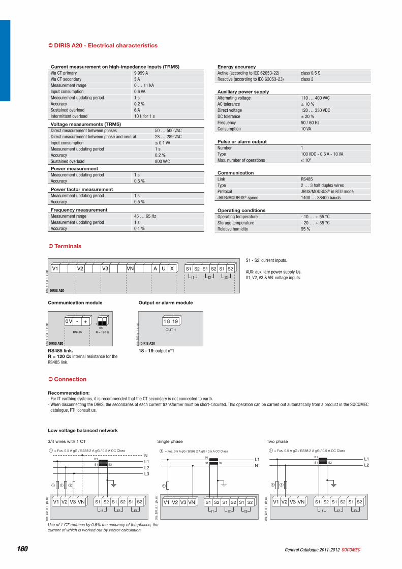
160 General Catalogue 2011-2012 SOCOMEC160
Connection
Recommendation:- For IT earthing systems, it is recommended that the CT secondary is not connected to earth.- When disconnecting the DIRIS, the secondaries of each current transformer must be short-circuited. This operation can be carried out automatically from a product in the SOCOMEC
catalogue, PTI: consult us.
Voltage measurements (TRMS)Direct measurement between phases 50 … 500 VACDirect measurement between phase and neutral 28 … 289 VACInput consumption 0.1 VAMeasurement updating period 1 sAccuracy 0.2 %Sustained overload 800 VAC
Power measurementMeasurement updating period 1 sAccuracy 0.5 %
Power factor measurementMeasurement updating period 1 sAccuracy 0.5 %
Frequency measurementMeasurement range 45 … 65 HzMeasurement updating period 1 sAccuracy 0.1 %
Energy accuracyActive (according to IEC 62053-22) class 0.5 SReactive (according to IEC 62053-23) class 2
Auxiliary power supplyAlternating voltage 110 … 400 VACAC tolerance ± 10 %Direct voltage 120 … 350 VDCDC tolerance ± 20 %Frequency 50 / 60 HzConsumption 10 VA
Pulse or alarm outputNumber 1Type 100 VDC - 0.5 A - 10 VAMax. number of operations 108
CommunicationLink RS485Type 2 … 3 half duplex wiresProtocol JBUS/MODBUS® in RTU modeJBUS/MODBUS® speed 1400 … 38400 bauds
Operating conditionsOperating temperature - 10 … + 55 °CStorage temperature - 20 … + 85 °CRelative humidity 95 %
DIRIS A20 - Electrical characteristics
Terminals
DIRIS A20
A U XV3 VNV1 V2
I3I2I1
S2S1 S2S1 S2S1
diris
_578
_a_1
_x_c
at
S1 - S2: current inputs.
AUX: auxiliary power supply Us.V1, V2, V3 & VN: voltage inputs.
0 V - +
R = 120 RS485
0n1
DIRIS A20diris
_579
_a_1
_x_c
at
RS485 link.R = 120 : internal resistance for the RS485 link.
Communication module
1 8 19
DIRIS A20
OUT 1
diris
_580
_b_1
_x_c
at
18 - 19: output n°1
Output or alarm module
Use of 1 CT reduces by 0.5% the accuracy of the phases, the current of which is worked out by vector calculation.
Low voltage balanced network
diris
_392
_d_1
_gb_
cat
3/4 wires with 1 CT
V1 V2 V3 VN
S2
P1
S1
NL1L2L3
I3I2I1
S2S1 S2S1 S2S1
= Fus. 0.5 A gG / BS88 2 A gG / 0.5 A CC Class1
1 1 1
diris
_393
_d_1
_gb_
cat
Single phase
V1 V2 V3 VN
S2
P1
S1L1N
I3I2I1
S2S1 S2S1 S2S1
= Fus. 0.5 A gG / BS88 2 A gG / 0.5 A CC Class1
1
diris
_394
_d_1
_gb_
cat
Two phase
V1 V2 V3 VN
S2
P1
S1L1L2
I3I2I1
S2S1 S2S1 S2S1
= Fus. 0.5 A gG / BS88 2 A gG / 0.5 A CC Class1
1 1
Current measurement on high-impedance inputs (TRMS)Via CT primary 9 999 AVia CT secondary 5 AMeasurement range 0 … 11 kAInput consumption 0.6 VAMeasurement updating period 1 sAccuracy 0.2 %Sustained overload 6 AIntermittent overload 10 In for 1 s
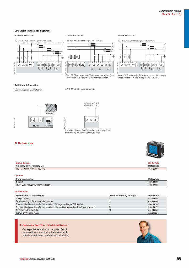
161General Catalogue 2011-2012SOCOMEC 161
Multifunction metersDIRIS A20
Low voltage unbalanced network
NLLL
S2
S2
P1
S1
P1
S1
V1 V2 V3 VN
I3I2I1
S2S1 S2S1 S2S1
= Fus. 0.5 A gG / BS88 2 A gG / 0.5 A CC Class1
1 1 1
diris
_395
_d_1
_gb_
cat
3/4 wires with 3 CTs
L1L2L3
S2
S2
P1
S1
P1
S1
V1 V2 V3 VN
I3I2I1
S2S1 S2S1 S2S1
= Fus. 0.5 A gG / BS88 2 A gG / 0.5 A CC Class1
1 1 1
diris
_396
_d_1
_gb_
cat
Use of 2 CTs reduces by 0.5% the accuracy of the phase, whose current is worked out by vector calculation.
3 wires with 2 CTs
L1L2L3
S2
P1
S1
P1
S1
V1 V2 V3 VN
I3I2I1
S2S1 S2S1 S2S1
= Fus. 0.5 A gG / BS88 2 A gG / 0.5 A CC Class1
1 1 1
diris
_397
_d_1
_gb_
cat
Use of 2 CTs reduces by 0.5% the accuracy of the phase, whose current is worked out by vector calculation.
3 wires with 2 CTs
Additional information
RS485
0 V - +ON
LIYCY-CY
diris
_398
_c_1
_x_c
at
Communication via RS485 link
References
Basic device DIRIS A20Auxiliary power supply Us Reference110 … 400 VAC / 180 … 350 VDC 4825 0200
A U X
110 / 400 VAC (IEC)120 / 350 VDC (IEC)
diris
_501
_d_1
_gb_
cat
It is recommended that the auxiliary power supply be protected by the use of 500 mA gG fuses.
AC & DC auxiliary power supply
Options
Plug-in modules Reference1 output 4825 0080RS485 JBUS / MODBUS® communication 4825 0082
Accessories
diris
_750
_a_1
_cat
Description of accessories To be ordered by multiple ReferenceIP65 protection 1 4825 0089Panel mounting kit for a 144 x 96 mm cutout 1 4825 0088Fuse combination switches for the protection of voltage inputs (type RM) 3 poles 4 5601 0018Fuse combination switches for the protection of the auxiliary supply (type RM) 1 pole + neutral 6 5601 0017Fuses type gG 10x38 0.5 A 10 6012 0000Current transformers range consult us
Our expertise extends to a complete offer of services like commissioning installation audit, training, maintenance and project engineering.
Services and Technical assistance
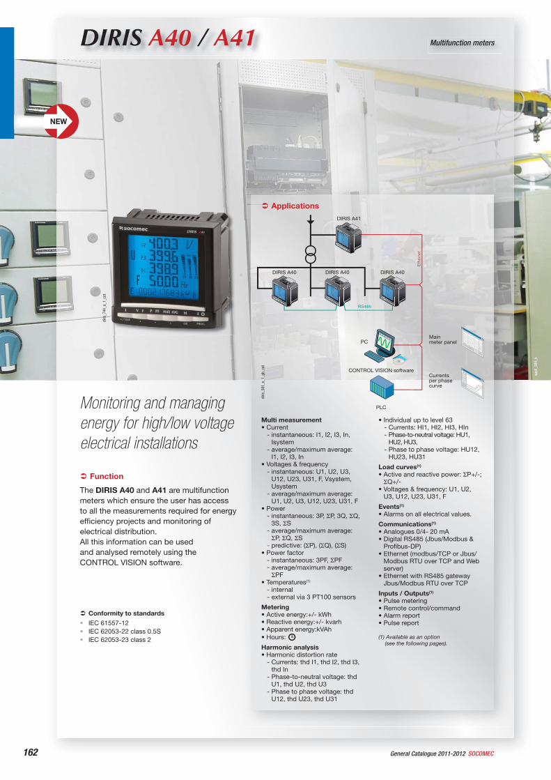
appl
i_38
4_b
162 General Catalogue 2011-2012 SOCOMEC
DIRIS A40 / A41 Multifunction meters
Monitoring and managing energy for high/low voltage electrical installations
Function
The DIRIS A40 and A41 are multifunction meters which ensure the user has access to all the measurements required for energy efficiency projects and monitoring of electrical distribution.All this information can be used and analysed remotely using the CONTROL VISION software.
Conformity to standards
IEC 61557-12IEC 62053-22 class 0.5SIEC 62053-23 class 2
•••
Applications
Multi measurement• Current
- instantaneous: I1, I2, I3, In, Isystem
- average/maximum average: I1, I2, I3, In
• Voltages & frequency- instantaneous: U1, U2, U3,
U12, U23, U31, F, Vsystem, Usystem
- average/maximum average:U1, U2, U3, U12, U23, U31, F
• Power- instantaneous: 3P, P, 3Q, Q,
3S, S- average/maximum average:
P, Q, S- predictive: ( P), ( Q), ( S)
• Power factor- instantaneous: 3PF, PF- average/maximum average:
PF• Temperatures(1)
- internal- external via 3 PT100 sensors
Metering• Active energy:+/- kWh• Reactive energy:+/- kvarh• Apparent energy:kVAh• Hours:
Harmonic analysis• Harmonic distortion rate
- Currents: thd I1, thd I2, thd I3, thd In
- Phase-to-neutral voltage: thd U1, thd U2, thd U3
- Phase to phase voltage: thd U12, thd U23, thd U31
• Individual up to level 63 - Currents: HI1, HI2, HI3, HIn- Phase-to-neutral voltage: HU1,
HU2, HU3, - Phase to phase voltage: HU12,
HU23, HU31
Load curves(1)
• Active and reactive power: P+/-;Q+/-
• Voltages & frequency: U1, U2, U3, U12, U23, U31, F
Events(1)
• Alarms on all electrical values.
Communications(1)
• Analogues 0/4- 20 mA• Digital RS485 (Jbus/Modbus &
Profibus-DP)• Ethernet (modbus/TCP or Jbus/
Modbus RTU over TCP and Web server)
• Ethernet with RS485 gateway Jbus/Modbus RTU over TCP
Inputs / Outputs(1)
• Pulse metering• Remote control/command• Alarm report• Pulse report
(1) Available as an option (see the following pages).
PC
RS485
DIRIS A41
DIRIS A40 DIRIS A40 DIRIS A40
Ethe
rnet
PLC
CONTROL VISION software
Mainmeter panel
Currentsper phasecurve
diris
_581
_e_1
_gb_
cat
diris
_744
_a_1
_cat
NEW
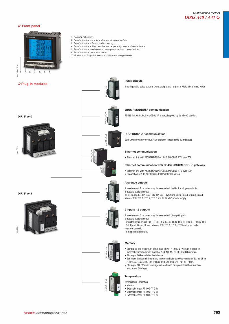
163General Catalogue 2011-2012SOCOMEC 163
Multifunction metersDIRIS A40 / A41
Plug-in modules
diris
_773
_a
DIRIS® A40
diris
_774
_a
DIRIS® A41
diris
_445
_a_1
_cat 2 configurable pulse outputs (type, weight and run) on ± kWh, ±kvarh and kVAh
Pulse outputs
• Ethernet link with MODBUS/TCP or JBUS/MODBUS RTU over TCP• Connection of 1 to 247 RS485 JBUS/MODBUS slaves
Ethernet communication with RS485 JBUS/MODBUS gateway
diris
_447
_a_1
_cat
RS485 link with JBUS / MODBUS® protocol (speed up to 38400 bauds).
JBUS / MODBUS® communication
diris
_775
_a_1
_cat
SUB-D9 link with PROFIBUS® DP protocol (speed up to 12 Mbauds).
PROFIBUS® DP communication
diris
_448
_a_1
_cat A maximum of 2 modules may be connected, that is 4 analogue outputs.
2 outputs assignable to: 3I, In, 3V, 3U, F, ± P, ± Q, S, PFL/C, I sys, Vsys, Usys, Ppred, Q pred, Spred, internal T°C, T°C 1, T°C 2, T°C 3 and to 17 VDC power supply
Analogue outputs
diris
_449
_a_1
_cat
A maximum of 3 modules may be connected, giving 6 inputs.2 outputs assignable to:- monitoring: 3I, In, 3V, 3U, F, ± P, ± Q, SS, PFL/C, THD 3I, THD In, THD 3V, THD
3U, Ppred, Qpred, Spred, internal T°C, T°C 1, T°C2, T°C3 and hour meter,- remote control,- timed remote control.
2 inputs - 2 outputs
diris
_682
_a_1
_cat
• Storing up to a maximum of 62 days of P+, P-, Q+, Q- with an internal or external synchronisation signal of 5, 8, 10, 15, 20, 30 and 60 minutes.
• Storing of 10 hour-dated last alarms.• Storing of the last minimum and maximum instantaneous values for 3U, 3V, 3I, In,
F, P±, Q±, S, THD 3U, THD 3V, THD, 3U, THD, 3V, THD, 3I, THD In.• Storing of 3U, 3V and F average values based on synchronisation function
(maximum 60 days).
Memory
diris
_747
_a_2
_cat
Temperature indication• Internal• External sensor PT 100 (T°C 1)• External sensor PT 100 (T°C 2)• External sensor PT 100 (T°C 3)
Temperature
diris
_777
_a_1
_cat
diris
_776
_a_1
_cat
1 2 3 4 5 6 7
diris
_744
x_a_
1_ca
t
1. Backlit LCD screen.2. Pushbutton for currents and setup wiring correction3. Pushbutton for voltages and frequency.4. Pushbutton for active, reactive, and apparent power and power factor.5. Pushbutton for maximum and average current and power values.6. Pushbutton for harmonics values.7. Pushbutton for pulse, hours and electrical energy meters.
Front panel
Ethernet communication
• Ethernet link with MODBUS/TCP or JBUS/MODBUS RTU over TCP
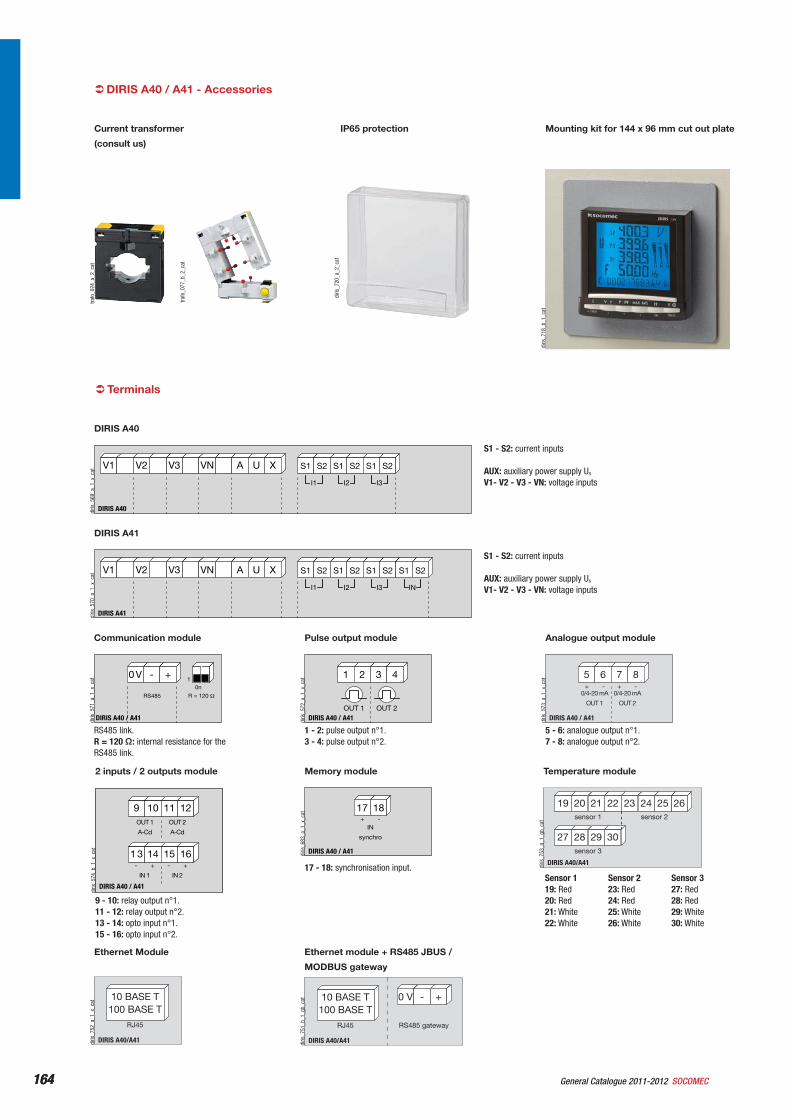
164 General Catalogue 2011-2012 SOCOMEC164
DIRIS A40 / A41 - Accessoriestra
fo_0
24_a
_2_c
at
Current transformer
(consult us)
trafo
_077
_b_2
_cat
diris
_720
_a_2
_cat
IP65 protection
diris
_718
_b_1
_cat
Mounting kit for 144 x 96 mm cut out plate
Terminals
DIRIS A40
A U XV3 VNV1 V2
I3I2I1
S2S1 S2S1 S2S1
diris
_569
_a_1
_x_c
at
S1 - S2: current inputs
AUX: auxiliary power supply Us
V1- V2 - V3 - VN: voltage inputs
DIRIS A40
0 V - +
R = 120 RS485
0n1
DIRIS A40 / A41diris
_571
_a_1
_x_c
at
RS485 link.R = 120 : internal resistance for the RS485 link.
Communication module
5 6 7 8
DIRIS A40 / A41
0/4-20 mA
OUT 1
0/4-20 mA
OUT 2
-+ -+
diris
_573
_a_1
_x_c
at
5 - 6: analogue output n°1.7 - 8: analogue output n°2.
Analogue output module
1 2 3 4
DIRIS A40 / A41OUT 1 OUT 2
diris
_572
_a_1
_x_c
at
1 - 2: pulse output n°1.3 - 4: pulse output n°2.
Pulse output module
9 10 11 12
DIRIS A40 / A41
IN 1
OUT 2
A-Cd
OUT 1
A-Cd
1 3 14 15 16
IN 2
- + - +
diris
_574
_b_1
_x_c
at
9 - 10: relay output n°1.11 - 12: relay output n°2.13 - 14: opto input n°1.15 - 16: opto input n°2.
2 inputs / 2 outputs module
17 18
DIRIS A40 / A41
IN
synchro
-+
diris
_683
_a_1
_x_c
at
17 - 18: synchronisation input.
Memory module
DIRIS A40/A41
10 BASE T100 BASE T
RJ45
diris
_752
_a_1
_x_c
at
Ethernet Module
DIRIS A41
A U XV3 VNV1 V2
I3I2I1
S2S1 S2S1 S2S1
IN
S2S1
diris
_570
_a_1
_x_c
at
S1 - S2: current inputs
AUX: auxiliary power supply Us
V1- V2 - V3 - VN: voltage inputs
DIRIS A41
DIRIS A40/A41
22 23 24 262519 20 21
27 28 29 30
sensor 1 sensor 2
sensor 3
diris
_753
_a_1
_gb_
cat
Temperature module
DIRIS A40/A41
10 BASE T100 BASE T
RJ45
0 V +-
RS485 gateway
diris
_751
_b_1
_gb_
cat
Ethernet module + RS485 JBUS /
MODBUS gateway
Sensor 119: Red20: Red21: White22: White
Sensor 223: Red24: Red25: White26: White
Sensor 327: Red28: Red29: White30: White
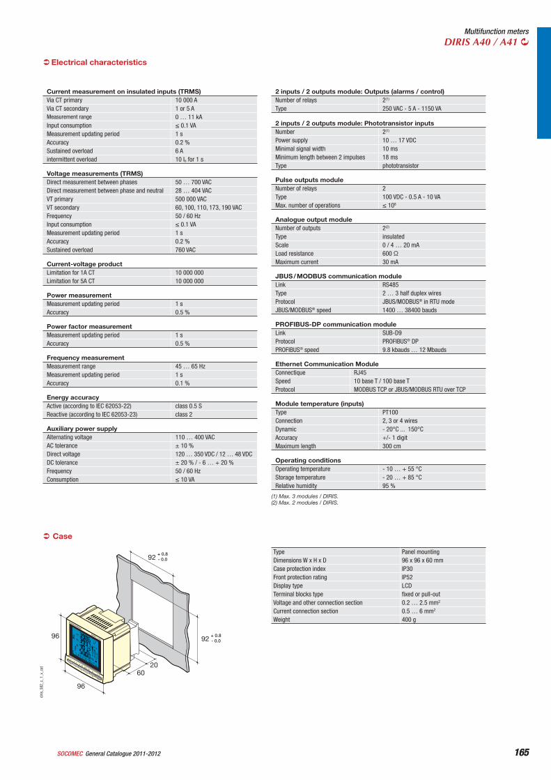
165General Catalogue 2011-2012SOCOMEC 165
Multifunction metersDIRIS A40 / A41
Case
Type Panel mountingDimensions W x H x D 96 x 96 x 60 mmCase protection index IP30Front protection rating IP52Display type LCDTerminal blocks type fixed or pull-outVoltage and other connection section 0.2 … 2.5 mm2
Current connection section 0.5 … 6 mm2
Weight 400 g
DIRIS A4096
96
6020
92+ 0.8- 0.0
92+ 0.8- 0.0
diris
_582
_c_1
_x_c
at
Current measurement on insulated inputs (TRMS)Via CT primary 10 000 AVia CT secondary 1 or 5 AMeasurement range 0 … 11 kAInput consumption 0.1 VAMeasurement updating period 1 sAccuracy 0.2 %Sustained overload 6 Aintermittent overload 10 In for 1 s
Voltage measurements (TRMS)Direct measurement between phases 50 … 700 VACDirect measurement between phase and neutral 28 … 404 VACVT primary 500 000 VACVT secondary 60, 100, 110, 173, 190 VACFrequency 50 / 60 HzInput consumption 0.1 VAMeasurement updating period 1 sAccuracy 0.2 %Sustained overload 760 VAC
Current-voltage productLimitation for 1A CT 10 000 000Limitation for 5A CT 10 000 000
Power measurementMeasurement updating period 1 sAccuracy 0.5 %
Power factor measurementMeasurement updating period 1 sAccuracy 0.5 %
Frequency measurementMeasurement range 45 … 65 HzMeasurement updating period 1 sAccuracy 0.1 %
Energy accuracyActive (according to IEC 62053-22) class 0.5 SReactive (according to IEC 62053-23) class 2
Auxiliary power supplyAlternating voltage 110 … 400 VACAC tolerance ± 10 %Direct voltage 120 … 350 VDC / 12 … 48 VDCDC tolerance ± 20 % / - 6 … + 20 %Frequency 50 / 60 HzConsumption 10 VA
Electrical characteristics
2 inputs / 2 outputs module: Outputs (alarms / control)Number of relays 2(1)
Type 250 VAC - 5 A - 1150 VA
2 inputs / 2 outputs module: Phototransistor inputsNumber 2(1)
Power supply 10 … 17 VDCMinimal signal width 10 msMinimum length between 2 impulses 18 msType phototransistor
Pulse outputs moduleNumber of relays 2Type 100 VDC - 0.5 A - 10 VAMax. number of operations 108
Analogue output moduleNumber of outputs 2(2)
Type insulatedScale 0 / 4 … 20 mALoad resistance 600 Maximum current 30 mA
JBUS / MODBUS communication moduleLink RS485Type 2 … 3 half duplex wiresProtocol JBUS/MODBUS® in RTU modeJBUS/MODBUS® speed 1400 … 38400 bauds
PROFIBUS-DP communication moduleLink SUB-D9Protocol PROFIBUS® DPPROFIBUS® speed 9.8 kbauds … 12 Mbauds
Ethernet Communication ModuleConnectique RJ45Speed 10 base T / 100 base TProtocol MODBUS TCP or JBUS/MODBUS RTU over TCP
Module temperature (inputs)Type PT100Connection 2, 3 or 4 wiresDynamic - 20°C ... 150°CAccuracy +/- 1 digitMaximum length 300 cm
Operating conditionsOperating temperature - 10 … + 55 °CStorage temperature - 20 … + 85 °CRelative humidity 95 %
(1) Max. 3 modules / DIRIS.(2) Max. 2 modules / DIRIS.
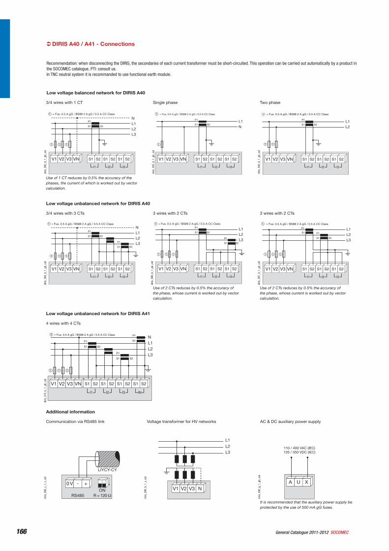
166 General Catalogue 2011-2012 SOCOMEC166
Recommendation: when disconnecting the DIRIS, the secondaries of each current transformer must be short-circuited. This operation can be carried out automatically by a product in the SOCOMEC catalogue, PTI: consult us.In TNC neutral system it is recommanded to use functional earth module.
Low voltage balanced network for DIRIS A40
diris
_392
_d_1
_gb_
cat
V1 V2 V3 VN
S2
P1
S1
NL1L2L3
I3I2I1
S2S1 S2S1 S2S1
= Fus. 0.5 A gG / BS88 2 A gG / 0.5 A CC Class1
1 1 1
Use of 1 CT reduces by 0.5% the accuracy of the phases, the current of which is worked out by vector calculation.
3/4 wires with 1 CT
V1 V2 V3 VN
S2
P1
S1L1N
I3I2I1
S2S1 S2S1 S2S1
= Fus. 0.5 A gG / BS88 2 A gG / 0.5 A CC Class1
1
Single phase
diris
_394
_d_1
_gb_
cat
V1 V2 V3 VN
S2
P1
S1L1L2
I3I2I1
S2S1 S2S1 S2S1
= Fus. 0.5 A gG / BS88 2 A gG / 0.5 A CC Class1
1 1
Two phase
diris
_393
_d_1
_gb_
cat
Low voltage unbalanced network for DIRIS A40
diris
_395
_d_1
_gb_
cat
NL1L2L3
S2
S2
P1
S1
P1
S1
V1 V2 V3 VN
I3I2I1
S2S1 S2S1 S2S1
= Fus. 0.5 A gG / BS88 2 A gG / 0.5 A CC Class1
1 1 1
3/4 wires with 3 CTs
diris
_396
_d_1
_gb_
cat
L1L2L3
S2
S2
P1
S1
P1
S1
V1 V2 V3 VN
I3I2I1
S2S1 S2S1 S2S1
= Fus. 0.5 A gG / BS88 2 A gG / 0.5 A CC Class1
1 1 1
Use of 2 CTs reduces by 0.5% the accuracy of the phase, whose current is worked out by vector calculation.
3 wires with 2 CTs
diris
_397
_d_1
_gb_
cat
L1L2L3
S2
P1
S1
P1
S1
V1 V2 V3 VN
I3I2I1
S2S1 S2S1 S2S1
= Fus. 0.5 A gG / BS88 2 A gG / 0.5 A CC Class1
1 1 1
Use of 2 CTs reduces by 0.5% the accuracy of the phase, whose current is worked out by vector calculation.
3 wires with 2 CTs
Low voltage unbalanced network for DIRIS A41
NL1L2L3
V1 V2 V3 VN
S2
S2
P1
S1
P1
S1
I3I2I1
S2S1 S2S1 S2S1
1 1 1
= Fus. 0.5 A gG / BS88 2 A gG / 0.5 A CC Class1
S1 S2
P1
S1
IN
diris
_575
_b_1
_gb_
cat
4 wires with 4 CTs
DIRIS A40 / A41 - Connections
Additional information
RS485
0 V - +ON
LIYCY-CY
V1 V2 V3 N
L1
L2L3
A U X
110 / 400 VAC (IEC)120 / 350 VDC (IEC)
diris
_400
_g_1
_gb_
cat
It is recommended that the auxiliary power supply be protected by the use of 500 mA gG fuses.
AC & DC auxiliary power supply
diris
_399
_b_1
_x_c
at
Voltage transformer for HV networks
diris
_398
_c_1
_x_c
at
Communication via RS485 link
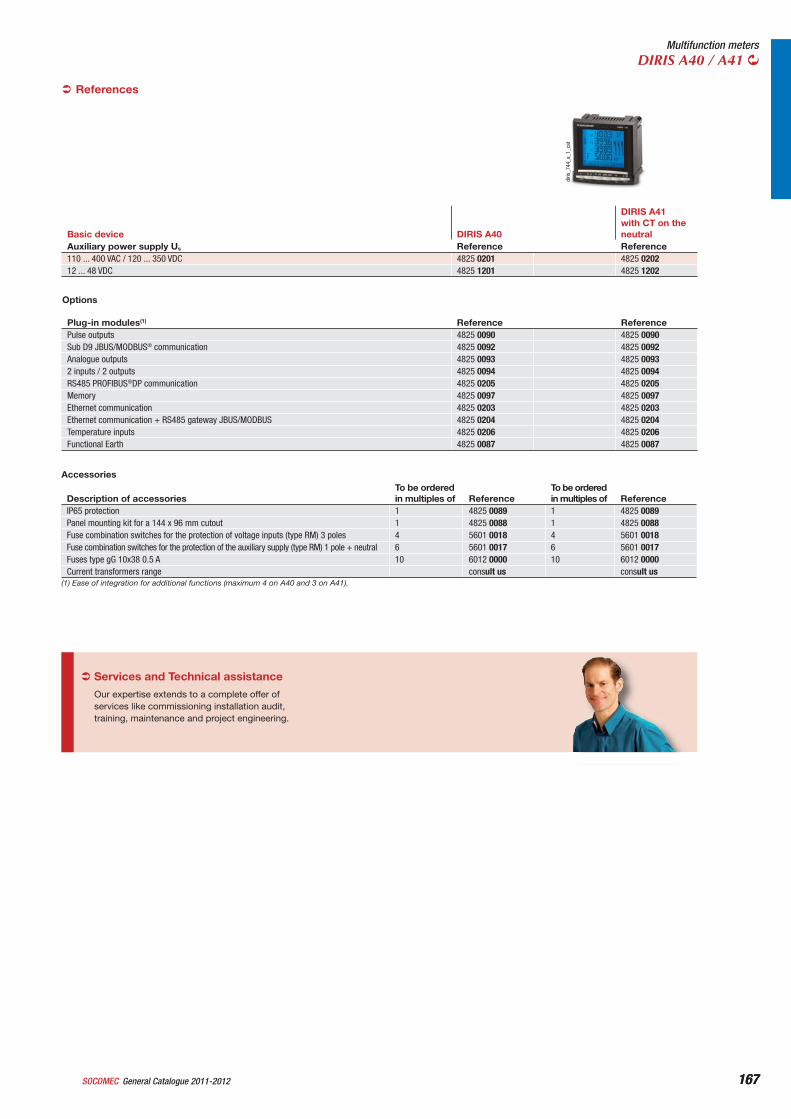
167General Catalogue 2011-2012SOCOMEC 167
Multifunction metersDIRIS A40 / A41
References
Basic device DIRIS A40
DIRIS A41with CT on the neutral
Auxiliary power supply Us Reference Reference110 ... 400 VAC / 120 ... 350 VDC 4825 0201 4825 020212 ... 48 VDC 4825 1201 4825 1202
diris
_744
_a_1
_cat
Our expertise extends to a complete offer of services like commissioning installation audit, training, maintenance and project engineering.
Services and Technical assistance
Options
Plug-in modules(1) Reference ReferencePulse outputs 4825 0090 4825 0090Sub D9 JBUS/MODBUS® communication 4825 0092 4825 0092Analogue outputs 4825 0093 4825 00932 inputs / 2 outputs 4825 0094 4825 0094RS485 PROFIBUS®DP communication 4825 0205 4825 0205Memory 4825 0097 4825 0097Ethernet communication 4825 0203 4825 0203Ethernet communication + RS485 gateway JBUS/MODBUS 4825 0204 4825 0204Temperature inputs 4825 0206 4825 0206Functional Earth 4825 0087 4825 0087
(1) Ease of integration for additional functions (maximum 4 on A40 and 3 on A41).
Accessories
Description of accessoriesTo be orderedin multiples of Reference
To be orderedin multiples of Reference
IP65 protection 1 4825 0089 1 4825 0089Panel mounting kit for a 144 x 96 mm cutout 1 4825 0088 1 4825 0088Fuse combination switches for the protection of voltage inputs (type RM) 3 poles 4 5601 0018 4 5601 0018Fuse combination switches for the protection of the auxiliary supply (type RM) 1 pole + neutral 6 5601 0017 6 5601 0017Fuses type gG 10x38 0.5 A 10 6012 0000 10 6012 0000Current transformers range consult us consult us
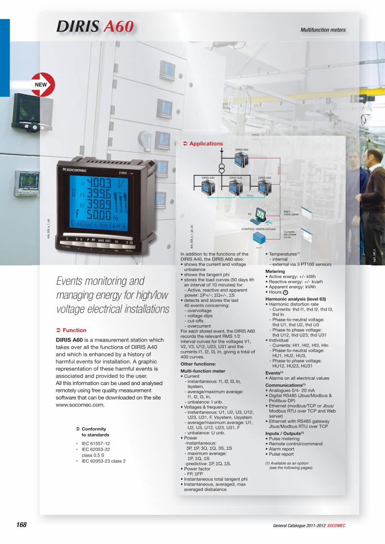
appl
i_38
6_b
168
DIRIS A60 Multifunction meters
Events monitoring and managing energy for high/low voltage electrical installations
Function
DIRIS A60 is a measurement station which takes over all the functions of DIRIS A40 and which is enhanced by a history of harmful events for installation. A graphic representation of these harmful events is associated and provided to the user.All this information can be used and analysed remotely using free quality measurement software that can be downloaded on the site www.socomec.com.
Conformityto standards
IEC 61557-12IEC 62053-22class 0.5 SIEC 62053-23 class 2
••
•
Applications
In addition to the functions of the DIRIS A40, the DIRIS A60 also:• shows the current and voltage
unbalance• shows the tangent phi• stores the load curves (50 days ith
an interval of 10 minutes) for:- Active, reactive and apparent power: P+/-; Q+/-, S
• detects and stores the last40 events concerning:- overvoltage- voltage dips- cut-offs - overcurrent
For each stored event, the DIRIS A60 records the relevant RMS 1/2 interval curves for the voltages V1, V2, V3, U12, U23, U31 and the currents I1, I2, I3, In, giving a total of 400 curves.
Other functions:
Multi-function meter• Current
- instantaneous: I1, I2, I3, In, Isystem,
- average/maximum average: I1, I2, I3, In,
- unbalance: I unb.• Voltages & frequency
- instantaneous: U1, U2, U3, U12, U23, U31, F, Vsystem, Usystem
- average/maximum average: U1, U2, U3, U12, U23, U31, F
- unbalance: U unb.• Power
-instantaneous:3P, P, 3Q, Q, 3S, S
- maximum average: P, Q, S
-predictive: P, Q, S.• Power factor
- FP, FP• Instantaneous total tangent phi• Instantaneous, averaged, max
averaged disbalance
PC
RS485
DIRIS A60
DIRIS A40 DIRIS A40 DIRIS A40
Ethe
rnet
PLC
CONTROL VISION software
Mainmeter panel
Currentsper phasecurve
diris
_826
_b_1
_gb_
cat
diris
_824
_a_1
_cat
• Temperatures(1)
- internal- external via 3 PT100 sensors
Metering• Active energy: +/- kWh• Reactive energy: +/- kvarh• Apparent energy: kVAh• Hours:
Harmonic analysis (level 63)• Harmonic distortion rate
- Currents: thd I1, thd I2, thd I3, thd In
- Phase-to-neutral voltage: thd U1, thd U2, thd U3
- Phase to phase voltage: thd U12, thd U23, thd U31
• Individual- Currents: HI1, HI2, HI3, HIn- Phase-to-neutral voltage:
HU1, HU2, HU3, - Phase to phase voltage:
HU12, HU23, HU31
Events(1)
• Alarms on all electrical values
Communications(1)
• Analogues 0/4- 20 mA• Digital RS485 (Jbus/Modbus &
Profibus-DP)• Ethernet (modbus/TCP or Jbus/
Modbus RTU over TCP and Web server)
• Ethernet with RS485 gateway Jbus/Modbus RTU over TCP
Inputs / Outputs(1)
• Pulse metering• Remote control/command• Alarm report• Pulse report
(1) Available as an option (see the following pages).
NEW
General Catalogue 2011-2012 SOCOMEC
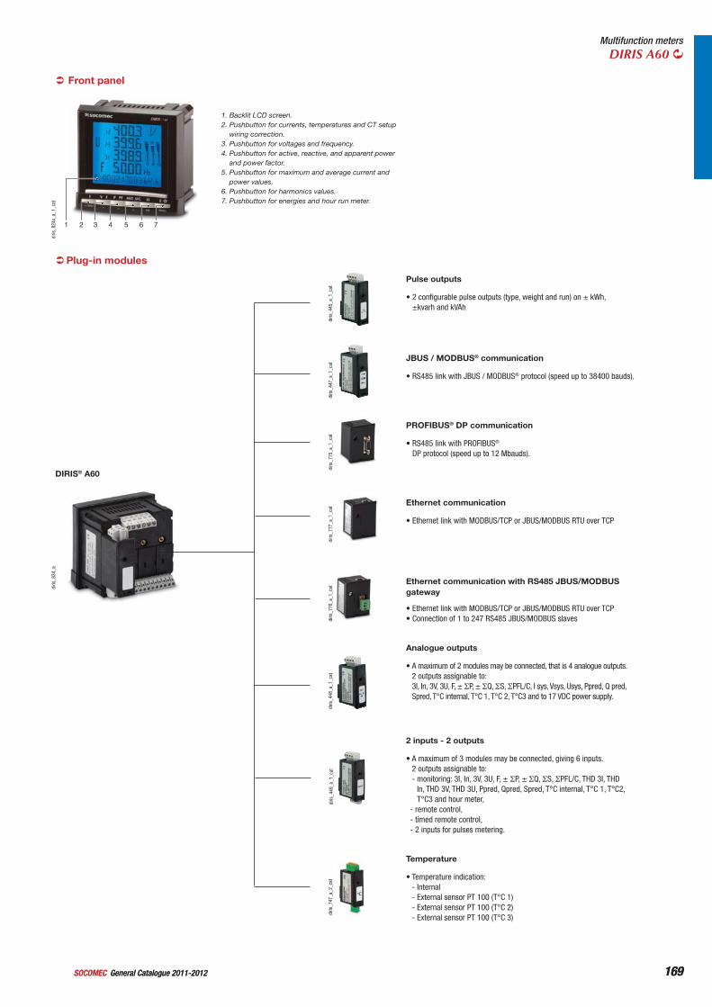
169169
Multifunction metersDIRIS A60
Plug-in modules
diris
_834
_a
DIRIS® A60
1 2 3 4 5 6 7
diris
_824
x_a_
1_ca
t
1. Backlit LCD screen.2. Pushbutton for currents, temperatures and CT setup
wiring correction.3. Pushbutton for voltages and frequency.4. Pushbutton for active, reactive, and apparent power
and power factor.5. Pushbutton for maximum and average current and
power values.6. Pushbutton for harmonics values.7. Pushbutton for energies and hour run meter.
Front panel
diris
_445
_a_1
_cat
• 2 configurable pulse outputs (type, weight and run) on ± kWh, ±kvarh and kVAh
Pulse outputs
diris
_447
_a_1
_cat
• RS485 link with JBUS / MODBUS® protocol (speed up to 38400 bauds).
JBUS / MODBUS® communication
diris
_775
_a_1
_cat
• RS485 link with PROFIBUS®
DP protocol (speed up to 12 Mbauds).
PROFIBUS® DP communication
diris
_777
_a_1
_cat
• Ethernet link with MODBUS/TCP or JBUS/MODBUS RTU over TCP
Ethernet communication
diris
_776
_a_1
_cat
• Ethernet link with MODBUS/TCP or JBUS/MODBUS RTU over TCP• Connection of 1 to 247 RS485 JBUS/MODBUS slaves
Ethernet communication with RS485 JBUS/MODBUS gateway
diris
_448
_a_1
_cat
• A maximum of 2 modules may be connected, that is 4 analogue outputs. 2 outputs assignable to: 3I, In, 3V, 3U, F, ± P, ± Q, S, PFL/C, I sys, Vsys, Usys, Ppred, Q pred, Spred, T°C internal, T°C 1, T°C 2, T°C3 and to 17 VDC power supply.
Analogue outputs
diris
_449
_a_1
_cat
• A maximum of 3 modules may be connected, giving 6 inputs.2 outputs assignable to:- monitoring: 3I, In, 3V, 3U, F, ± P, ± Q, S, PFL/C, THD 3I, THD
In, THD 3V, THD 3U, Ppred, Qpred, Spred, T°C internal, T°C 1, T°C2, T°C3 and hour meter,
- remote control, - timed remote control, - 2 inputs for pulses metering.
2 inputs - 2 outputs
diris
_747
_a_2
_cat
• Temperature indication:- Internal- External sensor PT 100 (T°C 1)- External sensor PT 100 (T°C 2)- External sensor PT 100 (T°C 3)
Temperature
General Catalogue 2011-2012SOCOMEC General Catalogue 2011-2012SOCOMEC
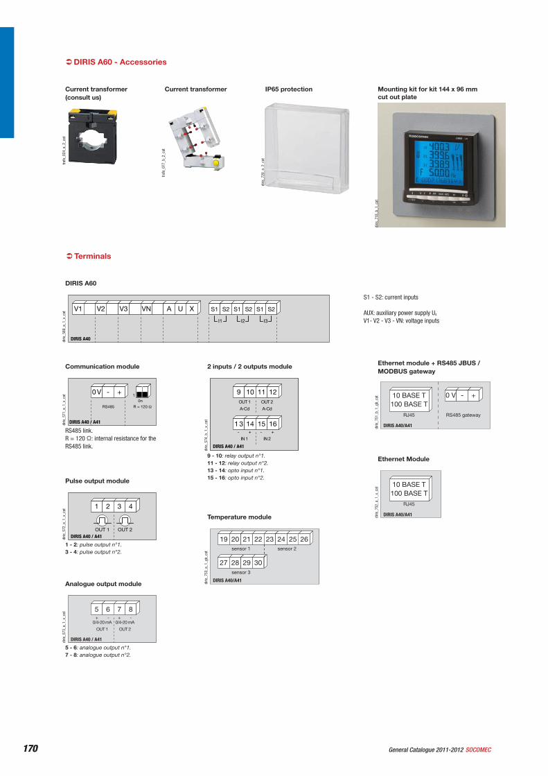
170170
DIRIS A60 - Accessoriestra
fo_0
24_a
_2_c
at
Current transformer (consult us)
trafo
_077
_b_2
_cat
Current transformer
diris
_720
_a_2
_cat
IP65 protection
diris
_718
_b_1
_cat
Mounting kit for kit 144 x 96 mm cut out plate
Terminals
DIRIS A40
A U XV3 VNV1 V2
I3I2I1
S2S1 S2S1 S2S1
diris
_569
_a_1
_x_c
at
S1 - S2: current inputs
AUX: auxiliary power supply Us
V1- V2 - V3 - VN: voltage inputs
DIRIS A60
0 V - +
R = 120 RS485
0n1
DIRIS A40 / A41diris
_571
_a_1
_x_c
at
RS485 link.R = 120 : internal resistance for the RS485 link.
Communication module
1 2 3 4
DIRIS A40 / A41OUT 1 OUT 2
diris
_572
_a_1
_x_c
at
1 - 2: pulse output n°1.3 - 4: pulse output n°2.
Pulse output module
5 6 7 8
DIRIS A40 / A41
0/4-20 mA
OUT 1
0/4-20 mA
OUT 2
-+ -+
diris
_573
_a_1
_x_c
at
5 - 6: analogue output n°1.7 - 8: analogue output n°2.
Analogue output module
9 10 11 12
DIRIS A40 / A41
IN 1
OUT 2
A-Cd
OUT 1
A-Cd
1 3 14 15 16
IN 2
- + - +
diris
_574
_b_1
_x_c
at
9 - 10: relay output n°1.11 - 12: relay output n°2.13 - 14: opto input n°1.15 - 16: opto input n°2.
2 inputs / 2 outputs module
DIRIS A40/A41
22 23 24 262519 20 21
27 28 29 30
sensor 1 sensor 2
sensor 3
diris
_753
_a_1
_gb_
cat
Temperature module DIRIS A40/A41
10 BASE T100 BASE T
RJ45
diris
_752
_a_1
_x_c
at
Ethernet Module
DIRIS A40/A41
10 BASE T100 BASE T
RJ45
0 V +-
RS485 gateway
diris
_751
_b_1
_gb_
cat
Ethernet module + RS485 JBUS / MODBUS gateway
General Catalogue 2011-2012 SOCOMEC
171171
Multifunction metersDIRIS A60
Case
Type Panel mountingDimensions W x H x D 96 x 96 x 60 mmCase protection index IP30Front protection rating IP52Display type LCDTerminal blocks type fixed or pull-outVoltage and other connection section 0.2 … 2.5 mm2
Current connection section 0.5 … 6 mm2
Weight 400 g
DIRIS A4096
96
6020
92+ 0.8- 0.0
92+ 0.8- 0.0
diris
_582
_c_1
_x_c
at
Current measurement on insulated inputs (TRMS)Via CT primary 10 000 AVia CT secondary 1 or 5Measurement range 0 … 11 kAInput consumption 0.1 VAMeasurement updating period 1 sAccuracy 0.2 %Sustained overload 6 Aintermittent overload 10 In for 1 s
Voltage measurements (TRMS)Direct measurement between phases 50 … 700 VACDirect measurement between phase and neutral 28 … 404 VACVT primary 500 000 VACVT secondary 60, 100, 110, 173, 190 VACFrequency 50 / 60 HzInput consumption 0.1 VAMeasurement updating period 1 sAccuracy 0.2 %Sustained overload 760 VAC
Current-voltage productLimitation for 1A CT 10 000 000Limitation for 5A CT 10 000 000
Power measurementMeasurement updating period 1 sAccuracy 0.5 %
Power factor measurementMeasurement updating period 1 sAccuracy 0.5 %
Frequency measurementMeasurement range 45 … 65 HzMeasurement updating period 1 sAccuracy 0.1 %
Energy accuracyActive (according to IEC 62053-22) class 0.5 SReactive (according to IEC 62053-23) class 2
Auxiliary power supplyAlternating voltage 110 … 400 VACAC tolerance ± 10 %Direct voltage 120 … 350 VDCDC tolerance ± 20 %Frequency 50 / 60 HzConsumption 10 VA
Temperature inputsType PT100Connection 2, 3 or 4 wiresDynamic - 20°C ... 150°CAccuracy +/- 1 digitMaximum length 300 cm
Operating conditionsOperating temperature - 10 … + 55 °CStorage temperature - 20 … + 85 °CRelative humidity 95 %
Electrical characteristics
2 inputs / 2 outputs module: Outputs (alarms / control)Number of relays 2(1)
Type 250 VAC - 5 A - 1150 VA
(1) Max. 3 modules / DIRIS.(2) Max. 2 modules / DIRIS.
2 inputs / 2 outputs module: Phototransistor inputsNumber 2(1)
Power supply 10 … 30 VDCMinimal signal width 10 msMinimum length between 2 impulses 18 msType phototransistor
Pulse outputs moduleNumber of relays 2Type 100 VDC - 0.5 A - 10 VAMax. number of operations 108
Analogue output moduleNumber of outputs 2(2)
Type insulatedScale 0 / 4 … 20 mALoad resistance 600 Maximum current 30 mA
JBUS / MODBUS communication moduleLink RS485Type 2 … 3 half duplex wiresProtocol JBUS/MODBUS® in RTU modeJBUS/MODBUS® speed 1400 … 38400 bauds
PROFIBUS-DP communication moduleLink SUB-D9Protocol PROFIBUS® DPPROFIBUS® speed 9.8 kbauds … 12 Mbauds
Ethernet Communication ModuleConnectique RJ45Speed 10 base T / 100 base TProtocol MODBUS TCP or JBUS/MODBUS RTU over TCP
General Catalogue 2011-2012SOCOMEC
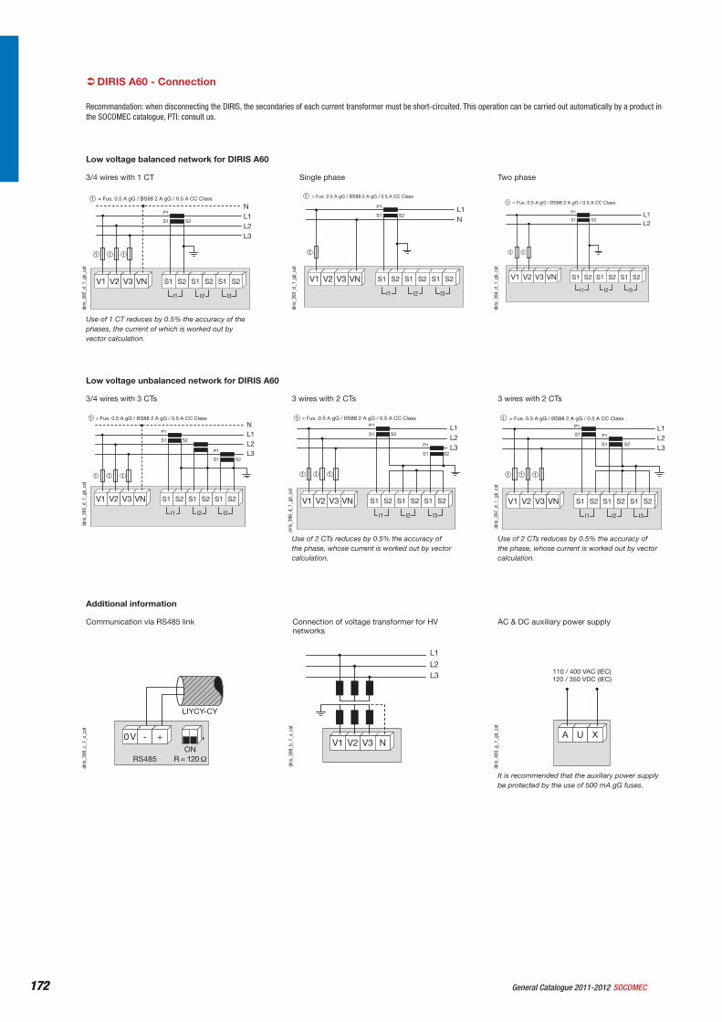
172172
DIRIS A60 - Connection
Recommandation: when disconnecting the DIRIS, the secondaries of each current transformer must be short-circuited. This operation can be carried out automatically by a product in the SOCOMEC catalogue, PTI: consult us.
Low voltage unbalanced network for DIRIS A60
NL1L2L3
S2
S2
P1
S1
P1
S1
V1 V2 V3 VN
I3I2I1
S2S1 S2S1 S2S1
= Fus. 0.5 A gG / BS88 2 A gG / 0.5 A CC Class1
1 1 1
diris
_395
_d_1
_gb_
cat
3/4 wires with 3 CTs
Use of 2 CTs reduces by 0.5% the accuracy of the phase, whose current is worked out by vector calculation.
diris
_396
_d_1
_gb_
cat
L1L2L3
S2
S2
P1
S1
P1
S1
V1 V2 V3 VN
I3I2I1
S2S1 S2S1 S2S1
= Fus. 0.5 A gG / BS88 2 A gG / 0.5 A CC Class1
1 1 1
3 wires with 2 CTs
Use of 2 CTs reduces by 0.5% the accuracy of the phase, whose current is worked out by vector calculation.
L1L2L3
S2
P1
S1
P1
S1
V1 V2 V3 VN
I3I2I1
S2S1 S2S1 S2S1
= Fus. 0.5 A gG / BS88 2 A gG / 0.5 A CC Class1
1 1 1
diris
_397
_d_1
_gb_
cat
3 wires with 2 CTs
Additional information
RS485
0 V - +ON
LIYCY-CY
diris
_398
_c_1
_x_c
at
Communication via RS485 link
V1 V2 V3 N
L1
L2L3
diris
_399
_b_1
_x_c
at
Connection of voltage transformer for HV networks
A U X
110 / 400 VAC (IEC)120 / 350 VDC (IEC)
diris
_400
_g_1
_gb_
cat
It is recommended that the auxiliary power supply be protected by the use of 500 mA gG fuses.
AC & DC auxiliary power supply
V1 V2 V3 VN
S2
P1
S1
NL1L2L3
I3I2I1
S2S1 S2S1 S2S1
= Fus. 0.5 A gG / BS88 2 A gG / 0.5 A CC Class1
1 1 1
diris
_392
_d_1
_gb_
cat
Use of 1 CT reduces by 0.5% the accuracy of the phases, the current of which is worked out by vector calculation.
3/4 wires with 1 CT
V1 V2 V3 VN
S2
P1
S1L1N
I3I2I1
S2S1 S2S1 S2S1
= Fus. 0.5 A gG / BS88 2 A gG / 0.5 A CC Class1
1
diris
_393
_d_1
_gb_
cat
Single phase
V1 V2 V3 VN
S2
P1
S1L1L2
I3I2I1
S2S1 S2S1 S2S1
= Fus. 0.5 A gG / BS88 2 A gG / 0.5 A CC Class1
1 1
diris
_394
_d_1
_gb_
cat
Two phase
Low voltage balanced network for DIRIS A60
General Catalogue 2011-2012 SOCOMEC
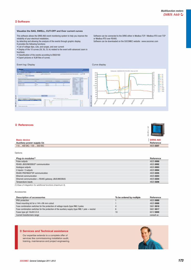
173173
Multifunction metersDIRIS A60
diris
_824
_a_1
_cat
References
Basic device DIRIS A60Auxiliary power supply Us Reference110 ... 400 VAC / 120 ... 350 VDC 4825 0207
Options
Plug-in-modules(1) ReferencePulse outputs 4825 0090RS485 JBUS/MODBUS® communication 4825 0092Analogue outputs 4825 00932 inputs / 2 outputs 4825 0094RS485 PROFIBUS®DP communication 4825 0205Ethernet communication 4825 0203Ethernet communication + RS485 gateway JBUS/MODBUS 4825 0204Temperature inputs 4825 0206
(1) Ease of integration for additional functions (maximum 3).
Accessories
Description of accessories To be ordered by multiple ReferenceIP65 protection 1 4825 0089Panel mounting kit for a 144 x 96 mm cutout 1 4825 0088Fuse combination switches for the protection of voltage inputs (type RM) 3 poles 4 5601 0018Fuse combination switches for the protection of the auxiliary supply (type RM) 1 pole + neutral 6 5601 0017Fuses type gG 10x38 0.5 A 10 6012 0000Current transformers range consult us
Our expertise extends to a complete offer of services like commissioning installation audit, training, maintenance and project engineering.
Services and Technical assistance
This software allows the DIRIS A60 event monitoring system to help you improve the reliability of your electrical installation, by detecting and allowing the analysis of the events through graphic display.It provides the following functions:• List of voltage dips, cuts, and surges, and over current• Display of the 10 curves (3V, 3U, 3I, In) related to the event with advanced zoom in functions• Classification of the events according to EN50160• Export pictures or XLM files of curves.
Software can be connected to the DIRIS either in Modbus TCP / Modbus RTU over TCP or Modbus RTU over RS485.Software can be downloaded on the SOCOMEC website : www.socomec.com
Visualize the SAG, SWELL, CUT-OFF and Over current curves
diris
_837
_a_1
_gb_
cat
diris
_845
_a_1
_fr_
cat
Event log: Display Curve display
Software
General Catalogue 2011-2012SOCOMEC
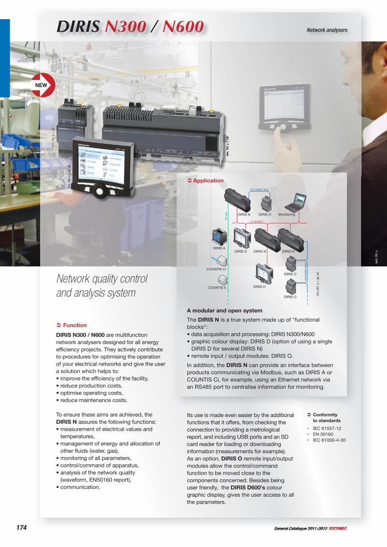
174 General Catalogue 2011-2012 SOCOMEC
appl
i_38
5_a
DIRIS N300 / N600 Network analysers
Network quality control and analysis system
diris
_754
_a_1
_cat
diris
_755
_a_1
_cat
diris
_762
_a_1
_gb_
cat
Function
DIRIS N300 / N600 are multifunction network analysers designed for all energy efficiency projects. They actively contribute to procedures for optimising the operation of your electrical networks and give the user a solution which helps to:• improve the efficiency of the facility,• reduce production costs,• optimise operating costs,• reduce maintenance costs.
To ensure these aims are achieved, the DIRIS N assures the following functions:• measurement of electrical values and
temperatures,• management of energy and allocation of
other fluids (water, gas),• monitoring of all parameters,• control/command of apparatus,• analysis of the network quality
(waveform, EN50160 report),• communication.
Conformityto standards
IEC 61557-12EN 50160IEC 61000-4-30
•••
Its use is made even easier by the additional functions that it offers, from checking the connection to providing a metrological report, and including USB ports and an SD card reader for loading or downloading information (measurements for example). As an option, DIRIS O remote input/output modules allow the control/command function to be moved close to the components concerned. Besides being user friendly, the DIRIS D600's colour graphic display, gives the user access to all the parameters.
Application
DIRIS D
Monitoring
DIRIS N DIRIS N
COUNTIS E
COUNTIS Ci
DIRIS A
DIRIS O
DIRIS O
DIRIS D600
DIRIS D
DIRIS ODIRIS N
SOCOMEC BUS
SO
CO
ME
C B
US
ETHERNET
RS
485
diris
_801
_a_1
_gb_
cat
A modular and open system
The DIRIS N is a true system made up of "functional blocks":• data acquisition and processing: DIRIS N300/N600• graphic colour display: DIRIS D (option of using a single
DIRIS D for several DIRIS N)• remote input / output modules: DIRIS O.
In addition, the DIRIS N can provide an interface between products communicating via Modbus, such as DIRIS A or COUNTIS Ci, for example, using an Ethernet network via an RS485 port to centralise information for monitoring.
NEW
175General Catalogue 2011-2012SOCOMEC
Network analysersDIRIS N300/N600
A hub of innovation
The DIRIS N, developed using innovative technology, has enabled some functions to cross a new frontier.
diris
_759
_a_1
_gb_
cat
• MeasurementsOptimal calculation functions and sampling in the range of 1.33
s ensuring a very high level of precision when measuring as shown below:- Voltages and currents in class 0.1- Active energy in class 0.2 as per
IEC 62053-22- Harmonics in class 1.
• OperatingA DIRIS D colour LCD display module gives the user access to all the installation's parameters with the greatest of ease. They will be able to access both numerical values and graphs.The DIRIS N offers the option of downloading all the data in its internal memory onto a USB key or SD card.
• InstallationThe DIRIS N, D and O have been designed to be located as close as possible to the function and its operation so as to reduce the number of cables needed.Using a remote display module avoids having lots of cables across the door; only an RJ45 cable is required. In the same way, power is supplied to the additional DIRIS O modules directly via the communication bus, thus avoiding the use of yet more cables.
General characteristics of the DIRIS N300 and N600
The vast majority of the functions below are available as numbers (instant, average, minimum and maximum values), graphs (wave captures and 1/2 period RMS) and logs.
Measurements:- Currents, voltages, frequency
(instant, average, minimum and maximum)
- Direct, inverse and homopolar voltages
- Voltage unbalance- Active, reactive, apparent and
predictive power- Power factor- Fresnel diagram- Temperatures.
M
Energy management:- Active, reactive and apparent
energy meters- Impulse meters
(up to 20 meters)- Timestamped meters
(up to 8 meters)- Load curves.
0 1 2 3e
Monitoring:- Display of an alarm and status
log- Indication of the parameter
concerned, the status at time T, the duration and date/time of the start and end of the event.
Network and event quality analysis:
- Dips, surges and voltage cut-offs- Crest factor- Voltage and current harmonics- Mains signalling voltages.
Q
Control/Command (only with the DIRIS O):
- Controls and commands the position of the remote devices
- Programmes the logical functions to create automatic processes.
Communication:- RS485 using Modbus- 10BaseT and 100BaseT
Ethernet (Modbus/TCP)- 2 USB ports (host/device)- Open CAN (internal bus for
DIRIS O modules).
DIRIS N°...
DIRIS N600:the user also has the following functions:- Flicker (Pst and Plt)- EN50160 report- Voltage transients
(sampling 1.33 s)- Voltage and current
interharmonics.
diris
_827
_a_1
_cat
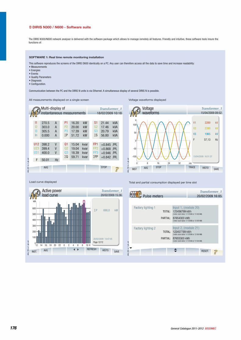
176 General Catalogue 2011-2012 SOCOMEC176
DIRIS N300 / N600 - Software suite
The DIRIS N300/N600 network analyser is delivered with the software package which allows to manage remotely all features. Friendly and intuitive, these software tools insure the functions of:
This software reproduces the screens of the DIRIS D600 identically on a PC. Any user can therefore access all the data to save time and increase readability:• Measurements• Energies• Events• Quality Parameters• Diagnosis• Configuration.
Communication between the PC and the DIRIS N units is via Ethernet. A simultaneous display of several DIRIS N is possible.
SOFTWARE 1: Real time remote monitoring installation
MMulti-display of instantaneous measurements 18/02/2009 10:18
Transformer_1
AVG STOP
270.5 A303.0 A 305.5 A0.000 A
398.2 V399.4 V400.0 V
16.20 kW20.00 kW17.39 kW51.72 kW
15.04 kvar19.04 kvar18.39 kvar59.71 kvar
21.44 kVA17.46 kVA20.79 kVA56.80 kVA
+0.845
I1I2I3In
U12U23U31
50.01 HzF
P1P2P3∑P
Q1Q2Q3∑Q
S1S2S3∑S
FP1FP2FP3∑FP
diris
_841
_b_1
_gb_
cat
M 20/02/2009 15:36Transformer_1Active power
load curve
INST.
20/02/2009 14:47:05
∑P 690,0 kW
Page 12/12
AVG HISTO. SAVE
kW
14 1612 18 20 H
REFRESH
600
500
400
300
200
100
22 0 2 4 6 8 100
diris
_783
_a_1
_gb_
cat
All measurements displayed on a single screen
Total and partial consumption displayed per time slot
M 15/04/2009 09:52Transformer_1Voltage
waveforms
INST
15/04/2009 16:51:37
AVG STOP TRACE HISTO SAVE
V1 2289 kV
V2 2289 kV
V3 1965 kV
F 57,13 Hz
V
100
50
0
-50
-100
0 8 16 24 32 ms
diris
_782
_b_1
_gb_
cat
diris
_842
_a_1
_gb_
cat
Voltage waveforms displayed
Load curve displayed
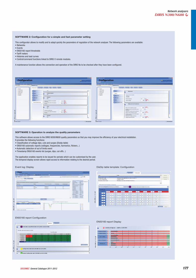
177General Catalogue 2011-2012SOCOMEC 177
Network analysersDIRIS N300/N600
This configurator allows to modify and to adapt quickly the parameters of regulation of the network analyser. The following parameters are available:• Networks• Events• EN50160 report thresholds• Tariff meters• Histories and load curves• Control/command functions linked to DIRIS O remote modules.
A maintenance function allows the connection and operation of the DIRIS Ns to be checked after they have been configured.
SOFTWARE 2: Configuration for a simple and fast parameter setting
diris
_787
_b_1
_gb_
cat
diris
_786
_b_1
_gb_
cat
This software allows access to the DIRIS N300/N600 quality parameters so that you may improve the efficiency of your electrical installation.It provides the following functions:• Classification of voltage dips, cuts and surges (Disdip table)• EN50160 automatic reports (voltages, frequencies, harmonics, flickers...)• Automatic detection of out of limits event• Timestamp EN50160 events list (surges, dips, cut-offs...)
The application enables reports to be issued for periods which can be customised by the user.The temporal display screen allows rapid access to information relating to the desired period.
SOFTWARE 3: Operation to analyze the quality parameters
diris
_837
_a_1
_gb_
cat
diris
_838
_a_1
_fr_
cat
Event log: Display DisDip table template: Configuration
diris
_839
_a_1
_fr_
cat
EN50160 report Configuration
diris
_840
_a_1
_fr_
cat
EN50160 report Display
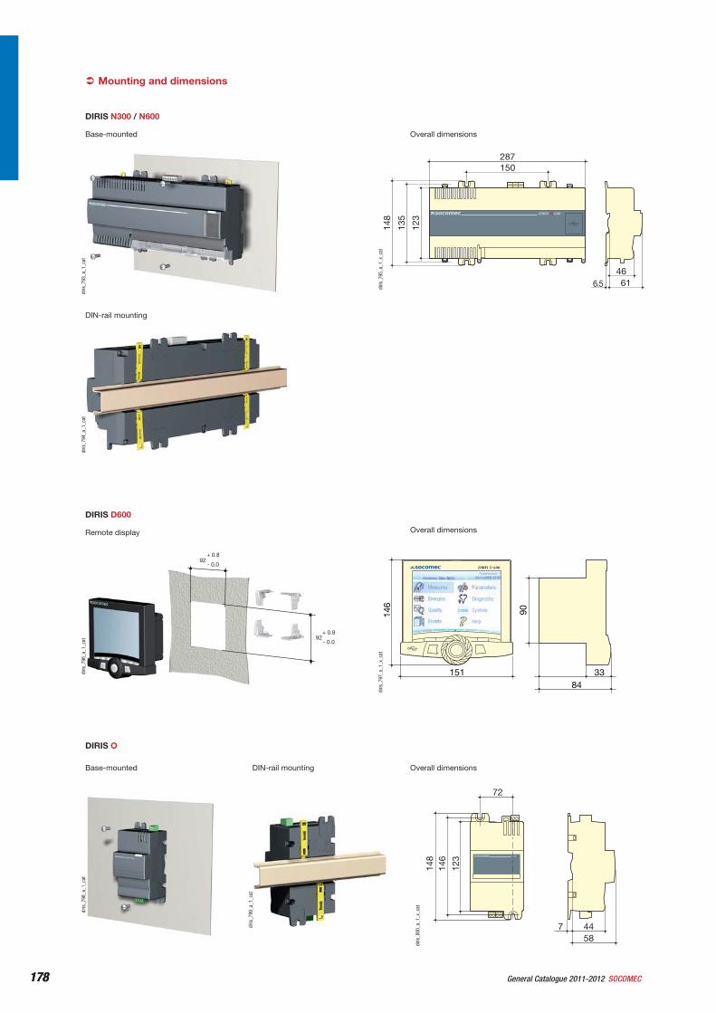
178 General Catalogue 2011-2012 SOCOMEC178
DIRIS N300 / N600
diris
_793
_a_1
_cat
DIN-rail mounting
diris
_794
_a_1
_cat
Overall dimensions
150
148
123
135
287
46616.5
DIRIS N 600
diris
_795
_a_1
_x_c
at
DIRIS D600
92+ 0.8
- 0.0
92+ 0.8
- 0.0
diris
_796
_a_1
_cat
Overall dimensions
DIRIS D 600
146
90
151 3384
diris
_797
_a_1
_x_c
at
Mounting and dimensions
Base-mounted
Remote display
DIRIS O
diris
_798
_a_1
_cat
Base-mounted DIN-rail mounting
diris
_799
_a_1
_cat
Overall dimensions
DIRIS O
72
123
146
148
4458
7
diris
_800
_a_1
_x_c
at
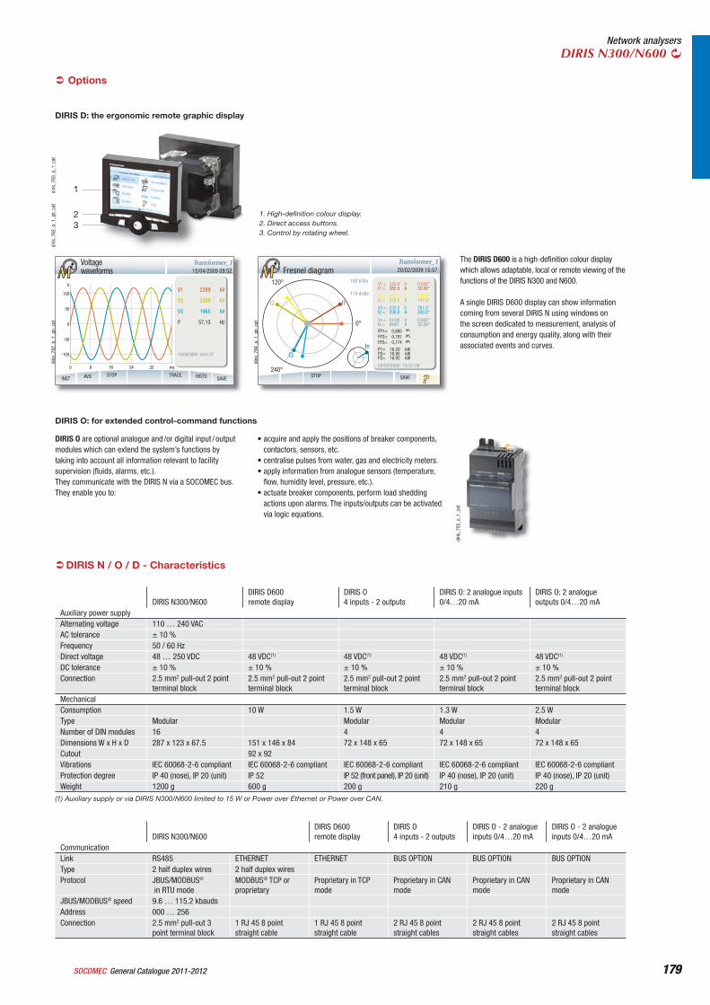
179General Catalogue 2011-2012SOCOMEC 179
Network analysersDIRIS N300/N600
DIRIS D: the ergonomic remote graphic display
The DIRIS D600 is a high-definition colour display which allows adaptable, local or remote viewing of the functions of the DIRIS N300 and N600.
A single DIRIS D600 display can show information coming from several DIRIS N using windows on the screen dedicated to measurement, analysis of consumption and energy quality, along with their associated events and curves.
M 15/04/2009 09:52Transformer_1Voltage
waveforms
INST
15/04/2009 16:51:37
AVG STOP TRACE HISTO SAVE
V1 2289 kV
V2 2289 kV
V3 1965 kV
F 57,13 Hz
V
100
50
0
-50
-100
0 8 16 24 32 ms
diris
_782
_b_1
_gb_
cat
M 20/02/2009 15:57Transformer_1
Fresnel diagram
SAVESTOP
120°
I2
I3
240°
0°
I1
100 V/div
114 A/div
In
V1 =I1 =
220.8282.0
VA
0.000°32.00°
V2 =I2 =
223.1272.5
VA
128.0°147.0°
V3 =I3 =
220.8230.0
VA
261.0°243.0°
Vn =In =
54.009400
VA
0.000°32.00°
FP1=FP2=FP3=
0,8850,7910,774
P1=P2=P3=
16.2018.9016.92
kWkWkW
20/02/2009 15:57:28
diris
_784
_a_1
_gb_
cat
Options
DIRIS N300/N600DIRIS D600remote display
DIRIS O 4 inputs - 2 outputs
DIRIS O - 2 analogue inputs 0/4…20 mA
DIRIS O - 2 analogue inputs 0/4…20 mA
CommunicationLink RS485 ETHERNET ETHERNET BUS OPTION BUS OPTION BUS OPTIONType 2 half duplex wires 2 half duplex wiresProtocol JBUS/MODBUS®
in RTU modeMODBUS® TCP or proprietary
Proprietary in TCP mode
Proprietary in CAN mode
Proprietary in CAN mode
Proprietary in CAN mode
JBUS/MODBUS® speed 9.6 … 115.2 kbaudsAddress 000 … 256Connection 2.5 mm2 pull-out 3
point terminal block1 RJ 45 8 point straight cable
1 RJ 45 8 point straight cable
2 RJ 45 8 point straight cables
2 RJ 45 8 point straight cables
2 RJ 45 8 point straight cables
DIRIS N / O / D - Characteristics
DIRIS N300/N600DIRIS D600remote display
DIRIS O 4 inputs - 2 outputs
DIRIS O: 2 analogue inputs 0/4…20 mA
DIRIS O: 2 analogue outputs 0/4…20 mA
Auxiliary power supplyAlternating voltage 110 … 240 VACAC tolerance ± 10 %Frequency 50 / 60 HzDirect voltage 48 … 250 VDC 48 VDC(1) 48 VDC(1) 48 VDC(1) 48 VDC(1)
DC tolerance ± 10 % ± 10 % ± 10 % ± 10 % ± 10 %Connection 2.5 mm2 pull-out 2 point
terminal block2.5 mm2 pull-out 2 point terminal block
2.5 mm2 pull-out 2 point terminal block
2.5 mm2 pull-out 2 point terminal block
2.5 mm2 pull-out 2 point terminal block
MechanicalConsumption 10 W 1.5 W 1.3 W 2.5 WType Modular Modular Modular ModularNumber of DIN modules 16 4 4 4Dimensions W x H x D 287 x 123 x 67.5 151 x 146 x 84 72 x 148 x 65 72 x 148 x 65 72 x 148 x 65Cutout 92 x 92Vibrations IEC 60068-2-6 compliant IEC 60068-2-6 compliant IEC 60068-2-6 compliant IEC 60068-2-6 compliant IEC 60068-2-6 compliantProtection degree IP 40 (nose), IP 20 (unit) IP 52 IP 52 (front panel), IP 20 (unit) IP 40 (nose), IP 20 (unit) IP 40 (nose), IP 20 (unit)Weight 1200 g 600 g 200 g 210 g 220 g
(1) Auxiliary supply or via DIRIS N300/N600 limited to 15 W or Power over Ethernet or Power over CAN.
diris
_762
_a_1
_gb_
cat
diris
_763
_a_1
_cat
1
23
1. High-definition colour display.2. Direct access buttons.3. Control by rotating wheel.
diris
_755
_a_1
_cat
DIRIS O are optional analogue and /or digital input / output modules which can extend the system’s functions by taking into account all information relevant to facility supervision (fluids, alarms, etc.).They communicate with the DIRIS N via a SOCOMEC bus.They enable you to:
DIRIS O: for extended control-command functions
• acquire and apply the positions of breaker components, contactors, sensors, etc.
• centralise pulses from water, gas and electricity meters.• apply information from analogue sensors (temperature,
flow, humidity level, pressure, etc.).• actuate breaker components, perform load shedding
actions upon alarms. The inputs/outputs can be activated via logic equations.
180 General Catalogue 2011-2012 SOCOMEC180
DIRIS N300 / N600 - Characteristics
Characteristics of the PMD (IEC 61557-12)Evaluation of the power supply quality (future function) WhitePMD classification SDTemperature K55Humidity + Altitude WhiteOperating performance class of active power or active energy (if possible function)
0.2
Startup duration 50 seconds
Characteristics of the functions/Evaluation of the power supply quality (IEC 61557-12)P (Total active power) - class 0.2 5 % In to 2 InQa, Qv (reactive power) - class 1 5 % In to 2 InSa, Sv - class 0.2 5 % In to 2 InEa - class 0.2 5 % In to 2 InEra, Erv - class 1 5 % In to 2 InEapa, Eapv - class 0.2 5 % In to 2 Inf - class 0.02 / class B complies IEC 61000 = 4-30 Fnom ±15 %I - class 0.1 0.1 In to 2 InIn / Inc - class 0.1 0.1 In to 2 InU - class 0.1PFa / PFv - class 0.5 PF = 0.5 lag to 0.5 leadPst / Pit - class 5 (complies IEC 61000-4-15) 0 … 20Udip - class 0.2 5 % Un to Un
Uswl - class 0.2 Un to 120 % Un
Utr 0 … 6 kVUint - class 0.2 0 … 5 % Un
Unba - class 0.2Unb - class 0.2Uh - class 1THDu - class 1THD-Ru - class 1Ih - class 1THDi - class 2THD-Ri - class 1Msv - class 1
MeasurementsNetwork type Three phase without neutral or with neutralNumber of power outlets 3 or 4Measurement category 600V cat III (IEC 61010-1)Measurement method class B (A except for temporal aggregation) (IEC
61000-4-30)TRMS up to level 50Measurement sampling frequency 10240 Hz (at the nominal network
frequency)Transient sampling frequency 750 kHz i.e. 1.33 sInstantaneous measurements refresh frequency
1 s
Plot refresh frequency 1 … 60 minutesHistory refresh frequency 1 … 60 s
Voltage inputsNumber of voltage inputs 3 Phase + Neutral + EarthNominal voltage without VT 346 V AC (phase/Neutral) and 600 >V AC (phase/
phase)Voltage transformer Primary maximum: 630 kVAC / Secondary:
60/100/110/115/120/173/190 VACSustained overload 800 VACFrequency 45 … 65 HzInsulation 600 V cat IIIConnection 2.5mm² pull-out 4 point terminal block
Current inputsNumber of current inputs 3 Phase + NeutralNominal current without CT 5 ACurrent transformer Primary: max 10 000 A / Secondary: 1 or 5 AInput consumption < 0.3 VASustained overload 20 AIntermittent overload 20 In / 1sInsulation mainConnection 6 mm2 8 point fixed terminal block
USBHost (low power : 100 mA max) 1Device 1
EnvironmentMax. operating temperature -10 … +55 °CMax. storage temperature -25 … 70 °CHumidity 0 … 75 % RHSalt spray EN 60068-2-52Protection degree IEC 60259Sine vibrations IEC 60068-2-6Dry heat test (operation and storage) IEC 60068-2-2Wet heat cyclic test IEC 60068-2-30in-operation and storage cold test IEC 60068-2-1
SD CardCompatible size Up to 1 Gb
Product standards and certificationProduct standard IEC 61557-12 ed. 1Active energy metering ICE 62053-22 (class 0.2S or 0.5S)Reactive energy metering IEC 62053-23 (class 2)
Measurement standards and certificationHarmonics and interharmonics measurement method IEC 61000-4-7Flicker measurement method IEC 61000-4-15Supply power quality measurement method IEC 61000-4-30Characteristics of the voltage supplied by public distribution networks
EN 50160
Communication standards and certificationRS485 TIA-485A
TSB-89-BIEE 802-3AF
Ethernet 802-1.3-2005_Section1802-1.3-2005_Section2
Protocol standards and certificationRS485 JBUSEthernet MODBUSUSB USB 2.0CAN ISO11898-2
DIRIS D600 screenTechnology TFTFormat 640 x 480 pixelsDimension 115.2 x 86.4 mm
DIRIS O 4i2o-d inputs (4 inputs/2 outputs)Number 4Type phototransistorPower supply 10 … 30 VDCMinimum current 1 mAMain insulation for < 300 VAC Ph/N network 2.5 kVAC rms 1 minuteLeakage path > 3 mmNumber of switchings 108 operations
DIRIS O 4i2o-d outputs (4 inputs/2 outputs)Number of switchings 105 operationsType 230 VAC - 250 VDC - 0.2 A - 1500 VA - 50 WNumber of relays 2Leakage path > 3 mmMain insulation for < 300 VAC Ph/N network 2.5 kVAC rms 1 minute
DIRIS O 2i-a inputs (2 analogue inputs)Number 2Scale 0 / 4 … 20 mAAccuracy 1 % of full scale (which is 0.2 mA)Max. impedance of inputs 200 Main insulation for < 300 VAC Ph/N network 2.5 kVAC rms 1 minuteLeakage path > 3 mm
DIRIS O 2o-a outputs (2 analogue outputs)Number of outputs 2Scale 0 / 4 … 20 mALoad resistance 600 Accuracy 0.5 % of full scale (which is 0.1 mA)Maximum current 25 mAMain insulation for < 300 VAC Ph/N network 2.5 kVAC rms 1 minuteLeakage path > 3 mm
MemoryMemory size 128 Mb
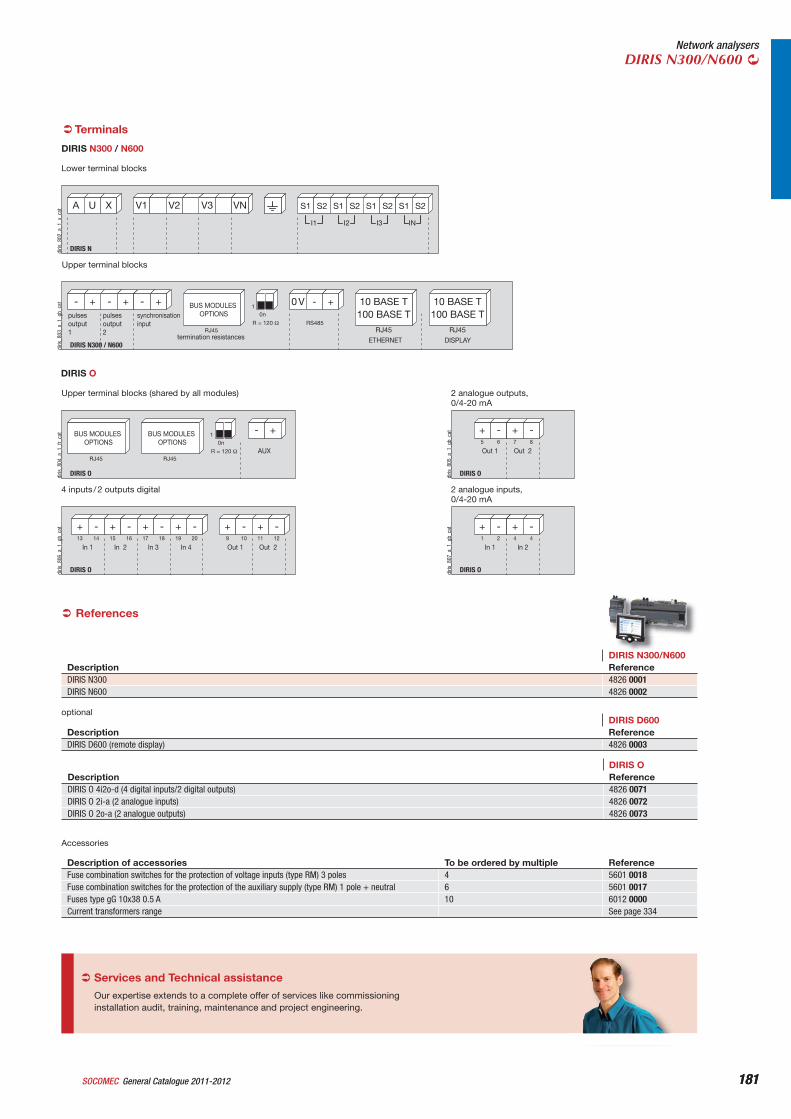
181General Catalogue 2011-2012SOCOMEC 181
Network analysersDIRIS N300/N600
Terminals
DIRIS N300 / N600
0 V - +
R = 120 Ω RS485
0n1
10 BASE T100 BASE T
RJ45RJ45
pulsesoutput1
BUS MODULES OPTIONS
ETHERNET
10 BASE T100 BASE T
RJ45
DISPLAYtermination resistances
pulsesoutput2
synchronisationinput
+- +- +-
diris
_803
_a_1
_gb_
cat
Upper terminal blocks
DIRIS N
A U X V3 VNV1 V2
I3I2I1
S2S1 S2S1 S2S1
IN
S2S1
diris
_802
_a_1
_x_c
at
Lower terminal blocks
DIRIS N300 / N600
DIRIS O
+
In 1
- +
In 21 2 4 4
-
diris
_807
_a_1
_gb_
cat
2 analogue inputs, 0/4-20 mA
DIRIS O
+
In 1
- +
In 213 14 15 16
- +
In 3
- +
In 417 18 19 20
- +
Out 1
- +
Out 29 10 11 12
-
diris
_806
_a_1
_gb_
cat
4 inputs / 2 outputs digital
DIRIS O
+
Out 1
- +
Out 25 6 7 8
-
diris
_805
_a_1
_gb_
cat
2 analogue outputs, 0/4-20 mA
DIRIS O
- +
R = 120 Ω AUX0n
1
RJ45
BUS MODULES OPTIONS
RJ45
BUS MODULES OPTIONS
diris
_804
_a_1
_fr_
cat
Upper terminal blocks (shared by all modules)
DIRIS O
References
DIRIS N300/N600Description ReferenceDIRIS N300 4826 0001DIRIS N600 4826 0002
DIRIS D600Description ReferenceDIRIS D600 (remote display) 4826 0003
DIRIS ODescription ReferenceDIRIS O 4i2o-d (4 digital inputs/2 digital outputs) 4826 0071DIRIS O 2i-a (2 analogue inputs) 4826 0072DIRIS O 2o-a (2 analogue outputs) 4826 0073
optional
Description of accessories To be ordered by multiple ReferenceFuse combination switches for the protection of voltage inputs (type RM) 3 poles 4 5601 0018Fuse combination switches for the protection of the auxiliary supply (type RM) 1 pole + neutral 6 5601 0017Fuses type gG 10x38 0.5 A 10 6012 0000Current transformers range See page 334
Accessories
Our expertise extends to a complete offer of services like commissioning installation audit, training, maintenance and project engineering.
Services and Technical assistance
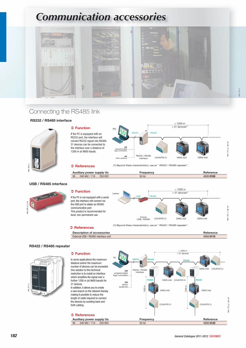
General Catalogue 2011-2012 SOCOMEC182
Communication accessories
RS232 / RS485 interface
inte
r_04
3_a
< 1200 m< 31 devices(1)
RS232 RS485
RS232 / RS485interface COUNTIS Ci DIRIS A20 DIRIS A40
ORprogrammable
logic controllers
ORother systems
PC
diris
_141
_g_1
_gb_
cat
(1) Beyond these characteristics, use an " RS422 / RS485 repeater".
If the PC is equipped with an RS232 port, the interface will convert RS232 signal into RS485. 31 devices can be connected to the interface over a distance of 1200 m at 9600 bauds.
Auxiliary power supply Us Frequency Reference95 … 240 VAC / 110 … 250 VDC 50 Hz 4899 0100
Function
References
USB / RS485 interface
USB RS485
COUNTIS Ci DIRIS A20 DIRIS A40Casing
USB / RS485
Laptop
< 1200 m< 31 devices(1)
inte
r_14
2_f_
1_gb
_cat
(1) Beyond these characteristics, use an " RS422 / RS485 repeater".
inte
r_00
2_a_
2_ca
t
If the PC is not equipped with a serial port, the interface will connect via the USB port to obtain an RS485 communication port. This product is recommended for local, non-permanent use.
Description of accessories ReferenceExternal USB / RS485 interface unit 4899 0110
References
Function
RS422 / RS485 repeater
BLB
LN
BLARDA RDB
PWR
R- R+ T- T+
R-R+T-T+
POWER
LINE-B
LINE-A
RS422/RS485REPEATER
DIRIS A40
DIRIS A40
RS485 RS485
DIRIS A40
RS485
COUNTIS Ci
BLB
LN
BLARDA RDB
PWR
R- R+ T- T+
R-R+T-T+
POWER
LINE-B
LINE-A
RS422/RS485REPEATER
1200
m
DIRIS A40
RS485
COUNTIS Ci
COUNTIS Ci
COUNTIS CiBLB
LN
BLARDA RDB
PWR
R- R+ T- T+
R-R+T-T+
POWER
LINE-B
LINE-A
RS422/RS485REPEATER
1200
m
RS232 / RS485Interface
RS232
< 1200 m< 31 devices
PC
ORothers
systemes
ORprogrammable
logic controllers
inte
r_14
3_g_
1_gb
_cat
inte
r_01
1_a
In some applications the maximum distance and/or the maximum number of devices can be exceeded. One solution to this technical restriction is to install an interface which amplifies the signal over a further 1200 m (at 9600 bauds) for 31 devices.In addition, it allows you to createa new branch on the network thereby making it possible to reduce the length of cable required to connect the devices by avoiding back and forth cabling.
Auxiliary power supply Us Frequency Reference95 … 240 VAC / 110 … 250 VDC 50 Hz 4899 0120
References
Function
appl
i_22
3_b
Connecting the RS485 link
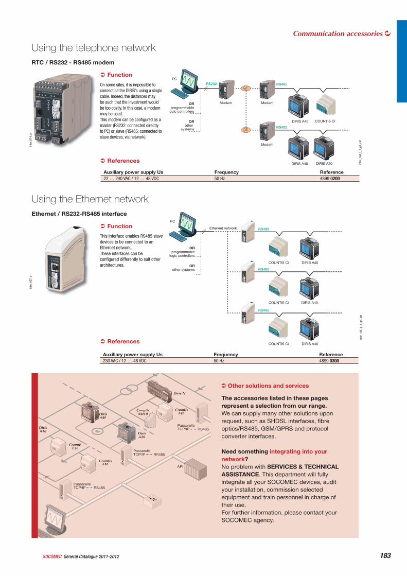
General Catalogue 2011-2012SOCOMEC 183
Communication accessories
RTC / RS232 - RS485 modem
inte
r_01
4_a
DIRIS A40
DIRIS A40
ModemModem
Modem
RS485
RS485
RS232
COUNTIS Ci
DIRIS A20
PC
ORother
systems
ORprogrammable
logic controllers
inte
r_14
4_f_
1_gb
_cat
On some sites, it is impossible to connect all the DIRIS’s using a single cable. Indeed, the distances may be such that the investment would be too costly. In this case, a modem may be used.This modem can be configured as a master (RS232: connected directly to PC) or slave (RS485: connected to slave devices, via network).
Auxiliary power supply Us Frequency Reference22 … 240 VAC / 12 … 48 VDC 50 Hz 4899 0200
References
Function
Ethernet / RS232-RS485 interface
COUNTIS Ci
COUNTIS Ci
COUNTIS Ci
Ethernet network RS485
RS485
RS485
DIRIS A40
DIRIS A40
DIRIS A40
PC
ORother systems
ORprogrammable
logic controllers
inte
r_14
5_g_
1_gb
_cat
inte
r_05
7_a
This interface enables RS485 slave devices to be connected to an Ethernet network.These interfaces can be configured differently to suit other architectures.
Auxiliary power supply Us Frequency Reference230 VAC / 12 … 48 VDC 50 Hz 4899 0300
References
Function
M
CountisE30
DirisA10
Diris N
CountisE40
CountisE50
DirisA20
DirisA40
CountisAM10
API
GTCGTC
PasserelleTCP/IPP RS485R
PasserelleTCP/IP RS485
PasserelleTCP/IP RS485
Other solutions and services
The accessories listed in these pages represent a selection from our range.We can supply many other solutions upon request, such as SHDSL interfaces, fibre optics/RS485, GSM/GPRS and protocol converter interfaces.
Need something integrating into your network?No problem with SERVICES & TECHNICAL ASSISTANCE. This department will fully integrate all your SOCOMEC devices, audit your installation, commission selected equipment and train personnel in charge of their use.For further information, please contact your SOCOMEC agency.
Using the telephone network
Using the Ethernet network
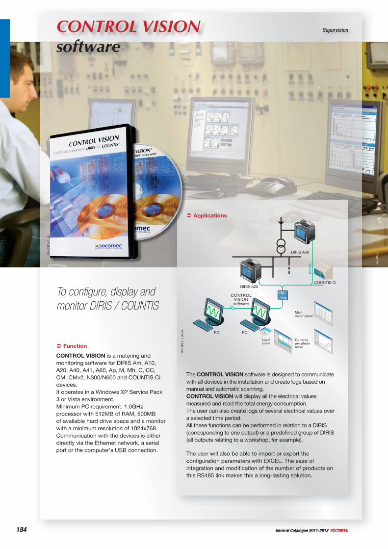
184 General Catalogue 2011-2012 SOCOMEC
CONTROL VISION software
Supervision
To configure, display and monitor DIRIS / COUNTIS
Applications
The user will also be able to import or export the configuration parameters with EXCEL. The ease of integration and modification of the number of products on this RS485 link makes this a long-lasting solution.
CONTROL VISION® 1
Logiciel de supervision DIRIS® et COUNTIS®
485
232
RS
485
CONTROLVISIONsoftware
Mainmeter panel
Currentsper phase curve
Loadcurve
PCPC
DIRIS A40
DIRIS A20COUNTIS Ci
diris
_689
_c_1
_gb_
cat
diris
_734
_a_1
_gb
Function
CONTROL VISION is a metering and monitoring software for DIRIS Am, A10, A20, A40, A41, A60, Ap, M, Mh, C, CC, CM, CMv2, N300/N600 and COUNTIS Ci devices.It operates in a Windows XP Service Pack 3 or Vista environment. Minimum PC requirement: 1.0GHz processor with 512MB of RAM, 500MB of available hard drive space and a monitor with a minimum resolution of 1024x768.Communication with the devices is either directly via the Ethernet network, a serial port or the computer's USB connection.
The CONTROL VISION software is designed to communicate with all devices in the installation and create logs based on manual and automatic scanning.CONTROL VISION will display all the electrical values measured and read the total energy consumption.The user can also create logs of several electrical values over a selected time period.All these functions can be performed in relation to a DIRIS (corresponding to one output) or a predefined group of DIRIS (all outputs relating to a workshop, for example).
site
_476
_a
General Catalogue 2011-2012SOCOMEC 185
Supervision
CONTROL VISION software
General characteristics
The CONTROL VISION software allows: • remote configuration of DIRIS and COUNTIS Ci devices,• displaying all electrical parameters measured, energies, indices,
alarms, harmonics and the configuration of all the devices,• creating readings, backups and automatic print-outs,• displaying, of DIRIS CM/CMv2/A40/A60 and COUNTIS Ci inputs:
- table of min. 10P, corresponding load curve,
• displaying historical data for each DIRIS in tabular or graphical format:- immediate measurements, - harmonics values, - status changing of inputs / outputs.
The CONTROL VISION software is available in a multilingual version comprising the following languages: english, french, german, italian, spanish.
CONTROL VISION software
Type ReferenceCONTROL VISION software 4805 0000CONTROL VISION software + INTRANET option (multi user) 4805 0001
General reading of measurements
Monthly general reading of COUNTIS Ci
diris
_509
_a_1
_gb_
cat
Monthly meter readings of all COUNTIS Ci present on the network.COUNTIS Ci memorises monthly consumption (energy or pulse), via each of their 7 inputs, the software retrieves the values and allocates them into the allocated “group”.This screen may be printed and extracted manually by clicking on the respective pushbuttons.
diris
_508
_a_1
_gb_
cat
Energy consumption table or metered pulses of all the DIRIS / COUNTIS Ci present on the network. This readout comprises (depending on the type of DIRIS) positive and negative active energy (kWh), positive and negative reactive energy (kVArh), apparent power (kVA) and pulses metered by the devices' on/off inputs. These pulses are configurable (name, weight and unit).These values can be added (or subtracted) in groups, allowing them to be grouped by type (electricity, water, gas, etc.).They can be printed and saved (Excel file) automatically (one file per day created at a set time, for example).This screen may be printed and extracted manually by clicking on the respective pushbuttons.
diris
_507
_a_1
_gb_
cat
Instantaneous measurement display
All electrical values displayed either with digital values or analogue indicators, depending on the tab selected: - currents,- phase to phase voltage,- powers,- frequency,- active energy and time meter (according to DIRIS) of the selected DIRIS.Alarm levels (programmed in the device) are indicated in red.The parameters to be displayed can be customised.All screens are refreshed automatically.
References
Functions
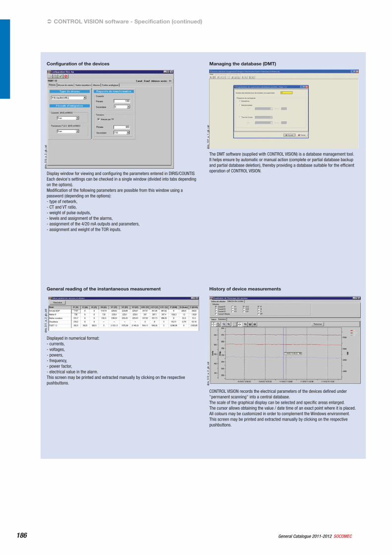
General Catalogue 2011-2012 SOCOMEC186
History of device measurements
diris
_512
_a_2
_gb_
cat
CONTROL VISION records the electrical parameters of the devices defined under "permanent scanning" into a central database.The scale of the graphical display can be selected and specific areas enlarged.The cursor allows obtaining the value / date time of an exact point where it is placed.All colours may be customized in order to complement the Windows environment.This screen may be printed and extracted manually by clicking on the respective pushbuttons.
General reading of the instantaneous measurement
diris
_511
_a_2
_gb_
cat
Displayed in numerical format: - currents,- voltages,- powers,- frequency,- power factor,- electrical value in the alarm.This screen may be printed and extracted manually by clicking on the respective pushbuttons.
Managing the database (DMT)
diris
_727
_a_1
_gb_
cat
The DMT software (supplied with CONTROL VISION) is a database management tool.It helps ensure by automatic or manual action (complete or partial database backup and partial database deletion), thereby providing a database suitable for the efficient operation of CONTROL VISION.
Configuration of the devices
diris
_510
_a_2
_gb_
cat
Display window for viewing and configuring the parameters entered in DIRIS/COUNTISEach device's settings can be checked in a single window (divided into tabs depending on the options).Modification of the following parameters are possible from this window using a password (depending on the options):- type of network,- CT and VT ratio,- weight of pulse outputs,- levels and assignment of the alarms,- assignment of the 4/20 mA outputs and parameters,- assignment and weight of the TOR inputs.
CONTROL VISION software - Specification (continued)
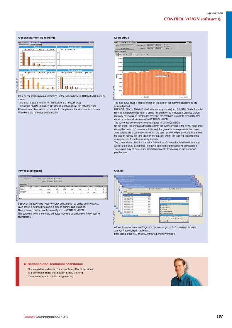
General Catalogue 2011-2012SOCOMEC 187
diris
_726
_a_1
_gb_
cat
Quality
Allows display of events (voltage dips, voltage surges, cut-offs, average voltages, average frequencies) in table form.It requires a DIRIS A60 or DIRIS A40 with a memory module.
diris
_515
_a_2
_gb_
cat
Power distribution
Display of the active and reactive energy consumption by period and by device.Each period is defined by a name, a time of starting and of ending.The concerned devices are those configured in CONTROL VISION.This screen may be printed and extracted manually by clicking on the respective pushbuttons.
diris
_514
_a_1
_gb_
cat
Load curve
The load curve gives a graphic image of the load on the network according to the selected periodDIRIS CM / CMv2 / A60 (A40 fitted with memory module) and COUNTIS Ci (via 4 inputs) records the average values for a period (for example, 10 minutes); CONTROL VISION regularly retrieves and records the results in the database in order to format the load data in a table of all devices within CONTROL VISION.The concerned devices are those configured in CONTROL VISION.On the graph, the orange section represents the average value of the power consumed during this period (10 minutes in this case), the green section represents the power zone outside the procured power (which the user has defined per product). This allows the user to quickly see (and zoom in on) the zone where the load has exceeded the value procured from the electricity supplier.The cursor allows obtaining the value / date time of an exact point where it is placed.All colours may be customized in order to complement the Windows environment.This screen may be printed and extracted manually by clicking on the respective pushbuttons.
diris
_513
_a_1
_gb_
cat
General harmonics readings
Table or bar graph showing harmonics for the selected device (DIRIS A40/A60) row by row for:- the 3 currents and neutral (on the basis of the network type)- the simple and Ph-Ph and Ph-N voltages (on the basis of the network type).All colours may be customized in order to complement the Windows environment.All screens are refreshed automatically.
Supervision
CONTROL VISION software
Our expertise extends to a complete offer of services like commissioning installation audit, training, maintenance and project engineering.
Services and Technical assistance
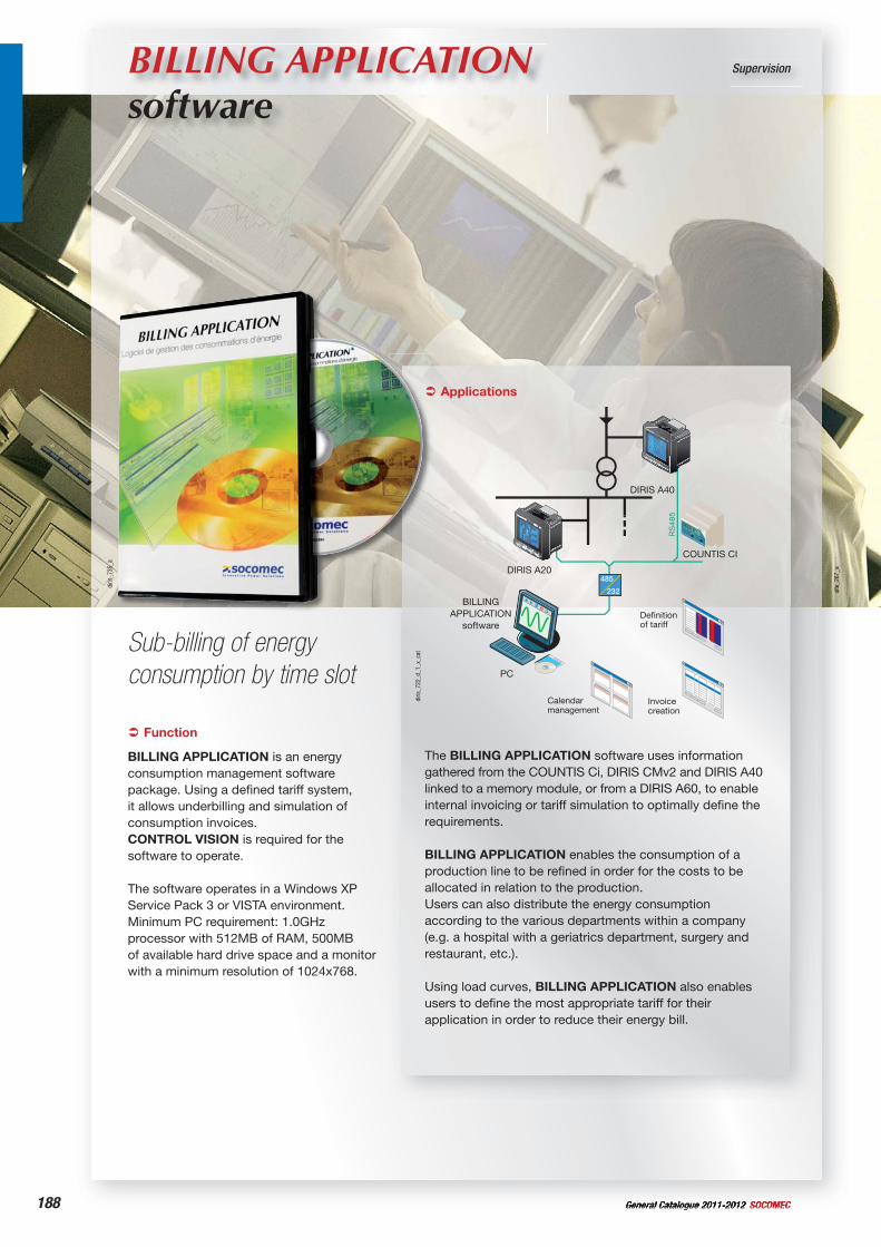
188 General Catalogue 2011-2012 SOCOMEC
site
_267
_a
BILLING APPLICATION software
Supervision
Sub-billing of energy consumption by time slot
The BILLING APPLICATION software uses information gathered from the COUNTIS Ci, DIRIS CMv2 and DIRIS A40 linked to a memory module, or from a DIRIS A60, to enableinternal invoicing or tariff simulation to optimally define the requirements.
BILLING APPLICATION enables the consumption of a production line to be refined in order for the costs to be allocated in relation to the production.Users can also distribute the energy consumption according to the various departments within a company (e.g. a hospital with a geriatrics department, surgery and restaurant, etc.).
Using load curves, BILLING APPLICATION also enables users to define the most appropriate tariff for their application in order to reduce their energy bill.
485
232
RS
485
DIRIS A40
COUNTIS CI
DIRIS A20
PC
BILLINGAPPLICATION
software
Invoicecreation
Definitionof tariff
Calendarmanagement
diris
_722
_d_1
_x_c
at
diris
_735
_a
Function
BILLING APPLICATION is an energy consumption management software package. Using a defined tariff system, it allows underbilling and simulation of consumption invoices.CONTROL VISION is required for the software to operate.
The software operates in a Windows XP Service Pack 3 or VISTA environment. Minimum PC requirement: 1.0GHz processor with 512MB of RAM, 500MB of available hard drive space and a monitor with a minimum resolution of 1024x768.
Applications
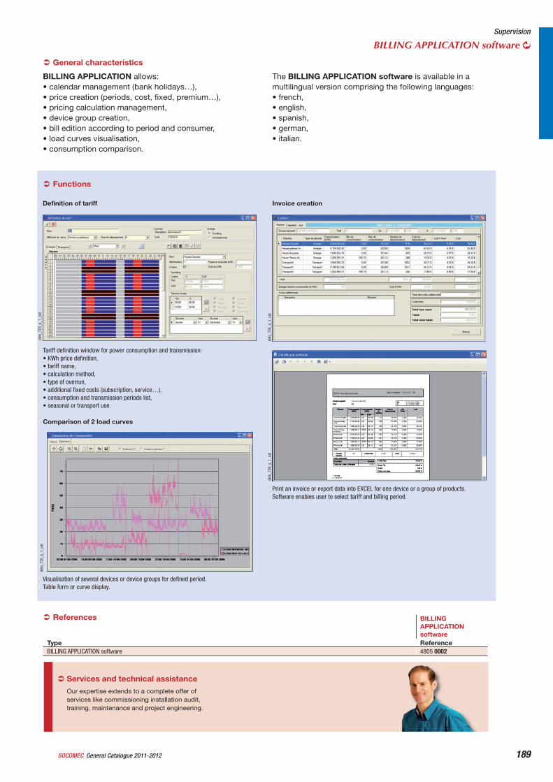
General Catalogue 2011-2012SOCOMEC 189
Supervision
BILLING APPLICATION software
Definition of tariff
diris
_723
_a_1
_cat
Tariff definition window for power consumption and transmission: • KWh price definition,• tariff name,• calculation method,• type of overrun,• additional fixed costs (subscription, service…),• consumption and transmission periods list,• seasonal or transport use.
diris
_725
_a_1
_cat
Comparison of 2 load curves
Visualisation of several devices or device groups for defined period.Table form or curve display.
diris
_728
_a_1
_cat
diris
_724
_a_1
_cat
Invoice creation
Print an invoice or export data into EXCEL for one device or a group of products.Software enables user to select tariff and billing period.
General characteristics
BILLING APPLICATION allows: • calendar management (bank holidays…),• price creation (periods, cost, fixed, premium…),• pricing calculation management,• device group creation,• bill edition according to period and consumer,• load curves visualisation,• consumption comparison.
The BILLING APPLICATION software is available in a multilingual version comprising the following languages: • french,• english,• spanish,• german,• italian.
BILLINGAPPLICATION software
Type ReferenceBILLING APPLICATION software 4805 0002
References
Functions
Our expertise extends to a complete offer of services like commissioning installation audit, training, maintenance and project engineering.
Services and technical assistance
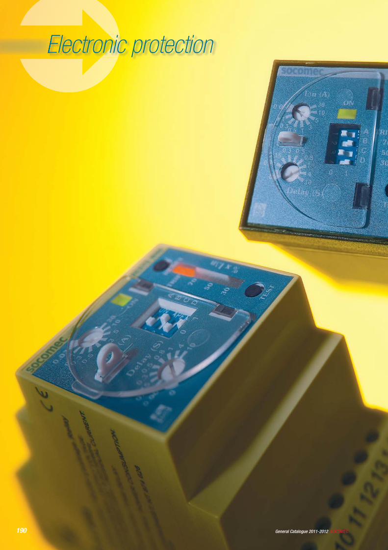
190 SOCOMECGeneral Catalogue 2011-2012
Electronic protection
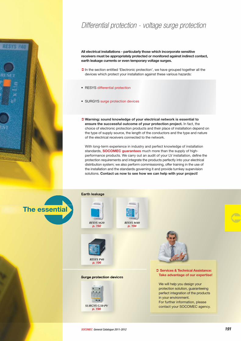
191General Catalogue 2011-2012SOCOMEC
Services & Technical Assistance: Take advantage of our expertise!
We will help you design your protection solution, guaranteeing perfect integration of the products in your environment.For further information, please contact your SOCOMEC agency.
All electrical installations - particularly those which incorporate sensitive receivers must be appropriately protected or monitored against indirect contact, earth leakage currents or even temporary voltage surges.
In the section entitled ‘Electronic protection’, we have grouped together all the devices which protect your installation against these various hazards:
• RESYS differential protection
• SURGYS surge protection devices
Warning: sound knowledge of your electrical network is essential to ensure the successful outcome of your protection project. In fact, the choice of electronic protection products and their place of installation depend on the type of supply source, the length of the conductors and the type and nature of the electrical receivers connected to the network.
With long-term experience in industry and perfect knowledge of installation standards, SOCOMEC guarantees much more than the supply of high-performance products. We carry out an audit of your LV installation, define the protection requirements and integrate the products perfectly into your electrical distribution system; we also perform commissioning, offer training in the use of the installation and the standards governing it and provide turnkey supervision solutions. Contact us now to see how we can help with your project!
Differential protection - voltage surge protection
Earth leakage
RESYS M20p. 192
The essential
Surge protection devices
RESYS P40 p. 196
SURGYS G50-PV p. 198
RESYS M40p. 194
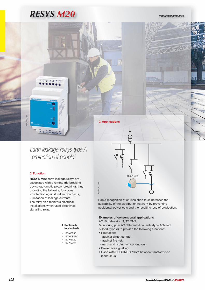
192 General Catalogue 2011-2012 SOCOMEC
RESYS M20 Differential protection
Earth leakage relays type A "protection of people"
Function
RESYS M20 earth leakage relays are associated with a remote trip breaking device (automatic power breaking), thus providing the following functions:- protection against indirect contacts,- limitation of leakage currents.The relay also monitors electrical installations when used directly as signalling relay.
Conformityto standards
IEC 60755IEC 60947-2IEC 62020IEC 60364
••••
Applications
Rapid recognition of an insulation fault increases the availability of the distribution network by preventing accidental power cuts and the resulting loss of production.
Examples of conventional applicationsAC LV networks: IT, TT, TNS.Monitoring pure AC differential currents (type AC) and pulsed (type A) to provide the following functions:• Protection:- against direct contact,- against fire risk,- earth and protection conductors.
• Preventive signalling.• Used with SOCOMEC “Core balance transformers”
(consult us).
RESYS M20
resy
s_05
2_b_
1_x_
cat
resy
s_04
1_a_
1_ca
t
appl
i_24
6_a
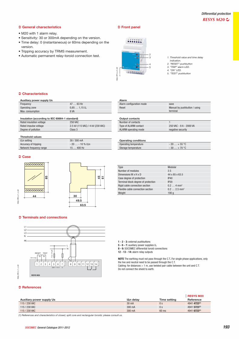
General Catalogue 2011-2012SOCOMEC 193
Differential protection
RESYS M20
Terminals and connections
RESYS M20
1 2 3 4 5 76 8 9 108 9 10 11 12 1413
LN
Fus.
2 A
gG
RESET TEST
L1L2L3N
PE
230 V
50 m max
115 V O
resy
s_05
3_b_
1_x_
cat
1 - 2 - 3: external pushbuttons5 - 6 - 7: auxiliary power supplies Us
8 - 9: SOCOMEC differential toroid connections12 - 13 - 14: alarm relay outputs
NOTE The earthing must not pass through the C.T. For single phase applications, only the live and neutral need to be passed through the C.T.Cabling: for distances > 1 m, use twisted pair cable between the unit and C.T.Do not connect the shield to earth.
RESYS M20Auxiliary power supply Us I n delay Time setting Reference115 / 230 VAC 30 mA 0 s 4941 4723(1)
115 / 230 VAC 300 mA 0 s 4941 5723(1)
115 / 230 VAC 300 mA 60 ms 4941 6723(1)
(1) References and characteristics of closed, split core and rectangular toroids: please consult us.
General characteristics
• M20 with 1 alarm relay.• Sensitivity: 30 or 300mA depending on the version.• Time delay: 0 (instantaneous) or 60ms depending on the
version.• Tripping accuracy by TRMS measurement.• Automatic permanent relay-toroid connection test.
54
32
1
resy
s_04
1x_a
_2_c
at
1. Threshold value and time delay indication.
2. "RESET" pushbutton3. “TRIP” alarm LED.4. "ON" LED.5. "TEST" pushbutton
Auxiliary power supply Us Frequency 47 … 63 HzOperating zone 0,85 … 1,15 Us
Max. consumption 6 VA
Insulation (according to IEC 60664-1 standard) Rated insulation voltage 250 VACRated impulse voltage 2.5 kV (115 VAC) / 4 kV (230 VAC) Degree of pollution Class 3
Threshold values I n setting 30 / 300 mAAccuracy of tripping - 20 … - 10 % I nNetwork frequency range 15 … 400 Hz
AlarmAlarm configuration mode saveReset Manual by pushbutton / using
terminal
Output contacts Number of contacts 1Type of ALARM contact 250 VAC - 8 A - 2000 VAALARM operating mode negative security
Operating conditions Operating temperature - 20 … + 55 °CStorage temperature - 30 … + 70 °C
Characteristics
Front panel
Type ModularNumber of modules 2.5Dimensions W x H x D 44 x 85 x 63.5Case degree of protection IP40Terminal block degree of protection IP20Rigid cable connection section 0.2 … 4 mm2
Flexible cable connection section 0.2 … 2.5 mm2
Weight 190 g
85 45 61
44 3049.5
63.5
resy
s_05
6_a_
1_x_
cat
Case
References
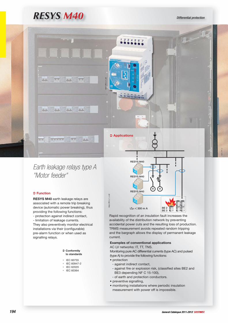
194 General Catalogue 2011-2012 SOCOMEC
RESYS M40 Differential protection
Earth leakage relays type A "Motor feeder"
Rapid recognition of an insulation fault increases the availability of the distribution network by preventing accidental power cuts and the resulting loss of production. TRMS measurement avoids repeated random tripping and the bargraph allows the display of permanent leakage current.
Examples of conventional applicationsAC LV networks: IT, TT, TNS.Monitoring pure AC differential currents (type AC) and pulsed (type A) to provide the following functions:• protection
- against indirect contact,- against fire or explosion risk, (classified sites BE2 and
BE3 depending NF C 15-100),- of earth and protection conductors.
• preventive signalling,• monitoring installations where periodic insulation
measurement with power off is impossible.
300 m A
RESYS M40
RESYS M40
RESYS M40
BE 2BE 3
resy
s_05
0_b_
1_x_
catFunction
RESYS M40 earth leakage relays are associated with a remote trip breaking device (automatic power breaking), thus providing the following functions: - protection against indirect contact,- limitation of leakage currents.They also preventively monitor electrical installations via their (configurable) pre-alarm function or when used as signalling relays.
Conformityto standards
IEC 60755IEC 60947-2IEC 62020IEC 60364
••••
resy
s_04
2_b_
1_ca
t
appl
i_24
7_a
Applications
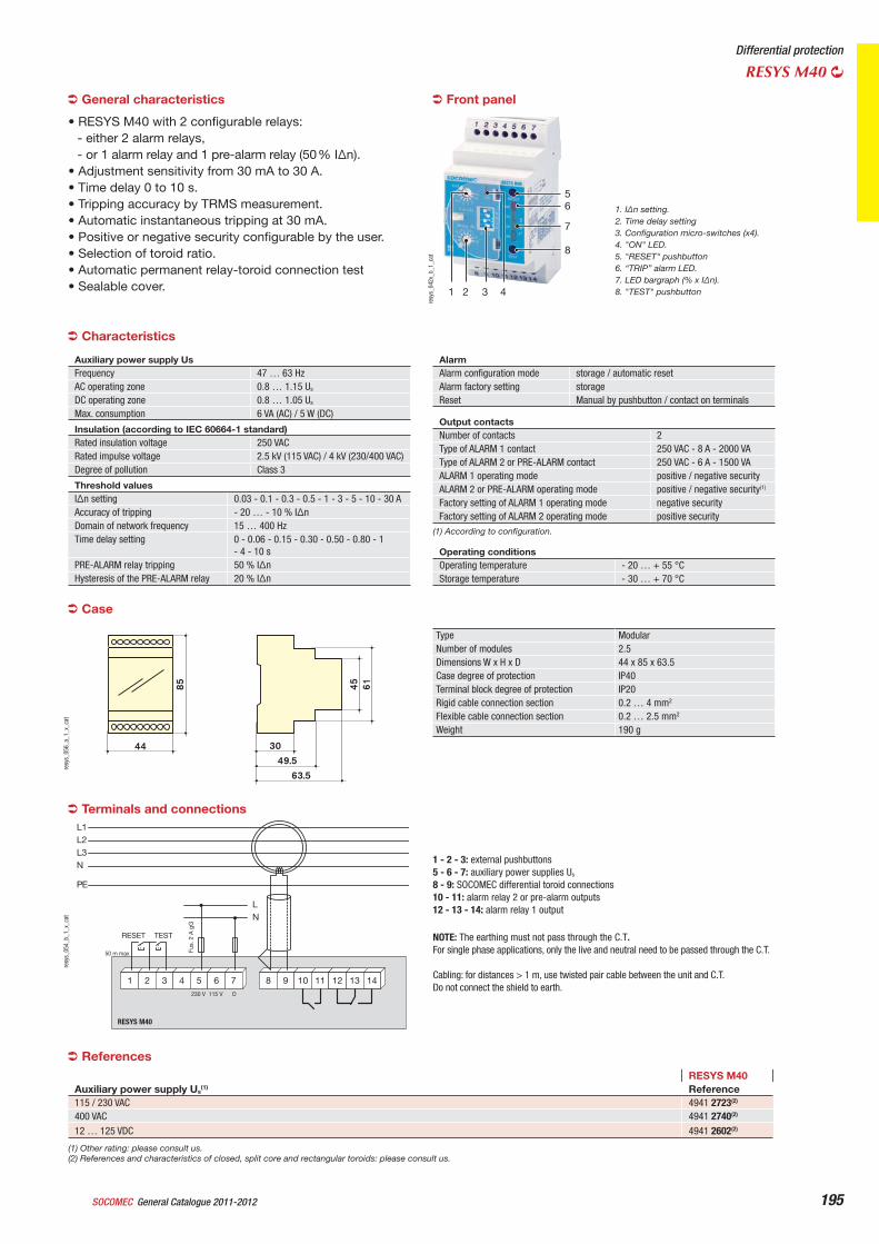
General Catalogue 2011-2012SOCOMEC 195
Differential protection
RESYS M40
Case
Type ModularNumber of modules 2.5Dimensions W x H x D 44 x 85 x 63.5Case degree of protection IP40Terminal block degree of protection IP20Rigid cable connection section 0.2 … 4 mm2
Flexible cable connection section 0.2 … 2.5 mm2
Weight 190 g
85 45 61
44 3049.5
63.5
resy
s_05
6_a_
1_x_
cat
General characteristics
• RESYS M40 with 2 configurable relays: - either 2 alarm relays,- or 1 alarm relay and 1 pre-alarm relay (50 % I n).
• Adjustment sensitivity from 30 mA to 30 A.• Time delay 0 to 10 s.• Tripping accuracy by TRMS measurement.• Automatic instantaneous tripping at 30 mA.• Positive or negative security configurable by the user.• Selection of toroid ratio.• Automatic permanent relay-toroid connection test• Sealable cover.
56
7
8
1 2 43
resy
s_04
2x_b
_1_c
at
1. I n setting.2. Time delay setting3. Configuration micro-switches (x4).4. "ON" LED.5. "RESET" pushbutton6. “TRIP” alarm LED.7. LED bargraph (% x I n).8. "TEST" pushbutton
Front panel
Auxiliary power supply UsFrequency 47 … 63 HzAC operating zone 0.8 … 1.15 Us
DC operating zone 0.8 … 1.05 Us
Max. consumption 6 VA (AC) / 5 W (DC)
Insulation (according to IEC 60664-1 standard)Rated insulation voltage 250 VACRated impulse voltage 2.5 kV (115 VAC) / 4 kV (230/400 VAC) Degree of pollution Class 3
Threshold values I n setting 0.03 - 0.1 - 0.3 - 0.5 - 1 - 3 - 5 - 10 - 30 AAccuracy of tripping - 20 … - 10 % I nDomain of network frequency 15 … 400 HzTime delay setting 0 - 0.06 - 0.15 - 0.30 - 0.50 - 0.80 - 1
- 4 - 10 sPRE-ALARM relay tripping 50 % I nHysteresis of the PRE-ALARM relay 20 % I n
AlarmAlarm configuration mode storage / automatic resetAlarm factory setting storageReset Manual by pushbutton / contact on terminals
Operating conditions Operating temperature - 20 … + 55 °CStorage temperature - 30 … + 70 °C
Characteristics
Output contacts Number of contacts 2Type of ALARM 1 contact 250 VAC - 8 A - 2000 VAType of ALARM 2 or PRE-ALARM contact 250 VAC - 6 A - 1500 VAALARM 1 operating mode positive / negative securityALARM 2 or PRE-ALARM operating mode positive / negative security(1)
Factory setting of ALARM 1 operating mode negative securityFactory setting of ALARM 2 operating mode positive security
(1) According to configuration.
RESYS M40Auxiliary power supply Us
(1) Reference115 / 230 VAC 4941 2723(2)
400 VAC 4941 2740(2)
12 … 125 VDC 4941 2602(2)
(1) Other rating: please consult us.(2) References and characteristics of closed, split core and rectangular toroids: please consult us.
References
RESYS M40
1 2 3 4 5 76 8 9 108 9 10 11 12 1413
LN
Fus.
2 A
gG
RESET TEST
L1L2L3N
PE
230 V
50 m max
115 V O
resy
s_05
4_b_
1_x_
cat
1 - 2 - 3: external pushbuttons5 - 6 - 7: auxiliary power supplies Us
8 - 9: SOCOMEC differential toroid connections10 - 11: alarm relay 2 or pre-alarm outputs12 - 13 - 14: alarm relay 1 output
Terminals and connections
NOTE: The earthing must not pass through the C.T.For single phase applications, only the live and neutral need to be passed through the C.T.
Cabling: for distances > 1 m, use twisted pair cable between the unit and C.T. Do not connect the shield to earth.
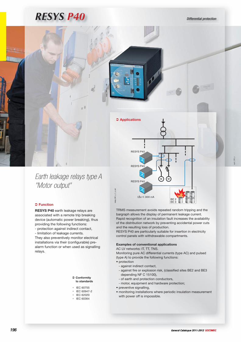
196 General Catalogue 2011-2012 SOCOMEC
RESYS P40 Differential protection
Earth leakage relays type A "Motor output"
Applications
TRMS measurement avoids repeated random tripping and the bargraph allows the display of permanent leakage current.Rapid recognition of an insulation fault increases the availability of the distribution network by preventing accidental power cuts and the resulting loss of production.RESYS P40 are particularly suitable for insertion in electricity control panels with withdrawable compartments.
Examples of conventional applicationsAC LV networks: IT, TT, TNS.Monitoring pure AC differential currents (type AC) and pulsed (type A) to provide the following functions: • protection
- against indirect contact,- against fire or explosion risk, (classified sites BE2 and BE3
depending NF C 15100),- of earth and protection conductors,- motor, equipment and hardware protection;
• preventive signalling,• monitoring installations where periodic insulation measurement
with power off is impossible.
RESYS P40
300 mA
BE 3BE 2
RESYS P40
RESYS P40
resy
s_05
1_c_
1_x_
cat
Function
RESYS P40 earth leakage relays are associated with a remote trip breaking device (automatic power breaking), thus providing the following functions: - protection against indirect contact,- limitation of leakage currents.They also preventively monitor electrical installations via their (configurable) pre-alarm function or when used as signalling relays.
Conformityto standards
IEC 60755IEC 60947-2IEC 62020IEC 60364
••••
resy
s_04
4_b_
1_ca
t
appl
i_26
9_a
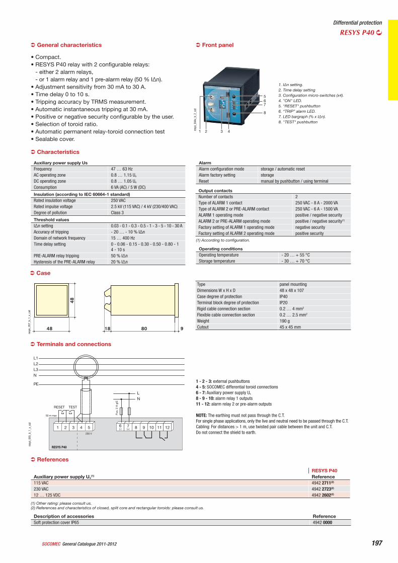
General Catalogue 2011-2012SOCOMEC 197
Differential protection
RESYS P40
1 2 3 4
567
8
resy
s_04
4x_b
_2_c
at
1. I n setting.2. Time delay setting3. Configuration micro-switches (x4).4. "ON" LED.5. "RESET" pushbutton6. “TRIP” alarm LED.7. LED bargraph (% x I n).8. "TEST" pushbutton
Front panelGeneral characteristics
• Compact.• RESYS P40 relay with 2 configurable relays:
- either 2 alarm relays,- or 1 alarm relay and 1 pre-alarm relay (50 % I n).
• Adjustment sensitivity from 30 mA to 30 A.• Time delay 0 to 10 s.• Tripping accuracy by TRMS measurement.• Automatic instantaneous tripping at 30 mA.• Positive or negative security configurable by the user.• Selection of toroid ratio.• Automatic permanent relay-toroid connection test• Sealable cover.
Case
Type panel mountingDimensions W x H x D 48 x 48 x 107Case degree of protection IP40Terminal block degree of protection IP20Rigid cable connection section 0.2 … 4 mm2
Flexible cable connection section 0.2 … 2.5 mm2
Weight 190 gCutout 45 x 45 mm80 948 18
48
resy
s_05
7_b_
1_x_
cat
1 2 3 4 5 8 9 106 7 8 9 10 1211
LN
Fus.
2 A
gG
RESET TEST
L1L2L3N
PE
230 V
50 m max
(+)(-)
RESYS P40resy
s_05
5_b_
1_x_
cat
1 - 2 - 3: external pushbuttons4 - 5: SOCOMEC differential toroid connections6 - 7: Auxiliary power supply Us
8 - 9 - 10: alarm relay 1 outputs11 - 12: alarm relay 2 or pre-alarm outputs
NOTE: The earthing must not pass through the C.T.For single phase applications, only the live and neutral need to be passed through the C.T. Cabling: For distances > 1 m, use twisted pair cable between the unit and C.T.Do not connect the shield to earth.
Terminals and connections
Characteristics
Auxiliary power supply Us Frequency 47 … 63 HzAC operating zone 0.8 … 1.15 Us
DC operating zone 0.8 … 1.05 Us
Consumption 6 VA (AC) / 5 W (DC)
Insulation (according to IEC 60664-1 standard) Rated insulation voltage 250 VACRated impulse voltage 2.5 kV (115 VAC) / 4 kV (230/400 VAC) Degree of pollution Class 3
Threshold values I n setting 0.03 - 0.1 - 0.3 - 0.5 - 1 - 3 - 5 - 10 - 30 AAccuracy of tripping - 20 … - 10 % I nDomain of network frequency 15 … 400 HzTime delay setting 0 - 0.06 - 0.15 - 0.30 - 0.50 - 0.80 - 1
4 - 10 sPRE-ALARM relay tripping 50 % I nHysteresis of the PRE-ALARM relay 20 % I n
AlarmAlarm configuration mode storage / automatic resetAlarm factory setting storageReset manual by pushbutton / using terminal
Operating conditions Operating temperature - 20 … + 55 °CStorage temperature - 30 … + 70 °C
Output contacts Number of contacts 2Type of ALARM 1 contact 250 VAC - 8 A - 2000 VAType of ALARM 2 or PRE-ALARM contact 250 VAC - 6 A - 1500 VAALARM 1 operating mode positive / negative securityALARM 2 or PRE-ALARM operating mode positive / negative security(1)
Factory setting of ALARM 1 operating mode negative securityFactory setting of ALARM 2 operating mode positive security
(1) According to configuration.
Description of accessories ReferenceSoft protection cover IP65 4942 0000
RESYS P40Auxiliary power supply Us
(1) Reference115 VAC 4942 2711(2)
230 VAC 4942 2723(2)
12 … 125 VDC 4942 2602(2)
(1) Other rating: please consult us.(2) References and characteristics of closed, split core and rectangular toroids: please consult us.
References
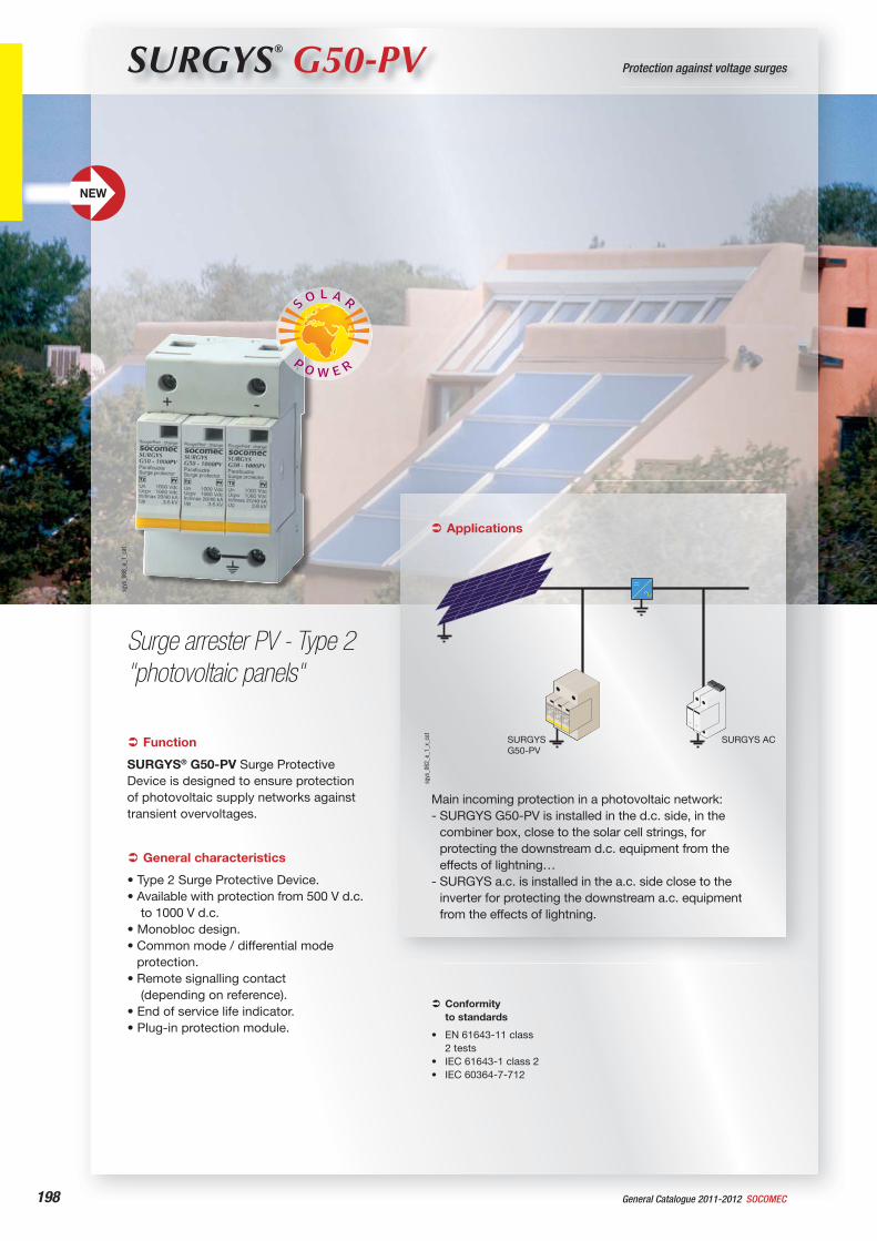
198 General Catalogue 2011-2012 SOCOMEC
SURGYS® G50-PV Protection against voltage surges
Surge arrester PV - Type 2"photovoltaic panels"
sgys
_068
_a_1
_cat
Function
SURGYS® G50-PV Surge Protective Device is designed to ensure protection of photovoltaic supply networks against transient overvoltages.
Conformityto standards
EN 61643-11 class 2 testsIEC 61643-1 class 2IEC 60364-7-712
•
••
General characteristics
• Type 2 Surge Protective Device.• Available with protection from 500 V d.c.
to 1000 V d.c.• Monobloc design.• Common mode / differential mode
protection.• Remote signalling contact
(depending on reference).• End of service life indicator.• Plug-in protection module.
Applications
Main incoming protection in a photovoltaic network:- SURGYS G50-PV is installed in the d.c. side, in the
combiner box, close to the solar cell strings, for protecting the downstream d.c. equipment from the effects of lightning…
- SURGYS a.c. is installed in the a.c. side close to the inverter for protecting the downstream a.c. equipment from the effects of lightning.
SURGYSG50-PV
ACAC
SURGYS AC
sgys
_062
_e_1
_x_c
at
NEW
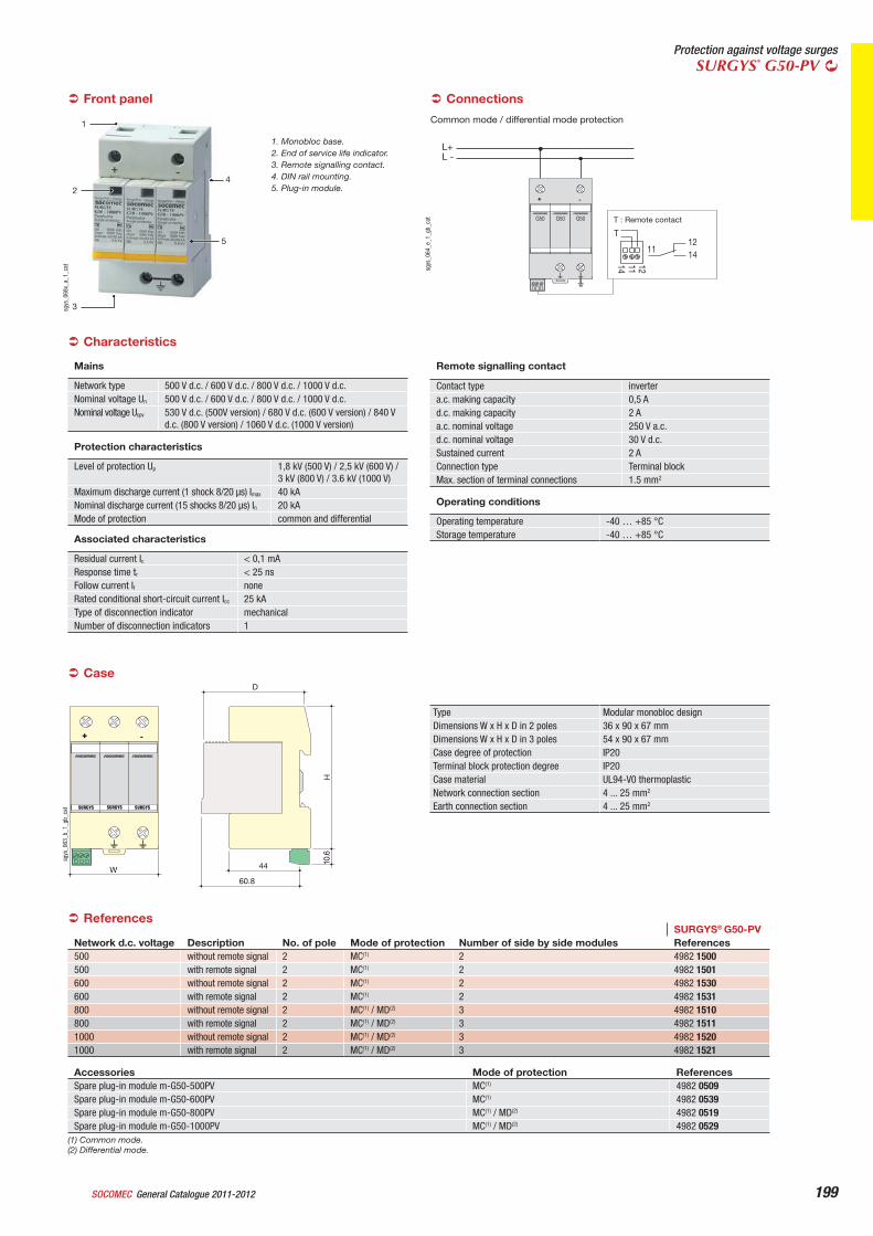
199
Protection against voltage surgesSURGYS® G50-PV
General Catalogue 2011-2012SOCOMEC
1
2
3
4
5
sgys
_068
x_a_
1_ca
t
1. Monobloc base. 2. End of service life indicator.3. Remote signalling contact.4. DIN rail mounting.5. Plug-in module.
Front panel
Mains
Network type 500 V d.c. / 600 V d.c. / 800 V d.c. / 1000 V d.c.Nominal voltage Un 500 V d.c. / 600 V d.c. / 800 V d.c. / 1000 V d.c.Nominal voltage Ucpv 530 V d.c. (500V version) / 680 V d.c. (600 V version) / 840 V
d.c. (800 V version) / 1060 V d.c. (1000 V version)
Protection characteristics
Level of protection Up 1,8 kV (500 V) / 2,5 kV (600 V) / 3 kV (800 V) / 3.6 kV (1000 V)
Maximum discharge current (1 shock 8/20 s) Imax 40 kANominal discharge current (15 shocks 8/20 s) In 20 kAMode of protection common and differential
Associated characteristics
Residual current Ic < 0,1 mAResponse time tr < 25 nsFollow current If noneRated conditional short-circuit current Icc 25 kAType of disconnection indicator mechanicalNumber of disconnection indicators 1
Remote signalling contact
Contact type invertera.c. making capacity 0,5 Ad.c. making capacity 2 Aa.c. nominal voltage 250 V a.c.d.c. nominal voltage 30 V d.c.Sustained current 2 AConnection type Terminal blockMax. section of terminal connections 1.5 mm2
Operating conditions
Operating temperature -40 … +85 °CStorage temperature -40 … +85 °C
Characteristics
Case
Type Modular monobloc designDimensions W x H x D in 2 poles 36 x 90 x 67 mmDimensions W x H x D in 3 poles 54 x 90 x 67 mmCase degree of protection IP20Terminal block protection degree IP20Case material UL94-V0 thermoplasticNetwork connection section 4 ... 25 mm2
Earth connection section 4 ... 25 mm2
W
H10
.6
D
44
60.8
-+
sgys
_063
_b_1
_gb_
cat
L+L -
-+
G50 G50 G50
T121411
121114
T : Remote contact
sgys
_064
_e_1
_gb_
cat
Common mode / differential mode protection
Connections
SURGYS® G50-PVNetwork d.c. voltage Description No. of pole Mode of protection Number of side by side modules References500 without remote signal 2 MC(1) 2 4982 1500500 with remote signal 2 MC(1) 2 4982 1501600 without remote signal 2 MC(1) 2 4982 1530600 with remote signal 2 MC(1) 2 4982 1531800 without remote signal 2 MC(1) / MD(2) 3 4982 1510800 with remote signal 2 MC(1) / MD(2) 3 4982 15111000 without remote signal 2 MC(1) / MD(2) 3 4982 15201000 with remote signal 2 MC(1) / MD(2) 3 4982 1521
References
Accessories Mode of protection ReferencesSpare plug-in module m-G50-500PV MC(1) 4982 0509Spare plug-in module m-G50-600PV MC(1) 4982 0539Spare plug-in module m-G50-800PV MC(1) / MD(2) 4982 0519Spare plug-in module m-G50-1000PV MC(1) / MD(2) 4982 0529
(1) Common mode.(2) Differential mode.
200 SOCOMECGeneral Catalogue 2011-2012
Busbar supports
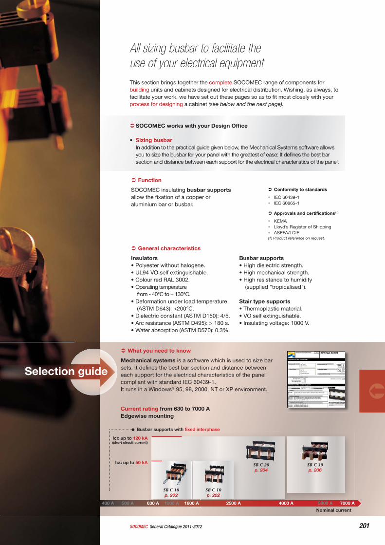
201General Catalogue 2011-2012SOCOMEC
What you need to know
Mechanical systems is a software which is used to size bar sets. It defines the best bar section and distance between each support for the electrical characteristics of the panel compliant with standard IEC 60439-1.It runs in a Windows® 95, 98, 2000, NT or XP environment.
SB C 10p. 202
SB C 10p. 202
SB C 20p. 204
SB C 30p. 206
Current rating from 630 to 7000 AEdgewise mounting
Icc up to 50 kA
Icc up to 120 kA(short circuit current)
Busbar supports with fixed interphase
400 A 500 A 630 A 1000 A 1600 A 2500 A 4000 A 5800 A 7000 A
Nominal current
All sizing busbar to facilitate the use of your electrical equipmentThis section brings together the complete SOCOMEC range of components for building units and cabinets designed for electrical distribution. Wishing, as always, to facilitate your work, we have set out these pages so as to fi t most closely with your process for designing a cabinet (see below and the next page).
SOCOMEC works with your Design Offi ce
• Sizing busbarIn addition to the practical guide given below, the Mechanical Systems software allows you to size the busbar for your panel with the greatest of ease: It defi nes the best bar section and distance between each support for the electrical characteristics of the panel.
Selection guide
Function
SOCOMEC insulating busbar supportsallow the fixation of a copper or aluminium bar or busbar.
General characteristics
Insulators• Polyester without halogene.• UL94 VO self extinguishable.• Colour red RAL 3002.• Operating temperature
from - 40°C to + 130°C.• Deformation under load temperature
(ASTM D643): >200°C.• Dielectric constant (ASTM D150): 4/5.• Arc resistance (ASTM D495): > 180 s.• Water absorption (ASTM D570): 0.3%.
Busbar supports• High dielectric strength.• High mechanical strength.• High resistance to humidity
(supplied "tropicalised").
Stair type supports• Thermoplastic material.• VO self extinguishable.• Insulating voltage: 1000 V.
Approvals and certifications (1)
KEMALloyd’s Register of ShippingASEFA/LCIE
(1) Product reference on request.
•••
Conformity to standards
IEC 60439-1IEC 60865-1
••
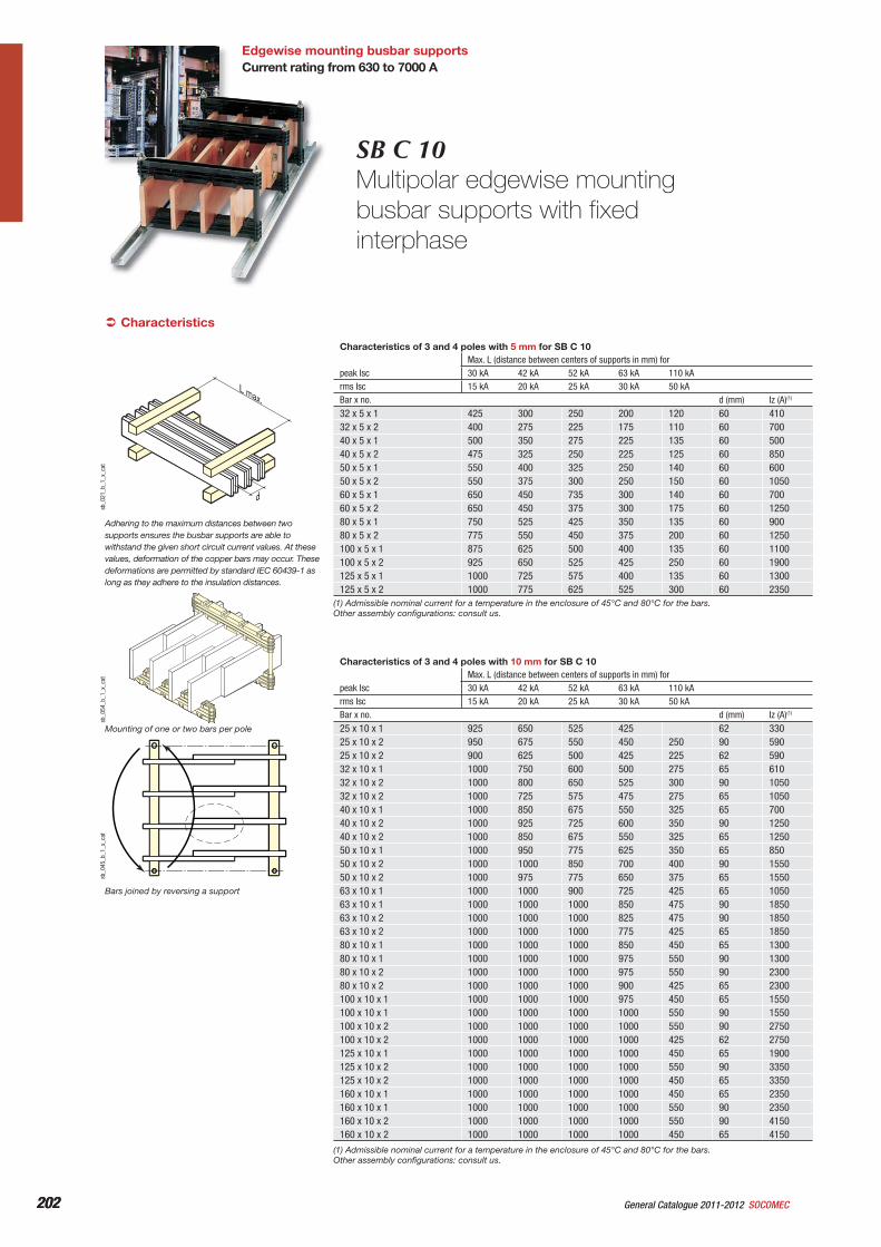
202 General Catalogue 2011-2012 SOCOMEC202
Edgewise mounting busbar supportsCurrent rating from 630 to 7000 A
Characteristics of 3 and 4 poles with 5 mm for SB C 10Max. L (distance between centers of supports in mm) for
peak Isc 30 kA 42 kA 52 kA 63 kA 110 kArms Isc 15 kA 20 kA 25 kA 30 kA 50 kABar x no. d (mm) Iz (A)(1)
32 x 5 x 1 425 300 250 200 120 60 41032 x 5 x 2 400 275 225 175 110 60 70040 x 5 x 1 500 350 275 225 135 60 50040 x 5 x 2 475 325 250 225 125 60 85050 x 5 x 1 550 400 325 250 140 60 60050 x 5 x 2 550 375 300 250 150 60 105060 x 5 x 1 650 450 735 300 140 60 70060 x 5 x 2 650 450 375 300 175 60 125080 x 5 x 1 750 525 425 350 135 60 90080 x 5 x 2 775 550 450 375 200 60 1250100 x 5 x 1 875 625 500 400 135 60 1100100 x 5 x 2 925 650 525 425 250 60 1900125 x 5 x 1 1000 725 575 400 135 60 1300125 x 5 x 2 1000 775 625 525 300 60 2350
Characteristics of 3 and 4 poles with 10 mm for SB C 10Max. L (distance between centers of supports in mm) for
peak Isc 30 kA 42 kA 52 kA 63 kA 110 kArms Isc 15 kA 20 kA 25 kA 30 kA 50 kABar x no. d (mm) Iz (A)(1)
25 x 10 x 1 925 650 525 425 62 33025 x 10 x 2 950 675 550 450 250 90 59025 x 10 x 2 900 625 500 425 225 62 59032 x 10 x 1 1000 750 600 500 275 65 61032 x 10 x 2 1000 800 650 525 300 90 105032 x 10 x 2 1000 725 575 475 275 65 105040 x 10 x 1 1000 850 675 550 325 65 70040 x 10 x 2 1000 925 725 600 350 90 125040 x 10 x 2 1000 850 675 550 325 65 125050 x 10 x 1 1000 950 775 625 350 65 85050 x 10 x 2 1000 1000 850 700 400 90 155050 x 10 x 2 1000 975 775 650 375 65 155063 x 10 x 1 1000 1000 900 725 425 65 105063 x 10 x 1 1000 1000 1000 850 475 90 185063 x 10 x 2 1000 1000 1000 825 475 90 185063 x 10 x 2 1000 1000 1000 775 425 65 185080 x 10 x 1 1000 1000 1000 850 450 65 130080 x 10 x 1 1000 1000 1000 975 550 90 130080 x 10 x 2 1000 1000 1000 975 550 90 230080 x 10 x 2 1000 1000 1000 900 425 65 2300100 x 10 x 1 1000 1000 1000 975 450 65 1550100 x 10 x 1 1000 1000 1000 1000 550 90 1550100 x 10 x 2 1000 1000 1000 1000 550 90 2750100 x 10 x 2 1000 1000 1000 1000 425 62 2750125 x 10 x 1 1000 1000 1000 1000 450 65 1900125 x 10 x 2 1000 1000 1000 1000 550 90 3350125 x 10 x 2 1000 1000 1000 1000 450 65 3350160 x 10 x 1 1000 1000 1000 1000 450 65 2350160 x 10 x 1 1000 1000 1000 1000 550 90 2350160 x 10 x 2 1000 1000 1000 1000 550 90 4150160 x 10 x 2 1000 1000 1000 1000 450 65 4150
Mounting of one or two bars per pole
Characteristics
Adhering to the maximum distances between two supports ensures the busbar supports are able to withstand the given short circuit current values. At these values, deformation of the copper bars may occur. These deformations are permitted by standard IEC 60439-1 as long as they adhere to the insulation distances.
SB C 10Multipolar edgewise mounting busbar supports with fixed interphase
(1) Admissible nominal current for a temperature in the enclosure of 45°C and 80°C for the bars.Other assembly configurations: consult us.
(1) Admissible nominal current for a temperature in the enclosure of 45°C and 80°C for the bars.Other assembly configurations: consult us.
L max.
d
sb_0
21_b
_1_x
_cat
sb_0
54_b
_1_x
_cat
sb_0
45_b
_1_x
_cat
Bars joined by reversing a support
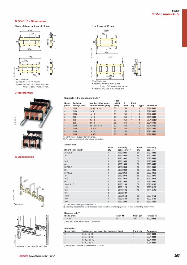
203General Catalogue 2011-2012SOCOMEC 203
BusbarBusbar supports
Accessories
Fixed interphase:• 3 poles 2 x 5, 1 x 10: 75 mm• 4 poles thickness bars. 5 mm: 60 poles
thickness bars. 10 mm: 65 mm.
SB C 10 - Dimensions
Fixed interphase:• 3 poles 1 bar of 10 mm: 75 mm
2 bars of 10 mm per pole: 90 mm• 4 poles 1 or 2 bars of 10 mm 90 mm.
1 or 2 bars of 10 mm2 bars of 5 mm or 1 bar of 10 mm
Supports without nuts and bolts (1)
No. of poles
Isolationvoltage (VAC)
Number of bars max x bar thickness (mm)
R bar height(mm)
B(mm)
Packqty Type Reference
3 1000 2 x 5 / 1 x 10 75 250 1 1 5024 63004 1000 2 x 5 60 250 1 1 5024 65004 1000 1 x 10 65 250 1 1 5024 65003 800 1 x 10 65 250 1 1 5024 64003 800 2 x 10 90 250 1 1 5024 6400(2)
4 800 2 x 10 65 250 1 1 5024 67004 1000 2 x 10 / 2 x 10 90 350 1 2 5024 66004 1000 1 x 6.35 65 253 1 3 5024 15004 1000 1 x 10 65 253 1 3 5024 25004 1000 1 x 6.35 60 253 1 3 5024 4500
sb_1
77_a
_1_x
_cat
Installation corner piece for bar holder
sb_0
94_a
_1_x
_cat
R
250
274
75
R+
66 B
R
250
65
60
20
20
R+
66 B
sb_1
12_e
_1_x
_cat
R
250
274
90
75
sb_1
87_b
_1_x
_cat
37490
35020
R+
66 B
sb_1
78_b
_1_x
_cat
sb_0
61_b
_2_c
at
References
sb_1
74_a
_2_c
at
(1) Content: one support per reference.(2) For interconnection details: please consult us.
Bar holder
Accessories
R bar height (mm)(1)Packqty
Mountingaccessories (2)
Packqty
Insulatingspacers
25 / 25.4 1 5020 2025 50 5020 402530 1 5020 2030 50 5020 403032 1 5020 2032 50 5020 403238.1 1 5020 2038 50 5020 403840 1 5020 2040 50 5020 404050 / 50.8 1 5020 2050 50 5020 405060 1 5020 2060 50 5020 406053 / 63.5 1 5020 2063 50 5020 406370 1 5020 2070 50 5020 407076.2 1 5020 2076 50 5020 407680 1 5020 2080 50 5020 4080100 / 101.6 1 5020 2100 50 5020 4100120 1 5020 2120 50 5020 4120125 1 5020 2125 50 5020 4125127 1 5020 2127152.4 1 5020 2152 50 5020 4152160 1 5020 2160 50 5020 4160200 1 5020 2200 50 5020 4200
(1) Other dimensions: please consult us.(2) Mounting accessories: 2 M8 threaded studs + 2 black insulating spacers + 4 nuts + mounting instructions.
Diamond nuts (1)
H x W (mm) Insert M Pack qty Reference34 x 20 M8 100 5000 0038
(1) Required when mounting on C profile rail.
Bar holder (1)
No. of poles Number of bars max x bar thickness (mm) Pack qty Reference3 2 x 5 / 1 x 10 1 5024 90314 2 x 5 / 1 x 10 1 5024 90413 1 x 10 / 2 x 10 1 5024 90344 1 x 10 / 2 x 10 1 5024 9044
(1) Bar holder: 1 support + 2 M8 screws + 2 nuts.
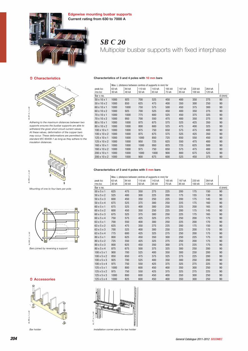
204 General Catalogue 2011-2012 SOCOMEC204
Edgewise mounting busbar supports Current rating from 630 to 7000 A
SB C 20Multipolar busbar supports with fixed interphase
Accessories
Bar holder
Mounting of one to four bars per pole
Installation corner piece for bar holder
Adhering to the maximum distances between two supports ensures the busbar supports are able to withstand the given short circuit current values. At these values, deformation of the copper bars may occur. These deformations are permitted by standard IEC 60439-1 as long as they adhere to the insulation distances.
Characteristics
Bars joined by reversing a support
L max.
d
sb_0
21_b
_1_x
_cat
sb_0
63_a
_1_x
_cat
sb_0
93_a
_1_x
_cat
sb_1
77_a
_1_x
_cat
sb_0
45_b
_1_x
_cat
Characteristics of 3 and 4 poles with 10 mm bars
Max. L (distance between centres of supports in mm) forpeak Iccrms Icc
63 kA30 kA
84 kA40 kA
110 kA50 kA
143 kA65 kA
165 kA75 kA
187 kA85 kA
220 kA100 kA
264 kA120 kA
Bar x no. d (mm)50 x 10 x 1 1000 925 700 525 450 400 350 275 9050 x 10 x 2 1000 850 625 475 400 350 300 250 9060 x 10 x 1 1000 1000 750 575 500 450 375 300 9060 x 10 x 2 1000 925 700 525 450 400 350 275 9070 x 10 x 1 1000 1000 775 600 525 450 375 325 9070 x 10 x 2 1000 950 700 550 475 400 350 275 9080 x 10 x 1 1000 1000 875 675 575 525 425 350 9080 x 10 x 2 1000 1000 800 600 525 475 400 325 90100 x 10 x 1 1000 1000 975 750 650 575 475 400 90100 x 10 x 2 1000 1000 875 675 575 525 425 350 90125 x 10 x 1 1000 1000 1000 850 725 650 550 450 90125 x 10 x 2 1000 1000 950 725 625 550 475 400 90160 x 10 x 1 1000 1000 1000 950 825 725 625 500 90160 x 10 x 2 1000 1000 975 750 650 575 475 400 90200 x 10 x 1 1000 1000 1000 1000 900 800 675 525 90200 x 10 x 2 1000 1000 900 675 600 525 450 375 90
Characteristics of 3 and 4 poles with 5 mm bars
Max. L (distance between centres of supports in mm) forpeak Iccrms Icc
63 kA30 kA
84 kA40 kA
110 kA50 kA
143 kA65 kA
165 kA75 kA
187 kA85 kA
220 kA100 kA
264 kA120 kA
Bar x no. d (mm)50 x 5 x 1 625 475 350 275 225 200 175 150 9050 x 5 x 2 525 400 300 225 200 175 155 130 9050 x 5 x 3 600 450 350 250 225 200 175 145 9050 x 5 x 4 675 525 375 300 250 225 175 160 9060 x 5 x 1 675 525 400 300 250 225 200 165 9060 x 5 x 2 600 450 350 250 225 200 175 145 9060 x 5 x 3 675 525 375 300 250 225 175 165 9060 x 5 x 4 750 575 425 325 275 250 200 175 9063 x 5 x 1 700 550 400 300 250 225 200 170 9063 x 5 x 2 625 475 350 275 225 200 175 150 9063 x 5 x 3 700 525 400 300 250 225 200 170 9063 x 5 x 4 775 600 425 325 275 250 200 175 9080 x 5 x 1 800 625 450 350 300 250 225 175 9080 x 5 x 2 725 550 425 325 275 250 200 175 9080 x 5 x 3 800 625 450 350 300 275 225 175 9080 x 5 x 4 875 675 500 375 325 300 250 200 90100 x 5 x 1 900 700 525 400 350 300 250 200 90100 x 5 x 2 850 650 475 375 325 275 225 200 90100 x 5 x 3 925 700 525 400 350 300 250 200 90100 x 5 x 4 975 750 550 425 375 325 275 225 90125 x 5 x 1 1000 800 600 450 400 350 300 250 90125 x 5 x 2 975 750 550 425 375 325 275 225 90125 x 5 x 3 1000 800 600 450 400 350 300 250 90125 x 5 x 4 1000 825 600 450 400 350 300 250 90
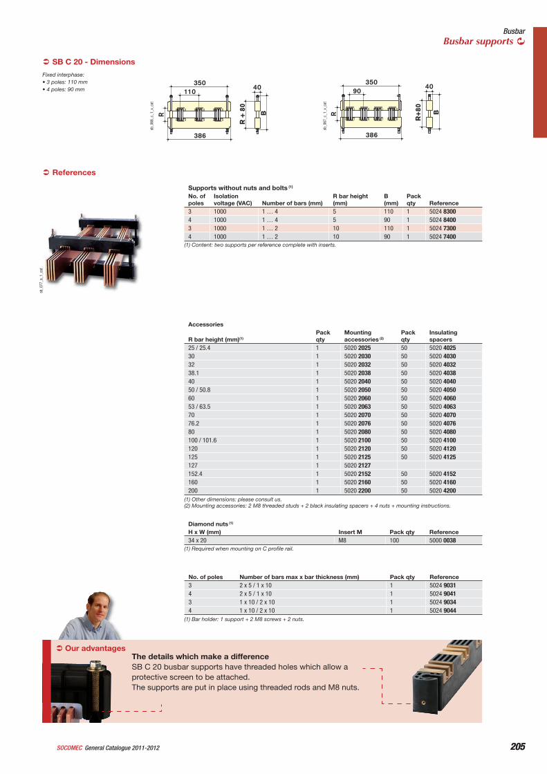
205General Catalogue 2011-2012SOCOMEC 205
BusbarBusbar supports
SB C 20 - Dimensions
Fixed interphase:• 3 poles: 110 mm• 4 poles: 90 mm
Our advantagesThe details which make a differenceSB C 20 busbar supports have threaded holes which allow a protective screen to be attached.The supports are put in place using threaded rods and M8 nuts.
R
35040
110
386
R +
80
B
sb_0
66_c
_1_x
_cat
R
35090
386
40
R+
80 B
sb_0
67_c
_1_x
_cat
sb_0
77_a
_1_c
at
References
Supports without nuts and bolts (1)
No. of poles
Isolationvoltage (VAC) Number of bars (mm)
R bar height (mm)
B(mm)
Packqty Reference
3 1000 1 … 4 5 110 1 5024 83004 1000 1 … 4 5 90 1 5024 84003 1000 1 … 2 10 110 1 5024 73004 1000 1 … 2 10 90 1 5024 7400
(1) Content: two supports per reference complete with inserts.
Accessories
R bar height (mm)(1)Packqty
Mountingaccessories (2)
Packqty
Insulatingspacers
25 / 25.4 1 5020 2025 50 5020 402530 1 5020 2030 50 5020 403032 1 5020 2032 50 5020 403238.1 1 5020 2038 50 5020 403840 1 5020 2040 50 5020 404050 / 50.8 1 5020 2050 50 5020 405060 1 5020 2060 50 5020 406053 / 63.5 1 5020 2063 50 5020 406370 1 5020 2070 50 5020 407076.2 1 5020 2076 50 5020 407680 1 5020 2080 50 5020 4080100 / 101.6 1 5020 2100 50 5020 4100120 1 5020 2120 50 5020 4120125 1 5020 2125 50 5020 4125127 1 5020 2127152.4 1 5020 2152 50 5020 4152160 1 5020 2160 50 5020 4160200 1 5020 2200 50 5020 4200
(1) Other dimensions: please consult us.(2) Mounting accessories: 2 M8 threaded studs + 2 black insulating spacers + 4 nuts + mounting instructions.
Diamond nuts (1)
H x W (mm) Insert M Pack qty Reference34 x 20 M8 100 5000 0038
(1) Required when mounting on C profile rail.
No. of poles Number of bars max x bar thickness (mm) Pack qty Reference3 2 x 5 / 1 x 10 1 5024 90314 2 x 5 / 1 x 10 1 5024 90413 1 x 10 / 2 x 10 1 5024 90344 1 x 10 / 2 x 10 1 5024 9044
(1) Bar holder: 1 support + 2 M8 screws + 2 nuts.
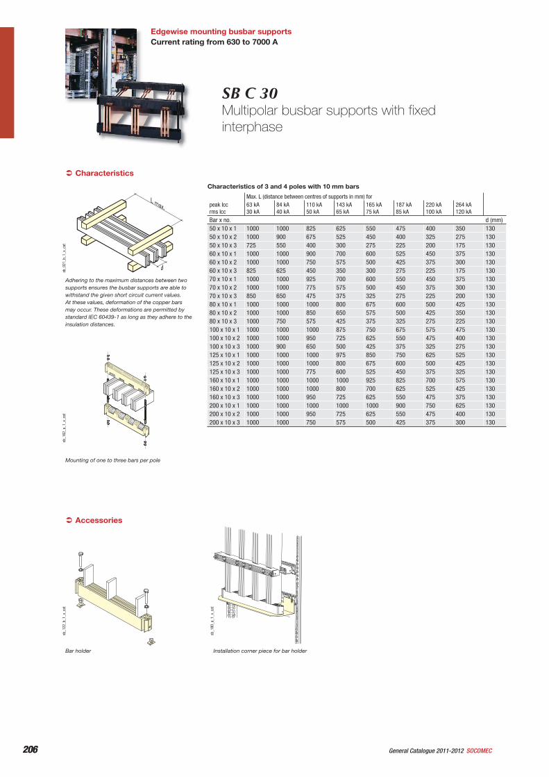
206 General Catalogue 2011-2012 SOCOMEC206
Edgewise mounting busbar supportsCurrent rating from 630 to 7000 A
SB C 30Multipolar busbar supports with fixed interphase
Characteristics
Mounting of one to three bars per pole
Accessories
Bar holder Installation corner piece for bar holder
L max.
dsb_0
21_b
_1_x
_cat
sb_1
62_a
_1_x
_cat
sb_1
22_b
_1_x
_cat
sb_1
80_a
_1_x
_cat
Adhering to the maximum distances between two supports ensures the busbar supports are able to withstand the given short circuit current values. At these values, deformation of the copper bars may occur. These deformations are permitted by standard IEC 60439-1 as long as they adhere to the insulation distances.
Max. L (distance between centres of supports in mm) forpeak Iccrms Icc
63 kA30 kA
84 kA40 kA
110 kA50 kA
143 kA65 kA
165 kA75 kA
187 kA85 kA
220 kA100 kA
264 kA120 kA
Bar x no. d (mm)50 x 10 x 1 1000 1000 825 625 550 475 400 350 13050 x 10 x 2 1000 900 675 525 450 400 325 275 13050 x 10 x 3 725 550 400 300 275 225 200 175 13060 x 10 x 1 1000 1000 900 700 600 525 450 375 13060 x 10 x 2 1000 1000 750 575 500 425 375 300 13060 x 10 x 3 825 625 450 350 300 275 225 175 13070 x 10 x 1 1000 1000 925 700 600 550 450 375 13070 x 10 x 2 1000 1000 775 575 500 450 375 300 13070 x 10 x 3 850 650 475 375 325 275 225 200 13080 x 10 x 1 1000 1000 1000 800 675 600 500 425 13080 x 10 x 2 1000 1000 850 650 575 500 425 350 13080 x 10 x 3 1000 750 575 425 375 325 275 225 130100 x 10 x 1 1000 1000 1000 875 750 675 575 475 130100 x 10 x 2 1000 1000 950 725 625 550 475 400 130100 x 10 x 3 1000 900 650 500 425 375 325 275 130125 x 10 x 1 1000 1000 1000 975 850 750 625 525 130125 x 10 x 2 1000 1000 1000 800 675 600 500 425 130125 x 10 x 3 1000 1000 775 600 525 450 375 325 130160 x 10 x 1 1000 1000 1000 1000 925 825 700 575 130160 x 10 x 2 1000 1000 1000 800 700 625 525 425 130160 x 10 x 3 1000 1000 950 725 625 550 475 375 130200 x 10 x 1 1000 1000 1000 1000 1000 900 750 625 130200 x 10 x 2 1000 1000 950 725 625 550 475 400 130200 x 10 x 3 1000 1000 750 575 500 425 375 300 130
Characteristics of 3 and 4 poles with 10 mm bars
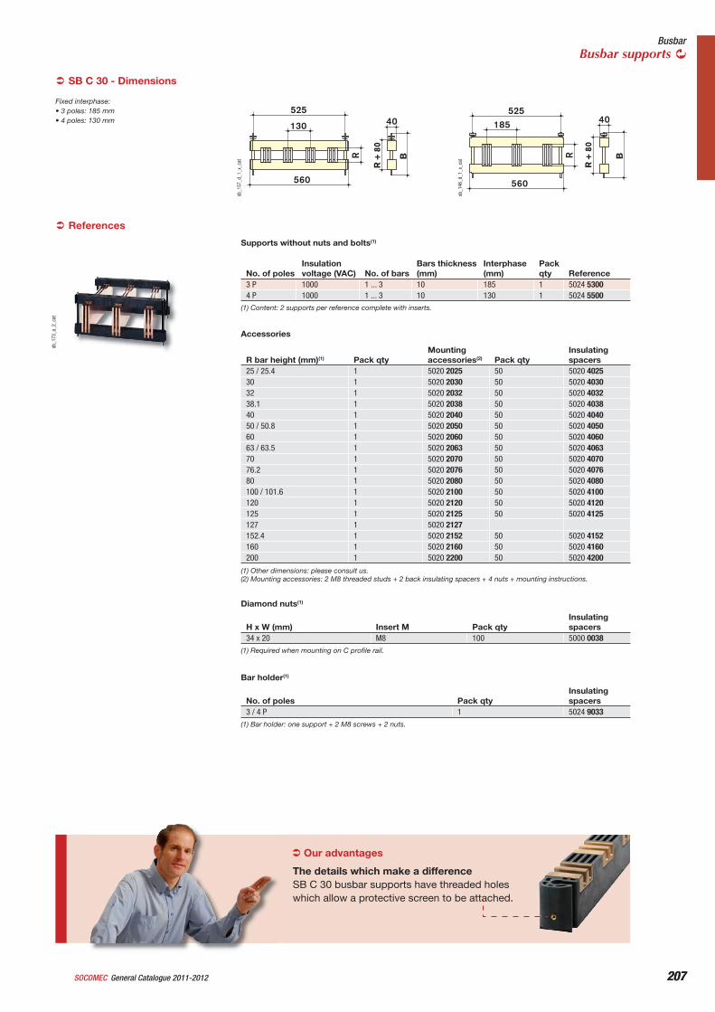
207General Catalogue 2011-2012SOCOMEC 207
BusbarBusbar supports
Fixed interphase:• 3 poles: 185 mm• 4 poles: 130 mm
SB C 30 - Dimensions
Our advantages
The details which make a differenceSB C 30 busbar supports have threaded holes which allow a protective screen to be attached.
sb_1
73_a
_2_c
at
525
560
185
R
40
B
R +
80
sb_1
46_d
_1_x
_cat
525
560
R +
80
130 40
R B
sb_1
57_d
_1_x
_cat
References
R bar height (mm)(1) Pack qtyMountingaccessories(2) Pack qty
Insulatingspacers
25 / 25.4 1 5020 2025 50 5020 402530 1 5020 2030 50 5020 403032 1 5020 2032 50 5020 403238.1 1 5020 2038 50 5020 403840 1 5020 2040 50 5020 404050 / 50.8 1 5020 2050 50 5020 405060 1 5020 2060 50 5020 406063 / 63.5 1 5020 2063 50 5020 406370 1 5020 2070 50 5020 407076.2 1 5020 2076 50 5020 407680 1 5020 2080 50 5020 4080100 / 101.6 1 5020 2100 50 5020 4100120 1 5020 2120 50 5020 4120125 1 5020 2125 50 5020 4125127 1 5020 2127152.4 1 5020 2152 50 5020 4152160 1 5020 2160 50 5020 4160200 1 5020 2200 50 5020 4200
Accessories
No. of polesInsulationvoltage (VAC) No. of bars
Bars thickness (mm)
Interphase(mm)
Packqty Reference
3 P 1000 1 ... 3 10 185 1 5024 53004 P 1000 1 ... 3 10 130 1 5024 5500
(1) Content: 2 supports per reference complete with inserts.
Supports without nuts and bolts(1)
(1) Other dimensions: please consult us.(2) Mounting accessories: 2 M8 threaded studs + 2 back insulating spacers + 4 nuts + mounting instructions.
Diamond nuts(1)
H x W (mm) Insert M Pack qtyInsulatingspacers
34 x 20 M8 100 5000 0038(1) Required when mounting on C profile rail.
Bar holder(1)
No. of poles Pack qtyInsulatingspacers
3 / 4 P 1 5024 9033(1) Bar holder: one support + 2 M8 screws + 2 nuts.
208 SOCOMECGeneral Catalogue 2011-2012
Integrated products
209General Catalogue 2011-2012SOCOMEC
Enclosures equipped with breaking or protection functions
p. 216
SOSE enclosuresp. 210
When they are not mounted in cabinets, load break switches, changeover switches or fuse combination switches are generally delivered enclosed. Placed as close as possible to the operator, their function is to guarantee his or her safety and to ensure continuity of operation.
For local safety breaking purposes, SOCOMEC - leader in this fi eld - offers the widest range of equipped enclosures on the market. This dual expertise means we can offer you complete systems to meet your specifi c requirements (normal or explosive atmosphere).
The result of many years building on our experience, our enclosures are quickand easy to fi t. These enable personnel who are not electricians to carry out work on the installation without risk of error and in complete safety, whilst adhering to the rules for ensuring safe electrical lockout.
Our services are regularly sought to create enclosures or boards according to specifi cation. If this is of interest to you, please consult us.
Do not hesitate to make the most of our expertise! To fi nd out more, please contact your SOCOMEC offi ce.
ATEX enclosuresp. 216
I N N O V A T I O N
Type-S handles
ATS By-Pass solution
Safety enclosuresSteel
Selection guide
Customised solutions
p. 216
FOSE enclosures p. 210
Need a suggestion? We will help you fi nd the best solution for your application.
A special requirement?SOCOMEC makes specifi c products. Please feel free to consult us.
For explosive atmospheres
ATS By-Pass solutionp. 216
40 A 3200 A
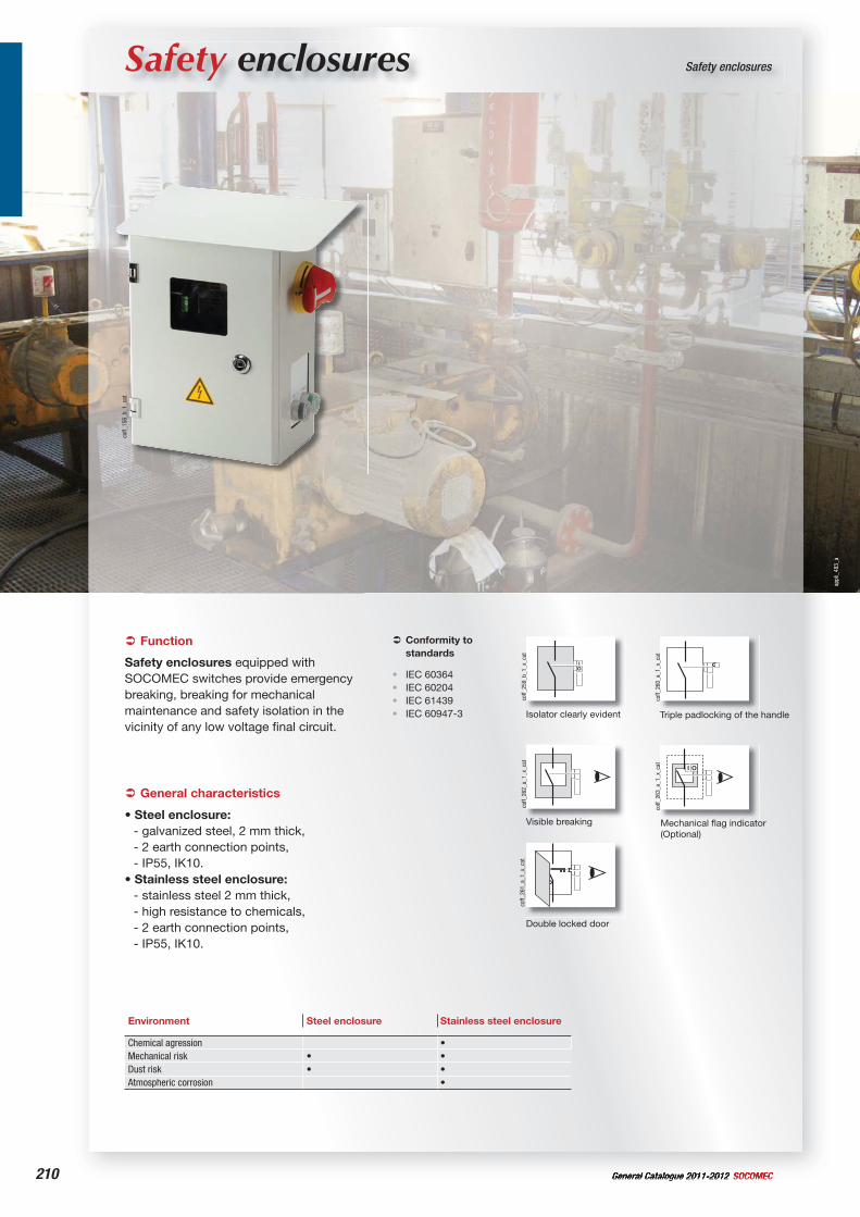
210 General Catalogue 2011-2012 SOCOMEC
Safety enclosures Safety enclosures
General characteristics
• Steel enclosure:- galvanized steel, 2 mm thick, - 2 earth connection points,- IP55, IK10.
• Stainless steel enclosure:- stainless steel 2 mm thick,- high resistance to chemicals,- 2 earth connection points,- IP55, IK10.
Environment Steel enclosure Stainless steel enclosure
Chemical agression • Mechanical risk • •Dust risk • •Atmospheric corrosion •
coff_
156_
b_1_
cat
Function
Safety enclosures equipped with SOCOMEC switches provide emergency breaking, breaking for mechanical maintenance and safety isolation in the vicinity of any low voltage final circuit.
Conformity to standards
IEC 60364IEC 60204IEC 61439IEC 60947-3
••••
IO
coff_
259_
b_1_
x_ca
t
coff_
260_
a_1_
x_ca
t
coff_
261_
a_1_
x_ca
tco
ff_26
2_a_
1_x_
cat
OI
coff_
263_
a_1_
x_ca
t
Isolator clearly evident Triple padlocking of the handle
Double locked door
Visible breaking Mechanical flag indicator (Optional)
appl
i_48
3_a
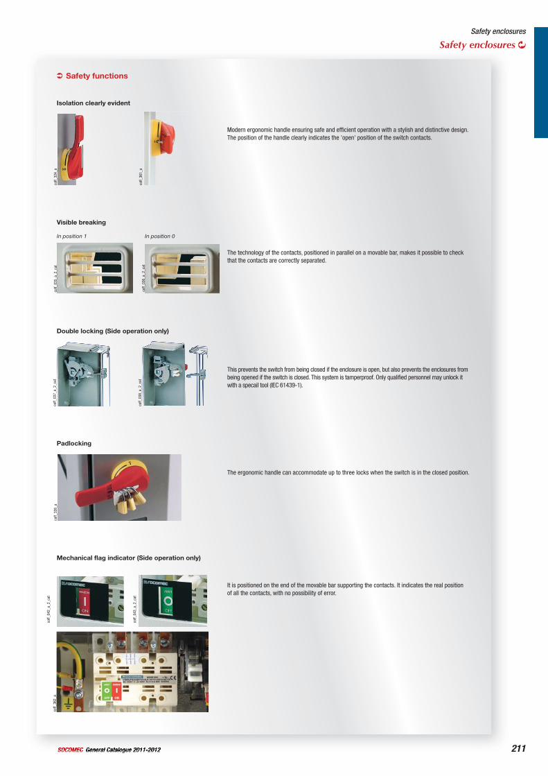
211General Catalogue 2011-2012SOCOMEC
Safety enclosures
Safety enclosures
Padlocking
coff_
326_
a
The ergonomic handle can accommodate up to three locks when the switch is in the closed position.
Double locking (Side operation only)
coff_
037_
a_2_
cat
coff_
038_
a_2_
cat
This prevents the switch from being closed if the enclosure is open, but also prevents the enclosures from being opened if the switch is closed. This system is tamperproof. Only qualified personnel may unlock it with a specail tool (IEC 61439-1).
Visible breaking
coff_
035_
a_2_
cat
In position 1
coff_
036_
a_2_
cat
In position 0
The technology of the contacts, positioned in parallel on a movable bar, makes it possible to check that the contacts are correctly separated.
Mechanical flag indicator (Side operation only)
coff_
362_
a
coff_
042_
a_2_
cat
coff_
043_
a_2_
cat
It is positioned on the end of the movable bar supporting the contacts. It indicates the real position of all the contacts, with no possibility of error.
Safety functions
Isolation clearly evident
coff_
324_
a
Modern ergonomic handle ensuring safe and efficient operation with a stylish and distinctive design.The position of the handle clearly indicates the 'open' position of the switch contacts.
coff_
361_
a
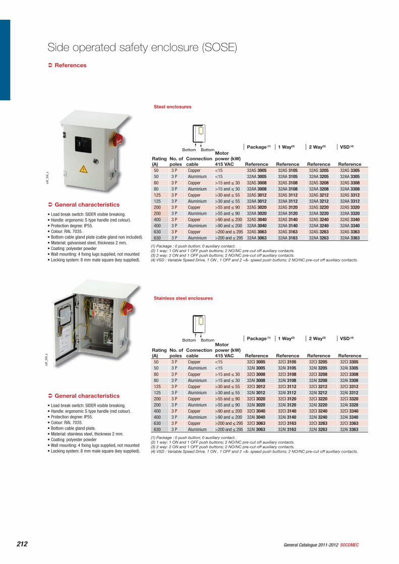
General Catalogue 2011-2012 SOCOMEC212
Steel enclosures
Package (1) 1 Way(2) 2 Way(3) VSD (4)
Rating(A)
No. of poles
Connectioncable
Motorpower (kW) 415 VAC Reference Reference Reference Reference
50 3 P Copper <15 32AS 3005 32AS 3105 32AS 3205 32AS 330550 3 P Aluminium <15 32AA 3005 32AA 3105 32AA 3205 32AA 330580 3 P Copper >15 and 30 32AS 3008 32AS 3108 32AS 3208 32AS 330880 3 P Aluminium >15 and 30 32AA 3008 32AA 3108 32AA 3208 32AA 3308125 3 P Copper >30 and 55 32AS 3012 32AS 3112 32AS 3212 32AS 3312125 3 P Aluminium >30 and 55 32AA 3012 32AA 3112 32AA 3212 32AA 3312200 3 P Copper >55 and 90 32AS 3020 32AS 3120 32AS 3220 32AS 3320200 3 P Aluminium >55 and 90 32AA 3020 32AA 3120 32AA 3220 32AA 3320400 3 P Copper >90 and 200 32AS 3040 32AS 3140 32AS 3240 32AS 3340400 3 P Aluminium >90 and 200 32AA 3040 32AA 3140 32AA 3240 32AA 3340630 3 P Copper >200 and 295 32AS 3063 32AS 3163 32AS 3263 32AS 3363630 3 P Aluminium >200 and 295 32AA 3063 32AA 3163 32AA 3263 32AA 3363
(1) Package : 0 push button; 0 auxiliary contact.(2) 1 way: 1 ON and 1 OFF push buttons; 2 NO/NC pre-cut off auxiliary contacts.(3) 2 way: 2 ON and 1 OFF push buttons; 2 NO/NC pre-cut off auxiliary contacts.(4) VSD : Variable Speed Drive, 1 ON , 1 OFF and 2 +&- speed push buttons; 2 NO/NC pre-cut off auxiliary contacts.
coff_
359_
aco
ff_35
8_a
References
Side operated safety enclosure (SOSE)
• Load break switch: SIDER visible breaking.• Handle: ergonomic S type handle (red colour).• Protection degree: IP55.• Colour: RAL 7035.• Bottom cable gland plate (cable gland non included).• Material: galvanised steel, thickness 2 mm.• Coating: polyester powder• Wall mounting: 4 fixing lugs supplied, not mounted• Locking system: 8 mm male square (key supplied).
General characteristics
Stainless steel enclosures
Package (1) 1 Way(2) 2 Way(3) VSD (4)
Rating(A)
No. of poles
Connectioncable
Motorpower (kW) 415 VAC Reference Reference Reference Reference
50 3 P Copper <15 32CI 3005 32CI 3105 32CI 3205 32CI 330550 3 P Aluminium <15 32AI 3005 32AI 3105 32AI 3205 32AI 330580 3 P Copper >15 and 30 32CI 3008 32CI 3108 32CI 3208 32CI 330880 3 P Aluminium >15 and 30 32AI 3008 32AI 3108 32AI 3208 32AI 3308125 3 P Copper >30 and 55 32CI 3012 32CI 3112 32CI 3212 32CI 3312125 3 P Aluminium >30 and 55 32AI 3012 32AI 3112 32AI 3212 32AI 3312200 3 P Copper >55 and 90 32CI 3020 32CI 3120 32CI 3220 32CI 3320200 3 P Aluminium >55 and 90 32AI 3020 32AI 3120 32AI 3220 32AI 3320400 3 P Copper >90 and 200 32CI 3040 32CI 3140 32CI 3240 32CI 3340400 3 P Aluminium >90 and 200 32AI 3040 32AI 3140 32AI 3240 32AI 3340630 3 P Copper >200 and 295 32CI 3063 32CI 3163 32CI 3263 32CI 3363630 3 P Aluminium >200 and 295 32AI 3063 32AI 3163 32AI 3263 32AI 3363
(1) Package : 0 push button; 0 auxiliary contact.(2) 1 way: 1 ON and 1 OFF push buttons; 2 NO/NC pre-cut off auxiliary contacts.(3) 2 way: 2 ON and 1 OFF push buttons; 2 NO/NC pre-cut off auxiliary contacts.(4) VSD : Variable Speed Drive, 1 ON , 1 OFF and 2 +&- speed push buttons; 2 NO/NC pre-cut off auxiliary contacts.
Bottom Bottom
Bottom Bottom
• Load break switch: SIDER visible breaking.• Handle: ergonomic S type handle (red colour).• Protection degree: IP55.• Colour: RAL 7035.• Bottom cable gland plate.• Material: stainless steel, thickness 2 mm.• Coating: polyester powder• Wall mounting: 4 fixing lugs supplied, not mounted• Locking system: 8 mm male square (key supplied).
General characteristics
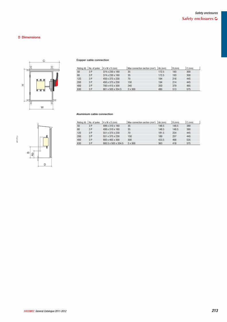
General Catalogue 2011-2012SOCOMEC 213
C
W
H
BA
b
D
coff_
372_
a
Copper cable connection
Rating (A) No. of poles H x W x D (mm) Max connection section (mm2) Ab (mm) B (mm) C (mm)50 3 P 374 x 230 x 160 35 172.5 193 30080 3 P 374 x 230 x 160 35 172.5 193 300125 3 P 450 x 375 x 230 70 194 216 445200 3 P 450 x 375 x 230 150 194 214 445400 3 P 700 x 415 x 300 240 350 379 485630 3 P 901 x 505 x 354.5 2 x 300 480 513 575
Dimensions
Safety enclosures
Safety enclosures
Aluminium cable connection
Rating (A) No. of poles H x W x D (mm) Max connection section (mm2) Ab (mm) B (mm) C (mm)50 3 P 499 x 310 x 160 35 148.5 148.5 38080 3 P 499 x 310 x 160 35 148.5 148.5 380125 3 P 551 x 375 x 230 70 181.5 254 445200 3 P 551 x 375 x 230 150 189 257 445400 3 P 900 x 465 x 300 300 423.5 468 535630 3 P 900.5 x 505 x 354.5 2 x 300 363 418 575
General Catalogue 2011-2012 SOCOMEC214
Steel enclosures
Package (1) 1 Way(2) 2 Way(3) VSD (4)
Rating(A)
No. of poles
Connectioncable
Motorpower (kW) 415 VAC Reference Reference Reference Reference
50 3 P Copper <15 33CA 3005 33CA 3105 33CA 3205 33CA 330550 3 P Aluminium <15 33AA 3005 33AA 3105 33AA 3205 33AA 330580 3 P Copper >15 and 30 33CA 3008 33CA 3108 33CA 3208 33CA 330880 3 P Aluminium >15 and 30 33AA 3008 33AA 3108 33AA 3208 33AA 3308125 3 P Copper >30 and 55 33CA 3012 33CA 3112 33CA 3212 33CA 3312125 3 P Aluminium >30 and 55 33AA 3012 33AA 3112 33AA 3212 33AA 3312200 3 P Copper >55 and 90 33CA 3020 33CA 3120 33CA 3220 33CA 3320200 3 P Aluminium >55 and 90 33AA 3020 33AA 3120 33AA 3220 33AA 3320400 3 P Copper >90 and 200 33CA 3040 33CA 3140 33CA 3240 33CA 3340400 3 P Aluminium >90 and 200 33AA 3040 33AA 3140 33AA 3240 33AA 3340630 3 P Copper >200 and 295 33CA 3063 33CA 3163 33CA 3263 33CA 3363630 3 P Aluminium >200 and 295 33AA 3063 33AA 3163 33AA 3263 33AA 3363
(1) Package : 0 push button; 0 auxiliary contact.(2) 1 way: 1 ON and 1 OFF push buttons; 2 NO/NC pre-cut off auxiliary contacts.(3) 2 way: 2 ON and 1 OFF push buttons; 2 NO/NC pre-cut off auxiliary contacts.(4) VSD : Variable Speed Drive, 1 ON , 1 OFF and 2 +&- speed push buttons; 2 NO/NC pre-cut off auxiliary contacts.
coff_
375_
a
coff_
374_
a
References
Front operated safety enclosure (FOSE)
• Load break switch: SIRCO M (50 A & 80 A), SIRCO (> 80 A).
• Handle: ergonomic S type handle (red colour).• Protection degree: IP55.• Colour: RAL 7035.• Bottom cable gland plate.• Material: galvanised steel, thickness 2 mm.• Coating: polyester powder• Wall mounting: 4 fixing lugs supplied, not mounted• Locking system: 8 mm male square (key supplied).
General characteristics
Stainless steel enclosures
Package (1) 1 Way(2) 2 Way(3) VSD (4)
Rating(A)
No. of poles
Connectioncable
Motorpower (kW) 415 VAC Reference Reference Reference Reference
50 3 P Copper <15 33CI 3005 33CI 3105 33CI 3205 33CI 330550 3 P Aluminium <15 33AI 3005 33AI 3105 33AI 3205 33AI 330580 3 P Copper >15 and 30 33CI 3008 33CI 3108 33CI 3208 33CI 330880 3 P Aluminium >15 and 30 33AI 3008 33AI 3108 33AI 3208 33AI 3308125 3 P Copper >30 and 55 33CI 3012 33CI 3112 33CI 3212 33CI 3312125 3 P Aluminium >30 and 55 33AI 3012 33AI 3112 33AI 3212 33AI 3312200 3 P Copper >55 and 90 33CI 3020 33CI 3120 33CI 3220 33CI 3320200 3 P Aluminium >55 and 90 33AI 3020 33AI 3120 33AI 3220 33AI 3320400 3 P Copper >90 and 200 33CI 3040 33CI 3140 33CI 3240 33CI 3340400 3 P Aluminium >90 and 200 33AI 3040 33AI 3140 33AI 3240 33AI 3340630 3 P Copper >200 and 295 33CI 3063 33CI 3163 33CI 3263 33CI 3363630 3 P Aluminium >200 and 295 33AI 3063 33AI 3163 33AI 3263 33AI 3363
(1) Package : 0 push button; 0 auxiliary contact.(2) 1 way: 1 ON and 1 OFF push buttons; 2 NO/NC pre-cut off auxiliary contacts.(3) 2 way: 2 ON and 1 OFF push buttons; 2 NO/NC pre-cut off auxiliary contacts.(4) VSD : Variable Speed Drive, 1 ON , 1 OFF and 2 +&- speed push buttons; 2 NO/NC pre-cut off auxiliary contacts.
Bottom Bottom
Bottom Bottom
• Load break switch: SIRCO M (50 A & 80 A), SIRCO (> 80 A).
• Handle: ergonomic S type handle (red colour).• Protection degree: IP55.• Colour: RAL 7035.• Bottom cable gland plate.• Material: stainless steel, thickness 2 mm.• Coating: polyester powder• Wall mounting: 4 fixing lugs supplied, not mounted• Locking system: 8 mm male square (key supplied).
General characteristics
General Catalogue 2011-2012SOCOMEC 215
BA
b
W
D
H
coff_
373_
a
Copper cable connection
Rating (A) No. of poles H x W x D (mm) Max connection section (mm2) Ab (mm) B (mm)50 3 P 452 x 300 x 160 35 154 15480 3 P 453 x 300 x 160 35 154 154125 3 P 600 x 375 x 230 50 265 392200 3 P 601 x 375 x 230 95 265 379.5400 3 P 901 x 505 x 354.5 240 395.5 550630 3 P 902 x 505 x 354.5 2 x 300 395.5 542.5
Dimensions
Safety enclosures
Safety enclosures
Aluminium cable connection
Rating (A) No. of poles H x W x D (mm) Max connection section (mm2) Ab (mm) B (mm)50 3 P 452 x 300 x 160 35 154 15480 3 P 453 x 300 x 160 35 154 154125 3 P 600 x 375 x 230 70 265 312.5200 3 P 601 x 375 x 230 150 265 304.5400 3 P 901 x 505 x 354.5 300 395.5 441630 3 P 902 x 505 x 354.5 2 x 300 395.5 448.5
216 General Catalogue 2011-2012 SOCOMEC
ATEX enclosures Safety enclosures
logo
_29_
00
logo
_115
_00
coff_
280_
b_1_
cat
Function
ATEX enclosures equipped with SOCOMEC switches provide emergency breaking, breaking for mechanical maintenance and safety isolation in the vicinity of any low voltage final circuit. Installed in an explosive area.
They offer the following features: • fully visible breaking• visible breaking• triple locking of the handle• double locked door, side operation• mechanical flag indicator
Conformity to standards
Directive 94/9/CEEN 50 281-1-1EN 50 281-1-2EN 50014EN 60204-1EN 60439-1EN 60695-2-11EN 60947-3NF C 15-100IEC 60364Decree 29.07.92:Machine safetyDecree n°88-1056 from 14-11-88:protection of workersDecree n°96-1010 from 19.11.96Decree 11.01.93:particularly for compliance with the machine
•••••••••••
•
•
•
Zone 21 and 22 (dust) as per European Directive ATEX 94/9/CE Category 2
IO
coff_
259_
b_1_
x_ca
t
coff_
260_
a_1_
x_ca
t
coff_
261_
a_1_
x_ca
tco
ff_26
2_a_
1_x_
cat
OI
coff_
263_
a_1_
x_ca
t
Isolation clearly evident Triple padlocking of the handle
Double locked door
Visible breaking Mechanical flag indicator (Optional)
site
_260
_a
General Catalogue 2011-2012SOCOMEC 217
SIDER steel enclosure, side operation
Safety enclosures
ATEX enclosures
Connectionbottom/bottom
Rating (A) No. of poles Reference50 3 P 3V41 300550 4 P 3V41 400580 3 P 3V41 300880 4 P 3V41 400880 6 P 3V41 6008125 3 P 3V51 3012125 4 P 3V51 4012160 6 P 3V51 6020200 3 P 3V51 3020200 4 P 3V51 4020400 3 P 3V51 3040400 4 P 3V51 4040630 3 P 3V51 3063630 4 P 3V51 4063
References
ConnectionBottom/Bottom
Rating (A)
No. of poles H x W x D (mm)
Max. connectionsection (mm2)
Ab(mm)
B1(mm)
Weight (kg)
50 3/4 P 350 x 225 x 150 16 288 198 8.280 3/4 P 350 x 225 x 150 35 288 198 8.480 6 P 500 x 425 x 200 35 288 198 25125 3/4 P 500 x 425 x 200 120 225 15160 6 P 500 x 425 x 200 120 242 275 25200 3/4 P 500 x 425 x 200 120 242 275 21.5400 3/4 P 700 x 500 x 250 2 x 150 340 385 34.5630 3/4 P 700 x 500 x 300 2 x 300 262 313 47
D
Ab
H
W (1)
B1
coff_
289_
c_1_
gb_c
at
(1) 50 … 400 A: 45 mm630 A: 61 mm
Cable gland ATEX
coff_
283_
a_1_
cat
coff_
329_
a_1_
cat
Black polyamideCable gland Locknut
Diameter (mm)
Min. cable diameter (mm)
Max. cable diameter (mm) Reference Reference
12 3.5 6 3240 1012 3240 301216 5 8 3240 1016 3240 301616 6 10 3240 101720 8 13 3240 1020 3240 302020 10 15 3240 102125 13 19 3240 1025 3240 302532 18 25 3240 1032 3240 303240 24 32 3240 1040 3240 304050 29 38 3240 1050 3240 3050
Crude brassCable gland Locknut
Diameter(mm)
Min. cable diameter (mm)
Max. cable diameter (mm) Reference Reference
10 1.5 5 3240 2010 3240 401012 4 8 3240 2012 3240 401216 6 11 3240 2016 3240 401620 7.5 13 3240 2020 3240 402025 12.5 18 3240 2025 3240 402532 17.5 25 3240 2032 3240 403240 24.5 33 3240 2040 3240 4040
Dimensions
Accessories
coff_
280_
b_2_
cat
General characteristics
• Adapted to mechanical risk and dust hazard.• Load break switch: SIDER/SIDER ND with visible
breaking and mechnical flag indicator.• Handle: S-type red handle padlockable.• Protection degree: IP65.• Colour: metallic grey.• Cable gland plate: bottom.• Material: steel, thickness 2 mm.• Coating: epoxy polyester powder.• Wall mounting: 4 fixing lugs supplied loose.• Locking system: 8 mm male square (key supplied).
For lock, please consult us.• Miscellaneous: earthing bolts, 2 internal connection
points, top configuration, connection through busbar system (range > 80 A).
• Installation of push-buttons and signaling lights on the right side of the enclosure: consult us.
• Installation of push-buttons and signaling lights on the front door of the enclosure: consult us.
• Polyamide or brass cable glands fitted: consult us.• Auxilary contact and push-button wired on
terminal: consult us.
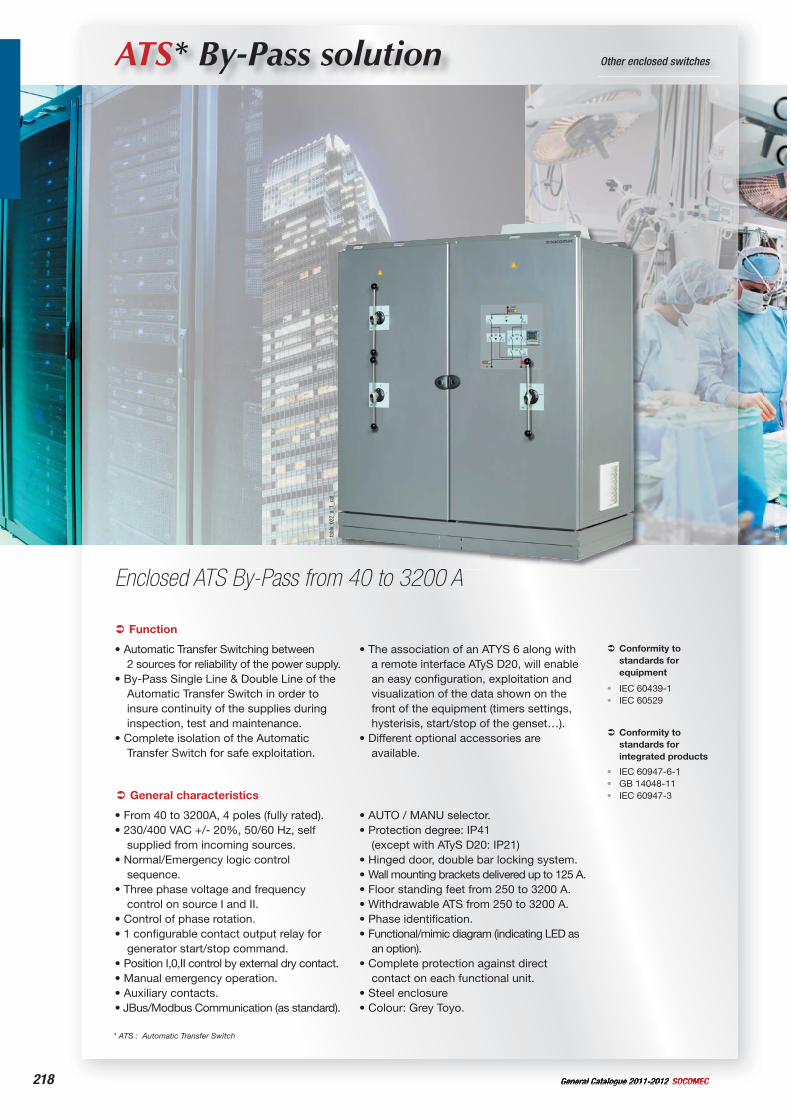
218 General Catalogue 2011-2012 SOCOMEC
site
_366
_483
_484
_a
ATS* By-Pass solution Other enclosed switches
Enclosed ATS By-Pass from 40 to 3200 A
tabl
o_02
2_a_
1_ca
t
* ATS : Automatic Transfer Switch
Function
• Automatic Transfer Switching between 2 sources for reliability of the power supply.
• By-Pass Single Line & Double Line of the Automatic Transfer Switch in order to insure continuity of the supplies during inspection, test and maintenance.
• Complete isolation of the Automatic Transfer Switch for safe exploitation.
• The association of an ATYS 6 along with a remote interface ATyS D20, will enable an easy configuration, exploitation and visualization of the data shown on the front of the equipment (timers settings, hysterisis, start/stop of the genset…).
• Different optional accessories are available.
Conformity to standards for equipment
IEC 60439-1IEC 60529
••
General characteristics
• From 40 to 3200A, 4 poles (fully rated).• 230/400 VAC +/- 20%, 50/60 Hz, self
supplied from incoming sources.• Normal/Emergency logic control
sequence.• Three phase voltage and frequency
control on source I and II.• Control of phase rotation.• 1 configurable contact output relay for
generator start/stop command.• Position I,0,II control by external dry contact.• Manual emergency operation.• Auxiliary contacts.• JBus/Modbus Communication (as standard).
• AUTO / MANU selector.• Protection degree: IP41
(except with ATyS D20: IP21)• Hinged door, double bar locking system.• Wall mounting brackets delivered up to 125 A.• Floor standing feet from 250 to 3200 A. • Withdrawable ATS from 250 to 3200 A.• Phase identification.• Functional/mimic diagram (indicating LED as
an option).• Complete protection against direct
contact on each functional unit.• Steel enclosure• Colour: Grey Toyo.
Conformity to standards for integrated products
IEC 60947-6-1GB 14048-11IEC 60947-3
•••
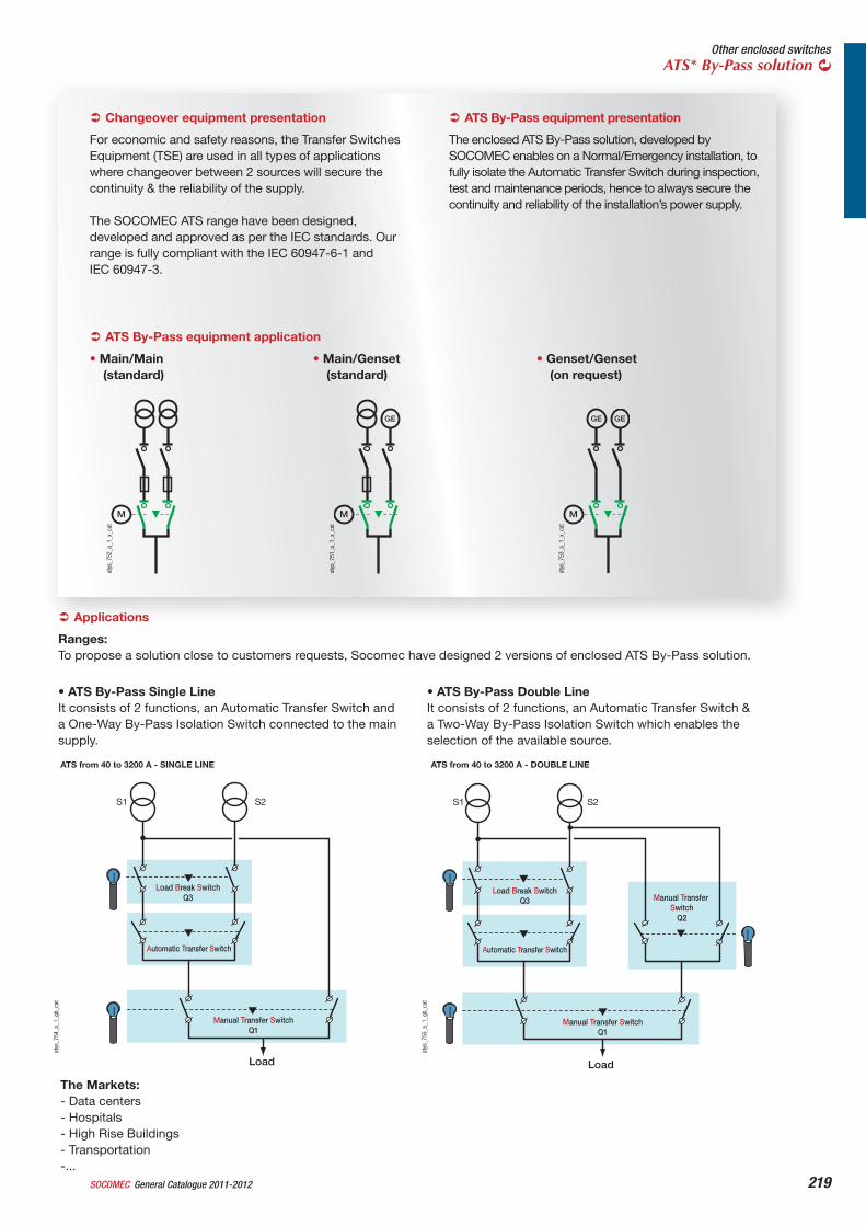
219General Catalogue 2011-2012SOCOMEC
Other enclosed switchesATS* By-Pass solution
ATS By-Pass equipment presentation
The enclosed ATS By-Pass solution, developed by SOCOMEC enables on a Normal/Emergency installation, to fully isolate the Automatic Transfer Switch during inspection, test and maintenance periods, hence to always secure the continuity and reliability of the installation’s power supply.
Changeover equipment presentation
For economic and safety reasons, the Transfer Switches Equipment (TSE) are used in all types of applications where changeover between 2 sources will secure the continuity & the reliability of the supply.
The SOCOMEC ATS range have been designed, developed and approved as per the IEC standards. Our range is fully compliant with the IEC 60947-6-1 and IEC 60947-3.
M
atys
_753
_a_1
_x_c
at
M
atys
_752
_a_1
_x_c
at
M
atys
_751
_a_1
_x_c
atATS By-Pass equipment application
• Main/Main(standard)
• Main/Genset(standard)
• Genset/Genset(on request)
Applications
Ranges:To propose a solution close to customers requests, Socomec have designed 2 versions of enclosed ATS By-Pass solution.
• ATS By-Pass Single LineIt consists of 2 functions, an Automatic Transfer Switch and a One-Way By-Pass Isolation Switch connected to the main supply.
• ATS By-Pass Double LineIt consists of 2 functions, an Automatic Transfer Switch & a Two-Way By-Pass Isolation Switch which enables the selection of the available source.
The Markets:- Data centers- Hospitals- High Rise Buildings- Transportation-...
S1 S2
Load
Load Break SwitchQ3
Automatic Transfer Switch
Manual Transfer SwitchQ1
Manual TransferSwitch
Q2
atys
_755
_a_1
_gb_
cat
ATS from 40 to 3200 A - DOUBLE LINE
S1 S2
Load
Load Break SwitchQ3
Automatic Transfer Switch
Manual Transfer SwitchQ1
atys
_754
_a_1
_gb_
cat
ATS from 40 to 3200 A - SINGLE LINE
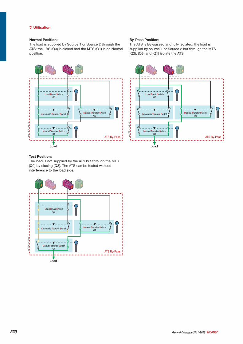
220 General Catalogue 2011-2012 SOCOMEC220
ATS By-Pass
Load Break SwitchQ3
Automatic Transfer Switch Manual Transfer SwitchQ2
Manual Transfer SwitchQ1
Load
ATS By-Pass
Load Break SwitchQ3
Automatic Transfer Switch Manual Transfer SwitchQ2
Manual Transfer SwitchQ1
Load
ATS By-Pass
Load Break SwitchQ3
Automatic Transfer Switch Manual Transfer SwitchQ2
Manual Transfer SwitchQ1
Load
atys
_758
_a_1
_gb_
cat
atys
_757
_a_1
_gb_
cat
atys
_756
_a_1
_gb_
cat
Utilisation
Normal Position:The load is supplied by Source 1 or Source 2 through the ATS; the LBS (Q3) is closed and the MTS (Q1) is on Normal position.
By-Pass Position:The ATS is By-passed and fully isolated, the load is supplied by source 1 or Source 2 but through the MTS (Q2); (Q3) and (Q1) isolate the ATS.
Test Position:The load is not supplied by the ATS but through the MTS (Q2) by closing (Q3). The ATS can be tested without interference to the load side.
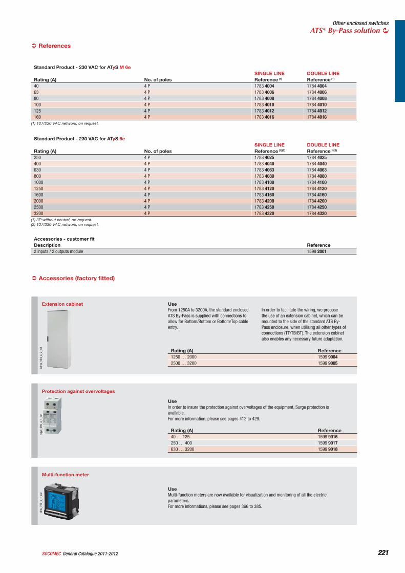
221General Catalogue 2011-2012SOCOMEC 221
Other enclosed switchesATS* By-Pass solution
References
Standard Product - 230 VAC for ATyS M 6eSINGLE LINE DOUBLE LINE
Rating (A) No. of poles Reference (1) Reference (1)
40 4 P 1783 4004 1784 400463 4 P 1783 4006 1784 400680 4 P 1783 4008 1784 4008100 4 P 1783 4010 1784 4010125 4 P 1783 4012 1784 4012160 4 P 1783 4016 1784 4016
(1) 127/230 VAC network, on request.
Standard Product - 230 VAC for ATyS 6eSINGLE LINE DOUBLE LINE
Rating (A) No. of poles Reference (1)(2) Reference(1)(2)
250 4 P 1783 4025 1784 4025400 4 P 1783 4040 1784 4040630 4 P 1783 4063 1784 4063800 4 P 1783 4080 1784 40801000 4 P 1783 4100 1784 41001250 4 P 1783 4120 1784 41201600 4 P 1783 4160 1784 41602000 4 P 1783 4200 1784 42002500 4 P 1783 4250 1784 42503200 4 P 1783 4320 1784 4320
(1) 3P without neutral, on request.(2) 127/230 VAC network, on request.
Accessories - customer fitDescription Reference2 inputs / 2 outputs module 1599 2001
Accessories (factory fitted)
Multi-function meter
diris
_750
_a_1
_cat
UseMulti-function meters are now available for visualization and monitoring of all the electric parameters. For more informations, please see pages 366 to 385.
Accessoires et options (consultez-nous)
Extension cabinet
kdry
s_50
4_a_
2_ca
t
UseFrom 1250A to 3200A, the standard enclosed ATS By-Pass is supplied with connections to allow for Bottom/Bottom or Bottom/Top cable entry.
In order to facilitate the wiring, we propose the use of an extension cabinet, which can be mounted to the side of the standard ATS By-Pass enclosure, when utilising all other types of connections (TT/TB/BT). The extension cabinet also enables any necessary future adaptation.
Rating (A) Reference1250 … 2000 1599 90042500 … 3200 1599 9005
Protection against overvoltages
sgys
_069
_a_1
_cat
UseIn order to insure the protection against overvoltages of the equipment, Surge protection is available.For more information, please see pages 412 to 429.
Rating (A) Reference40 … 125 1599 9016250 … 400 1599 9017630 … 3200 1599 9018
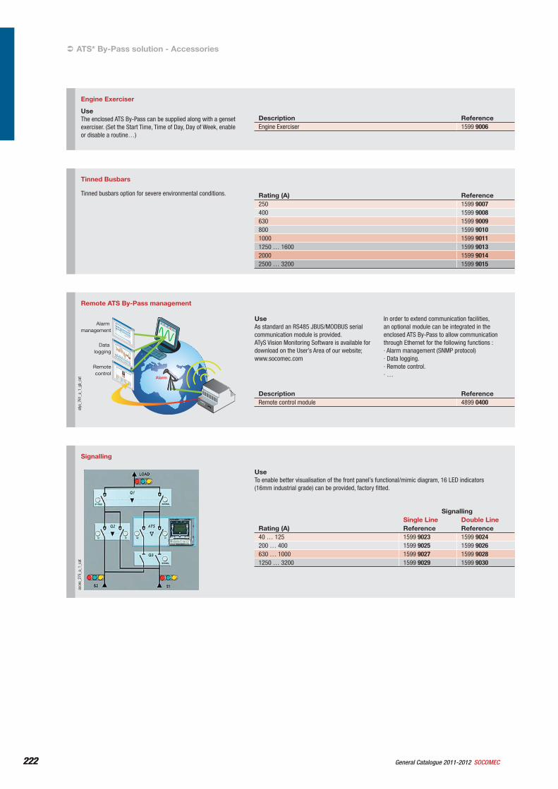
222 General Catalogue 2011-2012 SOCOMEC222
Engine Exerciser
UseThe enclosed ATS By-Pass can be supplied along with a genset exerciser. (Set the Start Time, Time of Day, Day of Week, enable or disable a routine…)
Description ReferenceEngine Exerciser 1599 9006
Tinned Busbars
Tinned busbars option for severe environmental conditions. Rating (A) Reference250 1599 9007400 1599 9008630 1599 9009800 1599 90101000 1599 90111250 … 1600 1599 90132000 1599 90142500 … 3200 1599 9015
Signalling
acce
s_27
5_a_
1_ca
t
UseTo enable better visualisation of the front panel’s functional/mimic diagram, 16 LED indicators (16mm industrial grade) can be provided, factory fitted.
SignallingSingle Line Double Line
Rating (A) Reference Reference40 … 125 1599 9023 1599 9024200 … 400 1599 9025 1599 9026630 … 1000 1599 9027 1599 90281250 … 3200 1599 9029 1599 9030
ATS* By-Pass solution - Accessories
Remote ATS By-Pass management
Alarmmanagement
Datalogging
Remotecontrol
Alarm
atys
_761
_a_1
_gb_
cat
UseAs standard an RS485 JBUS/MODBUS serial communication module is provided.ATyS Vision Monitoring Software is available for download on the User’s Area of our website; www.socomec.com
In order to extend communication facilities, an optional module can be integrated in the enclosed ATS By-Pass to allow communication through Ethernet for the following functions :· Alarm management (SNMP protocol)· Data logging.· Remote control.· …
Description ReferenceRemote control module 4899 0400
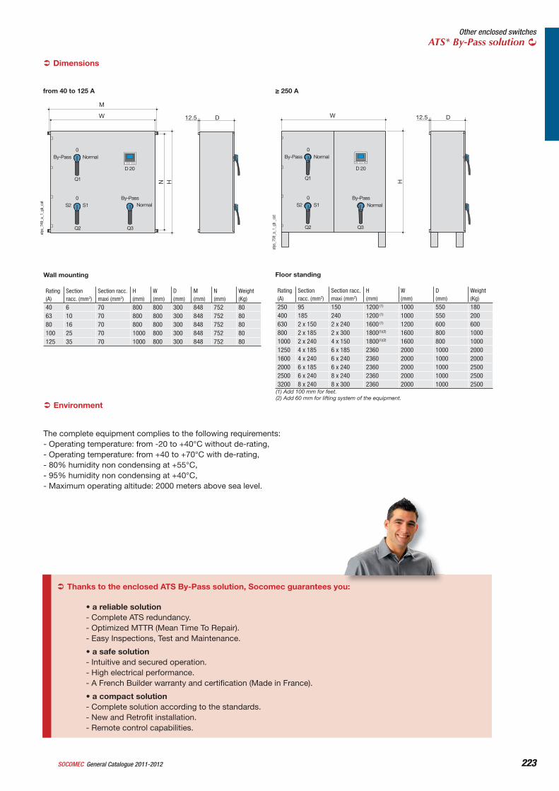
223General Catalogue 2011-2012SOCOMEC 223
Other enclosed switchesATS* By-Pass solution
from 40 to 125 A
D12.5
M
W
N HD 20
By-Pass
Normal
Normal
By-Pass
0
S2 S10
Q1
Q2 Q3
atys
_749
_a_1
_gb_
cat
Wall mounting
Rating (A)
Sectionracc. (mm2)
Section racc.maxi (mm2)
H(mm)
W(mm)
D(mm)
M(mm)
N(mm)
Weight (Kg)
40 6 70 800 800 300 848 752 8063 10 70 800 800 300 848 752 8080 16 70 800 800 300 848 752 80100 25 70 1000 800 300 848 752 80125 35 70 1000 800 300 848 752 80
Dimensions
250 A
D12.5W
H
D 20
By-Pass
Normal
Normal
By-Pass
0
S2 S10
Q1
Q2 Q3
atys
_759
_a_1
_gb
_cat
Floor standing
Rating (A)
Sectionracc. (mm2)
Section racc.maxi (mm2)
H(mm)
W(mm)
D(mm)
Weight (Kg)
250 95 150 1200 (1) 1000 550 180400 185 240 1200 (1) 1000 550 200630 2 x 150 2 x 240 1600 (1) 1200 600 600800 2 x 185 2 x 300 1800(1)(2) 1600 800 10001000 2 x 240 4 x 150 1800(1)(2) 1600 800 10001250 4 x 185 6 x 185 2360 2000 1000 20001600 4 x 240 6 x 240 2360 2000 1000 20002000 6 x 185 6 x 240 2360 2000 1000 25002500 6 x 240 8 x 240 2360 2000 1000 25003200 8 x 240 8 x 300 2360 2000 1000 2500
Environment
The complete equipment complies to the following requirements:- Operating temperature: from -20 to +40°C without de-rating,- Operating temperature: from +40 to +70°C with de-rating,- 80% humidity non condensing at +55°C,- 95% humidity non condensing at +40°C,- Maximum operating altitude: 2000 meters above sea level.
(1) Add 100 mm for feet.(2) Add 60 mm for lifting system of the equipment.
Thanks to the enclosed ATS By-Pass solution, Socomec guarantees you:
• a reliable solution- Complete ATS redundancy.- Optimized MTTR (Mean Time To Repair).- Easy Inspections, Test and Maintenance.
• a safe solution- Intuitive and secured operation.- High electrical performance.- A French Builder warranty and certification (Made in France).
• a compact solution- Complete solution according to the standards.- New and Retrofit installation.- Remote control capabilities.
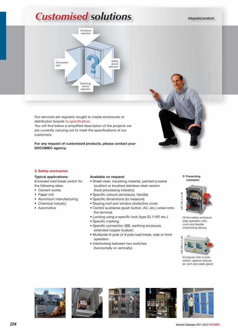
224 General Catalogue 2011-2012 SOCOMEC
Integrated productsCustomised solutionsEnclosureselection
Connectiontype
Safetydevice
selection
Switchingdevice
selection
Our services are regularly sought to create enclosures or distribution boards to specifi cation.You will fi nd below a simplifi ed description of the projects we are currently carrying out to meet the specifi cations of our customers.
For any request of customised products, please contact your SOCOMEC agency.
Typical applications:Enclosed load break switch for the following sites:• Cement works• Paper mill• Aluminium manufacturing• Chemical industry• Automotive
Safety enclosures
Available on request:• Sheet steel, insulating material, painted (coastal
location) or brushed stainless steel version (food processing industry).
• Specifi c colours (enclosure, handle).• Specifi c dimensions (to measure).• Sloping roof and window protective cover.• Control auxiliaries (push button, AC, etc.) wired onto
the terminal.• Locking using a specifi c lock (type EL11AP, etc.).• Specifi c marking.• Specifi c connection (BB, earthing enclosure,
extended copper busbar).• Multipolar 6-pole or 9 pole load break, side or front
operation.• Interlocking between two switches
(horizontally or vertically).
Presenting examples
Of the safety enclosure side operation with, Lock and double interlocking device.
Enclosure with 6-pole switch, special closure, air vent and cable gland
coff_
145_
c_3_
cat
coff_
040_
a_2_
cat
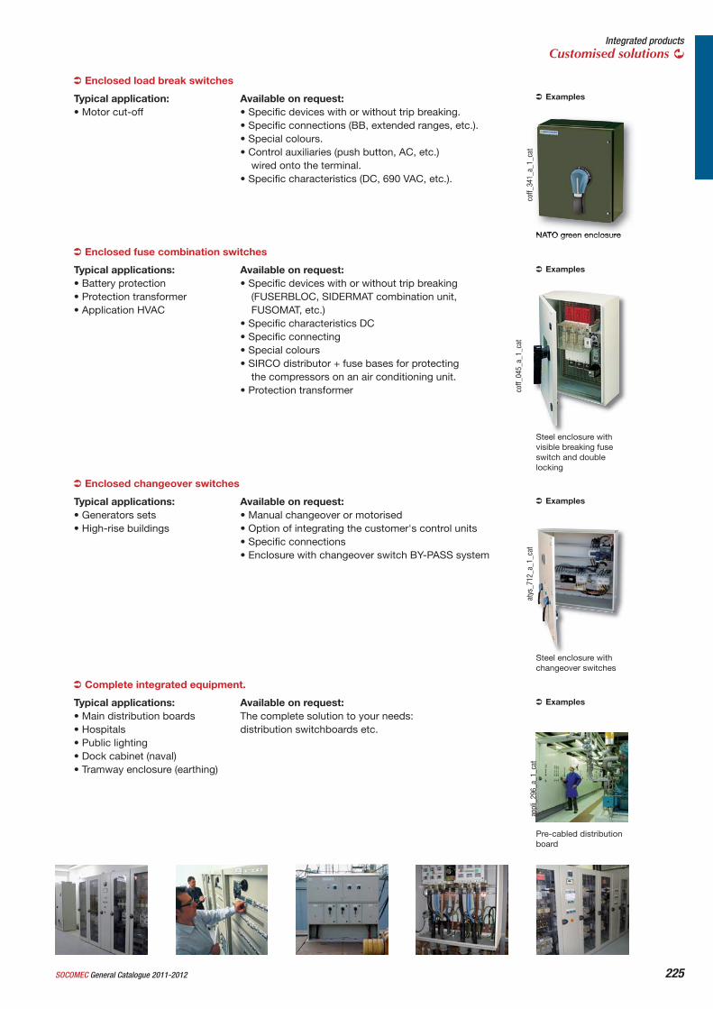
225SOCOMEC General Catalogue 2011-2012
Integrated productsCustomised solutions
Typical application:• Motor cut-off
Typical applications:• Battery protection• Protection transformer• Application HVAC
Steel enclosure with changeover switches
Typical applications:• Main distribution boards• Hospitals• Public lighting• Dock cabinet (naval)• Tramway enclosure (earthing)
Complete integrated equipment.
Available on request:The complete solution to your needs: distribution switchboards etc.
Examples
Pre-cabled distribution board
appl
i_29
6_a_
1_ca
t
Typical applications:• Generators sets• High-rise buildings
Enclosed changeover switches
Available on request:• Manual changeover or motorised• Option of integrating the customer's control units• Specifi c connections• Enclosure with changeover switch BY-PASS system
Examples
atys
_712
_a_1
_cat
Enclosed fuse combination switches
Available on request:• Specifi c devices with or without trip breaking
(FUSERBLOC, SIDERMAT combination unit, FUSOMAT, etc.)
• Specifi c characteristics DC• Specifi c connecting• Special colours• SIRCO distributor + fuse bases for protecting
the compressors on an air conditioning unit.• Protection transformer
Examples
Steel enclosure with visible breaking fuse switch and double locking
coff_
045_
a_1_
cat
Enclosed load break switches
Available on request:• Specifi c devices with or without trip breaking. • Specifi c connections (BB, extended ranges, etc.).• Special colours.• Control auxiliaries (push button, AC, etc.)
wired onto the terminal.• Specifi c characteristics (DC, 690 VAC, etc.).
Examples
NATO green enclosure
coff_
341_
a_1_
cat
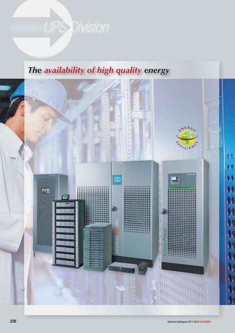
226 General Catalogue 2011-2012 SOCOMEC
UPS Division
The availability of high quality energy
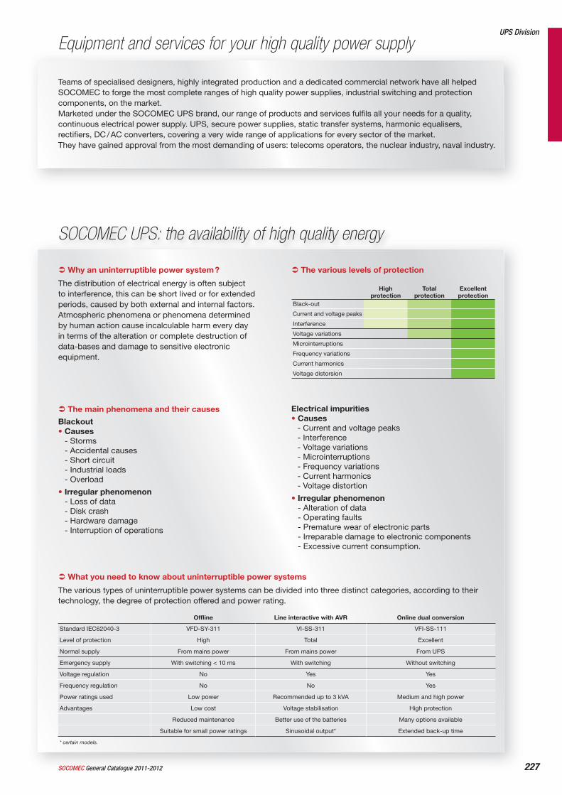
The main phenomena and their causes
Blackout• Causes
- Storms- Accidental causes- Short circuit- Industrial loads- Overload
• Irregular phenomenon- Loss of data- Disk crash- Hardware damage- Interruption of operations
Electrical impurities• Causes
- Current and voltage peaks- Interference- Voltage variations- Microinterruptions- Frequency variations- Current harmonics- Voltage distortion
• Irregular phenomenon- Alteration of data- Operating faults- Premature wear of electronic parts- Irreparable damage to electronic components- Excessive current consumption.
SOCOMEC UPS: the availability of high quality energy
The various levels of protection
Highprotection
Total protection
Excellentprotection
Black-out
Current and voltage peaks
Interference
Voltage variations
Microinterruptions
Frequency variations
Current harmonics
Voltage distorsion
Why an uninterruptible power system ?
The distribution of electrical energy is often subjectto interference, this can be short lived or for extendedperiods, caused by both external and internal factors.Atmospheric phenomena or phenomena determinedby human action cause incalculable harm every dayin terms of the alteration or complete destruction ofdata-bases and damage to sensitive electronicequipment.
Offl ine Line interactive with AVR Online dual conversion
Standard IEC62040-3 VFD-SY-311 VI-SS-311 VFI-SS-111
Level of protection High Total Excellent
Normal supply From mains power From mains power From UPS
Emergency supply With switching < 10 ms With switching Without switching
Voltage regulation No Yes Yes
Frequency regulation No No Yes
Power ratings used Low power Recommended up to 3 kVA Medium and high power
Advantages Low cost Voltage stabilisation High protection
Reduced maintenance Better use of the batteries Many options available
Suitable for small power ratings Sinusoidal output* Extended back-up time
* certain models.
What you need to know about uninterruptible power systems
The various types of uninterruptible power systems can be divided into three distinct categories, according to their technology, the degree of protection offered and power rating.
227SOCOMEC General Catalogue 2011-2012
Equipment and services for your high quality power supply
Teams of specialised designers, highly integrated production and a dedicated commercial network have all helped SOCOMEC to forge the most complete ranges of high quality power supplies, industrial switching and protection components, on the market.Marketed under the SOCOMEC UPS brand, our range of products and services fulfi ls all your needs for a quality, continuous electrical power supply. UPS, secure power supplies, static transfer systems, harmonic equalisers, rectifi ers, DC / AC converters, covering a very wide range of applications for every sector of the market.They have gained approval from the most demanding of users: telecoms operators, the nuclear industry, naval industry.
UPS Division

228 General Catalogue 2011-2012 SOCOMEC
SOCOMEC UPS: the availability of high quality energy (cont.)
(1) Rectifi er-chargers (2) DC-AC inverters (3) Static Transfer System (4) Harmonic compensator.
Private user •Offi ces and shops • • •Small and medium enterprises • • • • •Corporate networks and telephony • • •Rack 19” IT Networking • • • • • • • • • •Datacenters • • • • • • • • • •Telecom • • • • • • • • • • • • •
Choosing the right one
NeTY
S
ITYS
MODULY
S stan
d alon
e
MAST
ERYS
Green
Power
DELPH
YS MP el
ite
DELPH
YS MX el
ite
DELPH
YS MX
STAT
YS
Flywhe
el VSS
+ DC
SHARY
S(2) an
dSHARY
S IP
PHASY
S(3)
IT-SW
ITCH an
d LUM
(4)
ATRYS(
5)
SOCOMEC UPS: for a high quality power supply
Marketed under the SOCOMEC UPS trademark, our range of products and services fulfi ls all needs for a high quality, continuous electrical power supply. Our UPS, as well as our secure power supplies, static transfer systems, harmonic equalizers, rectifi ers and DC / AC and AC / DC converters, comprise the most complete ranges in the world and cover a very wide range of applications for every sector of the market.
A key requirement
High quality energy supply at any moment is vital in many fi elds such as telecommunications, data processing or certain industrial processes. It is even mission-critical for many medical applications. In all these sectors SOCOMEC UPS has over 40 years of experience at your disposal.
Product solutions that meet requirements
Underpinned by signifi cant R&D resources, our product offer continually evolves as a consequence of our contact with customers. Our products have the approval of some of the most stringently demanding users: Telecom companies worldwide, Ministries of Defence, nuclear industry
operators… To ensure the highest availability, we provide the latest UPS technology combined either with traditional batteries or with other innovating energy storage system.
Recognised expertise
Having already received the 2004 Award for Customer Service Excellence and the 2006 Award for Product Innovation from Frost & Sullivan, SOCOMEC UPS recently has once again excelled by winning the 2009 Best Practice Award for “European Energy & Power Systems Product Line Strategy”. This prestigious accolade was presented in recognition of the company’s ability to propose an extensive product range demonstrating the most insight into the needs and product demands of its customers.
Continuing innovation
“The facts speak for themselves: fi rst French manufacturer to offer static power supplies (1968), designer of the fi rst UPS with PWM technology (1980), fi rst to integrate IGBT technology into major power sources (1996), designer of the fi rst UPS in a modular rack system (2000), fi rst to integrate hybrid components (2001), fi rst 200 kVA UPS with IGBT rectifi er (2003), new battery
charging design (2004), dynamic energy storage system (fl ywheel) replacing the more traditional battery-based solution (2006), fi rst UPS true online double conversion 120-200 kVA with 96 % effi ciency certifi ed (2007), most compact STS 19” rack hot-swapable (2009), most compact UPS true online double conversion 900 kVA (2010).
Always focused on customer needs
Our sales and after-sales network means we are always there for you. Our partner-customers recognise the quality of our products, our availability, our fl exibility in meeting requirements and commitment.
An organisation “hard-wired” for customer satisfaction
Design and production in each UPS factory is certifi ed to ISO 9001. Together with quality service and maintenance, the UPS are your guarantee of a fail-safe electrical power supply.
A controlled environmental management
With its ISO 14001 certifi cation, SOCOMEC UPS is committed to continuous improvement of its environmental management system.
Innovative power solutions
VALID FOR FRANCE VALID FOR ITALY
ISO 9001FM 28237
ISO14001EMS 553476

229SOCOMEC General Catalogue 2011-2012
For maximum availability and true cost savingsAvailability
• The system is supplied with top-quality electrical power, minimising the risk of downtime.
• Protection is ensured by the use of on-line double conversion UPS, the most reliable technology on the market.
• The system is fully safeguarded against blackouts and any disturbance caused by the mains power supply and by distorting loads.
Saving
• UPS energy costs cut by up to 40 %.
• The saving is guaranteed by the highest available effi ciency performance for online double conversion UPS on the market, certifi ed up to 96 %.
• Optimising the power supply to the system makes it possible to reduce the use of nonrecyclable materials and cut CO2 emissions.
UPS Division
Commissioning, Inspection & Maintenance
Start-up
With the start-up of your equipment, CIM guarantees the compatibility of the UPS with your environment and checks it is compliant with the various installation standards.
Performance
Recovery from alarm state, replacement of faulty parts, mechanical and electrical checks, suggestions and advice on better use of the equipment.
Training
For the training of users on their UPS systems, SOCOMEC UPS organises
courses held at its training centre or at the user’s premises, with practical sessions involving “hands-on” use of machines.
Maintenance contracts
We tailor our services around your operating constraints. This means that for each of your contracts, we provide you with adapted solutions to match your expectations.Our Silver, Gold and Platinum solutions meet your needs by protecting and securing the electrical supply to your sensitive applications (offi ce, automation, servers, data-processing centres, NICT, security…).
Remote surveillance
Thanks to the T.Service remote monitoring service, our team of technical specialists remains continuously connected to the UPS via the telephone network or the internet.T.Service:• checking the parameters required to
enable your equipment to function properly,
• identifying potential problems in order to establish a reliable and comprehensive diagnostic function which can provide you with a quick and effective solution,
• supplies regular reports on the status of the UPS
Preventive and predictive maintenance
The CIM thermo service involves checking the components of your electrical installation using special equipment (thermal imaging cameras). In this way it is possible to perform a preventive diagnosis of breakdown risks by analysing the temperature (thermographic control) of each component.
CIM rent
When you require high-quality uninterrupted electrical energy over a limited period (weeks or months), leasing is the most economical answer for your short-term needs. Leasing enables you to draw on the global expertise of SOCOMEC, which not only assures the availability of the UPS system, but also provides an all-in-one service to guarantee you a clean and uninterrupted energy supply.
Our commitment to Absolute Green
SOCOMEC UPS can also provide
230
Reference list
References Pages References Pages References Pages References Pages
General Catalogue 2011-2012 SOCOMEC
1309 0xxx 110, 111
1309 2xxx 110, 111
1309 4xxx 110, 111
1309 9056 112
132x xxxx 110
1353 xxxx 110
1354 xxxx 110
1359 xxxx 110, 112
136x xxxx 111
138x xxxx 111
1399 4006 17, 21, 110, 111
1399 4017 112
1400 1020 43, 44
1400 1025 44
1400 1032 43, 44, 54, 55,
58, 59
1400 1050 43, 44
1400 1075 44
1400 1232 55, 59
1401 00xx 44, 102
1401 0532 54, 58
1401 06xx 17, 19, 37, 38
1401 1xxx 105
1402 xxxx 101, 102
1403 xxxx 101, 102
1407 xxxx 16, 19, 30, 99
1409 xxxx 17, 19, 37, 38
1411 2111 17, 18, 37, 38, 58
1411 2113 54, 101
1413 2111 18, 37, 38
1413 2113 101
1413 2114 101
1413 2115 54, 58
1413 28xx 101
1414 2111 17, 18, 37, 38,
54, 58
1414 2113 54
1414 2115 54, 58
1415 2111 17, 18, 37, 38,
54, 58
1415 2113 58
1417 2111 18, 37, 38
1418 2111 17, 18, 37, 38,
54, 58
1418 2113 58
1419 0000 19
141A xxxx 17, 18, 37, 38
141B xxxx 17, 18, 37, 38
1421 2111 43, 54, 55, 58, 59
1421 2113 54, 55, 58
1423 2111 43
1423 2115 54, 55, 58, 59
1424 2111 43, 54, 55, 58, 59
1424 2113 54, 55, 58
1424 2115 54, 55, 58, 59
1425 21xx 54, 55, 58, 59
1425 2113 59
1428 2111 54, 55, 58, 59
1428 2113 59
1429 0000 19, 43
1433 3111 55, 59
1433 3113 105
1434 xxxx 55, 59
1437 xxxx 55, 59
1438 xxxx 55, 59
144x xxxx 59
1471 1111 16, 18, 30
1471 1113 99
1473 1111 16, 18, 30
1473 1113 16, 18, 99
1473 1114 16, 18
1474 xxxx 16, 18, 30
147A xxxx 16, 18, 30
147B xxxx 16, 18, 30
148x xxxx 16, 18
1491 0111 17, 18, 37, 38
1493 0000 44, 102
1494 xxxx 17, 18, 37, 38
1499 7701 45, 105
1499 7702 105
149A xxxx 17, 18, 37, 38
149B xxxx 17, 18, 37, 38
1509 0001 119, 121, 124
1509 1xxx 119, 121, 125
1509 3xxx 120
1509 40xx 105, 118, 120, 125
1509 41xx 118, 120, 125
1509 42xx 118, 120, 125
1523 xxxxxx 118, 119
1529 xxxx 119, 126
1533 xxxxxx 118, 119
1539 xxxx 119, 121, 126
155x xxxx 124
156x xxxxxxxx 120, 121
157x xxxxxxxx 120, 121
1599 0002 118, 121, 125
1599 0003 119, 121, 125
1599 0004 119, 121, 125
1599 0032 118, 121, 125
1599 1xxx 118, 125
1599 2000 118, 120, 124
1599 2001 118, 120, 124, 221
1599 2009 112, 120, 126
1599 201x 111, 113, 120, 126
1599 202x 111, 113, 120, 126
1599 3xxx 133
1599 4001 112, 119, 126
1599 41xx 118, 121, 123
1599 42xx 118, 121, 123
1599 5xxx 119, 121, 123
1599 9004 221
1599 9005 221
1599 9006 222
1599 9007 222
1599 9008 222
1599 9009 222
1599 9010 222
1599 9011 222
1599 9013 222
1599 9014 222
1599 9015 222
1599 9016 221
1599 9017 221
1599 9018 221
1599 902x 222
1599 903x 222
17xx xxxx 221
192J 8015 153
2200 1xxx 16, 19
2200 300x 16
2200 3010 16
2200 3011 16
2200 3012 17
2200 3016 17
2200 31xx 17
2200 4xxx 17
2200 5xxx 16, 19
2200 9xxx 16, 19
2205 xxxx 16
2209 0xxx 37, 39
2209 2xxx 37, 39
2209 6009 16, 20
221x xxxx 32
223x xxxx 99
2269 6009 16, 20
2294 100x 16, 20, 31, 99
2294 1011 16, 20
2294 300x 16, 20, 31, 99
2294 3016 16, 17, 20, 39
2294 4016 17, 20, 39, 110,
111
2299 0xxx 16, 17, 20, 30, 31,
37, 39, 99
2299 30xx 99
2299 33xx 16, 21, 30, 31
2299 34xx 16, 21, 30, 31
2299 4xxx 99
2299 501x 16, 17, 30
2299 5022 17, 37, 38
2299 5032 16, 17
2299 5042 17, 37, 38
2299 6009 16, 20
2299 9409 21, 31
2299 9909 21
22PV 3xxx 37
22PV 400x 30
22PV 401x 37
22PV 41xx 37
22PV 43xx 32
22PV 44xx 32
22PV 6xxx 30
22PV 8xxx 30
260x xxxx 43, 45
261x xxxx 123
262x xxxx 123
263x xxxx 123
2694 3021 45
2694 3051 45, 120
2694 4014 105, 118, 120, 124
2694 402x 45, 105, 118,
120, 124
2694 405x 45, 105, 118,
120, 124
2698 xxxx 45
2699 00xx 43, 44
2699 01xx 44
2699 03xx 44
2699 1200 123
2699 3xxx 44
2699 4xxx 44
2699 5xxx 43
2699 6xxx 45
2699 9xxx 45
26Px xxxx 43
231
References Pages References Pages References Pages References Pages
SOCOMEC General Catalogue 2011-2012
27xx xxxx 105
29xx xxxx 45
324x xxxx 217
32Ax xxxx 212
32Cx xxxx 212
33xx xxxx 214
3615 200x 60
3615 2010 60
3615 2011 60
3615 2012 60
3615 2015 61
3615 2016 61
3615 202x 61
3615 203x 61
3615 300x 60
3615 3010 60
3615 3011 60
3615 3012 60
3615 3015 61
3615 3016 61
3615 302x 61
3615 303x 61
3615 600x 60
3615 6010 60
3615 6011 60
3615 6012 60
3615 6015 61
3615 6016 61
3615 602x 61
3615 603x 61
3625 200x 56
3625 2010 56
3625 2014 56
3625 2015 56
3625 2016 56
3625 2019 57
3625 202x 57
3625 203x 57
3625 300x 56
3625 3010 56
3625 3014 56
3625 3015 56
3625 3016 56
3625 3019 57
3625 302x 57
3625 303x 57
3625 600x 56
3625 6010 56
3625 6014 56
3625 6015 56
3625 6016 56
3625 6019 57
3625 602x 57
3625 603x 57
3629 4xxx 56, 60
3629 7900 56, 60
3629 7901 56, 57, 60, 61
3629 7903 56, 60
3629 7913 56, 57, 60, 61
363x xxxx 58, 60
364x xxxx 54, 56
367x xxxx 58
368x xxxx 54
381x xxxx 59, 61
3821 xxxx 55, 57
3829 9308 55, 59
3829 9310 54, 58
3829 9312 55, 59
3829 9320 54, 55, 59
3829 933x 55, 59
3831 200x 58
3831 2010 58
3831 2011 58
3831 2012 58
3831 2015 59
3831 2016 59
3831 202x 59
3831 203x 59
3831 300x 58
3831 3010 58
3831 3011 58
3831 3012 58
3831 3015 59
3831 3016 59
3831 302x 59
3831 303x 59
3831 600x 58
3831 6010 58
3831 6011 58
3831 6012 58
3831 6015 59
3831 6016 59
3831 602x 59
3831 603x 59
3841 200x 54
3841 2010 54
3841 2014 54
3841 2015 54
3841 2016 54
3841 2019 55
3841 202x 55
3841 203x 55
3841 300x 54
3841 3010 54
3841 3014 54
3841 3015 54
3841 3016 54
3841 3019 55
3841 302x 55
3841 303x 55
3841 600x 54
3841 6010 54
3841 6014 54
3841 6015 54
3841 6016 54
3841 6019 55
3841 602x 55
3841 603x 55
3870 300x 58
3870 3010 58
3870 3011 58
3870 3015 59
3870 3016 59
3870 302x 59
3870 303x 59
3870 600x 58
3870 6010 58
3870 6011 58
3870 6015 59
3870 6016 59
3870 602x 59
3870 603x 59
3880 300x 54
3880 3010 54
3880 3014 54
3880 3015 54
3880 3016 54
3880 3019 55
3880 302x 55
3880 303x 55
3880 600x 54
3880 6010 54
3880 6014 54
3880 6015 54
3880 6016 54
3880 6019 55
3880 602x 55
3880 603x 55
3898 xxxx 55, 57, 59, 61
3899 xxxx 57, 61
3998 2016 54 to 61
3998 2025 55, 57, 59, 61
3998 3016 54 to 61
3998 3025 55, 57, 59, 61
3998 4016 54 to 61
3998 4025 55, 57, 59, 61
3999 000x 56, 60
3999 002x 56, 57, 60, 61
3999 0600 54, 55, 58, 59
3999 070x 17, 20, 37, 39,
57, 61
3999 0710 54, 58
3999 82xx 61
3999 83xx 61
3999 84xx 61
3999 8906 60
3999 8912 60, 61
3Vxx xxxx 217
4100 xxxx 105
4109 0019 105, 122
4109 0021 105
4109 003x 105, 122
4109 006x 105, 122
4109 008x 105, 122
4109 0120 122
4109 0160 105, 122
4109 02xx 123
4109 03xx 123
4109 1xxx 105
4109 4xxx 118, 120
4359 4315 112
4430 xxxx 101
4439 0001 101, 102
444x xxxx 101
449x xxxx 101, 102
4805 0000 185
4805 0001 185
4805 0002 189
4825 001x 157
4825 0080 161
4825 0082 161
4825 0087 167
4825 0088 161, 167, 173
4825 0089 161, 167, 173
4825 0090 167, 173
4825 0092 167, 173
4825 0093 167, 173
4825 0094 167, 173
4825 0097 167
4825 0200 161
4825 0201 167
4825 0202 167
4825 0203 167, 173
4825 0204 167, 173
4825 0205 167, 173
4825 0206 167, 173
4825 0207 173
4825 1xxx 167
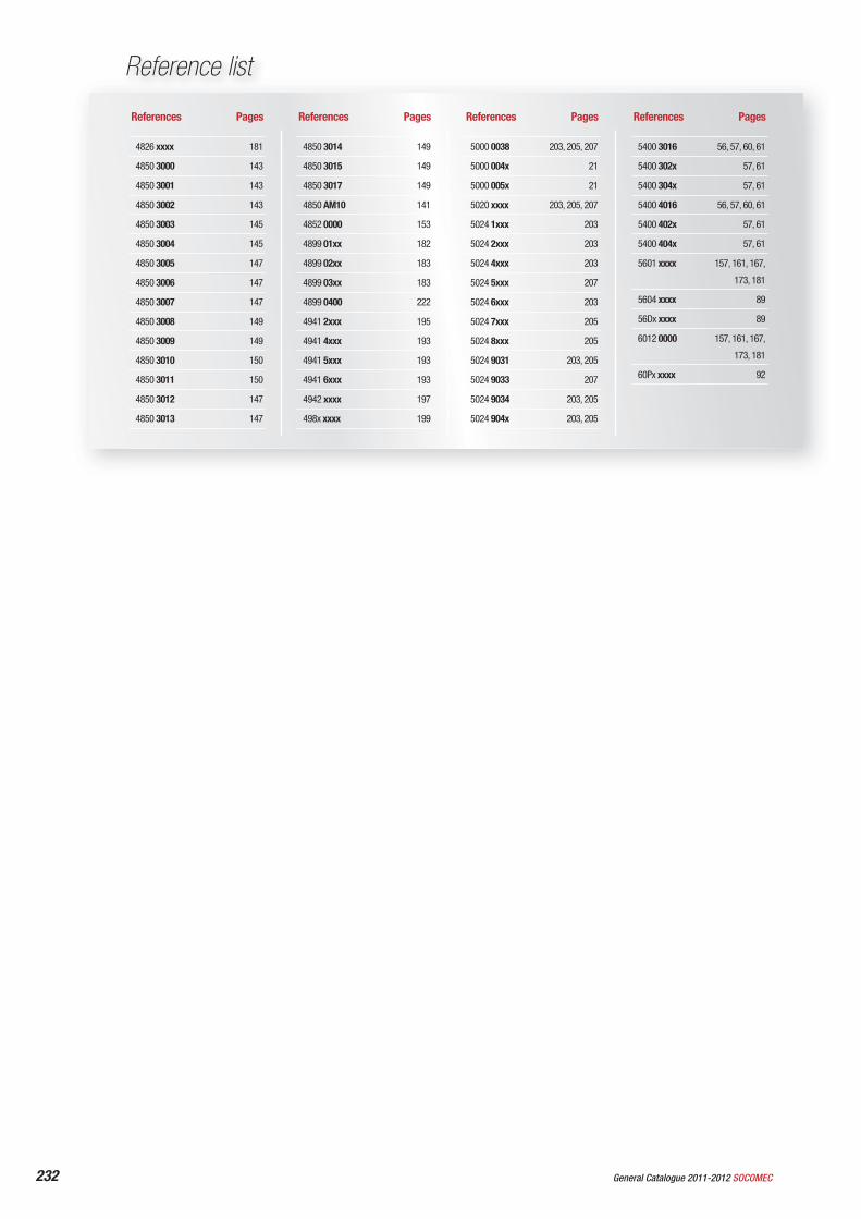
4826 xxxx 181
4850 3000 143
4850 3001 143
4850 3002 143
4850 3003 145
4850 3004 145
4850 3005 147
4850 3006 147
4850 3007 147
4850 3008 149
4850 3009 149
4850 3010 150
4850 3011 150
4850 3012 147
4850 3013 147
4850 3014 149
4850 3015 149
4850 3017 149
4850 AM10 141
4852 0000 153
4899 01xx 182
4899 02xx 183
4899 03xx 183
4899 0400 222
4941 2xxx 195
4941 4xxx 193
4941 5xxx 193
4941 6xxx 193
4942 xxxx 197
498x xxxx 199
5000 0038 203, 205, 207
5000 004x 21
5000 005x 21
5020 xxxx 203, 205, 207
5024 1xxx 203
5024 2xxx 203
5024 4xxx 203
5024 5xxx 207
5024 6xxx 203
5024 7xxx 205
5024 8xxx 205
5024 9031 203, 205
5024 9033 207
5024 9034 203, 205
5024 904x 203, 205
5400 3016 56, 57, 60, 61
5400 302x 57, 61
5400 304x 57, 61
5400 4016 56, 57, 60, 61
5400 402x 57, 61
5400 404x 57, 61
5601 xxxx 157, 161, 167,
173, 181
5604 xxxx 89
56Dx xxxx 89
6012 0000 157, 161, 167,
173, 181
60Px xxxx 92
232
Reference list
References Pages References Pages References Pages References Pages
General Catalogue 2011-2012 SOCOMEC
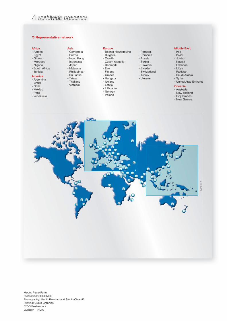
A worldwide presence
Representative network
Africa- Algeria - Egypt- Ghana- Morocco- Nigeria- South Africa - Tunisia
America- Argentina- Brazil- Chile- Mexico- Peru- Venezuela
Asia- Cambodia- Burma- Hong Kong- Indonesia- Japan - Malaysia- Philippines- Sri Lanka- Taiwan- Thailand- Vietnam
Europe- Bosnia Herzegovina- Bulgaria - Croatia- Czech republic- Denmark- Eire- Finland- Greece- Hungary- Iceland- Latvia- Lithuania - Norway- Poland
- Portugal- Romania- Russia- Serbia- Slovenia- Sweden- Switzerland- Turkey- Ukraine
Middle East- Iraq- Israel - Jordan - Kuwait- Lebanon- Libya- Pakistan- Saudi Arabia- Syria- United Arab Emirates
Oceania- Australia- New zealand- Fidji Islands- New Guinea
CA
RTE
021
A
Model: Piano Forte Production: SOCOMECPhotography: Martin Bernhart and Studio ObjectifPrinting: Gupta Graphics320/3 RoshanpuraGurgaon - INDIA
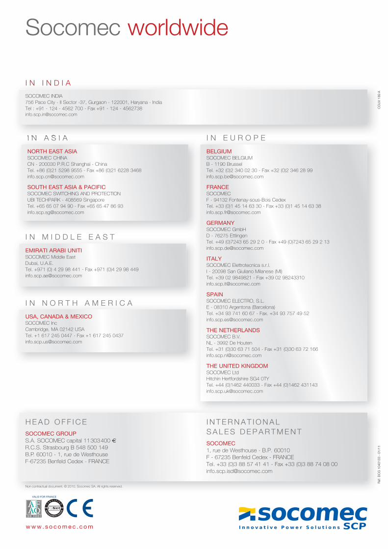
H E A D O F F I C ESOCOMEC GROUP S.A. SOCOMEC capital 11 303 400 R.C.S. Strasbourg B 548 500 149B.P. 60010 - 1, rue de Westhouse F-67235 Benfeld Cedex - FRANCE
I N T E R N A T I O N A L S A L E S D E P A R T M E N TSOCOMEC1, rue de Westhouse - B.P. 60010F - 67235 Benfeld Cedex - FRANCETel. +33 (0)3 88 57 41 41 - Fax +33 (0)3 88 74 08 [email protected]
Socomec worldwide
Non contractual document. © 2010, Socomec SA. All rights reserved.
w w w . s o c o m e c . c o m
VALID FOR FRANCE
I N A S I A
NORTH EAST ASIASOCOMEC CHINACN - 200030 P.R.C Shanghai - ChinaTel. +86 (0)21 5298 9555 - Fax +86 (0)21 6228 [email protected]
SOUTH EAST ASIA & PACIFICSOCOMEC SWITCHING AND PROTECTIONUBI TECHPARK - 408569 SingaporeTel. +65 65 07 94 90 - Fax +65 65 47 86 [email protected]
I N M I D D L E E A S T
EMIRATI ARABI UNITISOCOMEC Middle EastDubai, U.A.E. Tel. +971 (0) 4 29 98 441 - Fax +971 (0)4 29 98 [email protected]
I N I N D I A
SOCOMEC INDIA756 Pace City - II Sector -37, Gurgaon - 122001, Haryana - IndiaTel : +91 - 124 - 4562 700 - Fax +91 - 124 - [email protected]
I N N O R T H A M E R I C A
USA, CANADA & MEXICOSOCOMEC IncCambridge, MA 02142 USATel. +1 617 245 0447 - Fax +1 617 245 [email protected]
I N E U R O P E
BELGIUMSOCOMEC BELGIUMB - 1190 BrusselTel. +32 (0)2 340 02 30 - Fax +32 (0)2 346 28 [email protected]
FRANCESOCOMECF - 94132 Fontenay-sous-Bois CedexTel. +33 (0)1 45 14 63 30 - Fax +33 (0)1 45 14 63 [email protected]
GERMANYSOCOMEC GmbHD - 76275 EttlingenTel. +49 (0)7243 65 29 2 0 - Fax +49 (0)7243 65 29 2 [email protected]
ITALYSOCOMEC Elettrotecnica s.r.l.I - 20098 San Giuliano Milanese (MI)Tel. +39 02 9849821 - Fax +39 02 [email protected]
SPAINSOCOMEC ELECTRO, S.L.E - 08310 Argentona (Barcelona) Tel. +34 93 741 60 67 - Fax. +34 93 757 49 [email protected]
THE NETHERLANDSSOCOMEC B.V.NL - 3992 De HoutenTel. +31 (0)30 63 71 504 - Fax +31 (0)30 63 72 [email protected]
THE UNITED KINGDOMSOCOMEC LtdHitchin Hertfordshire SG4 0TYTel. +44 (0)1462 440033 - Fax +44 (0)1462 [email protected]
Réf
. DC
G 1
0401
33 -
01/
11
C
OU
V 18
9 A
Related Documents