COUNTIS E43 : ref. 4850 3065 COUNTIS E44 (MID) : ref. 4850 3066 MID Device code and certification data indications CORPORATE HQ CONTACT: SOCOMEC SAS, 1-4 RUE DE WESTHOUSE, 67235 BENFELD, FRANCE Technical characteristics Data in compliance with EN 50470-1, EN 50470-3 GENERAL Housing 4 modules DIN 43880 Mounting DIN rail EN 60715 OPERATING FEATURES Connectivity 4 wires MID model: 3x 230/400 V Non MID model: 3x 230/400 V to 3x 240/415 V Storage of energy values and configuration FRAM Display tariffs identifier T1, T2, T3 and T4 SUPPLY Autosupplied Operating voltage range 184 ... 288 VAC Operating frequency range 45 ... 65 Hz Rated power dissipation (max.) Pv 3.5 VA - 1 W CT burden (for each phase) 0,04 VA OVERLOAD CAPABILITY Voltage Un continuous 288 VAC Voltage Un momentary (1 s) 300 VAC Current Imax continuous 6 A Current Imax momentary 20 Imax for 0.5 s DISPLAY (ACCORDING TO THE SET CT PRIMARY ) Display type LCD 8 digits with backlight Active energy: 1 display, 8-digit 00000.000 kWh ... 999999.99 MWh Reactive energy: 1 display, 8-digit 00000.000 kvarh ... 999999.99 Mvarh Apparent energy: 1 display, 8-digit 00000.000 kVAh … 999999.99 MVAh Instantaneous active power: 1 display, 4-digit 0.000 kW ... 99.99 MW Instantaneous reactive power: 1 display, 4-digit 0.000 kvar ... 99.99 Mvar Instantaneous apparent power: 1 display, 4-digit 0.000 kVA ... 99.99 MVA Intantaneous voltage: 1 display, 4-digit 000.0 ... 999.9 V Intantaneous current: 1 display, 4-digit 0.000 ... 99.99 kA Power Factor: 1 display, 4-digit 0.000 … 1.000 Frequency: 1 display, 4-digit 45.00 … 65.00 Hz Display period refresh 1 s MEASURING ACCURACY Active energy class C acc. to EN 50470-3 Active energy class 1 acc. to EN 62053-21 Reactive energy class 2 acc. to EN 62053-23 MEASURING INPUT Type of connection via current transformer Certified voltage Un MID model: 3x 230/400 V Non MID model: 3x 230/400 V to 3x 240/415 V Current Iref 1 A Current Imin 0.10 A Operating range current (Ist ... Imax) 0.002 ... 6 A (Class 1) 0.001 ... 6 A (Class C) Certified frequency fn MID model: 50 Hz ± 1 Hz Non MID model: 50/60 Hz ± 1 Hz Starting current for energy measurement (Ist) 2 mA Class 1 1 mA Class C Measurements The parameters are available according to the device model. INSTANTANEOUS VALUES Symbol Measure unit Display Com Phase to Neutral voltages ∑V V • • V1, V2, V3 • Phase to Phase voltages ∑U • • U12, U23, U31 • Current ∑I A • • I1, I2, I3, IN • Power factor ∑PF • • PF1, PF2, PF3 • Apparent power ∑S, S1, S2, S3 kVA • • Active power ∑P, P1, P2, P3 kW • • Reactive power ∑Q, Q1, Q2, Q3 kvar • • Frequency f Hz • • Phase sequence CW / CCW • • Power direction • RECORDED DATA Symbol Measure unit Display Com Total energy counters Ea, Er (∑ & per phase) kWh, kvarh • • Total apparent energy Eap (∑) kVAh • • Eap (per phase) • Total ind. and cap. reactive energy Er (∑) kvarh • • Er (per phase) • T1/T2/T3/T4 tariff energy counters Ea, Er (∑) kWh, kvarh • • Ea, Er, Eap (∑ & per phase) kWh, kvarh, kVAh • T1/T2/T3/T4 tariff ind. and cap. reactive energy Er (∑) kvarh • • Er (per phase) • T1/T2/T3/T4 tariff resettable partial energy counters Ea (∑) kWh • • Resettable partial energy counters Ea, Er, Eap (∑) kWh, kvarh, kVAh • • Energy balance ∑ kWh, kvarh • • OTHER INFORMATION Symbol Value/status Display Com Present tariff T 1/2/3/4 • • Partial counters PAR START/ STOP • S0 output status Active/Not active • Energy balance values calculation ENERGY BALANCE Formula kWh (+kWh T1) – (-kWh T1) + (+kWh T2) – (-kWh T2) kvarh (+kvarh T1) – (-kvarh T1) + (+kvarh T2) – (-kvarh T2) CURRENT TRANSFORMER AND FSA Minimum CT primary 1 or 5 Maximum CT primary 12000 CT Secondary 1 or 5 A OPTICAL INTERFACES (LED) Meter constant 0.1 Wh/imp S0 OUTPUT Type Optoisolated - 5 to 27 VDC 27 mA acc. to EN 62053-31 Pulse weight according to the set CT ratio 1 WH CT = 1 ... 4 5 WH CT = 5 ... 24 25 WH CT = 25 ... 124 125 WH CT = 125 ... 624 1000 WH CT = 625 ... 3124 10000 WH CT = 3125 ... 12000 TARIFF INPUT Type Active optoisolated Voltage range per Tariff Tariff 1: 0 VAC/DC Tariff 2: 80 … 276 VAC/DC SAFETY Indoor meter yes Degree of pollution 2 Operational voltage 300 VAC AC voltage test (EN 50470-3, 7.2) 4 kV Impulse voltage test 6 kV 1.2/50 µs Protection class (EN 50470) class II Housing material flame resistance UL 94 class V0 EMBEDDED COMMUNICATION Modbus RTU 1200, 2400, 4800, 9600, 19200, 38400, 57600, 115200 bps Isolation class SELV Circuit ENVIRONMENTAL CONDITIONS Mechanical environment M1 Electromagnetic environment E2 Operating temperature -25 ... +55 °C Limit temperature of transportation and storage -25 ... +75 °C Relative humidity (not condensation) ≤80 % Vibrations ±0.075 mm Degree protection IP51(*)/IP20 (*) For the installation in a cabinet at least with IP51 protection. Dual dimensions : in/mm 2.83 72 3.54 90 0.24 6 1.73 44 2.52 64 1.77 45 547980D COUNTIS E43/E44 THREE-PHASE DIGITAL ENERGY METERS MEASURE VIA CT UP TO 12000-A MODBUS QUICK START GUIDE www.socomec.com Certificate of conformity with MID Directive. User Manual: https://www.socomec.com/documentation

Welcome message from author
This document is posted to help you gain knowledge. Please leave a comment to let me know what you think about it! Share it to your friends and learn new things together.
Transcript
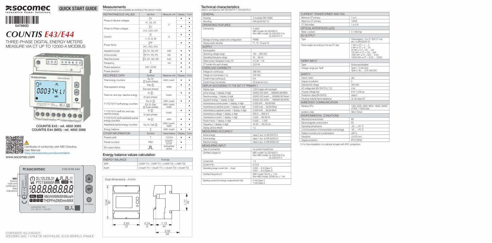
COUNTIS E43 : ref. 4850 3065COUNTIS E44 (MID) : ref. 4850 3066
MIDDevice
code and certification
data indications
CORPORATE HQ CONTACT: SOCOMEC SAS, 1-4 RUE DE WESTHOUSE, 67235 BENFELD, FRANCE
Technical characteristicsData in compliance with EN 50470-1, EN 50470-3
GENERALHousing 4 modules DIN 43880Mounting DIN rail EN 60715
OPERATING FEATURESConnectivity 4 wires
MID model: 3x 230/400 VNon MID model: 3x 230/400 V to
3x 240/415 V
Storage of energy values and configuration FRAMDisplay tariffs identifier T1, T2, T3 and T4
SUPPLYAutosuppliedOperating voltage range 184 ... 288 VACOperating frequency range 45 ... 65 HzRated power dissipation (max.) Pv 3.5 VA - 1 WCT burden (for each phase) 0,04 VA
OVERLOAD CAPABILITYVoltage Un continuous 288 VACVoltage Un momentary (1 s) 300 VACCurrent Imax continuous 6 ACurrent Imax momentary 20 Imax for 0.5 s
DISPLAY (ACCORDING TO THE SET CT PRIMARY )Display type LCD 8 digits with backlightActive energy: 1 display, 8-digit 00000.000 kWh ... 999999.99 MWh Reactive energy: 1 display, 8-digit 00000.000 kvarh ... 999999.99 MvarhApparent energy: 1 display, 8-digit 00000.000 kVAh … 999999.99 MVAhInstantaneous active power: 1 display, 4-digit 0.000 kW ... 99.99 MWInstantaneous reactive power: 1 display, 4-digit 0.000 kvar ... 99.99 MvarInstantaneous apparent power: 1 display, 4-digit 0.000 kVA ... 99.99 MVAIntantaneous voltage: 1 display, 4-digit 000.0 ... 999.9 VIntantaneous current: 1 display, 4-digit 0.000 ... 99.99 kAPower Factor: 1 display, 4-digit 0.000 … 1.000Frequency: 1 display, 4-digit 45.00 … 65.00 HzDisplay period refresh 1 s
MEASURING ACCURACYActive energy class C acc. to EN 50470-3Active energy class 1 acc. to EN 62053-21Reactive energy class 2 acc. to EN 62053-23
MEASURING INPUTType of connection via current transformerCertified voltage Un MID model: 3x 230/400 V
Non MID model: 3x 230/400 V to 3x 240/415 V
Current Iref 1 ACurrent Imin 0.10 A Operating range current (Ist ... Imax) 0.002 ... 6 A (Class 1)
0.001 ... 6 A (Class C)Certified frequency fn MID model: 50 Hz ± 1 Hz
Non MID model: 50/60 Hz ± 1 Hz
Starting current for energy measurement (Ist) 2 mA Class 11 mA Class C
MeasurementsThe parameters are available according to the device model.
INSTANTANEOUS VALUES Symbol Measure unit Display Com
Phase to Neutral voltages ∑V
V
• •V1, V2, V3 •
Phase to Phase voltages∑U • •
U12, U23, U31 •
Current∑I
A• •
I1, I2, I3, IN •
Power factor∑PF • •
PF1, PF2, PF3 •Apparent power ∑S, S1, S2, S3 kVA • •Active power ∑P, P1, P2, P3 kW • •Reactive power ∑Q, Q1, Q2, Q3 kvar • •Frequency f Hz • •Phase sequence CW / CCW • •Power direction •RECORDED DATA Symbol Measure unit Display Com
Total energy counters Ea, Er (∑ & per phase) kWh, kvarh • •
Total apparent energyEap (∑)
kVAh• •
Eap (per phase) •
Total ind. and cap. reactive energyEr (∑)
kvarh• •
Er (per phase) •
T1/T2/T3/T4 tariff energy countersEa, Er (∑) kWh, kvarh • •
Ea, Er, Eap (∑ & per phase)
kWh, kvarh, kVAh •
T1/T2/T3/T4 tariff ind. and cap. reactive energy
Er (∑)kvarh
• •Er (per phase) •
T1/T2/T3/T4 tariff resettable partial energy counters Ea (∑) kWh • •
Resettable partial energy counters Ea, Er, Eap (∑) kWh, kvarh, kVAh • •
Energy balance ∑ kWh, kvarh • •OTHER INFORMATION Symbol Value/status Display Com
Present tariff T 1/2/3/4 • •
Partial counters PAR START/STOP •
S0 output status Active/Not active •
Energy balance values calculationENERGY BALANCE Formula
kWh (+kWh T1) – (-kWh T1) + (+kWh T2) – (-kWh T2)
kvarh (+kvarh T1) – (-kvarh T1) + (+kvarh T2) – (-kvarh T2)
CURRENT TRANSFORMER AND FSAMinimum CT primary 1 or 5Maximum CT primary 12000CT Secondary 1 or 5 A
OPTICAL INTERFACES (LED)Meter constant 0.1 Wh/imp
S0 OUTPUTType Optoisolated - 5 to 27 VDC 27 mA
acc. to EN 62053-31Pulse weight according to the set CT ratio 1 WH CT = 1 ... 4
5 WH CT = 5 ... 2425 WH CT = 25 ... 124125 WH CT = 125 ... 6241000 WH CT = 625 ... 312410000 WH CT = 3125 ... 12000
TARIFF INPUTType Active optoisolatedVoltage range per Tariff Tariff 1: 0 VAC/DC
Tariff 2: 80 … 276 VAC/DC
SAFETYIndoor meter yesDegree of pollution 2Operational voltage 300 VACAC voltage test (EN 50470-3, 7.2) 4 kVImpulse voltage test 6 kV 1.2/50 µsProtection class (EN 50470) class IIHousing material flame resistance UL 94 class V0
EMBEDDED COMMUNICATIONModbus RTU 1200, 2400, 4800, 9600, 19200, 38400,
57600, 115200 bpsIsolation class SELV Circuit
ENVIRONMENTAL CONDITIONSMechanical environment M1Electromagnetic environment E2Operating temperature -25 ... +55 °CLimit temperature of transportation and storage -25 ... +75 °CRelative humidity (not condensation) ≤80 %Vibrations ±0.075 mmDegree protection IP51(*)/IP20
(*) For the installation in a cabinet at least with IP51 protection.
Dual dimensions : in/mm
2.8372
0.246
1.7344
2.5264
3.54 90 1.77 45
2.8372
0.246
1.7344
2.5264
3.54 90 1.77 45
547980D
COUNTIS E43/E44THREE-PHASE DIGITAL ENERGY METERSMEASURE VIA CT UP TO 12000-A MODBUS
QUICK START GUIDE
www.socomec.com
Certificate of conformity with MID Directive.User Manual:https://www.socomec.com/documentation
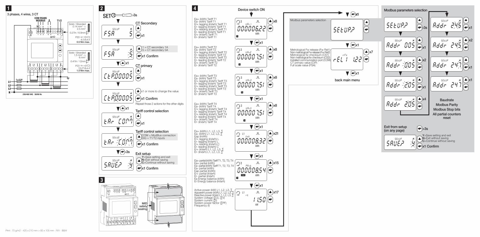
4 Device switch ON
Ea+ (kWh) Tariff T1Ea- (kWh) Tariff T1Er+ lagging (kVarh) Tariff T1Er- lagging (kVarh) Tariff T1Er+ leading (kVarh) Tariff T1Er- leading (kVarh) Tariff T1Er+ (kVarh) Tariff T1Er- (kVarh) Tariff T1
x8
x1
Ea+ (kWh) Tariff T2Ea- (kWh) Tariff T2Er+ lagging (kVarh) Tariff T2Er- lagging (kVarh) Tariff T2Er+ leading (kVarh) Tariff T2Er- leading (kVarh) Tariff T2Er+ (kVarh) Tariff T2Er- (kVarh) Tariff T2
x8
x1
Ea+ (kWh) Tariff T3Ea- (kWh) Tariff T3Er+ lagging (kVarh) Tariff T3Er- lagging (kVarh) Tariff T3Er+ leading (kVarh) Tariff T3Er- leading (kVarh) Tariff T3Er+ (kVarh) Tariff T3Er- (kVarh) Tariff T3
x8
x1
Ea+ (kWh) Tariff T4Ea- (kWh) Tariff T4Er+ lagging (kVarh) Tariff T4Er- lagging (kVarh) Tariff T4Er+ leading (kVarh) Tariff T4Er- leading (kVarh) Tariff T4Er+ (kVarh) Tariff T4Er- (kVarh) Tariff T4
x8
x1
Ea+ (kWh) L1, L2, L3, ∑Ea- (kWh) L1, L2, L3, ∑Eap (kVAh)Er+ lagging (kVarh) LEr- lagging (kVarh) LEr+ leading (kVarh) CEr- leading (kVarh) CEr+ (kVarh) L1, L2, L3, ∑Er- (kVarh) L1, L2, L3, ∑
x21
x1
Ea+ partial (kWh) Tariff T1, T2, T3, T4Ea+ partial (kWh)Ea- partial (kWh) Tariff T1, T2, T3, T4Ea- partial (kWh)Eap partial (kVAh)Er+ partial (kVarh)Er- partial (kVarh)Ea Energy balance (kWh)Er Energy balance (kVarh)
x15
x1
Active power (kW) L1, L2, L3, ∑Apparent power (kVA) L1, L2, L3, ∑Reactive power (kVar) L1, L2, L3, ∑System voltage (∑U), (∑V)System current (∑I)System power factor (∑PF)Frequency (f)
x17
13 phases, 4 wires, 3 CT
SETN
L1L2L3N
230/400 VAC 50/60 Hz
3 x 0.5A
L1
A V A A V A A V A
L2 L3
1 2 3 4 5 6 7
NC - + - +
COM RS485MODBUS T1/2
>3s
x1
x2
x1
x4
x1
x2
x1
x1
BaudrateModbus Parity
Modbus Stop bitsAll partial counters
reset
Modbus parameters selection
3
Exit from setup (on any page) >3s
x1 Confirm
Y=Save setting and exit N=Exit without saving C=Continue without saving
Solid / Stranded 0.14 mm2 ->
2.5 mm2
0.27in / 6.9mm
PZ2 4.5 lb.in /
0.5 Nm max.
Solid / Stranded 1.5 mm2 ->
6 mm2
0.47in / 12mm
PZ2 13.27 lb.in /
1.5 Nm max.
MID safety
sealing
2SETN
AA-V AA-V AA-V
L1 L2 L3
L1L2L3N
3 x 80A
230/400 VAC 50/60 Hz
1 2 3 4 5 6 7
NC - + - +
COM RS485MODBUS T1/2
>3s
CT Secondary
x1
x1 Confirm
1 = CT secondary 1A5 = CT secondary 5A
x1
CT primary
x1
x1 Confirm
x1 or more to change the value
Repeat those 2 actions for the other digits
x1
Tariff control selection
x1
Tariff control selection
x1 Confirm
COM = ModBus connectionDiG = T1/T2 inputs
>3s Exit setup
x1 Confirm
Y=Save setting and exit N=Exit without saving C=Continue without saving
x1
Modbus parameters selection
x1
Metrological Fw release (Fw Rel1)Non metrological Fw release (Fw Rel2)Metrological fw checksum (CS1)Non metrological fw checksum (CS2)Installed communciation port (COM)CT primary value (CtP)Full scale value (FSA)
x7
x1
back main menu
Print : 70 g/m2 - 425 x 210 mm > 85 x 105 mm - R/V - B&W
Related Documents