u C 11 856 D05 ho.7373-5 ne'na 1 of 11 )CE.ANnGRAP'Y rrr It Anchor-last Deployment Procedure for Mooring by Robert W. Thresher and John H. Nath SCHOOL OF SCIENCE OREGONI STATE UNIVERSITY Office of Naval Research Contract N00014-67-A-0369-0007 Project NA 063.102 and Sea Grant Program Reproduction in whole or in part is permitted for any purpose of the United States Government Reference 73.3, dune 1873 9

Welcome message from author
This document is posted to help you gain knowledge. Please leave a comment to let me know what you think about it! Share it to your friends and learn new things together.
Transcript

u
C11
856D05ho.7373-5
ne'na
1 of11 )CE.ANnGRAP'Y
rrrIt
Anchor-last DeploymentProcedure for Mooring
by
Robert W. Thresherand
John H. Nath
SCHOOL OF SCIENCE
OREGONI STATE UNIVERSITY
Office of Naval ResearchContract N00014-67-A-0369-0007
Project NA 063.102and
Sea Grant Program
Reproduction in whole or in part ispermitted for any purpose of the
United States Government
Reference 73.3,dune 1873
9
School of Oceanography,-
andDepartment of Mechanical Engineering
Oregon State University.Corvallis, Oregon 97331
ANCHOR-LAST DEPLOYMENT PROCEDUREFOR MOORING
A Progress Reportfor the
Ocean Science and Technology DivisionU.S. Office of Naval ResearchContract N00014-67-A-0369-0007
Project NR083-102
by
Robert W. ThresherAssistant Professor of Mechanical Engineering
and
John H. NathProfessor of Mechanical Engineering/Oceanography
John V. ByrneDean
Oceanography1Reference173-5School of Oceanography
June 1973
Approved For Public Release: Distribution Unlimited

ACKNOWLEDGMENTS
This research was supported by the United States Office of Naval Re-
search through contract N00014-67-A-0369-oo07 under project NR083-102 with
Oregon State University, and by the Sea Grant Program. Part of the compu-
ter work was supported by the Oregon State University Computer Center.
TABLE OF CONTENTS
List of FiguresAbstract
INTRODUCTION ................ ....................................... 1
NUMERICAL MODELS FOR EXTENSIBLE LINES ................................. 4
Method of Characteristics ........................................ 4
Lumped Mass Model ................................................ 6
Spring Force ................................................. 6
Hydrodynamic Drag Forces ..................................... 7
Added Mass Forces ................................ ......... 8
Governing Equations for the Line ............................ 8
Governing Equations for the Anchor .......................... 9
Numerical Integration ....................................... 10
A LUMPED MASS MODEL FOR INEXTENSIBLE LINES ............................ 15
RESULTS OF TEST RUNS .................................................. 16Nylon Line .......................................................Dacron Line ......................................... ...........Steel Wire Rope ................... ............................
16
18
19
CONCLUSIONS AND DISCUSSION ............................................ 21
REFERENCES ............................................................ 23
FIGURES ............................................................... 25
APPENDIXES
A. Listing for the Extensible Line ............................... 39B. Listing for the Inextensible Line ............................. 59C. Program Sequence .............................................. 87
D. Tabulation of Constants ....................................... 89
E. Computer Run Times ............................................ 91F. List of Symbols ............................................... 93
LIST OF FIGURES
Figures
1 The Lumped Mass Model
Free Body Diagram of a Typical Mass
Free Body Diagram of the Anchor
Computation Flow Chart
Standard Catenary Configuration
Goose Neck Catenary Configuration
Nylon Line 2.5" Dia. (NVRO5)
7 Tension Contours ' KIP 15° Catenary Nylon Line 2.5" Dia.(NVR05)
8 600 Catenary Nylon Line 2.5" Dia. (NVRO5)
Tension Contours % KIP 600 Catenary Nylon Line 2.5" Dia. (NVRO5)
10 Anchor Link Tension for Nylon Line
Components of Anchor Velocity Nylon Line 2.5" Dia. (NVRO5)
12 60° "Copse Neck" Catenary, Nylon Line, 2.5" Dia. (NVR06)
13 Anchor Link Tension for Nylon Lines Starting from 60° StandardCatenary and 60" Goose Neck Catenary.
14 15° CAT Dacron Line (NVRO8)
15 Tension Contours ti KIP 15° Catenary Dacron Line 1.0" Dia. (NVRO8)
16 60° Catenary Dacron Line 1.0" Dia (NVRO8)
17 Tension Contours " KIP 60° Catenary Dacron Line 1.0" Dia. (NVRO8)
18 Anchor Link Tension for Dacron Line
Vertical Component of Anchor Velocity Dacron Line 1.0" Dia. (NVR08)
20 15° Catenary Steel Line 2.5" Dia. (NVR07)
21 Tension Contours ti KIP 15° Catenary Steel Line 2.5" Dia. (NVR07)
5b
11
19
ABSTRACT
The anchor-last mooring procedure is investigated in order to determine
the transient forces in the mooring line and the velocities of the anchor. Tran-
sient forces were determined and the results showed that no severe snap loads
occurred for the cases investigated. In addition, it was found that the
vertical velocity of the anchor can be small as it approaches impact with the
floor of the ocean.
Both extensible (nylon and dacron) and inextensible (steel wire rope)
lines were investigated. Lumped mass numerical models were developed for both
cases. For the extensible line case the equations of motion were determined
for each mass from Newton's Second Law, and they were integrated using a
second order predictor-corrector integration technique. Hamiltonian techniques
were utilized to determine the equations of motion for the inextensible line.
The predictions from the numerical models show the line tensions and positions
as a function of time.
INTRODUCTION
Oceanographic research buoys moored in deep water are often deployed by
the anchor-last deployment procedure. The general sequence of events in this
procedures is: the buoy is deployed from the ship with the mooring line attached
and distributed in some manner on the ship; while the buoy drifts away from the
ship the line is paid out until only the anchor, which is secured to the lower
end of the mooring line, remains on board; finally the anchor is cast overboard.
At sometime during the descent of the anchor it is possible for large transient
forces to be exerted on the line, which can be destructive to the line or to
attached conductors and instruments. One purpose of this research is to examine
the possibilities of such large forces for line scopes greater than one. The line
scope is the unstressed length of the line divided by the water depth.
The Woods Hole Oceanographic Institution has conducted a series of field
measurements of the launching transient in mooring lines where the anchor-last
deployment procedure was utilized (1). However, the study was restricted to the
consideration of moorings where the scope was less than 1.0. It was found that
a fairly steady increase in line tension occurred after the anchor drop and
during the free-fall stage. Then a pendulum action followed where the final line
tension was equal to the submerged weight of the anchor. During the pendulum
action, the line (nylon) was stretching until the anchor reached bottom. After
the anchor reached bottom a reduction in line tension occurred.
A similar problem was investigated by Froidevaux and Scholten (4) with a
numerical model which considered the line to be a discrete number of lumped masses
connected by weightless line segments. However, when the elongation properties
of the line were included, a prohibitive amount of computer time resulted and the

2
investigation only calculated the first and last few seconds of fall. A short
system was considered and results were extrapolated to apply to the 6500 Oceanic
Telescope. One scope which was greater than 1.0 was investigated but the
distance from the buoy to the anchor at launch time was not determined, nor the
influence of scope and line type on line tensions. The conclusion from the
study was that there may be an overstress shortly after the drop and that a severe
transient may occur when the anchor made impact with the ocean floor. Therefore,
the anchor-first mooring procedure was recommended. During this investigation
it was found that large transient forces shortly after anchor deployment can be
an artifact of the numerical program.
The Electronics Division of General Dynamics has employed the anchor-last
deployment procedure for several moorings of the forty-feet diameter oceanographic
buoy for the Office of Naval Research. It has been noticed that some conductors
in the upper portion of the line have experienced large stresses during the
deployment of some moorings but not for others. Thus it was suspected that large
transient forces occurred during the anchor deployment either concentrated at the
buoy,or propagating up the line to the buoy. This investigation predicts that
large snap loads should not occur for such moorings.
Goeller (5) investigated snap loads in steel cables but the study was restricted
to the consideration of straight lines with a scope equal to 1.0 where the mooring
was already in place and the upper end was excited with a sinusoidal motion.
A review of the current techniques for the dynamic analysis of morring
line systems was presented by Casarella and Parsons (3).
The first technique to be employed during this study was like the one used
by Nath (7, 8) where the line is considered to be a continuum and the partial

3
differential equations of motion are solved by the method of characteristics.
Later the analysis technique was changed to a lumped mass approach that was
very similar to the analysis made by Wang (10) except that the equations
developed were in a different coordinate reference frame and the integration
technique was different.
NUMERICAL MODELS FOR EXTENSIBLE LINES
The numerical models presented here pertain specifically to the anchor-
last mooring procedure. The basic equations and procedures for the method of
characteristics solution were presented by Nath (7, 8) and they will not be
reproduced here. However, certain modifications to the earlier program will
be presented which shows the attempts to utilize the method of characteristics
for the anchor-last procedure. The lumped mass model for the extensible mooring
line will be presented in detail. It is similar to the approach taken by Froid-
evaux and Scholten (4). The lumped mass model for the inextensible case will
not be presented in detail because it is available in the work by Rupe (9).
Method of Characteristics
The computer program. presented in (7) was modified to accept the new boun-
dary conditions of the anchor-drop problem. The first runs produced results
which gave unrealistic mooring line shapes. Attempts to improve on the numerical
procedure met with only limited success. The problem was caused by the extremely
tight curvature of the line in the first few seconds of fall. The calculations
of line positions did not correspond to the line velocities.
The solution technique was to solve for the normal velocity, VN, the tangential
velocity VT and the local angle, 0, made by the tangent to the line and the horizon.

For simplicity and as a first approximation the buoy attachment point
was assumed to be fixed. At first it was assumed that the mooring line was
composed of a series of straight lines between calculation points. Then the
coordinates of points along the line could be calculated using:
XiXi-1 + AS cos 0i
= Z + AS sin 0i-1 1
where AS is the distance between calculation points. It is easy to visualize
why this technique would give unreasonable results if the mooring line were to
be given a high curvature or "kink", which is exactly what takes place during
the early stages of anchor drop.
In an attempt to eliminate this problem the following more accurate approx-
imation was used to calculate the mooring line position:
dx1
ds= cos 0
i
(2)
dzi= sin 0.
ds 1
Since the 0.'s are known at constant intervals along the line, then all that is1
required is to integrate the above equations along the line from the attachment
point to the anchor. For example, the trapazoidal integration formula gives
X. X. +AS
2(cos 0i + cos
0i+1
zi-1+
AS(sin 0i + sin 0 1+1)
=
Z.(1)
=
(3)
=
which is equivalent to assuming that the line shape is quadratic between
calculation points. Both the above formula and Simpson's rule were used, however,
the curvature of the line is so steep that even these higher order approximations
did not eliminate the problem. Therefore, the decision was made to proceed with
the lumped mass model of the following section.
Lumped Mass Model
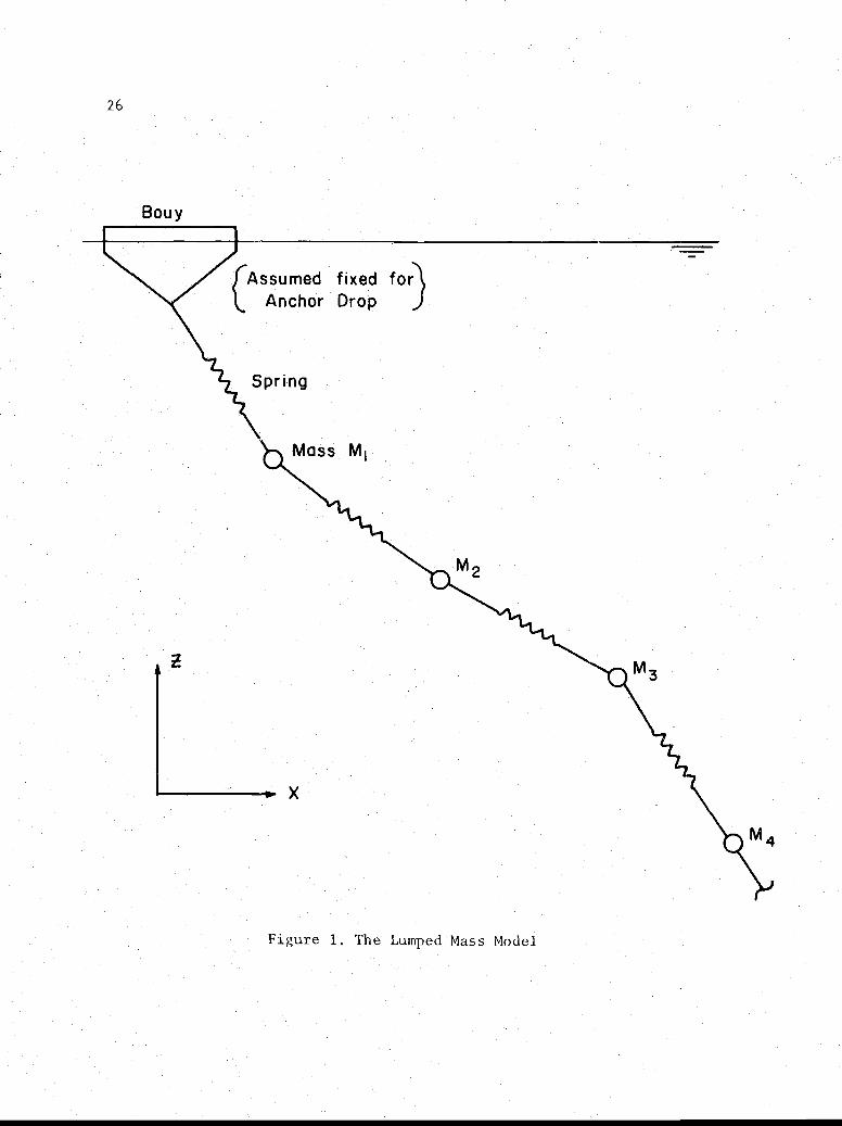
A mooring line can be modeled as a group of discrete masses interconnected
by springs as illustrated in Fig. 1. The various distributed forces which act
on a mooring line are gravity, hydrodynamic viscous drag and acceleration, and
the line tension, which is influenced by the internal, or structural, damping
and the stress-strain relationship. In the lumped mass model these forces are
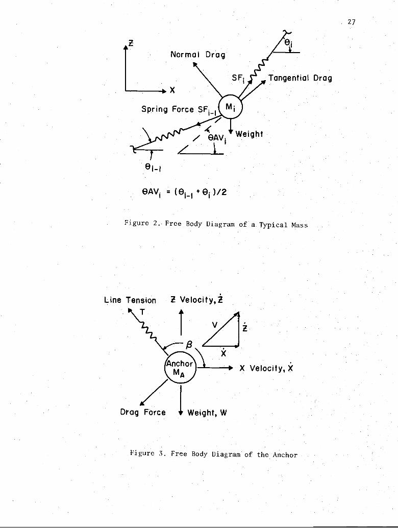
discretized and it is assumed that they act at each mass.. Figure 2 shows the
various forces acting on a typical mass. The magnitude of the various forces
were calculated in the following manner:
Spring Force. From closed solution studies of taut line mooring dynamics it
has been found that the external hydrodynamic forces are considerably larger
than the internal damping force. For this study in particular, where periodic
oscillations are not a factor, the internal damping force was negligible.
Therefore it was not included into the equations of motion of the masses.
Hooke's Law was taken in the general form
(4)
calculating the strain, using the straight line distance between masses, then
1/2OQ [(x.1 - + 2
i) (Zi+lZ) J - Qi
eiQ
Q (5)i 1.
= f
2

where Q1is the unstressed distance between masses and X and Z. are the coordin-
ates of the mass M1,. This gives the spring force SF as:i
SFi = Area
The net spring force acting on the mass M. is given by1
spring force
Lxdirection = SFX. = SF
1. cos(O
1.) - SF1.-1 cos(6 1.
1 -
spring force
z directionSFZ. = SF. sin(O.) SF, sin(O. )
1 1 1 1-1 1-l
The Hooke's Law relationship was assumed to be in the form
where Cl and C2 are constants. The values used for the various lines are given
in the appendix.
Hydrodynamic Drag Forces. Using the quadratic drag law, the tangential and
normal drag forces on the mass M.1
are given by
{Tangential brag} = DFTi CDTpAT (VTi)IVTiI2
{Normal Drag} DFN, = CDNpAN (VN.)1 2
(8)
where tangent. and normal are referrenced to the angle OAVi as illustrated in
Figure 2, and
7
CC
(7)
8
CDT = Tangential Drag Coefficient
CDN = Normal Drag Coefficient
VTi = Tangential Velocity of Mass Mi
VN = Normal Velocity of Mass M.i ip = Fluid Density
AT = Tangential Area = 7DQ_i
AN = Normal Area = D.i
Defining VCX and VCZ to be the local velocities due to currents and waves,
then the tangential and normal velocities of mass Miare given by
VTi = (k. - VCX) cos (OAVi) + (zi - VCZ) sin (OAVi)
(9)
VNi = - (xi - VCX) sin (@AVi) + (zi - VCZ) cos (OAVi)
Added Mass Forces. The added mass forces due to the acceleration of the
line masses through the still fluid was considered in the usual way. That is,
the excitation force accelerates the line and the fluid medium around the line.
The pressure distribution on the line from the accelerating fluid is characterized
by the displaced mass of fluid times a coefficient called the added mass coefficient
and the product is called the added mass. The sum of the line mass and the added
mass coefficient for the line in the direction normal to the line was taken equal
to that for a smooth cylinder (0.5) and in the tangential direction it was assumed
to be zero.
Governing Equations for the Line. Substituting the above forces into Newton's
second law and including the hydrodynamic added mass effect with the actual line
mass (the sum is the virtual mass)

9
A>Ftangential = (Mi + CITpVoli) ACTT
Fnormal = (M. + CINpVol.) ACN.
. 1 1 1
where
CIT = Added Mass Coefficient Tangential
CIN = Added Mass Coefficient Normal
p = Fluid density
Vol = Displaced Line Volume =7FD2 ki
4
ACN = Normal Acceleration of the Mass M.1
ACT = Tangential Acceleration of the Mass M
Then the accelerations are given by
ACT. _ (SFXi)cos(6AVi) +(SFZi - WTi) sin (6AVi) + DFTi
1 i + CITp ° i)
- (SFXi) sin (6AVi) + (SFZi - WTi) cos (6AVi) + DFNiACN _.
1 (Mi + CINpVoli)
In the x, z coordinate system the accelerations are given by
= ACTT cos (6AVi) - ACN.1
sin (OAV1.)
zi = ACTT sin (6AV.) + ACN cos (6AV1 1 1
(10)
(12)
Governing Equations for the Anchor. Figure 3 shows a free body diagram of the
anchor from which the following governing equations can he obtained
1
10
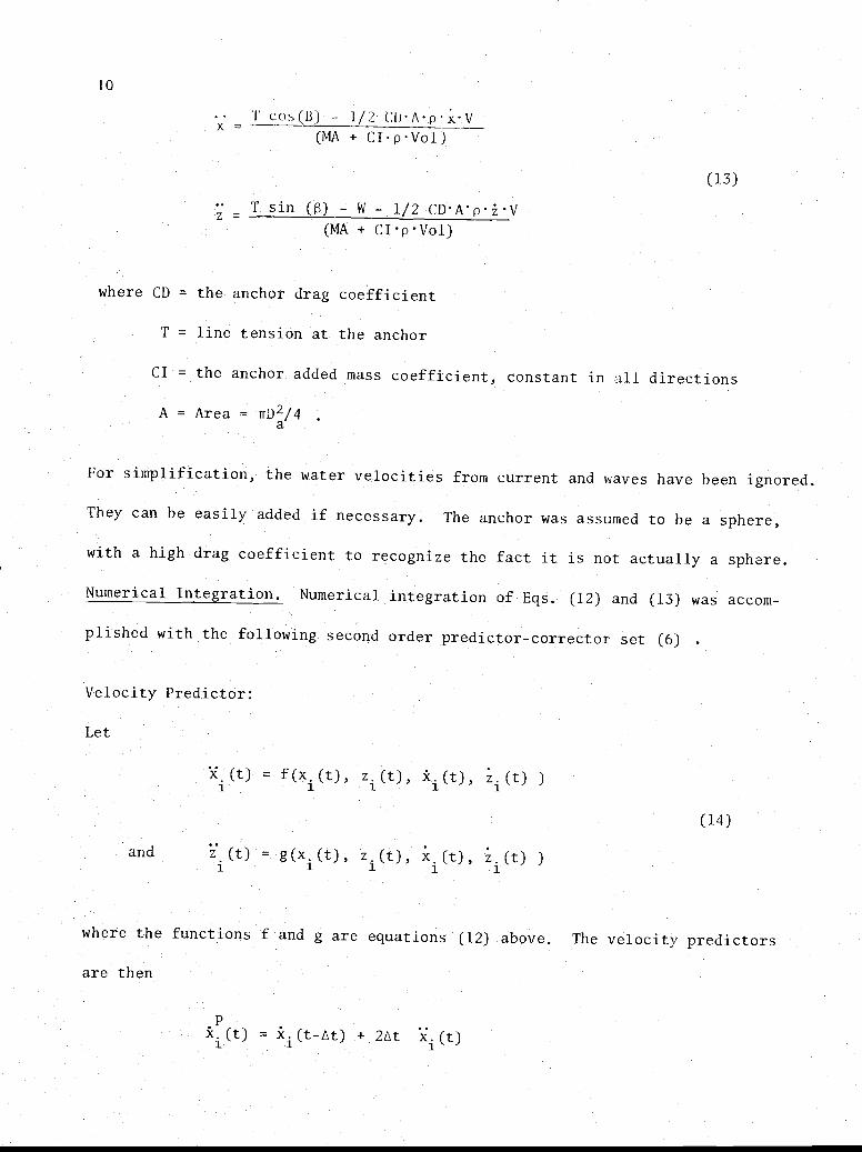
cos (B) - 1/2 C() A p x VX = (MA + CIpVol)
(13)
T sin (S) - W - 1/2 CDA'pzVZ = -(MA + CIpVol)
where CD = the anchor drag coefficient
T = line tension at the anchor
CI = the anchor added mass coefficient, constant in all directions
A = Area = TFD2/4a
For simplification, the water velocities from current and waves have been ignored.
They can be easily added if necessary. The anchor was assumed to be a sphere,
with a high drag coefficient to recognize the fact it is not actually a sphere.
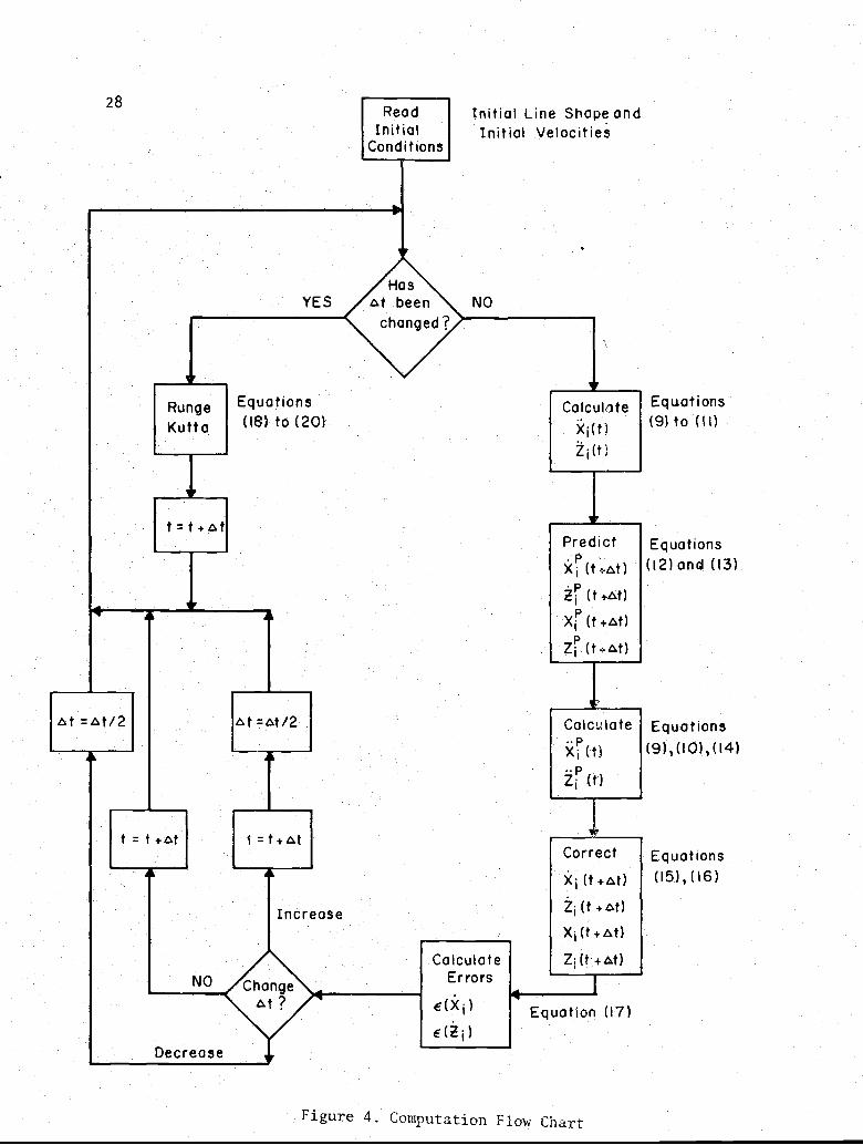
Numerical Integration. Numerical integration of Eqs. (12) and (13) was accom-
plished with the following second order predictor-corrector set (6) .
Velocity Predictor:
Let
Xi (t) = f (xi (t) , zi (t) , Xi(t), zi (t) )
(14)
and z (t) = g(x1(t),
1z. (t), x. (t), z. (t) )i 1 1
where the functions f and g are equations (12) above. The velocity predictors
are then
Pxi (t) = xi (t-At) + 2At xi (t)
11
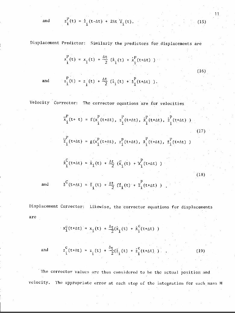
and zP (t) = zi (t-At) + 2At 'zi (t) , (15)
Displacement Predictor: Similarly the predictors for displacements are
xP (t) = x. (t) + of (x (t)+ XP (t+ot)
1 1 2 i 1
(16)
and zP(t) z. (t) + At (zi (t)i 1
Velocity Corrector: The corrector equations are for velocities
xP p(t+ t) = f (xi. (t+ht) , z (t+At), xP P(t+At), z (t+At) )i i(17)
..PZ1(t+At) = g(x
1.(t+ot), z
1(t+ot),
1P(t+ot), t
1.P (t+ot) )
. C (t+At) = x. (t) + at (X (t) + XP (t+At) )1 2 i 1
(18)
and zC (t+At) z (t)1
P
(t) + L. (t+At) )At
2
Displacement Corrector: Likewise, the corrector equations for displacements
are
xl(t+At) = x.(t) + (xi(t) + xi(t+At) )1 --7
and z. (t+At) = z. (t) At
i (t) + zi (t+At) ) (19)
The corrector values are then considered to he the actual position and
velocity. The appropriate error at each step of the integration for each mass M
= +2
= + ('z
+
12
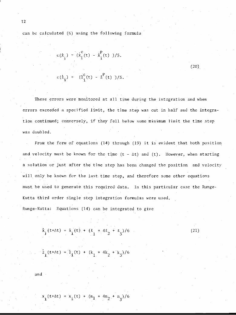
can be calculated (6) using the following formula
e(xi) = (xi(t) - x. (t) )/5.
c (zi) (zi (t) - ip (t) )/S.
(20)
These errors were monitored at all time during the integration and when
errors exceeded a specified limit, the time step was cut in half and the integra-
tion continued; conversely, if they fell below some minimum limit the time step
was doubled.
From the form of equations (14) through (19) it is evident that both position
and velocity must be known for the time (t - Lit) and (t). However, when starting
a solution or just after the time step has been changed the position and velocity
will only be known for the last time step, and therefore some other equations
must be used to generate this required data. In this particular case the Runge-
Kutta third order single step integration formulas were used.
Runge-Kutta: Equations (14) can be integrated to give
xi (t+Ot) = ki (t) + (21 + 422 + 2. ) /6
z1 (t+At) = zi(t) + (kI + 4k2 + k3 )/6
(21)
and
13
where
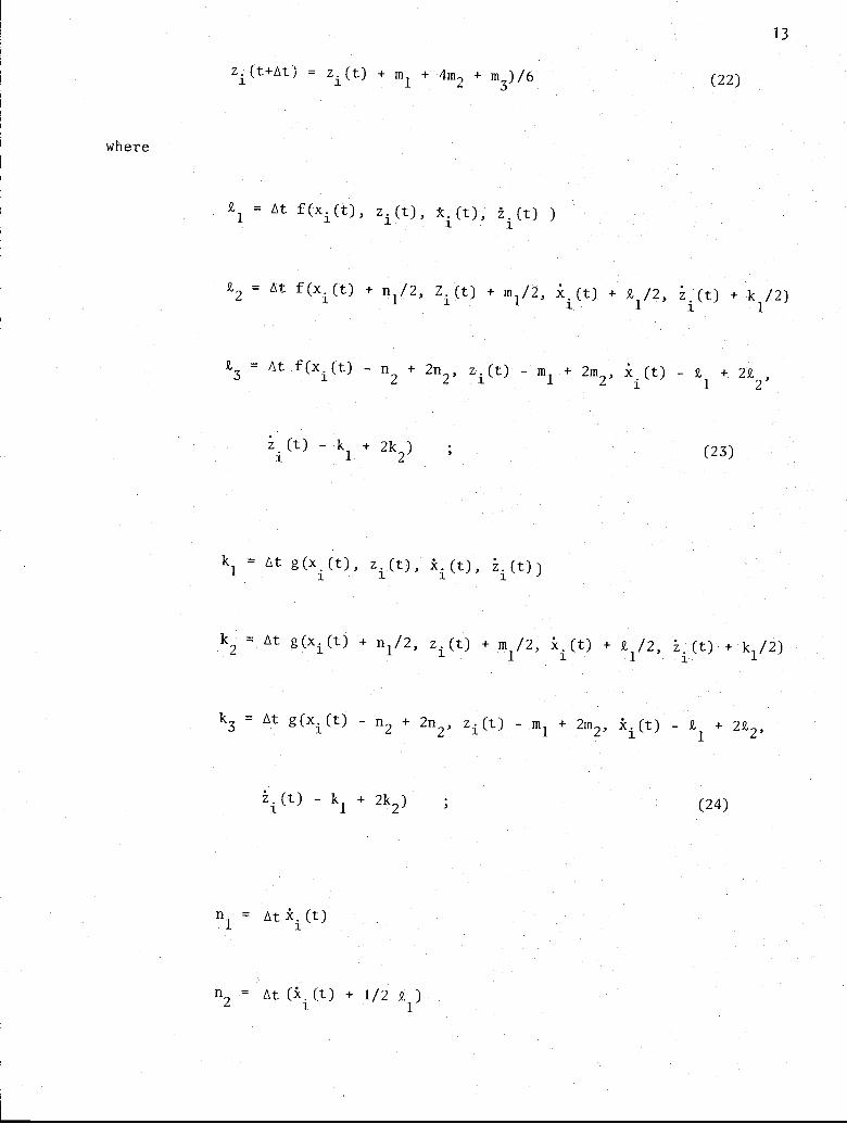
zi (t+Atj = zi (t) + ml + 4m2 + m3) /6
k1 = At f (xi (t) , zi (t) , Ai (t), z . (t) )
(22)
k2 = At f (xi (t) + nl/2, Z. (t) + ml/2, 1ci (t) + R,1/2, z. (t) + k1 /2)
k3 = At f (xi (t) - n2 + 2n2, zi (t) -
(t) - k1 + 2k2) ,
k1 = At g(x1(t), z
1. (t), k
1. (t), z
1. (t) )
+ 2m2, x (t) - k + 2ki 1 2
(23)
k2 = At g (xi (t) + n1/2, zi (t) + m1 /2, ki (t) + k1 /2, ii (t) + kl/2)
k3 = At g (xi (t) - n2 + 2n2, zi (t) - ml + 2m2, ki (t) - k1 + 2k2,
zi (t) - k1 + 2k2)
n1 = At ki (t)
n2 = At (X (t) + 1/2 R. l)
(24)
14
n3 = At (x (t) - Rl + 22 )
and
ml = At zi (t)
m2 = At (zi (t) + 1/2 k1)
(25)
m3 = At (zi (t) - kI + 2k2) (26)
Using the predictor-corrector set and the single step Runge-Kutta equation
for the first time step the governing equation for the lumped mass mooring line
and the anchor can be numerically integrated. In this routine, the error can
be automatically controlled by increasing or decreasing the time step At through
Eqs. (20). The general outline of the calculation scheme is illustrated in
Fig. 4.
It should be noted that higher ordered predictor-corrector schemes exist
which increase the precision of the integration. However, the accuracy of the
technique used may be well within the accuracy of the entire computations. Until.
data from physical models becomes available to prove otherwise it is felt that
this technique gives adequate results.

15
A LUMPED MASS MODEL FOR INEXTENSIBLE LINES
A tentative model for the inextensible case has been developed jointly
with the Oregon State University Sea Grant Program (9). Hamiltonian techniques
were utilized to develop the equations of motion. The explicit detailing of
the numerical procedures will not be presented here as for the inextensible
line case because this has been accomplished in Reference (9).
The model assumed the line to be perfectly inextensible. Thus the motion
of each mass is more directly influenced by the motion of each other mass than
for the extensible line case. A listing of the program is presented in the
Appendix B.
16 RESULTS OF TEST RUNS
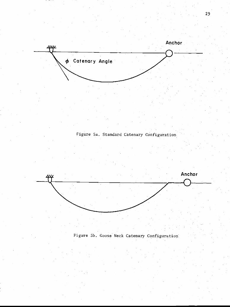
Prior to the production runs several preliminary tests were made. The
first of these showed large dynamic loading in the segment of the line near
the anchor at about 20 seconds after the anchor was released from the "standard
catenary configuration" of Fig. 5a. This result was reported in the 1972 report
to ONR together with results where the anchor was released from the "goose neck"
catenary configuration of Fig. 5b. The second configuration showed much lower
dynamic loading. Since that time the segment lengths were made considerably
smaller and the control on the time step was improved by using the integration
method described in this report. It is now evident that the high dynamic loading
reported earlier was an artifact of the first lumped mass numerical program.
The results presented in the following section show only a small amount of
transient loading during the early stages of anchor deployment.
After this experience, each test case to be run was divided into several
time segments and the computer results were examined at the end of each time
segment. In this manner, links in a critical area along the line could be
subdivided while links in areas where the line tensions were more constant could
be consolidated. After these adjustments, the computer continued the solution
from that time until the end of the next time segment where the output would
again be examined and adjustments made in the link lengths. In this way, accurate
results could be obtained without using an excessive number of links and computer
time could be conserved.
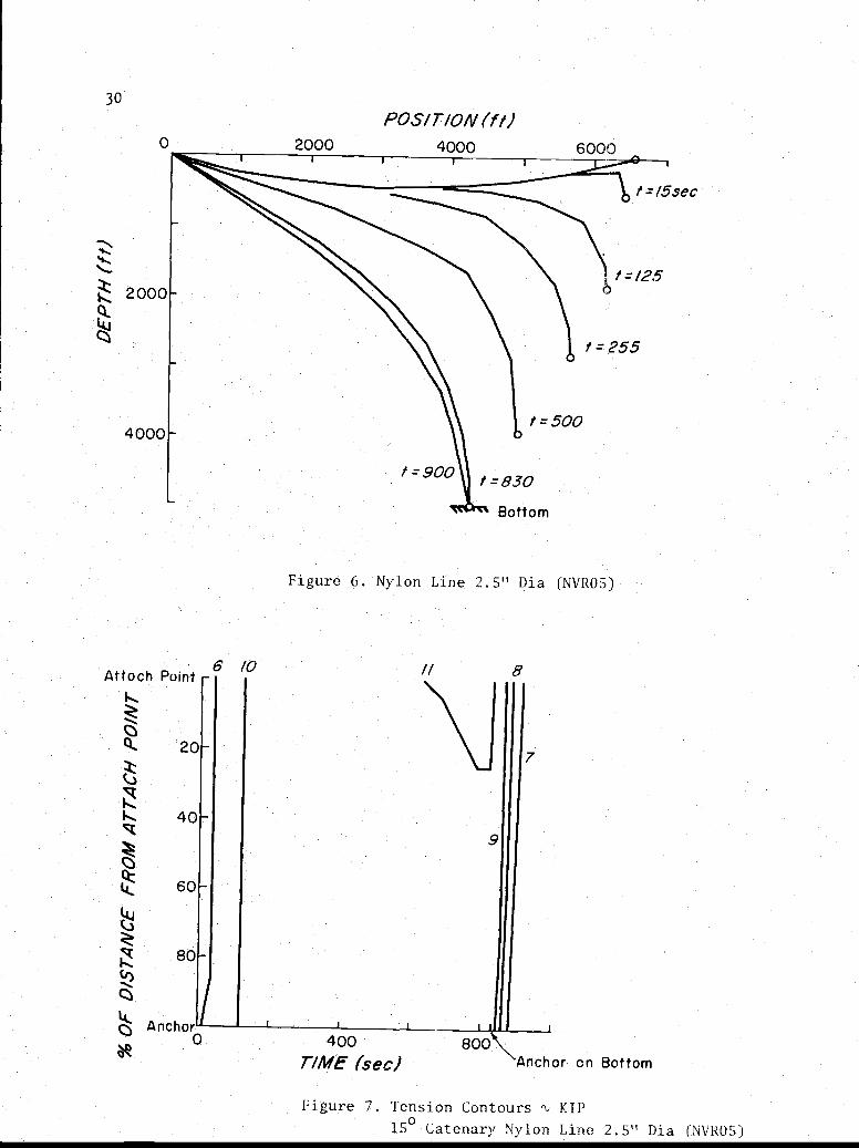
Nylon Line
Figures 6 through 13 present the results for the 2.5" diameter nylon mooring
line for both the 15° catenary and the 60° catenary initial condition. Figures
17
12 and 13 show results for the "goose neck" initial position. Figure 6 shows
the line shape for various times during the drop for the 15° catenary. Figure
7 shows the tension contours for the 15° catenary as a function of position
and time. The most notable feature of these results is that the line has
essentially constant tension during most of the drop, and there is no snap
load during the fall or after the anchor touches bottom. Figures 8 and 9
present the same plots for the 600 catenary. Although the line tension is not
constant the tensions vary slowly with time and position due to the high hydro-
dynamic resistance forces acting on the line.
Figure 10 compares the tension for both catenaries at the anchor link for
the first 140 seconds of drop. Figure 11 compares the vertical anchor velocities
during the drop. It is interesting to note that the terminal velocity for the
12,000 lb. anchor in free fall (unrestrained by a mooring line and where drag
acts only on the anchor) is about 50 ft/sec. When the anchor is attached to a
mooring line, the velocity approaches the terminal free fall velocity during the
first few seconds of fall and then reduces considerably due to the drag on the
mooring line. Figure 11 also shows the horizontal anchor velocities. The
maximum tension during the drop was approximately equal to the anchor weight.
In general, the long run times for these solutions (see Appendix E) were
a result of the high curvature in the line near the anchor. When the anchor is
released it drops straight down which causes a "kink" in the line just behind the
anchor. Early during the drop the line motion tends to be mostly tangential
especially near the anchor, which requires that the line on the buoy side of
the "kink" must move around the "kink" at relatively large velocities. For the
lumped mass model, this means that a lump on the buoy side of the "kink" is
18
accelerated toward the "kink" and obtains a relatively large horizontal velocity.
As this lump moves around the "kink" its velocity must very rapidly change from
nearly horizontal to vertical. Because of this large acceleration the time step
is drastically reduced as a mass moves around the "kink".
The problem is compounded if the links are relatively large. As a large
heavy link is accelerated toward the "kink" it obtains a considerable amount
of momentum and it has a tendency to over-shoot the "kink" which causes jumps
in the line tension. In one particular case the horizontal anchor velocity
changed directions as a relatively large line mass overshot the "kink". This
result is shown in Figure 11 where the horizontal anchor velocity becomes positive
for a short time during the early portion of the drop.
Comparison of the output for the "standard catenary configuration" and the
"goose neck catenary configuration" of Figure 5 showed about the same results
provided sufficiently small link lengths were used. Figures 12 and 13 show the
results for the "goose neck" catenary during the first 70 seconds of the drop.
The comparison of anchor link tensions for the "goose neck catenary" and the
"standard catenary".shown in Figure 13 indicates very similar results except
that at any given time the "standard catenary configuration" has about 1000 lb.
more tension. Since the"standard catenary configuration" seemed to be a more
realistic starting configuration, and because the results are very similar, no
further runs were made using the "goose neck" catenary.
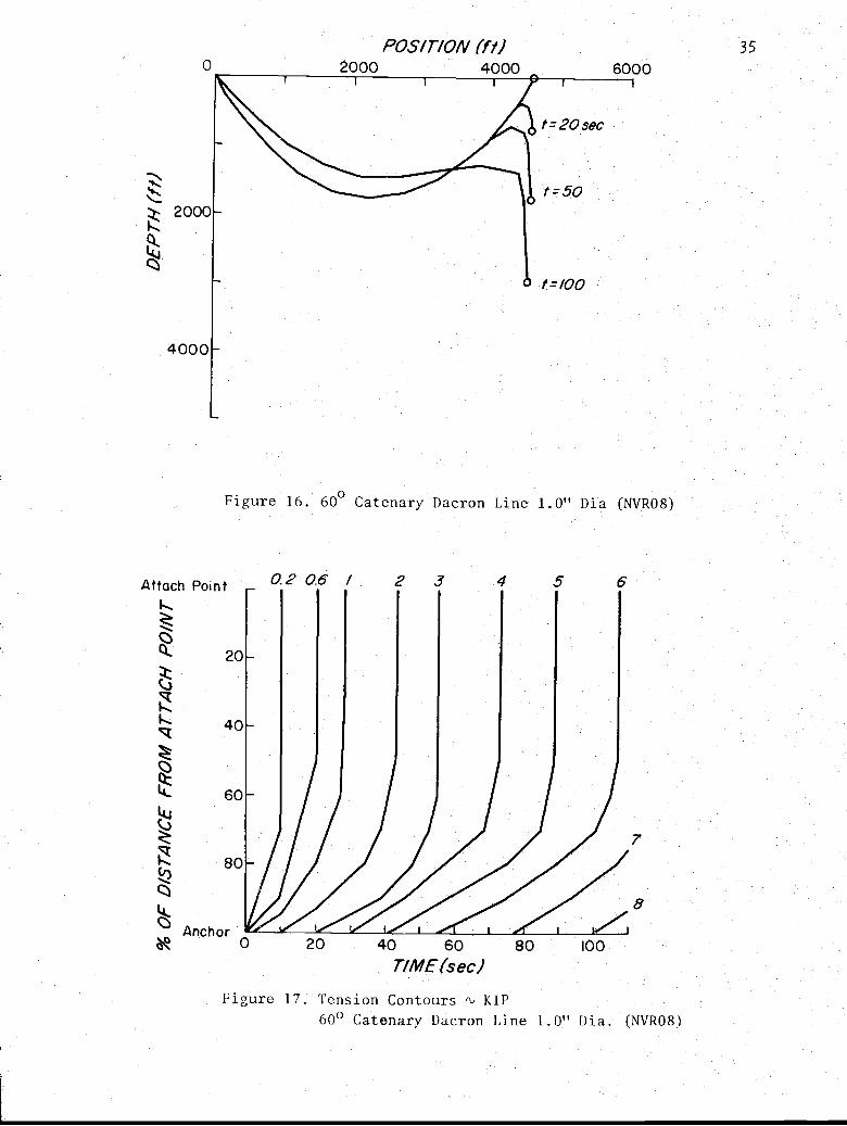
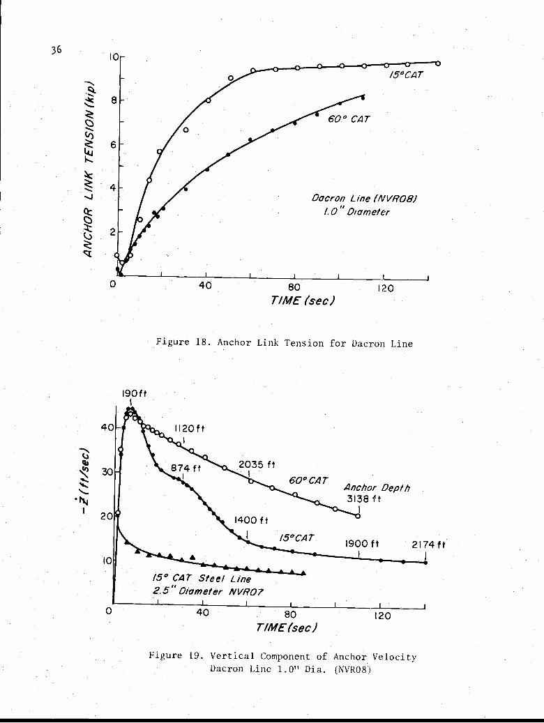
Dacron Line
Figure 14 through 19 present the results for a 1.0 "diameter dacron mooring
line for both the 15° catenary and 60° catenary initial conditions. Figure 14
shows the line shape for various times during the drop for the 15° catenary.

Figure 15 shows the tension contours for the 15° catenary as a function of position
along the line and time. The computer runs for this case were terminated after
140 seconds of drop because the results in general were not greatly different from
the 2.5" diameter nylong line presented in Figs. 6 and 7. There was no snap
and the tensions seemed to be fairly constant and approximately equal to the
anchor weight. Figures 16 and 17 present the same plots for the 600 catenary
initial condition. For this case the computer runs were terminated after 100
seconds of drop because of the general similarity to the results obtained for
the nylon line.
Figure.18 compares the tension in the anchor link for both catenary initial
conditions during the first 140 seconds of drop. Figure 19 compares the anchor
velocities during the drop and here again these results are very similar to the
results for the nylon line.
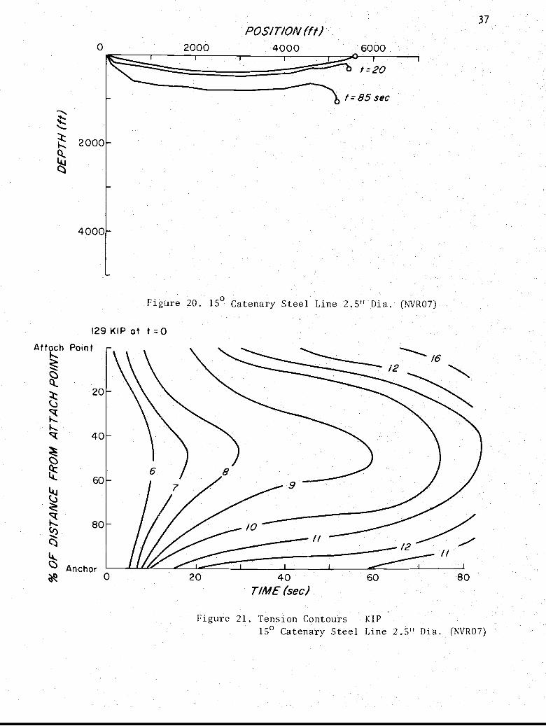
Steel Wire Rope
At the time of this writing a computer program to model inextensible steel
or chain mooring lines has just been completed. A few preliminary runs have been
made for the anchor drop problem. The results of one of these runs is presented
in Figs. 20 and 21. Figure 20 shows the line shape for various times during the
drop for the 15° catenary initial configuration of a fictitious equivalent 2.5"
diameter steel cable with a density of 350 lb/ft3. This diameter was selected
initially to compare with the 2.5" diameter nylon line results. Subsequent runs
will use more realistic diameters.
Although the program was only run for about the first 85 seconds of fall,
the results are considerably different from the previous results as would be
20
expected due to the large line weight and the inextensibility conditions. The
results show that the line falls almost as fast as the anchor, which is expected.
Figure 21 shows the tension contours in the line and the results are markedly
different with the maximum tensions occurring at the attachment point. Although
these results are preliminary, in that the link lengths should be reduced and a
more realistic case should be run, they do indicate general tendencies. The drop
was run for only 85 seconds due a limited computer budget.
21
CONCLUSIONS AND DISCUSSION
1. The lumped mass model together with an appropriate integration scheme
such as the predictor-corrector method is a useful tool for the dynamic
analysis of extensible mooring lines. It is easily adapted to almost any
line configuration and can readily handle non-linearities.
2. The results obtained for the anchor drop problem show no dynamic line snap
for the configurations that were considered. It appears that the high drag
of the long mooring line quickly disipates the kinetic energy of the anchor,
which slows the anchor to a velocity well below its free fall terminal
velocity of 50 ft/sec.
3. The elastic properties of the line do not seem to play a great role in the
line motion during anchor drop. The nylon and the dacron line showed
similar position time histories.
4. Mooring line diameter did not seem to play an important role in the
mooring line motion. Both the 2.5" line and the 1.0" line showed about the
same position time histories.
5. For an anchor drop from the 15° catenary as modelled here, the line tension
is essentially constant with respect to line position.
6. For an initial condition of a 600 catenary the tension increases more
slowly than for the 15° catenary.
7. At no time, for any run, was the line tension greater than the anchor weight
for the extensible mooring lines.
8. Time-velocity histories of the anchor show that the anchor settles onto
the bottom at a vertical velocity of about 5 ft/sec for the 2.5" nylon
rope.

22
9. Preliminary runs made for an inextensible steel line show a much different
behavior. At least for the limited runs made, no snaps loads were observed.
Further runs must be made to verify this result.
10. It is postulated that the high loads during buoy mooring implantment that have
been experienced at sea for scopes greater than one were not caused by shock,
or snap, loads in the line. Possibly, during the time of anchor fall, the
line was relatively taut and the dynamic loads from waves acting on the buoy
created the high tension forces close to the buoy.

23
REFERENCES
1. Berteaux, H. 0. and Walden, R. G., "Analysis and Experimental Evaluation
of Single Point Moored Buoy Systems", W.H.O.I. Reference No. 69-36.
2. Bulirsch, R. and Stoer, J., "Numerical Treatment of Ordinary Differential
Equations by Extrapolation Methods", Numerische Mathematik 8, 1-13 (1966).
3. Casarella, M. J. and Parsons, M.,"A Survey of Investigations on the Motion
of Cable Systems under Hydrodynamic Loading", Marine Tech. Soc. J.
Vol. 24, No. 4, pp 27-44 (Jul-Aug 1970).
4. Froidevaux, M. R. and Scholten, R. A., "Calculation of the Gravity Fall
Motion of a Mooring System", M.I.T. Instrumentation Laboratory Report.
E-2319, August, 1968.
5. Goeller, J. E. "A Theoretical and Experimental Investigation of Snap Loads
in Stranded Steel Cables", U. S. Naval Ordinance Laboratory Report NOLTR
69-215, November 26, 1969.
6. Lapidus, L. and Seinfeld, J. H., "Numerical Solution of Ordinary Differential
Equations", Academic Press 1971.
7. Nath, J. H., "Dynamics of Single Point Ocean Moorings of a Buoy--A Numerical
Model for Solution by Computer", Oregon State University, Dept. of Oceano-
graphy, ONR Progress Report, Ref. 69-10. July, 1969.
8. Nath, J. H., "Analysis of Deep Water Single Point Moorings", Colorado
State University, Technical Report CER 70-71 JHN 4, August, 1970.
9. Rupe, R., "An Inextensible Lumped Mass Dynamical Mooring Line Model",
M.S. Thesis, Oregon State University. To be completed, June 1973.

24
10. Wang, 1'. 11., "A Two-degree-of-freedom Model for the Two-dimensional
Dynamic Motion of Suspended Extensible Cable Systems". Naval Ship
Research and Development Center, Bethesda MD. Report 3663, October 1971.

25
FIGURES
26
Figure 1. The Lumped Mass Model
27
eAVi = (6i-1 + 0. )/2
Figure 2.. Free Body Diagram of a Typical Mass
Line Tension Z Velocity, 2T
Drag Force Weight, W
Figure 3. Free Body Diagram of the Anchor
At=
28
At/2
RungeKutta
=t+ot
=t +At
ReadInitial
Conditions
YES
Equations(l6) to (20)
at =At/2
Equations(9) to (11)
Predict
XP(t+ot)Equations(12) and (13).
P(t+At)xi (t +At)
ZP (t+At)
Calculate
XP(t)
Equations(9),(10), (14)
ZP (t)
Corr
Xi (t
ect
+At)
Equations(15),(16)
Zi (t +at)
Xi (t + At)
Zi (t *At)
Equation (17)
Initial Line Shape andInitial Velocities
NO
t
Figure 4. Computation Flow Chart
29
Figure Sa. Standard Catenary Configuration
Anchor
O
Figure 5b. Goose Neck Catenary Configuration
30
Attach Point 6 /0
POS/T/ON (f/)2000 4000 6000
Figure 6. Nylon Line 2.5" Dia (NVRO5)
//
9
Anchor0 400 800
1-110
r//WE (See) Anchor on Bottom
Figure 7. Tension Contours ti KIP15° Catenary Nylon Line 2.5" Dia (NVROS)
20
40
60
80
7

POSIT/ON (f /)2000 4000
Attach Point
6000
Figure 8. 60° Catenary Nylon Line 2.5" Dia. (NVRO5)
2 3 5 7 9 /0 II
200
o\° TIME (sect
J400
31
Figure 9. Tension contourstiKIP60° Catenary Nylon Line 2.5" Dia (NVROS)
60

32
I0
/50 CAT
6
NYLON LINE (NVR05)2.5" Diameter
' I I 1 1
40 80 120TIME (sec)
Figure 10. Anchor Link Tension for Nylon Line
VERTICAL COMPONENT600 CAT (HO
/50 CAT ( VERTICAL COMPONENTHORIZONTAL COMPONENT
200 400 Bottom 600 800
TIME (sec)
RIZONTAL COMPONENT
Bottom
Figure 11. Components of Anchor VelocityNylon Line 2.5" Dia. (NVRO5)
8
0
60° CAT

POS/T/ON(fl)33
2000 4000
Figure 12. 60° "Goose Neck" Catenary, Nylon Line, 2.5" Dia. (NVR06)
20 40TIME (sec)
Figure 13. Anchor Link Tension for Nylon Lines Startingfrom 600 Standard Catenary and 600 "Goose Neck Catenary".
60

34 POST/ON (ft)2000 4000 6000
Figure 14. 150 Cat Dacron Line (VR08)1.0" Dia.
8 9 9.5 9.7/ 2
0 40 80
TIME (sec)
Figure 15. Tension Contours % KIP150 Catenary Dacron Line 1.0" Dia. (NVR08)
t = 20 sec
f=50
Figure 16. 60° Catenary Dacron Line 1.0" Dia (NVR08)
Attach PointL
20
40
60
hO
80
Anchor20
POSITION (fl)2000 4000 6000
40 60 80TIME(sec)
100
35
Figure 17. Tension Contours ti KIP60° Catenary Dacron Line 1.0" L)ia. (NVR08)
0.2 0.6 /
0
36
/5°CAT
Dacron Line (NVR08)/.0 Diameter
40 80TIME (sec)
120
Figure 18. Anchor Link Tension for Dacron Line
vq)
19 Oft
15° CAT Steel Line2.5" Diameter NVRO7
40 80TIME(sec)
120
j
Figure 19. Vertical Component of Anchor VelocityDacron Line 1.0" Dia. (NVR08)
4000
POSITION (ft)4000 6000
Figure 20. 15° Catenary Steel Line 2.5" Dia. (NVR07)
129 KIP at t =0
2000
37
Figure 21. Tension Contours KIP15° Catenary Steel Line 2.5" Dia. (NVR07)
Attach Point
20
40
60
80
Anchor0 40 60
TIME (sec)

39
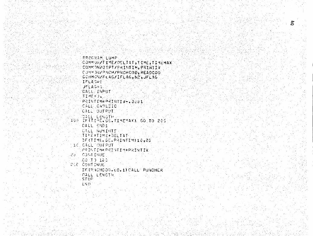
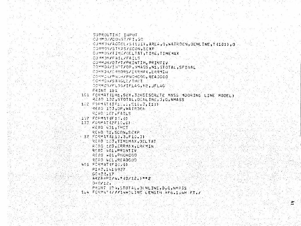
Appendix A
Listing for Extensible Line
PPOGRAf', LUMPCJMM )It/T I'IE/DELTAT IT TMEIT I'1EMAXCOMM 1 110 TPT/PRIttTIM, PRINTIVCall'-l )N/"'"JCM/PNCHCOO, REAOCOOCC11MC'i/FLAG/IFLAG, N2 , JFLAGIP* LA'-,J3 LAGCALL INPUTTIM: = 1.P,INtIM=0 INTIV-.3LU1CALLCALL
j= LL
C4`ILEICOUTPJTLET
1':r IF (Tt''E. G TIME" AY ) GO TO 2 `I
CALLC" LL
NO 1
NUM I,T2TII,E=Ti°"-+JELTAT
( T ;1 CALL "'UT PUT
?RI 1zIIM=°mY'JTI"1+P:INTIVLv "JtaTIvWE
GJ T 3 id'1C CDNTINIJE
IF CR'JJ'ECO1.cQ.1) CALL PUNCHCRPALL LENGTkkSLOP;:,N, FP
SUPRJLTI N" INPUT+,J 1m 111/CC,JST/PI,GC;JMM ):dACCEL/S (1J I ) 9 ARE A,0,WATP0EN ,DE NLINE ,T{1+ 1),{7;30l- 9 /ST"',AS/SCON,SEXPC J" "J43/T I' .=/OELTAT,T IMIE, TIMEMAXCJ'1MJ/PAIL/FAILSCJ'1MJr1/OTPT/PRINTIfi1, PRINTII
0 C1?",`T/0P,'41ASS,N3,STJTAL,SFINAL(") 3'1aRP0'SE; MAx,EKRlIW
.:'#V i/FNCHCon, REAJ0C0CM°1°J S A,4GLC/ THE T'J MJd/FL')C/IFLAS,P'2,JELAG
PRINT 1U .
iC a ; CRMAT (1 ti1, 5CX, 32HGI SCRETE MASS MOORING LINE MODEL)RZAr) 132,STOTAL,J_tLtNE,J,C,NMASS
RE BJ 1,'3 ,OP, WA T1?CEt,°R_tj t? 1.C7,cAILS
l 7 F^-';,rAT {F).C. 0)Iv3 PJRr1AT(2F111 .C)
REAL) 431,THETR-AG 72, SCUN,SE XP
32 t:CRmjT(E1J.3,F1C.))=P,0 S.C3,TIMEMAX,J34TAT;;" 1C 103 PR MA X, E"RF*4IN
R" AD +#:1 , PRINT IVRvPJ 4O1,PNGHC00REb0 4+ 1,READCOC
4`,1 FCRMAT (F1-). 3)PI=3.1415g27GC=? ,17AR FA=°I/4.*(0/12. 2J=11/12 .P-IINT 11+,STOTAL,0tNLINE,0,0,NM,"!SS
1v4 FC ',":T(///!4H2LINE LE'4G{ i =F6.194H FT./

DENSITY =F7.3,1'TM L8./FT `*3/21 ri-LI d OIAM-"TER ==`5.3,+F1 FT. /3131W'' DAI1PPIG CONSTANT =LIU.3,.13H L 3 SEC/FT's*2/4 1E14 OF MASS} S = 132)
Ni=N44SS+1N2=N1.+1PRINT lCr),DPWA'TR0EN,TIMEMAXj0ELTATPRINT 4:i2,ERRAAX,ERRMINPRINT 4t 5,THET
43 5, F3Rl,' AT (2 3140 CATENARY ANGLc Al SURFACE =F5.2,5H DEG. )T .-th T=THE T*PI/13.
4 2 FCRMAT(2 ,`VELOCITY ERROR BGUNDS,F8.4,3H TO,F8.4)1:;5 FO+ ' AT t 14H: WATER C PTH =F9.2, 3H FT /
1 16H 1W1AT DENSITY =F6.2,9h Lt3/FT-CU /? 1.'P.; +AX TIME =c8.2,4k SEC /
12W"TIME STEP =F5.3,41 SEC )PRINT 136,P?INTIV
1.6 R')kMT(1?"4PRINT LVFRY F5.3,4H SEC)PR1J1 1tr 8, NILS
1J3 FJC'`l^,T (2-4GLIN FAIL 'JR= LOAD _ F11.1,4H LF3S)t'Pit NT -,j :,PNCHCE)D
4 ? : r'i3 MAT tl 31=. ^U^;,'.j CC1E =FS. 1, 5X,S6HPUNCH CODE = 1. PUNCHS ALL POS AAT TI4L= TIME,1X
PR IN i Y j '+, RcAOCOO+ FR`^uTtl'41 R;A`l CCOr =F5.1,5X,57H REAL' CODE = I. READS ALL FOS A
1 J3 V -7L FO", TIM = TI MEMAX )IN t 4, 's, SCON,SEXF+
4 F; aT tlf.?_X,34 iSTP-SS-STCAIt RELATION STPESS ,E13.3.,-3H*STRAIN
C
L' ,F,.l)C S=GM=NT LENGTHSr
SL=Si0TALP14ASSS(I)=SL/2eDO ?'j I= 2,N'4ASSSt I) =SLC O NT [ IJE
(Ne1 ASS+ 1) =SL/?.RE TU RNEli)

Si; ?' )UTI i NUMINT :%;i.i lP J-i/T Im:-/Dli-I AT,T IMri, Tl,'IE:MAX
CuM.,+J/d`J"iy/XL {il),Z_L(1:1),XO(1°l1),ZD(11), XOO{11l9ZOD (131) 91 XLN(1C1),7LN(1+:1),XOt (iil),ZU.N(1C1),LRRORX(1J1),ERRORZ(1O1)
CCMI'C"4/I'SPT/OP,tNMASS,N1,STGTAL,SFINALCu '!J,d/AGv L/S (iii) , A+2.A, O, tAT20c,t, DENL INE,T (i31) , DC ""+' ad/4 L/FAILS
GGr`"Jd/)T"'T/P?I 3Tlmg L(4TIV
J
r
CC t`A )J/=) L-)fXLJL, ZLOL3(iu1),XUOLO(Ibl),Z'OOLO(I 1),XO90LO(1l1)))J_O(1.1)
G 1+','WFL:,S/IF L, N. ,JFL At.DIME SIO^i XUi)N(1-1),7OON(13ii)DIM 4 I0"; AKXi(I:,1),AK7_i(ILI),AKXZ(Imi),AKZ2(101),AKX3(IGI),AKZ3(I
Ix), )Xi(a.'1),0Z1(111),OX2(131),OZ2(1O1),OX3(1!1),QZS(131)
Oh. T ',,-_, CITY AN) °3SITION 4T TI"" T+D[LTAT
I ^_3 TI'1JLIi (ILL=t 0.C) GO TOC, C, I I = , N2'r (I GO TO 77CALL ACC LL(I,XL(I+1),XL(I),XL(I-i),ZL(I+1),7L(I),ZL(I-1),XO(I+1),
I XD(I),XC(1-1),ZO(I}1),ZD(I),ZD(I-1),XOO(I),ZJD(I))CyJ TJ 74
7;3 CALL -N)?(XL('N?),)(L(tdi),ZL(N2),ZL(N1),XD(N2),ZO(N2),S(Ni),AREA,1 XJD(P42) ,ZDD(N?))
IF(I...'D.N:.AND.ZL(N2)LT.-DP)XDCiLD(I)=C.1; (I.L0.+v?.ArdD.ZL(t2LI07f)ft 1J(I)=
-74 CCNTINUL
X
7 7tti{I)='_DO LOI+DcL7AT2ZDD{I
XL«(I)=XL.(I)+DELTAT* (XO(I)+XON(I)) /2.ZLN(I)=ZL(I)+O L T A T 4 (Z0(I)+ZDN(I))/2.
.).
C
.O'((I)=-XON(I)ER P02Z(I)=-ZON(I)
iL` CANT LNUE
CO . 0TO'Z
X'i=X.'4(2) ;ZM=ZLN(1) iXOM=XDN(1) SZOM=ZCN(1)C) 2 J I2N21 F (I.rO. 2) GO TO 75CMLL ."C-L(T,XLN(I+1),XL'J(I),XM ,7LN(I+1),ZLN(I),ZM
XCJ"J(I+1),XON(I),XC"7 ,ZCN(:+i),ZQN(I),ZDM ,DDX,DDZ)G O T ) 7 F
75 C I L L NX1XLN(N2XLfi((N1) 9ZLN(N2),ZL N(t i),XDN(N2),ZDN(N2),S(N1),I ARE ,JDX,JDZ)
'6 C2N,TT;JU''r
f,
X'=Y'-4(I) i7M=1-7LN(I) t'XDM=XDN(I) 3ZCM=ZOON(I)X'P.'t T -)=X)(_T)+C.LTAT*(XJC) (I)+')JX)/2.7J1,.(I)=7 (I)+O=LTAT*(700(1)+;)DZ)/2
X_tztl)=XL(I)+J.LTAT'(x0(I)+XJN(I))!?.ZLt'(C)=L (T)+%?=LTAT`(ZJ(L)+ZJPa(I)1/2.
X(I(cam;O,X{I)+X'7rd(I))/(5.*XON 1)r x :t Z(T)=('RR;);;Z{I)+ZJE.I))/(5.*ZONI1 ;,J2 7L t,2 LT -OP) z
2 41*4JZL t,,2 LI -0P)ERROKZ(N2)=L.
IF{( 3S(YI)).LT..1) X=10.IF IS XDWI)) LT.1. }F,<RX=1.IF ( A 3S{ -tORX(I)).CT.-RX .U+2.A3S( iRURZ(I) ).GT,ERRZ )1+3,2Q01L DELI AT=FiCLTAT/?.IFLC '`s=l,°RI!T 9. 3,U2L7AT,TIM,I,c!(JRX(I),ERRORZ(I)

F0k"'AT (132X ) )
IF ( :LTAT.LT.1.7 PTT 9YAP FUR T (2
STOP15E 3'- TO 12,.. C')NTI )U:.
155, i5
GE LTAT LT uc:l
)) 3,., I-1,v42XLCLJ(1) =YL(I)ZLCL)(T.) _7L(I)X,OL7(I) =XD(I)Z') CL. )(I) =7O(I)X_ U)=XLN(I)7r (I)=ZUN(I)X "(I)=XfN(I)ZJ (1 70N, (I)I=(ti3` (= ;tJ (T))LTIN.AND. A3S(ERFOPZ(I))LT.E R',4 IN)NOUNTE)2
O: ' 'CNTINUEIf- (^j,,JUNT»\.;0.fda)
35: 3uLTAT TAT2,IFLA3=(?)') + 7 I 1,N2XOLJ(I) XLN(I)ZLOLJ(I) =ZLN(I)X:)0L%) (I) =XON(I)
437 Z)OL J(I) =Z'DN(I)PRINT 91Ca,UELTAT,TIME
P1ta FORMAT (21HLOtLT ^,T I #CRE.ASLO TO F7.4,3H AT,F8.3,4H SEC)3O C3NTI'T E
Gi TO 2'; -.
1 : C C C NIT INUE
U,
TO
R'UNGE-KIJT1A (THIRD ORDER)
JJ 1 L 1=202Iw (I. r. k') GO TO I
-A C,r' L(1,XL( LOJ(II1),XLOLO(I),XLCLD(I-i),ZLOLD(I+i),ZLOLD(I),ZL`a(I-1) ,X` OLJ (I+1), XC0 LJ(I),X00LO(I-i),ZDOLD(I+1),7DOLD (I),ZOOLD(
1I-S) ,XJ7;J(I) ,Z)CL'3(I) ?GJ Ti) 11J,,
.L1 i -,ALL O (XLOL')( J2),XLOLD(N1),ZLOLD(N2),ZLOLO(Ni),XOCLD(N2),ZOOLO(1N ), S(,1),4KLA ,X)OOLO('42),7DDOLD(N2))
11'C C++PtiTI'it1
'< X1 (T)= LT -"T *K 3,)C L I)A<71 (I)=JMLTAT *ZDDCLO(I)i)x1(I)=)LTAT*XDOLC(I)O?1(I)=rLT T4ZrOLC,(I)Y)t! I=X--3LI+AKXL(I)tZ =77))Li1(I)+AKZi (I) / 2.XL N:(T)=XLULD(I)+OXI I)/2.ZL1ZL.AL`l(1 +0 Z1I)12.
I .) O TO 12 5(I,XidT+2XLNIXLhI-17LN(i+i)ZLN IZLNI-1)XON
T+1IXr)"tI-1L0ivI+1),ZD'd(I)2DN I- 1)XJD4 (1)9 ZDD fi)G C
T'1 12'10C1LL L-CNO?(XL`)(42),XLN(Ni),ZLti(N2),Z,-N(N1),XON(N2),ZON(N2),S(Ni),
12 rb T'TI U
1N( L)
44"X2 (I)= )c'LTAT*XO+i) )(I)AKZr (T)=JLTAT+ZD)N 1)OX 1)=D LTAT X004' I
2I)=DLTAT*7 DNIy2i, 3 NT INU:-
)(11 N
ia I=2,N21)=X;JOL0 1AKXI(1)+2.*,KX2(I)
Z3'I=73JL I IAKZ1 (I+2.'AKZ2 (IXLt,(I)=XLOL0(I)-(X1(I)+2.+DX2(I)
(I)=7LOLD(I)-QZ1(I)+2.4QZ2(I)13C CNTIu ;-
G" 1jiJ u i=2, N2I (I ,.:D. 'vc) CO TO 1---.15-
A CC L(I,XLN(1+1),XLi`a(I),XLN(I-1),ZLN(I+1)ZLN(I) 71 N(I-1)X'JNi1(T+13.X n(I),XON(I-1),ZDJI+1ZDN(IZ0 t4(I-1)X0ON(I),Z00N(I)G,j Ta 13,!6
1'C-- CALL 7-ND2(XLN(CSC),x'L"((i,41),ZL14(v2),ZLN(N1),X33 (N2),ZDN(N2),S( I),"R?=A,XDOIJ(W) 9ZION(N2) )
13: CJNTINUEI)=.tLTAT* X331v(I)
AKA (I)= =1F'LTAT+ZOcD ( 1)Q (1) TAT* XO ON (I)0'3(I) =)ELTAT*ZON (I)
14u i C) NT IN UEDO 1 U I=2, N2XJ(I)=XDCL O(I)+(AKX1(I)+,,.*AKX2(I)+AKXv(I))/6.t)ZJ (T)=Z3GL!n(I)+(AKZ1 (I)+4.#AKZ2(1)+AKZZ(I))/6.s0XL (I)=X,L3L.D(I)+(DX1(I)+4o*QX2(I)+OX3(I))/6.(3ZL(I)=ZLOLD(I)+(QZ1(I)+QZ2(I)*4.+QZ3(I))/6.C
1-3 ') CO SIT INUE117 LAtJ- i
2Jj0 CONTINUE03 73j I =2, N1CALL TENSION(I,XL(I+1),XL(I),XL(I-i),ZL(I+1),ZL(I),ZL(I-1))
38tU C3NTTNUL=no 4,). I=1,NiIF (T(I).GT.FAILS)41394G,
41C- CALL OUTPUTJJ 1-1: Y=RU OT (1 . )
4 (, . (:C NT INUEkE, TURN:jr)
1i4L/,,':LTAT IT 1M1-)TII-.MAX3,)+ )^alIS ( .13, A At Q, ,WAT OE1 9OEN INE T 1)D
);sfr,}CTXJP*44acSrfJ STOTALISF1NA.)"1')w'If ( ?L( ul),XO(l i3,Zt1.1),XJ {11),70f t1 1?s)tw(l ),_Zon(i,-' RCPX(1,3I),ERRORZ(1
L(1T
(2

SJmr,J!1TINE ACCrL(i,XP,X,XM,ZP,Z,ZM,XDP,XD,XDM,ZDP,ZO,ZOM,XDD,ZOD
C!°`°9 j/AiEL/S (1..,I),A,,,D,ATR'3,ZNLI?`lE,Tt1J1),dCr",!'l1 ft /I PT/DP,NMAcS,^N2,STOTAL,SFINALCJ 3'J/CJi T/PI,t C
C31 a);II/TI'?E/fELTAT, TI ,TIMEMAXCJM'9ON/OTPT/QP.INTIh', Pr;INTIJT t`Tw=,T"42((ZP-L), (XP-X) )T1ETA^A=aTZ-7M), (X-XI))
T J'J r OZCE O"! MASS I
°F '- ;T((x-XM)"*2+(Z-ZM)''2)/S(I-1)-1.P=S`)T((XP-X)4' 2+(ZP-Z)**2)/S(I)-1.
cr O*: X= IRS A*( STRASS (EP) *COS (THETA) -STR ASS (E PM) *COS ( THETAM) )SF OR'Jt Z=AREA4 (STPASS (cry) *SIN (TH ETA)-STRASS (EPM)' SIN (THEY AM) )
WA TES ;JA MPI!VC FORCES ON MASS ITH AV= (TM ETA+TH.TAM) / 2.
C
C '1. OLAD V7 ARE LOCAL VELOCITIES

vV X =,+ 4
V A°_J=(X'1-''IX)*COS(TH1V)+(ZJ-VZ)*SIN(THAV)V'40R A=-( )(0-M *SII(THAV)+(ZD-VZ)*(30S(1±AV)
E'(I.4(:.2)SL=S(I-1)fS(I)12.(1.0. 1)SL=S(I-1)!c+S(I)
A <FT=P.1+ 34 3LA_ L
;:T=1. +`« JCN=14O AGT=-;, T*WAT DFN*t ,ET*V T ANG*A3S (VTAU(;) / (2.4 3C)1at,' d=-,^,'" AT ,Jhl`FKe,V'Iu "k (VNOR14)/(2. C)
V-LT `J" L IAS:; CO CT ION
S SSL4ID _NL1'{ 4 .A /V0A 1AJWh T FZO_N* aK:I .CL /Gc : -f= i(
.
;CT :G= ((SFO }`CJS(1dA )+1 ^!(T"iH }+r;y C.T)I(S'ASS+CIT AMASS)
A"CN O+M= (-- (SFO 2C(:X ) SIN 1AV}.
C0S(TIaAV)± JZ4 6 `3)11S'dACIkx NMA S
FORCE Z
(SFORC E Z
Y 0= ;CTA,I=*!:OS (T-±CJ)-4CCNO M*Sl t(THAV)Z,JU= ACC, T01G4Sirk(Tt-AV)+4CCNORM* COS(THAV)
E D
-WT)*
-WT) *
(
SJ UTIN' LNU2(X,X",7_,Z`,XO,ZO,S,A ,XOO,ZOO)/FL.;GfiFL4G,ft2,JFLAG
C!MJ4/INPT/OpR AL ;
I ; : GO TO 95RhrI: iT=12o;c.ViL='4.r" =. i
W4.R 4i 2.P 4 2 2
^`vt IG HT-WO ids VOLnl 7.11 532,E
= E :,: 1G.1 1 /G+CI* VOL'`R#GA=rn#ARE A*K3O/(2.* 1)JF LA'a=1
5 ,0 "ITI,AUUIP(Z.L.T*-)F)53,S
55:, X i=Z1=XOO=7OOU= J.n=TUBA
6 =S )T ((r-XM)'2+(Z-Z1'?) 15-2.T=AR*ST ASS(EP)T E T A T AN2 (Z- ZM, X-XM) +PIF{-T*COS (THETA)FZ=T*SIN(THETA)-W9V=S`) T(XO**2+Zt9**2)XOO=EX/M-A*XD'"VZOO?=F'Z/M-A*'ZO * V
E TUI - !
7N, r)

FUMCTIO4 S1RASS(X)cc 1" 3 / TEAS/ScON,ScXP
s1 N STRAIN X, FINO STRESSIF{X.LT. .?1 2i'ST RA SS=;.
?. TU RNCC t, TIt;U7ST+y 3S-)CCia*X *S;XP
J T y cT t`.i I N,_,T =( x/-C0H) 44 (, * /SIX )
-1 7
T Y ?U7Tc IN, T
r'''AT(1X9 21-+ HAS 9c:.N RUPTUR O)Tt
F" ?UTI"J_ ENOICtiMM'1,4/i'I: /DLLTAT,TIMk:,TIME-MAXCl''!'N/'L1'^; /XL {1L`1),ZL (1u1),XD(131),Z(?(1v1),XtD{it31) ,?7D {131),
r,b(,.I :./."JIXLJLD {1CT1) ,ZL3L J (iv1, Xi)DLD (1:.1), Z3DOL0 (iu1),XDJDL(3(111)OO2 J( :)
T 3) ' -" Y O'+:1ITiONS xT END i9 (1)_... T 7 Ljd(I)=1a iXON(1)=2 4 Z)N(1)=uI
CILI(!) =XJOL`) (1)-ZLDL') =Z)OLD(1)=vL0-11 N
L r JUTI $ LENGTHIM )'/NNj 4I/XL (1':1) , ZL (1J1) ,XD(131) ,ZC)(1Q1) , XCO(1o1) ,ZOD (131),
1 <L(1;: ), ,f (11XD'4(11),ZOU(11E',90RX131),ERROR Z(131)
i',=T ',Nm4Ss, tkl a STOTAL, St= INAL
'T PA IN-1 -)
n3 1J
GTH OF CABLE
S;=I`JIL =,S;IN AL#S{)RT((X,.(I)-XL(I-1))*42+(Z.(I)-ZL(1-1))**2)
'DINT 1%1,S I i
IJ1 FO AT{//1 ?3,2}X,1: L1N LENGTH =,F8.1):
R, I JRt4d" N D
X
_N,
=,F8.1)
SUFRJUTINE OUTPUTCQM%I )N/T IMF/DELTAT, T IMt, T IMEMAXu.:`1M )r/ti1I/XLt11), ZL(11),Xpt11),ZD41fl1), XDQti{l1} ,ZD t171),
1 (l'fl «),?Li(lrl),x3tth1),ZIlPtl31),tRORXti1,ERf20R7tii,.C4mj',r/AC,;,;:-L/S (11), AREA,Q,WATRDENIOEt UNFIT (1C1)t:,O 1=i )v/Ivi)T/DP gNMASS,NI, STOTAL,SFTNAL--RI1iT iZI ,TIMEFOR'& T (1M1,//,7HOTIME =F6.2)P? Ip, T ii i
101 M"CP""'AT (/ /// 1H j , 5X, FH LINK 96H MASS , 6X,13H COORDINATES , 1OX, 7HTENS1ICX4 1,"iiVz`L;;CITi=S,14X,6FRR()RS)RIr,T
,7X,3HNO.,3)(,w,iN:U.,9X,1HX,9X,1HZ,25X,1HX,1OX,1HZ,BX,1 4HX )OT, iX, 4HZDOT)
PRINT 1! 3, (I,X-(I),ZL(I),XO(I),Z')(I),ERRORX(I),ERRO Z(I) ,I,T(I),1 I=i,'a1)
I:J7 c-JR'41T(13X,I3,2X,2(1X,F).2),17Y',2(1X,F1J.+),2(2X,E1o.3)/7X,I3,31X,1 E11.4)
2 =141uj t"PI"T 1,-',r,2,XL(N2),7L(hd_'),X')(" 2),ZO(td2),ERRORX(N2),ERRORZ(N2)RE T'J i"3EN 0

SU9'JUTi, CA?L ICOJ11Jr /SA.*JGL2/TH T:;CM4CIWOTPT/P INTI*', P'INTIV
M HLO0,REAJCOOC,J J I L T I TIM ' I
('u r 4ST/PI GOAR- a, 0,WATPO:Nti,O NLINFT (101)0
CC t^ NP// OP, fym 4 SS, N! t SP OTAL t S Fl N AL"4 /lJ3I1XL{iul),7,L L1)7X30d1"1i),ZJO(1G1,
<." (.I'a),ZL,a(11i),XO(iu1),ZCN(1:i),EFRC-X(1:1),ERRCkZ(1J1)"Mi UOL-/XLCLr (iLi),ZLJLJ(iLi)XDCLO(!Ll),ZJOL0(1'.ji)X)DOLO(IJI)
' ',.)3.O(i;1)" 1+1
IF (<2AOCUO.EO.1.) co TO 5UCW' - = ( J-NL 1' -WTR=OEN) A A
TIN!! Iv (Tr T) /COS(THET)31.=wfT)TAL
L 1 , 3SL /(2.`T4NO)
FL=T/WL*SINMI (TANG)
c 5 J=i,N2I;: (J.NE. 1) SL=SL+S U-1)x-(J)=FL/Z.+TO/wL*:INHI(SL* L/TO-SINH(WL*FL/(2.*TO)Z L (J) =T0/V L* (COSH (WWL /TO* (XL (J)-FL/2.))-COSH(WL*FL/ (2.*TO)) )T2=TJ*CJS14(WL/TO* (XL (J)-FL/Z.)).°,-,2=ST ;'A IN (T2/ AREA )IF (J.;:0. i) GO TO acsT(J-1)=(Ti+T2)/Z.O--:LTAL= (-.Pl+EP2) *S (J-1) /2.AN (,= IT 4N 2 (Z:. (,J) -ZL (J-1) , XL (J) -XL (J-1) )'(L (J)=XL (J)+Oc_LTAL*COS(ANG)
=ZL (J)+DcLTAL*SIN(ANG)SL=EL+ )CLTLOO I i T I1' L1 :V
T1=T?
Z7OLI(J) _jOxOcIL J(J) = r.7) (J)=f:.XD(J)=C.)(LN(J)=(L(J) IEZLN(J)=ZL(J)XL.fL)(J) =XL (J)ZLt)L3(J) =ZL(J)X') (1)=k . 170 N(J)=CE, FFI'RY (J)=L. 9FRRCRZ(J).
237 C3PNT INUE2"2 CONTINUE
RE TIJRN59" CCNTINUF
RFAO ,:):J,JELTAT,TIt IFP-IrTIM=TI4+PRINTIOno 63) 1=1,N2"hn :: ,XL(I),ZL(I},XJ(I),ZO(I}T(T)='.XL1,(I)=XL(1) 'ZL;J(I)=ZL(I})ON(I)=XJ(I) I70N(I)=Z3(I)YLOL )( 1) =XL (I)7LCL)(I)=7(I)
= X : ) )
7 iL)(1}=0(I)
R .O TTM 'lAXFOPM T2: _,.-)
0 1 FOc.., AT (4FI C, 2E12.5)R TUEND

SI(I ,XP ,X,X ,ZP,Z,Z41)I1i_ Q, T D£ta9 C Ni INE,T{131
IF (I. "c , 2) ;U TC° 1,
4''S(E P') F. tL ru J { J 1 i .....
T ( I) S T-R I'SS ( J-) *ARE Ar "f { _) t
(-X))
x) + (-X) )

59
Appendix B
Listing for Inextensible Line
FR O(= ?AM CARL: 1OI""F SIC?"d T44ETA(3 ), TO(3J),THLTA2(u T0 (3G),TOO(3t;To02(3.i},TOI
C (?C) ,THETA I (:, )DIPZ vSION Tlr)I(3Z)OIME,SION Vr_kROP(3C) , P`4kOk(3C)CO M1111 )N/ANC ASS/A(JC} ORCt) )N/POS/X(3 ),Y(3C)/T-zN/TEN(30)/VELIVX(3C),t/Y(33)/B3S/Xf,YQ,XQ,Y
r z), XD ), YO fl, Cl`-NS ITY, YCCCMHCw/3')FAG2/oRAG(?C)/G/GRAV(3C)C) ""-";/T/TT E,OFLTAT,OELTATNX.=' ThXO-Y("=XOC=YOC= ._A=t r,TI'"LCUUT,TP2ItJT,CI,CN,c;T,KORRECT
5 FCCMAT (FE.2,1X,F5.2,iX,FS.t+,tX,F4.2,1X,F5.4, 1X,I2)R=i»n 6,`)ELTAT,tUP,FLOW
6 FCPMAT (FE.F+, lX,F6.4, IX,Fli.9)CALL INPUT('d,OIA,OfN SITY,XC,YL,TOTAL,ANCHOR)CALL ADDMASS(N,OIA,CI)CALL TN( , UTA, CN,CT, A iCHt e:)F?I',.T 1-', ;3.,OENSITY,TOTaL,N,gCH0R,X:,Y( ,N
L1 E 1)IA= ,F4.2,/,15H LINE DENSITY= ,F5.1,/,14H LINCE LE IGTH= F4.51/114H ANCHOR MASS= ,F7.'=9/97H SPAN= ,F5.2,/,14H WACT,:P :Th= ,FS. ,/,18H NO. OF SEGMENTS= ,12)
PRI"'T 1 ,I1M CU ,TF ,INT,CI,CN,CT,KGRRECTTIMECtJT= F6.29/,i6H PRINT INCFEMENT= ,F5.2,/,1SH ADDED
C "Ass C OER= ,F4.2,/, l'H ORAC COEF,/,5-X, R,HNCRMAL= ,F4.2,/,5X,122HTANCG;hTIAL= NC OF CC ECTIONS= ,12)
P IC=T 1 ,,rUP, E LOWto C r,T t1 # tPOR LI'1ITS,/,5Y,7 R PEr,= ,F7.4, /,5X,7HLOWEk ,.F12.9,/
C////)CALL INITIAL (N,X",THETAI,TO1)CALL ANGLE (N,THETii)CALL COORlt9,XQ,YQ,YO,YO,TDI)FP It T 20
F:;
,P"..1+,2;
2 FFT(32X,1.$HINTTIAL. CDc$DZTIUN5',II/,1CX,1GHLINK MASS,9X,1HX,IjX,Ci"Y, 1X 97HT6'NSICNy 7X, 5HTHt.I 93X1, 91-1THETA 00T,/I)
= 1 ./ 141 -9>> T
(I)=T-i-'T ? ITTJc(I)=T:I(I)* A
r 's,=,I.T` I),TyETA2(I),TD2{I).I,X(I),Y(I)I;AT(tiyiT;,?uXyL1.+,k,F7.2_,3X,F515X912,5X,F7.2,1X,F7.2)
4t GC,TIhUPRII'T 5,)cLTAT
5aa c'C ;w1T(/III/,3. DELTA T ,Fo.Y,ll1I1)TII ='i,H_C<=k .
1_T ITl3=j;- T AT
FLA =
!ri LP:=..KC. .K=IF ( K 'z LA3.E 0.3) CG TO 62T;- (Y (4). LT.vr rO TO 52
CC Ti 1' Eb3 CALL "20TTDH Ni, TO ,TIwE}
KFLAG 1NF LA
62 a 6C TD 7aC:L.. CALL T4;'.TA,TD)CALL CL VE (',I ,igKC,hz2'CTGALL 01C (,N )r,LTA T,TDI9Tf!,T,jT9, i=)0,TifTA2fTD )
T-ftT 1.(I)=T' TA(I)
A E( J F
TOi(I)=TC(i)TJC4 (I)=r"OO(I)
61 C tNTI\!ECALL -,ALL (N,TH:TA2,TC2)CALL S(lLVr(4,T002tK0RRECT)CALL CC'R .CT(N,OF-LTA T,THETA1,T01,TOO1,T002,THETA,TO)CC c5 I=1,NVE' OR(I)=(TO2(I)-1O(I))/(S. TO(I))rFO(I)=(T9E:TA2(I}'-THtTA(I)}l(TiETA{I)5.1
65 CC V I",tip,?? 12 I=1,td
(,lE2n1R(I) ). w.Eup) GC TO 112G E E 3 0 i GO TO 138
PRINT 1; 5,'ELTAT,TI"1E,IF0R'A AT (174 DELTA T t#FLO TO ,F9.7,1C:H AT TIME= ,F11.7,i7H BECAUSE 0
CF LIv:K , 12)Go T) 11:'
108 ra:LTAFN=O'_' LTAT/(': .TIM! =T .1m _-')F.LT aTTOOH,.' ;K=TC'i`CK-}LL TAt01 LT AT=0ELTATNP +I"1T 10,", OFLTAT, TIME
1 J FO;'-'ST (??H ':)ELTn T OTC EASc3 TO 1 3 1 H AT TIME= q F11.7)Krf.;. =K;r4 CK+'1IF (u `=^Ks c_. W) CALL EXITJF Lj i=tGO T 1 EC
112 C:)t,T Ir,0 ECO it I=1,NIF (t ?S (d rte= n (1)) .,-LGw? GO TO 1iWOE.LTATN=JILTA1 *2.PRINT 3O,DELT1TN,TIME
60 FOP1"IT (22H DELTA T INC:2 ASEO TO ,F9.7,1 H AT TIME= ,Fi1.7)
7=)
Kwt,FO'=KCHCK+IIF (K0Hv:CK.Gr.3) CILL EXITJFLA ,='G C T ' 11C., I',T I1 uU,n^0 h,T INN17uUCL L ' (h,'? LTT,TH-TLI,TC1,TOc1,Tl#ETA,TO,KQ RECT)JWt.A=1
I I F TI'°= = T I"E+CrLTATT_ ,+'.=TCH -'CK+`,LLTT
I (T : K.f TT''ItT) Gv ToGC T r 6t'
13* 'CH CK=TCMICK-TPRI(T17G 77'.r rI,140 FCR''IT(////,7r TIME= ,F11.7,////, V.X,1LH INK MASS ,6X,11HCOOROINAT
C ,1 )x, }/TM LCCITY,r7X,22'T1T TH,-TA,7X,7HTENSION,13X,5HEPROR,//,2C7X,1,iX,5X,:.HY, gX,1HX,7X,1hY,15X,?HOCT,2;^X,5HTHEETA,4X,9HTHETA OOT,/
CALL At GLascw, T4ETA)GALL COORO('1N,XC',Yf ,X ,YO,TO)CnLL TE NSIOPlf ,YOJ,YOO,T #ETA,TO,TOO,OEFNSITY,XC,YO,YO)A=1}i ./3.141Fc;
T'1 T 2, (I )=THETA (I) '*AI C (1) =T C (I) *A

F;'IJT lc;" =,I,TI+=T42(I)sT 2(I),TEN(I)PEQRGR(I),VERRQR(I),I,X(I),Y(IC), /X(I)t JY(I)
1`,1 - aTt11X,22,45X,F6.212XIFC.214X,E22..4t4XIF4.513XyF11.81/117X,I2t4x IF 7.21 2X IF7.2s4XIF6.2? 2X9 F6.29/)
161? CCV T I \Ut:P INT
155 F' . ^ T t!/!/1)TF t ' 'L4G.E1).1) GO TO 63IF (TIFF. .TIM7-CUT) GO TO 170G'O T') E0
171 CC".TI rUFC4 Lt EXI TF N F,

ctjT Il,::,I!T(N9DIA,JttiTIYsX:9y11,9TOTAL 9ANCH R)i
T / L ( 3 2 ) / SS/ - ) / J-Kr N )!TOTMA S lTM(3 )y NcH0 0141D hvS17YxTCTALX1'9Y
Fig w , i ( I L k X j i f q ! )C 4 i ` Y T i f 1, X q P c > o 6`9 1X i F 5' J * C g l x 9;:c,;* C-)
( i ? j .. (I) C (I )
30 CCTINL
t" 1=t-
5 CCt,TIfyUFM ( ) = `s L (N) +4t C#_ORTV M) ="1( \)CC 41 I= 2, N=:+ *I
T(K)=T'1(K+1)+ (K)4 1 CC NT I'vUE
tr-: TURlEND
2

SL9 -1,ITIN AODMASS( ,CIA,CI)-,EAL L
CCM')'i/L L''+GTH/Lt37)IAQM4S/AM(3C)CI'i4.`.1+15g t IA/24.) 'ZPC 11 I=i, NAM (1)=A*L(1)
lfl CC KTI'YU:RE TIJI RN

T T \ Y I' r 1 <'X 1 ' j 4{ C T j 4 tom, J ri C1 h)
Iy','.fysJ'D"! )/cC'-p/JT ( ..) ,D`df?
i .` 1 159I./.L.A = ]E7N*f TA/12.
ON (T)=A LCT)T {1)=34LtI)CC t,T Nil:-'
* 1 rC`'f` 12. 43u = a NCHC /fL
,'tit':+.,.?=..,3r`13tiC!{:';l t+.'3e,t43JC67j )''0' .s/3+ C"'+_'Q=wasa 15g2Y.5` `+f1iH{3+(**2
=. i 'J-` -d*NANCHO / 2.R IE T
7N 0

SUP lUTI Nc IE'«dTIAE(tt,X.,,THETA,TD)`JSION Tr)4;TA(30)1T)(33TX(3G)9TYL,M
E GT4/L(30MASS/M(3j/TEN/tL-N3r=
4/L.NCTO'
iMSMI-S',)'1
QC i : I=1, NiTMASS=TMaSS+M(I)TC(I)=.4
1J CJt;TINUETO W) =u.TY (I)=.5*Tr ASSTX (PH) =TY tN)CAM"' A=.2 *TMASS
TX'S=TX(;))TYS=TY(N)
22 TX (i) =TY (11)TY(i)=TMA -TY(1)V !(1)=S CRT(TX(1)**,'+TY(1)**2)A=TY(1)/TX(1)THET(1) =ATAN(A)cX L(1) *CCS (THETA(:.) )E Y =_(1) *SIN (THETA(1) )CC f) I=2,MTY (i)=Tv(I-1)-,A(I-i)Tx(1)=TX(I-1)T: -(I)=SrRT(T)<(I)**2+TY(I)**2)A=TY(I)/TX(I)TtIETA(I)=ATAN(A)EX +==X*L(I)*t'7SCttETA{I))EYO=EYO+L(I)*SIN(TFETA(I))CC NT IN U;7
4
Cr0 L T F P YC.) : TO *if7 Ate;,",
( COs GC) Tu o.E xt _E xy
c VC EYE;T)S=TX (N)TYS=-TY(*,)
TK(=TxS+G A4(X(-=xIS)/S v
T Y (#`j) =TyS+Got M Y A * EY(S1SAVET O
C NT T',,'tl
q - 1 ?6'
CC 7) T= 1,N(T Ta(IGT.3.14!5965) T TA(I)=T H ET4tI?-470 CONTINUE
K`TURNEN 0
5'n
A=?.?-15
I

S U P =J T I E CALL (`4, THETA, TD)CCMtICN/C,S/XO,YO,XD,YC,X3O,Y+;J, OEF4SITY,YCCI4SI,Th THETA(33),Tr)(3CALL -A PISLES (N, THETA)CALL C0OR9(t4,XC,YC),X`),YJ,ID)COLL. 1tSS(4,Y'?)CALL R8 si.(N)CALL XYMASSI(N,X301YOc,YJ)CALL z'hVITY(u,Y(',LE14SIT Y)CALL )RAGA (""THETA)CALL SET U (J,TO)R: TL Mfrrt,C3

, - )UT I ". . W, L' S (Pv, R T H E T J- )",JCIvrNS ION :ITH TA(3( )
CCm,'-"I/AN.,/ (?T),C (ZZ)/OIF FANZ/32(3j,3L),C2CL 1 ? I=:,"S1 (I)= ST N(:T&,E TTA(TI
1)i)C Cr ) = 1 J T W i r 1 I I1) 1 J J=i,11CIF17= T!j , = (I)-;JHETA(J)S "I (I J) TN0.;, )
(I,J)=CJ (CIFF)CC NTINU2T)1 1

SURE .1U.TINtr COOROtt',XO,Y),XO,Y'J,TO)CI-q"} NSIJK T)(3 :)QEAL L.,.MM ld/L^'dGTf/Lt31)/A°1G/S1(:v),G1(?v)/CQS/X(?J) tY(3£)IVEL/VX(3(I3,v
CY(3L)X(1)=L(1)*C1(i)+XV(j)=_(i)4S1(1)+Y^VX (i) =X9 -L (1)4T,,3(1)*S1(1)Vy (1)=Y+L (1) * TC(1)*C1 (1))L 1' I=,, t.X(I)=y(T-1)+L(I} C1(I)Y(I)=Y(I-1) +L(I)4S1(I)VYI)=VXII LITJI} S1 I}VY I1 =VY (T-1? L (I TC(IC1(I)CC NT I. UL
Ttt'4r
SUR 0'1TT HASS(N,v )'R: AL "' ,L 9 1 !SS1,'1ASS2
"NITCTMAS/T'M(3rA34 AS,>1(3 0 IFF4NG/S2(3C,3C2(30,3Vo),LENG/L( p'SIt3a)Ihl*ASIMASS 1(3C,3P),NASS2(3L,3C)v
0'.. r*3 J=I, NiK = I
1 `-1 -A = J,
Ir I. ;T. J) U T0 IC
"1(i,J)=T'1(f) 3, IGmA*AJC2(I,J)1 J)TM(K)2 (i,J)TCTALM:=..TOTAL i2= .Cr 2) LI=K,MTOTA,.'11=TCTALMI+A (LI C'' (19LI.)#02 (J,Ll
23 CC It T Iv UEI: (J.Z). GO TO 4C'{I=J+iI (I. T. J) <1=ICC ?" L1=KI
Pr'TOTu;.'12=TJTALM2+A1(L1)+C2(I,L1.)*S2(J,L,)CC NT Tn1JE
40 J ) M19,1 SCI,J)= a7 (I,J)+TOTALM2
SS(I,J)="ASS2(I,J) `L(J)CCS:71°4UERETURN° 7
"4)
N
Sum }UTINE fRAGI (N)OI 4S ION Vt(3w),VT(3i )CO ","IONIVELI VX(3CVY(7' )/ANG/S1(3 ) ,Ci(30/0IFFA4GIS2(IVp30),C2(3CC,'0 /COEF/DT (3,3)-,Dt(3,:)/CURRENT/ VC (3 O),DRAG2,DRAG(3J)VN (1)=.5*((VC(1)-VX(1))*SI(1)+VY(1)*Ci(1))VT ( 3) = C. JwDC 1 _ I= 2, NJ=I-tV",(I)=.5*(VC(II+dC(J)-VX(I)-VX(J))*Sl(I)+.5* (VY(i)+VY(J))*Cl(I)VT (I)=.5*(VC(I)+V;"(,J)-VX(I)-VX(J)) *CI(I)-.5* (VY(I)+VY(9))*S1(I)
la CC NT I NUESC 71 I= 1, Nrr(I)=5.K(;C 'r W v
CC "'l J= I, N(I)="IRCC( I-IN0*Vd(JA75(V4 ?)C2IA-DT(J)*VT(J)A8S(VT((J))'?(I,J)
2(' C^TIUECC NT I'.tJFRwTU
'N C

1r
S4 esJTIf E xX1-1ASSI ( 0 1 , X ' J ',YcL
CC .'4/1 C r AyIT ( 3 A AS4 ?°) L Z.NGTH/ , (3 J iASSI+ 3 XYIXYMASSC>S :),G1(3;)/JI=FahG/S2 ( i,3r),C2dti;,3)no 2 1 I= 1, tiXYMAIS(I),-
Y" I='`v-5-'(1 v(J) `c: (J)*G2(I,J)*)(CC,-Am (J)+CI(J)*C2(I,J)*YCCD
C NT 1 U
XY ya4(I)=X"S"ASS (I)+;,X D*S1(I)-Y ')*C1(I)TM(I)CC NT INUER7 TU-RN
,';

SU9 J()TINE (-;,RAVITY(N,Y:3,JEN4SITY)R:-' AL v03 i 4/1 ;SS/MC:.vm"N/LIN+;,S1(3 ),C1(?-)/TJTr"ASJT<1t) PGS/X (?0) ty(30)/1GRA/( )WCEN =o4.G= 32.24 (DE SITY-WCEN) /!DENSITYcc I ; I=1,N
#j G(:lA v([)=G T9(I)'Cj(T)10 Cl. t, T IaNUE
IF (M(N).LT.IUC'zi0O.) GO '0 63cC 2 1 1= 1, N;
20G AV(I)=G' La tI) _'4(P) *C1(1)CGr T I"lU`.
I=1,11IF(Y{I).4T.Y_) GO TC 5u,DC 4, J=1,I
4CaKIaV(J)=CCC NT I'4U,--
HV(J)-1(I)Cj(J)'G5 CC J,T IMJEbJ CC NT INUE
R:IUUR,EN t0

TI`" TA)CI " I0 ( , 3 - '
Ct , 1 :Cat V; . VX f 3 L VY 3=) / Cf RAG 3IF Vx tO P+-.i . ,r} GC T0 2,..PHI
H= VY 4) / A 3 (V ( N
P,i ;T AN (H)
FCPb°. =04*( \X(N)**?-+VY(f)''`*2)ADC 4, I - i,Np3(I) =F N(Tri(TA(I)
40 C0 1, TI41 ,U-7
R N,

SLFRCUTINE SETUP(N,TO)REAL MASS1OASS2CIt NSION TO(3'),TCSQ(3"CC"14 3^lG/CrRA1t(30)/IJUMMAS/MASSI(3j,3;4),mASS2(3 v3G)IXY/XXMASS(30)/0
CRAG?PlRAG(3°) /EQUAL/ECUALS(3)CC MM O . /A P4C / A ORA G (3 t )DC I I=1, NTCSG(I)=TO (I)L`*2
12 CC NT P UEC I=l,N
GC c? J=1,NE'ALALS(I)=;.r}UALS(I)+MASS2(I,J)*TOSQ(J)
2'J CC ,TINUEEAU;A1.S(I)=I-QUALS(I)+A3rt4t(I)ECUA-S(I)=E^UAL (I)+GRAV(I}+XYMASS (I)+GRAG (I)C3hT I'tiUERETURN'END
SUP;;",UTIN4 OLVE(N,TD),KOKRECT)CIENSIC C^LTA(3),TCC{3RnAL a1, SSSS2,LCC?,"'WIN '-'4" AS/` ASS. : ,3,;) MASS 23 /EQUAL/EQUALS (3u /R 'SIC/R 3
C ) /W/WORK(*;',31)/LE_NGTH/L(3L)nC i 1 I= 1, NWCPK(I,N+1)=EQUALS (I)Cc 1 J=1,N
K. I,J) :;S1 (I,J)CCtTIN (3=-C-1 LL r,IlU ; (N,TCC)I;: T.2(I.") GC T0 5CC ' J K=1,KCK ECTC: I=1,Nq(I) ECLALS(I)
(I)= (I)# S)1(I,J)*TCC(J)CCNTI'^IUECC 3) I=19NWCRK(I,N+1)=P(I)CC 31 J=1,tti'NCoK (I,J)=MASS1 (I,CC NT INUSCALL -7 AU SS (I CELTA)C C 4 :i I=1.TOO( I)=T0 (I)-JELTA(I)
40 CC NT INU59 CONTINUE
O C 61 1=19NT'1C(I)=TC') (T)/L.(I)R=TURNEN 0
13
;;_
7).,

SLP0,)UTINE GAIJSS(N,X)JIM 9SION X(Z`)CCMMY4/w/WCpl< (3L, 31)
CC 71 I ,
WCRKII=WO K(I,I)IF (WCKI I.EC. . uu) GO TO 8GO TJ 5
8 PRINTFORMAT (53'4 AF#NOR4AL HALT CAUSED 9Y DIVIDING -3Y ZERO IN GAUSS ROUTI
CNE)CALL EXIT
5 CC 1) J=1041"WCRK (I,J)=WO,RRK (I, J)/WCRKII
13 CC NT INUEJ=1,t`
WCt*KIJ=WCRK (J, I)CC ?I K=1,ailIF (J. 'O. I) GO TO 3LtNORK(J,K)=WORK(J,K)-WO+ K(I,K)*WCRKIJ
24 CO NTrLNUt+
3tE CCikTINUE00 w.,; I-1,t4Y (I) =WCR K (I, t-) +1)
40 CONTINUERETURNENO

SL C " ,7 T I ? { P J , )L TA ,THE T 1,T019 TOO, THETA,TC,KG R GT)?Iif'4 ION Tit_'TA!(3L), `I)i(3,J)TO'DI(3 ,THETA (3 TO (30) pT 03(3J) ,THE
-T?( ', ),T' 2(!: TDC2(?),AK (?),AK2(2i)A)C(3w),Q1(3,),G?(3 ),G3(CTS)CALL O LL(P.,TLTAI,T' 1)CALL CLV ("y, )'J 71, K3 RCCT)'I: 1 ) i= 1, NA<1(T)=C'ELT AT*T^D1(I)01 ( I. ) - ; J LTt" TC1{IT
)e J ? ( I ) " ' I fl ( ) + A < I (1) /LTHE1 %2 ( I ) = T ! J E I Al (I)+C1(I)/r-.
1 CC TINUEECALL -ALL (`), IliETA2,TG2)CALL uGL (N,TC02,K0P 2CT)C C ? 1 1 , NAK2(I)=) LTAT*T,jD2(I)C2(I)=0 LiAT TJ'(i)
THETA? (I ) =THzTi1(I)-C1 (I)+2.4C2(I)
23 CONTINUECALL CALL(N,THETA2,T02)CALL SGL V (t4, TCU2, KGRRECT)GG t) T=1, NAK (I)=DELTT*TCG2(I)0: (T)=0E'l"TAT+T 2(I)T (I)=T0i(I)+(A!C1(I)+4.*AK2(I)+AK3(I))/b.
30 CC KT INUCALL CAL.L(N,THETA,78)CALLRE T') '< ",

SLRRJUTI N FFH )ICT (N, CELTAT , TDI 9 THETA *TD,TOQ, THETA2, TOE)t)ISICt T u'"},THETA(3C),TU( v),T'l(-7C)ITHFTA2(30),TD2(33)CL I I= 1, NTC2(I)=TOO (I) *2.*OFLTAT*TCo(I)T4FT12(I)=Tr- TA(I)+) LTAT*(T3(I)+TO2(I) )/2.
ID N11 TIM7 T1J

J I " c' NSIOP TRh
',T (N,D:LTAT,THETAI,TJ1,TflD1, TO2,TH_TA,TD)J1( ),TG 1(3,)T G2 (3 TH -z T A(3Ll T0(3C
TO (TT).! (:t) *)uLTA74 (Ti -, ( I ) + T D 0 2 ( D /2THCTI)=T 71Tt1 +3-iTAT TO1(I+TD;I)12
16 CC"TINU--:*' 1 V
SL,``PTUTlt; T--NSION MlYDD9THE, TA,T I,T -G, DENS ITYIXr7,YD,Y;aR E t L L,MDIMl-',4SIG"a THETA( 3'J),T! (?LTCDf?u),ATG),VN(3u),VT (3r-)CCM . N/L'J(,Tit/L,(3j),t-'ASS/P (:J)/CJEF/')T c3L),DN(3c)1VFL,VX {33) IVY {30G)/At"3/S1 7 ),C1(3,,)/0IFFANG/52(5,x,?,,) C^(3^s 3,;)/TEN/T(3t )CChMJ'1/CHHRRc.rjT/VC(, 0)/PuS/X(3O),Y(:.)CCMMCN/ACOEF/DAAT(1)=-X[ *C1(2)-YCD*S1(!)+L(I)*TO(1)**2!}e 13 I=2,rti11=1-1AT (I)=-xDD*C1(I)-Y^D*S1(I)+.(I)*TO(I)4*2iQ 1 1 J=1.,11AT(I)=AT(I)+L(J)*(TOO(J)*S2(J,I)+C2(J,I)*T0(J)**2)CCt.TINUEV' (i)=.5*L (?)*TD(1)-XD*S1t11+YD*:1(i} +VC(1) *S1ti3VT (1)=-Xrj*C1 (1) -YD*S I(!) +VC (1) *C1 (1)DD 2 t I=?, NI1=I-iVt (I)=.5*L{I)*TD(I)-VX(Ii)*S1(I)+VY (Ii) *G1(I)+VC(I) *S1 (I)VT (I)=-VX(II)*C1(I)-VY(Ii)*S1(I)+VC(I)*C1{I)
2 CC tTINUtar; ' #_,4 -
G=,;2,2*('?FNSITY-wtIp(VX"'A ^1) /')LNSITY(O TO 3
PHI=;. 1415P2E5/2,GO TO 2
3 ^=VY (N)/ltS(VX (I)IF(VX(to) .LT.",PHI=IT AN (A)GC TO 2
GO TO I
A=AS3(A)PHI= 3.141592t,5-ATAI,,
2 C0 NT 1NUET (l.) _4 (N) *AT (ti) +4 (P,) *C*Si (N) +.5*DT (',) *VT (:) *ABS(VT(#)) +D A* (VX(#V) **

VY (") ?) C,)S( 4I-TrwT` (1., )(f).'z-.:.:, . ) TCO :T('v)-MT:d)4;'S1U0-'1 (N')*AT(N)
Kw =.+
Kt=K+1'( (K;*,.T(-)+T4Y' (K,Kl)+'( (K)+.5*(OT(K)*VT (<)*ARS(VT';(JT(K;,))-CN(KI SKKI VN(K1 AP_}}+,T(.i)zCLfKKK JT(K.)"a-
(y It <) a I, } _ . V : ) ! (K. ) = ( ) - I., ( "1, ) * k7 * 1 ( K )7!S Lr.. , tv! ::T
T(T)=T(I)40 1, f, 1 w!J}i

L 9 JTI UTT0Mtt , TCC, TTEL
,M0I-3 LCr T)C` )
/L -',TFi/ t?:)IC:IFFANG/52433g3:C2t? 133
A4 'Y _ ,,
CC x j I- 1, t.t,=LII)TCCI)
1 C ' I"r)cTIC; I1 +IiLC i} 9 2 C",,t1))
P IT TI'21 rot,," 'AT `T(CaLL°.J AT Ti lt= , 11.7)
1(h) C'd*I. _. r
T"CZ)=TM ( )+nb31 (.)HT TL J)Z
c1C
87
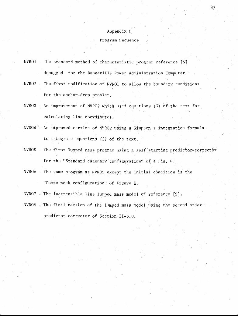
Appendix C
Program Sequence
NVRO1 - The standard method of characteristic program reference [5]
debugged for the Bonneville Power Administration Computer.
NVR02 - The first modification of NVRO1 to allow the boundary conditions
for the anchor-drop problem.
NVR03 - An improvement of NVR02 which used equations (3) of the text for
calculating line coordinates.
NVR04 - An improved version of NVR02 using a Simpson's integration formula
to integrate equations (2) of the text.
NVRO5 - The first lumped mass program using a self starting predictor-corrector
for the "Standard catenary configuration" of a Fig. G.
NVR06 The same program as NVRO5 except the initial condition is the
"Goose neck configuration" of Figure E.
NVR07 The inextensible line lumped mass model of reference [9].
NVR08 - The final version of the lumped mass model using the second order
predictor-corrector of Section 11-3.0.
-
-
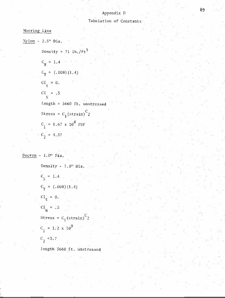
Appendix
Tabulation of Constants
Mooring Line
Nylon - 2.5" Dia.
Density = 71 lb./ft3
CN = 1.4
CT = (.008) (1.4)
CI = 0.t
CI = .5N
Length = 5660 ft. unstressed
Stress = CI(strain)C2
C1 = 1.67 x 10⁸ PSF
C2 = 4.37
Dacron - 1.0" Dia.
Density - 1.0" Dia.
CN = 1.4
CT = (.008) (1.4)
Cit = 0.
CI = .5N
Stress = C1(strain)C2
C1 = 1.2 x 10⁹
C2 =3.7
89
length 5660 ft. unstressed

90
Steel - 2.5" Dia.
Density = 350 lb/ft3
C = 1.3N
CT = (.008) (1.3)
CI = 0.tCI = .5
N
Inextensible
Anchor
Weight = 12000 lb.
Vol.- 24.5 ft3
Frontal Area = 12.6 ft2
CD = .4
CI = 1.0
Length = 5660 ft.
Water
Density = 64 lb/ft3
Depth = 5000 ft.
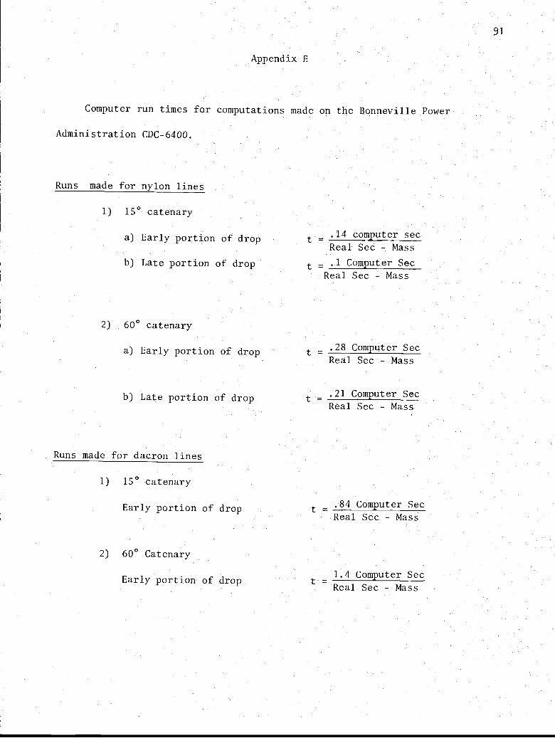
Appendix E
Computer run times for computations made on the Bonneville Power
Administration CDC-6400.
Runs made for nylon lines
1) 15° catenary
a) Early portion of drop
b) Late portion of drop
t.14 computer sec
Real Sec Mass
t _ .1 Computer Sec
Real Sec Mass
600 catenary
a) Early portion of drop t .28 Computer Sec
Real Sec - Mass
b) Late portion of drop
Runs made for dacron lines
1) 15° catenary
Early portion of drop
60° Catenary
Early portion of drop
t .21 Computer Sec
Real Sec - Mass
.84 Computer Sec
Real Sec - Mass
1.4 Computer SecL Real Sec Mass
91
2)
-
-
=
-
93
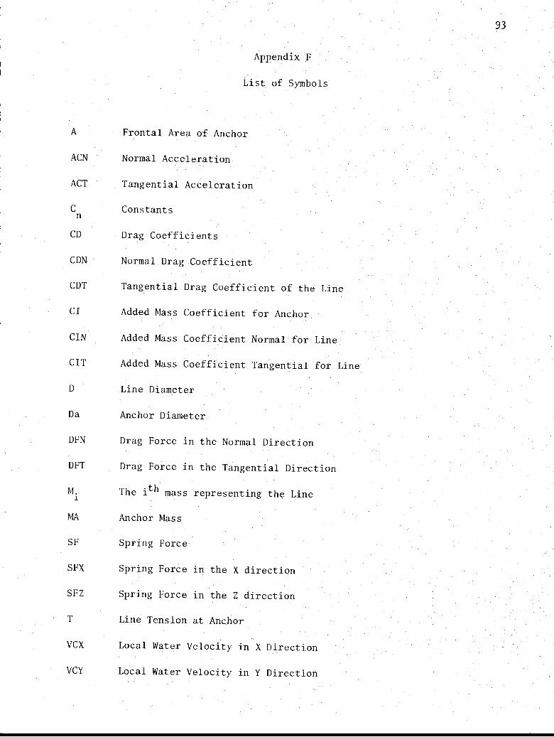
Appendix F
List of Symbols
A Frontal Area of Anchor
ACN Normal Acceleration
ACT Tangential Acceleration
C Constantsn
CD Drag Coefficients
CDN Normal Drag Coefficient
CDT Tangential Drag Coefficient of the Line
Cl Added Mass Coefficient for Anchor
CIN Added Mass Coefficient Normal for Line
CIT Added Mass Coefficient Tangential for Line
D Line Diameter
Da Anchor Diameter
DFN Drag Force in the Normal Direction
DFT Drag Force in the Tangential Direction
M.r
The ith mass representing the Line
MA Anchor Mass
SF Spring Force
SFX Spring Force in the X direction
SFZ Spring Force in the Z direction
T Line Tension at Anchor
VCX Local Water Velocity in X Direction
VCY Local Water Velocity in Y Direction

94
VOL Anchor Displaced Volume
Line Velocity Normal
Line Velocity Tangential
Anchor Weight
.WT Weight of the ith Mass0
ki Line Segment Length
kI to k4 Runge Kutta Parameters
to k3 Runge Kutta Parameters
mi to m4 Runge Kutta Parameters
nI to n4 Runge Kutta Parameters
Horizontal Coordinate
Vertical Coordinate
Arc Distance Along the Line
AS Equal Distance Taken between Calculation Point
At Time Increment
Angle from the Horizontal to the Anchor Line Link
Line Strain at the ith link
Angle Between the Horizontal and the Line Tangent
0AV The Average Between Two Adjacent Links
P
6
Mass Density of the Line
Mass Density of the Anchor
Stress in the Line
c Error in Velocity Computation
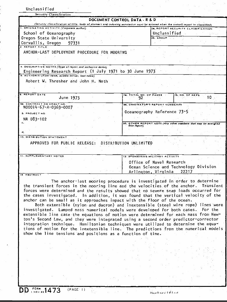
UnclassifiedSecurity Classification
DOCUMENT CONTROL DATA- R & D(Security classification of title, body of abstract and indexing annotation must be entered when the overall report is classified
1. ORIGINATING ACTIVITY (Corporate author) 2s. REPORT SECURITY CLASSIFICATION
School of Oceanography UnclassifiedOregon State University 2b. GROUP
Corvallis, Oregon 973313. REPORT TITLE
ANCHOR-LAST DEPLOYMENT PROCEDURE FOR MOORING
4. DESCRIPTIVE NOTES (Type of report and inclusive dates)
Engineering Research Report (1 July 1971 to 30 June 19735. AU THOR (S) (First name, middle initial, last name)
Robert W. Thresher and John H. Nath
6. REPORT DATEJune 1973
7a. TOTAL. N92O. OF PAGES 7b. NO. OF REFS 10
8a. CONTRACT OR GRANT NO.N00014-67-A-0369-0007
9a. ORIGINATOR$ REPORT NUMBER(S)
b. PROJECT NO. Oceanography Reference 73-5
NR 083-102C. 9b. OTHER REPORT NO(S) (Any other numbers that may be assigned
this report)
d.
10. DISTRIBUTION STATEMENT
APPROVED FOR PUBLIC RELEASE: DISTRIBUTION UNLIMITED
11. SUPPLEMENTARY NOTES 12. SPONSORING MILITARY ACTIVITY
Office of Naval ResearchOcean Science and Technology DivisionArlington, Virginia 22217
13. ABSTRACT
The anchor-last mooring procedure is investigated in order to determinethe transient forces in the mooring line and the velocities of the anchor. Transientforces were determined and the results showed that no severe snap loads occurred forthe cases investigated. In addition, it was found that the vertical velocity of theanchor can be small as it approaches impact with the floor of the ocean.
Both extensible (nylon and dacron) and inextensible (steel wire rope) lines wereinvestigated. Lumped mass numerical models were developed for both cases. For the
extensible line case the equations of motion were determined for each mass from New-ton's Second Law, and they were integrated using a second order predictor-correctorintegration technique. Hamiltonian techniques were utilized to determine the equa-tions of motion for the inextensible line. The predictions from the numerical modelsshow the line tensions and positions as a function of time.
DD FORM (PAGE 1)I N o v 6 5 1 4/ 3 l l...- 1,«: 4;- A

Ilnrlassif iedSecurity Classification
tA.KEY WORDS LINK A LINK B LINK C
ROLE WT ROLE WT ROLE WT
Numerical Models for LinesAnchor-Last Mooring ProcedureAnchoringLumped Mass Models
D U^ r
rwRi"asNov
33 (BACK)Unc lass i_f i ed

Related Documents