3GPP2 X.P0042-D v0.4 1 2 3 4 5 6 7 8 9 10 11 12 13 14 15 16 17 18 19 20 21 22 23 24 25 26 27 28 29 30 31 32 33 34 35 36 37 38 39 40 41 42 43 44 45 46 47 48 49 50 51 52 53 54 55 56 57 58 59 60 i Contents Voice Call Continuity between IMS and Circuit Switched Systems CONTENTS List of Figures ....................................................................................................................................................... vi List of Tables .......................................................................................................................................................viii Foreword ............................................................................................................................................................... ix REVISION HISTORY ........................................................................................................................................... x 1 Introduction .............................................................................................................................................. 1 1.1 Scope.......................................................................................................................................... 1 1.2 References .................................................................................................................................. 2 1.2.1 Normative References ................................................................................................. 2 2 Void.......................................................................................................................................................... 4 3 Definitions, Symbols and Abbreviations .................................................................................................. 5 3.1 Definitions ................................................................................................................................. 5 3.1.1 Symbols and Abbreviations ......................................................................................... 5 4 Stage 2: Architecture and Flow Diagrams................................................................................................ 8 4.1 Architecture Reference Model ................................................................................................... 8 4.2 Signaling Flows for Registration ............................................................................................. 11 4.2.1 IMS Registration........................................................................................................ 11 4.2.2 1x CS Registration ..................................................................................................... 13 4.2.3 Domain Availability Notification .............................................................................. 14 4.3 Signaling Flows for Call Origination ....................................................................................... 16 4.3.1 IMS VoIP Call Origination with VCC AS Anchoring .............................................. 16 4.3.2 CS Call Origination with VCC AS Anchoring .......................................................... 17 4.3.2.1 WIN Based Solution ............................................................................ 17 4.3.2.2 Non-WIN Based Solution .................................................................... 20 4.4 Signaling Flows for Call Delivery ........................................................................................... 22 4.4.1 Voice Call Delivery on 1x CS ................................................................................... 22 4.4.2 Voice Call Delivery on IMS ...................................................................................... 26 4.4.3 MDN Homed on 1x CS Redirected to IMS using WIN Triggers .............................. 28 4.4.4 MDN Homed on IMS using Local Number Portability ............................................. 30 4.4.5 MDN Homed on 1x CS Redirected to IMS without WIN support ............................ 31 4.5 Domain Transfer: HRPD VoIP-to-1x CS Voice ...................................................................... 33 4.5.1 HRPD VoIP-to-1x CS Voice DT ............................................................................... 37 4.5.2 HRPD VoIP-to-1x CS voice DT (3GPP2 PD Indicator) ........................................... 42 4.6 Domain Transfer: WLAN VoIP-to-1x CS Voice ..................................................................... 46 4.6.1 WLAN VoIP-to-1x CS Voice DT ............................................................................. 50 4.7 Domain Transfer: 1x CS Voice to WLAN ............................................................................... 55 4.7.1 1x CS Voice to WLAN DT ....................................................................................... 59

Welcome message from author
This document is posted to help you gain knowledge. Please leave a comment to let me know what you think about it! Share it to your friends and learn new things together.
Transcript
3GPP2 X.P0042-D v0.4
1
2
3
4
5
6
7
8
9
10
11
12
13
14
15
16
17
18
19
20
21
22
23
24
25
26
27
28
29
30
31
32
33
34
35
36
37
38
39
40
41
42
43
44
45
46
47
48
49
50
51
52
53
54
55
56
57
58
59
60
i Contents
Voice Call Continuity between IMS and Circuit Switched Systems
CONTENTS
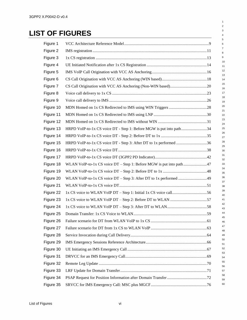
List of Figures ....................................................................................................................................................... vi
List of Tables .......................................................................................................................................................viii
Foreword ............................................................................................................................................................... ix
REVISION HISTORY ........................................................................................................................................... x
1 Introduction .............................................................................................................................................. 1
1.1 Scope.......................................................................................................................................... 1
1.2 References .................................................................................................................................. 2 1.2.1 Normative References ................................................................................................. 2
2 Void .......................................................................................................................................................... 4
3 Definitions, Symbols and Abbreviations .................................................................................................. 5
3.1 Definitions ................................................................................................................................. 5 3.1.1 Symbols and Abbreviations ......................................................................................... 5
4 Stage 2: Architecture and Flow Diagrams................................................................................................ 8
4.1 Architecture Reference Model ................................................................................................... 8
4.2 Signaling Flows for Registration ............................................................................................. 11 4.2.1 IMS Registration........................................................................................................ 11 4.2.2 1x CS Registration ..................................................................................................... 13 4.2.3 Domain Availability Notification .............................................................................. 14
4.3 Signaling Flows for Call Origination ....................................................................................... 16 4.3.1 IMS VoIP Call Origination with VCC AS Anchoring .............................................. 16 4.3.2 CS Call Origination with VCC AS Anchoring .......................................................... 17
4.3.2.1 WIN Based Solution ............................................................................ 17 4.3.2.2 Non-WIN Based Solution .................................................................... 20
4.4 Signaling Flows for Call Delivery ........................................................................................... 22 4.4.1 Voice Call Delivery on 1x CS ................................................................................... 22 4.4.2 Voice Call Delivery on IMS ...................................................................................... 26 4.4.3 MDN Homed on 1x CS Redirected to IMS using WIN Triggers .............................. 28 4.4.4 MDN Homed on IMS using Local Number Portability ............................................. 30 4.4.5 MDN Homed on 1x CS Redirected to IMS without WIN support ............................ 31
4.5 Domain Transfer: HRPD VoIP-to-1x CS Voice ...................................................................... 33 4.5.1 HRPD VoIP-to-1x CS Voice DT ............................................................................... 37 4.5.2 HRPD VoIP-to-1x CS voice DT (3GPP2 PD Indicator) ........................................... 42
4.6 Domain Transfer: WLAN VoIP-to-1x CS Voice ..................................................................... 46 4.6.1 WLAN VoIP-to-1x CS Voice DT ............................................................................. 50
4.7 Domain Transfer: 1x CS Voice to WLAN ............................................................................... 55 4.7.1 1x CS Voice to WLAN DT ....................................................................................... 59
3GPP2 X.P0042-D v0.4
1
2
3
4
5
6
7
8
9
10
11
12
13
14
15
16
17
18
19
20
21
22
23
24
25
26
27
28
29
30
31
32
33
34
35
36
37
38
39
40
41
42
43
44
45
46
47
48
49
50
51
52
53
54
55
56
57
58
59
60
Contents ii
4.8 Failure Scenarios ...................................................................................................................... 61 4.8.1 Failure Scenario for Domain Transfer- WLAN VoIP-1x CS Voice .......................... 61 4.8.2 Failure Scenario for Domain Transfer: 1x CS - WLAN VoIP ................................... 63 4.8.3 Service Invocation during Call Delivery ................................................................... 64
4.9 Dual Radio Domain Transfer: IMS Emergency Call to 1x CS ................................................ 66 4.9.1 Reference Architecture for IMS Emergency Session ................................................ 66 4.9.2 IMS Emergency Call Origination .............................................................................. 67 4.9.3 Dual Radio IMS Emergency Call Domain Transfer (PS-to-CS) ............................... 68
4.9.3.1 DRVCC for an IMS Emergency Call ................................................... 69 4.9.3.2 Remote Leg Update .............................................................................. 70
4.9.4 Location Reconfiguration for Domain Transfer (PS to CS) ...................................... 71 4.9.5 UE Location Determination After Domain Transfer ................................................. 72
4.10 Single Radio Domain Transfer: IMS Emergency Call to 1x CS .............................................. 74 4.10.1 Roles of Functional Elements for SRVCC Domain Transfer of an Emergency
Call from the E-UTRAN to the 1xCS Domain .......................................................... 74 4.10.1.1 SRVCC UE .......................................................................................... 74 4.10.1.2 1xCS MSC ........................................................................................... 74 4.10.1.3 MGCF .................................................................................................. 74 4.10.1.4 EATF .................................................................................................... 74 4.10.1.5 1xCS IWS ............................................................................................. 75 4.10.1.6 MME .................................................................................................... 75
4.10.2 Information Flows for SRVCC Domain Transfer of an Emergency Call from
the E-UTRAN to the 1xCS Domain .......................................................................... 76 4.10.2.1 SRVCC for IMS Emergency Call: MSC plus MGCF .......................... 76 4.10.2.2 SRVCC for IMS Emergency Call: MSC Enhanced with SIP
Interface ................................................................................................ 79
4.11 Single Radio Domain Transfer: IMS Call to 1xCS .................................................................. 82 4.11.1 Roles of Functional Elements for SRVCC Domain Transfer of a Call from the
E-UTRAN to the 1xCS Domain ................................................................................ 82 4.11.1.1 SRVCC UE .......................................................................................... 82 4.11.1.2 1xCS MSC ........................................................................................... 82 4.11.1.3 MGCF .................................................................................................. 82 4.11.1.4 VCC AS/ATCF .................................................................................... 82 4.11.1.5 1xCS IWS ............................................................................................. 83 4.11.1.6 MME .................................................................................................... 83
4.11.2 Information Flows for SRVCC Domain Transfer of a Call from the
E-UTRAN to the 1xCS Domain ................................................................................ 83 4.11.2.1 SRVCC for IMS Call: MSC plus MGCF ............................................. 84 4.11.2.2 SRVCC for IMS Call: MSC Enhanced with SIP Interface .................. 87
4.12 Dual Radio Domain Transfer: Call Alerting to 1xCS .............................................................. 89 4.12.1 Call Alerting for Incoming Call ................................................................................. 90 4.12.2 Call Alerting for Outgoing Call ................................................................................. 92
4.13 Dual Radio Domain Transfer: Supplementary Services to 1xCS............................................. 94 4.13.1 Call Hold .............................................................................................................. 94 4.13.2 Call Waiting Notify ................................................................................................... 97 4.13.3 Call Waiting Hold .................................................................................................... 101 4.13.4 Call Hold in 3WC .................................................................................................... 105 4.13.5 3WC ............................................................................................................ 108
3GPP2 X.P0042-D v0.4
1
2
3
4
5
6
7
8
9
10
11
12
13
14
15
16
17
18
19
20
21
22
23
24
25
26
27
28
29
30
31
32
33
34
35
36
37
38
39
40
41
42
43
44
45
46
47
48
49
50
51
52
53
54
55
56
57
58
59
60
iii Contents
5 Stage 3: Procedures and Protocol ......................................................................................................... 112
5.1 Overview of VCC between the CS domain and the MMD .................................................... 112 5.1.1 General .................................................................................................................... 112 5.1.2 Underlying Network Capabilities ............................................................................ 113 5.1.3 URI and Address Assignments ................................................................................ 113
5.2 Functional entities .................................................................................................................. 114 5.2.1 Introduction ............................................................................................................. 114 5.2.2 User Equipment (UE) .............................................................................................. 114 5.2.3 Application Server (AS) .......................................................................................... 114 5.2.4 Media Gateway Control Function (MGCF) ............................................................. 114 5.2.5 Emergency Access Transfer Function (EATF)........................................................ 114
5.3 Roles for Registration in the MMD ....................................................................................... 114 5.3.1 Introduction ............................................................................................................. 114 5.3.2 VCC UE................................................................................................................... 115
5.3.2.1 Constructing SMS Message ............................................................... 115 5.3.2.2 Processing SMS Acknowledgments ................................................... 116
5.3.3 VCC AS ................................................................................................................... 116 5.3.4 S-CSCF .................................................................................................................... 117
5.4 Roles for Call Origination ...................................................................................................... 117 5.4.1 Introduction ............................................................................................................. 117 5.4.2 VCC UE................................................................................................................... 117 5.4.3 MSC ......................................................................................................................... 117 5.4.4 VCC AS ................................................................................................................... 118
5.4.4.1 Distinction of Requests Sent to the VCC AS ..................................... 118 5.4.4.2 Call Origination in the MMD ............................................................. 118 5.4.4.3 Call Origination in the CS Domain – Procedures Towards the
WIN SCP............................................................................................ 119 5.4.4.4 Call Origination in the CS Domain – Procedures Towards the
MMD .................................................................................................. 120
5.5 Roles for Call Termination .................................................................................................... 120 5.5.1 Introduction ............................................................................................................. 120 5.5.2 VCC UE................................................................................................................... 120 5.5.3 MSC ......................................................................................................................... 121 5.5.4 VCC AS ................................................................................................................... 121
5.5.4.1 Distinction of Requests Sent to the VCC AS ..................................... 121 5.5.4.2 Call Termination in the MMD ........................................................... 121 5.5.4.3 Call Termination in the CS Domain ................................................... 122 5.5.4.4 Call Termination in the CS Domain – Procedures Towards
MMD .................................................................................................. 124
5.6 Roles for Domain Transfer of a Call from the CS Domain to the MMD ............................... 124 5.6.1 Introduction ............................................................................................................. 124 5.6.2 VCC UE................................................................................................................... 124 5.6.3 VCC AS ................................................................................................................... 125
5.6.3.1 Distinction of Requests Sent to the VCC AS ..................................... 125 5.6.3.2 Domain transfer in the MMD ............................................................. 125
5.6.4 MGCF ...................................................................................................................... 126
5.7 Roles for Domain Transfer of a call from the MMD to the CS Domain ................................ 126

3GPP2 X.P0042-D v0.4
1
2
3
4
5
6
7
8
9
10
11
12
13
14
15
16
17
18
19
20
21
22
23
24
25
26
27
28
29
30
31
32
33
34
35
36
37
38
39
40
41
42
43
44
45
46
47
48
49
50
51
52
53
54
55
56
57
58
59
60
Contents iv
5.7.1 Introduction ............................................................................................................. 126 5.7.2 VCC UE ................................................................................................................... 126 5.7.3 MSC ......................................................................................................................... 127 5.7.4 VCC AS ................................................................................................................... 127
5.7.4.1 Distinction of SIP INVITE Requests Sent to the VCC AS ................ 127 5.7.4.2 Domain Transfer Procedures Towards the WIN SCP ........................ 127 5.7.4.3 Domain Transfer in the MMD ............................................................ 128
5.8 VCC Application Message Format ........................................................................................ 129 5.8.1 Message Types......................................................................................................... 129
5.8.1.1 Domain-Attachment-Status ................................................................ 129
5.9 Signaling Protocol for VCC Domain Transfer of IMS Emergency Call to 1x CS ................. 130 5.9.1 Modifications to MAP Operations ........................................................................... 130
5.9.1.1 Origination Request ([J-STD-036-C] Chapter 8, Section 2.2.1.8) ..... 130 5.9.2 Modifications to MAP Parameters ........................................................................... 131
5.9.2.1 MobileCallStatus ([J-STD-036-C] Chapter 8, Section 2.3.2.15) ........ 131
5.10 Signaling Procedures for DRVCC Domain Transfer of IMS Emergency Call to 1x CS ....... 132 5.10.1 MSC Analyze MS Dialed Number ([J-STD-036-C] Chapter 8, Section 3.1.1) ....... 133 5.10.2 Idle MS Origination ([J-STD-036-C] Chapter 8, Section 3.1.2) .............................. 134 5.10.3 MSC Initiating an OriginationRequest for an Emergency Services Call ([J-
STD-036-C] Chapter 8, Section 3.2.1) .................................................................... 137 5.10.4 MSC Initiating DRVCC Domain Transfer for an IMS Emergency Services
Call (new Section 3.2.2 for [J-STD-036-C] Chapter 8) ........................................... 139 5.10.4.1 MSC Initiating DRVCC Access Transfer for an IMS Emergency
Services Call (new Section 3.2.2.1 for [J-STD-036-C] Chapter
8) ........................................................................................................ 140 5.10.4.2 MSC Notifying MPC of Domain Transfer (new Section 3.2.2.2
for [J-STD-036-C] Chapter 8) ............................................................ 141
5.11 Signaling Procedures for SRVCC Domain Transfer of IMS Emergency Services Call
to 1x CS ................................................................................................................................. 142 5.11.1 MSC Receiving SRVCC Domain Transfer Request from MME (new Section
3.2.3 for [J STD 036 C] Chapter 8) ......................................................................... 142
5.12 Signaling Procedures for SRVCC Domain Transfer of IMS Call to 1x CS ........................... 144 5.12.1 Annex G: Signaling Procedures for SRVCC Domain Transfer of IMS Call to
1x CS ............................................................................................................ 144
5.13 Roles for DRVCC domain transfer of alerting call from the IMS to the CS domain ............. 146 5.13.1 Introduction ............................................................................................................ 146 5.13.2 DRVCC UE ............................................................................................................ 146
5.13.2.1 Incoming call at alerting state............................................................. 146 5.13.2.2 Outgoing call at alerting state ............................................................. 146
5.13.3 MSC ............................................................................................................ 146 5.13.4 VCC AS ............................................................................................................ 146
5.13.4.1 Incoming call at alerting state............................................................. 146 5.13.4.2 Outgoing call at alerting state ............................................................. 147
5.14 Roles for DRVCC domain transfer of supplementary service from the IMS to the CS
domain ................................................................................................................................... 147 5.14.1 Introduction ............................................................................................................ 147 5.14.2 DRVCC UE ............................................................................................................ 147
5.14.2.1 Call Hold ............................................................................................ 147
3GPP2 X.P0042-D v0.4
1
2
3
4
5
6
7
8
9
10
11
12
13
14
15
16
17
18
19
20
21
22
23
24
25
26
27
28
29
30
31
32
33
34
35
36
37
38
39
40
41
42
43
44
45
46
47
48
49
50
51
52
53
54
55
56
57
58
59
60
v Contents
5.14.2.2 Call Waiting Notify ............................................................................ 148 5.14.2.3 Call Waiting Hold .............................................................................. 148 5.14.2.4 Call Hold in 3WC............................................................................... 148 5.14.2.5 3WC ................................................................................................... 149
5.14.3 MSC ............................................................................................................ 149 5.14.3.1 Call Hold ............................................................................................ 149 5.14.3.2 Call Waiting Notify ............................................................................ 149 5.14.3.3 Call Waiting Hold .............................................................................. 149 5.14.3.4 Call Hold in 3WC............................................................................... 150 5.14.3.5 3WC ................................................................................................... 150
5.14.4 VCC AS ............................................................................................................ 150 5.14.4.1 Call Hold ............................................................................................ 150 5.14.4.2 Call Waiting Notify ............................................................................ 150 5.14.4.3 Call Waiting Hold .............................................................................. 151 5.14.4.4 Call Hold in 3WC............................................................................... 151 5.14.4.5 3WC ................................................................................................... 152
3GPP2 X.P0042-D v0.4
1
2
3
4
5
6
7
8
9
10
11
12
13
14
15
16
17
18
19
20
21
22
23
24
25
26
27
28
29
30
31
32
33
34
35
36
37
38
39
40
41
42
43
44
45
46
47
48
49
50
51
52
53
54
55
56
57
58
59
60
List of Figures vi
LIST OF FIGURES
Figure 1 VCC Architecture Reference Model ................................................................................... 9
Figure 2 IMS registration ................................................................................................................ 11
Figure 3 1x CS registration ............................................................................................................. 13
Figure 4 UE Initiated Notification after 1x CS Registration ........................................................... 14
Figure 5 IMS VoIP Call Origination with VCC AS Anchoring ...................................................... 16
Figure 6 CS Call Origination with VCC AS Anchoring (WIN based) ............................................ 18
Figure 7 CS Call Origination with VCC AS Anchoring (Non-WIN based).................................... 20
Figure 8 Voice call delivery to 1x CS ............................................................................................. 23
Figure 9 Voice call delivery to IMS ................................................................................................ 26
Figure 10 MDN Homed on 1x CS Redirected to IMS using WIN Triggers ..................................... 28
Figure 11 MDN Homed on 1x CS Redirected to IMS using LNP .................................................... 30
Figure 12 MDN Homed on 1x CS Redirected to IMS without WIN ................................................ 31
Figure 13 HRPD VoIP-to-1x CS voice DT - Step 1: Before MGW is put into path ......................... 34
Figure 14 HRPD VoIP-to-1x CS voice DT - Step 2: Before DT to 1x ............................................. 35
Figure 15 HRPD VoIP-to-1x CS voice DT - Step 3: After DT to 1x performed .............................. 36
Figure 16 HRPD VoIP-to-1x CS voice DT ....................................................................................... 38
Figure 17 HRPD VoIP-to-1x CS voice DT (3GPP2 PD Indicator) ................................................... 42
Figure 18 WLAN VoIP-to-1x CS voice DT – Step 1: Before MGW is put into path ....................... 47
Figure 19 WLAN VoIP-to-1x CS voice DT – Step 2: Before DT to 1x ........................................... 48
Figure 20 WLAN VoIP-to-1x CS voice DT – Step 3: After DT to 1x performed ............................ 49
Figure 21 WLAN VoIP-to-1x CS voice DT ...................................................................................... 51
Figure 22 1x CS voice to WLAN VoIP DT – Step 1: Initial 1x CS voice call .................................. 56
Figure 23 1x CS voice to WLAN VoIP DT – Step 2: Before DT to WLAN .................................... 57
Figure 24 1x CS voice to WLAN VoIP DT – Step 3: After DT to WLAN....................................... 58
Figure 25 Domain Transfer: 1x CS Voice to WLAN ........................................................................ 59
Figure 26 Failure scenario for DT from WLAN VoIP to 1x CS ....................................................... 61
Figure 27 Failure scenario for DT from 1x CS to WLAN VoIP ....................................................... 63
Figure 28 Service Invocation during Call Delivery........................................................................... 64
Figure 29 IMS Emergency Sessions Reference Architecture............................................................ 66
Figure 30 UE Initiating an IMS Emergency Call .............................................................................. 67
Figure 31 DRVCC for an IMS Emergency Call................................................................................ 69
Figure 32 Remote Leg Update .......................................................................................................... 70
Figure 33 LRF Update for Domain Transfer ..................................................................................... 71
Figure 34 PSAP Request for Position Information after Domain Transfer ....................................... 72
Figure 35 SRVCC for IMS Emergency Call: MSC plus MGCF ....................................................... 76
3GPP2 X.P0042-D v0.4
1
2
3
4
5
6
7
8
9
10
11
12
13
14
15
16
17
18
19
20
21
22
23
24
25
26
27
28
29
30
31
32
33
34
35
36
37
38
39
40
41
42
43
44
45
46
47
48
49
50
51
52
53
54
55
56
57
58
59
60
vii List of Figures
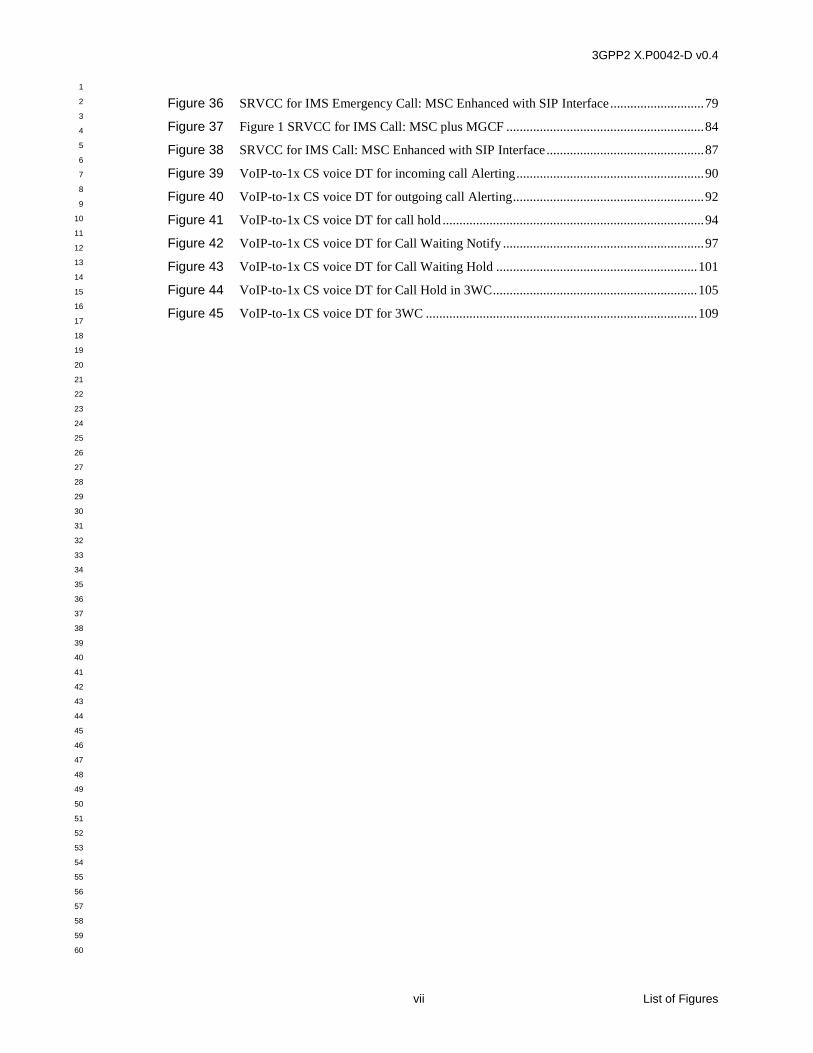
Figure 36 SRVCC for IMS Emergency Call: MSC Enhanced with SIP Interface ............................ 79
Figure 37 Figure 1 SRVCC for IMS Call: MSC plus MGCF ........................................................... 84
Figure 38 SRVCC for IMS Call: MSC Enhanced with SIP Interface ............................................... 87
Figure 39 VoIP-to-1x CS voice DT for incoming call Alerting ........................................................ 90
Figure 40 VoIP-to-1x CS voice DT for outgoing call Alerting ......................................................... 92
Figure 41 VoIP-to-1x CS voice DT for call hold .............................................................................. 94
Figure 42 VoIP-to-1x CS voice DT for Call Waiting Notify ............................................................ 97
Figure 43 VoIP-to-1x CS voice DT for Call Waiting Hold ............................................................ 101
Figure 44 VoIP-to-1x CS voice DT for Call Hold in 3WC ............................................................. 105
Figure 45 VoIP-to-1x CS voice DT for 3WC ................................................................................. 109
3GPP2 X.P0042-D v0.4
1
2
3
4
5
6
7
8
9
10
11
12
13
14
15
16
17
18
19
20
21
22
23
24
25
26
27
28
29
30
31
32
33
34
35
36
37
38
39
40
41
42
43
44
45
46
47
48
49
50
51
52
53
54
55
56
57
58
59
60
List of Tables viii
LIST OF TABLES
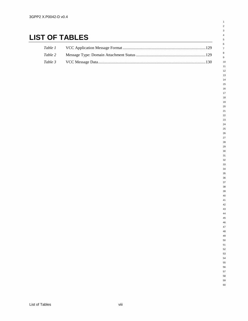
Table 1 VCC Application Message Format ................................................................................. 129
Table 2 Message Type: Domain Attachment Status .................................................................... 129
Table 3 VCC Message Data ......................................................................................................... 130
3GPP2 X.P0042-D v0.4
1
2
3
4
5
6
7
8
9
10
11
12
13
14
15
16
17
18
19
20
21
22
23
24
25
26
27
28
29
30
31
32
33
34
35
36
37
38
39
40
41
42
43
44
45
46
47
48
49
50
51
52
53
54
55
56
57
58
59
60
ix Foreword
FOREWORD
(This foreword is not part of this document.)
“Shall” and “shall not” identify requirements to be followed strictly to conform to this
document and from which no deviation is permitted. “Should” and “should not” indicate that
one of several possibilities is recommended as particularly suitable, without mentioning or
excluding others, that a certain course of action is preferred but not necessarily required, or
that (in the negative form) a certain possibility or course of action is discouraged but not
prohibited. “May” and “need not” indicate a course of action permissible within the limits of
the document. “Can” and “cannot” are used for statements of possibility and capability,
whether material, physical or causal.
3GPP2 X.P0042-D v0.4
1
2
3
4
5
6
7
8
9
10
11
12
13
14
15
16
17
18
19
20
21
22
23
24
25
26
27
28
29
30
31
32
33
34
35
36
37
38
39
40
41
42
43
44
45
46
47
48
49
50
51
52
53
54
55
56
57
58
59
60
REVISION HISTORY x
REVISION HISTORY
Revision Date Comments
0.1 03/04/2015 SX20-20150128-002R2 eDRVCC Stage1 service requirement (CTC)
0.1 03/04/2015 SX20-20150128-003R1 eDRVCC Stage2 incoming call alerting (CTC)
0.1 03/04/2015 SX20-20150128-004R2 eDRVCC Stage2 outgoing call alerting (CTC)
0.1 03/04/2015 SX20-20150128-005R1 eDRVCC Stage2 call hold (CTC)
0.1 03/04/2015 SX20-20150128-006R1 eDRVCC Stage2 call waiting notify (CTC)
0.1 03/04/2015 SX20-20150128-007R1 eDRVCC Stage2 call waiting hold (CTC)
0.1 03/04/2015 SX20-20150128-008R2 eDRVCC Stage2 call hold in 3WC (CTC)
0.1 03/04/2015 SX20-20150128-009R2 eDRVCC Stage2 3WC (CTC)
0.2 05/07/2015 SX20-20150507-001R1 eDRVCC Stage3 (CTC)
0.2 05/07/2015 SX20-20150507-002R1 eDRVCC for alerting Stage3 (CTC)
0.3 05/2802015 SX20-20150528-003R1 eDRVCC for supplementary service Stage3 (CTC)
0.3 05/28/2015 SX20-20150528-004R1 eDRVCC for supplementary service Stage3 (CTC)
0.3 05/28/2015 SX20-20150528-005R1 eDRVCC for supplementary service Stage3 (CTC)
0.4 8/28/2015 SX20-20150827-001 X.P0042-D v0.3 R&F Consolidated.doc
3GPP2 X.P0042-D v0.4
1
2
3
4
5
6
7
8
9
10
11
12
13
14
15
16
17
18
19
20
21
22
23
24
25
26
27
28
29
30
31
32
33
34
35
36
37
38
39
40
41
42
43
44
45
46
47
48
49
50
51
52
53
54
55
56
57
58
59
60
1 1 Introduction
1 Introduction
The purpose of this section is to introduce the readers to the contents of the whole document.
1.1 Scope
Voice call continuity allows users to move voice calls between the Circuit-Switched (CS)
domain and the Multimedia Domain (MMD), connected through different Internet Protocol -
Connectivity Access Networks (IPCANs) (e.g., WLAN, HRPD). This document defines an
inter-technology Domain Transfer (DT) call model which supports procedures that allow a
mobile subscriber to DT from an HRPD or WLAN multimedia session with a voice
component to a 1x CS voice session and from a 1x CS voice session to a WLAN VoIP
session.
It is the goal of this specification to allow the core network to know as precisely as possible
the current accessibility of the User Equipment (UE) and to deliver services efficiently across
the appropriate access network while minimizing the impact on the legacy systems.
The UEs in this specification include three types: HRPD/1x; E-UTRA/1x; and WLAN/1x
handset. Single Radio HRPD/1x and E-UTRA/1x handsets are assumed to be incapable of
simultaneous full-duplex radio communications with both an HRPD or E-UTRA radio access
network and a 1x radio access network. Dual radio HRPD/1x, E-UTRA/1x, and WLAN /1x
handsets are capable of being in simultaneous full-duplex communication with both a HRPD,
E-UTRAN, or WLAN access network and a 1x radio access network.
For Single radio handset, supplementary services and supplementary services continuity are
not addressed in this specification (e.g., Call Waiting, Call Transfer, 3WC, Call Hold).
For Dual radio handset, supplementary services (e.g. Call Waiting, Call Hold, or 3WC)
continuity and call intermediate states (e.g. Alerting) continuity from IMS to 1xCS are
addressed in this specification.
The Stage 2 of this document specifies the interactions and signaling flows between a new
functional entity in the MMD network called the VCC Application Server (VCC AS) and
Access Transfer Control Function (ATCF) with the:
Serving-Call/Session Control Function (S-CSCF)
Home Location Register (HLR)
Home Subscriber Server (HSS)
High Rate Packet Data Access Terminal (HRPD AT)
Evolved Universal Terrestrial Radio Access User Equipment (E-UTRA UE)
Wireless Local Area Network (WLAN) Station (STA)
Mobile Switching Center (MSC)
Media Gateway Control Function (MGCF)
The Stage 3 specification in this document provides the protocol details for voice call
continuity between the MMD based on the Session Initiation Protocol (SIP) [RFC 3261] and
3GPP2 X.P0042-D v0.4
1
2
3
4
5
6
7
8
9
10
11
12
13
14
15
16
17
18
19
20
21
22
23
24
25
26
27
28
29
30
31
32
33
34
35
36
37
38
39
40
41
42
43
44
45
46
47
48
49
50
51
52
53
54
55
56
57
58
59
60
1 Introduction 2
the Session Description Protocol (SDP) [RFC 2327] and the 3GPP2 CS domain which uses
MAP and ISUP.
This document makes no VCC specific enhancements to SIP, SIP events or SDP, beyond
those specified in [MMD Part-4].
This document is applicable to UEs, VCC AS, ATCF, MSC, and MGCF providing voice call
continuity capabilities.
1.2 References
1.2.1 Normative References
The following standards contain provisions which, through reference in this text, constitute
provisions of this Standard. At the time of publication, the editions indicated were valid. All
standards are subject to revision, and parties to agreements based on this Standard are
encouraged to investigate the possibility of applying the most recent editions of the standards
indicated below. ANSI and TIA maintain registers of currently valid national standards
published by them.
References are either specific (identified by date of publication, edition number,
version number, etc.) or non specific.
For a specific reference, subsequent revisions do not apply.
For a non-specific reference, the latest version applies. In the case of a reference to a
3GPP2 document, a non-specific reference implicitly refers to the latest version of
that document in the same Release as the present document.
[A.S0008] 3GPP2 A.S0008-C, “Interoperability Specification (IOS) for High Rate
Packet Data (HRPD) Radio Access Network Interfaces with Session
Control in the Access Network”
[A.S0009] 3GPP2 A.S0009-C, “Interoperability Specification (IOS) for High Rate
Packet Data (HRPD) Radio Access Network Interfaces with Session
Control in the Packet Control Function”
[ANSI ISUP] ANSI T1.113: “Telecommunications Signaling System No. 7 (SS7) –
Integrated Services Digital Network (ISDN) User Part (ISUP)”
[C.S0005] 3GPP2 C.S0005-D v2.0: “Upper Layer (Layer 3) Signaling Standard
for cdma2000 Spread Spectrum Systems – Release D”, October 2005
[C.S0082] 3GPP2 C.S0082-0: “Circuit Services Notification Application
Specification for cdma2000 High Rate Packet Data”
[ITU ISUP] ITU-T Recommendations Q.761to Q.764 (2000): “Specifications of
Signaling System No.7 ISDN User Part (ISUP)”
[MMD Part-4] 3GPP2 X.S0013-004: “IP Multimedia Call Control Protocol based on
SIP and SDP; Stage 3”
[MMD Part-10] 3GPP2 X.S0013-010: “All-IP Core Network Multimedia Domain - IP
Multimedia Subsystem Sh Interface; Signaling Flows and Message
Contents – Stage 2”
3GPP2 X.P0042-D v0.4
1
2
3
4
5
6
7
8
9
10
11
12
13
14
15
16
17
18
19
20
21
22
23
24
25
26
27
28
29
30
31
32
33
34
35
36
37
38
39
40
41
42
43
44
45
46
47
48
49
50
51
52
53
54
55
56
57
58
59
60
3 1 Introduction
[MMD Part-11] 3GPP2 X.S0013-011: “All-IP Core Network Multimedia Domain: Sh
Interface Based on Diameter Protocols Protocol Details - Stage 3”
[RFC 2327] IETF RFC 2327: “SDP: Session Description Protocol”, April 1998
[RFC 3261] IETF RFC 3261 (June 2002): “SIP: Session Initiation Protocol”,
June 2002
[RFC 3840] IETF RFC 3840: “Indicating User Agent Capabilities in the Session
Initiation Protocol (SIP)”, August 2004
[WIN] 3GPP2 N.S0013: “WIN Phase 1”
[X.S0004-540] 3GPP2 X.S0004-540: “MAP Operations Signaling Protocols”
[X.S0004-550] 3GPP2 X.S0004-550: “MAP Parameters Signaling Protocols”
[X.S0004-630] 3GPP2 X.S0004-630: “MAP Call Processing Signaling Tasks”
[X.S0004-641] 3GPP2 X.S0004-641: “Mobile Application Part (MAP) - SMS”
[X.S0050] 3GPP2 X.S0050-0, “Session Initiation Protocol (SIP) to ISDN User
Part (ISUP) Interworking”
[23.167] 3GPP TS 23.167, “IP Multimedia Subsystem (IMS) emergency
sessions”, (Release 10)
[23.216] 3GPP TS 23.216. “Single Radio Voice Call Continuity (SRVCC);
Stage 2”, (Release 10)
[23.237] 3GPP TS 23.237, “IP Multimedia Subsystem (IMS) Service
Continuity; Stage 2”, (Release 10)
[23.271] 3GPP TS 23.271, “Functional stage 2 description of Location Services
(LCS)”, (Release 10)
[24.229] 3GPP TS 24.229, “IP multimedia call control protocol based on
Session Initiation Protocol (SIP) and Session Description Protocol
(SDP); Stage 3”, (Release 10)
[24.237] 3GPP TS 24.237, “IP Multimedia Subsystem (IMS) Service
Continuity; Stage 3” (Release 10)
[24.605] 3GPP TS24.605, “Conference (CONF) using IP Multimedia (IM) Core
Network (CN) subsystem; Protocol specification” (Release 10)
[29.205] 3GPP TS 29.205, “Application of Q.1900 series to bearer independent
Circuit Switched (CS) core network architecture; Stage 3”,
(Release 10)
[29.277] 3GPP TS 29.277, “Optimised Handover Procedures and Protocol
between E-UTRAN access and non-3GPP accesses (S102); Stage 3”,
(Release 12)
[J-STD-036] ANSI/J-STD-036-C-2011, “Enhanced Wireless 9-1-1 Phase II”,
June 2011
3GPP2 X.P0042-D v0.4
1
2
3
4
5
6
7
8
9
10
11
12
13
14
15
16
17
18
19
20
21
22
23
24
25
26
27
28
29
30
31
32
33
34
35
36
37
38
39
40
41
42
43
44
45
46
47
48
49
50
51
52
53
54
55
56
57
58
59
60
2 Void 4
2 Void
This page is empty.
3GPP2 X.P0042-D v0.4
1
2
3
4
5
6
7
8
9
10
11
12
13
14
15
16
17
18
19
20
21
22
23
24
25
26
27
28
29
30
31
32
33
34
35
36
37
38
39
40
41
42
43
44
45
46
47
48
49
50
51
52
53
54
55
56
57
58
59
60
5 3 Definitions, Symbols and Abbreviations
3 Definitions, Symbols and Abbreviations
3.1 Definitions
1x CS
The 3GPP2 circuit switched signaling system
VCC AS
An entity that:
1. assists in domain selection for terminating services to a terminal that is 1x CS
registered, or IMS registered, or both.
2. assists in DTs between IMS VoIP and 1x CS voice. Depending on the IP-CAN
technology used to connect to MMD, the handoff may be supported in both
directions (e.g., WLAN VoIP to/from 1x CS) or only in one direction (e.g., HRPD
VoIP to 1x CS).
Domain Transfer (DT)
Transfer of a voice call from the CS domain to MMD while maintaining an active session, or
transfer of a voice media from MMD to the CS domain while maintaining an active session.
Retarget
A SIP request is retargeted when the original “target” indicated by the Request-URI is
changed to a new “target” by changing the Request-URI.
3.1.1 Symbols and Abbreviations
ANSI American National Standards Institute
AP Access Point
AS Application Server
AT Access Terminal
ATCF Access Transfer Control Function
ATGW Access Transfer Gateway
B2BUA Back-to-Back User Agent
BGCF Border Gateway Control Function
BS Base Station
CdPN Called Party Number
CS Circuit-Switched
CSCF Call/Session Control Function
CSNA Circuit Services Notification Application
DRVCC Dual Radio Voice Call Continuity
DT Domain Transfer
EATF Emergency Access Transfer Function
ECS Emergency Call Server
E-CSCF Emergency-CSCF
3GPP2 X.P0042-D v0.4
1
2
3
4
5
6
7
8
9
10
11
12
13
14
15
16
17
18
19
20
21
22
23
24
25
26
27
28
29
30
31
32
33
34
35
36
37
38
39
40
41
42
43
44
45
46
47
48
49
50
51
52
53
54
55
56
57
58
59
60
3 Definitions, Symbols and Abbreviations 6
EDTN Emergency Domain Transfer Number
EPS Evolved Packet System
E-STN-SR Emergency Session Transfer Number for SRVCC
E-UTRA Evolved Universal Terrestrial Radio Access
E-UTRAN Evolved Universal Terrestrial Radio Access Network
GPOSREQ GeoPositionRequest INVOKE
gposreq GeoPositionRequest RETURN RESULT
GPRT Geo Position Request Timer
HLR Home Location Register
HRPD High Rate Packet Data
HSS Home Subscriber Server
IAM Initial Address Message
iFC initial Filter Criteria
IMRN IMS Routing Number
IMS IP Multimedia Subsystem
IMSI International Mobile Subscriber Identity
IP-CAN IP-Connectivity Access Network
IPRT Intersystem Position Request Timer
ISPOSREQ IntersystemPositionRequest INVOKE
isposreq IntersystemPositionRequest RETURN RESULT
ISUP ISDN User Part
I-CSCF Interrogating-CSCF
LRF Location Retrieval Function
MAP Mobile Application Part
MC Message Center
MCALSTAT MobileCallStatus parameter
MDN Mobile Directory Number
MEID Mobile Equipment Identifier
MGCF Media Gateway Control Function
MGW Media Gateway
MMD Multimedia Domain
MOBINFO Mobile Information macro
MPC Mobile Position Center
MPCAP MobilePositionCapability parameter
MSC Mobile Switching Center
ORREQ OriginationRequest INVOKE
orreq OrigiantionRequest RETURN ESULT
PCM Pulse Code Modulation
P-CSCF Proxy-CSCF
PDE Position Determining Entity
PDIF Packet Data Interworking Function
PDSN Packet Data Serving Node
POSINFO PositionInformation parameter
POSREQTYPE PositionRequestType parameter
POSRSULT PositionResult parameter
PSAP Public Safety Answering Point
PSI Public Service Identity
PSTN Public Switched Telephone Network
3GPP2 X.P0042-D v0.4
1
2
3
4
5
6
7
8
9
10
11
12
13
14
15
16
17
18
19
20
21
22
23
24
25
26
27
28
29
30
31
32
33
34
35
36
37
38
39
40
41
42
43
44
45
46
47
48
49
50
51
52
53
54
55
56
57
58
59
60
7 3 Definitions, Symbols and Abbreviations
RTP Real-time Transport Protocol
SCP Service Control Point
SDP Session Description Protocol
SIP Session Initiation Protocol
SMS Short Message Service
SCELLID ServingCellID parameter
S-CSCF Serving-CSCF
SRVCC Single Radio Voice Call Continuity
STN-SR Session Transfer Number for SRVCC
T-ADS Terminating Access Domain Selection
TDM Time Division Multiplexing
TLDN Temporary Local Directory Number
TRK trunk
UDP User Datagram Protocol
UE User Equipment
URI Uniform Resource Identifier
UTC Coordinated Universal Time
VCC Voice Call Continuity
VCC AS Voice Call Continuity Application Server
VDN VCC Domain Transfer Directory Number
VDI VCC Domain Transfer URI
VoIP Voice over IP
VLR Visitor Location Register
WIN Wireless Intelligent Network
WLAN Wireless Local Area Network
3GPP2 X.P0042-D v0.4
1
2
3
4
5
6
7
8
9
10
11
12
13
14
15
16
17
18
19
20
21
22
23
24
25
26
27
28
29
30
31
32
33
34
35
36
37
38
39
40
41
42
43
44
45
46
47
48
49
50
51
52
53
54
55
56
57
58
59
60
4 Stage 2: Architecture and Flow Diagrams 8
4 Stage 2: Architecture and Flow Diagrams
4.1 Architecture Reference Model
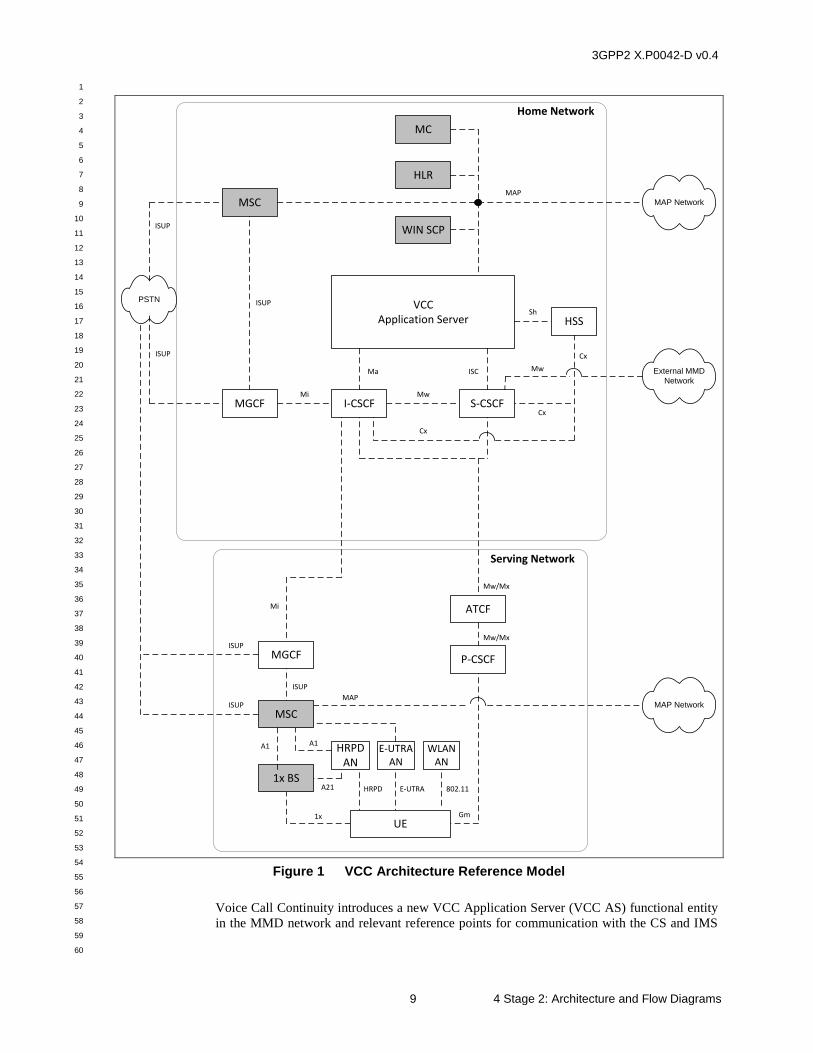
The following figure illustrates the architecture reference model to support Voice Call
Continuity, including IMS-CS DTs, call origination and call termination. Only those MMD
or CS network entities or interfaces supporting VCC are shown.
3GPP2 X.P0042-D v0.4
1
2
3
4
5
6
7
8
9
10
11
12
13
14
15
16
17
18
19
20
21
22
23
24
25
26
27
28
29
30
31
32
33
34
35
36
37
38
39
40
41
42
43
44
45
46
47
48
49
50
51
52
53
54
55
56
57
58
59
60
9 4 Stage 2: Architecture and Flow Diagrams
VCCApplication Server
Sh
WIN SCP
HLR
PSTN ISUP
ISUP
ISUP
Ma ISC
Cx
Mi Mw
MAP
Cx
Cx
MAP Network
Home Network
ISUP
MAP Network
P-CSCF
1x Gm
Mw/MxISUP
A1 A1
A21 HRPD 802.11
Serving Network
MAP
Mi
External MMD
Network
Mw
ISUP
MC
ATCF
Mw/Mx
E-UTRA
MSC
MGCF I-CSCF S-CSCF
HSS
MGCF
MSC
1x BS
UE
WLAN AN
HRPD AN
E-UTRAAN
Figure 1 VCC Architecture Reference Model
Voice Call Continuity introduces a new VCC Application Server (VCC AS) functional entity
in the MMD network and relevant reference points for communication with the CS and IMS
3GPP2 X.P0042-D v0.4
1
2
3
4
5
6
7
8
9
10
11
12
13
14
15
16
17
18
19
20
21
22
23
24
25
26
27
28
29
30
31
32
33
34
35
36
37
38
39
40
41
42
43
44
45
46
47
48
49
50
51
52
53
54
55
56
57
58
59
60
4 Stage 2: Architecture and Flow Diagrams 10
functional entities. The VCC AS makes use of existing CS and IMS functional entities and
reference points.
The VCC Application Server comprises two main functions:
assists in terminating services to a terminal that is 1x CS registered and/or IMS
registered
is involved in voice call setup signaling to facilitate HRPD/E-UTRA/WLAN VoIP-
to-1x CS voice call DTs and 1x CS voice call to WLAN VoIP DTs
The VCC AS is anchored in the call signaling path of all voice calls originated from, or
terminated to, a VCC UE that is IMS registered and tuned to HRPD/E-UTRA/WLAN, or 1x
CS registered and tuned to 1x. It has the following signaling interfaces:
VCC AS / S-CSCF (ISC)
The VCC AS serves as a SIP Back-to-Back User Agent (B2BUA) that interfaces to the S-
CSCF via an ISC SIP signaling interface.
VCC AS / I-CSCF (Ma)
The VCC AS interfaces to an I-CSCF via an ‘Ma’ SIP signaling interface. This interface is
used to anchor the VCC AS in the call path by sending SIP request from I-CSCF directly to
the VCC AS.
VCC AS / HLR (MAP)
The VCC AS interfaces to the 1x CS HLR using MAP in order to obtain routing information
for terminating voice calls to a UE via the 1x CS network.
VCC AS / HSS (Sh)
The VCC AS also interfaces to the HSS via an Sh interface [MMD Part-10] using the
Diameter protocol to transfer data between the VCC AS and HSS.
VCC AS / WIN SCP (MAP)
The VCC AS interfaces to the WIN SCP using the MAP protocol in order to provide routing
information for 1x voice call originations and terminations and to anchor the VCC AS in these
calls. The WIN SCP may be integrated with the VCC AS or may be a standalone network
element.
The Access Transfer Control Function (ATCF) is defined in [23.237] and is a function in the
serving (visited if roaming) network. The ATCF allocates an STN-SR and instructs the
ATGW to anchor the media path of the IMS sessions to 1x CS access network. The ATCF
keeps track of the IMS sessions, performs access transfer and informs the VCC AS about that
access transfer. The ATCF has the following signaling interface:
ATCF / CSCF (Mw/Mx)
3GPP2 X.P0042-D v0.4
1
2
3
4
5
6
7
8
9
10
11
12
13
14
15
16
17
18
19
20
21
22
23
24
25
26
27
28
29
30
31
32
33
34
35
36
37
38
39
40
41
42
43
44
45
46
47
48
49
50
51
52
53
54
55
56
57
58
59
60
11 4 Stage 2: Architecture and Flow Diagrams
4.2 Signaling Flows for Registration
This section illustrates signaling flows for registration. The registration model supports a
“dual registration”, i.e., the mobile may be registered in either the IMS network, in the CS
network (i.e., in the HLR), or in both.
Registration is the procedure by which the UE is authorized and granted permission to access
and utilize either, the IMS network, the CS network, or both. IMS Registration provides
limited real-time information (e.g., only at the time of registration) as to the status of access
network connectivity. There is a defined mechanism (see section 4.2.3) by which the UE can
inform the VCC AS as to the loss of WLAN/HRPD access connectivity if the UE is CS access
connected.
4.2.1 IMS Registration
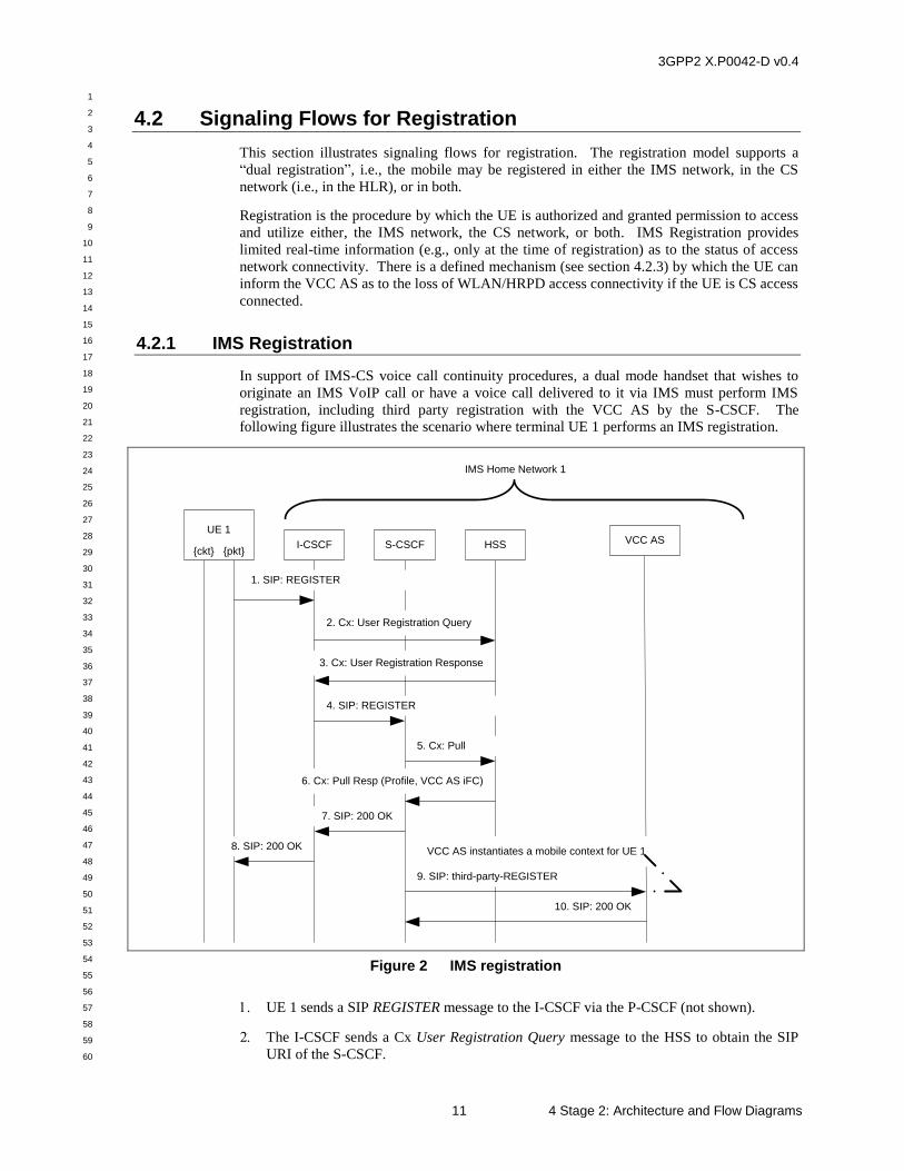
In support of IMS-CS voice call continuity procedures, a dual mode handset that wishes to
originate an IMS VoIP call or have a voice call delivered to it via IMS must perform IMS
registration, including third party registration with the VCC AS by the S-CSCF. The
following figure illustrates the scenario where terminal UE 1 performs an IMS registration.
S-CSCF HSS
IMS Home Network 1
I-CSCF
6. Cx: Pull Resp (Profile, VCC AS iFC)
2. Cx: User Registration Query
3. Cx: User Registration Response
4. SIP: REGISTER
1. SIP: REGISTER
9. SIP: third-party-REGISTER
5. Cx: Pull
VCC ASUE 1
{ckt} {pkt}
10. SIP: 200 OK
7. SIP: 200 OK
8. SIP: 200 OKVCC AS instantiates a mobile context for UE 1
Figure 2 IMS registration
UE 1 sends a SIP REGISTER message to the I-CSCF via the P-CSCF (not shown).
The I-CSCF sends a Cx User Registration Query message to the HSS to obtain the SIP
URI of the S-CSCF.
3GPP2 X.P0042-D v0.4
1
2
3
4
5
6
7
8
9
10
11
12
13
14
15
16
17
18
19
20
21
22
23
24
25
26
27
28
29
30
31
32
33
34
35
36
37
38
39
40
41
42
43
44
45
46
47
48
49
50
51
52
53
54
55
56
57
58
59
60
4 Stage 2: Architecture and Flow Diagrams 12
The HSS returns a Cx User Registration Response message to the I-CSCF with the S-
CSCF URI.
The I-CSCF sends the REGISTER message to the S-CSCF.
The S-CSCF sends a Cx Pull message to the HSS.
The HSS returns a Cx Pull Resp message to the S-CSCF with the user’s profile
information, as well as the VCC AS iFC.
The S-CSCF sends a SIP 200 OK to the I-CSCF.
The I-CSCF sends a 200 OK via the P-CSCF (not shown) back to UE 1.
The S-CSCF executes a SIP third-party registration with the VCC AS to indicate that UE
1 has just registered with the S-CSCF.
The VCC AS instantiates a context for UE 1 and sends a 200 OK back to the S-CSCF.
3GPP2 X.P0042-D v0.4
1
2
3
4
5
6
7
8
9
10
11
12
13
14
15
16
17
18
19
20
21
22
23
24
25
26
27
28
29
30
31
32
33
34
35
36
37
38
39
40
41
42
43
44
45
46
47
48
49
50
51
52
53
54
55
56
57
58
59
60
13 4 Stage 2: Architecture and Flow Diagrams
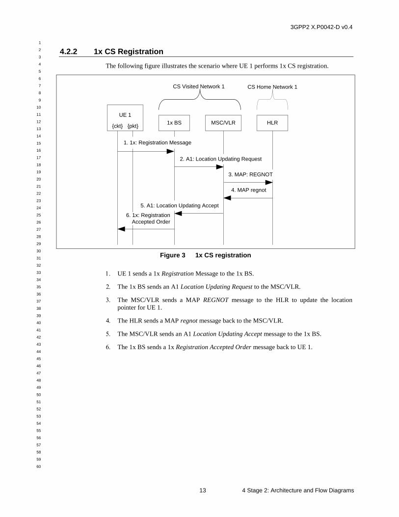
4.2.2 1x CS Registration
The following figure illustrates the scenario where UE 1 performs 1x CS registration.
HLR
CS Visited Network 1 CS Home Network 1
MSC/VLR
4. MAP regnot
1x BS
3. MAP: REGNOT
1. 1x: Registration Message
2. A1: Location Updating Request
6. 1x: Registration
Accepted Order
5. A1: Location Updating Accept
UE 1
{ckt} {pkt}
Figure 3 1x CS registration
UE 1 sends a 1x Registration Message to the 1x BS.
The 1x BS sends an A1 Location Updating Request to the MSC/VLR.
The MSC/VLR sends a MAP REGNOT message to the HLR to update the location
pointer for UE 1.
The HLR sends a MAP regnot message back to the MSC/VLR.
The MSC/VLR sends an A1 Location Updating Accept message to the 1x BS.
The 1x BS sends a 1x Registration Accepted Order message back to UE 1.
3GPP2 X.P0042-D v0.4
1
2
3
4
5
6
7
8
9
10
11
12
13
14
15
16
17
18
19
20
21
22
23
24
25
26
27
28
29
30
31
32
33
34
35
36
37
38
39
40
41
42
43
44
45
46
47
48
49
50
51
52
53
54
55
56
57
58
59
60
4 Stage 2: Architecture and Flow Diagrams 14
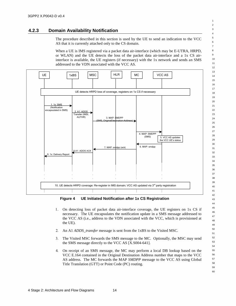
4.2.3 Domain Availability Notification
The procedure described in this section is used by the UE to send an indication to the VCC
AS that it is currently attached only to the CS domain.
When a UE is IMS registered via a packet data air-interface (which may be E-UTRA, HRPD,
or WLAN) and the UE detects the loss of the packet data air-interface and a 1x CS air-
interface is available, the UE registers (if necessary) with the 1x network and sends an SMS
addressed to the VDN associated with the VCC AS.
8.A1: ADDS ACK
UE MSC MC
1. 1x: SMS
(Notification
encapsulated in SMS)
HLR1xBS
2. A1: ADDS
Transfer (IMSI,
AUTHR) 3. MAP: SMDPP
(SMS_OriginalDestination-Address)
7. MAP: smdpp (ack)
VCC AS
4. MAP: SMDPP
(SMS)
6. MAP: smdpp
9. 1x: Delivery Report
10. UE detects HRPD coverage: Re-register in IMS domain; VCC AS updated via 3rd
party registration
UE detects HRPD loss of coverage, registers on 1x CS if necessary
5. VCC AS updates
the VCC UE’s status
Figure 4 UE Initiated Notification after 1x CS Registration
On detecting loss of packet data air-interface coverage, the UE registers on 1x CS if
necessary. The UE encapsulates the notification update in a SMS message addressed to
the VCC AS (i.e., address to the VDN associated with the VCC, which is provisioned at
the UE).
An A1 ADDS_transfer message is sent from the 1xBS to the Visited MSC.
The Visited MSC forwards the SMS message to the MC. Optionally, the MSC may send
the SMS message directly to the VCC AS [X.S004-641].
On receipt of an SMS message, the MC may perform a local DB lookup based on the
VCC E.164 contained in the Original Destination Address number that maps to the VCC
AS address. The MC forwards the MAP SMDPP message to the VCC AS using Global
Title Translation (GTT) or Point Code (PC) routing.
3GPP2 X.P0042-D v0.4
1
2
3
4
5
6
7
8
9
10
11
12
13
14
15
16
17
18
19
20
21
22
23
24
25
26
27
28
29
30
31
32
33
34
35
36
37
38
39
40
41
42
43
44
45
46
47
48
49
50
51
52
53
54
55
56
57
58
59
60
15 4 Stage 2: Architecture and Flow Diagrams
The VCC AS updates the domain availability of the VCC UE in order to deliver all
incoming voice calls to the UE on 1x CS.
The VCC AS responds to the delivered SMS message with a positive acknowledgement.
If the MSC sent the SMS message directly to the VCC AS, the VCC AS would send the
response directly to the MSC [X.S0004-641].
7-9. The delivery report message is forwarded through the MC/MSC to the originating UE.
When the packet data air interface becomes available again, the UE shall perform an IMS
re-registration and the VCC AS is updated via 3rd party registration (as described in
Section 4.2.1) so that future calls can be delivered over IMS through the packet data air
interface.
3GPP2 X.P0042-D v0.4
1
2
3
4
5
6
7
8
9
10
11
12
13
14
15
16
17
18
19
20
21
22
23
24
25
26
27
28
29
30
31
32
33
34
35
36
37
38
39
40
41
42
43
44
45
46
47
48
49
50
51
52
53
54
55
56
57
58
59
60
4 Stage 2: Architecture and Flow Diagrams 16
4.3 Signaling Flows for Call Origination
This section illustrates signaling flows for call origination.
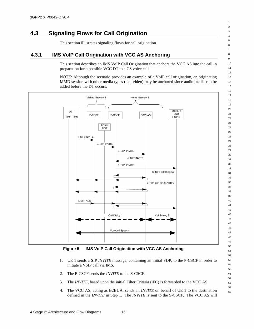
4.3.1 IMS VoIP Call Origination with VCC AS Anchoring
This section describes an IMS VoIP Call Origination that anchors the VCC AS into the call in
preparation for a possible VCC DT to a CS voice call.
NOTE: Although the scenario provides an example of a VoIP call origination, an originating
MMD session with other media types (i.e., video) may be anchored since audio media can be
added before the DT occurs.
S-CSCF
Visited Network 1
2. SIP: INVITE
3. SIP: INVITE
4. SIP: INVITE
5. SIP: INVITE
Home Network 1
1. SIP: INVITE
8. SIP: ACK
6. SIP: 180 Ringing
UE 1
{ckt} {pkt}
7. SIP: 200 OK (INVITE)
VCC AS
OTHER
END
POINTP-CSCF
PDSN/
PDIF
Vocoded Speech
Call Dialog 1 Call Dialog 2
Figure 5 IMS VoIP Call Origination with VCC AS Anchoring
UE 1 sends a SIP INVITE message, containing an initial SDP, to the P-CSCF in order to
initiate a VoIP call via IMS.
The P-CSCF sends the INVITE to the S-CSCF.
The INVITE, based upon the initial Filter Criteria (iFC) is forwarded to the VCC AS.
The VCC AS, acting as B2BUA, sends an INVITE on behalf of UE 1 to the destination
defined in the INVITE in Step 1. The INVITE is sent to the S-CSCF. The VCC AS will
3GPP2 X.P0042-D v0.4
1
2
3
4
5
6
7
8
9
10
11
12
13
14
15
16
17
18
19
20
21
22
23
24
25
26
27
28
29
30
31
32
33
34
35
36
37
38
39
40
41
42
43
44
45
46
47
48
49
50
51
52
53
54
55
56
57
58
59
60
17 4 Stage 2: Architecture and Flow Diagrams
remain in the call session signaling path for the remainder of the call and assist in any
future DT of the VoIP call to a 1x CS voice call as needed.
The S-CSCF sends the INVITE to the Other End Party (OEP).
The OEP returns a SIP 180 Ringing message to the VCC AS that is sent back along the
signaling path to UE 1.
The OEP answers the call and sends a SIP 200 OK message to the VCC AS that is sent
back along the signaling path to UE 1.
UE 1 responds with a SIP ACK that is sent through the signaling path towards the OEP.
The VCC AS reception of the ACK from the UE 1 completes the establishment of call
dialog 1 between UE 1 and the VCC AS. The OEP’s reception of the ACK from the
VCC AS, completes the establishment of call dialog 2 between the VCC AS and the
OEP.
4.3.2 CS Call Origination with VCC AS Anchoring
4.3.2.1 WIN Based Solution
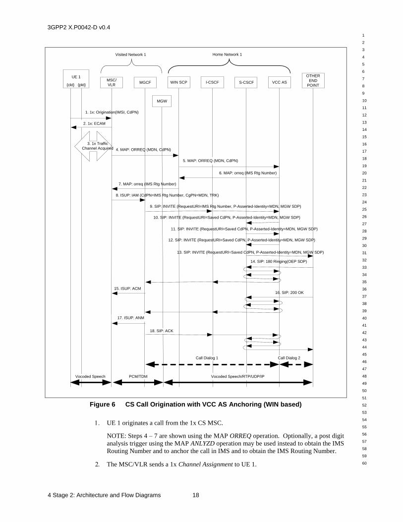
This section describes a CS Voice Call Origination that anchors the VCC AS into the call in
preparation for a possible VCC DT to IMS VoIP. The following figure illustrates the call
flow that uses a WIN SCP to route the CS voice call to the VCC AS. The WIN SCP function
may be performed by a separate entity, or optionally (not shown), it may be performed as an
integrated function within the VCC AS.
3GPP2 X.P0042-D v0.4
1
2
3
4
5
6
7
8
9
10
11
12
13
14
15
16
17
18
19
20
21
22
23
24
25
26
27
28
29
30
31
32
33
34
35
36
37
38
39
40
41
42
43
44
45
46
47
48
49
50
51
52
53
54
55
56
57
58
59
60
4 Stage 2: Architecture and Flow Diagrams 18
4. MAP: ORREQ (MDN, CdPN)
1. 1x: Origination(IMSI, CdPN)
13. SIP: INVITE (RequestURI=Saved CdPN, P-Asserted-Identity=MDN, MGW SDP)
10. SIP: INVITE (RequestURI=Saved CdPN, P-Asserted-Identity=MDN, MGW SDP)
9. SIP: INVITE (RequestURI=IMS Rtg Number, P-Asserted-Identity=MDN, MGW SDP)
8. ISUP: IAM (CdPN=IMS Rtg Number, CgPN=MDN, TRK)
15. ISUP: ACM
7. MAP: orreq (IMS Rtg Number)
12. SIP: INVITE (RequestURI=Saved CdPN, P-Asserted-Identity=MDN, MGW SDP)
14. SIP: 180 Ringing(OEP SDP)
16. SIP: 200 OK
11. SIP: INVITE (RequestURI=Saved CdPN, P-Asserted-Identity=MDN, MGW SDP)
6. MAP: orreq (IMS Rtg Number)
Visited Network 1
VCC AS
Home Network 1
MSC/
VLR
3. 1x Traffic
Channel Acquired
Vocoded Speech PCM/TDM
MGCF S-CSCF
2. 1x: ECAM
17. ISUP: ANM
18. SIP: ACK
I-CSCF
MGW
OTHER
END
POINT
Call Dialog 1 Call Dialog 2
UE 1
{ckt} {pkt}WIN SCP
5. MAP: ORREQ (MDN, CdPN)
Vocoded Speech/RTP/UDP/IP
Figure 6 CS Call Origination with VCC AS Anchoring (WIN based)
UE 1 originates a call from the 1x CS MSC.
NOTE: Steps 4 – 7 are shown using the MAP ORREQ operation. Optionally, a post digit
analysis trigger using the MAP ANLYZD operation may be used instead to obtain the IMS
Routing Number and to anchor the call in IMS and to obtain the IMS Routing Number.
The MSC/VLR sends a 1x Channel Assignment to UE 1.
3GPP2 X.P0042-D v0.4
1
2
3
4
5
6
7
8
9
10
11
12
13
14
15
16
17
18
19
20
21
22
23
24
25
26
27
28
29
30
31
32
33
34
35
36
37
38
39
40
41
42
43
44
45
46
47
48
49
50
51
52
53
54
55
56
57
58
59
60
19 4 Stage 2: Architecture and Flow Diagrams
UE 1 acquires the 1x traffic channel.
The MSC invokes a call origination WIN trigger to obtain routing information. The
MSC sends a MAP ORREQ message, containing the Calling Party MDN and the Called
Party Number (CdPN), to the WIN SCP. Optionally, the MSC/VLR may send the
ORREQ message directly to a VCC AS that has an integrated WIN SCP function and step
5 is skipped.
The WIN SCP sends the ORREQ message on to the VCC AS. This initiates VCC call
anchoring.
The VCC AS stores the MDN and CdPN for later call setup and returns a MAP orreq
response message with the IMS Routing Number (E.164) of the VCC AS as the routing
information for this call.
The WIN SCP returns the orreq message to the MSC/VLR. Step 7 is skipped if the VCC
AS has an integrated WIN SCP function.
The MSC/VLR sends an ISUP IAM message to the MGCF in the serving network,
containing UE 1’s routing information (i.e., IMS Routing Number in the CdPN field and
UE 1’s MDN in the CgPN) and a PCM/TDM trunk to be connected between the MSC
and the MGW.
The MGCF requests that the MGW connect to the PCM/TDM trunk and allocate an
ephemeral termination to be connected to the far end. The MGCF then sends the SIP
INVITE with the IMS Routing Number (i.e., VCC AS PSI) in the Request URI header
and UE 1’s MDN in the P-Asserted-Identity header to the I-CSCF. The I-CSCF queries
the HSS in order to determine the next hop in the routing path for the PSI. In this case, it
is the VCC AS.
The VCC AS acting as a B2BUA creates an INVITE request containing MGW-SDP and
the tel URI of the UE, generated from the MDN. The VCC AS sends the INVITE to the
S-CSCF for IMS Processing.
Based on filter criteria, the S-CSCF sends an INVITE message to the VCC AS containing
UE 1’s routing information as received in the previous step.
The VCC AS sends the INVITE back to the S-CSCF.
Upon completion of filter criteria processing, the S-CSCF sends the INVITE to the Other
End Point (OEP) (IMS user or PSTN MGCF/MGW).
The OEP responds with a SIP 180 Ringing message, which is sent back along the
signaling path and is received at the MGCF. It contains the OEP SDP.
The MGCF modifies the MGW ephemeral termination with the remote OEP SDP and
sends an ISUP ACM message to the MSC/VLR.
The OEP answers the call and sends a SIP 200 OK message back to the MGCF back
along the signaling path.
The MGCF sends an ISUP ANM message to the MSC/VLR.
The MGCF also sends a SIP ACK message back to the OEP along the signaling path.
This completes the establishment of call dialog 1 between the MGCF and the VCC AS
and call dialog 2 between the VCC AS and the OEP.
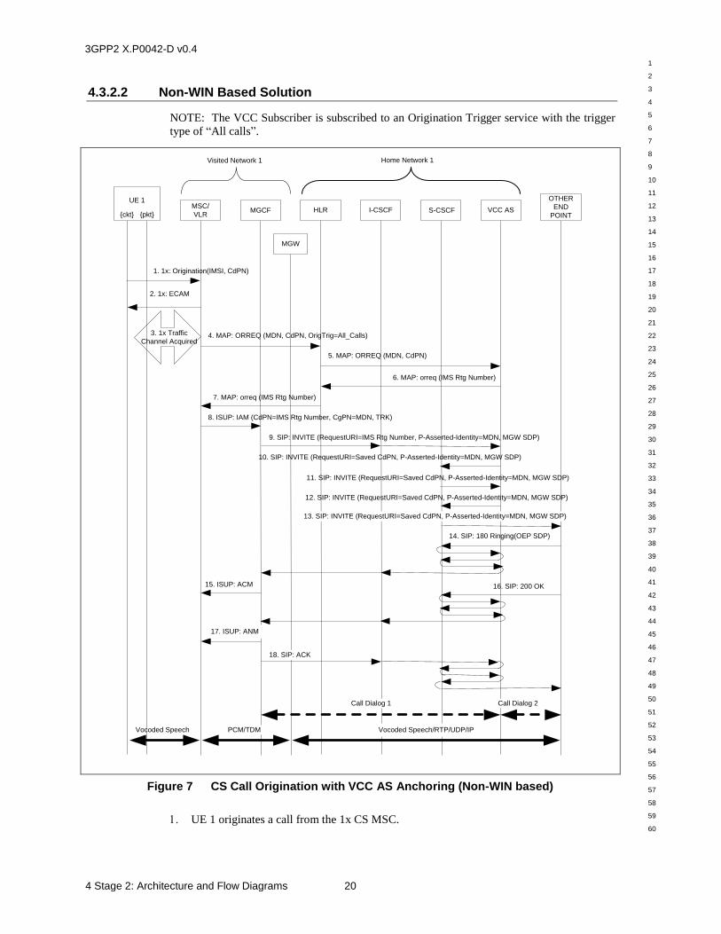
3GPP2 X.P0042-D v0.4
1
2
3
4
5
6
7
8
9
10
11
12
13
14
15
16
17
18
19
20
21
22
23
24
25
26
27
28
29
30
31
32
33
34
35
36
37
38
39
40
41
42
43
44
45
46
47
48
49
50
51
52
53
54
55
56
57
58
59
60
4 Stage 2: Architecture and Flow Diagrams 20
4.3.2.2 Non-WIN Based Solution
NOTE: The VCC Subscriber is subscribed to an Origination Trigger service with the trigger
type of “All calls”.
9. SIP: INVITE (RequestURI=IMS Rtg Number, P-Asserted-Identity=MDN, MGW SDP)
8. ISUP: IAM (CdPN=IMS Rtg Number, CgPN=MDN, TRK)
15. ISUP: ACM
3. 1x Traffic
Channel Acquired4. MAP: ORREQ (MDN, CdPN, OrigTrig=All_Calls)
7. MAP: orreq (IMS Rtg Number)
1. 1x: Origination(IMSI, CdPN)
10. SIP: INVITE (RequestURI=Saved CdPN, P-Asserted-Identity=MDN, MGW SDP)
12. SIP: INVITE (RequestURI=Saved CdPN, P-Asserted-Identity=MDN, MGW SDP)
14. SIP: 180 Ringing(OEP SDP)
2. 1x: ECAM
16. SIP: 200 OK
11. SIP: INVITE (RequestURI=Saved CdPN, P-Asserted-Identity=MDN, MGW SDP)
5. MAP: ORREQ (MDN, CdPN)
6. MAP: orreq (IMS Rtg Number)
Visited Network 1
VCC AS
Home Network 1
MSC/
VLR
Vocoded Speech PCM/TDM
MGCF
Vocoded Speech/RTP/UDP/IP
S-CSCF
17. ISUP: ANM
18. SIP: ACK
I-CSCF
MGW
OTHER
END
POINT
Call Dialog 1 Call Dialog 2
13. SIP: INVITE (RequestURI=Saved CdPN, P-Asserted-Identity=MDN, MGW SDP)
UE 1
{ckt} {pkt}HLR
Figure 7 CS Call Origination with VCC AS Anchoring (Non-WIN based)
UE 1 originates a call from the 1x CS MSC.
3GPP2 X.P0042-D v0.4
1
2
3
4
5
6
7
8
9
10
11
12
13
14
15
16
17
18
19
20
21
22
23
24
25
26
27
28
29
30
31
32
33
34
35
36
37
38
39
40
41
42
43
44
45
46
47
48
49
50
51
52
53
54
55
56
57
58
59
60
21 4 Stage 2: Architecture and Flow Diagrams
The MSC/VLR sends a 1x Channel Assignment to UE 1.
UE 1 acquires the 1x traffic channel.
The MSC invokes a call origination trigger to obtain routing information from the HLR.
The MSC sends a MAP ORREQ message, containing the Calling Party MDN and the
Called Party Number (CdPN), to the HLR.
Upon receiving the ORREQ message, the HLR sends an ORREQ message to VCC AS.
This initiates VCC call anchoring.
The VCC AS stores the MDN and CdPN for later call setup and returns a MAP orreq
response message with the IMS Routing Number (E.164) of the VCC AS as the routing
information for this call.
The HLR returns the orreq message to the MSC/VLR.
The MSC/VLR sends an ISUP IAM message to the MGCF in the serving network,
containing UE 1’s routing information (i.e., IMS Routing Number in the CdPN field and
UE 1’s MDN in the CgPN) and a PCM/TDM trunk to be connected between the MSC
and the MGW.
The MGCF requests that the MGW connect to the PCM/TDM trunk and allocate an
ephemeral termination to be connected to the far end. The MGCF then sends the SIP
INVITE with the IMS Routing Number (i.e., VCC AS PSI) in the Request URI header
and UE 1’s MDN in the P-Asserted-Identity header to the I-CSCF. The I-CSCF queries
the HSS in order to determine the next hop in the routing path for the PSI. In this case, it
is the VCC AS.
The VCC AS acting as a B2BUA creates an INVITE request containing MGW-SDP and
the tel URI of the UE, generated from the MDN. The VCC AS sends the INVITE to the
S-CSCF for IMS processing.
Based on filter criteria, the S-CSCF sends an INVITE message to the VCC AS containing
UE 1’s routing information as received in the previous step.
The VCC AS sends the INVITE back to the S-CSCF.
Upon completion of filter criteria processing, the S-CSCF sends the INVITE to the Other
End Point (OEP) (IMS user or PSTN MGCF/MGW).
The OEP responds with a SIP 180 Ringing message, which is sent back along the
signaling path and is received at the MGCF. It contains the OEP SDP.
The MGCF modifies the MGW ephemeral termination with the remote OEP SDP and
sends an ISUP ACM message to the MSC/VLR.
The OEP answers the call and sends a SIP 200 OK message back to the MGCF back
along the signaling path.
The MGCG sends an ISUP ANM message to the MSC/VLR.
The MGCF also sends a SIP ACK message back to the OEP along the signaling path.
This completes the establishment of call dialog 1 between the MGCF and the VCC AS
and call dialog 2 between the VCC AS and the OEP.
3GPP2 X.P0042-D v0.4
1
2
3
4
5
6
7
8
9
10
11
12
13
14
15
16
17
18
19
20
21
22
23
24
25
26
27
28
29
30
31
32
33
34
35
36
37
38
39
40
41
42
43
44
45
46
47
48
49
50
51
52
53
54
55
56
57
58
59
60
4 Stage 2: Architecture and Flow Diagrams 22
4.4 Signaling Flows for Call Delivery
This section illustrates signaling flows for call delivery. Domain selection for delivery of
terminating services to a hybrid mobile (HRPD/1x or WLAN/1x) may be based on current
information about the user's registration status, radio network connectivity and may also take
into account the operator's policy and subscriber's preference.
4.4.1 Voice Call Delivery on 1x CS
This section describes the delivery of a voice call to a subscriber that has performed 1x CS
registration with the CS network as described in Section 4.2.2. The following figure
illustrates a signaling flow for the scenario where a terminal that is 1x CS registered receives
an IMS VoIP call that is delivered to the subscriber as a CS voice call. It is assumed that the
VCC AS determines that UE 1 is connected to the 1x CS network. The initial SIP INVITE
comes from an Other End Point (OEP), which may be another IMS, an MGCF, or other SIP-
capable entity.
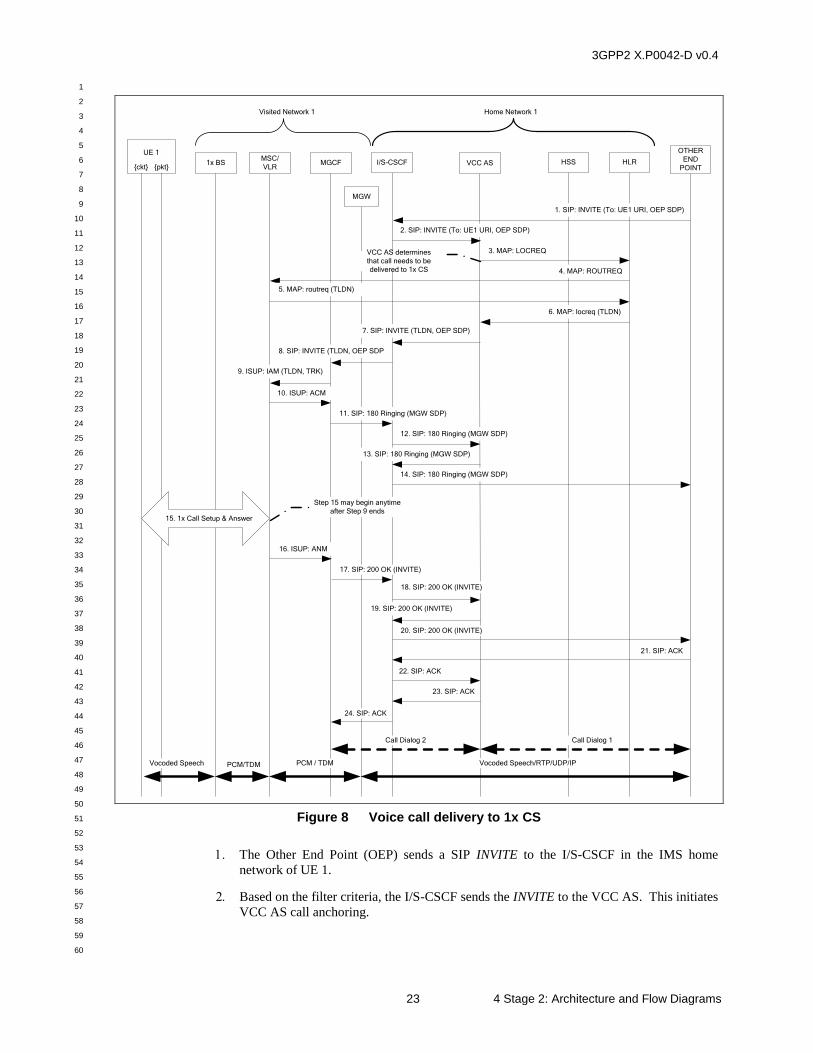
3GPP2 X.P0042-D v0.4
1
2
3
4
5
6
7
8
9
10
11
12
13
14
15
16
17
18
19
20
21
22
23
24
25
26
27
28
29
30
31
32
33
34
35
36
37
38
39
40
41
42
43
44
45
46
47
48
49
50
51
52
53
54
55
56
57
58
59
60
23 4 Stage 2: Architecture and Flow Diagrams
1x BS I/S-CSCF HSS
Visited Network 1
HLR
1. SIP: INVITE (To: UE1 URI, OEP SDP)
2. SIP: INVITE (To: UE1 URI, OEP SDP)
Home Network 1
MGW
VCC ASMSC/
VLR
9. ISUP: IAM (TLDN, TRK)
3. MAP: LOCREQ
6. MAP: locreq (TLDN)
4. MAP: ROUTREQ
5. MAP: routreq (TLDN)
8. SIP: INVITE (TLDN, OEP SDP
10. ISUP: ACM
14. SIP: 180 Ringing (MGW SDP)
13. SIP: 180 Ringing (MGW SDP)
16. ISUP: ANM
MGCF
UE 1
{ckt} {pkt}
7. SIP: INVITE (TLDN, OEP SDP)
11. SIP: 180 Ringing (MGW SDP)
12. SIP: 180 Ringing (MGW SDP)
Step 15 may begin anytime
after Step 9 ends15. 1x Call Setup & Answer
17. SIP: 200 OK (INVITE)
Vocoded Speech PCM/TDM PCM / TDM Vocoded Speech/RTP/UDP/IP
OTHER
END
POINT
Call Dialog 1
20. SIP: 200 OK (INVITE)
19. SIP: 200 OK (INVITE)
18. SIP: 200 OK (INVITE)
22. SIP: ACK
23. SIP: ACK
21. SIP: ACK
24. SIP: ACK
Call Dialog 2
VCC AS determines
that call needs to be
delivered to 1x CS
Figure 8 Voice call delivery to 1x CS
The Other End Point (OEP) sends a SIP INVITE to the I/S-CSCF in the IMS home
network of UE 1.
Based on the filter criteria, the I/S-CSCF sends the INVITE to the VCC AS. This initiates
VCC AS call anchoring.
3GPP2 X.P0042-D v0.4
1
2
3
4
5
6
7
8
9
10
11
12
13
14
15
16
17
18
19
20
21
22
23
24
25
26
27
28
29
30
31
32
33
34
35
36
37
38
39
40
41
42
43
44
45
46
47
48
49
50
51
52
53
54
55
56
57
58
59
60
4 Stage 2: Architecture and Flow Diagrams 24
The VCC AS determines that the call needs to be delivered to 1x CS and sends a MAP
LOCREQ message to the HLR to determine UE 1’s location and routing information.
The HLR sends a MAP ROUTREQ message to the MSC/VLR to determine UE 1’s
routing information.
The MSC/VLR sends a MAP routreq message back to the HLR containing UE 1’s
routing information (i.e., TLDN).
The HLR sends a MAP locreq message back to the VCC AS containing UE 1’s routing
information (i.e., TLDN).
The VCC AS sends an INVITE message back to the I/S-CSCF containing UE 1’s routing
information (i.e., TLDN).
The I/S-CSCF sends an INVITE message to the MGCF containing UE 1’s routing
information (i.e., TLDN). The interaction between the S-CSCF and BGCF, and MGCF
and BGCF are not shown for brevity.
The MGCF requests that the MGW be configured with an ephemeral termination to be
connected to the OEP and a physical PCM trunk termination, TRK, to be connected to
the MSC/VLR. The MGCF sends an ISUP IAM message to the MSC/VLR. Note that if
the MGCF/MGW does not have TDM trunks connecting it to the MSC/VLR, then the
call may be routed to the PSTN and then to the MSC/VLR.
The MSC/VLR returns an ISUP ACM message to the MGCF.
The MGCF sends a SIP 180 Ringing message to the I/S-CSCF. It contains the SDP for
the MGW ephemeral termination.
The I/S-CSCF sends the 180 Ringing to the VCC AS.
The VCC AS sends the 180 Ringing to the I/S-CSCF.
The I/S-CSCF sends the 180 Ringing to the OEP.
Anytime after Step 9 has ended, a call is setup between the MSC/VLR, the 1x BS and UE
1. UE 1 answers the call.
When the call is answered, the MSC/VLR sends an ISUP ANM message to the MGCF.
The MGCF sends a SIP 200 OK message to the I/S-CSCF.
The I/S-CSCF sends a 200 OK message to the VCC AS.
The VCC AS sends a 200 OK message to the I/S-CSCF.
The I/S-CSCF sends a 200 OK message to the OEP.
The OEP sends a SIP ACK message to the I/S-CSCF.
The I/S-CSCF sends the ACK to the VCC AS. This completes the establishment of SIP
call dialog 1 between the VCC AS and the OEP.
The VCC AS sends the ACK to the I/S-CSCF.
The I/S-CSCF sends the ACK to MGCF. This completes the establishment of SIP call
dialog 2 between the VCC AS and the MGCF.
3GPP2 X.P0042-D v0.4
1
2
3
4
5
6
7
8
9
10
11
12
13
14
15
16
17
18
19
20
21
22
23
24
25
26
27
28
29
30
31
32
33
34
35
36
37
38
39
40
41
42
43
44
45
46
47
48
49
50
51
52
53
54
55
56
57
58
59
60
25 4 Stage 2: Architecture and Flow Diagrams
Post-conditions:
There is now a voice call setup between the UE and the OEP via the 1x CS network. SIP
call dialog 1 for this voice call is illustrated by a heavy dashed double arrow between the
VCC AS and the OEP. SIP call dialog 2 for this voice call is illustrated by a heavy
dashed double arrow between the VCC AS and the MGCF. The voice bearer path is
illustrated by heavy solid double arrows connecting the UE, MSC MGW and the OEP.
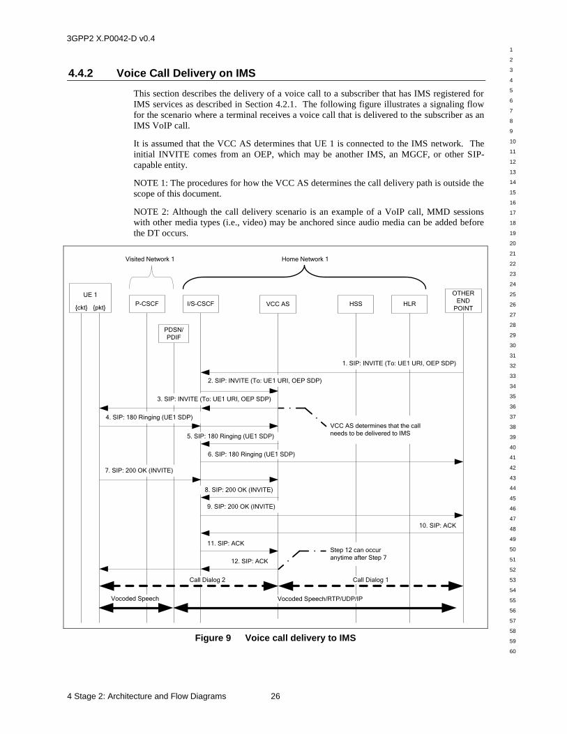
3GPP2 X.P0042-D v0.4
1
2
3
4
5
6
7
8
9
10
11
12
13
14
15
16
17
18
19
20
21
22
23
24
25
26
27
28
29
30
31
32
33
34
35
36
37
38
39
40
41
42
43
44
45
46
47
48
49
50
51
52
53
54
55
56
57
58
59
60
4 Stage 2: Architecture and Flow Diagrams 26
4.4.2 Voice Call Delivery on IMS
This section describes the delivery of a voice call to a subscriber that has IMS registered for
IMS services as described in Section 4.2.1. The following figure illustrates a signaling flow
for the scenario where a terminal receives a voice call that is delivered to the subscriber as an
IMS VoIP call.
It is assumed that the VCC AS determines that UE 1 is connected to the IMS network. The
initial INVITE comes from an OEP, which may be another IMS, an MGCF, or other SIP-
capable entity.
NOTE 1: The procedures for how the VCC AS determines the call delivery path is outside the
scope of this document.
NOTE 2: Although the call delivery scenario is an example of a VoIP call, MMD sessions
with other media types (i.e., video) may be anchored since audio media can be added before
the DT occurs.
P-CSCF I/S-CSCF HSS
Visited Network 1
1. SIP: INVITE (To: UE1 URI, OEP SDP)
2. SIP: INVITE (To: UE1 URI, OEP SDP)
3. SIP: INVITE (To: UE1 URI, OEP SDP)
4. SIP: 180 Ringing (UE1 SDP)
7. SIP: 200 OK (INVITE)
Home Network 1
PDSN/
PDIF
9. SIP: 200 OK (INVITE)
8. SIP: 200 OK (INVITE)
6. SIP: 180 Ringing (UE1 SDP)
UE 1
{ckt} {pkt}
VCC AS determines that the call
needs to be delivered to IMS
Vocoded Speech Vocoded Speech/RTP/UDP/IP
HLR
5. SIP: 180 Ringing (UE1 SDP)
OTHER
END
POINTVCC AS
Call Dialog 2 Call Dialog 1
12. SIP: ACK
10. SIP: ACK
11. SIP: ACKStep 12 can occur
anytime after Step 7
Figure 9 Voice call delivery to IMS
3GPP2 X.P0042-D v0.4
1
2
3
4
5
6
7
8
9
10
11
12
13
14
15
16
17
18
19
20
21
22
23
24
25
26
27
28
29
30
31
32
33
34
35
36
37
38
39
40
41
42
43
44
45
46
47
48
49
50
51
52
53
54
55
56
57
58
59
60
27 4 Stage 2: Architecture and Flow Diagrams
The Other End Point (OEP) sends a SIP INVITE to the I/S-CSCF in the IMS home
network of UE 1.
Based on the filter criteria, the I/S-CSCF sends the INVITE to the VCC AS, which acts as
a SIP B2BUA, in order to establish SIP call dialog 1 between the OEP and the VCC AS.
This initiates VCC AS call anchoring.
The VCC AS, which acts as a SIP B2BUA, determines that the call need to be delivered
to IMS and generates the INVITE to the I/S-CSCF serving UE 1, and the I/S-CSCF sends
the INVITE to UE 1 via the P-CSCF (not shown), in order to establish SIP call dialog 2
between the VCC AS and UE 1.
UE 1 returns a SIP 180 Ringing message with the SDP of the bearer to the I/S-CSCF, via
the P-CSCF (not shown), and the I/S-CSCF sends it to the VCC AS.
The VCC AS sends the 180 Ringing message to the I/S-CSCF.
The I/S-CSCF sends the 180 Ringing message to the OEP.
UE 1 sends a SIP 200 OK message to the I/S-CSCF, via the P-CSCF (not shown), and the
I/S-CSCF sends it to the VCC AS.
The VCC AS sends the 200 OK message to the I/S-CSCF.
The I/S-CSCF sends the 200 OK message to the OEP.
The OEP returns a SIP ACK message to the I/S-CSCF.
The I/S-CSCF sends the ACK to the VCC AS. This completes the establishment of SIP
call dialog 1 between the OEP and the VCC AS.
Anytime after Step 7, the VCC AS sends the ACK message to UE 1 via the I/S-CSCF and
the P-CSCF (not shown). This completes the establishment of SIP call dialog 2 between
UE 1 and the VCC AS.
Post-conditions:
There is now voice call setup between UE 1 and the OEP via the IMS network. SIP call
dialog 1 for this voice call is illustrated by a heavy dashed double arrow between the
VCC AS and the OEP. SIP call dialog 2 for this voice call is illustrated by a heavy
dashed double arrow between UE 1 and the VCC AS. The voice bearer path is illustrated
by heavy solid double arrows connecting the UE, PDSN/PDIF and the OEP.
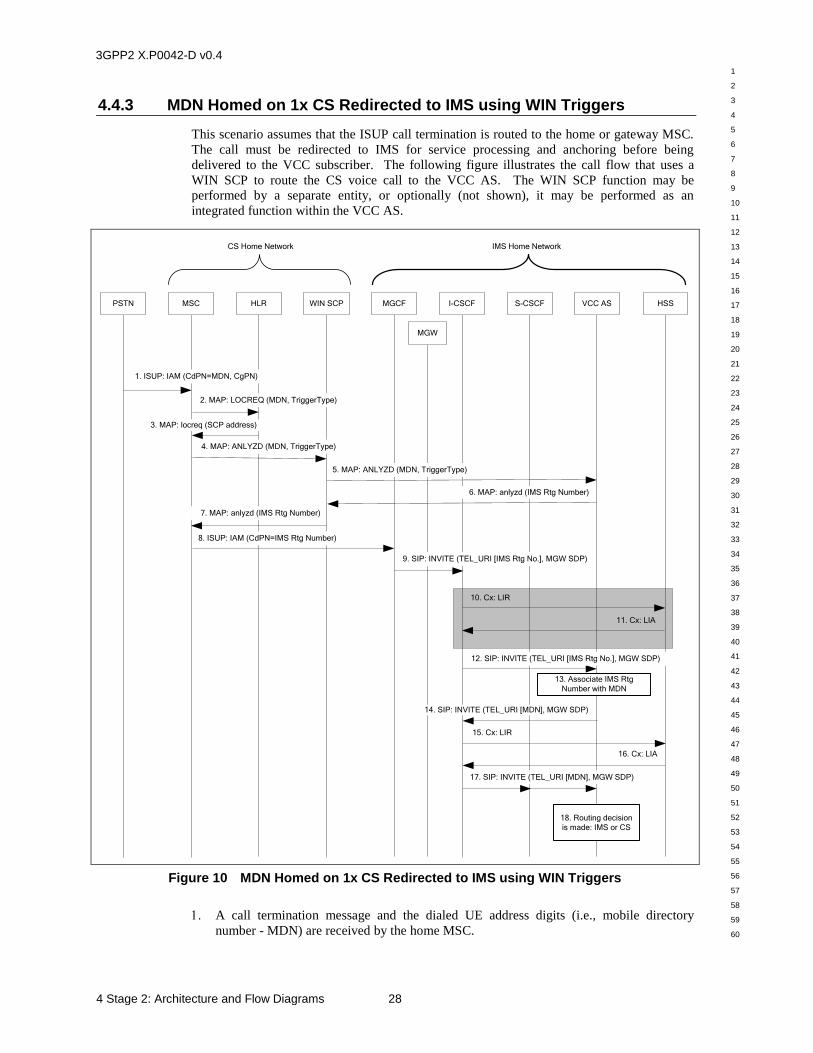
3GPP2 X.P0042-D v0.4
1
2
3
4
5
6
7
8
9
10
11
12
13
14
15
16
17
18
19
20
21
22
23
24
25
26
27
28
29
30
31
32
33
34
35
36
37
38
39
40
41
42
43
44
45
46
47
48
49
50
51
52
53
54
55
56
57
58
59
60
4 Stage 2: Architecture and Flow Diagrams 28
4.4.3 MDN Homed on 1x CS Redirected to IMS using WIN Triggers
This scenario assumes that the ISUP call termination is routed to the home or gateway MSC.
The call must be redirected to IMS for service processing and anchoring before being
delivered to the VCC subscriber. The following figure illustrates the call flow that uses a
WIN SCP to route the CS voice call to the VCC AS. The WIN SCP function may be
performed by a separate entity, or optionally (not shown), it may be performed as an
integrated function within the VCC AS.
MSC WIN SCP
IMS Home NetworkCS Home Network
I-CSCFHLR S-CSCFPSTN HSSMGCF
1. ISUP: IAM (CdPN=MDN, CgPN)
2. MAP: LOCREQ (MDN, TriggerType)
3. MAP: locreq (SCP address)
4. MAP: ANLYZD (MDN, TriggerType)
7. MAP: anlyzd (IMS Rtg Number)
9. SIP: INVITE (TEL_URI [IMS Rtg No.], MGW SDP)
8. ISUP: IAM (CdPN=IMS Rtg Number)
10. Cx: LIR
11. Cx: LIA
12. SIP: INVITE (TEL_URI [IMS Rtg No.], MGW SDP)
13. Associate IMS Rtg
Number with MDN
14. SIP: INVITE (TEL_URI [MDN], MGW SDP)
17. SIP: INVITE (TEL_URI [MDN], MGW SDP)
18. Routing decision
is made: IMS or CS
15. Cx: LIR
16. Cx: LIA
VCC AS
5. MAP: ANLYZD (MDN, TriggerType)
6. MAP: anlyzd (IMS Rtg Number)
MGW
Figure 10 MDN Homed on 1x CS Redirected to IMS using WIN Triggers
A call termination message and the dialed UE address digits (i.e., mobile directory
number - MDN) are received by the home MSC.
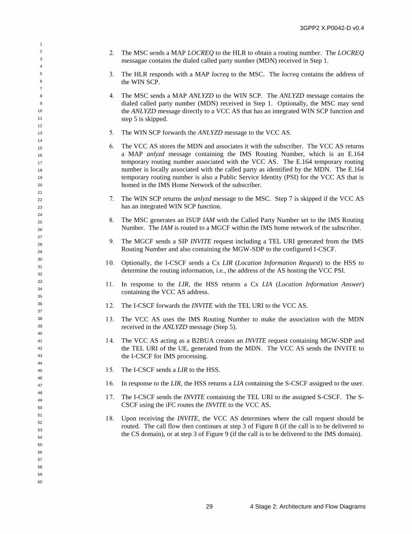
3GPP2 X.P0042-D v0.4
1
2
3
4
5
6
7
8
9
10
11
12
13
14
15
16
17
18
19
20
21
22
23
24
25
26
27
28
29
30
31
32
33
34
35
36
37
38
39
40
41
42
43
44
45
46
47
48
49
50
51
52
53
54
55
56
57
58
59
60
29 4 Stage 2: Architecture and Flow Diagrams
The MSC sends a MAP LOCREQ to the HLR to obtain a routing number. The LOCREQ
messagae contains the dialed called party number (MDN) received in Step 1.
The HLR responds with a MAP locreq to the MSC. The locreq contains the address of
the WIN SCP.
The MSC sends a MAP ANLYZD to the WIN SCP. The ANLYZD message contains the
dialed called party number (MDN) received in Step 1. Optionally, the MSC may send
the ANLYZD message directly to a VCC AS that has an integrated WIN SCP function and
step 5 is skipped.
The WIN SCP forwards the ANLYZD message to the VCC AS.
The VCC AS stores the MDN and associates it with the subscriber. The VCC AS returns
a MAP anlyzd message containing the IMS Routing Number, which is an E.164
temporary routing number associated with the VCC AS. The E.164 temporary routing
number is locally associated with the called party as identified by the MDN. The E.164
temporary routing number is also a Public Service Identity (PSI) for the VCC AS that is
homed in the IMS Home Network of the subscriber.
The WIN SCP returns the anlyzd message to the MSC. Step 7 is skipped if the VCC AS
has an integrated WIN SCP function.
The MSC generates an ISUP IAM with the Called Party Number set to the IMS Routing
Number. The IAM is routed to a MGCF within the IMS home network of the subscriber.
The MGCF sends a SIP INVITE request including a TEL URI generated from the IMS
Routing Number and also containing the MGW-SDP to the configured I-CSCF.
Optionally, the I-CSCF sends a Cx LIR (Location Information Request) to the HSS to
determine the routing information, i.e., the address of the AS hosting the VCC PSI.
In response to the LIR, the HSS returns a Cx LIA (Location Information Answer)
containing the VCC AS address.
The I-CSCF forwards the INVITE with the TEL URI to the VCC AS.
The VCC AS uses the IMS Routing Number to make the association with the MDN
received in the ANLYZD message (Step 5).
The VCC AS acting as a B2BUA creates an INVITE request containing MGW-SDP and
the TEL URI of the UE, generated from the MDN. The VCC AS sends the INVITE to
the I-CSCF for IMS processing.
The I-CSCF sends a LIR to the HSS.
In response to the LIR, the HSS returns a LIA containing the S-CSCF assigned to the user.
The I-CSCF sends the INVITE containing the TEL URI to the assigned S-CSCF. The S-
CSCF using the iFC routes the INVITE to the VCC AS.
Upon receiving the INVITE, the VCC AS determines where the call request should be
routed. The call flow then continues at step 3 of Figure 8 (if the call is to be delivered to
the CS domain), or at step 3 of Figure 9 (if the call is to be delivered to the IMS domain).
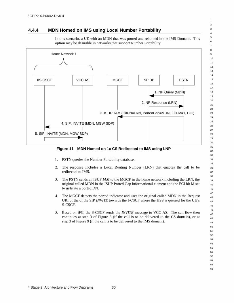
3GPP2 X.P0042-D v0.4
1
2
3
4
5
6
7
8
9
10
11
12
13
14
15
16
17
18
19
20
21
22
23
24
25
26
27
28
29
30
31
32
33
34
35
36
37
38
39
40
41
42
43
44
45
46
47
48
49
50
51
52
53
54
55
56
57
58
59
60
4 Stage 2: Architecture and Flow Diagrams 30
4.4.4 MDN Homed on IMS using Local Number Portability
In this scenario, a UE with an MDN that was ported and rehomed in the IMS Domain. This
option may be desirable in networks that support Number Portability.
I/S-CSCF
4. SIP: INVITE (MDN, MGW SDP)
5. SIP: INVITE (MDN, MGW SDP)
Home Network 1
PSTNVCC AS NP DBMGCF
1. NP Query (MDN)
2. NP Response (LRN)
3. ISUP: IAM (CdPN=LRN, PortedGap=MDN, FCI-M=1, CIC)
Figure 11 MDN Homed on 1x CS Redirected to IMS using LNP
PSTN queries the Number Portability database.
The response includes a Local Routing Number (LRN) that enables the call to be
redirected to IMS.
The PSTN sends an ISUP IAM to the MGCF in the home network including the LRN, the
original called MDN in the ISUP Ported Gap informational element and the FCI bit M set
to indicate a ported DN.
The MGCF detects the ported indicator and uses the original called MDN in the Request
URI of the of the SIP INVITE towards the I-CSCF where the HSS is queried for the UE’s
S-CSCF.
Based on iFC, the S-CSCF sends the INVITE message to VCC AS. The call flow then
continues at step 3 of Figure 8 (if the call is to be delivered to the CS domain), or at
step 3 of Figure 9 (if the call is to be delivered to the IMS domain).
3GPP2 X.P0042-D v0.4
1
2
3
4
5
6
7
8
9
10
11
12
13
14
15
16
17
18
19
20
21
22
23
24
25
26
27
28
29
30
31
32
33
34
35
36
37
38
39
40
41
42
43
44
45
46
47
48
49
50
51
52
53
54
55
56
57
58
59
60
31 4 Stage 2: Architecture and Flow Diagrams
4.4.5 MDN Homed on 1x CS Redirected to IMS without WIN support
This scenario assumes that the ISUP call termination is routed to the home or gateway MSC.
The call must be redirected to IMS for service processing and anchoring before being
delivered to the VCC subscriber. The following figure illustrates the call flow that uses HLR
to route the CS voice call to the VCC AS.
4. MAP: routreq (IMS Rtg Number)
3. MAP: ROUTREQ (MDN)
MSC
IMS Home NetworkCS Home Network
I-CSCFHLR S-CSCFPSTN HSSMGCF
1. ISUP: IAM (CdPN=MDN, CgPN)
2. MAP: LOCREQ (MDN)
5. MAP: locreq (IMS Rtg Number)
7. SIP: INVITE (TEL_URI [IMS Rtg No.], MGW SDP)
6. ISUP: IAM (CdPN=IMS Rtg Number)
8. Cx: LIR
9. Cx: LIA
10. SIP: INVITE (TEL_URI [IMS Rtg No.], MGW SDP)
11. Associate IMS Rtg
Number with MDN
12. SIP: INVITE (TEL_URI [MDN], MGW SDP)
15. SIP: INVITE (TEL_URI [MDN], MGW SDP)
16. Routing decision
is made: IMS or CS
13. Cx: LIR
14. Cx: LIA
VCC AS
MGW
Figure 12 MDN Homed on 1x CS Redirected to IMS without WIN
A call termination message and the dialed UE address digits (i.e., mobile directory
number - MDN) are received by the home MSC.
The MSC sends a MAP LOCREQ to the HLR to obtain a routing number. The LOCREQ
message contains the dialed called party number (MDN) received in step 1.
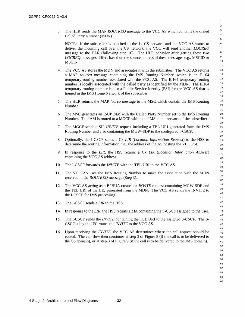
3GPP2 X.P0042-D v0.4
1
2
3
4
5
6
7
8
9
10
11
12
13
14
15
16
17
18
19
20
21
22
23
24
25
26
27
28
29
30
31
32
33
34
35
36
37
38
39
40
41
42
43
44
45
46
47
48
49
50
51
52
53
54
55
56
57
58
59
60
4 Stage 2: Architecture and Flow Diagrams 32
The HLR sends the MAP ROUTREQ message to the VCC AS which contains the dialed
Called Party Number (MDN).
NOTE: If the subscriber is attached to the 1x CS network and the VCC AS wants to
deliver the incoming call over the CS network, the VCC will send another LOCREQ
message to the HLR (following step 16). The HLR behavior after getting these two
LOCREQ messages differs based on the source address of these messages e.g., MSCID or
MSCIN.
The VCC AS stores the MDN and associates it with the subscriber. The VCC AS returns
a MAP routreq message containing the IMS Routing Number, which is an E.164
temporary routing number associated with the VCC AS. The E.164 temporary routing
number is locally associated with the called party as identified by the MDN. The E.164
temporary routing number is also a Public Service Identity (PSI) for the VCC AS that is
homed in the IMS Home Network of the subscriber.
The HLR returns the MAP locreq message to the MSC which contain the IMS Routing
Number.
The MSC generates an ISUP IAM with the Called Party Number set to the IMS Routing
Number. The IAM is routed to a MGCF within the IMS home network of the subscriber.
The MGCF sends a SIP INVITE request including a TEL URI generated from the IMS
Routing Number and also containing the MGW-SDP to the configured I-CSCF.
Optionally, the I-CSCF sends a Cx LIR (Location Information Request) to the HSS to
determine the routing information, i.e., the address of the AS hosting the VCC PSI.
In response to the LIR, the HSS returns a Cx LIA (Location Information Answer)
containing the VCC AS address.
The I-CSCF forwards the INVITE with the TEL URI to the VCC AS.
The VCC AS uses the IMS Routing Number to make the association with the MDN
received in the ROUTREQ message (Step 3).
The VCC AS acting as a B2BUA creates an INVITE request containing MGW-SDP and
the TEL URI of the UE, generated from the MDN. The VCC AS sends the INVITE to
the I-CSCF for IMS processing.
The I-CSCF sends a LIR to the HSS.
In response to the LIR, the HSS returns a LIA containing the S-CSCF assigned to the user.
The I-CSCF sends the INVITE containing the TEL URI to the assigned S-CSCF. The S-
CSCF using the IFC routes the INVITE to the VCC AS.
Upon receiving the INVITE, the VCC AS determines where the call request should be
routed. The call flow then continues at step 3 of Figure 8 (if the call is to be delivered to
the CS domain), or at step 3 of Figure 9 (if the call is to be delivered to the IMS domain).
3GPP2 X.P0042-D v0.4
1
2
3
4
5
6
7
8
9
10
11
12
13
14
15
16
17
18
19
20
21
22
23
24
25
26
27
28
29
30
31
32
33
34
35
36
37
38
39
40
41
42
43
44
45
46
47
48
49
50
51
52
53
54
55
56
57
58
59
60
33 4 Stage 2: Architecture and Flow Diagrams
4.5 Domain Transfer: HRPD VoIP-to-1x CS Voice
This section illustrates signaling flows for HRPD VoIP-to-1x CS voice DT. The signaling
shown between the UE and the MSC for the flows in this section does not represent actual
signaling messages. One should look to the appropriate references to see the signaling details.
Figure 13, Figure 14, and Figure 15 illustrate the three-step process involved during the
HRPD VoIP-to-1x CS voice DT procedure.
In Step 1, the bearer path for UE is routed through the visiting network PDSN. Note that the
VCC AS has already been put into the call flow signaling path during session setup as
illustrated in Figure 5 (IMS VoIP Call Origination with VCC AS Anchoring) or Figure 9
(Voice Call Delivery to IMS). The P-CSCF can be either in the Visited Network for UE 1 or
the Home Network for UE 1. Also, the SIP signaling between UE 1 and the P-CSCF
traverses the HRPD AN and PDSN but is shown as a dotted-line directly between UE 1 and
the P-CSCF for brevity.
In Step 2, the MSC and MGCF in the Visited Network for UE 1 in conjunction with the VCC
AS in the Home Network for UE 1 execute procedures to put the MGW in the Visited
Network for UE 1 into the bearer path between UE 1 and the far end.
In Step 3, UE 1 performs a DT to the 1x CS network. Subsequently, the bearer path between
UE 1 and the MSC in the Visited Network is routed between the MSC and the far end via the
MGW in the Visited Network for UE 1.
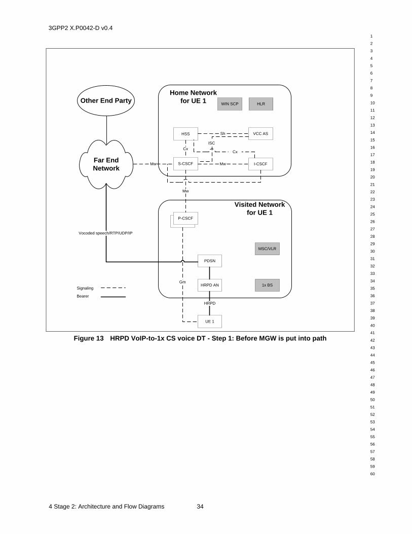
3GPP2 X.P0042-D v0.4
1
2
3
4
5
6
7
8
9
10
11
12
13
14
15
16
17
18
19
20
21
22
23
24
25
26
27
28
29
30
31
32
33
34
35
36
37
38
39
40
41
42
43
44
45
46
47
48
49
50
51
52
53
54
55
56
57
58
59
60
4 Stage 2: Architecture and Flow Diagrams 34
Home Network
for UE 1
Visited Network
for UE 1
HRPD AN
PDSN
UE 1
S-CSCF
HSS
1x BS
MSC/VLR
P-CSCF+P-CSCF
Gm
HRPD
Mw
Mw
Cx
VCC AS
HLR
Sh
Other End Party
Far End
Network
ISC
I-CSCFMw
Cx
Signaling
Bearer
Vocoded speech/RTP/UDP/IP
WIN SCP
Figure 13 HRPD VoIP-to-1x CS voice DT - Step 1: Before MGW is put into path
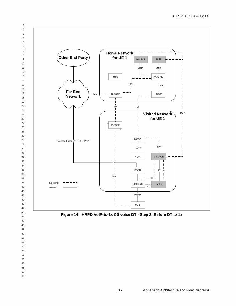
3GPP2 X.P0042-D v0.4
1
2
3
4
5
6
7
8
9
10
11
12
13
14
15
16
17
18
19
20
21
22
23
24
25
26
27
28
29
30
31
32
33
34
35
36
37
38
39
40
41
42
43
44
45
46
47
48
49
50
51
52
53
54
55
56
57
58
59
60
35 4 Stage 2: Architecture and Flow Diagrams
Visited Network
for UE 1
HRPD AN
PDSN
UE 1
1x BS
MSC/VLR
P-CSCF+P-CSCF
A1
HRPD
Mw
MGCF
MGW
H.248
A2
MAP
ISUP
Home Network
for UE 1
S-CSCF
HSS
Mw
VCC AS
HLR
MAP
ISC
Mi
A1
Vocoded speech/RTP/UDP/IP
Gm
I-CSCF
Ma
Other End Party
Far End
Network
A21
Signaling
Bearer
WIN SCP
MAP
Figure 14 HRPD VoIP-to-1x CS voice DT - Step 2: Before DT to 1x
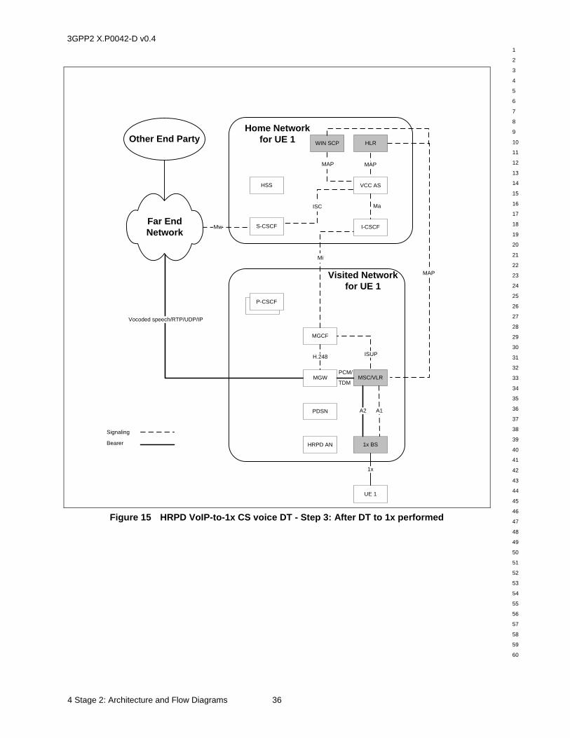
3GPP2 X.P0042-D v0.4
1
2
3
4
5
6
7
8
9
10
11
12
13
14
15
16
17
18
19
20
21
22
23
24
25
26
27
28
29
30
31
32
33
34
35
36
37
38
39
40
41
42
43
44
45
46
47
48
49
50
51
52
53
54
55
56
57
58
59
60
4 Stage 2: Architecture and Flow Diagrams 36
Visited Network
for UE 1
HRPD AN
PDSN
UE 1
1x BS
MSC/VLR
P-CSCF+P-CSCF
A1
1x
Vocoded speech/RTP/UDP/IP
MGCF
MGW
H.248
A2
MAP
ISUP
Home Network
for UE 1
S-CSCF
HSS
Mw
VCC AS
HLR
MAP
ISC
Other End Party
Far End
Network
Mi
I-CSCF
Ma
PCM/
TDM
Signaling
Bearer
WIN SCP
MAP
Figure 15 HRPD VoIP-to-1x CS voice DT - Step 3: After DT to 1x performed
3GPP2 X.P0042-D v0.4
1
2
3
4
5
6
7
8
9
10
11
12
13
14
15
16
17
18
19
20
21
22
23
24
25
26
27
28
29
30
31
32
33
34
35
36
37
38
39
40
41
42
43
44
45
46
47
48
49
50
51
52
53
54
55
56
57
58
59
60
37 4 Stage 2: Architecture and Flow Diagrams
4.5.1 HRPD VoIP-to-1x CS Voice DT
The following figure illustrates a detailed call flow for the HRPD VoIP-to-1x CS voice DT
procedure.
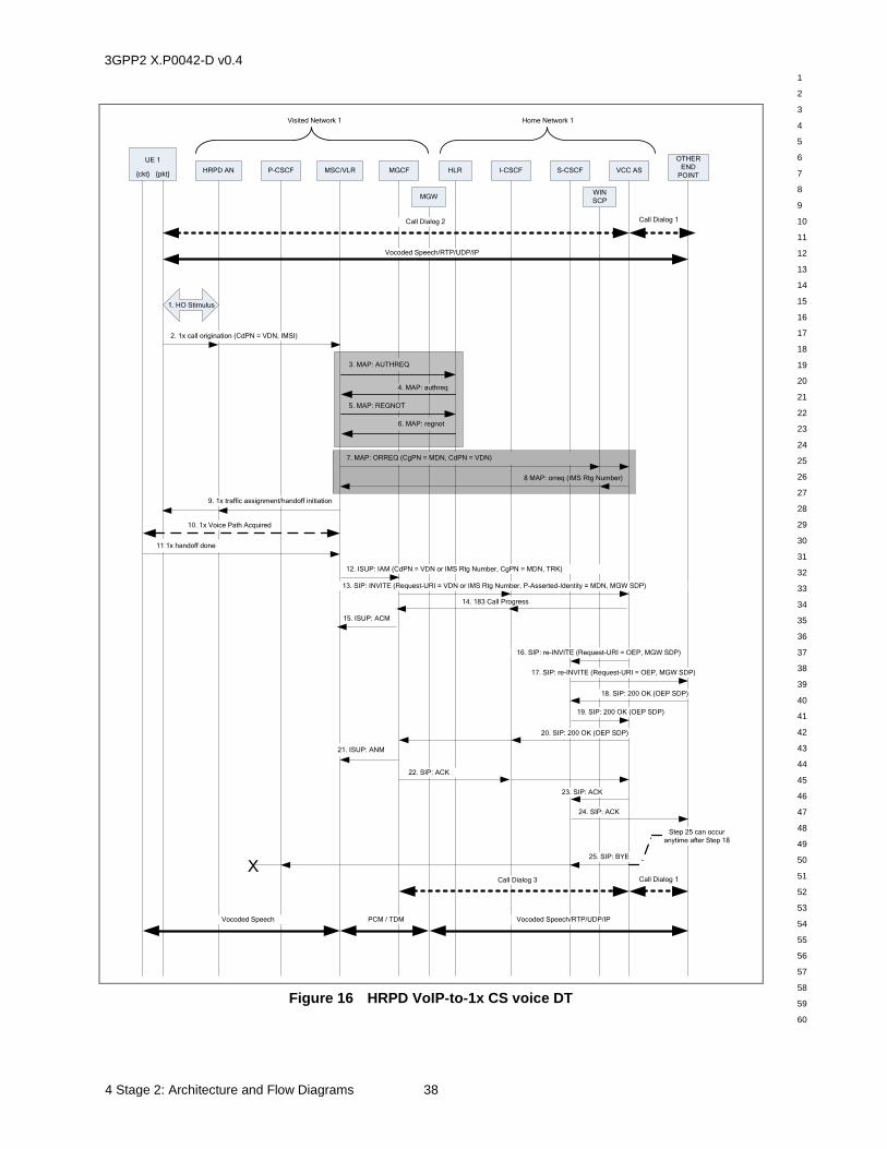
3GPP2 X.P0042-D v0.4
1
2
3
4
5
6
7
8
9
10
11
12
13
14
15
16
17
18
19
20
21
22
23
24
25
26
27
28
29
30
31
32
33
34
35
36
37
38
39
40
41
42
43
44
45
46
47
48
49
50
51
52
53
54
55
56
57
58
59
60
4 Stage 2: Architecture and Flow Diagrams 38
Call Dialog 1
HRPD AN P-CSCF MSC/VLR MGCF HLR
OTHER
END
POINT
Home Network 1
25. SIP: BYE
22. SIP: ACK
2. 1x call origination (CdPN = VDN, IMSI)
5. MAP: REGNOT
3. MAP: AUTHREQ
4. MAP: authreq
Visited Network 1
I-CSCF
6. MAP: regnot
13. SIP: INVITE (Request-URI = VDN or IMS Rtg Number, P-Asserted-Identity = MDN, MGW SDP)
16. SIP: re-INVITE (Request-URI = OEP, MGW SDP)
18. SIP: 200 OK (OEP SDP)
20. SIP: 200 OK (OEP SDP)
21. ISUP: ANM
23. SIP: ACK
MGW
VCC AS
UE 1
{ckt} {pkt}
Vocoded Speech/RTP/UDP/IPPCM / TDMVocoded Speech
Vocoded Speech/RTP/UDP/IP
Step 25 can occur
anytime after Step 18
Call Dialog 2 Call Dialog 1
Call Dialog 3
17. SIP: re-INVITE (Request-URI = OEP, MGW SDP)
19. SIP: 200 OK (OEP SDP)
24. SIP: ACK
S-CSCF
9. 1x traffic assignment/handoff initiation
12. ISUP: IAM (CdPN = VDN or IMS Rtg Number, CgPN = MDN, TRK)
X
1. HO Stimulus
7. MAP: ORREQ (CgPN = MDN, CdPN = VDN)
8 MAP: orreq (IMS Rtg Number)
WIN
SCP
11 1x handoff done
10. 1x Voice Path Acquired
15. ISUP: ACM
14. 183 Call Progress
Figure 16 HRPD VoIP-to-1x CS voice DT
3GPP2 X.P0042-D v0.4
1
2
3
4
5
6
7
8
9
10
11
12
13
14
15
16
17
18
19
20
21
22
23
24
25
26
27
28
29
30
31
32
33
34
35
36
37
38
39
40
41
42
43
44
45
46
47
48
49
50
51
52
53
54
55
56
57
58
59
60
39 4 Stage 2: Architecture and Flow Diagrams
Pre-condition:
It is assumed that initially there is an HRPD/IMS VoIP call setup between UE 1 and the
Other End Point (OEP). SIP call dialog 1 for this voice call is illustrated by a heavy
dashed double arrow between the VCC AS and the OEP. SIP call dialog 2 for this voice
call is illustrated by a heavy dashed double arrow between the VCC AS and UE 1. The
voice bearer path is illustrated by a heavy solid double arrow between UE 1 and the OEP.
UE 1 and the HRPD AN interact to initiate a DT1. See [A.S0008] & [A.S0009] for
signaling details.
UE 1 sends a 1x call origination2 to the MSC/VLR via the HRPD AN (and optionally,
the 1x BS) and includes the VDN. The specific messages and any acknowledgements are
not shown for brevity. See [A.S0008] & [A.S0009] for signaling details.
NOTE 1: steps 3-6 are optional, depending on whether the UE has previously been 1x CS
registered and authenticated.
The Visited MSC/VLR may initiate a 1x registration procedure on behalf of UE 1. The
Visited MSC sends a MAP AUTHREQ message to UE 1’s HLR to authenticate UE 1
prior to allowing registration and prior to allocating a 1x traffic channel to UE 1.
UE 1’s HLR responds by sending an MAP authreq message to the Visited MSC.
The Visited MSC sends an MAP REGNOT message to UE 1’s HLR.
UE 1’s HLR responds by sending an MAP regnot message to the Visited MSC.
NOTE 2: Steps 7-8 are shown using the MAP ORREQ operation. Optionally, a post digit
analysis trigger using the MAP ANLYZD operation may be used instead to obtain routing
information for the DT.
NOTE 3: If either origination triggers are not supported by the MSC/VLR or origination
triggers are not armed for this subscriber, proceed to Step 9.
Once the visited MSC/VLR has obtained the service profile for the originating subscriber
(i.e., by Step 4), the Visited MSC/VLR invokes a call origination trigger to obtain routing
information. The Visited MSC/VLR sends a MAP ORREQ message to the WIN SCP (or
to the HLR), containing the Calling Party Number (MDN) of UE 1 (derived from the
IMSI) and the Called Party Number from the call origination. The WIN SCP (or HLR)
sends the ORREQ message on to the VCC AS. Optionally, the Visited MSC/VLR may
send the ORREQ message directly to a VCC AS that has an integrated WIN SCP
function.
The VCC AS determines that this is a DT scenario based on the VDN in the Called Party
Number (and the Calling Party Number) in the ORREQ message, and then allocates an
IMS Routing Number, which is an E.164 temporary routing number associated with this
DT. The VCC AS then sends back the MAP orreq message to WIN SCP (or HLR),
which returns the orreq message to the MSC/VLR. Optionally, the VCC AS has an
integrated WIN SCP function and sends the orreq message directly to the MSC/VLR.
Anytime after Step 2 the MSC/VLR sends a 1x traffic assignment/handoff initiation3 to
UE 1 via the HRPD AN and the HRPD air interface. This instructs UE 1 to perform the
1 The HRPD AN determines that UE 1 is close to the edge of HRPD coverage and sends an HRPD 3G1XServices
message containing a 1x Service Redirction message to UE 1. UE 1 sends the HRPD 3G1XServiceAck message to the HRPD AN in an acknowledgement.
2 The CSNA protocol is used to deliver a 1x Call Origination message from UE 1 via the HRPD AN.
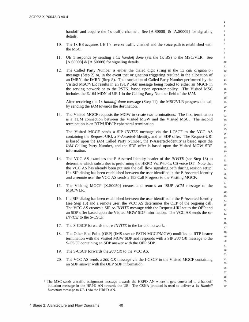
3GPP2 X.P0042-D v0.4
1
2
3
4
5
6
7
8
9
10
11
12
13
14
15
16
17
18
19
20
21
22
23
24
25
26
27
28
29
30
31
32
33
34
35
36
37
38
39
40
41
42
43
44
45
46
47
48
49
50
51
52
53
54
55
56
57
58
59
60
4 Stage 2: Architecture and Flow Diagrams 40
handoff and acquire the 1x traffic channel. See [A.S0008] & [A.S0009] for signaling
details.
The 1x BS acquires UE 1’s reverse traffic channel and the voice path is established with
the MSC.
UE 1 responds by sending a 1x handoff done (via the 1x BS) to the MSC/VLR. See
[A.S0008] & [A.S0009] for signaling details.
The Called Party Number is either the dialed digit string in the 1x call origination
message (Step 2) or, in the event that origination triggering resulted in the allocation of
an IMRN, the IMRN (Step 8). The translation of Called Party Number performed by the
Visited MSC/VLR results in an ISUP IAM message being routed to either an MGCF in
the serving network or to the PSTN, based upon operator policy. The Visited MSC
includes the E.164 MDN of UE 1 in the Calling Party Number field of the IAM.
After receiving the 1x handoff done message (Step 11), the MSC/VLR progress the call
by sending the IAM towards the destination.
The Visited MGCF requests the MGW to create two terminations. The first termination
is a TDM connection between the Visited MGW and the Visited MSC. The second
termination is an RTP/UDP/IP ephemeral termination.
The Visited MGCF sends a SIP INVITE message via the I-CSCF to the VCC AS
containing the Request-URI, a P-Asserted-Identity, and an SDP offer. The Request-URI
is based upon the IAM Called Party Number, the P-Asserted-Identity is based upon the
IAM Calling Party Number, and the SDP offer is based upon the Visited MGW SDP
information.
The VCC AS examines the P-Asserted-Identity header of the INVITE (see Step 13) to
determine which subscriber is performing the HRPD VoIP-to-1x CS voice DT. Note that
the VCC AS has already been put into the call flow signaling path during session setup.
If a SIP dialog has been established between the user identified in the P-Asserted-Identity
and a remote user the VCC AS sends a 183 Call Progress to the Visiting MGCF.
The Visiting MGCF [X.S0050] creates and returns an ISUP ACM message to the
MSC/VLR.
If a SIP dialog has been established between the user identified in the P-Asserted-Identity
(see Step 13) and a remote user, the VCC AS determines the OEP of the ongoing call.
The VCC AS creates a SIP re-INVITE message with the Request-URI set to the OEP and
an SDP offer based upon the Visited MGW SDP information. The VCC AS sends the re-
INVITE to the S-CSCF.
The S-CSCF forwards the re-INVITE to the far end network.
The Other End Point (OEP) (IMS user or PSTN MGCF/MGW) modifies its RTP bearer
termination with the Visited MGW SDP and responds with a SIP 200 OK message to the
S-CSCF containing an SDP answer with the OEP SDP.
The S-CSCF forwards the 200 OK to the VCC AS.
The VCC AS sends a 200 OK message via the I-CSCF to the Visited MGCF containing
an SDP answer with the OEP SDP information.
3 The MSC sends a traffic assignment message towards the HRPD AN where it gets converted to a handoff
initiation message in the HRPD AN towards the UE. The CSNA protocol is used to deliver a 1x Handoff Direction message to UE 1 via the HRPD AN.
3GPP2 X.P0042-D v0.4
1
2
3
4
5
6
7
8
9
10
11
12
13
14
15
16
17
18
19
20
21
22
23
24
25
26
27
28
29
30
31
32
33
34
35
36
37
38
39
40
41
42
43
44
45
46
47
48
49
50
51
52
53
54
55
56
57
58
59
60
41 4 Stage 2: Architecture and Flow Diagrams
The Visited MGCF requests modification of the Visited MGW ephemeral termination
with the OEP SDP information and instructs the Visited MGW to reserve/commit
Remote resources. The Visited MGCF sends an ISUP ANM message.
Anytime after the 200 OK is received, the Visited MGCF sends a SIP ACK message via
the I-CSCF to the VCC AS. This completes the establishment of SIP call dialog 3
between the MGCF and the VCC AS. The VCC AS records the location of UE 1 as
present in the 1x CS domain.
Anytime after the VCC AS receives the 200 OK, it sends an ACK message to the S-
CSCF.
The S-CSCF forwards the ACK to the OEP.
Anytime after Step 18, the VCC AS sends a SIP BYE message to UE 1 via the S-CSCF to
release SIP call dialog 2 between UE 1 and the VCC AS. Note that since UE 1 is already
on a 1x traffic channel it will not respond to this BYE.
Post-conditions:
There is now voice call setup between UE 1 and the OEP via the 1x CS network. SIP call
dialog 1 for this voice call is illustrated by a heavy dashed double arrow between the
VCC AS and the OEP. SIP call dialog 3 for this voice call is illustrated by a heavy
dashed double arrow between the VCC AS and the MGCF. The voice bearer path is
illustrated by heavy solid double arrows connecting the UE 1, MSC, MGW and the OEP.
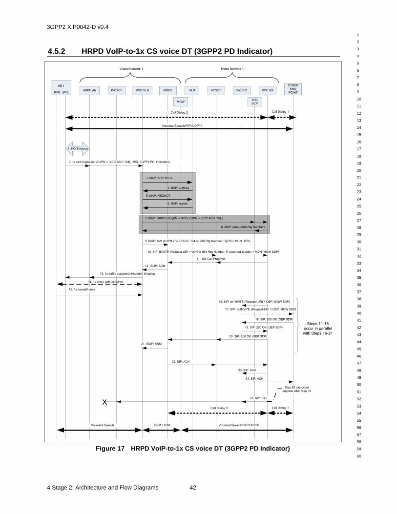
3GPP2 X.P0042-D v0.4
1
2
3
4
5
6
7
8
9
10
11
12
13
14
15
16
17
18
19
20
21
22
23
24
25
26
27
28
29
30
31
32
33
34
35
36
37
38
39
40
41
42
43
44
45
46
47
48
49
50
51
52
53
54
55
56
57
58
59
60
4 Stage 2: Architecture and Flow Diagrams 42
4.5.2 HRPD VoIP-to-1x CS voice DT (3GPP2 PD Indicator)
Call Dialog 1
HRPD AN P-CSCF MSC/VLR MGCF HLR
OTHER
END
POINT
Home Network 1
25. SIP: BYE
22. SIP: ACK
15. 1x handoff done
2. 1x call origination (CdPN = [VCC AS E.164], IMSI, 3GPP2 PD Indication)
5. MAP: REGNOT
3. MAP: AUTHREQ
4. MAP: authreq
Visited Network 1
I-CSCF
6. MAP: regnot
10. SIP: INVITE (Request-URI = VDN or IMS Rtg Number, P-Asserted-Identity = MDN, MGW SDP)
16. SIP: re-INVITE (Request-URI = OEP, MGW SDP)
18. SIP: 200 OK (OEP SDP)
20. SIP: 200 OK (OEP SDP)
21. ISUP: ANM
23. SIP: ACK
12. ISUP: ACM
MGW
VCC AS
UE 1
{ckt} {pkt}
14. 1x voice path acquired
Vocoded Speech/RTP/UDP/IPPCM / TDMVocoded Speech
Vocoded Speech/RTP/UDP/IP
Step 25 can occur
anytime after Step 19
Call Dialog 2 Call Dialog 1
Call Dialog 3
17. SIP: re-INVITE (Request-URI = OEP, MGW SDP)
19. SIP: 200 OK (OEP SDP)
24. SIP: ACK
S-CSCF
13. 1x traffic assignment/handoff initiation
9. ISUP: IAM (CdPN = VCC AS E.164 or IMS Rtg Number, CgPN = MDN, TRK)
X
Steps 11-15
occur in parallel
with Steps 16-21
1. HO Stimulus
7. MAP: ORREQ (CgPN = MDN, CdPN = [VCC AS E.164])
8. MAP: orreq (IMS Rtg Number)
WIN
SCP
11. 183 Call Progress
Figure 17 HRPD VoIP-to-1x CS voice DT (3GPP2 PD Indicator)
3GPP2 X.P0042-D v0.4
1
2
3
4
5
6
7
8
9
10
11
12
13
14
15
16
17
18
19
20
21
22
23
24
25
26
27
28
29
30
31
32
33
34
35
36
37
38
39
40
41
42
43
44
45
46
47
48
49
50
51
52
53
54
55
56
57
58
59
60
43 4 Stage 2: Architecture and Flow Diagrams
Pre-conditions:
It is assumed that initially there is an HRPD/IMS VoIP call setup between UE 1 and the Other
End Point (OEP). SIP call dialog 1 for this voice call is illustrated by a heavy dashed double
arrow between the VCC AS and the OEP. SIP call dialog 2 for this voice call is illustrated by
a heavy dashed double arrow between the VCC AS and UE 1. The voice bearer path is
illustrated by a heavy solid double arrow between UE 1 and the OEP.
UE 1 and the HRPD AN interact to initiate a DT4. See [A.S0008] & [A.S0009] for
signaling details.
UE 1 sends a 1x call origination5 to the MSC/VLR via the HRPD AN (and optionally,
the 1x BS) and includes the VDN and an optional 3GPP2 PD indicator. The specific
messages and any acknowledgements are not shown for brevity. See [A.S0008] &
[A.S0009] for signaling details.
Note, steps 3-6 are optional, depending on whether the UE has previously been 1x CS
registered and authenticated.
The Visited MSC/VLR may initiate a 1x registration procedure on behalf of UE 1. The
Visited MSC sends an MAP AUTHREQ message to UE 1’s HLR to authenticate UE 1
prior to allowing registration and prior to allocating a 1x traffic channel to UE 1.
UE 1’s HLR responds by sending an MAP authreq message to the Visited MSC.
The Visited MSC sends an MAP REGNOT message to UE 1’s HLR.
UE 1’s HLR responds by sending an MAP regnot message to the Visited MSC.
Note: Steps 7-8 are shown using the MAP ORREQ operation. Optionally, a post digit
analysis trigger using the MAP ANLYZD operation may be used instead to obtain routing
information for the DT.
Note 2: If either origination triggers are not supported by the MSC/VLR or origination
triggers are not armed for this subscriber, proceed to Step 9.
Once the visited MSC/VLR has obtained the service profile for the originating subscriber
(i.e., by Step 4), the Visited MSC/VLR invokes a call origination trigger to obtain routing
information. The Visited MSC/VLR sends a MAP ORREQ message to the WIN SCP (or
to the HLR), containing the Calling Party Number (MDN) of UE 1 (derived from the
IMSI) and the Called Party Number from the call origination. The WIN SCP (or HLR)
sends the ORREQ message on to the VCC AS. Optionally, the Visited MSC/VLR may
send the ORREQ message directly to a VCC AS that has an integrated WIN SCP
function.
The VCC AS determines that this is a DT scenario based on the VDN in the Called Party
Number (and the Calling Party Number) in the ORREQ message, and then allocates an
IMS Routing Number, which is an E.164 temporary routing number associated with this
DT. The VCC AS then sends back the MAP orreq message to WIN SCP (or HLR),
which returns the orreq message to the MSC/VLR. Optionally, the VCC AS has an
integrated WIN SCP function and sends the orreq message directly to the MSC/VLR.
The MSC creates an ISUP IAM. The Called Party Number is either the dialed digit
string in the 1x call origination message (Step 2) or, in the event that origination
4 The HRPD AN determines that UE 1 is close to the edge of HRPD coverage and sends an HRPD 3G1XServices
message containing a 1x Service Redirction message to UE 1. UE 1 sends the HRPD 3G1XServiceAck message to the HRPD AN in an acknowledgement.
5 The CSNA protocol is used to deliver a 1x Call Origination message from UE 1 via the HRPD AN.
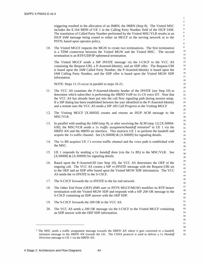
3GPP2 X.P0042-D v0.4
1
2
3
4
5
6
7
8
9
10
11
12
13
14
15
16
17
18
19
20
21
22
23
24
25
26
27
28
29
30
31
32
33
34
35
36
37
38
39
40
41
42
43
44
45
46
47
48
49
50
51
52
53
54
55
56
57
58
59
60
4 Stage 2: Architecture and Flow Diagrams 44
triggering resulted in the allocation of an IMRN, the IMRN (Step 8). The Visited MSC
includes the E.164 MDN of UE 1 in the Calling Party Number field of the ISUP IAM.
The translation of Called Party Number performed by the Visited MSC/VLR results in an
ISUP IAM message being routed to either an MGCF in the serving network or to the
PSTN, based upon operator policy.
The Visited MGCF requests the MGW to create two terminations. The first termination
is a TDM connection between the Visited MGW and the Visited MSC. The second
termination is an RTP/UDP/IP ephemeral termination.
The Visited MGCF sends a SIP INVITE message via the I-CSCF to the VCC AS
containing the Request-URI, a P-Asserted-Identity, and an SDP offer. The Request-URI
is based upon the IAM Called Party Number, the P-Asserted-Identity is based upon the
IAM Calling Party Number, and the SDP offer is based upon the Visited MGW SDP
information.
NOTE: Steps 11-15 occur in parallel to steps 16-21.
The VCC AS examines the P-Asserted-Identity header of the INVITE (see Step 10) to
determine which subscriber is performing the HRPD VoIP-to-1x CS voice DT. Note that
the VCC AS has already been put into the call flow signaling path during session setup.
If a SIP dialog has been established between the user identified in the P-Asserted-Identity
and a remote user the VCC AS sends a SIP 183 Call Progress to the Visiting MGCF
The Visiting MGCF [X.S0050] creates and returns an ISUP ACM message to the
MSC/VLR.
In parallel with sending the IAM (step 9), or after receiving the ACM (step 12) [X.S0004-
630], the MSC/VLR sends a 1x traffic assignment/handoff initiation6 to UE 1 via the
HRPD AN and the HRPD air interface. This instructs UE 1 to perform the handoff and
acquire the 1x traffic channel. See [A.S0008] & [A.S0009] for signaling details.
The 1x BS acquires UE 1’s reverse traffic channel and the voice path is established with
the MSC.
UE 1 responds by sending a 1x handoff done (via the 1x BS) to the MSC/VLR. See
[A.S0008] & [A.S0009] for signaling details.
Based upon the P-Asserted-ID (see Step 10), the VCC AS determines the OEP of the
ongoing call. The VCC AS creates a SIP re-INVITE message with the Request-URI set
to the OEP and an SDP offer based upon the Visited MGW SDP information. The VCC
AS sends the re-INVITE to the S-CSCF.
The S-CSCF forwards the re-INVITE to the far end network.
The Other End Point (OEP) (IMS user or PSTN MGCF/MGW) modifies its RTP bearer
termination with the Visited MGW SDP and responds with a SIP 200 OK message to the
S-CSCF containing an SDP answer with the OEP SDP.
The S-CSCF forwards the 200 OK to the VCC AS.
The VCC AS sends a 200 OK message via the I-CSCF to the Visited MGCF containing
an SDP answer with the OEP SDP information.
6 The MSC sends a traffic assignment message towards the HRPD AN where it gets converted to a handoff
initiation message in the HRPD AN towards the UE. The CSNA protocol is used to deliver a 1x Handoff Direction message to UE 1 via the HRPD AN.
3GPP2 X.P0042-D v0.4
1
2
3
4
5
6
7
8
9
10
11
12
13
14
15
16
17
18
19
20
21
22
23
24
25
26
27
28
29
30
31
32
33
34
35
36
37
38
39
40
41
42
43
44
45
46
47
48
49
50
51
52
53
54
55
56
57
58
59
60
45 4 Stage 2: Architecture and Flow Diagrams
The Visited MGCF requests modification of the Visited MGW ephemeral termination
with the OEP SDP information and instructs the Visited MGW to reserve/commit
Remote resources. The Visited MGCF sends an ISUP ANM message.
Anytime after the 200 OK is received, the Visited MGCF sends a SIP ACK message via
the I-CSCF to the VCC AS. This completes the establishment of SIP call dialog 3
between the MGCF and the VCC AS. The VCC AS records the location of UE 1 as
present in the 1x CS domain.
Anytime after the VCC AS receives the 200 OK, it sends a ACK message to the S-CSCF.
The S-CSCF forwards the ACK to the OEP.
Anytime after Step 19, the VCC AS sends a SIP BYE message to UE 1 via the S-CSCF to
release SIP call dialog 2 between UE 1 and the VCC AS. Note that since UE 1 is already
on a 1x traffic channel it will not respond to this BYE.
Post-conditions:
There is now voice call setup between UE 1 and the OEP via the 1x CS network. SIP call
dialog 1 for this voice call is illustrated by a heavy dashed double arrow between the
VCC AS and the OEP. SIP call dialog 3 for this voice call is illustrated by a heavy
dashed double arrow between the VCC AS and the MGCF. The voice bearer path is
illustrated by heavy solid double arrows connecting the UE 1, MSC, MGW and the OEP.
3GPP2 X.P0042-D v0.4
1
2
3
4
5
6
7
8
9
10
11
12
13
14
15
16
17
18
19
20
21
22
23
24
25
26
27
28
29
30
31
32
33
34
35
36
37
38
39
40
41
42
43
44
45
46
47
48
49
50
51
52
53
54
55
56
57
58
59
60
4 Stage 2: Architecture and Flow Diagrams 46
4.6 Domain Transfer: WLAN VoIP-to-1x CS Voice
This section illustrates signaling flows for WLAN VoIP-to-1x CS voice DT. The signaling
shown between the UE and the MSC for the flows in this section does not represent actual
signaling messages. One should look to the appropriate references to see the signaling details.
Figure 18, Figure 19, and Figure 20 illustrate the three-step process involved during the
WLAN VoIP-to-1x CS voice DT procedure.
In Step 1, the bearer path between UE 1 and the far end is routed between the PDIF in the
Visited Network for UE 1 and the PDIF and the far end network. Note that the VCC AS has
already been put into the call flow signaling path during session setup as illustrated in Figure
5 (IMS VoIP Call Origination with VCC AS Anchoring) or Figure 9 (Voice Call Delivery to
IMS). The P-CSCF can be either in the Visited Network for UE 1 or the Home Network for
UE 1. Also, the SIP signaling between UE 1 and the P-CSCF traverses the WLAN AP and
PDIF but is shown as a dotted-line directly between UE 1 and the P-CSCF for brevity.
In Step 2, the MSC and MGCF in the Visited Network for UE 1 in conjunction with the VCC
AS in the Home Network for UE 1 execute procedures to put the MGW in the Visited
Network for UE 1 into the bearer path between UE 1 and the far end.
In Step 3, UE 1 performs a DT to the 1x CS network. Subsequently, the bearer path between
UE 1 and the MSC in the Visited Network for UE 1 is routed between the MSC and the far
end via the MGW in the Visited Network for UE 1.
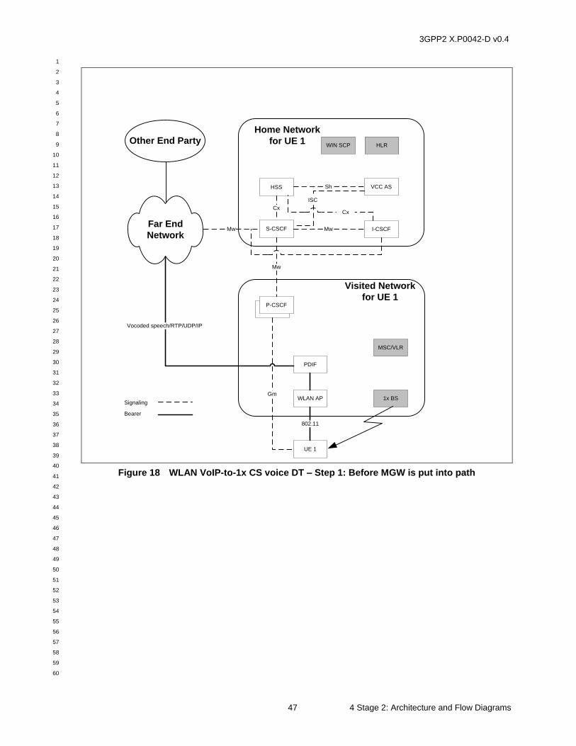
3GPP2 X.P0042-D v0.4
1
2
3
4
5
6
7
8
9
10
11
12
13
14
15
16
17
18
19
20
21
22
23
24
25
26
27
28
29
30
31
32
33
34
35
36
37
38
39
40
41
42
43
44
45
46
47
48
49
50
51
52
53
54
55
56
57
58
59
60
47 4 Stage 2: Architecture and Flow Diagrams
Home Network
for UE 1
Visited Network
for UE 1
WLAN AP
PDIF
UE 1
S-CSCF
HSS
1x BS
MSC/VLR
P-CSCF+P-CSCF
Gm
802.11
Mw
Mw
Cx
VCC AS
HLR
Sh
Other End Party
Far End
Network
ISC
I-CSCFMw
Cx
Signaling
Bearer
Vocoded speech/RTP/UDP/IP
WIN SCP
Figure 18 WLAN VoIP-to-1x CS voice DT – Step 1: Before MGW is put into path
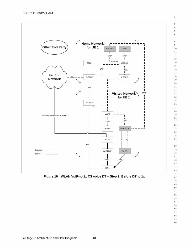
3GPP2 X.P0042-D v0.4
1
2
3
4
5
6
7
8
9
10
11
12
13
14
15
16
17
18
19
20
21
22
23
24
25
26
27
28
29
30
31
32
33
34
35
36
37
38
39
40
41
42
43
44
45
46
47
48
49
50
51
52
53
54
55
56
57
58
59
60
4 Stage 2: Architecture and Flow Diagrams 48
Visited Network
for UE 1
WLAN AP
PDIF
UE 1
1x BS
MSC/VLR
P-CSCF+P-CSCF
A1
802.11
Mw
MGCF
MGW
H.248
A2
MAP
ISUP
Home Network
for UE 1
S-CSCF
HSS
Mw
VCC AS
HLR
MAP
ISC
Mi
Vocoded speech/RTP/UDP/IP
Gm
I-CSCF
Ma
Other End Party
Far End
Network
Signaling
Bearer
WIN SCP
MAP
Figure 19 WLAN VoIP-to-1x CS voice DT – Step 2: Before DT to 1x
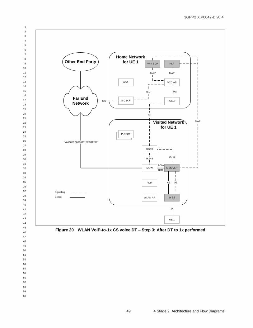
3GPP2 X.P0042-D v0.4
1
2
3
4
5
6
7
8
9
10
11
12
13
14
15
16
17
18
19
20
21
22
23
24
25
26
27
28
29
30
31
32
33
34
35
36
37
38
39
40
41
42
43
44
45
46
47
48
49
50
51
52
53
54
55
56
57
58
59
60
49 4 Stage 2: Architecture and Flow Diagrams
Visited Network
for UE 1
WLAN AP
PDIF
UE 1
1x BS
MSC/VLR
P-CSCF+P-CSCF
A1
1x
Vocoded speech/RTP/UDP/IP
MGCF
MGW
H.248
A2
MAP
ISUP
Home Network
for UE 1
S-CSCF
HSS
Mw
VCC AS
HLR
MAP
ISC
Other End Party
Far End
Network
Mi
I-CSCF
Ma
PCM/
TDM
Signaling
Bearer
WIN SCP
MAP
Figure 20 WLAN VoIP-to-1x CS voice DT – Step 3: After DT to 1x performed
3GPP2 X.P0042-D v0.4
1
2
3
4
5
6
7
8
9
10
11
12
13
14
15
16
17
18
19
20
21
22
23
24
25
26
27
28
29
30
31
32
33
34
35
36
37
38
39
40
41
42
43
44
45
46
47
48
49
50
51
52
53
54
55
56
57
58
59
60
4 Stage 2: Architecture and Flow Diagrams 50
4.6.1 WLAN VoIP-to-1x CS Voice DT
The following figure illustrates a detailed call flow for the WLAN VoIP-to-1x CS voice DT
procedure.
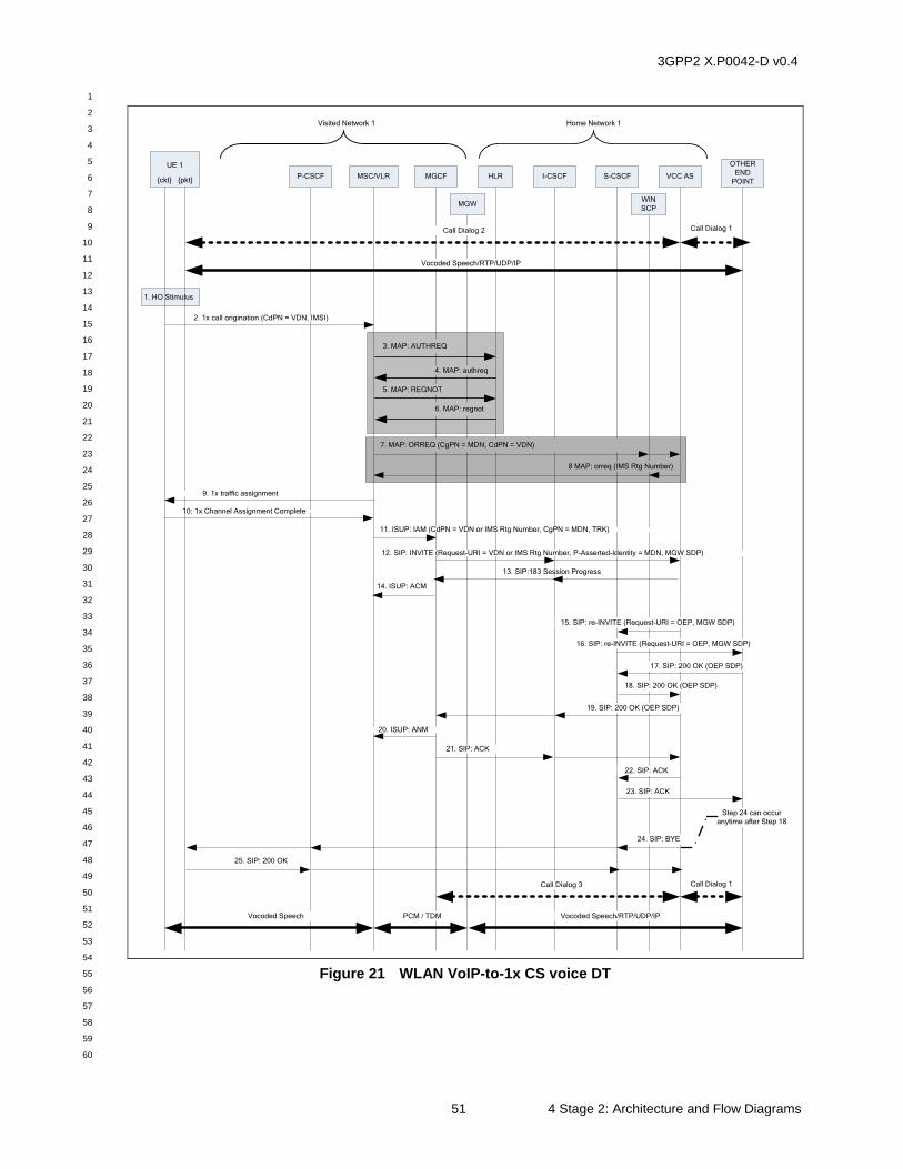
3GPP2 X.P0042-D v0.4
1
2
3
4
5
6
7
8
9
10
11
12
13
14
15
16
17
18
19
20
21
22
23
24
25
26
27
28
29
30
31
32
33
34
35
36
37
38
39
40
41
42
43
44
45
46
47
48
49
50
51
52
53
54
55
56
57
58
59
60
51 4 Stage 2: Architecture and Flow Diagrams
Call Dialog 1
P-CSCF MSC/VLR MGCF HLR
OTHER
END
POINT
Home Network 1
24. SIP: BYE
21. SIP: ACK
2. 1x call origination (CdPN = VDN, IMSI)
5. MAP: REGNOT
3. MAP: AUTHREQ
4. MAP: authreq
Visited Network 1
I-CSCF
6. MAP: regnot
12. SIP: INVITE (Request-URI = VDN or IMS Rtg Number, P-Asserted-Identity = MDN, MGW SDP)
15. SIP: re-INVITE (Request-URI = OEP, MGW SDP)
17. SIP: 200 OK (OEP SDP)
19. SIP: 200 OK (OEP SDP)
20. ISUP: ANM
22. SIP: ACK
MGW
VCC AS
UE 1
{ckt} {pkt}
Vocoded Speech/RTP/UDP/IPPCM / TDMVocoded Speech
Vocoded Speech/RTP/UDP/IP
Step 24 can occur
anytime after Step 18
Call Dialog 2 Call Dialog 1
Call Dialog 3
16. SIP: re-INVITE (Request-URI = OEP, MGW SDP)
18. SIP: 200 OK (OEP SDP)
23. SIP: ACK
S-CSCF
9. 1x traffic assignment
11. ISUP: IAM (CdPN = VDN or IMS Rtg Number, CgPN = MDN, TRK)
1. HO Stimulus
7. MAP: ORREQ (CgPN = MDN, CdPN = VDN)
8 MAP: orreq (IMS Rtg Number)
WIN
SCP
10: 1x Channel Assignment Complete
14. ISUP: ACM
13. SIP:183 Session Progress
25. SIP: 200 OK
Figure 21 WLAN VoIP-to-1x CS voice DT
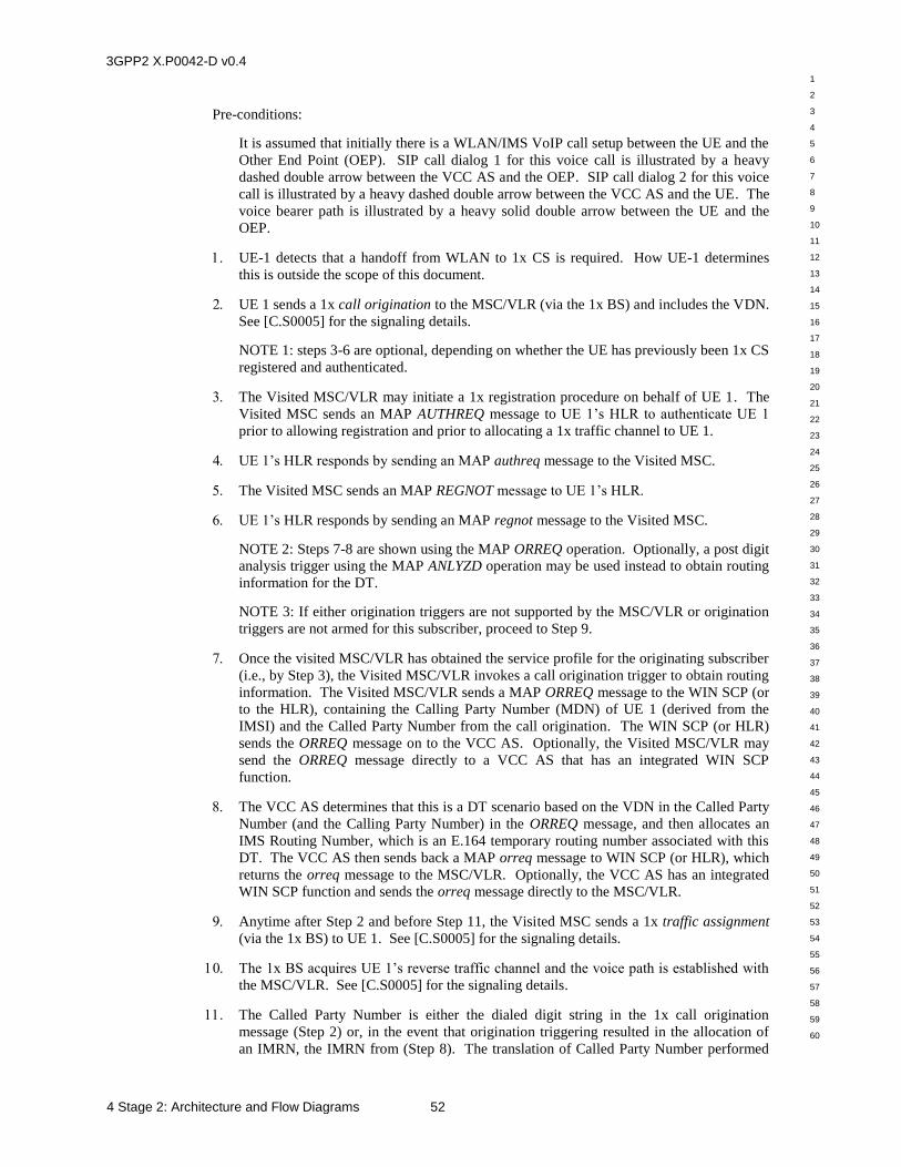
3GPP2 X.P0042-D v0.4
1
2
3
4
5
6
7
8
9
10
11
12
13
14
15
16
17
18
19
20
21
22
23
24
25
26
27
28
29
30
31
32
33
34
35
36
37
38
39
40
41
42
43
44
45
46
47
48
49
50
51
52
53
54
55
56
57
58
59
60
4 Stage 2: Architecture and Flow Diagrams 52
Pre-conditions:
It is assumed that initially there is a WLAN/IMS VoIP call setup between the UE and the
Other End Point (OEP). SIP call dialog 1 for this voice call is illustrated by a heavy
dashed double arrow between the VCC AS and the OEP. SIP call dialog 2 for this voice
call is illustrated by a heavy dashed double arrow between the VCC AS and the UE. The
voice bearer path is illustrated by a heavy solid double arrow between the UE and the
OEP.
UE-1 detects that a handoff from WLAN to 1x CS is required. How UE-1 determines
this is outside the scope of this document.
UE 1 sends a 1x call origination to the MSC/VLR (via the 1x BS) and includes the VDN.
See [C.S0005] for the signaling details.
NOTE 1: steps 3-6 are optional, depending on whether the UE has previously been 1x CS
registered and authenticated.
The Visited MSC/VLR may initiate a 1x registration procedure on behalf of UE 1. The
Visited MSC sends an MAP AUTHREQ message to UE 1’s HLR to authenticate UE 1
prior to allowing registration and prior to allocating a 1x traffic channel to UE 1.
UE 1’s HLR responds by sending an MAP authreq message to the Visited MSC.
The Visited MSC sends an MAP REGNOT message to UE 1’s HLR.
UE 1’s HLR responds by sending an MAP regnot message to the Visited MSC.
NOTE 2: Steps 7-8 are shown using the MAP ORREQ operation. Optionally, a post digit
analysis trigger using the MAP ANLYZD operation may be used instead to obtain routing
information for the DT.
NOTE 3: If either origination triggers are not supported by the MSC/VLR or origination
triggers are not armed for this subscriber, proceed to Step 9.
Once the visited MSC/VLR has obtained the service profile for the originating subscriber
(i.e., by Step 3), the Visited MSC/VLR invokes a call origination trigger to obtain routing
information. The Visited MSC/VLR sends a MAP ORREQ message to the WIN SCP (or
to the HLR), containing the Calling Party Number (MDN) of UE 1 (derived from the
IMSI) and the Called Party Number from the call origination. The WIN SCP (or HLR)
sends the ORREQ message on to the VCC AS. Optionally, the Visited MSC/VLR may
send the ORREQ message directly to a VCC AS that has an integrated WIN SCP
function.
The VCC AS determines that this is a DT scenario based on the VDN in the Called Party
Number (and the Calling Party Number) in the ORREQ message, and then allocates an
IMS Routing Number, which is an E.164 temporary routing number associated with this
DT. The VCC AS then sends back a MAP orreq message to WIN SCP (or HLR), which
returns the orreq message to the MSC/VLR. Optionally, the VCC AS has an integrated
WIN SCP function and sends the orreq message directly to the MSC/VLR.
Anytime after Step 2 and before Step 11, the Visited MSC sends a 1x traffic assignment
(via the 1x BS) to UE 1. See [C.S0005] for the signaling details.
The 1x BS acquires UE 1’s reverse traffic channel and the voice path is established with
the MSC/VLR. See [C.S0005] for the signaling details.
The Called Party Number is either the dialed digit string in the 1x call origination
message (Step 2) or, in the event that origination triggering resulted in the allocation of
an IMRN, the IMRN from (Step 8). The translation of Called Party Number performed
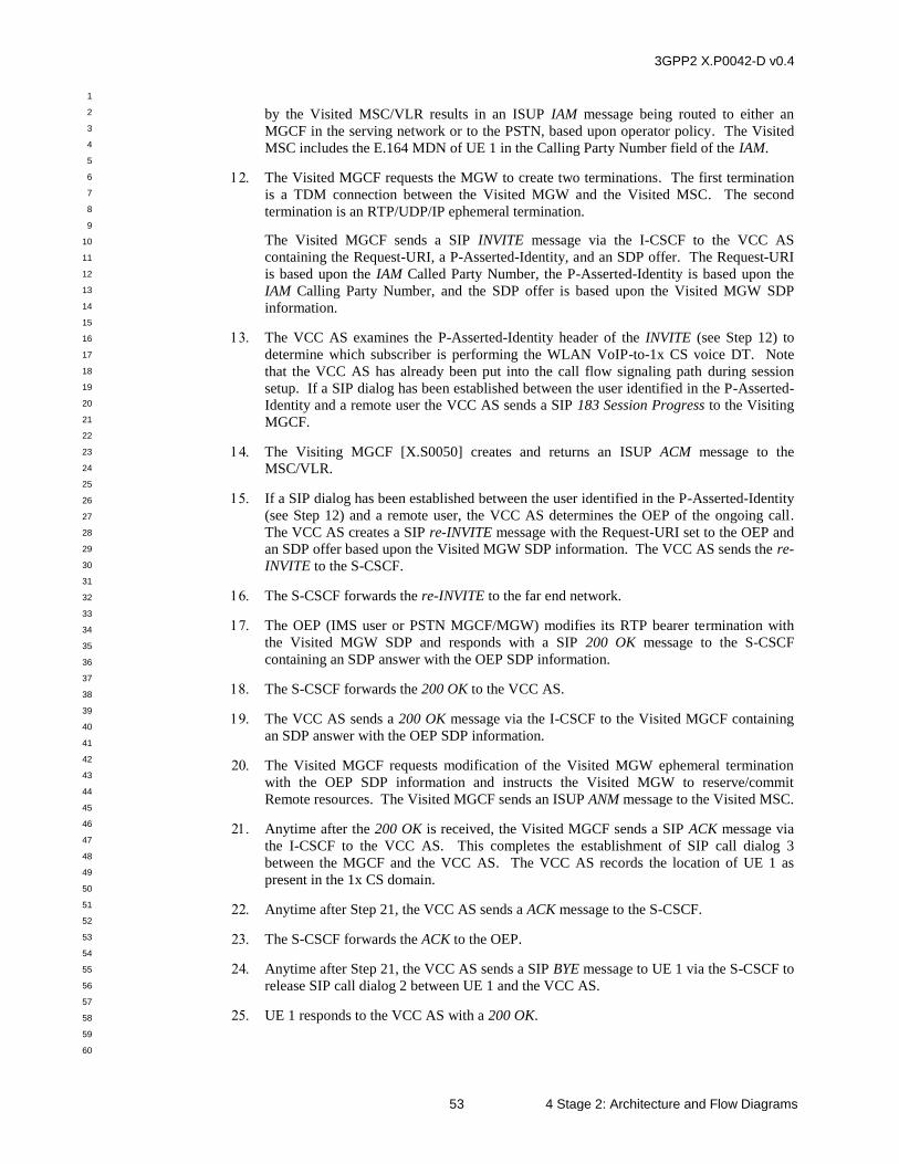
3GPP2 X.P0042-D v0.4
1
2
3
4
5
6
7
8
9
10
11
12
13
14
15
16
17
18
19
20
21
22
23
24
25
26
27
28
29
30
31
32
33
34
35
36
37
38
39
40
41
42
43
44
45
46
47
48
49
50
51
52
53
54
55
56
57
58
59
60
53 4 Stage 2: Architecture and Flow Diagrams
by the Visited MSC/VLR results in an ISUP IAM message being routed to either an
MGCF in the serving network or to the PSTN, based upon operator policy. The Visited
MSC includes the E.164 MDN of UE 1 in the Calling Party Number field of the IAM.
The Visited MGCF requests the MGW to create two terminations. The first termination
is a TDM connection between the Visited MGW and the Visited MSC. The second
termination is an RTP/UDP/IP ephemeral termination.
The Visited MGCF sends a SIP INVITE message via the I-CSCF to the VCC AS
containing the Request-URI, a P-Asserted-Identity, and an SDP offer. The Request-URI
is based upon the IAM Called Party Number, the P-Asserted-Identity is based upon the
IAM Calling Party Number, and the SDP offer is based upon the Visited MGW SDP
information.
The VCC AS examines the P-Asserted-Identity header of the INVITE (see Step 12) to
determine which subscriber is performing the WLAN VoIP-to-1x CS voice DT. Note
that the VCC AS has already been put into the call flow signaling path during session
setup. If a SIP dialog has been established between the user identified in the P-Asserted-
Identity and a remote user the VCC AS sends a SIP 183 Session Progress to the Visiting
MGCF.
The Visiting MGCF [X.S0050] creates and returns an ISUP ACM message to the
MSC/VLR.
If a SIP dialog has been established between the user identified in the P-Asserted-Identity
(see Step 12) and a remote user, the VCC AS determines the OEP of the ongoing call.
The VCC AS creates a SIP re-INVITE message with the Request-URI set to the OEP and
an SDP offer based upon the Visited MGW SDP information. The VCC AS sends the re-
INVITE to the S-CSCF.
The S-CSCF forwards the re-INVITE to the far end network.
The OEP (IMS user or PSTN MGCF/MGW) modifies its RTP bearer termination with
the Visited MGW SDP and responds with a SIP 200 OK message to the S-CSCF
containing an SDP answer with the OEP SDP information.
The S-CSCF forwards the 200 OK to the VCC AS.
The VCC AS sends a 200 OK message via the I-CSCF to the Visited MGCF containing
an SDP answer with the OEP SDP information.
The Visited MGCF requests modification of the Visited MGW ephemeral termination
with the OEP SDP information and instructs the Visited MGW to reserve/commit
Remote resources. The Visited MGCF sends an ISUP ANM message to the Visited MSC.
Anytime after the 200 OK is received, the Visited MGCF sends a SIP ACK message via
the I-CSCF to the VCC AS. This completes the establishment of SIP call dialog 3
between the MGCF and the VCC AS. The VCC AS records the location of UE 1 as
present in the 1x CS domain.
Anytime after Step 21, the VCC AS sends a ACK message to the S-CSCF.
The S-CSCF forwards the ACK to the OEP.
Anytime after Step 21, the VCC AS sends a SIP BYE message to UE 1 via the S-CSCF to
release SIP call dialog 2 between UE 1 and the VCC AS.
UE 1 responds to the VCC AS with a 200 OK.
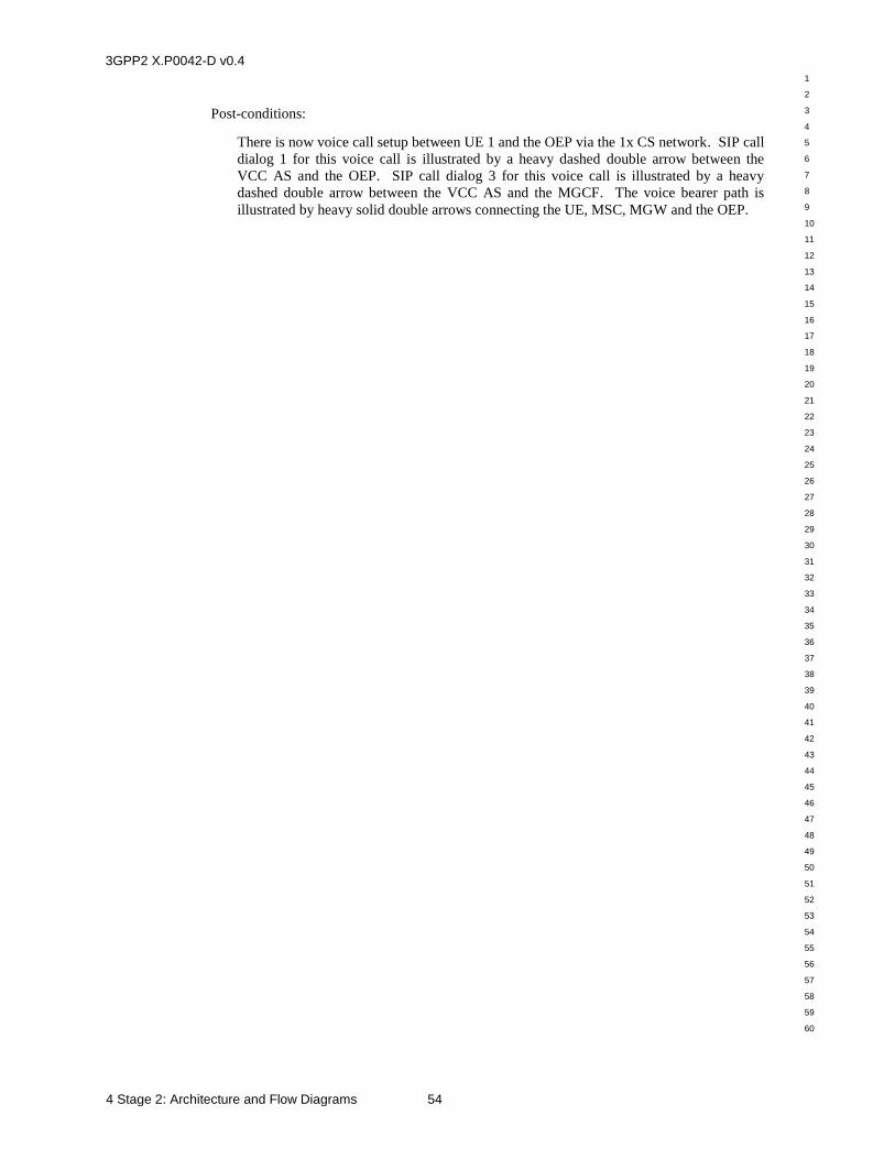
3GPP2 X.P0042-D v0.4
1
2
3
4
5
6
7
8
9
10
11
12
13
14
15
16
17
18
19
20
21
22
23
24
25
26
27
28
29
30
31
32
33
34
35
36
37
38
39
40
41
42
43
44
45
46
47
48
49
50
51
52
53
54
55
56
57
58
59
60
4 Stage 2: Architecture and Flow Diagrams 54
Post-conditions:
There is now voice call setup between UE 1 and the OEP via the 1x CS network. SIP call
dialog 1 for this voice call is illustrated by a heavy dashed double arrow between the
VCC AS and the OEP. SIP call dialog 3 for this voice call is illustrated by a heavy
dashed double arrow between the VCC AS and the MGCF. The voice bearer path is
illustrated by heavy solid double arrows connecting the UE, MSC, MGW and the OEP.
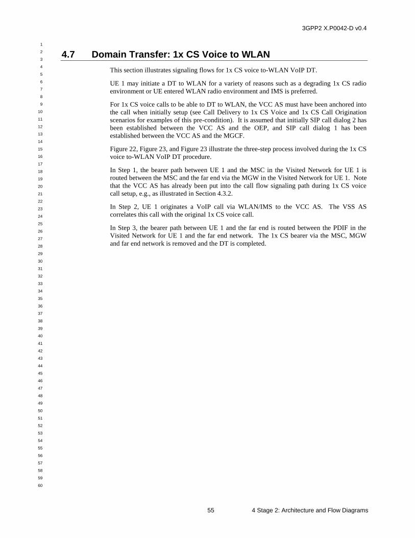
3GPP2 X.P0042-D v0.4
1
2
3
4
5
6
7
8
9
10
11
12
13
14
15
16
17
18
19
20
21
22
23
24
25
26
27
28
29
30
31
32
33
34
35
36
37
38
39
40
41
42
43
44
45
46
47
48
49
50
51
52
53
54
55
56
57
58
59
60
55 4 Stage 2: Architecture and Flow Diagrams
4.7 Domain Transfer: 1x CS Voice to WLAN
This section illustrates signaling flows for 1x CS voice to-WLAN VoIP DT.
UE 1 may initiate a DT to WLAN for a variety of reasons such as a degrading 1x CS radio
environment or UE entered WLAN radio environment and IMS is preferred.
For 1x CS voice calls to be able to DT to WLAN, the VCC AS must have been anchored into
the call when initially setup (see Call Delivery to 1x CS Voice and 1x CS Call Origination
scenarios for examples of this pre-condition). It is assumed that initially SIP call dialog 2 has
been established between the VCC AS and the OEP, and SIP call dialog 1 has been
established between the VCC AS and the MGCF.
Figure 22, Figure 23, and Figure 23 illustrate the three-step process involved during the 1x CS
voice to-WLAN VoIP DT procedure.
In Step 1, the bearer path between UE 1 and the MSC in the Visited Network for UE 1 is
routed between the MSC and the far end via the MGW in the Visited Network for UE 1. Note
that the VCC AS has already been put into the call flow signaling path during 1x CS voice
call setup, e.g., as illustrated in Section 4.3.2.
In Step 2, UE 1 originates a VoIP call via WLAN/IMS to the VCC AS. The VSS AS
correlates this call with the original 1x CS voice call.
In Step 3, the bearer path between UE 1 and the far end is routed between the PDIF in the
Visited Network for UE 1 and the far end network. The 1x CS bearer via the MSC, MGW
and far end network is removed and the DT is completed.
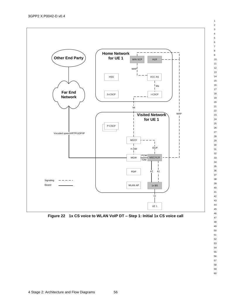
3GPP2 X.P0042-D v0.4
1
2
3
4
5
6
7
8
9
10
11
12
13
14
15
16
17
18
19
20
21
22
23
24
25
26
27
28
29
30
31
32
33
34
35
36
37
38
39
40
41
42
43
44
45
46
47
48
49
50
51
52
53
54
55
56
57
58
59
60
4 Stage 2: Architecture and Flow Diagrams 56
Visited Network
for UE 1
WLAN AP
PDIF
UE 1
1x BS
MSC/VLR
P-CSCF+P-CSCF
A1
1x
Vocoded speech/RTP/UDP/IP
MGCF
MGW
H.248
A2
MAP
ISUP
Home Network
for UE 1
S-CSCF
HSS VCC AS
HLROther End Party
Far End
Network
Mi
I-CSCF
Ma
PCM/
TDM
Signaling
Bearer
WIN SCP
MAP
Figure 22 1x CS voice to WLAN VoIP DT – Step 1: Initial 1x CS voice call
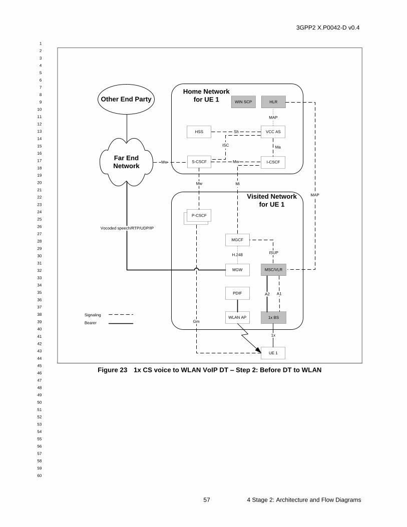
3GPP2 X.P0042-D v0.4
1
2
3
4
5
6
7
8
9
10
11
12
13
14
15
16
17
18
19
20
21
22
23
24
25
26
27
28
29
30
31
32
33
34
35
36
37
38
39
40
41
42
43
44
45
46
47
48
49
50
51
52
53
54
55
56
57
58
59
60
57 4 Stage 2: Architecture and Flow Diagrams
Visited Network
for UE 1
WLAN AP
PDIF
UE 1
1x BS
MSC/VLR
P-CSCF+P-CSCF
A1
1x
Mw
MGCF
MGW
H.248
A2
MAP
ISUP
Home Network
for UE 1
S-CSCF
HSS
Mw
VCC AS
HLR
MAP
ISC
Mi
Gm
I-CSCF
Ma
Other End Party
Far End
Network
Signaling
Bearer
Sh
Mw
WIN SCP
Vocoded speech/RTP/UDP/IP
Figure 23 1x CS voice to WLAN VoIP DT – Step 2: Before DT to WLAN
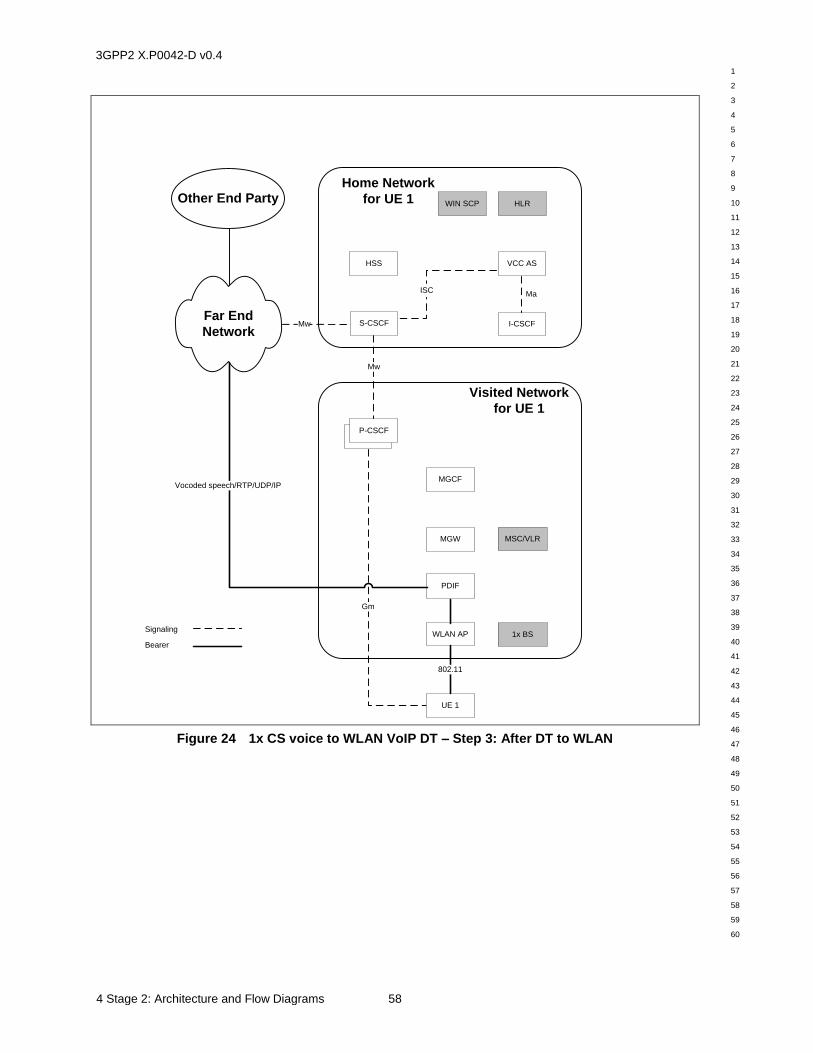
3GPP2 X.P0042-D v0.4
1
2
3
4
5
6
7
8
9
10
11
12
13
14
15
16
17
18
19
20
21
22
23
24
25
26
27
28
29
30
31
32
33
34
35
36
37
38
39
40
41
42
43
44
45
46
47
48
49
50
51
52
53
54
55
56
57
58
59
60
4 Stage 2: Architecture and Flow Diagrams 58
Visited Network
for UE 1
WLAN AP
PDIF
1x BS
MSC/VLR
P-CSCF+P-CSCF
Mw
MGCF
MGW
Home Network
for UE 1
S-CSCF
HSS
Mw
VCC AS
HLR
ISC
Gm
I-CSCF
Ma
Other End Party
Far End
Network
Signaling
Bearer
WIN SCP
Vocoded speech/RTP/UDP/IP
UE 1
802.11
Figure 24 1x CS voice to WLAN VoIP DT – Step 3: After DT to WLAN
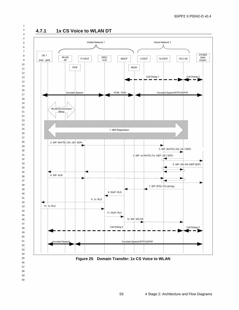
3GPP2 X.P0042-D v0.4
1
2
3
4
5
6
7
8
9
10
11
12
13
14
15
16
17
18
19
20
21
22
23
24
25
26
27
28
29
30
31
32
33
34
35
36
37
38
39
40
41
42
43
44
45
46
47
48
49
50
51
52
53
54
55
56
57
58
59
60
59 4 Stage 2: Architecture and Flow Diagrams
4.7.1 1x CS Voice to WLAN DT
MSC/
VLR
WLAN
APP-CSCF MGCF
OTHER
END
POINT
Home Network 1
7. SIP: BYE( CS call leg)
10. 1x: RLC
Visited Network 1
4. SIP: re-INVITE (To: OEP, UE1 SDP)
5. SIP: 200 OK (OEP SDP)
12. SIP: 200 OK
9. 1x: RLS
2. SIP: INVITE( VDI, UE1 SDP)
8. ISUP: RLS
MGW
VCC AS
UE 1
{ckt} {pkt}
Vocoded Speech/RTP/UDP/IPPCM / TDMVocoded Speech
Vocoded Speech/RTP/UDP/IP
WLAN Environment
Setup
6. SIP: ACK
3. SIP: INVITE( VDI, UE1 SDP)
11. ISUP: RLC
Vocoded Speech
I-CSCF
PDIF
Call Dialog 1 Call Dialog 2
Call Dialog 3 Call Dialog 2
1. IMS Registration
S-CSCF
Figure 25 Domain Transfer: 1x CS Voice to WLAN
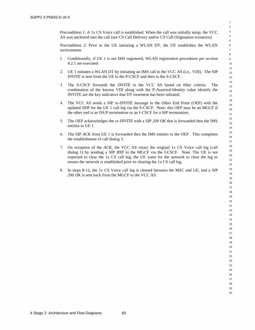
3GPP2 X.P0042-D v0.4
1
2
3
4
5
6
7
8
9
10
11
12
13
14
15
16
17
18
19
20
21
22
23
24
25
26
27
28
29
30
31
32
33
34
35
36
37
38
39
40
41
42
43
44
45
46
47
48
49
50
51
52
53
54
55
56
57
58
59
60
4 Stage 2: Architecture and Flow Diagrams 60
Precondition 1: A 1x CS Voice call is established. When the call was initially setup, the VCC
AS was anchored into the call (see CS Call Delivery and/or CS Call Origination scenarios).
Precondition 2: Prior to the UE initiating a WLAN DT, the UE establishes the WLAN
environment.
Conditionally, if UE 1 is not IMS registered, WLAN registration procedures per section
4.2.1 are executed.
UE 1 initiates a WLAN DT by initiating an IMS call to the VCC AS (i.e., VDI). The SIP
INVITE is sent from the UE to the P-CSCF and then to the S-CSCF.
The S-CSCF forwards the INVITE to the VCC AS based on filter criteria. The
combination of the known VDI along with the P-Asserted-Identity value identify the
INVITE are the key indicators that DT treatment has been initiated.
The VCC AS sends a SIP re-INVITE message to the Other End Point (OEP) with the
updated SDP for the UE 1 call leg via the S-CSCF. Note: this OEP may be an MGCF if
the other end is an ISUP termination or an I-CSCF for a SIP termination.
The OEP acknowledges the re-INVITE with a SIP 200 OK that is forwarded thru the IMS
entities to UE 1.
The SIP ACK from UE 1 is forwarded thru the IMS entities to the OEP. This completes
the establishment of call dialog 3.
On reception of the ACK, the VCC AS clears the original 1x CS Voice call leg (call
dialog 1) by sending a SIP BYE to the MGCF via the I-CSCF. Note: The UE is not
expected to clear the 1x CS call leg; the UE waits for the network to clear the leg to
ensure the network is established prior to clearing the 1x CS call leg.
In steps 8-12, the 1x CS Voice call leg is cleared between the MSC and UE, and a SIP
200 OK is sent back from the MGCF to the VCC AS.
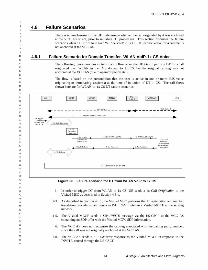
3GPP2 X.P0042-D v0.4
1
2
3
4
5
6
7
8
9
10
11
12
13
14
15
16
17
18
19
20
21
22
23
24
25
26
27
28
29
30
31
32
33
34
35
36
37
38
39
40
41
42
43
44
45
46
47
48
49
50
51
52
53
54
55
56
57
58
59
60
61 4 Stage 2: Architecture and Flow Diagrams
4.8 Failure Scenarios
There is no mechanism for the UE to determine whether the call originated by it was anchored
at the VCC AS or not, prior to initiating DT procedures. This section discusses the failure
scenarios when a UE tries to initiate WLAN-VoIP to 1x CS DT, or vice versa, for a call that is
not anchored at the VCC AS.
4.8.1 Failure Scenario for Domain Transfer- WLAN VoIP-1x CS Voice
The following figure provides an information flow when the UE tries to perform DT for a call
originated over WLAN in the IMS domain to 1x CS, but the original call-leg was not
anchored at the VCC AS (due to operator policy etc.).
The flow is based on the precondition that the user is active in one or more IMS voice
originating or terminating session(s) at the time of initiation of DT to CS. The call flows
shown here are for WLAN-to-1x CS DT failure scenarios.
UE1 MSC MGCFI/S-
CSCFVCC AS
3. ISUP IAM
(CdPN=VDN;
CgPN=MDN)
4. INVITE (VDN; CgPN)
Call Dialog 1
UE2
Call Dialog 2
MGW
5. INVITE (VDN; CgPN)
UE triggers
domain
transfer from
IMS to CS
6. VCC AS
does not
recognize call
leg associated
with CgPN7. 4xx Response8. 4xx Response9. ISUP: Release
11. Continue Call on IMS
Vocoded Speech - RTP/UDP/IP
2. CS
Origination
Procedures
1. 1X: Call Origination
10. 1X: Release
Figure 26 Failure scenario for DT from WLAN VoIP to 1x CS
In order to trigger DT from WLAN to 1x CS, UE sends a 1x Call Origination to the
Visited MSC as described in Section 4.6.1.
2-3. As described in Section 4.6.1, the Visited MSC performs the 1x registration and number
translation procedures, and sends an ISUP IAM routed to a Visited MGCF in the serving
network.
4-5. The Visited MGCF sends a SIP INVITE message via the I/S-CSCF to the VCC AS
containing an SDP offer with the Visited MGW SDP information.
6. The VCC AS does not recognize the call-leg associated with the calling party number,
since the call was not originally anchored at the VCC AS.
7-8. The VCC AS sends a SIP 4xx error response to the Visited MGCF in response to the
INVITE, routed through the I/S-CSCF.

3GPP2 X.P0042-D v0.4
1
2
3
4
5
6
7
8
9
10
11
12
13
14
15
16
17
18
19
20
21
22
23
24
25
26
27
28
29
30
31
32
33
34
35
36
37
38
39
40
41
42
43
44
45
46
47
48
49
50
51
52
53
54
55
56
57
58
59
60
4 Stage 2: Architecture and Flow Diagrams 62
9. The Visited MGCF converts the 4xx response to ISUP Release message and forwards it
to the Visited MSC.
10. The Visited MSC sends back a failure notification (1x Release Order message) to the
UE1 via the 1x BS. The UE 1 responds back with a 1x Release message to the Visited
MSC.
11. At this point, UE 1 continues the call with the other end party in the IMS domain.
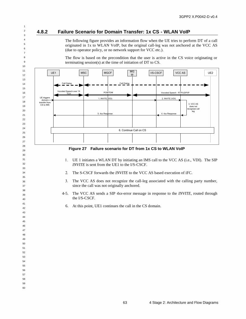
3GPP2 X.P0042-D v0.4
1
2
3
4
5
6
7
8
9
10
11
12
13
14
15
16
17
18
19
20
21
22
23
24
25
26
27
28
29
30
31
32
33
34
35
36
37
38
39
40
41
42
43
44
45
46
47
48
49
50
51
52
53
54
55
56
57
58
59
60
63 4 Stage 2: Architecture and Flow Diagrams
4.8.2 Failure Scenario for Domain Transfer: 1x CS - WLAN VoIP
The following figure provides an information flow when the UE tries to perform DT of a call
originated in 1x to WLAN VoIP, but the original call-leg was not anchored at the VCC AS
(due to operator policy, or no network support for VCC etc.).
The flow is based on the precondition that the user is active in the CS voice originating or
terminating session(s) at the time of initiation of DT to CS.
Call Dialog
2. INVITE (VDI)UE triggers
domain
transfer from
CS to IMS 3. VCC AS
does not
recognize call
leg
4. 4xx Response5. 4xx Response
6. Continue Call on CS
Call Dialog
1. INVITE (VDI)
Vocoded Speech over 1X
TCHPCM/TDM Vocoded Speech - RTP/UDP/IP
UE1 MSC MGCF I/S-CSCF VCC AS UE2MG
W
Figure 27 Failure scenario for DT from 1x CS to WLAN VoIP
UE 1 initiates a WLAN DT by initiating an IMS call to the VCC AS (i.e., VDI). The SIP
INVITE is sent from the UE1 to the I/S-CSCF.
The S-CSCF forwards the INVITE to the VCC AS based execution of iFC.
The VCC AS does not recognize the call-leg associated with the calling party number,
since the call was not originally anchored.
4-5. The VCC AS sends a SIP 4xx-error message in response to the INVITE, routed through
the I/S-CSCF.
6. At this point, UE1 continues the call in the CS domain.
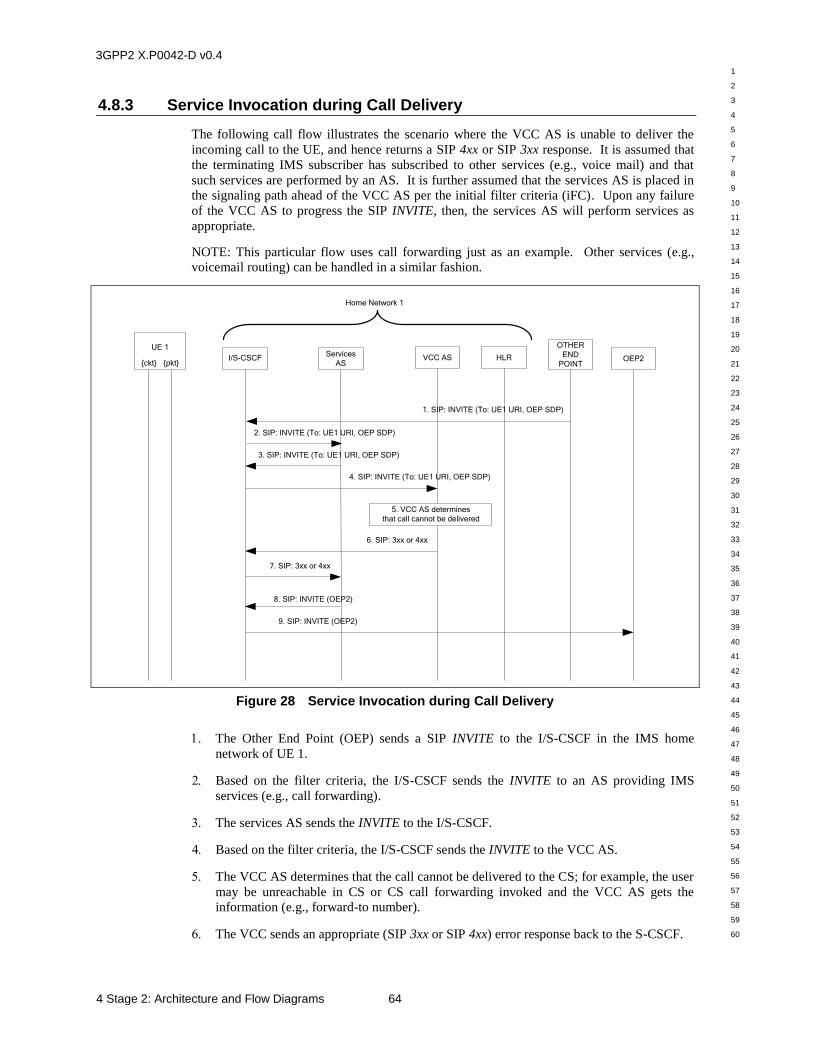
3GPP2 X.P0042-D v0.4
1
2
3
4
5
6
7
8
9
10
11
12
13
14
15
16
17
18
19
20
21
22
23
24
25
26
27
28
29
30
31
32
33
34
35
36
37
38
39
40
41
42
43
44
45
46
47
48
49
50
51
52
53
54
55
56
57
58
59
60
4 Stage 2: Architecture and Flow Diagrams 64
4.8.3 Service Invocation during Call Delivery
The following call flow illustrates the scenario where the VCC AS is unable to deliver the
incoming call to the UE, and hence returns a SIP 4xx or SIP 3xx response. It is assumed that
the terminating IMS subscriber has subscribed to other services (e.g., voice mail) and that
such services are performed by an AS. It is further assumed that the services AS is placed in
the signaling path ahead of the VCC AS per the initial filter criteria (iFC). Upon any failure
of the VCC AS to progress the SIP INVITE, then, the services AS will perform services as
appropriate.
NOTE: This particular flow uses call forwarding just as an example. Other services (e.g.,
voicemail routing) can be handled in a similar fashion.
I/S-CSCF VCC AS HLR
1. SIP: INVITE (To: UE1 URI, OEP SDP)
2. SIP: INVITE (To: UE1 URI, OEP SDP)
Home Network 1
Services
AS
8. SIP: INVITE (OEP2)
UE 1
{ckt} {pkt}
6. SIP: 3xx or 4xx
OTHER
END
POINTOEP2
4. SIP: INVITE (To: UE1 URI, OEP SDP)
3. SIP: INVITE (To: UE1 URI, OEP SDP)
7. SIP: 3xx or 4xx
9. SIP: INVITE (OEP2)
5. VCC AS determines
that call cannot be delivered
Figure 28 Service Invocation during Call Delivery
The Other End Point (OEP) sends a SIP INVITE to the I/S-CSCF in the IMS home
network of UE 1.
Based on the filter criteria, the I/S-CSCF sends the INVITE to an AS providing IMS
services (e.g., call forwarding).
The services AS sends the INVITE to the I/S-CSCF.
Based on the filter criteria, the I/S-CSCF sends the INVITE to the VCC AS.
The VCC AS determines that the call cannot be delivered to the CS; for example, the user
may be unreachable in CS or CS call forwarding invoked and the VCC AS gets the
information (e.g., forward-to number).
The VCC sends an appropriate (SIP 3xx or SIP 4xx) error response back to the S-CSCF.
3GPP2 X.P0042-D v0.4
1
2
3
4
5
6
7
8
9
10
11
12
13
14
15
16
17
18
19
20
21
22
23
24
25
26
27
28
29
30
31
32
33
34
35
36
37
38
39
40
41
42
43
44
45
46
47
48
49
50
51
52
53
54
55
56
57
58
59
60
65 4 Stage 2: Architecture and Flow Diagrams
The S-CSCF forwards the error response to the Services AS.
The Services AS decides to execute a call forwarding feature and forwards the call to
another endpoint (OEP2).
The S-CSCF forwards the call to OEP2.
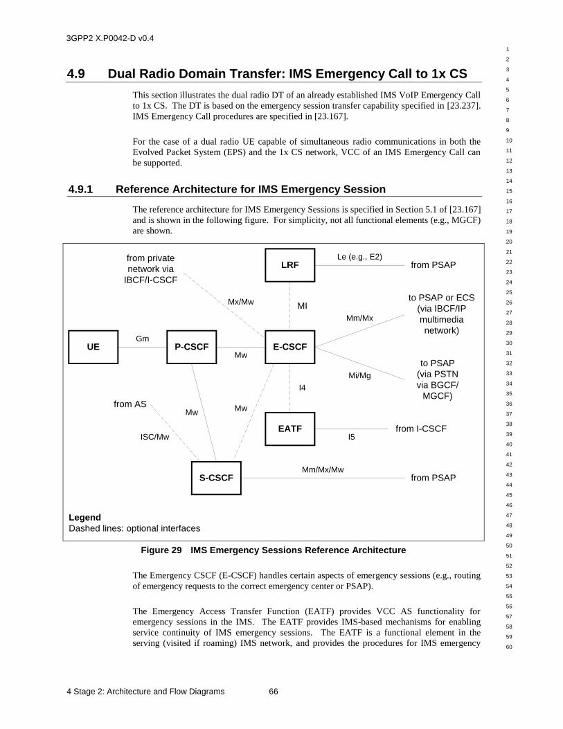
3GPP2 X.P0042-D v0.4
1
2
3
4
5
6
7
8
9
10
11
12
13
14
15
16
17
18
19
20
21
22
23
24
25
26
27
28
29
30
31
32
33
34
35
36
37
38
39
40
41
42
43
44
45
46
47
48
49
50
51
52
53
54
55
56
57
58
59
60
4 Stage 2: Architecture and Flow Diagrams 66
4.9 Dual Radio Domain Transfer: IMS Emergency Call to 1x CS
This section illustrates the dual radio DT of an already established IMS VoIP Emergency Call
to 1x CS. The DT is based on the emergency session transfer capability specified in [23.237].
IMS Emergency Call procedures are specified in [23.167].
For the case of a dual radio UE capable of simultaneous radio communications in both the
Evolved Packet System (EPS) and the 1x CS network, VCC of an IMS Emergency Call can
be supported.
4.9.1 Reference Architecture for IMS Emergency Session
The reference architecture for IMS Emergency Sessions is specified in Section 5.1 of [23.167]
and is shown in the following figure. For simplicity, not all functional elements (e.g., MGCF)
are shown.
LRF
UE
EATF
P-CSCF E-CSCF
S-CSCF
from PSAPLe (e.g., E2)
MI
I4
I5from I-CSCF
to PSAP or ECS
(via IBCF/IP
multimedia
network)
to PSAP
(via PSTN
via BGCF/
MGCF)
Mw
Gm
Mx/Mw
from private
network via
IBCF/I-CSCF
Mm/Mx
Mi/Mg
from PSAPMm/Mx/Mw
MwMw
ISC/Mw
from AS
Legend
Dashed lines: optional interfaces
Figure 29 IMS Emergency Sessions Reference Architecture
The Emergency CSCF (E-CSCF) handles certain aspects of emergency sessions (e.g., routing
of emergency requests to the correct emergency center or PSAP).
The Emergency Access Transfer Function (EATF) provides VCC AS functionality for
emergency sessions in the IMS. The EATF provides IMS-based mechanisms for enabling
service continuity of IMS emergency sessions. The EATF is a functional element in the
serving (visited if roaming) IMS network, and provides the procedures for IMS emergency
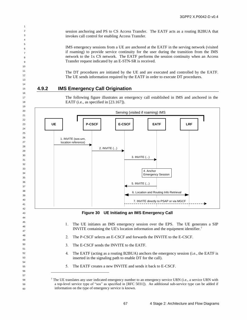
3GPP2 X.P0042-D v0.4
1
2
3
4
5
6
7
8
9
10
11
12
13
14
15
16
17
18
19
20
21
22
23
24
25
26
27
28
29
30
31
32
33
34
35
36
37
38
39
40
41
42
43
44
45
46
47
48
49
50
51
52
53
54
55
56
57
58
59
60
67 4 Stage 2: Architecture and Flow Diagrams
session anchoring and PS to CS Access Transfer. The EATF acts as a routing B2BUA that
invokes call control for enabling Access Transfer.
IMS emergency sessions from a UE are anchored at the EATF in the serving network (visited
if roaming) to provide service continuity for the user during the transition from the IMS
network to the 1x CS network. The EATF performs the session continuity when an Access
Transfer request indicated by an E-STN-SR is received.
The DT procedures are initiated by the UE and are executed and controlled by the EATF.
The UE sends information required by the EATF in order to execute DT procedures.
4.9.2 IMS Emergency Call Origination
The following figure illustrates an emergency call established in IMS and anchored in the
EATF (i.e., as specified in [23.167]).
2. INVITE (...)
UE P-CSCF
1. INVITE (sos-urn,
location reference)
E-CSCF EATF
3. INVITE (...)
4. Anchor
Emergency Session
LRF
5. INVITE (...)
6. Location and Routing Info Retrieval
7. INVITE directly to PSAP or via MGCF
Serving (visited if roaming) IMS
Figure 30 UE Initiating an IMS Emergency Call
The UE initiates an IMS emergency session over the EPS. The UE generates a SIP
INVITE containing the UE's location information and the equipment identifier.7
The P-CSCF selects an E-CSCF and forwards the INVITE to the E-CSCF.
The E-CSCF sends the INVITE to the EATF.
The EATF (acting as a routing B2BUA) anchors the emergency session (i.e., the EATF is
inserted in the signaling path to enable DT for the call).
The EATF creates a new INVITE and sends it back to E-CSCF.
7 The UE translates any user indicated emergency number to an emergency service URN (i.e., a service URN with
a top-level service type of “sos” as specified in [RFC 5031]). An additional sub-service type can be added if information on the type of emergency service is known.
3GPP2 X.P0042-D v0.4
1
2
3
4
5
6
7
8
9
10
11
12
13
14
15
16
17
18
19
20
21
22
23
24
25
26
27
28
29
30
31
32
33
34
35
36
37
38
39
40
41
42
43
44
45
46
47
48
49
50
51
52
53
54
55
56
57
58
59
60
4 Stage 2: Architecture and Flow Diagrams 68
See [23.167] for a description of this optional procedure.
The E-CSCF uses the routing information to format the INVITE message. The E-CSCF
sends the INVITE directly to the PSAP or to the PSAP via the MGCF.
4.9.3 Dual Radio IMS Emergency Call Domain Transfer (PS-to-CS)
This section describes DT of an IMS Emergency Call to a 1x CS network for a dual radio
device capable of simultaneous radio communications in both the EPS and 1x CS networks.
Both the UE and the MSC in the serving 1x CS network must be capable of supporting the
IMS Emergency Call DT. Additionally, the UE is configured to perform DRVCC at the time
of DT. This UE configuration is not made known to the network prior to DT.
IMS Emergency Call DT enables call continuity when the UE can no longer be served by the
PS domain. The DT is controlled by the EATF in the serving IMS network at the request of
the UE.
When the UE determines that DT is required for an IMS Emergency Call, the UE initiates an
“emergency DT” call on the 1x CS network. The CdPN is a reserved number (e.g., *911) for
emergency DT. The MSC in the serving 1x CS network detects the emergency DT number
(EDTN) and initiates the procedures for DT.
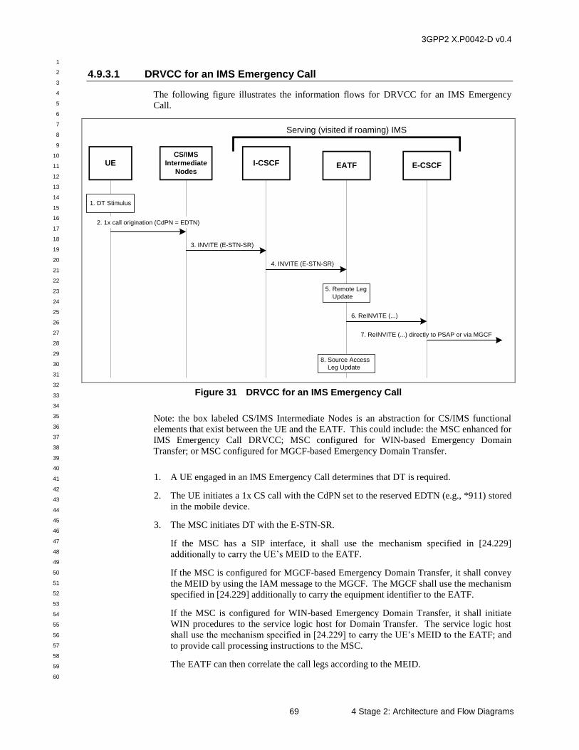
3GPP2 X.P0042-D v0.4
1
2
3
4
5
6
7
8
9
10
11
12
13
14
15
16
17
18
19
20
21
22
23
24
25
26
27
28
29
30
31
32
33
34
35
36
37
38
39
40
41
42
43
44
45
46
47
48
49
50
51
52
53
54
55
56
57
58
59
60
69 4 Stage 2: Architecture and Flow Diagrams
4.9.3.1 DRVCC for an IMS Emergency Call
The following figure illustrates the information flows for DRVCC for an IMS Emergency
Call.
6. ReINVITE (...)
3. INVITE (E-STN-SR)
UECS/IMS
Intermediate
Nodes
2. 1x call origination (CdPN = EDTN)
I-CSCF EATF E-CSCF
Serving (visited if roaming) IMS
1. DT Stimulus
5. Remote Leg
Update
4. INVITE (E-STN-SR)
8. Source Access
Leg Update
7. ReINVITE (...) directly to PSAP or via MGCF
Figure 31 DRVCC for an IMS Emergency Call
Note: the box labeled CS/IMS Intermediate Nodes is an abstraction for CS/IMS functional
elements that exist between the UE and the EATF. This could include: the MSC enhanced for
IMS Emergency Call DRVCC; MSC configured for WIN-based Emergency Domain
Transfer; or MSC configured for MGCF-based Emergency Domain Transfer.
1. A UE engaged in an IMS Emergency Call determines that DT is required.
2. The UE initiates a 1x CS call with the CdPN set to the reserved EDTN (e.g., *911) stored
in the mobile device.
3. The MSC initiates DT with the E-STN-SR.
If the MSC has a SIP interface, it shall use the mechanism specified in [24.229]
additionally to carry the UE’s MEID to the EATF.
If the MSC is configured for MGCF-based Emergency Domain Transfer, it shall convey
the MEID by using the IAM message to the MGCF. The MGCF shall use the mechanism
specified in [24.229] additionally to carry the equipment identifier to the EATF.
If the MSC is configured for WIN-based Emergency Domain Transfer, it shall initiate
WIN procedures to the service logic host for Domain Transfer. The service logic host
shall use the mechanism specified in [24.229] to carry the UE’s MEID to the EATF; and
to provide call processing instructions to the MSC.
The EATF can then correlate the call legs according to the MEID.
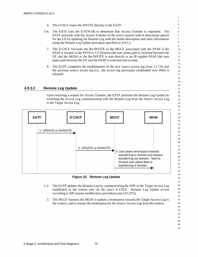
3GPP2 X.P0042-D v0.4
1
2
3
4
5
6
7
8
9
10
11
12
13
14
15
16
17
18
19
20
21
22
23
24
25
26
27
28
29
30
31
32
33
34
35
36
37
38
39
40
41
42
43
44
45
46
47
48
49
50
51
52
53
54
55
56
57
58
59
60
4 Stage 2: Architecture and Flow Diagrams 70
4. The I-CSCF routes the INVITE directly to the EATF.
5-6. The EATF uses the E-STN-SR to determine that Access Transfer is requested. The
EATF proceeds with the Access Transfer of the active session with bi-directional speech
for the UE by updating the Remote Leg with the media description and other information
using the Remote Leg Update procedure specified in 4.9.3.2.
7. The E-CSCF forwards the Re-INVITE to the MGCF associated with the PSAP if the
PSAP is located in the PSTN or CS Domain (the user plane path is switched between the
UE and the MGW) or the Re-INVITE is sent directly to an IP-capable PSAP (the user
plane path between the UE and the PSAP is switched end-to-end).
8. The EATF completes the establishment of the new source access leg (over 1x CS) and
the previous source access leg (i.e., the access leg previously established over IMS) is
released.
4.9.3.2 Remote Leg Update
Upon receiving a request for Access Transfer, the EATF performs the Remote Leg Update by
switching the Access Leg communicating with the Remote Leg from the Source Access Leg
to the Target Access Leg.
3. User plane termination towards
transferring-in domain and release
transferring-out domain. Start to
forward user plane data to
transferring-in domain
1. UPDATE or ReINVITE
EATF E-CSCF MGCF MGW
2. UPDATE or ReINVITE
Figure 32 Remote Leg Update
1-2. The EATF updates the Remote Leg by communicating the SDP of the Target Access Leg
established to the remote end via the user's E-CSCF. Remote Leg Update occurs
according to SIP session modification procedures (see [23.237]).
3. The MGCF instructs the MGW to update a termination towards the Target Access Leg to
the context, and to release the termination for the Source Access Leg from the context.
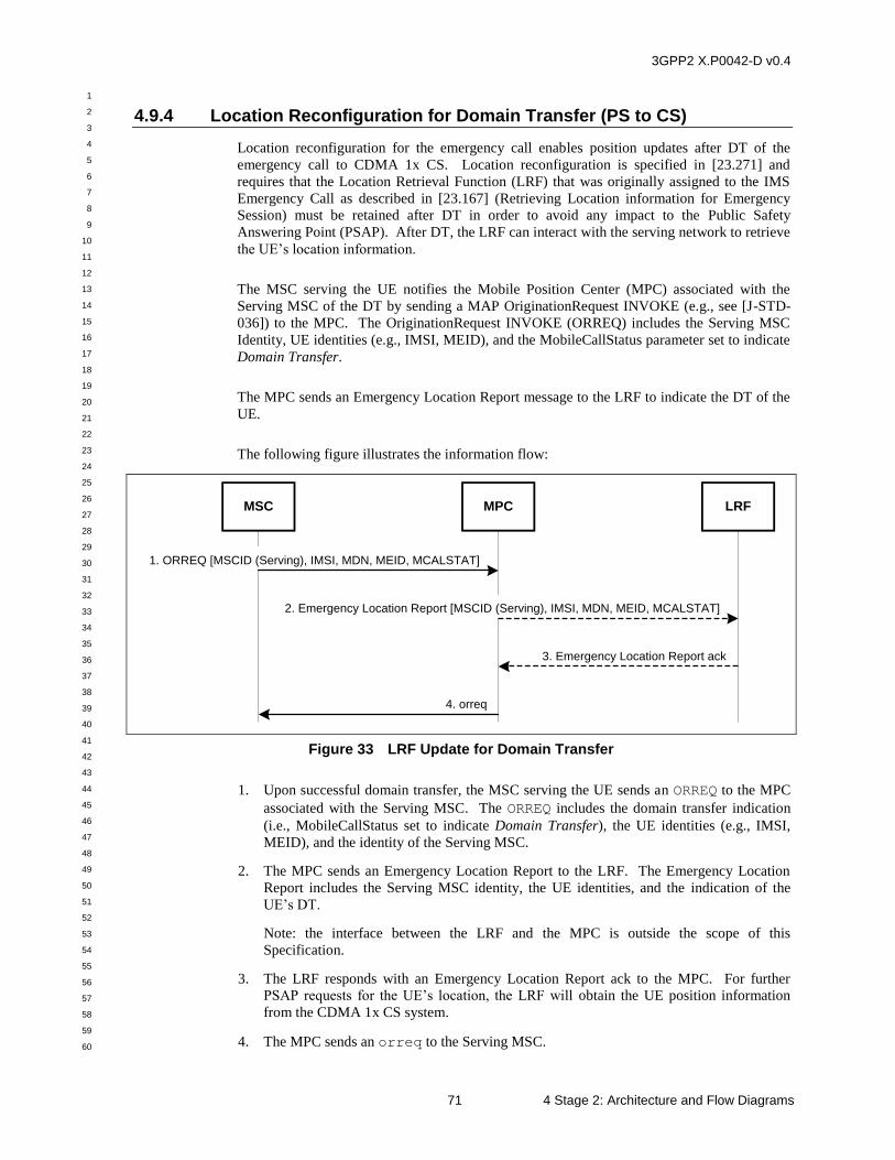
3GPP2 X.P0042-D v0.4
1
2
3
4
5
6
7
8
9
10
11
12
13
14
15
16
17
18
19
20
21
22
23
24
25
26
27
28
29
30
31
32
33
34
35
36
37
38
39
40
41
42
43
44
45
46
47
48
49
50
51
52
53
54
55
56
57
58
59
60
71 4 Stage 2: Architecture and Flow Diagrams
4.9.4 Location Reconfiguration for Domain Transfer (PS to CS)
Location reconfiguration for the emergency call enables position updates after DT of the
emergency call to CDMA 1x CS. Location reconfiguration is specified in [23.271] and
requires that the Location Retrieval Function (LRF) that was originally assigned to the IMS
Emergency Call as described in [23.167] (Retrieving Location information for Emergency
Session) must be retained after DT in order to avoid any impact to the Public Safety
Answering Point (PSAP). After DT, the LRF can interact with the serving network to retrieve
the UE’s location information.
The MSC serving the UE notifies the Mobile Position Center (MPC) associated with the
Serving MSC of the DT by sending a MAP OriginationRequest INVOKE (e.g., see [J-STD-
036]) to the MPC. The OriginationRequest INVOKE (ORREQ) includes the Serving MSC
Identity, UE identities (e.g., IMSI, MEID), and the MobileCallStatus parameter set to indicate
Domain Transfer.
The MPC sends an Emergency Location Report message to the LRF to indicate the DT of the
UE.
The following figure illustrates the information flow:
3. Emergency Location Report ack
1. ORREQ [MSCID (Serving), IMSI, MDN, MEID, MCALSTAT]
MSC LRF
4. orreq
MPC
2. Emergency Location Report [MSCID (Serving), IMSI, MDN, MEID, MCALSTAT]
Figure 33 LRF Update for Domain Transfer
1. Upon successful domain transfer, the MSC serving the UE sends an ORREQ to the MPC
associated with the Serving MSC. The ORREQ includes the domain transfer indication
(i.e., MobileCallStatus set to indicate Domain Transfer), the UE identities (e.g., IMSI,
MEID), and the identity of the Serving MSC.
2. The MPC sends an Emergency Location Report to the LRF. The Emergency Location
Report includes the Serving MSC identity, the UE identities, and the indication of the
UE’s DT.
Note: the interface between the LRF and the MPC is outside the scope of this
Specification.
3. The LRF responds with an Emergency Location Report ack to the MPC. For further
PSAP requests for the UE’s location, the LRF will obtain the UE position information
from the CDMA 1x CS system.
4. The MPC sends an orreq to the Serving MSC.
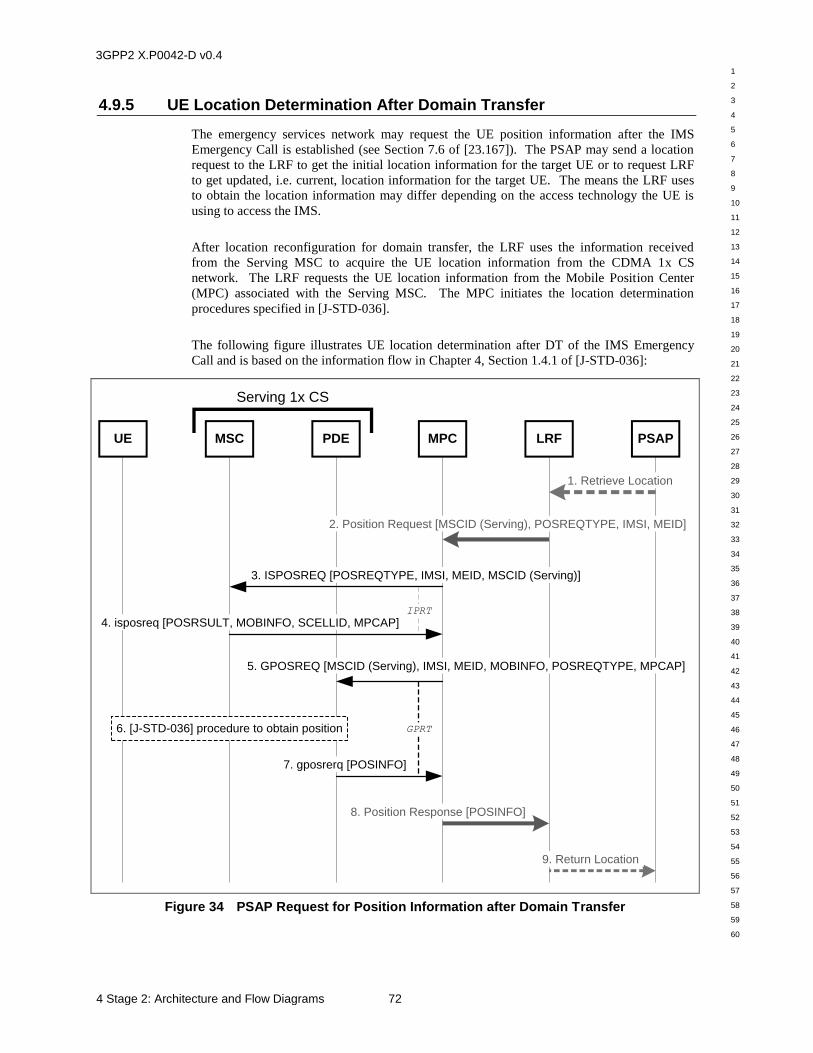
3GPP2 X.P0042-D v0.4
1
2
3
4
5
6
7
8
9
10
11
12
13
14
15
16
17
18
19
20
21
22
23
24
25
26
27
28
29
30
31
32
33
34
35
36
37
38
39
40
41
42
43
44
45
46
47
48
49
50
51
52
53
54
55
56
57
58
59
60
4 Stage 2: Architecture and Flow Diagrams 72
4.9.5 UE Location Determination After Domain Transfer
The emergency services network may request the UE position information after the IMS
Emergency Call is established (see Section 7.6 of [23.167]). The PSAP may send a location
request to the LRF to get the initial location information for the target UE or to request LRF
to get updated, i.e. current, location information for the target UE. The means the LRF uses
to obtain the location information may differ depending on the access technology the UE is
using to access the IMS.
After location reconfiguration for domain transfer, the LRF uses the information received
from the Serving MSC to acquire the UE location information from the CDMA 1x CS
network. The LRF requests the UE location information from the Mobile Position Center
(MPC) associated with the Serving MSC. The MPC initiates the location determination
procedures specified in [J-STD-036].
The following figure illustrates UE location determination after DT of the IMS Emergency
Call and is based on the information flow in Chapter 4, Section 1.4.1 of [J-STD-036]:
Serving 1x CS
MSC MPC PSAPLRFUE PDE
1. Retrieve Location
2. Position Request [MSCID (Serving), POSREQTYPE, IMSI, MEID]
3. ISPOSREQ [POSREQTYPE, IMSI, MEID, MSCID (Serving)]
6. [J-STD-036] procedure to obtain position
4. isposreq [POSRSULT, MOBINFO, SCELLID, MPCAP]IPRT
8. Position Response [POSINFO]
5. GPOSREQ [MSCID (Serving), IMSI, MEID, MOBINFO, POSREQTYPE, MPCAP]
GPRT
7. gposrerq [POSINFO]
9. Return Location
Figure 34 PSAP Request for Position Information after Domain Transfer
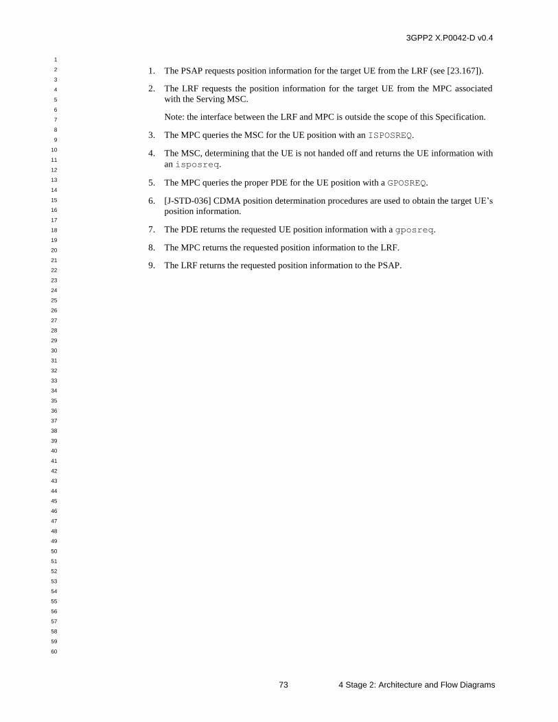
3GPP2 X.P0042-D v0.4
1
2
3
4
5
6
7
8
9
10
11
12
13
14
15
16
17
18
19
20
21
22
23
24
25
26
27
28
29
30
31
32
33
34
35
36
37
38
39
40
41
42
43
44
45
46
47
48
49
50
51
52
53
54
55
56
57
58
59
60
73 4 Stage 2: Architecture and Flow Diagrams
1. The PSAP requests position information for the target UE from the LRF (see [23.167]).
2. The LRF requests the position information for the target UE from the MPC associated
with the Serving MSC.
Note: the interface between the LRF and MPC is outside the scope of this Specification.
3. The MPC queries the MSC for the UE position with an ISPOSREQ.
4. The MSC, determining that the UE is not handed off and returns the UE information with
an isposreq.
5. The MPC queries the proper PDE for the UE position with a GPOSREQ.
6. [J-STD-036] CDMA position determination procedures are used to obtain the target UE’s
position information.
7. The PDE returns the requested UE position information with a gposreq.
8. The MPC returns the requested position information to the LRF.
9. The LRF returns the requested position information to the PSAP.
3GPP2 X.P0042-D v0.4
1
2
3
4
5
6
7
8
9
10
11
12
13
14
15
16
17
18
19
20
21
22
23
24
25
26
27
28
29
30
31
32
33
34
35
36
37
38
39
40
41
42
43
44
45
46
47
48
49
50
51
52
53
54
55
56
57
58
59
60
4 Stage 2: Architecture and Flow Diagrams 74
4.10 Single Radio Domain Transfer: IMS Emergency Call to 1x CS
4.10.1 Roles of Functional Elements for SRVCC Domain Transfer of an Emergency Call from the E-UTRAN to the 1xCS Domain
This section specifies the roles of the functional elements for SRVCC DT of an emergency
call from E-UTRAN to the 1xCS domain.
4.10.1.1 SRVCC UE
The UE reports signal strength measurements on E-UTRAN and 1xCS to the network. If the
UE receives a handover request from E-UTRAN to 1xCS, the UE shall send a domain transfer
request that contains the 1xCS Origination message and MEID set to IMEI, to the eNodeB.
Upon receipt of the 1xCS channel assignment from the eNodeB, if the UE engaged in
multiple sessions on the UE, it shall initiate the release of all inactive sessions and all other
sessions that are not the identified sessions for DT (i.e., by sending a SIP BYE for the session)
before initiating a DT. The UE shall send the 1xCS channel assignment complete message to
the 1xCS MSC.
4.10.1.2 1xCS MSC
Upon receipt of the domain transfer request, 1xCS MSC shall allocate 1xCS traffic channel.
If the 1xCS MSC has a SIP interface, it shall send a SIP INVITE request with the Request
URI header field set to E-STN-SR associated with the EATF, the P-Asserted-Identity header
field set to IMEI, and the SDP of the MGW. The 1xCS MSC shall send the SIP INVITE
request toward the EATF.
If the 1xCS MSC does not have a SIP interface, the 1xCS MSC shall send an ISUP IAM with
the CdPN set to E-STN-SR associated with the EATF and the CgPN set to IMEI, toward the
MGCF.
The MSC shall initiate the LRF update for the domain transfer of the Emergency Services
Call (see Section 4.9.4).
4.10.1.3 MGCF
Upon receipt of an ISUP IAM with the CdPN set to an E-STN-SR associated with EATF and
the CgPN set to IMEI, the MGCF shall populate a SIP INVITE request with the Request URI
header field set to E-STN-SR associated with EATF, the P-Asserted-Identity header field set
to IMEI, and the SDP of the MGW. The MGCF shall send the request toward the EATF.
Upon receipt of the SIP 200 OK response with the SDP answer, the MGCF shall send an
ISUP ANM toward the 1xCS MSC.
4.10.1.4 EATF
The role of EATF is specified in [24.237].
Upon receipt of a SIP INVITE request with the Request URI set to an E-STN-SR, the EATF
determines that the request is related to DT. The EATF shall populate a SIP re-INVITE
3GPP2 X.P0042-D v0.4
1
2
3
4
5
6
7
8
9
10
11
12
13
14
15
16
17
18
19
20
21
22
23
24
25
26
27
28
29
30
31
32
33
34
35
36
37
38
39
40
41
42
43
44
45
46
47
48
49
50
51
52
53
54
55
56
57
58
59
60
75 4 Stage 2: Architecture and Flow Diagrams
request containing the MGW SDP and send the request toward the PSAP to update the session
properties.
Upon update of the session properties with the PSAP, the EATF shall send a SIP 200 OK
response containing the SDP answer toward the 1xCS MSC. If the 1xCS MSC does not have
a SIP interface, the EATF shall send a SIP 200 OK response containing the SDP answer
toward the MGCF.
4.10.1.5 1xCS IWS
The role of the 1xCS IWS is specified in [23.216].
4.10.1.6 MME
The role of the MME is specified in [23.216].
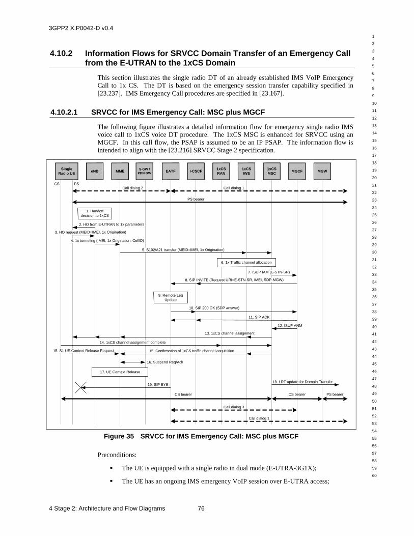
3GPP2 X.P0042-D v0.4
1
2
3
4
5
6
7
8
9
10
11
12
13
14
15
16
17
18
19
20
21
22
23
24
25
26
27
28
29
30
31
32
33
34
35
36
37
38
39
40
41
42
43
44
45
46
47
48
49
50
51
52
53
54
55
56
57
58
59
60
4 Stage 2: Architecture and Flow Diagrams 76
4.10.2 Information Flows for SRVCC Domain Transfer of an Emergency Call from the E-UTRAN to the 1xCS Domain
This section illustrates the single radio DT of an already established IMS VoIP Emergency
Call to 1x CS. The DT is based on the emergency session transfer capability specified in
[23.237]. IMS Emergency Call procedures are specified in [23.167].
4.10.2.1 SRVCC for IMS Emergency Call: MSC plus MGCF
The following figure illustrates a detailed information flow for emergency single radio IMS
voice call to 1xCS voice DT procedure. The 1xCS MSC is enhanced for SRVCC using an
MGCF. In this call flow, the PSAP is assumed to be an IP PSAP. The information flow is
intended to align with the [23.216] SRVCC Stage 2 specification.
Single
Radio UEeNB
1xCS
MSCMGW
1. Handoff
decision to 1xCS
S-GW /
PDN GWI-CSCF
15. Confirmation of 1xCS traffic channel acquisition
CS
1xCS
RAN
10. SIP 200 OK (SDP answer)
11. SIP ACK
Call dialog 2
PS bearer
4. 1x tunneling (IMEI, 1x Origination, CellID)
5. S102/A21 transfer (MEID=IMEI, 1x Origination)
16. Suspend Req/Ack
17. UE Context Release
2. HO from E-UTRAN to 1x parameters
1xCS
IWS
PS
MME EATF
Call dialog 1
3. HO request (MEID=IMEI, 1x Origination)
8. SIP INVITE (Request URI=E-STN-SR, IMEI, SDP-MGW)
6. 1x Traffic channel allocation
9. Remote Leg
Update
14. 1xCS channel assignment complete
13. 1xCS channel assignment
CS bearer CS bearer PS bearer
Call dialog 1
Call dialog 3
18. LRF update for Domain Transfer19. SIP BYE
MGCF
7. ISUP IAM (E-STN-SR)
12. ISUP ANM
15. S1 UE Context Release Request
Figure 35 SRVCC for IMS Emergency Call: MSC plus MGCF
Preconditions:
The UE is equipped with a single radio in dual mode (E-UTRA-3G1X);
The UE has an ongoing IMS emergency VoIP session over E-UTRA access;
3GPP2 X.P0042-D v0.4
1
2
3
4
5
6
7
8
9
10
11
12
13
14
15
16
17
18
19
20
21
22
23
24
25
26
27
28
29
30
31
32
33
34
35
36
37
38
39
40
41
42
43
44
45
46
47
48
49
50
51
52
53
54
55
56
57
58
59
60
77 4 Stage 2: Architecture and Flow Diagrams
The emergency VoIP session is anchored in the IMS network;
The 1xCS MSC is enhanced for SRVCC using an MGCF;
The UE moves into a 1x SRVCC Border Area.
SIP call dialog 1 for the VoIP session is illustrated by a heavy dashed arrow between the
EATF and the IP PSAP. SIP call dialog 2 for the VoIP session is illustrated by a heavy
dashed arrow between the EATF and the UE. The VoIP bearer path is illustrated by a heavy
solid arrow between the UE and the IP PSAP.
1. The E-UTRAN makes a determination to initiate an inter-technology handoff to the
cdma2000® 1xCS access network based on measurement reports from the single radio
UE.
2. The E-UTRAN signals the UE to perform an inter-technology handoff by sending a
Handover from E-UTRA Preparation Request (3G1x Overhead Parameters, RAND
value) message.
3. The UE initiates signaling for establishment of a 1xCS access leg by sending a UL
handover preparation Transfer message containing the MEID set to the IMEI value of the
UE and the 1xCS Origination message.
4. The eNodeB sends an Uplink S1 cdma2000 Tunneling message to the MME. The
message includes a Reference CellID, RAND and the cdma2000 HO Required Indication
to indicate that handoff preparation has started.
5. Upon receipt of the Uplink S1 cdma2000 Tunneling message, the MME selects a 1xCS
IWS based on local configuration in the MME and the received Reference CellID. The
MME encapsulates the 1x Origination Message along with the MEID and RAND in a
S102 Direct Transfer message (as “1xCS Air Interface Signaling”) and sends it to the
1xCS IWS. The message includes the Global Emergency Call field set to indicate the
emergency call. See [29.277] for signaling details.
The 1xCS IWS sends the message to the 1xCS MSC.
6. The MSC allocates a traffic channel for handoff.
7. The MSC sends an ISUP IAM message to the MGCF with the CdPN set to the E-STN-SR
associated with the EATF for the speech media component to be transferred. The MSC
includes the IMEI of the MS in the Application Transport Parameter of the IAM message.
8. The MGCF sends a SIP INVITE request to the I-CSCF with the request URI set to the E-
STN-SR for the session with speech media component to be transferred. The instance-id
feature tag in the Contact header field is set to a value based on the IMEI (see [23.003]).
The SDP offer is set to the media characteristics of the MGW the MSC will use.
The I-CSCF routes the SIP INVITE request directly to the EATF.
9. The EATF correlates the IMEI information in the Contact header field in the received SIP
INVITE request with the local and remote call legs of the existing VoIP session between
the UE and the PSAP. The EATF performs the remote leg update (see [24.237]).
The PSAP has all resources available and provides the SDP answer.
cdma2000® is the trademark for the technical nomenclature for certain specifications and standards of the
Organizational Partners (OPs) of 3GPP2. Geographically (and as of the date of publication), cdma2000® is a registered trademark of the Telecommunications Industry Association (TIA-USA) in the United States.
3GPP2 X.P0042-D v0.4
1
2
3
4
5
6
7
8
9
10
11
12
13
14
15
16
17
18
19
20
21
22
23
24
25
26
27
28
29
30
31
32
33
34
35
36
37
38
39
40
41
42
43
44
45
46
47
48
49
50
51
52
53
54
55
56
57
58
59
60
4 Stage 2: Architecture and Flow Diagrams 78
10. The EATF sends a SIP 200 OK to the I-CSCF with the SDP answer. The I-CSCF routes
the SIP 200 OK to the MGCF.
11. The MGCF sends a SIP ACK (to the SIP 200 OK) to the I-CSCF. The I-CSCF routes the
SIP ACK to the EATF.
12. The MGCF send an ISUP ANM message to the MSC.
13. The MSC sends a 1xCS channel assignment to the UE (via the 1xCS IWS, MME and
eNodeB). This instructs the UE to perform the handoff and acquire the 1x traffic
channel. See [A.S0008] and [A.S0009] for signaling details.
14. The UE acquires the 1xCS traffic channel and sends a 1xCS channel assignment
complete to MSC. Step 13 and Step 14 may occur anytime after Step 6.
15. The MME receives either: an S1 UE Context Release Request (Cause) message
indicating the S1 release procedure is caused by handover from E-UTRAN to 1xCS; or a
confirmation of the 1xCS channel assignment from the MSC (via the 1xCS IWS).
16. The MME deactivates the PS bearers for the PS VoIP session.
17. The S1 UE Context in the eNodeB is released as specified in [23.401].
18. The MSC initiates LRF update for domain transfer (see Section 4.9.4).
19. Any time after Step 11, the EATF sends a SIP BYE message to the UE to release the SIP
call dialog 2 between the UE and the EATF. Note that since the UE is already on a 1xCS
traffic channel, it will not respond to this SIP BYE message.
Post-conditions:
A voice call is setup between the UE and the IP PSAP via the 1xCS MSC and the
MGW.
SIP call dialog 1 for this voice call is illustrated by a heavy dashed arrow between
the EATF and the IP PSAP.
SIP call dialog 3 for this voice call is illustrated by a heavy dashed arrow between
the EATF and the MGCF.
The voice bearer path is illustrated by heavy solid arrows connecting the UE, 1xCS
MSC, MGW and the IP PSAP.
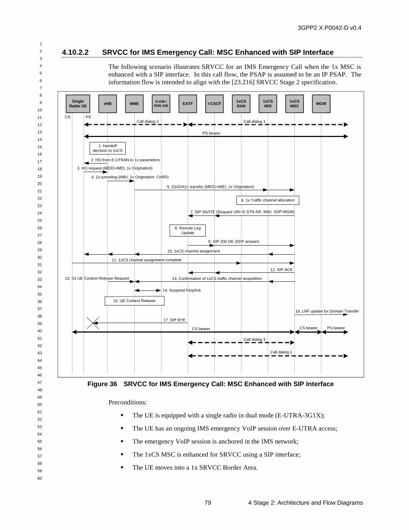
3GPP2 X.P0042-D v0.4
1
2
3
4
5
6
7
8
9
10
11
12
13
14
15
16
17
18
19
20
21
22
23
24
25
26
27
28
29
30
31
32
33
34
35
36
37
38
39
40
41
42
43
44
45
46
47
48
49
50
51
52
53
54
55
56
57
58
59
60
79 4 Stage 2: Architecture and Flow Diagrams
4.10.2.2 SRVCC for IMS Emergency Call: MSC Enhanced with SIP Interface
The following scenario illustrates SRVCC for an IMS Emergency Call when the 1x MSC is
enhanced with a SIP interface. In this call flow, the PSAP is assumed to be an IP PSAP. The
information flow is intended to align with the [23.216] SRVCC Stage 2 specification.
Single
Radio UEeNB
1xCS
MSC
1. Handoff
decision to 1xCS
S-GW /
PDN GWI-CSCF
13. Confirmation of 1xCS traffic channel acquisition
CS
1xCS
RAN
9. SIP 200 OK (SDP answer)
12. SIP ACK
Call dialog 2
PS bearer
4. 1x tunneling (IMEI, 1x Origination, CellID)
5. S102/A21 transfer (MEID=IMEI, 1x Origination)
14. Suspend Req/Ack
15. UE Context Release
2. HO from E-UTRAN to 1x parameters
1xCS
IWS
PS
MME EATF
Call dialog 1
3. HO request (MEID=IMEI, 1x Origination)
7. SIP INVITE (Request URI=E-STN-SR, IMEI, SDP-MGW)
6. 1x Traffic channel allocation
8. Remote Leg
Update
11. 1xCS channel assignment complete
10. 1xCS channel assignment
CS bearer CS bearer PS bearer
Call dialog 1
Call dialog 3
16. LRF update for Domain Transfer
17. SIP BYE
MGW
13. S1 UE Context Release Request
Figure 36 SRVCC for IMS Emergency Call: MSC Enhanced with SIP Interface
Preconditions:
The UE is equipped with a single radio in dual mode (E-UTRA-3G1X);
The UE has an ongoing IMS emergency VoIP session over E-UTRA access;
The emergency VoIP session is anchored in the IMS network;
The 1xCS MSC is enhanced for SRVCC using a SIP interface;
The UE moves into a 1x SRVCC Border Area.
3GPP2 X.P0042-D v0.4
1
2
3
4
5
6
7
8
9
10
11
12
13
14
15
16
17
18
19
20
21
22
23
24
25
26
27
28
29
30
31
32
33
34
35
36
37
38
39
40
41
42
43
44
45
46
47
48
49
50
51
52
53
54
55
56
57
58
59
60
4 Stage 2: Architecture and Flow Diagrams 80
SIP call dialog 1 for the VoIP session is illustrated by a heavy dashed arrow between the
EATF and the IP PSAP. SIP call dialog 2 for the VoIP session is illustrated by a heavy
dashed arrow between the EATF and the UE. The VoIP bearer path is illustrated by a heavy
solid arrow between the UE and the IP PSAP.
1. The E-UTRAN makes a determination to initiate an inter-technology handoff to the
cdma2000 1xCS access network based on measurement reports from the single radio UE.
2. The E-UTRAN signals the UE to perform an inter-technology handoff by sending a
Handover from E-UTRA Preparation Request (3G1x Overhead Parameters, RAND
value) message.
3. The UE initiates signaling for establishment of a 1xCS access leg by sending a UL
handover preparation Transfer message containing the MEID set to the IMEI value of the
UE and the 1xCS Origination message.
4. The eNodeB sends an Uplink S1 cdma2000 Tunneling message to the MME. The
message includes a Reference CellID, RAND and the cdma2000 HO Required Indication
to indicate that handoff preparation has started.
5. Upon receipt of the Uplink S1 cdma2000 Tunneling message, the MME selects a 1xCS
IWS based on local configuration in the MME and the received Reference CellID. The
MME encapsulates the 1x Origination Message along with the MEID and RAND in a
S102 Direct Transfer message (as “1xCS Air Interface Signaling”) and sends it to the
1xCS IWS. The message includes the Global Emergency Call field set to indicate the
emergency call. See [29.277] for signaling details.
The 1xCS IWS sends the message to the 1xCS MSC.
6. The MSC allocates a traffic channel for handoff.
7. The MSC sends a SIP INVITE request to the I-CSCF with the request URI set to the E-
STN-SR for the session with speech media component to be transferred. The instance-id
feature tag in the Contact header field is set to a value based on the IMEI (see [23.003]).
The SDP offer is set to the media characteristics of the MGW the MSC will use.
The I-CSCF routes the SIP INVITE request directly to the EATF.
8. The EATF correlates the IMEI information in the Contact header field in the received SIP
INVITE request with the local and remote call legs of the existing VoIP session between
the UE and the PSAP. The EATF performs the remote leg update (see [24.237]).
The PSAP has all resources available and provides the SDP answer.
9. The EATF sends a SIP 200 OK to the I-CSCF with the SDP answer. The I-CSCF routes
the SIP 200 OK to the MSC.
10. The MSC sends a 1xCS channel assignment to the UE (via the 1xCS IWS, MME and
eNodeB). This instructs the UE to perform the handoff and acquire the 1x traffic
channel. See [A.S0008] and [A.S0009] for signaling details.
11. The UE acquires the 1xCS traffic channel and sends a 1xCS channel assignment
complete to MSC. Step 10 and Step 11 may occur anytime after Step 6.
12. The MSC sends a SIP ACK (to the SIP 200 OK) to the I-CSCF. The I-CSCF routes the
SIP ACK to the EATF.
13. The MME receives either: an S1 UE Context Release Request (Cause) message
indicating the S1 release procedure is caused by handover from E-UTRAN to 1xCS; or a
confirmation of the 1xCS channel assignment from the MSC (via the 1xCS IWS).
3GPP2 X.P0042-D v0.4
1
2
3
4
5
6
7
8
9
10
11
12
13
14
15
16
17
18
19
20
21
22
23
24
25
26
27
28
29
30
31
32
33
34
35
36
37
38
39
40
41
42
43
44
45
46
47
48
49
50
51
52
53
54
55
56
57
58
59
60
81 4 Stage 2: Architecture and Flow Diagrams
14. The MME deactivates the PS bearers for the PS VoIP session.
15. The S1 UE Context in the eNodeB is released as specified in [23.401].
16. The MSC initiates LRF update for domain transfer (see Section 4.9.4).
17. Any time after Step 12, the EATF sends a SIP BYE message to the UE to release SIP call
dialog 2 between the UE and the EATF. Note that since the UE is already on a 1xCS
traffic channel it will not respond to this SIP BYE message.
Post-conditions:
A voice call is setup between the UE and the IP PSAP via the 1xCS MSC and the
MGW.
SIP call dialog 1 for this voice call is illustrated by a heavy dashed arrow between
the EATF and the IP PSAP.
SIP call dialog 3 for this voice call is illustrated by a heavy dashed arrow between
the EATF and the 1xCS MSC.
The voice bearer path is illustrated by heavy solid arrows connecting the UE, 1xCS
MSC, MGW and the IP PSAP.
3GPP2 X.P0042-D v0.4
1
2
3
4
5
6
7
8
9
10
11
12
13
14
15
16
17
18
19
20
21
22
23
24
25
26
27
28
29
30
31
32
33
34
35
36
37
38
39
40
41
42
43
44
45
46
47
48
49
50
51
52
53
54
55
56
57
58
59
60
4 Stage 2: Architecture and Flow Diagrams 82
4.11 Single Radio Domain Transfer: IMS Call to 1xCS
4.11.1 Roles of Functional Elements for SRVCC Domain Transfer of a Call from the E-UTRAN to the 1xCS Domain
This section specifies the roles of the functional elements for SRVCC DT of a call from
E-UTRAN to the 1xCS domain.
4.11.1.1 SRVCC UE
The UE reports the signal strength measurements on E-UTRAN and 1xCS to the network. If
the UE receives a handover request from E-UTRAN to 1xCS, the UE shall send a request to
the eNodeB containing 1xCS Origination message (which includes the STN-SR as the CdPN)
and the MEID set to the IMEI.
Upon receipt of the 1xCS channel assignment from the eNodeB, if the UE is engaged in
multiple sessions, it shall initiate the release of all inactive sessions and all other sessions that
are not the identified for the DT (i.e., by sending a SIP BYE for the session), before initiating
a DT. The UE shall send the 1xCS channel assignment complete message to 1xCS MSC.
4.11.1.2 1xCS MSC
Upon receipt of the domain transfer request, the 1xCS MSC shall verify that the received
STN-SR is valid for the domain transfer. If the STN-SR is valid, the 1xCS MSC shall
allocate a 1xCS traffic channel. If the 1xCS MSC has SIP interface, it shall send a SIP
INVITE request with the Request URI header field set to the STN-SR, the P-Asserted-Identity
header field set to IMEI, and SDP of the MGW. The 1xCS MSC shall send the SIP INVITE
request toward the VCC AS/ATCF.
If the 1xCS MSC does not have any SIP interface, the 1xCS MSC shall send an ISUP IAM
with the CdPN set to STN-SR and the CgPN set to IMEI, toward MGCF.
4.11.1.3 MGCF
Upon receipt of ISUP IAM with the CdPN set to and STN-SR and the CgPN set to an IMEI,
the MGCF shall populate a SIP INVITE request with the Request URI header field set to the
STN-SR, the P-Asserted-Identity header field set to IMEI, and the SDP of the MGW. The
MGCF shall send the request toward the VCC AS or ATCF.
Upon receipt of the SIP 200 OK response with SDP answer, the MGCF shall send an ISUP
ANM toward the 1xCS MSC.
4.11.1.4 VCC AS/ATCF
Depending on implementation, VCC AS may not be the first IMS network destination. If
ATCF is included in the network topology, the VCC AS role may be reduced to receiving an
update from the ATCF that Access Transfer has occurred, to ensure T-ADS operates
correctly.
If ATCF is implemented, the ATCF performs the Access Transfer and updates the ATGW (if
media anchoring is used, see [23.237]) with the new media path for the CS access leg without
3GPP2 X.P0042-D v0.4
1
2
3
4
5
6
7
8
9
10
11
12
13
14
15
16
17
18
19
20
21
22
23
24
25
26
27
28
29
30
31
32
33
34
35
36
37
38
39
40
41
42
43
44
45
46
47
48
49
50
51
52
53
54
55
56
57
58
59
60
83 4 Stage 2: Architecture and Flow Diagrams
requiring updating the remote leg. This will include sending a SIP 200 OK response
containing the SDP answer toward the 1x CS MSC or MGCF.
If ATCF is not implemented, the VCC AS determines that a received SIP INVITE request
with the Request URI set to STN-SR is related to DT. The VCC AS shall populate a SIP re-
INVITE request containing MGW SDP and shall send the request toward the remote leg to
update the session properties.
Upon update of the session propertie, the VCC AS shall send a SIP 200 OK response
containing the SDP answer toward the 1xCS MSC. If 1xCS MSC does not have any SIP
interface, the VCC AS shall send a SIP 200 OK response containing the SDP answer toward
the MGCF.
Upon receipt of a SIP INVITE request with the Request URI set to an E-STN-SR, the EATF
determines that the request is related to DT. The EATF shall populate a SIP re-INVITE
request containing the MGW SDP and send the request toward the PSAP to update the session
properties.
Upon update of the session properties with the PSAP, the EATF shall send a SIP 200 OK
response containing the SDP answer toward the 1xCS MSC. If the 1xCS MSC does not have
a SIP interface, the EATF shall send a SIP 200 OK response containing the SDP answer
toward the MGCF.
4.11.1.5 1xCS IWS
The role of the 1xCS IWS is specified in [23.216].
4.11.1.6 MME
The role of the MME is specified in [23.216].
4.11.2 Information Flows for SRVCC Domain Transfer of a Call from the E-UTRAN to the 1xCS Domain
This section illustrates the single radio DT of an already established IMS VoIP Call (non-
emergency) to 1x CS. The DT is based on the session transfer capability specified in
[23.237].
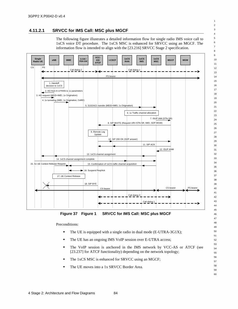
3GPP2 X.P0042-D v0.4
1
2
3
4
5
6
7
8
9
10
11
12
13
14
15
16
17
18
19
20
21
22
23
24
25
26
27
28
29
30
31
32
33
34
35
36
37
38
39
40
41
42
43
44
45
46
47
48
49
50
51
52
53
54
55
56
57
58
59
60
4 Stage 2: Architecture and Flow Diagrams 84
4.11.2.1 SRVCC for IMS Call: MSC plus MGCF
The following figure illustrates a detailed information flow for single radio IMS voice call to
1xCS voice DT procedure. The 1xCS MSC is enhanced for SRVCC using an MGCF. The
information flow is intended to align with the [23.216] SRVCC Stage 2 specification.
Single
Radio UEeNB
1xCS
MSCMGW
1. Handoff
decision to 1xCS
S-GW /
PDN GWI-CSCF
15. Confirmation of 1xCS traffic channel acquisition
CS
1xCS
RAN
10. SIP 200 OK (SDP answer)
11. SIP ACK
Call dialog 2
PS bearer
4. 1x tunneling (IMEI, 1x Origination, CellID)
5. S102/A21 transfer (MEID=IMEI, 1x Origination)
16. Suspend Req/Ack
17. UE Context Release
2. HO from E-UTRAN to 1x parameters
1xCS
IWS
PS
MME
VCC-
AS/
ATCF
Call dialog 1
3. HO request (MEID=IMEI, 1x Origination)
8. SIP INVITE (Request URI=STN-SR, IMEI, SDP-MGW)
6. 1x Traffic channel allocation
9. Remote Leg
Update
14. 1xCS channel assignment complete
13. 1xCS channel assignment
CS bearer CS bearer PS bearer
Call dialog 1
Call dialog 3
18. SIP BYE
MGCF
7. ISUP IAM (STN-SR)
12. ISUP ANM
15. S1 UE Context Release Request
Figure 37 Figure 1 SRVCC for IMS Call: MSC plus MGCF
Preconditions:
The UE is equipped with a single radio in dual mode (E-UTRA-3G1X);
The UE has an ongoing IMS VoIP session over E-UTRA access;
The VoIP session is anchored in the IMS network by VCC-AS or ATCF (see
[23.237] for ATCF functionality) depending on the network topology;
The 1xCS MSC is enhanced for SRVCC using an MGCF;
The UE moves into a 1x SRVCC Border Area.
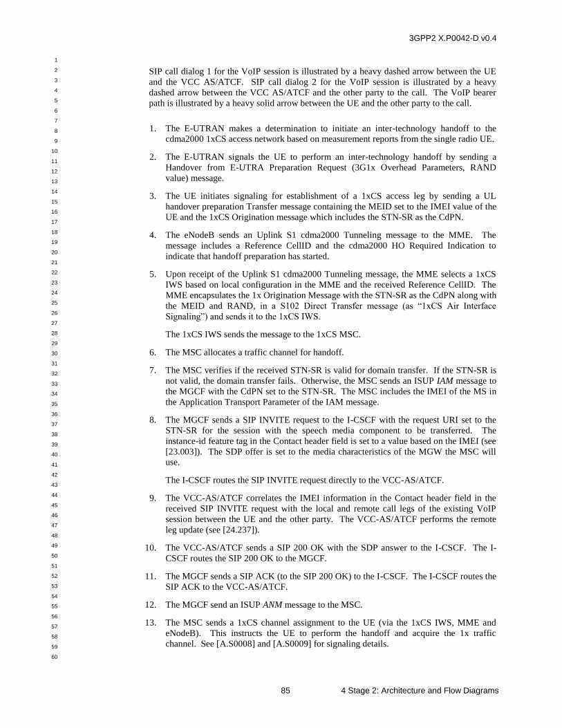
3GPP2 X.P0042-D v0.4
1
2
3
4
5
6
7
8
9
10
11
12
13
14
15
16
17
18
19
20
21
22
23
24
25
26
27
28
29
30
31
32
33
34
35
36
37
38
39
40
41
42
43
44
45
46
47
48
49
50
51
52
53
54
55
56
57
58
59
60
85 4 Stage 2: Architecture and Flow Diagrams
SIP call dialog 1 for the VoIP session is illustrated by a heavy dashed arrow between the UE
and the VCC AS/ATCF. SIP call dialog 2 for the VoIP session is illustrated by a heavy
dashed arrow between the VCC AS/ATCF and the other party to the call. The VoIP bearer
path is illustrated by a heavy solid arrow between the UE and the other party to the call.
1. The E-UTRAN makes a determination to initiate an inter-technology handoff to the
cdma2000 1xCS access network based on measurement reports from the single radio UE.
2. The E-UTRAN signals the UE to perform an inter-technology handoff by sending a
Handover from E-UTRA Preparation Request (3G1x Overhead Parameters, RAND
value) message.
3. The UE initiates signaling for establishment of a 1xCS access leg by sending a UL
handover preparation Transfer message containing the MEID set to the IMEI value of the
UE and the 1xCS Origination message which includes the STN-SR as the CdPN.
4. The eNodeB sends an Uplink S1 cdma2000 Tunneling message to the MME. The
message includes a Reference CellID and the cdma2000 HO Required Indication to
indicate that handoff preparation has started.
5. Upon receipt of the Uplink S1 cdma2000 Tunneling message, the MME selects a 1xCS
IWS based on local configuration in the MME and the received Reference CellID. The
MME encapsulates the 1x Origination Message with the STN-SR as the CdPN along with
the MEID and RAND, in a S102 Direct Transfer message (as “1xCS Air Interface
Signaling”) and sends it to the 1xCS IWS.
The 1xCS IWS sends the message to the 1xCS MSC.
6. The MSC allocates a traffic channel for handoff.
7. The MSC verifies if the received STN-SR is valid for domain transfer. If the STN-SR is
not valid, the domain transfer fails. Otherwise, the MSC sends an ISUP IAM message to
the MGCF with the CdPN set to the STN-SR. The MSC includes the IMEI of the MS in
the Application Transport Parameter of the IAM message.
8. The MGCF sends a SIP INVITE request to the I-CSCF with the request URI set to the
STN-SR for the session with the speech media component to be transferred. The
instance-id feature tag in the Contact header field is set to a value based on the IMEI (see
[23.003]). The SDP offer is set to the media characteristics of the MGW the MSC will
use.
The I-CSCF routes the SIP INVITE request directly to the VCC-AS/ATCF.
9. The VCC-AS/ATCF correlates the IMEI information in the Contact header field in the
received SIP INVITE request with the local and remote call legs of the existing VoIP
session between the UE and the other party. The VCC-AS/ATCF performs the remote
leg update (see [24.237]).
10. The VCC-AS/ATCF sends a SIP 200 OK with the SDP answer to the I-CSCF. The I-
CSCF routes the SIP 200 OK to the MGCF.
11. The MGCF sends a SIP ACK (to the SIP 200 OK) to the I-CSCF. The I-CSCF routes the
SIP ACK to the VCC-AS/ATCF.
12. The MGCF send an ISUP ANM message to the MSC.
13. The MSC sends a 1xCS channel assignment to the UE (via the 1xCS IWS, MME and
eNodeB). This instructs the UE to perform the handoff and acquire the 1x traffic
channel. See [A.S0008] and [A.S0009] for signaling details.
3GPP2 X.P0042-D v0.4
1
2
3
4
5
6
7
8
9
10
11
12
13
14
15
16
17
18
19
20
21
22
23
24
25
26
27
28
29
30
31
32
33
34
35
36
37
38
39
40
41
42
43
44
45
46
47
48
49
50
51
52
53
54
55
56
57
58
59
60
4 Stage 2: Architecture and Flow Diagrams 86
14. The UE acquires the 1xCS traffic channel and sends a 1xCS channel assignment
complete to the MSC. Step 13 and step 14 can happen anytime after Step 6.
15. The MME receives either an S1 UE Context Release Request (Cause) message indicating
the S1 release procedure is caused by handover from E-UTRAN to 1xCS, or a
confirmation of the 1xCS channel assignment from the MSC (via the 1xCS IWS).
16. The MME deactivates the PS bearers for the PS VoIP session.
17. The S1 UE Context in the eNodeB is released as specified in [23.401].
18. Any time after Step 11, the VCC-AS/ATCF sends a SIP BYE message to the UE to
release SIP call dialog 2 between the UE and the VCC-AS/ATCF. Note that since the
UE is already on a 1xCS traffic channel, it will not respond to this SIP BYE message.
Post-conditions:
A voice call is setup between the UE and the other party to the call via the 1xCS
MSC and the MGW.
SIP call dialog 1 for this voice call is illustrated by a heavy dashed arrow between
the UE and VCC-AS/ATCF.
SIP call dialog 3 for this voice call is illustrated by a heavy dashed arrow between
the VCC-AS/ATCF and the MGCF.
The voice bearer path is illustrated by heavy solid arrows connecting the UE, 1xCS
MSC, MGW and the other party to the call.
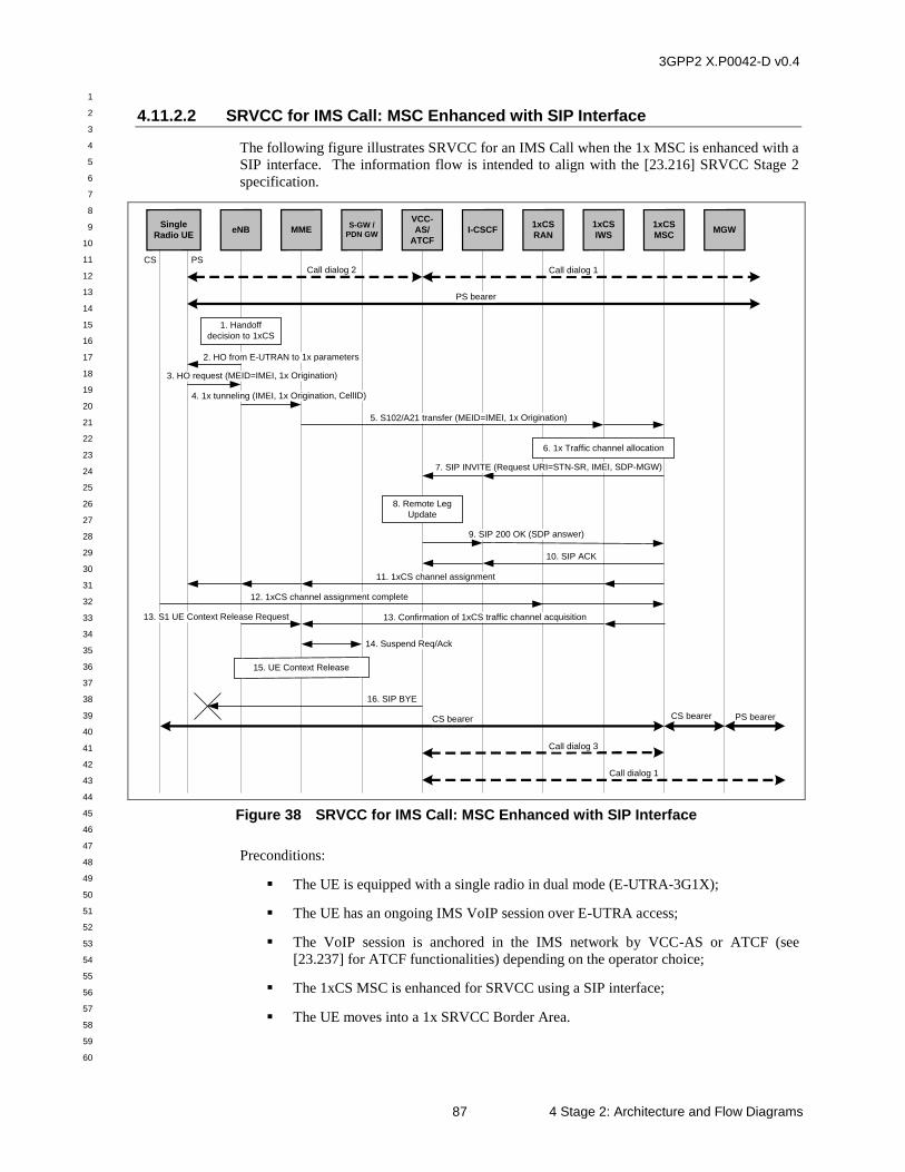
3GPP2 X.P0042-D v0.4
1
2
3
4
5
6
7
8
9
10
11
12
13
14
15
16
17
18
19
20
21
22
23
24
25
26
27
28
29
30
31
32
33
34
35
36
37
38
39
40
41
42
43
44
45
46
47
48
49
50
51
52
53
54
55
56
57
58
59
60
87 4 Stage 2: Architecture and Flow Diagrams
4.11.2.2 SRVCC for IMS Call: MSC Enhanced with SIP Interface
The following figure illustrates SRVCC for an IMS Call when the 1x MSC is enhanced with a
SIP interface. The information flow is intended to align with the [23.216] SRVCC Stage 2
specification.
Single
Radio UEeNB
1xCS
MSC
1. Handoff
decision to 1xCS
S-GW /
PDN GWI-CSCF
13. Confirmation of 1xCS traffic channel acquisition
CS
1xCS
RAN
9. SIP 200 OK (SDP answer)
10. SIP ACK
Call dialog 2
PS bearer
4. 1x tunneling (IMEI, 1x Origination, CellID)
5. S102/A21 transfer (MEID=IMEI, 1x Origination)
14. Suspend Req/Ack
15. UE Context Release
2. HO from E-UTRAN to 1x parameters
1xCS
IWS
PS
MME
VCC-
AS/
ATCF
Call dialog 1
3. HO request (MEID=IMEI, 1x Origination)
7. SIP INVITE (Request URI=STN-SR, IMEI, SDP-MGW)
6. 1x Traffic channel allocation
8. Remote Leg
Update
12. 1xCS channel assignment complete
11. 1xCS channel assignment
CS bearer CS bearer PS bearer
Call dialog 1
Call dialog 3
16. SIP BYE
MGW
13. S1 UE Context Release Request
Figure 38 SRVCC for IMS Call: MSC Enhanced with SIP Interface
Preconditions:
The UE is equipped with a single radio in dual mode (E-UTRA-3G1X);
The UE has an ongoing IMS VoIP session over E-UTRA access;
The VoIP session is anchored in the IMS network by VCC-AS or ATCF (see
[23.237] for ATCF functionalities) depending on the operator choice;
The 1xCS MSC is enhanced for SRVCC using a SIP interface;
The UE moves into a 1x SRVCC Border Area.
3GPP2 X.P0042-D v0.4
1
2
3
4
5
6
7
8
9
10
11
12
13
14
15
16
17
18
19
20
21
22
23
24
25
26
27
28
29
30
31
32
33
34
35
36
37
38
39
40
41
42
43
44
45
46
47
48
49
50
51
52
53
54
55
56
57
58
59
60
4 Stage 2: Architecture and Flow Diagrams 88
SIP call dialog 1 for the VoIP session is illustrated by a heavy dashed arrow between the VCC
AS/ATCF and the other party to the call. SIP call dialog 2 for the VoIP session is illustrated
by a heavy dashed arrow between the VCC AS/ATCF and the UE. The VoIP bearer path is
illustrated by a heavy solid arrow between the UE and the other party to the call.
1. The E-UTRAN makes a determination to initiate an inter-technology handoff to the
cdma2000 1xCS access network based on measurement reports from the single radio UE.
2. The E-UTRAN signals the UE to perform an inter-technology handoff by sending a
Handover from E-UTRA Preparation Request (3G1x Overhead Parameters, RAND
value) message.
3. The UE initiates signaling for establishment of a 1xCS access leg by sending a UL
handover preparation Transfer message containing the MEID set to the IMEI value of the
UE and the 1xCS Origination message which includes STN-SR as the CdPN.
4. The eNodeB sends an Uplink S1 cdma2000 Tunneling message to the MME. The
message includes a Reference CellID and the cdma2000 HO Required Indication to
indicate that handoff preparation has started.
5. Upon receipt of the Uplink S1 cdma2000 Tunneling message, the MME selects a 1xCS
IWS based on local configuration in the MME and the received Reference CellID. The
MME encapsulates the 1x Origination Message with STN-SR as the CdPN along with the
MEID and RAND in a S102 Direct Transfer message (as “1xCS Air Interface Signaling”)
and sends it to the 1xCS IWS.
The 1xCS IWS sends the message to the 1xCS MSC.
6. The MSC allocates a traffic channel for handoff.
7. The MSC verifies if the UE inserted STN-SR is valid for domain transfer. If the STN-SR
is not valid, the domain transfer fails. Otherwise, the MSC sends a SIP INVITE request
to the I-CSCF with the request URI set to the STN-SR for the session with speech media
component to be transferred. The instance-id feature tag in the Contact header field is set
to a value based on the IMEI (see [23.003]). The SDP offer is set to the media
characteristics of the MGW the MSC will use.
The I-CSCF routes the SIP INVITE request directly to the VCC AS/ATCF.
8. The VCC AS/ATCF correlates the IMEI information in the Contact header field in the
received SIP INVITE request with the local and remote call legs of the existing VoIP
session between the UE and the other party to the call. The VCC AS/ATCF performs the
remote leg update (see [24.237]).
9. The VCC-AS/ATCF sends a SIP 200 OK with the SDP answer to the I-CSCF. The I-
CSCF routes the SIP 200 OK to the MSC.
10. The MSC sends a SIP ACK (to the SIP 200 OK) to the I-CSCF. The I-CSCF routes the
SIP ACK to the VCC-AS/ATCF.
11. The MSC sends a 1xCS channel assignment to the UE (via the 1xCS IWS, MME and
eNodeB). This instructs the UE to perform the handoff and acquire the 1x traffic
channel. See [A.S0008] and [A.S0009] for signaling details.
12. The UE acquires the 1xCS traffic channel and sends a 1xCS channel assignment
complete to MSC. Step 11 and Step 12 may occur anytime after Step 6.
13. The MME receives either an S1 UE Context Release Request (Cause) message indicating
the S1 release procedure is caused by handover from E-UTRAN to 1xCS, or a
confirmation of the 1xCS channel assignment from the MSC (via the 1xCS IWS).
3GPP2 X.P0042-D v0.4
1
2
3
4
5
6
7
8
9
10
11
12
13
14
15
16
17
18
19
20
21
22
23
24
25
26
27
28
29
30
31
32
33
34
35
36
37
38
39
40
41
42
43
44
45
46
47
48
49
50
51
52
53
54
55
56
57
58
59
60
89 4 Stage 2: Architecture and Flow Diagrams
14. The MME deactivates the PS bearers for the PS VoIP session.
15. The S1 UE Context in the eNodeB is released as specified in [23.401].
16. Any time after Step 10, the VCC AS/ATCF sends a SIP BYE message to the UE to
release SIP call dialog 2 between the UE and the VSS AS/ATCF. Note that since the UE
is already on a 1xCS traffic channel, it will not respond to this SIP BYE message.
Post-conditions:
A voice call is setup between the UE and the other party to the call via the 1xCS
MSC and the MGW.
SIP call dialog 1 for this voice call is illustrated by a heavy dashed arrow between
the VCC AS/ATCF and the other party to the call.
SIP call dialog 3 for this voice call is illustrated by a heavy dashed arrow between
the VCC AS/ATCF and the 1xCS MSC.
The voice bearer path is illustrated by heavy solid arrows connecting the UE, 1xCS
MSC, MGW and the other party to the call.
4.12 Dual Radio Domain Transfer: Call Alerting to 1xCS
This section illustrates signaling flows for the domain transfer from IMS to CS for DRVCC
UE in alerting state. The signaling shown between the DRVCC UE and the MSC for the flows
in this section does not represent actual signaling messages. One should look to the
appropriate references to see the signaling details.
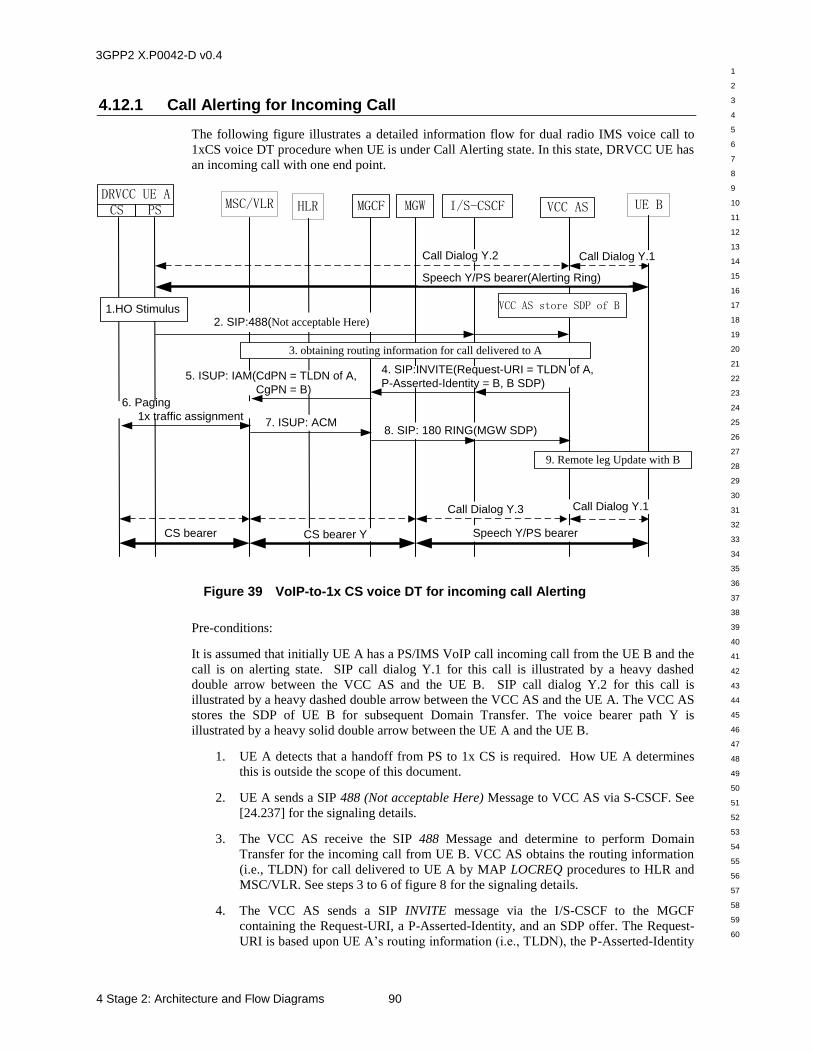
3GPP2 X.P0042-D v0.4
1
2
3
4
5
6
7
8
9
10
11
12
13
14
15
16
17
18
19
20
21
22
23
24
25
26
27
28
29
30
31
32
33
34
35
36
37
38
39
40
41
42
43
44
45
46
47
48
49
50
51
52
53
54
55
56
57
58
59
60
4 Stage 2: Architecture and Flow Diagrams 90
4.12.1 Call Alerting for Incoming Call
The following figure illustrates a detailed information flow for dual radio IMS voice call to
1xCS voice DT procedure when UE is under Call Alerting state. In this state, DRVCC UE has
an incoming call with one end point.
MSC/VLR MGCF VCC ASDRVCC UE ACS PS UE B
1.HO Stimulus
I/S-CSCFMGWHLR
Speech Y/PS bearer(Alerting Ring)
Call Dialog Y.2 Call Dialog Y.1
Speech Y/PS bearerCS bearer YCS bearer
Call Dialog Y.3 Call Dialog Y.1
2. SIP:488(Not acceptable Here)
4. SIP:INVITE(Request-URI = TLDN of A,
P-Asserted-Identity = B, B SDP)
8. SIP: 180 RING(MGW SDP)
5. ISUP: IAM(CdPN = TLDN of A,
CgPN = B) 6. Paging
1x traffic assignment7. ISUP: ACM
9. Remote leg Update with B
VCC AS store SDP of B
3. obtaining routing information for call delivered to A
Figure 39 VoIP-to-1x CS voice DT for incoming call Alerting
Pre-conditions:
It is assumed that initially UE A has a PS/IMS VoIP call incoming call from the UE B and the
call is on alerting state. SIP call dialog Y.1 for this call is illustrated by a heavy dashed
double arrow between the VCC AS and the UE B. SIP call dialog Y.2 for this call is
illustrated by a heavy dashed double arrow between the VCC AS and the UE A. The VCC AS
stores the SDP of UE B for subsequent Domain Transfer. The voice bearer path Y is
illustrated by a heavy solid double arrow between the UE A and the UE B.
1. UE A detects that a handoff from PS to 1x CS is required. How UE A determines
this is outside the scope of this document.
2. UE A sends a SIP 488 (Not acceptable Here) Message to VCC AS via S-CSCF. See
[24.237] for the signaling details.
3. The VCC AS receive the SIP 488 Message and determine to perform Domain
Transfer for the incoming call from UE B. VCC AS obtains the routing information
(i.e., TLDN) for call delivered to UE A by MAP LOCREQ procedures to HLR and
MSC/VLR. See steps 3 to 6 of figure 8 for the signaling details.
4. The VCC AS sends a SIP INVITE message via the I/S-CSCF to the MGCF
containing the Request-URI, a P-Asserted-Identity, and an SDP offer. The Request-
URI is based upon UE A’s routing information (i.e., TLDN), the P-Asserted-Identity
3GPP2 X.P0042-D v0.4
1
2
3
4
5
6
7
8
9
10
11
12
13
14
15
16
17
18
19
20
21
22
23
24
25
26
27
28
29
30
31
32
33
34
35
36
37
38
39
40
41
42
43
44
45
46
47
48
49
50
51
52
53
54
55
56
57
58
59
60
91 4 Stage 2: Architecture and Flow Diagrams
is the MDN of UE B, and the SDP offer is UE B’s SDP offer which is stored by
VCC AS when UE B initiates call to UE A. This is a new SIP call dialog Y.3
between UE A and the VCC AS.
5. The MGCF requests that the MGW be configured with an ephemeral termination to
be connected to UE B and a physical PCM trunk termination to be connected to the
MSC/VLR. The MGCF sends an ISUP IAM message to the MSC/VLR. The Called
Party Number field of the IAM is UE A’s routing information (i.e., TLDN).
6. The MSC/VLR pages UE A and assigns 1x traffic channel.
7. After the traffic channel is assigned, the MSC returns an ISUP ACM message to the
MGCF.
8. The MGCF sends a SIP 180 Ringing message to the I/S-CSCF. It contains the SDP
for the MGW ephemeral termination. The I/S-CSCF sends the 180 Ringing to the
VCC AS.
9. The VCC-AS performs the remote leg (SIP call dialog Y.1) update to UE B with the
SDP from MGW in step 8. See [24.237] for the signaling details.
Now the call between UE A and UE B is transferred from PS to 1x CS. There are CS bearer
from UE A to MGW and PS bearer from MGW to UE B. The UE A is on alerting state in 1x
CS.
Post-conditions:
There is an incoming call from UE B to UE A via the 1x CS network. SIP call dialog Y.1 for
this call is illustrated by a heavy dashed double arrow between the VCC AS and the UE B.
SIP call dialog Y.3 for this call is illustrated by a heavy dashed double arrow between the
VCC AS and the MGCF. For communication Y connection between UE A and UE B, there
are CS bearer from UE A to MGW and PS bearer from MGW to UE B. The UE A is on
alerting state in 1x CS.
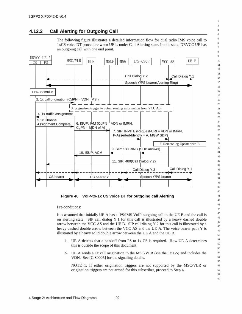
3GPP2 X.P0042-D v0.4
1
2
3
4
5
6
7
8
9
10
11
12
13
14
15
16
17
18
19
20
21
22
23
24
25
26
27
28
29
30
31
32
33
34
35
36
37
38
39
40
41
42
43
44
45
46
47
48
49
50
51
52
53
54
55
56
57
58
59
60
4 Stage 2: Architecture and Flow Diagrams 92
4.12.2 Call Alerting for Outgoing Call
The following figure illustrates a detailed information flow for dual radio IMS voice call to
1xCS voice DT procedure when UE is under Call Alerting state. In this state, DRVCC UE has
an outgoing call with one end point.
MSC/VLR MGCF VCC ASDRVCC UE ACS PS UE B
1.HO Stimulus
I/S-CSCF
8. Remote leg Update with B
MGWHLR
Speech Y/PS bearer(Alerting Ring)
Call Dialog Y.2 Call Dialog Y.1
2. 1x call origination (CdPN = VDN, IMSI)
3. origination trigger to obtain routing information from VCC AS
4. 1x traffic assignment
5.1x Channel
Assignment Complete 6. ISUP: IAM (CdPN = VDN or IMRN,
CgPN = MDN of A)7. SIP: INVITE (Request-URI = VDN or IMRN,
P-Asserted-Identity = A, MGW SDP)
9. SIP: 180 RING (SDP answer) 10. ISUP: ACM
11. SIP: 480(Call Dialog Y.2)
Speech Y/PS bearerCS bearer YCS bearer
Call Dialog Y.3 Call Dialog Y.1
Figure 40 VoIP-to-1x CS voice DT for outgoing call Alerting
Pre-conditions:
It is assumed that initially UE A has a PS/IMS VoIP outgoing call to the UE B and the call is
on alerting state. SIP call dialog Y.1 for this call is illustrated by a heavy dashed double
arrow between the VCC AS and the UE B. SIP call dialog Y.2 for this call is illustrated by a
heavy dashed double arrow between the VCC AS and the UE A. The voice bearer path Y is
illustrated by a heavy solid double arrow between the UE A and the UE B.
1- UE A detects that a handoff from PS to 1x CS is required. How UE A determines
this is outside the scope of this document.
2- UE A sends a 1x call origination to the MSC/VLR (via the 1x BS) and includes the
VDN. See [C.S0005] for the signaling details.
NOTE 1: If either origination triggers are not supported by the MSC/VLR or
origination triggers are not armed for this subscriber, proceed to Step 4.
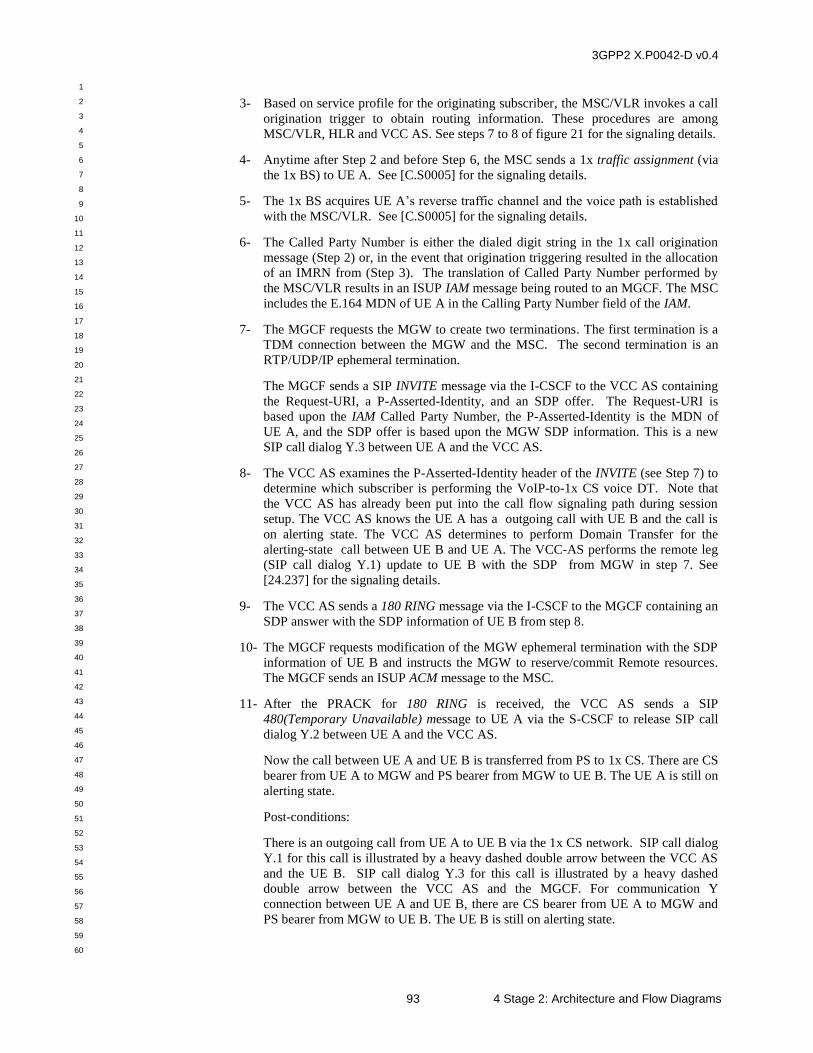
3GPP2 X.P0042-D v0.4
1
2
3
4
5
6
7
8
9
10
11
12
13
14
15
16
17
18
19
20
21
22
23
24
25
26
27
28
29
30
31
32
33
34
35
36
37
38
39
40
41
42
43
44
45
46
47
48
49
50
51
52
53
54
55
56
57
58
59
60
93 4 Stage 2: Architecture and Flow Diagrams
3- Based on service profile for the originating subscriber, the MSC/VLR invokes a call
origination trigger to obtain routing information. These procedures are among
MSC/VLR, HLR and VCC AS. See steps 7 to 8 of figure 21 for the signaling details.
4- Anytime after Step 2 and before Step 6, the MSC sends a 1x traffic assignment (via
the 1x BS) to UE A. See [C.S0005] for the signaling details.
5- The 1x BS acquires UE A’s reverse traffic channel and the voice path is established
with the MSC/VLR. See [C.S0005] for the signaling details.
6- The Called Party Number is either the dialed digit string in the 1x call origination
message (Step 2) or, in the event that origination triggering resulted in the allocation
of an IMRN from (Step 3). The translation of Called Party Number performed by
the MSC/VLR results in an ISUP IAM message being routed to an MGCF. The MSC
includes the E.164 MDN of UE A in the Calling Party Number field of the IAM.
7- The MGCF requests the MGW to create two terminations. The first termination is a
TDM connection between the MGW and the MSC. The second termination is an
RTP/UDP/IP ephemeral termination.
The MGCF sends a SIP INVITE message via the I-CSCF to the VCC AS containing
the Request-URI, a P-Asserted-Identity, and an SDP offer. The Request-URI is
based upon the IAM Called Party Number, the P-Asserted-Identity is the MDN of
UE A, and the SDP offer is based upon the MGW SDP information. This is a new
SIP call dialog Y.3 between UE A and the VCC AS.
8- The VCC AS examines the P-Asserted-Identity header of the INVITE (see Step 7) to
determine which subscriber is performing the VoIP-to-1x CS voice DT. Note that
the VCC AS has already been put into the call flow signaling path during session
setup. The VCC AS knows the UE A has a outgoing call with UE B and the call is
on alerting state. The VCC AS determines to perform Domain Transfer for the
alerting-state call between UE B and UE A. The VCC-AS performs the remote leg
(SIP call dialog Y.1) update to UE B with the SDP from MGW in step 7. See
[24.237] for the signaling details.
9- The VCC AS sends a 180 RING message via the I-CSCF to the MGCF containing an
SDP answer with the SDP information of UE B from step 8.
10- The MGCF requests modification of the MGW ephemeral termination with the SDP
information of UE B and instructs the MGW to reserve/commit Remote resources.
The MGCF sends an ISUP ACM message to the MSC.
11- After the PRACK for 180 RING is received, the VCC AS sends a SIP
480(Temporary Unavailable) message to UE A via the S-CSCF to release SIP call
dialog Y.2 between UE A and the VCC AS.
Now the call between UE A and UE B is transferred from PS to 1x CS. There are CS
bearer from UE A to MGW and PS bearer from MGW to UE B. The UE A is still on
alerting state.
Post-conditions:
There is an outgoing call from UE A to UE B via the 1x CS network. SIP call dialog
Y.1 for this call is illustrated by a heavy dashed double arrow between the VCC AS
and the UE B. SIP call dialog Y.3 for this call is illustrated by a heavy dashed
double arrow between the VCC AS and the MGCF. For communication Y
connection between UE A and UE B, there are CS bearer from UE A to MGW and
PS bearer from MGW to UE B. The UE B is still on alerting state.
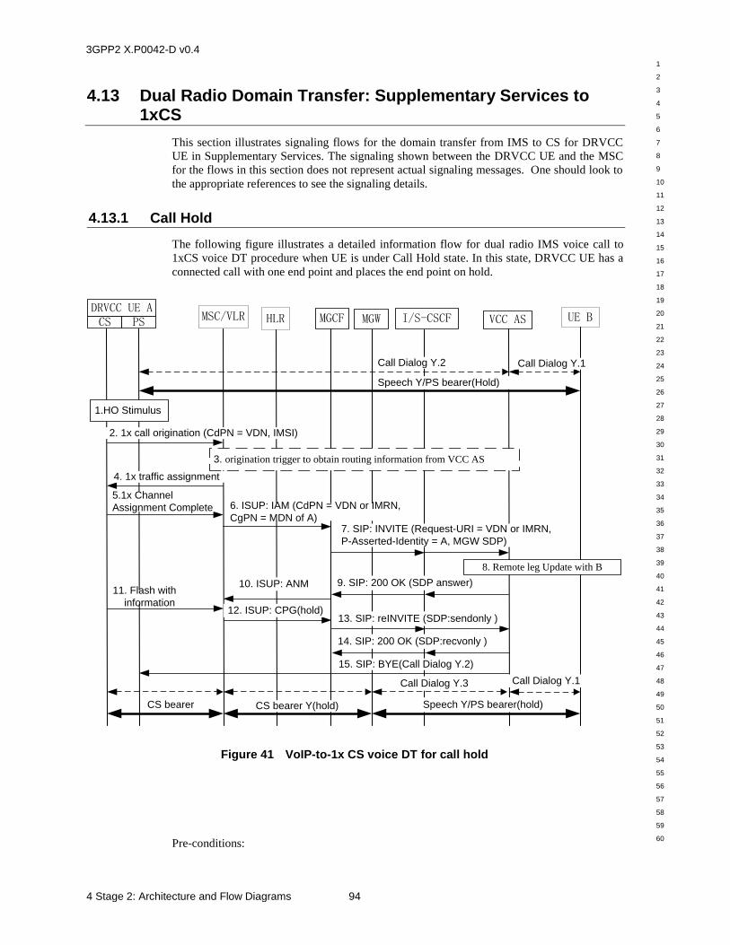
3GPP2 X.P0042-D v0.4
1
2
3
4
5
6
7
8
9
10
11
12
13
14
15
16
17
18
19
20
21
22
23
24
25
26
27
28
29
30
31
32
33
34
35
36
37
38
39
40
41
42
43
44
45
46
47
48
49
50
51
52
53
54
55
56
57
58
59
60
4 Stage 2: Architecture and Flow Diagrams 94
4.13 Dual Radio Domain Transfer: Supplementary Services to 1xCS
This section illustrates signaling flows for the domain transfer from IMS to CS for DRVCC
UE in Supplementary Services. The signaling shown between the DRVCC UE and the MSC
for the flows in this section does not represent actual signaling messages. One should look to
the appropriate references to see the signaling details.
4.13.1 Call Hold
The following figure illustrates a detailed information flow for dual radio IMS voice call to
1xCS voice DT procedure when UE is under Call Hold state. In this state, DRVCC UE has a
connected call with one end point and places the end point on hold.
MSC/VLR MGCF VCC ASDRVCC UE ACS PS UE B
1.HO Stimulus
I/S-CSCF
8. Remote leg Update with B
MGWHLR
Speech Y/PS bearer(Hold)
Call Dialog Y.2 Call Dialog Y.1
2. 1x call origination (CdPN = VDN, IMSI)
3. origination trigger to obtain routing information from VCC AS
4. 1x traffic assignment
5.1x Channel
Assignment Complete 6. ISUP: IAM (CdPN = VDN or IMRN,
CgPN = MDN of A)7. SIP: INVITE (Request-URI = VDN or IMRN,
P-Asserted-Identity = A, MGW SDP)
9. SIP: 200 OK (SDP answer) 10. ISUP: ANM
15. SIP: BYE(Call Dialog Y.2)
Speech Y/PS bearer(hold)CS bearer Y(hold)CS bearer
Call Dialog Y.3 Call Dialog Y.1
12. ISUP: CPG(hold)
11. Flash with
information
13. SIP: reINVITE (SDP:sendonly )
14. SIP: 200 OK (SDP:recvonly )
Figure 41 VoIP-to-1x CS voice DT for call hold
Pre-conditions:
3GPP2 X.P0042-D v0.4
1
2
3
4
5
6
7
8
9
10
11
12
13
14
15
16
17
18
19
20
21
22
23
24
25
26
27
28
29
30
31
32
33
34
35
36
37
38
39
40
41
42
43
44
45
46
47
48
49
50
51
52
53
54
55
56
57
58
59
60
95 4 Stage 2: Architecture and Flow Diagrams
It is assumed that initially UE A has a PS/IMS VoIP call with the UE B and then UE A places
the call on hold. SIP call dialog Y.1 for this call is illustrated by a heavy dashed double arrow
between the VCC AS and the UE B. SIP call dialog Y.2 for this call is illustrated by a heavy
dashed double arrow between the VCC AS and the UE A. The voice bearer path Y is
illustrated by a heavy solid double arrow between the UE A and the UE B.
1. UE A detects that a handoff from PS to 1x CS is required. How UE A determines
this is outside the scope of this document.
2. UE A sends a 1x call origination to the MSC/VLR (via the 1x BS) and includes the
VDN. See [C.S0005] for the signaling details.
NOTE 1: If either origination triggers are not supported by the MSC/VLR or
origination triggers are not armed for this subscriber, proceed to Step 4.
3. Based on service profile for the originating subscriber, the MSC/VLR invokes a call
origination trigger to obtain routing information. These procedures are among
MSC/VLR, HLR and VCC AS. See steps 7 to 8 of figure 21 for the signaling details.
4. Anytime after Step 2 and before Step 6, the MSC sends a 1x traffic assignment (via
the 1x BS) to UE A. See [C.S0005] for the signaling details.
5. The 1x BS acquires UE A’s reverse traffic channel and the voice path is established
with the MSC/VLR. See [C.S0005] for the signaling details.
6. The Called Party Number is either the dialed digit string in the 1x call origination
message (Step 2) or, in the event that origination triggering resulted in the allocation
of an IMRN from (Step 3). The translation of Called Party Number performed by
the MSC/VLR results in an ISUP IAM message being routed to an MGCF. The MSC
includes the E.164 MDN of UE A in the Calling Party Number field of the IAM.
7. The MGCF requests the MGW to create two terminations. The first termination is a
TDM connection between the MGW and the MSC. The second termination is an
RTP/UDP/IP ephemeral termination.
The MGCF sends a SIP INVITE message via the I-CSCF to the VCC AS containing
the Request-URI, a P-Asserted-Identity, and an SDP offer. The Request-URI is
based upon the IAM Called Party Number, the P-Asserted-Identity is the MDN of
UE A, and the SDP offer is based upon the MGW SDP information. This is a new
SIP call dialog Y.3 between UE A and the VCC AS.
8. The VCC AS examines the P-Asserted-Identity header of the INVITE (see Step 7) to
determine which subscriber is performing the VoIP-to-1x CS voice DT. Note that
the VCC AS has already been put into the call flow signaling path during session
setup. The VCC AS knows the UE A has a call with UE B and the call is on hold.
The VCC AS determines to perform Domain Transfer for the hold call between UE
B and UE A. The VCC-AS performs the remote leg (SIP call dialog Y.1) update to
UE B with the SDP from MGW in step 7. See [24.237] for the signaling details. The
remote leg update procedure keeps the UE B on hold.
9. The VCC AS sends a 200 OK message via the I-CSCF to the MGCF containing an
SDP answer with the SDP information of UE B from step 8.
10. The MGCF requests modification of the MGW ephemeral termination with the SDP
information of UE B and instructs the MGW to reserve/commit Remote resources.
The MGCF sends an ISUP ANM message to the MSC.
11. UE A automatically sends flash with information to MSC to hold the call with UE B.
3GPP2 X.P0042-D v0.4
1
2
3
4
5
6
7
8
9
10
11
12
13
14
15
16
17
18
19
20
21
22
23
24
25
26
27
28
29
30
31
32
33
34
35
36
37
38
39
40
41
42
43
44
45
46
47
48
49
50
51
52
53
54
55
56
57
58
59
60
4 Stage 2: Architecture and Flow Diagrams 96
12. The MSC sends an ISUP CPG message to MGCF. CPG message indicates hold the
call.
13. The MGCF sends a SIP reINVITE message via the I-CSCF to the VCC AS. The
attribute for SDP offer is sendonly which means the call is on hold.
14. The VCC AS return 200 OK message. The attribute for SDP answer is recvonly.
15. The VCC AS sends a SIP BYE message to UE A via the S-CSCF to release SIP call
dialog Y.2 between UE A and the VCC AS.
Now the call between UE A and UE B is transferred from PS to 1x CS. There are CS bearer
from UE A to MGW and PS bearer from MGW to UE B. The call state on MSC, UE A and
UE B is on hold.
Post-conditions:
There is a call between UE B and UE A via the 1x CS network. SIP call dialog Y.1 for this
call is illustrated by a heavy dashed double arrow between the VCC AS and the UE B. SIP
call dialog Y.3 for this call is illustrated by a heavy dashed double arrow between the VCC
AS and the MGCF. For communication Y connection between UE A and UE B, there are CS
bearer from UE A to MGW and PS bearer from MGW to UE B. The call is on hold.
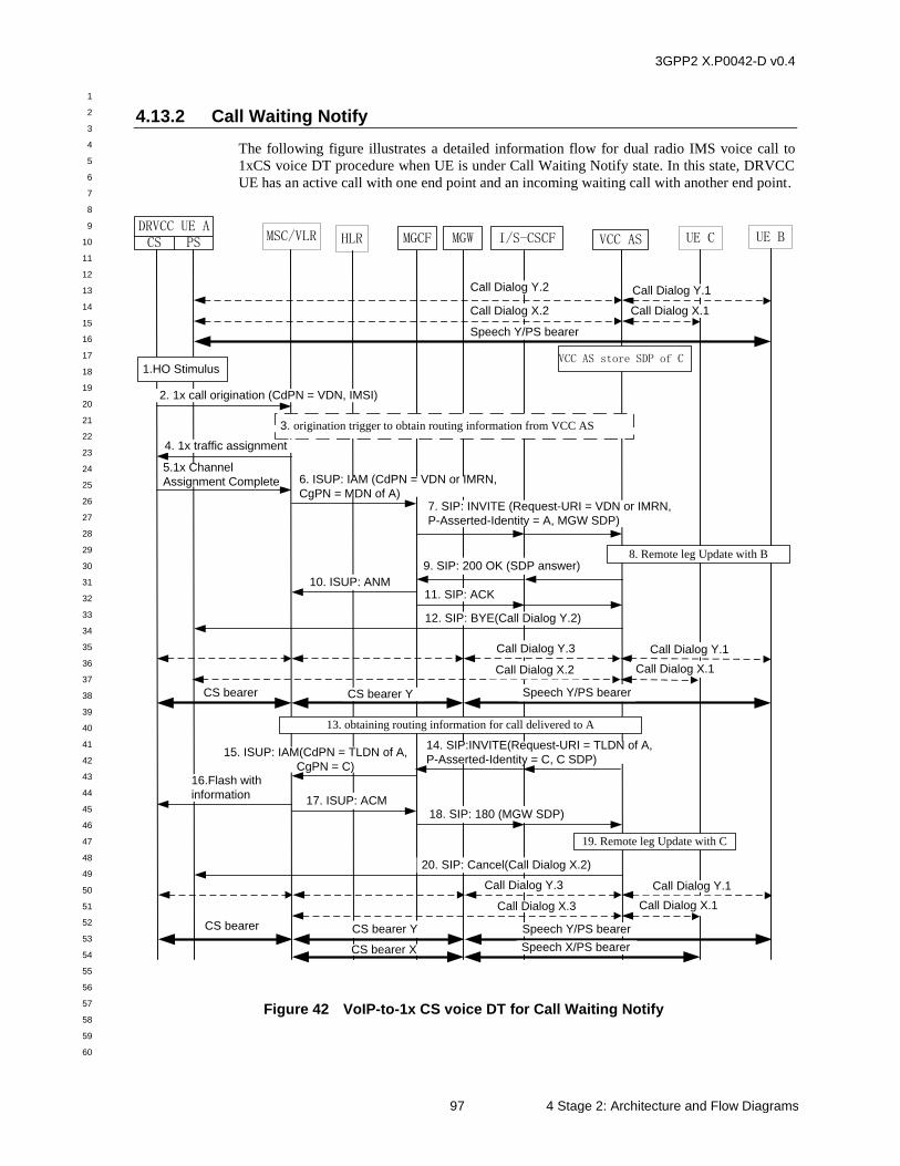
3GPP2 X.P0042-D v0.4
1
2
3
4
5
6
7
8
9
10
11
12
13
14
15
16
17
18
19
20
21
22
23
24
25
26
27
28
29
30
31
32
33
34
35
36
37
38
39
40
41
42
43
44
45
46
47
48
49
50
51
52
53
54
55
56
57
58
59
60
97 4 Stage 2: Architecture and Flow Diagrams
4.13.2 Call Waiting Notify
The following figure illustrates a detailed information flow for dual radio IMS voice call to
1xCS voice DT procedure when UE is under Call Waiting Notify state. In this state, DRVCC
UE has an active call with one end point and an incoming waiting call with another end point.
UE CMSC/VLR MGCF VCC ASDRVCC UE ACS PS UE B
1.HO Stimulus
I/S-CSCF
8. Remote leg Update with B
VCC AS store SDP of C
MGWHLR
Speech Y/PS bearer
Call Dialog Y.2
Call Dialog X.1
Call Dialog Y.1
2. 1x call origination (CdPN = VDN, IMSI)
3. origination trigger to obtain routing information from VCC AS
4. 1x traffic assignment
5.1x Channel
Assignment Complete 6. ISUP: IAM (CdPN = VDN or IMRN,
CgPN = MDN of A)7. SIP: INVITE (Request-URI = VDN or IMRN,
P-Asserted-Identity = A, MGW SDP)
Call Dialog X.2
9. SIP: 200 OK (SDP answer)
11. SIP: ACK 10. ISUP: ANM
12. SIP: BYE(Call Dialog Y.2)
Speech Y/PS bearerCS bearer YCS bearer
Call Dialog Y.3
Call Dialog X.1
Call Dialog Y.1
Call Dialog X.2
13. obtaining routing information for call delivered to A
14. SIP:INVITE(Request-URI = TLDN of A,
P-Asserted-Identity = C, C SDP)
18. SIP: 180 (MGW SDP)
15. ISUP: IAM(CdPN = TLDN of A,
CgPN = C) 16.Flash with
information17. ISUP: ACM
19. Remote leg Update with C
20. SIP: Cancel(Call Dialog X.2)
Speech Y/PS bearerCS bearer YCS bearer
Call Dialog Y.3
Call Dialog X.1
Call Dialog Y.1
Call Dialog X.3
Speech X/PS bearerCS bearer X
Figure 42 VoIP-to-1x CS voice DT for Call Waiting Notify
3GPP2 X.P0042-D v0.4
1
2
3
4
5
6
7
8
9
10
11
12
13
14
15
16
17
18
19
20
21
22
23
24
25
26
27
28
29
30
31
32
33
34
35
36
37
38
39
40
41
42
43
44
45
46
47
48
49
50
51
52
53
54
55
56
57
58
59
60
4 Stage 2: Architecture and Flow Diagrams 98
Pre-conditions:
It is assumed that initially there is a PS/IMS VoIP call connected between the UE A and the
UE B. SIP call dialog Y.1 for this call is illustrated by a heavy dashed double arrow between
the VCC AS and the UE B. SIP call dialog Y.2 for this call is illustrated by a heavy dashed
double arrow between the VCC AS and the UE A. The voice bearer path Y is illustrated by a
heavy solid double arrow between the UE A and the UE B.
During the communication between UE A and UE B, UE C initiates a call to UE A and then
UE A is notified with a waiting call from UE C. The call waiting service is controlled by IMS
and the VCC AS stores the SDP of UE C for subsequent Domain Transfer. SIP call dialog
X.1 for this call is illustrated by a heavy dashed double arrow between the VCC AS and the
UE C. SIP call dialog X.2 for this call is illustrated by a heavy dashed double arrow between
the VCC AS and the UE A. Because the call from UE C is on waiting, so there is not a voice
bearer between UE A and UE B.
1. UE A detects that a handoff from PS to 1x CS is required. How UE A determines
this is outside the scope of this document.
2. UE A sends a 1x call origination to the MSC/VLR (via the 1x BS) and includes the
VDN. See [C.S0005] for the signaling.
NOTE 1: If either origination triggers are not supported by the MSC/VLR or
origination triggers are not armed for this subscriber, proceed to Step 4.
3. Based on service profile for the originating subscriber, the MSC/VLR invokes a call
origination trigger to obtain routing information. These procedures are among
MSC/VLR, HLR and VCC AS. See steps 7 to 8 of figure 21 for the signaling details.
4. Anytime after Step 2 and before Step 6, the MSC sends a 1x traffic assignment (via
the 1x BS) to UE A. See [C.S0005] for the signaling.
5. The 1x BS acquires UE A’s reverse traffic channel and the voice path is established
with the MSC/VLR. See [C.S0005] for the signaling.
6. The Called Party Number is either the dialed digit string in the 1x call origination
message (Step 2) or, in the event that origination triggering resulted in the allocation
of an IMRN from (Step 3). The translation of Called Party Number performed by
the MSC/VLR results in an ISUP IAM message being routed to an MGCF. The MSC
includes the E.164 MDN of UE A in the Calling Party Number field of the IAM.
7. The MGCF requests the MGW to create two terminations. The first termination is a
TDM connection between the MGW and the MSC. The second termination is an
RTP/UDP/IP ephemeral termination.
The MGCF sends a SIP INVITE message via the I-CSCF to the VCC AS containing
the Request-URI, a P-Asserted-Identity, and an SDP offer. The Request-URI is
based upon the IAM Called Party Number, the P-Asserted-Identity is the MDN of
UE A, and the SDP offer is based upon the MGW SDP information. This is a new
SIP call dialog Y.3 between UE A and the VCC AS.
8. The VCC AS examines the P-Asserted-Identity header of the INVITE (see Step 7) to
determine which subscriber is performing the VoIP-to-1x CS voice DT. Note that
the VCC AS has already been put into the call flow signaling path during session
setup. The VCC AS knows the UE A have a connected call with UE B and a waiting
call from UE C. The VCC AS determines to perform Domain Transfer for the
connected call between UE B and UE A. The VCC-AS performs the remote leg (SIP
3GPP2 X.P0042-D v0.4
1
2
3
4
5
6
7
8
9
10
11
12
13
14
15
16
17
18
19
20
21
22
23
24
25
26
27
28
29
30
31
32
33
34
35
36
37
38
39
40
41
42
43
44
45
46
47
48
49
50
51
52
53
54
55
56
57
58
59
60
99 4 Stage 2: Architecture and Flow Diagrams
call dialog Y.1) update to UE B with the SDP from MGW in step 7. See [24.237] for
the signaling details.
9. The VCC AS sends a 200 OK message via the I-CSCF to the MGCF containing an
SDP answer with the SDP information of UE B from step 8.
10. The MGCF requests modification of the MGW ephemeral termination with the SDP
information of UE B and instructs the MGW to reserve/commit Remote resources.
The MGCF sends an ISUP ANM message to the MSC.
11. Anytime after the 200 OK is received, the MGCF sends a SIP ACK message via the
I-CSCF to the VCC AS. This completes the establishment of SIP call dialog Y.3
between the MGCF and the VCC AS. The VCC AS records the UE A as present in
the 1x CS domain.
12. The VCC AS sends a SIP BYE message to UE A via the S-CSCF to release SIP call
dialog Y.2 between UE A and the VCC AS.
Now the connected call between UE A and UE B is transferred from PS to 1x CS.
For communication Y connection, there are CS bearer from UE A to MGW and PS
bearer from MGW to UE B. UE A is communicating with UE B by the call on CS
bearer.
13. The VCC AS determine to perform Domain Transfer for the on waiting call between
UE C and UE A. VCC AS obtains the routing information (i.e., TLDN) for call
delivered to UE A by MAP LOCREQ procedures to HLR and MSC/VLR. See steps
3 to 6 of figure 8 for the signaling details.
14. The VCC AS sends a SIP INVITE message via the I/S-CSCF to the MGCF
containing the Request-URI, a P-Asserted-Identity, and an SDP offer. The Request-
URI is based upon UE A’s routing information (i.e., TLDN), the P-Asserted-Identity
is the MDN of UE C, and the SDP offer is UE C’s SDP offer which is stored by
VCC AS when UE C initiates call to UE A. This is a new SIP call dialog X.3
between UE A and the VCC AS.
15. The MGCF requests that the MGW be configured with an ephemeral termination to
be connected to UE C and a physical PCM trunk termination to be connected to the
MSC/VLR. The MGCF sends an ISUP IAM message to the MSC/VLR. The Calling
Party Number field of the IAM is the MDN of C.
16. The MSC/VLR knows there is already a connected call between UE A and UE B.
The MSC places the call from UE C on waiting and notify UE A with a flash with
information. Based on UE implementation, UE A may not play the notification tone
for call waiting.
17. The MSC returns an ISUP ACM message to the MGCF.
18. The MGCF sends a SIP 180 Ringing message to the I/S-CSCF. It contains the SDP
for the MGW ephemeral termination. The I/S-CSCF sends the 180 Ringing to the
VCC AS.
19. The VCC-AS performs the remote leg (SIP call dialog X.1) update to UE C with the
SDP from MGW in step 18. See [24.237] for the signaling details.
20. The VCC AS sends a SIP Cancel message to UE A via the S-CSCF to release SIP
call dialog X.2 between UE A and the VCC AS.
3GPP2 X.P0042-D v0.4
1
2
3
4
5
6
7
8
9
10
11
12
13
14
15
16
17
18
19
20
21
22
23
24
25
26
27
28
29
30
31
32
33
34
35
36
37
38
39
40
41
42
43
44
45
46
47
48
49
50
51
52
53
54
55
56
57
58
59
60
4 Stage 2: Architecture and Flow Diagrams 100
Post-conditions:
There is an active voice call connected between UE A and UE B via the 1x CS network. SIP
call dialog Y.1 for this call is illustrated by a heavy dashed double arrow between the VCC
AS and the UE B. SIP call dialog Y.3 for this call is illustrated by a heavy dashed double
arrow between the VCC AS and the MGCF. For communication Y connection between UE A
and UE B, there are CS bearer from UE A to MGW and PS bearer from MGW to UE B.
There is a waiting call between UE A and UE C via the 1x CS network. SIP call dialog X.1
for this voice call is illustrated by a heavy dashed double arrow between the VCC AS and the
UE C. SIP call dialog X.3 for this voice call is illustrated by a heavy dashed double arrow
between the VCC AS and the MGCF. For communication X connection between UE A and
UE C, there are CS bearer from MSC to MGW and PS bearer from MGW to UE C.
The Call Waiting service is controlled by MSC. If UE A wants to answer the call from C and
then switch the call between B and C, the MSC will perform the CS bearers switch between X
and Y.
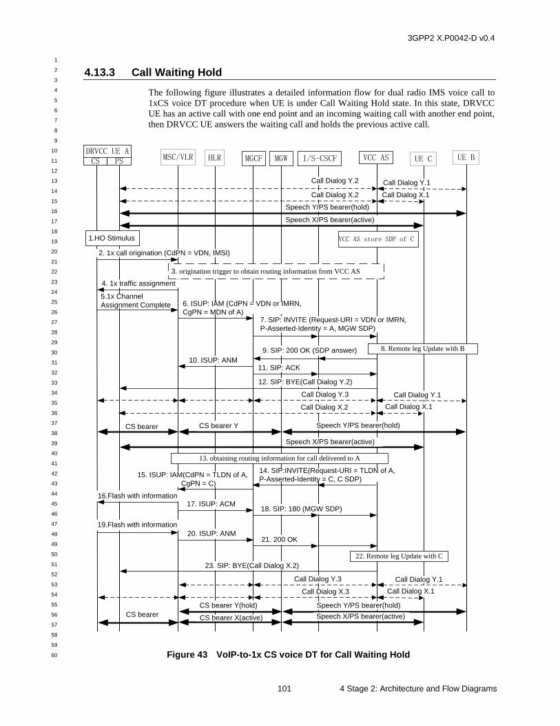
3GPP2 X.P0042-D v0.4
1
2
3
4
5
6
7
8
9
10
11
12
13
14
15
16
17
18
19
20
21
22
23
24
25
26
27
28
29
30
31
32
33
34
35
36
37
38
39
40
41
42
43
44
45
46
47
48
49
50
51
52
53
54
55
56
57
58
59
60
101 4 Stage 2: Architecture and Flow Diagrams
4.13.3 Call Waiting Hold
The following figure illustrates a detailed information flow for dual radio IMS voice call to
1xCS voice DT procedure when UE is under Call Waiting Hold state. In this state, DRVCC
UE has an active call with one end point and an incoming waiting call with another end point,
then DRVCC UE answers the waiting call and holds the previous active call.
UE CMSC/VLR MGCF VCC ASDRVCC UE ACS PS UE B
1.HO Stimulus
I/S-CSCF
8. Remote leg Update with B
VCC AS store SDP of C
MGWHLR
Speech X/PS bearer(active)
Call Dialog Y.2
Call Dialog X.1
Call Dialog Y.1
2. 1x call origination (CdPN = VDN, IMSI)
3. origination trigger to obtain routing information from VCC AS
4. 1x traffic assignment
5.1x Channel
Assignment Complete 6. ISUP: IAM (CdPN = VDN or IMRN,
CgPN = MDN of A)7. SIP: INVITE (Request-URI = VDN or IMRN,
P-Asserted-Identity = A, MGW SDP)
Call Dialog X.2
9. SIP: 200 OK (SDP answer)
11. SIP: ACK 10. ISUP: ANM
12. SIP: BYE(Call Dialog Y.2)
Call Dialog Y.3
Call Dialog X.1
Call Dialog Y.1
Call Dialog X.2
13. obtaining routing information for call delivered to A
14. SIP:INVITE(Request-URI = TLDN of A,
P-Asserted-Identity = C, C SDP)
18. SIP: 180 (MGW SDP)
15. ISUP: IAM(CdPN = TLDN of A,
CgPN = C)
16.Flash with information17. ISUP: ACM
22. Remote leg Update with C
23. SIP: BYE(Call Dialog X.2)
Speech Y/PS bearer(hold)CS bearer Y(hold)
CS bearer
Call Dialog Y.3
Call Dialog X.1
Call Dialog Y.1
Call Dialog X.3
Speech X/PS bearer(active)CS bearer X(active)
Speech X/PS bearer(active)
19.Flash with information
20. ISUP: ANM 21. 200 OK
Speech Y/PS bearer(hold)CS bearer YCS bearer
Speech Y/PS bearer(hold)
Figure 43 VoIP-to-1x CS voice DT for Call Waiting Hold
3GPP2 X.P0042-D v0.4
1
2
3
4
5
6
7
8
9
10
11
12
13
14
15
16
17
18
19
20
21
22
23
24
25
26
27
28
29
30
31
32
33
34
35
36
37
38
39
40
41
42
43
44
45
46
47
48
49
50
51
52
53
54
55
56
57
58
59
60
4 Stage 2: Architecture and Flow Diagrams 102
Pre-conditions:
It is assumed that initially there is a PS/IMS VoIP call connected between the UE A and the
UE B. SIP call dialog Y.1 for this call is illustrated by a heavy dashed double arrow between
the VCC AS and the UE B. SIP call dialog Y.2 for this call is illustrated by a heavy dashed
double arrow between the VCC AS and the UE A. During the communication between UE A
and UE B, UE C initiates a call to UE A and then UE A is notified with a waiting call from
UE C. The call waiting service is controlled by IMS and the VCC AS stores the SDP of UE C
for subsequent Domain Transfer. SIP call dialog X.1 for this call is illustrated by a heavy
dashed double arrow between the VCC AS and the UE C. SIP call dialog X.2 for this call is
illustrated by a heavy dashed double arrow between the VCC AS and the UE A. UE A
answers the waiting call from UE C, and holds the call to UE B. The voice bearer path X
which is active is illustrated by a heavy solid double arrow between the UE A and the UE C.
The voice bearer path Y which is held is illustrated by a heavy solid double arrow between the
UE A and the UE B.
1. UE A detects that a handoff from PS to 1x CS is required. How UE A determines
this is outside the scope of this document.
2. UE A sends a 1x call origination to the MSC/VLR (via the 1x BS) and includes the
VDN. See [C.S0005] for the signaling details.
NOTE 1: If either origination triggers are not supported by the MSC/VLR or
origination triggers are not armed for this subscriber, proceed to Step 4.
3. Based on service profile for the originating subscriber, the MSC/VLR invokes a call
origination trigger to obtain routing information. These procedures are among
MSC/VLR, HLR and VCC AS. See steps 7 to 8 of figure 21 for the signaling details.
4. Anytime after Step 2 and before Step 6, the MSC sends a 1x traffic assignment (via
the 1x BS) to UE A. See [C.S0005] for the signaling details.
5. The 1x BS acquires UE A’s reverse traffic channel and the voice path is established
with the MSC/VLR. See [C.S0005] for the signaling details.
6. The Called Party Number is either the dialed digit string in the 1x call origination
message (Step 2) or, in the event that origination triggering resulted in the allocation
of an IMRN from (Step 3). The translation of Called Party Number performed by
the MSC/VLR results in an ISUP IAM message being routed to an MGCF. The MSC
includes the E.164 MDN of UE A in the Calling Party Number field of the IAM.
7. The MGCF requests the MGW to create two terminations. The first termination is a
TDM connection between the MGW and the MSC. The second termination is an
RTP/UDP/IP ephemeral termination.
The MGCF sends a SIP INVITE message via the I-CSCF to the VCC AS containing
the Request-URI, a P-Asserted-Identity, and an SDP offer. The Request-URI is
based upon the IAM Called Party Number, the P-Asserted-Identity is the MDN of
UE A, and the SDP offer is based upon the MGW SDP information. This is a new
SIP call dialog Y.3 between UE A and the VCC AS.
8. The VCC AS examines the P-Asserted-Identity header of the INVITE (see Step 7) to
determine which subscriber is performing the VoIP-to-1x CS voice DT. Note that
the VCC AS has already been put into the call flow signaling path during session
setup. The VCC AS knows the UE A has held the call with UE B and answered the
call from UE C. The VCC AS determines to perform Domain Transfer for the hold
call between UE B and UE A. The VCC-AS performs the remote leg (SIP call dialog
3GPP2 X.P0042-D v0.4
1
2
3
4
5
6
7
8
9
10
11
12
13
14
15
16
17
18
19
20
21
22
23
24
25
26
27
28
29
30
31
32
33
34
35
36
37
38
39
40
41
42
43
44
45
46
47
48
49
50
51
52
53
54
55
56
57
58
59
60
103 4 Stage 2: Architecture and Flow Diagrams
Y.1) update to UE B with the SDP from MGW in step 7. See [24.237] for the
signaling details. The remote leg update procedure keeps the UE B on hold.
9. The VCC AS sends a 200 OK message via the I-CSCF to the MGCF containing an
SDP answer with the SDP information of UE B from step 8.
10. The MGCF requests modification of the MGW ephemeral termination with the SDP
information of UE B and instructs the MGW to reserve/commit Remote resources.
The MGCF sends an ISUP ANM message to the MSC.
11. Anytime after the 200 OK is received, the MGCF sends a SIP ACK message via the
I-CSCF to the VCC AS. This completes the establishment of SIP call dialog Y.3
between the MGCF and the VCC AS. The VCC AS records the UE A as present in
the 1x CS domain.
12. The VCC AS sends a SIP BYE message to UE A via the S-CSCF to release SIP call
dialog Y.2 between UE A and the VCC AS.
Now the call between UE A and UE B is transferred from PS to 1x CS. For
communication Y connection, there are CS bearer from UE A to MGW and PS
bearer from MGW to UE B. UE A is still communicating with UE C by the active
call on PS bearer.
13. The VCC AS determine to perform Domain Transfer for the active call between UE
C and UE A. VCC AS obtains the routing information (i.e., TLDN) for call delivered
to UE A by MAP LOCREQ procedures to HLR and MSC/VLR. See steps 3 to 6 of
figure 8 for the signaling details.
14. The VCC AS sends a SIP INVITE message via the I/S-CSCF to the MGCF
containing the Request-URI, a P-Asserted-Identity, and an SDP offer. The Request-
URI is based upon UE A’s routing information (i.e., TLDN), the P-Asserted-Identity
is the MDN of UE C, and the SDP offer is UE C’s SDP offer which is stored by
VCC AS when UE C initiates call to UE A. This is a new SIP call dialog X.3
through MGCF between UE A and the VCC AS.
15. The MGCF requests that the MGW be configured with an ephemeral termination to
be connected to UE C and a physical PCM trunk termination to be connected to the
MSC/VLR. The MGCF sends an ISUP IAM message to the MSC/VLR. The Calling
Party Number field of the IAM is the MDN of C.
16. The MSC/VLR knows there is already a call between UE A and UE B. The MSC
places the call from UE C on waiting and notify UE A with a flash with information.
17. The MSC returns an ISUP ACM message to the MGCF.
18. The MGCF sends a SIP 180 Ringing message to the I/S-CSCF. It contains the SDP
for the MGW ephemeral termination. The I/S-CSCF sends the 180 Ringing to the
VCC AS.
19. After receives flash with information at step 16, UE A automatically answers with
flash with information to MSC to connect the call from UE C and hold the call from
UE B. Then UE A changes the communication from PS bearer to CS bearer.
20. The MSC returns an ISUP ANM message to the MGCF, connects UE A and UE C,
places UE B on hold.
21. The MGCF sends a 200 OK message to the I/S-CSCF. The I/S-CSCF sends the 200
OK message to the VCC AS.
3GPP2 X.P0042-D v0.4
1
2
3
4
5
6
7
8
9
10
11
12
13
14
15
16
17
18
19
20
21
22
23
24
25
26
27
28
29
30
31
32
33
34
35
36
37
38
39
40
41
42
43
44
45
46
47
48
49
50
51
52
53
54
55
56
57
58
59
60
4 Stage 2: Architecture and Flow Diagrams 104
22. The VCC-AS performs the remote leg (SIP call dialog X.1) update to UE C with the
SDP from MGW in step 18. See [24.237] for the signaling details.
23. The VCC AS sends a SIP BYE message to UE A via the S-CSCF to release SIP call
dialog X.2 between UE A and the VCC AS.
Post-conditions:
There is a held voice call between UE A and UE B via the 1x CS network. SIP call dialog
Y.1 for this call is illustrated by a heavy dashed double arrow between the VCC AS and the
UE B. SIP call dialog Y.3 for this call is illustrated by a heavy dashed double arrow between
the VCC AS and MGCF. For communication Y connection between UE A and UE B, there
are CS bearer from MSC to MGW and PS bearer from MGW to UE B.
There is an active call between UE A and UE C via the 1x CS network. SIP call dialog X.1
for this voice call is illustrated by a heavy dashed double arrow between the VCC AS and the
UE C. SIP call dialog X.3 for this voice call is illustrated by a heavy dashed double arrow
between the VCC AS and the MGCF. For communication X connection between UE A and
UE C, there are CS bearer from UE A to MGW and PS bearer from MGW to UE C.
The Call Waiting service is controlled by MSC. If UE A wants to switch the call between B
and C, the MSC will perform the CS bearers switch between X and Y.
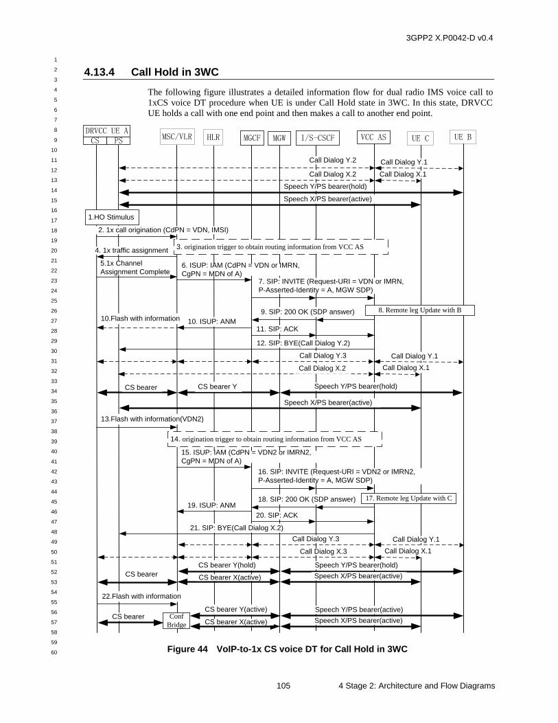
3GPP2 X.P0042-D v0.4
1
2
3
4
5
6
7
8
9
10
11
12
13
14
15
16
17
18
19
20
21
22
23
24
25
26
27
28
29
30
31
32
33
34
35
36
37
38
39
40
41
42
43
44
45
46
47
48
49
50
51
52
53
54
55
56
57
58
59
60
105 4 Stage 2: Architecture and Flow Diagrams
4.13.4 Call Hold in 3WC
The following figure illustrates a detailed information flow for dual radio IMS voice call to
1xCS voice DT procedure when UE is under Call Hold state in 3WC. In this state, DRVCC
UE holds a call with one end point and then makes a call to another end point.
UE CMSC/VLR MGCF VCC ASDRVCC UE ACS PS UE B
1.HO Stimulus
I/S-CSCF
8. Remote leg Update with B
MGWHLR
Speech X/PS bearer(active)
Call Dialog Y.2
Call Dialog X.1
Call Dialog Y.1
2. 1x call origination (CdPN = VDN, IMSI)
14. origination trigger to obtain routing information from VCC AS
4. 1x traffic assignment
5.1x Channel
Assignment Complete6. ISUP: IAM (CdPN = VDN or IMRN,
CgPN = MDN of A)7. SIP: INVITE (Request-URI = VDN or IMRN,
P-Asserted-Identity = A, MGW SDP)
Call Dialog X.2
9. SIP: 200 OK (SDP answer)
11. SIP: ACK 10. ISUP: ANM
12. SIP: BYE(Call Dialog Y.2)
Call Dialog Y.3
Call Dialog X.1
Call Dialog Y.1
Call Dialog X.2
21. SIP: BYE(Call Dialog X.2)
Speech Y/PS bearer(hold)CS bearer Y(hold)
CS bearer
Call Dialog Y.3
Call Dialog X.1
Call Dialog Y.1
Call Dialog X.3
Speech X/PS bearer(active)CS bearer X(active)
Speech X/PS bearer(active)
Speech Y/PS bearer(hold)CS bearer YCS bearer
Speech Y/PS bearer(hold)
13.Flash with information(VDN2)
17. Remote leg Update with C
15. ISUP: IAM (CdPN = VDN2 or IMRN2,
CgPN = MDN of A)
16. SIP: INVITE (Request-URI = VDN2 or IMRN2,
P-Asserted-Identity = A, MGW SDP)
18. SIP: 200 OK (SDP answer)
20. SIP: ACK
19. ISUP: ANM
3. origination trigger to obtain routing information from VCC AS
10.Flash with information
22.Flash with information
Speech Y/PS bearer(active)CS bearer Y(active)CS bearer
Speech X/PS bearer(active)CS bearer X(active)Conf
Bridge
Figure 44 VoIP-to-1x CS voice DT for Call Hold in 3WC
3GPP2 X.P0042-D v0.4
1
2
3
4
5
6
7
8
9
10
11
12
13
14
15
16
17
18
19
20
21
22
23
24
25
26
27
28
29
30
31
32
33
34
35
36
37
38
39
40
41
42
43
44
45
46
47
48
49
50
51
52
53
54
55
56
57
58
59
60
4 Stage 2: Architecture and Flow Diagrams 106
Pre-conditions:
It is assumed that initially there is a PS/IMS VoIP call connected between the UE A and the
UE B. SIP call dialog Y.1 for this call is illustrated by a heavy dashed double arrow between
the VCC AS and the UE B. SIP call dialog Y.2 for this call is illustrated by a heavy dashed
double arrow between the VCC AS and the UE A. During the communication between UE A
and UE B, UE A initiates 3WC call to let UE C join. UE A holds the call with UE B, and then
calls UE C. SIP call dialog X.1 for this call is illustrated by a heavy dashed double arrow
between the VCC AS and the UE C. SIP call dialog X.2 for this call is illustrated by a heavy
dashed double arrow between the VCC AS and the UE A. The voice bearer path X which is
active is illustrated by a heavy solid double arrow between the UE A and the UE C. The voice
bearer path Y which is held is illustrated by a heavy solid double arrow between the UE A
and the UE B. The 3WC call service is controlled by IMS and the VCC AS knows the state
during the call.
1. UE A detects that a handoff from PS to 1x CS is required. How UE A determines
this is outside the scope of this document.
2. UE A sends a 1x call origination to the MSC/VLR (via the 1x BS) and includes the
VDN. See [C.S0005] for the signaling details.
NOTE 1: If either origination triggers are not supported by the MSC/VLR or
origination triggers are not armed for this subscriber, proceed to Step 4.
3. Based on service profile for the originating subscriber, the MSC/VLR invokes a call
origination trigger to obtain routing information. These procedures are among
MSC/VLR, HLR and VCC AS. See steps 7 to 8 of figure 21 for the signaling details.
4. Anytime after Step 2 and before Step 6, the MSC sends a 1x traffic assignment (via
the 1x BS) to UE A. See [C.S0005] for the signaling details.
5. The 1x BS acquires UE A’s reverse traffic channel and the voice path is established
with the MSC/VLR. See [C.S0005] for the signaling details.
6. The Called Party Number is either the dialed digit string in the 1x call origination
message (Step 2) or, in the event that origination triggering resulted in the allocation
of an IMRN from (Step 3). The translation of Called Party Number performed by
the MSC/VLR results in an ISUP IAM message being routed to an MGCF. The MSC
includes the E.164 MDN of UE A in the Calling Party Number field of the IAM.
7. The MGCF requests the MGW to create two terminations. The first termination is a
TDM connection between the MGW and the MSC. The second termination is an
RTP/UDP/IP ephemeral termination.
The MGCF sends a SIP INVITE message via the I-CSCF to the VCC AS containing
the Request-URI, a P-Asserted-Identity, and an SDP offer. The Request-URI is
based upon the IAM Called Party Number, the P-Asserted-Identity is the MDN of
UE A, and the SDP offer is based upon the MGW SDP information. This is a new
SIP call dialog Y.3 between UE A and the VCC AS.
8. The VCC AS examines the P-Asserted-Identity header of the INVITE (see Step 7) to
determine which subscriber is performing the VoIP-to-1x CS voice DT. Note that
the VCC AS has already been put into the call flow signaling path during session
setup. The VCC AS knows the UE A has held the call with UE B and made a call to
UE C. The VCC AS determines to perform Domain Transfer for the hold call
between UE B and UE A. The VCC-AS performs the remote leg (SIP call dialog
Y.1) update to UE B with the SDP from MGW in step 7. See [24.237] for the
signaling details. The remote leg update procedure keeps the UE B on hold.
3GPP2 X.P0042-D v0.4
1
2
3
4
5
6
7
8
9
10
11
12
13
14
15
16
17
18
19
20
21
22
23
24
25
26
27
28
29
30
31
32
33
34
35
36
37
38
39
40
41
42
43
44
45
46
47
48
49
50
51
52
53
54
55
56
57
58
59
60
107 4 Stage 2: Architecture and Flow Diagrams
9. The VCC AS sends a 200 OK message via the I-CSCF to the MGCF containing an
SDP answer with the SDP information of UE B from step 8.
10. The MGCF requests modification of the MGW ephemeral termination with the SDP
information of UE B and instructs the MGW to reserve/commit Remote resources.
The MGCF sends an ISUP ANM message to the MSC. Depend on network
configuration, the MSC may send a 1x Flash with information to DRVCC UA for
notifying the connection of the call.
11. Anytime after the 200 OK is received, the MGCF sends a SIP ACK message via the
I-CSCF to the VCC AS. This completes the establishment of SIP call dialog Y.3
between the MGCF and the VCC AS.
12. The VCC AS sends a SIP BYE message to UE A via the S-CSCF to release SIP call
dialog Y.2 between UE A and the VCC AS.
Now the call between UE A and UE B is transferred from PS to 1x CS. For
communication Y connection, there are CS bearer from UE A to MGW and PS
bearer from MGW to UE B. UE A is still communicating with UE C by the active
call on PS bearer.
13. After receiving Flash with information from 1x at step 10 or SIP BYE message at
step12, UE A sends a 1x Flash with information to the MSC/VLR including the
VDN2 to hold the previous call and make a new call. The VDN2 is different from
VDN.
NOTE 2: If either origination triggers are not supported by the MSC/VLR or
origination triggers are not armed for this subscriber, proceed to step 15.
14. Based on service profile for the originating subscriber, the MSC/VLR invokes a call
origination trigger to obtain routing information. These procedures are among
MSC/VLR, HLR and VCC AS. See steps 7 to 8 of figure 21 for the signaling details.
15. The Called Party Number is either the dialed digit string in the 1x Flash with
information message (Step 13) or, in the event that origination triggering resulted in
the allocation of an IMRN2 from (Step 14). The translation of Called Party Number
performed by the MSC/VLR results in an ISUP IAM message being routed to an
MGCF. The MSC includes the E.164 MDN of UE A in the Calling Party Number
field of the IAM.
16. The MGCF requests the MGW to create two terminations. The first termination is a
TDM connection between the MGW and the MSC. The second termination is an
RTP/UDP/IP ephemeral termination.
The MGCF sends a SIP INVITE message via the I-CSCF to the VCC AS containing
the Request-URI, a P-Asserted-Identity, and an SDP offer. The Request-URI is
based upon the IAM Called Party Number, the P-Asserted-Identity is the MDN of
UE A, and the SDP offer is based upon the MGW SDP information. This is a new
SIP call dialog Y.3 between UE A and the VCC AS.
17. The VCC AS examines the P-Asserted-Identity header of the INVITE (see Step 16)
to determine which subscriber is performing the VoIP-to-1x CS voice DT. Note that
the VCC AS has already been put into the call flow signaling path during session
setup. The VCC AS knows the UE A has held the call with UE B and made a call to
UE C, and the call between UE A and UE B is already transferred to CS domain. The
VCC AS determines to perform Domain Transfer for the active call between UE C
and UE A. The VCC-AS performs the remote leg (SIP call dialog X.1) update to UE
C with the SDP from MGW in step 16. See [24.237] for the signaling details.
3GPP2 X.P0042-D v0.4
1
2
3
4
5
6
7
8
9
10
11
12
13
14
15
16
17
18
19
20
21
22
23
24
25
26
27
28
29
30
31
32
33
34
35
36
37
38
39
40
41
42
43
44
45
46
47
48
49
50
51
52
53
54
55
56
57
58
59
60
4 Stage 2: Architecture and Flow Diagrams 108
18. The VCC AS sends a 200 OK message via the I-CSCF to the MGCF containing an
SDP answer with the SDP information of UE C from step 17.
NOTE 3: It is assumed UE C has answered the call from UE A. If UE C is on
alerting state, the VCC AS sends a 180 RING message.
19. The MGCF requests modification of the MGW ephemeral termination with the SDP
information of UE C and instructs the MGW to reserve/commit Remote resources.
The MGCF sends an ISUP ANM message to the MSC.
20. Anytime after the 200 OK is received, the MGCF sends a SIP ACK message via the
I-CSCF to the VCC AS. This completes the establishment of SIP call dialog X.3
between the MGCF and the VCC AS. The VCC AS records the UE A as present in
the 1x CS domain.
21. The VCC AS sends a SIP BYE message to UE A via the S-CSCF to release SIP call
dialog X.2 between UE A and the VCC AS.
Post-conditions:
There is a held voice call between UE A and UE B via the 1x CS network. SIP call dialog
Y.1 for this call is illustrated by a heavy dashed double arrow between the VCC AS and the
UE B. SIP call dialog Y.3 for this call is illustrated by a heavy dashed double arrow between
the VCC AS and MGCF. For communication Y connection between UE A and UE B, there
are CS bearer from MSC to MGW and PS bearer from MGW to UE B.
There is an active call between UE A and UE C via the 1x CS network. SIP call dialog X.1
for this voice call is illustrated by a heavy dashed double arrow between the VCC AS and the
UE C. SIP call dialog X.3 for this voice call is illustrated by a heavy dashed double arrow
between the VCC AS and the MGCF. For communication X connection between UE A and
UE C, there are CS bearer from UE A to MGW and PS bearer from MGW to UE C.
After DT, the 3WC service is controlled by MSC. If UE A sends a Flash with information
(Step 22), the MSC shall set UE B active, then connect UE A, UE B and UE C in a
conference bridge.
4.13.5 3WC
When DRVCC UE is in 3WC conference with two end points, there are two options to
perform DT from IMS to CS domain.
option1: Transfer 3WC service from IMS to CS and then 3WC service is controlled
by MSC.
The two call legs are transferred one by one from IMS to CS. The detailed call flow
is similar with the call flow at 4.13.4. After the two call legs are transferred, the
DRVCC UE automatically sends a Flash with information (Step 22), then the MSC
connects DRVCC UE and the two end points in a conference bridge.
option2: Transfer DRVCC UE from IMS to 1x and then 3WC service is still
controlled by IMS.
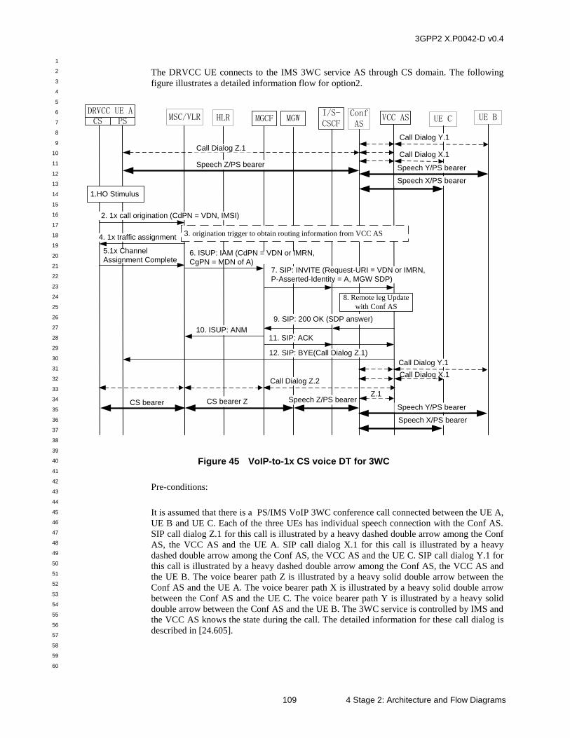
3GPP2 X.P0042-D v0.4
1
2
3
4
5
6
7
8
9
10
11
12
13
14
15
16
17
18
19
20
21
22
23
24
25
26
27
28
29
30
31
32
33
34
35
36
37
38
39
40
41
42
43
44
45
46
47
48
49
50
51
52
53
54
55
56
57
58
59
60
109 4 Stage 2: Architecture and Flow Diagrams
The DRVCC UE connects to the IMS 3WC service AS through CS domain. The following
figure illustrates a detailed information flow for option2.
UE CMSC/VLR MGCF VCC ASDRVCC UE ACS PS UE B
1.HO Stimulus
I/S-CSCF
MGWHLR
Speech Z/PS bearer
Call Dialog X.1
Call Dialog Y.1
2. 1x call origination (CdPN = VDN, IMSI)
4. 1x traffic assignment
5.1x Channel
Assignment Complete6. ISUP: IAM (CdPN = VDN or IMRN,
CgPN = MDN of A)7. SIP: INVITE (Request-URI = VDN or IMRN,
P-Asserted-Identity = A, MGW SDP)
9. SIP: 200 OK (SDP answer)
11. SIP: ACK 10. ISUP: ANM
12. SIP: BYE(Call Dialog Z.1)
CS bearer ZCS bearer
3. origination trigger to obtain routing information from VCC AS
ConfAS
Speech Y/PS bearer
Speech X/PS bearer
Call Dialog Z.1
8. Remote leg Update
with Conf AS
Call Dialog X.1
Call Dialog Y.1
Speech Y/PS bearer
Speech X/PS bearer
Speech Z/PS bearer
Call Dialog Z.2
Z.1
Figure 45 VoIP-to-1x CS voice DT for 3WC
Pre-conditions:
It is assumed that there is a PS/IMS VoIP 3WC conference call connected between the UE A,
UE B and UE C. Each of the three UEs has individual speech connection with the Conf AS.
SIP call dialog Z.1 for this call is illustrated by a heavy dashed double arrow among the Conf
AS, the VCC AS and the UE A. SIP call dialog X.1 for this call is illustrated by a heavy
dashed double arrow among the Conf AS, the VCC AS and the UE C. SIP call dialog Y.1 for
this call is illustrated by a heavy dashed double arrow among the Conf AS, the VCC AS and
the UE B. The voice bearer path Z is illustrated by a heavy solid double arrow between the
Conf AS and the UE A. The voice bearer path X is illustrated by a heavy solid double arrow
between the Conf AS and the UE C. The voice bearer path Y is illustrated by a heavy solid
double arrow between the Conf AS and the UE B. The 3WC service is controlled by IMS and
the VCC AS knows the state during the call. The detailed information for these call dialog is
described in [24.605].
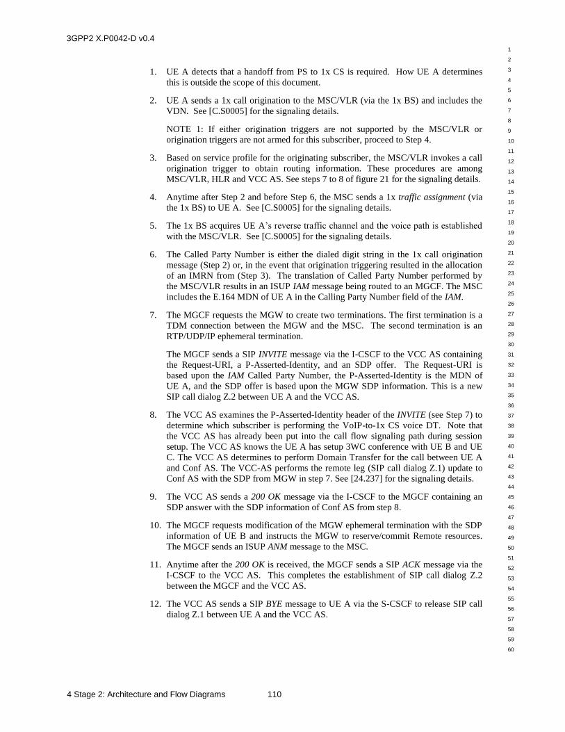
3GPP2 X.P0042-D v0.4
1
2
3
4
5
6
7
8
9
10
11
12
13
14
15
16
17
18
19
20
21
22
23
24
25
26
27
28
29
30
31
32
33
34
35
36
37
38
39
40
41
42
43
44
45
46
47
48
49
50
51
52
53
54
55
56
57
58
59
60
4 Stage 2: Architecture and Flow Diagrams 110
1. UE A detects that a handoff from PS to 1x CS is required. How UE A determines
this is outside the scope of this document.
2. UE A sends a 1x call origination to the MSC/VLR (via the 1x BS) and includes the
VDN. See [C.S0005] for the signaling details.
NOTE 1: If either origination triggers are not supported by the MSC/VLR or
origination triggers are not armed for this subscriber, proceed to Step 4.
3. Based on service profile for the originating subscriber, the MSC/VLR invokes a call
origination trigger to obtain routing information. These procedures are among
MSC/VLR, HLR and VCC AS. See steps 7 to 8 of figure 21 for the signaling details.
4. Anytime after Step 2 and before Step 6, the MSC sends a 1x traffic assignment (via
the 1x BS) to UE A. See [C.S0005] for the signaling details.
5. The 1x BS acquires UE A’s reverse traffic channel and the voice path is established
with the MSC/VLR. See [C.S0005] for the signaling details.
6. The Called Party Number is either the dialed digit string in the 1x call origination
message (Step 2) or, in the event that origination triggering resulted in the allocation
of an IMRN from (Step 3). The translation of Called Party Number performed by
the MSC/VLR results in an ISUP IAM message being routed to an MGCF. The MSC
includes the E.164 MDN of UE A in the Calling Party Number field of the IAM.
7. The MGCF requests the MGW to create two terminations. The first termination is a
TDM connection between the MGW and the MSC. The second termination is an
RTP/UDP/IP ephemeral termination.
The MGCF sends a SIP INVITE message via the I-CSCF to the VCC AS containing
the Request-URI, a P-Asserted-Identity, and an SDP offer. The Request-URI is
based upon the IAM Called Party Number, the P-Asserted-Identity is the MDN of
UE A, and the SDP offer is based upon the MGW SDP information. This is a new
SIP call dialog Z.2 between UE A and the VCC AS.
8. The VCC AS examines the P-Asserted-Identity header of the INVITE (see Step 7) to
determine which subscriber is performing the VoIP-to-1x CS voice DT. Note that
the VCC AS has already been put into the call flow signaling path during session
setup. The VCC AS knows the UE A has setup 3WC conference with UE B and UE
C. The VCC AS determines to perform Domain Transfer for the call between UE A
and Conf AS. The VCC-AS performs the remote leg (SIP call dialog Z.1) update to
Conf AS with the SDP from MGW in step 7. See [24.237] for the signaling details.
9. The VCC AS sends a 200 OK message via the I-CSCF to the MGCF containing an
SDP answer with the SDP information of Conf AS from step 8.
10. The MGCF requests modification of the MGW ephemeral termination with the SDP
information of UE B and instructs the MGW to reserve/commit Remote resources.
The MGCF sends an ISUP ANM message to the MSC.
11. Anytime after the 200 OK is received, the MGCF sends a SIP ACK message via the
I-CSCF to the VCC AS. This completes the establishment of SIP call dialog Z.2
between the MGCF and the VCC AS.
12. The VCC AS sends a SIP BYE message to UE A via the S-CSCF to release SIP call
dialog Z.1 between UE A and the VCC AS.
3GPP2 X.P0042-D v0.4
1
2
3
4
5
6
7
8
9
10
11
12
13
14
15
16
17
18
19
20
21
22
23
24
25
26
27
28
29
30
31
32
33
34
35
36
37
38
39
40
41
42
43
44
45
46
47
48
49
50
51
52
53
54
55
56
57
58
59
60
111 4 Stage 2: Architecture and Flow Diagrams
Post-conditions:
There is a call between UE A and Conf AS via the 1x CS network. SIP call dialog Z.2 for this
call is illustrated by a heavy dashed double arrow between the VCC AS and the UE A. SIP
call dialog Z.1 for this call is illustrated by a heavy dashed double arrow between the VCC
AS and Conf AS. For communication Z connection between UE A and Conf AS, there are CS
bearer from UE A to MGW and PS bearer from MGW to Conf AS.
3GPP2 X.P0042-D v0.4
1
2
3
4
5
6
7
8
9
10
11
12
13
14
15
16
17
18
19
20
21
22
23
24
25
26
27
28
29
30
31
32
33
34
35
36
37
38
39
40
41
42
43
44
45
46
47
48
49
50
51
52
53
54
55
56
57
58
59
60
5 Stage 3: Procedures and Protocol 112
5 Stage 3: Procedures and Protocol
5.1 Overview of VCC between the CS domain and the MMD
5.1.1 General
VCC allows a UE employing two separate technologies, one the traditional CS domain
accessed via cdma2000 1x, and the other the MMD accessed via a number of access
technologies, e.g., HRPD or WLAN, to have calls flexibly delivered over either the CS
domain or the MMD, and to transfer the calls from one technology to the other when access
or other conditions alter.
Calls originated by VCC subscribers in both the MMD and in the CS domain are subject to
anchoring in the MMD. Similarly calls terminated to VCC subscribers are subject to
anchoring in the MMD. When anchoring occurs, such calls have a path to the VCC AS from
either the CS domain or the MMD, so that the VCC AS can be used to execute a DT
procedure of the voice session or the voice component of a multimedia session. If a call from
a VCC subscriber is not anchored in the MMD, DT is not supported for that call.
For the above to occur, the following procedures are defined within this document:
procedures for initializing a VCC AS for a specific subscriber before the VCC UE
makes or receives calls are specified in Section 5.3;
procedures for call origination are specified in Section 5.4;
procedures for call termination are specified in Section 5.5;
procedures for transfer of a call from the CS domain to the MMD are specified in
Section 5.6;
procedures for transfer of a call from the MMD to the CS domain are specified in
Section 5.7;
format of VCC application message is specified in Section 5.8;
signaling protocol for VCC domain transfer of IMS Emergency Call to 1xCS is
specified in Section 5.9;
signaling procedures for DRVCC domain transfer of IMS Emergency Call to 1xCS
are specified in Section 5.10;
signaling procedures for SRVCC domain transfer of an IMS Emergency Call to
1xCS are specified in Section 5.11;
signaling procedures for SRVCC domain transfer of an IMS call to 1xCS are
specified in Section 5.12;
procedures for DRVCC domain transfer of alerting call from the IMS to the CS
domain are specified in Section 5.13; and
procedures for DRVCC domain transfer of supplementary service call from the IMS
to the CS domain are specified in Section 5.14.
3GPP2 X.P0042-D v0.4
1
2
3
4
5
6
7
8
9
10
11
12
13
14
15
16
17
18
19
20
21
22
23
24
25
26
27
28
29
30
31
32
33
34
35
36
37
38
39
40
41
42
43
44
45
46
47
48
49
50
51
52
53
54
55
56
57
58
59
60
113 5 Stage 3: Procedures and Protocol
5.1.2 Underlying Network Capabilities
VCC assumes the use of a number of underlying network capabilities:
1. deployment by the home network operator of VCC AS on the MMD;
2. signaling within the CS domain (both within the home network and between the
home network and any serving network) supported using ISUP ([ITU ISUP] or
[ANSI ISUP]) and MAP [X.S0004-540];
3. provisioning of WIN capability (as specified in [WIN]) at the MSC (download of the
subscriber's trigger profile) or the HLR (relay by the HLR of the ORREQ to the
SCP);
4. interworking between CS domain and the MMD provided by an MGCF in
accordance with [X.S0050]; and
5. capability of the IP-CAN to support VoIP.
5.1.3 URI and Address Assignments
In order to support VCC to a subscriber, the following URI and address assignments are
assumed:
a. in this version of the document, the VCC UE will be configured with both a VDI and
a VDN in order to initiate a DT;
b. the VCC UE will be configured to be reachable in both the MMD and the CS domain
by one or more public telecommunication numbers which should be correlated
between the CS domain and the MMD. A public telecommunication number can be
a MDN used in the CS domain which is conveyed in international format to the VCC
UE as a part of the implicit registration set associated with that VCC UE through
MMD, or the VCC AS can be configured to provide a functional relationship
between separate numbers providing each of these identities;
NOTE: One way of correlating the public telecommunication numbers of the CS
domain and the MMD is, to set them to the same values.
c. if WIN is supported, an IMRN may be assigned that can reach a VCC AS that can
either support the VCC capabilities for that VCC UE, or otherwise locate the VCC
AS supporting the VCC capabilities for that VCC UE. The IMRNs are dynamically
allocated to route the call to MMD for anchoring purposes, or during DT from the
MMD to the CS domain. The MMD is configured to treat the IMRN as a PSI;
d. the MDN will be subject to routing to the MMD in order for anchoring to be
performed by the VCC AS. A TLDN is assigned to be able to route to a serving
MSC (via an MGCF) such that the TLDN is not subject to the same routing back to
the MMD and the VCC AS; and
e. not all calls are suitable for DT, and application of DT to other calls might be against
subscriber or operator preferences.
3GPP2 X.P0042-D v0.4
1
2
3
4
5
6
7
8
9
10
11
12
13
14
15
16
17
18
19
20
21
22
23
24
25
26
27
28
29
30
31
32
33
34
35
36
37
38
39
40
41
42
43
44
45
46
47
48
49
50
51
52
53
54
55
56
57
58
59
60
5 Stage 3: Procedures and Protocol 114
5.2 Functional entities
5.2.1 Introduction
This clause associates the functional entities described for the MMD and for the CS domain,
with the VCC roles described in the stage 2 architecture (see Section 4).
5.2.2 User Equipment (UE)
A UE compliant with this document shall implement the role of a VCC UE (see sections
5.3.2, 5.4.2, 5.5.2, 5.6.2 and 5.7.2).
5.2.3 Application Server (AS)
An AS compliant with this document shall implement the role of a VCC AS (see sections
5.3.3, 5.4.4, 5.5.4, 5.6.3 and 5.7.4).
5.2.4 Media Gateway Control Function (MGCF)
In order to support VCC for any call, the MGCF has to provide signaling interworking and
control of the media between the CS domain and the MMD. The VCC AS can only be
configured to operate where appropriate interworking is provided.
As the procedures for call termination in the CS domain may involve an MGCF provided by
another network operator, the provision of appropriate interworking can extend to peering
agreements between operators.
5.2.5 Emergency Access Transfer Function (EATF)
An Emergency Access Transfer Function (EATF) implements the VCC AS functionality for
emergency sessions in the IMS.
5.3 Roles for Registration in the MMD
5.3.1 Introduction
In addition to the procedures specified in this section, the VCC UE and the VCC AS shall
support the procedures specified in [MMD Part-4] appropriate to the functional entity in
which they are implemented. The VCC AS can be configured with any of various options for
obtaining information from the MMD specified in [MMD Part-4], [MMD Part-10], [MMD
Part-11] for example:
a. receipt of REGISTER request which causes a third-party REGISTER request to be
sent to the VCC AS;
b. receipt of REGISTER request which causes a third-party REGISTER request to be
sent to the VCC AS. The VCC AS then subscribes to the reg event package for that
user to obtain information; or
c. receipt of REGISTER request which causes a third-party REGISTER request to be
sent to the VCC AS. The VCC AS then uses the Sh interface to obtain information.
This document places no requirement on the use of all or any of these mechanisms.
3GPP2 X.P0042-D v0.4
1
2
3
4
5
6
7
8
9
10
11
12
13
14
15
16
17
18
19
20
21
22
23
24
25
26
27
28
29
30
31
32
33
34
35
36
37
38
39
40
41
42
43
44
45
46
47
48
49
50
51
52
53
54
55
56
57
58
59
60
115 5 Stage 3: Procedures and Protocol
5.3.2 VCC UE
When the VCC UE registers with the IMS subsystem, the VCC UE shall apply the procedures
as specified in [MMD Part-4]. When constructing a REGISTER request, the UE shall include
a “Timestamp” header [RFC 3261] in the SIP REGISTER request. The value of the
“Timestamp” header shall be set to the time, in seconds since January 1, 1900 00:00 UTC, at
which the UE generated the REGISTER message. The UE shall indicate its capabilities (for
example, supported applications) using the procedures defined in [RFC 3840].
In this release of the specification, the UE shall use the “audio” feature tag defined in
[RFC 3840] to indicate the support for real-time VoIP capability.
When the VCC UE enters an IP-CAN coverage area where the negotiated VoIP capabilities
are different from the previous IP-CAN area, the VCC UE shall re-register with IMS to
update its negotiated VoIP capabilities.
NOTE 1: Depending on operator policy, registration to the IMS subsystem can impact
whether calls are delivered to the VCC UE using the MMD or using the CS domain.
NOTE 2: The VCC UE performs registration in the IMS subsystem independent of the UE’s
state in the CS domain.
If the VCC UE is both IMS registered and CS registered and the VCC UE detects that the IP-
CAN connection is temporarily unavailable and still has CS network coverage, the VCC UE
shall send an SMS, constructed as specified in section 5.3.2.1, on the CS network to notify the
VCC AS that it is reachable only through the CS domain. The VCC UE shall follow
procedures specified in section 5.3.2.2 for processing SMS acknowledgements. The
“Destination Address” in the SMS message shall be set based on VDN. When the UE regains
MMD coverage, the UE shall sends a SIP re-REGISTER message over IMS to indicate to the
VCC AS that it has regained MMD coverage.
5.3.2.1 Constructing SMS Message
The UE shall construct the SMS message as specified below.
The UE shall set the SMS_MSG_TYPE of the SMS transport layer to ‘0000000’
(SMS Point-to-Point).
The UE shall set the contents of the SMS Point-to-Point message to the following:
— set the Parameter ID ‘0000000’ (Teleservice identifier) with the IDENTIFIER
field set to’4242’ (IMS Services Teleservice, IMSST).
— set the Parameter ID ‘00000100’ (Destination Address) to the VDN.
— include the Parameter ID ‘00000110’ (Bearer Reply Option). The REPLY_SEQ
field of the Bearer Reply Option shall be set to a value identifying the SMS
message being constructed at the SMS transport layer.
— set the Parameter ID ‘00001000’ (Bearer Data) to value specified below.
The UE shall set include the following sub parameters in Bearer Data:
— include the sub parameter ‘00000000’ (Message Identifier) with
MESSAGE_TYPE set to ‘0010’ (Submit) and the MESSAGE_ID field set to a
value identifying the SMS message being constructed at the Teleservice Layer.
— include the sub parameter ‘00000001’ (User Data) with the MSG_ENCODING
parameter set to ‘00000’ (Octet). The UE shall set the CHARi field of the User
3GPP2 X.P0042-D v0.4
1
2
3
4
5
6
7
8
9
10
11
12
13
14
15
16
17
18
19
20
21
22
23
24
25
26
27
28
29
30
31
32
33
34
35
36
37
38
39
40
41
42
43
44
45
46
47
48
49
50
51
52
53
54
55
56
57
58
59
60
5 Stage 3: Procedures and Protocol 116
Data as specified in section 5.8.1.1. The UE shall set the ‘Domain-Status’ field
in VCC Message Type to 0x00 (Domain-Attachment-Message), and set the
VCC Message Data to 0x00 (CS-only). The UE shall also set the ‘Timestamp’
field to the time, in seconds since January 1, 1900 00:00 UTC, at which the UE
generated the IMSST message.
— include the sub parameter ‘00001000’ (Priority) with the PRIORITY field set to
‘10’ (Urgent).
— include the sub parameter ‘00001010’ (Reply Option) with the
USER_ACK_REQ field set to ‘0’, DAK_REQ field set to ‘1’, and
READ_ACK_REQ field set to 0.
5.3.2.2 Processing SMS Acknowledgments
Upon receiving an SMS Ack Message that corresponds to the previously sent SMS message
for VCC, the UE shall:
If the Cause Codes parameter indicates temporary failure, i.e., ERROR_CLASS is
‘10’, the UE may retry the VCC SMS message.
Otherwise, no action is required.
Upon receiving an SMS Delivery Ack Message that corresponds to the previously sent SMS
message, the UE shall:
If the Delivery Ack Message does not contain the Message Status sub parameter, no
further action is required.
If the Delivery Ack Message contains the Message Status sub parameter:
— If the ERROR_CLASS is ‘10’ (temporary condition), the UE may retry the
VCC SMS message.
— Otherwise, no action is required.
5.3.3 VCC AS
The VCC AS can obtain information from any received third-party REGISTER request, or
any received reg event package, or the Sh interface, that it needs to implement the domain
selection policy of the network operator.
If the third-party REGISTER request does not carry a P-Access-Network-Info header
provided by the UE, and the VCC AS requires this knowledge for domain selection
procedures, the mechanisms by which the VCC AS determines the domain are outside the
scope of this document.
Upon receiving a third-party REGISTER from the S-CSCF, the VCC AS shall apply the
procedures as specified in [MMD Part-4] with the following additions:
The VCC AS shall store the S-CSCF information associated with the VCC UE;
If the Expires header or the expires parameter in the Contact header has a value equal
to zero, the VCC AS shall mark the VCC UE’s status as not reachable by IMS.
The VCC AS shall check to see whether the time value specified in “Timestamp”
field is later than the previously stored value of the Timestamp header. If the
timestamp value is not later, the VCC AS shall not update the UE’s reachability
3GPP2 X.P0042-D v0.4
1
2
3
4
5
6
7
8
9
10
11
12
13
14
15
16
17
18
19
20
21
22
23
24
25
26
27
28
29
30
31
32
33
34
35
36
37
38
39
40
41
42
43
44
45
46
47
48
49
50
51
52
53
54
55
56
57
58
59
60
117 5 Stage 3: Procedures and Protocol
status. Otherwise, the VCC AS shall store the value of the header and shall mark the
VCC UE’s status as reachable via IMS.
When the VCC UE is reachable via IMS, the VCC AS may also store information on whether
the VCC UE is VoIP capable based on information received in Section 5.3.2.
Upon receiving a SMS from the VCC UE with the Teleservice identifier set to IMSST, the
VCC AS shall do the following:
If the VCC Message Type is ‘Domain-Attachment-Status’ and the ‘Domain-Status’
field is set to 0x00 (CS-only), the VCC AS shall check to see whether the time value
specified in “Timestamp” field is later than the previously stored Timestamp value.
If the time in the SMS message is later, the VCC AS shall store the new Timestamp
value and shall mark the UE’s status as reachable only over CS domain. Otherwise,
the VCC AS shall ignore the SMS message.
5.3.4 S-CSCF
When the S-CSCF sends a third-party REGISTER message to the VCC AS, the S-CSCF shall
follow the procedures as specified in [MMD Part-4]. In addition, if the “timestamp” header is
sent by the UE in a REGISTER message, the S-CSCF shall transparently pass that along in
the third-party REGISTER message to the VCC AS (as it would to all other AS in user's
profile for the REGISTER message).
5.4 Roles for Call Origination
5.4.1 Introduction
This section specifies the procedures for call origination, both where the VCC UE is
generating calls in the CS domain and where the VCC UE is generating calls using the MMD.
Procedures are specified for the VCC UE and other VCC functional entities.
5.4.2 VCC UE
The VCC UE shall support origination of calls suitable for VCC via both the CS domain
[C.S0005] and the MMD [MMD Part-4].
There are no VCC specific requirements for the origination of calls that may be subject to
VCC.
NOTE 1: For INVITE requests initiated by the VCC UE in the MMD, the following are some
of the response codes that can indicate failure of the VCC AS to process the request with its
current characteristics:
484 (Address Incomplete);
488 (Not Acceptable Here) or 606 (Not Acceptable);
503 (Service Unavailable) or 603 (Decline).
5.4.3 MSC
There are no VCC specific procedures at the MSC.
NOTE: the MSC interacts with triggers for call origination.
3GPP2 X.P0042-D v0.4
1
2
3
4
5
6
7
8
9
10
11
12
13
14
15
16
17
18
19
20
21
22
23
24
25
26
27
28
29
30
31
32
33
34
35
36
37
38
39
40
41
42
43
44
45
46
47
48
49
50
51
52
53
54
55
56
57
58
59
60
5 Stage 3: Procedures and Protocol 118
5.4.4 VCC AS
5.4.4.1 Distinction of Requests Sent to the VCC AS
The VCC AS needs to distinguish between the following initial SIP INVITE requests to
provide specific functionality relating to call origination:
SIP INVITE requests routed to the VCC AS over either the ISC interface or the Ma
interface using the IMRN as a PSI, and therefore distinguished by the presence of the
IMRN in the Request-URI header, and which are known by interaction with the
MAP functionality [X.S0004-540] to relate to an originating request rather than a DT
request or a termination request. In the procedures below, such requests are known
as “SIP INVITE requests due to originating IMRN”; and
SIP INVITE requests routed to the VCC AS over the ISC interface as a result of
processing filter criteria at the S-CSCF according to the origination procedures
defined in [MMD Part-4], are distinguished by the contents of the Request-URI. If
the Request-URI contains a VDI, then it is for a DT request. However, absence of a
VDI in the Request-URI indicates an origination request. In the procedures below,
such requests are known as “SIP INVITE requests due to originating filter criteria”.
Section 5.5.4.1, section 5.6.3.1 and section 5.7.4.1 detail other procedures for initial INVITE
requests with different recognition conditions.
Other SIP initial requests for a dialog and requests for a SIP standalone transaction can be
dealt with in any manner conformant with [MMD Part-4].
The VCC AS also processes MAP requests as defined in [X.S0004-540]. The VCC AS shall
differentiate MAP requests that relate to an originating request, containing an ordinary called
party number, covered in this section, and those relating to a DT request, which contain a
VDN as the called party number.
5.4.4.2 Call Origination in the MMD
When the VCC AS receives a SIP INVITE request due to originating filter criteria, the VCC
AS shall:
1. check anchoring is possible for this session;
NOTE 1: The conditions that prevent anchoring are a matter for implementation, but
can include operator policy on a number of conditions, e.g., roaming of the VCC UE,
the present IP-CAN used to access the IMS subsystem. In general, the number of
calls presented for anchoring on behalf of the same user, and the media
characteristics relating to these calls, will not prevent anchoring, as these issues are
dealt with at DT.
2. if the session is not subject to anchoring, either:
i. forward the SIP INVITE request by acting as a SIP proxy as specified in [MMD
Part-4]. The VCC AS shall not Record-Route on such requests, and the request
is not retargeted by changing the Request-URI; or
ii. reject the SIP INVITE request. The following response codes are
recommended:
- 484 (Address Incomplete), if the Request-URI supplied is not resolvable in
the home network (such a Request-URI may have been resolvable in the
local network which may be visited by the VCC UE at this time);
3GPP2 X.P0042-D v0.4
1
2
3
4
5
6
7
8
9
10
11
12
13
14
15
16
17
18
19
20
21
22
23
24
25
26
27
28
29
30
31
32
33
34
35
36
37
38
39
40
41
42
43
44
45
46
47
48
49
50
51
52
53
54
55
56
57
58
59
60
119 5 Stage 3: Procedures and Protocol
- 488 (Not Acceptable Here) or 606 (Not Acceptable), if some aspect of
operator policy precluded anchoring; or
- 503 (Service Unavailable) or 603 (Decline) for all other conditions;
and no further VCC specific procedures are performed on this session;
NOTE 2: Some checks may also form part of the initial filter criteria in the S-CSCF to
determine if the SIP INVITE request is sent to the VCC AS in the first place.
3. if the session is subject to anchoring, operate as an application server providing 3rd
party call control, and specifically as a routing B2BUA, as specified in [MMD Part-
4] for this request and all future requests and responses in the same dialog with the
following additions:
i. copy the Request-URI unchanged from the incoming SIP INVITE request to the
outgoing SIP INVITE request;
ii. copy all other headers unchanged from the received SIP INVITE request to the
outgoing SIP INVITE request; and
iii. copy the body unchanged from the received INVITE request to the outgoing SIP
INVITE request.
NOTE 3: Call anchoring is performed before all originating services are executed and
thus the VCC AS is invoked as the first AS in the originating initial Filter Criteria.
5.4.4.3 Call Origination in the CS Domain – Procedures Towards the WIN SCP
When the VCC AS receives an MAP ORREQ or a MAP ANLYZD, containing a called party
number that is not a VDN, the VCC AS shall:
1. check anchoring is possible for this call;
NOTE 1: The conditions that prevent anchoring are a matter for implementation, but
can include operator policy on a number of conditions, e.g., roaming of the VCC UE,
lack of resources, such as available IMRNs, or a lack of translation rules if the called
party number is not in international number format. In general, the number of calls
presented for anchoring on behalf of the same user will not prevent anchoring, as
these issues are dealt with at DT.
2. if the session is not subject to anchoring:
i. set the AccessDeniedReason to the appropriate value and the AnnouncementList
to the appropriate value and respond with an ORREQ or ANLYZD RETURN
RESULT; or,
ii. set the ActionCode to “continue processing” and respond with an ORREQ or
ANLYZD RETURN RESULT.
3. if session is subject to anchoring, allocate an IMRN. The IMRN is such that when
the VCC AS receives a SIP INVITE request it can derive by inspection that the
request is due to an originating IMRN. How IMRNs are allocated may vary from
one VCC AS to another and is not specified in this version of the specification. The
VCC AS shall create a binding between the allocated IMRN and the ORREQ or
ANLYZD Digits Parameter (i.e., the Called Party Number (CdPN)).
4. if session is subject to anchoring, the VCC AS shall send an ORREQ or ANLYZD
RETURN RESULT with the allocated IMRN in TerminationList.
3GPP2 X.P0042-D v0.4
1
2
3
4
5
6
7
8
9
10
11
12
13
14
15
16
17
18
19
20
21
22
23
24
25
26
27
28
29
30
31
32
33
34
35
36
37
38
39
40
41
42
43
44
45
46
47
48
49
50
51
52
53
54
55
56
57
58
59
60
5 Stage 3: Procedures and Protocol 120
5.4.4.4 Call Origination in the CS Domain – Procedures Towards the MMD
When the VCC AS receives SIP INVITE request due to originating IMRN, the VCC AS
shall:
1. operate as an application server providing 3rd party call control, and specifically as a
routing B2BUA, as specified in [MMD Part-4] for this request and all future requests
and responses in the same dialog;
2. set the Request-URI of the outgoing initial SIP INVITE request to a tel-URI which
represents the original called party number of the call as initiated in the CS domain.
This is mapped from the binding created in step 3 of section 5.4.4.3;
3. set the To header field of the outgoing initial SIP INVITE request to a tel-URI which
represents the original called party number of the call as initiated in the CS domain.
This is mapped from the binding created in step 3 of section 5.4.4.3;
4. insert a Route header pointing to the S-CSCF serving the VCC UE, or to the entry
point of the VCC UE’s network (e.g., I_CSCF) and append the orig parameter to the
topmost Route header of the outgoing initial SIP INVITE request;
5. set the P-Asserted-Identity header of the outgoing INVITE request to a tel-URI
which represents the calling party number of the call initiated in the CS domain.
This is either available from information associated against the received IMRN or is
the value as received in P-Asserted-Identity header of the incoming INVITE request.
NOTE: It can happen that the P-Asserted-Identity header is not included in the
incoming INVITE request.
The VCC AS should, in the outgoing requests and responses, include the same values as
received in the incoming requests and responses in all other headers with the exception
given in this section and in [MMD Part-4].
The VCC AS will handle the Privacy header in the outgoing INVITE request in the
following way. The VCC AS shall either:
— if a Privacy header is received in the incoming INVITE request, include the
Privacy header as received in the incoming INVITE request; or
— if a value is associated to IMRN and indicates that the presentation of the calling
party number is restricted in the CS domain, include a Privacy header with the
value set to “id”.
6. release the IMRN and the ORREQ/ANLYZD Digits binding.
5.5 Roles for Call Termination
5.5.1 Introduction
This section specifies the procedures for call termination, both where the VCC UE is
receiving calls in the CS domain and where the VCC UE is receiving calls using the MMD.
Procedures are specified for the VCC UE and other VCC functional entities.
5.5.2 VCC UE
The VCC UE shall support termination of calls suitable for VCC both via the CS domain as
specified in [C.S0005] and the MMD as specified [MMD Part-4].
3GPP2 X.P0042-D v0.4
1
2
3
4
5
6
7
8
9
10
11
12
13
14
15
16
17
18
19
20
21
22
23
24
25
26
27
28
29
30
31
32
33
34
35
36
37
38
39
40
41
42
43
44
45
46
47
48
49
50
51
52
53
54
55
56
57
58
59
60
121 5 Stage 3: Procedures and Protocol
5.5.3 MSC
There is no VCC specific procedure at the MSC.
NOTE: The MSC may interact with triggers for call termination.
5.5.4 VCC AS
5.5.4.1 Distinction of Requests Sent to the VCC AS
The VCC AS needs to distinguish between the following initial SIP INVITE requests to
provide specific functionality relating to call termination:
SIP INVITE requests routed to the VCC AS over the ISC interface as a result of
processing filter criteria at the S-CSCF according to the termination procedures as
defined in [MMD Part-4] and therefore distinguished by the URI relating to this
particular filter criteria appearing in the topmost entry in the Route header. In the
procedures below such requests are known as “SIP INVITE requests due to
terminating filter criteria”; and
SIP INVITE requests routed to the VCC AS over the ISC interface or Ma interface
using the IMRN as a PSI, and therefore distinguished by the presence of the IMRN
in the Request-URI header, which is different from the VDN. In the procedures
below such requests are known as “SIP INVITE requests due to terminating IMRN”.
Section 5.4.4.1, section 5.6.3.1 and section 5.7.4.1 detail other procedures for initial INVITE
requests with different recognition conditions.
Other SIP initial requests for a dialog and requests for a SIP standalone transaction can be
dealt with in any manner conformant with [MMD Part-4].
The VCC AS also processes MAP requests related to call termination as defined in [X.S0004-
540].
5.5.4.2 Call Termination in the MMD
When the VCC AS receives a SIP INVITE request due to terminating filter criteria, the VCC
AS shall:
1. check anchoring is possible for this session;
NOTE 1: The conditions that prevent anchoring are a matter for implementation,
but can include operator policy on a number of conditions, e.g., roaming of the
VCC UE, or a lack of resources. In general, the number of calls presented for
anchoring on behalf of the same user will not prevent anchoring, as these issues
are dealt with at DT. If anchoring fails, the call is presented to the user without
anchoring.
NOTE 2: Such a check can also form part of the initial filter criteria in the S-
CSCF to determine if the SIP INVITE request is sent to the VCC AS in the first
place.
2. if the session is not subject to anchoring:
i. if the preferred delivery domain for such unanchored calls is the MMD, forward
the SIP INVITE request by acting as a SIP proxy as specified in [MMD Part-4].
3GPP2 X.P0042-D v0.4
1
2
3
4
5
6
7
8
9
10
11
12
13
14
15
16
17
18
19
20
21
22
23
24
25
26
27
28
29
30
31
32
33
34
35
36
37
38
39
40
41
42
43
44
45
46
47
48
49
50
51
52
53
54
55
56
57
58
59
60
5 Stage 3: Procedures and Protocol 122
The VCC AS shall not Record-Route on such requests. No further VCC specific
procedures are performed on this session.
ii. if the preferred delivery domain for such unanchored calls is the CS domain, the
VCC AS shall send an MAP LOCREQ to the HLR of the terminating
subscriber. Upon receiving the LOCREQ RETURN RESULT the VCC AS shall
forward the SIP INVITE request by acting as a SIP proxy as specified in [MMD
Part-4], after first retargeting the request by changing the Request-URI to the
TerminationList value (i.e., TLDN) in the LOCREQ RETURN RESULT . The
VCC AS shall not Record-Route on such requests. No further VCC specific
procedures are performed on this session.
NOTE 3: How the VCC AS determines the preferred delivery domain is outside
the scope of this specification.
3. if the session is subject to anchoring, operate as an application server providing 3rd
party call control, and specifically as a routeing B2BUA, as specified in [MMD Part-
4] for this request and all future requests and responses in the same dialog;
4. if the session is subject to anchoring, perform domain selection based on:
i. operator preferences;
ii. callee capabilities of the terminating UE, as obtained during IMS registration;
iii. access network information, as provided in the P-Access-Network-Info header
of the terminating UE;
iv. and session states;
5. if the MMD is selected, leave the Request-URI unchanged between the incoming SIP
INVITE request and the outgoing SIP INVITE request;
6. if the CS domain is selected:
i. send an MAP LOCREQ to the HLR of the terminating subscriber.
ii. upon receiving the LOCREQ RETURN RESULT, the VCC AS
1. shall set the Request-URI of the outgoing SIP INVITE request to a tel URI
based upon the DestinationDigits [X.S0004-550] in the TerminationList in
the LOCREQ RETURN RESULT; and
2. should set the To header field of the outgoing SIP INVITE request to a tel
URI based upon the DestinationDigits [X.S0004-550] in the
TerminationList in the LOCREQ RETURN RESULT.
On completion of the above procedure, the call is anchored in the VCC AS.
NOTE 4: The VCC AS acting as a B2BUA - which performs the 3rd party call control - needs
to be the last located application server to ensure that all application servers that need to
remain in the path of a call after DT will do so.
If the call delivery attempt fails and if allowed by operator policy, the VCC AS may re-
attempt the call termination to the CS Domain. If the re-attempted call delivery also fails, no
further call attempts shall be made.
5.5.4.3 Call Termination in the CS Domain
The following section defines two options for implementing call termination in the CS
domain.
3GPP2 X.P0042-D v0.4
1
2
3
4
5
6
7
8
9
10
11
12
13
14
15
16
17
18
19
20
21
22
23
24
25
26
27
28
29
30
31
32
33
34
35
36
37
38
39
40
41
42
43
44
45
46
47
48
49
50
51
52
53
54
55
56
57
58
59
60
123 5 Stage 3: Procedures and Protocol
5.5.4.3.1 Call Termination in the CS Domain – Procedures Towards the WIN SCP
When the VCC AS receives an MAP ANLYZD request [X.S0004-540] with the TriggerType
set to “ADVANCED_TERMINATION” the VCC AS shall:
1. check anchoring is possible for this call;
NOTE 1: The conditions that prevent anchoring are a matter for implementation, but
can include operator policy on a number of conditions, e.g., roaming of the VCC UE,
or a matter of lack of resources, e.g., available IMRNs. In general, the number of
calls presented for anchoring on behalf of the same user will not prevent anchoring,
as these issues are dealt with at DT. If anchoring fails, the call is presented to the
user without anchoring.
2. if the session is not subject to anchoring:
i. set the AccessDeniedReason to the appropriate value and the AnnouncementList
to the appropriate value, and respond with an ANLYZD RETURN RESULT
[X.S0004-540]; or
ii. set the ActionCode to “continue processing” and respond with an ANLYZD
RETURN RESULT [X.S0004-540].
3. if the call is subject to anchoring, allocate an IMRN. How IMRNs are allocated may
vary from one VCC AS to another and is not specified in this version of the
specification. The VCC AS shall create a binding between the allocated IMRN and
the ANLYZD Digits Parameter (i.e., the Called Party Number (CdPN)).
4. if anchoring is possible for this call, the VCC AS shall send an ANLYZD RETURN
RESULT with the allocated IMRN in TerminationList.
5.5.4.3.2 Call Termination in the CS Domain – Procedures Towards the HLR
NOTE 1: HLR procedures for recognition of VCC subscribers and LOCREQ and
ROUTEREQ handling are proprietary.
When the VCC AS receives a ROUTREQ request [X.S0004-540], the VCC AS shall:
1. check anchoring is possible for this call;
NOTE 2: The conditions that prevent anchoring are a matter for implementation, but
can include operator policy on a number of conditions, e.g., roaming of the VCC UE,
or a matter of lack of resources, e.g., available IMRNs. In general, the number of
calls presented for anchoring on behalf of the same user will not prevent anchoring,
as these issues are dealt with at DT. If anchoring fails, the call is presented to the
user without anchoring.
2. if the session is not subject to anchoring, the VCC AS shall set the
AccessDeniedReason to the appropriate value and the AnnouncementList to the
appropriate value, and respond with an ROUTREQ RETURN RESULT [X.S0004-
540].
3. if the call is subject to anchoring, allocate an IMRN. How IMRNs are allocated may
vary from one VCC AS to another and is not specified in this version of the
specification. The VCC AS shall create a binding between the allocated IMRN and
the ROUTREQ Digits Parameter (i.e., the Called Party Number (CdPN)).
3GPP2 X.P0042-D v0.4
1
2
3
4
5
6
7
8
9
10
11
12
13
14
15
16
17
18
19
20
21
22
23
24
25
26
27
28
29
30
31
32
33
34
35
36
37
38
39
40
41
42
43
44
45
46
47
48
49
50
51
52
53
54
55
56
57
58
59
60
5 Stage 3: Procedures and Protocol 124
4. if anchoring is possible for this call, the VCC AS shall send an ROUTREQ
RETURN RESULT with the allocated IMRN in DestinationDigits.
5.5.4.4 Call Termination in the CS Domain – Procedures Towards MMD
When the VCC AS receives SIP INVITE request due to terminating IMRN, the VCC AS:
NOTE 1: All SIP INVITE requests directed to the VCC AS using an IMRN are assumed
to be suitable for VCC anchoring, because any checks have been performed in
conjunction with the MAP procedures.
1. shall operate as an application server providing 3rd party call control, and
specifically as a routeing B2BUA, as specified in [MMD Part-4] for this request and
all future requests and responses in the same dialog;
NOTE 2: The SIP AS that implements the DT function of VCC AS acting as a
B2BUA - which performs the 3rd party call control - needs to be the last located
application server to ensure that all application servers that need to remain in the
path of a call after DT will do so.
2. shall set the Request-URI of the outgoing initial SIP INVITE request to a tel-URI
which represents the called party number of the original call as terminated in the CS
domain. This is mapped from the binding created in section 5.5.4.3;
3. should set the To header field of the outgoing initial SIP INVITE request to a tel-
URI which represents the called party number of the original call as terminated in the
CS domain. This is mapped from the binding created in section 5.5.4.3;
4. shall release the IMRN and the ANLYZD Digits binding.
5.6 Roles for Domain Transfer of a Call from the CS Domain to the MMD
5.6.1 Introduction
This section specifies the procedures for DT of a call from the CS domain to the MMD when
accessed via WLAN. Procedures are specified for the VCC UE and other VCC functional
entities.
5.6.2 VCC UE
If the VCC UE determines that an ongoing call in the CS domain needs to be supported over
the MMD instead, e.g., based on radio conditions, then the VCC UE shall send a SIP INVITE
request in accordance with [MMD Part-4]. For a UE originated call, the VCC UE shall send
the SIP INVITE request only if it has entered the “Conversation Substate”. For a UE
terminated call, the VCC UE shall send the SIP INVITE request only if it has entered the
“Conversation Substate” and sent a “Connect” message to the BS. See [C.S0005] for the
ongoing call in the CS domain. The VCC UE shall populate the SIP INVITE request as
follows:
1. the Request-URI set to the VDI;
2. the To header field set to the VDI;
3. the P-Preferred-Identity header set to the a public telecommunication number of the
calling party in accordance with Section 5.1.3; and
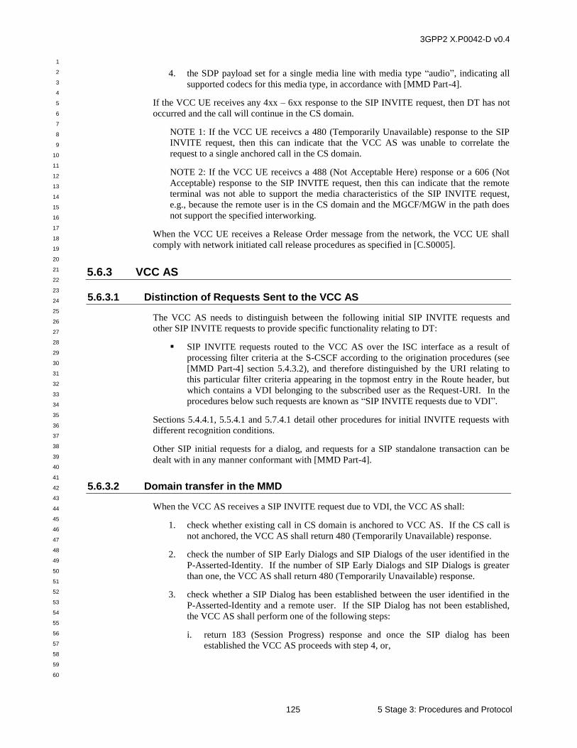
3GPP2 X.P0042-D v0.4
1
2
3
4
5
6
7
8
9
10
11
12
13
14
15
16
17
18
19
20
21
22
23
24
25
26
27
28
29
30
31
32
33
34
35
36
37
38
39
40
41
42
43
44
45
46
47
48
49
50
51
52
53
54
55
56
57
58
59
60
125 5 Stage 3: Procedures and Protocol
4. the SDP payload set for a single media line with media type “audio”, indicating all
supported codecs for this media type, in accordance with [MMD Part-4].
If the VCC UE receives any 4xx – 6xx response to the SIP INVITE request, then DT has not
occurred and the call will continue in the CS domain.
NOTE 1: If the VCC UE receivcs a 480 (Temporarily Unavailable) response to the SIP
INVITE request, then this can indicate that the VCC AS was unable to correlate the
request to a single anchored call in the CS domain.
NOTE 2: If the VCC UE receivcs a 488 (Not Acceptable Here) response or a 606 (Not
Acceptable) response to the SIP INVITE request, then this can indicate that the remote
terminal was not able to support the media characteristics of the SIP INVITE request,
e.g., because the remote user is in the CS domain and the MGCF/MGW in the path does
not support the specified interworking.
When the VCC UE receives a Release Order message from the network, the VCC UE shall
comply with network initiated call release procedures as specified in [C.S0005].
5.6.3 VCC AS
5.6.3.1 Distinction of Requests Sent to the VCC AS
The VCC AS needs to distinguish between the following initial SIP INVITE requests and
other SIP INVITE requests to provide specific functionality relating to DT:
SIP INVITE requests routed to the VCC AS over the ISC interface as a result of
processing filter criteria at the S-CSCF according to the origination procedures (see
[MMD Part-4] section 5.4.3.2), and therefore distinguished by the URI relating to
this particular filter criteria appearing in the topmost entry in the Route header, but
which contains a VDI belonging to the subscribed user as the Request-URI. In the
procedures below such requests are known as “SIP INVITE requests due to VDI”.
Sections 5.4.4.1, 5.5.4.1 and 5.7.4.1 detail other procedures for initial INVITE requests with
different recognition conditions.
Other SIP initial requests for a dialog, and requests for a SIP standalone transaction can be
dealt with in any manner conformant with [MMD Part-4].
5.6.3.2 Domain transfer in the MMD
When the VCC AS receives a SIP INVITE request due to VDI, the VCC AS shall:
1. check whether existing call in CS domain is anchored to VCC AS. If the CS call is
not anchored, the VCC AS shall return 480 (Temporarily Unavailable) response.
2. check the number of SIP Early Dialogs and SIP Dialogs of the user identified in the
P-Asserted-Identity. If the number of SIP Early Dialogs and SIP Dialogs is greater
than one, the VCC AS shall return 480 (Temporarily Unavailable) response.
3. check whether a SIP Dialog has been established between the user identified in the
P-Asserted-Identity and a remote user. If the SIP Dialog has not been established,
the VCC AS shall perform one of the following steps:
i. return 183 (Session Progress) response and once the SIP dialog has been
established the VCC AS proceeds with step 4, or,
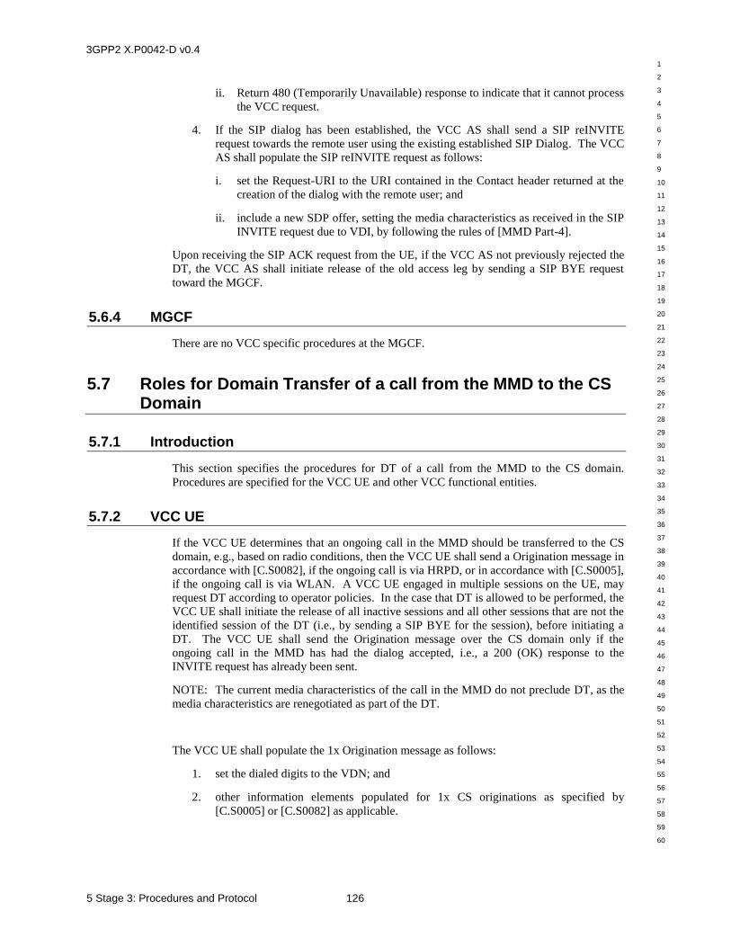
3GPP2 X.P0042-D v0.4
1
2
3
4
5
6
7
8
9
10
11
12
13
14
15
16
17
18
19
20
21
22
23
24
25
26
27
28
29
30
31
32
33
34
35
36
37
38
39
40
41
42
43
44
45
46
47
48
49
50
51
52
53
54
55
56
57
58
59
60
5 Stage 3: Procedures and Protocol 126
ii. Return 480 (Temporarily Unavailable) response to indicate that it cannot process
the VCC request.
4. If the SIP dialog has been established, the VCC AS shall send a SIP reINVITE
request towards the remote user using the existing established SIP Dialog. The VCC
AS shall populate the SIP reINVITE request as follows:
i. set the Request-URI to the URI contained in the Contact header returned at the
creation of the dialog with the remote user; and
ii. include a new SDP offer, setting the media characteristics as received in the SIP
INVITE request due to VDI, by following the rules of [MMD Part-4].
Upon receiving the SIP ACK request from the UE, if the VCC AS not previously rejected the
DT, the VCC AS shall initiate release of the old access leg by sending a SIP BYE request
toward the MGCF.
5.6.4 MGCF
There are no VCC specific procedures at the MGCF.
5.7 Roles for Domain Transfer of a call from the MMD to the CS Domain
5.7.1 Introduction
This section specifies the procedures for DT of a call from the MMD to the CS domain.
Procedures are specified for the VCC UE and other VCC functional entities.
5.7.2 VCC UE
If the VCC UE determines that an ongoing call in the MMD should be transferred to the CS
domain, e.g., based on radio conditions, then the VCC UE shall send a Origination message in
accordance with [C.S0082], if the ongoing call is via HRPD, or in accordance with [C.S0005],
if the ongoing call is via WLAN. A VCC UE engaged in multiple sessions on the UE, may
request DT according to operator policies. In the case that DT is allowed to be performed, the
VCC UE shall initiate the release of all inactive sessions and all other sessions that are not the
identified session of the DT (i.e., by sending a SIP BYE for the session), before initiating a
DT. The VCC UE shall send the Origination message over the CS domain only if the
ongoing call in the MMD has had the dialog accepted, i.e., a 200 (OK) response to the
INVITE request has already been sent.
NOTE: The current media characteristics of the call in the MMD do not preclude DT, as the
media characteristics are renegotiated as part of the DT.
The VCC UE shall populate the 1x Origination message as follows:
1. set the dialed digits to the VDN; and
2. other information elements populated for 1x CS originations as specified by
[C.S0005] or [C.S0082] as applicable.
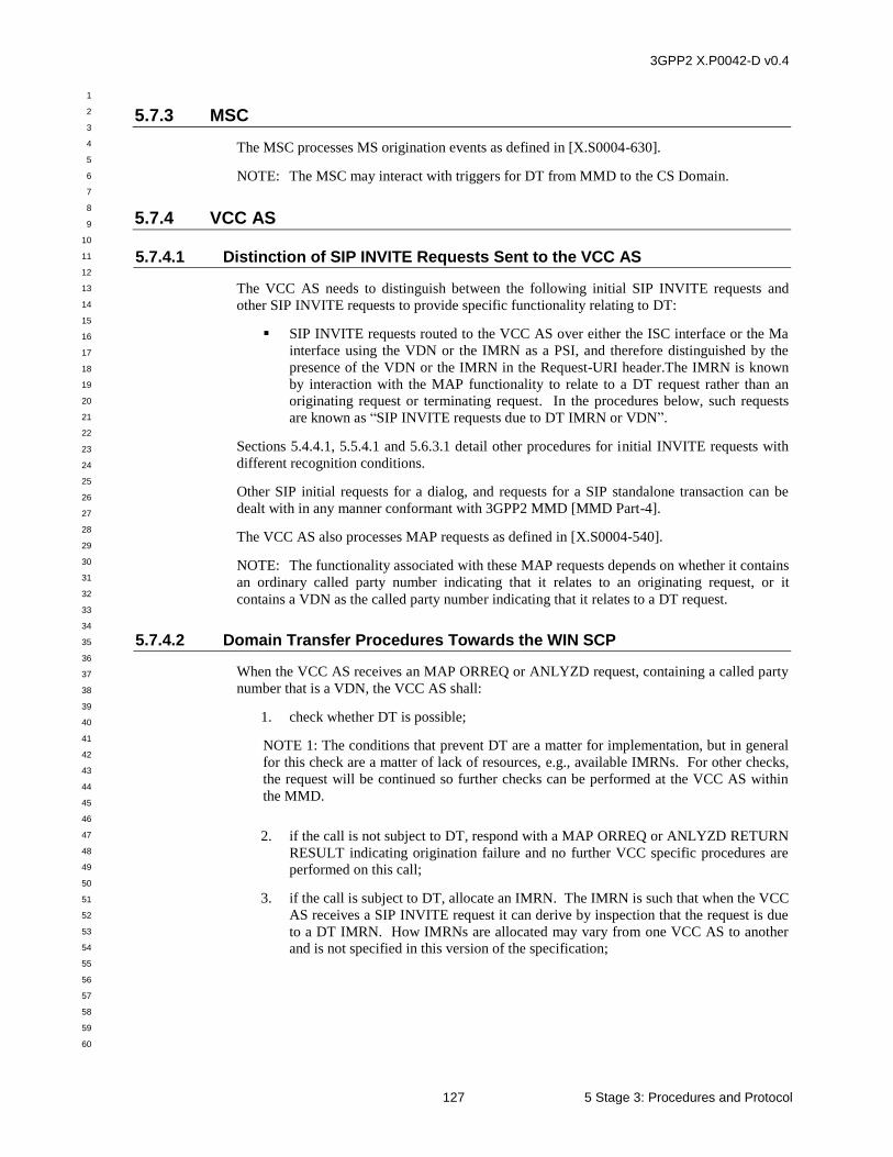
3GPP2 X.P0042-D v0.4
1
2
3
4
5
6
7
8
9
10
11
12
13
14
15
16
17
18
19
20
21
22
23
24
25
26
27
28
29
30
31
32
33
34
35
36
37
38
39
40
41
42
43
44
45
46
47
48
49
50
51
52
53
54
55
56
57
58
59
60
127 5 Stage 3: Procedures and Protocol
5.7.3 MSC
The MSC processes MS origination events as defined in [X.S0004-630].
NOTE: The MSC may interact with triggers for DT from MMD to the CS Domain.
5.7.4 VCC AS
5.7.4.1 Distinction of SIP INVITE Requests Sent to the VCC AS
The VCC AS needs to distinguish between the following initial SIP INVITE requests and
other SIP INVITE requests to provide specific functionality relating to DT:
SIP INVITE requests routed to the VCC AS over either the ISC interface or the Ma
interface using the VDN or the IMRN as a PSI, and therefore distinguished by the
presence of the VDN or the IMRN in the Request-URI header.The IMRN is known
by interaction with the MAP functionality to relate to a DT request rather than an
originating request or terminating request. In the procedures below, such requests
are known as “SIP INVITE requests due to DT IMRN or VDN”.
Sections 5.4.4.1, 5.5.4.1 and 5.6.3.1 detail other procedures for initial INVITE requests with
different recognition conditions.
Other SIP initial requests for a dialog, and requests for a SIP standalone transaction can be
dealt with in any manner conformant with 3GPP2 MMD [MMD Part-4].
The VCC AS also processes MAP requests as defined in [X.S0004-540].
NOTE: The functionality associated with these MAP requests depends on whether it contains
an ordinary called party number indicating that it relates to an originating request, or it
contains a VDN as the called party number indicating that it relates to a DT request.
5.7.4.2 Domain Transfer Procedures Towards the WIN SCP
When the VCC AS receives an MAP ORREQ or ANLYZD request, containing a called party
number that is a VDN, the VCC AS shall:
1. check whether DT is possible;
NOTE 1: The conditions that prevent DT are a matter for implementation, but in general
for this check are a matter of lack of resources, e.g., available IMRNs. For other checks,
the request will be continued so further checks can be performed at the VCC AS within
the MMD.
2. if the call is not subject to DT, respond with a MAP ORREQ or ANLYZD RETURN
RESULT indicating origination failure and no further VCC specific procedures are
performed on this call;
3. if the call is subject to DT, allocate an IMRN. The IMRN is such that when the VCC
AS receives a SIP INVITE request it can derive by inspection that the request is due
to a DT IMRN. How IMRNs are allocated may vary from one VCC AS to another
and is not specified in this version of the specification;
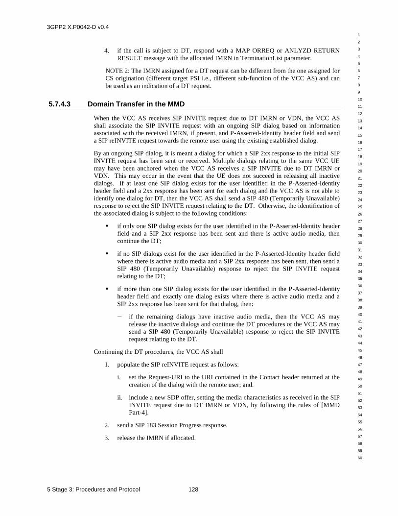
3GPP2 X.P0042-D v0.4
1
2
3
4
5
6
7
8
9
10
11
12
13
14
15
16
17
18
19
20
21
22
23
24
25
26
27
28
29
30
31
32
33
34
35
36
37
38
39
40
41
42
43
44
45
46
47
48
49
50
51
52
53
54
55
56
57
58
59
60
5 Stage 3: Procedures and Protocol 128
4. if the call is subject to DT, respond with a MAP ORREQ or ANLYZD RETURN
RESULT message with the allocated IMRN in TerminationList parameter.
NOTE 2: The IMRN assigned for a DT request can be different from the one assigned for
CS origination (different target PSI i.e., different sub-function of the VCC AS) and can
be used as an indication of a DT request.
5.7.4.3 Domain Transfer in the MMD
When the VCC AS receives SIP INVITE request due to DT IMRN or VDN, the VCC AS
shall associate the SIP INVITE request with an ongoing SIP dialog based on information
associated with the received IMRN, if present, and P-Asserted-Identity header field and send
a SIP reINVITE request towards the remote user using the existing established dialog.
By an ongoing SIP dialog, it is meant a dialog for which a SIP 2xx response to the initial SIP
INVITE request has been sent or received. Multiple dialogs relating to the same VCC UE
may have been anchored when the VCC AS receives a SIP INVITE due to DT IMRN or
VDN. This may occur in the event that the UE does not succeed in releasing all inactive
dialogs. If at least one SIP dialog exists for the user identified in the P-Asserted-Identity
header field and a 2xx response has been sent for each dialog and the VCC AS is not able to
identify one dialog for DT, then the VCC AS shall send a SIP 480 (Temporarily Unavailable)
response to reject the SIP INVITE request relating to the DT. Otherwise, the identification of
the associated dialog is subject to the following conditions:
if only one SIP dialog exists for the user identified in the P-Asserted-Identity header
field and a SIP 2xx response has been sent and there is active audio media, then
continue the DT;
if no SIP dialogs exist for the user identified in the P-Asserted-Identity header field
where there is active audio media and a SIP 2xx response has been sent, then send a
SIP 480 (Temporarily Unavailable) response to reject the SIP INVITE request
relating to the DT;
if more than one SIP dialog exists for the user identified in the P-Asserted-Identity
header field and exactly one dialog exists where there is active audio media and a
SIP 2xx response has been sent for that dialog, then:
— if the remaining dialogs have inactive audio media, then the VCC AS may
release the inactive dialogs and continue the DT procedures or the VCC AS may
send a SIP 480 (Temporarily Unavailable) response to reject the SIP INVITE
request relating to the DT.
Continuing the DT procedures, the VCC AS shall
1. populate the SIP reINVITE request as follows:
i. set the Request-URI to the URI contained in the Contact header returned at the
creation of the dialog with the remote user; and.
ii. include a new SDP offer, setting the media characteristics as received in the SIP
INVITE request due to DT IMRN or VDN, by following the rules of [MMD
Part-4].
2. send a SIP 183 Session Progress response.
3. release the IMRN if allocated.
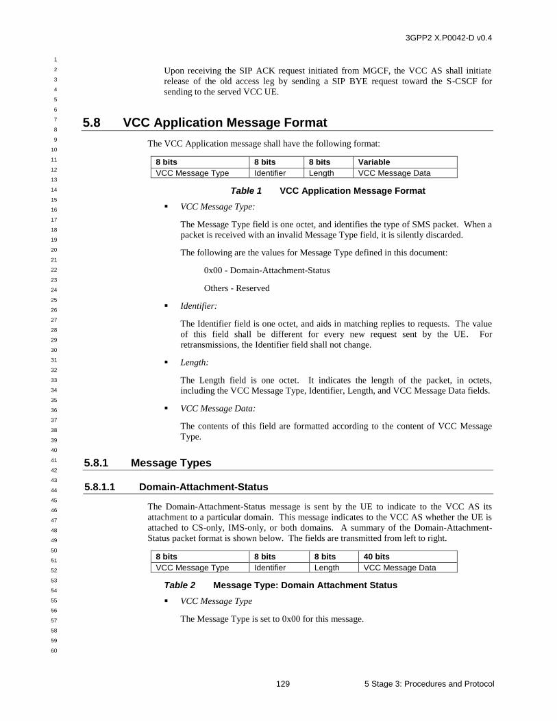
3GPP2 X.P0042-D v0.4
1
2
3
4
5
6
7
8
9
10
11
12
13
14
15
16
17
18
19
20
21
22
23
24
25
26
27
28
29
30
31
32
33
34
35
36
37
38
39
40
41
42
43
44
45
46
47
48
49
50
51
52
53
54
55
56
57
58
59
60
129 5 Stage 3: Procedures and Protocol
Upon receiving the SIP ACK request initiated from MGCF, the VCC AS shall initiate
release of the old access leg by sending a SIP BYE request toward the S-CSCF for
sending to the served VCC UE.
5.8 VCC Application Message Format
The VCC Application message shall have the following format:
8 bits 8 bits 8 bits Variable
VCC Message Type Identifier Length VCC Message Data
Table 1 VCC Application Message Format
VCC Message Type:
The Message Type field is one octet, and identifies the type of SMS packet. When a
packet is received with an invalid Message Type field, it is silently discarded.
The following are the values for Message Type defined in this document:
0x00 - Domain-Attachment-Status
Others - Reserved
Identifier:
The Identifier field is one octet, and aids in matching replies to requests. The value
of this field shall be different for every new request sent by the UE. For
retransmissions, the Identifier field shall not change.
Length:
The Length field is one octet. It indicates the length of the packet, in octets,
including the VCC Message Type, Identifier, Length, and VCC Message Data fields.
VCC Message Data:
The contents of this field are formatted according to the content of VCC Message
Type.
5.8.1 Message Types
5.8.1.1 Domain-Attachment-Status
The Domain-Attachment-Status message is sent by the UE to indicate to the VCC AS its
attachment to a particular domain. This message indicates to the VCC AS whether the UE is
attached to CS-only, IMS-only, or both domains. A summary of the Domain-Attachment-
Status packet format is shown below. The fields are transmitted from left to right.
8 bits 8 bits 8 bits 40 bits
VCC Message Type Identifier Length VCC Message Data
Table 2 Message Type: Domain Attachment Status
VCC Message Type
The Message Type is set to 0x00 for this message.
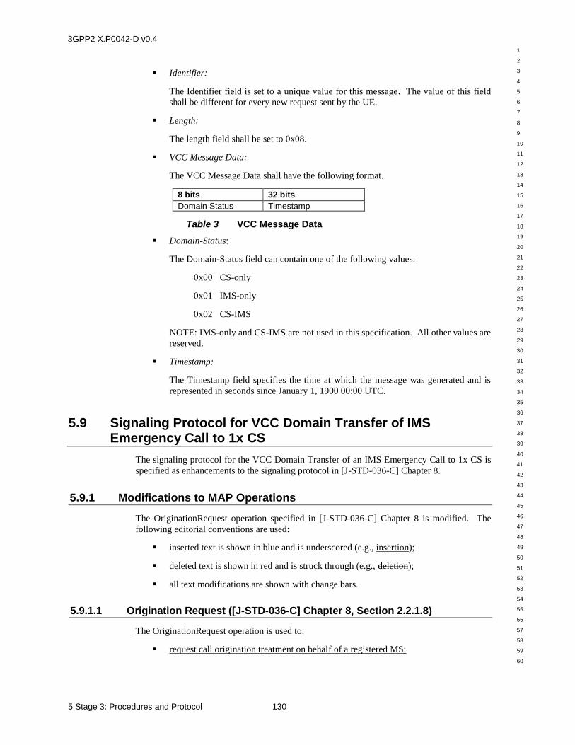
3GPP2 X.P0042-D v0.4
1
2
3
4
5
6
7
8
9
10
11
12
13
14
15
16
17
18
19
20
21
22
23
24
25
26
27
28
29
30
31
32
33
34
35
36
37
38
39
40
41
42
43
44
45
46
47
48
49
50
51
52
53
54
55
56
57
58
59
60
5 Stage 3: Procedures and Protocol 130
Identifier:
The Identifier field is set to a unique value for this message. The value of this field
shall be different for every new request sent by the UE.
Length:
The length field shall be set to 0x08.
VCC Message Data:
The VCC Message Data shall have the following format.
8 bits 32 bits
Domain Status Timestamp
Table 3 VCC Message Data
Domain-Status:
The Domain-Status field can contain one of the following values:
0x00 CS-only
0x01 IMS-only
0x02 CS-IMS
NOTE: IMS-only and CS-IMS are not used in this specification. All other values are
reserved.
Timestamp:
The Timestamp field specifies the time at which the message was generated and is
represented in seconds since January 1, 1900 00:00 UTC.
5.9 Signaling Protocol for VCC Domain Transfer of IMS Emergency Call to 1x CS
The signaling protocol for the VCC Domain Transfer of an IMS Emergency Call to 1x CS is
specified as enhancements to the signaling protocol in [J-STD-036-C] Chapter 8.
5.9.1 Modifications to MAP Operations
The OriginationRequest operation specified in [J-STD-036-C] Chapter 8 is modified. The
following editorial conventions are used:
inserted text is shown in blue and is underscored (e.g., insertion);
deleted text is shown in red and is struck through (e.g., deletion);
all text modifications are shown with change bars.
5.9.1.1 Origination Request ([J-STD-036-C] Chapter 8, Section 2.2.1.8)
The OriginationRequest operation is used to:
request call origination treatment on behalf of a registered MS;
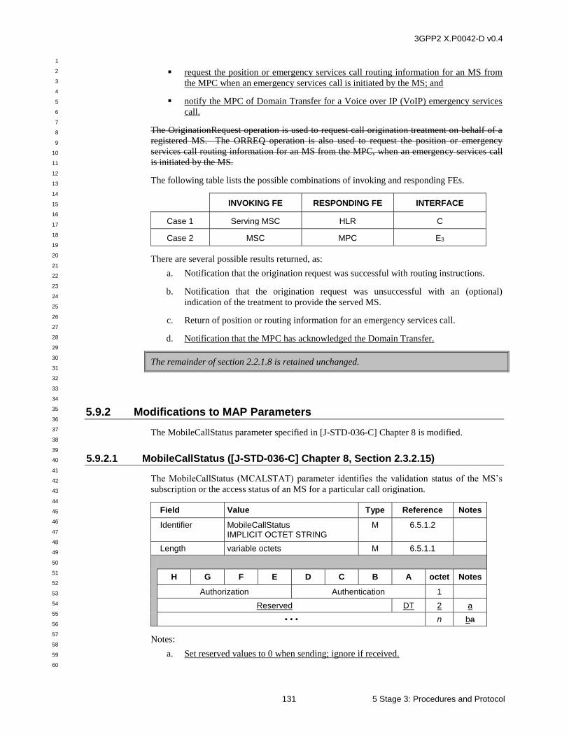
3GPP2 X.P0042-D v0.4
1
2
3
4
5
6
7
8
9
10
11
12
13
14
15
16
17
18
19
20
21
22
23
24
25
26
27
28
29
30
31
32
33
34
35
36
37
38
39
40
41
42
43
44
45
46
47
48
49
50
51
52
53
54
55
56
57
58
59
60
131 5 Stage 3: Procedures and Protocol
request the position or emergency services call routing information for an MS from
the MPC when an emergency services call is initiated by the MS; and
notify the MPC of Domain Transfer for a Voice over IP (VoIP) emergency services
call.
The OriginationRequest operation is used to request call origination treatment on behalf of a
registered MS. The ORREQ operation is also used to request the position or emergency
services call routing information for an MS from the MPC, when an emergency services call
is initiated by the MS.
The following table lists the possible combinations of invoking and responding FEs.
INVOKING FE RESPONDING FE INTERFACE
Case 1 Serving MSC HLR C
Case 2 MSC MPC E3
There are several possible results returned, as:
a. Notification that the origination request was successful with routing instructions.
b. Notification that the origination request was unsuccessful with an (optional)
indication of the treatment to provide the served MS.
c. Return of position or routing information for an emergency services call.
d. Notification that the MPC has acknowledged the Domain Transfer.
The remainder of section 2.2.1.8 is retained unchanged.
5.9.2 Modifications to MAP Parameters
The MobileCallStatus parameter specified in [J-STD-036-C] Chapter 8 is modified.
5.9.2.1 MobileCallStatus ([J-STD-036-C] Chapter 8, Section 2.3.2.15)
The MobileCallStatus (MCALSTAT) parameter identifies the validation status of the MS’s
subscription or the access status of an MS for a particular call origination.
Field Value Type Reference Notes
Identifier MobileCallStatus IMPLICIT OCTET STRING
M 6.5.1.2
Length variable octets M 6.5.1.1
H G F E D C B A octet Notes
Authorization Authentication 1
Reserved DT 2 a
• • • n ba
Notes:
a. Set reserved values to 0 when sending; ignore if received.
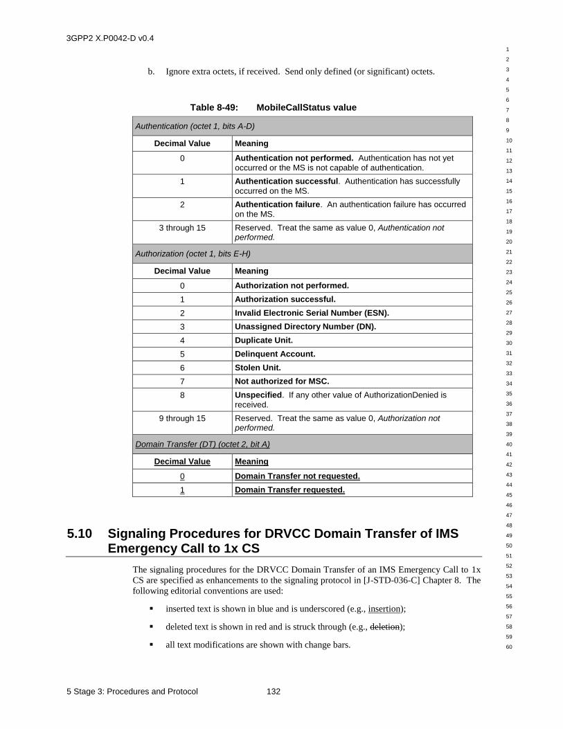
3GPP2 X.P0042-D v0.4
1
2
3
4
5
6
7
8
9
10
11
12
13
14
15
16
17
18
19
20
21
22
23
24
25
26
27
28
29
30
31
32
33
34
35
36
37
38
39
40
41
42
43
44
45
46
47
48
49
50
51
52
53
54
55
56
57
58
59
60
5 Stage 3: Procedures and Protocol 132
b. Ignore extra octets, if received. Send only defined (or significant) octets.
Table 8-49: MobileCallStatus value
Authentication (octet 1, bits A-D)
Decimal Value Meaning
0 Authentication not performed. Authentication has not yet
occurred or the MS is not capable of authentication.
1 Authentication successful. Authentication has successfully
occurred on the MS.
2 Authentication failure. An authentication failure has occurred
on the MS.
3 through 15 Reserved. Treat the same as value 0, Authentication not performed.
Authorization (octet 1, bits E-H)
Decimal Value Meaning
0 Authorization not performed.
1 Authorization successful.
2 Invalid Electronic Serial Number (ESN).
3 Unassigned Directory Number (DN).
4 Duplicate Unit.
5 Delinquent Account.
6 Stolen Unit.
7 Not authorized for MSC.
8 Unspecified. If any other value of AuthorizationDenied is
received.
9 through 15 Reserved. Treat the same as value 0, Authorization not performed.
Domain Transfer (DT) (octet 2, bit A)
Decimal Value Meaning
0 Domain Transfer not requested.
1 Domain Transfer requested.
5.10 Signaling Procedures for DRVCC Domain Transfer of IMS Emergency Call to 1x CS
The signaling procedures for the DRVCC Domain Transfer of an IMS Emergency Call to 1x
CS are specified as enhancements to the signaling protocol in [J-STD-036-C] Chapter 8. The
following editorial conventions are used:
inserted text is shown in blue and is underscored (e.g., insertion);
deleted text is shown in red and is struck through (e.g., deletion);
all text modifications are shown with change bars.
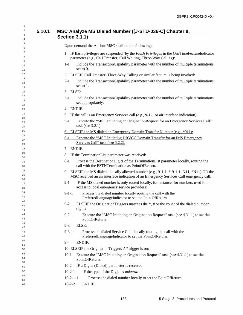
3GPP2 X.P0042-D v0.4
1
2
3
4
5
6
7
8
9
10
11
12
13
14
15
16
17
18
19
20
21
22
23
24
25
26
27
28
29
30
31
32
33
34
35
36
37
38
39
40
41
42
43
44
45
46
47
48
49
50
51
52
53
54
55
56
57
58
59
60
133 5 Stage 3: Procedures and Protocol
5.10.1 MSC Analyze MS Dialed Number ([J-STD-036-C] Chapter 8, Section 3.1.1)
Upon demand the Anchor MSC shall do the following:
1 IF flash privileges are suspended (by the Flash Privileges in the OneTimeFeatureIndicator
parameter (e.g., Call Transfer, Call Waiting, Three-Way Calling):
1-1 Include the TransactionCapability parameter with the number of multiple terminations
set to 0.
2 ELSEIF Call Transfer, Three-Way Calling or similar feature is being invoked:
2-1 Include the TransactionCapability parameter with the number of multiple terminations
set to 1.
3 ELSE:
3-1 Include the TransactionCapability parameter with the number of multiple terminations
set appropriately.
4 ENDIF.
5 IF the call is an Emergency Services call (e.g., 9-1-1 or air interface indication):
5-1 Execute the “MSC Initiating an OriginationRequest for an Emergency Services Call”
task (see 3.2.1).
6 ELSEIF the MS dialed an Emergency Domain Transfer Number (e.g., *911):
6-1 Execute the “MSC Initiating DRVCC Domain Transfer for an IMS Emergency
Services Call” task (see 3.2.2).
7 ENDIF.
8 IF the TerminationList parameter was received:
8-1 Process the DestinationDigits of the TerminationList parameter locally, routing the
call with the PSTNTermination as PointOfReturn.
9 ELSEIF the MS dialed a locally allowed number (e.g., 9-1-1, *-9-1-1, N11, *N11) OR the
MSC received an air interface indication of an Emergency Services Call emergency call:
9-1 IF the MS dialed number is only routed locally, for instance, for numbers used for
access to local emergency service providers:
9-1-1 Process the dialed number locally routing the call with the
PreferredLanguageIndicator to set the PointOfReturn.
9-2 ELSEIF the OriginationTriggers matches the *, # or the count of the dialed number
digits:
9-2-1 Execute the “MSC Initiating an Origination Request” task (see 4.31.1) to set the
PointOfReturn.
9-3 ELSE:
9-3-1 Process the dialed Service Code locally routing the call with the
PreferredLanguageIndicator to set the PointOfReturn.
9-4 ENDIF.
10 ELSEIF the OriginationTriggers All trigger is on:
10-1 Execute the “MSC Initiating an Origination Request” task (see 4.31.1) to set the
PointOfReturn.
10-2 IF a Digits (Dialed) parameter is received:
10-2-1 IF the type of the Digits is unknown.
10-2-1-1 Process the dialed number locally to set the PointOfReturn.
10-2-2 ENDIF.
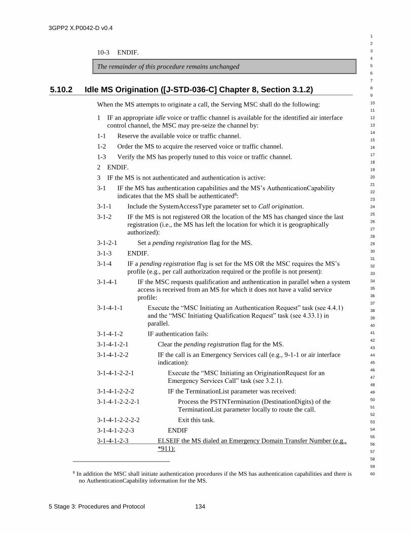
3GPP2 X.P0042-D v0.4
1
2
3
4
5
6
7
8
9
10
11
12
13
14
15
16
17
18
19
20
21
22
23
24
25
26
27
28
29
30
31
32
33
34
35
36
37
38
39
40
41
42
43
44
45
46
47
48
49
50
51
52
53
54
55
56
57
58
59
60
5 Stage 3: Procedures and Protocol 134
10-3 ENDIF.
The remainder of this procedure remains unchanged
5.10.2 Idle MS Origination ([J-STD-036-C] Chapter 8, Section 3.1.2)
When the MS attempts to originate a call, the Serving MSC shall do the following:
1 IF an appropriate idle voice or traffic channel is available for the identified air interface
control channel, the MSC may pre-seize the channel by:
1-1 Reserve the available voice or traffic channel.
1-2 Order the MS to acquire the reserved voice or traffic channel.
1-3 Verify the MS has properly tuned to this voice or traffic channel.
2 ENDIF.
3 IF the MS is not authenticated and authentication is active:
3-1 IF the MS has authentication capabilities and the MS’s AuthenticationCapability
indicates that the MS shall be authenticated8:
3-1-1 Include the SystemAccessType parameter set to Call origination.
3-1-2 IF the MS is not registered OR the location of the MS has changed since the last
registration (i.e., the MS has left the location for which it is geographically
authorized):
3-1-2-1 Set a pending registration flag for the MS.
3-1-3 ENDIF.
3-1-4 IF a pending registration flag is set for the MS OR the MSC requires the MS’s
profile (e.g., per call authorization required or the profile is not present):
3-1-4-1 IF the MSC requests qualification and authentication in parallel when a system
access is received from an MS for which it does not have a valid service
profile:
3-1-4-1-1 Execute the “MSC Initiating an Authentication Request” task (see 4.4.1)
and the “MSC Initiating Qualification Request” task (see 4.33.1) in
parallel.
3-1-4-1-2 IF authentication fails:
3-1-4-1-2-1 Clear the pending registration flag for the MS.
3-1-4-1-2-2 IF the call is an Emergency Services call (e.g., 9-1-1 or air interface
indication):
3-1-4-1-2-2-1 Execute the “MSC Initiating an OriginationRequest for an
Emergency Services Call” task (see 3.2.1).
3-1-4-1-2-2-2 IF the TerminationList parameter was received:
3-1-4-1-2-2-2-1 Process the PSTNTermination (DestinationDigits) of the
TerminationList parameter locally to route the call.
3-1-4-1-2-2-2-2 Exit this task.
3-1-4-1-2-2-3 ENDIF
3-1-4-1-2-3 ELSEIF the MS dialed an Emergency Domain Transfer Number (e.g.,
*911):
8 In addition the MSC shall initiate authentication procedures if the MS has authentication capabilities and there is no AuthenticationCapability information for the MS.
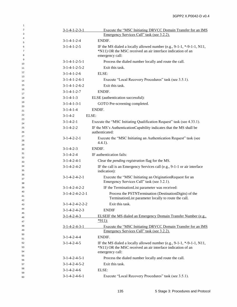
3GPP2 X.P0042-D v0.4
1
2
3
4
5
6
7
8
9
10
11
12
13
14
15
16
17
18
19
20
21
22
23
24
25
26
27
28
29
30
31
32
33
34
35
36
37
38
39
40
41
42
43
44
45
46
47
48
49
50
51
52
53
54
55
56
57
58
59
60
135 5 Stage 3: Procedures and Protocol
3-1-4-1-2-3-1 Execute the “MSC Initiating DRVCC Domain Transfer for an IMS
Emergency Services Call” task (see 3.2.2).
3-1-4-1-2-4 ENDIF.
3-1-4-1-2-5 IF the MS dialed a locally allowed number (e.g., 9-1-1, *-9-1-1, N11,
*N11) OR the MSC received an air interface indication of an
emergency call:
3-1-4-1-2-5-1 Process the dialed number locally and route the call.
3-1-4-1-2-5-2 Exit this task.
3-1-4-1-2-6 ELSE:
3-1-4-1-2-6-1 Execute “Local Recovery Procedures” task (see 3.5.1).
3-1-4-1-2-6-2 Exit this task.
3-1-4-1-2-7 ENDIF.
3-1-4-1-3 ELSE (authentication successful):
3-1-4-1-3-1 GOTO Pre-screening completed.
3-1-4-1-4 ENDIF.
3-1-4-2 ELSE:
3-1-4-2-1 Execute the “MSC Initiating Qualification Request” task (see 4.33.1).
3-1-4-2-2 IF the MS’s AuthenticationCapability indicates that the MS shall be
authenticated:
3-1-4-2-2-1 Execute the “MSC Initiating an Authentication Request” task (see
4.4.1).
3-1-4-2-3 ENDIF.
3-1-4-2-4 IF authentication fails:
3-1-4-2-4-1 Clear the pending registration flag for the MS.
3-1-4-2-4-2 IF the call is an Emergency Services call (e.g., 9-1-1 or air interface
indication):
3-1-4-2-4-2-1 Execute the “MSC Initiating an OriginationRequest for an
Emergency Services Call” task (see 3.2.1).
3-1-4-2-4-2-2 IF the TerminationList parameter was received:
3-1-4-2-4-2-2-1 Process the PSTNTermination (DestinationDigits) of the
TerminationList parameter locally to route the call.
3-1-4-2-4-2-2-2 Exit this task.
3-1-4-2-4-2-3 ENDIF
3-1-4-2-4-3 ELSEIF the MS dialed an Emergency Domain Transfer Number (e.g.,
*911):
3-1-4-2-4-3-1 Execute the “MSC Initiating DRVCC Domain Transfer for an IMS
Emergency Services Call” task (see 3.2.2).
3-1-4-2-4-4 ENDIF.
3-1-4-2-4-5 IF the MS dialed a locally allowed number (e.g., 9-1-1, *-9-1-1, N11,
*N11) OR the MSC received an air interface indication of an
emergency call:
3-1-4-2-4-5-1 Process the dialed number locally and route the call.
3-1-4-2-4-5-2 Exit this task.
3-1-4-2-4-6 ELSE:
3-1-4-2-4-6-1 Execute “Local Recovery Procedures” task (see 3.5.1).
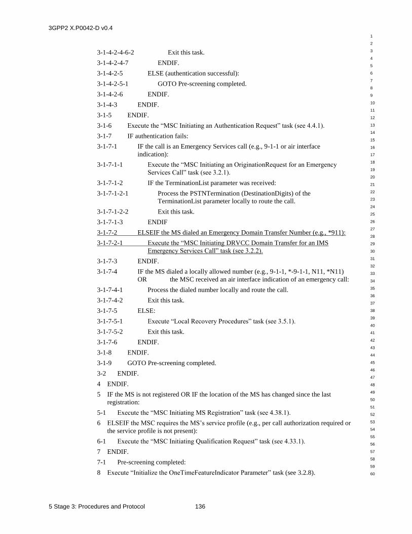
3GPP2 X.P0042-D v0.4
1
2
3
4
5
6
7
8
9
10
11
12
13
14
15
16
17
18
19
20
21
22
23
24
25
26
27
28
29
30
31
32
33
34
35
36
37
38
39
40
41
42
43
44
45
46
47
48
49
50
51
52
53
54
55
56
57
58
59
60
5 Stage 3: Procedures and Protocol 136
3-1-4-2-4-6-2 Exit this task.
3-1-4-2-4-7 ENDIF.
3-1-4-2-5 ELSE (authentication successful):
3-1-4-2-5-1 GOTO Pre-screening completed.
3-1-4-2-6 ENDIF.
3-1-4-3 ENDIF.
3-1-5 ENDIF.
3-1-6 Execute the “MSC Initiating an Authentication Request” task (see 4.4.1).
3-1-7 IF authentication fails:
3-1-7-1 IF the call is an Emergency Services call (e.g., 9-1-1 or air interface
indication):
3-1-7-1-1 Execute the “MSC Initiating an OriginationRequest for an Emergency
Services Call” task (see 3.2.1).
3-1-7-1-2 IF the TerminationList parameter was received:
3-1-7-1-2-1 Process the PSTNTermination (DestinationDigits) of the
TerminationList parameter locally to route the call.
3-1-7-1-2-2 Exit this task.
3-1-7-1-3 ENDIF
3-1-7-2 ELSEIF the MS dialed an Emergency Domain Transfer Number (e.g., *911):
3-1-7-2-1 Execute the “MSC Initiating DRVCC Domain Transfer for an IMS
Emergency Services Call” task (see 3.2.2).
3-1-7-3 ENDIF.
3-1-7-4 IF the MS dialed a locally allowed number (e.g., 9-1-1, *-9-1-1, N11, *N11)
OR the MSC received an air interface indication of an emergency call:
3-1-7-4-1 Process the dialed number locally and route the call.
3-1-7-4-2 Exit this task.
3-1-7-5 ELSE:
3-1-7-5-1 Execute “Local Recovery Procedures” task (see 3.5.1).
3-1-7-5-2 Exit this task.
3-1-7-6 ENDIF.
3-1-8 ENDIF.
3-1-9 GOTO Pre-screening completed.
3-2 ENDIF.
4 ENDIF.
5 IF the MS is not registered OR IF the location of the MS has changed since the last
registration:
5-1 Execute the “MSC Initiating MS Registration” task (see 4.38.1).
6 ELSEIF the MSC requires the MS’s service profile (e.g., per call authorization required or
the service profile is not present):
6-1 Execute the “MSC Initiating Qualification Request” task (see 4.33.1).
7 ENDIF.
7-1 Pre-screening completed:
8 Execute “Initialize the OneTimeFeatureIndicator Parameter” task (see 3.2.8).
3GPP2 X.P0042-D v0.4
1
2
3
4
5
6
7
8
9
10
11
12
13
14
15
16
17
18
19
20
21
22
23
24
25
26
27
28
29
30
31
32
33
34
35
36
37
38
39
40
41
42
43
44
45
46
47
48
49
50
51
52
53
54
55
56
57
58
59
60
137 5 Stage 3: Procedures and Protocol
9 IF a pending registration flag is set for the MS:
9-1 Clear the pending registration flag for the MS.
9-2 Execute the “MSC Analyze MS Dialed Number” task (see 3.1.13.2.3) and spawn the
“MSC Initiating MS Registration” task (see 4.38.1) in parallel.
10 ELSE:
10-1 Execute the “MSC Analyze MS Dialed Number” task (see 3.1.13.2.3).
11 ENDIF.
12 IF the PointOfReturn is ToneTermination:
12-1 Execute “Apply Access Denial Treatment” task (see 3.4.5).
12-2 Exit this task.
13 ENDIF.
14 IF the MS is not authorized:
14-1 Execute “Apply Access Denial Treatment” task (see 3.4.5).
14-2 Exit this task.
15 ENDIF.
16 Execute the “MSC PACA Call Origination Invocation” task (see 5.17.2).
17 IF unsuccessful:
17-1 Execute “Apply Access Denial Treatment” task (see 3.4.5).
18 ELSE (seize the channel by):
18-1 Reserve the available voice or traffic channel.
18-2 Order the MS to acquire the reserved voice or traffic channel.
18-3 Verify the MS has properly tuned to this voice or traffic channel.
18-4 IF unsuccessful:
18-4-1 Execute “Apply Access Denial Treatment” task (see 3.4.5).
18-5 ENDIF.
19 ENDIF.
20 Execute the “MSC MWN Call Origination Invocation” task (see 5.13.7).
21 ENDIF.
22 IF the AnnouncementList parameter is received:
22-1 Execute the “Play All Announcements in the AnnouncementList” task (see 3.2.5).
23 ENDIF.
24 Execute the “MSC Routing Points Of Return” task (see 3.2.6).
25 Exit this task.
5.10.3 MSC Initiating an OriginationRequest for an Emergency Services Call ([J-STD-036-C] Chapter 8, Section 3.2.1)
When the MSC determines that it requires information from the MPC for an emergency
service call, it shall perform the following:
1 Include the OriginationTriggers parameter with length zero.
2 IF the Mobile Station Identity (MSID) is available:
2-1 Include the MSID parameter set to identify the originating MS.
3 ELSE (MSID unavailable):
3GPP2 X.P0042-D v0.4
1
2
3
4
5
6
7
8
9
10
11
12
13
14
15
16
17
18
19
20
21
22
23
24
25
26
27
28
29
30
31
32
33
34
35
36
37
38
39
40
41
42
43
44
45
46
47
48
49
50
51
52
53
54
55
56
57
58
59
60
5 Stage 3: Procedures and Protocol 138
3-1 Include the InternationalMobileSubscriberIdentity identifier type of MSID of length
zero.
4 ENDIF.
5 IF the Mobile Directory Number (MDN) of the MS is available AND IF (authentication
was successful OR the MS’s AuthenticationCapability indicates no authentication
required):
5-1 Include the MobileDirectoryNumber parameter set to the MDN of the MS.
6 ELSE (MDN unavailable):
6-1 Include the MobileDirectoryNumber parameter set to the pseudo-callback number.
7 ENDIF.
8 Include the TransactionCapability parameter set to identify the current capabilities.
9 Include the MobileCallStatus parameter set appropriately, if applicable.
10 Include the OriginationIndicator parameter set to identify the types of call the MS can
originate, if applicable.
11 Include the TerminationRestrictionCode parameter set to identify the types of calls the
MS is allowed to terminate, if applicable.
12 IF the MSC is currently serving the MS:
12-1 Include the applicable parameters defined in the technology-specific MobInfo macros
(see 2.3.2.17, and following).
12-2 Include the ServingCellID parameter set to the cell currently serving the MS.
13 ENDIF.
14 IF known:
14-1 Include the MobilePositionCapability parameter set to identify the position
determination capability of the MS.
15 ENDIF.
16 Send an OriginationRequest INVOKE to the MPC associated with the MSC.
17 Start the Origination Request Timer (ORT).
18 Await Result:
19 WAIT for Origination Request response:
20 WHEN a RETURN RESULT is received:
20-1 OriginationRequest RETURN RESULT received:
20-2 Stop timer (ORT).
20-3 IF the message can be processed:
20-3-1 IF the GeographicPosition parameter is received:
20-3-1-1 Relay the contents of the GeographicPosition parameter for use as the ISUP
Calling Geodetic Location parameter for the call to the calling task.
20-3-2 ENDIF.
20-3-3 IF the DMH_BillingDigits parameter is received:
20-3-3-1 Relay the contents of the DMH_BillingDigits parameter for use as the ISUP
Charge Number parameter or as MF ANI information to the calling task.
20-3-4 ENDIF.
20-3-5 IF the MobileDirectoryNumber parameter is received:
20-3-5-1 Relay the contents of the MobileDirectoryNumber parameter for use as the
ISUP Calling Party Number parameter to the calling task.
3GPP2 X.P0042-D v0.4
1
2
3
4
5
6
7
8
9
10
11
12
13
14
15
16
17
18
19
20
21
22
23
24
25
26
27
28
29
30
31
32
33
34
35
36
37
38
39
40
41
42
43
44
45
46
47
48
49
50
51
52
53
54
55
56
57
58
59
60
139 5 Stage 3: Procedures and Protocol
20-3-6 ENDIF.
20-3-7 IF the GenericDigits parameter is received:
20-3-7-1 Relay the contents of the GenericDigits parameter for use as the ISUP Generic
Digits Parameter to the calling task.
20-3-8 ENDIF.
20-3-9 Return to the Calling Task.
20-4 ELSE (message cannot be processed):
20-4-1 Return to calling task with an Unsuccessful indication.
20-5 ENDIF.
21 WHEN an InterSystemPositionRequest INVOKE is received:
21-1 Execute the “MSC Receiving an InterSystemPositionRequest INVOKE” task (see
3.3.1).
21-2 GOTO Await Result.
22 WHEN a RemoteUserInteractionDirective INVOKE is received:
22-1 Send a RETURN ERROR with Error Code set to indicate
OperationSequenceProblem.
22-2 GOTO Await Result.
23 WHEN the MS disconnects:
23-1 Stop timer (ORT).
23-2 Return to the calling task with a Call Abandoned indication.
24 WHEN a RETURN ERROR or REJECT is received:
24-1 Stop timer (ORT).
24-2 Return to the calling task with an Unsuccessful indication.
25 WHEN timer (ORT) expires9:
25-1 Return to the calling task with an Unsuccessful indication.
26 ENDWAIT.
27 Return to calling task.
5.10.4 MSC Initiating DRVCC Domain Transfer for an IMS Emergency Services Call (new Section 3.2.2 for [J-STD-036-C] Chapter 8)
When the MSC determines DRVCC Domain Transfer for an IMS Emergency Services Call is
required (i.e., MS dialed an Emergency Domain Transfer Number), it shall perform the
following:
1 Execute the “MSC Initiating DRVCC Access Transfer for an IMS Emergency Services
Call” task (see 3.2.2.1).
2 IF the Access Transfer failed:
2-1 Exit this task.
3 ELSE:
4 Execute the “MSC Notifying MPC of Domain Transfer” task (see 3.2.2.2)10.
9 This will not normally occur since the MPC will send a response when a timer (POST) in the MPC which is shorter than ORT expires.
3GPP2 X.P0042-D v0.4
1
2
3
4
5
6
7
8
9
10
11
12
13
14
15
16
17
18
19
20
21
22
23
24
25
26
27
28
29
30
31
32
33
34
35
36
37
38
39
40
41
42
43
44
45
46
47
48
49
50
51
52
53
54
55
56
57
58
59
60
5 Stage 3: Procedures and Protocol 140
5 ENDIF.
6 Exit this task.
5.10.4.1 MSC Initiating DRVCC Access Transfer for an IMS Emergency Services Call (new Section 3.2.2.1 for [J-STD-036-C] Chapter 8)
When the MSC determines that Access Transfer is required for an IMS Emergency Services
Call, it shall perform the following:
1 IF the MSC is configured to use a SIP interface to interact with the IMS Emergency
Access Transfer Function (EATF).
1-1 Send an Access Transfer request to the EATF using the mechanism specified in
[24.237]. The MEID of the MS is included in the Access Transfer request.
1-2 IF the Access Transfer request failed:
1-2-1 Execute the “Local Recovery Procedures” task (see 3.5.1).
1-2-2 Return to the calling task with a failure indication.
1-3 ENDIF.
1-4 Process the call origination locally and route the call for the Domain Transfer.
2 ELSEIF the MSC is configured for MGCF-based Emergency Domain Transfer:
2-1 Include the MEID of the MS in the in the Application Transport Parameter of the
ISUP Initial Address Message as specified in [29.205].
2-2 Process the call origination locally and route the ISUP call to the media gateway for
Domain Transfer as specified in [24.237].
2-3 IF the ISUP call setup failed:
2-3-1 Execute the “Local Recovery Procedures” task (see 3.5.1).
2-3-2 Return to the calling task with a failure indication.
2-4 ENDIF.
3 ELSE (the MSC is configured for WIN-based Emergency Domain Transfer11):
3-1 Include the MEID parameter set to identify the originating MS.
3-2 Include the MSID parameter set to identify the originating MS.
3-3 Include the Digits (Dialed) parameter set to the digits received from the MS.
3-4 Include the OriginationTriggers parameter set to indicate Emergency Domain
Transfer.
3-5 Include the BillingID (Originating) parameter set to the billing identifier for the call
assigned by the current Originating MSC.
3-6 Include other applicable parameters.
3-7 Send an OriginationRequest INVOKE to the service logic host address for the
Emergency Domain Transfer.
3-8 Continue processing the Origination Request as specified in X.S0004-640-E v2.0,
section 42.1.
3-9 IF the call set up failed:
10 If the MSC does not successfully notify the MPC of Domain Transfer, the Domain Transfer for the emergency
services call should not stop. The only service that would be affected is PSAP retrieval of updated MS location information.
11 The MSC is configured with an office-based WIN trigger for the Emergency Domain Transfer.
3GPP2 X.P0042-D v0.4
1
2
3
4
5
6
7
8
9
10
11
12
13
14
15
16
17
18
19
20
21
22
23
24
25
26
27
28
29
30
31
32
33
34
35
36
37
38
39
40
41
42
43
44
45
46
47
48
49
50
51
52
53
54
55
56
57
58
59
60
141 5 Stage 3: Procedures and Protocol
3-9-1 Return to the calling task with a failure indication.
3-10 ENDIF.
4 ENDIF.
5 Return to the calling task with a successful indication.
5.10.4.2 MSC Notifying MPC of Domain Transfer (new Section 3.2.2.2 for [J-STD-036-C] Chapter 8)
When the MSC determines it shall notify the MPC of the Domain Transfer of an IMS
Emergency Services Call, it shall perform the following:
1 Include the OriginationTriggers parameter with length zero.
2 Include the Digits (Dialed) parameter set to the digits received from the MS.
3 IF the Mobile Station Identity (MSID) is available:
3-1 Include the MSID parameter set to identify the originating MS.
4 ELSE (MSID unavailable):
4-1 Include the InternationalMobileSubscriberIdentity identifier type of MSID of length
zero.
5 ENDIF.
6 IF the Mobile Directory Number (MDN) of the MS is available AND IF (authentication
was successful OR the MS’s AuthenticationCapability indicates no authentication
required):
6-1 Include the MobileDirectoryNumber parameter set to the MDN of the MS.
7 ENDIF.
8 Include the TransactionCapability parameter set to identify the current capabilities.
9 Include the MobileCallStatus parameter. Set the Domain Transfer field to indicate
Domain Transfer requested.
10 Include the OriginationIndicator parameter set to identify the types of call the MS can
originate, if applicable.
11 Include the TerminationRestrictionCode parameter set to identify the types of calls the
MS is allowed to terminate, if applicable.
12 Include the applicable parameters defined in the technology-specific MobInfo macros (see
2.3.2.17, and following).
13 Include the ServingCellID parameter set to the cell currently serving the MS.
14 IF known:
14-1 Include the MobilePositionCapability parameter set to identify the position
determination capability of the MS.
15 ENDIF.
16 Send an OriginationRequest INVOKE to the MPC associated with the MSC.
17 Start the Origination Request Timer (ORT).
18 Await Result:
19 WAIT for Origination Request response:
20 WHEN a RETURN RESULT is received:
20-1 OriginationRequest RETURN RESULT received:
20-2 Stop timer (ORT).
3GPP2 X.P0042-D v0.4
1
2
3
4
5
6
7
8
9
10
11
12
13
14
15
16
17
18
19
20
21
22
23
24
25
26
27
28
29
30
31
32
33
34
35
36
37
38
39
40
41
42
43
44
45
46
47
48
49
50
51
52
53
54
55
56
57
58
59
60
5 Stage 3: Procedures and Protocol 142
20-3 IF the message can be processed:
20-3-1 Return to the calling task with a successful indication.
20-4 ELSE (message cannot be processed):
20-4-1 Execute the “Local Recovery Procedures” task (see 3.5.1).
20-4-2 Return to the calling task with a failure indication.
20-5 ENDIF.
21 WHEN the MS disconnects:
21-1 Stop timer (ORT).
21-2 Execute the “Local Recovery Procedures” task (see 3.5.1).
21-3 Return to the calling task with a failure indication.
22 WHEN a RETURN ERROR or REJECT is received:
22-1 Stop timer (ORT).
22-2 Execute the “Local Recovery Procedures” task (see 3.5.1).
22-3 Return to the calling task with a failure indication.
23 WHEN timer (ORT) expires:
23-1 Execute the “Local Recovery Procedures” task (see 3.5.1).
23-2 Return to the calling task with a failure indication.
24 ENDWAIT.
5.11 Signaling Procedures for SRVCC Domain Transfer of IMS Emergency Services Call to 1x CS
The signaling procedures for the SRVCC Domain Transfer of an IMS Emergency Services
Call to 1xCS are specified as additions to the signaling protocol in [J-STD-036-C] Chapter 8.
5.11.1 MSC Receiving SRVCC Domain Transfer Request from MME (new Section 3.2.3 for [J STD 036 C] Chapter 8)
When the MSC receives an SRVCC Domain Transfer request for an IMS Emergency Call
from an MME (see [29.277] for signaling details), the MSC shall do the following:
1 IF an appropriate idle voice or traffic channel is available for the Emergency Call ANDIF
a trunk to the MGW is available:
1-1 Reserve the available voice or traffic channel.
1-2 IF the MSC is configured for MGCF-based Emergency Domain Transfer:
1-2-1 Send an ISUP IAM message to the MGCF with the CdPN set to the E-STN-SR
associated with the EATF for the speech media component to be transferred. The
MSC includes the MEID of the MS in the Application Transport Parameter of the
IAM message as specified in [29.205].
1-2-2 WAIT for an ISUP response message.
1-2-3 WHEN an ISUP ANM message is received:
1-2-3-1 Send a channel assignment message to the MS (via the 1xCS IWS, MME, and
eNodeB). This instructs the MS to perform the handoff and acquire the traffic
channel. See [A.S0008] and [A.S0009] for signaling details.
1-2-3-2 WAIT for the channel assignment complete from the MS.
3GPP2 X.P0042-D v0.4
1
2
3
4
5
6
7
8
9
10
11
12
13
14
15
16
17
18
19
20
21
22
23
24
25
26
27
28
29
30
31
32
33
34
35
36
37
38
39
40
41
42
43
44
45
46
47
48
49
50
51
52
53
54
55
56
57
58
59
60
143 5 Stage 3: Procedures and Protocol
1-2-3-3 WHEN a channel assignment complete is received:
1-2-3-3-1 Route the call to the MGW for the Domain Transfer.
1-2-3-3-2 IF the MSC is configured to notify the MME of channel assignment
confirmation:
1-2-3-3-2-1 Send confirmation of the channel assignment to the MME (via the
1xCS IWS). See [29.277] for signaling details.
1-2-3-3-3 ENDIF.
1-2-3-3-4 Send confirmation of the channel assignment to the MME (via the 1xCS
IWS). See [29.277] for signaling details.
1-2-3-4 WHEN the MSC determines that the channel assignment was unsuccessful:
1-2-3-4-1 Execute the “Local Recovery Procedures” task (see 3.5.1).
1-2-3-4-2 Exit this task.
1-2-3-5 ENDWAIT.
1-2-4 WHEN the MSC determines that the ISUP call setup failed:
1-2-4-1 Execute the “Local Recovery Procedures” task (see 3.5.1).
1-2-4-2 Exit this task.
1-2-5 ENDWAIT.
1-3 ELSEIF (the MSC is configured to use a SIP interface to interact with the IMS
EATF):
1-3-1 Send a SIP INVITE request to the EATF (via the I-CSCF) with the request URI
set to the E-STN-SR for the session with speech media component to be
transferred. The instance-id feature tag in the Contact header field is set to a value
based on the MEID (see [23.003]). The SDP offer is set to the media
characteristics of the MGW the MSC will use.
1-3-2 WAIT for a response to the SIP INVITE.
1-3-3 WHEN a SIP 200 OK is received with the SDP answer:
1-3-3-1 Send a channel assignment message to the MS (via the 1xCS IWS, MME, and
eNodeB). This instructs the MS to perform the handoff and acquire the traffic
channel. See [A.S0008] and [A.S0009] for signaling details.
1-3-3-2 WAIT for the channel assignment complete from the MS.
1-3-3-3 WHEN a channel assignment complete message is received:
1-3-3-3-1 Route the call to the MGW for the Domain Transfer.
1-3-3-3-2 IF the MSC is configured to notify the MME of channel assignment
confirmation:
1-3-3-3-2-1 Send confirmation of the channel assignment to the MME (via the
1xCS IWS). See [29.277] for signaling details.
1-3-3-3-3 ENDIF.
1-3-3-4 WHEN the MSC determines that the channel assignment was unsuccessful:
1-3-3-4-1 Execute the “Local Recovery Procedures” task (see 3.5.1).
1-3-3-4-2 Exit this task.
1-3-3-5 ENDWAIT.
1-4 ELSE:
1-4-1 Execute the “Local Recovery Procedures” task (see 3.5.1).
1-4-2 Exit this task.
1-5 ENDIF.
3GPP2 X.P0042-D v0.4
1
2
3
4
5
6
7
8
9
10
11
12
13
14
15
16
17
18
19
20
21
22
23
24
25
26
27
28
29
30
31
32
33
34
35
36
37
38
39
40
41
42
43
44
45
46
47
48
49
50
51
52
53
54
55
56
57
58
59
60
5 Stage 3: Procedures and Protocol 144
2 ELSE:
2-1 The MSC shall send an acknowledgement message to the MME (via the 1xCS IWS)
with the failure indication. See [29.277] for signaling details.
2-2 Exit this task.
3 ENDIF.
4 Execute the “MSC Notifying MPC of Domain Transfer” task (see 3.2.2.2)12.
5 Exit this task.
5.12 Signaling Procedures for SRVCC Domain Transfer of IMS Call to 1x CS
The signaling procedures for the SRVCC Domain Transfer of a non-emergency IMS VoIP
Call to 1xCS are specified as a new normative annex for X.S0004-691-E v3.0, Mobile
Application Part (MAP) - Annexes for the 6XX Series.
5.12.1 Annex G: Signaling Procedures for SRVCC Domain Transfer of IMS Call to 1x CS
This Annex is normative and is considered part of this Standard.
When the MSC receives an SRVCC Domain Transfer request for an IMS VoIP Call (non-
emergency) from an MME (see [29.277] for signaling details), the MSC shall do the
following:
1 IF the MSC determines that the STN-SR received from the MME is not valid:
1-1 Execute the “Local Recovery Procedures” task (see 3.5.1).
1-2 The MSC shall send an acknowledgement message to the MME (via the 1xCS IWS)
with the failure indication. See [29.277] for signaling details.
1-3 Exit this task.
2 ELSEIF an appropriate idle voice or traffic channel is available for the call ANDIF a trunk
to the MGW is available:
2-1 Reserve the available voice or traffic channel.
2-2 IF the MSC is configured for MGCF-based Domain Transfer:
2-2-1 Send an ISUP IAM message to the MGCF with the CdPN set to the STN-SR for
the speech media component to be transferred. The MSC includes the MEID of
the MS in the Application Transport Parameter of the IAM message as specified in
[29.205].
2-2-2 WAIT for an ISUP response message.
2-2-3 WHEN an ISUP ANM message is received:
2-2-3-1 Send a channel assignment message to the MS (via the 1xCS IWS, MME, and
eNodeB). This instructs the MS to perform the handoff and acquire the traffic
channel. See [A.S0008] and [A.S0009] for signaling details.
2-2-3-2 WAIT for the channel assignment complete from the MS.
2-2-3-3 WHEN a channel assignment complete is received:
12 If the MSC does not successfully notify the MPC of Domain Transfer, the Domain Transfer for the emergency
services call should not stop. The only service that would be affected is PSAP retrieval of updated MS location information.
3GPP2 X.P0042-D v0.4
1
2
3
4
5
6
7
8
9
10
11
12
13
14
15
16
17
18
19
20
21
22
23
24
25
26
27
28
29
30
31
32
33
34
35
36
37
38
39
40
41
42
43
44
45
46
47
48
49
50
51
52
53
54
55
56
57
58
59
60
145 5 Stage 3: Procedures and Protocol
2-2-3-3-1 Route the call to the MGW for the Domain Transfer.
2-2-3-3-2 IF the MSC is configured to notify the MME of channel assignment
confirmation:
2-2-3-3-2-1 Send confirmation of the channel assignment to the MME (via the
1xCS IWS). See [29.277] for signaling details.
2-2-3-3-3 ENDIF.
2-2-3-4 WHEN the MSC determines that the channel assignment was unsuccessful:
2-2-3-4-1 Execute the “Local Recovery Procedures” task (see 3.5.1).
2-2-3-4-2 Exit this task.
2-2-3-4 ENDWAIT.
2-2-4 WHEN the MSC determines that the ISUP call setup failed:
2-2-4-1 Execute the “Local Recovery Procedures” task (see 3.5.1).
2-2-4-2 Exit this task.
2-2-5 ENDWAIT.
2-3 ELSEIF (the MSC is configured to use a SIP interface to interact with the IMS VCC
AS):
2-3-1 Send a SIP INVITE request to IMS with the request URI set to the STN-SR for the
session with speech media component to be transferred. The instance-id feature
tag in the Contact header field is set to a value based on the MEID (see [23.003]).
The SDP offer is set to the media characteristics of the MGW the MSC will use.
2-3-2 WAIT for a response to the SIP INVITE.
2-3-3 WHEN a SIP 200 OK is received with the SDP answer:
2-3-3-1 Send a channel assignment message to the MS (via the 1xCS IWS, MME, and
eNodeB). This instructs the MS to perform the handoff and acquire the traffic
channel. See [A.S0008] and [A.S0009] for signaling details.
2-3-3-2 WAIT for the channel assignment complete from the MS.
2-3-3-3 WHEN a channel assignment complete message is received:
2-3-3-3-1 Route the call to the MGW for the Domain Transfer.
2-3-3-3-2 IF the MSC is configured to notify the MME of channel assignment
confirmation:
2-3-3-3-2-1 Send confirmation of the channel assignment to the MME (via the
1xCS IWS). See [29.277] for signaling details.
2-3-3-3-3 ENDIF.
2-3-3-4 WHEN the MSC determines that the channel assignment was unsuccessful:
2-3-3-4-1 Execute the “Local Recovery Procedures” task (see 3.5.1).
2-3-3-4-2 Exit this task.
2-3-3-4 ENDWAIT.
2-4 ELSE:
2-4-1 Execute the “Local Recovery Procedures” task (see 3.5.1).
2-4-2 Exit this task.
2-5 ENDIF.
3 ELSE:
3-1 The MSC shall send an acknowledgement message to the MME (via the 1xCS IWS)
with the failure indication. See [29.277] for signaling details.
3GPP2 X.P0042-D v0.4
1
2
3
4
5
6
7
8
9
10
11
12
13
14
15
16
17
18
19
20
21
22
23
24
25
26
27
28
29
30
31
32
33
34
35
36
37
38
39
40
41
42
43
44
45
46
47
48
49
50
51
52
53
54
55
56
57
58
59
60
5 Stage 3: Procedures and Protocol 146
3-2 Exit this task.
4 ENDIF.
5 Exit this task.
5.13 Roles for DRVCC domain transfer of alerting call from the IMS to the CS domain
5.13.1 Introduction
This section specifies the procedures for DRVCC DT of alerting call from the IMS to the CS
domain. The procedures which include DT procedure of incoming call and DT procedure of
outgoing call are specified for the DRVCC UE and other VCC functional entities.
5.13.2 DRVCC UE
5.13.2.1 Incoming call at alerting state
In the incoming call case, If the DRVCC UE determines that an alerting call in the IMS needs
to be transferred to the CS domain, e.g., based on radio conditions, then the VCC UE shall
send a SIP 488 Message to VCC AS and wait for the call from VCC AS through CS domain.
5.13.2.2 Outgoing call at alerting state
In the outgoing call case, if the DRVCC UE determines that an alerting call in the IMS needs
to be transferred to the CS domain, e.g., based on radio conditions, then the VCC UE shall
send a Origination message in accordance with [C.S0005].
NOTE: The current media characteristics of the call in the IMS do not
preclude DT, as the media characteristics are renegotiated as part of the DT.
The VCC UE shall populate the 1x Origination message as follows:
1. set the dialed digits to the VDN; and
2. other information elements populated for 1x CS originations as specified by
[C.S0005] as applicable.
5.13.3 MSC
In incoming call case, the MSC processes MS termination events as defined in [X.S0004-
630].
In outgoing call case, the MSC processes MS origination events as defined in [X.S0004-630].
NOTE: The MSC may interact with triggers for DT from IMS to the CS
Domain.
5.13.4 VCC AS
5.13.4.1 Incoming call at alerting state
When the VCC AS receives SIP 488 Message due to DT, the VCC AS knows that the
DRVCC UE has an incoming SIP call which is on alerting state. To initiate the DT of the

3GPP2 X.P0042-D v0.4
1
2
3
4
5
6
7
8
9
10
11
12
13
14
15
16
17
18
19
20
21
22
23
24
25
26
27
28
29
30
31
32
33
34
35
36
37
38
39
40
41
42
43
44
45
46
47
48
49
50
51
52
53
54
55
56
57
58
59
60
147 5 Stage 3: Procedures and Protocol
DRVCC UE, the VCC AS shall send a SIP INVITE request towards DRVCC UE through CS
domain using the SDP offer stored from the previous call dialog of remote UE to DRVCC
UE. For making the request pass through CS domain, VCC AS shall set the Request-URI with
routing information of DRVCC UE. Upon receiving the SIP 180(Ringing) response from
MGCF, the VCC AS shall send a SIP UPDATE request towards the remote UE in the existing
alerting dialog to update the SDP negotiation with the SDP offer coming from CS domain.
5.13.4.2 Outgoing call at alerting state
When the VCC AS receives SIP INVITE request due to DT IMRN or VDN, based on
information associated with the received IMRN, if present, and P-Asserted-Identity header
field, the VCC AS knows that the DRVCC UE has an outgoing SIP call which is on alerting
state and shall associate the SIP INVITE request with this alerting SIP dialog. VCC AS shall
send a SIP UPDATE request towards the remote UE in the existing alerting dialog to update
the SDP negotiation with the SDP offer coming from the CS domain. After receiving the SIP
200(OK) response to the SIP UPDATE request from the remote UE, the VCC AS shall send
a SIP 180(Ringing) response to DRVCC UE request due to the PS to CS DT with an SDP
answer based on the SDP answer received from the remote UE. The VCC AS shall now
initiate release of the old access leg by sending a SIP 480 toward the DRVCC UE.
5.14 Roles for DRVCC domain transfer of supplementary service from the IMS to the CS domain
5.14.1 Introduction
This section specifies the procedures for DRVCC DT of supplementary service from the IMS to the CS
domain. These supplementary service include call hold, call waiting and 3WC. The procedures which
include DT procedure of supplementary service are specified for the DRVCC UE and other VCC
functional entities.
5.14.2 DRVCC UE
5.14.2.1 Call Hold
When the DRVCC UE has a call on hold with the remote UE in IMS, if the DRVCC UE determines
that the call needs to be transferred to the CS domain, e.g., based on radio conditions, then the DRVCC
UE shall send an Origination message in accordance with [C.S0005].
The VCC UE shall populate the 1x Origination message as follows:
1. set the dialed digits to the VDN; and
2. other information elements populated for 1x CS originations as specified by [C.S0005] as
applicable.
After transferring the call from IMS to CS, the DRVCC UE shall send flash with information to MSC
to hold the call with remote UE.
3GPP2 X.P0042-D v0.4
1
2
3
4
5
6
7
8
9
10
11
12
13
14
15
16
17
18
19
20
21
22
23
24
25
26
27
28
29
30
31
32
33
34
35
36
37
38
39
40
41
42
43
44
45
46
47
48
49
50
51
52
53
54
55
56
57
58
59
60
5 Stage 3: Procedures and Protocol 148
5.14.2.2 Call Waiting Notify
When the DRVCC UE has an active call in IMS with one remote UE and received an incoming waiting
call notify from another remote UE, if the DRVCC UE determines that the two dialogs need to be
transferred to the CS domain, e.g., based on radio conditions, then the DRVCC UE shall send an
Origination message in accordance with [C.S0005] to transfer the active call from the IMS domain to
the CS domain as follows:
1. set the dialed digits to the VDN; and
2. other information elements populated for 1x CS originations as specified by [C.S0005] as
applicable.
After receiving the flash with information from MSC, the DRVCC UE knows that the incoming
waiting call is being transferred from the IMS domain to the CS domain.
5.14.2.3 Call Waiting Hold
When the DRVCC UE answers the incoming waiting call in the IMS domain with one remote UE and
holds an existing call with another remote UE, if the DRVCC UE determines that the two dialogs need
to be transferred to the CS domain, e.g., based on radio conditions, then the DRVCC UE shall send an
Origination message in accordance with [C.S0005] to transfer the two dialogs from the IMS domain to
the CS domain as follows:
1. set the dialed digits to the VDN; and
2. other information elements populated for 1x CS originations as specified by [C.S0005] as
applicable.
After receiving the flash with information from MSC, the DRVCC UE knows both active and held
calls are now being transferred from the IMS domain to the CS domain. The DRVCC UE shall send
flash with information to MSC to answer the active call.
5.14.2.4 Call Hold in 3WC
When the DRVCC UE holds a call with a remote UE and then makes second call to another remote UE
for 3WC purpose in the IMS domain, if the DRVCC UE determines that the two dialogs need to be
transferred to the CS domain, e.g., based on radio conditions, then the DRVCC UE shall send an
Origination message in accordance with [C.S0005] to transfer the held dialog from the IMS domain to
the CS domain as follows:
1. set the dialed digits to the VDN; and
2. other information elements populated for 1x CS originations as specified by [C.S0005] as
applicable.
The DRVCC UE may receive a Flash with information while the held dialog being transferred to the
CS domain. Upon completion of this transfer the DRVCC UE shall send Flash with information in
accordance with [C.S0005] to transfer the second dialog from the IMS domain to the CS domain. In
Flash with information message, the DRVCC UE shall set the dialed digits to the VDN2 which is
different from VDN.
3GPP2 X.P0042-D v0.4
1
2
3
4
5
6
7
8
9
10
11
12
13
14
15
16
17
18
19
20
21
22
23
24
25
26
27
28
29
30
31
32
33
34
35
36
37
38
39
40
41
42
43
44
45
46
47
48
49
50
51
52
53
54
55
56
57
58
59
60
149 5 Stage 3: Procedures and Protocol
After transferring the two dialogs, if the DRVCC UE wants to connect the two remote UEs in
conference, the DRVCC UE shall send a final Flash with information to setup the 3WC conference as
described in [X.S0004-630].
5.14.2.5 3WC
When the DRVCC UE is in 3WC conference in IMS with two remote UEs, if the DRVCC UE
determines that the 3WC sessions need to be transferred to the CS domain, e.g., based on radio
conditions, the DRVCC UE shall initiate DT from IMS to CS domain. There are two options for the
DRVCC UE to perform DT.
For option 1, the DRVCC UE shall follow the procedures in 5.14.2.4 to transfer the dialogs with the
two remote UEs.
For option 2, the DRVCC UE shall send an Origination message in accordance with [C.S0005] to
transfer the dialog between DRVCC UE and 3WC conference server from the IMS domain to the CS
domain as follows:
1. set the dialed digits to the VDN; and
2. other information elements populated for 1x CS originations as specified by [C.S0005] as
applicable.
5.14.3 MSC
5.14.3.1 Call Hold
For the MS initiated call leg DT, the MSC processes MS origination events as defined in [X.S0004-
630].
After the MS initiated call leg DT, if the MSC receives the flash with information from MS, the MSC
shall process call hold events as defined in [X.S0004-630].
5.14.3.2 Call Waiting Notify
For the MS initiated call leg DT, the MSC processes MS origination events as defined in [X.S0004-
630].
If a UE is already on the call and it receives an incoming call, the MSC shall send Flash with
information as described in [X.S0004-630].
5.14.3.3 Call Waiting Hold
For the MS initiated call leg DT, the MSC processes MS origination events as defined in [X.S0004-
630].
The held exiting call and the new active call are transferred to the CS as the held call being active and
the new active call is an incoming call, thus the MSC shall behave according to [X.S0004-630] and
send a flash with information to the MS about the incoming call. Upon receipt of Flash with
information from the MS, the MSC shall proceed with call waiting hold event as described in
[X.S0004-630].
3GPP2 X.P0042-D v0.4
1
2
3
4
5
6
7
8
9
10
11
12
13
14
15
16
17
18
19
20
21
22
23
24
25
26
27
28
29
30
31
32
33
34
35
36
37
38
39
40
41
42
43
44
45
46
47
48
49
50
51
52
53
54
55
56
57
58
59
60
5 Stage 3: Procedures and Protocol 150
5.14.3.4 Call Hold in 3WC
For the MS initiated call leg DT, the MSC processes MS origination events as defined in [X.S0004-
630].
After the MS initiated call leg DT, if the MSC receives the flash with information including the called
number from MS, the MSC shall process 3WC hold events as defined in [X.S0004-630]. If then the
MSC receives the flash with information from MS, the MSC shall connect the three parties in 3WC
conference as defined in [X.S0004-630].
5.14.3.5 3WC
Two options are defined for this feature:
option 1: The MSC procedures are described in 5.14.3.4 and the MSC connects the three
parties in 3WC conference as defined in [X.S0004-630].
option 2: For the MS initiated call leg DT, the MSC processes MS origination events as
defined in [X.S0004-630] and connects to the 3WC conference server.
5.14.4 VCC AS
5.14.4.1 Call Hold
When the VCC AS receives SIP INVITE request with the Request URI set to IMRN or VDN, and P-
Asserted-Identity header field set to MDN of the DRVCC UE, since the VCC AS knows that the
DRVCC UE has a call on hold with a remote UE in the IMS domain it shall associate the SIP INVITE
request with this held SIP dialog. VCC AS shall send a SIP UPDATE request towards the remote UE
in the existing held dialog to update the SDP negotiation with the SDP offer coming from the CS
domain. This update procedure keeps the remote UE on hold. After receiving the SIP 200(OK)
response to the SIP UPDATE request from the remote UE, the VCC AS shall send a SIP 200(OK)
response to DRVCC UE request due to the PS to CS DT with an SDP answer based on the SDP answer
received from the remote UE.
After receiving the SIP reINVITE request for the held call, the VCC AS shall respond with a SIP
200(OK) response, and then release the old access leg by sending a SIP BYE request toward the
DRVCC UE.
5.14.4.2 Call Waiting Notify
When the VCC AS receives SIP INVITE request with the Request URI set to IMRN or VDN, and P-
Asserted-Identity header field set to MDN of the DRVCC UE, since the VCC AS knows that the
DRVCC UE has an active call with a remote UE in the IMS domain and received an incoming waiting
call notify from another remote UE it shall associate the SIP INVITE request with the active SIP
dialog. VCC AS shall send a SIP UPDATE request toward the remote UE in the existing active dialog
to update the SDP negotiation with the SDP offer coming from the CS domain. After receiving the SIP
200(OK) response to the SIP UPDATE request from the remote UE, the VCC AS shall send a SIP
200(OK) response toward the DRVCC UE with an SDP answer based on the SDP answer received
from the remote UE. The VCC AS shall now initiate release of the old access leg of active call by
sending a SIP BYE request toward the DRVCC UE.
For the incoming waiting call notify from the other remote UE, the VCC AS shall send a SIP INVITE
request towards the DRVCC UE through CS domain to initiate the DT of the waiting dialog using the
3GPP2 X.P0042-D v0.4
1
2
3
4
5
6
7
8
9
10
11
12
13
14
15
16
17
18
19
20
21
22
23
24
25
26
27
28
29
30
31
32
33
34
35
36
37
38
39
40
41
42
43
44
45
46
47
48
49
50
51
52
53
54
55
56
57
58
59
60
151 5 Stage 3: Procedures and Protocol
SDP offer stored from the call waiting dialog of remote UE. For making the request pass through CS
domain, the VCC AS shall set the Request-URI with routing information of the DRVCC UE. Upon
receiving the SIP 180(Ringing) response from CS domain, the VCC AS shall send a SIP UPDATE
request towards the remote UE in the existing call waiting dialog to update the SDP negotiation with
the SDP offer coming from CS domain. The VCC AS shall now initiate release of the old access leg of
waiting call by sending a SIP Cancel request toward the DRVCC UE.
5.14.4.3 Call Waiting Hold
When the VCC AS receives SIP INVITE request with the Request-URI set to DT IMRN or VDN, and
P-Asserted-Identity header field set to MDN of the DRVCC UE, the VCC AS knows that the DRVCC
UE is on active call with an incoming call in the IMS domain while holding an existing call with
another remote UE. The VCC AS shall associate the SIP INVITE request with the held SIP dialog and
shall send a SIP UPDATE request towards the remote UE in the existing held dialog to update the SDP
negotiation with the SDP offer coming from the CS domain. After receiving the SIP 200(OK) response
to the SIP UPDATE request from the remote UE, the VCC AS shall send a SIP 200(OK) response
toward the DRVCC UE request with an SDP answer based on the SDP answer received from the
remote UE. The VCC AS shall now initiate release of the old access leg of held call by sending a SIP
BYE request toward the DRVCC UE.
Then the VCC AS shall send a SIP INVITE request towards DRVCC UE through CS domain to
initiate the DT of the answered waiting dialog using the SDP offer stored from the answered waiting
dialog of remote UE. For making the request pass through CS domain, the VCC AS shall set the
Request-URI with routing information of DRVCC UE. Upon receiving the SIP 200(OK) response from
CS domain, the VCC AS shall send a SIP UPDATE request towards the remote UE in the existing
answered waiting dialog to update the SDP negotiation with the SDP offer coming from CS domain.
The VCC AS shall now initiate release of the old access leg of waiting call by sending a SIP BYE
request toward the DRVCC UE.
5.14.4.4 Call Hold in 3WC
When the VCC AS receives SIP INVITE request with the Request-URI set to IMRN or VDN, and P-
Asserted-Identity header field set to MDN of the DRVCC UE, the VCC AS knows that the DRVCC
UE holds a call with a remote UE in the IMS domain and makes a second call to another remote UE for
3WC purpose. The VCC AS shall associate the SIP INVITE request with the hold SIP dialog and shall
send a SIP UPDATE request towards the remote UE in the existing held dialog to update the SDP
negotiation with the SDP offer coming from the CS domain. After receiving the SIP 200(OK) response
to the SIP UPDATE request from the remote UE, the VCC AS shall send a SIP 200(OK) response
towards the DRVCC UE with an SDP answer based on the SDP answer received from the remote UE.
The VCC AS shall now initiate release of the old access leg of held call by sending a SIP BYE request
toward the DRVCC UE.
After receiving SIP INVITE request with the Request-URI set to IMRN2 or VDN2, the VCC AS shall
associate the SIP INVITE request with the second SIP dialog. The VCC AS shall send a SIP UPDATE
request towards the remote UE in the existing second dialog to update the SDP negotiation with the
SDP offer coming from the CS domain. After receiving the SIP 200(OK) response to the SIP UPDATE
request from the remote UE, the VCC AS shall send a SIP 200(OK) response towards the DRVCC UE
with an SDP answer based on the SDP answer received from the remote UE. The VCC AS shall now
initiate release of the old access leg of second call by sending a SIP BYE request towards the DRVCC
UE.
3GPP2 X.P0042-D v0.4
1
2
3
4
5
6
7
8
9
10
11
12
13
14
15
16
17
18
19
20
21
22
23
24
25
26
27
28
29
30
31
32
33
34
35
36
37
38
39
40
41
42
43
44
45
46
47
48
49
50
51
52
53
54
55
56
57
58
59
60
5 Stage 3: Procedures and Protocol 152
5.14.4.5 3WC
There are two options for VCC AS to work with DRVCC UE to perform DT.
For option 1, the VCC AS shall follow the procedures in 5.14.4.4 to work with the DRVCC UE to
transfer the dialogs with the two remote UEs. After then the VCC AS shall release the access leg
between DRVCC UE and 3WC conference server by sending a SIP BYE request towards the DRVCC
UE.
For option 2, when the VCC AS receives SIP INVITE request with the Request-URI set to IMRN or
VDN, and P-Asserted-Identity header field set to MDN of the DRVCC UE, the VCC AS knows that
the DRVCC UE is in 3WC conference with two remote UEs in the IMS domain. The VCC AS shall
associate the SIP INVITE with the SIP dialog between the DRVCC UE and the 3WC conference
server. The VCC AS shall send a SIP UPDATE request towards 3WC conference server to update the
SDP negotiation with the SDP offer coming from the CS domain. After receiving the SIP 200(OK)
response to the SIP UPDATE request from the 3WC conference server, the VCC AS shall send a SIP
200(OK) response towards the DRVCC UE with an SDP answer based on the SDP answer received
from the 3WC conference server. The VCC AS shall now initiate release of the old access leg between
DRVCC UE and 3WC conference server by sending a SIP BYE request toward the DRVCC UE.
Related Documents