-. . .. . ... - NAVAL POSTGRADUATE SCHOOL Monterey, California THESIS THE USE OF COMMERCIAL LOW EAR'TE ORBIT SATELLITE SYSTEMS TO SUPPORT DOD COMMUNICATIONS by Haralambos Stelianos Thesis Advisor: Co-Advisor : December, 1996 Tri T. Ha Vicente Garcia ~ ~~ Approved for public release; distribution is unlimited. 0 0 r-

Welcome message from author
This document is posted to help you gain knowledge. Please leave a comment to let me know what you think about it! Share it to your friends and learn new things together.
Transcript

-. . .. . ... -
NAVAL POSTGRADUATE SCHOOL Monterey, California
THESIS
THE USE OF COMMERCIAL LOW EAR'TE ORBIT SATELLITE SYSTEMS
TO SUPPORT DOD COMMUNICATIONS
by
Haralambos Stelianos
Thesis Advisor: Co-Advisor :
December, 1996
Tri T. Ha Vicente Garcia
~ ~~
Approved for public release; distribution is unlimited.
0
0 r-
REPORT DOCUMENTATION PAGE
Monterey, CA 93943-5000 3. SPONSORING / MONITORING AGENCY NAME@) AND ADDRESS(ES)
Form Approved I OM6 NO. 0704-0188
10. SPONSORING / MONITORING
AGENCY REPORT NUMBER
I
’ublic reporting burden for this collection of information is estimated to average 1 hour per response, including the time for reviewing instruction, searching existing data sources, gathering and maintaining the data needed, and completing and reviewing the collection of information. Send :omments regarding this burden estimate or any other aspect of this collection of information, including suggestions for reducing this burden, to Nashington headquarters Services, Directorate for Information Operations and Reports, 1215 Jefferson Davis Highway, Suite 1204, Arlington, VA !2202-4302, and to the Office of Management and Budget, Papework Reduction Project (0704-0188) Washington DC 20503.
I. AGENCY USE ONLY (Leave blank) 2. REPORT DATE 3. REPORT TYPE AND DATES COVERED December 1996 Master’s Thesis
1. TITLE AND SUBTITLE 5. FUNDING NUMBERS
rm USE OF COMMERCIAL LOW EARTH ORBIT SATELLITE SYSTEMS TO SUPPORT DOD COMMUNICATIONS
Stelianos, Haralambos 5. AUTHOR(S)
12a. DISTRIBUTION /AVAILABILITY STATEMENT
Approved for public release; distribution unlimited.
8. PERFORMING ORGANIZATION REPORT 7. PERFORMING ORGANIZATION NAME@) AND ADDRESS(ES)
Naval Postgraduate School NUMBER
12b. DISTRIBUTION CODE
14. SUBJECT TERMS Satellite Communications, Low Earth Orbit Systems, Marine Air Ground Task Force
17. SECURITY CLASSIFICATION OF SECURITY PAGE CLASSIFICAT1oN OF 19. SECURITY CLASSIFI- CATION REPORT OF ABSTRACT Unclassified Unclassified Unclassified
i
15. NUMBEROF PAGES 112 16. PRICE CODE
20. LIMITATION OF ABSTRACT
UL

.. 11

Approved for public release; distribution is unlimited
THE USE OF COMMERCIAL LOW EARTH ORBIT SATELLITE SYSTEMS TO SUPPORT DOD COMMUNICATIONS
Haralambos Stelianos Captain, Hellenic Army
B.S.E.E., National Technical University of Athens, 1993
Submitted in partial fulfillment of the requirements for the degree of
MASTER OF SCIENCE IN ELECTRICAL ENGINEERING
from
NAVAL POSTGRADUATE SCHOOL December 1996
Author: \
Haralknbos Stelianos /
Approved by: It-UT- k Tri T. Ha, Thesis Advisor
O+b&L =4*
Department of Electrical and Computer Engineering
... 111

iv
ABSTRACT
Within the next five years there will be a proliferation of commercial Low Earth
Orbit (LEO) satellite systems providing voice/data services to anywhere in the world.
Instead of investing heavily in new satellite systems, the military services can use these
forthcoming commercial satellite systems to enhance their existing satellite-based
systems. An in-depth study and detailed summary is provided in this thesis for each of the
following four commercial LEO satellite systems: Iridium, Teledesic, Odyssey, and
Globalstar. Then, a comparison of these systems is performed from the military point of
view by using criteria such as antijam protection, security, mobility, flexibility,
interoperability, coverage, and capacity. It is shown that an architecture consisting of
Globalstar and Odyssey has the potential to provide communications support for DOD’s
less critical needs which include administration, logistics, and other support functions.
Finally, other military applications of these systems are given.
V

vi

TABLE OF CON'IENTS
I . INTRODUCTION ............................................. 1 A . CURRENT AND PROPOSED SATELLITE SYSTEMS . . . . . . . . . . 1
1 . Geostationary Satellite Systems ........................ 1 2 . Low Earth Orbit Satellite Systems ...................... 2 3 . Medium Earth Orbit Satellite Systems . . . . . . . . . . . . . . . . . . . 2
B . RESEARCH ............................................ 2
I[ . IRTDrUM .................................................... 5
A . INTRODUCTION ....................................... 5
B . MARKETS AND PROPOSED SERVICES .................... 7
C . SYSTEM DESCRIPTION ................................. 1 . Space Segment ...................................
a . Constellation ................................ b . Frequency Plan .............................. c . Frequency Reuselcell Management . . . . . . . . . . . . . . . d . System Capacity ............................. e . Transmission Characteristics ....................
2 . Groundsegment ................................... a . Gateways ...................................
System Control Facility ........................ b . Subscriber Unit Segment .............................. 3 .
8 8 8 9 10 11 12 13 13 14 15
D . SUMMARY ............................................ 16
III . TELEDESIC ................................................. 17
A . INTRODUCTION ........................................ 17
B . MARKETS AND PROPOSED SERVICES .................... 17
C . SPACESEGMENT ...................................... 19 1 . Constellation ...................................... 19 2 . The Satellites ...................................... 21
D . THENETWORK ......................................... 23 1 . General Description ................................. 23 2 . Earth-Fixed Cells ................................... 25
vii
3 . Multiple Access Method .............................. 27 4 . Communication Links ................................ 29
E . EARTHSEGMENT ...................................... 30
F . CONTROL SEGMENT ................................... 31 1 . Control Functions .................................. 31 2 . Adaptive Routing ................................... 32
G . SUMMARY ........................................... 33
IV . ODYSSEY ................................................... 35
A . INTRODUCTION ....................................... 35
B . MARKETS AND PROPOSED SERVICES .................... 35
. C . SYSTEMDESCRIPTION ................................. 1 . Space Segment ...................................
a . Constellation ................................ b . Frequency Plan .............................. c . Frequency Reuse/Cell Management . . . . . . . . . . . . . . . . d . System Capacity ............................. e . Transmission Characteristics ....................
2 . Groundsegment ................................... 3 . Handset Segment ...................................
36 36 36 38 41 42 42 43 45
D . SUMMARY ............................................ 46
V . GLOBALSTAR ............................................... 47
A . INTRODUCTION ........................................ 47
B . MARKETS AND PROPOSED SERVICES .................... 47
C . SYSTEM DESCRIPTION ................................. 48 1 . Space Segment ................................... 48
a . Constellation ................................ 48 b . FrequencyPlan ............................... 50 c . Frequency ReuseKell Management . . . . . . . . . . . . . . . . 50 d . Systemcapacity .............................. 52
Transmission Characteristics ..................... 52 e . 2 . Groundsegment ................................... 53
a . Gateways ................................... 53 b . Network Control Center ........................ 54
... Vll l

C . Constellation Control ........................... 54 3 . Usersegment ...................................... 55
D . SUMMARY ............................................. 56
VI . COMPARISON ............................................... 57
A . INTRODUCTION ......................................... 57
B . SYSTEM PARAMETERS SUMMARY ....................... 57
C . CRITERIA ............................................. 59
2 . Security .......................................... 60 3 . LPI/LPD ......................................... 61 4 . Interoperability .................................... 61 5 . Grade of Service .................................... 62 6 . Systems Availability ................................. 63 7 . SignalQuality ...................................... 63 8 . Cost ............................................. 64 9 . Coverage ......................................... 64 10 . Mobility .......................................... 65 11 . Flexibility ......................................... 66 12 . Control ........................................... 66 13 . Capacity .......................................... 66
1 . Antijam Protection ................................. 59
D . CONCLUSIONS ......................................... 67
VII . MILITARY APPLICATIONS ..................................... 69
A . INTRODUCTION ........................................ 69
B . HISTORICAL OVERVEW OF MILSATCOM SYSTEMS . . . . . . . . 69
C . CURRENT MILSATCOM SYSTEMS ........................ 71 1 . Fleet Satellite Communications System (FLTSATCOM) . . . . . 71 2 . Air Force Satellite Communications System (AFSATCOM) . . . 72 3 . Defense Satellite Communications System (DSCS) . . . . . . . . . . 72 4 . TheMILSTARSystem ............................... 72
D . APPLICATIONS ......................................... 73 1 . General Military Applications .......................... 73 2 . U.S. Army Applications .............................. 74
3 . U.S. Navy Applications .............................. 77 a . Application to MSE ........................... 75
ix
E . APPLICATION TO MAGW ............................... 1 . Definitions ........................................
a . Marine Air Ground Task Force . . . . . . . . . . . . . . . . . . . Type of Services ..............................
c . Topology ...................................
MAGTF Circuits Requirements ........................
b .
d . Data Rate ................................... e . Protection ....................................
2 . 3 . Globalstar-Odyssey-Teledesic Capacity . . . . . . . . . . . . . . . . . . 4 . Circuits Requirements For CVBG ......................
77 77 77 79 80 80 80 82 82 87
F . SUMMARY ............................................ 87
VIII . CONCLUSIONS ............................................... 91
LISTOFREFERENCES .............................................. 95
I N I W DISTRIBUTION LIST ........................................ 99
X

LIST OF SYMBOLS, ACRONYMS AND/OR ABBREVIATIONS
ACE AFSATCOM ATDMA ATM BER B-ISDN
c 2 C&R cco CDMA CE cocc CONUS CSSE CVBG DSCS DoD ECCM ECM EHF ES FCC FDM FDMA FEBA FLTSATCOM FSS Gbps GCE GEO GMF HDR IF ISDN ISU JTIDS Kbps LAN LDR LEN LEO
bPS
Aviation Combat Element Air Force SATellite COMmunications Asynchronous Time Division Multiple Access Asynchronous Transfer Mode Bit Error Rate Broadband Integrated Services Digital Network bits per second Command & Control Coordination and Reporting Constellation Control Operation Code Division Multiple Access Command Element Constellation Operations Control Center Contiguous United States Combat Service Support Element Carrier Battle Group Defense Satellite Communication System Department of Defense Electronic Counter Counter Measures Electronic Counter Measures Extremely High Frequency Earth Station Federal Communications Commission Frequency Division Multiplexing Frequency Division Multiple Access Forward Edge of Battle Area FLeeT SATellite COMmunication Fixed Satellite Services Giga bits per second Ground Combat Element Geostationary Earth Orbit Ground Mobile Forces High Data Rate Intermediate Frequency Integrated Services Digital Network Iridium Subscriber Unit Joint Tactical Information Distribution System Kilo bits per second Local Area Network Low Data Rate Large Extension Node Low Earth Orbit
xi

LHC LOS LPD LPI LQP MAGTF Mbps MDR ME0 MEB MEF MEU MILSATCOM MSE MSS NC NCC NOCC PCN PCS PIN PLMN PSTN PTP QPSK RAU RDSS Fw RHC SATCOM SAW SEN SHF SINCGARS socc TDM TDMA TT&C TWTA UAV UHF VTC WAN
Left Hand Circular Line Of Sight Low Probability of Detection Low Probability of Interception Lord Qualcomm Partnership Marine Air-Ground Task Force Mega bits per second Medium Data Rate Medium Earth Orbit Marine Expeditionary Brigade Marine Expeditionary Force Marine Expeditionary Unit MILitary SATellite COMrnunications Mobile Subscriber Equipment Mobile Satellite Services Node Center Network Control Center Network Operation Control Center Personal Communication Networks Personal Communication Systems Personal Identification Number Public Land Mobile Network Public Switch Telephone Network Point To Point Quadrature Phase Shift Keying Radio Access Unit Radio Determination Satellite Services Radio Frequency Right Hand Circular SATellite COMmunications Surface Acoustic Wave Small Extension Node Super High Frequency SINgle Channel Ground-Airborne Radio System Satellite Operation Control Center Time Division Multiplexing Time Division Multiple Access Telemetry, Tracking and Control Traveling Wave Tube Amplifier Unmanned Air Vehicle Ultra High Frequency VideoTeleConference Wide Area Network
xii
I. INTRODUCTION
In little more than two decades, communications satellite technology has gone
from being revolutionary to commonplace, from an idea to world wide service. In both
industrialized and developing countries, economic and social progress depends on
improved telecommunications. Today, several commercial systems have been proposed
(being built) to provide for the global communication of the mobile users using clusters
of smaller, less complex satellites in low earth (LEO) and medium earth orbits (MEO).
Mobile satellite systems are the future of the satellite communications technology
applications. [Ref. 61
A. CURRENT AND PROPOSED SATELLITE SYSTEMS
Three types of satellite-based communication systems are currently being
proposed. The fundamental difference among them lies in the altitude at which the
satellites orbit the earth.
1. Geostationary Satellite Systems
The satellites of these systems sit at an orbit altitude of about 36,000 km and as
few as three or four satellites are enough for global equatorial coverage. For many years,
communication satellites have been maintained in GEO so that the ground antennas could
point to a fixed location because of their twenty-four hours period. However,
geostationary orbits have several disadvantages including the high cost of placing the
1

satellites in orbit, significant propagation delays due to the high altitude of the satellites,
poor visibility for regions of mid latitude and above, high power levels on board the
satellites in order to relay information back to earth, and high gain antennas at earth
stations. [Ref. 251
2.
A LEO satellite system consists of a constellation of a number of satellites in
circular orbits, at altitudes between five hundred to two thousand kilometers. LEO
systems have the following advantages: the cost and complexity of launching satellites is
moderate; the propagation delay is minimal; power requirements of both satellites and
ground stations are minimized. Therefore, handheld terminals can be used for global
personal communications. [Ref. 251
Low Earth Orbit Satellite Systems
3.
Medium-earth orbit systems are a compromise between LEO and GEO systems.
The altitude of the orbit is about 10,000 km. These systems require fewer and less
complex satellites than the LEO systems. Signal propagation delays, power requirements,
and antenna gains are more acceptable than GEO systems. [Ref. 61
Medium Earth Orbit Satellite Systems
B. RESEARCH
Within the next few years there will be a few LEO satellite systems providing
voice/data services anywhere in the world. On the other hand, due to budget cuts and
fiscal constraints, it is beneficial for the military to use the forthcoming commercial
2
LEO/MEO systems to meet the information requirements of the tactical commanders.
This thesis attempts to formulate a concept of operations on how the military services can
effectively leverage the worldwide capability of commercial LEOME0 systems.
A detailed summary of four commercial satellite systems (Iridium, Teledesic,
Odyssey, and Globalstar) is provided. These systems were chosen because they have been
granted licenses by the Federal Communications Commission (Iridium, Odyssey,
Globastar) or are in the process of acquiring a license (Teledesic). Then a comparison is
performed to identify strengths and weaknesses in their militarization. Finally, the
military applications of these systems are given.
3

4
11. IRIDIUM
A. INTRODUCTION
In June 1990 Motorola announced the development of its Iridium mobile satellite
system which envisions the use of very small low earth orbit satellites to provide
worldwide cellular personal communications services. Subscribers to this system will use
portable or mobile transceivers with low profile antennas to reach a constellation of 66
satellites (the system design originally consisted of 77 satellites and the project name was
selected because the element Iridium has atomic number 77)(see Figure 2.1). These
satellites will be interconnected to one another by radio communications as they traverse
the globe approximately 420 nautical miles (780 km) above the earth in six near-polar
orbits. Principles of cellular diversity are used to provide continuous line-of-sight
coverage from and to virtually any point on the earth’s surfaces, as well as all points
within an altitude of 100,000 feet above mean sea level, with spot beams providing
substantial and unprecedented frequency reuse.
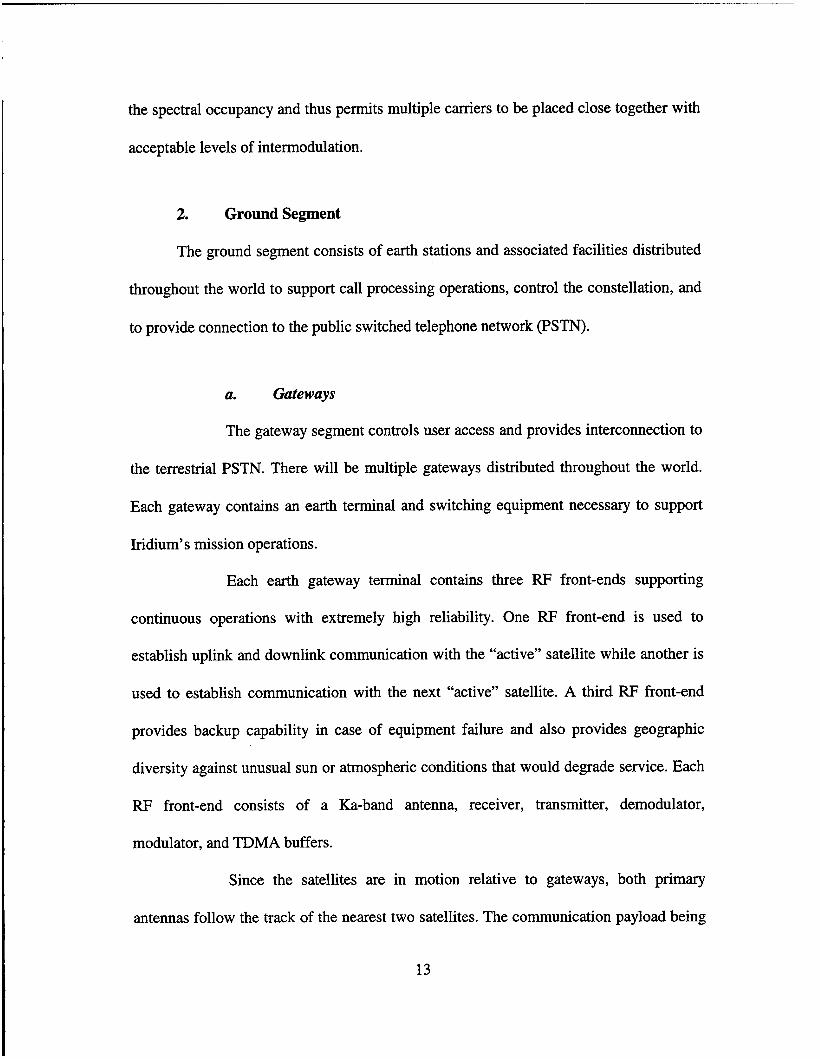
As a global communications satellite system with worldwide continuous
coverage, Iridium can offer the full range of mobile communications services including
radiodetermination, two-way voice and data, on land , in the air, and on water. Any
subscriber unit will be able to communicate with any other Iridium subscriber unit (ISU)
anywhere in the world, or with any telephone connected to the public switched telephone
network (PSTN) (see Figure 2.2).
5
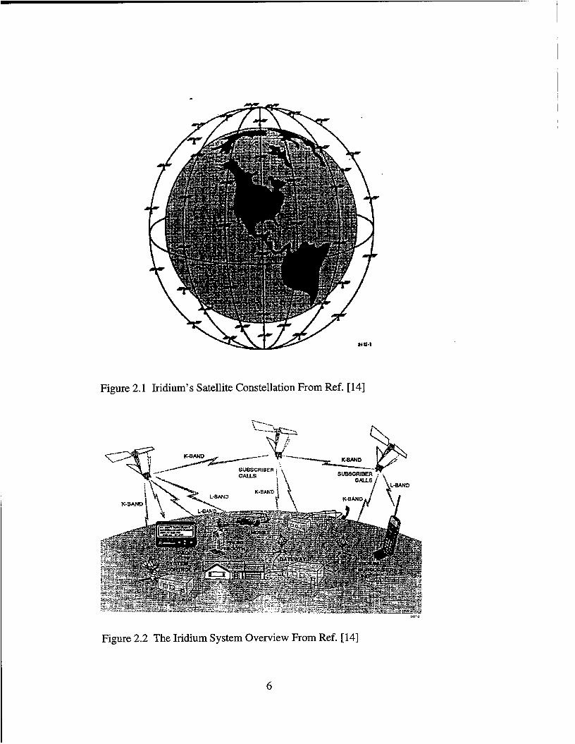
Figure 2.1 Iridium’s Satellite Constellation From Ref. [ 141
- * --. \ - - ..-..---
Figure 2.2 The Iridium System Overview From Ref. [ 141
6

B. MARKETS AND PROPOSED SERVICES
Bulk transmission capacity on the Iridium system will be provided to licensed and
authorized carriers, who in turn will sell mobile communications to the public in their
authorized areas. Due to its limited capacity and cost structure, Iridium is not designed to
compete with existing landline and terrestrial based cellular mobile systems. Instead,
Iridium will target markets not currently served by mobile communications services, such
as
1. sparsely populated locations where there is insufficient demand to
justify constructing terrestrial telephone systems
2. areas in many developing countries with no existing telephone service,
and
3. small urban areas that do not now have a terrestrial mobile
communications structure.
Iridium will provide mobile communications services to the entire United States,
including all of its territories and possessions. In addition, Iridium will extend the reach
of modern, reliable telecommunications services to and from all worldwide locations. It
will offer the full range of mobile services including radiodetermination satellite services
(RDSS), paging, messaging, voice, facsimile and data services.
7

C. SYSTEM DESCRIPTION
1. Space Segment
a. Constellation
The system consists of a constellation of 66 low-earth orbit satellites in
six near-polar orbits, with eleven satellites equally spaced in each orbital plane. The
apogee is 787 km, the perigee is 768 km, and the inclination angle is 86.4’. The satellites
within each plane are spaced 32.7 degrees apart, and travel at the same direction at
approximately 16,669 miles per hour in a northhouth direction and 900 miles per hour
westward over the equator. Each satellite circles the earth every 100 minutes. In addition
up to 12 in-orbit spare satellites will be launched into a near polar orbit approximately
645 km above the earth. Initially, only seven in-orbit spares will be constructed and
launched with the 66 operational satellites.
The six planes of satellites co-rotate towards the north pole on one side of
the earth and “crossover” and come down towards the south pole on the other side of the
earth. Of course, the earth continues to rotate beneath the constellation. The 11 satellites
in each plane are equally spaced around their planar orbit, with the satellites in the odd
numbered planes (1,3, and 5) in phase with one another, and those in the even numbered
planes (2,4, and 6) in phase with each other and halfway out of phase with the odd
numbered planes. In order to prevent the satellites from colliding at the poles, a minimum
m i s s distance is maintained between the planes in phase. Each of the six co-rotating
planes are separated by 31.6 degrees, and the ”seam” between planes 1 and 6, which
8

represents plane 1 satellites going up on one side of the earth and plane 6 satellites
coming down in the adjacent plane, is separated by 22 degrees.
This satellite constellation provides coverage over the entire surface of the
earth with single coverage provided at the equator and increasing levels of coverage as
the satellites move towards the poles (due to individual satellite coverages beginning to
overlap).
b. Frequency Plan
Iridium provides L-band (1 6 16- 1626.5 MHz) communications between
each satellite and individual subscriber units, Ka-band (uplink 29.1-29.3 GHz, downlink
19.4-19.6 GHz) communications between each spacecraft and ground-based facilities,
and Ka-band (23.18-23.38 GHz) crosslinks from satellite to satellite.
(1) L-band Subscriber Links. Subscriber units communicate with
the satellites (when the specific area is not served by a terrestrial cellular system) in L-
band. Motorola asked for 10.5 MHz bandwidth (1616-1626.5 MHz) for uplink and
downlink subscriber links using a combination of TDMA and FDMA. The frequency plan
for L-band is shown in Figure 2.3. The channel bandwidth is 31.5 KHz and the channel
spacing 41.67 KHz. The polarization will be righthand circular.
(2) Gateway Links. The Ka-band gateway links support
simultaneous communications with two ground-based gateways per satellite. Multiple
antennas separated by up to 34 nautical miles provide spatial diversity which avoids sun
interference and helps mitigate rain attenuation. This provides link availability of 99.8%
for gateways.The polarization is circular (lefthand for downlink and righthand for uplink).
9

/=--
Figure 2.3 L-Band UplinkDownlink R.F. Frequency Plan From Ref. [15]
(3) Intersatellite Crosslinks. Each satellite operates crosslinks as a
medium used to support internetting. These crosslinks operate in the Ka-band (23.18-
23.38 GHz) and include both forward and backward looking links to the adjacent
satellites in the same orbital plane which are nominally at a fixed angle and 2,173 nautical
miles away. Up to 4 interplane crosslinks are also maintained and these links vary in
angle and distance from the satellite. Crosslink beams never intercept the earth. The
polarization will be horizontal.
c. Frequency Reuse/Cell Management
The constellation of satellites and its projection of cells is somewhat
analogous to a cellular telephone system. In the case of cellular telephones a static set of
cells serves a large number of mobile users. In the case of Iridium, the users move at slow
pace relative to the spacecraft, so the users appear static while the cells move.
Each satellite will utilize up to 48 separate spot-beams to form cells on the
surface of the earth. Multiple relatively small beams allow to use the higher satellite
antenna gains and reduce the RF power required in the satellite and the user terminal. The
spatial separation of the beams allows increased spectral efficiency via time/
10

frequency/spatial reuse over multiple cells, enabling many simultaneous user messages
over the same frequency channel.
The constellation has a potential beam service capacity of 3,168 beams.
The full satellite beam capacity is utilized to provide effective continuous coverage near
the equator, while fewer beams are required at higher latitudes. Beam shut-down
techniques are used to provide a uniform beam density upon the earth’s surface.
On a global basis, the entire constellation’s beam pattern as projected on
the surface of the Earth results in approximately 2,150 active beams with a frequency
reuse of about 180 times. Within contiguous United States, the system will achieve about
five times frequency reuse.
d. System Capacity
The multiple access forrnat for Iridium uses both time division (TDMA)
and frequency division (FDMA) which results in a very efficient use of spectrum. The
TDMA format is shown in Figure 2.4. The peak capacity in any given beam over 10.5
MHz of L-band frequency spectrum is 960 channels of which 780 are full duplex voice
channels. The contiguous U.S. is covered by approximately 59 beams which yield a
capacity of 4,720 channels of which 3,835 are full duplex voice channels.
The end-to-end bit error rate will be better than lo’* for digital voice
transmission with a rate of 4800 bps. Basic data services will be accomodated with a rate
of 2400 bps and bit error rate of The estimated minimum lifetime of an in-orbit
satellite is five years.
11

Figure 2.4 TDMA Frame Format From Ref. [15]
e. Transmission Characteristics
Iridium has been designed to provide RDSS plus voice and data services
using digital transmission in a combined time and frequency division multiplexing
scheme. RDSS is accomplished by performing an electronic calculation of the stationary
position of the ISU relative to a satellite orbit. Given these results and a description
of the satellite orbit, the position of the subscriber’s unit can be determined to within one
mile. Voice is provided by the transmission of the output of a VSELP 4800 bps voice
coder. Processing by this type of voice coder produces discrete blocks or packets of data
at the coder framing rate. Each information packet will be protected from errors with a
combination of forward error correction and error detection which increase the
information bit rate of 4800 bps to a link transmission rate of about 8500 bps.
The system will use differentially encoded, raised cosine filtered,
quadrature phase shift keying (QPSK) modulation. This specific forrnat has been chosen
as the best compromise for the transmission channel between the satellites and the earth
which may experience a combination of multipath fading and transmission impairments
(shadowing) due to natural vegetation. Raised cosine filtering of the digital signal reduces
12
the spectral occupancy and thus permits multiple carriers to be placed close together with
acceptable levels of intermodulation.
2. Ground Segment
The ground segment consists of earth stations and associated facilities distributed
throughout the world to support call processing operations, control the constellation, and
to provide connection to the public switched telephone network (PSTN).
a. Gateways
The gateway segment controls user access and provides interconnection to
the terrestrial PSTN. There will be multiple gateways distributed throughout the world.
Each gateway contains an earth terminal and switching equipment necessary to support
Iridium’s mission operations.
Each earth gateway terminal contains three FW front-ends supporting
continuous operations with extremely high reliability. One RF front-end is used to
establish uplink and downlink communication with the “active” satellite while another is
used to establish communication with the next “active” satellite. A third RF front-end
provides backup capability in case of equipment failure and also provides geographic
diversity against unusual sun or atmospheric conditions that would degrade service. Each
RF front-end consists of a Ka-band antenna, receiver, transmitter, demodulator,
modulator, and TDMA buffers.
Since the satellites are in motion relative to gateways, both primary
antennas follow the track of the nearest two satellites. The communication payload being
13
conveyed across the “active” link must be handed off periodically, from the current
satellite to the next one as the active link disappears from view. This hand-off process
will be transparent to both Iridium and PSTN users involved in active calls.
Each gateway provides switching equipment to interface between the
communication payload in the Ka-band link and the voice/data channels of the PSTN for
establishing, maintaining, and terminating calls.
Each satellite can communicate with earth-based gateways either directly
or through other satellites by means of crosslink network. The system architecture is
designed to accommodate about 250 independent gateways.
b. System Control Facility
Obviously, there has to be control over these satellites. This is to be
performed in the system control facility and functions performed by this facility fall into
two general areas; active control of the satellites, and control of the communications
assets of the satellites. These tasks are performed by two separate, collocated subsystems.
(1) Constellation Operations. The primary functions of this
subsystem are; to manage each satellite’s orbit, to monitor each satellite’s health, to
support satellite launch and checkout, and to remove satellites from the constellation.
(2) Network Operations. This subsystem provides the capability to
manage the communications network. Under normal conditions the network will be
autonomous, but in the event of abnormal conditions this subsystem will provide
instructions to the network nodes on what steps to take to maintain service quality.
14
Two system control facilities, geographically separated, will be built to
help assure continuous operation. The master control facility will be located in Virginia
near Washington, DC and the back up control facility in Italy.
3. Subscriber Unit Segment
Three types of ISU (Iridium Subscriber Unit) will be offered; portablehand-held,
mobile, and transportable. The mobile unit can be installed in an automobile or boat and
the transportable can be moved between remote fixed locations. Each type of unit will
place a call to the nearest satellite. These units are to be compatible with both a user’s
local terrestrial system as well as the Iridium system. Where the user’s terrestrial system
is available at home or as a roamer, the user could use the terrestrial system. Where a
terrestrial system is not available, barring regulatory restrictions, an Iridium dial tone
should be available.
The portablehand-held unit is currently designed to operate for 24 hours on a
single recharge in a combination of standby ( able to receive a “ring” indicating an
incoming call) and active modes. The system now is being designed to operated with ISU
transmit power levels comparable to those of hand-held cellular telephones.
Communications between the ISU and the satellite is over a full-duplex FDMA
channel in TDMA bursts of QPSK modulated digital data. Digitized voice is encoded and
decoded using the Motorola 48OObps VSELP vocoder algorithm. Subscriber 2400 baud
data and 4800 bps digital voice data are protected with convolutional coding and
interleaving.
15
ISU uplink TDMA burst timing is synchronized to the downlink burst. The ISU
compensates for changes in satellite range by timing the uplink burst transmission to
arrive at the satellite with correct TDMA frame alignment. The ISU also compensates for
the satellite Doppler frequency shift by adjusting the uplink transmit frequency.
D. SUMMARY
The Iridium communications system is to be a global, digital, satellite-based,
personal communivations system primarily intended to provide low-density, portable
service via hand-held subscriber units, employing low-profile antennas. Calls could be
made and received anywhere in the world with a personal pocket-sized, portable unit. A
constellation of small satellites are to be internetted to form the network’s backbone.
Small, battery powered, cellular-telephone-like user units are to communicate directly
with the satellites. Terrestrial gateways are to interface the satellite network with the
public switched telephone network. The system is intented to complement the terrestrial
telephone network in densely populated areas by providing a similar service everywhere
in the world.
16
III. TELEDESIC
A. INTRODUCTION
Teledesic Corporation plans to construct a global network of 840 low earth orbit
(LEO) satellites operating in Ka-band (30120 GHz), that will help deliver a wide array of
affordable, yet advanced, interactive broadband information services to people in rural
and remote parts of the United States and the world. Open and ubiquitous, like a “Global
Internet”, the Teledesic Network will offer a means of providing a wide range of
information services, from high-quality voice channels to broadband channels supporting
videoconferencing, interactive multimedia, and real-time, two-way digital data. It will
provide “bandwidth on demand”, allowing users to adjust their channel capacity from one
moment to the next to accommodate their various applications.
The Teledesic Network will be fully interoperable with public networks in the
United States and abroad. Teledesic will operate as a non-common carrier and will not
market its services directly to users. Rather, it will provide an open platform for service
providers in the United States and in host countries to bring affordable access to rural and
remote locations.
B. MARKETS AND PROPOSED SERVICES
The benefits to be derived from such services are as vast as the areas of need to
which they can extend. With universal access to interactive broadband capabilities,
information can flow freely between people, creating wider communities of interest and
17
support. In the field of health care, for example, doctors and other caregivers can consult
with specialists thousands of miles away, share medical records and x-rays, relay critical
medical information during epidemics, distribute globally the latest medical research,
ensure priority routing of medical supplies during disaster relief programs, and provide
remote instruction in nutrition, sanitation, and prenatal and infant care.
The interactive broadband capabilities of the Teledesic Network, coupled with its
wireless access technology, also hold the promise of delivering distance learning services .
to the most remote parts of the United States and the world, thereby offering meaningful
educational opportunities to people who would otherwise be cut off -either economically
or geographically- from traditional centers of learning.
Advanced technologies have revolutionized the way people exchange and process
information in urban areas of the United States and other developed nations. But there is a
broader, unmet need. Today, the cost to bring modern communications to poor and
remote areas is so high that many of the world’s people cannot participate in the global
community. Yet the benefits of the communications revolution should be extended to all
of the world’s citizens, including those who do not reside in or near centers of commerce
or industry, who do not have access to doctors, hospitals, schools, or libraries, and who
are at risk of being shunted aside. Teledesic hopes to inspire an effort to serve these
people.
18
C. SPACE SEGMENT
1. Constellation
The Teledesic constellation is organized into 21 circular orbit planes that are
staggered in altitude between 695 and 705 km. Each plane contains a minimum of 40
operational satellites plus up to four on-orbit spares spaced evenly around the orbit. The
orbit planes are at a sun-synchronous inclination (approximately 98.2’), which keeps
them at a constant angle relative to the sun. The ascending nodes of adjacent orbit planes
are spaced at 9.5’ around the equator (see Figure 3.1). Satellites in adjacent planes travel
in the same direction except at the constellation “seams”, where ascending and
descending portions of the orbits overlap. There is no fixed phase relation between
satellites in adjacent planes; the position of a satellite in one orbit is decoupled from those
in other orbits.
The Teledesic constellation is designed to ensure that there is always at least one
satellite above a 40’ elevation angle over the entire coverage area. Coverage is provided
twenty-four hours a day between 72’ north and south latitude, with partial day coverage to
higher latitudes (that is, 95% of the Earth’s surface and almost 100% of its population).
Also, the altitudes of satellites in different orbit planes are staggered to eliminate the
possibility of collision between satellites in crossing orbits. The nominal 700 km altitude
and 40’ elevation mask angle yield a satellite footprint approximately 1400 km in
diameter. Teledesic’s minimum of 40 satellites per plane and 9.5’ spacing between planes
19

Figure 3.1 Teledesic’s Orbits From Ref. [17]
provides a high degree of coverage redundancy and allows satellites in one plane to be
repositioned without opening coverage gaps between planes. Figure 3.2 illustrates the
coverage redundancy over the continental United States. These constellation
characteristics reduce both the effect of a satellite failure and the time to “repair” the
constellation. If a satellite failure causes a coverage gap, it can be filled within two hours
by repositioning the satellites in that plane.
20

Figure 3.2 Teledesic’s Footprint Coverage Over the Continental U.S. From Ref. [17]
2. The Satellites
The on-orbit configuration of the Teledesic satellite resembles a flower with eight
“petals” with a large boom-mounted-square solar array as shown in Figure 3.3. The
deployed satellite is 12 m in diameter and the solar array is 12 m on each side. Each petal
consists of three large electronically-steered phased-array antenna panels with integrated
transmit, receive, and ancillary electronics. The octagonal baseplate also supports eight
pairs of intersatellite link antennas, the two satellite bus structures that house the
engineering subsystem components, and propulsion thrusters. A third satellite bus
structure, containing power equipment and additional propulsion thrusters, is mounted at
the end of the solar array boom. The solar array is articulated to point to the sun.
21
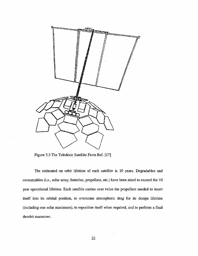
Figure 3.3 The Teledesic Satellite From Ref. [17]
The estimated on orbit lifetime of each satellite is 10 years. Degradables and
consumables (i.e., solar array, batteries, propellant, etc.) have been sized to exceed the 10
year operational lifetime. Each satellite carries over twice the propellant needed to insert
itself into its orbital position, to overcome atmospheric drag for its design lifetime
(including one solar maximum), to reposition itself when required, and to perform a final
deorbit maneuver.
22

D. THENETWORK
1. General Description
The Teledesic Network provides a quality of service comparable to today’s
modem terrestrial communication systems, including fiber-like delays, bit error rates less
than lo-’, and a link availability of 99.9% over most of the United States. The 16 Kbps
basic channel rate supports low-delay voice coding that meets “network quality”
standards. A variety of terminals accommodate “on-demand” channel rates from 16 Kbps
up to 2.048 Mbps (El), and for special applications up to 1.24416 Gbps (OC-24). This
allows a flexible, efficient match between system resources and the requirements of
users’ diverse applications.
The initial Teledesic constellation has a capacity equivalent to a peak load of more
than 2,000,000 simultaneous full-duplex 16 Kbps connections, corresponding to over
20,000,000 users at typical “wireline” business usage levels. The actual user capacity will
depend on the average channel rate and occupancy. The system design allows graceful
evolution to constellations with much higher capacity without altering the system
architecture, spectrum plan or user terminals. The network capacity estimates assume a
realistic, non-uniform distribution pattern of users over the earth’s land masses; some
cells will generate over 100 times the traffic of the “average” cell.
End users will be served by one or more local service providers in the United
States and in each host country. Terminals at gateway and user sites communicate directly
with Teledesic’s satellite-based network and through gateway switches, to terminals on
other networks. Figure 3.4 is an overview of Teledesic’s Network.
23

STANDARD TERYIHAL
CG 4LlhK TERUINAL
Figure 3.4 The Teledesic Network From Ref. [17]
The network uses fast packet switching technology based on the asynchronous
transfer mode (ATM) technology now being used in local area networks (LAN), wide
area networks (WAN), and the broadband integrated services digital network (B-ISDN).
All communication is treated identically within the network as streams of short fixed-
length packets. Each packet contains a header that includes address and sequence
information, an error-control section used to verify the integrity of the header, and a
payload section that carries the digitally encoded voice or data. Conversion to and from
the packet format takes place in the terminals. The fast packet switch network combines
the advantages of a circuit-switched network (low delay "digital pipes"), and a packet-
switched network (efficient handling of multi-rate and bursty data). Fast packet switching
technology is ideally suited for the dynamic nature of a LEO network.
24

Each satellite in the constellation is a node in the fast packet switch network, and
has intersatellite communication links with eight adjacent satellites. Each satellite is
normally linked with four satellites within the same plane (two in front and two behind)
and with one in each of the two adjacent planes on both sides. Each intersatellite link
operates at 155.52 Mbps, and multiple of this rate up to 1.24416 Gbps depending upon
the instantaneous capacity requirement. This interconnection arrangement forms a non-
hierarchical “geodesic,” or mesh, network and provides a robust network configuration
that is tolerant to faults and local congestion.
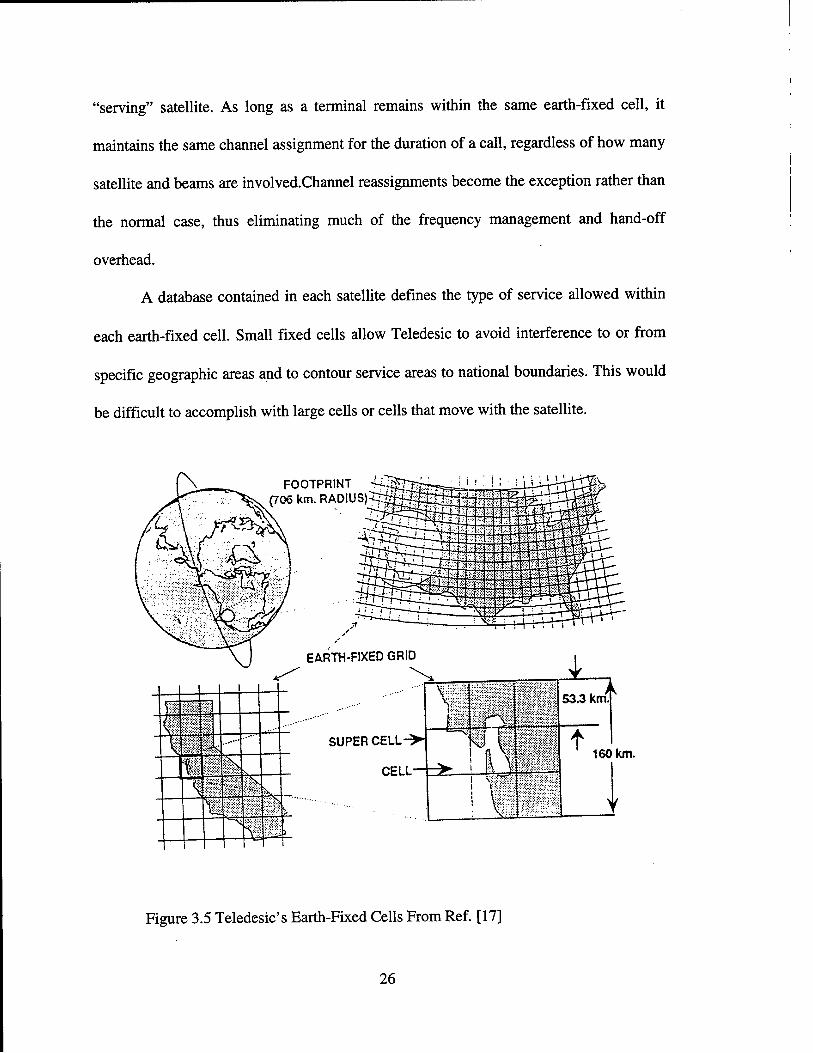
2. Earth-Fixed Cells
The Teledesic Network uses an Earth-fixed cell design to minimize the hand-off
problem. The system maps the earth’s surface into a fixed grid of approximately 20,000
“supercells”, each consisting of nine cells (see Figure 3.5). Each supercell is a square 160
km on each side. Supercells are arranged in bands parallel to the equator. There are
approximately 250 supercells in the band at the equator, and the number per band
is not constant, the “north-south” supercell borders in adjacent bands are not aligned. A
satellite footprint encompasses a maximum of 64 supercells, or 576 cells. The actual
number of cells for which a satellite is responsible varies by satellite with its orbital
position and its distance from adjacent satellites. In general, the satellite closest to the
center of a supercell has coverage responsibility. As a satellite passes over, it steers its
antenna beams to the fixed cell locations within its footprint. This beam steering
compensates for the satellite’s motion as well as the earth’s rotation. Channel resources
(frequencies and time slots) are associated with each cell and are managed by the current
25
“serving” satellite. As long as a terminal remains within the same earth-fixed cell, it
maintains the same channel assignment for the duration of a call, regardless of how many
satellite and beams are involved.Channe1 reassignments become the exception rather than
the normal case, thus eliminating much of the frequency management and hand-off
overhead.
A database contained in each satellite defines the type of service allowed within
each earth-fixed cell. Small fixed cells allow Teledesic to avoid interference to or from
specific geographic areas and to contour service areas to national boundaries. This would
be difficult to accomplish with large cells or cells that move with the satellite.
....’ ...” ....- ....
SUPER
Figure 3.5 Teledesic’s Earth-Fixed Cells From Ref. [ 171
26

3. Multiple Access Method
The Teledesic Network uses a combination of multiple access methods to ensure
efficient use of the spectrum (see Figure 3.6). Each cell within a supercell is assigned to
one of nine equal time slots. All communications take place between the satellite and the
terminals in that cell during its assigned time slot. Within each cell’s time slot, the full
frequency allocation is available to support communication channels. The cells are
scanned in a regular cycle by the satellite’s transmit and receive beams, resulting in
time division multiple access (TDMA) among the cells in a supercell. Since propagation
delay varies with path length, satellite transmissions are timed to ensure that cell N (N=l,
2, 3, ... 9) of all supercells receive transmissions at the same time. Terminal transmissions
to a satellite are also timed to ensure that transmissions from the same numbered cell in
all supercells in its coverage area reach that satellite at the same time. Physical separation
(space division multiple access or SDMA) and a checkerboard pattern of left and right
circular polarization eliminate interference between cells scanned at the same time in
adjacent supercells. Guard time intervals eliminate overlap between signals received from
time-consecutive cells.
Within each cell’s time slot, terminals use frequency division multiple access
(FDMA) on the uplink and asynchronous time division multiple access (ATDMA) on the
downlink. On the uplink, each active terminal is assigned one or more frequency slots for
the call’s duration and can send one packet per slot each scan period (23.11 1 msec). The
number of slots assigned to a terminal determines its maximum available transmission
rate. One slot corresponds to a standard terminal’s 16 Kbps basic channel with its
27

CELL SCAN PATTERN
I
I I
Cell 9 illuminated in all supercells
- CELL SCAN CYCLE
TRkNSMlTmECElVE TIME = 2.276 mseclCELL CYCLE = 23.1 11 msec. PER SUPERCELL
I
CHANNEL MULTIPLEXING IN A CELL UP LINK (FDM)
L / 7 776 msec. ->I DOWN LINK (ATOM)
b 2 . 2 7 6 msec. -s,
_ _ J
A
i I
400 MHz
c HkN N E L ---)
1 1 !
- !
_. 11LO
Figure 3.6 Teledesic’s Standard Terminal Multiple Access Method From Ref. [17]
28
associated 2 Kbps signaling and control channel. A total of 1,440 slots per cell scan
interval are available for standard terminals.
The terminal downlink uses the packet’s header rather than a fixed assignment of
time slots to address terminals. During each cell’s scan interval the satellite transmits a
series of packets addressed to terminals within that cell. Packets are delimited by a unique
bit pattern, and a terminal selects those addressed to it by examining each packet’s
address field. A standard terminal operating at 16 Kbps requires one packet per scan
interval. The downlink capacity is 1,440 packets per cell per scan interval. The satellite
transmits only as long as it takes to send the packets queued for a cell.
4. Communication Links
All of the Teledesic communications links transport data and voice as fixed-length
(512) bit packets. The basic unit of channel capacity is the “basic channel”, which
supports a 16 Kbps payload data rate and an associated 2 Kbps “D-channel” for signaling
and control. Basic channels can be aggregated to support higher data rates. A Teledesic
terminal can support multiple simultaneous network connections. In addition, the two
directions of a network connection can operate at different rates.
The links are encrypted to guard against eavesdropping. Terminals perform the
encryptioddecryption and conversion to and from the packet format. The uplinks use
dynamic power control of the RF transmitters so that the minimum amount of power is
used to carry out the desired communication. Minimum transmitter power is used for
clear sky conditions. The transmitter power is increased to compensate for rain.
29
E. EARTH SEGMENT
The Teledesic Network accommodates a wide variety of terminals and data rates.
Standard terminals will include both fixed-site and transportable configurations that
operate at multiples of the 16 Kbps basic channel payload rate up to 2.048 Mbps (the
equivalent of 128 basic channels). All data rates, up to the full 2.048 Mbps, can be
supported with an average transmit power of 0.3 W by suitable choice of antenna size.
Within its service area, each satellite can support a combination of terminals with a total
throughput equivalent to over 100,000 simultaneous basic channels.
The Network also supports a smaller number of fixed-site gigalink terminals that
operate at the OC-3 rate (155.52 Mbps) and multiples of this rate up to OC-24 (1.24416
Gbps). Transmit power will range from 1 W to 49 W depending on antenna diameter,
data rate, and climatic conditions. Antenna site-diversity can be used to reduce the
probability of rain outage in situations where this is a problem.
Gigalink terminals provide gateway connections to public networks and to
Teledesic support and data base systems including network operations and control centers
(NOCC) and constellation operations control centers (COCC), as well as to privately
owned networks and high-rate terminals. A satellite can support up to sixteen gigalink
terminals within its service area.
30

F. CONTROL SEGMENT
1. Control Functions
The network control hierarchy is distributed among the network elements.
Terminals and other network elements use a packet-based protocol for signaling and
control. The network handles these “control” packets in the same manner as normal
information packets.
The highest levels of network control reside in distributed, ground-based systems
that are connected via gigalink terminals to the satellite network. Database systems
provide terminalher feature and service profiles, authentication and encryption keys, call
routing data, and other administrative data. Administrative systems, from “network-level”
to local “in-country” systems, provide secure access to various levels of the database and
billing systems.
High-level call control functions reside in feature processors and gateway
switches. The feature processor controls intra-network calls as well as the initial setup of
inter-network calls which involve a gateway. Only control and signaling packets are
passed to the feature processor; user packets are transmitted through the network over the
path of least delay. A gateway switch controls calls that are connected through that
switch.
The satellite-based switch node includes some mid-level call control functions in
addition to its packet routing function. It manages the assignment, supervision, and
release of all channels in its coverage area and the “hand-off’ of channels to other
31
satellites. It also monitors channel signal quality and initiates uplink power control when
required.
Terminals control some low-level call control functions similar to those of a
cellular or ISDN functional signaling terminal. These functions include user
authentication, location registration, link encryption, monitoring and reporting of channel
quality, channel assignments and hand-offs, and D-channel signaling.
2. Adaptive Routing
The topology of a LEO-based network is dynamic. Each satellite keeps the same
position relative to other satellites in its orbital plane. Its position and propagation delay
relative to earth terminals and to satellites in other planes change continuously and
predictably. In addition to changes in network topology, as traffic flows through the
network, queues of packets accumulate in the satellites, changing the waiting time before
transmission to the next satellite. All of these factors affect the packet routing, choice
made by the fast packet switch in each satellite. These decisions are made continuously
within each node using Teledesic’s distributed adaptive routing algorithm. This algorithm
uses information transmitted throughout the network by each satellite to “learn” the
current status of the network in order to select the path of least delay to a packet’s
destination. The algorithm also controls the connection and disconnection of intersatellite
links.
The network uses a “connectionless” protocol. Packets of the same connection
may follow different paths through the network. Each node independently routes the
packet along the path that currently offers the least expected delay to its destination. The
32

required packets are buffered, and if necessary resequenced, at the destination terminal to
eliminate the effect of timing variations.
G. SUMMARY
There is a significant worldwide demand for broadband communication capacity.
Teledesic plans to meet this demand using a constellation of 840 low earth orbit (LEO)
satellites operating in Ka-band. The Teledesic Network provides worldwide bandwidth-
on-demand, quality service with bit error rates less than lo-’ and fiber-like delays. The
data rates are from 16 Kbps (basic channel) up to 2.048 Mbps and for special applications
from 155.52 Mbps up to 1.24416 Gbps. Teledesic Corporation hopes to bring the
information revolution to people who could not be served economically through existing
technologies.
33

34

IV. ODYSSEY
A. INTRODUCTION
Today there is a growing demand to provide increased mobile communications for
both commercial and personal use. TRW plans to meet this demand with Odyssey.
Odyssey is a satellite based communication system bringing world-wide communications
ability to the palm of a person’s hand. It will provide high quality personal and mobile
communications services with a constellation of twelve medium earth orbit (MEO)
satellites. These services include voice and data (including messaging).
Communication can be established either between mobile and fixed users or
between pairs of mobile users. A dual-mode handset allows the user to communicate
either through local cellular networks, when available, or through the Odyssey system
when cellular is not present. Odyssey earth stations and associated gateways to the PSTN
interconnect mobile (between 70’ North latitude and 55’ South latitude) and fixed users
around the world via the “bent-pipe” satellite transponders.
B. MARKETS AND PROPOSED SERVICES
Odyssey system will be used by its customers for the provision of high quality
satellite capacity, for mobile voice services that will serve the ever-increasing number of
cellular “roamers” and other unserved or underserved segments of the burgeoning cellular
telephone market, and for the provision of innovative and low-cost data services. End
35
users of Odyssey capacity would also include any business or commercial entity that has a
need to track its inventory or freight carriers and maintain constant communication with
its personnel; municipal, local, and state governments that are responsible for the
provision of emergency services; and cellular services providers that are interested in
augmenting and expanding the coverage areas of their systems.
TRW does not intend to provide space segment on Odyssey directly to end users,
but will instead sell or lease space segment capacity in bulk to resellers and others that
will, in turn, offer commercial mobile radio services to end users. As a result, TRW is
entitled to be regulated as a non-common carrier.
C. SYSTEM DESCRIPTION
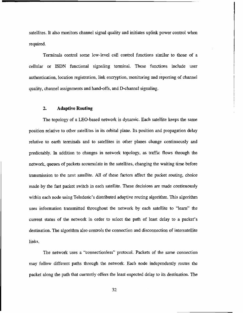
An overview of the Odyssey system is illustrated in Figure 4.1. The system
basically is composed of a space segment, a ground segment and a handset segment.
1. Space Segment
a. Constellation
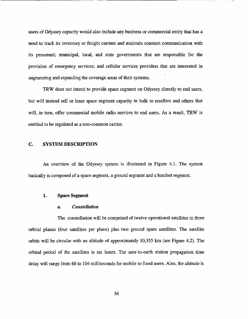
The constellation will be comprised of twelve operational satellites in three
orbital planes (four satellites per plane) plus two ground spare satellites. The satellite
orbits will be circular with an altitude of approximately 10,355 km (see Figure 4.2). The
orbital period of the satellites is six hours. The user-to-earth station propagation time
delay will range from 68 to 104 milliseconds for mobile to fixed users. Also, the altitude is
36
Figure 4.1 Odyssey System Overview From Ref. [ 191
' Number of satellites: 12 Number of planes: 3 ' Altitude (circular): 5600 nm (or 10355 Km) ' Inclination: 50" ' Apogee: 5600 nm
Perigee: 5600 nm Argument of Perigee: 0" Active Service Arcs: WA ' Right Ascension of ascending node(s) - Reference: 0". 120°, 240"
-Varies during life time 0.1" per day
Figure 4.2 Odyssey Satellite Constellation From Ref. [ 181
37
high enough so that the effects of the Van Allen radiation belt are minimal. An
additional benefit for system operation is the long time interval (up to an hour and half)
during which the satellite is visible to a user and the associated earth station. This
minimize the number of intra-call handoffs. The Odyssey constellation of twelve
satellites will be deployed by launching two satellites at a time into one of three orbital
planes. Twelve satellites will ensure that at least two satellites are visible to any user
anywhere in the world. Replacement satellites will be launched as needed.
b. Frequency Plan
(1) US-band Links. The forward link includes a Ka-band link from
the earth station to the satellite and an S-band link down to the user (see Figure 4.1). The
return link from the user to the earth station includes an L-band to the satellite and a Ka-
band link down to the earth station. The satellite payload will function as a bent pipe,
simple frequency translating transponder receiving and transmitting code division
multiple access (CDMA) signals with no on-board signal processing.
The Odyssey system will share with other CDMA systems a
bandwidth of 11.35 MHz in both the forward (1610-1621.35 MHz, L-band) and return
(2483.5-2494.85 MHz, S-band) user links. This bandwidth will be divided in sub-bands
ranging from 0.25 MHz to 2.5 MHz in order to maximize the efficiency of spectrum
utilization in areas of high service demand.
(2) Ka-band Links. The mobile link frequency bands are assembled
into a frequency division multiplex (FDM) format of 300 MHz bandwidth for
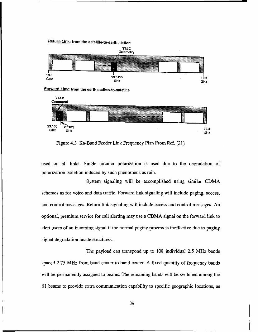
transmission on the Ka-band feeder links as shown in Figure 4.3. Circular polarization is
3s
Return Link: from the satelliteto-earth station
TT&C Xelemetrv
1 Y.J
GHz 19.3415 GHz
I 19.6 GHz
Fotward Link: from the earth station-to-satellite
TT&C Command
I 29.4 GHz
Figure 4.3 Ka-Band Feeder Link Frequency Plan From Ref. [21]
used on all links. Single circular polarization is used due to the degradation of
polarization isolation induced by such phenomena as rain.
System signaling will be accomplished using similar CDMA
schemes as for voice and data traffk. Forward link signaling will include paging, access,
and control messages. Return link signaling will include access and control messages. An
optional, premium service for call alerting may use a CDMA signal on the forward link to
alert users of an incoming signal if the normal paging process is ineffective due to paging
signal degradation inside structures.
The payload can transpond up to 108 individual 2.5 MHz bands
spaced 2.75 MHz from band center to band center. A fixed quantity of frequency bands
will be permanently assigned to beams. The remaining bands will be switched among the
61 beams to provide extra communication capability to specific geographic locations, as
39
traffic requires. The filtering will be accomplished by narroband surface acoustic wave
(SAW) filters. The filter outputs will be combined into a single 300 MHz FDM signal.
The FDM signal will be identically divided three ways, upconverted to the 20 GHz Ka-
band downlink frequency and amplified a traveling wave tube amplifier (TWTA). The
three redundant TWTAs will each output to a dual band (20 and 30 GHz, Ka-band),
circularly polarized narrow beam antenna. Each of the three Ka-band antennas will be
indepedently gimbaled and pointed toward earth stations. Since the same signals are to be
transmitted by the three Ka-band antennas, up to three downlink footprints will be
created, enabling three or more earth stations to simultaneously receive the return link
traffic and telemetry.
The 30 GHz band uplink signals will be collected by one or more
Ka-band spacecraft receive antennas. The uplink signal has a 300 MHz bandwidth
consisting of 108 2.5 MHz FDM bands and the spacecraft command signal. Each
antenna’s output will be amplified and downconverted to IF. The IF signal from the three
receivers will be combined into a single 300 MHz IF signal. The combined IF will be
separated into 2.5 MHz using SAW filters. By combining the IF signals of all three
antennas and selecting the bandwidth for each mobile link beam, the traffic for a
particular beam can originate from any earth station without the need for instantaneous
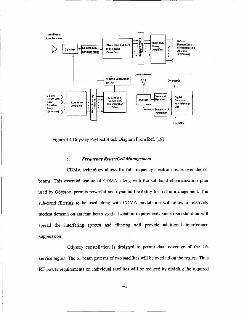
reconfiguration of the payload. A block diagram of the Odyssey payload is shown in
Figure 4.4.
40
ThreeFeeder Link Antennas
Diplexen 7 I ' I I I u - Ka Band Upconverler. k57
Conversion, Channelization
Fillers
Dirscl Low Noisa Radialing Array (6t beams) m
W a n d ForwardLink Diwa Radiating Anlenna (61 Beams)
Omnihtennas
P Commands
Telemetry
Figure 4.4 Odyssey Payload Block Diagram From Ref. [ 191
C. Frequency ReuseKell Management
CDMA technology allows for full frequency spectrum reuse over the 61
beams. This essential feature of CDMA, along with the sub-band channelization plan
used by Odyssey, permits powerful and dynamic flexibility for traffic management. The
sub-band filtering to be used along with CDMA modulation will allow a relatively
modest demand on antenna beam spatial isolation requirements since demodulation will
spread the interfering spectra and filtering will provide additional interference
suppression.
Odyssey constellation is designed to permit dual coverage of the US
service region. The 61 beam patterns of two satellites will be overlaid on the region. Thus
RF power requirements on individual satellites will be reduced by dividing the required
41
power for peak traffic periods between a pair of satellites. Frequency assignments will be
made so as to maximize satellite and system capacity.
d. System Capacity
Each satellite will have a capacity of 3,000 circuits. This capacity results in
economical satellite primary power requirements. Distribution of the 3,000 circuits
among the 61 cells will not be uniform. The satellite transmitter complement is designed
using matrix amplifier techniques so that each satellite has the capability to support 600
circuits in a “hot spot” beam.
Most regions will be able to take advantage of dual satellite coverage.
Dual satellite coverage improves the overall availability of the communication system to
a user. Additionally, dual coverage of a region allows 6,000 circuits to serve the region.
Basic digital data service will be accommodated by using a data rate of
2400 bps. Digital data service quality will be assured by maintaining a system BER of
loa5 through the use of sophisticated error correction encoding schemes. The voice data
rate is 4800 bps with BER
e. Transmission Characteristics
Odyssey will provide voice and data services. Voice service at 4800 bps is
to be provided by transmission of digitally encoded voice and in-band signaling. Several
such voice encoders (vocoders) exist and can be implemented within the processing used
at the earth station and handset. Processing by these vocoders produces discrete blocks or
packets of data at the coder framing rate. Each information packet is protected from errors
42

with a combination of a forward error correcting code and interleaving.
Basic data service will be provided by the handset with transmission at the
rate of 2400 bps. Forward error correction and interleaving will be used to protect against
transmission errors. Higher transmission rate data services maybe provided through more
sophisticated user terminals dedicated to this function. Digital modulation using CDMA
techniques is employed for both voice and data information.
Spread spectrum CDMA has been chosen for multiple access because it
minimizes intersystem interference and allows frequency spectrum sharing. The spread
spectrum functions can easily be implemented with microelectronic technology.
Quadrature phase shift keying (QPSK) is the basic signal structure used for
waveform modulation. For the voice user, a speech detector within the voice encoder
determines when the user is not actively speaking. In this case, the bit rate at handset
output will be reduced to the minimum required to maintain the link. This feature
increases the channel capacity by nearly a factor of two by taking advantage of the fact
that a user will actively be speaking only about one half of the time.
The Odyssey space segment will provide system availability exceeding
99.5% for 10 years. The entire system will feature highly reliable components and
subsystems with redundancy implemented throughout, achieving a satellite mean mission
duration of 12 years. Expendables are sized for 15 years.
2. Ground Segment
The Ground Segment which will provide user service to the US region and
adjacent areas is to be comprised of two earth stations (ES); one in each coast. Each ES
43 I
Anlonne Subsyslom
Ramolo
local antennas
and
Figure 4.5 Odyssey Ground Station From Ref. [ 191
Switch Subsysleiii I Oasebend Processing Subsyslcm
IF Procossing Subsystem
snam processing Terreslrial
relay swIIch Switch Equipment
Baseband p:gz ~ e l ~ a r Network ,:;:'" Antenna S@am switch modems SWilch Mulllplexlng
seam processing
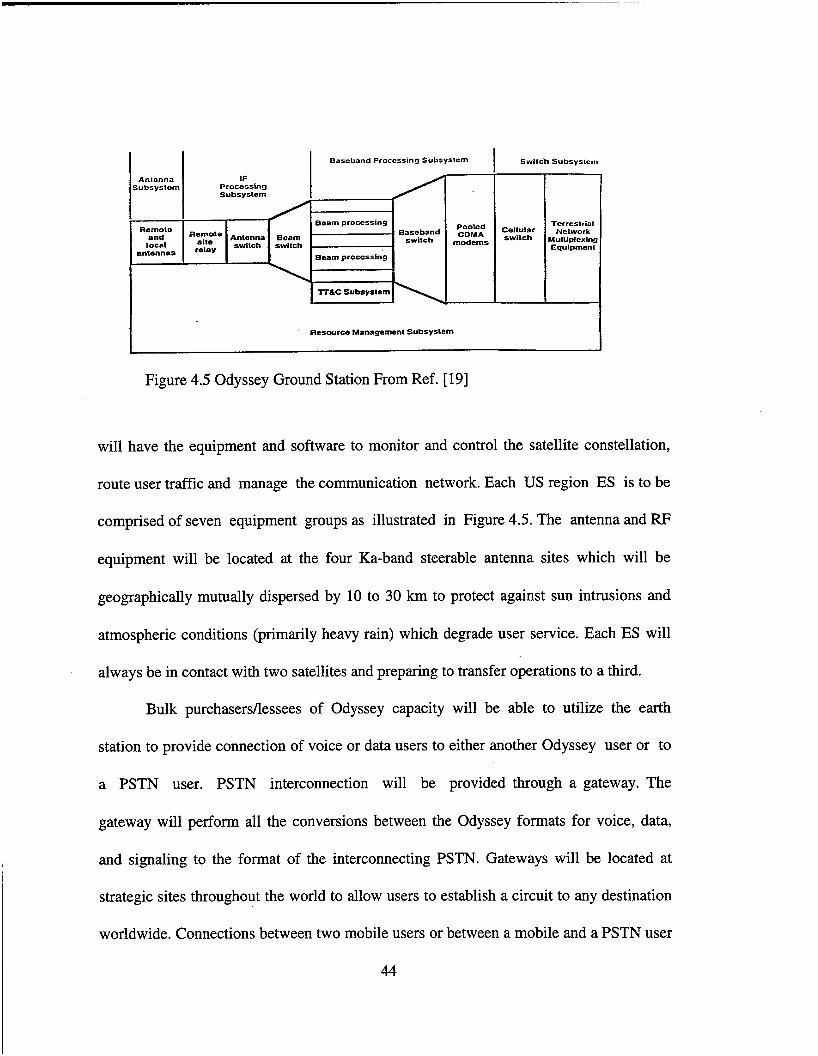
will have the equipment and software to monitor and control the satellite constellation,
route user traffic and manage the communication network. Each US region ES is to be
comprised of seven equipment groups as illustrated in Figure 4.5. The antenna and FW
equipment will be located at the four Ka-band steerable antenna sites which will be
geographically mutually dispersed by 10 to 30 km to protect against sun intrusions and
atmospheric conditions (primarily heavy rain) which degrade user service. Each ES will
always be in contact with two satellites and preparing to transfer operations to a third.
Bulk purchasersllessees of Odyssey capacity will be able to utilize the earth
station to provide connection of voice or data users to either another Odyssey user or to
a PSTN user. PSTN interconnection will be provided through a gateway. The
gateway will perform all the conversions between the Odyssey formats for voice, data,
and signaling to the format of the interconnecting PSTN. Gateways will be located at
strategic sites throughout the world to allow users to establish a circuit to any destination
worldwide. Connections between two mobile users or between a mobile and a PSTN user
44

will be accomplished through a digital matrix switch. The common carrier interface, to be
located on the PSTN side of the matrix switch, will provide the final multiplexing and
protocol interface to the public switched telephone network.
3. Handset Segment
The Odyssey handset is a dual mode design that will support user communication
through the Odyssey system and a terrestrial cellular system. Several versions of the
handset will be available to support dual mode service with the various terrestrial cellular
standards .
Full duplex communication between the handset and the satellite will be provided
by modulated digital data using spread spectrum CDMA techniques. Subscriber voice is
to be digitized, compressed, formatted, and error correction encoded in the handset and
routed to the transmitter section. Basic 2400 bps data service may be input to the handset
through a compatible data port in the place of voiced data. This data will be formatted and
encoded into a data stream. The data stream will then be used to modulate the L-band
uplink carrier. The user received S-band signal is to undergo the reverse processing to
deliver either voice or digital data to the subscriber.
The protocol between the handset and the ground station is similar to that used
for a typical cellular system to the greatest extent possible. The protocols for placing a
call, call setup, handover, termination, and other administrative functions have been
modeled after the terrestrial cellular systems. Handsets are similar to cellular ones and
will conform to their size, weight and power. The average power will be less than 0.5 W,
the polarization circular, and the modulation QPSK (see Table 4.1).
45
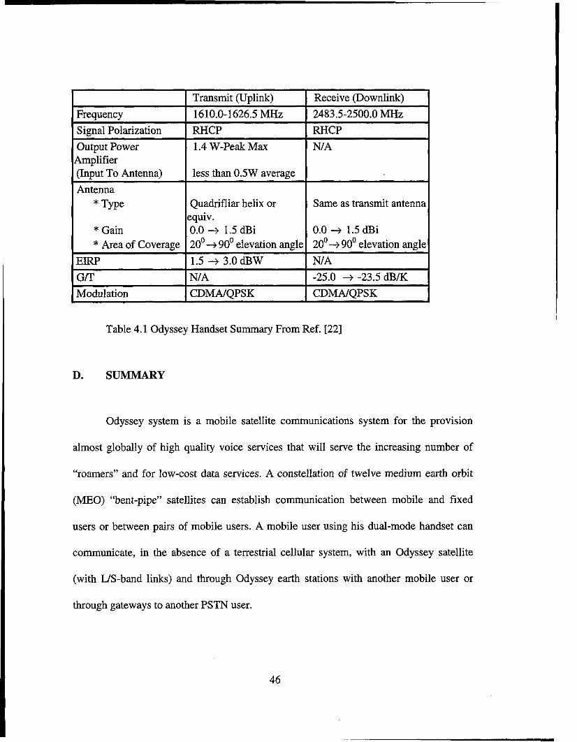
Transmit (Uplink) Frequency 1610.0-1626.5 MHz
Receive (Downlink) 2483.5-2500.0 MHz
Signal Polarization Output Power 4mplifier (Input To Antenna) Antenna
* Type
* Gain * Area of Coverage
EIRP
Table 4.1 Odyssey Handset Summary From Ref. [22]
RHCP RHCP 1.4 W-Peak Max NIA
less than 0.5W average
Quadrifliar helix or equiv. 0.0 + 1.5 dBi 20’ + 90’ elevation angle zoo+ 90’ elevation angle 1.5 + 3.0 dBW NIA
Same as transmit antenna
0.0 + 1.5 dBi
D. SUMMARY
G/T Modulation
Odyssey system is a mobile satellite communications system for the provision
almost globally of high quality voice services that will serve the increasing number of
“roamersyy and for low-cost data services. A constellation of twelve medium earth orbit
(MEO) “bent-pipe’, satellites can establish communication between mobile and fixed
users or between pairs of mobile users. A mobile user using his dual-mode handset can
communicate, in the absence of a terrestrial cellular system, with an Odyssey satellite
(with US-band links) and through Odyssey earth stations with another mobile user or
through gateways to another PSTN user.
NIA -25.0 + -23.5 dBK CDMNQPSK CDMNQPSK
46
V. GLOBALSTAR
A. INTRODUCTION
Globalstar is a low earth orbit (LEO) satellite-based digital telecommunications
system that will offer wireless telephony and other telecommunications services
worldwide beginning in 1998. Globalstar will provide low-cost, high quality telephony,
data transmission, paging, facsimile, and position location to areas currently underserved
or unserved by existing wireline and cellular telecommunications systems.
With a constellation of 48 satellites at an altitude of 1414 km any mobile user can
establish communication either with another mobile user (who is located between 74'
North and South latitude) or with a fixed user (by using earth stations and gateways to the
public switched telephone network, PSTN).
B. MARKETS AND PROPOSED SERVICES
Globalstar will operate on a non-common carrier basis. It will own and operate the
satellite links of the network. It will sell its satellite communications capacity, either in
bulk or on demand, to communications carriers, including cellular telephone providers as
well as other carriers and entities.
Globalstar provides mobile RDSS, voice, and data services in conjunction with
terrestrial cellular telephone service providers and/or other communications service
providers.
47

. . -.
Globalstar provides RDSS on a stand-alone basis or in combination with
messaging and voice communication services. By subscribing to these services in various
combinations, the user can meet his location determination and communications needs at
costs equal to or lower than those of comparable terrestrial facilities. Applications for this
service include, for example, location of fleet vehicles, tracking of klitary movements,
medical emergency, location of stolen vehicles, and recreational activities.
Globalstar provides voice and data services to many groups of users (fixed and
mobile). These groups of users may include, for example, governmental agencies,
commercial users, managers of fleets of air, land and water vehicles, persons traveling on
business or pleasure, emergency service providers, transportation entities and others.
Government agencies will benefit from two-way voice communications and
position location capabilities in the areas of disaster relief, law enforcement, air traffic
control, resource management and weather reporting.
C. SYSTEM DESCRIPTION
The Globalstar system consists of three major segments; space segment, ground
segment, and mobile user segment. Figure 5.1 shows an overview of the system.
1. Space Segment
a. Constellation
The space segment is composed of a constellation of 48 operational LEO
satellites at an altitude of 1414 km and 8 in-orbit spares. This constellation provides 100
48

Figure 5.1 Overview of Globalstar From Ref. [23]
percent coverage among 74' North and South latitude for 24 hours a day at a 5' elevation
angle. There are eight circular orbital planes with 52' inclination. The separation between
planes is 45'. Each plane has six satellites, which are equally phased within the orbital
plane (60' intervals). Each orbital plane has a 7.5' phase shift to the satellite in the
adjacent orbital plane. The orbital period is 114 minutes. Over the United States,
coverage is such that there are three or more satellites providing services to the public, for
100 percent of the time.
49
b. Frequency Plan
LoraVQualcomm Partnership (LQP) constructs its MSS system with the
capability to operate over the 1610-1626.5 MHz uplink band (L-band) and the 2483.5-
2500 MHz downlink band (S-band). Globalstar is a CDMA system so it possibly will
operate its uplinks within the 1610-1621.35 MHz segment in order- to conform to the
band-sharing plan proposed by FCC.
Globalstar will operate its feeder links in C-band. Its feeder uplink in the
5025-5225 MHz band and its feeder downlink in the 6875-7075 MHz band (see Figure
5.2). In the user link bands, the spectrum is divided into 1.23 MHz sub-bands (13 sub-
bands in 16.5 MHz bandwidth). Within each 1.23 MHz sub-band, CDMA is used for
multiple access purposes.
c. Frequency ReuseKell Management
Each satellite has sixteen spot beams which form “coverage cells” on the
surface of the earth for links between the mobile users and the satellites (see Figure 5.3).
Spread spectrum CDMA techniques, combined with multiple spot beam antennas, permit
the spectrum to be reused many times over United States and world, to achieve high
spectral utilization efficiency. With 48 satellites and 16 beams, the spectrum can be
reused 768 times over its global coverage.
The sixteen spot beams of the satellite generate elliptical coverage cells on
the surface of the earth. The major axis of these elliptical coverage cells are aligned with
the velocity vector of the satellite movement, so that the time a user stays within the same
satellite cell is increased and the number of call hand-off operations among the satellite
50
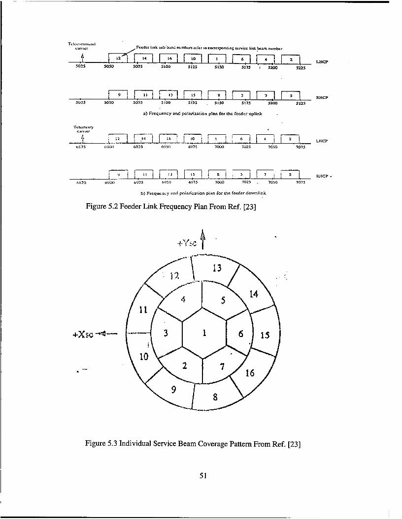
Fccdcr lmk subhdnd numbers rckr 10 COmSpondlnS scrv~cc link beam number /
I
L n e fi -1 14 1 I 16 10 i l i 6 2
5075 5 loo 512s S I M 5175 I 5200 522s 501s MX)
a) Frceqtiency and polarization plan for the fccdcr up!ink .
i-- , - - I .- -
b) Frequency and painrizalion pian for crbc fccd-r Lowmiink
Figure 5.2 Feeder Link Frequency Plan From Ref. [23]
Figure 5.3 Individual Service Beam Coverage Pattern From Ref. [23]
51
beam cells is reduced. The Globalstar satellites’ spot beam antennas are also designed to
compensate for the difference in the satellite-to-user link losses between the “near” and
the “far” users, so that the power flux density of the “far’ users is about the same as the
“near” users (ie., an isoflux design). This antenna will reduce the near-far problem
experienced by many cellular type systems. Also, with this type of antenna, harmful
interference into the system can be reduced and the capacity of the system can be
increased.
d. System Capacity
The CDMA techniques used by Globalstar result in a very efficient use of
spec rum. The system can achieve over 2,800 full duplex voice channels capacity through
a single satellite. Of course, a mobile user will be covered by two or more satellites.
Therefore, neighboring satellites can coordinate to provide about 5,000 simultaneous
voice channels. Over 134,400 full duplex voice channels can be achieved for the global
coverage.
Digital data services will be accommodated by using a variable data rate
from 2.4 Kbps up to 9.6 Kbps. The quality of services will be high by using error
correction techniques.
e. Transmission Characteristics
Globalstar will provide RDSS, voice and data services at low cost with
“bent-pipe” type transponders. Voice service is to be provided at 4800 bps and data
services at speeds of 2400, 4800, and 9600 bps. The services provided will be of high
52
quality by using error correction code. At the forward link the code will be convolutional
with -112 and k=9 while at the reverse link will be also convolutional with r=1/3 and
k=9.
Spread spectrum CDMA has been chosen for multiple access and QPSK is
the basic signal structure used for waveform modulation.
The polarization is LHC (Left-Hand Circular) on all service beams and
both RHC (Right-Hand Circular) and LHC on feeder beams.
2. Ground Segment
The Globalstar ground segment consists of: (1) gateways, (2) the network control
center, and (3) the telemetry, trdcking and command stations and satellite operation
control centers.
a. Gateways
Each satellite communicates with the mobile user via the satellite-user
links and with gateway stations directly via the feeder links. Figure 5.4 illustrates the
block diagram of a gateway terminal. The RDSS functions are performed at the gateway
stations or at the user terminal, while voice/data communications are routed through the
gateway stations. Each gateway station initially will communicate with three satellites
simultaneously. Gateways handle the interface between the Globalstar network and the
PSTN. There are many gateways (six coordination gateways and ideally a gateway for
each cellular telephone operator) distributed throughout the United States. Most of these
gateway stations are connected directly to the mobile switch centers of the land mobile
53
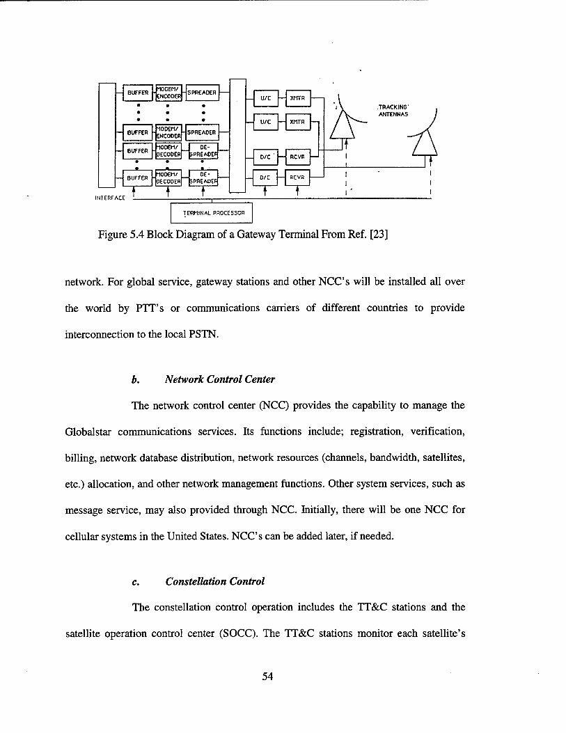
I I
I
TERMINAL PROCESSCR
Figure 5.4 Block Diagram of a Gateway Terminal From Ref. [23]
network. For global service, gateway stations and other NCC’s will be installed all over
the world by PTT’s or communications carriers of different countries to provide
interconnection to the local PSTN.
b. Network Control Center
The network control center (NCC) provides the capability to manage the
Globalstar communications services. Its functions include; registration, verification,
billing, network database distribution, network resources (channels, bandwidth, satellites,
etc.) allocation, and other network management functions. Other system services, such as
message service, may also provided through NCC. Initially, there will be one NCC for
cellular systems in the United States. NCC’s can be added later, if needed.
C . Constellation Control
The constellation control operation includes the TT&C stations and the
satellite operation control center (SOCC). The TT&C stations monitor each satellite’s
54

operation via the telemetry of the satellites and send commands to the satellite to control
its on-orbit performance. The TT&C stations also perform tracking and ranging functions
for the orbiting satellites. The ephemeris of the satellites are transmitted to the SOCC.
The SOCC processes the satellite orbit information for various network functions, e.g.,
acquisition and synchronization, hand-off between satellites and hand-off between beams.
The processed information and databases are distributed to Globalstar gateways for
tracking and other purposes. The SOCC also plans and executes orbit station-keeping for
the satellites, so that all satellites are maintained in the appropriate orbits.
The constellation control operation (CCO) supports the launch operation
and in-orbit-test operation. When a satellite reaches the end of its life, the CCO removes
the satellite from orbit and moves spare orbiting spacecraft to replace the old spacecraft.
Initially, two TT&C stations and one SOCC will be installed in the US.
Additional TT&C’s and SOCC’s will be implemented for the global network.
1
3. User Segment
The user segment consists of hand-held, mobile and fixed terminals. Hand-held
and mobile terminals may be single or dual mode (i.e. to operate as a terrestrial cellular
terminal and as a Globalstar terminal). Fixed terminals would be used solely for
Globalstar services. The hand-held unit is similar to those for terrestrial cellular networks
in size, weight, and power. The mobile unit is similar to a car-radio.
Globalstar is a fully digital system which uses a variable rate voice encoding
technique to provide high quality voice service. Bit rates range from 2.4 Kbps to 9.6
Kbps. The digital signal is spread over 1.25 MHz bandwidths in the US-bands using
55

Direct Sequence CDMA. The peak power of the user segment is 2W and the modulation
technique is QPSK. Forward error correction techniques are also used.
D. SUMMARY
Globalstar system will provide voice, data, facsimile and RDSS services. It will
use a network of 48 satellites in inclined orbits 1414 km above the earth to provide almost
global coverage. Each satellite directs 16 beams to the earth to receive and send messages
to hand-held units or to gateways. The system is intended to work with the existing public
switched telephone network (PSTN). Calls are relayed through the satellite only when
access cannot be made to the terrestrial network. The existing PSTN will be accessed via
gateways and will be used for long-distance connections including transoceanic calls.
56
VI. COMPARISON
A. INTRODUCTION
In previous chapters a detailed summary for each of four important satellite-based
commercial personal communications systems (PCS) was given. Three of them (Iridium,
Globalstar, and Teledesic) are LEO satellite systems and one (Odyssey) is ME0 satellite
system. Also, three of them are narrowband systems (Iridium, Globalstar, and Odyssey)
while Teledesic is a wideband one. In this chapter a comparison of the four systems will
be presented. First a summary of system parameters will be obtained. Then criteria for
comparison are defined.
B. SYSTEM PARAMETERS SUMMARY
Table 6.1 lists the system parameters of the four systems described in details in
previous chapter. There are a few papers in the literature that compare Iridium,
Globalstar, and Odyssey using as criteria, technical, technology, business, and regulatory
aspects. Gany M. Comparetto compares these systems and concludes: [Ref. 31
“It is clear that Iridium will be the most challenging to deploy due to the inclusion
of on-board processing techniques within the satellite communications payload together
with a high data rate satellite crosslink capacity. Furthermore, The FDMAITDMA
multiple access scheme proposed for Iridium presents a number of complex issues
57

Iridium I Teledesic I Odyssey I Globalstar Orbit Class I LEO LEO ME0 LEO Altitude (km) Number of Satellites Number of Planes Period (minutes)
780 700 10355 1414 66 840 12 48 6 21 3 8
100 98.8 360 114 Inclination (Degrees)
ProDosed Services Elevation (Degrees)
I ~~~
katellite Antenna I Fixed I Steerable I Steerable I Fixed
86.4 98.16 50 52 8.2 40 20 10
RDSSNoicelData Multimedia RDSSNoicelData RDSSNoiceData
Table 6.1 System Parameters Summary
involving cell utilization, cell frequency management, and time synchronization. The
Globalstar system seems to be well postured, from a technical standpoint, due to the in-
house experience of QUALCOMM in the area of CDMAkellular applications. However,
Odyssey may be in the best position to achieve its stated cost and performance objectives
58
due to the small number of satellites required in the design along with the use of a proven
communications bus onboard the satellite.”
Klaus G. Johannsen also compares Iridium, Globalstar, and Odyssey among other
commercial satellite based PCS and concludes that Odyssey may be the best mobile
satellite system [Ref. 51. Of course, in our case the criteria will be different from those of
the two above authors in order to compare these systems for military applications.
c. CRITERIA
The objective of this thesis is to find out if these commercial PCS satellite
systems can be used for DoD communications. Therefore, these systems will be
compared using the following criteria; antijam protection, security, low probability of
interceptionhow probability of detection (LPULPD), interoperability, grade of service,
signal quality, systems availability, cost, coverage, mobility, flexibility, control, and
capacity.
1. Antijam Protection
For tactical and strategic military satellite communications (MILSATCOM),
antijam protection is of major concern. In a satellite link either the uplink or the downlink
may be targeted by an intentional jammer. The vulnerable element has traditionally been
the uplink since a successful jamming attack on the uplink can disrupt the entire user
community utilizing the transponder(s). Generally ECCM techniques can be employed on
either the spacecraft or the ground and should be considered as part of the total link
protection. These techniques comprise: spread spectrum, error control coding, adaptive 59
.
nulling or multi-beam antennas, spacecraft autonomy, intersatellite links. It is highly
likely that one or more of these methods will be employed in military satellite
communications depending on the required grade of service, the priority links,
availability and the perceived threat. [Ref. 11
The proposed commercial satellite PCS systems are not designed to sustain
intentional jamming. Thus, during a crisis, electronic jamming could severely degrade the
performance of these systems and limit system capacity to support a high number of
requests. However, two of the above four systems offer some degree of antijam
protection.
Globalstar and Odyssey plan to use code division multiple access (CDMA) which
by its nature is a spread spectrum technique. Iridium and Teledesic plan to use
intersatellite links. These two systems have forward error correction coding and Viterbi
decoding which enhance the antijam capability.
2. Security
This issue is of primary concern for all PCS users and is expected to be resolved
by the PCS industry. The “masquerade attack” is an example of one threat, where an
intruder pretends to be an authorized user to gain access to services for which hisher
victim then pays. In DoD applications, the weakness to attack could severely damage the
usefulness of PCS. A cost-effective, time-efficient solution must be developed to improve
access security and information protection. An example to provide secure network access
is by mutual authentication, as opposed to a simple personal identification number (PIN).
Once the identity of the user has been firmly established, standard techniques can be used
60

to protect user information. An example is to use an enhanced STU-III style encryption
into mobile terminal handset. Current versions of STU-III including the planned digital
one are not applicable to satellite PCS applications from a physical protection standpoint.
Protecting tactical data and messaging is equally important. An example could be
the implementation of National Security Agency approved cryptographic algorithm called
MISSI, which is a low cost method to protect unclassified but sensitive messaging. [Ref.
101
3. LPYLPD
For satellite personal communication systems, allowing system access anywhere
in the world is important and useful for DoD. This feature however results in mobile user
vulnerability since they can be located and their movement can be tracked by intercepting
their transmit signals at two or more sites [Ref. 101. Therefore, low probability of
interception and detection is required for mobile satellite systems.
LPYLPD capability of a communications system relates to its coverage as well as
the waveform used. CDMA waveforms provide limited signal discrimination and
LPYLPD. [Ref. 41
4. Interoperability
DoD wants to achieve interoperability among tactical users and seamless
communications support under flexible force deployment options in any environment
including maritime, air and ground. Up to now, fierce competition in the PCS business
has kept the satellite systems developers working indepedently in order to protect their
61

proprietary information. For example, different voice coding algorithms are being
pursued. An effect could be that two users using different systems might not be able to
communicate with one another. The other differences between the planned satellite PCS
systems include different frequency plans, multiple access schemes, and transponded'
satellites versus on board processed satellites. The satellite systems planning to use the
CDMA waveform design such as Globalstar and Odyssey could conceivably interoperate
over each other satellite. However, different proprietary technologies in these PCS
systems will create more costly and complex solutions for interoperability .
Furthermore, since a hybrid PCS network is envisioned, a common handset
allowing accesses to different systems will be desired offering convenience and
improving systems interoperation. Otherwise, a user must be equipped with many
terminals to use different satellite PCS systems. DoD wants an approach such that a
multi-mode terminal commonality is feasible without excessive costs. [Ref. 101
5. Grade of Service
Tactical commanders require assured access to satellite systems 24 hours a day
throughout the world. During a crisis, tactical commanders may keep getting busy signals
due to demands for service exceeding capacity. Thus, military satellite PCS users may
have to be provided with a special signaling channel in order to achieve immediate access
and high priority service. None of the systems considered previously has any kind of this
capability. [Ref. 101
62
6. Systems Availability
Most of the systems (Globalstar, Iridium, Odyssey) are planned to be available by
1998. However, while the technical feasibility of the systems seems to be secure, their
economic viability is somewhat more questionable. Yet, Iridium still- needs about $1.8
billion of the $3.4 billion estimated for its network. Globalstar have raised much less
amounts than needed. Teledesic ($9 billion estimated cost) has not yet be granted a
license from Federal Communications Commission (FCC). Because of these
uncertainties, maybe it is better for DoD to wait until it is learned which systems will
come to reality.
In addition, there are some other issues that could delay the availability of the
proposed systems. They include worldwide frequency allocation and management, inter-
system interference, and gateway complexity.
7. Signal Quality
All PCS providers plan to offer voice, data, facsimile and other services such as
messaging, paging, and position location service. Teledesic plans to offer and multimedia
service. The bit error rate (BER) for voice is for the others. The
bit error rate for data is lo-’ for Teledesic and for the others. The typical supportable
data rates are 4.8 Kbps for voice and between 1.2 Kbps and 9.6 Kbps for data. Teledesic
supports more than 2 million simultaneous full-duplex 16 Kbps basic channels, up to
2.048 Mbps “on demand” channel rates, and for special applications up to 1.24416 Gbps.
for Iridium and
63
8. cost
Although cost is not an explicit criteria, let’s have an idea about prices for the
mobile terminals and cost of service. The estimated initial prices for the mobile terminals
vary considerably with Odyssey projected selling for under $500, followed by Globalstar
at $750, and Iridium at $2000 to $3000. The mobile terminal for Teledesic is briefcase
sized and there is no estimation for its price. On the other hand, the projected cost of
service ranges from $0.30 per minute to over $3 a minute. LQP plans to charge $0.30 per
minute for the Globalstar service plus $0.10 per minute for tail charges to connect to local
or long-distance services. In addition, a monthly service charge of $8 to $10 is anticipated
based on current cellular experience. The retail price of Odyssey service is estimated at
$0.65 per minute plus about $0.10 for tail charges and a monthly service of about $24.
Motorola plans to charge $3 per minute plus tail charges. Teledesic plans to charge
subscribers to those charged for similar services provided by terrestrial systems.
9. Coverage
Global changes have resulted in a fundamental change to U.S. National Military
Strategy. This strategy will increasingly rely on the capability to project combat power
with joint military and/or government organizations. The Armed Forces must be prepared
to support joint operations ranging from peacetime engagements to war. These operations
could included nation assistance, civil-military operations, regional conflicts, attacks and
raids, and declared wars. Also, satellites are the optimum choice (not to say the only one)
to communicate with warships operating anywhere on the globe. Therefore, satellite 64
systems must cover the whole earth’s surface 100% of the time, including polar (north
and south) regions. [Ref. 71
Iridium plans to provide global coverage, Teledesic between 72’ north and south
latitude, Globalstar between 74’ north and south latitude, and Odyssey between 70’ north
and 55’ south latitude.
10. Mobility
At the present, communicating over an existing commercial satellite would
require the use of terminals that are not conveniently carried from location to location as
many mobile users would want. Planned satellite based PCS systems on the other hand
would offer seamless communication mobility for users with conveniently carried
transceivers [Ref. 101. Today considerations for about the deployment of a military force,
emphasize on its mobility. As forces begin to move to their objectives, the ability to
communicate with them during the move, is a challenging issue.
The concept of a digital connection to anywhere at anytime is perfectly adaptable
to the needs of a mobile military force. Planned PCS systems using LEOME0 satellite
constellations make this concept a reality and will support the military needs of
“Communications on the Move” .[Ref. 111
Iridium, Globalstar, and Odyssey with their hand-held units will support enough
mobile military forces. Teledesic on the other hand will also offer mobile satellite
services (MSS) to them, but its primary plan is to offer fixed satellite services (FSS).
65
11. Flexibility
DoD requires satellite-based systems to be flexible in two ways: to be compatible
with other satellite systems and to be compatible to many digital PSTNs and public land
mobile networks (PLMNs). All four systems provide the capability to be connected to
PLMN with dual mode terminals and to PSTN with gateways.
Gateways also must be flexible and transportable. Globalstar’s feeder links are in
C-band allowing to support a tactical system with inter-theater connectivity. Iridium and
Odyssey on the other hand, use Ka-band feeder links that require use of multiple,
interconnected gateways spaced at least 10 km apart in order to overcome potential loss
of availability due to rain attenuation.[Ref. 41
12. Control
All four systems are designed and will be operated by U.S. companies (Motorola,
Teledesic Corp., LoraVQualcomm, and TRW). However, it is risky to say definately that
DoD will have complete control on these systems whenever it is needed.
13. Capacity
Last but the most important, the issue of capacity. Teledesic by its proposed
mission has the largest capacity of 100,000 full-duplex 16 Kbps connections per satellite.
Iridium is power-limited at 1,100 circuits per satellite. Odyssey and Globalstar have
capacities of 3,000 and 2,800 full-duplex voice channels respectively through a single
satellite. These numbers can be increased up to 6,000 and 5,000 respectively, whenever
users are covered by two or more satellites. 66
D. CONCLUSIONS
Without question there is a role for commercial mobile satellite communications
in support of world-wide military operations. An effort by a Loral team showed that
approximately 1/3 of the MSS DoD traffic is general purpose traffic which does not need
to meet the full spectrum of MlLSATCOM requirements. The remaining 2/3 traffic is
core traffic and has more stringest requirements. Commercial MSS systems can meet
approximately 45% of the DoD MSS requirements, if the 1 1 % of the core requirements
are added to the general purpose traffic. [Ref. 41
Commercial satellite PCS systems have the potential to satisfy military mobile
communications needs that are currently satisfied by UHF military communications
satellites. Transferring military UHF traffic to commercial satellite PCS systems frees up
capacity on government systems that would be used to support additional mobile tactical
users. Another benefit is possible cost reduction derived from use of commercial-off-the-
self (COTS) products and from competitive service charges resulting from anticipated
fierce competition in the PCS market. An example is the availability of commercial
maintenance support and equipment warranties, which means that DoD does not have to
establish unique and more costly operational and maintenance. Another benefit is military
mobile users are provided with state-of-the-art commercial technology. [Ref. 101
Conclusions are summarized as follows:
67
1. Commercial LEOME0 satellite systems have the potential to provide
communications support for DoD’s less critical needs which include administration,
logistics, and other support functions.
2. None of the commercial systems that were studied meets all the DoD
requirements.
3. An architecture consisting of Odyssey and Globalstar meets the most of
the criteria and government requirements for MSS services.
4. Teledesic is the only system to provide higher data rates (>64 Kbps) to
mobile users operating directly with FSS systems.
5. Iridium is the only system to provide polar (north and south) coverage.
68

VII. MILITARY APPLICATIONS
A. INTRODUCTION
In this chapter, we investigate which are the potential military applications of the
commercial satellite systems described in previous chapters. A historical overview of
military communications by satellites and a brief description of current systems are
provided. Then, a brief discussion of the areas where the LEOS systems can be used is
provided. Finally, the possibility to provide satellite communications to MAGTF (Marine
Air-Ground Task Force) is investigated.
B. HISTORICAL OVERVIEW OF MILSATCOM SYSTEMS
It all started in October 1957, when the Soviets launched Sputnik, the first
artificial satellite to be sent into space. Sputnik could be considered as an orbiting radio
transmitter rather than a communications satellite. It was soon recognized that human-
made artificial satellites offered a novel transmission medium with unique features for
both commercial and military communications. Only a few satellites could provide
worldwide coverage with distance-insensitive cost, flexible interconnectivity among
dispersed users over a wide geographic area, large transmission bandwidths to support
high data rates, rapid extension of communications into new or isolated areas, and beyond
line-of-sight service to mobile platforms such as aircraft, ships and submarines. In many
military scenarios, satellites provide a more reliable alternative to conventional
69
microwave, troposcatter, and high frequency radio systems; in particular for
accomplishing such important functions as broadcast, report-back, and conferencing
among dispersed users.
As launch vehicle capability increases, the first geostationary satellite (SYNCOM
nor> was launched in August 1964 implementing Arthur Clarke’s idea of geostationary
satellites as communications relay. In April 1965 the first commercial communications
satellite (INTELSAT I or “Early Bird”) was launched with a capacity of 240 two-way
transatlantic voice circuits.
The first U.S. military communications satellites, the DSCS I, were launched in
June 1966. A total number of 26 satellites, were launched in four groups by TITAN 3C
launch vehicles to near equatorial, 18,300 statute miles orbits. These satellites drifted
from west to east at a rate of up to 30’ per day for a lifetime of six years. This initial
experiment was followed in February 1969 with the more ambitious tactical satellite
(TACSAT) communications program. One satellite was placed in geostationary orbit and
was used to evaluate mobile user needs in tactical situations.
In June 1970, residual DSCS I and TACSAT assets were available to U.S. Navy.
This was followed by the approval of the Fleet Satellite Communications
(FLTSATCOM) program by the Secretary of Defense in September 1971. TACSAT
located in the Pacific area failed in December 1972. The Navy was faced with a five year
period in the Pacific and a potential four year period in Atlantic during which no UHF
SATCOM relay would be available. This was based on the assumption that the first
FLTSATCOM satellite would be available by December 1978. To minimize this gap the
Navy decided to lease UHF satellite communication services. A contract for a two ocean
70

coverage (Atlantic and Pacific) was signed and then modified to include coverage of the
Indian Ocean.
DSCS I satellites were followed by DSCS II and ID. The first two DSCS II were
launched in November 1971. By September 1982, 16 phase II satellites had been
launched, four were not placed in orbit due to launch vehicle failures and four are
operational with varying degrees of availability. The DSCS llI satellites are currently
replace the DSCS 11 ones. [Ref. 21
C. CURRENT MILSATCOM SYSTEMS
The DoD currently uses both military and commercial systems to meet its demand
for satellite communications. Military systems operate in the UHF (240-400 MHz) and
SHF (8/7 GHz) bands with a diverse mix of fixed, mobile, and transportable terminals.
Additional communications are provided through leased circuits on commercial C (6/4
GHz) and K, (14/11 GHz) band satellites.
1.
This UHF system consists of government-owned FLTSAT, and leased-service
provided by contractor-owned LEAS AT satellites. These geostationary satellites, provide
communications to tacticdmobile users such as ships and submarines. They have
multiple 25-KHz and 5-KHZ channels, and one 500-KHz channel. The signal on the
uplink is a pseudo-noise spread spectrum one at X-band. This signal is despread onboard
the satellite and retransmitted on the downlink at UHF.
Fleet Satellite Communications System (PLTSATCOM)
71

2.
This system consists of a number of satellites in inclined elliptical orbits and
shares FLTSAT with FXTSATCOM system. The system provides a global capability for
dissemination of the emergency action messages to nuclear-capable forces, and associated
Airforce Satellite Communications Systems (AFSATCOM)
report-back communications. Principal users of the A F S ATCOM system are small
ground-transportable and airborne terminals. Each satellite carries twelve 5-KHz
narrowband channels which are frequency hopped on the uplink.
3.
Principal users of the DSCS system are fixed and transportable terminals and a
limited number of mobile terminals supporting naval and air operations. It is the DoD’s
primary system for long-haul high-volume trunk traffic. The DSCS 11 satellites are
currently replaced by DSCS III ones. The frequency plan of DSCS II allows operation in
four frequency bands within the allocated 500-MHz spectrum. The DSCS III is the first
military satellite with antenna nulling capability and its anti-jam capability is increased
Defense Satellite Communications System (DSCS)
over DSCS II.
4. The MILSTAR System
This new system, will use the 44 GHz band on the uplink and 20 GHz on the
downlink. The space segment will consist of a number of satellites in geostationary and
inclined circular orbits for global coverage. Each Milstar satellite will incorporate
onboard processing for enhanced anti-jam, multiple uplink and downlink beams to cover
widely dispersed users, and nuclear hardening to achieve a high degree of survivability.
72

c The signals will be frequency hopped over a wide bandwidth. The satellites will be
crosslinked for world-wide connectivity, without the use of ground relays.
D. APPLICATIONS
The above described current military satellite communication systems offer high
protection but have limited capacity. Today, there is a great demand for satellite
communications to more users especially for mobile ones. The commercial satellite
systems described in previous chapters have high capacity but low/medium protection.
Therefore, they can be used for DoD’s less critical communications needs such as
administrative, logistics and other support functions. Transfering military traffic to these
commercial PCS frees up capacity on military satellite systems to support more critical
communication needs.
There are three categories of information services supported by current satellite
systems; voice, data, and video services. These services are provided by three types of
satellite communication systems; narrowband, wideband, and broadcast systems. Iridium,
Odyssey, and Globalstar are narrowband systems and provide voice and low data rate
services. Teledesic is a wideband system and provides data services (medium and high
data rates), and video services. Of course, none of them is a broadcast system.
1. General Military Applications
Globalstar and Odyssey provide radiodetermination services. These services can
be exploited by the military as follows: [Ref. 131
73
1. Track position of units at command posts.
2. Track position of logistics throughout shipment with subscriber units
integrated into the asset.
3. Remotely interrogate electronic tags and manifests.
4. Collect crucial environmental data located anywhere in the battlespace.
5. Monitor the status of remote sensors from the U.S. or field command
posts.
6. Query the status of rapidly moving weapon systems.
7. Provide global search and rescue coverage for downed pilots.
2. U.S. Army Applications
Several changes in the global environment occurred within the past years that
affected the operational requirements for communications on the battlefield. There is less
concentrated focus on Eastern Europe and the former Soviet Union and more worldwide
focus on new centers of power and regional conflicts. As a result, the following
communications requirements are becoming increasingly important for GMF (Ground
Mobile Forces): [Ref. 261
1. Ability to rapidly deploy and scale the communications infrastructure to
meet the requirements of the force structure as it changes.
2. Ability to deploy in a variety of environments.
3. Ability to provide communications on a dispersed battlefield.
4. Ability to provide communications support for rapidly moving forces,
to include command and control.
5. Less reliance on terrestrial LOS systems, increased use of satellite ones.
74
Existing and planned U.S. Army’s satellite and troposcatter
communication systems require the user to stop, deploy, and point an antenna in order to
establish a link. Other digital communication systems such as JTIDS (Joint Tactical
Information Distribution System), SINCGARS (SINgle Channel Ground-Airborne Radio
System) , and MSE (Mobile Subscriber Equipment) are limited by LOS and require
relays. Therefore, Globalstar and Odyssey can be used by the U.S. Army to provide
beyond the line of sight “communications on the move” for its units.
a. Application to MSE
The MSE (Mobile Subscriber Equipment) provides circuit-switched digital
voice and data communications for a nominal U.S. Army Corps area and five associated
divisions. It also provides packet-switced data communications service for LANs (Local
Area Networks) and individual hosts. A block diagram of MSE is shown in Figure 7.1.
The fundamental principles of PCS (ubiquity, complete and continuous
coverage) are critical for tactical communications. In a modern tactical environment users
will require access to switched services in command posts, in vehicles, and in isolated
forward areas. The authors in Ref. [26] suggest the adjusted MSE network shown in
Figure 7.2, where the configuration consists of a command post, a wide area vehicular
coverage, and an isolated forward area. Satellites are used to provide wireless access
between base stations in forward areas and node centers. Also, there is no handoff
capability in this proposed network. Handoff is not feasible for fast moving forces.
75

Figure 7.1 MSE System From Ref. [26]

Globalstar and Odyssey can be used to connect any mobile user of directly
with the node centers, at least for logistics and other support functions. Also, can be used
for LOS communication between node centers.
3. U.S. Navy Applications
Satellite communications is the essential link for Naval Forces. Naval Forces are
mobile, worldwide dispersed, forces. There is no fiberkable connectivity and non-
satellite beyond line-of-sight communications systems by themselves will not satisfy the
capacity and mobility requirements for Naval Forces.
Current satellite communication systems provide mainly communications between
maneuver elements and command posts in CONUS. As information requirements are
increased, more satellite capacity is needed to extend these services to lower echelons.
Globalstar and Odyssey can be used to provide voice and low data rate services to ships,
submarines, Marine Corps units.
E. APPLICATION TO MAGTF
1. Defmi tions
a. Marine Air-Ground Task Force
This is a task organization of marine forces (division, aircraft wing, and
service support groups) under a single command and structure to accomplish a specific
mission. The MAGTF components will normally include command, aviation combat,
ground combat, and combat service support elements (including navy support elements).
Three types of MAGTF which can be task organized are the marine expeditionary unit
77

(MEU), marine expeditionary brigade (MEB), and marine expeditionary force (MEF).
The four elements of a MAGTF are: [Ref. 281
(1) Command Element (CE). This is the MAGTF headquarters.
The CE is a permanent organization composed of the commander, general or executive
and special staff sections, headquarters section, and requisite communications and service
support facilities. The CE provides command, control, and coordination essential for ,
effective planning and execution of operations by the other three elements of MAGTF.
There is only one CE in a MAGTF.
(2) Aviation Combat Element (ACE). The MAGTF element that is
task organized to provide all or a portion of the functions of Marine Corps aviation in
varying degrees based on the tactical situation and the MAGTF mission and size. These
functions are air reconnaissance, antiair warfare, assault support, offensive air support,
electronic warfare, and control of aircraft and missiles. The ACE is organized around an
aviation headquarters and varies in size from a reinforced helicopter squadron to one or
more marine aircraft wing(s). It includes those aviation command (including air control
agencies), combat, combat support, and combat service support units required by the
situation. Normally there is only one ACE in a MAGTF.
(3) Ground Combat Element (GCE). The MAGTF element that is
task organized to conduct ground operations. The GCE is constructed around an infantry
unit and varies in size from a reinforced infantry battalion to one or more reinforced
marine division(s). The GCE also includes appropriate combat support and combat
service support units. Normally, there is only one GCE in a MAGTF.
78
(4) Combat Service Support Element (CSSE). The MAGTF
element that is task organized to provide the full range of combat service support
necessary to accomplish the MAGTF mission. CSSE can provide supply, maintenance,
transportation, deliberate engineer, health, postal, disbursing, enemy prisoner of war,
automated information systems, exchange, utilities, legal, and graves registration services.
The CSSE varies in size from a marine expeditionary unit service support group to a force
service support group.
Marine expeditionary force (MEF) is the largest of the MAGTF
and is normally built around a divisiodwing team while marine expeditionary unit
(MEU) is the smallest of the MAGTF and is normally built around a battalion landing
team, reinforced helicopter squadron, and logistic support unit.
b. Type of Services
Services can be distinguished in voice, data, and video services. Video
services include videoteleconferencing (VTC), teletraining, telemedicine, broadcast TV,
UAV imagery, movies, sports and recreational television. Data services include, tactical
communications between maneuver elements and command facilities ashore and
command and control (C2) for command elements (see Figure 7.3). Voice services
include phones, voice mail, command nets, and coordination and reporting nets (C&R).
[Ref. 27:p. 15-18]
79
. .. .. . .. .
c. Topology
A network topology can be distinguished in netted, hub & spoke, point to
point, reportback, broadcast, and virtual. These topologies are illustrated in Figure 7.4.
d. Data Rate
The data rate can be high, medium, or low. Low data rate (LDR) is the rate
less than 9.6 Kbps, high data rate (HDR) when is greater than 1.544 Mbps (Tl), and
medium data rate (MDR) when is between 9.6. Kbps and T1. MDR can divided
furthermore in MDRl (between 9.6 Kbps and 64 Kbps) and MDR2 (between 64 Kbps
and 1.544 Mbps). [Ref. 27:p. 1091
e. Protection
Protection can be categorized as high (operate through nuclear event, anti-
scintillation, sanctuary jammer), medium (jammer with 200 nm of FEBA, transportable
jammer), low (nuisance jammer, man-portable, neutral country jammer, US ownership
and control of entire communications path), or none (no protection). [Ref. 27:p. 1101
80

SHIPS SHORE OTHER PLATFORMS
Figure 7.3 MAGTF Satellite Communications From Ref. [27]
Figure 7.4 MAGTF Satellite Communications From
Point to Point
f -7
Ref. [27]
81

2. MAGTF Circuit Requirements
The circuit requirements for MEF and MEU are shown in Figures 7.5, and 7.6.
The circuit requirements for MEF are 250 voice, 300 data, and 10 video links. The
circuits requirements for MEU are 30 voice, 70 data, and 5 video links-.
3. Globalstar-Odyssey-Teledesic Capacity
Each Odyssey satellite has a capacity of 3,000 circuits and a “hot spot” beam 600
circuits. Each satellite provides high quality voice and data services. The basic digital
data service for the handheld unit is 2400 bps (low data rate). The protection according to
the criteria discussed above can be characterized as medium and of course Odyssey is not
a broadcast system. With these assumptions Odyssey has the potential to provide all the
voice services required for MAGTF (250 links for MEF, and 30 for MEU). Also can
support part of the data services needed (see Tables 7.1, and 7.2).
Each Globalstar satellite has a capacity of 2,800 circuits. With the same
assumptions as Odyssey, Globalstar can provide the same number of links as Odyssey.
Teledesic is the only proposed LEO wideband satellite system and can support
MAGTF with video services (except broadcast services) and MDR and HDR data
services (see Tables 7.1, and 7.2).
82
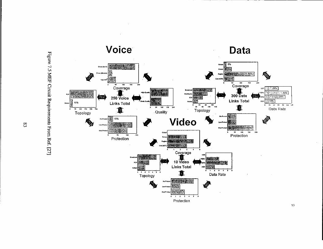
00 w
Woke Data
PIP
0 ?O <J 60 LO IM 110
Data Rate
Protection
0 1 2 1 4 5
Protection
Coverage LDR
3E PTP 10 Video
H.8.d Links Total Hull
Rr Data Rate 0 * 2 1 4 5 6
To~olonv
0 1 2 1 4 1 6
Protection 10
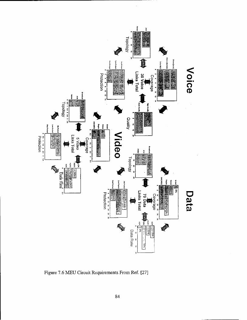
I
? t a
2- -0
0 (D Y Z
0 s
Y
Y
Figure 7.6 MEU Circuit Requirements From Ref. [27]
84
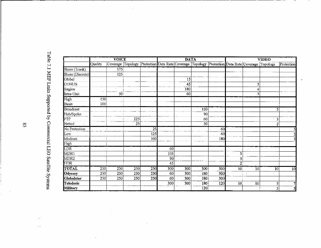
cn E: 'd 'd 0
a 3 HubISpoke __ 90 PTP 225 60 ' 3 Netted 25 30 2 No Protection __ I 25 60 5
125 60 2 Low Medium 100 180 3 High LDR 60 MDR 1 105 3 MDR2 90 5 HDR 45 2 TOTAL 250 250 250 250 300 300 300 300 10 10 10 10 Odyssey 250 250 250 250 60 300 180 300 Globals tar 250 250 250 250 60 300 180 300 Teledesic 3 00 300 180 120 10 10 5 7 Military 120 5 3
~-
_ _ _ ~
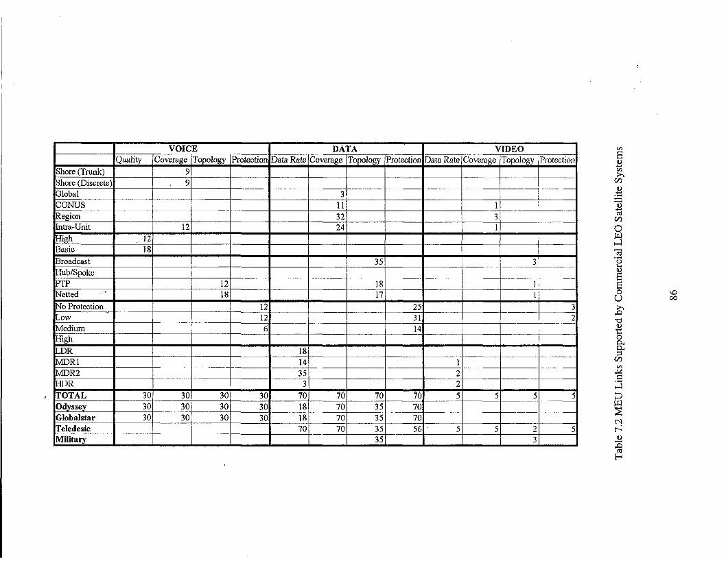
4. Circuit Requirements for CVBG
Carrier battle group (CVBG) is a standing naval task group consisting of a carrier,
surface combatants and submarines as assigned in direct support, operating in mutual
support with the task of destroying hostile submarine, surface and air forces within the
group’s assigned area of responsibility and striking at targets along hostile shore lines or
projecting fire power inland.
Suppose that MAGTF is supported by one CVBG. The circuits requirements for
CVBG are shown in Figure 7.7 and are 300 for voice, 285 for data , and 20 for video
services. In Table 7.3 shows that all voice and a part of data links can be established using
Globalstar and Odyssey. Teledesic will provide also provide a part of the required video
services.
F. SUMMARY
In this last chapter the potential role of LEO commercial satellite communication
systems to military communications systems was examined and particularly to Marine
Air-Ground Task Force. It was shown that these systems can provide all the required
voice services and a significant part of data and video services. Therefore, it is beneficial
for DoD to use these systems instead of investing heavily in new satellite systems.
However, there are some issues that have to be investigated furthermore such as
interoperability with existing military communication systems, priority, and security.
87

Voice Data
0 M IW IM 2w
PlP
0 10 IW I S " 100
Data Rate N t l d
u u a i i r y NoPIDI.~
L a P8oL.d
u.d PI0I.d
IdghP8oI.d ~~
Protection
0 10 20 Y) 40 SO 60 70 81
Protection
PlP
N.Id
Data Rate 0 1 1 a I 1 0 1 1
TODO~OUV
E 2 c4
23 a
0 1 1 4 0 1 0 1 2
Protection
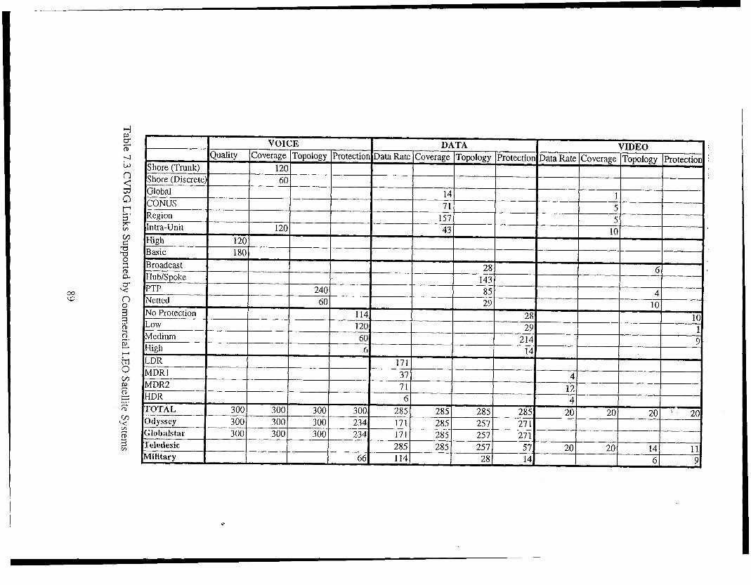
0 c w
High 6 14 LDR 171
MDRZ HDR TOTAL 300 300 Otly\scy 300 300 300 234 171 285 257 27 1 Globalsta1 300 300 300 234 171 285 257 27 1 Teledesic Military
MDRl 37 4 71 12 6 4
300 300 285 285 285 285 20 20 20 ' 20
285 285 257 57 20 20 14 11 66 114 28 14 6 9
r m 0

90
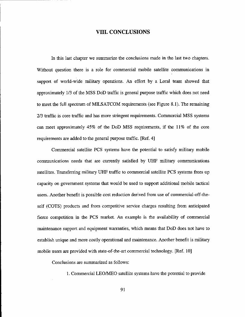
VIII. CONCLUSIONS
In this last chapter we summarize the conclusions made in the last two chapters.
Without question there is a role for commercial mobile satellite communications in
support of world-wide military operations. An effort by a Lord team showed that
approximately 1/3 of the MSS DoD traffic is general purpose traffic which does not need
to meet the full spectrum of MlLSATCOM requirements (see Figure 8.1). The remaining
2/3 traffic is core traffic and has more stringent requirements. Commercial MSS systems
can meet approximately 45% of the DoD MSS requirements, if the 11% of the core
requirements are added to the general purpose traffic. [Ref. 41
Commercial satellite PCS systems have the potential to satisfy military mobile
communications needs that are currently satisfied by UHF military communications
satellites. Transferring military UHF traffic to commercial satellite PCS systems frees up
capacity on government systems that would be used to support additional mobile tactical
users. Another benefit is possible cost reduction derived from use of commercial-off-the-
self (COTS) products and from competitive service charges resulting from anticipated
fierce competition in the PCS market. An example is the availability of commercial
maintenance support and equipment warranties, which means that DoD does not have to
establish unique and more costly operational and maintenance. Another benefit is military
mobile users are provided with state-of-the-art commercial technology. [Ref. 101
Conclusions are summarized as follows:
1. Commercial LEONE0 satellite systems have the potential to provide
91
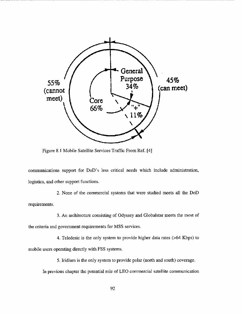
Figure 8.1 Mobile Satellite Services Traffic From Ref. [4]
communications support for DoD’ s less critical needs which include administration,
logistics, and other support functions.
2. None of the commercial systems that were studied meets all the DoD
requirements.
3. An architecture consisting of Odyssey and Globalstar meets the most of
the criteria and government requirements for MSS services.
4. Teledesic is the only system to provide higher data rates (>64 Kbps) to
mobile users operating directly with FSS systems.
5. Iridium is the only system to provide polar (north and south) coverage.
In previous chapter the potential role of LEO commercial satellite communication
92
systems to military communications systems was examined and particularly to Marine
Air-Ground Task Force. It was shown that these systems can provide all the required
voice services and a significant part of data and video services. Therefore, it is beneficial
for DoD to use these systems instead of investing heavily in new satellite systems.
However, there are some issues that have to be investigated furthermore such as
interoperability with existing military communication systems, priority, and security.
93

94
LIST OF REFERENCES
1.
2.
3.
4.
5.
6.
7.
8.
9.
10.
Fermor, N.C., “Trends in Military Satellite Communications,” ZEE Colloquium on Military Communications-The Trend Towards Civil Standards, London, UK, 3 Apr 1990, pp. 9/1-7.
Jain, Pravin C., “Architectural Trends in Military Satellite Communications Systems,” Proceedings of the ZEEE, Vol. 78, Iss: 7, July 1990, pp. 1176-89.
Comparetto, Gary M., “Global Mobile Satellite Communications: A Review of Three Contenders,” Proceedings of 15th AZAA International Communication Satellite Systems Conference, San Diego, CAY 1-3 Mar 1994, pp. 1507-1517.
Price, Kent M. and Leamon, Richard G., “Definition of a Commercial Mobile Satellite Services Network to Meet DoD Communications Needs,” Proceedings of MZLCOM 93, Boston, MA, 11-14 Oct 1993, Vol. 3, pp. 821-825.
Johannsen, Klaus G., “Mobile P-Service Satellite System Comparison,” Znternational Journal of Satellite Communications, Vol. 13, Nov/Dec 1995, pp. 453-47 1.
Mangir, Tulin E., “The Future of Public Satellite Communications,” 1995 ZEEE Aerospace Applications Conference Proceedings, New York, 4-1 1 Feb 1995, Vol. 1 , pp. 393-410.
Freeman, Michael W. and Cotton, Randy M., “Army Tactical Satellite Communications,” ZEEE Tactical Communications Conference Proceedings, Fort Wayne, IN, 30 Apr 1992, pp. 237-244.
Ananasso, Fulvio and Carosi, Marco, “Architecture and Networking Issues in Satellite Systems for Personal Communications,” International Journal of Satellite Communications, Vol. 12, 1994, pp. 33-44.
Ananasso, Fulvio and Priscoli, Francesco Delli, “The Role of Satellites in Personal Communication Services,” ZEEE Journal on Selected Areas in Communications, Vol. 13, No 2, February 1995, pp.180-196.
Bartko, A1 , Lee, Anh Q., Thomas, Thomas N. and Sheet, Lenny, “Perceived Issues Associated with Military Use of Satellite Based Personal Communications Systems,” MZLCOM 95 Proceedings, San Diego, CAY 5-8 Nov 1995, Vol. 3, pp. 1224- 1228.
95
11.
12.
13.
14.
15.
16.
17.
18.
19.
20.
21.
22.
23.
24.
25.
26.
Turcotte, Randy L. and Arneson, Steve, “The Role of Commercial LEOS in Global Grid,” MILCOM 93 Proceedings, Boston, MA, 11-14 Oct 1993, Vol. 1, pp. 247- 251.
Mazzella, M., Cohen, M. and Rouffet, D., “Multiple Access Techniques and Spectrum Utilisation of the Globalstar Mobile Satellite System,” 4th IEE Conference on Telecommunications Proceedings, Manchester, UK, 18-2 1 April 1995, pp. 306-31 1.
Reut, Anton B. and Hara, Todd, “Remote Monitoring of Military Assets Using Commercial LEO Satellites,” MILCOM 95 Proceedings, San Diego, CA, 5-8 Nov 1995, Vol. 2, pp. 869-873.
Application of Motorola Satellite Communications Inc. for Iridium, a Low Earth Orbit Mobile Satellite System before the FCC, December 1990.
Minor Amendment for Motorola’s Iridium, 10 August 1992.
Minor Amendment for Motorola’s Iridium, 15 November 1994.
Application of Teledesic Corporation for Teledesic, a Low Earth Orbit Satellite System in the Fixed Satellite Service before the FCC, 21 March 1994.
Application of TRW Inc. for Odyssey, a New Communications Satellite System before the FCC, 3 1 May 1991.
Amendment to Application of TRW for Odyssey, 15 November 1994.
Amendment to Application of TRW for Odyssey, 29 September 1995.
Amendment to Application of TRW for Odyssey, 29 December 1995.
Amendment to Application of TRW for Odyssey, 17 January 1996.
Application of LQP for Globalstar before the FCC, 3 June 199 1.
Amendment to Application of LQP for Globalstar, 15 November 1995.
Sheriff, R.E., Dobson, J., and Gardiner, J.G., “The Applicability of LEO Satellites to 3rd Generation Networks,” 4th IEE Conference on Telecommunications Proceedings, Manchester, UK, 18-21 April 1995, pp. 296-300.
Duncombe, Christopher, and Harrington, Edmund, “Tactical PCS Deployment,” MILCOM 95 Proceedings, San Diego, CA, 5-8 Nov. 1995, Vol. 3, pp. 1248-1252.
96
27. Chief of Naval Operations/N6, Naval Space Command, Naval Satellite Communications - Functional Requirements Document, 29 July 1996.
28. Joint Publication 1-02, “Department of Defense Dictionary of Military and Associated Terms,” 23 March 1994.
97

98
INITIAL DISTRIBUTION LIST
1.
2.
3.
4.
5.
6.
7.
Defense Technical Information Center . . . . . . . . . . . . . . . . . . . . . . . . . . . . 2 8725 John J. Kingman Rd., STE 0944 Fort Belvoir, Virginia 22060-621 8
Dudley b o x Library . . . . . . . . . . . . . . . . . . . . . . . . . . . . . . . . . . . . . . . . . 2 Naval Postgraduate School 41 1 Dyer Rd. Monterey, California 93943-5 101
Chairman, CodeEC.. . . . . . . . . . . . . . . . . . . . . . . . . . . . . . . . . . . . . . . . . 1 Department of Electrical and Computer Engineering 833 Dyer Road, Rm 437 Naval Postgraduate School Monterey, CA 93943-5121
Dr. Tri T. Ha, Code EC/Ha . . . . . . . . . . . . . . . . . . . , . . . . . . . . . . . . . . . . Department of Electrical and Computer Engineering 833 Dyer Road, Rm 437 Naval Postgraduate School Monterey, CA 93943-5121
3
Dr. Vicente Garcia, Code EC/Ga . . . . . . . . . . . . . . . . . . . . . . . . . . . . . . . . 1 Department of Electrical and Computer Engineering 833 Dyer Road, Rm 437 Naval Postgraduate School Monterey, CA 93943-5 121
Dr. Herschel H. Loomis, Jr., Code ECLm . . . . . . . . . . . . . . . . . . . . . . . . . 1 Department of Electrical and Computer Engineering 833 Dyer Road, Rm 437 Naval Postgraduate School Monterey, CA 93943-5121
Haralambos Stelianos . . . . . . . . . . . . . . . . . . . . . . . . . . . . . . . . . . . . . . . . . 2 Aggelokastrou 41 Agrinio 30100 GREECE
99
Related Documents