NASA CR-159722 ' GDC-CRAD-80-O01 t P i .¢.,;, '! ORBITALREFILL OF PROPULSIONVEHICLE TANKAGE (NASA-CR-159722) ORBITAL REFILL OF N80-I_076 PROPULSION VEHICLE TANKAGE (Genecal D]namics/Convaic) 256 p HC AI2/NF A01 CSCL 22A Uaclas G3/12 47310 (SlINIIRAI.. DYNAMI_I Convair Division t_:> _ _ RECEIVED _-'_! _-_ NASASTIFACILITY _'_. f_ _CESS DEPT. ,:: 1980009811

Welcome message from author
This document is posted to help you gain knowledge. Please leave a comment to let me know what you think about it! Share it to your friends and learn new things together.
Transcript
NASA CR-159722' GDC-CRAD-80-O01
t
P
i.¢.,;,
'!
ORBITALREFILL OFPROPULSIONVEHICLE TANKAGE
(NASA-CR-159722) ORBITAL REFILL OF N80-I_076PROPULSION VEHICLE TANKAGE (GenecalD]namics/Convaic) 256 p HC AI2/NF A01
CSCL 22A Uaclas
G3/12 47310
(SlINIIRAI.. DYNAMI_IConvair Division
t_:>_ _ RECEIVED _-'_!_-_ NASASTIFACILITY_'_.
f__CESSDEPT.,::
1980009811
NASA CR-1 59722GDC-CRAD-80-O01
ORBITAL REFILL OFPROPULSION VEHICLE TANKAGE
February 1980
Prepared by 1F. Merino
J.A. RisbergM. Hill
Prepared forNationalAeronauticsand Space Administration
LEWIS RESEARCH CENTER21000 BrookparkRoadCleveland, Ohio 44135
Prepared UnderContract NAS3-21360
i
I Prepared byGENERAL DYNAMICS CONVAIR DIVISIONP.O. Bo_, 80847
San Diego, California 92138I
1980009811-002
1980009811-003
TABLE OF CONTENTS
Section Page
1 INTRODUCTION ..................... 1-1
i 1 SCOPE 1 1
i.2 GROUNDRULES ........................... 1-2
1.2.1 Earth StorableVehicle ...................... 1-2
1.2.2 CryogenicVehicle ......................... 1-2
i.2.3 Experiment Modeling ....................... 1-2
2 IDENTIFICATION OF CANDIDATE RECEIVERS ........... 2-1
2.i LITERATURE REVIEW ...................... 2-2
2.2 IDENTIFICATION OF FLUID PARAMETERS AND
TANK GEOMETRY ......................... 2-3
2.3 CATEGORIZATION ........................ 2-4
2.4 BASELINE CANDIDATE VEHICLES ............. 2-5
2.5 VEHICLE RECOMMENDED FOR ANALYSIS ........ 2-5
2.5.1 Class A-Earth Storable Vehicle With Partial
Acquisition Device ......................... 2-6
2.5.2 Class B-Cryogenic Vehicle With Partial AcquisitionDevice ................................. 2-6
2.5.3 Class C-Cryogenic Vehicle Without Acquisition Device. 2-8
3 POTV ORBITAL RESUPPLY ........................ 3-1
3.1 MISSION SCENARIO ........................ 3-1
3.i.1 SelectedPOTV Mission ...................... 3-2
3.I.1.1 Timelines ............................... 3-2
i 3.1.2 Orbiter Tanker Configuration .................. 3-43.1.3 POTV Configuration ........................ 3-5
3..1.. 3.1 Subsystems Influenced by Mission Requirements ..... 3-6
3.1.3.2 Subsystems Influenced by Space-Basing Requirements. . 3-73.2 ORBITAL PROPELLANT RESUPPLY TECIINIQUES. 3-11} • •
3.2.1 On-Orbit Resupply Concepts .................. 3-113.3 SE LECTED ORBITAL RESUPPLY METHOD ........ 3-15
3.3.1 InitialVent .............................. 3-15
3.3.1.1 PropellantTank Helium Dilution................ 3-15
3.3.1.2 Peak Pressure Reduction..................... 3-17
3 3 2 Receiver Tank Prechill 3 17• • • • • • • • o • • • • • • • • • • • • • • • --
3.3.2.1 Tank Over-Pressure ....................... 3-21
3.3.2.2 Modelling........................................ 3-23
3.3.2.3 Liquid Venting ..................................... 3-23
"_FC_'_I_ ......_.. _ iii"' i_ _,
i
__ _
1980009811-004
'FABLE OF CON"gENTS (CON'I"D)
Section
3.3.2.4 Telnuinattng Prechill ............................... 3-24
3.3.2.5 l'rechill Analysis ................................... 3-25
3.3.2.6 Summ,_ry .............................. 3-213.3.3 Receiver Tank Fill ......................... 3-3 t
3.3.3.1 Tank Refill (Autogenous) ...................... 3-36
3.3.3.2 Tank Fill Analysis .......................... 3-37
3.3.3.3 Supply Tank Influence ........................ 3-47
3.3.3.4 Alternative Refill Concept ..................... 3-48
3.3.5 Mechanical Mixers to Assist Propellant Refill ....... 3-52
;i 3.5.1 Mixer Power Relationahip to Liquid-Ullage Heat Exchange 3--523.3.5.2 Mixer Power/Fluid Power Equivalence, ............ 3-52
3.3.6 Start Basket Refill .......................... 3-55
3.3.6.1 Passive Method of Bubble Collapse ............... 3-55
3.3.6.2 Active Method of Bubble Collapse ................ 3-58
3.3.6.3 _mary ................................ 3-66
3.4 ORBITAL PROPE LLANT TANKING OPERATIONS ..... 3-67
3.4.1 Conceptual Design Modifications for On-Orbit Refill .... 3-67
3.4.1.1 Propell,-mt T:mk Modifications .................. 3-67
3,4.1.2 Transfer Line Design ....................... 3-70
3,4,1.3 tlelimu System D(,sign ....................... 3-71
3.4.2 Orbital Propell,'mt Tanking Operations ............ 3-74
3.4.2.1 Subsystem Influence Upou Refill Procedures ........ 3-74
3.4.2,2 Shuttle Flight hffluence Upon Refill Procedure ....... 3-743.4.2.3 Tank Fill Procedures ........................ 3-75
} 3.4.3 Zero-G Mass Gauging ........................ 3-763.4.3,1 Current Mass Gauging Devices .................. "3-76
3.4.3.2 Thermodynamic Mass Gauging .................. 3-80
4 COTV ORBY£AL RESUPPI,Y .......................... 4-1
4.1 MISSION SCENARIO ......................... 4-1
4.1.1 Selected COTV Missions ..................... 4-14.1.1.1 Timelines ................................ 4-2
4.1.2 Orbital Depot C onfiguration ................... .t-2
4.1.2,1 AnciUary Equipment ........................ 4-2
4.1.3 COTV Configuration ......................... 4-4
4.1.3.1 Advanced Attitude Control System ................ 4-54.1.3.2 Advanced M_n Engine ........................ 4-54.1.3.3 COTV/POTV Procedural Differences .............. 4-54.2 POSI' MISSION DE-TANKING OPERATIONS .......... _-6
iv
A1980009811 -r)05
TABLE OF CONTENTS (CONT'D)
Section
4.2.1 Operationsfor Autogenous Pressurant ............ 4-6
4.2.1.1 The Cost of PropellantDumping ................ 4-7
4.2.1.2 PropellantReclarnination..................... 4-8
4.2,1.3 Residualsfor RCS PropeUants ............... 4-104.2.2 OperationsforHeLium Pressurant................ 4-13
4.2.2.1 The Cost of PropellantDumping ................. 4-134.2.2.2 Propellant Reclamation ....................... 4-16
4.2 2.3 Residual for RCS Propellants .................. 4-16 ,_4.3 COTV ON-ORBIT RESUPPLY ................... 4-17
4.3.1 COTV Prechill ............................ 4-18
4.3.1.1 Prechill Procedures ........................ 4-18
4.3.2 COTV Tank Fill ........................... 4-21
5 LTL ORBITAL RESUPPLY .......................... 5-1
5.1 MISSION SCENARIO ......................... 5-1
5.1.1 SelectedLTL Mission ....................... 5-1
5.1.2 LTL Configuration.......................... 5-1
5.1.2.1 Main PropulsionTankage ..................... 5-1
5.1.2.2 ReductionControlSystem ..................... 5-3
5.I.3 LTL VehicleConcepts ....................... 5-3
5.1.3.1 VehicleConcept One ........................ 5-3
5.1.3.2 VehicleConcept 2 .......................... 5-6
5.1.3.3 FluidSystems for Concept 1 ................... 5-8
5.2 ORBITAL PROPELLANT RESUPPLY TECHNIQUES ... 5-11
5.2.1 PropellantTank RefillRequirements.............. 5-12
5.2.1.1 Vent PropellantTanks Prior toOrbiterRendezvous . . . 5-12
5.2.I.2 Minimize LiquidVent Potential................. 5-12
5.2.1.3 Helium Must Not Enter ScreenGalleries........... 5-12
5.2.2 InitialFill............................... 5-12
5.2.2.1 Non-EquilibriumFill........................ 5-12
5,2.2.2 Thermal EquilibriumTank Fill................. 5-13
5.2.3 On-Orblt Refill............................ 5-14
5.2.3.1 Thermodynamics of PropellantTank Vent .......... 5-15
5.2.3.2 PropellantTank Refill....................... 5-17
5,3 HELIUM VENTING ......................... 5-17
5.3.1 AlternativeVent Procedures ................... 5-18
5.3.2 SelectedVent Procedure ...................... 5-21
5.4 PROPELLANT REFILL PROCEDURE ............. 5-23
5.4.1 Earth StorablePropellantDisconnect............. 5-23
5.4.2 Helium BottlcResupply ...................... 5-28
5.4.2.1 Helium Transferfrom Orbiter ................. 5-28
V
1980009811-006
I
!
TABLE OF CONTENTS (CON"r'D) !
i
Section P_4
5.4.2.2 Helium Modules 5-28
5.4.3 Zero-G Mass Gauging 5-31
6 EXPERIMENTAL MODELING ...................... 6-1
6.1 RECEIVER TANK SCALE ................... 6-2
6.1.1 Receiver Tank Shape ....................... 6-36.1.2 Test Scale .............................. 6-3
6.1.2.1 Preliminary Test Tank Design ................ 6-3
6.1.2.2 Larger Test Tank Designs ................... 6-106.2 PRECHILL MODELING ..................... 6-13
6.2.1 SealingPeak Pressures ..................... 6-146.2.1.1 Model Tank SizeInfluence................... 6-15
6.2.2 Time Scaling............................ 6-176.2.3 FluidSubstitute........................... 6-226.2.4 PredictedPrechillTest Variationsfrom theIdeal. . . 6-24
6.2.4.1 Zero-G Test Environment Limitations........... 6-24
6.2.4.2 One-(]Test Environment Limitations............ 6-26
6.2.5 PrechillSummary ........................ 6-266.3 TANK FILL MODELLING ................... 6-29
6.3.1 Vapor Bubble Dominant Heat Exchange Process ..... 6-29
6.3.1.1 InitialFluidTemperature ................... 6-31
6.3.1.2 EquilibxiumTemperature ................... C-316.3.1.3 DimensionlessTime Parameter ............... 6-33
6.3.1.4 Mixer Power/Fluid Power Relationship.......... 6-40
6.3.1.5 Model Tank V*/M* Influence................. 6-436.3.2 FluidSubstitute.......................... 6-44
6.3.3 One-G Test Environment IAmiations ............ 6-46
6.3.4 StartBasket RefillTest Considerations.......... 6-476.4 SPACELAB EXPERIMENT INTEGRATION ........ 6-48
6.5 MODELLING OF LTL REFUELING OPERATIONS .. . 6-49
7 REFERENCES 7-1
Appendix
A Identification of Candidate Vehicle Receiver Tanks ........ A-1B Spacecraft Accommodations B- 1
C DistributionList C-I
vi
1980009811-007
LlSq' OF FIG URES
F_ Pa_e
2-1 Three Vehicle Configurations Were Selected With Concurrence
from NASA/LeRC ................................. 2-2
2-2 A Straightforward Review of all Upper Stage Concepts wasEmployed to Yield Representative Study-Candidates .......... 2-3
3-1 Orbiter Tanker Configuration ......................... 3-1
3-2 Operations for 5-Day Manned GEO Sortie Mission ........... 3-2
3-3 Time].ine for 5-Day Manned GEO Sortie Mission (One OrbiterTanker ........................................ 3-3
3-4 Tanker Flight 1 and 2 Operations TimeLine ................ 3-3
3-5 Features of An Orbiter Tanker Kit ...................... 3-4 IJ
3-6 A Representative POTV Was Selected for this Study .......... 3-5 ]]
3-7 Influence of MLI External Shield Radiative Properties and
Orientation Upon Propellant Tank Equilibrium Temperature .... 3-8
i 3-8 Time for POTV Liquid Residuals to Boiloff in LEO ........... 3-8
3-9 Transient Time for POTV LO 2 Tank to Attain TemperatureEquilibrium in LEO ................................ 3-9
3-10 Transient Time for POTV LH 2 Tank to Attain TemperatureEquilibrium in I,EO ................................ 3-10
3-11 Liquid Oxygen Tank Helium Partial Pressure Following Refueling
Operation....................................... 3-16
3-12 LiquidHydrogen Tank Helium PartialPressure Following
RefuelingOperation................................ 3-I7
vii
198000981-i -008
I LIST OF FIGURES (CONT'D)
i
P__ e
3-13 Oxygen Tank Blowdown forHelium Expulsion................ 3-18
3-14 POTV LH 2 Tank Pressures Could Exceed Tank AllowablesDuringPreehill........................................ 3-22
3-15 PrecisionMetering of LH 2 Is Not Needed toAvoid Over-PressureDuring Prechill................................... 3-22
3-16 A Prechill Procedure Can Be Identified to Eliminate Excessive
Tank Pressures Due to Wall Boiling ...................... 3-23
3-17 Tank Pressure Increases Will Yield Total Energy Removal DuringPrechill ........................................ 3-26
3-18 Hydrogen Tank Prechill Vent Mass Is Not Excessive Even at
Large Tank Wall to Ullage Temperature Differences .......... 3-26
3-19 POTV Liquid Hydrogen Tank Pressure History During Prechill • • • 3-29
3-20 POTV Liquid Hydrogen Tank Temperature History During Prechill • 3-29
3-21 Mass Flow Rate and Velocity Influence Upon Liquid HydrogenTank Prechill Duration .............................. 3-30
22 Influence of Tank , ll-to-Vapor Temperature Difference UponPrechill Duration .................................. 3-30
3-23 Charge Mass Influence Upon Liquid Hydrogen Tank Peak Pressures. 3-32
3-24 Final LH 2 Tank Pressures for Thermodynamic Equilibrium FillProcess (POTV and COTV Tanks) ........................ 3-35
3-25 Final LO 2 Tank Pressures for Thermodynmnlc EquilibriumFill Process (POTV and COTV Tanks) .................... 3-35
viii
1980009811-009
LIST OF FIGUI{£S (CONT'D)
3-2(; Entering Liquid tlydrogen Vapor Pressure Required to Maintain
a Constant Vapor Pressure in Tank During Fill .............. 3-',38
3-27 Flowrate htfluences Tank Pressure During Fill ............. a-a9
3-28 hffluenee of Liquid Spray Droplet Dimneter Upon Liquid Hydrogen
Tank During Fill .................................. 3-40
3-29 hffluence of Liquid Spray Volume in Ullage Upon Liquid tlydrogcn
Tank Pressure During Fill ........................... 3--t0
3-30 Mass Flow Rate hffluence Upon Liquid Hydrogen Tank Pressure
During Fill ....................................... 3-.tl
3-31 Required Average Ullage-to-I,iquid Ileat Transfer Rate for Liqmd
ttydrogen Tank Refueling Operation ..................... 3--t3
3-32 hffluence of Vapor-Bubble lteat Exchange Meeh,'mism Upon
ttydrogen 'Fanl{ Fill Pressures for Range of Liquid Spray
Droplet Diameter. ................................. 3-.i_;
a-33 hffluenee of Vapor-Bubble tteat Exchange Mechanism Upon Hydrogen
'r_k Fill Pressures for Range of Liquid Spray Drolg,:, Dimneter . 3--t_;
3-34 Irffluence of Vapor Bubble tteat Exchange Mechanism Upon
ttydrogen Tank Fill Pressures for Range of Tanking Flow Rates... 3--t7
3-35 Supply 'Fm_k Liquid Temperature During POTV Refill .......... 3-.ti)
a-3a Supply 'Faltk Liquid Vapor Pressure During POTV Refill ........ 3-,1i)
3-37 Supply 'l'al_ 1212 Temperature hffluenee Upon POTV Tank Pressure
During Refill ...................................... 3-50
ix
1980009811-010
LIST OF FIGURES (CONTTD)
3-38 Mixer Power Influence Upon Entrained Vapor-to-Liquid HydrogenHeat Transfer Rate " -,• e • • • • o • • • • • • • • • • • • a o • • • • • • • • • • • _
3-39 Mixer Power Influence Upon Entrained Vapor-to-Liquid O_'genHeat Transfer Rate ................................ 3-53
3-40 Mixer Power Influence Upon Hydrogen Bubble Diameter Duringi Tank Fill ....................................... 3-54
3-_1 Mixer Power Influence Upon Oxygen Bubble Diameter During
Tank Fill ....................................... 3-543-42 Fluid Power Input Equivalence to Mixer Power During OTV
LH2 Tank Fill .................................... 3-56
3-43 Fluid Power Input Equivalence to Mixer Power During OTV
IX) 2 Tank Fill .................................... 3-56
3-44 Start Basket Schematic .............................. 3-57
3-45 Collapse Times for Spherical Bubbles in Liquid Hydrogen ....... 3-59
i 3-46 Collapse Times for Spherical Bubbles in Liquid Oxygen 3-59
I 3-47 Active Method for Start Basket Bubble Co:lapse 3-60
3-48 Hydrogen Vapor Bubble Diameter During Start Basket Refill ..... 3-61
i
P 3-49 Oxygen Vapor Bubble Diameter During Start Basket Refill 3-61
3-50 Maximum Allowable Bubble Diameter for Condensing Hydrogen
Vapor in Start Basket During POTV Propellant Tank Fill ....... 3-62
3-51 Maximmn AUowable Bubble Diameter for Condensing Oxygen
Vapor in Start Basket During POTV Propellant Tank Fill ....... 3-62
X
L
1980009811-011
!
LIST OF FIG URES (CONT'D) !
'
3-52 Influenceof Liquid Subcooling Upon Start Basket Refill
Flow Parameters ................................. 3-65
3-53 Propellant Flowrate Required to Fill Start Basket During Tank
Fill Operations ................................... 3-66
3-54 FOTV Tankage Systems ............................. 3-68J
3-55 POTV Tankag,, Systems ............................. 3-69
3-56 Typical _ehiclc Propellant Disconnect Arrangement ........... 3-71
3-57 Modular Pressurization System (Applicable to POTV_ COTV i
and LTL Vehicle).................................. 3-73 !
3-5[_ Propellant Tank Conditions for Thermodynamic Mass Gauging
Operations ...................................... 3-St 1
3-59 Thermodynamic Mass Gauging Tanking Error ............... 3-84
3-60 Final Helium Partial Pressures Resulting from LH 2 Tank
Mass Gauging Operations at 80 Percent Fill ................ :1-_53-61 Final Helium Partial Pressures Resulting from Lll 2 Tank
Mass Gauging Operations at 88 Percent Fill ................ 3-85)
4-1 Orbital Propellant Depot ............................. 4-3
4-2 Schematic: ET Propellant Depot ....................... -1-3
4-3 COTV Characteristics ............................... l-.i
4-4 Cost of Replacing Dumped COTV Residuals ................. 4-7
4-5 Alternative Methods of Reclaiming COTV Residual Propellants
During Vehicle Post Mission Operations .................. t-9
xl
1980009811-012
LIS_x'OF FIGU:)./_S (CONT,D)
Page
4-6 ReliquefierCapacity-Time Requirements for Reliquefying
COTV Hydrogen Residuals .......................... 4-10
4-7 Cost of Dumping COTV Hydrogen Residuals Compared to
Cost of Reclaiming Vapor Residual .................... 4-11
4-8 Estimated Vapor Feed Performance for Oxygen/Hydrogen
RCS Engines ................................... 4-11
4-9 Schematic of a Propellant Residual Reclamation Process ...... 4-17
4-10 COTV and POTV Peak PrechillPressures Will Be The Santo . . . 4-18
4-11 COTV Liquid Hydrogen Tank Pressure History During Prechill 4-19
4-12 COTV Liquid Hydrogen Tank Temperature History During
Prechill ...................................... 4-20
4-13 Excellent Correlation Exists Between COTV and POTV
LH 2 Tank Prechill Predictions ....................... 4-20
4-14 Supply Tank Temperature InfluenceUpon COTV Pressure
During Refill ................................... 4-22
4-15 Predicted Supply Tank Liquid Temperature During COTV Refil]_. 1-23
4-16 Predicted Supply Tank Liquid Vapor Pressure During COTV
Refill ........................................ 4-23
5-1 LTL Earth Storables Vehicle Configuration ............... 5-2
5-2 OMS PropeU,.mt Tank .............................. 5-4
5-3 Low Thrust Liquid (LTL) Vehicle Concept One ............. 5-5
xii
1980009811-013
LIST OF FIGURES (CONT'D)
__F ,ure
5-4 Low Thrust Liquid (LTL) Vehiclo Concept 2 ................ 5-7
5-5 LTL Concept 1 Fluid System Plumbing Arrangement ........... 5-b
5-6 LTL Concept 1 Fluid Systems Schematic .................. 5-10
5-7 Maximum OMS Propcll,-mt Tank Pressure During Initial Fill
With N204 ....................................... 5-13
5-8 Final Storage Tank Pressures for N204 ThermodynamicEquilibrium Fill Process ............................. 5-15
5-9 Propellant Tank Ventiltg Can Occur Without Losing Liquid FromScreen Galleries .................................. 5-16
5-10 OMS Propellant Tank Prcssures During Refill ............... 5-17
5-11 Expansion Angle of Ideal N204-Hclium and MMH-Helium Mixturcsas a Function of Helium Partial Pressure ................. 5-19
5-12 Helium Recovcry System ............................. 5-20
5-13 Earth Storablc Propellant Disconnect Valv(_................. 5-25
5-14 Operation Sequence of Earth Storable Propellant Disconnect Valvc.. 5-.30
6-1 Orbital RefillExperiment Installationin Spacelab Standard Double
Rack ........................................... 6-4
6-2 Test Tmlk Design Details ............................. 6-6
6-3 Test Tank Design Details (0.2 Scale)...................... 6-II
6-4 Test Tank De:dgn Details (0.3 Scale) ...................... (;-12
xiii
-- 9sooo9s11-o14
I I,i.'q'l' Ol,' I,'IGLIRI,,'._/C'ON'l',l'q
6-5 A I_rt'chill Proct'dure _':nl lit, hlenlified to l,:limin:llt, l,:xce,,_six'e
T,'uxk I'x'essuce,_ Due io \V:xll Boilinf, ..................... 6-1'3
6-6 M:txi:num Pressure l_urin_ OT\" Propell:ud'l':lnk Prtx,hill ....... 6-I.I
6-7 pV, 1_1is :l lq_r:tmcier for _':llinK l't':ik l_ressures llurin£. I'rechill. 1; Ih
I;-S 'l'e_l 'l':lttk .q¢:lle lnl'l.Llence oil \'* l_l* ..................... 6-16
t;--9 Pt':fl_ Prechill I'res_ure:-; M:O I_,e l':xcessive for Sin:ill ,'gc:lh'
I,_xperimenls ..................................... I;- I I;
(;-Ill ilia Ill (.'p)l is Al_plic:fl_h' :Is Time St'lilt' Pllr:ltllt,lor i_r I'rt,chill|'l'oct, s_ ........................................ J,;- I ?
6-11 Predicted I,I1., OTY 'l':lnl¢ 'l't,tllpt'l':llllrt' llisiorit,s from "|1'_" I'Rl,_8 '_
I'ompult'l" Simul:dion of O. 10S Scnh, Model Prechill 'l'psls ....... 6--25
t;-I '_ Pl'4.'dit'lt'd 1,11,, (.YI'V 'l':nll;, I'l't',gStll't' Ilistorit,s from "11_ I_RI._S''..
I'ol,q_ulev _imul dion of O. 10S Sc:_h, Model I'l'echi|l 'l't'sls ....... if- :_7
6-!3 A Norm:ll I;c:wily l,',nvironm_,lfl will lll[lut,nco tYI'\' Model 'l':nfl,
l'rechill 'l't, sl I{e:.;ull:-; ............................... I;-2.S
6-1.| ilia 1" m t'p_ is Apl_lic:flfe :_s Time S_':|h, P:lr:mleler for I';mk
I.'ilt Process ..................................... I; 30
ti-15 Ax'_,l':|l_t, \':|por to I,iquid Ih,:flin_. R:lh, Needed Io Achieve 'l'herm:_l
i,',qui iibrimn ...................................... (;- 3,'_
6-16 Mixer l'ox_t,l" hffluen_'e Ilp_m 1.:nir:_ined \'npor lo i,iquid Ilwlrop, en
Ile_d 'l'r:u_fec R:de. ................................ _; 3,_
I;-17 Mixer POW_.'I' lllt'lll['llC[' I'potl I':ntt':lined \':lpor to 1 iquid OX'xl',_'nlh,:ll 'l'r:ll_sfer II,_lt, . ............................... I;.-:lll
xiv
1980009811-015
(;-IS Mixer Power Influence Upon llydrogen I_ubbh' I)iametcr
During Tank Fill .................................. 6-41
(;-t9 Mixer Power llfflut'nct' Upon Oxygen l_ubblc l)ianlt, t,,r I)urint2/
Tanl,. 1.'i 11 ....................................... 6-.t 1
6-20 l,'luid l_owt'r lnl_ut l,_'quivalcnt't, to Mixt, r Power I)uring O'F\ r
1,tI._ Tank Fill .................................... 6-.12
6-21 1,'hlid Power Inlmi l,;quivalcnce to Mixer Powt, r During OTV
1,O_ Tank Fill ................................... t;--12
6-22 V*/M* hl[ltlt,|lct' Ilpoll I_O'I'V I,|! 2 Tank Prt'sstlrt' Following
'l'hcrmal Eqttilibrium Fill Process ..................... 6-.t3
xv
1980009811-016
I
rMgr OF TABLES
Table Page
2-1 Categorization Limits ................................. 2-4
2-2 Initial Selection of Representative Vehicles ................... 2-6
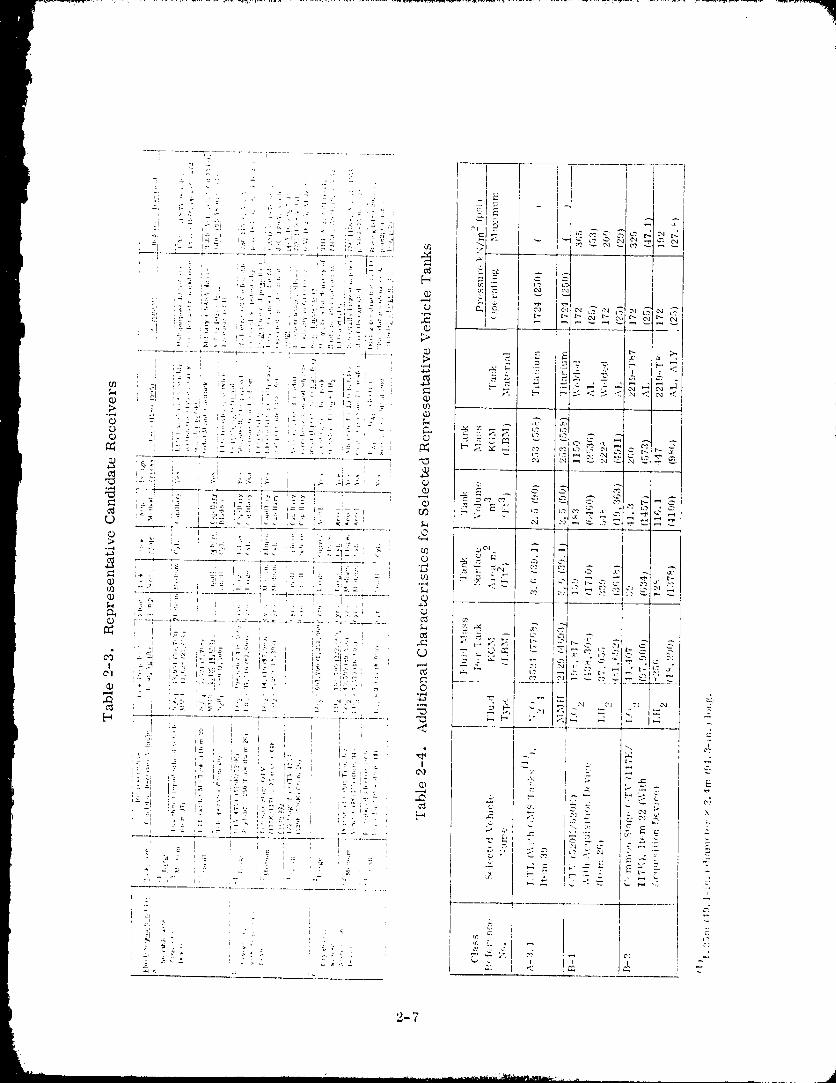
2-3 Representative Candidate Receivers ........................ 227
Pi 2-4 Additional Characteristics for Selected Representative Vehicle Tanks • 2-7
3-1 A Minimum Set of On-Orbit Refueling Criteria is Required for
Acceptable Operation .................................. 3-12
3-2 Typical Exml_ple of a Resupply Concept Screening Procedure ....... 3-13
3-3 Propellant Tank Refill with Liquid Spray was Previously Identified
as a Viable Concept .................................. 3-14
3-4 Helium Expended for Pressurization of Dual Stage POTV .......... 3-17
3-5 Propellant Transporation Efficiency for On-Orbit Resupply of
Dual Stage POTV ..................................... 3-27
i 3-6 Baseline Conditions Selected for Liquid Hydrogen Tank Prechill
Procedure ........................................ 3-33
3-7 Baseline Conditions Selected for Liquid Hydrogen Propellant Tank
Fill Analysis ....................................... 3-42
3-8 Ullage Cooling Required to Attain Thermal Equilibrium During POTV
LH 2 T_, ,k Fill ....................................... 3-42
3-9 Supply Tank Conditions During LH 2 Tank POTV Refill ...... . ..... 3-500
3-10 POTV Start Basket CharaCteristics ........................ 3-57
PRECEDING PAGE BLANK NOT FIItJIIIE]D
xvLi
19800098-i-1-017
LIST OF TABLES {CON_I"D)
Table Page
3-11 Subsystem hffluence Upon Refill Procedures. ................. 3-75
b3-12 Propellant Trm_sfer Can Be Accomplished Within Three ttours ..... 3-75
3-13 Propellant Tr,'msfer Timelines (Flights 1 & 2) ................ 3-77
3-14 LH 2 Propellant Tr,-msfcr Flow Conditions Selected for POTV RefillOperations ........................................ 3-7S
3-15 Propellm_t Transfer 'rimeline (Flight 3) .................... 3-79
4-1 COTV Propellaut Tanks Final MECO Residuals. ................ t-7
II ilit_ "4-2 Prope mlt Depot Fac . Cost Estimate: ..................... t-1 `7
4-3 On-Orbit Refueling of a COTV (Helium Pressurization _'stem) ..... 4-1-t
4-4 Conditions Selected for COTV Liquid tlydrogen 'l'.'mk PrechillProcedure ........................................ 4-21
5-1 LTL Vehicle Tanks Venting Procedure Prior to Orbiter Rt,ndezvous ,,-.-_""
5-2 LTL Vehicle Propellmlt Tanks Refill Procedure (Applicable toN20 4 and MMtl) ..................................... 5-2-t
5-3 LTL Vehicle Helium Re-Supply Options ........... _ "'
6-1 OTV Ltt 2 Mt_el Test Tank Weight Summakw ................. i;_t_
6-2 Model 'rest Tank Volume-To-Mass Ratio Comparistm With
OTV LH rot type T tk,_ P o. at .............................. 6-10
6-3 Mode] Tank Sczde hfflueuce Upon Test Variables .............. 6-21
6-4 Scale Model Test Variables for Simulating OTV Iat2 Tank Prechill • • t;-2S
x'viii
1980009811-01
LIST OF TABLES (CONT'D
Table _,
6-5 Model Tank Scale hffluenee Upon Fill Tank Variables
d* ::: [ 0{I*v*2/VL *) ................................ 6-37
6-6 Model Tank Scale hffluenec Upon Fill 'l'alfl_ Variables (d*=l) ...... 6-37
(;-7 Model Tank Scale and Fkdd Substitute hfflucnce Upon Fill TestVariables d* I " '_
{m*v*'/VL* ), for I,N 2 ................... 6-47
!
xix
1980009811-019
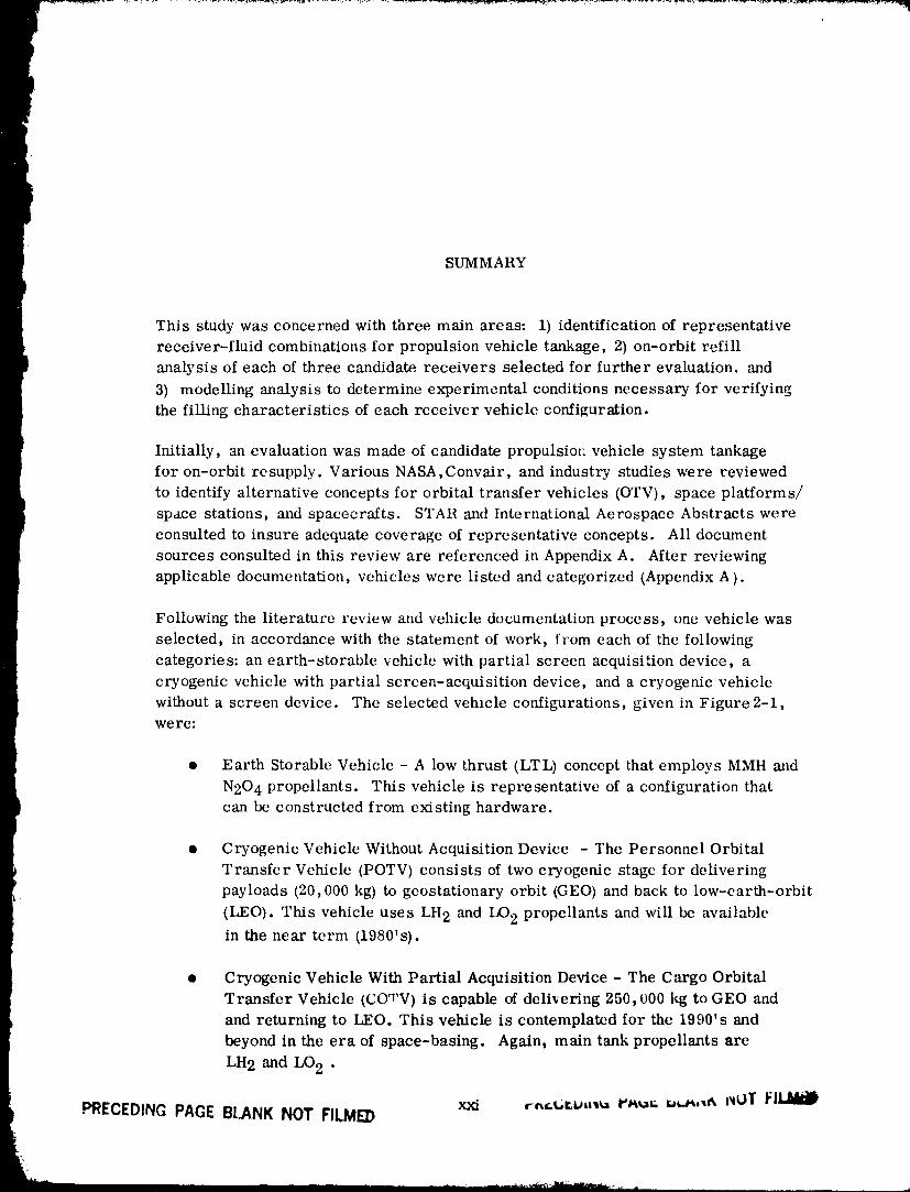
SUMMARY
This study was concerned with three main areas: 1) identification of representative
receiver-fluid combinations for propulsion vehicle tankage, 2) on-orbit refill
analysis of each of three candidate, receivers selected for further evaluation, and
3) modelling analysis to determine experimental conditions necessary for verifying
the filling characteristics of each receiver vehicle configuration.
Initially, an evaluation was made of candidate propulsiol _.vehicle system tankage
for on-orbit resupply. Various NASA,Convair, and industry studies were reviewed
to identify alternative concepts for orbital transfer vehicles (OTV), space platforms/
space stations, and spacecrafts. STAR and International Aerospace Abstracts were
consulted to insure adequate coverage of representative concepts. All document
sources consulted in this review are referenced in Appendix A. After reviewing
applicable documentation, vehicles were listed and categorized (Appendix A).
Following the literature review and vehicle documentation process, one vehicle was
selected, in accordance with the statement of work, from each of the following
categories: an earth-storable vehicle with partial screen acquisition device, a
cryogenic vehicle with partial screen-acq_sition device, and a cryogenic vehicle
without a screen device. The selected vehicle configurations, given in Figure 2-1,were:
• Earth Storable Vehicle - A low thrust (LTL) concept that employs MMH and
N20 4 propellants. This vehicle is representative of a configuration that
can be constructed from existing hardware.
• Cryogenic Vehicle Without Acquisition Device - The Personnel Orbital
Transfer Vehicle (POTV) consists of two cryogenic stage for delivering
payloads (20,000 kg) to geostationary orbit (GEO) and back to low-earth-orbit
(LEO). This vehicle uses LH 2 and LO 2 propellants and will be availablein the near term (1980's).
• Cryogenic Vehicle With Partial Acquisition Device - The Cargo Orbital
Transfer Vehicle (COTV) is capable of delivering 250,000 kg to GEO and
and returning to LEO. This vehicle is contemplated for the 1990's and
beyond in the era of space-basing. Again, main tank propellants are
LH 2 and LO 2 .
PRECEDING PAGE BLANK NOT FILMED
1980009811-020
Vehicle mission, s were defined for each candidate receiver to encompass the key
I issues of orbital-refueling operations. These operations included major activitiesfrom post-mission "storage" in the LEO parking orbit throu_ resupply. A re-fueling
analysis of each mission was then performed to determine such variabies as propellant
L losses, propellant tank pressures, fill levels and total refill time.
PAnalysis of POTV and COTV orbital refill indicated that key issues (or concerns)
were the same for each vehicle. These were: a) how to avoid excessive tank pressures,
b) how to avoid liquid venting, and c) how to perform refill with the limited resources
available in space. It was also found that the same refill technique and procedures
were applicable to each vehicle. This was a surprising result in light of the limited
orbiter-tanker resources available for POTV refueling, which contrasts with the
substantially greater orbital depot resources assumed for COTV refill operations.
The refueling analysis showed that problems could be circumvented by introducing
the processes of initial tank vent, prechill and fill.4
Initial tank vent is required olzly if helium is present. Tank vent (or blowdown) to a
low pressure will expel sufficient helium that concern for excessive tank pressure
(due to helium partial pressure) or helium trapped within a screen device is eliminated.
The prechill process is required to reduce tank temperature to an acceptably low
level prior to initiating tank fill. Prechill will consist of a series of charge and
vent cycles, where either liquid or vapor is introduced during the charge cycle.
Vapor only will be expelled during cash vent cycle because the elevated tank
temperatures will preclude the possibility that liquid is present at vent initiation.
Significant analysis results are listed below:
1. Liquid oxygen tank prechill is not required because under no eircmnstance
will excessive tank pressures occur during refueling operations. Thus
emphasis was directed at the liquid hydrogen tank.
2. Rapid prechill of the hydrogen tank do_zs not appear to be an important
consideration. Figure 3-4 indicates that up to 64 hours of activity is
required to support a single orbiter/POTV rendezvous and transfer
operation, five percent of which may be required for propellant transfer.
It seems evident that propellant transfer operations could be increased
to 10 percent of the total timeline without significant impact. This is
nearly two orders of magnitude more time than the approximate 200 second
prechill time indicated by Figure 3-20.
xxii
1980009811-021
3. Liquid hydrogen consumed for the tank prechill process will have an
insig_fifica,_t hffluence upon overall efficiency and cost of transporti,lg
propellants into space for POTV refueling. As a result, propellant
transfer efficiency should not be an important consideration in the
prechill process selection.
It is concluded that the prechill process described and analyzed in Section 3.3.2.5
will satisfy th,, requirements of simplicity, reliability and safety.
At the completion of prechill, the tank is locked up and liquid introduced through one
or more spray nozzles to accomplish tank fill. A fill condition of 90 percent or
greater will be achieved without the need for ventiz': ' if near-thermal equilibritun
conditions are present. It was determined that sufficient bulk fluid agitation will be
created by the entering liquid to provide near-thermal equilih.rimu durhlg fill.
Together, tank prechill and bulk fluid agitation should provide a no-vent fill orrefill.
Propellant trapsfer timelines were developed for a POTV refueled by anorbiter-tanker. Tables 3-13 and 3-15 show that this transfer operation can be
performed in three hours by over-lapping Ltt 2 and LO 2 transfer.
The primary requirements for LTL refueling operations are:
t. Mitfimize propellant tank venting in the vicinity of the orbiter because
N204 and MMH are corrosive. Liquid venting must be avoided.
2. Prevent helium entry to the screen galleries because vapor-free liquid
flow from each propeUant tank must be assured.
Refueling will include the ittitial vent and tank fill processes, but not prechill,
because tank and propellaqt temperatures will be approximately the same.
Propellant tank fill pressures will remain below the vent pressure levels if the
initial vent (or blowdown) process reduces tank pressure to approxianatdy one to
two atmospheres.
A procedure was identified that would satisfy the above requirem_ts during initial
vent. Basically the approach is to rely upon procedures and added propellant
plumbing _o transfer propellant between tallks. In this way a tatlk may be drained
of excess propellant prior to the initial vent process that expels helium.
The single potential concern of the selected refueling procedure is that propellant
contained within the screen devices might boil during tank vent. Boiling
will be avoided if sufficient liquid residual is maintained in contact with the screen
to replenish liquid lost through evaporation. Orbital experiments were not recommendedbecause such tests would be colffiguration sensitive and have limited applicability.
xxiii
_ J
1980009811-022
r
An important result of this study is that zero-g mass gauging devices will bc
required for on-orbit refueling operations of earth storable and cryogenically
: fueled vehicles. A survey was conducted of existing radiatiot_ aud RF type devices
l to identify the state of the art.
An analysis was also conducted which indicates that propellant mass gauging is
feasible through thermodynamic memos of m casuring tank pressure increases
i resulting from a fixed helittm mass addition.
The processes selected for further evaluation (i.e. modeling) were prechill
and fill. The initial tank vent process was judged to be sufficiently well de||nedto preclude experimentation. Prechil/ and fill are similar in oac important aspect;
it _s intended that heat and mass transfer be dominatcd by forced convvction in
order that these processes remain independent of acceleration environment.Consequently, a modelling analysis was performed to identify conditions under
which these processes can be simulated with a 45.7 em (18 inch) diameter test
tank (the largest size that can be contained within a spacclab doubleraek). Per
NASA/LeRC directive, the Spacclab was groundruled as the orbital experimental
test facility.
It was concluded from computer simulations that rcsults could not be directlyextrapolated to a full sc.a.le OTV, even for tests conducted in a zero-g environment
with LH2. This discrepancy between model and prototype behavior is influenced
by the substantial difference between prototype and model tank volume-to-mass
ratio, which is an important test parameter. It is expectt, d, however, that the
heat transfer phenomena involved in the prechill and fill processes can ix,
evaluated. Empirical coefficients obtained from such tests could be applied to an
analytical model such as HYPRES, which would then be employed for full scale
vehicle predictions.
Assessments were also made of the influence of a [luid substitute (LN2) and aone-g test environment on Wst results. It was concluded that onc-g test results
I would not be applicable to prototype vehiclc predictions but that tests with LN 2would provide useful data.
Finally, discussions with NASA/MSFC safety personnel yielded the following
comments regarding the propos<_d receiver tank experiments to be conducWd in
the Spacelab environment:
1. A waiver would be required by the experiment integration s'Mety review
board to 'allow the anticipated LN 2 quantities for refueling tests.
2. Liq!_d hydrogen is unacceptable under any condition.
XXiV
1980009811--023
1INTI/ODUCTION
The United States is on the threshold of a space industrialized era. Some of the am-
bitious space programs conceived by the NASA and industry include the construction of
large antenna structures, solar powered satellites, and propellant depots. A common
element of these programs is the roquiremcnt of effectively transferring propellants
in space.
This area of orbital propellant transfer, or propellant management, has long beenidentified as a technology area by the NASA-LeRC and Convair. A previous study,
"Orbital Refill of Fluid Management Systems", Refc,'encc 1-1, dealt with the
problems of refilling small cryogenic and earth-storable systems. Convair has
performed independent studies in the area for several years, Reference 1-2 and 1-3.
Experience gained in the previous studies has selwed as a starting poh_t for this
study on orbital refuelling of vehicle tankage.
The objectives of this study were to 1) develop techniques for such necessary orbital
propellant transfer and, 2) to identify experimental programs to verify these techniques.
1.1 SCOPE
A number of future missions have been defined which require orbital propellant transfer
capability. In near-term, space programs such as the manned-geosynchronous-sorue,
and very high energy probes to other planets will require the transfor of propellant
quantities in the order (_f 30 to 300 metric tons per year. Earlier studies have shown
that performance and lift_ of operational spacecraft can be increased by resupplyingattitude control propellants, fuel cell reactants, sensor coolm_ts, or chemical laser
fluids. Beyond the year 2000, large space industrialization programs may require
propellant quantities that are several orders of magnitude greater than for the near-
term. The most ambitious program now being considered is the Solar Power Satellite
Program requiring lleavy Lift Launch Vehicle (IILLV), space constz'uction bases, andboth electric and chemical Orbital Transfer Vehicle ((/FV).
Although there are many potential orbital refuelling applications, the scope of this
study was limited to analysis ()f and experimental modeling techniques for propellant
transfer between supply tanks and receiver ()TVs. The three OTV config'urations select-
ed for orbital refill analysis were identified using the selection procedure describedin Section 2.
1980009811-024
a.,_.,_, _¸ _
1.2 GROUNDRULES
Guidelines were established for selecting three vehieh, confi[.,mrations representative
of those contemplated fro" various types of future space progr:uns. It was required ]that one vehicle would be selected from each of the following ealt'gol'it's: an eaFth
stor&blc vehicle with p'trtial-screen acquisiti,m device; a cryogenic vehicle with a p_:rtial- i
screen acquisition device; and a cryogenic vehicle without a screen-device. Repre-
sentative vehicle selections were to be made following a literature review of previously
} conducted NASA and industry studies, as well as current Convair studies on future spaceprograms.
1.2.1 EARTH S'FOIIABLE VEHICLE. An :_dditional requirement was imposed upon this
selection process; that of identifying hardware either from existing progrml_s, or
from previous study efforts. Because tile data base for t, arth storable vehicles and
missions was considerably smaller titan for cryogenic (_TVs, no attempt was n_ade
to optimize the vehicle configxtration, llathcr, tilt' intent was to select a configuration[ which would be representative of its vehicle class.
1.2.2 CRYOGENIC \'EIIICLI,:. (If the two cryogenic vehicle classes selected, one was
assumed to be availabh, in /he near-term (1980_s) and the other was selected for appli-
cation in the late 1990's and beyond. The vehicle fin" near-term applictltion was assum-
ed to have subsystems c()nsistenl with its early devel(_pment peri_xt. Consequently, this
vehicle will not have a screen acquisitim_ devicc nor any subsystela_ requiring con-
siderable techn()h)gy. The luore ,ldvaIIc'ed ()TV will be comprised of more sophisticated
subsystems, such as a I)arti:ll scvt'en acquisition ,uld :ill adv:illCt'tt t'llg_l_t' syslt'll_ l'et]uil'- ]
ing no pre-pressurizati¢m, i
Different meth(xts of propellant supply will also be available to t, ach ()TV. Space pro-
grams for the 1980Is will rely upon propellant resupply from an orbiter tanker. Pr_>-
I grams contemplated for the 1990_s and beyond wel'e :tssumt,d to h:tvc ()l'bil:ll i)ropt'll;|ntdepots available for (Vl'V resupply.
1.2.3 EXPI-:RI1M ENT MODI,:I,ING. |,:xperil_wntal la,)dellng techniques of receiver-tank-
resupply were deveh,ped during the study. These techniqut s _vert, emph)ye(I to determine
the usefulness of simulant fluids and scale n_odel testing. B,,til ground based facilities,
including drop towers, and the Spacelab on-board the shuttle were :lsSl.lllled tO be avail-
able for conducting tbe experiments. Scah, rfl_Xll'l sizt' w:ls limited t,, the largest
experiment test package that could be installed within a Spact, lab d()ublc rack eDcl(_sui'e.
This restrictien confined analysis tt)that of a relatively small scale It, st tank (appr,,xi-
mately on(:-tenth :;tale t)r less).
1-2
198o009811-025
t _ N , . . ,r .IDI,_NTI_qCATI()N ()F [ A, I)IDA'I E RI,,CI,.'I'_ I,,RS
The purpose of task I was to select thrce potential vehicle concepts for subsequent
orbital-rcfllcling analysis. These concepts were to he representative of those vehicles
expected to be designed for the 1980's _md 1990's; that is, represcnlative ir terms of
equivalent subsystems, orbital staytimcs, thermal requirement. _, h'gistics and reful'-
bish.ment requiremcnts.
Following the literature review, one vehicle was selected, in accord,'mec with the
skltement of work, from each of the following categories:I
1. An earth-storable velficle with partial acquisition device
2. A cryogenic vehicle with partial acquisition device
3. A cryogczfie vehicle without an acquisition device.
The three vehicle concepts selected are shown in Figure 2-1.
Convair's approach for reviewing these eoncci)tual des|gins and [or determining
representative config-ur,ltions to be further ,analyzed in Task II, is shown in Figure
'2-'2. First, a literature review wits accomplished. In order for i¢ to be complete,
all potential prot)ulsive vehicle receive_" tanks were included to show the _de variety
of uses for propelltmt tr:msfer technoh)k'_W. 'rite types of receiver t_mks identified
include the following:
Orbital Transfer Vehicles
I Mini-maneuvering (e.g., teleopcrator)lligh :rod low thrust chenfieal
Nuclear :rod solar electric I()MS, RCS)
Orbital Maintenance :rod RCS Taltkage
Space station
P rope ll_mt detx)ts
Large space structures
Automated satellik, s (include cooling pro Wll:mtI
After revie_'h_g applicable dtx'umentation, the,-'e vehicles _'ere listed ;rod c;lt_g, orized
according to fluids used, flow ratt, s, tat_k gcometrs" and pressure, acceleration-
'2-1
1980009811-026
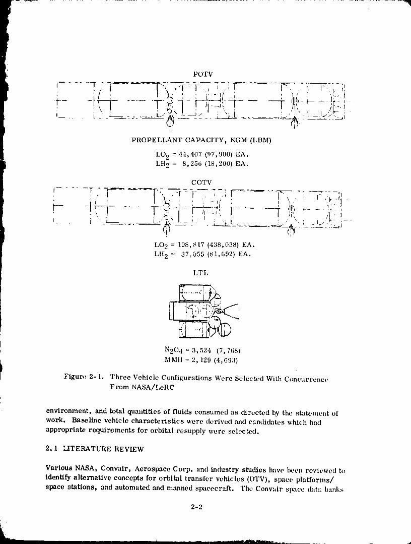
POTV
=
PROPELLANT CAPACITY, KGM (I.BM)
LO 2 = 44,407 (97,900) EA.
LH 2 = 8,256 (18,200) EA.
COTV
...... T,,--r--'-_-,, ,-r- r- , -:-__---'--7,. , " ;i' iL_: -- _:_, ,,,-.,i ; , ,, i.}__t- -!, .;7i '"-'" ' /,., '
1
[,02 = 198,817 1438,038) EA.
LH 2 = 37,055 (_1,692) EA.
LTL
N20 4 = 3,524 (7,768)
MMI! = 2,129 (4,693)
I Figure 2-I. Three Vehicle Configura_ons Were Selected With Concurrence
From NASA/LeRC
environment, ,'rod total quantities of fluids constimed as directed by the statement ofwork. Baseline vehicle characte_stics were derived ,'rod candidates which had
appropriate requirements for orbital resupply were selected.
2.1 LITERATURE REVIEW
Various NASA, Convair, Aerospace Corp. and industry studies have been reviewed to
identify alternative concepts for orbital transfer vehicles (OTV), space platforms/
space stations, and automated and manned spacecr_fft. The Conwdr slmce dat:: banks
2-2
i --
1980009811-027
1
!J
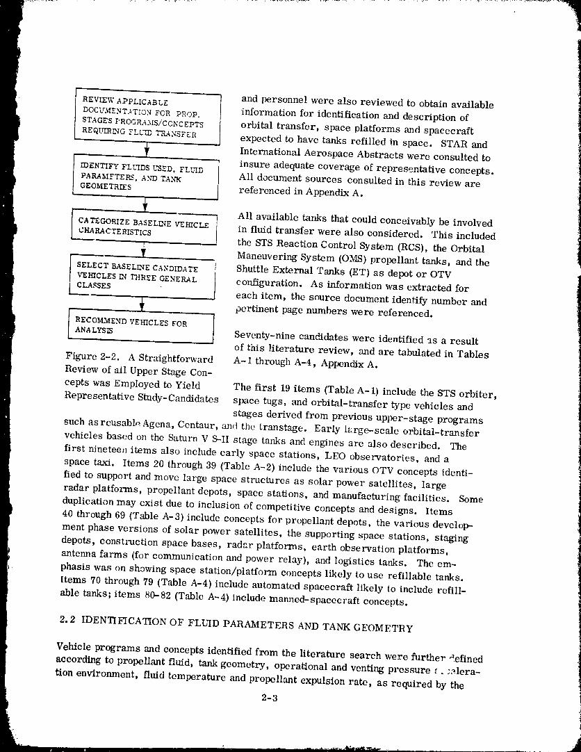
:1REVIEWAPPLICABLE and personnel were also reviewed to obtain available
information for identification and description ofDOCUMENTATION FOR PROP.
STAGESPROGRAMS/CONCEPTS orbital transfer, space platforms and spacecraft
REQ[qlRLNGFLL_ TRANSFER expected to have tanks refilled in space. STAR and
._ International Aerospace Abstracts were consulted toinsure adequate coverage of representative concepts._DENTIFY FLLqDS USED, FLSUd3
PARAMFTERS, ANDTA.N"K All document sources consulted in this review areGEOMETRIES referencedinAppendix A.
-_ All available tanks that could conceivably be involved]
CATEGORIZEBASELINEVEI-IICLE } in fluid transfer were also considered. This included "_
CHARACTERISTICS / the STS Reaction Control System (RCS), the Orbital
Maneuvering System (OMS) propellant tanks, and the
SELECTBASELINECANDIDATE I Shuttle External Tanks (ET) as depot or OTVVEHICLESIN THREEGENERAL I_ configuration. As information was extracted for
[ CLASSES l each item, the source document identify number and
pertinent page numbers were referenced.
I RECOMMEND VEHICLES FOR IANALYSIS Seventy-nine candidates were identified as a result
of this literature review, and are tabulated in Tables
Figure 2-2. A Straightforward A-1 through A-4, Appendix A.
Review of all Upper Stage Con-
cepts was Employed to Yield The first 19 items (Table A-1) include the STS orbiter,
Representative Study-Candidates space tugs, and orbital-transfer type vehicles mad
stages derived from previous upper-stage programs
such as reusable Agena, Centaur, and the transtage. Early large-scale orbital-transfer
vehicles based on the Saturn V S-II stage tanks and engines are also described. The
first nineteen items also include early space stations, LEO observatories, and a
space taxi. Items 20 through 39 (Table A-2) include the various OTV concepts identi-
fied to support and move large space structures as solar power satellites, large
radar platforms, propellant depots, space stations, and manufacturing facilities. Some
duplication may exist due to inclusion of competitive concepts and designs. Items
40 through 69 (Table A-3) include concepts for propellant depots, the various develop-
ment phase versions of solar power satellites, the supporting space stations, staging
depots, construction space bases, radar platforms, earth observation platforms,
antenna farms (for communication and power relay), and logistics tanks. The em-
phasis was on showing space station/platform concepts likely to use refillable tanks.
Items 70 through 79 (Table A-4) include automated spacecraft likely to include refill-
able tanks; items 80-82 {Table A-4) include manned-spacccraft concepts.
2.2 IDENTIFICATION OF FLUID PARAMETERS AND TANK GEOMETRY
Vehicle programs and concepts identified from the literature search were further _efined
according to propellant fluid, tank geometry, operational and venting pressure _. -elera-
tion environment, fluid temperature and propellant expulsion rate, as required by the
2-3
1980009811-028
Statement of Work, Data not currently existing was derived from conceptual dcsig-nL
• data. For instance, tank geometry was assumed to be constrained by STS Orbiter
i car_o-bay dimensions, where STS was the designated delivery vehicle. Similarly,acceleration forces were matched to the mission. For example, delivery of large
space structures from LEO to GEe requires low-thrust acceleraticm less thtm 1G;
consequently, prot)ulsion t.'ulks of associated vclficlcs were assumed to operate in aless-than IG acceleration environment.
2.3 CATEGORIZATION
A generalized classification of space vehicle tm_ks into fluid/acquisition classes was
accomplished using the following gl'oupizlgs as stipulated by the proposal.
Class A Storable with Acquisition Device
Class B Cryogenic with Acquisition I:kwice
t Class C Cryogenic without Acquisition Device
Additional categorization was accomplished in terms of tank size, t-ink g('ometry,
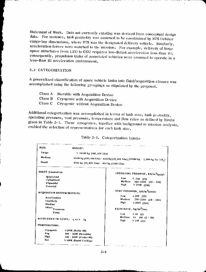
I operating pressure, vent pressure, temperature m_d flow rates as defined by limitsgiven in Table 2-1. These categories, together with background in mission analysis,enabled the selection of representatives for each tank size.
'Fable 2-i. Categorization Limits
SIZE_ WEltllrr:
l.ai'go ) 45.1iiil ktl ll0(), liiill lira)
Medluni 45411ii ktl (100, IlilO l.lm) - 45t0 kg (10_ 000 I l$). (.15000 kg - ') 0ilo kl_ lot !.11.,}
Hnl,,ll 45.10 kti (Ill, 000 Ilia) - 4b.I lit ilO00 IJ_)
_JlMiPF (lloonii_lryli OPFIIATINIt PIIEI_IIIIIE. kN/nl2(p=_hi):
t_phorohhtl hIw < 2tit) (29)(;ylhiilrll_ill Moillliiii 200-7000 (29- 290)
EIIp=toldal Illlh ) 2000 (290)i 'ril ixll ilii I
VENT PlIESiIlilIE. kN/nl2(p_lii):
ACQLII_rI'ION _I¥_rrFM/METIIOI): I_,w < 200 (29)
Acceliiralloll Mmlhl,,ll 200-2000 (29 - 29ti}
I;,,plll-r# IIIl_h >20oo(:,Do)lll.,&lor
(lihilrllll.Oltlturt I t'lillV liti, TE, kl/nlT/_oc
llilillll I*ll < ill (2)
Meilhiili Ill- lllli (2 - 20)
AI:CEI.F.IIATItIN I.FVEI.I ,_ oi') Ill Illllh "> iiiO (20)
TEMI_EIIATIIIIEI
Cryo#ll_iilc <20ilk (llillhi ill)
Avi 200 - 320K (_hlrahle)
IIIIth 320 - 4001," (Co*lla O(()
Ihll ) t00K (ihllllll I;llilllnll )
..........................................................................................
2-4
198u009811-029
2.4 P,ASEI,INI.] C,\NI)li)..VFI,_ YI,]IIICi,I.',S
t l_aseline e:mdidilte vehi,'les were selected from tile tot:ll listing ill T:ll)les :\ (Appendix
A). This list of e:mdid:lh, vehieles is conlprist,d of reln'e:;ent:ltive :lIl(I realistic designsthat are most likely to require propellant tr:msfer in the next t_vo decades.
Initially, likely camdid:ltes _ve:'e st'l'eened b,lsed Oll those thought to be applicable for
missions projected in this time period. On-orbit propell:mt tr:lnsfcr will opel':lte ill
t_vo ,<-'neral n_i,ssion arch:is. One is tht, transt,_vt:ltion of payloads from l,go to a
high ellel'_,._,5• orbit, e.g., [,EO to GI,W_, :Uld I,l.:t) to lun:lr orbit. The st,eond is lll()\rill_I
systems within :Ill orbit. The ['ornler requires lligll i:lpulse Cl'yOg't, nie l_ropell:mts
J lifting heIIvy payhmds. '['he lattel" opt,l'ales heal" :1 bits(" lob'at[on for servichlg andlll,lllell\'e_'illg p:13'lO:ltls. These vehicles nmy require long t, rbit stay times be_veen
rt,fill :lnd are better suited tor e:lrth stor:lbh, propellants. Generally these vehicles
eta'rate within a few hundred miles .llld ill :1 r:lngO of orbit inclinations from the
propellant base.
,vn this timefranle [wopellant tr:lnsfer tt,chnolog,v will first be ilSt,d for topping off
} cryogenic vehicles _llieh c:lnnot be t':ll'l'ied ['till to orbit due to S'['S p:tylo:ld limitations.
} Toward the l:ltter pal'[: of the 1990s both el'yogi,hie :lnd e:lrth stm'abh, \'ehicles :ire
expected to be space h:l._'ed,
In tilt, process o[" vehich' selection, those st:lg,,es bast,d otl existing eXl_md:lble vehieles
were elimin,ltett quickly. These vehicles if used in the Shutth,/t)rl,,ik, r will be flown
in one fligh[; therefol"e, not requiring_ propelhmt tr:msfer. Also eliminated were
l'eceivers for i{C,q In'opell:l,.lt. Tht'se gt,nt, rall,v l'equil'e sin:ill :lmounts of prot_ell:mt;
a better solution might be total l'eeeivel' [.a.lll< ehatlg'et,ilt Vel'StlS tn'opcll:mt transft,r.
In the past two years, much effol't h:ls i_eell t'onct,lti':ll.ed defining the Sol:it Power
Satellite (,_qPS) and [Is t r:msl_rt:ltion s Vs[enl. Vehich, s h:lx'e been defined ill those
studies xvhieh depend oll propellant tl':lnster either at [,lq() or GI.:O. Tht' ,ql_ vt,hieles
at)[R,_ll' representative of [hose required for ftll:urt' Sp:lee lleeds, i"rOlll these-defined
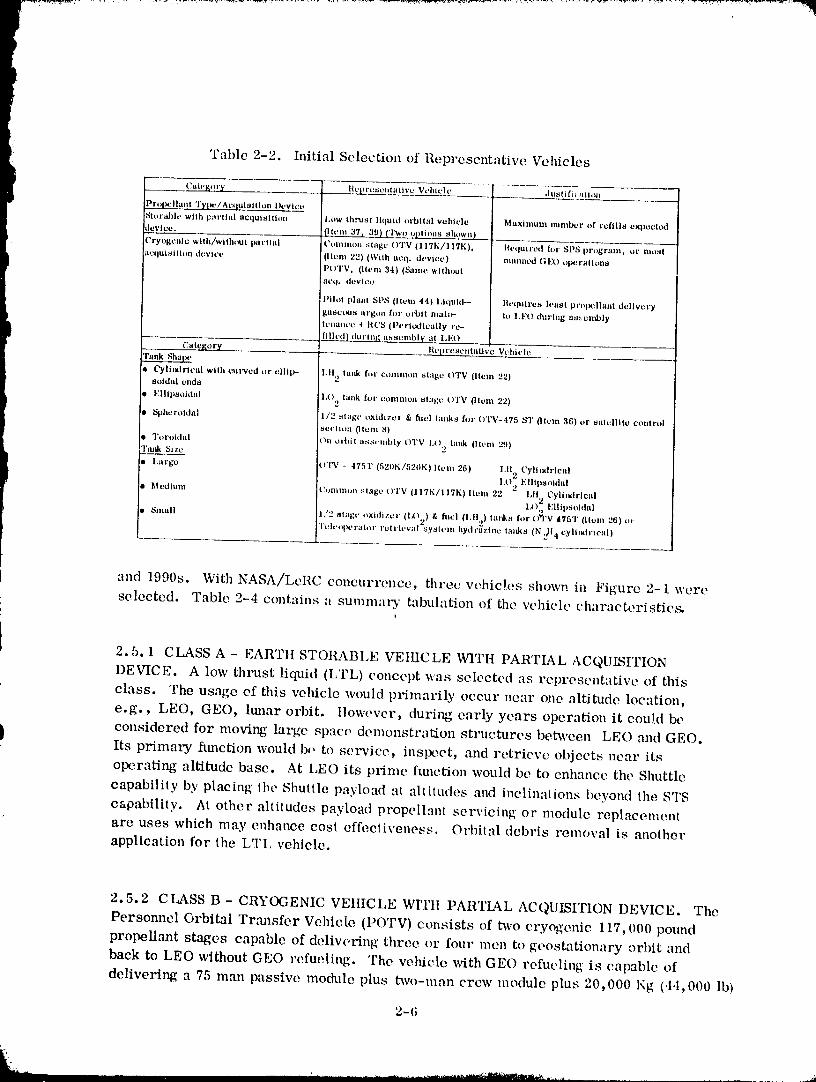
vehicles, Tal_le 2-2 details tilt, \'ehiele selectt,d b:lst, d on [wopell:mt type :lnd acquisition
device, :rod tank shape and size.
're t,llal)h, a lllore thol'OilRh Sel't,enillg, each of tilt, three major t':ltegol-ies wel'o bl'okell
down into tl'_l't'e sul>c:ltt'gol'ies (lat'ge, nleditllll, "llltt small tank). An :lttempt \v.'ls lnitde
to obtain :l l'eIH'esentiltive eandid:lte for eat'h Ill:|jof t':l[t'lVOl"_ ' alld stll_-e:ltegol'y :Is showii
in "[':lble 2-3. This eotnparatiw, matrix was used to determine the fin;ll three vehiclesselected.
2.5 VEIIIC l,l,i [_ECOMIHI,INI)I,;I) FOR :\NAI,YSIS
The dek, rminat-ion of which three w, hicles should be seh, eted ft'om Talbh, 2-3 was
prinmrily based on us:lg'e alld eonl'igut'ati,,,ns inost likely to be in'educed ill Lhe 1980s
2-5
J
1980009811-030
r
r[ Table 2-2. Initial Selection of Representative Vehicles
t _ C_teF_t_'y l;tcpl't!,¢t2t_t alive .]u_ti fi_'ittiol_
Vehich_
Prolmlhtt!t Tylw/Act|utsltlon l)cy|ct.._2
St_t'ah|c with vart|al aCq_lit_ttitm 1,ow thtxtst liqutd twbttai vehielt_ Maximum number of refil|s exDectcd
Jevice. {1tc m__ sh,___2w nEL_ -
[_:ryogcnlc with/withe|It partial Commoll stage OTV 1117K/117K), I{cquircd foe SPS program, or nmst
acqtl/_lilon device (Item 22) (With tlcq. tit, vice) manned I[]].Jt) tlpcl'al|on8
i I>OTV, 0tern 34) (Same wlihont
acq. dcvtcc
Pilot plant SPS (item 44) l,|quid-- ilcquirca least pvol_llant delivery
ga_etats al'g<ttt for ot'btt mat_- U_ I.E_O during at_...cmbly
tl!tLaJtt'c _ ItCS {l>cvltxticMly rt._
_auncmbly at LEO
Categoz'_ Rcpvcae_ttatlve Vehlt'le
'l'a_k Shaix,
tl Cylit)dl'ieal wllh t_'ul'vcd or viii|>- LII 2 lard,, ft_l. Ct)lllltlOII stage ()'I'V (Item 221soldzd ends
I EIIIp_oidal l.() 2 Iallk ft)l" ct)l]tlnloll s|iI_,e ()TV 0leln 22)tIt, _._hevoldal 1/2 stage _xltlizer & fltvl tin|ks hJt" ()'1"V-475 Sq' {Item 36) or satelllt0 control
I .'_ctttitm Otcm 8)
D Tot'otdal ()It elicit _,ssvmbly (}'I'V IX) t:mk _]tt!ln _(.1)
'rm_ Size 2I
l.argc !(Vl'Y - 4751' (520K/520K} lien| 26) 1,112 ('ylit_trleal
I.O., FIIIpsoithtl
lt,|ctiiuw, th,mn'_ol_ _[age OTV (II7K/117K) Item 22 " LII Cyll,_rlcal
1,C)2 Ellll)soltlal
Snlall 1,/2 ._tagc ox.itlizev (1,_,_) & fttcl (1.11,,) ta_ks t'_r t.)'q'V 4'rsT {Item 26) t_t
'l't_hrol)crator rtllt'it, val_ysttrm hytJr_zlnc tin|ks (N _l,t cylilalrtcal)
and 1990s. With NASA/LoRC concurrence, three vehicles shown in Figure 2-1 were
selected. Table 2-4 contains a summa_T tabulation of the vehicle characteristics.
2.5.1 CLASS A - EAR'rtt STORABLE VEHICLE WITH PARTIAL ACQUK'Z,I'I'ION
DEVICE. A low thrust liquid (LTL) concept was selected as representative of this
class. The usage of this vehicle would primarily occur near one altitude location,
e.g., LEO, GEe, ltmar orbit, llowever, during early years operation it cou!d be
considered for moving large space demonstration structures between LEO and GEe.Its primary function would be to selwice, inspect, mad retrieve objects near its
operating altitude base. At LEO its prime function would be to enhance the Shuttle
capability by placing the Shuttle payload at altitudes and inclinations beyond the STS
capability. At other altitudes payload propellant servicing or module replacementare uses which may enhance cost effectiveness. Orbital debris removal is another
application for the LTI, vehicle.
2.5.2 CLASS B - CRYOGENIC VEtIICLE WI'l?tI PARTIAL ACQUISITION DEVICE. The
Personnel Orbital 'rrm_sfcr Vehicle (POTV) consists of two cryogenic 117,000 pound
propellant stages capable of delivering three or four men to goost_ationary orbit and
back to LEO without GEe rcfueling. The vehicle with GEe refueling is capable of
delivering a 75 man passive module plus two-man crew module plus 20,000 l<g (.t,I,000 lb)
2-6
1980009811-031
1980009811-032
of payload to GEO and returning both rammed modules. Tiffs is 48,500 Kg (107,000 lb)
i to GEO and returning 28,500 Kg (63,000 lb).This vehicle is a very effective system for the SPS era when large manned requirements
are required at GEO for repair and construction of these satellites. Further, th_svehicle is not limited to the era of heavy lift launch vehicles (HLLVs), the vel-dcles can
} be carried in separate Shuttle flights .'rod topped with propellants by an Orbiter/Tanker
or by a propellant depot. Early uses of the POTV would be required for GEO payload
servicing and repair. The function of man h_ space is to augment unmanned servicing
] tasks, Man would be used to diagnose and repair space structures; do the out-of-the-ordinary space functions.
2.5.3 CLASS C- CRYOGENIC VEHICLE WITttOUT ACQUISITION DEVICE. The Cargo
Orbital Trmlsfer Vehicle (COTV) is capable of delivering 250,000 Kg (550,000 lb) to
GEO and returning to LEO. This vehicle would operate in an era of space basing.
Present concepts consider use of an electric OTV. However, these vehicles require
nearly a year to transfer payloads from LEO to GEO. Should mission duration require-
ments of electric OTV teclmolog), prove iTffeasiblc the COTV would be developed m_d
represent the largest vehicle category.
2-8
l_qAnnna _nqq
POTV ORBITAL RESUPPLY
In this section a mission scenario will be developed for the POTV concept selected
in Section 2. A realistic mission will be defined which encompasses the key issues
of orbital-refueling operations. These operations will include all major activities
from post-mission "storage" in the LEO parking orbit through resupply. Vehicle and
orbiter-tanker subsystem requirements needed for orbital refueling will be
identified. Operational procedures and techniques for orbital propellant transferwill then be developed.
3.1 MISSION SCE NARIO
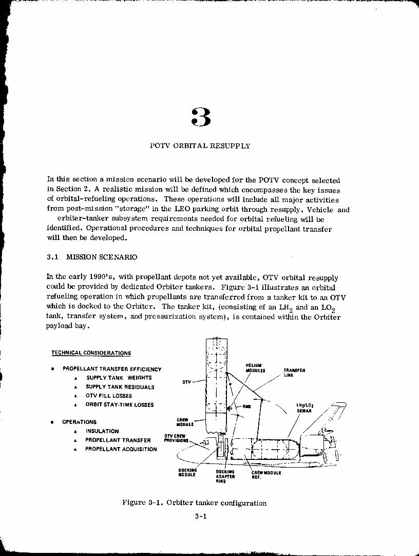
In the early 1990's, with propellant depots not yet available, OTV orbital resupplycould be provided by dedicated Orbiter tankers. Figure 3-1 illustrates an orbital
refueling operation in which propellants are transferred from a tmflCer kit to an OTV
which is docked to the Orbiter. The tanker kit, (consisting of an LH 2 and an LO 2tank, transfer system, and pressurization system), is contained within the Orbiterpayload bay.
t TECHNICAL CONSIDERATIONS .....l I I
HELIUM
• PROPELLANT,SUPPLyTRANSFERTANKWEIGHTsEFFICIENCY !_/_ : MOOULES TRANSFER
. I
I ' - ,._ LHzILI]| ._/..2__• ORBIT STAY-TIME LOSSES - 2 _
__"" I \ OEW,R/ ,j/• O,ER,*T,ONS ,R., _-- ?" / / /",'//
.oo.. , /- TJ"-''_ /,_• INSULATION ow CR[W _ . --
_. coooDOCKINg CREWMODULE
MODULE ADAPTER REF,RINI
Figure 3-1. Orbiter tanker configuration
3-1
...... _1 _u'_" ...... I_f,f i m ............
1980009811-034
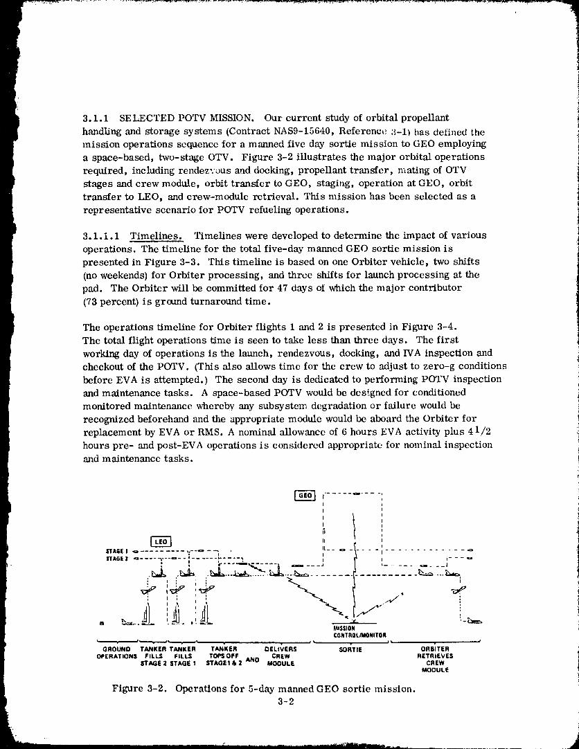
3.1.1 SELECTED POTV MISSION. Our current study of orbital propellant
handling and storage systems (Contract NAS9-15640, Reference 3-1) has defined the
mission operations sequence for a manned five day sortie mission to GEO employing
a space-based, two-stage OTV. Figure 3-2 iIlustrates the major orbital operations
required, including rendezvous and docking, propellant transfer, n-rating of OTV
stages and crew module, orbit transfer to GEO, staging, operation at GEO, orbit
transfer to LEO, and crew-module retrieval. This mission has been selected as a
representative scenario for POTV refueling operations.
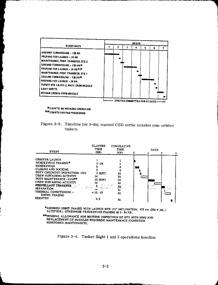
3. i. i. 1 Timelines. Timelines were developed to determine the impact of various
operations. The timeline for the total five-day manned GEO sortie mission is
presented in Figure 3-3. This timeline is based on one Orbiter vehicle, two shifts
(no weekends) for Orbiter processing, and three shifts for launch processing at the
pad. The Orbiter will be committed for 47 days of which the major contributor
(73 percent) is ground turnaround time.
The operations timeline for Orbiter flights 1 and 2 is presented in Figure 3-4.
The total flight operations time is seen to take less than three days. The first
working day of operations is the launch, rendezvous, docking, and IVA inspection and
checkout of the POTV. (This also allows time for the crew to adjust to zero-g conditions
before EVA is attempted. ) The second day is dedicated to performing POTV inspection
and maintenance tasks. A space-based POTV would be des__gncd for conditioned
monitored maintenance whereby any subsystem degradation or failure would be
recognized beforehand and the appropriate module would be aboard the Orbiter for
replacement by EVA or RMS. A nominal allowance of 6 hours EVA activity plus 4 1/2
hours pre- and post-EVA operations is considered appropriate for nominal inspectionand maintenance tasks.
III
tII
II _ o - 1STAGEI _ _ _ ............................ I-- _ ISTAGE2 Q .... -_---a-- : ...... *',.... •, 1 r
....... ..................... . , i
: '| I
I !
MISSIONCONTROL/MONITOR
GROUND TANKER TANKER TAN'KER DELIVERS SOl'TIE ORSiTER
OPERATIONSFIL_ FILLS TOeSOFFANO CREW .ET.IEVESEl"AGE 2 STAGE I $TAGEI & 2 MODULE CREW
MODULE
Figure 3-2. Operations for 5-day manned GEO sortie mission. !
3-2i
|
1980009811-035
WEEKSm=
EVENT/DAYS 1 2 3 4 5 § 7
GROUNDTURNAROUND- 136HR m m
PREPAREFOR LAUNCH- 24 HR •
MAINTENANCE,PROP.TRANSFER,STG2 m•
GROUNDTURNAROUND- 138 HR_ m m
PREPAREFOR LAUNCH- 24 HR:'j'::_ •
MAINTENANCE,PROP.TRANSFER,STG1 m•
GROUNDTURNAROUND- 136 HR_ mm_ mm
PREPAREFOR LAUNCH- 24 HR •
TQPOFFSTG 1& STG2, MATE CREWMODULE m
5-DAYSORTIE m
RETURNCREW& CREWMODULE i
•",'------- ORBITERCOMMII-FEDFOR 47 OAYS----'_
:(':2SHIFTS;NOWEEKENDOPERATION
::_r'_3SHIFTS FORPAOPROCESSING
Figure 3-3. Timeline for 5-day manned GEO sortie mission (one orbiter
tanker)
ELAPSED CUMULATIVETIME TLME DAYS
EVENT (HR) (HR) 0 t 2 3
i
ORBITER LAUNCH 1 l IRENDEZVOUS PHASING* 0-24 1RENDEZVOUS 5 6 iCLOSING AND DOCKING 2 8 IIPOTV CHECKOUT/INSPECTION -IVA 2 (EST) I0 |CREW SUSTAINING ACTIVITY 14 24 r---
POTV MAINTENANCE -EVA _ I0 (EST) 34 iCREW SUSTAINING ACTIVITY 14 48 r--"-PROPELImm_ri_ANSt_R . " : ' _ . : :".... _L:': :' ' .... :..... i ::. 'SEPARATION -- 51 ITHERMAL CONDITIONING + _ 12 - 15 63 r'--"l
ENTRY PHASING
REENTRY 0.S 64 II
*ASSUMED ORBIT PHASED WITH LAUNCH SITE (31"INCLINATION, 478 km (258N.MI.)ALTITUDE), OTHERWISE FENDEZVOUS PHASING IS 0 -24 fIR.
**NOMINAL, ALLOWANCE FOR ROUTINE INSPECTION OF OTV WITH MMU AND
REPLACEMENT OF MODULES REQUIRING MAINTENANCE (CONDITIONMONITORED MAINTENANCE}.
Figure 3-4. Tmtker flight 1 and 2 operations timeline
3-3
J
198000981;I-036
It was estimated in Reference 3-1 that only three hours will be required for propellant
transfer operations. Although this duration may not be correct, it is significant that
propellant transfer may represent only 5 percent of the total flight operations
timeline. It appears from Figure 3-4 that doubling this time will have virtually no
impact upon the total flight operations. Thus, the capability for rapid propellanttransfer became a minor element in this study.
3.1.2 ORBITER TANKER CONFIGURATION. The orbiter tanker selected for this
scenario is the configuration defined in Reference 3-1.
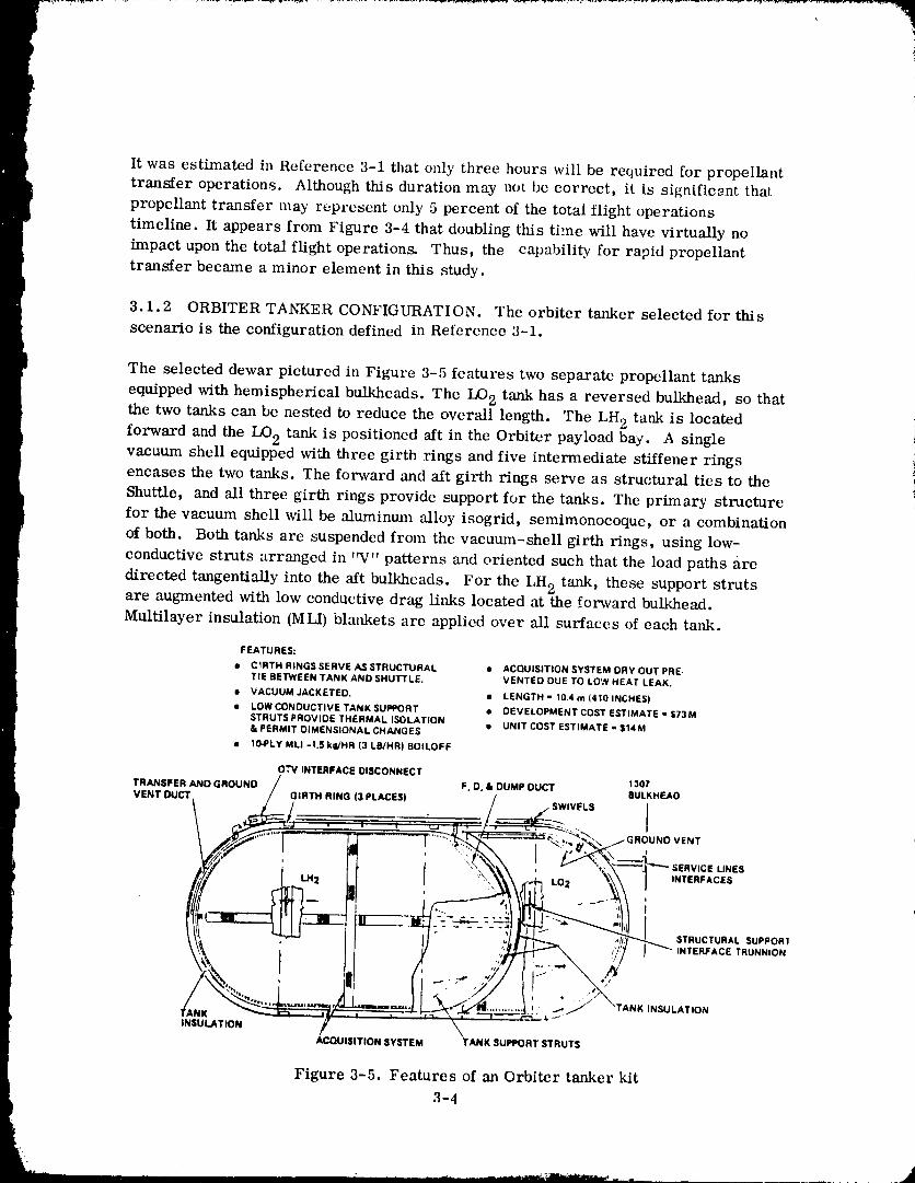
The selected dewar pictured in Figure 3-5 features two separate propellant tanks
equipped with hemispherical bulkheads. The IX)2 tank has a reversed bulkhead, so that
the two tanks can be nested to reduce the overall length. The LH 2 tank is located '
forward and the LO2 tank is positioned aft in the Orbiter payload bay. A single i
vacuum shell equipped with threc girth rings and five intermediate stiffener rings iencases the two tanks. The forward and aft girth rings serve as structural ties to the
Shuttle, and all three girth rings provide support for the tanks. The primary structure
for the vacuum shell will be aluminum alloy isogrid, semimonocoque, or a combination
of both. Both tanks are suspended from the vacuum-shell girth rings, using low-
conductive struts arranged in 'W" patterns and oriented such that the load paths are
directed tangentially into the aft bulkheads. For the LH 2 tank, these support strutsare augmented with low conductive drag links located at the forward bulkhead.Multilayer insulation (MLI) blankets are applied over all surfaces of each tank.
FEATURES;
• C_RTH RINGS SERVE AS STRUCTURAL • ACQUISITION SYSTEM DRY OUT PRE.TIE BETWEEN TANK AND SHUTTLE. VENTED DUE TO LOW HEAT LEAK.
• VACUUM JACKETED. LENGTH - 10.4 m (410 INCHES)
• LOW CONDUCTIVE TANK SUPPORT : DEVELOPMENT COST ESTIMATE - $73M
STRUTS PROVIDE THERMAL ISOLATION .... 'IT "_" ='_T'M'_'= - '_"='"& PERMIT DIMENSIONAL CHANGES • u,1 _._,J_ _,J., _.¢ _,.._m
• IO-PLY MLI -1.5 kg/HR (3 LB/HR) BOILOFF
O,'V INTERFACE DISCONNECT
F P 1301TRANSFER AND GROUND / , D. & OUM OUCT a .......
VENT DUCT \ _.__. _._IRTH NG 13 PLAC SI __-- SWIVFLS', _..:" _.\ /GROUNOVENT
LO ,_ I INTERFACES
. _ STRUCTURAL SUPPORt
_/I, I ''_" INTERFACE TRUNNION
.._ _, .,,,. / NK INSULATION
INSULATION / _ ""ACQUISITION SYSTEM TANK SUPPORT STRUTS
Figure 3-5. Features of an Orbiter tanker kit
3-4
1980009811-037
Propellant acquisition is accomplished using a full-screen channel system, which
maintains communication with propellants located anywhere in the tank without any
special settling thrust. This concept was selected because it imposes no r_straints
upon Orbiter operations, since propellant transfer can be successfully performed for
any orientation, even during maneuvers. There is a family of Orbiter interface lines
including propellant ground fill and vent, nearly identical to a ground-based OTV.
On top of the propellant supply tank are folded lines which can be extendeu to connect
with OTV fill and vent ports.
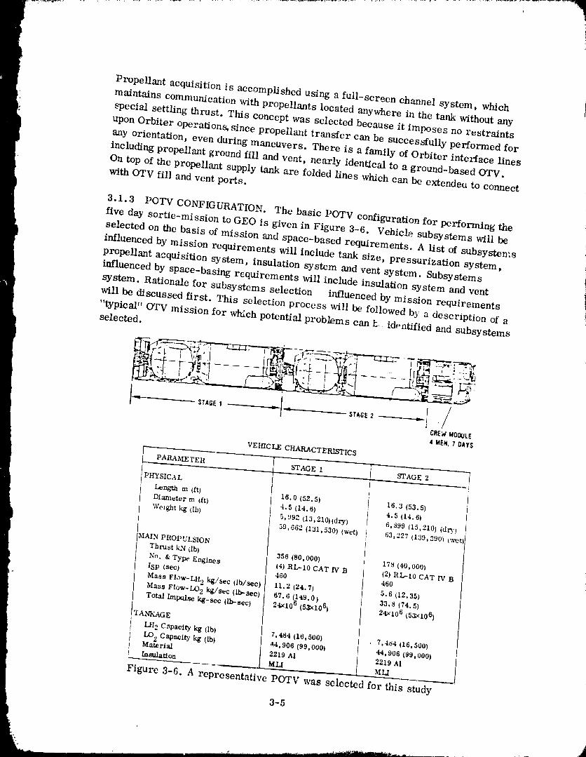
3.1.3 POTV CONFIGURATION. The basic POTV configuration for performing the
five day sortie-mission to GEe is given in Figure 3-6. Vehicle subsystems will be
selected on the basis of mission and space-based requirements. A list of subsysten's
influenced by mission requirements will include tank size, pressurization system,
propellant acquisition system, insulation system and vent system. Subsystems
influenced by space-basing requirements will include insulation system and vent
system. Rationale for subsystems selection influenced by mission requirements
will be discussed first. This selection process will be followed b} a description of a
"typical" OTV mission for which potential problems can h. identified and subsystemsselected.
I I '/"q' STAGE1 ---------"--'-4" _'- STAGE2 _ I 'CREWMOO_JLE4 MEN,7 DAYS
VEHICLE CHARACTERISTICS
PARAM.ETER STAGE 1 STAGE 2
PHYSICA L
Length m (ft) 16.0 (52.5) 16.3 (53.5)Diameter m /ft) 4.5 (14.6) 4.5 (14.6)
Wei_7,ht kg rib) 5,992 (13,210)(dry) 6,399 (15,210) (dr)')
59,662 (131,530) (wet) 63,227 (139,390_ C,_ct
MAIN PROPULSION
Thrust kN db) 358 (80,000) 178 (40,000)
No. & Type Engines (4) RL-10 CAT IV B (2) RL-10 CAT IV BISp (sec) 460 460
Mass Flow-LH 2 kg/sec (lb/sec) 11.2 (24,7) 5.6 (12,35)Maas Flow-LO 2 kg/sec (Ib.-sec) 67.6 (la9.0) 33.8 (74.5)Total Imptllse kg-sec (lb-sec) 24_¢106 (53x106) 24xi06 (53x106)
TANKAGE
LH 2 Capacity kg (lb) 7,484 (16,500) , 7,484 (16,500)
LO 2 Capacity kg (lb) 44,906 (99,000) 44,906 (99,000)Material 2219 AI 2219 Al
Insulation MLI MLI
Figure 3-6. A representative POTV was selected for this study
3-5
198000981 1-£
3.1.3.1 Subsystems Influenced by Mission Requirements.
Pressurization System - The selected pressurization sTstcm will require helium for
propellant tank pre-pressurization for each main eng2ne start. Prcssurization
requirements during main engine firing will be autogenous for the liquid hydrogen tank
and helium for the liquid oxygen tank. Main engine-start helium usages will not be
excessive because engine-start NPSP requirement will be approximately 3.45 kN/m 2
(0.5 psid) (LI-I2 tank) and 6.9 kN/m 2 (1.0 psid) (1.O2 tank). Torn! mission heliumusages will be relatively small for the LO 2 tank because helium will be bubbled throughthe liquid bulk. The tank pressure increase will be primarily due to propellant evaporation
into the helium bubbles. Autogeneous pressurization was selected for the hydrogen tank
because a) it is a simple ',_ndproven approach, and b) the alternative helium pressurization
approach will be considerably heavier. This type of pressurization system was analyzedin contract NA83-20092, Reference 3-2.
Helium within a propellant tank can complicate an orbital tanking procedure because of
the need to expel most of the inert gas before propellant transfer can be initiated.
Unfortunately, in the near-term, there is no viable alternative to helium pressurizataon
formain engine start since main engine NPSP requirements nmst be satisfied. An
advanced engine with "boot-strap" capability, i.e., with no NSPS requirements, may be
developed in the future. A major benefit from this development will be a simplifiedrefueling procedure. Until then, refueling operations must be capable of dealing with
helium inside the propellant tanks.
Propellant Acquisition System - Analyses were performed in Contract NAS3-20092
to assess the benefits of a partial propellant acquisition system for o'rv. The
acquisition system combined with a thermal subcooler was analyzed to determine if
the se subsystem s could replace helium pressurization and RC S subsy stem s. Althougha final assessment has not been reported, it is likely that an acquisition b3"stem is not
performance effective for a nmnber of OTV missions. At this time, it is judged that a
partial screen acquisition device will not be included as part of an OTV eotffiguration.ttowever, an exception to subsystem selection is made in this ease and with the
pressurizatior, cstem, as explained below.
To provide a more thorough discussion and analysis of t,o'rv orbital refueling operations,it was decided to include the helitm_ pressurization and screen acquisition (start basket)
subsystems. In this way the influence of each upon refueling techaiqucs or procedurescould be assessed.
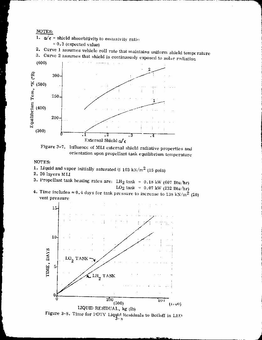
Insulation S_rstem - A multilayer insulation (MIJ) system was selected as being
representative of thermal protection systems which may be employed for OTV. A singleblanket consisting of twenty MLI layers was selected on the basis of a previous analysis
conducted for Contract NAS3-20092. Radiative properties of the organic_flly-eoated
aluminized Kapton Super floe MLI will result in a maximum equilibrium temperature
of 2_9K (.+520R) (Figure 3-7) for the estin_ated o_/'c of 0.3. This maxinmm temperature
is based upon the worst case assmnption of a tank surface continuously exposed to the
3-6
1980009811-039
sun. The lower temperature curve is for the assumed condition of a vehicle rotating
at a rate sufficient to maintain uniform skin temperatures throughout.
' The time required for the propellant tanks to attain equilibrium temperatures will be
dependent upon the propellant mass remaining at POTV final MECO. These
residuals must first boiloff and be vented overboard before the propellant tank
temperatures can increase. Figure 3-8 g2ves the time required for residual liquids
te boiloff as a function of initial liquid residual. Studies have not yet been conducted
from which an acceptable liquid residual range can be determined. On the basis of
Centaur vehicle flight experience, however, a residual of about 200 kg (441 lb) pertank appears reasonable. These quantities will boiloff in about 6 to 8 days. Beyond
this time, the propellant tanks an_ remaining vapor will begin to increase in
temperature as shown in Figures 3-9 and 3-10. The rate of temperature increase will
depend upon the external shield temperature, which can be as high as 2_:)K {520R), as
indicated by Figure 3-7. Propellant tank transient time to steady state is given for
three external temperatures to show how this transient will be itdluenced by vehicle
roll-rate and a/c. It is seen that liquid-oxbgen tank equilibrium can be attained in a
minimum of 8 to 12 days, and hydrogen tank equilibrium can occur in a minimum
of 16 to 22 days.
Vent S_stem - A thermodynamic vent-system will be required to provide ventcapability for the proposed OTV mission profile_. This type of vent system can
maintain vehicle tank pressure control in a zero-g environment regardless of fluid
quality at the heat exchanger inlet. Vent system sizing will be keyed to the MLI
thermal protection capability, Additional vent capability may be required to satisfy
refueling procedures. Further discussion will be postponed until _tcr space-basing
requirements have been evaluated.
3.1.3.2 Subsystems Influenced by Spacc-Ba,_ing Requirements - Space-basing
conditions are defined as those conditions _fecting the OTV from post-nfission
} storage of each stage until after resupply. The period where (YI'V and orbiter aredocked is exempted, since it is part of the tm_ing duration. _ny subsystem capability
needed to maintain the OTV in a "safed" condition for subsequent refueling operations
is considered to be a space-basing vehicle requirement. The insulation and vent
systems _lection will be influenced by space-basing considerations.
Insulation System -In addition to the mission requirements previously identified, theinsulation system must provide thclvaal protection for propellants where multiple
orbiter flights are needed to support a single (yrv mission, For this scenario, it is
likely that the OTV stages will reside in orbit for several weeks before tanking is
complete. Too little insulation will result in excessive propellant tx)iloff prior to a
mission. Ideally, a trade analysis should be cunducted to balance mission versus
space-based requirements. This stud)' assumed twenty MM layers was acceptable
for both requirements.
3-7
7
NOTE S:
1. a/¢ = shield absorbit_vity to emissivity rati,,
= 0.3 (expected value)
2. Curve 1 assumes vehicle roll rate that maintains uniform shield temperature3. Culwe 2 assumes that shield is continuously exposed to solar radiation
(600) ......... :............ i
300, - : ' "
,_ (500)
o 250-
(400).p"4
,.Q
200-
(300)
E._ernal Shield 0_¢
Figure 3-7. Influence of MLI external shield radiative properties and
orientation upon propellant tank equilibrium temperature
NOTES:
1. Liquid and vapor initially saturated (_ 103 kN/m 2 (15 psia)
2. 20 layers M LI
3. Propellant tank heating rates are: LH 2 tank = 0.18 kW (607 Btu/_r)LO 2 tank = 0.07 kW (232 Btu/hr)
4. Time includes _ 0.4 days for tank pressure to increase to 138 kN/m 2 (20)
vent pressure• ! "
15- ;
<__ca .. 2 T !_i
O_o 'zbo :iu,_ '
(500) (_.,_vO)
I2QUff) RE _'IT)UAI,, kg (Ib)
Figure 3-$. Time for I'OTV ldq,aht Residuals to Boih)ff in LEO
1980009811-041
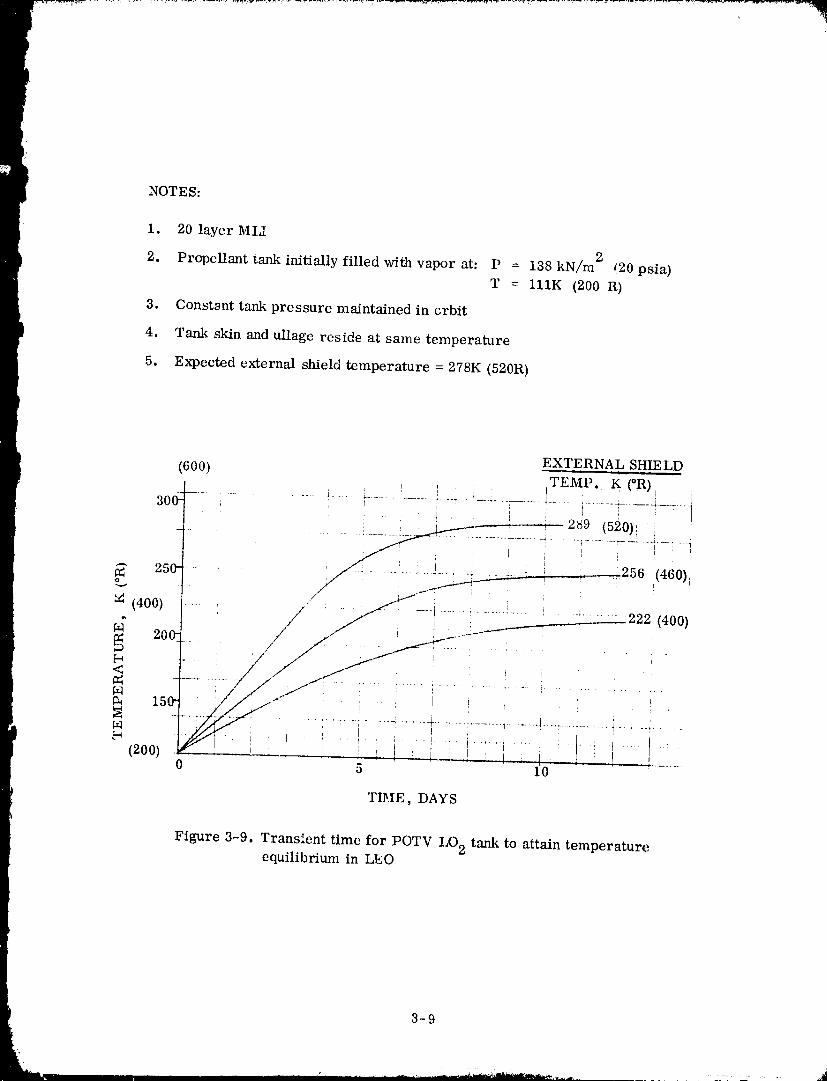
NOTES:
1. 20 layer MLI
2. Propellant tank initially filled with vapor at: P = 138 kN/m 2 (20 psia)
T = 111K (200 R)
3. Constgnt tank pressure maintained in crbit
} 4. Tank skin and ullage reside at same temperature
5. Expected external shield temperature = 278K (520R)
EXTERNAL SHIELD
(600) TEMP. K (°R) I i
I ' ! " ' ! ' _ i , i :289 (520)_ J I
I"
-- 250_-- /. ..... ..... .... _ __ :_ _ ,,,2a6(460)
<
MN 15_ ' / / /"
Iii ..... lilT- ............. : ................. _ ..... :........................................_4 i
(2oo) _ I .i , i _ ,1 _i. i .'_ . i t :. !... 10 5 10
TIhIE, DAYS
Figure 3-9. Transient time for POTV IX)2 tank to attain temperatureequilibrium in LEO
1980009811-042
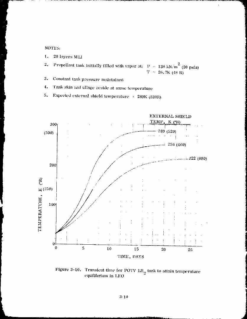
NOTE_:
I. 20 layers MLI
2. Propellant tmlk initially filled with vapor at: !' =- 138 kN/m 2 (20 psia)
T = 26.7K (48 ll)
3. Consttmt tmlk pressure maintained
4. 'l'mlk skin :md ullage reside at smue temperature
5. E.xRoecWd ex-terual slfield temperature : 289K (520R)
EXTERNAL SIIIE IX)
TEMI'_ K [OR)30e : " ! 'q ...... ':i, ': .....7-'"" ........ ' ..... :
'__-.---_ .... 289 (520)(5oo) ...._-_ . ..... _ , ....t_
, t_.__,___.___.--_ 256 (460);
//"/ :_...___z22(400)20(
..-f
/ /.,f
IO0-
M
T
0 5 10 15 20 25
TIME, I)AYS
Figure 3-10. Transient time for POTV LII,, tmfl¢ to attain temperature
equilibrium in LEO
3-10
" ' ' " 1980009811-043
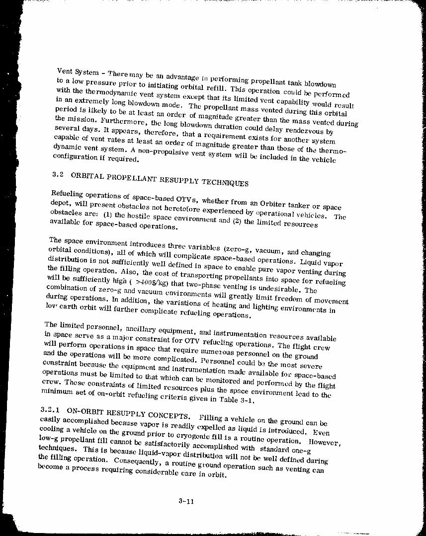
Vent System - There may be an advantage in performing propellant tank blowdown
to a low pressure prior to initiating orbital refill. This operation could be performed
with the thermodynmnic vent system except that its limited vent capability would result
in an extremely long blowdown mode. The propellant mass vented during this orbital
period is likely to be at least an order of magnitude greater than the mass vented during
the mission. Furthermore, the long blowdo_a duration could delay rendezvous by
several days. It appears, therefore, that a requirement exists for another system
capable of vent rates at least an order of magnitude greater than those of the thermo-
dynamic vent system. A non-propulsive vent system will be included in the vehicle
configuration if required.
3.2 ORBITAL PROPELLANT RESUPPLY TECHNIQUES
Refueling operations of space-based OTVs, whether from an Orbiter tanker or space
depot, will present obstacles not heretofore experienced by operational vehibles. The
obstacles are: (1) the hostile space cnvironnmnt and (2) the limited resources
available for space-based operations.
The space environment introduces three variables (zero-g, vacuum, and changing
orbital conditions), all of which will complicate space-based operations. Liquid vapor
distribution is not sufficiently well defined in space to enable pure vapor venting during
the filling operation. Also, the cost of transporting propellants into space for refueling
will be sufficiently high (>400$/kg) that two-phase venting is undesirable. The
combination of zero-g and vacutun environmcnts will greatly lhnit freedom of movement
during operations. In addition, the variations of heating m_d lighting environments in
low earth orbit will further complicate refueling operations.
The limited personnel, ancillary equipment, and instrumentation resources available
in space serve as a major constraint for OTV refueling operations. The flight crew
will perform operations in space that require numerous personnel on the ground
and the operations will be more complicated. Personnel could by the most severe
constraint because the equipment and instrmnentation made available fo_" space-based
operations nmst be limited to that which can be monitored and performed by the flight
crew. These constraints of limited resources plus the space environment lead to the
minimum set of on-orbit refueling crik_ria given in Table 3-1.
3..2.1 ON-ORBIT RESUPPLY CONCEPTS. Fillinga vehicleon theground can be
easilyaccomplishedbecause vapor is readilyexpelledas liquidisintroduced. Even
coolinga vehicleon theground priortocryogelflcfillis a routineoperation. However,
low-g propellantfillcannotbe satisfactorilyaccomplishedwith standardone-g
techniques.This is becauseliquid-vapordistributionwillnot be welldefinedduring
thefilllngoperation.Consequently,a routinegi_und operationsuch as ventingcan
become a process requiringconsidcrablecare inorbit.
3-II
198000981 '1-04,
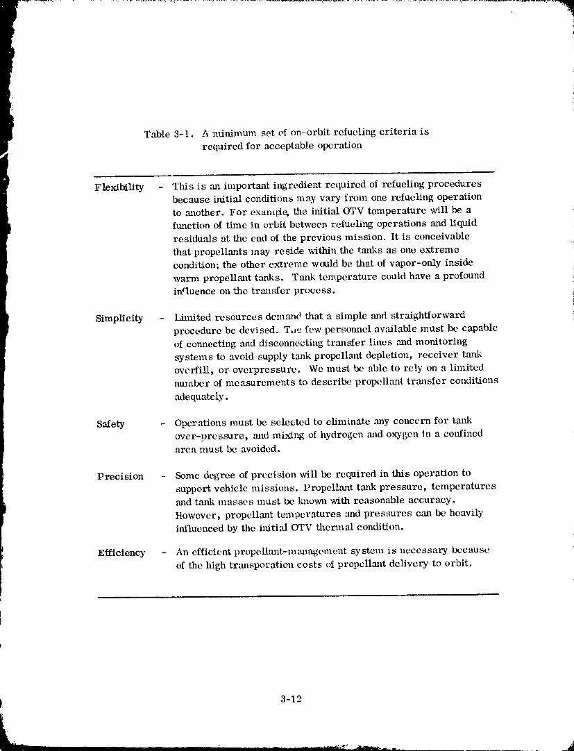
Table 3-1. A ntinimmn set of on-orbit refueling criteria is
required for acceptable operation
Flexibility - This is ,an important iltgredient required of refueling proceduresbecause initial conditions may vary from one refueling operation
to another. For exanqte, the ilfitial OTV temperature will be afunction of time in orbit between refueling operations and liquid
residuals at the end of the previous mission. It is conceivable
that propellants may reside within the tmfl¢s as one ex'tremecondition; the other extreme would be that of vapor-only inside
warm propellant tanks. Tmlk temperature could have a profound
inquence on the transfer process.!
Simplicity - Lhnited resources demand that a simple and straightforwardprocedure be devised. T,_e few personnel available must be capable
of connecting mid disconnecting transfer lines ",andmonitoring
systems to avoid supply tank propellant depletion, receiver taukoverfill, or ovcrprcssure. Wc must be able to rely on a limitednumber of measurements to describe propellant transfer conditions
adequately.
Safety - Operations must bc selected to eliminate ,any concern for tmtkover-pressure, and mixing of hydrogen and oxygen In a colffinedarea must be avoided.
Precision - Some degree of precision will be required in this operation to
support vehicle missions. Propeltant tank pressure, temperatures,and tmlk masses must be Imown with reasonable accuracy.
ttowevcr, propcllmlt temperatures and pressures can be heavily
influenced by the iltiti_fl OTV thenual condition.
Efficiency - An efficient propellm_t-management system is necessary becauseof the high trm_sporation costs of propellant delivery to orbit.
) 3-12
1980009811-045
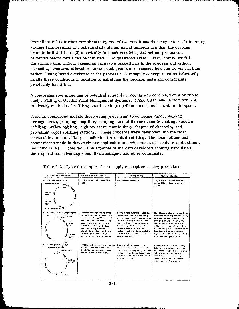
Propellant fill is further complicated by one of two conditions that may exist: (1) in empty
storage tank residing at a substantially higher initial temperature than the cryogen
prior to initial fill or (2) a partially full tazdc requiring th_._ helium pressurant
be vented before refill can be initiated. Two questions arise. First, how do we fill
the storage tank without expending excessive propellants in the process and without
exceeding structural allowable storage tank pressure ? Second, how can we vent helium
without losing liquid overboard in the process? A resupply concept must satisfactorily
handle these conditions in addition to satisfying the requirements and constraints
previously identified.
A comprehensive screening of potential rcsupply concepts was conducted on a previous
study, Filling of Orbital Fluid Management Systems, NASA CR159404, Reference 3-3,
to identify methods of refilling small-scale propellant-management systems in space.
_¢?ystems considered include those using pressurant to condense vapor, valving
arrangements, pumping, capillary pumping, use of thermodynamic venting, vacuum
refilling, inflow baffling, high pressure manifolding, shaping of channels, and
propellant depot refilling stations. These concepts were developed into the most
reasonable, or most likely, candidates for orbital refilling. The descriptions and
comparisons made in that study are applicable to a wide range of receiver applications,
including OTVs. Table 3-2 is an example of the data developed showing candidates,
their operation, advantages and disadvantages, and other comments.
Table 3-2. Typical example of a resupply concept screening procedure
C._NI_fD_TE CI_('EPTqJ METIK_D OF' I_Pt:I_TI_N ADVANTACIF_ I_I_ADV_NTAI;E_z
I. ._I.l,.la_J ane- i flllbl| FHI umln I no_nal |Pound .liEn| No md,l*Ilonn| hMrd_are. Liquid v_por Inllrfole unk_.c_n
_m,.lu,.,r mrrll_ -__ Intel. durlnlt Itliin| V_p_,r _m_ppt.J In
/)II_llUJl_ "FressvrMt/)kfald |prs_ Fill iiitk wlUt Ik/_ld utbtil ipray Flirty _lmple hlNWlm¢l), DoN lot lille pres_ura fin will uc_:ur durll_
tulle. _ •acm_s._ I1_:_ Ca _:hk'vo f_rmodyn_m k* dol_md upt_ pc_lllon o| Iba low- I ¢hlll4uwlt whl_h mI, req_lrl v_nllttl_
- _ _. mu_m _r,lllhl_:m du_ tni_ ©hllhlown urn! Ih(mrfl_e _ Ih_rmk_r_ _sm be l_l¢_ to occur. Ille ,O4h_llum i,_nk©w
' "_ -- ¢_,t_ fUI [h._a Ik'lhm_ Io co_k'_so al_y lit r +rm_l dr_,lly _lh _e_tlu_ce flllln I • p_rli=lly full I._nE m_re
i ) _|_L. vllt_r trapp_'d II _h0 capillary thll II w_ll ,_p,lrale ta I_r ICr_Vliy. e_m,pll,'_led b_c_u.,+ Iho h,:tl,ml
r'' ":_UtC_ clevlee _k_r_l_g filling. Ife_lum T_arln_l equilibrium t_lullu In |ow will pr,at_bl y h,_ io I_, vPah.d ;_1[
_ _" ¢,_uhl I,e ._,khd |,_( I_l,_r_ pr_._ur_ rlie ,t_;rleq I fill. No I,_ k,._.p flh;d pcu_vulcl within Ilmlll
w_lls, I ,d f_,ll_ll_ B _p,_r In *hv ¢.*pII- II_ r_ _lrt_. (',._ld LIe I, 1;_411¢,td b_ rvph,_,e _;llv _lth 1_11; Ix I,,r_+ IIII of
J_, Ifellum _l'lliurl_l,_ i_1111._l_ wtUt ,llff_o_,r la ¢_¢'hlJVi Iov FiiIrl_ _l_lpte _lnl_'lt'e, I ew N,,*._l_lllitlriunl e,,s.illllm_ *hit Iflg
_ iClll_Ib _llh i t+ll_l I,_ tlllll rl lllU_,ll
,,/
3-i3
J
1980009811-046
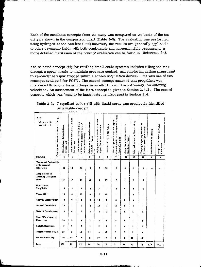
Each of the candidate concepts from the study was compared on the basis of the ten
criteria shown in the comparison chart (Table 3-3). The evaluation was performedusing hydrogen as the baseline fluid; however, the results are generally applicableto other cryogenic fluids with both condensible and noncondensible pressurant. Amore detailed discussion of the concept evaluation can be found in Reference 3-3.
The selected concept (#2) for refilling small scale systems includes filling the tank
through a spray nozzle to maintain pressure control, and employing helium pressurant
to re-condense vapor trapped within a screen acquisition device. This was one of two
concepts evaluated for POTV. The second concept assumed that propellant was
introduced through a large diffuser in an effort to achieve extremely low entering
velocities. An assessment of the first concept is given in Section 3.3.2. The second
concept, which was _ound to be inadequate, is discussed in Section 3.4.
1980009811-047
3.3 SELECTED ORBITAL RESUPPLY METHOD
For initial filling, the POTV is expected to reside at a temperature of about 289K (520R).
This will be the approximate equilibrium temperature dictated by the multilayer
insulation (MLI) radiation properties (Figure 3-7). Vehicle equilibriurf_ conditions
are also expected to occur during the approximate six- to eight-week period between
the end of one mission and the beginning of refueling operations for another mission.
Thus, propellant boiloff could complicate propellant transfer operations. The key
issues to be resolved are: 1) how to fill the tanks without expending excessivepropellants in the process and without exceeding structural allowable receiver tank
pressure, and 2) how to assure that the start basket (if one is present) will be free
of vapor at end of propellant tank refill. The approach selected for the POTV appears
to resolve these issues. The following steps serve as the primary elements of an
acceptable propellant transfer procedure: initial vent, prechill, fill. Each element
will be analyzed in detail.
A recommended refueling procedure will be developed for a POTV having each of the
following pressurization system-start basket combinations:
a_ no helium pressurization - no start basket
b) no helium pressurization - start basket
c) helium pressurization - no start basket
d) helium pressurization - start basket
3.3.1 INITIAL VENT. Propellant tank venting is required whenever it will simplify
the prechill and tank-fill operations. There are two occasions when venting is either
desirable or mandatory; when helium is to be expelled prior to the refueling operation,
and to reduce peak pressures that occur during prechill.
3.3.1.1 Propellant Tank Helium Dilution. Refueling of the empty or near-empty
vehicle propellant tanks will be performed prior to a scheduled mission. It is expected
that the propellant tanks will be refueled to the 95-97 percent level. Because helium
is non-condensible, that quantity in the tank at the start of fill will also be present
at the end of tanking. Consequently, the large ullage volume reduction experienced
during refill can substantially increase helium partial pressure.
This fact is illustrated by Figure 3-11 which shows that as little as 0.5 kg (_. 1 lb) heliumin the IX)2 t_,mk can provide a helium partial pressure in excess of 69 kN/m" (10 psia).A partial pressure of this magnitude is considered to be unacceptably high. It is
estimated that _ helium pressure no greater than 20.7 kN/m 2 (3 psia) would be acceptable.
This assessment is based upon the need to know liquid-vapor-pressure conditions at the
end of propellant tanking. Since only tank pressure can be measured, ,_,, uncertaints'
in the residual helium quantity directly affects our knowledge of propell,-mt vapor
pressure.
3-15
1980009811 -04
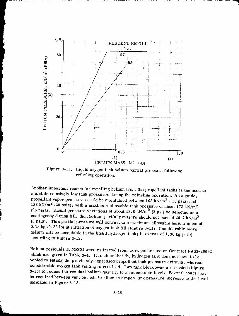
(10)_ PERCENT REFILL ....: _ _-}FILL
60- / 97 --_• I
// '..... 295!- -4 .................
...........-.*=.....7_-...........?i-7[
I
0 , , ,, , J _. ! _ _ T.0 0.5 1.0
(1) (2)IIELIUM MASS, KG (LB)
Figure 3-11. Liquidoxygen tank helium partialpressure following
refuelingoperation.
Another important reason for expelling helium from the propellant tanks is the need to
maintain relatively low tank pressures during the refueling operation. As a guide,
propellant vapor pressures could be maintained between 103 kN/m 2 ( 15 psia) and
138 kN/m 2 (20 psia), with a maximum allowable tank pressure of about 172 kN/m 2
i (25psia). Shouldpressure variationsof about13.8 kN/m 2 (2psi)be selectedas acontingencyduringfill,thenhelium partialpressure shouldnotexceed 20.7 kN/m 2
(3psia). This partialpressure willconvertto a maximum allowablehelium mass of
0.13 kg (0.28Ib)atinitiationof oxygen tankfill(Figure3-11).Considerablymore
! helium will be acceptable in the liquid hydrogen tank ; in excess of 1.36 kg (3 lb)P
according to Figure 3-12.
Hehum residuals at MECO were estimated from work performed on Coatract NAS3-20092,which are given in Table 3-4. It is clear that the hydrogen tank does not have to be
vented to satisfy the previously expressed propellant tank pressure criteria, whereas
considerable oxygen tank venting is required. Two tank blowdowns arc needed (Figure
3-13) to reduce the residual helium quantity to an acceptable level. Several hours may
be required between vent periods to allow an oxygen tank pressure increase to the levelindicated in Figure 3-13.
3-16
1980009811-049
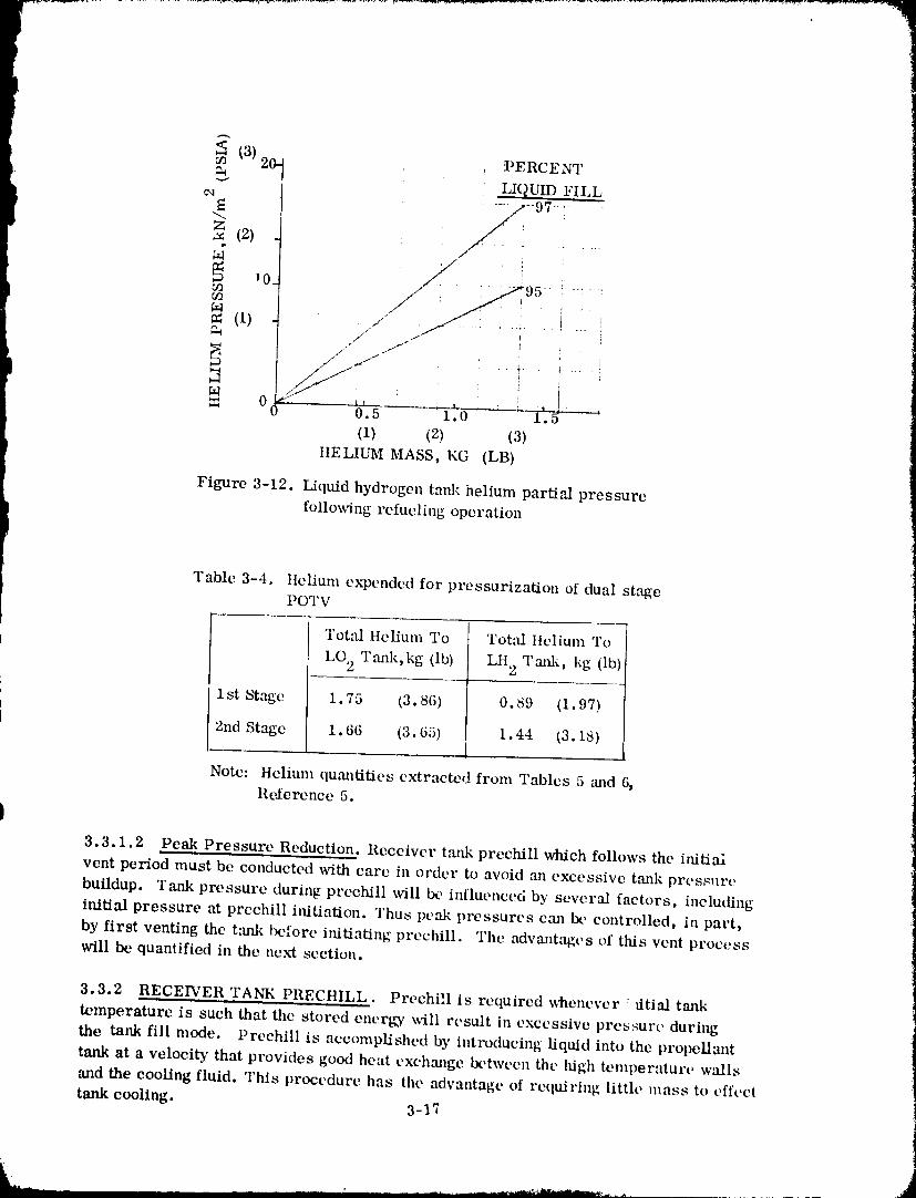
20- _ 'PERCENT(3)
"-_ LIQUID FILL
(2) : ....
/N : :
102 _ :
M /, /(1) ........
' i I
M , i= o- b'.5_-_l.0 ' : i'._ i
(1) (2) (3) ._ii
HELIUM MASS, KG (LB) ]]
Figure 3-12. Liquid hydrogen tan].: helium partial pressure
following relueling operation
Table 3-4_ ltelium expended for pressurization of dual stagePOTV
Tot_ Helium To Total Ilelium To
LO 2 T,-mk,kg (lb) LH 2 Tmfl_, kg (lb)
1st St,_e 1.75 (3.86) 0.89 (1.97)
2nd Stage 1,66 (3.65) 1.44 (3.18)
Note: Helium quantities extracted fronl Tables 5 oJld 6,Re.ference 5.
I3.3.1.2 Peak Pressure Reduction. Receiver tank prechill which follows the iaiti,-d
vent period must be conducted with care in order to avoid an excessive tank pressure
buildup. Tank pressure during prcchill x_dll Ix, influenced by several factors, including
initial pressure at preehill iltitiation. Thus peak pressures can ix, controlled, in part,
by first venting the tank before initiating prechill. The advant,'W;es of this vent processwill be quantified in the next section.
3.3.2 RECE_'ER 'rANK PRECHILL. Prechill is required whenever _fltial tank
temperature is such that the stored energy _-ilI result in excessive pressure during
the tank fill mode. Prechill is accomplished by intlx)ducing liquid into the prol)ellant
tank at a velocity that provides good heat exch,'mge between the high temperature walls
and the cooling fluid. This procedure has the advantage of requiring little mass to effect
tank cooling. 3-1_
_N
1980009811-050
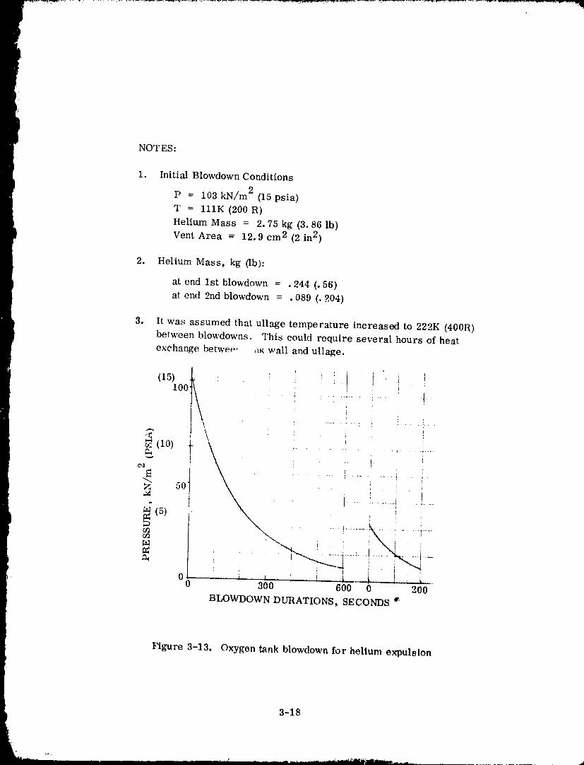
I
I NOTES:
1. InitialBlowdown Conditions
P = 103 kN/m 2 (15psia)
T = 111K (200R)Helium Mass = 2.75 kg (3.86Ib)
Vent Area = 12.9 cm 2 (2in2)
2. Helium Mass, kg (Ib):
at end 1stblowdown = •244 (.56)
atend 2nd blowdown = •089 (.204)
3. Itwas assumed thatullagetemperature increasedto 222K (400R)between blowdowns. This couldrequireseveralhours of heat
exchange betwee' ,m wall and ullage.
(_5_oo_ i
i '
, i
"_" i t
t i ..... :...... ' ...... i ....
' P_ I I
_'_ 50 ' ' "
i , _'x ' i
', ', i . ,. i , ,i, L.... I, L,0 0 300 600 0 200
BLOWDOWN DURATIONS, SECONDS q'
Figure 3-13. Oxygen tank blowdown for helium expulsion
3-18
" 1980009811-051
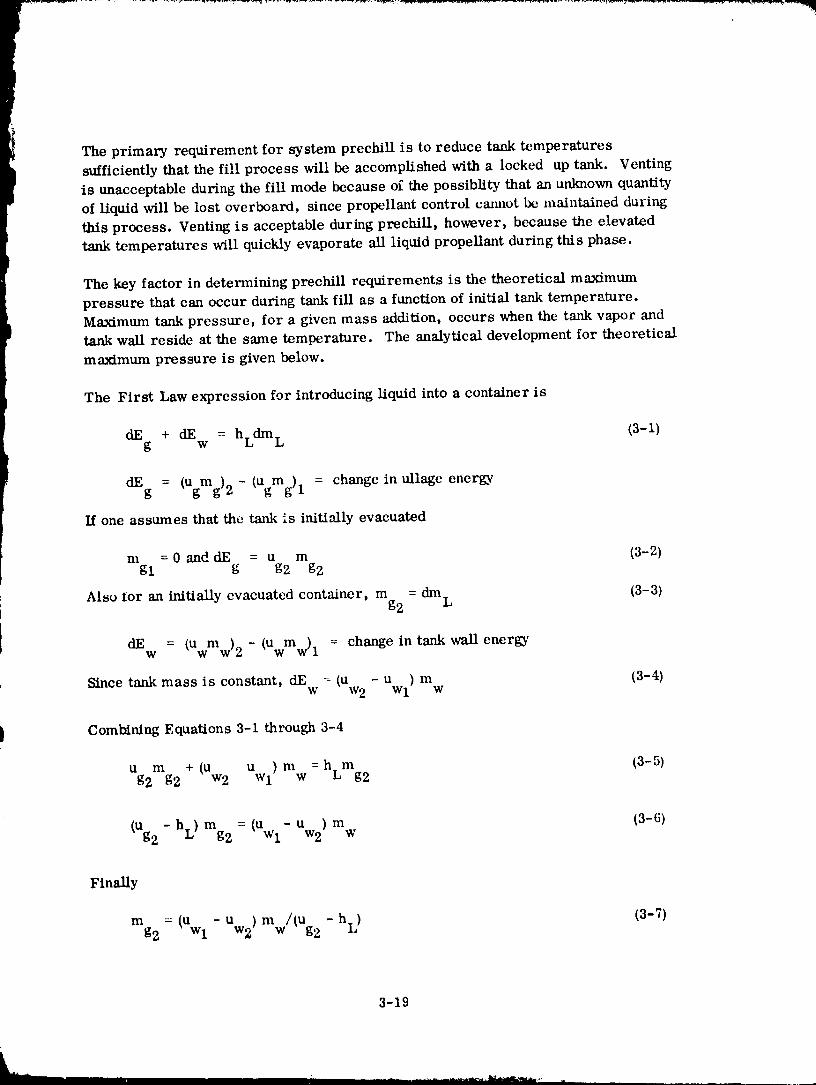
The primary requirement for system prechill is to reduce tank temperaturessufficiently that the fill process will be accomplished with a locked up tank. Venting
is unacceptable during the fill mode because of the possiblity that an unknown quantity
of liquid will be lost overboard, since propellant control camlot be maintained during
this process. Venting is acceptable during prechill, however, because the elevated
tank temperatures will quickly evaporate all liquid propellant during this phase.
The key factor in determining prechill requirements is the theoretical maximum
pressure that can occur during tank fill as a function of initial tank temperature.
Maximmn tank pressure, for a given mass addition, occurs when the tank vapor and
tank wall reside at the same temperature. The analytical development for theoretical
maximum pressure is given below.
The First Law expression for introducing liquid into a container is
dE + dE = hLdm L (3-1)g w
dE = - = change in ullage enerKvg (Ugmg)2 (Ugmg) I
If one assumes that the tank is initially evacuated
m =0 and dE = u m (3-2)gl g g2 g2
Also tor an initially evacuated container, m = dm L (3-3)g2
dEw = (Uwmw)2 - (Uwmw)t = change in tank wall energy
Since tank mass is constant, dE = (u - Uwl ) m (3-4)w w2 w
Combining Equations 3-1 through 3-4
u m + (u u ) m =h m (3-5)g2 g2 w2 w1 w L g2
(u - m = - m (3-6)g2 hL) g2 (Uwl Uw2) w
Finally
mg 2 = (uwl - Uw2) mw/(Ug 2 - hL) (3-7)
3-19
1980009811-052
where
uw2 and Ug2 are evaluated at T 2
dEg = change in tank wall internal energy
hL = cnthalpy of liquid entering tank
dm L -- differential liquid mass addition to tank
u = internal energy of vapor in tankg
m = mass of vapor in tankg
u = internal energy of tank wallw
m = tank wall massw
T = temperature
subscript
1 = conditionsat beginningofinterval
2 = conditions at end of interval
From the equation of state, gas pressure is
/
p = [m ZRT (3-8)
g2 / Vt g2
where
Z = compressibility factor
R = gas constant
Vt = tank volume
Pg2 = gas pressure
3-20
1980009811-053
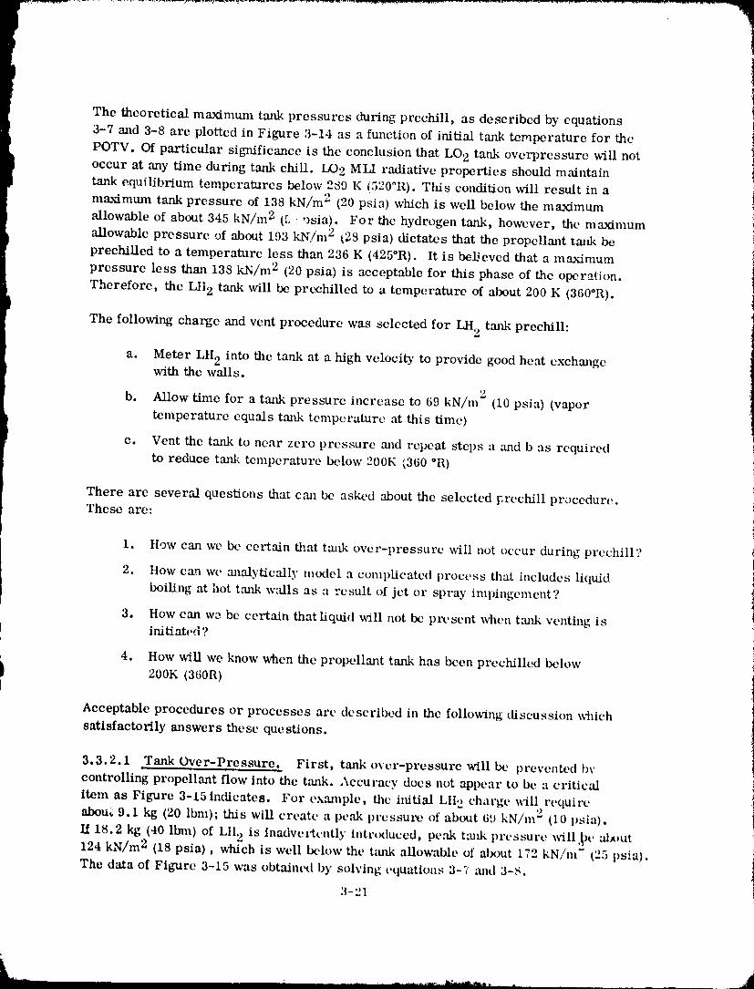
The theoretical maximum tank pressures during prechill, as described by equations
3-7 and 3-8 are plotted in Figure 3-14 as a function of initial tank temperature for the
POTV. Of particular significance is the conclusion that LO 2 tank overprcssure will notoccur at any time during tank chill. LO 2 MLI radiative properties should m,'dntain
tank equilibrium temperatures below 289 K (5200R). This condition will result in a
maximum tank pressure of 138 kN/m 2 (20 psia) which is well below the maximum
allowable of about 345 kN/m 2 (5 vsia). For the hydrogen tank, however, the maximum
allowable pressure of about 193 kN/m 2 _28 psia) dictates that the propellant tmtk be
prechilled to a temperature less than 236 K (425°R). It is be]Jevcd that a maxinmm
pressure less than 138 kN/m 2 (20 psia) is acceptable for this phase of the operation.
Therefore, the LH 2 tmtk will be prcchilled to a temperature of about 200 K (360°R).
The following charge and vent procedure was selected for LH 2 tank prechilh
a. Meter LH 2 into the tank at a high velocity to provide good heat exchangewith the walls.
b. Allow time for a tank pressure increase to 69 kN/m 2 (10 psia) (vapor
temperature equals tmtk temperature at this time)
e. Vent the tank to near zero pressure and repeat steps a ,and b as required
to reduce tank teml)eraturc below 200K (360 °R)
There are several questions that can be asked about the selected [,rechill procedure.These are:
1. }low can wc be certain that tmlk over-pressure will not occur during prcchill?
2. How can we analytically model a complicated process that includes liquid
boiling at hot tank w_flls as a result of jet or spray impingemcnt?
3. How can we be certain thatliqaid will not be pit, sent when tmtk venting isinitiated?
4. How will we know when the propellant tank has been prechilled below200K (360R)
Acceptable procedures or processes are described in the following discussion which
satisfactorily answers these questions.
3.3.2.1 Tank Over-Pressure. First, tank over-pressure will be prevented by
controlling propellant flow into the tank. Accuracy does not appear to be a critical
item as Figure 3-15 indicatea. For exan_ple, the initial LII 2 charge will require
abou; 9.1 kg (20 Ibm); this will create a peak pressure of about 69 kN/m 2 (10 psia).
if 18.2 kg (40 ll:nn) of LI[ 2 is inadve,'tcntly introduced, peak t:u_k pressure will _)e al,)ut124 kN/m 2 (18 psia), which is well below the tzmk allowable of about t72 kN/m" (25 psia).
The data of Figure 3-15 was obtain¢_l by solving equations 3-7 and 3-s.
3-21
'19800098"1'1-054
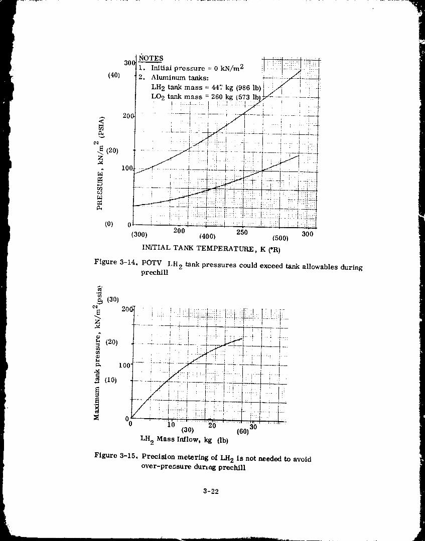
1980009811-055
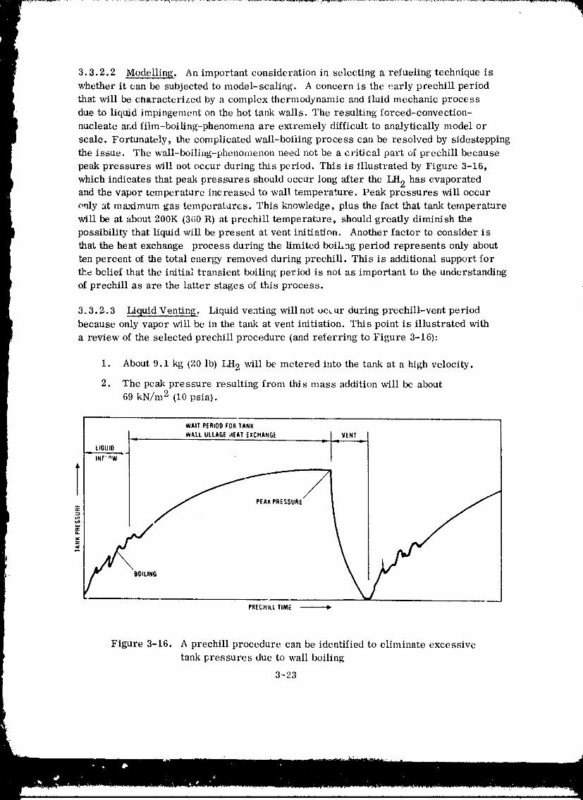
3.3.2.2 Modelling. An important consideration in selectinga refuelingtechnique is
whether itcan be subjected to model-scaling. A concern is the early prechillperiod
thatwillbe characterized by a complex thermodynamic and fluidmechanic process
due to liquidimpingement on the hot tank walls. The resultingforced-convection-
nucleate and fihn-boiling-phenomena are extremely difficultto analyticallymodel or
scale. Fortunately, the complicated wall-boilingprocess can be resolved by sidestepping
the issue. The w_all-boiliag-phenomenon need not be a criticalpart of prechillbecause
peak pressures willnot occur during thisperiod. This is illustratedby Figure 3-16,
which indicatesthatpeak pressures should occur long afterthe LH 2 has evaporatedand the vapor temperature increased to wall temperature. Peak pressures willoccur
ouly at maximum gas temperatures. This knowledge, plus the factthattank temperature
willbe at about 200K (360 R) atprechill temperature, should greatly diminish the
possibilitythatliquidwillbe present atvent initiation.Another factor to consider is
thatthe heat exchange process during the limitedboiLng period represents only about
ten percent of the totalenergy removed during prechill.This is additionalsupport for
the beliefthatthe initialtransientboilingperiod is not as important to the understandiz_g
of prechillas are the latterstages of thisprocess.
3.3.2.3 Liquid Venting. Liquid venting will not occur during prechill-vent period
because only vapor will be in the tank at vent initiation. This point is illustrated with
a review of the selected prechill procedure (and referring to Figure 3-16):
1. About 9.1 kg (20 lb) LH 2 will be metered into the tank at a high velocity.
2. The peak pressure resulting from this mass addition will be about
69 kN/m 2 (10 psia).
WAIT PERIOD FOR TANK
WALL ULLAGE HEAT EXCHANGE =..I VENT
__ LIQUID I- INF' nW _'"
PEAK PRESSURE
PRECHILL TIME
Figure 3-16. A prechillprocedure can be identifiedto eliminate excessive
tank pressures due to wall boiling
3-23
1980009811-056
3. Venting will t)e initiated as tank pressure peaks out (i.e., pressure rise-
rate approaches zero}. This should coincide with ullage and tank wall
temperatures approaching the same value.
4. If liquid had been present in the tmlk prior to vent initiation, it is likelythat
] a. belling would then occur due to the average wall temperature
being greater than 200 K (360 R), and
b. tank pressure would not be leveling off due to boiloff.
5. It is highly unlikely that liquid hydrogen can reside in the tmlk for more
than a short time interval, if the average tank temperature is 178K (320 R)
greater than liquid temperature.
3.3.2.4 Terminating Prechill. One solutim to the problem of determining propellmlt
'tmlk temperature at prechill termination is to monitor a large number of temperatures
during this procesm Many measurements will be needed because the tanks will not be
prechilled at a uniform rate. It is likely that the various measurements could be
integrated, with the aid of a computer, to arrive at an average propellant tank tempera-
ture. This appr(mch may be unacceptable if telemetry requirements become excessive.
or if the transieni conditions yield an inaccurate average vehicle temperature.
A potenti,-dly useful method is to use the accmuulated tank pressure increase during
the charge m_d vcut process for detcrmiyling how much energy has been removed from
; the propellm_t tm_.
tThe tank wall energy trmlsferrcd to the propellant during prcchill is approximately
proportional to the tmfl¢ pressure iuclx, asc. Rcarran6dng equation 3-7 provides the
following relationship:
(uw 1 - uw2) mw =- mg 2 (ug 2 - hL) (3-9)
mid
rag2 : Pg2 VT (3-10)
Pg2 = propellant tmlk vapor densits,
NOTE: This derivation assumes that the tmlk is initially evacuated.
3-24
1980009811-057
Equation (3-9) shows that tanl¢-wall energ.5'-remov_fl is a function of final vapor nlass
mid vapor internal ellerg_', However, both lllass :lilt[ internal encrg3' are a ftlllCtiOIl Of
fin,M telnt)crature :llld pl'essure. (,:t)llbetltlelltly _ tanl¢ enex'gy l'ellloval Call IX' rehfled to
these variables. This relationship is shoual by l:igurc 3-i7. There are two significmlt
points to be llladc [1'o111 this figure, l,'irst, etlt'rgy l't, lllOV:ll is :ll)proximately independent
of vapor tempcraturc. SccoIld_ lilt' energy rellloval is directly prol_ortioival to final task
pressure. It is concluded that tilt, energy extracted during prechill can bc approximak, d
fronl the t:mk pressure illeretlse eN)ericnced during the. process, even if gas temperature
is not known. The gas tcmt)crature uncertmnty will result in an uncertainty in l)ropelhmt
vapor generated during prechill.
More propelhmt will bc evaporated lllml tile theoretical minimmn reqttired for tmfl¢
prechill. This is true because gas lenlperature _dll Ix'. less thml t:mk temperature
whell VOlltillg oeCtll'S, l,'ortunatcly, lhc additiomfl vapor that may bc vented does n,)t appear
to be excessive, :is i_ldicated by Figure 3-18. This figure indicates that even if tilt,
tmlk-to-gas tcmperature diffcrence is :Is great as 50 K (90°R), hydrogen losses will be
increased by only 5..1 kg (t2 lb) per POTV stage, a small qua, llity compared to other
losses that will IX, experit'need during refueling operatiolls.
Propt, ll,'mt trtmsporat_on inefficiencies io Ix, experienced during a POTV orbital
refueling t)l)erallion wt' l'e detern/ined dul'hlg the llefere;lee 1-1 study, ;llld :1t'e _ivell ill
Table 3-5. 'these inefficiencies were calculated for tile orbitcr-tanker configuration
(Figure 2-1) in suppt_rl o1' lhe Iivc-day mission sortie. The lish,d i)reehill h_sses :ire
two times greak,er than tht, thcorelieal millJmunl values. Even so, fllese qualllitics
are insignificmlt :uld, as a result., it is concluded that a pr(,chill procedtlvt' should mRbe selected on lilt' basis of minimum fluid losses.
a.a.e.5 Prechill Analysis. A tu'echill subrouLille, dr'Ycleped _\dlh IRAI) funds, ]was e,nph_yed to evalu:de tilt' details of a POTV preclfill proccss. This subroutine
which deta.ils are dot'tltlletlted ill Ilefet'etlce 3--,:, wtls use, t l_ iltlalyze fluid
llllUl.q_elllellt syslelll prechill for that study. The compuk, r progrmn is c:lpable of {
ev:flu:d,ing prechiIl for lilt, condil,ion o[ vapor elllry to flit' propelhlnt ttmk, but not
liqttid cntw. This limit:ltion does Ilot rel)rest'llt tl htuldit'al) becllUSt', tls t'N)lained
in Section 3.3.2. :2, liquid entry will have only a miltinl_fl ilffluence upou the t)roeess, i
The l,ey to lifts mmlysis ix in identifying tilt' :lppropriate heat trmlsfer coefficient
between incomillg vapor lllld Lilt, t:l_lli wails. {.7OliVell_ioll/l] forced t'Ollvet'lion t'xl)ressiollS i
for flow over a flat 1)lah , or for jet ilnl)ingement upoll tl stiff at, e, reprt'selll t'Ollfigul'atiolls
tllat art, too tlissinlilar It) I._' applicable. Iilste/ld, tl corl'el:ltioll tlevtqol)ed [or industrial
nliXilll_ processes was selected as Ix'trig re|lrt, sentative of the hi, at exchange ineehaJtism i
that will oeetlr whcn vapor is eolifilltlOUSly introduced Into lilt' lU'ol_ellant ,..:
ttlllk. The heat trtmafer ctwrelatioll illltt required mt,dificalions are giVOll :IS
_ep N1)il 0.13 02 (lhfferencc 3-3) (3-11) t43 - 2 ,q t
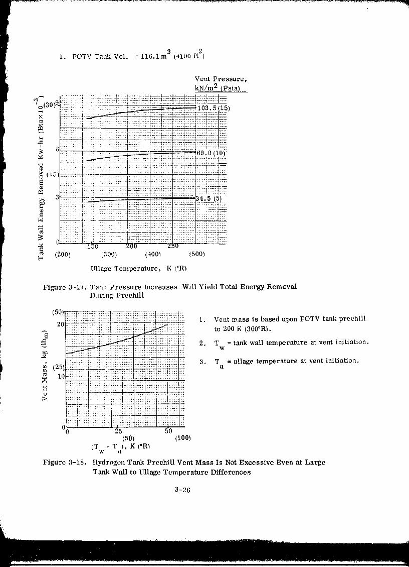
i. POTV TankVol. = 116.1m 3 (4100ft 2)
Vent Pressure,
kN/m 2 (Psia)
X
I .....
6 :'"I " " _I l , _ _ O_ U _U)
........ ,. • + .......... _ ......... _ ............... : ......
_:::::::_:_--t-"::: :_::"7_::-- ::::::::::::::::::::::::::::::::+ :::-_-::: =_t.,17._....... ..--:-...............:=::....._.-- .....--
_) i-.. i" -I ....... 1 .... _ ......
•_--.- :: :: : ; ;' ' 4 :.,_.-',,:' • ....... 34.5 (5)
::::::::::::::::::::: :,: :_:::+:=_:__:__:.=___'::_:_l_J:)c,;=.::_t=5:.......
(200) (300) (400) (500)
Ullage Temperature, K (°R)
Fio-x_re3.-17.Tmfi< Pressure Increases Will Yield Total Energy RemovalDuring Prcchill
• "_:_ : .T:_:.L:: I :-:2:-_ .... L-S-T:.......... -20 .................. F........ _,-_ 1 Vent mass is based upon POTV tank prechill
.._ !!!ii:i_! '::!!!!!iti!i!t!!ii:)::i:._. :_::!i _ to 200 K (360"R).:::::: :::.::i:::: ::::i- ii_'_!}i) i_!iii:_: 2. T -- tank wall temperature at vent initiatmn.
I :!:!;i!i!t!!!:!!iiitii}LiL:3!,!-:iS_i?_i !ii{!!{:_i " 3. T = ullage temperature at vent initiation.
_; (25)_L_:__ ....... u--_.... :=_-:_--_--_= u
:.:.,...:.................t....................i_
:!:.!._:::. :::i_::.I i:::: ::::i:::..:.:i::::::::t:::: ::::!:::: ::AS:: ::::t:::-:::::.::::
00 i:i!::: : ::::::::::::::::::::::::::::::::25 ::T_I:::::50(50) (100)
(T - T ), K (*R)W tl
Figure 3-18. ttydrogen Tank Preehill Vent Mass Is Not Excessive Even at LargeTank Wall to Ullage Temperature Differences
3-26
1980009811-059
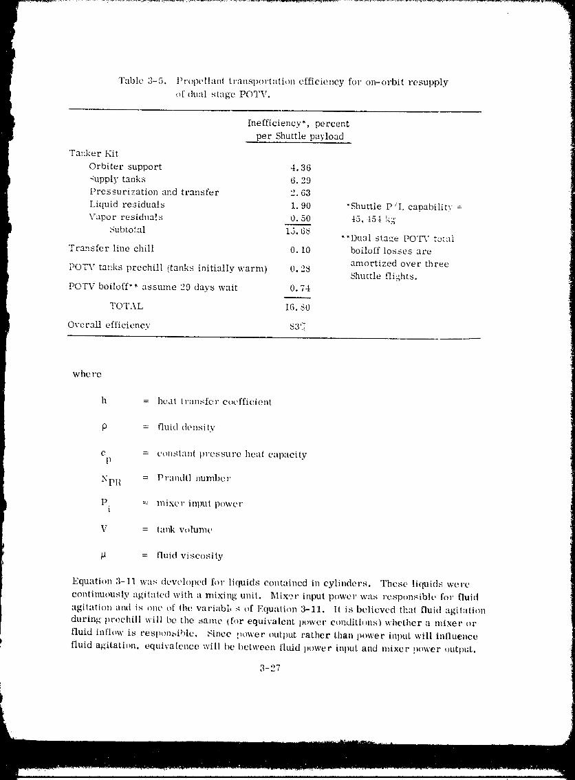
t Inefficiency*, percentper Shuttle payload
Tanker Kit
Orbiter support 4.36
_upply tanks 6.29
Pressurization and transfer 2.63
Liquid reaiduals 1.90 "ShuttleP :L capability=
Vapor residuals O.50 45,!51 k.g
Subtotal 15.68"*Dual stage POT'," total
Transfer line chill 0.10 boiloff losses are
amortized over threePOTV tanks preehill (tanks initially warm) 0.28
Shuttle flights.
POTV boiloff** assume 29 days wait 0.74
TOTAL 16.80
Overall efficiency 83'_{
where
h = heat transfer coefficient
p = fluid density
C = CoilS|till[ pressure heat capacityP
NpI { = Prandtl number
P = mixer intmt poweri
V = lanl¢ volume
_t = fluid viscosity
Equation 3-11 was dew'loped f()r liquids contained in cylinders. These liquids were
continuously agitated with a mixing unit. Mix,_r inpul power was responsible for fluid
agilation and is one of the variabi, s of Equalion 3-11. It is believed thal fluid agilali(m
during preehill will be the same tt',)r equivalent power condithms) whether a mixer or
fluid inflow is responbible. Since power outl)ut rather than power inlmt will influence
fluid agitation, equivalence will bc between fluid power intmt and mixer power output.
3-27
1980009811-060
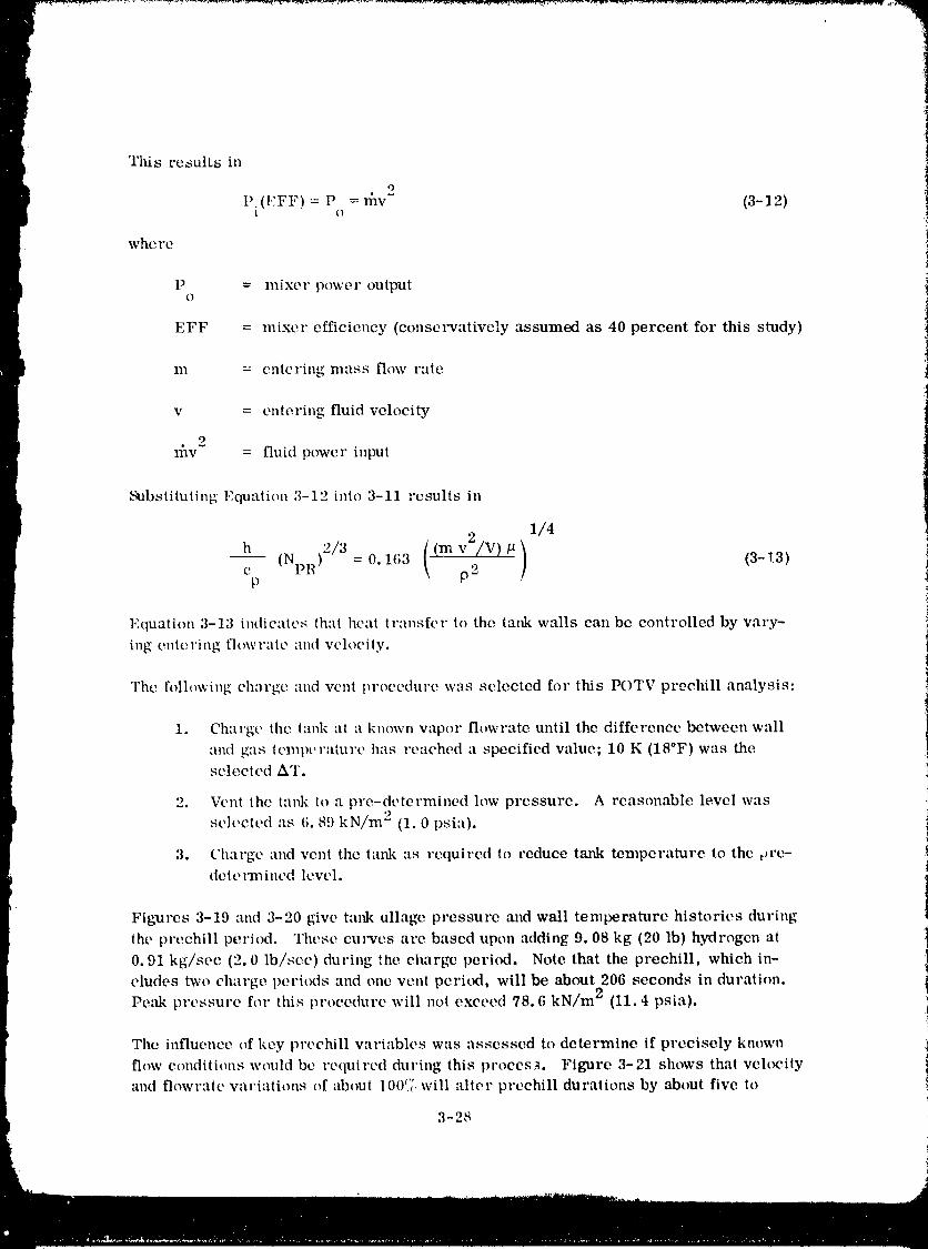
Tltis results in
O
P.(EFF) = P = nav- (3-12)1 O
where
P = lnixer power outputO
EFF = mixer efficiency (eonsmwatively assumed as 40 percent for this study)
m = entering mass flow rate
v = entering fluid velocity
2l{av = fluid power input
Substituting Equation 3-12 into 3-11 results in
1/4
h (NI, R)9/3=0.163 ((mv2/V)#) (3-13)ep p 2
Equation 3-13 indieales thai heal transfer to the tm_k walls can be controlled by vary-
ing entering flowraic and velocily.
The following charge and vent procedure was selected for this POTV prechill analysis:
1. Charge tile lank at a known vapor flowrate until the difference between wall
and gas temperature has reached a specified value; 10 K (18°F) was the !selected AT. !
2. Vent the tank to a pro-determined low pressure. A reasonable level was
selected :is 6.89 kN/m 2 (1.0 psia).
3. Charge and vent the tank :is required to reduce tank temperature to the ore-dele ITnined level.
Figlarcs 3-19 and 3-20 give tank ullage pressure and wall temperature histories during
the prechill period, rI'hese curves arc based upon adding 9.08 kg (20 lb) hydrogen at
0.91 kg/sec (2.0 lb/,_ec) during the cimrge period. Note that the prechill, which in-
cludes two charge peri(xts and one venl period, will be about 206 seconds in duration.
Peak pressure for this procedure will not exceed 78.6 kN/m 2 (11.4 psia).
The influence of key prechill variables was assessed to determine if precisely known
flow conditions would be required during this process. Figure 3-21 shows thai velocity
and flowraie variations of about 10017_,will alter preehill durations by about five to
3-28
1980009811-061
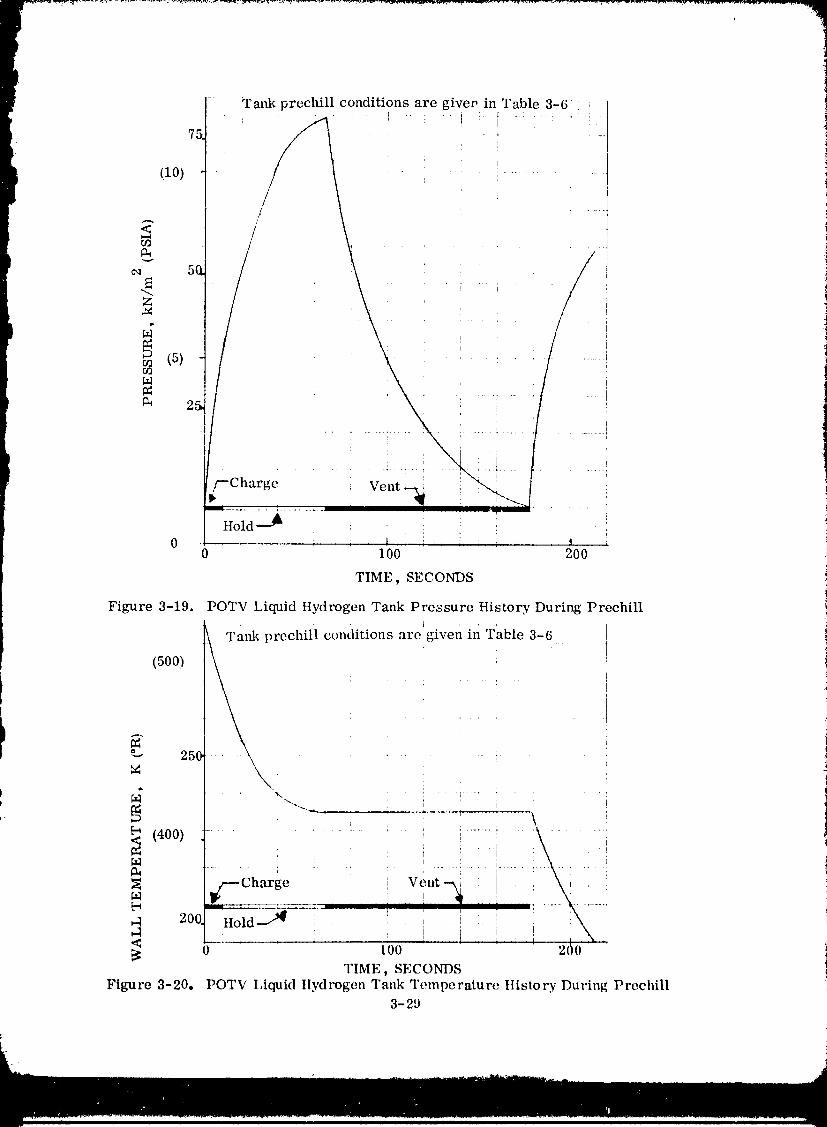
- :Tank prechill_ conditions....... are giveP!.in Table,:: , 3-6! -i[[75 : .- :
i
(1o) .... _......
<
5(
"_,_Z " i - i " I
/..... : .................. [ ........ [
z-Charge ' _ _ ': _ Vent i : : : :
J ............. _. i 1
Ilold --_ : _ _
0 0 100 200
TIME, SECONDS
Figure 3-19. POTV Liquid Hydrogen Tank Pressure History During Prechill
prechitl .... _ _ ''ra,fl_ conditions are given in Table 3-6
(500) _ :
\\ '25q
(400) ............. i : ........
! ; : : i ' ! i1
_Charge : Veat--_i : [ . , :,
• _ 1 . ! , : I i20, IIold_ : ' ' : \i _ i i J \ I
0 100 ' _ _ 2(10TIME, SECONDS
Figure 3-20° POTV IAquid Hydrogen Tank Temperature History During Prechill3-29
1980009811-062
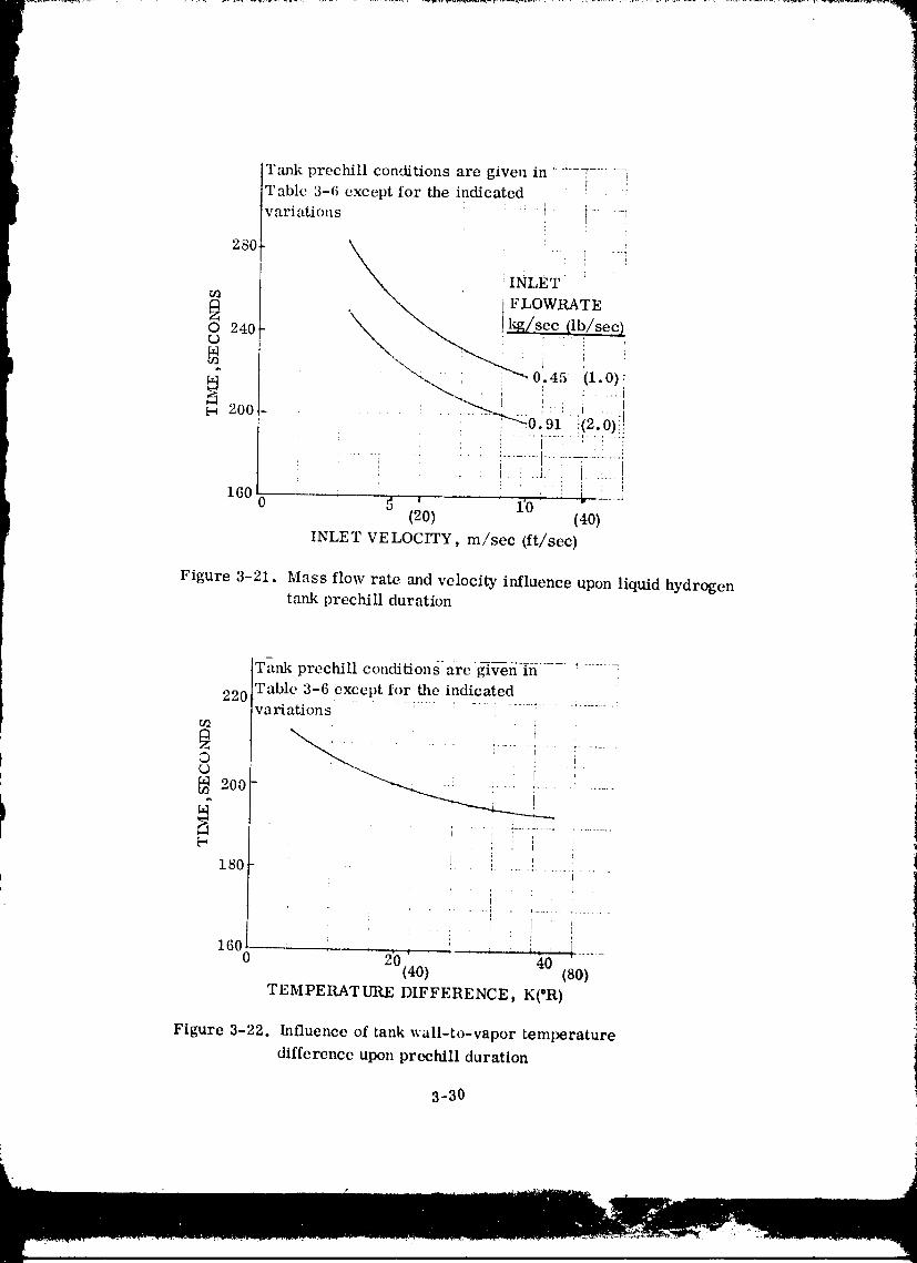
!Tank prechill conditions are given in_----_-- I ---Table 3-6 except for the indicatedvariations : -i _......
: l '
280 _ i _ --._' INLET '
t_ . "_ FLOWRATE
\ ! secO 240
200- , • ! ..... _0.91=.i(2.'0)!!i _ :i ....i !i!t
1600 _o _ _ 1'0 I " _" .....(20) (40)
INLET VELOCITY, m/sec (ft/sec)
Figure 3-21. Mass flow rate and velocity influence upon liquid hydrogentank prechill duration
Tank prechill conditionsa-re _;¢-e-h_---7 ! ......
220 Table 3-6 except for the indicatedvariations
.... i'-'i ;'' I .....0 _ _
200 --....._ ' :-- :- ' : ......
is0 i i...... i............[ J
! i : _ 't
: i !..... _ , ! !16, ., l..,,i_l ......
0 20(40) 40 (SO)
TEMPERATURE DIFFERENCE, K(°R)
Figure 3-22. Influence of tank wall-to-vapor temperature
difference upon prechtll duration
3-30
1980009811-063
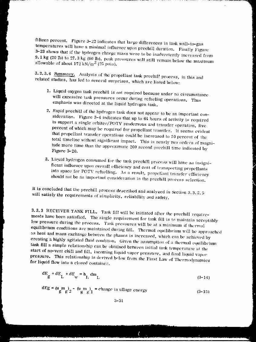
P
P
fifteen percent. Figure 3-22 indicates that large differences in tank wall-tc,-gas
!: temperatures will have a minimal influence upon prechill duration. Finally Figure
I 3-23 shows that if the hydrogen charge mass were to be inadvertently increased from9.1 kg (20 lb) to 27.3 kg (60 lb), peak pressures will still remain below the m.-ux'imum
, > (05allowableof about172 kN/m" - psia).
3.2.3.6 _Summary. Analysisof lhepropellanttankprechil!process, inthisand
I ,'elated studies, has led to several surprises, which are listed below:
1. Liquid oxygen tank prechill is act required because under no circumstance
will excessive tank pressures occur during refl_eling operations. Thus
emphasis was directed at the liquid hydrogen tank.
2. Rapid prechill of the hydrogen tank does not appear to be an important con-
sideration. Figure 3-4 indicates that up to 64 hours of activity is required
to support a single orbiter/POTV rendezvous and transfer operation, five
I percent of which may be required for propellant transfer. It seems evidentthat propellant transfer operations could be increased to 10 percent of the
total timeline without significant impact. This is nearly two orders of magni-tude more time than the apprt;ximate 200 second prechill time indicated by
Figure 3-20.
3. Liquid hydrogen consumed flw the tank prechill procc_4s will have aa insigni-ficant influence upon overall efficiency and cost of transporting propellants
into space for POTV rcflwlling. A:: a result, propellant transfer efficiency
should not be an important consideration in tile preehill process selection.
It is concluded that the prechill process described and analyzed in Section 3.3.2.5
will satisfy Lhe requirements of simplicity, reliability and safety.
3.3.3 RECEIVER TANK FILL, Tank fill will be initiated after the prechill require-
ments have been satisfied. The single requirement for tank fill is to maintain accet)tably
low pressure during the process. Tank pressures will be at a minimum if ihcrmal
equilibrium conditions arc maintained during fill. Thermal equilibrium will be approached
v,s heat and mass exchange between the plmses is increased, which cau be acMeved by
creating a highly agitated fluid condition. Given the assumption of a thermal cquilibriumtank fill a simple relationship can be obtained between initial tank temperature at the
start of no-vent emil and fill, incoming liquid vapor pressure, and final liquid vapor
presaure. This relationship is derived b,,low from the First I,aw of Thermodynamics
for liquid flow into a closed container.
dEg + dE L + dEw = hi, dmL (3-14)
dEg = (Ugmg) 2 - (Ugmg) 1 = change in ullage energy (3-15)
3-3[
1980009811-064
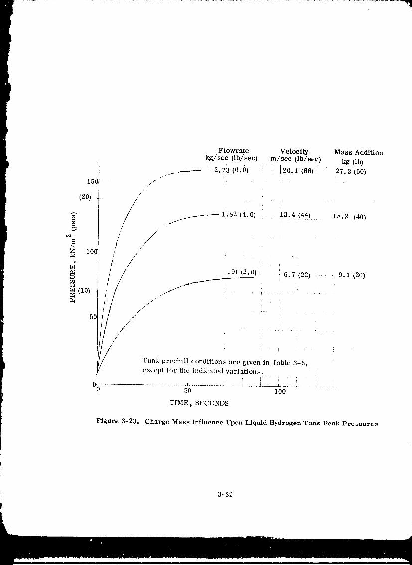
Flowrate Velocity Mass Addition
kg/sec (lb/sec) m/sec (lb/sec) kg (lb)
_------- 2.73 (6.0) i i 20.1 (86)_ 27.3 (60)
150 /I :J
(20) /,/' ........
/ • ..................... 18.2 (40)"_ /11__-------- 1 82 (4.0) 13.4 (44)/¢a / / . !
Z I0_ /' /,
/ // .9J (2.0) 6.7 (22) ..... 9.1 (20)
m /(lO)
5{ r/
J i ' ' i :Tank prechill conditions are given in Table 3-6,except for the indicated variations.
I _ I" i ' _, '00 ._ ............. _ , _ .... !50 I00
'rIME) SECONDS
Figure 3-23. Charge Mass Influence Upon Liquid Hydrogen Tank Peak Pressures
3-32
1980009811-065
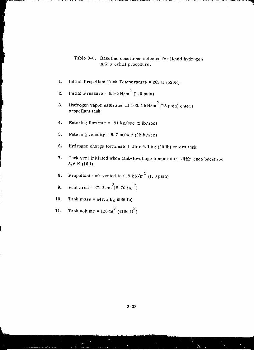
Table 3-6. Baseline conditions selected for liquid hydrogen
tank prechill procedure.
1. Initial Propellant Tank Ten_perature = 289 K (520R)
o2. Initial Pressure = 6.9 kN/m" (1.0 psia)
o3. Hydrogen vapor saturated at 103.4 kN/m" (15 psia) enters
propellant tank
4. Entering flowrate =. 91 kg/sec (2 lb/sec)
5. Entering velocity = 6.7 ha�see (22 ft/sec)
6. Hydrogen charge tel_ninated after 9.1 kg (20 ]b) enters tank
7. Tank vent initiated when tank-to--ul!age temperature difference becomes
5.6 K (10R)
8. Propellant tank vented to 6.9 kN/m 2 (1.0 psia)
'. 29. Vent area = 37.2 cm2(5.76 in. )
10. Tank mass = 447.2 kg (986 lb)
3 311. Tank volume = 116 m (4100 ft )
3-33
1980009811-066
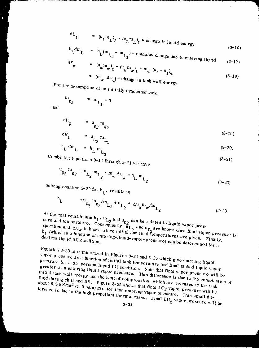
dE L = (UL'ml)2 - (ULmL) 1 = change inliquidenergy (3-16)
hLdm L = hL(mL2 roLl ) = enthalpy change due to entering liquid (3-17)
dE = - - - (3-18)w (Uwmw)2 (Uwmw)l mw (u2 Ul)w
= (m AUv) = change in tank wall energyw
For the assumption of an initially evacuated tank
m = roLl=0gl
and
1
dE = u m (3-19)g g2 g2
dl.:L = UL2 mL2 (3-20)
hLdm L = h LmL2 (3-21)
Co__hining Equations 3-14 through 3-21 we have
Ug2mg2 _ uL2mL2+mwAUw=hLmL2 (3-22)
Solving equation 3-22 for h L, results in
hL =u m /In +UL2+ AUm /mL2 (3-23)g2 62 _2 w w
At thermal equilibrium h L, UL2 and Ug2 can be related to liquid vapor pres-sure and temperature Consequently, u L and u,, are known once final vapor pressure is
• O t_
specified and Au w ts known since m_tial and hnal _e...... mperatures are given. Finally,
hL (which is a function of entering-liquid-vapor-pressure) can be determined for adesired liquid fill condition.
Equation3-23 is summarized inFigures 3-24 and 3-25 which giveenteringliquid
vapor pressure as a function of ilfitial tank temperature and final tanked liquid vapor
pressure for a 95 percent liquid fill condition. Note that final vapor pressure willgreater than entering liquid vapor pressure. This difference is due to the combinatit_n of
initial tank wall enerk-_ and the heat of compression, which are released to the tm_k
fluid du,'ing chill and fill. Figure 3-25 shows that final LO 2 vapor pressure will beabout 6.9 kN/m 2 (1.0 psia) greater than entering vapor pressure. This small dif-
ference is due to the high propellant thermal mass. Yinal LH 2 vapor prcs._urc will by
3-34
1980009811-0
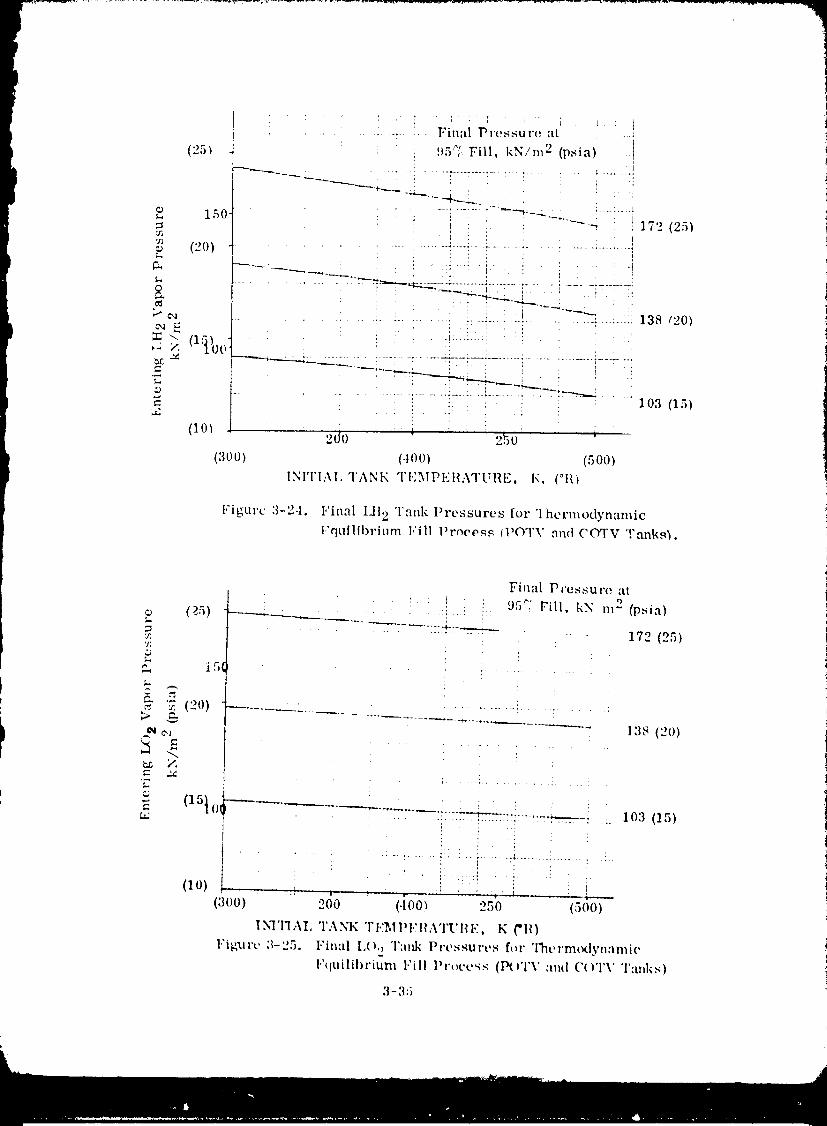
It
1980009811-068
about 20.7 kN/m 2 (3.0 psia) greater thai entering wlpor pressure, as indicated by
Figure 3-24. All _,f the above is based upon the assumption that near-thc,aTml eq, 7;-
brium conditions will exist during tank fill, as will be discussed below.
3.3.3.1 Tank refill (autogenous). Refill of a propellant tank containing liquid and its
own vapor as a pressurant is a straightforward operation Liquid must be introdueect
at the correct vapor pressure, and fluid inflow conditions must be sufficiently high to
assure near-thermcKtyn'tmie equilibrium conditions during fill. An evaluation will be
made of the re,ationship between initial and final tank fired conditions, and cqterir_g
liquid vapor pressure for a ihelznal equilibrium process. The inlet wtpor pressur,,, is
determined on the basis of the following First Law analysis
dE ,_dE = hdm (3-24)L g
dE L = (ULmL) 2 - (_,LmL)I = change in liquid energy (3-25)
dE = - = change in vapor energy (3-26)g (Ugmg)2 (Ugmg) 1
hdm = h (roT2 - mT1) = total energy of entering liquid (3-27)
m = m + mT L g
The following equalities result from the assumptions of phase equilibrium and initial
liquid temperature equals final liquicl temperature: ,u. 9 = t'L" = UL and u 9 = ug 1= Ug. Combining these conditions with Equations 3-24bfhroug_ 3-27 results in
uI, (ml, 2- ml,1) + u - h - (3-28)g (rag2 mg 1) = (roT2 mTl_'
Now, total mass within the tank can be expressed as
mT=VT PL- (a-1)m (3-29)g
and
- -mg 2) (3- 30)MT2 roT1 =(c_- 1) (rag 1
whe re
m T = m L+m =totalmass of fluid in tankg
PI, -- liquid density
pg = vapor density
a -- _L/Pg3-36
1980009811-069
Combining Equations 3-28 through 3-30 we find that
uL (mL2- mL1 ) + u - = h (a- 1) - (3-31)g (rag2 rob1) (ragI mg 2)
Also, by addingand subtractingULmg I and ULmg 2 to theleftsideof Equation3-31
uL (roT2- roT1 ) + u - = h (_- 1) - (3-32)ev (rag2 rag1) (rag1 rag2)
where
Uev = (Ug - UL) = internal energy of evaporation
Combining Equations 3-30 and 3-32
u L (c_- 1) (rag 1 - rag2) + Uev (rag2 - rag1) = h ( '×- 1) (rag2 - mgl) (3-33)
Solving for the entering liquid enthalpy,
h = u L- uev/(a- 1) (3-34)
Results are plotted in Figure 3-26 showing liquid hydrogen tank final vapor pressure as
a function of incoming liquid vapor pressure. It is interesting to note that this vapor
pressure relationship is independent of initial propellant load at the start of refill.
Furthermore, although Equation 3-34 was developed for an initial thermal equilibrium
condition, results are also applicable to an initially superheated ullage.
The above results ih ,icate that refill can be simplified because the same entering
liquid vapor pressure will be required regardless of initial fill conditioa and ullage
temperature. Figure 3--26 indicates that final tank pressure will be approximately27.6 kN/m 2 (4 psi_) higher than entering liquid vapor pressure.
The thermal equilibrium processes described above have demonstrated that tank fill
(and refill) can be performed without having to vent. This is an important conclusion
because selective vapor venting will not be possible once tank fill is initiated. Liquid
venting must be avoided because the propellant loss and resulting disturbing torques
could be unacceptably high. Consequently, it is mandatnry that the refueling
process be perfolzned with a closed tank. The next step is to analytically describe the
tank fill process in order to assess the influence of such key variables as entering
flowrate and velocity upon thermal equilibrium. If thermal equilibrium conditions
can be readily achieved _or a reasonable range propellant flowrates and velocities,
theJ. orbital refueling, without venting, will be possible.
3.3.3.2 Tank fill analysis. The intent of the tank fill process will be to create
turbulent conditions within the tank. These conditions will be achieved by introducing
3-37
l
1980009811-070
.... ! ,I
(o,}).. = :i
O i4 0
< / Notes:> _-.
._ / 1. Thernlodynanlic equilibrium conditions:/, _ / : exist {turillg refill.
_cq< "_ / 2. l)ata is applicable to any 8i;'e lank andff (181 ,' to any initial liquid fill volume.
_;/' 120 / i I ',' i '0-_ / t
/ , i
100 _ii i(1.t) ............. , .............. ,-.._,...................... ,.__ : ,
'10) £0 (14)10(} 120 (18) oVAI}OI_ 1}III,:SS1]RI.: Ol,' I,:NTI.:i_IN{; 1,IQUID, kN/w" {psia)
I.'igure 3-26. Entering 1,iquid llydrogen Vapor Pressure llt,quit-ed to
M:liniain a Constant Vat×_,r l}ressure in Tank I}uring Fill
liquid into lilt' lanl< ill high veh}cilies (and perhaps ihr{algh :1 spraly nozzle) it} I}r{_vid{,
lilt' high he'lt-lraulsfer rales needed it} :lilain nt, ar-iht rmal equilibriunl. As lank-fill
e{}ntintle,'-;, lilt' inlernal i:lnk fluid envil'ollllaenl changes from liqllid droldels in lilt'
ullage voluzlze h} Vllpor bllbbh, s entrained wilhin a liquid bulk. It is expel'led lh,ii lhc
transilioll frolll IIt';ll l l'allsfer {h}lllillltle{I by liquid {tPoplels It} heat I I'llnsf{'r {l{}Illinlilcd
by vapor bul}bles will occur in tile range of .1{}'7:to {;0% liquid fill. The mechanism {}f
liquid spray in a vapor cnvir{mznenl will ehlmge Io that of vapor bul}l}h, enll'ainlllt, lll
and disl}ers:ll , within lhe lhluid volumt,. This meeh:tnislai willbe Illt, d{m_in:lnl m{}{te
of heal and mass exchange through{}u! much {}f the hmk fill process, and is lhe only
nlt, chanisnl that will influence t:u& pressures toward file c{naq}It, lion of lank-fill.
'Pile basis fl}r any fill t}roeess is lhal sufficient fluid motion created within a pr,q}elhul!
lanli will lllainlain near Iht, rlual equilibriunl. As t,quilibriull_ is al}pr{}itched, the prcs-
s_l re diffe I'ellt't' ( A I}) l}elwecn llml< pres,m re and liquid vlq}{w pl-t,ssl.i l'e will :lt}l}roach
zt, ro, and absolutt, laid< l}ressures {luring fill will al}l}rollch a minilnul]l. '1'{}aid in
{tescril}ing Ill{' I}ht,n{}l]_cna lhat apt, eXl}t,cl{,d 1{}occur, lank fill t,Xl}t, rilnt, lfl rt,sull:_ art'
1WI}otht, sizt'{t and given in l.'igllr{, 3-27. The figl_re ilh_slrales lw{} ilnp{}rll|lfl i}{}inls:
First, tank A p I}t,{'{mlt,s Sl_lllli{'_ :t,'_ t'l_wrlli{' for II given illnk {,,mfil!.l_r:tli{m is incrt,as-
eft. This is t,Xl},,t,lt,tl, I}t,t,alust, lit,ill t, ,lllsf{,l" {'{_t'ffit',t'nls will ill{'l't,:lse :1,,-;I'],_wr:ll{'
3-38
1980009811-071
...................................... incl'e:tst, s. &,cond, therc is n fill flow-
er ,! SlAI_I_. _lii. _ l';llt' :ibOVt' WlliCh VIIl'ill(iOIIS ill AI ) bt, t'olllt'
{ ii_sl_uific;inI bet:lust, fluid :il2/iI:lliou h{Isbt, t, ll iIwl't,:ist, d lo :l lt, x,t,l Wkt'l't' 110:11"
I lllS_SAt lhollllodyn;lllli(' t'qtlilibl'itllll :lll't'lldY t'xisls.
_lllq&110N. Tht, ob.iectivc of lhi,'; analysis will bt" to
_r**,_ ",_k,,_...._ identify fluid inflow t):lralllt, tcrs Ihat will
i " _ [ l>,'<widt,,lt,:i,'-t,quilib,'iui,,c<,,lditi<,,,sdu,*ingfill.
............ 1
illil£tlililNittitt .... t* Fill _l,_tt'l for 1,it tlUi.d Spl':lV l)olllill'lllt't'.
1,'ig_.lrc &-27. l'h,wralc influcnt'e,_ l,lnk 1)uring the eal'ly phases of lank fill, ue'ir-
llrt,,_sui'c duriil_" fill. lhel'lll;il equilibl'iulll condition,_ will bt,
acilit, vt, d by illl i'l_hlt'in_ liquid inl,_ lhl,
lll'otltqlailI tallkS through ._t_i':i) • liO_',zh,,_. Tht' rt,.quli!n_ ,_t_i':i) • will ci't':llt, "i llii'l_t' liquid-
vapor ._ul'f;ico. The colltbillaliou of lai'_t, stit'f;it'o al'Oa alttt hi_i_ tli'ot_lt'1%;t,h_oily will
iwovittt, lilt' high ht,;il l l;lll,_ft'i' raI_,.,4 ut, t,dt,d Io :lll;liil Ilt,;ll_-t'qtiilibl'itilll t'olldilions.
I
i (]t'llt, l':ll |)yll;illlit's dt'vch_t_cd ;I t'Olll}lilit'l" 1_1"o_1".'1111(ItYI'II I,]S) on III..\D fillltts thai des-
t'ribt, s lilt, lht, i'llll_ik'll:llllic :llllt fluid lilt'oh:lilt\' |_ht, nolllt, ll_i ot'OUl'l'illl_ dlll'illl_ lilt' t"lYk'
phase of ;I I't't't, ivt'l" l:illk fill tll'ot't'ss. This tank fill i_l'O{'_'l';llil WilS tist,d to tll't'ltit't l]uid i
Ill/ill,lilt'lilt'ill syslt'lll fill lli't'._sl;i'_"J dui'int{ _1lll't'vitlil,_ sillily, l"illinQ; of OlbilM l"luid
<_l_lll_l_'lllt'lll S%'._lt'llls, I_t'ft't'Cltt't' 3-3. _'tibl'oUlillt' 1)11()! >, of I_l'Ot_l';illl llYPIII.'S, whit'h
dt','_cvibt',<4 iht' lill:l_•t'-sl_i';iy dl'Otllt'( intt'l'llt'Iioil i._ 12/ivt,!l ill :\l_t_oudix C of Ilia( i/efc'L'cnct'.
Tkt, cqu',ltion,_ coi_l:lint'd ii_ lilis ._libl'olilillt, iildit':llt' lh:lI dl'ol_lcl tti;lll/t'It'l', spi"ly vt'lot'ily
:lill| lll:ls_ l'lowl",llt" lll:ly h:lvt' [I ll_:l,iov ill|'hlt'llt'c lll_t_Âl l_l'ot_t'll',llll l_lill_ t_l't'_tll't's dtll'{ilt_
the o:lrly ._l:ll>_o,_ of lilt' i'ofliellin_ ot_oralion. ('oil._oqtlt, illly, ,'i ,_el'it',_ of t'oll/t_litor llins
W0l't, lll.lde witll ll'fl_lll,:_ to evalllale illl',_t' vai-iillllo._ lind to :i._._os,_ wlleliler 'iot't'l_t:li_l)"
low liquid hYtt l'tlr.l,, 'll l:lllk pi'O._,_lil'O._ woultt lit, lll3illl_lillt,d. 'l'ho_l' I'O,_tlll_,4 "ll'l, ._llilllll;ll'iZOd
in l.'i_ul'e 3-2,_4 and :I-"9.
1,'t[4lll't' ,1-.._ shows lilt, ill['ltlt'llt'O Of dvopicl di_llllt'il'l" Up,_ll l:lllk I_i't'sstli't ' dlll'in!( lilt' lhluid
,_l_l':iy itolllin:lnco t_t,l'iott. "I'll\, I':iil_t' of dl'ol)h'l ..4i7x,,.4t'oll_idt'l't, tl int'hlltt, siT.t's lh:ll
._llouht bc l_i't'st'lil Ihlriil_ ;ill ;l('lli_ll l'cflicllin._ ot_Oi';ilioll. Ilowtwcv, lilt' fil(lii't' indic;lies
lh:it drolqet <ti;illlt,{t,l" will llot havt' _i lll:i.iOl' illt'hlt,llCt, oil t'lllk l_i'l'SSill't ,, 'l'llll,_, iti
_lpllt,.'li'S lh;il di'_plt'l di_illlt, ll,l'S Olll,_iltt' lilt' iilltit'alt,d i'_iill_t' will have "1 lllillilll31 illltl_lt'l
tliloil I't'ftlt'[liil_ opt' i'_lliOll,_,
l"igtll'e 3-29 14"ivcs lhc influt'nct, of liquid st_l'ily w_iumt' upou hyttl'ot_t,n l'lnk fill pl'e._-
sul't,s. An inpiil Io IIYi_ilIqS includes ;I v:il'i_lble (c:llh'd l_,.\t'l{) which idt, ulil'ic,_ lilt'
vohilllt, of liquid in dl'oplt, t form lh'il will t'xt'hall._t' t'nt'l'l_" wilh lht, ull;il_c, Sleet'trio;lily,
I>At'K t,_ tht, vohilllc i':liio <if liquid to tlll'il4't', and tili,_ It'i'lll is nuiltil4ied by Ill|a!(\'
vohllllt' lo _41l;iillt,iI lolal lhluid dl'otlh, l spray vohilllt,. 1.'i_tli't' 3-:29 ilidit'ilit,._ thai Ihis
3-'19
1980009811-072
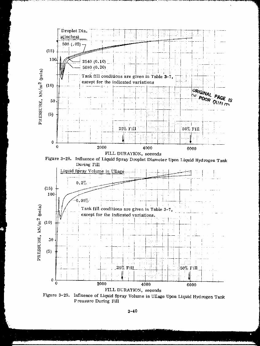
1980009811-073
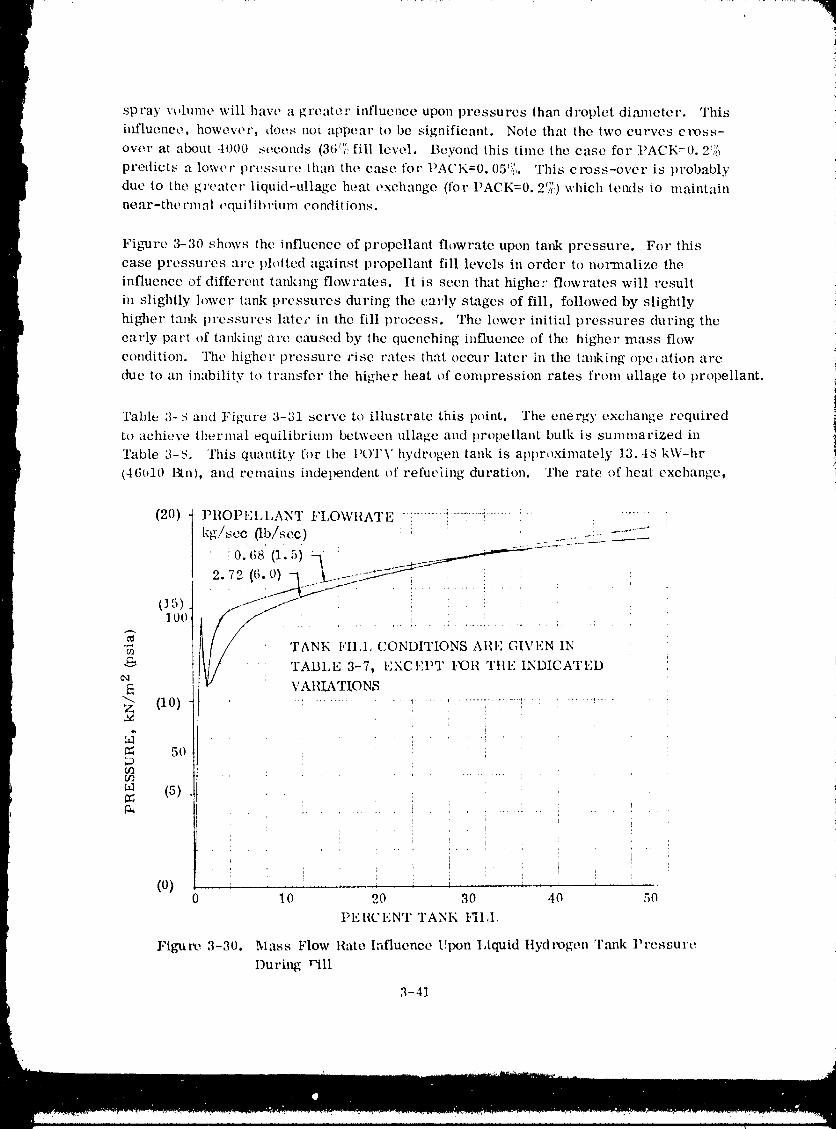
spray \'_,lume will have a greater influence upon pressures than droplet diameter. This
itffluenee, however, does not appear to be significant. Note that the two curves cross-
over at almut 401)0 seconds (36C;, fill leve,1. Beyond this time the ease for PACI,:=0. ,.°"'_;0
predicts a lower pressure than the ease for PACK=0.05_i[,. This cross-over is probably
due to the greater liquid-ullage heat exchange (for I'ACK=0.._/_,I which tends to maintain
near-the, rm al oquilil)rium eondit ions.
Figure 3-30 shows the influence of propellant flowrate upon tank pressure. For this
case pressures are plotted against propellant fill levels in order to normalize the
influence of different tal&mg flowrates. It is seen that higher flowrates will result
in slightly lower tank pressures during the early stages of fill, followed by slightly
higher tank pressures late," in the fill process. The lower initial pressures during the
early part of tainting are caused by the quenching influence of the higher mass flow
condition. The higher pressure rise rates that occur later in the tanking ope,ation are
(h_e to an inability to transfe.r the higher heat of compression rates from ullage to propellant.
Table 3-8 and Figure 3-31 serve to illustrate this point. The energy exchange required
to achieve thermal equilibrium between ullage and propellant bulk is summarized in
'rabte a-8. This quantity for the I'(.)TV hydrogen tank is approximately 13.4S kW-hr
(46u10 l_n), and remains independent of refueling duration. The rate of heat exchange,
(20) PliOPt_:LLANT FLOWIIATE } ....... i'........ _......... : .... ! +....kg/sec 0b/see) ! ........ :..... ' .....
• i0.(;S' (1.5) a : ..--_':----
(15) j_, , : . L
_. 100
•_ 'rANK I,'IIA, CONDITIONS ARE GIVEN IN
"_ _// TABLE 3-7, EXCFlm.' I,_31/ TIlE INDICATED
VAIILa, TIONS(10) : ....... ' .................... ' _ .......
: i
50
0fl .. : .............. : •
_a (5) _ :
t
: i "l
(0) :.... i ! _ 1 t0 10 20 30 40 50
PEI{CENT TANK FII,I,
Figure 3-30. Mass Flow Rate Influence Upon I,iquid ttydrogen Tank ])re,q£Ul'O
During Pill
.%,11
1980009811-074
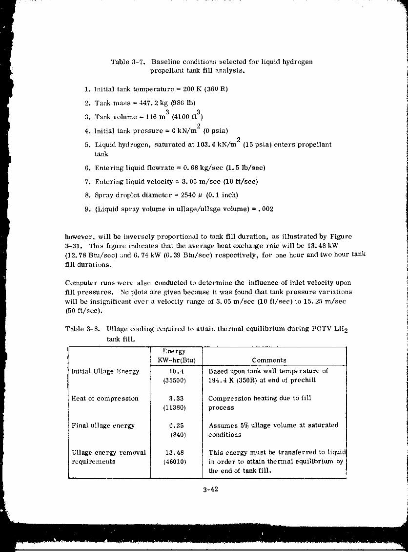
Table 3-7. Baseline condition,'_ selected for liquid hydrogenpropellant tank fill analysis.
1. Initial tank temperature = 200 K (360 R)
2. Tal& mass = 447.2 kg (986 lb)
3 ft3 )3. Tank w)lume = 116 m (4100
4. Initial tank pressure = 0 kN/m 2 (0 psia)
5. Liquid hydrogen, saturated at 103.4 kN/m 2 (15 psia) enters propellanttank
6. Enteling liquid flowrate = 0.68 kg/sec (1.5 Ib/sec)
7, Entering liquid velocity = 3.05 m/scc (10 ft/sec)
8. Spray droplet diameter = 2540 p (0.1 inch)
9. (Liquid spray volume in ullage/ullage volume) =. 002
however, will be inversely proportional to tank fill duration, as illustrated by Figure
3-31. This figure indicates that the average heat exchange rate will be 13.48 kW
(12.78 Btu/sec) ,rid 6.74 kW (6.39 Btu/sec) respectively, for one hour and two hour tankfill durations.
Computer tuns were also conducted to determine the influence of inlet velocity upon
fill pressures. No plots are given because it was found that tank pressure variations
will bc insiguificant over a velocity rm_ge of 3.05 m/sec (10 fi/sec) to 15, 25 m/sec
(50 ft/scc).
Table 3-8. Ullage cooling required to attain thermal equilibrium during POTV LH 2
tank fill.
Energy
KW-hr(Btu) Comments
Initial Ullage Energy 10.4 Based upon tank wall temperature of
(35500) 194.4 K (350R) at end of prechill
Heat of compression 3.33 Compression heating due to fill
(11380) process
Final ullage energy 0.25 Assumes 5% ullage volume at saturated
(840) conditions
Ullage energy removal 13.48 This energy must be transferred to liquid
requirements (46010) in order to attain thermal equilibrium bythe end of tank fill.
3-42 !
1980009811-075
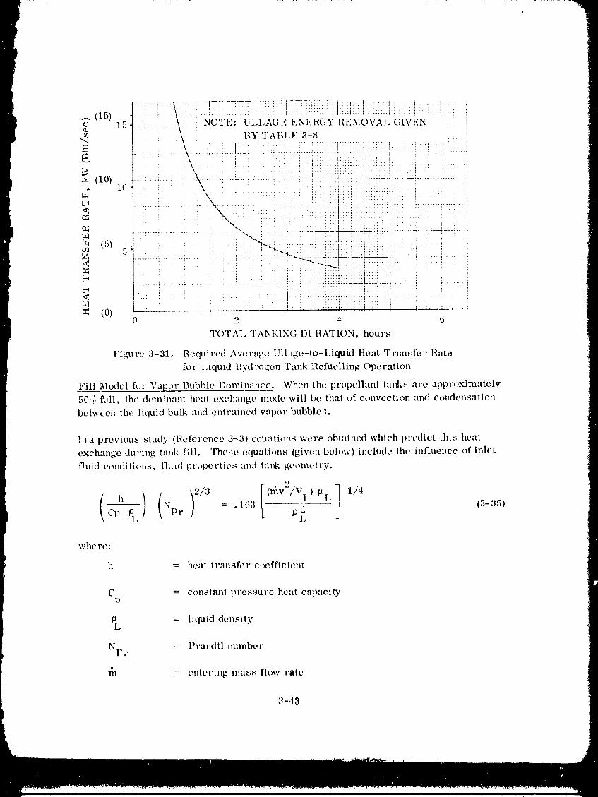
. i : • I ' ' . .'.:' "I.,:,: ......................
(15) ' \: N0:l'i:'£UL,iXG,:2i.iNi.:i_G_:iii.li;i:_SVAi.G_VE.:No 15 .
, ---m BY 'I'ABI.I'] 3-8
_ : I i : ;:::::: t:: "'::ti _ ', I.. ' L ' ' L ' '
(10) ............... :- : . , .! ,:.: . ,".............
ar to \ : , : ! ! ..... ,
a_ (5) _ . .. • -I " "_:i7_!i:iL::iii:i! !
' t : '":::: I 'i ............ i ........ [
< _.... :..... i :::l"::'"' : : .....
(0) 0 2 4 6
TOTAL TANKING DURATION, hours
Figure 3-31. Uequired Aver,_e Ullage-to-Liquid Heat Transfer Rate
for 1.iquid Hyd rogen Tank Refuelling Operation
Fill Model for Vapor Bubble Dominmme. When the propellant tanks are approximately
50('(', full. the d()minant heal exchange mode will be that of convection and condensation
between the liquid bulk and entrained val)or bubbles.
In a previous study (Reference 3-31 equations were obtained which predict this heat
exchange during tank fill. These equations (given below) include the influence of inlet
fluid conditions, fired properties and tank geometry.
_ *)
( )( 1,4h Np r = . 11;3 ,) (3-35)cp q, of_
whe re:
h = heat transfer e¢_ffieient
C = constanl pressure,heat capacityP
OL = liquid density
NI.,, = Prandtl number
= entering mass flow rate
3-43
n m
1980009811-076
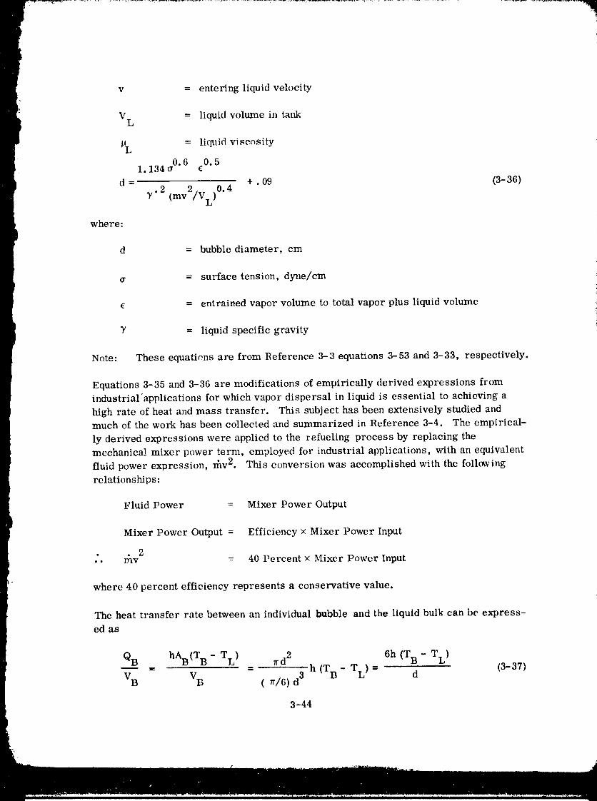
v = entering liquid velocity
VL = liquid volume in tank
_li. = liquid viscosity
1. 134 frO,6 EO.5
d = +. 09 (3-36)2 0.4
y. 2 (mv /V L)
where:
d = bubble diameter, cm
a = surface tension, dyne/cm
e = entrained vapor volume to total vapor plus liquid volume
_' = liquid specific gravity
Note: These equatiens are from Reference 3-3 equations 3-53 and 3-33, respectively•
Equations 3-35 and 3-36 are modifications of empirically derived expressions fromindustrial applications for which vapor dispersal in liquid is essential to achieving a
high rate of heat and mass transfer. This subject has been extensively studied andmuch of the work has been collected and summarized in Reference 3-4. The empirical-
ly derived expressions were applied to the refueling process by replacing the
mechanical mixer power term, employed for industrial applications, with an equivalent
fluid power expression, rhv 2. This conversion was accomplished with the followingrelationships:
Fluid Power = Mixer Power Output
Mixer Power Output = Efficiency × Mixer Power Input
• 2• • _lv = 40 Percent × Mixer Power Input
where 40 percent efficiency represents a conservative value.
The heat transfer rate between an individual bubble and the liquid bulk can be express-
ed as
QB hAB(T B - TL) _d 2 6h (T B - T L)
VB VB (_/6) d3 h (T B TL) d (3-37)
3-44
1980009811-077
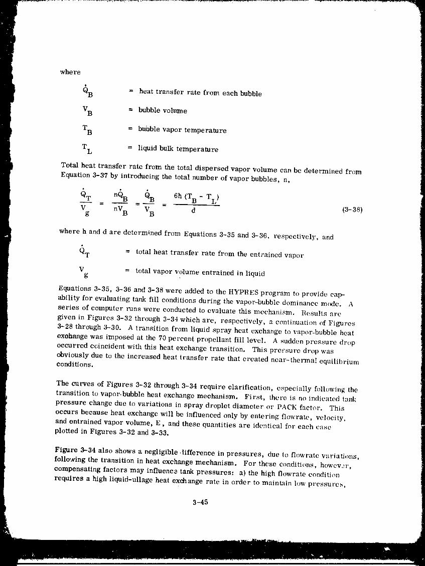
where
QB -- heat transfer rate from each bubble
VB = bubble volume
TB = bubble vapor temperature
T L = liquid bulk temperature
Total heat transfer rate from the total dispersed vapor volume can be determined from
Equation 3-37 by introducing the total number of vapor bubbles, n,
QT n(_B QB 6h (TB - TL)- - - (3-38)
V nVB VB dg
where h and d are determined from Equations 3-35 and 3-36. respectively, and
(_T = total heat transfer rate from the entrained vapor
V = total vapor volume entrained in liquidg
Equations 3-35, 3-36 and 3-38 were added to the HYPRES program to provide caw
ability for evaluath_g tank fill conditions during the vapor--bubble dominance mode. A
series of computer runs were conducted to evaluate this mechanism. Results are
given in Figures 3-32 through 3-34 which are, respectively, a continuation of Figures
3-28 through 3-30. A transition from liquid spray heat exchange to vapor-bubble heat
exohange was imposed at the 70 percent propellant fill level. A sudden pressure dropoccurred ccincident with this heat exchange transition. This prc_'sure drop was
obviously due to the increased heat transfer rate that created near-thermal equilibriumconditions.
The curves of Figures 3-32 through 3-34 require clarification, especially following the
transition to vapor-bubble heat exchange mechanism. First, there is no indicated tank
pressure change due to variations in spray droplet diameter or PACK factor. This
occurs because heat exchange will be influenced only by entering flowrate, velocity,
and entrained vapor volume, E, and these quantities are ideqtical for each case
plotted in Figures 3-32 and 3-33.
Figure 3-34 also shows a negligible 4ifference in pressures, due to flowratc w_riations,
following the transition in heat exchange mechanism. For these conditions, howew'r,
compensating factors may influence tank pressures: a) the high flowrate condition
req_res a high liquid-ullage heat exchange rate in order to maintain low pressure_,
3-45
1980009811-078
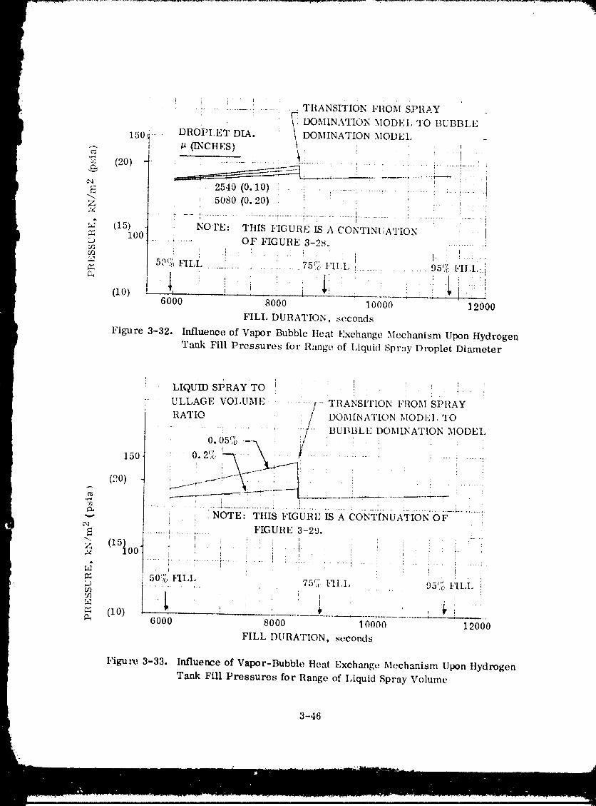
|It
i i i ' I i TtiANSITION FROM SPRAY
l 150 - . DROi_LET DIA. : DOMINATI N MOI)EL _ !
(20, _'-- .,--'7_.... : --.- - .... ': _ '? _ ..;_' I{ _:C',I , I :
a .... 2540 (0,10) . - .; ... ..... : ...... ' " i " i....... !17-!
"-7. 50so (0.20) _ _ : i ': i: : r ' !i i
_,_ (15{o0- NOrE: TttIS FIGURE IS A CONTINUATION ;, i=3 ..... + .... OF FIGURE 3-28. :.........
m : ,.: • , .. ,50'" _ t JI ' ' ' .... Im ,V FILL _ _ ... 75% FII , , : 95% I,'ILI,:...... _ .... ..... b
; i
I (i0) ,, i i i ,-,i ' ; :,._. , I6000 8000 10000 1 2000
FILL DURATION, seconds
t Figure 3-32. Influence of Vapor Bubble tlcat Exchange Mechanism Upon HydrogenTank Fill Pressures for Range of IAquid Spray Droplet Dimneter
i
LIQUID SPRAY TO
ULLAGE VOI,UMF ...... I- TRANSITION FROM SPRAY/ oo U A'r oN ODm.TO
........... /'" BUBBLE DOMINATION MODEl,
o.osro-,, /• " 0.2% ""_-" _j_....lP--" : .................... : ...... :150
(.'!.0) ' ---'_-:" • ...... : • : ........
"_ ........... 2 ............. _...................................................¢_ NOTE: TtlIS I,'IGURI" IS A CONTINUATION OF
¢,a FIGURE 3-29,
. , , . .00 r.t
_._ . .P = 50% 15II,L 75'J;. FII,1, 95% 1,'II,I_L- _3 ........... /"
rJl52
(10) ' ' ;¢" 6000 8000 10000 12000
FILL DURATION, seconds
Figure 3-33. Influence of Vapor-Bubble tleat Exchange Mechanism Upon IlydrogenTank Fill Pressures for Range of Liquid Spray Volume
t 3-46
1980009811-079
' _ ! ! ! ! i i ! • iPI.{OI )EI,I,ANT , _ : ' il :: :. _: : ; :
I"LOW [Ia'l' E f/'----i i..... 150 kg/sec 0b/see) TRANSITION I,'llOM SPRAY .DOMINATION MODEl, TO i--7¢ •
2. 2 (6.0) -'_ ..I----_ BUBBI_E DOMINATION MODEI i
.... _ ....... t • : ................. : .... .-.
.... :........... i ............... i...... ; I.A..... ........_........ i :. ! t:NOTE: TtIIS I,IGUI1E IS A CONTINUATION , i !
OI,' FIGUIIE 3-30 .... i ........ i.i I ' r,'15_ _ i : I
r._ ............. : ...... ! ................... _ .......... ;-M
i. . : . i ;
(10) i : : : _ _ : [ i ,i, i r !50 60 70 80 90 100
PEIICENT TANK FILL
Figure 3-34. Influence of Vapor Bubble tteat Exchange Mechanism Upon
tlydrogen Tar& Fill Pressures for Rangc. o[ Tanking Flow Rates
and b) the high flowrate condition creates a high heat transfer coefficient, which
se_-ves to maintain low presstlreq. The negligible difference in tanking pr _sure
indicates tlkat the above factors were, in fact, compensating, or that the heat exchange
mechanism is sufficient to assure near-thermal equilibrium e_mditions. The latter
condition is a more likely possibility.
Results of this analysis supports the assertion, stated earlier, that heat and mass
exchange due to vapor bubble entrainment and dispersal within the liquid volumt, will
dominate. More importaht ix the likeliht)od that this is the only mechanism that
will influence tank pressure towards the completion ()f tank fill. Furthermore, it
appears that he'tt and mass exeh:mge rates will be _)f such a high magnitude that near-
thermal equilibrium conditions will be maintained over a broad range _)f entering
liquid flowrates :rod vch)eities. This ix a significant conclusion ])t'eause the thermal
equilibrium parametric data of Figxtres 3-24 through 3-2(; can be employed t()predict
tank pressure conditions at fill (or refill) c(mq)letion.
3.3.3.3 .Supply tank influence. All analyses to date have been based on the
assumption that propellant enters the receiver tank at a constant temperature. This
temperature corresponds to,'tvapor pressure of 103.4kN/m 2 (15 osia), in fact,
entering liquid wtpor pressure (and tempt, rature) will wiry through_)ut the refueling
process because ()f the ,_upply tank pressurization rneth(_(l, llelim,i i)ressurizati_)n of the
supply tank during propellant transfer was selected because it appe:trs t,) have fewer
complications than other apt)roaches.
3-4"/
1980009811-080
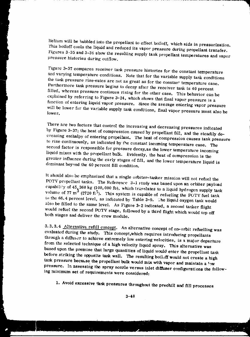
ttelium will be bubbled into the propellant to effect, boiloff, which aids in pressurization.This boiloff cools the liquld and reduced its vapor pressure during propellant transfer.
Figures 3-35 and 3-36 show the resulting supply tank propellant temperatures and vapor
pressure histories during outflow.
Figure 3-37 compares receiver tank pressure histories for the constant temperature
and varying temperature conditions. Note that for the variable supply tank conditionsthe tank pressure rise--rates are not as great as for the constan _ temperature case.
Furthermore tank pressure begins to decay after the receiver tank is 40 percent
filled, whereas pressure continues rising for the other case. This behavior can be
explained by referring to Figure 3-24, which shows that final vapor pressure is a
function of entering liquid vapor pressure. Since the average entering vapor pressure
will be lower for the variable supply tank conditions, final vapor pressure must also belower.
There are two factors that control the increasing and decreasing pressures indicated
by Figure 3-37; the heat of compression caused by propellant fill, and the steadily de-
creasing enthalpy of entering propellant. The heat of compression causes tank pressureto rise continuously, as indicated by the constant incoming temperature case. The
second factor is responsible for pressure decay, as the lower temperature incoming
liquid mixes with the propellant bulk. Evidently, the heat of compression is the
greater influence during the early stages of fill, and the lower temperature liquid is
dominant beyond the 40 percent fill condition.
It should also be emphasized that a single orbiter-tanker mission will not refuel the
POTV propellant tanks. The Reference 3-1 _tudy was based upon an orbiter payload
capability of 45,360 kg (100,000 lb), which translates to a liquid hydrogen supply tank
volume of 77 m 3 (2720 ft3). This system is capable of refueling the POTV fuel tankto the 66.4 percent level, as indicated by Table 3-9. ;he liquid oxygen tank would
also be filled to the same level. As Figure 3-2 indicated, a second tanker flight
would refuel the second POTV stage, followed by a third flight which would top off
both stages and deliver the crew module.
3.3.3, 4 Alternative refill concept. An alternative concept of on-orbit refuelling was
evaluated during the study. This concept,which requires introducing propellants
through a diffuser to achieve extremely low entering velocities, is a major departure
from the selected technique of a high velocity liquid spray. This alternative was
based upon the premise that large quantities of liquid would enter the propellant tank
before striking the opposite tank wall, The resulting boiloff would not create a high
tank pressure because the propellant bulk would mix with vapor and maintain a lowpressure. In assessing the spray nozzle versus inlet diffuser configurations the follow-
ing minimum set of requirements were considered:
1. Avoid excessive tank pressures throughout the prechlll and fill processes
3-48
1980009811-081
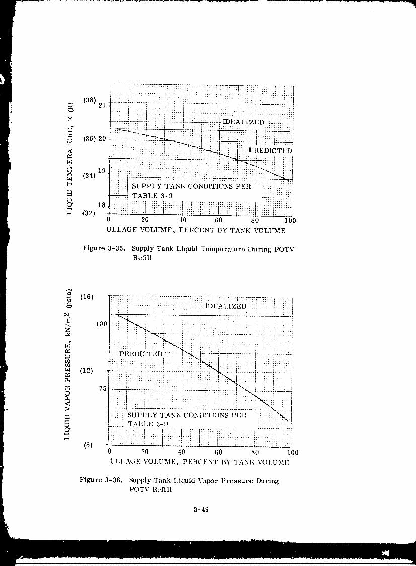
(38) :::: i : ;_:L: ::_::_: :i:_.::_:t :_:: " :::::::i:::::::::
• :: ':I: : : I : ' i " l: ::' : ' :: t .....
: :: i ' +'"_ : : ::!:;: ; ': " .... ::::::::::::::::::::::::::: :::::::::::::::::::::
< - :!! !:!iiii ::i::-:i:i!:: :::_!i-.ii PREDICTED
19 :::iiiiit:::!iii:i:i:i!!:!!:i!i!i_/ii:i: i!i :i
_ sui>t,LYTA_ co_,mo_s ,,_:R i!i:::illi;iiiilt!!ii!!, TABLE 3-9
18 i::! _i i_i _;!i}ili!!_!;!iii:!iii}=_ii!_ii_ !!ii_ii_ti i _t :_ii} il i:!iiIiiiiiiiii
0 20 -I0 60 80 i00
ULLAGE VOLU'ME, ]_ERCENT BY TANK VOLUME
Figure 3-35. Supply Tank Liquid Temperature During POTVRefill
Figure 3-36. Supply Tank I,iquid Vapor l)i'essure DuringPOTV Refill
3-49
1980009811-082
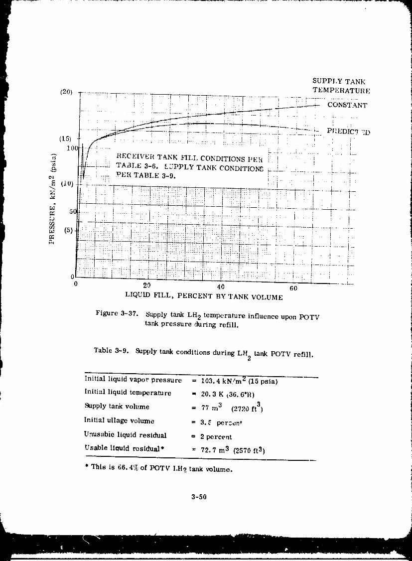
. SUPPLY TANK
i TEMPEIIATURE(20) "l , [ , I--17_7- :. i.:-,[-7.........i .....]---.:_-:.............'-t ' ' . . . , ..... lj_____' _._--_ CONSTANT
: : " I ' "
.........;,- - _----r-....=_ ....J.......:-:-?:-:"-?....k...............I
:o4t--/-!.... _ ................................,,,,It!7 :I{ECEIVER T&NK FILL CONDITIONS PER :
} ,,_ _i._ TABLE 3-6. LZPPLY TANK CONDITIONS :,--...................... i.......
[_ll'i:,,"!7 ::i-;..'.OEHTABLE 3-9+ :.......... , ....It0)-":- -.. _._.'_... ...... .-"._.. ....7. :.-.. , _--_'_+-+-+ ........ "_---" ......
.........._"':....: "i''l" : "'i--:"-'-":::'::r....... :'" . .
.............................. _............ ' ' r ' ' I i:-" '1: ; ':' ".+ ': ::i .';I ." ::' .i" ;::",'.:;',' : ;.:-;. ' ' '..: I I ' ;.-: .... :l...:+.:.-.! .... ,-: .... .:: ...... ::'..: .... :..:.;=:.I.-..:.'.;[..1::._-.i':-.:.I ...... ' .... 1 .. l . -.
(s) ::::i:.:::::l...:.::.:i:i]]::i::::_.:.:::W.:_:.:l::::..!:.._: i ! ' i ::i : 't::::i:::i::I:" :i::::r:::::::i:::::::.l:.ii:::4.:.::t:i::i_:.t_i:i::.I _! i i -:::::l::,:.....::::::::,.........::-.,,....:::::::::::::::::::::::::::::::...............::l:::::_:i:_:i:::l...._ :. :, _i' " ....I ::' ::, :I '::: ::I: ' l ' :', ;: , .l i:': I :: ' • .I" _ ' _:: ' { ' i ' I
" ::"I . I.. I ' ; :" :I::.:.l:.:.::.i'.'.' "::'' : " : ' i I , i::::::I:::::::::::::::::::::::::::::::::::::::::::::::::::::::::::::::::::::::::::::::::,,:::..... :!:: : ,' : : I " ',: ' ' t ": " : ......... ,..... : " " ', " " I ' :, , i ..... I 'I I , I ......... i
0 20 40 60
LIQUID FILL, PERCENT BY 'rANK VOLUME
Figure 3-37. Supply tank LH 2 temperature influence upon POTV !tank pressure during refill, t
Table 3--9. Supply tank conditions during LH 2 tank POTV refill, i
l Initial liquid vapor pressure = 103.4 kN/m 2 (15 psia)
I Initial liquid temperature = 20.3 K t36.6"11)
' Supply tar& volume ffi 77 m 3 (2720 ft 3)
Initial ullage volume ffi3.._ perzcn*
Unusabie liquid residual = 2 percent
Usable llcmld residual* = 72.7 m 3 (2570 ft3)
* This is 66, 4_ of POTV I,H2 tank volume,
3-50
1980009811-083
:q
2. Minimize vent mass requirements
3. If venting is necessary, aw_id two-phase venting
With regard to the LO 2 tank, any tank _nlet configuration will bc satisfactory. Ventingwill not be required during prechill: therefore, t=wophase venting is not a pos-
sibility. The only question that may arise is that of excessive tank pressure during
the fill ,._ocess. It is obvious f,'om Figure 3-25 that moderately low pressure wil!
exist for near-thermal equilibrium condition_. But these conditions will occur only
if sufficient fluid turbulence is present to enhance heat and mass exchange between
the phases. Fluid turbulence is more likely to occur with a spray nozzle than with an
inlet diffuser, whose primary function is to introduce liquid into the tank at extremely
lo_, velocities. Tiros, a spray noz_,le inlet eo_figlaration would appear to best satisfy
the LO 2 tank fill requirements.
A spray nozzle inlet: config'aration for the Lit 2 tank will result in venting during the pre-
chill process, as indicated by Figure 3-19. This is so because the sp_ay velocity
conditions wi]l create a hig_i heat and mass exchange environment between hydrogen
vapor or liquid and the tank walls. However, two-phase venting will be avoided because
liquid will not be present ,:n the tank when venting is initiated Once tank fill is initiated,
the spray nozzles will create the turbulent fluid condilions that are beneficial to main-
taining low preszures during fill.
The affect of an inlet diffu3er upon hydrogen tank pi'essure during prechill is not quite
so clear. Ideally, a h,w velocitv diffxmer will allow large quantities of propellant to be
introduced into the tank befere the leading edge c,_ '_ lalt_e-<tiamcler jet impinges at the
opposite end of the tank. It has been hypothesized that _ large propellant mass will
serve to quench the pressurc-ri' e that occurs due tc liquid impingement upon the hotwalls. However, the propellant mass can only be effective if sufficic'nt heat exchange
occurs with the vapor. Such cor, ditions r._ay not exist because of the deliberately low velo-
city of entering liquid. Thus, it is poss.Tde that an inlet dlfff_scr colffiguration
may not be able to satisfy the conflicting requirements of both a low velocit'y, (to assure a
large propellant mass in the tank), and a high veh city(to provide effective quenching
by that liquid mass). Shcmld ,,er, ting be required because of insufficient heat exchange
between liquid and vapor, liqmd may be lost _werboard in the pr,_ccss.
Once tank _11 is initiated, the spray nozzle will be t)referable to an inlet diffuser bc_
cause of the ;Jrbulent condit'ons that will serve to maintain low pressure
The choice is betweer a spray I_ozzle, whieh will result in vontitlg during prechill, or
an inlet dlfluser, which may l_ot req, firc venting, but should it occur, could result in
liquid lest overboard. The spray nc,zzlc configuratiou was selected because prech_ll
losses with *.his concept will bc insignificant compared to other losses (Table 3-5).
3-51
1980009811-084
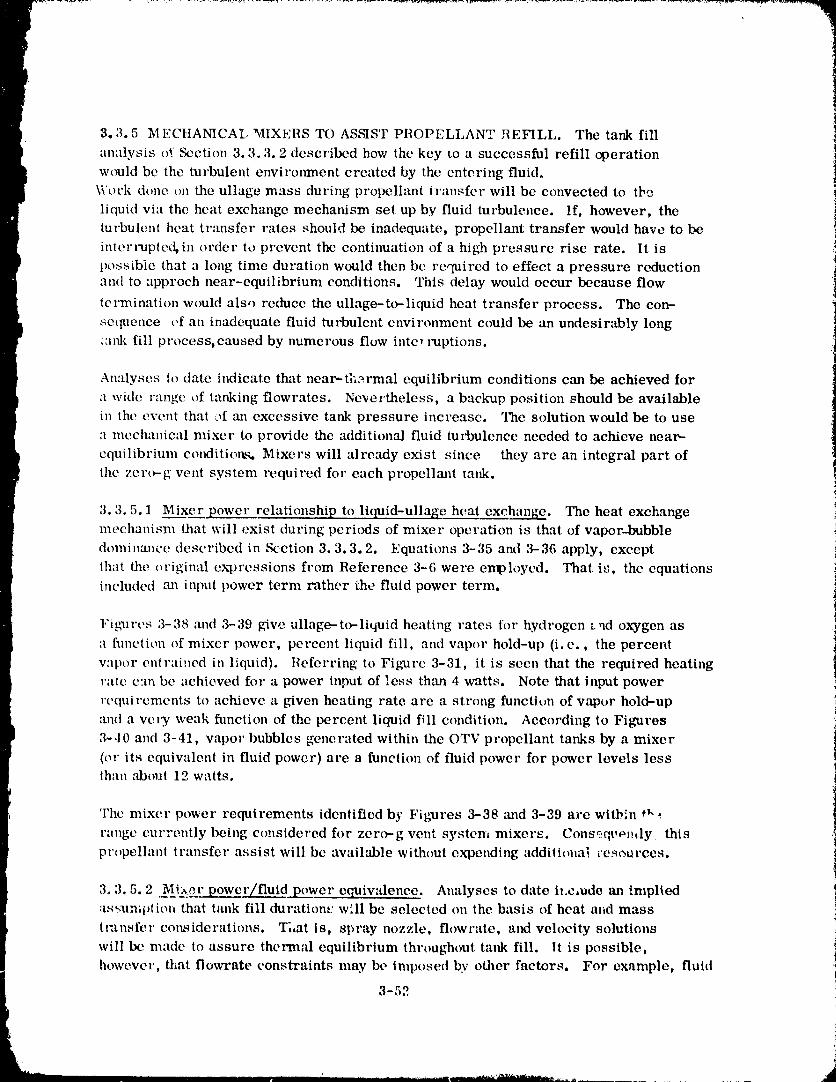
3.3.5 M ECHANICAL MIXERS TO ASSIST PROPELLANT REFILL. The tank fill
analysis o_ _,ction 3.3.3.2 described how the key to a successful refill operationwould bc the turbulent envirmtment created by the entering fluid.Work done on the ullage mass during propellant transfer will be convected to the
liquid via the heat exchange mechanism set up by fluid turbulence. If, however, theturbulent heat tr:msfer rates should be inadequate, propellant transfer would have to be
inter_xipted, in order to prevent the continuation of a high pressure rise rate. It is
possible that a long time duration would then be required to effect a pressure reductionand to approch near-equilibrium conditions. This delay would occur because flow
termination would also reduce the ullage-to--liquid heat transfer process. The con-
sequence t,f an inadequate fluid turbulent environment could be an undesirably long',ank fill process, caused by numerous flow intc, lxtptions.
Analyses to date indicate that near--ti_et_nal equilibrium conditions can be achieved for
a wide range of tanking flowrates. Nevertheless, a backup position should be available
in the event that of m_ excessive tank pressure increase. The solution would be to use
a mechanical mixer to provide the additional fluid turbulence needed to achieve near-
equilibrium condition_% Mixers will already exist since they are an integral part ofthe zer_g vent system lx_quired for" each propellm_t tmlk.
3.3.5.1 Mixer power relationship to liquid-ullage heat exchange. The heat exchangemechanism that will exist during pcri¢xts of mixer operation is that of vapor-bubble
dominance described in Scction 3.3.3.2. Equations 3-35 and 3-36 apply, except
that the original expressions from Reference 3-6 were employed. That is, the equationsincluded ,'m input power term rather the fluid power term.
1,'igxlrcs 3-38 .'rod 3-39 give ullage--to-liquid heating rates for hydrogen and oxygen as
a flmction of mixer" power, percent liquid fill, and vapor hold-up (i. e., the percent
vapor ent,'ained in liquid). Referring to Figure 3-31, it is seen that the required heatingrate can be achieved for a power input of less than 4 watts. Note that input power
,'equiremcnts to achieve a given heating rate are a strong function of vapor hold--up
and a vet T weak function of the percent liquid fill condition. According to Figures
:_-40 and 3-41, vapor bubbles generated within the OTV propellant tanks by a mixer
(or its equiwdent in fluid power) arc a function of fluid power for power levels lessthan about 12 watts.
The mixer power requirements identified by Fig_Jres 3-38 and 3-39 arc within *_"•
range currently being considered for zero-g vent system mixers. Consoqt, emly this
prc,pelhtnt transfer assist will be available without expending addiliona_ rcs_)urccs.
% 3.5.2 _13_?r power/fluidpowcr cquiwdence. Analyses to date it.crude an implied;ts_umption that tank fill duration.,: will be selected on the basis of heat and mass
transfer considerations. That is, spray nozzle, flowrate, al_l velocity solutions '<
will bc made to assure thermal equilibrium throughout tank fill. It is possible,however, that flowrate constraints may be imposed by other factors. For example, fluid
3-52 i
1980009811-085
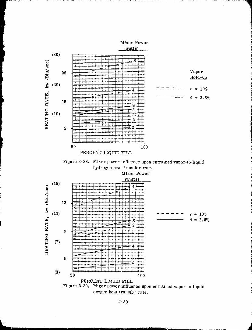
Mixer Power
(watts)(30) _ _____.__
= 25 Vapor
m_ Hold-up
__ (20) = l(f/cd
¢ = 2.5%
N (10)
<
5
50 100
PERCENT LIQUID FILL
Figure 3-38. Mixer power influence upon entrained vapor-to-liquidhydrogen heat transfer rate.
Mixer Power
lw_s)
V_
"_ _ ,.._t___ ', ,_iJ,
_. 13 +H(II) '_" ....
-:-- = 10%-r---t--
-_'_-_- - _-_ ¢ = 2.5% I
- 9 _ _
(7) _._+
r_.-_--_-(3)50 I00
PERCENT LIQUID FILL
Figure 3-39, Mixer power influenceupon entrainedvapor---to-liquidoxygen heat transfer rate.
3-53
] 9800098 ] ] -086
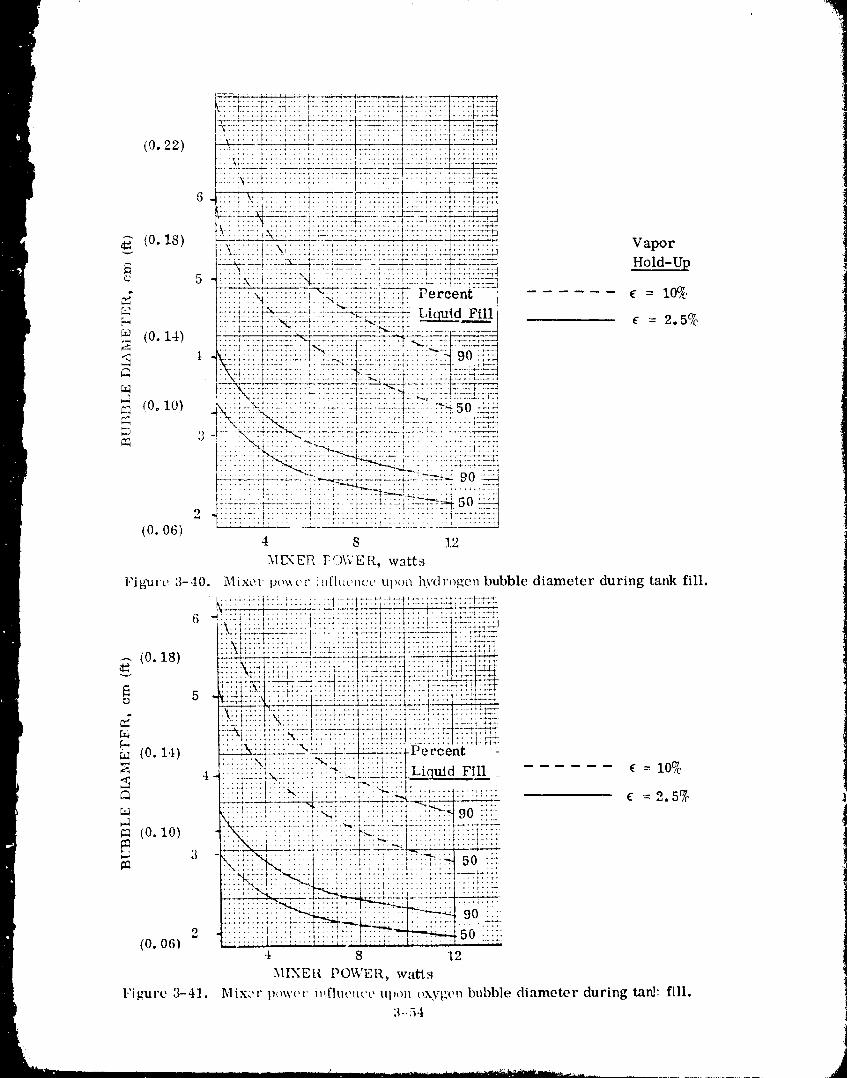
902 ::::;"::I:: :::::
(0.06)4 8 12
MIXER POWER, watts
I:il_nare 3-41. Mixer l)OWt'r i,_fhwuco Ul),.m oxygen bubble diameter during tard: fill.3-54
J
1980009811-087
loads acting on the transfer lines and/or propellant tanks may preclude tank fill
durations of less than five or six hours. It might not be possible to maintain low tankingpressures at these lower flowrate without conti,., _us mixer power assist. For this circum-
stance the required fluid turbulence would be provided with a combination of fluid
power and mixer power• This combination could be selected from curves similar to
those given in Figures 3--42 and 3-43. An example of how these figures can be applied
is given below:
1° Assumptions
• The fluid power equivalence of 15 watts mixer power is required during
tanking to maintain near- equilibrium conditions•
• Other considerations require that tap.k fill be performed in six hours
using a 6.35 cm (2.5 inch) diameter equivalent nozzle inlet•
2• LH 2 Tank Solution• Fluid power = 2.75 watts
• Mixer Power = 15.00 • 2.75 = 12.25 watts required
3. LO 2 Tank Solution• Fluid power = 1.75 watts
• Mixer power = 15.00 - 1.75 = 13.25 watts required•
3.3.6 START BASKET REFILL. If propellant screen acquisition devices (start baskets)
are included as POTV subsystems, an additional complication must be addressed in
selecting an on-orbit refill concept, that of completely refilli._g the start baskets with-
out trapping vapor. Vapor entrapment is unacceptable because pure liquid flow from
the start basket is normally required, and cannot be guaranteed unless the screen
device is free of vapor• Vapor will be present at some t,:mc within the start baskct
regardless of the method of propellant fill. Any trapped vapor bubbles must subsequent--
ly be condensed by using pressurant. The ty.pe of pressurant can either be helium
(non-condensible) or vaporized propellant (condensible)• The question of trappedhelium bubbles will be discussed in Section 3.3.6.3.
Two methods of vapor bubble collapse were evaluated; passive and active. In each case
the propellant tank will be pressurized to sub-cool the liquid surrounding the entrapped
vapor, so that vapor condensation will occur. The passive method assumes that con-
duction heat transfer is t_.j only mechanism that exists to cool and subsequently condense
the vapor. The active method relies upon forced convection heat transfer to condense
the entrapped vapor• An evaluation of each method follows.
3.3.6.1 Passive method of bubble collapse. Start basket designs, generated for
POTV during the Reference 3-2 stddy, were analyzed to determine if vapor-free refill
would be possible. A sketch and start-basket-dimensions are given i,_ Figure 3-44 and
Table 3-10. A very conservative assumption was made for this analysis.
The start basket would be filled with a single large bubble at the end of the on-orbitr
i 3-55
1980009811-088
_:_i_iKi"__i}:j OTV LHo TANE VOLUME = 116 m 3 (4100 ft3) "-:_
G i!i':i::i:!}[i::':i.._ssw_E5Mrx_aEI,_FIC_:NCV=400; _;_4]1__=._t2_"i___....... -,-='= ==:-r:,:::=:-_!,"===:,!==:=:=t==_j a'.=_:_tu ::_,::E.i_i: _ ti_i."qi i ii iiiili:i ;:::: ::: :: :_.::::::.: :::::::::::::::::::::::::::::::::::::::::::::
:::::::::::::::::::::::::::::::::::::: .:::_::::' .:-i : ! : " ,,.... , ...... :..1.,:: ..... ,. Ir:msfer Line :=:;._..=:
m I::::i::i:i..:N.:: :.:.'. -_..',_:::::::l:::::ii i: : : - : Nozzle Inlet :2_]}::_:i:::::. ::2:2: :::::::::::::::: ::::::::::: .... ! .... : :"4 : ....... "-....
...... : .... :. "::: :::: :t::::: :.':'._:: 6.35 :: :::::_:::i=
........................ : .......... _ ......... 7. 62 3. 0 "_t .... _'- "
:::::::::::::::::::::::::::::::: :=::::::. :::. -_,_._-:._-x_;:: ..... ---=:::::::_._b}._:.=................... ! ....._ ......ii:Iiiii! , =.:.::,:=,=lo.z_ (4.0)_=_=.... , .... I.................................... 1....... ,.....................
_:_..:_:7;!-:_-.t7×::[!_!!:7-!-[_-:=i-:t{7!;!:!; ::i-:i-:- !:- :::::::::::::::::::::::::: ::::;:::::::: :::::::::::::::::::::::::::: :::::: ::: :.:: i.:::,:: :::::::::::::::::::::::::::::::::::::::::::
. : := ;. :.. _.: : : : ._-..'-7._..-_.. ,-+%:_,_"_7_.:-.'_i-r7: ,r--_:-ITT_ ; ,L .----,.i.. t .... : .... t i.. i .... i ',_. ri -- ..'-"-7.
0 ::::::::::::::::::::::::::: :'::::::' i: ::i :::::: :: :: :::::::::::::::: : :: ":} :":0 5 I0 15
ML\ER POWEI{, watts
1980009811-089
, A
i SINGLE SCREEN " 1
STANDPIPE d l
\ i flu / B
" i __L -/ , c
o_ _,_ w_i_---_ /-_1_ _ \....... '_1.38 ELLIPTICAL _ 1 [ [ _ MAIN SCREEN
i
BULKHEAD iTYPICAL SCREEN CHANNEL-- BASKET VOLUME = EFT 3
4 REQD
ALL CHANNELS END AT PLANE SEE TABLE 3-10 FOR SPECII_,C
OF ELLIPTICAL SECTION VEHICLE TANK DIMENSIONS.
Figure 3-44. Start basket schematic.
Table 3-10. POTV start basket characteristics.
LH Tank LO Tank2 2
A. Radius, cm (in) 142.2 (56.0) 85. _ (33.5)
B. Standpipe height, cm (in.) ll. 9 (4.7) 4.6 (1.8)
C. Cone height, cm (in.) 16.5 (6.5) 9.9 (3.9)
D. Ellipsoidal height, cm (in.) 42. 2 (16.6) 17.5 (6.9)
E. Basket volume, m 3 (ft 2) 1,92 (67.8) 0.34 (11.9)
3-57
1980009811-090
refill operation. The largest spherical bubble that can be trapped within each screen
device was computed to be about 0.61m (2 ft) and 0.3 m (1 ft). An analysis was
conducted to determine the time for each bubble te collapse.
Bubble condensation times were determined using bubble collapse equations described
in Reference 3-3. Computer output results are given in Figure 3-45 and 3-46 for
hydrogen "rod oxygen, respectively. The oxygen bubble will collapse in about 5 minutes
if it is subcooled by about 20.7 kN/m2 (3 psid), which is an acceptable maximum
helium partial pressure during refill. The hydrogen bubble will require about three to
four hours to collapse at the same degree of subcooling, which may be an unacceptably
long duration. These calculated collapse times should be greater than actual collapse
times because of the conservatively large bubble sizes selected. It should also be
mentioned that the bubble collapse prc4ictions are subject to added uncertainty because
the analytic._,l model was developed for small diameter bubbles.
3.3.6.2 Active Method of bubble collapse If vapor-bubble collapse times which use
the passive method are excessive, an alternative is to use an active method to greatly
decrease bubble collapse times. This method rcquires that propellant be sprayed
into the start basket during tank fill. The fluid ,_itation induced by entering propellant
will create a high heat exchange mechanism equivalent to that occurring outside thestart basket during propellant fill. Furthermore, this turbulent fluid condition will
serve to create small vapor bubbles which will greatly enhance the condensation
process.
A model has been developed to determ'ne the conditions under which the condensation
of all propellant vapor within a start basket will occur. The model is based upon the
following assumptions:
1. Liquid inflow velocity and flowrate are known.
2. Only liquid will exit the start basket; vapor is removed only bycondensation.
3. Liquid enters the basket at a constant temperature.
4. Vapor trapped within _he basket is in spherical bubble form (Figure 3-47}.
Thus, this model is valid only for vapor volunm conditions of about 40
percent or Less by basket volume.
5. Bubble dimneter is obtained from equation 3-36,
0.6 0.51. 134 a (
d - +. 09
30.2(mv2/VL) O. 4
!
i 3-58
1980009811-091
..........................................i-¸_.........."-!
_ LIQum VAPOR PFESSURE - 103 kN/m- (15 psia) g g _] -: ::_;t_:-i_!_ii !=_Z=. -t_:!_50 -_== TANK PRESSURE " VAPOR PRESSURE �<Ti _ _.:) )-] --_-t : :_.r:_.}_ f--l=:; :[:] '--:/:: :::I:T:FI:
a0) "f zkl_T " 68.9 kN/m 2 (10 psid) ___,__A:::_:..b-_=t*_:t= ::i :|:I :_-_-_:_!:f::! :::-i:::: ;:!i .... --i:t.-*:iii:_.t:)
Bubble Ccllapse "rime, Sec.
Figure 3-45. Collapse Times for Spherical Bubbles in L'.quid Hydrogen
iLIQUID VAPOR PDESSURE - 103 kl_/m 2 -: _.;gi:: t::i_,L fT:::::
_"TANK PRESSURF - VAPOR PRE_URE c_ -r_--'-r--qz-P-7! :'"i' I [ "l:
T
F_4t_ '¢_'PT --'_ _'J5 k_/m'_' (5 'psid, _i l_:!iiii:iti::!:l ! 1 l:!
c:- ' ...... +......... _ :;:;]: ) : .... : ....
L:_.-=_. ::_-ld%_lz_+_=T::'_ !]_:F:!: FiZ4]-av.. _.s9 kN/m 2 (1. u psid):
Bubble. Collapae Time, See.
Figure 3-46. Collapse Times for Spherical Bubbles in Liquid Oxygen
L 3-59
1980009811-092
Figure 3-47. Active Memod for Start Basket Bubble Collapse
whe re
d = bubble diameter, cm
a = surface tension, dyne/cm
e = entrained vapor volume to basket volume ratio
7 = liquid specific gravity
VL = (1 - ¢ ) VT = liqu!d volume within basket
VT = ba,-'ket volume
Substituting (1 - ¢ ) VT for VL gives,
6 .4 .5
d 1,134 a" (1- c ) •- +. 09 (3-39)2 .4
7" (_v2/VT)
Figures 3-48 and 3-49 give plots of hydrogen and oxygen bubble diameter as
function of _v2/V T andas a g
6. Bubble condensation rates are extremely high for the small bubble diameters
anticipated (see Figures 3-50 and 3-51). Consequently, it is expected that
liquid within the basket will rapidly _aturate at tank pressure due to absorbingthe heat of condensation.
7. All liquid leaving the basket will exit saturated at tank pressure,
8, Vapor bubble pressure = tank pressure throughout tank fill,
An analytical model that includes the above list of assumptiens is given below:
3-.60
1980009811-093
7
J
• r-- ....,........................ ! .... - .... :.i -...............i.................I"::-.-_--.I:......._......._ ........._--_ ......., :-::-:_-:-:_:-_..............._......... I......................................... :
_l_ _Ir ' '.......I _7--..... T--.,_T.-.T- ". ................. : . , :..I.....1........I i . • :.........:: _, . ,..............'"_'": ............ t : 1 ':"! ": _' : i :
Z"'-V::: :: '..: ......... _ : t :_ " ;_. ::..::-::, : : t .
0 ..... k:- ...... *..-LLLL.... :_._;._4_:' ......... :..... _ ..... _" " ; .... T -
' =0'1.2:::_!:_iiI:": ::!:::: I :.'.: ,. 2LL2__ : i : . :, - -_..a I -:, _ _ .:. _?.'. + ' " ' : I" ." • , ._o :L.L \I .:::::I. : ; : : ! ' ' :. : .
::_-k---_-:::',:---:.....4---:--:.i-.:- t.....:--! : -I.... r....:....] _ ":. ::.'. : .;.... : '. i : . : .... ; . :. . , :
... t'-,X(: _.×\'_,_ff _ ' ', . . I..: . ',_ : : . ,, ,_ e,F.."-",%:"_ r:I:'_.-_, ._ t • .' ..... .x--- --- .....
"_ I , _ i : , ,
L__ i_i-.L.-!._.i:.i_._i..i.... i---:......:....i....! i ": ";F'TT-'E_ .... . _ ,' ', ' t ' " '_ " "
0 iO 20 50 40
(i0) ¢0) (30)
I_v2/VT, kg/sec3-m (Ibm/sec3-ft)
Figure 3-49. Oxygen Vapor ,Subble Diamomr During Start Baslmt Refill.
3-61
1980009811-094
1980009811-095
First Law
(mu)2L 4-(mu)2v - (mu)l L - (mu)lv = hiAm.i - hc),_mo (3-40)
where
m -- mass
u = internalenergy
h, = cnthalpy of cntc_.ihgliquidmass increment1
h = cnthalpy of exitingliquidmass incrcrncnto
Am. = liquidmass increment cntcring tank in time,l
Am = liquidmass increment leaving tank in time,O
stlbscript
2 = conditmns at end of intc_'wll
1 = c_mditions at start of interval
L = liquid
v = vapor
Now, U2v = Ulv = Uv (vapor is saturated at tank pressure, assumption 8)
Also, U2L = UlL = u L (assumption 6)
The refo re,
(m2- ml)LUL+(m._- ml)vUv =hiAmi- hoAmo (3-41)
From continuity, roll + mlv + ;,m.l = m2i, + m,_>v + Amo (3-42)
- = Am , =AmJ- Am (3-43)or, m2T mlT BASKET o
where m T = m L + m v (3-44)
_ntBASKET = propellant mass increment accumulated in start baskut
Ackiing and subtracting m2vU L and mlvuL to equation 3-41 rc_ult_ in,
(m2T - mlT ) u L + (m2v - mlv) u -_ h i Am I - hoAm ° (3-,t5)ev
where
3-63
II IIIIII I I _ II I I i i ...... Jill...... '_Hibiii_'J_T,sd_',,,_......... ..d
1980009811-096
_ ...........
ru = (Ug- UL)ev
l But, (m2T_ mlT)
m2v-mlv = - (£)L/D g)-I (3-46)
; _[herefore, equation (3-45) become,s
Uev
(m2T- mlT) (UL- (0L/0 g)- 1 = hi Ami - }_o_mo (3-47)
Nlbstituting equation (3-43) into (3-47) gives,
UoV
(Ami- hmo) (UL- (D L/P g)-I ) = hi Ami - h° Am° (3-48)
Rearranging terms and solving for Amo/ Am i we h::;-c,
u l/I= [hi - u L + ev evAmi (O L/P g)-I h° ' UL + q_ L/D g)-I (3-49)
However, from eq_ ".,L.o,_ (3-43: we can show that
AmBASKET A me= 1 - or,
A m i A m i
u ]/ o ]I 0V OV&mBASKET =l- hi- �[h°-uL+ _o 1A mi uL (pL/p g)--1 L/0 g)-I (,3-50)
Equation (3-50) g_;'es the maximum fraction oi entering propellant tb:lt wi'.l accumulate
within the start basLet as a result ()f vap_)r condcL:sation. This fracti,)n is shown in |Figure 3-52 for hydrogen and oxu, gen as a funeti(m ()f the differential pressure term,
Ap (tank, pressure minus enterin_ liquid vapor pressure). These tulwes indicate that
an increasing fraction of entering liquid remains in the bask( as AP tncreases. An
increase in Ap is equivaleu, to liquid c'nte,'ing the basket a, c()oler t._mperatures, which
increases its heat abst)rbi1_g capability. This in turn will increase lhe rate of val),_r
condensation, and subsequent liquid accu_,nulati,)n within the basket.
According tc Figure 3-52, 100_ _' of L(} 2 entering the basket will remain within the basket,if the entering liquid is subcoolcd by about {;. 8 kN/m 2 (1.0 psid), (): g," _,ater. 1.'or this
condition one could :;elect a flt_'ratc (m o) that w,,t_]d just fill the bask,:t at tank fill
comp!etion ,:Figure 3 53). A c,mse_wativc, and preferred, appr,_tch w(_uld be t,_ provitie
3- 54
1980009811-097
A m B _ mass fraction of entering liquid whichA mi remains in stag basket
rh = i_lO/(AmB/A mi)
_nc = :naximum basketHquidmasstank fill duration
rh = selected start basket flowrate
1.o__-I.-S::: :,_:;-._-.i::::I: _ 1:-:-! :_-::::: i :: : , _:_ - -__7 ::7=-=_=::LO-:::I:=::t:.:-_: i:::_i-:::i:::i::-:i-::-:::i--! :l, .- ........ ::: ...... Z:-=::-:, ..... :_ -::-"- :--_.... 1::::_, .2_::' Lllo_T__. "_ .... * ......... # t -# .... . ...... : _ _ . ,_
_-i ' t -'_1-' t / i J / _ , i , ............
--'"P---_t .... f-----_---4--f ....... t .................. L._-_, \:I:::1:':: ... ;: " ; ; i :
<l l:__l£-:_:_h_]i]:!_ :-17AP = (taj_k pressure -enteriilg liquid vapor pressure)
10 20 30
(1) (2) (3) (,t) (5)
AP, kN/m 2 (psid)
Figure 3-52, Influence of liquid subcooling upon start basket refill flow paramelers.
a greater basket flowrate (l_l) to assure basket refill even at AP's less thall 6, 9 kN/m 2
(1,0 psid), As a first approximation it is suggested thai rh = 3 _ , It is seen frmn• O
the curve that +he basket will completely refill for this flow condition at AP's greaterthan 1, 7 kN/m 2 (0, 25 psid),
Hydrogen properties are such tha a considerably greater AP is required to accumulate
the same fraction of LH 2 entering a basket than if LO 2 was entering a basket. This isillustrated by the hydrogen curve of Fi_,mre 3-52,which shows thai abotd .I0 kN/m 2
(5.7 psid) is needed for all entering liquid to remain within the baskot. If, as above,
we select _h -- 3 _h , then basket refill will occur for a Ap greater than ] 0 kN/m 2O
3-65 )
k .
1980009811-098
(1.4 psid). This condition should be satisfied since Figaare 3-2,t sh¢ws |hat fin:fl
LII 2 eqafilibrium tank pressure fro" PtYI'V will be aboul 21 kN/m 2 (3 psid) grealer ihmlentering LlIo for initial tank wall telllper,'lillre.q less Ill:in 200K (360°!1). Tile degree of
liquid subcooling will be even g'reate r if llOn-lhe rmal equilibrium conditions occur
thlring tank fill.
The above analysis has indicated lhat liquid inflow to a situ'i basket is a feasible means
of providing baskei refill during the llropcllani i:ud¢ fill process. A conservative
lhermtxiyn:m_ie meclmnism has been analy;;ed whiell int|icales |hat a retlsonl_ble rtlIIge
of propellant inflow r:des will provide baskel refill for POTV. Ill fact, :l flowrate of
Ill - 3 1_ should result in a eoml_leiely filh,d si:trl basket at the el!d of propell'mt iltllkO
fill.
3.3.6.3 &mmmry. The liquid-oxygen tank start basket will be vapor free within tme-O / ')half hour after being pressurized by .0.7 kN m- (3 psid). This same passive approach
may require a considerably hmger time for the liquid hydrogen tank. An alternative
active-method was considered for the hydrogen tank in order to reduce tile time required
to condense all vapor. This condition will l_e satisfied at the end of propellant tank fill
if hydrol.,en flows into tile start basket at three times ihe rate indicated by Figure 3-53.
This method requires tile addititmal complication t)f a small diameter line plumbed
between the main fill duct and tile start basket. A preliminary design sketch of this
set-up is given in ,':ection 3..t.
%!_i!_:!:i:,!_i:_!_!_::i:!,__N"tes..... ;_-:I: i ; " .: i ' Ill V ".
(0.a) i}, : !il......... ," ll Pl,
.A.i. t.... '. ! .... :.l
:. ! ;! 'i..i ;:I V _ basket volu,ne (from Tabh'3-10} :
7!7i:i;;I;;:!?i::;,.:ilo liquia,le,l_tv i:l(0.2) 1::::;.-- :::- : ..:i:_. ,r tank fill dur'ltmn .-
.......... , I,:, ; .... , ; [
"_ 7 i :t ' : : :!!i i_:,1 ,:_:,::i: i ii i_:iit!iii
O. 5 I .... t ," ':' ......... " ":::
........................,v ",....................1......l It:::: ;::: .:::::::: : g,.._ ! ! ',)_,: l,lqtlld llvdrogell 7
• _ _ ........... ,' , {: : _ '.: ;,b',. , ........ .... , ;.*,, :.,
0 1 2 3
TANK FII,l, I)I,IllATION, hrs
I,'tgurt_ %53. Propellmlt l,'lowrate llequired to Fill Start l_askei During
Tank Fill ()peralions
1980009811-099
3.40ltl31'l'Al, Pllt)I'IqI,I_:\NT 'I':\NI(IN(; ()Pl,:IIA'I1t)NS !
The ira[met of the on-twbit refill upoll vehicle design is described in this seeti_m. C,m- !ieeptual t!eSlgh m,,di fic:tli_llS arc presented which depict propellant tank, [l';llIS[t'r line
and helittm system m_diiieatitms. A detailed discussiOll of all on-orbit refill iwocedure8
is given, inc hlttit_g how tilt: procedures are influenced by the presence of helium and orstart baskets.
3.4.1 CON('I,?IrI'U.\I, [)I,?S1L;N MODIFICATIONS FOIl ON-OllBIT lll,;l,'lI.,1,. The
analyses ,ff _qt'ciion :1. :_ h:we established requirenlenls for achieving I'OTV m_-orbil refill
from an orbiter-t:ml_cr, t/cquirements which affect the vehicle design include:
:l. :\ fluid s.t)r:ly cir('uit Ihroug|l which propell:lnls are inlrod/leed into lilt' pl't>
pellanl l:tnl<s.
b. :\ bleed line to rotlle I,lI 2 1o lhe star! b-tskel during refill.
e. A non-propulsive vent syblem lhrtmgh which propellanl vapor is vo:llod duringl:lnk bl,,wdowu.
These and other plmnbing nlodificalit_ns are depicted in _elion 3.4.1. L N'elion
3.4. l. 2 :rod 3..1. l. 3 includes skelches of reeolnll_ended transfer line t|csign:_ and a
lllC_ttll:l ri ','eli hcl i tllll p l't's,,-;Ii ri Z,ll iOll syslelll.
3.-t. 1.1 _!_r}J_cll:lut lank nh_dilTicallions. Figllrcs 3-54 and 3-55 show some l:lnl,;l_w'
system ;lrl':ingt'lllt'lll:_ for ;I two sl;Igt, Ih,)rl'\ :. Propellanl refill is aeeol/_plished I'1,_111
the shuttle, (hcrc6,rc, the t'Catching c:tpabilily of the transfer lines is |imitcd t_, the
length _,f lhc [{t'llhqt' M:lnipul:tlin< >'ystem (RMS). \Ve h:tve the choice (,1 1) l,,a_ling each
stage sep::r:llely, hqlo_ved by interstage attachment maneuvers, 2) having the sta_es
inilially il_!crcmmet'tc_t and equipped with external phlmbing Mrs or ;1/ adding a mot_q"
driven hinge system di lhe I'(YI'V separation plane so that the vehicle can be "i:lck
knifed" $o wilhitt l't,ach of tilt' II,MS. It is assumed that each shire will be tankcd scl,aratcly,
thus aw,iding lilt, Cl'llNsill g O[ the separation plane with propellant duels. The s vstems
shown art" c,mlm,,n it, cat'h sta_e alld include lwopellant fill circuits vent sXslcv,/s and
aequisittou device6 for both the fuel and oxidizer tank_.
The fuel lank fill eircuil ,'darls ill lhe skin lille of lhe POTV b_dy slrilelurt, wilh dis-
_, connect :lssembly c,mlaining all ill[t'l'llHl poppet closure, :1 slalic seal inlerfacc, and at
cone section which :_crvcs :1_ :m alignnlenl tool and a stl'llellll':ll ait:lChlllt, lll _vil]l the
lllltling half. ,\ rh,xiblc ihlel section is rouled [rein lhe di,qeonneel [o :| fuel l;mk il_lol
fitting° The duel mah'rial is Ores and inem'porates three axially restrained fh,x
jotnls which permits lenglh and :tngxflar ellanges between the duet ends.
Tile illtlk iulel filling is t'qtlil_ped wiih a flilllge (inside the ill.Ilk) for I't'ceiVillb', :! _tislri-
bullet| dtle|, lllld ;! Ih_s,q f_,_' :lIIaching a 3/.Finch 1)leed line. The disll.ibuli,m duc{ i'111!::
along (he cylindrical st,el ion _)f lank alld is eqllipped with (We oullels c_)nl;linin!" ,_1,_:_5'
3-(;7
1980009811-1O0
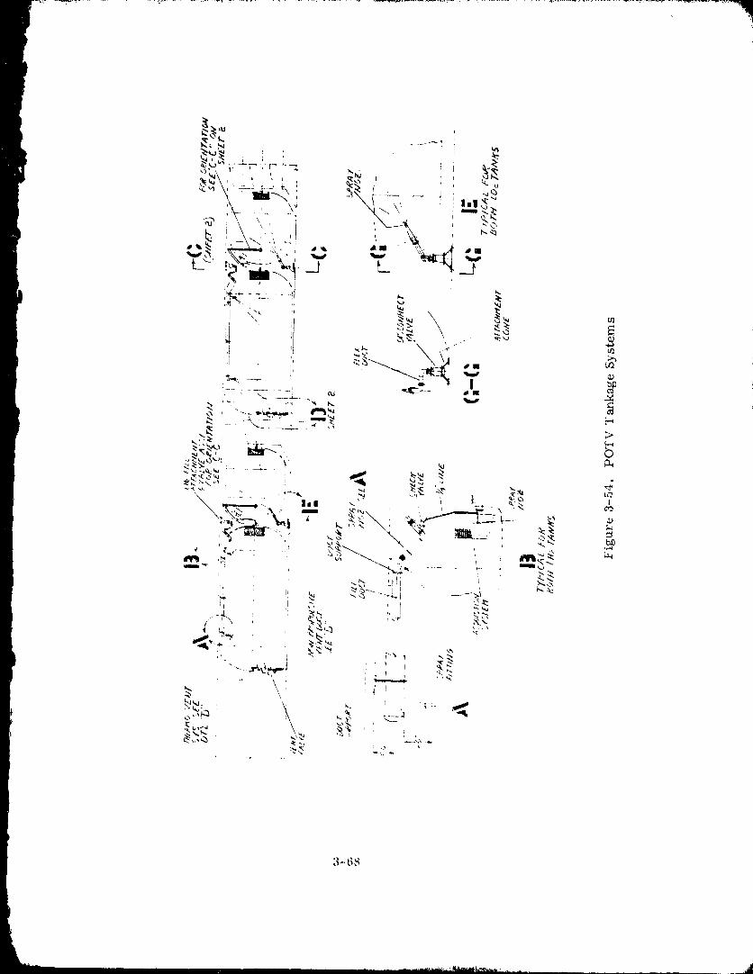
1980009811-101
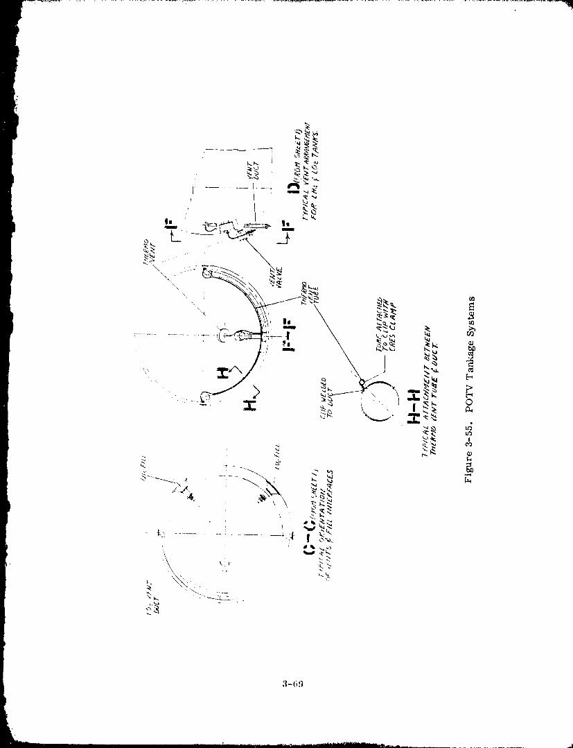
3-6!t
1980009811-102
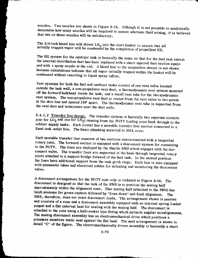
nozzles. Two nozzles are shown in Figure 3-54. Although it is not possible to analytically
determine how many nozzles will be required to assure adeouate fluid mixing, it is believedthat two or three nozzles will be satisfactory.
The 3/4-inch bleed line will direct LH 2 into the start basket to assure that allinitially trapped vapor will be condensed by the completion of propellant fill.
The fill system for the oxidizer tank is basically the same as that for the fuel tank except
the internal distribution duct has been replaced with a short tapered duct section equip-
ped with t spray nozzle at the end. A bleed line to the acquisition device is not shown
because calculations indicate that all vapor initially trapped within the basket will be
condensed without resorting to liquid spray inflow.
Vent systems for both the fuel and oxidizer tanks consist of one vent valve locatedoutside the tank wall, a non-propulsive vent duct, a thermodynamic vent system mountedoff the forward bulkhead inside the tank, and a small vent tube for the thermodynamicvent system. The non-propulsive vent duct is routed from the vent valve to two pointsat the skin line and spaced 180_ apart. The thermodynamic vent tube is supported fromthe vent duct and terminates near the duct ends.
3.4.1.2 Transfer line design. The transfer system is basically two separate circuits(one for LO2 and one for LH2) running from the POTV loading point back through to theorbiter supply tanks. Each circuit has a movable transfer line section connected to a
fixed tank outlet line. The basic plumbing material is 304L cres.
Each movable transfer line consists of two sections intercormected with a tangentialrotary joint. The forward section is equipped with a disconnect system for connecting
to the POTV. The lines are deployed by the Shuttle RMS wMch engages with the dis-
connect valve. The transfer lines are supported at the base through tangential rotary
joints attached to a support bridge forward of the fuel tank. In the stowed position
the lines have additional support from the tank girth rings. Each line is also equipped
with pneumatic tubes and electrical c,_d)les for actuating and monitoring the disconnectvalve,
A disconnect arrangement for the I_TV side only is included in Figure 3--56. The
disconnect is designed so that the task of the BMS is to position the mating half
approximately within the alignment cone. This mating half (attached to the RMS) has
latch systems for gross capture followed by "draw down" and final alignment. The
RMS, therefore, does not react disconnect loads. The arrangement shown is passive
and consists of a cone and a disconnect assembly equipped with an internal spring loaded
poppet and a fiat external land for sealing with the mating half. The disconnect isattached to the cone using a ball-socket type fitting which permits angular misalignments.
The mating disconnect assembly has an electromechanical drive which positions a
pressure sensitive static seal against the flat land. The seal arrangement is shown in
detail "C" of the figure. The electromechanically driven assembly is basically a short
3-70
1980009811-103
Fibmre 3-56. 'l_'pical vehicle pr(>pellant disconnect arrangement.
telescopic tube sealed externally wifll a bellows and actuated externally by three screw
jack actuators or by a single threaded collar with a worn_ drive. GD/C has designed
a liquid flourine tandem butterfly valv,,, for _cro spillagc at separation using such
techniques. For this applicati(m, tilt, telescopic section would have an internal poppet
closure similar to that shown in Figxlre 3-56.
In summary, a typical connection starts with the RMS positioning the transfer line dis-
connect inside the cone. Ang_fiar, axial and lateral misalig_mepts are permP_ed at
this time. The second step is to actuate tilt, h)cking pawls on the transferline discommct
t to an inboard position which capt'ures the fl:mgc on the cone. This is a ioose engagement
only between cones. On the third ste_) the paxvls are actuated parallel to the discomlect
center line which pulls the two cones t()gt'tht'r thus completing the structural connection.
Fourth, the motorized discounect carrying the external seal is actuated pressing the
seal against the flat huM. Ul)on further actuation, the poppet on the transfer line
disconnect forces tile poppet shown in the layout to an open position. Fluid transfer is
now permitted. For disengagenmnI, the abe,re steps are reversed. After fluid transfer
both poppets are closed before the external seal is disengaged from the flat land. Also
the poppet interfaces are d('sig_md for near zero spillage.
A detailed discussion of the design and operati<m of a transfer line disconnect valve is
given in Section 5.4.1.
3.4.1.3 Helium system design. Spae(,-based vehicles will require gaseous helium
resupply during refueling operations. One mt, thod of resupply is by flowing helium "'
from a storage tank (located in the Shuttle p:tyh),td bay) to the vehicle through a h)ng
transfer line. However, :_nalyses indicate that helium bottle charge operations would
3-71
...... j
1980009811-104
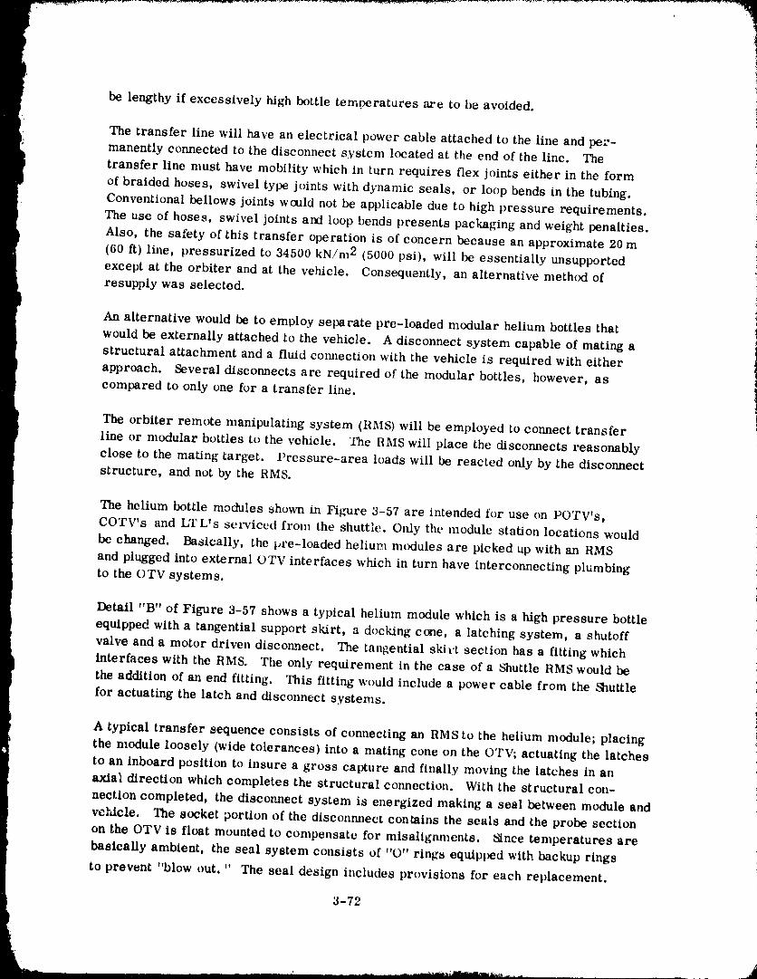
be lengthy if excessively high bottle temperatures are to be avoided.
The transfer line will have an electrical power cable attached to the lille and per-manently connected to the disconnect system located at the end of the line. The
transfer line must have mobility which in turn requires flex joints either in the form
of braided hoses, swivel type joints with dynamic seals, or loop bends in the tubing.Conventional bellows joints would not be applicable due to high pressure requirements.
The use of hoses, swivel joints and loop bends presents packaging and weight penalties.
Also, the safety of this transfer operation is of concern because an approximate 20 m
(60 It) line, pressurized to 34500 kN/m 2 (5000 psi), will be essentially unsupported
except at the orbiter and at the vehicle. Consequently, an alternative method of
resupply was selected.
}An alternative would be to emuloy separate pre-loaded modular helium bottles that
would be externally attached to the vehicle. A disconnect system capable of mating astructural attachment and a fluid connection with the vehicle is required with either
I approach. Several disconnects are required of the modular bottles, however, as
compared to only one for a transfer line.
1
The orbiter remote manipulating system (RMS) will be employed to connect transferline or modular bottles to the vehicle. The RMS will place the disconnects reasonably
close to the mating target. Pressure-area loads will be reacted only by the disconnect
structure, and not by the RMS.
The helium bottle modules shown in Figure 3-57 are intended for use on POTV's,
COTV's and LTL's serviced from the shuttle. Only the module station locations would
be changed. Basically, the pre-loaded helium mtxiules are picked up with an RMS
and plugged into external OTV interfaces which in turn have interconnecting plumbing
to the OTV systems.
Detail "B" of Figure 3-57 shows a typical helium module which is a high pressure bottle
equipped with a tangential support skirt, a docking cone, a latching system, a shutoff
valve and a motor driven disconnect. The tangential skit,t section has a fitting which
I interfaces with the RMS. The only requirement in the case of a Shuttle RMS would bethe addition of an end fitting. This fitting would include a power cable from the _huttlefor actuating the latch and disconnect systems.
A typical transfer sequence consists of connecting an RMS to the helium module; placing ithe module loosely (wide tolerances) into a mating cone on the OTV; actuating the latches
to an inboard position to insure a gross capture and finally moving the latches in an
axta!l direction which completes the structural connection. With the structural con-
nection completed, the disconnect system is energized making a seal between module and
vehicle. The socket portion of the disconnnect contains the seals and the probe section
on the OTV is float mounted to compensate for misalignments, a2nce temperatures are
basically ambient, the seal system consists of "O" rings equipped with backup rings
to prevent "blow out. " The seal design includes provisions for each replacement.
3-72
1980009811-105
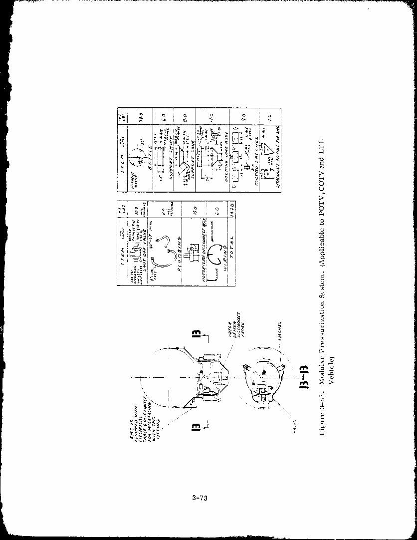
3-73
1980009811-106
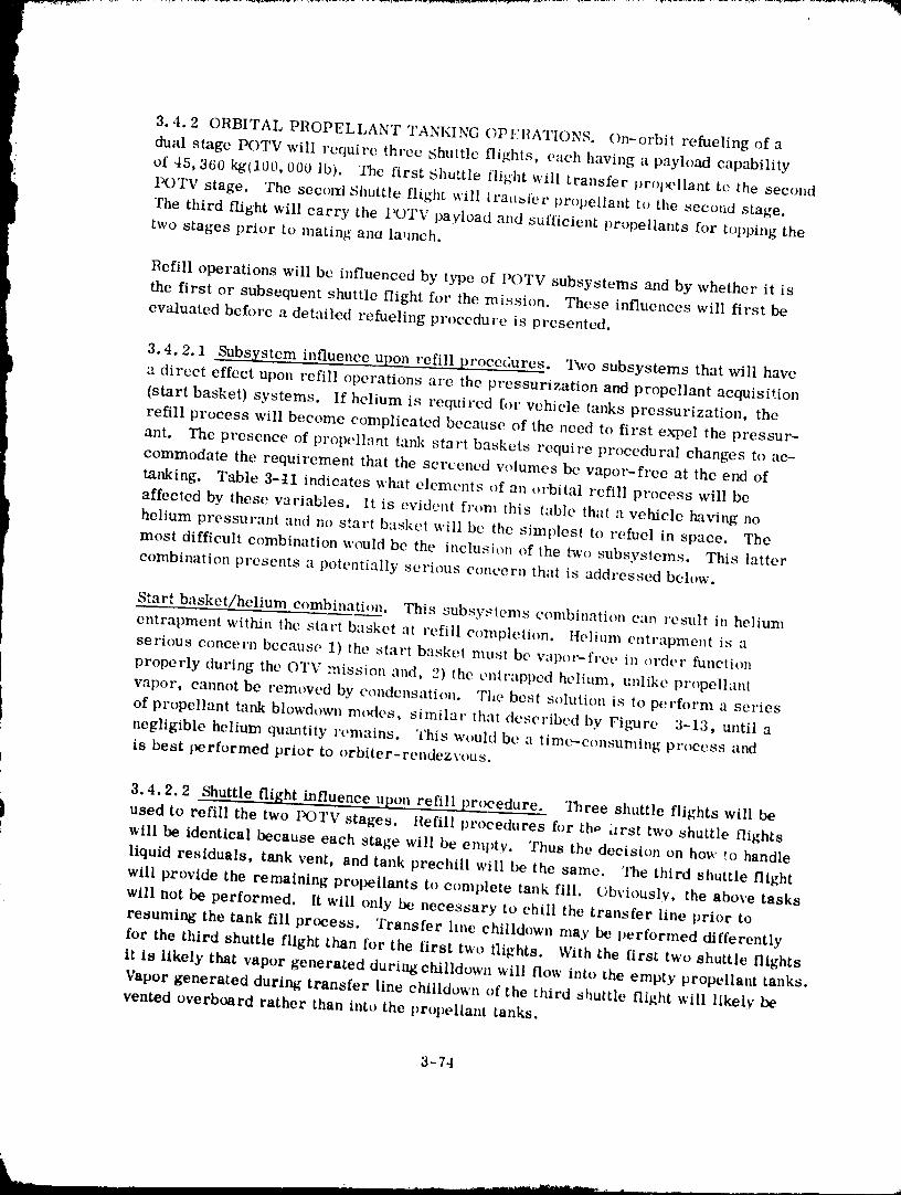
3.4.2 ORBITAL PROPELLANT TANKING OPI,:I1ATIONS. On-orbit refueling of a
dual stage POTV will require three Shuttle flights, each having a payload capabilityof 45,360 kgtl00,000 lb). "llm first Shuttle flight will transfer propellant te the second
POTV stage. The second Shuttle flight will tra,_fer propellant to the secoad stage.
The third flight will carry the I_TV payload and sufficient propellants for topping thetwo stages prior to mating aria Is,inch.
Refill operations will be influenced by type of POTV subsystems and by whether it is
the first or subsequent shuttle flight for the mission. These influences will first be
evaluated before a detailed refueling procedure is presented.
3.4.2.1 Subsystem influence upon refill procedures. 'IXvo subsystems that will have
a direct effect upon refill operations are the pressurization and propellant acquisition
(start basket) systems. If helium is required for vehicle tanks pressurization, the
refill process will become complicated because of the need to first expel the pressur-
ant. The presence of propell_nt tank start baskets require procedural changes to ac-
commodate the requirement that the screened w_lumes be vapor-free at the end of
tanking. Table 3-tl indicates what eleme, nts of an orbital refill process will be
affected by these variables. It is evident from this table that a vehicle having nohelium pressurant and no start basket will be the simplest to refuel in space. The
most difficult combination would be the inclusion of the two subsystems. This latter
combination presents a potentially serious concern that is addressed below.
Start basket/helium combination. This subsystems combination can result in helium
entrapment within the start basket at refill completion. Helium entrapment is a
serious concern because 1) the start basket must be vapor-free in order function
properly during the OTV mission and, 2) the entrapped helium, unlike propellant
vapor, cannot be removed by condensation. The best st_lution is to perform a series
of propellant tank blowdown modes, similar that described by Figure 3-13, until a
negligible helium qmmtity remains. This would be a time-consuming process and
is best performed prior to orbiter-rendezvous.
3.4.2.2 Shuttle flight influence upon refill procedure. Three shuttle flights will be
used to refill the two I:_gTV stages. Refill procedures for th_ hrst two shuttle tlights
_ill be identical because each stage will be empty. Thus the decision on how t,o handle
liquid residuals, tank vent, and tank prechill will be the same. The third shuttle flight
will provide the remaining propellants to complete tank fill, Obviously, the above tasks
will not be performed. It will only be necessary to chill the transfer line prior to
resuming the tank fill process. Transfer line ehilldown may be performed differently
for the third shuttle flight than for the first two tlights. With the first two shuttle flights
it is likely that vapor generated during chilldown will flow into the empty propellant tanks.
Vapor generated during transfer line chilldown of the third shuttle flight will likely be
vented overboard rather than into the propellant tanks.
3-74
1980009811-1-1-07-
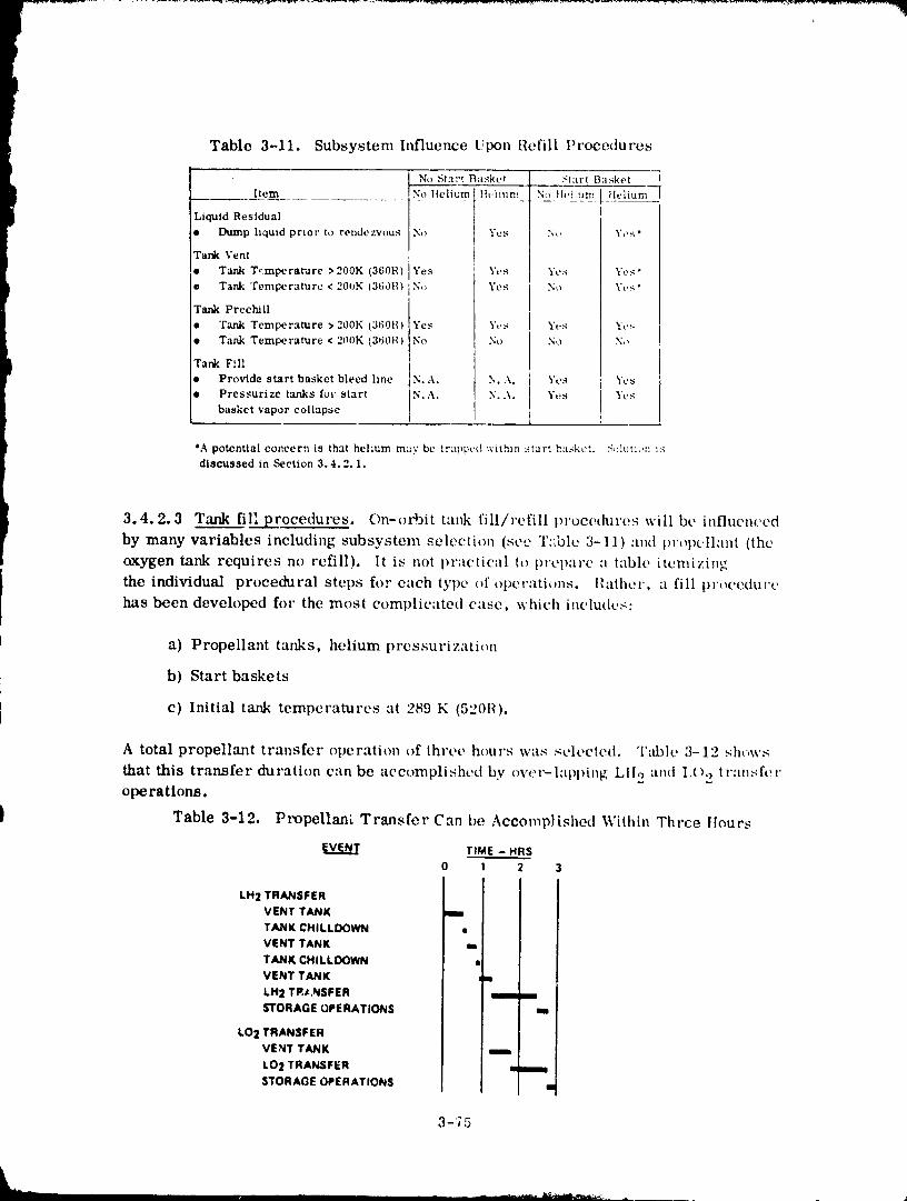
Table 3-11. Subsystem Influence Upon Refill Procedures
No .S,tart B!tskt, t ] Start Basket
Item _ NoHeliuml,h, itun_ lN_,lviluw,[!hqiumLiquid Residual
• l:Mmp liquid prior to rendezvous No ] Yes ] No Yes*
Tank Vent !|
• Tank T,:mperamre >200K (360R) Yes ' Yes Yt,s Yes °
o Tank 'femperature < 200K (36dR) No Yes N,) Yt, s °
Tank Preehill
• "rank Temperature > 200K (360R) Yes Yes Yes Yt,s
• Tank Temperature < 200K (360R) No No No No
Tank Fill
• Provide start basket bleed line N.A. N..\. Yes Yes
• Pressurize tanks for start N.A. N..\. Yt?s Yt,_
basket vapor collapse i
*A potential concern is that helium may be tr:tp_cd within ,_tart b:u;kct. S,4uti,m ;:_discu.tsed in Section 3.4.2.1.
3.4.2.3 Tank fill procedures. On-orbit tank fill/refill procedures will be influem'ed
by many variables including subsystem selection (so-, T:,blc 3-11) and I)r,)pcllant (the
oxygen tank requires no refill). It is not practical to prepare :t table itemizing
the individual procedural steps fl):" each type or"operati_ms, l{athcr, a fill prt,cedurchas been developed for the most complic:tted case, which includes:
a) Propellant tanks, helium pressurization
b) Start baskets
e) Initial tank temperatures at 289 K (520R).
A total propellant transfer operation of three hours was selected. Table 3-12 shows
that this transfer duration can be accomplished by over-lapl)ing Ltlo and I,()o transferoperations.
) Table 3-12. Propellam Transfer Can be Aecomp!ished Within Three tlours
V_ TIME - HRS
0 l 2 3I
VENT TANK
TANK CHILLDOWNVENT TANK
TANK CHILLDOWN _l]VENT TANK _lm
LH 2 TR#,NSFER ] mmms'rORAGE OPERATIONS ] m
LO2 TRANSFER ]VENT TANK " m
LO2 TRANSFER ' • m
STORAGE OPERATIONS I ,
3-75
1980009811-108
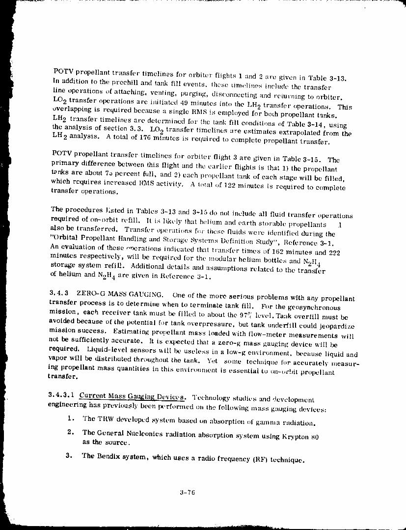
POTV propellant transfer timelines for orbiter flights 1 and 2 :ire given in Table 3-13.
In addition to the preehill and tank fill events, those timolines i::clude the transfer
line operations of attaching, venting, purgiug, disconnecting and retutmng to orbiter.
LO 2 transfer operations are initiated 49 minutes into the I,H 2 transfer operations. Thisoverlapping is required because a single RMS is employed for both propellant tanks.
LH 2 transfer timelines are determined for the tank fill conditions of T.'tble 3-14, using
the analysis of section 3.3. LO 2 transfer timelines are estimates extrapolated from theLH 2 analysis. A total of 176 milmtes is required to complete propellant transfer.
POTV propellant transfer timelines for orbiter flight 3 are given in Table 3-15. The
primary difference between this flight and the earlier flights is that 1) the propellant
tanks are about 70 percent fldi, and 2) each propellant tank of each stage will be fil!ed,
which rcquires increased RMS activity. A t_qal of 122 minutes is required to complete
transfer operations.
The procedures l_sted in "l'_d_les 3-13 and 3-15 t|o not include all fluid transfer operations
required of on-orbit refill. It is likely that helium and earth storable propellants 1
•also be transferred. Transfer operations ft',t' these fluids were identified during the
"Orbital Propellant Handling and Stor:tgc .',3,stems Definition Study", l{eference 3-1.An evaluation of these ooerations indicated that transfer times of 162 minutes and 292
minutes respectively, will be required for the modular helium bottles and N2tl 4storage system refit!. Additional details ,'rod assumptions related to the transfer
of helium and N2tt 4 are given in Reference 3-1.
3.4.3 ZEHO-G MASS GAUGING. One of the more serious problems with any propellant
transfer process is to determine when to terminate tank fill. For the geosynchronousmission, each receiver tank must be filled to at_mt the 97_; level. Tank overfill must be
avoided because of the potential for tank overpressure, but tank underfill could jeopardize
mission success. Estimating prot_ellant mass lt_ded with flow-meter measurements will
not be sufficiently zccurate. It is expected that a zero-_ mass gauging device will be
required. Liquid-level sensors will be usele.ss in a low-g envirunment, beck:use liquid and
} vapor will be distributed throughout the tank. Yet some teclmique l't_r accurately measur-ing propellant mass quantities in this envirtmment is essential to tm-urbit prol_llanttransfer.
3.4.3.1 Current Mass Gauging Devices. Technology studies _md development
engineering ires previ_usly been wrformed on the following mass gauging devices:
1. The TRW developed system based on absorption of ganxma radiation,
9+. The General Nucleonics radiation absorption system using Krypton t40as the source.
3. The Bendix system, which uses a radio frequency (RF) technique.
3-76
t
.<
1980009811-109
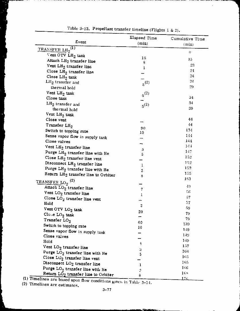
Table 3-13. Propellant transfer timeline (Flights 1 & 2).
Elapsed Time Cumulative Time
Event (rain) (rain)
TRANSFEIt LH2 (1) _)Vent OTV LH 2 tank 15 15
Attach LH 2 transfer line 8 23
Vent LH 2 transfer fin6 1 24
Close LH 2 transfer line -- 24
Close LH 2 tank -- 24
Lit 2 transfer and 5(2) 29thermal hold
Vent LH 2 tank 5(2) 34
Close tank -- 34
LH 2 transfer and 5(2) 39 'thermal hold i
Vent LH 2 tank 44 4
Close vent -- 44
Transfer LH 2 90 13,{Switch to topping rate 10 144
Sense vapor flow in supply tank -- 14,tClose valves -- 144
Vent LH2 trazmfer Une _ 147
Purge LH 2 transfer line with He 5 152Close LH 2 transfer line vent -- 152
Disconnect LH2 transfer line 1 15,2
Purge LH 2 transfer line with He 2 ] 55
Return LH2 transfer line to Orbiter 8 1_;3
TRANSFER LO 2 (2) -- 49Attach LO2 transfer line 7 5_;Vent LO 2 transfer line 1 57
Close LO 2 transfer line vent -- 57
Hold 2 59
Vent OTV LO 2 tank 20 79
Clo_e LO2 tank -- 79Transfer LO2 60 139
Swtt,-h to topping rate 10 149Sense vapor flow in supply tank -- 149
Close valves -- 1,t9Hold _ 157
Vent LO2 transfer line 3 1(;oPurge LO 2 transfer line with He 5 1¢;5
Close LO 2 transfer line vent -- 1_;5Disconnect LO 2 transfer line 1 l I;(;Purge LO2 trausfer line with He o 1_;_
Return LO2 transferline to Orbiter 8 ]7_i , .(1) Timelines are based upon flow conditions _ive,, in Table 3-14.
(2) Timellnes are estimates.3-77
1980009811-110
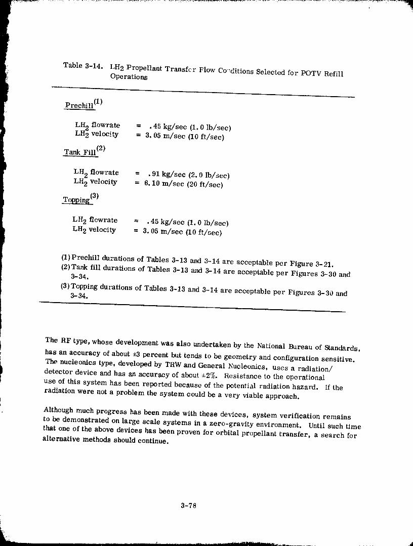
I
i_ Table 3-14. LH2 Propellant Transfer Flow Co'ditions Selected for POTV RefillOperations
Prechill (1)
LH flowrate = .45 kg/sec (1.0 lb/sec)
) LH22 3.05velocity = m/sec (10 ft/sec)
Tank Fill (2)
LH 2 flowrate = .91 kg/sec (2.0 lb/sec)LH 2 velocity = 6.10 m/sec (20 ft/sec)
Topping (3)
LH 2 flewrate = .45 kg/sec (1.0 lb/sec)
LH 2 velocity = 3.05 m/sec (10 ft/sec)
(1)Prechill durations of Tables 3-13 and 3-14 are acceptable per Figure 3-21.
(2)Tank fill durations of Tables 3-13 and 3-14 are acceptable per Figures 3-30 and3-34.
(3)Topping durations of Tables 3-13 and 3-14 are acceptable per Figures 3-30 and3-34.
The RF type, whose development was also undertaken by the National Bureau of Standards,
has an accuracy of about ,-3 percent but tends to be geometry and configuration sensitive.
i The nucleonics type, developed by TRW and General Nucleonics, uses a radiation/detector device and has an accuracy of about 4=2%. Resistance to the operational
use of this system has been reported because of the potential radiation hazard. If the
radiation were not a problem the system could be a very viable approach.
Although much progress has been made with these devices, system verification remains
to be demonstrated on large scale systems in a zero-gravity environment. Until such timethat one of the above devices has been proven for orbital propellant transfer, a search for
alternative methods should continue.
3-78
19800098-1-1--111
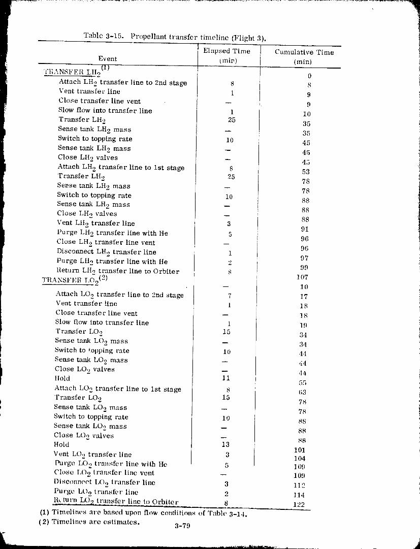
Table 3-15. Propellant transfer timeline (Flight 3).
Elapsed Time Cumulative Time
Event (,nip) (rain)
O)FIL_.NSFER LII2 0
Attach LH 2 transfer line to 2rid stage 8 8Vent tnmsfer line 1 9
Close transfer linevent -- 9
Slow flow into transfer line 1 10
Transfer LH 2 25 35
Sense tank LH 2 mass -- 35
Switch to topping rate i0 45
Sense tank LH 2 mass -- 45
i Close LH 2 valves -- 45Attach LH 2 transfer line to 1st stage 8 53 i
Transfer Lifo. 25 78 _]
I Sense tank LH 2 mass -- 78 ,_,][ Switch to topping rate 10 88
Sense tank LH 2 mass -- 88
t Close LH 2 valves -- 88Vent LH 2 transfer line 3 91
Purge LH 2 transfer line with He 5 96
Close LH 2 transfer linevent -- 96
Disconnect LH 2 tr,'msferline 1 97
Purge LH 2 transfer line with He 2 99Return LIIotransfer llne to Orbiter 8
L _'2(2)t_' 107TI1ANSFEll -- 10
Attach LO 2 transfer line to 2rid stage 7 17Vent transfer line 1 18
Close transfer line vent -- 18
Slow flow into transfer line 1 19
T ransfer LO 2 15 3,t
Seuse t,q_nk LO,2 mass -- 34Switch to topping rate 10 44
Sense tank LO 2 mass -- 44
Close LO 2 valves -- ,14
Itold li 55
Attach LO 2 transfer line to 1st stage 8 t;3
Transfer LO 2 15 78b
Sense t',mk LO 2 mass -- 78
L Switch to topping rate 10 88
Sense tank LO 2 nmss -- 88
Close LO 2 valves -- 88Hold 13 t01
Vent L()o transfer llne 3 104
Purge LO 2 transfer line with He 5 109Close LO 2 transfer line vent -- 109
Disconnect LO 2 i ransfer line 3 11'2Purge LOo t ransfer line ') l 1,ta,d
13_luj:n - LO2 t ransfe r line i9_ 0rbi_tej:._ 8 122
(1) Timelines are based upon flow conditions of Table 3-14.
(2) Timelines are estimates. 3-79
1980009811-112
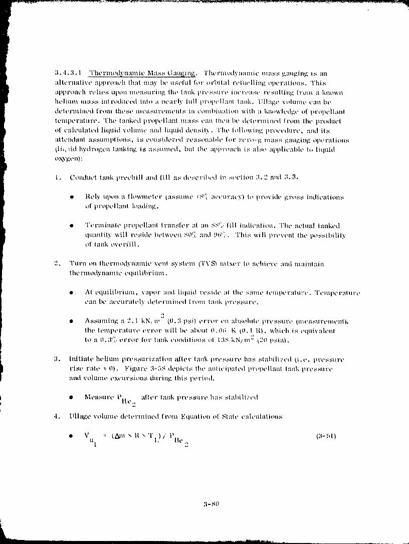
3 - 81)
1980009811-113
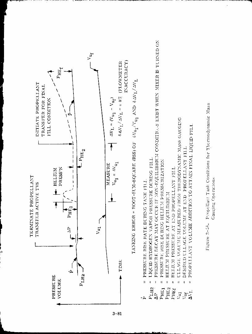
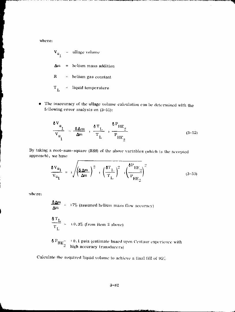
where:
Vul - ulk_e volume
_n = helium mass addition
R = helium gas constant
l
T = liquidtemperature
L
• The inaccuracy of the ullage volume calculationcan be determined with the
following error analysis on (3-51):
PHE ,6 VUl 6Am 6 'FL L
i -- • _ (3-52)
V u _m T PI L ttE 2
By taking a root-stma-square (RSS) of the above variables (which is the accepted
approach), we have
-- :_: _ •_ _3-53)Vul \ TL \ PHE,) !
whe re:
:: J-7(_ (assmned helium mass flow accuracy)_n
I8'I" L
: :LO.3(X_ (from item 2 above)'1"L
P = i:0.1 psia (estimate based upon ('t, nl:ltlr cxpcricllce wii.h
HE2 high accuracy transducers)
Calculate, the required liquid w_lume to achieve a tintd fill of ',),)_ ,,_"
3-82
1980009811-115
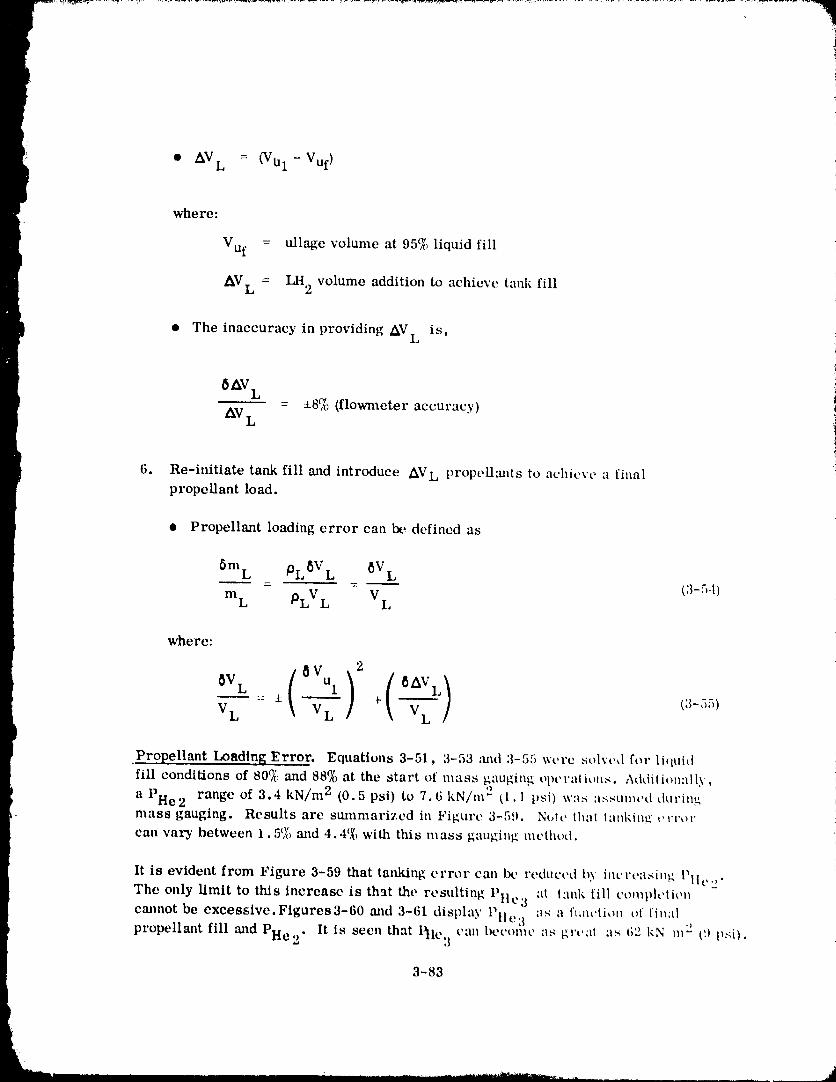
I.
• AVL = (VuI -Vuf )
where:
Vuf = ullage volume at 95c_ liquid fill
L AVL = LH 2 volume additionto achievetankfill
i • The inaccuracyinprovidingAV L is,
6AV L- 18(,'{,(flowmeteraccuracy)z_v
L
i 6. Re-initiatetankfilltrodintroduce propellantsto achieve finalAVL a
propellantload.
• Propellant loading error can Ix', defined as
6m L PL 8VL 8V L- - (3-54)
mL PLV L V L
where:
2
--• + --- (3-55)V L V L V L ]
,Propellant Loading Error. Equations 3-51, 3-53 :rod 3-55 were solve,1 for liquidfill conditions of 80_}/_and 88(){_at the start el mass gauging el)ovations. Attditiotmlly,
range of 3.4 kN/m 2 (0.5 psi) to 7.6 kN/m fi (1.1 psi) wa_ asstllllt,d tluFiII':L'a Pile 2mass gauging. Results are stanmarizcd in Figure 3-59. Nt,_t, that tanldn_ cvl'ov
can vary between 1.5t}_)and 4.4(J{)with this mass gaul_ing method.
It is evident from Figure 3-59 that tankilvg error can _, reduct,d by incrcasin;4 Pllc2"
The only limit to this increase is that the resulting Pile3 at tank fill comt)h'tioncannot be excessive.Figures3-60 mad 3-61 display l)ll , :is a fum'tion of finalt, 3 .,
propellant fill ,and Pile 2" It is seen that l_}te3 can bet't)lllt, :IS gl't'at ;Is 62 kN m- (9 psi).
3-83
1980009811-116
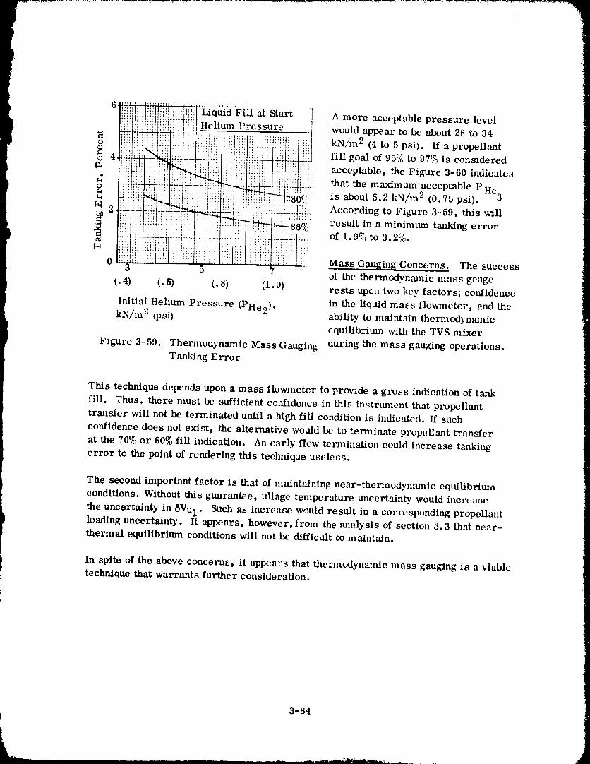
6'__'_qaid'Fiil:'__l::;; . at Start ] A more acceptable pressure leveli_)!t!!!!_'r_:::! Hehum Pressure would appear to be about 28 to 34
i!i::![;i:,_.:_,!ilii'iiii:::!::i!li!:i::i::i..r !.......... :............. kN/m2 psi) propellant:iii!ti:/_:!i[ .... ii:i:I: ::i::i:=___ :,_,,_::L,:'::._,': fill goal of 95% to 97% is considered
. ,:_iI]_i!__I!{::::!{_!,:...... ::: :i:?i:?{;:!ii:l i:: #i::!!i!'lihi,l i: ,!!, acceptable, the Figure 3-60 indicatesu i!!!i !: ,_:r:'_: i!: i{iiiiiil i! that the maximum acceptable PHe
:_80,,,:::li:i : 'c, is about 5.2 kN/m 2 (0.75 psi). 3
:!i::,_ :_AI:- '-" result in a minimum tanking error_. :,.[ L_88/o
_ of 1. 970 to
0 :i!!:Ei! :: ::; : ;ii Mass Gauging Concerns. The success
3 5 7 of the thermodynamic mass gauge
(. 4) (. 6) (. 8) (1.0) rests upon two key factors; confidence
Initial Helium Pressure (PHe2) , in the Liquid mass flowzneter, and thekN/m 2 (psi) ability to maintain thermodynamic
equilibrium with the TVS mixer
Figure 3-59. Thermodynamic Mass Gauging during the mass gauging operations.Tanking Error
This technique depends upon a mass flowmeter to provide a gross indication of tank
fill. Thus, there must be sufficient co_ffidence in this instrmncnt that propellant
transfer will not be terminated until a high fill condition is indicated. If such
confidence does not exist, the alternative would be to terminate propellant transfer
at the 70% or 60% fill indication. An early flow termination could increase tanking
error to the point of rendering this technique useless.
The second important factor is that of maintaining near-thermodynan_ic equilibrium
conditions. Without this guarantee, ullage temperature uncertainty would increase
the uncertainty in 6Vul. Such as increase would result in a corresponding propellantloading uncertainty. It appears, however, from the analysis of section 3.3 that near-thermal equilibrium conditions will not be difficult to maintain.
In spite of the above concerns, it appears that thern_odynanflc mass gauging is a viable
technique that warrants further consideration.
3-84
1980009811-117
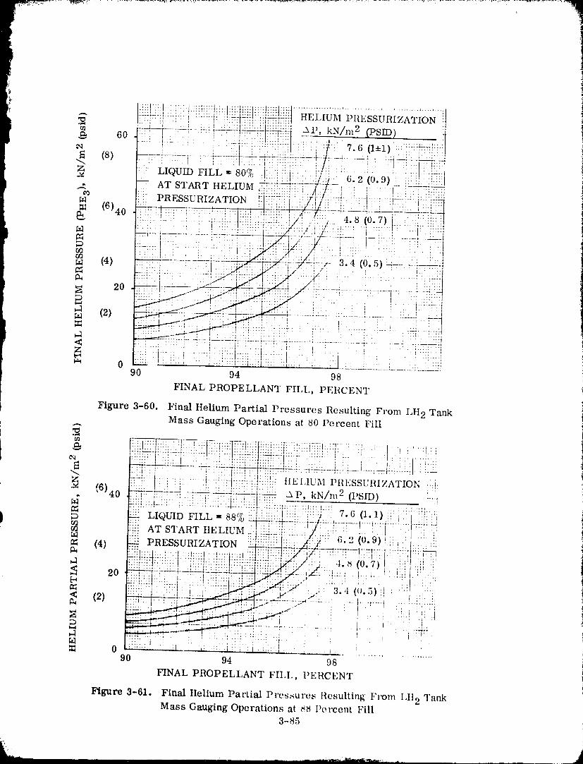
1980009811-118
4COTV ORBITAL RESUPPLY
In this section a mission scenario will be developed for the Cargo Orbital Transfer
Vehicle (COTV) concept selected in Section 2. A mission will be defined as an aid in
identifying the key issues of orbital refill operations. These operations will include all
major activities from post-mission return to LEO through resupply. Vehicle and depotsubsystem orbital refill requirements will also be identified. Operational procedures
and techniques for propellant transfer will then b_, 'cveloped. Attention will focus onlyon COTV differences with POTV refill operations, because many aspects of orbital
propellant transfer operations will be similar or identical.
4.1 MISSION SCENARIO
Large space industrialization programs have been conceived for the 1990's and beyond.
One of the most ambitious is the Solar Powered Satellite (SPS) program that will re-
quire propellant quantities several orders of magnitude greater than those identified
for the near term. In this SPS project Heavy Lift Launch Vehicles (HLLV) will be
developed to transport personnel, material and propellants into low earth orbit (LEO).
Liquid hydrogen and liquid oxygen will be transported in large supply tanks containing
approximately 436 metric tons (960,000 lb) at a 6 to 1 ratio. These supply tanks will
be transferred directly to depots in LEO, and empty tanks will be returned to earth for
refuelling. Depot ancillary equipment will _nelude reliquefiers for reclaiming stored
propellant boiloff, and large solar arrays for converting solar power to the electmcal
energy needed to operate the orbital facility.
I! Personnel and material will be transported fr(_m depots to higher orbital altitudes to
i support industrialization programs. Personnel will be transported in POTV_; material(or cargo) wilJ be dispatched to, work sites (per imps G]!:O) in a common stage COTV.
Conceptual studies have been performed to identify COTV configurations, some of whichwere discussed in Section 2.
P}
4.1.1 SELECTED COTV MISSIONS. A two stage COTV will fly a round trip mission
to dispatch its payload to GEe. Total missi,,n duration will be approximately five days;the first stage will return to LEO a short time after the vehicle is launched. The
second stage will return to LEO following the five day round trip mission to GEe.
Upon return, each vehicle stage will enter a phasing orbit pr¢_paratory to depot rendez-
vous. Several revolutions of this orbit (_- 3.1 hours per revolution) may be required
before rendezvous is attempted. Rendezwms and docking maneuvers will consume
approximately two hours.
4-1
1980009811'119
Post-docking operations will include cost effective procedures to reclaim all pro-
pellant liquid and vapor practicable. This is the primary area where substantial dif-
ferences between POTV and COTV operations will occur because, tht, d. poi :mcillary
equipment can be employed to minimize pr(_pellant loss. The impetus for such pro-
cedures is derived from the relatively high cost of transporting propellants into space.
4.1.1.1 Timelines. Timelines have not yet been developed for COTV operations.
However, a previous study "Orbital Propellant Itandling and Storage Systems for
Large Space Programs," Reference 4-1, indicated that a launch schedule of ten or more
flights per year is conceiv&ble. Therefl_re, a rapid turnaround time between missions
is expected. Subsystems will be inspected and tested to verify flight worthiness once
post-mission operations are complete. A safed condition will e_st onec liquid pro-pellants have been transferred and t.-mk pressures stabilized. Pressure stabilization
will be relatively easy to manage once liquids have been transferred.
4.1.2 ORBITAL DEPOT CONFIGURATION. Orbital depot conceptual designs were
developed under Contract NAS9-15640 (Reference 4-2) for Johnson Space Center (JSC).
That study concluded that largc scale space activities would benefit from orbital pro-pellant depots such as shown m Figure 4-1, which illustrates a five-storage-module
depot, with optional crew quarters and maintenance h_mgars, refueling a manned OTV.Basic features include capillary propellant acquisition systems so that no rotation or
thrusting is necessary to position propell:mts. Reliquefitction systems eliminate longterm boiloff losses.
Benefits of such a depot are:
a. Reliquefaction eliminates boiloff losses.
b. Operations are more flexible, accommc_lating launch delays and OTV waiting.
c. Operating costs are reduced for probable 1990's OTV missions.
i Investment considerations are:a. Reliquefaction with power and radiators is a major item.
) b. Station keeping uses significant amounts of propellants. "p
c. Propellant delivery tanks may also be used for storage.
d. Docking provisions, solar power array, and radiators are common to any
space base.
4.1.2.1 Ancillary _-quipmcnt. Reliquefters will be pt, rmm_ently plun_bed to the supply
tank farm for continuous reliquation of propt, llant boih_ff. :';tudies e(mducted in
Reference 4-2 indicate that reliquefiers will be ('out-t'fft'etivt, in eol_tra:t to tht, alter-
native of transporting additional prq)vllants from earth. Sill('t, Iht'y reqllire eleetl'ieal
.t-2
1980009811-120
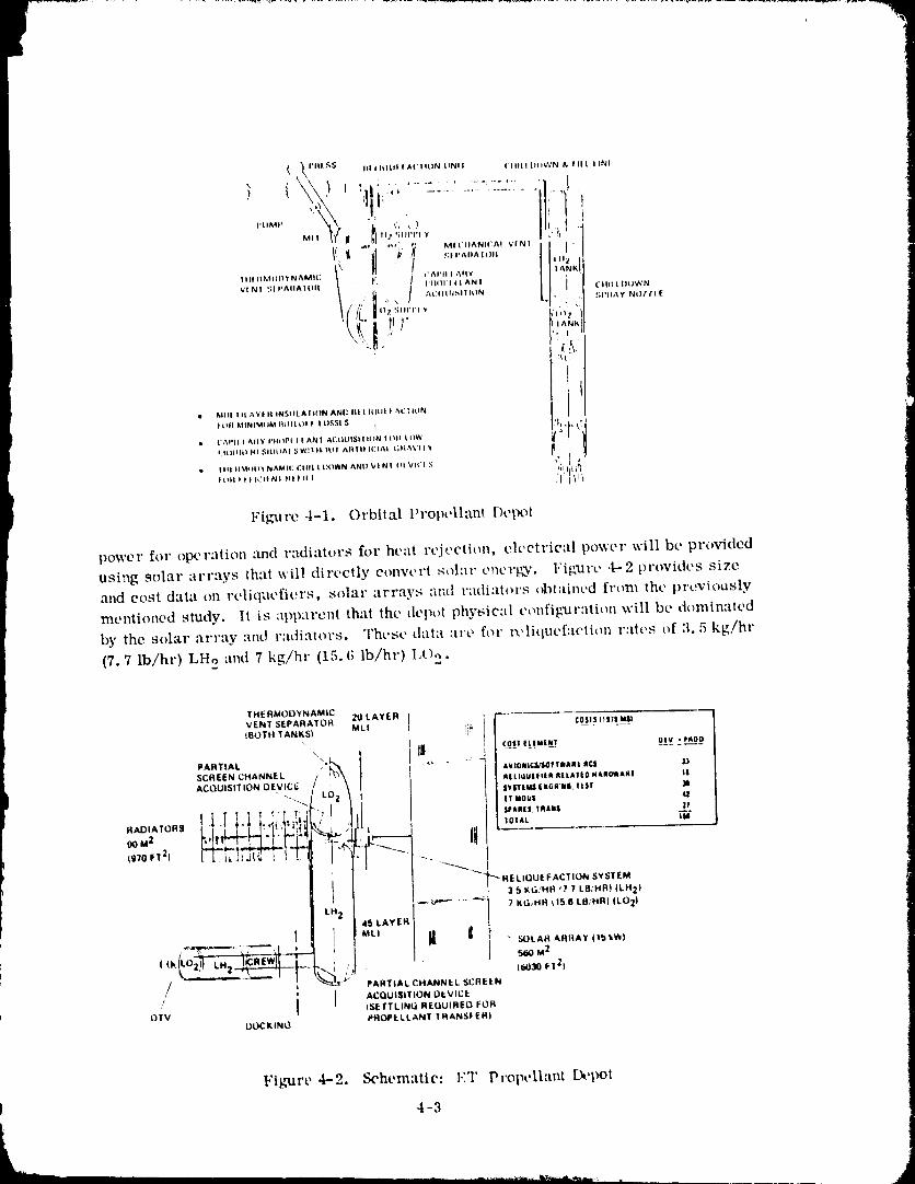
( _ I'll| '¢;5 III t It|ttl I At' I I(.)N tlNI I ('1|11,11)(I_'¢N & I It | | INI
I k' :;,|'^,,^_o,, '||_ tl
" '^,_"11Ili| III_AL)|)Y N/_MI(+; *'/_lql I ;_flY
VIP_I +';|I+AIIAIO|( / +'0 \ / )')|I)VII|+£_N| ! CIlIIL|IA)WN
+++"+l /L ()2SIII'I'IY ' " t: .*;|'tIAyNIIITI[• . !
| O|l MINIMIIM IqLIIL OI ! I tlSSI S ( _' " k. L:AI'II I Ally PIII)PI l I ANI AI:()UISll ION I tSit I OW
| Itltlli) lit SILiLIAI _,W+l )l, )Ill AIIIII ICIAI +.+t_1&VI I +n 1 ,_lI I Ill IIMI )p_ PsIAMI(: t_llll L LX)WN ^HI) V I P'dI I)k VIt'I S "_
lli|l I i| ICII NI HI III l ] II{_+
Figure 4-1. Orbital Propollant I)cpot
power for opet'ation and t'adiatot's for heat t'vjoction, elcctt'ieal powel" will bc pt'ovided
using solar art-ays that will directly convt'rt sol:it eT)t't'[k+"¢, l"igtll'c 4-2 provides size
and cost data on roliqucfiers, solar arrays and r;tdiat(_]'s obtained from the previously
mentioned study. I( is apparent that the depot physical cotffig'uvttti()tl will be dominated
by the solar array and I':tdi:ttot's. Tht, st, data :tt't, [of l't, litltlcf:tctit_l_ l':ttt, s of 3.5 kg/hr
(7, 7 Ib/hr) LHo and 7 kg/hr (15. (; lb/hr) Lt)o.
THERMODYNAMICVENT SEPARATOR 21) LAYER
IBOTtl TANKS) MLI ? C0SI_I HSTe MI)
PARTIAL \ I_I C0S_'Ittu|lu! otv , P#0OSCREEN CHANNEL
AC(_UISITION OEVICE _lLldUl[+Iti4 RELATI0 H&II0IAIII tlSyl'Ttttl i 146i_'111,lkSr J
"+_ "'_. It II0 r'l 4J
RADIATORS / : "_t : ; tO+At, iM
(gTo FT 2)
" '--'_"_"_ RE LIQUE F ACTION SYSTEM, 3SKG/NR{?TLB/HR_ILH 2)
/ _ :_'t JEll" _'_ PAmTIAL CHANNEL SCREEN
/ I ACQUISITION DkVICE
I I_IETTLINL_ REUUIREO FOROTV PROPELLANT TRANSFER!
D_KING
Fl_,mz'e4-2. Schematic: I.:'T Pt'opeltatU I),,pot
4-3
1 j1.qRNnnaR1 1 _191
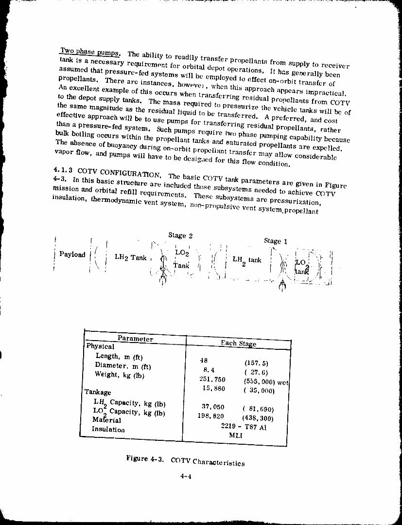
,i_ _ .......
)
I Two phase pumps. The ability to readily transfer propellants from supply to receiver
b tank is a necessary requirement for orbital depot operations. It has generally been !assumed that pressure-fed systems will be employed to effect on-orbit transfer of
propellants. There are instances, howevel, when this approach appears impractical.
An excellent example of this occurs when transferring residual propellants from COTV
to the depot supply tanks. The mass required to pressurize the vehicle tanks will be of
the same magnitude as the residual liquid to be transferred. A preferred, and cost
effective approach will be to use pumps for transferring residual propellants, rather
than a pressure-fed system. Such pumps require two phase pumping capability because
bulk boiling occurs within the propellant tanks and saturated propellants are expelled.
The absence of buoyancy during on-orbit propellant transfer may allow considerable
vapor flow, and pumps will have to be desig;_ed for this flow condition.
4.1.3 COTV CONFIGURATION. The basic COTV tank parameters are given in Flgnre4--3. In this basic structure are included those subsystems needed to achieve COTV
mission and orbital refill requirements. These subsystems are pressurization,
insulation, thermodynamic vent system, non-propulsive vent system, propellant
Stage 2 Stage 1
x ' i "' \i I..."t, 'ii i '._,\.:'.".,_.:._............:.-:._............,,
- Parameter _- .. Each Stage ....
PhYsicalLength, m (ft) 48 (157.5)Diameter, m (ft) 8.4 (27.6)
Weight, kg (lb) 251,750 (555,000) wet15,880 (35,000)
Tankage
LH 2 Capacity, kg (lb) 37,050 (81,690)LO2Capacity, kg (lb) 198,820 (438,300)Maferial 2219 - T87 A_.Insulation MLI
Figure 4-3. COTV Characteristics
4-4
1980009811 -12
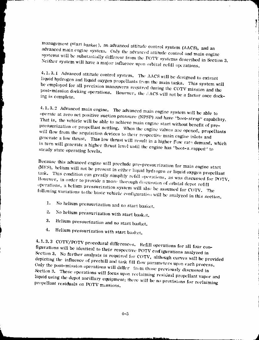
management (start basket ), an advanced atti_Me control system (AACS), and an
advanced main engine systeln. O_]y the advanct,d attitude control and main engine)¢,systems will bc substantially differe1_t trom the P( l V systems described in Section 3.
Neither system will have a major influe'_ce upon orbital refill oIx:rations.
4. i. 3.1 Advanced attitude control system. The AACS will be designed to extract
liquid hydrogen and liquid oxygen propelkmts t',:om the main tanks. This system will
be employed for all precision maneuvers required during the COTV mission and the
post-mission docking operations. However, the .¢ACS will not be a factor once dock-
ing is complete.
44.1.3.2 Advanced main engine. The adv.'meed main engine system will be able to
operate at zero net positive suction pressure (NPSP) :tad have "boot-strap" capability. I
That is, the vehicle will be able to achieve main engin,., start without benefit of pro- ipressurization or propellaa]t settling. When the engine valves arc opened, propellants
will flow from the acquisition devices to their respectWe main engi_e inlets and
generate a low thrust. This low thlxlst will result in a higher flow rat _ demand, which i
in turn will generate a higher thrust level until the engine has "boot-s. rapped" to
steady state operating levels.
Because this advanced engine will preclude prc_-pressvrization for main engine start
_IES), helium will not be, present in either liquid hydlogen or liquid oxygen propellant
tank. This condition can greatly simplify refill o|)er:ltions, as was discussed for P(bTV.
llowever, in olxler to provide a more thorough di_c'ussion of orbital (leper refill
operations, :l helium pressul-ization system will also be assumed for C()TV. The
following variations to the basic vehicle configxiratio,_ will bt' analyzed in this section.
t
1. No helium pressurization and no start basket, i
2. No helium pressurization with start bask,._t.
3. Helium pressurization and no start basket.
I 4. Helium pressurization with start basket.4.1.3.3 COTV/POTV procedural differenc,.,s. Refill operations for all four eort-
figurations will be identical to their respective POTV corfignirations analyzed in_ction 3. No further analysis is required for COTV, although curves will be provideddepicting the influence of preehill atuI tank fill t'low paramt, ters upon each process.
Only the post-mission operations will differ fr(m_ those previously discussed in
Section 3. These operations will focus upon reclaiming residual propellant vapor "rod
liquid using the depot ancillary equipment; there will be no provisions for reclaiming
propellant residuals on POTV m_ssions.
-t-5
1980009811-123
4.2 POST MISSION DE- TANKING OPERATIONS
I Once vehicle is and the payload/crew module isdocking complete secure, post mission
de-tankingoperationsw'llbe initiated.One or Tr_re ofthefollowingreasonsmay be
justificationforinitiatingpr3pellantde-tankingina tin]elymanner.
) If it is feasible to reclaim propellants --
• Return liquid to the better insulated supply tanks in order to minimize boiloff.
• Relique_ propellant vapor and return to supply tank, thereby reclaiming vapor for ifuture missions.
If a helium pressurization system is used (i. e., helium is in propellant tanks) --
• Helium must be expelled before refill can be initiated. This requires that tank
propellants be expelled.
If an autogenous pressurization system is used (i. e., no helium) --
• Propellants u-ill be expelled if vehicle component replacement requires that
propellant tanks be "opened-up". As an example, vent valve replacement can be
performed conveniently only if tank pressure resides at or near zero.
It is seen f:om the above that propellants should almost always be transferred from I
the COTV shortly after docking. An exception to this would be if a) there was no
advantage to reclaiming residual propellants, b) the vehicle stage had autogenous pres-
surization, and c) component replacement would not be performcd between vehicle
missions. Under these conditions, propellants would remain aboard, gradually evapo-
rate and be vented. There would be no compelling reason for transferring liquid propellaetbecause all maintenance, except for major component replacement,could be perform_l
with liquid on-board.
The remaining discussion and analysis will deal w_th the question of when it is costeffective to reclaim residual propellants, and when these propellants should be dumped
overboard. Because helium can complicate pr_,cedures, _perations for an aut(_
' genous pressurization system wiE be evaluated separately from he',lure system
operations.
4.2.I OPERATIONS FOR AUTOGENOUS PRESSURANT. A totallyautogenouspres-
surizationsystem for COTV willonlybe reallzt_iforan advancedenginesy_t,_mwith
zero N'PSP capability.Propellantvapor willbe tappedofffrom theenginesystem for
tankpressurizationduring"transient"and steadystateoperation. Consequently,only
liquidand itsvapor willresidewithinthepropellanttanksfollowinga mission. Thi'_
conditionreduces thecomplexityofpropellanttr:msferoperations.
4-6
n
198000'-Jb 3-I"g
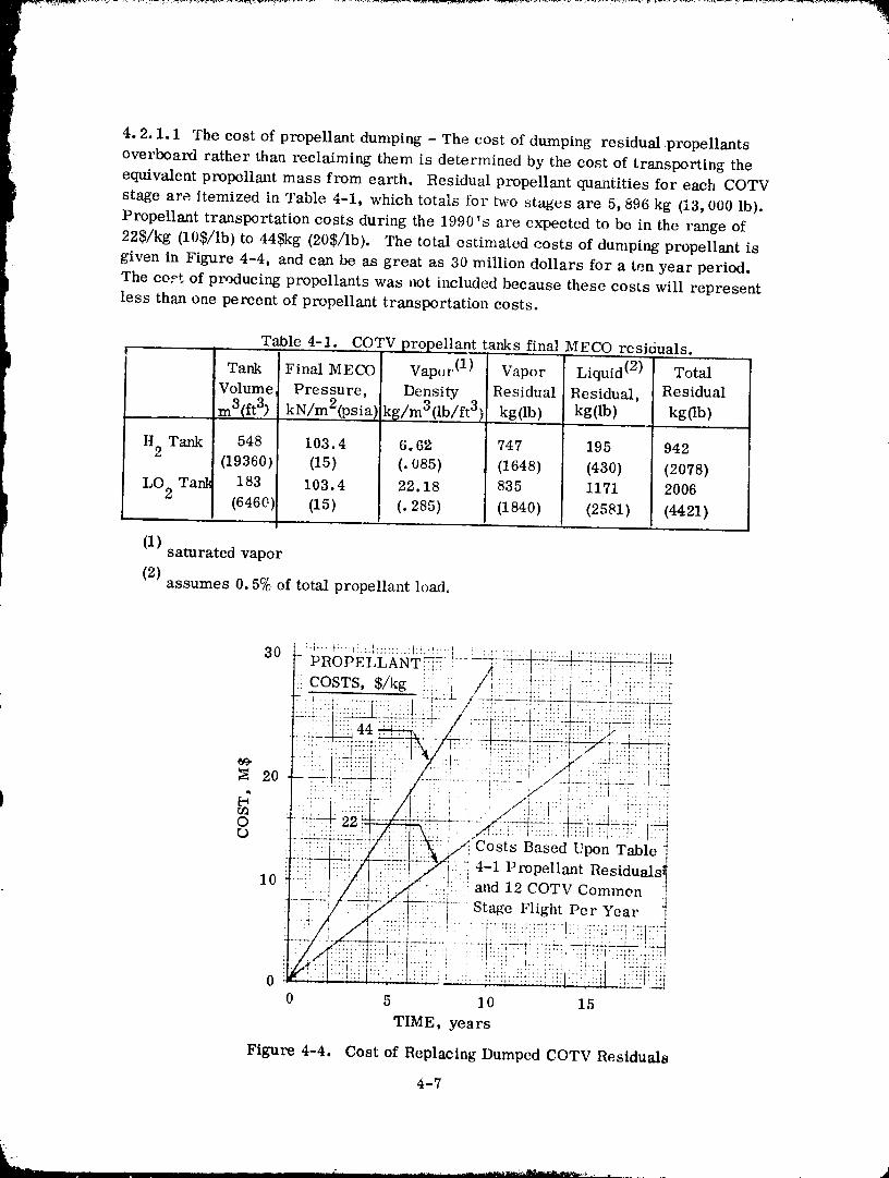
4, 2.1.1 The cost of propellant dumping - The cost of dumping residual propellants
i overboard rather than reclaiming them is determined by the cost of transporting the
equivalent propellant mass from earth. Residual propellant quantities for each COTV
stage are itemized in Table 4-1, which totals for two stages are 5,896 kg (13,000 lb).
Propellant transportation costs during the 1990's are expected to be in the range of
225/kg (10$/lb) to 445kg (205/lb). The total estimated costs of dumping propellant is
given in Figure 4-4, and can be as great as 30 million dollars for a ten year period.
The co,_t of producing propellants was not included because these costs will represent' less than one percent of propellant transportation costs.
Table 4-1. COTV propellant tarLks final MECO rcsiduals.
!
Tank Final MECO Vapor (1) Vapor Liquid (2) Total
Volume Pressure, Density Residual Residual, Residual
m3(ft 3) kN/m2(.psia).k_../m3(lb/ft 3) kg(lb) kg(lb) kg(lb)
H2 Tank 548 103.4 6, 62 747 195 942(19360) (15) (.085) (1648) (430) (2078)
LO 2 Ta_ 183 103.4 22.18 835 1171 2006(6460) (15) (.285) (1840) (2581) (4421)
(1) saturated vapor
(2)assumes 0.5% of total propellant load,
::::::::::::::::::::::::::::::::: :I !: : t :::::::::::::::::::::::::::::::::::::::::
30 PROPELLANT _- ,T--:-/_--,_-?]_::i:f::.:i:::: :i(_[COSTS, $/kg i l : //i: I :iiii!i:': i:ii:il::!i"! ii
O -_ 22 ...._i:: --..¢"-i-_:_ ._:'.:_:+i_- -_,' " " ' /":I.;:,::: t;::I:, :l.:',:t::::l: .: : . t:
r.) Costs Based Upon Table ]
4-1 PropellantResiduals110 :::_!iiand 12COTVCommen :
Stage FlightPer Year I
0 5 10 15
TIME, years
Figure 4-4. Cost of Replacing Dumped COTV Residuals
a-7
198000981"i-125
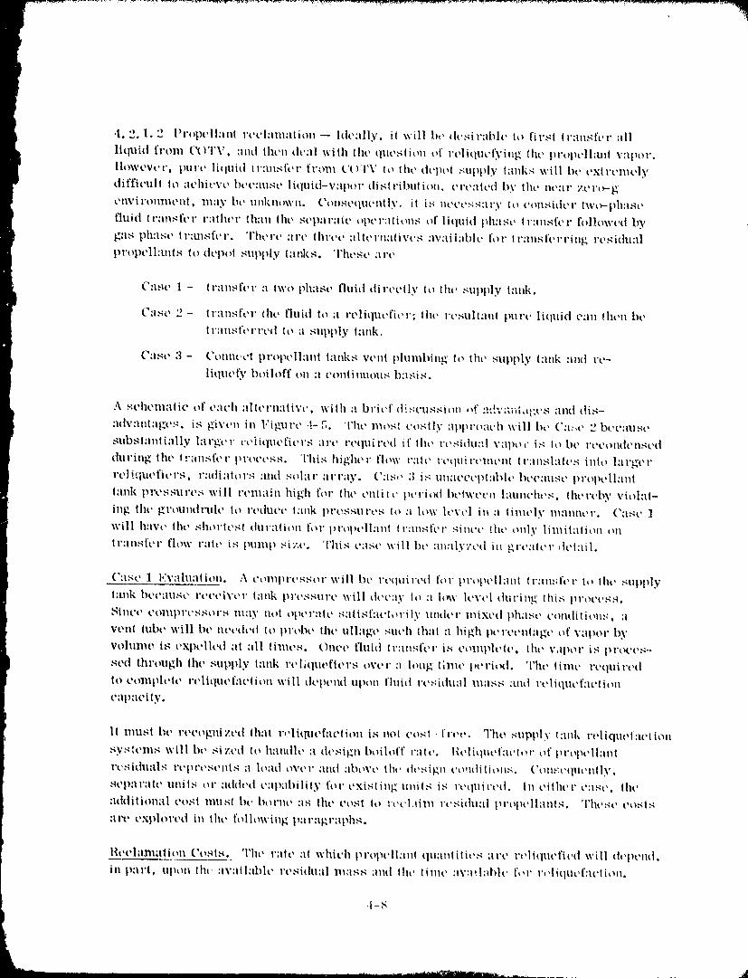
•t. 2.1.2 Propt'llan{ reclanlation -- hh':dly, il will I,,, _lt',-;iral_h, to first [ransfer all
liq'uid from (_YI'\:, and iht, n th,,ll wtlh lilt, question of rt,liquet:ving tilt' propell:tnt vapor.
llowevcr, pure liquidtV:UlSl\'rfl'onlt't)'l'Vto tilt'depot supply tanks willbt'extremely
difficull Io achieve bee,rest' liquid-v:lpor dislribulion, crealt'd by the near _'.t'l'_g
ClIVil'Ollll_t'lll. lllaV bt' UllkllOWII, ('O|lSeq%R'lltl.V, it i:_ IICCt',';S:ll'y to ¢'ollsidt'l" twO'-phl_st'
l']uid tr:ln,qft'r rather th:lll tilt, st'parllit' oper:ltiollS of liquid ph:t,gt, tr:lnsft, r followed by
gas ph:ist, tl':msfer. Tht, rt' are l|u'ct, allt, rn:flivt,s avail:lbh' for ll'ansft'rring residu,d
pvopell:tnts to depot supply tanks. These are
Case I - transft'r a two phase fluid directly Io tilt, supply l:ulk.
Case 2 - Ir:lnsfer {lit, fluid Io :i reliqucficr; lilt, ,'t'sullani purl' liquid can then bt,
t l'illlSl't'X'l't't| lO ;I supply tank,
grist, 3 - Collllt't'l propellant lanks venl plunlbing/ to tilt' supply l:mk and re-
liquefy boiloff t,n a t'onlinuolts b:,sis.
A scllelnalic of each :lllt'rxl:lliVt', wilh :t brief discl.lssion ,*!":Id;'aiitdgt's ;.llld (ti.q-
:ldVillllllg'CS. is given in 1.'igllrt, .t.-5. l'ht, nlosl costly apprtmch will bc ('a:_t, 2 bt'(':lllSt"
sltbsl:tnlially l:lrgt'!" veiiqut, ficrs ;u't' l't,qllirt,d if lilt, l'csidual x':lpoc is It)be l't't'olldt'llst'd
dul'ing lilt' |.'Ansft'l" pl'Ot't'SS. This higher flow l':llt' l't'qllil't'lllt'lll tl':lllS|'llt'S into larger
rt, liqtlt'fit, rs, r:uliators a.lld sollll" ;irrg|y. (':Is,, :l is tulat'¢t,t)l:ll_l(, 1)ct':lust, prol_t, ll:lnl
l:ulk pl'essurt,:; will renlah_ high for tht, enli_ c pcri_ut bt'lwt't,n l:luncht's, thereby viol:ll-
ing lilt, grount|rllh' to rt,dtit't, I:mk i_rt,sSllX't,s to :1 low lcvt,l in :l timely lll:lllllt'l'. ("lSt _ ]
will have the shorlesl t|lll'alioll for propelhlnt tC:UlSft, r siuce the only limitation on
Ir:lnsft'r flow x':ltt' is plllllp siv, t'. This case will bt' :m:llyzcd in _rt':llcr detail.
Case 1 ]'Tv:Ihx:IIiOll. A t'Olllpl't,s,'qox" will bt' rt'qtlirt'd lot" pl't_pt'll:illI tX'Hll:;ft'l" 1o lilt' SUpllly
l:tnk bt't'iill,qt' l't't't'i'_;t'x" l:lnk pl't'SSlll't' will dt't';iy lo :1 h'w lcvt,I during this I_X't_t't',,-l,q,
SilICt' COlllpl'CSSOl',q llIiiyllOl Opt'l','llt' S;llisf:lt'torily IXlldt'l" Illixt'd phalst' t'Olltlilioll:_, ;I
venl tubt' will bt' nt, t,tit,d to pro|_t' lhe ullage such that :t high pt, l't't'lxlalgt, of vapor byvohmle is t, xpt'llt'd ;ll all lilnt, s. Ollt't, fluid lr:ulSfel' i_ eolllph'lt', tilt' vapor is pl'tWes--
sed lhrt)tlgh tilt' supply tank vt'litltmftt, rs over a long till_t' I_t'ri_|. Tilt' lime required
Io ¢olllph'It' rt'liqllt'f:lt'iion will dt't)t'nd uptm fluid rt,sithl:ll lll;IsS and rt, liqut'l'at'titm
c:lp:icily.
11 must bt' l't'¢Ogll|Zt'd Ill:it r,'liqut, f'lction is not cost -lrt,t,. Tho supply lank relique[:lt'ltolx
syslt'lllS will bt' sized to h:lndh' :i dr,sign boiloff talc. l{t'litlllt'f:lt'lor of prt_pt, llatd
l't'sit|lllil,q I't, prt,st'lltS ;I load oVt, l" :llld ilbovt, lilt, dt,sigll t,o_ltliliolxs. (,'Oll,,'t'qllt, lltly,
sCpllt':lto units or added cap:d)ility for t'Xislilxg Illlit,q i,q I't'qliil't'd. Ill t'ilht'x" cast', tilt'
:iddilionall t'osl llllisl l)t' borne :is lilt' t'O.ql to rt't'l,lilll l't'sidil;ll propt,ll:lnls. 'l'llt'st' t, osls
art, exph_red in lilt' following par.tgr:lphs.
Ih,elalamllon Costs. Tilt, l';llt' lit which propt'il:ult tlll;llllilit's ;ll't' vt,llquefit,d will th'pend,
in part. upon lh,' :lv:lil;ll)h' residual mass alltl lilt' lixllt' :w:lilahh' I',,v rt'litlllt'f:lt'lioll.
,I-8
19-800098i i--126
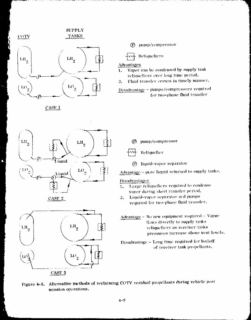
CASI,:1
,I F--_ _:" LH 2t (
® llquid-vapor sep,lrlltor
\ 2) . Liquid { _ { __.i AdvanlaE_- pt:,'e li,p,,id relu,'ned 1o supply tanks.
.... l)isadvamt:_ges
1. l,argt, rt'liqllt, fit, rs reqtlirt, d Io eondt, llst,
vapor during shm't tr,'lllsft'r pt, ritxt.
CASE 2 '2. I,iquid-vape, r scpar:ltor m'd pumps
rt'qttired for twt_phase fluid lransft, r.
("_ Adv:mtltg g - No new equiplllenl l't, qtlirt, d-- Vapor
,I tqows directly to supply t:mks
rt'liqllt'fit'rs llS rt'et'ivt'r lallks
pl't'SSUl't'S [llCl'011St' :lbove Vt'll[ levels.
_--.- Dis'ldvanlagc- l,ong time required for boihfff• ,--- + --
S "CA_ I_, 3
Flbnire 4--5. Alternative rl_ath(xts of reclaiming COTV residual propellants during vehicle postmission ope. rations.
4-9
198000.qR 11- 19 7
Estimated residual propelhult qumltities have been given in Table 4-1. These pr¢_
pell.'mts should probably be reliqueficd in a till_t' eompar:lble to the intexwal between
COTV launches; which is .tbtmt 30-36 days for lilt, selected scollario of 10-12 launches
wr year. Figure 4-6 gives reliquefaction rates as a function of time for the COTV
hydrogen residuals, (Note: This discussion will focus on hydrogen bec:mse its re-
liquefaction costs are considend)ly greater th:m for oNwgen. )
._ _:+::_4"_:_ ::::I:::::.............. _"
_ii_] AI'I'I/ON. 60 I'EliCENT OF _i I
(20) _ i!!ii IN EARTII SIIADOW) ii!"1
}i}}}}i}_ii.'¢Q_.; :t: ::} 1 '. :: :!::i !1!!i!: !iii i!l!i:i}:!i;I!! :! :I
_.,',_!; !_;212:12t!!22L2i2I:..i.2ii_:2;2!12_ii:i;:,;,2k_
0 10 20 30
TIME, days
Figure 4-6. Reliqueficr ";apacity-'rime Requirements for ReliquefytngCOTV Ilydrogon Rosidu&ls
The cost of hydrogen reliquefactlon units and their associated capacities are given inTable 4-2 for two unit sizes. These oosis wore determined from Rofcrence 4--1 and
do not include development costs; only tim cost of an additionM unit is assessed. The
smallest unit has a hydrogen reliquefaction capacity of 9.5 kg/hr (21 lb/hr) which is
capable of reliquefying COTV hydrogen residuals in about 14 days. This unit ir ml
adequate size for propellant reclamation, and its 16.6 MS cost rt, presents the cost of
reclaiming propellm_ts. Figure 4-7 indicates that abtmt five to ten years of opera,ion
may be requiredto recover reliquefiercosts.
4.2.1.3 Residuals for RCS propellants -- The o,_ii:tl depot will consume substantial
quantities of hydrogen and (xxTgen for drag makeup and attih_de control requirements.
The annum usage rates ,,_ere estimated in Reference 4-1 lit 22608 kg (49,872 lb)
4-10
1980009811-128
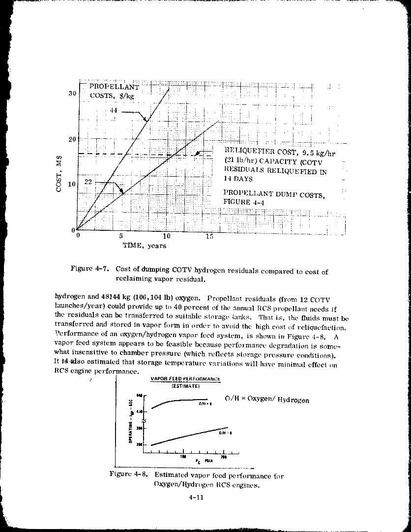
I
ROI-'LLLANT :."f.:: _ T ,, . ,.:, . . , . .
30 COSTS, $/kg : '_ _/i:::_, . :::: :.... _ :i: : -i- '; : !' !
......... _-l-;'l, ...... i-. . I........ i...... i.... _'"V -_..... _ ....
•.44 .... : _:II._: i--N/ ',:, .I i: : , . I _ : i.l':'i: .I! i.mq ' :i '.' I": I : ! i ,' i
-.=---,-.......... _-I......... ::_._l_:,z:__..___ __::_::.._..___ : .._ .... i.........._..... ,
•, _ } . : , .. :':: .... , ! :: .... :;;... ---':-7
20 I:IELIQUEHEII COST, 9.5 kg/hr' _ _ ............ : ; _ v
f ......
' / ' ' ___,'_:I,. ! RESLDUALSI_ELIQUI_:HED IN '
I ...'::'::::,'I". .'::::.I0
! _,._i[!':: PROPELLANT DUMP COSTS,"77, _" 77- . " T" --TW--Tr: 7.,'T_... ° . ., t .... *TT'T_"TT'7_7_- "'
:t...:,.:::t:::::::::::::::::::::::::::::::::::::::___' _ ::.' ! '- ' :_:i : i" ::' " t'""' : ' I i
0 ..................... _ .......... =.-_-:..-1- ........ k--.a-_.!......... .s-....... i...... '0 5 10 15
TIME, years i
Figure 4-7. Cost of dumping COTV hydrogen residuals compared to cost of
reclaiming vapor residual.
hydrogen and 48144 kg (106,104 lb) oxygen. Propellant residuals (from 12 COTV
launches/year) could provide up to 40 percent of the annual RCS propellant needs if
the residu,'tls c,-m be transferred to suitable storage tanks. That is, the fluids must be
tr:msferred and stored in vapor form in order to avoid the high cost of reliquefaction.
.r'erformanee of an oxsrgen/hydrogen vapor feed system, is shown in Figure ,t-8. A
vapor feed system appears to be feasible because performance degradation is some-
what insensitive to chamber pressure (which refleels storage pressure conditions).
It l_-atso estimated that storage temperature variations will have minimal effect on
RCS engine performance.. VAPOR FEED PEHFOIIMANCE
(ESTIMATE)
_ - O/H = Oxygen/Hydrogen
,, _ _ 1 l__x..._IM ZOO
_C - PStA
Figmre 4-8. Estimated vapor feed perfomnanee for
Oxygen/Hydrogen IICS engines.
i 4-11
i
1980009811-129
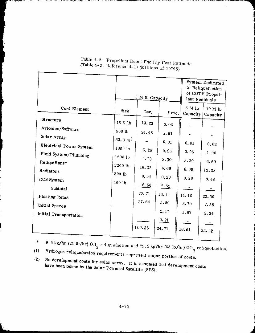
Table 4-2. Propellant Depot Facility Cost Estimate
(T,'uble 9-2, P,eference 4-1) (Millions of 19795)
......... System Dedicated
to Reliquefaction
of COTV Propel-
5 M lb Cap_ cit_z lant Residuals.
5 M lb 10 M lb
Cost Element Size Dev. Proc. Capacity Capacity
Structure 15 K lb i 13.23 0.06 - -
Avionics/Soft'ware 500 lb 24.48 i 2.61 - -t
]
Solar Array 33.3 rn 2 - i 0.01 0. 01 0, 02t
Electrical Power System 1000 lb 6.26 0.95 0.95 1.90
Fluid System/Plumbing I 1500 lb 5.23 3.30 3.30 6, 60
Reltquiflers* 2200 lb 16.32 6.69 6, 69 13.38
Radiators 300 lb 0. 54 0.20 0.20 0, 40
RCS System 400 Ib 6, 56 2.62 - -
Subtotal 72.71 16.44 11.15 22, 30
Floating Items 27.64 5.59 3.79 7.58
Initial Spares 2.47 1.67 3.34
Initial Transportation 0.21 - -
100.35 24.71 i 16.61 33.22i..... 1 I L
* 9.5 kg/hr (21 lb/hr) GH_ rt, liquefaction and 29.5 kg/g_r ((;5 lb/hr) GO_ rcliqucfaction.
(I) Hydrogen reliquefaction requirements represent major portion of costs.
(2) No development costs for solar array. It is assumed that development costshave been borne by the Solar Powered Satellite (SPS).
4-12
1980009-8i-1-130
Two disadvantages have been identified for an oxygen/hydrogen vapor feed system.These are- a) the need for compressors to transfer residual propellants to the RCS
storage tanks, and b) the increased storage tank mass and volume required for vapor
storage over that of liquid storage.
These disadvantages appear to be minimal as explained below:
1. Compressors and/or considerably more complex equipment will be requiredfor the reliquefier approach.
2. The increased RCS storage tank weight should be small in comparison to the
residual mass reclaimed annually.
4.2.2 OPERATIONS FOR HELIUM PRESSURANT. Reclaiming COTV residual pro-
pellants can be a more complicated process, than described in Section 4.2.1, if
helium is present in the propellant tanks. The helium will have been introduced during
the vehicle mission to provide NPSP for each main engine start. As discussed in
Section 3, helium must be removed prior to a refill operation because excessive
partial pressure may result for a fully loaded tank condition. Steps must also be taken
to prevent helium from entering the start baskets during refill because, once present,
that helium will remain until expelled during a vehicle mission. Pure liquid flow from
the start baskets is a requiren_ent; consequently, helium trapped within a start basketis unacceptable.
These potential helium problems will be avoided with POTV by expelling virtually
all propellant residuals and helium from the propellant tanks through a blowdown
process. Several blowdown periods are contemplated to provide assurance that helium
is diluted to an acceptably low level. This approach is acceptable for POTV because
equipment and facilities will not be available in the orbiter to reclaim propellant
residuals. But, since it can be assumed that the appropriate facilities and equipment
will be an integral part of the orbital depot, aad evaluation is required to determine what
options are available, and which option is acceptable. Table 4-3 identifies the problems
(caused by heliBm) associated with the COTV post-mission operations; possible solu-
tions are summarized for each problem. The following three solutions (which are
identical to those of Sec_on 4.2.1) will be discussed:
1. Propellant dump to space (with no attempt to reclaim residuals).
2. Reliquefy propellant vapor and return to the depot supply tanks.
3. Transfer residuals to depot RCS propellant tanks for subsequent reuse for
drag m_eup and attitude control requirements.
4.2.2.1 The cost of propellant dumping -- The cost of dumping propellants from aCOTV will be the same whether thc vehicle includes a helium pressurizatioL_ system
or an autogenous pressurization. This is because propellant tank total residuals will
4-13
19800098i%131
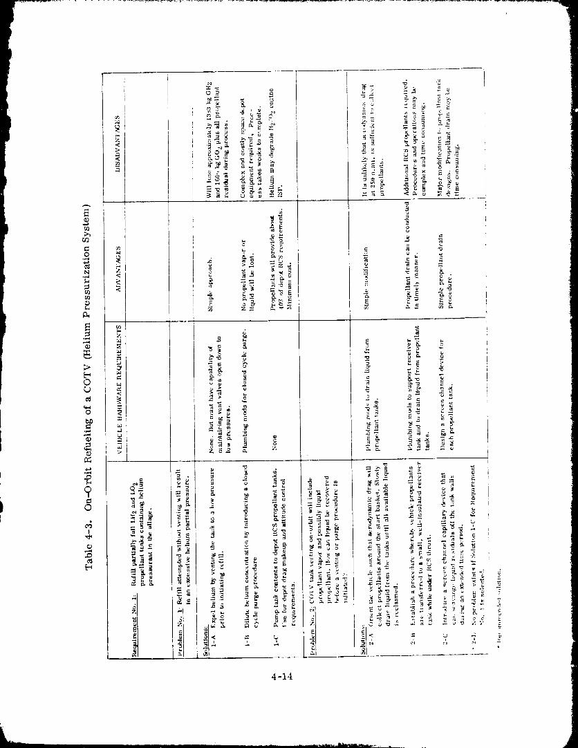
_w_ _-_. _ . _,_w_,_......__ _ _ __ _r._-- 18 i
4-14
A1980009811 - 132
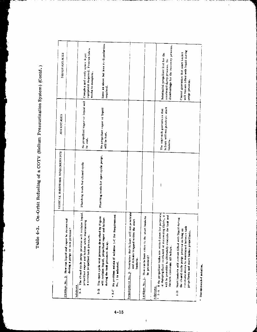
4-15
1980009811-133
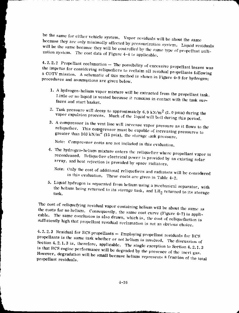
be the same for either vehicle system. Vapor residuals will be about the same
because they are only minimally affected by pressurization system. Liquid residuals
will be the same because they will be controlled by the same type of pr_pelIant utili-
zation system. The cost data of Figure 4-4 is applicable.
4.2.2.2 Propellant reclamation -- The possibility of excessive propellant losses was
the impetus for considering rcliquefiers to reclaim all residual pr,_pellants following
a COTV mission. A schematic of this method is shown ill Figure 4-9 for hydrogen;
procedures and assumptions are given below.
1. A hydrogen-helium vapor mixture will be extracted from the propellant tank.
I,ittle or no liquid is vented because it remains in contact with the tank sux,-faces at_d start basket.
2. Tank pressure will decay to approximately 6.9 kN/m 2 (1.0 psia) during thevapor expulsion process. Much of the liquid will boil during this period.
3. A compressor in the vent line will increase vapor pressure as it flows to the
reliquefier. This compressor must be capable of increasing pressures togreater than 103 kN/m (15 psia), the storage _ank pressure.
Note: Compressor costs are not included in this evaluation.
4. The hydrogen-helium mixture enters the' reliquefier where propellant vapor isrecondensed. Reliquefier electrical power is provided by an existing solar
_rray, and heat rejection is provided by space radiators.
Note: Only the cost of additional reliquefiers and radiators will be considered
in this evaluation. These costs are given in Table 4-2.
5. Liquid hydrogen is separated from helium using a mechanical separator, with
the helium being returned to its storage tank, and Llto returned to its storagetank.
The cost of rcliquefying residual vapor containing helium will be about the same as
the costs for no helium. Consequently, the same cost curve (Figure 4-7) is appli-
cable. The same conclusion is also drawn, which is, the cost of reliqucfaction is
sufficiently high that propellant residual reclamation is not an obvious choice.
4.2, 2.3 Residual for RCS propellants -- Employing propellant residuals for RCS
propellants is the same task whether or not helium is involved. The discussion of
Section 4.2. 1.3 is, therefore, applicable. The single exception to Section 4, 2.1.3
is that RCS engine performance will be degraded by the presence of the inert gas.
However, degradation will be small because helium represents a fraction of the total
propellant residuals,
4-16
t
1980009811-134
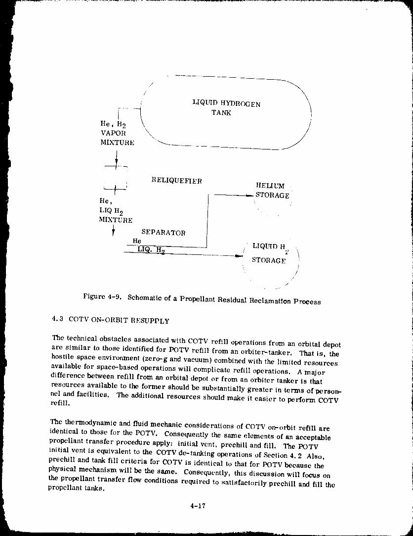
F
J \i uQ - D" ROCEN
He, H2 /
VAPOR _\. //_MIXTURE "_
i
I R ELIQUEFIER HELIUM 'l t * _-_ STORAGEt
He, '
LIQ H2MIXTURE
I _ SEPARATORHe/. LIQUID H2 \LIQ. H2 e,.
STORAGE
, ]/
/
Figure 4-9. Schematic of a Propellant Residual Reclamation Process
4.3 COTV ON-ORBIT RESUPPLY i
The technical obstacles associated with COTV refill operations from an orbital depotare similar to those identified for POTV refill from an orbiter-tanker. That is, the
i hostile space environment (zero--g and vacuum) combined with the limited resourcesavailable for space-based operations will complicate refill operations. A majordifference between refill from an orbital depot or from an orbiter tanker is that
resources available to the former should be substantially greater in terms of person-
nel and facilities. The additional resources should make it easier to perform COTVrefill.
The thermodynamic and fluid mechanic considerations of COTV on-orbit refill are
identical to those for the POTV. Consequently the same elements of an acceptable
propellant transfer procedure apply: initial vent, prechill and fill. The I_)TV
initial vent is equivalent to the COTV de-tanking operations of Section 4.2 Also,
prechill and tank fill criteria for COTV is identical to that for POTV because the
physical mechanism will be the same. Consequently, this discussion will focus onthe propellant transfer flow conditions required to satisfactorily prechill and fill the
propellant tanks,
4-17
" " ' ' ' "' '""" " ....... 1980009811-135
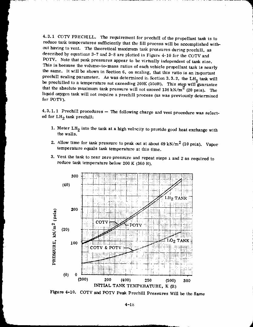
4.3.1 COTV PRECHILL. The requirement for prechill of the propellant tank is toreduce tank temperatures sufficiently that the fill process will be accomplished with-out having to vent. The theoretical maximum tank pressures during prechill, asdescribed by equations 3-7 and 3-8 are plotted in Figurv 4-10 for the COTV and
POTV. Note that peak pressures appear to be virtually independent of tank size.This is because the volume-to-mass ratios of each vehic}e propellant tank is nearlythe same. It will be shown in Section 6, on scaling, that this ratio is an important
prechill scaling parameter. As was determined in Section 3.3.2, the LH 2 tank willbe prechilled to a temperature not exceeding 200K (350R). This step will guaranteethat the absolute maximum tank pressure will not exceed 138 kN/m_(20 psia). The
liquid oxygen tank will not require a prechill process (as was previously determinedfor POTV).
4.3.1.1 Prechill procedures -- The following charge and vent procedure was select-
ed for LH 2 tank prechiU:
1. Meter LH 2 into the tank at a high velocity to provide good heat exchange withthe walls.
2. Allow time for tank pressure to peak otlt at about 69 kN/m 2 (10 psia). Vapor
temperature equals tank temperature at this time.
3. Vent the tank to near zero pressure and repeat steps :t and 2 as required toreduce tank temperature below 200 K (360 R).
300
' _ .................. LIt 2 TANK _/
3 .00 ii!:li!:i
¢q
I_ (20)
100 .02 TANK!..i ili! i!'i: : ::.::.... , ..
C_ :'ICOTV & t) v_ ' :t: :!. ::::: 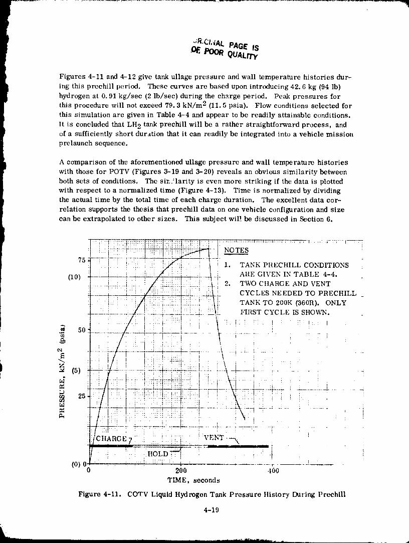
.OEPOORQUALITy
Figures 4-11 and 4-12 give tank ullage pressure and wall temperature histories dur-
ing this prechill period. These curves are based upon introducing 42.6 kg (94 lb)hydrogen at 0.91 kg/sec (2 lb/sec) during the charge period. Peak pressures for
tl-ds procedure will not exceed 79.3 kN/m 2 (11.5 psia). Flow conditions selected for
this simulation are given in Table 4-4 and appear to be readily attainable conditions,
It is concluded that LH 2 tarLk prechill will be a rather straightforward process, and
of a sufficiently short duration that it can readily be integrated into a vehicle mission
prelaunch sequence,
A comparison of the aforementioned ullage pressure and wall temperature histories
with those for POTV (Figures 3-19 and 3--20) reveals an obvious similarity between
both sets of conditions. The sir,.'larity is even more striking if the data is plotted
with respect to a normalized time (Figure 4-13). Time is normalized by dividing
the actual time by the total time of each charge duration. The excellent data cor-
relation supports the thesis that prechill data on one vehicle configuration and size
can be extrapolated to other sizes. This subject wiP. be discussed in Section 6.
1980009811-137
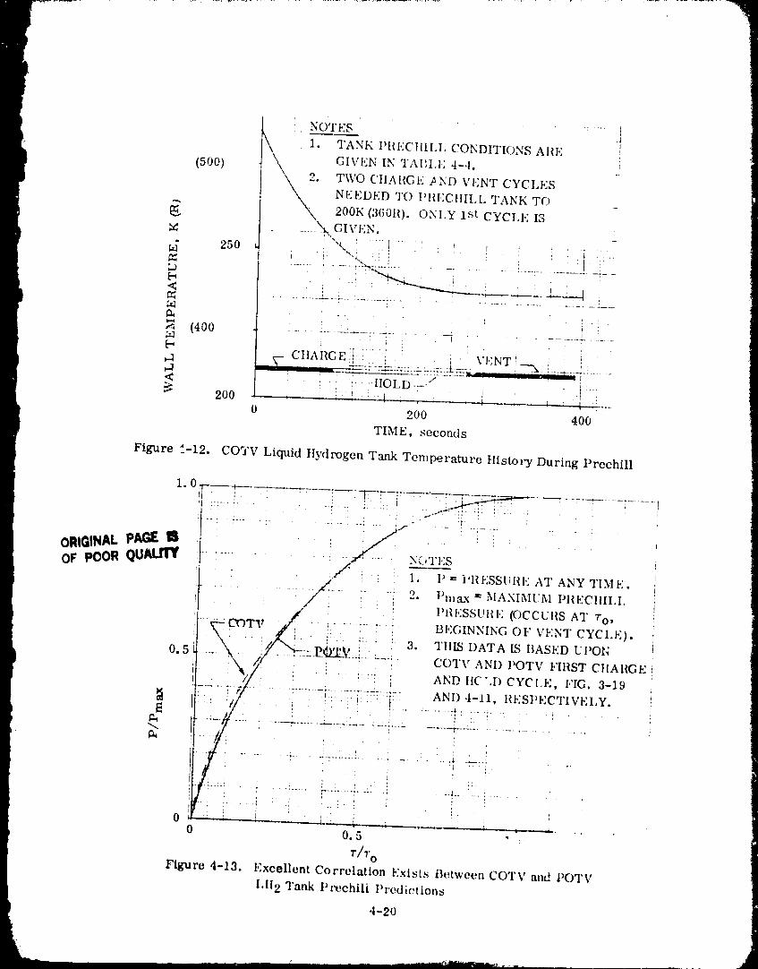
NOTES ._
_i TANK I)III,;C]III,I, CONDITIONS ARE J
(500) GIVEN IN TAI;I,I,; 4-4. _,i• TWO CtIARGE _ND VENT CYCI,ES
NEEDED TO !'IIECtlII, I, TANK TO
__, 200K(360II). ONIX 1st CYCI,E IS\..... .'_GIVI:N.
u_ 250 _..'_,,_ i ::,i!ii '' LI. '. !, ! : : i .i
,_ (400 ..... x----: ...... L......... : .... ' _ . i :
[" CIIAilGE [i : i " VI':NT_--_ i ! [ '
< :: ': .i:' :':IIOLD .... i ! .,i:::::200 -- _ .... ". _ _:-,:: ! _ , ! t...'.--
0 2OO 40O
TIME, seconds
Figure ,t-12, CO'YV Liquid Ilydrogen Tank Temperature History During Prechill
1980009811 -138
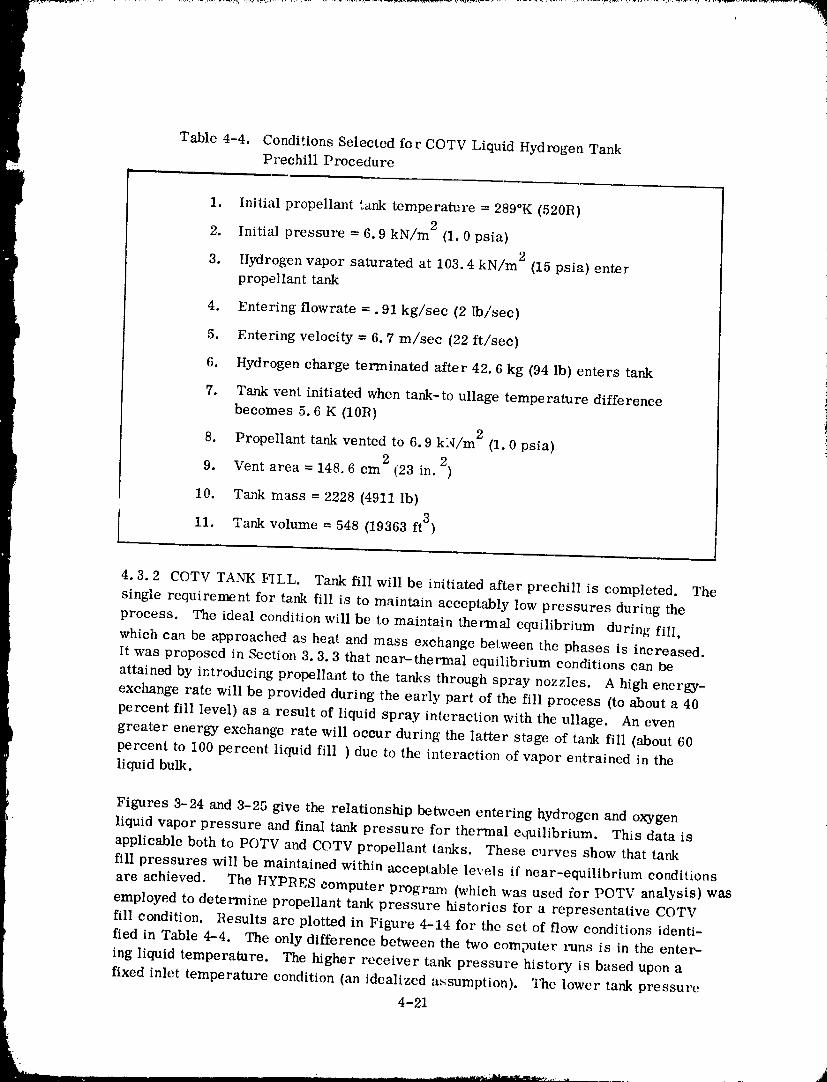
Table 4-4. Conditions Selected for COTV Liquid Hydrogen TankPrechfll Procedure
m,
1. Initial propellant tank temperature = 289°K (520R)
2. Initial pressure = 6.9 kN/m 2 (1.0 psia)
3. Hydrogen vapor saturated at 103.4 kN/m 2 (15 psia) enter
propellant tank
4, Entering flowrate -. 91 kg/sec (2 Ib/sec)
5. Entering velocity = 6.7 m/see (22 ft/sec)
6. Hydrogen charge terminated after 42.6 kg (94 lb) enters tankl
7, Tank vent initiated when tank-to ullage temperature difference
becomes 5.6 K (10R)
8. Propellanttankventedto 6.9 kN/m 2 (1.0psia)2 2
9. Vent area = 148,6 cm (1123in. )
10. Tank mass = 2228 (4911Ib)
11. Tank volume = 548 (19363ft3)
4.3.2 COTV TANK FILL. Tank fill will be initiated after prechill is completed. The
single requirement for tank fill is to maintain acceptably low pressures during the
process. The ideal condition will be to maintain thermal equilibrium during fill,which can be approached as heat and mass exchange between the phases is increased.It was proposed in Section 3.3.3 that near-thermal equilibrium conditions can be
attained by introducing propellant to the tanks through spray nozzles. A high energy-
exchange rate will be provided during the early part of the fill process (to about a 40
percent fill level) as a result of liquid spray interaction with the ullage. An even
greater energy exchange rate will occur during the latter stage of tank fill (about 60
percent to 100 percent liquid fill ) due to the interaction of vapor entrained in the
liquid bulk.
Figures 3-24 and 3-25 give the relationship between entering hydrogen and oxygen
liquid vapor pressure and final tank pressure for thermal equilibrium. This data is
applicable both to POTV and COTV propellant tanks. These curves show that tank
fill pressures will be maintained within acceptable levels if near-equilibrium conditions
are achieved. The HYPRES computer program (which was used for POTV analysis) wasemployed to determine propellant tank pressure histories for a representative COTV
fill condition. Results are plotted in Figure 4-14 for the set of flow conditions identi-
fied in Table 4-4. The only difference between the two computer l'uns is in the enter-
ing liquid temperature. The higher receiver tank pressure history is based upon a
fixed inlet temperature condition (an idealized assumption). The lower tank pressure
4-21
198000981-i-139
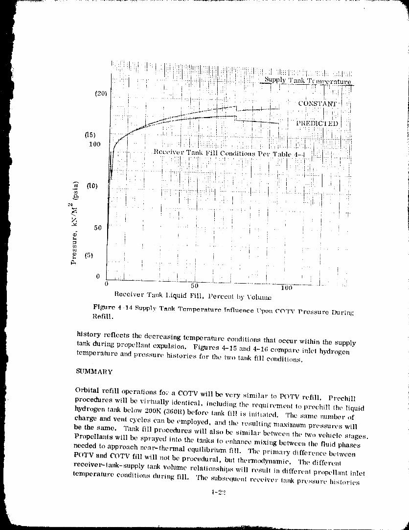
': ' !' : :."i:':! i!?i!":i _!': :i:i .' t.i:1': I: Supply Tank'l'cm_,erature
(20_ ....... ,,.......... : CdNSTAiVr-:l -..
•' ' i/' " Z" _ .... ' - v-- I L_.L_.ILJLI._ I ,ILL+t++
I .+...-y.+._ _+.+- + .. . , + ........
I ",+++_ ' + + :' , ' :;++,
.. :,,_.+I .! , .... : + . ,+ + ..... ,+ .... _+.._...:_ ....... ,.,+_ ,._.+, .... +: ..+:_ ._+_++..0 5 ) + _ ' 1 j ' ' . + ' ' " m + .... 2 + + ' j ' +_i+:
r r 1 ' t l . t 1 _
l 0 0 / [ + d + ' : .... + ' I ' , !:'.0 ';+:'1t : ' ' + ' ' ' :1:+11+ d i + ' 'h ' _ ' ' ' + O + r ' + : + ' I ' i " ....• -l Receiver Tank Fill Conditions Pet" Table 4--I i}:::i[ _ !t:,,, [ +. + i , ,+ I " , "
i :+i .... l I t] ......... I '" .+.+
[ l+ ,;' t
_ O) .......... } ......... [':@:_'l'@ 7l'l:@l ,l+ I ......... _ .............. ' " " ' : _ 7 I ........ , "
I
N +.............
d
mc/J
%
i
1_u _ ....................... .....0 5O 100
Receiver Tank Liquid Fill, Percent by Voluarm
Figure 4-!4 Supply Tank Temperature Influence Upon COTV Pressure During'
Refill.
history reflects the decreasing temperature conditions that occur within the supply
tank during propellant expulsion. Figures 4-15 and 4-16 compare inlet hydrogen
temperature and pressure ltistories for the two lank fill conditions.
SUMMARY
Orbital refill operations fo;" a COTV will be very similar to POTV refill. Preehill
procedures will be virtually identical, including the requirement to prechill the liquid
hydrogen tank [xqow 200K (360R)before tank fill is initiated. The same number of
charge and vent cycles can be employed, and the resulting maxi_num pressures will
be the s+tme. Tank fill procedures will also be similar between the two vehicle stages.
Propellants will be sprayed into the tanks to enhance mixing between the fluid phases
needed to approach ncar-themnal equilibrium fill. The primat.'y difference between
POTV and C()TV fill will not be procedural, bnl thetmu)dynamie. The di[fereltl
receiver'-tank-supply tank volume relationships will result in different propellant inlet
temperature conditions during fill. The subsequt'nt receiver ttmk prt.ssurt' histories
1-22
198000-98 -- i-40
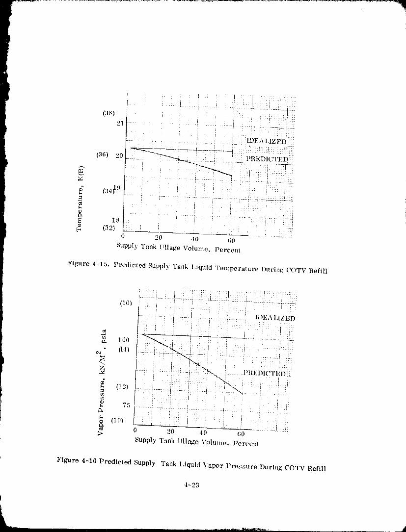
t
IP
(38) : " ::.... : I !
b ! :IDEA LIZEDi!
(36) 20 "_'_'_-" _,-'-7"----.._ . I. !: PREDICTED::_
(34_ 9 ' ' i .............. i :'. ....................... _"--!-" _r_,-:"'" i "_-_
E 18 ! _ ......® (3,,) . . ........ __2.-_
0 2O 40 60
Supply Tank Ullage Volurne, Pereent
Figure 4-15. Predicted Supply Tank IAquid Temperature During COTV Refill
(_(;_ i: ;. i:: ii i : ! ! ! ::!:!::;t I IDEA LIZED.......... -i ..-L-:4 .....L__ !................. ;.
, ; i . ) "ii i _ ' i i i ' " '_...... ¢ , ,, , . , .. 7 • . .2
•,,,4(/] 100 _ I; * 2 ' ; ' i '-" '_Y
(14) --i-::-i -::r:-+-:'_- �t�4#��€! ..... ;,..... i._.: _i_:
"" i : .: ::l ::. l) .... I
m ... q:i it : } .....: ; : I :'¢ ....
....................... i ............... 4,..... i "::i ..... ; "'"
(10) ! '. 1 _--- ........ :_]..E:0 20 40 (;0
Supply Tank Ullage Vohmm, Percent
Figure 4-16 Predicted Supply Tank IAquid Vapor Pressure During COTV Refill
-t-23
1980009811-141
will also differ {compare Figure 3-37 to 4-14}. This difference, however, is notsufficient to alter the conclusion that POTV and COTV orbita! refill operations can be
considered identical. Any experimental program devised for one vehicle configuration
will also be applicublc to the other.
']?he only new requirements identified by the COTV analysis dealt with alternatives of
reclaiming, or employing, the vehicle _rooellant residuals. It was concluded that
reclaiming residuals through a reliquefaction process was marginal at best because
of high reliquefier costs. A suprisiag result was that dumpiug propellants over-board could be preferrable to reliqucfaction. The best alternative, however, could
be to use the residuals to supplement the orbital depot I_CS system propellant require-ments.
4-24
1980009811-142
LTL OllBITAL R FSUPPLY
A mission scenario will be developed in this section for the low thrust liquid (LTL)earth storable propellant vehicle concept. A mission will be defined which encom-
passes the important issues of orbital-refueling operations using earth storable
propellants. These operations will include the major activities from post-mission
storage in the LEO parking orbit through resupply. Particular emphasis will be
placed upon vehicle "sating" operations that can be perfl_rmed prior to orbite_--tanker
rendezvous. Vehicle and orbiter-tanker subsystem requirements needed for orbitalrefueling will be identified. Operational procedures and ieclmiques for orbital pro-
pellant transfer will then be developed, i
A groundrule imposed upon this vehicle concept was to utilize hardware from existing/
on-going programs, if possible. Because the data base for earth storable vehicles and
missions was considerably sm:_ller than for cryogenic OTVs, no attempt was made to
optimize the vehicle eonfig, aration. Rather, the intent was to select a configuration
that would be representative of its vehicle class.
5.1 MISSION SCENARIO
In the 1980's-1990's time fr,'up.e a requirement may e.,cist for a w}rsatile, low cost
vehicle capable of accomplishing small orbital transfers, service, inspection, and
retrieval tasks. It will require frequent refill from a dedicated orbiter-tanker. The
orbiter-tanker will be equipped to resupply the main propellant _anks and the RCS
supply tanks with N20 4 and MMH, and the pressurization system bottles with helium.
5.1.1 SEI,ECTED LTL MISSION. As previously stated, there is not the data base
available describing potential earth storable vehicle missions that exists for cryo-
genic POTV's. Fortunately, it appears that a wide range of missions could be
selected without impacting orbital refill procedures. For this study, the LTL primary
i task will be to transfer large space stl'ucturv_; ( 65317 kg (144,000 lb) from LEO
(.,- 200 n. mi. ) to a slightly higher orbit (- 600 n. mi. ) under low accelerations. Ai
vehicle thrust level of approximately 26.7 kN (6000 lbs) will be required.
5.1.2 LTL CONFIGURATION. In keeping with the intent of a low cost vehicle design,
the LTL configuration is comprised of existing hardware. Figure 5-1 provides a
description of the selected systems, all of which are currently available.
5,i.2.1 Main propulsiontankage-- This propulsiontankagesystem consistsoffour
identical propella,:_ tanks, each containing a screen acquisition device (four galleries)
5-1
1980009811-143
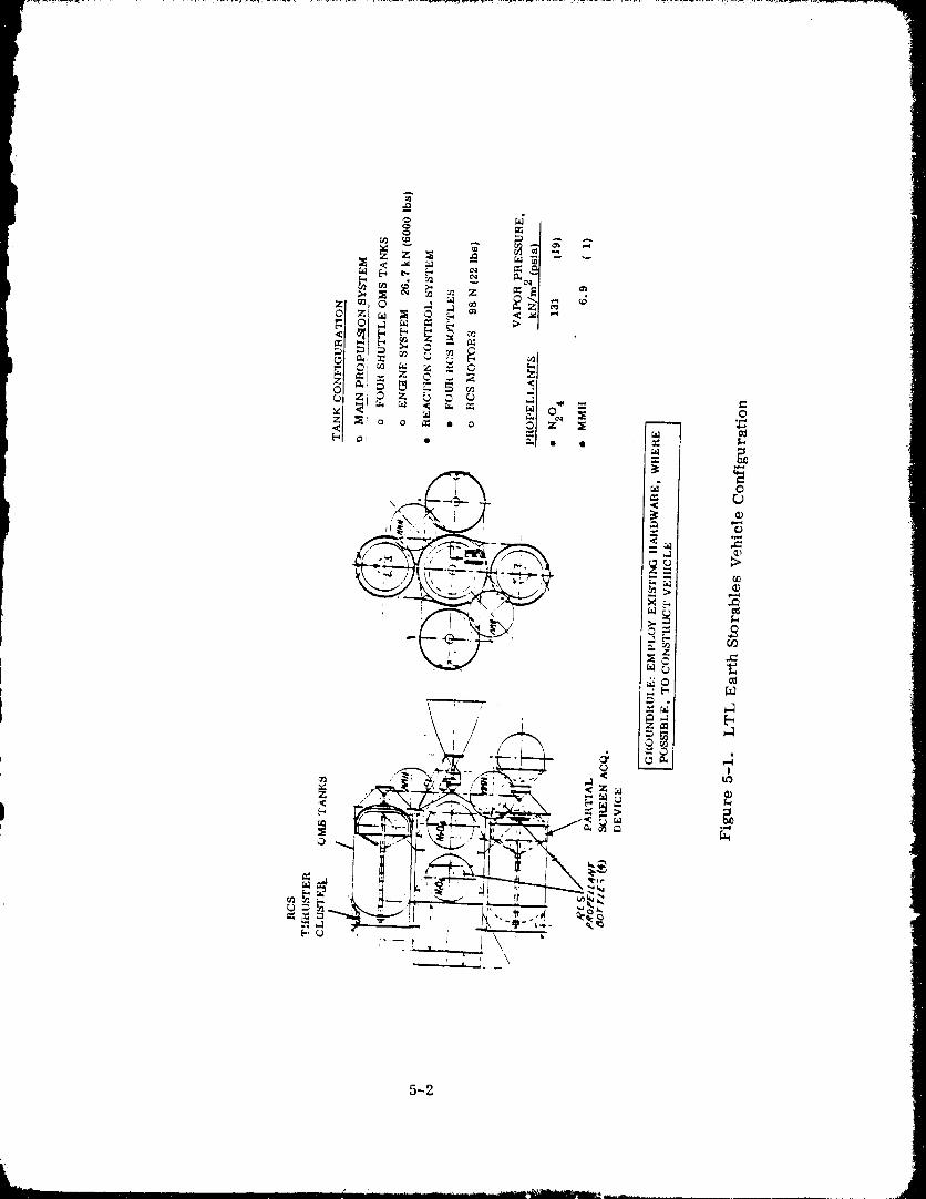
5-2
1g8000g811-144
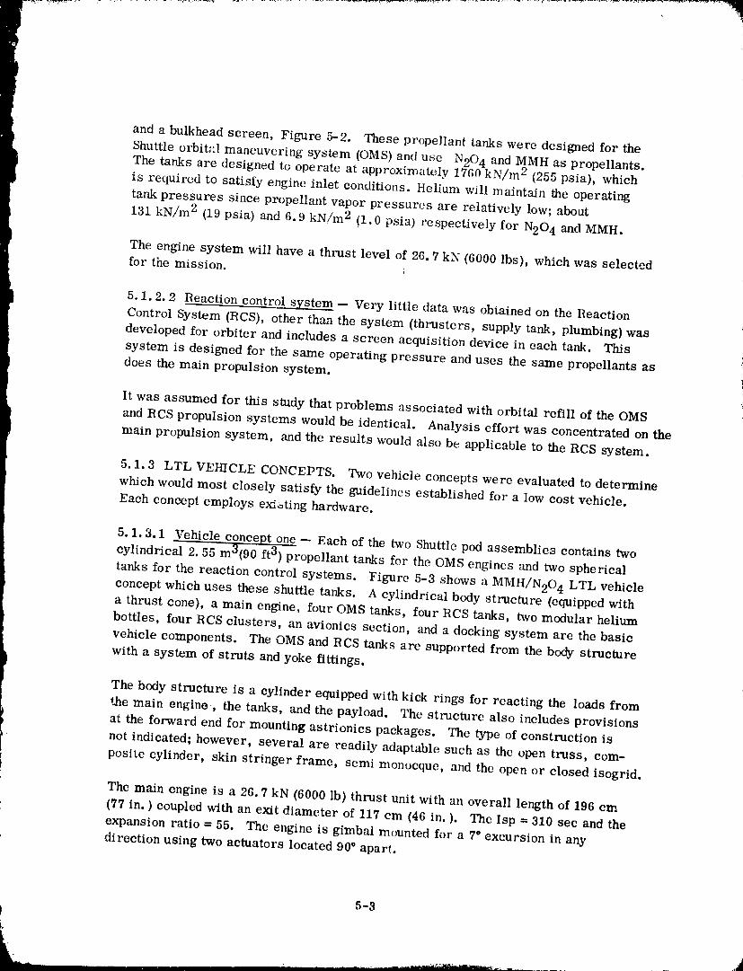
and a bulkhead screen, Figure 5-2. These propellant tanks were designed for the
Shuttle orbit_:l maneuvering system (OMS) and use N20 4 and MMH as propellants.The tanks are designed to operate at approximately 1760 kN/m 2 (255 psia), which
is required to satisfy engine inlet conditions. Helium will maintain the operating
tank pressures since propellant vapor pressures are relatively low; about
131 kN/m 2 (19 psia) and 6.9 kN/m 2 {1.0 psia) respectively for N20 4 and MMH.
The engine system will have a thrust level of 26.7 kN {6000 lbs), which was selectedfor the mission.
5.1.2.2 Reaction control system -- Very little data was obtained on the Reaction
Control System (RCS), other than the system (thrusters, supply tank, plumbing) wasdeveloped for orbiter and includes a screen acquisition device in each tank. This
system is designed for the same operating pressure and uses the same propellants asdoes the main propulsion system.
It was assumed for this study that problems associated with orbital refill of the OMS
and RCS propulsion systems would be identical. Analysis effort was concentrated on the
main propulsion system, and the results would also be applicable to the RCS system.
5.1.3 LTL VEHICLE CONCEPTS. Two vehicle concepts were evaluated to determine
which would most closely satisfy the guidelines established for a low cost vehicle.
Each concept employs ex_ting hardware.
5.1.3.1 Vehicle concept one -- Each of the two Shuttle pod assemblies contains two
cylindrical 2.55 m3(90 ft 3) propellant tanks for the OMS engines and two spherical
tanks for the reaction control systems. Figure 5-3 shows a MMH/N20 4 LTL vehicleconcept which uses these shuttle tanks. A cylindrical body structure (equipped with
a thrust cone), a main engine, four OMS tanks, four RCS tanks, two modular helium
bottles, four RCS clusters, an avionics section, and a docking system are the basic
vehicle components. The OMS and RCS tanks are supported from the body structure
with a system of struts and yoke fittings.
The body structure is a cylinder equipped with kick rings for reacting the loads from
the main engine, the tanks, and the payload. The structure also includes provisions
at the forward end for mounting astrionics packages. The type of construction is
not indicated; however, several are readily adaptable such as the open truss, com-
posite cylinder, skin stringer frame, semi monocque, and the open or closed isogrid.
The main engine is a 26.7 kN (6000 lb) thrust unit with an overall length of 196 cm
(77 in. ) coupled with an exit diameter of 117 cm (46 in. ). The Isp = 310 sec and the
expansion ratio -- 55. The engine is gimbal mounted for a 7° excursion in anydirection using two actuators located 90 ° apart.
5-3
i,
1980009811-14
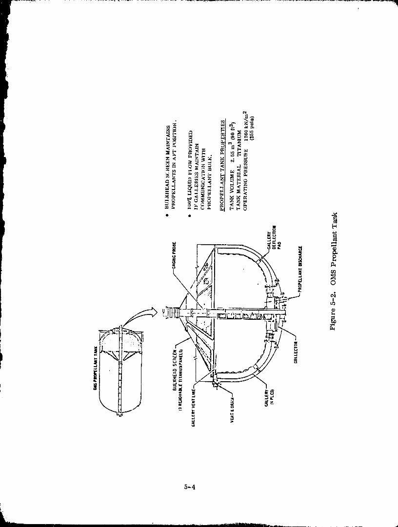
5-4
1980009811-146
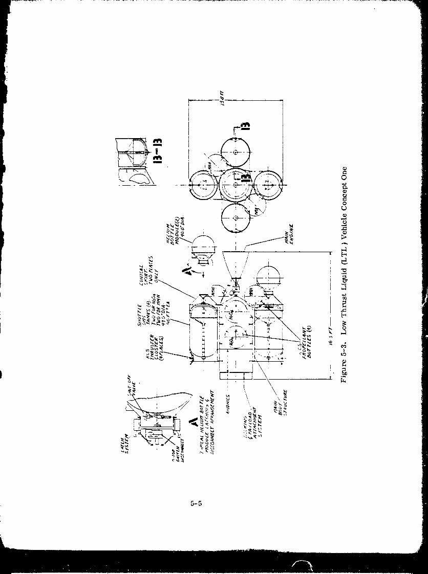
5-5
1980009811-147
Some minor additions to the OMS tanks will be required such as an aft conical skirt
equipped with a disconnect for receiving the helium bottle modules; a forward cylin-
drical skirt for mounting the ACS clusters and several fittings for structural and
plumbing supports. Alterations for plumbing interfaces may also be required to
accommodate the vent and fill circuits. The aft conical skirt section previously
mentioned will be required for two tanks only; one for each helium bottle module
required.
The four RCS tanks are spheres equipped with acquisition devices. Two of the spheres
are located inside the body structure and two are located externally near the main
engine thrust cone. A strut support system is indicated; however, other methods m.:y
be used such as girth flanges or skirts.
The helium supply is two 102 cm (49 in. ) spherical modules equipped with a latch
system and a motor driven disconnect. Details of this system will be discussed in
Section 5.4.2. Additional conceptual information is shown in detail "A" of Figure 5-3.
A typical reaction control system (RCS) cluster consists of four thrusters mounted
inside the OI._S tank skirt structure "," pointing outboard (see layout). Four clusters
are used and are 98 N (22 lb) fo" . a unit with an Isp = 280 sec and a mixture ratio
of 1.85. The approximate overall length of each thruster is 25.4 cm (10 in. _ Flange
type mounting is provided.
Theastrtonicssection is located at the forward end of the body structure. The four
OMS tanks shadow tiffs section therefore heat dissxpating systems may be required
such as heat pipes and radiators. Possible locations for thc radiators would bebetween the OMS tanks.
The docking and payload attachment system is located forward of the astrionics and
interfaces with the shuttle or the payload. Features such as gross capture under wide
misaligrm_ents, shock absorbing, pull down and final alignment, followed by structural
attachment would be included in this system.
5.1.3.2 Vehicle Concept'2 -- In Concept 1, two types of propellant storage tanksare shown. For the main propulsion system, four OMS tanks are used and for the
RCS system, four spherical tanks are used. An alternate approach is shown in Figure5-4 which uses six OMS tanks. Two of these tanks seI've the RCS system and the
remaining four supply the main propulsion. Similar to Concept 1, the tanks are attach-
ed to a cylindrical body structure equipped with a thrust cone. In this case the thrust
cone is reversed to minimize the vehicle length.
Two of the RCS clusters are mounted on the forward ends of two OMS tanks and the
remaining two clusters are supported from an ()pen truss structure located between
the OMS tanks. The purpose for the truss structure is to permit a 90* spacing
between clusters. The 'russ is shown attached to the main body section, however,
5-6
1980009811-148
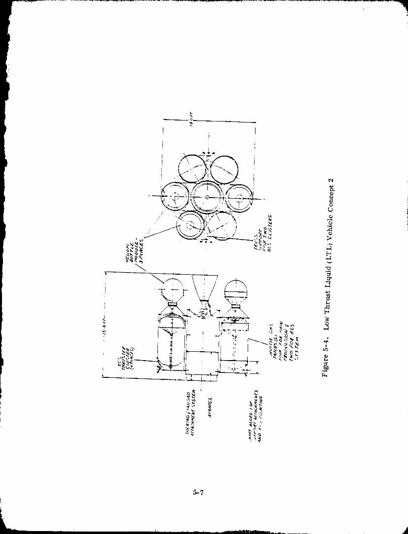
5--7
1980009811-149
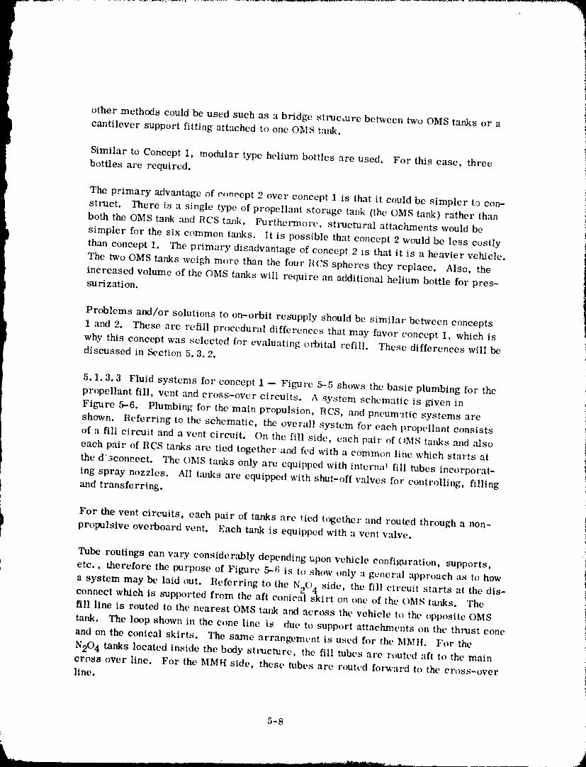
other methods could be used such as a bridge structure betwccn two OMS tanks or a
cantilever support fitting attached to one OMS tank.
Similar to Concept 1, modular type helium bottles are used. For this case, three
bottles are required.
The primary advantage of concept 2 over concept 1 is that it could be simpler to con-
struct. There is a single type of propellant storage tank (the OMS tank) rather thanboth the OMS tank and RCS t_'mk. Furthermore, structural attachments would be
simpler for the six common tanks. It is possible that concept 2 would be less costly
than concept 1. The primary disadvantage of concept 2 is that it is a heavier vehicle.
The two OMS tanks weigh more than the foul" HCS spheres thcy replace. Also, the
increased volume of the OMS tanks will require an additional helium bottle for pres-surization.
Problems and/or solutions to on-orbit resupply should be similar between concepts
1 and 2. These are refill procedural difff:rences that may favor concept 1, which is
why this concept was selected for evaluating orbital refill. These differences will bediscussed in Section 5.3.2.
5.1.3.3 Fluid systems for concept 1 -- Figure 5--5 shows the basic plumbing for the
propellant fill, vent and cross-over circuits. A system schematic is given in
Figure 5-6. Plumbing for the main propulsion, RCS, and pneumatic systems arc
shown. Eeferring to the schematic, the overall system for each propellant consists
of a fill circuit and a vent circuit. On the fill sidc, each pair of OMS tanks and also
each pair of RCS tanks are tied together and fed with a common line which starts at
the d'3connect. The OMS tanks only are equipped with interred fill tubes incorporat-
ing spray nozzles. All tanks are equipped with shut-off valves for controlling, filling
t and transferring.V
i For the vent circuits, each pair of tanks are tied together and routed through a non-
I propulsiveoverboardvent. Each tankis equippedwith ventwfive.a
Tube routingscan vary considerablydependingupon vehicleconfiguration,supports,
etc., therefore the purpose of Fibmrc 5-6 is to show only a gcner:tl approach as to how
a system may be laid out. Referring to the N204 side, the fill circuit starts at the dis-connect which is supported from the aft conical skirt on one of the OMS Umks. The
fill line is routed to the nearest OMS tm_k and across the vehicle to the opposite OMS
tank. The loop shown in the cone line is due to support attachments on the thrust cone
and on the conical skirts. The same arrangcmvnt is used for the MMII. For the
N204 tanks located inside the body st,'uct_arc, the fill tubes are routed aft to the maincross over line. For the MMH side, these tubes arc routcd for_,'ard to the cross-overline.
5-8
1980009811"150
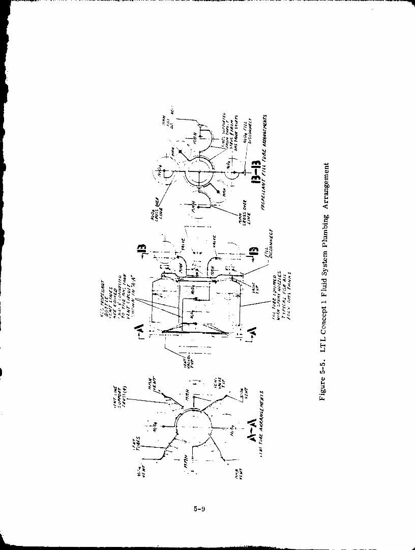
5-9
1980009811-151
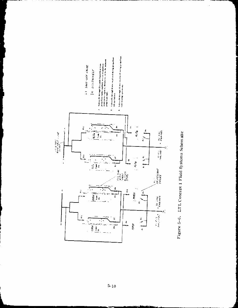
t 5-10
1980009811-152
• A non--propulsive vent system fer each propellant is located at the forward end. The
exits for each of these circuits are positioned outboard to prevent impingement on theOMS tanks, payload and 'adjacent structures. Four open truss arms attached to the
body structure provide support for the tubing. Basically the non-propulsive vent is
a loop of tubing with the ends of 180 ° apart. This arrangement is frequently referred
to as the "steer horn". The vent lines from each lank are connected to this loop oftubing such that there is equal distance from each point of connection to the overboard
ends. A typical tube assembly would feature welded joints and the use of bends insteadof fittings where possible. Large sections would be bench fabricated to ensure maxi-
m,_l quality control.
The fill and vent circuits were designed for the purpcse of enhancing on-orbit propel-lant refill. Refill must be conducted with caution because of the corrosive nature of
the earth storable propellants. Refill can be difficult because the OMS and RCS pro-pellant tanks must first be vented from about 1760 kN/m" (255 psia) to 207 kN/m 2(30 psia) in order to expel sufficient helium to enable refill.
5.2 ORBITAL PROPELLANT RESUPPLY TECHNIQUES
The obstacles of on-orbit refill are the same for the LTL vehicle as for a cryogenicPOTV. These obstacles are: 1) the hostile space environment and (2) the limited
resources available for space-based operations. The primary variable complicatingrefill is the zero-g environment.
Propellant tank fill with N20 4 or MMH in an orbital environment poses fewer problemsthan liquid hydrogen because of temperature environment and operating pressure level
differences between a earth storable and cryogen system. System temperatures
will not vary significantly for these propellants at any time during a fill or refilloperatio .. Consequently, prechill will not be required to precede tank fill.
Propellant tank operating pressure of 1760 kN/m 2 (255 psia) is considerably higher
than for liquid hydrogen. This higher pressure level will simplify tank fill because
fill pressures will be maintained below the normal operating levels without difficulty.
One problem that cryogenics and earth storables have in common is that an undefined
(or poorly defined) liquid-vapor distribution will exist during low-gravity tank fill.This inability to determine vapor location will make it difficult both to assure that no
liquid is vented during tank fill, and to assure that vapor is not trapped within thescreen channel device.
For the analyses that follow attention will focus upon the problems associated with
N204 and with main propellant tank refill. N20 4 is selected because it represents amore difficult propellant to handle than MMH due to its higher vapor pressure. The
main propellant tanks were used in these analyses.
5-11
1980009811- 153
5.2.1 PROPELLANT TANK REFILL REQUIItl,;MI,:NTS. _,veral recftirements were '!identified as being necessary to assure that LTI, vehicle refill will be s'ffely mad !
effectively performed. These are gen¢ral requiremellts that should apply to a variety
of vehicle eonfigalrations. There will undoubtedly be eonfiguration--rclated rec/uirements
for "my vehiele, llowever, such requirements c'umot be identified without first having
considerably nlore vehicl¢ desigll detail than was available for this study.
5.2.1.1 Vent protxql:mt talks prior to orbiter rendezvous -- N2Q I is a particularlycorrosive fluid, in wiper or liquid form. Fluid imping,-ment upon the LTL or orbiter
surfaces could have a long-term ;ldvtrse afflict upon vehicle components. The orbiter
will be spart._ this potential hazard if LTL vent procedures are performed well in
advance of orbiter rel_dezvtals.
5. '2.1. '2 Minimize liquid vent potenti:d -- This requirement addresses two major co_a-
ecrns; propellant corrosiveness and vehicle control. Liquid venting must be minimized
because ii is potentially more damagfng than vapor x'cnting. First, a liquid vent plume
e:mnot be readily eonfi rmcd, i.e., liquid exposed to a vacuum wilI boil and expand in
M1 directions. Also, the impingement mass flux from a liquid vent is likely to be great-
¢'r than fi'oln a wlpnr veil| plume, which illcl'e:lst's tilt' ¢orl'osive potential.
The second aspect t,, the potential problems of liquid venting is vt;hicle control.
Because procedures will be identified for remote venting of the LTL propellant l..mks,
it is mandatol'y that vehicle control be n_atnl:tim,d. Liquid venting eotfld jeopardize
vehicle control because it is unlikely th'tt a net zero ih_'usl wt_ald resuil, even if vent-
ing thrt_ugh a hot, propulsive (desigamd for vapor) vent system.
5.2.1.3 ttelium must not tulter screen galleries -- The purpose of tile screen acquisition
device in each propellan! t:uak is to provide the capability for pure liquid flow. Any
helium entering a scrtell device will be lrapped and remain trapped until removed through
special procedures, or until it flows frolu flat' lank 1o the ellg'illt' system. Special pro-
cedures for removing trapped heliulll :Ire undesirable bt, cause they .'Ire time eonsulllin[_
and may be complicated, lit,liuln t,xpulsion with propellant is lmacceplable bee:rest, it
violates the requirt?nlent of 100 pel't-¢nt liquid avail:dgilit v to the ellglnt' systelll.
5.2.2 INITIAL FILL. It is unlikely that tilt' vehicle will undergo an iaitial propellant
fill in space because of thc t"lse with which it can be filled o1_ the ground prior to flight.
There is a possibility, however, that the propellant t.mks could be completely evacuated
at a future time for m:lintt'nanee. Following such an occurrem'e propellant t'mk till
would be performed on t, vacuated talks residing at :llnbicnt temperature.
5. '2.2. 1 Not_-equilibrium fill -- The high operating pressure levels will simpli_ ()MS
Prolx;llant ta_& fill because fill pressures will be maintained below the normal op,,r'tt-
tag levels without difficulty. This is illustrated in Figure 5-7 which shows maxi-
nmm tank pressure :is a function of percent liquid fill. Isentropie compression of the
ullage is assumed, which means that heat exchange with the liquid and lank wlflls is
5-1"
1980009811-154
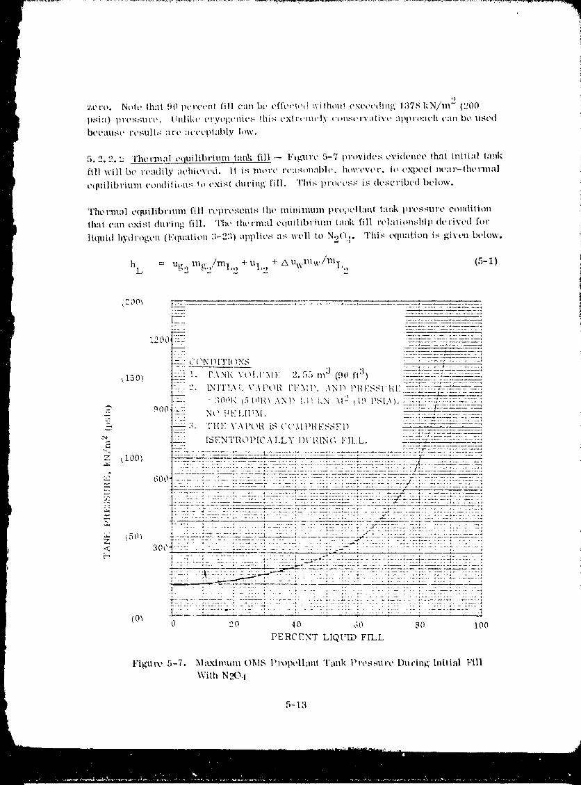
,)
zovo. Nole th'll 90 pcvct, n! fill can bu cfl'e_'l,'_t'vithou! _'xct,cdin_ 137_kN/m" (200
psi:t) pw,,s,gure, iinlikc u,,'yog_'nit'_ lifts t'xlr,mu'ly ,:_ms,,,rv,lti'vt' :q'.l'_r_meh can bt, ust, d
i._,c:lu,g_, vcsulls :Ire :wct'pt:lbly low.
5.2.2. '._ Therm:fl t, quilibrium I:mk fill _ 1,'ig'uvt' 5-7 t)vovidcs cvidem'o (ha( initi:d l:mk
fill will bt' re:ldily ,n,'hit,vt'd. It is lllOl't' l't,:l_m:lble, hov't'vt'r, to eXl)t'ct nt,:ll'-lht, rlllal
eqaHlibvium conttititms to t'xisl during fill. This 131"occss is dcscribcd Ix'low.
q'herla_:fl equilibrium fill rtqwt,,qcnis the minimum prt_i_t'll:ud i:tnk IH't'S.qtll'e oondilion
that can exist during fill. Tht, thevn_:d t'quilibviuln t:mk fill relalitmshit_ dcrivt,d for
liquid hytll'ogen (l,_qtl:l|ion :1-2:1) ,q_vlies as wt, ll to N,)O I. This tXluation is given below.
hi, = Ug,_ na_. -'/ml' L' + uI'''- + zXUwm w freT,,,_ (5-1}
(200_-- I
l--_ -: "__..--ZZL.2_':: T "Z2-.2__--_'_-2.'-:_"--_L"_
1200 _-S_: -_-_-:-_.--z-x:::;:::: ..... :
.... C ( "IN l') IT I_ 3 N,q : :7::_-:_.-__::,__.-__-_'s"_.-:7-221
-- 1. ['.\NI< \'t_l,['3llq 2.55 na 3 (90 ft 3) :::::::__:=:L:-_-___-.--_-_,t150) ---_ .2. [N1TI.\I., \':\Ptq_ I'I"._IP. .\ND Pt_l.:,gSll_l:.--.--:-:::.,m:v_-r-::,
900 ' -:.......... Nt_"_00!xHt:"I.II_M.(5 [nt{_ AND I:;! I,N, X12 t l9 P_I;_ }. :.::=:::=.:. _:::::az__:.________,:---:;'-:=::;--=:'-:__-:z-.:_,
_:_. Ttll,: \':\IX_I_ [S ('t_MI'|{ESSED ............................ 7"-: :5-*.Z_L_"-t 222"_'Z_ .--'Z-.222g
- " [SI:,NTI_Ot_[C:\LLY 1)II_ING 1,'II_,L. ..... :--_:- - 7............._25-22 . ...... _ .................... -4
"-_ . ............................. _ ........................ , ................ : ::---22_ :Z;L.-- "I 7Z-Z': :7 .'7_
tl00_ .................................................................... _.................
:._ __ ::,2:.:--::: '.:_-tz2z: ;.:..:.-L"_:_,;:..S : : ;_ .:..__s:._:=_:. _::._ : : :.:.-:_:_-t. 7::: ::._'::-:::: L :.::_'7_::. i
• *2-- I . -. L..: . ::iL. lZ7-S-.-': :Z..:.: "'_:-'--:."22 .;" :J':.::-.*,Y-:._-.:.-.L'*,.LS :::::_,:.2 ,:: 72;.......... • ................. r...... " "2"" ................................... *
,_ "_ . ,:L*. " : : " : :S .......................... _ ........ " ................. ' ......OOt.._ --, ...... _ ..... ::.'.. '.' .±:7:-5:':: -.: .: ;s_:._:. : .:.:.._._::.. :::::::::::::::::::::::::::::::
H t
;':. : : :7-_ ;- :1 _7:7 L : "7";7:_::_.: :_T :'::.:': ;: :: ;., '-'::'L:': ::2:_.*: :-'-.77 ".
: :-;:;_:-:it"-:. :-z.:_ : :- : :.:_ : : :.: ..... :::.: :.:.:. :.::L .. :7: ::_-:_-.-:-:-7:-....I
(0_ 0 2;0 40 d0: _r0 100
PERCENT LIQtq_D FILL
l"lgx_re 5-7, Maximum OI_IS P_xqxqlm_l Tank Pressure DuciuK hfltial l,_ll
With N_).I
5-13
1980009811-155
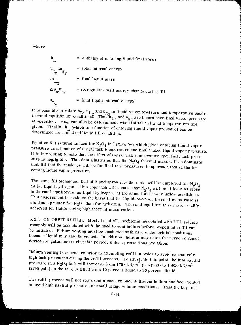
where
h = enthalpy of entering liquid final vaporL
u m = total internal enerK'yg2 g2
mL2 = final liquid mass
AUm = stor,_e tank wall energy change during fillw w
u = final liqui(_ internal energyL 2
It is possible to relate h., u L and u _ to liquid vapor pressure and temperature under" 2 gzthermal equilibrium conditions. Thus UL, ) and Ug2 are known once final vapor pressureis specified. Au w can also be detcrminc('l, when initial mid final temperatures are
given. Finally, hL (which is a function of entering liquid vapor pressure) can bedetermined for a desired liquid fill condition.
Equation 5--1 issummarized for N204 in Figure 5-8 which gives entering liquid vaporpressure as a function of initi:fl tank temperature and final tanked liquid vapor pressure.
It is interesting to note that the effect of i,fitial wall tempcraturt, upon final tank pres-i
sure is negligible. This data illustrates that the N20 4 thermal mass will so dominate :_
tank fill that the tendency will be for final tmlk pressures to approach that of the ira- icoming liquid vapor pressure, i
The same fill techltiquc, that of liquid spray into the tank, will be employed for N20 4
as for liquid hydrogen. This appr,mch will assure that N20 4 will be at least as closeto thermal equilibrium as liquid hydrogen, at the same fluid power inflow conditions.
This assessment is made on the basis that the liquid-t(_vapor thermal mass ratio is
sLx times greater for N204 than for hydiogcn. Thermal equilibrium is more readily !
achieved for fluids having high thermal mass ratios, i
5.2.3 ON-ORBIT REFILL. Most, if not all, problems assoeiatcd wiih LTL vehiclet
resupply will be associated with the need to vent helium before propelhmt refill can
be initiated. Helium venting must be conducted with care under orbital conditions
because liquid may also be vented. In addition, helium may enter the screen chmmcl
device (or galleries) during this peri(x], unless precautions are t&kcn.
Helium ventingis necessaryprior toattemptingrefillinorder toavoidoxccssively
hightankpressures duringthe refillprocess. To illustratethispoint,helium partial
pressure ina N20 4 tmlkwillincreascfrom 1758 kN/m 2 (255psia)to 15820 kN/m 2
(2295psia)as thelankis filledfrom I0 perc(,ntliquid1o90 perccniliquid.
The refill process will not represent a concern ()nee sufficient helium has been vented
to avoid high partial pressures at small ullage volume conditions. Thus thc key to a
5-14
1980009811-156
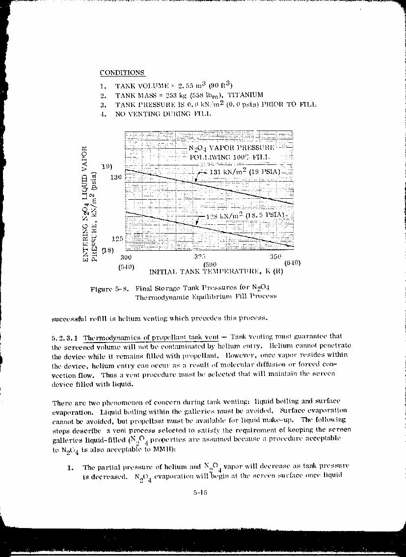
CONDITIONS
1. TANK VOIA_ME = 2.55 m 3 (90 ft 3)
2. TANK MA_S = 25:1 kg (558 Ibm), TITANIUM
3. TANK PlIESSUIIE IS 0.0 kN/m 2 (0.0 psia) PllIOR TO FILL
•t. NO VENTING [)tilliNG 1,'ll_l,
_--_ ::. - :==-_ ::_-7.-- N 20.1 VAPO I! P 11ESSU II I.: i ::_O I - : :- : :" :: " ',gh r'-----=- :--_ ........ :- I_)I,I,[\VING 100°_, I"II,I, --: :5
;-- : _: . .... .. - .....
< '19) . :-_:-: : :: :':----"--":'- --:---: ........ --_:'-=-_> .-. __:L !:-.:_::_,i.--;;::_:la_ kN/,,,2 (1.')J'SU_)-:;_i
1_.2 13o ..... :........ :-:.-_, O,I g:_ .._7____77T}7.:._7.771=:. 7_ :}7__{ -:7i:: _ L :.... i "7-: : {'! ": i: :
o _ __:;_ : !:_:!:;:2>'.!_., s _,_/,,,e0s.5 vs!))::::_Z_
;..9 lo 5 -::: :::_-:.:GO" "_ 12 .......... :.:_:_:_r_22 7:-2: .... 7,.% _£ __: :__5.: ......... 2:-: ...... : ..... _--.2_
_ 300 3 °5 350
(540) (5:)0 (640)INITIAl, TANK TEM1)EIG\TIII{I':, K (11)
Figure 5-8. Final Stor-tge T-ink Pw;ssures for N20.tThe mnodynamie Equilibrium Fill P races s
successful refill is helium venting which precedes this process.
t 5.2.3.1 The,'m(xtyn:m_ics of propellant i:mk vent -- Tank venting must guarantee thai
I the screened volume will not be cont:ullinated by helium entry, llelium eanno! penetrate
I the device while it remains filled with propellant, llowevcr, once vapor resides withinthe device, helium entry can oecm as a rcsult of molecular diffl_sion or forced con-
veeiion flow. Thus a Vellt proeedl.ll'e IlIUS[ bc selected that will maintain the screen
device filled with liquid.
There arc two phenonmnon of concern during lank venting: liquid boiling and surface
evaporation. Liquid boiling within the gallerics musl be avoided, b'urface evaporation
emmet Ix." avoided, but propellant lllust be awtilable for liquid re:dee-up. The following
steps describe a vent proces_ selected to satisfy the requirement of keeping the screen
galleries liquid-filled (N20.I properties are :ls:aulned because a pro(,ed_lre acceptable
to N2(, 4 is also acceptable to MMll):
1. The partial pressure of helium :rod N20 4 vapor will decrease as tank pressure
is decreased. N204 ev._poraii(m will begin at the screen surface one(' liquid
5-11;
1980009811-157
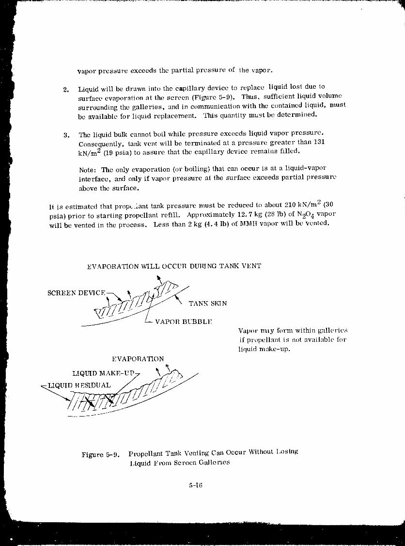
vapor pressure exceeds the partial pressure of the vapor.
2. Liquid will be drawn into the capillary device to replace liquid lost due to
surface evaporation at the screen (Figure 5-9). Thus, sufficient liquid volume
surrounding the galleries, and in communication with the contained liquid, must
be available for liquid replacement. This quantity must be determined.
3. The liquid bulk cannot boil while pressure exceeds liquid vapor pressure.
Consequently, tank vent will be terminated at a pressure greater than 131
kN/m 2 (19 psia) to assure that the capillary device remains filled.
Note: The only evaporation (or boiling) that can occur is at a hquid-vaporinterface, and only if vapor pressure at the surface exceeds partial pressure
above the surface.
It is estimated that propt.Aant tank pressure must be reduced to about 210 kN/m 2 (30
psia) prior to starting propellant refill. Approximately 12.7 kg (28 lb) of N20 4 vaporwill be vented in the process. Less than 2 kg (4.4 lb) of MMIt vapor will be vented.
EVAPORATION WILL OCCUR DURING TANK VENT
SCREEN DEVICE-_ _ c._7_(,/_/_/ ",VAPOR BUBBLE
Vapor n_ty form within galleries
if propellant is not available for
liquid make-up.EVAPORATION
LIQUID MAKE-UP 7 _
LIQUID RESIDUAL ./ T _" /
Figure 5-9. Propellant Tank Venting Cml Occur Without l,osing
Liquid From Scrocn Gtflierms
5-16
1980009811 -158
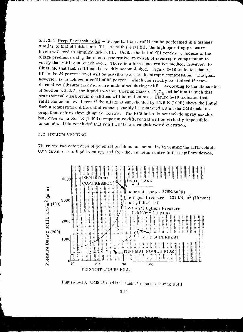
5.2.3.2 Propellant tank refill -- Propell'm( ta)tk refill can be performed in a mannersimilal to t.hat of initi:fl tm_k fill. As with initial fill, the high operating pressure
levels will tend to simplit'y tank refill. Unlike (he initial fill condition, helium m the
ullage precludes using the most conse_wativc apprtx_eh of isentropie compression to
verify that refill can be aehievecl. There is a less e(mselwative meth(xt, however, to
illustrate that tank refill can be readily accomplished. Figure 5-10 indicates that re-
fill to the 87 percent level will be possibh' even f()r isentropie compression. The goal,
however, is to achieve a refill of 95 pereem, which can readily be attained if near-
thermal equilibrium conditions arc maintained during refill. According to the discussion
of Section 5.2.2.2, the liquid-to-wlpor thermal mass of N20 4 and helium is such thatnear thermal equilibrium conditions will be maintained. Figure 5-10 indicates that
refill can be achieved even if the ullage is superheated by 55.5 K (100R) above the liquid.
Such a temperature differential emmot possibly be sustained within the OMS tanks as
propellant enters through spray nozzles. The IICS tanks do not include spray nozzles
but, even so, a 55.5°K (100°R) temperature differential will be virtually impossible
to sustain. It is concluded that refill will be a straightforward operation.
5.3 HELIUM VENTING
There are two categories of potential pr,_blems associated with venting the LTL vehicle
OMS tanks; one is liquid venling, and lhe other is helium entry to the capillary device.
Figure 5=10. OMS Protxdlant "l'aak Prt,s,,;urt, s l)uring Refill
5-17
1980009811-159
The loss of liquid overboard during the venting process is not only an inefficient
operation, it also represents a corrosion hazard if N204 is vented. Because of its
corrosive properties even N204 vapor venting must be carefully performed to avoid vaporimpingement upon LTL vehicle and orbiter surfaces. Liquid venting will represent amore serious concern because the vapor cloud formed when liquid is exposed to the
vacuum environment will expand in all directions and be difficult to control.
Regarding the second category of problems, tank venting must guarantee that thescreened volume will not be contaminated by helium eutry. Helium cannot penetrate the
device while it remains filled with propellant. However, once vapor resides within the
device, helium entry can occur as a result of molecular diffusion or focused convection
flow. Thus a vent procedure must be selected that will prevent the loss of liquid fromthe screen device.
5.3.1 ALTERNATIVE VENT PROCEDURES. Various alternatives were considered
for the tank venting procedure. An overview of each alternative, is presented below.
1. Venting while the propellants are settled by the OMS main engines or the RCS.
I This concept will eliminate the possibility of venting liquid overboard. Amajor disadvantage is that the tank cannot be completely vented down. This
is because both the main engi_.es and the I1CS require a substantial operating
pressure.
2. Venting while docked to the orbiter with the propellants settlcd by the orbiter
RCS. This concept also eliminates the possibility of venting liquid overboard.
It will also be possible to completely vent the OMS tank down since the orbiter
RCS is used to settle propellants. A possible disadvantage is thai firing of the
: orbiter RCS engines after docking has been completed may be an operational
1 complexity. The major disadvantage is that this approach violates the require-ment for venting prior to orbiter rendezwms.
3. Venting while docked to the orbiter with the propellant settled by atmospheric
drag. This concept eliminates the possibility of venting liquid overboalxi.
One disadvantage is that an orbital altitude < 130 n. mi. is required for ae_x)-
dyt amic drag to overcome propellant surface tension forces, which is
substantially below the desired altitude of 200-250 n. mi. Another disadvant-
age would be the necessity of attaching a vent duct extension to keep the
corrosive vapor of the earth storables from contacting the vehicle surface.
The requirement for a vent duct extension is based on calculations, plotted
in Figure 5-11 of the maximum Prandtl-Meyer exqaansion angle of an earth
storable-helium mixture. The same major disadvm_tage exists as for Item
2, above.
4. Venting with the propellant unsettled prior to docking with thc orbiter. T_tis
concept-approach could result in the venting of liquid overboa_xl, which
violates a major requirement. It would also require the use of a _ :,it tubt
to Prevent vehicle contact with the vented ptx)pellant.5-18
1980009811-160
5. Venting through a helium rccovt, l'y syslt,n_ prior t()docking with the orbiter.
The (_jcctivcs of a helium r('covery system are a) h) climinale the loss of
helium prcssur:mi as art, sult t)f vcutilt_ ,wt, vb,_av(t, and b) to climin'_tc the
hazalxts of venting corrosive fluids. The l'CC()vcl'y syslelll, illustrated iu
i Fig'arc 5-12, is a closed ,_ystem. lh;t'crring to l,'ig_:'c 5-11, a description of
the system corllponcRts is :is f()llows: The molecular _'_it'vc is used h) absorb
any N20 4 or MMIt vapor eOllt_|itlt'tl in tht' v:lj)of llliXlUl'e. Tile multi-stagecompressor pumps hclium from tile (),MS tank pl't, ssure o[) to a shwlt[/,e botile
m,'t_imum pressure of 33,100 _¢N/m 2 (,t800 l)sia), llowt, ver. the heliun_
must be passed through a radiator bt, tv,t,o|l t,:l('|l of tile compressor stages
to reduce vapor IOl_pol','ltuF(, Io lh(,, :tllow:lb|t_ lel_per:lluve, taupe of the
helium storage supply l:lllk.
5-1:)
1980009811-161
P
Sieve [,/ Sieve
t Valve() _j Regulator () ValveNCheck ---_
Valve ( MMtI )
,:igure 5-12. Helium Recovery System
This concept requires that the helium recovery system be contained as a
} package within the LTL vehicle.
6. Venting with the helium recovery system following docking with the orbiter,
Tlm helium recovery system used would be identical to that described in
method (5). However, the system now would be a unit contained on the orbiter
as opposed to a unit contained on the LTL vehicle. Consequently, there would
be no need to provide special attention to the attitude control system.
The helium ree(wery system is a desirable solution to the venting problem since
it provide:, for the continued reuse of the helium pressurant and eliminates any vent
hazard. It does represent a major and, perhaps, costly vehicle modification because
of the development effort required to integrate a compressor, space radiators andmolecular sieves. Furthermore this hardware addition represents a reduction in
payload capability and an increased vehicle complexity.5-20
P
19800098i-'i-162
5.3.2 SELECTED VENT PROCEDURE. The preferred procedure for venting helium
while minimizing or eliminating the problems of liquid venting is given in Table 5-1.
The advantages of this approach are that it is simple and requires no development.
Basically the approach is to utilize the two sets of main propellant tanks and RCS
propellant tanks for transferring propellants from one tank to another.Table 5-1 describes how any given propellant tank can be drained by transferring
propellant to an adjacent tank. Once drained, the tank can be vented with a minimum
concern for liquid venting. It is visualized that the procedure can be initiated on a
signal from the ground or from the orbiter. Also, portions of the procedure will beautomated so that valves can be commanded open and closed on the basis of continuous
monitoring of propellant tank pressures and propellant mass gaging output signals.Additional assurance for liquid free venting can be provided, if necessary, by com-
manding the RCS settling thrusters to fire prior to and during all venting operations.
The Table 5-1 procedure is applicable t, N20 4 and _II_{II as well as to the mainand RCS propellant tanks. At the completion of this venting operation one set of
propellant tanks will be empty (except for a minimum liquid residual volume) and theother set of tanks will contain the bulk of propellant residuals. Tank pressures will
be approximately 207 kN/m 2 (30 psia) in all tanks except for a set of RCS propellant
tanks. These tanks cannot be vented until after docking with the orbiter is complete
because LTL attitude control capability must be maintained until that time, and this
capability will be lost once the RCS tanks have been vented. The two tanks will be
vented in exactly the same manner as described in Table 5-1.
The following LTL vehicle conditions will exist prlor to initiating refueling
operations:
1. One each of the OMS and RCS propellant tanks will contain minimum liquid
residuals. The other set of tanks will contain propellants in excess of the
t minimum liquid residuals.r
I 2. Propellant lines are primed with liquid.3. All screen devices are primed with liquid.
4. All tank pressures are about 207 kN/m 2 (30 psia).
The vent procedure of Table 5-1 is better suited to vehicle concept 1, which has a
second set of RCS tanks, than vehicle concept 2. This second tank set provides the
capability of first draining propellants from the RCS tanks to be vented while docked to
the orbiter. This step greatly minimizes the possibility of losing liquid overboard
during the RCS tank vent process. With concept 2, the RCS (OMS) tanks would be
vented while containing all propellant residual.
5-21
1980009811-163
Table [-1. LTL vehicle tanks venting procedure prier to orbiter rendezvous.
1. Close the shutoff valve between helium supply and ()MS MMII tal_s. This will
enable tank venting without helium resupply through the pressurization system
pressure.
2. Monitor the zero--g mass gauging devices of tanks #1 and #2 to determine which
i contains fewer propellants. Note: The tank with less p_opellant will be drained
first. (Assume for this discussion, that tank #2 has less propellant. )
3. Close valves #3, #4. Valves #7 and #8 are also closed (Refer to Figure 5-6
schematic).4. Open valve #11. This enables venting through the r,on--propulsive vent system.5. Close valve #11 when pressure in tank #1 decays from the initial 1720 kN/m
(250 psia) to TBD kN/m 2. This pressure will automatically be selected bycomputer which continually monitors mass gaugin_ device output,
The procedures will not be performed simultaneously for both propellants because of
the desire to avoid simultaneous venting of MMI{ and N20 4 vapors.
6. Open valves #3 and #4. The pressure difference will enable propellant transferfrom tank #2 to tar& #1.
7. A signal to close valves #3 and #4 will be sent when the mass gauging deviceindicates that minimum liquid residuals remain in tank #2.
8. Open valve #12 and vent tank #2 from 1720 kN/m 2 (250 psia) to about 207 kN/m 2(30 psia). The possibiliW of liquid loss during venting has been minimizcd
because the bulk of propellants was previously transferred to tank #2. Helium
penehation of the screen device will not occur during venting because the device
is filled with liquid. Furthermore bulk liquid boiling will not occur until tank
pressure decays to 131 kN/m 2 (19 psia) for N20 4 and 6.9 kN/m 2 (1 psia) forMMH. Tank #2 is now ready to be refilled,
9. Close valve #12 mid open valves #3 and #4. The pressure difference will all(_w
propellant transfer from tank #1 to tank #2.
I 10. A signal to close valves #3 and #4 will be sent when the mass _auging deviceindicates that minimum liquid residuals remain in Tank #1.
11. Open valve #11 and vent tank #1.
12. Close valve #11 when tank pressure has decayed to ab()ut 207 kN/m 2 (30 psia).I
Tank #1 is now ready to be refilled.
5-22
1980009811-164
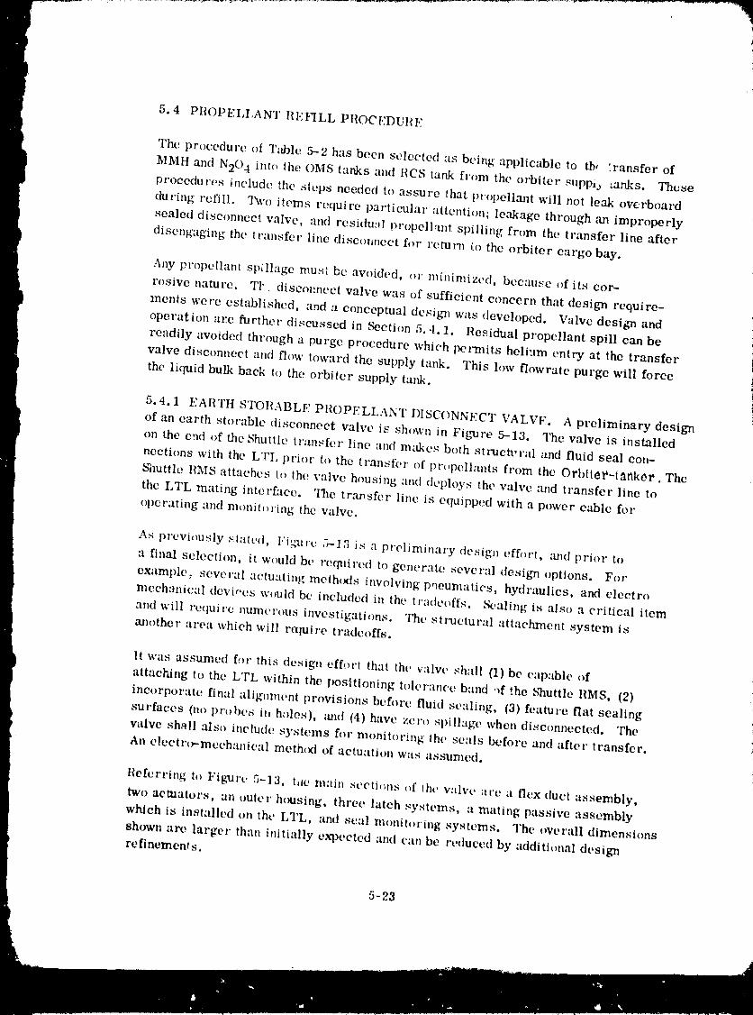
5.4 PROPELI,ANT REVILL PROCI.]DURE
The procedure oI Table 5--2 has been selected as being applicable to tb, :ransfer of
MMH anti N20 4 into the OMS tanks and RCS tank from the orbiter suppia ranks. Thc_e
procectu res include the steps needed to assure that propellmlt will not leak overboard
during refill. Two items require partieular attention; leakage through ,-m improperly
sealed disconnect valve, and residual propellant spilling from the transfer line after
disengaging the transfer line discmmeet for return (o the orbiter cargo bay.
Any propellant spillage must be avoided, or minimized, because of its cor-
rosive nature. TI- discopnect valve was of sufficient concern that design require-
ments were established, and a conceptual design was developed. Valve desit,m and
operation are further discussed in Section 5.4.1. Residual propellant spill can be
readily avoided through a purge procedure which permits helium entry at the transfer i
valve disconnect and flow toward the supply tank. This low flowrate purge will force
the liquid bulk back to the orbiter supply tank. i
5.4.1 EARTtt STOHABLE PROPELLANT DISCONNECT VALVI,:. A preliminary design
of an earth storable disconnect valve is shown in Figmre 5-13, The valve is installedon the end of the Shuttle transfer line and makes both stI_etural and fluid seal con-
nections with the LTI, prior to the transfer of propellants from the Orbit_l*-t_nker, The
Shuttle HMS attaches t() the valve housing and deploys the valve and transfer line to
the LTL mating interface. The tr,'msfer line is equipped with a power cable for
ope rating and monito ring the valve.
As previously stated, l.'igxlre 7,--1,2 is a preliminary design cff(,rt, amd prior to
a finalselection, itwould be req_firedto gencr:ttcseveral desi_,moptions. For
example: several actuatingmeth(,ds involvingpneumatics, hydraulics, and electro
mechanical dcvi,.e.swould be included in the lradeoffs. _,aling is also a criticalitem
and will require numerous investigations. The structural attachment system is
another area which will r_luiretradeof[s.
Itwas assumed [or thisdesign effl_t'tthat the valw' shall (1)be capable of
attacLingto the LTL within the positioningtolerance band .ffthe ShuttleRMS, (2)
incorporate final alignment provisions before fluid sealing, (3) feature flat sealing
surfaces (no probes in holes), and (4) have zero spill'tge when disconnected. The
valve shall also include systems for monitoring the seals before and after transfer.
An electr(_-meehanical meth(_ of actuation was assumed.
l{eferring t,) Fib,nJrt. 5-13, tae main secti,ms ()f the valve are a flex duct assembly,
two actuators, an outer housing, three latch systems, a mating passive assembly
which is installed on the LTL, aml seal monito,'ing systems. The overall dimensions
shown are larger than initially expected and can be reduced by additional design
re finement s.
5-23
1980009811-16!
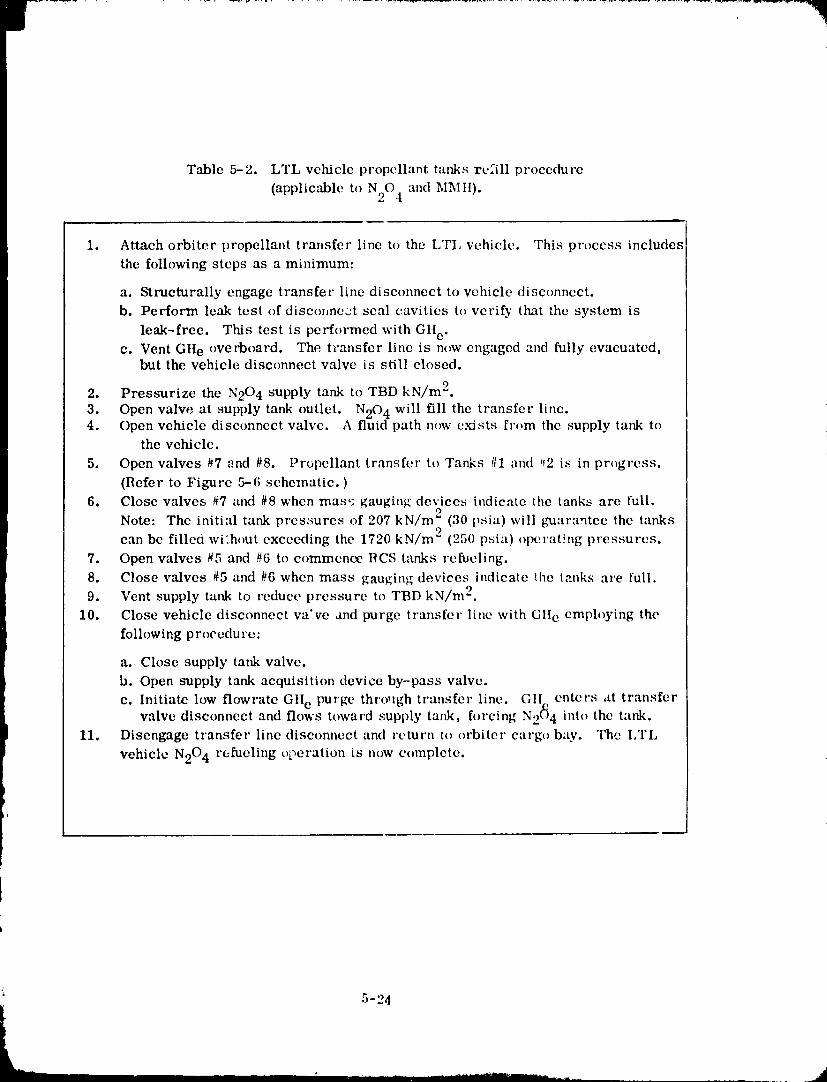
Table 5-2. LTL vehicle propellant tanks refill procedure
(applicable to N204 and M_Ttl).
1. Attach orbiter propellant transfer line to the LTI, vehicle. This process includes
the following steps as a minimum:
a. Structurally engage transfer line disconnect to vehicle disconnect.
b. Perform leak test of disconnc:A seal cavities to verify that the system is
leak-free. This test is performed with GH e.c. Vent Gtte overboard. The transfer line is now engaged and fully evacuated,
but the vehicle disconnect valve is still closed.
2. Pressurize the N20 4 supply tank to TBD kN/m2.
3. Open valve at supply tank outlet. N20 4 will fill the transfer line.4. Open vehicle disconnect valve. A fluid path n(,w exists from the supply tank to
the vehicle.
5. Open valves #7 and #8. Propellant transfer to Tanks ttl and #2 is in progress.
(Refer to Figure 5-6 schematic. )
6. Close valves #7 and #8 when mare; gauging devices indicate the tanks are full.
Note: The initial tank prcs:;ures of 207 kN/m 2 (30 psia) will guarantee the tanks
can be filled wi:hout exceeding the 1720 kN/m 2 (250 psia) operating pressures.
7. Open valves #5 and #6 to commence RCS t_mks refueling.
8. Close valves #5 and #6 when mass gauging devices indicate the tanks are full.
9. Vent supply tank to reduce pressure to TBD kN/m 2.
10. Close vehicle disconnect valve and purge transfer line with GIte emph)ying the
following procedure:
a. Close supply tank valve.
b. Open supply tank acquisition device by-pass valve.
c. Initiate low flowrate GHe purge through transfer line. GII. enters at transfervalve disconnect and flows toward supply tank, forcing N2(_4 into the tank.
11. Disengage transfer line discom_ect and return t() orbiter cargo bay. The LTL
vehicle N204 refueling operation is now c¢_mplcte.
5-24
_A
1980009811-166
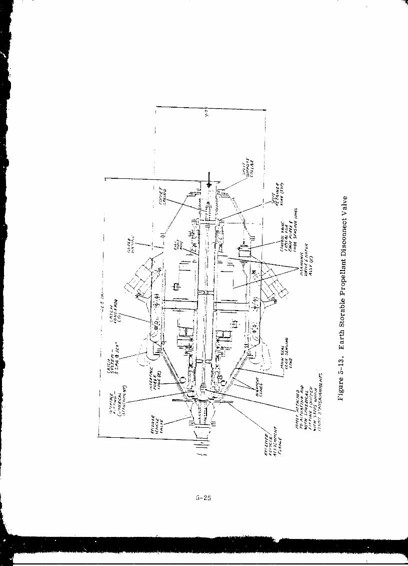
f 5-25
1980009811-167
111t' flex duet as,qcmbly Yuns the flfil h,ngih of the v'tlve and eon,qisls of two
short tube sections, three bellows, one poppel with :in ach|:ding rod :lssenlbly, two
guide vane fittings, one mounting flange, _me illiel'f:lee fitting with _qeals, one fitting
for actuating the poppet and one inh,i lilting. Ext'opi t'or tilt' seal,,; illld tilt' poppcl
assembly, all parts are 304L CHICS and arc welded into one assentb!y. The seals
would t)rob_lbly be a rubber t.'q)e eonlpound lilt)lilt, it or bonded into the interface fitting
and the poppet. The poppet assembly will probably be 30-iI, ('R I,_S m:_chined paris
assembled with threaded fillings. The popl)et spring m:deriid is 178 Ineonel.
The flex duet assembly in tilt' htulri of ihc valve system. ()pening ov cl,_sing is
aeeonlplished by compressing oY exlendillg lilt' be:lows wilh :lettlaiOl's h_eaied oulside
the flow Sil'e_.llll. No dylllllllie sellls _ll'e i'eqtlil'ed. The spherical ('ollileetiorl between
the actuator and the interface lilting plus tilt, ball so('kei type ('mmeetionbetween
poppet and actuating rod permits angular misalignments between sealing sut faces. !
The ;IctU_.ltOl" system is two h;ll'lllOllie t Vpt' drives. 1.;aeh tlrive is illte_t'att'tt with :l i
hollow shaft, electric motor. The drives and motors are eonfi_;ured to :fllow the flex
duet assembly to pass thl'O/Igll _.lt lhe uelltel" line. 'l'o permit :lssel,tb|y, each dl'ive hlls
a split collar fl_r attaching to the flex duct :t,_st,nfl_ly. l'his type of Itt,tuilior ,qystenl
peYnlits a compact asst,,lllbly but does I'equil'e t/UllX" I'OUS l_)ill'l,'qo The lll:lill p;.ll'iS [t)l"
each drive are one wave generator, one flex splint,, :1 eil'eUlill" ,qplinc :10,d it dynillllie
spline. Approximately seven bearings will be reqtliret| (plus l'elaillel'.q), including
two fel" 1tlo nlotol'. Two additional screw jack parts are also required on tile outpuiend of each drive.
Thf outer housing" eonsisis of a cylindrical St'clioi'l which ix t'qllil_pt,d with ;I
conical fitting at each end. thee era/teal fitting has two ,,xtt.rn,d l_lll('lxillt't_ lands plus
a flange for maiing with tht' conie:ll st'ellen oil lilt, I,TI,. The [_l,ll'po.'¢c for lilt' t'onit)al
llliltjllg 8ul'[ileeS ix Io pel'l//il loose t'll_tlgelllt'll| e_,'ell wil.n lill'_t' illisllligl/ll_t'lltS plus
_IccUI'IllO aliglllllent when the eolles ;ll't, tmlh'd to_t, lht, l'.
The second conical lilting has two fh_nges; ,me tel" illt:lehing it, the eylindvie:tl
section and one for the flex (luet ait,lt'hnlet:i. This conical fitting l_rovi(les :1 rigid
interface [Of connecting tilt' tl'll.llSt't'l' ill, let illltt I'e_,lut,q the l_l'essul'e ;.If'i'll loil{|S [l'Olll the
flex duet bellows. To permit asst, lnbly, ,l :q_lii collar is uscd at the fh,x duet ati'lel_-
file Ill,
The t'Altel" hol.lSillg eylilldl'icill st, oiioll hil.q thl't,e t, xtt'l'tl:ll loll_t'l'olls fOl" Slll_p_l.lillg
the latching systems and an illterltill ,_pidel" beall/ for SUl_l_orting the :leiuatol's. Filt'h
end is also equipped with a flange for :ltt:tehing the colic,'-;. A fitting for :lttaehing to
the RMS is located betweell two of the l,mgerons. This fitting in trot showtl oil the
lay,_ut.
All outer hoti,'-tillg p:ll'i,'-; ill't' '_°19 ;I]ll/'_il}l',ll ;lll,,y. '['ht' t'tqle.'-; ¢'_ltl bt' t'ithev
single sptlll fOl'lqled plll'|,'_ OF weldlllCnts COllsisiing of rolled eollc,'_ :llld ll/ilt'hilled ring
5-26
1980009811-168
flanges. The eylimtrical section is a weldment. The latching systems are basically
iUl over ct'ntet" dr, vii't, powered by an eleett'Olllechalfical Sel'eW jack actuator. The
locking pawls arc e:qmble of rotating outboard ('onfl)ined with axial displacement
away from lilt" housing cone. The pawls can also rotate inboard followed by an axial
movement toward the housing eouc. This type of kinematics permits gross initial
eaptu re with the ma ling cone on tile LTL followed by draw down and final ali_ment.
The passive section t,f the valve which attaches to tile Lq'L is a single piece cone
and valve b_rty cquit)ped with a spring loaded poppet. The valve body fcatures a fiat
faced scaling surfat`c equipped with flow passages fl)r interface purg'ing and seal
monitoring. FXeCl)l l'()r lht, poppet spring, the entire assembly is 2219 aluminum alloy.
Flow passages are provided on both sides of the sealing plane. 'lqmsc passages lprovidc a means for monitoring leifl_ag(, ,rod for purging tile interface cavity. Small {tubes with flex loops are routed from these passages to solenoid control valves. The
circuits are activated with GIIe. ()tht`r addititmal moans for monitoring leaks is the
use of sniffers. (;H e supply for the system indicated can be from tubes routed along d
the transfer (tu(,l or fr()ln a small bottle (with controls) attached to tile valve housing.
f A second small bollh, (attached It) the valve housing) can also be used to act as acatch reservoir when purging the interface cavity. The use of bottles attached to the
valve sinlplifics tilt' tvansft`r line assembly since only one electrical cable is required.
An operation st`qtlence is shown on Figure 5-1,1. l/efcrring to Step 1, the two wflve
sections ave in a gross eapturt` mode. At this stage the latches art` rotated inboard
which eapttll'e_q lilt' (,oRe [']:lllgt` oll tilt' LTL side.
In Step 2 the latcht, s ave actuated parallel to _tte valve taxis pulling tilt, two cones !together. The structur:ll connection is now completed, i
In Step 3 one of the harmonic drives is actuated which engages tile primary seals with
the mating flat face. Stop lands machined on the fl:tnge containing the seals controls
the _mumn! of Sqtlt,ezt, ()n the seals. A leak check is perf()rmed by pressurizing the
cavity bt`_ween the two t)l'illlal'y seals and lll()llitol'ed [Of pressure decay.
The second harmonic drive is actuated in Step 4 which opens the valve for transfer.
During transfer, the main seal is monitored with a sniffer located in the GR e supplytube.
The vMvt` is closed at the completion of propellant transft, r, as indicated in Step 5, and
the small interface cavity purged. The sealing arrangement for this purge circuit is
shown in Detail "A". Before disengagTing, the transfer line is purged and the poppet
seal on the LTL side ix checked for le;fl_s by activating the sniffer circuit in the tube
leading to tim interface cavity.
5-27
1980009811-169
In Step 6, the main seal is disengaged, the latches opened, and the wdve separated bythe RMS.
5.4.2 HELIUM BOTTLF RESUPPLY. Space-based vehicles will require gaseous
helium resupply during refueling operations. One moth{x:! of resupply is by flowing
helium from a storage tank (located i_ the Shuttle payload bay) to the vehicle through a
long transfer line. An alternative would be to employ separate pro-loaded modularhelium bottles that would be externally attached to the vehicle. A disconnect system
capable of mating a structural attachment and a fluid connection with the vehicle is
required with either approach. Several disconnects are rcquircd of the modu!ar bottles,
however, as compared to only ,.me•for a transfer line.
The orbiter remote manipulating system {RIMS)will be employed to ctmnect transfer
line or modular bottles to the vehicle. The IiMS will place the disconnects reasonably
close to the mating target. Pressure-area loads will be reacted only by the disconnect
structure, aLJ not by the RMS.
5.4.2.1 ttelium transfer from orbiter -- 7he transfer line approach will have an
electrical power cable attached to the line and permanently c(mnected to the disconnect
system located at the end of the line. The transfer line must have mobility which in
turn requires flex joints either in the fm:m of braided hoses, swivel type joints with
dynamic seals, or loop bends in the tubing. Conventional belh;ws jonts would not be
applicablc due to high pressure requirements. The use of hoses, swivel joints and loop
bends presents packaging and weight penalties. Also, the s'ffety _)f this transfer
l °operation is of concern because a 21m(70 ft. ) line, pressurized to 34500 kN/M'(5000 psi),will be essentially unsupported except at the orbiter and at the vehicle.
Aside from the question of safety is the problem _f excessive tlelium [emperattlres
occurring the bottle eharging period. This pr,)blem exists 0eeause the heal of cem-
pression generated during the charge peri_t emmot be readily dissipated; and may
require the aid of space radiators. Potential solutions arc summarized in Table 5-3,
| only one of which was considered acceptable.
5.4.2.2 Helium Modules -- The preferred method for I/I'L vehicle helium resupply isto use helium bottle modules.
Basically, the prc_-loaded helium m_×hiles are picked up with an RMS and plugged into
external LTL interfaces which in turn have intereommcting plumbing to the LTLsystems.
Detail "A" of Figure 5-3 shows a typical helium module which is a high pressure
bottle equipped with a tangential support skirt, a docking cone, a latching system, a
shutoff valve aald a motor driven disccmncel. The tm_geuti:tl skirt secti(,n has a fitting
which interfaces with the RMS. The _mly requirement in the case _f a Shuttlc RMS _i
5-28 t
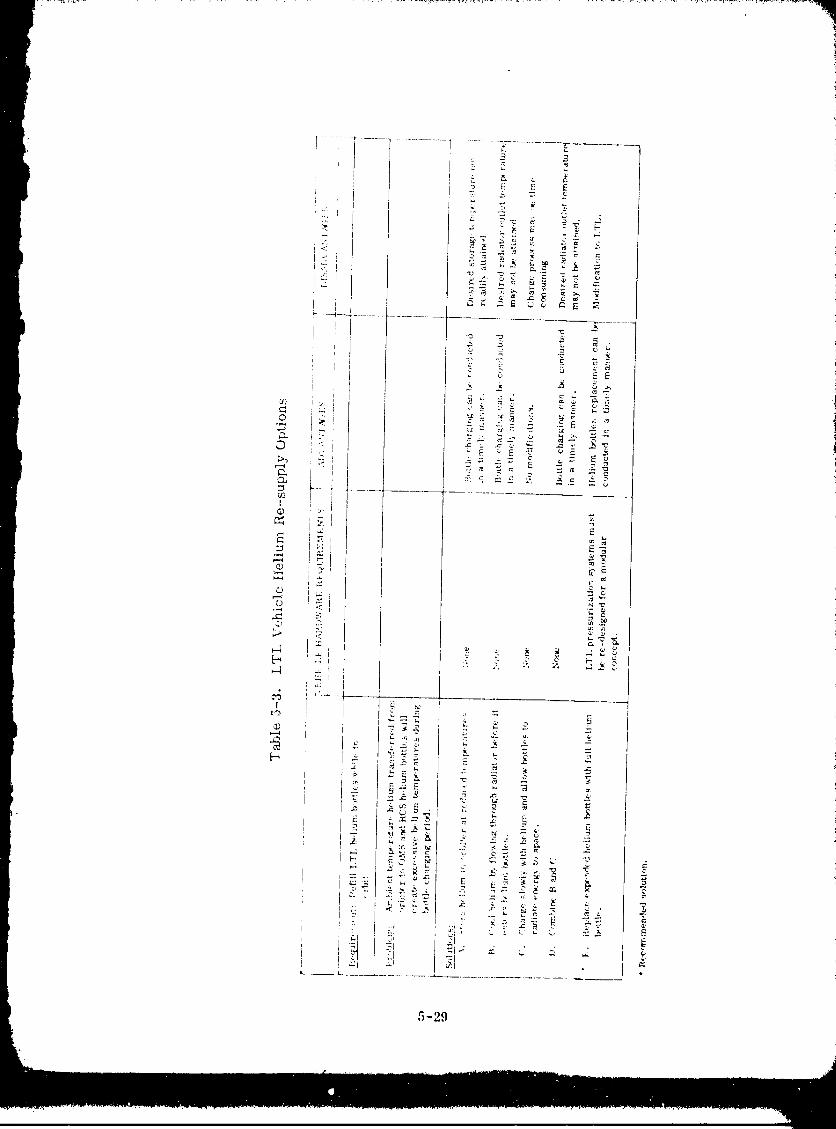
5-29
1980009811-171
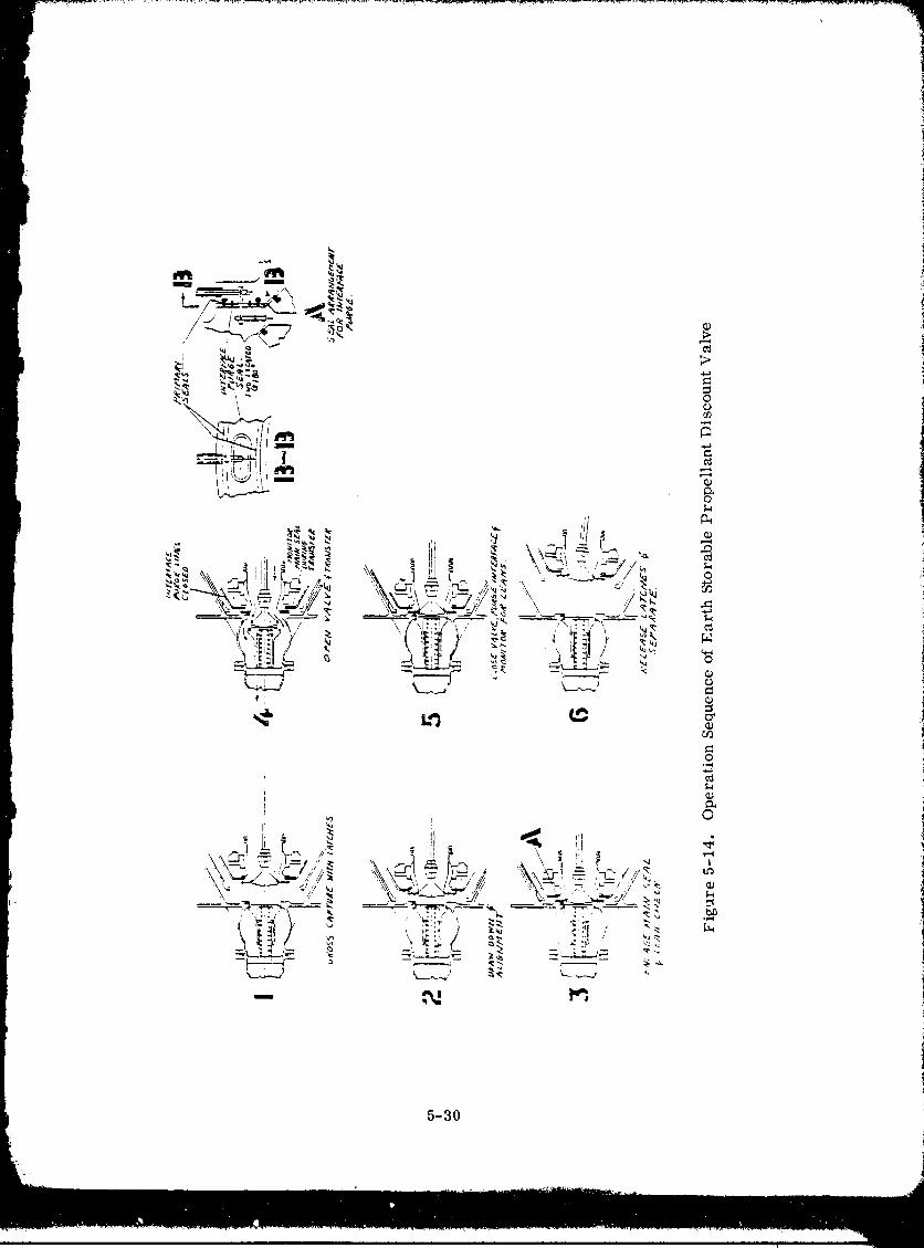
.... 7_
1
5-30
1980009811-172
would be the addition of an end fitting. This fitting would include a power cable from
the Shuttle for actuating the latch and diseo_mect systems.
A typical transfer sequence consists of connecting an RMS to the helium module;
placing the module loosely (wide tolerances) into a mating cone on the LTL; actuating
the latches to an inboard position to insure a gross cap.re and finally moving thelatches in an axial direction which completes the ntruct_aral connection. With the struc-
tural cop.nection completed, the disconnect system is energized malting a seal between
module a_d vehicle, The socket portion of the diseormect contains the seals and the probe
section on the LTL is float mounted to compensate for misalignments, Since tempera-
tures are basically ambient, the seal system consists of "(Y' rings equipped with backuprings to prevent "blow out". The seal design includes provisions for easy replacement.
5.4.3 ZERO-G MASS GAUGING. A zero--g mass gauging system will be as importantto refill of earth storable vehicles as to POTV and COTV refill. The measurement of
propellant mass quantities is critical at two intervals during on-orbit refill; whenminimum liquid residuals and when final tanked mass mus t be measured. Total
propellant load must be known to verify that sufficient propellant has been tanked to per-
form a mission. Propellant quantities in excess of requirements could unnecessarily
penalize the vehicle mission. A continuous mass measurement during the latter stages
of tank fill would also prevent the protential of tank over-pressure caused by over-fill.
The second occasion where mass measurement will be necessary is during the pro-
pellant tank venting procedure described by Table 5-1. Step 5 of this procedurestates that a signal will be sent to terminate propellant transfer from one tank to
another when the mass gauging device indicates that a minimum liquid residual
remains. Screen g:dlery liquid replenishment (to mnke-up for surface evaporation) will
be provided from this residual liquid volume. Less propellant thaJ_ this minimum
may not be sufficient to maintain communication with the screen device; resulting invapor penetration due to the loss of liquid replenisttment. Substantially more residual
than the minimum will increase the probability that propellant can be vented overboard.
,
5-31
w
1980009811-173
6EXP ERIME NT AI, MODE LING
On-orbit fill and refill of a propulsion tankage system is examined in this section to
determine what experimentation is required to demonstrate this capability in a zero
or low g environment. Emphasis is placed on identifying the major scaling para-
meters that must be satisfied in order to model the thermodynamic and fluid mech-i
anic conditions of a refill operation. The influence of fluid properties and model i
tank scale on the validity of test results was also evaluated. Per the study guide- ilines, the analysis effort was directed at conducting these experiments in low earth iorbit inside the Spacelab.
iModeling or scaling analysis will be used to determine the feasibility, and subse- {
quently the conditions and eonfigxlrations, of the shuttle experiments for providing !
data useful in determining procedures for refueling a sp_ce-based vehicle. This
discussion on scaling will focus on our understanding of the fluid phenomena as well
as the complexities involved in experimental modeling.
Based upon the analyses performed in sections 3, 4 and 5, the important areas of
c ryogenic and ea eth storable p repellant tank on-o rbit refill have been identified.
These areas, for a cryogenic stage, are tank vent, prechill and fill. The only area
of concern for an earth storable stage is tank vent (experimentation is not recom-
mended, as discussed in section 6.). The influence of such factors as helium present
within the propellant tanks, and partial acquisition devices was also determined.
Not all of the important elements of a refill process _,hould be subjected to a rigorous
experimental program. Ikather, only those elements that require verification, or
i processes which phenomenon is not well understood, should be considered for experi-
mentation. As an example, propellant tanks vent will be an important part of
any cryogenic refill operation. There is not a compelling reason, however, for per-
forming such experiments in space. Means can readily be de_Sscd for safely vent-ing the propellant tanks without just per'forming orbital tests. Those areas requir-
ing experimentation are listed below. Specific outputs are identified that will pro_de
design criteria and procedures for refueling operations of space-based OTVs:
1. Tank Prechill - Obtain empirical data to establish relationships
for scaling peak tank pressures, prechill times, and vent mass
requirements.
6-1
1980009811-174
2. Tank Fill - Obtain empirical data to establish the influence of
b propellant tank inflow parameters on thermodynamic equilibrium
t conditions.3, Support Experiments Criteria - Identify an empirical relationship
between start basket in-flow parameters and successful refill.
Each phase of the propellant-transfer process will require a separate scaling analy-
sis. Three basic scaling methods were considered in this study: (1) dimensional
i analysis, (2) order of magnitude analysis on the equations of motion, and (3) ratio
of phenomenological equations.
Dimensional analysis is the cl,,ssic method, and it provides a simple and direct
procedure for obtaining all parameters that may affect a process. Since exact
scaling is not usually possible, however, we must determine which parameters are
most important. Dimensional analysis alone does not provide a solution to the prob-
lem, and a significant amount of experimentation is required to determine exact re-
lationships between the resulting dimensionless groups. The complex heat and mass
exchange mechanism associated with orbital refill did not readily lend itself to di-
mensional analysis.
The order-of-magnitude and ratio methods require writing the equations that describe
the process. With order-of-magnitude analysis, the boundary value problem that
describes the process is written and transformed into dimensionless variables. The
important variables are determined from an ordcr-bf-mag-nitude analysis and the
lower-order terms are neglected in the scaling process. The ratio method is the
same approach that is used when an analytical solution is described.
If the differential equation can be solved accurately, the scaling p_oblem is redund-
ant and is replaced by an exact solution. However, it is usua!ly impossible to solve
the differential equation _ith boundary and initial conditions without making some
gross simplifying assumptions that may considerably reduce the credibility of themathematical model.
The ratio method was employed as the scaling technique for the orbital refill process.
Empirical equations are identified in Sections 6-2 and 6-3 which describe the prechtll
and tank fill processes of a cryogenic vehicle refueling operation. The key variables
of these processes were readily identified. Model test flow para_neters and time
scaling relationships were subsequently identified as a function of tank scale.
6.1 RECEIVER TANK SCALE
Normally, when an experimental test program is defined, sc,'ding equations derived
from the modeling analyses will sccve to identify the tank scale and fluid selection.
For this study however, a grouadmle to perform tests within the Spacelab facility
limited the test tank size to a 1/10th scale maximum. The following ,'elates the
specifics of tank size, in addition to tank shape.6-2
1980009811-175
6.1.1 RECEIVER TANK StlAPE. The OTV includes liquid hydrogen and liquid oxygen
propellant tanks, both of which will be refilled in space. A single receiver tank will be
selected for conducting orbital refueling experiment._, and the question is, which
propellm_t tank configuration shall be tested ?
It was shown in Section 3.3.2.1 (Figure 3-14) that the liquid oxygen propellant tank can
be refilled more easily than the liquid hydrogen tank becuase it will not experience
excessive pressure during refueling. The conclusion was made, correctly, that
liquid hydrogen tank L-efueling should be subjected to experimentation in order to verify
the selected refill technique. However, it will "always be more difficult to refill any
tank with liquid hydrogen than with liquid oxygen; fluid property differences are
responsible for this condition. Consequently, the difficulty in LH 2 tank refill is due to
the propellant, n_'t the tank shape. If liquid hydrogen is eliminated as a test fluid, what
justification exists for using the LH 2 tank configuration?
It appears that adequate mixing of the liquid and wtpor phases will be easier to attaie
in the LO2 tank than in the LH 2 tank. This conclusion seems valid if we compare
two tanks (having the same volume), where one is cylindrical and has a large length-to-diameter ratio, and the other is a sphere. Intuitively, uniform mixing in a cylinder
should be more difficult to achieve than in a sphere. SeleL_t!on of the LH 2 tank con-figuration will guarantee that the most difficult configuration for orbital refill will betested.
6.1.2 TEST SCALE. In general, when an experiment plan is developed it is neees-
sa_'y to compromise between the desire for a full scale test program and the limita-
tions imposed by resources and facilities, large scale tests are always desirable
because the uncertainty of e.xtrapolating test data to a prototype condition can be mini-
mized. Thus, for the Spacelab experiment, the desire is to design the largest tankscale that can be accommodated. In this case, test tank size will be limited to a
package that fits within a doublerack structure, Figure 6-1. Design details are
provided in the following discussion.
6.1.2.1 Preliminary test tank design. In Figure 6-1, an experimental apparatusis shown positioned in a Spacelab doublcrack st ructure, which will demonstrate on-
orbit propellant loading of OTV's. This apparatus consists of a scale model OTV
LH 2 tank suspended within a vacuum-jacketed shell. The intent of Figure 6-1 is todetermine a basic tank size for the apparatus within the nominal envelopes described
by the Spacelab payload accommodation handbook, Reference 6-1. Betails for plumb-
ing, wiring and supports are emitted. For this case the areas controlling the tank
siuc are Zones "B" and "C" shown cross hatched on the layout. Zone "B" is
reserved for payload cabling and Zone "C" is reserved for subsystem access.
The apparatus is positioned near the right wall of the rack (as viewed by the operator)so that the tank bulkhead clears the corner of Zone "C", Tank length is then limited
by Zone "B". Adjustments between diameter and length were made within these con-fines to arrive at an acceptable L/D ratio. The tank shown has a 457 mm (18 in. )
6-3
1980009811-176
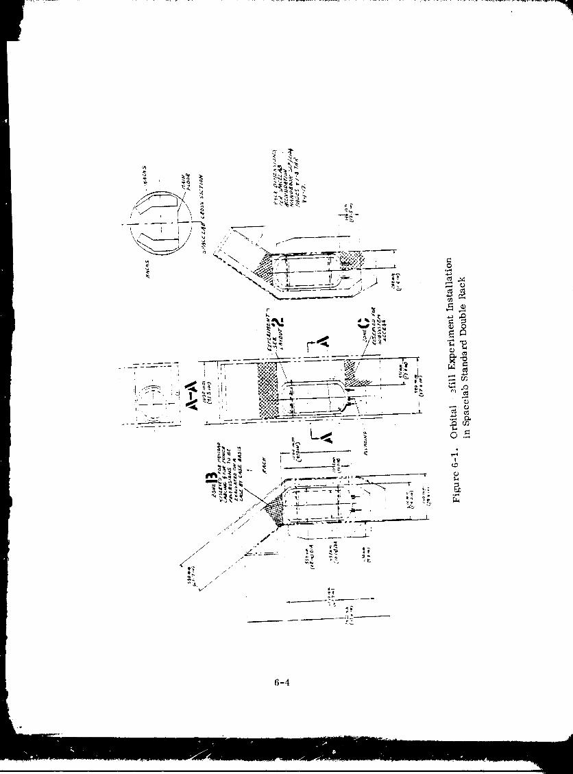
6-4
1980009811 -177
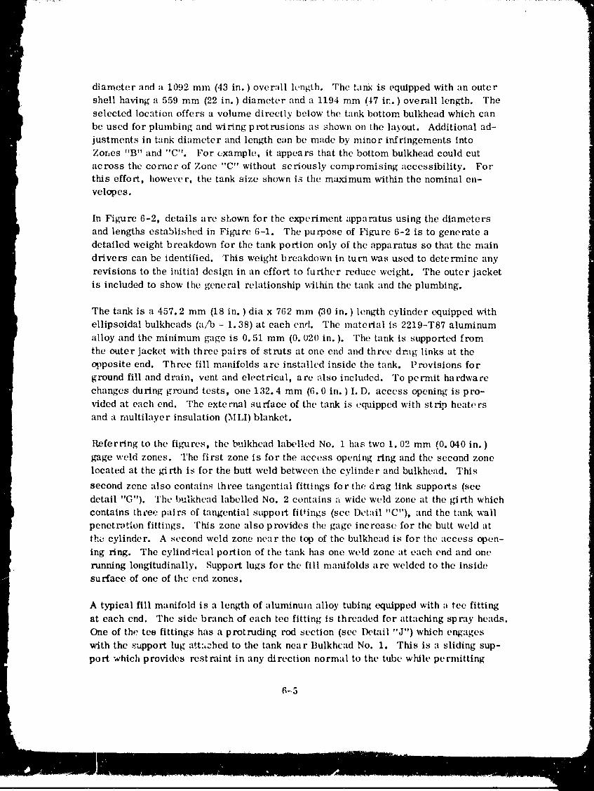
diameter and a 1092 mm (43 in. ) overall length. The t.ln_ is equipped with an outer
shell having a 559 mm (22 in. ) diameter and a 1194 mm (_7 ix'. ) overall length. Theselected location offers a volume directly below the tank bottom bulkhead which can
be used for plumbing and wiring protrusions as shown on the layout. Additional ad-
justments in tank diameter and length can bc made by minor infringements into
Zones "B" and "C". For example, it appears that the bottom bulkhead could cut
across the corner of Zone "C" without seriously compromising accessibility. Forthis effort, however, the tank size shown is the maximum within the nominal en-
velopes.
In Figure 6-2, details are sLown for the experiment apparatus using the diameters
and lengths established in Figure 6-1. The pucpose of Figure 6-2 is to generate a
detailed weight breakdown for the tank portion only of the apparatus so that the main
drivers can be identified. This weight breakdown in turn was used to determine any
revisions to the initial design in an effort to further reduce weight. The outer jacket
is included to show the general relationship w-ithin the tank and the plumbing.
The tank is a 457.2 mm (18 in. ) dia x 762 mm (30 in. ) length cylinder equipped with
ellipsoidal bulkheads (a/b = 1.38) at each end. The material is 2219-T87 aluminum
alloy and the minimum gage is 0.51 mm (0. 020 in. ). The tank is supported from
the outer jacket with three pairs of struts at one end and three drag links at theopposite end. Three fill manifolds are installed inside the tank. Provisions for
ground fill and drain, vent and electrical, are also included. To permit hardware
changes during ground tests, one 132.4 mm (6.0 in. ) I. D. access opening is pro-
vided at each end. The external surface of the tank is equipped with strip heaters
and a nmltilayer insulation (MLI) blanket.
Referring to the fig'ures, the bulkhead labelled No. 1 has two i. 02 mm (0. 040 in. )
gage weld zones. The first zone is for the :recess opening ring and the second zonelocated at the _,--irth is for the butt weld between the cylinder and bulkhead. This
second zone also contains three tangcntial fittings for the drag link supports (see
detail "G"). The l)ulkhead labelled No. 2 contains a wide weld zone at the girth which
contains thcee pairs of tangential support fittings (see Detail "C"), and the tank wallpenetn_tlon fittings. This zone also provides the gage increase for the butt weld at
the cylinder. A second weld zone near the top of the bulkhead is for the access open-
ing ring. The cylindrical portion of the tank has one weld zone at each end and one
running lont,dtudinally. Support lugs for the fill manifolds are welded to the insidesurface of one of the end zones.
A typical fill manifold is a length of aluminum alloy tubing equipped with a tee fitting
at each end. The sidc branch of each tee fitting is threaded for attaching spray heads.
One of the tee fittings has a protruding rod section (sec Detail "J") which engages
with the support lug att:,ched to the tank near Bulkhead No. 1. This is a sliding sup-
port which provides rcstraint in any direction normal to the tube while permitting
_5
1980009811-178
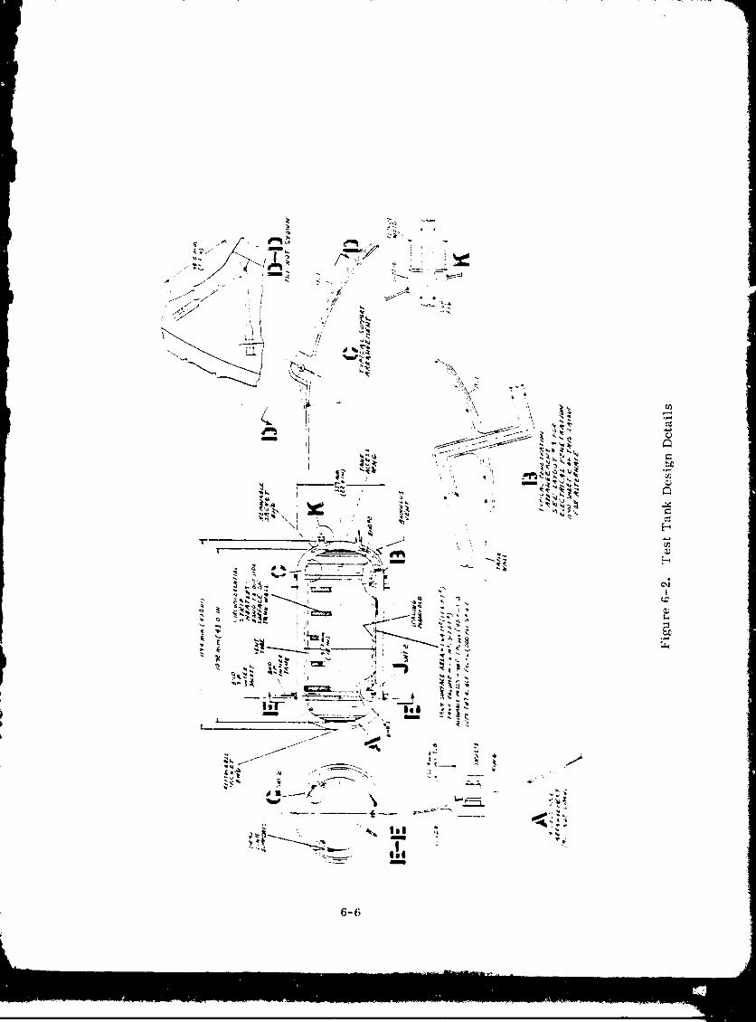
1980009811-179
6-7
1980009811-180
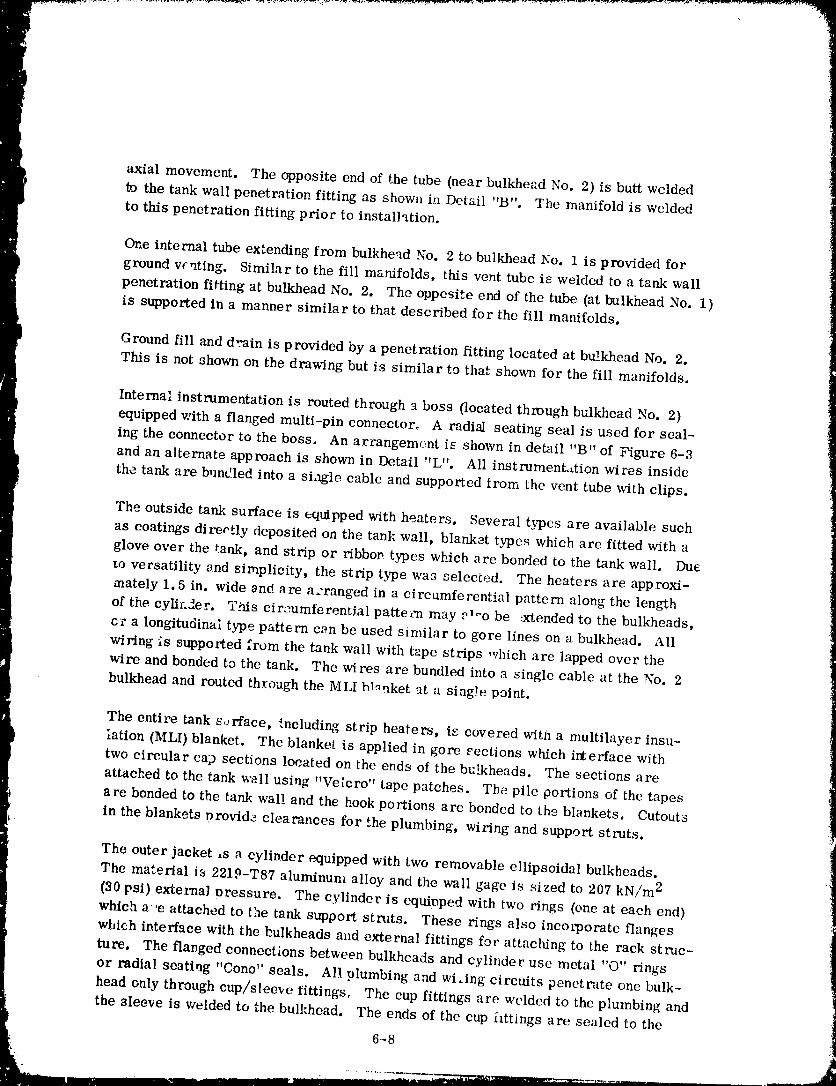
axial movement. The opposite end of the tube (near bulkhead No. 2) is butt welded
_o the tank wall penetration fitting as shown in Detail "B". The manifold is welded
to this penetration fitting prior to installation.
One internal tube extending from bulkhead No. 2 to bulkhead No. 1 is provided for
ground vc_ting. Similar to the fill manifolds, this vent tube is welded to a tank wall
penetration fitting at bulkhead No. 2. The oppesite end of the tube (at bulkhead No. 1)
is supported in a manner similar to that described for the fill manifolds.
Ground fill and d-_ain is provided by a penetration fitting located at bu'..khead No. 2.
This is not shown on the drawing but is similar to that shown for the fill manifolds.
Interna: instrumentation is routed through _ boss (located through bulkhead No. 2)
equipped with a flanged multi-pin connector. A radial seating seal is used for seal-
ing the connector to the boss. An arrangement iE shown in detail "B" of Figure 6-3
and an alternate approach is shown in Detail "L 't. All instrumentation wires insidethe tank are b,mdled into a single cable and supported from the vent tube with clips.
The outside tank surface is equipped with heaters. Several types are available such
as coatings direotly deposited on the tank wall, blanket types which are fitted with a
glove over the tank, and strip or ribbop types which are bonded to the tank wall. Dueto versatility and simplicity, the strip type was selected. The heaters are approxi-
mately 1, 5 in. wide _nd are a:ranged in a circumferential pattern along the length
of the cylh.2er. T_s cir_-umferen_ial patte_'n may ._*oo be :xtended to the bulkheads,
cr a longitudinal type pattern c_n be used similar to gore lines on a bulkhead. All
wiring is supported from the tank wall with tape strips which are lapped over thewire and bonded to the tank. The wires are bundled into a single cable at the No. 2
bulkhead and routed through the MLI bl.uket at a siag)e point.
The entire tank s.:rface, '.ncluding strip heaters, is covered with a multilayer insu-lation (MLI) blanket. The blanket is applied in gore eections which irterface with
two circular cap sections located on the ends of the bulkheads. The sections are
attached to the tank wall usirlg "Veicro" tape patches. The pile portions of the tapes
are bonded to the tank wal! and the hook portions are bonded to tho blankets. Cutouts
in the blankets providz clearances for the plumbing, wiring and support struts.
The outer jacket ,s a cylinder equipped with two removable ellipsoidal bulkheads.
The material is 2219-T87 aluminum alloy and the wall gage is sized to 207 kN/m 2
(30 psi) extel_nal t_ressure. The cylinder is equipped with two rings (one at each end)
which a 'e attached to the tank support struts. These rings also incorporate flanges
which interface with the bulkheads and external fittings for attaching to the rack struc-ture. The flanged connections between bulkheads and cylinder use metal "O" rings
or radial seatirlg "Cono _' seals. All plumbing and wiAng circuits penetrate one bulk-
head only through cup/sleeve t ittings, The cup fittings are welded to the plumbing and
the sleeve is welded to the bulkhead. The ends of the cup httings are sealed to the
6-8
1980009811-181
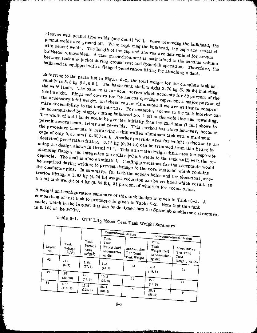
:!
sleeves with peanut type welds (see detail "K"). When removing the bulkhead, the i
peanut welds are .,round off, When replacing the bulkhead, the cups are resealedi
with peanut welds. The length of the cup and sleeves are determined for severabulkhead removables. A vacuum environment is maintained in the annulus volume
between tank and jacket du_-ing ground test and Spacelab operation. Therefore, the
bulkhead is equipped with a flanged penetration fitting for attaching a duet.
Referring to the parts list in Figure 6-2, the to_al weight for the complete tank as-
sembly is 5.8 kg (13.0 lb). The basic tank shell weighs 2.76 kg (6.08 lb) including '
the weld lands. The balance is for accessories which accounts for 53 percent of the
total weight. Ring.; and covers for the access openings represent a major portion of
the accessory total weight, and these can be eliminated if we are willing to compro-
mise accessibility to the tank interior. For example, access to the tank interior can
be accomplished by simply cutting bulkhead No. 1 off at the weld line and rewelding.
The width of weld lands would be gi-e_ter initially than the 25.4 mm (1 in. ) shown to
permit several cuts, trims and re-welds. This method has risks however, because
the procedure amounts to reworking a thin walled aluminum tank with a minimum
gage of only 0.55 mm( 0.020 in. ). Another possible area for weight reduction is the
electrical penetratio:, fitting. 0.16 kg (0.34 lb) can be trimmed from this fitting by
using the design shown in Detail "L". This alternate design eliminates the separate
clamping flange, and integrates the collar (which welds tc the tank wall) with the re-
ceptacle. The seal is also eliminated. Cooling provisions for the receptacle would
be required during welding to prevent damage to the core material which contains
the conductor pins. In summary, for both the access holes and the electrical pene-
tration fitting, a 1.93 kg (4.24 lb) we!.ght reduction can be realized which results in
a total tank weight of 4 kg (8.84 lb), 31 percent of which is for accessories.
A weight and configuration summary of this tank design is given in Table 6-1. A
comparison of test tank to prototype is given in Table 6-2. Note that this tank
scale, which is the largest that can be designed into the Spacelab doublerack structure,is 0. 108 of the POTV.
Table 6-1. OTV LH 2 Mooel Test Tank Weight Summary
ConveatiotmI Design .... Non-conventio'nal DesignJ _ _
Total Total
T_ Tank T_nk Acce_sories
Tank Su_e Weight Incq Acoessories Weight Incq _ of Tot_Layout Volume Area Accessories, _ of Total Ac2essories, Tanl¢
No. m3(R 3) m2(ft2) kg (Ib) Tank Weight kg (Ib) Weight, kb db)
#2 .16 1.64 5.8 53 4.0 31
(S.7) _7,6) (13.0} (_'8.S4)
- _" ..... ! .... , i , , . ,. ,,,#3 ,93 5. i I0.8 32 9.0 17
(32.76) (55. O) (23.8) (19.9)
l 3. 3 'h.5" s.4 ....... .... 2 :4 9 "I (llo. 7) 0.23.9) (60.2) (ss. 9)
,]
6-9
' 1980009811-1
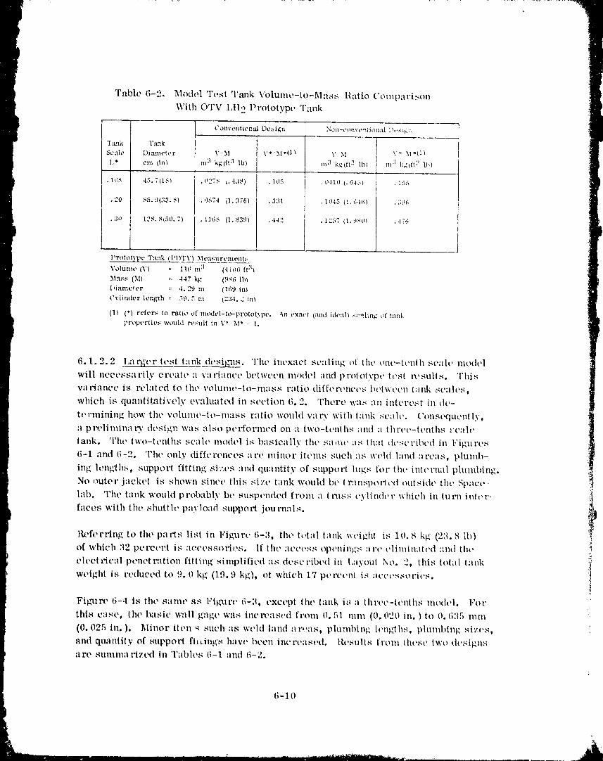
"Fable 6-2. Model Test T,-mk Volunlo-to-Mass Ratio ('otnparison
\Vith OTV l,tl 2 Prototype Tank
Conventlor...._ Design Non-convontiot_al D,*st_,::
T:u_k 'rm_k
Sc_th, DL:u_etor V M V* ,XI*tl) V 51 \+" .M*_1/
1,* cm (lt'_ m 3 kg(ft 3 "lb) m 3 k_4_It:I !b) ,,n 3 I<_tft 3 1.t,)
. 10S 45.7_1S) .0275 (.438) . 105 .0410 1.64oJ . lo5
• 20 85.9(33.8) .0S74 (1.376l .331 .10.15 (1.846! .3tq;
.3o 12S. S(50.7) .1168 (1.$3:)) .442 .1257 (1.'3S0_ ..176i__
Proto_x) e 'ra_TV_ _tcasu r oTnynt:,
Volunlo (_,') :- 116 m 3 (-lit)t) ft3_
M._._s (3I) :: .147 kg (9S6 lb_
f,iame_er :: 4.29 m (169 in)
Cylinder length _ 5:). 5 m t23-i. 2 in_
(1_ (*_ refers to ratio of modt, l-tt_-protot?,pt,. .X_ exact (and idt,:lll scqling of taIlkl,,roperties would result in V* M* : 1.
6.1.2.2 l,al'gcr test tank dosi_js. The incx-wt scaling of tilt, ont'-tt'nth so:de nlodt'l
will ncct'ssarily ert'att' :l vat'ianct, bt'twocn m_)dt'l and prototypt, test ix'suits. This
V31"i_,lllCO is rt, latt, d to tilt, vohlnlt'-to-nl_lSs r:ltio difft'l'once.,; b(,twt,t,|l t,tnk st, alt, s t
which is quantit,qtively evaluated in section 6° '2. There u_is "_n itllcl't, st in de-
tt_rmining how tilt, volunlc-to-nlass r_ltio wolfld vary with tank scah,. ('onst'qtR'ntly.
a ptx, liminat'y tlt'si_l_ was also pt'rformod on a two-tenths nmt :t throo-tt'nths _"c:|lt'
tank. Tilt, two-tt, nths sc',lh, nlodol is l/:lsic:llly thc sa,uc :Is that dt'st'l'ibt'd ill l"igtlPt'S
6-1 and (;-2. The only diffcronces :_rt, l_linor itt, ms such :ts wchl land ::l'cas, plunlb-
ing lengths, supper'( fitting si:'os :lint qtmntity of suppol-t lugs for tilt. intt'l'mll plumbing.No
,rater jacket is shown sinct' this sizc tank wouht bt' t r:_nspot'tt,d outside the Spacelab. The tank would probably bt' suspt,nd(,d fvonl a t l'tlss cylindt't" which in lu t'n tuft' l'-
faces with tilt, shut(h, plly]O:lf] suppol't journ:lls. !'i$lkfferring to tilt, parts list in Figxlrt. (;-3, tilt' tutal tatfl_ wt,ight is it). S kg (23. S lb)
of which :12 pt'l'Ct'l_t is :|O('t'SSOl'it'S. If tilt' llCt't'ss opt'nillg,'-; 31"t' t'linlin_ltt'd :'nti tilt'
electrical ptmot rution fitting simplifit, d :is dt, scr, ibt, d in l,ayout No. 2. this total tank _(_wt'ight is reduced to 9.0 kg (19.9 kg)_ ot which 17 pt, Fot,n[ is at'ct,s_ol'it,s. :t
'1¢
Fig'ure 6-.I is the sam(, as l.'iffur(, (;-3, t,xct,pt the tank i8 a thl'cc-tt't_ths moth, i. l"oP
this c:lse, the basic wall gag(' was incl'oast,d from O. 51 nun (0. 020 in. ) to O. (;35 nlnl
(0. 025 in. ). Minor it t, tl u such :is weld land :ll'('aS, plu:ubit_g h'ng'ths, pluml)ing sizes,
and quantity of SllppOl'l fittings htlvt, lit'ell int'l't, ast,d, lit'stilts [lOlll lilt'sO tWO lit'signsare summ:ll'izcd In Tabh, s (;-1 :lnd I;-2.
t;- 1 0
1980009811 -183
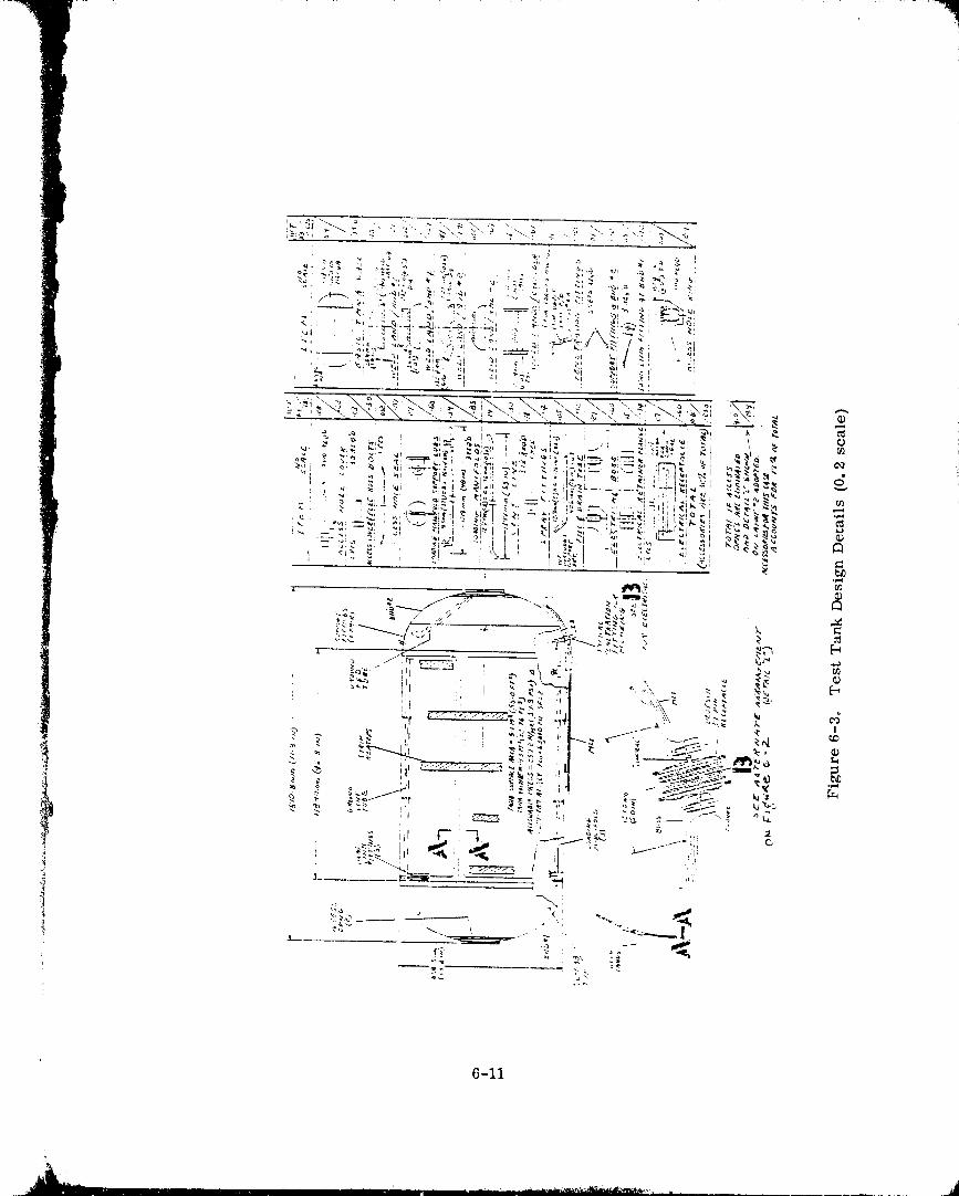
6-11
.A
1980009811 -184
1980009811-185
6.2 PRECHILL MODELING
The prechill process that has received much attention during this study is illustrated
by Figure 6-5. The process _ill be accomplished by 1) metering liquid at a highvelocity into the receiver tank for a fixed du ration, 2) allowing heat exchange between
fluid and tank walls for an unspecified duration until tank pressure has increased to
the vent level, and 3) venting the tanks back down to near zero pressure. The early
p rcchiU period is characterized by a complex tile rmodynamic and fluid mechanic p re-
cess due to liquid impingement on the hot tank waits. The resulting forced convection
nucleate and iilm boiling phenomena a re extremely difficult to analytically model orscale.
Fortunately, it can be shown that this initial period of tank chill may not be signifi-cant to the overall process. First, the heat exchange during t_e limited boiling period
represents only about ten percent of the total energy removed during prechill. Second,
we should be more concerned with the tank conditions prio_" to tank vent rather thanwitn the initial transient. The initial tnu_sient pressures will be well below the near-
steady-state pressures if propellant iifflow is adequately controlled. Figure 3- 15
indicates that precision metering of LtI 2 is not needed to avoid ovez_ressure during
prechill. Thus, effort c::,: be concentrated on scaling steady-state conditions of the
p rechill p recess.
WAIr PERIODFORTANI_
WALLULLAGEHEATEXCHANGE ] _ VENT I
UGU_O I,,.mh..-.....----..ira,
INFLOW
i
'/, t
801LING
PRECHILLTIME
Figure 6-5. A PrechiI1 Procedure Can be Ideatified to ELiminateExcessive 'rank Pressures Duc to Wall Boilir, g
6-13
;
'"" ' - '"" 1980009811-186
6.2.1 SCALING PEAK PRESSURES. This is an important requirement because
f excessive pressures must be avoided during POTV on-orbit prechill, Peak pres-sure will occur as tank and fluid temperatures reach equilibrium. Fig_arc. 6-6 shows
the theoretical maximum pressure for a POTV liquid hydrogen tank as a f, mction nf
tank thermo-physical properties and geometry. This fig_arc also shows that tank
volume-to-mass ratio (V/M) is an important variable.
1. Initial Tank Pressure : 0 kN/m L:._i_-._!;:. ::...__y_:_i_:!V/M,m /kg (ft _lb) l
600_2 Entering Liquid Vapor Pressure = ____i::!:!:::::i!:::!:!:!i-?;:-_!..... t " , 2 :---:_::: :::::::::::::::::::::::::::: :::×:::;:: :::::::t
•_ (6u) ] 103 kN/m (-15 psia), LH 2 ;_.'-:y:_:::-!::::!::; I:_:_2.<-i':. :!2:::!| ::::=:i..::i::::_
..... _..-------'--__...... -w.,- ...... _-F _---_..:".... :':._:.__y'__:_.-_.._.__.___.--Y.._._-..T:T.'Z.TTY.-Y-7: U-:,._.E.--:--Y +-.... Y_- :" _T_Y _.
300) (400) _500)
INITIAL TANK TEMPERATUt_E ,K (°R)
Fig_re 6-6. Ma,ximum Pressure During OTV Propellant Tank Prcchill
Figure 6-7 suggests that the pressure scaling paFameter is PV/M. These curves
have been generated for a V/M range of. 125 m3/kg (2 ft3/lb) to . 259 m3/kg (4.1_; ft3/
lb) (V/M for OTV is , 259 (4.16)). This figure shows that PV/M is a Vunction of initial
tank temperature, tank material, and propellant. By selecting these variables to b('
the same for a model tes_ as for the prorotypc (full scale) vehicle, the resulting
PV/M will also be the same. Expressed mathematically, (PV/M)m (PV/M)p, or
P*V*/M* = 1 (6-1)
whe re:
P = peak tank pressure during prechillV = tank volume
M = tank mass
subscript, m : model
p = prototypc
_uperseript, (*) = the ratio of model to prototype.
6-14
1980009811-187
When model test variables are selected such that P*V*/M* = 1,
then P* = Pm/Pp = I (6-2)
I Equation 6-2 means that prototype tank peak pressures will be equal to model test
tank peak pressures. There are other boundary co nditions (discussed later) to besatisfied for the above statement to hold true.
If test constraints are such that V*/M* # 1, then
P* = M*/V*, or Pp = Pm (V*/_vl*) (6-3)
In this instance, Pp is determined by multiplying the observed Pm by (V*/M*).
• , +.......................... : .... _ -- 4 ...... : ..... +.......... 3 ....
I 2. Enter:ngLH 2 & LO 2 Vapor :,+-::__:_=_._.:._:_.::.:.:::::v:u . :- :::::.:::::_:::.;_::::::::::::_-:_:_Pressure = 103 k..N/m2(lo ps:a) _:_:::_. :: :.._ ......... ='.._:/2._=-:_=_:__+:w--_::=:-.....t
I " -....... "-::::::I_::¢:=========================
(:4o)6o
!
_ (60)
(20) (300) 200 (400) 250 (500)INITIAL TANK TEMPERATURE,K (R)
Figu_r ,, 6-7. PV/M is a Parameter for Sealing Peak Pressures During Preehill
6.2.1.. 1 Model Tank Size Influence. Test tank scale will have a major affect upon
the peak pressures experienced during experimentation, because of the V*/M* influence,
Figure 6-8 shows the rclationshiD V*/M* and tank scale (I,*), where L is a
characteristic tank dimension. Figure 6-9 shows the i_,J'luence of scale upon nodcl tank
6-15
1980009811-188
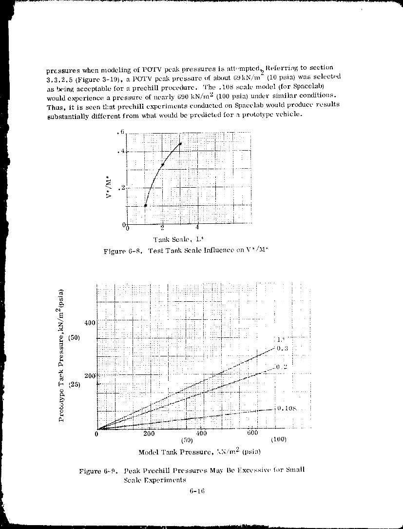
pressures when modeling of POTV peak pressures is atl,,mpted_ Referring to section3.3.2.5 (Figure 3-19), a POTV pc:fl_ pressure of about 69kN/m (10 psia) was selected
as being acceptable for a preehill procedure. The . 108 scale model _for Spacelab)
would experience a pressure of nearly 690 kN/m 2 (100 psia) under similar conditions.
Thus, it is seen tFat prechill ex?eriments conducted on Spacelab would produce results
substantially different from what would be predicted for a prototype vehicle.
}• 6 ........ T ....
. : i i: ! i i
| :! :! i::::':iii!i,i:i_ii:!ti:ii:+!Ti:'i' i i i
0 - 2 ' 4
Tmfl_ Scale, L*
Figure 6-8. Test Tank Scale Influence on V*/M*
¢_ : t ! _ : i : i : I ::...... i"-_ 400 :--:!..... ,'----:-4 ---_.... !.:: -! ....... _.-'-i'::!---!:::_ :..... !........ !-
l ............................. ,
M ...... " _t --r ..... *
¢J] t :'::'' t' , t". i '7' ' :'::: " " ' ': .... 1 _"_'-" 0" ') ! i
::::i:" .:: i:: i:: '': ::'i ! i" ::: . '. '_-_" : ' : ,, :
: ", l:.::: : . ', ' , ;_'*: : :.;,:A_. : .:: .......
L_ I " _':: :_ :: " :: i ! : : . '
-:=:-_:-: .... :--;..-*:::..:J-'--'- .....: : ',-:=:'_.... ;--.1-:::-..',., :. _......._,_ 0 lob '
0 200 400 600
(50) ttoo)Mode,1 Tmtk Pressure, ',,N/n,, 2 (psia)
Figure 6-9. Peak Preehill Pressures May Be Excessive tor Small
Scale Experiments
6- t 6
1980009811-189
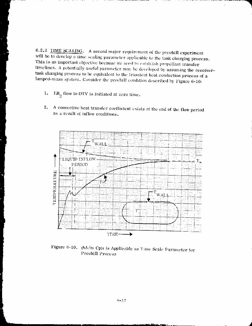
6.2.2 TIME SCAI,ING. A second major requirument of the prechill experiment
i _ill be to develop a time scaling parameter apl)lieablc to the tattk charging process.
This is m/ importm_t objective ix,cause we need (o establish propellant trmlsfcr
timelines. A potentially useful parameter may be developed by assmning the receiver-
tank charging process to }×,equivalent to the transient heat conduction process of a
lmnped-mass system. Consider the prechill condition descrilx'd 15' Figu;'c 6-10:
1. LIt 2 flow to OTV is initiated at zero time.
2. A convective heat transfer coefficient e.,dsts at the end of the flow periodas a result of itfflow conditions.
:::::::: ::::!!:: t:: ::: : ::::::::::::::::::::::::::::::::::::::::::::::::::::::::::::::::::
I.: ..... I :::: . , : :::::::::::::::::::: ::::.. : ; : - ::. _ :-..-.. :::::.:.;-:::, ..... _.... r.'4i:_ \_ALL ...................... t . , ...... t............::::::::::::::::::::::::: :::::::: ..::I::::: ... :..:;. :.-.:: "::::. ::.:
|:: .-"v--.._ : 11,; : .... . : " :': : .... :.' " _ .......... ',..........
': : .. ; ..: * _.... . * -.. !... : . .... .. : .... , .: qT"Y., ._. ,..'7"
I: )_ • . ". ::.::: . :: ; - .... : • : •., . ; .........
• r_R.OD _ ..... __,i : i. _ ..........
" .F::::'-,&!;--- : :. :: ::::,/_': :-:..:::::: .::: : ; : ::..;-: ', .:.:.:...b--:.- _:..
__..-a.-- ..... f---. " _ - " .. ;2 24-25.:Z-L-2 ,___:2--'_.4 .' :Z--4- _'. 2 2 -_'.22 ...... L_.i.:-.'.......
:- - _ i : T : "7 " "* ............... I ................ :--
"7--.;/"3 '.. _:.. i - - t _ ' =- .... s --+.-_" .......•" _, " S..'._ _i:{{!:[7{:::":::-::: :::::'::: : :,--'p :.::: ::.:.: :--
. :.:it. _'-- A ;: : _ " :.. I :. :. ' t _ - ..... _.... t- -...... f' _ ,' _............ _........ "_ ...... • • _ ,- ::;/ ; :'.. :': '. ::'I:. :"''T "t t .... , ..... : ...... _ " , *__-,,._ • - _ ..........
'=]'i:, i: }.......... --=::;" ..... :': :4.+-' : -'--'-: ' --'}'-"_ : ' " :•::: .. [ -: : {.: ::::::-; ::*:::: : " .... , I • ; : .............=:42:-.. _ .- :±:_ _' . :_::__. =I .:_: .... ',:._4-_:_..:_ =; _ _", ..... _- ' \: :' :::: :, : :
"]" t ..... i ..... _........ :...... F i . T :...... :-:-: .....::,::t::r-r:._..... :....:'" :::: ::: i::::: :::::::::::::::::::::::: : :t ':: _: ': ' ::'_[::::: :+ :'"
TE,IE-----_
Figure 6-10. (hA/m Cp)_ is Applicable as Time Scale Parmneter forPrcchill Process
t;-t 7
1980009811- 190
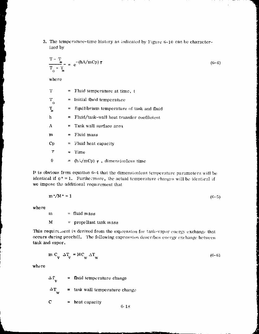
3. The temperatlare-time history as iI_dic-tled by Figure 6-10 can be character-ized by
T-T- (hA/mCp) T (6-4)-- e
T -TO
where
T = Fluid temperature at time, t
T = Initial fluid temperatlireO
T = Equilibrium temperature of tank and fluid
h = Fluid/tank-wall heat transfer coefficient
A = Tank wall surface area
m = Fluid mass
Cp = Fluid heat capacity
7" = Time
O = 01A/mCp) _r , dimensionless time
It is obvious from equation 6-4 that the dimensionless temperature parameters will be
identical if 0* = 1. Furthe:more, the actual temperature changes will be identical if
we impose the additional requirement that
m*/M* = 1 (G-5)
where
m = fluid mass
M = propellant tank mass
This requirement is derived from the expression for tank-vapor cncrgT exchmlg_ that
occurs during preehill. The fl_llowing expressio,_ describes cn,.'rgy oxchange betweentmtk and vapor.
m C AT =MC AT (6-6)V V W W
whe re
A.r = fluid temperature changev
AT = tank wall temperature changew
C = heat capacity6-18
1980009811-191
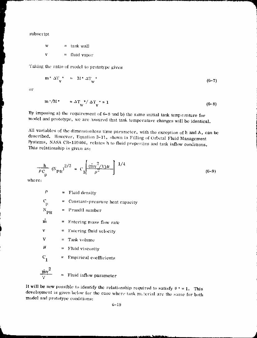
subscript
w = tank wall
v = fluid vapor
Taking the ratio of model to prototspc gives
m* AT * = 1_I* ,aT * (6--7)V W
OF
re%f M* =AT */ eXT *= 1 (6- 8)W V
By imposing a) the requirement of (;--8 "md b) the s:.trne initial tank tenp cmmre for
nuxtel and prototype, we arc assured that tank temperature changes will be identical,
All variables of the dimensionless time parameter, with the exeeption of h and A, can be
described, tlowever, Equation 3-11, shown in Filling of Orbital Fluid Management
Systems, NASA CR-159404, relates h to fluid properties and tank inflow conditions.
"Iltis relationship is g_ven as:
I ]1/4h " ..... V)
(N ),./3 = Cvc 11" ,"/ (6-.q)P
whe re:
P = Fluid density
C = Constant-pressure heat capacityP
} NpR = Prand_l number
; n'_ = Entering mass flow rate
I v Vntering veh)eity
fluid
V = Tamk volume
' // = Fluid viscosity
C1 = Empirical eoefficients
my 2V = Fluid inflow parameter
It will be now possible to identify the relationship retpairt_t to satisfy 0 * = 1. This
development is given below for the case whet',.., tank m:.,'erial are the same for both
model and prototype conditions:6-19
1980009811-i92 ....
Normalizing the dimensionless time parameter, we have
0* = h* A* T'/m* (Cp* = 1) (6-10)
From (6-9) we have
h* = (m*v*2/V*) 1/4 (O*) 1/2 (6-11)
But p* =m*/V*=(m--_-_')(M*' M* m*_)=--_ sinceM, -1' from (6-5)
Thus, (6-11) becomes
h* = (rh*v*2/V*) 1/4 (M*/V*) 1/2 (6-12)
Combining 6-10 and 6-12 results in
• 9
0* = (m*v*'/V*) 1/4 0VI*/V*) 1/2 (A* "r*/m*) 15-13)
m* = m*/T* (6-14)
Combining 6-13 and 6-14 gives
0* = (_*v*2/V*) 1/4 (M*/V*) 1/2 (A*/_*) (6-15)
now, A* = L*2 (6-16)
Also the fluid inflow parameter can be modified as follows,
m*v*2/V * = r_*3/(A *2V*) -: l:l*3/L .7n (6-17)
whe re:
A a = nozzle flow area
Combirfing (6-15), (6-16), and (6-17) gives
10* = (n_*3/L*7) 1/4 _I*/V*) /" (L*2/_ *)
1/4
= (M */V*) 1/2 ((;-18)
Finally, in order to have similarity between model and prototype dimensionless
temperature parameters we rc(Nire that 0* = 1, which will be satisfied if
(_,t_,)1/4 (M *tV*) 1/2 = 1 ((;-19)
6-20
1980009811 -193
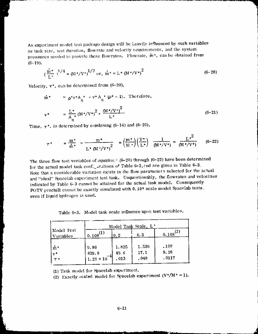
An experiment model test package design will be l.eavily influenced by such variables
as tank size, test duration, flowrate and velocity lequirernents, and lhe systempressures _wc(ted t() provide these flowrates. Flowz'ate, _*, can be obtained from
(6-19).
!/4 (hI*/V*) 1/2 or, rn* = L* _I*/V*) 2 (6-20)(L" =
Velocity, v*, can be determined from (6-20),
= * =v*A * (p* = 1). Therefore,• P'V'An n
L*
v* - ._ ", (M*/V*) 2 '_VI*/V*)2-- L* (6-21)n
Time, "r*, is determined by combining (6-14) and (6-20),
_ ltv. /r* - m* L* ('M*/V*) 2 = _-_]\'-'_] (M*/V*) - (M*/V*) (6-22)
The three flow test variables of equation.? (6-20) through (6-22) have been determined
for the actual model tank conf- ar::tions of Table 6-2, end are given in Table 6--3.Note that a considerable variation exists in the flow parameter_ selected for the actual
and "ideal" _)aeelab e_)eviment test tank. Unquestionably, the flowrates and velocities
indicated by Table 6-3 cannot be attained for the actual tank model. Consequently
POTV prechill cannot be exactly simulated with 0.10_ scale model Spaeelab tests.-.
even if liquid hydrogen is used.
Table 6-3. Model tank scale influence upon test vari,',J_les.
Model Tm_ Scale) L*Model 'rest
Variables 0, 108 _lp'' 0.2 0.3 0. 108 _2p__
_* 9.80 1.825 1.536 .108
v* 839.8 45 6 17.1 9.26
T* 1.2S × 10 .013 .040 .0117i
(1) Tank model for S'pacelab ex0eriment.
(2) Exactly _caled model for _:acelab experiment (V*[M* = 1).
6-21
II I IIII I I' II m........ -- ............ ...... _._ ..... ,_
i'980009811-194'
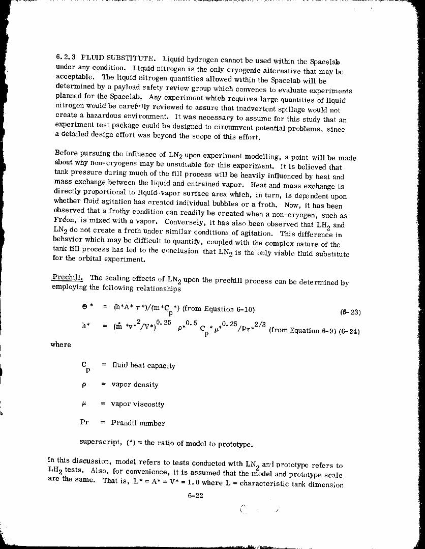
6.2.3 FLUID SUBSTITUTE. Liquid hydrogen cannot be used within the Spacelabunder any condition. Liquid nitrogen is the only cryogenic alternative that may be
acceptable. The liquid nitrogen quantities allowed within the Spacelab will be
determined by a payload safety review group which convenes to evaluate experiments
planned for the Spacclab. Any experiment which requires large quantities of liquid
nitrogen would be careflqly reviewed to assure that inadvertent spillage would not
create a hazardous environment. It was necessary to assume for this study that an
experiment test package could be designed to circumvent potential problems, since
a detailed design effort was beyond the scope of this effort.
Before pursuing the influence of LN 2 upon experiment modelling, a point will be made
about why non-cryogens may be unsuit-able for this experiment. It is believed thattank pressure during much of the fill process will be heavily influenced by heat and
mass exchange between the liquid and entrained vapor. Heat and mass exchange is
directly proportional to liquid.-vapor surface area which, in turn, is dependent upon
whether fluid agitation has created individual bubbles or a froth. Now, it has been
observed that a frothy condition can readily be created when a non-cryogen, such as
Frdon, is mixed with a vapor. Conversely, it has also been observed that LH 2 andLN 2 do not create a froth under similar conditions of agitation. This difference inbehavior which may be difficult to quantify, coupled with the complex nature of the
tank fill process has led to the conclusion that LN 2 is the only viable fluid substitutefor the orbital experiment.
Prechill. The scaling effects of LN 2 upon the preckill process can be determined byemploying the following relationships
(9 * = (h'A* T*)/(m*Cp*) {from Equation 6-10) (6-23)
h* = (1{1*v*2/V*) O"25 p,O. 5 C */1*0" 25/pr'2/3 (from Equation 6-9) (6-24)P
whe re
: C = fluid heat capacity
p = vapor density
_ = vapor viscosity
Pr = Prandtl number
superscript, (*) = the ratio of model to prototype.
In this discussion, model refers to tests conducted with LN 2 an'! orototype refers toLH 2 tests. Also, for convenience, it is assumed that the model and prototype scale
are the same. That is, L* = A* = V* = 1.0 where L = characteristic tank dimension
6-22
1980009811-195
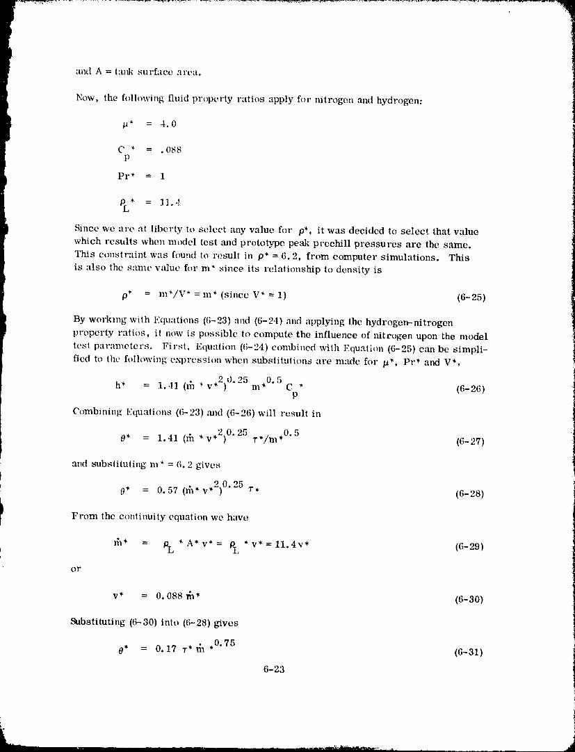
and A = tm_k suI'filCC area.
Now, the following fluid property ratios apply for mtrogen and hydrogen:
/2* = 4.0
C * = .088P
Pr* = 1
PL* = 11.4
Since we "u'e at liberty to select any value for p*, it was decided to select that valuewhich results when model test and prototype pe,'tk prechill pressures are the same.
This constraint was found to result in p* = 6.2, from computer simulations. This
is also the same wtlue for m* since its relationship to density is
p* = m*/V * = m* (since V* = 1) (6-25)
By working with Equations (6-23) and (6-2,1) and applying the hydrogen-nitrogen
property ratios, i! now is possible to compute the influence of nitrogen upon the model
test parameters. First, Equation (6-24) combined with Equation (6-25) cml be simpli-
fied to the following exl)ression when substitutions are made for /_*, Pr* and V*,
• 2)0.25 ,0.5h* = 1.41 (_h * v m C * ((;-2(;)P
Combining Equations ((;-23)mid (6-26)will result in
0* 1.41 Oh *v*2) 0"25 ,0,5= r */m (6- 27)
and substituting m* = 6.2 gives
• 2)0.250* = 0.57 (_* v T, (6-28)
I From the continuity equation we have
lil* = PL * A* v* = PL * v* = 11.4v* ((;-29)
or
v* = 0.088 _* (6-30)
Substituting (6-30) into ((;-28)gives
0* = 0.17 _-* fix ,0.75 (6-31)
6-23
1980009811 -196
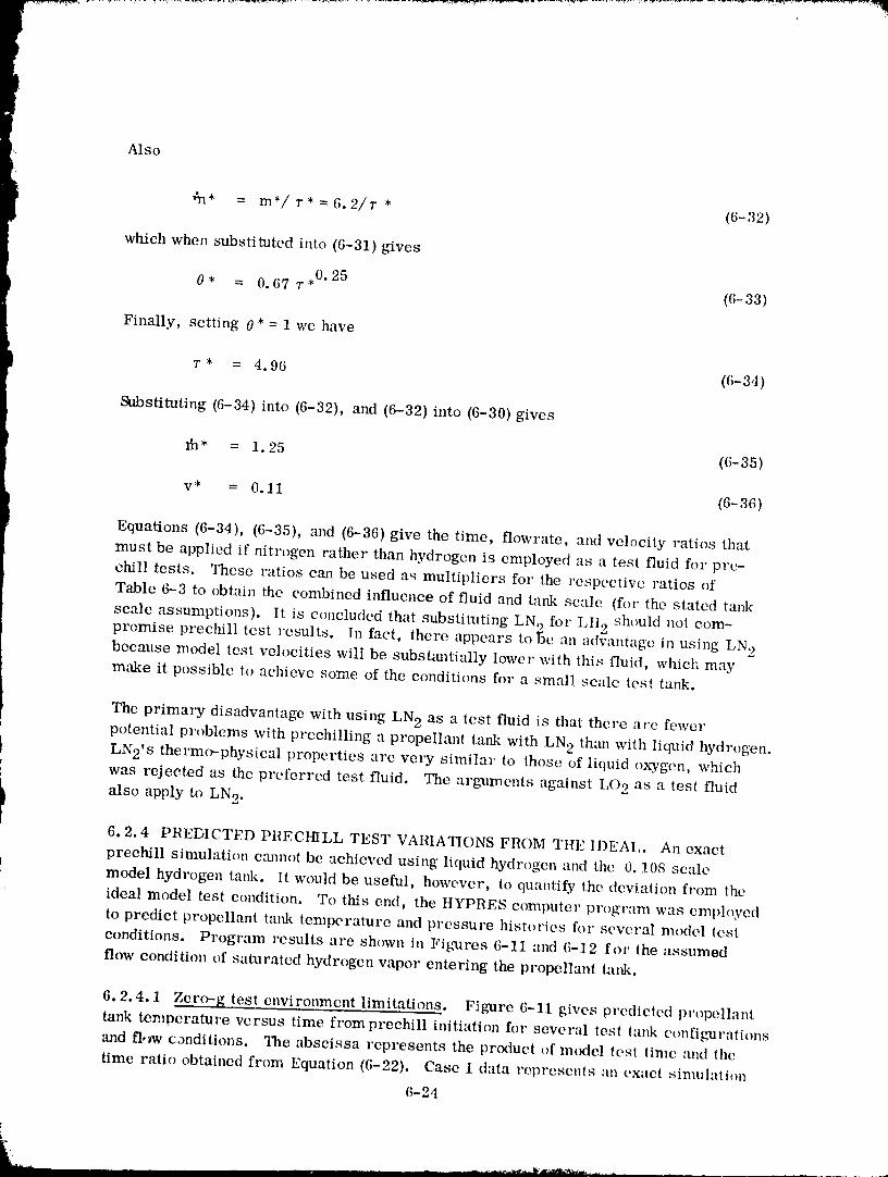
Also
i ,}n* = in*/7"* = 6.2/1" * (6-32)[
which when substituted into (6-31)gives
O* = 0.67 "r*0"25 (6-33)
Finally, setting 0* = 1 we have
t T* = 4.96 (6-34)
Substituting (6-34) into (6-32), and (6-32) into (6-30) gives
_* = 1.25 (6-35)
v* = 0.11 (6-36)
Equations (6-34), (6-35), and (6-36) give the time, flowrate, and velocity ratios that
must be applied if nitrogen rather than hydrogen is employed as a test fluid for pre-
chill tests. 2_ese ratios ca1 be used as multipliers for the respective ratios of
Table 6-3 to obtain the combined influence of fluid and tank scale (for the stated tank) _h()uld not cornscale assumptions). It is concluded that substituting LN2fc r LI12 :
promise prechill test results. In fact, there appears tobe an adwmtagc in using LN 2because model test velocities will be substantially lower with this fluid, which maymake it possible to achieve some of the conditions for a small scale test tank.
1 The prima_T disadvantage with using LN 2 as a test fluid is that there are fewer
potential problems with prechilling a propellant tank with LN 2 tha_l with liquid hydrogen.I LN2's thermo-physieal properties are very similar to those of liquid oxygen, whicht
I was rejected as the preferred test fluid. The argxlments against I,O 2 as a test fluid
I also apply to LN 2.6.2.4 PREDICTED PRECHILL TEST VARIATIONS FROM THE IDEAL. An exact
prechill simulation c0amot be achieved using liquid hydrogen and the 0. !0S scaleI
model hydrogen talfl<. It would be useful, however, to quantify the deviation from the
ideal model test condition. To this end, the HYPRES computer program was eml)h_yedto predict propellant tank temperature and pressure histories for several model lest
conditions. Program results are shown in Figures (;-11 and (;-12 for the assumed
flow condition of saturated hydrogen vapor entering the propellant lank.
6.2.4.1 Zero-g test enviromnent limitations. Figure 6-11 gives predicted pt'opellant
tank temperature versus time from prechill initiation for several test lank configurations
and fl,_w conditions. The abscissa represents the product of model (es! time and the
time ratio obtained from Equation (6-22). Case 1 data represents :m exact simulali()n
6-24
1980009811-197
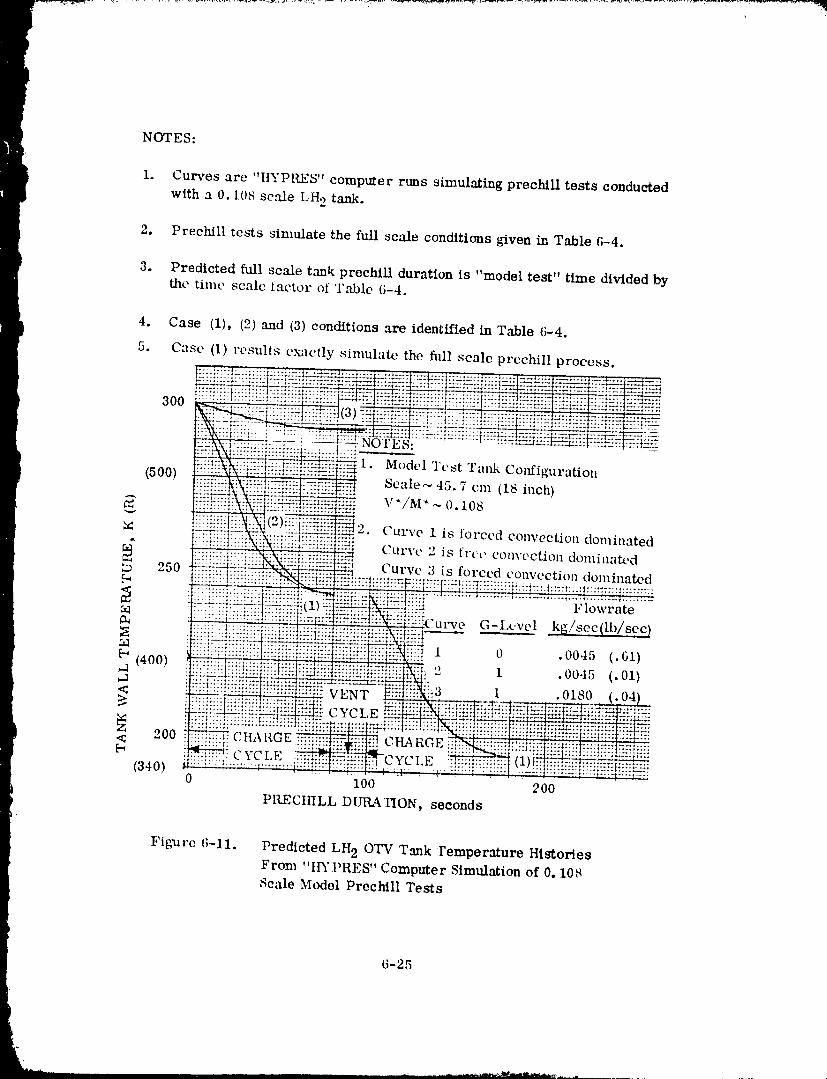
t
NOTES:
I i. Curves are "I_'PILES" computer runs simulating prechlll tests conductedwith a 0.1()8 scale LH 2 tank.
2. Prechill tests simulate the full scale conditions given in Table 6-4.
3. Predicted full scale tank preehfll duration is "model test" time divided bythe time scale factor of Table 6-4.
Figure (;-11. Predicted LH 20TV Tank remperature Histories
From "tl3"PRES" Computer Simulation of 0. 108Scale Model Prechill Tests
6-25
19800098-1 ;I-198
P
where V*/M* = 1. These results are identical to th(_se obtained for the full scale
_ tank conditions of Table 3. Case 2 shows how ta_fl_ conditions w_)uld be altered if
t ._ubstantially low_..v model test flowrate and velocity conditions were imposed. Thisdeviation is small compared to deviations which results when V*/M* is not matched
(although velocity and flowrate are matched), Case 3.
l Figmre 6--12 g_ves predicted pressure histories for the same test tank and flow con-
ditions identified in Figure 6-11. Again, only the first charge and vent cycle is shown
for the non-ideal model test ease. Also, as before, Case 1 results wove identical to
those of the flfil scale tank. Similarly, Case 2 and Case 3 results were patteraed after
those of Figure 1. That is, an order of magnitude change in incoming fl_)wrate had a
minor influence (m results, whereas an order of magnitude change in V/M had a mt0orinfluence.
6.2.4.20ne-g test environment 1.imitation, s. Ground-based tests for determining the
validity of the 9rechJll process will bc applicable only if a) the normal gravity h-ec
convection heat transfer process is dominated by the forced e()nveclion mechanism
created by the entering propellant, and b) the fluid flow mechanisn_ is the same: for
model tests as for the prototype config'uration. To satisfy the f()rmer condition we
must verify that the heat transfer coefficient s_iven by equation (6-9) exceeds that free
convection cocfficicnl created by a normal gravity environnlcnt. Vquati(m (6-9) is
applicable to heat exchange between a propellant tank surface and ils contained v:q)or.
Preehill Process. The primary 2oncern with normal gravily preehill tcsls is that in-
flow conditions required for similarity on the basis of tm_k scale (Table 6-4) will not
be sufficient to guarantee the dominance of forced convection heal transfer. This
point is illustrated by Figure 6-13 which shows how prcchill test ta_fl< pressures will
be affected a)by the influence of a normal gravity environment, and b) by lhe increased
inflow conditions necessary to provide a forecd convection d(m_inatcd envi v(mmcnt.
Cu_we 1 is the predicted 45.7 cm (18 inch) diameter test tank pressure at the indicated
flow conditions in a zero gravity environment. Obviously, the heat exchange mech:tnism
is forced convection dominated. (Mrve 2 shows the predicted tank pressure if the same
i test is performed in a normal gravity environment. The lank wall-ullage heal exchangemechanism is free convection dominated. Ilowever, a forced eonveclion (](,lnilmted
environment is necessary for a valid model lust. This will require a |':l('tt)|' of fo/Ir
increase in entering flowrate :rod v(_loeity. Th,, outcome is thai a g,'catcv difference
' results between lhe zevo-g and one-g test lank pressure profiles, Cu_wes 3.
It is questionable that results of one-g tests that meet the criterion fl)r forced ctm-
vection heat transfer donlinanee can be employed to scale the zcvo-g pvechill process:.
6.2.5 PRECIt/LL St_MMARY. It is concluded from the computer simulati(ms thai Ill(,
45.7 em (18 in. ) diameler lest tazfi¢ cannot be employed lo obtain rcsulls that are
directly extrapolated to a prototype OTV vehicle, This is so even if It, sis :ire e¢)ndueted
with LH 2 in a near zer()--g environment. Direct extrapolation bee(,mcs even less likely• ) ,fi-,-6
1980009811--1-9
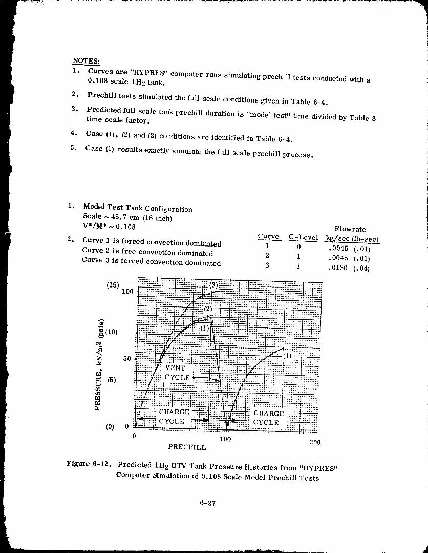
NOTES:
1. Curves are "HYPRES" computer runs simulating prech "l tests conducted with a
0.108 scale LH 2 tank.
2. Prechill tests simulated the full scale conditions given in Table 6-4.
3. Predicted full scale tank prechill duration is "model test" time dividcd by Table 3time scale factor.
4. Case (1), (2) and (3) conditions are identified in Table 6-4.
5. Case (1) results exactly simulate the full scale prechill process.
Figure 6-12. PredictedLII20TV Tank Pressure Historiesfrom "HYPRES"
Computer Simalationof0.108 ScaleM,xlelPrechillTests
6-27
19800098i 1-200
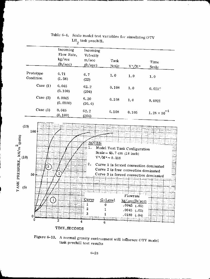
Table 6-4. Scale model test variables for simulating OTV
LH tank prechill.2
Incoming Incoming
Flow Rate, Velocity
kg/sec m/sec Tank Time
. (lb/sec } (ft/sec). _alc V *(tl_I* Scale
Prototype 0.71 6.7 1.0 1.0 1.0
Condition (1.56) (22)
Case (1) 0. 045 62. 2 0. 108 1.0 0. 0117(0.100) (204)
Case (2} O.0045 6.20 O.108 1.0 O.0021
(0.0100) (20.4)-4
Case i3) O.045 62.2 O.108 O.105 1.28 × 10
(0.100) (204)
(I5) ::-.:::t::::::::::
t: ....
_'-" 1. Model Test Tank Configuration-_ .. Scale~ 45.7 cm (18inch)Z ' "
..... V*/M* ~ 0. 108-_(io) --.:Z!i:ii_ 2. Curve 1 is fo:'ced convection dominated
Curve 2 isfreeconvectiondominated
¢n -7 i}/_}!] :::: Curve 3 is forced convection dominated _a_ 50 "
< (5) .... ......
.......... h'o ,te"G-Level kgl_ec(Iblsec)
i o .oo45_.oI)•2 1 .0045 (.01)
. 3 1 .0180 (.04)00 4 6
TIME ,SECONDS
Figure 6-13. A normal gravity environment will influence OTV modeltank prechill test results
6-25
"19800098'1"1-20'1
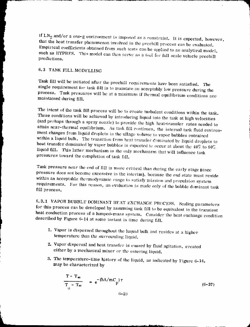
if LN 2 and/or a one--g environment is imposed as a constraint. It is expected, however,that the heat transfer phenomenon involved in the prechill process can be evaluated.
Empirical coefficients obtained from such tests can be applied to an analytical model,
such as HYPRES. '['his model can then serve as a tool h_r full scale vehicle prechillpredictions.
6.3 TANK FILL MODELLING
Tank fill will be initiated after the prechill reqmrements have been satisfied. The
single requirement for tank fill is to maintain an acceptably low pressure during the
process. Tank pressures will be at a minimum if thermal equilibrium conditions are
maintained during fill.
The intent of the tank fill process will be to create turbulent conditions within the tank. iThese conditions will be achieved by introducing liquid into the tank at high velocities i(and pe'chaps through a spray nozzle) to provide the high heat-transfer rates needed to iattain near-thermal equilibrium. As tank fill continues, the internal tank fluid envirol_
ment changes from liquid droplets in the ullage volume to vapor bubbles entrained
within a liquid bulk. The tnmsition from heat tr:msfer df)minatcd by liquid droplets to
heat transfer dominated by vapor bubbles is expected tc occur at about the 40_ to 607{
liquid fill. This latter mechanism is the only mechanism that will influence tank
pressures toward the completion of tank fill.
Tank pressure near the end of fill is more critical than during the early stage (since
pressure does not become excessive in the interim), because the end state must reside
within an accept_tble thermodynamic range to satisfy mission and propulsion system
requirements. For this reason, an evaluation is made only of the bubble dominant tm-,k
fill process.
6.3.1 VAPOR BUBBLE DOMINANT HEAT EXCHANGE PROCESS. Scaling parameters
for this process can be developed by assuming tank fill to be equivalent to the transient
heat conduction process of a lumped-mass system. Consider the heat exchange condition
described by Figure 6-14 at some instant in time during fill.
1, Vapor is dispersed throughout the luquid bulk and resides at a higher
temperature than the surrounding liquid.
2. Vapor dispersal and heat tr:msfer is caused by fluid agitation, created
either by a mechanical mixer or the enlering liquid.
3. The temperature-time history of the liquid, as indicated by Figure 6-14,
may be characterized by
T - T_ (hA/mCp) "rT - Too = e- (6-37)
O
6-29
1980009811-202
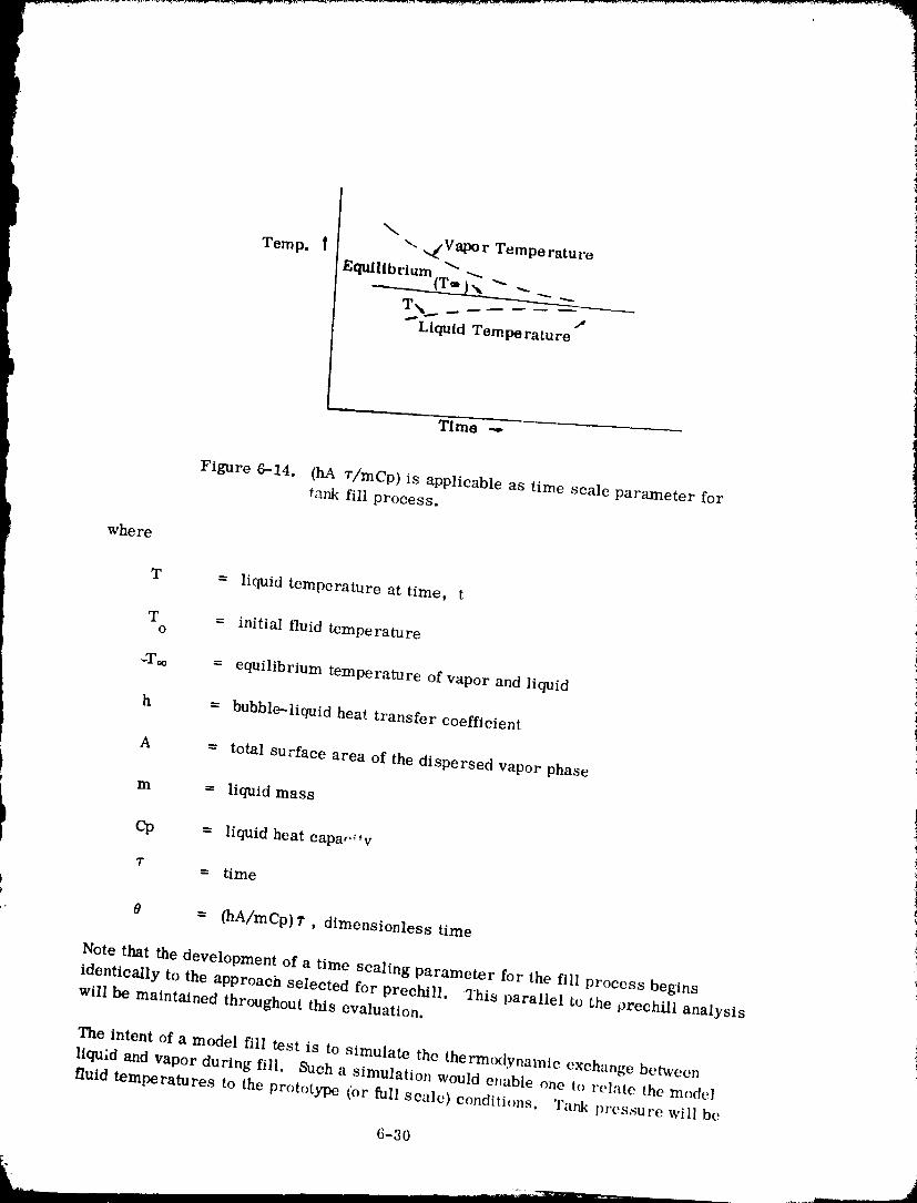
Temp. | "-. ,._Vapor TemporaturoF.quillb _-
rium(T_ _,_ --_ _ ._
j
"_Llquld Tempe rature
1Time _ _
J
Figure 6-14. (hA r/mCp) is applicable as time scale parameter fortank fill process.
where
T = liquid temperature at time, t
T = initial fluid temperatureo
_Too = equilibrium temperature of vapor and liquid
h - bubble-liquid heat transfer coefficient
A = total surface area of the dispersed vapor phase
m - liquid mass
i Cp = liquid heat capao_ *vT = time
)
,. 0 = (hA/mCp)T, dimensionless time
Note that the development of a time scaling parameter for the fill process begins
identically to the approach selected for prechill. 2his parallel to the prechill analysis
will be maintained throughout this evaluation.
The intent of a model fill test is to simulate the thermcnlynamic exchange between
liquid and vapor during fill. Such a simulation would enable one to relate the model
fluid temperatures to the prototype (or full scale) conditions. Tank pressure will be
6-30
1980009811-2(
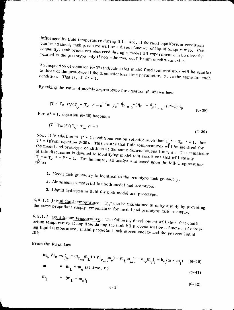
influenced by fluid temperature during fill. And, if thermal equilibrium conditions
can be attained, tank pressure will be a direct function of liquid tcmpen:_re. Con-
sequently, tank pressures observed during a model fill experiment can be directly
related to the prototype only if near-thermal equilibrium conditions exist.
An inspection of equation (6-37) indicates that model fluid temperatures will be similar
to those of the prototype., if the dimensionless time parameter, 0, is the same for each
condition. That is, if 0* = 1.
By taking the ratio of model-t_prototype for equation (6-37) we have
(T- T_ )*/(T - T_ )*=e- 0m /e- 0p =e- (@m - 0p)=e-(@*-l) 0p (6-38)O
For 0* = 1, equation (6-38)becomes
* ' )* = 1 (6-39)(T- T¢¢ ) /(io- T
Now, ifin additionto 0* = 1 conditions can be selected such that T * = 2_ * = 1, then
T* = 1(from equation 6-39). This means thatfluidtemperatures w_] be identicalfor
the model and prototype conditionsat the same dimensionless timc, 0. The remainder
of thisdiscussion is devoted to identifyingmodel testconditionstlmtwill satisfy
T * = T,_ * = 0 * = i. Furthermore, allanalysis isbased upon the folh,wingassump-O
tions:
I. Model tank geometry is identicalto the prototype tank gcometry.
2. Aluminum is material for both mcxiel and prototype.
3. LiQuid hydrogen is fluid for both model and prototype.
6.3.1.1 Initial fluid temperature. To* c_m be maintained at unity simply by providing
the same propellant supply temperature for model ,-rod prototype t:mk resupply.
b6.3.1.2 Equilibrium temperature. The following deveh,D_lent will _how !b:,A e0ui!i-
brium temperature at any time during the tank fill process will be a function of enter-
ing liquid temperature, initial propellant tank stored energy and the percent liquidfill:
From the First Law
m w (u_-ui) w+(uL mL)+(u m v)- (ULmL) i- (Uvmv) i =hL(m- m) (6-40)V¢o 1
m = m L + m v (at time, r ) (6-41)
m i = (mL + mv) l (6-.t2)
6-31
1980009811-204
where
l u = internal energy
h = enthalpy
Ill ---- mass
subscript,
L = liquid
v = vapor
w = wall
t i = conditions at tank fill initiation
•o = equilibrium property conditions at time 7"
The solution to equation (6-40) can be readily obtained by recognizing that mLi,
mv. and Uw,* are either zero or insignJ.ficaat. Fluid mass at tank fill initiation
wi_ be essentially zero for filling an evacuated tank and Uw,* will be near zerothroughout much of the tank fill because tank wall temperatures will be at or very
near liquid temperature. Thus, combimng (6-40), (6-41) and (6-42) results in
UL. om L+u m =h + +m u (6-43)v,o v L (mL mv) w w.1
Since mw uw. represents the initial tank stored energy, AQi, we can make this sub-stitution _n (_-43)
u m +u my hL + + (6-44)L= L %0 = (mL mv) AQi
Dividing (6-44) by m L gives
UL, _ + Uv** (mv/mL) = hL (1 + mv/m L) + ZXQi/m L (6-45)
The left hand side of (6-45) is a function only of equilibrium temperature and vapor tc
liquid mass ratio, mv/m L. The right hand side of the equation is a function of
entering fluid temperature (hi_̀ = f ('£o)), &Qi/mL ' and mv/m L.
It is concluded from (6-45) that T,o = f (T o and AQi/m L) for a given n_/m L. There-fore, T** * = 1 when To* =-.(AQi/mL)* = (mv/mL)* = 1. As stated previou_ty To* canbe selected by controlling supply temperature. ( AQt/mL)* can be selected by varyingmodel tank mass and/or initial tank temperature. The variable (mv/mL)* imposesno restraint other than to stipulate the obvi(_us, which is that a comparison of m(xtcl to
6-32
1980009811-205
prototype tank fill behavior is applicable only at the same tank. fill conaition, ttowever,
this requirement does provide the following relationship between time and tank scale
m *=n_L=m*=l--(m [m )=(PVT) /(PVT) =V *=L .3 (6-46)v m p m p T
where
VT = tank volume
L = characteristics tank dimension
P = fluid density
= (same fluid)Pm Pp
Time can be introduced by recognizing that
m L = Inn" or "r = mL/rh ;-47)
where
da = entering flowrate
r = flow duration
m = liquid mass in'roduced to tank during rL
Dividing model variables by prototype wtriables gives
1"* = mL*/rh* (6-45)
Substituting (6-46) into (6-48) results in
v* = L*3/th * ((i-48"l)
6.3.1.3 Dimensionless time parameter. It is now necessary to identify conditionsunder which O * = I.
All variables of the dimensionless time parameter ( 0 ), with the exception of h and A,
can be described. Equation 3-11, Referencc_-3, relates h to fluid properties anti tank
inflow conditions. This relationship is given as
• 2 -] I/4
(Npll) 2/3 = C [(mv /V L) /Jj _6-,t9}PCp 1L -7"--
6-33
'" " 1980009811-206
! -,!l
where all variables have been previously identified except:
V = fluid volumeL
Normalizing equation 6-49 provides the following exl:.ression
h* = (r_* v*2/VL_) 1/4 (6-50)
The total surface area, A, of the dispersed phase is
A = n Ab (6-51a)
n = Vu/V b (6-52)
Vb = _ d3/6 (6-53)
Ab = _d 2 (6-54)
Therefore
A = 6V /d (6-51b)U
or
A* = V */d* (6-51c)U
whe re
[ n = total number oi bubbles immersed in liquidP
Ab = bubble surface area (assumed spherical)
V = total vapor volumeV
bp d = bubble diameter |
Now, equation 3-36 ca_ be written as
d = Fl¢"_(rhv2/Va)0"4_ + C (6-55) i
whe re
¢ _- Vu/V T
6-34
J
1980009811-207
F 1 = 1.134_-'O 6/0.- 2 = constant based upon fluid properties
C = empirical constant = 0.09
By assuming that C is insignificant,
i
5 • 2 0:40d* = e*" /(m'v* /VL* ) (6-56)
AI' o since tank ttll condition is the same for model and prototype, VL* = Vv* = VT*and _ * = 1. Thus (6-56) becomes
d* - Oh* v*2/VL*) -0"40 (6-5g)
This, of course, assumes that the same _roportion of vapor is entrained in liquid for
both the model and prototype.
If one assumes that C is the dominant term in (6-55) the result is
d* = 1 (6-58)
Both 6-57 and 6-58 will be considered in evaluating experiment modelling require--ments.
Normalizing the dimensionless time parameter, we have
e* = h* A* r*/m* (Cp* = 1 for same fluid) (6-59)
Substituting(6-48)into(6-59)gives
0* = h* A*/_* (6-60)!
Consider first the condition where bubble diameter is primarily influenced by
(mv2/VL). Substituting equations 6-50, 6-51 and 6-57 into 6-60 provides
0 * = (_, v,2/VL,)0.25 (Vu*/fil*)/(m* v*2/XrL*)-0' 40 (6-61a)
- (Ih* v*2/VL *)0"65 (%*/Ii_*) (6-61)
Now, from continuity
l:n = PAv (6-62)n
where A = nozzleinletdiameter.n
6-35
1980009811-208
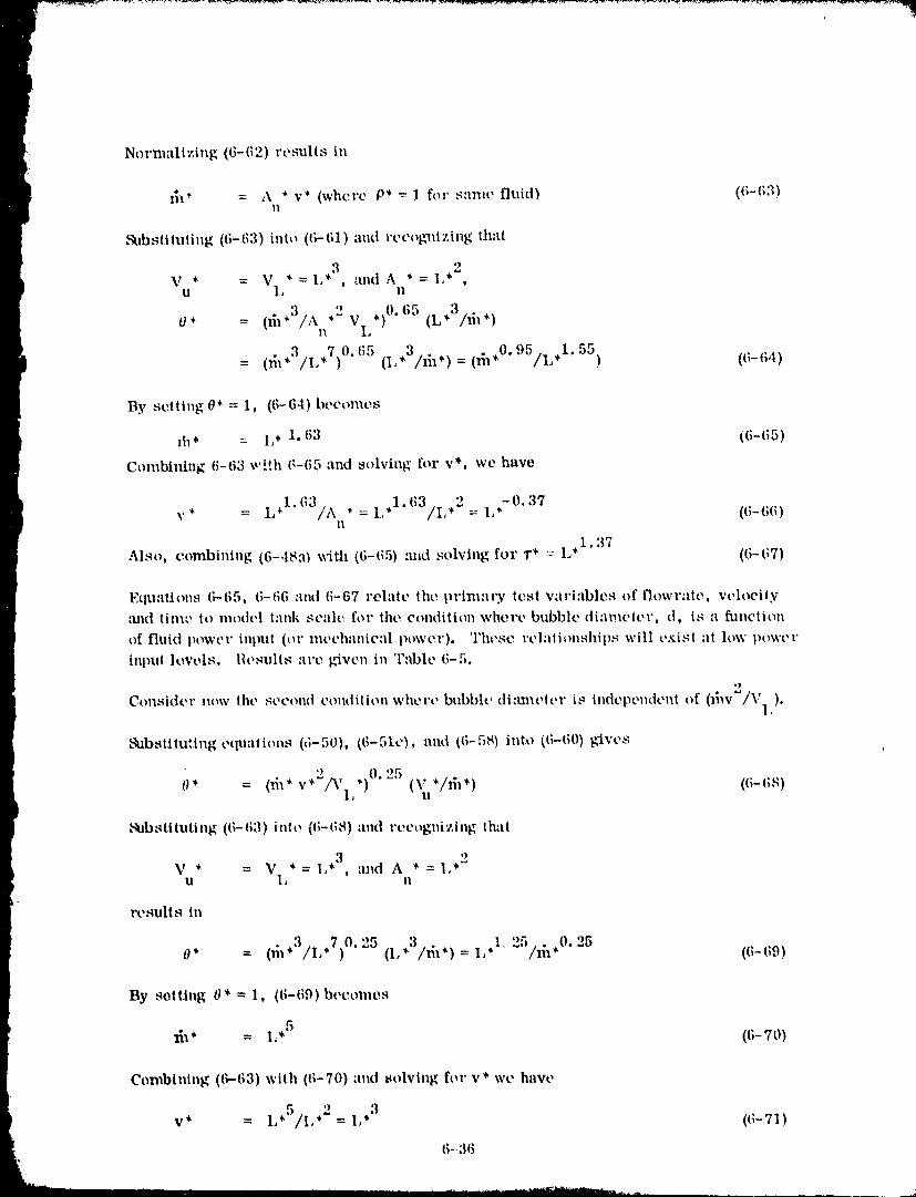
Normalizing (6-62) results in
l_ _ = A _ v _ (where P* -- 1 for same fluid) (6-63)n
&lbsiiluting (6- 63) into ((_ 61) :rod recogl_izing that
3 2V * = V * = L* , and A * = I,* ,
U 1, !1
' ,2 VL,)0.65 (L,3/lh,)O* = (61*J/A n
= (_,3/L,7)0. I;5 (1 ,3/Ii_,) = (l_,0.95/L,1.55) (I;-t;4)
By setting 0* = 1, (6-64) becomes
lh* = IJ* 1.63 (6-(;5)
Combining 6-63 w!!h 6-65 and solving for v*, we have
x'* = L,1.63/A , = L,1.63/L,2= L,-0.37 (6-66)II
Also, combining (6-.18a) with (6-65) :rod solving for 1"* : L .1"37 ((;-(;7)
Equaitons 6-65, 6-66 and (;-67 relate the primary test variables of flowrate, velocitytrod time it) model lank scale for the condition where bubble di'nueler, d. is a funciion
of fluid power inpul (or mechanical power). These rehHionships will cxisi ;It low powt'r
input h:vels. Results are g_vcn in Table 6-5.
*)
Consider now the second condilion where bubble di:m_eler is independent of (_hv_/Vl).
Subsiituling equations ((;-50), (6-51c), nnd ((;-58) into (6-60) gives
0* = 0i_*v*2/y *)°'251Vu*/_h*) (6-(is)I,
Sub s ti iuii ng (6- 63) int o (6- (;8) and recogni zing thai
,3 ,2V * = V *=I, , and A *=l,U I, II
results in
0* (_1,3/I ,7)0. 25 ,3 ,, 1,1 25 25= (I, /m ) = /_,0. (6-(;9)
By setting 0* = 1, (6-69)becomes
5x_* = I,* (6-70)
Combining (6-63) with (6-70) and t_olving for v* we have
,5 ') 3v* = L /I,*'=I,* (6-71)
6--36
1980009811-209
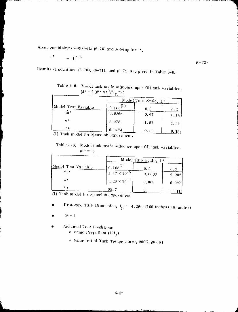
Also, combining ((;-49) with (6-70) and solving f-)" *,
r = L ((;-72)
Results of equations (6-70), (6-71), and (6-72) arc given in Table (;-6.
b
T_lc (;-5. M(xiel tank scale influence upon fill t:mk variables.
(d* -- f (_* v*2/tVi *) )_lodel Tar& Seal% .L*_
_4¢)del Test Variable 0. 108 (1") 0.2 0. 3
_* 0.02(;6 0.07 0.14
v* 2. 278 1.81 1.56
r* 0. 0474 0.11 0.19
(1) Tank model for Spacclab experiment.
Table (;-6. Model i:ud{ scale influence upon fill lank variables.
(d* = 1)
M<xiel Tank _'ale_ I,
_lodel Tesl Variable 0.108 (1) 0.2 0.3
ill* 1..t7 x 10-5 0. 0003 0. 002
v* 1.26 x 10 -t 0. 008 0. 027
1 , 85.7 25 11.11
(1) Tank rn(xtel for Spaoplab exl)eri:menl
• Prototype 'l':ufi¢ Dimension, lp - 4.29m (169 inches) (diameter)
i • 0* = 1
• Asstn'ncd Tesl Ctmdiliot_sI
O S;illlt' Prope, ll:ult (LII.))
o S:uue lnilial Tank Tempe ra lu re, 200K, _](;()l{)
6-37
1980009811 210
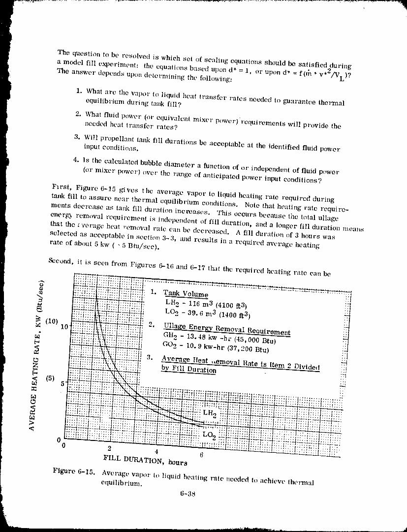
The question to be resolved is which set of sealing equations should be satisfied during
a model fill experiment: the equations based upon d* = 1, o1" upon d* = f(t]_ * v*2/VL)?The answer depends upon determining the folh)wing:
i 1. What are tile vapor to liquid heat transfer rates needed to guarantee thermalequilibrium during tank fill?
2. What fluid power (or equivalent mixer power)'requirements will provide theneeded heat transfer rates?
3. Wi!l propellant tmtk fill durations be acceptable at the identified fluid power
input eonditi(uls.
4. ls the cMeulated bubble dia.meter a function of or independent of fluid power
(or mixer power) ()vet" the nulge of anticipated power input conditions?
First, Figmre 6-15 gives the average vapor to liquid heating rate required during
tm_k fill to assure near thermal equilibriun: conditions. Note that healing rate require-
ments decrease as tank fill duration increases. This occurs because tim tolal ullage
energ_ removal requirement is independent of fill duration, and a longer fill duration means
that the overage heat removal rate can be decreased. A fill duration of 3 hours was
selected as acceptable in section 3-3, mid results in a required average heating
rate of about 5 kw ( - 5 Btu/scc).
1980009811-211
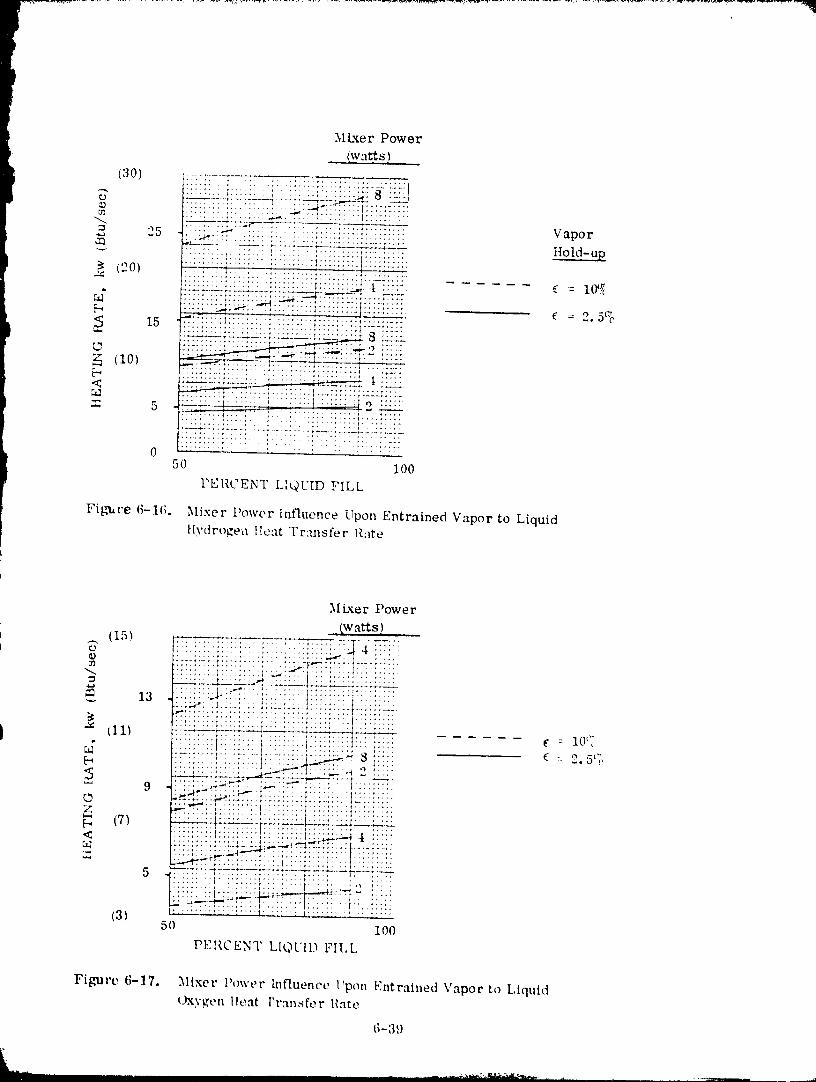
Mixer Power
(30) i ,..................._" ...... =:--._:=:::::::_,:. _-.... :; ::::: :._ 8
" 25 [':'....... ::-.er .: _7: ............. ,..:.;.:33 3:::: ::: Vapor
•....... ' ........................ itold-up(20) "'-' ::" .................................: .:: :' il '" _..... ::'.t.:.:_
................. _....... :: :3::;::"_ .........
_" _::::............. :::_:_L,_.._-.._r_..7.:_- :=-77
15 -"::::1: ;: :I:: ; : : ::73 ":: =========================....... _t_.Sj__" ........... ¢..................... .-_- _ ._
_i2 :::::(10) _._- ...... .---_._ :;-.::::: '_ ........................... _ , _.
....... 5 _"_i ,;:,.... _....... : : :t,:,:i:::l_.o _::::
........ , , *-* ......... + .... , .... ,...........
0 _:::: :.:::.: ::!ii!:iiii:iiiii50 100
PERCENT LIQUID FILL
Fi[.,_re 6-16. Mixer t'ower Influence Upon Entrained Vapor to LiquidHydrogen IIeat T r:msfe r Rate
M Lxer Power
(watts)
--. (15) .-:=-..-_7_..r=7:=-.. I .... ___ := -o !i_!:-i::::::::::::::::::::::::_ 4 :::::_'_ ........... ;.+_:, ,'17::.: .... _..........
...... :_2C-c-:-::._-r't... ___:_" • ..t ..... : : :::
::::::::::::::::::::::::::: :::: ::::t:: :::i!!iii!i!:t:!; i: !::..::.._--.:,: :.t ...... :.:
I - (11_ ---+---_ u-_=__u:.u_a=_:_u.......:.... :'.:, ...,..'" :":::::.:: ',::::.::::t ..... _. : lOt{....... ::I:: ::.: _ :: t::::;::::l .....',: ::================================_..._"_::'"."_ _ ; : :- 2, 5_,,
:_. :i_::_'=:t.: : t :::::::l:': .....
E; ................. t....... ! ...... t!........
..... , ..... .,,_-._P"L""_, :: "'::1 ......... ¢.... ' ....
5 ............... _ ...... +....- -r,:-:.-=-..::::::::F ::::::::::: :::: ::::: : -_
.................... _.., _ I ',,;::'"
(3) "_:'-:' __: :",':':t=-::::l ...............50 100
PERCENT I.I_3UII) FII, L
Figure 6-17, Mixer Power h_fluence I'pon Entrained Vapor to LiquidOxygen Heat I'r:msfer llate
t;-39
9800098 ] ] -2 ] 2
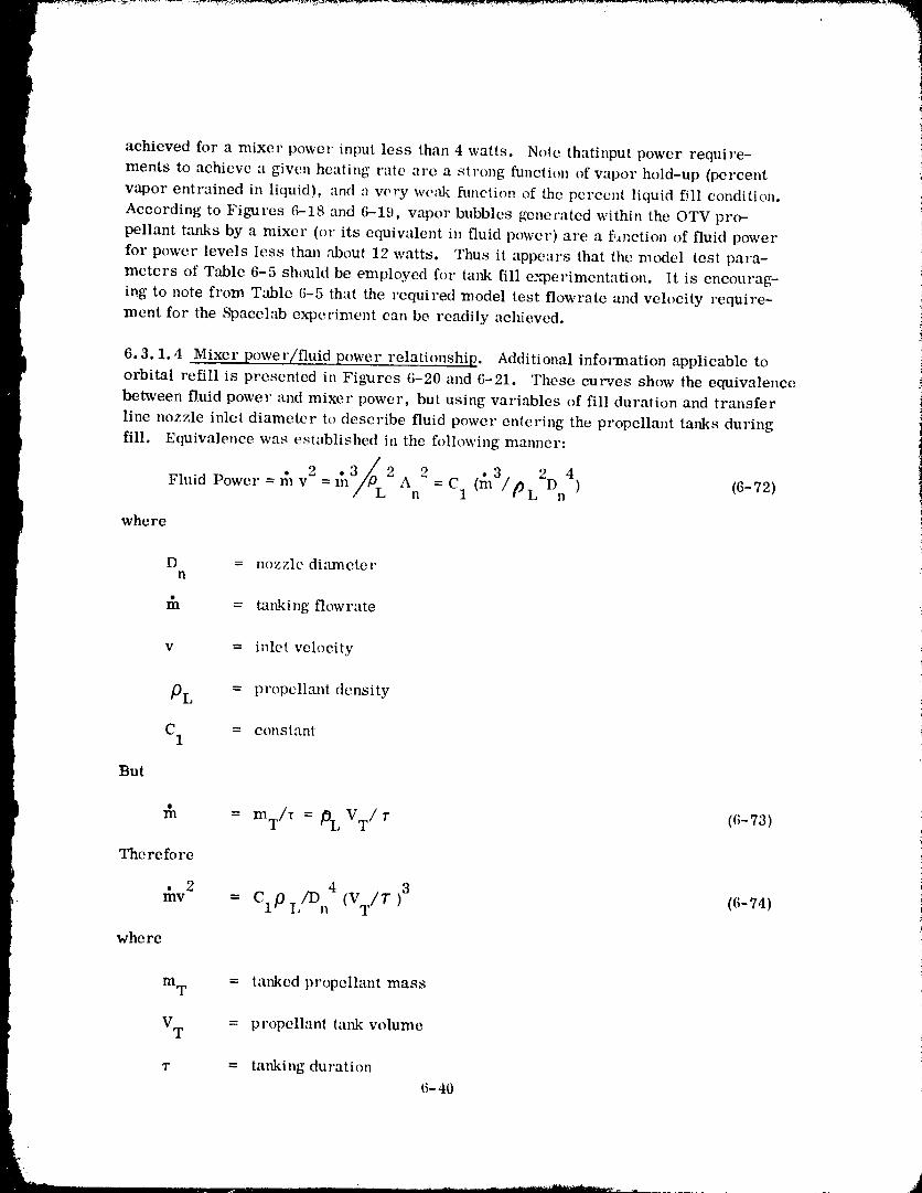
achieved fox" a mixer power input less than 4 watts. Note thatinput power require-ments to achieve a given heating rate are a strong function of vapor hold-up (percent
vapor entrained in liquid), and :_very we:tk fut_ction of the percent liquid fql condition.According to Figures 6-18 and 6-19, vapor bubbles genecated within the OTV pro-
pellant tanks by a mixer (or its equivalent in fluid power) are a f,anetion of fluid power
for power levels less thin1 about 12 watts. Thus it appears that the model test para-meters of Table 6-5 should be employed for tank fill e.,'_perimentation. It is encourag-
ing to note from Table 6-5 that the required model test flowrate and velocity require-
ment for the Spacelab experiment can be readily achieved.
6.3.1.4 Mixe!" power/fluid power relationship. Additional information applicable to} orbital refill is presented in Figxtres 6-20 and 6-21. These curves show the equivalence
between fluid power and mixer power, but using variables of fill duration and transfer
line nozzle inlet diameter to describe fluid power entering the propellant tanks during
fill. Equivalence was est_lblished in the following malmer:
2=m/%2 2 2D4Fluid Power = m v A = C (n13/ ) (6-72)n 1 tOL n
where
D = nozzle diametern
_a = tanking flowrate
v = inlet velocity
PL = propcllm_t density
C = constant1
But
m = InT/T = /0L VT/r (6-73)
The re fo re
_v 2 = ClP L/Dn4 (VT/T )3 ((;-74)
whe re
m T = tanked propellant mass
VT = propellant tat& volume
1" = tanking duration6-40
A
....1-980009811-213
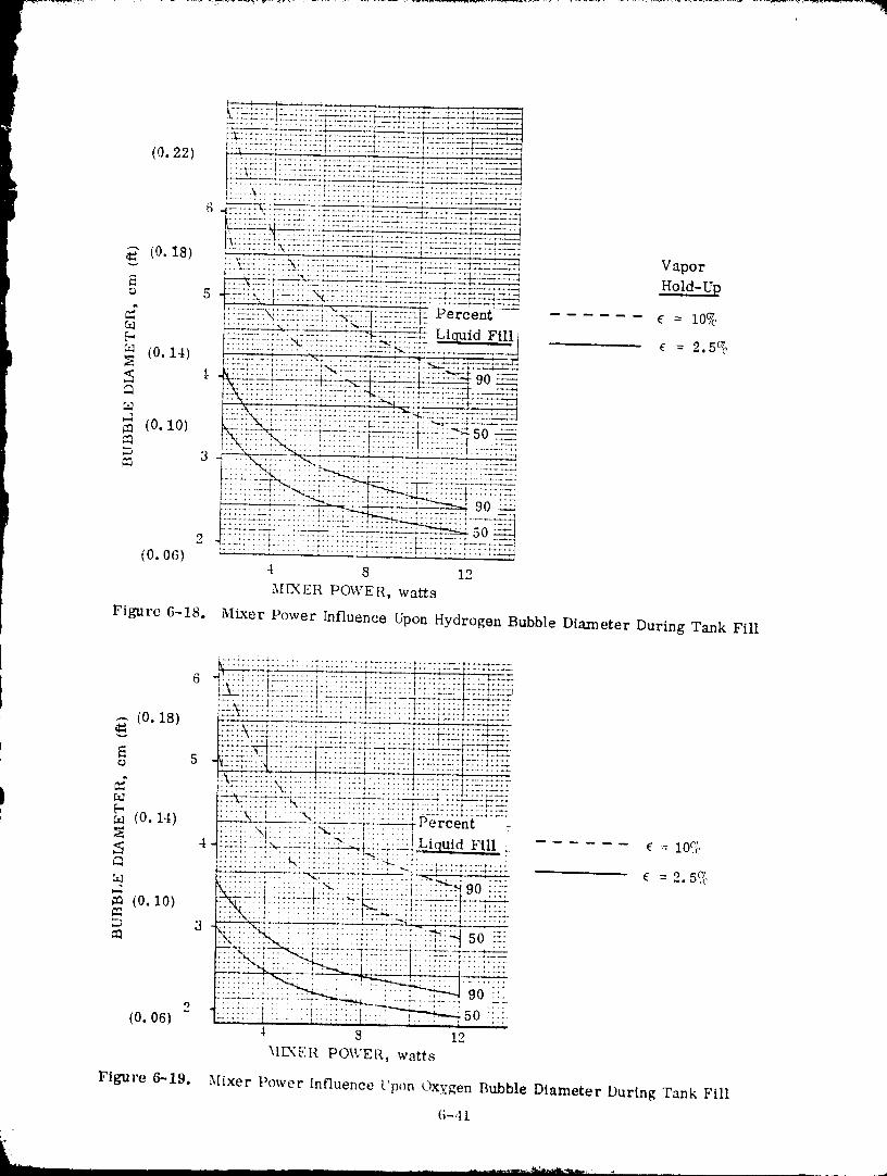
1980009811-214
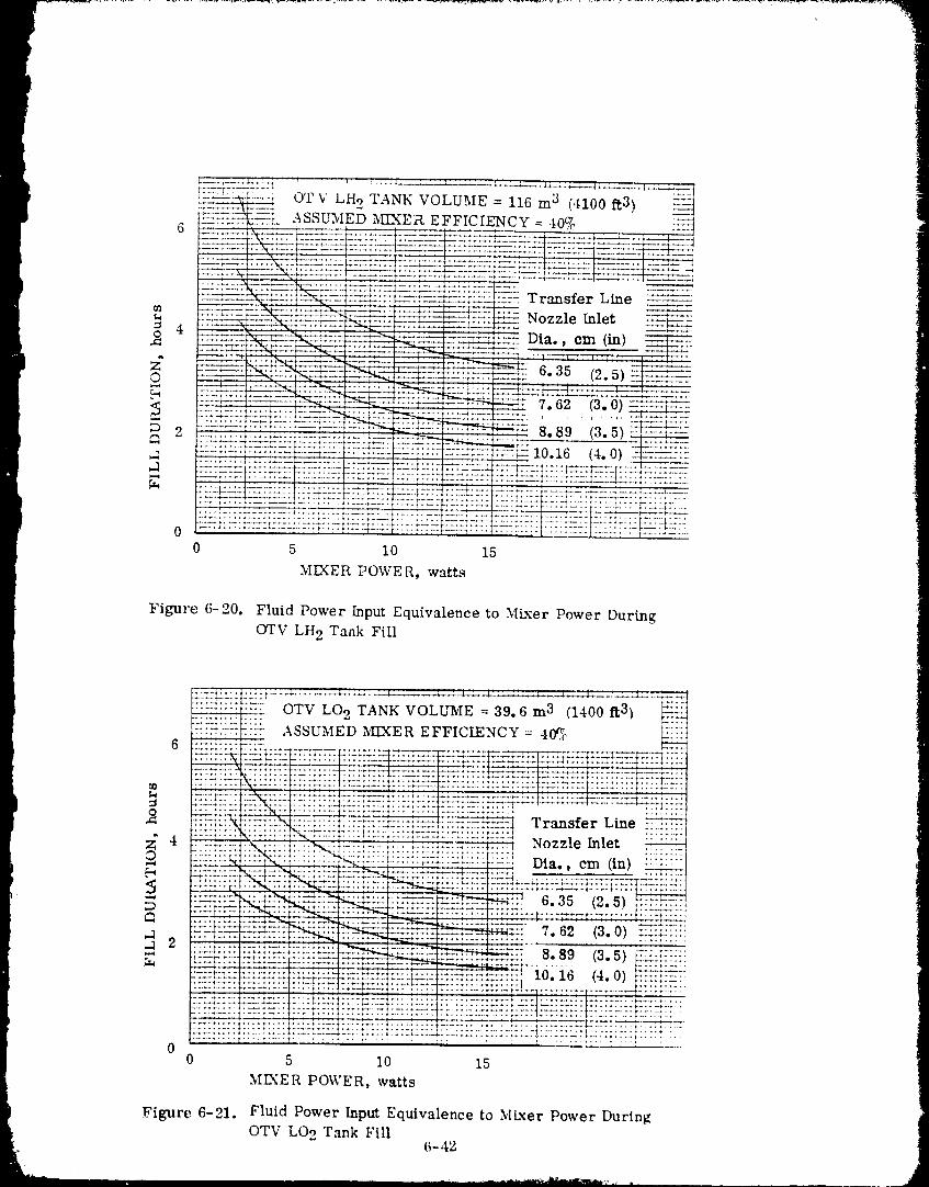
[--- !i
t
OT V LH 2 TANK VOLUME = 116 m 3 (4100 ft3%
ASSUMED _-XER EFFICIENCY = 40_ ___
_= Ozz[e [._e= 4
................. --..- ,- .35 2 5 _-0 2=_-- : t............................ ;.................... :::_ ::-:! -:-. ::....;=-::...:: :}:: ::
Y.U2:_+:Z_._...........LL:g.2_..............................:2: t: 1t: :: : : t-:.. I.... .1: -
•":7,j__........ * ............ L I ;---2- t ......... _....... ; .................. : .... Z....... 7: :_ _:LL-:-_.IL:
0 5 I0 15
MIXER POWE R, watts
Figure 6-20, Fluid Power Input Equivalence to MLxer Power During
OTV LI-{2 Tank Fill
OTV LO 2 TANK VOLUME = 39.6m 3 (1400 t%3)
ASSUMED MLXER EFFICIENCY = 40_. _iJ.6
::::::=_::::::::::::::::::::::::::::::::::::::::::::::::::::::::::: :::::::::_::.::::.... ;.................. _•k....... _"..... P'-'_ .... ;.... P"'-_ ........... : ..... _"*'t .... rT-:: -_.... t ..............
"_ :::::::::::::::::::::::::::::::::::::::::::::::::::::::::::::::::: ::::::::::'::i:'_ :':_"_i:':':":: ::::::::::::_.:::L::::::::::.=::_=_:: Transfer Line ---="--::::::_:..'-::. ::::'.:::: :::::::::::::::::::::::::::::: :::-:::::: ::i:., ::::::::.................................................{............ I
;_ 4 :_.:-::.].>L'i::.:t..?_it.::.:::!:..;.:::_.:.:_:_:_::::; Nozzle Inlet .::;:::._::-::::--: ::: :':::{i:!:: . " :::-"i" :_-':::: -: .......... ; ........
.:_R._ ,...:...'.'b_:_--*......_-_- ............... _=_,., 6.35 (2.5) ,......... ,:...--=.r::=::.'I-_..':!_::=-::_ :.:zr.'=V..-::::r:}::u,::_. t ........, .......... f::::;-':::l
::_=::_::=r{_.____: _:-_ 7.62 (3.0) =.:::;::::............. *.--., ..... ..... :_ ..................... 8. 9 ........
_::_ ..... ; ;_:_:-;:' ::_':::--': .... ::::_ 10.16 4.0 :::::':::::::::::::::::::::::::::::::::::::::::: "="_:' ( ) i
.... :: ::t: ......... :::::::::::::::::::::
00 5 I0 15
ME_ER POWER, watts
Figure 6-21, Fluid Power Input Equivalence to MLxer Power DuringOTV LO 2 Tank Fill
6- 42
1980009811-215
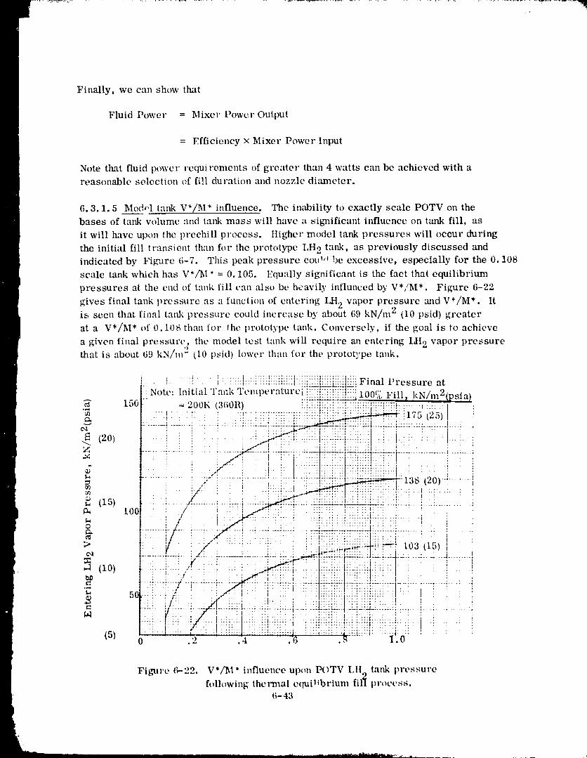
Finally, we can show that
Fluid Power = Mixer Power Output
= Efficiency x Mixer Power Input
Note that fluid power rcqui rements of greater than 4 watts can be achieved with areasonable selection of fill duration and nozzle diameter.
6.3.1.5 Mod,'l tank V*/M* influence. The inability to exactly scale POTV on the
bases of tank volume and tank mass will have a significant influence on tank fill, as
it will have upon the prcchill process, tligher model tank pressures will occur during
the initial fill transient th:m fl)r the prototype LH 2 tank, as previously discussed and
indicated by Figure 6-7. This peak pressure cou!,' be excessive, especially for the 0. 108
scale tank which has V*/M* = 0.105. I.:qual]y significant is the fact that equilibrium
pressures at the end of tank fill can also be heavily influnced by V*/M*. Figure 6-22
gives final tank pressure as a function of entering LH 2 vapor pressure mid V*/M*. Itis seen that final taak pressure could increase by about 69 kN/m 2 (10 psid) greater
at a V*/M* of 0.11)8 than for the prototype tank. Conversely, if the goal is to achieve
a given final pressure, the model test tank will require an entering LH 2 vapor pressure
that is about 69 kN/m 2 tl0 psid) lower th'.m for the protoE'pe tank.
: .... I :.: i ::I:: : :::::::::::::::::::::::::::::::::::::: F,nal t ressure atNote" Initial Tank 'l'emperatureii!!_t_!!i-t--{ ,nnc: w',, ,.,._i...2 ......
_" 150 -_ 200K (360R) ::7..:::::::::::::::::::::::::: .... ' i -- '.."_ .............................1,...... . . _........... :.ii}iii._:!i!ti i:-Zii.:::: !:..l_a._./2ali'S"" "
Z : : i " : i/1 , : . : d::::.::': t:i :!,: . i ' ! ' ; .
• '_':!i'-7 .... " " "_....... ' i'i:i-m"::_ ":':"+................. _..........: ' :I...::A: :+:+;1 ., I' /" I : :':'":::' " :'.' '1.:::: ::1': +.::"_:: :". t.: '
............. ;,....... : ...... : ........ :-V___ 13s (2o)-4........, _...... ', . .:.,-. .:::,.:: , ,: ii" . ' ; I .... ,.... :::.:'::': ..: ..I .::: ...t. : :
i : '
i /. . t ./q _ :i. i '_:i!:ii::!_:i_i::i.:.i :t ' _ i il ::::::::::::::::: I ,: ; • : . : I .............. .......... , . .
: j ' , 5/, : ,. . : ,.:::,_._,_._:,:.:: t03 (to) :....:.__L_=. i Z.. L...L_A.L .....J.-::-: ._-'-ZZ.I_:.L:::IL.-:L-:r_.. ..... ! 2 A. _!
"'* / 1 .: ::: : : ................... I I
.... ' .... ; ' l., , " ', , '.. :::.::.' ':::: ':: : ,I !
"=- g ! ';_#'-!-:"7[":7T +T72"7;::"t..... N:-'._:"_."I:r'7:,Y':l.: .... ivT " : ...... ".... :
• : ': .... l " , ; . • : ,:: ::,: .... ]::;:[:.::|:: : .:. ::; : , "(5) o .2 " ::i .... 76 .,_...... I. 0
Figure 6-22. V*/'M* h_flucncc upon POTV LIL,,, tank pressurefollowing,* ""the i'mal equillbrium,, fil'[ process.
6- 43
1980009811-216
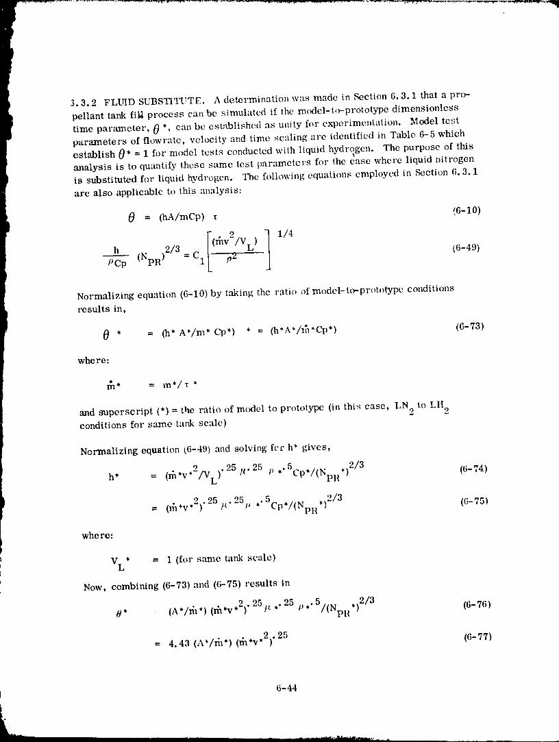
3.3.2 FLUID SUBSTITUTE. A determination was made in Section 6.3.1 that a pro-
pellant tank fill process can be simulated if the model-t(_prototype dimensionless
time parameter, 0 *' can be established as unity fro" experimentation. Model testparameters of flowrate, velocity and time scaling are identified in Table 6-5 which
establish 0* = 1 for model tests conducted with liquid hydrogen. The purpose of thisanalysis is to qumltify these same test parameters for the case where liquid nitrogen
is substituted for liquid hydrogen. The following equations employed in Section 6.3.1
are also applicable to this analysis:
0 = (hA/mCp) _ (6-10)
PCp (NpR)2/3 = C1 (6-49)
Normalizing equation (6-10)by taking the ratio of model-to-prototype conditions
results in,
0 * = (h* A*/m* Cp*) * = (h*A*/I_*C-p*) (6-73)
whe re:
and superscript (*) = the ratio of mtxiel to prototype (in this case, LN 2 to LH 2conditions for same tank scale)
Normalizing equation (6-49) and solving fee h* gives,
h* = (_,v,2/VL). 25/t" 25 I' *"5Cp*/(NpII*) 2/3 (6-74)
9 25 . 5Cn,fl N ,12/3= (rh*v*')" /t 25p ,. (6-75)" " PR "
whe re:
VL* = 1 (for s:mm tank scale)
Now. combining (6-73) and (6-75) results in
8' (i*/rh*) (d_*v*2)" 251L *"25 p,. 5/(NpR,)2/3 (6-76)
= 4.43 (A*/fi_*) (fn*v*2) "25 (6-77)
6-44
1 .c)lqO(')r) .q 1 1-91 7
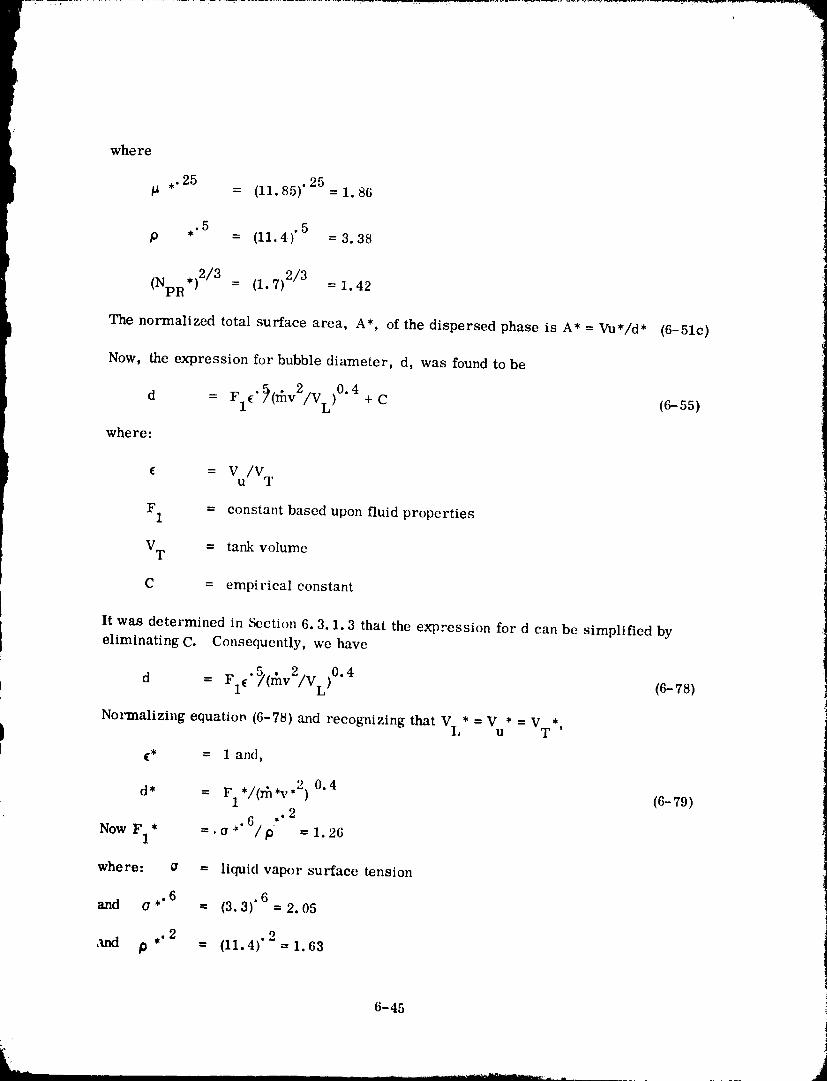
where
,.25 = (11.85)'25=1.86
,.5P = (11.4) "5 =3.38
,)2/3(NpR = (1.7) 2/3 = 1.42
The normalized total surface area, A*, of the dispersed phase is A* = Vu*/d* (6-51c)
Now, the expression for bubble diameter, d, was found to be
d = F1 _. _(_v2/VL)0.4 + C (6-55)
whe re:
c = V/Vu T
F 1 = constant based upon fluid properties
VT = tank volume
C = empirical constant
It was determined in Section 6.3.1.3 that the expression for d can be simplified byeliminating C. Consequently, we have
d •_(_v2/VL)0.4= FI¢ (6-78)
Normalizing equatiop (6-78) and recognizing that VL* ---V * -- V *U T '
(* = 1 and,
d* = F1,/(_,v,2 ) 0.4 (6-79).2
NowF 1. =.a*'6/p* =1.26
where: a = liquid vapor surface tension
and o ,.6 6-- (3.3)" =2.05
,rod P ,.2 2= (11.4)' =1.63
]
6-45
!
] 9800098 ] ] -2 ] 8
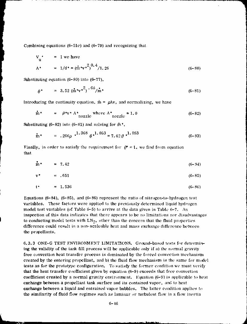
Combining equations (6-51e) and (6-79) and recognizing that
V * = 1 we haveU
• 20.A* = l/d* = (m'v*) 4/1.26 (6-80)
Substituting equation (6-80) into (6-77),
0* = 3.52 (_*v .2) .65/_, 16-81)
Introducing the continuity equation, lh = f}Av, and normalizing, we have
_* = P'v* A'nozzle where A'nozzle = 1.0 (6-82)
Substituting (6-82) into (6-81) and solving for Ih*,
_n* = .266p ,1.368 0,1.053=7.420,1.053 (6-83)
Finally, in order to satisfy the requirement for 0* = 1, we find from equationthat
m* = 7.42 (6- _i)
v* = .651 (6- 85)
t" = 1.53(; ((')--86)
Equations (6-84), (6-85), and (6-86) represent the ratio of nitrogen-to-hydrogen test
variables. "lhesc factors were applied to the previously determined liquid hydrogen
model test vat*i;dalcs (of Table 6-5) to arrive at the data t.,iven in Table (;-7. An
inspection of this data indicates that there appears to be no limitations nor disadvantages
} to conducting model tests with LN 2, other than the concern that the fluid p_'opertiesdifference could result in a non-scaleable heat and mass exchange difference betweenthe propellants.
6.3.30NE-G TEST ENVIRONMENT LIMITATIONS. Grtmnd-based tests for determi,_-
ing the validity of the tank fill process will be applicable only if a) the normal gravity
free convection heat transfer process is dominated by the forced convection mechanism
created by the entering propellant, and b) the fluid flow mecha_lism is the same for m(ttel
tests as for the p:'ototype configuration. To satisfy the former condition wc must verifythat the heat transfer coefficient given by equation (6-9) exceeds that free ct_nvection
coefficient created by a nol'mal gravity environment. Equation (6-9) is applicable to heat
exchange between a propellant tank surface and its contained vapor, and to heatexchange between a liquid and entrained vapor bubbles. The latter condition applit, s to
the similarity of fluid flow regimes such as laminar or turbulent flow in a flow incrtia
6-16 i
J
1980009811-219
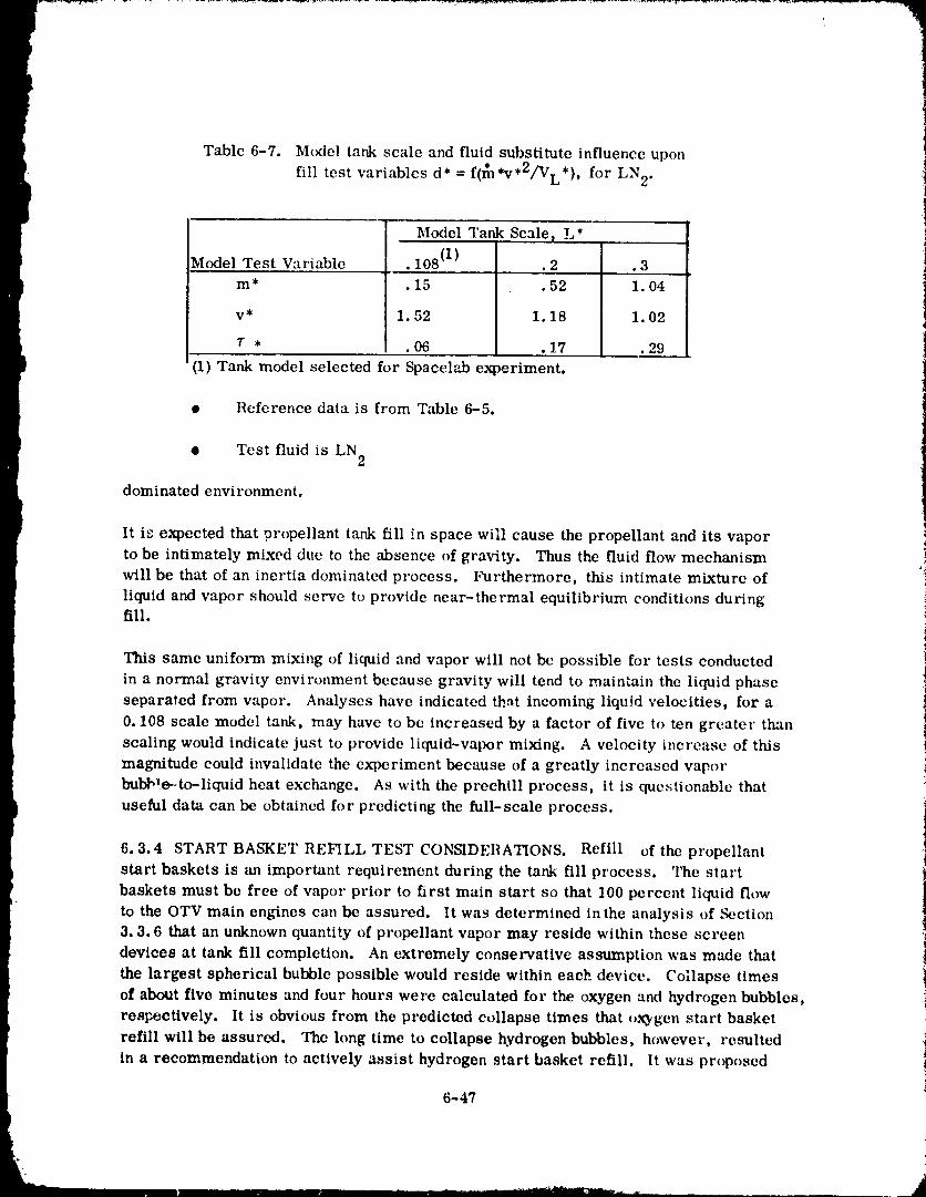
Table 6-7. Model tank scale and fluid substitute influence upon
fill test variablcs d* = f(_*v*2/VL*), for LN 2.
Model Tank Scale) L*
Model Test Variable • 108 (1)'" .2 .3m* .15 .52 I. 04
v* 1.52 1.18 1.02
T , .06 .17 .29
(1)Tank model selectedfor Spaeclabex )eriment.
• Reference data is from Table 6-5.
• Test fluid is LN 2
dominated envi ronmcnt.
It is expected that propellant tank fill in space will cause the propellant and its vaporto be intimately mixed due to the absence of gravity. Thus the fluid flow mechanism
will be that of an inertia dominated process. Furthe_nore, this intimate mixture of '_
liquid and vapor should serve to provide near-thermal equilibrium conditions duringfill.
This same uniform mixing of liquid and vapor will not be possible for tests conducted
in a normal gravity environment because gravity will tend to maintain the liquid phase
separated from vapor. Analyses have indicated that incoming liquid velocities, for a
0. 108 scale model tank, may have to be increased by a factor of five to ten greater than
scaling would indicate just to provide liquid-vapor mixing. A velocity increase of this
magnitude could invalidate the experiment because of a greatly increased vapor
bubb'e--to-liquid heat exchange. As with the preehill process, it is questionable thatuseful data can be obtained for predicting the full-scale process.
6.3.4 START BASKET REFILL TEST CONSIDERATIONS. Refill of the propellant
start baskets is an important requirement during the tank fill process. The start
baskets must be free of vapor prior to first main start so that 100 percent liquid flow
to the OTV main engines can be assured. It was determined in the analysis of _ction3.3.6 that an unknown quantity of propellant vapor may reside within these screen
devices at tank fill completion. An extremely conservative assumption was made that
the largest spherical bubble possible would reside within each device. Collapse times
of about five minutes and four hours were calculated for the oxygen and hydrogen bubbles,
respectively. It is obvious from the predicted collapse times that oxygen start basket
refill will be assured. The long time to collapse hydrogen bubbles, however, resulted
in a recommendation to actively assist hydrogen start basket refill. It was proposed
6-47
1980009811-220
that a small diameter line be routed from the tank fill port to the basket so that liquidwould be sprayed into the volume during the fill process. Cal,_ulations, for a conser-
vative fill model, indicated that all entrapped vapnr would b,: ,:(,ndensed before tank
fill completion.
The mechanism for removing vap Jr from the start basket i_ identical to that described
for tank fill. That is, the incoming liquid momentum will serve the dual function of
creating small bubbles and a high heat exchar, gc e_ivironment between liquid and
vapor, both of which enhance condensation. The strategy to assure start basket
refill will be to create sufficient agitation within the screen volume to assure complete
vapor condensation. It appears that there will be fewer restraints imposed upon start
basket refill than tank refill, consequently, a propellant flow split can be selected to
assure basket refill before tank fill completion. As an extreme example, tank fill
could be performed by flowing all propellant through the screen device.
Since it appears that basket refill can be assured, and because tank fill experiments
will also be useful in assessing condensation conditions within the start basket, a
detailed test program is not recommended. Ra_her, it may be sufficient to provide arange of start basket flowrates as part of the tank fill experiment. There would be
an advantage to performing several tank fill experiments without flowing propellant to
the start basket. These tests would identify if an active means ,_ start basket refill isnecessary.
6.4 SPACELAB EXPERIMENT INTEGRATION
The Spacelab provides facilities for investigating fluid behavior in a low gravity environ-ment. The experiment payload accommodated within the pressurized Spacelab, however,
must adhere to strict safety regulations regarding the crew, the mission, and the
payloads. Specifically, Reference 6-1 restricts the use of cryogens to the exterior ofthe Spacelab.
To confirm the Reference 6-1 guidelines, Merle Slayden, a NASA/'MSFC Safety
Engineer was contacted to discuss current directives regarding the use ()f cryogens.
The proposed receiver tank experiment, employing a 457 mm (18 inch) diameter
tank mounted within a double rack, was discussed and h*2stated such LN 2 quantitieswould require a waiver for Spacelah. Uafortunatel] a waiver can only be obtained
during the experiment integration safety review period, which occurs after payload
design and fabrication. As a guideline, Mr. Slayden offered the inf()rmation that LN 2quantities of about 3.6 kg (8 lb) would be acceptable. The proposed test tank, would
cont',Lin a maxim,:m of 120 kg (264 lb) LN 2. Liquid hydrogen is unacceptable under anycondition.
There will be additional restraints imposed upon the receiver tank experiment design
other than the use of LN 2. These Spacelab general experiment accommctlation factorsare given in Appendix B and have been extracted from the "Life Sciences Guide t()
6-48
1980009811-221
the Space Shuttle and Spacelab" experimenters handbook, and the Reference 6-1handbr, ok
6.5 MODELLING OF LTL REFUELING OPERATIONS
A mission scenario was selected in Section 5 for the purpose of analyzir, g orbital re-
fill o_erations• A low thrust liquid (LTL) vehicle configuration was selected from
existing vehicle hardware; principally, the OMS tanks were selected as the main
propellant tanks, apd the shuttle RCS bottles were selected for the same function on
the LTL. N204 and MMH were the propellants selected for the main propulsion andRCS systems. _Each of the storage tanks and bottles contained a screen acquisitiondevice.
I The analysis of Section 5 identified the refill requirements listed in Table 6-8 • Itwas determined that all potential problems, such as liquid venting and helium entering
the screen devices, resulted from the need to expel helium from the storage vessels
before initiating refill. Furthermore, it was found that refill could be performed in
a very straightforward manner; venting would not be required, and tank pressures
would not exceed normal operating pressures during refill•
Table 6-8 . LTL vehicle refueling requirements•
• Propellant Tank Venting Must Not Damage LTL or Orbiter
Liquid Venting Potentially More Damaging Than Vapor Veuting
• Helium Must Not I_:nter Partial Screen Device Galleries
• Vehicle Control Must Be Maintained During I_efill Operations
• Liquid Venting is Undesirable
• Simplified Operations Are a Necessity
i • Must Have Ability to Refill to _--95_. LevelIt was concluded from the refill analysis that virtually all potential problems would be
eliminated through the use of procedures, if certain vehicle modifications were in-
corporated. These modifications included adding plumbing between storage vessels
{see Figure 5-- 5 ) to enable propellant transfer between common tanks. With these
changes, procedures were established so that propellants could be transferred from
one tank to another before initiating a tank vent.
The single concern of the selected refueling procedure was that propellant contained
within the screen devices might boil during tank vent to expel helium. The solution
would be to maintain sufficient liquid residual that it would replenish any screen
device liquid lost by evaporation. This solution will be effective ouly if cow ,unication
is maintained between liquid pool and screen device. Thus, the purpose of a,_ orbital
experiment would be to verify that communication is maintained during the tank vent
6-49
[
1980009811-222
process, and thi_willb_,-,functionc,[geomet ry O:m!.:and screen) and :weeler:liion ._
Cq'IViI'0111"IIC I1[.
L:tboraiory experiments conducted in a normal gravity envir,,nmeni will iioI b_._ ll_L'flll
becquse "inear 7.ertv.-gt,iwil'olHll¢,lllis rq.,qllir,.,d.'['hc,api'_rol'_ri;Itc,IccelerlHion¢qlviroll-
merit can be provided by orbital experimelH_.
Orbital experimtmls to verify that the screen devic,'s will remain filled with liquid are
tloI recollllalt, nt|t'd, Such iesi_ would not |l/lye wide :lpplict_bilily bet'zlllse i't, slllls would
be v(.'ry st, llsilivc 1o gc.'Olll_.,tl'y, it is l'OCOllllllctld¢'d I|l:lI t,xtk'l'illlt'llI.'4 t_f this type not be
COlldtl(_t¢,d until :m opcrzilion;ll vehiclc configl|r;liioll czlll llm'est:_blishcd.
6-50
1980009811-223
R E I,'E R ENC ES
I-1 Merino, F., et al," I,'llllng of Orbital Fluid Management Systems,"NASA-CR-159404, CASD-NAS-78-010, July 1978.
1-2 Blatt, M. II. , Br:udshaw, et al, "Orbital Transfer of Cryogenic Propellants,"
t CASD-ERR-77-093, l)ccembcr 1977.
1-3 Merino, F., Thies, e{ al, :'Orbital Transfer of Cryodenic Propellants, "
CASD-ERR-78-088, December 1978.
I 3-1 "Orbital ])repellant tlandllng and Stor,'lge Systems I)efinitton Study,"
GDC-ASP- 002, August 1979.
3-2 Blait, M. II., Risberg, J. A. "Study of IAquid and Vapor Flow Into a Centaur
Capillary Device," NASA CH-159657, GDC-NAS-7:)-001, _Ttember 1979.
3-3 Merino, F., ct al, "l.'illing of Orbit;fl Fluid Man._ement Systems, "
NASA-CR-159404, CASD-NAS-78-010, July 1978.
3-4 Uhl, V. W. and Gray, J. B., "Mixing, Theory and Pract'ce, " Volume II,
Academic Press, 1967.
4-1 "Orbital Propellant Ilandling m_d Storage Systems for Large Space Programs, "
JSC-13967, CASD-ASP-78-001, April 1978.
4-2 "Orbital Propellant ttandling mid Stor,'kge System Definition Study,"
GDC-ASP-79-002, August 1979.
6-1 "Payload Accomodations llandbook, " paragraph 8.3.9, Cryogenic Stor,_c,
SLP/2104, 30 June 1977.
7-1
- 1980009811-224
I APPENDIX A
IDENTIFICATION OF CANDIDATE VEHICLE
RECEIVER TANKS
TABLE A-I. GENERAL SUMMARY (1975-1990)
TABLE A-2. ORBITAL TRANSFER VEHICLE (OTV'S)
TABLE A-3. SPACE PLATFORMS/SPACE STATIONS
TABLE A-4. AUTOMATED AND MANNED SPACECRAFT
TABLE A-5. REFERENCES
A-1
1980009811-22!
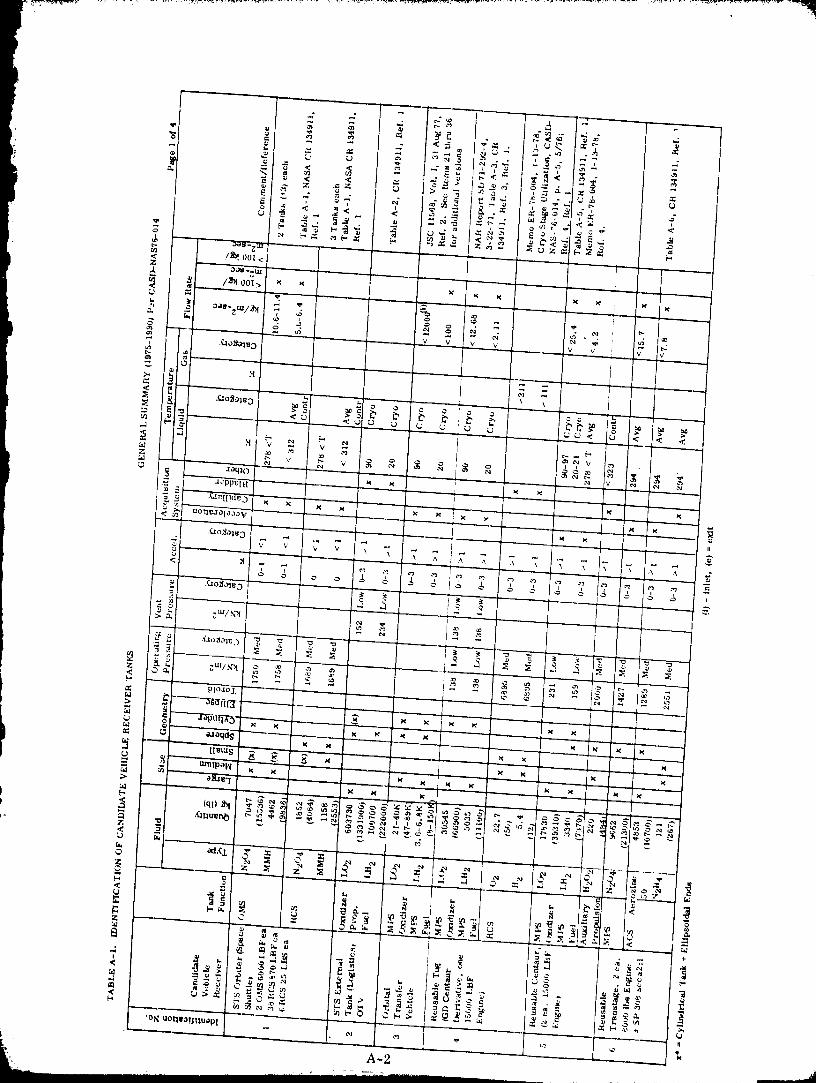
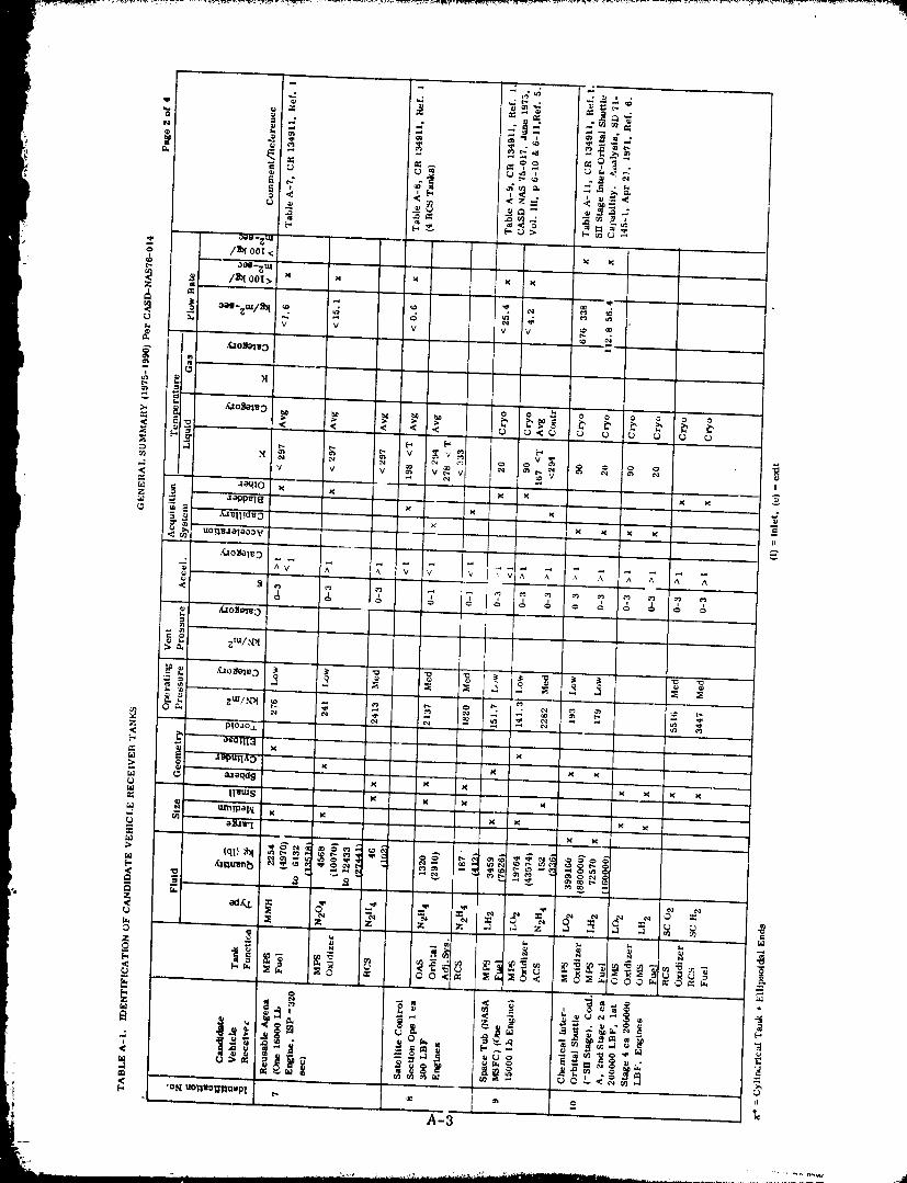
19800O08-1-1'227
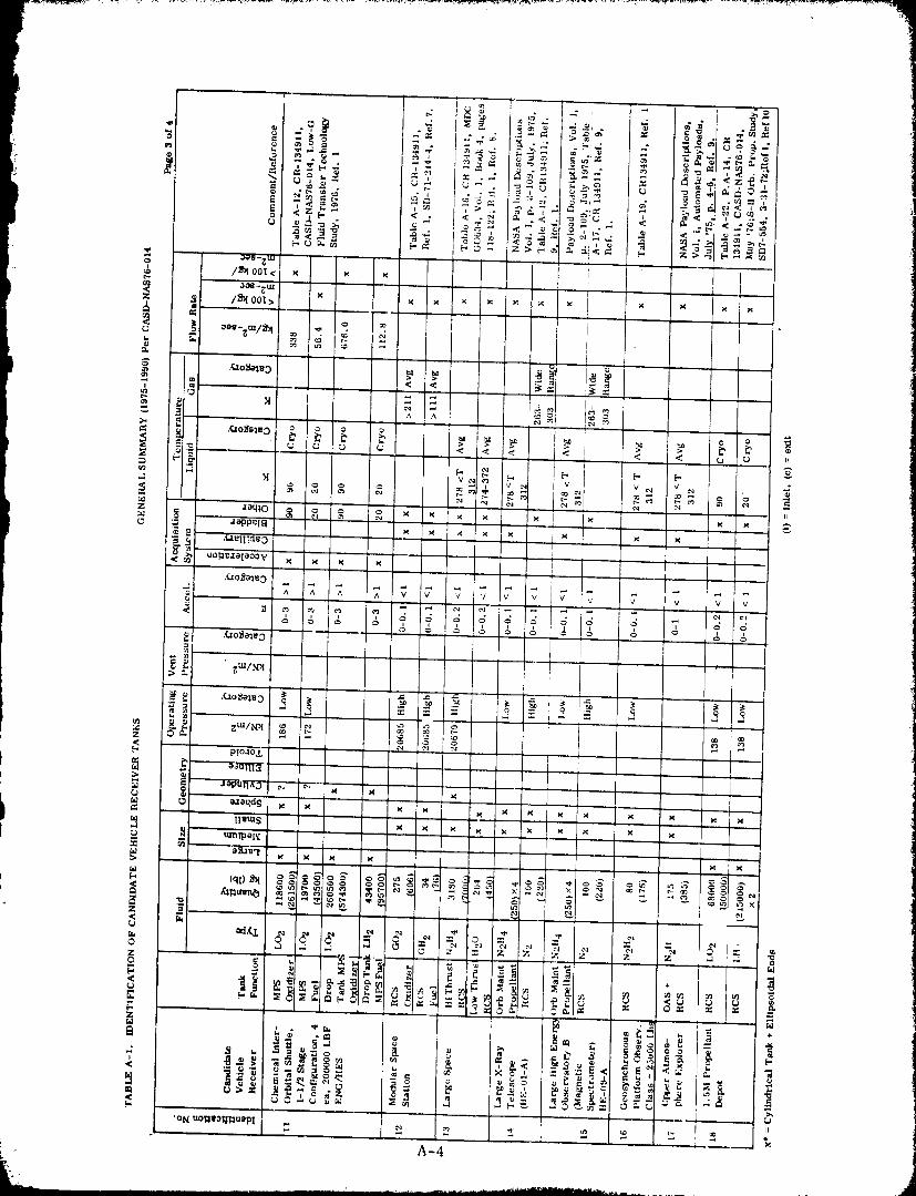
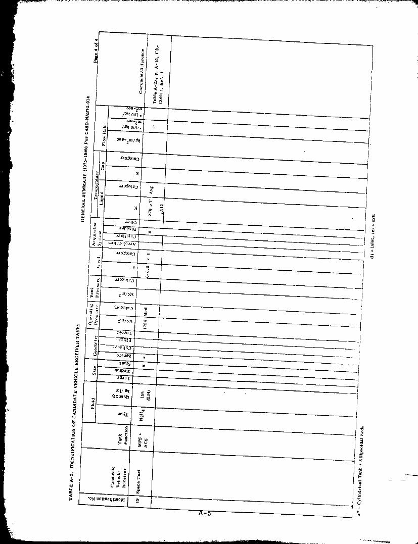
' • 1980009811-229
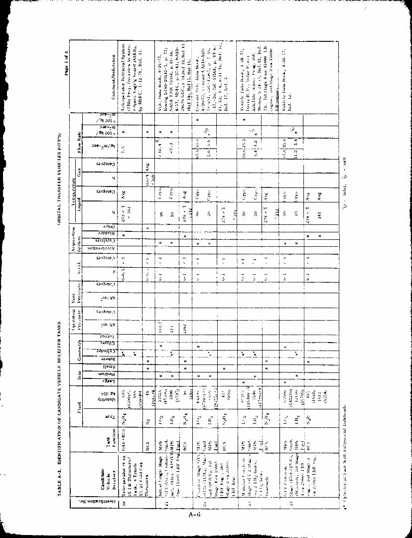
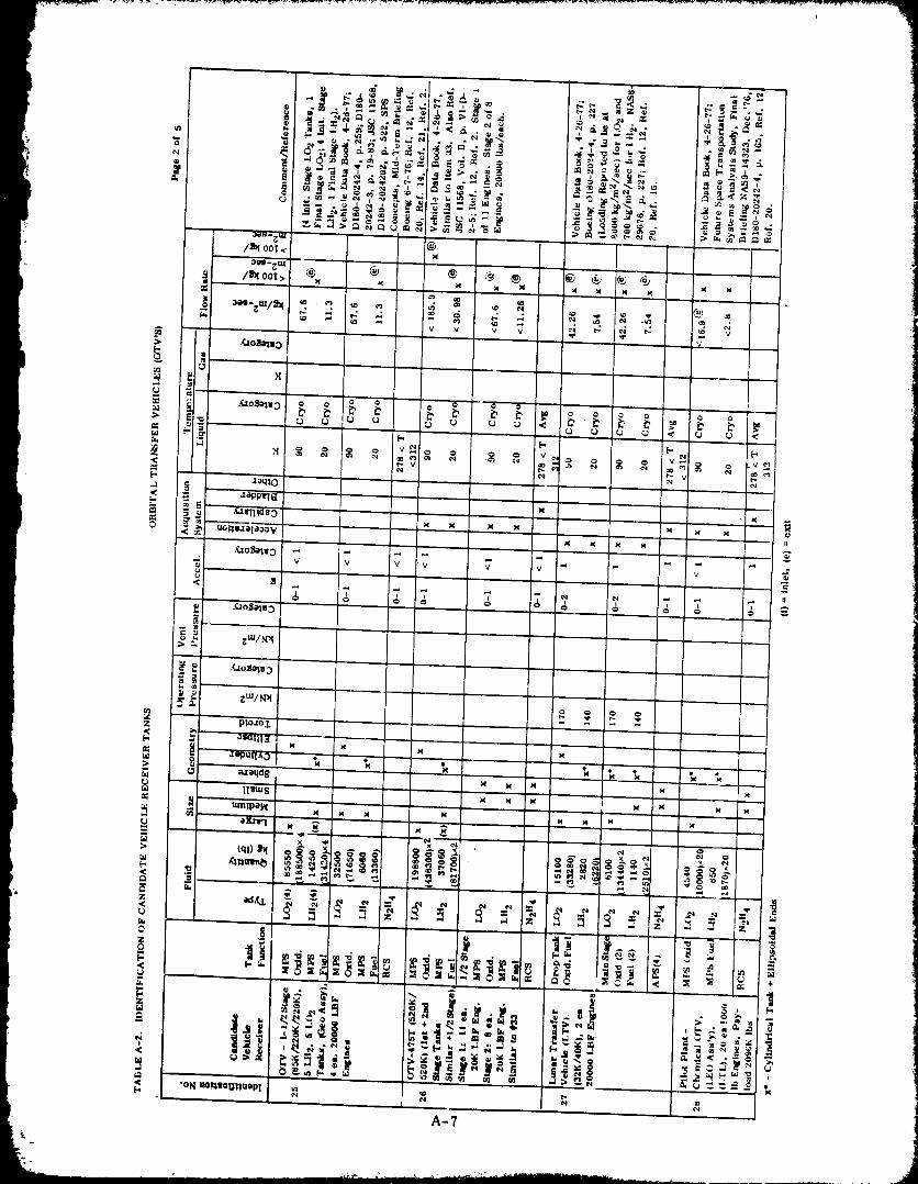
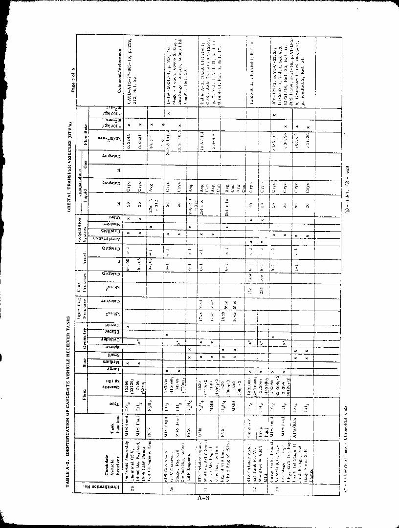
1980009811-232
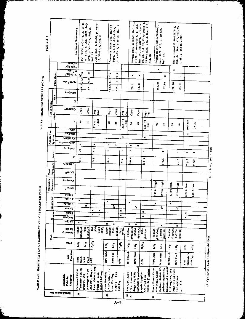
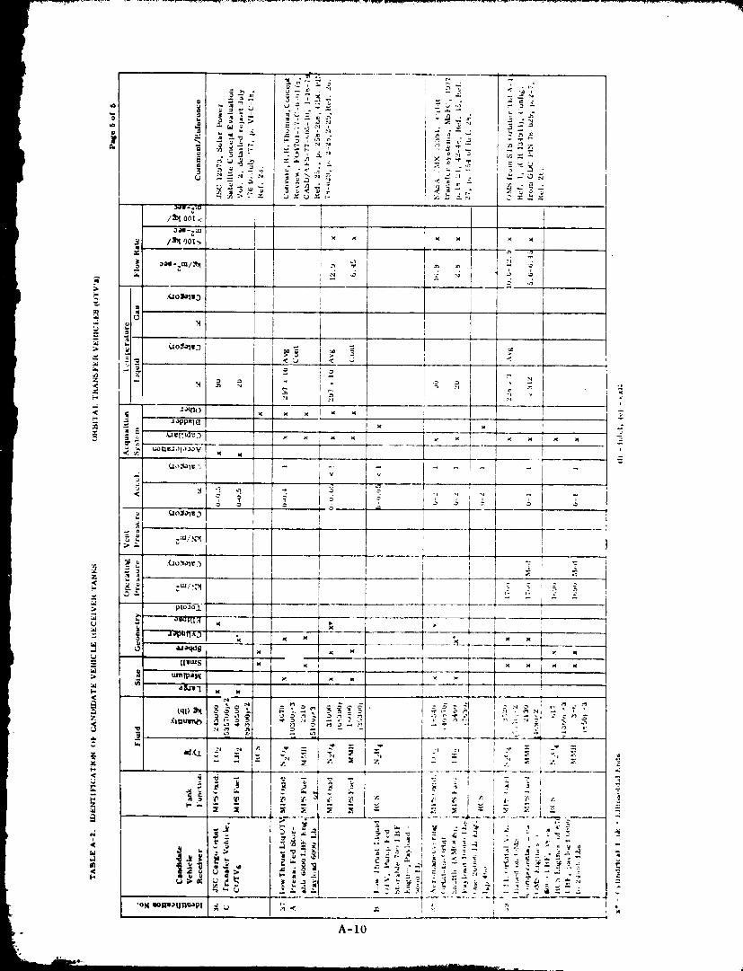
.... • • . . .
1980009811-234
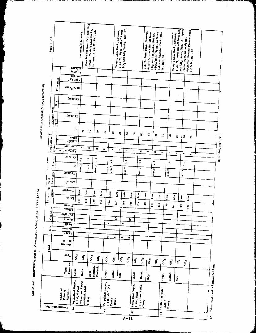
1980009811-235
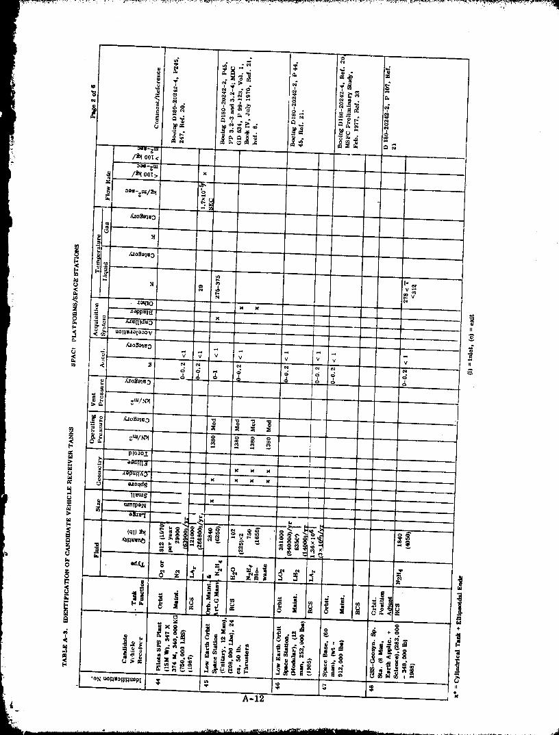
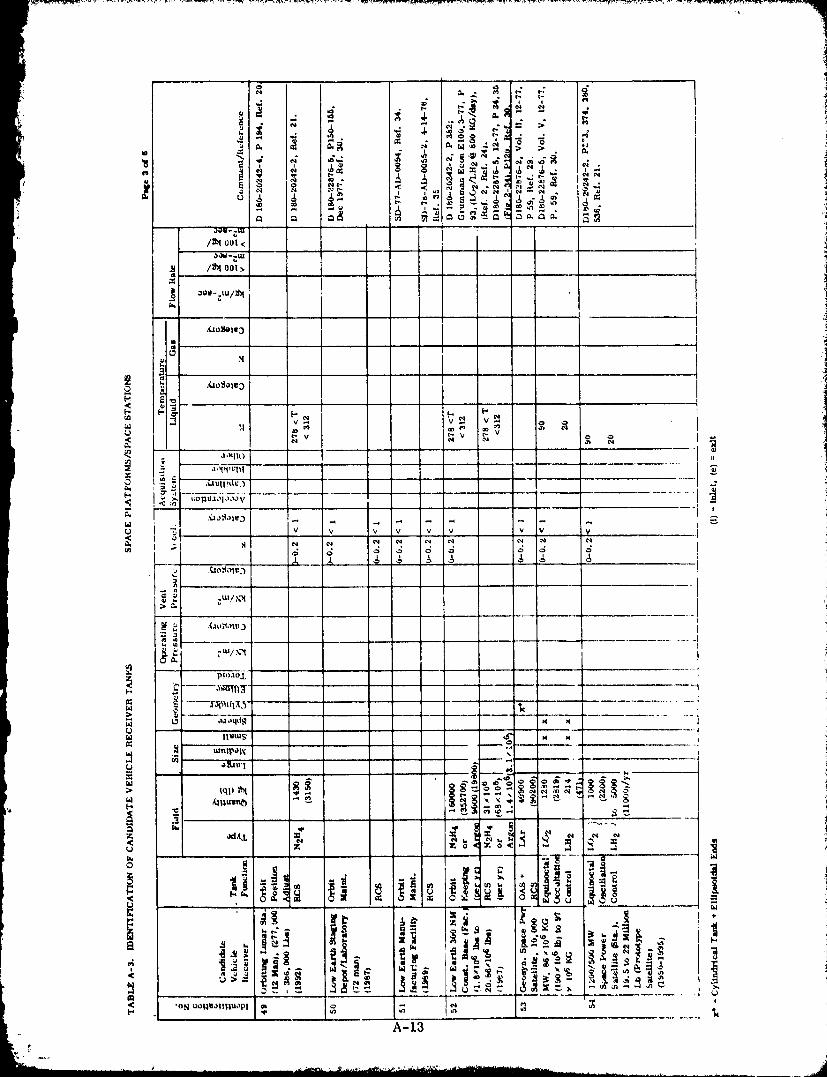
H
•|°_]l) I II
II
,(ao_l,'_ItV,3
PI°J°'L
um]p._tg
•oS uol_vaHl-lUOpl _ _ _ _ N
A-13
]9800098] ]-237
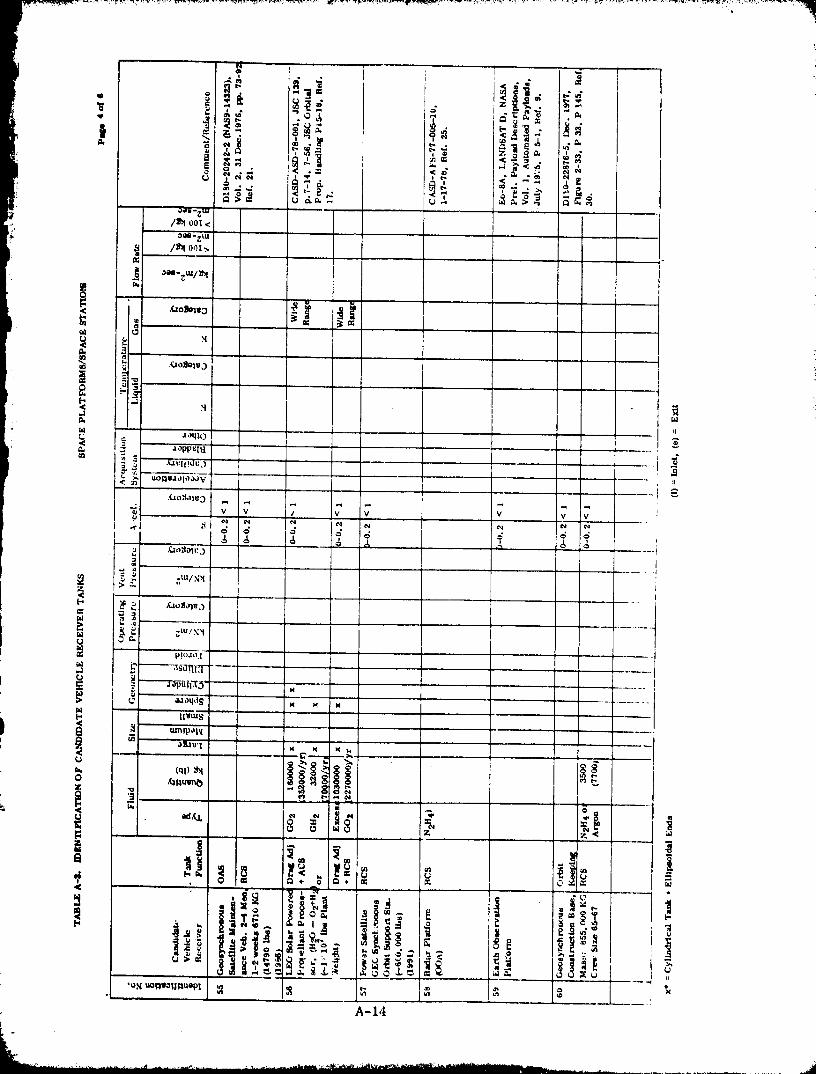
1980009811-238
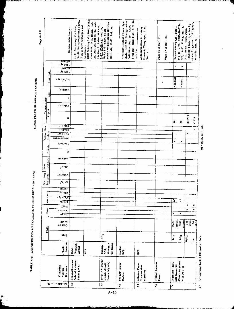
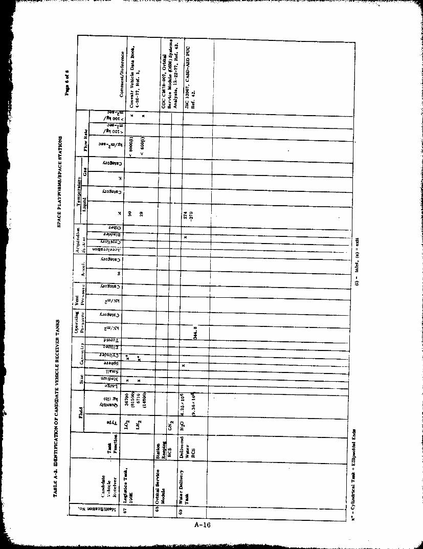
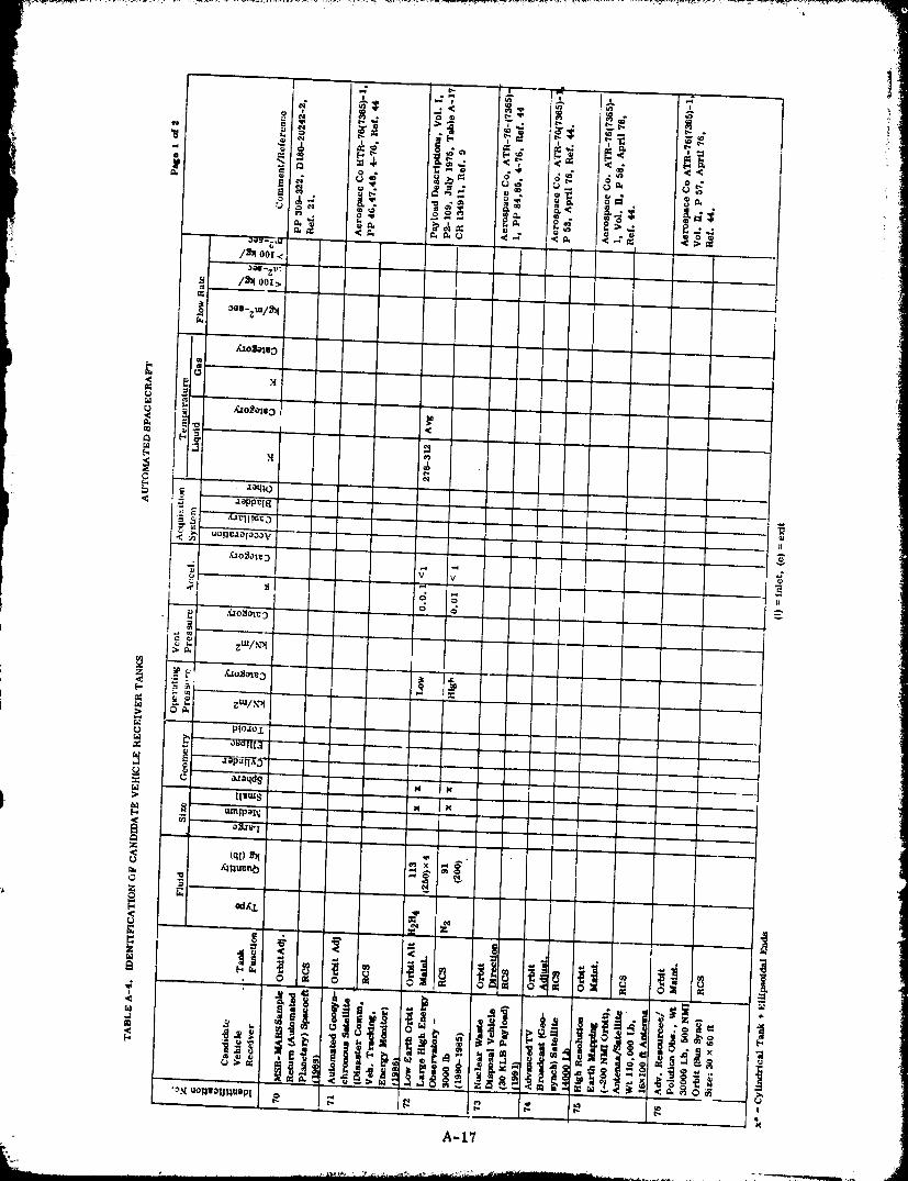
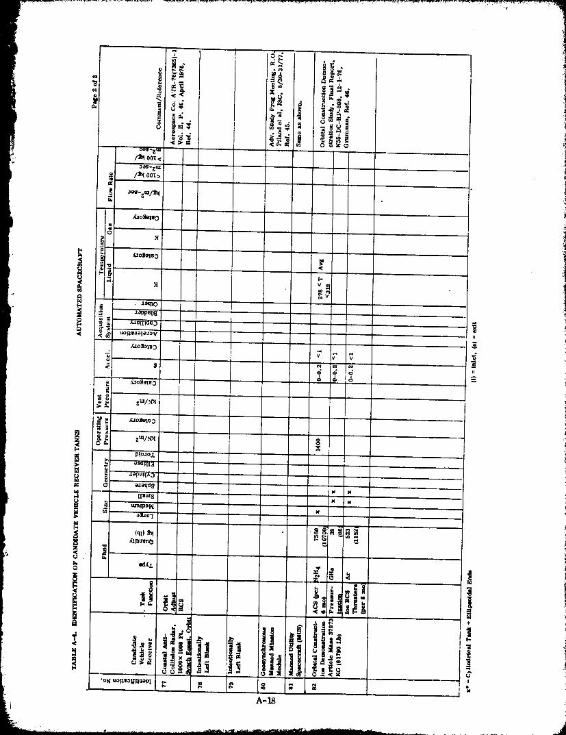
&aoJelsO
r_
e_
I ._ S.
_o_
_._I_4
g
o
I o i
A-18
"IU_UUUUb'I I Z_l,Z
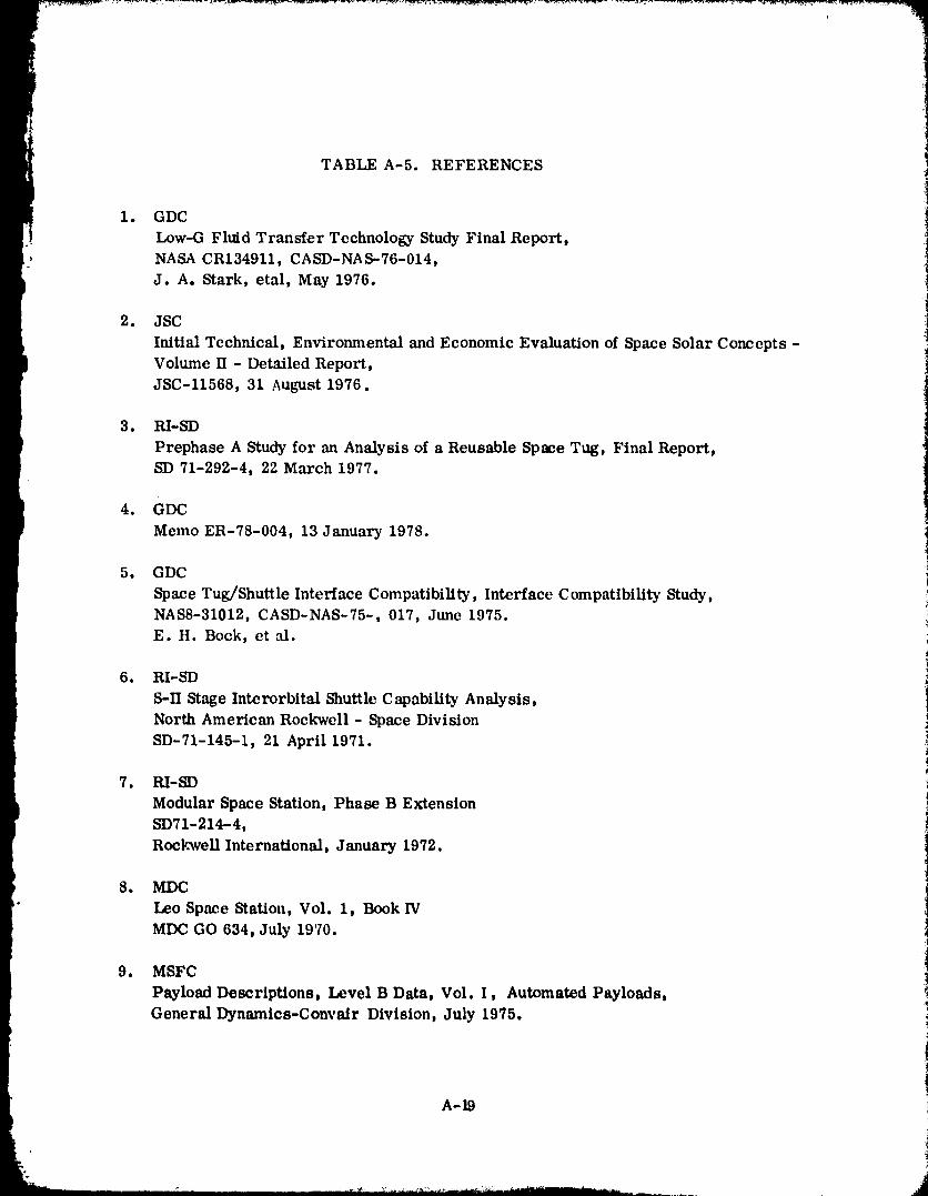
TABLE A-5. REFERENCES
1. GDC
Low-G Fluid Transfer Technologs, Study Final Report,' NASA CR134911, CASD-NAS-76-014,
J. A. Stark, etal, May 1976.
2. JSC
Initial Technical, Environmental and Economic Evaluation of Space Solar Concepts -
Volume II - Detailed Report,JSC-I1568, 31 August 1976.
3. RI-SD
Prephase A Study for an Analysis of a Reusable Space Tug, Final Report,SD 71-292-4, 22 March 1977.
4. GDC
Memo ER-78-004, 13 January 1978.
5. GDC
Space Tug/Shuttle Interface Compatibility, Interface Compatibility Study,NAS8-31012, CASD-NAS-75-, 017, June 1975.E. H. Bock, et al.
6. RI-SD
S-II Stage Interorbital Shuttle Capability Analysis,
North American Rockwell - Space DivisionSD-71-145-1, 21 April 1971.
7. RI-SD
Modular Space Station, Phase B ExtensionSD71-214-4,
Rockwell International, January 1972.
8. MDC
" Leo Space Station, Vol. 1, Book IV
MDC GO 634, July 1970.
9. MSFC
Payload Descriptions, Level B Data, Vol. I, Automated Payloads,
General Dynamics-Convair Division, July 1975.
A-19
1980009811-243
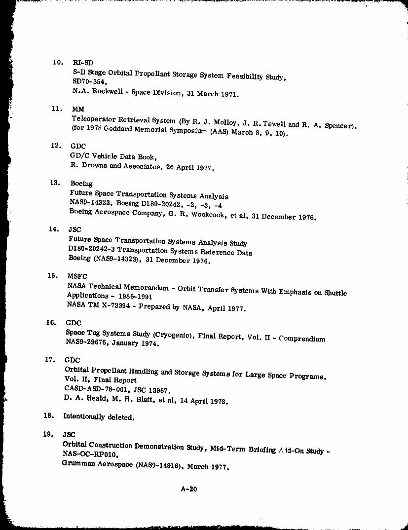
10. RI-SD
S-IfStageOrbitalPropellantStorageSystem FeasibilityStudy,SD70-554,
N.Ao Rockwell - Space Division, 31 March 1971.
11. MM
Teleoperator Retrieval System (By R. J. Molloy, J. R. Tewell and R. A. Spencer),(for 1978 Goddard Memorial Symposium (AAS) March 8, 9, 10).
12. GDC
GD/C Vehicle Data Book,
| R. Drowns and Associates, 26 April 1977.
13. Boehg
Future Space Transportation Systems Analysisi NAS9-14323, Boeing D180-20242, -2, -3, -4r Boeing Aerospace Company, G. R. Wookcook, et al, 31 December 1976.
14. JSC
Future Space TransportationSystems AnalysisStudy
D180-20242-3 TransportationSystems Reference Data
t Boeing (NAS9-14323), 31 December 1976.
15. MSFC
NASA Technical Memorandum - Orbit Transfer Systems With Emphasis on Shuttle
Applications- 1986-1991NASA TM X-73394 - Prepared by NASA, April 1977.
16. GDC
Space Tug Systems Study(Cryogenic),FinalReport, Vol.II- Comprendium
NAS9-29676, January 1974.
17. GDC
Orbital Propellant Handling and Storage Systems for Large Space Programs,
Vol. If, Final ReportCA_D-ASD-78-001, JSC 13967,
D. A. Heald, M. H. Blatt, et al, 14 April 1978.
18. Intentionally deleted.
19. JSC
Orbital Construction Demonstration Study, Mid-Term Briefing _ td-On Study -NAS--OC-RP010,
Grttmman Aerospace (NAIl9-14916), March 1977.
A-20
.......................... .............. 1--980:C)098-i_244
2O. JSC
Future Space Transportation Systems Analysis StudyD180-20242-4 - Final Briefing,Boeing (NAS9-14323), December 1976.
21. JSC
Future Space Transportation Systems Analysis StudyD180-20242-2 Final Report,Boeing (NAS9-14323), 31 December 1976.
22. DOD/STS On-Orbit Assembly Concept Design Study (Preliminary Concept forAnalysis)CASD-AFS-66-005-10
R. H. Thomas and Team (GDC), 18 January 1978.
23. JSC
Solar Power Satellite - Concept EvaluationActivities Report, July 1976 to June 1977 (Vol. 2, Detailed Report)JSC 12973, July 1977.
24. GDC
(Proposal) Advanced Composites Design Data for Spacecraft StructuralApplic:_tion- Volume 1 - TechnicalGDC-PIN77-337, 31 October 1977.
25. GDC
DOD/STS On-Orbit Assembly Concept Design Study(Preliminary Concept for Analysis)CAb-_D-AFS-77-005-10
R. H. Thomas and Teams 18 January 1978.
26. Orbital Refill of Propulsion Vehicle TankageRFP-3833354, GDC-PIN 78-029,
i M.H. Blatt and associates, 197&
27. MSFC
Extended Applications Study of AMOOS and AMRS - Final ReportLMSC-HREC TR D497150,
Lockheed Missiles and Engineering Center
Cummings Research Park, 4800 Bradford Drive, Huntsville, Alabama
28. Feasibility and Tradeoff Study of an Aeromaneuvering Orbit-to-Orbit ShuttleLMSC - D390272, July 1974.
A-21
1980009811-245
29. Solar Power Satellite, System Definition Study
i Part I and Part II,Volume IITechnicalSummary.D180-22876-2 (NAS9-15196), December 1977.
30. Solar Power SatelLite, System Definition Study,:_ Volume V Space Operations(Constructionand Transportation)
i: D 180-22876-5 (NAS9-15196), December 1977.
31. AIAA/MSFC Symposium on Space Industrialization Proceedings26, 27 May 1978.
32. Space Station Systems Analysis Study, Grumman ProgramReview Presentation
17 June 1976.
33. MSFC
Space Construction Base Preliminary Study by Program DevelopmentPreliminary Design OfficeFebruary 1977.
34. MSFC
Industries in Space to Benefit Mankind - A View Over the Next 30 Years
(RIC Contract NAS8-32198) Managed by Dr. Drafft Ehricke.SD 77-AP-0094,
Joint Project of MSFC and Rockwell International, 30 March 1978.
35. MSFC
Auxiliary Payload Power System Study - Final Report
Volume IIIA- Task I, Establish Design Constraints for the APPSMDC E1466, (Copy 71), 29 February 1976.
b)
36. GDC
I Near-Term Applications for Beam Fabricators14 June 1978.
37. COMSATOrbital Antenna Farms
77 CLR37 1Reprint from Astronautics and Aeronautics_ Vol. 15,No. 9D Pages 20-29.B. I. Edelson and W. L. Morgan, Sept. 1977.
38. JSC
Small Power Modale - Status Review With Dr. Kraft
NASA-S--77-5339, September 1977.
A_2
1980009811-246
39. MSFC
Auxiliary Payload Power System Study, Phase ]IThermal ControlDPD No. 533
McDonnell Douglas Corp., 31 July 1976.
40. MSFC
Auxiliary Payload Power System Study - Final ReportVolume II - Technical Report
M.DC E1466, Copy 14MI)C, 29 February 1976.
41. GDC
Orbital Transfer Vehicles (Briefing)GDC 15028000 JU 604A
D. Heald, June 1978.
42. Intentionally Deleted
43. GDC
Orbital Service Module (OSM), Systems AnalysisGDC CM78-00722 December 1977.
44. Aerospace CorporationMission Requirements for Orbit Transfer OperationsContract No. NASW 3141
"Coordination Meeting With Dr. R. W. Johnson," by M. G. Wolfe)
26 January 1978.
45. JSC
Manned Geosynchronous Mission Systems Analysis Study (11. O. Piland)Encl. M - Memo from HDQ Dated 14 September 19% - Advanced Planning
Meeting of August 20-31, 1977.30-31 ,august 1977.
46. Grumman
Orbital Construction Demonstration Study, Final ReportNSS-DC-RP-008, 1 December 1976.
.A-23
1980009811-24
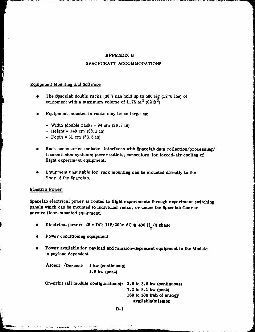
APPENDIX B
SPACECRAFT ACCOMMODATIONS
Equipment Mounting and Software
• The SDacelab double racks (38") can hold up to 580 K_ (1276 lbs) ofequipment with a maximum volume of 1,75 m 3 (62 ft °)
• Equipment mounted in racks may be as large as:
- Width (double rack) = 94 cm (36.7 in)- Height = 149 cm (58.1 in)
- Depth = 61 cm (23.8 in)
• Rack accessories include: interfaces with Spacelab data collection/processing/
transmission systems; power outlets; connectors for forced-sir cooling offlight experiment equipment.
• Equipment unsuitable for rack mounting can be mounted directly to thefloor of the Spacelab.
Electric Power
Spacelab electrical power is routed to flight experiments through experiment switching
i panels which can be mounted to individual racks, or under the Spscelab floor toservice floor-mounted equipment.
L
I '• Electrical power: 28 v DC; 115/200v AC @ 400 Hz/3 phase
• Power conditioning equipmentb
• Power available for payload and mission-dependent equipment in the Moduleis payload dependent
Ascent /Descent: 1 kw (continuous)1.skw (peak)
On-orbit(allmudule configurations):_.6 to 3.5 kw {continuous)
7.2 to 8.1 kw (peak)160 to 300 kwh of em_
available/mission
13-I
1980009811-248
Thermal Control
The Spacelab Thermal Control 8ubsys*_.m (TCS) L:onsists of four thermal controlloops:
• The mdoule cabin air loop provides conditioned air, within established
j comfort criteria, for '.he crew within the module
• The module avion/cs loop provide_ forced-air cooling for equipmentmounted in racks.
• The freon loop supplies cooling to cold plates mounted on any pallets
that might be carried on the flight
• The module water loop exchanges heat with the three loops already
discussed and, in turn,transfers Spacelab heat into the Orbiter coolantloop. The water loop also provides c(.ld plate cooling for Spacelabsubsystems, and can a(.commodate an Experiment Heat Exchanger andone Experiment Cold Plate.
The TCS transfer 8.5 kw, maximum, continuously to the Orbiter. It can alsoaccommodate peak heat loads of up to 12.4 kw for 15 minutes every 3 hours.However, for Spacelab co_igurations incorporating a Module, part of the water
loop heat rejection capability is u_d to cool Module subsystems. The remainingcapability may be used by experiments and other mission dependent equipment.The water loop heat rc.tection available to such equipment is 3.7 to 5.2 kw,
continuous; and _ .6 to 9.0 kw peak. This range of values covers all possibleSpacelab Module configurations. Within these limits, the remaining thermalcontrol loops have their ind/vidual capacities to provide experiment cooling.These are:
• Cabin alr.4oop - 0.4 to 1.6 kw, continuous; 2.4 to 3.6 kw, peak
• Avionics loop - 3.3 kw, continuous; 8.7 kw, peak.
• Freo n loop - 8.0 kw, continuous_ 11.9 kw, peak (Nc_e: In pallet-only coufigurations, the {reon loop exchanges he_tdirectly with the Orbiter loop. In this case theSpacelab total heat rejection capability is 7.0 kw,
continuous and 10.9 kw, peak).
B-2
1980009811-249
The Experiment Heat Exchanger can be mounted only in experiment double rack
number 4 in the Spacelab Core segment. Its nominal heat transfer capability
is 4kw. However, its actual performance depends on where it is connected into the
water loop on the other loads along the water loop.
The Experiment Cold Plate must also be mounted in rack 4. When both the
Heat Exchanger and the Cold Plate are flown, they must be connected in series
and must share the same connection into the water loop. The cold plate is
500 mm × 390 mm × 4.4 mm and has a 70 x 70 mm hole pattern. When filler is
used to improve the contact between the experim_.nt and plate, the conductance
will be 0.07 watts per cm 2 per "C. Without filler the conductance is approximately
1.0 watt per °C per bolt area
Di gital Data
The Spacelab Modules's data management system enables the collection, processing,
recording, on-board display, and transmission of low-rate digital data (including
digitized analog) received from the flight experiments at 1 Mb/sec or less.Experiment produced data with rates between 1 Mb/sec and 16 Mb/sec can bestored and/or transmitted to the ground, but these data cannot be processed or
displayed on-board the spacecraft.
Depending on the needs of the experiment, low-rate digital data can be:
• Processed and analyzed on-board the spacecraft using experiment sup'pliedsoftware
• Formatted and displayed for review and analysis by the Payload Specialistson-board the spacecraft.
• Annotated with voice recordings and/or time marks.
• Recorded on data tapes or transmitted to the ground.
High-ratedigitaldatacan be recordedon tapesor trm_smittedtotheground.
Additionalinformationaboutlow-ratedataand high-ratedatafollows:
Low rate (,_ 1 Mb/sec)
• Remote Acquisition Units (RAU's) receive experiment data and deliver
them to the Spacelab data management sy stem for computer processing
display, storage and/or transmission to the grand. RAU's may be mountedin equipment racks, under the Spacelab floor, and inside an Atrlock.
B-3
1980009811-250
• RAU's provide an 8 bit resolution, anniog-to-digital conversioncapability, and can accept serial digital data.
• The RAU data acquisition function is under experiment-supplied softwarerontrol
• Signal conditioning equipment will be available, as required, to interfaceexperiment hardware with the RAU
• A data processing computer (Mitra 125 S, 64K core, 16 bitwords,
3.5 x 10⁵ opcrations/sec) which cm_ anMyzc experiment data onboardthe spacecraft, format data for on-board display, paid foxanat data fortransmission to the ground will bc on-board.
• A mass memory unit for storage of software will be on-board
• A data display unit and keyboard which penuit on-board review of
experiment data will be available on-board.
• Data may bc stored on tape or transmitted to the ground at up to64 Kb/sec.
High rate (62.5 Kb/sec to 16 Mb/sec)
• On-board data recording and transmission to the ground will be
provided.
• Experfment data can be automatically annotated with time references,
and digitized voice signals via the high data rate system.
Voice Data and Communications
The spacecraft provides voic_ recording, voice communications between thespacecraft and the ground, and an intercom system within the spacecraft.
Analog Data
Investigations which produce analog data will have two basic options. If feasiblethe analog data should be digitized, to take full advm_tage of the Spacelab Modulets
extensive digital data recording processing, and transmission capabilities.
Analog data, that cannot be digitized, may be recorded on-board and/or
transmitted to the ground. Planned capabilities include:
B-4
1980009811-251
[
} • Analog to digital conversion. Data may be stored, transmitted to _eground, or processed m_d displayed on-board the spacecraft. Conversionrates are programmable at 1,10, and 100 smnples/scc.
• Analog-down-limk transmission for up to 85% of the mission. Data may
be real-time or tape records (3 HZ to 4.2 Mh,_).
Video Data
IAn Orbiter-to-Spacelab interface has been provided that would enable the collection
monitoring and recording of black-and-white and color video signals. Also, black-m_d-white video data could be transmitted to the ground, one channel at a time,
through this interface. Spacelab video capabilities currently under considerationinclude:
• Black-and-whitevideocameras
• Black-and-whitevideomonitor
• Black-and-whitevideotaperecorder plustapes
• Camera Control - Provides automatic and manual camera/recorder/
monitor switching and tags video records with time and experimentidentification.
• Camera Timer - Provides automatic time-controlled activation/
deactivation of cameras and recorders.
• Accessories- Mounting brackets, lens assortments, cabling, andremote controls.
• Color video camera
• Color video montior
• Color v_deo tape recorders plus tapes
B-5
1980009811-252
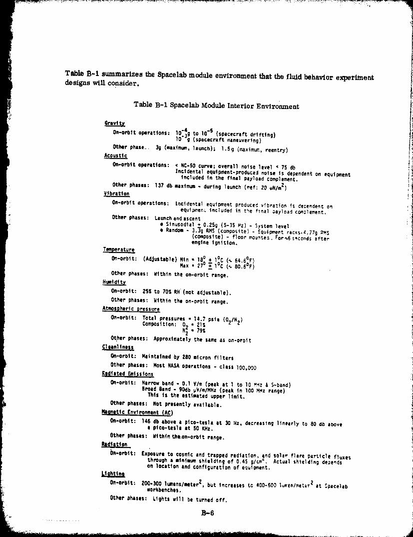
Table B-1 summarizes the Spacelab module environment that the fluid behavior experime.tdesigns will consider.
Table B-1 Spacelab _odule Interior Environment
On-orbtt ol_rattons: lO'_g to 10"s (spacecraft dr|fttng)
lO"g (spacecraft maneuvering) !iOther phase. 3g (maximum. launch); |.Sg (_dximurn, reentry) !!<Acoustt_
on-orbtt operations: < NC-SO curve; overall notse level • 7S db i_
Incidental equipment-produced no|se is dependent on equipment _included tn the ftnal payload complement. _,
Other phases: 137 db ,ulxtmum- durtn9 |aunch (ref: 20 uN/m2) _'_Vibration t_;
I On-orb|t o_rattons: Inctdenta_ equiDment produce_ vibration is _e_e.dent on iiequl_ren_ included in _e final _ayload complement. _ !
Other phases: Launchand ascent ! i
i! • S,nuSod,.1. 0._Sg (5-35 Mz)- S,stem level ii
• Random- 3.3"_ RMS(composite) - EQu|_ent r_c_s.c.77g _MS(cow,site) - floor mounte_. For_econds afterengtne _gnttton.
Tmperature
On-orbit: (Adjustable) Xtnxax_ _7°ls° ;+ 1°C1°c (_(_ 80.6"r)64"s_r}
Other phases: Wtthtn the on-orbit range.
On-orbit: 25_ tO 70%RH (not adjustab|e).
Other phases: gtthin the on-orbit range.
Atmospheric pressure
On-orbit: Tota_ pressures • _.7 psta (02IN _)Composition: 02 • 21_
Nz - 79%Other phases: Approxlmatel_ the sameas on-orate
Cleanliness
On-orbit: Maintained by 280 micron f|lters
t Other phases: MOStNASAopera,tons - claSS 100,000
!_ Rad_a_ad. E_tsstons
on-orbit: Narrow band - O.1 V/m (peak a_ 1 to 10 _Hz & S-band) •_Broad Band = 90db wV/m/NHz (peak tn 100 MHz range)
I Th|I iS the estimated upper limit. I
Other _hases: hot presently available._gnettc _nvtron_nt _AC)
On-orbit: 146 db above a pl¢o-tesla at 30 az, decreasing l_neerly to 80 db above ia pt¢o-tesle at 50 KHz.
Other phases: Within the.on-orbit range.
I_l_tat_on
bn-orblt: Exposure to cosmic and trapped radta¢ton, _nd solar flare particle fluxesthrough a mtn|mumshielding of 0.45 g/cm . Actual sHeldtng dependson locatton and configuration of equf_ent.
On-orbit: 200-300 |umens/meter2, but increases to 400-600 l,[enl_e_er 2 at _acelab i! workbenches.
Other phases: Lights wtl| be turned off.
]3-6
1980009811-253
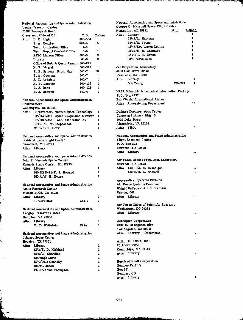
National Aeronautics andSpace Administration National Aeronautics and Space Administrai_onLewis Research Center George C. Marshall Space Flight Center
21000 Brookpark Road Huntsville, AL 35812 M.S__•
Cleveland, Ohio 44135 M.S___... Copies Attn: Library 1Attn: L.E. Light 500-306 1 _P43/L. Hastings 1
E. A. Bourke 501-5 5 EP43/G. Young 1Tech. UtilizationOffice 7-3 I EP45/Dr. Wayne Littles 1
Tech. Report Control Office 5-5 i EP24/K. B. Chandler 1AFSC LiaisonOffice 501-3 2 ES24/E. W. Urban 1
Library 60-3 2 EP43/Eric Hyde 1Officeof Rel. & Qua/. Assur. 500-211 I
N. T. Musial 500-318 1 Jet Propulsion Laboratory
E. P. Symons, Proj. Mgr. 501-7 20 4800 Oak Grove DriveT. H. Cochran 501=7 1 Pasadena, CA 91103
J. C. Aydelott 501-7 I Attn- Library 1
R. F. Lacovic 500-109 1 Don Young 125-224 I
_i L.J. Ross 500-113 1E. J. Domino 501-4 i NASA ScientLflc& TechnicalInformationFacility
P.O. Box 9757National Aeronautics and Space Administration Bait/Wash. International AirportHeadquarters Attn. Aceessioning Department 10
Washington, DC 20546Attn: RS/Director, Manned Space Technology 1 Defense Documentation Center
RP/Director, Space Propulsion & Power I Cameron Station - Bldg. 5I BT/Dtrector, Tech. Utilization Div. 1 5010 Duke Street
[_- RTP-6/F. W. Stephenson I Alexandria, VA 22314f_ MHE/P. N. Herr I Attn: TISIA i
i NationalAeronautics and Space Administration NationalAeronautics and Space AdministrationGoddard Space FlightCenter FlightResearch Center
Greenbelt, MD 20771 P.O. Box 273Attn: Library 1 Edwards, CA 93523
Attn: Library i
National Aeronautics and Space Administration
John F. Kennedy Space Center Air Force Rocket Propulsion Laboratory
Kennedy Space Center, FL 32899 Edwards, CA 93523
Attn: _Library I Attn: LKCC/J. E. Brannigan 1DD-MED-41/F. S. Howard I LKDS/R. L. W1swell 1
DE-A/W. H. BogEs 1Aeronautical Systems Division
National Aeronautics and Space Administration Air Force Systems CommandAmes Research Center Wright Patterson Air Force Base
Moffett Field, CA 94035 Dayton, OH
Attn: Library I Ate: Library iJ. Vorreiter 244-7 I
Air Force Office of Scientific Research
National Aeronautics and Space Administration Washington, DC 20333
I Langley Research Center Attnz Library 1
• Hampton, VA 23365Attn: Library 1 Aerospace Corporation
C. T. D'Aiutolo 249A 1 2400 E. E1 Segundo Blvd.LOS Angeles, CA 90045
t National Aeronautics and Space Administration Attez Library - Documents 1p Johnson Space Center_ Housten, TX 77001 Arthur D. Little, Inc.
Attns Library I 20 Acorn ParkEP2/Z. D. Kiridand 1 Cambridge, MA 02140
EPS/W. Chandler i Atmx Library 1ER/Hu_h Davis iEP4/Dale ConneUy 1 Beech Aircraft CorporationER/M. Jones 1 Boulder Facility
PD13/Jarnes Thompson I Box 631Boulder, COAt_nz Library 1
1980009811-254

1
)BeLl Aerosyatems, Inc. Space DivisionBox I RockweLl InternaCtonal Corpora_ton
Buffalo, NY 14240 M.S__, Copies 12214 Lakewood Blvd.Attn: Library 1 Downey, CA 90241 M.S____. Co_ies
L. Thompson I Attn: Library 1J. Nichols 1
Boeing Company A. Jones 1
Space DivisionP.O. Box 868 Northrop Research and Technology CenterSeattle, WA 98124 1 Research ParkAttn: Library 1 Palos Verdes Peninsula., CA 90274
Attar Library IChrysler Corporation
Space Division TRW Systems, Inc.P. 0. Box 29200 1 Space ParkNew Orleans, LA 70129 Redondo Beach, CA 90278Attn: Library 1 Attn: Tech. Lib. Doc. Acquisitions 1
McDonneLl Douglas Astronautics Co. National Science Foundation, Engr. Div.5301 Balsa Avenue 1800 G. Street, NW
Huntington Beach, CA 92647 Washington, DC 20540Attn. Library 1 Atm: Library 1
E. C. Cady 1
Florida Institute of TechnologyGeneral Dynamics Convair DSvision ME Department
P.O. Box 80847 Melbourne, FL 32901San Diego, CA 92138 Attn: Dr. T. E. Bowman IAttn: Library 40-6640 1 m
R. D. Bradshaw 22-6960 1 RCA/AEDP.O. Box 800
Missiles and Space Systems Center Princeton, NJ 08540General Electric Company Attn: Mr. Daniel Balzer I "_
Valley ForKe Space Technology Center 1P.O. Box 8555 Southwest Research Institute _
Pht|adelphia, PA 19101 Dept. of Mechanical SciencesAttn. Library 1 P.O. Drawer 28510
San Antonio, TX 78284Grumman Aircraft Engineering Corporation Attn: H. Norman Abramson 1
Bethpage, Long Island, NY Franklin Dodge IAttn. Library 1
Tufts University
IrT Research Institute Mechanical Engineering Dept.Technology Center Medord, MA 02156
Chicago, IL 60816 Attn: Dr. Lloyd Trefethen 1Attn: Library I
McDonnell Douglas Astronautics CO. - EastLockheed Missiles and Space Comply P.O. Box 516
P.O. BoX 504 St. Louis, MO 63166Sun_vale, CA 94087 Attn: G. Orion 1
Atem Library 1 W. Regnier iG. D. Bizzell 1
S. O. DeBrock i Xerox Electro Optical Systems300 North Halstead
Linde, Div, of Union Carbide Pasadena, CA 91107P.O. Box 44 Attnz Robert Richter 1Tonawanda, NY 11450
Ate: G. Nles 1 Science Applications, Inc,1200 Prospect Street
Denver Division P.O. Box 2381
Martin-Marietta Corporation La JoLla, CA 92037 1P.O. Box 179
Denver, CO 80201 Heat Transfer • Thermod_namic Lab.
Attn: Library I University of Michigan
D. Fester I Ann Arbor, MI 4810_J. Tegart 1 ARm Dr. John A Clark 1A. Villars l
_- C-2
1980009811-255
Heat Transfer and Thermodynamic Lab.University of Michigan
Ann Arbor, MI 48107 M.S__2. CopiesAttn. Dr. John A. Clark 1
Dr. Edward B. Igenbergs8000 Muchen 80Rauchstrasse 3
Germany 1
Office National D'Etudes Et De
Recherches Aerospatiales29, Avenue de la Division LeClerc92 Chatillon
FrancePar Jean Maulard 1
Michel Delattre
16827 Oak View Dr.
Encino, CA 91436
Attn: Dr. Marvin Adelberg 1
Boeing AerospaceP.O. Box 3999
Seattle, QA 98124Attn. C.L. Wilkensen 8K/31 1l
i C-3
Related Documents