NASA TECI-:NICAL April 1,J_4 MEMORANDUM # NASA TMX-04810_ "A_i--[_l__ _, _.4.. _ _ l_ . '181 "" , "w ,,t_-- _-,__. _ ...___,__., .'_," • .... =7_---_._-_.. _ ___-__ "qr_-IL-'l_ill,,l_.-[ ,' i ".'_-.._ __' I '"_P _,._1_II_,.,-" - - --_f ", _-'_-"' .-- _-wr.,d/_'_..- _" " -_. ' ; "_ " _, ,' . J'l irl '" /L _ ,_ "*'_'_"_I_'-_W .-- MSFC SKYLAB AIRLOCK MODULE : Vol. I ( _ Skylab Program Office !, t i NASA , GeorgeC. Narsha]/S/)ace Flight Center ._ Narsha/,! Space Flight Center, Alabama " (N ASA-TM-X-6_8 I0-¥oi- 1) MSFC 5KYLAB N7_-26321 AIFLOCK HODULE, VOLUHE 1 Final Report (RASA) 631 P HC $11.00 CSCL 22B gnclas : G3/31 110151 _J MSFC - Form JlgO (Rev June 19711 I

Welcome message from author
This document is posted to help you gain knowledge. Please leave a comment to let me know what you think about it! Share it to your friends and learn new things together.
Transcript
NASA TECI-:NICAL April 1,J_4
MEMORANDUM#
NASATMX-04810_ "A_i--[_l__ _,
_.4.._ _ l_ . '181 " " , "w
,,t_--_-,__._ ...___,__., .'_,"• .... =7_---_._-_.. _ ___-__
"qr_-IL-'l_ill,,l_.-[ , ' i ".'_-.._ _ _' I '"_P_,._1_II_,.,-" - ---_f",_-'_-"' .--
_-wr.,d/_'_..-_" " -_. ' ; " _" _,,' . J'l irl'" /L
_ ,_"*'_'_"_I_'-_W .--
MSFC SKYLABAIRLOCKMODULE: Vol. I(
_ Skylab Program Office!,t
i NASA
, GeorgeC. Narsha]/S/)ace Flight Center
._ Narsha/,! Space Flight Center, Alabama" (NAS A-TM-X-6_8 I0-¥oi- 1) MSFC 5KYLAB N7_-26321
AIFLOCK HODULE, VOLUHE 1 Final Report
(RASA) 631 P HC $11.00 CSCL 22Bgnclas
: G3/31 110151
_J MSFC - Form JlgO (Rev June 19711 I
1974018208
,,, TECHNICAL REPORT STANDARD T|TLE[ PAGE
'1 NIEPONT NO. I z GOVERN.NT ACCESSION NO. J 3.' RECIPIIrNT'S CATALOG NO.
! IIq_qA TMX-64810 ,,i. TITLE AkO SUITITLE i _ =[:_O_*T _,ATt"
Apml I q7dMSFC Skylab A:rlock Module 16 P[_O_Mlm, OmGANIZATIONCOOZ
_ V,,i. I [
7. AUTHOIqIS) I 8, PERPONMING 0_GANIZATION Iq[p(_r II
9. PERIrONMING OiqGANIZATION NAME AN0 ADDRESS tt_. Wt_K UNIT NO.
George C. Marshall Space Flight Center
Marshall Space Fhght Center, AL 35812 I CONr,*X',OP.an'NrNO.
|1. TYPE 0 Ir IPi[PON', _ PEAlOO COVERED
12. $1i0NSOAING AGENCY NAkCl AND #.ODRI[SS
FLn,,I Rel)ort
National k,-,ronautics and Space Admir, istratlon Technical MemorandumWashm_',on, b. C. 20546 ,4 S_ONSOM,._A=t.CV¢0OC
IS. SUPPLEMENTARY NOTES
Lirlock/M ultiple D_ck,ng Adapter Project Office
16, A! STIIACT
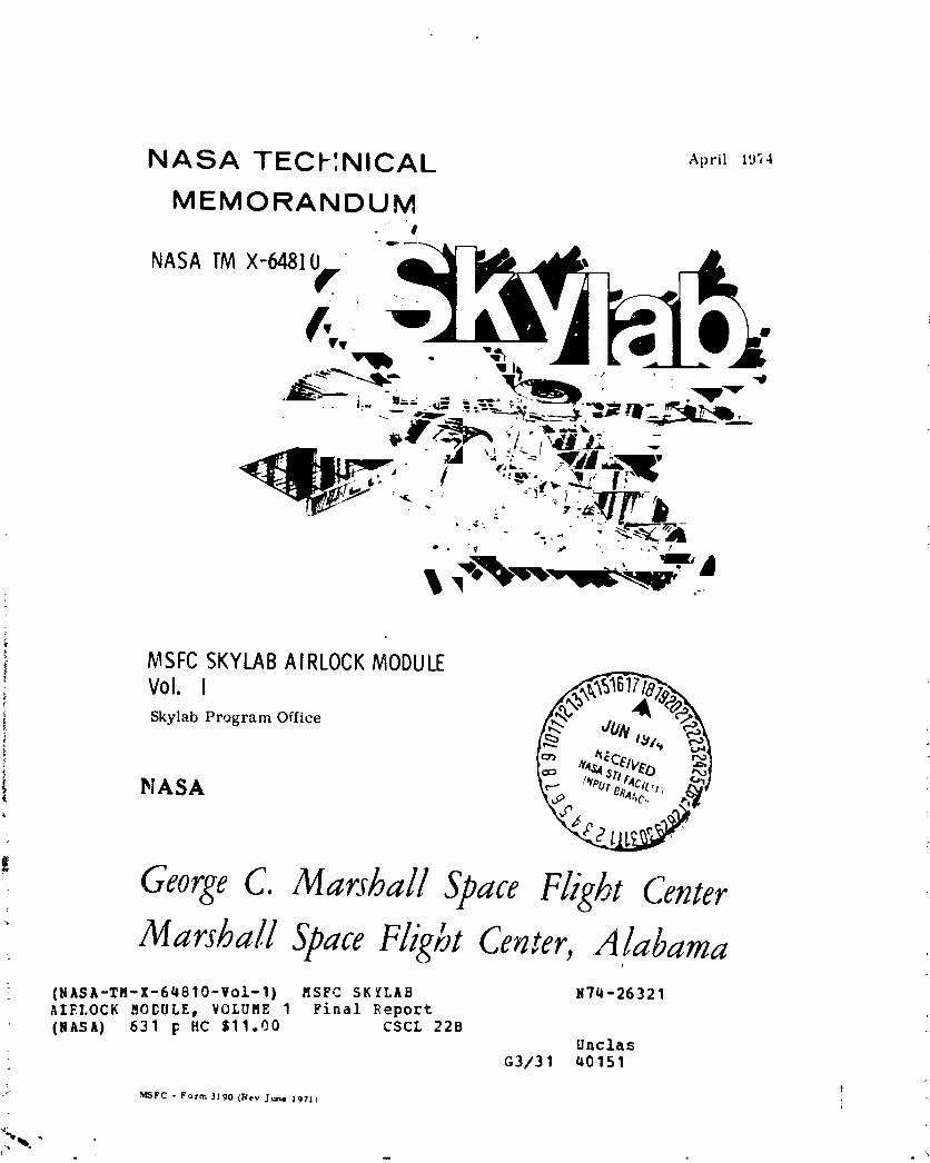
This report presents the history and development of the Skylab Airlock Moduleand the Payload Shroud, NASA Contract No. NAS9-6555, from initial conceptthrough final design, related test programs, mission performance and lessonslearned.
Althouqh so,c.e problems were encountered, the Alrlock Module performed
successfully throughout the three manned Skylab missions.
NOTE: Volume I - Sections 1.0 through 2.95.
Vo_um,, Ii - Sections 2.10 through 8.0.
ILI 17[ KEY WOIlOS 18. DISTAIIIUTION STATEMENT
Ur_lassified-unli mite(t
j. CoolPr_ct Manager,Alrlock,/lVlultiple Docking Adapter
J
U ncla s s : fled U ncla s st fled 629 NTIS :
_llrC • Yore ! I i t"_Rrv Dec*m_, | | I ! ) "' Fo( ,hi, by National Technical Infornt,tton S, rvt¢,. Sprmlfleld. Virllnll III $1
1974018208-002
• i
%,
1974018208-003
AIRLOCK MODULE FINAL TECHNICAL REPORT MDC E0899 • VOLUME I!
TABLE OF CONTENTS
VOLUME I
SECTION I INTRODUCTION l-I
l.l PURPOSE AND SCOPE l-I
1.2 SU_C_ARY I-2
1.2.1 Airlock Features l-2
l.?.2 Airlock Module Weight and Dimensions I-9
lo2.3 FAS Weight and Dimensions I-9
1.2.4 DA Weight and Dimensions l-lO
1.2.5 Payload Shroud (PS) l-lO
1.2.6 Environmental/ThermalControl Systems (ECS/TCS) l-ll
1.2.7 Electrical Power Syste_ (EPS) 1-12
1.2.8 Sequential System l- 2
1.2.9 InstrumentationSystem 1-12
l 2.10 CommunicationsSystem 1-13
l 2.1l Caution and Warning System (C&W) 1-14
l 2.12 Crew Systems ]-15 :-
l 2.13 Trainers 1-16
l 2.14 Experiments ]-16
l 2.15 Ground Support Equipment (GSE) 1-17 :
l 2.16 Roliability and Safety 1-17
l 2.17 Testing 1-18
l 2,18 Mission Operations Support 1-19
1.2.19 New Technology 1-20
1.2.20 Conclusions 1-21
SECTION 2 SYSTEM DESIGN AND PERFORMANCE 2.l-I
2.l GENERAL 2.l-l
2.1.l Program Inception 2.1-I
2.1.2 SSESM 2.l-I
2.1.3 Wet Wcrkshop Evolution 2.1-3
2.1.4 Wet Workshop Configuration 2.1-6
2.1.5 Dry Workshop Configuration 2.1-6
2 2 STRUCIURES AND MECHANICAL SYSTEMS 2.2-I
2.2.1 Design Requirements 2.2-I
2.2.2 Systems Description 2.2-4
iv
PRBC.,EDING PAGE BLANK NOT FILMI'I'I'I_
1974018208-004
AIRLOCK MODULE FINAL TECHNICAL REPORT MDCEOe. • VOLUM_- II
TAL_LEOF CONTENTSVOLU_ I CONTINUED
.'.2.3 by"ternVerltIcation 2.2-22
J.2.4 Mission Res,Jlts 2.2-30
2.2.') O,rtclusionsand RecGm,w_ndations 2.2-31
) 3 _A'c PROPERTIES 2.3-1
2 3.l A1rlock Wei:sht,MonitoringPlan 2.3-1
3.2 Actadl _le],iht Program 2.3-I
3.1 Lajnch Weight 2.3-6
? 4 THERMAL CONTROL SYSTEM 2.4-I
/ 4.1 Design Require_nts 2.4-I
2 4.2 IntegrateOTl_ermalAnalysis 2.4-5
2.4.3 System Description 2.4-13
2 4." ;esting 2.4-60
? 4.5 Mission Performance 2.4-98
2 4.6 Development Problems 2.4-121
2 4.7 Conclusions and Recommendatlons 2.4-123
2 5 ENVIRONMENTALCONTROL SYSTEM 2.5-1
2 5.1 Design Requirements 2.5-1
2 5.2 System Description 2.5-9
? 5.3 Testing 2.5-56
2 5.4 Mission Results 2.5-88
2 5.5 Development Problems 2.5-119
2 5.6 Conclusions and Recommeadat'ions 2.5-122
2 6 EVA/IVA SUIT SYSTEM 2.6-1
2 6.; Design RequiremePts 2.6-1
r . ..... ipt_.,,._ oy_t.v Descr ion 2.6-4
2.6.3 Testing 2.6-2_
2.6.4 Mission Performance 2.6-46
:' 2.6.5 Development Problems 2.6-52@
2.6.6 Conclusions and Recor,_endations 2.6-54
2.7 ELECTRICAL POWER SYSTEM 2 7-1
2.7.1 Design Requirements 2 7-I
_ 2.7.2 System Description 2.7-3
: | 2.7.3 Testing 2.7-44
! 2.7.4 Mission Resu]ts 2 7-84
2.7.5 Conclusions and Recommendations 2.7-143
! vt_
1974018208-005
AIRLOCK MODULE FINAL TECHNICAL REPORT MDC E0899 • VOLUME II
TABLE OF CONTENTS VOLUME I AND II3
Z.8 SEQUENTIAL SYSTEM z.8-I '
2.8.1 Pay]oad Shroud Jettison Subsystem 2.8-5
2.8.2 ATM Deployment Subsystem 2.8-19
2.8.3 Discone Antenna Deployment Subsystem 2.8-28
2.8.4 Power Control Subsystem 2.8-32
2.8.5 Radiator Shield Jettison/RefrigerationSubsystemActivation 2.8-36
2.8.6 OWS Venting Subsystem 2.8-40
2.8.7 OWS Meteoroid _hield Deployment Subsystem 2.8-47 :
2.8.8 OWS SAS Deployment Subsystem 2.8-49
2.R.9 ATM SAS Deployment/CanisterRelease Subsystem 2.8-53
2.8.10 ATM Activation Subsystem 2.8-37
2.8.11 MDA Venting Subsystem 2.8-60
2.9 INSTRUMENTATIONSYSTEM 2.9-1
2.9.1 Design Requirements 2.9-I
2.9.2 System Description 2.9-3
2.9.3 Testing 2.9-26
2.9.4 Mission Results 2.9-35
2.9.5 Conclusions and Recommendations 2.g-41
VOLUME II
2.10 COMMUNICATIONS SYSTEM 2.10-1
2.lO.l Audio Subsystem 2.10-6
2.10.2 Data Transmission and Antenna Subsystem 2.10-23
2.10.3 Digital Command Teleprinter and Time ReferenceSubsystem 2.10-4l
2.10.4 Rendezvous and Docking Subsystem 2.10-67
2.11 CAUTION AND WARNING SYSTEM 2.11-I
2.11.1 Design Requirements 2.11-2
2.11.2 System Description 2.11-3
2.11.3 Testing 2.11-15
2.11.4 Mission Results 2.]1-21
2.11.5 Conclusions and Recommendations 2.11-24
2.12 CREW STATION AND STOWAGE 2.12oi
2.12.1 Internal Arrangement and In-Flight MaintenanceProvisions 2.12-I
2.12.2 Controls and Displays 2.12-11
vi
#
1974018208-006
AIRLOCK MODULE FINAL TECHNICAL REPORT MDC E0899 • VOLUMEII
TA::LL ,JF CONTENTS VOLUME II CONTINUED
2.i_._' VlSlbli_)' 2.12-20
2.12.4 L_tra Venlcular Activity 2.12-23
2.12.5 Lighting 2.12-33
2.i2.6 Stowage 2.12-49
2.13 CREW TRAINERS 2.13-I
2.13.1 ;_ASATrainer 2.13-I
i 2._3.2 Zero-G Trainer 2.13-13
I 2.1_.3 Neutra; _uoyancy Trainer 2.13-16I; . _3.4 SKylab Systems Integration Equipment 2.13-27
3.]a EXP[RIMENTS 2.14-1>
2 14.1 M509 Nitrogen Recharge Station 2.14-I
2 14.2 $193 Experiment 2.14-5
2 14.] b02_ Experiment 2.14-7
2 14.4 $230 Experiment 2.14-9
2 14.5 Radio Nolse Burst Monitor 2.14-11
2 14.6 Conclusions and Recommendations 2.14-i2
2.15 GROUND SUPPORT EQUIPMENT 2.15-I
2.15.1 GSE Categories and Classifications 2.15-4
3.15.2 GSE Development and Design Requirements 2.15-5
2.15.3 GSE Design Description 2.15-II
3.15.4 GSE Certification 2.15-48
2.15.5 Conclusions and Recommendations 2.15-52
2.16 SYSTEMS SUPPORT ACTIVITIES 2.!b-I
2.16.I ElectromagneticCompatibility Requirements 2.16-I
2.16.2 Sneak Circuit Analysis 2.16-9
2.16.3 Maintenance Technology Support 2.16-12
2.16.4 Program Spares Support 2.16-16
SECTION 3 RFLIABILITY PROGRAM 3-1
3.1 METHODOLOGY 3-I
3.2 DESIGN EVALUATIOP_ 3-2
3.3 SUPPLIER EVALUATIOd 3-II
3.4 TEST REVIEW 3-11
3.5 NONCONFORMANCE REPORTING, ANALYSIS, ANDCORRECTIVE ACTION CONTROL 3-13
I 3.6 ALERT INVESTIGATIONS 3-17
Ti vii
1974018208-007
AIRLOCK MODULE FINAL TECHNICAL REPORT uDc E0899 • VOLUME II
TABLE OF CONTENTS V_OLUMEII CCNTINUED
).I MISSION RFLIABILITY 3-19
3.8 CONCLUSIONS AND RECOMMENDATIONS 3-19
SECTION 4 SAFETY PROGRAM 4-!
4.] GROUND PEESONNEL AND CREW SAFETY 4-I
4.2 INDUSTRIA,.SAFETY 4-9
4.3 CONCLUSIONS AND RECOMMENDAT!ONS 4-11
SECTION 5 TEST PHILOSOPHY 5-I
5.1 IEST REQUIREMENTS 5-I
5.2 VERIFICATION TEST PHILOSOPHY 5-6
5.3 U-I VERIFICATION TESTING 5-22
5.4 U-2 VERIFICATION TESTING 5-36
5.5 MISSION SUPPORT TESTING 5-38
5.6 CONCLUSIONS 5-39
SECTION 6 ENGINEERING PROJECT MANAGEMENT 6-I
6.1 PLANNING AND SCHEDULING 6-3
6.2 ENGI,,EERINGREVIEWS 6-9 -
6.3 PROJECT REVIEWS 6-15
6.4 ENGINEERING REPORTS 6-20
6.5 INTERFACE COORDINATION 6-23
6.6 CONFIGURATION MANAGEMENT 6-31
SECTION 7 MISSION OPERATIONS SUPPORT 7-I
7.1 MISSION OPERATIONS PLAN 7-2
7.2 MISSION SUPPORT ORGANIZATION 7-3
7.3 MISSION SUPPORT FACILITIES 7-6
7.4 MISSION SUPPORT ACTIVITY 7-29
7.5 CONCLUSIONS AND RECOMMENDATIONS 7-43
SECTION 8 NE_JTECHNOLOGY 8-IL
J
(; viii
'4
] 974018208-008
AIRLOCK MODULE FINAL TECHNICAL REPORT MUC E0899 • VOLUME II
TABLE OF CONTENTS VOLUME II CONTINUED
SELTIO'd_ CONCLUSIONS 9-I
9.] AIRLOCK MISSION PERFORMANCE 9-I
9.2 AIRLOCK END-OF-MISSION SYSTEMS STATUS 9-3
9.3 AIRLOCK PROGRAM "LESSONS LEARNEG" 9-4
APPL;IDIXA AIRLOCK COrlTROLAND DISPLAY PANELS A-l
APPENDIK 5 MATRIX OF TE3TING REQUIRED TO QUALIFY AIRLOCKEQUIPMENT B-I
APPL:_blAc: DEVELOPMENT AND QUALIFICATIOr_TEST REQUEST INDEX r l
APPErIDI<') :CS/TCS STU TEST REQUEST INDEX D-l
APPEr_OIXE MIT]ION DISCREPANCIES E-l
APPE;iDIXF END-OF-MISSIONSTATUS F-l
APPE=_DIXG ACRONYMS AND ABBREVIATIONS G-l
APPENDIX H REFERENCES H-I
APPENDIX I ABSORBTION CAPACITY OF ACTIVATED CHARCOAL I-l
* APPENDIX I FINAL TECHNICAL REPORT FOR THE PAYLOAD SHROUD I-]
,NOTE: The Final Technical Report for the Pay|oad Shroud is presented ini_OCReport G4679A.
t
¢
; T
(
ii ix
] 974018208-009
AIRLOCK MODULE FINAL TECHNICAL REPORT MDC E0899 • VOLUME II
LIST OF FIGURES
,I(,lJrlNO. TITLE PAGE
I-I Airlock Module Jeneral Arrangement 3-3
I-_ Airl_ck Components I-4
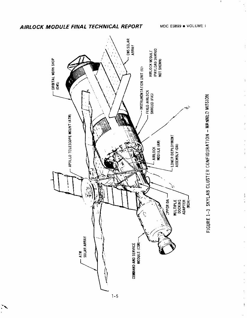
l-j Skylab Cluster Configuration - Manned Mi_sior 1-5
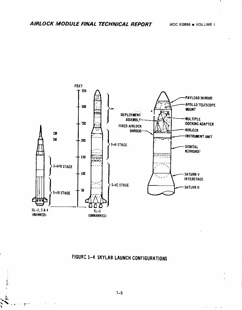
I-4 Skylab Launch Configurations 1-6
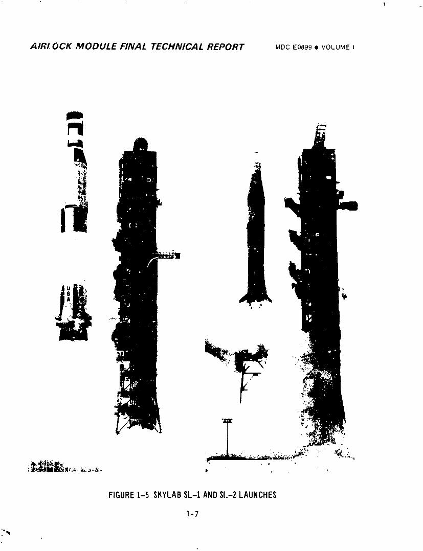
_-5 Skylab SL-I and SL-2 Launches 1-7
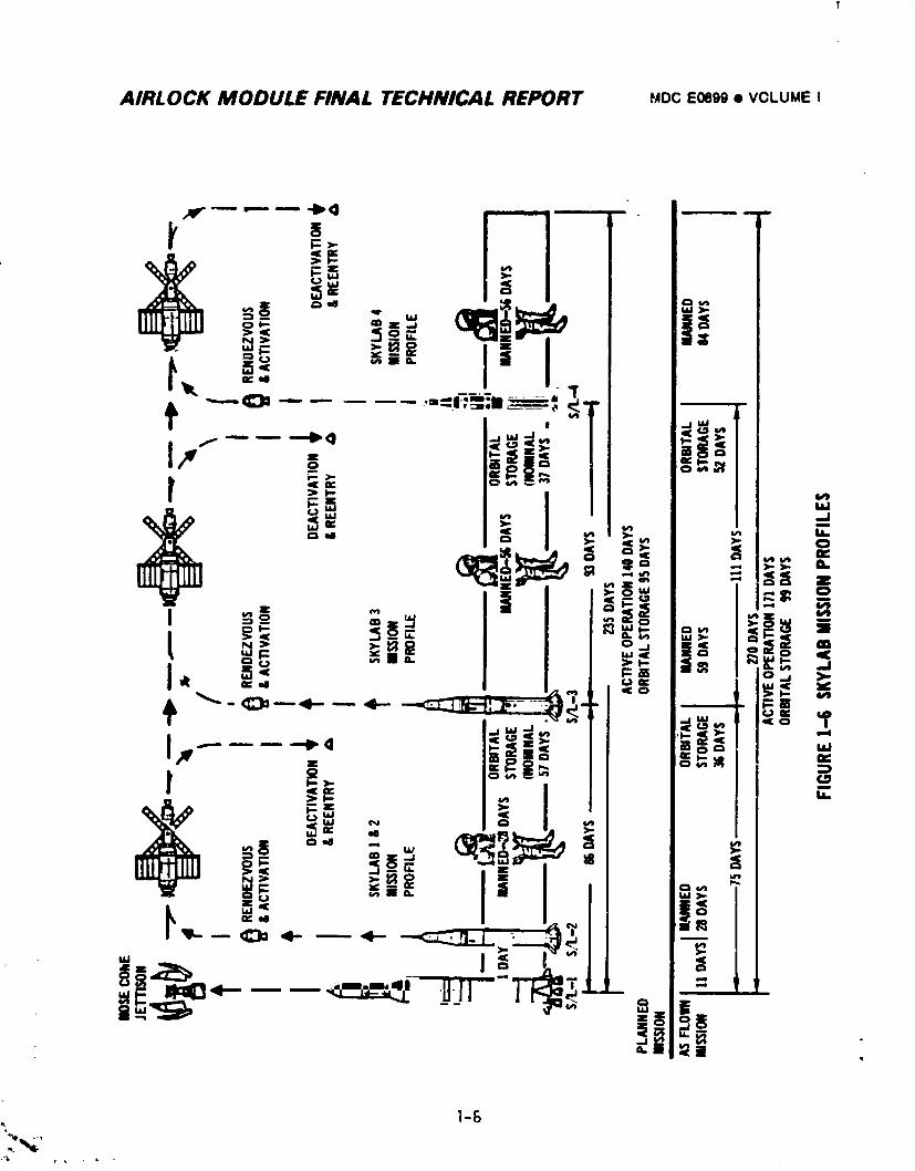
;-5 Skylad Mission Profiles I-8
2.1-I Spend Stage Experiment Support Module (SSESM) 2.1-2
2.1-2 wet Workshop Confiquration Evolution from Spent StageExperiment Support Module 2.1-4
2.1-3 Orbital Wet Workshop Configuration (Unmanned Launch) 2.1-5
2.1-4 _pollo Applications Program - Wet Worksnop Configuration 2.1-7
2.1-_ Airlock Module Arrangen_nt (AAP-2) 2.1-8
2.1-6 Workshop Mission Profile (AAP) 2.1-9
2.1-7 Airlock Weight Growth History 2.1-II
2.2-I Airlock Module 2.2-2
2.2-2 STS and Radiators 2.2-5 -
2.2-3 Tunnel Assembly 2.2-7
2.2-4 InternalHatch 2.2-8
2.2-_ EVA Hatch 2.2-I0
2.2-6 Flexible Tunnel Extension 2.?-II
2.2-7 Support Truss Assembly 2.2-12
2.2-8 Deployment Assembly 2.2-13
2.2-9 _TM Ri9idizing Mechanism 2.2-14
2.2-10 Deployment Assembly Rotation Mechanism 2.2-15
2.2-II Deployment System Release Mechanism 2.2-16
2.2-12 Deployment System Pyro System Schematic 2.2-17
2.2-13 Deployment System Trunnion Mechanism 2.2-18
2.2-'4 Deployment System Latching Mechanism 2.2-20
2.2-15 Fixed Airlock Shroud 2.2-21
2.2-]6 AM/MDA/DA Mechanical Systems Test Flow 2.?-25
2.2-17 AM, AM/MDA, and DA Stacking and Alignment 2.2-26
2.2-18 Fixed Airlock Shrnud Maximum Daily Temperature 2.2-32i
°.
X
] 974018208-010
AIRLOCK MODULE FINAL TECHNICAL REPORT MDC Eoe99 • VOLUME II
LIST OF FIGURES CONTINUED
FIGURENO. TITLE PAGE
2.3-I WPi,;nt Mon_.rlng Plan 2.3-2
2.!-2 AI, Iu,.K WelgnL History 2.3-3
2.3-3 WeIUhi_g _nJ Center of Gravity Determination Flow 2.3-4
2.3-4 Airlock Module Actual Weight and Balance Results versusCalLu!ated 2.3-5
: 2.3-.5 U-i _aunch Weight versus Maximum Speclfication Weight 2.3-6
2.4-I TF__,r:.;_]Contrc! Interface 2.4-2
2.4-? Thermal Design :;ata 2.4-6
2.4-3 FREPDesign Maneuvers 2.4-7
2._-4 Control Moment Gyros Desaturation Maneuvers 2.4-7
2.4-5 Kuhoutek Comet Viewing Design Maneuvers 2.4-8
2.4-6 Thermal Control System Design Requirenmnts 2.4-8
: 2.4-7 External Design Heat Load Conditions - Orbital 2.4-10
2.4-8 Internal Design Heat Loads 2.4-]I
2.4-9 AM Compartment Heat Loads 2.4-12
2.4-10 External Surface Temperature Profile During Launch andAscent 2.4-14
2.4-I] Coolant System 2.4-]6
2.4-12 ECS Control Panel 203 2.4-17
2.4-13 Coolant System Flow Performance 2.4-18
2.4-14 Typical Coolant Reservoir Characteristics 2.4-20
2.4-15 Co_dplaLe Mounted Equipment 2._-22
2.4-16 Coldplate Locations 2.a-24
2.4-17 Pad and VAB Ground Cooling System 2.4-25
2.4-18 Pre-Liftoff Cooling Requirements 2.4-27
2.4-]9 Ground Coo]ing Requirements for a Hold After Ferminationof Normal Ground Cooling 2.4-2 Q
2.4-20 Ground Cooling System Coolant Volume CompensatorCharacteristics Curves _.4-30
2.4-2! Radiator Capacity 2.4-31
2.4-22 Radiator Performance for EREPManeuvers (60 ° Arc Pass) 2.4-33
2.4-23 Radiator Performance for EREPManeuvers (120 ° Arc Pass) 2.4-34
2.4-24 Radiator Stretchout - Looking Outboard 2.4-35 :
2.4-25 Thermal Capacitor 2.4-36
2.4-26 Coolant System Performance 2.4-37 r
2.4-27 SL-4 Coolant Reservicing 2.4-39
1974018208-011
AIRLOCK MODULE FINAL TECHNICAL REPORT MDC E0899 • VOLUME II
LIST OF FIGURES CONTINUED
fiG'J_ NO. TITLE PAGE
2.4-28 Coolant Reservicing Pressure Characteristics 2.4-41
Z.4-29 Coolant Reservicing Mass Characteristics 2.4-42
2.4-30 ATM C&D Panel/EREP Cooling System 2.4-43
2.4-3] EREP Electrical Loads (60° Arc Pass) 2.4-44
2.4-32 EREP Electrical Loads (120_'Arc Pass) 2.4-44
2.4-33 Power Conditioning Group Waste Heat - Two Solar ArrayWings 2.4-47
2.4-34 Power CondiLioning Group Waste Heat - Solar Array Wing #1 2.4-48
2.4-35 Dredicted Battery Temperatures - Two Solar Array Wings 2.4-49
2.4-36 Predicted Battery Temperatures - Solar Array Wing #1 2.4-49
2.4-37 AM/MDA Thermal Coating Design Values 2.4-50
2.4-38 DA apd FAS Thermal Coating Design Values 2.4-51
2.4-39 Vehicle Thermal Insulation 2.4-53
2.4-40 Equipment Thermal insulation 2.4-55
2.4-41 Wall Heater Location/ThermostatInstallation 2.4-57
2.4-42 Molecular Sieve Overboard Exhaust Duct Heater 2.4-59
2.4-43 Thermal Control Subassembly Tests 2.4-65
2.4-44 Coolant System Test History - MDAC-E 2.4-67
2.4-45 ATM C&D Panel/EREP Cooling System Test History - MDAC-E 2.4-68
2.4-46 Coolant System Requirement Verification 2.4-74
2.4-47 Coolant System Pump/InverterFlow Tests - MDAC-E 2.4-76
2.4-48 Coolant System Pump/Inverter Flow Tests - KSC 2.4-77
2.4-43 ATM C&D Panel/EREP H20 Cooling System RequirementVerification 2.4-78
2.4-50 Thermal Control Coating Requirement Verification 2.4-79
2.4-51 AM U-] Radiator Solar Reflectance Test Results - KS£ 2.4-80
2.4-52 Thermal/MeteoroidCurtains Gold Coated Surface EmissivityMeasured at MDAC-E 2.4-81
2 4-53 Coolant F]owrate 2.4-I00
2 4-54 Coolant System Pump Inlet Pressures 2.4-I01
2 4-55 Coolant System Coo]anol Mass 2.4-I02
; _ 2 4-56 Coolant Loop Heat Loads 2.4-I05
; 2 4-57 Coolant Temperatures During Radiator Cooldown 2 4-I06
I 2 4-58 Thermal Capacitor Performance 2.4-I07
2 4-59 SL-2 Radiator/Thermal Capacitor Temperatures 2.4-108
2 4-60 SL-3 Radiator/ThermalCapacitor Temperatures 2.4-I08
i xii
1974018208-012
AIRLOCK MODULE FINAL TECHNICAL REPORT MDC E0899 • VOLUME ti
LIST OF FIGURES CONTINUED
FIGURENO. TITLE PAGE
2.4-61 SL-4 Radiator/Thermal Capacitor Temperatures 2.4-108
2.4-32 Radiator/_hermal Capacitor Temperatures During aKohoutek Viewing Maneuver 2.4-110
2.4-63 Radiator/Thermal C_pacitor Temperature During an EREPZ-LV Maneuver 2.4-110
2.4-64 Effect of SL-I Attitude on Airlock Module Temperature 2.4-115
2.4-65 STS Wall Temperature 2.4-116
2.4-66 STS Gas Temperature at Mole Sieve - Compressor Inlet 2.4-117
2.4-67 gAS Sk!_ Temperature Solar Inertial Attitude 2.'a-I18
2.4-68 02 Tank Temperature - Solar Inertial Attitude 2.4-113
2.4-69 N2 Tank Temperature - Solar Inertial Attitude 2.4-1202.5-I Airiock Environmental Control Interface 2.5-?
2.5-2 Gas System 2.5-10
2.5-3 Airlock Cluster Purge and Cooling Requirements 2.5-11
2.5-4 STS Window Assembly 2.5-13
2.5-5 Ozygen and Nitrogen Tanks 2.5-14
2.5-6 02/N 2 Control Panel 225 2._-162.5-7 Cabin Pressure Regulator Flowr_te Characteristics 2.5-21
2.5-8 Control and A]arm Ranges for Two Gas Control Systems 2.5-22
2.5-9 Forward Compartment Pressure Relief Valve 2.5-23
2.5-10 Atmospheric Control System 2.5-24
2.5-11 Dewpoint Temperature During Activation 2.5-25
2.5-12 Cluster Dewpoint Temperature Range After Activitation 2.5-26
2.5-13 ECS Control Panel 203 2.5-28
2.5-14 ,,_olecular Sieve Condensing Heat Exchanger Control Panels 2.5-29
2.5-15 Molecular Sieve Condensing Heat Exchanger Air Flow Valve 2.5-30
; 2.5-]6 Condensing Heat Exchanger 2.5-31
I 2.5-17 Single Molecular Sieve System 2.5-33
I 2.5-18 Molecular Sieve Vent Valves and Bed Cycle N2 Supply Valves 2.5-36
2.5-]9 Molecular Sieve A Valve Control Panels 226 and 228 2.5-372.5-20 Molecular Sieve Operating instructions 2.5-38
2.5-21 PPCO2 Sensor 2.5-39
2.5-22 Molecular Sieve A PPCO2 Sensors 2.5-40 :
2.5-23 PPCO2 Sensor Recharge Require,"ts 2.5-aI2.5-24 Tunnel Stowage Container (_) 2.5-42
xiii
i 9740i 8208-0i 3
AIRLOCK/',,fODULE FINAL TECHNICAL REPORT MDC E0899 • VOLUblE i,
LIST OF FIGURES CONTINUED
: ._k_ :_0 TITLE _r
2._ 2_ 'VentilationFiowrates Delivered to OWS 2.5-43 _
Z.6-26 Ventilation Flowrates Delivered to MDA 2.5-:_4
2.5-Z7 Atr_spheric Cooling Capability - Condensing Heat ExchangerFlow Diverted to OWS 2.5-45
L._-2_ Atmospheric Cooling Capability - Condensing Heat ExchangerFlow Diverted to MDA ?.5-46
2.5-29 AM Condensate System P..5-48
_.5-30 Condensate Control Panel 216 2.5-49
2.5-31 Effect of Cabin Gas Leakage on OWS HolJing TankPressurization 2.5-50
2.5-32 AM Condensate Tank Pressure Buildup 2.5-51
2.,-33 Water Separator Plate Servicing 2.5-53
._-3_ In-fl,ghtWater Servicing 2.5-54
_.5-3S AtmDspheric Control System Test History - MDAC-E 2.5-65
._,-36 Gas System Test History - MDAC-E 2.5-66
_.5-37 Condensate System Test History - MDAC-E 2.5-67
2.5-36 ECS Gas System Roquirement Verification 2.5-72
_'.5-39 ECS Atmospheric Control System Requirement Verification 2.5-78
2.,_,-10 ECS Condensate System Requirement Verification 2.5-81 _
2.5-41 Compartment Differential Pressures DJring Ascent 2.5-89
2.5-42 Prelaunch Loading of Airlock Module 02 and N2 Tanks 2.5-90
2.5-43 02 and N2 Consumable Usage Summary 2.5-91
2.5-44 Gas System Regulated 02 Pressures 2.5-92
2.5-_5 Gas System Regulated N2 Pressures 2.5-93
Z.5-46 Regulated N2 Pressures During SL-3 2.5-94
2.5-47 Regulated N2 Pressures During SL-4 2.5-95_..5-48 Cluster PressurizationPrior to SL-3 2.5-96
2.5-_.9 Cabin Total and Oxygen Partial Pressure Control 2.5-I00
2.5-50 SL-2 Dewpoint History 2.5-I02
Z.5-51 Sl.-3Dewpoint History 2.5-I03
2.5-52 SL-4 Dewpoint History 2.5-I04
2.5-53 Molecular Sieve A Inlet CO2 Partial Pressure 2.5-I062.5-54 Molecular Sieve Performance 2.5-I07
2.5-55 Summary of Molecular Sieve Bed Bakeouts During Flight 2.5-I0}_
2.5-56 Airlock Modu',,_Fan Performance 2.5-I09
2,5 5/ InterchangeDuct Fan Flowrate 2.5-III
xiv
1974018208-014
AIRLOCK MODULE FINAL TECHNICAL REPORT MDC Eg899 • VOLUME II
!!ST OF FIGUPES CONTINUED
FIGURE NO. TITLE PAGE
2.5-58 Aft Compart:nentCab1r,i_cot_xchanger Fan Flowrate 2.5-I12
2.5-59 Heat Removal from Cabin Atmosphere 2.5-I14
2.5-60 SL-2 Condensdte System Activation 2.5-I15
2.5-61 Condensaze Syste:ePressure During EVA on DOY 158 2.5-I16
2.5-62 Conaensate 3yst__ eres_,Jre3urlng OWS Ho'ding Tank Dump 2.5-117
2.5-63 ,L-_ :ionJens_te_/steF Activation 2.5-_18
2.6-i ;VA Control _dnei 2i7 2.6-5
_._-2 EVA _o. i Conzroi Panel _I/ 2.6-6
2.6-3 ETA ;_o. 2 Control Panei 3_ 2.6-7
o 6-4 Lock ComPartment Control Pane] 316 2.6-8
2.6-5 Airlock Suit Cooling System 2.6-10
2.6-i Lighting, Caution and Warning Control Panel 207 2.6-11
2.6-7 System 1 LCG Reservoir Pressure Valve Panel 223 2.6-13
2.6-8 LSU Stowage in AM 2.6,-I4
2.6-9 Liquid/Gas Separator 2.6-15
2.6--10 Funnel Stowage Container 305 2.6-16
2.6-ii SUS Water Flowrate Performance 2.6-17
2.6-12 Suit Cooling S_stem Performance 2.6-19
2.5-i3 Suit Cooling System Performance 2.6-20
2.6-]4 Suit Coolln9 System Performance 2.6-22
2.6-15 Lock Depressurization Valve and Forward Hatch 2.6-25
2.6-16 Lock/Aft Compartment Ventinq for EVA 2.6-26
2.6-|7 EVA Lock/Aft Compartment Repressurization 2.6-26
2.6-18 EVA Lock/Aft Repressurization Profile - Alternate 2.6-27
2.6-19 Suit Cooling System Test History - MDAC-E 2.6-34
2.6-20 Suit Coolin9 System Requirement Verification 2.6-38
2.6-21 EVA/IVA 02 Sdpply System Requirement Verification 2.6-402.6-22 EVA/IVA Gas Delivery System 2.6-42
2.6-23 EVA Lock Pressure Control Valve Requirement Verification 2.6.-43
2.6-24 Summary of Suit Cooling System Operation 2.6-47
2.6-25 Suit Cooling System Performance - DOY 158 EVA 2.6-48
2,6-26 Suit Cooling System Performance - DOY326 EVA 2.6-49
2.7-I Module Layout - Solar Array Group 2.7-5
2.7-2 AM EPS Equipment Location 2.7-6
xv
i 9740i 8208-0i 5
AIRLOCK MODULE FINAL TECHNICAL REPORT _DC E0899 • VOLUME ,J
LIST OF FIGURES CONTINUED
_,D_ _,,_ TITLE PAGE. "'_y_'_. _'2 j . _ __-_
2 /-3 PCG Component Location - Battery Module 2.7-7
7-4 Typical PCG Circuit - Controls and Instrumentation 2.7-8
7-5 Battery Charger Functional Block Diagram 2.7-10
2 7-6 Ampere-Hour Return Factor versus Battery Temperature 2.7-12
2 7-7 Battery Charging Mode Curves 2.1-14
2.7-_ Voltage Regulator Block Diagram 2.7-]7
2./-9 Voltage Regulator and Current Characteristics 2.7-I_
2.7-10 Typica] Voltage Regulator Total Output Characteristic 2.7-,20
2.7-II Battery Output Function Diagram 2.7-22
2.7-12 Simplified Orbital Assembly Power Distribution Diagram 2.7-24
2.7-13 Simplified Bus Control and Monitor Diagram 2.7-26
7-14 Shunt Regulator 2.7-31.
2.7-]5 Continuous PCG Power DeterminationDiagrams 2.7-35
".7-16 Battery State-of-Chargeversus Orbital Time for VariousLoad Conditions 2.7-36
3.3-17 Regulator Output Voltage and Current Curves 2.7-40
._.7-1_ AM EPS Testing History 2.7-45
3.7-19 MDAC-E Battery Test Parameters 2.7-59
,'._-20 Maximum Load Capabilities of PCG's 2.7-64
2.I-21 []ectrical Power System - SST Flow Diagram 2.7-73
2 7-22 Calculated AM EPS Bus Power Capability versus Day-of-Year 2.7-_6
2 l-Z3 AM EPS Bus Power for SL-2 to SL-3 Storage Period 2.7-88
2 7-24 AM EPS Bus Power tapability versus Day-of-Year - SL-3 Mission 2.7-_9
Z /-25 AM EPS Bus Power for SL-3 tO SL-4 Storage Period 2.7-92
2 7-26 AM EPS Bus Power for SL-4 Manned Mission 2.7-94
2 /-27 Typical PCG Orbital Parameter Variations 2.7-97
_.1-2}_ Limitation of AM Battery Charge VoltageSL-2 and 3 Mission Composite 2.7-99
2.7-29 Ampere-Hour Meter State-of-Charge Integration 2./-I00
7-30 Battery St_Jte-of-CharqeIntegration 2 7-104(. , •
/.7-71 _)CG=3 Bat:ery State-of-ChargeAccuracy 2.7-I06
2.7-_2 PCG =8 Bdtcery State-of-ChargeRecovery 7.7-110
._.7-33 SL-2 Mission Composite AM Battery Discharge Characteristic Z.7-111
2.7-34 PCG :6 Inflight Capacity Discharge 2.7-115
2./-35 PCG =C_Inflight Capacity Discharge 2.7-116
xvi
__
,_b-i
1974018208-016
AIRLOCK MODULE FINAL TECHNICAL REPORT MOC E0899 • VOLUME il
LIST OF FIGURES CONTINUED
FIGURE NO. TITLE PAGE
2.7-36 SL-3 Composite AM Battery Discharge Characteristic 2.7-I17
2./-37 SL-.iComposite AM Battery Discharge Characteristic 2.7-I19
Z 7-38 PCG -6 inflight Capacity Discharger 2.7-120
2 7-3g Typical 3800 Cycle Discharge Profile for Indicated Batteries 2.7-122
Z 7-40 Typical 3_00 Cycle Discharge Profile for Indicated Batteries 2.7-123
2 7-41 Typical Volzage Regulator Input and Output Voltages 2.7-124
2 7-_2 AM Bus Regulation Curves (Typical) 2.7-126
2 7-43 SAS --_C,,rrentPaths 2.7-137
L 7-44 Simul_ted "SAS =4 Return Wire Short" Test Results 2.7-142
.;-i SL-I and SL-2 Major Sequential Events 2.8-2
2.;_-L ILJ/OWSSwitch Selector System 2.8-3
2.8-3 Discrete Latch Actuator System 2.8-6
2.8-4 Payload Shroud Electrical Ordnance 2.8-7
2.8-5 Payload Shroud Thrusting Jolnt System 2.8-8
2.8-6 Payload Shroud Component Location 2.8-I0
2.8-7 Payload Shroul Electrical-Commands/Functions 2._-II
2.8-8 Payload Shroud Electrical Jettison Diagram 2.8-13
2.8-9 System Testing - Payload Shroud Jettison Subsystem 2.8-14
2.8-I0 Sunu;_aryof Launch Site Significant Ordnance and Deplo_nnentProblems 2.8-15
2.8-II Payload Shroud Jettison 2.8-16
2.8-12 Typical EBW Firing Unit Charge/Trigger Curve (Telemetry Data) 2.8-17
2.8-14 Payload Shroud Jettison Sequence 2.8-18
__.8-14 ATM Deplo_nent Electrical Commands/Function,, 2.8-21
2.8-15 ATM Deployment Diagram 2.8-22
2.8-16 System Testing • ATM Deployment Subsystem 2.8-23
2.8-17 ATM Deployment 2.8-25
2.8-18 Typical EBW Firing Unit Charge/Trigger Curve (Telemetry Data) 2.B-26
2._I-19 ATM Deployment Sequence 2.8-26
_.8-20 Discone Antenna Deployment Diagram 2.8-29
2.8-2] Discone Ante ,has 2.8-30
2.8-22 Deploy Bus Control Diagram 2.8-33
2.8-23 Sequential Bus Control Diagram 2.8-3t
2.8-24 Refrigeration System Radiator Shield Jettison Diagram 2.8-37
2.B-25 Refrigeration System Radiator Shield Jettison 2.8-37
_,_,_- xvii
1974018208-017
AIRLOCK MODULE FINAL TECHNICAL REPORT MDC E0899 • VOLUME tl
LIST OF FIGURES CONTINUED
FIGURE NO. TITLE PAGE
2._-26 Refrigeration System Control Diagram 2.8-38 -
2._-27 OWS RefrigerationRadiator Temperature 2.8-39
2._-28 O!JSHabitation Area Vent Valves 2.8-4]
2.C-29 OWS Waste Tank Vent Diagram 2.8-41
_._-30 OWS Pneumatic Sphere Dump Diagram _._ 42
2._-31 OWS Solenoid Vent Valves (Habitation Area) Diagram 2.b-43
2.;_-32 OWS Habitation Area Vent 2.8-44
2._-33 OWS Waste Tank Vent 2.8-45
_._-34 Pneumatic Sphere Dump 2.8-46
2.3-35 Meteoroid Shield Deployment Diagram 2.8-48
_._-36 OWS Beam Fairing DepiolmlentDiagram 2.8-50
2.B-37 OWS Wing Deployment Diagram 2.8-51
Z.d-38 ATM SAS Deployment/ATMCanister Release 2.8-54
2.3-39 ATM SAS/Canister - Commands/Functions 2.8-55
2.8-40 ATM Activatlon/Control 2.8-58
2._)-4| Typical AM CRDU Circuit 2.8-59
2._-42 MDA Vent Valve Functions 2.8-61
2._-43 Typical Vent Valve Control Circuit 2.8-61
?.4-44 MDA _ent Valve Operation 2.8-63
Z.9-| S_;,a Workshop InstrumentationSystem 2.9-2
2.9-2 InstrumentationRegulated Power Subsystem ?.9-12
2.9-3 PCM Multiplexer/Encoder 2.9-14
2.9-4 PCM Multiplexer/EncoderChannel Capability 2.9-15
2.9-5 Recorded Data Signal Flow 2.9-18
2.9-6 Mission Data Processing Flow (DRR Magnetic Tape) 2.9-27
Z.9-7 InstrJmentationSystem Test Flow (MDAC-E) 2.9-29
2.9-8 InstrumentationSystem Test Flow - KSC 2.9-34 •
2.9-9 i_strumentationSystem Summary - First Mission 2.9-37 t
2.'J-IO InstrumentationSystem Summar_ - Second Mission 2.9-39
2.9-11 InstrumentationSystem Summary - Third Mission 2.9-40
2.10-I Communications System 2.10-3
2.]0-2 Communication, System Test Flow - MDAC-E 2.10-4 ,
2.|0-] Communi_dtions System Test _]ow - KSC 2.10-5
2.10-4 Orbital %sembly Audio Subsystem 2.10-9
xviii
1974018208-018
AIRLOCK MODULE FINAL TECHNICAL REPORT MOC E089@• VOLUME ;;
LIST OF FIGURES CONTINUED
FIGURE NO. TITLE PAGE
2 ]0-5 Airlock Data Transmission and Antenna System 2.10-23
2 I0-6 DCS, Teleprinter, and TRS Subsystem 2.10-41
2 10-7 Command Code Format 2.]0-44
2 I0-8 Teleprinter Subsystem Data Format 2.10-54
2 I0-9 Teleprinter System Characters and Test Message 2.10-56
2 ]O-lO VHF Rang ng Subsystem 2.10-58
2.10-1] Tracking Lights 2.10-71 :
2.10-12 Docking Lights 2.10-73
2.11-I Cluster Caution and Warning System 2.11-4
2.11-2 Caution and Warning System Controls and Displays 2.11-5
2.11-3 Caution and Warning System Parameter Inputs 2.11-8
2.11-4 Caution a,ldWarning System Test Flow - MDAC-E 2.11-16
2.12-I Internal Arrangement (+Y, -Z) 2.12-2
2.12-2 Internal Arrangement (-Y, +Z) 2.12-3:
2.12-3 Panel Locations (+Y, -Z) 2.12-13
2.12-4 Panel Locations (-Y, +Z) 2.12-14 :
2.12-5 Control and Display Panel References 2.12-15
2.12-6 Main Instrument Panel 2.12-I.
2.12-7 EVA Equipment (+Y, -Z) 2,12-34
2.12-8 EVA Equipment (-Y, +Z) 2.12-25
2.12-9 EVA Handrails and Lighting 2.12-26
2.12-I0 LSU Stowage 2.12-27
2.12-II EVA Provisions 2.12-29
2.12-12 EVA Workstation 2.]2-30
2.12-]3 Lighting Provisions and Illumination Levels 2.12-34
2.12-14 General Illumination 2.12-36
2.12-15 AM/OWS Initial Entry/Emergency Lights 2.12-38
2.12-16 AM/MDA Emergency Lights 2.12-39
2.12-17 Lighting System Test History - MDAC-E 2.12-40
2.12-18 Status Light Sensor Versus Function 2.12-43
2.12-19 EVA Lights 2.12-46
2.12-20 Stowage Locker M168 2.12-50
2.12-21 Stowage Location M201 _.12-51
2.12-22 Stowage Lncker M202 2.12-52
i 2.12-23 Stowaqe Locker M208 2.12-51
I xix
1974018208-019
AIRLOCK MODULE FINAL TECHNICAL REPORT MDC E0899 • VOLUMEII
,Tc_ OF FIGURES CONTINUEDLA _._ 8
FIGURE NO. TITLE PAGE
2.1Z-24 Stowage Locker M30] 2.12-54 '"
?.12-25 Stowdge Locker M303 Z.12-55
?.i2-2& Stuw,_ueLocker M305 _.12-56
2.1_-2/ _towage Locations M308 and M313 2.12-57
2.12-28 Stowage Locations M310 and M311 2.12-5F_
2.12-29 Stowa'jeLocation M326 2.12-59
2.12-30 Film Transfer Boom/Hook Stowage 2.12-60
2.13-1 Early Airlock Trainer 2.13-2
2.13-2 The NASA Trainer 2.13-3
2.13-3 NASA Trainer Connector Panel 2.13-5
2.13-4 NASA Trainer- Initial Support Stand 2.13-5
2.13-5 EVA Stand Modifications 2.13-7
2 13-6 EVA Dev,:_opmentStand at rISFC 2.13-9
2 13-7 Zero-G Trainer 2.13-14
2 13-8 Zero-G Trainer - EVA Hatch Damper 2.13-15
2 13-9 Zero-G Trainer Used as a High Fidelity One-G Trainer 2.13-17
2 13-lO Original Neutral Buoyancy Trainer 2.13-17
2 13-ll Airlock Neutral Buoyancy Trainer on Rotating Dolley 2.13-19 "-
2 13-12 Neutral Buoyan;y Trainer 2.13-20
2 13-13 Neutral Buoyancy Trainer in JSC Facility 2.13-21
2.13-14 Model of Neutral Buoyancy Trainer in _SFC Facility 2.13-23
2.13-15 Neutral Buoyancy Trainer- Crew Training 2.13-24
2.!3-16 Neutral Buoyancy Trainer - _Hssion Support Activity 2.13-26
2.14-I Experiment Locations 2.14-2
2.14-2 M509 Recharge Station and iiold-downBracket 2.14-4
2.14-3 S193 Package Installation 2.14-6
2.14_4 D024 Thermal Control Coating 2.14-8
2.14-5 $230 Experiment 2.14-I0
2.15-I Design Criteria for Handling Equipment 2.15-7
2.!5-2 Airlock in Vertical TransDorter 2.15-123
2.15-3 IlatedAM/MDA in Horizontal Trailer 2.15-13C
•.._ i
] 974018208-020
AIRLOCK MODULE FI_'AL TECHNICAL REPORT MDC E0899 • VOLUME il
LIST OF FIGURES CONTINUED
; FIGURE NO. TITLE PAGE
2 15-4 FAS it_Transportc_ - Lau_ichAxis Horizontal 2.15-14
2 15-5 Mated DA in Transporter 2.15-15
2 15-6 A;_Vertical Transporter and Associated GSE 2.15-17
2 15-7 AM/MDA Horizontal Handling Trailer 2.15-19
2 15-8 Mated AM/MDA Being Loadee on Shipping Pallet 2.15-20 +
2 lS-g Fixed Airlock Shroud Transporter and Associated GSE 2.15-21
2 15-10 Fixed Airlock Shroud Air Shipment 2.15-21
2 15-li DA Transporter 2.15-23
2 15-12 Deployment Assembly Air Shipment 2.15-24
2 15-13 FAS/MDA/AM/DA/PSCylinder Stack Handling 2.15-25
2.15-14 Access and Hoisting Provisions 2 15-27
2.15-15 Payload Shroud Access Platform Trial Fit 2 15-28
2.15-16 AM/MDA Electrical/ElectronicGSE - MDAC-E 2 15-30
2.15-17 02/N2 Servicing and AM/MDA N2 Purge 2 15-41
2.15-18 02/N2 Servicing and AM/MDA N2 Purge Schematic 2 15-432.15-19 Airlock Ground Cooling 2 15-44
2.15-20 Airlock Ground Cooling Schematic 2 15-45
2.15-21 Altitude Chamber Fire Suppression 2.15-47
2.16-I Electro Magnetic Compatibility Test Flow 2.16-5
2.16-2 Tools and In1"lightSpares 2.16-13
3-I Failure Mode and Effect Analysis Report - Sample Page 3-4
3-2 Critical Item List Report - Sample Page 3-5
3-3 Nonconformance Reporting, Analysis and Corrective Action 3-14
3-4 MDAC-E Alert Summary 3-18
++ 5-I Test Program Trade Study 5-3
.,-2 Airlock Test Program Trade Study Results 5-3
5-3 Test Program Documentation 5-5V
i 5-4 Process for Qualification Program Definition 5-75-5 Flight Hardware Criticality Category 5-8
i 5-6 Suggested Number of Qualification Test Articles 5-8
5-7 Endurance Testlng 5-9
5-8 Overall Planned Test Flow 5-13
• 5-9 Planned Test Flow at MDAC-E 5-14
5-I0 Total Acceptance Test Publications (U-I and U-2) 5-171
•XXI
1974018208-021
AIRLOCK MODULE FINAL TECHNICAL REPORT MDCE0899• VOLUMEII
LIST OF FIGURES CONTINUED
FIGURENO. TITLE PAGE
5-I! Typical Major Fest Document Preparation Sequence 5-18
5-12 Acceptance Test Documentation Tree 5-20
5-_3 Generalized Overall Test Flow 5-21
-_-i4 AM/MDA/FAS/L_AMating Activity 5-26
5-15 FAS and OA Test Fie.. -ollowing Soft-Mate Activity 5-28
5-16 U-I MDAC-L lzst Flow - Planned 5-29
5-17 U-I MOAC-ETest Flow - Actual 5-31
b-18 U-I Latmcn Site Test Flow - Planned 5-32
b-19 U-I Launch Site Test Flow - Actual 5-35
5-20 U-2 MDAC-ETest Flow - Actual 5-37
6-I Engineering _-laster Sciledule - Sample 6-4
6-2 Acceptance Test >taster Schedule - Sample 6-6
6-3 Engineering Job S,leet Flow Plan 6-8
6-4 Syst_m/Suosyste_:, Design _eviews 6-9
6-5 Uerification Documentation Relationsilip 6-21
6-6 luterfac_ Control Document 3aseline Su_)mitcals b-24
6-7 F!ig,;t Ve,,icle iu_rfa_e'., 6-25
6-8 GSE [ nterfac..:s 6-26
6-9 Airlock I f_terface C_ntrol Document Ci_ange Activity 6-27
6-I0 Technical P.equirements Documentation 6-32
6-II Class [ Chanqe Flo,v Plan 6-36
7-I Lxample Airlock Project >lission Communications at;dResponsibillti_s (;\.i Design and Tecnnical Groups) 7-5
7-2 HDAC-E Hission Opt.rations Communications Facility 7-7
7-3 Systems Tr:_'r,d C_lar_.s CommCenter 7-8
7-4 Systems Schematic_ and Trend Charts - CommCenter 7-9
7-5 U-2 BacLup Fiiqnt _iardw,lre 7-]3
7-6 Skylaa STU/STD,I Jloc_, D_a(iram 7-16
7-7 AM/OWS/ATH/MDASi_,,u]a_or 3lock Diagram 7-17
7-8 STU/STD,i CommandControl Console 7-18
7-9 STLI/STD,i Dat,d Acq'Jisi tion System 7-18
/-lO TV _quipmenL and ._-_and Sround Statio,l 7-18
7-ll CommandControl Ccr_solu In;)ut/Output L{Ioc._ Diaqram 7-20
i Z- 1Z DaLa Presenta ti on Teclmi ques 7-_i"',
•7-13 .'.irloc; [CS/ICS 5[U Capabilities 7-25 -
t xxii
1974018208-022
AIRLOCK MODULE FINAL TECHNICAL R£PORT MDC E0899 • VOLUME II
I LIST OF FIGURES CONTINUED
FIGURE NO. TITLE PAGE
7-14 ECS/TCS STU Cabin Environment Chamber 7-26
7-15 ECS/TCS STU External Environment Chamber Simulation Setup 7-26
7-16 __CS/TCSSTU Test Configuration 7-27
7-17 Vendors Supporting MDAC-E Mission Operations 7-32
7-18 Airlock Project Hission Operations Support Coverage 7-33
8-I Published NASA Technology 8-2
[ 8-2 Juployment Assembly Latching Mechanism 8-2
o
This document consists of the following pages:
VOLUME ITitle Page
iii through xxiii 2.4-I through 2.4-124l-I through 1-22 2.5-I through 2.5-123
2.l-I through 2.1-12 2.6-I through 2.6-562.2-I through 2.2-32 2.7-I through 2.7-1462.3-I through 2.3-6 2.8-I through 2.8-64
2.9-I .'_'through 2.9-44
,_ VOLUME II•- Title Page 7-I through 7-44
iii through xxiii 8-I through 8-42,10-I through 2.10-78 9-I through 9-14
2.11-1 through 2.11-26 A-l through A-202.12-I through 2.12-64 B-l through B-142.13-I through 2.13-28 C-l through C-242.14-I through 2.14-12 D-l through D-122.15-1 through 2.15-54 E-I through E-16 ,2.16-I through 2.16-18 F-l through F-12
3-1 through 3-20 G-1 through G-84-I through 4-12 H-I through H-8 _,5-I th,'ough5-40 l-I through 1-46-1 through 6-42 J-Illthrough J-65
4 xxiii
1974018208-023
t AIRLOCK MODULE FINAL TECHNICAL REPORT MDCE0899• VOLUMEJ
• SECTIONl INTRODUCTION
I I.I PURPOSEAND SCOPEThe AirlockModulewas one elementof a very ;bccessfulSkylabProgram. This
reportdocumentsthe technicalresultsof the AirlockProject,i.e.,the conceptlon,
i development,and verificationof f!,gntand groundsupporthardware,and includes
!: the controllingprogramfunctionsthat resultedin the on-scheduledeliveryof a
flightworthyspacecraft.Problemsand theirsolution_are alsodocumentedso that
experienceoeinedduringall phasesof this pregrammay be used as buildingblocks
for futurespacecraftprograms.
o._ Module each systemi.¢describedTo providea fullunderstandingof the Airl _'
in terms of requirements,configuration,v_rification,and missionperformance.
To providea betterunderstandingof the open-endedtest concept,Ai¢locktest
phiIasophyis discussedthroughits evolutioninto the final,implementedtestplan.
To demonstratethe importanceof managementcontrolfunctionsto a succe_sfai
_rogram,the technicaldisciplinesof reliability,safety,and engineeringschedulin9
and controlare discussed.
To illustratethe methodand extentof activityrequiredto support_ long-term,
complexspaceoperationsystem,missionoperationsupportis detailed.
To allowfurtherrefinementof the Nation'sspaceefforts,conclusionsderivedc
from total programresultsare discussedand recommendation3for futureprograms
are made.
Additionally,directsupportof the MannedSpaceFlightCenter(MSFC)and
other NASA centers,duringboth prelaunchand missionoperatiuns,is summarized,
as is the r_sultsof the New TechnologyReportinoProqram.
i The AirlockProgramContract(NAS9-6555)coversthe AirlockModule,includingthe ATM DeploymentAssembly(DA),the FixedAirlockShroud(FAS),the Payload
_', Shroud(PS),and all associatedGroundSupportEquipment(GSE)and trainers. The_e i
,i "
1974018208-024
AIRLOCK MODULE FIP#ALTECHNICAL REPORT MDCE0899• VOLUMEI
ei_m_.nts,with one exception of the Payload Shroud, were designed, fabricated, and
verifipd at the McDonnell Douglas, St. Louis, Missouri Facility and are covered in
this report (MDC _eDort E0899, Airlock Module Final Technical Rt:port).
The Payload ohroud was designed, fabricated, and verified at the McDonnell
Douglas, Huntington Beach, California Facility and is discussed in MDC Report G4679A,
Payload Shroud Final Technical Report.
These two reports, MDC Reports E0899 and G4679A, together comprise the Skylab
Airlock Project Final Technical Report.
1.2 SUMMARY
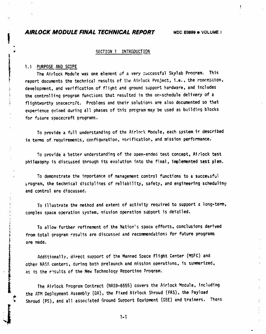
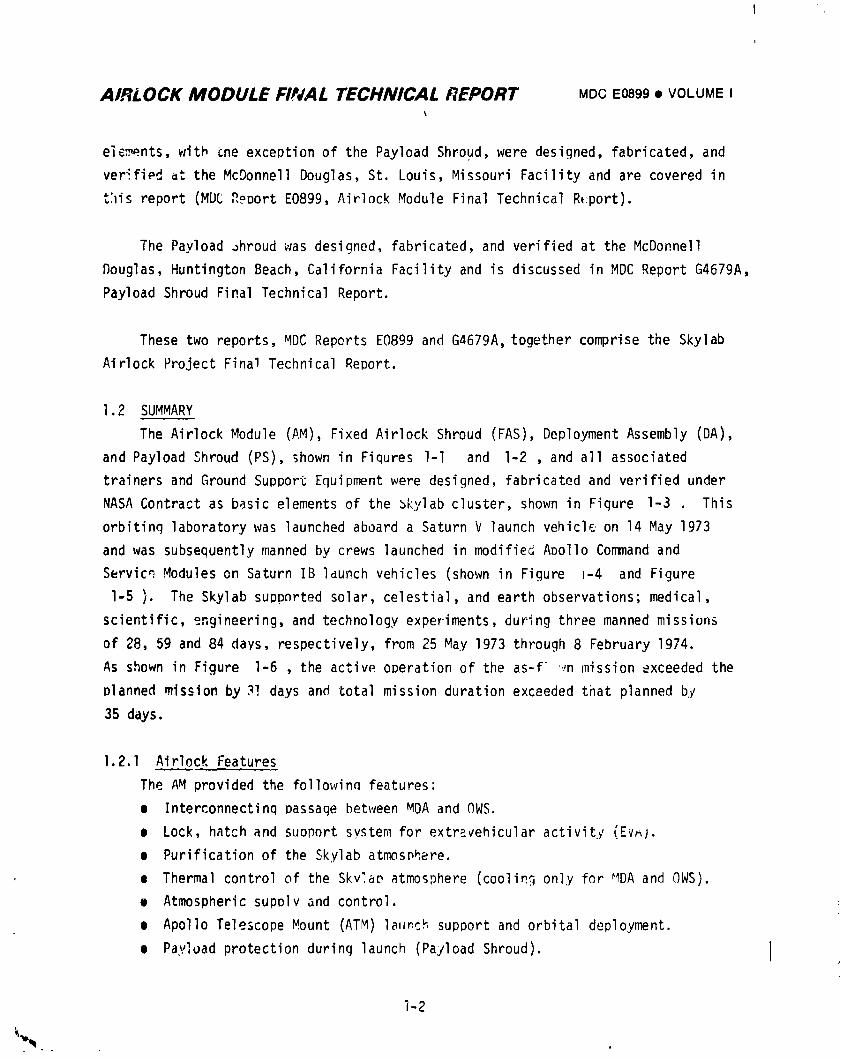
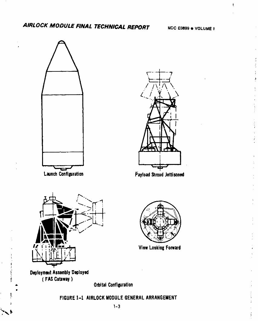
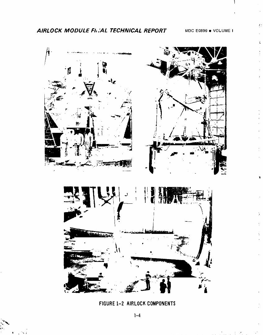
The Airlock Module (AM), Fixed Airlock Shroud (FAS), Deployment Assembly (DA),
and Payload Shroud (PS), shown in Fiqures l-l and I-2 , and all associated
trainers and Ground Support Equipment were designed, fabricated and verified under
NASA Contract as basic elements of the 3kylab cluster, shown in Figure I-3 This
orbiting laboratory was launched aboard a Saturn V launch vehicle on 14 May 1973
and was subsequently manned by crews launched in modified Apollo Command and
Servicq Modules on Saturn IB launch vehicles (shown in Figure m-4 and Figure
I-5 ). The Skylab suppnrted solar, celestial, and earth observations; medical,
scientific, engineering, and technology experiments,during three manned missions
of 28, 59 and 84 days, respectively, from 25 May 1973 through 8 February 1974.
As shown in Figure I-6 , the active operation of the as-f ,inmission exceeded the
planned mission by 3! days and total mission duration exceeded that planned by
35 days.
1.2.1 Airlock Features
The AM provided the followinn features:
m Interconnectinqpassage between MDA and OWS,
e Lock, hatch and suoport system for extravehicularactivity (Ev_).
m Purification of the Skylab atmosphere.
o Thermal control of the Skv_,aDatmosphere (coolin_only for _4DAand OWS).
e Atmospheric supply and control.
e Apollo Telescope Mount (ATM) launch support and orbital deployment.
e Payload protection durinq launch (Payload Shroud). I
i-2
. o
1974018208-025
AIRLOCK MODULE FINAL TECHNICAL REPORT MDCE0899• VOLUME I
% ,/"
LaunchConfi_ration PayloadShroudJettisoned
S)
AIRLOCK MODULE FI,.'AL TECHNICAL REPORT MDCE0899• VOLUMEI
FIGURE1-2 AIRLOCKCOMPONENTS
1-4
.L'( ,
a "',,.. j ,'_ ="
1974018208-027
1-5
1974018208-028
AIRLOCK MODULE FINAL TECHNICAL REPORT MC)CE0899• VOLUMEI
FEET
-,_o C_ , /-_,'*,m
PAYLOADSHROUD- 300 !!.._ /,--," ,';'",I_APOLLO TELESCOPE
-_ OE,"O',,E,T;__ .--L----___.... I' ASSEMBLY-------.L.,_-_ :'_'_MULTIPLE
FIXEDAIRLOCK
SHROUD_ _.L--.-'-'--AIRLOCK
._ .------INSTRUIIENT UNITSM - 200
>S-..I!STAGE ,,.,.,.-----ORBITAL
............ WORKSHOP
_a_lL_t, laL,,- • 150 ,, .......
S-.IVBSTAGE ," ",
• 100 ,,,...-.----SATURNV
_,_ INTERSTAGE
S-.ICSTAGE .I--- SATURNII
S..-IBSTAGE • 50
SL-2, 3 &4 SL-](MANNED) IUNMANNED)
FIGURE1-4 SKYLABLAUNCHCONFIGURATIONS
_- 1-6
1974018208-029
AIR! OCK MODULE FINAL TECHNICAL REPORT MDCE0899• VOLUMEI
FIGUREI-5 SKYLABSL-IAND SI.-2LAUNCHES
I-7
1974018208-030
AIRLOCK MODULE FINAL TECHNICAL REPORT MDC E0899 • VCLUMEI
i
°"r,.)uj2=
t' --o ...... .=,,-r-=_ s':I,-"- - _' I__--_-_
• _- - (:3=...- 4-- ---- .co ,
i
N
lllIF i lilil _,. _ ..I = 3 , I ,
L ,.=,"= I I "_i_ ,-',o I I _
,,__<_., ._ ___
.-----_ _.]_- _-_l____1___
_ I-8
I g74018208-031
AIRLOCK MODULE FINAL TECHNICAL REPORT MDCE0899• VOLUMEI
• Llectr_cal power conditioning control, d,U distribution.
• Real and delayed time data.
• Cluster interco_unication.
• Cluste_ f,_,]t;rewarning.
• Command system link with ground _etwork.
e VHF ranging link for CSM rendezvous.
• Controls and displays.
• Teleprinter.
e Experiment installation of D024 sample panels.
• Experiment antennas (EREP and radio noise burst monitor).
• ATM C&D Panel cooling.
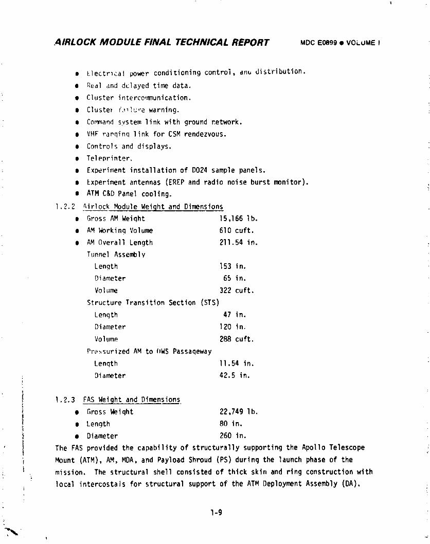
1.2.2 Airlock Module Weight and Dimensions
e Gross AM Weiqht 15,166 lb.
• AM Working Volume 610 cuft.
e AM Overall Length 211.54 in.
Tunnel Assembly
Length 153 in.
Diameter 65 in.
Volume 322 cuft.
Structure Transition Section (STS)
Lenqth 47 in.
Diameter 120 in.
Volume 288 cuft.
PressurizedAM to (IWSPassageway
Length II.54 in.
: Diameter 42.5 in.}
1.2.3 FAS Weight and Dimensionsr
( e Gross Weiqht 22,749 lb.I
e Length BO in.
• Diameter 260 in.
' i The FAS provided the capability of structurally supporting the Apollo Telescopei Mount (ATM), AM, MDA, and Payload Shroud (PS) during the launch phase of the
i mission. The structural shell consisted of thick skin and ring construction with
local intercostals for structural support of the ATM Deployment Assembly (DA).
I-9
1974018208-032
AIRLOCK MODULE FINAL TECHNICAL REPORT MDCE0899• VOLU_EI
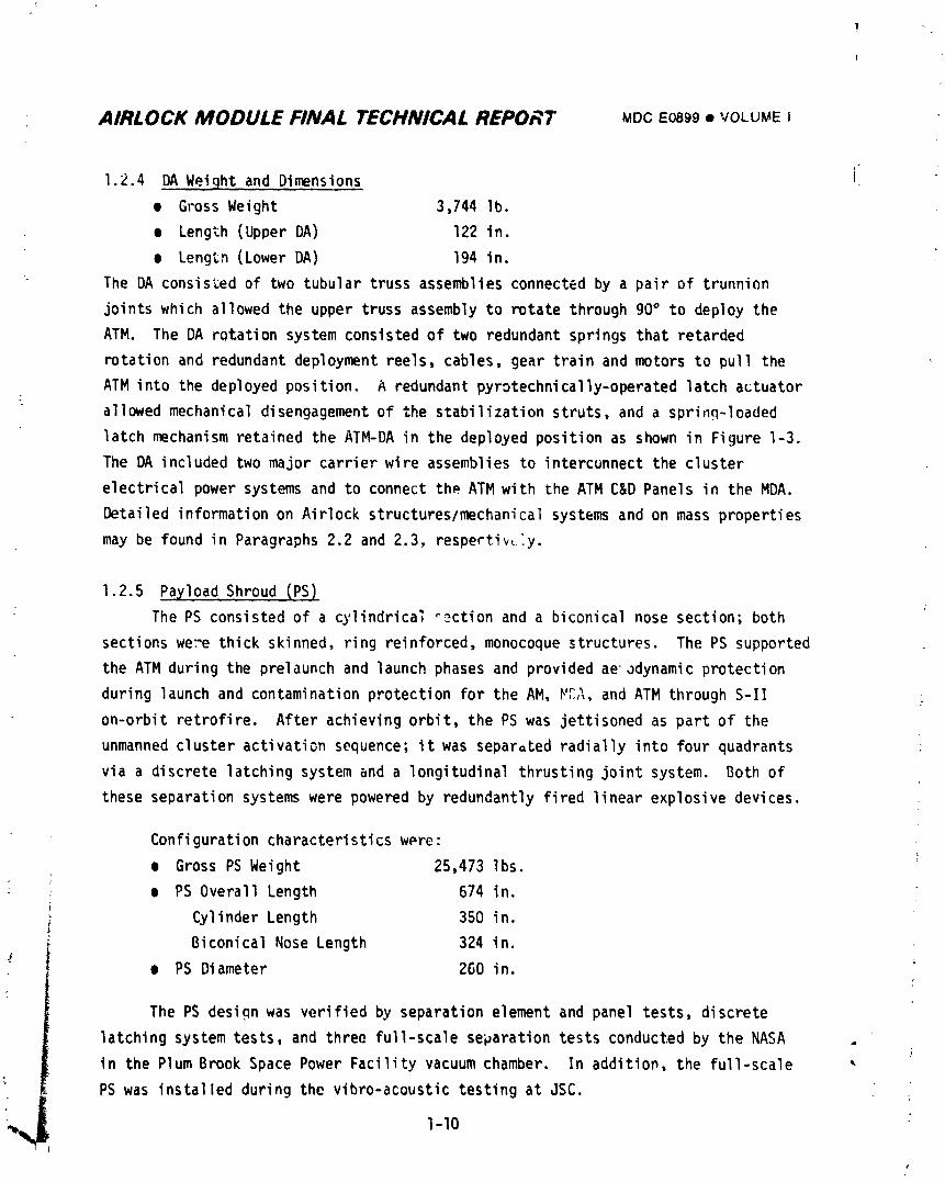
1.2.4 DA Weight and Dimensions
e Gross Weight 3,744 lb.
• Length (Upper DA) 122 in.
e Lengtn (Lower DA) 194 in.
The DA consisted of two tubular truss assemblies connected by a pair of trunnion
joints which allowed the upper truss assembly to rotate through go° to deploy the
ATM. The DA rotation system consisted of two redundant springs that retarded
rotation and redundant deployment reels, cables, gear train and motors to pull the
ATM into the deployed position. A redundant pyrotechnically-operatedlatch actuator
allowed mechanical disengagement of the stabilization struts, and a sprinq-loaded
latch mechanism retained the ATM-DA in the deployed position as shown in Figure I-3.
The DA included two major carrier wire assemblies to intercunnect the cluster
electrical power systems and to connect the ATM with the ATM C&D Panels in the MDA.
Detailed information on Airlock structures/mechanicalsystems and on mass properties
may be found in Paragraphs 2.2 and 2.3, respectively.
1.2.5 Payload Shroud (PS)
The PS consisted of a cylindrica; _ction and a biconical nose section; both
sections were thick skinned, ring reinforced, monocoque structures. The PS supported
the ATM during the prelaunch and launch phases and provided ae'odynamic protection
during launch and contaminationprotection for the AM, _A, and ATM through S-II
on-orbit retrofire. After achieving orbit, the PS was jettisoned as part of the
unmanned cluster activation sequence; it was separated radially into four quadrants
via a discrete latching system and a longitudinal thrusting joint system. Both of
these separation systems were powered by redundantly fired linear explosive devices.
Configuration characteristicsw_re:
• Gross PS Weight 25,473 Ibs.
e PS Overall Length 674 in.
Cylinder Length 350 in.
Biconical Nose Length 324 in.
• PS Diameter 260 in.C
The PS design was verified by separation element and panel tests, discrete
latching system tests, and three full-scale separation tests conducted by the NASA
in the Plum Brook Space Power Facility vacuum chamber. In addition, the full-scale
PS was installed during the vibro-acoustictesting at JSC.
'_ 1-10
1974018208-033
AIRLOCK MODULE FINAL TECHNICAL REPORT MDC 1:0899 • VOLUME I
PayloadShroudS/N 03 was launchedon Skylab1 and was subsequently
jettisonedin-orbitwithoutproblem;all functionsperformedas plannedat the
correctattitudeand the designedseparationvelocitywas i_artc..'.
Completedetailsof the requirements,designconfiguration,verification,anO
missionperformanceof the PS is givenin MDC ReportG4679A,PayloadShroudFinal
Technical Report.
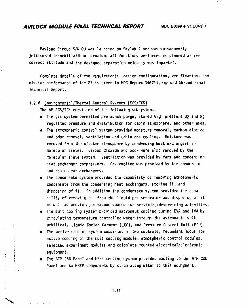
1.2.6 Environme.n_tal_!.ThermalControlSystems(ECS/TCS)
The AM ECS/TCSconsistedof the followin9subsystems:
e The gas systempermittedprelaunchpurge,storedhigh pressure02 and _2
regulatedpressureand distributionfor cabinat:,_osphere,and other uses.
e The atmosphericcontrolsystemprovidedmoistureremoval,carbondioxide
and odor removal,ventilationand cabingas cooling. Moisturewas
removedfrom the clusteratmosphereby condensingheatexchangersan_
molecularsieves. Carbondioxideand odorwere also removedby the
molecularsievesystem. Ventilationwas providedby fansand condensin9
heat exchangercompressors.Gas coolingwas providedby the condensing
and cabinheatexchangers.
• The condensatesystemprovidedthe capabilityof removingatmospheric
condensatefrom the condensingheat exchangers,storingit, and
disposingof it. In additionthe condensatesystemprovidedthe caDa--
bilityof removig gas from the liquidgas separatorand disposingof it
as well as provi<linga vacuumsourcefor servicing/deservicingactivities.
• The suit coolingsystemprovidedastronautcoolingduringEVA and IVA by
circulatingtemperaturecontrolledwater throughthe astronautssuit
umbilical,LiquidCooledGarment(LCG),and PressureControlUnit (PCU).!
• The activecoolingsystemconsistedof two separate,redundantloops for
activecoolingof the suit coolingmodule,atmosphericcontrolmodules,
selecteoexperimentmodulesand coldplatemountedelectrical/elec;tronic
equipment.
• The ATM C&D Paneland EREP coolingsystemprovidedcoolingto the;ATM C&D
: Paneland to EREP componentsby circulatingwater to thisequip_r,t.
I-II
1974018208-034
AIRLOCK MODULE FINAL TECHNICAL REPORT MDC E0899 • VCLUME I
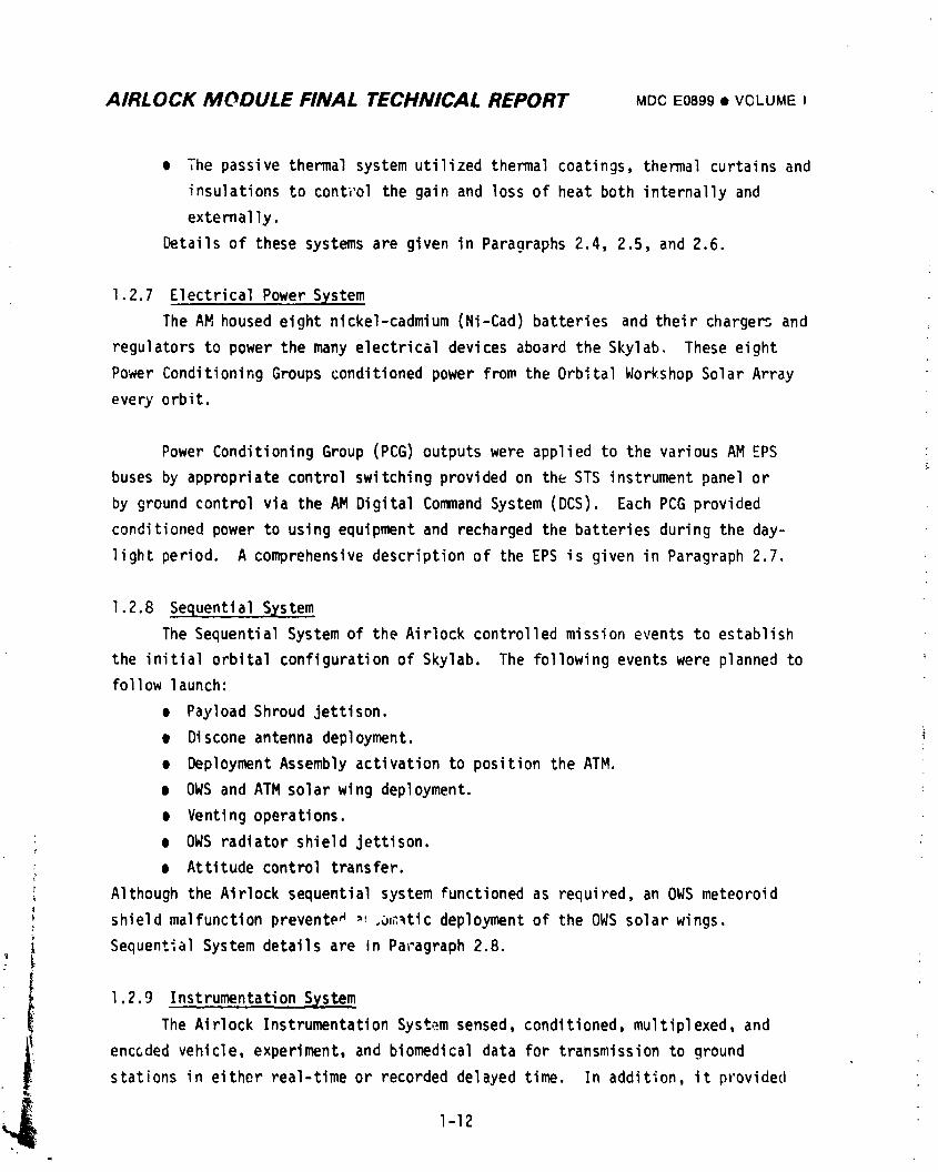
e The passive thermal system utilized thermal coatings, thermal curtains and
insulations to cont_'olthe gain and loss of heat both internally and
externally.
Details of these systems are given in Paragraphs 2.4, 2.5, and 2.6.
1.2.7 Electrical Power System
The AM housed eight nickel-cadmium (Ni-Cad) batteries and their charge_ and
regulators to power the many electrical devices aboard the Skylab. These eight
Power Conditioning Groups conditioned power from the Orbital Workshop Solar Array
every orbit.
Power Conditioning Group (PCG) outputs were applied to the various AM EPS
buses by appropriate control switching provided on the STS instrument panel or
by ground control via the AM Digital Command System (DCS). Each PCG provided
conditioned power to using equipment and recharged the batteries during the day-
light period. A comprehensivedescription of the EPS is given in Paragraph 2.7.
1.2.8 Sequential S_,stem
The Sequential System of the Airlock controlled mission events to establish
the initial orbital configuration of Skylab. The following events were planned to
follow launch:
e Payload Shroud jettison.
• Discone antenna deployment. :i
e Deployment Assembly activation to position the ATM.
• OWS and ATM solar wing deployment. "
e Venting operations.
e OWS radiator shield jettison.
e Attitude control transfer.
i Although the Airlock sequential system functioned as required, an OWS meteoroid
shield malfunction prevente_ ,_.o,_,_ticdeployment of the OWS solar wings.
Sequential System details are in Paragraph 2.8.
1.2.9 InstrumentationS_,stem
The Airlock InstrumentationSystem sensed, conditioned, multiplexed, and
enccded vehicle, experiment, and biomedical data for transmission to ground
stations in either real-time or recorded delayed time. In addition, it provided
1-12
1974018208-035
AaRLOCK MODULE FINAL TECHNICAL REPORT MDCE0899• VOLUMEI
data for on-board : splays, and through hardlines, enabled readout during ground
checkout. The system included the following subsystems:
• Sensors Used to convert physical quantities being measured (such as
temperature or pressure) into proportional electrical signals and Signal
Conditione,.s- consisting of interface circuits used to condition
incomDatible signals.
e Regulated Power Converters - Devices used to provide stable excitation
voltages to the instrumentationhardware.
e PCM Multiplexer/Encoder- System used to provide time sequenced and
coded data for transmission to the Space_light Tracking and Data Network
(STDN).
• Tape Recorder/Reproducer- Devices used to acquire and store between station
data for subsequent playback to STDN in delayed time.
A description of these subsystems is provided in Section 2.9.
1.2.10 CommunicationsSystem
The Communications System transmitted and received voice, instrumentation
data, the television data between: crew members in the Skylab and on EVA; crew
members and ground tracking stations; Skylab systems and ground tracking stations;
and Skylab and the rendezvousing Command/ServiceModule. The CommunicationsSystem
consisted of the following subsystems:
e Audio System - Used In conjunction with the Apollo Voice Communications
Systems to provide communications among the three crewmen and between _
Skylab and the Spaceflight Tracking and Data Network (STDN).
e Digital Command System (DCS) - A sophisticated, automatic command systeln
which provided the STDN with real-time command capabilitle: for _he AM,
OWS, and MDA. The Digital Command System permitted control of experir,ents,
antennas, and cluster system functions.
e Teleprir_ter- In conjunction with the AM receiver/decoders the teleprinter, i,
provided on-board paper copies of data transmitted by th_ SFDN.
e Time Reference System (TRS) - Provided time correlation to the Pulse Code
Modulation (PCM) Data System, automatic reset of certain DCS comands,
automatic control of the redundant DCS receiver/decoders,and timing data
to the Earth Resources Experiment Package (EREP) and on-board displays in
the AM and OWS.
1-13
I
i9740i8208-03G
AIRLOCK MODULE FINAL TECHNICAL REPORT MDCE0899• VOLUMEI
• Telemetry Transmission System - Used in conjunction with the Air_ock
Antenna System, the Telemetry System provided RF transmission capability
to the STDN during prelaunch, launch, and orbit for real-time data.
delayed time data, delayed time voice, and emergency voice (during
rescue transmission), in both stabilized and unstabilized vehicle
attitudes. This system included four telemetry transmitters, three of
which could be operated simultaneouslyduring orbital phases.
• Antenna System - Consisted of a modified Gemini Quadriplexer, two
modified Gemini UHF Stub Antennas, four RF Coaxial Switches, two Antenna
Booms, two Discone Antennas and a hellcal VHF Ranging Antenna.
m Rendezvous Systems - Consisting of a VHF Ranging System and four tracking
lights, these systems facilitated rendezvous of Command Modules (SL-2,
-3, and -4) with the Saturn Workshop (SWS). The Airlock equipment
comprised a VHF Transceiver Assembly, a Ranginq Tone Transfer Assembly
(RTTA), and a VHF Ranqing Antenna.
Detailed information on the Communications System may be found in Paragraph 2.10.
!o2,!! Caution and Warninq System (C&W)
The Caution and Warning System monitored critical Skylab parameters and
provided the crew with audio/visual alerts to imminent hazards and out-of-spec
conditions which could lead to hazards. Emergency situations resulted in
activation of a Klaxon horn which could be heard throughout the Skylab vehicle.
Caution or warning conditions were brought to the crew's attention through crew
earphones and speaker/interco_ panels. Emergency parameters were defined as:
• MDA/STS fire.
• AM aft compartment fire.
• OWSforward/experiment/crew compartment fire.
• Rapid chanqe in vehicle pressure.
Warning parameters included:
• Low oxygen partial pressure.
• Primary and secondary coolant flow failure.
• AM and ATM regulated power bus out-of-spec.
'_ e Cluster attitude control failure.
e EVA suit coolinq out-of-spec.
e AM and CS_ crew alerts. "
1-I 4
] 974018208-037
AIRLOCK MODUAE FINAL TECHNICAL R,_F'ORT MOOE0899 • VOLUME I
C._:,t_o.-p.:rame'_rsconsisted of:
• Mole sieve overtemperature, high carbon dioxide content, flow failure,
and s_quencing.
e OWS ventilation out-of-spec.
• RapiO condensate tank pressure change.
e Primary and secondary coolant temperature out-of-spec.
• C&W system bus voltage out-of-spec.
e EPS voltages out-of-spec.
• ATM attitude control system malfunctions.
• ATM coolant system malfunctions.
System details may be found in Paragraph 2.11.
1.2.12 Crew Systems
The Airlock functioned as a nerve center for monitoring and operating many
complex vehicle sysL_ms, either autumaticallyor by the crew.
A. STS - Primary crew controls for AM systems:
• Electrical Power System.
e Environmental Control System (ECS)
Molecular Sieve
Atmospheric Fans
Coolant Control
Condensate System
• IntravehicularActivity (IVA) Control Panel.
e Flight Logbook and Records.
e Cluster Caution and Warning Monitor System.
e 02/N2 Gas Distribution System.
_ B. Lock Compartment - EVA/IVA Operations
_ e EVA/IVA Control Panels (2).
• Internal and EVA Lighting Controls.
, e Compartment Pressure Displays.
• Vacuum Source.
C. Aft Compartment
| • OWS Fntry Lighting.
e Thermal Fan and Valve Control.
, • M50g Recharge Station.
rf 1-15
1974018208-038
AIRLOCK MODULE FINAL TECHNICAL REPORT MDCE0899• VOLUMEI
Other AM Crew Systems included the followinq:
• Mobility Aids.
• Internal Lighting.
• Communications- Placement of internal voice communications.
• Stowage.
Additional information concerning Crew Systems may be found in Paragraph 2.12.
1.2.13 Trainers
MDAC-E designed, built, maintained, and updated the NASA Trainer (NT), the
Neutral Buoyancy Trainer (NBT), the Zero-G Trainer and the zero-g aft compart-3nt
(part task) trainer. In addition, MDAC-E assisted MSFC in convertinq the Airlock
Static Test Article (STA-3), after completion of full-scale vibro-acoustic testing,
into the Skylab Systems Integration Equipment (SSIE) unit. Of lower fidelity than
the NASA Trainer at JSC, the SSIE was used at MSFC for mission support of crew EVA.
The NBT was used in the MSFC Neutral Buoyance Facility both premission and
during the missiun to support EVA task training. It was used extensively during
the early days of SL-I missior,to develop the techniques and procedures used by the
SL-2 crew to release and deploy SAS Wing #1 and to erect a solar shield. The
NBT was used throughout the mission for this type of real time mission support.
1.2.14 Experiments
The experiments and experiment support equipment which were mounted on the
Airlock are as follows:
e D024 Thermal Control Coatings - Evaluated selected thermal control
coatings exposed to near-earth space environment.
e S193 Microwave Radiometer Scatterometer/Altimeter- Determined land/sea
characteristicsfrom active/passive microwave measurements,
e $230 Magnetospheric Particle Collection - Measured fluxes and composition
of precipitatina magnetospheric ions and trapped particles.e Radio Noise Burst Monitor - Permitted prompt detection of solar flare
activity.
• M509 Gaseous Nitrogen '"' '_N2} Bottle Recharge Station - Supporting hardware
for recharging three OWS-stowed N2 bottles.
Paragraph 2.14 provides detailed information on AM experiment hardware.
:" 1-I 6
I
] 974018208-039
AIRLOCK MODULE FINAL TECHNICAL REPORT MDCE0899• VOLUMEI
1.2.15 GroundSupportEquipment(GSE)
AirlockGSE is nonflighthardwareand softwareused in supportof the flight
articleto satisfya specificsupportfunctionor to accomplisha definedtest.
It is used to insp.;ct,test, calibrate,assemble/disassemble,transport,protect,
service,checkout,etc.,or to otherwiseperforma designatedfunctionin support
of the flightarticleduringdevelopmenttesting,manufacturingassembly,
acceptancetestinq,systemstesting,delivery,prelaunchcheckout,and launch
GSE usedin supportof the AM, FAS,DA and PS is categorizedas follows:
• Handling,Transportationand MechanicalGSE.
• Electrical/ElectronicGSE.
• Servicingand FluidsGSE.
ComprehensiveinformationconcerningAM GSE is given in Paragraph2.15.
1.2.16 Reliabilityand Safety
The basicapproachfor achievingAirlockreliabilitygoalsof 0.85 for
missionsuccessand 0.995for crew safetywas to designreliabilityintoall
Airlocksystemsand maintainthatreliabilitythroughoutthe fabrication,test,
and end use phasesof the program. Major activitiesfor achievingthe necessary
Airlockreliabilityincludedthe following:
• FMEA- _ FailureMode and EffectAnalysisidentifiedcriticalmodes of
equipmentfailureand facilitatedcorrectiw designchanges.
m CIL - A CriticalItemList,which includedSingleFailurePoints(SFP's)
derivedfromthe FMEA,criticalredundant/backupcomponents,and launch
criticalcomponents,identifiedprimarycomponentsrequirinqtest
emphasis,contingencyprocedures,and managementcontrol.
• ReliabilityModel- Containeda quantitativeassessmentof mission
reliabilityand crew safetyfor purposesof recommendingdesign
improvementsto meet AM reliabilitygoals.
m Trade and specialstudies,
, e Design Reviews.
e Potential suppliers evaluation.
e Reporting system for analysis and nonconformance correction.
e NASAAlert investigation and origination of MDAC-EAlerts.
An MDCReport G671, "Airlock Systems Safety Plan," established the requirements
1-17
1974018208-040
AIRLOCK MODULE FINAL TECHNICAL REPORT MDCE0899• VOLUME I
for performing all Airlock functions from design through altitude chamber testing
and shipment to KSC without injury te personnel or damage to equipment, An
Airlock Safety Officer verified compliance with the Safety Plan and provideJ
additional guidance in areas involving potentially hazar ,us operations not
specifically covered by the plan.
Sections 3 and 4 provide comprehensive coverage of the Airlock Reliability
and Safety Programs.
1.2,17 Testin 9
MDAC-Eaccomplished all structur_.l, dynamic, functional and system tests
necessary for the development, qualification, acceptance and verification of the
Airlock Module prelaunch checkout capability, k_fer to Section 5.
A test plan was implemented for verification tests to define the test
documentation used tc verify the integrity of the Airlock hardware and to
provide historical test data.
Development tests were performed to establish a desiqn concept or to prove
the feasibility of an established design concept. Development te=ts supplemented
the design process with performance data on equipment and systems, str,mgth
characteristics of structural elements, and the eCfects of long-ter_ exposure of
materials and components to a hard wcuum, as well as to space radiation and
corrosive environments.
The Airlock Qualification Test Prog.'am was designed to verify the capabilit_
of the component hardware to function as specified within the design and perform-
ance requirements. This proqram was based on the Apollo Applications Test
Requirements (AATR) Document (NHB 8080.3) which required that equipment qualifi-
cation testing be varie_ d_pending upon the criticality relationship to the crew
safety and achievement of the mission objectives.
1-18
1974018208-041
AIRLOCK MODULE FINAL TECHNICAL REPORT MD(.,_0899• VOLUMEI
Qualification of the Airlock systems was accomp'..ishedwith component ievel
testing and equipment er_durancetests. In some instances, components such as
the EnvironmentalControl System/Thermal Control System (ECS/TCS)were combined
into a module test to verify the system. In this way, endurance testing at the
highest p,_ctisal level verified the equipment performance in mission-si_,ulated
environ_ents and mission-simulatedduty cycles. Qualificatlon tests verified
t_at the hardware met the performance/designrequirements to assure operation:i
suitability of the anticipated e_vironments.
t.IDAC-Edelivered to HSFC a Structural Test Article (STA-I) which was
subsequently refu;-bishedinto a Dynamic Test Article (STA-3). The structura,
testing was performed at the MSFC facilities at Huntsville, Alaba_.aand at the
JSC facilities at Houston, Texas by a joint NASA/MDAC/MMC test team. The Airlock
Dynamic Test Article provided a structurally and dynamically representative
vehicle of the Airlock Module. It consisted of a Structural Transition Section,
Tunnel and Irusses. The test configuration included the Fixed Airlock Shroua,
the ATM DeploymentAssembly, the Payload Shroud, and the test article ballas
w,_ichsimulated the equipment and experiments in mass, center of gravity and
attachment points. The dynamic configuration was representative of the flight
article overall weight, center of gravity and mass moments of inertia.
The objective of thP dynamic test was te subject the dynamic test articie
to the predicted flight level acoustic and vibration environments to espErimentally
determine the frequercy mode shapes and damping values of the Skylab assembly,
equipment and subsystems i_ both launch and orbit configurations.
Section 5.0 provides detailed information on the Airlock Test Philosophy.
1.2.18 Hission OpeFations Support
A Skylab Communications Center was installed at MDAC-E to support MSFC prior
to and during Skylab launch anf flight operations and to evaluate the Skylab
mission performance. In addition, Orbital Assembly flight operations support was
provided by MDAC-E via the MSFC Huntsville Operations Support Center (HOSC).
: MDAC-E support included analyzing off-nominal Skylab conditions providing additional
• engineering data, and providing systems simulations for systems performance.
• For additional information, see Section 7.r
1--19
_,.
i974018208-042
AIRLOCK MODULE FINAL TECHNICAL REPORT MDCE0899® VOLUMEI
1.2.19 New Technolo_gsy-
The initial Mrlock concept _f a state-of-the-artvehicle had a limited new
technology requirement. However evolutiun, particularily the wet to dry launch
configuration change, required advanced state-of-the-artdesigns, i.e., emergency
warning system, a two-gas spacecraft environment, increasea elo_ctricalpower,
active cooling for ATM usage, etc.
Of the 4Sl New Technology Disclosures submitted, 15 were published as NASA
Tech Briefs and it is anticipated that additional Tech Briefs will be publishea
subsequent to submittal of ti_isreport. Three of the submittals resulted in the
preparation of patent applications by the NASA, and one was filed in the U.S.
Patent Office. Additional information on New Technology is given in Section 8.
_, 1-20
,_ I J t ";
1974018208-043
AIRLOCK MODULE FINAl.. TECHNICAL REPORT MDCE0899• VOLUMEI
1.2.20 Conclusions
The successful Airlock system performar,ce during the Skylab Program indicates
the effect_venesL of the MDAC-E design, fabrication, and test activities that
preceded the ,iiqht mission. It also indicates the effectiveness of the mission
support activity in responding to discrepant conditions and providing real-time
work ar_,,ndplans.
The major conclusion that can be drawn from a program point of view is that
the Airlock program philosophy of ,naximumuse of existing, qualified space
hardware with extensive use of system engineering analysis and previous test
results to identify the minimum supplemental test program required to complete
system verificationwas proven as a valid, economical approach to a successful
mission.
The most important lesson learned, from its impact on future space system
planning, is the demonstrated capability of the crewman to function as a major
link in the system operation. He demonstrated the capability to function
effectively in zero-g for long periods of time a .d to perform, with proper constraints,
tools, and procedures. Additionally, the ability of the crew to perform contingency
EVA's and to accomplish _ifficult repair/maintenanceactivities will be a significant
input to all future manned space programs.
Each s_ction of this report discusses conclusions ar.drecommendationsfor
the system or engineering activity being covered.
Section 9.0 enumerates what MDAC-E considers the .mostsignificant "Lessons
Learned" from the Airlock Program and their applicability to future programs.
1-21/22
1974018208-044
AIRLOCK MODULE FINAL TECHNICAL REPORT MDCE089,• VOLUMEI
SECTION 2 SYSTEMDESIGNAND PERFORMANCE
2.1 GENERAL
2.1.1 Program Inception
The inception of the MDAC-E Airlock Program dates back to E3 December 1965
when NASA directed MDAC-E to appraise the appiicability of Gemini hardware for
inclusion in an Airlock Module to support use of a spent S-IVB Stage as a manned
shelter and workshop. Subsequently,on 5 April 1966, MDAC-E received a Request
for Proposal from the NASA to design, develop, manufacture, and check out a Spent
Stage Experiment Support Module (SSESM) for manned launch aboard a Saturn I-B
vehicle. This module was to provide an interconnectingtunnel _nd airlock between
the Apollo Command Module and the S-IVB stage, which would subsequently be converted
into a manned orbital workshop after its propellant content was expended and it had
been purged.
The SSESM proposal was submitted on II June 1966 and verbal go-ahead was
received on 19 August 1966.
2.1.2 SSESM
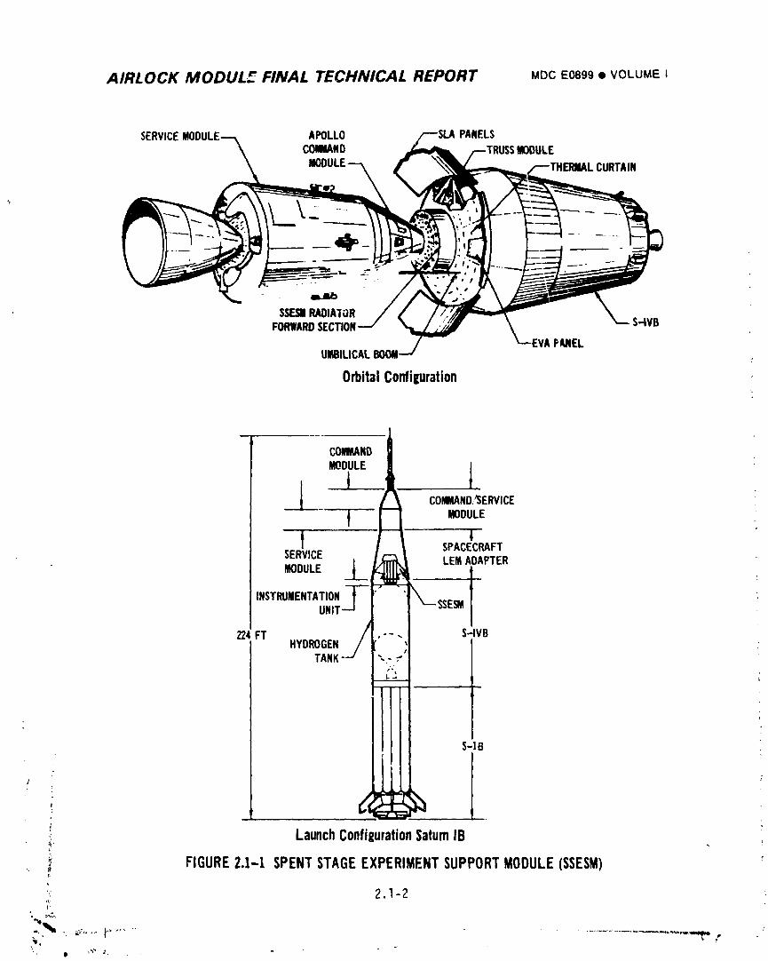
Th? objective of the SSESM was tn demonstrate the economical utilization of an
S-IVB spent stage hydrogen tank as a workshop for a manned mission. As shown in
Figure 2.l-I the SSESM was to be la,mched on a Saturn I-B with an Apollo CSM; it
was to be installed in the Spacecraft Lunar Adapter (SLA) on the Lunar Exploration
Module (LEM) attach points.
In orbit, the CSM was to separate from the remaining vehicle, rotate 180°, andJ
dock using the SSESM docking adapter.
The SSESM consisted of a tunnel/airlockthat provided a habitable pressure
vessel between the spent S-IVB stage and the docked CSM and that supported EVA. It
included a section of a Gemini adapter/radiator and four mounting trusses that
supported cryogenic 02 and H2 bottles.
",_ 2.1-I
i"_ _.F
i 9740i 8208-045
AIRLOCK MODUL5 FINAL TECHNICAL REPORT MDCE0899• VOLUME i
SERVICE APOLLO PANELSCOWMND MODULE
CURTAIN
COkWL_ND
___ COWAND,_SERVICE
MODULE
t +SPACECRAFTSERVICE LEMAOAPTERMODULE
INSTRUMENTATIONUN
224FT S-IVBHYDROGEN
TANP
S-IB
+ 1r
; ?
LaunchConfiEurationSaturnIB9- !
FIGURE2.1-1 SPENTSTAGEEXPERIMENTSUPPORTMODULE(SSESM) 'r,
"'_ 2.1-2
+" ill +"+_ J-
]9740] 8208-046
AIRLOCK MODULE FINAL TECHNICAL REPORT MDCE0899• VOLUMEI
!
Durin.n,activation, a crew member would perform an EVA to renx)veand stow the
S-IVb dome nlam:L)lecover, connect a flexible tunnel extension to complete the
pressuF,_t,lDa_,_,,ew,_;¢,and connect tile02 and H2 boom uni_ilicalsto the Service
M,_dul,;.,_fterp_,,_ingand furbishing, the S-IVG spent stage would have served as
a ,qannedlabordtorv. SSESM mission philosophy was that of an open-ended flight
operation _ubseque_itto the first 14 days _ith 30-day goal.
Over 98:,of the SSESM components were Gemini flight qualified hardware and no
additional q_alification testing was to have been per;ormed as long as operatior,al
requirel;w_tltswere similar to Gemini.I
_'.1.3 Wet Workshop Evolution
As the program matured and requirementswere firmed up, it underwent consider-
able evolution of mission definition and systems requiren_n;s. ]
Initially, to support additional radiator area and to provide increased
pressurized volume for expendables and experiment launch stowage, the Gemini
adapter was replaced with a short cylindrical pressure vessel with an axial docking
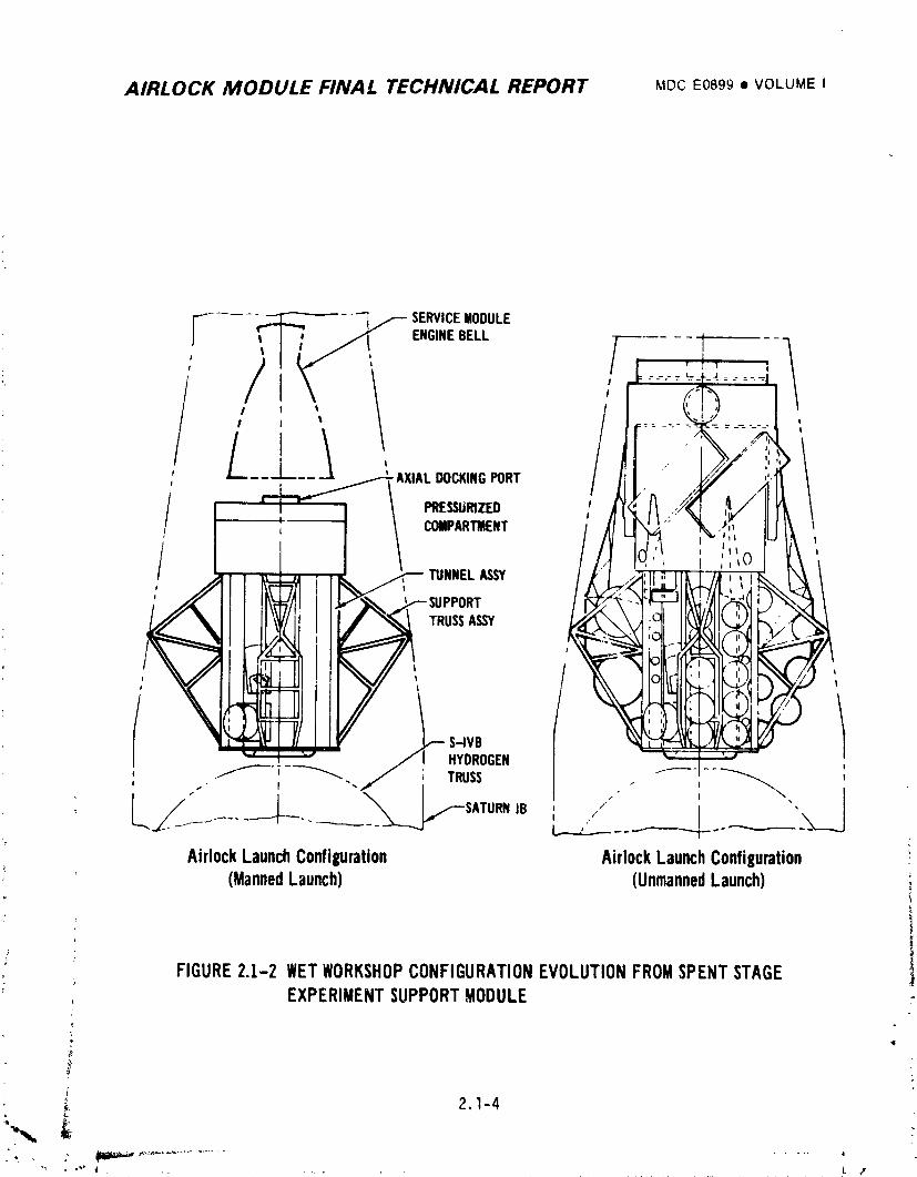
port and external radiators (Refer to Figure 2.1-2). This version was to be
launched on a Saturn I-B with a CSM for a 30-day mission; it was designated the
Airlock Module.
Subsequently, in December 1966, the pressurized cylindrical o}mpartment was
lengthened _nd four radial decking ports were added (the single axial docking port
was retained). Additionally, a solar array system was evaluated for Airlock instal-
lation ard gaseous 0,,.and N2 tanks were designed for installation on the Airlock
trusses (the cryogenic tanks were retained for CSM fuel cell usage). A molecular
sieve expe;'imentwas added.
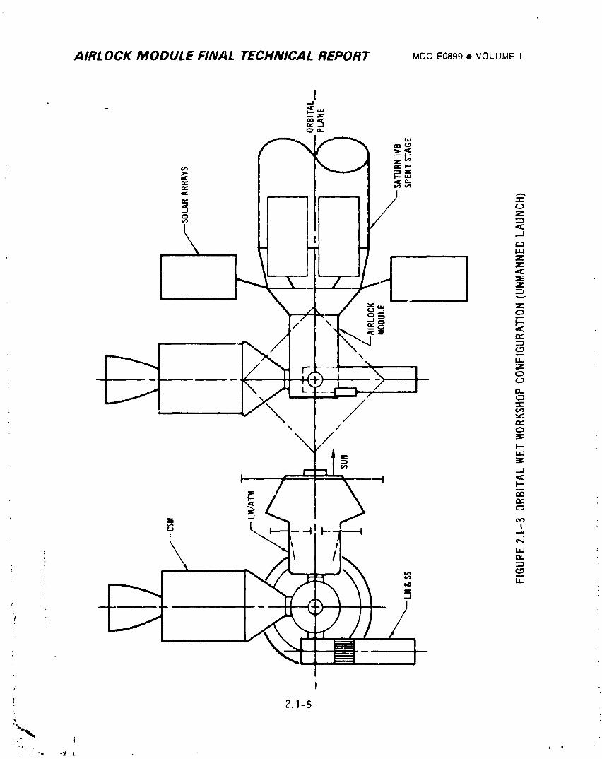
This configuration (refer to Figure 2.1-2) was to be launched unmanned on a
Saturn I-B with tl_ecrew following in a CSM on a second Saturn I-B; crew revisit
i: and station resupply was planned. Additional Saturn I-B launches were required to
orbit and rendezvous either a Lunar Mapping and Survey Station Module (SM&SS) or a
Lunar Module/Apollo Telescope Mount (LM/ATM) which was to be docked into one of the
radial docking ports by remote control. The orbital configuration is shown in
Figure 2.1-3.
2.1-3
"_ _ |
., , ..... _. ,_ _
1974018208-047
AIRLOCK MODULE FINAL TECHNICAL REPORT Moc E0899• VOLUME i
j" .... _ ---- SERVICEMODULE
ENGINEBELL [ ' -1
/ ,t
'-AXIAL DOCKINGPORT
/ ,PRESSURIZED ICI_IPARI_ENT
TUNNEL_$Y!J
TRUSSASSY
/t tt
L S-IVB t
Jl HYDROGEN
/ SATURNIB //
AirlockLaunchConfiguration AirlockLaunchConfiguration ,(MannedLaunch) (UnmannedLaunch) _
/ FIGURE2.1-2 WETWORKSHOPCONFIGURATIONEVOLUTIONFROMSPENTSTAGE 1, EXPERIMENTSUPPORTMODULE
_, 2.1-4
] 9740] 8208-048
AIRLOCK MODULE FINAL TECHNICAL REPORT MDCE0899• VOLUMEI
1
co.
<c ,,,-.,
z._1
_Z3
i4 'i i |= Z
Z
"5Z
_uJ Z
_ J o
_\:_! _"' '==/ 'x, /
N 3,.1 ..J
; i f _ '-I
,g
2.1-5
1974018208-049
AIRLOCK MODULE FINAL TECHNICAL REPORT MDCE0899• VOLUMEI
2.1.4 Wet Workshop Conflguration
By Mid-1967 a firm workshop configuration had evolved and major changes had
been made to the Airlock Module and its systems.
The forward end of the pressurized cylinder, includinn the docking ports, was
rcn_ved as part of the AM and a new module, the Multiple Docking Adapter (MDA)
created. The MDAwas to be Governnw_nt Furnished, but the radiators covering the
exterior of the MDAremained part of the AM task. The solar arrays were removed
from the AM and added onto the O&5. Both the cryoqenic 02/H 2 and gaseous 02/N 2
supplies were removed from the AM; gases were to be supplied from the CSMthrough
.in umbilical. Battery modules were added onto the AM trusses and a scientific
airlock was adned to the AM. This configuration as shown in Figures 2.1-4 and
2.1-5 was the Apollo Application Program (AAP) "wet" workshop configuration.
i
The AAP "wet" workshop mission profile also undm_vent considerable change.
In Mid-1967 the mission consisted of two CSMlaunches, an unmanned orbital workshop
launch and an unn_nned LM/ATM launch. All launches were on Saturn I-B vehicles
with total mission duration of up to 9 months, as shown in Fig,re 2.1-6. A
possible CSM revisit was considered within 6 to 12 months after AAP-3 splashdown.
By Mid-1968 the AAP mission hod evolved into a 28-day mission and two 56-day
missions with 90-day orbital storage periods in between; all five launches were by
Saturn I-B:
• T.,ree manned CSMlaunches.
• One unmanned workshop launch.
• One unmanned LM/AI'M launch.
2.1.5 Dry Workshop Confi.quration
(3n 28 August 1969 the wet workshop configuration was superseded by a dry work-
shop configuration -- the Skylab. The basic chanqe was to launch the workshop,
including all experiments and expendables, in a single unmanned Saturn V launch.
• The S-IVB stage was to be launched dry after having been configured on
the ground for manned laboratory use.
' e Separate launch of LM/ATM was eliminated, and the ATMwas included in the
unmanned workshop launch payload.
I
i #
1974018208-050
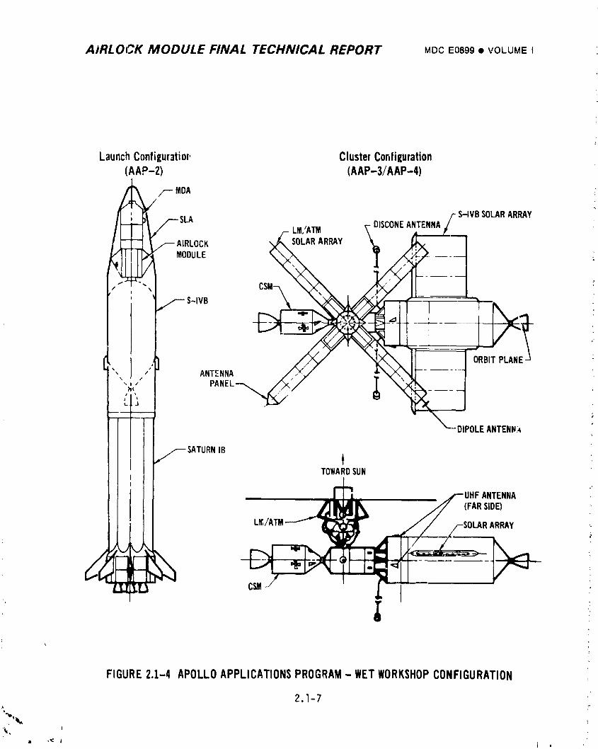
A/RLOCK MODULE FINAL TECHNICAL REPORT MDCE0899• VOLUMEI
LaunchConfigur3tior, ClusterConfiguration(AAP-2) (AAP-3/AAP-4)
" //-- MDA "t_ S_VB SOLARARRAY
I _ _ _ AIRLOCK SOLARARRAY
_llr,4"I- /_ MODULE ---
/ \
S-IVB
ORBITPLANE-
"" / ANTENNA\
, ,' PANEL-_iI _l
'DIPOLEANTENN,_
./_ SATURNIBTOWARDSUN
2'
ANTENNA(FARSIDE)
L_,/A'rM ARRAY
FIGURE2.1-4 APOLLOAPPLICATIONSPROGRAM- WETWORKSHOPCONFIGURATION
2.1-7
III "_ l I I '_
1974018208-051
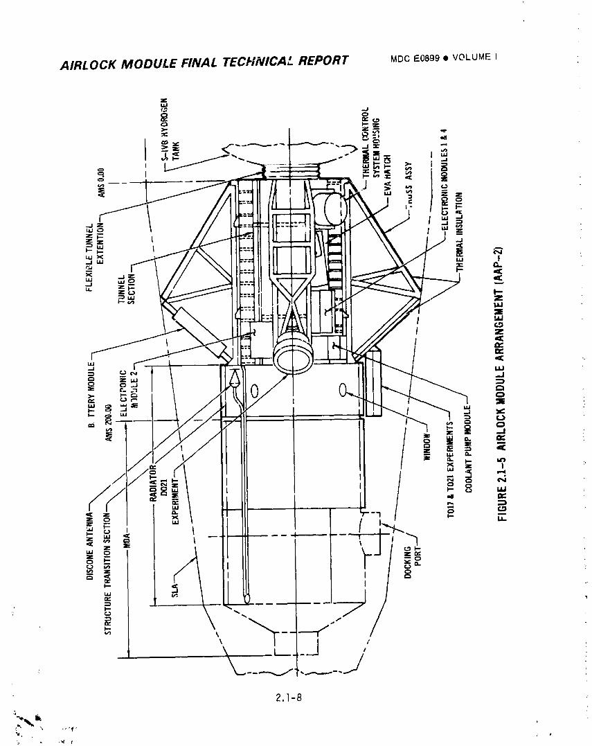
AIRLOCK MODULE FINAL TECHNICAL REPORT MDCE0899• VOLUMEI
2.1-8
19740182N£-_9
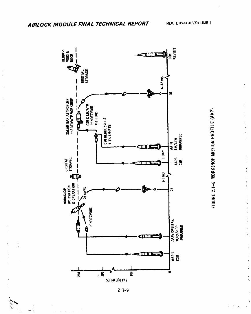
AIRLOCK MODULE FINAL TECHNICAL REPORT MDCE0899• VOLUME I
_.=:=zCi_l_='= I 5"'°_ I
'=¢ ¢'_ i,=
O=: I..- _" I
!1°-
I0.
_< I-,- M =,a ¢:_ .,,.., _
_ _- o L_J
_ ' _._---. =_ • ,,_= I - " =.i I ,= =:
N u. :
R ,1 _ =$3111N3FIlVlS _-
2.1-9
,' I l ,,
1974018208-053
AIRLOCK MODULE FINAL TECHNICAL REPORT MDCE0899• VOLUMEI
The planned mission profile of the Skylab, shown in Figure I-6, included an
unmanned workshop launch on a Saturn V vehicle and three successive CSMlaunches onc f,,_.urn I-B vehicles. Manned operation periods of 28_ 56, and 56 days were planned 1with nominal unmanned storage periods of 57 and 37 days. Launch configurations of !
both the unmanned workshop and the manned CSMare shown in Figure I-4.
The change to the dry workshop involved major chanqes to the Airlock Module.
• Addition of Deployment Assembly (DA), to deploy the ATM 90° from launch
to orbital operating position.
e Addition of a new design, jettisonable Payload Shroud (PS) to support the
ATM during launch and to provide aerodynamic a,;dcontamination protection
until jettisoned in orbit -- the PS replaced the SLA.
• Addition of a Fixed Airlock Shroud (FAS) to provide launch support for the
AM/MDA/PS/DA/ATM.
• Additiun of tankage to supply gaseous 02 and N2 for the cluster atmospheric
gas system.
m Addition of two-gas control system.
m Deletion of the scientific airlock (moved to OWS).
Change in MDA docking port configuration (from five to two) and a
matching change in AM radiator panels installed on the MDA.
e Addition of an active cooling system for the ATM control and display panel.
• Thermal blanket relocation and redesign.
• Revised AM electrical power system to provide for cluster power load sharing
with the ATM electrical power system, and deletion of the CSM as a cluster
electrical power source.
e Provision of a cluster "_ution and warning system.
The as-flown Airlock Module configuration is shown in Figure I-3 w_th the
other modules of the Skylab cluster configuration. Figure 2.1-7, the Airlock
Module weight history from SSESMto SL-I launch, indicates, on a weight basis, the
magnitude of the Airlock system changes through its design phase -- from 7985 lbs
to 75978 Ibs all-up launch weight with the major change associated with the
conversion to a dry launch workshop configuration.
Concurrent with the major mission and vehiL!e changes were many AM system
requirement changes and hardware redesigns and modifications. Where pertinent to
2.1-10
i974018208-054
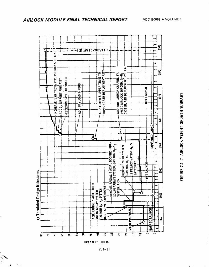
AIRLOCK MODULE FINAL TECHNICAL REPORT MDCE0899i VOLUME I
AIRLOCK MODULE F_._,_4LTECHNICAL REPORT MDCE0899• VOLUMEI
understandinq,system design evolution is discussed in the individual systpm
report sectio._s.
Although the Airlock Module evolved from the simple SSESM to a highly complex
space vehicle over the life of the program, the primary design requirement of
+_akinemaximum use of existing flight qualified hardware remained. Additionally,
the verificationprocess continued to stress extensive use of system engineering
analysis and previous test results in identifying the supplemental tests necessary _
to assure confidence in achieving primary mission objectives and preserving crew
safety.
L
] 9740] 8208-056
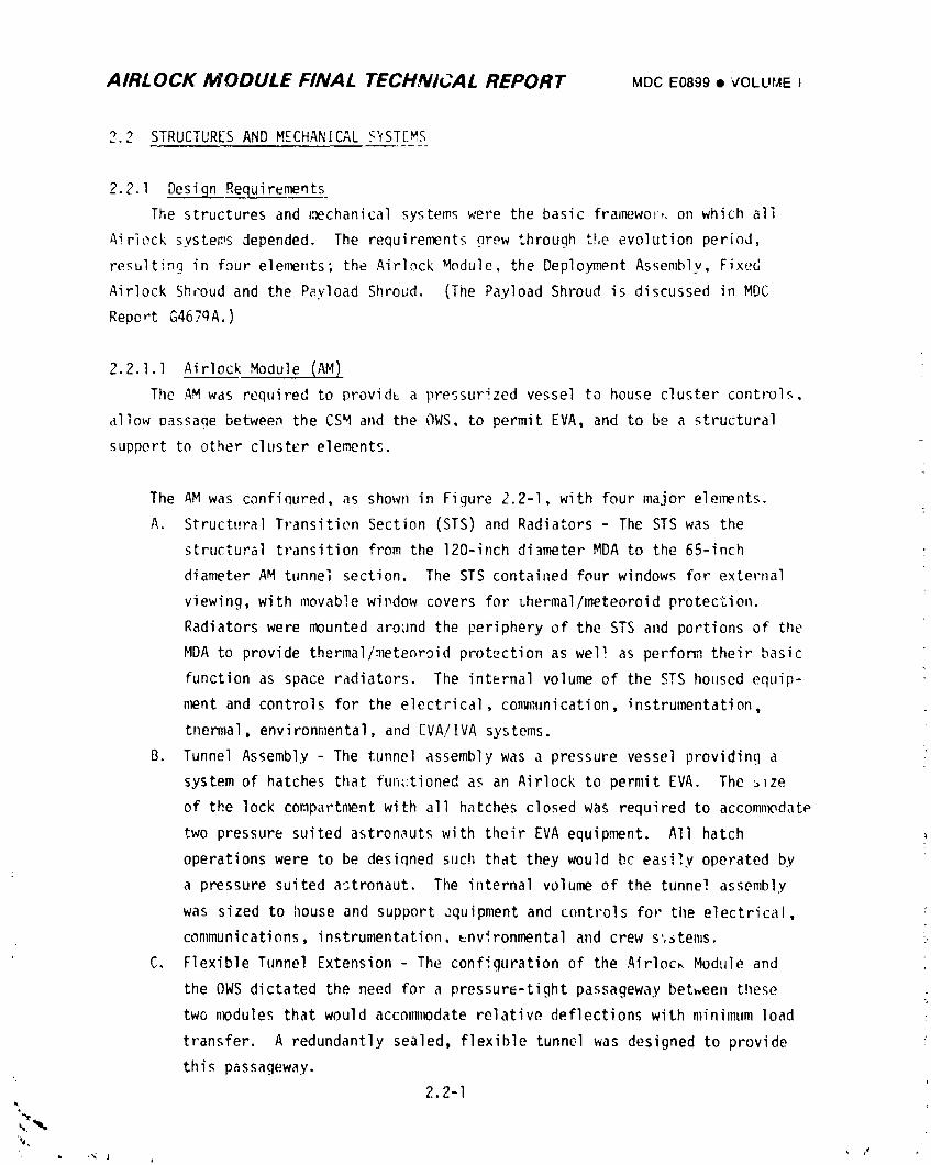
AIRLOCK MODULE FINAL TECHNICAL REPORT MDCE0899• VOLL'I'.4EI
2.2 STRUCTURESAND MECHANICALS?ST[MS
2.2.1 Design R_equirements
The structures and i_chanical systems were the basic fra_Iwawo_,,on which all
Airieck systems depended. The requirements nrew through the evolution period,
resulting in four elements, the Airlock Module, the Deployment Assembly, Fixed
Airlock Shroud and the Payload Shroud. (The Payload Shroud is discussed in MDC
Report G467qA.)
2.2.1.1 Airlock Module (AM)
The AMwas required to provid_ a pressurized vessel to house cluster controls,
allow passage between the CSMand the OWS, to permit EVA, and to be a structural
support to other cluster elements.
The AMwas confinured, as shown in Figure 2.2-I, with four major elements.
A. Structural Transitien Section (STS) and Radiators - The STS was the
structural transition from the 120-inch diameter MDAto the 65-inch
diameter AM tunnel section. The STS contained four windows for exte_'nal
viewing, with movable wi1_dow covers for thermal/meteoroid protection.
Radiators were mounted around the periphery of the STS and portions of the
MDAto provide thermal/meteoroid protection as well as perform their basic
function as space radiators. The internal volume of the STS housed equip-
ment and controls for the electrical, communication, instrumentation,
thermal, environn_ental, and [VA/IVA systems.
B. Tunnel Assembly - The tunnel assembly was a pressure vessel providing a
system of hatches that functioned as an Airlock to permit EVA. The _ze
of the lock compartn_nt with all hatches closed was required to accomn_date
two pressure suited astronauts with their EVA equipment. All hatch
operations were to be desiqned such that they would bc easily operated by
a pressure suited astronaut. The internal volume of the tunnel assembly
was sized to house and support equipment and controls for the electrical,
communications, instrun_entation, _nvironmental and crew s',stems.
C. Flexible Tunnel Extension - The configuration of the Airloc_ Module and
the OWSdictated the need for a pressure-tight passageway between these
two nw)dules that would acconmlodate relative deflections with minimum load
transfer. A redundantly sealed, flexible tunnel was designed to provide
this passageway.
2.2-I
I
1974018208-057
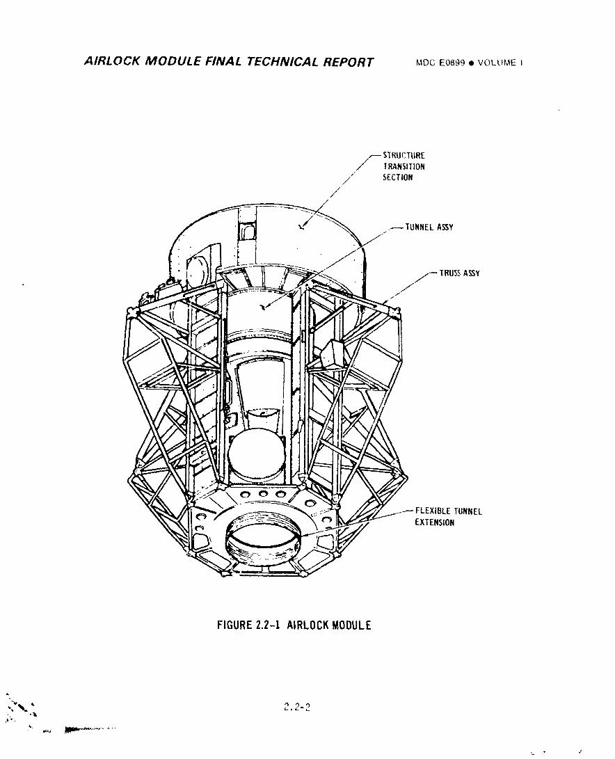
AIRLOCK MODULE FINAL TECHNICAL REPORT MDCEOB_9• VOLUUEI
S $TRUC,TLIRETRANSITION
./
/ SECTION
/
._ TUNNELASSY
J
/-- TRUSSASSY
i
FIGURE2.2-I AIRLOCKMODULE
J, v
1974018208-058
AIRLOCK MODULE FINAL TECHNICAL REPORT MDCE0899• VOLUMEI
D. Support Ir_,ss Assembly - The AM and MDAwere supperted by four truss _
:,_=,,,,,,:cs_" "",,,:t ,,-'_'e ,_....... to the t,-nne! assemhly and mated :_ith four attach
points on tne 7AS. The trusses were also used to support N2 tanks,
battery n',_Huies, experiments and miscel!aneous equipment.
2.2.1.2 Deploynw_nt Assembly (DA)
A deployment assembly was required for rotation of the ATM from a launch
stowed position to the mission operating position. The ATM was supported during
ground operations and launch by the PS. Upon PS separation the ATM was mechanically
rigidized to the DA which was then rotated 90° into its in-orbit position, with a
pointing accuracy of +! "_. Rotation of the ATMwas, to be accomplished in less than
lO minutes. The natural frequency of the deployed ATM/DAwas to be greater than
O. 6 Hertz.
2.2.1.3 Fixed Airlock Shroud (FAS)
_, structural assembly was to interface with the IU, provide continuity of
external surface configuration and provide attachments for the DA, AM, PS, and
02 tanks. Concentrated loads generated at these attachments were to be distri-
buted by the FAS to the IU interface. Access and ground umbilical doors were
required in the FAS. The FAS was also used to support ant_.nnas and miscellaneous
EVA equipment.
2.2-3i
Q it ,
] 974018208-059
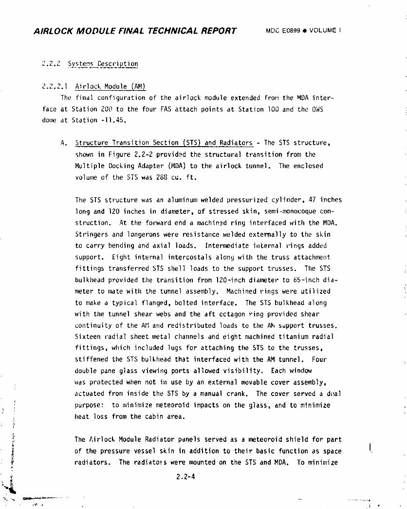
AIRLOCK MODULE FINAL TECHNICAL REPORT MDC E0899 • VOLUME I
2.2.2 Systems Bescription
2.2.2.1 Airlock Module (AM)
The final configuration of the airlock module extended from the MDAinter-
face at Station 200 to the four FAS attach points at Station I00 and the OWS
done at Station -11.45.
A. Structure Transition Section (STS) and Radiators - The STS structure,
shown in Figure 2.2-2 provided the structural transition from the
Multiple Docking Adapter (MDA) to the airlock tunnel. The enclosed
volunw_ of the STS was 288 cu. ft.
The STS structure was an aluminum welded pressurized cylinder, 47 inches
long and 120 inches in dian_ter, of stressed skin, semi-monocoque con-
struction. At the forward end a machin__dring interfaced with tileMDA.
Stringers and 1ongeronswere resistance welded externally to the skin
to carry bending and axial loads. Intermediateinternal rings added
support. Eight internal intercostals along with the truss attachment
fittings transferred STS shell loads to the support trusses. The STS
bulkhead provided the transition from 120-inch dianmter to 65-inch dia-J
nw_terto mate with the tunnel assembly. Machined rings were utilized
to make a typical flanged, bolted interface. The STS bulkhead along
with the tunnel shear webs and the aft cctagon ring provided shear
continuity of tl}eA_ and redistributed loads to the Ah sdpport trusses.
Sixteen radial sheet metal channels and eight machined titanium radial
fittings, which included lugs for attaching the STS to the trusses,
stiffened the STS bu]khead that interfacedwith the AM tunnel. Four
double pane glass viewing ports allowed visibility. Each window
was protected when not in use by an external movable cover assembly,
actuated from inside tileSTS by a manual crank. The cover served a dLlal
purpose: to minimize n_teoroid impacts on the glass, and to minimize
i heat loss from the cabin area.
; The Airlock Module Radiator panels served as a ,wzteoroidshield for partIof the pressure vessel skin in addition to their basic function as space
i radiators. The radiators were mounted on the STS and MDA. To minimize
_' 2.2-4I
1974018208-060
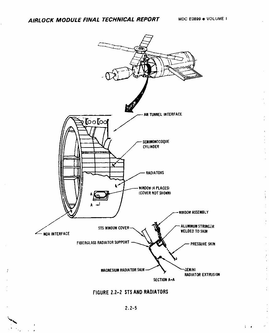
AIRLOCK MODULE FINAL TECHNICAL REPORT MOC E0899 • VOLUMEI
OO ...yAMTUNNELINTERFACE
SEJIIMONOCOQUECYLINDER
RADIATORS
I (4 PLACES)(COVERNOTSHOWN)
?
A-.J
f iVfttOOWASSEMBLY
S'-TS_INDOWCOVER "_ UMSTR/NG.:R
MAGNESIUMRADIATORSKINJ _v "-,GEMINIRADIATOREXTRUSION
: SECTIONA-A
FIGURE2.2-2 STSANDRADIATORS
2.2-5
1974018208-061
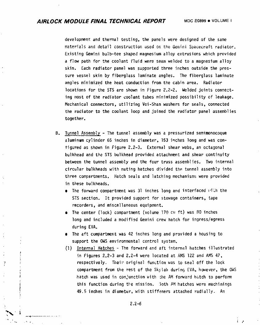
AIRLOCK MODULE FINAL TECHNICAL REPORT MDCE0899• VOLUMEI
development and thermal testing, the panels were designed of the same
materials and detail construction used on the Gen_iniSpacecraft radiator.
Existing Gemini bulb-tee shaped magnesium alloy extrusions which provided
a flow path for the coolant fluid were seam welded to a magnesium alloy
skin. Each radiator panel was supported three inches outside the pres-
sure vessel skin by fiberglass laminate angles. The fiberglass laminate
angles minimized the heat conduction from the cabin area. Radiator
locations for the STS are shown in Figure 2.2-2. Welded joints connect-
ing most of the radiator coolant tubes minimized possibility of leakage.
Mechanical connectors, utilizing Voi-Shan washers for seals, connected
the radiator to the coolant loop and joined the radiator panel assemblies
together.
B. Tunnel Assembl_,- The tunnel assembly was a pressurized seminmnocoque
a]uminum cylinder 65 inches in diameter, 153 inches long and was con-
figured as shown in Figure 2.2-3. External shear webs, an octagonal
bulkhead and the STS bulkhead provided attachment and shear continuity
between the tunnel assembly and the four truss assemblies. Two internal
circular bulkheads with mating hatches divided the tunnel assembly into
three compartments. Hatch seals and latching mechanisms were provided
in these bulkheads.
• The forward compartment was 31 inches long and interfaced ,_,iththe
STS section. It provided support for stowage containers, tape
recorders, and miscellaneous equipment.
• The center (lock) compartment (volume 170 cuft) was 80 inches
long and included a modifi__dGemini crew hatch for ingress/egress
during EVA.
¢ The aft compartment was 42 inches long and provided a housing to
i support the OWS environmental control system.
(1) Internal Hatches -.The forward and aft internal hatches illustrated
in Figures 2.2-3 at_d2.2-4 were located at AMS 122 and AMS 42,
}, respectively. Tileiroriginal function was to seal off the lock
compartment from the rest of the Skylab during EVA, however, the OWS
hatch was used ir_conjunction with :he AM forward hatch to perform
this function during t_'emission, r)othAM hatches were machinings
_ 49.5 inches in diameter, with stiff,.=nersattached radially. An
: 2.2-6•
1974018208-062
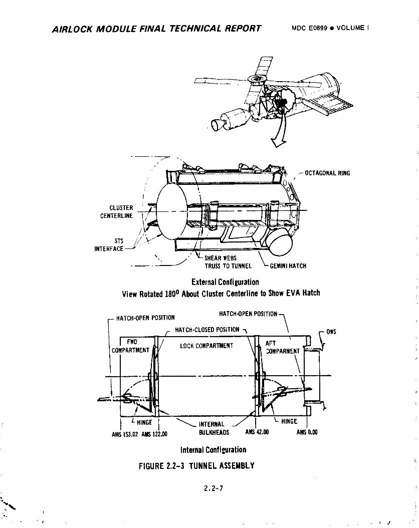
AIRLOCK MODULE FINAL TECHNICAL REPORT MDCE0899• VOLUMEI
/
,- OCTAGONALRING
C)0/
CLUSTER 'CENTERLINE
STS //,.,INTERFACE_' "
%. ,',, j SHEARWEBS- --- TRUSSTOTUNNEL GEMINIHATCH
ExternalConfigurationViewRotated1800AboutClusterCenterlineto ShowEVAHatch
- HATCH-OPENPOSITION HATCH-OPENPOSlTION-_/- HATCH-CLOSEDPOSITION-._ OWS
I Fwo \ 'COMPARTMENT LOCKCOMPARTMENT AFT U_OMPARMENT
• "'_ d
.2
l
AMS1_.02Am122._ BUL_r_DS Am42.OO AMS0._
InternalConfiguration
FIGURE2.2-3 TUNNELASSEMBLY '_
2,2-7k
- !
J. , _ , _ _ . | ¢f
1974018208-063
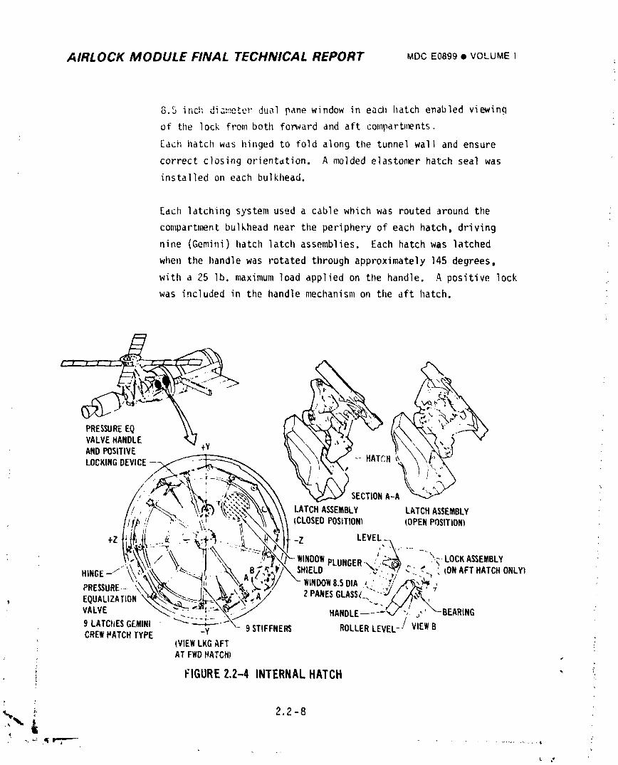
AIRLOCK MODULE FINAL TECHNICAL REPORT MDCE0899• VOLUMEI
8.5 inch dia_,ete:"dual pane window in each hatch enabled viewing
of the lock from both fonvard and aft comparb_ents.
Eaci_hatch was hinged to fold along the tunnel wall and ensure
correct closing orientdtion. A molded elaston_r hatch seal was
installed on each bulkhead.
Each latching system used a cable which was routed around the
compartnw_ntbulkhead near the periphery of each hatch, driving
nine (Gemini) hatch latch assemblies. Each hatch was latched
when the handle was rotated through approximately 145 degrees,
with a 25 lb. maximum load applied on the handle. A positive lock .-
was included in the handle mechanism on the aft hatch.
VALVEHANDLE _ _ _ \i_i.£'_
ANDPOSITIVE
LOCKINGDEVICE--_. - HATCH
ill'iLI _'.._'_:""_L_ ---_I_" _ _Ik\\ICLOSEDPOSITIONI IOPENPOSITIONI
,_ WINDOWPLUNGER-.,'_--'_-_ .-_LOCKASSEMBLY _'
PRESSURE....C_ " ' " --k ,_'> / "-WINDOW8.5DIA _.,'.",'/..,C_)_'
VALVE _" -- _-_ ._ """-. ........-_// HANDLE---_/ ";._,'_-BEARING
9LATC'IESGEMINI-_-___ STIFFNER_ ROLLERLEVEL-/VIEWBCREWMATCHTYPE _y 9
(VIEWLKGAFTATFWDHATCH)
; FIGURE2.2-4 INTERNALHATCH "
;_ 2.2 -8
-,_ ._!,e"?"-_- • ................ ,
1974018208-064
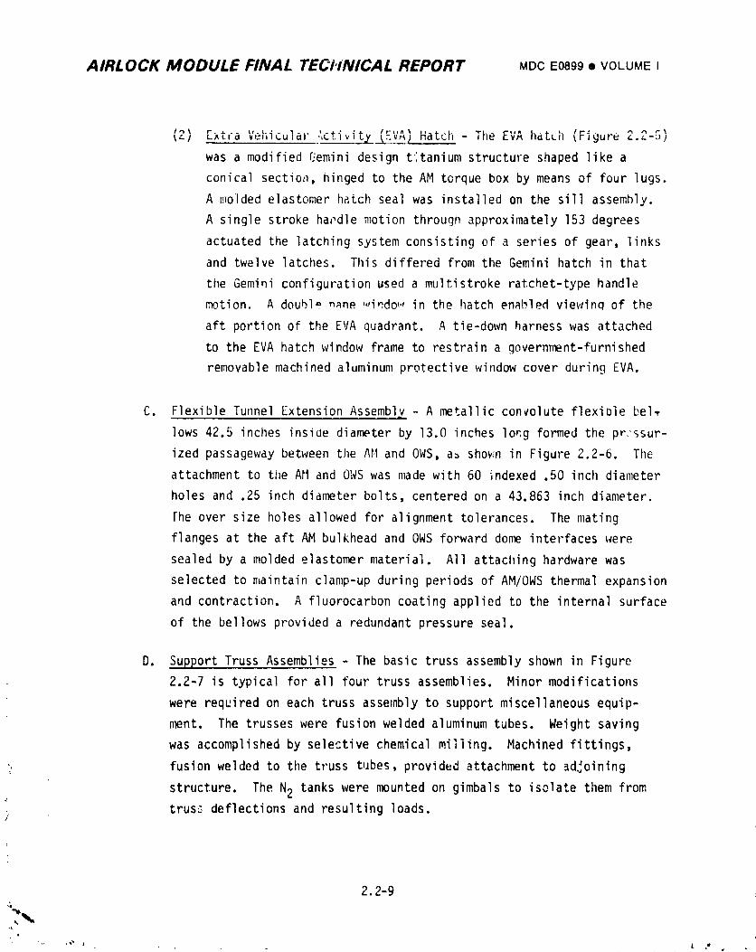
AIRLOCK MODULE FINAL TECHNICAL REPORT MDCE0899• VOLUMEI
_,) [xt,a Vehicular ',ctivitv l;.v_/ Hatch - The EVA hatch (Figure c._-5)
was a modified qemini design titanium structure shaped like a
conical sectioa, hinged to the AM torque box by means of four lugs.
A molded elastomer hatch seal was installed on the sill assembly.
A single stroke ha_dle motion through approximately 153 degrees
actuated the latching system consisting of a series of gear, links
and twelve latches. This differed from the Gemini hatch in that
tile Gemini configuration used a multi stroke ratchet-type handle
motion. A double n_ne ,,,indo_., in the hatch enabled viewinq of the
aft portion of the EVA quadrant. A tie-down harness was attached
to the EVA hatch window frame to restrain a government-furnished
removable machined aluminum protective window cover during EVA.
C. Flexible Tunnel Extension Assembl X - A metallic convolute flexiDie bel_
lows 42.5 inches inside diameter by 13.0 inches long formed the pr:ssur-
ized passageway between the AM and OWS, a_ shov.n in Figure 2.2-6. The
attachment to the All and OWSwas made with 60 indexed .50 inch diameter
holes and .25 inch diameter bolts, centered on a 43.863 inch diameter.
The over size holes allowed for alignment tolerances. The mating
flanges at the aft AM bulkhead and OWSforward dome interfaces were
sealed by a molded elastomer material. All attaching hardware was
selected to maintain clamp-up during periods of AM/OWSthermal expansion
and contraction. A fluorocarbon coating applied to the internal surface
of the bellows provided a redundant pressure seal.
D. Support Truss Assemblies - The basic truss assembly shown in Figure
2.2-7 is typical for all four truss assemblies. Minor modifications
were required on each truss assembly to support miscellaneous equip-
ment. The trusses were fusion welded aluminum tubes. Weight saving
was accomplished by selective chemical milling. Machined fittings,
•, fusion welded to the truss tubes, provided attachment to adjoining
structure. The N2 tanks were mounted on gimbals to isolate them from' trusc_deflections and resulting loads./
2.2-94
i 9740i 8208-065
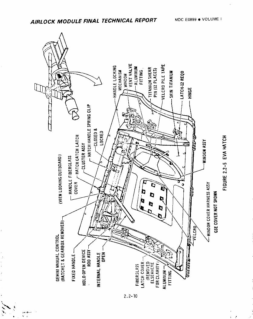
AIRLOCK MODULE FINAL TECHNICAL REPORT MDCE0899• VOLUME I
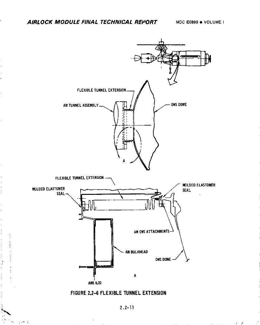
AIRLOCK MODULE FINAL TECHNICAL REPORT MDCE0899I VOLUMEI
FLEXIBLETUNNEL
AMTUNNELASSEMBLY OWSDOME
FLEXIBLETUNNELEXTENSION
" MOLDEDELASTOMERMOLDEDELASTOMER SEAL
SEAL--_
AMOWSATTAC
_ AMBULKHEAD
OWSDOME
A
- AMS0,00
'_ FIGURE2.2-6 FLEXIBLETUNNELEXTENSION
,!_,,_ 2.2-11
1974018208-067
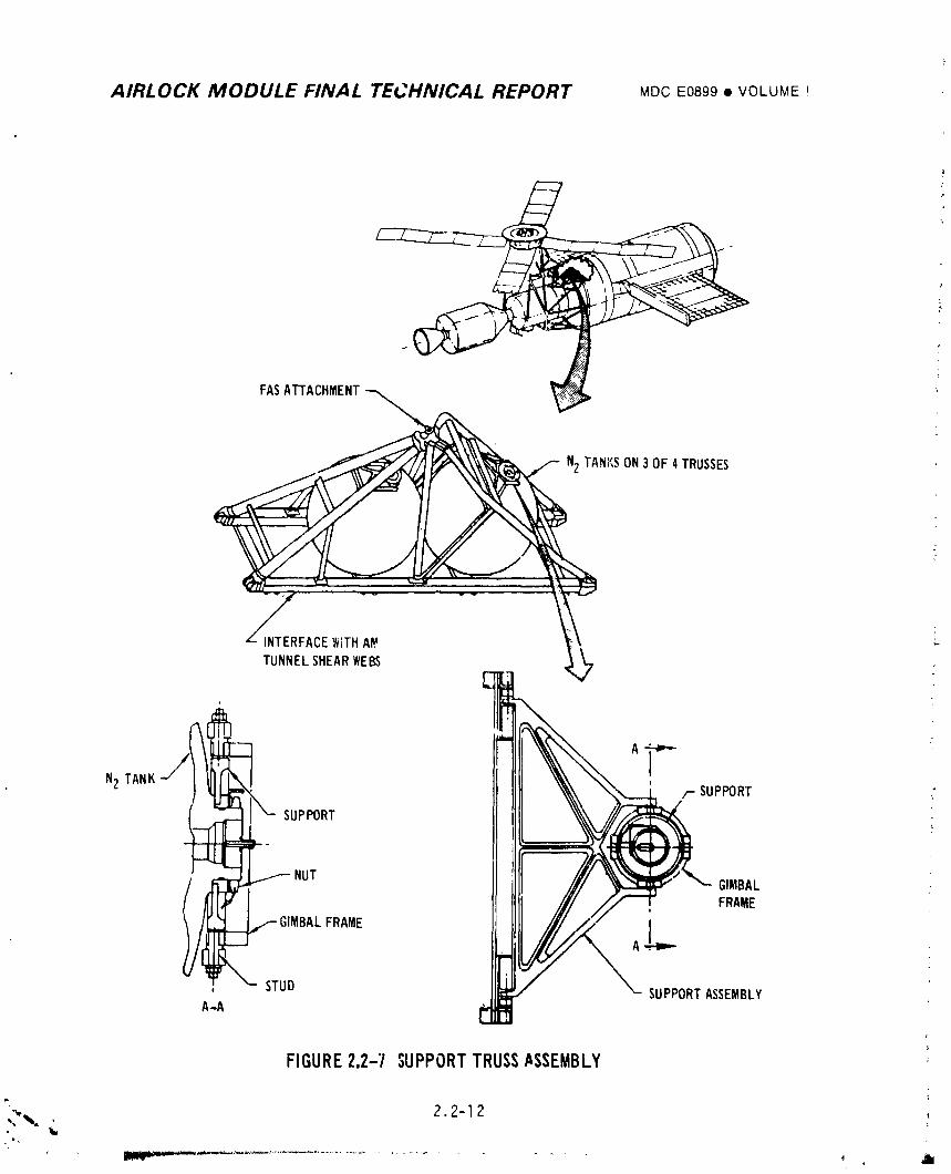
AIRLOCK MODULE FINAL TECHNICAL REPORT MDCE0899• VOLUME!
b,FASAI'FACHMENT
CEWITH
TUNNELSHEARWEBS
N2TANK/-- SUPPORT
_-- SUPPORT
_-.
/ _ _" _NUT FRAMEG'MBAL -
: "- STUD SUPPORTASSEMBLYA-A
FIGURE2.2-7 SUPPORTTRUSSASSEMBLY
_'_- 22-12Iw,
i 9740i 8208-068
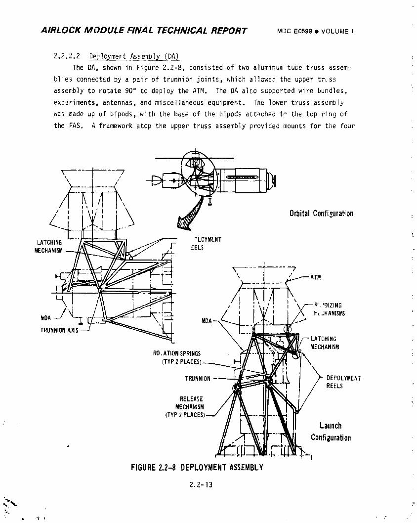
AIRLOCK MODULE FINAL TECHNICAL REPORT MDCE0899• VOLUMEI
2.2.2.2 Dep!oymert Assembly IDA)
The DA, shown in Figure 2.2-8, consisted of two aluminum tube truss assem-
blies connected by a pair of trunnion joints, which allowed the upper tr_ss
assembly to rotate 90 ° to deploy the ATM. The DA al_o supported wire bundles,
experiments, antennas, and miscellaneous equipment. The lower truss assembly
was made up of bipods, with the base of the bipods attached t _ the top ring of
the FAS. A frdmework atcp the upper truss assembly provided mounts for the four
7
/ f t '_ OrbitalConfi_rationL "LOYMENT
LATCHING J _ \_7AIMECHANISM J' -" "_.__._Y,(II17/ ,! EELS
t -
_ ,_-1_ t I '91ZINGI I_x,.;HANISMS
NIDA " ,._
LATCHINGMECHANISM
RO,ATIONSPRINGS
(TYP2 PLACES\
TRUNNION- _" DEPOLYMENTREELS
RELEASE oMECHANISM
(TYP2PLACES
_ Launch
Configuration
FIGURE2.2-8 DEPLOYMENTASSEMBLY
2.2-13
,,.._., :,-
1974018208-069
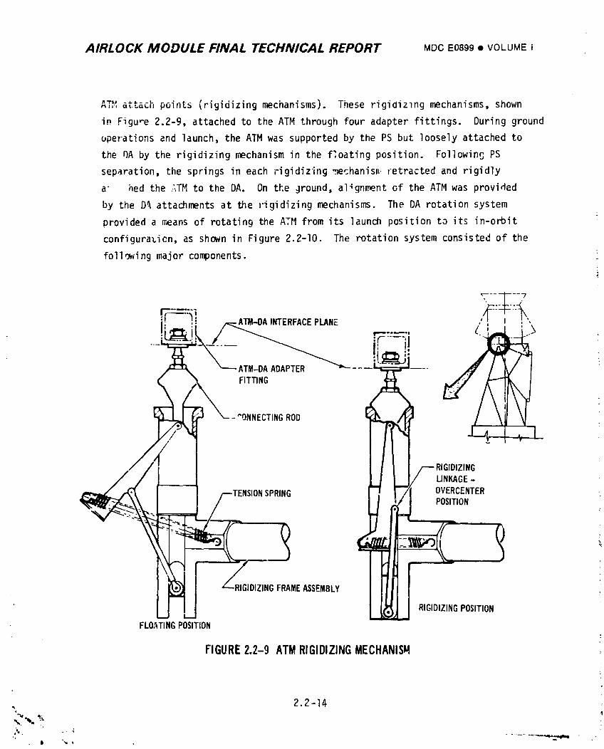
AIRLOCK MODULE FINAL TECHNICAL REPORT MDCEOB99m VOLUMEI
ATe'attach points (rigidizingmechanisms). These rigidiz_ng mechanisms, shown
in Figure 2.2-9, attached to the ATM through four adapter fittings. During ground
operations and launch, the ATM was supported by the PS but loosely attached to
the DA by the rigidizing mechanism in the f:oating position. Following PS
separation, the springs in each rigidizing _echanisn retracted and rigidly
a" hed the _TM to the DA. On the jround, alignment of the ATM was provided
by the D_ attachments at the rigidizing mechanisms. The DA rotation system
provided a means of rotating the ATtlfrom its launch position to its in-orbit
configurazicn,as shown in Figure 2.2-I0. The rotation system consisted of the
following major components.
{
li :. _,.-ATM-.DAINTERFACEPLANE , ,
t
_---ATM-DAADAPTER _- ----_ ---"
FITTING
.!_, I . 7;ROD
• .[ I -'
F RIGIDIZINGLINKAGE-P'- OVERCENTER
SPRING l/ POSITION
RIGIDIZINGFRAMEASSEMBLY _ I RIGIDIZINGPOSITIONFLOATINGPOSITION
FIGURE2.2-9 ATMRIGIDIZINGMECHANISM
, 2.2-14
_,_, _
,, . ....... _,-..,,,..4,,.y_lmm m ,_ •I 'w *
1974018208-070
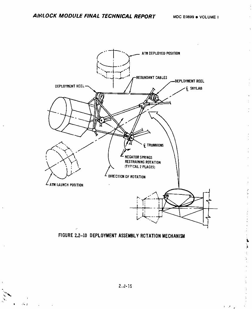
AIRLOCK MODULE FINAL TECHNICAL REPORT MDCE0899• VOLUMEI
'" -- _ "" _ ATMDEPLOYEDPOSITION
I, "r'--' •"'"_:.L : "J.-.J,,.-'" CABLES
REEL
DEPLOYMENT / _ SKYI.AB
- iS
'_ NEGATORSPR,NCS \_,'";' RESTRAININGROTATION
,_\ _ ..,_ //_ (I"YP'CAL:_PLACES) ,"- DIRECTIONOFROTATION
Am LAUNCHPOSITION
s s
FIGURE2,2-10 DEPLOYMENTASSEMBLYRCTATIONMECHANISM
k: .4
2.2-15. !
"",, f "
z :_ J
1974018208-071
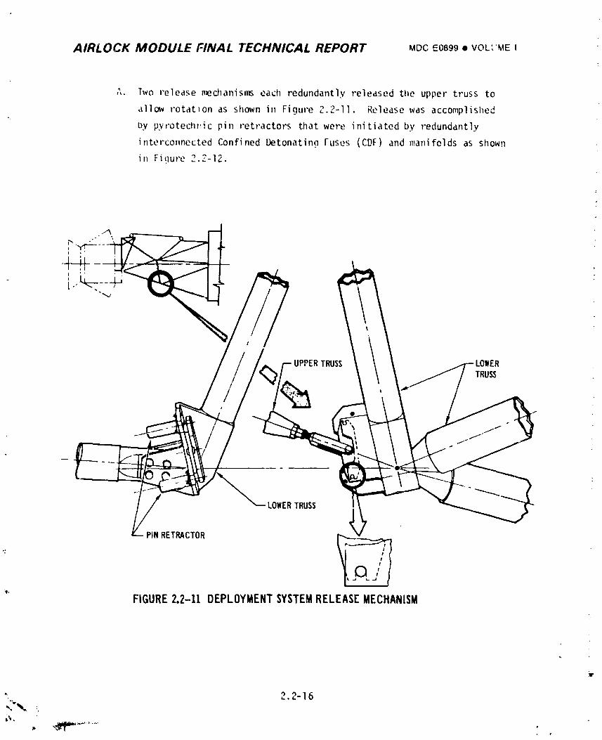
AIRLOCK MODULE FINAL TECHNICAL REPORT MDCE0899• VOL','MEI
;,. Two release nw_d_anisms each redundantly released the upper truss to
a11c_v rotation as shown in Figure 2.2-11. Release was accomplished
by pyvotechllic pin retractors that were initiated by redundantly
interconnected Confined Detonatin_ Fuses (CDF) and manifelds as shown
in Figure 2.?-12.
UPPERTRUSSTRUSS
LOWERTRUSS
PINRETRACTOR
": /#
e#qJFIGURE2.2-11 DEPLOYMENTSYSTEMRELEASEMECHANISM
Y
" 2.2-16,,C,"%,_',,,,
1974018208-072
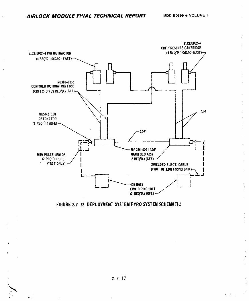
AIRLOCK MODULE FPVAL TECHNICAL REPORT MDC E0899 • VOLUMEI
:51C130002-7
CDFPRESSLIKECARTRIDGE
GtC.,330002-3PINRETRACTOR1
t4REQ'O3(MDAC-EAST)_
CONFINEDDETONATINGFUSE
(COF)(5 LI"IESREQ'O.) ,.
',DF
7865742EBWDETOHATOR
(2eEq'O.)(GFE)_. /--COF
L---J_
_i" "-] uE288.-ooo;COF I
MANIFOLDA_Y IEBWPULSEEENSOR (2REQtD.}(GFE)
12REQ'D._,GFEI SHIELDEDELECT.CABLE |
• (TESTONLY) (PARTOF EBWFIRINGUNI'i")---_ |
40klZ9515
EBWFIRINGUNIT /(2 REQ'D.)(GFEI
FIGURE2,2-12 DEPLOYMENTSYSTEMPYROSYSTEM_CHEMATIC
2.2-17
I. t
1
' 07- 1974018208-
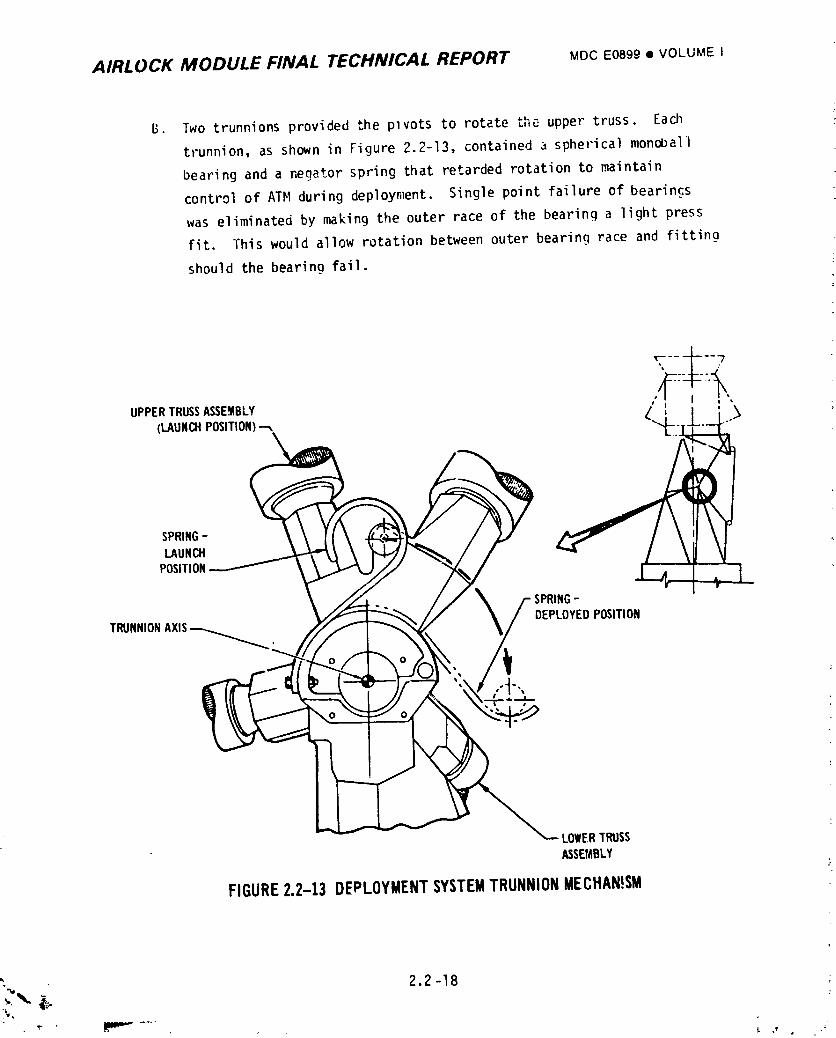
AIRLOCK MODULE FINAL TECHNICAL REPORT MOOE0899• VOLUME I
B. Two trunnions provided the plvots to rotate tha upper truss. Each
trunnion, as shown in Figure 2.2-13, contained a spherical monoUall
bearing and a negator spring that retarded rotation to maintain
control of ATM during deployment. Single point failure of bearings
was eliminated by making the outer race of the bearing a light press
fit. This would allow rotation between outer bearing race and fitting
should the bearing fail.
UPPERTRUSSASSEMBLY , _ _
(LAUNCHPOSITION)_ /' _'
SPRING-LAUNCH
POSITION
SPRING-
TRUNNIONAXIS DEPLOYEDPOSITION
LOWERTRUSSASSEMBLY
FIGURE2.2-13 DEPLOYMENTSYSTEMTRUNNIONMECHAN!SM
_,,_ 2.2 -18
19740i 8208-074
AIRLOCK MODULE FINAL TECHNICAL REPORT MDCE0899• VOLUMEI
C. Two deD1_vm_nt rPelK prnvi(|Pd thp redundant means to pull (rotate) the
ATH into the deployed position. The reels were mechanically designed to
redundantly lock against cable paying out and were sized to be capable
of reeliPc in all the cable r_quired for total deployment with one reel
inoperative. Each reel was capable of total deployment regardless of the
point of failure of the other reel. When the ATM DA reached the deployed
position, switches on the latch mechanism were cycled, initiating a time
delay relay which cut off power to the reels after they had achieved
their full stal] load and DA deploy latchimg was complete.
D. The latch mechanism, sho',n in Figure 2.2-14, was used to retain the
ATH/DA in the deployed position. Camaction retracted the spring
loaded latch as the ATM/DA approached the deployed position. At the
deployed position the spring force latched the hook, eliminating all
assembly movement due to thruster attitude control system firings. A
ratchet mechanism made the latch irreversible, locking the ATM/DA in
the deployed p_sition. Upon latching, redundant switches were cycled
initiating turn off of the deployment reels. This triggered the TM
signal that deployn_nt was completed and removed the inhibit from the
ATM SAS deployment system.
2.2.2.3 Fixed Airlock Shroud
The FAS was a ring-stiffened thick-skinned cylinder approximately 80 inches
in height, 260 inches in diameter and configured as shown in Figure 2o2-15.
Intercostals distributed concentrated loads introduced by the DA, AM and 02 tank
support points. Two doors were provided in the FAS; one for access to the FAS
interior and the AM EVA hatch during ground operations and the other for access
to ground umbilical connectors. Four antennas; two deployable discones, and two
UHF antennas were mounted on the FAS. The FAS structure also contained EVA
support equipment as follows: egress handrails, work platform, film cassette tree
supports, film transfer boom also called TEE, a TEE hook stowage box and lights.
2.2-19
h ,_ d _ ae
1974018208-075
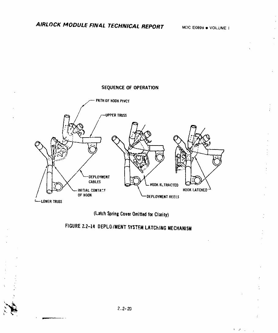
AIRLOCK MODULE FINAL TECHNICAL REPORT Mt_CE0899• VOLUMEI
SEQUENCEOFOPERATION
PATH OF HOOKPIVCT
/--UPPER TRUSS _ _ /7
CABLES R_.TRACTEO _ '"" _ \
__InN/THAnL:ONTA3T____ DEPLO,MENT REELS HOOKLATCHED'"
c_..LOWERTRUSS
(LatchSpringCoverOmittedforClarity)
FIGURE2.2-14 DEPLO/MENT._;YSTEMLATCHINGMECHANISM
;_'-_ 2.2-20
1974018208-076
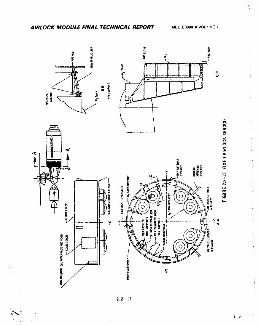
%
AIRLOCK MODULE FINAL TECHNICAL REPORT MDC E0899 • VOL_'MEI
I
1974018208-077
AIRLOCK MODULE FINAL TECHNICAL REPORT MDCE0899¢ VOLUMEI
2.2.3 System Verification
2.2.3.1 qualification Testing
: A. Structural integrity of the Airlock Tunnel and STS was demonstrated _#ith
Static Test Article No. l vehicle mated to the static test MDA. This
structure was subjected to 12.4 psid and to ultimate loads simulating
"wet" workshop launch and ascent loads. The launch and ascent loads
for the "dry" workshop configuration were later verified by analysis as
i reported in "Verificationof U-l Launch and Ascent Structural Capabilities
Based on Evaluation of STA-I Static Test Results," MAC Report E0517.
Structural capability for subsequent weight increases was verified by
analysis and reported in "Effect of AM/MDA Mass Properties Change on
AM Structural Capabilities,"MAC Report E0654.
B. The EVA hatch and internal hatch seals were initially fabricated to the
same ultra low durometer silicone rubber compound requirements as those
successfully used on the Gemini flights. Although these seals did not
leak it became apparent during AM checkout and seal specimen testing
that the Gemini seal compound was unacceptable for tl.eSkylab long-term
space environment. This was evidenced by specimen testing which reflected
a low and inconsistent state of cure resulting in excessive outgassing,
inconsistent hardness, undesirable surface adhesion, poor bond integrity
and unacceptable permanent set. Therefore, a new seal compound was
developed which was basically the same as the Gemini seal except _abri-
cated with up-to-date rubber industry technology, methods and techniques.
A consistent low durometer silicone rubber cJmpound was developed that
would fully cure with low outgassing prope':tiesand was resistant to
compression set and reversion. A cleanir_ procedure and the application
of a surface release agent was developed for maximum reduction of sur-
face adhesion. Verification testing was conducted by subjecting a flight
article seal segment to temperature altitude testing. Tileresults
verified that the above objectives had been met.
C. Tileinternal hatch and its meci,tn_smsystem was qualified in a test fix-
ture wI1ichsimulated a 3-foot section of the AM tunnel s_ructure includir_
a production type forward hatch bulkhead and sill assembly. All func-
._ tional, pressure, leakage, handle loads, life cycles and environmental
, requirements were successfully demonstrated.
'. _':. 2.2-22
i9740i8208-078
AIRLOCK MODULE i:;NAL TECHNICAL REPORT MDCE0899• VOLUMEI
D. To establish c_nfidence in the design cancept for the flexible tunnel
extension bellows, a readily available bellows, similar to the eventual
production configuration,was subjected to _ibration, stiffness and
fatlgue te.ting. Results of these tests proved the concept acceptable.
E. Prior to avai1_bility of the first production DA, a steel truss with
spring rates equivalent to the flight article was used for development
testing of the DA desiqn concept. The steel truss, with production
fittings and components at the critical areas, was supported horizontally
with the rotation axis normal to the ground. A system of pulleys,
counterbalancu.(and pivots were employed to simulate the effect of zero
gravity and ATN inertia upon deployment. Overall system perfomance was
evaluated with induced failure modes. Cycle life of the deployment reels
and the effect of flexing of the wire bundles at the trunnions were prime
objectives. The only significant change that resulted was the addition
of a spring mecF,anism to the deployment reels to insure control of the
deployment reel cables during deployment. All objectives of the
developn_nt testing were successfully met.
F, Qualification testing of DA components was conducted at the component
le_,,l as recorded in the Airlock Equipn_nt Acceptability Review-Structural
and Mechanical Systems, MDCReport G499, Volume 4. In addition, the
deployment assembly was subjected to a total system qualification test.
The first production DA (STA-3) was mounted horizontally to a simulated
FAS with the trunnion axis vertical. Counterbalances were attached at
optimum points to simulate zero-g and the ATM mass was simulated. All
mechanisms and systems were successfully operated durirg the qualification
cycle.
G. The FAS and DA were designed to a factor of safety of 3.0 for manned
loading conditions and 2.0 for unmanned. Strength analysis, utilizinq
finite element computer programning when justified, was performed to
show structural capability. Based on these large factors of safety and
the detailed strength analysis, static testing was not required tJ
verify the structural adequacy, All major structural components of the
AM including the FAS and DA were subjected to vibro-acoustic testing and
successfully passed these environments.
: 2.2-23
i-,.
1974018208-079
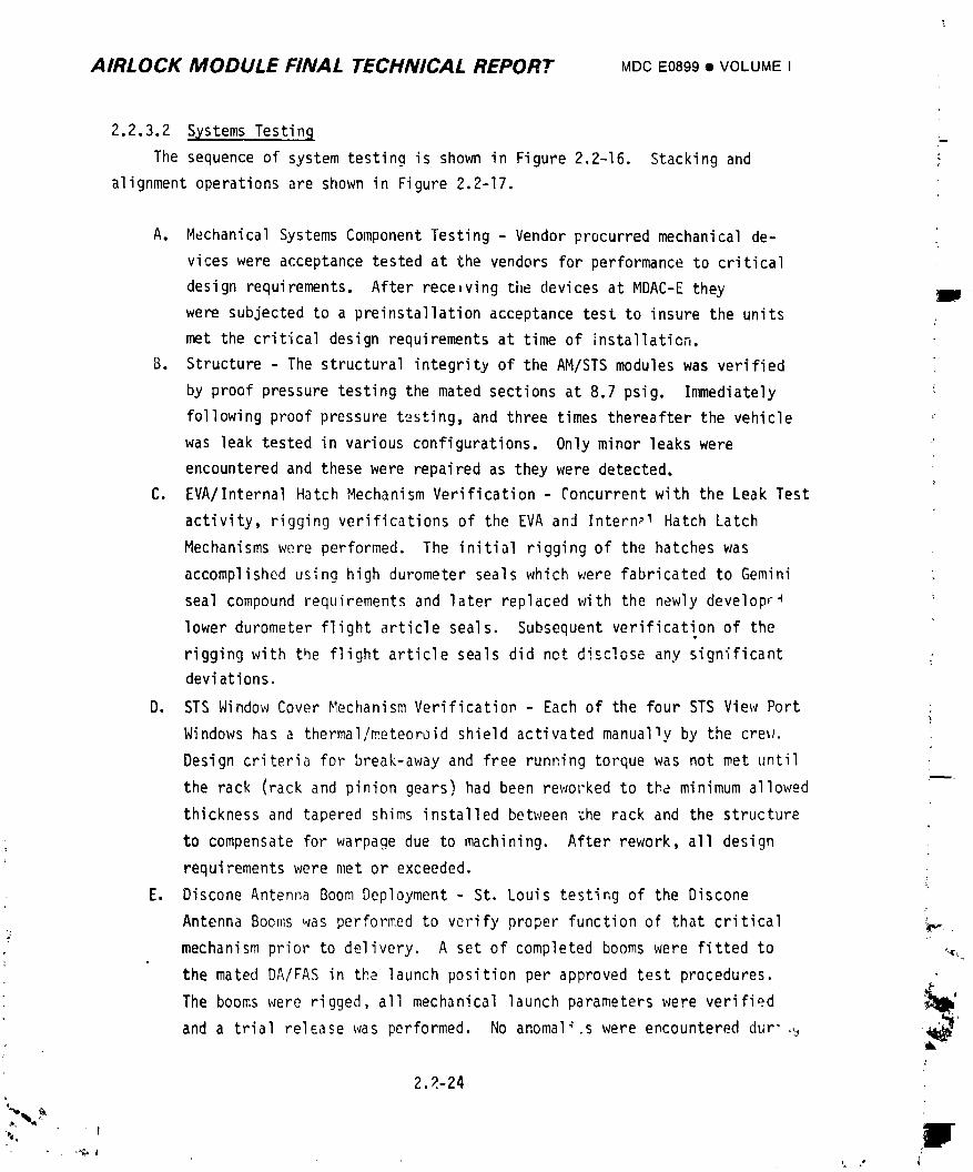
AIRLOCK MODULE FINAL TECHNICAL REPORT MDCE0899• VOLUMEI
2.2.3.2 Systems Testin9
The sequence of system testing is shown in Figure 2.2-16. Stacking and
alignment operations are shown in Figure 2.2-17.
A. Mechanical Systems Component Testing - Vendor procurred mechanical de-
vices were acceptance tested at the vendors for performance to critical
design requirements. After receiving the devices at MDAC-E they
were subjected to a preinstallationacceptance test to insure the units /
met the critical design requirements at time of installation.
B. Structure - The structural integrity of the AM/STS modules was verified
by proof pressure testing the mated sections at 8.7 psig. Immediately ':
following proof pressure testing, and three times thereafter the vehicle
was leak tested in various configurations. Only minor leaks were
encountered and these were repaired as they were detected.
C. EVA/Internal Hatch Mechanism Verification - Concurrent with the Leak Test
activity, rigging verifications of the EVA and Intern_1 Hatch Latch
Mechanisms were performed. The initial rigging of the hatches was
accomplished using high durometer seals which were fabricated to Gemini
seal compound requirements and later replaced with the newly developr_
lower durometer flight article seals. Subsequent verification of thet
rigging with the flight article seals did not disclose any significantdeviations,
D. STS Window Cover Mechanism Verificatiop - Each of the four STS View Port
Windows has a thermal/_eteoroid shield activated manually by the creel.
Design criteria for break-away and free running torque was not met until
the rack (rack and pinion gears) had been reworked to the minimum allowed
thickness and tapered shims installed between the rack and the structure
to compensate for warpage due to machining. After rework, all design
requirements were met or exceeded.
E. Discone Antenna Boom Deployment - St. Louis testing of the Discone
Antenna Booms was performed to verify proper function of that critical _r_'_.
mechanism prior to delivery. A set of completed booms were fitted to ,,,i
the mated DA/FAS in the launch position per approved test procedures. /.
The booms were rigged, all mechanical launch parameters were verified _°
and a trial release was performed. No anomal_.s were encountered dur" ,,j _'
2.2-24,,
i ,i i
1974018208-080
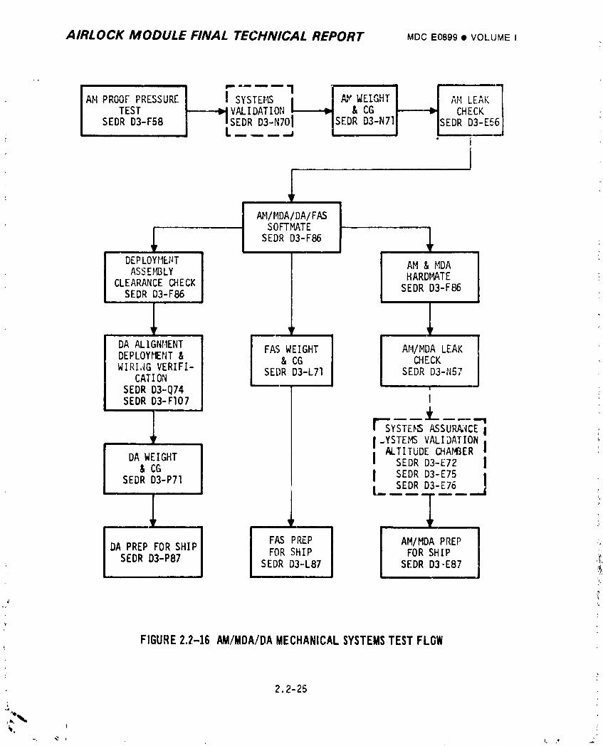
AIRLOCK MODULE FINAL TECHNICAL REPORT MDCE0899• VOLUMEI
I i'sTST_"1 I ,,' "AN PROOFPRESSURE AV WEIG AMLEAKTEST _,---_._VALIDATION _ & CG _ CHECK
SEDR D3-F58 m ISEDR D3-N701 ISEDRD3-N71 SEDR D3-E56, I L ..- ...- .-......; 1 • -
i
ir
AMIMDA/DA/FASSOFTMATE
SEDRD3-F86 ,_ _ , .DEPLOYMENT I AM & MDA
ASSEMBLY I HARDMATECLEARANCECHECK SEDR D3-F86SEDR D3-F86
ii
,,DA ALIGNMENT FAS WEIGHT AM/MDALEAK :DEPLOYMENT& & CG CHECKWIRI;4GVERIFI- SEDRD3-L71 SEDRD3-N57
CATIONSEDR D3-Q74 ' :SEDRD3-F107 I
r-_sy_ E_ ASSTR_ E II.YSTEMSVALIDATION
ALTITUDECHA_fJERiDA WEIGHT I SEDR D3-E72 I& CGSEDR D3-P71 I SEDR D3-E75 I
[_ SEDR D_-E76
mm am,
I FAS PREP l AM/MDAPREP
DA PREP FOR SHIP FOR SHIP FOR SHIP _
SEDR D3-P87 SEDR D3-.L87 SEDR D3-E87 '_"
FIGURE2.2-16AM/MDA/DA MECHANICAL SYSTEMSTEST FLOW
2.2-25
1974018208-081
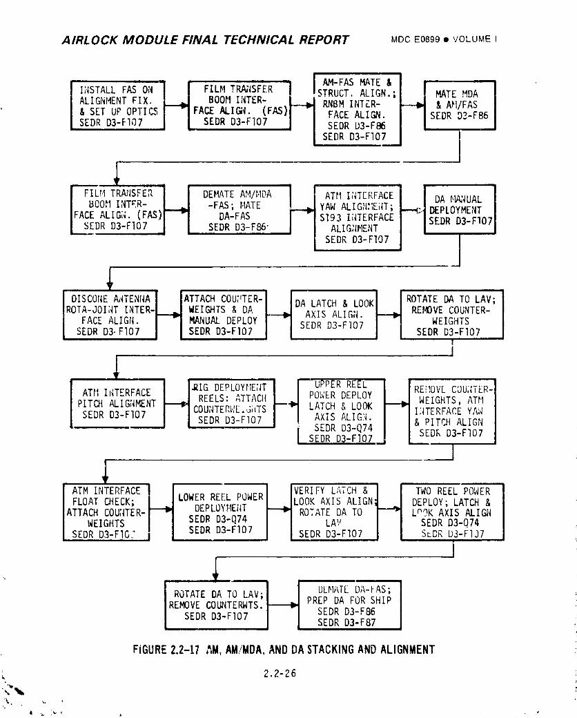
AIRLOCK MODULE FINAL TECHNICAL REPORT MDCE0899• VOLUMEI
I;_STALLFASON I I FILMTRN_SFER'"i AM-FASMATE &ALIGNMENTFIX. l .] BOOMINTER- _ STRUCT.ALIGN.; MATEMDA& SET UP OPTICSJ "lF'ACEALIGN. (FAS)I_ RNBM INTZR- & AH/FASSEDR D3-Fl07 J L SEDR D3-FIO7 J SEDRFACEALIGN.u3_F86 SEDR D3-F86
_SEDR D3-FI07 j II
BOOH INT_.R- | _ -FAS; MATE YAW ALIGNt_Ei_T;_..(_DEPLOYMENTFACEALIGi_.(FAS)F--_I DA-FAS S193 I;_TERFACE SEDR D3-FIO)
._EDRD3-FI07 | [ SEDR DB-F86" ALIG_IMENT
SEDR D3-FI07 ]
DISCOr_EA,_TENr_AJ lATTACHCOU:'TER-IIDA'_TC., oo,I IROTATEDATOLAV;,o:_-_OI,Tt,,TE,-L_.JWEIC_TS,OA_ _X__,I_,._ RE.OVECOU,_,-WEIGHTS
FACEALIGN. I "] MANUALDEPLOYI -J SEDRD3-FI07 J j SEDRD3-FI07SEDRD3.FIO;'I I SEDRD3-F107I I ,,!
I
,__- I I_GDEPLOYHE;_TI !--UPPERREELATH I T_KFACE _ REELS:ATTACHI_J POWER DEPLOY REi]OV[COU;ITER-PITCHALIGNMENTj "JCOU,_TERI'IF_GhTSr---_'1LATCH & LOOK ._ WEIGHTS,ATMSEDR D3-FI07 j J SEDR D3-FI07 || AXIS ALIG_. Ii_TERFAC,E YAW
_ SEDR D3-Q74 & PITCH ALIGNJ SEDR D3-FI07 SEDF,D3-FI07
HFLOAT CHECK; LOWERREI-LPOWERI ,]LOOKAXIS ALIGN___J DEPLOY;LATCH&
ATTACH COU;_TER- DEPLOYMEIIT ROTAT DA TO LnOK AXIS ALIGNWEIGHTS SEDR D3-Q74 A SEDR D3-Q74
SEDR D3-FIG;" SEDR D3-FI07 j J SEDR D3'-FI07 J [ SEDP,U3-FIJ7
i' • - • iii
J DFt,I_T[DA-FAS;ROTATEDA TO LAV; PREP DA FOR SHIPJREMOVECOUNTERWTS._ SEDR D3-F86
SEDRD3-FI07, , , SEDR D3-F87
FIGURE2.2-17,'_M,AM/MDA,AND DA STACKING AND ALIGNMENT
2.2-26 i
1974018208-082
AIRLOCK MODULE FINAL TECHNICAL REPORT MDCE0899• VOLUMEI
the test. The booms originally designated for the U1 vehicle and fitted
to tl'e FAS/DA were subsequently fuund by X-ray tests to contain defective
coaxial connectc;-s and were replaced by backup units which had validated
connectors. All booms were tested prior to installation on a special
developed fixture and level track with ai,' bearing supports that allowed
full deployment under simulated zero gravity environment. When the booms
were tested in the fixture they h_d high deployment limes which required
replacing the outboard rotation joints. The units the.l succPssfully passed
testing. The discone a"enna booms were shipped to KSC and mounted to the
FAS/DA. All mechanical parameters were adjusted and/or referified.
F. Weight and CG - Actual v,'ight and center of gravity determinations were
perforn_d at I.IDAC-Eon the Airlock Module, Fixed Airlock Shroud, and
Deployment Assembly individually. No problems developed during the
testing and the ,esults were satisfactory. The measured data was
coordinated with the Project Weights Group for updating the overages and
shortages for issuance of actual flight weight report. Continued
monitoring of the vehicle after delivery to KSC provided an accurate
launch weight and c_nter of gra'_ity determination.
G. Alignment - Alignment and alig,m_ent verification were integrated with
the deployment assembly test This approach resulted from close coordi-
nation with design engineering, manufactu,'ing and the test conducters to
eliminate dJplication of manufacturing operations, eliminate duplicate
testing effort, and ol)taia more precise alignment. Review of the
vehicular alignment parameters indicated that th_, requirements were
within the capability of "off-the-shelf" optical instrument and stand,_rd
equipmeht. However, many of tFe requirements were considered to be
outside the normal "built-in-oy-manufacturing" capability. Therefore,
it was necessary to perfor1,1 alignment during the assembly and stacki
operations using optical instruments, In general, the blueprint align-
ment tolerances were more stringent than those specified on the interface
control documents. Working tolerances for the tests were usually less
than the blueprint tolera.lces. This philosophy allowed a portion of
blueprint tolerance and some interface cushion fer alignment degradatinn
due to disassembly at St. Louis, shipment anJ reassembly at KSC. ;_
2.2-27
%
II
i 9740i 8208-083
AIRLOCK MODULE FINAL TECHNICAL REPORT M'JCE0899• VOLUME I
problt:ms developed in meeting the working tolerances. The alignment
approach described abo_e was used on the following:
Interface A1ienments
STS/_,_DA
Tunnel / Bel 1ows
Radio doise Burst !.!onltor
EREP (S193)
VHF Ranging Antenna
ATH/DA
Hardwar_ Alianr_ents
Depl oyr_.ent Assembly
Discone Artennas
Axes Identification
2.2.3.2 Integrated T_stir _
A. STS ana EVA Hatch Window Inspection - Structural requirements for the
STS viewing ports a_d EVA h,_tch window specified that eac' completcd
assembly be tested at 14.6 _+1.0 psid in the volume between the tv,o
panes, lq addition, all surface defects such as scratches, sleeks, and
coating -^nconfo, ties were to be recorded on a full scale drawi:,g
i,r:mediatel," _,,io, .o the 14.6 -+ 1.0 psid test and ccrnarison made again
durin ,,,_ "nspection sequence at KSC. The 14.6 +__I.0psid test was
completed _, conjunction with the AM/MD; altitude chamber test by
evacuating the 30-foot space chamber to 1 psia and maintaining ambient
pressure in the 'o. ume between the wit_Jow panes with a net result of
13,6 Dsid as a proof wressure test load. Only one new defect was detected
during the KSC mapping activity. This new defect was viewed _ith a i0
F)wer magnifier and determined to be of insuff-'cient magnitude to
material,,, affect the integrity of the glas._. None of the deferts
recorded affected the opti_.al requirements of tile windows.
B. AM/MDALeakage Testinr at MDAC-E - Two leakage tests were pe_ 'ormed
prior to the Altitu_e Chamber J'est. In the first test che AM/_IDAwas
pressurized ,_o ,5 psi_q using G_?. The recorded leak rate w_s 2350 SCCH
versus an al .:able ef 3930 CCCH. The sEt ond and fin._l leakage test was
pe_rformed in t _ altit'j,ir- cn:,mber _ith tile ch]mber evacuated to simL,late
J
2.2 28
!
I g74018208-084
AIRLOCK MODULE FINAL TECHNICAL REPORT _ac E0899• VOLUMEI
150,000 ft. and with t(_e AM/MSApressurized to 5 psia using GN2. Therecorded leak rate was 345 SCSMversus an allowable of _450 SCCM.
C. EVA/internal Hatch Flight Sea] Lns_ailation and Mechanism Reverificazion -
To preclude any pessibiiity cf the vehicle being launched with damaged
seals, the seals used during all test activity at MDAC-Ewere replaced
at KSC prior to flight. Reverie,cation of the critical rigging require-
ments was performed _ter installation of the flight seals.
D. AM/MDALeakage Tcst at KSC - _ne final prelaunch leakage rate at KSC was
2049 SCCM(N2) ,.t 5 psig versus ar, allowable of 3930 SCCM.E. Clearance and Fit Checks - Meci_anical and electrical fit checks were
perfom;ed prior to shipment from St. Louis to assure compatibility with
the major modules of various component packages including the S193
experiment and the VHF antenna. Clearance checks were perfmmed in
St. Louis to verify that the vehicle could be assembled in the p!anned
sequence upon arrival at the ;aunch site. The DA was hoisted past the
mated AM/MDAzo assure no clearance problems would later hinder assembly.
The upoer DA was deployed to its orbital positior to assure clearance
between the DA ana the MDAand associated p_,_tr,_e_.
F. GSE _ sting - Mechanical GSEwas tested in accordance with Lhe intended
use of the equipment. These items were designed _o perform hoisting,
hamdling, transportation and mechanical testing functions. Handling and
hoisting equlpme_t wa_ p_oof loaded prior to first _sage and at regular
,ntervals thereafter. Mechanical test and zransportation GSE that
involved functional systems was tested in accordance with acceptance
t_st procedures which reflected design equirements prior to first usage
on flight equipment. Where required to assure rel,ability, readiness
tests 'ere performed on all GSEwhich mated with the fllght vehicle prior
to use in St. Louis or shipment of the GSE to KSC. Where required to
assure reliability, readiness tests were performed prior to each usage of
GSE. Trial fit checks were mdde of the GSE to the static test article
prior to usage on U1 flight equipment to preclude possible damage to
flight equipment. Periodic inspections were performed on all GSE while
in St. Louis t(_ assure any time oriented degradation was detected and
corrected.
2.2-29
1974018208-085
AIRLOCK MODULE FINAL TECHNICAL REPORT MDCE0899• VOLUME!
2.2.4 Mission Results
The structural integrity of the vehicle was maintained throuqhout the mission
and mechanical systems functioned without failure. _Iospecial tests were required
or conducted to support the mission.
2.2.4.1 Airlock Module
The launch loads on all the AM structural components were well within the
design tolerances. Gas leakage fer the entire cluster, with leakage rates well
within their requirements, indicated that all the pressure vessels and joints were
in excellent condition. Adequate st.'uctura] suppo't of the 0 2 and N2 bottles wasalso demonstrated.
All crews reported the AM tunnel size as "almost ideal," being large enough
to work in, yet smal_ enough to allow the crew to use the walls to push aqainst.
The SL-2 crew also comm,en_e: that the STS size and eouipment arrangement were
"generally good" and that the bellows area was adequate for eGuipment transfer.
During both SL-2 EVA's, fogging was no_ed in the lock compartment at around
3.5 to 3.0 psia while venti_.g the gas pressure. This fogging was visible as it
streamed through the vent valve. Moisture began to collect and freeze on the
vent, tending to i:_pede the lock depressurization. A screen cap cover for the
vent was designed and launched on %-3. The screen cap was to trap the ice forma-
tion so the screen could be removed to f'_ee the v_nt orifice and i_prove gas flow;
it functioned without problems during SL-3 and SL-4
2.2.4.2 DA
ATM DA deployment performed as planned with no need for DCS backup commands.
The rigidizing mechanism rigidized the AT_' to the DA upon payload shroud
separation.
The TM data, M-0013-530 at 16 i:lin.36.69 seconds after lift-off and M-0014-
530 at 16 rain.36.79 seconds after lift-off, verified capacitor charge and dis-
charge indicating proper initiacion of the DA release mechani,ms which allowed
normal deployment of ti,eATM/DA.
,_ 2-30_o
, %
t • I
] 974018208-086
AIRLOCK MODUI.E FINAL TECHNICAL REPORT MDCE0899I VOLUMEI
Voltage was applied tn hoth I)A motors :* _6 min_:_, 52 seconds after lift-off.
Three minutes, :1 seconds later the position switch telemetry indicated deployment
and 1._tching ccmDleted. A comparison of time to deploy with ground test time
verified that bc_n deployment motors performed properly and that there was no
abnormal operatior of the system.
The redundant switches on the latch mechanism both functioned to initiate
turn-off of the DA motors, triggered a TM siqnal that deployment was completed,
and removed the inhibit from the ATM solar array deployment syster,,.
Telemetry indicated latching at 20 minute:., 3 seconds after lift-off.
Latching was further verified a few minutes later by normal deployment of the ATM
SAS.
Data obtained during doc_ing and orbital maneuvering from accelerometers in
the ATM rate gyros indicated the ATM had rigidized and the ATM/DA had a natural
frequency greater than D.6 Hertz.
2.2.4.3 FAS
Telemetered accelerometer and pressure data show that FAS design loads were
not exceeded and the St-2 crew reported the PAS structure and FAS mounted equipment
to be in excellent condition. Fixed skin temperatures were monitored at four
locations near the vehicle axes throughout the mission. Figure 2.2-18 shows the
maximum temperature at each location _- _y of yea- 154 thru 178 (1973).
2.2.5 Conclusions and Recommendations
As a result of the h_ghly successful prelaunch, launch, ascent, and in-ortit
performance of the structure and mechanical systems, no changes or improvements
are recomnended.
2.2-31
h
1974018208-087
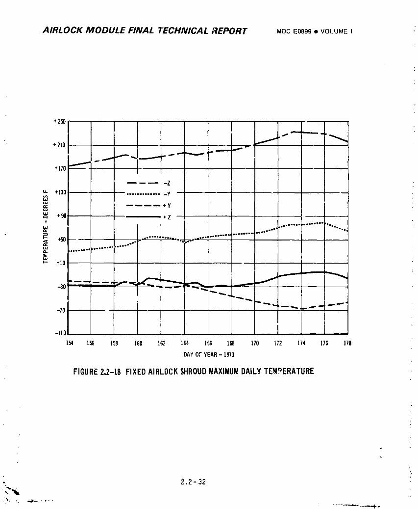
AIRLOCK MODULE FINAL TECHNICAL REPORT MDCE0899• VOLUMEI
+250
+ 210 , _
i ""_ ....==m=.+170 _ "" __''_'_" " ""
-Z
u,. +130 .............. yILl
_. .-- ._ _ .... + yla.i,.., +90 -+Z!
tl,"z=l I J°e°l'l°sbm°mlgmn° DOtOmQtm• "2 _ • • iImmolaal )aoBm°°°°lmll mgo
ta alI-- +50 - " ••• °a°•m "_ _• _•_ • .a •=o=si_ = iI, -'°°LI_ _.moo m'mrw •i'_ iiio• i, ol
I,.L,
_- +10
_30
-110 __! -
154 156 158 160 162 164 166 168 170 172 174 176 178
DAYOFYEAR- 1973
FIGURE2.2-18 FIXEDAIRLOCKSHROUDMAXIMUMDAILYTEN_ERATURE
- 2,2-32
"0.
1974018208-088
AIRLOCK MODULE FINAL TECHNICAL REPORT MDCE0899• VOLUMEI
2.3 MASS PROPERTIES
Airlock mass properties ;vhici_.nc,uded the basic AH, bA, FAS, experiments,
HDAC-E designed MDA coq_por,ents, 02, _2, stowed and fixed GFE, and PS, were com-
puted and maintained on a cuFrent basis. These data were reported to the NASA
monthly in accordance with the mass properties requirements specified in the
Statement of Work. The Airlock maximum specificationweight was established by
the Airlock Performance/ConfigurationSpecification, MDC Report E946 and Payload
Shroud Detail CEI S_ecification, _,DCReDort E0047.
2.3.1 Airlock Weight Monitorin.qPlan
Although the Saturn V launch v'ehiclehad ample boost capability for the
__L-ylabmisslon a weight monitoring and control plan (See Figure 2.3-I) was used
to assure continuous Airlock mass properties status. Bogey w_.ightswere
established for all components a,_dincorporated inhouse and on vendor
specifications. Mass properties were calculated for all drawings and overweight
conditions reported for corrective action. As actual weights replaced calculated
weight__,reports were updated to reflect current conditions. The MIL-STD-I/6A
functionalweight code identificationwas utilized to categorize and report
weights. The result was published and updated in Airlock Project Mass
Properties Status Report, 233-M-501-XX.
i
The mcnitoring plan continued at the launch site when parts/materials
installed and ren_)vedfrom the vehicle were weighed and recorded in accordance
with KSC POP 4-00_, Weight and Balance Control Procedure. Daily logs were
maintained by MDAC-E personnel through launch. Thes_ data were also reported in
the F'.assProperties Report mentiored above.
2.3.2 A_c_tualW__ eight Program
An actual weight program was pursued at MDAC-Z where as many detail
manufactured parts as possible were weighed and, in many cases, asseni_lies
were weighed. In all cases these data were used to verify or adjust calculated
weights as soo,lin the program as possible to verify the predicted launch
weights and to give confidence in the total mass properties program.
Figure 2.3-2 illustrates the estimated/calcdlated/actualweight history of
" the Ai,-lockModule as it evolved in the last two years prior to launch. It
should be noted that at the time ef delivery, (less gas and fluid expendables
2.3-I
1974018208-089
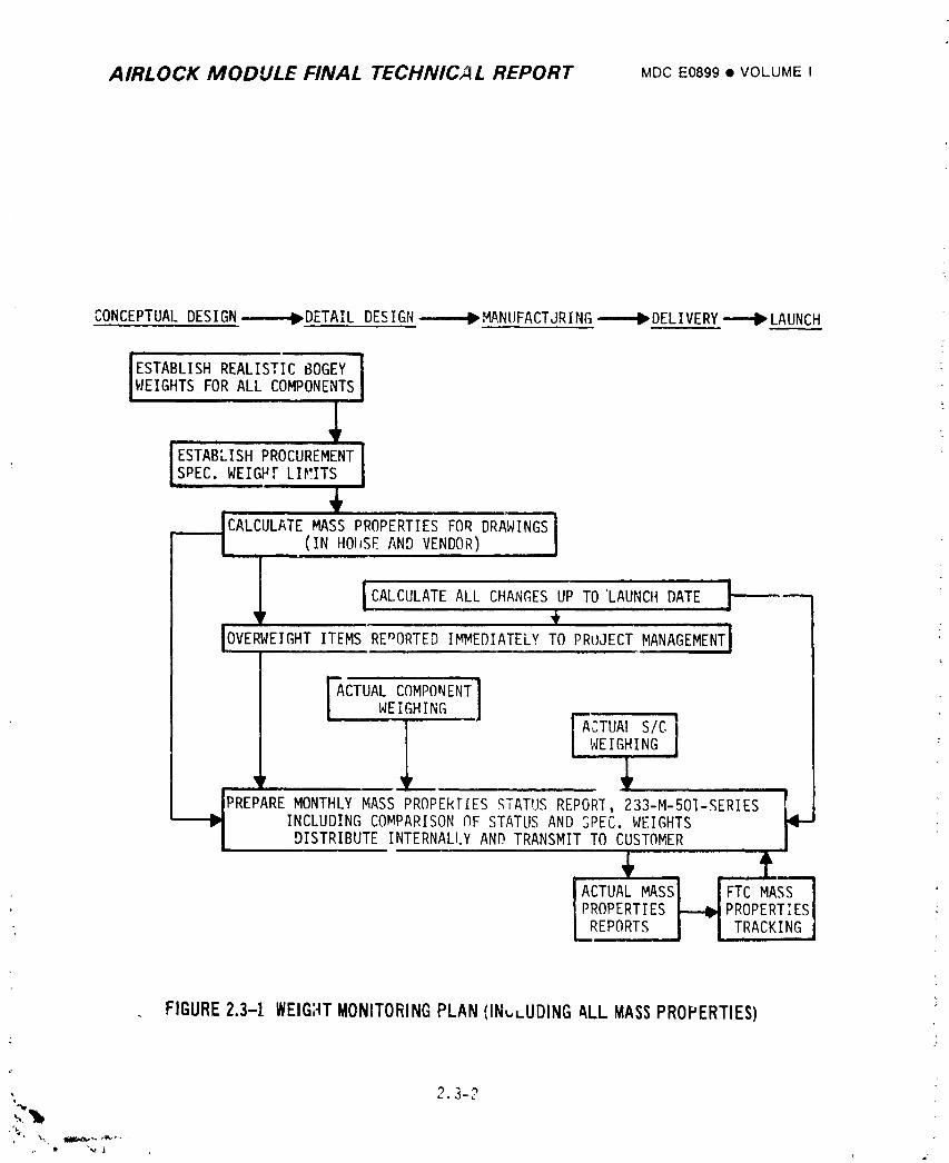
AIRLOCK MODULE FINAL TECHNICAL REPORT MDCE0899• VOLUMEI
CONCEPTUALDESIGN_DETAIL DESIGN--------P,,"tA,NUFACTJRING_DELIVERY---=-B_LAUNCH
ESTABLISHREALISTIC60GEY1WEIGHTSFOR ALL COMPONENTSI
I
[CALCULATEMASSPROPERTIESFORDRAWINGSIL (IN HOarSEANDVENDOR) I
ii =IIOVERWEIGHT REnORTEDIMMEDIATELYTO PRUJECTMANAGEMENTITEMS
FACTUALCOMPONENTWEIGHING. ,l
WEIGHING
INCLUDINGCOMPARISONOF STATUSANDSPEC.WEIGHTSDISTRIBUTEINTERNALI.YANDTRANSMITTO CUSTOMER
ACTUALMASSI i FTC MASSPROPERTIES_-_I_PROPERTIES._REPORTS.I | TRACKING
FIGURE2.3-1 WEIGHTMONITORINGPLAN (IN,.,-UDINGALL MASSPROPERTIES)
. 2.3-2
1974018208-090
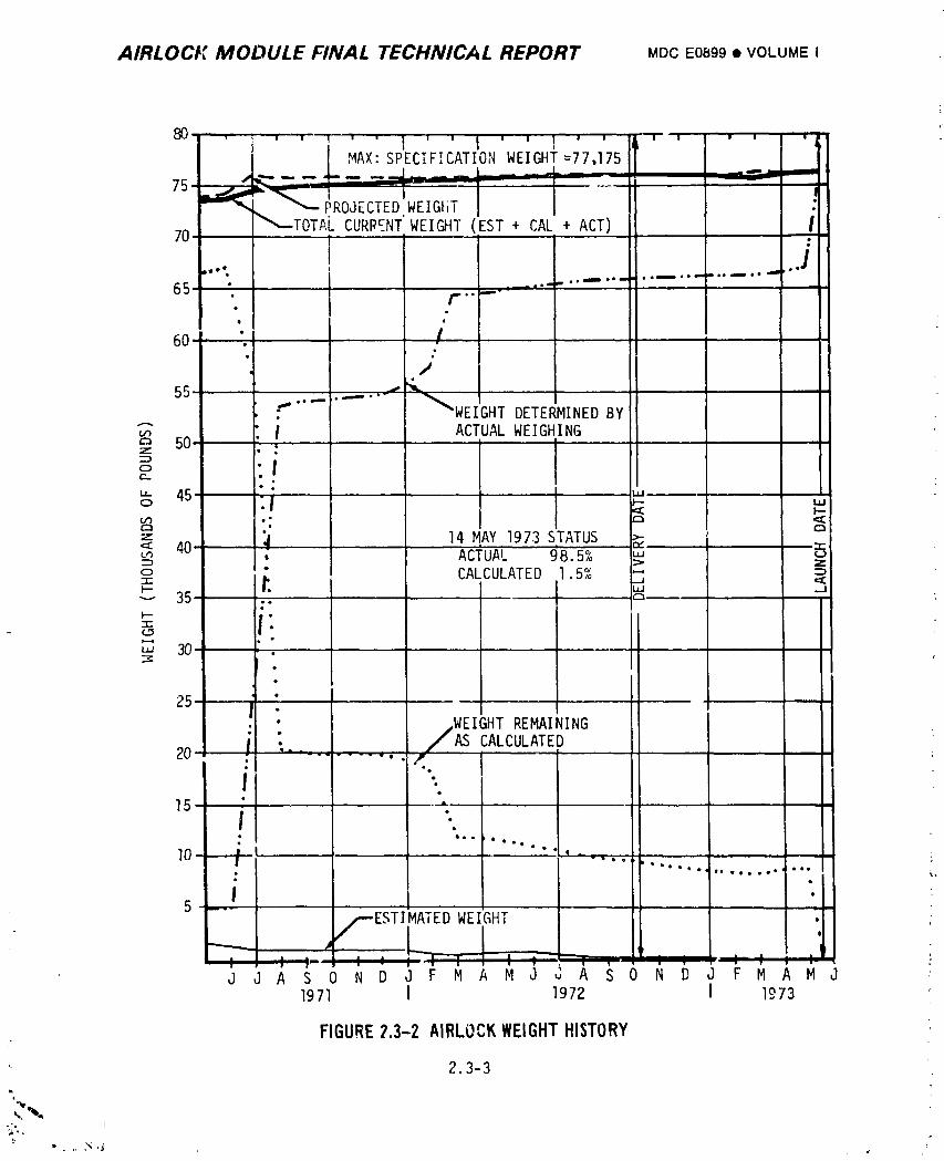
AIRLOCt: MODULE FINAL TECHNICAL REPORT MDCE0899• VOLUMEI
q
iMAX: SPECIFICATION WEIGHt=77,175
75-
PROJECTEDWEIGHTCURR__NT"WEIGHT(EST + CAL + ACT)7O
: J J A S 0 N D J F M A M J C A S O N D J F M A M J -_1971 I 1972 I 1973
FIGURE7.3-2 AIRLOCKWEIGHTHISTORY
2.3-3
,i;,
i 9740i 8208-09i
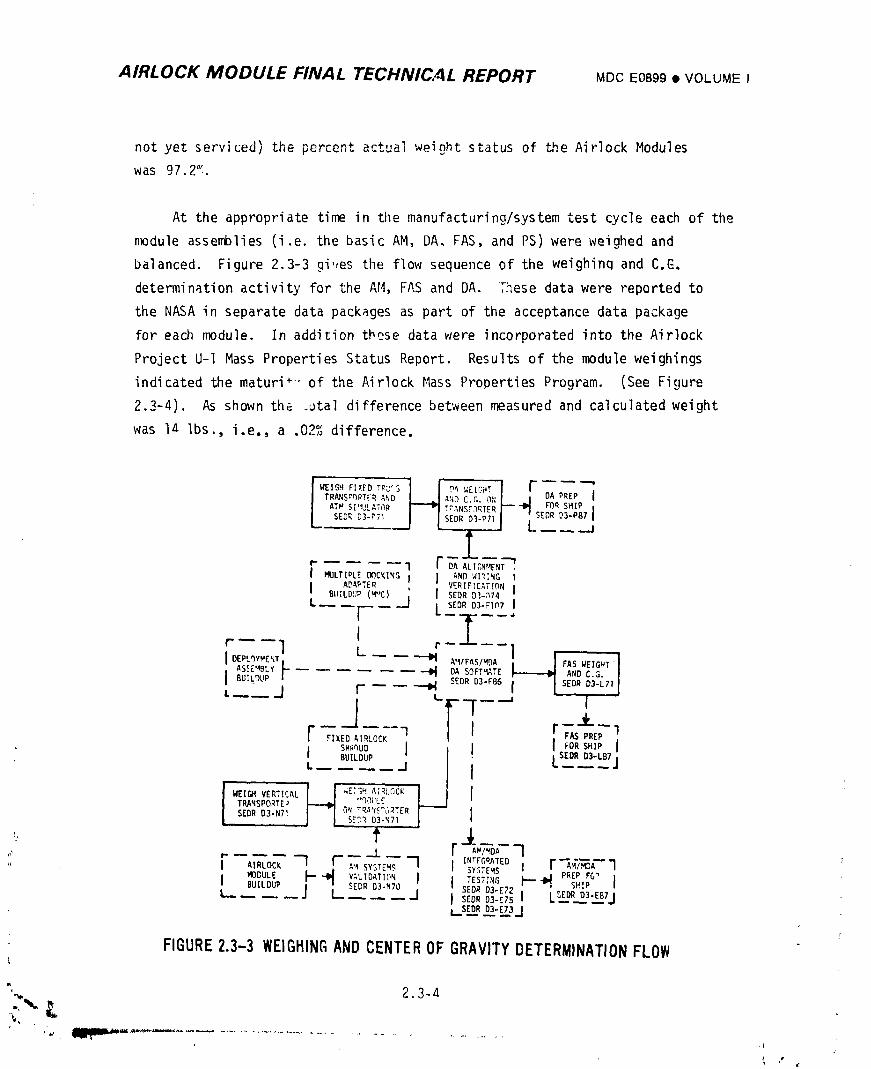
AIRLOCK MODULE FINAL TECHNICNL REPORT MDCE0899• VOLUMEI
not yet serviced) the percent actual weight status of the Airlock Modules
was 97 2°`
At the appropriate time in tile manufacturing/system test cycle each of tile
module assemblies (i.e. the basic AM, DA, FAS, and PS) were weighed and
balanced. Figure 2.3-3 gi,les tile flow sequence of the weighinq and C.C-.
determination activity for the AM, FAS and DA. These data were reported to
the NASA in separate data packages as part of the acceptance data package
for each module. In addition these data were incorporated into the Airlock
Project U-I Mass Properties Status Report. Results of the module weighings
indicated the maturi*'" of the Airlock Mass Properties Program. (See Figure
2.3-4). As shown the ._ta] difference between measured and calculated weight
was la Ibs., i.e., a .02% difference.
TR,%Ns_r)PTFRAmiD _'_Dc.r,.ON DA PREPATW SI'_UtATC}R T_._NSr3RTER FOR SHIP
SEDR D3-PTI SEDR D3-PTI SEDR 03-P87
J__._,I r T_A'T_,.ENT.MULTIPLE DOCKING I J AND WI_ING I
I ADAPTER VERIFICATION IBLIILDUP(MuC) ' I SEDR D1-n74
L I' _1 L SE_Ros-Fl_7I
t I "r----I L '- --1
I BUILDUP" _ SEDR D3-FSB I- SEDR 03-L71
-J- FlF FIXED AIRLQCK F/kS PREP1
BUILDUP
[SEDR D3-LB7|
L_ _J I .....i
TRANSPORTE* "qD{rLf
SEDR D3-NT1 ON T_5^_'_TER IS'.'3_,D3-NTI
tI AIRLOCK1 F"- _ r IN'FCmATEOAW/MDAIA'JISYSTEMS 'J J SYSTEMS l r "_I_/,_A" "I
BUILDUP SEDR D3-N70 J SEDRTEST_'_GD3-E7?I"" -I_, PREPsH!PFG_ l,
_ _ I SEDR D3-E75 I ____,,,,[SEDRD3-EB7l
i_sED._.RD3__-ETjJ
FIGURE2.3-3 WEIGHINGANDCENTEROFGRAVITYDETERMINATIONFLOW
_' 2.3-a
i-
] 974018208-092
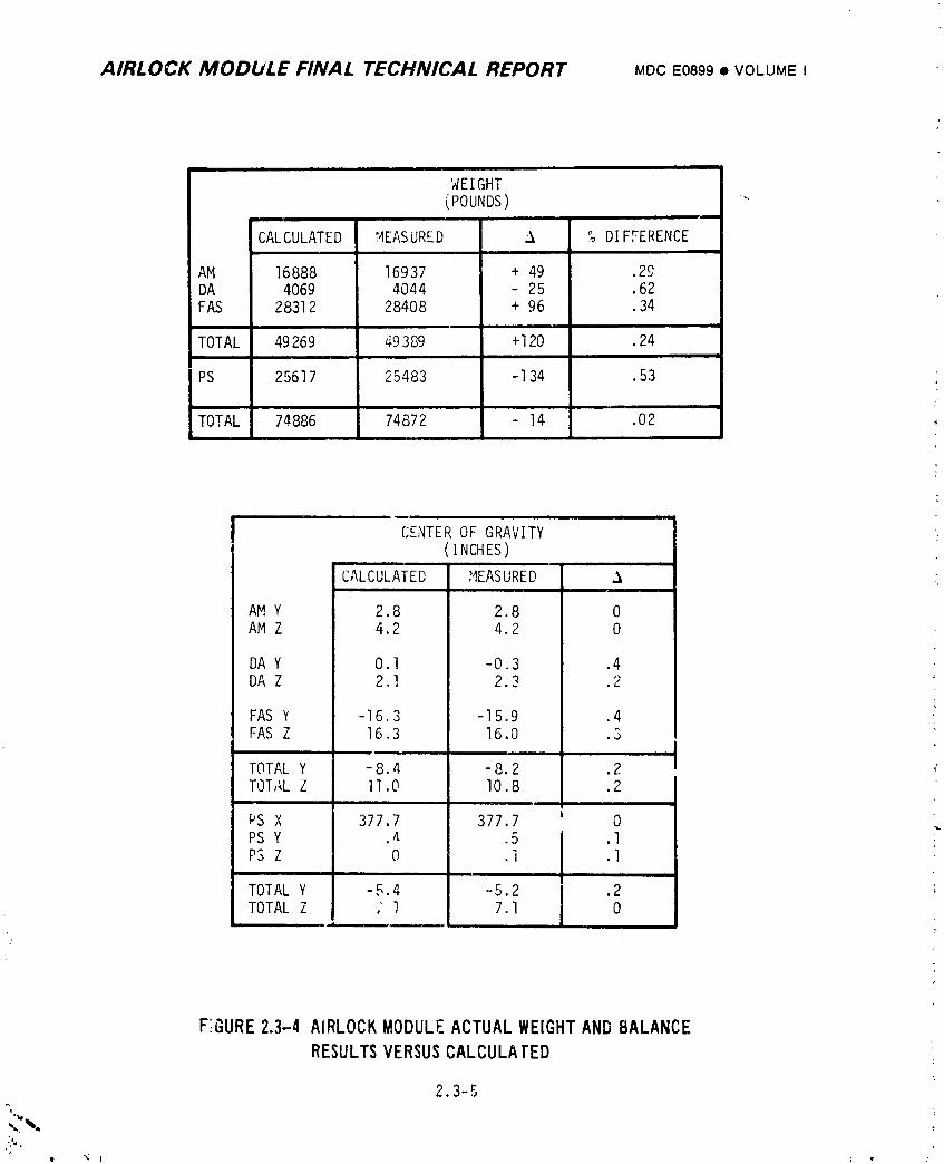
AIRLOCK MODULE FINAL TECHNICAL REPORT MDCE0899• VOLUMEI
WEIGHT(POUNDS) -_
CALCULATED MEASURED _ % DIFFERENCEi
AM 16888 16937 + 49 .29DA 4069 4044 25 .62FAS 28312 28408 + 96 .34
TOTAL 49269 49389 +120 .24
PS 25617 25483 -I 34 .53L
TOTAL 74886 74872 - 14 .02
CENTEROF GRAVITY(INCHES)
CALCULATED MEASURED .%
AM Y 2.8 2.8 0AM Z 4.2 4.2 0
DA Y 0.I -0.3 .4DA Z 2.1 2.3 .2
FAS Y -16.3 -15.9 .4FAS Z 16.3 16.0 .3
TOTAL Y -8.4 -8.2 .2TOTAL Z ll.O 10.8 .2
PS X 377.7 377.7 0PS Y .4 .5 .IPS Z 0 .i .I
TOTAL Y I -5.4 -5.2 .2TOTAL Z I , 1 7.1 0
, , ,, ,
F;GURE2.3-4 AIRLOCKMODULEACTUALWEIGHTANDBALANCERESULTSVERSUSCALCULATED
2.3-5
%.%. ,_-
,:',,,| _ t I ,' :
1974018208-093
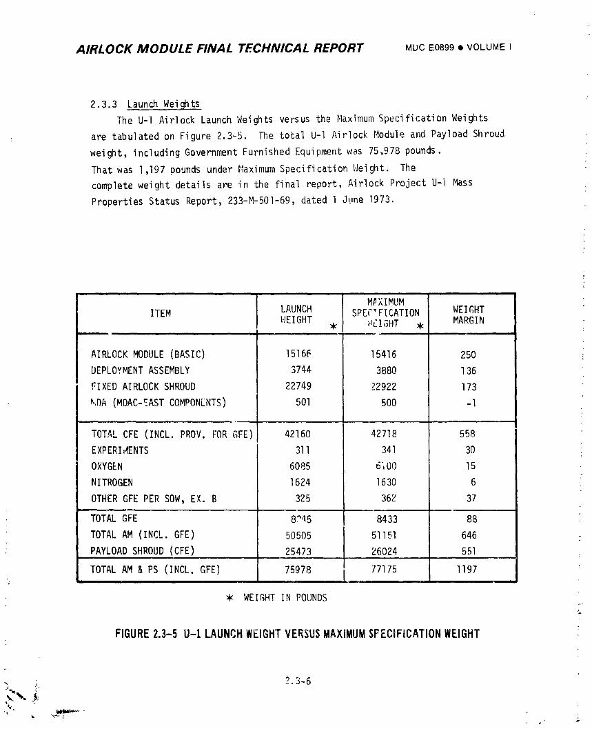
AIRLOCK MODULE FINAL TECHNICAL REPORT MUCE0899• VOLUMEI
2.3.3 La__unchWeights
The U-I Airlock Launch Weights versus the Maximum Specification Weights
are tabulated on Figure 2.3-5. The total U-I Airlock Module and Payload Shroud
weight, including Government Furnished Equipment was 75,978 pounds.
That was 1,197 pounds under Maximum Specification Weight. The
complete weight details are in the final report, Airlock Project U-] Mass
Properties Status Report, 233-M-501-69, dated 1 June 1973.
M#XIMUMITEM LAUNCH SPECTFICATION WEIGHT
WEIGHT _ _f_IGHT _ MARGIN.| i = - ,.
AIRLOCK MODULE(BASlC) 15166 15416 250
DEPLOYMENTASSEMBLY 3744 3880 136
FIXED AIRLOCKSHROUD 22749 22922 173
_,DA (MDAC-_ASTCOMPON[NTS) 501 500 -I
.,.,
TOTAL CFE (INCL. PROV. FORGFE) 42160 42718 558
EXPERI,_ENTS 311 341 30
OXYGEN 6085 6iO0 15
NITROGEN 1624 1630 6 :
OTHER GFE PER SOW, EX. B 325 362 37
TOTAL GFE 87a5 8433 88
TOTAL AM (INCL. GFE) 50505 51151 646
PAYLOADSHROUD(CFE) 25473 26024 551
........ I 77175 1197TOTAL AM & PS (INCL. GFE) 75978 I
WEIGHTIN POUNDS
FIGURE2.3-5 U-I LAUNCHWEIGHTVERSUSMAXIMUMSFECiFiCATIONWEIGHT
'>3-6
1974018208-094
AIRLOCK MODUtE FINAL TECHNICAL REPORT MDCE0899i VOLUMEI
2.4 THERHA! OOi'ITi<OLSYSTEM
The Airlock thermal control system (TCS) provided temperature control for
the Airlock and cooling to the MDAand OWS. It consisted of an active coolant
system, ATM C_,DPa.lel/EREP cooling system, battery coo]ina system, thermal
coatings,thermal curtains, equipment insulation, AM wall heaters, and molecular
sieve exhaust duct heaters. The actlve coolant system provided coldplates and
heat exchangers for equipment and atmospheric cooling. Primary and secondary
flow paths provided the required redundancy. <
2.4.1 Desi__i_z!_Requirements :
Th_ basic requirements of the TCS were to provide temperature control for
the AM crew compartment, equipment, and structural surfaces during prelaunch,
launch ascent, and orbital phases of the mission. In addition, interface require-
ments were to provide atmospheric cooling to the MDAand OWS, to provide
temperature controlled coolant to the ATM and EREP panels, and to meet the thermal
control interfaces to the MD_, OWS,ATM, CSM, IU, the experiments, and GSE, as
shown in Figure 2.4-I. The AM/MDA interface requirements are presented in ICD
13MO2521Aand the AM/OWSinterface requirements are presented in ICD 13MO2519B.
Additional requirements associated with the TCS design were to provide instru-
mentation intelligence and procedures as a basis for system operation.
2.4.1.1 Evolution
As the Skylab program evolved from the SSESMto the f_AP concept, and ulti-
mately to the Saturn V workshop conceTt si3nificant changes irl mission plan and
systems design requirements were made. Conseq,_ntly, the design requirements of
the Airlock Module thermal control system also cnanged significantly throughout
its development. This section presents a discussion of the significant changes
to th _ Airlock Module thermal control system design and requirements.
A. External Design Requirements - The change to the Saturn V workshop
concept resulted in several changes to the external thermal environment
" conditions. The change in orb;t inclination_,_:igle from 35° to 50°
incred_ed the mission beta angle extremes from _5B I/2 ° to _73 I/2 ° . !
Combined with the c,lange to the basic solar inertial attitude, this
resulted in a more severe hot case external environment design condition.
t
. 2. 4-_'
1974018208-095
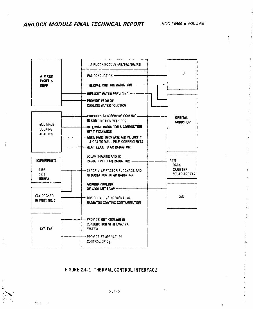
AIRLOCK MODULE FINAL TECHNICAL REPORT MDCE0899• VOLUMEI
AIRLOCKMODULE(M_VFAS/DA/F'S)
ATM C&D FASCONDUCTION IU ,,
PANEL&
EREP THERMALCURTAINRADIATION I
INFLIGHTWATERSERVICING l, /I
PROVIDEFLOWOF IICOOLINGWATER"OLUTION
PROVIDESAll_OSPHERECOOLING ORBITALINCONJUNCTIONWITHECS WORKSHOPMULTIPLEINTERNALRADIATION&CONDUCTION
DOCKINGHEATEXCHANGE
ADAPTERAREAFANSINCREASEAIRVE:..OCITY
& GASTOWALLFILMCOEFFICIENTS
';_ HEATLEAKTOAMRADIATORS
SOLARSHADINGAND IR I"-I
EXPERIMENTS| IRAL;IATIONTO AM RADIATORS I ATM
$192 ' SPACE,VIEWFACTORBLOCKAGE AND CANISTER :$193 IRRADIATIONTO AM RADIAT(JR SOLARARRAYSRNBMA
GROUNDCOOLING }
I OF COOLANTLC'_Op J
CSMDOCKED RCSPLUME _MPINGEMENT.AM GSE
IN PORTNO.! RADIATORCOATINGCONTAMINATION
' PROVIDESUITCOOLINGINCONJUNCTIONWITHEVAAVA
EVAAVA SYSTEM
- PROVIDETEMPERATURE | '°
m
CONTROLOF02 __ -,_,-' , ,.a
FIGURE2.4-1 THERMALCCNTROLINTERFACE
"". • 2.4-2 " ,'
-%, 'w
] 9740] 8208-096

AIRLOCK MODULE FINAL TECHNICAL REPORT MDC . 0899 • VOLUME I
The change to the basic solar inertial atzitude also had an impact on the _
passive temperature control system, and resulted in the change from a ._
mf'_tiple layer "superinsulation" concept to the thermal curtain insula-
tion design. The addition of the EREPmode of operation required the
incorporation of the Z-LV (Z-axis Local Vertical) vehicle orientatinn
into the AM TCS design.
B. Internal Design Requirements - Several added requirements significantly
affected the design of the active coolant subsystem of the AM TCS. In
addition to the normal grow_L of heat loads associated with system
definition, the requiremen_ for reduced water delivery temperatures in
the EVA/IVA suit cooling loops, as discusse_ :n Section 2.6 had a major
impact on AM cooldnt system Jesign. Prior to the 45°F water delivery
temperature requirement, the AM coolant loop design included a s,_;gle
40°F TCV downstream of the radiator. To provide for the lower water
delivery temperatures, a heat exchdnger interfacing each water suit
cooling loop with .he associ.ted AM active coolant Icop was moved
upstream of the 40°F TCV. To assure that temperature control would be
maintained at the 40°F TCV, a thermal capacitor was added to the AM
coolant loops immediately downstream of the radiator. The thermal
capacitcr was added to limit coolant supply temperatures to the EVA
heat e'change)s to a maximum of 28°F after it was concluded that improved
radiator performance c_uld not be achieved due t_ limited space available
for increased radiator area, and also because of limiLations on radiator
thermal coating values (_/E)
Concern over life of the AM batteries led to the requirement of providing
lower coolant temperatures at the battery modules. In conjunctier with
a requirement to maintain a minimum cluster dew point temperature of
46°_ this resulted in the addition of twF 7°F TCV's ir each cnolant
loop and the design of the su;t/battery cooling module. A second i--
thermal capacitor was added to offset the reduced radiator ,.erfcrmance
due to the Z-LV orientation associated with EREPoperatien.
L.4-3
_ I
1974018208-097
• _ ...... _ _ _ _r.,c_J _
AIRLOCK MODULE FINAL TECHNICAL REPORT MDC E0899 • VOLUME I
1F
Design requirement changes that occurred Juring the program resulted in _._the need for expanded system capability. Examples of such changes in
addition to those described above are the requirement for more OWS
atmospheric cooling, addition of the ATM C&D/EREP water cooling syste_
and the addition of various electronic equipment requiring cold plate
cooling. Incorporatlonof the plumbing, co_d plates, heat exchange_s,
and valves needed for meeting these requirements substantialiy increased
system coolant flow resistance. This led to higher pressure l_.velsin
some portif_nsof the loop, which exceeded component specification allow-
ables during contingency situations requiring operation of two pumps in
one coolant ;oop. System pressure levels were ultimately reduced by
design ch_,igessuch as modifying the radiator to a bifiler type design
(i.e., parallel coolant flow paths), paralleling coolant flow paths in
t_,ebattery and electronic modu:_s, increasing plumbing size, and boring
out standard plumbing connectors to l rcer internal diameters. , hough
Jthe above methods eliminated the'major portion of the pressure leve
problem, requalificationof some of the off-the-shelf hardware to higr
pressure levels was also required. _"
C
T2.4-4 1
1974018208-098
+ AIRLOCK MODULE FINAL TECHNICAL REPORT MDCE0899• VOLUMEIi
l+.
) 2 4.1 2 FlightConfiguration
Thermalcontrolsystemdesignrequirementsconsistof externaldesign
requirementsand internaldesignrequirements.
A. ExternalDesignRequirements- The missionthermaldesigndataare
listedin Figure2.4-2 per MDAC-EDReportF319. The originaldesign
vehicleorientationwas the solar inertial• ShortdurationZ-LV (Z-axis
Local Vertical)orientationfor EREP and rendezvousas well as CMG
desaturationmaneuverswere accommodated.The EREP designmaneuvers
. are illustratedby Figure2.4-3and the CMG desaturationmaneuverby
Figure2.4-4. A fifth designorientationrequirementwas accommodated
duringthe flight- namelythe orientationnecessaryfor studyof the
Kohoutekcometduringthe SL-4mission. The Kohoutekcometviewing
designmaneuversare describedin Figure2.4-5.
B. InternalOesignRequirements- A su,nmaryof generaldesignr_quir_ments
for the activeand passivesubsystemsof the AirlockModulethermal
controlsystemare shown in Figure2.4-6. Detailedrequirementsof
individualsubsystemsare discussedin the SystemsDescriptionSections
_ as indicatedin Figure2.4-6.
2.4.2 IntegratedThermalAnal_/sis
An integratedtP.,rmalanalysiswas requiredto convertdesignrequirements
for the AM ThermalControlSystem(Section2.4.1)to designrequirementsfor
each system(Section2.4.3). The integratedthermalanaly._swere conducted
usingdetailedmathematicalthermalmodels. Sincethe AM was shadedpartially
by the ATM,was structurallyattachedto the IU and MDA, had sevenof eleven
radiatorpanelsin the AM CoolantSystemmountedon a portionof the MDA, and
providedcoolingto the OWS and MDA with the atmosphericcontrolsystem,the
thermaleffectsof thesestructuraland systemsfactorswere includedin the
thermalmodel. Ir,fact,the thermalmodel includeda thermalrepresentationof
all pertinentstructureand AM/MDAsystemsto permitcalculationof realisticheat
loaddivisionbetweensystems. The AM/ATM,AM/MDAand AM/OWSinterfacesare
definedin ICD 13M20726,ICD 13MO2521A,and ICD 13MO2519B,respectively.Inte-
gratedthermalanalysesalsowere requiredto thermallyq,_alifythe vehiclefor
ii flight. In addition,integratedthermalanalysesas valuablemissionsupportI) aids.
2.4-5Ik
1974018208-099
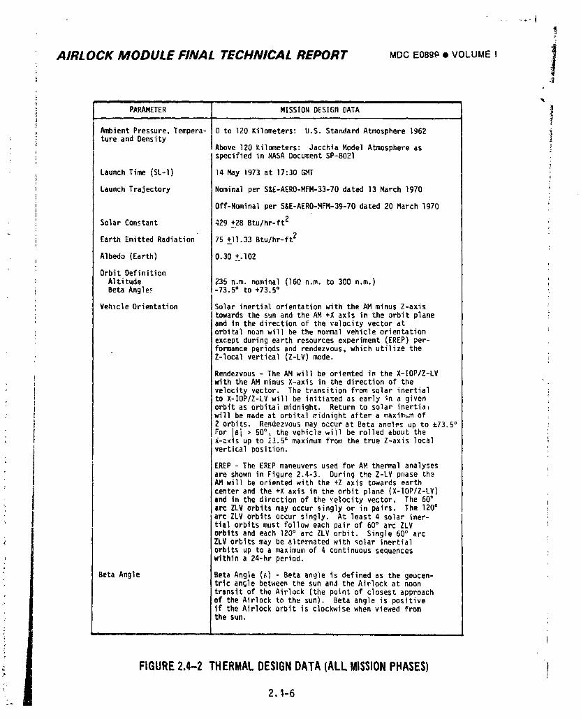
AIRLOCK MODULE FINAL TECHNICAL REPORT MDC E0899 • VOLUME I 1
-- ii i i i i i ii •
PARAMETER MISSION DESIGN DATA 1A_ient Pressure,Tempera- 0 to 120 Kilometers: U.S. Standard Atmosphere 1962
'. ture and DensityAbove 120 Kilometers: Jacchia Model Atmosphere asspecifiedin NASA Document SP-8021
Launch Time (SL-I) 14 May 1973 at 17:30 GMT
Launch Trajectory Nominalper S&E-AERO-MFM-33-70dated 13 March 1970F
Off-Nominalper S&E-AERO-HFM-39-70dated 20 March Ig70
Solar Constant 429 +28 Btu/hr-ft2
Earth EmittedRadiation• 75 _II.33 Btu/hr-ft2
Albedo (Earth) 0.30 +.102
Orbit DefinitionAltitude 235 n.m. nominal (160 n.m. to 300 n.m.)Beta Angle_ -73.5° to +73.5°
VehicleOrientation Solar inertial orientationwith the AM minus Z-axistowardsthe sun and the AM +X axis in the orbit planeand in the directionof the velocity vector atorbitalnoon will be the normal vehicle orientationexceptduring earth resources experiment (EREP) per-formanceperiodsand rendezvous,which utilize theZ-localvertical (Z-LV)mode.
Rendezvous- The AM will be oriented in the X-IOP/Z-LV:withthe AM minus X-axis in the direction of thevelocityvector. The transitionfrom solar inertialito X-IOP/Z-LVwill be initia_edas early in a given
" _ orbit as orbitalmidnight. Return to solar inertia_will be made at orbital_idnight after a maximum of2 orbits. Rendezvousmay occurat Beta anaIes up to _73.5°
• For iSl > 50°, the vehiclewi)l be rolled about theX-_xIsup to 23.5° maximum from the true Z-axis local
vertical position.EREP - The EREP maneuvers used for AM thermal analysesare shown in Figure 2.4-3. During the Z-LV phase th_AM will be orientedwith the +Z axis towardsearthcenter and the +X axis in the orbit plane (X-IOP/Z-LV)and in the directionof the _:elocityvector. The 60°arc ZLV orbits may occur singly or in pairs. The 120°arc ZLV orbits occur singly. At least 4 solar iner-tial orbitsmust follow each pair of 60° arc ZLVorbits and each 120° arc ZLV orbit. Single 60° arcZLV orbits may be alternatedwith _olar inertialorbits up to a maximum of 4 continuous sequenceswithin a 24-hr period.
Beta Angle Beta Angle (_) - Beta angle is definedas the geocen-tric an£le between the sun and the Airlock at noontransitof the Airlock (the point of closestapproachof the Airlock to the sun). Beta angle is positiveif the Airlock orbit is clockwisewhen viewed fromthe sun.
i ,m
FIGURE2.4-2 THERMALDESIGNDATA(ALL MISSIONPHASES) 1
2, _,-6
1974018208-100
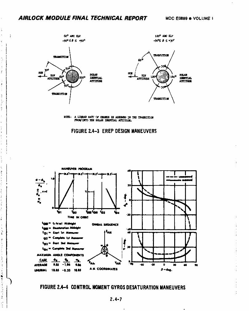
AIRLOCK MODULE FINAL TECHNICAL REPORT MOCE0899• VOLUME!
L
': 6ook,c ft,,v la)o _c r.,;,,
_o \ /
8_t3
. _pv/ _ A_
_NEZTZal
znRoW__ souuR2Jem_,J,L1_.,_z,z,z_jrjz.
FIGURE2,4-3 EREPDESIGNMANEUVERS
i At41eluvlnl
,..o. ,. -,,t I
1)2=" CuqdleleIst Mmeuvw /
103= ihed =ridldenm_
,vl';'_ t.u-_._ t.,6 o , ,o ,..._L iLu -.., Itu ,M cootm,l. _._,,
3FIGURE2.4-4 CONTROLMOMENTGYROSDESATURATIONMANEUVERS
2.4-7
1974018208-101
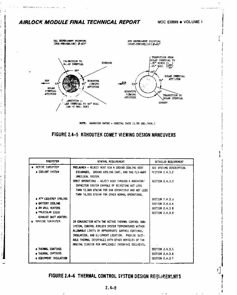
}
t
AIRLOCK MODULE FINAL TECHNICAL REPORT MOC E0899 • VOLUME I 1
;I
m, mzm_T m11,m¢ A_ m, mw,_¢ POZ,_ZN_ _.
(mz-m_zme, ion) B-67° (vosT-z,r_nr_,zo_)a,6o° !
_srrloN _M
_P_NSITION ]SOLAP INERTIAL TO
\SG.,iLR _IAL'I'O SUNRISE ___o PITCH (y.) i
/ _ \ SOLAR it_,rz_
/ /" _,, \ ,_.0 ATTT,_
SOLAR
,TTrrUDE _ _ ,Cj_:/,_ VI_ING _ _ TRANSITIONTO
/ ._SITION _L_ ATTITUDE -"-----"I _SOIAR L_ERTIAL/ ; ,CARIIf]_TI.ALTO 90° ROr.T."- strNsE'T _.
/ (AM +Y T,tD.SUN) i
W0'11¢: MANEUVER RATES - ORBITAL RATE (5.86 DEG./MIN.)
FIGURE2.4-5 KOHOUTEKCOMETVIEWINGDESIGNMANEUVERS
ISUBSYSTEM GENERALREQUIREMENT DETAILEDREQUIREMENT
..
• ACTIVESURSY_TEP PRELAUNCH- REJECTHEAT VIA A GROUND COOLINGHEAT SEE SYSTEMSDESCRIPTION,
IDCOOLANTSYSTEM EXCHANGER. GROUNDCOOLINGCART,AND FAS FLY-AWAY ,_ECTION2.4.3.2
, UMBILICALSYSTEM.
ORBITOPEPu_TIONS- REJECT HEATTHROUGHA RADIATOR/ SECTION2.4.3.2
CAPACITORSYSTEMCAPABLEOF REJECTINGNOT LESS
THAN 12,000BTU/HRFOR EVA OPERATIONSAND NOT LESS
THAN 16.000BTU/HRFOR OTHERNORMALOPERATIONS.
e ATq C&D/EREPCOOLING SECTION?.4.3.._
e BATTERYCOOLING SECTION2.4.3.4
e AM W_LLHEATERS SECTION2.4.3 8
e _WlLECULARSIEVE SECTION2.4.3.9
EXHAUSTDUCTHEATERS
e OAC;_IVE_I_;YSTEM IN CONJUNCTIONWITH THE ACTIVE THERMALCONTROLSUB-
SYSTEM.CONTROLAIRLOCKSYSTEMTEMPERATURESWITHIN
ALLOWABLELIMITSBY APPROPRIATESURFACECOATINGS,
INSULATIEN:AND Eq"IPMENTLOCATION. PROVIDESUIT-
ABLE THERMAL INTERFACE,__.ITHOTHERVEHICLESOF THE
ORBITALCLUSTERPER APPLICABLEINTERFACEDOCb;4E_;TS.
• THEP,RkL COATINGS SECTIONZ.4.3.5
t THERMALCUPTAINS SECTION2,4.3.6
e E_IPHENT INSULATION SECTION2.4.3.7
FIGURE2.4-6 THERMALCONTROLSYSTEMDESIGNREQL_IP,EM.LNTS
2.4-8
1974018208-102
AIRLOCK MODULE FINAL TECHNICAL REPORT MDCEoegg• VOLUMEI
Other structuresand systemswere includedin the thermalmodel. The OWS l
forwardskirtand domewere representedto completethe enclosureformedwith
IU and FAS. Electricalwall heatersand thermostatsoperationwas simulatedfor
both the AM and MDA to verifyadequateheaterpowerfer coldmode operations.
Heat leaksfrom the MDA walls to the AM radiatorwere calculatedto define
radiator/capacitorsystemheatloads. Convectiveheat transferbetweenMDA walls
and equipmentand the cabinatmospherewas also includedas a partof the overall
systemheat balanceto establishheatload splitbetweenthe wall heatingsystem,
equipment,and atmospherlccontrolsystem. The ATM C&D paneland EREPcomponents
were includedin the model to providea realisticdistributionof heatloads to
the cabin and the ATM/EREPwater coolingloop. A thermalrepresentationof the
electricalequipmentfromthe electricalpowersystem,instrul_entationsystem,
cautionand warningsystem,and communicationsystemwas included.
An operationalplanfor the clusterwas assumedso that heat loadscould be
established.It was decidedthatall operatingmodes could be represented
adequatelyfor designwith eight basiccases. They consistedof one prelaunch/
launchascentmodecase and sevenorbitaloperationcases.
2.4.2.1 ExternalDesignHeatLoads
The externalheat loadconditionsfor the sevenorbitalcasesare shown in
Figure2.4-7. Analysesfor the hot modes and the EVA/IVAmode were basedon
maximumbetaangleand high externalheatingrates. Coldmode analysesutilized
zerobeta angleand low externalheatingratesfor minimumorbitalheating.
Nominalheatingrateswere used for the rendezvousand EREP analyses,as indi-
cated in Figure2.4-7.
2.4-9h,.
1974018208-103
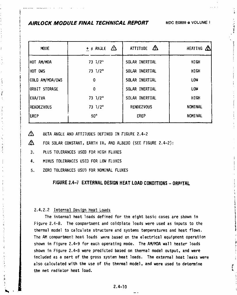
AIRLOCK MODULE FINAL TECHNICAL REPORT MDCEOS99• VOLUMEI
; MODE ± B ANGLE Z_ ATTITUDE Z_ HEATING& ii , i ii ii i
HOT AM/MDA 73 l/2_ SOLAR INERTIAL HIGHi,
HOT OWS 73 I/2° SOLAR INERTIAL HIGH ;
COLDAM/MDA/OWS 0 SOLAR INERTIAL LOW
ORBITSTORAGE 0 SOLAR INERTIAL LOW
EVA/IVA 73 I/2° SOLAR INERTIAL HIGH
RENDEZVOUS 73 1/2° RENDEZVOUS NOMINAL3_
> IEREP 50° EREP NOMINAL
Z_ BETAANGLEAND ATTITUDESDEFINEDIN FIGURE2.4-2"L
_ Z_ FOR SOLARCONSTANT,EARTHIR, AND ALBEDO (SEEFIGURE2.4-2):
3. PLUSTOLERANCESUSED FOR HIGH FLUXES
4. MINUSTOLERANCESUSEDFOR LOW FLUXES
5. ZEROTOLERANCESUSED FOR NOMINALFLUXES
FIGURE2.4-7 EXTERNALDESIGNHEATLOADCONDITIONS- ORBITAL
2.4.2.2 InternalDesignHeatLoads
The internalheat loadsdefinedfor the eight basiccasesare shown in
Figure2.4-8. The compartmentand coldplateloadswere used as inputsto the
thermalmodel to calculatestructureand systemstemperaturesand heatflows.
The AM compartmentheatloads were basedon the electricalequipmentoperation
shown in Figure2.4-9 for each operatingmode. The AM/MDAwall heaterloads _
shown in Figure2.4-8were predictedbased on thermalmodel output,and were
_ includedas a partof the gross systemheat loads. The externalheat leakswere
Y alsocalculatedwith the use of the thermalmodel,and were used to determineC'
the net radiatorheat load.
2.4-I0 ,:
1974018208-104
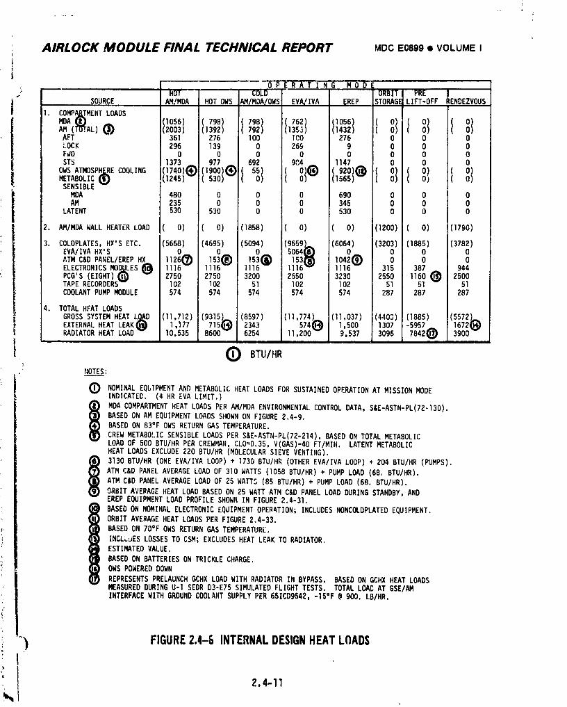
AIRLOCK MODULE FINAL TECHNICAL REPORT MDC E0899• VOLUME I
F
|
0 P E R A T ! N G M 0 _ ORBIT PRE IHOT.... COLDf
SOURCE AH/MDA HOTOWS AM/MOA/OWS EVA/IVA _REP STORAGELIFT-OFF RENDEZVOUS
1. COHP_TMENTLOADS
AM (1_r,AL) _'_ (2003) (1392) 792) (135_) 1(1432) ( O) (AFT 361 276 100 100 _ 276 0 0 0LOCK 296 139 0 26_ 9 0 0 0FWD 0 0 0 0 0 0 0 0
STS 1373 I 692 1147 0O) 0 0OWS ATMOSPHF=RECOOLING (1740)(_ 11977 984METABOLIC_ (1245) 530) , ( (1565) (SENSIBLEw
i MOA 480 0 0 0 690 0 0 0
AM 235 0 0 0 345 0 0 0LATENT 530 530 O 0 530 0 0 O
2. AM/MDAWALL HEATERLOAD ( O) ( O) (1858) ( O) ( O) (1200) ( O) (1790)
3. COLDPLATES,HX'S ETC. (5668) (4695) (5094) (96591 (6064) (3203) (1885) (3782)
o o o oATM C&D PANEL/EREPHX 112 15 15 153( 1042(_) 0 0 0ELECTRONICSMOD=QLES_ 1116-- 1116-- 1116-- 1116 1116-- 315 387 944PCG'S (EIGHT)(_) 2750 2750 3200 2650 3230 2550 I160 _ 2500TAPE RECORDERSw I02 102 51 102 102 51 51 51COOLANTPUMPMODULE 574 574 574 574 574 287 287 287
4. TOTALHEATLOADS
GROSSSYSTEMHEATL_D (11,712) (9315).,... (8597) 1(11,774).._ (11,037) (4403) (1885) (5572).,,..EXTERNALHEAT LEAKfJ]) 1,177 7151f_._)2343 574Q.4_ 1,500 1307 -5957 1672q._RADIATORHEAT LOAD-- I0,535 8600 6254 11,200-- 9.537 3096 7842@ 3900--
(_ BTU/HRNOTES:
Q NOMINALEQbIPMENTAND METABOLICHEAT LOADS FOR SUSTAINEDOPERATIONAT MISSIONMODEINDICATED. (4 HR EVA LIMIT.)
MDA COMPARTMENTHEAT LOADSPER AM/MDAENVIRONMENTALCONTROLDATA, S&E-ASTN-PL(72-130).
BASEDON AM EQUIPMENTLOADS SHOWNON FIGURE2.4-9.BASED ON 83°F OWS RETURNGAS TEMPERATURE.
CREW METABOLICSENSIBLELOADS PER S&E-ASTN-PL(72-214),BASEDON TOTAL METABOLICLOAD OF 500 BTU/HRPER CREWMAN,CLO=O.35,V(GAS)=40FT/MIN. LATENTMETABOLICHEAT LOADS EXCLUDE220 BTU/HR (MOLECULARSIEVE VENTING).
3130 BTU/HR (ONE EVA/IVALOOP) + 1730BTU/HR (OTHEREVA/IVALOOP) + 204 BTU/HR(PUMPS).
ATM C&D PANEL AVERAGELOAD OF 310 WATTS (1058BTU/HR)+ PUMP LOAD (68. BTU/HR).ATM C&D PANELAVERAGELOAD OF 25 WATTS (85 BTU/HR)+ PUMP LOAD (68. BTU/HR).
ORBITAVERAGEHEAT LOAD BASEDON 25 WATT ATM C&D PANEL LOAD DURINGSTANDBY,ANDEREP EQUIPMENTLOAD PROFILESHOWN IN FIGURE2.4-31.
I BASEDON NOMINALELECTRONICEQUIPMENTOPERATION;INCLUDESNONCOLDPLATEDEQUIPMENT.
ORBIT AVERAGEHEAT LOADSPER FIGURE2.4-33.BASED ON /O°F OWS RETURNGAS TEMPERATURE.
INCLLuESLOSSESTO CSM; EXCLUDESHEAT LEAK TO RADIATOR.ESTIMATEDVALUE.
BASED ON BATTERIESON TRICKLECHARGE.OWS POWEREDDOWN
REPRESENTSPRELAUNCHGCHX LOAD WITH RADIATORIN BYPASS. BASEDON GCHX HEAT LOADSMEASUREDDURINGU-1SEDR D3-E75 SIMULATEDFLIGHTTESTS. TOTALLOACAT GSE/AMINTERFACEWITHGROUNDCOOLANTSUPPLYPER65ICD9542, -1S°F @900. LB/HR.
"') FIGURE2.4-8 INTERNALDESIGNHEATLOADSI
%1 2.4-II
1974018208-105
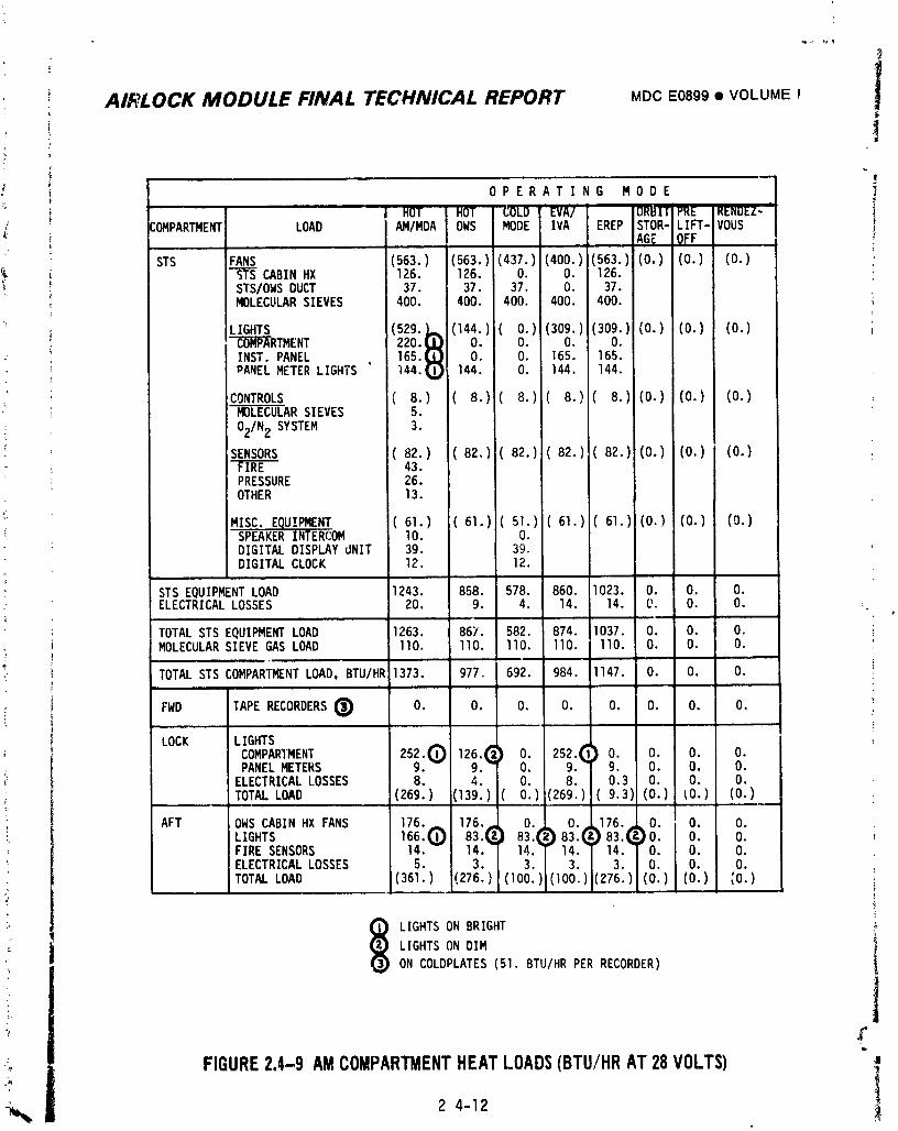
I
AIRLOCK MODULE FINAL TECHNICAL REPORT MDCE0899• VOLUMEI
r OPERATING MODE
' | HOT HOT COLD EVA/ DRBI_'PRE RENDEZ-i :OMPARTMENT LOAD AM/MDA OWS MODE IVA EREP STOR-LIFT-VOUS
AGE OFF i
STS FANS (563.) (563.)(437.)(400.)(563.)(0.) (0.) (0.) 'STS CABINHX 126. 126. O. O. 126. :STS/OWSDUCT 37. 37. 37. O. 37.MOLECULARSIEVES 400. 400. 400. 400. 400. i
LIGHTS (529.i,L (144.)(0.) (309.) 309.) (0.) (0.) (0.) i
_RTMENT 220.I_ O. O. O. O.
INST.PANEL 165.( O. O. 165. 165.PANELMETERLIGHTS ' 144.( 144. O. 144. 144.
CONTROLS (8.) (8.) (8.) (8.) (8.) (0.) (0.) (0.)-_ _AR SIEVES 5. '
02/N2 SYSTEM 3.
SENSORS (82.) (82.) 82.) (82.) (82.) (0.) (O.) (0.)"_IRE 43.PRESSURE 26.OTHER 13.
MISC.EQUIPMENT (61.) ;(61.) (51.) 61.) (61.) (0.) (0.) (0.)SPEAKERINTERCOM I0. O.DIGITALDISPLAYdNIT 39. 39.DIGITALCLOCK 12. 12.
STS EQUIPMENTLOAD 1243. 858. 578. 860. I023. O. O. O.ELECTRICALLOSSES 20. 9. 4. 14. 14. _. O. O. :.
TOTALSTS EQUIPMENTLOAD 1263. 867. 582. 874. 1037. O. O. O. i
MOLECULARSIEVEGAS LOAD 110. llO. llO. llO. liD. O. O. O. '
TOTALSTS COMPARTMENTLOAD,BTU/HR1373. 977. 692. 984. 1147. O. O. O. !ii,
® 'FWD TAPERECORDERS O. O. O. O. O. O. O. O.
LOCK LIGHTS
; COMPARIMENT 25_.0 12_.(_} O. 25_.(_)O. O. O. O.PANELMETERS . . O. . 9. O. O. O.ELECTRICALLOSSES 8. 4. O. 8. 0.3 O. O. O.
TOTALLOAD (269.) (]39.)(0.) (269.)(9.3) (0.) tO.) (0.) :- i
AFT OWS CABINHX FANS 176. ]76._ O. O. 176. O. O. O.
FIRESENSORS 14.-- ]4. 14. O. O. O. ;ELECTRICALLOSSES 5. 3. 3. 3. 3. O. O. O.
TOTALLOAD (36].) (276. (lO0. (I00. i(276.)(0.) (0.) CO.) }
LIGHTSON BRIGHT i
LIGHTSON DIM
ON COLDPLATES(51.BTU/HRPER RECORDER)
t,f
FIGURE2.4-9 AMCOMPARTMENTHEATLOADS(BTU/HRAT28VOLTS) a
,,_ 2 4-12 I,
1974018208-106
_. _._.-_ ,,.._ _r~.v_ ....._._ ....... ,_ ....... _ ............... ,......... r..._........... _r_ ...... -_,r_-,,,_-,_ ......_'_"'_'_'_'_"_:_'J_
AIRLOCK MODULE FINAL TECHNICAL REPORT MOCE0899• VOLUMEI .
_" 2.4.3 SystemDescription
The followingdescriptionof the TCS subsystemsreflectsthe as-flowncon-
figuration.The TCS subsystemsmadeup the overallTCS to providefor tempera-
ture controlof: AM structureand equipment,AM crew compartmnts,suitcooling
system,water solutionfor ATM C&D/EREPcooling,and atmosphericgas for OWS and
MDA cooling.
Both activeand passivetechniqueswere used in the TCS subsystemsto
providethe necessarytemperaturecontrol. The payloadshroudprovidedfor
! temperaturecontrolof structureand equipmentduringprelaunch,launch,andI ascent. The temperaturesof AM structureand crewcompartmentsurfaceswere
! controlledduringorbitaloperationsby the thermalcoatings,thermalcurtains,
i and equipmentinsulationsubsystemsutilizingpassivetechniques,and by the Arl
) wall heatingsubsystemusingactivetechniques.I
i Equipmenttemperaturecontrolutilizedthe activetechniquesof the coolantsubsystem,batte_ coolingsubsystem,and AM wall heatingsubsystem,in addition
to the passivetechniquesof the thermalcoatinos,thermalcurtains,and equip-
ment insulationsubsystems.Temperaturecontrolof suit coolingwater in the
EVA/IVASuit System(Section2.6)was providedby the coolantsubsystemin
conjunctionwith equipmentinsulation.Similarly,the ATM C&D/EREPcooling
water temperaturewas controlledthroughheat exchangewith the coolantsub-
system,and by the thermalcoatingsand thermalcurtainssubsystems. The
atmosphericgas temperaturecontrolwas providedby the exchangeof heatbetween
the coolantsubsystemand the atmosphericcontrol_ubsyste,nin the Environmental
ControlSystemheatexchangers,as describedin Section2.5.
2.4.3.1 Payload Shroud
The payload shroud supported the prelaunch purge and protected against
aerooynamic heating of payload during launch ascent, The external temperatures
duringlaunchand ascent,Figure2.4-I0,were predictedusing solar heatingat
; launchtime,the off-nomlnallaunchtrajectoryand standardatmospherelisted
in Figure2.4-2.
'_, 2.4-15-i t
1974018208-107
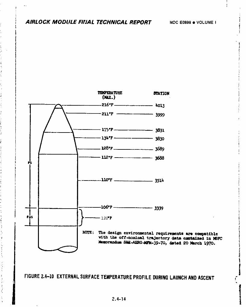
]
r
i AIRLOCK MODULE FIrJAL TECHNICAL REPORT MDCE0899• VOLUMEI
|
¢l_aP]g_A'_l_ ,.q'I'ACZONOuJc.)
i 21.6"F 1_O13
21],'F 3999
r_'5"F 3831
z.3_.'F 383o :q: i
].28'F 3589
----- ! I_ Z.O6"F 3339Ffs -- 122"F
NDTE: The design environmental requirements are compatible
wlth the off-no.trial trajectory data annte£ned Zn MSFCMelorandul S_-AERO-_/-39-70_ &ated 20 Nareh 1970.
IFIGURE2.4-10 EXTERNALSURFACETEMPERATUREPROFILEDURINGLAUNCHANDASCENT _°
2.4-14 1
1974018208-108
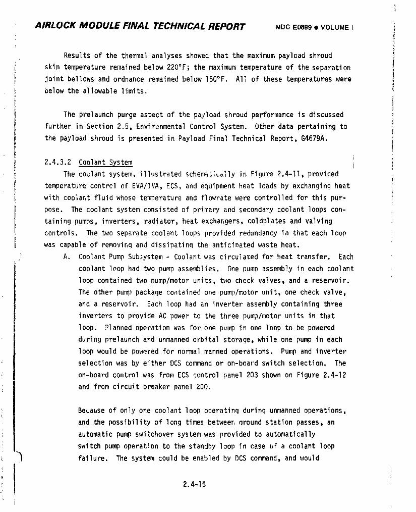
AIRLOCK MODULE FINAL TECHNICAL REPORT MOC E0899 • VOLUME I i
Results of the thermal analyses showed that the maximum payload shroud !skin temperature remained below 220°F; the maximum temperature of the separation
joint bellows and ordnance remained below 150°F. All of these temperatures were _
below the allowable limits.
The prelaunch purge aspect of the payload shroud performance is discussed
further in Section 2.5, EnvironmentalControl System. Other data pertaining to
the payload shroud is presented in Payload Final Technical Report, G4679A.
2.4.3.2 Coolant System
The coclant system, illustrated schemaL;colly in Figure 2.4-II, provided
temperature contrcl of EVA/IVA, ECS, and equipment heat loads by exchanging heat
with coo]ar,t fluid whose temperature and flowrate were controlled for this pur-L
pose. The coolant system consisted of primary and secondary coolant loops con-
taining pumps, inverters, radiator, heat exchangers, coldplates and valving
controls. The two separate coolant loops provided redundancy in that each loop
was capable of removiF,q and dissipatinq the anticinated waste heat.
i A. Coolant Pump Subsystem - Coolant was circulated for heat transfer. Each
coolant loop had two pump assemblies. _ne pump assembly in each coolant
loop contained two pump/motor units, two check valves, and a reservoir.
The other pump package colltainedone pump/motor unit, one check valve,
and a reservoir. Each loop had an inverter assembly containing three
inverters to provide AC power to the three pump/motor units in that
loop. Planned operation was for one pump in one loop to be powered
during prelaunch and unmanned orbital storage, while one pump in each
loop would be poweYed for normal manned operations. Pump and inve-ter
selection was by either DCS command or on-boa1"dswitch selection. The
on-board control was from ECS control panel 203 shown on Figure 2.4-12
and from circuit breaker panel 200.
BeLause of only one coolant loop operating during unmanned operations,
and the possibility of long times betweer,nround station passes, an
automatic pump swi_chover system was provided to automatically
switch pump operation to the standby loop in case of a coolant loop
_ failure. The system could be enabled by DCS command, and would
2.4-15
1974018208-109
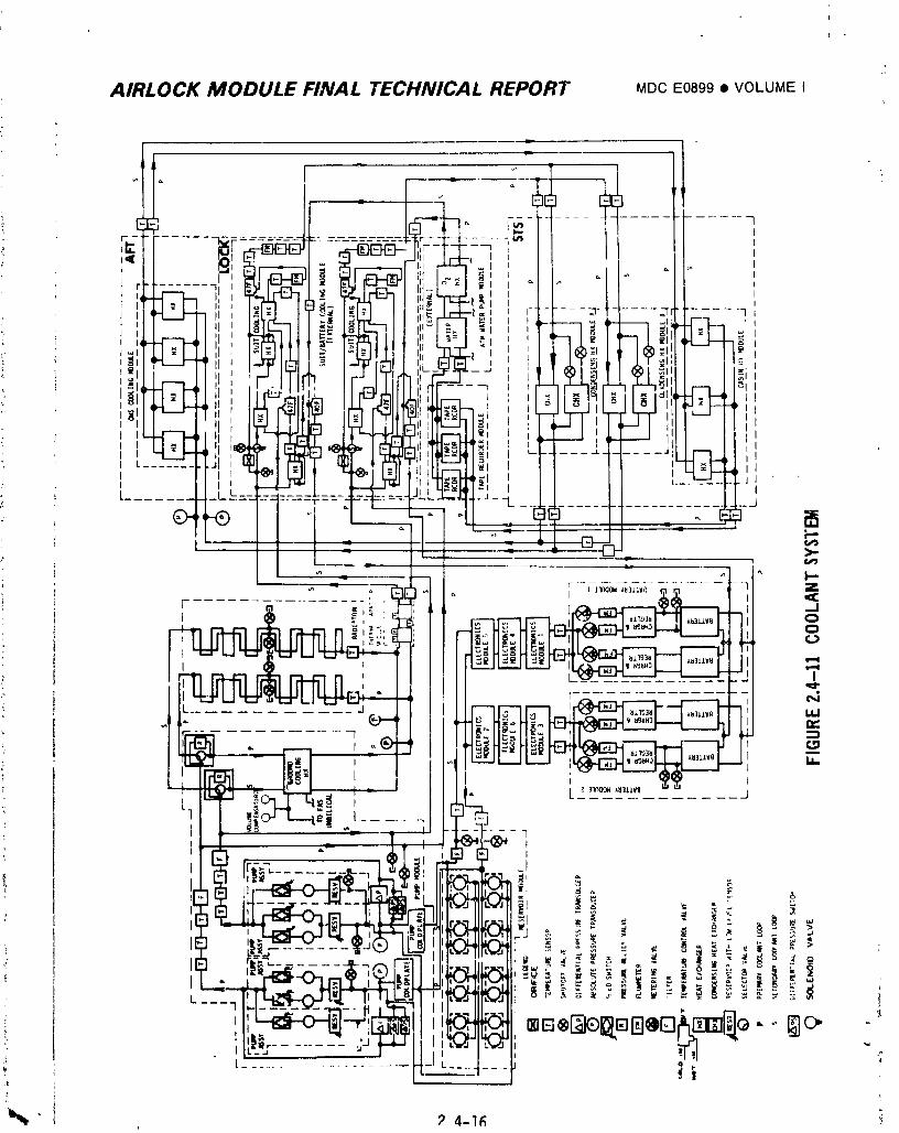
AIRLOCK MODULE FINAL TECHNICAL REPORT MDCE0899• VOLUMEI
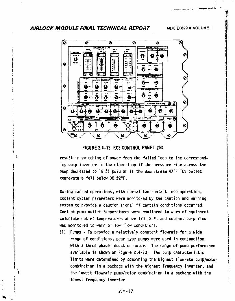
........... _ "_','_'_°'L_'_P''_'_
AIRLOCK MODULE FINAL TECHNICAL REPORT MDCE0899• VOLUMEI i
* t_A.I_CUL#_ _aZY|
t II -+--I
1 I '--,i.,.'_.i;;;_",,m--t _'_' - I -
; o ; "" 010 ... v-.i IJJ uc I _" I o*, I uc I _,,m _ ml j
! Illo...l@l@l 0...Io..._Z _l-'l-. J'" I "'I "* I ....I' ' ,J
t i_UL&¥e_ 1 k_f • I l ] I I:i • _ I II1{ lr • Ql_ •
' IN IIo+o+o o_ o+_+o o H�D�o|o I@I l (o ,.__ - l , I 1.0 +.o I ca+ II o_, owe
I__".,_ .,+ '. ,+,--'--?"+"_=._-i+_ .'- .'-'+--+_++ 17+%,,I,,,_ IO I o IV_,,-,lo I + I o+ el w'.,,.l +" + I x./',,:.l "I" +;+ ..IL
FIGURE2.4-i2 ECSCONTROLPANEL203
i resu_.tin switchingof powerfromthe failedloopto the _o;'respond-
ing pump inverterin the other loopif the pressureriseacrossthe
pumpdecreasedto 18 +I psidor if the downstream47°FTCV outlet
temperaturefellbelow38 +2°F.
Duringmannedoperations,with normaltwo coolantloopoperation,
coolantsystemparameterswere monitoredby the cautionand warning
systemto providea cautionsignalif certainconditionsoccurred.
Coolantpump outlettemperatureswere monitoredto warn of equipment
coldplateoutlettemperaturesabove 120 ±2°F, and coolantpump flow
was monitoredto warn of low flowconditions.
(1) Pumps- To providea relativelyconstantflowratefor a wide
rangeof conditions,geartype pumpswere used in conju,ction
with a threephaseinductionmotor. The rangeof pump performance
availableis shownon Figure2.4-13. The pumpcharacteristic
limitswere determinedby combiningthe highestflowratepump/motor
combinationin a packagewith the highestfrequencyinverter,and4
A the lowestflowratepump/motorcombinationin a packagewith the
i 'lowestfrequencyinverter.
I 2.4-17
1974018208-I11
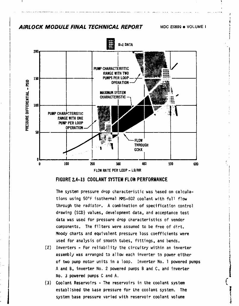
i !!
.................................................................................................................... 4-
AIRLOCK MODULE FINAL TECHNICAL REPORT MDCE0899• VOLUME I!
B U-IDAIA
'°° ,b
PUMPCHARACTERISTICRANGEWITHTWO
150 PUMPSPERLOOP
-J MAXlMUI_SYSTEM
PUMPCHAR,eqTERISTICLLI" RANGEWITHONE ___
PUMPPERLOOP .Lf _ __w"l"" OPF.RATIONJ BY I
Ia. 50 ' i;FLOW
I _ ®-h:a I T..ooG. I...........-' "1 Gc,x
FIGURE2,4-13 COOLANTSYSTEMFLOWPERFORMANCE
The systempressuredropcharacteristicwas basedon calcula-
tionsusing 50°F isothermalMMS-602coolantwith fullflow
throughthe radiator. A combinationof specificationcontrol
drawing(SCD)values,developmentdata, and acceptancetest
datawas usedfor pressuredrop characteristicsof vendor
components.The filterswere assumedto be freeof dirt.
Moody chartsand equivalentpressurelosscoefficientswere
used for analysisof smoothtubes,fittings,and bends.
(2) Inverters- For reliabilitythe circuitrywithinan inverter
assemblywas arrangedto alloweach inverterto power either
of two pumpmotor units in a loop. InverterNo. l poweredpumps
A and B, inverterNo. 2 poweredpumpsB and C, and inverter
No. 3 poweredpumpsC and A.
(3) CoolantReservoirs- The reservoirsin the coolantsystem
establishedthe base pressurefor the coolantsystem. TheL
systembase pressurevariedwith reservoircoolantvolume
1974018208-I12
I
T
: I AIRLOCK MODULE FINAL TECHNICAL REPORT MDC E0899 • VOLUME I
: " and coolant temperature. Each coolant loop contained ten
reservoirs. Eight were contained within the four reservoir
assemblies in the reservoir module. The other two, mentioned
above, were contained in the two pump packages. Figure 2.4-II
shows how the reservoirs were connected into the coolant loops.
C
Figure 2.4-14 presents typical coolant reservoir characteris-
tics. The initial fill was set to provide pressure greater
than 5 psia, to prevent pump cavitation and less than 47.5
psia so as to not exceed maximum allowable operating pressures I
' for the temperature range of 40°F to 150°F. This fill also
_ provided a qood margin on reservoir volume at maximum allow-
able coolant leakage rates. The plan was to fill each
reservoir to a level which corresponds with (neglectingeleva-
tion effects on pressure) the upper line of the shaded area
on Figure 2.4-14. This was to be accomplished by filling
) each loop completely at 70°F then removing 2500 cc of coolant. 'The maximum allowable coolant loss per reservoir during pre-
L
" launch and flight is also indicated on the figure.
The actual coolant volume at which both the primary and secJnd-
i ary coolant loops on U-I were launched was less than specified
:; by Figure 2.4-14 as the minimum prelaunch coolant volume.|
This condition resulted from breaking into the coolant loops>
at KSC. The primary loop was reserviced after replacement of
coolant lines damaged in shipment of the vehicle to KSC. The
secondary loop had a piggyback pressure transducer added atD223.
; The lower than planned coolant volumes were cunsidered adequate
because the prelaunch data indicated the leakage rate was very
_ low with respect to the design allowable and ample coolant was
available to last the entire duration of the mission with both
-) loops leaking at their maximum allowable design rate.
! t '
_: 2,4-19
1974018208-113
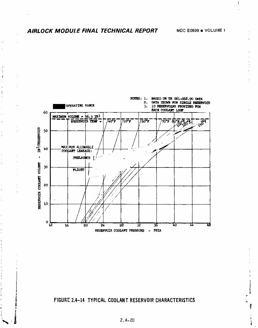
AIRLOCK MODULE FINAL TECHNICAL REPORT MDCE0899• VOLUMEI
wo'l'_: 1. Ba,._D 011TR 061.,.068. 90 raTA2. I_TA b'H_ FORSINGLE_0I_
OPL1_TI'NC,RANGE 3. lo ]RlCSIIWOII__ I'OREACHCOOLIU_.LOOP60 , _
NAXDit_VOMIIG- 56.3 IN3- - - TF,_ T,_--_- rsa_ - 7"6o'=',- - "7_4"_-T_..'T_,."
,o /.;.
o ,,[_"'_"')/i / /" ' , //_,/,/
o //;'/,"f1.2 16 20 2_ 28 32
RE,._IR COOL_'rl=_gl_ - PSIA
: i
FIGURE2.4-14 TYPICALCOOLANTRESERVOIRCHARACTERISTICS
,,,_ • 2.4-20
1974018208-114
AIRLOCK MODULE FINAL TECHNICAL REPORT MDCE0899• VOLUMEI
Flightcoolantmass is discussedin 3ection2.4.5.2.
B. Heat Loads - Temperaturecontrolof the heat loadswas throdghtheir
heat transferwith the coolant. The coolantsystemdesignheat loads
presentedin Section2.4.2may be groupedintothe threeregions.
(1) Suit Cooling- Suit coolingheatloadswere introducedinto the
coolantsystemthroughsuit coolingheat exchangersin the
suit/batterycoolingmodule. Basicallythe loadw_s the sum of
suit coolingload,the water pump heat load,and heatgain
fromenvironment.
(2) ECS - ECS heat loadswere addedto the coolantsystemthrough
condensingheat exchangers,cabin heatexchangersfor OWS and
AM/MDA,threetape recorders,an ATM C&D Panel/EREPheat
' exchanger,an oxygenheat exchanger,and heat leaks. The
portionof the compartmentloads leakedfrom the equipment
sectionof the coolantsystem(e.g.,via coldplatesmounted
on compartm_, walls)were enteredintothe integratedthermal
model as equipmentheat load.
(3) Equipment- The activecoalantsystemutilizedcoldplatesto
controlthe temperaturesof equipmentwhich had small contact
areas,high he:tdissipationrequirementsand smallallowable
temperatureranges. Threetape recorders,two batterymodules,
six electronicsmodules,and two coo_i_tpump inverterassemblies
were coldplatemounted. Due to theirlocationin the coolantloop,
the tape recordercoldplateand the ATM C&D/EREPcoolingsystem
heat loadwere consideredto be partof the ECS heat load.
The coldplatedequipmentand coldplatesurfacecontactareas
a_= listedin Figure2.4-15. The coldplatedesignheatremoval
capabilitywas based on a compqnentbase/coolantfluidconduc-
tance of 50 Btu/hr-ft2°F.CondLctancewas based on use of a
heattransferco_poundper MDAC-EProcessSpecification13618.
"7 The heat transfercompoundwas used on all coldplatesexceptL
II 2 4-21
1974018208-I15
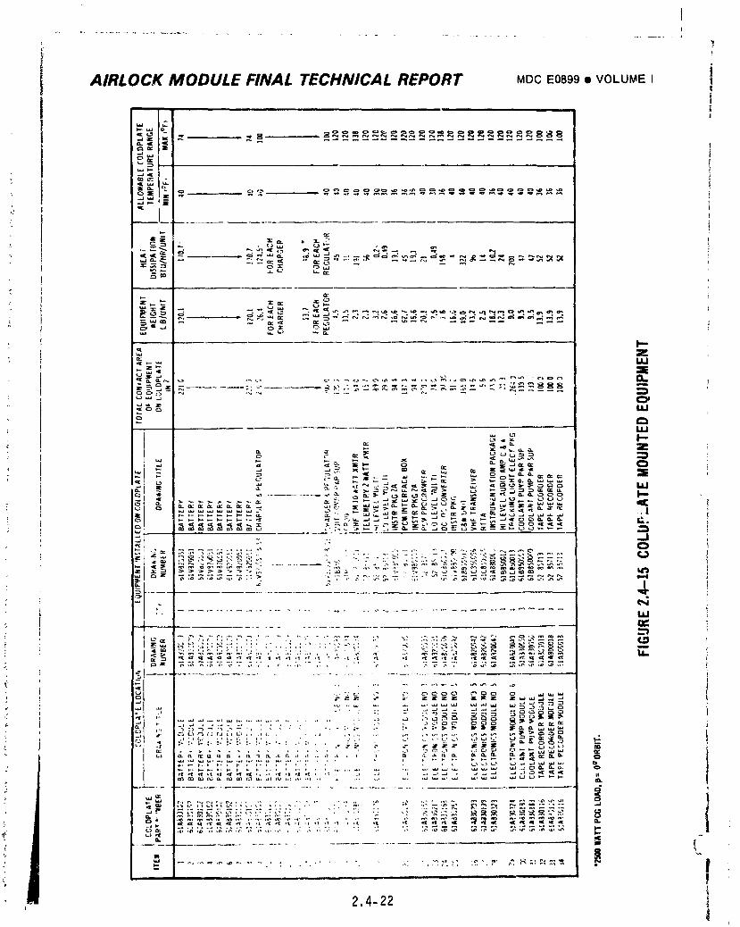
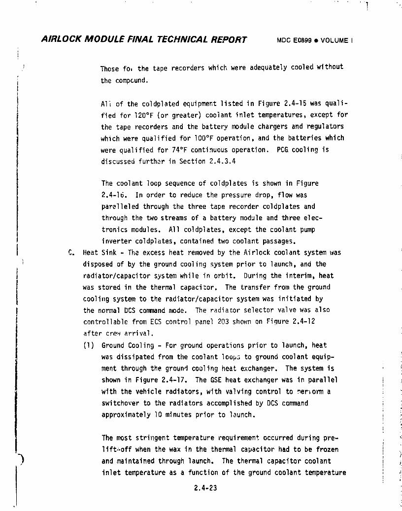
AIRLOCK MODULE FINAL TECHNICAL REPORT MDCE0899• VOLUMEI
Those fo, the tape recorders which were adequately cooled without
the compcund.
AI_ of the coldplatedequipmentlistedin Figure2.4-15was quali-
fied for 120°F(or greater)coolantinlettemperatures,exceptfor
the tape recordersand the batterymodulechargersand regulators
whichwere qualifiedfor lO0°Foperation,and the batterieswhich
were qualifiedfor 740F continuousoperation. PCG coolingis
discussedfurtherin Section2.4.3.4
The coolantloopsequenceof coldplatesis shown in Figure
2.4-16. In order to reducethe pressuredrop,flowwas
parelleledthroughthe threetape recordercoldplatesand
throughthe twostreamsof a batterymoduleand threeelec-
tronicsmodules. All coldplates,exceptthe coolantpump
invertercoldplates,containedtwo coolantpassages.
C. HeatSink - The excessheat removedby the Airlockcoolantsystemwas
disposedof by the groundcoolingsystempriorto launch,and the
radiator/capacitorsystemwhile in orbit. Duringthe interim,heat
was storedin the thermalcapacitor. The transferfromthe ground
coolingsystemto the radiator/capacitorsystemwas initiatedby
the normalDCS commandmode. The radiatorselectorvalvewas also
controllablefromECS controlpanel 203 shown on Figure2.4-12
aftercrewarrival.
(1) GroundCooling- For groundoperationspriorto launch,heat
was dissipatedfrom the coolantloopsto groundcoolantequip-
ment throughthe groundcoolingheatexchanger. The systemis
shownin Figure2.4-17. The GSE heat exchangerwas in parallel
with the vehicleradiators,with valvingcontrolto _er_orma
switchoverto the radiatorsaccomplishedby DCS command
approximatelyI0 minutespriorto l_unch.
The most stringenttemperaturerequirementoccurredduringpre- ,
lift:.offwhen the wax in the thermalcapacitorhad to be frozen>
). and maintainedthroughlaunch. The thermalcapacitorcoolant
inlettemperatureas a functionof the groundcoolanttemperature
2.4-23
i9740i8208-ii7
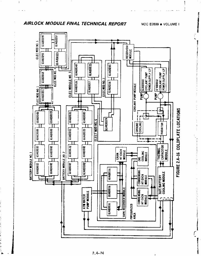
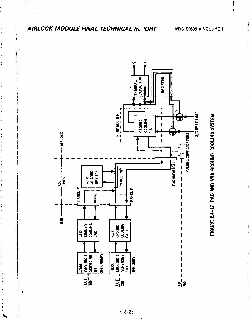
! !T
]: 1t ......
t
I
AIRLOCK MODULE FINAL TECHNICAL REPORT MDCE0899• VOLUMEI !
supplied to the A_/GSE interface at tne FAS is shown in
I Figure 2.4-18. This data _as generated using the pre-lift-off
equipment loads plus heat leaks to the coolant lines, ECS, and
electrical equipment. The heat leaks were based on data
determined during test (SEDR D3-E75), and modified for the
expected 80°F effective heat leak environment at the launch
site. Figure 2.4-18 shows a capacitor module inlet temperature
of approximately 12°F for an Arl/GSEinterface supply tempera-
ture of -15°F. The GSE ceoling equipment capacity was sized to
meet the requirements, taking into consideration the heat leaks
of the launch site interconnecting lines. The prelaunch total
spacecraft heat load (equipment plus leaks) was approximately
9000 Btu/hr. No minimum Redline was established since minimum
temperatures attainable by ground cooling equipment were well
above the TCV qualification minimum temperature of -lO0°F. The
18°F maximum Redline was enforced by Launch Mission Rule during
the time period from 30 minutes before lift off until termina-
tion of ground cooling. The rules applied specifically to the
thermal capacitor skin temDeratures (C262, C263, and C264)_
the capacitor No. 2 primary coolant inlet temperature (C265),
and the capacitor module primary coolant outlet temperature
(C244).
Coolant loop analysis was used to determine that satisfactory
first orbit temperatures Ivouldresult if ground cooling and
switchover to vehicle radiator occurred at the T-lO minute
point. Figure 2.4-1_ defir,es the ground cooling req_1_rements
for a launch hold aftcr termination of gre_md cooling. This
data was part of the Redline requirement.
Also during prelaunch operations, the Hission Rules Redlines i
for the condensing heat exchanger inlet temperatures (C209 and
C217) were set at 42.7°F minimum and 51.OOF maximum. This
assured that the downstream 47°F TCV in the primary coolant
1oop was in control. _r..
t
2.4-26 ii
1974018208-120
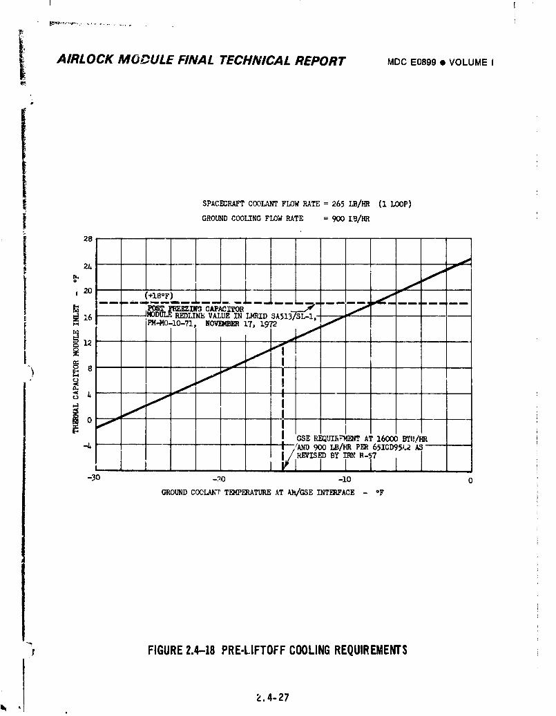
T I
i AIRLOCK MODULE FINAL TECHNICAL REPORT MDCE0899• VOLUMEI
i
SPACECRAFT COOLANT FLOW RATE = 265 I,B/HR (i LOOP)
GROUND COOLING FLOW RATE = 900 LB/HR
28
FIGURE2.4-18 PRE-LIFTOFFCOOLINGREQUIREMENTS
,I _',4-27
1974018208-121
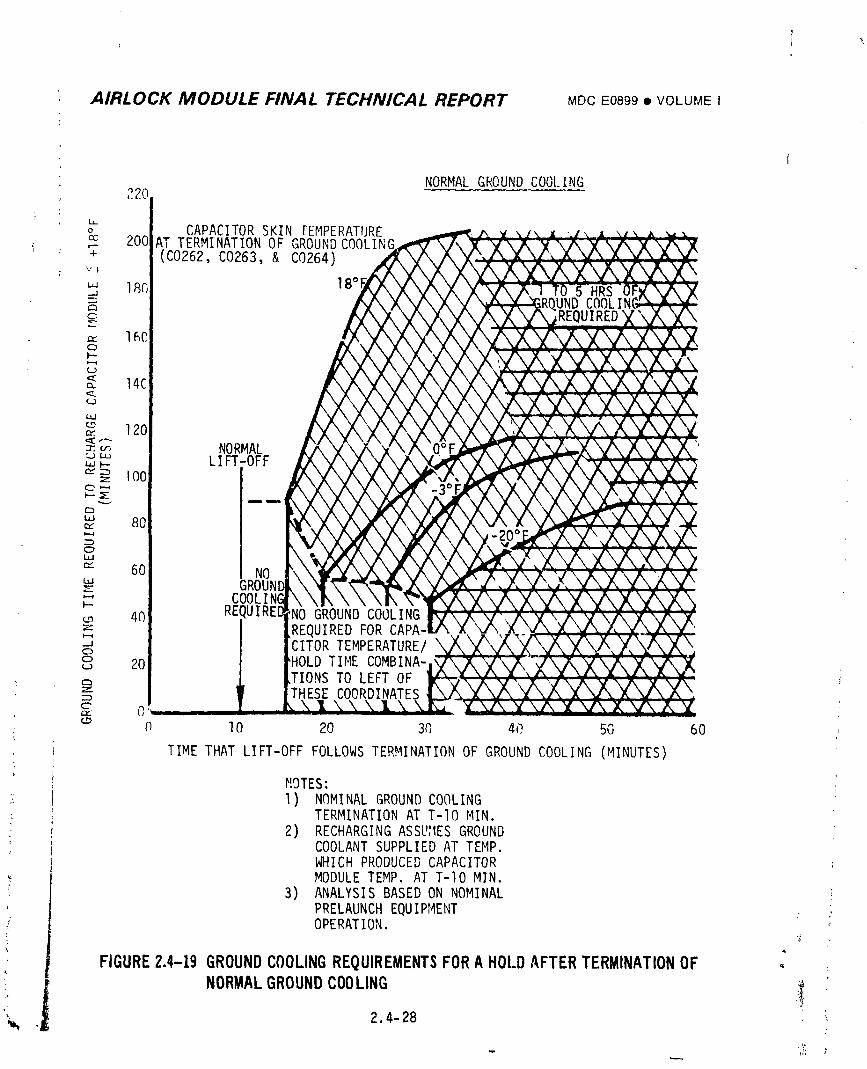
7
AIRLOCK MODULE FINAL TECHNICAL REPORT MDCE0899• VOLUMEI
I
NORMALGROUNDCOOLING220
f :
° CAPACITORSKIN TEMPERATURE• cc 200 AT TERMINATIONOF GROUNDCOOLIN
'T (C0262, C0263, & C0264)V I
'" 18fl 18°1.-.I
,--h
160c_I---
c,_ 14C,::i,.(J
120
_. u_ NORMAL,.,_ LIFT-OFF
I00
"' 80t_
o
_" 60 NOILlGROUt
COOLIl--4fl RE,
_Jc)0_ 20
-" rc"
fl 10 20 30 4,? 5G 60
TIME THAT LIFT-OFF FOLLOWSTERMINATIONOF GROUNDCOOLING (MINUTES)
NOTES:i: I) NOMINALGROUNDCOOLING
TERMINATIONAT T-IO MIN. "- 2) RECHARGING ASSU_IESGROUND
COOLANTSUPPLIED AT TEMP.WHICH PRODUCED CAPACITORMODULETEMP. AT T-IO MIN.
3) ANALYSIS BASEDON NOMINALPRELAUNCHEQUIPMENTOPERATION.
FIGURE2.4-19GROUNDCOOLINGREQUIREMENTSFORAHOLDAFTERTERMINATIONOF • :
NORMALGROUNDCOOLING '! /2.4-28 :
]9740]8208-]22
l
I AIRLOCK MCDULE FINAL TECHNICAL REPORT _oc EOe,9• VOLUME, ]i) Two volumecompensatorswere providedin the flightportionof the
!
groundcoolingsystemfor redundantprotectionagainstoverpressuri-
zationdue to thermalexpansionof the coolanttrappedby prelaunch
disconnectionof the groundcoolingumbilicals.With a maximum
interfacepressureof Ill psia,the expansionvolumeprovidedin
one compensatorwas sufficientto accommodateexpansionof the
coolantin the full system,plus coolantwhich couldfill the
secondcompensatorshouldit fail. Pressureat a guage in the
operatingcoolantand servicingunit afterT-lOminuteswas limited
to 80 psiaby MissionRuleto ensurea maximumpressureat the
compensatorbelowlO0 psia. The performancecharacteristic_of
one of the compensatorsis shownin Figure2.4-20.
(2) Radiator/Capacitor- The coolantsystemradiatorrejectedthe waste
heat to spacewhile in orbit. The capacitormodulesupplemented
' the Airlockspaceradiatorduringhigh heat load periodsassociated
, with EVA/IVAand EREPmissionoperationsin orbit and provided
coolingduringthe initiallaunchphasepriorto radiatorcooldown.
Specificationradiator/capacitorsystemtotalheat rejection
requirementswere 16,000Btu/hrfor solar inertial,non-EVA,one
pump per loop,two loopoperationwithoutCMG desaturationand
12,000Btu/hrfor solarinertial,4200 Btu/hrmaximumEVA, one i
Ipumpper loop,two loopoperationwithoutCMG desaturation.
Radiator/capacitorperformanceversusload criteriawas considered !
Jto be satisfactoryif the performancemet the load basedon opera-
tion of one pump per loop,two loops operational.The radiator/
capacitorprovidedcoolingat a reducedlevelwith one pump,one
loopoperation. Operationof more than two pumpswas not planned.
Radiator/capacitorcapacityfor _olar inertialattitude,with EVA
operationsand normaloperations,includingthe effectsof experi-
ment view factorblockage(see Figure2.4-I)are shown in
Figure2,4-21.
• 2.4-29
1974018208-123
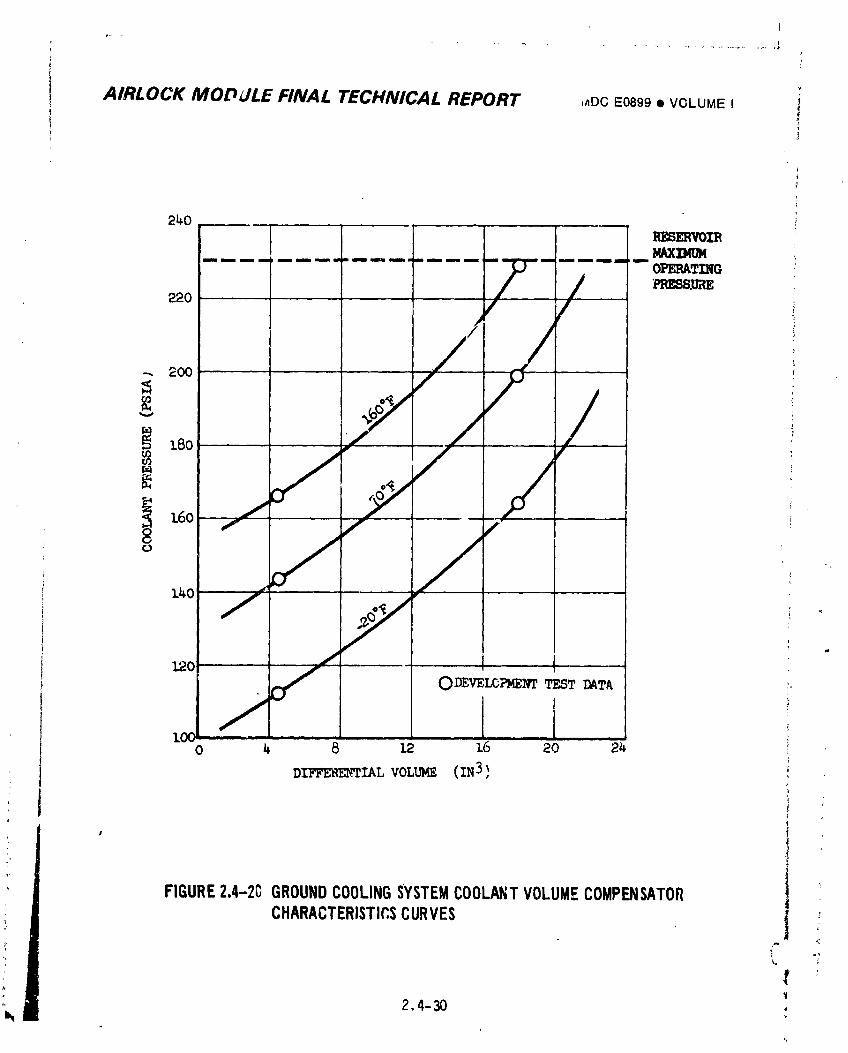
AIRLOCK MODdLE FINAL TECHNICAL REPORT ,mc E0899• VOLUME I
240P,ESERVOIR
-- i....--i_o , ,//
/o /
_o / " 1 ,-S ODEVELOPMENTTEST DATA _.
/ _0 _. 8 ].2 16 20 24 :.
DIFFERENTIAL VOLUME (IN3} I
1' I
FIGURE2.4-2CGROUNDCOOLINGSYSTEMCOOLANTVOLUMECOMPENSATOR j
CHARACTERISTICSCURVES j ;
2,4-30v_
1974018208-124
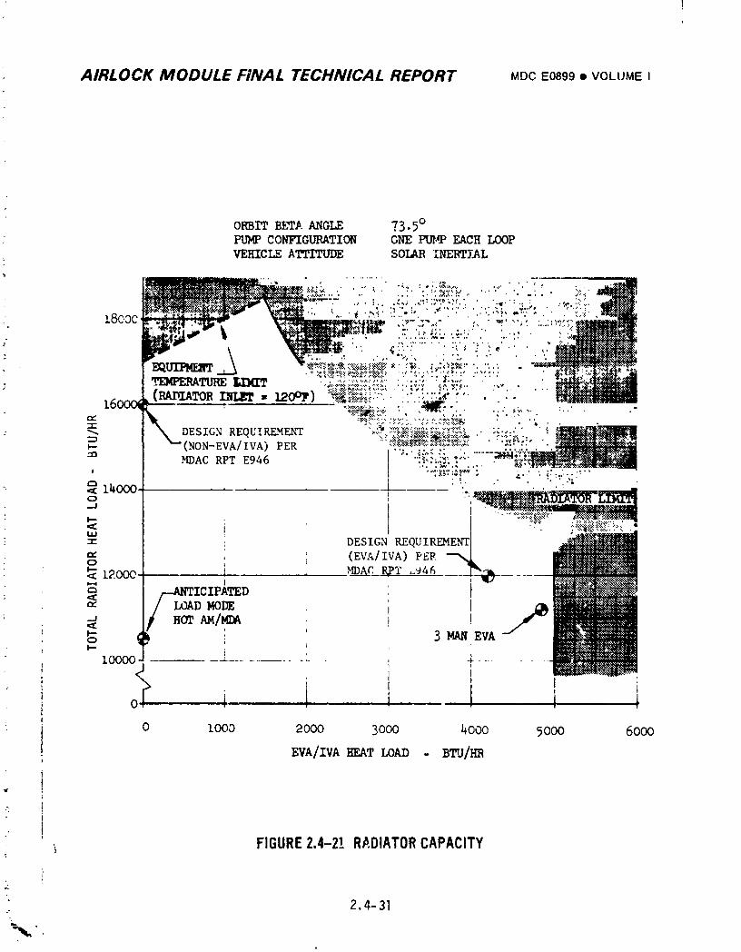
AIRLOCK MODULE FINAL TECHNICAL REPORT MDCE0899• VOLUMEI
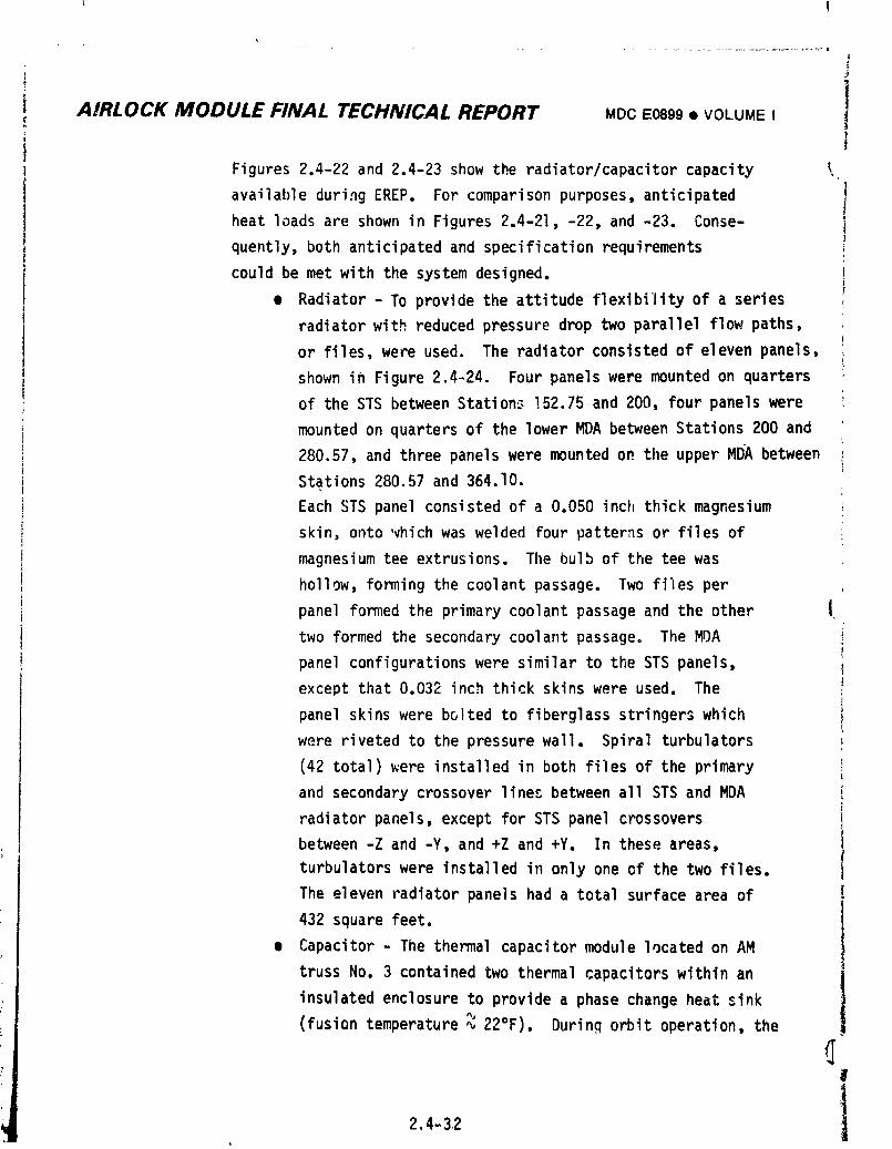
I
!
AIRLOCK MODULE FINAL TECHNICAL REPORT MDCE0899• VOLUMEI i
Figures2.4-22and 2.4-23show the radiator/capacitorcapacity _.
availableduringEREP. For comparisonpurposes,anticipated
heat loadsare shown in Figures2.4-21,-22,and -23. Conse-
quently,bothanticipatedand specificationrequirements
could be met with the systemdesigned.
• Radiator- To providethe attitudeflexibilityof a series
radiatorwith reducedpressuredrop two parallelflow paths,
or files,were used. The radiatorconsistedof elevenpanels,
shownin Figure2.4-24. Fourpanelswere mountedon quarters
of the STS betweenStations152.75and 200, fourpanelswere
mountedon quartersof the lowerMDA betweenStations200 and
280.57,and three panelsweremountedon the upperMDA between
Stations280.57and 364.10.
EachSTS panelconsistedof a 0.050inch thickmagnesium
skin,onto'vhichwas welded fourpatternsor filesof
magnesiumtee extrusions.The bulbof the tee was
hollow,formingthe coolantpassage. Two files per
panel formedthe primarycoolantpassageand the other J
two formedthe secondarycoolantpassage. The MDA
panelconfigurationswere similarto the STS panels,
exceptthat0.032 inch thickskinswere used. The
panel skinswere boltedto fiberglassstringerswhich
were rivetedto the pressurewall. Spiralturbulators
(42 total)were installedin both filesof the primary
and secondarycrossoverlinesbetweenall STS and MDA
radiatorpanels,exceptfor STS panelcrossovers
between-Z and -Y, and +Z and +Y. In these areas,
turbulatorswere installedin onlyone of the two files.
The elevenradiatorpanelshad a totalsurfacearea of
432 squarefeet.
• Capacitor- The thermalcapacitormodulelocatedon AM
trussNo. 3 containedtwo thermalcapacitorswithinan
insulatedenclosureto providea phasechangeheat sink
(fusiontemperature_ 22°F). Duringorbit operation,the
I
2.4-32 1
1974018208-126
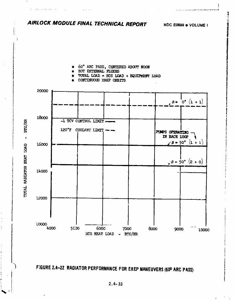
!
, AIRLOCK MODULE FINAL TECHNICAL REPORT MOCE0899$ VOLUMEI
t
• 60 ° /_ P/_$, C_ _Ot_ NOON
• ,'t'OT,_LLOAD-- ECS LOAD+ EQ_• COI_INUOI_ _ ORBITS
2oooo I l - ,._.o°(i+11
lmmmmm m mmm im m mmm mm m mm mm m mm um m upmm am m mumm im mm me gnmm all,, mmm m mm mm m
)
4._ c_'t_OLL_----L_O°F COOLANT LIMIT "---- _ OFERATING --_
INEACHLOOP ,_!
t6ooo - , , , r:_" 5o',(1+i
14000 -, ' "
12000 "
_ooo 5coo 6o6o 7ooo 8000 9000 .... loooo_s _T LO_D - BTU/_
FIGURE2.4-22 RADIATORPERFORMANCEFOREREPMANEUVERS(600ARCPASS)°i
2.4°33
%,
1974018208-127
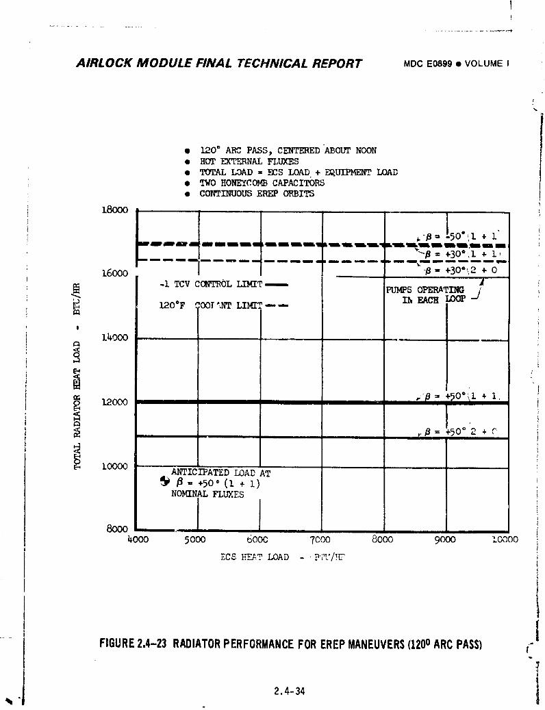
AIRLOCK MODULE FINAL TECHNICAL REPORT MDCE0899• VOLUMEI
• 120° ARC PASS, CENTERED "ABOUTNOON• HOT EXTERNAL FLUXES• TOTAL LOAD = ECS LOAD + EQUIPMENT.LOAD• TWO _ONEYCOMB C&PAClTORS• CONTINUOUS EREP ORBITS
180OO!
,_-# = [50"_,i+ l'iil_ml Hiram. blmmmmLl_l. Llmllll,lm I
"-/_= +30°',i+ i,mini m mmoam nmm nm mm nm m mmun nmmm m mmm mm _emm mJ m _i maiim_n nil
16000 ,, '_ = +300'2 + OA
-1 _v cca_oT.LIMIT----- PUMPSOPm_TmS j"" I_ EACB LOOPL?.O°F COOl'/_9 LIMIT--
!
14000
<o iii
i ,,-p ,1,120O0
,.#= _.5o°2 +
ANTICIPATED LOADATP_ +50"(1+1)NOMINAL FLUXES
8000_ooo 5ooo 6ooo 70oo 8ooo 90oo zoooo
ECS }..'E_.TLOAD : /.- . u'i'U '5"
tFIGURE2.4-23 RADIATORPERFORMANCEFOREREPMANEUVERS(1200ARCPASS) t'"
!
. 2.4-34 l1
1974018208-128
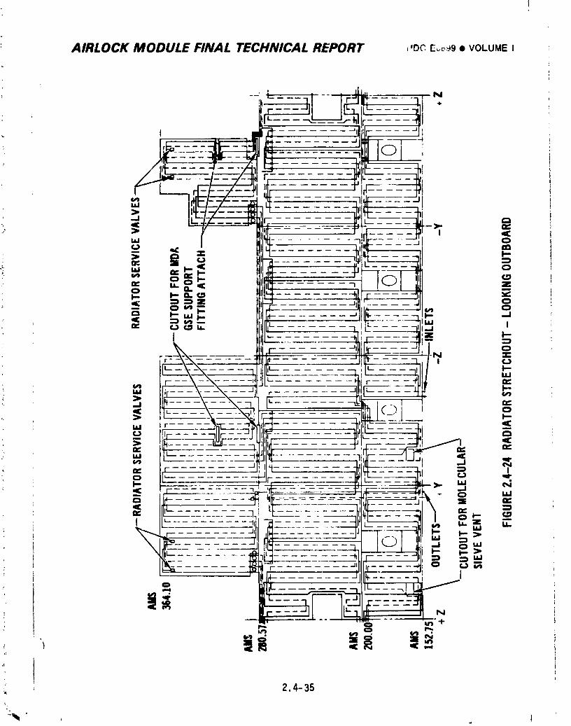
: AIRLOCK MODULE FINAL TECHNICAL REPORT _,DCE,.,c,_9• VOLUMEI
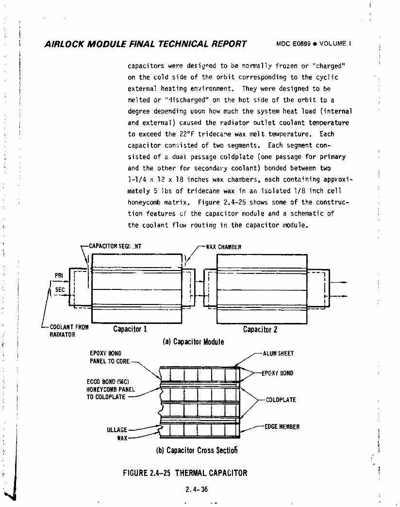
, AIRLOCK MODULE FINAL TECHNICAL REPORT MDCE0899• VOLUMEI
i capacitors were designed to be normally frozen or "charged"
I on the cold side of the orbit corresponding to the cyclic
i external heating environment. They were designed to be
! melted or "discharged" on the hot side of the orbit to a
: degree depending UPOn how much the system heat load (internal
; and external) caused the radiator outlet coolant temperatureI
I to exceed the 22°F trideca_e wax melt t_,iperature. Each
_ capacitor consisted of two segments. Each segment con-
sisted of a dual passage coldplate (one passage for primary
_ and the other for secondary coolant) bonded between two
l-I/4 x 12 x 18 inches wax chambers, each containing approxi-
mately 5 ]bs of tridecane wax in an isolated I/8 inch cell
honeycomb matrix. Figure 2.4-25 shows some of the construc-
tion features of the capacitor module and a schematic of
the coolant flow routing in the capacitor module.
SE_::NT CHAMBER
PRI
COOLANTFROM CapacitorI Capacitor2/ RADIATOR
(a)CapacitorModule(
EPOXYBONDPANELTO
Xl DONDECCOBOND(_C)HONEYCOMBPANELTOCOLDPLATE
ULLAGE MEMBER
WA_
(b)CapacitorCrossSectio_ !
FIGURE2.4-25 THERMALCAPACITOR
1974018208-130
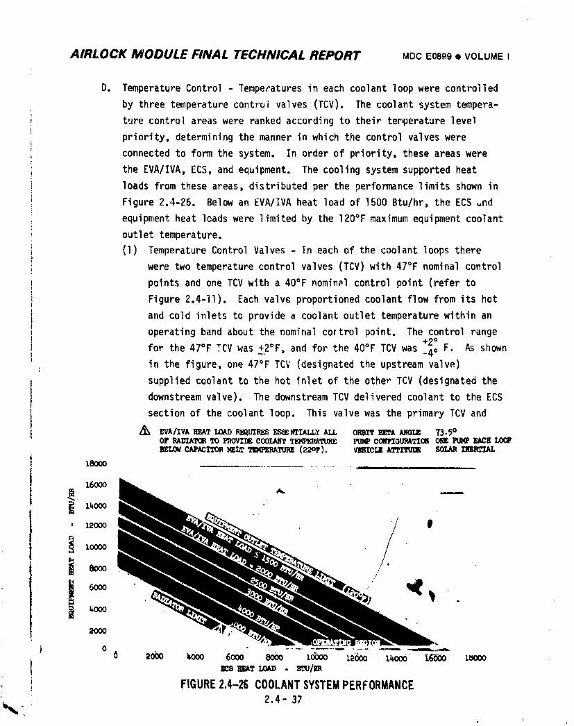
AIRLOCK MODULE FINAL TECHNICAL REPORT MDCEOSP9• VOLUME I
D. Temperature Control - Temperatures in each coolant loop were controlled
by three temperature control valves (TCV). The coolant system tempera-
, ture control areas were ranked according to their temperature level
priority, determining the manner in which the control valves were
connected to form the system. In order of priority, these areas were
the EVA/IVA, ECS, and equipment. The cooling system supported heat
loads from these areas, distributed per the performance limits shown in
Figure 2.4-26. Below an EVA/IVA heat load of 1500 Btu/hr, the ECS _nd
equipment heat loads were limited by the 120°F maximum equipment coolant
outlet temperature.
(1) Temperature Control Valves - In each of the coolant loops there
were two temperature control valves (TCV) with 47°F nominal control
points and one TCV with a 40°F nominal control point (refer to
Figure 2.4-II). Each valve proportioned coolant flow from its hot
' and cold inlets to provide a coolant outlet temperature within an
operating band about the nominal cortrol point. The control range+2°, for the 47°F TCV was +2°F, and for the 40°F TCV was _4o F. As shown
in the figure, one 47°F TCV (designated the upstream valve)
i supplied coolant to the hot inlet of the other TCV (designated thedownstream valve). The downstream TCV delivered coolant to the ECS
I section of the coolant loop. This valve was the primary TCV andJI Z_ EVA/IVAIIF_,A?LOADI_Q.UIRD5_ Iff'IALL¥ALL OlmlTB_A AllOl.,lg ?3.5°Or _xn'zx'roeTo z_'zzz cooum'r_'nmE m._ com,'zou_'z'zcmon _ ¢,¢_
mow cAPacrronmLm _m_J_xn_ (22or). v_e_ A_rrmz SOLA_
18000 .............., ....
_6OOO
]._0OO
, 12OOO 0
2OOO
ms agaT LOAD- m,u/n
FIGURE2.4-26 COOLANTSYSTEMPERFORMANCE2.4- 37
_.I
I
1974018208-131
i
• AIRLOCK MODULE FINAL TECHNICAL REPORT MDC E0899 • VOLUME : !" l f
; J
maintained contro] automatically for all heat heat loads within the
system capacity limits shown in Figure 2.4-26. The 40°F TCV
supplied coolant to the equipment section of the coolant loop.
This valve was in control, except fur combinations of high EVA/ECS
heat loads and warm capacitor module outlet coolant conditions.
For these conditions high coolant flow was required by the down-
stream 47°F TCV cold inlet; the flow from the upstream 47°F TCV was
proportionallyreduced. Since coolant flow to the upstream 47°F
TCV cold inlet was the source of supplemental cooling for the 40°F
TCV, the reduced flow allowed the 40°F TCV to go out-of-control on
• the high side. The upstream 47°F TCV thus served as an inter-
mediary, regulating the cooling available at the battery cooling
heat exchanger after the demands of the downstream 47°F TCV were
met.
The downstream 47°F TCV outlet temperat_res in both loops were moni-
tored by the caution and warning system to warn of condensing heat
exchanger inlet temperature below 38 +I.75°F. No h h temperature
caution and warning was provided for this parameter since a double
failure (both upstream and downstream 47°F TCV's) would have to
Occur,
(2) EVA/IVA Heat Exchanger Coolant Flow Valves - In each con ant loop a
flow selector valve was provided to bypass ceolant around heat
exchangers used for suit cooling when water solution was not being
circulated in the suit cooling loop. These valves are discussed in
Section 2.6.2.2.
E. In-flight Coolant Loop Re_ervicing - The coolant reservicing equipment
provided the ability to top off both coolant loops with Coolanol 15 to
replenish coolant lost through leakage. The hardware used for reservicing
is shown on Figure 2.4-27. The basic method involved pressurizing the
co,Aant supply tank with 35 psig N2, and forcing coolant into the loop i
through a line-piercing saddle valve.
2.4-38
1974018208-132
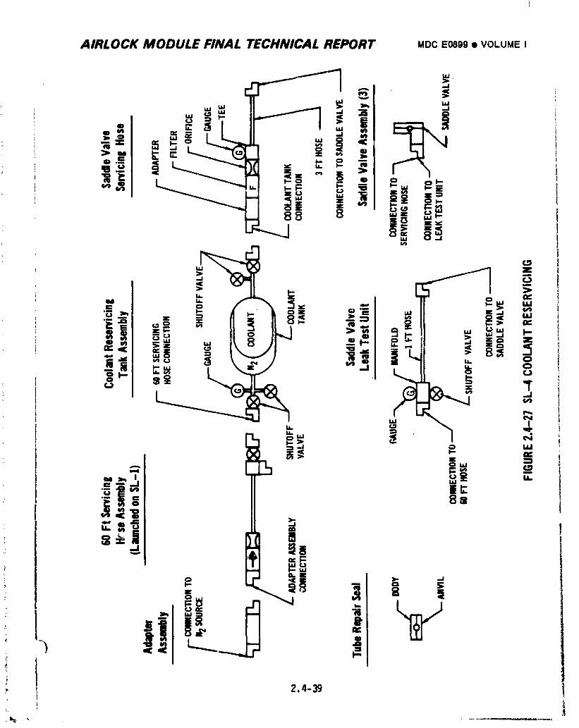
AIRLOCK MODULE FINAL TECHNICAL REPORT MDCE0899• VOLUMEI
• AIRLOCK MODULE FINAL TECHNICAL REPORT MDCE0899• VOLUMEI I
Hardware and procedures were developed during the SL-3 mission for
reservicing the coolant loops due to the gradual loss of coolant from
: both loops. The reservicing hardware (except for the 60 ft hose
assembly) and procedures were launched with SL-4, and the primary/
coolant loop was reserviced during the SL-4 mission. Primary loop
reservicing is discussed further in Section 2.4.5.
The supply tank was designed to be launched on SL-4 with 42 Ibs of
coolant and 180 in3 of pressurized nitrogen. The tank was to be main-
tained at a positive pressure prior to and during launch by initially
' aerating the coolant to a dissolved gas content of 340 ppm by weight
i and pressurizing the tank to 26.7 psia for launch.
i Coolant servicing was planned to be accomplished by: (I) attaching th_
:: saddle valve to the coolant line; (2) performing two leakage checks on
the installed saddle valve, one with N2 gas and the other with Coolanol;
(3) piercing the coolant line by turning the saddle valve stem until it
• bottomed on saddle valve body, then retracting to stop; (4) opening
coolant supply valve on the reservicing tank to establish flow into
the loop; (5) closing the flow valve when the desired pressure level
(21 to 23 psig) was indicated by the gage on the 3 ft servicing hose;
: (6) turning saddle valve until it bottomed again on saddle valve body;
: and (7) disconnecting the servicing hoses.
Figures 2.4-28 and 2.4-29 show desiqn values of loop pressure increase
and coolant addition during reservici_g. The actual coolant mass added
is discussed in Section 2.4.5.2(E). The combined resistances of the
' 3 ft servicing valve orifice and the saddle valve resulted in ani
approximate flowrate of 2 Ib/min.
i
2.4-40
i 9740i 8208-i 34
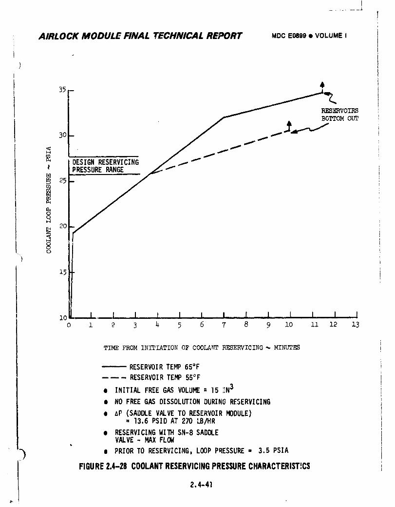
I
AIRLOCK MODULE FINAL TECHNICAL REPORT MDCE0899• VOLUMEI
35 - _KES _ERVOIRS
DESIGNRESERVICING / / s_
25-
8
15 :
zo • I I I,_ I I I. I [ I I ,,I I Io z 2 3 _ 5 6 7 8 9 Zo zz z2 z3
TIME FROM INITIATIONOF COOLA_ RESERVICING_MINUTES
i,, RESERVOIRTEMP65°F
----- RESERVOIRTEMP 55°F
• INITIALFREEGAS VOLUME: 15 ;IN3
• NO FREEGAS DISSOLUTIONDURINGRESERVICING
e AP (SADDLEVALVETO RESERVOIRMODULE)= 13.6PSIDAT 270 LB/HR
e RESERVICINGWITH SN-8SADDLEVALVE- MAXFLOW
"_ • PRIORTO RESERVICING,LOOP PRESSURE- 3.5 PSIA
FIGURE2.4-28 COOLANTRESERVICINGPRESSURECHARACTERISTICS
2.4-41
1974018208-135
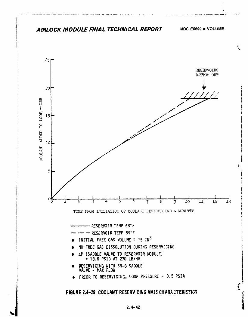
A!RLOCK MODULE FINAL TECHNICAL REPORT MDCE0899• VOLUMEI
1
O0 1 5 o 7 8 9 lO ll 12 13
TIME FROM II_ITIATIO?IOF COOLA_'[TRESERVICII_G--HI,_UTES
RESERVOIRTEMP 65°F
m _ -- RESERVOIRTEMP 55°F
0 INITIALFREEGAS VOLUME= 15 IN3
• NO FREEGAS DISSOLUTIONDURINGRESERVICING
e AP (SADDLEVALVETO RESERVOIRMODULE)= 13.6PSID AT 270 LB/HR
e RESERVICINGWITH SN-8SADDLEVALVE- MAXFLOW
• PRIORTO RESERVICING,LOOP PRESSURE- 3.5 PSIA
¢FIGURE2.4-29 COOLANTRESERVICINGMASSCHARA_TERIST!CS
2.4-42 1
1974018208-136
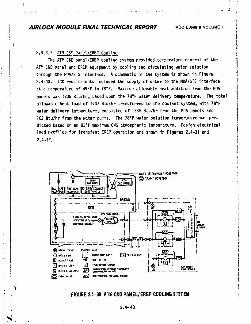
I
AIRLOCK MODULE FINAL TECHNICAL REPORT MDCE0899• VOLUME I 1
2.4.3.3 ATM C&D Panel/EREP Cooling
The ATM C&D panel/EREP cooling system provided temperature control of the
ATM C&D panel and EREP equipme_,tby cooling and circulating water solution
through the MDA/STS interface. A schematic of the system is shown in Figure
2.4-30. ICD requirements included the supply of water to the MDA/STS interface
at a temperature of 49°F to 78°F. Maximum allowable heat addition from the MDA
panels was 1335 Btu/hr, based upon the 78°F water delivery temperature. The total
allowable heat load of 1437 Btu/hr transferred to the coolant system, with 78°F
water delivery temperature, consisted of 1335 Btu/hr from the MDA panels and
102 Btu/hr from the water pum"s. The 78°F water solution temperature was pre-
dicted based on an 83°F maximum OWS atmospheric temperature. Design electrical
]oad profi|es for transient EREP operation are shown in Figures 2.4-31 and
2.4-32.
Ii
.! 2.4- 43
-, - ,r i
1974018208-137
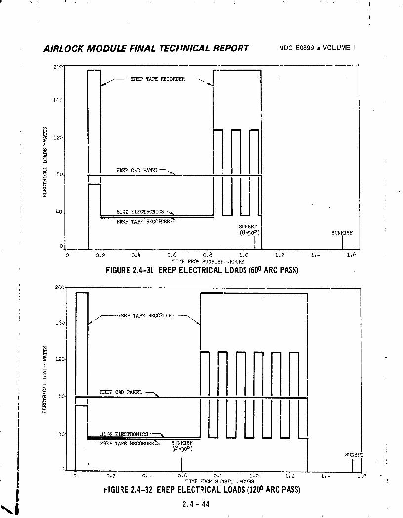
AIRLOCK MODULE FINAL TECtJNICAL REPORT MDCE0899• VOLUMEI
2OOm
/,------ EREP TAPE KECOEDER _..."=,
16o
r_3
40 S192 ELECTRONICS--.,%
E_EP TAPE RECORDER _SUNSk_=
(8=5oo) sum_Is_
o 1 1o 0£2 o.U 0.6 0.8 1.o 1.2 1.u z_
TII._ FROM SUNRISE-_HOURS
FIGURE2.4-31 EREPELECTRICALLOADS(600ARCPASS)
2OO.i_ml
/-----ENEPT.AFERECORDER----.150 *
00 LJUUULIL;O" S192 ELECTRONICS "---%
Em_PTAR _C0_ER_ SUmUSE@=3o°)
0 .
o o.2 0.4 0.6 o.'. l.o 1.2 z_ l._ -TI_ _'ROM SU_{SET _F_OURS
I FIGURE2.4-32 EREPELECTRICALLOADS(1200ARCPASS)2.4- 44
1974018208-138
! AIRLOCK MODULE FINAL TECHNICALREPORT MDCE0899• VOLUMEIg
i The water flowrate delivered to the MDA/STS interface was to be 220 Ib/hrminimum. The pressure drop on the MDA side of the interface was to be less .¢
[ than 6.75 psid at 220 Ib/hr. An abnormally low pressure rise across the pump :_
woz'J have been indicated by illumination of the LOAP light on the ECS control
I panel 203. The design water delivery pressure was not to exceed 37.2 psia.
! The water loop was serviced prior to flight with a mixture prepared in 1• | accordance_ith Process Bulletin 3-302 (Rev. E), containing 97% deaera_ed
_ MMS-606 water, 2% by weight dipotassium hydrogen phosphate, 0.2% by weight
_ I sodium borate, and _O0 PPM Rocc_i The system was designed to allow in-flight• _
) reservlring. The systam c!so contained an in-flight replaceable filter. The
filter was i_stalled on panel 235. It was to be replaced at the beginning off.
_ each mission with a p_serviced filter brought up in the command module. The i
! water system was protected against freezing durinq orbi:al storage as follows:the ATM tank module by its loc_tion within the heated vehicle, the ATM pump
module by its location under the thermal curtains and its heat transfer with
the tunnel wall, and the AM lines by insulation isolating them from cold
environmentwhile providing controlled heat exchange with warm coolant lines
The system was deactivated for orbital storage and could be deactivated forEVA/IVA, if required to decrease c_olant system heat loads during manned opera-
tions. The water-to-coolant he_t exchanger and water pumps formed part of the
ATM _ter pump module. The system was operated from the ECS control panel 203
and circuit breaker panel 202. i
2.4 - 45
1974018208-139
AIRLOCK MODULE FINAL TECHNICAL REPORT MDCE0899• VOLUMEI
2.4.3.4 Battery Coolin_:
The battery couling system reduced the temperature of coolant entering the
power conditioning equipment to as close to 39 +3°F as permitted by the total
coo]ant loop heat load and b) radiator performance. The system for one coolant
l_op consisted of a three-passageheat exchanger and a 40°F TCV. This equipment
was part of the suit/battery cooling module, as indicated in Figure 2.4-II. The
electrical load of eight power conditioning groups (PCG) is shown in Figure
2.4-33, based upon the as-designed two OWS solar array system wing configuration.
Dup to the loss of solar array wing number two from the OWS during ascent, PCG
• waste heat preCictions were made for operation of wing number one. Figure
2.4-34 presents waste heat predictions for the one wing solar array configuration
with typical flight operating conditions noted.
For pre-lift-off operation, the temperature on top of the second battery
cell case was predicted to be 47°F, as shown in Figure 2.4-35 for continuous
battery charging and 40°F battery module coolant inlet temperature. The continu-
ous charging condition is represented by the 6 = 73.5° curve.
For orbit operation,s the second battery top of cell temperature was predicted
ta be approximately 56°F during hot AM/MDA operations, per Figure 2.4-36. Similar
top of cell temperatureswere expect_J for hot OHS, EREP, and EVA modes.
Transient effects, however, were expected to slightly reduce the top of cell
temperatures during EREP and EVA. With a 40°F battery module coolant inlet temp-
erature, the top of cell temperatures were expected to range from 46°F to 50°F
during m._nnedcold mode or unmanned r_dezvous and orbital storage mode operations
(refer to Figure P.4-36).
2.4.3.5 Thermal Coatingsi
Coatings were used to co trol the transfer of heat. The external thermal i
coating design values of the oruital vehicle are shown in Figures 2.4-37 and
2.'-38. The external surface coatings employed were aluminum, black, and white
paints. The white paint, with a _ow ratio of solar absorptivity (_) to emissivity•
(c), provided low effective sink temperatures and resulted in higher heat rejec- 1
tion rates. The hot case design value used for the radiator surface accounted for
degradation during the mission due to UV exposure, meteoroids, exhause plume
impingement, etc. Both black and white paints were used on the forward skirt and
black paint was used on IU, FAS, and MDA.
2.4-46, ::.--:-.- ......... _ ___ .
1974018208-140
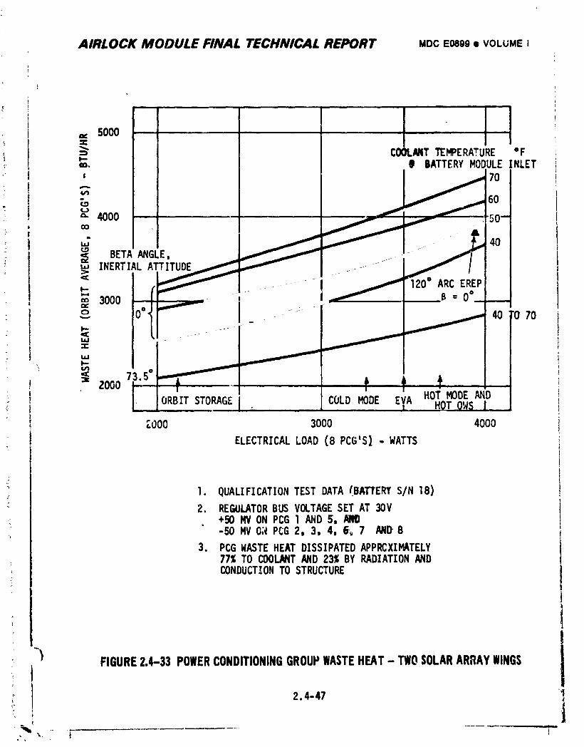
AIRLOCK MODULE FINAL TECHNICAL REPORT MDCE0899• VOLUMEI
== sooo....... i ,, I_" COOLMTTEI_ERATURE °F,',,. B BATTERYNODULEINLET
' _ 70
(,n
_ 60=" 4000 ""--oO
u2 40BETA ANGLE, __
'.'INERTIALATTITUDE ---
_- _ _ ," ARC EREP" _, I B="" 3000 --,
= I -._. _ 40' 70
II.iJ
MJI.-
_C
_= 2000
i ORBIT STORAGEL COLD MODE E' HOT MODE AND
,"000 3000 4000
ELECTRICALLOAD (8 PCG'S)..WATTS
I. QUALIFICATIONTEST DATA(BATTERIS/N 18)
2. REGULATORBUS VOLTAGESET AT 30V+50 MVONPCG1 AND5,-50 MVO;_PCG2, 3, 4, 5_, 7 MD 8
3. PCGWASTEHEATDISSIPATEDAPPRCXIMATELY77%TO COOLANTAND23_ BY RADIATIONANDCONDUCTIONTO STRUCTURE
-_) FIGURE2.4-33 POWERCONDITIONINGGROUPWASTEHEAT- TWOSOLARARRAYWINGSt
i, 2.4-47 ]
" I ]'%'--, " t q....
1974018208-141
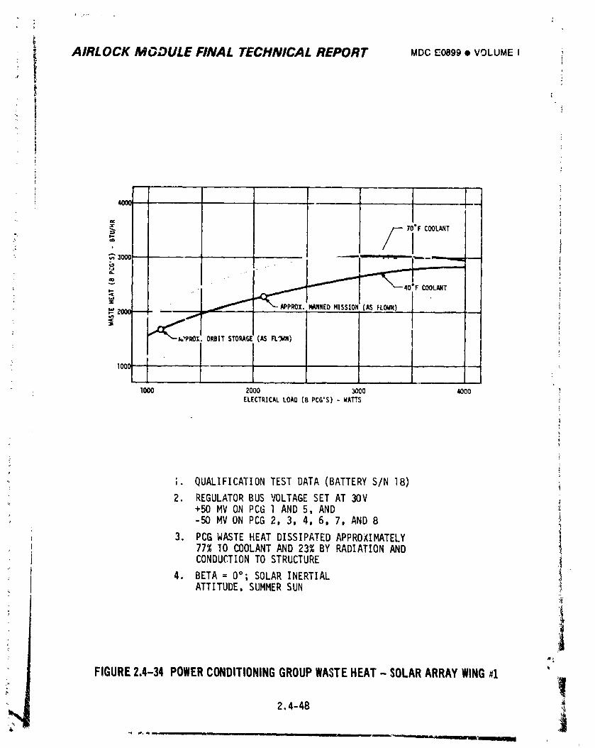
i AIRLOCK MGDULE FINAL TECHNICAL REPORT MDCE0899• VOLUMEI
" I
70"F COOLANT
- ,,_ 300t --, ..... ', _-_[
_ _ 40IF COOLANT- I
_., ZOOI _
PROX. ORBIT STORAGE(AS FL"MN)
: looc I
1OO0 2000 3000 4000 ?ELECTRICALLOAO(8 PCG'S) - WATTS
t
, ;. QUALIFICATIONTEST DATA (BATTERYS/N 18) i
2. REGULATORBUS VOLTAGESET AT 30V+50 MV ON PCG l AND 5, AND
, -50 MV ON PCG 2, 3 4, 6, 7, AND 8 is
3. PCG WASTEHEAT DISSIPATEDAPPROXIMATELY i77% "IOCOOLANTAND 23% BY RADIATIONAND
CONDUCTIONTO STRUCTURE -i.4. BETA = 0°; SOLAR INERTIAL
ATTITUDE,SUMMERSUN '_.
!FIGURE2.4-34POWERCONDITIONINGGROUPWASTEHEAT- SOLARARRAYWING#1
]2,4-48
B, _ am n,I I n i I I i i _ .... _ ..... ,=,,
1974018208-142
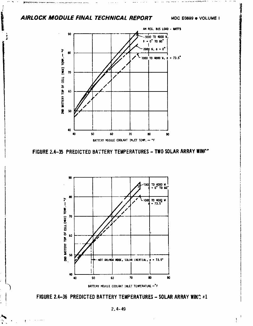
!
All#LOCK MODULE FINAL TECHNICAL REPORT MDC E0899 • VOLUME I !AM R[G. BUSLOAD- tlMT$
I /_x' "l°"'_""
40 50 60 70 80 90
BATTERYHIBDULECOOLAHTIN_.ETTEMP.,,,, "F
FIGURE2.4-35 PREDICTEDBATTERYTEMPERATURES- TWOSOLARARRAYWIN('"
9O
10(_ TO 4000 U
• O" TO 60'
8O
; 70 J
50 ,,
• _-HOT AMIMOAHOOE,SOLARINERTI.t.L, J • ?l.S"
Ii40
40 50 60 70 80 90
-"_ BATTERYHOOIJLECOOLANTINLETTEHPERATURE-*F
I FIGURE2.4-35 PREDICTEDBATTERYTEMPERATURES- SOLARARRAYWlN_#1
2.4-49
1974018208-143
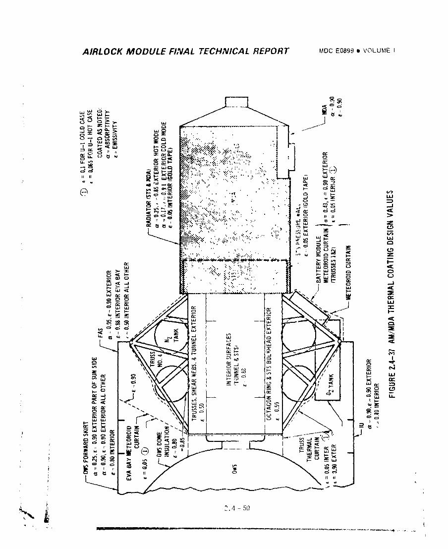
AIRLOCK MODULE FINAL TECHNICAL REPORT MOCE0090II VOLUMEI
1974018208-144
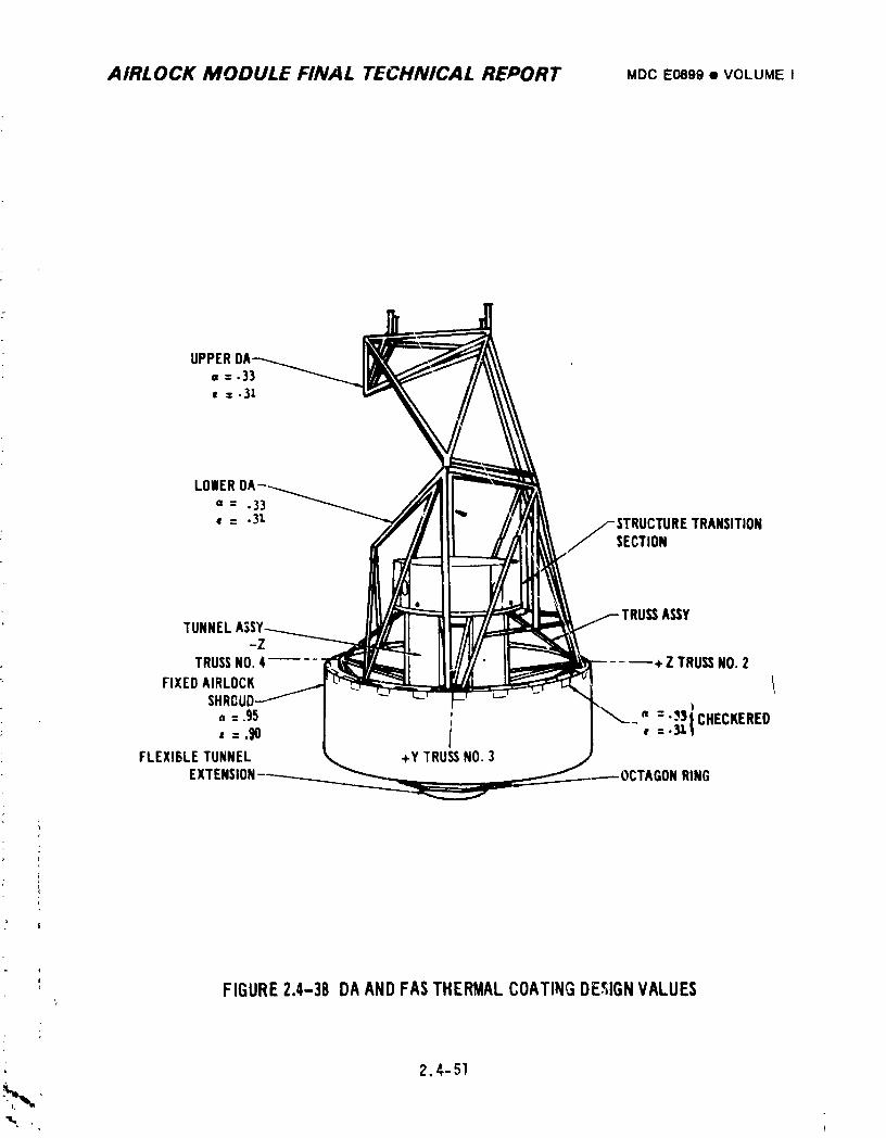
AIRLOCK MODULE FINAL TECHNICAL REPORT MDC E0899 • VOLUMEI
LOllERDA-_a = .33_• = .3l _'-.
./-STRUCTURE TRANSITION! 1 /SECTION
e
A_YTUNNEL
-ZTRUSSNO.4 + Z TRUSSNO.2
FIXEDAIRLOCK _ tSHRCUD 4
a =.95 : " =':_P}CHECKEREDL =.90 I f
i
FLEXISLETUNNEL +Y TRUSSNO.3EXTENSION---------. :TAGONRING
FIGURE2.4-38 DAANDFASTHERMALCOATINGDESIGNVALUES
2.4-51
1974018208-145
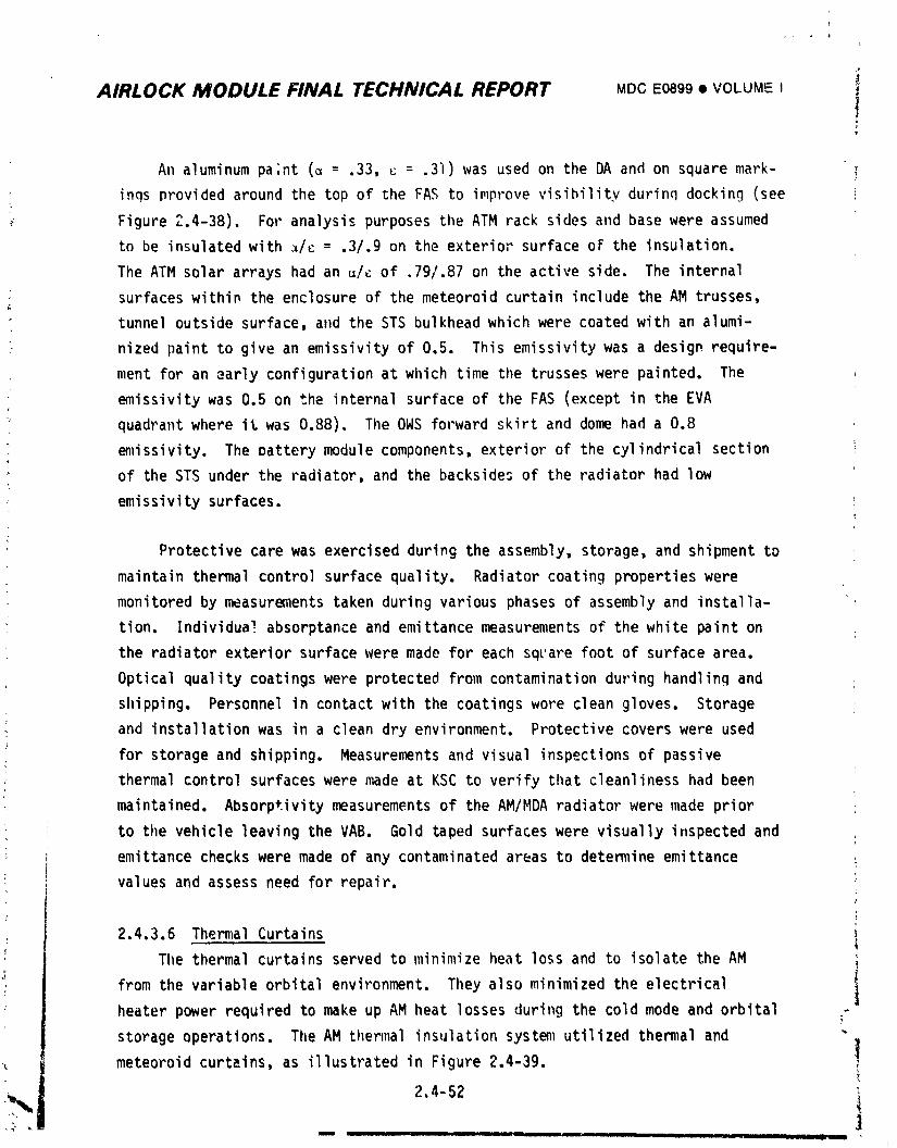
AIRLOCK MODULE FINAL TECHNICAL REPORT MDC E0899 • VOI..UM!EI iJ
An aluminum paint (_ = .33, _ = .3i) was used on the DA and on square mark-
inqs provided around the top of the FAS to improve visibility durinq docking (see
Figure 2.4-38). For analysis purposes the ATM rack sides and base were assumed
to be insulated with _/_ = .3/.9 on the exterior surface oF the insulation.
The ATM solar arrays had an _/c of .79/.87 on the active side, The internal
surfaces within the enclosure of the meteoroid curtain include the AM trusses,
tunnel outside surface, a11dthe STS bulkhead which were coated with an alumi-
nized paint to give an emissivity of 0,5. This emissivity was a design require-
ment for an early configurationat wi_ichtime the trusses were painted. The
emissivity was 0.5 on the internal surface of the FAS (except in the EVA
quadrant where it was 0.88), TileOWS forward skirt and dome had a 0.8
emissivity. The oattery module components, exterior of the cylindrical section
_ of the STS under the radiator, and the backsides of the radiator had low
emissivity surfaces.
Protective care was exercised during the assembly, storage, and shipment to
maintain thermal control surface quality. Radiator coating properties were
monitored by measurements taken during various phases of assembly and installa-
tion, Individual absorptance and emittance measurements of the white paint on
the radiator exterior surface were made for each square foot of surface area.
Optical quality coatings were protected from contamination during handling and
shipping. Personnel in contact with the coatings wore clean gloves. Storage
and installationwas in a clean dry environment. Protective covers were used?
for storage and shipping. Measurements and visual inspections of passive
thermal control surfaces were made at KSC to verify that cleanliness had been
maintained, Absorptivity measurements of the AM/MDA radiator were made prior
to the vehicle leaving the VAB. Gold taped surfaces were visually irlspectedand
emittance checks were made of any contaminated areas to determine emittance
values and assess need for repair.
2.4.3.6 Thermal Curtains
The thermal curtains served to minimize heat loss and to isolate the AM
from the variable orbital environment. They also minimized the electrical
heater power required to make up AM heat losses during the cold mode and orbital
storage operations. The AM thermal insulation system utilized thermal and
meteoroid curtains, as illustrated in Figure 2.4-39, _
t i-_, 2.4-52 :
I II II I I II --- __ II j _---- .I
1974018208-146
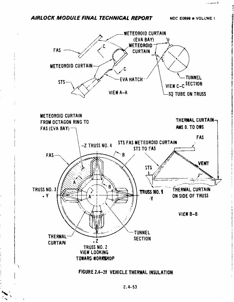
7
AIRLOCK MODULE FINAL TECHNICAL REPORT MDCE0899® VOLUME I ii!.---METEOROIDCURTAIN
_-,-'1"t (EVABAY) _._,'_c .,METEORO)D-7-
METEOROIDCURTAIN
STS __'_"'--_ EVAHATCH_/ \ _--TUNNEL
_-..._ VIEWA-A L--SQTUBEONTRUSS
METEOROIDCURTAINFROMOCTAGONRINGTO THERMALCURTAIN-_
FAS(EVABAY) AMSO.TOOWS
FAS
-Z TRUSSNO 4 STSFASMETEOROIDCURTAINSTST AS
FAS /_"_ B
TRUSSNO.3 'tRUSSNO.t THERMALCURTAIN+ Y .y ONSIDEOFTRUSS
VIEWB-B
TUNNELTHERMAL SECTIONCURTAIN +Z
TRUSSNO.2VIEWLOOKING
TOWARDWORt_IU_OP
!i FIGURE2,4-39 VEHICLETHERMALINSULATION
2.4-53
1974018208-147
..... o, 4
' AIRLOCK MODULE FINAL TECHNICAL REPORT MDCE0899v VOLUMEI
The thermal curtains consisted of a single layer of fiberglass, Viton
rubber impregnated on one side and gu]d coated on the other side. The thermal
curtains were installed with the black Viton side external except for the quadrant
covering the suit/battery cooling module. The meteoroid curtain was similar to
the thermal curtain except it was thicker and had an off-white fiberglass cloth
exterior facing.
Emissivity of the thermal and meteoroid curtain gold surfaces was measured
after trial fit on the vehicle to assure desired values• All flight vehicle
curtains were doubly bagged individually in heat sealed polyethylene bags. The
bagging was done in white rooms at dew point temperaturesbelow 60°F. The
bagged curtains were then maintained at temperatures greater than 60°F to prevent
condensation. Visual inspection of the curtains has made at KSC prior to vehicle
installation. Emissivity test checks were made if there was e,_idenceof contami- :
nation. Gold surface damage was repaired by gold tape.
2.4.3.7 Eeuipment Insulation
Insulation was used to limit the transfer of heat to equipment and in some
cases provide acoustic suppression. Bulkhead fittings were insulated from
support structure by fiberglass washers. Lines in the suit cooling, cou;ant,
and ATM C&D Pa _e'/EREPcooling systems were insulated from structure by fiber-
glass washers A,! hea_ exchangers except the condensing heat exchangers and i
the ATM C&D/EREP heat exchanger were covered with low density foam insulation•
The condensing heat exchangers were covered with mosite except over the water
separator plate assemblies. The thermal capacitor module was insulated with
glass fiber batt, and covered with a rubberized fiberglass cloth vapor barrier
with a flap-type vent valve to provide launch ascen_ venting. The outer surface _'
of the fiberglass cloth was overlayed with low e_iLLance gold tape. Typical
examples of equipment thermal insulation are shown on Figure 2.4-40. External
water and coolant lines were routed together where practical and wrapped with
Microfoil insulation. The ground coolant supply and return (FAS to GCHX) and
the interfacing GCHX spacecraft line insulation consisted of 1 inch wide, I/2
inch thick, 8 Ib/ft3 glass fibe, insulation strips enclosed in heat sealed
plastic• The spirally wrapped plastic bags were overlayed with aluminum foil r.
tape followed by Mylar tape to seal the surfaces aad provide high emissivity .
2.4-54K
1974018208-148
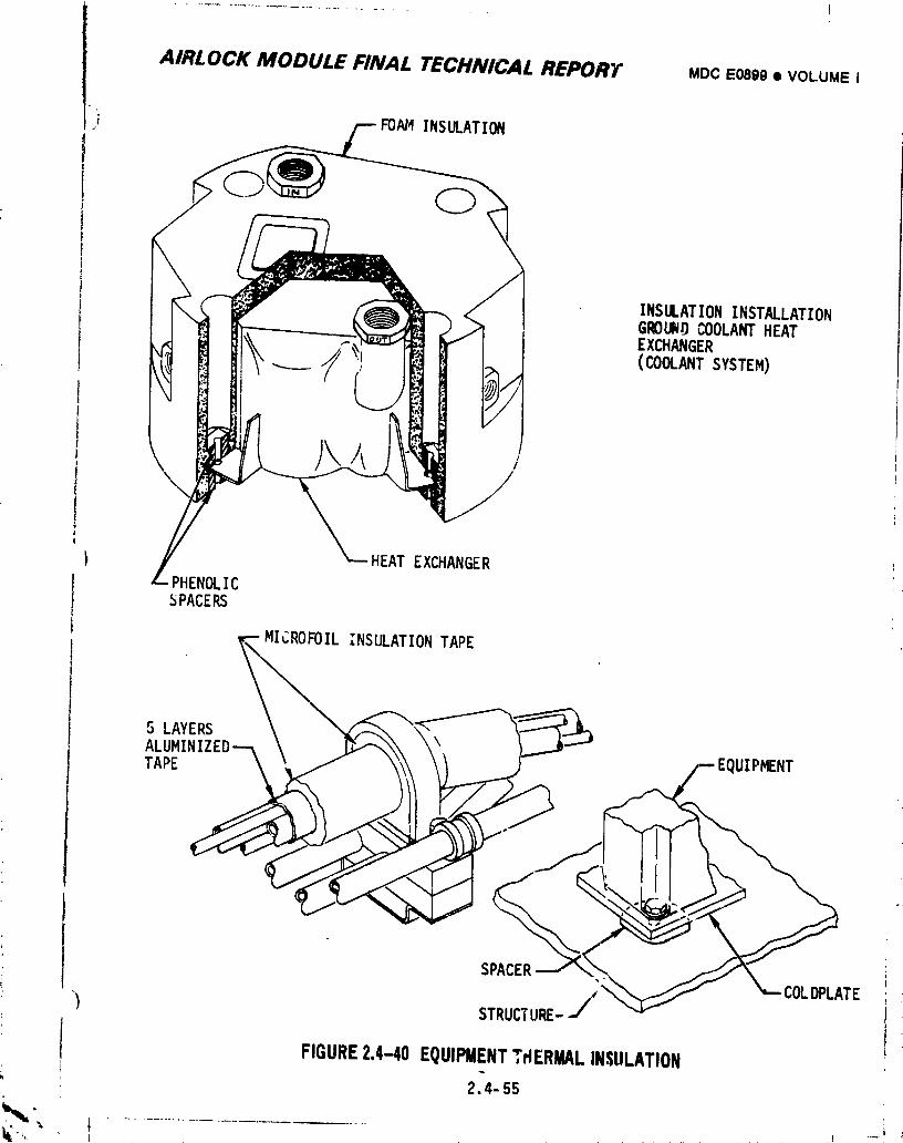
A/ilL OCK MODULE FINAL TECHNICAL REPORT MDCEO89g• VOLUMEI
FOAM INSULATION
. INSULATIONINSTALLATIONG_UND COOLANTHEATEXCHANGER(COOLANTSYSTEM)
// HEAT EXCHANGER
,--/PHENOLICSPACERS
MICROFOILINSULATIONTAPE
,,
SPACER_ "_.'_ _j \"_'_. _'_ _ COLCOLDPLATEDPL,
_) STRUCTURE--/
FIGURE2.4-40 EQUIPMENTTHERMALINSULATION
2,4-55
' 1974018208-149
AIRLOCK MODULE FINAL TECHNICAL REPORT MDCE0899• VOLUMEI
exterior surface. Mosite insulation was used on internal water and coolant
lines as required to limit condensation and heat leak during prelaunch and
orbit. The suit/battery module water lines wer_ not insulated because analysis
indicated no potential water freezing problem in this subsystem (the tunnel
wall and thermal curtain minimum temperatures in this area were expected to
remain above the water freezing point). The internal portion of the condensate
: transfer line to the OWS was deliberately tied to the structure and was not
insulated,
2.4.3.8 AM Wall Heaters
Fifteen electrical heaters were provided on the AM walls to mail_tain
temperatures. Wall heater locations are shown in Figure 2.4-41.
Each heater had 42°F, 62°F, and 85°F (nominal closing settings) thermostats.
The closer3 temperature design tolerance was +5°F about the nominal setting.
The opening temperaturewas O.5°F to 8°F above the closing setting. The 42°F
and 62°F thermostats were located approximately midspan between heater elements.
Tne 8,_F thermostats were located immediately adjacent to heater elements. The
62°! thermostats provided primary minimum wall temperature control during all
mission phases. Wall temperature control by the 42°F and 62°F thermostats was
: selected by manual or DCS commands. The selection of the _3°F thermostats was
manual only. The 85°F thermostats also provided the overall wall temperature
limit for the 42°F and 62°F heater thermostats. The thermostats were operated
from ECS control panel 203. The (On/Off/Cmd) AM wall heater switch normally was
to remain in the CMDposition. The (Hi/Lo) AMwall heater switch was inactive
when the (On/Off/Cmd) switch was in Cmd; but was to be left in the Lo position,
Both the 42°F and 62°F thermostats were to be activated by DCS during prelaunch
and remain activated through the entire mission.
Each of the 15 heaters was rated at 15 _.1.5 watts at 28 VDC. Tests on
actual heater elements indicated that 14.4 watts averaqe heat dissipation would
occur with 28V at the heater terminals. Even thouqh the orbit storage minimum
bus voltaqe was 2BY, the heater terminal voltaqe was lower due to line losses.Consequently, an average heater dissipation was estimated at 12.4 watts.
T
] 974018208-150
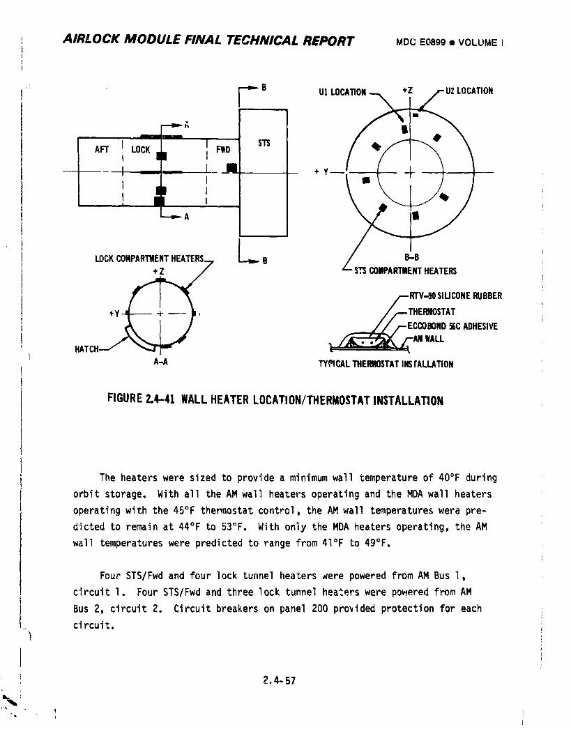
I AIRLOCK MODULE FINAL TECHNICAL REPORT MDCE0899• VOLUMEI
---_ B U! LO ION
,, _;'
Art LOCK.L. I FWDI J +y _ __III
A
t
B-Bi LOCKCOMPARTMENTHEATERS__ _ B
+Z+_ _--RTV_JO SIUCONERUBBER
, //--..THERf_OSTAT_/-ECCOBOND 56CADHESIVE
HATCH--/ _A-A TYPICALTHERMOSTATINSrALLATION
FIGURE2.4-41 WALLHEATERLOCATION/THERMOSTATINSTALLATION
The heaters were sized to provide a minimum wall temperature of 40°F during
orbit storage. With all the AM wall heaters operating and the MDA wall heaters
operating with the 45°F thermostat control, the AM,wall temperatureswere pre-
dicted to remain at 44°F to 53°F. With only the MDA heaters operating, the AM
wall temperatures were predicted to range from 41°F to 49°F.
Four STS/Fwd and four lock tunnel heaters _ere powered from AM Bus l,
circuit I. Four STS/Fwd and three lock tunnel heaters were powered from AM
Bus 2, circuit 2. Circuit breakers on panel 200 provided protection for each
circuit, i1
J
2.4-57
L
L bJ
1974018208-151
AIRLOCK MODULE FINAL TECHNICAL REPORT MDC E0899 • VOLUME I
2.4.3.9 Molecular Sieve Exhaust Duct Heaters
Heaters _ere provided to prevent freezing of _ater vapor during molecular
sieve operation. The heaters were located on the seven separate duct sections
shown in Figure 2.4-42. Primary and secondary heaters were mounted to the duct
at each section. Primary heater thermostats were set to activate at 50°F,
nominal. The secondary heaters acted as a redundant system and were activated
by nominal 42°F thermostats. The closing design tolerance was +_5°Fabout the
nominal. The opening range was O.5°F to 8°F above the closing setting.
Heater thermostats 3, 4, 5, 6, and 7 were actiwlted malluallywhe_ever mole
sieve A was operated. All heater thermostats were activated manually whenever
mole sieve B was operated. Heater power was controlled from ECS control panel
203 and circuit breaker panel 200. Two temperature sensors'for telemetry
(C266 and C267) _er¢ mounted on the duct to monitor system performance.
Primary and secondary healers each had a total capacity of 62.4 watts at
28 VOC. The heaters were sized based on tradeoff_ of heater power, insulation
thickness, and external surface radiation properties. To minimize the heater
power required, Microfoil insulation tape (0.5 inch thick) was wrapped around
the duct. A low emissivity tape (Schjeldahl GlOlS) was then wrapped arouna the
insulation. Perforations in the tape allowed venting during launch ascent.
1974018208-152
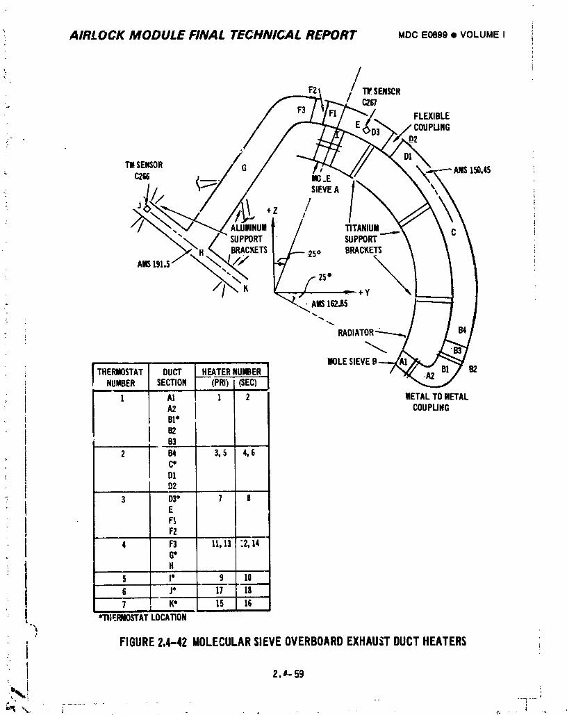
AIRLOCK MODULE FINAL TECHNICAL REPORT MDC E0899 • VOLUME I _
!
/F21 _ SENSCR
F3 FLEXIBLEIPLING
;-
111SENSOR AMS150.45C266 _ .E |
_ SIEVEA r
//I
+Z /
ALUUlNUH / TITANIUII" SUPPORT / SUPPORT
BRACY_ETS___ :25o BRACKETS
A_ ;:/i /- 2s°K .j _ +y
RADIATOR'-:---...._
MOLESIEVETHERMOSTAT DUCT HEATERNUIBER B2
NUMBER SECTION (PRI)J(SEC)1 AI 1 2 METALTOMETAL
A2 COUPUNGB[*B2B3
2 134 3,5 4,6C*DID2
3 D3° 7 8'
" I E- ! F!F2
• t 4 F3 11,13 "..2,14! 6"
I "
5 I* 9 106 J* 17 187 K* 15 16
m
! "THERMOSTATLOCATION-,_
j FIGURE2,4-42MOLECULARSIEVEOVERBOARDEXHAUSTDUCTHEATERSI
I 2._- 59
1974018208-153
AIRLOCK MODULE FI.A/AL TECHNICAL REPORT MDC E0899 • VOLUME I '
2.4.4 Testin_
Testing was performed to provide information needed by e_glneering
for design, to qualify a particular part numbered component, to verify that the
particular part and serial numbered components operated properly, tc verify that
U-I and U-2 modules and systems functioned properly, and to support verification
that the vehicle was ready for flight. Postlaunch tests were conducted to provide
information needed for real time mission planning. Information on the test "
philosophy is presented in Section 5 of thi_ report.
2.4.4.1 Development Tests
Development tests were performed on components and systems to obtain data on
the functional characteristics needed to support the design process. Test require-
ments were specified by Test Request (TR).
A. Performance Tests - PerC_rma,lcetests were conducted to establish the
performance of new components and systems. Some were conducted by vendors
to satisfy requirements identifed in Specification Control Drawings (SCD).
Those tests _onducted by MDAC-E are summarized below:
• TITLE ATM C&D Panel Cooling Subsystem Development Test
BACKGROUND The ATM C&D panel water cooling loop transferred heat dis-
sipated by the panel, located in the MDA, to the AM
coolant loop.
OBJECTIVE Establish the performance of the water cooling modu!e, to
assure that ATM C&D panel heat loads could be rejected to
the Airlock coolant loop and that cooling water could be
supplied to the AM/MDA interfacewithin specified
temperature limits.
RESULTS The temperature of the water, at the inlet of the C&D
panel simulator, ranged from 45.4°F during operation with
lowest coolant supply temperature (40°F) to 84.6°F when
the coolant was supplied at 80°F. The system operated
satisfactorilywithin predicted limits during all conditions
tested, Reference TR 061-06B 41.
2.4-60
\-.!.... _%
1974018208-154
AIRLOCK MODULE FINAL TECHNICAL REPORT MDCE0899• VOLUMEI
i TITLE Space Radi.tor Convection Heat Transfer Element
BACKGROUND Analytical prediction of radiator performance required
inputs of fluid-to-wall convection heat transfer coefficient.
OBJECTIVE Determine the f]tJid-to-wallconvection heat transfer coef-
ficient for the Airlock space radiator configuration.
RESULTS Temperature distribution, flow, and pressure drop data was
determined for II test conditions, Reference TR 061-068.67.
: • TITLE Ground Coolih_ Heat Exchanger Test
; BACKGROUND Additional pe,formance data was needed to assist in
: defining cooling system modifications.
OBJECTIVE Obtain performance data on ground cooling heat exchanger.
RESULTS Performance data was obtained for each of the three heat
exchanger passages, Reference TR 061-068.75.
4 e TITLE Coolant System Thermal Development Test
BACKGROUND Performance verification was necessary for operating
conditio,s expected during an actual mission.
OBJECTIVE Develop a coolant system and verify its operation during
conditions defined for orbital p3sition of the spacecraft,
heat loads of equipment, and astronauts metabolic heat lo_d.
RESULTS The coolant system operated satisfactorily during normal
and emergency modes of operations tested. The system
maintained stable control of all temperatures throughout
the loop, Reference TR 061-068.76.
• TITLE Coolant Reservoir _'_ C_cle Test
BACKGROUND Dry pressure cycling occurred when the Airlock coolant
system was leak checked with gas.
OBJECTIVE Verify that dry cycling would not adversely affect operation
of the coolant reservGirs.
_ RESULTS The coolant reservoirs operated satisfactorily during cycle
and burst test. Examination of chamber walls revealed no
abnormal wear, Reference TR 061-068.79.
_ 2.4-61
1974018208-155
AIRLOCK MODULE FINAL TECHNICAL REPORT MDCE0899• VOLUMEi !
I TITLE CoolantReservoirPerformanceTest
BACKGROUND At low temperaturesthe Freon-ll4pressurantin the coolant
reservoirsexistedin a two-phasestateand the performance
characteristicsw_re uncertain.
OBJECTIVE Determinethe pressure-volumecharacteristicsof the
coolantreservoirin the temperaturerangeof 40°F to _20°F.
RESULTS Pressure-volumecharacteristicsof a coolantreservoir
were determinedoverthe requiredtemperaturerangefor use
in subsequentanalysis,ReferenceTR 061-068,9n.
• TITLE StretchPressureTest of the CabinHeat Exchanger
BACKGROUND Strengthdata was neededto evaluatean overpressure
conditionof the cabinheatexchanger.
OBJECTIVE Determinethe effectof overpressureon flowratecharacter-
isticsof a cabinheat exchangerand determineits rupture
pressure.
: RESULTS The cabinheat exchangerwas pressurizedto 230 psig. The
pressuredropwas 1.77 psi and 1.82psi at 220 Ib/hr,
respectively,beforeand _fter pressurization.The unit
was pressurizedat lO00 psiwithoutrupture,Reference
TR 061-068.91.
• TITLE OWS ThermalCapacitorIUndecanefilled)H_Iting/Freezing
Characteristics
BACKGROUND A platefin thermalcapacitorfailedat MDAC-W.
: OBJECTIVE Determinethe meltingand freezingcharacteristicsof the
p.atefin capacitorwhen filledwith Undecanewax and
determinestresslimitswhen filledwith Tridecane.
RESULTS None of the configurationstestedproducedacceptable
c resultsunderall simulatedflightconditions,Reference
FR 061-068.92.
_._ ,_ 2.4-62i "
1974018208-156
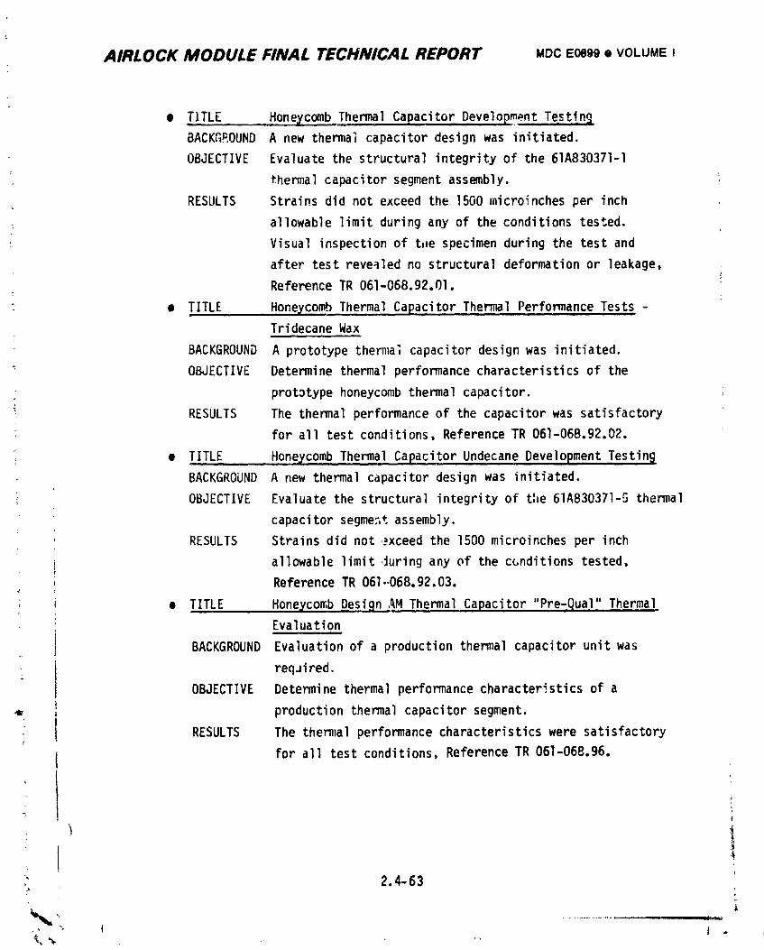
AIRLOCK MODULE FINAL TECHNICAL REPORT MOC EOe_O• VOLUME i
• TITLE Honeycomb Thermal Capacitor Development Testing
BACKGEOUND A new thermal capacitor design was initiated.
OBJECTIVE Evaluate the structural integrity of the 61A830371-1
thermal capacitor segment assembly.
RESULTS Strains did not exceed the 1500 microinches per inch
allowable limit during any of the conditions tested.
: Visual inspection of tflespecimen during the test and
after test reve_led no structural deformation or leakage,
Reference TR 061-068.g2.01.
• TITLE HgneEcomb Thermal Capacitor Thermal Performance Tests -
Tridecane Wax
BACKGROUND A prototype therma_ capacitor design was initiated.
OBJECTIVE Determine thermal performance characteristicsof the
prototype honeycomb thermal capacitor.
RESULTS The thermal performance of the capacitor was satisfactory
for all test conditions, Reference TR 061-068.92.D2.
e TITLE Honeycomb Thermal Capacitor Undecane Development Testin_
BACKGROUND A new thermal capacitor design was initiated.
i OBJECTIVE Evaluate the structural integrity of the 61A830371-5 thermal
capacitor segme3t assembly.
RESULTS Strains did not _xceed the 1500 microinches per inch
, allowable limit ,_uringany of the c_nditions tested.
Reference TR 061-068.92.03.
, , • TITLE Honeycomb Design AM Thermal Capacitor "Pre_ual" Thermal.
Evaluation
BACKGROUND Evaluation of a production thermal capacitor unit was
reqJired.
OBJECTIVE Determine thermal performance characteristics of a
production thermal capacitor segment.
RESULTS The the_zal performance characteristicswere satisfactory
I for all test conditions, Reference TR 061-068.96.
I ,
: 2.4-63
,, '_ ( i
1974018208-157
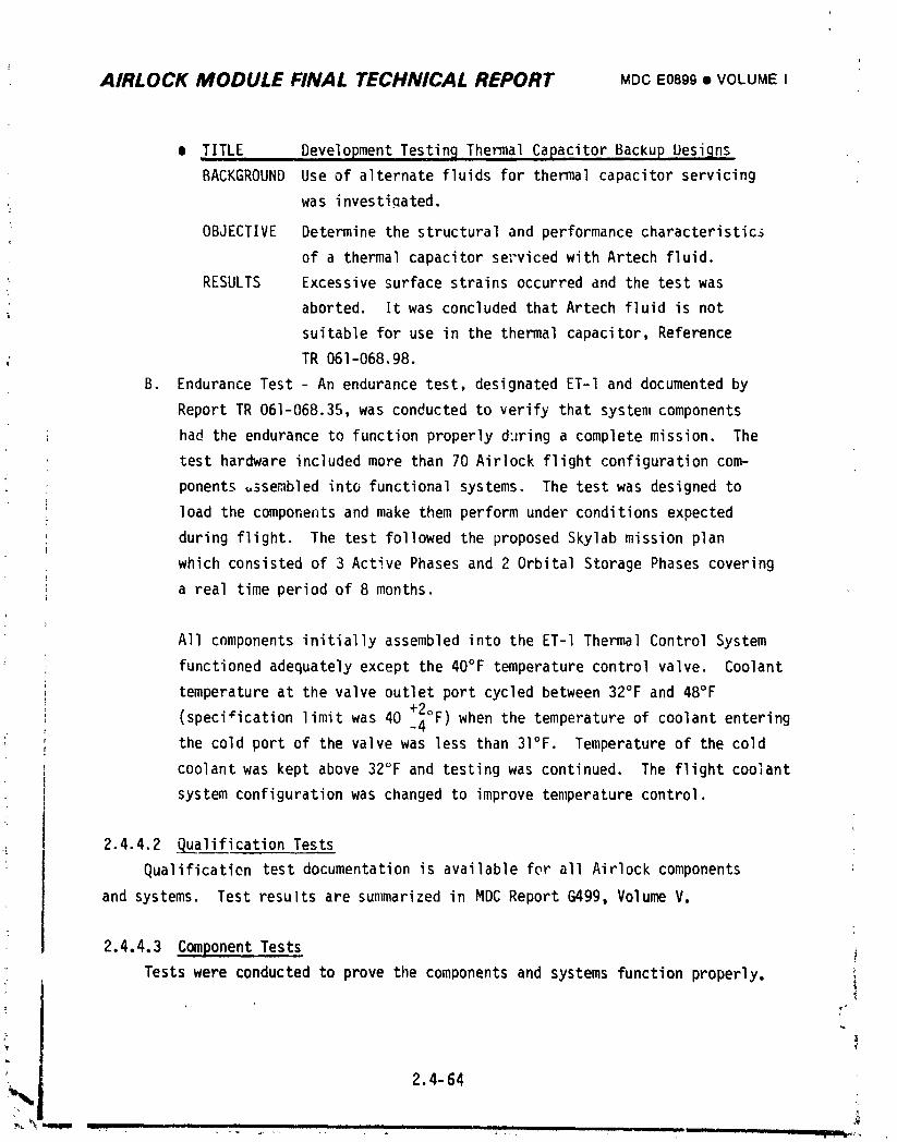
AIRLOCK MODULE FINAL TECHNICAL REPORT MDCE0899• VOLUME I
• .TITLE Development Testing.Thermal Capacitor Backup Uesi_ns
BACKGROUND Use of alternate fluids for thermal capacitor servicing
. was investiQated.
OBJECTIVE Determine the structural and performance characteristics
of a thermal capacitor set'vicedwith Artech fluid.
RESULTS Excessive surface strains occurred and the test was
aborted. It was concluded that Artech fluid is not
suitable for use in the thermal capacitor, Reference
: TR 061-068.98.
B. Endurance Test - An endurance test, designated ET-I and documented by
Report TR 061-068.35, was conducted to verify that system components
had the endurance to function properly d:zringa complete mission. The
test hardware included more than 70 Airlock flight configuration com-
_; ponents _sembled into functional systems. The test was designed to
load the components and make them perform under conditions expected
during flight. The test followed the proposed Skylab mission plan
which consisted of 3 Active Phases and 2 Orbital Storage Phases covering
a real time period of 8 months.
All components initially assembled into the ET-I Thermal Control System
functioned adequately except the 40°F temperature control valve. Coolant
temperature at the valve outlet port cycled between 32°F and 48°F
(specificationlimit was 40 _°F) when the temperature of coolant entering
_ the cold port of the valve was less than 3I°F. Temperature of the cold
coolant was kept above 32°F and testing was continued. The flight coolant
system configurationwas changed to improve temperature control.
2.4.4.2 Qualification Tests
Qualificatien test documentation is available for all Airlock components
and systems. Test results are summarized in MDC Report G499, Volume V.
2.4.4.3 Component Tests !
Tests were conducted to prove the components and systems function properly, i
2.4-64
1974018208-158
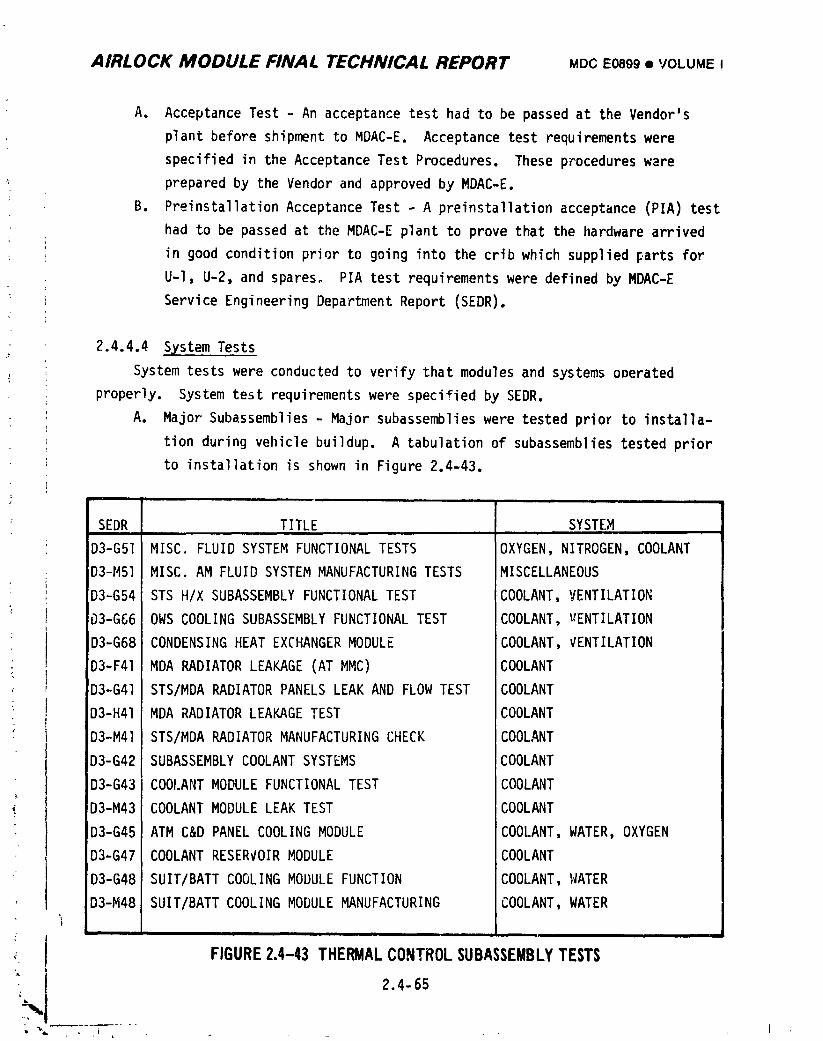
AIRLOCK MODULE FINAL TECHNICAL REPORT MDCE0899• VOLUMEI
A. AcceptanceTest - An acceptancetesthad to be passedat the Vendor's
plant beforeshipmentto MDAC-E. Acceptancetest requirementswere
specifiedin the AcceptanceTest Procedures.These procedureswere
preparedby the Vendorand approvedby MDAC-E.
B. PreinstallationAcceptanceTest - A preinstallationacceptance(PIA)test
had to be passedat the MDAC-Eplantto prove thatthe hardwarearrived
in good conditionpriorto goinginto the cribwhich suppliedpartsfor
U-l, U-2,and spares. PIA testrequirementswere definedby MDAC-E
ServiceEngineeringDepartmentReport(SEDR),
2.4.4.4 SystemTests
Systemtestswere conductedto verifythat modulesand systemsoperated
properly. Systemtest requirementswere specifiedby SEDR.
A. Major Subassemblies- Major subassemblieswere testedprior to installa-
tion duringvehiclebuildup. A tabulationof subassembliestestedprior
to installationis shown in Figure2.4-43.
SEDR TITLE SYSTEMi ii
D3-G51 MISC. FLUIDSYSTEMFUNCTIONALTESTS OXYGEN,NITROGEN,COOLANT
D3-M51 MISC.AM FLUIDSYSTEMMANUFACTURINGTESTS MISCELLANEOUS
D3-G54 STS H/X SUBASSEMBLYFUNCTIONALTEST COOLANT,VENTILATION
_3-G66 OWS COOLINGSUBASSEMBLYFUNCTIONALTEST COOLANT,VENTILATION
D3-G68 CONDENSINGHEATEXCHANGERMODULE COOLANT,VENTILATION
D3-F41 MDA RADIATORLEAKAGE(ATMMC) COOLANTD3-G41 STS/MDARADIATORPANELSLEAKAND FLOWTEST COOLANT
D3-H41 MDA RADIATORLEAKAGETEST COOLANT
D3-M41 STS/MDARADIATORMANUFACTURINGCHECK COOLANT
D3-G42 SUBASSEMBLYCOOLANTSYSTEMS COOLANT
D3-G43 COOI.ANTMODULEFUNCTIONALTEST COOLANT
D3-M43 COOLANTMODULELEAKTEST COOLANT
D3-G45 ATM C&D PANELCOOLINGMODULE COOLANT,WATER,OXYGEN
D3-G47 COOLANTRESERVOIRMODULE COOLANT
D3-G48 SUIT/BATTCOOLINGMODULEFUNCTION COOLANT,WATER
D3-M48 SUIT/BATTCOOLINGMODULEMANUFACTURING COOLANT,WATER
f, FIGURE2.4-43 THERMALCONTROLSUBASSEMBLYTESTS
i 2.4-65
; %" i ,_ I
1974018208-159
AIRLOCK MODULE FINAL TECHNICAL REPORT MDCE0899• VOLUMEI
B. Systems - Final system and integrated acceptance test flow of the TCS at
the contractor facility are depicted in Figures 2.4-44 and 2.4-45 for
the Coolant System and the ATM C&D/EREP Cooling System.
I Coolant S>,stem- Prior to the first systems test, leak tests were per-
formed and servicing was accomplished. During SEDR D3-N46-1, the STS
Radiators were leak checked with a helium mass spectrometer and a flow
AP test was performed to verify that the radiator flow pressure drop
was within the specified limits. The radiators were then drained and
flushed with solvent, and connected to the vehicle coolant system.
A complete system leak check was performed. The vehicle was then
serviced per SEDR D3-FgO-I Vol. I. Servicing consisted of filling the
• primary and secondar_ loops w_.n MMS 602 coolant, establishing proper
reservoir pressure and verification of acceptable entrapped air
volume. The pumps were verified for proper operation by monitoring
system flow and AP data.• I
o S_,stemsValidation - The first system test was performed during Systems ,
Validation (SEDR D3-N70). The MDA portion of the radiator system was
not installed during this test so a thermal/pressurecontrol unit was
added to the primary loop. This unit was set up to supply coolant
temperatures simulatir.gexpected radiator outlet temperatures during
flight while controlling the differential pressure of the unit to
correspond to expected flight system conditions. During SEDR D3-N70-I
system performance was verified utilizing both single and dual pump
modes of operation. All parameters were verified to be within specified
limits. Caution and warning system functions were verified by applying
' heat and cooling to the appropriate sensors. The automatic switch-over
capability of the cooling system was demonstrated. Coolant fluid
samples were withdrawn and particle and chemical analysis were per-
! formed A thermal stability test WdS conducted to verify the thermal
stability of the vehicle cooling systems during extreme thermal con-
, ditions. Various heat loads were applied and system response noted. A
• coolant pump "start-up" during simulated orbit storage also was demon-
strated. Deservicing of the vehicle prior to connecting the MDA
radiators to the coolant loops was accomplished by SEDR D3-F90, Vol. II.
It was also necessary to replace several damaged fle_bl_ hoses and to
, remove the coolant pump module for transduce: replacement and to rework
" 2.4- 66
,,_, _., ._........................................ _ --! _ , ,.,x.•, -'_li
i9740i8208-iG0
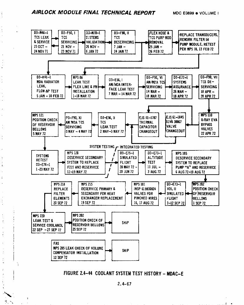
: AIRLOCK MODULE FINAL TECHNICAL REPORT MDCEO899• VOLUMEI
o,_.._,,, iTCSLEAK TCS ; IS',STEMSI ITCS FCSPUMPMODi[REWORKFILTERIN& SERVICE SERVICING_I_VALIDATION_,I_ DESERVICING--,1-,I_REMOVAL J'I_PUMP MODULERETEST
! i•23OCT- 21NOV- I J26NOV- I I 7 JAN- PERMPS78. 3 FEB7224NOVT] 23NOV71 I 16JAN72 J [ 24JAN72 6 FEB72
1 ,D3-,41-I_] IMPS86 i I I ID3-Fg0,V,] IO3-E72-II I'D3-Fg°;V"I
MDARADIATOR _ LEAKTEST I I D3-E56,1 i IAM_DATC..I I.SYSTEm i ITCSDE_ I
LEAK, FLEX LINE& I:M]--I_ AM/_IDAINTER- _I_'SERVICING _I_IASSURANCE_(_ SERvi_ciNGIFLOW_5@TEST INSTALLATIONI I FACE LEAKTEST I 114MAR-I I26MAR-I I IeAPR- I5JAN-IOFEB72 ]-]8MAR72 J [ 7MAR-I4MAR72 I 118MAR72 ! I,]8APR72 I I28APR72 j
MPS121 _I, II___f:_T_L] _iAi_E_ ]
|OFRESERVOIR[_,-IAM''MDATCS TCS _,_,_JTHERMAL . A/ _ " _SERVICING LEAKTEST I- _' ICAPACITORBELLOWS
/5MAY72 J 13MAY-4MAY7 2 MAY-3MAY72J i [CHANGEOUT' 1 JSYSTEMTESTING/-:,INTEGRATEDTESTING
i RETEST SYSTEMTOREPLACE _ FLIGHT TEST SYSTEMTOREPLACED3-E76-i F21EANDRESERVICE I /" I 28MAY72- 11JUL- PUMP"A" ANDRESERVICE
] -23MAY72 12-19MAY72 jj" [ 20JUN72 3 'AUG72 6 AUG72-19AUG72
REPLACE DESERVICEPRIMARY& INSP61B830024 VOLII I IPOSITIONCHECKI
FILTER SECONDARYFORHEAT VALVESFOR SIMULATED_,_--_OFIRESERVOIRIELEMENTS EXCHANGERREPLACEMENT PINCHEDWIRES FLIGHT I I BELLOWS I20SEP72 19SEP72 16,]7 AUG72 3-1_2SEP721 J1 SEP72 J
I LEAKTEST& L_mJPOSITIONCHECKOF ]._ISERVlCECOOLANOLI 7 RESERVO!RBELLOWSI"_ SHIP122SEe-27SEP72l 125sEP72 I I
FAS m
MPS205LEAKCHECKOF VOLUME SHIPCOMPENSATORINSTALLATIONI;_sEP7_2-
{
FIGURE2.4-44COOLANTSYSTEMTESTHISTORY-MDAC-E
2,4-67
_c
1974018208-161
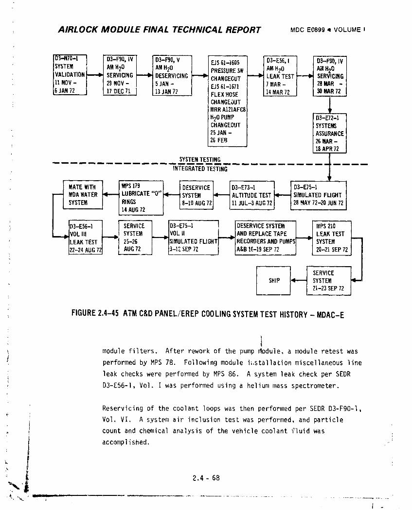
: AIRLOCK MODULE FINAL TECHNICAL REPORT MDCE0899• VOLUMEI
SYSTEM AMH20 AMH20 PRESSURESW AMH20 A_wlH20VALIDATION SERVICING DESERVICING CHANGEGUT LEAKTEST SERV!CINGU NOV- 29NOV- 5JAN- F_JS61-1671 7MAR- 28MAR-6 JAN72 17DEC71 13JAN72 FLEXHOSE 14MAR72 30MAR72
CHANGEOUTMRRAI2IAFC8
H2OPUMP ] D3-_2-1 I
CHANGEOUT SYSTEMS25JAN- ASSURANCE26FEB 26MAR-
: 18APR72
SYSTEMTESTINGiN fm Im iN mm mm m_ am iN m ammm _m mm _m_ _mmm _mmm m m n im_ mm imm tmmm m m_ _ mm mm w m m mm mmlm iNN
INTEGRATEDTESTING
MDAWATER_ LU.R,CATE"O"SYSTEMl"---iALT,_D_TEST S,MULATEOFLIG.T
SYSTEMl i,,RINGSAuG72,-_0AUG72JIH_°.-_AUG,22,.AY,2-20JU.72
I _IVOLIII L___l SYSTEM L___VOL II J._ ANDREPLACETAPE L_ LEAKTEST' -],.E_TESTI --i zs-26) -IS,MULATEDFUGHTI -IRECORDERSANDPUMPSI "1SYST_
]22-24AUG72] [ AUG72 ) [3-17.SEP72 ) IA&B16-19SEP72 ) [ 20-21SEP72
SHIP SYSTEM21-23SEP72
T
FIGURE2.4-45 ATMC&DPANEL/EREPCOOLINGSYSTEMTESTHISTORY- MDAC-E
! module filters. After rework of the pump _odule, a module retest was
performed by MPS 78. Following module i;.stallationmiscellaneous line
leak checks were performed by MPS 86. A system leak check per SEDR
D3-E56-1, Vol. I was performed using a helium mass spectrometer.
Reservicing of the coolant loops was then performed per SEDR D3-F90-1,
Vol. VI. A system air inclusion test was performed, and particle
count and chemical analysis of the vehicle coolant fluid was
accomplished.
[ 2.4 - 68
xt
1974018208-162
i AIRLOCK MODULE FINAL TECHNICAL REPORT MDCE0899• VOLUMEI
t• Systems Assm'ance - During SEDRD3-E72-1 the AM/MDAcoolant systems
were activated to provide cooling for subsequent testing. Cooling
system pumps and transducer performance were verified in single and
dual pump modes. The coolant systems were then placed in command moae i- and various pump relay and pump inverter combinations verified. The !,
high and low temp parameters of the C&Wsystem were verified. After
completion of SZDRD3-E72-l, a decision was made to redesign the thermal
capacitor and to rework the EVA bypass valves per requirements of
EJS 61-18%. The valves were x-rayed per MPSII0. System primary and
secondary coolant loops were deserviced and the original thermal
capacitor and three-way solenoid valves removed. The equipment removed
was replaced and the vehicle was leak tested per SEDRD3-E56-1, Vol II
with a mass spectrometer using a mixture of nitrogen and helium. The iJ
vehicle coolant systems (AM/MDA) were then serviced per SEDRD3-FgO-I,
Vol. XI. Air entrapment tests were performed on both coolant loops.
After vehicle servicing a check of reservoir position was performed
per MPS 121.
A systems retest per SEDR D3-E76-1 was begun after the completion of
the reservoir position test verified that all reservoirs were properly
serviced. The coolant systems were activated and verification of
performance, using both DCS and Manual control, was accomplished. A!
functional test of the coolant filters located on both the coolant pump
module and the reservoir module was performed to verify prooer opera-
tion of the filters in both "off" and "on" positions. During the
performance of SEDR D3-E76-1 the secondary coolant loop flo_neter
system failed and the secondary loop was deserviced, a flowmeter
system was removed from U-2 vehicle and installed on U-l per MPS 128.
MPS 128 also leak checked and reserviced the secondary coolant loop
to prepare for Simulated Flight Test.
i ATM C&D Panel/EREP Cooling System (AM Portion) - When SEDR D3-N70 was
performed, the MDA was not mated to the Airlock Module (AM). Therefore,
the AM portion of the ATM C&D panel/EREP cooling system was ju'nperedat
the AM/MDA interface to provide a flow-thru capability. Durirg SEDR
•) D3-N/O the AM portion of the loop was leak tested and serviced per
I D3-F90-1, Vol. IV. After servicing, the system was operated and!
" ' 2.4- 69t
1974018208-163
i
AIRLOCK MODULE FINAL TECHNICAL REPORT MDCE0899• VOLUMEI
functionally tested. After D3-N7O, the system was deserviced and
vacuum dried per u3-F_O-l, Vol. V to change pressure switch c_qfigura-
tion per EJS 61-1605 and flex hoses per EJS 61-1671. The water pumps
were also replaced per MRR AI21AFG8. Since the MDA portion of the
loop w_s still not available, the AM portion of the loop was maintained
jumpered at the AM/MDA interface and another leak test performed per
SEDR D3-E56-l, Vol. I. The system was serviced per SEDR D3-F90-1,
Vo]. IV and pumps were operated to support Systems AssuraD_ce
(D3-E72-1) testinq.
e AM Heating System - The electrical heating portion of the Thermal
Control System was tested by heating and/or cooling appropriate
thermostats and obtaining respective voltage at associated test
-! points. Resistance of heating elements was also verified.
During Systems Validation (SEDR D3-N70), testing c_nsisted of a heater
resistance test and a voltage test of the STS, lock, mole sieve and
condensate heaters. Voltage tests were accomplished by heating and
cooling thermostats and by DCS commands which operated the high and
low temperature heaters. A reverificationof AM wall heaters and
condensate system heaters was performea during Systems Assurance
(SEDR D3-E72).
' During SEDR D3-N70, mole sieve heater No. 9 resistance measurement
indicated an open circuit. A miswired thermostat was corrected and
satisfactorily retested. Mole sieve B duct heaters No. 5 and No. 6
were found to have internal shorts to structure. Heater No. 6 was
replaced and verified acceptable. Heater No. 5 was replaced and
subsequently retested at KSC. [he cause of failure was determined
to be corrosion caused by moisture and dissimilar metals.
Mole sieve duct heaters No. 3, No. 4, and No. 5 had corrosion damage
on the heater rods at KSC. The damaged heater rods were replaced and2
Y
re cested. All heater rods were waterproofed to prevent electrolytic i= corrosion.
- 2.4-70
" I III r_. ........... h
1974018208-164
AIRLOCK MODULE FINAL TECHNICAL REPORT MDCE089g• VOLUMEI
2.4.4.5 Integrated Tests
Integrated tests were condurted to verify the vehicle was ready for flight
both before it left the factory for the launch site and after it arrived at the
Kennedy Space Center (KSC).
i' A. Factory Tests - The tests conducted by MDAC-E in St. Louis are summarized
below. Integrated test requirements were specified by SEDR.
(1) Coolant System - Integrated testing of the Coolant System at
St. Louis is shown in Figure 2.4-44.
• Simulated Flight Test - Thermal tests of the coolant system
were conducted during simulated flight checkout of the
vehicle per SEDR D3-E75-1, Vol. I. Thermal tests were con-
ducted to verify the AM coolant system performance during
hot and cold modes, and during simulated EVA operation and
Orbit Storage. The Simulated Flight Test (SEDR D3-E7S)
occurred after the Coolant System was completed (i.e._ all
radiator panels and new thermal capacitor module wer:
installed). Since it _as not desirable to break ,_to the
Coolant System to control radiator outlet temperatures
directly, it was decided to control temperatures through the
ground cooling heat exchanger.
As in the previous test in conjunction with Systems Valida-
tion Test (SEDR D3-N,u), it was planned to operate the system
at various temperature profiles to ensure the proper opera-
tion of the Coolant System. The initial phases of the testi
were performedwithout problems, however, the low temperature
i portions of the test, i.e., simulated radiator temperatures
below -40°F, were not accomplished. Heat loss to ambient
from the ground cooling heat exchanger and associated plumb-
_ iny under the abnormal conditions being applied was such that
the desired system temperatures could not be attained. Since
all ,_therphases of the test were successful and tests per-
formed in Systems Validation Test (SEDR D3-N70) had demon-
strated acceptable systeb.,performance, it was not deemed
necessary to modify the vehicle to perform the low tempera-
ture tests.
24-71. ..... .... J ,
i9740i8208-iG5
AIRLOCK MODULE FINAL TECHNICAL REPORT MDCE0899• 'VOLUMEI
: • Altitude Test - After the simulated flight test the vehicle
_ was moved into the altitude chamber for the altitude test
per SEDRD3-E73-1. During the ,;!titude chamb_ test the
reed switch on coolant pump A of the secondary coolant loop
malfunctioned. After completion of the altitude chamber
test, the vehicle secondary coolar loop was deserviced and
coolant pump A was replaced, the system was leak tested and
reserviced per MPS 185.
" • FliBht Checkout Simulation - Afte: ._ervice of the vehicle
coolant system, ;IPS 202 was initiated to verify that the
bellows in the secondary loop reservoir module were properly
positioned, and vehicle service was acceptable. SEDR
_ D3-E75-1, Vol. II was performed to simulate flight checkout
of the vehicle. This test manually activated the coolant
loops and then the inverter select _witches were _;z_ed in
the co, -and position for the remainder of the test. The
coolant oops were maintained in a vehicle support configura-
tion during the remainder of the simulated flight test.
Following the test, MPS181 was accomplished which inspected
the 3-way latching solenoid valve_, located on the suit and
battery module, for pinched electrical conductors. The
results were acceptable. As a result of p_'_blems in the suit
cooling system MPS 215 was initiated which ,'emoved the primary
and secondary coolant loop EVA H20 heat exchangers from thesuit and battery module. The primary and secondary coolant
. loops were deserviced and replacement heat exchangers
: installed. While the coolant loops were deserviced, the
coolant filters were replaced by MPS 218. The system was
' then helium leak tested _nd reserviced with Coolanol per
MPS 220. # final check of reservoir bellows position was
performed per MPS _02.
• Leak Check - The ground coolant volume compensator installed
in the FAS was leak checked with nit'ogen per MPS 205. This
portion of the coolar, t loop was not serviced with coolant
fluid at _t. Louis.
__ 2.4-72 ,,_
1974018208-166
_- AIRLOCK MODULE FINAL TECHNICAL REPORT MDCE0899• VOLUMEI
(2) _TM C&D/EREP Cooling System - The integrated testing of this system
at St. Louis is shown in Figure 2.4-45. The ATM C&D/EREP Cooling
System was operated to support Simulated Flight (D3-E75-l, Vol. I)
and Altitude Chamber Test (D3-E73-1). After the altitude chamher
test, the system was deserviced to lubricate '0" rings in the water
filter quick disconnects aca to mate the MDA portion of the loop to
the AM. After final mate the entire system was leak tested per
SEDR D3-E56-1, Vol. Ill and serviced per D3-FgO-I, Vol. XIII to
operate the water pumps for EMC purposes in support of SEDR D3-E75-1,
Vol. II. After Simulated Flight Vol. II, the system was d_ined to
replace EREP tape recorders and two water pumps. After component
replacement,the system was leak te-ted p_, _PS 210 and final system
servizing was performed prior to delive'7 to the launch site.
B. KSC Tests - Results of testing at KSC togetaer with factory test results
are presented in Figures 2.4-46 through 2.4-52. Launch site test require-
ments were specified in MDAC-E Report MDC E0122, Specification and
Criteria at KSC for AM/MDA Test and Checkout Requireme.ts; and KSC Report
KS 2001 Test and Checkout Plan.
i
i
7. i
2.4-73b
_"_ i "
1974018208-167
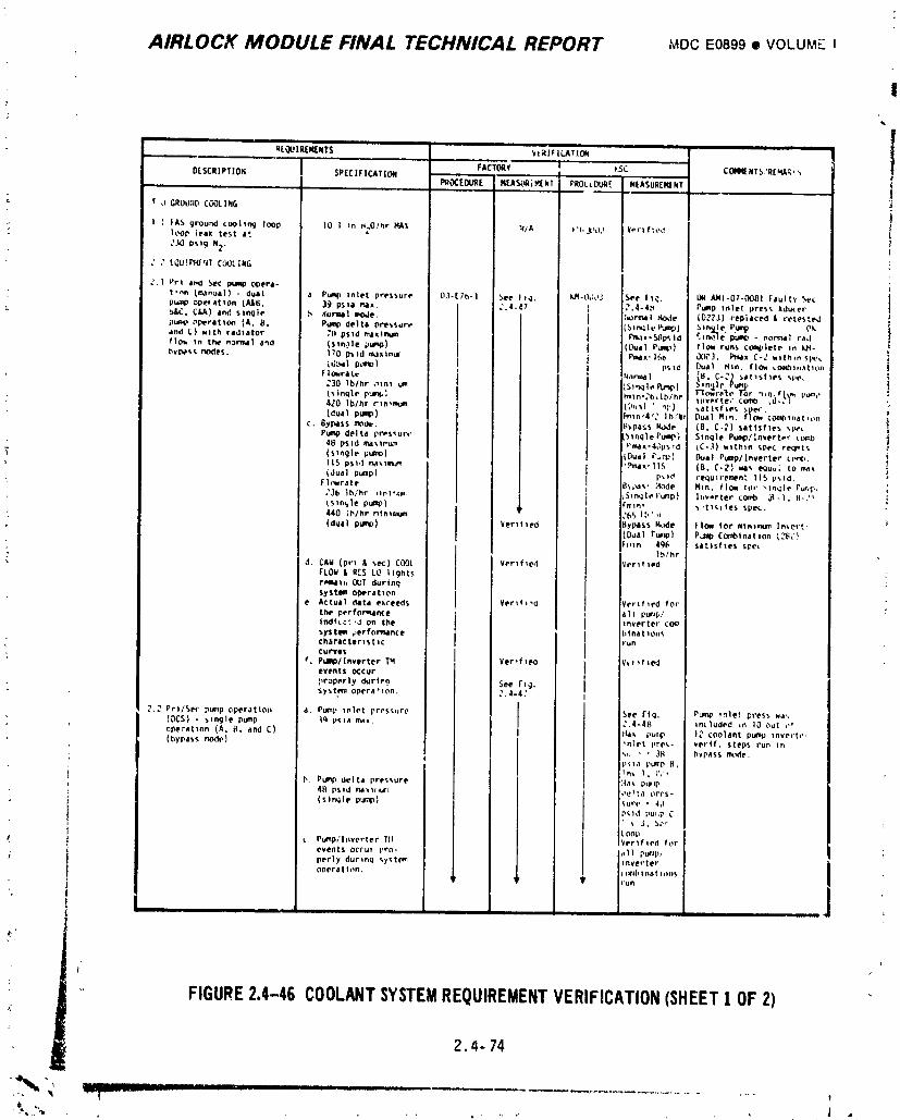
AIRLOCK MODULE FINAL TECHNICAL REPORT MDCE0899• VOLUME I
!
:
R[(_ IREIq[NTS _t;_IFILMION
FACTORY ! p.SC COI4NENTS 'R[NA.'_,DESCRIPTION SPECIFICATION • J
P_OCEDURE MEA_kq[ MENT PROCEDURE MEASURENfNT
t' a GRUU;ID CC_3LING
I _. _A_ ground coo|In 9 loop 10 Inn H_O/hr RAt :_/A )'I-jL_)2 ¥Pr|f:_,dloot leak test e'.
J30 P_g NZ-
: _" LQU!P_r4; C'30L;NG
:. | Pr! _f_ :)eC p_ Opere-t'_n (manua|) - dual a Pump Inlet pressure D.}°[Tb-I See It_]. kR-LlOdJ See |t_. _ ANI-07oO081 Faulty 5ecP_ ODe* 4tqon (AJ[_, 39 pS_a P.ax. i ,_.L_,7 _ _.4-&_ P_p lnle_ pres_ Z.dL,_er
_,C. C,_A) and slnqle _ ._u_l mode. I j ] :torm4I Hode (0323) replaced & retes[ed
pu_p nperatlon CA. 8, Pump delta pressure _ {_ln_leF_) _n%le Pump Okand C) _lth radtatOr 7(I pstd I_11xtllt_ i _ ?max-_p%lO _t_]e _ - n_,t_ c_d
flo_ In the noemal aqd {stn,}le pum_) j I, I {Oual Pump) flo_ runs co¢_plete t,_ kJa-t_v_ re, des. I_'O p_td m.zztmur I [ Pma_, lfi_ _X_.t, Pmax C-: wlth*n sl_'_
t't_ratt [ ] _4n_l (B. C-:) _at_sftes '.pe,
I _n,Jle Pu_p
Is{nqle p'J¢_,_, I'_tn._'b,lb/hr InePt{e," ctxlv_ _tl-,)
C. 8yPasS _Od_. : Bypass K_le (B. C-_) satisf}es %_P_
pump delta pressure [ 5tnqlePu_P) Slnqle Puc_o/:nvertp_' _.t_)48 psld ma_r_J_ I V_x'4_ps_d _C-,_) _'_th'_n (,_ec re_t_.
_" (s_ngle P_) I {Dual |'_,._p} Dual Pump/Inverter tr_L
(dual pump) I p_ld lequ_re_en_ 115 p_d,fl_wrate B_ls' :4ode Nln. flow {or _tn_le Pu_,;I,_-}b lh/hr it_lr',till, ! _in_lel'Ll_p) l_,v-rter comb _-l. t_-J _
tsln_le pur_) I l :m_n, _ 't_¢_ _es spec.440 i_',/hr n_n{r_Jm I ?65 lb' .
: (dua| pgmp) ker_t_ed _pass H_)de FIo_ for mtntmu_ ln_ert.(Ddal ru._p) PJp Cornbtnatlon _GL'}Fmn 496 saltsf les spe_
- 1._/hr
: d. C&ld (pr_ &sec) COOL Vertf_e..1 VeritiedIrLOi_ & R[S LO I_ghtsr_h OUT durin(_SyS tim Opera{ 1on
e Actual ¢kllta exceeds Yer_f_-o :Vertt_ed for
the perfot_l_ce ! i1 I pucIb/_nd_._ 'J On the I tnver_el" C_
%yst._m _erfo_n¢ e I [1| na [ 1Oil
CUrVesch_rICtIrlS_IC I run
_, P_mp/lnverter T_ Ver_f _eo ) _._ _r _edevents occur Iproperly durt,? :Tee I'1_.
SyS t,em opera'_on. C.4-4" I
2.2 err�See pump eperat{on a. Pu_lp _nlet pres_,ure See r{q. Pum_ _nle! press ll.t_(DCS) - single pump 19 ps_a me_. _'.4-4B tncluded *n 10 out P'
ope=at_on (A, i;, and C) I l-lax pu,_,p 12 coolant pump _nvrrt,',(bypas._ mode} _nlet pre_- vertf, steps tun t.
p_,la _urnp [4,
b. Pump delta pressure ',4a_ p_p
(stn_le P_m_ i ,u,-e• 4oP_,ld pul.p C
i t OOp
t _ Pu_p/lnvt, rter T!t _/erlfled ft_revents occu_ pro* ,_1| pmlp_perly durtnq _,yst_ inverteropera t t on. (x_lbI na t 1_mS
FIGURE2.4-46 COOLI_ITSYSTEMREQUIREMENTVERIFICATION(SHEET! OF2)
- 2._- 74
-%,.. ¸ .......... ,...... ,J .
1974018208-168
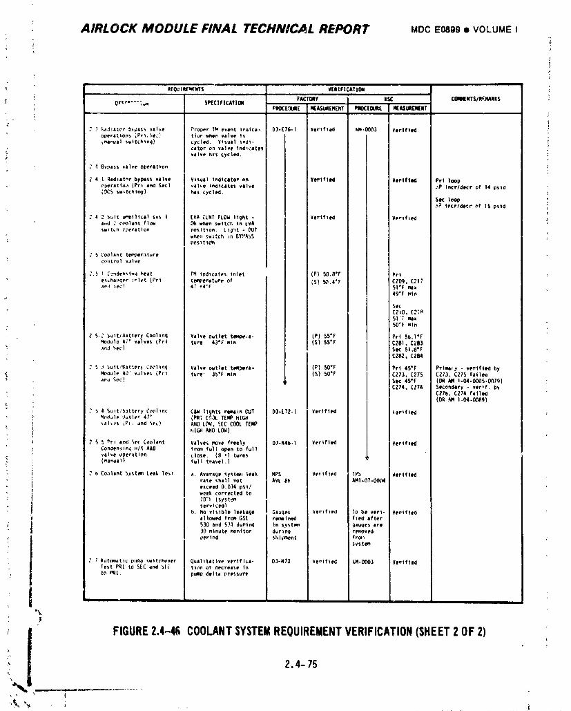
AIRLOCK MODULE FINAL TECHNICAL REPORT MDCE0899• VOLUMEI
L
T
- ,.... •RLrQUIR£q(NT5 VEIIIFIEAT I011
FAET011V i II_ C:_4q[NTS/REJqMtS !$P£CIF ICATION w
PIIOE[,'JUIIE IIEASUIIEIIENT PII0CEOUII[ MEASUR(NENT
2 3 _adlator b_,dass valve Proper TM event trotce- 03-E76-1 Vertfled I_q-O003 Verifiedoperatlon,_ _Prl,._e:, _ Stun i,_n valve is_llnual 5uttchtmJ} c_'cle_. Visual _nOt- i
,_ cator on valve tndlcetet .._ valve h:S cyCled.
; _ OvpiSS _|lve operltton Ji
2 4 I ;tadtet_r byPasS valve Visual indicator nn Vertfled Vertfted Prt loop
_peratto,_ (Prt end $ec) val_e Ir_tcates vilve ._P trice/tiEr of 14 pstd([_C$ searching) has cycled.
Sec loop '.._._ lncr/dc,:.r of 15 psld
e
4 _ _,u_t u_bllical sv5 I [V_ CLNT IrLOi_ light - Verified V_,'tfteda,.d _ coolant flC_d _ when swttcr, In tVASWltLh eper¢tton pOSItion. L)g_t - OUT
w_n _;tch _n 8¥,t'A3S
post t io_t
5 CO01_nt tt_p_r.tture ic_ntrol valve
_',_ l _nden_.tnq beet YM tndtcah's inlet ! (P) 50.8"r Pr_
ex_ha_,qer :elet (Prt te_,_ereture of (S) 50.4"r CZ09, C?l?a_,! _ecl 4_" *4°f 51°F mix
49"F m_n
$ec
51 "_ m_x
: S0_f mln
Z 5., _ _t/_attery Cool_nq Velve outlet tmq_.a- _P) 55"F Prt 56.1"F_4odule 47 _ valves (Prt tur_ 43"f min (S) SS'F C_81. CZ83
"- ,tnd 5eel $K $1.8"FCZ82, CZlN
: S ._ _ult/Bat:er) Cooltnq Valve outlet t_p_ra- (P) 50*F !Pet 45*F Prtl_¥ - vertfted byNodule 40" valves (Pet ture" 35'F min (S) 50"F J :C273, C275 CZ73, CZ75 faille
_. aPu _ec) ,_ I Sec 4S'f (Oeq AM 1-04-0005-007g)
I CZ74, C_76 SlKondery - ver_f, by; C_71_, C274 latin
, i (o__ i-o_-oo_)." 5 4 Su_t,',_,tttrry Cool,no C&M lights ree_in CUT 03-[7Z-1 Verified I _ertfted
qodule Outlet 47 ° (PR[ C_ TERP hlC_d_l_._ _P_, and ",e_.) AND LCN. SEC COOL TEMP J
hl_ AND LOM) i
5 5 nrl end _ec Coolant Valves move freely D3-N45-1 Verified i Verified
Condenstn_ H/_ A&0 frc=n fu_l open to full !valve operation close. (H *1 turns i'(manua 11 full reeve1.)
2 b Coolant _.vstem Leek Te_t a. Average _yete_= leak MPS Verified TP_, _'erifledrite shill _Ot AVE 8(_ AM1-07-0004
exceed 0.0,14 psi/week corrected to70"t ( SySt'=_mservlcedl
b. NO visible leakage Gauqes Verified To be verl- Verifiedallo_ed tram GS[ remained f_ed ,trier
/ 530 and 531 durinq In syst_ gauqes _re30 minute monitor during r_K_vedperiod Shlpm_n| froI1
svtt_
1 A_=to_kttlc p_l_p ¢.wttchover Quallt_tlive veriflca- 03-N70 Verified kM-O003 VerlfledTest PRI to SEE and _1_" lion of decrease into PRI. pump delta pressur_
°_
FIGURE2.4-4E COOLANTSYSTEMREQUIREMENTVERIFICATION(SHEET2 OF2)T
2.4-75
1974018208-169
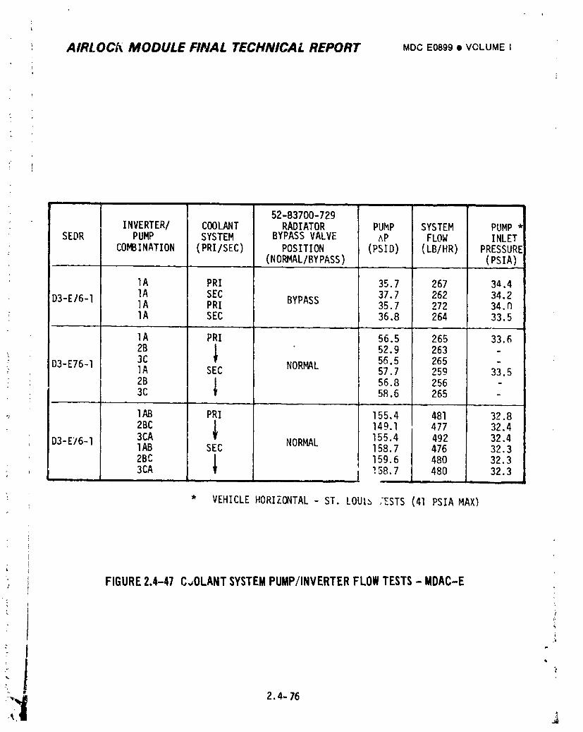
_ AIRI.OC[_ MODULE FILIAL TECHNICAL REPORT MDCE0899• VOLUMEI
i
I
_1 - , i L7
52-83700-729INVERTER/ COOLANT RADIATOR PUMP SYSTEM PUMP*
SEDR PUMP SYSTEM BYPASSVALVE ^p FLOW INLET: COMBINATION (PRI/SEC) POSITION (PSID) (LB/HR) PRESSURE
(NORMAL/BYPASS) (PSIA)
IA PRI 35.7 267 34.4
D3-E/6-1 IA SEC 37.7 262 34.2IA PRI BYPASS 35.7 272 34.nIA SEC 36,8 264 33.5
...... _L
IA PRI 56.5 265 33._2B | 52.9 263 -
D3-E76-1 3C 5_.5 265 -' IA SEC NORMAL 57.7 259 33.5
2B | 56.8 2563C t 58.6 265 -
IAB PRI 155.4 481 32.82BC I 149.1 477 32.4
D3-E76-1 3CA Y NORMAL 155.4 492 32,4IAB SEC 158.7 476 32.3
2BC3CA i 159.6 480 32,3158.7 480 32.3_tl i
' * VEHICLEHORIZONTAL- ST. LOUI_ :ZSTS(41 PSIAMAX)
_ FIGURE2.4-47 C_,OLANTSYSTEMPUMP/INVERTERFLOWTESTS- MDAC-E
t:it__ 2.4- 76
1974018208-170
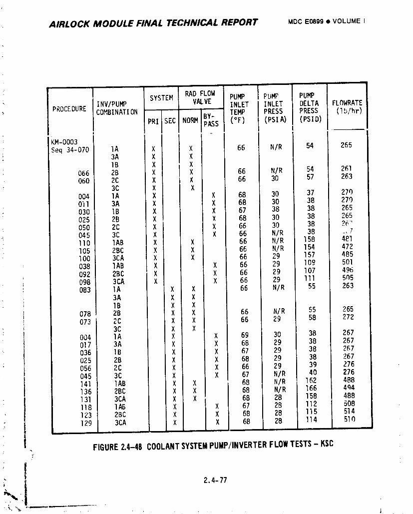
_. AIRLOCK MODULE FINAL TECHNICAL REPORT MDCEosgg• VOLUMEI
I .... --
" PROCEDURE INV/PUMP SYSTEH RAD FLOW PUMP PUMP PUMPVALVE INLET INLET DELTA FLf)WRATECOMBINATION -
BY- TEMP PRESS PRESS (!b/hr)RRI SEC NO_ PASS (°F) (PSIA) (PSID)
J I | ,
: KM-0003 i
: Seq 34-070i IA X X 66 N/R 54 265; , 3A X X
IB X X066 2B X X 66 N/R 54 261060 2C X X 66 30 57 263
; 3C X X004 lA X X 68 30 37 2700"Il 3A X X 68 30 38 270030 IB X X 67 38 38 265025 2B X X 68 30 38 265
• 050 2C X X 66 30 38 26'045 3C X X 66 N/R 38 _, 7110 IAB X X 66 N/R 158 481] 05 2BC X X 66 N/R 154 472I00 : 3CA X X 66 29 157 485038 IAB X X 66 29 109 501092 2BC X X 66 29 107 496098 3CA X X 66 29 111 5n5083 1A X X 66 N/R 55 263
3A X X1B X X
078 2B X X 66 N/R 55 265073 2C X X 66 29 58 272
3C X X004 1A X X 69 30 38 267017 3A X X 68 29 38 267036 IB X X 67 29 38 267025 2B X X 68 29 38 267056 2C X X 66 29 39 276045 3C X X 67 N/R 40 276141 IAB X X 68 N/R 162 488136 2BC X X 68 N/R 166 404
- 131 3CA X X 68 28 158 488118 1AB X X 67 28 112 508123 2BC X X 68 28 I15 514129 3CA X X 68 28 114 510
m
. FIGURE2.4-48COOLANTSYSTEMPUMP/INVERTERFLOWTESTS- KSCa-
2.4-77
'_', 'N- _'_""'_ L,
1974018208-171
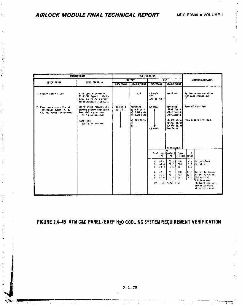
AIRLOCK MODULE FINAL TECHNICAL REPORT MDCE0899• VOLUME I _
?
?
(
RE(_JIREN[NTS VERIFICATlUH
FACTORY KSC coNqENTS/REMARxS
OESCRIPTION SPECIFICAI,,,_ PROCEOUR[ [MEJLSUR[M(NT P_OC(OUR[ Iq[ASUqEIq[Rf
I. SySttN_ water flusfi FI11 tank with water N/A KS-UOI6 Verified System reservtce after
PS 13240 Type I. W_th- 1PS tl20 tank cltal_e-out.draw 4,0 _O._.]b prior AM|-OS-ZZ5to ec,£han{c_t _;oseout.
?. Pump operation - Operat. LO _P l_qht reewl_n$ OUT 03-[75-1 Verlfted IJ4-0003 Vertfted Pump _P verlfleo_nd_vldual pump_ {A, 8, dur_n 9 system operat_o_ Vol. I[ l| 9.8 ps_d I _PA-9.2psldC). via rewInua] Swttchtn(j. Pump delta p_ssure; b) 6.04B pstd 3PB-8.Spsld
23.2 p_d nwIxter_Jl_ I c) 9.28 p$id _PC=7.Sp$|dIPump t|ow. ! !a) 293 _b/hr ,_.1=300 ;b/hi F|Ole PIHIBts vet|fled.
220 :b/hr .ntntnJ_:,. i b) -- ,_-297 Iblh!
; I' c) -- Ir _C.279 1himK5-0045 See 8etow
MLA_URLMENII
TLHP v 1
PI:HP _E'_ [LOW ,P
_. {'F_ el; (L_/HRI (PSID
_3 _ 73 _ _ UUU g._ initial Test
bl _ 71._ I 2_ 9.0 (9 |eb 7_)
C _1 3 _q._ 351 _._
_; "_ I UUU _1._ Retest f_ I_w_.q, L,5_, 71 I 297 10,_; lfliqht ser_,_n_
........... )t _O tank wa_
UtlU - OFt _CAL[ HiGH rPplaced and syr-ian reservlcodafter thl_ te_t
FIGURE2.4-49 ATMCaDPANEL/EREPH20COOLINGSYSTEMREQUIREMENTVERIFICATION
i_ 2.4- 78
_.._.._,..... _v - -- "' ..................... , "I'T";,.
1974018208-172
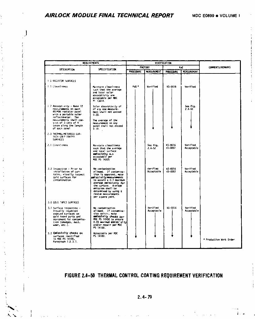
; AIRLOCK MODULE FINAL TECHNICAL REPORT MDCE0899• VOLUMEI
I
L
REOU_EqENTS VERIFICATION Ii,
FACTORY I_C COMIENTS/REMARKS
DESCRIPTION SPECIFICATION PROCEDURE NEASUREMEIIT PROCEBJR'E MEASUREMENT j
I O RADIATORSURFACES
I 1 Clednllness Ralntaln cleanliness PIJO* Verified KS-OOI6 Verified
such that the average iand local solarabsorptivity areacceptable per NDC i
P_ 13514. I I
) 2 Absorpt,vlty - Hake 12 Solar absorptivity of See Fig.measurements off each of a_y one measure- Z.4-SIN1/_OA radlatm" panel merit shall not exceedwith a portable solar O.ZO.reflectc_._ter. Ther_easurementS shall co_- The average of theslst of 3 sets of A measurement on anytaken along the length panel shall not exceed _pof eacn panel 0.19.
2.0 THERMAL/HETEROIDCUR-TAI_ G_ PtP,ATrnSURFACES
2.] Clean!lness Maintain cleanliness See Fig. KS-O016 Verifiedsuch that the average 2.4-52 KS-O007 Acceptableand local surfaceeudss| vl ty w.sacceptable per
; NOCPS 14205
2.? Inspection - Prior to NO contamination VerifteO KS-O016 Vertfiedinstallation of cur- allowed. If contamlne- Acceptable KS-O007 Acceptabletaint, visually inspect tton iS apparent. Nkegold surfaces for eIItSS|vitymsurmmntscontamination, to assure a 0.1 mextmu_
average emissivlty forthe curtain. AYerageemission shall bedetermined by usang 6rand.x, measurementsper square yard.
-i 3.0 GOLDTAPED SURFACES
3.1 Surface inspection- No contamlnatlon i Verified KS-0016 VerifiedVisually inspected allowed. [f contamina- Acceptaule Acceptableexposed surfaceson tlon exists,make
gold taped parts and eldSliVtty checks perequipment for contamtna- ROCPS 14100 to ensuretion (smudges. dust. 0.05 _ximum mtss' vi tywear, etc.), and/or repair per IqI_C
PS 14100.
3.2 Elds$1vtt_y checks on Acceptable per MDCsurfaces identified PS 14100. ,e Ir ,pin MOC PS 14100, * Production Work OrderParagraph 7.2.3.!.
FIGURE2.4-50 THERMALCONTROLCOATINGREQUIREMENTVERIFICATION[
: 2.4- 79%
\( 1
1974018208-173
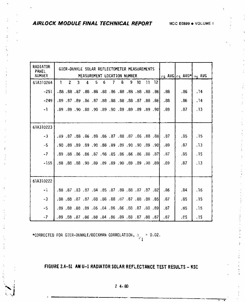
AIRLOCK MODULE FINAL TECHNICAL REPORT MDCE0899• VOLUMEI
RADIATOR GIER-DUNKLE SOLAR REFLECTOMETERMEASUREMENTS: PANEL
NUMBER MEASUREMENT LOCATION NUMBER ps AVG _s AVG* _s AVGm.
61A310264 l 2 3 4 5 6 7 8 9 lO II 12
-251 .88 .88 .87 .88 .88 .88 .86 .88 .8B .B8 .B8 .86 .88 .86 .14
-249 .89 .87 .89 .86 ,87 .88 .88 .88 .88 .87 .88 .86 .88 .86 .14
-l ,89 .89 .90 .88 .90 .89 .90 .89 .89 .89 .89 .90 .89 .87 .13
61A310223
-3 .89 .87 .88 .86 .88 .86 .87 .88 .87 .86 .88 .88 .87 .85 .15
-5 .90 .89 .89 .89 .90 .88 .89 .89 .90 ,90 .89 .90 .89 ,87 .13
-7 .89 .88 .86 .86 .87 °88 .85 .86 .86 .86 .88 .87 .87 .85 ,15
-155 .88 .88 .88 .90 .89 ,89 .89 .90 .89 .89 .90 .89 .89 .87 .13
J
61A310222
-] .88 ,87 .83 .87 .84 .85 .87 ,88 .88 .87 .87 .82 .86 .84 .16
-3 .88 .88 .87 .87 .88 .88 .88 ._7 .87 .88 .88 .851 .87 .85 .15
-5 .89 .88 .88 .89 .86 .84 .86 .86 .88 .87 .88 .891 .87 .85 .15
; -7 .89 .88 .87 .86 .88 .84 .86 .89 .88 .87 ,88 .87 .87 ._5 .15
*CORRECTEDFORGIER-DUNKLE/BECKMANCORRELATION,,\ = 0.02.
• ?
;
FIGURE2.4-51 AMU-I RADIATORSOLARREFLECTANCETESTRESULTS- KSC
L,
2 4-mu _ ) ..... i
1974018208-174
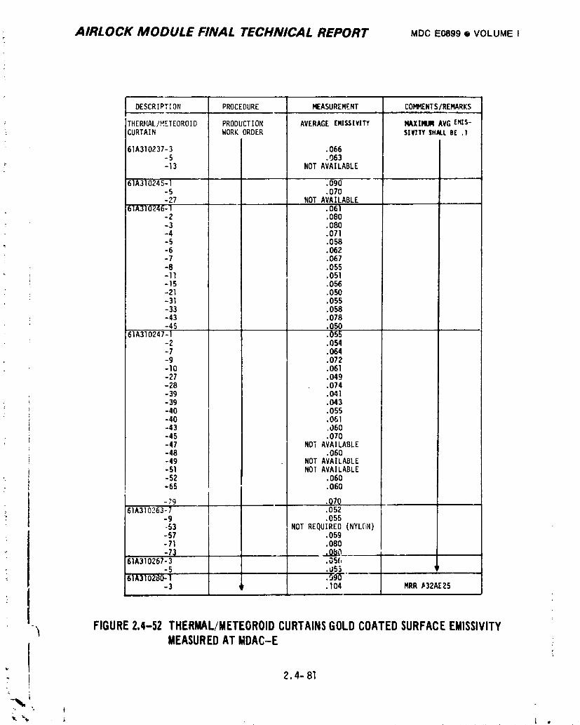
AIRLOCK MODULE FINAL TECHNICAL REPORT MDCEO899e VOLUMEI
DESCRIPTION PROCEDURE MEASUREMENT COMMENTS/REMARKS
THERFIAL/HETEOROID PRODUCTION AVERAGE £NI_IVITY MAXIMUM AVG EMIS-" CURTAIN WORK ORDER SIVITYSHALLBE .1
61A310237-3 .066-5 .063
-_" -13 NOT AVAILABLE
61A310245-1 .090-5 .070-27 NOT AVAI.LA.BLE .,
61A310246-1 . 061-Z .080- 3 ,080-4 .071-5 .058-6 .062-7 .067-B .055-11 .051-15 .056-21 .050-31 .055-33 .O58-43 .078
• 50-45 .85561A310247-1-2 .054- 7 .064-9 .072-10 .061-27 .049-28 .074-39 .041
- -39 .043-40 .O55
: -40 .061-43 ,060-45 .070-47 NO; AVAILABLE-48 .060-49 NOTAVAILABLE-51 NOI AVAILABLE
', - 52 .060-65 .060
-79 .Q7Q61A310263-7 .052
-9 .055-53 NOTREQUIRED (NYLC',N)-57 .059-71 .080-7_ .o_o__
61A310267-3 .05(,-5 .US._
61A310280-1 J .O_-"-3 ,_ .104 MRR.a32AE25
-,_ FIGURE2.4-52 THERMAL/METEOROIDCURTAINSGOLDCOATEDSURFACEEMISSIVITY
MEASUREDAT MDAC-E! 2.4-81
1974018208-175
A/RLOCK MODULE FINAL TECHNICAL REPORT MD¢E0899• VOLUMEI
2.4.4.6 Nission SupFort
Mission support testing of the Skylab Test Unit (STU) and of the U-2 vehicle
was conducted under simulated U-l flight conditions.
A. STU Simulation - A sunm_aryof TCS tests performed utilizing the Skylab Test
Unit is presented on the following pages. Test details as we|l as descrip-
tions of STU are presented in the ECS/TCS Skylab Test Unit Report No.
• TR 061-068.99.
e TITLE U-I Cold Coolant Simulation
BACKGROUND U-l coolant loop temperatureswere low due to low heat
load of 615 Btu/hr.
OBJECTIVE Determine coolant system operational characteristics under
simulated low heat load conditions experienced in U-l and
verify proper operation of the SUS and ATM water pumps under
these conditions, Reference TR 061-015-600.02.
RESULTS The coolant system and the water pumps operated
satisfactorily, Reference TM 252:664.
• TITIF ATM PumpStartin9 Transient Test
BACKGROUND U-l ATM "Lo .\P"light took longer than expected to go out
after an ATM pump was turned on.
OBJECTIVE Det_.rminetime required to obtain "Lo AP" actuation pres-
sure;, TR 061-015-600.05.
RESULT The '.i,:;es to obtain minimum and maxinlum specified actuation
pressures of 1.5 psid lower and 5.5 psid higher limit were
approximately i and 3 seconds, Reference TFI 252:660.
"_i 2.4- 82
1974018208-176
AIRLOCK MODULE FINAL TECHNICAL REPORT MDC Eosg9,I VOLUMEI
O TITLE 47° TemperatureControlValve "B" Tests
BACKGROUND Du_'ingEVA activitiesfromU-l, the 47° TemperatureControl
Valve "B" stuckwith the cold inletport open so thatthe
outlettemperaturedecreasedbelow the controltemperature
limit.
OBJECTIVE Determineif thermalshockswill cause the Temperature
ControlValve (TCV)to stick,ReferenceTR 061-015-600.06.
Evaluatethe _ffecton coolantsystemoperationof turning
two coolantpumpson when the radiatorbypassvalve is in
the bypassposition,ReferenceTR 061-015-600.07.
)
Evaluateoperationof the TCV at varioushot and cold
inlettemperatureprofiles,ReferenceTR 061-Ol5-600.12.
: Evaluateo_erationof the TCV when subjectedto contamina-
tionby ir,troducingvarioussizesof metal part;cles,
ReferenceTR 061-015-606.13.
Evaluateoperationof the TCV when subjectedto tempera-
tures causingslow strokingof valve,P _erence
TR 061-015-600.14.
RESULTS Thermalshocksdid not cause the TCV to stick. Outlet
temperaturerecoveryoccurredwithin5 minutesof the
thermalshocks,ReferenceTM 252:675.
Turningtwo coolantpumps on when the radiatorbypass
valvewas in the bypasspositiondid not causeabnormal
systemoperation,ReferenceTM 252:718.
Varioushot and cold inlettemperaturesdid not adversely
effectoperationof the TCV. The outlettemperature
remainedwithinthe specificationallowablelimit_ <,f
} 47° +2°F, ReferenceTM 252:696.
_._- 83
%.,
1974018208-177
?
AIRLOCK MODULE FINAL TECHNICAL REPORT MDC E08_9 • VOLUME I
Injection uf particulate contamination did eventually
cause the TCV to jam. Subsequent attemDts to free the
valve were successful and the valve functioned properly,
• Reference I_4252:710.
I_duced slow stroking of the TCV did not cause abnormal
o_eration, Reference TM 252:682.
• TITLE Coolant Pump Shutdown and Startup.Test_
; BACKGROUND Coolant pump start-up characteristicswere required to
analyze the automatic switchover feature.
OBJECTIVE Determine coolant pump shutdnwn and sta,t-up characteris-
tics, Reference TR 061-015-600.19.
RESULTS Coolant pump flowrates and differential pressures were
obtained during pump shutdown and start-up, Reference
I_I252:657.
m TITLE Altltude Test of 2-Watt and lO-Watt Airlock Transmitters
Without Cooling
BACKGROUND Air|ock 2-watt and lO-watt transmittersmight nat have
active cooling available when operated.
OBJECTIVE Determine the duty cycle required to keep the temperature
of Airlock 2-watt and lO-watt transmitters below their
maximum allowable operating temperatures when operated
without coldplates, Reference TR 061-015-600,10.
RESULTS The Airlock 2-watt and lO-watt transmitters were operated
for 82 minutes and 32 minutes, respectively, without
active cooling before attaining maximum temperature limits,
Reference TM 252:723.
; • TITLE Coolant Loop Simulated Leak Tests
BACKGROUND U-l prir,_ryloop coolant pressure was steadily decreasing.
OBJECTIVES Simulate coolant loop leakage conditions and det_:rmine
_ pump operating characteristicsat low system pressures.
, Reference TR 061-015-600.16.
c{
Determine if the combined exposure effects of solar simula-i
tion (IR and UV) and Coolanol would produce visible color
change of four thermal control materials used on Skylab:
_ _ 2.4-84
i9740i8208-i78
AIRLOCK MODULE FINAL TECHNICAL REPORT MDCE0899• VOLUMEI
(a) Z93 thermal control coating, (b) Thermal capacitor
cover (gold surface), (c) thermal curtain (white fiberglass
surface), and (d) Johns-Manvillealuminum covered insula-
tion (aluminum surface), Reference TR 061-015-60C.17.
Determine visual characteristics of leaks at typical
coolant system connectiors as a possible aid in locating
leaks on the U-I vehicle, Re_erence TR 061-015-600.21
Determine the pressure-temperaturerelationship of the
coolant pump reservoir and a dua. reservoir to aid in
predicting U-l coolant loop performance, ReF_rence
TR 061-015-6d0.23.
Determine coolant system reservoir mrdule performance
characteristicsat simulated temperature conditions to
enable refined evaluation of U-l coolant system leakage
effects, Reference TR 061-015-600.26.
Determine if a Coolanol leak into a water loop system
could be detected by visual inspection of quick discon-
nects, Reference TR 061-015-600.27.
Simulate a Coolanol leak under the condensing heat exchanger
module cover and determine quantity of Coolanol removed by
the condensing heat exchanger-_cle sieve installation,
Reference TR 061-015-60C.51.
Evaluate the effect of a combination of reduced tempera-
' tures and fitting torques on coolant leakage characteris-
tics of six typical coolant line connsctions and a coolant
valve, Reference TR 061-015-600.52.
, RESULTS Coolant loop leakage was simulated and resulting profiles
• _ obtained of pump flowrate, inlet pressure and differential
T. pressures, Reference TM 252:685.¢
,} A 85I LO'T"
1974018208-179
: AIRLOCK MODULE FINAL TECHNICAL RE,'ORT MDCEOBO• VOLU EI
The four thermal control materials exhibited no appreciable
visual color changes after being expDsed to Coolanol and
solar simulation, Reference TM 252:678.
Coolanel leakage from typical coolant system connections
showed up as _ light stain on fiberglass tape, only,
Keference TM 252:_95.
The pressure-temperature relationship of the coolant pump
reservoir and a dual reservoir was obtained, Reference
TM 252:683.
Coolant system reservoir modu'e performance characteristicswere determined for 33 test conditions which included
: simulated thermal curzain temperatures, Airlock wall
zc_rzratures and coolant system hca+ loads, Reference
:, TM 252:725.
)
Visual inspection of quick disconnects subjected to
C,_olanol/Type I fluid mixture !10%/90%) showed an oil,,
appearance_ Reference TN 252:689.
All of the rvaporated Coolanol from a simulated leak under
the condensing heat exchanger module was absorbed in the
heat exchanger core, Re_erence TM 252:731.
1 Coolant leakag_ from six typical coolant line connection_.,
subjected to a combination of reduced temperatures and
: suanormal fitting torques, was minimal on five cennections
:_ while one connection exhibited gross le_._ge. Coolant
:' leakage from a coolant valve was qinimal, Reference
TM 252:729.7
e TITLE Saddle Valve Tests
BACKGROUNDU-I primary coolant loop might be serviced b,' utilizing a
saadle valve applied onto one of the 5/16" diameter lines
: in the system.
2.4-86
1974018208-180
AIRLOCK MODULE FINAL TECHNICAL R/£PORT MDCE0899• VOLUMEI
OBJECTIVES Evaluate two saddle valves (WATSCO Inc. Types Al and API)
for possible use to reservice the primary coolant loop,
Reference TR 061-015-600.20.
: CGnduct development tests on MDAC saddle valve, 61A830412-I,
for possible use to reservice coolant loops, Reference
TR 061-015-600.24.
Evaluate leakage from MDAC saddle valve when installed on
304 stainles_ steel tube of various outside diameters and
wall thick_aess,Reference TR 061-015-600.25.
Tvaiuate l_akage from MDAC saddle valve for ten different
se_ls when installed on various size tubes, Reference
'R 061-015-600.31.
Evaluate the RA346?OBN curved seal and then the MSFC
cylindrical seal while installed in the MDAC saddle valve,
61A83G412-31, Reference TR 06!-015-600.33.
Delermine if the 61A83041L 31 saddle valve with a
61A830412-;5 MSFC cylinc.'icalmold seal would leak when
puncturing a 5/16 O.D. x .015 wall 304L stainless steel
tube filled with Coolanol and pressurized at 5 and 25 psig,
Reference TR 061-015-600.35.
Evaluate several secondary seal materials and determine the
p-essure sealing cap_bilitie_ of each sea] materi_l while
installed in the 61A830412 saddle valve, Reference
TR 061-015-600.3_.
Evaluate epoxy and fluorosiliconeas secondary seals when
installed in the 61A830412 saddle valvesat Coblanol
pressur_ of lO0 psig_ Reference TR 061-015-600.42.
2.4-B7
_", • - i •
1974018208-181
!AIRLOCK MODULE FINAL TECHNICAL REPORT MDC E08_9 • VOLUME I l:
]RESLILTS Two WATSCOInc. saddle valves were te_ted for puncture,
external leakage and flowrate characteristics_t various ;
line pressures. There was no evidence of external leakage i
from either valve, Reference TM 252:691. i
The MDAC saddle valve, 61A830412-I, was tested for
puncture, _xternal leakage and flowrate characteristics,
Reference TM 252:686.
The MDAC saddle valve tested for leakage when installed on
various sizes of tubes did not leak under any of the condi-
tions evaluated, Reference TM 252:692.!
Ten different seals were installed one at a time in MDAC
saddle valve, applied on various size tubes, and tested
for leakage, Reference TM 252:700.
Both the RA34670BN curved seal and the MSFC cylindrical
seal while installed in the MDAC saddle valve, 61A830412-31,
passed all exterqal leakage tests satisfactorily,L
Reference TM 252:719.
The 61A830412-31 saddle valve with a 61A830412-55 MSFC
cylind}ical molded seal was leak tested when puncturing a
tube filled with Coolanol pressurized at 5 and 25 psig.
No leaks occurred during either puncture test, Reference
TM 252:693.
Several seal materials including Vi_on, fluorel, epoxy,
and fluorosiliconewere tested to determine secondary
sealing capabilities w;;ileinstalled on the 61A8304L2
saddle valve. Viton and fluorel seals leaked while the
epoxy and fluorosilicone seals did not leak at pressure
of 5, 25, ana lO0 psig, Reference TM 252:694.
c
2.4-88
1974018208-I 82
AIRLOCK MODULE FINAL TECHNICAL REPORT MDCE0899• VOLUMEI
Epoxy and fluorosilicone seals were installed in 61A830412
saddle valves and leak tested with Cooianoi at iO0 psig.
The valve with the epoxy seal leaked while the valve with
the fluorosiliconeseal completed a 7-day period without
leaking, Reference _M 2521699.
• TITLE Coolant System Reservicin9 Tests
BACKGROUND Pressure loss in U-I coolant system loops indicated
coolant leakaca. The primary coolant loap required
reservicing.
OBJECTIVES Verify the adequacy of the servicing hardware (including
the modified OWS portable t_nk) and procedure developed
for reservicing the coolant loop, Reference TR 061-015-
600.29.
Verify the adequacy of the servicing hardware !including
Lhe CSM fuel tank) and procedure developed for reservicing
the coolant loop, Reference TR 061-015-600.30.
Determine the effect of free gas injected into the coolant
system from saddle valve installations on coolant pump
performance, Reference TR 061-015-600.36.
Evaluate the SS4JBA NUPRO shutoff valve for use on the SL-4
coolant system servicing kit, Reference 061-015-600.38.
Evaluate sealing characteristics of a rerair fixture
61A830421, to be used to seal a punctured line made by a
saddle valve installation, Reference TR 061-015-600.39.
Eva_Jate procedures for removing a saddle valve from a
coolant line and in_tailing a 61A830421-23 repair seal,
Reference TR 061-015-600.47.
Determine if free gas will cause coolant pumps to cavltate
_ since free gas might be inadverently introduced into the
coolant system during reservicing, Reference TR 061-015-
_ 600.43.
2.4-89
1974018208-183
AIRLOCK MODULE FINAL TECHNICAL REPORT MDCEO89g• VOLUMEI
Obtain coolart loop temperature stabilization data to be
used for refining thermal model to predict coolant ioop
performance during reservicing, Reference TR 061-015-600.46.
RESULTS The servicing hardware, including the modified OWS portable
tank and 61A830412-35 saddle valve, was used to reservice
the coolant loop. Both hardware and reservicing procedures
were satisfactory. There was no evidence of Coolanol
leakage. Reference TM 252:724.
The servicing haraware, including the CSM fuel tank, was
used in three test trials to reservice the coolant loop.
Two attempts using different S/_J61A830412-61 saddle
valves were terminated due to saddle valve seal leakage.
Res_rvicing with an MSFC saddle valve, 20M33247, was
successful, Reference TM 252:707.
Free gas, 3 SCC, was injected into the coolant system
approximately lO inches upstream of the coolant pump. No
change in pump performance was apparent, Reference
TM 252:684.
Two SS4JBA NUPRO valves were subjected to qualification
tests for use as {ackup hardware. Both valves passed all
test_ _;Iceptone unit failed the internal leakage test
a_ter beL_g subjected to vibration, Reference TM 252:720.
The repair fixture, 61A830421, was installed on a tube
: previou:ly punctured by a saddle valve inst_llation and
leak checked at 5, 35, lO0 and 200 psig. No leaks were
_. observed, Reference TM 252:687.
Procedures for removing a saddle valve from a coolant line
and installiag a 61A830421-?3 repair seal were verified
satisfactory. No Coolanol leakage occurred d,_ringthe,C
installation process or when one or both coolant pumps
' were operated. Reference TM 252:715.
1974018208-184
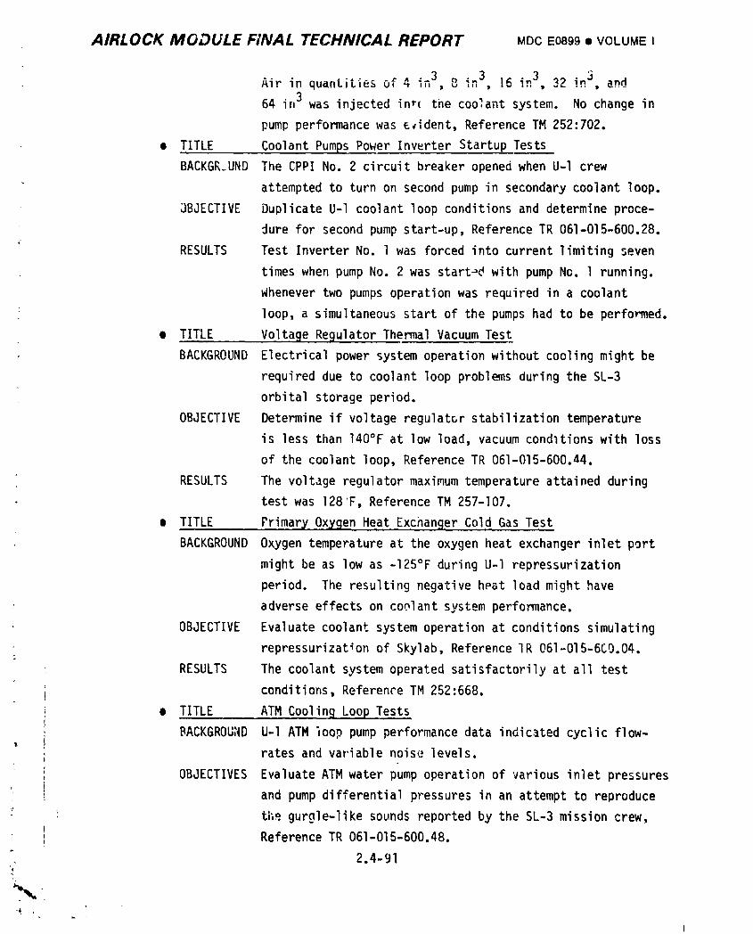
AIRLOCK MODULE FINAL TECHNICAL REPORT MDCE0899• VOLUMEI
=3 in3, R_ inj, Bn dAir in quantities of 4 ,,,, 8 " j_ _3
64 in3 was injected in*( the coolant system. No change in
pump performance was e_ident, Reference TM 252:702.
• TITLE Coolant Pumps Power Inwrter Startup Tests
BACKGLUND The CPPI No. 2 circuit breaker opened when U-l crew
attempted to turn on second pump in secondary coolant loop.
3BJECTIVE Duplicate U-l coolant loop conditions and determine proce-
dure for second pump start-up, Reference TR 061-015-600.28.
'; RESULTS Test Inverter No. l was forced into current limiting seven
• times when pump No. 2 was start_ with pump No. l running.
Whenever two pumps operation was required in a coolant
: loop, a simultaneous start of the pumps had to be performed.
• TITLE Voltage Regulator Thermal Vacuum Test
BACKGROUND Electrical power system operation without cooling might be
required due to coolant loop problems during the SL-3
orbital storage period.
OBJECTIVE Determine if voltage regulator stabilization temperature
is less than 140°F at low load, vacuum conditions with loss
of the coolant loop, Reference TR 061-015-600.44.
RESULTS The voltage regulator maximum temperature attained during
• test was 128F, Reference TM 257-I07.
m TITLE Primary Oxygen Heat Exchanger Cold Gas Test
BACKGROUND Oxygen temperature at the oxygen heat exchanger inlet port
might be as low as -125°F during U-l repressurization
period. The resulting negative heat load might have
adverse effects on coolant system performance.
OBJECTIVE Evaluate coolant system operation at conditions simulating
repressurizat_on of Skylab, Reference IR 061-015-6C0.04.
RESULTS The coolant system operated satisfactorily at all test
conditions, Reference TM 252:668.
• TITLE ATM CoolinB Loop Tests
BACKGROUND U-l ATM _oop pump performance data indicated cyclic flow-T
rates and variable noise levels.
OBJECTIVES Evaluate ATM water pump operation of various inlet pressures
and pump differential pressures in an attempt to reproduce
the gurgle-like sounds reported by the SL-3 mission crew,
Reference TR 061-015-600.48.
2.4-91
I
1974018208-185
AIRLOCK MODULE FINAL TECHNICAL REPORT MDCE0899• VOLUME IY
Evaluate ATM pump start-up characteristicsat various inlet
pressures and pump differential pressures, Reference
TR 06i-015-600.50.
Determine if U-I ATM pump cycle flowrate is caused by a
= high differential pressure which activates the relief
valve, Reference TR 061-015-600.54.
Determine delta P of ATM loop filter cartridge returned
from SL-3 mission and compare with PIA data, Reference
TR 063-015-600.55.
Determine if the liquid-gas separator, normally used in
the suit umbilical system could remove free air from the
ATM loop, Reference TR 061-015-600.56.
Evaluate single and dual pump performance during both
normal flow and blocked flow conditions in the ATM cooling
loop, Reference TR 061-016-600.57.
Determine transient temperature characteristics of the ATM
water pump (exposed to lab ambient environment) when 28 VDC
is applied while the pump rotor is stalled, Reference
TR 061-015-600.58.
• Compare present performance data of two ATM water pumps with
initial PIA data. Water pumps were installed in STU ATM
• loop for approximately seven months, Reference TR 061-015-
; 600.59.
Determine water pump performance characteristicswhen
quantities of air are injected into the ATM cooling loop,
Reference TR 061-015-600.60.
I
} 2.4-92
1974018208-186
AIRLOCK MODULE FINAL TECHNICAL REPORT MDCE0899• VOLUMEI
Determine transient temperature characteristics of the #TM
water pump (exposed to vacuum environment) when 28 VDC is
applied while the pump rotor is stalled, Reference
TR 061-015-600.61.
Determine ATM pump performance characteristicsat voltage
betv_een12 VDC and 28 VDC, Reference 061-015-600.62.
RESULTS The ATM water pump was operated at various inlet pressures
and pump differential pressures in an attempt to reproduce
the gurgle-like sounds reported by the SL-3 mission crew.
None of the tests performed produced gurgle-like so,_nds,
Reference TM 252:712.
ATM water pump start-up p_rformance was determined for
> various pump inlet pressures and differert_al pressure_.
Performance was normal at all test conditions, Reference
TM 252:711.
L
ATM pump flowrate excursions were experienced with pump
differential pressure settings between 20 and 26 psid.
. Flowrates fluctuated as much as 40 Ib/hr with no _pparent
cyclic pattern, Reference TM 252:728.
ATM loop filter cartridge returned from SL-3 mission was
r tested to determine delta P with water flow of 250 Ib/hr.!
Delta P was II inc' ; of water - no change f_om PIA test
conducted during May 1972.
A liquid-gas separator was substituted for the ATM loop
filter and removed 60 SCC of gas from the ATM loop before
clogging, Reference TM 252:740.
Single and dual pump performance data was determined for
, both normal flow and blocked flow conditions in the ATM
; loop, Single and dual pump flowrate and delta P for normal
W 2.4-93
1974018208-187
AIRLOCK MODULE FINAL TECHNICAL REPORT MDCE0899• VOLUMEI
flow was 275 Ib/hr at 13.5 psid and 390 Ib/hr at 25 psid,
respectively. Pump delta P was 30.2 psid for the blocked
line condition id single or dual pump operation,
Reference TM 252:736.
Transient temperature profiles of the ATM pump motor
housing and the rotor housing were determined for the con-
dition of 28 VDC power on while pump rotor is stalled.
ATM pump w;,s exposed to lab ambient environment, Reference
TM 252:737.
Comparison of two ATMwater pumps current performance data
with initial PIA data showed no degradation. Water pumps
were installed in STU system for approximately seven
months, Reference TM 252:741.
Various Quantities of air were introduced into the ATM
cooling loop to determine effects on pump performance. The
i largest amount was 130 cubic inches. This amount of air
caused the flowmeter instrumentation to register zero flow
for a duration of 116 seconds. Normal pump noise was
greatly reduced du_'ing this period, Reference TM 252:744.
Transient tf_perature profiles of the ATM punlp motor housing
and the rotor housing were determined for the condition of
28 VDC power on while pump rotor was stalled. ATM pump was
exposed to vacuum environment, Reference TM 252:745.
ATM pump performance=data was determined for voltages
betweer_ 12 VDC and 28 VDC. Data included flowrate.
delta P, and current, Reference TM 252:746.I
i
+
,_ 2.4-£4
:-_ ,,_
i
1974018208-188
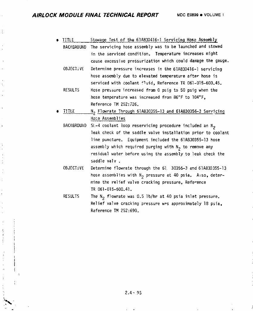
AIRLOCK MODULE FINAL TECHNICAL REPORT MDCE0899• VOLUMEI
• TITLE StowaBe Test of the 61A830416-I Serv_c_n9 Hose Assemblx
BACKGROUND The servicing hose assembly was to be launched and stowed
in the serviced condition. Temperature increases might
cause excessive pressurizationwhich could damage the gauge.
OBJECTIVE Determine pressure increases in the 61A830416-I servicing
hose assembly due to elevated temperature after hose is
serviced with coolant fluid, Reference TR 061-015-600.45.
RESULTS Hose pressure increased from 0 psig to 50 psig when the
hose temperature was increased from 86°F to 104°F,
Reference TM 252:726.
• TITLE N2 Flowrate Through 61A830355-13and 61A830356-3 ServicingHose Assemblies
BACKGROUND SI-4 coolant loop reservicing procedure included an N2
leak check of the saddle valve installation prior to coolant
line puncture. Equipment included the 61A830355-13 hose
assembly which required purging with N2 to remove any
residual water before using the assembly to leak check the
saddle valv .
OBJECTIVE Determine flowrate through the 61 30356-3 and61A830355-13
hose assemblies with N2 pressure at 40 psia. Ahso,deter-mine the relief valve cracking pressure, Reference
TR 061-015-600.41.
RESULTS The N2 flowrate was 0.5 Ib/hr at 40 psia inlet pressure.
Relief valve cracking pressure w_s approximately 18 psia,
Reference TM 252:690.
I
i
24-q _
=
1974018208-189
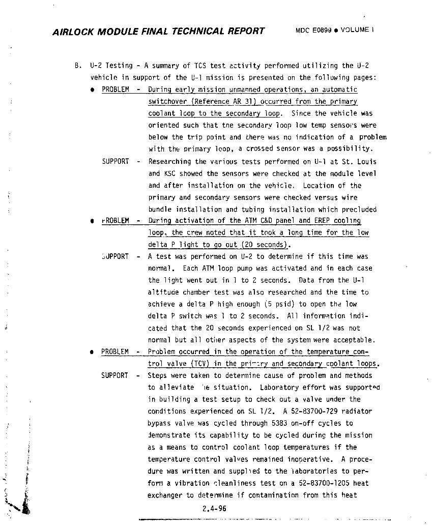
AIRLOCK MODULE FINAL TECHNICAL REPORT MDCE0899• VOLUMEI
B. U-2 Testing - A summary of TCS test activity performed utilizing the U-2
vehicle in support of the U-I mission is presented on the following pages:
o PROBLEM -During early mission unmanned operations, an automatic
• switchover IReference AR 31) occurred from the primary
coolant loop to the secondary loop. Since the vehicle was
oriented such that tne secondary loop low temp sensors were
below the trip point and there was no indication of a problem
with the primary loop, a crossed sensor was a possibility.
SUPPORT - Researching the various tests performed on U-I at St. Louis
and KSC showed the sensors were checked at the module level
and after installation on the vehicle. Location of the
primary and secondary sensors were checked versus wire
bundle installation and tubing installation which precluded
• rROBLEM- During activation of the ATMC&Dpanel, and EREP coolln_
lo_oo_p,the crew noted that it took a lon 9 time for the low
delta P light to _o out (20 seconds).
3UPPORT - A test was performed on U-2 to determine if this time was
normal. Each ATM loop pump was activated and in each case
the light went out in 1 to 2 seconds. Data from the U-I
altituae chamber test was also researched and the time to
achieve a delta P high enough (5 psid) to open the low
delta P switch was 1 to 2 seconds. All information indi-
,_ cated that the 20 seconds experienced on SL I/2 was not
normal but all other aspects of the system were acceptable.
• PROBLEM - Problem occurred in the operation of the temperature con-
trol valve (TCV) in the _ri_ry_and secqndar_ coolant loops.SUPPORT - Steps were taken to determine cause of problem and methods
to alleviate '_e situation. Laboratory effort was supported
in building a test setup to check out a valve under the
conditions experienced on SL I/2. A 52-83700-729 radiator
; _ bypass valve was cycled through 5383 on-off cycles to
Jemonstrate its capability to be cycled during the missioni
as a means to control coolant loop temperatures if the
temperature control val_,es remained inoperative. A proce-
dure was written and suppl_ed to the 'laboratories to per-
form a vibration cleanliness test on a 52-83700-1205 heat
_ exchanger to determine if contaminatinn from this heat2.4-96
i 9740i 8208-i 90
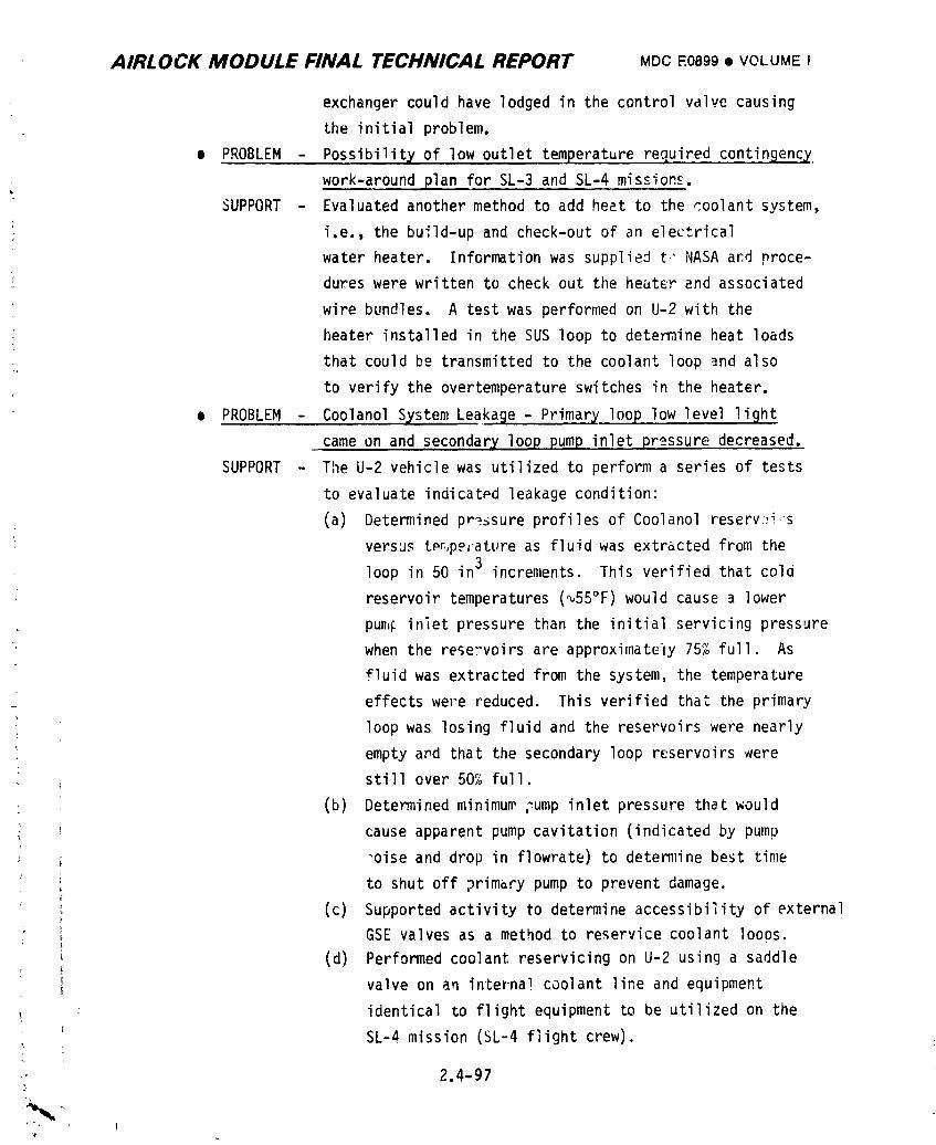
AIRLOCK MODULE FINAL TECHNICAL REPORT MDC E0899 • VOLUME I
exchanger could have lodged in the control valve causing
the initial problem.
¢ PROBLEM - Possibility of low outlet temperature required contingency
work-around plan for SL-3 and SL-4 missions.
SUPPORT - Evaluated another method to add heat to the coolant system,
! i.e., the build-up and check-out of an electrical
water heater. Information was supplied t" NASAand proce-
dures were written to check out the heater and associated
wire bundles. A test was performed on U-2 with the
heater installed in the SUS loop to determine heat loads
that could be transmitted to the coolant loop _nd also
to verify the overtemperature switches in the heater.
o PROBLEM - Coolanol System Leakage - Primary loop low level light
came on and secondary loop pump inlet pressure decreased.
SUPPORT - The U-2 vehicle was utilized to perform a series of tests
to evaluate indicatPd leakage condition:
; (a) Determined pressure profiles of Coolanol reserv:_i s
versus tPn,perature as fluid was extracted from the
loop in 50 in 3 increments. This verified that cold
reservoir temperatures (_55°F) would cause a lower
pun,_ inlet pressure than the initial servicing pressure
when the rese:voirs are approximately 75% full. As
fluid was extracted from the system, the temperature
effects were reduced. This verified that the primary
loop was losing fluid and the reservoirs were nearly
empty and that the secondary loop reservoirs were
still over 50% full.
(b) Determined minimum _ump inlet pressure that would
cause apparent pump cavitation (indicated by pump
"oise and drop in flowrate) to determine best time
to shut off primary pump to prevent damage.
(c) Supported activity to determine accessibility of external
GSE valves as a method to reservice coolant loops.
(d) Performed coolant reservicing on U-2 using a saddle
, valve on an internal coolant line and equipment
: identical to flight equipment to be utilized on the
SL-4 mission (SL-4 flight crew).t
_,, 2.4-97
1974018208-191
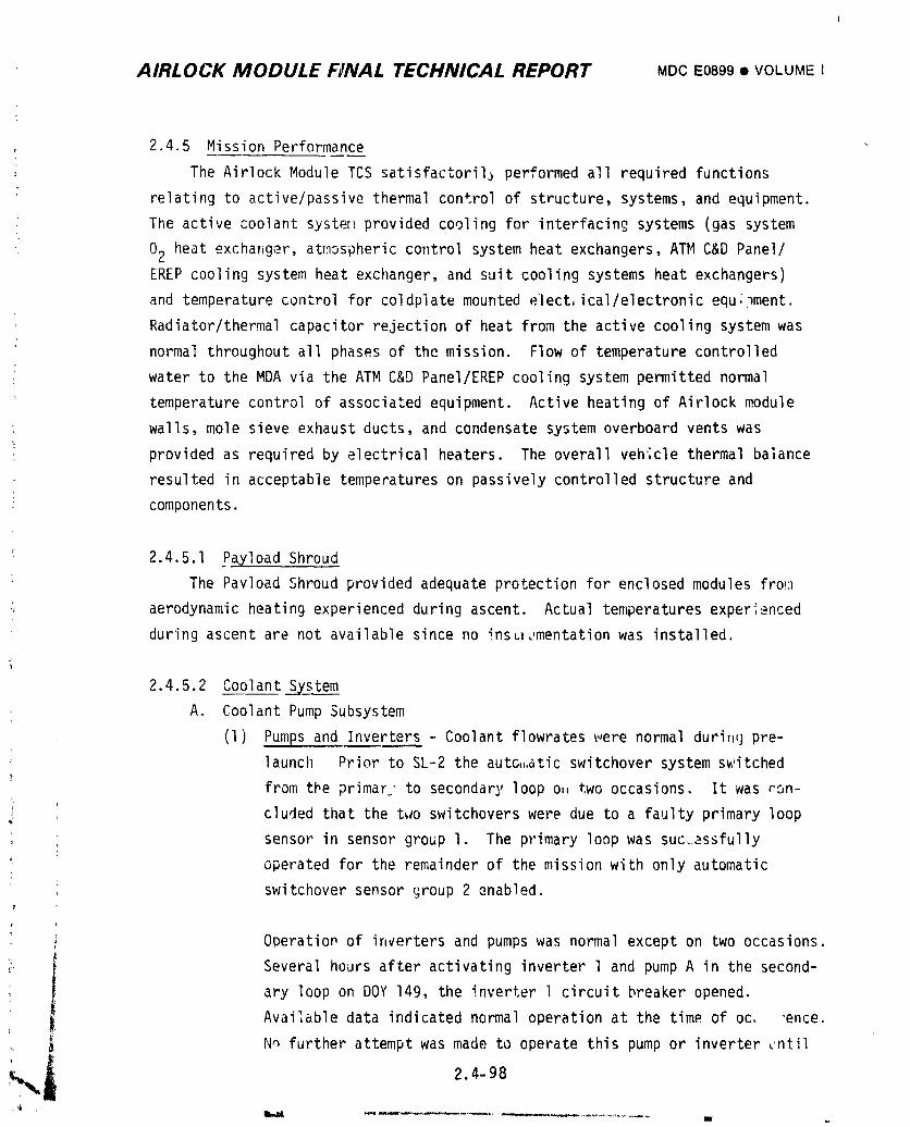
AIRLOCK MODULE FINAL TECHNICAL REPORT MDCE0899• VOLUMEI
2.4.5 Mission Performance
The Airlock Module TCS satisfactoril_performed all required functions
relating to active/passive thermal control of structure, systems, and equipment.
; The active coolant syster._provided cooling for interfacing systems (gas system
02 heat exchanger, atmospheric control system heat exchangers, ATM C&D Panel/
EREP cooling system heat exchanger, and suit cooling systems heat exchangers)
and temperature control for co!dpiate mounted elect,ical/electronicequ;_ment.
Radiator/thermalcapacitor rejection of heat from the active cooling system was
normal throughout all phases of the mission. Flow of temperature controlled
water to the MDA via the ATM C&D Panel/EREP cooling system permitted normal
temperature control of associated equipment. Active heating of Airlock module
walls, mole sieve exhaust ducts, and condensate system overboard vents was
• provided as required by electrical heaters. The overall vehicle thermal balance
resulted in acceptable temperatures on passively controlled structure and
components.
2.4.5.1 Payload Shroud
The Payload Shroud provided adequate protection for enclosed modules fro_:1
aerodynamic heating experienced during ascent. Actual temperatures experienced
during ascent are not available since no insL_.,mentationwas installed.
2.4.5.2 Coolant System
A. Coolant Pump Subsystem
(1) Pumps and Inverters - Coolant flowrates were normal durinu pre-
launch Prior to SL-2 the auto,,,aticswitchover system switched
from the primar" to secondary loop o,,two occasions. It was ron-
i cluded that the t_Joswitchovers were due to a faulty primary loop
sensor in sensor group I. The primary loop was suc.essfully
operated for the remainder of the mission with only automatic
switchover sensor group 2 enabled.
Operatiop of inverters and pumps was normal except on two occasions.
i Several hours after activating inverter 1 and pump A in the second-
ary loop on DOY 149, the inverter 1 circuit breaker opened.
Available data indicated normal operation at the time of oc, "ence.
N_ further attempt was made to operate this pump or inverter _ntil
im
1974018208-192
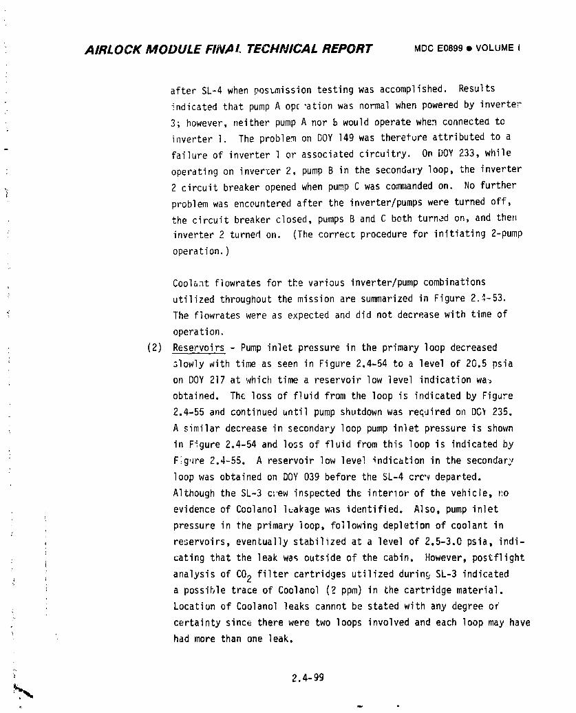
AIRLOCK MODULE FINAl. TECHNICAL REPORT MDCE0899• VOLUMEI
after SL-4 when pos_mission testing was accomplished. Results
indicated that pump A op_ "ationwas normal when powered by inverter
3; however, neither pump A nor b would operate when connected to
inverter I. The problem on DOY 149 was thereture attributed to a
failure of inverter l or associated circuitry. On DOY 233, while
: operating on inverter 2, pump B in the seconddry loop, the inverter
_ 2 circuit breaker opened when pump C was commanded on. No furtherproblem was encountered after the inverter/pumpswere turned off,
the circuit breaker closed, pumps B and C both turned on, and thell
inverter 2 turned on. (The correct procedure for initiating 2-pump
operation.)
Coolant f]owrates for the various inverter/pumpcombinations
utilized throughout the mission are summarized in Figure 2.7-53.
The flowrates were as expected and did not decrease with time of
operation.
: (2) Reservoirs - Pump inlet pressure in the primary loop decreased
slowly with time as seen in Figure 2.4-54 to a level of 20.5 psia
on DOY 217 at which time a reservoir low level indication wa:
obtained. The loss of fluid from the loop is indicated by Figure
2.4-55 and continued until pump shutdown was reGuired on DG_ 235.
A similar decrease in secondary loop pump inlet pressure is shown
in Figure 2.4-54 and loss of fluid from this loop is indicated by
F;gure 2.4-55. A reservoir low level _ndication in the secondary1
loop was obtained on DOY 039 before the SL-4 crc'vdeparted.
Although the SL-3 clew inspected the interlor of the vehicle, _:o
evidence of Coolanol l:akage was identified. Also, pump inlet
pressure in the primary loop, following depletion of coolant in
reservoirs, eventually stabilized at a level of 2.5-3.0 psia, indi-
cating that the leak wa_ outside of the cabin. However, postflight
_ analysis of CO2 filter cartridges utilized durin§ SL-3 indicated
a possible trace of Coolanol (? ppm) in _he cartridge material.
Locatiun of Coolanol leaks cannnt be stated with any degree of
' certainty since there were two loops involved and each loop may have
had more than one leak.
2.4-99
1974018208-193

AIRLOCK MODULE FINAL TECHNICAL REPORT MDCE0899• VOLUMEI
F' ?WRATECOOLANTLOOP INVERTER PUMP(S) (LB/HR)
PRIMARY 1 A 270
B ZkAB 510 ._
2 B 270
c ASBC 510 Z_
3 c Z_xA Z_AS z_k
SECOND#R_ 1 A ']Tq
B
AB 5_J
2 B 270
AS,_ BC _'5
3 C 275
A 270 l_
ac ASf
NOTES: Z_ Inverter/pqmp(s) combination not utilized
, =/_ Estimated from TCV.3 hot inlet flow measurement since
" TCV-B outlet flowmeter not availaD!e at time of
designated operation
: FIGURE2.4-53 COOLANT_LI.,_RATESt'
• i"_"_' i 2.4-160
I g74018208-I g4
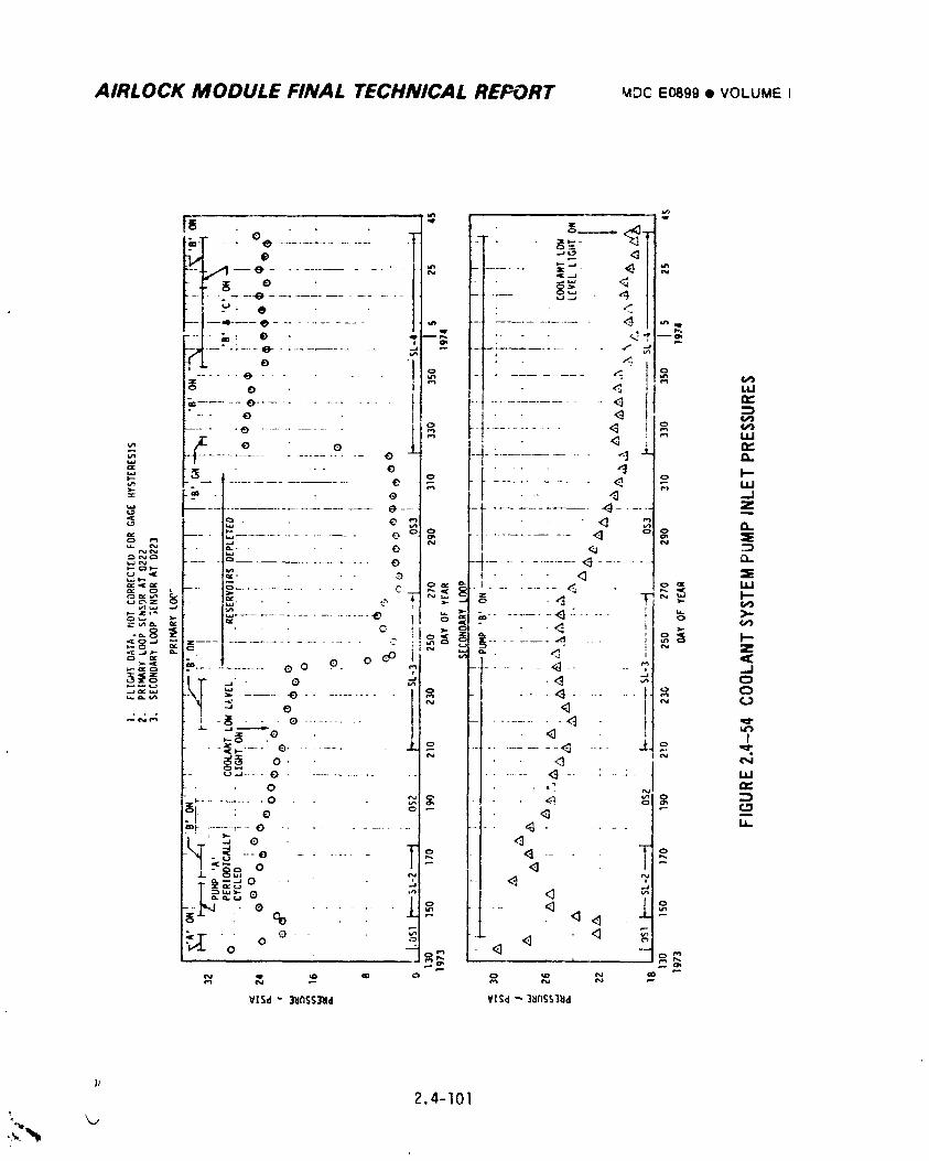
AIRLOCK MODULE FINAL TECHNICAL REPORT mDCE0899• VOLUMEI
II
2.4-101
1974018208-195
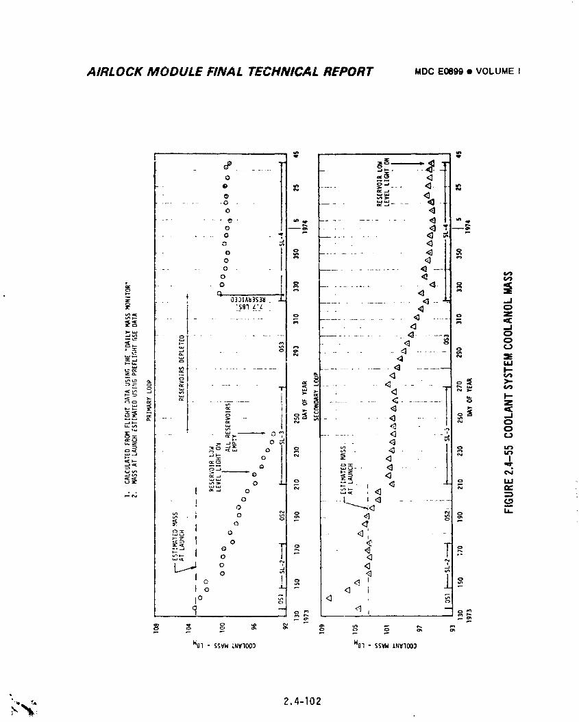
AIRLOCK MODULE FINAL TECHNICAL REPORT MDCE0899• VOLUMEI
o =_.__.-- e ¢ ..... o-.. <t. ¢
e "" <3
o <_....... _. - ............ <) 'i'
....... o _ g_,-° 10 ........ _ "=o
-" - oo .............. _ --- i
i ...............
" i}gl L'_z . --- <3 o
"_ I ......... o .,_u. ult_ .......................... '3 ....... I"
_,_ _ .... -_.... _ ........... <;........... _ I--
,o
_I o ur__W o _ _ "_ "" " _ <3 I
._ [ =.-' o w._ , _ i :_
o .... _L...._. !<i<II o ,'Z
w_ o _ _'
"_'- o _ <_ ""
o _o _
Io I1
o 4 _oI0 _ <_ _o
_ oo _ _, _ _ o_ _ _ _,
W@l - 5SVW LNVIO03 Nil - 5S_W INVlO03
"-,,_, 2.4-102
1974018208-196
AIRLOCK MODUL£ FINAL TECHNICAL REPORT MDCE0899m VOLUMEI
.rl_JrJerto _axi;nizethe probability of adequate coolant loop
(,pc,._tioJ_,procedures were developed and ground testing perfornmd
_o _r;vide a means nf extracting Coolanol from the backup refrig-
_.'ationloop in the OWS and introducing the fluid into the AM
p,i".,ryloop. _owever, such action was not required on SL-3 and
h6rJware _as prc_i_ed cn SL-4 along with applicable procedures to
perform the r'eservicingoperation. A discussion of the reservicing
may be found in Section 2.4.5.2(E).
B. Heat Loads - During the initial ten days of the mission, both the
active cooling system and passive temperature control system were
exposed to heat Inads well below design levels as a result of losing
the OWS meteroid shield and one solar array system wing during ascent,
the inability to successfully deploy the remaining wing, and an off-
nominal vehicle orientation. This situation resulted in delayed activa-
tion of AM power conditioning groups with the loss of battery module
waste heat, excessive heat leaks to abnormally cold structure obtained
with the pitch-up attitude being flown to minimize OWS temperatures,
and the obvious need to conserve electrical powpr. Throughout this
period, coolant flow through the radiator was at a minimum and
approached zero on several occasions. However, loop operation was main-
tdined by increasing heat loads via DCS commanding of instrumentation
system components when absol_tely necessary. Also, it was recommended
that p_rging of the cluster be accomplished with N2 _'atherthan 02 to
avoid unnecessary heat removal from tileloop via the 02 heat exchanger.
An _2 purge was performed. Testing on the ECS System Test Unit (STU)
indicated that the cluster could be pressurizedwith 02 in preparation
for the first manned mission if multiple pumps were operated to add heat
to the loop. The cluster was pressurized successfully with two pumps
operating in the secondary coolant loop.
Following SL-2 activation and return to solar inertial orientation,
coolant loop heat loads increased and normal external loads were
restored. Internal heat loads remained somewhat below design load levels
as a result of the lower battery module waste heat levels associated with
power inputs from only one OWS solar array wing instead of the normal
2.4-I03
1974018208-I97
AIRLOCK MODULE FINAL TECHNICAL REPORT _cc E0899• VOLUMEI
two as discus,ed in Paragraph 2.4.3.4. Total internal coolant loop
heat loads during the various mission phases are presented in Figure
2.4-56. Maximum loads approached II,000 Btu/hr dqring the period of
high Beta angles when three coolant pumps were operated near the end of
SL-4.
C. Heat Sink
(I) Ground Coolin_ - Operation of the AM primary and secondary coolant
loops for ,.re_aunch cooling was normal with freezing of the
thermal capacitors complete at approximately 14 hours prior t _
lift-off. After this time, coolant temperatures at the thermal
capacitor outlet remained between -7°F and -II°F until termination
of ground cooling approximately ten minutes prior to lift-off.
All other loop temperatures were nominal and well within redline
limits.
During ascent and prior to radiator cooldown during the initial
orbit, coolant temperatures were maintained at desired levels by
the thermal capacitors as shown in Figure 2.4-57. All temperature
control valves (TCV) remained in control throughout this period.
Capacitor skin temperatures during discharge and subsequent
refreezing are plotted in Figure 2.4-58.
(2) Radiator/Capacitor - Since heat loads were slightly lower than
anticipated, the full capability of the radiator/thermal capacitor
system was not required during normal operation with a solar
inertial vehicle orientation. Figure 2.4-59 through 2.4-61 pre-
sent typical inlet and outlet temperatures for a single orbit
during each of the manned missions. Data presented is for similar
heat loads, Beta angles and operating configuration. No signifi-
cant degradation is indicated although crew reports and D024
Experiment data have identified contamination and discoloration of
painted surfaces exposed to the sun. Although thermal capacitors
remained frozen, their heat sink effect on modulation of radiator
outlet temperatures can be seen in the above figures.
Maximum radiator outlet temperatures were obtained during those
periods when the vehicle was maneuvered out of the solar inertial
; 2,4-I04
i 9740i 8208-i 98
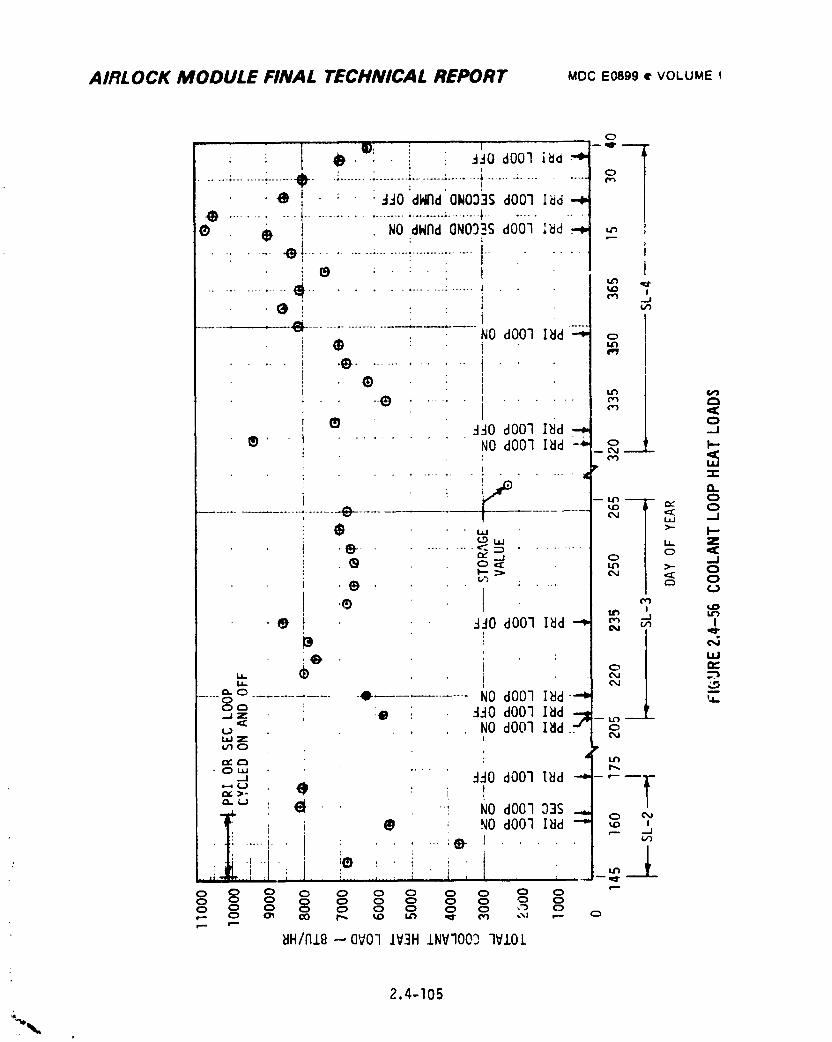
AIRLOCK MODULE FINAL TECHNICAL REPORT MDCE0899• VOLUMEt
o
t i
e* i.........e !......... I_';W_"ONOO_S:.,dOOq........_d _ --/
I
! ® : " : ' ' t.. , ..... ° ...... |
' i
/
® i
d_O dO07 I_d _
® ........... NO dO01 I_d °____I................ _ _
- 0
.........................-.e-.... I- -_ -- _ o
• e ii _o• • _o a00ni_d_ _ _ W
2" ,i .• _
.... _o ..... Z ..... 0 NO dO0] I_d "_ --" _dO dO07 I_d
, NO dOO3 lad_o
._ ....
_ : "" No dO0333Si _ ; NO dO03 I_d _ _ '
• _ ............ _ 1 ..... m
0 0 0 0 0 0 0 0 0 00 0 0 _ 0 0 0 0 0 ,_ 0
_H/NIg--QVO] IV3H INVqOO2 3V/OL
2.4-I05
w_
1974018208-199
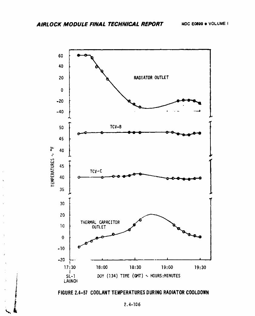
AIRLOCK MODULE FINAL TECHNICAL REPORT MDCEosgg• VOLUME I
i m i i
60
40
20
0
-20
-40 ' -"
50 TCV-B
45
i,.m.,, 40
_ 45F.-
TCV-C40 o • ''-''e'e "e''v - -
XwI,--
35
30
20
THERMALCAPACITOR =(_" "%,
o-10¢
-20 -- ' I I
17:30 18:00 18:30 19:00 19:30I
SL-I DOY (134)TIrE(@IT)_,HOURS:HINUTES
; i LAUNCH
FIGURE2.4-57 COOLANTTEMPERATURESDURINGRADIATORCOOLDOWN
1974018208-200
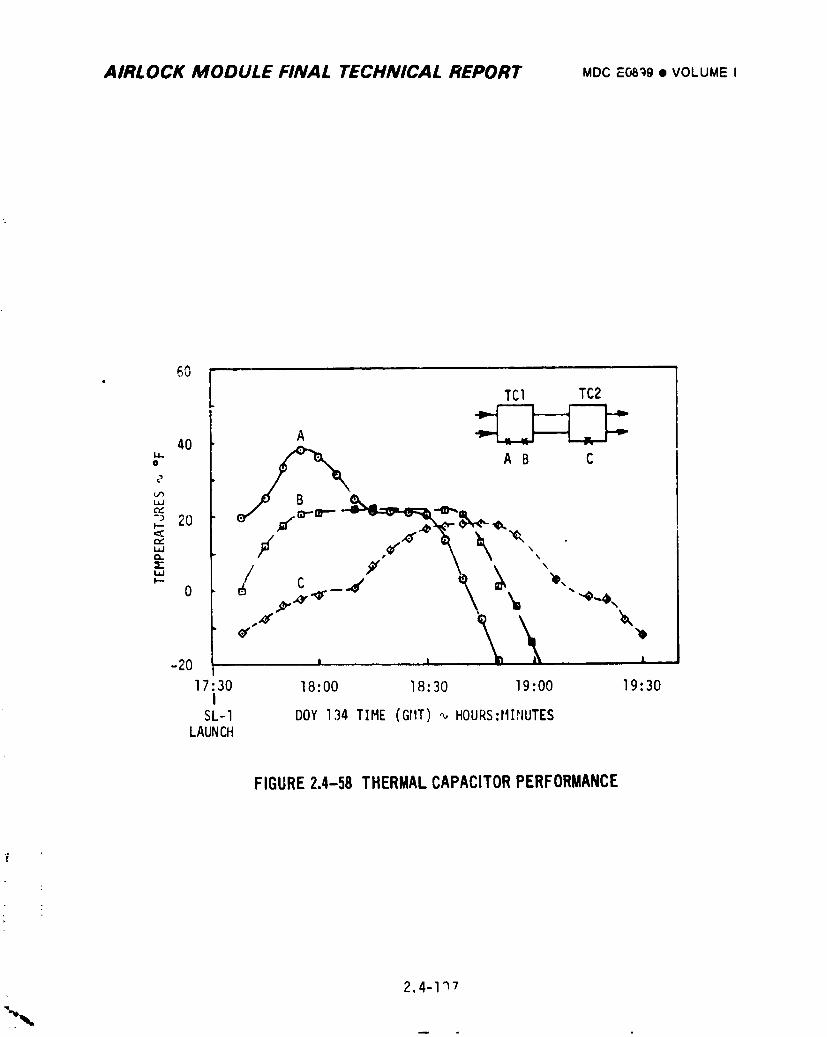
AIRLOCK MODULE FINAL TECHNICAL REPORT uoc EOB_@• VOLUMEI
6OTCl TC2
A _40
" m/" _,,,. A B C0
c"
-_'20 _.I'-"
0 ,e ._,.,_. -- -
-20 J ' •
17 30 18:00 18:30 19:00 19:30
SL-I DOY 134 TIME (GRIT),,,,HOURS:MI,"JUTESLAUNCH
FIGURE2.4-58 THERMALCAPACITORPERFORMANCE
2.4_i'_'7
i9740i8208-20i
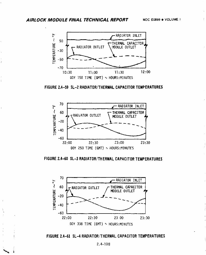
AIRLOCK MODULE FINAL TECHNICAL REPORT MDCEo899• VOLUME I :
RADIATORINLETo
5O_"-THERMALCAPACITOR
RADIATOROUTLET _40DULEOUTLET-30 _
,r,. ....,w--"-50 ....
-70
I0:30 ll:O0 II:30 12:00
DOY 158 TIME (GMT)_ HOURS:MINUTES
FIGURE2.4-59 SL-2RADIATOR/THERMALCAPACITORTEMPERATURES
70 j " 'oU" - , . , t"-RADIATORINLET
60 J _--THERMALCAPACITOR.
.,, T_ADIATOROUTLET \ M0_- ' DULEOUTLET a;,_ -20
• : -40I,J.IF'"
-60 ....22:00 22:30 23:O0 23:30
DOY250 TItlE (GMT) '_ HOURS:MINUTES
FIGURE2.4-60 SL-3RADIATOR/THERMALCAPACITORTEMPERATURES
70" i .r-"RADIATORINLET"0 __-- -- 11 ..
I 60 i_'RADIATOROUTLET /--THERMALCAPACITOR'" ' 7'\ / MODULEOUTLET
z -40
-60
22:00 22:30 23 O0 23:30
DOY338 TIME (Ggr) '_ HOURS:MINUTES
FIGURE2.4-61 SL-4RADIATOR/THERMALCAPACITORTEMPERATURES
2.4-I08
i 9740i 8208-202
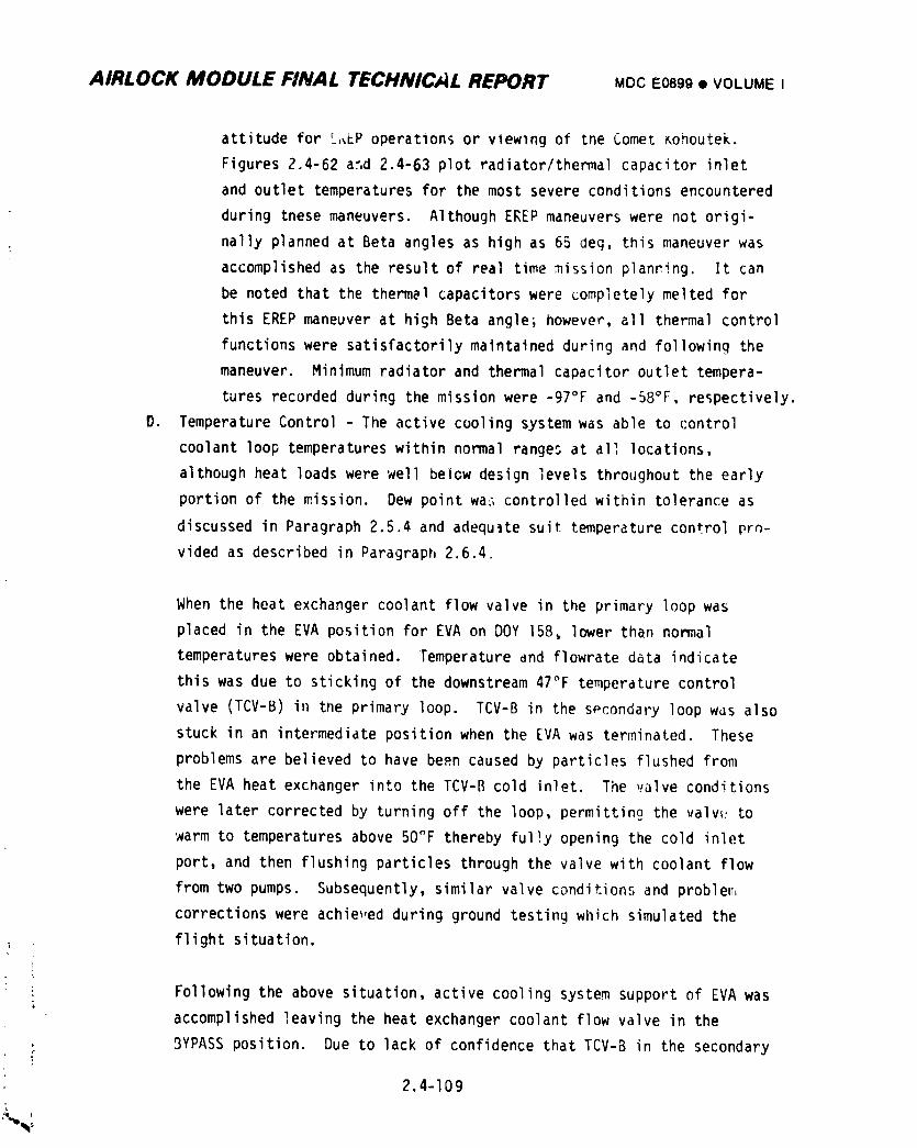
AIRI.OCK MODULE FINAL TECHNICAL REPORT MDCE0899• VOLUME I
attitude for L,,_Poperations or vlewlng of the Comet _ohoutek.
Figures 2.4-62 and 2.4-63 plot radiator/thermalcapacitor inlet
and outlet temperatures for the most severe conditions encountered
during these maneuvers. Although EREP maneuvers were not origi-
nally planned at Beta angles as high as 65 deg, this maneuver was
accomplished as the result of real time mission planting. It can
be noted that the thermal capacitors were completely melted for
this EREP maneuver at high Beta angle; however, all thermal control
functions were satisfactorilymaintained during and following the
maneuver. Minimum radiator and thermal capacitor outlet tempera-
tures recorded during the mission were -97°F and -58°F, respectively.
O. Temperature Control - The active cooling system was able to control
coolant loop temperatureswithin normal ranges at all locations,
although heat loads were well below design levels throughout the early
portion of the mission. Dew point wa_ controlled within tolerance as
discussed in Paragraph 2.5.4 and adequate suit temperature control pro-
vided as described in Paragraph 2.6.4.
When the heat exchanger coolant flow valve in the primary loop was
placed in the EVA position for EVA on DOY 158, lower than normal
temperatures were obtained. Temperature and flowrate data indicate
this was due to sticking of the downstream 47°F temperature control
valve (TCV-B) in the primary loop. TCV-B in the spcondary loop was also
stuck in an intermediate position when the EVA was terminated. These
problems are believed to have be_n caused by particles flushed from
the EVA heat exchanger into the TCV-B cold inlet. The valve conditions
were later corrected by turning off the loop, permitting the valw: to
warm to temperatures above 50_F thereby fu1!y opening the cold inlet
port, and then flushing particles through the valve with coolant flow
from two pumps. Subsequently, similar valve conditions and problem
corrections were achie_,edduring ground testing which simulated the
: flight situation.
: Following the above situation, active cooling system support of EVA was
accomplished leaving the heat exchanger coolant flow valve in the
3YPASS position. Due to lack of confidence that TCV-B in the secondary
2.4-I09i
1974018208-203
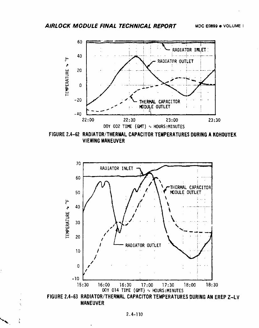
AIRLOCK MODULE FINAL TECHNICAL REPORT MDCE0899• VOLUMEI
: 'RADIATOR'INLET'.: t ; : :
(" DIA@
-20 J _ .I._ THERMALCAPACITOR " : "..-"" ,- . MODULEOUTLET _ . !
-_U - , ....... , , , ,, , , ,
22:O0 22:30 23: O0 23: 30
DOY 002 TIME (GMT),,,,HOURS:MItCUTES
FIGURE2.4-62 RADIATOR/THERMALCAPACITORTEMPERATURESDURINGA KOHOUTEKVIEWINGMANEUVER
0 - - - ;
60 /X,/_1"% : i "f V _ ^/f j,"_ Xz'THERMAL CAPACITOR
50 I X I V l ? _ MODULEOUTLET
,., 40 ........,,, Ir_
l.l.l I
DIAT R OUT ETI0 I :"
//
0 I :....,
/T
-lO .......... L...... i....
15:30 16:00 16:30 17:00 17:30 18"00 18:30
DOY 014 TIME (GIIT)_ HOURS:MINUTES
FIGURE2.4-63RADIATOR/THERMALCAPACITORTEMPERATURESDURINGANEREPZ-LV_ MANEUVER
2.4-110
1974018208-204
AIRLOCK MODULE FINAL TECHNICAL REPORT MDCE0899• VOLUMEI
loop was free of contamination, action was taken to avoid perturbing
the valve uf_til DOY233 when it anpeared to be modulating during a
checkout for EVA. However, TCV-B again stuck during EVA on DOY236
with am o,jtlet temperature of approximately 42°F. Ope_, "_ with TCV-B
in this condition was continued into SL-4 since out_"t temp_,,cures
were considered acceptable for normal operation. M_nimu_ TCV-_ outlet
temperature achieved during the colder orbit storage period was 40.1°F.
The TCV-B was observed to modulate properly when subjected to increased
temperdtures at the cold inlet port during EREPmaneuvers at high Beta
angles on SL-4. TCV-B operated normally after DOY019 for the remainder
of the mission.
E. In-flight Reservicing - The primary loop was serviced on DOY323 with
approximately 7./ pounds of Coolanol being added to the reservoirs per
the planned procedure in Section 2.4.3.2(E). Although gas leakage was
indicated during a leak check of the saddle valve installation, no leak-
age was observed during the subsequent Coolanol leak check. It was con-
cluded that gas leakage was in the leak test hook-up and servic;ng
proceded normally. Although leakage from the loop continued as shown in
Figure 2.4-55, further servicing was not required to complete the SL, 4
mission. Operation of the primary coolant loop was completely normal
following servicing.
2.4.5.3 ATM C&D Panel/EREP Cooling System
The ATM C&D Panel/EREP cooling system was operated satisfactorily throughout
all manned mission phases. Water temperatures of 52°F to 78°F and heat loads
between 200 and 1400 Btu/hr were nominal. Water flowrates were normally between
225 and 300 Ib/hr; however, periodic, short-duration decreases in flow below this
range were observed as described below. The filter in the loop was changed on
DOY149, 165:266 and 352 and three assemblies returned on SL-2 and SL-3 showed
no significant leveK of contaminants.
Following initial activation of the system on SL-2, water flow was observed
to cycle between 240 and 300 Ib/hr with a period near one minute for approximately
eight minutes. A relatively stable flow of 240 to 245 Ib/hr was then achieved.
Although this flc,,.'ate was well below the 293 Ib/hr level obtained during ground
2.4-111
1974018208-205
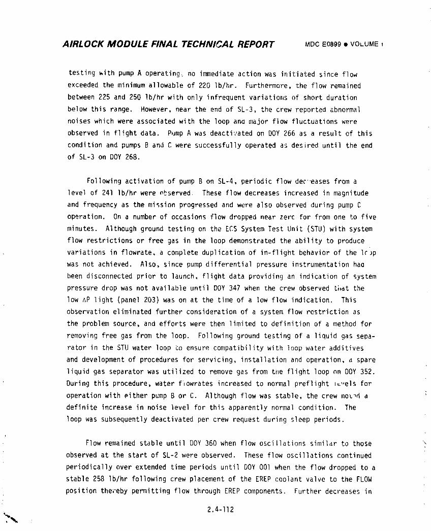
AIRLOCK MODULE FINAL TECHNICAL REPORT MDCE0899• VOLUME ,
testing with pump A operating_ no immediate action was initiated since flow
exceeded the minimum allowable of 220 Ib/hr. Furthermore, the flow remained
between 225 and 250 Ib/hr with only infrequent variations of short duration
below this range. However, near the end of SL-3, the crew reported abnormal
noises which were associated with the loop ana major flow fluctuations were
observed in flight data. Pump A was deactivated on DOY 266 as a result of this
condition and pumps B and C were successfully operated as desired until the end
of SL-3 on DOY 268.
Following activation of pump B on SL-4, periodic flow dec"eases from a
level of 241 Ib/hr were observed, These flow decreases increased in magnitude
and frequency as the mission progressed and were also observed during pump C
operation. On a number of occasions flow dropped near zerc for from one to five
minutes. Although ground testing on the ECS System Test Unit (STU) with system
flow restrictionsor free gas in the loop demonstrated the ability to produce
variations in flowrate, a complete duplication of in-flight behavior of the Ic)p
was not achieved. Also, since pump differential pressure instrumentationhaa
been disconnected prior to launch, flight data providing an indicationof system
pressure drop was not available until DOY 347 when the crew observed that the
low AP light (panel 203) was on at the time of a low flow indication. This
observation eliminated further consideration of a system flow restriction as
the problem source, and efforts were then limited to definition of a method for
removing free gas from the loop. Following ground testing of a liquid gas sepa-
rator in the STU water loop _o ensure compatibility with loop water additives
and development of procedures for servicing, installation and operation, a spare
liquid gas separator was utilized to remove gas from tim flight loop on DOY 352.
During this procedure, water f_owrates increased to normal preflight _t,,elsfor
operation with either pump B or C. Although flow was stable, the crew noL',da
definite increase in noise level for this apparently normal condition. The
loop was subsequently deactivated per crew request during sleep periods.
Flow remained stable until DOY360 when flow oscillations similar to those
observed at the start of SL-2 were observed. These flow oscillations continued
periodically over extended time periods until DOY001 when the flow dropped to a
stable 258 Ib/hr following crew placement of the EREPcoolant valve to the FLOW
position thereby permitting flow through EREPcomponents, Further decreases in
2.4-112
.%w
i 9740i 8208-206
AIRLOCK MODULE FINAL TECHNICAL REPORT MDCE0899• VOLUMEI
flow were observed on the following days and prompted a repeat of the gas removal
procedure on DOY004. Flow rates anain increased to normal levels as a result
of this ooeration. However, continued operation of the loop resulted again in
a flowrate degradation to 250-260 Ib/hr during the last several weeks of the
mission, producing the same symptoms caused by gas in the water loop. The
flight controllers elected not to attach the liquid/gos separator again for gas
removal, since the flowrates were above the minimum allowable of 220 Ib/hr
except for an occasional downward glitch. Pump A was reactivated on DOYO3S for
the first time since shutdown on DOY266. The pump operated properly, confirming
that it haa not failed during SL-3; the erratic flowrates instead being due to
g_s ir, the loop.
The most probable cause of gas in the loop was qeneration by electrolysis
from stray currents introduced by EREP tape recorders. Gas leakage from the
cabin into the water loop was unlikely since the cabin pressure was generally
less than the water reservoir pressure except for periods during M509 experiment
and cabin oxygen enrichment operations.
2.4.5.4 Battery Coolin 9
Coolant temperatures and flowrates to battery module coldplates were normal
throughout the mission. Temperature control valves upstream of battery modules
we'_e in control at all times except during IVA operations with suit cooling
system water flow and EREPmaneuvers at high Beta angles. During normal operation_
with the TCV's in control,coolant temperatures ranged between 36°F and 43°F, and
battery temperatures ranged from approximately 42°F to _8°F, as predicted. For
DOY014 EREPmaneuvers at high Beta anale, coolant inlet temperature reached
68.2°F and battery temperatures approached 60°F. System design changes made to
provide supplemental battery cooling permitted batteries to operate at desired
temperature levels at all times.
2.4.5.5 Integrated Temperature Control
Integrated temperature control of Airlock Module structure and noncoldplated
equipment was provided by normal operat;on of the active cooling system,
atmospheric control system and wall heaters in conjunction with thermal coatings,
\ curtains and insulation. Temperatures of all equipment and structure remained
within acceDtab_e limit _hrouqhout all phases of the mission.
2.4-I13
1974018208-207
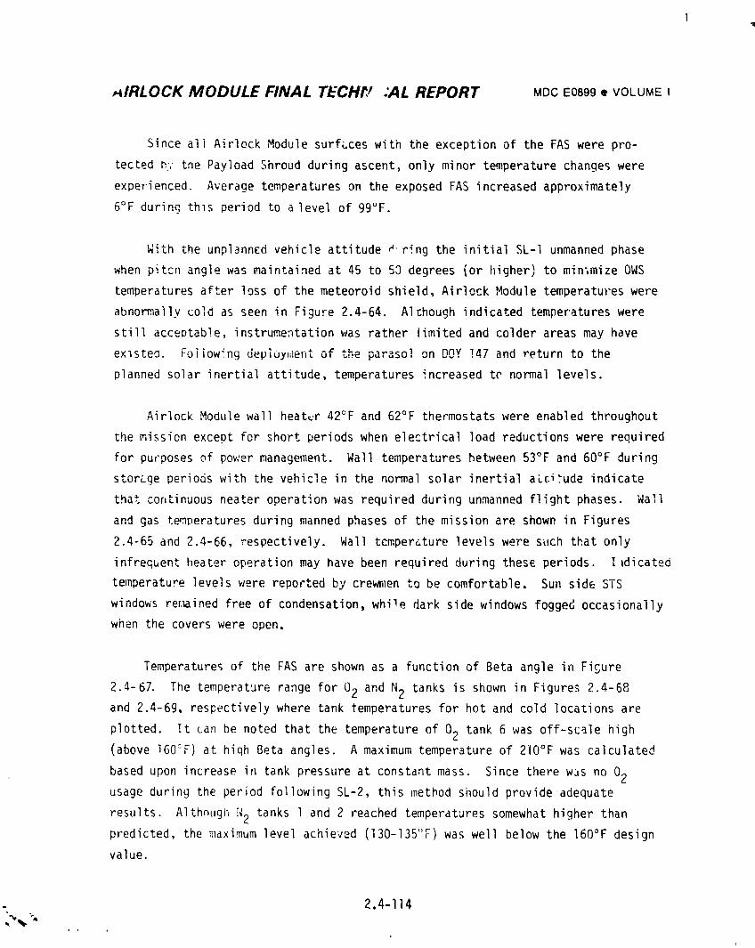
_IRLOCK MODULE FINAL TECH_P :AL REPORT MDCE0899• VOLUMEI
Since all Airlock Module surfaces with the exception of the FAS were pro-
tected _,'the Payload Shroud during ascent, only minor temperature changes were
expeTienced. Average temperatureson the exposed FAS increased approximately
6°F during thls period to alevel of 99°F.
With the unplanned vehicle attitude a, ring the initial SL-I unmanned phase
when pitcn angle was maintained at 45 to 50 degrees (or higher) to minlmize 0WS
temperatures after loss of the meteoroid shield, Airlock Module temperatures were
abnormally cold as seen in FiguFe 2.4-64. Although indicated temperatures were
still acceDtab!e, instrumentation was rather limited and colder areas may have
existed. Fo_owing d_ploy,ient of the parasol on DOY!47 and return to the
planned solar inertial attitude, temperatures increased tr normal levels.
Airlock Module wall heater 42°F and 62°F thermostatswere enabled throughout
the mission except for short periods when electrical load reductions were required
for purposes of power management. Wall temperatureshetween 53°F and 60°F during
storage periods with the vehicle in the normal solar inertial aLci_ude indicate
that continuousneater operation was required during unmanned flight phases. Wall
and gas temperaturesduring manned phases of the mission are shown in Figures
2.4-65 and 2.4-66, respectively. Wall tcmperature levels were such that only
infreGuent heater operation may have been required during thes_ periods. I1dicated
temperature levels were reported by crewmen to be comfortable. Sun side STS
windows retained free of condensation, while dark side windows fogged occasionally
when the covers were open.
Temperatures of the FAS are shown as a function of Beta angle in Figure
2.4-67. The temperature range for 02 and N2 tanks is shown in Figures 2.4-68and 2.4-69, respectively where tank temperatures for hot and cold locations are
plotted. It can be noted that the temperature of 02 tank 6 was off-scale high(above 160°F) at hiqh Beta angles. A maximum temperature of 210°F was calculated
based upon increase in tank pressure at constant mass. Since there wJs no 02usage during the period following SL-2, this method should provide adequate
results. Althnugl_ N2 tanks 1 and 2 reached temperatures somewhat higher than
predicted, the maximum level achieved (130-135_F) was well below the 160°F design
value.
.. 2.4-114
i
i9740i8208-208
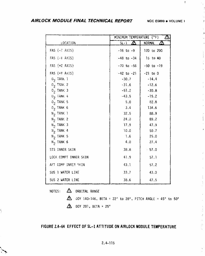
AIRLOCK MODULE FINAL TECHNICAL REPORT MDC E0899 • VOLUME I ,
" MINIMUM TEMPERATU-RE(°F)• , , ,, , ,
LOCATION SL-I _ NORMAL
FAS (-7 AXIS) -16 to -9 120 to 200
FAS (-Y AXIS) -48 to -34 15 to 40
FAS (+Z AXIS) -70 to -56 -50 to -19
FAS (+Y AXIS) -42 to -21 -21 to 0
02 TANK 1 -30.7 -]4.4
02 TANK 2 -31.6 -12.6
02 TANK 3 -51.2 -30.8
U2 iANK 4 -43.5 -15.2
02 TANK 5 5.0 82.8
02 TANK 6 3.4 13A.6
N2 TANK 1 32.5 88.9N_ TANK 2 24.0 89.2
N2 TANK 3 17.9 47.9
N2 TANK 4 I0.0 50.7
N2 TANK 5 1.6 25.0
N2 TANK6 4.0 27.4
STS INNER SKIN 38.8 57.0
LOCK COMPTINNER SKIN 41.9 57.1
AFT COMPINNE_ gKIN 43.1 57.2
SUS 1 WATERLINE 33.7 43.0
SUS 2 WATERLINE 38.6 47.5m
NOTES: Z_ ORBITAL RANGE
Z_ OOY 140-146, BETA = 22° to 28° , P!ICH ANGLE= 45° to 50°
/_ DOY 201, BETA = 25°'j
FIGURE2.4-64 EFFECTOF$L-1 ATTITUDEONAIRLOCKMODULETEMPEKATURE
2.4-115l
,_._-
1974018208-209
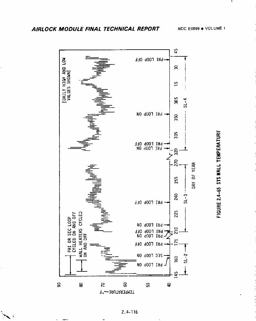
AIRLOCK MODULE FINAL TECHNICAL REPORT MDCEOSg9• VOLUMEI
| u3
"" ---- "l'JOdOOl ll_d---"
_ _j
____ -- NO dOOl I_d _
-- -JJOdO01 I_d _ "(
-- NO dOOl l_d _ o_-.-L ,.,
_ _j
=__ _ _
,_j N_JO dO0] I_d --" u_ uJ
- :] o•" 0 -J -'-" U.0 (.J --------.O_ >-
.-,__ _ NO dOOlIBd--,"0 f../'} --"
'"Z "_ _ "4-10 dO0] I_d-- ______L_U'IC) L_J"_-.,.,. NO dOOlI_dJ "
,,,,"r-._'_0 "_ _')
.J _:c_- _0 dOOl I_d -
,',(o N z --___ NO dOOl D3S__ 0 !-- _0 -.J
__ _ f./)
------, NO dOOlINd
-
-Io'--3_nlV_3dH31
". 2.4-I16
1974018208-210
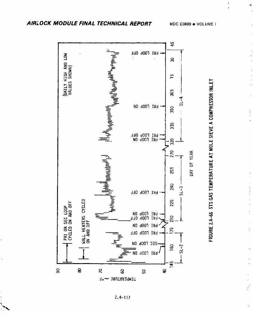
1
!
AIRLOCK MODULE FINAL TECHNICAL REPORT MDC _'0899 • VOLUMEI
m t i u | mw I iJr}
o
>-. LtJ ._-- _.j _
"- I ¢,#'b
NO dOOl I_d "-" o m
=_ f,_ •
-'-- N <:_. _ uJ
_ NO dOOl I_d-" _ _ _ _eo ._J
z" °
p-
LLI ,p-
"t:10 dOO1<Z
go_ - _ NO dOO] ,.0
__ ddO dOOl
,,,,__ _ 'NOdOO1 _ ":"uJ04oui, ,_-,_,_ _ ddO dOO] =}r,,, >.
- NO dO0"1 I_d
• _2
do_ 3_nlV'd3dW3,1.
2.4-117
1974018208-211
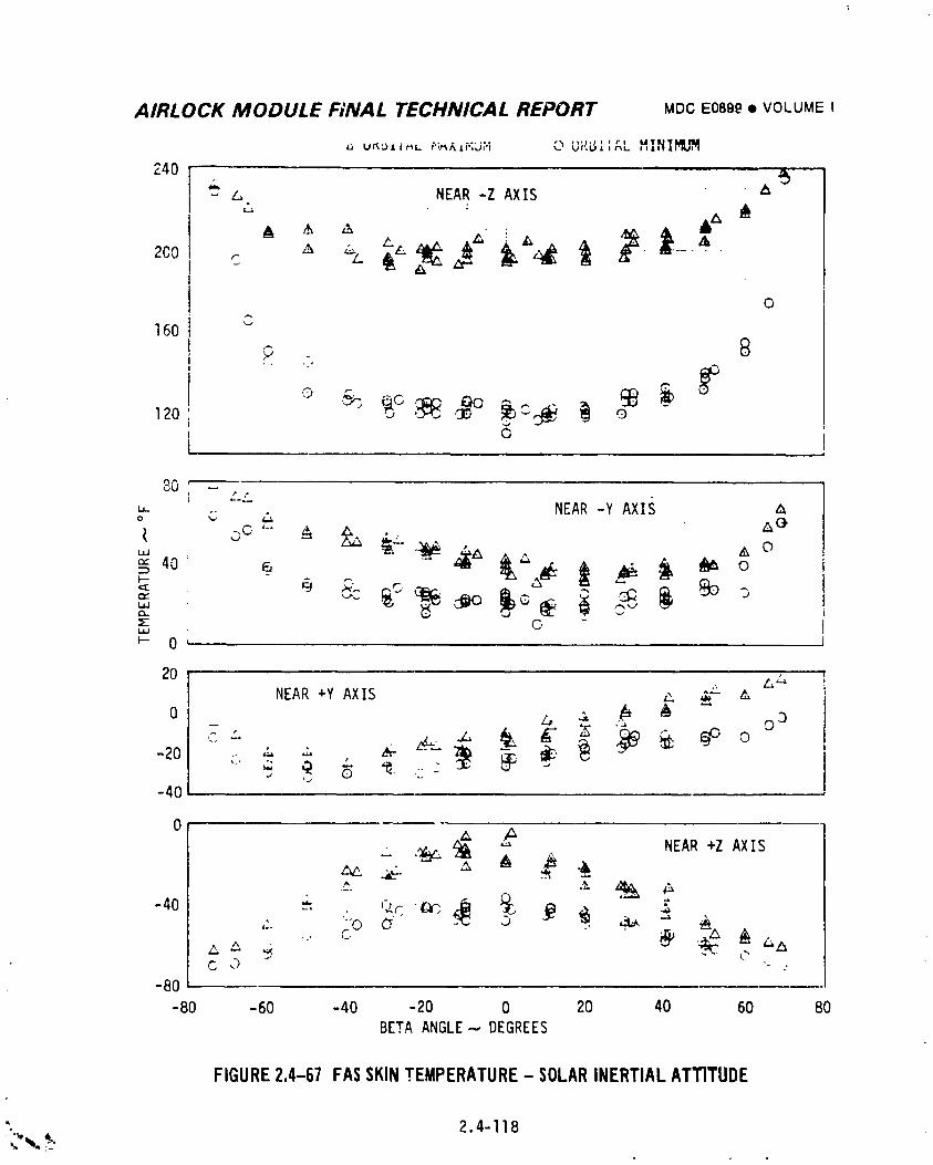
AIRLOCK MODULE F;NAL TECHNICAL REPORT MDCEO89g• VOLUMEIa_IlL n
L_ U_L)_t_L /"i_J.i";LJ;"i _J ur, GA ' r'jr_L MINI_I_J_
240 I '",', NEAR -Z AXIS "''_
! oA
160 I ""
120 'i
t _ ,
8G -2-.'.2
,-,- NEAR -Y AXIS Ao C
l.JJ
I-- 0 L ,
20 ,., L_NEAR +Y AXIS ,,,.,_-
0 _ z, ._ ,_ A o 3
_20
-40
0
, ._ _ _' NEAR+Z AXIS_- ._ ,_ • ±,_ __
C
-80
-80 -60 -40 -20 0 20 40 60 80BETA ANGLE.-,,.DEGREES
FIGURE2.4-67 FASSKINTEMPERATURE- SOLARINERTIALATTITUDE
". 2.4-I18,w%.,:_'
1974018208-212
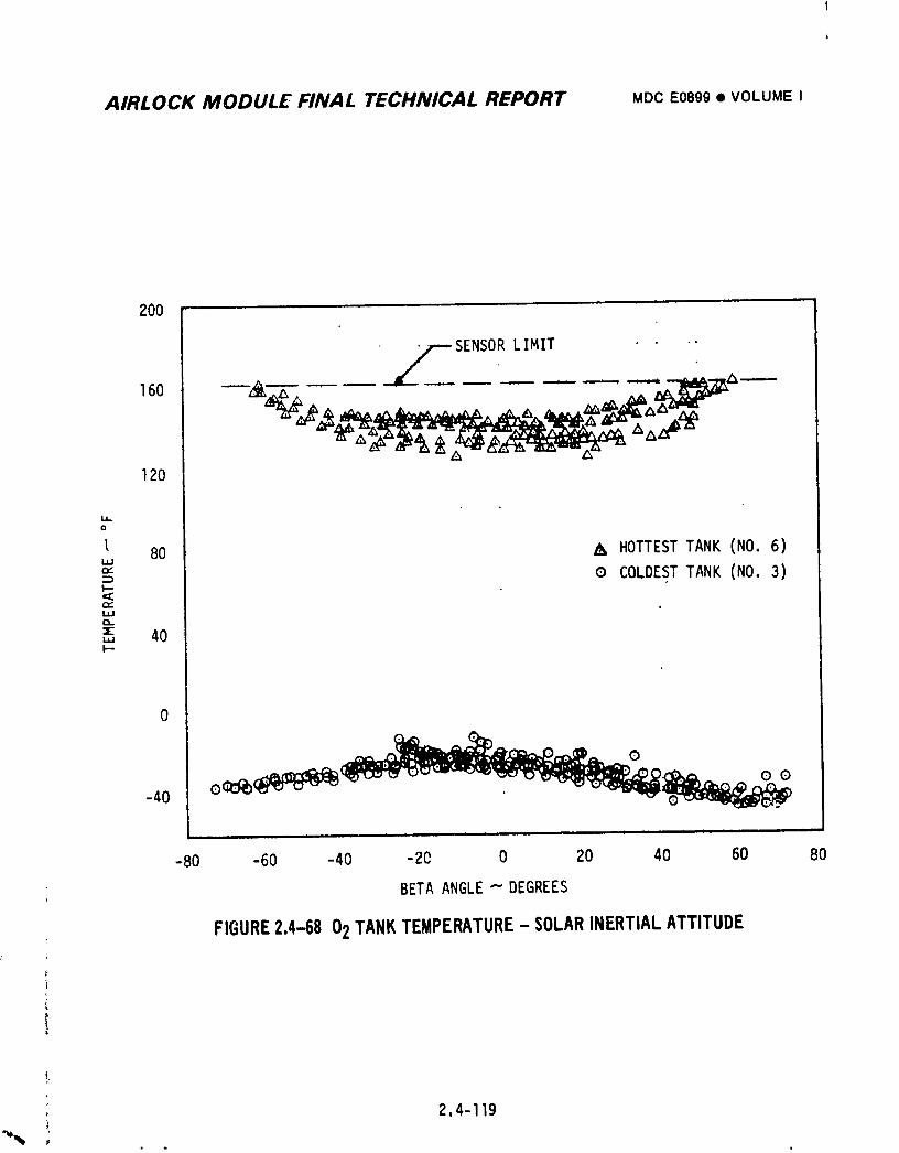
AIRLOCK MODULE FINAL TECHNICAL REPORT MOCE0899• VOLUMEI
200
• . o
SENSORLIMIT16o _.,A. --- -- --- --- ---- ___""̂_z_
120
0
80 _ HOTTESTTANK (NO.6)LIJ
0 COLDESTTANK (NO 3)
IJJ
,, 40
0
.,o_ i i i ill i i i i i i i L I i I =
-80 -60 -40 -20 0 20 40 60 80
BETAANGLE"-"DEGREES
FIGURE2.4-6802TANKTEMPERATURE- SOLARINERTIALATTITUDE
2.4-119
1974018208-213
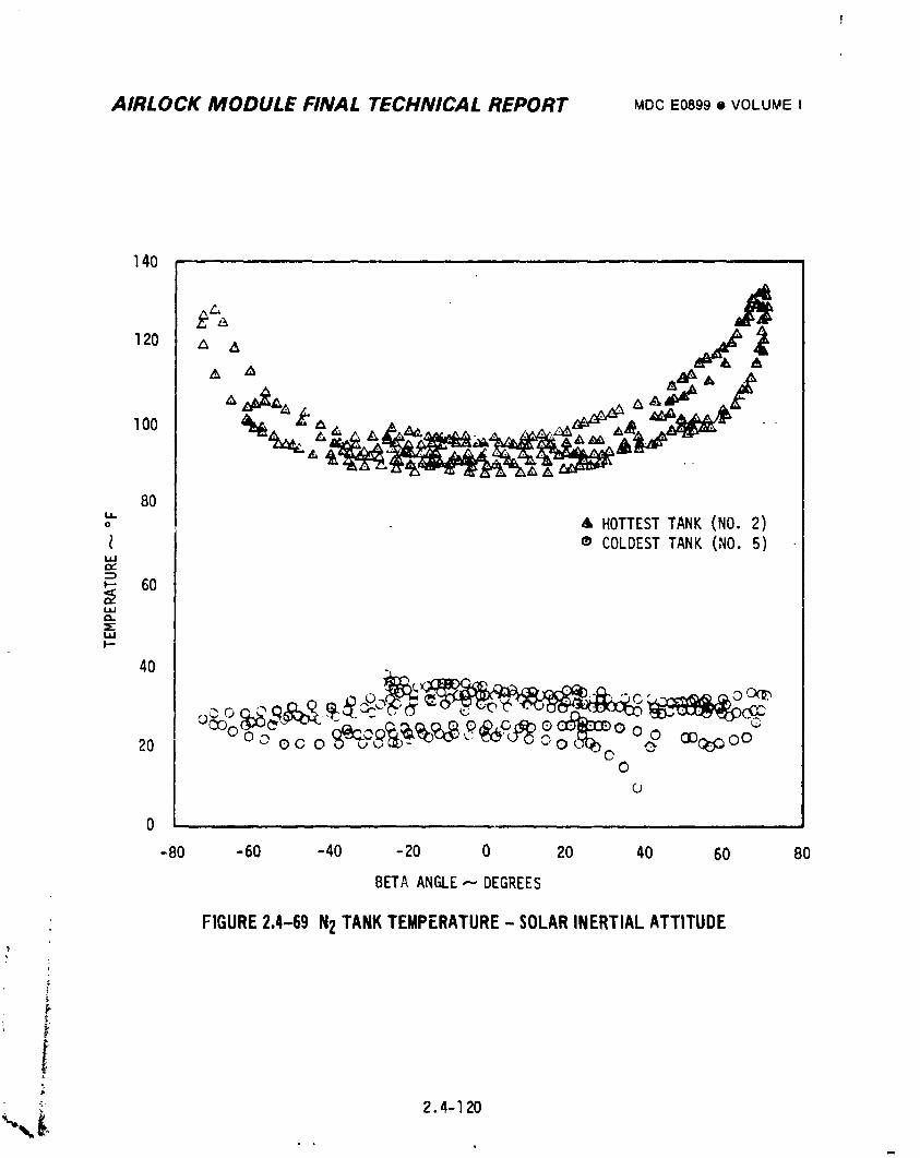
AIRLOCK MODULE FINAL TECHNICAL REPORT MDCE0899• VOLUMEI
140
120 A ,_
8(1i,
o ,LHOTTESTTANK (NO.2)® COLDESTTANK (NO.5)
Ia,J(XCZ_
,- 60W
40
,.,o._ _. .... c oO_.
0o
0 ,
-80 -60 -40 -20 0 20 40 60 80
BETAANGLE.---DEGREES
FIGURE2.4-69 N2TANKTEMPERATURE- SOLARINERTIALATTITUDE
t.,,'F
i _ 2.4-I20
1974018208-214
AIRLOCK MODULE FINAL TECHNICAL REPORT MDCE0899• VOLUMEI
2.4.5.6 Molecular Sieve Exhaust Duct and Condensate System Vent Heaters
Based on data available from limited instrumentation, molecular sieve duct
heaters BQintained temperatures well within desired levels. The only discrepancy
associated with Airlock Module heaters was reported on DOY 147 when the crew
failed to obtain an indication of temperature rise after condensate system heaters
on the secondary vent were activated. Although normal operation was indicated
with primary vent heaters, attempts to operate with the secondary vent were
later repeated and normal indications of heater operation were obtained. The
earlier difficulty was attributed to a display problem.
2.4.6 Development Preblems
Three development problems were experienced in the thermal control system.
An awarness of these may be of benefit to future programs.
2.4.6.1 Coolant System Temperature Control Stability
When the coolant system configuration was changed to meet the 46°F minlmum
dew point and supplemental battery cooling requirements, development tests were
conducted to determine system stability. These tests showed a stability problem.
Because of the short time available to develop a design which would provide con-
trol stability, a test approach was taken. The tests led to rearrangement of the
tubing interconnecting the suit cooling heat exchangers, the addition of a heat
exchanger bypass line with bleed orifice, and the addition of the EVA flow
selector valve.
The purpose of the rearrangement of interconnecting tubing was to isolate
thermally the hot and cold inlets to the downstream temperature control valve
(TCV-B) as much as possible without freezing the water. With the hot and cold
inlets coupled through additional heat exchangers, the time lag between TCV-B move-
ment and TCV-B outlet temperature change was larger. In addition, flowrate cycles
caused reversal in temperature of streams entering the hot and cold ports of TCV-B.i
k
=
2.4-121
1974018208-215
AIRLOCK MODULE FINAL TECHNICAL REPORT MDCE0899• VOLUMEI
The purpose of adding the cold bypass around the suit cooling heat exchangers
was to reduce the time lag between TCV-B movement and temperature control valve out-
let temperature change during suit cooling operation. The small amount of flow by-
passed had a negligible effect on suit cooling capacity.
The purpose of adding the flow selector val_e was to reduce the time lag between
TCV-B movement and TCV-B outlet temperature change when the cold port of TCV-B opened
during normal system operation. This was achieved by routing cold fluid to the cold
port of TCV-B and preventing warm fluid in the suit cooling heat exchangers from
entering the cold port. Before the selector valve was added, most of the time when
suit cooling was not utilized there was negligible coolant flowing through the cold
port of TCV-B. Consequently there was no coclant or water flow through the main
cooling heat exchanger and it approached a temperature equal to the surroundings.
Even a small flow of warm fluid into the cold port of TCV-B created some instability.
Use of the selector valve in accordance with procedures eliminated this instability.
2.4.6.2 Coolant System Thermal Capacitor Inteqrity
Because of uncertainties in both the method of fabricating a capacitor housing
containing isolated cells and the need for isolated cells, the cells in the original
design were interconnected and development tests were run to establish design adequacy.
The development and qualification performance simulation tests on the AM capacitor
were run for the expected range of temperature profiles with coolant flow through both
coldplate passages and no problems were encountered. However, tests conducted on a
similar container containing Undecane wax for use in the OWSrefrigeration system
resulted in bulges of the wax chamber side walls and cracking of the wall. After a
thorough investigation it was determined that one-passage coolant flow together with
large heat up rates could cause bulging and ultimately cracking of the wax chamber.
The capacitor housing was redesigned to provide isolated wax cells.
2.4.6.3 E_quipmentInsulation Vapor Barrier
During SST prelaunch U-l tests the Microfoil insulated lines exposed to the cold
ground coolant (Sugply and Return, FAS to GCHX) and the interfacing GCHX spacecraft
lines developed considerable water condensation which apparently penetrated the Micro-
foil vapor seal and caused a degradation in the insulation effectiveness. The insul-
ation on these lines was then redesigned to include a positive vapor seal.
; 2.4-122,_
1974018208-216
AIRLOCK MODULE FINAL TECHNICAL REPORT MDCE0899• VOLUMEI
2.4.7 Conclusions and Recommendations
The TCS performed so effectively that original mission objectives were
expanded and all mission obJectives were accomplished. Designed-in redundancies
and real-time work-around procedures were used to alleviate the effect of system
discrepancies that did occur. Consequently, it is recommended that, in general,
the Airlock Thermal Control System design and test concept, as well as system
hardware, be considered as the starting point for development of a future mission
system.
A more detailed discussion of conclusions and recommendations is glve_ below:
m System design requirements were realistic and should be used oF _the_
programs.
• The integrated thermal analysis was effective in establishing realistic
interface requirements and simplifyingthe vehicle design. It is
recommended that integrated thermal analysis be performed by the desig-
nated lead group which will provide detailed requirements to ocher groups
for use as basis for design of their systems.
• The AM temperature control concept which allocated cooling to the various
loads on a priority basis was proven and should be considered for future
programs.
• Radiator/thermal capacitor performance was outstanding - even during
ZLV maneuvers at much higher beta angles than originally planned. No
significant degradation was noted. These components are prime candidates
for future mission use.
• Thermal Control Valves (TCV) did jam due to loop contamination - several
changes are available to minimize this condition:
(1) Utilize inline filters and bypass relief valves more effectively.
(2) Redesign valves to reduce susceptibility to contamination.
(3) Improve loop cleanliness controls.
• Although both coolant systems exhibited leakage, no degradation of mission
occurred. The primary system was successfully reserviced by SL-4 crew.
Although type and location of leak could not be detcrmined,minimizing use
of mechanical fasteners would reduce a leak potential. Capability for
" reservicing coolant systems in orbit should be incorporated in systems
for future programs.
2.4-123
i
i9740i8208-2i7
t
AIRLOCK MODULE FINAL TECHNICAL REPORT MDCE089g• VOLUMEI
e ATM C&D/EREP cooling system flow became erratic late in SL-3 Mission.
Successful deaeration of loop, using liquid gas separator, temporarily
corrected flow oscillatioms. Fluid hydrolysis was the most probable cause
of gas in the loop. Better control of stray electrical currents is
needed on future programs.
• Battery temperatureswere maintained within the nnrmal range of 45° to 50°F.
This transient cooling concept should be considered for the next program.
e Thermal system verification concept of detailed thermal analysis plus
limited tests was proven. Components were qual tested but no vehicle
thermal qualification was performed.
; • Acceptable temperatureswere maintained c_ all passively cooled equipment
and structure. The use of coating, insul._ion and single layer thermal
: curtains should be considered for future space vehicles.C
_ 2.4-124 ._
i
1974018208-218
AIRLOCK MODULE FINAL TECHNICAL REPORT MDCE0899• VOLUMEI
2.5 ENVIRONMENTAL CONTROL SYSTEM
The environmental control system provided a habitable environment for the
Skylab crew. It consisted of an integrated array of systems and subsystems.
Included were subsystems for 02 and N2 gas storage, distribution and pressure
control, atmosphere cooling and circulation, CO2 a_d odor removal, atmospheri_
condensate removal and disposal, and in-flight water systems servicing.
2.5.1 Design Requirements
The basic requirements were to provide atmospheric composition, pressure, and
temperature control. In addition, interface requirementswere provided for the
Muttiple Docking Adapter, Orbital Workshop, Apollo Telescope Mount, Payload Shroud,
IU, Experiments, Thermal Control System, EVA/IVA, and GSE. The interface functions
are presented in Figure 2.5-I. Additional requirements associated with the
ECS design were to provide instrumentationintelligence and procedures as a basis
for system operation.
2.5.1.I Evolution
The AM ECS evolved with a minimum hardware development concept, utilizing
subsystem equipment previously developed, tested, and flown on the Gemini space-
craft. This minimum development _pproach was maintained where possible throughout
the program in the interest of austerity, but subsequent mission changes and new
program objectives dictated many design requirement changes. Evolution of the
overall Skylab Program is summarized in Section 2.1. The highlights of the
resultant effect of these dlanges on th _nvironmentalcontrol system requirements
and design are summarized as follows:
A. Gas System - The initial requirementswere to store and supply 02 at
sufficient quantities and flowrates for replenishment of atmospheric
leakage and metabolic consumption for three crewmen for a 30 day mission and
to provide 02 and H2 for the CSM fuel cell. Initially the cluster atmosphere
was to be 5 psia 02. To store th_ required 02 and H2, modified Gemini
02 and H2 cryogenic tanks were mounted on _M trusses. Thermostatically
: controlled calrod heaters, installed on the lines downstream of the
cryo tanks, warmed the gases supplied to the distribution system.
Gemini pressure regulators p,ovided 02 supply and pressure control.
' Later, the atmosphere was changed to an 02/N2 mixture at 5.0 psia total
pressure. N2 gas tanks, regulators, and manual controls were added to
the AM.: 2.5-I
i9740i8208-2i9
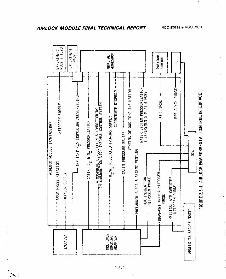
AIRLOCK MODULE FINAL TECHNICAL REPORT MDC E0899 • VOLUMEI
2.5-2
_%., ,
1974018208-220
AIRLOCK MODULE FINAL TECHNICAL REPORT MDC E0899 • VOL'JME I
As the Wet Workshop design rrogressed, both the cryo tan:<s _._,_dgas _anks
were rer_oved from AM. 02 anm _<2was then supplied from th - CSMfor a two gas
atmos,#here. 02 flowrates available f_om the CSM, however, were
insufficient for meeting EVA/IVA and M509/T020 experiments support
requirements. To meet the higher flowrate requirements, two high
pressure gaseous 02 tanks (LM descent tarks) as wall as 120 psig
and 240 psig 02 pressure regulators were added to the AM. The gaseQus
02 tanks were to be launci_ed pressurized to 2250 psia, and then, after
depressurization to below I000 psi by usage, were to serve asaccumulators.
The accumulators were to be charged with 02 delivered from the CSMto the
AM through an u_ilical. Gas in the "ccumulators was used to supplemen_
02 flowrates from the CSM. Tile N2 and 02 required for S-IVB purging and
initial pressurization was supplied from the CSMthrough the same uni_ilical.
The N2 ,equired for mainzenanr- of atmospheric pressure and 02/N 2
composition control was introduced in the CSM. Both initial pressurization
and 02/N 2 composition were _ccomp'lished by inflight manual controls.
Changeover to the Dry WorKshop with Saturn V booster permitted a large
allowable launch weight. Consequently direction was given te store all
02 and N2 supplies required for the Skylab mission onboard the AM.
Storage of the 02 and N2 as high pressure gases was selected over
c,Lvogenic sturage because of lower cost, lower development risks, ease
of servicing, and more operational flexibility for the multi-mission
Skylab program. Additional changes in design requirements which
reflected on the system design during this time are listed below:
(I) Requirement for DCScommand and onboard control of 02 and N2
flowrates for Skylab initial pressurization.
(2) Addition of an automatic two-gas (02/N 2) atmosphere control system.
(3) Requirement for supplying N2 to the OWSfor drinking water tank
pressurization and MI71 experiment.
(4) Requirement to supply N2 instead of 02 for mole sieve valve
actuation and water system reservoir pressurization.L
(5) Addi'_ion _f an N2 recharge station for in-flight servicing M509
N2 supply _anks.
2.5-3° ._ ¢,
i 9740i 8208-22i
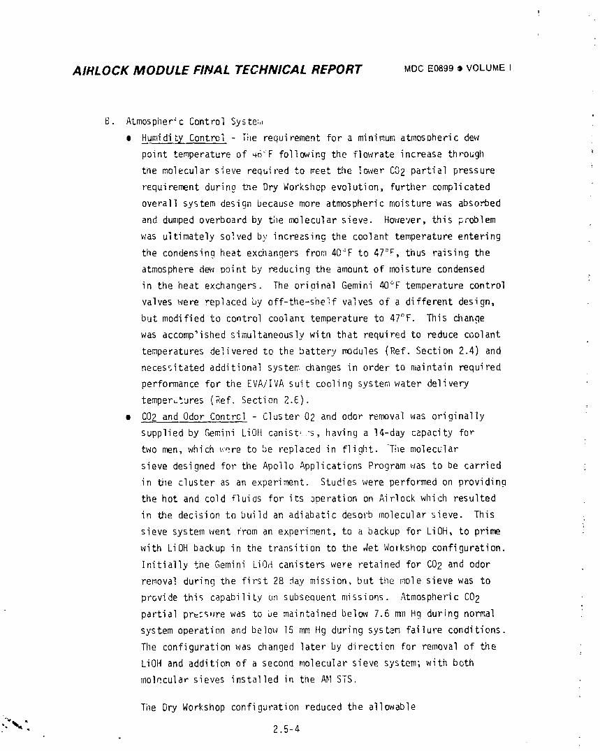
AIRLOCK MODULE FINAL TECHNICAL REPORT MDCE0899• VOLUMEI
l
B. Atmospheric Control System •
o Humidity Control Ti_e requirement for a minimum atmospheric dew
point temperature of _6"F following the flowrate increase through "_
the molecular sieve required to meet the lower C02 partial pressure
requirement durino the Dry Workshop evolution, further complicated
overall system design because more atmospheric moisture was abso_ed
and dumped overboard by the molecular sieve. However, this problem
was ultimately solved by increasing the coolant temperature entering
the condensing heat exchangers from 40_F to 47°F, thus raising the
atmosphere dew point by reducing the amount of moisture condensed
in the heat exchangers. The oriminal Gemini 40°F temperature control
valves were replaced by off-the-shelf valves of a different design,
but modified to control coolant temperature to 47°F. This change
was accomp'ished simultaneously witn that required to reduce coolant
temperatures delivered to the battery modules (Ref. Section 2.4) and
necessitated additional system changes in order to maintain required
performance for the EVA/IVA suit cooling system water delivery
temperatures (Ref. Section 2._).
e C02 and Odor Contrcl - Cluster 02 and odor removal was originally
supplied by Gemini LiOH canist, :s, having a 14-day capacity for
two men, which were to be replaced in flight. The molecular
sieve designed for the Apollo Applications Program was to be carried
in iu_e cluster as an experiment. Studies were performed on providing
the hot and cold fluids for its 3peration on Airlock which resulted
in the decision to build an adiabatic desorb molecular sieve This
sieve system went from an experiment, to a backup for LiOH, to prime
with LiOH backup in the transition to the _et WoYkshop configuration.
Initially the Gemini LiOH canisters were retained for C02 and odor
removal during the first 28 .day mission, but the mole sieve was to
provide this capability on subsequent missions. Atmospheric CO2
partial prof.s,ire was to be maintained below 7.6 nl_ Hg during normal
system operation and below 15 mmHg during system failure conditions.
The configuration was changed later by direction for removal of the
LiOH and addition of a second molecular sieve system; with both
molecular sieves installed in the AM STS.
Tile Dry Workshop configuration reduced the allowable
"_"_, 1 2.5-4
1974018208-222
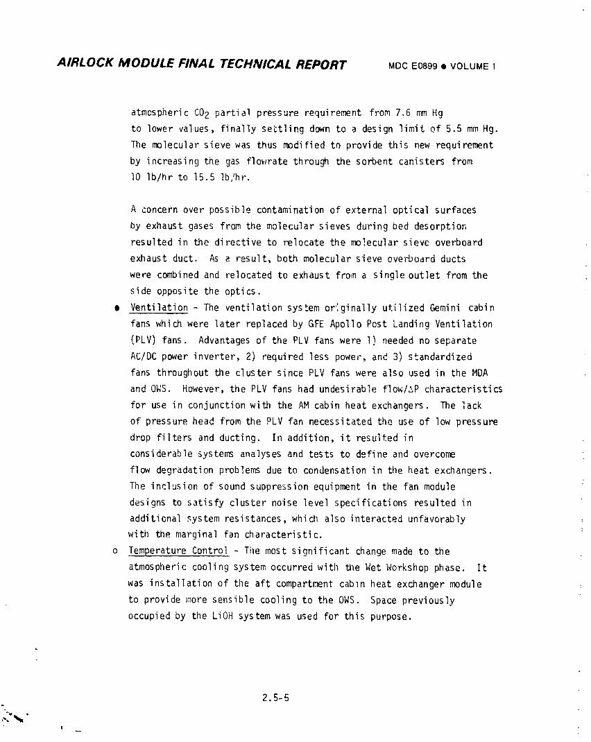
AIRLOCK MODULE FINAL TECHNICAL REPORT MDCE0899• VOLUMEI
atmospheric CO2 partial pressure requirement from 7.6 mmHg
to lower values, finally settling down to a design limit of 5.5 mmHg.
The molecular sieve was thus modified to provide this new requirement
by increasing the gas flowrate through the sorbent canisters from
I0 Ib/hr to 15.5 Ib/hr.
A concern over possible contamination of external optical surfaces
by exhaust gases from the molecular sieves during bed desorption
resulted in the directive to relocate the molecular sieve overboard
exhaust duct. As a result, both molecular sieve overboard ducts
were co_ined and relocated to exhaust from a single outlet from the
side opposite the optics.
o Ventilation - The ventilation system originally utilized Gemini cabin
fans which were later replaced by GFE Apollo Post Landing Ventilation
(PLV) fans. Advantages of the PLV fans were I) needed no separate
AC/DC power inverter, 2) required less power, and 3) standardized
fans throughout the cluster since PLV fans were also used in the MDA
and OWS. However, the PLV fans had undesirable flow/_P characteristics
for use in conjunction with the AM cabin heat exchangers. The lack
of pressure head from the PLV fan necessitated the use of low pressure
drop filters and ducting. In addition, it resulted in
considerable systems analyses and tests to define and overcome
flow degradation problems due to condensation in tile heat exchangers.
The inclusion of sound suppression equipment in the fan module
designs to satisfy cluster noise level specifications resulted in
additional system resistances, which also interacted unfavorably
with the marginal fan characteristic.
o Temperature Control - Tile most significant change made to the
atmospheric cooling system occurred with the Wet Workshop phase. It
was installation of tlle aft compartment cabin heat exchanger module
to provide more sensible cooling to the OWS. Space previously
occupied by the LiOH system was used for this purpose.
2.5-5
I
i 9740i 8208-223
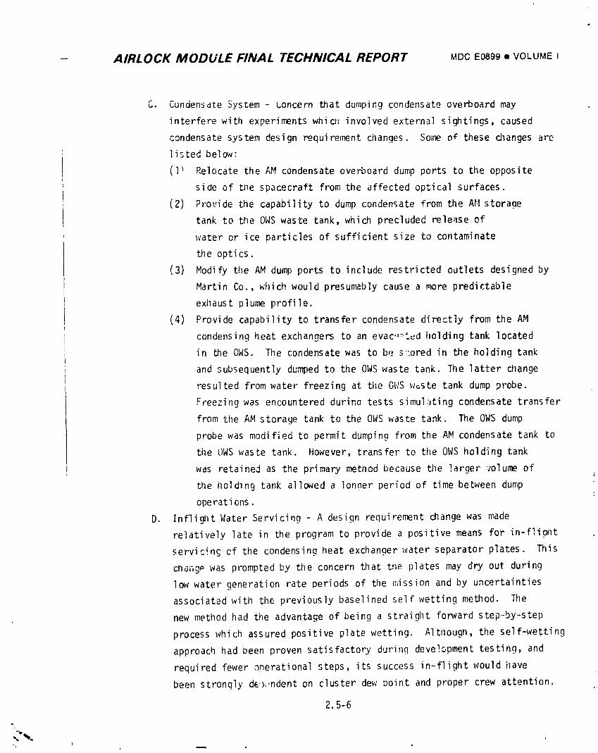
- AIRLOCK MODULE FINAL TECHNICAL REPORT MDCE0899o VOLUMEI
C. Cundensate System - concern that dumping condensate overboard may
interfere with experiments whic, involved external sightings, caused
condensate system design requirement changes. Some o_ these changes are
listed below:
(l _ Relocate the AM condensate overboard dump ports to the opposite
side of the spacecraft from the affected optical surfaces.
(2) Provide the capability to dump condensate from the AM storaae
tank to the OWSwaste tank, which precluded release of
water or ice particles of sufficient size to contaminate
the optics.
(3) Modify the AM dump ports to include restricted outlets designed by
Martin Co., which would presumably cause a more predictable
exhaust plume profile.
(4) Provide capability to transfer condensate directly from the AM
condensing heat exchangers to an evac.,=ted holding tank located
in the OWS. The condensate was to be s:ored in the holding tank
and subsequently dumped to the OWSwaste tank. Tile latter change
resulted from water freezing at the OWSw_ste tank dump probe.
Freezing was encountered durina tests simulating condensate transfer
from the AM storage tank to the OWSwaste tank. The OWSdump
probe was modified to permit dumping from the AM condensate tank to
tile OWSwaste tank. However, transfer to the OWSholding tank
was retained as the primary method because the larger volume of
the holding tank allowed a lonaer period of time between dump
operat ions.
D. Inflight Water Servicing - A design requirement change was made
relatively late in the program to provide a positive means for in-fliQht
servicing ef the condensing heat exchanger water separator plates. This
cllang_ was prompted by the concern that the plates may dry out during
low water generation rate periods of the mission and by uncertainties
associated with the previously baselined self wetting method. The
new method had the advantage of being a straight forward step--by-step
process which assured positive plate wetting. Although, the self-wetting
approach had been proven satisfactory during development testing, and
required fewer anerational steps, its success in-flight would have
been strongly de)_,ndent on cluster dew point and proper crew attention.
2.5-6
L.
i
i g740i 8208-224
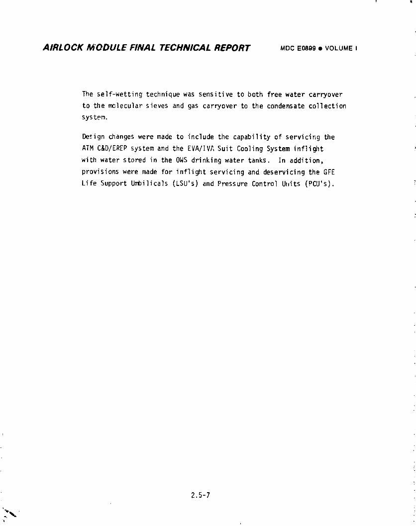
! I
AIRLOCK MODULE FINAL TECHNICAL REPORT MDCE0899• VOLUMEI
The self-wetting technique was sensitive to both free water carryover
to the molecular sieves and gas carryover to the condensate collection
system.
De_=ignchanges were made to include the capability of servicing the
ATM C&D/EREP system and the EVA/IVA Suit Cooling System inflight
with water stored in the 0WS drinking water tanks. In addition,
provisions were made for inflight servicing and deservicing the GFE
Life Support Umbilicals (LSU's) and Pressure Control Uhits (PCU's).
2.5-7
1974018208-225
AIRLOCK MODULE FINAL TECHNICAL REPORT MDCE0899• VOLUMEI
2.5.1.2 Flight Confiquration
Design requirements for the flight article are presented in tllissection.
A. Atmospheric Contrel - Atmospheric parameterswere pressure, humidity,
purity, ventilation, and temperature.
• Pressure
• Allow launch ascent venting and orbital pressurization/
depressurization.
• Provide remote pressurizationof AM/MDA/OWS with oxygen, nitrogen
or mixed gas for initial fill.
• Automatically maintain the minimum 02/N2 atmospheric pressure in
the _/MDA/OWS to 5 + 0.2 psia with PP02 of 3.6 + 0.3 psia after
activation.
• Provide on-board pressurization capability for redundancy.
e Limit the maximum atmospheric pressure to 6.0 psig after
activation.
• Provide the capability to maintain atmospheric pressure above
0.5 psia during orbit storage.
• Humidity
• Permit prelaunch purge for humidity control. :
• Provide proper humidity levels by removing metabolic moisture for
three men from the AM/MDA/OWS to bulk average dew point temperature
between 46°F and 60°F after activation. Dispose of condensate by
transferring to OWS holding tank or venting to space.
• Purity• Permit prelaunch purge of AM/MDA for purity control.
• Remove carbon dioxide and odors from the AH/MDA/OWS after
activation.
• Ventilation
• Permit prelaunch purge of AM/MDA for ventilation
¢ Provide circulation and atmospheric movement after activation.
• Temperature
e Permit prelaunch purge of AM/MDA for temperature control.
e Cool atmospheric temperature in AM between 60°F and 90°F after
activation.
¢ Provide atmospheric cooling for the MDA and the OWS.
.; 2.5-8
C%L
1974018208-226
AIRLOCK MODULE FINAL TECHNICAL REPORT MDCE0899• VOLUMEI
B. Sto_e and Supply Gases - Oxygen and nitrogen were stored and distributed
for various usages.
m Store oxygen and nitrogen in gaseous state.
• Provide oxygen and nitrogen for metabolic consumptiop and cabin
leakage.
m Provide oxygen for EVA/IVA support.
• Provide pressurized nitrogen supply for mole sieve operation.
• Provide nitrogen to the recharge station for Experiments M509 or TO20,
and to the OWS for water tank pressurization and Experiments Ml71 and
M092.
C. Provide In-flight Servicing/Deservicing- Provide in-flight servicing of
the water separator :-1_teassemblies, and water systems used in the
ATM C&D/_REP _nd EVA/IVA systems.
2.5.2 System DescriRtion
Fhe enviroPmental control system included several systems such as the gas
system, atmospheric control sw*-_ .;ndensatesystem, and the it-flight ,:_ter
servicing/deservici_ equipment.
2.5.2.1 Gas System
The gas system permitted prelauJ_cn purge and ascent venting, provided 02 and
N2 storage, pressure regulation, and gas distribution for in-orbi_ flight
operations. The gas system is shown schematically in Figure 2.5-2.
A. Preiaunch Purge - Prelaunch purging of the AM/MDAinternal atmosphere,
the Payload Shroud, and the MDAand OWSHigh Performance Insulation (HPI)
was provided to control gas composition, temperature and pressure through
launch preparation. Prelaunch purge interfaces and flowrate requirements
are shown in Figure 2.5-3. For launch, the AM/MDA internal atmosphere
i was purged with dry nitrogen gas until the oxygen content within the
compartments was less than 4%. The purge gas was introduced through the
I aft compartment purge fitting, GSE 413 (Figure 2.5-2) at a flowrate of
i I0 Ib/min maximum and exhausted through Government Furnished Equipment
(GFE) vent valves located in the MDA. The OWS was pressurized with GN2
andmaintained at a pressure level equal to, or greater than, the AM/MDA
pressure. During purging, AM/MDA pressure was sensed from the aft
2,5-9
(
i9740i8208-227
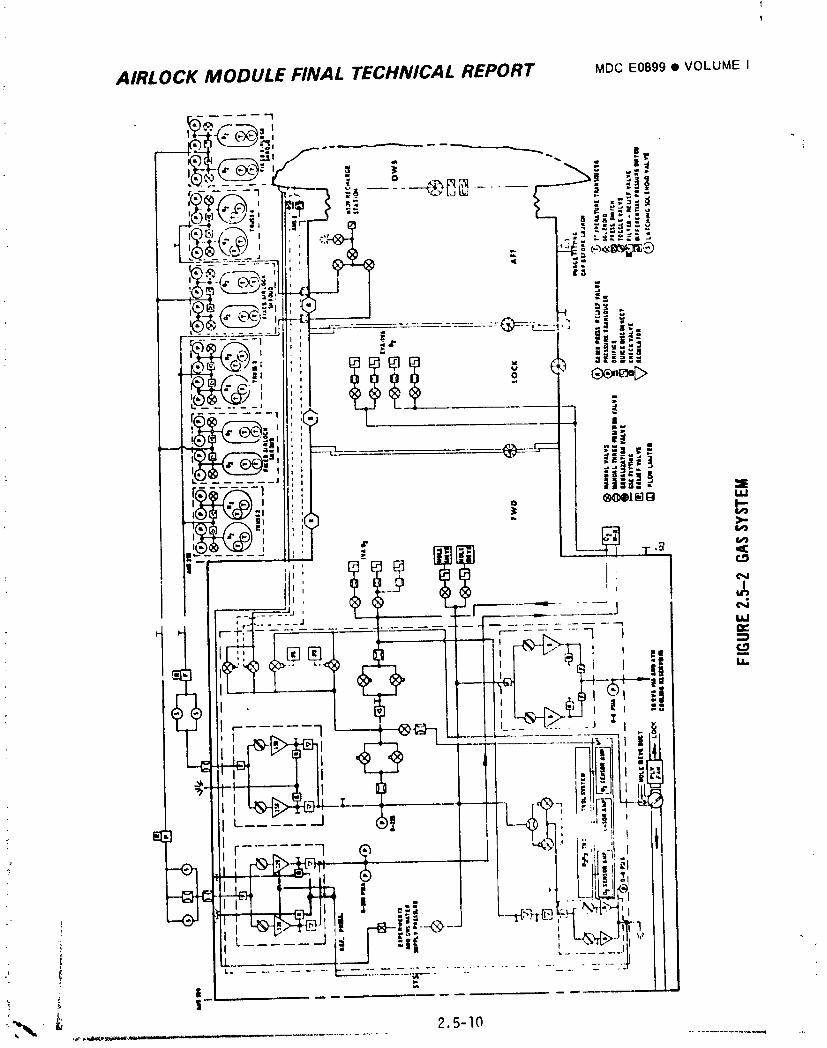
AIRLOCK MODULE FINAL TECHNICAL REPORT MDCE0899• VOLUMEI
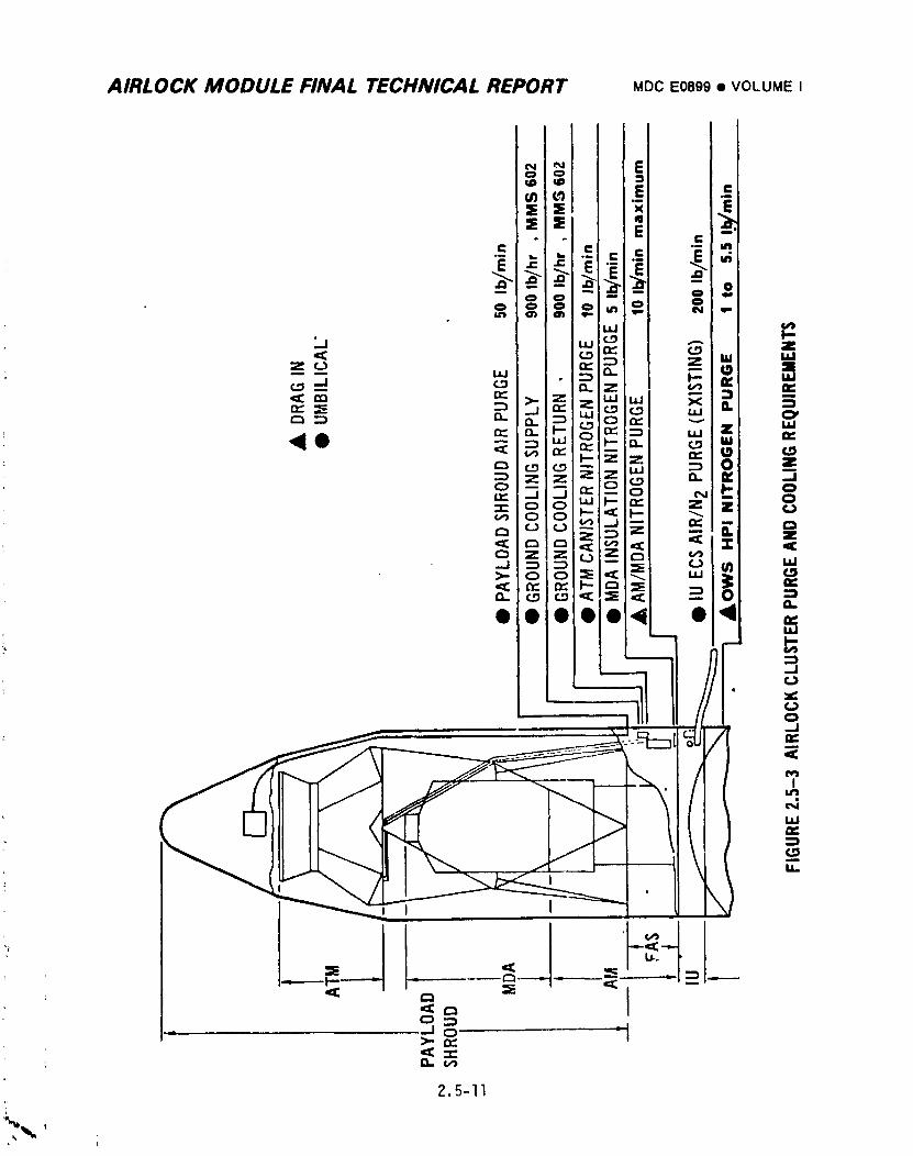
AIRLOCK MODULE FINAL TECHNICAL REPORT MDCE0899• VOLUME I
2.5-II
1974018208-229
AIRLOCK MODULE FINAL TEChlNICAL REPORT MDCE0899• VOLUMEI
compartmentmonitor fitting, GSE 412, and was limited to 6.2 psig by a GS;-
pressure sensing switch which, if actuated, would automatically stop :_tJr_;_
flow. Prelaunch purge time to reduce oxygen content to less than 4% wa':
determined during SST by gas composition sampling at MDA vent valves and
at the STS monitor fitting, GSE 523. Results of this test showed that
40 minutes was adequate with purge gas flow of 5.0 + 0.5 Ib/min and was
the basis for prelaunch purging criteria at KSC. The maximum allowable
depressurizationrate was 0.30 psi/sec. Gas from the OWS HPI purge was
vented through AM thermal curtain vents.
B. Launch Ascent Ventinq - Launch ascent venting of the AM/MDA was performed
through the MDA vent valves to prevent the cabin pressure differential
from exceeding 5.5 psid. The maximum allowable depressurlzation rate was
0.17 psi/sec. The MDA vent valves were closed automatically at a
preselected time during ascent by commands from the IU to maintain the
absolute pressure at or above 0.5 psia. After orbit insertion the OWS
was vented to a pressure of 0.5 psia minimum through vent valves by IU
command. The maximum allowable AM depressurizationrate from this venting
was O.lO psi/sec. Prior to launch, the volume between the STS window panes
was vented _.othe cabin; after crew arrival the window pane vents were
closed. The STS window controls are shown in Figure 2.5-4.
C. Gas Storage - Oxygen and nitrogen for all missions was stored in the
gaseous state and carried during initial launch. Design usable gas
quantities were based upon a pressure ra,ge of 3000 psig to 300 psig.
(1) Oxyqen - Oxygen was stored in six tanks contained in three modules
• mounted on the Fixed Airlock Shroud. Each tank had a fill valve, a
check valve, two temperature transducers, and two pressure trans-
ducers. The oxygen tanks shown in Figure 2.5-5 were constructed with
' a thick fiberglass_rap on a thin welded metallic liner. Each,was cylin-
drical shaped with elliptical ends and was 45 inches in diameter and
90 inches long. A minimum design total of 5,620 Ibs of oxygen was
required, of which 4,939 Ibs was to be usable at normal design
flowrates. As described in Section 2.5.4, a total of 6,085 Ibs was
the calculated quantity actually loaded. The margin above the
_ design value was included to account for instrumentation inaccuracies
at the time of servicing.
2.5-12
1974018208-230
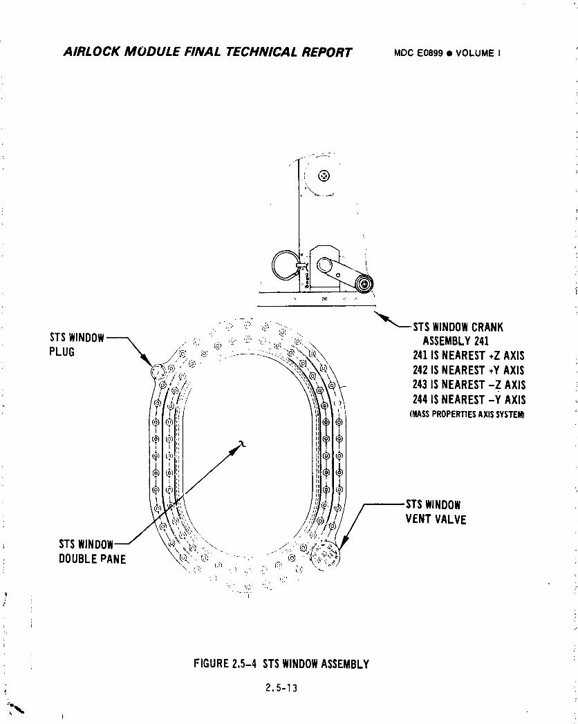
AIRLOCK MODULE FINAL TECHNICAL REPORT MDCE0899• VOLUMEI
i @
(
-.:i, -,',_';,_ _::. _ STSWINDOWCRANK
STSWINDOW'_ [ co.: ' '_',:_,t_"
,,-. :_....,.. ,.:_:., ASSEMBLY241PLUG /e ca_' ;f:-::_-_._.L_:'_' 241ISNEAREST+ZAXIS
(5 ./.i_i!;:,/ _<; 243ISNEAREST-Z AXIS
Ill/ _1_t 244ISNEAREST-Y AXIS;' I) (MASSPROPERTIESAXISSYSTEM)
!i/,, STSW,NOOW/ _,_;/ VENTVALVE
; STSWINDOWj _oi\'_:'_2-,,""-.. . ':__lgDOUBLEPANE _._",._: . -....,- "....:i__._-'{'_'_':
FIGURE2.5-4 STSWINDOWASSEMBLY
2.5-13
i
1974018208-231
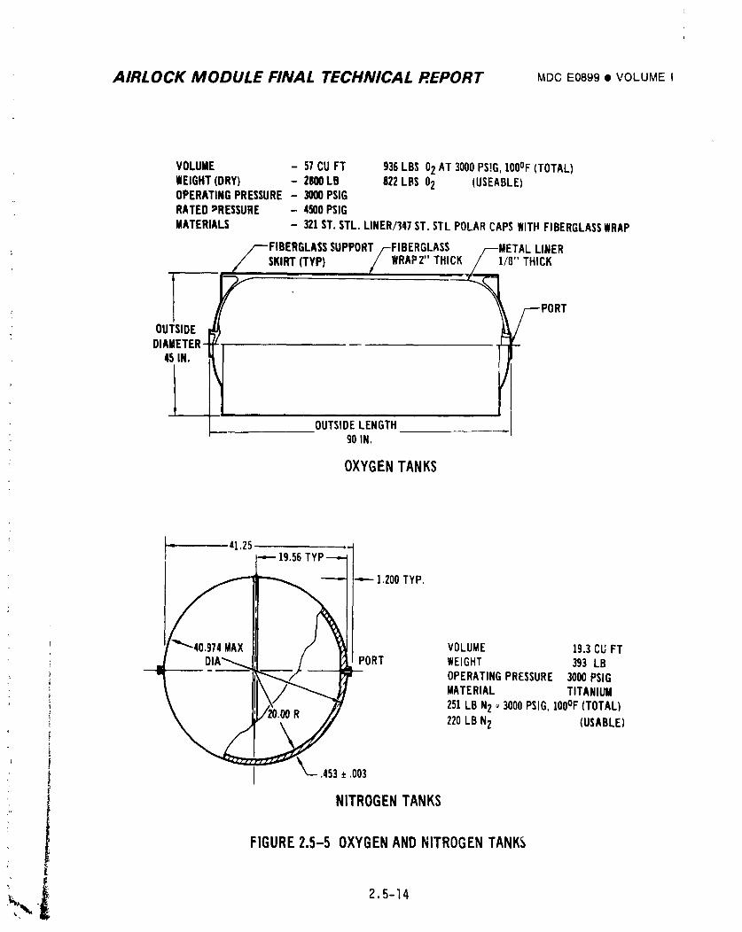
AIRLOCK MODULE FINAL TECHNICAL REPORT MDCE0899• VOLUMEI
VOLUME - 57CUFT 936LBS 02AT 3000PS!G,100OF(TOTAL)WEIGHT(DRY) - 2800LB 822LBS 02 (USEABLE)OPERATINGPRESSURE- 3000PSIGRATEDPRESSURE - 4500PSIG
MATERIALS - 321ST.STL. LINER/]47ST.STL POLARCAPSWITHFIBERGLASSWRAP
I _ /-DIAMETER_T_ --
_' OUTSIDELENGTH/ 90 IN.
OXYGENTANKS
41,25-- 19.56TYP--_=-
I
!--- ].200 TYP,
PORT WEIGHT 393 LBOPERATINGPRESSURE 3000PSIG
' MATERIAL TITANIUM
251LBN2 _3000PSIG,100°F(TOTAL)
220LB N2 (USABLE)
_-.453 ± .003
NITROGENTANKS
FIGURE2.5-5 OXYGENANDNITROGENTANKS
_",i 2.s-14
1974018208-232
AIRLOCK MODULE FINAL TECHNICAL REPORT MDCE0899t VOLUMEI
(2) Nitrogen - Nitrogen was stored in six tanks contained in three
modules mounted on the AM trusses. Each tank had a fill valve, a
check valve, two temperature transducers, and two pressure trar_s-
ducers. The nitrogen tanks were 40-inch diameter spheres constructed
of titanium (Figure 2.5-5). A minimum design total of 1,520 Ibs of
nitrogen was required of which 1,329 Ibs was usable at normal design
flowrates. The calculated quantity actually loaded was 1,623 Ibs.
Gas quantities were calculated by using tank volumes which were known
and gas temperatures and pressures which were measured. On-board
displays of temperature and pressure from each of the 02 and N2
storage tanks were provided on panel 225 (Figure _.5-6).
D. Gas Supply - The gas system provided flows of oxygen and nitrogen at
regulated pressure. The oxygen flow was used for initial pressurization,
the two-gas control system and EVA/iVA support and was regulated to
120 _lO psig. The nitrogen flow was used for initial pressurization,the
two-gas control system, molecular sieve valve actuation, water systems
reservoir pressurization,OWS water system pressurization, and experiment
support and was regulated to 150 _lO psig. Actual flowrates were a
function of demand within the limits of regulator maximum flowrate
capabilities. The design flow capacity of each of the two regulators
within both the oxygen and nitrogen regulator assemblies was 22.8 Ib/hr
for an inlet pressure range of 3000 to 300 psig.
Both oxygen and nitrogen supply gas pressures were controlled by pressure
regulator assemblies. Each assembly included an inlet filter, redundant
regulators, and relief valves. Lockup pressures for the supply regulator
assemblies were IA5 psig for the 02 assembly end 180 psig for the N2
assembly. Should a regulator fail open, the maximum downstream pressures
would have been limited to 170 psig oxygen and 210 psig nitrogen by the
pressure relief valves, The failed regulator could be isolated by a manual
upstream shutoff valve, The shutoff valve controls were located on
panel 225 (Figure 2.5-6).
2.5-15
i
1974018208-233
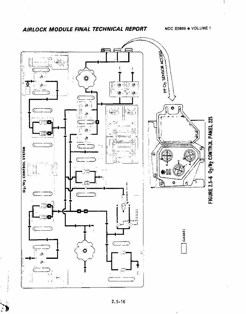
AIRLOCK MODULE FINAL TECHNICAL REPORT MDCE0899• VOLUME I
,-'+-j<--+--t,.... .'-'7 _..++._!++,+ItL
I F+++_,++I + ]..L._:._,,i,, !; _. !; _ , .--I I" _--
,'--u_<i'l!,t ,--:- _.:....i_r%:::._..:.:=:__ +,11J :_I I <_......... : I+i + + L,i_+-,-_ +" - o..
', . .:L_Fr-...." .O:fl ++t! {{_I ff_WilII I+iS ++ 'r ]_i ,+ - II - /i'_ ,111 +_,i.t.,_t_ i,._;, _.+r4-_,-: t_ll®_-°-,_tt,"P_.JJ//t!
." Ji "+"+_
I , --- , ii_
<
F ,e, I _i";-i'+ @_,
____i
i,i t,
" C-- ---_, , I ++.' I_ + i +
i ', _t.-<, _ i C +,t i +'1 --'i + . ,+,+
;. 2.5-16,+ ,
-:)
i974018208-234
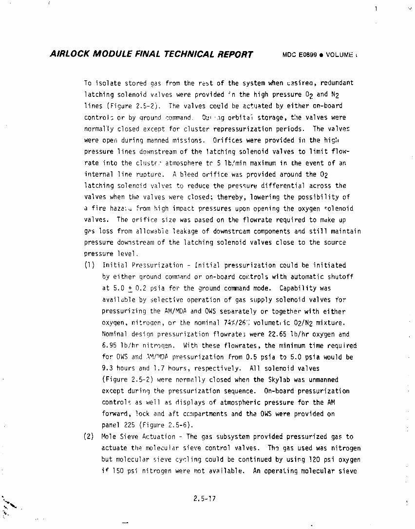
AIRLOCK MODULE FINAL TECHNICAL REPORT MDCE0899• VOLUME ,
To isolate stored gas from the rest of the system when _._sireo, redundant
latching solenoid valves were provided ;n the high pressure 02 and N2
lines (Figure 2.5-2). The valves could be actuated by either on-board
control; or by ground command Ou, ._g orbita_ storage, the valves were
normally closed except for cluster repressurization periods. The valves
were open during manned missions. Orifices were provided in the hig:,
pressure lines downstream of the latching solenoid valves to limit flow-
rate into the clust_." atmosphere tc 5 Ib/min maximum in the event of an
internal line rupture. A bleed orifice was provided around the 02
latching solenoid valves to reduce the pressure differential across the
valves when the valves were closed; thereby, lowering the possibility of
a fire haza;_ From high impact pressures upon opening the oxygen _olenoid
valves. The orifice size was based on the flowrate required to mdke up
g_s loss from allowable leakage of downstrcam components and still maintain
pressure downstream of the latching solenoid valves close to the scurce
pressure level.
(I) Initial Pressurization Initial pressurization could be initiated
by either ground commandor on-board cm:trols with automatic shutoff
at 5.0 + 0.2 psia fm" the ground commandmode. Capability was
availdble by selective operation of gas supply solenoid valves for
pressurizing the AM/MDAand OWSseparately or together with either
oxygen, nitrogen, or the nominal 74%/26% volumetlic 02/N2 mixture.
Nominal design pressurization flowrate_ were 22.65 Ib/hr oxygen and
6.95 Ib/hr nitroqen. With these flowrates, the minimum time required
for OWSand AM/MDApressurization From 0.5 psia to 5.0 psia would be
9.3 hours and 1.7 hours, respectively. All solenoid valves
(Figure 2.5-2) were normally closed when the Skylab was unmanned
except during the pressurization sequence. On-board pressurization
controls as well as displays of atmospheric pressure for the AM
forward, lock and aft ccmpartments and the OWSwere provided on
. panel 225 (Figure 2.5-6).
(2) Mole Sieve Actuation - The gas subsystem provided pressurized gas to
actuate the molecular sieve control valves. Th? gas used was nitrogen
but molecular sieve cycling could be continued by usi,g 120 psi oxygen
if 150 psi nitrogen were not available. An operating molecular sieve
_. 2.5-17
1974018208-235
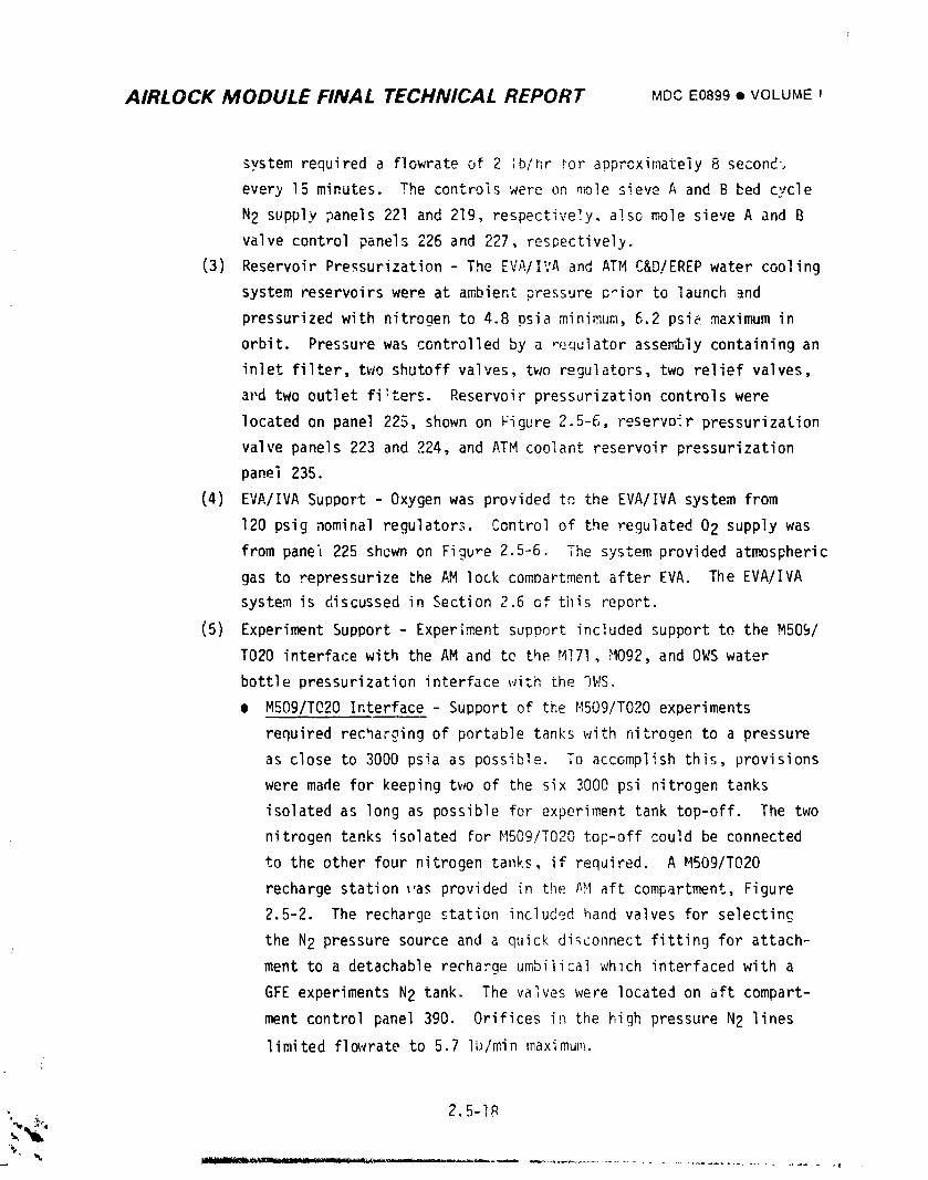
AIRLOCK MODULE FINAL TECHNICAL REPORT MDCE0899tl VOLUME I
system required a flowrate of 2 ;b/hr tor apprcximately 8 second',
every 15 minutes. The controls were on mole sieve A and B _ed cycle
N2 supply panels 221 and 219, respectively, also mole sieve A and B
valve control panels 226 and 227, res_ective]y.
(3) Reservoir Pressurization - The EVA/I:;A and ATM C&D/EREPwater cooling
system reservoirswere at ambient pressure _ior to launch and
pressurizedwith nitrogen to 4.8 psia minimum, 6.2 psie maximum in
orbit. Pressure was controlled by a _equlator assembly containing an
inlet filter, two shutoff valves, two regulators, two relief valves,
ai_dtwo outlet fi!ters. Reservoir pressurization controls were
located on panel 225, shown on Figure 2.5-6, reservoir pressurization
valve panels 223 and 224, and ATM coolant reservoir pressurization
panel 235.
(4) EVA/IVA Support - Oxygen was provided to the EVA/IVA system from
120 psig nominal regulator._.Control of the regulated 02 supply was
from pane= 225 shewn on Figure 2.5-6. The system provided atmospheric
gas to repressurize the AM lock comDartment after EVA. The EVA/IVA
system is discussed in Section 2.6 of tl}isreport.
(5) Experiment Support - Experiment support included support to the M509/
TO20 interfacewith the AM and tc the M!71, M092, and OWS water
bottle pressurization interface with the %fS.
• M509/T020 Interface - Support of the MSO9/T020 experiments
required recharging of portable tanks with nitrogen to a pressure
as close to 3000 psia as possible. To accomplish this, provisions
were made for keeping two of the six 3000 psi nitrogen tanks
isolated as long as possible foF experiment tank top-off. The two
nitrogen tanks isolated for M509/T020 top-off could be connected
to the other four nitrogen tanks, if required. A M509/T020
recharge station _as provided in the AM aft compartment, Figure
2.5-2. The recharge station included hand valves for selecting
the N2 pressure source and a quick disconnect fitting for attach-
ment to a detachable recharge umbilical whlch interfaced with a
GFE experiments N2 tank. The valves were located on aft compart-
ment control panel 390. Orifices in the high pressure N2 lines
limited flowrate to 5.7 Ib/min maximum.
, 2.5-IR
_.'_-_,.
,t
I
1974018208-236
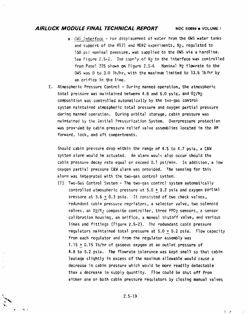
AIRLOCK MODULE FINAL TECHNICAL REPORT MDCE0899• VOLUMEI
GWS Interface- kor displacement ot water from the OWS water tanks
and suppcrt of the Hi7i and HD92 experiments, N2, regulated to
150 psi nominal pressure, was supplied to the OWS via a hardline.
See Figure 2.5-2. Tne supply of N2 to the interface was controlled
from Pane_,225 shown on Figure 2.5-6 Nominal N2 flowrate to the
OWS was 0 to 3.0 Ib/hr, with the maximum limited to 13.5 Ib/hr by
an orifice in the line.
E. Atmospheric Pressure Control - During manned operation, the atmospheric
total pressure was maintained between 4.8 and 6.0 psia, and 02/N2
composition was controlled automaticallyby the two-gas control
system maintained atmospheric total pressure and oxygen partial pressure
during manned operation. During orbital storage, cabin pressure was
maintained _" _-uy _,,= inltial Pressurization System. Overpressure protection
was prowded by cabin pressure relief valve assemblies located in the AM
forward, lock, and aft compartments.
Should cabin pressure drop within the range of 4.5 to 4.7 psia, a C&W
system alarm would be actuated. An alarm would also occur should the
cabin pressure decay rate equal or exceed O.l psi/min. In addition, a low
oxygen partial pressure C&W alarm was provided. The sensing for this
alarm was integratedwith the two-gas control system.
(1) Two-Gas Control System - The two-gas contrcl system automatically
controlled atmospheric pressure at 5.0 + 0.2 psia and oxygen partialq
pressure at 3.6 + 0.3 psia. It consisted of two check valves,
redundant cabin pressure regulators, a selector valve, two solenoid
valves, an 02/N2 composite controller, three PPO2 sensors, a sensor
calibration housing, an orifice, a manual shutoff valve, and various
lines and fittings (Figure 2.5-2). The redundant cabin pressure
regulators maintained total pressure at 5.0 _0.2 psia. Flow capacity
from each regulator and from the regulator assembly was
1.15 _ 0.15 Ib/hr of gaseous oxygen at an outlet pressure of
4.8 to 5.2 psia. The flowrate tolerance was kept small so thai:cabin
leakage slightly in excess of the maximum allowable would cause a
decrease in cabin pressure which would be more readily detectable
than a decrease in suppiy quantity. Flow could be shut off from
either one or both cabin pressure requlators by closing manual valves
". 2.5-19
1974018208-237
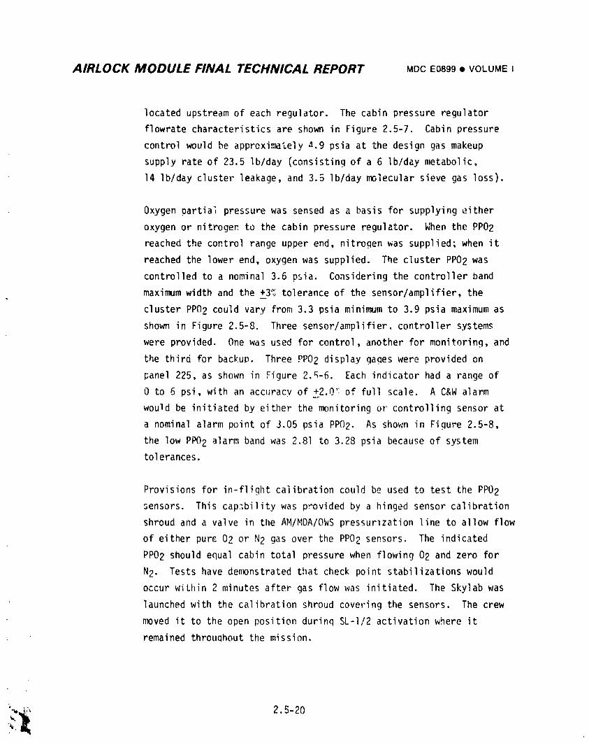
AIRLOCK MODULE FINAL TECHNICAL REPORT MDCE0899• VOLUMEI
located upstream of each regu|ator. The cabin pressure regulator
flowrate characteristicsare shown in Figure 2.5-7. Cabin pressure
control would be approximately a.9 psia at the design gas makeup
supply rate of 23.5 Ib/day (consistingof a 6 Ib/day metabolic,
14 Ib/day cluster leakage, and 3.5 Ib/day molecular sieve gas loss).
Oxygen partial pressure was sensed as a basis for supplying either
oxygen or nitrogen to the cabin pressure regulator. When the PP02
reached the control range upper end, nitrogen was supplied; when it
reached the lower end, oxygen was supplied. The cluster PP02 was
controlled to a nominal 3.6 psia. Considering the controller band
maximum width and the +3% tolerance of the sensor/amplifier,the
cluster PPO2 could vary from 3.3 psia minimum to 3.9 psia maximum as
shown in Figure 2.5-8. Three sensor/amplifier,controller systems
were provided. One was used for control, another for monitoring, and
the third for backup. Three PP02 display gages were provided on
panel 225, as shown in Figure 2._-6. Each indicator had a range of
0 to 6 psi, with an accuracy of +2.0':of full scale. A C&W alarm
would be initiated by either the monitoring or controlling sensor at
a nominal alarm point of J.05 psia PP02. As shown in Figure 2.5-8,
the low PPO2 alarm band was 2.81 to 3.28 psia because of system
tolerances.
Provisions for in-flight calibration could be used to test the PPO2
sensors. This capability was provided by a hinged sensor calibration
shroud and a valve in tlleAM/MDA/OWS pressumzation line to allow flow
of either pure 02 or N2 gas over the PPO2 sensors. The indicated
PPO2 should equal cabin total pressure when flowing 02 and zero for
N2. Tests have demonstrated that check point stabilizationswould
occur wiLhin 2 minutes after gas flow was initiated. The Skylab was
launched with the calibration shroud covering the sensors. The crew
nmved it to the open position durinq SL-I/2 activation where it
remained throuQhout the mission.
'_,_;, 2.5-20
"l
1974018208-238
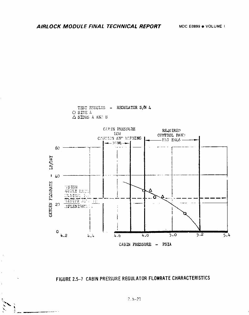
AIRLOCK MODULE FINAL TECHNICAL REPORT MDCE0899• VOLUMEI
T_T P_F6ULTS - REGULATOR S/N0 SIDE A
A SID.'_."A AN7,B
C;.VIN PI_SE,'LE REQUIREDlOW CO_PJOL PAW3
C; ;TT,'N AN;" W.'.PNII_C = F,.7 EgA6
60 .................
O. 'm i
- II
I AO ......... -_....
[--,
"" 'Ui:i_LY PJ' """ I":'k U!:'IE; _'''" Z_
2.o ,}YLENISH:'.:" .
0 _ II "
4.2 4.4 4.b 4.O 5.0 ,.2 5.4
CABIN PRESSUP_E - PSIA
FIGURE2.5-7 CABINPRESSUREREGULATORFLOWRATECHARACTERISTICS
,_, 2.5-21
1974018208-239
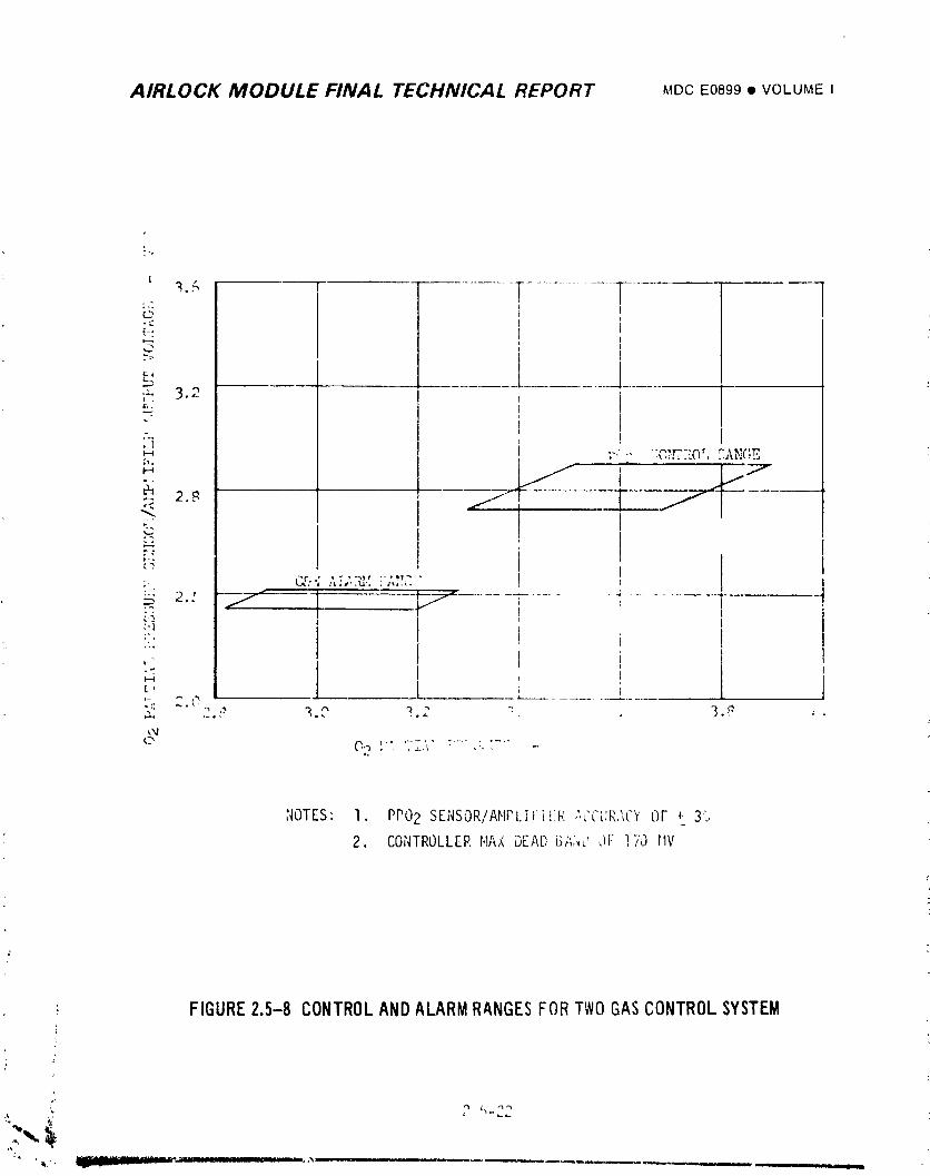
AIRLOCK MODULE FINAL TECHNICAL REPORT MDCE0899• VOLUMEI
r
' "_." -T..................1c,, I t"::. 1 i12-: ! i,,.._, l
F_
,: 3.2
,]:',-- ":O,,xrTToLF.AN(":E
_ 2._ _, 'i _
;- Or= A_L.N'.'. :',V"'.,.,.
_,i;'o i
D-
I--4
12,
'.-..: 2. t_ ' -
J.
NOTES: I. PPO2 SENSOR/Ar,IPI.iFii:R ;'.CC_.:R.",CYOF + 3%
2. CONTROLLERHAX DEAl.)i31;;.,:.'JF !7,.) rIv
: FIGURE2.5-8CONTROLAND ALARM RANGESFOR TWO GASCONTROL SYSTEM
.k
iXi
1974018208-240
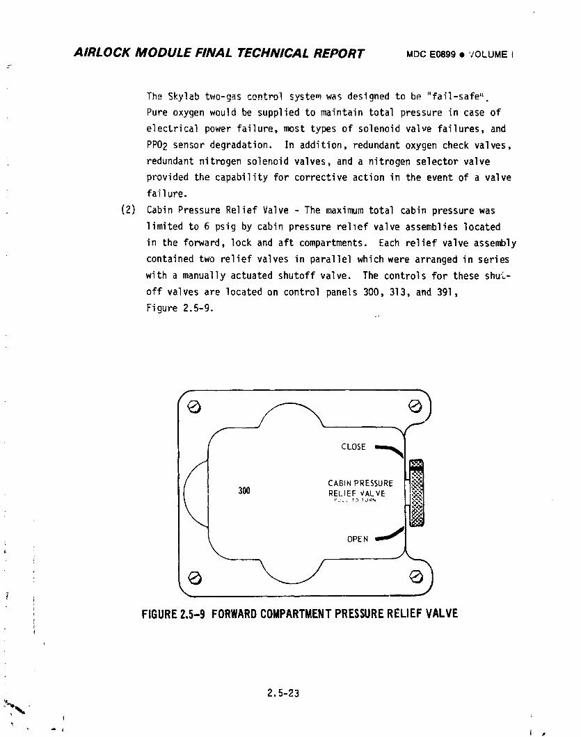
AIRLOCK MODULE FINAL TECHNICAL REPORT MDCE0899,VOLUME I
The Skylab two-gas control system was designed to be "fail-safe".
Pure oxygen would be supplied to maintain total pressure in case of
electrical power failure, most types of solenoid valve failures, and
PP02 sensor degradation. In addition, redundant oxygen check valves,
redundant nitrogen solenoid valves, and a nitrogen selector valve
provided the capability for corrective action in the event of a valve
failure.
(2) Cabin Pressure Relief Valve - The maximum total cabin pressure was
limited to 6 psig by cabin pressure rellef valve assemblies located
in the forward, lock and aft compartments. Each relief valve assembly
contained two relief valves in parallel which were arranged in series
with a manually actuated shutoff valve. The controls for these shut-
off valves are located on control panels 300, 313, and 391,
Figure 2.5-9.
fI CLOSE
A/ ! CAB,.PRESSURE
300 RELIEF VALVE
PU, L ?O _'URN
OPEN
FIGURE2.5-9 FORWARDCOMPARTMENTPRESSURERELIEFVALVE
2.5-23.%
I
!
1974018208-241
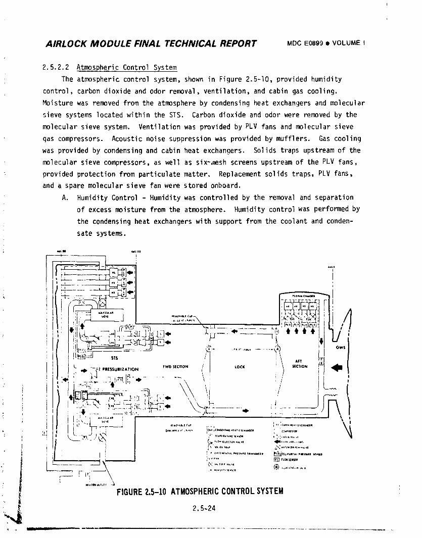
AIRLOCK MODULE FINAL TECHNICAL REPORT MDCE0899• VOLUMEI
2.5.2.2 Atmospheric Control System
The atmospheric control system, shown in Figure 2.5-10, provided humidity
control, carbon dioxide and odor removal, ventilation, and cabin gas cooling.
Moisture was removed from the atmosphere by condensing heat exchangers and molecular
sieve systems located within the STS. Carbon dioxide and odor were removed by the
molecular sieve system. Ventilationwas provided by PLV fans and molecular sieve
qas compressors. Acoustic noise suppression was provided by mufflers. Gas cooling
was provided by condensing and cabin heat exchangers. Solids traps upstream of the
molecular sieve compressors, as well as six-,neshscreens upstream of the PLV fans,
provided protection from particulate matter. Replacement solids traps, PLV fans,
and a spare molecular sieve fan were stored onboard.
A. Humidity Control - Humidity was controlled by the removal and separation
of excess moisture from the atmosphere. Humidity controlwas performed by
the condensing heat exchangers with support from the coolant and conden-+
sate systems.i
Nmti _i I$_
i}if.cL_ZL--J_,+ . ::'+,:'.,":::.\+!t _ - C"'t -_ . ._1:lEt g t_j {tj _, '_ I-T--_+,+_.._ __
t "' /t .... (\ ,,,
' FW' '|CTION / LOCK /// LY\ '[¢"ON ,' /_
$ --_| PIE$$UIIZATION i I
T :t', J ...., r . _
|'+ ""r -r _j ........... . _, I,,_................"-t T I,,,,w....,,,,' .',..,. to,, ,_:o,,,m.,.,+,,m.,,,, _,_,,,,,,m+. " 'I' _.,: j ,k-4 . ..........
+, 1.__i iI_N+,i_ Pal_q! Iii_i+_,ci Ii t_._ip?.++l,l+lltl_+ll,NI?,Ulll wW_Oll
[-!,. :.................. ® ..............',.
i+ FIGURE?.5-10ATMOSPHERICCONTROLSYSTEM
i',_. 2.5-24
1974018208-242
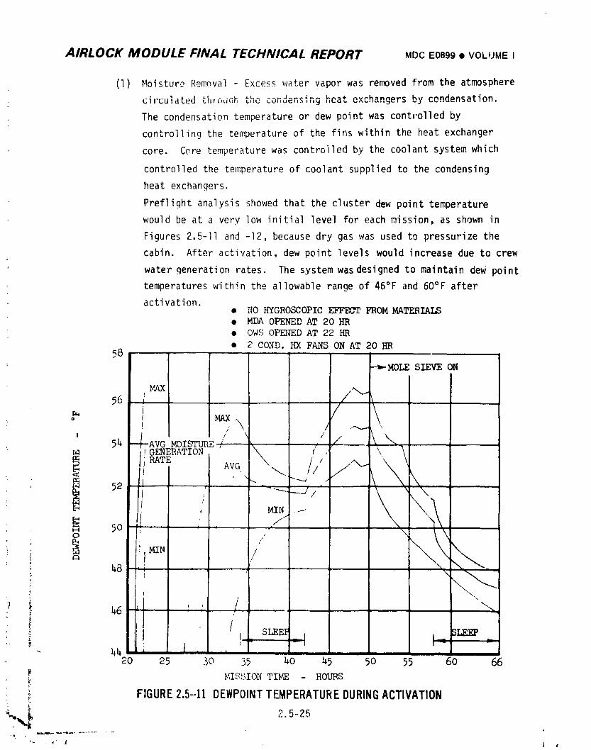
AIRLOCK MODULE FINAL TECHNICAL REPORT MDCE0899• VOLUME I
(l) Moisture Removal - Excess water vapor was removed from the atmosphere
circulated th,c, Linh _ .... __,,u _u,,_,ens,ng heat exchangers by condensation
The condensation temperature or dew point was cont,'olled by
controlling the temperature of the fins within the heat exchanger
core. Core temperature was controlled by the coolant system which
controlled the temperature of coolant supplied to the condensing
heat exchangers.
Preflight analysis showed that the cluster dew point temperature
would be at a very low initial level for each mission, as shown in
Figures 2.5-11 and -12, because dry gas was used to pressurize the
cabin. After activation, dew point levels would increase due to crew
: water generation rates. The system was designed to maintain dew point
temperatures within the allowable range of 46°F and 60°F after
activation.• NO HYGROSCOPIC EFFECT FROM MATERIALS• MDA OPENED AT 20 HR• OWS OPEI_EDAT 22 HE
• 2 COND. HX FANS ON AT 20 HE58
--_MOLE SIEVE ON
/ \I
/ // \ / . \
/
_ NIN /
_8 , * ) \
i
° / SLEE]_ BLEEP
20 25 30 35 I_0 45 50 55 60 66
MISSION TIME - HOURS
FIGURE2.5-11 DEWPOINTTEMPERATUREDURINGACTIVATION
_._ 2.5-25
• * J 1 •
"19740"18208-243
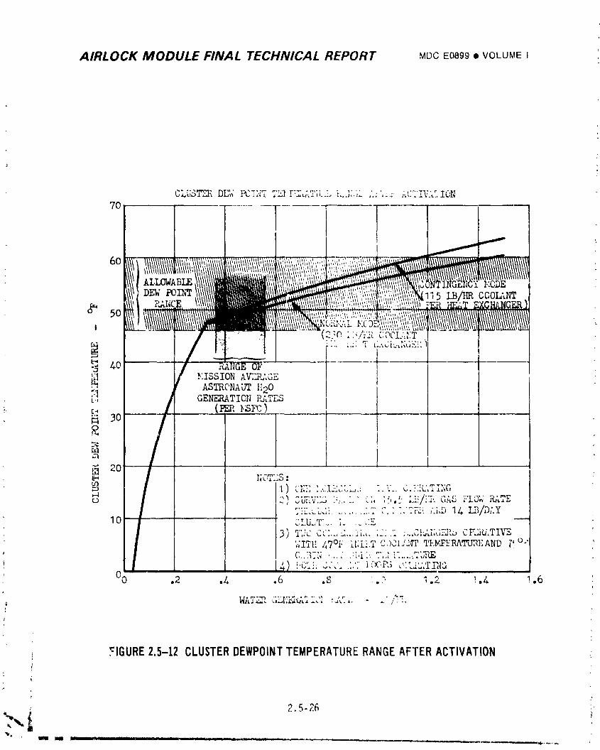
AIRLOCK MODULE FINAL TECHNICAL REPORT MOCE0899• VOLUMEI
CLUST"_ DEW !EE,,7 _'_........ i ,'.,_.,......... I\.._ ION
?o
I/t/////| '""' ' ° '
2}(_]}_!'i]{COOL.:,_;T..... [ ....
_o_'.iss_o_:,_.,_ASTRCNAUT }120
?' i GEIT_T ION It_TES
_. _._ L (P_R _}E )
t_
i
_'_ - _'" ...... " " " ." " t _ , "- ; .... _ t" _;' -_,- . t,
I'!:L_.Ldi ......... ;.l" ,". ; :,"7F2. ,',hD 14 L_I/D;,Y10 " -_ " " " _':_ --.... IJ.,T .... _.....
;.;ITt!, _7°i , ll;li.TC,)31_i'ri' TI';F_P_'RATUREANDp,o.,C,..,_,_ '. ..... '_'i ," .,., ; ...... _bT_
O0 .2 .4 .6 .8 , .,.', I .2 ! .A .6
_11'"_, GLI'_fSCdi,.'I ' dd .... /: :.
FIGURE2.5-12 CLUSTERDEWPOINTTEMPERATURERANGEAFTERACTIVATION
-_'_ i 2.5-26
1974018208-244
AIRLOCK MODULE FINAL TECHNICAL REPORT MDCE0899• VOLUMEI
Four condensing heat exchangers were provided (two in parallel
upstream ef each molecular sieve). Normal procedure was to operate
one condensing heat exchanger upstream of each molecular cieve
assembly. The two remaining heat exchangers were redundant. The
moisture removal portion of the atmosphere control system was operated
from ECS control panel 203 shown in Figure 2.5-13, circuit breaker
panel 200, molecular sieve condensing heat exchanger control panels
23u and 232 shown in Figure 2.5-14 and also molecular sieve
condensing heat exchanger air flow valves 233 and 239 shown in
Figure 2.5-15. The operation of all valves shown in Figures 2.5-14
and 2.5-15 must be integrated in order to assure proper system
operation.
(2) Condensate Separation - Within each condensing heat exchanger,
condensate was transported from the fins to the wiczing by surface
tension and from the wicking to the water separator assemblies by
capillary action. The water separator plate assemblies served to
hold bar, the atmosphere and allow passage of condensate into the
condensate system. The design minimum water removal rate from one
co'_ensing heat exchanger was 0.78 Ibs/hr for a gas to condensate
pressure differential of 8" H20. Each water separator plate assembly
contained two plates whose faces were covered with fritted glass,
see Figure 2.5-16. The pores in the fritted glass were sized to be
sealed against 6.3 psi cabin to condensate pressure differential by
the surface tension of water',
, 2.5-27
!
i974018208-245
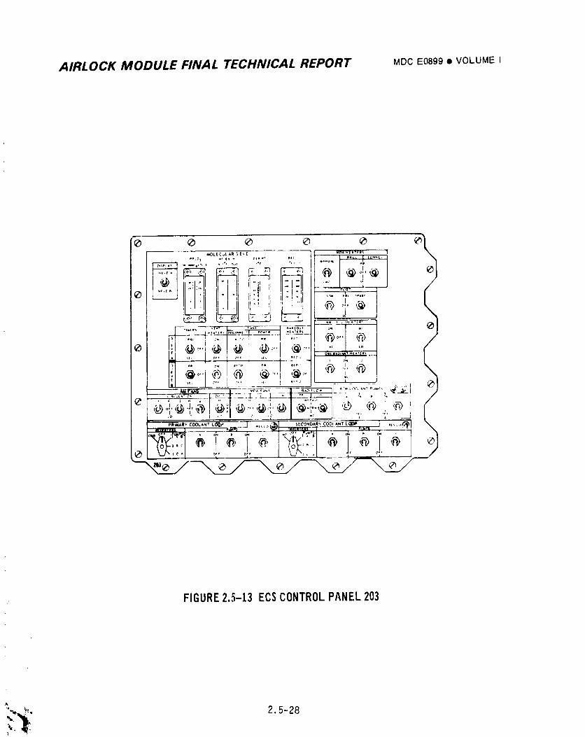
AIRLOCK MODULE FINAL TECHNICAL REPORT MDC EO899 • VOLUME I
FIGURE2.5-13 ECSCONTROLPANEL203
_' _ 2.5-28
1974018208-246
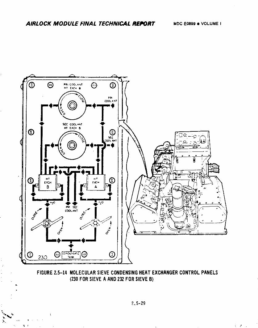
AIRLOCK MODULE FINAL TECHNICAL REPORT MDCEO899• VOLUMEI
_" _,m e, ....
• ._ _, _, n .20 . _ I
,-- m coo_T_ m
I
3 2300__J
FIGURE2.5-14 MOLECULARSIEVECONDENSINGHEATEXCHANGERCONTROLPANELS(230FORSIEVEAAND232FORSIEVEB)
w
2.5-29
_k,, _.<* ' '
1974018208-247
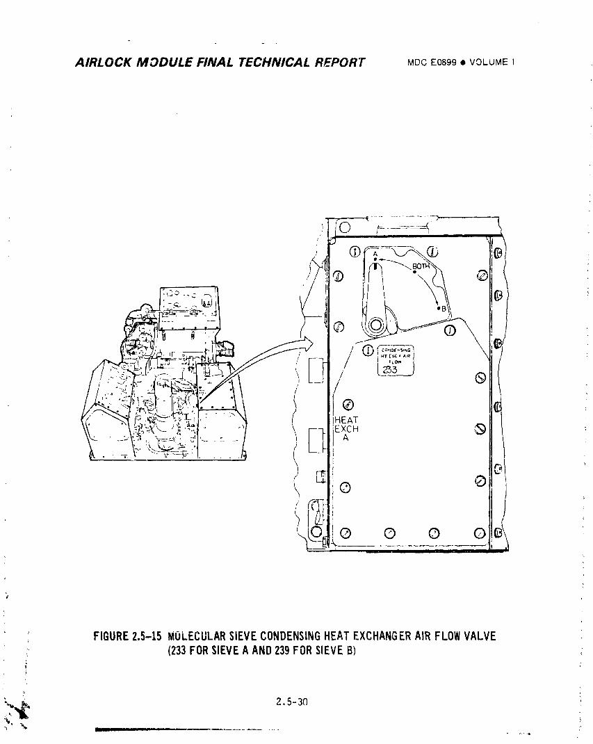
AIRLOCK MODULE FINAL TECHNICAL REPORT MDCE0899• VOLUMEI
>
> FIGURE2.5-15 MOLECULARSIEVECONDENSINGHEATEXCHANGERAIRFLOWVALVE ,_, (233FORSIEVEA AND239FORSIEVEB)
t
]9740]8208-248
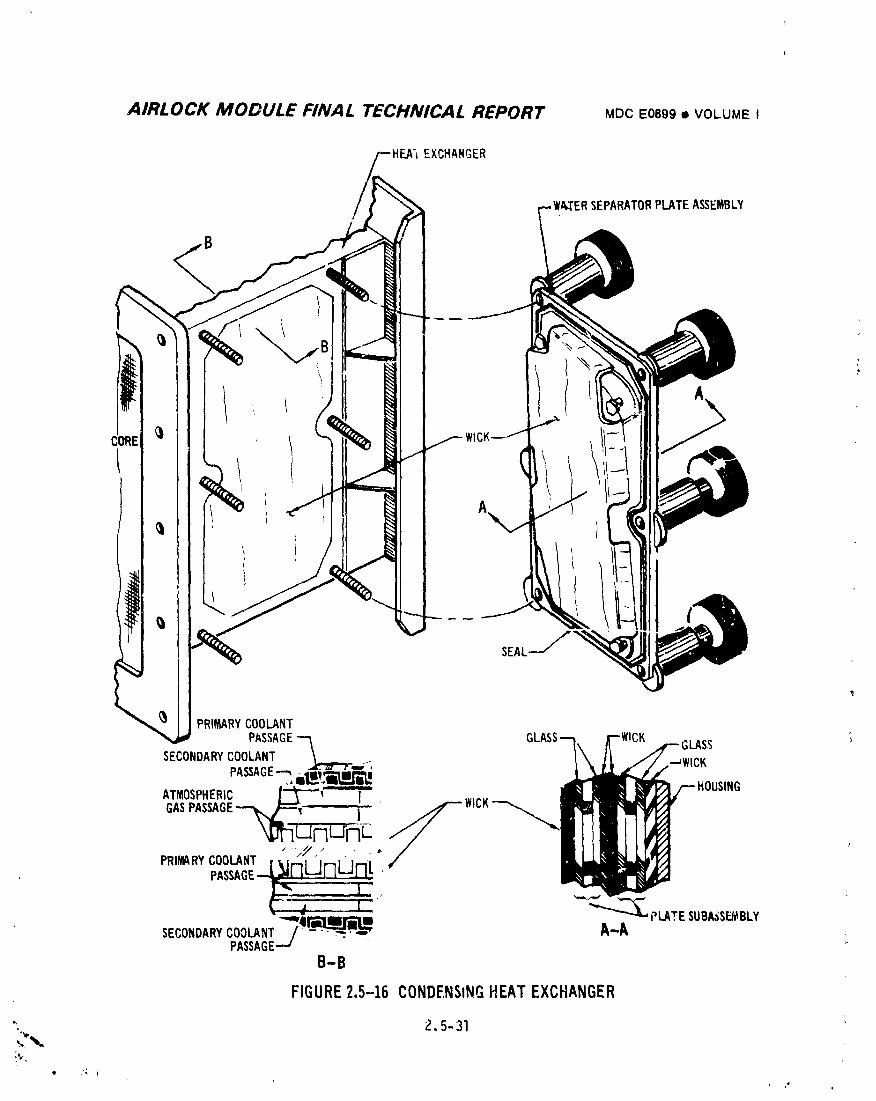
AIRLOCK MODULE FINAL TECHNICAL REPORT MDCE0899• VOLUMEI
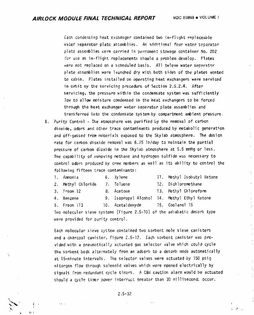
AIRLOCK MODULE FINAL TECHNICAL REPORT MOCE0899• VOLUME I
Eacn condensing heat exchanger contained two in-filght replaceable
water separator plate assemblies An _dd_*i,_nalfour water _.....+_-
plate assemblies_;erecarried in permanent stowage container No. 202
for use as in-flight replacementsshould a problem develop• Plates
_ere not replaced on a scheduled basis. All twleve water separator
plate assemblieswere launched dry with both sides of the plates vented
to cabin. Plates installed on operating heat exchangers were serviced
in orbit Dy the servicing procedure of Section 2.5.2.4. After
servicing, the pressure within the condensate system was sufficiently
low to allow moisture condensed in the heat exchangers to be forced
through the heat exchanger water separator plate assemblies and
transferred into the condensate system by compartmentambient pressu_.
B. Purity Control - The atmospl-erewas purified by the removal of carbon
dioxide, odors and other trace contaminants produced by metabolic generation
and off-gassed from materials exposed to the Skylab atmosphere• _e design
rate for carbon dioxide removal was 6.75 Ib/day to maintain the partial
pressure of carbon d;oxide in the Skylab atmosphere at 5.5 mmHg or less.
The capability of removing methane and hydrogen sulfide was necessary to
control odors produced by crew members as well as its ability to control the
following fifteen trace contamit_ants:
I. Ammonia 6. Xylene II. Methyl Isobutyl Ketone
2. Methyl Chloride 7. Toluene 12. Dichloromethane
3. Freon 12 8. Acetone 13. Hethyl Chloroform
4. Benzene 9. Isopropyl Alcohol 14. Methyl Ethyl Ketone
5• Freon i13 I0. Acetaldehyde 15. Coolanol 15
Two molecular sieve systems (Figure 2.5-I0) of the adiabatic desorb type
were provided for purity control.
Each molecular sieve system contained two sorbent mole sieve canisters
and a charcoal canister, Figure Z.5-17. Each sorbent canister was pro-
vided with a pneumaticallyactuated gas selector valve which could cycle
the sorbent beds alternately from an adsorb to a desorb mode automatically
at 15-minute intervals. The selector valves were actuated by 150 psig
nitorgen flow through solenoid valves which were opened electrically by
signals from redundant cycle tiff,ors. A C&W caution alarm would be actuated
should a cycle ti:nerpower interrupt qreater than 30 millisecondL occur.
2.5-32
1974018208-250
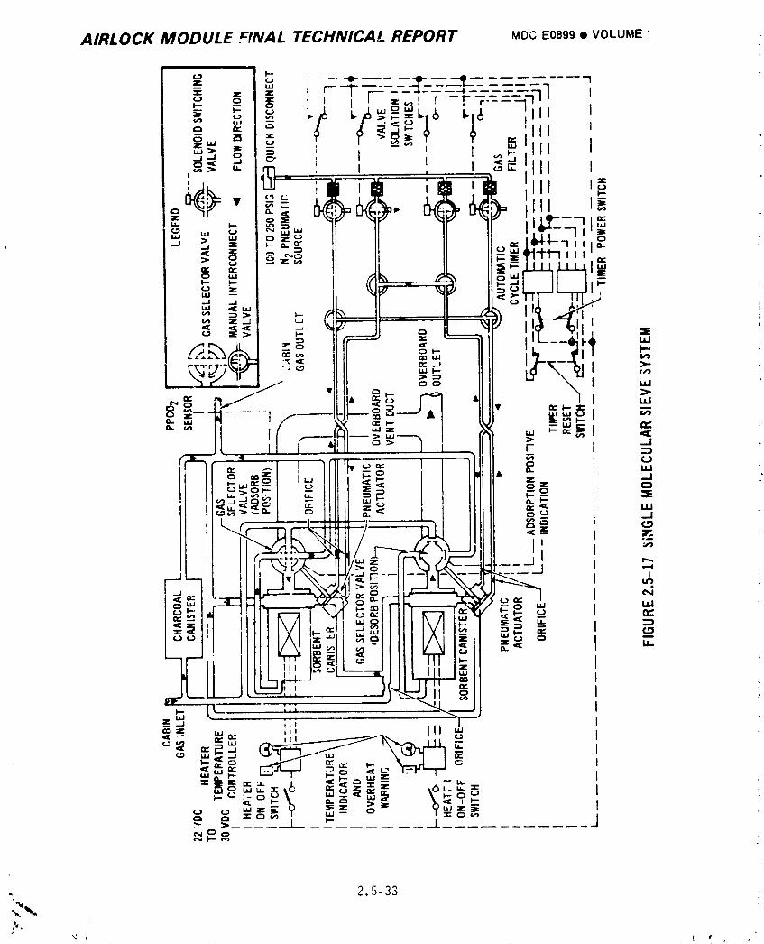
AIRLOCK MODULE FINAL TECHNICAL REPORT MOCE0899• VOLUMEI
; 2.5-33
1974018208-251
AiRLOCK MODULE FINAL TECHNICAL REPORT MDCE0899• VOLUMEI
_J_u_or valve cyci_ , required a flo_,;rateot Z Iblhr for"approximately
8 seconds every 15 minutes. The sorbent canisters contained Linde Type
13X molecuiar sieve material for water vapor adsorption and Linde Type
5A molecular sieve material for"CO2 aJso:'ption. Carbon dioxide water vapor,
and some trace contaminantswere rer,_ovedfro_;1cabin gas flowing through
tlresorbent canister in tlreadsorb mode _'hilethe canister in the desotJo
mode was regeneratedby exposure to vacuum.
The cl_arcoalcanister-swere proviJed For"odourand trace contaminant
control. A list of materials removed by the canister is presented in
Appendix I. Each charcoal canister was desi(Inedfor"in-flight replace-
ment and contained 9 lbs of activated cq,_rcoal. It was scheduled for
replacement at 28-day intervals.
S(_T_oentcanister -peration of only one s,_stemw]s required for C02 removal.
The two inoperative sorbent canisters were provided for redundancy. Cabin
gas Flowing into the operative system (5..5 Ib/hr) was routed into three
parallel paths: (l) so_Vaentcanister Flov,for"CO2 removal (15.5 Ib/hr),
_,) charcoal canister flow for odor re_,)v,_l(18.2 lb/hr) a_d (3) bypass
flow for fl_v balancing and choline the so_i_entcanister l_ousingsduring
bakeout periods (19.8 Ib/hr) .
The so_Ioentcanister-sof the inoperativemolecular sieve were i,zolated
from both cabin ati_x)sphereand w_cuum by an intemediate position of the
gas selector valve. Cabin gas f'Imventerin(_the inoperative mole sieve
(45.9 Ib/hr) went througilonly the charco,_lcanister (21.8 Ib/hr) and the
bypass line (24.1 Ib/hr).
Tilesorbent beds were to be baked out to _ncrcase C02 ten:ovalperformance
by elimination oF moisture accumul,_tedin the downstream portion of the
sorbent canister._. Hoi_ture was removed uv ire,_tin,nthe beds sequentlallyJ
to between 360"F and 410"F by internal electrical bakeout heaters while
the beds were exposed to vacuum. Should bed temperatures increase beyond
this range, a C&N alarm would be actuated between 425'F to 450"F to
warn the crew of the over-temperature c,,mdition. Scheduled bakeouts
were 24 hnurs per canister durin:1preIaund_, 5 iloursduring the first
i
z.5-34
1974018208-252
AIRLOCK MODULE FINAL TECHNICAL REPORT MDCE0899• VOLUMEI
_ission"" GC,,L;""_,_.v,.,...........A _ he,JrsHuring the _econd and third activations.
Bakeout during the manned mission was recommended if the cabin PPCO2
correct'..dreadi..gwas 6.0 mn_Hgafter a verification check. The time
between bakecJts was to be 28 days minimum.
Each molecular sieve system had redundant cvcle timers. It had manual
interconnectvalves which provided isolation and permitted use of redundant
solenoid switchinq valves. In addition, each sorbent canister had a
separate bakeout heater temperature cm_troller. In the unllkely event
that more than one sorbent canister could not be operated, the inlet PPC02
could have been limited to 12 mmHg maximum with one canister operation for
the design C02 removal rate of 6.75 Ib/day and an inlet dew point tempera-
ture of 52°F.
The carbon dioxide and odor ren_val portion of the atmospheric control
system w.lsoperated from panel 203 shown in Figure 2.5-13, circuit breaker
panel 200, molecular sieve B and A vent valves panels 218 and 220,
respectively,shown in Fiaure 2.5-18, and molecular sieve A and B valve
control panels 226, 227, 228, and 229 shown in Figure 2.5-19. Molecular
sieve operating modes are shown in Figure 2.5-20.
Cabin CO2 partial pressure was measured at the inlet to both operating
condensing heat exchaneers. Outlet CO2 partial pressure was measured by
the two sensor_ at the outlet of sorhent canisters of the operating
molecular sieve system. Normally no outlet PPCO2 readings were available
for the molecular sieve which was in the "isolate" mode. Duchy elements
which prevented flow throuqh the transducer replaced the normal cartridge
elements in these units. On-board display and TM were provided at both
the inlet and outlet. The on-board display appeared on ECS cortrol panel
203 shm._nin Figure 2.5-13. A C&W siqnal was provided when the outlet
"_ PPC02 reached 4.4 + 1.4 mmHg.
, 2.5-35
1974018208-253
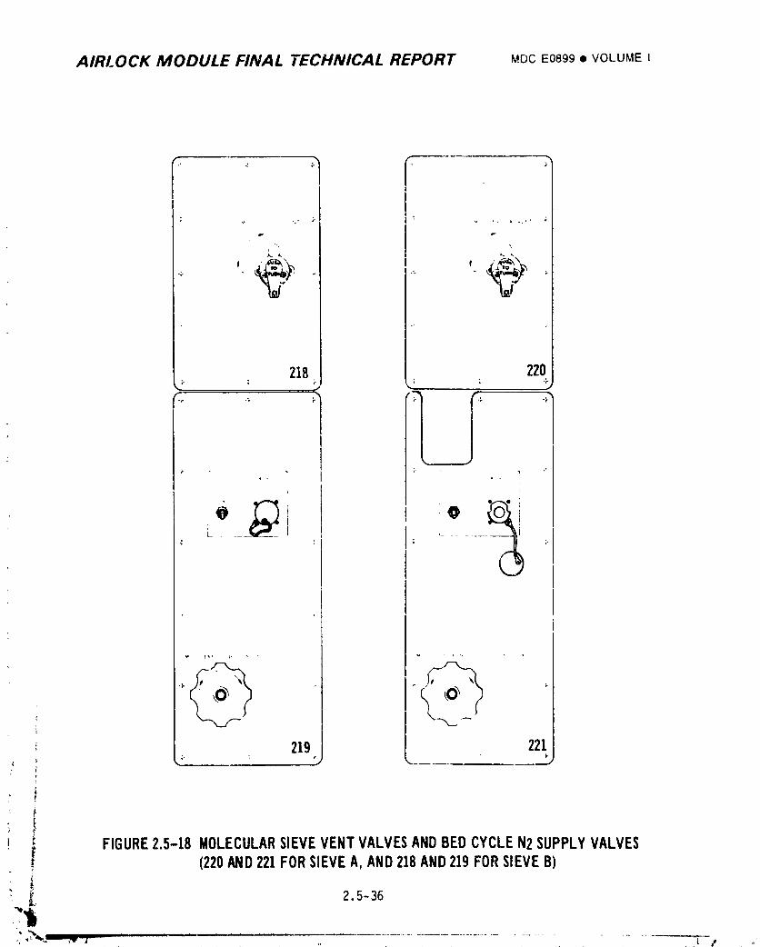
AIRLOCK MODULE FINAL TECHNICAL REPORT MDCEO899• VOLUMEI
r •
219 221J
i
)
i _ FIGURE2.5-!8 MOLECULARSIEVEVENTVALVESANDBEDCYCLEN2SUPPLYVALVESI[ (220AND221FORSIEVEA,AND218AND219FORSIEVEB)
2.5-36
1974018208-254
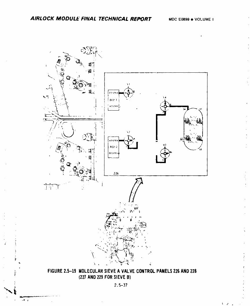
AIRLOCK MODULE FINAL TECHNICAL REPORT MDCE0899• VOLUMEI
-'c:. :p\" 1
,, /_x
l I \o/ _:
I
_,2
J ...!t_i
k
, " ,. . _
,_,.T ,_....tik_
,_:,_.'"7, ' "_'',
. .._,(. _, _.,: ,, , , . L-e_--_",.,
:, FIGURE2.5-19 MOLECULARSIEVEAVALVECONTROLPANELS226AND228 :(227AND229FORSIEVEB)
7
2.5-37
1974018208-255
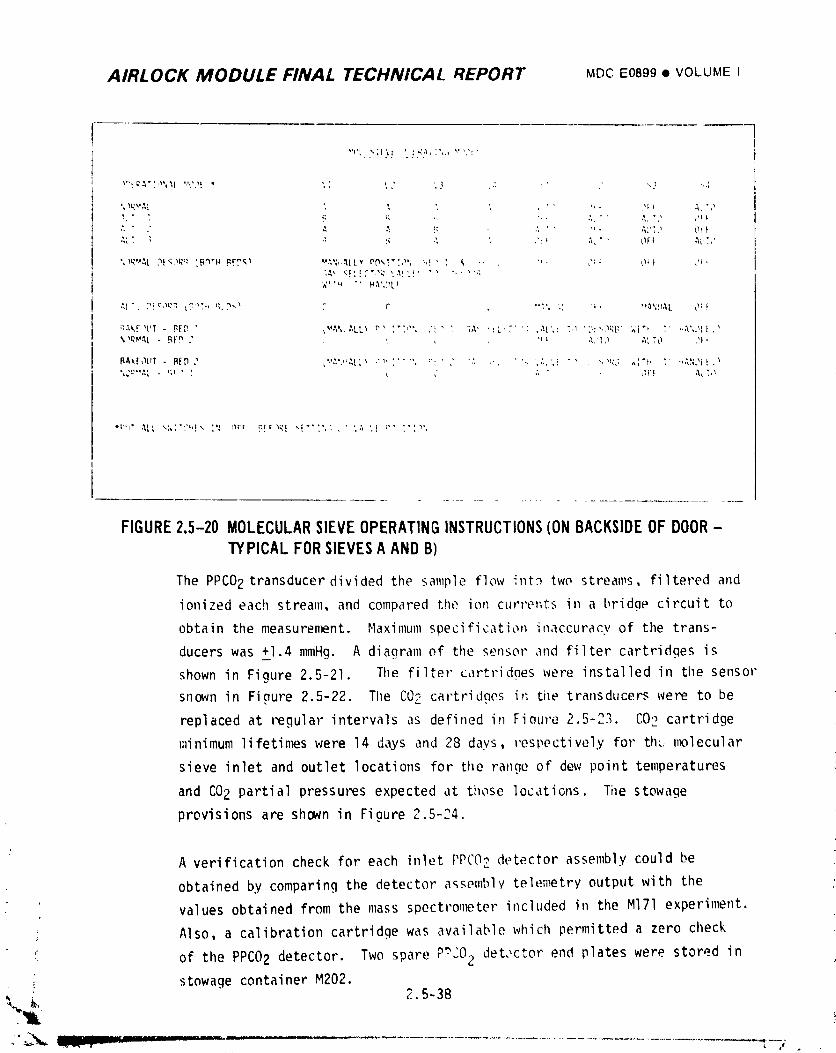
AIRLOCK MODULE FINAL TECHNICAL REPORT MDCE0899• VOLUME I
FIGURE2.5-20MOLECULARSIEVEOPERATINGINSTRUCTIONS(ONBACKSIDEOFDOOR-TYPICALFORSIEVESAANDB)
The PPCO2 transducer divided the sample flow in_ two streams, filtered and
ionized each stream, and compared the ion currents in a bridge circuit to
obtain the measuren_nt. Maximum specificati_n inaccuracy of the trans-
ducers was +1.4 nm_Hg. A diagram of the sensor and filter cartridges is
shown in Figure 2.5-21. The filter cartridnes were installed in the sensor
ShOWnin Figure 2.5-22. The COZ cartrid,aes in the transducers were to be
replaced at regular intervals as defined in Fieure 2.5-23. CO2 cartridge
minimum lifetin_s were 14 days and 28 days, respectively for th,: nx)lecular
sieve inlet and outlet locations for tl_e range of dew point temperatures
and CO2 partial pressures expected at those locations. The stowage
provisions are shown in Figure 2,5-24.
A verification check for each inlet PPCO2 detector assembly could be
obtained by comparing the detector assembly telemetry output with the
values obtained from the mass spectron_ter included in the Ml71 experiment.
Also, a calibration cartridge was available which permitted a zero check
of the PPCO2 detector. Two spare P?'O2 det,,ctorend plates were stored in
stowage container M202.• 2,5-38
-,L_,_.....: ........................_ .... ___.,
1974018208-256
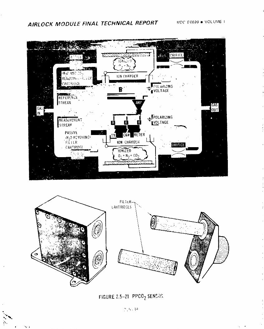
AIRLOCK MODULE FINAL TECHNICAL REPORT MDCE0699• VOLUMEI
FIGURE2,5-21 PPCO2 SEN_I)R
_,'b,
• %. i
"19740]8208-257
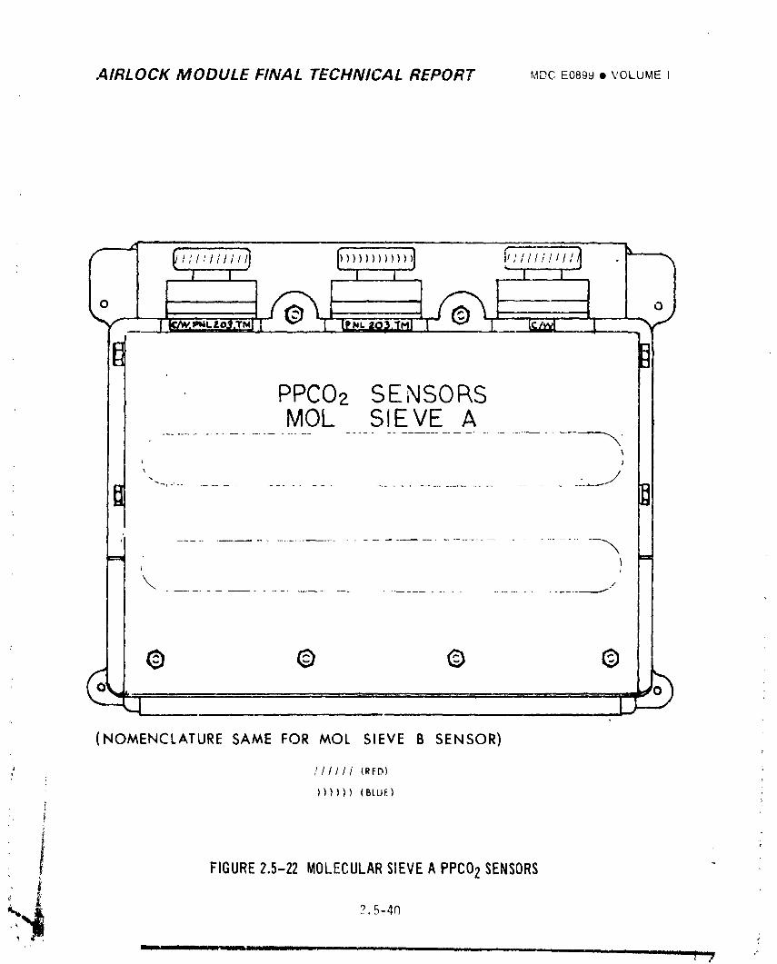
AIRLOCK MODULE FINAL TECHNICAL REPORT UDC E0899• VOLbME I
,_ ,. .
r_ R_I Ul
PPCO_ SENSORSMOL SIEVE A
t
................................... gI:1
t ,
I \ ,
© © © ©
(NOMENCLATURE SAME FOR MOL SIEVE B SENSOR)
/ /11111 (RFD)t
)))))) (BLUE)
FIGURE2.5-22 MOLECULARSIEVEA PPCO2 SENSORS
_,_ 2.5-4r')[ ill I ill . I ....... _ ,,,m
1974018208-258
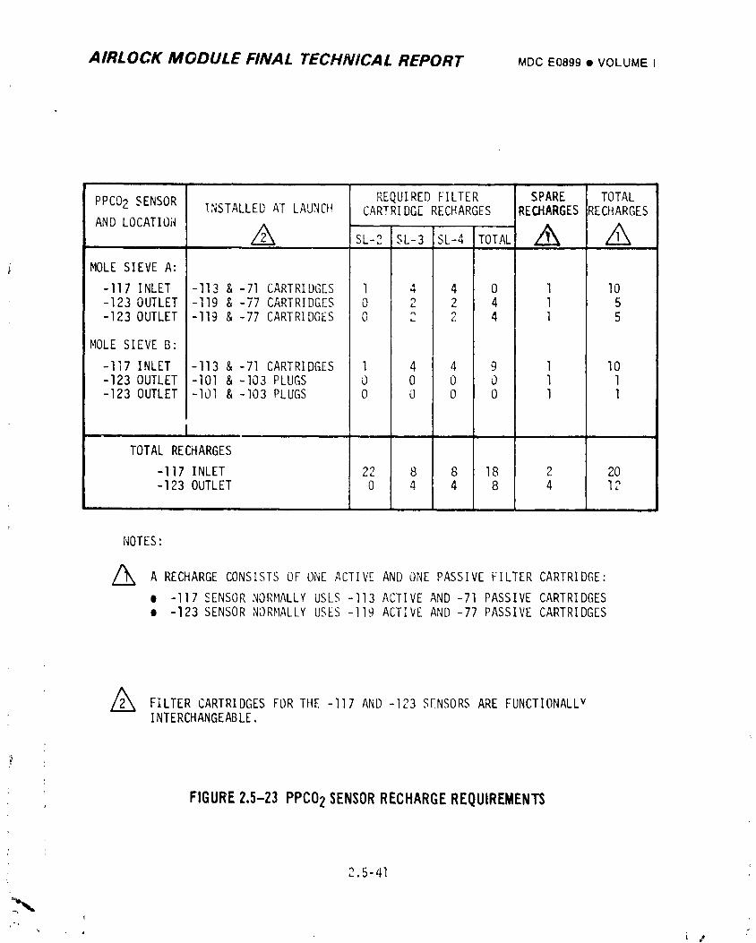
AIRLOCK MODULE FINAL TECHNICAL REPORT MOCE0899• VOLUMEi
REQUIRED_ILTERS_,_ETOTALPPC02SENSOR;:,S,AL,EOATLAUNCHCARTRIO_ERECHARGESRE_,ROESRECHARGES
i MOLESIEVE A:
-117 INLET -113 &-71 CARTRIDGES 1 4 4 0 1 I0-123 OUTLET -119 & -77 CARTRIDGES 0 2 2 4 1 5-123 OUTLET -119 &-77 CARTRIDGES 0 2 2 4 1 5
MOLESIEVE B"
-117 INLET -113 &-71 CARTRIDGES 1 4 4 9 1 I0-123 OUTLET -I01 & -103 PLUGS 0 0 0 0 1 1-123 OUTLET -I01 & -103 PLUGS 0 0 0 0 1 1
L , i
TOTAL RECHARGES
-117 INLET 22 8 8 18 2 20-123 OUTLET 0 4 4 8 4 12
NOTES:
/_ A RECHARGECONSISTSOF ON[ ACTIVE AN[) ONEPASSIVE FILTER CARTRIDGE:o -117 SENSORNORHALLYUSLS -113 ACTIVE AND -71 PASSIVE CARTRIDGES• -123 SENSORNORMALLYUSES-I19 ACTIVE AND -77 PASSIVE CARTRIDG[S
/_ FILTER CARTRIDGESFOR THE -117 AND -123 S[NSORSARE FUNCTIONALLvINTERCHANGEABLE.
FIGURE2.5-23 PPCO2 SENSORRECHARGEREQUIREMENTS
2.5-41
I
" " L / /
i 9740i 8208-259
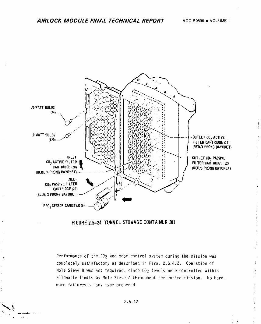
AIRLOCK MODULE FINAL TECHNICAL REPORT MDCEO899• VOLUMEI
20WATTBULBS
j ri
10WATTBULBS _" CO2 ACTIVE(120)J FILTERCARTRIDGE112)
t (RED/4PRONGBAYONET)
INLET ' OUTLETCO2 PASSIVE
CO2ACTIVEFILTE?,_ FILTERCARTRIDGE(12_CARTRIDGE120) (RED/'3PRONGBAYONETI(BLUE'4 PRONGBAYONET)
INLET j// if;'CO2 PASSIVEFILTER _ /_
CARTRIDGE(20) / j_c_,,/
(BLUE,3PRONG BAYONET)---/_jl '_J_
PPO2 SENSORCANISTER(6_
FIGURE2.5-24 TUNNELSTOWAGECONTAINER301
Performance of the CO2 and odor control system during the mission was
completely satisfactory as described in Para. 2.5.4.2. Operation of
Mole Sieve B was not required, since CO2 levels were controlled within l
allowable limits bv Mole Sieve A throughout the entire mission. No hard-
ware failures _, any type occurred.
, 2.5-42
)," t
i 9740i 8208-260
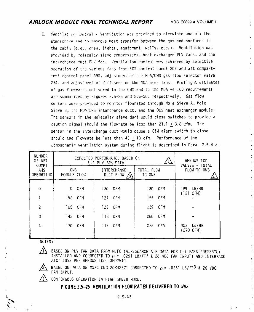
AIRLOCK MODULE FINAL TECHNICAL REPORT MDCE0899• VOLUMEI
C. Ventilat re f:_ntrol - Ventilation was provided to circulate and mix the
atmnsDh_rp and tn improve heat transfer between the gas and surfaces in
the cabin (e.g., crew, lights, equipment, walls, etc.). Ventilation was
_,rovided by molecular sieve compressors, heat exchanger PLV fans, and the
interchanqe duct PLV fan. Ventilation control was achieved by selective
operation of the various fans from ECS control panel 203 and aft compart-
ment control panel 390, adjustment of the MDA/OWSgas flow selector valve
234, and adjustment of diffusers on the MDAarea fans. Preflight estimates
of gas flowrate_ delivered to the OWSand to the MDAvs ICD requirements
are summarized by Figures 2.5-25 and 2.5-26, respectively. Gas flow
sensors were provided to monitor flowrates through Mole Sieve A, Mole
Sieve B, the MDA/OWSinterchange duct, and the OWSheat exchanger module.
The sensors in the molecular sieve duct would close switches to provide a
caution signal should the flowrate be less than 21.1 _ 3.8 cfm. The
sensor in the interchange duct would cause a CAWalarm switch to close
should tne flowrate be less than 45 + lO cfm. Performance of the
_tn_spherir ventilation system during flight is described in Para. 2.5.4.2.
NUMBER EXPECTEDPERFOR>IA_CEBASED011 AOF AFT U-I PLV FAN DATA Zl-_ AM/OWSICD
COMPT VALVES- TOTALFAJ_S OWS INTERCHANGE TOTAL FLOW FLOWTO OWS
OPERATING MODULE FLO,; DUCT FLOW /_ TO OWS I_L ,.I_%
0 0 CFM 130 CFM 130 CFM !89 LB/HR(121 CFM)
l 58 CFM 127 CFM 185 CFM -
2 I06 CFM 123 CFM }:29 CFM
3 142 CFM ll8 CFM 260 CFM -
4 170 CFM ll5 CFM 285 CFM 423 LB/HR(270 CFM)
NOTES:
• A,_ BASEDON PLV FAN DATA FROMMSFC (AIRESEARCHATP DATA FOR U-I FANS PRESENTLYINSTALLED AND CORRECTEDTO p = .0261 LB/FT3 & 26 VDCFAN INPUT) AND INTERFACE
DUCF LOSS PER AM/OWSICD 13M02519.
/_ BASEDON nATA ON MSFCDWG20M42371 CORRECTEDTO p = .0261 LB/FT 3 & 26 VDCFAN INPUT.
CONTINUOUSOPERATIONIN HIGH SPEEDMODE.
FIGURE2.5-25 VENTILATIONFLOWRATESDELIVEREDTOOlt.i
•_, 2.5-43
1974018208-261
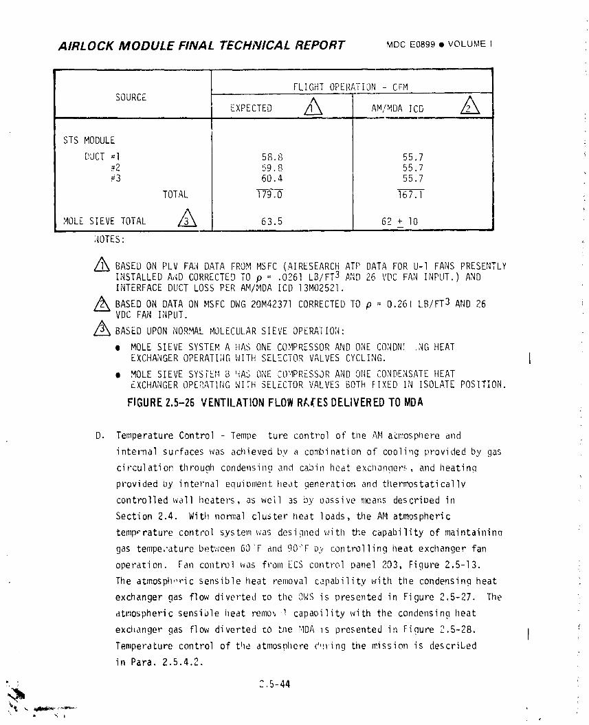
AIRLOCK MODULE FINAL TECHNICAL REPORT MDCE0899• VOLUMEI
FLIGHTOPERATION CFMSOURCE I I
EXPECTED ___ AM/MDAICD Z_, ,, ,,i,, r , .......
STS MODULE
DUCT=l 58.8 55.7_2 59.8 55.7#3 60.4 55.7
TOTAL 179.0 167.] i
AMOLE SIEVETOTAL 63.5 62 + I0I
;_OTES: ,.i.
//_ BASEDONPLV FANDATAFROMMSFC(AIRESEARCHATP DATAFORU-1 FANSPRESENTLYINSTALLEDAADCORRECTEDTO p = .0261 LB/FT3 AND26 VDCFANINPUT.) ANDINTERFACEDUCTLOSSPERAM/MDAICD 13M02521.
//_ BASEDONDATAONMSFCDWG20M42371CORRECTED p = 0.261 AND26LB/FT3TOVDC FAN INPUT.
Z_ BASED UPONNORMALMOLECULARSIEVEOPERA]ION:
• MOLE SIEVESYSTEMA HAS ONE COMPRESSORAND ONE CONDN[ .NGHEATEXCHANGEROPERATINGWITHSELECTORVALVESCYCLING. I
• MOLESIEVE SYSTEMB HASONECOMPRESSORANDONECONDENSATEHEATEXCHANGEROPERATINGWITHSELECTORVALVESBOTHFIXED IN ISOLATEPOSITION.
FIGURE2,5-26 VENTILATION FLOWRA{ES DELIVEREDTO MDAZ
D. Temperature Control Tempe ture control of tile AMacmospnereand
internal surfaces was achieved by a cont_ination of cooli_ig provided by .gas
circulatioP through condensing and cabin heat exchanaers, and heating
provided by internal equipment heat generation and thermostatically
controlled wall heaters, as well as by passive n_ans described in
Section 2.4. With non_al cluster neat loads, the AMatmospheric
temp, rature control system was designed with tJ;e capability of maintainina
gas temperature between 60'F and 90"F b2 controlling heat exchanger fan
operation. Fan control was from ECScontrol panel 203, Figure 2.5-13.
The atmosph,'ric sensible lleat removal capability with the condensing heat
exchanger gas flow diverted _o the OWSis presented in Figure 2.5-27. The
atmospheric sensible heat remo,,'l capability with the condensing heat
excilanger gas flow diverted to ti_e r,IDA_s presented in Figure 2.5-28. ITemperature control of the atmosphere d,!ring the mission is described
in Para. 2.5.4.2.
: 2.5-44 ;
1974018208-262
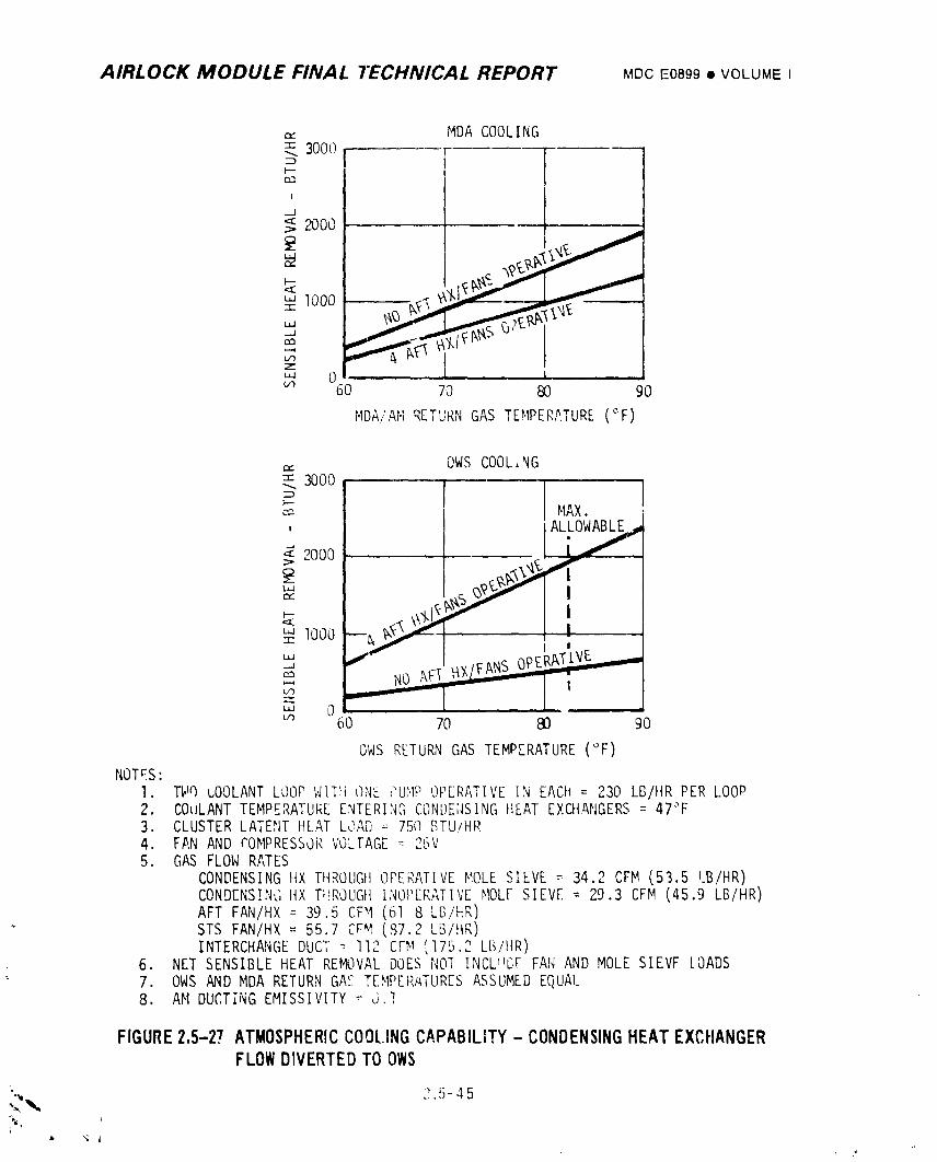
AIRLOCK MODULE FINAL TECHNICAL REPORT MDCE0899• VOLUMEI
,_. MDA COOLING= 3000Z:)I'--
I
J
<>2o00
m 60 70 80 90
MDA/AMRETURNGAS TEMPERATURE(°F)
_. OWSCOOL,NG-'- 3000I.--
MAX. ,
, ALLOWA_,_2000 i/"
# looo
NO AFT ,_X l
70 m' ;oOWSRETURNGASTEMPERATURE(°F)
NOTES:1. TWQLOOLANTLOOPWITti ONE PUMPOPERATIVEIN EACh = 230 LB/HR PER LOOP
• r'_ ,2 COULANTTEMPERATUREENTERINGCON_E,ISINGHEAT EXCHANGERS= 47°F3. CLUSTERLATE,_ITttLAT LOAD= 750 BTU/HR4. FAN AND COMPRESSORVOLTAGE= 2'3V5. GAS FLOWRATES
CONDENSINGHX THROUGHOPERATIVEMOLESIEVE = 34.2 CFM(53.5 LB/HR)CONDENSINGHX T_!ROUGHINOPERATIVEMOLESIEVE = 29.3 CFM(45.9 LB/HR)AFT FAN/HX = 39.5 CFM(61 8 LB/ttR)STS FAN/HX = 55.7 CFM (87.2 LG/HR)INTERCHANGEDUCT-- 112 CFM!175.2 Lf.-_/ltR)
6. NET SENSIBLE HEAT REMOVALDOESNOI INCL_E,F FAN AND MOLESIEVF LOADS7. OWSANDMDA RETURNGAS TEMPERATLIRESASSUMEDEQUAl_8. AM DUCTiNGEMISSIVITY -" J.!
FIGURE2.5-27 ATMOSPHERICCOOLINGCAPABILITY- CONDENSINGHEATEXCHANGERFLOWDIVERTEDTOOWS
" ? 5-45
1974018208-263
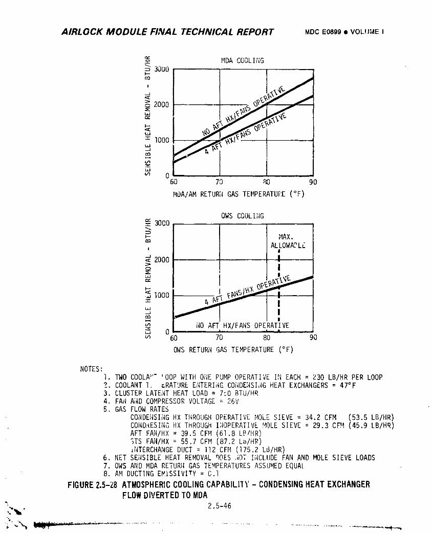
AIRLOCK MODULE FINAL TECHNICAL REPORT MDCE0899• VOLI/;_E I
MDA COOLING
,.,-,,30UOI _'_I2000 _
1000
m 060 70 80 90
MDA/AMRETURNGASTEMPERATUK[(OF)
OWSCOOLII_GC_ 3000
MAX.
, ALILOWA_L;2000 [ I
1ooo I
itO AFTHX/FANSOPERATIVEL.J 0 I I •
,.n 60 70 80 90
_'VSRETURNGAS TEMPERATURE(°F)
NOTES:I. TWO COOLA_''-'OOPWITH OHE PUMPOPERATIVEIN EACH= Z30 LB/HR PER LOOP?. COOLANT1. r.RATUREE_';TERI;'_C-COi,IDENSI,,IGHEATEXCHANGERS= 47°F3. CLUSTERLATE;ITHEAT LOAD= 7"..DBTU/HR4. FAN A;,IDCOMPRESSORVOLTAGE:-26V5. GAS FLOWRATES
CONDENSINGHX THROUGHOPERATIVEMOLFSIEVE = 34.2CFM (53.5LB/HR)COND:iESING}'IXTHROUGHI;IOPERATIVEMOLESIEVE = 29.3CFM (45.9LB/HR)AFT FAN/HX= 39.5CFH (61.8LE_/I'{R)";TSFAN/HX= 55.7CFM (87.2Lb/HR)J.NTERCHANGEDUCT = I!2 CFM (175.2LS/HR)
6. NET SENSIBLEHEAT REMOVAL_OES JOT I;,ICI..UDEFAN AND MOLESIEVE LOADS7. OWS AND MDA RETURNGAS TEMPERATURESASSUMEDEQUAL8. AM DUCTINGEMISSIVITY= G.l
FIGURE2.5-Z8ATMOSPHERIC COOLINGCAPABILIIY- CONDENSING HEAT EXCHANGER
FLOW DIVERTED TO MDA
"" 2.5-46
1974018208-264
AIRLOCK MODULE FINAL TECHN;CAL REPORT MDCE0899• VOLUMEI
The condensate system provided the capability of removing, storing, and
disposing of condensate from the condensing heat exchanger water separator assemblies.
The system also prc¢ided the capability of removing, storing, and disposing of gas
from the EVA/IVA liQuid/gas separator assembly installed in the SUS water loops.
In addition, it provided support for the servicing/deservicing operations discussed
in Section 2.5.2.4. The condensate system, shown schematically in Figure 2.5-29, was
controlled from panel 216, shown by Figure 2.5-30, circuit breaker panel 200, mole
sieve condensing heat exchanger control panels 230 and 232, lock compartment
control panel 316, HX plate servicing panel 303, condensate dump panel 393, and
OWScuntrol panels.
The system employed redundant check valves in the transfer line, overboard
dump line exits, solenoid valves, and electrical heaters. Freezing of water within
the transfeY and overboard dump lines was prevented by gas purge _,d by wrapping
spacecraft coolant lines and dump lines together with aluminum full tape and in-
sulating the bundle. The condensate tank module was in-flight replaceable and a
spare condensate module was provided for module replacement, if required.
A. Removal Ade.q]ate removal was provided by maintaining the pressure level
between 0.5 and 6.2 psi below cabin pressure but above the triple point
pressure of water. This range is compatible with removal of water from
the water separator plate assemblies on _ne condensing heat exchanger ._t
rates exceeding the normal production rate, with operation of the EVA/IVA
water separator, an_ wit h servicing/deservicing _upport. Pressures within
this range were provided by the stowage and dump functions.
B. Stowage - During all manned operations except EVA stowage was provided in
the OWSby a holding tank containing 2 bellows with I0 ft3 of water
collection volu_a. The design stowage duration for this primary stowaoe
tank was 30 days. For stowage during EVA and backup operation, a 0.265
ft 3 condensate tank module was provided in the STS. The design str, vage
duration for this alterna;.e tank module was 18 hours. These times are
based upon the performance characteristics shown in Figures 2.5-31 and
2.5-32 for the primary and alternate tanks, respectively, specification
leakage rates, the maximum water generation rate, and a final tank
pressure of 4.3 psia.
' 2.5-47
1974018208-265
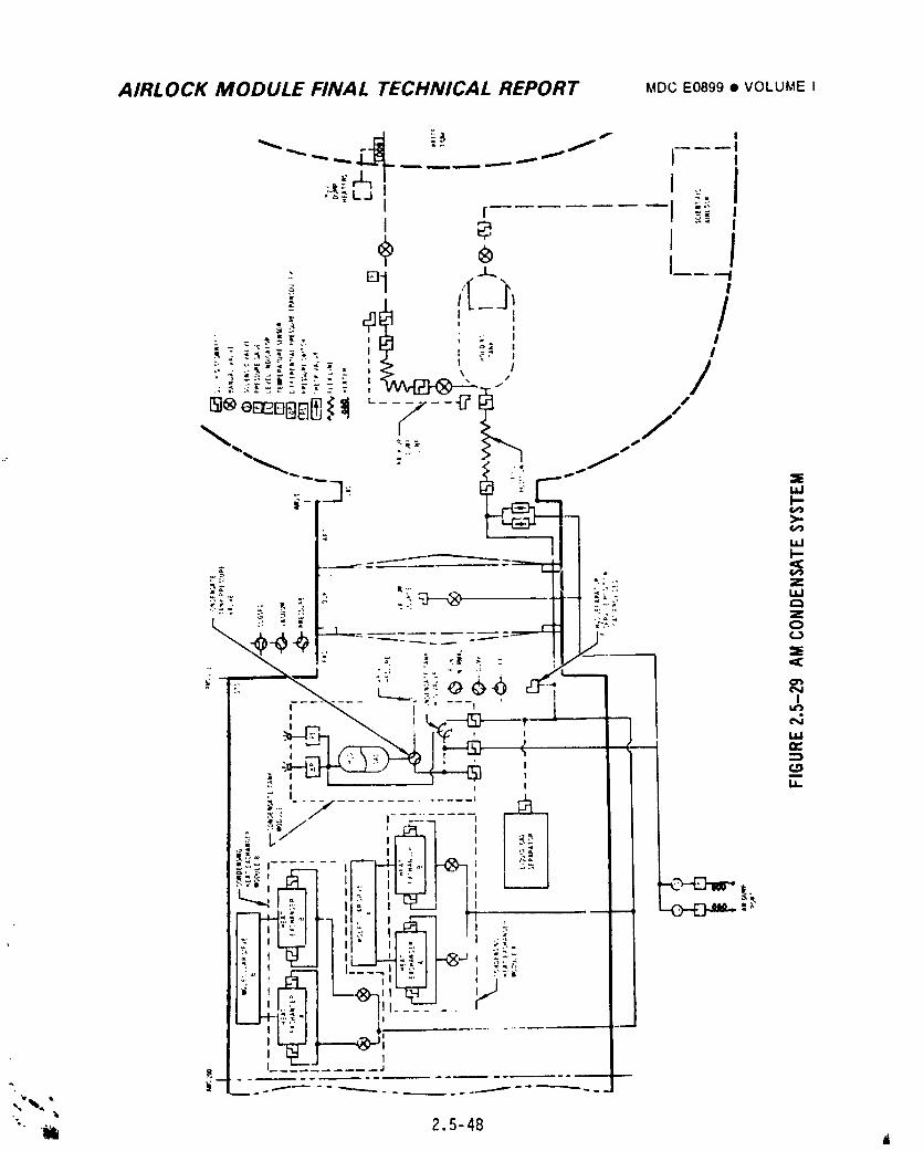
AIRLOCK MODULE FINAL TECHNICAL REPORT MDCE0899• VOLUMEI
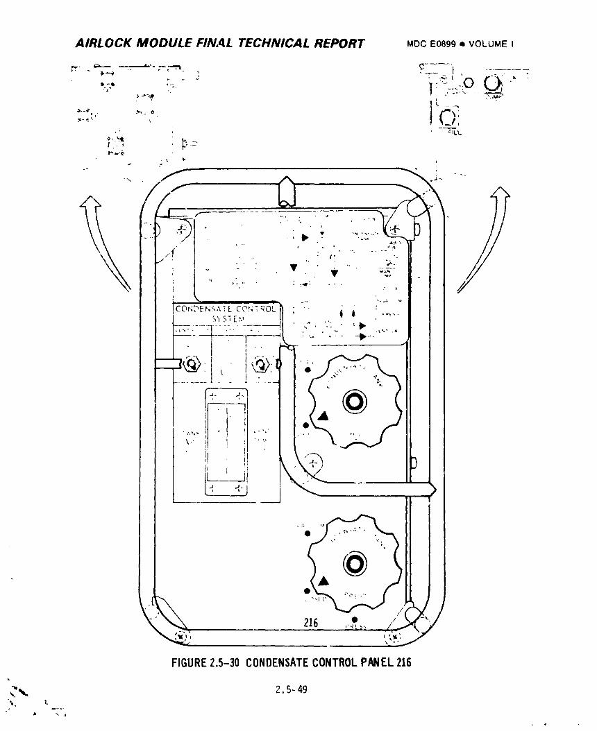
AIRLOCK MODULE FINAL TECHNICAL REPORT MDCE0899Q VOLUMEI
I.- J ----'
j.
:.:i.-:,.,...,.4 _L L, ,.',."_ .' " -.i!CO_;'_ENS'_'tCbu;_OL1] : "" _ i : ..[ s_s_e,., II .... " _. • " "FT-_--:- -:T - .-.- :---_,1 ' ," " .'" , ' .,..,.,
,._ / I ,._' "1
J@: , @;_I . f,,_\
\-_ ,i i ? I,,, ,3 "
''Q "' I
i
FIGURE2.5-30 CONDENSATECONTROLPANEL216
.:,,.,. 2.5-49
1974018208-267
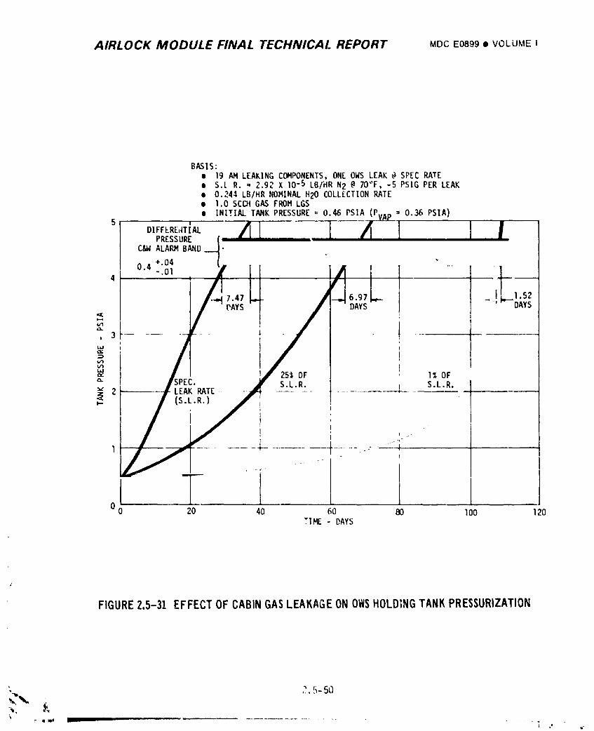
AIRLOCK MODULE FINAL TECHNICAL REPORT MDCE0899• VOLUME I
BASIS:• 19 AM LEAKINGCOMPONENTS,ONE OWS LEAK @ SPEC RATE• S.[ R. ,,2.92 X 10-5 LB/HR N2 @ 70"F, -5 PSIG PER LEAK• 0.244 LB/HR NOMINALH20 COLLECTIONRATE• 1.0 SCC](GAS FROM LGSe INITIALTANK PRESSURE= 0.46 PSIA (P, = 0.36 PSIA)
5DIFFERE,(TIALPRESSURE
C&W ALARM BAND I
I+.0404 i ..... 11
• - .01 I4 •
7.47 ~ IL TMPAYS DAYS ''- DAYS
ILl
V_
25% OF I% OF" S.L.R. S.L.R."" 2 LEAK RATE.... +--
(S.L.R.),- !
i .
t i
o T0 20 40 60 80 1O0 120
TIME - DAYS
FIGURE2.5-31 EFFECTOFCABINGASLEAKAGEONOWSHOLDINGTANKPRESSURIZATION
: _ 5-50L.Q
\I" II _ _. I li II I ...................
1974018208-268
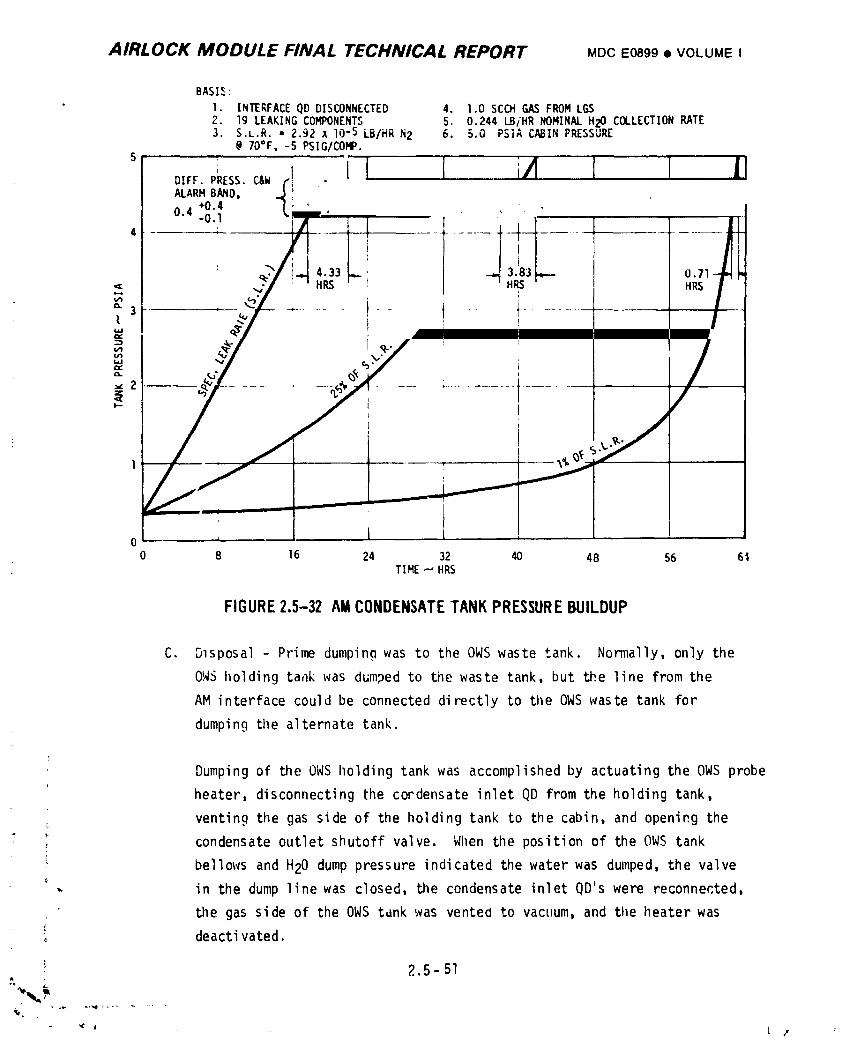
AIRLOCK MODULE FINAL TECHNICAL REPORT MDCE0899• VOLUMEI
BASI_:
* I. INTERFACEQD DISCONNECTED 4. 1.0SCCHGAS FROMLGS2. 19 LEAKINGCO_NENTS 5. 0.244 LB/HRNOMINALH_I COLLECTIONRATE3. S.L.R." 2.92X lO-SLB/HRN2 6. 5.0 PSIACABINPRESSURE
@ 70°Fo-5 PSIG/COMP.5
If I....i/I IDIFF.PRESS.C&WALARMBAND, ,
+0.40.4 -0.I i
_,.
"3 ....... t .....I
m
ix
$
0 _ l h i
0 8 16 24 32 _ 48 56 61TIME_ HRS
FIGURE2.5-32 AMCONDENSATETANK PRESSUREBUILDUP
C. Disposal- Primedumpingwas to the OWS waste tank. Normally,only the
OWS lloldingtankwas dumpedto tilewaste tank,but the line fromthe
AM interfacecouldbe connecteddirectlyto the OWS waste tank for
dumpingthe alternatetank.
Dumpingof the OWS holdingtankwas accomplishedby actuatingthe OWS probe
heater,disconnectingtilecordensateinletQD fromthe holdingtank,
ventingthe gas side of the holdingtank to tilecabin,and openingthe
; condensateoutletshutoffvalve. When the positionof the OWS tank
bellowsand H20 dumppressureindicatedthe waterwas dumped,the valve
- in the dump linewas closed,the condensateinletQD'swere reconnected,
the gas side of the OWS tdnkwas ventedto vacuum,and the heaterwasC
.. deactivated.
2.5-51
j-- t
1974018208-269
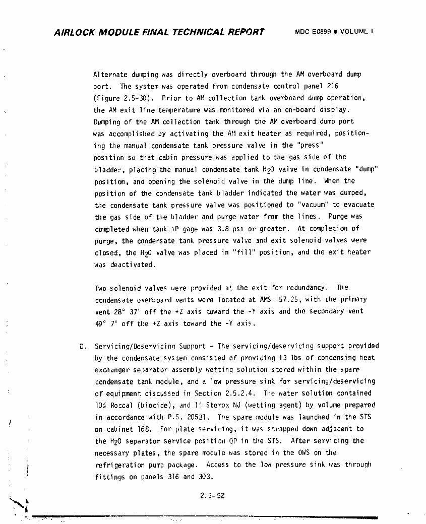
AIRLOCK MODULE FINAL TECHNICAL REPORT MDCEo89g• VOLUMEI
Alternate dumping was directly overboard through the AM overboard dump
port. The system was operated from condensate control panel 216
(Figure 2.5-30). Prior to AM collection tank overboard dump operation,
the AM exit line temperature was monitored via an on-board display.
Dumping of the AM collection tank through the AM overboard dump port
was accomplished by activating tile AH exit heater as required, position-
ing the manual condensate tank pressure valve in the "press"
position so that cabin pressure was applied to the gas side of the
bladder, placing the manual condensate tank H20 valve in condensate "dump"
position, and opening the solenoid valve in the dump line. When the
position of the condensate tank bladder indicated the water was dumped,
tile condensate tank pressure valve was positioned to "vacuum" to evacuate
the gas side of the bladder and purge water from the lines. Purge was
completed when tank ._P gage was 3.8 psi or greater. At completion of
purge, the condensate tank pressure valve and exit solenoid valves were
closed, the H20 valve was placed in "fill" position, and the exit heater
was deactivated.
Two solenoid valves were provided at the exit for redundancy. Tile
condensate overboard vents were located at AMS 157.25,with rileprimary
vent 28° 37' off tile+Z axis toward the -Y axis and the secondary vent
49° 7' off the +Z axis toward the -Y axis.
D. Servicing/DeservicinnSupport - The servicing/deservicingsupport provided
by the condensate system consisted of providing 13 Ibs of condensing heat
exchdnger se.)aratorassembly wetting solution stored within tilespare
condensate tank module, and a low pressure sink for servicing/deservicing
: of equipment discussed in Section 2.5.2.4. The water solution contained
I0% Roccal (biocide), and I% Sterox NJ (wetting agent) by volume prepared
in accordance with P.S. 20531. The spare module was launched in the STS
on cabinet 168. For plate servicing, it was strapped down adjacent to
the H20 separator service position QP in the STS. After servicing the
necessary plates, the spare module was stored in the OWS on the
; refrigeration pump package. Access to the low pressure sink was throughi' fittings on panels 316 and 303.
1974018208-270
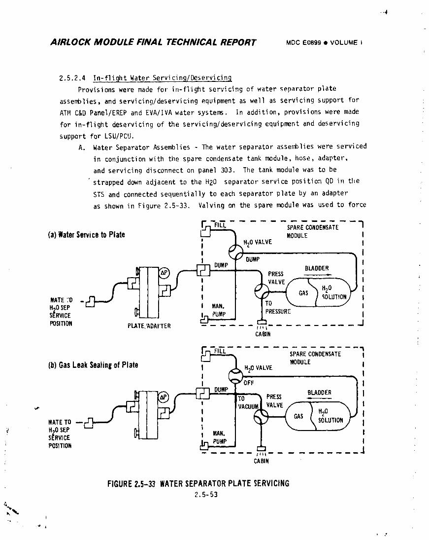
=-._-
AIRLOCK MODULE FINAL TECHNICAL REPORT MOCE0899• VOLUMEi
2,5.2.4 In-flight Water Servicing/Deservicin9
Provisions were made for in-flight servicing of water separator plate
assemblies, and servicing/deservicingequipment as well as servicing support for
ATI4C&D Panel/EREP and EVA/IVA water systems. In addition, provisions were made
for in-flight deservicing of the servicing/deservicingequipment and deservicing
support for LSU/PCU.
A. Water Separator Assemblies - The water separator assemblies were serviced
in conjunctionwith the spare condensate tank module, hose, adapter,
and servicing disconnect on panel 303. The tank module was to be
strapped down adjacent to the H20 separator service position QD i_ the
STS and connected sequentially to each separator plate by an adapter
as shown in Figure 2.5-33, Valving on the spare module was used to force
,_ --S_R_OTOENSA',Eq(a)WaterServicetoPlate L__I _ MODULE I
; /_H20 VALVE II ' I
1 O _DUMPMw----vc_ _ D-UMPI BLADDER IL&r) f- LL._J ] _ PRESS _ '
.--FT1 LV_ I ' I ..L VALVE,/'- L _ I
...-o _ J F_ . I T-f?T-L°'_/,o_..o._.H._OSEP -L--J _ I I MAN. I I'o;......> -- 1 ," "" ' " PUMP • z r_un_ I
SERVICE L_ -- wJ I_ ! i -POSITION PLATE,'ADAYTER ...... _ .......... J
CABIN
(b)GasLeakSealingofPlate _' I H20VALVE MODU,.E II _ , _ II "r" OFF } I
=---® /''- _.- _ --%) _ VACUuM_LVALVE_ _ H el _ { '
I -- ZJ" I I (.._---.( GAS/ 2 _.JIMATETO --C_- ---./ _ "---" ' I _ _ - _ SOLUTION[ IH,JOSEe I}. _ .... I T _ '_ _ I
' _v,c_ _-- L ;3;;I I ,POSITION _ rumr__l ... J
: CABIN
FIGURE2.5-33 WATERSEPARATORPLATESERVICING2.5-53
t
1974018208-271
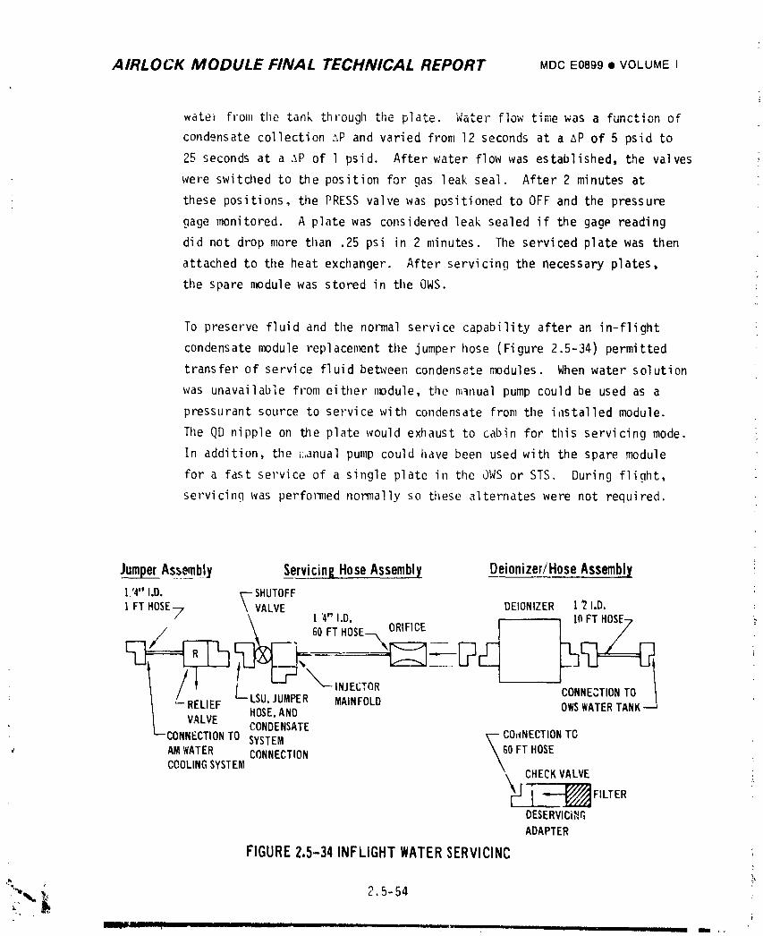
AIRLOCK MODULE FINAL TECHNICAL REPORT MDC E0899 • VOLUME I
wate_ from the tank through the plate. Water flow' time was a function of
condensate collection ._P and varied from 12 seconds at a AP of 5 psid to
25 seconds at a ,_P of 1 psid. After water flow was established, the valves
were switched to the position for gas leak seal. After 2 minutes at
these positions, the PRESSvalve was positioned to OFF and the pressure
gage monitored. A plate was considered leak sealed if the gagP reading
did not drop more tilan .25 psi in 2 minutes. The serviced plate was then
attached to the heat exchanger. After servicing the necessary plates,
ti_espare module was stored in tileOWS.
To preserve fluid and tilenormal service capability after an in-flight
condensate module replacement the jumper hose (Figure 2.5-34) permitted
transfer of service fluid between condensate modules. When water solution
was unavailable from either nx_dule, tile m_nual pump could be used as a
pressurant source to service with condensate from the i,lstalled module.
The QD nipple on the plate would exhaust to cabin for tilis servicing mode.
In addition, the ;:,anual pump could have been used with the spare module
for a fast service of a single plate in the JWS or STS. During flight,
seevicing was performed normally so these alternates were not required.
?
Ju_qg_erAssembly Servicing Hose Assembly Deionizer/Hose Assembly :
1,'4"I.D. _-- SHUTOFFI FTHOSE7 \VALVE DEIONIZER I _ I.D. :
\ 1'4" I.D. I(1FTHOSE7/ I 60FTHOSE--_ORIFICE L"
. co,,,.,ON.o'- RELIEF L_LSU,JUMPER MAINFOLD
HOSE,AND OWSWATERTANK--JVALVECONDENSATE
--CONNECTIONTO SYSTEM _ COrCNECTIONTG;;" AMWATER CONNECTION \60 FTHOSE
COOLINGSYSTEM \kH CHECKVALVE
_-_'--'__ FILTERDESERVICi_GADAPTER
FIGURE 2.5-34 INFLIGHT WATER SERVICINC
F___}L'J. l li_ _ I d i i,,, i, ,,
1974018208-272
AIRLOCK MODULE FINAL TECHNICAL REPORT MDCE0899• VOLUMEI
B. Other Equipn_nt - The servicing/deservicinQ equipment illustrated in
Figure 2.5-34, ATM C&D Panel/EREP System, and EVA/IVA Water System were
serviced using the OWSwater system, the assemblies shown in Figure 2.5-34
and the condensate system. The water allocated for in-flight servicing
was 126 Ibs contained in OWStank no. 9. The allocation included:
(I) filling 6 umbilicals - 36 !bs, (2) servicing suit cooling system
twice - 24 Ibs, (3) servicing the ATM C&Dpanel/EREP cooling system
twice - 24 Ibs, (4) 50% additional amount for contingencies - 42 Ibs.
The water in the OWSwater tank contained Iodine and Potassium lodide
whicll were removed by the deionizcr during system servicing, llle water war
pressurized to 35 + 2 p._.ig by a metal bellows and gas pressure. The water
in the OWStank was deaerated to contain a maximum of 6.9 ppm dissolved
air, so excessive amounts of dissolved gases, which could degrade pump
life, would not be introduced into the water loops upon servicing. An
orifice in the servicing hose assembly limited flow to a maximum of
2.5 Ib/min. A relief valve in the jumper hose assembly limited
maximum pressure to 15 psig, thus protecting reservoirs in water
loops from overpressurization.
The deionizer/hose assembly was launched serviced while the servicing
hose and jumper hose assemblies were launched dry. The servicing
equipment was stored in the OWSwhen not in use. llle servicing/
deservicing equipn_nt and LSU/PCUwere deserviced using the
assemblies shown in Figure 2.5-34 and the cundensate system.
_, 2.5-55
i9740i8208-273
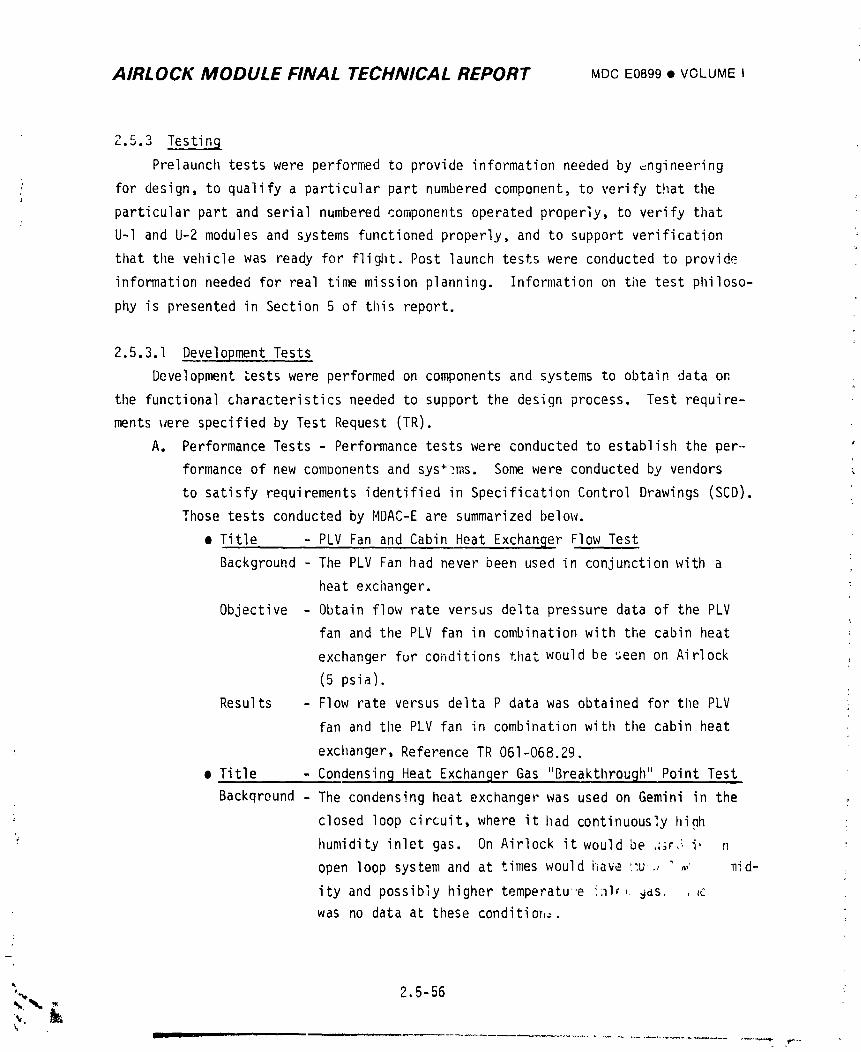
AIRLOCK MODULE FINAL TECHNICAL REPORT MDCE0899• VOLUMEI
2.5.3 Testing
Prelaunch tests were performed to provide information needed by _ngineering
for design, to qualify a particular part numbered component, to verify that tile
particular part and serial numbered components operated properly, to verify that
U-I and U-2 modules and systems functioned properly, and to support verification
that tile vehicle was ready for flight. Post launch tests were conducted to provide
information needed for real time mission planning. Information on the test philoso-
phy is presented in Section 5 of this report.
2.5.3.1 Development Tests
Development tests were performed on components and systems to obtain data on
the functional characteristics needed to support the design process. Test require-
ments were specified by Test Request (TR).
A. Performance Tests - Performance tests were conducted to establish the per-
formance of new components and sys .Somewere conducted by vendors
to satisfy requirements identified in Specification Control Drawings (SCD).
Those tests conducted by MDAC-Eare summarized below.
• Title - PLV Fan and Cabin Heat Exchanger Flow Test
Background - The PLV Fan had never been used in conjunction with a
heat exchanger.
Objective - Obtain flow rate versus delta pressure data of the PLV
fan and the PLV fan in combination with the cabin heat
exchanger fur conditions that would be seen on Airlock
(5 psia).
Results - Flow rate versus delta P data was obtained for the PLV
fan and tlle PLV fan in combination with tile cabin heat
exchanger, Reference TR 061-068.29.
• Title . - Condensin9 Heat Exchanger Gas "Breakthrough" Point Test
Backqreund - The condensing heat exchanger was used on Gemini in the
closed loop circuit, where it had continuously hinh L
humidity inlet gas. On Airlock it would be ,_;r,_ i, n
open loop system and at times would have ",u , _ _ _id-
ity and possibly higher temperatue 'alr, 9as, ._c
was no data at these condition_-.
'_, 2.5-56 ;
1974018208-274
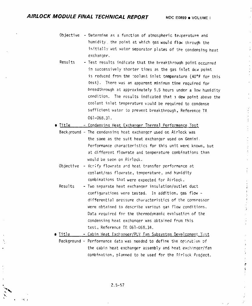
A 10,..,,,,LOCK MODULE FINAL TECHNICAL REPORT MDCE0899• VOLUMEI
Objective - Determine as a function of atmospheric te,,iperature and
humidity_ the point at which gas would flow through the
initially wet water separator plates of the condensing heat
exchanger.
Results - Test results indicate that the breakthrough point occurred
in successively shorter times as the gas inlet dew point
is reduced from the coolant inlet temperature (40°F for this
test). There was an apparent minimum time required for
breadthrough at approximately 5.5 hours under a low humidity
condition. The results indicated that _ dew point above the
coolant inlet temperature would be required to condense
sufficient water to prevent breakthrough, Reference TR
061-068.31.
e Title - Condensinq Heat Exchanqer Thermal Performance Test
Background - The condensinq heat exchanger used or. Airlock was
the same as the suit heat exchanger used on Gemini.
Performance characteristics for this unit were known, but
at different flowrate and temperature combinations than
would be seen on Airlock.
Objective - Vcr;fy flowrate a_d heat transfer performance at
coolant/qas flowrate, temperature, and humidity
combinations that were expected for Airlock.
Results - Two separate heat exchanqer insulation/outlet duct _-
configurations were tested. In addition, gas flow -
differential pressure characteristics of the compressor
were obtained to describe various gas flow conditions.
Data required for the thermodynamic evaluatioq of the
condensing heat exchanqer was obtained from this
tesl, Reference TR 061-068.34.
e Title - Cabin Heat Exchanqer/PLV Fan Subsystem Develcpment Tast
", Background - Performance data was needed to define tile op_rGtiun of
the cabin heat exchanger assembly and heat exchanger/fan
combination, planned to be used for the Airlock Project.
, 2.5-57
i 9740i 8208-275
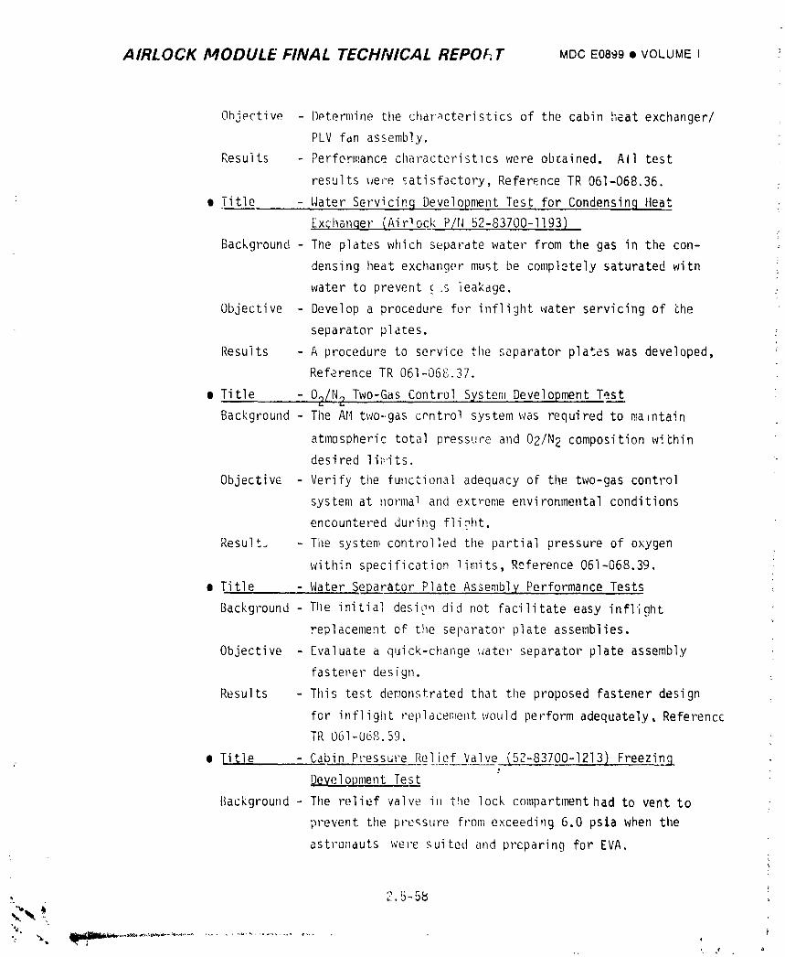
AIRLOCK MODULE FINAL TECHNICAL REPOI£.T MDCE0899• VOLUMEI
Objective Determine the char,_cteristics of the cabin heat exchanger/
PLV fdn assembly.
Results Performance characteristics were obtained. All test
results were _atisfactory, Reference TR 061-068.36.
• • Title - Water Servicinq Development Test for Condensinq Heat
[xchanqer (Airlock P/N 52-83700-1193)
Background - The plates which separate water from the gas in the con-
densing heat exchanger must be completely saturated with
water to prevent (.s leakage.
Objective - Develop a procedure for inflight water servicing of che
separator plates.
Results - A procedure to service the separator plates was developed,
Reference TR 061-068.37.
• Title - 02/N 2 Two-Gas Control System Development TestBackground - The AH two-gas control system was required to maintain
atmospheric total pressure and 02/N 2 composition withindesired li_its.
Objective - Verify the functional adequacy of the two-gas control
system at normal and extreme environmental conditions
encountered during fli,_ht.
Result_ - The system controlled the partial pressure of oxygen
within specification limits, Reference 061-068.39.
• Title - Water Separator Plate Assembly Performance Tests
Background -Tlle initial desi_q did not facilitate easy inflight
replaceme_t of the separator plate assemblies.
Objective - [valuate a quick-change _ater separator plate assembly
fastener design.
Resu|ts - This test demonstrated tilat the proposed fastener design
for inflight replacel;_ent,vould perform adequately, Reference
TR 061-068.59.
• _il;le - Cabin Pressure Relief Valve (52-83700-1213,) Freezing
Development Test
Background - The relief valw; in the lock c_mpartment had to vent to
prevent the pressure from exceeding 6.0 psia when the
astronauts were suited and prcparing for EVA.
)
1974018208-276
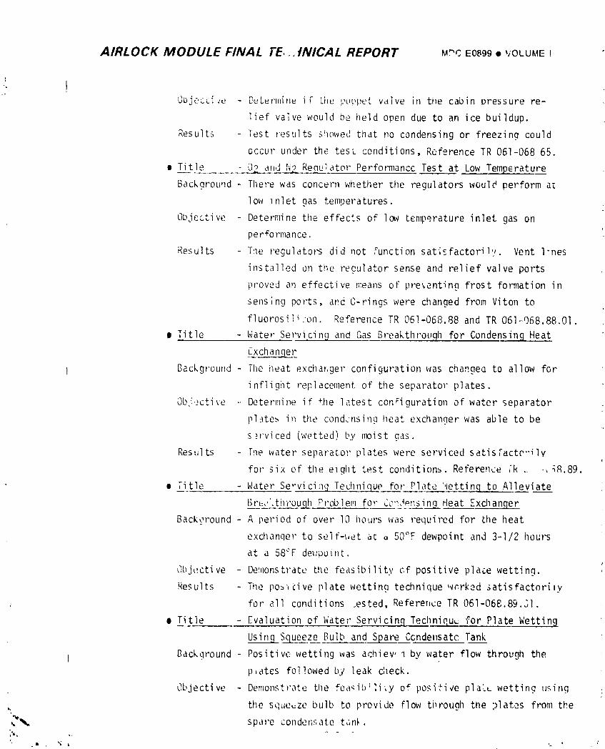
AIRLOCK MODULE FINAL l'E, . tNICAL REPORT M"C E0899• VOLUMEI
1
Jujt;ccire - D_L_r',lin_ iF LI_ ,;uupeL vdlve i,q tile cabin pressure re-
lief valve would be held open due to an ice buildup.
Results - Test results showed that no condensing or freezina could
occur under the test conditions, Reference TR 061-068 65.
• Title O_LJ ,N2 Requ]ator Performancc Test at Low Temperature
Backgrouqd - There was concern whether the regulators would perform a_
low Inlet gas temperatures.
Objective - Determine the effects of Ic_v temperature inlet gas oni
per#o rmance.
Results - The regulators did not ,%nction satisfactoril,_. Vent l-nes
installed on the regulator sense and relief valve ports
proved an effective means oF pre_enting frost formation in
sensing ports, and C-rings were changed from Viton to
fluorosili;on. Reference TR 061-068.88 and TR 061_g68.88.01.
| Title - Water Servicing and Gas Breakthrouqh for Condensinq Heat
Exchantjer
Background - The heat exchar,ger configuration was changea to allow for
inflight replacement of the separator plates.
Ob,iective -. Determine if the latest configuration of water separator
pl.lte__ in the condensing heat exchanger was able to be
s,_rviced (wetted) by lixDist gas.
Results - The water separator plates were serviced satisFacte,-ilv
for six of the elght test conditions. Reference _'k _ -_Rg.89.
• Title - Water Servicing Technique for Plate '.lettin.q to Alleviate
[_e,, ti1'rouqh Problem for Ce::Jensin__qHeat Exchanqer
Background - A period of over lO flours was required for the heat
exchanqer to self-_et ac o 50'_F dewpoint and 3-I/2 hours
at a 58"F dev;point.
Objective Demonstrate the feasibility of positive place wetting.
Results The po_cive plate wetting technique wr.rked satisfactorily
for all conditions .ested, Reference TR 061-068.89.JI.
e Title - Evaluation of Water Servicinq Techniquu for Plate Wettin 9
Usin____gqSqueeze Bulb and Spare Ccndensatc Tank
Background - Positive wetting was achiev, I by water flow through the
p,ates followed by leak check.
Objective - Demonstrate the fea_ib:li,y of positive plaLL wetting using
, the squeeze bulb to provide flow ti_rough the plates from the
_ spare conden;;ate tc,n_.
1974018208-277
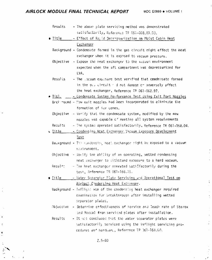
AIRLOCK MODULE FINAL TECHNICAL REPORT MDCE0899• VOLUME I
Results - The above plate servicing method was demonstrated
• lysat_ _t- _-'.- .-- ,._L_ur, , _=rerence Tr, .........-uuo.c_ 03
I Title - E#fect of Re,iid Derr_ssurization or, tloist Cabin Heat
Exchanqer
Background - Condensate fo,'med in the gas circuit might effect the heat
exchanger when it is expnsed tc vacuum pressure.
Objective - Expose _he I;eat excllanger to the v,.cuu '_,environment
expected when the aft compartment was depressurized for
EVA.
Resul&s - The ._cuum exposure test vem f_ed that condensate formed
in the o_ circuit " d not damage c _ adversely affect
the heat exchanger, Reference TP 061-068.97.
Titl_ - Condensate System Performance Test Using Exit Port Nozzles
BzcI_ound - _'ew exit nozzles had been incorporated to elimin3te the
formation of ice cones.
Objective - Ve,'ify tbat tile condensate system, modified by the new'
nozzles was capable c _ meetino all system requirements
Results - The system operated satisfactorily, Reference TR 061-168.04.
iitle - Condensin__ Heat Excnanqer Vacuum Ex!_osure Development
Tes.___t
Background - T!; ..... _r_i:_ L- .._,,..... ilea', exchanger _,ioht be. exposed to a vacuum
e.: ,Ji runment.
Obj_:ctive ']e, ify the abi;ity of an o_erating, wetted rondensing
neat exci_,,nger to '.:ithstand exoosure to a hard vacuum,
Resul _ The heat exchanger o!)erated sati_factorily during the
test, ?,eference TR 061-168._5.
o Title Water Separator Plate Servicing _ud. Operational Test on
__r_]_O_C____£qndersinqHeat Exci;_.n.qer.
Background - .Tnflit_[ l_se of the conder,sing heat exchanger required
examinatlon for breakthrough after installing wetted
separator pl "_aL_S,
nbi_ccive - Determine etfectiveness of service anJ leach rate of Sterox
_nd Reccal from servic__d plates after installation.
_ Results - It _cs concluded that the ,vater separator plates were
'. satisr-actoril_ serviced using the in+light servicing pro- ;
cedures an_ hard_,,are, Reference TR )61-16_.0,,.!
2.5-60
1974018208-278
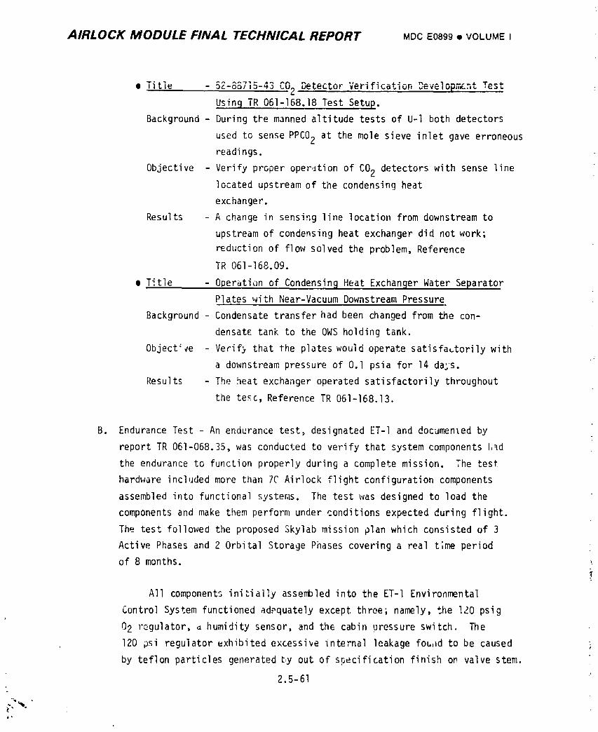
AIRLOCK MODULE FINAL TECHNICAL REPORT MDCE0899• VOLUMEI
........... CO2 ....• _Itle - D_-oo/_-,a Detector Verification _:v:lopmm,_tTest
Usin9 TR 061-168.18 Test Setup.
Background - During tVe manned altitude tests of U-l both detectors
used to sense PPCO2 at the mole sieve inlet gave erroneous
readings.
Objective - Verify proper oper,Jtionof CO2 detectors with sense line
located upstream of the condensing heat
exchanger.
Results - A change in sensing line location from downstream to
upstream of condensing heat exchanger did not work;
reduction of flow solved the problem, Reference
TR 061-168.09.
I Title - Operation of Condensin 9 Heat Exchanger Water SeparatorPlates with Near-Vacuum Downstream Pressure
Background - Condensate transfer had been changed from the con-
densate tank to the OWSholding tank.
Object:_e - Verif) that the plates would operate satisfactorily with
a downstream pressure of 0.I psi a for 14 days.
Results - The heat exchanger operated satisfactorily throughout
the tea,c, Reference TR 061-168.13.
B. Endurance Test - An endurance test, designated ET-I and documented by
report TR 061-068.35, was conducted to verify that system components l,_d
the endurance to function properly during a complete mission. The test
hardware included more than 7C Airlock flight configuration components
assembled into functional systeras. The test was designed to load the
components and make them perform under conditions expected during flight.
The test followed the proposed Skylab mission plan which consisted of 3
Active Phases and 2 Orbital Storage Phases covering a real t;me period
of 8 months, _
All components ini_ially assembled into the ET-I Environmental
Control System functioned adequately except three; namely, the !20 psig
02 regulator, a humidity sensor, and the cabin pressure switch. The
120 psi regulator exhibited excessive internal leakage fouad to be caused
by teflon particles generated by out of specification finish on valve stem.
2.5-61
1974018208-279
AIRLOCK MODULE FINAL TECHNICAL REPORT MDCE0899• VOLUMEI
Valve stems on all valves were inspected and reworked as required. Both
the humidity sensor and the cabin pressure switch were rejected for being
out of tolerance. Since these failures could not be duplicated,further
use of these particular componentswere sepcially controlled. After
replacementof these components early in the te=t sequence, testing was
continued and concluded satisfactorily.
.:?% 2.5 - 62
I
1974018208-280
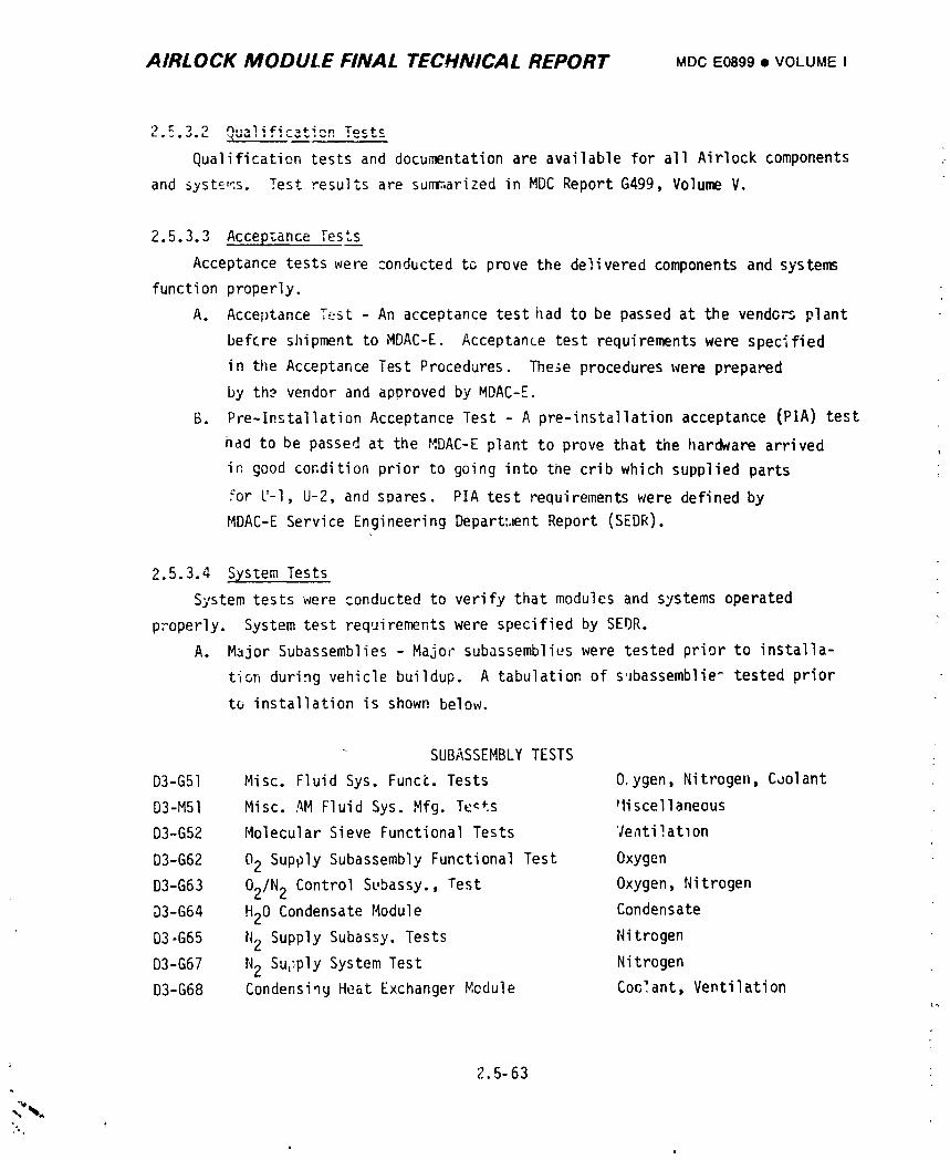
AIRLOCK MODULE FINAL TECHNICAL REPORT MDCE0899• VOLUMEI
2._.3.2 qualification Tests
Qualification tests and documentation are available for all Airlock components
and syste,_s. Test results are summarized in MDCReport G499, Volume V.
2.5.3.3 Accepzance Tests
Acceptance tests were conducted to prove the delivered components and systems
function properly.
A. Acceptance Test - An acceptance test had to be passed at the vendo_ plant
before shipment to MDAC-E. Acceptance test requirementswere specified
in the Acceptance Test Procedures. These procedureswere prepared
by th._ vendor and approved by MDAC-E.
B. Pre-lnstallationAcceptance Test - A pre-installation acceptance (PIA) test
had to be passed at the MDAC-E plant to prove that the hardware arrived
in good condition prior to going into the crib which supplied parts
for U-l, U-2, and spares. PIA test requirementswere defined by
MDAC-E Service Engineering Depart:._ntReport (SEDR).
2.5.3.4 System Tests
System tests were conducted to verify that modules and systems operated
p_operly. System test requirements were specified by SEDR.
A. Major Subassemblies - Major subassemblieswere tested prior to installa-
tion during vehicle buildup. A tabulation of subassemblie_ tested prior
to installation is shown below.
SUBASSEMBLYTESTS
D3-G51 Misc. Fluid Sys. Funct. Tests O.ygen, Nitrogen, C_olant
D3-M51 Misco AM Fluid Sys. Mfg. Te_ts P1iscellaneous
D3-G52 Molecular Sieve Functional Tests Veati!atlon
D3-G62 02 Supply Subassembly Functional Test Oxygen
D3-G63 02/N 2 Control Subassy., Test Oxygen, Nitrogen
D3-G64 H20 Condensate Module Condensate
D3-G65 N2 Supply Subassy. Tests Nitrogen
D3-G67 N2 SuL;plySystem Test Nitrogen
D3-G68 Condensing Heat Exchanger Nedule Coolant, Ventilation
2.5-63
1974018208-281
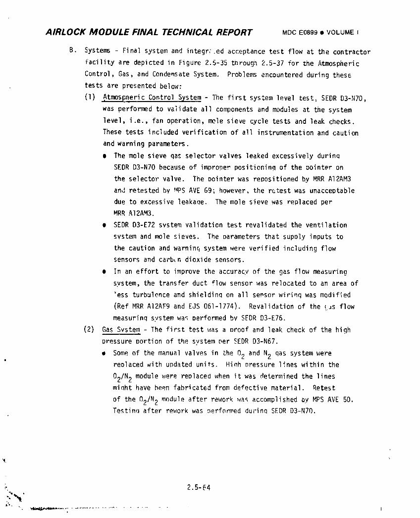
AIRLOCK MODULE FINAL TECHNICAL REPORT MDCE0899• VOLUMEI
B. Systems - Final system and integr:.ed acceptance test flow at the contractor
facility are depicted in Figure 2.5-35 through 2.5-37 for the Atmospheric
Control, Gas, and Condensate System. Problems encountered during thesG
tests are presented below:
(1) Atmospneric Control System - The first system level test= SEDR D3-N70,
was performed to validate all components and modules at the system
level, i.e., fan operation, mole sieve cycle tests and leak checks.
These tests included verification of all instrumentationand caution
and warning parameters.
• The mole sieve qas selector valves leaked excessively durinq
SEDR D3-N70 because of improDer positioning of the oointer on
the selector valve. The pointer was repositioned by MRR AI2AM3
and retested bv _PS AVE 69; however, the retest was unacceptable
due to excessive leakaQe. The mole sieve was replaced per
MRR Al2AM3.
• SEDR D3-E72 system validation test revalidated the ventilation
system and mole sieves. The oarameters that supoly inputs to
the caution and warninq system were verified including flow
sensors and ca;-b_ndioxide sensors.
m In an effort to improve the accuracy of the gas flow measuring
system, the transfer duct f|ow sensor was relocated to an area of
'ess turbulence and shieldin_ on all sersor wirinq was modified
(Ref MRR AI2AF9 and EJS 061-1774). Revalidation of the (_s flow
measurinq system wa_ performed by SEDR D3-E76.
(2) Gas System - The first test was a Droof and leak check of the high
pressure portion of the system per SEDR D3-N67.
• Some of the manual valves in the 02 and N2 qas system werereplaced _ith updated units. Hinh nressure lines within the
02/N2 module were reDlaced when it was determined the linesminht have been fabricated from defective material. Retest
of the (_2/N2module after rework wa_ accomplished oy MPS AVE 50.TestinQ after rework was Derformed durinQ SEDR D3-NTO.
,., 2.5-64
:-"N"
1974018208-282
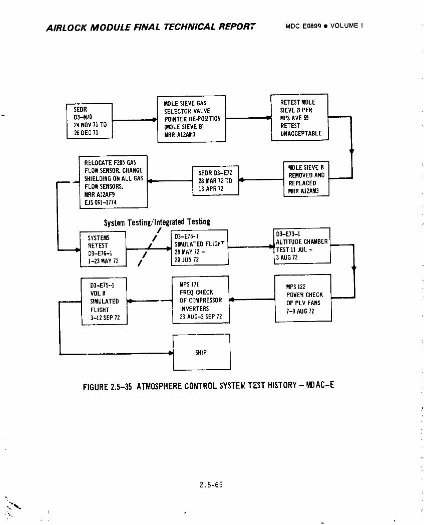
AIRLOCK MODULE FINAL TECHNICAL REPORT MDCE0899• VOLUMEI
I MOLESIEVEGAS I RETESTMOLE
SEDR SELECTORVALVE SIEVEB PERD3-N70 POINTERRE-POSITION MPSAVE6924NOV71TO (MOLESIEVEB) RETEST26DEC71 MRRA12Ak13 UNACCEPTABLE
RELOCATEF205GAS
L MOLESIEVEBFLOWSENSOR.CHANGE SEDRD3-E72 REMOVEDAND ------_ SHIELDINGONALL GAS ¢ 28MAR72TO I"- REPLACED
FLOWSENSORS. 13APR72 ] MRRAI2AM3MRRAI2AF9F.JS061-1774
SystemTesting/IntegratedTesting
SYSTEMS / D3-E75-,!RETEST I SIMULA"EDFLIGHT _ALTITUDE CHAMBER,--.--..-
-iTEST 11JUL-
D3-E76-! / 28MAYZ2- 13AUG721-23MAY72 / 20JUN72i
D3-E75--I L I MPS171 MPS122
VOLII FREQCHECK POWERCHECK------ SIMULATED OF COMPRESSOR_ OFPLVFANS
3-12SEP72 23AUG-2SEP72
I"J SHIP
lFIGURE2.5-35 ATMOSPHERECONTROLSYSTENITESTHISTORY- _AC-E
2.5-65
o
1974018208-283
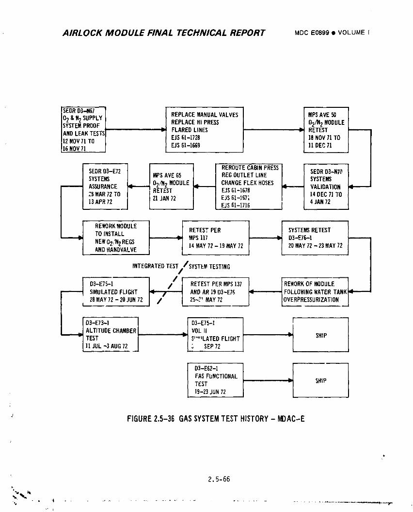
AIRLOCK MODULE FINAL TECHNICAL REPORT MDCEO899• VOLUMEI
]sEo o3 67I I02& N2SUPPLY REPLACEMANUALVALVES MPSAVE50SYSTEMPROOF REPLACEHI PRESS O2/N2 MODULEANDLEAKTESTS FLAREDLINES RETEST -------12NOV7t TO EJS61-1728 18NOV71TO16NOV71 EJS6]-1669 11DEC71
9p_ REROUTECABINPRESS
SEDRD3-E72 MPSAVE65 REGOUTLETLINE SEDRD3-NTO
SYSTEMS O2/)12MODULE_ CHANGEFLEXHOSES SYSTEMS------- ASSURANCE _ VALIDATION;.8MAR72TO I RETEST EJS61-1678
13APR72 [ 21JAN72 EJS61-1671 14DEC71TOEJS61-1716 4JAN72
TO INSTALL RETESTPER SYSTEMSRETESTMPS117 D3-E76-1
NEWO2,'N2REGS 14MAY72- 19MAY72 20MAY72-23 MAY72ANDHANDVALVE
INTEGRATEDTEST//SYSTEMTESTING
D3-E75-1 / RETESTPERMPS137 ]REWORKOF MODULE ]" ANDAR19D3-E76 _ I FOLLOWINGWATERTANKi_ '
SIMULATEDFLIGHT / 25-?' LOVERPRESSURIZATION[28MAY72-20 JUN72 / MAY72
ALTITUOECHAMBERI ._ VOLII .]
TEST I -I S'""LATED FLIGHT -L SHIP]1 JUL-3 AUG72 __[ _, SEP72
D3-E62-] I
FASFUNCTIONALTEST ' SHIP19-23JUN72
FIGURE2.5-36 GASSYSTEMTESTHISTORY- MDAC-E
2.5-66A
]9740]8208-284
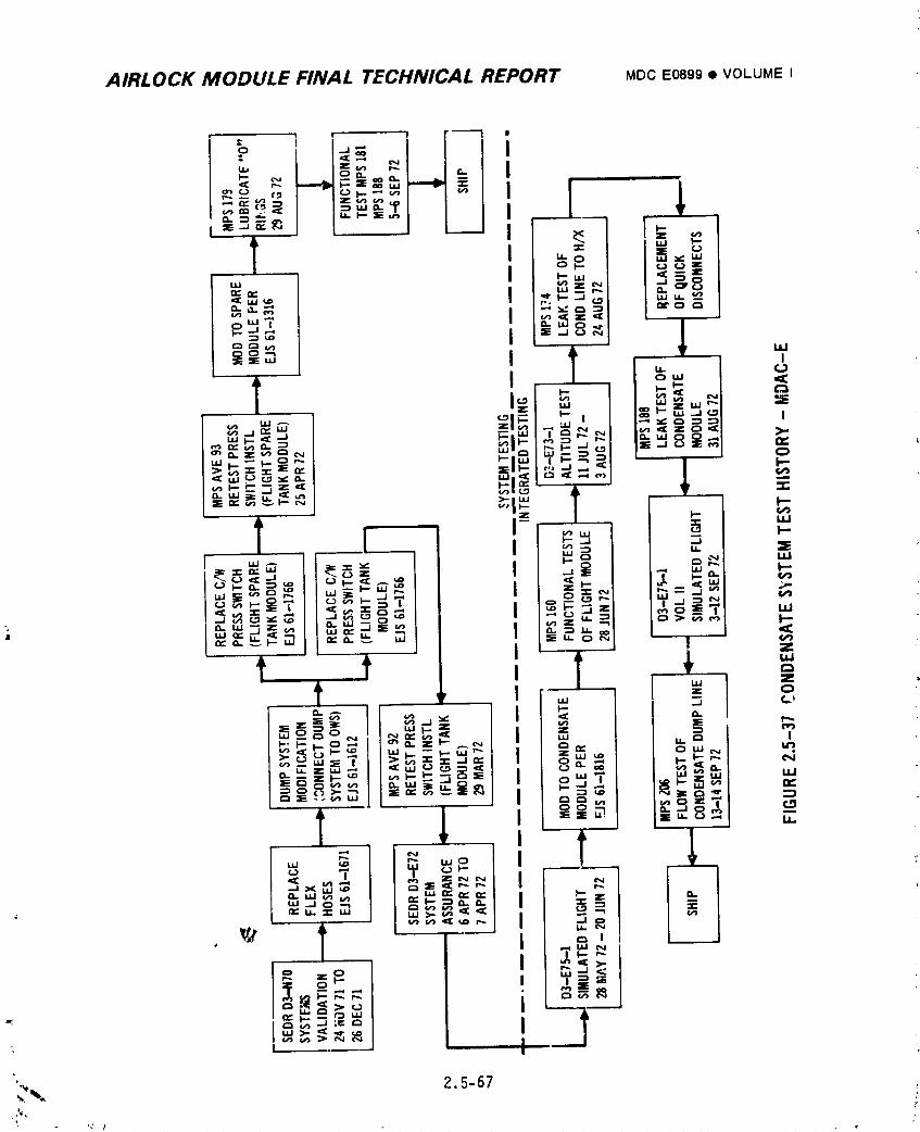
AIRLOCK MODULE FINAL TECHNICAL REPORT MDCE0899• VOLUME I
AIRLOCK MODULE FINAL TECHNICAL REPORT MDCE0899• VOLUMEI
• SEDRD3-N70 was the first system level test. During this
test, the 02 and N2 gas system was leak checked, componentswere functionally checked, and system flow rates verified.
System instrumentation and caution and warning parameters
were validated along with verification of DCS controlled
functions.
• During SEDRD3-N70 it was found that inadequate flow
occurred from the cabin 02/_!2 fill line. The 02/N 2 moduleand fill line were both modified to correct the problem.
The 02/N 2 modu)e was removed from the vehicle for tilerework and retested per MPSAVE 65, prior to reinstallation.
Retest of the fill line was deferred to SEDRD3-E72.
Various flexible hoses in the system were updated to the
latest configuration and some hardlines were insulated
during the time of 02/N 2 module modification.
• The 02/N 2 system was revalidated during SEDRD3-E72. A
functional c' _ck of the EVA/IVA 02 system using a suited Icrew man at sea level ambient cond" ions was also performed.
Following SEDRD3-E72-1, the 02/N 2 module was removed from
the vehicle and the high pressure 02 and N2 regulators
were replaced because of a configuration change. During
this time the shutoff valve far the OWSN2 supply was
replaced with an updated unit. Retest of the reworked
module was accomplished by MPSaVE 117 prior to reinstalla-
tion in the spacecraft.
e The 02/N 2 module was reinstalled in the vehicle and system
retest was accomplished by SEDRD3-E76. During retest the
water tank N2 pressurizatlon system was inadvertently over-
pressurized. The 02/N 2 module was removed from the vehicleand some components were replaced. Retest of the module
after component replacement but prior to reinstallaLion
was accomplished by MPSAVE 137.
e The 02/N 2 module was reinstalled in the spacecraft and the
02 and N2 gas system retested by AR 19 versus SEDRD3-E76. i
., 2.5-68
A. ,-_jI e
]9740]8208-286
AIRLOC[; MODULE FINAL TECHNICAL REPORT MDCE0899• VOLUMEI
(3) Condensate System - The initial system level test was performed by
SEDRD3-N70. This test included system leak and functional checks
at operating pressures and a dump cycle test using No. Instrumen-(.
tation and caution and warning parameters were verified. Several
modifications were performed to improve the system. These
included: (l) replacement of flexible hoses to provide a more
reliable hose where the hose is used wlth a quick disconnect,
(2) connecting the dump system to the OWSwaste tank to eliminate
ice particle generation outside the vehicle as a result of an
overboard dump, (3) replacement of the condensate tank module pres-
sure switch because of a dielectric failure following vibration
testing of the pressure switch. Following rework, the condensate
tank modules were retested by MPSAVE 93 for the flight spdre and
MPSAVE 92 for the flight unit. System functional and leakage
tests were performed during SEDRD3-E72. This testing also
included verification of caution and warning and overboard du_,,a
heater functions.
2.5.3.5 Integrated Tests
Integrated tests were conducted to verify that the vehicle was ready for flight
both at the factory prior to delivery to the launch site and at the Kennedy Space
Center (KSC) prior to launch.
A. Factory Tests - The tests conducted by MDAC-E in St. Louis are summarized
below. Tntegrated test requirements were specified by SEDR,
• Atrlospheric Control System - The system was operated in _ support
mode during simulated flight (SEDR D3-E75, Vol. I). The support
operation included verificai:ion of fan operation and molecular
sieve valve cycling. Timemole sieve beds we,e baked out at the
end of the test. Proper operation of the ventilation system was
verifiPd under simulated altitude conditions during the D3-E73-i
altitude chambur test. This included cabin environment contamina-
tion remnva I , humidity and temperature control, and verification
of proper flow rates. Tests were conducted during unmanned and
manned altitude runs.
' 2.5-69
i
1974018208-287
AIRLOCK MODULE FINAL TECHNIf';AL REPORT MLCE0899• VOLUMEI
Power ccnsumption of each of the 8 PLV fans was determined by tests
per MPS AVE 122. Frequency output of each mole sieve compressor"
power inverter was determined after the aitltude chamber test
(SEDR D3-E73) per MPS 171.
The system was operated again in a support mode during simulated
flight (SEDR D3-E75, Vol. II). At the end of the test the mole
sieve beds were baked out in preparation for shipment.
• Gas System - During simulated "light (SEDR D3-E75, Vol. I) the 02
and N2 gas system was operated in a support mode.
During the altitude chamber test (SEDR D3-E73) the system was
operated i_ a fl"gnt mode except the gas storage tanks were not
pressurize_. 0 and N2 was supplied from GSE connected to the
vehicle high pressure lines. Fhis included supplying N2 for mole
sieve valve cycling, 02 for EVA/IVA operations, and 02 and N2 forcabin pressurization.
i.
During simulated flight (D3-E75, Vol. ii) the gas system was operated
in a support mode. Mole sieve beds were cycled and instrumentation
parameters monitored during this test. Proof pressure and leakage
measurement tests of that portion of the O_ system installed in the
FAS were conducted per SEDR D3-L62. This included all plumbing and
components from the 02 tank check valves to the FAS/AM interface.The tank assemblies had been previously verified by SEDRD3-G62.
® Conaensate S_stem - The system was operated in a support mode du_ing
simulated flight (SEDR D3-E75, Vol. I). Caution and warning check_
and overboard dump hea_:er functional tests were performed again
during this test.
After the simulated flight test, condensate tank moaules were
modified to allow use of gas from the gas side of the tank to
purg_ water from dump lines after a normal condensate dump operG-
2.5-70
1974018208-288
AIRLOCK MODULE FINAL TECHNICAL REPORT MDCE0899• VOLUMEI
zion. Checkout of the module after mod]fication was accomplished
by tIPS AVE 161 for the flight spare and MPSAVE 160 for the flight
unit.
lhe system was used without the t_nk module for condensate removal
du_ing the manned altitude chamber test (the tank module could not
be used due to the l-g environmenti.,Li
After the manned altitude chamber test, the condensing heat
exchangers were trea_ed with a germicide ana dried. Also, one of
the condensate removal flexible hoses was reorientated to providea better installation. Retest of the nose was accomplished by
MPSAVE 174.
Some quick disconnects were replaced and O'rings relubed to the
laLest Q.D. configuration. After Q.D. modification retest was
accomplished by MPSAVE 188. The system was operated in a support
, mode during simulated flight test (SEDR D3-E73, Vol. II).
Tim final test at the MDAC.E facility was a system flow Lest
to determine pressure drop !n the condensate system between the
tank module and the OWS/AMinterface. This test was performed b_
rIPS AVE 206.
B. KSC Tests - Launch site test requirements were specified in MDCReport
E0122, Speclfic_tion and Criteria at KSC for AM/MDATest and Checkout
Requiren_mt_, and K_r Report KS2001, Test and Checkout Plan. Results of
testihg at KSC together with factory test results are presented in
Figures 2.5-38 through 2.5-40 For the gas system, atmosFhere control system,
and condensate system, respectively.
2.5-71L
1974018208-289
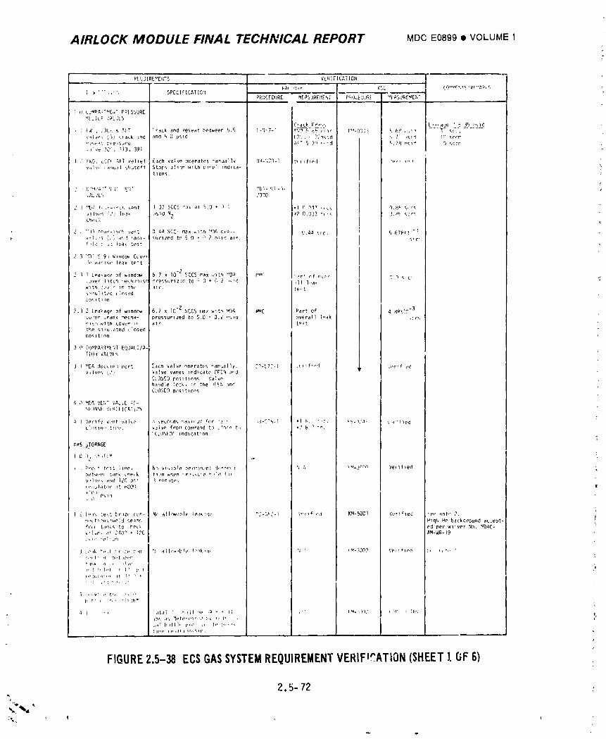
AIRLOCK MODULE FINAL TECHNICAL REPORT MDCE0899• VOLUME I
RZQ'JIRU_ErlTS VERIFICATION
_-A(T(IP_ KS{. CO,,._r,Te ,_c..Ap,q
[',_ ' '", ,'', SPECIFICATIHq PROCEDURE MEASuREr4EhT PfVO_LDLJRE uIASdF_£'xEM,,. _ ,,,
I d LJNIPAUT_E,,TP_ESSUREUZLILF VALVLS
Crdck Pr_J__, L,_,rlcie_ 5 ]5 n_Id) ; iA' . LJLK f,AFT (rack and reseat between 5.5 [,-q'.7-1 r'_5-_-}'%Ic Y'_-O]J3 _,&£ , ,_", "-T _ q{t'........
valvP_ _3J ttaLk dnd and 6 0 psld ( Q_ii - 7;_d ', 7] ,_id lq Sccr," 's,.at [_re,surc _FT % 7n ,, Id r_.7,_n_" ") _CCr.!]re 30'_, 113, 391
1 .' F_D, _')C_ AFT rel_ef Each valve o[Jerate_ r'anuallv hR-'i70-l V, tlflml '_r_ _v,_Iv, ianual '_hutoff Stops 3111_ wlth panel Indlca- '_
tlons, iLi "
J ,C_'_,'_'T'[;T 'E'IT "9;-,CO-n- l ,,AL JL', .'oqo,
2 I "[_.'_f, _-m_L _e,lt l 37 SCCS tna, at 5.0 + O 1 -l o Q_ _rcs 0.8F S_c_
valw,_ :?) h,ak used N2 ,2 0.033 _r,_ '].P_ <_cr_,checl,
2 _ "[1% teur-l.lCh vent 0 44 SCC- max ,_ith "DA Dr_,- U,44 scc, I 5 67Pv! --_
, v,_l_ 's (J_ a' _ 'anl- _umzed to 5 0 + '_ 2 Pql't air. f n,c'
f'l,l = _ leak test
2 3 "D' C19, W_,idO_ Cov.'_'P nan_v, leak t#-t
2 _ l LPakaee :if window 5 7 x I0 -2 SCCS max iiltr,'_DA l '_'r "_r + nf n_o,-- I 9.,_ _ c,,cuv_r l_tch r'_chanlsr _ressurlt-_d tO _ 0 + C 2 _Id _ll l.,a. Iwith c,,¢ " in the, ]lr. ,+e%t_H'lulated ( lo_.ed20S 1t:nn
2.3 2 Leakagp of window 6.7 x I0-2 SCCS flaxwlt'l uDA Im4C Part of 4 RRXIO -3co'er Lrdnk mecha- 3ressurlzed to 5.0 + O.L nSla overall ]_ak ,ors
" s w th cover in _ir. t:_tthe Slmulated L1osed[10S 1t 1on
3 0 COMPARTME'IT EQUALIZA-
TlO,w VALVES lI
J I _DA docklnq [;err Zacn valve nneratt.s _anuallv. ['_-ET?-I ,_,lfl,-d ','(,rlf.ed
v_Ives (21 Valve vanes _nd_cate OPEN andCLOSED po_Itlnns Valvnhandle lock> In the IFEPI IndCLOSED Ons_ t_ons
4 J MI)A VEldT VAL,E P[-
',P'iNSE'h_l iICAT iON
T4 l Verlfv VeIlt valve ,_seLor,ds '_aXlliUmfor '3rh ,',3-E'5-l :l 6.J _'c. kS.n?_, ',,,_led
ch_Sln,, tl:_'e, valve from comi'landto cTqq _ tn _[' 6 _ "_"CLOSED" Ind_cat_nn.
C,_S _I"ORAGE
1 0 C/2 <,_>T[U
, i Pi'O, t te_t line, h_ visible bprrtl,ln,,nt 'J,.f._r_.t- 'i -", _M.j,_.',n Vetltledhetw,,+,n tank tnetk tl_m when _r,<.qure n,,ld f,.V41V+', a,,d 120 p+,_ I minute,,i,,ql*l ator ,it oOOO I+I01
I 2 I,,Ik test brlze con- N_ allew,lbl_ leakl,l,, _]-(,t,j-I V,-r,_ ,'d KM-500I Verified _m, lint,, 7.
n,,ctImls _we :3 seam _, HI clhHe backQround ac_ept- ?fix,r I tank_ to _heck ed per w_iver Nn. _IDAC-vllvn, a_ 240r �170AM-WR-I9
i 3 k,'lk t*,,t !,'tL*' c,n '_ all+_w_bl, , l,'_kt(], 'I " 1_-30OO t,'ei'l¢lr, d k, ,tit,> • ,n,,, t ' ,1 h,,t _o.,n
tl,,w a ,, ,Iv,, "l,,,d',l,,t t 1 ' I' I, e, fill ,11tl, tl [,ll_ •
l I ',+,,v,,,, th+ ,', '_
I_ t'h,, I,, tlllh_'
I ,i 1 I',t lotal I, ,ln_ll '_i, ,_ i_ . II +'* l_t-_rl'], ' ,_Y _ lb',Ib£ ,1,, _i, terll'lr_t ',_ hv II,ll, ,}+ _tlal b,_ttl,' nlil 11 Ii _ i,, r t.ltirp i_,l,lll m,,hl_,,
FIGUREZ.5-38ECSGASSYSTEMREQUIREMENTVERIF=CATION(SHEETIOF 6)
2,5-72
_.._ji- I
1974018208-290
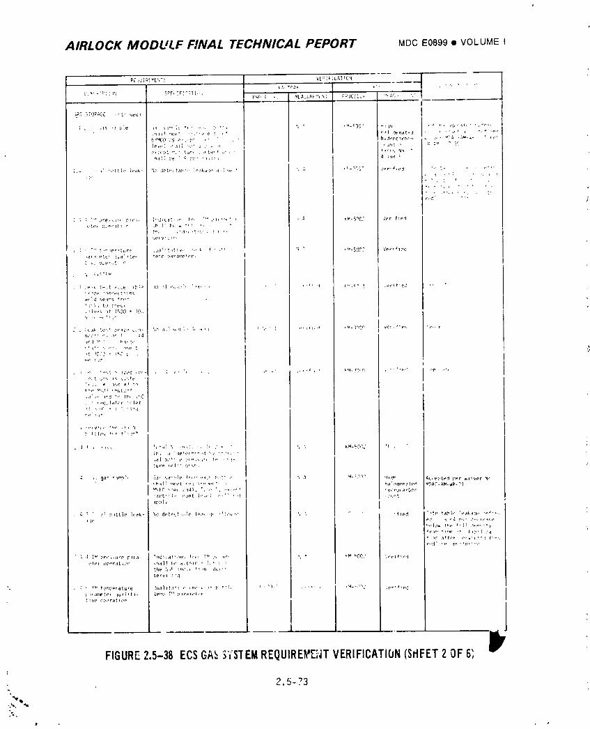
AIRLOCK MODULF FINAL TECHNICAL PEPORT MDCE0899• VOLUME
P[ _JIP_ _EqT. _ '_[_I _;CA,_TC'_ J
,t,_ -ADV _'' _ ' " ," '"[X_D::'TI_'; Srr :r'.f_TI,', P_(, F -: MEAShP_'_t'_; P'_OCE/',." ",;,S, ',"
II
]AS -_T')_AGE '" t" 'ued) I
; L _,ts -a Li:e ,_ _l_,']_ it' ,,,, t, **i ,_ * iM-_,]0' -l_n i'"
r, ,
,h_: mt,_" ,,_,''e e t ,+ ,_,,1 qenat_d ' '','' ' _'" "'P_
6_ML}0 'P9 P" .,'['" _. ] , , h,dro£,lrb,-m _ , ,_ t ,_r_ ..1,_... r_,,
le,¢] ,' all m," _ ji. ,r , jr,t ,,_r_S Nne,ce[,t ,_l" fur, . ,rt_ ,t ,,',, '
r,'C" " ' 3
_'te_ {L,er_'.l r .b I] b_, _ t'_ ', , '
" "" t,-_erature uallt tlv.. , ,+- k f . ,_ , N ' !_-500_ V_rlfl2c
t. ',. 9._pr,.%'
', <,';T_v
r,zP con_,Pct _ mq
_,Vl',, to cqeLk
.,iv,,_ _t 1500 + 10_,
q ,, -% ' _u"
" _ ;cal, re'." Dra,:., c,'rl- '_,_ a',l,'_'t 1" ','q <-',, _ ] .',_1,'_ ,M-lnOn Ver, '_'+",, 'e',' r
nec+l _. ,,_ T =4
''!', r, ,:_. q,,e, t
• _ ,. %._.t ",_ _z_,d ,(.t- , ,; ,. ,, , ,_ , ._,_ , _M._40,-'O , ,,+'_d ,'e ,"*
T, ,, • _',d .3 to
.4' ,,-, _,ld * i_ t h_ I J '10
• ' ,-qulator ,plPt
b f. tlt,s +,,r f'l_ "_
4 r r'l%_ "*it-t] '_ ,h,] "* ]* C ' " kM_[_O(_' 1_ . ',
;rs j ,,1e+er_,_,,l '.r '.,'_.,
.t ,, ga _ Slm,_],' '_d" sa"ph, fr,,,'+,_,.b r,,,t' ,, ,_ _ _nr" _lqh AL_ei,ted p_r walvPr Nn
',_'a}] ._','t ,-,,mlr,, '_,, "' , _alneenated _DAC-AM-WP-?I
MS_C k,_p_ Z_4'*, ",:,' ', ,',,,"+ .y,lro(arb._n
,art't_p Lmmt i*',,,i h,'_ , ,t ,run_
tppl <
r,id_',P x_' _'0,'",I
4 [_' pr,_,,urP p41,1- 'ndl.atl_n,. fr_l T_ 2, ,ira. % " '_ kOO,' ',erl_lP_
_ervl 1,1q
I
FIGURE2.5-38 ECSGA_3YSTEMREQUIRE_Z;_ITVERIFICATION(SflFET2 OF6; Dr
2.5-73
1974018208-291
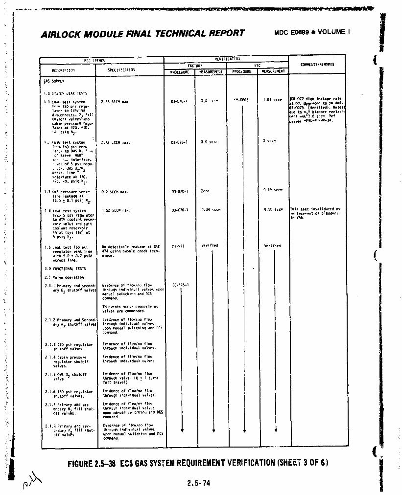
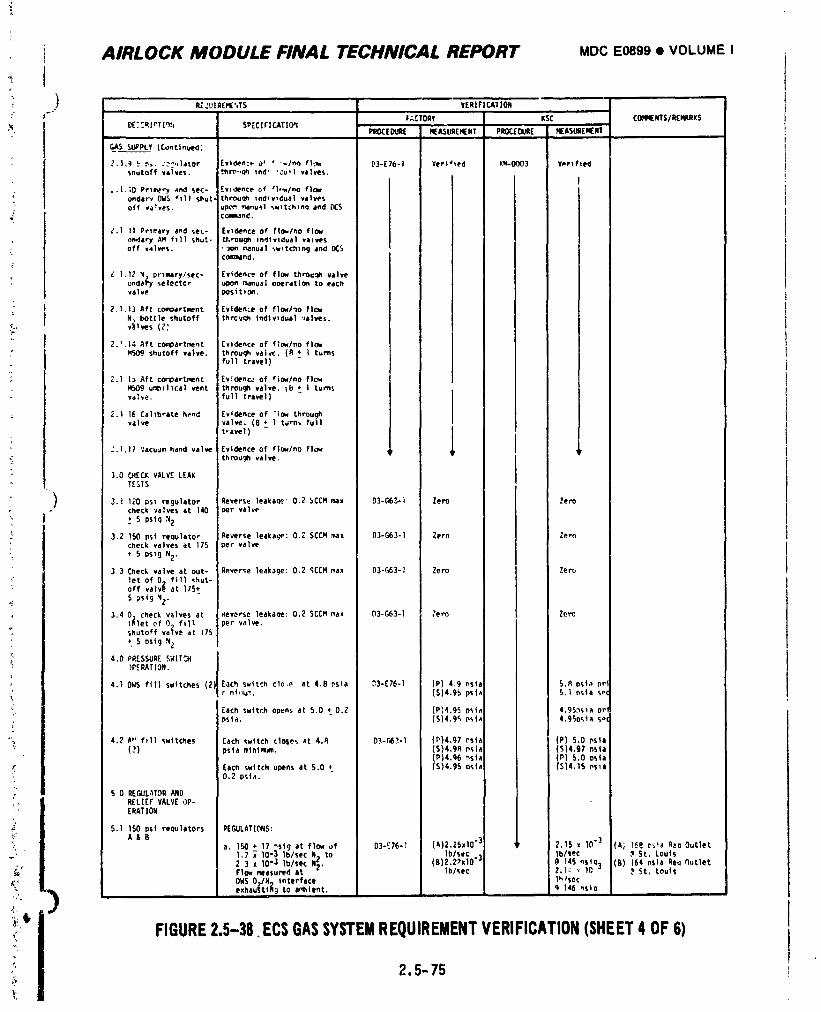
k
J AIRLOCK MODULE FINAL TECHNICAL REPORT MDCE0899• VOLUMEI
: ) R[._Ul RE_',T_ VERIFIEAT'ION
J- =:;.CTORV KSC COm_NTS/REPVmKS
I OE;Cq lDT|q_'; SPEC| FICATIO'! PROC[DUAE H£J_SUflEH[NT PROC[OuR[ HEASLIREMENTGAS SUPPLY (Continued',
2.|,_1 __ ,_,..'_',*|ator [vi_.nc_, o _ " -,/no fl,_ _3-[76-1 Vert*led Ku_-O003 V_,r_fted
snutoff valves, thr_.,_ tnd' "Cu-I valves. I ]l,-|,;0 Prl_-y and seE- Evidence of tire/no f]_
ondare OWS "11| S_ut. throu_ Ind_v_dual valves i• off valveS. UpO_t_lnu_1%_ltChtnq and [_:S
cGa_3n(_.
Z.1 II Prlrary and sec* Evidence of fto=lno flow I
ondary A_ fill shut- tt.rou_ Individual vails I Ioff valves. ' _On _nual _wltchtn 9 dnd DC$ I
COa_and.' I [
L. l, 12 "4)prlmlrylsec- [videnc_ of flow *,.hrouq_ valveondet_ se|ectc_ upon r_nua| o_ration to eachwaive Posit 1Cm.
Z.1,13 Aft comoartmnt Evidence of flow/')o flow i lN:, bottle shutoff thrCuqh tndtwdu81 'lalves. i I I
." i
_.',14 Aft compartment [v)dence of f]o_/no fl(_ I
M509 shutoff valve, throuqh valve. (8 * I turns
full travel) i
2.1 1_ Aft co_oartmen_ Ev_Oenc_ of fi_/no fl_H509 umbilical vent through valve. _8 + I turns iyah, e. full travel) I
I
_..| 16 Calibrate h_,nd Evidence of "1_ throughvalve valve. (8 *_ I t_n_ full
t_avel) L-'.I.17 ;'acu_m hand valve Evidence of flo_Ino flo_ 'i 'rthrou._ valve.
3.0 CHECK VALVE LEAKTESTS
3.1 17.0 ps_ regulator Reverse leakage- 0.2 _CCM max Zero ZeroD3-C,6_-I
check va]ves at 140 oer valv_
• S pslg :42
3.2 15(1 psi reQulato_ Reverse leaka_: 0._ SCCH max 03-£,63-1 Zero 7.e,'ocheck valves at 175 per valve
+ S pslg N2.
3 3 Check valve at out- Reverse leakage: 0.2 %CCMmax 03-G_3-1 Zero I Zero
let of O_ fill _hut-off valvl} at 175__
5 psi9 '4_.
3.4 0 check v_lves at _everse leakage: 0.2 SCC_ max 1_3-G63-1 7ero Z_ro
t_let of 0_ fill per valve.shutoff va_vt = at 175
5 osi9 N_
4.0 PRESSURE SWITCH1pcRATlO._.
4.10WS ftll switches (2', Each switch clo,e at 4.8 Psia _3-E76-1 (P) 4.9 nsla 5._ os_a _r!
Each Switch opens at S.O _ 0.2 (P)4.9_ p_,ia 4.95._sla or'ps_a, (5)4.95 osi_ 4.9_o_.Ia s_
4.2 /_*' fill switches Each switch clOSes at 4._ o3-r_2-1 (P)4.97 _,sla (P) 5.0 psla
(-_) psla minimum. (S)4.9R Psia (S)4.97 f_sla(P)4.g6 ,_sia (P) 5.0 osta
Each switch opens at 5.0 * (5)4.95 nsla (514.15 ns_a0.2 psia.
S 0 REGUL,,TOR AND
5,1 150 psi requlators PEGULATIONS:A&8
a. 150 + 17 %lg at flow of D3-E76-_ (A)Z.25x10 "3 _ Z.1S _ 10.3 (eG I_8 _ta _o Outlet
1,7 _" 10"3 Iblsec N2 to Iblsec _ Iblsec _ St. Louis
_ 2 3 x 10.3 1b/see Ng. (B)2.Z_x10"" P 145 nStO] (_) 164 nsta Req r_utletFlow measured at " lP/sec 2,1c _ 1_, ? St. Louts
_, OWS 07/11;, interface 1_/sec
exhauSt|It 9 to ambient. _ 146 nsio
:, I FIGURE2,5-38.ECSGASSYSTEMREQUIREMENTVERIFICATION(SHEET4OF6)2.5-75
1974018208-293
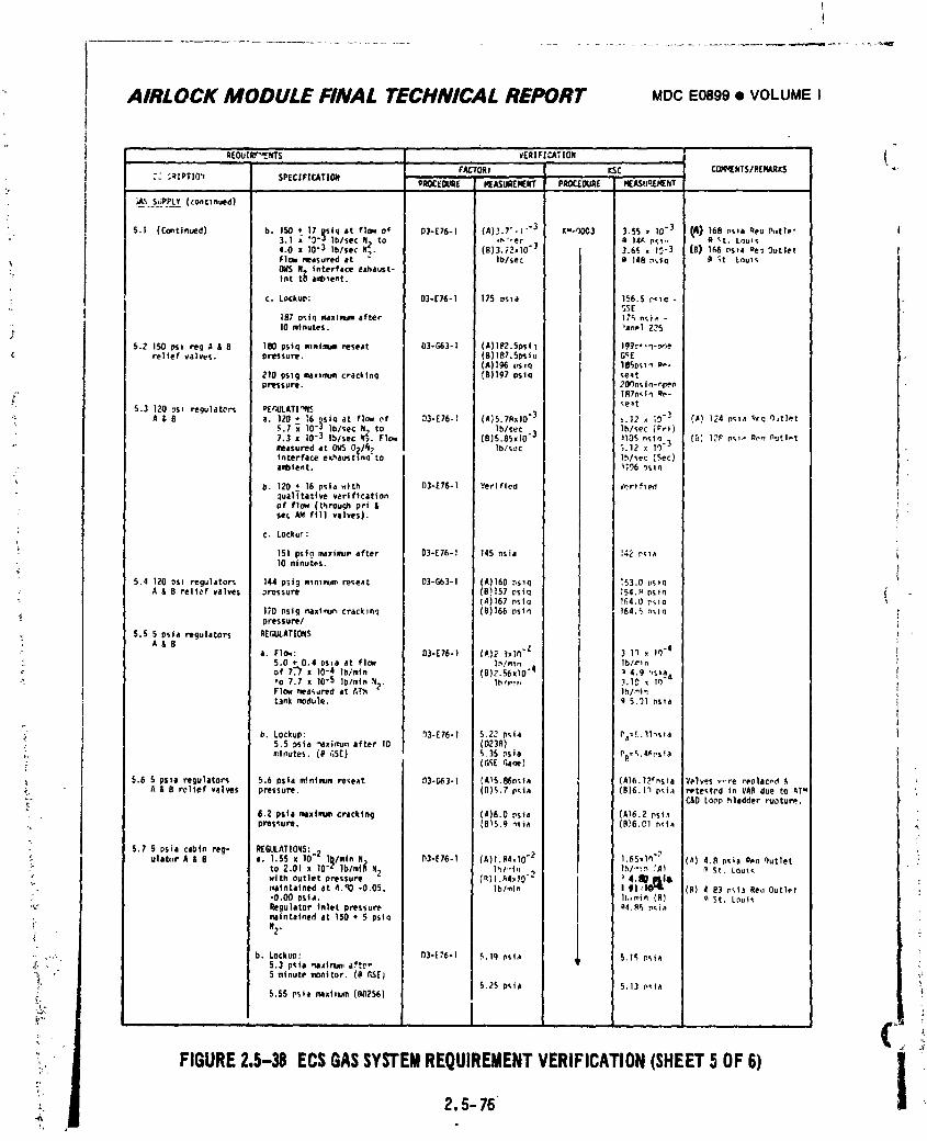
AIRLOCK MODULE FINAL TECHNICAL REPORT MDCI=0899• VOLUMEI
_[_t__.TS _rRzF;CA:IO. - {_' " fACTORy _SC _NTS/REHARKS " --
:.._ :_;tXPT10'_ SPECIFZCAT|ON PROCI£DI.q_ MEASuR[MENT PROC[OURE NEASUC_ERENT
___ s_]PP!_v(cont:n.ee)
5.1 (Contim._d) b. 150 + 17 Rsig at flow o_" 03-[76-1 (A)._.T,i "'3 K'dJ)OC3 ).55 _ 10"3 (A) 168 psla Re_ P.tlet |: 3.1 _ °_)'-_ |b/see N. to ,_"ec • 14_¢p_- la 't. Lnu:s
4.0 • 10"3 Ib/sec N_. (El3 .;2*10") I 3.6_ e IO'] (S) lee nsla De-.OutletFIoN eeasured at _ lb/sec J G 141_p%in _ _( LouIt.
- OMSN:, interface exhaust- itot tlJ aeib_ent. I
Z C. Lookup: 03-E76-1 175 _sla I._6.5 r, la -5SE
187 pslq maximumafter i 17_ n_ia -
_' 10 minutes. _anel Z?$5.Z 150 psi re<] a & 8 180 psiq mnimum reseat 03-663-I (A)lP2.Spsll I9_r.,'l-._e
relief valves, pressure. (B) l_7.5psi_ I G<£(A)t96 _S:O 185os_ P_-
ZlO pslg max:mumcracklnq (B)Ig7 osta _e_tpressure. ?Or_nst n-e.pen
_" l_q7n_tn qe-"-e_t5.3 120 os: regulaters PEt'4JLATI_NS
A & B a. 1;?0+ 16 _siq at flow (_f 03-E76-I (A}5.7RxlO "3 I _.17 • _9"_ .f_! 1_4 r)_;la r_q el_tlet5.7 _ I0.3 Ib/sec N_ to Ib/sec 3 1h/see _¢'rl)7.3 x I0 -3 lb/sec N_. Flow (B)S.85xlO" }lOS nstn _ {_ 1_ ps_ _n nutlotmeasured at O_SO21q_ Ib/s_c _ _.1_ x lq'"interface exhaustlnq_o ' lh/_ec (_ec)ambient. _196 .%_
/
b. 120 • 16 psia wi_h 03-E75o1 Verified _'_.rlfled_ual_tati ve verificationof flew (threuch pri &
: sec A_ fill vaives). !!
": ¢. Lockur: I
151 psi? maximumafter O3*E7E-1 145 nsia :4_ r_a• 10 minutes.
5.4 1ZOos_ regulators 144 pstg m_mmumreseat 03-Gb3-1 (A)160 .%_q I "53.0 t_s_o: A & B relief valves _ressure (B1157 pslq 154._ pstn _'"- (A)167 nSlq I_4.0 r_;i(_
170 I]signlaxinlUr,cracklflq (_1160 pSiC; |64._ n'_lq_- pressure/
_ 5.5 5 psta regulators REGULATIONSA&B
a. FI_: 03-E76-) (A)_)xlt_ "_ 3 lq x lO"l5.0 + 0.4 OS_aat flow l,_/m_r: • lb/e'_nof 7."7 • 10"4 lb/mtn (R)z. S6xlO-_ 1 4.g %_aa
•_. "0 7.7 x 10.5 lP/min N_. lh/._r, .1.1_ _ 10 -Flow measured at AT.'q " lhl_In
Lank module. [ _i5.'J1ns_a!
_ b, Lookup: ._3-E76-1 5.22 p_la P_,r.ll_s_a5.5 psta _aximumafter lO (023A)
,, minutes. (P _;S[) _.35 ._sla Pp©_.4_Psia
_. 5.6 5 psla regulator_ 5.6 psla mtntmumreseat 1_3-G_3-1 {AIS.8_O_la (A)6.1?fns_a V_lves _','re replaced .e,_. A & B relief valves pressure. (lt)_,7' p_ta {S)6.1_ p_ia retested In VAn due to ATu_- C&DLOOphladder ruotur_e.
• . 6.2 ps|a max|mumcracking (A)6.O psta (A16.2 ps_a.. pressure. (BI5.9 n_;ia (B)6,O1 n_t_
. 5,7 S osta cabin reg- REGULATIONS:Zulab_r A & O a. 1.55 x 10" l_/mtn N_ 03-[76-1 (A)I.AI,IO "2 1.E5,1_'? (_} 4.p p_ta Pen qutlet
to 2.01 x 10"c lb/mt_ N2 lhl'-t. _ lh/.-:n _A) _ St, loul_' wJth outlet pressure (qll.A4_lO "_ _ 4._ pile,". maintained at _,_0 -0.05, lb/mtn I ¢I ._lO'm (B) 4 83 r_I_ Re,_Outlet" -0.00 OSia. h.,min {61 raSt. l_ut_'_ _�ulator Inletpressure _4._¢, p_a
maintained at 150 + 5 pslq
•-_ ,,,:_ b. Lockun: B3-E76.1 5,1q P_la 5,1r_ pr,ta_, . 5.3 p_ta ,_i_ln_n, aftr-"_ 5 minute monitor, ((I t,$E)_' 5._5 psta 5,13 p_a
FIGURE2.5-38 ECSGASSYSTEMREQUIREMENTVERIFICATION(SHEET5OF6)
2.5- 76
1974018208-294
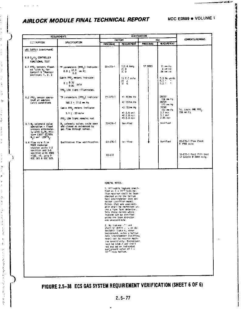
.......... l
: 1 AIRLOCK MODULE FINAL TECHNICAL REPORT MDCE0899• VOt.UUEI!
PJ_QUl REHENTS VERI FI CATION_'ACTORY KSC COMNENTSIREMARKS
rE-cRiPTlO;l SPECIFICATION PROCEDURE MF.ASURERENT PROCEDURE MEASURE_e_-I--
uAS SUPPLY (conttmRd)
6.0 02/;; 2 CONTROLLERFUNCTIONAL TEST
I)2.4 AmHg Ku 0003 11 mm Fa6.1 PPO) sensors flood- FM parameters (PPO2) indicate: 03"E73-1 2_ 0 6 mm Pa
eo "with ?42 for IContr-1 _- Ponitor 0.0 + 17.0 mm H_ 3'_ 0 I .06 mm r,a- 0.0
positions I, Z, 3 ICabin PPOZ meters indicate: 1) O. _. I_sia 9.3 No units
2) d 0.I "0 ,0.33
- O.OG psia 3_ 0 q.2 "
;)POZ LOW light illuminates.
6.2 PrO sensor opera- TE i_rameters (PPOz) indicate" _7,-:470-] mi 1S3mmHa D0237tiol_ at ambient IS9 mm,q
(air) condtttcms 160.3 + ]7.0 mm Hg a2 lS7r_n Ha DO23917r) _m ,g
Cabin PPO2 meters indicate: m_ l$0mm Hg _'_q2&_i5._ mm Hq St. Louis AMB PPO2
3.1 ", .33 osia al 2.9 osi 3.0 osl 156 menII 982 2.8 nsl 3.1 psi
PPO? LOW light remains nut, u3 2.9 nsi 2.95 nsl
6._ N2 solenoid valve N_ solenoio valves cycle o_en I)3=E76-I Ver;fled Verifiedoperation - Flood alld closed as evidenced bys-nsors alternate- gas flow through valves.
lj with O_,/N 2 mix-tur_ (35: _ 0_/65%
N2) one OO%'N z.
6.4 Flow ra_e f:om Qualltatlve fl_ verlflcatinn. 03-E76-] ';e_ified ,p Verified D3-E76-1 Flow Check
M509 recharge _ lnO0 {)sinstation usin9 I-2nosttion and 3-6
_,_ oosition with 3000
+100, -0, _sig @ 03-L7Z 33-E72-1 Fast fill testGSE _5 & GSE 529. )f bottle @ 2_00 nsig.
I i
AENEPAL NOTES:
1, A1l_wable le_kane snecl-fled a_ I x 1N"a SCCS he-lium _xl_Um shall he leak-checked u_In9 the hell ummas_ spectrometer leak de-tector LsniCflnn mode).Pelnt_ that are unaccept-
able shall he rechecked u_-_nn a _son leak detectnr._nlv thnse pnTnt$ whore1_akaae can be verified
uslno th_ Uson det-ctorare uneccent_h]e.
2. No lcakane ,'" redshall b - defln .r _ nn de-
tectahl, _ 1:aka'e. abnveback_round_ ._Inn a heliummass _ectromoter (_niffinc
mode) _et to n,axIPl_r_mach-
ine sensitlvlty. Backqroun_nust he stab_ and shall
_ot exc ed an indicated
OaC_OPourd valu_ Of 1 xI_"p ¢CCS helium,
FIGURE2.5-38 EC$GASSYSTEMREQUIREMENTVERIFICATION(SHEET6 OF6)
2.5-77
m
1974018208-295
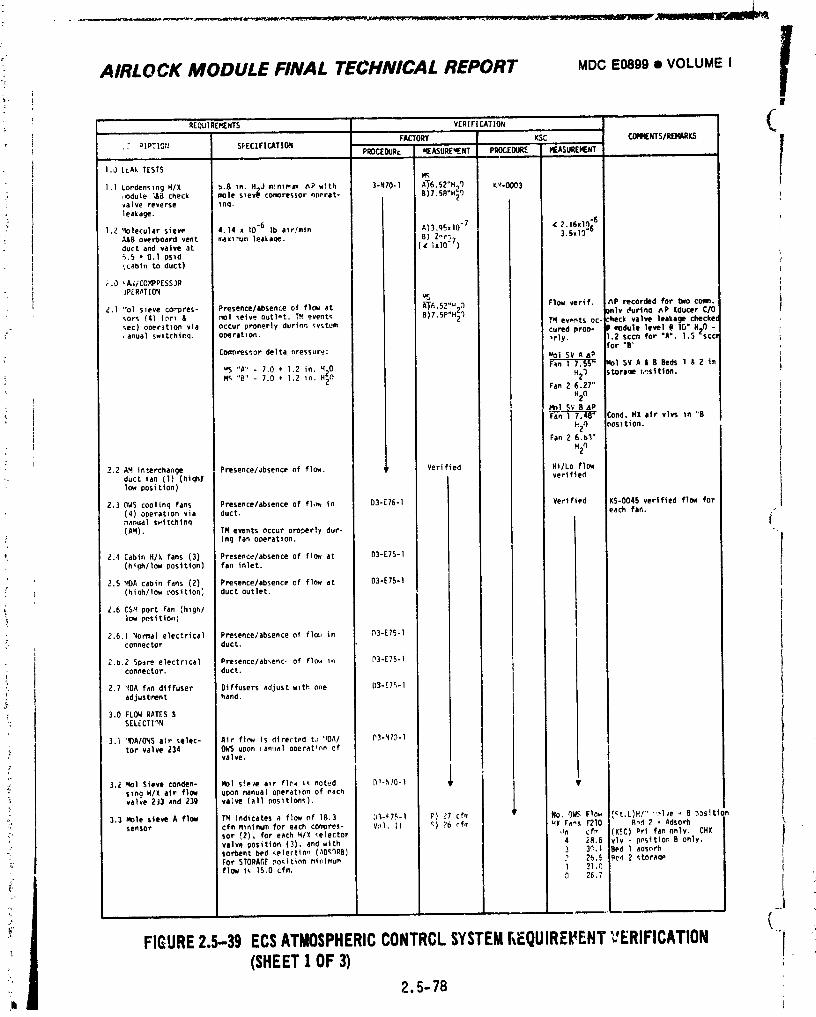
t-
AIRLOCK MODULE FINAL TECHNICAL REPORT MDCEo89g• VOLUMEI
' e
, , (' REQUIREt_NTS vERIFICATION
i FACTORY KSC CO_NTS/RENARKS l
." _lPTION SPECIFICATION ' PROCEDURe _ASUREqENT PROCEDURE HEASUREHENT ,
1.0 LLAk TESTSt_
I.I Cordenslng H/X 2.8 in. HgJ mnlP_m _P with 3-Pt70-1 A_'6.S2"H_'I K;_-O003 J
i_ ,_)dule "_B check mole slev_ compressor ncerat- B)7.SR"H_Ovalve reverse _nq. Ileakage.
1.2 '4olecular siew 4.14 x 10⁻⁶ Ib alr/mtn A)3'qSxlO" 7 (?.16xltl_6 I3.5x10"A&Bover_ooardvent rnaxl,_jm leakaqe. B) Z_r_7duct and valve at (_ Ix10" )_,.5 • 0.1 psld_Cabtn to duct)
_.0 __/CC.V_PESSJR- }PER_TIOq
A-_-_,S2,,_-) Plo_ vertf. ,_P recorded for _eOcorm.• _.1 "Ol_or_szeve(4)(nr_C°r'Dres'& _olPresence/absenCe_etveoutlot, ofT,u,flOWeventsat I B)7.SP.H_) only durtno eP Xducer C/O
_ec) ooer_tlon via occur pronerly durtnn _ystum J _ events PC- check vllive leakage checke(_" , anual SWltChinq. ooeratton, i cured proD- II _odule level @ 10" H_O-
•rly. 1._ sccm for "A". 1,$ %confor "B'
;" Co_ores_or delta nressure: _O1SV A_P
,_"A-70.1_o .-o _ _SVA_ee_Zi.V_ "B" 7.0 * 1.2 _n. H_n H_I storage _,_sttton.
Fan 2 6.27"
H2n" No1 SV BaP
Fan-_'n--_--7"_[__ Cond. HX air vlvs _n "B
h2_ position.Fan 2 6,b'_"
• _2n
: 2.2 AMinterchange Presence/_bsence of flc_. _, Verified H_/Lo flow_- duct fan (1) (hiqh/ verified
low position)
2.30WS coolinq fans Presence�absence of fl,x_ in D3-E76-1 Verified KS-O045 verified flow for(4) operatzon via duct. each fan.,_,anua1 swt tchtnq(AM). TM events occu_ properly dur-
ing fan operation,
,, E.4 Cab|n H/X fans (3) Presence/absence of flow at D3-ET5-1(h_gh/10_ position) fan inlet.
2.5 MDAcabin fans (_) Presence/absence of flow at D3-E75-I(hiah/Iow posttlon_ duct outlet.
_,6 CSM fanport (h,gh/low position;
• 2.6.1 Non,a1 electrical Presence/absence of flo_, in (13-E75-1 Jconnertoe duct.
- _.b.Z Spareelectrical Presence/ab_enc, of flow _ P3-E75-1connector, duct.
. 2,7 's,OA f_n dfffuser Offfusers adjus_ wl th one D3-E7%1__ adjustment hand. I
3.0 FLOWRATES$: SELECT_n_
3.1 'IIIAIONSair selec- Air fl_w is directedt,_'_OAI P3-_7,_-Itot valve 234 OWS upon ian.aloperationof I
valve,
3.i 'qol Sieve conden- Nol s_eve a_r flew I_ noted D_-NI0-1 ¥s_ng X/X air f](_ upon n_nual operationof eachvalve_J3 and 23g va_W (a11oosltlon,.).
3.3 Mole sieve A flow TN Indlcetesa flowof 18,3 b'_-_l.r,-I P) 27 cfm _' NO. OWS Flow {_t.l)H/""'.,1_e- B ooslt1(sensor cfm mntmum for each comores- v(_l, II _) 76 rfm _X ra_ F210 R_.4_ _ Adsorb
see (2),for each HIX _elector an cf_ (K_C)Prl fan only. CHXvalveposition (3),and with 4 2R.6 vlv - pnsltlonB only.so_ent bed _ete('tln,_ (AOe.'_RB) 3 3_.1 Bed 1 adsorbForSTORAGE.no_tlnnmt_lrnum ._ 26.5 Bed ? _tora_ft_ f_ TS.Ocfm, _ ?L*'_
26,7
FIGURE2.5-39 ECSATMOSPHERICCONTRCLSYSTEMEEQUIREFEHTVERIFICATION 'i i(SHEET1OF3)2.5-78
1974018208-296
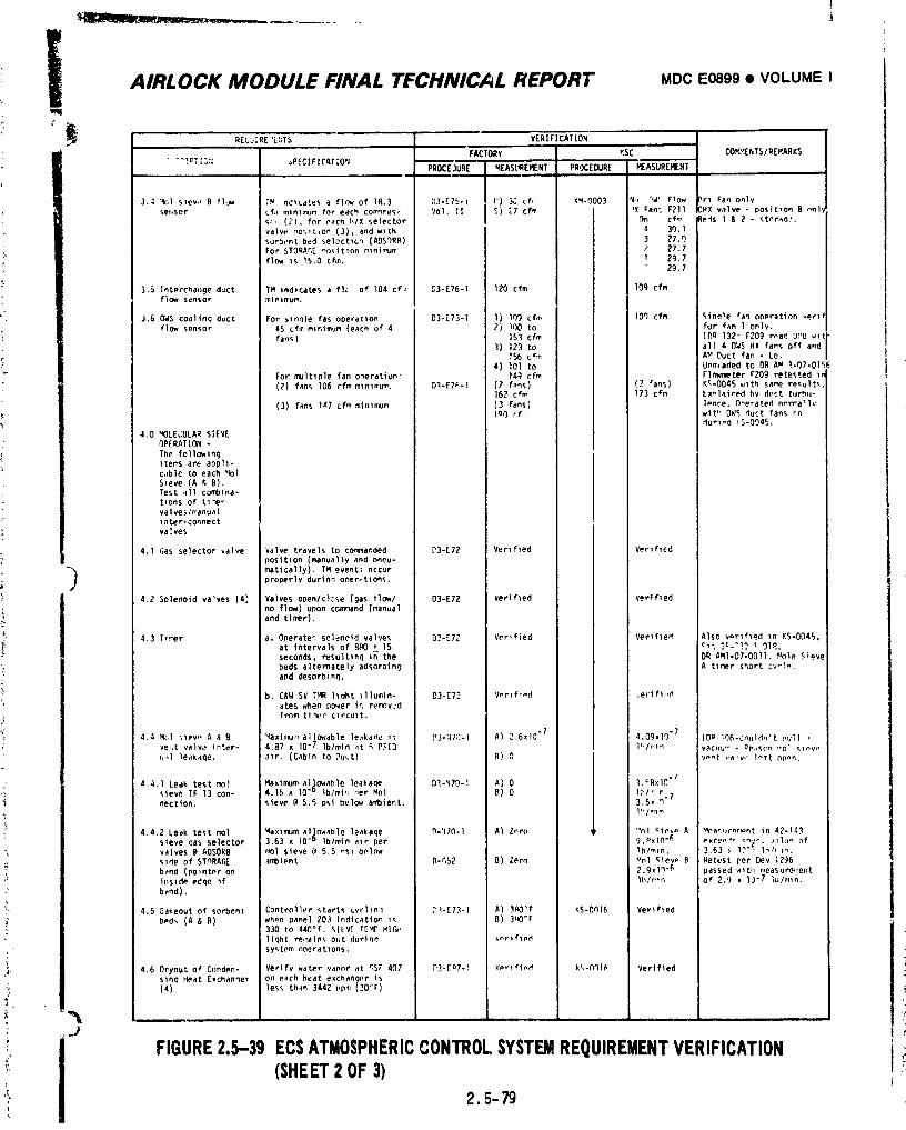
I
" AIRLOCK MODULE FINAL TFCHNICAL REPORT MDCE0899• VOLUMEI
REbUiRE':L;_TS VERIFICATION , . .FACTORY KSC COVb_ENTS/ R[V_RKS
" "_!rT |3:; _PECIFICATIO'IPROCE.)URE MEASUREMENT PR,)CEOUR[ MEASUREMENT
3.-I '401 slav., B flow T_ ncIlcates a flow of 18.3 :)3-E75-= I')3_ of,' K'_-O003 N(, n_, IrlOW )rl Fan only
se.sor ;cfAI mtnlI_Jm for each corn'Ires- Vol. IT S) ;.7 cfm 'X Fan; F2ll ;Hx valve - posit_on B only
S(, 42), for each li/Xselector C_n cf_' lads I & 2 - stnrao_.
va|ve _O_,Tt_on 43). and wlth -4 30.1sorb,,nt bed sel_ctlc_ (ADSORB) ] 27.qFor _TORAr,E -o_itlon l_ini,,_m ? _7.7
flow Is 15.0 cfm. I 2g.729.7
3.5 Interchat=ge duct TM tndlcates a flc of I04 of,, D3-E/6-1 120 cfm log cfmflow sensor minin_um.
J.60WS coolinq duct For slnqle fas operation D3-273-1 1) IO_)cfm 10r) cfm C,inale (ranoperation verlf
flow sensor 45 cfm mintmum (each of 4 2) 100 to for fan 1 only.
fan_) 151 cfm IDR 132" F209 r_a_ UI'U wit3) 123 to all 40_#S HX fans off and
lSb cfm AM Duct fan - to.
&) lOl to Unmaded to OR AW 1-07-015For multlple fan oneratiun" 14_ cfm Flowmeter F209 retested i_
(2) fans 106 cfm mlnlmum. D1-E7_-t 42 f_ns) 42 fans) Kc-O04S wlth sa_wErresults.162 cfm 173 cVm Lxnlained bv di,ct turb.-
(3) fans la7 cfm minimum (3 fans) l_,nre, f)_erated n_rrallvleo rf- wit" OWS duct fans rn
durlro _S-OO4L
4.0 MOLE,;ULAR SIEVEOPERAT ION -
The following
5 Items are aDph-cable to each _l
Sieve (A r,B).Test _II cornblna-tlOnS of tl,-lervalve ;/_anualinter-connect
i valves
4.1 (;aS selector valve Valve travels to co_Imanded ['3-L72 Verified Verified
position (manually and nneu-
) maticelly). TM event_ occurproperly durinn ooerr,tlons.
4.2 Solenoid valves (A) Valves open/clc,_e (gas tlowl D3-272 Verified Verified
no flow) upon command (manualand timer).
4.3 Tl!.er a, Oneraten solenoid valves D2-[72 Verified Verified Also v_rlfled in KS-O045,at intervals of 8_0 + 15 _.. 3=._!? t Ol_.
seconds, resulting i_ the DR AMl-07-OOll. f_le Sieve
beds alternately adsoroln 9 A tlmer short :v-l_.and desorbinq.
b. C&W SV TMR hqht lllumln- D3-E72 VprlfipO .erifineares when pover ir, remnvJdfrom ti-_r circuit,
": 4.4 M;,I _l_v,, A & B _aximu,'_allowable leakane is D3-)(7_3-I A) 2.6x)0 "7 4.09xi0 "7 IDg Ir)6-cnuldn't null ,
ve,,t valve inter- 4.87 x IO"7 lb/mln ,it _ PFI3 I_/'In vacuu .... oe,,scn ,',oi_l_v,,_,_.1 leakaoe, a_r. (Cabin to Du;t) B) O v_.t valv ,_ l_rlZ npnn.
,' a.4,1 Leak test tool Maximum al_owable leakaqe DI-N70-1 A) O l._Bxl(l"/
sieve TF 13 con- 4.15 x lO"° lb/mi,l r,er Mol B) O l,_/'' r 7C_" nectlon, sieve (a 5.5 i)_lbelow ambient. 3.5,,q
r
: lhlr,ln
4,4.2 Leak te_t mol Waxlmum aljnwable leakaqe D-'¢/O-I A) Z-re ,, "nl ciPv_ A _nanur.n=nt in 42-14)sieve oas selector 3.63 x 10"° lblmln alr per g. Pxl(l-& _xceo!, _.,_. _,ll_o of
\ valves @ ADSORB r,ol sieve (_ 5.5 nsl below lhlmln, 3.63 _ I?"( l_h in.side of STnRAGE ambient D-r,52 B) Zorn _ol Kiev_ B Retest per Dev 1296
band (pointer on 2.gw19 "6 passed wlth ,leasure_,ent;; inside edcle _f lhlr',in of 2.g x 13-7 lu/mln.
band).
_" 4.5 I]_keout of sorbent Controller starts cvcllnq ,_.E73-I A) )_'F kS-OOl6 Verified
bPd_ (A & B) when panel 203 indication i_ B) 3RO"F330 to 440°f, _IEV £ TEMP Hlrw_
light re,nains Out durinrl Verlflf, d
,' Sy_ tPm nperatlons,
') 4.6 Dryout of C{)nden- Verify water vapnr at qSF &07 _3-En7-1 VP_Ifind k',-Oq16 Verifiedsinq Heat Exchanqer on each heat ewchang,_r is
: (4) less th_n 344Z l,p,,(20"F)
' FIGURE2,5-39 ECSATMOSPHERICCONTROLSYSTEMREQUIREMENTVERIFICATION "(SHEET2OF3)
r_ 2 ' 5-- 79
1974018208-297
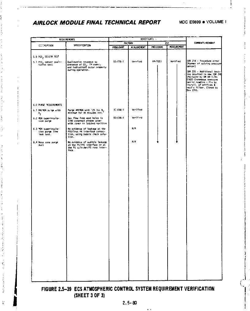
: ii AIRLOCK MODULE FINAL TECHNICAL REPORT MDCE0899• VOLUMEI t
REQUIREMENTS VERZFICATI ',FACTORY KSC COHMENTS/RERARK_
[-." CqIPTIOtl SPECIFICAT|ONPROCEDURF N;A'_UREMENT PRCCEDURE HEASUREVENT
5.0 PCOZ S[:_S_RTEST
:: 5.1PCO sensor lual_- Qualitative resoonse to 03-F76-1 Verified KN-_O03 Verified log ?14 - Procedure errort tat(vetest )resenceof CO9. TM event> (Mannerof valvlngoressulN
and tndicetton_ occur nroperly sensor)
duringope_atlon. IDR 225 - Addltloneltest-, _ inq resultedIn new 1OR 241(
{_e_lacedby DR AM 1-70-
i 0162) Erroneous nressuresen-_r reedinq - Fix by.: Ins*all.of orifices &
; rep1'cfilter.Closedby_v Z765.
6.0 PLiRC__EQUIRERENTS i
6.1 AHIqDA bv'gewlth Purge AMIHOAwlth ?ZS Ibs N2 02-E56-I VerifiedNZ minimum for 45 minutes mln, i
6.Z HDAsuperinsula- Gas flow from vent holes in 03-E56-1 Verifiedfinn purge $190 external windowcover
wlth _:over in latched no_Itinn
: 6.3 VOAsuoerinsula- No evidence of leakage at the N/A 'tion purge line FAS/Trus _4 interface connec-leak test. tton, using bubble check solu-
tlon.
6.4 Nose cone purge No evidence of audible leakage N/A 'r iduct at the PS/FAS _nterface or at
; the PS cyltr.der/PS cone inter-"_ face.
L
FIGURE2,5-39 ECSATMOSPHERICCONTROLSYSTEMREQUIREMENTVERIFICATION _'1(SHEET3OF3) r
2.5-80, I
1974018208-298
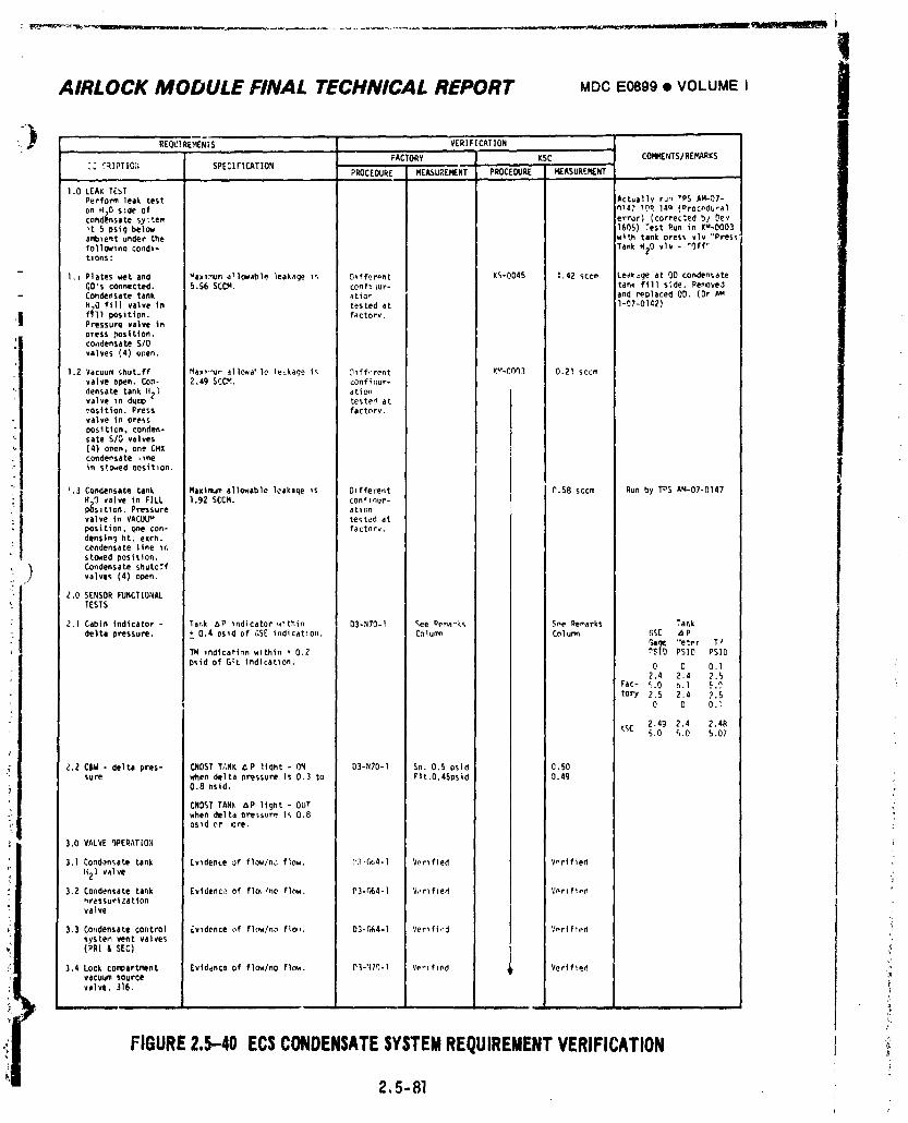
!
AIRLOCK MODULE FINAL TECHNICAL REPORT MDC E0899 • VOLUME I i
,-, LFACTORY KSC COMMENTS/REMARKS
: : C_IPTIOT¢ SPE_IFIC_,TION PROCEOURE MEASUREMENT PROCEDURE MEASUREMENT"
1.0 LEAKTEbTPerform leak test Actually run TPSAM-QT-
on H_Oside of nla) _0_ leo (Orocpdu-alcondensate sy:tem error) (corrected b/ D_v't 5 psig below 1COS)Test Run in K"-O003ambient under the Ntth tank Dress vlv "Pressfollowlnacond)- TankH_O vlv - "Off"tlOnS:
- 1. _ Plateswet and _axlr_mallowableleakageI_ DIffor_nt K_-0045 1.42 _ccm Leakageat OD condensateQO's connected. 5.$6 SCCM. conflaur- tank fill side.Pe_oved
- Condensatetank ation and replacedon. (Dr AM
H_O flll valvein tested at I-g7-0142)
!m• f_]1 position, factory.Pressure valve inDress position,condensate S/Ovalves (4) open.
1,2 Vacuum shutoff Hax_-u_allowa_le le:kagei_ _lff.'rent Ku-O0_3 0.21 sccmvalve open. Con- 2,49 SCCM. conficlur-
densatetankH2) ationvalve In dump te_tedat_osttion. Press factory.valve in pressposition,conden-sate S/O valves(4) omen, one CHXcondensate ,mein s_wed eositlon.
_.3 Condensatetank Maximumallowableleakaqeis Olffe;_nt C.$8 sccm Run by TDS AM-07-0147M_O valvein FILL 1.92SCCM. cDnflnur-p_sltlon. Pressure atlonvalve in VACUUM te_tedatposition,(;mecon- factorv.densing ht. exrh.condensate llne 1_stowed position.
Condensate shutcffvalves (4) o_en.
2.0 SENSORFUNCTIONALTESTS
2.1 Cabin indicator- Tar,k _P Indicatorwlthin D3-N70-I _ee Rema"ks Spe Oemarks Ta_k
delta pressure, _ 0.4 _sld of GSE indication. Calumn Column GS[ ApGa_ "eter T!_
TM indicationwlthln + 0,2 PSID PSID PSID
Dsidof G_L indication. 0 C 0.I2.4 2.4 2.5
Fac- _,0 b,l _.0tory 2.5 2.4 2.5
0 0 0.I
K_C 2.49 2.4 2.4_5.0 5.0 5.07
_.Z C&W- delta pres- CNDSTT;,NK 6P liqht - ON 03-N70-1 So. 0.5 psid O.SOsure when delta pressure is 0.3 to Flt.0.45osid 0.49
0.8 Dstd. ':
CNOSTTANk _P light* OUTwhen deltaPressureis 0,8osid or Qre.
3,0 VALVEQPERAT[02(
3.1Condansate tank Evidence of flawlnJflow, P3.Gb4-1 Verified V,rified
It2) valve ,;
3.2 Condensate tank Evidence of fide, _no flow. D3-r_4-I V,,rl fled Vnrl fipdnressurlzatlonvalve
3.3 Condensatecontrol Lv_denceof flow/noflo_. D3-C_4-I Verifi,'_ Vprifled
systenvent valves(PR1 & SEC)
3.4 Lock compartment Evidenceof flowlnoflow. Dl-';lq-I Verified i_ VerifiedVaCUU_sourcevalve,316.
i,
FIGURE2.5-40 ECSCONDENSATESYSTEMREQUIREMENTVERIFICATION
2, 5-81
1974018208-299
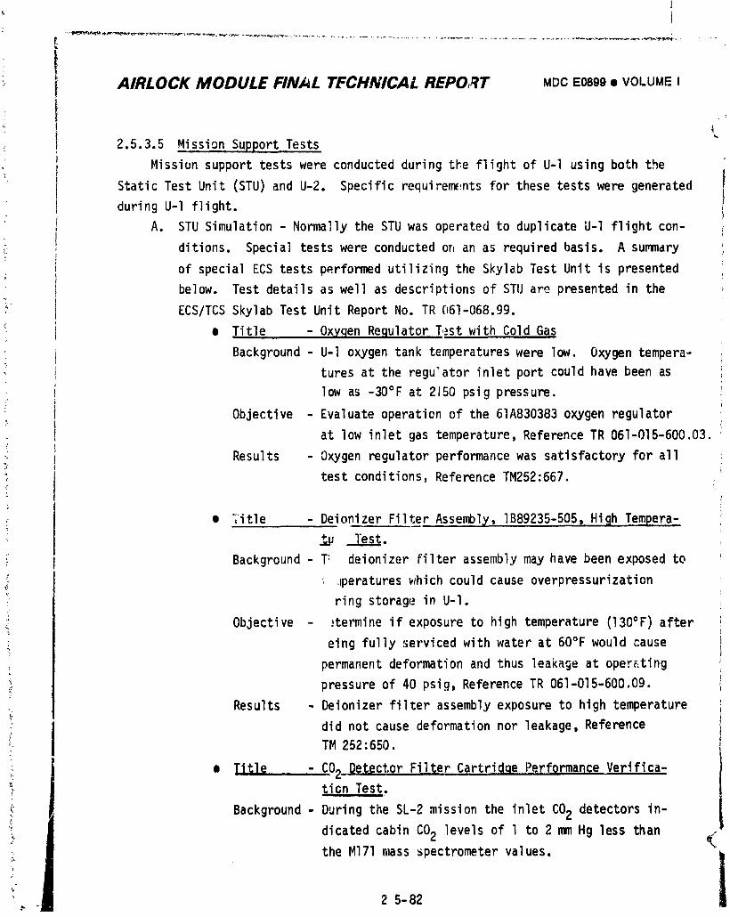
I
AIRLOCK MODULE FINAL TECHNICAL REPORT MDCE0899• VOI.UMEI
2.5.3.5 MissionSupportTests
Missionsupporttestswere conductedduringtke flightof U-I usingboth the
StaticTest Unit (STU)and U-2. Specificrequirem(_ntsfor these testswere generated
duringU-l flight.
A. STU Simulation- Normallythe STU was operatedto duplicateU-l flightcon-
ditions. Specialtestswere conductedorJan as requiredbasis. A summary
of specialECS tests performedutilizingthe SkylabTest Unitis presentedbelow. Test detailsas well as descriptionsof STU ar_.presentedin the
_ ECS/TCSSkylabTest Unit ReportNo. TR 061-068.99.
_: • Title - OxygenRe.qulatorTestwith Cold Gas
Background- U-l oxygentank temperatureswere low. Oxygentempera-
turesat the regulatorinletport couldhave been as
low as -30°F at 2150psig pressure.5'
Objective - Evaluateoperationof the 61A830383oxygenregulator
at low inletgas temperature,ReferenceTR 061-015-600.03.
Results - Oxygenregulatorperformancewas satisfactoryfor all
test conditions,ReferenceTM252:667. :
• Title - DeionizerFilterAssembly,IB89235-505,High Tempera-
*-u. l'es__.___t.
: Background- T: deionizerFilterassemblymay havebeen exposedto
_ ,Jperatures_hich couldcause overpressurization
;* ring storagei_ U-l.
Objective - :termineif exposureto hightemperature(130°F)after
eing fullyservicedwith water at 60°Fwould cause_r
permanentdeformationand thus leaka§eat oper_:ting
pressureof 40 psig,ReferenceTR 061-015-600.09.
Results - Deionizerfilterassemblyexposureto hightemperature
did not causedeformationnor leakage,Reference
TM 252:650.
• Title - C02 DetectorFilterCartridqePerform.anpeVerifica-_ tion Test.
_ Background- Duringthe SL-2missionthe inletCO2 detectorsin-
; dicatedcabinCO2 levelsof l to 2 mm Hg lessthan
the Ml71mass _pectrometervalues, i
I,-._ 2 5-82
1974018208-300
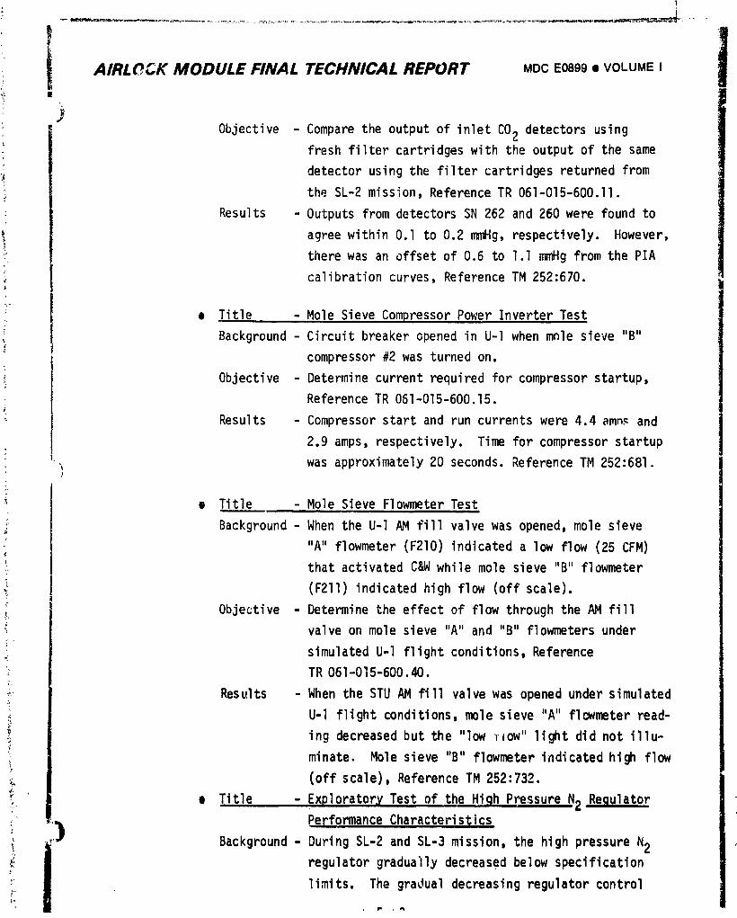
; l-- _ - =_ __,u_ _-_ ,_-_.===_._,{=-_,_=_-_i_..f_,_,_-_._,,-_--,m_[ _t •"
iAIRL_CK MODULE FINAL TECHNICAL REPORT MDCE0899• VOLUME I!
JObjective - Comparethe outputof inletCO2 detectorsusing
:_ freshfiltercartridgeswith the outputof the same
detectorusingthe filtercartridgesreturnedfrom,jthe SL-2mission,ReferenceTR 061-015-600.II,, •
: Results - OutputsfromdetectorsSN 262 and 260 were found to
agreewithinO.l to 0.2 mrnHg,respectively.However,
_ therewas an offsetof 0.6 to l.l mmHg from the PIAcalibrationcurves,ReferenceTM 252:670.
• Title - Mole SieveCompressorPower InverterTest
Background- Circuitbreakeropenedin U-l when mole sieve "B"
compressor#2 was turnedon.
Objective - Determinecurrentrequiredfor compressorstartup,
ReferenceTR 061-Of5-600.15.
: Results - Compressorstart and run currentswere 4.4 amn_and
2.9 amps, respectively.Time for compressorstartup
was approximately20 seconds.ReferenceTM 252:681.
• Title - Mole Sieve FlowmeterTest
Background- When the U-l AM fill valvewas opened,mole sieve
"A" flowmeter(F210)indicateda low flow(25 CFM)
thatactivatedC&W whilemole sieve"B" flowmeter
(F211)indicatedhigh flow (offscale).
Objective - Determinethe effectof flow throughthe AM fill
valveon mole sieve "A" and "B" flowmetersunder
simulatedU-l flightconditions,Reference
TR 061-015-600.40.
Results - When the STU AM fill valvewas openedundersimulated
U-l flightconditions,molesieve "A" flcwmeterread-
ing decreasedbut the "low_ow" light did not illu-
minate. Molesieve "B" flowmeterindicatedhigh flow
(offscale),ReferenceTM 252:732.
e Title - ExploratoryTest of the High PressureN2 RegulatorPerformanceCharacter•st;ics
J Background- DuringSL-2 and SL-3 mission,the high pressureN2
i regulatorgraduallydecreasedbelow specification
limits. The gradualdecreasingregulatorcontrol
1974018208-301
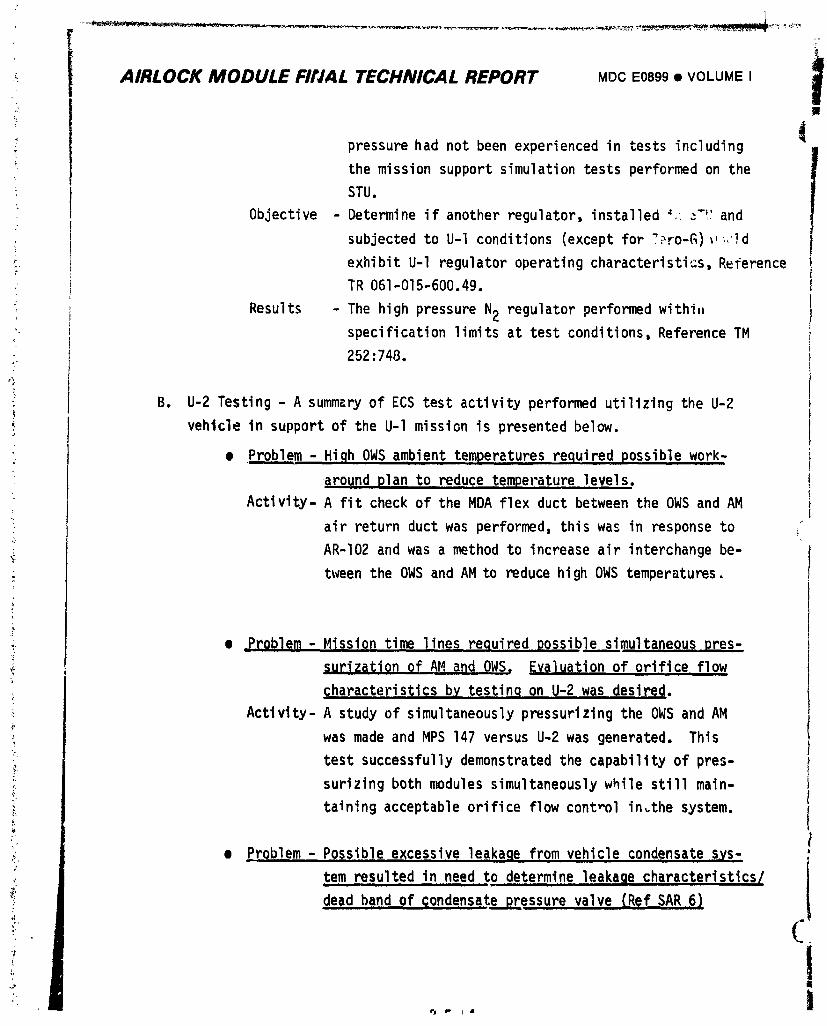
._ AIRLOCK MODULE FIfJAL TECHNICAL REPORT MOO E0899 • VOLUME I
, pressure had not been experienced in tests including
the mission support simulation tests performed on the
STU.
Objective - Determine if another regulator, installed _;,_ and
subjected to U-l conditions (except for TPFo-G)_,_,!d
" exhibit U-I regulator operating characteristics,R_ference
, TR 061-015-600.49.
Results - The high pressure N2 regulator performed withi.
specification limits at test conditions, Reference TM
252:748.
B. U-2 Testing - A summary of ECS test activity performed utilizing the U-2
vehicle in support of the U-l mission is presented below.
_ • Prpblem - High OWS ambient temperatures required possible work-
around plan to reduce temperature levels.(
Activity- A fit check of the MDA flex duct between the OWS and AM
: air return duct was performed, this was in response to
AR-I02 and was a method to increase air interchange be-tween the OWS and AM to reduce high OWS temperatures.
• _°roblem- Mission time lines required possible simultaneous pres-
surizatiQn of AMa_d OWS, Evaluation of orifice flow_ ill ii
c_haracteristicsb$ testin..qon U-2 was desired.
Activity- A study of simultaneously pressurizing the OWSand AM
was made and MPS 147 versus U-2 was generated. This
test successfully demonstrated the capability of pres-
il surizing both modules simultaneouslywhile still main-_ taining acceptable orifice flow control in,the system.
._ • problem - Possible excessive leakage from vehicle condensate s,ys-,t
_; t.e.mresulted in need to determine leakaQe characteristics/
dead band of condensate pressure valve {Ref SAR 6)
" I?
1974018208-302
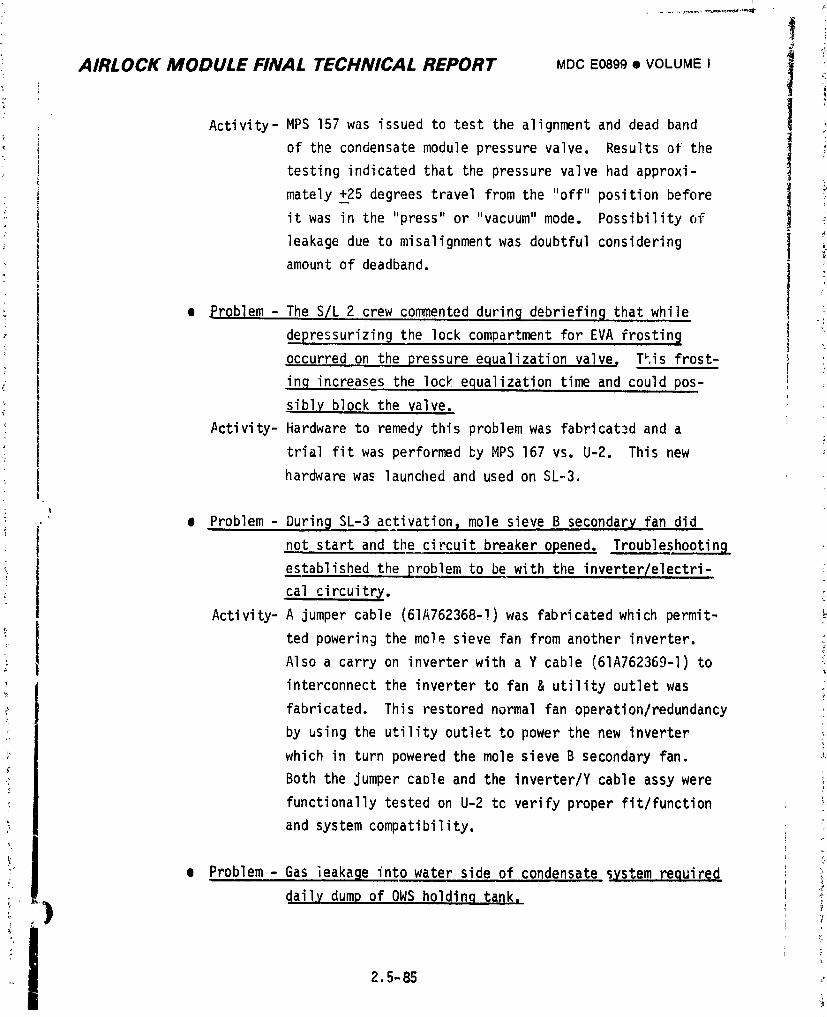
I
AIRLOCK MODULE FINAL TECHNICAL REPORT MDCE0899• VOLUMEI
Activity-MPS 157 was issuedto test the alignmentand dead band
of the condensatemodulepressurevalve. Resultsof the
testingindicatedthat the pressurevalve had approxi-
mately+_25degreestravelfrom the "off"positionbefore
it was in the "press"or "vacuum"mode. Possibilityof
leakagedue to misalignmentwas doubtfulconsidering
amountof deadband.
e Problem- The S/L 2 crewcommenteddurinBdebriefin9 thatwhile
• , depressurizin_the lock compartmentfor EVA frosting
occurredon the pressureequalizationvalve. T_,isfrost- i..; in,qincreasesthe lock equalizationtime and could pos-
siblyblockthe valve.
#ctivity-Hardwareto remedythis problemwas fabricatedand a
trialfit was performed_y MPS 167 vs. U-2. This new
hardwarewa._launchedand usedon SL-3.
e Problem - DurinBSL-3activation_mole sieveB secondaryfan did
not startand the circuitbreakeroRened_ Troubleshooting
establishedthe problemto be with the inverter/electri-
cal circuitry.
Activity-A jumpercable (61A762368-!)was fabricatedwhich permit-
ted poweringthe mole sieve fan from anotherinverter.Alsoa carryon inverterwith a Y cable (61A762369-I)to
interconnectthe inverterto fan & utilityoutletwas
fabricated.This restorednormalfan operation/redundancy
by usingthe utilityoutletto power the new inverter
which in turn poweredthe mole sieveB secondaryfan.
Boththe jumpercaDle and the inverter/Ycableassywere
functionallytestedon U-2 tc verifyproperfit/function
and systemcompatibility.
e Problem- Gas leakageintowater sideof condensatesystemrequired
dail,ydump of OWS holdinqtank,
2.5-85 _
1974018208-303
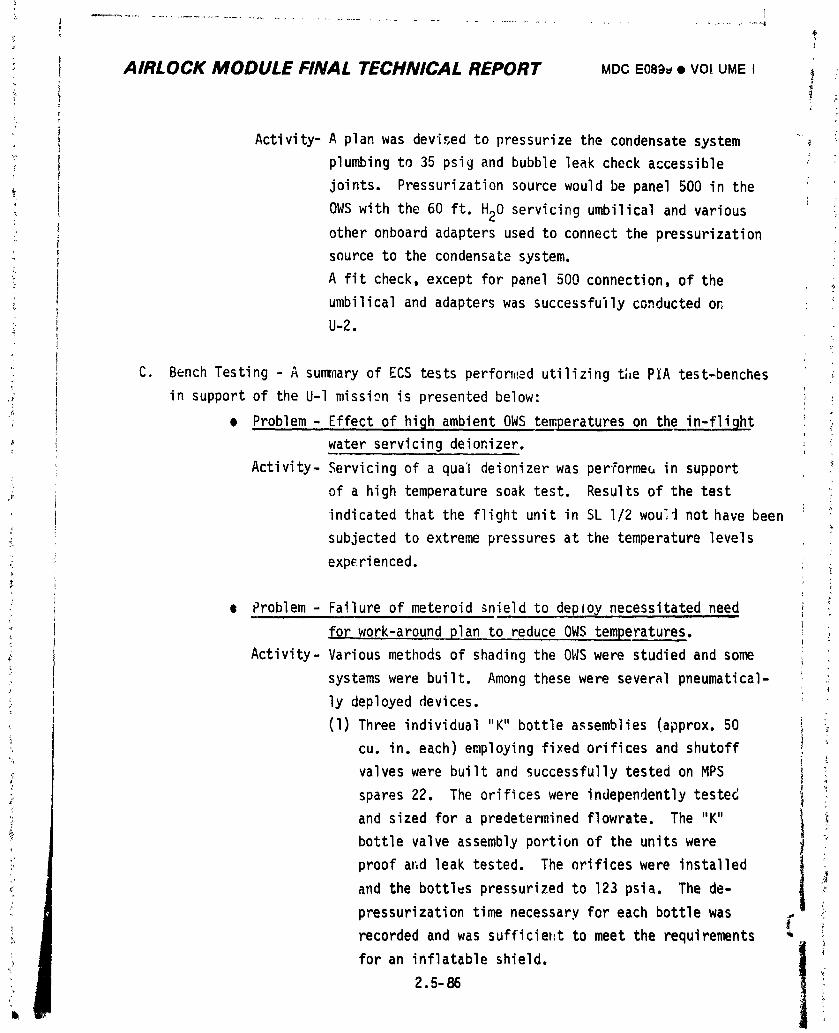
AIRLOCK MODULE FINAL TECHNICAL REPORT MDC E08_)_• VO! UMEI _ ,_-
4 'L
Activity-A plan was devi_ed to pressurize the condensate system "_
plumbing to 35 psig and bubble leak check accessible :
joints. Pressurization source would be panel 500 in the
OWS with the 60 ft. H20 servicing umbilical and various
other onboard adapters used to connect the pressurization
source to the condensate system.
A fit check, except for panel 500 connection, of the
umbilical and adapters was successfu'llyconducted or_
;- U-2.
• C. Bench Testing - A sunwnaryof ECS tests performad utilizing the PIA test-benches
" in support of the U-l mission is presented below: ii
e Problem - Effect of high ambient OWS temperatures on the in-flightq
water servicing deionizer. _
Activity- Servicing of a qual deionizer was performem in support
of a high temperature soak test. Results of the test
indicated that the flight unit in SL I/2 wou'i not have been
subjected to extreme pressures at the temperature levels
experienced.
; e Problem - Failure of meteroid _nield to deploy necessitated need '
for work-around plan to reduce OWS temperatures. ,
Activity- Various methods of shading the OWS were studied and some
:_ systems were built. Among these were several pneumatical-
i ly deployed devices.
(1) Three individual "K" bottle a,_semblies(approx. 50
cu. in. each) employing fixed orifices and shutoff _
valves were built and successfully tested on MPS i!
spares 22. The orifices were independently tested
and sized for a predetermined flowrate. The "K"
bottle valve assembly portion of the units were
proof aF.dleak tested. The orifices were installed
and the bottles pressurized to 123 psia. The de-
pressurization time necessary for each bottle was
recorded and was sufficieht to meet the requirements _-
for an inflatable shield. I
I2.5-86
1974018208-304
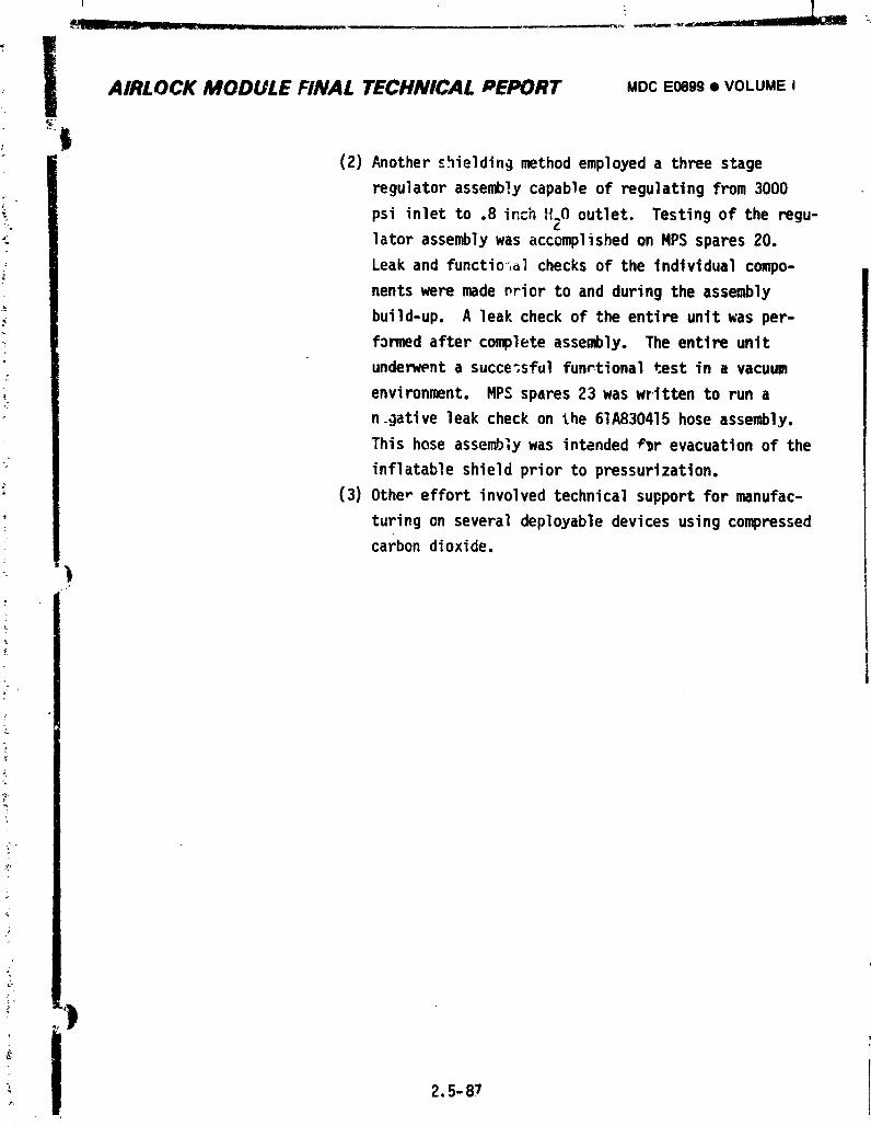
! AIRLOCKMODULEFINAL TECHNICALPEPORT MOCE0899• VOLUMEi(2) Another _.hielding methodemployeda three stage
regulator assembly capable of regulating from 3000
psi inlet to .8 inch ff.O outlet. Testing of the regu-
lator assembly was accomplished on HPSspares 20.
Leak and function, a] checks of the individual compo-
nents were madenrior to and during the assembly
build-up. A leak check of the enttre untt was per-
formed after complete assembly. The entire untt
undenvent a succe;sful funrtional test in a vacuum
environment. HPSspares 23 was wr-ttten to run a
n.gative leak check on the 61A830415hose assembly.
This hose assembly was intended r_r evacuation of the
inflatable shield prior to pressurization.
(3) Other effort involved technical support for manufac-
turing on several deployable devices using compressedcarbon dioxide.
2.5-87
1974018208-305
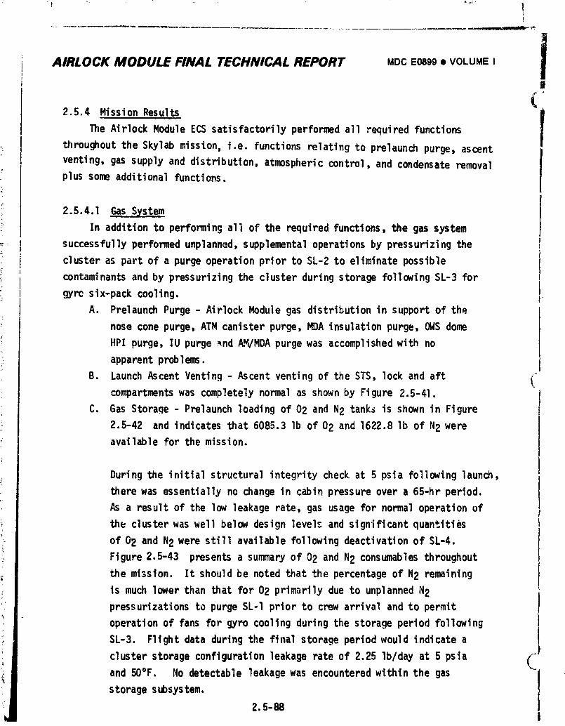
AIRLOCK MODULE FINAL TECHNICAL REPORT MDCE0899• VOLUMEIi
2.5.4 Hission Results (|
lThe Airlock Hodule ECSsatisfactorily performed all required functions
throughout the Skylab mission, i.e. functions relating to prelaunch purge, ascent
venting, gas supply and distribution, atmospheric control, and condensate removalplussome additionalfunctions.
2.5.4.1 ,GasSystemIn addition to performing all of the required functions, the gas system
successfully performed unplanned, supplemental operations by pressurizi ng the
cluster as part of a purge operation prior to SL-2 to eliminate possible
contaminants and by pressurizing the cluster during storage following SL-3 for
gyrc six-pack cooling. +A. Prelaunch Purge - Airlock Module gas distribution in support of the
nose cone purge, ATMcanister purge, MDAinsulation purge, OWSdome
HPI purge, IU purge _nd /L_/RDApurge was accomplished with no
apparent problems.
B. Launch Ascent Venting - Ascent venting of the STS, lock and aftcompartmentswas completely normal as shownby Figure 2.5-41.
C. Gas Stora qe - Prelaunch loading of 02 and N2 tanks is shown in Figure
2.5-42 and indicates that 6085.3 lb of 02 and 1622.8 lb of N2 wereavailable for the mission.
Duringthe initialstructuralintegritycheckat 5 psia followinglaunch,
therewas essentiallyno changein cabinpressureover a 65-hr period.
a resultof the low leakagerate,gas usagefor normaloperationof
th_ clusterwas well below designlevelsand signiflcantquantities
of 02 and N2 were still availablefollowingdeactivationof SL-4.
Figure2.5-43 presentsa summaryof 02 and N2 consumablesthroughout
the mission. It shouldbe notedthat the percentageof N2 remaining
is much lowerthan thatfor 02 primarilydue to unplannedN2
pressurizationsto purgeSL-I priorto crewarrivaland to permit
operationof fans for gro coolingduringthe storageperiodfollowing
SL-3. Flightdata duringthe finalstorageperiodwould indicatea
cluster storage configuration leakage rate of 2.25 lb/day at 5 psta (_"
and 50°F. No detectable leakage was encountered within the gas "-j
istorage subsystem.
2.5-88I
1974018208-306
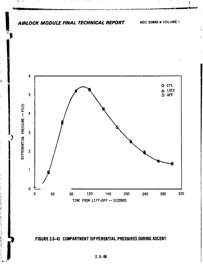
E
AIRLOCK MODULE FINAL TECHNICAL REPORT MDCE0899• VOLUMEI
6
0 STS& LOCK
5 D AFT
/0 '
0 40 80 120 160 200 240 280 320
TIME FROM LIFT-OFF--.SECONDS
FIGURE2.5-41 COMPARTMENTDIFFERENTIALPRESSURESDURINGASCENTli
,,! 2.5-B9
1974018208-307
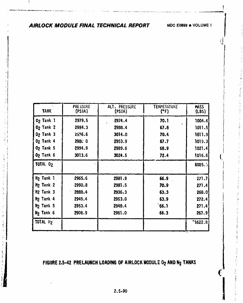
AIRLOCK MODULE FINAL TECHNICAL REPORT MDCEo89g• VOLUMEI
¢
: ' PRESSURE ALT.PRESSURE TEHPEP,ATURE "j MASS -:_; TANK (PSIA) (PSIA) (=F) (LBS) !
, ,- im i l i
_ 02 Tank1 2979.5 2974.4 70.1 1004.602 Tank 2 2984.3 2988.4 67.8 1011.5
I
, 02 Tank3 Z_96.6 3014.0 70.4 1011.9• J
I 02 Tank4 298t_0 2953.9 67.7 1019.3
02 Tank5 2994.9 2989.6 68.9 1021.4
02 Tank6 3013.6 3024.5 72.4 1016.6 (-- m, ii le L L '_
TOTAl.02 6085.5 !ii i I i i i mmJgl ii i ml •
N2 Tank 1 2965.6 2981.9 56.9 271.7 I :
N2Tank2 2990.8 2981.5 70.9 27i.4 i _:H2Tank3 2888.4 2935.3 63.3 268.0 •
H2Tank4 2949.4 2953,0 63,9 272.4 i
H2Tank S 2953.4 2948,4 "66,1 271.4
H2 Tank6 2908.9 2961,0 66,3 267.9.... el I I I
TOTALN2 "'1622.8
i I I I I I I ;:
:]/
i
1.
FIGURE2.5-42 PRELAUNCHLOADINGOFAIRLOCKMODULE02 ANDN2 TANKS :
:i2. =.,-90
1974018208-:308
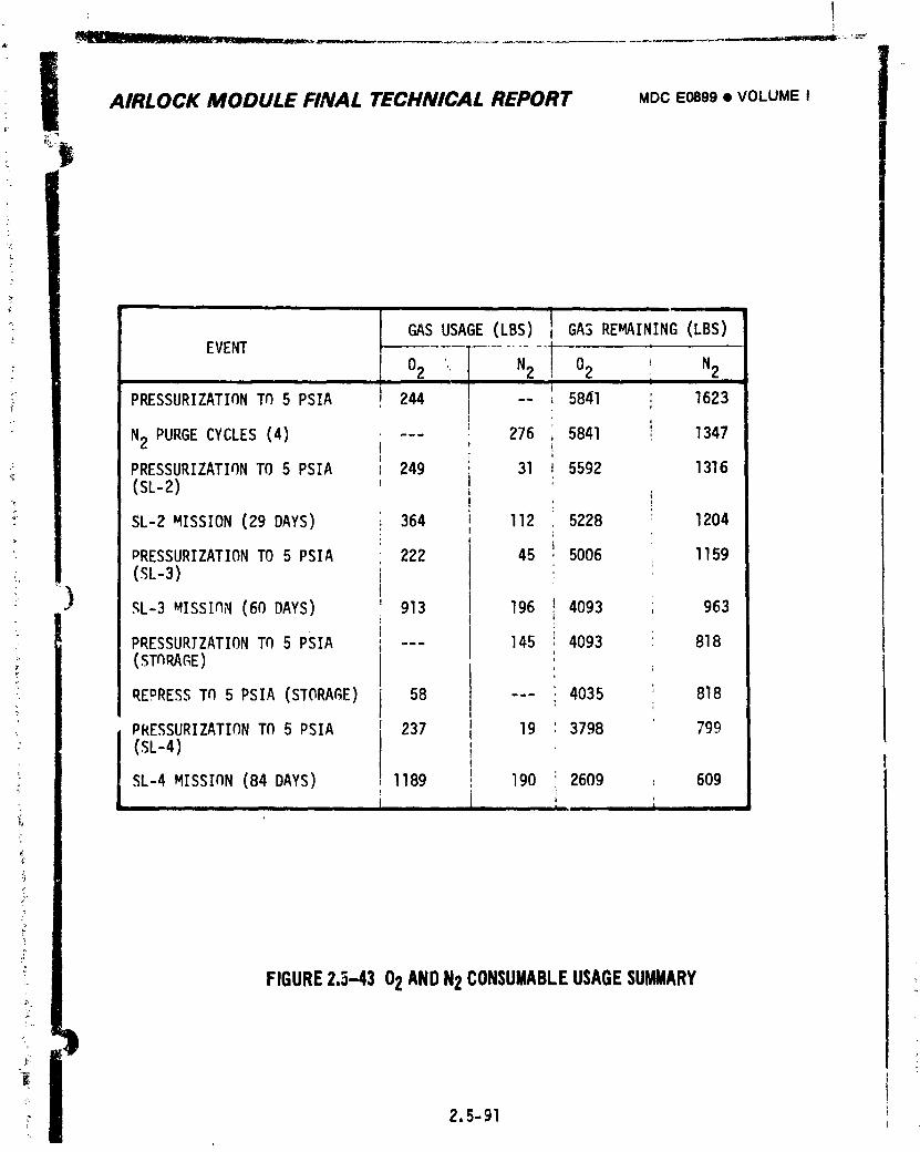
AIRLOCK MODULE FINAL TECHNICAL REPORT MDCE0899• VOLUMEI i
i , ,
GAS USAGE (LBS) GAS REMAINING(LBS)EVENT
02 . N2 02 i N2, ! , i
t
PRESSURIZATIONT_ 5 PSIA I 244 t -- _ 5841 i 1623[
i 1347--- 276 I 5841 ,N2 PURGECYCLES(4) i ' ,
PRESSURIZATIqNTO 5 PSIA = 249 : 31 J 5592 1316(SL-2) , I
SL-2 MISSION(29 DAYS) _ 364 i ll2 . 5228 : 1204I
PRESSURIZATIONTO 5 PSIA 222 45 ! 5006 I159
(SL-3) !!
) _L-3 _ISSInN (60 DAYS) ' 913 196 ! 4093 , 963I r '
PRESSURIZATIONTO 5 PSIA ; --- 145 ; 4093 818(STORAGE) l
t
REmRESSTO 5 PSlA (STORAGE) 58 --- ' 4035 : 818: i
PkESSURIZATIONTO 5 PSIA _ 237 I 19 ' 3798 799(SL-4) I
I
SL-4 MISSInN (84 DAYS) , 1189 ! 190 : 2609 , 609l i ,, , _ |
FIGURE2.5-43 02 ANDN2 CONSUMABLEUSAGESUMMARY
_' 2.5-91
1974018208-309
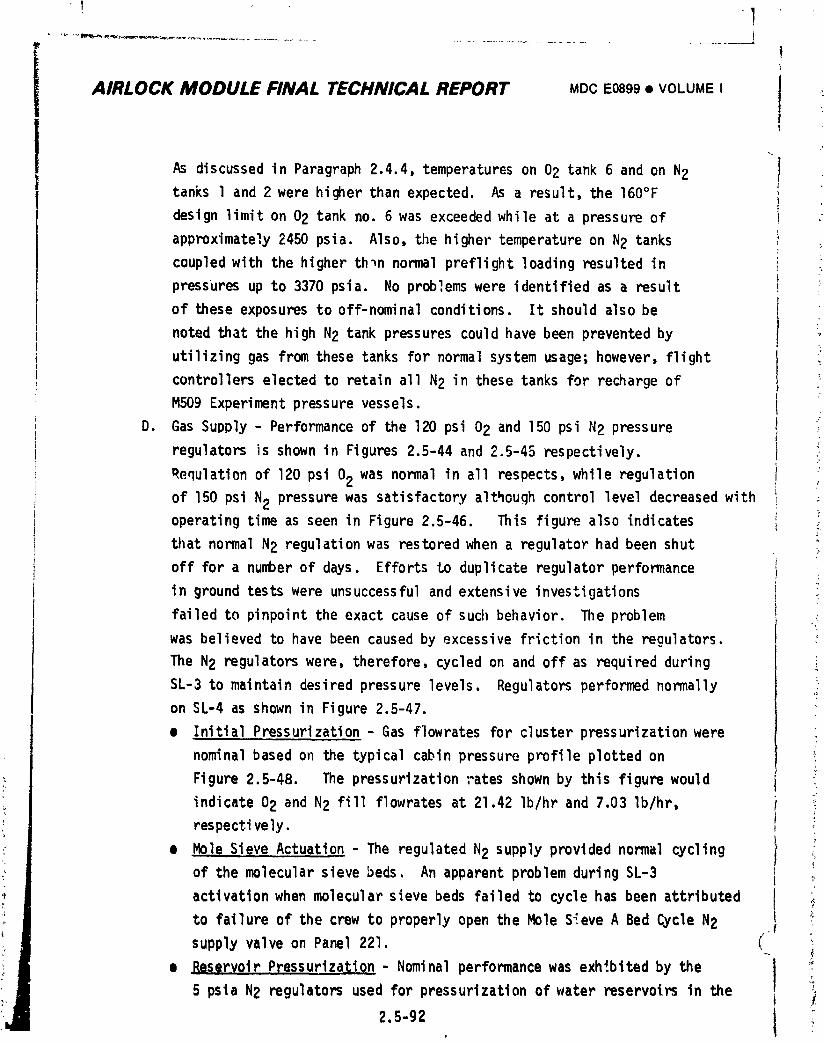
I!
AIRLOCK MODULE FINAL TECHNICAL REPORT MDCE0899• VOLUMEI II
I 'As discussedin Paragraph2.4.4,temperatureson 02 tank 6 and on N2
tanks l and 2 were higherthan expected. As a result,the 160°F
designlimiton 02 tank no, 6 was exceededwhile at a pressureof
approximately2450psia. Also,the highertemperatureon N2 tanks
coupledwith the higherth_nnormalpreflightloadingresultedin
pressuresup to 3370 psia. No problemswere identifiedas a result
of theseexposuresto off-nominalconditions. It shouldalsobe
notedthatthe high N2 tankpressurescouldhave been preventedby
utilizinggas fromthesetanksfor normalsystemusage;however,flight
controllerselectedto retainall N2 in thesetanks for rechargeof
M509 Experimentpressurevessels.
D. Gas Supply- Performanceof the 120 psi 02 and 150 psi N2 pressure
regulatorsis shown in Figures2.5-44and 2.5-45respectively. !
Requlationof 120 psi 02 was normalin all respects,while regulation
of 150 psi N2 pressurewas satisfactoryalthoughcontrolleveldecreasedwithoperatingtime as seen in Figure2.5-46 This figurealso indicates :_• ,_
tilatnormalN2 regulationwas restoredwhen a regulatorhad been shut :_
off for a numberof days. Effortsto duplicateregulatorperformance _;
in groundtestswere unsuccessful and extensiveinvestigations !
failedto pinpointthe exact causeof such behavior. The problem !was believedto havebeen causedby excessivefrictionin the regulators.
The N2 regulatorswere, therefore,cycledon and off as requiredduring
SL-3 to maintaindesiredpressurelevels. Regulatorsperformednormally
on SL-4 as shown in Figure2.5-47.
e InitialPressurization- Gas flowratesfor clusterpressurizationwere
nominalbased owlthe typicalcabinpressureprofileplottedon
Figure2.5-48. The pressurizationratesshownby this figurewould ' ::
indicate02 and N2 fill flowratesat 21.42 Ib/hrand 7.03Ib/hr, _;
respectively.
e MoleSieve Actuation- The regulatedN2 supplyprovidednormalcycling _,
of the molecularsievebeds. An apparentproblemduringSL-3 ' _,
activationwhen molecularsieve beds failedto cyclehas been attributed ._,
to failureof the crewto properlyopen the Mole S_eveA Bed CycleN2supplyvalveon Panel221, (
• ReservoirPressurization- Nominalperformancewas exhibitedby the j '_
5 psla N2 regulatorsused for pressurizationof water reservoirsin the 6 /
2.5-92 t
1974018208-310
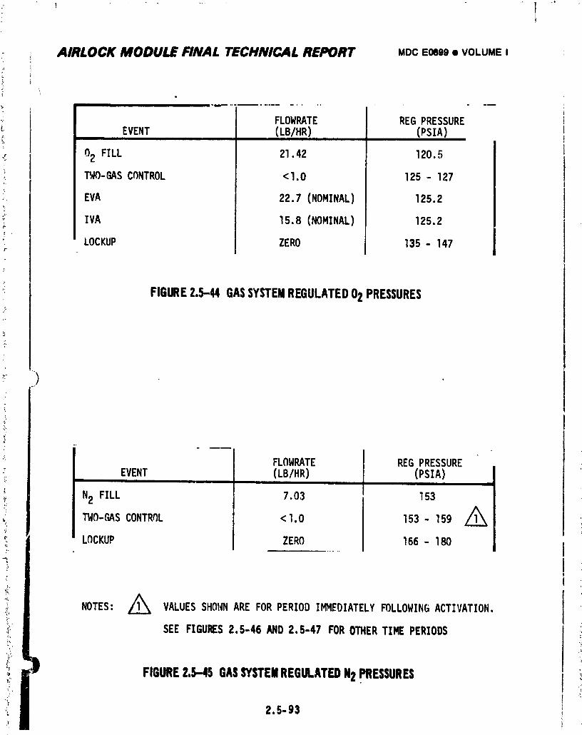
AIRLOCK MODULE FINAL TECHNICAL REPORT MDCE0899• VOLUMEI
i
• r ...........
FLOWRATE REGPRESSURE
EVENT (LB/HR) (PSIA)
02 FILL 21.42 120.5
I_._O-GASCfINTROL <1.0 125- 127
EVA 22.7(NOMINAL) 125.2
IVA 15.8(NOMINAL) 125.2
LOCKUP ZERO 135- 147
FIGURE2.5-@1GASSYSTEMREGULATED02PRESSURES
)
FLOWRATE J REGPRESSURE
EVENT (LB/HR) (PSIA)
N2 FILL 7.03 l 153
TWO-('_,SCONTROL < 1.0 153 - 159 Z_
LOCKUP ZERO 166 - 180
ANOTES: 1_ VALUESSHONNARE FORPERIODIMMEDIATELYFOLLOWINGACTIVATION.
SEEFIGURES2.5-46 AND2.5-47 FOROTHERTIMEPERIODS
FIGURE2.5-45GASSYSTEMREGULATEDN2pRESSURES!
2.5-93
1974018208-311
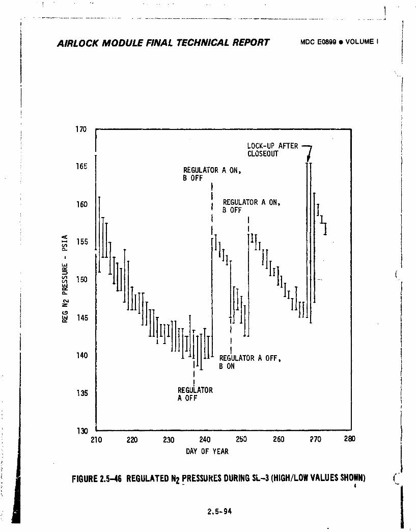
Ii,
i
AIRLOCK MODULE FINAL TECHNICAL REPORT MDCE0899• VOLUMEI j1t
\
170 ......
LOCK-UPAFTER-7CLOSEOUT
16g REGULATORA ON,B OFF
t
I REGULATORA ON,
160 I B OFF ]
I ,
' II Ill,]fill]Ill{
,., T
= (_ 150 .....
z
145
'lil[II140 REGULATORA OFF,B ON
REGULATOR135 A OFF
30 i i i
210 220 230 240 250 260 E70 280
DAYOF YEAR
FIGURE2.5-46REGULATEDN2PRESSURESDURINGSL-3(HIGH/LOWVALUESSHOWN) ("I ""
2.5-94
i
1974018208-312
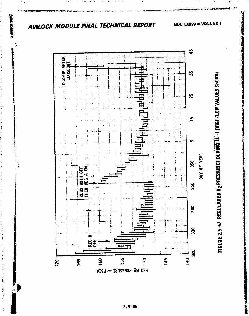
2.,_-95
1974018208-31."4
1 I_, AIRLOCK MODULE FINAL TECHNICAL REPORT MDCE0899• VOLUMEI
_!
THISPAGEINTENTIONALLYLEFTBLANK
2.5-96
1974018208-314
_ ........ ___..:_ _ LI........ J_ _ lit I _ tl_ll.____ ......
j AIRLOCK MODULE FINAL TECHNICAL REPORT MDCE0899• VOLUMEI
? IJ
THISPAGEINTENTIONALLYLEFTBLANK
.%
_ 2.5-97I
1974018208-315
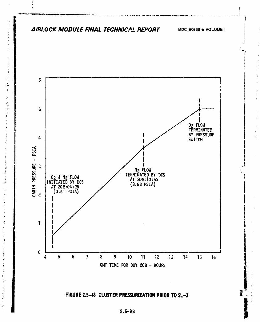
!!
AIRI.OCK MODULE FINAL TECHNICAL REPORT MDCE0899• VOLUMEI iL
i
6
II
5II
02 FLOWTERMINATED
I BY PRESSURE
4 I SWITCH,¢t.,,.l
I
, I Itu i"3
N2 _LOWv_ TERMINATEDBY DCS }02 & N2 FLOW AT _8:10:56" INITIATEDBY DCS
AT208:04:26 (3.63PSIA)" (0.61PSIA)_2
lI
',tII
|ll i i i Jl ii _ i
4 5 6 7 8 9 10 II 12 13 14 15 16
GMT TIME FOR DOY 208 - HOURS
FIGURE2.5-48 CLUSTERPRESSURIZATIONPRIORTOSL-3 _, _
2.5-98
1974018208-316
AIRLOCK MODULE FINAL TECHNICAL REPORT MDCE0899• VOLUMEI
ATM C&D Panel/EREPand Suit CoolingSystems. Followinginitialventing
of the reservoirsduringascent,pressur_was maintainedbetween4.95
and 6.0 psiathroughoutthe missionwith the higherlevelbeing attained
duringservicingof the Suit CoolingSys';eml reservoiron DOY 361.
• EVA/I.VASupport- EVA/IVASupportwas ncrmalas discussedin Section2.6.
• Experimentand OWS Water SystemSupport- The regulatedN2 supply
providednormalOWS water systempressurizationand _xperimentsupport.
Rechargeof M509bottleswas accomplished,withoutdifficulty,on
48 separateoccasions. The pressurein N2 tanks l and 2, whichhad
been reservedfor tanktop-offduringthis operation,was 3080psia
duringtileinitialtop-offon DOY 168 in SL-2 and 1900psia following
the final top-offon DOY 026 duringSL-4. Tanks l and 2 were never
openedto the remainderof the N2 system.
E. AtmosphericPressureControl
• MaintainMinimum02/N2Pressure- Controlof cabinpressurewas well
withinthe 5.0+_.0.2 psia allowablerangeand PP02 remainedbetween
3.3 and 3.9 psiaduringall periodswhen operationof the two-gas
: _ controlsystemwas not overriddenby gas additionand/orventing
_Rsociatedwith performanceof MsOg/T020,EVA operations,CM 02
flowintothe clusteror inadvertentcrewaction. Figure2.5-49
presentsPP02and cabinpressurelevelsduringa typicalperiod
when the aboveinfluenceswere not presentand the two-gascontrol
systemwas permittedto operatenormally. Operationo',PP02sensors
was completelynormalwith no degradaticAbeingobservedduringany of
the mannedmissionsbased uponcomparisonsof outputs(controland
,(.onitoring)with Ml71mass spectrometerreadings. The capabilityto
flow02 and N2 for 9PO2 sensorcalibrationwas successfullydemonstrated
on DOY 330.
On severaloccasions,the factthat flow capabilityof cabinpressure
regulatorswas intentionallydesignedto a close limitpermitted
rapidrecognitionof abnormalc_in leakagewhen a decreasingcabin
pressurewas observed. For example,on DOY 211,a pressuredecreaseequiva-
leet to an observedclusterleakagerateof approximately4 Ib/hrprompteda
crew investigation_Ich locatedan improperlypositionedvalveon the Trash
I Alrlockin the OWS. Similarly,on DOY 257,a cabinpressuredecreaseof
2.5-gg i
1974018208-317
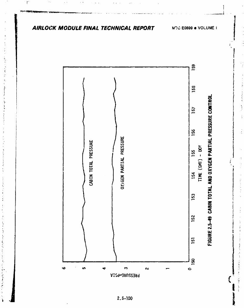
1
AIRLOCK MODULE FINAL TECHNICAL REPORT M_CE0899eo_VOLUMEI
_' i ................ !_
.J
E
e4
}-
1974018208-318
_ _..,_._,,c.,-t,,_._,,_'L'_'_'_#f_-_ "'
i AIRLOCK MODULE FINAL TECHNICAL REPORT MDCEOG99• VOLUMEI!
%
• yapWoxtnkltely Q.I psia over a _ix,hour period was found to be the result
of at, Improperly sealed door on va_te processo_ in the OWS. With a higher
maxtmumflow rate regulator, ldentiftcatfon of such leakage would not havebeen possible until the crew used these componentsagain or until
excessive gas usage from storage tanks was noted. In either case,
_ numberof days may have elapsed and the overboard gas loss would
havebeensignificantlygreater, lle Limit MaximumAtmosphericPressure - Gas flow from the cluster
atmospherevia cabinpressurereliefvalvesoccurredon two occasions i=
6uringSL-4 due to a proceduralerror. Cabinpressurenormallyre-
mainedwell belowthe reliefvalveminimumcrackingpressureof 5.5
psidexceptduringM509/T020operationswhen pressurewas permitted
to increaseto higherlevels(5.95psidmaximum)afterthe manual
shutoffvalveon AirlockModulereliefvalveshad been closed.
However,the crew failedto closethe aft compartmentreliefvalveon
SL-4priorto M509operationsand overboardreliefoccurredas cabin
pressurereached5.7 psia on DOY 017 and 020. Protectionagainst
overpressurizationof the clusterduringperiodswhen AirlockModule
reliefvalveswere closedwas affordedby CM reliefvalves.
2.5.4.2 AtmosphericControlS_stem
In additionto performingall of the requiredfunctions,the systemprovided
more coolingthanthe maximumplannedto assistcooldown of the workshopcrew
quarters.No midmissionmolecularsievebakeoutswere requiredper the bakeoutcriteria
(paragrapn2.5.2.2,B.)duringthe entireflightand nonewere performedduringthe 84
day SL-4mission.
A. HumidityControl- Figures2.5.50through2.5-52presentdewpoint
historiesfor each of themissionsand indicatean overalldewpoint
rangeof 39.8°Fto 63.5°Fwhen activationperiodsare excluded.
Normally,dewpointwas maintainedbetween46°F and 60°Fexceptduring
EVA periodsand on SL-4crewshowerdays. DuringEVA,dewpointdecrea;ed
| • due to reducedmoisturegenerationrates (onlyone crewmaninternal_o
i the vehicle)and the smallervolumeof atmospherebeing conditioned.
) Dewpointquicklyreturnedto normallevelsfollowingEVA when the OWS" hatchwas againopenand circulationwith the largervolumere-established.
J On crewshowerdays,additionalmoisturewas introducedintothe cluster
atmosphereand resultedin dewpointsexceeding60°F on severaloccasions 1
i2.5-I01
1974018208-319
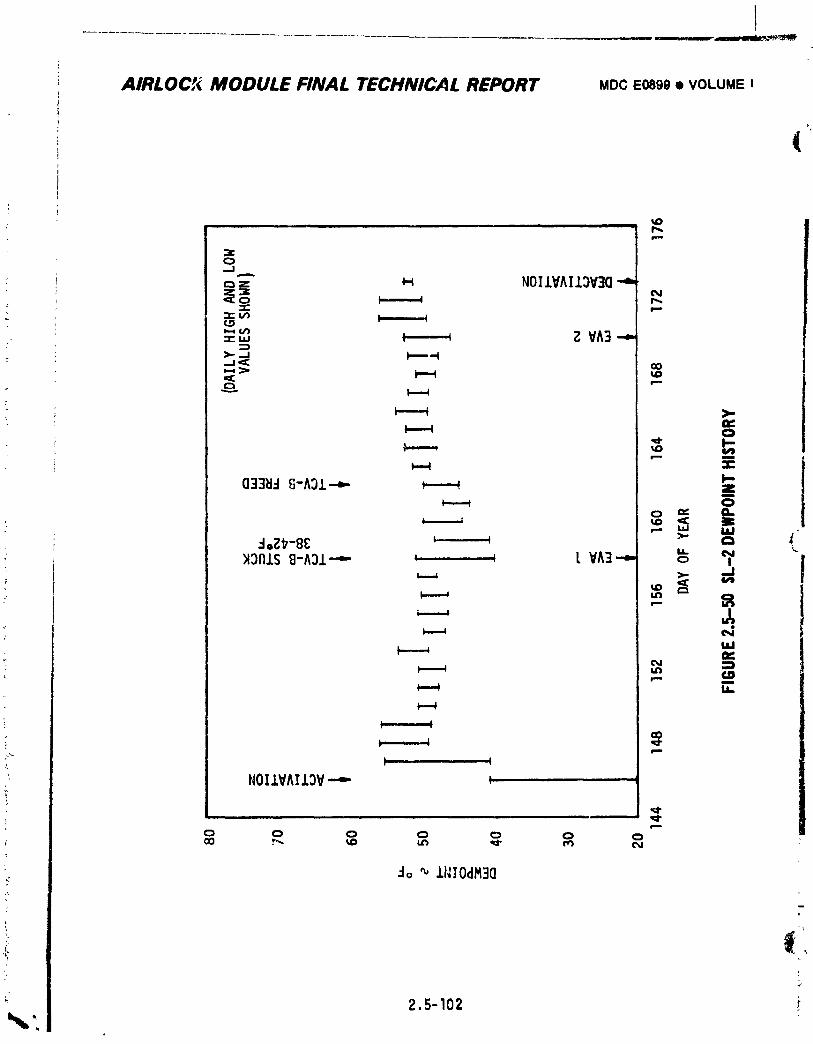
T
AIRLOCP,(MODULE FINAL TECHNICAL REPORT MDCE089g• VOLUME !
(
tDll|| i i ii ,i -. • _,_
NOIIVAI13V3(]"4'_ r,_
¢._ .
= ,., _ Z VA3 --,._..._t l,--m--t..t'_ (3O
"_ ,_,."--" t'-'-4
(]33_ t]-A31-..,,.- _
- 1_ M
t,l_ e,e
N _
_ Et.-.4
:. . _ ,_
I I
NOI1VAI13V.--- _,
e,,.,=
Jo _ 11110dM3(]
_L
2.5-102 _
1974018208-320
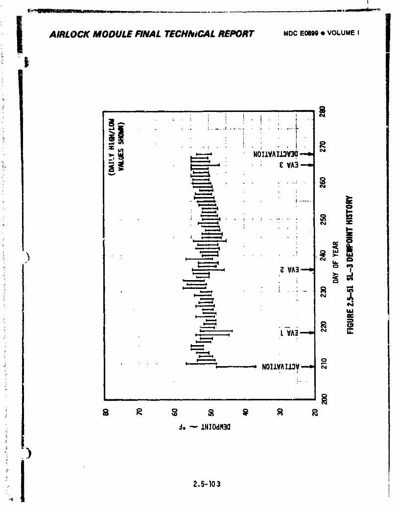
i
i AIRI.OCK MODULE FINAl. TECHllIiCAI. REPORT MDC EOOl)9• VOLUME I I
I 0:ac .: . . ' .. ! r,,
_ '
= 1
i
L_^_
,_ NOI.LVAI.L;N_ o
0.. ,
i i t i t lit i i tile t I t t __ am
do "" .LNIOdH3a
_.,, )
2,5-103
-",i
1974018208-321
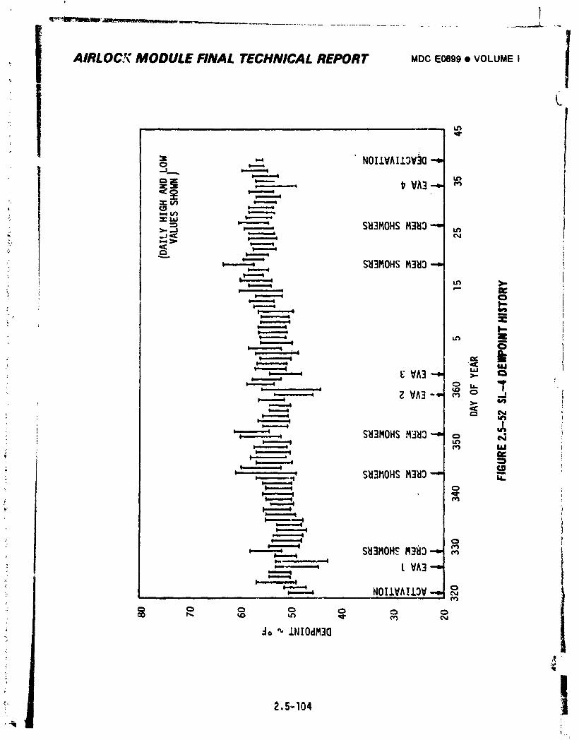
l
i ...........................iAIRLOC-r_° MODULE FINAL TECHNICAL REPORT MDCE0899• VOLUMEI
i imll im L
,-', NOIIVAI,I.OV]O-,
= _ S_3MOHSM3_3""
-" w-,--.w S_I3MOHSM3_l_""
>-- _ i_
-j _
_ VA3_ _-t , . a
: Z VA3 "" ml-.,----m
,--. g_ N
; _", SI_3MOHSM31:13"" o Nl.lr}e,_ lad
• . ;
_' ,.._.__.._' S_I3110HSM3_ID-" _.
S_I3MOH_M3BD-" r,iI,,- ,, i
I VA3"-"l-..--.,---,.w
,-.--.w NOILVAIL_V-..,,llm ........... |
do _'LNIOdM3O
2,S-104
i
1974018208-322
!
T
i AIRLOCK MODULE FINAL TECHNICAL REPORT MDC ;.0899 • VOLUME I
W
I* during SL-4. This is believed to be due to water spills uiscussed in
the SL-4 debriefing report.
The original water separator plate assemblies were used throughout the
entire mtssiof=. Liquid/gas separation was accomplished in a normalmanner,
B. Purity Control - Molecular sieves perfomed in an outstanding manner as
indicated by atmospheric CO2 levels shown in Figure 2.5-53. It can be
seen that average daily PPCO2 was nomally well below 5.5 mmHg. Somewhathigher levels were obtained dur.ng and following the SL-3 mid-mission
bakeout period (DOY231 to 234). Significantly lower levels indicated
on EVAdays were a result of reduced CO2 generation rates (only one crew-man internal to the vehicle) and the smaller volume of atmosphere being
conditioned with the lock compartment forward hatch closed. Hole sieve
perfomance indicated by the difference between measuredinlet and outlet
carbondioxidepartialpressuresis shown in Figure2.5-54. Three
PPCO2 measurementsfrom ExperimentMlTl takenduringthe same time span:_ were in closeagreementwith the valuesmeasuredat the mole sieve inlets.
)
Effectsof crew activityon atmosphericPPCO2 is apparentby the cycles
of PPCO2 levelsduringeach24 hour period. The PPCO2 leveldecreasedduringcrewsleep periodsand increasedduringperiodsof crew activity.
)
iJ 2,5-105
1974018208-323
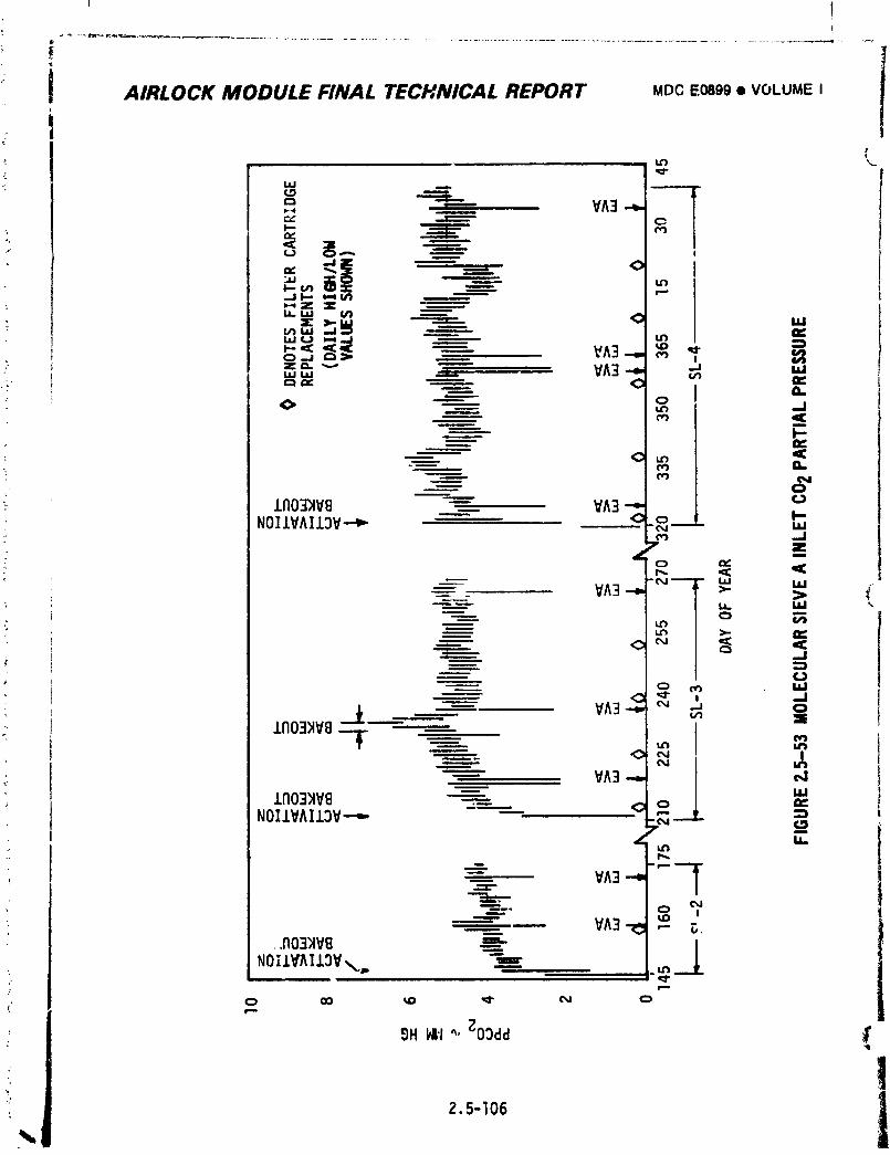
= t
AIRLOCK MODULE FINAL TECHNICAL REPORT MDC Eosgg • VOLUME I
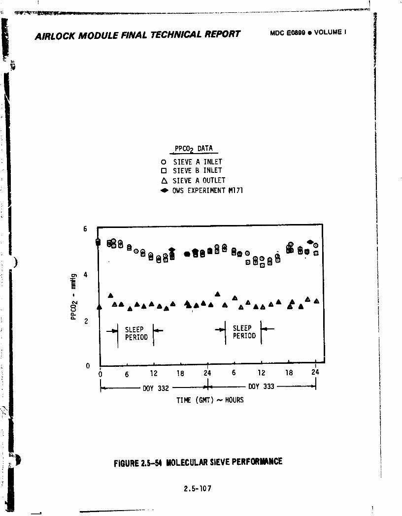
I
AIRLOCK MODULE FINAL TECHNICAL REPORT MOCE0899• VOLUMEI
PPCO2 DATA
0 SIEVEA INLET13 SIEVEB INLET
Z_ SIEVEA OUTLET
'0 OWS EXPERIMENTM171
0 I , , ....... _ , . , _. , II0 6 12 18 24 6 12 18 24
L ± .1I- DOY332 -,- DOY333
TIME (GMT)--" HOURS
i _ _ FIGURE2.5-54 MOLECULARSIEVEPERFORMANCE
2.5-107
_L_ I I I
1974018208-325
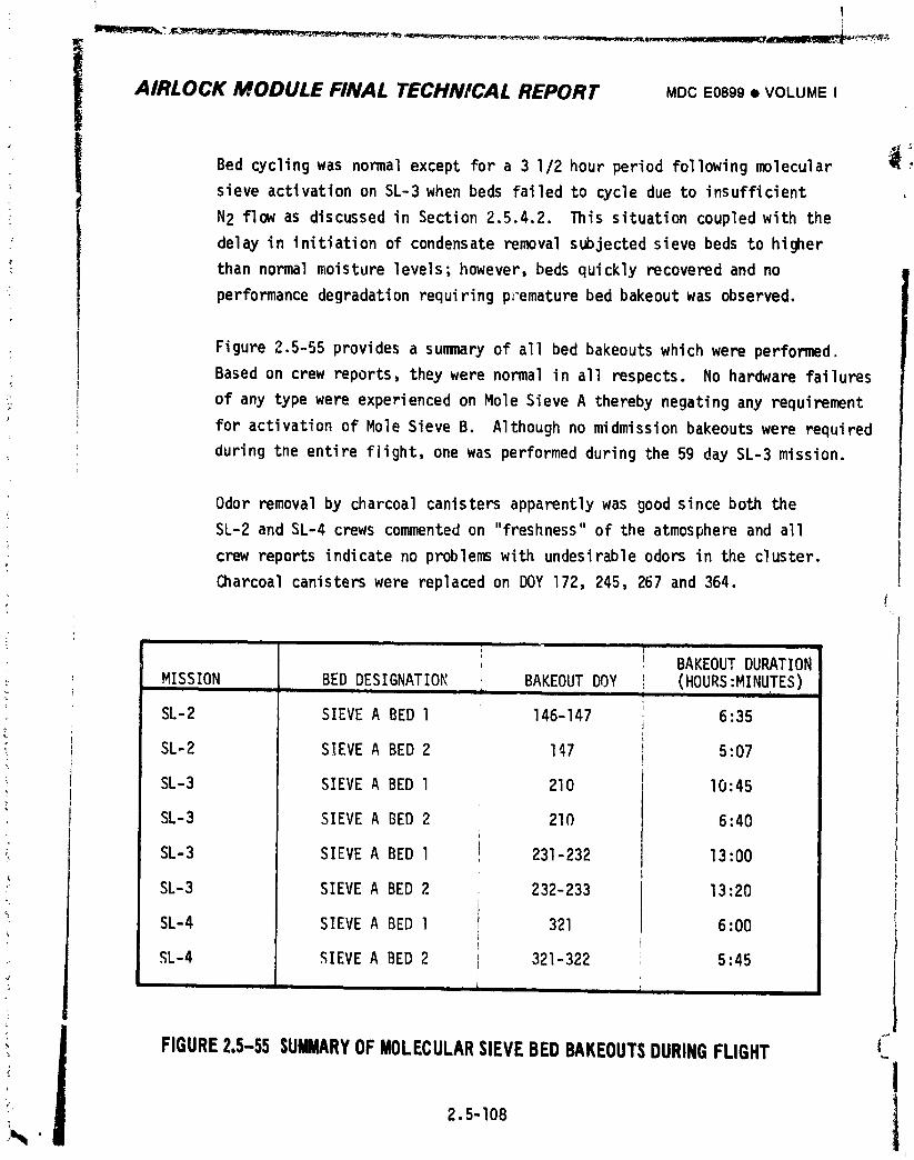
]
i
fl_l_?. • _.., _,_ _ =. _ _ ..... ..... ,_fl_llm_ _
i AIRLOCK MODULE FINAL TECHNICAL REPORT MDCE0899• VOLUMEI
Bed cyclingwas normalexceptfor a 3 I/2 hour periodfollowingmolecular _ _
sieveactivationon SL-3when beds failedto cycledue to insufficient
N2 flowas discussedin Section2.5.4.2. This situationcoupledwith the
delayin initiationof condensateremovalsubjectedsieve bedsto higher
_ than normalmoisturelevels;however,beds quicklyrecoveredand no
" performancedegradationrequiringprematurebed bakeoutwas observed.
_ Figure 2.5-55 provides a summaryof all bed bakeouts which were performed.Basedon crewreports,theywere normalin all respects. No hardwarefailures
_ of any typewere experiencedon Mole SieveA therebynegatingany requirement
for activationof Mole SieveB. Althoughno midmissionbakeoutswere required
duringthe entireflight,one was performedduringthe 59 day SL-3 mission.
Odor removalby charcoalcanistersapparentlywas goodsinceboth the
SL-2 and SL-4 crewscommentedon "freshness"of the atmosphereand all
crewreportsindicateno problemswith undesirableodors in the cluster.
Charcoalcanisterswere replacedon DOY 172, 245,267 and 364.
, BAKEOUTDURATIONMISSION BED DESIGNATIOR BAKEOUTDOY t (HOURS:MINUTES)J i
SL-2 SIEVEA BED l 146-147 6:35
" SL-2 SIEVEA BED 2 I_7 5:07
SL-3 SIEVEA BED l 210 I0:45)
SL-3 SIEVE A BED 2 210 6:40
SL-3 SIEVEA BED l 231-232 13:00
SL-3 SIEVEA BED 2 232-233 13:20
_ SL-4 SIEVEA BED l 321 6:00 ,
SL-4 SIEVEA BED 2 321-322 5:45
'i FIGURE2.5--55SUMMARYOFMOLECULARSIEVEBEDBAKEOUTSDURINGFLIGHT ('_
_ 2.5-108 1• t
i
1974018208-326
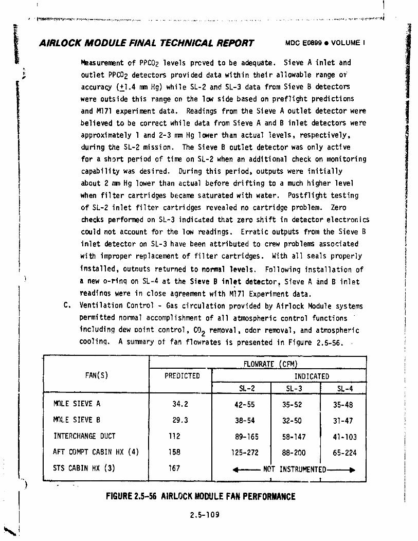
lt
ii AIRLOCK MODULE FINAL TECHNICAL REPORT MDCE0899• VOLUMEIMeasurementof PPC02levels prcved to be adequate. Sieve A inlet and
' outletPPCO2 detectorsprovideddatawithintheirallowablerangeof#
accuracy(+l.4mm Hg) while SL-2 and SL-3 data fromSieve B detectors
were outsidethis rangeon the low sidebased on preflightpredictions
and M171experimentdata. Readingsfromthe SieveA outletdetectorwere ibelievedto be correctwhile data fromSieveA and B inlet detectorswere
approximatelyl and 2-3 mm Hg lowerthan actuallevels,respectively,
duringthe SL-2 mission. The Sieve B outletdetectorwas only active
for a short periodof timeon SL-2when an additionalcheckon monitoring
capabilitywas desired. Duringthis period,outputswere initially
about2 nanHg lowerthan actualbeforedriftingto a much higherlevel |when filtercartridgesbecamesaturatedwithwater. Postflighttesting
of SL-2 inletfiltercartridgesrevealedno cartridgeproblem. Zero
checksperformedon SL-3 indicdtedthat zeroshift in detectorelectronics
couldnot accountfor the low readings. Erraticoutputsfromthe SieveB
inlet detectoron SL-3have been attributedto crewproblemsassociated
with improperreplacementof filtercartridges.With all seals properly
installed,outnutsreturnedto normallevels. Followinginstallationof
) a new o-rlnqon SL-4at the SieveB inlet detector,SieveA and B inlet
readinaswere in closeagreementwith Ml71Experimentdata.
C. VentilationControl- Gas circulationprovidedby AirlockModule systems
permittednormalaccomplishmentof all atmosphericcontrolfunctions
includingdew Dolntcontrol,CO2 removal,odor removal,and atmosphericcooling. A summaryof fan flowratesis presentedin Figure2.5-56.
FLOWRATE(CFM) ,FAN(S) PREDICTED INDICATED
L I
SL-2 SL-3 SL-4iJ II
MOLE SIEVEA 34.2 4Z-55 35-52 ( 35-48
MOLE SIEVEB 29.3 38-54 32-50 31-47
INTERCHANGEDUCT 112 89-165 58-147 41-103
AFT COMPTCABINHX (4) 158 125-272 88-200 65-224
STSCABINHX (3) 167 ¢ NOTINSTRUMENTED--------_
}
I FIGURE2.5-5G AIRLOCKMODULEFANPERFORMANCE
I 2.5-109
1974018208-327
!.................................................................................................................. -_. _ ._4_ _ "
AIRLOCK MODULE FINAL TECHNICAL REPORT MDCE0899• VOLUME I
Although a portion of the spread in flovlratesis due to fluctuations in
the output of flow sensors, a deqradation in indicated flowrate was
"observedin the interchanqe duct and aft compartment cabin heat
exchanqer module as shown in Figures 2.5-57 ar,d 2.5-58 respectively.
Aft comDartment cabin heat exchanger flmv returned to normal levels after
the inlet face of each heat exchanger was cleaned. Thereafter, flow was
maintained at desired levels by periodic cleaning of heat exchanger
inlets. Also, all four heat exchanger fans were replaced on DOY 018 in
an attemDt to obtain higher flow and increased cooling of the _)WSduring
the neriod of high beta angles. Hmvever, no increase in flow was
observed. A significant decrease in flow was obtained on DOY 019 when
water wa_ discovered in the heat exchanqers. This condition occurred
due to a high dewooint level following crew showers and low coolant inlet
temperatures with three coolant pump o_eration. Water rem._valwasJ
accomplished by vacuuming the heat exchangers and flow again returned to _
normal levels.l
Cleaning of screens and installation of an alternate fan by the crew
failed to improve the indicated ineerchange duct flowrate. It is likely
that gas flow was normal and the low flow indication was a result of
contamination on the flow ser,sor. It should be noted that interchange
duct flow at the indicated ievels would have caused no circulation problem.
The molecular sieve compressor actual flowrates were believed to be
relatively constant and closer to the predicted values shown in Figure
2.5-56 than the indicated values. The inverter output frequency was
set and matched with compressor performance during preflight altitude
chamber tests to provide flowrates near the predicted val_es listed.
The flowrate indications in flight as well as during preflight fluctuated
on the high side of actual.
Although fan flow through STS cabin heat exchangers was not measured,
adequate cooling was available at all times. Crew reports indicated
that all fans were extremely quiet. _ :
2.5-II0 I
1974018208-328
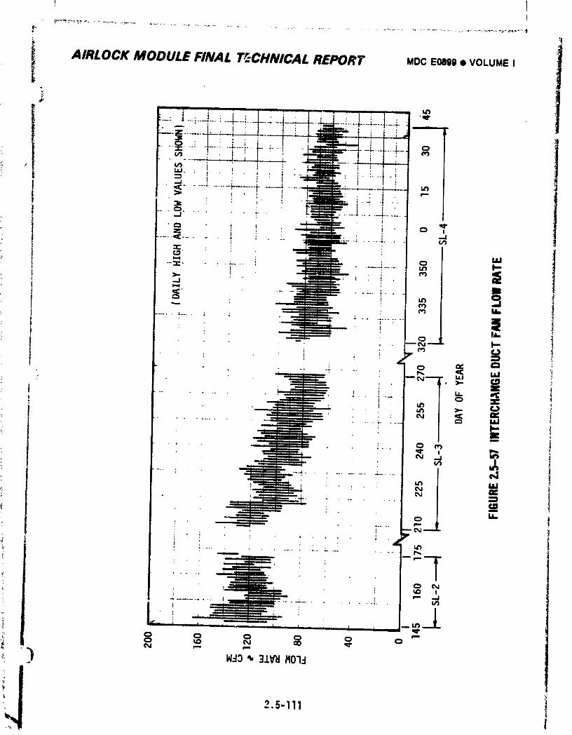
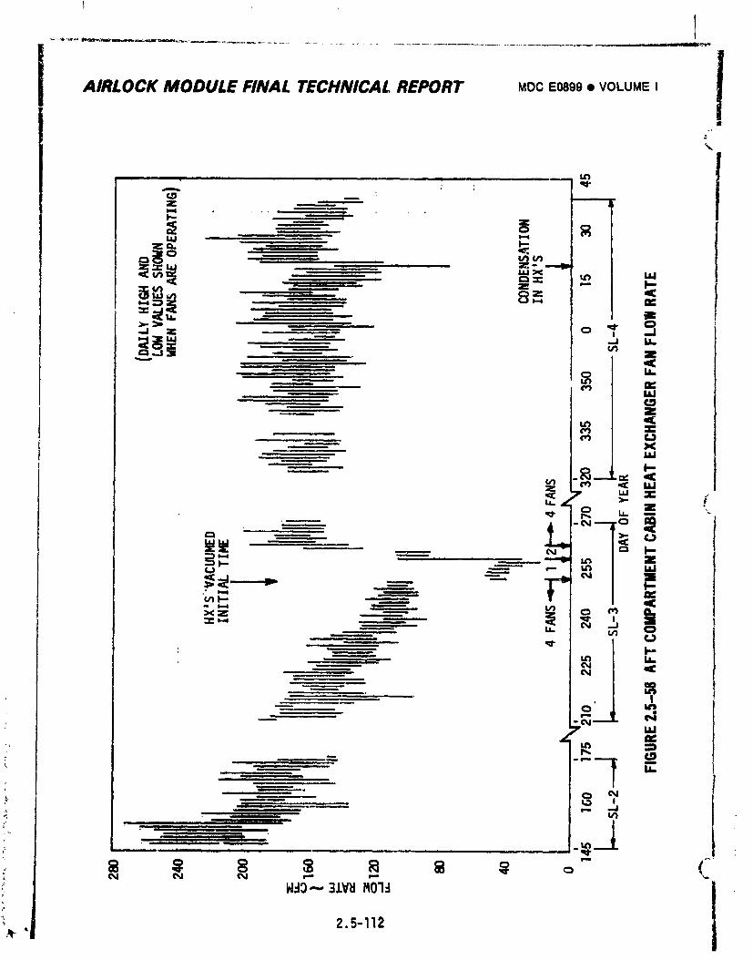
AIRLOCK MODULE FINAL TECHNICAL REPORT MOCE0899• VOLUME I lJ
%.
t z a. "" T,"7 "--,
I =_ r
_: 9C
_ i |l, ii ..... T
H.-13-- 31Wt MOT-1
, 2.5-112
1974018208-330
l
i AIRLOCK MODULE FINAL TECHIWCAL REPORT MDC E0899 • VOLUME I !Theonlyfailureassociatedwithatmosphericcirculationinvolvedthe
molecularsieveB secondaryfanwhichfailedto startduringSL-3
activation.Theproblemwasbelievedto bewiththeinverteror
electricalcircuitrysinceinstallationof an alternatefanfailedto
correctthesituation.
D. TemperatureControl- Levelsof atmosphericcoolingprovidedduringmanned
missionphasesvariedconsiderablydependingon heatloadsandresulting
equilibrium_emperaturelevels.Figure2.5-59presentsatmospheric
coolingaccomplishedby condensingheatexchangers,OWS (aftcompartment)
cabinheatexchangers,andSTScabinheatexchangersforthethree
missions.Higherthanexpectedlevelsof atmosphericcoolingwereimposed
uoonAlrlockModulesystemsdueto highOWS temperaturelevelsresulting
fromlossof theOWSmeteoroidshield.Everyeffortwasmadetomaxim4ze
AM coolingprovidedto theOWS. Threecoolantpumpswereoperatedfora
shorttimeon SL-4to reducetemperatureat theheatexchangersanda
portablefanwasperiodicallyinstalledat theOWS interfacewiththeaft
comoartmentto increasecirculationbetweenthetwomodules.Allincreased
demandsWeremet by AHsystems.
2.5.4.3 Condensate.S_stemSatisfactory condensateremoval, stowageanddisposal wasmaintained throulh-
out all mannedmission phasesas evidencedby the acceptable dewpotntlevels shown
in Figure 2.5-50 through2.5-52. However,excessivegas leakage into the systemresulted in the need for morefrequent dumpingof the system.
A. Removaland Stowaqe- Ftqure 2.5-60 presents condensatesystemAP following
initialactivationof SL-2. AftertheOWS condensateholdingtankhad I
)" been connectedto the systema AP level of 3.5 to 4.5 pstd wasmaintained
at all times except during those periods whenthe holding tank was
disconnectedfor EVAor a hclding tank dump. With the holding tank idisconnects.d,systemAP decreasedmorerapidly than expectedas seen in
Figure 2.5-61 and2.5-62. Since systempressurewasnot affected whileconnectedto the holding tank, it was concludedthat gas leakage into
the gasside of the AMcondensatetank was respon._ible. Thesp_re
condensatemodulewas not installed, however,since EVAandholding tank
"'_,_]_ dumpswere performedinfrequently andwere of short duration. The
i systemwasdeactivated normally at the end of SL-2.
2.5-113
1974018208-331
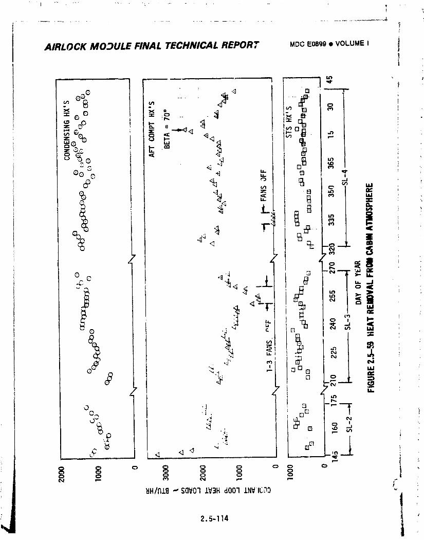
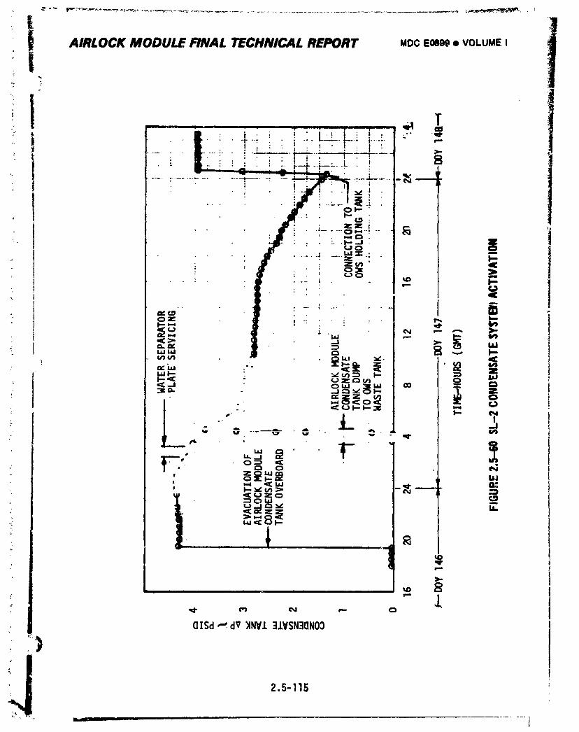
QISd _. dV _WWJ.3.L_SN3QNO3
,)
2.5-115
- _..,,...
1974018208-333
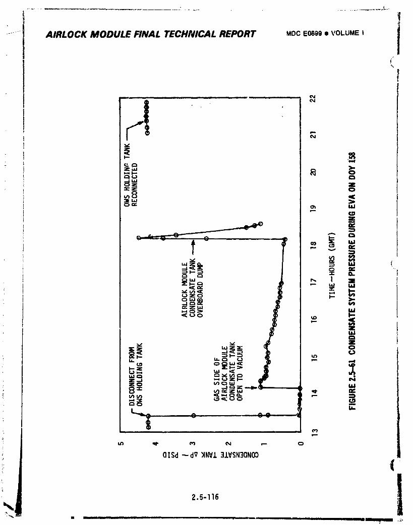
!J---- AIRLOCK MODULE FINAL TECHNICAL REPORT MOCE0899• VOLUMEI
i ii w i |11 i _
i °wILl
' °
14
i
rn
OlSd-,-dr)tNV.I.3J.VSN3CINO_)
2.5-116 I: _" • I _ . -- . ,_ I I I I I I -- llBIBli_illilB ,_
1974018208-334
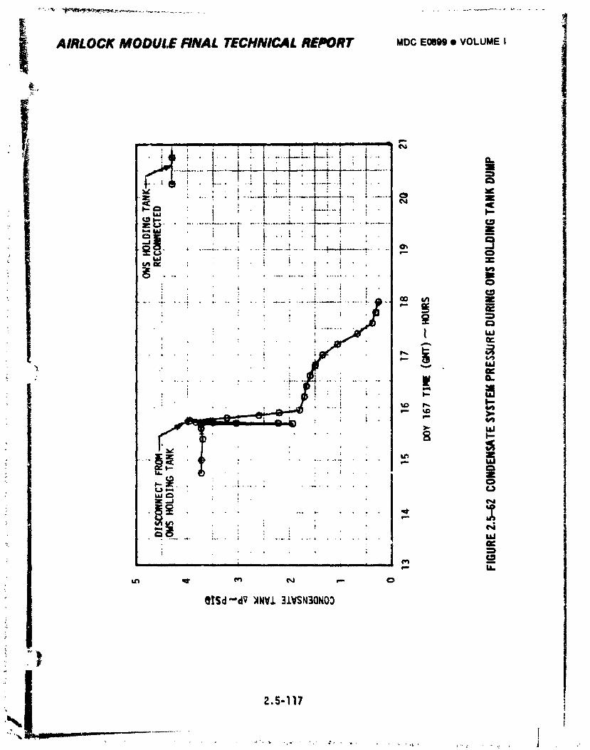
AIRLOCK MODULE FINAL TECHNICAL REPORT MOCEOBI)9• VOLUMEI_,.,
1974018208-33_
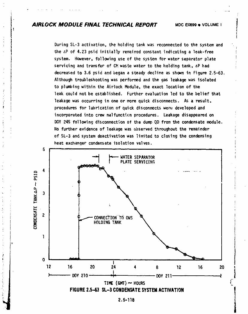
|AIRLOCK MODULE FINAL TECHNICAL REPORT MDCE0899• VOLUMEI |
iDuring SL-3 activation, the holding tank was reconnected to the system and
the AP of 4.23 psid initially remained constant indicating a leak-free
system. However, following use of the system for water separator plate
servicing and transfer of CP_waste water to the holding tank, AP had
decreased to 3.6 psid and began a steady decline as shown in Figure 2.5-63.
Although troubleshooting was performed and the gas leakage was isolated
to pluffbingwithinthe AirlockModule,the exact locationof the
leakcouldnot be established,Furtherevaluationled to the beliefthat
leakagewas occurringin one or morequick disconnects.As a result,
proceduresfor lubricationof quick disconnectswen= developedand!
incorporatedinto crewmalfunctienprocedures. Leakagedisappearedon
_ DOY 245 followingdisconnectionof the du_ QD fromthe condensatemodule.
No furtherevidenceof leakagewas observedthroughoutthe remainder
of SL-3 and systemdeactivationwas limitedto closingthe condensing
heat exchangercondensateisolationvalves.5
-_ _-- WATER SEPARATORPLATE SERVICING
4 .......
¢L
t
3z
m 2• z T(_OW_ CONNECTION
.
1
0 _I
12 16 20 24 4 8 12 16 20
• DOY 210 ,- DOY 211 Z
TI_ (GHT)-- HOURS _"
FIGURE2.5-63 SL-3 CONDENSATESYSTEMACTIVATION tJ
] 974018208-336
r_
i AIRLOCK MODULE FINAL TECHNICAL REPORT MDC E0899• VOLUMEI
f
Condensatesystemactivationwas completelynormalat the stert of SL-4
with a systemAP of 2.86psidhavingbeenmaintainedduringthe storage
period. No evidenceof significantgas leakageintothe systemwas
observeduntilDOY 034 when the QD was disconnectedfromthe liquid9as
separatorat Panel 217 after EVA operations.Followingdisconnection,
systemAP decreasedto zerowithinapproximately15 minutes. After attempts
to stop the leakusingKrytoxand universalsealantwere unsuccessful,a
cap launchedon the SL-4 CSHwas installedon the disconnectedQD and no
furtherevidenceof leakagewas observed.
B. Disposal- Essentiallyall condensatewas dumpedinto the OWS waste tank
via the OWS holdingtank. The holdir_gtankwas dumpedtwice on SL-2,
dailyon SL-3 untilDOY 245when systemleakagewas stopped,and three
timeson SL-4 Priorto holdingtankactivationon DOY 14B, the AM
condensatetankwas dumpeddirectlyto the OWS waste tankon one r _ion.
Overboarddumps via the AM overboardventwere limitedto mixtures_ontain-
ing a high percentageof gas and only occurredduringsystemactivationon
SL-2 (DOY 146),duringEVA on DOY 158,and as a part of systemtrouble-
shootingduringSL-3.
C. Servicing/DeserviclngSupport- Servicing/deservicingfunctions
supportedby the condensatesystemrelatingto water separatorplate
assembliesand otherequipmentwere accomplishedin a normalmanner.
2.5.4.4 Servlcinq/Deserviclng
The orialnalcondenslnoheatexchanqerwater separatorplate assemblies
oerformedso well theywere servicedand reusedat the beginningof both SL-3 and
$L-4. All servicing/deservicinqooerationswent as planned.
2.5.5 DeveloomentProblems
Problemswere encounteredwlth the functionalperformanceof flve components
durlnqdevelopmentof the ECS. The componentswere the qas flowmeters,PPCO2
sensors,PLV fan and heat exchanqerassemblies,120 psi 02 pre._surerequlators,
filial_ and cabinpressurerequlators,
2.5-119
t
1974018208-337
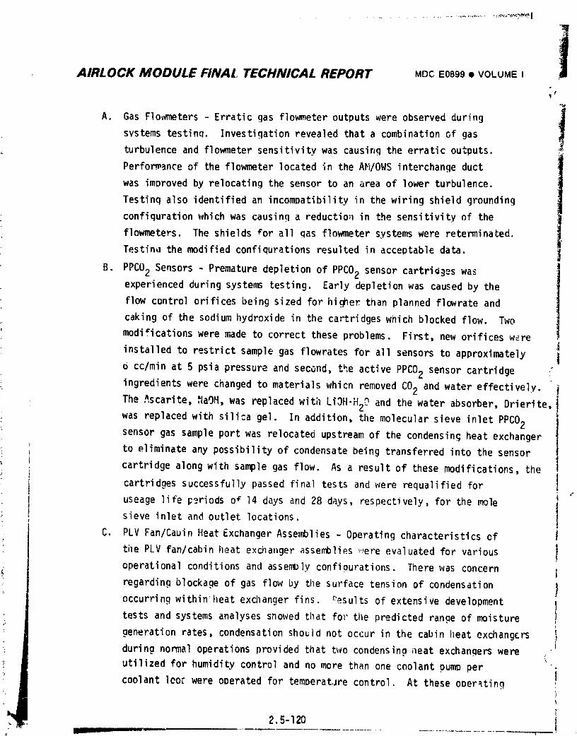
3AIRLOCK MODULE FINAL TECHNICAL REPORT MDCE0899• VOLUME I 1
A. Gas Flo_meters- Erraticgas flowmeteroutputswere observedduring J
svstemstesting. Investigationrevealedthata combinationof gas
turbulenceand flowmetersensitivitywas causingthe erraticoutputs. _
Perfom_anceof the flowmeterlocatedin the AN/OWSinterchangeduct
was improvedby relocatingthe sensorto an areaof lower turbulence.
Testinqalso identifiedan incomDatibilityin the wiringshieldgrounding
confiqurationwhich was causinga reductio;_in the sensitivityof the
flowmeters.The shieldsfor all gas flowmetersystemswere reterminated.
Testin_the modifiedconfigurationsresultedin acceptabledata. j
B. PPCO2 Sensors- Prematuredepletionof PPCO2 sensorcartri_)eswasexperiencedduringsystenstesting. Earlydepletionwas causedby the
flow controlorificesbeing sized for higherthan plannedflowrateand
cakingof the sodiumhydroxidein the cartridgeswnich blockedflow. Two
modificationswere made to correcttheseproblems. First,new orificesw_re
installedto restrictsamplegas flowratesfor all sensorsto approximately
6 cc/minat 5 psiapressureand second,t_.eactivePPCO2 sensorcartridge
ingredientswere changedto materialswhicn removedCO2 and watereffectively.
The Ascarite,.=laOH,was replacedwith LiOH-H2Oand the water absorber,Drierite,
was replacedwith silicagel. In addition,the molecularsieveinletPPCO2sensorgas sampleportwas relocatedupstreamof the condensingheatexchanger
• to eliminateany possibilityof condensatebeing transferredinto the sensor
cartridgealongwith samplegas flow. As a resultof thesemodificationsthe
" cartridgessuccessfullypassedfinaltests and were requalifiedfor
useagelifep_riodso• 14 daysand 28 days, respectively,for the mole
• , sieve inletand outletlocations.
C. PLV Fan/CabinHeatExchangerAssemblies- Operatingcharacteristicsof
tilePLV fan/cabinlleatexchangerassemblies,.,ereevaluatedfor various !operationalconditionsand assemblyconfiourations.Therewas concern i
regardingblockageof gas flowby tilesurfacetensionof condensation 1occurringwithinheat exchangerfins. r'esultsof extensivedevelopment 1
testsand systemsanalysesshowedthat for the predictedrangeof moisture !
generationrates,condensationshouldnot occur in the cabinheatexchangers iduringnormaloperationsprovidedthat two condensingneat exchangerswere J
utilizedfor humiditycontroland no more thanone coolantoumD per icoolantleorwere operatedfor temDeratJrecontrol. At theseoDer_tinq
:,y 2. -12o I
1974018208-338
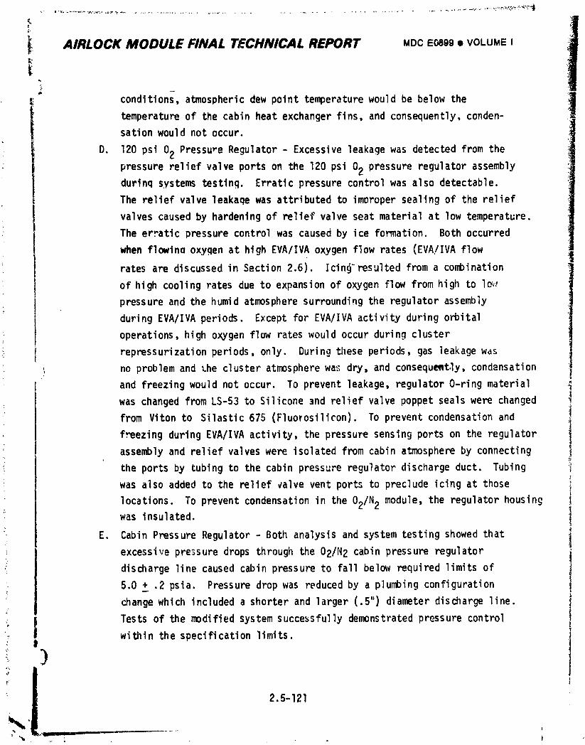
_ AIRLOCK MODULE FINAL TJECHNICAL REPORT MDCE0899• VOLUMEI
* conditions,atmosphericdew point temperaturewould be below the
i temperatureof the cabinheat exchangerfins,and consequently,conden-sationwould not occur.
D. 120 psi 02 PressureRegulator- Excessiveleakagewas detectedfrom the
pressurereliefvalveportson the 120 psi 02 pressureregulatorassemblydurinqsystemstesting. Erraticpressurecontrolwas also detectable.
The reliefvalve leakaqewas attributedto imoropersealingof the relief
valvescausedby hardeningof reliefvalveseatmaterialat low temperature.
The erraticpressurecontrolwas causedby ice formation. Bothoccurred
whenflowinaoxyqenat highEVA/IVAoxygenflow rates (EVA/IVAflowratesare discussedin Section2.6). Icing-resultedfroma combination
of high coolingratesdue to expansionof oxygenflowfromhigh to lo,,,
' pressureand the humid atmospheresurroundingthe regulatorassembly
duringEVA/IVAperiods. Exceptfor EVA/IVAactivityduringorbital
operations,high oxygenflow rateswould occur duringcluster
i repressurizationperiods,only. Duringthese periods,gas leakagewas
no problemand the clusteratmospherewas dry, and consequemt.ly,condensation
and freezingwould not occur. To preventleakage,regulatorO-ringmaterial
was changedfromLS-53to Silicone3nd reliefvalvepoppetsealswere changed _!
from Vitonto Silastic675 (Fluorosilicon).To preventcondensationand
freezingduringEVA/IVAactivity,the pressuresensingports on the regulator |
assemblyand reliefvalveswere isolatedfromcabin atmosphereby connecting 1the portsby tubingto the cabinpressureregu'latordischargeduct. Tubing
was also addedto the relief_alveventports to precludeicingat those !
locations. To preventcondensationin the 02/N2 module,the regulatorhousing i
was insulated. 1
E. CabinPressureRegulator- Both analysisand systemtestingshowedthat i
excessivepressuredrops throughthe 02/N2 cabinpressureregulator _I
dischargelinecausedcabinpressureto fallbelow requiredlimitsof i
5.0 + .2 psia. Pressuredropwas reducedby a plumbingconfiguration I
changewhich includeda shorterand larger(.5")diameterdischargeline. I
, | Testsof the modifiedsystemsuccessfullydemonstratedpressurecontroli
I withinthe specificationlimits. 1
t) Iiti
2.5-121
1974018208-339
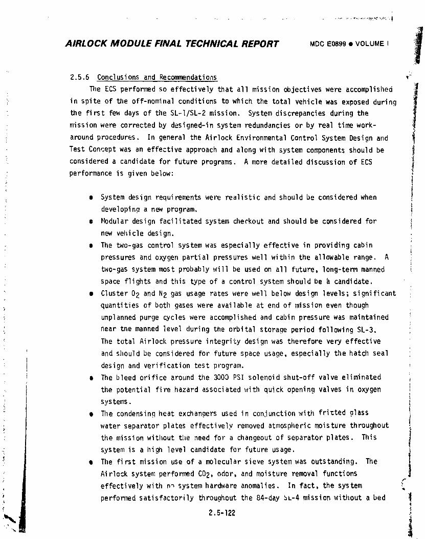
AIRLOCK MODULE FINAL TECHNICAL REPORT MDC E0899 • VOLUME I il
2.5.6 Conclusions and Recommendations _
TileECS performed so effectively that all mission objectiveswere accomplished
!in spite of the off-nominal conditions to which the total vehicle was exposed during
the first few days of the SL-I/SL-2 mission. System discrepancies during the
mission were corrected by designed-insystem redundancies or by real time work-
procedures. In general the Airlock Environmental Control System Design and iaround
Test Concept was an effective approach and along with system components should be
considered a candidate for future programs. A more detailed discussion of ECS
performance is given below:
: • System design requirementswere realistic and should be considered when
developing a new program,
• Hodular design facilitated system checkout and should be considered for
new vehicle design.
e The two-gas control system was especially effective in providing cabin
pressures and oxygen partial pressures well within tileallowable range. A
two-gas system most probably will be used on all future, long-term manned
space flights and this type of a control system should be _ candidate.
• Cluster 02 and N2 gas usage rates were well below design levels; significant
:. quantities of both gases were available at end of mission even though
; unplanned purge cycles were accomplished and cabin pressure was maintained
near tne manned level during the orbital storage period following SL-3.
Tiletotal Airlock pressure integrity design was therefore very effective
and should be considered for future space usage, especially the hatch seal
; design and verification test program. ,
m The bleed orifice around the 3000 PSI solenoid shut-off valve eliminated
the potential fire hazard associatedwith quick opening valves in oxygen
systems.
• The condensing heat exchangers used in con,iunctionwith fri_ted glass
water separator plates effectively removed atmospheric moisture throughout
the mission without the need for a changeout of separator plates. This
system is a high level candidate for future usage,
e The first mission use of a molecular sieve system was outstanding. The
Airlock system performed C02, odor, and moisture removal functionsr-
effectively with n_ system hardware anomalies. In fact, the system
performed satisfactorily throughout the 84-day _L-4 mission without a bed :_
2.5-122 ;
1974018208-340
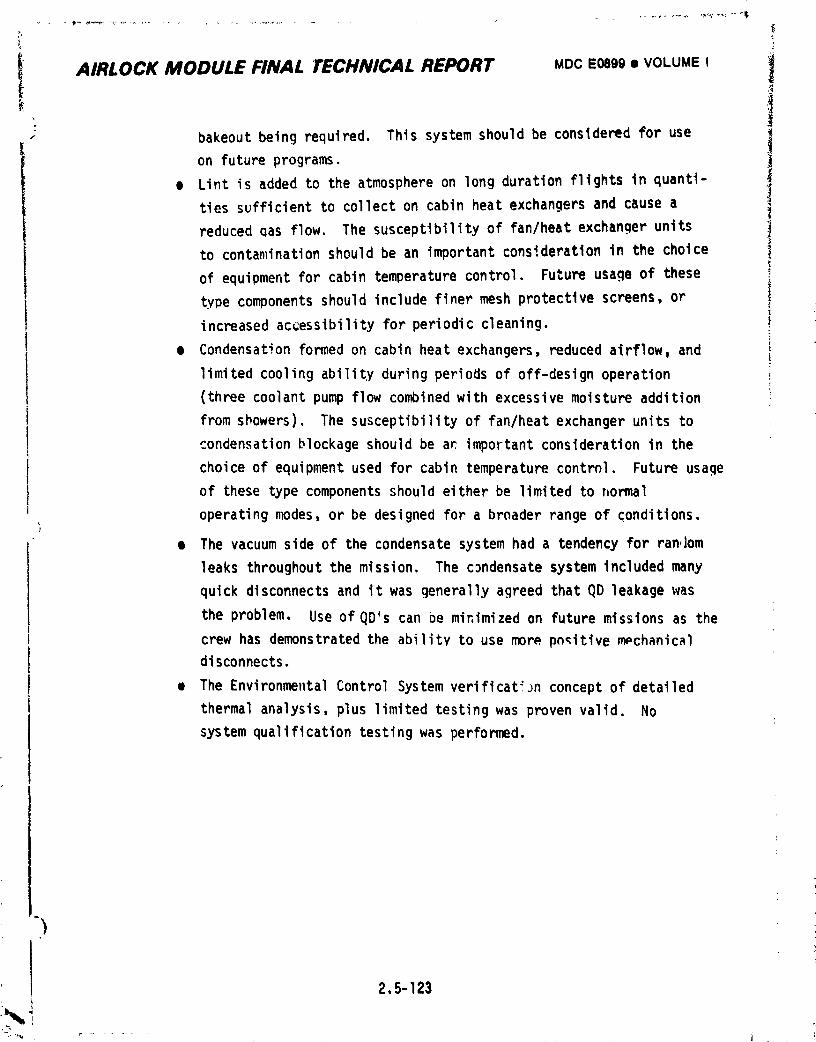
I AIRLOCK MODULE FINAL tECHNICAL REPORT MDC E0899 • VOLUME I i
- bakeout betng required. This system should be considered for use 1on future programs.
Lint is added to the atmosphere on long duration flights in quantl- 1e
ties sufficient to collect on cabin heat exchangers and cause a
reduced qas flow. The susceptibilityof fan/heat exchanqer units !
to contamination should be an important consideration in the choice i
of equipment for cabin temperature control. Future usage of these
type components should include finer mesh protective screens, or
increased accessibility for periodic cleaning.
• Condensation formed on cabin heat exchangers, reduced airflow, and
limited cooling ability during periods of off-design operation
(three coolant pump flow combined with excessive moisture addition
from showers). The susceptibility of fan/heat exchanger units to
condensation blockage should be an impoFtant consideration in the
' choice of equipment used for cabin temperature control. Future usage
of these type components should either be limited to normal
operating modes, or be designed for a broader range of _onditions.
• The vacuum side of the condensate system had a tendency for random
leaks throughout the mission. The condensate system included many
quick disconnects and it was generally agreed that QD leakage was
the problem. Use of QD's can be minimized on future missions as the
crew has demonstratedthe ability to use more pn_itive m_chanical
disconnects.
• The EnvironmentalControl System verificat:Jn concept of detailed
thermal analysis, plus limited testing was proven valid. No
system qualificationtesting was performed.
2.5-123
1974018208-341
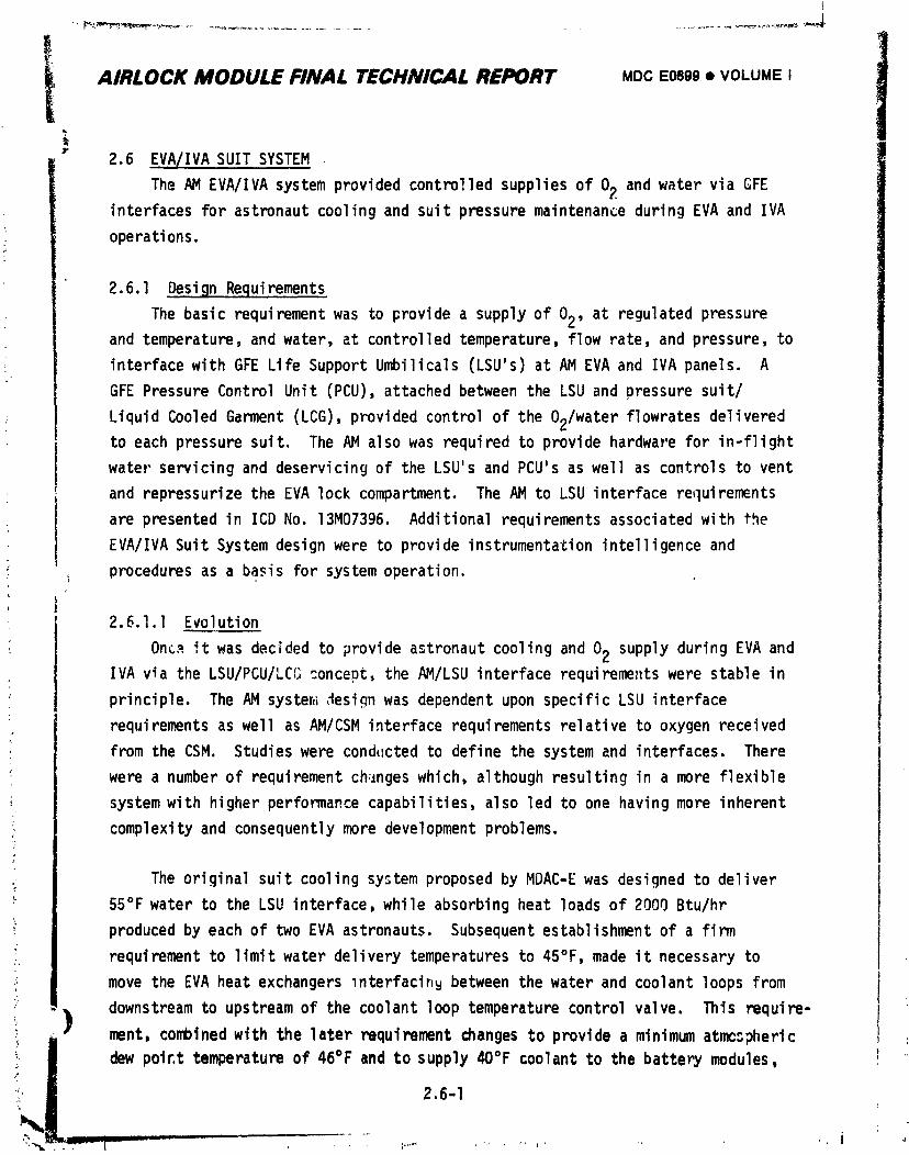
-,-p_,l_.3_.,,_,..r.._ _ .... _ ..................... -.............. _-_,_._ _-
i AIRLOCK MODULE FINAL TECHNICAL REPORT MDC E0899 • VOLUME I
;,1
IJt
2.6 E.VA/IVASUIT SYSTEM
The AM EVA/IVAsystemprovidedcontrolledsuppliesof 02 and water via GFEinterfacesfor astronautcoolingand suitpressuremaintenanceduringEVA and IVA
operations.
2.6.l De.sign Re.quirements
The basic requirementwas to providea supplyof 02, at regulatedpressureand temperature,and water,at controlledtemperature,flowrate,and pressure,to
interfacewith GFE LifeSupportUmbilicals(LSU's)at AM EVA and IVA panels. A
GFE PressureControlUnit (PCU),attachedbetweenthe LSU and pressuresuit/
LiquidCooledGarment(LCG),providedcontrolof the 02/waterflowratesdeliveredto each pressuresuit. The AM alsowas requiredto providehardwarefor in-flight
water servicingand deservicingof the LSU'sand PCU'sas well as controlsto vent
and repressurizethe EVA lockcompartment.The AM to LSU interfacerequirements
are presentedin ICD No. 13M07396. Additionalrequirementsassociatedwith the
EVA/IVASuit Systemdesignwere to provideinstrumentationintelligenceand
proceduresas a basis for systemoperation.
2.6.l.I Evolution
OncPit was decidedto provideastronautcoolingand 02 supplyduringEVA andIVA via the LSU/PCU/LCGconcept,the AM/LSUinterfacerequireme_Itswere stablein
principle. The AM syster,_,_esignwas dependentupon specificLSU interface
requirementsas well as AM/CSMinterfacerequirementsrelativeto oxygenreceived
from the CSM. Studieswere cond_Ictedto definethe systemand interfaces.There
were a numberof requirementch,_ngeswhich,althoughresultingin a more flexible
systemwith higherperformancecapabilities,alsoled to one havingmore inherent
complexityand consequentlymore developmentproblems.
The originalsuit coolingsystemproposedby MDAC-Ewas designedto deliver
55°Fwater to the LSU interface,while absorbingheat loadsof 2000 Btu/hr
producedby each of two EVA astronauts.Subsequentestablishmentof a firm
requirementto limitwater deliverytemperaturesto 45°F,made it necessaryto
move the EVA heatexchangersinterfacinybetweenthe waterand coolantloopsfrom
downstreamto upstreamof the coolantlooptemperaturecontrolvalve. This require-
l ment, combinedwith the laterrequirementchangesto providea minimumatmcspheric
_.! dew poir,t temperature of 46°F and to supply 40°F coolant to the battery modules,
2.6-I
1974018208-342
I
AIRLOCK MODULE FINAL TECHNICAL REPORT MDCE0899I VOLUMI::I IIi had a profound impact on the coolant system design. The culmination was the
design and development of the suit battery cooling module described in Section 2.4. r
Other design requirement changes from the original system included the i
addition of a GFE liquid gas separator for removal of free gas from the circu- I
lating water loops, the addition of negative heat load to accommodate heat losses i
from the GFE part of the system, and utilization of the AM aft compartment in !
f
addition to the lock compartment to provide increased volume for the EVA crewmen, i
-. Implementationof the liquid gas separator assemb:y proved to have a significant
_- effect on system development in that it dictated a change of additives in the suit I
cooling loops. This, in turn, led to materials incompatibilityand pump opera- iitional problems, which were subsequently solved by using still different system
additives and ihcreasing the pump vane clearances, !
; The addition of the STS IVA panel along with the requirement to ._upply02 ii '
_ and cooling water simultaneouslyto three crewmen's 'SU's instead of two, resulted
in increased 02 flowrate and system heat load requirements. 1; i
2.6.1.2 Flight Configuration il
!_ The flight system functional design requirements are summarized as follows. I
The physical and operational requirements are described in Section 2.12. I
A. Oxygen Supply - Supply 40-90°F 02 at the following conditions to LSU's I
from EVA/IVA panel disconnects for suit pressurization and ventilation, i
(1) With AM 02 tank pressure greater than 400 psia, supply a total
flowrate of 22.7 Ib/hr to two crewmen (13.7 Ib/hr to one umbilical
connection and 9.0 Ib/hr to the other connection) with a minimum
interface pressure to the LSU of 65 Dsia.
(2) With AM 02 tank pressures greater than 500 psia, supply a total
flowrate of 31.? Ib/hr to three crewmen. To one umbilical connection
the flowrate shall be 13.7 Ib/hr at a minimum interface pressure of
55 psia, and at each of the other two connections the flowrate shall
be 9 Ib/hr with a minimum interface pressure of 65 psia.
(3) With AM 02 tank pressures greater than 450 psia and loss of one
crewman's umbilicals pressure integrity, provide a minimum of
9.0 Ib/hr at 65 psia to the other crewman's umbilical con,_ection.
ii Ill Ill _ lljll ]
1974018208-343
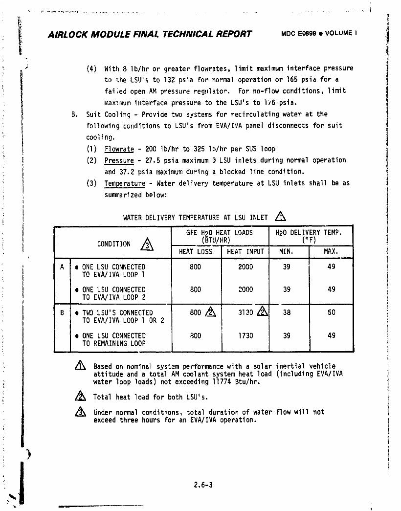
I AIRLOCK MODULE FINAL TECHNICAL REPORT MDCE0899• VOLUME I ,i• 4
" (4) Witll8 Ib/hror greaterflowrates,limitmaximuminterfacepressure
I to the LSU'sto 132 for normaloperationor 165 psia for apsia
fai;edopen AM pressureregulator. For no-flowconditions,limit
max:mumi,terfacepressureto the LSU'sto I)6 psia.
B. SuitCooling- Providetwo systemsfor recirculatingwater at the
followingconditionsto LSU'sfromEVA/IVApaneldisconnectsfor suit
cooling.
! (1) Flowrate- 200 Ib/hrto 325 Ib/hrper SUS loop
(2) Pressure- 27.5psia maximum@ LSU inletsduringnormaloperation
and 37.2psiamaximumduringa blockedlinecondition. ,
(3) Temperature- Waterdeliverytemperatureat LSU inletsshallbe as
summarizedbelow:
WATER DELIVERYTEMPERATUREAT LSU INLET Z_
GFE H20 HEAT LOADS H20 DELIVERYTEMP.
,_ (BTU/HR) (°F)CONDITIONHEATLOSS HEATINPUT MIN. MAX.
; A e ONE LSU CONNECTED 800 2000 39 49TO EVA/IVALOOPl
i e ONE LSU CONNECTED 800 2000 39 49TO EVA/IVALOOP 2f
B e TWO LSU'SCONNECTED 800 /_ 3130Z_ 38 50 iTO EVA/IVALOOP l OR 2
e ONE LSU CONNECTED 800 1730 39 49TO REMAININGLOOP
Z_ Basedon nominalsystemperformancewith a solar inertialvehicle iattitudeand a totalAM coolantsystemheat load (includingEVA/IVAwater looploads)not exceedingI1774 Btu/hr.
Z_ Total heatloadfor both LSU's.
Z_ Undernormalconditions,totaldurationof water flowwill notexceedthreehours for an EVA/IVAoperation.
! )
2.6-3
1974018208-344
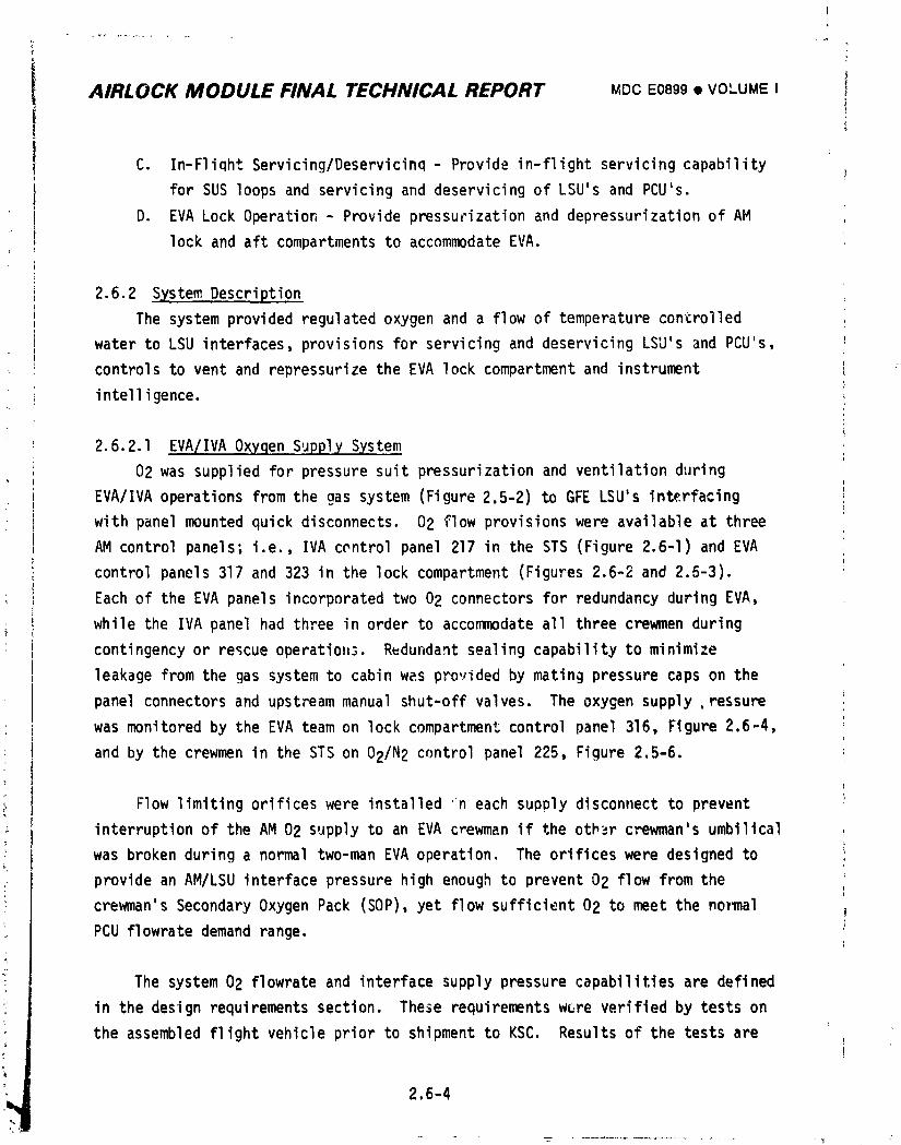
(
?
AIRLOCK MODULE FINAL TECHNICAL REPORT MDCE0899I VOLUMEI I
C. In-FliqhtServicing/Deservicinq- Providein-flightservicingcapability
for SUS loopsand servicingand deservicingof LSU's and PCU's.
D. EVA Lock Operation- Providepressurizationand depressurizationof AM
lockand aft compartmentsto accommodateEVA.
2.6.2 SystemDescription
The systemprovidedregulatedoxygenand a flow of temperaturecontrolled
waterto LSU interfaces,provisionsfor servicingand deservicingLSU's and PCU's,
controlsto ventand repressurizethe EVA lockcompartmentand instrument
intelligence.
2.6.2.1 EVA/IVAOxygenSupplySystem
02 was suppliedfor pressuresuit pressurizationand ventilationduring
EVA/IVAoperationsfromthe gas system (Figure2.5-2)to GFE LSU'sinterfacing
with panelmountedquickdisconnects.02 flow provisionswere availableat three
AM controlpanels;i.e., IVA controlpanel 217 in the STS (Figure2.6-I)and EVA
controlpanels317 and 323 in the lockcompartment(Figures2.6-2and 2.5-3).
Eachof the EVA panelsincorporatedtwo 02 connectorsfor redundancyduringEVA,
while the IVA panelhad threein order to accommodateall three crewmenduring
contingencyor rescueoperatiol_s.R_dundantsealingcapabilityto minimize
I leakagefromthe gas systemto cabinw_s providedby matingpressurecapson the
i panelconnectorsand upstreammanualshut-offvalves, The supply ressureoxygen I
was monitoredby the EVA teamon lock compartmentcontrolpanel 316, Figure2.6-4,
i and by the crewmenin the STS on 02/N2 controlpanel225, Figure2.5-6.
Flowlimitingorificeswere installedn each supplydisconnectto prevent
interruptionof the AM 02 supplyto an EVA c_ewmanif the other crewman'sumbilical
was brokenduringa normaltwo-manEVA operation, The orificeswere designedto
providean AM/LSUinterfacepressurehigh enoughto prevent02 flow fromthe
crewman'sSecondaryOxygenPack (SOP),yet flowsufficient02 to meet the no_al
PCU flowratedemandrange.
The system02 flowrateand interfacesupplypressurecapabilitiesare defined
in the designrequirementssection. These requirementswere verifiedby testson
the assembledflightvehiclepriorto shipmentto KSC, Resultsof the testsare
!,,_ 2.6-4
1974018208-345
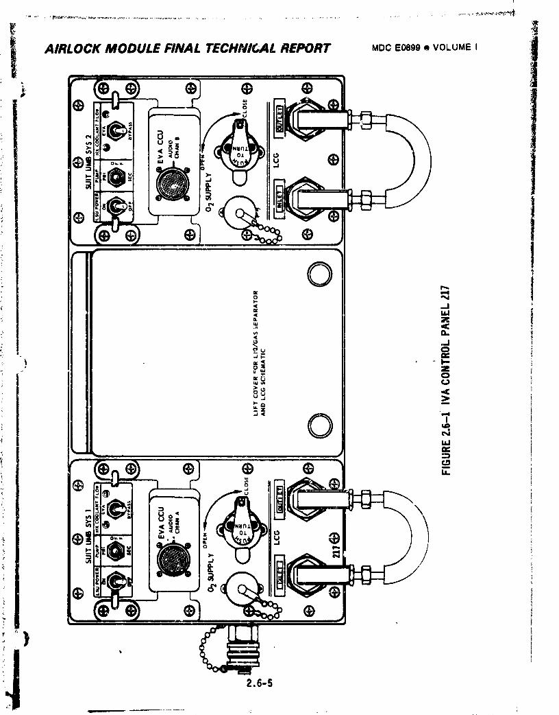
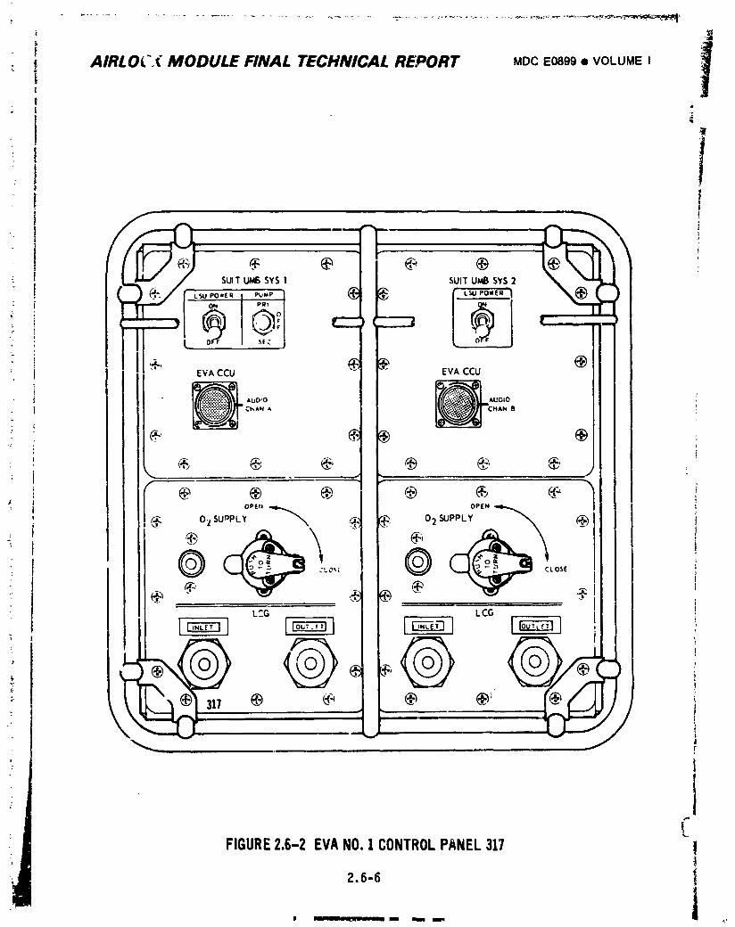
; AIRLOC.( MODULE FINAL TECHNICAL REPORT MDCEo89g• VOLUMEI 1
: ii
/ SUIT UMB SYS I SUIT UMB SYS 2
_ , [,_,o.,_ I ,_-, 6 ,__ _,o._.m
' EVA CCU EVA CCU
k J
OPEt_ OPEN
, .,. SUPPLYo_SUDPL,_ _ _, 02
- @ CLO_._ CLOSE
cia .o,., _ @ _ . _ILCG LCG
\ - : ..... /1 ,
FIGURE2.6-2 EVANO.1CONTROLPANEL317 12,6-6
!
1974018208-347
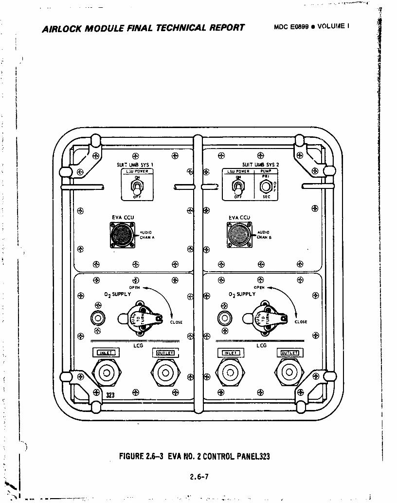
_r
AIRLOCK MODULE FINAL TECHNICAL REPORT MDC E0899 • VOLUME I !
l
' !
"r SUIT UMB SYS SUIT UMB SYS 2
l
EVA CCU EVA CCU
_ m,UOIO
J tHAN A O
r- r
OPEN OPEN
SUPPLY ___ Q 2 SUPPLY
CLOSE CLOSE
LCG LCG
\ //
i )
: ! FIGURE2.6-3 EVAtl0.2 CONTROLPANEL323
#
i_. 2.6-7
I
1974018208-348
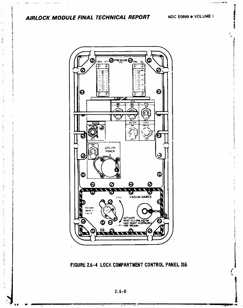
I AIRLOCK MODULE FINAL TECHNICAL REPORT MDCE0899• VOLUME I
_' i; f
Loc,..,(9'R_UREeo.,o, 1: t ,
FIGURE2.6-4 LOCKCOMPARTMENTCONTROLPANEL316
!2.6-8 _I
1974018208-349
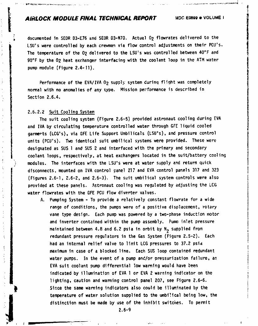
I
I i• AI_LOCK MODULE FINAL TECHNICAL REPORT MZ:)CE0899• VOLUMEI .I
k documentedin SEDRD3-E76and SEDRD3-N70. Actual02 flowratesdeliveredto the
I.SU'swere controlledby each crewmanvia flowcontroladjustmentson their PCU's. 1
The temperatureof the 02 deliveredto the LSU'swas controlledbetween40°F and
gO°F by the 02 heat exchangerinterfacingwith the coolantloop in the ATM water!pumpmodule (Figure2.4-11).
Performanceof the EVA/IVA02 supplysystemdurinqflightwas completely
normalwith no anomaliesof any type. Missionperformanceis describedin
Section2.6.4.
2.6.2.2 SuitCoolingSystem
The suitcoolingsystem(Figure2.6-5)providedastronautcoolingduringEVA
and IVA by circulatingtemperaturecontrolledwater throughGFE liquidcooled I
garmerts(LCG's),via GFE Life SupportUmbilicals(LSU's),and pressurecontrol II
units (PCU's). Two identicalsuitumbilicalsystemswere provided. These were II
designatedas SUS l and SUS 2 and interfacedwith the primaryand secondary !
coolantloops,respectively,at heat exchangerslocatedin the suit/batterycooling
modules. The interfaceswith the LSU'swere at water supplyand returnquick
disconnects,mountedon IVA controlpanel217 and EVA controlpanels317 and 323
(Figures2.6-1,2.6-2,and 2.6-3). The suit umbilicalsystemcontrolswere also
providedat thesepanels. Astronautcoolingwas regulatedby adjustingthe LCG
water flowrateswith the GFE PCU flowdivertervalves.
A. PumpingSystem- To providea relativelyconstantflowratefor a wide
rangeof conditions,the pumpswere of a positivedisplacement,rotary
vane typedesign. Eachpumpwas poweredby a two-phaseinductionmotor
and invertercontainedwithinthe pump assembly. Pump inletpressure
maintainedbetween4.8 and 6.2 psia in orbitby N2 suppliedfrom
redundantpressureregulatorsin the Gas System(Figure2.5-2). Each
had an internalreliefvalveto limitLCG pressuresto 37.2psid
maximumin caseof a blockedline. Each SUS loopcontainedredundant
water pumps. In the event of a pump an_/orpressurizationfailure,an
EVA suitcoolantpump differentiallow warningwould havebeen
indicatedby illuminationof EVA l or EVA 2 warningindicatoron the
lighting,cautionand warningcontrolpanel207, see Figure2.6-6.
Sincethe samewarningindicatorsalso couldbe illuminatedby the
iiJ temperatureof water solutionsuppliedto the umbi_,icalbeing low, the
distinctionmust be made by use of the inhibitswitches. To permit
2.6-g
1974018208-350
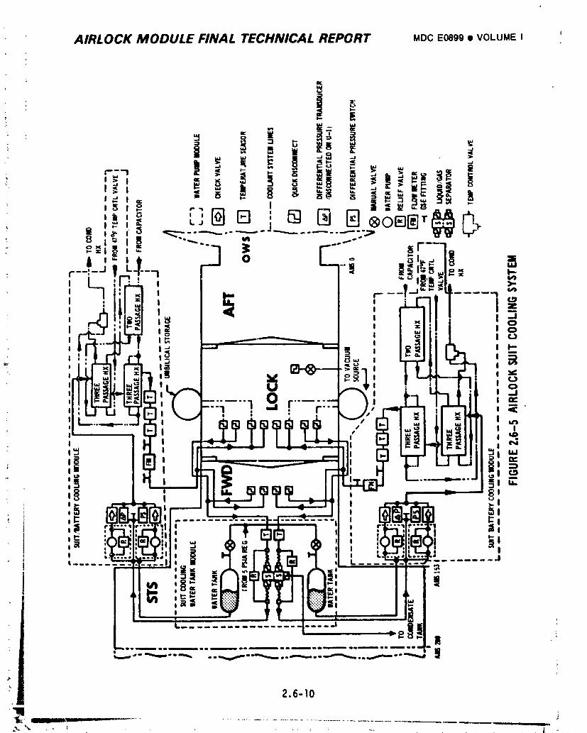
AIRLOCK MODULE FINAL TECHNICAL REPORT MDC E0899 • VOLUME I "
2.6-10
III
1974018208-351
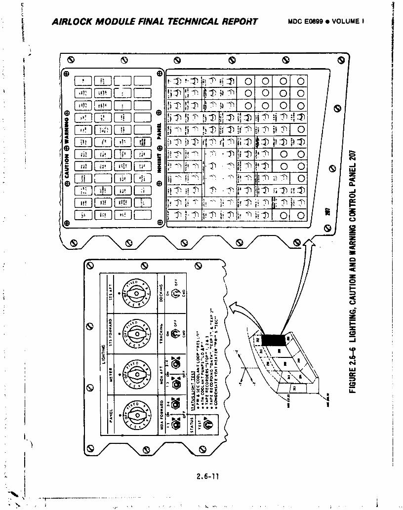
• _ AIRLOCK MODULE FINAL TECHNICAL REPORT MDCE0899• VOLUMEI
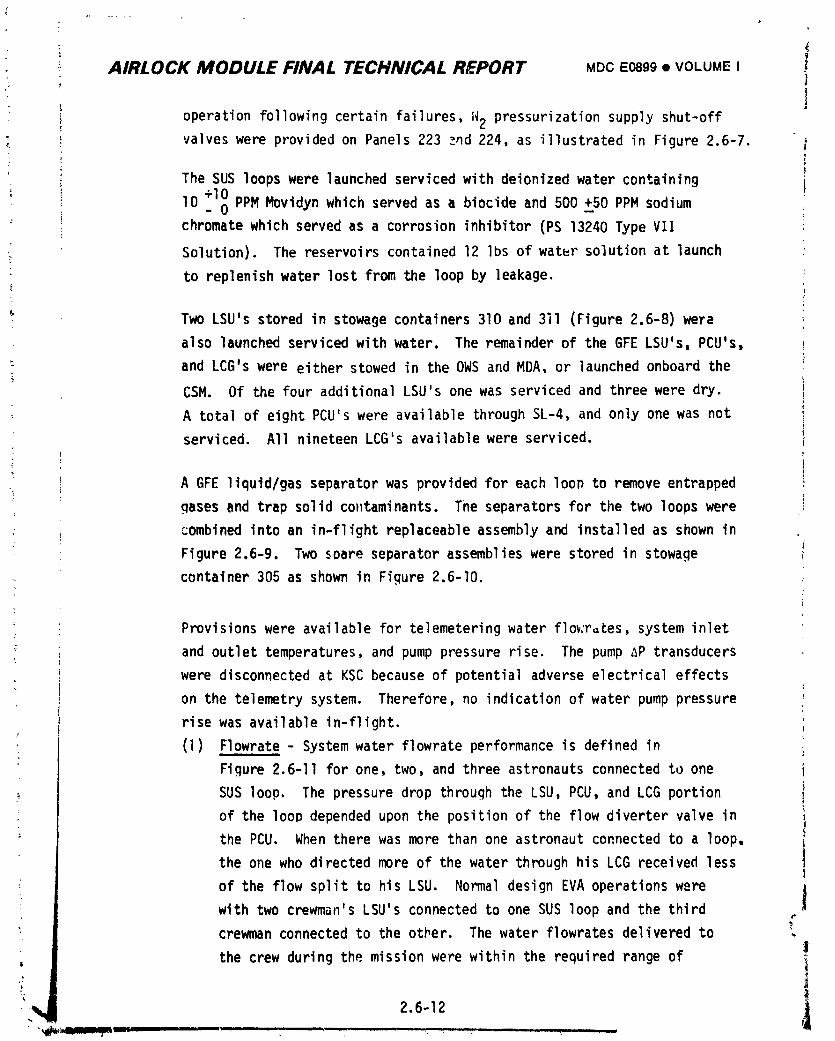
AIRLOCK MODULE FINAL TECHNICAL REPORT MDCE0899• VOLUMEIJ
joperation following certain failures, N2 pressurization supply shut-off
• valveswere providedon Panels223 _nd 224, as illustratedin Figure2.6-7.
The SUS loopswere launchedservicedwith deionizedwatercontaining
lO +lO_0 PPM Movidynwhich servedas a biocideand 500 _+50PPM sodiumchromatewhich servedas a corrosioninhibitor(PS 13240TypeVII
Solution). The reservoirscontained12 Ibs of water solutionat launch
to replenishwater lost from the loopby leakage.
Two LSU'sstoredin stowagecontainers310 and 3il (Figure2.6-8)were
also launchedservicedwithwater. The remainderof the GFE LSU's,PCU's,
and LCG'swere eitherstowedin the OWS and MDA, or launchedonboardthei
CSM. Of the fouradditionalLSU'sone was servicedand threewere dry.
A totalof eightPCU'swere availablethroughSL-4,and only one was not
serviced. All nineteenLCG's availablewere serviced. )i
A GFE liquld/gasseparatorwas providedfor each loo_to removeentrapped
gases and trap solidcontaminants.The separatorsfor the two loopswere ;
: ;ombinedintoan in-flightreplaceableassemblyand installedas shownin
Figure2.6-9. Two soareseparatorassemblieswere storedin stowage
container305 as shownin Figure2.6-I0.
t
Provisionswere availablefor telemeteringwater flov:r=tessysteminlet?
:; and outlettemperatures,and pump pressurerise. The pumpAP transducers
were disconnectedat KSC becauseof potentialadverseelectricaleffects
on the telemetrysystem. Therefore,no indicationof water pump pressure
risewas availablein-flight.
• (l) Flowrate- Systemwater flowrateperformanceis definedin
Figure2.6-11for one, two,and three astronautsconnectedto one
SUS loop. The pressuredrop throughthe LSU,PCU, and LCG portionof the loopdependedupon the positionof the flowdivertervalvein
the PCU. When therewas more thanone astronautconnectedto a loop,
the one who directedmoreof the water throughhis LCG receivedless
of the flow splitto his LSU. NormaldesignEVA operationswere |i
with two crewman'sLSU's connectedto one SUS loop and the thirdC
': crewmanconnectedto the other. The water flowratesdeliveredto ,
the crew duringthe missionwere withinthe requiredrangeof
] 974018208-353
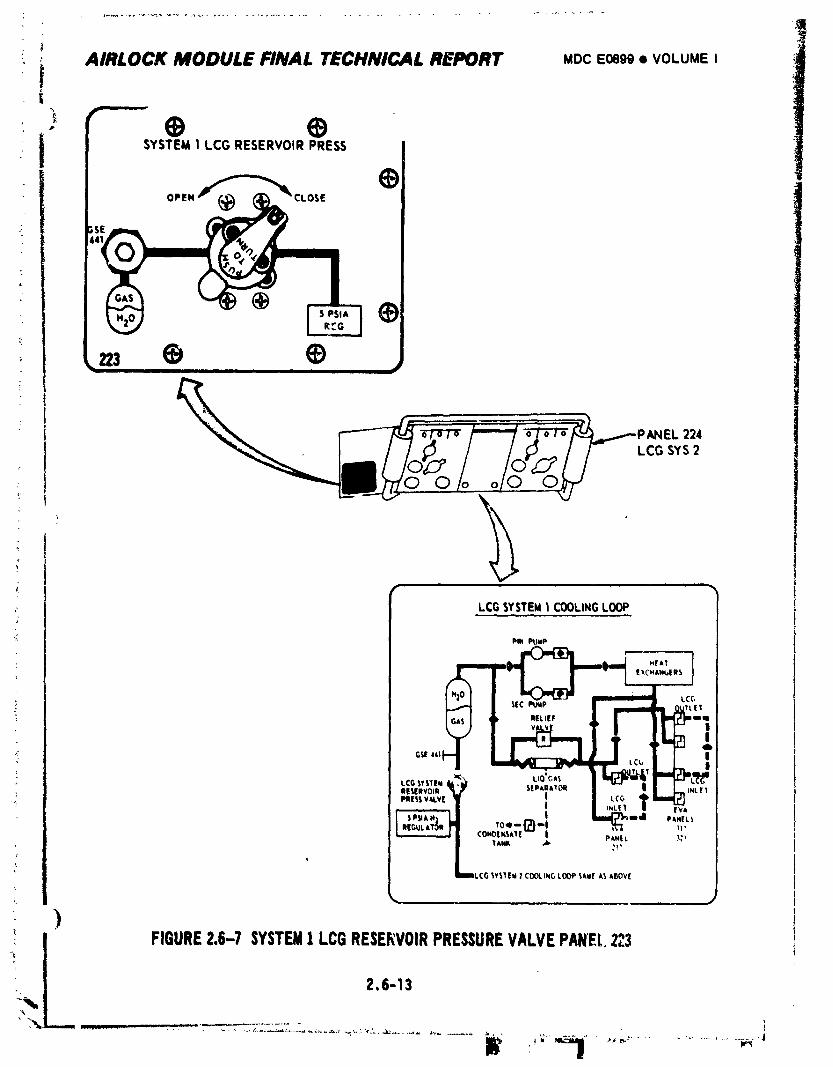
: _ AIRLOCK MODULE FINAL TECHNICAL REPORT MocEo899• VOLUMEIi
* t SYSTEM1 LCGRESERVOIRPRESS
OPEN CLOSE
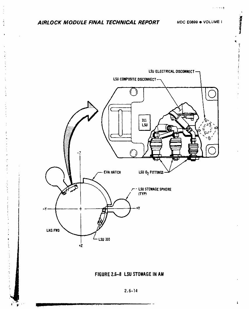
AIRLOCK MODULE FINAL TECHNICAL REPORT MDCE0899• VOLUME I
LSUELECTRICALDISCONN
LSUCOMPOSITEDIS(
"tw
EVAHATCH LSU02FITTINGS
: F" LSUSTOWAGESPHERE(TYP)
; LKGFWD
e
* LSU310
+Zl
FIGURE2.6-8 LSUSTOWAGEINAM
14 2.6.14 i
1974018208-355
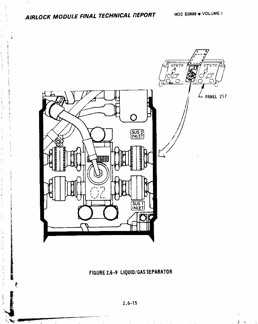
_, AIRLOCK MODULE FINAL TECHNICAL REPORT MDC E0899 • VOLUME I
~
FIGURE2.6-9 LIQUID/GASSEPARATOR
1974018208-356
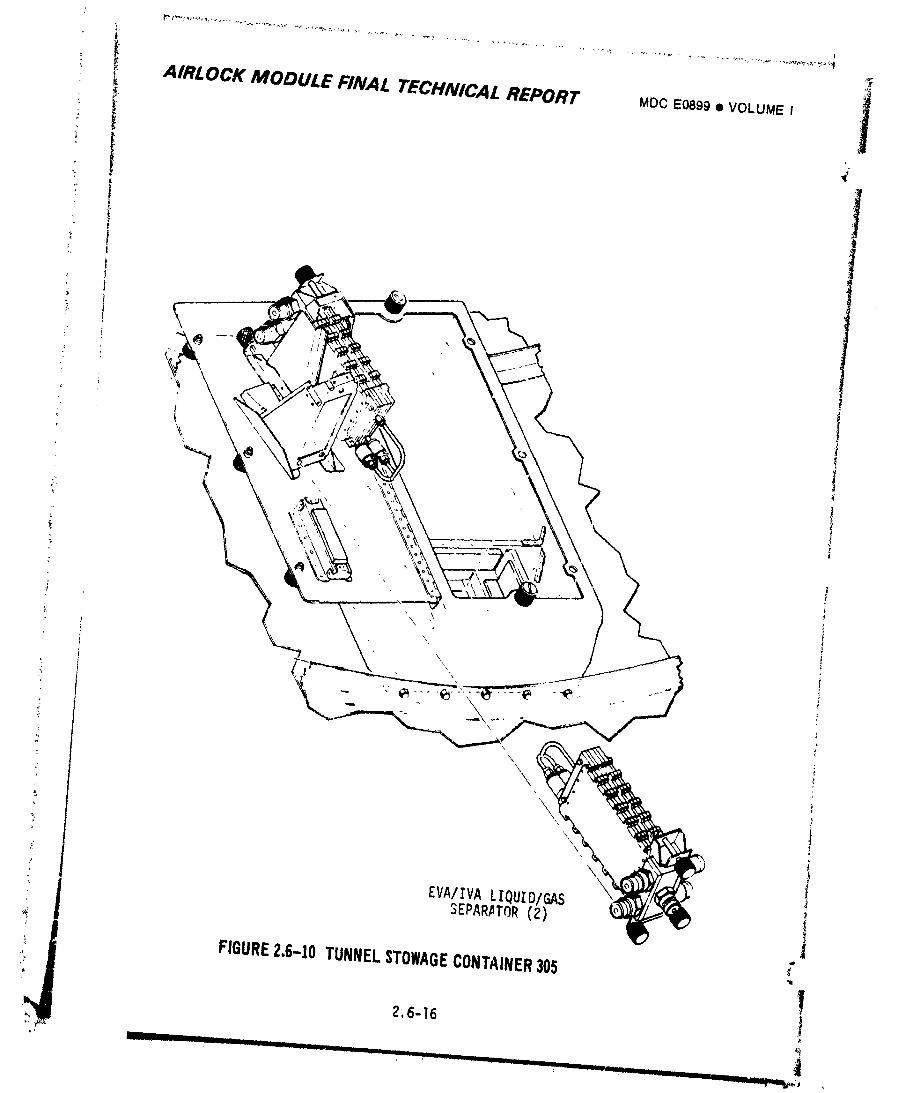
"' _, AIRLOCK MODULE FINAL TECHNICAL REPORT MDCE0899• VOLUME I .
I
&
: t_, '\ ,x !
_ ", {
(
g
1i
._EPARA,TOR {2) _ _ I
_ FIGURE2,6-10TUNNELSTOWAGECONTAINER305 -}
' 12,6-16
......... ' ........ .'-'---/ -'-'- "' 'L: ......... _ .' .............. _.............. . Jll.lllll.l] I I_,_,_
19740182'08-3_
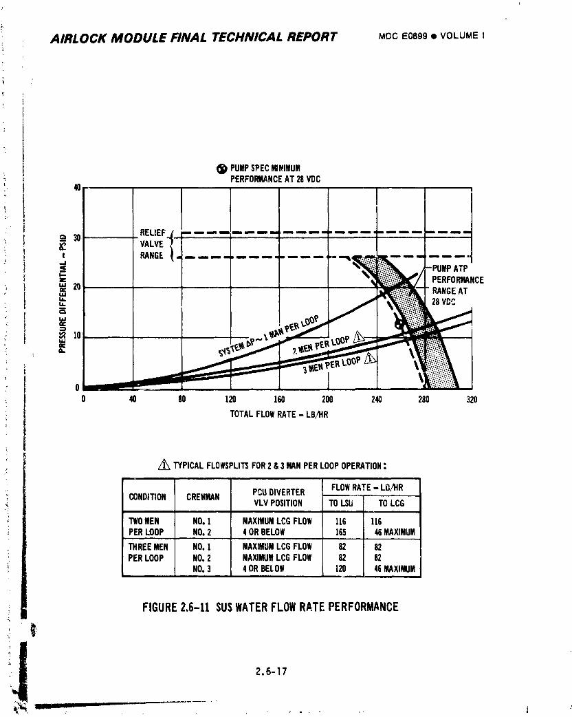
AIRLOCK MODULE FINAL TECHNICAL REPORT MDCE0899• VOLUMEI
(_ PUMPSPECMINIMUM_ PERFORMANCEAT28VDC
40
t
c_ 30 RELIEF.f• .........................' '"_ _, VALVE
................ -;u; °'_ _ 2_ PERFORMA
"" __ ' RANGEAT- u.
,__ __"_ _£tLPE_Lug, _ _.:,...'...;.'//_.0 _
0 40 80 120 160 200 240 280 320
TOTALFLOWRATE- LB/ItR
,/_ TYPICALFLOWSPLITSFOR2 &3 MANPERLOOPOPERATION:
FLOWRATE- LB/HRCONDITION CREWMAN PCUBIVERTER
VLVPOSITION TOLSU TOLCG
TWOMEN NO.1 MAXIMUMLCGFLOW 116 U6PERLOOP NO.2 4ORBELOW |65 46MAXIMUM
THREEMEN NO.1 MAXIMUMLCGFLOW 82 82PERLOOP NO.2 MAXIMUMLCGFLOW 82 82
NO.3 4ORBELOW 120 46MAXIMUM
FIGURE2.6-11 SUSWATERFLOWRATEPERFORMANCE
ii_ 2.6-17
1974018208-358
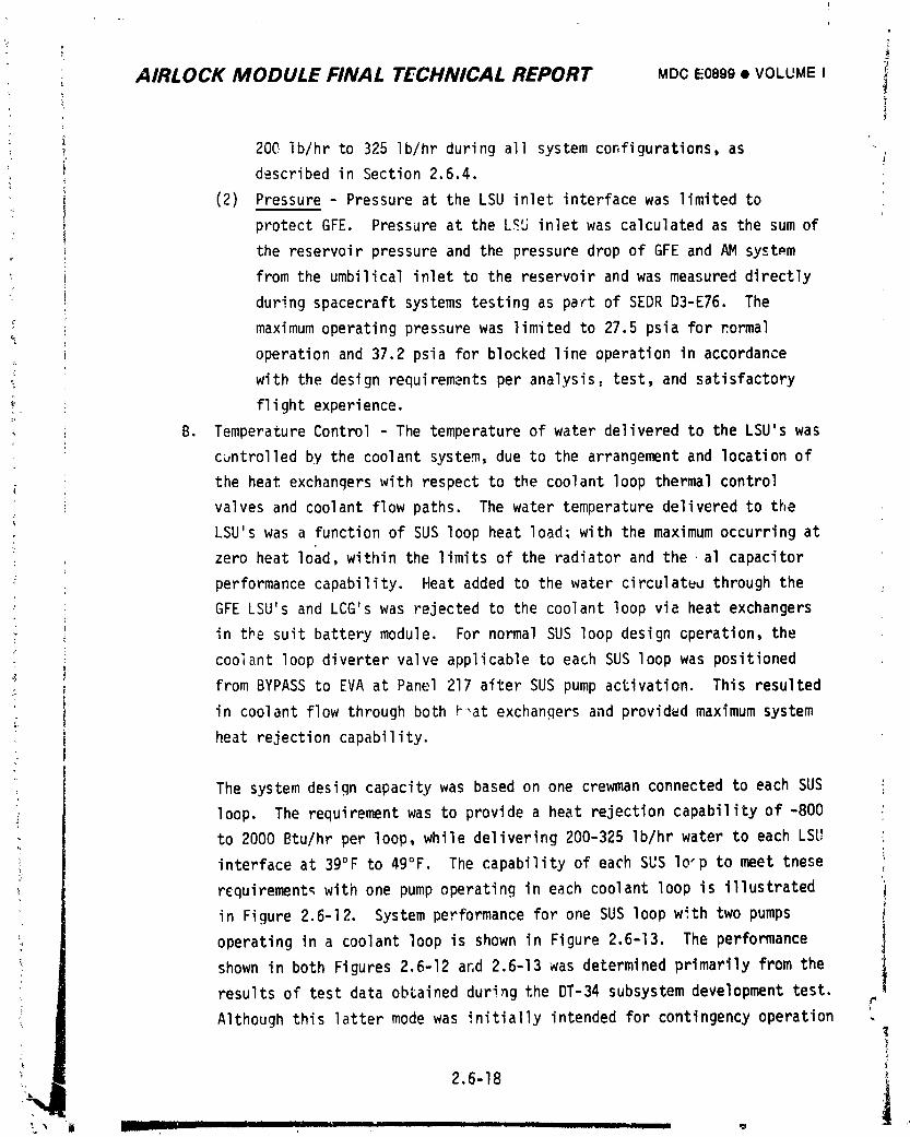
I
i
,i
AIRLOCK MODULE FINAL TECHNICAL REPORT MDCE0899• VOLUME I i
i 200 Ib/hr to 325 ib/hr during all system configurations, asdescribed in Section 2.6.4•
(2) Pressure - Pressure at the LSU inlet interface was limited to
protect GFE. Pressure at the LSU inlet was calculated as the sum of
the reservoir pressure and the pressure drop of GFE and AM system
from the umbilical inlet to the reservoir and was measured directly
during spacecraft systems testing as part of SEDR D3-E76. The
maximum operating pressure was limited to 27.5 psia for formal
operation and 37.2 psia for blocked line operation in accordance
with the design requirements per analysis, test, and satisfactory
flight experience.
B• Temperature Control - The temperature of water delivered to the LSU's was
cuntrolled by the coolant system, due to the arrangement and location of
the heat exchangers with respect to the coolant loop thermal control
valves and coolant flow paths. The water temperature delivered to the
LSU's was a function of SUS loop heat load; with the maximum occurring at
zero heat load, within the limits of the radiator and the ,al capacitor
performance capability. Heat added to the water circulatuu through the
GFE LSU's and LCG's was rejected to the coolant loop via heat exchangers
in the suit battery module. For normal SUS loop design Gperation, the
coolant loop diverter valve applicable to each SUS loop was positioned
from BYPASS to EVA at Panel 217 alter SUS pump activation• This resulted
in coolant flow through both F_at exchangers and provided maximum system
heat rejection capability.r
The system design capacity was based on one crewman connected to each SUS
,_ loop. The requirement was to provide a heat rejection capability of -800
to 2000 Btu/hr per loop, while delivering 200-325 Ib/hr water to each LSU
interface at 39°F to 49°F The capability of each SUS lo-p to meet tnese
-: requirement_with one pump operating in each coolant loop is illustrated
in Figure 2.6-12. System performance for one SUS loop with two pumps
operating in a coolant loop is shown in Figure 2.6-13. The performance
shown in both Figures 2.6-12 ar,d 2.6-13 was determined primarily from the
results of test data obtained during the DT-34 subsystem development test.
Although this latter mode was initially intended for contingency operation .
1974018208-359
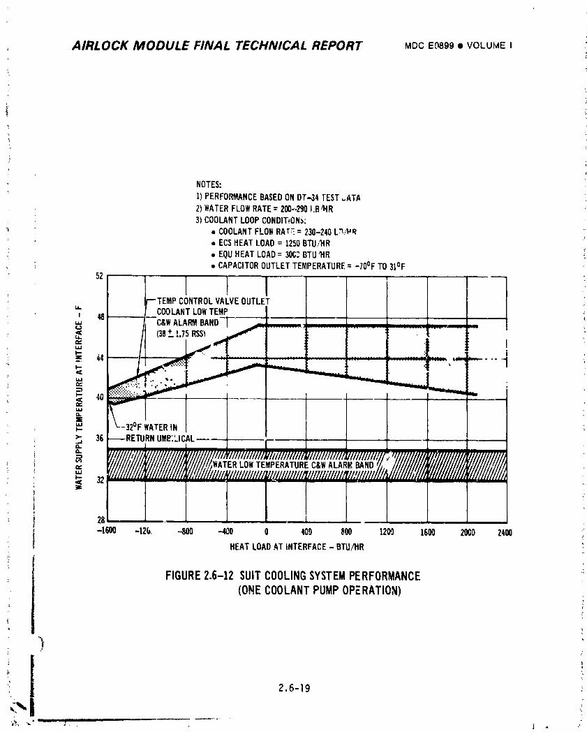
AIRLOCK MODULE FINAL TECHNICAL REPORT MDCE9899• VOLUMEI
NOTES:
1)PERFORMANCEBASEDONDT-,34IEST ,..ATA2)WATERFLOWRATE= 200-.290I.B4,1R3) COOLANTLOOPCONDIT_ON_:
_ • COOLANTFLOWRAT;:= 230-240L_I_R=,ECSHEATLOAD; 1250BTU/tlR
• EQUHEAT LOAD= 30C_BTUq'IR
• CAPACITOROUTLETTEMPERATURE= -70°F TO31°F
CONTROLVALVEOUTLET" CO0I.ANTLOWTEMP I"' C&WALARMBAND-ir,_,l
"" (38+__1.75RSSIW
_= 44 .... "1
_- 40 J
= ta,.EuJ_.. L-32°F WATERIN>" 36 UME',LICAL--
== WATERLOWTEMPERATUREC&WALARMBANDLLI
32
28
-1600 -12@, -800 --400 0 400 800 1209 1600 20G0 2400c
HEATLOADAT INTERFACE- BTU/HR
FIGURE2.6-12 SUITCOOLINGSYSTEMPERFORMANCE(OlqECOOLANTPUMPOPERATION)
r
2.6-19 :
_ll,_ _- III i iiiiiii i
1974018208-360
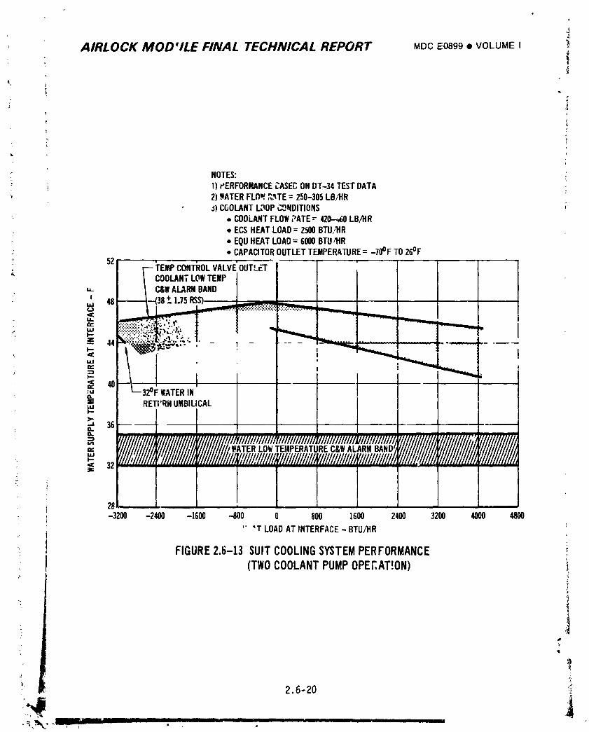
4AIRLOCK MOD'ILE FINAL TECHNICAL REPORT MDCE0899• VOLUMEI
!
?
L,
NOTES:i 1) r'ERFORMANCECASECONDT-34 TESTDATA
' 2)_ATERFLOW._.'tTE= 250-305LBil'IR_)C(_OLANTL_OPI,,,._NDITIDNS
• COOLANTFLOWPATE= 42_0 LB/HR• ECSNEATLOAD= 2500BTUITIRz
• EQUHEATLOAD= 6000BTU/HR: • CAPACITOROUTLETTEMPERATURE= -70°F TO26°F
52 "-- TEMPCON'I'ROLVALVE'OUTLErCOOLANTLOWTEMP
,. C&WALARMBAND
.... :=========================_
_-.!i:...._.__:.._'t,. !. - ......, _ 44_.__ .... . .. I !
= i "40 32°FWATER
i RETI'RNUMBILICALI-->,-•J 36----o.
= IIII "''=""=" ",,,'_" f/####/kWATERLOWTEMPERATUREC&WALARMBAND_- ,- 'i/lli/1/1/ill711111111/Illtll/1/1/1/Ilk/llllllllilllJ'111111111111132
°
28 ,-3200 -2400 -161111 -400 800 1600 241111 3200 4000 4800
" 'T LOADAT INTERFACE- BTU/HR
FIGURE2.6-13 SUITCOOLINGSYSTEMPERFORMANCE(TWOCOOLANTPUMPOPERAT!ON) i
*l
" _: 2.6-20 _.
] 9740] 8208-36]
..... !
AIRLOCK MODULE FINAL T£CHNICAL REPORT MDCE0899• VOLUMEI
: for cooling two EVA crewmen from one SUS loop in the event of failure of ._
_ the other SUS or coolant loop, it was also applicable for cou;'ng one or _
T _ three crewmen connected to the same SUS loop. In the event of a failure =]
!_ which caused the temperature of water solution supplied to the umbilicalto be as low as the C&W alarm band shown in Figures 2.6-12 and 2.6-13,
the EVA l or EVA 2 warning indicators on liqhting, caution and warning
control panel 207, shown in Figure 2.6-6, would illuminate. Since the
same warning indicators also could be illuminated by the pump pressure_. rise being low, the distinction must be made by use of-the inhibit
• _ switches. _ _.
system requirement resulting from operational procedural changes ]A later
late in the program after design completion was to provide cooling water "
; to the IVA crewman as well as the two EVA crewmen. This requirement was ] :ito provide a heat rejection capability of -800 to 3130 Btu/hr for two
crew_n on one SUS loop and -800 to i730 Btu/hr for the third crew.nancn
the other loop, while delivering 200-325 Ib/hr water from each loop Lo
;, the respective LSU interfaces at 38°F to 50°F and 39°F to 49°F. The ;_
! capability of the system to meet these conditions with one pump operating
I in each coolant loop was determined to be available as long as the
_ coolant system gross heat load was less than II,774 Btu/hr. Higher./
i coolant system heat loads would have caused increaseG radiator and
thermal capacitor outlet coolant temperatures, and thus higher SUS loop
water temperatures.
During EVA and IVA operations '_iththe coolant loop diverter valve in the ?
i BYPASS position, higher water delivery temperatures and reduced cooling
!. were available as shown in Figure 2.6-14. Due to coolant system problems >
experienced during the mission, this operational mode was used during all
EVA and IVA operations except the first one, as described in Section 2.6.4.
, However, suit cooling was reported to be adequate even with three
crewmen connected to the one SUS loop.
Freezing of water in lines on the suit/battery module was prevented by an
) additional thermal curtain over the module. Freezing of water in lines _ ,
i external to the suit/battery module while the system was inoperative was _!,_\ prevented by providing a cont;x)lledheat leak from warm coolant lines, i
2.6-21 _ :
1974018208-362
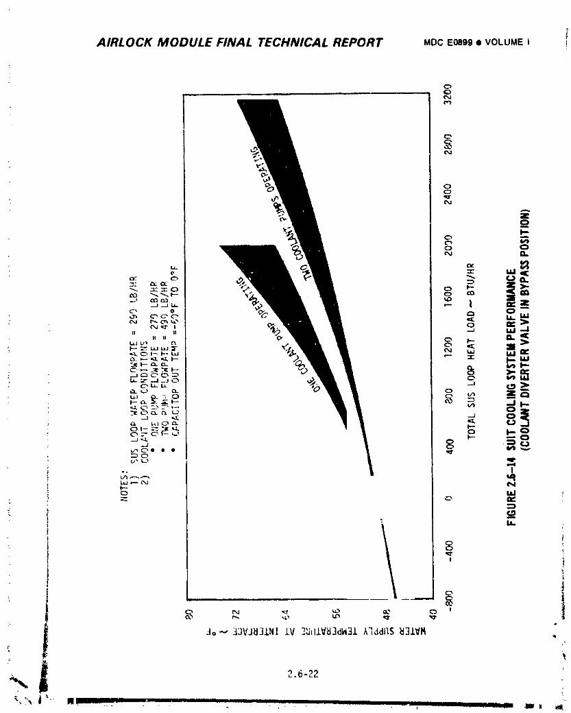
AIRLOCK MODULE FINAL TECHNICAL REPORT MDCEO8gg• VOLUMEI !
¢:>
c"
O,J
7
.
i AIRLOCI_" MODULE FINAl. TECHNICAL REPORT MOCE0899• VOLUMEI
' !; C. Jumper Hose Assembly - A re1_vab!e jumper hose assenW)lywas attached to
each pair of water quick disconnects on panel 217, Figure 2.6-I, toprevent excessive pressure buildup due to thermal expansion of the water
_ between check valves at the pump outlet and the quick disconnects without
connecting the GFE. In addition, they permitted circulation with pump
operation between EVA/IVA operations without connectin_ the GFE. Each
_ jumper hose assembly was disconnectedwhen the suit cooling system was
operating.
•2.6.2.3 In-fllqht Water Servicinq/Deservicinq
Provisions were available for servicing the SUS loops, LSU's, ,nd PCU's in- _l
• i flight with water from the OWS tanks as well as deservicing the L_U's and PCU's.
i The servicing equipn_nt is described in Section 2.5.2.4 and depicted in'Figure i• { 2.5-34. The detailed procedures are outlined in the SWS Systems Checklist. The
_ additives initially in the SUS loops were sufficiently concentrated to tolerate
: _ dilution resulting from addition of the untreated _WS water.
_: _ LSU and PCU s_rvicing was done by a _low-through purge technique; consistinqk I of flowing water from OWS Tank #9 through the delonizer, servicing hose assembly,
• LSU and PCU, and through the AM condensate system into the OWS holding tank. The
gas contained initially in the LSU/PCU assembly was thus purged out and replaced
by deionized water. Deservicing the LSU/PCU was accomplished with a similar i
hardware arrangement, except the deservicing adapter was attached to the inlet of i
the 60 ft. servicing hose. This permitted cabin qas t "'cw through the assemblfd
servicing hose ano LSU/PCU and into the OWS holding ta, thus displacing the _)
water in the LSU and PCU with gas. Servicing the AM portion of the SUS loops was
provided by flowing water from OWS Tank #9, through the servicing equipment, and
into the SUS loop via the liquid/gas separator inlet quick disconnect. _
The in-flight ser'Icinq and deservicing operations conducted during the
mission are described in Section 2.6.4. Performance of the servicing equipment i .
and pmcedures was completely normal and adequate; with no hardware failures or i "
anomalies being experienced. !
1 ! '_ 2.6-23
1974018208-364
AIRLOCK MODULE FINAL TECHNICAL REPORT MDCE0899• VOLUMEI
2.6.2.4 EVA Lock Operations
Lock compartn_nt pressure control for EVA was provided by a vent valve in the
EVA lock compartment wall which pernntted depressurization of the AM lock compart-
ment and equalization valves in the internal AM and OWS hatches for repressurization
: from the CSM/MDA/STS and OWS atmospheres. The EVA team monitored lock, aft, and
OWS pressures on lock compartment control panel 316, shown in Figure 2.6-4. The
cre_anar_in the STS monitored OWS, FWD, lock, and aft pressures on 02/N2 control
panel 225, shown in Figure 2.5-6.
A. Ventinq- The combined lock and aft compartments were normally
; depressurized for EVA using valve 31.8shown in Figure 2.6-15; with theAM aft hatch maintained in a stowed position and available for contingency
use. The 279 ft3 volume could be depressurized throuqh the vent valve to
0.20 psia in approximately 200 seconds, _s shown by the depressurization
profile in Figure 2.6-16. Slower depressurizationwas available by
partially opening valve 318. The EVA hatch could be opened safely at
: pressures below 0.3 psid.
B. Repressurization- The primary method of repressurizationutilized suit
; exhaust flow for an initial two-minute period to verify compartmentr_
pressure integrity. This was followed by compartment pressurization from
the CSM/MDA/STS atmospheres via the AM forward hatch equalization valve,
shown in Figure 2.6-15, for 30 seconds to achieve a relatively soft-suit
: condition. Final compartment pressure equalizatior was then achieved by
opening the AM forward hatch handle, opening the OWS hatch equalization
valve, and then opening the OWS and AM fonvard hatcnes, llleresulting
_ repressurizationprofile is showv_in Figure 2.6-17.
An alternate method of repressurizationwas available by opening the
equalization valve in the OWS dome ha*oh. The combined lock/aft compart-ment could be repressurized to 4.86 psia using suit exhaust and OWS gas
in approximately 160 seconds as shown in Figure 2.6-!8. The main
disadvantaqe to this method was poorer access to the OWS hatch
equalization valve during e hard suit condition.
i
2.6-24
1974018208-365
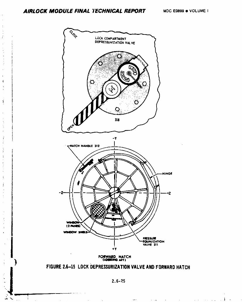
AIRLOCK MODULE FINAL TECHNICAL REPORT MOOEOSgS• VOLUMEI
!
WINDOW
MIESSUBEI _z,
h�h311
FORWARDHATCHIrOStra,ca A,4PV)
!_ ) FIGURE2.6-15 LOCKDEPRESSURIZATIONVALVEANDFORWARDHATCH2.6-_.5
+,,,,,,'% _ ...... J
1974018208-366
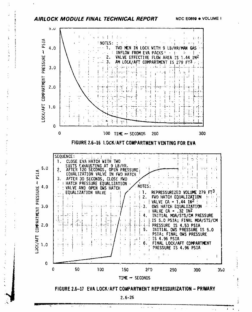
AIRLOCK MODULE FINAL TECHNICAL REPORT MDCE0899• VOLUMEI
:, 3,U -'i
"_., _ , . :NOTES:I ! ', ', ' '" 'i'' "'! !'_" 4.0 \ .... I. TWO MEN IN LOCK WITH 9 LB/HR/MAN GAS '-_ \ : '. -' ... _ INFLOW FROM EVA PACKS' ,I. _" ' I
_ _:"' \ , ,.;- 2. VALVE EFFECTIVE FLOW AREA IS 1.44 IN_'"
-_ _ _ ; ' ! i ,...:3. AM LOCK/AFT COMPARTMENT IS 279 FT3 :-;,vl_ k ! ' . ( , , • ' , _ • A _ .
3.0 \ i i"i ..... r"i":"i ...... i " "' .... f..... t-'i ....... :" "........$ . , • . , .
r, _ ,"' . ! , .,, .:...' ,: ....., l, -:-'I. "" ; " ".'1 : '1 "" ,,- ;- : ...... ::.'.-::.1.,.-:-. _ _:.: i ! _ ..-!..-i.-: ! _---"-" \. : ;.... I . t ...... i . :.! .,....
X ' • : l . I ' '] ]¢'_ %, , ' , ', . I , ! ' l ' ' .... _ . _ : ; '
. . . t . J , ....._- : 1.,.,.' ..... I ..... t-"'r--' . a I .... 1-4-; --_ • '.---_....
" (_ : . ' . a . . " ' ' ; : ' _ . .' " \ ' " ' 1' , . , , / , I , ',, . _ . . .a ..... ; ..... ;.. . L • .. '.. I ..... ,: , \ : ; _ ! i .'; ;. ; .i t , : "t, | : _ ; /
_ 1 0 _ _ : • "", "f ' _ ' ' ' ' /.'' ',"4 ' * \" ';" ""-: ..... _ I ............. "...... ' : "t-;-'-, '-'t'"'_'" i "_"1
I ';.. ,.. .., •-J . . . i . _. I ..... ].... ,,.I. , , , ,... I_ 1 ! ' a ....... L /
0 I00 TIE ,- SECONDS 200 300
" FIGURE2.6-16 LOCK/AFTCOMPARTMENTVENTINGFOREVA
SEQUENCE: i _ , _' i. ' '! I. CLOSEE A HATCHWITH TWO : ' "
SUITS EXHAUSTING AT 9 LBIHR. ; !' I i
5.0 2 AFTER 120 SECONDS, OPEN PRESSURE .!_ i-- i. ':":':.'i•_E • i ,
•_ _ ' EQUALIZATIONVALVE IN _D HATCH /; , ; ;' ,!a. 3. AFTER30 SECONDS,CLOSEFWD v/_ ....... "i .......... ,I ,.( _ HATCH PRESSURE EQUALIZATION ,_/,_T,-,-':.,-.. ' I _ (
: ,.,4,0 ' VALVE AND OPEN OWS HATCH //-_ul_.' . . . _ i .¢," L :' i
uau_ _ : i . _ ; ,-i 2. FWD HATCH EQUALIZA]_ION I....... }¢= . ! ' ' i ',: VALVE CA = 1.44 IN_:', ' I '
' _" 3.0 ! ,:"" i........i ; ' !.......,1-,,........i.3. OWS HATCH EQUALIZATION .'. .;.= . / . ,.. . VALVE CA = .32 IN2, "'_......... r ' ' ;'_4. INITIAL MDA/STS/CM PRESSURE.,,..,,."; , , ! ._". I' . _ :IS5.0PSIA;FINALMDA/STS/CM
@,2.0"_ "'I'_."I"!.........., ,,,i;.I..,!_..i--'/i' _i: ....;4.-.-PRESSUREIS4.53PSIAo ..I , . , , , I li ' I 5 INITIALOWSPRESSUREIS 5,0(J ' '' , , : _ ' , _ I I' I' I I ,
. , ......... , _._ ',....., PSIA; FINAL OWS PRESSURE• ' I i,h- . • ,', ".. , ' ' ,., :,' IS 4,96 PSIA
-.'_ , I ' f ! 6. FINALLOCK/AFTCO_ART_NT..;1.0 , ! : i i ,- i ,_-i,I _ ....I _ : :" ' "PRESSUREIS4.96PSIAU I I _ ' ',-.,.) , " : / , (
", ,.j
0 ..... , !
0 50 1O0 150 200 250 300 350
TIME.,-SECONDS ._
i/ FIGURE2,6-17 EVALOCK/AFTCOMPARTMENTREPRE$$URIZATION- PRIMARY2,6-26
1974018208-367
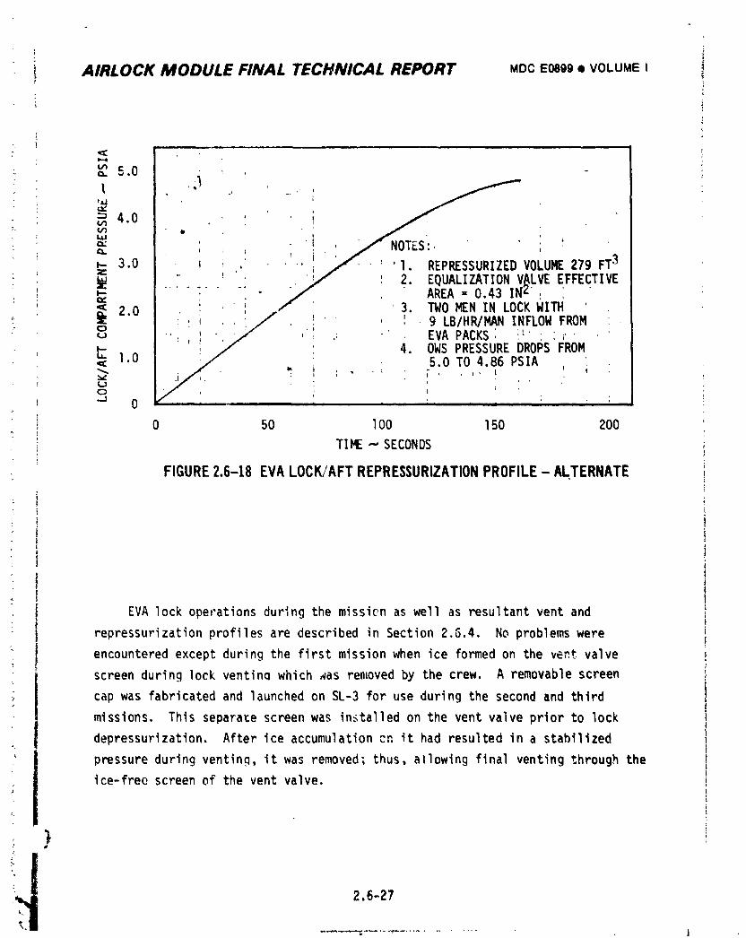
' i
i AIRLOCK MODULE FINAL TECHNICAL REPORT MDCE0699• VOLUMEI
, i
,, 5.0 .
P_
u'_u'__ 4.0 =, ' ' ,= ! / NOTasL. •_- 3.0 i ; , ; _ / '1. REPRESSURIZEDVOLUME279 FT3_ ",,," 2. EQUALIZATIONV_LVEEFFECTIVE
_ " AREA =0,43 !Nz , i"_ 2.0 • ' , f ' ' 3. TWOMENIN LOCKWIN '
i: ,:/:.. - .: : , ' _'" ,' 9 LB/HR/MAN INFLOW,FROM
_ EVAPACKS. D P "FROM'
t:-. 1.0 : 4. OWSPRESSURE RO S,_ 5.0 TO 4.86 PSIA
0 i , = ', r
0 50 lO0 150 200
"rIME.- SECONDS
FIGURE2.6-18 EVALOCK/AFT REPRESSURIZATIONPROFILE - ALTERNATE
"_' EVA lock operations during the mission as well as resultant vent and
repressurizationprofiles are described in Section 2.5.4. No problems were
encountered except during the first mission when ice formed on the ve,-.tvalve
screen during lock ventinq which aas removed by the crew. A removable screen
cap was fabricated and launched on SL-3 for use during the second and third
missions. This separate screen was installed on the vent valve prior to lock
depressurization. After ice accumulation cn it had resulted in a stabilized
pressure during venting, it was removed; thus. allowing final venting through the
ice-free screen of the vent valve.
) ,
!i_ 2.6-27
1974018208-368
AIRLOCK MODULE FINAL TECHNICAL REPORT MOCE0899• VOLUMEI I
2.6.3 Testing *
Pre-launch tests were performed to provide information needed by engineer-
ing for design, to qualify a particular part numbered component, to verify
tilatthe particular part and serial numbered components operated properly, to
verify that U-l and U-2 modules and syste1,1sfunctioned properly, and to support
verification that the vehicle was ready for flight. Post launch tests were con-
ducted to provide informationneeded for real time mission planning.
2.6.3.1 Development Tests
Development tests were performed on components and systems to obtain data
on the functional characteristicsneeded to support the design process. Test
requirementswere specified by Test Request (TR).
A. Performance Tests - Performance tests were conducted to establish the
performance of new components and systems. Some were conducted by
vendors to satisfy requirements identified in Specification Control
Drawings (SCD). Those tests conducted by MDAC-E are summarized below.
• TITLE EVA/IVA Water Cooling Subsystem Development Test.
BACKGROUND The Water Cooling r_dule rejected metabolic heat
wilichhad been absorbed from an Astronaut by
water flowing through the LCG.
OBJECTIVE Evaluate tileperfomnance of the EVA/IVA Water
Cooling Subsystem.
RESULTS The performance of the EVA/IVA Water Cooling
Subsystem was satisfactory for all test condi-
tions. Reference TR 061-068.22.
i e TITLE Water Dump Gas Tolerance Development Test,
BACKGROUND Free gas might be present in Water Cooling Systems,
OBJECTIVE Determine the effects of dissolved and free gas
on water pump performance.
RESUI.TS The wa_er flowrate decreased as the air injection
rates were increased but the pump did not stall
under any of _he conditions tested.
Reference TR 061-068.77.
lm
2.6-28
............i!I
1974018208-369
AIRLOCK MODULE FINAL TECHNICAL REPORT MDC E0899 • VOLUME I
* BACKGROUND The LSU and PCU were to be serviced with water prior
to use during EVA/IVA.
OBJECTIV[ Develop the in-flight procedures for servicing and
,, deservicing the LSU/PCU and for servicing the
AM SUS loops.
:: RESULTS Procedures for servicing and for deservicing the
: ; LSU/PCU and servicing the AH SUS loops _vere
_ developed. Reference TR 061-068.81.
• TITLE Water Pump Flush And DrY Confidence Test: Iodine
_ Water Injection and Absorption Test.
BACKGROUND Water flush and vacuum drying procedures must beL
_ developed for water pumps.
_. OBJECTIVE Determine an acceptable water flushing and vacuum
drying procedure for the water pumps.!- _ RESULTS No procedure was developed which consistently
_ flushed the water solutions from the pump. No
apparent damage occurred to the pump when water
_. containing iodine was mixed with the Airlock water
solutions. Reference TR 061-068.85.
_ • TITLE 61CB30069 Water Pump/Suit Coolin.qLoop Additive Test.
_ BACKGROUND Restart failures had occurred with the water pumps,
used in the EVA/IVA suit cooling loops.
OBJECTIVE Evaluate the compatibility of the water pump _vith
: PS 13240 Type If, IV, V, AND Vl fluids.
Dei,ermine if pump restart could be achieved with
_ il PS 13240 Type VII solution. Evaluate procedures forservicing the suit cooling system with Type Vll fluid.
Verify proper operation of the Suit Cooling System
and the ALSA when serviced with TYPE VII fluid.
RESULTS Pumps serviced with Type If, IV, and Vl fluids showed
deposits of materials on pump vanes and rotor after
- restart failures. Pump serviced with Type V fluid
operated satisfactorily and showed no evidence
._ of deposits, Reference TR 061-168.10, TR 061-168.10.01.
i Pumps serviced with Type VII operated satisfactorily
_ and showed no evidence of deposites. Reference
i._.. TR 061-168.10.02.
2.6-29
,,_. ,_
1974018208-370
AIRLOCK MODULE FINAL TECHNICAL REPORT MDC E0899 • VOLUME I i
;}
Procedures for servicing the Suit Cooling System
with Type VII fluid were satisfactory. Reference
061-168.10.05.
Suit Cooling System and ALSA operated satisfactorily
when serviced with Type VII fluid. Reference
TR 061-168.10.06.
• TITLE Apollo CSM Pump Performance Test.
! BACKGROUND The Apollo CSM pumps should be evaluated as backup
to the 61C830069 water pumps.
OBJECTIVE Evaluate operation of Apollo CSM water pump assembly
when serviced with PS 13240 Type IV fluid.
RESULTS Pu,ps operated satisfactorily throughout the test
but were found to be susceptible to stalling
when small air bubbles were at pump inlet.
Reference TR 061-168.11.
m TITLE Apollo PLSS Pump Performance Test.
BACKGROUND The Apollo PLSb pumps should be._va]_ as barJcup.
_ for the 61C830069 water pumps.
: OBJECTIVE Determine the performance characteristicsof two
' series-connectedApollo PLSS r ,ips.
_ RESULTS The series operated pumps did no_ meet the minimum
performance requirements of the Suit Coolant Loop.
_ Reference TR 061-168.12.
• TITLE CompatibilitX of deionized OWS water with 61C830069
- Water Pump/SUS Fl_'id_Test.
BACKGROUND There was a requirement to show compatibility of the
OWS servicing fluid with the SUS fluid and SUS loop
_" components.
" OBJECTIVE Verify that OWS potable water, when deionized, is
compatible with PS 13240 Type VII solution, and
will allow normal pump operation.
RESULTS The system operated satisfactorily.
Reference TR 061-168.14.
J
p
•'_ 2.6-30
1974018208 371
+,
i AIRLOCK MODULE FINAL TECHNICAL REPORT MDCE0e99• VOLUMEI
," B. Endurance Test - An endurance test, designated ET-I and documented by ,_L
report TR 061-068.35, was conducted to verify that system components
would function properly during a complete mission.
The tess hardware included more than 70 Airlock flight configuration
; components assembIPd into functional systems. The test was d.esig,ed
I to load the components and make them perform under condit1,+nsexpectedduring flight. The test followed the proposed Skylab mission plan :
• which consisted of 3 Active Phases and 2 Orbital Storage Phases cover-
• ing a real time _eriod of 8 months.
During the formative stages of ET-I, the Suit Cooling System and ATM
_ C&D/EREP cooling system used essentially the same hardwa;e (pumps,
check valve;, filters, heat exchangers, and instrumentation),and the
: same cooling fluid additive (500 ppm Roccal, 2% by weight dipotassium
hydrogen phosphate, and 0.2% by weight sodium borate). A single
water loop was, therefore, used during ET-I for assessing the endurance it
: of both cooling water loops. The GFE liquid-gas separator was not i
} included, nor were the GFE LSU, PCLI,AND LCG. The aluminum interral i
+_ surfaces of the GFE portion of the C&D loop were simulated, however,
based on information available at tt;attime.
s
: All components initially assembled into the ET-I EVA/IVA System func-
tioned adequately except one of the cooling water pumps (P/N 61C83006g-303,
S/N I03), which failed to start during initial system checkout after
• servicing. Failure analysis disclosed that the problem was due to bind-
ing of the vane and rotor, caused by contamination introduced to the
system during installation. After removal cf the failed pump, testing
was conducted with the alternate pump (S/N ll7), which performed satis-
factorily throughout ET-I. The alternate pump was operated 69S6 hours
out of a total expo:,,retime of I0,368 hours and successfully underwent
14 on-off cycles. Post test tear-down and analysis of the pump sF(r_'ed
negligible eviaence of wear or corrosion+ Germicidal effectiveness
testing and analysis for products of corrosion were also conducted on
cooling water samples and provided satisfactory results. Small amounts
+ ) of nickel were noted however to be in solution in the cooling water,
I evidently originating from the nickel in the fins of the heat exchangers.
_+ ! 2.6-314111111T I I I i
++_• , , i ........ 1,, ,, ,. ,, _+ . +.... p< ,< _ , u_-
1974018208-372
i
o AIRLOCK MODULE FINAL TECHNICAL REPORT MDCE0899• VOLUMEI
A coolant loop instability problem was experienced during ET-I, which
resulted in coolant flowrate oscillations thrcuqh the hot and cold ports
of th_ 40°F temperature control valve and coolant temperature oscilla-
tions at the valve outlet. Thi_ problem was due to iv_teractionof hot
and cold flow in the EVA/IVA heat _xchangers immediately upstream of
the temperature control valve and is dlscussed further in Section 2.4.
2.6.3.2 qualification Tests
: Qualification tests and documentation are available for all Airlock
components and systems. Test results are summarized in MDAC-E Report G499,
Volume V.
' 2.6.3.3 Acceptance Testsf
Acceptance tests were conducted to prove the delivered components and!
systems functioned properly.
A. Vendor Acceptance Test - An acceptance test had to be passea at the
vendor's plant before shipment to the contractor. Acceptance test require-
ments were specified in the Acceptance Tes_ Procedures (ATP's). These
procedures were prepared by the vendor and approved by the contractor.
B. Pre-lnstallation Acceptance Test - A Pre-lnstallation Acceptance: (PIA)
Test had to be passed at the contractor's plant to prove that tllehard-
C ware arrived in guod condition prior to going into the crib which supplied
! parts for U-l, U-2 and spares. PIA test procedures were written by_, MDAC-E Servicing Engir,eering Department Report _SEDR) and basically
- included the same requirement as the ATP documents.
2,6.3.4 System Tests
System tests were conducted to verify that modules and systems operated
properly. System test requirementswere specified by SEDR.
_i 2.6-3',)
1974018208-373
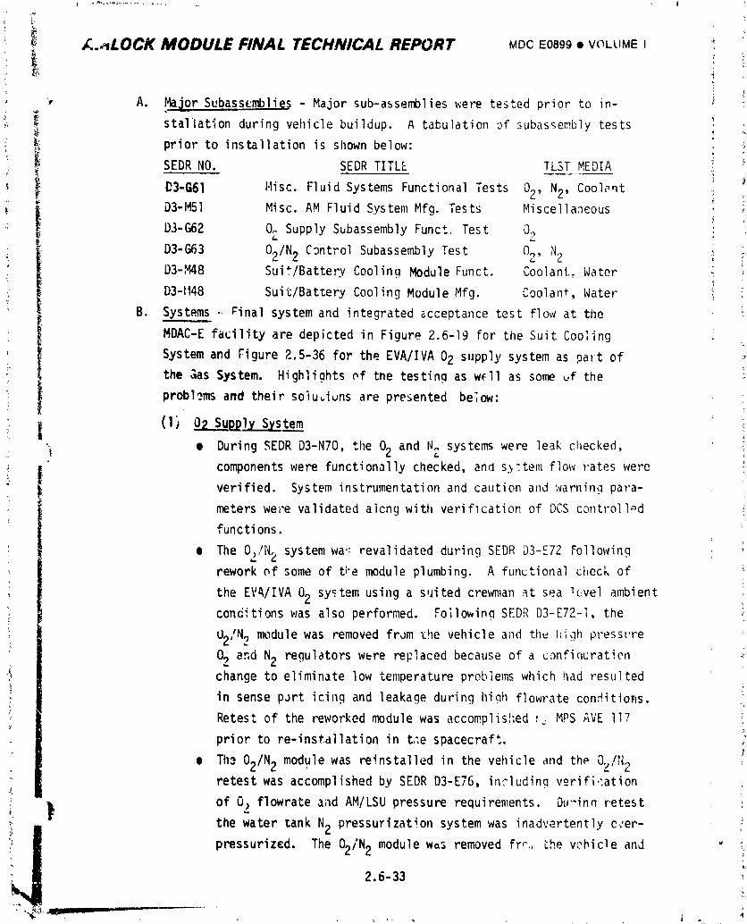
!
[..,LOCK MODULE FINAl. TECHNICAL REPORT MDCE0899• VCLLIMEI _
t
• A. Ma__orSubassemblies - Major sub-assemblieswere tested prior to in- _ :
. stallation during vehicle buildup. A tabulation _f subassembly tests •
prior to installation is shown below: _,
SEDR NO. SEDR TITLE TLST MEDIA
D3-G61 Misc. Fluid Systems Functional Tests 02, N2, Coolant _D3-M51 Misc. AM Fluid System Mfg. Tests Miscellaneous
D3-G62 O^ Supply Subassembly Funct. Test O_
D3-G63 O2/N2 C_ntrol Subassembly Test 02, N2 _:D3-M48 Suit/Battery Cooling Module Funct. Coolant. Water
D3-1148 Suit/Battery Cooling Module Mfg. Coolant, Water
B. Systems - _inal system and integrated acceptance test flow at the _
MDAC-E facility are depicted in Figure 2.6-19 for the Suit Coo_ing
System and Figure 2.5-36 for the EVA/IVA 02 supply system as paFt of
the _as System. Highlights _f the testing as w_ll as some uf the
problems and their soiu_iuns are presented be,ow:
' i (1)o2su lySystem• ] e During SEDR D3-N70, the 02 and N_:systems were leak checked,
components were functionally checked, and s,,'tem flow rates were
verified. System instrumentation and caution and warning para-
meters were validated alcng with verification of DCS controll_d
functions.
• The Oz/N2 system wa':revalidated during SEDR D3-E72 Following i
rework of some of t;'emodule plumbing. A functional check of
the EV_/IVA 02 system using a suited crewman ,_tsea _vel ambient
concitions was also performed. Foilowinq SEDR D3-E72-1, the
02/N2 module was removed from _he vehicle and th_ I',i,.lhpressure
02 and N2 regulators were replaced because of a confiquratien ._
change to eliminate low temperature problems which had resulted
in sense port icing and leakage during hiah flowrate condition,s. .:
Retest of the reworked module was accomplished r_ MPSAVE 117L
prior to re-installationin t._espacecraft.
m Th._02/N2 module was reinstalled in the vehicle and the O2/N2retest was accomplished by SEDR D3-E76, includinq verifi.:ation
: ) of 02 flowrate and AM/LSU pressure requirements. Du-inn retest :
!_ the water tank N2 pressurization system was inadvertently c_,er-
pressurized. The 02/N2 module was removed fr_.,the vehicle anJ ' ;
2,6-33,i
1974018208-374
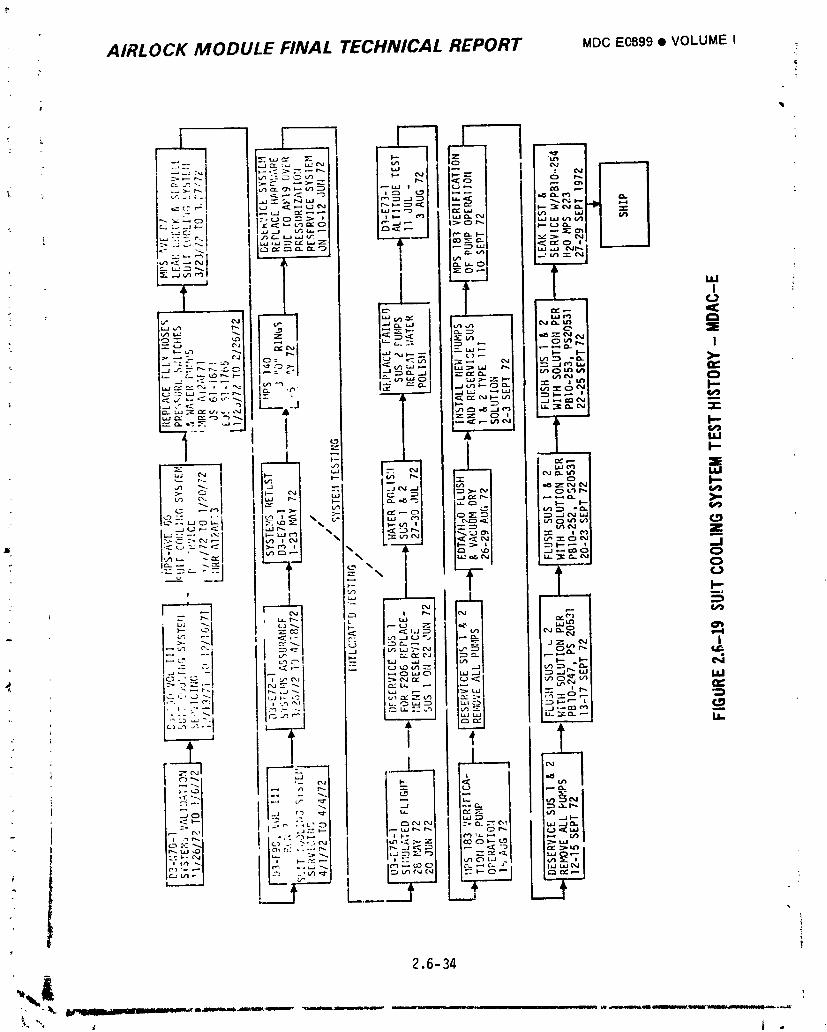
AIRLOCK MODULE FINAL TECHNICAL REPORT MDCE0899• VOLUME I ?
.. AIRLOCK MODULE FINAL TECHNICAL REPORT MDCE0899• VOLUME I
t,-,e damaged components replaced. Retest of the module after _
T compor,en= replacement but prior to reinstalla_ion was accomplish- "
ed by MPSAVE 137. Retest after module re-installation was
• accomplished by AR 19 versus SEDRD3-E76.
(2) Suit Coolir,_ System
• The Suit Umbilical Systems (SUS -I and #2) were leak checked
during Systems Validation (D3-N70) and then serviced per
SEDRD3-F90-I, Vol. III. After servicing both systems were
• functionally checked to verify flowrates, system AP's and inter-
; face pressures.
• The systems were a_so operated during the thermal control systems
checkout. Durlng this period a water pump failure occurred.
_- The problem was documented on MRRAI2AFGI and dispositioned for
later removal. The fluid analysis of the system indicated an
out of specification condition with respect to particulate con-
tamination which was recorded on MRRAI2AFI3. At the conclusion
of SEDR D3-N70 the systems were deserviced per MPS66 and fiushe_ i
_. and vacuum dried per M;iR AI__AFI3. While the systems were de-
serviced, flexible hoses and pressure switches were changed out
per EJS 61-1671 and EJS 16-1765. The suit systems were leak
checked per MPS87 after completion of all rework and _ere then
reserviced by SEDRD3-F90-1, Vol. II.
• The systems were functionally checked during Systems Assurance
Test (SEDR D3-E72-1) with a suited subject in the loop to verify
, temperature and flow capabilities of both Suit Umbilical Systems.
•' _ ihe systems were operated and verified during a systems retest, "
I SEDR D3-E76-1. During _he course of testing, i_was discovered •
: I that some of the quick disconnects had been cleaned with freon, I!
; i after assembly which could wash lubrication from the 0" ringseals. To prevent any leakage problems, the "0" rings in the
quick disconnects on the vehicle _ere lubricated per MPS 140.
1 'During D3-E76 an inadvertent overpressurizationoccurred on )the SUS loops. The systems were dese.viced and any hardware
! that could have seen pressures in excess of proof were replaced.
;" _ Leak t_:-tsand reservicing of the systems were then performed 'i
; in preparation for SEDRD3-E7.r-I simulated i']ight testing.
. i 2.6-35
1974018208-376
AIRLOCK MODULE FINAL TECHNICAL REPORT MDC E0899 t VOLUME I
y
2.6.3.5 IntegratedTests
Integrated tests were conducted to verify the vehicle was ready for flight
both before it left the factory for the launch site and after it arrived at the
Kennedy Space Center (KSC).
A. Factory Tests - Th_ tests conducted by MDAC-E in St. Louis are summarized
below. Integrated test requirementswere specified by SEDR.
(1) 02 Supply System - llle02 supply system was not functionally
operated nor any special testing conducted on it during Simulated
Flight, SEDR D3-E75. The system was operated during the Manned
';" Altitude Chamber Test, SEDR D3-E73, to supply 02 to the crewmen
via the AM/LSU interfaces for simulated EVA/IVA operations.
o (2) Suit Cooling System
• The SUS -_lwater flowmeter (F206) ceased operation during I
_ SEDR D3-E75 si_,.:iatedflight testing. SUS -_lwas deserviced to :
: replace the flowmeter. The loop was then reserviced and operated :
successfully. A r_quirement was initiated to filter the SUS loops '
to preclude cloqqing of the liquid/gas separator. During this
filtration process (water polishing) the pumps In the SUS #2 loop
failed to operate. SUS-2 was deserviced, pumps replaced, re-
serviced and ";-_n,_ system polished in preparaticq for _Ititude
: Chamber testing, SEDR D3-E73-1.
• SUS loop_ were utilized during D3-E73--Iand monitored for proper
operation with the Astronauts on the loop i, liquid cooled gar-(
ments. Ro problems occurred in the loops during chamber de-
pressurizationor EVA/IVA activities.
• After the altitude chamber test, MPS 183 _,as initiated to operate
•_: the water _ump daily to veri_y operation. The pumps failed to i. operate. A review of the failure indicated potentia_ problems
" associated with the additives used in the water solution. The ;J
systems were flushed ,vith an EDTA/H20 solution. The pumps again (.
failed to operate during the MPS 183 verification. Further #
investigationre_ealed that the nickel in the systems _,tainless, st•e] heat exchangers was being attacked by the additives in
the solution causing a nard precipitate to form which c_4sed '..the pumps to be inoperative. The solution to this problem
, f
i9740i8208-377
AIRLOCK MODULE FINAL TECHNICAL REPORT MDCE0899• VOLUMEI
" consistedof installingnew pumpswith greatervane to rotor
clearance,and new additivesfor the water solutions(solution
: per PS 13240,Type VII). The new pumps couldnot be ready
; for installationprior to U-I deliveryto KSC, however,the
systemswere treatedto removethe precipitateand passivated
to preventrecurrence.The flushingagentwas an EDTA solution
per PB 10-247versusPS 20531,and an ammoniumhydroxideso]u-
! tion per PB 10-252versusPS 20531. The heatexchangersw_re
changedout for unitsthathad neverseenadditives. The
entiresystemwas passivatedwitha sodiumchromatesolution
per PB 10-253vs. P_ 20531.
• The systemsw_re thenservicedwith low conductivityMF_ 606
water per FB ]0-254vs. PS 20531 and preparedfor deliveryto
the l_unchsite.
B. KSC Tests - Resultsof testingat KSC tr,getherwith a comparisonwith
Factorytest resultsare presentedin Figures2.6-20through2.6-23.
i Launchsite test requirementswere specifiedin MDC ReportE0122,
Specificationand Criteriact KSC for AM/MDATest and CheckoutRequire-
ments;and KSC ReportILS2001,Testand CheckoutPlan.
. =-
t$
i
'_' • I 2.6-37
1974018208-378
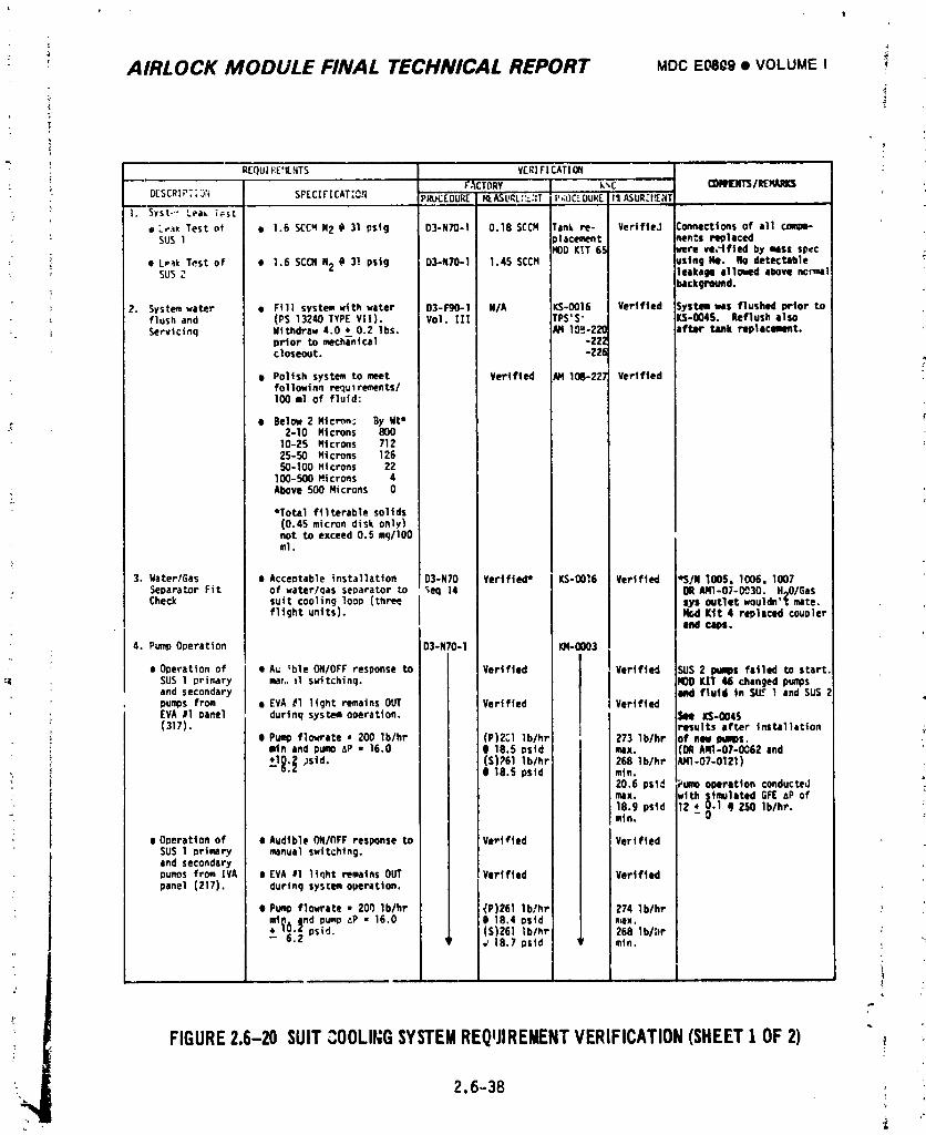
_- _ AIRLOCK MODULE FINAL TECHNICAL REPORT uDC E0809 • VOLUME I ,
i
RF()U[F:E,'¢NTS V£Riri CAT[ONF'._CTORY k_C" COIeEIJTS/REHARI_
DESCRIP::.);; SPECIi'ICAT:O.q PROCEDUR[_ASURL'_.';T P_IC'IJUR[../_ASUR_fSaTi. SySt.'" Lea_ ;_st
• :e*_ Test of • 1.6 SCC_N2 @31 psig 03-N70-1 0.18 SCCM Iank re- Verified :onnections of 811 compe-• : SUS1 ,lacement _tn*_s replaced
qODK_T 65 ,ere ve,_tfled by miSS spec ;i e Lp4k Test of e 1.6 SCCNN2 (I 31 Pstg 03-N70-1 1.45 SCCH _stng lie. No detectable, SUS2 leakage IlloNed above non,a1
_lckgroufld.
2. Systemwater • FIll system with water 03-P90-1 N/A KS-0016 Verified Systemwas flushed prior toflush and (PS 13240 TYPEVii). Voi. II1 rPS'S- _S-OOlS. Reflush also
_ Servicinq Withdraw 4.0 lbs. _ 10S-220 iftor tank replecamt.prior to mechanical -222closeout. -226
• Pol|sh system to meet Vertfted AM108-227 Verif|edfollowlnn requl rements/100 ml of flu|d:
• Below 2 Mtcr_ By lit*2-10 Microns 80010-25 tqtcrons 71225-50 Microns 126S0-100 Htcrons 22
100-S00 H| crons 4Above 500 Microns 0
• Total filterable solids(0.45 micron disk only)not to exceed 0.5 mq/lO0ml.
3. gater/Gas • Acceptable installation 03-N70 Verified* KS-0016 Verlfted *S/M 1005, 1006, 1007SeparaLOr Fit of water/qas separator to _eq 14 ORAKI-O_-O030. HoO/Gas
: Check sutt cooling 1ooo (three Sys outlet wouldn't mate.fltght units). Nod K|t 4 replaced couoler
and CapS.
4. PumpOoeratton 03-N70-I 10t-0003, I
• Operation of e Au 'ble OH/OFFresponse to Verified Verified ISUS2 pqlps fitled to start,:q SUS1 I_rimary mah, 11 swttchinq. , ,RODKIT 46 changed pumps
and secondary lied flutd tn Si_, t and SU$ 2pUl_S from • EVA_1 light remains OUT Varified VerifiedEVA ll oanel durtnq systemooeration. See KS-O045(317). results after Instillation ,_
• Pumpflo_ate • 200 lb/hr (P)2(,1 lb/hr 273 lb/hr of new Immps.mtn and pure AP - 16.0 8 18.5 ostd rex. (DR AR1-07-0062 and
)std. (S)761 lb/hr 268 lb/hr AN1-07-0121);1_:| , _e.spstd min.
i i 20.6 psi.4 Pumooperation conductedI max. with simulated GFE6P of -
18.9 psid 12 • 0.1 i) 250 1b/hr.mtn. u
e O_erattOn of •Audtble OH/OFFresponse to Ve-t_ted VerifiedSUS 1 ortmary manual swttchfn 0.and secondarypun_s from [VA I EVA_1 ltqht remains OUT Verified Verifiedpanel (217). during systemoperation.
• Pu_p flowrate • 200 lb/hr _P)261 lb/hr 274 lb/hrmt_, p.ndpump6P • 16.0 8 18.4 pstd n,ax.
y._ ps|d. (S)261 lb/hr 268 lblhr"°." ' ,18.7pstd ,, min
FIGURE2.6-20 SUITCOOLINGSYSTEMREQIJIREMENTVERIFICATION(SHEET1 OF2)
2.6-38
1974018208-379
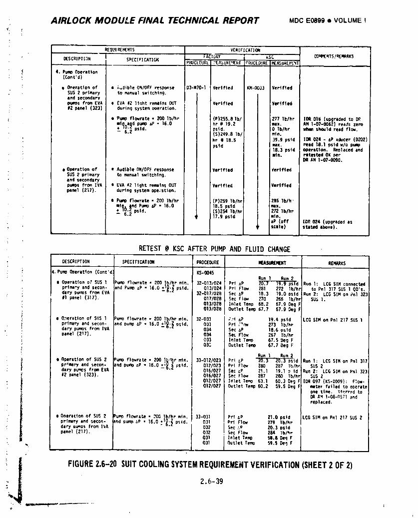
• AIRLOCK MODULE FINAL TECHNICAL REPORT MDCEO899• VOLUMEI;t T
R[QUIREH[NTS VERIFICAT|ON.... i
FACTORY kSC COU/qENTS/_EqIkRK$_SCR|PTION _ SPECIFICATIONJ P_OCL_URLI:_A_URE'_N[ PROCEDURE_ASUREF,£_T
4. PumOOoeratlon(ConS'd)
e O_eratlon of • _,dible ON/OFFresponse D3-N70-1 Verified K_-OC03 VertftedSUS2 prl_ry tO manual switching.and secondarypu_s from EVA a EVA 12 lt_ht remains Ob_ Vertfted I Verified#2 panel (323) during system operation.
e Pumpflowrate • 200 lb/hr (P)255.8 lb/ i 277 lblhr IDR 016 (upgraded tomt__aad pumpAP • 16.0 hr @ 19.2 max. AN 1-07-0062) reads zero+ /U._ n¢4d- 6 2 ..... psld. 0 161hr _ should read flow.• (S)249.8 IbI I mln,
hr e 18.S 39.9 p$td IOR 024 - 6P xducer (0202) ipstd t max. reid 18.1 pstd w/o pump
18.3 pstd operation. Replaced andm|n. retested OK per
OR /J4 1-07-0090.
e Operation of • Audible ON/OFFresponse Verlfted #ertfledSUS2 primary to manual swttchtn 9.and secondarypu_)s from IVA • EVAa2 light rematns OUT Vertfted Verlfted_nel (217). during system ope.'ation, i
i
e Pumpflowrate • 200 lb/hr ; (P)259 lb/hr 285 lb/h '_
QtQA ind Pump@ - 16.0 18.5 pstd I mix.(S)254 lb/hr 272 lb/hr
• pstd. 179psld ,I..AP (off IDR 024 (upgraded as, scale) stated above).
RETEST@ KSC AFTER PUMPAND FLUIDCHANGE
OESCRIPTION SPECIFICATIOM PROCEDURE ICcASlJRERENT REMARKS
4. PumoOperation (Cont'd KS-0045Run 1 Run 2
e Operat]on oY SUS 1 Pumoflowrate • 200 lb/hr mtn. 32-0131024 Prl AP 20.7 19.9 pstd Run !: LCGSlt4 connectedprima_j and secon- and PumaAP = 16.0 _+1_'_.pstd. 013/024 Pri Flow 281 272 lb/hr to Pnl 317 SUS1 OO's.dary pumosfrom EVA 32-017/028 Sec aP 18.3 19.0 osid Run 2: LCGSIM on Pnl 323#1 panel (317). 017/028 Sec Flow 270 266 Ib/hr SU:>1.
013/028 I Inlet Temp 68.2 67.9 Oeg F013/028 Outlet Temp67.7 67.9 _g F
• O._eratton of SUS1 Pumpflowrate • 200 Ib/hr mtn. 32-033 ! ;:t _p 19.4 pstd LCGSIN on Pnl 217 SUS1primary and secon- and pumpAP = 16.0 +_1_:_vstd. 033 Prt ;'n_ 273 lb/hrdary pu_msfrom IVA 034 Sec AP 18.6 pstdoanet (217). 034 Sec Flow 267 lblhr
033 Inlet Temp 67.5 Oeg F03: Outlet Te¢_ 67.7 Oeg F
Run I Run 2• Operation of SUS2 _umoflowrate • 200 l_r mtn. 33-012/023 Prt AP 20.3 20.3 ps|d Run 1: LCGSIN on Pnl 317
pr_mry and secon- and pum_AP • 16.0 +,_._ pstd. 0121023 Prt Flow 280 287 lb/hr SUS2dary pumcsFromEVA 0161027 Sec _P 21.1 19.1 p td Run 2: LCGSIM on Vnl 32312 Panel (323). 0161027 Sec Flow 287 280 Ib/hr SUS2
: 012/027 Inlet Te_o 63.1 60.3 Oeg r IDR 097 (KS-O009): F;ow-0121027 Outlet Te_ 60,2 59.5 Oeg F mater falled to ooerate
one time. Xferrnd toORA'41-08.(1571 andrepI iced.
I• Operation of SUS2 Pumnflowrate • 200 lb/hr min. 33-031 I Prl AP 21.0 pstd LCGSIM on Pnl 217 SUSZ
primary and secon- and pump_P • 16.0 _+1_'_.psid, 031 Prt Flow 279 1b/hedary Ou_os from I_A 032 J Sec :.P 20.3 psidpanel (217). 032 1. $ec Flow 284 1blUr
031 J Inlet Temp _1.80eq F
,. 031 J Outlet Te_ sg.s De9 F
] 9740] 8208-380
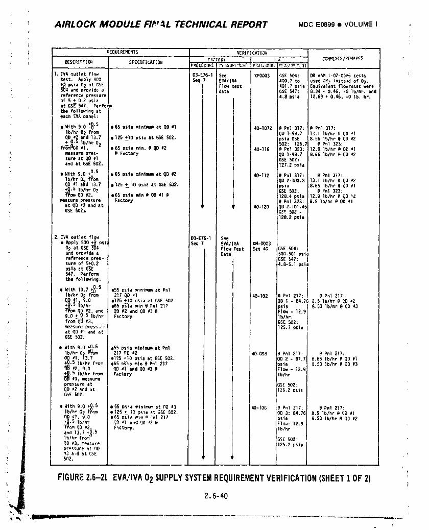
AIRLOCK MODULE FIr' TECHNICAL REPORT MDCE0899• VOLUMEI
"_ ; REQUIREMENTS VERIFICATION} F_:T_RY _,_L CO'_[_TS/RZ_K$
• _ DESCRIPTI_ SPECIFICATION P_CEDURt _'z%URi'tNI P,:JCLbUi{[_'(_%_L:_T
I. EVA outlet flow 03-E76-I See KM.O003 GSE 504: DR •AM 1-07-00_6tests
test. Apply 400 Seq 7 EVA/IVA 400.7 to usedGR2 insteadof 02."; +__ImSia02 at GSE Flow test 401.7 psia Equivalentflo_rateswere; 504 and provide a data GSE547: 8.34 + 0.46, -0 1b/hr. and
reference pressure 4.8 psla 12.69 + 0.46, -0 lb. hr.of 5 �0.2usiaat GS_ 547. Perform
the following ateach EVA panel:
•Wtth 9.0 _B"5 •65 psla minimum at QDJl 40-1072 ;0 Pnl 317: _ Pnl 317:ib/hr 02 from 100 1-99.7 13.1 lb/hr @0D '1
_Do?_ and 13.7 • 125 +10 psia at GSE502. psia GSE 8.56 lb/hr 0 QO #2lb/hr 02 502: 126.7 @ Pnl 323:fr_mO(}D_1, • 65 psia min. _ QD #2 40-116 @Pnl 323: 12.9 lb/hr @QC al
_- measurepres- @ Factory 00 1-98.7 8.65 Iblhr @ 00 #2sure at QD #1 i GSE502:and at GSE502. 127.2 psta
• With 9.0 +0.5 • 65 psta minimum at QD #2 40-112 0 Pnl 317: @ Pnl 317:lb/hr O) Y_om 00 2-I00.S 13.1 lb/hr @ 00 #2QD al ahd 13.7 • 125 psia at GSE502, )sia 8.65 lb/hr @QD#1+_j_.5ib/hr 09 GSE 502: @ Pn_ 323:flt_QO #2, - • 65 Dsta Btn@ QD #1 @ _ 128.4 psta 12.9 lb/hr _ OO _Z
measure pressure Factow I l @Pnl 323: 8.5 lb/hr @00 #1_ at 00 #2 and at _' ' 40-120 QD 2-101.45GSE 502. GSE 502 -
128.2 psta
2. IVA outlet flow D3-E76-1 See• Apply 500 +__psi Seq 7 EVA/IVA KM-O003
02 at GSE 504 Flow Test $eq 40 GSE 504:and providea Data 500-501 psia
• referencepres- ] GSE 547: Isure of 5 �`�4.8-5.1psiaos]a ac G_E I547. Perform
the following: I
•Wtth 13.7_ "S eS5 Dsia m_nimumat Pnllb/hr 02 f_m 217 QD ,1 40-102 @Pnl 217: @Pal 217:00 #I, 9.0 0125+10 osiaat GSE 502 QD 1 - 84.76 8.5 Ib/hr @ QD ,2_.5 Ib/hr e65 p_la min @ Pnl 217 )siz 8.53 Ib/hr@ QD #3
" f_omQD _2, and QD #2 and 00 #3 @ Flow - 12.99.0 �0.5lb/hr Factory 1b/hr.from"O,_#3, GSE 502:me_sure press."• 125.7 psiaat QD,1 and atGSE 502.
e With 9.0 œ!´�l�•55psta mlnimumat PnlIb/hr 02 _om 217 nO _2 40-098 @Pnl 217: @Pnl 217:
; 00 .I, 13,7 e125 +10 osia at GSE 502. QD 2 - 87.7 8.65 Ib/hr@ QD #I• +_R0.5 Ib/hrf-om e65 osia mln @ Pnl 217 osia 8.53 Ib/hr@ QD #3
O_ #2, q.o QD _1 and 0D #3 _ Flow - 12.9+R.5 lb/hr from Factory I lb/hr
• _ #3, measurepressure at I GSE 502:QD ,2 and at I 126.2 psta
G_E 502. I
+_.5 i0 With 9.0 0 55 asia mtntmumat NO 13 _ 40-106 :@P_I 217: @Pnl 217:Iblh_02 f nm e125 • 10 _s_aat GSE 502. QD 3:84.75 8.5 Iblhr@ 00 #1OD _l, 9.0 •65 o_i_ _n a :'nl217 }sia 8.53 Ib/hr@ QD #2•R.5 lh/hr _D _I and QD *2 @ Flow: 12.9f#om OO '2, F_ctory.and 13.7 �X)0�d�lb/hrIb/hr from" GSE 502:QD #3, measure i125.2pslapressure at 00_3 _,d at G_E5n2. I
FIGURE2.6-21 EVA/IVA02SUPPLYSYSTEMREQUIREMENTVERIFICATION(SHEET1OF2)2.6-40
t
1974018208-381
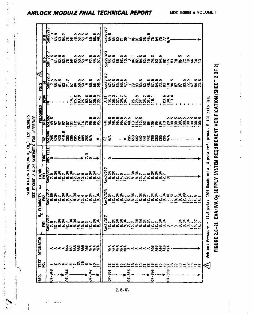
AIRLOCK MODULEFINALTECHNICALREPORT MDCE_ggeVOLUMEI
/ i ....
_ •f
? _JJje 6oo le6 .. •_R_NN¢_ROO_k_ R
i
____'___ _
m
!! 2.6-4_
] 9740] 8208-_82
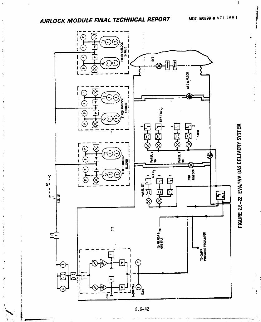
+I
AIRLOCK MODULE FINAL TECHNICAL REPORT MDC E0899 • VOLUME I i_
'I ! •! "
_ L ....
F --_ _< -
I I ..j
v
I I
L_ ;..__--..J I..->.
r _ --1 >-,a _._o ., .- _ >I _" -'<,:ill "'I fl,,_ I *ar,,_
-+ ,c._¥ ._._..+,,.,,+,"_" ,,,°, ,__ _i . <L_I._+ i,J.i
I• - " - =1 '_.
l NILl
2-_ E
" "!i- ?
i I IIII _ I I I
"L i:,+-_ - 2.6-42
+, ,,, +,.... ,_. + ................................... ,_
1974018208-383
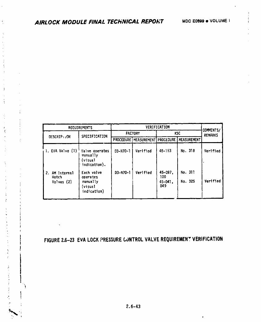
6
AIRLOCK MODULE FINAL TECHNICAL REPOI','T MDC E0,_99 • VOLUME I
i .. ' COR_ENTS/'REQUIREMENTS VERIFICATION
FACTORY KSC
DESCRIPILON SPECIFICATION PROCEDUREMEASUREMENTPROCEDURE MEASUREMENT REMARKSi lil l
I. EVA Valve (1) Valve operates D3-N70-1 Verified 45-153 No. 318 Verifiedmanually
(visual•indication).
2. AM Internal Each valve D3-N70-] Verified 45-097, No. 3llHatch operates lO0
' Valves (2) manually 45-041, No. 325 Verified: (visual 049
indication)
FIGURE2.6-23 EVALOCKPRESSURECONTROLVALVEREQUIREMENTVERIFICATION
I
, 2.6-43
1974018208-:384
MODULE FINAL TECHNICAL REPORT MDC E0899 • VOLUME I i :AIRLOCK
2.6.3.6 Mission Support Tests '
Mission Support Tests were uonducted during the fliqht of U-l using the
Static Test Unit (STU). A summary of special tests associated with EVA/IVA
operations which were performed with STU is presented below. Test details as
well as descriptions of STU are presented in the ECS/TCS Skylab T_ot Unit Report .:
No. TR 061-068.99.• /
e TITLE SUS Loop Operation Using Two 60 Foot LSU's In Series.
BACKGROUND U-l cre_vmight have used two 60-foot umbilicals
connected in series to permit additional distance for
repair work during EVA.
OBJECTIVE Determine SUS loop operation _hen an additional Life _
SuD_crt Umbilical (LSU) is installed in the SUS loop.
Reference TR 061-Ol5-600.01.
RESULTS SUS water pump performance was satisfactory when the flow
restriction of another LSU was added to the SUS loop.,i
Reference TM 262:_53. _
e TITLE SUS Loop Cooiinq Rates With By-PAsS/EVA Valve In _Y-PAS$
Position.
BACKGROUND Coolant _op temperature control valve "B" stuck when !
U-l crew positioned the BY-PASS/EVA valve in the EVA
position. Remaining EVA periods were planned wltn the
valve'in BY-PASS.
OBJECTIVE Determine coolinq effectiveness of SUS loop No. l heat
' exchanger. Reference TR 061-015-600.08.
RESULTS Coolinq effectiveness oF the SUS loop was determined for
several imposed heat loads with the BY-PASS/EVA valve in
the BY-PASS position. Reference TM 252:714.\
m TITLE Life S,JDDortUmbilical (LSU) Pressure Test
BACKGRnUND The U-l LSU might have remained serviced for long periods.J
OBJECTIVE Determine if a LSU can _vithstandproof pressure following _
a long term service condition. Reference TR 061-015-600.32. 1
: RESULTS An LSU had been serviced with fluid for #our monCh_. Theiunit sustained proof pressure of 74 nsiq without damage.
Reference TM 252:703.F
2.6-44
• -, i,It! II --- I _' II __ -. ]
1974018208-385
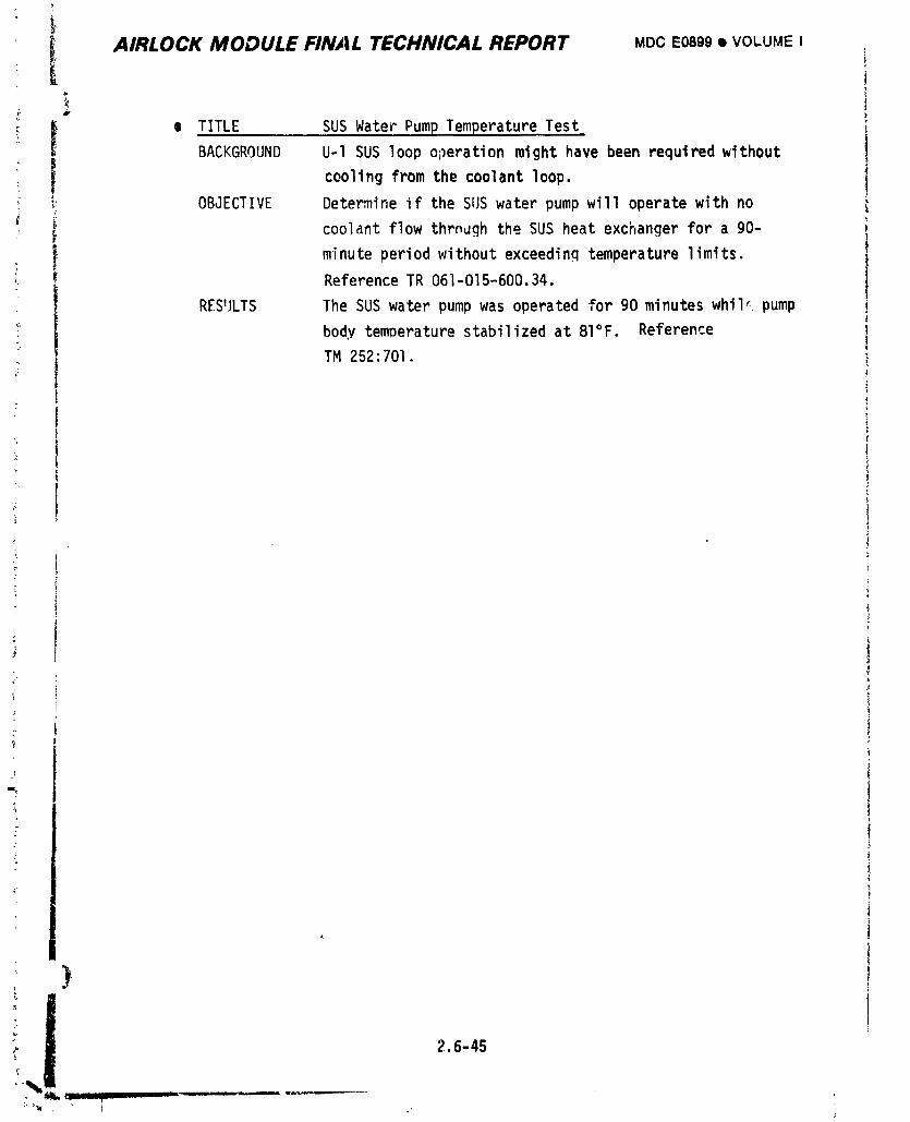
I AIRLOCK MODULE FINAL TECHNICAL REPORT MDCE0899• VOLUMEI
" I e TITLE SUS Water PumpTemperatureTestBACKGROUND U-1 SUS loop operation might have been required without
I coolingfrom the coolantloop.! _! OBJECTIVE Determineif the SUS water pumpwill operatewithno
! i coolantflow throughthe SUS heat exchangerfor a go-minute period without exceedinq temperature limits.
i ReferenceTR 061-015-600.34.
RESULTS The SUS water pumpwas operatedfor 90 minuteswhil_ pump '
body temperaturestabilizedat 81°F. Reference
TM 252:701.I
\
1
)
_%! 2.6-45..... - i ii ,, _,mmmm8 _,,w, I
1974018208-386
I
: ' AIRLOCK II_ODULE FINAL TECHNICAL REPORT MDCE0899• VOLUMEI
2.6.4 MissionPerformance
AirlockModulesystemsprovidedsupportfor twelveEVA/IVAoperationsrangingC
! up to a recorddurationof sevenhours (exclus_e of EVA preps or post-EVA
_ activity)on DOY 359. Oxygenflowto suitedcrewmenwas completelynormalon each: occasionand was utilizedfor coolingof the crewmenduringthe final EVA on SL-3
(DOY265)due to shut-downof the primarycoolantloop. Satisfactoryv_ter cooling
,, was suppliedfor all otherEVA operationswith up to thre_ crewmenon one suit
• cooling_y_tem. Operationof the lockcompartmentwas accomplishednormallyalthough
_ depressurizationrateswere decreasedas ice formedfrommoisturein the gas
collecteden the protectivescreenover the depressvalvevent port.
-I
2.6.4.1 OxygenSupply
Oxygenwas suppliedto the LSU at normalpressuresand temperaturesduringallsuitedoperations.Regulated02 pressuresduringtheseperiodsrangedbetween
122 and 127 psiawhile 02 temperatureswere normallycontrolledbetween50 and 6u°F
by the heatexchangerinterfacingwith AM coolantloops. Althoughnot a planned
operation,high02 flowrateswere utilizedfor coolingof EVA crewmenduring
the DOY 26_ EVA with satisfactoryresultsfo,'existingheatloads. Average
metabolicratesduringthisperiodwere reportedto be 790 and I060 Btu/hrfor
the two EVA crewmen. No pFoblemswere _dentifiedwith the EVA/IVA02 supplysyste,,
2.6.4.2 SuitCoolingSystem
Suitcoolingsystemswere successfullyactivatedon 29 separateoccasionsas
shown in Figure2.6-24 and performedin a normalmannerat all times. Of this
total,II operationswere in directsupportof EVA/IVA,two were to provideheat
intothe secondarycoolantloopfollowinga temperaturecontrolvalvediscrepancy,
and the remainderwere for normalsystemscheckout, Waterflowratesof 225 to
296 Ib/hrwere obtainedwith SUS l while SUS 2 providedflowratesbetween265 and
300 Ib/hrdependingon systemconfiguration.Watertemperaturesand flowdurations
are also shownin Figure2.6-24.
Suit coolingsystemperformance,in termsof water deliverytemperatureend
systemheat loadsas a functionof tim:, is shownin Figures2.6-25and 2.6-26
for two typicalEVA operations.The EVA on DOY 158 was conductedwith the coolant
loopdivertervalve in the EVA positionand resultedin waterdeliverytemperatures
2.6-46
1974018208-387
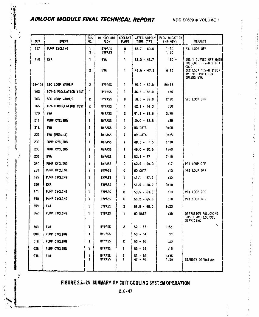
AIRLOCK MODULE FINAL TECNN!CAI. REPORT _,DC50899• VOLUMEI
i i ii i ii l
....... ti :...........iUS HX COOLANTCOO ,,ATERSUPPLY FLOWDURATION "
DOY EVENT I_D, FLOW PUMPS TEMP (.r) (HR:MIN) REMARYS
157 PUMPCYCLING 1 BYPASS 0 48.7 - 60.0 _:30 PR, LOOPOFF2 BYPASS 1 1:30
158 EVA I EVA I 33.0 - 48.7 :SO + SUS l TURNED OFF WHENPRI L00,' JCV-BSTUCKCOLD
2 EVA I 43,6 - 47.2 6:10 5EC LOOP T;V-B STUCKIN C%D POSITION :DURING EVA
159-162 SEC LOOPWARMUP 2 BYPASS _ 56.0 - S9.O 84:15
162 TCV-g MODULATIONTEST I BYPASS 1 46.5 - 58.0 :30
163 SEC LOOPWARMUP _ BYPASS 0 5B.O - 92.0 2:20 SECLOOPOFF
165 TCV-B MODULATIONTEST ._ BYPASS _ 52.1 - 54.0 :30
170 EVA I BYPASS 2 51.5 - 59.6 3:35
217 PUMPCYCLING I BYPASS I 49.0 - 52.5 :30
218 EVA I BYPASS 2 NODATA q:CO
229 IVA (MSOg-3} I BYPASS 1 NODATA 3:354
230 PUMPCYCLING I BYPASS 1 49.5 -2.5 _:30
233 PUMPCYCLING P BYPASS 1 49.0 - SO.S 1:40
236 EVA ) BYPASS 2 52,5 - 57 7"10
24q PUMPCYCLING BYPASS 0 62.5 • 64.0 :17 PRI LOOPOCF :
_59 PUMP CYCLING _ BYPASS U NO dATA :10 PRI LOOP OFF
325 PUMPCYCLING 1 BYPASS 1 ,_._ - 57.2 :30 i
326 EVA 1 BYPASS 2 51.5 - 58.2 9:10
3'I PUMP CYCLING l BYPASS 0 53.5 - 63.0 :I0 PRI LOOP OFF)
350 PUMPCYCLING 1 BYPASS O 55.2 - 65.5 :lO PRI LOUPOFF •
359 E_A 1 BYPASS 51.5 - 55.0 9:20
362 PUMPCYCLING 1 BYPASS 1 NO DATA :30 OPERATIONPOLLOWINGSUS 1 AND LSU/PCUSERVICING r:
363 EVA 1 BYPASS 62 - 55 _:St
008 PUMPL;YCLING I BYPP_S I 50 - 54 "_
018 PUMPCYCLING 1 BYPASS 2 50 - SS :,;_ 'r
OZB PUHPCYCLING 1 BYPASS 1 50 - 53 :15 ,:
014 EVA 1 BYPASS ] 2 S1 - 54 8:35
2 BYPAS_ I 1 47 - 49 1:25 STANDBYOPERATIONi i _ • • ill
FIGURE2._-24 SUMMARYOF:UITCOOLINGSYSTEMOPERATION
2.6-47:
1974018208-388
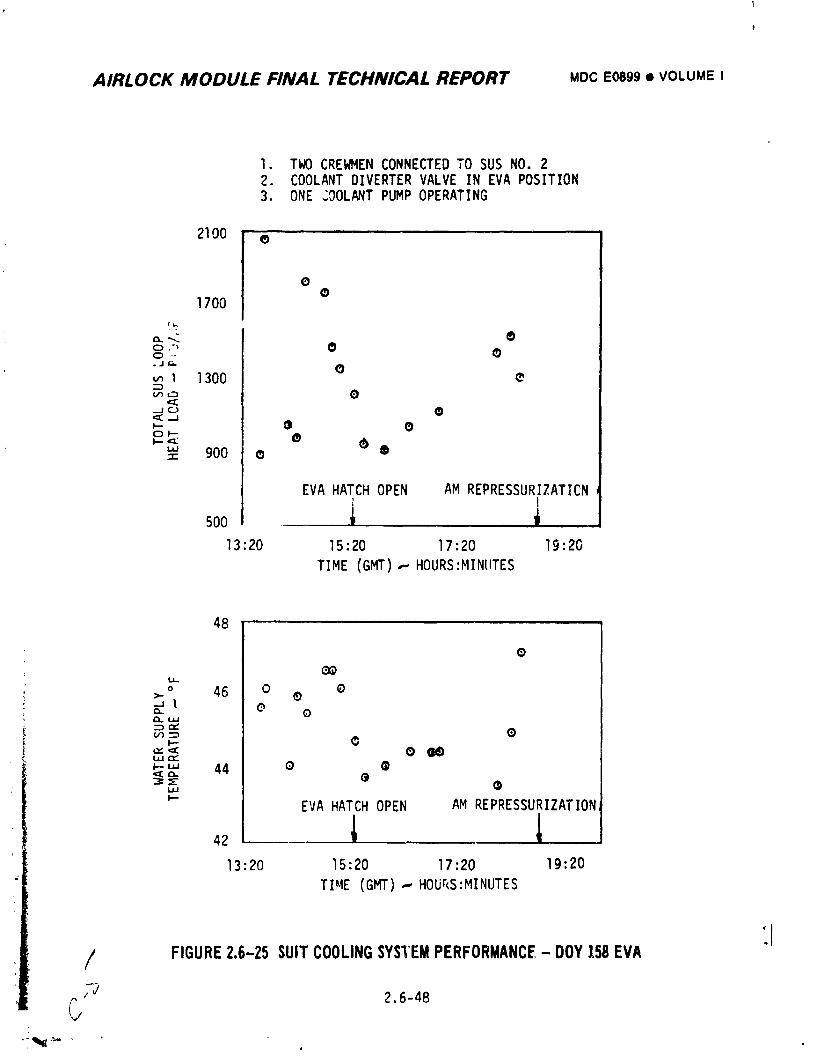
AIRLOCK MODULE FINAL TECHNICAL REPORT MDCE0899• VOLUMEI
I. TWO CREWMEN CONNECTED TO SUS NO. 22. COOLANT DIVERTER VALVE IN EVA POSITION3. ONE COOLANT PUMP OPERATING
21O0 e
o
1700IL..
c:).'_ •o ,.
.jr'. (_
I 1300 •v__n O
<I;_JO •
oF-
"' 900 • •-r-
EVA HATCH OPEN AM REPRESSURIZATICN
,0o i13:20 15:20 17:20 19:20
TIME (GMT),-.HOURS:MINUTES
48
o
LI-
o 46 0 0>- ®t 0cL 0¢LU.I
•-_,-,.,U')_ ®
''< 0 _,.,,-,._'" 44 e
13:20 15:20 17:20 19:20
TIME (GMT),-,Hour<s:MINUTES
:I/ FIGURE2.6-25 SUITCOOLINGSYSTEMPERFORMANCE- DOY158EVA
_'_ 2.6-48
G
1974018208-389
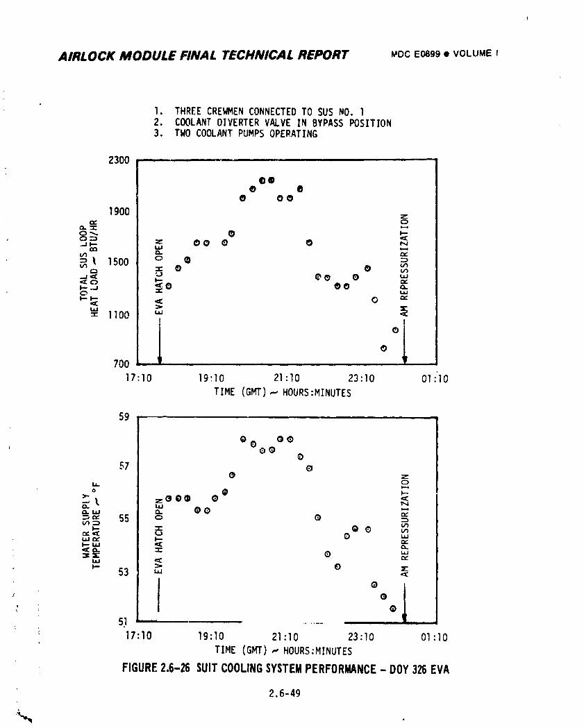
AIRLOCK MODULE FINAL TECHNICAL REPORT _oc Eosg9• VOLUME I
1. THREE CREWMEN CONNECTED TO SUS NO. 12. COOLANT DIVERTER VALVE IN BYPASS POSITION3. TWO COOLANT PUMPS OPERATING
2300
00• •
• oo
1900 z,'Y CD
O:D...=p_ z OO ¢ • N
0_3 Wo'1 _ tY::'_ 1500 o • :o,--, "," • • w
-a< _ eO 0 "'.J ._0 • • ,',
I,-t-- o_
::z: 1100 u..,
l °0
700 . . . 'r
17:10 19:10 21:10 23:10 01:0
TIME (GMI"),-.HOURS:MINUTES
59
o
057 g
• zIJ_ oo (_ v-
), zO gO • <13. L_ No.,,, o. O0 '-'::="" 55 o g e,::l./3'-'_ (./.)
laJrv I-- r_-
_=X O "'
53 ,1,
° 1_ G; Q
51 '....... I I I
17:10 19:I0 21:10 23:10 Ol:I0
TIME (GMT) ,-'HOURS:MINUTES
FIGURE2.6-26SUITCOOLINGSYSTEMPERFORMANCE- DOY 32BEVA
2.6-49
1974018208-390
AIRLOCK MODULE FINAL TECHNICAL REPORT MDC Eo89g• VOLUMEI
within the required range. The EVA on DOY 326 was conducted with the diverter
va|ve in the BYPASS position, resulting in somewhat higher water delivery temper-
atures but sufficient for effective cooling for all three astronauts on the same
SUS loop. A survey of the Skylab EVA's showed that the astronaut heat loads were
considerably below the maximum values required for design. Also, no situation was
encountered which resulted in a negative heat load on the system.
During EVA on DOY 359, a water leak at the GFE LSU/PCU composite connector
resulted in depletion of water in the SUS I reservoir. However, the EVA was
completed without difficulty.
During EVA on DOY 034, a water leak occurred for the second time at the LSU/
PCU composite connector. Crew action was taken to minimize the leakage rate and
the EVA was completed with SUS I. However, SUS 2 was activated and operated
normally in a standby mode during the latter portion of EVA.
Gas removal from water in the suit cooling systems was apparently normal
throughout the mission and the liquid-gas separator assembly installedat launch
was never replaced.
During EVA on DOY 158, water in SUS l was exposed to subfreezing temperatures
in the heat exchanger due to AM primary coolant flow at temperatures below O°F
when the downstream temperature control valve (TCV-B) stuck in a cold position.
Although water was initially flowing, measured water temperatures did approach the
freez1,,gpoint and all indications were that system water flow was lost. It is
therefore suspected that freezing in the affected heat exchanger was encountered.
Similarly, during SL-I operation in the abnormally cold vehicle attitude, water
line temperatures as low as 33.7°F were recorded on DOY 145; however, freezing
temperatures could have existed in other areas where instrumentationwas not
available.
2.6.4.3 In-Flight Water Servicing/Deservicing
LSU/PCU's were successfully deserviced on SL-3 just prior to the DOY 265 EVA
since water flow would not be provided through these components and such action
_ was desired by flight controllers to prevent the possibility of localized freezing.
ReQuired components were aqain serviced prior to the first EVA on SL-4. Following
2.6-50
1974018208-391
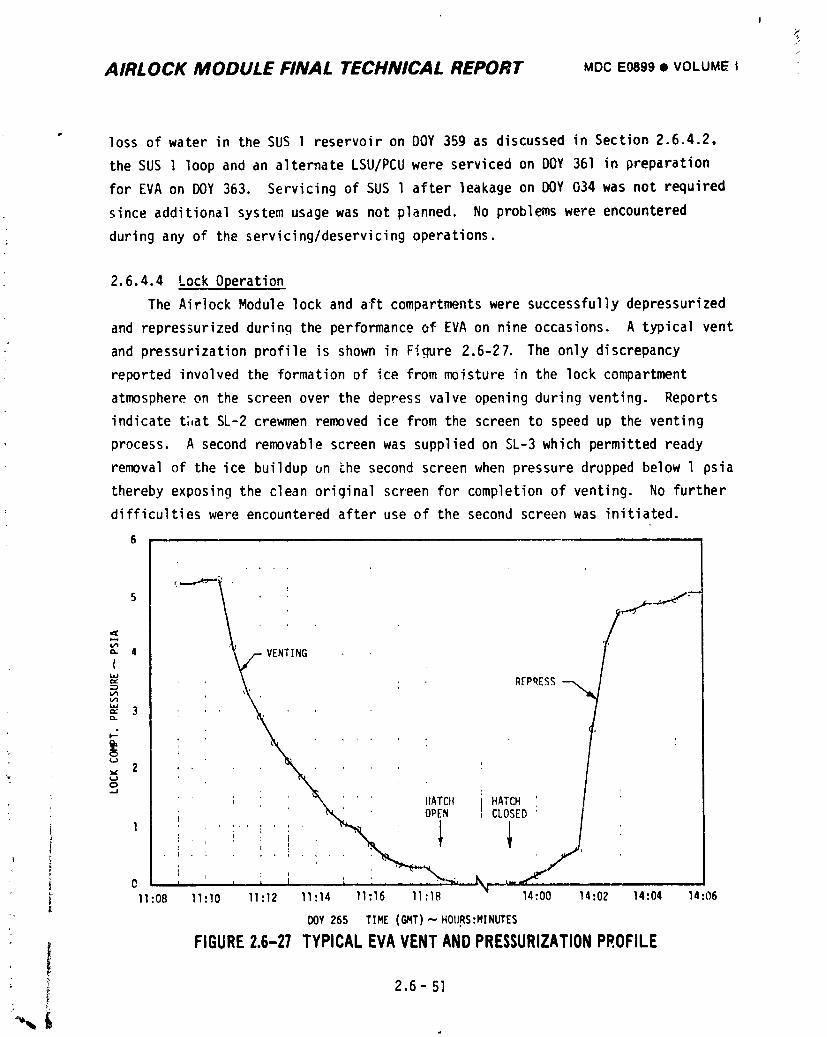
!
//
AIRLOCK MODULE FINAL TECHNICAL REPORT MDCEO899• VOLUME |
• loss of water in the SUS I reservoir on DOY 359 as discussed in Section 2.6.4.2,
the SUS I loop and an alternate LSU/PCU were serviced on DOY 361 in preparation
for EVA on DOY 363. Servicing of SUS l after leakage on DOY 034 was not required
since additional system usage was not planned. No problems were encountered
during any of the servicing/deservicingoperations.
2.6.4.4 Lock Operation
The Airlock Module lock and aft compart.mentswere successfully depressurized
and repres_urizedduring the performance of EVA on nine occasions. A typical vent
and pressurizationprofile is shown in Figure 2.6-27. The only discrepancy
reported involved the formation of ice from moisture in the lock compartment
atmosphere on the screen over the depress valve opening during venting. Reports
indicate t;,atSL-2 crewmen removed ice from the screen to speed up the venting
process• A second removable screen was supplied on SL-3 which permitted ready
removal of the ice buildup un _he second screen when pressure dropped below l psia
thereby exposing the clean original screen for completion of venting. No further
difficulties were encountered after use of the second screen was initiated•
6
'-'_*'-I / _J- -_e_
5 . " "-"
&/14
{
_ . REPRESS_" 3
,, 20 ,
: "J i ! ' _%, ' HATCII HATCH; N_ OPEN CLOSED
. i.. i • : . : :
i 11:08 11:10 11:12 11:14 11:16 11:18 14:00 14:02 14:04 14:06DOY26S TIME(GMT),"-"HOURS:MINUTES
_ FIGURE2.6-27 TYPICALEVAVENTANDPRESSURIZATIONPROFILE
_ 2.6- 51{,
1974018208-392
AIRLOCK MODULE FINAL TECHNICAL REPORT .oc EOeg9• VOLUME I
2.6.5 _nt Probl_s
2.6.5.1 EVA02 Supply -m
Problems were encountered in developtn_ a 120 psi _ressure r_ulator assembly
for the ECS whichwouldmeet the requirementsimposedby the EVA/IVA_ystem.
Basicallythe high EVA/IVAflowrates createolow temperatureswhich causedrelief
valve leakageand combinedwith cabin humidityto cause senseportblockagewith
ice. Theseoroblemsare discussedin Section2.5.5.
2.6.5.2 Suit Cooling S_st.em
The major problem encountered was the occurrence of corrosion tn the loop
which caused ;ormatton of deposits in the pump. This phenomenonresulted in thet
• inabilityof the pumpsto startafterhavingbeendormantfor a oerlodof time.
The problemwas ultimatelysolvedby additionof a suitablecorrosioninhibitor
to the fluid and increasingthe pump vane/rotorclearances.
The earlydesignof the SUS loopsutilizeduntreatedMMS-606wateras theL
circulatinqmedium. Vendorp_io testsusingthis fluiddisclosedstartingproblems,
causedby corrosionon the pump internalparts. Theseproblemsforceda changeof
the pumpvanes,rotor,and linermaterialsfrom the more wear resistanttungsten
carbideto a more corrosionresistantColmonyalloy. The materialschanges
combinedwith the additionof additivesto the water for corrosionand bacteria
controlresultedin satisfactorypump performance.These additiveswere 2% hy
• weightof dlpotasslumhydrogenphosphateand 0.2% by weightof sodiumboratefor
corrosioncontroland 500 PPM Roccalfor bacteriacontrol. This fluid,PB 3-302
(Rev.E), and pumpdesignalsowas used in the ATM C&D/EREPcoolantsystem.
After installationof the liquidgas separatorin the SUS loops,NASA
materialstestingindicatedthat the Roccaladditivewas incompatiblewith the/
separatorperformance,causingwatercarry-overthroughthe gas dischargeport.
A concernwas also expressedaboutthe presenceof theRoccalreducingthe
strengthpropertiesof the tygontubingin the LCG's. The Roccalwas therefore
replacedby 20 PPM movldyn, anotherbiocldeconsistingof a colloidalsilver
solution. SubsequentSUS loopoperationwith this new fluidresultedagain in
problemswith pump starting. Failureanalysisdetermined+hat the pump locked
• up afterdormancydue to depositsformedby interactionof thf)dipotas_lum
J 2.6-52,_
i
1974018208-393
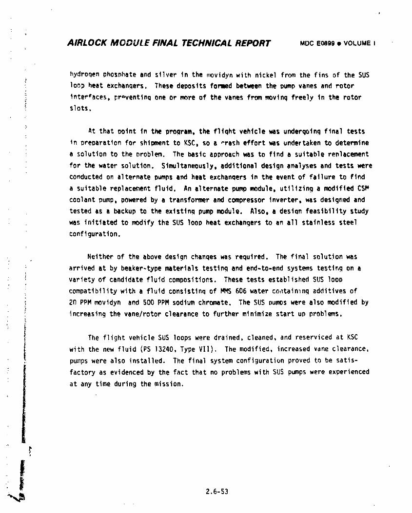
AIRLOCK MODULE FINAL TECHNICAL REPORT MDCEoagg• VOLUMEI
hydrogen phosnhate and silver in the movidyn with nickel from the fins of the SUS
loo_ heat exchangers. These deposits fon_d between the Dumpvanes and rotorc
tnter_aces, praventtnQ one or more of the vanes from movinq freely in the rotor
! slots.
At that ootnt in the program, the flight vehicle was underqotnq final tests
in orebaratlon for shipment to KSC, so a _rash effort was undertaken to determine
a solution to the problem. The basic approach was to find a suitable renlacement
for the water solution. Simultaneously,additional design analyses and tests were
conducted on alternate pumps and heat exchanaers in the event of failure to find
a suitable replacement fluid. An alternate _ module, utilizing a modified CSM
coolant pump, powered by a transformer and compressor inverter, was designed and
tested as a backup to the existing pumpmodule. Also, a desian feasibility study
was initiated to modify the SUS looo heat exchanqers to an a11 stainless steel
configuration.
Neither of the above design chanqes was required. The final solution was
arrived at by beaker-typematerials testing and end-to-end systems testing on a
• variety of candidate fluid compositions. These tests established SUS loop
compatibilitywith a fluid consistinq of MMS 606 water co,_tainlngadditives of
20 PPM movidyn and 500 PPM sodium chromate. The SUS Dumps were also modified by
increasing the vane/rotor clearance to further minimize start up problems.
The flight vehicle SUS loops were drained, cleaned, and reserviced at KSC
with the new fluid (PS 13240, Type VII). The modified, increased vane clearance,
. pumps were also installed. The final system configuration proved to be satis-
factory as evidenced by the fact that no problems with SUS pumps were experienced
at any time during the mission.
!2.6-53
i
1974018208-394
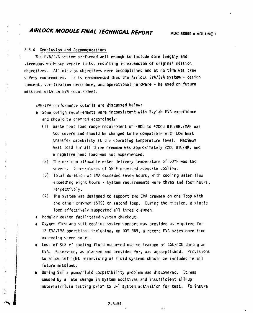
AIRLOCK MODULE FINAL TECHNICAL REPORT MOCE0899• VOLUME I
2.6.6 Conclusion _nd Recor_nendations
The EVA/IVA _;'_,tem performed well enough to include some lengthy and
.trenuous_ork__hoprepair tasks, resulting in expansion of original mission
objectives. All mis._4onobjectiveswere acco_lished and at no time was crew
safety compromised. It is recommendedthat the Airlock EVA/IVA system - design
concept, verification procedure, and operational hardware - be used on future
missions with an EVA requir_.ment.
EVA/IVA performance details are discussed below:
• S_ne design requirementswere inconsistentwith Skylab EVA experience
and should be chapqed accordingly:
(1) Waste heat load range requirement of -800 to +2000 BTU/HR./MAN was
too severe and should be changed to be compatible with LCG heat
transfer capability at the operating temperature level. Maximum
heat load for all three crewmen was approximately 2200 BTU/HR. and
a negative heat load was not experienced.
(2) The maxi,_umallowable_.,aterdelivery temperatureof 50°F was.too
9evere. Temperatures of 58_F provided adequate coolinq.
(3) Total duration of EVA exceeded seven hours, with cooling water flow
exceeding eight hours - system requirementswere three and four hours,
re_pectirely.
(4) The system was designed to support two EVA crewmen on one loop with
the other c_ewman (STS) on second loop. During the mission, a single
loop effectively supported all three c_ewmen.
= Modular design facilitatedsystem checkout.
e Oxygen flow and suit cooling system support was provided as required for
12 EVA/IVA operations including, on DOY 359, a record EVA hatch open time
exceeding seven hours.
e Loss of SUS _I cooling fluid occurred due to leakage of LSU/PCU during an
EVA. Reservice, as planned and provided for, was accomplished. Provisions
to allow inflight reservicingof fluid systens should be included in all
future missions.
e During SST a pump/fluid compatibilityproblem was discovered. It was
caused by a late change in system additives and insufficient all-up
material/fluid testing prior to U-l system activation for test. To insure
_ 2.6-54i
i
1974018208-395
_m
AIRLOCK MODULE FINAL TECHNICAL REPORT MDC E0899 • VOLUME I
)
no repetitionon futureprogram, nkaterlal/fluldtestingmustbe conducted )
) earlyand all-upsystemtestinq,with all materialsand components,should( be conducted as early as possible for all fluid system, especialiv water i
i syst_s.
i • Dlfferentlalpressureinstrumentationwms _activat_d priorto launchduet
) to a potentlalof shortingoutthe5Vbus andeliminatingalli instrumentationconnectedto thatbus. Lossof_P informationcomplicated l
) thedeterminationof loopperformanceandtheisolationof flowproblems. ,
Differential pressure transducer design improvementshould be madeprior
) to next progr,_musage,
e Airlock EVAvent formedice whenventing moist gas overboard. Theprobi_,,was solvedby providing a screen, on SL-3, that could be removed(with 'ce
fomatlon)latein ventingoperation.Futureoverboardventsshouldinclude
meansto preventexcessiveice build-up,l.e.,ventheatersor removable
screens.
!
2.6-55/56i
1974018208-396
AIRLOCK MODULE FINAL TECHNICAL REPORT Moc E0099 • VOLUMEI
2.7 ELECTRICALPOWERSYSTEM
2.7.1 Design Requirements
2.7.1.I Introduction
The AirlockElectricalPower System(EPS)designevolvedfroma simpleprimary
batterysystemto a complexsolar array/secondarybatterysystem. Thisevolution
was promptedby changesin missionobjectivesand designrequirements.
2.7.1.2 Des__lqnEvolution
Initially,all systempower afterdockingwas to be derivedfrom the CSM;
therefore,the AM was requiredto provideonly a minimalamountof powewduring
the initialmissionphase. The AM EPS consistedof a numberof silver-zincprimary
batteriesand a distributionsystem.
As the missiondurationwas extendedand the sophisticationof the OWS
increasedto accommodatea more ambitiousexperimentprogram,the AM EPS design
conceptwas changedto a solararray/secondarybatterysystemfor orbitalopera-
tions,with primarysilver-zincbatteriesused for preactivationpower requirements.
The firstof thesedesignshad solararraysmountedon the Airlockin various
configurations.As the requirementsincreased,the solar arrayswere movedto the
OWS where therewas mere room to accommodatethe increasedarray size. Also, in
theearly designstages,the batteriesand powerconditioningequipmentdesignwere
evolvedthrougha seriescf tradeoffstudies. Althoughboth silver-cadmiumand
nickel-cadmiumbatterics_ereconsidered,the nickel-cadmiumtypewas selected
based on the availabilityof considerablymere test and flightdata, implyin9less
developmentrisk. A numberof solararray/secondarybatterysystemdesignswere
evaluated,with the primarygoalof increasingthe overallefficiencyand
reliabilityof the system. This necessitateddeparturesfrom somenormally
acceptedconservativepracticesand considerableeffortin state-of-the-art
advancement.To increaseEPS efficiency,buckregulationwas selectedfor both
the batterychargerand voltageregulator,and a peak powertrackerwas
Incorporatedin the chargerto extractmaximumarray powerwhen demandedby the,k
system. The modularregulatordesignwas selectedfor both the _atterycharger
" and voltageregulatorfor maximumreliabilityand highefficiency,in additionto
•":_, i 2.7-I =
1974018208-397
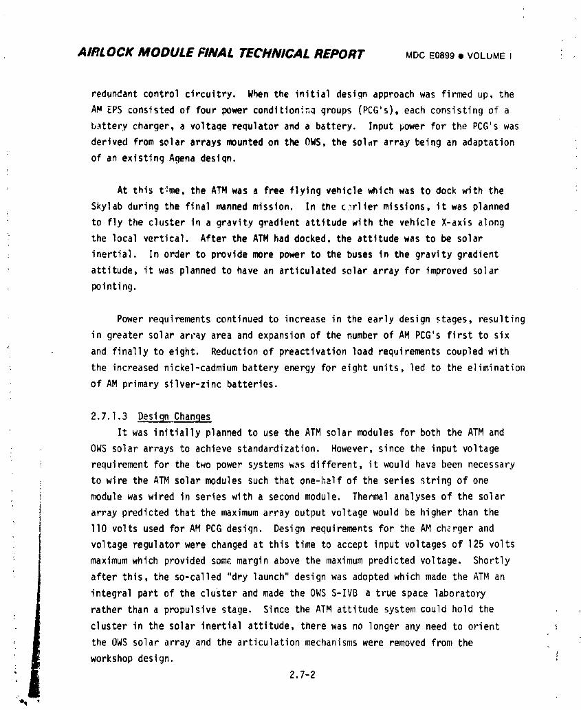
AIRLOCK MODULE FINAL TECHNICAL REPORT MDCE0899• VOLUMEI :
redundant control circuitry. When the initial design approach was firmed up, the
AM EPS consisted of four power condition_=_ groups (PCG's), each consisting of a
battery charger, a voltage requlator and a battery. Input power for the PCG's was
derived from solar arrays mounted on the OWS, the solar array being an adaptation
of an existing Agena deslqn.
At this t:me, the ATM was a free flying vehicle which was to dock with the
Skylab during the final manned mission. In the c_rlier missions, it was planned
; to fly the cluster in a gravity gradient attitude with the vehicle X-axis along
the local vertical. After the ATM had docked, the attitude was to be solar
inertial. In order to provide more power to the buses in the gravity gradient
attitude, it was planned to have an articulated solar array for improved solar
pointing.
Power requirements continued to increase in the early design stages, resulting
in greater solar ar_'ayarea and expansion of the number of AM PCG's first to six
and finally to eight. Reduction of preactivation load requirements coupled with
the increased nickel-cadmiumbattery energy for eight units, led to the elimination
of AM primary silver-zinc batteries.
2.7.I.3 Deset_gn_'Changes
It was initially planned to use the ATM solar modules for both the ATM and
OWS solar arrays to achieve standardization. However, since the input voltage
requirement for the two power systems was different, it would have been necessary
to wire the ATM solar modules such that one-half of the series string of one
module was wired in series with a second module. Thermal analyses of the solarI
. array predicted that the maximum array output voltage would be higher than the
llO volts used for AH PCG design. Design requirements for the AM chcrger and
voltage regulator were changed at this time to accept input voltages of 125 volts
maximum which provided some margin above the maximum predicted voltage. Shortly
after this, the so-called "dry launch" design was adopted which made the ATM an
integral part of the cluster and made the OWS S-IVB a true space laboratory
rather than a propulsive stage. Since the ATM attitude system could hold the
cluster in the solar inertial attitude, there was no longer any need to orient i
the OWS solar array and the articulation mechanisms were removed from the
workshop design.
2.7-2
1974018208-398
AIRLOCK MODULE FINAL TECHNICAL REPORT MDC I=0899• VOLUME I
An optimized solar array was later conceived for th_ OWS which was designed
specifically to be used with th_ AM PCG's as an integrated power system. Maximum
and minimum voltage and power requirementswere specified the sadieas the l-I/2 ATM
module design, and, therefore, did not necessitate any PCG redesign.
In the process of design evolution, a second amp-hour meter (AHM) was added
to the battery charger to improve its reliability. Also, a discharge limit
feature was added to provide a signal to the vo]tage regulator when the AHM
computed battery SOC equaled 30%. The voltage regulator reduced its output
voltage by 2 volts in response to this signal and effectively removed the
associated battery from the bus. This feature was added to prevent inadvertant
overloading of any one bat+cry, although intentional deep discharges were still
possible by use of over-ride logic circuitry. An on-board display of AHM status
was added in addition to ground telemetry. A feature was also added to permit
manual override of the I00% state-of-charge (SOC) signal from the AHM and to
continue battery charging at the voltage limi:.
Battery cell evaluations during initial testing prompted internal cell (hanges
to reduce the probability of cell internal shorts. To further improve cyclic life,
battery operating temperature was reduced. This lowering of operating temperature
was accomplished by changing the battery case material, lowering the coolant loop
battery module inlet temperature, and reducing the AHM return factor and battery
trickle charge rate. The latter necessitated battery charger design changes.
2.7.2 System Description
2.7.2.! Introduction
_he AM EPS was one of three electrical power systems which provided power for
the entire Orbital Assembly. The performance requirements of the AM EPS included
compatibilitywith those of the other two power systems and of the consuminq
elements. This description is basically limited in scope to the AM EPS, but also
takes cognizance of the characteristics of other module systems where they are
pertinent to the design of the AM EPS. Performance values and tolerances used in
this description are intended for illustrative purposes only. The individual
1 2.7-3
i9740i8208-399
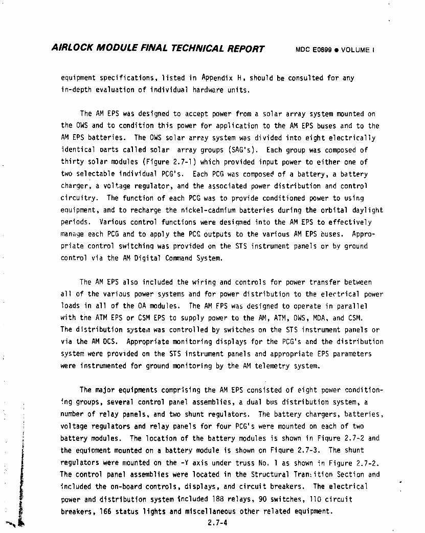
AIRLOCK MODULE FINAL TECHNICAL REPORT MDCE0899• VOLUMEI
equipment specifications,listed in Appendix H, should be consulted for any
in-depth evaluation of individual hardware units.
The AM EPS was designed to accept power from a solar array system mounted on
the OWS and to condition this power for application to the AM EPS buses and to the
AM EPS batteries. The OWS solar array system was divided into eight electrically
identical Darts called solar array groups (SAG's). Each group was composed of
thirty solar modules (Figure 2.7-I) which provided input power to either one of
two selectable individual PCG's. Each PCG w_s composed of a battery, a battery
chargerl a voltage regulator, and the associated power distribution and control
circuitry. The function of each PCG was to provide conditioned power to using
equipment, and to recharge the nickel-cadmium batteries during the orbital daylight
periods. Various control functions were designed into the AM EPS to effectively
man_ge each PCG and to apply the PCC outputs to the various AM EPS buses. Appro-
priate control switching was provided on the STS instrument panels or by ground
control via the AM Digital Command System.
The AM EPS also included the wiring and controls for power transfer between
all of the various power systems and for power distribution to the electrical power
loads in all of the OA modules. The AM FPS was designed to operate in parallel
with tne ATM EPS or CSM EPS to supply power to the AM, ATM, OWS, MDA, and CSM.
The distribution syste_awas controlled by switches on the STS instrument panels or
via the AM DCS. Appropriate monitoring displays for the PCG's and the distribution
system were provided on the STS instrument panels and appropriate EPS parameters
were instrun_nted for ground monitoring by the AM telemetry system.
The major equipments comprising the AM EPS consisted of eight power condition-
ing groups, several control panel assemblies, a dual bus distribution system, a
number of relay panels, and two shunt regulators. The battery chargers, batteries,
voltage regulators and relay panels for four PCG's were mounted on each of two
battery modules. The location of the battery modules is shown in Figure 2.7-2 and
the equipment mounted on a battery module is shown on Fiqure 2.7-3. The shunt
regulators were mounted on the -Y axis under truss No. l as shown in Figure 2.7-2.
The control panel assemblies were located in the Structural Transition Section and
included the on-board controls, displays, and circuit breakers. The electrical
power and distribution system included 188 relays, 90 switches, llO circuit
breakers, 166 status lights and miscellaneous other related equipment.-_ 2.7-4
1974018208-400
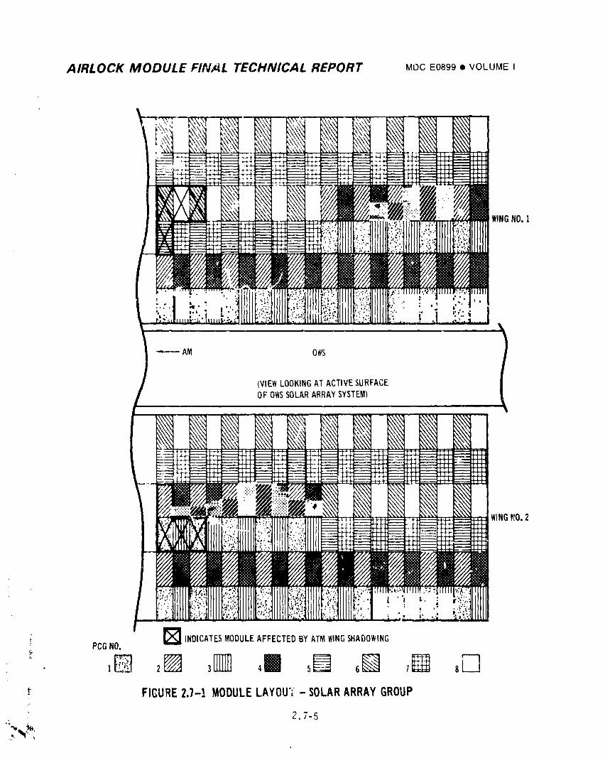
AIRLOCK MODULE FINAL TECHNICAL REPORT MOCE0899I VOLUMEI
------ AM OWS
I
(VIEWLOOKINGAT ACTIVESURFACEOF OWSSOLARARRM SYSTEM)
X\\\ ...... -\-,,,\', .......... X\\\': ..........
I x\\X
_lr;_ _-.::,_ " " ---.-.t.L_
JJ/i
( PCGNO. _ INDICATESMODULEAFFECTEDBYATMWINGSHADOWING177
_" FIGURE2.7-1 MODULELAYOU';- SOLARARRAYGROUP
2.7-5
i
1974018208-401
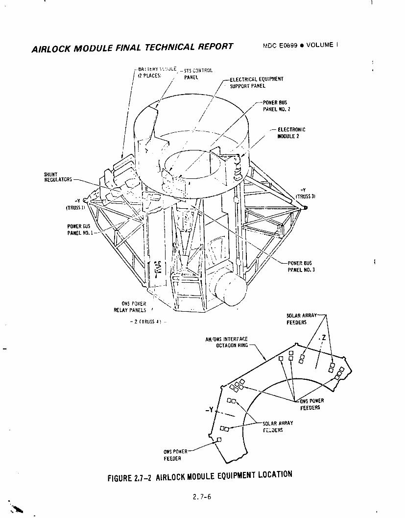
AIRLOCK MODULE FINAL TECHNICAL REPORT ,v,_cE0899• VOLUMEI
PO_/ER£,USPANELNO.l --
AM/OWSINTERFACE
OCTAGONRING-_
OWSPOWERFEEDER
FIGURE2.7-Z AIRLOCKMODULEEQUIPMENTLOCATION
- 2.7-6
I
197401820R-4NP
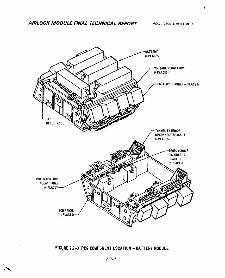
AIRLOCK MODULE FINAL TECHNICAL REPORT MDCE0899• VOLUMEI
REGULATOR(4PLACES)
BATTERYCHARGER(4PLACESj
EST
RECEPTACLE
TLINNELEXTERIOR
DISCONNECTBRACK[.F(2PLACES)
MODULEDISCONNECTBRACKET(2 PLACES_
POWER CONTROLRELAY PANEL
(4PLACES)_--I'
SCRPANEL(4
FIGURE2.7-3 PCGCOMPONENTLOCATION- BATTERYMODULE
2.7-7=,
1974018208-403
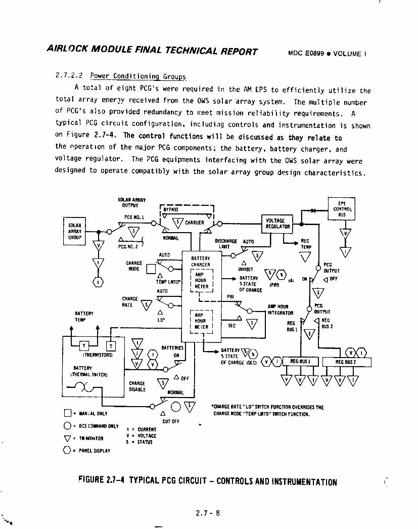
AIRL OCK MODULE FINAL TECHNICAL REPORT MDCE0899• VOLUMEI
2.7.2.2 Power ConditioningGroups
A total of eight PCG's were required in the AM EPS to efficiently utilize the
tota| array energy received from the OWS solar array system. The multiple number
of PCG's also provided redundancy to n:eetmission reliability requirements. A
typical PCG circuit configuration, includiag controls and instrumentationis shown
on Figure 2.7-4. The control functionswill be discussed as they relate to
the pperatlon of the major PCG components; the battery, battery charger, and
voltage regulator. The PCG equipments interfacingwith the OWS solar array were
designed to operate compatibly with the solar array group design characteristics.
SOLARARRAY
OUTPUT r BYPASS 1PCGNO.] Iv V I VOLTAGE
7 . LIMIT TENIP
AUTO BATTERY _ A _
; CHARGEF---]__,,._.,(_)__ CHARGER PCGMODE OUTPUTr---7 ] ,nHIBST_CC__P
Xnili_ I _ BATTERY V_J A) ON <_ OFF
( ) tE,,,,',__o".....-I _ ,STATE_p_ 'L"ETE%/ o,c.,_c_AUTO
CHARGE,___ -._7"-_ L
RATE W ""(_)--- ---- _u_._ AUPHOUR PCGBATTERY A F A'M'P-- "l A _ INTEGRATOR OUTPUTTEMP LO° I HOUR I A _ I REG REG
I METERI SEC _ I g_ 1, BUS2
L_-] _J
OF CHARGE(SEC) REGBUS| REGBUS2BATTERY
(THERMALS,ITCH) _OFF
DISABLE nORMAL
0,_0_ "CRARGERATE"LO" IffITCHFUNCTIONOVERRIDESTHEI'-]. MAN;ALONLY A CHARGE,OOE"TE,P LklTD"$11TCHFUNCTION.
CUTOFF
O = DC$COMMANOONLY I . CURRENT
= TIMONITOR V • VOLTAGE$ • STATUS
O= PANELOISPLAY
FIGURE2.7-4 TYPICALPCGCIRCUIT- CONTROLSANDINSTRUMENTATION
2.7-8
1974018208-404
AIRLOCK MODULE FINAL TECHNICAL REPORT MDCE0899• VOLUMEI
A. Battery Charger - The complete detailed characteristicsof an individual
battery charger were specified in McDonnell Procurement Specification
61B76900_. Physically, each charger weighed 27 Ibs, with dimensions of
7.25' × _" x II.55", and required coldplate mounting. Each battery
chargeF conditioned the power obtained from an associated OWS solar
array group, controlled the charging of its associated nickel-cadmium
battery, and fed solar array conditioned power or battery power to its
associated voltage regulator to satisfy system load requirements. The
battery charger was designed to provide a maximum instantaneousoutput
power of 2300 watts and a maximum continuous output power of 1500 watts.
Maximum output voltage was 52 VDC.
The acceptable AM/OWS interface voltage range for battery charger opera-
tion was from 125 volts maximum at open circuit to 51 volts minimum at
the peak power point of the solar array group V-I characteristics. Maxi-
mum input power was 2580 watts.
The battery charger consisted functionally of three major circuits; the
switching regulator circuit, the peak power tracker circuit, and the
ampere-hour meter circuit. These circuits are shown on the battery
charger block diagram, Figure 2.7-5. The switching regulator was the
actual power conversion circuit which conditioned the solar array power
and provided the regulated output. The peak power tracker restricted the
load demand on the solar array group to the peak power available from the
group. The ampere hour meter controlled the charging modes for the
battery.
(1) Peak Power Tracker - The function of the peak power tracker circuit
was to automatically adjust the battery charger output voltage such
that the power demand on the associated solar array group was limited
to its available peak power. Without the peak power tracker, a load
de_Jnd in excess of the available peak power would cause a sharp drop
: ' in the solar array output voltage, and, therefore, a sharp drop in
its output power
i
2.7-9
1974018208-405
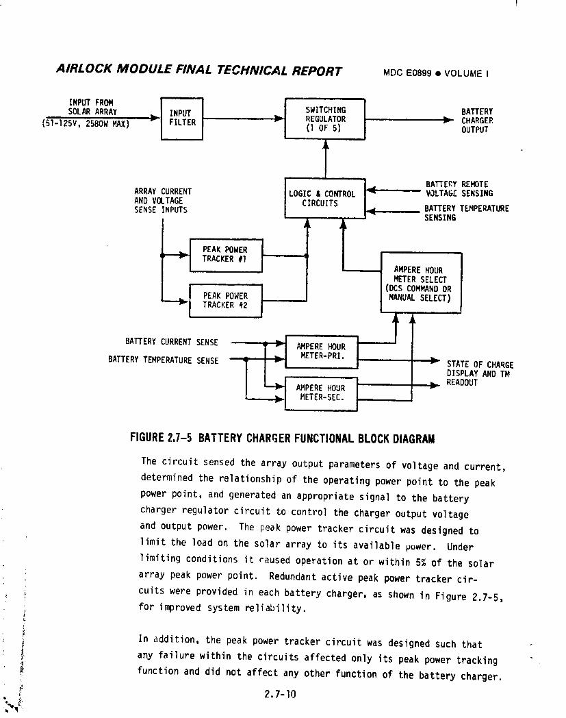
AIRLOCK MODULE FINAL TECHNICAL REPORT MDCE0899• VOLUMEI
i i ii
i b FsWITcHIN°8A E YSOL_ ARRAY INP_ _ REGULATOR _ CHARGER(51-125V,2580W_X) _ FILTER (IOF 5) OUTPUT
i
ill • I
ARRAYCURRENT LOGIC& CO_ROL VOLTAGESENSING
ANDV_TAGE CIRCUITS _ BAKERY TEMPE_T_ESENSE NPUTS I_ - SENSING
PEAKPOWER ' ITRACKER#1 AMPEREHOURMETERSELECT
(DCSCOMMANDORPEAKPOWER MANUALSELECT)TRACKER#2
BATTERYCURRENTSENSE AMPEREHOURMETER-PRI.
BATTERYTEMPERATURESENSE STATEOF CHARGEDISPLAYAND TMREADOUT
AMPEREHOURMETER-SEC.
FIGURE2.7-5 BATTERYCHARGERFUNCTIONALBLOCKDIAGRAM
The circuit sensed the array output parameters of voltage and current,
determined the relationship of the operating power point to the peak
power point, and generated an appropriate signal to the battery
charger regulator circuit to control the charger output voltage
and output power. The peak power tracker circuit was designed to
limit the load on the solar array to its available puwer. Under
limiting conditions it raused operation at or within 5% of the solar
array peak power point. Redundant active peak power tracker cir-
i cuits were provided in each battery charger, as shown in Figure 2.7-5,
; for improved system reliability.b
In addition the peak power tracker circuit was designed such that
_ any failure within the circuits affected only its peak power tracking
_: function and did not affect any other function of the battery charger.
2.7-I0
1974018208-406
AIRLOCK MODULE FINAL TECHNICAL REPORT MDCE08g9• VOLUMEI
(2) Ampere Hour Meter - The function of the ampere hour meter circuit
was to continuously compute the state-of-charge (SOC) of the
associated battery and to provide charge control signals based on
the computed SOC. This was accomplished by monitoring the battery
• discharge in ampere-hours during dark periods and the battery
;'" recharge in ampere-hours (including the return factor) during
d__!ight periods. The battery status at any time was then computed
in % SOC based on starting at I00% with a fully charged battery.
The I00% SOC was based on a battery capacity of 33 ampere hours.
The primary control signal, generated when the co_}uted SOC reached
I00%, terminated the voltage limited charge mode and initiated the
current limited charge mode. An analog signal indicating the
computed SOC was also generated in the ampere-hour meter for
telemetry and display usage. Two identical ampere hour meter
circuits were provided in each battery charger, as shown on
Figure 2.7-5, for improved system reliability. Both of these
circuits computed the battery SOC at all times and provided a
continuous analog signal indicating computed battery SOC for
telemetry and display. However, only one of these circuits provided
battery charqe control signals at any one time. Selection of either
the primary or secondary circuit for control purposes was made by a
DCS command or by a crew manual switch.
Temperature compensation was provided during charge cycles to account
for the interrelationshipbetween charging efficiency and battery
temperature. Three thermistors in the associated battery provided
i temperature sense signals to the compensating network of the ampere-
! hour meter. The battery was considered fully recharged when the
ampere-hours delivered to the battery were equal to the ampere-hours; ! removed, multiplied by the "return factor" shown in Figure 2.7-6.
i At that point, the ampere-hcur meter output indicated a battery SOC
of I00%, and a signal was provided to the battery charger regulator
I circuit to cause operation in the constant current battery charging
mode rather than the voltage limited battery charging mode used at
computed SOC values less than I00%. When the computed battery SOC
_ value dropped to 30%, a signal was provided to the associated AM EPS2.7-11
i
1974018208-407
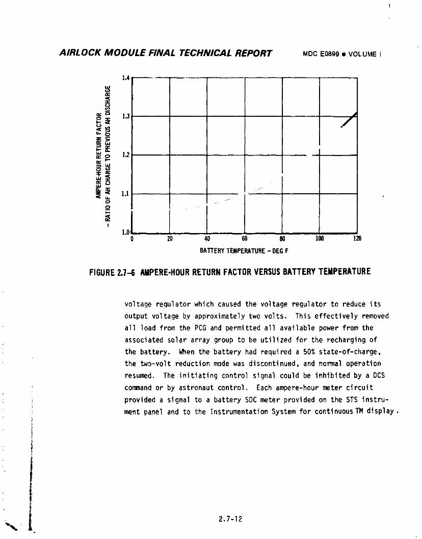
AIRLOCK MODULE FINAL TECHNICAL REPORT MDCE0899• VOLUMEI
|.4,
I.IJ
O¢
-i,¢Jw
o 1.3 -,
O
.-=
o_ 12I--
I.iJ¢...q
t,U
,, _as 1.1t,t.
I
1.00 20 40 60 80 100 120
BATrERYTEMPERATURE- DEGF
FIGURE2.7-6 AMPERE-HOURRETURNFACTORVERSUSBATTERYTEMPERATURE
voltage regulator which caused the voltage regulator to reduce its
output voltage by approximately two volts. This effectively removed
all load from the PCG and permitted all available power from the
associated solar array group to be utilized for the recharging of
the battery. When the battery had required a 50% state-of-charge,
the two-volt reduction mode was discontinued, and normal operation
resumed. The initiating control signal could be inhibited by a DCS
command or by astronaut control. Each ampere-hour meter circuit
: ; provided a signal to a battery SOC meter provided on the STS instru-
ment panel and to the InstrumentationSystem for continuousTM display.
•k i 2.7-12i
1974018208-408
AIRLOCK MODULE FINAL TECHNICAL REPORT MDCE08gg• VOLUMEI
(3) Regulator - The battery charger regulator was a pulse width modulated
type voltage regulator where the regulated DC output voltage was less
than the unregulated DC input voltage. The regulator consisted of an
,nput filter and five individual power modules. A multiple number of
regulator modules were used for both increased system reliability and
minimum parasitic losses at low load conditions, resulting in high
overall efficiency of operation.
A battery charging cycle typically included three modes of battery
charger operation; a peak power tracking mode as explained above, a
voltage limited mode, and a constant current mode. A charging cycle
would start with the battery SOC at some value less than I00%, and
operate in the peak power tracking mode until the battery terminal
voltage increased to the temperature dependent voltage limit; then
operate in the voltage limited mode and provide an o,tput voltage
determined by the battery temperature curve of Figure 2.7-7,
When the battery SOC reached I00%, the battery charger switched
from the voltage limited mode to the constant ca,'rentmode, maintain-
ing the battery charging current at 0.75 +_0.5amp.
Battery charging in either mode was terminated and battery current
+0.5 amps if the battery temperature exceededwas reduced to zero -2.0
a high temperature limit of approximately 120°F as measured by
thermistors in the battery. A thermal switch in the battery acted as
a backup to the thermistors and provided the same results at a maxi-
• mum temperature of 125°F.
_, Several manual and DCS controls could be used to modify the charging
cycle. The Charge Mode control (manual only), when set to its
, Temperature Limited position, inhibited the I00% SOC signal. This
: prevented the automatic changeover from the voltage limited mode
to the constant current mode when I00% SOC was reached. Battery
I charging would then proceed in the voltage limited mode as long as
. the battery temperature limit was not reached. The Charge Rate
| control (manual or DCS) when set to the Lo position restricted
_ il 2.7-13
i
1974018208-409
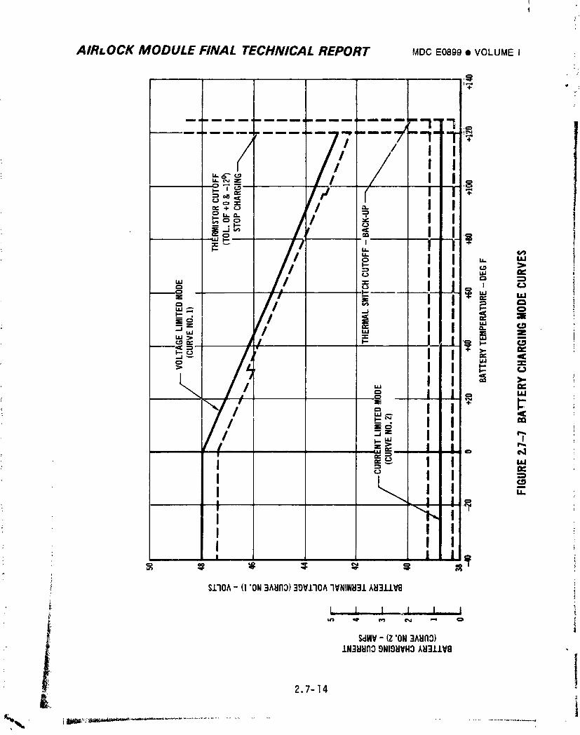
AIRLOCK MODULE FINAL TECHNICAL REPORT MDC E0899 • VOLUME I :L.
•. {/,/ i i_
I ?_'Tm I/=._ I i I/'-'=_ I I I/,_,,+_ '--_oo / I I/|J_ J'
/,, !I I >
L I i '_ _ ,I I o ,
; I I . _ i
--_-m- / ; =d:,- /' I I =21.; "=-=i i _=I I
' ==_ii = =": I c
' II I I
; , I I
,_ S170A- (I "ON3A_t113)30VlTOA7VNINH31AH311V8
J_ L I I I I I
i" SdViV-(Z"ON":iA_llO)
i 1N:IHHn39NIOHVH3,_i3.LIV9 " I2.7-14
x J
] 9740] 8208-410
I
... t
AIRLOCK MODULE FINAL TECHNICAL REPORT MDCEo89g• VOLUMEI
• charging to the constant current mode. This included overriding of
the Charge Mode control. The Charge Disable Control (DCS only),
when set to the cut off position caused the battery charger to
maintain the battery charging current at zero +0.5 amperes. The
positive power connection from the battery to -_'0e battery chargLr
could be opened by positioning the "Batteries" switch (manual or DCS)
to the "Off" position. This condition was _ensed by the battery
charger as a complete loss of the battery voltage signal. The
battery charger voltage, then applied only to the voltage regulator,
was controlled at 52 +l volt for this condition.
There were four different operational conditions arising from varying
levels of available solar array power. The condition where solar
array power was sufficient to supply both the equipment load and the
battery load has previously been described. Under the condition
where the available power was sufficient to supply equipment It_ds,
but not sufficient to supply the total of equipment and battery
loads, the charger output voltage was reduced such that _ne equip-
ment load was satisfied and the remaining available power was
utilized for charging the battery. When the available array power
was not sufficient to supply the equipment load alone, the charger
output voltage was reduced further until the battery and battery
cllargerin parallel could supply the equipment load. When the
solar array voltage became less than approximately 51 volts at
the AM/OWS interface, the battery charger was switched off and
equipment loads were totally supplied from the battery. The latter
condition included the normal operation during orbital dark periods.
B. Voltage Regulator - The detailed performance characteristics of an
ii individual voltage regulator were specified in McDonnell Procurement
_: Specification 61B76go0_. Physically, each regulator weighed 14 Ibs
with dimensions of 4.3" x IO" x I0.85" and required coldplate mounting.
_ Eight voltage regulators were included in the AM EPS, one in each PCG.The function of the voltage regulator was to furnish regulated DC power,
within specified voltage limits, to the AM REG buses and the EPS Control
- buses.
' l 2.7-15
1974018208-411
AIRLOCK MODULE FINAL TECHNICAL REPORT MDCE0899• VOLUMEI
Each voltageregulatorreceivedinput powerfromone of foursources,
the nickel-cadmiumbattery,the batterycharger,the batteryand battery
chargeroperatingin parallel,or the associatedsolararray group. The
inputvoltagelevelvariedaccordingto the outputcharacteristicsof
these sources. The batterysuppliedpowerwithinan approximatevoltage
rangeof 30 to 40 volts,dependingon b_tterySOC and batterytemperature.
For the parallelbatteryand batterychargeroperation,the voltage
variedfrom approximately35 voitsto 46 volts,dependingon the amount
of sharingand on batterySOC. The aboveconditionsare discussedin
detailin the descriptionsof the batterychargerand battery. In a
contingencymode of operationpower couldbe supplieddirectlyfromthe
solararraygroupoutputto the voltageregulatorinputby positioning
the Chargerswitchto its Bypassposition. F_ this case,the input
voltageto the regulatorwould b_ approximately51 voltsminimumto
125 voltsmaximum.
The voltageregulatorprovidedspecifiedvoltagelevelsat the AM REG bus
for inputvoltagesfrom 32 to 125 volts. For inputvoltagesless than
32 volts,the regulatorprovidedthe specifiedbus voltagelevelor the
inputvoltagelevelminus approximatelytwo volts,whicheverwas lower.
Each voltag_regulatorbasicallyconsistedof fivepowermodulesand an
inputfilter,as shownon Figure2.7-8. The multiplenumberof power
moduleswas includedin the designfor improvedsystemreliability,Each
powe',-modulewas a pulsewidth modulatedtype regulatorwhere the output
voltagewas lessthan the inputvoltageat all times. The powermodule
_ was designedto providehigh efficiencyoperationeven at low load
conditions.
Figure2.7-9showsthe outputcharacteristicor V-I curve for an individual
voltageregulatorusingnominalvaluesfor the definingparameters. For
the AM EPS voltageregulators,the slope factorhas a value of
0.04_ 0.002volt per a_ipere.
The no-loadvoltagefor each reoulatorwas crew adjustableonly by means
of two EPS manualcontrolpotentiometers:a Reg Bus, and a fine adjust
i potentiometer.Eachof thesepotentiometerswas connecteddirectly_'_ 2.7-16
1974018208-412
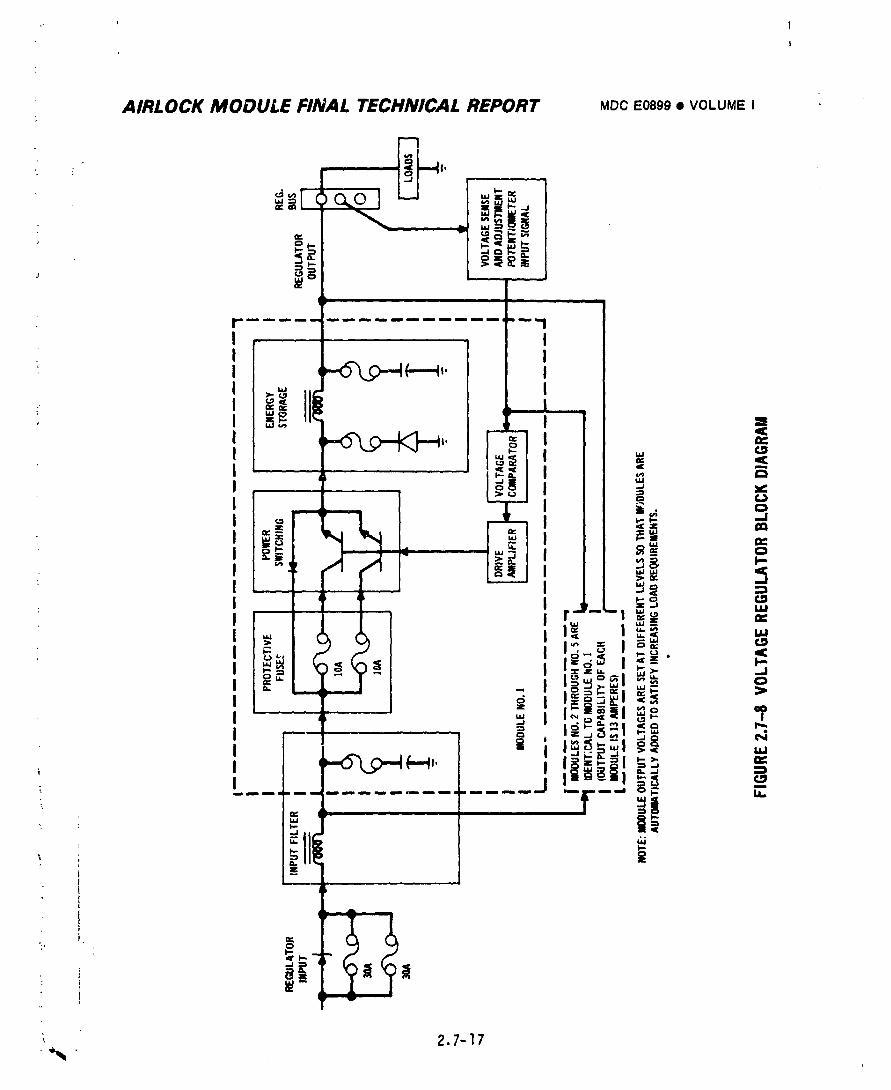
I
1974018208-413
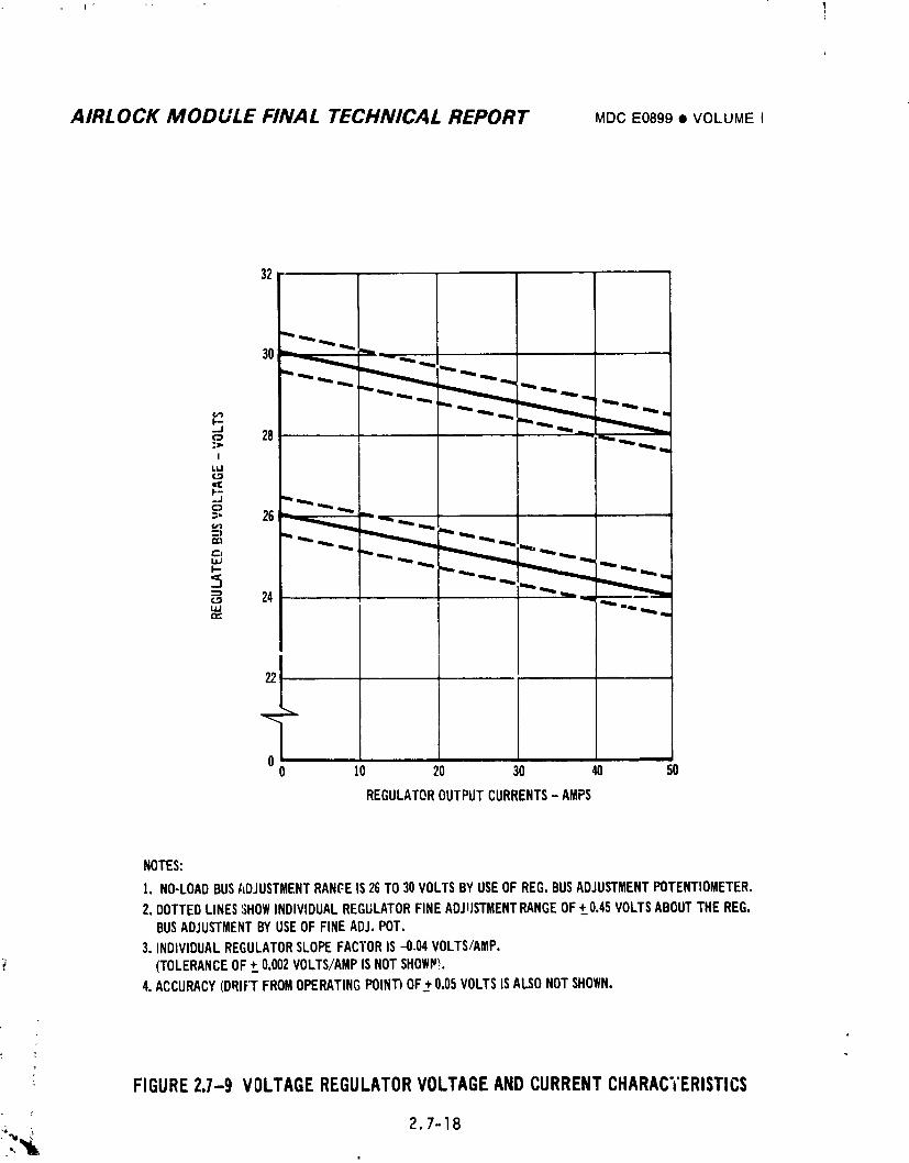
I"
AIRLOCK MODULE FINAL TECHNICAL REPORT MDCEO899• VOLUMEI
22
00 10 20 30 40 50
REGULATOROUTPUTCURRENTS- AMPS
NOTES:
1. NO-LOADBUSADJUSTMENTRANC-EIS26TO30VOLTSBYUSEOFREG,BUSADJUSTMENTPOTENTIOMETER,2. DOTTEDLINES:;HOWINDIVIDUALREGULATORFINEADJUSTMENTRANGEOF+_.0.45VOLTSABOUTTHEREG.
BUSADJUSTMENTBYUSEOFFINEADJ.POT.3. INDIVIDUALREGULATORSLOPEFACTORIS-0,04VOLTS/AMP.
(TOLERANCEOF+_.0.002VOLTS/AMPISNOTSHOWP!.4.ACCURACY(DRIFTFROMOPERATINGPOINT)OF+0.05VOLTSISALSONOTSHOWN.
FIGURE2.7-9 VOLTAGEREGULATORVOLTAGEANDCURRENTCHARACTERISTICS
._, _ 2,7-18
1974018208-414
AIRLOCK MODULE FINAL TECHNICAL REPORT MDCE0899• VOLUMEI
across the Reg bus and furnished a signal to the vo3tage regulator.
There were two Reg bus potentiometers,one for each of the two Reg buses
in the AM EPS. Each Reg bus potentiometer _vashard wired to its Reg bus.
but its control signal was switched to each of the voltcce regulators
supplying power to that Reg bus. It, therefore, simultaneously adjusted
the outputs of a jroup of regulators in order to adjust the Reg bus
voltage level. The no-load adjustment voltage range provided by the Reg
bus potentiometerwas from 26 to 30 volts.
There were eight Fine Adjust potentiometers in the AM EPS, one for each
of the eight voltage regulators. The adjustment range associated with a
Fine Adjust pot. was _0.45 volts with respect to the voltage level set
by the appropriate Reg bus pot. The purpose of the Fine Adjust potenti-
ometers was to provide an individual regulator adjustment to allow cortrol
of load sharing among regulators connected to a common Reg Bus.
In addition to the above parameters which affect the output V-I curve,
the regulator output had an allowable drift of +_0.05volt under conditions
of constant loading within the allowable output current range.
The output current range for voltage regulator specification performance
was from 0 to 50 amperes. The voltage regulator automatlcally limited
its output current to a maximum of 65 _3 amperes, regardless of loading
conditions. A typical curve for the voltage regulator characteristic
from no-load to short circuit is shown on Figure 2.7-I0. Fiqure 2.7-I0
also shows the allowable Voc, I max, and Isc tolerance bands.
For c'Jrrentloads in excess of 50 amperes the regulator was not required
to maintain specified voltage performance. The regulator was, however,
capable of operating continuously under any load condition without sus-
taining damage and was capable of providing specified performance upon
removal of any excess current loading condition.
In a special mode of operation, the output of the voltage regulator was
reduced by 2 volts upon receipt of a signal from its associated battery
' charger. This signal was the 30% battery SOC signal previously described
in the battery charger description, l'heeffect of the 2 volt reduction
2 "-19
i974018208-415
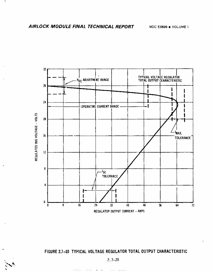
AIRLOCK MODULE FINAL TECHNICAL REPORT MDCE0899• VOLUME I
32
.... TYPICALVOLTAGEREGULATOR
j,.,r-Voc ADJUSTMENTRANGE TOTALOUTPUTC_;ARACTERISTIC28 - I
- -'-" "_" _-- _ II I I
.... '.,.,Io 20 => J _i
' / /, All.o 16 .....> TOLERANCE
"' /p-
_ 12._1
8 •
/--_sc //
0 ! |0 16 24 32 40 48 56 64 72
REGULATOROUTPUTCURRENT- AMPS
FIGURE2.7-10 TYPICALVOLTAGEREGULATORTOTALOUTPUTCHARACTERISTIC
,..,, _ 2,7-20
-i,,j ........ _ ..........
1974018208-416
AIRLOCK MODULE FINAL TECHNICAL REPORT MDCE0899• VOLUMEI
was L_,lL_aliy unioad one regulator as pr__viuu_iy d,_u_u. Upon
remov,'l ,,f the signal from the battery _harger, the voltage regulator
autpuL r_se 2 volts to its original voltage level of operation.
C. Batte"y - 1he AM EPS batteries were nickel-cadmium batteries designed
for act_w cooling. Detail requirements aqd characteristics were specified
in HcDonnell Procurement Specification 61B769004.
(i) Function - The function of the batteries was to furnish power to
equipment loads through the AM EPS voltage regulators during
orbital dark periods when there was no power available from the solar
array system and to furnish supplemental power during periods when
the power available from the solar array was insufficient to satisfy
the total equipment load requirement. Battery capacity was
33 amp-hrs based on 120°F temp and 18 amp discharge rate to 30V. i
Average flight discl,argevoltane was 38V. Specified cycle life was
4000 cycles at approximately 25% depth of discharge.
(2) Recharge - The batteries were recharged whenever"array power
greater than the bus load requirement was available. The charge
potential applied to the battery during the initial phase of
recharging was limited to a level consistent with n,aintaining peak
solar array power utilization. The recharge potential necessary to
maintain peak solar array power utilization increased as the bat-
teries approached completion of recharge. This phase of recharge
was tenninated when a potential limit consistent with battery
temperature was imposed by the battery charger. Full utilization
of the array power was no longer accomplished during the constant
potential charge mode which continued until sucI_ time as the
ampere-hour meter within the charger indicated sufficient recharge
had been accomplished. Upon generation of such an indication the
chamler switched to a low level (0.75 +_0.5 ampere), constant current
charge mode for the remainder of the charging period.
(3) Construction - Each of the eight AM EPS batteries consisted of 30
series connected cells and associated temperature sensing devices
packaged in a 7" x 8.25" x 27.25" aluminum container, and weighed
123 Ibs.
2.7-21
1974018208-417
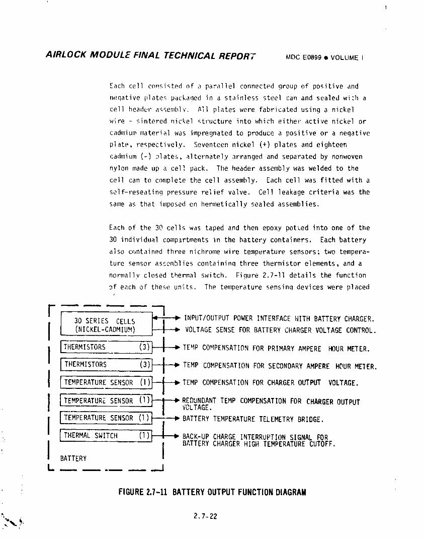
AIRLOCK MODULE FINAL TECHNICAL REPORT MDCE0899• VOLUMEI
Each cell c(msi_ted of a parallel connected group of positive and
neqative plates packaqed in a stainless steel can and sealed wizh a
cell header a_semblv. All plates were fabricated using a nickel
wire - sintered nickel _tructure into which either active nickel or
cadmium material was impregnated to produce a positive or a negative
plate, respectively. Seventeen nickel (+) plates and eighteen
cadmium (-) _lates, alternately arranged and separated by nonwoven
nylon made up a cell pack. The header assembly was welded to the
cell can to complete the cell assembly. Each cell was fitted with a
self-reseating pressure relief valve. Cell leakage criteria was the
same as that imposed en hermetically sealed assemblies.
Each of the 30 cells was taped and then epoxy potted into one of the
30 individual comp_rtments in the battery containers. Each battery
also cf, ntained three nichrome wire temperature sensors; two tempera-
ture sensor assemblies containinq three thermistor elements, and a
normally closed thermal switch. Figure 2.7-11 details the function
_f each oF these units. The temperature sensinq devices were placed
F m m I m
30 SERIES CELLS INPUT/OUTPUTPOWERINTERFACEWITH BATTERYCHARGER.I
I (,Ic E,-CAD,Iu,./ VOLTAGEFOR,A'f E YCHARGERVO,TAGCONTROL.I
ITHERMISTORS (3)_ TEMP COMPENSATIONFOR PRIMARYAMPERE HOURMETER.I I 1 I _I THERMISTORS (3)_--i--P TEMP COMPENSATIONFORSECONDARYAMPERE HOURMEIER.
BATTERY
L ..... ._J
FIGURE2.7-11 BATTERYOUTPUTFUNCTIONDIAGRAM
" 2,7-22
i
1974018208-418
AIRLOCK MODULE FINAL TECHNICAL REPORT MDCE0899• VOLUMEI
such that the top of cell case te_erature was monitored rather than
terminal or cell interconnect temperatures to minimize or preclude
terminal and/or cell interconnect 12R heating effects. Ihe containt_,"
was compartnmntalizedto provide heat transfer from five surfaces
of each cell to the container coldplate mounting surface. Onc,elec
trical connector was provided for power transfer"and charge control
circuits and another for ground access to individual cell voltages.
The battery container also contained a pressure relief valve.
2.7.2.3 Power Distribution Syste_
The AH Power Distribution Syster;received power from the AH Power Conditioning
_reups _ the AH Reg buses. Power was distributed from the AH Reg buses to the OWS
buses for OW.Sloads; to the AH buses for AM, MDA, and certain OWS loads; and t(_the
AH tr._.nsferbuses for CSH loads. Transfer of power to the CSM buses utilized an
umbilical cable across the MDA/CSM interface which was connected hy the crew for
each manned mission phase. The AM transfer buses also supplied power to, (,
accepted power from, the ATM for parallel operation of the AH and the AT,_ power
systems in order to share all orbital vehicle loads.
The AM Power Distribution System utilized two separate isolated DC bus syste,_.
These systems were two wire systems with the exceptions that the ,qWSb'Jses,the ATH
buses, and the CSM buses utilized a co,r_nonreturn bus system. T_:eneqative return
bus system was connected to vehicle structure at one point only, either the sinqle
point ground (SPG) in the ALlor the vehicle ground point (VGP) in the CSH.
Figure 2.7-12 is a simplified power bus system diagram which shows the intra-
connections between buses in the AM and their interconnectionswith buses in other
n_dules. All loads throughout the Skylab were powered from one of the Buses shown
on Fiqure 2.7-12. Circuit breakers utilized by the AM Power Distribution System
were located on STS Circuit Breaker Panels 201 and 202. The on-board controls and
monitors for the AH Power Distribution System were located on STS Control Panels
; 205 and 206, with three exceptions: the AM transfer bus to the CSM bus inter-
connections were independentlycontrolled from the CSM; the ON-OFF controls for"/ :
the AH EREP buses were controlled from the ATM C&D Panel in the HDA; and the At!
_. transfer bus to the ATM bus interconnectionscould also be opened in case of
emergency by the ATM Power Off switch located on the ATM C&D Panel in the MDA.i
• 2.7-23
i974018208-419
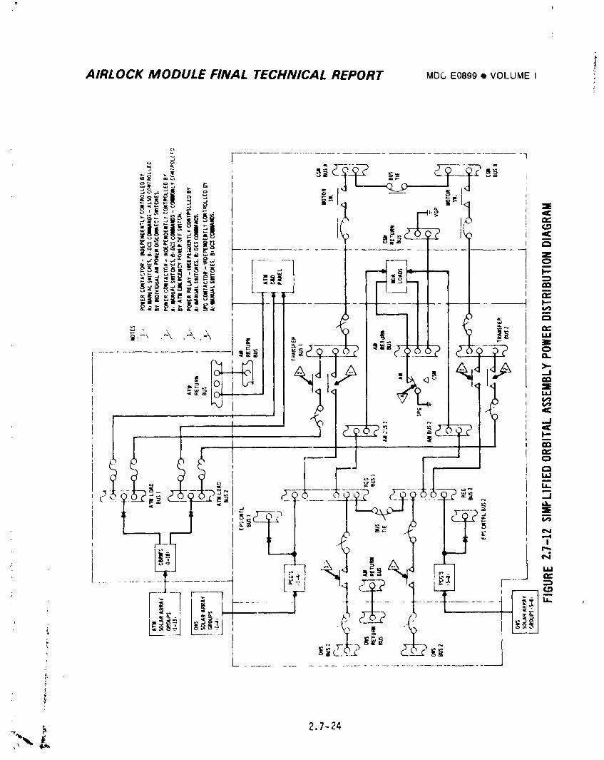
AIRLOCK MODULE FINAL TECHNICAL REPORT MDC E0899 • VOLUME I '-
2.7-24
1974018208-420
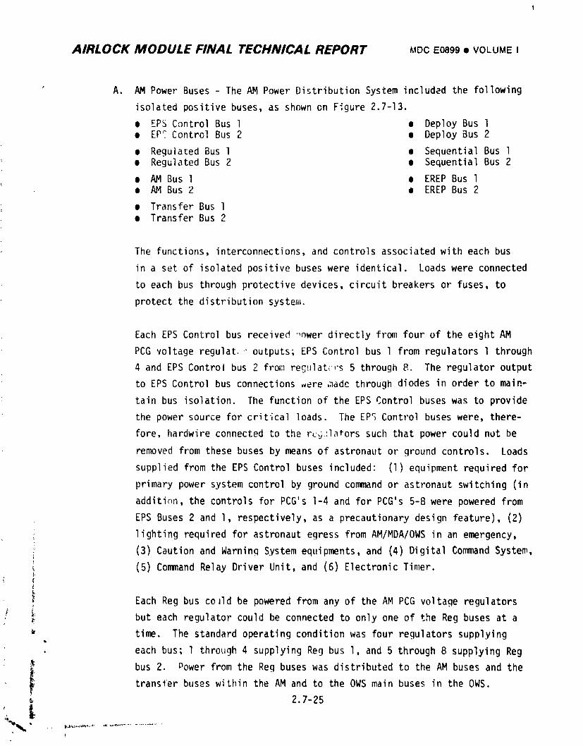
AIRLOCK MODULE FINAL TECHNICAL REPORT MDCE0899• VOLUMEI
A. AM Power Buses - The AM Power Distribution System included the following
isolated positive buses, as shown on Figure 2.7-13.
e EPS Control Bus l • Deploy Bus l• EPC Control Bus 2 • Deploy Bus 2
• ReguJated Bus l • Sequential Bus lm Regulated Bus 2 e Sequential Bus 2
• AM Bus l • EREP Bus l• AM Bus 2 • EREP Bus 2
• Transfer Bus I• Transfer Bus 2
The functions, interconnections,and controls associated with each bus
in a set of isolated positive buses were identical. Loads were connected
to each bus through protective devices, circuit breakers or fuses, to
protect the distribution syste_.
Each EPS Control bus received ,_wer directly from four of the eight AM
PCG voltage regular," outputs; EPS Control bus l from regulators l through
4 and EPS Control bus 2 from reg,_lat_-,'s5 through 8. The regulator output
to EPS Control bus connections ,ere ,;ladethrough diodes in order to main-
tain bus isolation. The function of the EPS Control buses was to provide
the power source for critical loads. The EPS Control buses were, there-
fore, hardwire connected to the r_.]:latorssucllthat power could not be
removed from these buses by means of astronaut or ground controls. Loads
supplied from the EPS Control buses included: (1) equipment required for
primary power system control by ground command or astronaut switching (in
additi_1, the controls for PCG's I-4 and for PCG's 5-8 were powered from
EPS Buses 2 and l, respectively, as a precautionary design feature), (2)
lighting required for astronaut egress from AM/MDA/OWS in an emergency,
[ (3) Caution and Warning System equipments, and (4) Digital Command System,
(5) Command Relay Driver Unit, and (6) Electronic Timer.
Each Reg bus co Jld be powered from any of the AM PCG voltage regulators
. _ but each regulator could be connected to only one of the Reg buses at a
time. The standard operating condition was four regulators supplying
• each bus; l through 4 supplying Reg bus l, and 5 through 8 supplying Reg
• _ bus 2. Dower from the Reg buses was distributed to the AM buses and thetransler buses within the AM and to the OWS main buses in the OWS.
2.7-25
'%%, , ..........................t
1974018208-421
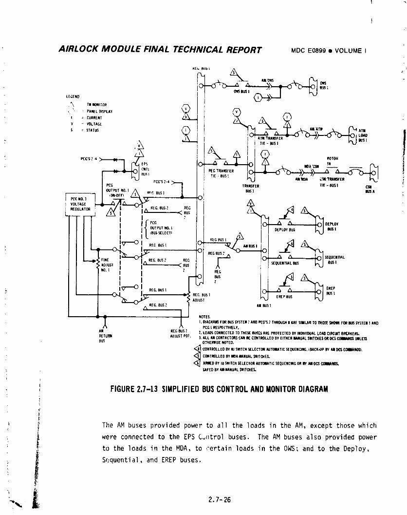
AIRLOCK MODULE FINAL TECHNICAL REPORT MDCE0899• VOLUMEI
t_EbBU_I
B_ 1BU
I|GEND
', " PANELDISPLAY Vt = CURRENT v
Y VOLTAG[
s s,,,us ]_ x ^ "CJ_>";',_'_ __ l
ATI_',,--
I TIE- BUSI
=PCG'S?4 _:_'"1 MOTOR =
v BOA _ SW
I " -- 1-_ I_J'. REG IRANSFER ))TIE BUS!
IP_° PCG'S.,_,>_!,HEu_ ,,,_ _.', ,
TRANSFER TIE- BUSI C311
I oE__BUSIOUTPUTNO.I BUSI BUSA .qON-OFF_ L_ O]PCGNO.I |
REGULATOR REG BUS?
l /S_l
OUTPUTNO.I DEPLOYBUS BUSII tBUSSELECT'_I
_, /% REG.BUS? REG C)_ /% "/% SEQUENII_L' i ADJUST -_ BUS SEQUENTIALBUS_ BUS|
NO.I
E %F C BUSj-
1. _ REG.BUSI _ _ 1% EREP
0__ : rec,BUSt EREPBUS BUS!ADJUST
_, REG.BUS," AMBUSt
1 NOTES.|. D_AGRAJI$FORBUSSYSTEM."ANDPCG'S2 Ti4_UGHI ARE9MILARTOniObE SHOWNFORBUSSYSTEMI AND
PCG| RESPECTIVELY.
AM REGBUS? 2. LOAOSCONNECTEDTOTHESEBUSESAREPROTECTEDBYINDIVIBUALLOADCIRCUITBREAKERS.RETURN ADJUSTPOT. 3. ALLAMCONTACTORSCANBECONTROLLEOBYEITHERMANUALSWITCHESORI)CS_DS UNLESSBUS OTHERNISENOTED.
_ CONTROLLEDBYIU SWITCHSELECTORAUTOIMTICSEQUENCING.IMACK.UPBYAllOC$COIINANO_').
CORTROLLEDBYBOAMANUALSMITO4ES.
AMI[O BYiU SWITCHSELECTORAUTOMATICSEQUENCINGORBYMI DCSCOMMANDS.
,?dkFEOBYAMMANUALSIlITCHES.
(
; FIGURE2.7-13 SIMPLIFIEDBUSCONTROLANDMONITORDIAGRAM
f_
f The AM buses provided power to all the loads in the AM, except those which
" l were connected to the EPS C_ntrol buses. The AM buses also providea powerto the loads in the MDA, to certain loads in the OWS; and to the Deploy,
:, il Sequential, and EREP buses.
"_ 2.l-26
19740] 8208-422
I
i AIRLOCK MODULE FINAL TECHNICAL REPORT MDCE0899• VOLU.E I
" The sequential buses provided the power required for payload shroud!
jettison, OWS radiator shield jettison, and ATM deployment. The deploy
buses provided the power required for antenna, OWS solar array, OWS
meteoroid bumper, and ATM solar array deployments. The deplcy andt
sequential buses were disabled after the sequential portions of the SL-1
mission for purposes of safety.
: The transfer Euses provided the electrical power interface between the AM,
ATM and CSM. Bidirectional power transfer between the AM EPS and the ATM
EPS could be accomplished by connecting both the AM Keg buses and the ATM
load buses to the transfer buses. The CSM, when p_rt of the cluster, also
had its power system normally connected to the transfer buses, as shown
in Figure 2.7-12. Power for the CSM could, therefore, be supplied by
either the AM or ATM EPS or by the parallel combination of the two EPS
systems.
The EREP buses, located in the AM, provided power to the Earth Resources
Experiments which were primarily located in the MDA.
B. Bus Control Functions - A simplified schematic of the controls associated
with the positive power bus system is shown on Figure 2.7-13. For pur-
poses of brevity and clarity, only the circuitry and components necessary
to explain the control logic for the output of one AM voltage regular:or
and for one of the two independent bus systems, System No. l, are shown
on the diagram, The circuitry and components for the other seven
regulator outpJts and for System No. 2 were similar in function and were
related as indicated on the diagram. The power return bus system has
also been omitted in the interest o_ clarity.
i The output of each voltage regulator was connected, through an isolation
i iode, to one of the EPS Control buses. There were purposely no controlsassociated with this power connection in order to ensure that the con-
i nection could not inadvertently be opened. This ensured a continuous• . power source to the critical loads connected to the EPS Control buses.
' , Each EPS Control bus was supplied from a specific set of four voltage
_ regulators.
2.7-27
i
1974018208-423
AIRLOCK MODULE FINAL TECHNICAL REPORT MDCE089'=9• VOLUMEI
The output of each voltage regulator could also be connected to either of
the two Reg buses by means of two controls. The PCG Output Bus Select
control connected the output to either Reg bus l or to Reg bus 2 when
the PCG Output On-Off control was in the On position. The Off position
of the PCG Output On-Off control isolated the regulator output from
either of the Reg buses.
The functions of the following controls were straightforwardand as shown
on Figure 2.7-13; OWS Bus l, Reg/Transfer Tie-Bus l, ATM/Transfer
Tie-bus l, and AM bus I. One feature to be observed was that a single
Reg bus could supply power to both AM buses by means of the AM bus l
and AM bus 2 switches.
All of the control functions described in this section so far, with the
exception of the adjustment pots, were controllable either by astronaut
manual switching or by ground control commands. Inflight control of the
EPS by the various astronaut manual switcileswas obtained when the Power
System Control switch was placed in Manual position. When the switch was
in the CMD (Command) position, control was possible only from the ground
by ineansof AM DCS commands.
There were, however, several controls which were not controlled by the
Power System Control Switch. The Power Disconnect switches l and 2 were
for emergency power down of Reg buses l and 2, respectively. They were
operational at all times by crew action only. Power Disconnect switch
#1, when thrown to its Off position, disconnected the outputs of PCG's
, I-4 and disconnected Transfer bus #1 from Reg bus #1. Power Disconnect
switch #2, when thrown to its Off position, disconnected th_ outputs of
PCG's 5-8 and disconnected Transfer bus #2 from Reg bus #2. The ELEC GND
switch, which controlled the location of the single point ground, was
• also independent of the Power System Control switch position. The con-
nections between the Transfer buses and the CSM buses were controlled
from the CSM and were independent of the AM Power System Control. The
connections between the ATM buses and the AM Transfer buses could also be
opened in an emergency by an ATM Power Off swltch on the ATM C&D panel
2.7-28
1974018208-424
AIRLOCK MODULE FINAL TECHNICAL REPORT MDCE0899e VOLUMEI
which was independent of the AM Power System Control switch. The con-
nections _,etweenthe AM buses and the Sequential and Deploy buses were
normally controlled automatically by the Sequential and Deploy systems,
respectiwly. There were Sequential and Deploy switches on the STS
panel to provide backup control for these buses.
In addition to the control logic functions discussed above, the Reg Bus
Tie circuit breakers between Reg bus l and Reg bus 2 could also be COh-
sidered as part of the control logic. By manual crew control of these
two 26.4 amp circuit breakers, the two Reg buses could be operated in
parallel. Parallel operation could be used to reduce the effects of
unbalanced Systems l and 2 load demands or unbalanced Systems l and 2
power availability. The normal operating mode was with the Reg Bus tie
circuit breakers closed.
C. Power Return and Grounding - The electrical power distribution system,
as previously discussed, consisted of a two wire system employing
separate buses for both power feeders and negative returns. The return
buses were tied to vehicle structure at only one point. This connection
to vehicle structure was accomplished in one of two locations. During
periods when the CSM/MDA interface connectors were not mated, the grounding
was via the SPG in the AM. During periods when the CSM was part of the OA
with the CSM/MDA interface connectors mated, grounding was via the VGP
in the CSM structure. The connection to the VGP in the CSH was automatic
when the CSM/MDA interface connectors were mated. The control switching
in the AM was used to connect and disconnect the SPG in the AM. This is
shown on Figure 2.7-12. Control of the SPG connection in the AM was by
either crew manual operation or by DCS con111andat all times.
D. Power Feeder Design and Protection - The power feeder lines hetv_eenthe
various power and return buses consisted of multiple numbers of wires
'_ which were selected both for current carryinq capacity and voltage drop
il requirements. As shown on Figure 2.7-13, circuit breakers were
' _ incorporated in the positive feeder lines between buses located in dif-
• i ferent Skylab modules, with a separate set of breakers located in each
' _ of the modules. In addition to these circuit breakers, adequate circuit
• protection was incorporated into power distribution circuitry to all
i'
• 2.7- 29L
1974018208-425
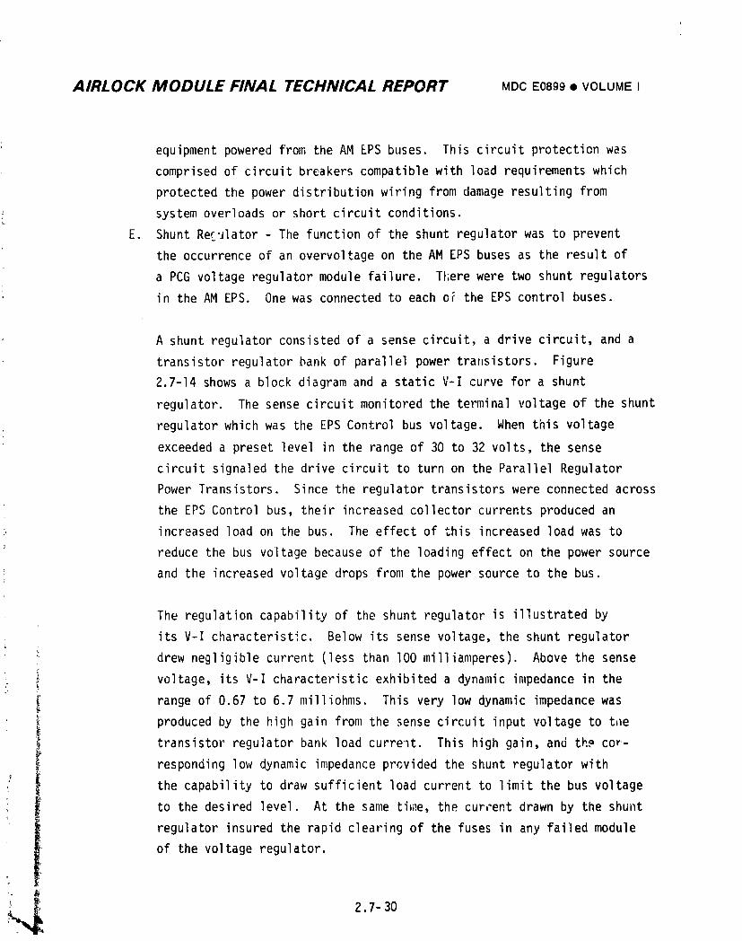
AIRLOCK MODULE FINAL TECHNICAL REPORT MD¢E0899• VOLUMEI
equipment powered from the AM EPS buses. This circuit protection was
comprised of circuit breakers compatible with load requirements which
protected the power distribution wiring from damage resulting from
system overloads or short circuit conditions.
E. Shunt Reculator - The function of the shunt regulator was to prevent
the occurrence of an overvoltage on the AM EPS buses as the result of
a PCG voltage regulator module failure. There were two shunt regulators
in the AM EPS. One was connected to each oF the EPS control buses.
A shunt regulator consisted of a sense circuit, a drive circuit, and a
transistor regulator bank of parallel power transistors. Figure
2.7-14 shows a block diagram and a static V-I curve for a shunt
regulator. The sense circuit monitored the terminal voltage of the shunt
regulator which was the EPS Control bus voltage. When this voltage
exceeded a preset level in the range of 30 to 32 volts, the sense
circuit signaled the drive circuit to turn on the Parallel Regulator
Power Transistors. Since the regulator transistors were connected across
the EPS Control bus, their increased collector currents produced an
increased load on the bus. The effect of this increased load was to
reduce the bus voltage because of the loading effect on the power source
and the increased voltage drops from the power source to the bus.
The regulation capability of the shunt regulator is illustrated by
its V-I characteristic. Below its sense voltage, the shunt regulator
_ drew negligible current (less than lO0 milliamperes). Above the sense
_ _ voltage, its V-I characteristic exhibited a dynamic impedance in the
range of 0.67 to 6.7 milliohms. This very low dynamic impedance was
i produced by the high gain from the sense circuit input voltage to thetransistor regulator bank load current. This high gain, and the cor-
responding low dynamic impedance prGvided the shunt regulatoY with
the capability to draw sufficient load current to limit the bus voltage
to the desired level. At the same tiD_e,the current drawn by the shunt
regulator insured the rapid clearing of the fuses in any failed module
of the voltage regulator.
2,7l 30
1974018208-426
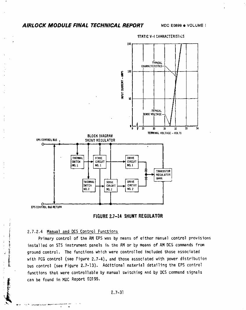
AIRLOCK MODULE FINAL TECHNICAL REPORT MDCE0899• VOLUMEI
STATICV-I CHARACTERISTICS
ITYPICAL
CHARACTERISTICS-\
][ 1® \I
B
!r 'PICAL /
'-J_ SENSEVOLTAGE--_/0 29 30 31 32 33 34
TERMINALVOLTAGE- VOLTSBLOCKDIAGRAM
EPSCONTROLBUS I SHUNTREGULATORO----'- ---_
O------EPSCONTROLBUSRETURN
FIGURE2.7-14 SHUNTREGULATOR
2.7.2.4 Manual and DCS Control Functions
! Primary control of the AM EPS was by means of either manual control provisions
_. installed on STS instrument panels it,the AM or by means of AM DCS commands from
j _ ground control. The functions which were controlled included those associated
f with PCG control (see Figure 2.7-4), and those associated with power distribution[ bus control (see Figure 2.7-13). Additional material detailing the EPS control
functions that were controllable by manual switching and by DCS command signals
: _ can be found in MDC Report E0195.
•, 2.7-31
l
1974018208-427
AIRLOCK MODULE FINAL TECHNICAL REPORT MDCE0899• VOLUMEI
2.7.2.5 Display and Telemetry Parameters
A number of AM EPS analog parameters were displayed on meters installed on
the STS instrument panel in the AM. These parameters were displayed to indicate
instantaneous power system status to the astronauts and to assist the astronauts
in their manual management of the system. A greater number of parameters were
monitored and transmitted by means of telemetry to ground control to aid in
ground control analysis and management of the EPS. The status of certain EPS
control functions was monitored by means of bi-level signals which were trans-
mitted by telemetry to ground control. These signals also aided ground control
in their analysis and management of the AM EPS. More detailed information can be
found in Report MDCE0195. Figures 2.7-4 and 2.7-13 show the schematic
locations of the display and telemetry points associated with the PCG's and the
power distribution system respectively.
2.7.2.6 System Operation and Performance
The AM EPS was a complex and flexible electrical power conditioning and
distribution system as a result of its many capabilities and controls. Most
of this flexibility, particularly in the PCG area, was not required for normal
mission operations. It was associated with maintaining the highest possible
level of system performance and reliability in the event of any possible
malfunction in system equipment.
This section describes the normal modes of operation and defines performance
characteristics. Performance under secondary or contingency modes would only
be a modification of that described in this section and could be determineJ
based on this section and the information throughout Section 2.7.2.
A. Power Capabilities - There were two power capabilities which were
pertinent to evaluating the AM EPS mission performance. These were
the solar inertial (SI) and nonsolar inertial power capabilities.
The solar inertial refers to the continuous power capability of the
EPS while the Skylab vehicle orbited in the solar inertial attitude.
The nonsolar inertial refers to the power capability on a per orbit
basis for orbits where the solar inertial attitude was not maintained
over the entire orbit. There were two types of nonsolar inertial
attitude orbits for the Skylab mission. These were the Z-Local
, 2,7-32
I
=
1974018208-428
AIRLOCK MODULE FINAL TECHNICAL REPORT MD_,E0899• VCLUME:
Vertical (Z-LV) orbits performed for Edrth Resources Experiment Package
(EREP' oLerations and the rendezvous orbits performed for docking and
undoc_inq of the CSM. The following sections define ar,d explain each of
these capabilities for an individual PCGand then explain the comblr.ing
of the in_ividual PCGcapabilities into an overall _M Reg Bus power
capability.
(I) PCGSolar Inertial Capabi!it] - The SI po_ r capability is defined
as the constant load supplied to the Reg Bus at which the PCG
battery became fully recharged (a 100% SOCamp-J,our meter indication)
coincident with the end of the daylight charging period.
Orbital parameters affected the solar array power input to the PCG.
The operational characteristics of the PCGequipments affected
how much of the input power could be delivered to the loads. In
the solar inertial attitude mode, the plane of the arrays was
maintained perpendicular to the sun's rays, resulting in constant
maximum array output power. The vehicle altitude determined the
length of an orbit period. The Beta angle, which is the angle
between the sun-line and the orbit plane, determines the length of
the dark and daylight portions of each orbit period. The
specified average solar array power available to at,
individual PCGduring a Beta = 0° SI orbit daylight period was
!312 watts. The Beta : 0° SI orbit will be used throughout this
discussion as the basis for a representative numerical value
analysis. The length of the daylight period, chef,fore, determined
the total amount o_ solar array energy available, and also the
amount of time available to recharge the battery. The length of
the dark period, on the other hand, determined the length of time
the batLery had to supply power to the bus and this fixed the
total energy removed from the battery.
The PCGequipments whose operational characteristics affected the
PCGoutput power capability were the battery, the battery charger,
and the voltage regulator. The recharge characteristics of the
battery determined how much energy could be returned to the battery
during a daylight period. These characteristics were dependent on
2.7-33
J
i 9740i 8208-429
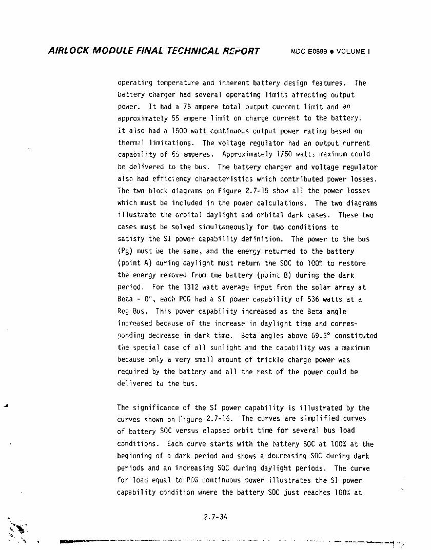
AIRLOCK MODULE FINAL TECHNICAL REPORT MDCE0899• VOLUMEI
operatiPg temperatureand inherent battery design features. The
battery ci_argerhad several operating limits affecting output
power. It had a 75 ampere total output current limit and an
approximately55 ampere limit on charge current to the batteFy.
it also had a 1500 watt coatinuo_s output power rating based on
thermal limitations. The voltage regulator had an output rurrent
capability of 65 amperes. Approximately 1750 watt_ maximum could
be delivered to the bus. The battery charger and voltage regulator
also had efficiency characteristicswhich contributed power losses.
The two block diagrams on Figdre 2.7-15 show all the power losse_
which must be included in the power calculations. The two diagrams
illustrate the orbital daylight and orbital dark cases. These two
cases must be solved simultaneouslyfor two conditions to
satisfy the SI power capability definition. The power to the bus
(PB) must be the same, and the energy returned to the battery
(point A) during daylight must returr,the SOC to I00% to restore
the energy removed from the battery (point B) during the dark
period. For the 1312 watt average input from the solar array at
Beta = 0°, each PCG had a SI power capability of 536 watts at a
Reg Bus. This power capability increased as the Beta angle
increased because of the increase in daylight time and corres-
9onding decrease in dark time. Beta angles above 69.5° constituted
the special case of all sunlight and the capability was a maximum
because only a very small amount of trickle charge power was
required by the battery and all the rest of the power could be
delivered to the bus.
The significanceof the SI power capability is illustrated by the
curves shown on Figure 2.7-16. The curves are simplified curves
of battery SOC versus elapsed orbit time for several bus load
conditions. Each curve starts with the battery SOC at I00% at the
beginning of a dark period and shows a decreasing SOC during dark
periods and an increasing SOC during daylight periods. The curve
for load equal to PCG continuous power illustrates the SI power
capability condition where the battery SOC just reaches I00% at
, 2.7-34
L_
1974018208-4:30
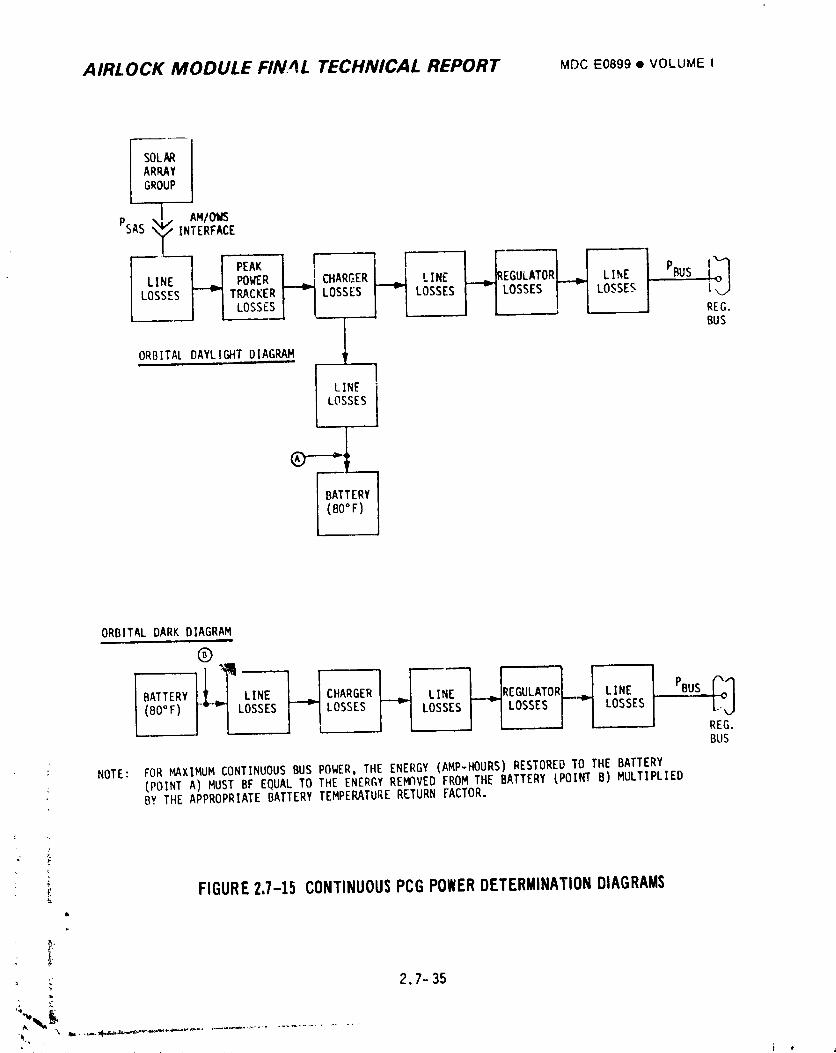
AIRLOCK MODULE FIN4L TECHNICAL REPORT MDCE0899• VOLUMEI
SOLARARRAYGROUP
X_ AM/OWS
PSAS INTERFACE
LOSSES 1 _ ! 1. REG.I BUS
ORBITALDAYLIGHTDIAGRM4 _I&
I iLINELOSSES
ORBITALDARK DIAGRAM
@
BATTERY LINE CHARGER LINE REGULATOR LINE PBUS
(BO°F) - LOSSES LOSSES LOSSESI-ILOSSES I-I LOSSES REG.BUS
; NOTE: FOR MAXIMUM CONTINUOUSBUS POWER,TilEENERGY (AMP-HOURS)RESTOREDTO THE BATTERY: (POINTA) MUST BF EQUALTO THE ENERGYREMOVEDFROM THE BATTERY (POINTB) MULTIPLIED
BY THE APPROPRIATEBATTERYTEMPERATURERETURN FACTOR.
]'
z,,
,_ FIGURE2,7-15 CONTINUOUSPCGPOWERDETERMINATIONDIAGRAMSe.
l",
; 2.7-35•
1974018208-431
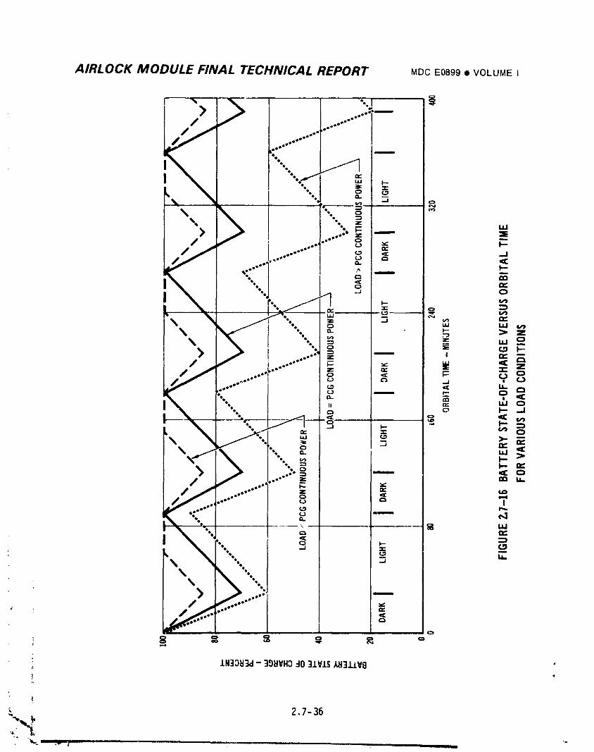
AIRLOCK MODULE FINAL TECHNICAL REPORT MDCE0899• VOLUMEI
AIRLOCK MODULE FINAL TECHNICAL REPORT MDCE0899• VOLUME I
the end of the daylight or recharqe period. The upper curve, where
_.'_eload is less tha,lthe PCG continuous power illustrates that for
.i,l_terthan SI power capability loads, the battery did not discharge
,.<_",_ch,_ndconsequentlywas *'Llllvrecharged prior to the end of the
orbit. Timethird curve, where the load is qreater than the PCG
continueus power, shows why the SI Dower capability was an important
operational limit on tileAH EPS. It shows that if a load caused the
b,lttervto discharQe to a depth such that it could not be fully
recharged during the next dayliqht period, this same load would
produce the same 1'esulti,_subsequept orbits and timebattery would
eventually l,ecot_w_full_ discharqed and retain no stoTed energy.
(2) PCG Z-LV Capability Nonsolar inertial attitiJdeswere normally
.qroupedtogether and referred to as the Z-LV attitude. The Z-LV
power capability was defined as the averaje load (over the Z-LV
period) supplied to the Req Bus at wilichthe minimull_,battery DOD
during the Z-LV period was 50_.. TileZ-LV period started with the
battery at I00% at the beginning of the dark period p_ior to the Z-LV
daylight period and ended at the end of the dark period following
the Z-LV daylight period. There were two factors which could
markedly decrease the available solar array power during non-solar
inertial orbits. These were tl_eorientation of the solar array
_urface with respect to the sunline and the shadowing of array
surfaces by the other parts of the vehicle. In solar inertial
both the pitch and roll attitudes of the vehicle were controlled
so tnat the array surface was perpendicular to tlmesunline. This
produced maximum solar array output power since the power was
proportional to the cosine of both the sunline to vehicle pitch
axis angle and sunline to vehicle roll axis angle. In Z-LV, the
_unline to pitch a.,.i_angle varied constantly fr_mlas much as -90°
to +90° so that the power could go as low as zero during the
daylight period. The su_llineto roll axis angle was equivalent
' 2.7-37w
t
] 9740] 8208-433
AIRLOCK MODULE FINAL TECHNICAL REPORT MDC E0899 • VOLUME I
to the Beta _nqle cO tl_erpcllltamtpower decreas_ durina Z-LV was
also proportional to the Beta angle.
Shadowinq of the OWS solar array winQs could rest_Itfrom the ATM
solar array winqs, the OWS array fairinq and the body of the OWS
vehicle. The ATM shadowinQ occurred when the sunline to pitch axis
anqle changed. As the angle changed, different modules were shadowed
so that different PCG inputs were affected. The amount of this
shadowing and thc modules siladowedwere also affected by the Beta
angle. As the vehicle roll axis angle changed for Z-LV, the body
of the OWS shadowed the inboard array modules. Since the wings
were at different elevation attachment levels on the OWS body, the
effect of body shadowing was different for + and - Beta angles.
A typical Z-LV orbit included a S] to Z-LV maneuver, the Z-LV opera-
tional period, and a Z-t.Vto SI maneuver. Both attitude and
shadowing were affected by the period of each maneuver and of the
Z-LV operation, and hy the orbital position at which they occurred.
Because of all these variables, the solar array input power could
be insufficient to supply the total bus load during certain
portions of the daylight period. At such times the battery would
be required to supply the rest of the bus load. Such periods
would effectively be dark periods for the battery since the
battery was supplying energy instead of receiving recharge energy
as it normally did in daylight periods. As soon as the solar array
input power exceeded the bus load requirement, the excess power was
again used to recharge the battery.
rileZ-LV power capability was calculated for each Z-LV case
individuallybecause of all the variables and their inter-
dependence on one another In effect the Z-LV capability involved
the trade-off between the type and duration of the maneuvers, and
the amount oF bus power that could be supplied. Following a Z-LV
_ period, several orbits of SI were required in order to restore the q_ battery to a lO0't;SOC. The number of orbits depended on the actual
_ minimum battery SOC.
2 7-38
I ..... I _, I
"10740"18208-434
AIRLOCK MODULE FINAL TECHNICAL REPORT MDCE0899• VOLUMEI
(3) AM EPS Solar Inertial Capability - The AM EPS solar inertial
capability was the total continuous power that the 8 PCG's could
supply to the Reg buses with none of the PCG's operating above
its individual power capability. Each PCG= though identical in
physical c_nstruction, had some difference in performance. The
most significant performance characteristics that differed from
PCG to PCG was the amount of solar array power available, the
battery recharge characteristics,and the voltage regulator
output characteristics. The array power differences could occur
because of shadowing and temperature vibrations. Each battery
had a somewhat different recharge characteristic affecting the
amount of energy required for recharge and the rate at which the
energy would be accepted by the battery. The voltage regulator
characteristicswere important in the way that the individual
PCG outputs could be combined at the Reg buses into a total
capability.
The AM EPS power capability was based on the two Reg buses
; operating in parallel (Reg bus tie C/B's closed), and with each
bus supplied by 4 PCG's. The arithmetic sum of the individual
PCG capabilities of 536 watts was 4288 watts. This value, however,
coula only be used as an optimum limit value because of practical
considerations. The output characteristic of the vo]tage regulator
,_ in each PCG had a slope of -0.04 + 0.002 volts/ampere. _n addition
_. the output level of each regulator could shift by a maximum of
0.05 volts due to temperature variations, ageing, and drift.
i Figure Z.7-17 illustrates the effects of slope variations andvoltage level variations on combining PCG outputs. It does this
by showing several regulator output V-I curves having different
characteristics (within specification limits) and determining
their outputs at a common operating voltaQe level. As shown inY
the tabulation on the figure, regulators B and C were delivering
less power than regulator A.i
I 2.7-39
,,_.',w,,aunom, mlm_-.,_m--._---- ...............
' J . l # "j
i974018208-435
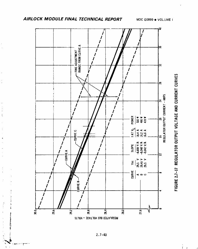
AIRLOCK MODULE FINAL TECHNICAL REPORT MDCE0899• VOLUMEI
r /I ,// ,. /T/ ../
/ ,.,
/ '.':>n,.
!', .I:,,.',. ..,t"--- I "
, N/i • , i, I ¢._
I'-
: i'I "L _
: /
_ /L
,, _ S.I.IOA- 39V.1.10$̂flB031V'II'193_I
I
2,7-40
1974018208-436
AIRLOCK MODULE FINAL TECHNICAL REPORT MDC1=0899• VOLUMEI
The output voltage level of each regulator c_uld he controlled
relative to the other PCG's by the associated fine adjustment
potentiometer. The range of the adjustment is shown on Figure
2._-17 for regulator A by the dashed line slopes. This capa-
: bility was designed so that the previously listed variations
between PCG's could be o_ercome along with possible contingencies
such as module failures in a battery charger or voltage regulator.
This adjustment capability, however, could also introduce some
small unbalance between PCG's. For purposes of analysis it was
assumed that the fine adjustment potentiometers overcame all
variations except the regulator output characteristics as illus-
trated by Figure 2.7-17. Based on this assumption the SI total
power capability was 3930 watts compared to the optimum possible
va1,Jeof 4288 watts.
The total power capability for operating the two Reg buses inde-
pendently remained the same at 3930 watts or 1965 watts per bus,
if the buses were equally loaded. If the loads on the two buses
were not equal, only tilecapability of the heavier loaded bus
could be fully utilized and this reduced the total output power
to less than 3930 watts. The paralleled bus system therefore had
the advantage of improving the utilization of the total AM EPS
continuous power capability.
(4) AM EPS Z-LV Capability - The AM EPS power capability for Z-LV
was the total of the individual capabilities with none of the
batteries going below the 5Or',SOC limit. The preceding discussion
on combining individual PCG capabilities for SI also applies to
the Z-LV case. However, the shadowing encountered during Z-LV,
as previously discussed, was tilepredominant factor af1ecting the
Z-LV total capability. Depending on the Beta angle and the
." maneuvers there could be a wide range of battery SOC's during aL
• _ Z-LV period, Therefore, all were limited to power capabilities
- consistent with the most shadowed one reaching the 50% SOC limit
" during the period. Once anain the Z-LV capabilitv had to be
calculated for each specific set of Z-LV orbital c_nditions.
2.7-41
4 L _
1974018208-437
AIRLOCK MODULE FINAL TECHNICAL REPORT MDCE0899• VOLUMEI
B. Parallel Operation With ATM EPS - The AM EPS could be operated in
parallel with the ATM EPS Lu supply toLdl cluster load requirements.
The objective of operating the AM and ATM electrical power systems in
parallel was to utilize the full capability of both of the EPS systems
to satisfy cluster ;oad reeuiFaments. Parallel operation eliminated
cases where one power system might be overloaded while the other system
had power a_ailable in excess of its individual load demand.
Paralleling therefore, allowed load levels to be based on total cluster
EPS capability instead of being based on individual EPS capabilities.
Paralleling was accomplished by connecting the AM Reg. buses and the
ATM buses to the Transfer buses in the AM. The load sharing between
electrical power systems was controlled by means oF the AM Reg. bus
adjustment potentiometers. These potentiometersadjusted the overall
AM Reg. bus V-I curve with respect to the overall ATM Load bus V-I
curve. The operation was similar in nature to that of the fine adjust-
ment potentiometers in controlling load sharing between AM PCG regula-
tors. Therefore, some loss in power capability must also be assumed
when attempting to share a specific load between the AM and ATM elec-
trical power systems.
A 3% loss in AM Reg. bus power capability had been assumed for parall-
eling losses. This reduced the AM Reg. bus continuous power capability
from 3930 watts to 3814 watts. The capability specified for the ATM EPS
was 3716 watts. A total capability of 7530 watts was thus provided,
with the 3814 watts supplied by the AM EPS and the 3716 watts by the
ATM EPS.
The amount of power transferred between the AM and ATM could be expected
' to vary over a wide range. Tc account for contingency conditions, the
_ requirement for allowable power transfer was set at a maximum of 2500
! watts. Therefore, the AM EPS distribution system wiring and control
_. equipments which were associated with AM/ATM po#er transfer were
designed to transfer 2500 watts continuous in either direction, as
measured at the AM Transfer buses.
V-
_ 2.7-42
i974018208-438
AIRLOCK MODULE FINAL TECHNICAL REPORT MDCE0899• VOLUMEI
C. CSMConnected Operation - The CSMcould be powered from the parallel
cnmhination of the AM and ATM electrical power systems or from either
power system individuaily during manned phases of the Skylab Program.
Interconnection of the AM, ATM, and CSMpower bus systems could be
accomplished by use of the Transfer buses in the AM. Connection of the
AM Reg buses and the ATM buses to the Transfer buses was accomplished
by use of controls and switching provided in the AM EPS. The connection
of the CSMbuses to the Transfer buses was accomplished by use of
controls and switching provided in the CSM. When the AM Reg buses
were connected to the Transfer buses, the Reg bus potentiometers
could be used to adjust the voltage levels on all buses connected to the
Transfer buses. They could once again be used to make load sharing
adjustments when the AM and ATM were operating in parallel and supplying
power to the CSM. The use of proper procedures in adjusting these
potentiometers provided the required voltage levels and load sharing.
It was possibie, however, to adjust these potentiometers out of the
desired ranges for either voltage level or load sharing. This ce, ditio:,
could occur because of the necessity for the potentiometers to haw_
a range such Lhat required bus levels could be maintained under
various conditions. The use of proper procedures assured operation at
desired voltage levels a_d load sharing conditions.
The wiring and c_,_ ;'oi equipments in the AM EPS distribution system
which were associated witr_ the transfer of power to the CSMwere
designed to deliver 2472 watts continuous (1236 watts/bus) as measured
at the AM/MDAinterface.
An essential operation, related to CSM connected operation, was the
operation of the ELEC. GND. Control on the AM STS instrument panel.
When the CSM docked and the CSM/MDA interface connectors were mated,
the negative return bus system was automatically connected to vehicle
structure by the VGP in the CSM. The connection to the vehicle struc-
ture by way of the SPG in the AM was also present at that time. It
was therefore necessary to position the ELEC. GND. Control on the STS
. instrument panel to its CSM position in order to disconnect the AM SPG
from vehicle structure. Prior to CSM undocking the ELEC. GND. Control
was positioned to its Airlock position to reconnect the AM SPG to
vehicle structure for orbital storage periods.
2.7- 43
I
i9740i8208-439
AIRLOCK MODULE FINAL TECHNICAL REPORT MDCE0899• VOLUMEt
2.7.3 Testing
Testing of the AM EPSwas conducted throughout the Airlock program at the
component, black box, subsystem, system, and flight vehicle levels. The objec-
tives of all the test programs were to assure as much as possible, by testing
that the flight vehicle AM EPS could be expected to meet all the Skylab require-
ments with a high level of confidence. The overall testing can be divided into
three categories: qualification; development and corfidence; and flight vehicle
testing. The timely progression of testing can be seen on the AM EPS testing
History chart on Figure 2.7-18.
Qualification testing was required on all individual components and func-
tional units which were to c3mprise the AM EPS. The qualification testing on
the major functional units is discussed in detail in the following section.
Development testing was concentrated in four areas. These were the battery
life test area, battery charger design area, voltage regulator design area and
the PCG and subsystem area. Development and confidence tests of the AM nickel-
cadmium (Ni-Cad) batteries were performed both at MDAC-Eand at the battery vendor.
_ extensive series of tests were performed because of the importance of battery
life characteristics to the success of the Skylab mission. The battery char eer
and voltage regulator vendor performed a substantial amount of development
testing in order to meet specification requirements which represented _,ignificant
advances in the state-of-the-art for power conditioning equipment. The system
development test verified individual PCGoperation, parallel PCGoperation, and
the operation of the power distribution system. This test included ambient and
temperature-altitude conditions to verify operations under mission environn_nts.
The Silicon Controlled Rectifier (SCR) Panel development test was conducted
as a result of a design problem which was encountered during Spacecraft Systems
testing. The generation and incorporation of the SCR circuits to overcome the
problem had to necessarily be done on an expedited basis so as to minimize the
; impact on vehicle testing and delivery schedules, The testing was perfornled to
verify the effectiveness of the solution and to enhance the confidence in its
fl i ghtwor thi ness.,.
: 2.7-44
, ._4, J IBn=,,=',""" .......................... i ,,
1974018208-440
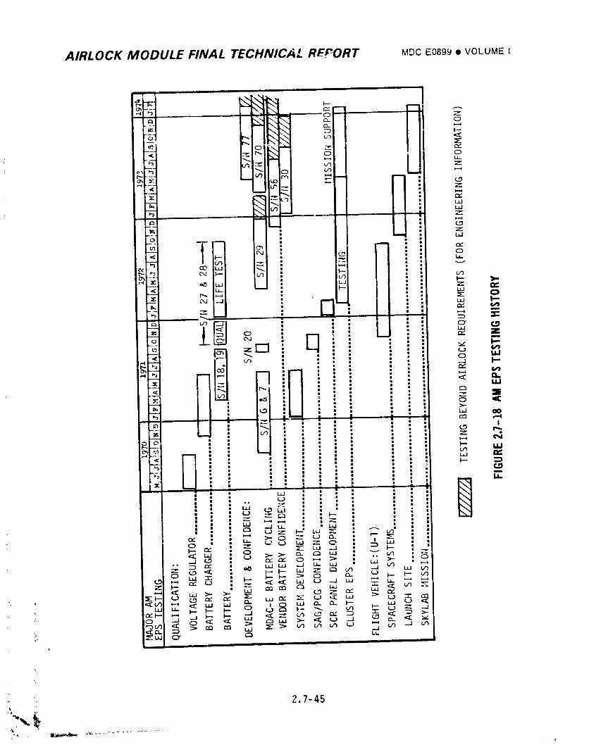
AIRLOCK MODULE FINAL TECHNICAL REPORT MOCE0899• VOLUMEI
2.7-45
,i
1974018208-44 ]
AIRLOCK MODULE FINAL TECHNICAL REPORT MDC E0899 • VOLUME I
The compatibility of the AM EPS and its interfaces was verified during the _
development phase of the prngram by two Independent test programs. Tile Integrated
SAG/PCGtest verified the interlace between the individual Solar Array Group (SAG)
of the OWSand the individual Power Conditioning Group (PCG) of the AM EPS. The i
interfaces between the AM EPS, and the ATM and CSHelectrical power systems were
verified during the Cluster EPS development test at MSFC. The Cluster
EPS consisted of flight type AM and ATM systems and a simulated CSMsystem. The
Cluster EPS testing preceded the actual mating of the flight vehicle power systems
and therefore provided a timely early verification of overall EPS co_,patibility.
The final EPS test before delivery of the Airlock Module by MDAC-Ewas during
the SPacecraft Systems testing on the U-I vehicle. This primarily verified tile
compatibility of the AM EPS with all other AM and MDAsystems and verified the
flightworthiness of the actual flight system of the U-I vehicle.
Further testing at the launch site verified interfaces with the ATM and CSII
EPS and maintained the status of the system up to the launch. The mission performance
monitoring after launch continued to check and verify that the AM EPSwas meeting
all mission requirements.
2 7.3.1 .qualification and Acceptance Testing of Major Hardware Units
A. Battery Char_er ,
I/ QualifiGal;io_q Testing- The bdttery charger was subjected to and
successfully passed an extensive qualification test. The qualifica,ion
test procedure QTR 714244 defined the testing methods and procedures
necessary to comply with the qualification test requirements specified
in MDAC-EProcurement Specification 61B769006. Two qualification
samples, identical to the actual flight units except for internally
mounted thermocouples,were utilized during the testin'_. The quali- '
fication testing included temperature altitude, random vibration
(operating),humidity, electromagnetic interference (EMI) and life
-_ testing. Fungus resistance requirementswere satisfied by vendor
certification that all of the materials used in the battery charger
are pot nutrients to fungus. The only design change to the battery
charger that was required as a result of the qualification test program
2.7-46
1974018208-442
AIRLOCK MODULE FINAL TECHNICAL REPORT MDCEOB99• VOLUME ,
was the addition of a moisture seal to improve the ability of the unit to '_
withstand humici envirenment_. This change was incorporated dfter" U_e
battery charger failed to pass humidity tesLing. Following a successful
retest, the mnisture seal was incorporated nn all units. Qualification
Test Report QTR _2639 is a comprehensive report on the qualiflcation
program. All pertinent information relating to the qualiFication test
program is contained in this report.
Two battery chargers successfully passed environmental sections of the
qualification test. In addition, one sample was subjected to and passed
the lO00 hour life test. The other sample successfully accumulated in
excess of 15,000 hours during MDAC-Ecycling tests on 61B769004-13 S/N 29
and -19 S/H; 70, batteries.
2/ Vendor Acceptance Testing - All battery chargers were subjected to an
extensive acceptance test prior to shipment from the vendor's faciiity.
The testing included both performance and environmental tests. The
battery charger acceptance testing was performed with the ald of a complex
test console. The console included a solar array simulator, a battery
simulator and a flight type voltage regulator. Thus, the acceptance
testing was performed under conditions which closely represented the actual !
flight application. A test connector was provided on each battery charger
which when used _, conjunction with the equipment in the test console,
allowed detailed measurements with accuracy not attainable in the actual
flight system. The internal redundancy of the battery cF,arger was
verif:,_.d in so far as was practical.
All phases of battery charger performance, encompassing all spec,fication
requirements,were checked during the acceptance test, Complete perform-
ance verification tests were performed immediately following the non-
operation environmental tests of thermal shock and ra_,demvibration. The
, resulting data was recorded in a test record which constitutes a matrix
' of performance data for each individual unit. The acceptance test _
procedure ATP 714243 can be consulted for the detailed test proceduresL
and sample test record for'ms.
2.7-47
L
1974018208-443
AIRLOCK MODULE FINAL TECHNICAL REPORT MDCE0899• VOLUMEI
3/ Pre-lnstallationAcceptance Testing - All battery chargers were
subjected to Dre-installationacceptance (PIA) testing upon receipt
of the unit from the vendor. The PiA test was repeated if the unit
was held in storage for more than 12 months. The PIA test is essen-
tially a repeat of the physical examination and room temperature per-
formance portions of the vendor acceptance test. The temperature shock,
burn-in and random vibration tests of the AT? were not repeated in the
PIA test. A test console identical to the vendor test console was
used for PIA testing.
B. Battery
I/ QualificationTestin.q- Qualification tests were conducted at the
vendors facility per test procedure QTP I07 in the period between
May 1971 and October 1972. De batteries were tested for design
adequacy when subjected to the environmental,operational, and life
requirements commensuratewith integration into the Skylab EPS system.
Simulation of flight environmental and operational conditions for various
qualification tests required design and fabrication of some major pieces
of test equipment. Battery thermal control was accomplished utilizing
spacecraft coolant and a special coolant bench plumbed to flight con-
figuration batter)'coldplates. This bench provided the capability to
adjust flow and inlet temperature conditions to simulate anticipated
levels of spacecraft operation. Radiated heat transfer was negligible
during altitude-temperaturetesting and was precluded during ambient
life testing by encapsulation of the batteries in a granulated insula-
tie.:material. Charge and discharge controls which simulated those
commensuratewith flight conditionswere provided for each battery by
a special automatic test consoie. These consoles provided; programmed
loads, adjustable day-night cycle periods to compensate for B£ta angle
variations, adjustable charge voltage limit and recharge fraction to
compensate for battery temperature variations, and battery level data
monitoring and recording capabilities. Later configuration batteries
had provisions for monitoring individual cell voltaqes and a data
2.7-48
.' i • Ill# _,
1974018208-444
AIRLOCK tt4ODULE FINAL TECHNICAL REPORT MDCE0899• VOLUMEI
ac,luislt',onqvstem console wa¢ added to the te_t complex to ,onitor cell
,',_lta.Te....All qualification te:ts were perfor_,_'dof complete batteries
with the e'<contion ,'f th,, bur<t mc,s,,Jre te,:t of cell and battery
conta;nt, r,:. The te_ts on complete batterie_ consisted of Temperature-
Shock, Vibration, Acceleratlon, Pulse _ischarqe, Installed Storable,
Temperature-Altitude and Cvcle Life.
51B76qO04-9 configuration batteries, S/N 18 and 19 were the initial
qualification test specimens, lhese units completed all the qualifi-
cation tests with the exception of the Cycle Life test. Testing of
this configurationwas stopped when i,_fo_,ationbecanw_available from
Engineering ConfidenLe Life !esting tllata plastic plate hold-down block
within the cell caused incv ased plate deforJnationwith c,vcle accumulation
eventually resulting in cell short_. A new 61B769004-13 confiq-
uration was established in t,hich the plate hold-d(_vnblock was
eliminated. T_o specinw_ns,S/,N27 and S/N ?S of tllet_ash13 configur-
ation we_ subsequently subjected to Vibration, Acceleration, Installed
Storage and Life Testing. Tllesetests were successfully passeu by
the 61B76900,I-]3configurationspecin_enswith the e×ception of the
Life Test. Battery S/N ?7 satisfied simulated mission loads at required
voltage levels throughout the 4000 cycle life requirement,h(_vever,
. 2_OJ. life test_nq wasS/N 28 failed the voltaqe requirement on cycle _ _'
concluded on 3 October 1972 when S,'N27 accumulated its 4000th cycle.
Detailed results of the Qualification tests can be found in report
QIR I07. Failure analysis results indicated the basic problem
experienced with quMificatio,: unit_ S/N .'7and S/N 28 was one of work-
manship inconsistency in the plate tab sl_apin9process. Confidence
in the battery design concepts _mmained hig',_based on failure analysis
findings of the qual units and the excellent performance of a life test
unit (S/N 29) of the sa:,_)configuration at HDAC, '._hichwas six months
into th_ eight month te._t. Because of possible workmanship problems
within existing batteries, a decisior,was made to fabricate new
batteries, 61B769004-_9 configuration, for the flight by using a
, special tab shaping tool to assure controlled shaping of the tabs with
2.7-49
-'%,
, r.* _ ......
1974018208-445
AIRLOCK MODULE FINAL TECHNICAL REPORT MDCE0899• VOLUMEI
an adequate strain relief loop f, - plate tabs interior to the cell pack.
Faced with _nsuttlclent time to de;_;onstrate life ddequ_l uf the new
batteries, two additional snecimens of the 61B769004-13 confi.quratlon
(S/N ]0 and S/N 56) were placed on life test at the vendor in late
October !972 for the purpose of maximizinq confidence in the design
conceot. Two batteries of the newly fabricated 61B76900_-19 configuration
(S/N 73 and S/N 77) were placed on life test at MDAC-Ewhen they became
available in March and May of 1973. Since that time, S/N 29 which was in
the sixth month of a live test at MDACin October 1972 and S/N 30 and
S/N 56 wllich were placea ;)n test at the vendor in late October 1972 have
each subsequently denw_nstrated cycle life in excess of 4000 cyclPs without _
cell failure. The S/N 70 and S/N 77 batteries placed on test in March
and May 1973. respectively, also satisfactorily completed 4000 cycles
without a cell failure. MDAC-Etests on batteries S/N's 29, 70, and 77
were accomplished utilizing flight configuration chargers.
2/ Vendor Acceptance Testina - Acceptance testing was performed at the
vendors facility per test procedure ATP-180 to verify compliance
with the requirements of siqnificant physical and performance
criteria of the design specification. Data from these tests also
provided engineerinll information pertinent to indiviuual battery per-
formance characteristics and overall design.
Acceptance tests included subassenIDly and final dsse..,6!y testing. At
the subassenIoly level battery cells were tested for performance and
physical characteristics; the battery container was tested to verify
proof pressure integrity; and the relief valves and thermal switch
were verified for operation actuation points. Assembled batteries
were tested to verify wirin._ integrity, temperature sensor indication
consistency, and battery tolerance to anticipated launch vibration
, exposure. Battery operational characteristics were determined during
" > mission type acceptance cycling which simulated flight charging and
discharging conditions. During this cycling and subsequent capacity
discharging the batteries were ,,_aintained at a constant (75 '_ +_5"F)
temperature utilizing fligi_t type coldplates and a test coolant bench. .
_ Physical inspection and din_nsional verification completed the
acceptance tests.• ._ 2.7-50
1974018208-446
AIRLOCK MODULE FINAL TECHNICAL REPORT MDCE0899• VOLUMEI
All batteries were suhjocted tu and pa_Pd the acceptance test
requirements. A significant design benefit derived from the evalua-
tion of early acceptance test data was an early insight into a tem-
perature gradient situation within the battery which was inconsistent
with long cycle life. This condition was subsequently resolved
by a change in the battery container material on later configurations.
3/ Pre-lnsta]lation Testin.q - The AM flight batteries (-19) completed the
fabrication process and were delivered via NASA aircraft directly to
KSC very near the time schedule for vehicle installation. The entire
fabrication nrocess and the acceptance test of these units at the ven-
dors facility were witnessed by MSFCand MDACQuality Assurance
personnel. The KSC pre-installation testing was reduced to a visual
inspection, a wiring integrity check and a full charge of tile batteries
for installation. A full capacity cycle, normally performed as part
of the Pre-lnstallation Acceptance test was eliminated. The source
inspection coverage, the special delivery arrangements, and the in-
versicle tests scheduled after installation warranted _"_,,_t +._,..+saving
change.
C. Voltage Regulator
I/ qualification Testinq - Tile Voltage Regulator was subjected to
and successfully passed an extensive qualification test. Qualifi-
cation test procedure QTP 714282 defined the testing methods and procedures
necessary to comply with the qualification test requirements specified
in MDAC-East Procurement Specificatitm 61B769005. Two qualification
test samples, identical to the actual flight units except for inter-
nally mounted thernmcouples, were utilized during the testing.
The qualification testing included temperature altitude, electro-
magnetic interfere_.ce (EMI), humidity, random vibration (operating),
and life testing. Funsus resistance requirements were satisfied by
certification. All qu_,lification testing was successfully completed
without a regulator malfunction or fail,.;'e. No design changes were
incorporated as a result of the qualification test program. Qualifi-
: 2.7-51
i 9740i 8208-447
AIRLOCK MODULE FINAL TECHNICAL REPORT MDCE0899• VOLUMEI
cation Test Report QTR 2586 is a comprehensive report on the quali-
fication program.
2/ Vendor Acceptance TestinQ - All voltage regulatorswere subjected
to an extensive acceptance test prior to shipment from the vendor's
facility. The testing included both performance and environmental
tests. The voltage regulator acceptance tests were performed with the
aid of a test console. The console simulated the AM electrical power
system in the areas of input voltage range, wire resistances, remote
sensing, etc. A voltage regulator, identical to the flight voltage
regulator, was wholly contained within the test console for the parallel
operation testing. All phases of voltage regulator performance, en-
compassing all specification requirements,were checked during the
acceptance testing. Complete performance verification tests were
performed in,mediatelyfollowing the environmental tests of thermal
shock and random vibration. ,Theresulting data was recorded on a test
record form which constitutes a matrix of performance data for each
individual unit. The acceptance test procedure ATP 714281 can be
consulted for tiledetailed test procedures and sample test record forms.
3/ Pro-lnstallationAcceptance Testinq - All voltage regulatorswere
subjected to pre-installation acceptance (PIA) testing upon receipt
of the unit from the vendor. The PIA test was repeated if the unit
was held in storage for more than 12 1,1onths.The PIA test was essen-
tially a repeat of the physical examination and room temperature per-
fonnance portions of the vendor acceptance test. The temperature
shock, burn-in and random vibration tests of the AI'Pwere not repeated
in the PIA test. All phases of the voltage regulator performapce were
tested in the PIA test. A test console identical to the vendor ATP
console was used for PIA testing.
2.7-52
• i _ :z i i i i ._
] 9740] 8208-448
AIRLOCK MODULE FINAl TECHNICAL REPORT MDCE0899• VOLUMEI
:
_ 2.7.3.2 Developmentand Confidence Testlnq
i A. VendorBatteryTesting- In additionto Acceptanceand Qualification=T
tests,batteryand celltestswere conductedat the vendorsfacility
_ to assistin designchangedecisions,to establishimprovedprocedures
for installedbatterymaintenance,and to increaseconfidencein the
lifecapabilityof the design.
• _ I/ PrototypeTest- The initialdevelopmenttest conductedat thevendorsfacilitywas performedon a batteryspecimenmade from cells
fabricatedfrompre-AMplaquesand a proto-typeAM batterymagnesium
container. The objectivesof the testwere to determinethe following: =
i rechargeamp-hourefficienciesatselectedtemperatu;'esand rates for
__ states-of-chargerangingfrom25 tO I00 percent;currentcharge
_ _ characteristicsat selectedvoltages,temperaturesand states-of-
I charge;and waste heat generationduringoverchargeat selected
temperaturesand chargerates. The parametricdata from thistest
_ programwas to be used for power systemperformancecalculationsand
computersimulations.One of the major difficultiesexperiencedin
_ thistestingwas the inabilityto establishthe batteryat an accurately
predictablestate-of-chargeat the beginningof each amp-hourefficiency
testsequerce. Inefficienciesof the smallmagnitudeanticipatedfor
rechargeslessthan 80% couldnot be establishedbecauseof this
• problem. The testwas terminatedwithoutattainingall of its objec-
tives. However,the informationobtainedwas usefulin formulatinga
new definitionof batteryoperationfor power systemcalculationpurposes.
2/ Batter_ParametricData Test- This testwas a follow-ontestto
the PrototypeTest. The testspecimenwas one of the early AM produc-
tionbatteries. The testwas conductedto investigatethe magnitude
" of the temperaturegradientconditionfirstdetectedduringacceptance
: i testing. Itwas also conductedto substantiatethe validityof the new
l definitionof batteryoperationwith respectto full rechargeefficien-t, cies at varioustemperatures,and with respectto chargecurrent
: " profilesas a functionof temperature,voltagelimit and percentof
: dischargeampere-hoursreturnedduringthe recharge. Test results
2.7-53
1974018208-449
AIRLOCK MODULE FINAL TECHNICAL REPORT MDC E0899 • VOl..ulviE I ;
verifiedthat a significanttemperaturegradientproblemdid exist.
Subsequentchangesin case and cellpottingmaterialsand a coolant i:
systemchangeto lowercoolantinlettemperatureswere made to alle-
viate thisproblem. Test resultssubstantiatedthe validityof the
• performancedefinitionbeing used for powersystemanalysis.
3/ ModifiedCellVibrationSusceptabilityEvaluation- This eval-
uationwas conductedat the vendorsfacilityin June 1971afterthe
prematurecell failuresin the lifetestingof 61B769004batteries
were attributedto the effectof the platehold-downused in these
particularbatteries. The testswere performedon three cellshaving
differentinternalconfigurations.One had the existinghold-downused
in Dash 3's;the secondhad a modifiedhold-down;and the thirdhad
no hold-down. The testswere run to determinethe effectsof random
vibrationenvironmentson the cell integrityand performance.X-rays
were takenafterthe signi#:icantsteps of activation,conditioncycling,
and vibrationexposures. Electricalperformancewas monitoredfor
. voltagestabilityand continuityduringthe vibrationexposures. No
i detrimentaleffectswere experiencedby the threecells duringor after
; any of the vibrationexposures.
: The use of the cellconfigurationwithoutthe hold-downto eliminate
the lifeproblemwas therefore,alsodeemedacceptablefromthe vi-C
brationexposureaspectbased on the resultsof these cell tests,Dash9
batterie_(S/N27 and S/N 2B) which incorporatedthe no hold-downcell
configurationsubsequentlydemonstratedtheirabilityto successfully
withstandthe qualificationrandomvibrationexposurelevelof 7g(rms).
4/ Batter_MaintenanceProcedureDevelopment- A batterymaintenance
procedurewas necessaryto maintainthe chargedAM batteriesin a state
• of launchreadinessduringthe periodfromtheir flightvehicleinstal-
lationuntilthe Skylablaunch. The originalprocedure,recommended |
i by the batteryvendor,was to tricklechargefor 5 hours on a weekly -
basis. When the tricklechargelevelwas changedfrom 2.0 amperesto
" 2.7-54
q9740q8208-450
AIRLOCK MODULE FINAL TECHNICAL REPORT MDCE0899• VOLUMEI
: i 0.75 amperes, it was deemedundesirable to change the procedure from
. 5 hoursto over 14 hours. An alternateprocedurewas then recommended
whichwas to use a constantpotentialboost chargeon the batteries
! for one-halfhour on a weeklybasis. This procedurewas then checked
) on qualificationDashg batteriesat the vendorfacility. The fouriweek test resultedin some lossin ampere-hourstatusof the batteries
! This precipitateda comparativetestof severalmaintenancemethods
: _ on a cell levelbasis. These testswere alsoperformedat the
E vendorsfacilityin Septemberand Octoberof Ig71. A totalof four-
._ _{ teen cellswere usedin thistesting. The methodsevaluatedwere:
i I) a weeklyconstantpotentialboost chargefor timedurationsof
_ I/2, 1, and 2 hours,2) a weekly tricklechargeperiodof 14 hours
I at amperes, 3) charging, of0.75 and continuous trickle Evaluation
y
the testsindicatedthat the 2-hourconstantpotentialboost charge
I and both tricklechargeprocedures,periodicand continuous,were
: I effectivein maintainingthe ampere-hourstatusof the batteries
over an extendedperiodof time.
The 2-hourweeklyboost chargewas, therefore,selectedas the final
• procedureto minimizethe impacton vehiclelaunchpreparation
activity,and to minimizecoolantpump usagepriorto launch. This
= procedurewas subsequentlyverifiedon the batterylevelin the qual-
- ificationtestof Dash13 batteries.
5/ Evaluationof New ProductionTo_l - A new productiontoo!was
designedto copewith a fabricationworkmanshipproblemevidentfrom
; the October1972 failureanalysisof cells fromthe
: l_,fetest of Dash 13 battery. The subjectevaluationprogramwas
conductedat the vendorsfacilityin Nove_er 1972to verifythat plate
: straightness,adequatetab strainrelief,tab shapinguniformity,and
bottomof cellplategrowthallowancewould consistentlyresultfrom
the use of the new tool.
; _ The evaluationwas performedon g cellsand consistedof e_tens_ve i: qualitycoverageduringfabricationand X-ray inspectio,_after cell
2.7-55\
I
1974018208-451
AIRLOCK MODULE FINAL TECHNICAL REPORT MDCE0899• VOLUMEI
assembly, activation, vibration, and simulated orbit cycling. The
cycling was for a total of 100 cycles with X-ray inspection after
25, 50 and 100 cycles. A tear-down analysis was performed on all
cells as a final step in the evaluation.
All radiographic inspections of the cells showedconsistent and uni-
form tab sJlaping.Platesand tabs did not assumethe bent or distorted
configurationsseen in the cellsfrom the-13 qualificationbatteries.
Therewere no indicationsof pressurepointsor bendingof the plates •
nearthe tab locationafter themajor portionof the anticipatedposi-
tive plategrowthhad takenplace. The evaluationdemonstratedthat
• the use of this productiontooleliminatedthe deficienciesdetected
in the analysisof the shortedqualificationbatterycells, Therefore,
the toolwas approvedfor the new battery(-19)fabrication.
6/ BatteryConfidenceLifeTest - A batteryconfidencelifetest
was begunat the batteryvendorfacilityin October1972. Two
61B769004-13batteries,S/N 30 and S/N 56,were subjectedto this
test. The primepurposesfor this testprogramwere: to increasethe
lifetestsamplesize from threeto five;to obtainlife testdata at
updatedflightconditions;and the therebyincreasethe confidence
in the batteryand celldesigns.
, Bothbatteriespassedthe 4,000cyclesof simulatedorbitaloperationwith no cell problems;S/N 56 in July 1973,and S/N 30 in August
Ig73. A capacitycheckwas performedon each batteryafter its required
4,000 cycles. S/N 56 had a capacityof 34.76A-H comparedto an
acceptancetest valueof 40.2 A-H. S/N 30 had a capacityof 33.37A-H
comparedto an acceptancetest valueof 41.3 A-H. The completionofthe required4,000cycleswith no cell failuresincreasedthe con-
fidencethat the improvedflightbatteriesshouldbe able to complete _
the Skylabmission. The ampere-hourvaluesobtainedafter4,000 cycles _i
. also indicatedthatthe flightbatteriesshouldmaintaina performance
levelin excessof the requirementsthroughoutthe Skylabmission.
" 2.7-56
1974018208-452
AIRLOCK MODULE FINAL TECHNICAL REPORT MDCE0899• VOLUMEIt
The batteryvendorelectedto continuethe lifetestingon these
batteriesbeyondthe 4,000 cyclerequirementsfor engineeringinformation.
S/N 30 battery'slifetestingwas terminatedon 20 December1973after
5704 cjcleshad beenaccumulated.This batteryexperiencedits first cell
failureat 5427cyclesand subsequentlylost fourothers,the lasttwo
comingon consecutivecyclesat the timeof termination.Test conditions
were unchangedduringthe cell failureperiod.
S/N 56 batteryaccumulatedin excessof 7250cycles. This batteryhas had
one cell failureat 6251 cycles. The proximityof an automatictest
consolemalfunctionwhich causedthe batteryto be overdischargedto this
failuresupportsa cause and effectrelationship.Becauseof this the
chargevoltagelimitswere reducedto a levelcomparablewith a 29 cell
batteryand the testwas continued.
: B. MDAC-EBatteryTesting- The purposeof the testingwas to determine
batteryoperatingcharacteristicsoverthe expectedlifeof Airlock
(240days)as follows: batteryperformanceas a functionof accumulative
discharge/chargecyclingundermissionsimulatedconditions;cell voltage. characteristicsduringdischargeand charge;and thermalcharacteristics.
All batterieswere testedin the Space SimulationLaboratoryby the
SpacecraftElectricalSystemsLaboratoryof the McDonnellAircraft
Companyin St. Louis. Two 61B76go04-3batteriesS/N 6 and 7 were tested
in a lO-monthperiodendingJune 1971and a 61B76go04-15battery,S/N 20
•_ was testedin SeptemberIg71. Battery61B769004-17,S/N 29, was tested
for II monthsendingin March 1973. Two 61B769004-19batteries,S/N 70
and 77 were placedon test in March and May 1973, respectively;these
testswere completedin February1974.
I/ Test Specimens- All batteriestestedwere productionbatteries.
The batterieswere instrumentedfor temperaturemonitoringwith 20
temperaturesensorsmountedon the outsideand withinthe battery.
Some of the temperaturesensorswere mountedon top of the cellsand
othersinsertedin the internalwebbingof the batterycase. The -3
") batterieshad magnesiumcaseswhile the othershad aluminumcases.
2.7-57
1974018208-453
I
AIRLOCK MODULE FINAL TECHNICAL REPORT MDCE0899• VOLUMEI
ilI Cells used in the -15 battery contained modified geometry cell plates.
Fhe -17 battery had cells without internal hold-down blocks and its cells
were x-rayed on a sampling basis to check for proper alignment of cell
plates and plate tabs. The -19 batteries were similar to the -17 except
all their cells were x-rayed for plate and plate-tab alignment and their
plate-tabs were formed on a fixture for stress relief. The -19's are of
the same configuration as those flown on the Skylab vehicle.
2/ Description of Tests - Battery testing consisted of discharge/charge
cycling of the batteries to simulate the Skylab night/day orbital
conditions. The gOD (depth-of-discharge)was varied from one cycle to
the next. Additionally, the average DOD was varied to simulate the
manned and unmanned phases and on battery S/N 70 and 77 tests the
night/day times were varied to simulate the effects of anticipated Beta
angle variations.
, Figure 2.7-19 outlines the differences in the tests perforn_d on the
various batteries in regard to battery temperature, DOD, trickle charge
current, charqe return factor, maximum charging current and total number
of cycles performed on the batteries. These differences were brought
about by design changes in the PCG hardware and by the updating of mission
requirements and conditions to those predicted at the time of the
particular test.
3/ Test Results - S/N 6 and 7 batteries completed the specified test
cycles with five and nine failed cells, respectively. S/N 20 battery
completed the required 448 test cycles successfully. After 4011 cycles
(3840 cycles required to 240-day mission), S/N 29 battery delivered
29.4 ampere-hourswhen discharged at 18 amperes to 30 volts. When
testing of S/N 29 was terminated en 15 March 1973 at 4932 cycles to free
the test setup for S/N 70 battery, S/N 29 had no failed cells and was
capable of providing all anticipated mission load requirements. S/N 70
and 77 have completed 5091 and 4021 cycles, respectivelywithout cell
failure; 4000 cycle capacity discharges were 29.0 AH and 32.18 AH,
respectively.
2.7-58
L ,
1974018208-454
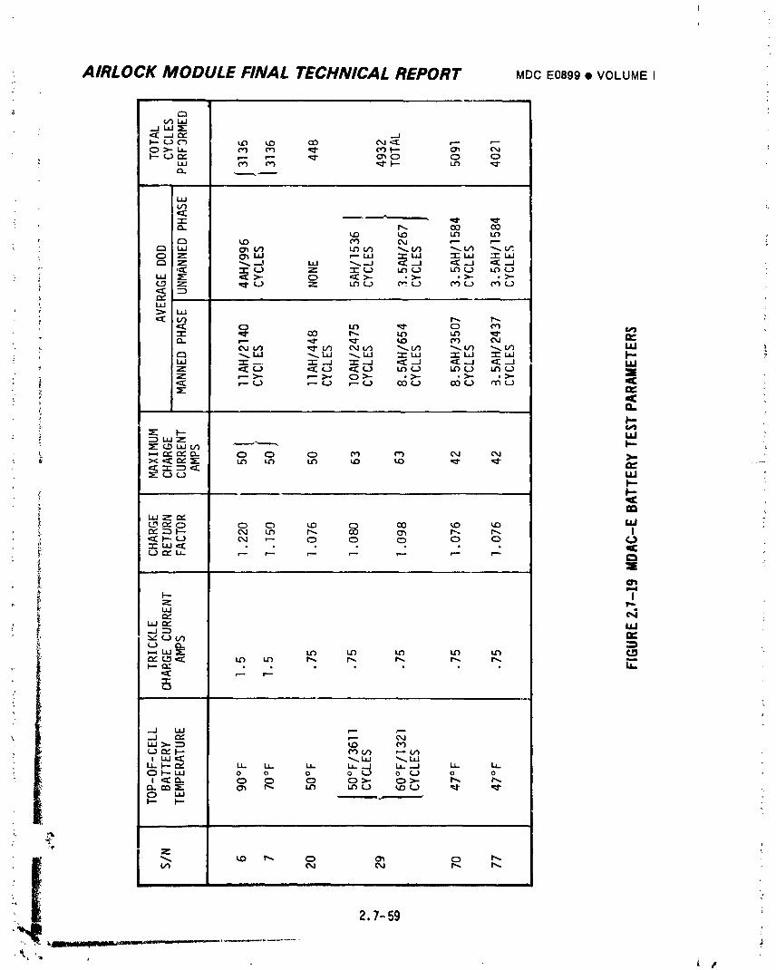
_J 0_ ,_ O,J
(.JOg I--- P3L/3 _"" V3
I._. t-- _ IJ.. I._ II- LL._J la....I I_- I.¢.OI'--IJJ 0 o o 0 _ o (..3 o o
f_ LO U'_ (,.3 '¢J" ¢¢'0 I.tJ _,_ "'I--" I"-
, i ,,, ,t
2.7-59
ut
1974018208-455
AIRLOCK MODULE FINAL TECHNICAL REPORT MDCE0899e VOLUMEII
C. Veld_r Battery Charger Testinq Because of the extremely rigid
• specifications requirements of high efficiency, reliability, functional
accuracy and power density, an extf.nsive development program was
necessary to develop the battery charger circuitry.
I/ Circuitrj/ Development - The areas which required the most
extensive development were the peak power tracker circuitry, the
battery temperature compensated charge voltage limit circuitry,
the ampere hour meter return factor circuitry, and the power trans-
istor drive circuitry. Development of each of these circuits required
extensive breadboard testing. During the initial development phase,
:_ the battery trickle charge and charge cutoff circuitry included a
mechanical relay. A review of the relay application concluded
that this design was inadequate for reliable performance for an
eight month mission. Therefore, the vendor was directed to replace
the relay with solid state circuitry. All solid state circuitry was
developed which was doubly redundant in each of the Five power
modules. This re-design significantly increased the reliabi"ty
of the battery charger.
2/ Power Transistor Procurement - As the battery charger neared the
production stages, a serious procurement problem arose. The vendor
was experiencing difficulty in obtaining power transistors in suf-
ficient quantities to maintain a timely production schedule. The
cause of the problem was poor manufacturing yield of the high
voltage, high power, high speed transistors which are required for
the main power switching circuits in the battery charger. An eva-
luation program was initiated to develop an alternate transistor
' '- source. When the evaluation program indicated that an alternate
transistor was satisfactory, the alternate transistors were in-
' stalled in tilt battery charger qualification unit No. 2. This
• I qualification unit was then subjected to the battery charger quali-
i fication tests of humidity, random vibration temperature altitude,_ and electromagnetic interference. It successfully passed each test.
2.7-60
1974018208-456
AIRLOCK MODULE FINAL TECHNICAL REPORT MDCE0399• VOLUMEI
D. Vendor Voltaqe Requ_ator Te_tinq -The voltage regulator specification
requirements of high efficiency, high power density and high reliability
required significant advances in the state-of-the-art for power
uonditioping equipment. For this reason, the development of the voltage
_egulator required the wndor to perform a substantial _mount of testing
and design evaluation.
I/ Power Transistor Eva_uation - Developmen _f a high efficiercy
voltage regulator required the implementation of a non-dissipative,
pulse-width modulated type design. To achieve the high level of
efficiency desired, the main power transisto;_ , ere required to be
of the high speed switching type. In addition, the specification
requirement that the voltage regulator input v)Itage range from 0
to 125 volts required that the power transistors be screened for
high collector to emitter breakdown voltage (BVc_o). A transistor
whicil met the high switching speed, high BVcE0 and high powerrequirements had not previously been used for high reliability
applications. T_ extensive evaluation of various transistors
was performed by t, _: vendor in order to determine a suitable tran-
_ sistor specification and a device which best met all of the _bove
criteria. In June 1968, vendor specification EM 712989 was issued
and a Westinghouse transistor determined to be an acc_.ptable device.
2/ Filter Capacitor Selection - To acilieve high effi'iency, capa-
citors of extreme.ly low series resistance were requir.,;d. Thus, the
vendor selected the tantalum wet slug type capacitor for the voltage
regulator input and output filters. This type capacitor offered a
substantial improvement in equivalent series resistance and density?
': (microfarads per cubic inch) over other types of capacitors.
i However, because there had been little previous use of tantalu_,
I wet slug capacitors in high reliability applications and because
_ some manufacturing problems had been incurred with th_s type
+ I capacitor, an extensive testing program was conducted to establish
, the performance, life stability and failure rate of these capacitors.
xi
1974018208-457
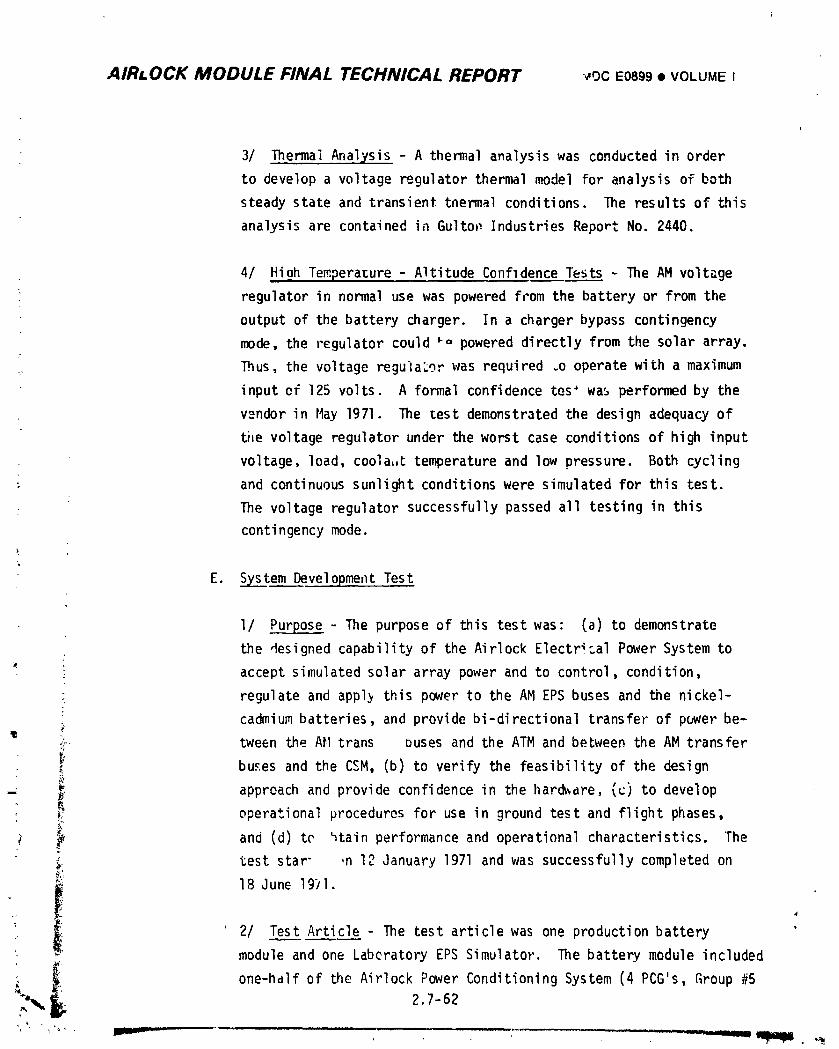
AIRLOCK MODULE FINAL TECHNICAL REPORT -_,oc E0899 • VOLUMEI
i
3/ Thermal Anal:/sis- A thermal analysis was conducted in order
to develop a voltage regulator thermal model for analysis of both
steady state and transient tnermal conditions. The results of this
analysis are contained in Gulton Industries Report No. 2440.
4/ Hiah Temperature - Altitude Confldence Tests - The AM voltage
regulator in normal use was powered from the battery or from the
output of the battery charger. In a charger bypass contingency
mode, the regulator could _o powered directly from the solar array.
_ Thus, the voltage regulator was required .o operate with a maximum
input ef 125 volts. A formal confidence tes' was performed by the
v_=ndorin May 1971. The test demonstrated the design adequacy of
ti,evoltage regulator under the worst case conditions of high input
voltage, load, coola,,Ctemperature and low pressure. Both cycling
; and continuous sunlight conditionswere simulated for this test.
The voltage regulator successfully passed all testing in this
contingencymode.k
E. S_xstemDevelopment Test
I/ _ - The purpose of this test was: (a) to demonstrate
the designed capability of the Airlock Electrical Power System to
= accept simulated solar array power and to control, condition,
° regulate and appl_ this power to the AM EPS buses and the nickel-
; cadmium batteries and provide bi-directional transfer of power be-
".'c tween the AM trans buses and the ATM and between the AM transfer
i _" buses and the CSM, (b) to verify the feasibility of the design
- _ approach and provide confidence in the llard_are,(c) to develop
_ operational procedures for use in ground test and flight phases,
and (d) te _tain performance and operational characteristics. The
_" test star" ,n 12 January 1971 and was successfully completed on@,_
"_ 18 Jun_ 1971.
' 2/ Test Article - The test article was one production battery "module and one Laberatory EPS Simulator. The battery module included
: _i one-half of the Airlock Power Conditioning System (4 PCG's, Group #5L'_,_, 2.7-62
..... _ , "_._,
1974018208-458
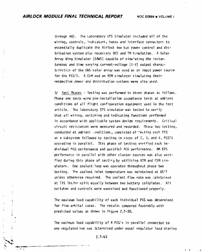
AIRLOCK MODULE FINAL TECHNICAL REPORT MDCE0899• VOLUMEI
through _8). The Laboratory [PS Simulator included all of the
wiring, controls, indicators, buses and interface connectors to
essentially duplicate the Airlock two bus power control and dis-
tribution system plus necessary DCS and TM Sir.lulation.A Solar
Array Wing Simulator (SAWS) capable of simulating the instan-
taneous and tin_ varying current-voltage (I-V) output charac-
teristics of tileOWS solar array was used as an input power source
for the PCG'S. A CSH and an ATM simulator simulatin9 their
respective power and dlstrlbution systems were also used.
3/ Test Phases - Testing was performed in three phases as follows.
Phase one tests were pre-installation acceptance tests at anl)ient
conditions of all flight confiqurationequipment used in the test
article, lllelaboratory EPS simulator was tested to verify
that all wiring, switching and indicating functions performed
in accordancewith applicable system design Paquiren_nts. Critical
circuit resistanceswere measured and recorded. Phase two testing,
conducted at a_ient ,onditions, consisted of _esting each PCG
as a subsystem followed by testing in steps of 2, 3, and 4, PCG'S
operating in parallel. This phase of testing verified each in-
dividual PCG performance and parallel PCG performance. AH EPS
performance in parallel with other cluster sources was also veri-
fied during this phase of testir_ by utilizing ATM and CSM sim-
ulators. One coolant loop was operated throughout phase two
testing. The coolant inlet temperature was maintained at 65('F
unless otherwise required. The coolant flow rate was ::_aint._i_ad
at If5 Ibs/hr split equally between bwo battery coldplates. All
switches and controls were exercised and functioned properly.
The maximum load capability of each individual PCGwas determined
, for five orbital cases. The results compared favorably withf
i : predicted values as shown in Figure 2,7-20.
The maximum load capability of 4 PCG's in parallel connected toC
one regulated bus uas dctern,iredunder equal regulator load sharing
; , 2.7-63
1974018208-459
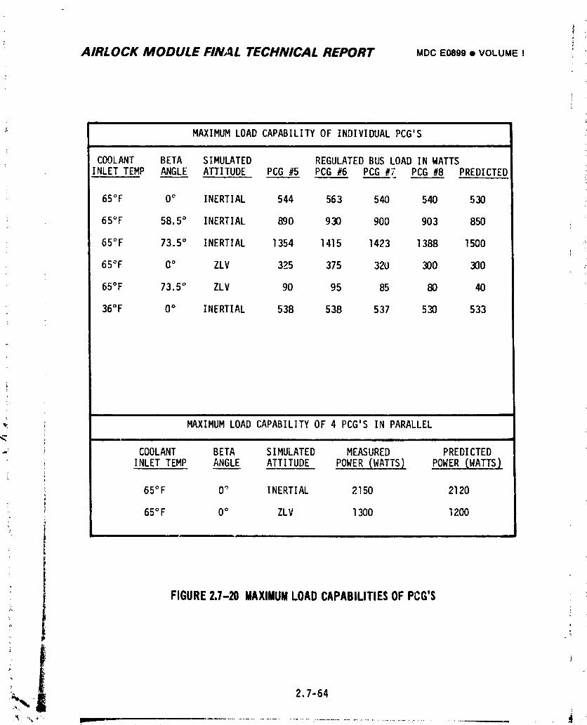
AIRLOCK MODULE FINAL TECHNICAL REPORT MDC E0899 • VOLUME !
Z"
i| i i
MAXIMUMLOAD CAPABILITYOF INDIVIDUALPCG'Si i
COOLANT BETA SIMULATED REGULATEDBUS LOAD INWATTSINLETTEMP ANGLE ATTITUDE PCG #5 PCG #6 PCG #7 PCG #8 PREDICTED
65°F 0_ INERTIAL 544 563 540 540 530
65°F 58.5° INERTIAL 890 930 900 903 850
65°F 73.5° INERTIAL 1354 1415 1423 1388 1500
65°F 0° ZLV 325 375 320 300 300
65°F 73.5° ZLV 90 95 85 80 40
36°F 0° INERTIAL 538 538 537 530 533
i,
wl
MAXIMUMLOAD CAPABILITYOF 4 PCG'S IN PARALLELi i i -
COOLANT BETA SIMULATED MEASURED PREDICTED
INLETTEMP ANGLE ATTITUDE POWER (WATTS) POWER (.WATTS)
65°F 0° INERTIAL 2150 2120
65°F 0° ZLV 1300 1200
7
FIGURE23-20 MAXIMUMLOADCAPABILITIESOFPCG'S
,a
t"- 2.7-64
] 9740] 8208-460
AIRLOCK MODULE FINAL TECHNICAL REPORT MDC E0899 • VOLUME I :
; conditions for two orbitd; crises _,e results compared favorablyf
i with the predicted values as shown in Figure 2.7-20. It was con-
cluded from this test and was confirmed from individual PCG testing
• that the maximum load capability of a PCG depends on the battery
; charging characteristics,i.e., the higher the battery charge !
{ current at constant potential near the end of the orbital daylight
_" period the higher the maximum load capability of the PCG. ;
, The failure of a voltage regulator resulting in a bus overvoltage
condition was simulated to verify proper operation of the shunt reg-f
ulator. This test w_s performed at no bus load and various regulator -
input voltage levels. The shunt regulator cleared the simL!;aLed
voltage regulator failure and maintained the bus voltage at accep-
i table levels in all cases.
; Phase three testing was a thermal vacuum test simulating electrical
and temperature altitude flight conditions. The EPS was tested at
: the simulated orbital conditions of /3= 0° /3=58.5° and /3= 73.5°
in the solar inertial attitude. Coolant loop temperatures at the
battery module coolant inlet were held constant at the temperature
• levels predicted for each test condition. The Reg bus load was a
typical mission day load at maximum loao :._pability. That is,
the typical day load profile was adjusted u, J such that the
average load over 15 orbits was equal to th_ Iculatedmaximum
load capability. The result of testing at the three orbita_
conditions showed that the AM EP3 would meet the missiun require-
I ments under normal operating conditions. Contingency operationswith simulated critical EPS failures such as with a failed battery
charger or : failed voltage regula¢or were verified utilizing
developed contingency operational procedures. The AM EPS manage-
ment and control system was effectively utilized to isolate the
failed component, to minimize the effect of the failure on
mission objectives and to identify operational constraints.
l27-6s
' L ,"
1974018208-461
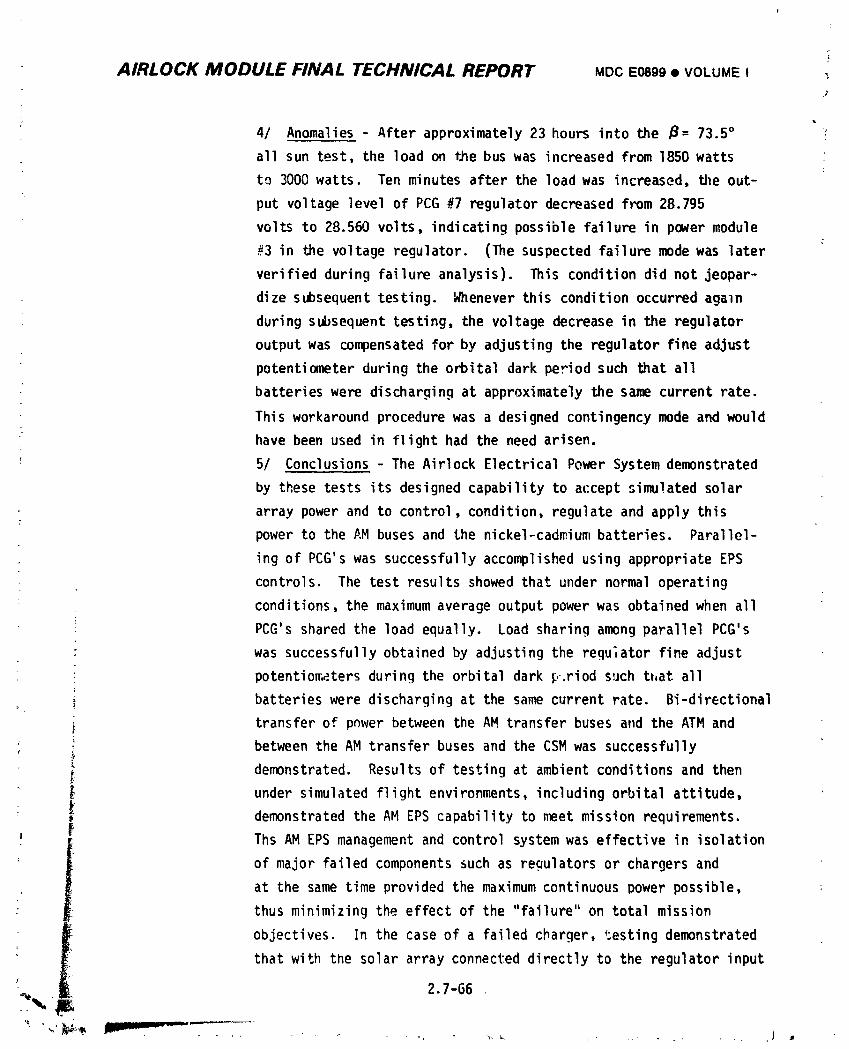
AIRLOCK MODULE FINAL TECHNICAL REPORT MDC E0899 • VOLUME I -_
4/ Anomalies - After approximately 23 hours into the /3= 73.5° _
all sun test, the load on tJ_ebus was increased from 1850 watts
to 3000 watts. Ten minutes after the load was increased, the out-
put voltage level of PCG #7 regulator decreased from 28.795
volts to 28.560 volts, indicating possible failure in power module
#3 in the voltage regulator. (The suspected failure mode was later
verified during failure analysis). This condition did not jeopar-
dize subsequent testing. Whenever this condition occurred aga]n
during subsequent testing, the voltage decrease in the regulator
output was compensated for by adjusting the regulator fine adjust
potentiometer during the orbital dark period such that all
batteries were discharging at approximately the same current rate.
This workaround procedure was a designed contingency mode and would
have been used in flight had the need arisen.
5/ Conclusions - The Airlock Electrical Power System demonstrated
by these tests its designed capability to accept simulated solar
array power and to control, condition, regulate and apply this
power to the AM buses and the nickel-cadmiumbatteries. Parallel-
ing of PCG's was successfully accomplished using appropriate EPS
controls. The test results showed that under normal operating
conditions, the maximum average output power was obtained when all
PCG's shared the load equally. Load sharing among parallel PCG's
was successfullyobtained by adjusting the regu,ator fine adjust
potentio_.atersduring the orbital dark _,.riodsuch that all
batteries were discharging at the same current rate. Bi-directional
transfer of pnwer between the AM transfer buses and the ATM and
: between the AM transfer buses and the CSM was successfully
_ demonstrated. Results of testing at ambient conditions and then' _ under simulated flight environments, including orbital attitude,
demonstrated the AM EPS capability to meet mission requirements.
' f Ths AM EPS management and control system was effective in isolation
of major failed components such as regulators or chargers and
at the same time provided the maximum continuous power possible,
thus minimizing the effect of the "failure" on total mission
objectives. In the case of a failed charger, _;estingdemonstrated
that with the solar array connected directly to the regulator input$
• , j
1974018208-462
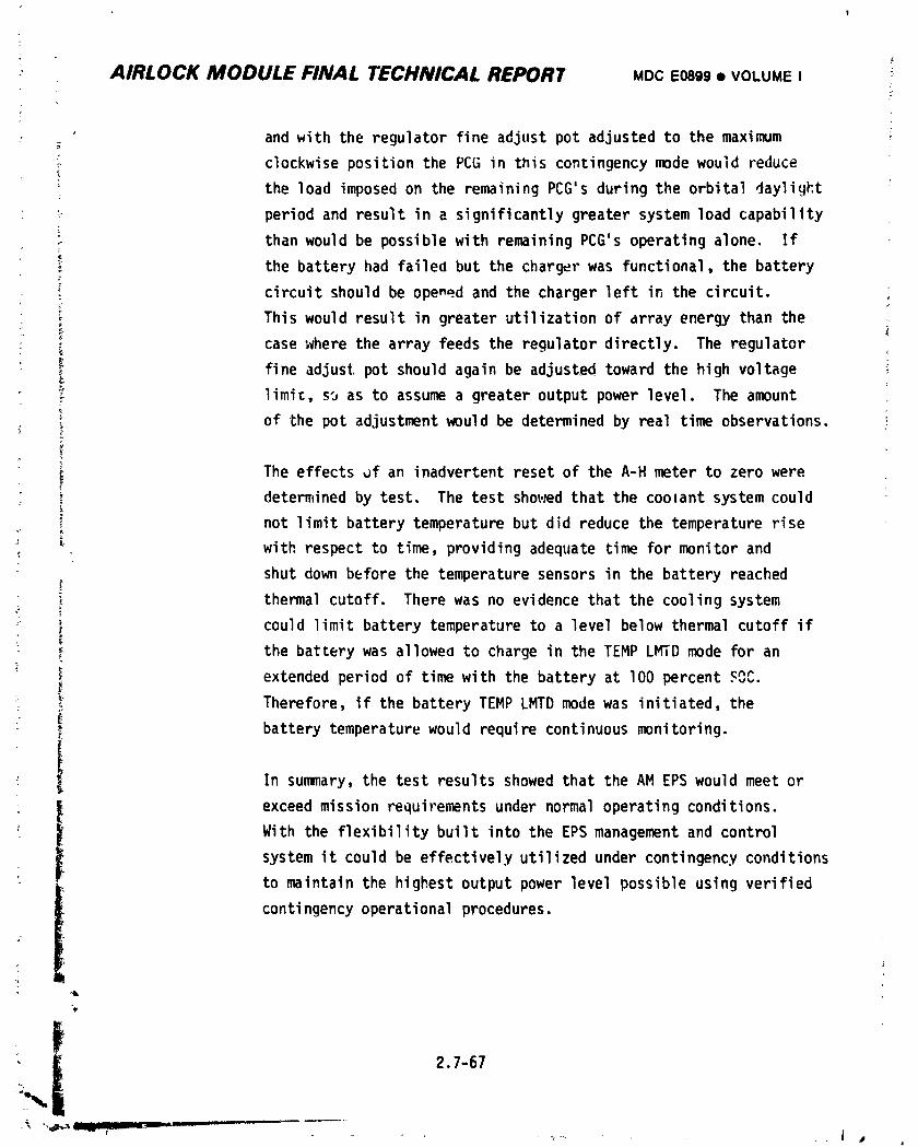
#
AIRLOCK MODULE FINAL TECHNICAL REPOR7 MDC E0899 • VOLUME I _
; and with the regulator fine adjust pot adjusted to the maximum
_ clockwise position the PCG in this contingency mode would reduce
: the load imposed on the remaining PCG's during the orbital daylight *
_ period and result in a significantly greater system load capability
F than would be possible with remaining PCG's operating alone. If
the battery had failed but the charger was functional, the battery
circuit should be opened and the charger left in the circuit.
_; This would result in greater utilization of array energy than the
: _ case ;vherethe array feeds the regulator directly. The regulator
• _ fine adjust pot should again be adjusted toward the high voltage ;
limit, so as to assume a greater output power level. The amount
; of the pot adjustment would be determined by real time observations.
The effects _f an inadvertent reset of the A-H meter to zero were
determined by test. The test sho;.sedthat the coolant system could
not limit battery temperature but did reduce the temperature rise
with respect to time, providing adequate time for monitor and
shut down before the temperature sensors in the battery reached
thermal cutoff. There was no evidence that the cooling system
_ _ could limit battery temperature to a level below thermal cutoff ifx
_ the battery was allowed to charge in the TEMP LMTD mode for an
; ) extended period of time with the battery at lO0percent _nr
_ _ Therefore, if the battery TEMP LMTD mode was initiated, the
battery temperature would require continuous monitoring.!
I In summary, the test results showed that the AM EPS would meet or
• _ exceed mission requirements under normal operating conditions.
With the flexibility built into the EPS management and control
system it could be effectively utilized under contingency conditions
to maintain the highest output power level possible using verified
i contingency operational procedures.
"¥
i 2.7-67• _ __ j I iii, _.....
i
1974018208-463
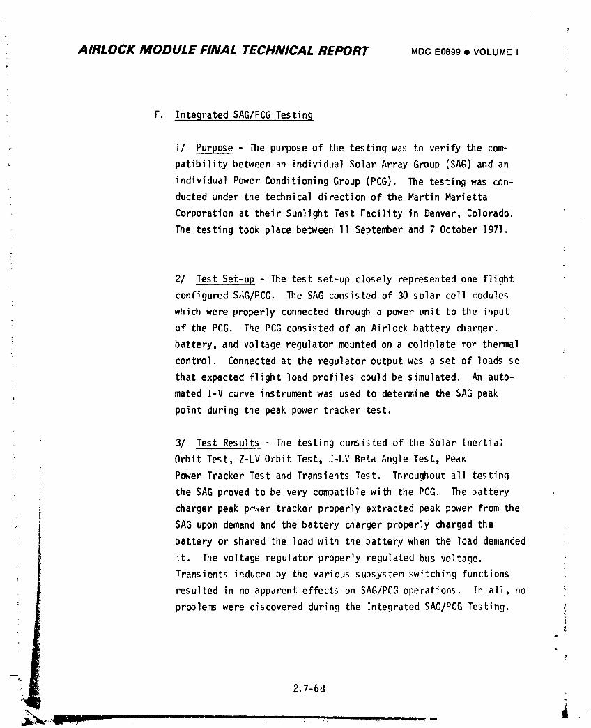
AIRLOCK MODULE FINAL TECHNICAL REPORT MDC E08_9 • VOLUME I ;
F. Integrated SAG/PCG Testing
1/ Pur__ - The purpose of the testing was to verify the com-
patibility between an individual Solar Array Group (SAG) and an
individual Power ConditioningGroup (PCG). The testing was con-
ducted under the technical direction of the Martin Marietta
Corporation at their Sunlight Test Facility in Denver, Colorado.
The testing took place between II September and 7 October 1971.
2/ Test Set-up - The test set-up closely represented one flight
configured SAG/PCG. The SAG consisted of 30 solar cell modules
which were properly connected through a power unit to the input
of the PCG. The PCG consisted of an Airlock battery charger,
; battery, and voltage regulator mounted on a coldplate for thermal
control. Connected at the regulator output was a set of loads so
that expected flight load profiles could be simulated. An auto-
mated I-V curve instrumentwas used to determine the SAG peak
point during the peak power tracker test.
3/ Test Results - The testing consisted of the Solar Inertial
Orbit Test, Z-LV Orbit Test, ,:-LVBeta Angle Test, Peak
Power Tracker Test and Transients Test. Throughout all testing
: the SAG proved to be very compatible with tilePCG. The battery
charger peak p_ver tracker properly extracted peak power from the
SAG upon demand and the battery charger properly charged the
battery or shared tileload with the battery when the load demanded
it. The voltage regulator properly regulated bus voltage.
Transients induced by the various subsystem switching functions
resulted in no apparent effects on SAG/PCG operations. In all, no
problems were discovered during the Integrated SAG/PCG Testing.
2.7-68
1974018208-464
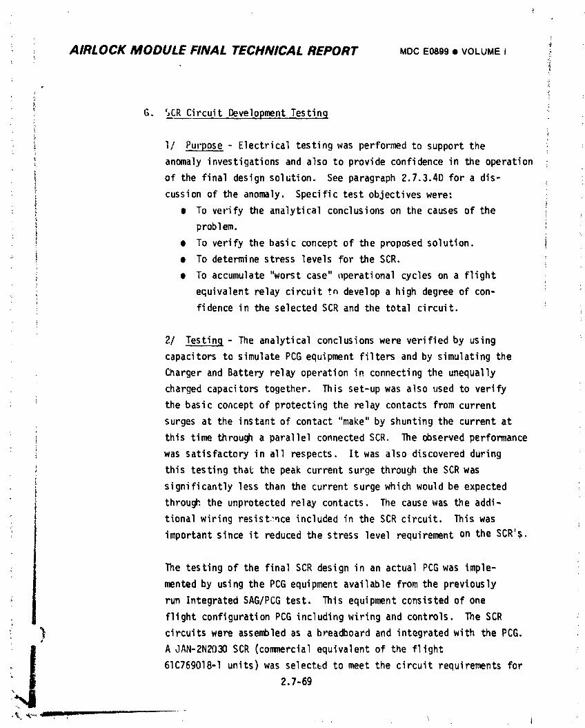
tAIRLOCK MODULE FINAL TECHNICAL REPORT MDCE0899• VOLUME I _-
, _:
=
E ,!) G. SCR CircuitDevelopmentTestingF
' I/ Purpose- Electricaltestingwas performedto supportthe i
anomalyinvestigationsand also to provideconfidencein the operation
of the finaldesignsolution. See paragraph2.7,3.4Dfor a dis-
cussionof the anon_ly. Specifictestobjectiveswere:
• To verifythe analyticalconclusionson the causesof the
probIem.
• To verifythe basic conceptof the proposedsolution.
• To determinestresslevelsfor the SCR.
• To accumulate"worstcase"t_perationalcycleson a flight
equivalentrelaycircuit+,ndevelopa high degreeof con-
: fidencein the selectedSCR and the total circuit.
2/ Testinq- The analyticalconclusionswere verifiedby using
capacitorsto simulatePCG equipmentfiltersand by simulatingthe
Chargerand Batteryrelayoperationin connectingthe unequally
chargedcapacitorstogether. This set-upwas also used to verify
the basic conceptof protectingthe relaycontactsfrom current
surgesat the instantof contact"make"by shuntingthe currentat
thistime througha parallelconnectedSCR. The observedperformance
was satisfactoryin all respects. Itwas also discoveredduring
thistestingthat the peak currentsurge throughthe SCR was
significantlylessthan the currentsurgewhich would be expected
throughthe unprotectedrelay contacts. The causewas the addi-
tionalwiring resist.:nceincludedin the SCR circuit. Thiswas
importantsince it reducedthe stresslevelrequirementon the SCR'$.
The testingof the finalSCR designin an actualPCGwas Imple-
mentedby usingthe PCG equipmentavailablefrom the previously
run IntegratedSAG/PCGtest. This equipmentcc,nsistedof one
flightconfigurationPCG includingwiring and controls. The SCR
circuitswere assembledas a breadboardand integratedwith the PCG.
!,_ A JAN-2N2030SCR (commercialequivalentof the flight
61c76g018-Iunits)was selectedto meet the circuitrequirementsfor
2.7-69
1974018208-465
% !
AIRLOCK MODULE FINAL TECHNICAL REPORT MDCE0899• VOLUMEI
the SCR application. The wiring _-esistancesin the SCR circuits
were designed to be equivalent to the anticipated flight equip-
ment installation. The operation of each SCR circuit was observed
under all combinationsof circuit conditions which would exercise
their associateJ relay contacts. Also all relay closing sequen-
ces were simulated by controlling relay closure times with opera-
tion again being observed.
3/ Conclusions - The testing demonstrated the ability of the SCR
circuits to successfully protect the Charger and Battery relays.
Current surges caused by the charginc and discharging of the
voltage regulator and battery charger capacitors were conducted
through the appropriate SCR during the closure of the associated
power relay. The JAN-2N2030 SCR operated satisfactorily through-
out the testing. There were no SCR failures and no evidence of
any SCR degradationwas observed during the testing. No SCR
i failed to fire when properly triggered and there were no inadver-
i tent, i.e., without a trigger pulse, firing of any SCR.!
I!i A confidence test of more than 500 cyclic operations was performed
; i at the circuit conditions causing worst case transient current.
: i Al_ aspects of operation were successful throughout this test
which indicated that the SCR and SCR circuits could meet any
possible flight requirements.
H. Cluster EPS Testing
I/ PurPose - The overall purpose of this testing was to verify
proper operation of the Cluster EPS systems in their parallel
; modes of operation prior to the mating of the actual flight
. , systems. To accomplish this purpose a Skylab Cluster Power Sim-
ulator (SCPS) was developed at the Marshall Space Flight CenterI
(MSFC). The specific primary objectives of the testing on the
!_ SCPS were as follows:2.7.70IIIRIIIm I II i iiii _L I _ I.II jlllll ii i El I I ,
...... . • j _;
1974018208-466
AIRLOCK MODULE FINAL TECHNICAL REPORT MDCE0899• VOLUME I "
;- ,z
e To demonstratethe capabilityof the AM and ATM power
systeLnsto operatein paralleland to verifystableoper-
ation of the two systemswhen subjectedto the flight
i powerprofile.
; e To demonstratethat flightcircuitwiringis adequatefor
properloadsharingby the powersystems.
_ e To analyzethe effectsof the single-point-groundsystem
._ conceptwith the clusterpowersystemsin its various ;
i configurations
• _ • To demonstrateand analyzepowersystemfailuresand con-
I tinger,cy n_desof operation. '
e To determineshort-termand long-termeffectsof simulated
I orbitaloperationon the systemsand particularlyont
theirbatteries.
• 2/ SCPS Description- The SCPS hardwareconsistedof both flight
_ systemshardwareand electricalsupportequipment(ESE)hardware.
_ The flight(or flightequivalent)hardwareincluded: two AM
: _ batterymodules(8 PCG'S);18 ATM ChargerBatteryRegulator, _ Modules(CBRM'S);an ATM PowerTransferDistributor;an AM power
distributiensystem;and threeAM control,display,and circuit
: breakerpanels. The ESE equipmentincluded: ATM solar array
i simulators;OWS solar arraysimulators;clusterloadbanks;a
_ CSM sourceand loadsimulator;networkcol,troland switching
equipment;a digitaldataacquisitionsystem;a low temperature
test unit;an airconditioningsystem;and variousESE control
! and displaypanels. All power distributioninterconnecting
; cablingwas made equivalentto flightwiring.
' 31 Testing- Testingon the SCPS commencedin February1972.
Testswere performedin compliancewith the "SkylabCluster
PowerSystemBreadboardTest Requirernents"Document,40M35693.
_ The SCPSwas also used as a trainlngaid duringtrainingclasses
on the clusterEPS for flightcontroland astronautpersonnel.
2.7-71
J .
1974018208-467
AIRLOCK MODULE FINAL TECHNICAL REPORT MDC E0899 • VOLUME I
:" 4/ Test Results- Testing on the SCPS was very successful.
Testing was initiated early enough so that any problems could"1
have been solved without affecting launch schedules. However,
no problems were encountered with the parallel operations ofi,
the cluster EPS systems. The testing verified the compatibility
of the AM and ATM power systems and their capability to inter-
: face with the simulated CSM power system. Flight procedures
_ associated with the EPS systems were verified on the SCPS. Con-
tingency procedures to overcome simulated system malfunctions
were also verified by SCPS testing.
5/ Mission Support Status - The SCPS was maintained in an up-
: to-date flight system equivalent status for the Skylab mission
phases to allow for system support testing. Several such
: tests have been performed during the mission. They include +.he
SL-I/SL-2 Battery Storage Test; the SL-3 AM EPS Shutdown Pro-L.
cedures Test; and the SL-3 SAS #4 Current Anomaly Test. These
_ tests are discussed in Section 2.7.4.8 of this report.
2.7.3.3 Spacecraft System Testing
The Spacecraft System Test (SST) was perforn_d on the flight Airlock
Module at MDAC-E from October 1971 through September 1972. The progression
of the Electrical Power Systelnthrough the SST is shown by the flow diagram
on Figure 2.7-21. This diagram shows the n:_jortests, changes, and retests
which verified that the EPS design met all requirements and that the EPS
' hardware was satisfactory for delivery to the customer for flight usage.
The procedures for the SST and the test results are given in the4
various Service Engineering Data Reports (SEDR's) as referenced on the flow
diagram. Dynamic resistance measurements were perfon1_edon the end-to-end
PCG and feeder/distributionwiring in SEDR D3-Nl4-1 to verify the wiring
design prior to powered operations. Pre-power bus isolation check, .. !
the initial bus power applicationwere performed in SEDR D3-_I_C- _, ,!
included:
e Bus isolation checks.
/
_,, 2.7-72
1974018208-468
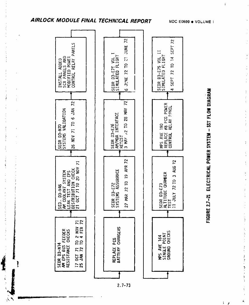
AIRLOCK MODULE FINAL TECHNICAL REPORT MDCE0899• VOLUME t
e Bus power application and distribution.
• System status light verification (excluding _CG) and light test
circuit checks.
• Power distribution and polarity checks to ECS and coolant components
_ prior to component hookup.
¢ Fan and pump inverter output power pt,ase-to-phase checks prior to
cr,nponent hookup.
The systen_ validation test, SEDRD3-N70-1, accomplished an overall
check of the Airlock power system and monitored ai,J applied signals at
; the AM/OWS,AM/MDA, AM/ATMand DA/PS interfaces. Included were the following
checks :
e Individual PCGend-to-end voltage distribution and polarity varifi-
cation.
• Individual PCGoperation in all modes (manual & command).
• Individual PCGand combined bus voltage droop measu_ments.
e Determination of voltage trigger points for EPS C&Wparameters,
! emergency lighting and bus shunt regulators.
• Emergency power disconnection.
• Maximum interface power transfer per the associated ICD levels.
; • EPS telemetry and on-board parameter correlatio,,.
During the systems validation test, several PCGDower control relays
were damaged by l_rge transient currents. After SEDRD3-N70-1 silicon
controlled rectifier (SCR) panels were incorporated to protect the relay
contacts from these current transients. Also, at this time all PCG
: battery chargers were replaced with units which had been upgraded to; include a reduced battery current trickle charge rate and a reduced
return factor. During the systems assurance test, SEDR D3-F_2-1, the
_ systems v_lidation checks on the PCG's were repeated due to the extentof the PCG modifications. The following checks were also performed:
_ e Verification of the new battery current trickle c'.=argerate.
;i e Verification of operation of the SCR protective circuits.
; _ e Verification of maximum power transfer across AM/MDA and MDA/CSM "interfaces in accordance with the respective interface specifi'cations.
:_ 2,7- 74
1974018208-470
AIRLOCK MODULE FINAL TECHNICAL REPORT ,,..:,._cE0899• VOLUME ,'
e Veriflcationo,:propPrloadcurrentsi_aringon poweF feedersand
distributionnetworks.
• Emergencypower'down circuitverificationfor on-boardand
GSE initiation.
• Voltagepolarityand distributionto NDA componentspriorto ..
componentconnection.
e Correlationof telemetry,C&'dand on-boarddisplayparamete's.
DuringAM/MDAinterfaseretest,SEDR D3-E76-1,the correctmec:,anical
and electricaloperationof the modifiedReg bus adjustpotentiometer
installationwas 'erified.The shunt regulatorswere replacedby up-
gradedunitsand measurementof the primarytriggervoltagelevelwas
performed.i
Duringsimulatedflighttess,SEDR D3-E75-1Vol_,_I, a simulated
flightmi.-.sionprofileof the AM/MDAwas _,er_ormedto supportEMC critical
circuitmeasurementsand to demonstratean all systemEMC compat?bility.
The AM EPSbatteriessuppliedall AM electricalbus power -equirements
fromsimulatedliftoff throughthe completior=of the simulatedOWS solar
arraywing d_ploymentsequence. PCG'swere operatedin theircyclicmcde
fromsimulatedsolar arraywing deploymentto the terminationof the test
which occurredafteroperationin the orbitalstorageconfiguration.
_equentialand deploybus activati(.,_,ATM/AMEPS paralleling.CSM ground
swit,_overs,SWS/CSMEPS parallelingand unparallelingwere all perfon;}ed
duringthe cyc,ic¢,oeration.The isolationbetweenthe singlepoint ground
and the Airlockpower returnson the AM/M[_were continuouslymonitor_d,
per the MissionPreparationSheet (Mr,:)for Aero.=paceVehicleEquipment
(AVE) 164,duringGSE cablingand equipmentinstallation,andwhenever
the AM/_IDAwas not being powered. ThisMPS was initiatea_riorto the
altitudechambertest, 3EDR D3-E73-1,and continueduntilshir-entto KSC.
i The altitudechambertestwas performedin three (3) phases;theunmannedaltitudephase,the mannedambientphase,ar,J themanned altitude
• phase. Prior to initiallyoperatingthe AM/MDAin a low pressureenvir_,_-
,nentt,_eabilityto reJ11ove power fromthe bussesall electrical AM under
: simulatedemergencyconditionswas verified Duringthe unm_.nedrun_ 2.7-7b
1974018208-471
AIRLOCK MODULE FINAL TECHNICAL REPORT MDCE0899• VOLIJMEI
the power systernwas operated to a simulated fliaht profile with simu-
lated electrical loads as required. From liftoff to completion of the
solar array deploy sequence, AM flight type batteries supplied all AM
bus loads. The PCG's were operated in a cyclic mode for the remainder of
the unmanned run. Single point ground transfer to the CSMsimulator was
accomplished. ATM and CSMsimulator power systems were paralleled with
the AM EPS. All CSMsimulator loads were transferred to AM power. The
EPS _emained operative for an additional 84 hours in support of the out-
gassing test. The manned ambient run was at, evaluation of the procedures
to be used in tF ._.,.._nned altiLude run. Prior to ascent to simulated
altitude Jring c.,e manned ruT_, the capability to remove all electrical
powe " , t'le alrl_ck was reverified. The manned runs began with the EPS
operatiny in _.e normal orbita, mode with the AM and ATMparalle!ed
and CSMsimulator receiving pGwer from the Atl busses. The crew evaluated
the responses of the EPS to manual system controls. The CSMsimulator
EPSwas reactivated and isolated from the AM EPS. Single point gro z.ld
was restored in the AM by the crew. The objectives of EPS verification
,t sl,,.ulated altitude conditions were satis" 2d by this testing.
A ground fault detected during SEnR D3-F90-1 Volume IV, was isolated
to PCG#8 c_trol relay panel. After replacement c _ the panel all func-
tions in the new panel were veri,'ied per MPSAVE 190 with satisfactory
results.
Simulated fligl,t tests, SEDRD3-E75-1 Volume II, demo,,strated both
the operational and the elecLrcm.agnetlc compatibility between the AM/MDA
suppor_.in,q systems and the earth r;sources experi men.. package (EREP).
In conjunction with the above demonstrations, AM/MDAcritical circuit
measurements wore performed with satisfactory results. After the removal
; of the grouna support eq_'-'ent used to measure critical AM/MDAcircuits
and the reconnect on of the AM/MDAfliqllt circuits, the EREPsimulated
flight was repeated to a;sure flight integrity of these circuits. This
was done with the EPS confinured in the orbital mode and wi_h nominal
EREForbital !odds applied.
AIRLOCK MODULE FINAL TECHNICAL REPORT MDCE0899• VOLUMEI
Durina SST a joint NASA/MDAC-E Review Team reviewed all testing; evaluated
the significance of problems as they occurred; and evaluated the suitability of
solutions. This joint cooperation allowed for quick classificationof problems
and the timely implementationof acceptable selutions.
SST testing on the Airlock Module EPS was very successful. In addition to
passing the specific E)S tests, the power system successfully performed its normal
function of supplying AM electrical power during many of the tests on the other AM
systems. The problems that were uncovered during the testing were thoroughly
investigated and their resultant solutions were expedited to minimize the retest
effects on the overail test program. The Spacecraft System test program,
therefore, met its objectives of verifying that the EPS design met its requirements
ana that the U-I hardware was satisfactory for flight.
2.7.3.4 Design Modifications
A. Battery - The design selected for the Airlock batteries was one which had
a successful flight history. At the o,.tset of the Airlock program no
battery hardware development was anticipated. However, it became
necessary tu modify this design in order to resolve problems which were
encountered in the course of the Airlock program. In all, three design
cot.figuration changes were incorporated.
I/ Case Material Chanqe and Cell Plate Shape Modification - The first
design configuration change was twofold. First, three shorted cells were
detected during early cel_ conditioni,_g activity. Vendor analysis of
these cells revealed inadequate clearance existed between the top of one
plate and the tab attachment to the adjacent plate. This condition would
allow l_ttle pack misalignment during assembly and represented a potential
life limiting problem in the ewnt of plate shifting after cell assembly.
Second, newly manufactured batteries indicated during acceptance testing
that _perating temperature gradients within the battery case were
greater than anticipated. This condition also represented a detriment
to attaining the necessary cycle life. To correct these conditions, a
• new design configurationwah established in March 1971. The new
con_;guration :ncorporateda change of th_ battery case material from
2.7-77
1, •
1974018208-473
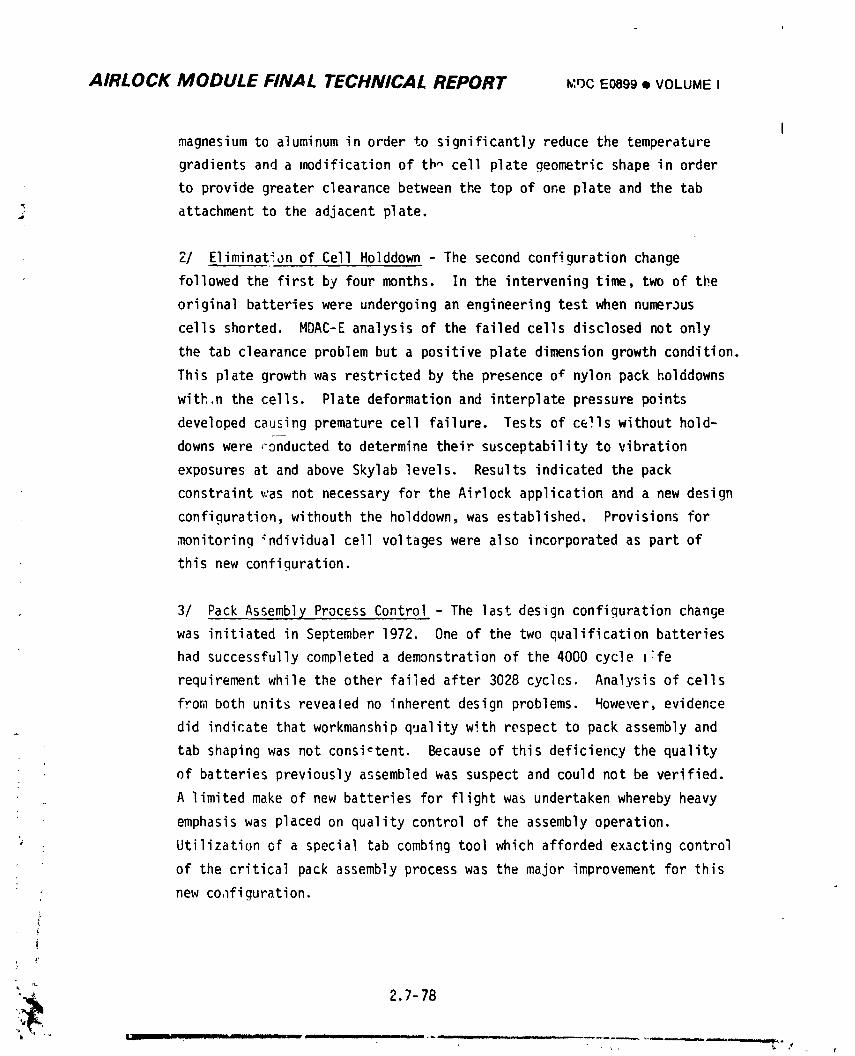
AIRLOCK MODULE FINAL TECHNICAL REPORT _:r_cE0899I VOLUMEI
Imagnesium to aluminum in order to significant|y reduce the temperature
gradients and a modification of th_ cell plate geometric shape in order
to provide greater clearance between the top of one plate and the tab
attachment to the adjacent plate.
2/ Eliminatijn of Cell Holddown - The second configuration change
followed the first by four months. In the intervening time, two of the
original batteries were undergoing an engineering test when numerJus
cells shorted. MDAC-E analysis of the failed cells disclosed not only
the tab clearance problem but a positive plate dimension growth condition.
This plate growth was restricted by the presence o# nylon pack holddowns
with.n the cells. Plate deformation and interplate pressure points
developed causing premature cell failure. Tests of cells without hold-
downs were ,-onductedto determine their susceptability to vibration
exposures at and above Skylab levels. Results indicated the pack
constraint was not necessary for the Airlock application and a new design
configuration,withouth the holddown, was established. Provisions for
monitoring _ndividual cell voltages were also incorporated as part of
this new configuration.
3/ Pack Assembly Process Control - The last design configuration change
was initiated in September 1972. One of the two qualification batteries
had successfully completed a demonstration of the 4000 cycle 1:fe
requirement while the other failed after 3028 cycles. Analysis of cells
from both units revealed no inherent design problems. However, evidence
. did indicate that workmanship quality with respect to pack assembly and
tab shaping was not consistent. Because of this deficiency the quality
of batteries previously assembled was suspect and could not be verified.
A limited make of new batteries for flight was undertaken whereby heavy
emphasis was placed on quality control of the assembly operation.
' Utilization of a special tab combing tool which afforded exacting control
of the critical pack assembly process was the major improvement for this
new co,lfiguration.
Z
i
2,7 78
" " • ,_ _ II II _.. I! III1_ II ' Ill • L -- "'r : _',_-',_i_,,ila_._.iianL_
, _ , , r I
1974018208-474
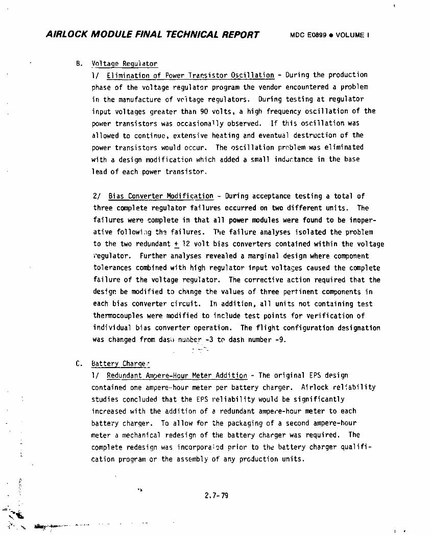
AIRLOCK MODULE FINAL TECHNICAL REPORT MDCE0899• VOLUMEI
B. VoltaQe Reguiator
I/ Elimination of Power Transistor Oscillation - During the production
phase of the voltage regulator program the vendor encountered a problem
in the manufacture of veitage regulators. During testing at regulator
input voltages greater than go volts, a high frequency oscillation of the
power transistorswas occasionally observed. If this oscillation was
allowed to continue, extensive heating and eventual destruction of the
power transistors would occur. The oscillation preblem was eliminated
with a design modification which added a small indJctance in the base
lead of each power transistor.
2/ Bias Converter Modification - During acceptance testing a total of
three complete regulator failures occurred on two different units. The
failures were.complete in that all power modules were found to be inoper-
ative following th? failures. The failure analyses isolated the problem
to the two redundant + 12 volt bias converters contained within the voltage
regulator. Further analyses revealed a marginal design where component
tolerances combined with high regulator input voltages caused the complete
failure of the voltage regulator. The corrective action required that the
desigr,be modified to change the values of three pertinent components in
each bias converter circuit. In addition, all units not containing test
thermocoupleswere modified to include test points for verification of
individual bias converter operation. The flight configuration designation
was changed from das_ number -3 tP dash number -g.
C. BatterX Charge,'_
I/ Redundant Ampere-Hour Meter Addition - The original EPS design
contained one ampere.-hourmeter per battery charger. Airlock reliability
studies concluded that the EPS reliability would be significantly
increased with the addition of a redundant ampere-hour meter to each
battery charger. To allow for the packaging of a second ampere-hour
' meter a mechanical redesign of the battery charger was required. The
complete redesign was incorpora',__dprior to the battery charger qualifi-L
cation program or the assembly of any production units.
2.7-79
i974018208-475
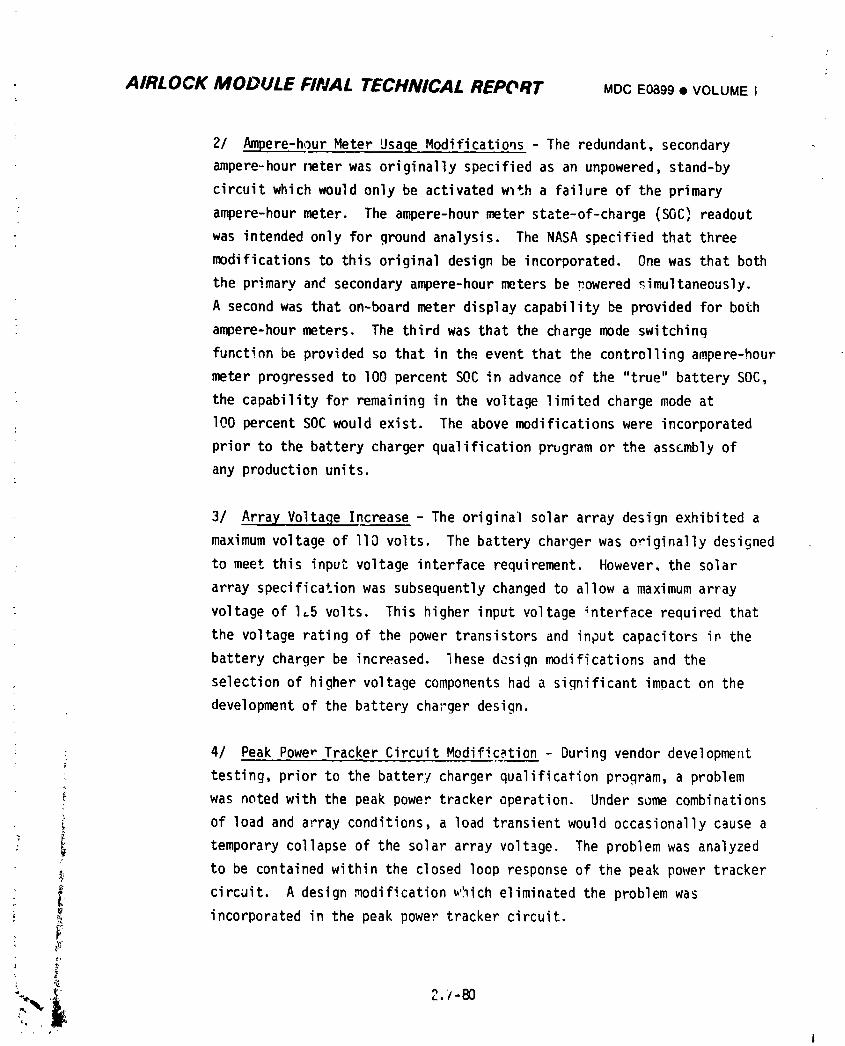
AIRLOCK MODULE FIIVAL TECHNICAL REPORT MDC E0899 • VOLUME I
2/ Ampere-hour Meter Usaqe Modifications - The redundant, secondary
ampere-hourrmter was originally specified as an unpowered, stand-by
circuit which would only be activated wlth a failure of the primary
: ampere-hourmeter, The ampere-hour meter state-of-charge (SOC) readout
was intended only for ground analysis. The NASA specified that three
modifications to this original design be incorporated. One was that both
the prima[v and secondary ampere-hour meters be powered _imultaneously.
A second was that on-board meter display capability be provided for both
ampere-hour meters. The third was that the charge mode switching
function be provided so that in the event that the controlling ampere-hour
meter progressed to lO0 percent SOC in advance of the "true" battery SOC,
the capability for remaining in the voltage limited charge mode at
lO0 percent SOC would exist. The above modifications were incorporated
prior to the battery charger qualification prugram or the assembly of
any production units.
3/ Array Voltage Increase - The original solar array design exhibited a
maximum voltage of llO volts. The battery charger was originally designed
: to meet this input voltage interface requirement. However, the solar
array specificationwas subsequently changed to allow a maximum array
: voltage of I_5 volts. This higher input voltage _nterface required that
the voltage rating of the power transistors and input capacitors in the
battery charger be increased, lhese design modifications and the
selection of higher voltage components had a significant impact on the
development of the battery cha;'gerdesign.
: 4/ Peak Powe_ Tracker Circuit Modific._tion- During vendor development
testing, prior to the batter:/charger qualification program, a problem
i was noted with the peak power tracker operation. Under some combinations
_' of load and array conditions a load transient would occasionally cause a_ g
: _ temporary collapse of the solar array voltage. The problem was analyzed
to be contained within the closed loop response of the peak power tracker
i circuit. A design modification _"_icheliminated the problem was; _ incorporated in the peak power tracker circuit.
_,_-
, ¢..
1
1974018208-476
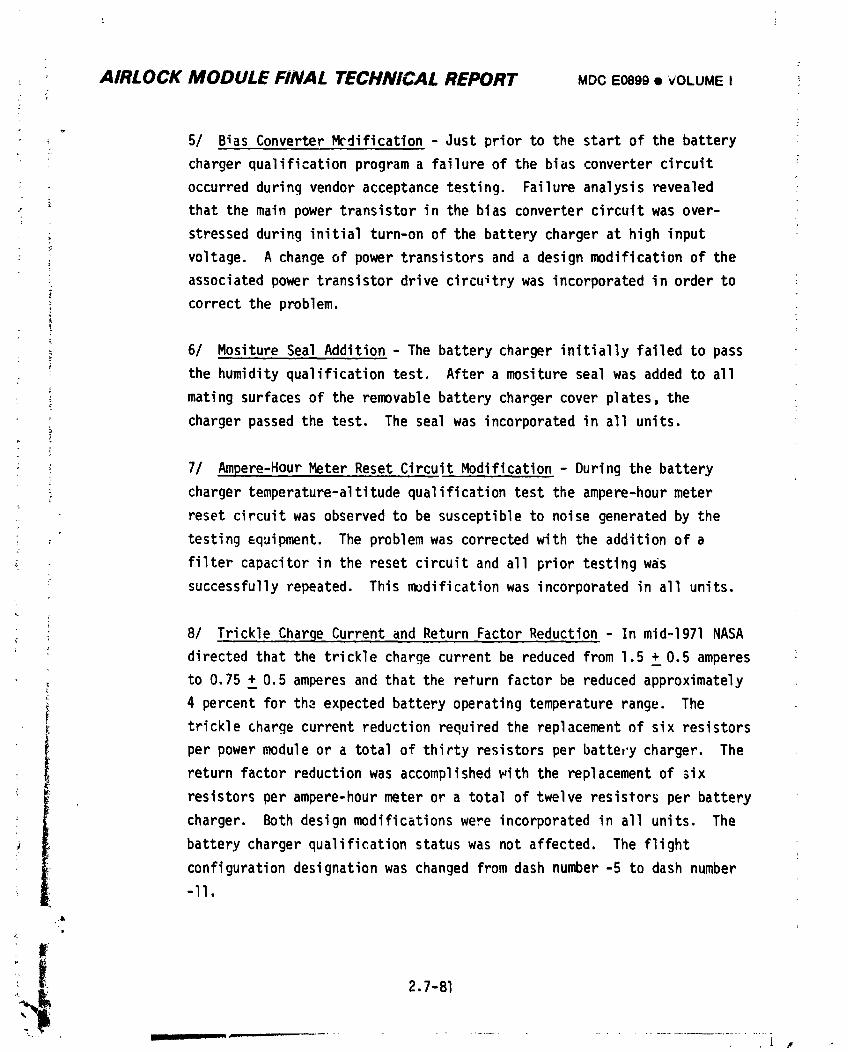
' AIRLOCK MODULE FINAL TECHNICAL REPORT MDC E0899 • VOLUME I ;
.F
_r 5/ Bias Converter Mcdificatlon - Just prior to the start of the battery
charger qualification program a failure of the bias converter circuit
• occurred during vendor acceptance testing. Failure analysis revealed
that the main power transistor in the bias converter circuit was over-
stressed during initial turn-on of the battery charger at high input
voltage. A change of power transistors and a design modification of the
associated power transistor drive circuitry was incorporated in order to
correct the problem.
6/ Mositure Seal Addition - The battery charger initially failed to pass
the humidity qualification test. After a mositure seal was added to all
mating surfaces of the removable battery charger cover plates, the
charger passed the test. The seal was incorporated in all units.
; 7/ Ampere-Hour Meter Reset Circuit Modification - During the battery
_ charger temperature-altitudequalification test the ampere-hour meter
: reset circuit was observed to be susceptible to noise generated by the
• testing _quipment. The problem was corrected with the addition of a
" filter capacitor in the reset circuit and all prior testing was
successfully repeated. This modification was incorporated in all units.
8/ Trickle Charge Current and Return Factor Reduction - In mid-1971 NASA
directed that the trickle charge current be reduced from 1.5 +_0.5 amperes
to 0.75 + 0.5 amperes and that the return factor be reduced approximately
_ 4 percent for the expected battery operating temperature range. Thef
j: trickle charge current reduction required the replacement of six resistors
per power module or a total of thirty resistors per battery charger. Thereturn factor reduction was accomplished _ith the replacement of 3ix
• resistors per ampere-hour meter or a total of twelve resistors per battery
charger. Both design modifications were incorporated in all units. The
battery charger qualification status was not affected, The flight
configuration designation was changed from dash number -5 to dash number
-ll.
,&
_I 2.7-81
1974018208-477
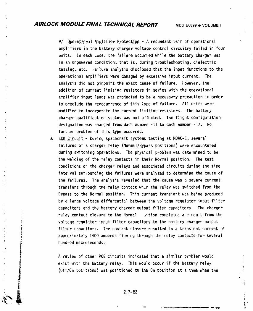
AIRLOCK MODULE FINAL TECHNICAL REPORT MDCE0899• VOLUMEI
9/ Operatin_l Amplifier Protection - A redundant pair of operational
amplifiers in the battery charger voltage control circuitry failed in four
units. In each case, the failure occurred while the battery charger was
in an unpowered condition; that is, during troubleshooting, dielectric
testing, etc. Failure analysis disclosed that the input junctions to the
operational amplifiers were damaged by excessive input current. The
analysis did not pinpoint the exact cause of failure. However, the
addition of current limiting resistors in series with the operational
amplifier input leads was projected to be a necessary precaution in order
• to preclude the reoccurrence of this Lype of failure. All units were
modified to incorporate the current limiting resistors. The battery
charger qualification status was not affected. The flight configuration
designation was changed from dash number -ll to dash number -17. No
further problem of this type occurred.
D. SCR Circuit - During spacecraft systems testing at MDAC-E, several
failures of a charger relay (Normal/Bypasspositions) were encountered
during switching operations. The physical problem was determined to be
the welding of the relay contacts in their Normal position. The test
conditions on the charger relays and associated circuits during the time
interval surrounding the failures were analyzed to determine the cause of
the failures. The analysis revealed that the cause was a severe current
transient through the relay contact wh,n the relay was switched from the
Bypass to the Normal position. This current transient was being p,'oduced
by a large voltage differential between the voltage regulator input filter
: capacitors and the battery charger output filter capacitors. The charger
relay contact closure to the Normal ,ition completed a circuit from the
i voltage regulator input filter capacitors to the battery charger output
I filter capacitors. The contact closure resulted in a transient current of
approximately 1400 amperes flowing through the relay contacts for severa_
hundred microseco.lds.
A review of other PCG circuits indicated that a similar problem would
• exist with the battery relay. This would occur if the battery relay
(Off/On positions) was positioned to the On position at a time when the
2.7-82 ,•
1974018208-478
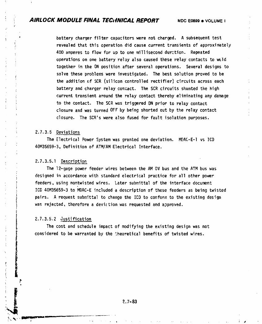
AIRLOCK MODULE FINAL TEC,fNICAL REPORT MDCE0899• VOLUMEI
_ batterychargerfiltercapacitorswere not charged. A subsequenttest
revealedthatthis operationdid causecurrenttransientsof approximately
400 amperesto flow for up to one millisecondduration. Repeated
• operationson one batteryrelay alsocausedtheserelaycontactsto w_Id
togetherin the ON positionafterseveraloperations. Severaldesignsto
solvetheseproblemswere investigated.The best solutionprovedto bethe addition_f SCR (siliconcontrolledrectifier)circuitsacrosseach
batteryand chargerrelaycontact. The SCR circuitsshuntedthe high
currenttransientaroundthe relay contacttherebyeliminatingany damage
to the contact. The SCR was triggeredON priorto relaycontact
closureand was turnedOFF by being shortedout by the relaycontact
closure. The SCR'swere also fusedfor fault isolationpurposes.
2.7.3.5 Deviations
The ElectricalPowerSystemwas grantedone deviation. MDAC-E-Ivs ICD
40M35659-3,Definitionof ATM/AMElectricalInterface.
2.7.3.5.1 Description
The 12-gagepowerfeederwires betweenthe AM OV bus and the ATM bus was
designedin accordancewith standardelectricalpracticefor all other power
feeders,usingnontwistedwires. Later submittalof the interfacedocument
ICD 40M35659-3to MDAC-E includeda descriptionof these feedersas being twisted
pairs. A requestsubmittalto changethe ICD to confor,nto the existingdesign
was rejected,thereforea deviationwas requestedand approved.
2.7.3.5.2 Justification
The cost and scheduleimpactof modifyingthe existingdesignwas not
consideredto be warrantedby the theoreticalbenefitsof twistedwires.
k_
?.7-83
1974018208-479
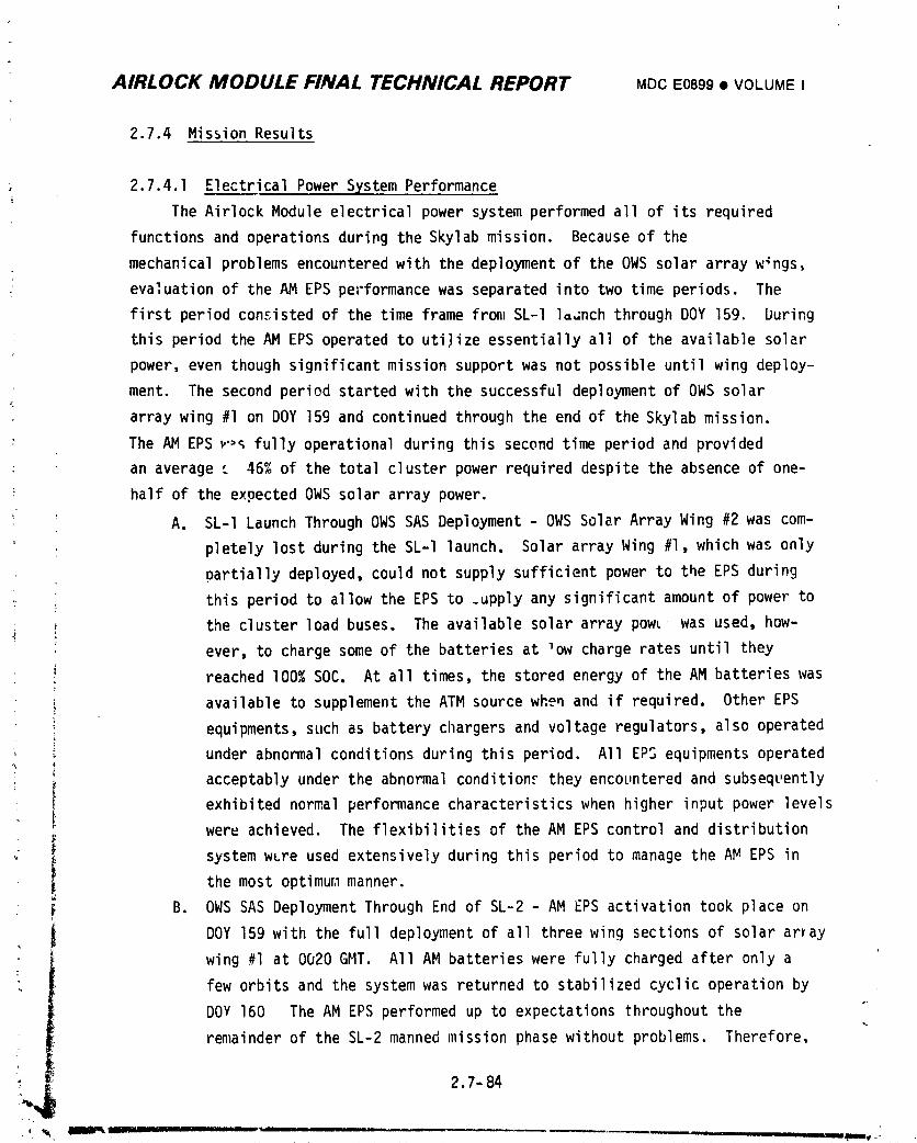
AIRLOCK MODULE FINAL TECHNICAL REPORT MDCE0899• VOLUMEI
2.7.4 Mission Results
2.7.4.1 Electrical Power System Performance
The Airlock Module electrical power system performed all of its required
functions and operations during the Skylab mission. Because of the
mechanical problems encounteredwith the deployment of the OWS solar array w_ngs,
• evaluation of the AM EPS pel'formancewas separated into two time periods. The
first period consisted of the time frame from SL-I laGnch through DOY 159. buring
• this period the AM EPS operated to utilize essentially all of the available solar
power, even though significant mission support was not possible until wing deploy-
ment. The second period started with the successful deployment of OWS solar
array wing #1 on DOY 159 and continued through the end of the Skylab mission.
> The AM EPS _',_fully operational during this second time period and provided
; an average t 46% of the total cluster power required despite the absence of one-
half of the expected OWS solar array power.
' A. SL-I Launch Through OWS SAS Deployment - OWS Solar Array Wing #2 was com-
pletely lost during the SL-I launch. Solar array Wing #1, which was only
partially deployed, could not supply sufficient power to the EPS during
this period to allow the EPS to _upply any significant amount of power to
! the cluster load buses. The available solar array pow__ was used, how-
: ever, to charge some of the batteries at low charge rates until they
reached I00% SOC. At all times, the storea energy of the AM batteries was
available to supplement the ATM source when and if required. Other EPS
equipments, such as battery chargers and voltage regulators, also operated
under abnormal conditions during this period. All EPS equipments operated
acceptably under the abnormal condition_ they encountered and subsequently
exhibited normal performance characteristics when higher input power levels
,_ weru achieved. The flexibilities of the AM EPS control and distribution
system w_re used extensively during this period to manage the AM EPS in
the most optimum1manner.
B. OWS SAS Deployment Through End of SL-2 - AM EPS activation took place on
DOY 159 with the full deployment of all three wing sections of solar amay
wing #1 at 0020 GMT. All AM batteries were fully charged after only a
few orbits and the system was returned to stabilized cyclic operation by
DOV 160 The AM EPS performed up to expectations throughout the
remainder of the SL-2 manned mission phase without problems. Therefore,
i__ 2.7- 84
• _ _, •BllUmkL:"L---_---:--- .............. ' -- -- ' '_ -_- ' _T _J'-_
1974018208-480
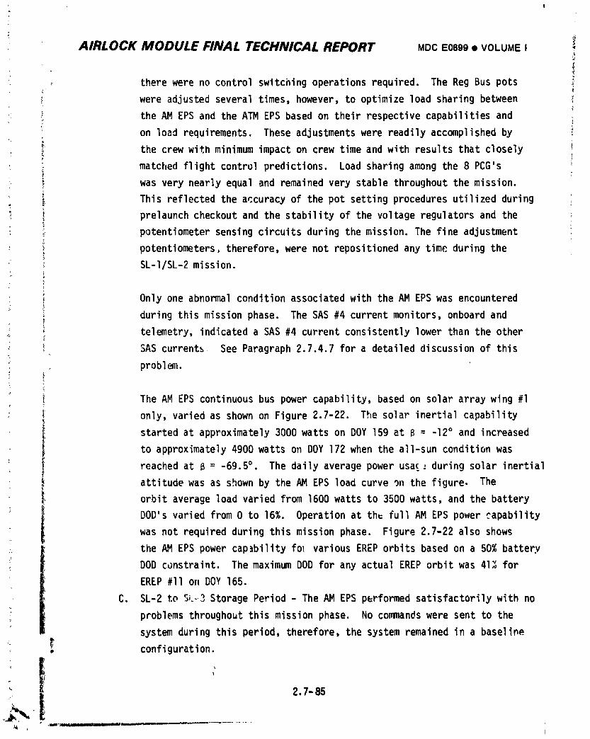
AIRLOCK MODULE FINAL TECHNICAL REPORT MDCE0899• VOLUMEIJ
therewereno controlswitchingoperationsrequired. The Reg Bus pots
were adjustedseveraltimes,however,to optimizeload sharingbetween
• the AM EPS and the ATM EPS based on theirrespectivecapabilitiesandK
on load requirements.These adjustmentswere readilyaccomplishedby
: the crewwithminimumimpacton crew timeand with resultsthat closely i
matchedflightcontrolpredictions.Load sharingamong the 8 PCG's
was verynearlyequal and remainedvery stablethroughoutthe mission.
This reflectedthe accuracyof the pot settingproceduresutilizedduring
_ prelaunchcheckoutand the stabilityof the voltageregulatorsand the ;
) potentiometersensingcircuitsduringthe mission.The fineadjustmentt
potentiometers,therefore,were not repositionedany time duringtheSL-I/SL-2mission.
_ Onlyone abnormalconditionassociatedwith the AM EPS was encountered
duringthismissionphase. The SAS #4 currentmonitors,onboardand
. telemetry,indicateda SAS #4 currentconsistentlylower thanthe other
1_ SAS currents See Paragraph2.7.4.7for a detaileddiscussionof this
• problem.
i The AM EPS continuousbus powercapability,based on solararraywing #1
I only,variedas shownon Figure2.7-22. The solar inertialcapability
startedat approximately3000watts on DOY 159 at B = -12° and increased
to approximately4900watts on DOY 172 when the all-sunconditionwasreachedat B = -69.5°• The daily averagepowerusa£_ duringsolar inertial
i attitudewas as shownby the AM EPS loadcurve on the figure. The
orbit averageload variedfrom 1600watts to 3500watts,and the battery
" i DOD'svariedfrom0 to 16%. Operationat th_ fullAM EPS powercapability
i was not requiredduringthismissionphase. Figure2.7-22also shows_ the AM EPS power capabilityfo_ variousEREPorbitsbasedon a 50% battery
DOD constraint.The maximumDOD for any actualEREPorbitwas 41_ for
EREP#11 on DOY 165.
C. SL-2 to S_.-3StoragePeriod- The AM EPS performedsatisfactorilywith no
problemsthroughoutthismissionphase. No commandswere sent to the
systemduringthis period,therefore,the systemremainedin a baseline
_ _, configuration.
t
1974018208-481
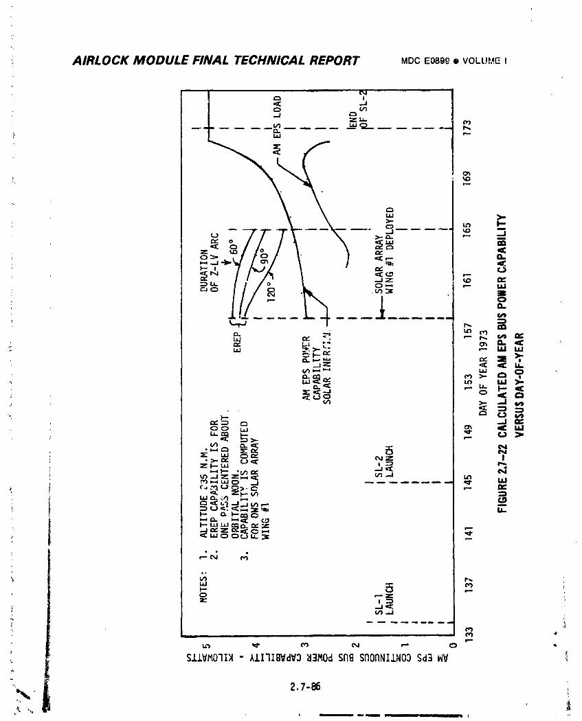
AIRLOCK MODULE FINAL TECHNICAL REPORT MDCE089_• VOLL!._,4.EI
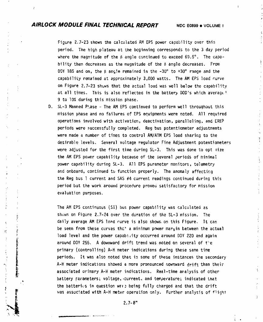
AIRLOCK MODULE FINAL TECHNICAL REPORT MDCE0899• VOLUMEIL
, Figure2.7-23showsthe calculatedAM EPS powercapabilityover this
period. The highplateauat the bcginningcorrespondsto the 3 day period
where the magnitudeof the 8 angle con'Cinuedto exceed69.5°. The capa-
bilitythen decreasesas the magnitudeof the B angledecreases. From f
DOY 185 and on, the B an_!e remainedin the -30° to +30° r_ngeand the
capabilityremainedat approximately3,000watts. The AM EPS loadcurve
on Figure2.7-23shuwsthat the actualloadwas well belowthe capability
at all times. This is also reflectedin the batter_DOD'swhich averag_-_
9 to I0% duringthismissionphase.
D. SL-3MannedPhase- The AM EPS continuedto performwell throughoutthis
missionphaseand no failuresof EPS equipmentswere noted. All required :
operationsinvolvedwith activation,deactivation,paralleling,and EREP
_ periodswere successfullycompleted. Reg bus potentiometeradjustments
were made a numberof timesto controlAM/ATMEPS loadsharingto the
desirablelevels. SeveralvoltageregulatorFineAdjustmentpotentiometers
were adjustedfor the firsttimeduringSL-3. This was done to opt nize
the AM EPS power capabilitybecauseof the severalperiodsof minimal
powercapebilityduringSL-3. All EPS parametermonitors,telemetry
: and onboard,continuedto functionproperly. The anomalyaffecting
the Reg bus l currentand SAS #4 currentreadingscontinuedduringthis
,, periodbut the work aroundprocedureprovedsatisfactoryfor mission
evaluationpurposes.
c
: The AM EPS continuous(SI)bus powercapabilitywas calculatedas
i shuwnon Figure2.7-24overthe durationof the SL-3mission. ThedailyaverageAM EPS Ina_ rurve is also showr,on thisFigure. It can ,
i be seen fromthese curvesthe_ a minimumpnwermar_inbetweenthe actual
load leveland the powercapab14ityoccurredaroundDOY 220 and again
aroundDOY 255. A downwarddrift trendwasnoted on severalof t"e
primary(controlling)A-H meter indicationsduringthesesame time
, periods. It was also notedthat in some of these instancesthe secondary
A-H meter indicationsshoweda more pronounced_ownwarddriftthantheir
associatedarimaryA-H meter indications.Real-timear_alysisof other
batteryFarameters;voltage,,current,and temperature;indicatedtnat
the batteri_,sin questionwE_ being fullychargedand that the drift
! _ was associatedwithA-H meteroperationonly. Furtheranalysisof flight
_-_' ,_ 2.7-8"
1974018208-483
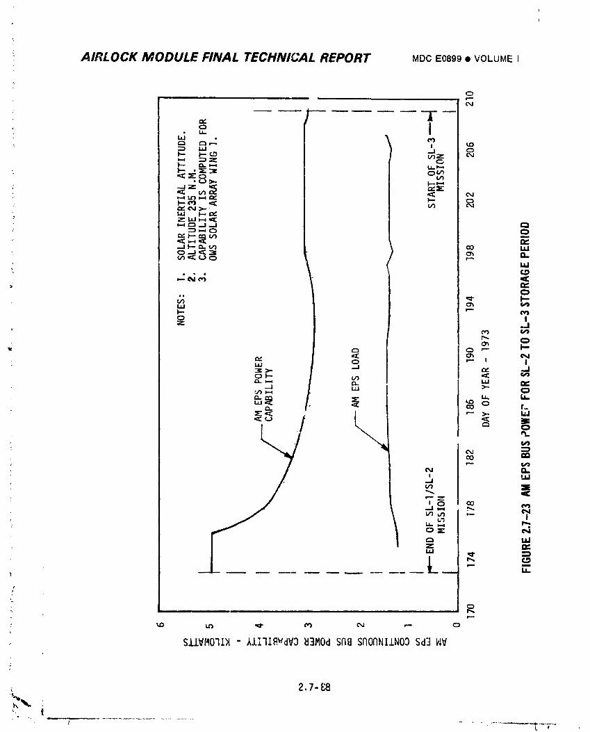
AIRLOCK MODULE FINAL TECHNICAL REPORT MDCE0899• VOLUMEI
o
O_ _ _
_ _ _ _ _J
_ _ |
f
• _i ii a | --, tl
2,7-_
] 9740] 8208-484
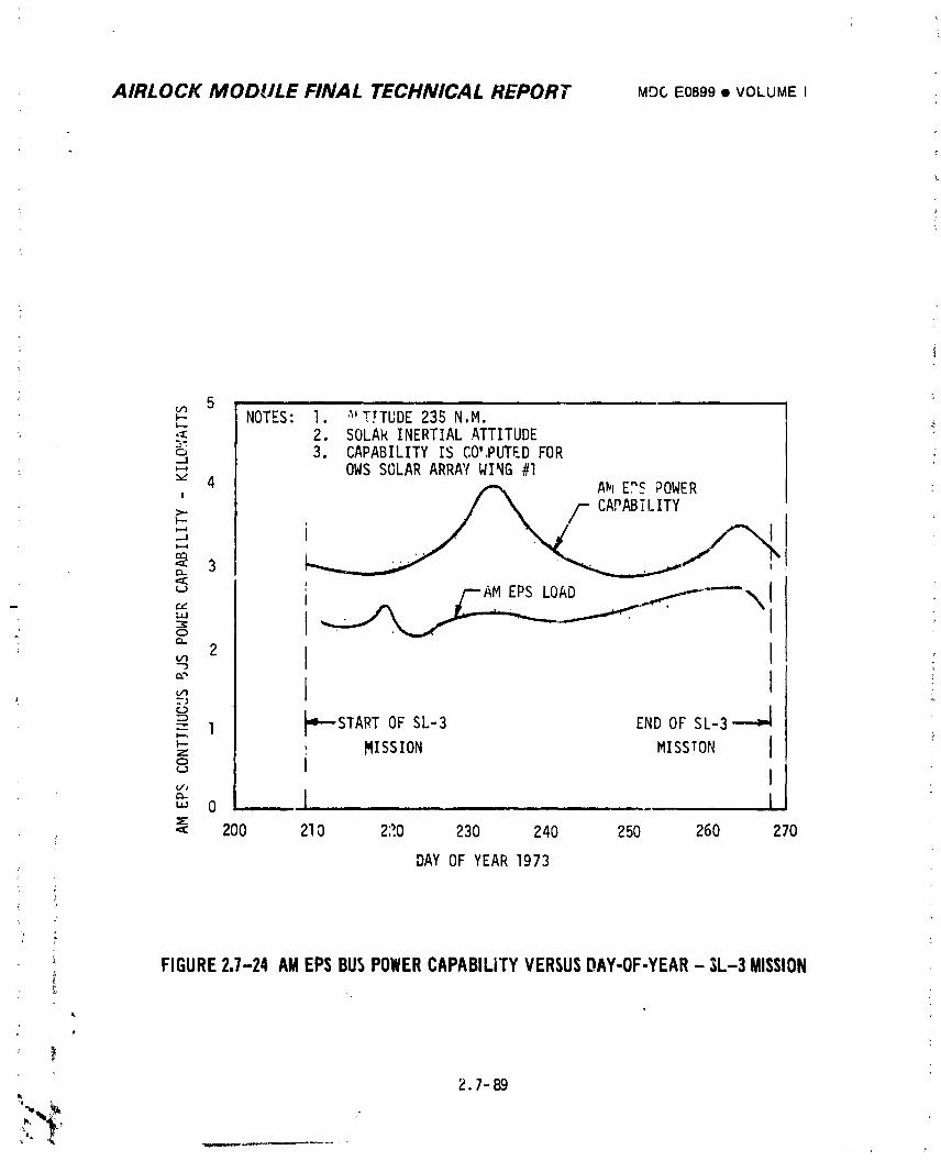
AIRLOCK MODULE FINAL TECHNICAL REPORT ME)C E0899 • VOLUME I
_- NOTES: 1 '_'T.TTUDE235 N M.-_: 2. SOLARINERTIALATTITUDEo 3. CAPABILITYIS CO!,PUTEDFOR-J
_" 4 OWS SOLAR ARRAYWING #I AM E?__ POWER
' _ /-- CAPABILITYF-- '
- i
"_ I' /---AMEPS LOAD ,,..---'f----\iI""'
° _ --_l START OF SL-3 END OF SL-3 ,
_-z ,, MISSION MISSION i° II./J
"' o , I, -.. . ... L•:: 200 210 27.0 230 240 250 260 270
DAYOF YEAR1973
i FIGURE2.7-24AMEPSBUSPOHERCAPABILITYVERSUSDAY-OF-YEAR- SL-3MISSION
2.7-89
] 9740] 8208-485
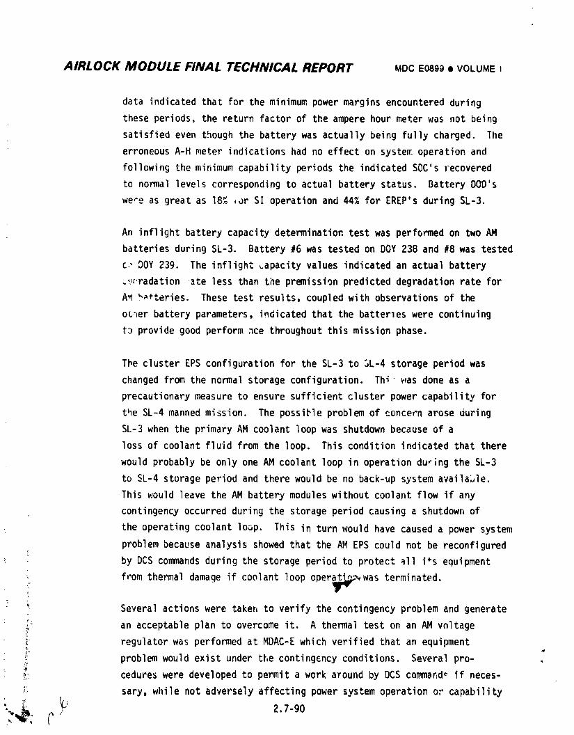
AIRLOCK MODULE FINAL TECHNICAL REPORT MDCE0899• VOLUME I
data indicated that for the minimum power margins encountered during
these periods, the return factor of the ampere hour meter was not being
satisfied even though the battery was actually being fully charged. The
erroneous A-H meter indications had no effect on systeE operation and
following the minimum capability periods the indicated SOC's recovered
to normal levels corresponding to actual battery status. Battery DOO's
were as great as 18% ,_r SI operation and 44% for EREP's during SL-3.
An inflight battery capacity determination test was performed on two AM
batteries during SL-3. Battery #6 was tested on DOY 238 and #8 was tested
c,,DOY 239. The inflight Lapacity values indicated an actual battery
_¢'radation _te less than the premission predicted degradation rate for
A_ _teries. These test results, coupled with observations of the
ot_er battery parameters, indicated that the batterles were continuing
t3 provide good perform,_ce throughout this mission phase.
The cluster EPS configuration for the SL-3 to 3L-4 storage period was
changed from the normal storage configuration. Thi v_asdone as a
precautionarymeasure to ensure sufficient cluster power capability for
the SL-4 manned mission. The possible problem of concern arose during
SL-3 when the primary AM coolant loop was shutdown because of a
loss of coolant fluid from the loop. This condition indicated that there
would probably be only one AM coolant loop in operation du_ing the SL-3
to SL-4 storage period and there would be no back-up system availaJle.
This would leave the AM battery modules without coolant flow if any
contingencyoccurred during the storage period causing a shutdown of
• the operating coolant loop. This in turn would have caused a power system
problem because analysis showed that the AM EPS could not be reconfigured
by DCS commands during the storage period to protect all i% equipment
!. from thermal damage if coolant loop oper_,was terminated.
; _ Several actions were taken to verify the contingency problem and generate
:_ an acceptable plan to overcome it A thermal test on an AM vnltage?
_ regulator was performed at MDAC-E which verified that an equipment
' problem would exist under the contingency conditions. Several pro- .
_,:. cedures were developed to permit a work a_ound by DCS commar,d_ if neces-
;: sary, while not adversely affecting power system operation o_ capability
_i_ 2.7-90
1974018208-486
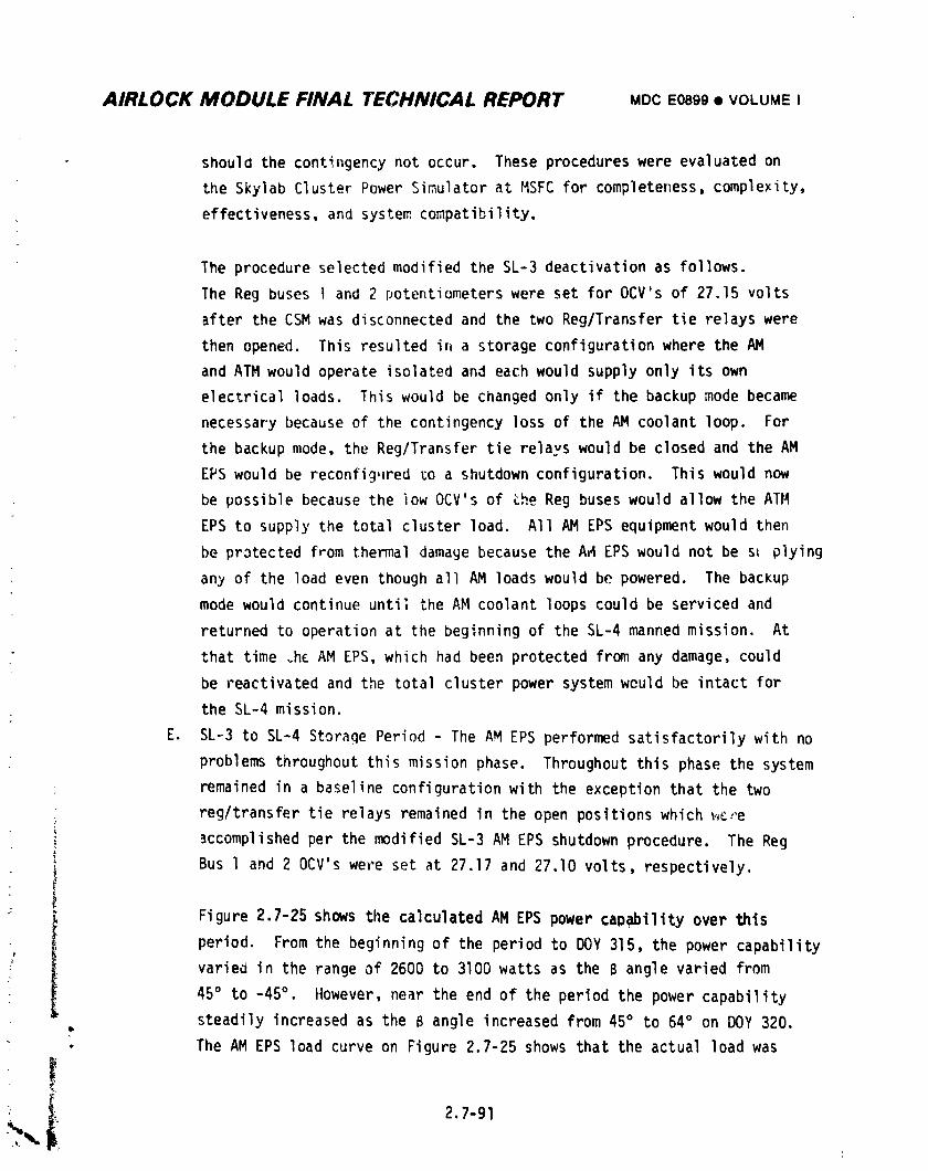
AIRLOCK MODULE FINAL TECHNICAL REPORT MDCEo8gg• VOLUMEI
should the contingency not occur. These procedures were evaluated on
the Skylab Cluster Power Simulator at MSFC for completeness, complexity,
effectiveness,and system compatibility.
The procedure selected modified the SL-3 deactivation as follows.
The Reg buses I and 2 potentiometerswere set for OCV's of 27.15 volts
after the CSM was disconnected and the two Reg/Transfer tie relays were
then opened. This resulted in a storage configurationwhere the AM
and ATM would operate isolated and each would supply only its own
electrical loads. This would be changed only if the backup mode became
necessary because of the contingency loss of the AM coolant loop. For
the backup mode, the Reg/Transfer tie relays would be closed and the AM
EPS would be reconfig,lred_o a shutdown configuration. This would now
be possible because the iow OCV's of the Reg buses would allow the All4
EPS to supply the total cluster load. All AM EPS equipment would then
be protected from thermal damage because the A_4EPS would not be st plying
any of the load even though all AM loads would be powered. The backup
mode would continue until the AM coolant loops could be serviced and
returned to operation at the beginning of the SL-4 manned mission. At
that time _h_ AM EPS, which had been protected from any damage, could
be reactivated and the total cluster power system weuld be intact for
the SL-4 mission.
E. SL-3 to SL-4 Storage Period - The AM EPS performed satisfactorily with no
problems throughout this mission phase. Throughout this phase the system
; remained in a baseline configuration with the exception that the two
; reg/transfer tie relays remained in the open positions which _,_,_'e
! _ccomplished per the modified SL-3 AM EPS shutdown procedure. The Reg
i Bus l and 2 0CV's were set at 27.17 and 27.10 volts, respectively.
• iFigure 2.7-25 shows the calculated AM EPS power capability over this
I period. From the beginning of the period to DOY 315, the power capability
varied in the range of 2600 to 3100 watts as the B angle varied from
45° to -45°. ilowever,near the end of the period the power capability
steadily increased as the B angle increased from 45° to 64° on DOY 320.
• The AM EPS load curve on Figure 2.7-25 shows that the actual load was
: _ 2.7-91
-':.,.1
i
1974018208-487
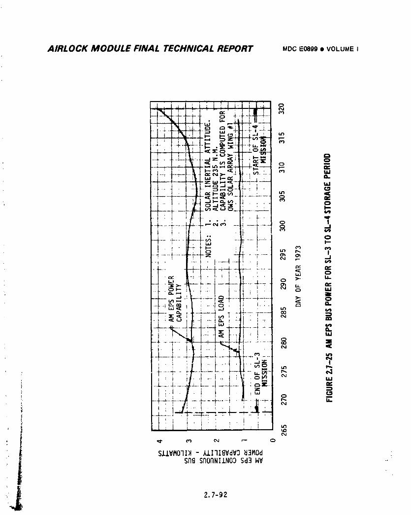
AIRLOCK MODULE FINAL TECHNICAL REPORT MDCE0899• VOLUMEI
.[ , i ,L.J..i t _ t : ] vl ; L.._. o",-,if.: I ' I' I ' " _,y ' ' I i It I
l-_t--,_,,--__+,,._:-!/1-.:-t--=.' _- S--+"'_._"-:-'.,_____,.!-,'.-.._: ,-" ' | ! * I,-I; l
! " t I ,!. *_J_: t ,,__.. I_
_..:;_----L-_4-L*_7, _ _ E_+-4----t-_ ,-° _:--_---:,L:-4-_- ,_,,,,- -.ti .._..... _ "_
-, "r- ,--T-q . "_,-,-_ " ............. _ '_"- , ._11-- ¢_.v) i, .- 1. I _i.- o---_'= ...... o
_.+.... =......._ ..... N_ .... . __.., .__ o Io --I
-F- -_.... -L,,, ...._....._...... o! ; , I C_z • _ • _ r-. I
.... ' .:.-i - _...... I ..... _ - ' '- _'_. ' t ' I
. L .... --L--L-:--L-i.--L .... ,_......... _ _ _=I I I I i ' ' : I _
• i . iv, -: -I • I. : I . , _ . . . i_-._ . - - _-.-- _- -_- _-_-_-....Jr.....-4-....
.... t " _= "_ ' ' t 1 ..... o "_ -J _. 4-4--. _'_ ......... "F......Jr--,,,,,.., . t ._ _ • <_- o..._.4._._ _1_ .. -l q • : I. . _ r, I_.
..__._ ..... J._--._,__ "' _-_q-L......i ....• _ ' ; ..... _: 't_ " I • ,u
-_ i t._ !..._ .':'t_j.l . .--i.......!.....4-I--_---_......!,.:_!.--Z=- "
i_t i....
' " : It _ " ' : " '
_..L......_ ._ _:::::_.-:........
I ', 1 I . ; ', ', ..,! !
, _ _ O,J _'- 0
S.I..I.VMOll)_- k.l.l'llBVdV3_3MOdSABSAOFINIJ.NO9Sd3IdV -.
1974018208-488
AIRLOCK MODULE FINAL TI:.CHNICAL REPORT MDCE0899• VOLUMEI
well belowthe power capabilityat all times. The actualloadwas also
an averageof approximately300 watts lowerthan thatfor the SL-2 to
SL-3 storageperiod. This was due to zeropower transferfrom the reg
buses tc thetransferbuses duringthis periodand is also reflectedin
the lowerbatteryDOD'swhich averagedapproximately7% duringthis
missionphase.
A minordiscrepancywas observedduringthisperiod. Beginningon DOY 298
throughthe end of the period,telemetrydata indicatedPCG #5 battery
voltageslightlyhigherthannormalduringboth the chargeand discharge
periods. Basedon a thoroughinvestigationas to the cause of the
discrepancy,it was concludedthat the high readingswere due to an
upwardshiftin the M137telemetryparameter.
F. SL-4MannedPhase- The AM EPS continuedto performwell throughoutthis
: missionphase. All requiredoperationsinvolvedwith activation,deacti-
vation,parallelingand EREPand Kohoutekobservationperiodswere
successfullycompleted.
The AM EPS continuous(SI)powercapabilitywas calculatedto be as shown
in Figure2.7-26over the durationof th_ SL-4mission. The daily
averageAM EPS loadcurve is also shownon thisfigure. Duringthe low
beta p_riod,(DOY332, 1973,throughDOY 9, 1974,and DOY 23 throughthe
end of SL-4),the AM EPS powercapabilitywas closelyapproachedand at
_imesexceededby the AM EPS load. In particular,duringthe many EREP
: and Kohoutekpassesthis conditionoccurred. This conditioncontributed
! to a downwarddrift of the ampere-hourmetersduringthis periodand some
I amp-hourmetersnever had the opportunityto recoverto I00 percentSOC
: indicationby the end of the mission. However,real-timeanalysisof
other batteryparametersindicatedthat all AM batterieswere being fully
chargedthroughoutSL-4exceptduringsomeEREP and Kohoutekpasses.
BatteryDOD'swere as great as 19% for Sl operation;57% for EREPpasses;
and 32% for Kohoutekpassesand 46% for JOP passesduringSL-4.
t1
2.7-93
I
1974018208-489
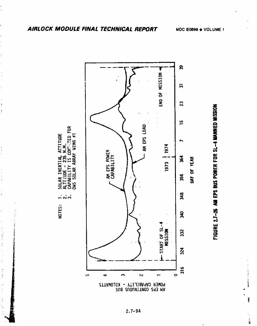
AIRLOCK MODULE FINAL TECHNICAL REPORT MocEO899• VOLUMEI
.=.-.....,_p_ ,e.,d
i,,,q
,?.=,.:_=
<z_
/go • |
N_ No N E
• . _
S.I.lVMO'II)I- AII'IIBVdV3_i3MOd ISnB srIOaNI.LN03Sd3 &iV .-
1974018208-490
AIRLOCK MODULE FINAL TECHNICAL REPORT MDCE0899• VOLUMEI
•
- End-of-mission testing included capacity discharges of several batteries.
Refer to Paragraph 2.7.4.3F for details of these tests.
The M137telemetryparameterdiscrepancyobserveddurln_the SL-3 to SL-4
storageperiodreturnedto normalshortlyinto the SL-4mission. During
SL-4severalothertelemetryparametersbegan to showerraticindications.
However,real-timeanalysisof the AM EPS systemwas not significantly ic
affectedbecausealternateparameterswere available.
2.7.4.2 BatteryChargers
A. SL-I LaunchThroughOWS SAS Deployment- The batterychargersexhibited
satisfactoryperformanceboth duringand after the abnormalconditions
encounteredduringpartialdeploymentof SAS Wing #1. The battery
chargersin PCG's5, 6, and 7 operatedwith dual low power solararray
inputsto satisfactorilychargetheir respectivebatteriesto 100% SOC.
SAS currentsduringthe chargingof thesebatterieswere approximally
0.6, 1.2,and 0.5 amperesfor SAS's5 through7, resnectively.The_e
currentlevelswere well belowthe expectedoperatinnranqefor the
batterycharqersin any mode of operation.
The other batteriescouldnot be chargedbecausethe arraypower available,
evenfromdual solar arraygroupcombinations,was insufficientto operate
the batterychargers. Thesebatterychargersencounteredanotherabnormal
conditionbecauseof this extremelylow solar arraypower. This condition
can bestbe describedas an oscillatinginputto the batterycharger
causedby the repetitivecollapseand recoveryof the solararrayoutput
characteristic.The arrayvoltagewould riseto the pointwhere the
batterychargerbiascircuitswould turn on. The currentdrawn by the
biascircuits,however,would pulldown the solararrayvoltageto such a
level,becauseof the low solararraypowercharacteristic,that the
circuitswouldturn off again. At this pointthe array voltagewould
recoverto its originalleveland the cyclewould repeat. Analysisof
the batterychargercircuitsindicatedthat thisconditionshouldnot
causeany problems. As a safetyfactor,however,itwas recommendedthat
the conditionbe avoidedby operatingwith the chargerswitchin the
!_j 2.7-95
1974018208-491
AIRLOCK MODULE FINAL TECHNICAL REPORT MOCE0899• VOLUMEI
bypasspositiontherebyremovingthe solararray outputfrom the battery
chargerinput. This recommendationwas followedthroughoutmost of this
period. The data showedthat the batterychargersin PCG'sl, 3, 4, and
8 definitelyencounteredthisabnormalcondition. All the battery
chargersprobablyencounteredit at some timeduringthe period,however,
no adverseeffectson systemor componentperformanceresultedfrom this
abnormalInterfacecondition. Anotherabnormalconditionoccurredwhen
the amp-hour (A-H) meters for PCG_8 were reset to 0%on DOY147. This
resultedwhen A-H integratorCB #8 on STS Panel201 was inadvertently
openedby crewaction. After solararray powerbecameavailable,the A-H
metersfor #8 soon returnedto synchronizationwith the actualbattery
SOC and theyoperatednormallythereafter.
B. OWS SAS DeploymentThroughEnd of SI-2- The eightAM batterychargers
performednormallythroughthe end of SL-2. Eachbatterychargerproperly
conditionedits associatedsolararray groupinputsuch that peakpower
was extractedupondemandduringinitialbatterycharging;limitedits
batteryvoltageas determinedby batterytemperatureduringthe voltage
limitchargemode; and regulatedits batterycurrentwhen the battery
chargercontrollingampere-hourmeter indicateda lO0) batterystate-of-
charge. Figure2.7-27illustratesthe batterychargecharacteristics
typicalfromOWS SAS deploymentthroughthe startof the all-sunattitude
conditionon DOY 172. The followingsectionsdescribebatterycharger
functionsin detail.
; (I) PeakPowerTracking- Availablesolararray powerwas maximumat sun-
riseand it graduallydecreasedfollowingsunriseas the solararray
grouptemoeratureincreased, The peakpower trackingportionof the
chargerinputpowercurve in Figure2.7-27illustratesthe battery
chargerinputpowercharacteristictypicalfor all eight PCG's in
the peakpower trackingmode. As expected,the chargerpeak power
trackerextractedmaximumpowerfrom the solararray group immediately
2.7-96
1974018208-492
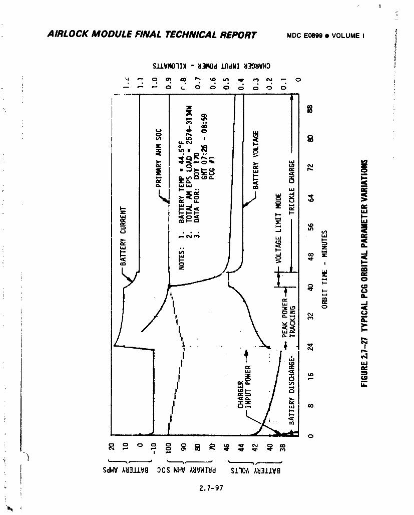
I
AIRLOCK MODULE FINAL TECHNICAL REPORT MDCE0899• VOLUMEI _'
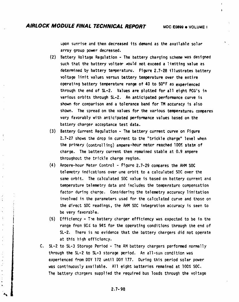
L
AIRLOCK MODULE FINAL TECHNICAL REPORT MDCE0899• VOLUMEI
uponsunriseand then decreasedits demandas the availablesolar
array grouppowerdecreased.
(2) BatteryVoltageRegulation- The batterychargingschemewas designed
suchthatthe batteryvoltac__ouldnot exceeda limitingvalueas
determinedby batterytemperature.Figure2.7-28illustratesbattery
voltagelimitvaluesversusbatterytemperatureover the entire
operatingbatterytemperaturerangeof 40 to 50°Fa) experienced
throughthe end of SL-2. Valuesare plottedfor all eight PCG's in
variousorbitsthroughSL-2. An anticipatedperformancecurve is
shownfor comparisonand a tolerancebandfor TM accuracyis also
shown. The spreadon the valuesfor the varioustemperature_compares
veryfavorablywith anticipatedperformancevaluesbasedon the
batterychargeracceptancetestdata.
(3) BatteryCurrentRegulation- The batterycurrentcurveon Figure
2.7-27showsthe drop in currentto the "tricklecharge'°levelwhen
the primary{controlling)ampere-hourmeter reachedI00% stateof
charge. The batterycurrentthen remainedstableat o.g ampere
throughoutthe tricklechargeregion.
(4) Ampere-hourMeterControl- Figure2.7-29comparesthe AHM SOC
telemetryindicationsoverune orbit to a calculatedSOC over the
sameorbit. The calculatedSOC value is basedon batterycurrentand
temperaturetelemetrydata and includesthe temperaturecompensation
factorduringcharge. Consideringthe telemetryaccuracylimitation
: involvedin the parametersused for the calculatedcurve and thoseon
the directSOC readings,the AHM SOC integrationaccuracyis seento
be very favorable.
(5) Efficiency- T_e batterychargerefficiencywas expectedto be in the
rangefrom 9C_ to 94% for the operatingconditionsthroughtheend of
SL-2. Thereis no evidencethat the batterychargersdid not operate
at thishigh efficiency.
C. SL-2 to SL-3 StoragePeriod- The AM batterychargersperformednormally
throughthe SL-2to SL-3 storageperiod. An all-sunconditionwas
experiencedfromDOY 172 untilDOY 177. Duringthisperiodsolarpower
was continuouslyavailable. All eightbatteriesremainedat I00% SOC.
The batterychargerssuppliedthe requiredbus loadsthroughthe voltage
J
'l 2.7-98
i
1974018208-494
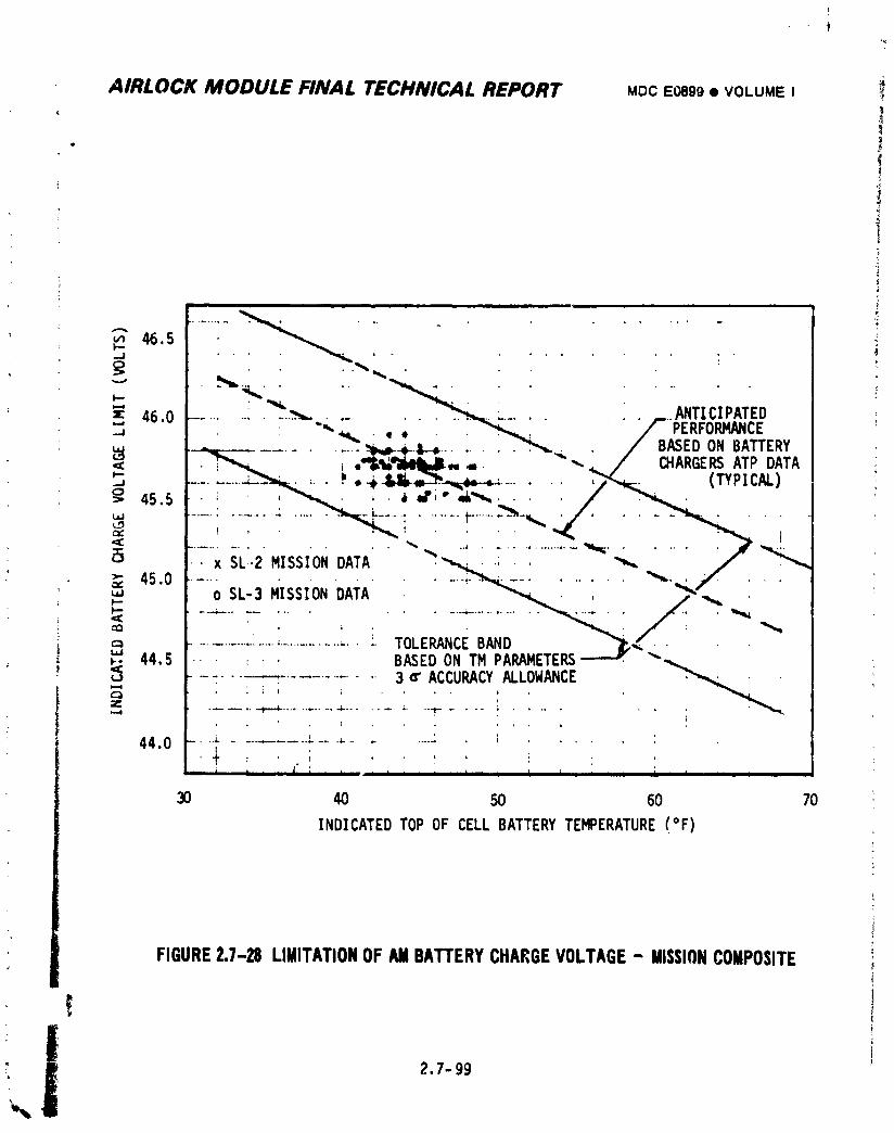
t
AIRLOCK MODULE FINAL TECHNICAL REPORT MDCE0889• VOLUME I
' I• _
t
J
.,.,-,46.5p.,-..j -
_;_ .... _ ,_. ....
"" ' _"""_w,..... _ ........"=: 46.0 _....... _ .... _ ....... .._.. ;_.......... ANTICIt'ATED
: ",-.,,,,= . ,, . _ " ;_.--; _'- PERFORMANCE= .--.,_¢-............ _k,,_+-t-_ ....... ._",,-._ • / BASEDONBATTERY<_ • _ , ,"IL_'_MI4bJI,,4=. --'-.,_ / CHARGERSATP DATA.J_ ----_-----_ _......_ ,_Jkl_o_---,_ . .• _ (TYPICAL)C}> 45.5 i , _ , ,b =f'," _,_ .... / _
.......:....:...._ .....:......._....._-_../.... _ .._" ' ' ' "_ :_ ' ° '' "_ _ I
• x SL.2MISSIONDATA "?._._ . .'_.'_i i /"_L"_
p-.
,¢¢cfl
_" ..... LE
,_"' 44.5 " • : ' ' BASEDONTM PARAMETERS_ "
.....-- .............3 ¢' ACCURACYALLOWANCE= !_ ..... _ ........... "_"....... :' ""1- ..........
--,-,,,aa.n ..-_...... ' ._...... ;I
- i, i , , ( i ,,, i i i i, , :, , I I L | i I i I E I i I, i
30 40 50 60 70
INDICATEDTOPOF CELLBATTERYTEMPERATURE(°F)
FIGURE2.7-28 LIMITATIONOFAMBATTERYCHARGEVOLTAGE- MISSIONCOMPOSITE
" 2.7-99
1974018208-495
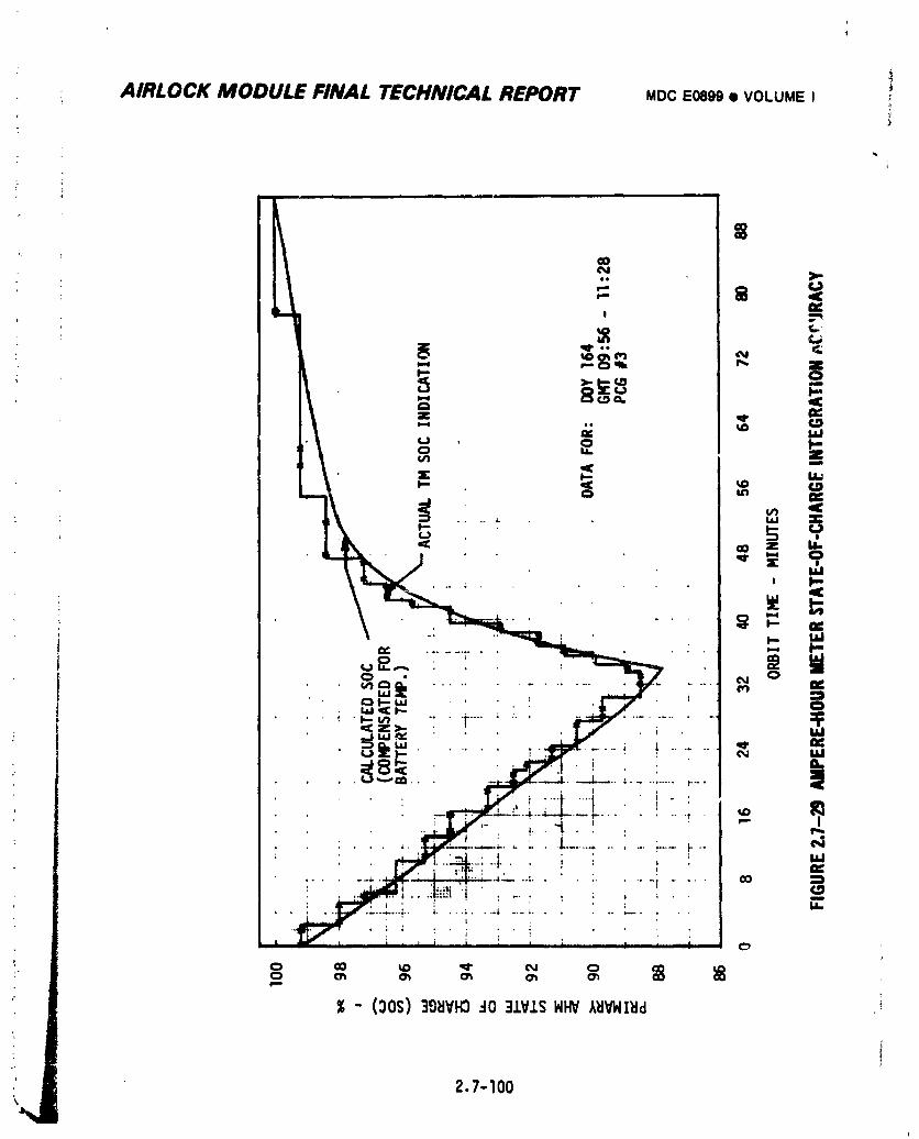
AIRLOCK MODULE FINAL TECHNICAL REPORT MDC E0889 • VOLUME I ;
2.7-100
1974018208-496
AIRLOCK MODULE FINAL TECHNICAL REPORT MDCE0899• VOLUMEI
regulatorsand suppliedtricklechargecurrentto the batteries.
FollowinQthe all-suncondition,day/nightcyclingperformance
continuedto be normal. Performancein the area of chargerpeakpower
tracking,voltageregulation,chargerefficiency,and ampere-hourmeter
controland indicationcontinuedto be normal.
D. SL-3MannedPhase- The eightbatterychargersperformednormallythrough-
out the SL-3mission. Eachbatterychargercontinuedto performits
: requiredfunctionsof peakpower tracking,batteryvoltagelimiting,ampere-
hourmeter controland batterycurrentregulationundertricklecharge
conditions.The studyof all availablePCG parametersindicated
satisfactorybatterychargerefficiencythroughoutthe SL-3manned
:_ phase. The curvesof Figure2.7-27for SL-2are also representativeof
the observedSL-3batterychargerperformance.
(1) BatteryCurrentRegulation- All batterychargersproperlyregulated
the batterycurrentat tricklechargeleve'Iswhen the controlling
ampere-hourmeter indicateda I00%stateof charge. The designof
the batterjchargeris such that the temperaturecompensatedvcltage
limitcannotbe exceededunder any circumstances.In some instances
duringSL-3,the characteristicsof the batterieswere such thatthe
batteryvoltagerequiredto maintainthe normaltricklechargecurrent
was higherthanthe voltagelimit. In these instances,the battery
voltagewas limitedto the voltagelimitvalueand as a resultthe
, batterycurrentwas reducedbelowthe normaltricklechargelevel.
(2) Ampere-HourMeterOperation- Duringthe SL-3missiontherewere
severalperiodswhenthe ampere-hourmeter SOC indicationdid not
returnto I00%at the end of each daylightperiodalthoughthe
batteryvoltageand currenttelemetryparametersindicateda fully
chargedbattery. Divergenceof controllingand backupAHM SOC
indicationswere alsoobservedduringtheseperiods. The reasonfor
the downwarddriftof these AHM SOC indicationswas that for load
levelsapproachingthe powercapabilityexperiencedat these
times,the returnfactorof the ampere-hourmeterwas not being
satisfied. The divergencebetweenthe controllingand noncontrolling
_ AHM'swas causedby the cumulativeeffectsof small differences
i I in the AHM accuracieswhen the AHM's are not returningto I00%. A|
i__, __ 2.7-101
1974018208-497
AIRLOCK MODULE FINAL TECHNICAL REPORT MDCE0899• VOLUMEI
detailedexplanationof the reasonsfor theseeffectsis given in the
subsequentparagraphs.The validityof these reasonsis borneout by the
followingperformanceobservations.There were no indicationsof any
hardwaremalfunctionsor failuresduringtheseperiodsand therewere no
systemp_rformanceeffectsas a resultof the driftof the AHM indications.
The AHM indicationsreturnedto correlationwith other batteryparameters
aftershort periodsof operationat reducedload levels.
Althoughthe returnfactorwas only compensatedfor batterytemperature
variations,the actualreturnfactorrequiredvarieda smallamountwith a
numberof other factorsincludingbatterydepth-of-discharge(DOD),
batteryaging,etc. To allowfor theseotherfactors,the returnfactor
was slightlyconservatlveto assurethatthe batterywas alwaysfully
chargedwhen tricklechargewas initiated. In additionto the design
returnfactorbeingconservative,most of the flightAHM'sexhibiteda
toleranceerror in the devicecircuitrywhich was in the directionto
increasethe returnfactor. I
At the beginningof a typicalchargeperiod,all availablearray powerwas!
deliveredto the batteryafterthe loadwas satisfied. The battery
_ chargerwas peakpowertrackingat this time. As the batteryaccepted
charge,batteryvoltageslowlyincreasedto the temperatLrecompensated
voltagelimitvalue. The batterychargerthenmaintainedthis voltage
untilthe batterySOC,as indicatedby the controllingAHM, reachedI00%.
i As the batteryapproacheda fullychargedstate,the batterycurrent
decayedto a low level. Ifthe AHM reachedI00% SOC prior to the end of
the daylightperiod,the batterychargerswitchedto tricklecharge. If
the AHM integratedSOC had not reachedlO0_ priorto the end of the day-
light period,the returnfactorhad not been satisfiedand the batteYy
chargermaintainedthe voltagelimitvoltageat th_ batterytermillals.
This conditionwas observedfor severalampere-hourmetersduringthe
SL-3missionand was also observedin severalgroundsystemtest
programs. Althoughsufficientsolararraypowercouldhavebeen available,
the characteristicsof the batterymay have been,such,that in thechargingtime available,the _atterycurrentat voltagelimitwas so low
2.7-102
mi
1974018208-498
• ,2_r T
I
AIRLOCK MODULE FINAL TECHNICAL REPORT MDC E0899• VOLUME I
that the battery would not accept sufficient charge to satisfy the AHM
return factor. The battery was, in fact, achie_,inga fu,]y charged state.
This was demonstrated in ground test pr_nrams _y capacity discharge
testing of the battery after a number of cycles under these conditions.
Figure 2.7-30 shows a typical discharge/chargecycle during which the AHM
SOC indication at sunset was less than the previous sunset. During this
cycle, the battery voltage reached voltage limit 31 minutes after the
beginning of the daylight cycle. The battery cur ent then decayed to a
ievel of approximatelyone ampere and maintained °�Œfor the
remainderof the charge cycle. The calculated ratio of ampere hours
returned to the battery to the ampere hours removed (actual return factor
achieved) was 1.061. Since the AHM was designed fJr a retu-n factor of
1.075 at the battery temperature observed, the AHM SOC indication could
not recover to the previous sunset level. If the condition of not
satisfying the AHM return factor was maintained over a number of c, _es,
the AHM indication would decay downward. The AHM was an analog measdre-
ment device and as such contained so_ error, both in battery current
measurc_znt and in the utilization of the battery temperature sensor to
establish the "eturn factor. Also, there was a small error whicilcould
occur in the transition from charge to discharge or from discharge to
charge. If the AHM was i_otreturning to _00% SOC, the effect of these
errors was not erased each cycle and could accumulate. These cumulative
errors could cause divergence between the primary and secondary AHM's and
in some instances could aggravate a downward trend of the AHM SOC
indication. Thus, if the AHM had not returned to I00% SOC over a large
number of cycles, the AHM wo_Id not have had a clo'_ correlation to the
actual battery SOC and a divergence between the controlling and non-
controllingAHM SOC indicationwould have occurred. Either or both of
these conditions represented no compromise in system performance. Under
these conditions, the battery charging current characteristicwas the
principal indication of the battery state-of-charge. Near trickle charge
levels for the final minutes of charge at the battery voltage limit
. indicated that the battery w_; fully charged. Observation of battery
' voltage durinq discharge also provided an indication of proper battery
_ state-of-chargeand this was observed to be normal in each instance
2.7-103
1974018208-499
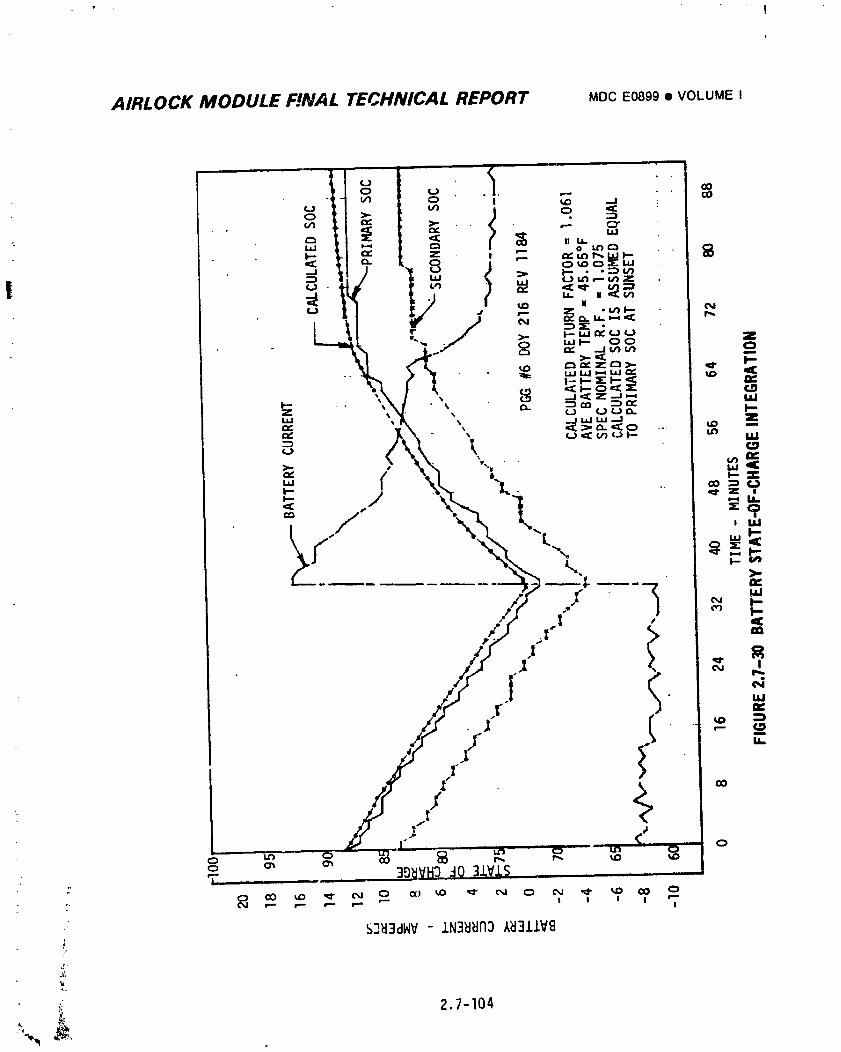
t
AIRLOCK MODULE F!NAL TECHNICAL REPORT MDCE0899• VOLUMEI
AIRLOCK MODULE FINAL TECHNICAL REPORT MDCE0899• VOLUMEI
observed on SL-3. The probability of not satisfying the AHM return
factor increased sharply as the AM EPS load demand approached the AM EPS
power carability. An analysis of data during SL-3 indicated that the
downward -rend of the AHM SOC indications occurred during periods in
which the actual AM EPS load approached or exceeded the calculated AM EPS
continuous power capability. The potentiometeradjustments, both reg bus
and fine adjust affected the amount of power provided by each PCG and
therefore affected which PCG's exhibited the downward drift in SOC
indication at any particular time.
_en the conditions of load demand and available array power were such
that the AHM return factor was again satisfied, the SOCindication would
recover toward a 100% sunset indication. The rate at which the AHMSOC
indication recovered was directly dependent on the amount by which the
battery recharge ampere hours exceeded the amount required to satisfy the
AHMreturn factor. Figure 2.7-31 represents a typical cycle during which
the AHM recovered. The primary AHMbeqan the discharge period with a
75.6% SOC. A depth of discharge (DOD) of approximately 12.9% indicated a
moderately liqht load. During the charging period, sufficient current
was delivered to the battery to attain an indicated primary AHMSOCof
78.0 at sunset, a recovery of 2.4%. At the end of SL-3, all AHM's except
PCG_5 secondary were returning to 100% at sunset. With the light
orbital storage loads, the #5 secondary SOCrecovered from a 38% sunset
indication to a 100% sunset SOCindication in five days.
E. SL-3 to SL-4 Storage Period - The AM battery chargers operated normally
through the SL-3 to SL-4 storage period. Performance in the areas of
: charger peak power tracking, voltage regulation, charger efficiency and
ampere-hour meter control and indication was normal. All primary and
secondary ampere-hour meter state-of-charge indications with the
exception of PCG #5 secondary AHM, were lO0 percent at the start of the
storage period. PCG #5 secondary ampere-hourmeter state-of-charge
indicatiun recovered to lOO percent several days after the start of this
storage period.
2.7-105
i 9740i 8208-50i
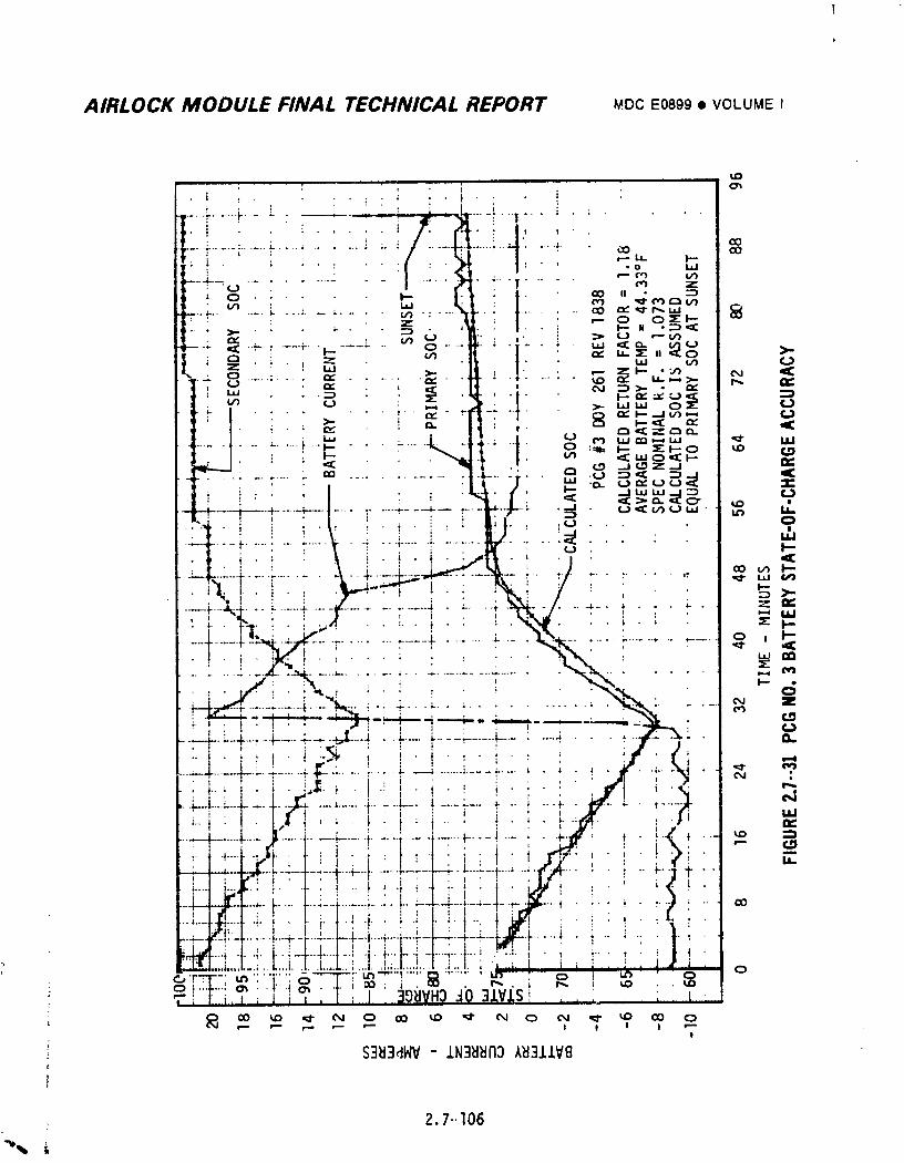
AIRLOCK MODULE FINAL TECHNICAL REPORT MDCE0899• VOLUMEI
2.7-.I06
i 9740i 8208-502
AIRLOCK MODULE FINAL TECHNICAL REPORT MOCEOe99• VOLUMEI
• F. SL-4MannedPhase- The eightbatterychargersperformednormallythrough-
out the SL-4mission. Eachbatterychargercontinuedto performits
requiredfunctionsof peakpower tracking,batteryvoltagelimiting,
ampere-hourmeter controland batterycurrentregulatiohtindertrickle
chargeconditions.The studyof all availablePCG parametersindicates
satisfactorybatterychargerefficiencyexistedthroughoutthe SL-4
mannedphase. The curvesof Figure2.7-27for SL-2are also representa-
tiveof the observedSL-4batterychargerperformance.
(1) Ampere-hourMeter Operation- Duringthe SL-4mission,as duringthe
; SL-3mission,therewere severalperiodswhen the ampere-hourmeter
SOC indicationdid not returnto IO0%at the end of each daylight
periodalthoughthe batteryvoltageand currenttelemetryparameters
indicateda fullychargedbattery. Divergenceof controllingand
backupAHM SOC indicationswere alsoobservedduringthese periods.
Paragraph2.7.4.2-D(2)describesthe reasonsfor this ampere-hour
meteroperation.
2.7.4.3 Batteries
A. SL-ILaunchThroughOWS SAS Deployment- The eightAM EPS batteries
. providedpowerto clusterloadsduringthe SL-!launchphaseper the mission
plan. The batterieswere thenturnedOFF when it was determinedthatOWS
: solararray powerwould not be availablein the near future. This
occurredat approximately1930GMT on DOY 134. BatterySOC'sat thistime
rangedfrom65% to 68%. The batterieswere turnedOFF to
retaintheirstoredcapabilityas back-uppowersourcesfor peak power
periodssuch as EREP passes,a_d to retainmaximumflexibilityin managing
the batteriesas the missionprogressed.
All batterieswere turnedON on DOY 144 in preparationfor the first EVA
attemptto deploySAS Wing #I; however,theyprovidedpoweronly to the
EPS controlbusesbecausethe PCG output switcheswere OFF. All batteries
were turnedOFF aqaln on DOY 145 afterapproximately8 hours
of operation. BatterySOC'sfor PCG'sI-4 at this time rangedfrom48% to
: 53%. Batteries1 through4 remainedOFF untilDOY 158 when theywere
turnedON as part of the preparationfor the successfulattemptto deploy
OWS SolarArray Wing#I. No other interimactivitieswere initiatedwith
2.7-107
1974018208-503
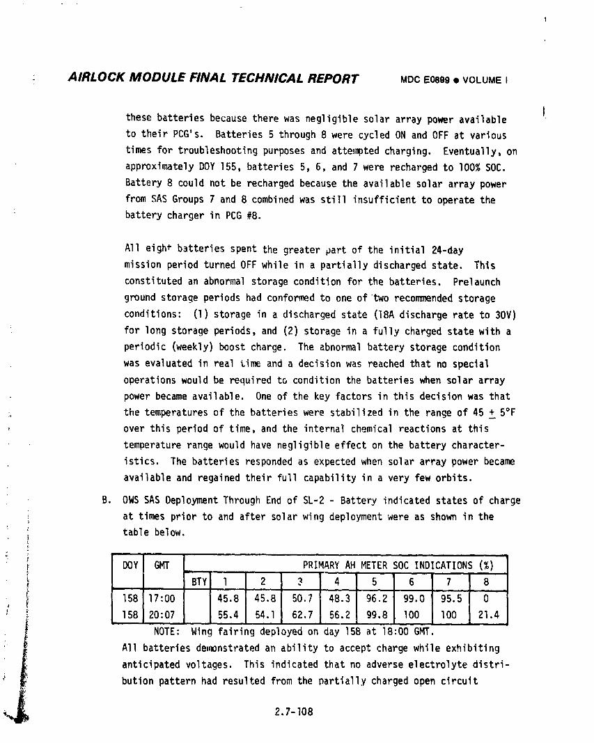
AIRLOCK MODULE FINAL TECHNICAL REPORT MDC E0899 • VOLUMEI
Ithesebatteriesbecausetherewas negligiblesolararray poweravailable
to their PCG's. Batteries5 through8 were cycledON and OFF at various
timesfor troubleshootingpurposesand attemptedcharging. Eventually,on
approximatelyDOY 155, batteries5, 6, and 7 were rechargedto I00%SOC.
Battery8 could not be rechargedbecausethe availablesolararraypower
fromSAS Groups7 and 8 combinedwas stillinsufficientto operatethe
: batterychargerin PCG #8.
All eigh* batteriesspentthe greaterpartof the initial24-day
missionperiodturnedOFF while in a partiallydischargedstate, This
constitutedan abnormalstorageconditionfor the batteries, Prelaunch
groundstorageperiodshad conformedto one of two recommendedstorage
conditions: (1)storagein a dischargedstate (18Adischargerate to 30V)
for long storageperiods,and (2) storagein a fullychargedstatewith a
periodic(weekly)boostcharge. The abnormalbatterystoragecondition
was evaluatedin realtime and a decisionwas reachedthat no special
operationswould be requiredto conditionthe batterieswhen solararray
powerbecameavailable. One of the key factorsin thisdecisionwas that
the temperaturesof the batterieswere stabilizedin the rangeof 45 + 5°F
over this periodof time, and the internalchemicalreactionsat this
temperaturerangewould havenegligibleeffecton the batterycharacter-
istics. The batteriesrespondedas expectedwhen solararray power became
availableand regainedtheir fullcapabilityin a very few orbits.
B. OWS SAS DeploymentThroughEnd of SL-2- Batteryindicatedstatesof charge
_ at timespriorto and aftersolarwing deploymentwere as shown in the: table below.I{
DOY GMT PRIMARYAH METERSOC INDICATIONS(%)
BTYl l 2 _ 4 5 6 7 8L
, _ 158 17:DO 45.8 45.8 50.7 48.3 96,2 99.0 95.5 O_ 158 20:07 55,4 54.1 62.7 56,2 99,8 lO0 lO0 21.4
I NOTE: Wing fairingdeployedon day 158 at 18:00GMT.
: __ All batteriesdemonstratedan abilityto acceptchargewhile exhibiting
• _ anticipatedvoltages. This indicatedthatno adverseelectrolytedistri-
_ butionpatternhad resultedfromthe partiallychargedopen circuit
__ 2,7-108
1974018208-504
AIRLOCK MODULE FINAL TECHNICAL REPORT MDCE0899• VOLUMEI
exposure. Recovery of the state-of-charge indication for battery 8, as
L shownin Figure2.7-32,providedqualitativeinformation_charge
retentionduringthe abnormalpartiallycharqedopen circuitexposure.
The indicatedstate-of-chargeof battery#8 on day 147 was approximately
45% at which time it was inadvertentlyresetto zero. Figure2.7-32
shows thatonce the measured55% depletionwas returnedto the battery,a
differentrateof recoveryof the Ampere-hourmeterdeveloped. This
suggeststhat no appreciablecapacitylosswas experienceddue to the
open circuitexposure.
Batterycyclicperformancefrom the timeof solararray deploymentuntil
the undockof the CSMwas good. Two hundrednineteenbatterycycles
were accumulatedin the courseof the SL-I/SL-2mission. The battery
parametersfor a representativeorbitalcycleare shownon Figure2.7-27.
The dischargeand rechargemodesof batteryoDerationare distinguishable
by examinationof the figure.
T!tedepthof dischargerangemost commonlyexperiencedduringthe SL-2
; missionwas 12 to 14%. Depthsup to 30% were experiencedduringhigh
activityperiodsor periodsof other thansolar inertialvehicleattitude.
Compositebatterydischargeexperienceis presentedin Figure2.7-33.
The datashownon thesegraphscoversthe operatingperiodfrom D_Y 162
throuqhDOY I12 and includesdatapointsfor all eightbatteries. The
telemetrydatawas scannedto obtaindischargecurrentrates in the three
differentranges;6.0 to 7.9 amperes,8.0 to 9.0 amperesand g.l to ll.O
amperes. Data pointswere then selectedfor each ranqeto coveras great
an SOC rangeas possible. A comnositecurve is thenshownon each graph.
The curvesand the dataspreadindicaterepeatabledischarqevoltage
characteristicsover the depthsmost consistentlyexperiencedduringthe
mission. Wherespecialmissionactivityresultedin depthsof discharge
qreaterthannormallyexperienced,the developmentof a plateaucan be
seen. Similarresultshave been experiencedin previousAM batterytest
! programs. The data dispersionseen on these graphsr_sultsfrom instru-, mentationaccuracytoleranceallowances;+-.25 voltson individualvoltage
I readinqsand _ 2.5% on SOC readings.
" L 2.7-109
1974018208-505
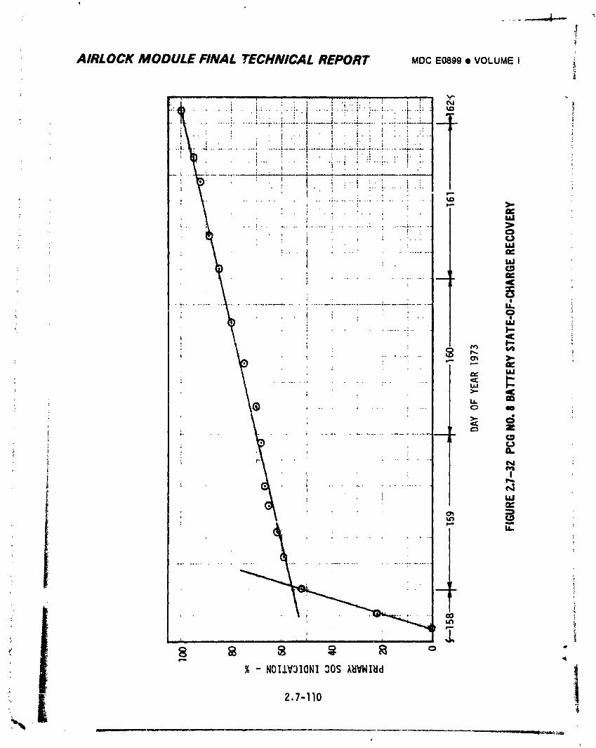
J?i
AIRLOCK MODULE FINAL TECHNICAL REPORT MDCE0899• VOLUMEI
: "i. " ' ' 1 : ].| * ,
/
i i..i :i .... i,i.I I
: t
: L ...... ' ...... *..
I
i
I _ : : C _
, ..
........... [ ..... hi
i
i-- ,4
, % -NOI.LV31ONI30S/_IVWI_Id !' 2,7-II0
__-i
1974018208-506
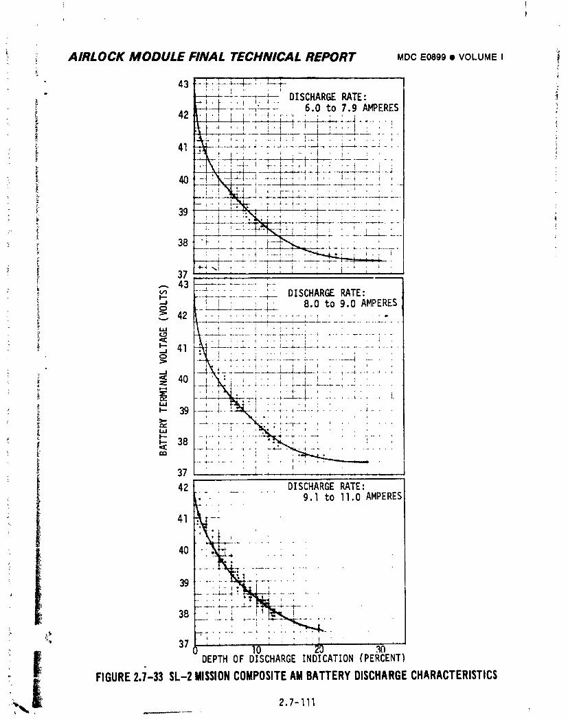
ii
_: :i AIRLOCK MODULE FINAL TECHNICAL REPORT MOOE0899• VOLUMEI i
; 43 F+,'" q---L--l---:--L:--p. ....... -- DISCHARGERATE: ]
-_--t-----:--_:-i--6.0 to 7.9 AMPERES
"_ _--L--._---_---_---_ .... ----L--_-_----i---_.....
: _-4\ : - '. -4..- i _._ __ _ ,i. .' i ,. ,: ,.,. t ,1 ..... , , -4--q-,'--r--+-'-r- _L_
: _ _"_-'_ t _ , -*-T-'.,._L.::.___ t , , I ...... _ ......... -_--:--.
.... ______ _ I ._,._, :, '__ : ..__.___+ ....
" _i-',, _ : !- _ i ,.; . .' . _ ,
!- 37 :- : : , ,' ,,,. , , i . , , _ , ,,
u_ DISCHARGERATE:--I--- --- -r-...... -+--
_ _' , 8.0 to 9.0 AMPERESi_; _ 42 L _'_ : _'i-'_'I"_' ......._. _ (___.__,_..,_ _ ] : ; : , _ -_-: ............... _ -
_" _ _ • i . .-_ ! . i . _ - , , .: i i ' 1
--.ll':41 _.i---_i_:" ,' ....'," -L...' ':._-.'..' l--l--,--i-+.,'' :' ........................., , I ' ,'-+--It---.L_4---i-- -I - -;-...... --;--- ;-............ i .... :
i_ i .... t ._ t i i _ . , , _---l-._';--,---i-_;-.--L- ! , _, _ _, ....... _---+ .-, .....
_ 40 i'xk:; t != I 1 ,+ ! : ' : '
...._------;--.---_li-;.--;-_-i--;---_--.---._-_............... L.- , i I:'i,<4: I , . _ ' I ' '_- 39 ----;----4--!-._---L.-: - +-.+.......; ..... _- . ,
.... .........38 ........"..... -+ : .... ' ....
37 ............
42 ........_ _. DISCHARGERATE:........
• -, 9.I to II.0AMPERES41
40 _ *
% 37 ,: ....0 l 0 '20 .3_
_ i DEPTHOF DISCHARGEINDICATION(PERCENT)
" i FIGURE2.7-33SL-2MISSIONCOMPOSITEAMBATTERYDISCHARGECHARACTERISTICS,
1974018208-507
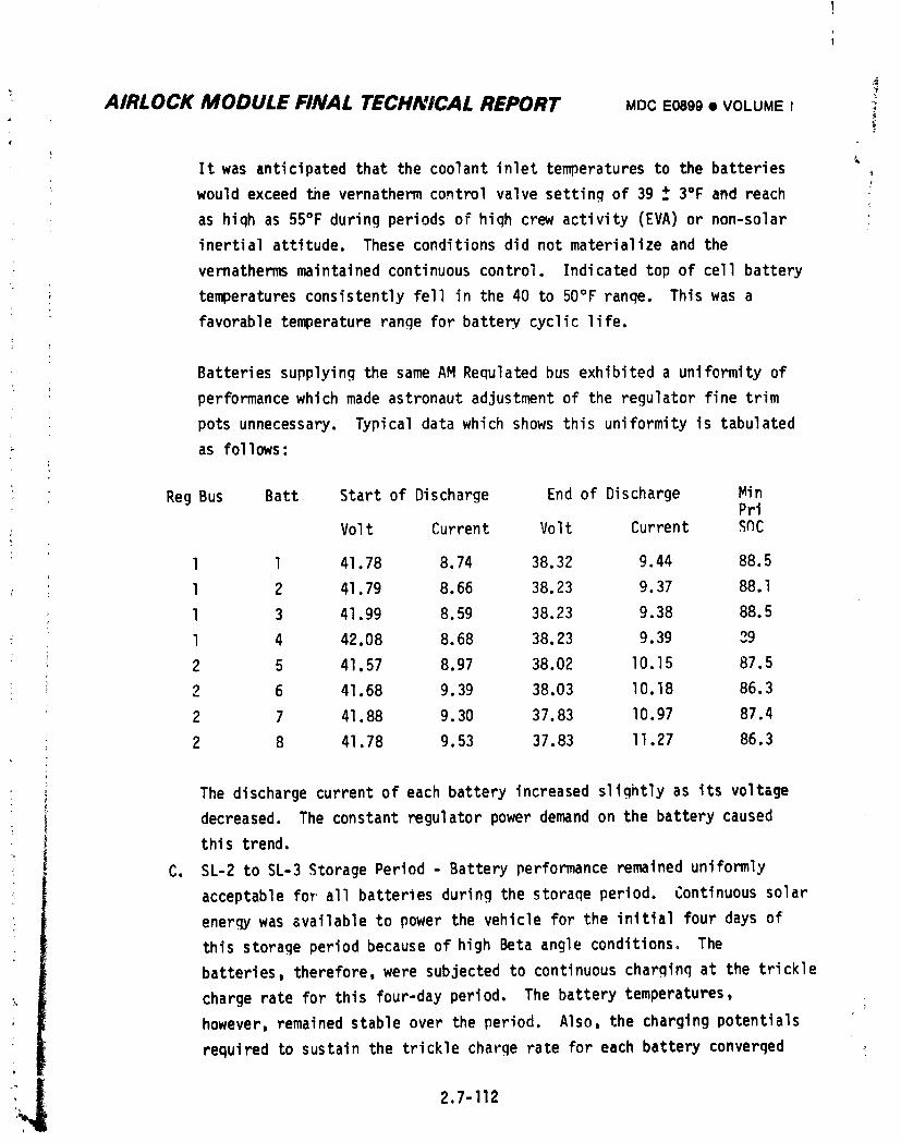
l
AIRLOCK MODULE FINAL TECHNICAL REPORT MDC E0899• VOLUMEI, !
It was anticipated that the coolant inlet temperatures to the batteries
would exceed the vernatherm control valve setting of 39 _ 3°F and reach
as hiqh as 55°F during periods of hiqh crew activity (EVA) or non-solar
inertial attitude, These conditions did not materialize and the
vernathermsmaintainedcontinuouscontrol. Indicatedtop of cellbattery
; temperaturesconsistentlyfell in the 40 to 50°Franqe. This was a
favorabletemperaturerangefor battery,cycliclife.
Batteriessupplyingthe sameAM Requlatedbus exhibiteda uniformityof
performancewhich made astronautadjustmentof the regulatorfinetrim
potsunnecessary.Typicaldatawhich shows thisuniformityis tabulated
as follows:
t
Reg Bus Batt Start of Discharge End of Discharge MinPri
Volt Current Volt Current S_C
: l l 41.78 8.74 38.32 9.44 88.5
l 2 41.79 8.66 38.23 9.37 88.1
l 3 41.99 8.59 38.23 9.38 88.5
l 4 42.08 8.68 38.23 9.39 29
2 5 41.57 8.97 38.02 lO.15 87.5
2 6 41.68 9.39 38.03 lO.18 86.3
2 7 41.88 9.30 37.83 I0.97 87.4
2 8 41.78 9.53 37.83 II.27 86.3
: ) The dischargecurrentof each batteryincreasedslightlyas its voltage, decreased. The constantregulatorpowerdemandon the batterycaused
this trend.
[ C. SL-2 to SL-3StoragePeriod- Batteryperformanceremaineduniformly
acceptablefor all batteriesduringthe _toraqeperiod. Continuoussolar
enerqywas availableto power the vehiclefor the initialfourdays of
thisstorageperiodbecauseof high Betaangle conditions.The
batteries,therefore,were subjectedto continuouscharginqat the trickle
chargerate for this four-dayperiod. The batterytemperatures,
however,remainedstableover the period. Also,the chargingpotentials
requiredto sustainthe tricklechargeratefor each batteryconverqed
2.7-112
] 974018208-508
i AIRLOCK MODULE FINAL TECHNICAL REPORT MDCE0899• VOLUMEI
• toward a mnre uniform level as expected. The batteries resumed normal
cyclic operation on June 26th (DOY 177) and cycled at an average DOD of
approximately 9% during the remainder of the storage period. Cycle
accui._lationat the time of SL-3 launch (DOY 209) totalled 772 cycles.
D. SL-3 Manned Phase - The AM batteries performed well during this period.
The batteries had accumulated 1683 flight cycles at the time the SL-3
crew departed on DOY 268. The depth of discharge range most commonly
experienced during the SL-3 mission was 13 to 16%. Forty-one earth
resource experiment package (EREP) passes were performed during this
mission. Battery depths of discharge were generally greater during these
passes than during normal solar inertial operation. The maximum DOD
experienced, occurred during the final EREP (DOY 264) where it ranged
from 36 to 42.7%.
AM batteries were actively cooled. Parallel coolant flow at controlled
temperatures (40 + 2 - 4°F) _ _ provided to coldplates for PCGbatteries
3, 4, 7 and 8. The coolant from these coldplates flowed to coldplates
for PCG batteries I, 2, 5 and 6, respectively, such that the coolant
inlet temperatures were increased by the heat pickup from the battery
first in line. A coolant loop system operational change was made on
DOY 237. This change decreas(_ the coolant mass flow by approximately
50% and the effects were detectable by an increase of approximately 2°F
in the operating temperaturesof PCG batteries l, 2, 5 and 6. Temperature
changes of PCG batteries 3, 4, 7 and 8 were too small to be detected in
the telemetry scatter. Other than this detected increase, the indicated
' top of cell (TOC) battery temperatures were comparable to those
i experienced during the SL-2 mission.
I Two of the eight AM batteries were purposely deep discharged during theSL-3 mission to deter'minetheir available capacities. Capacity of AM
batteries has been determined in ground tests by measuring the ampere-
_ hours extracted at an 18 ampere discharge rate to an end voltage ofJ
30.0 volts. The in-flight discharge procedure deviated from the groundi
• practice in that the astronauts terminated the discharge when they
• detected a terminal voltage of 33 volts. The charger ampere-hour meter
_ state-of-charge indication was used to measure the obtained capacities
2.7-113
1974018208-509
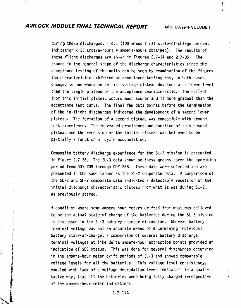
AIRLOCK MODULE FINAL TECHNICAL REPORT MDCE0899• VOLUMEI
duringthesedischarges,i.e., (I00minus finalstate-of-chargepercent _
indicationx 33 ampere-hours= ampex.e-hoursobtained). The resultsof
these flightdischargesaro si,,.,nin Figures2.7-34and 2.7-35. The
changein the generalshapeof the dischargecharacteristicssincethe
acceptancetestingof the units can be seen by examinationof the figures.
The characteristicexhibitedat acceptancetestinghas, in both cases,
changedto one where an initialvoltageplateaudevelopsat a lower level
than the singleplateauof the acceptancecharacteristic.The roll-off
fromthis initialplateauoccursmuch soonerand is more gradualthan the
acceptancetest curve. The finalfew data pointsbeforethe termination
of the in-flightdischargesindicatedthe developmentof a secondlower
plateau. The formationof a secondplateauwas compatiblewith ground
testexperience.The increasedprominenceand durationof this second
plateauand the recessionof the initialplateauwas believedto be
partiallya functionof cycleaccumulation.
Compositebatterydischargeexperiencefor the SL-3missionis presented
in Figure2.7-36. The SL-3data shownon thesegraphscoverthe operating
periodfrom DOY 209 throughDOY 268. These datawere selectedand are
presentedin the samemanneras the SL-2compositedata. A comparisonof
the SL-3and SL-2compositedata indicateda detectablerecessionof the
initialdischargecharacteristicplateaufromwhat it was duringSIo-2,
as previouslystated.
A conditionwhere someampere-hourmetersdriftedfromwhat was believed
to be the actualstate-of-chargeof the batteriesduringthe SL-3 mission
is discussedin the SL-3 batterychargerdiscussion.Whereasbattery
terminalvoltagewas not an accuratemeans of dLcerminingindividual
batterystate-of-charge,a comparisonof severalbatterydischarge
terminalvoltagesat like deltaampere-hourextractionpointsprovidedan
indicationof SOC status. Thiswas done for severaldischargesoccurring
in the ampere-hourmeter drift periodsof SL-3and showedcompaYable
voltagelevelsfor all the batteries. This voltagelevelconsistency,
coupledwith lackof a voltagedegradationtrend indicate' in a quali-
tativeway, that all the batterieswere beingfully chargedirrespective
of the ampere-hourmeter indications.
2.7-114
1974018208-510
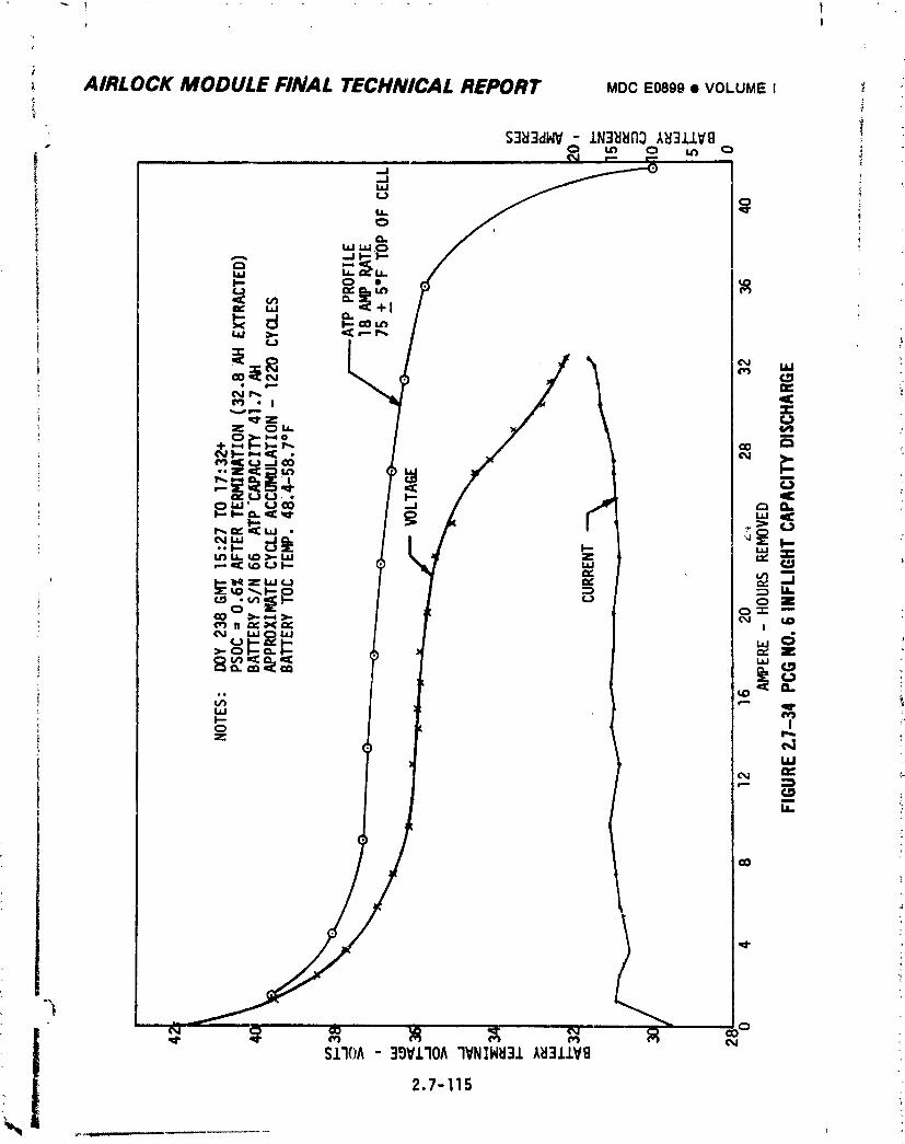
1974018208-511
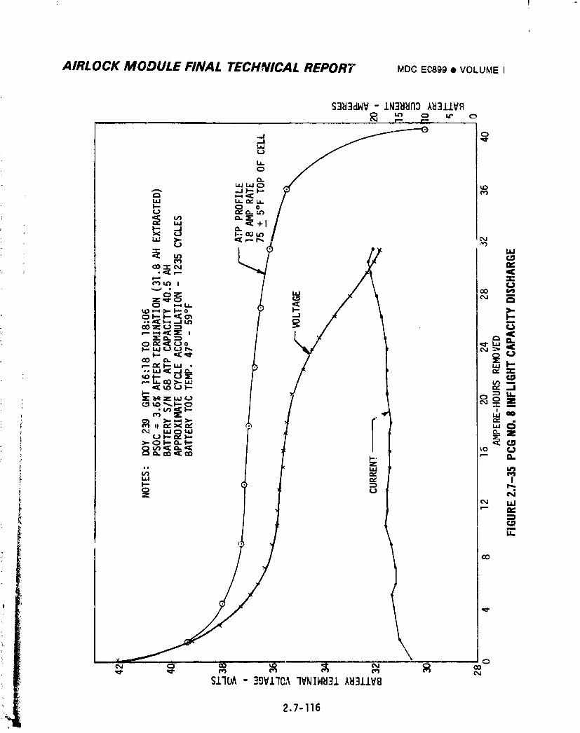
AIRLOCK MODULE FINAL TECHNICAL REPORT MDCEC899• VOLUMEI
\Q
1974018208-512
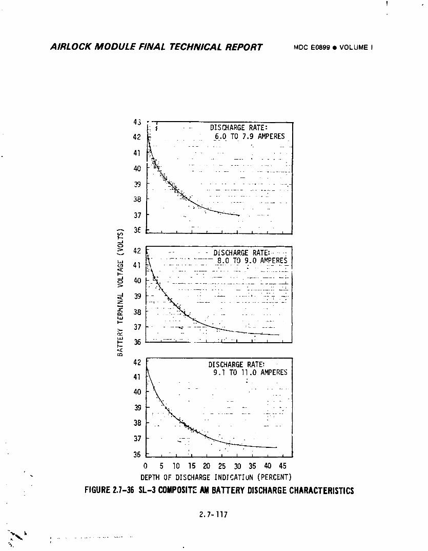
AIRLOCK MODULE FINAL TECHNICAL REPORT MDCE0899• VOLUMEI
43 ," ,_ i i " DISCHARGE RATE:
42 : _6.0.TO 7.9 AMPERES
41
4O
38 _
37
3E .......l i 1 _ t I I I Il'----J
> 42 _ .... DISCHARGE RATE:....._- - : _8_.0TO 9.0 AMPERE_" _- -_41 ---.....
< - . . ........ "___ _:_ - ,-__..: .... -i--._Jo 40
-J< 39Z
"" 38e_
I...-
,_ 37
I--I-.-
cQ
42 DISCHARGERATE'9.1 TO ll.O AMPERES
41 _ .
4o • " -_/
39 -. _ .--
38 .......
37L .
3b , , ', , , , , , ,
0 5 lO 15 20 25 30 35 40 45
" DEPTH OF DISCHARGEINDICATION (PERCENT)
FIGURE2.7-36 SL-3COMPOSITEAMBATTERYDISCHARGECHARACTERISTICS
2.7-]]7
_'_i fk _ .......................t
1974018208-513
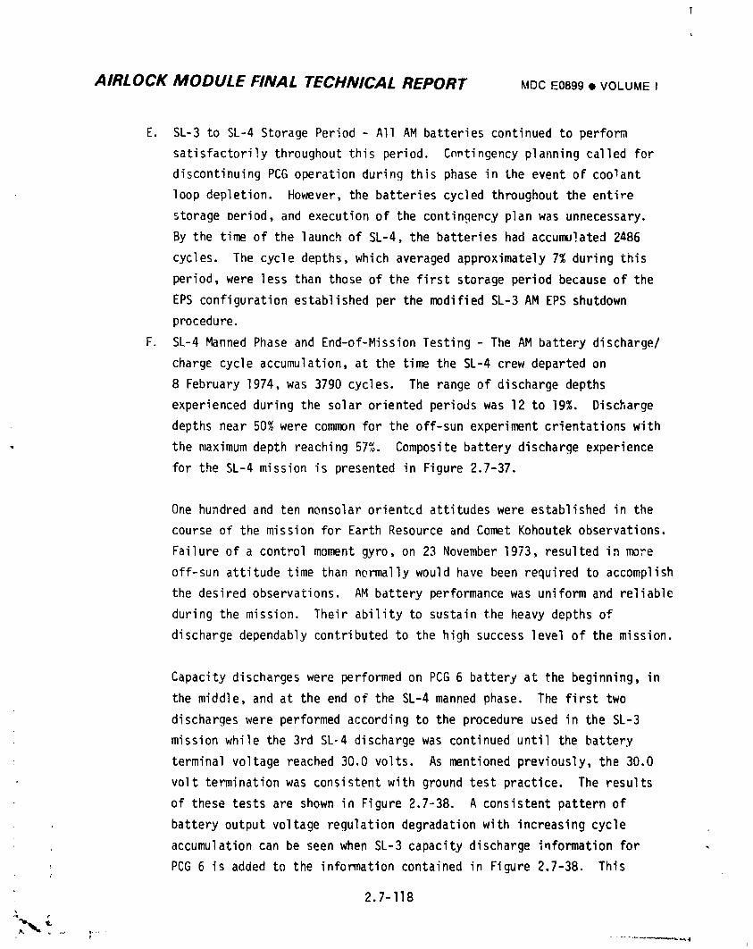
AIRLOCK MODULE FINAL TECHNICAL REPORT MOCE0899• VOLUME I
E. SL-3 to SL-4 Storage Period - All AM batteries continued to perform
satisfactorilythroughout this period. Cnntingency planning called for
discontinuing PCG operation during this phase in the event of coo]ant
loop depletion. However, the batteries cycled throughout the entire
storage Period, and execution of the contingency plan was unnecessary.
By the time of the launch of SL-4, the batteries had accumulated 2486
cycles. The cycle depths, which averaged approximately 7% during this
period, were less than those of the first storage period because of the
EPS configuration established per the modified SL-3 AM EPS shutdown
procedure.
F. SL-4 Manned Phase and End-of-MissionTesting - The AM battery discharge/
charge cycle accumulation, at the time the SL-4 crew departed on
8 February 1974, was 3790 cycles. The range of discharge depths
experienced during the solar oriented periods was 12 to 19%. Discharge
depths near 50% were common for the off-sun experiment crientations with
the maximum depth reaching 57%. Composite battery discharge experience
for the SL-4 mission is presented in Figure 2.7-37.
One hundred and ten nonsolar oriented attitudes were established in the
course of the mission for Earth Resource and Comet Kohoutek observations.
Failure of a control moment gyro, on 23 November 1973, resulted in more
off-sun attitude time than normally would have been required to accomplish
the desired observations. AM battery performance was uniform and reliable
during the mission. Their ability to sustain the heavy depths of
discharge dependably contributed to the high success level of the mission.
Capacity discharges were performed on PCG 6 battery at the beginning, in
the middle, and at the end of the SL-4 manned phase. The first two
discharges were performed according to the procedure used in the SL-3
mission while the 3rd SL-4 discharge was continued until the battery
terminal voltage reached 30.0 volts. As mentioned previously, the 30.0
volt termination was consistent with ground test practice. The results
of these tests are shown in Figure 2.7-38. A consistent pattern of
battery output voltage regulation degradation with increasing cycle
accumulation can be seen when SL-3 capacity discharge information for
PCG 6 is added to the information contained in Figure 2.7-38. This
2.7-I18
1974018208-514
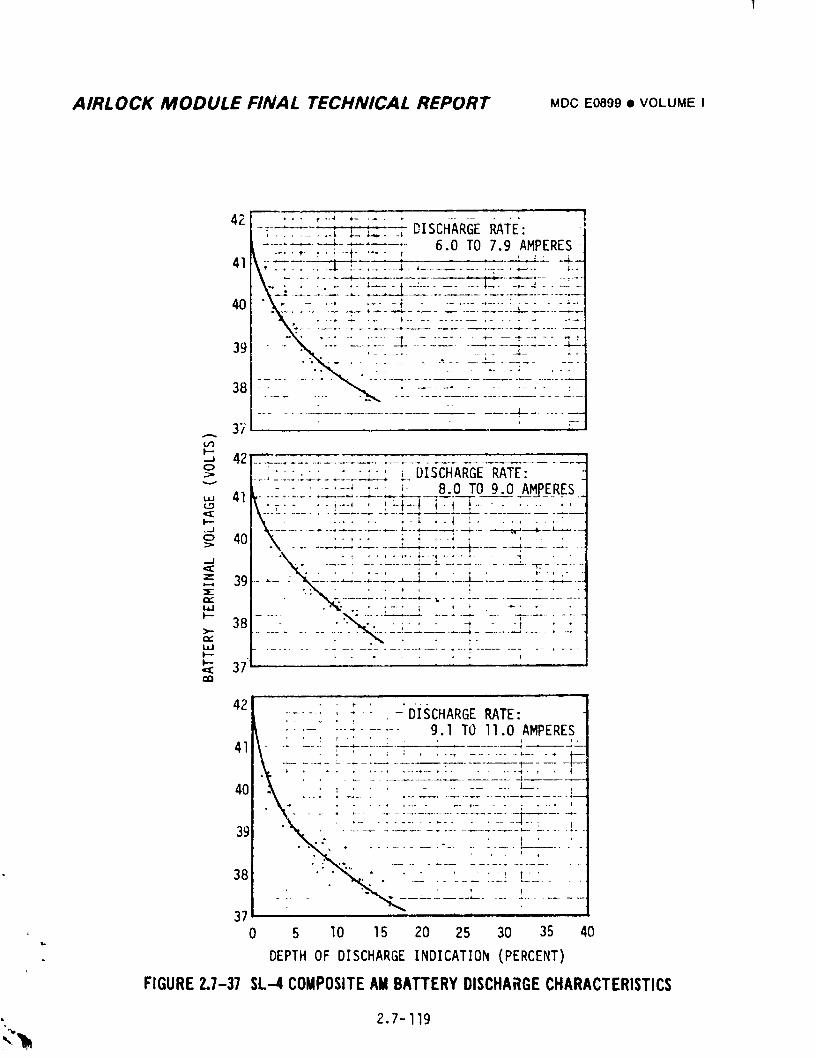
AIRLOCK MODULE FINAL TECHNICAL REPORT MDC E0809 • VOLUME I
42 -,. t--_ ........... ,-iL _: _; DISCHARGE RAI:E':L ....-+-""--F-,r----_-- 6.0 TO 7.9 AMPERES
li_ ; , ..- ,- i----i----' ......... $_- -I-4 ..... :
40 'y: ;-_-"_TZ[_2___2LT_:_-_;2-:2'
39 " --'_ "--: ---;"- --I-_-_L --.___T__-_2.:Z_L'_ _G..L_".. , ...... ;- --(-- ;.
37 _-- - : --
o> I---,'" " _ _ DISCHARGE RATE: -"" |....;'-T"-T-'--T----TL-". T: B.O TO 9.0 AMPERES-
i_ ._1 II .................. . --+--_---,_----t--- • t, i ....401 %. '- t-- ; i ,-,; ' " •> I "\ ............. ---r ..... --f ..... 4.....
I ......._.... ,._:-; -,::_ 37ELL ! ..... : ......
42 ........ i . -'DiSCHARGE RATE:
.... ;...... 9,1 TO ll,O AMPERES• " ; , "'- ' ] , , I m.41
....... :- .......... _...... "!---"..... _--"
40 . . i .......... l_. :
"- T T..- .-'. : ;L-.-TT"_TL--T-T-T:_ .... ]-39 . . , . .
• . .................. L....... i38 '" " "_ ," ...... _ T' !
37 ....0 5 10 15 20 25 30 35 40
DEPTH OF DISCHARGE INDICATION (PERCENT)
FIGURE 2.1-37 SL--4COMPOSITE AM BATTERY DISCHARGE CHARACTERISTICS
• 2.7-119
:?'_.
1974018208-515
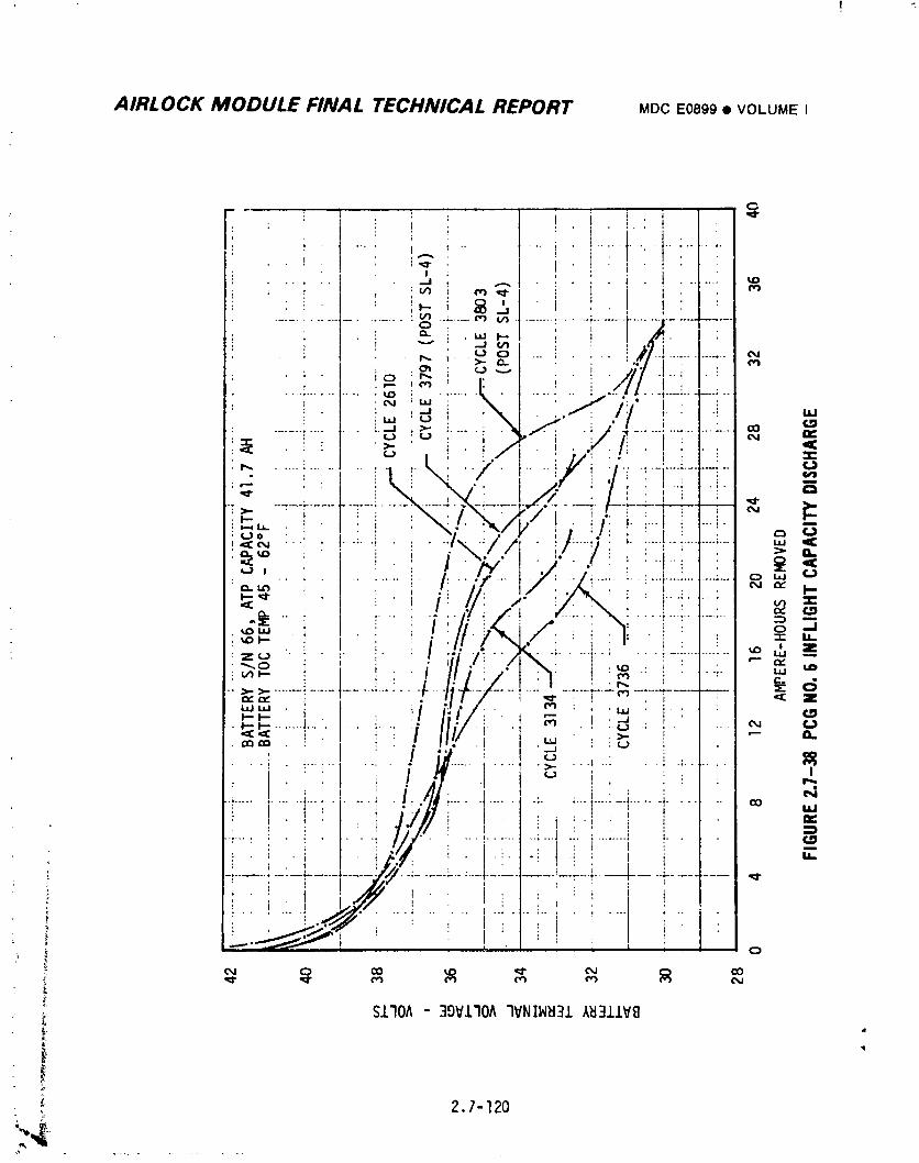
AIRLOCK MODULE FINAL TECHNICAL REPORT MDCE0899• VOLUMEI
• _ !,it _! _, : i i • ! : I . ! : i
: _ : !_.,.. i _ '.] "I. .. _t ! : "........... ,.......... "_ "';.... _ _t .... :...... _---t .... r--
I : _, ,.,.,_/ , , | _1 ; ,.. ; ,.-,oi_ _ .... :,#-i- ,',,
.... _ " >- r_ l ' ' _-dl'" ['" " ¢_• ; . ,._ : p,_ i ¢J "_ I •. [ • /11 .'--:
; t ._ ,,", ' I', t _ i /71 t ;.... : ........... _ : ................ ; ... • _.--_--: ...._ I _:;_i \I ._// !: ..,
...... i .... 1.. i._ ._ _..... i .'_I .,,,¢I. .i /'A ....... ! ...... _ t,_-,- _ I _ '_ ' i _" i :/ I_ t . _ 13¢;_. . i ! [ '>- ' . i /i . _ . ;," . n i . i :
.....i: i ! k_".4/ I....j.,,,"i .:/....i::t..... "': / ! "_ ,",_ ! I ' --L : _ "_--7 .... F--I--:'_--:.i'_-:-_/;--.r---_-T. t _ i_
_,.,-i ' / : i : x,.:,/. :'X_/j,' I. i/: I r ! !_-_o ' ; . : _ I . • , . r'_ C_,<:_ ..._ • t..... , . • • -.lx-.t,," • :/-.-:j. _...... !--..... ,.,
=_ "; " !.....i I./[- t..>,z',Z_-: i't-! _ "'=_.¢..q
-li-/ ---'-= _ '__>. .......! .......... _..i.. 4-.... /-._.I...: _ ..... L.-:_r,¢ I _ ' ! : '_: Z
• .,,,JI"-" I'--' ....... ........ _ .... _
.>,. _¢IQ ''_ _ ! ; t,,,.J• ,.,.j
................ ! /it. _ ,: .... _.......
r, I'J//i" : :' ; :i ii i i " |
-_ ........... L- ..........................; i
_ S.L'IOA- 39V.L'IOA"IVNIN_I31/k_13.1.lVB
2.7-120
74-.a .........
1974018208-516
AIRLOCK MODULE FINAL TECHNICAL REPORT E0899• VOLUMEI
progressive pattern of nickel-cadmium "memory" development is appa_entIj
minimalIv effected by incomplete capacity discharges. More will be said
concerning this subject in the end-of-mission test discussion.
A special EPS configurationwas established as part of the SL-4 crew
closeout of the Skylab. This was done in anticipation of capacity testing
of all AM batteries after crew departure. The devised system configura-
tion allowed ground selection of any one of the eight AM batteries for
discharge, established discharge rates near the ground test level of C/2,
permitted continuous discharge of the selected battery to a 30.0 volt
completion, and provided a self limitation of battery discharge as the
battery terminal voltage approached 29.0 volts. The last feature was
desirable as ground station coverage could not be assured at every
critical discharge time. The flexibility of the AM EPS control capability
proved invaluable in accomplishing the test objectives.
All eight AM batteries were discharged to 30.0 volts during the post SL-4
test period. In addition, PCG 6 and 8 batteries received a second full
capacity discharge during this period.
Three distinct discharges profiles were found to exist. Figure 2.7-39
depicts the discharge characteristic of PCG l and 4 batteries, while
Figure 2.7-40 shows the characteristic of the remainder, with the
exception of PCG 6.
PCG 6 battery, which was discharged to 30.0 volts shortly before the crew
departed, exhibited discharge characteristics as shown in Figure 2.7-38.
When comparing Figure 2.7-39, Figure 2.7-40, and previous ground test
experience on units with similar history, a marked consistency was noted
except for the duration of the second voltage plateau which begins at
about 16 amp-hours. The second voltage plateau for PCG l and 4
batteries, was longer, and resulted in greater amp-hour capacity. One
possible contributing factor to this difference is the length of time the
. various batteries were in the vehicle before launch. PCG 1 and 4
2.7-121
i 9740i 8208-5i 7
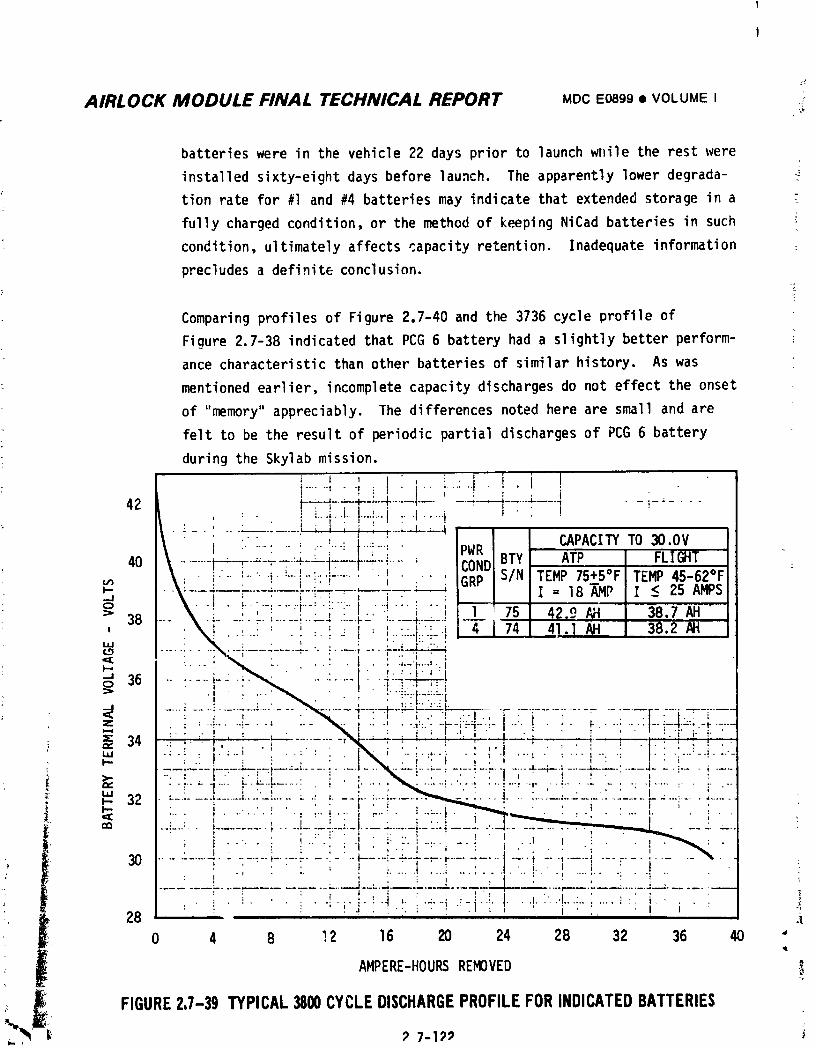
AIRLOCK MODULE FINAL TECHNICAL REPORT MDC E0899 • VOLUME I ._
batteries were in the vehicle 22 days prior to launch while the rest were
installed sixty-eight days before launch. The apparently lower degrada-
tion rate for #1 and #4 batteries may indicate that extended storage in a
fully charged condition, or the method of keeping NiCad batteries in such
condition, ultimately affects capacity retention. Inadequate information
precludes a definite conclusion.
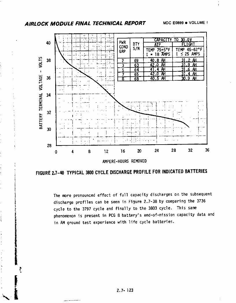
AIRLOCK MODULE FINAL TECHNICAL REPORT MDC E0899• VOLUMEI
• I _" i i '• • : • -.. , : : '; ,
• [ :-..,..__.L___._'_--._!_ : !__L._ DuD CAPACITY TO 30.OV' " ' _" _ ] - - I ' I "• FIll% m lml40 \ .I....|-"'-.I.;.-4....,L,...i.... rn_, BTY ATP I FLIGHT
, _ -"'!' i_" GRP S/N TEMP 75+5"F TEMP 45-62"F• o _ t , I _ ." ,.."
\_....!...._-_-'!_'.....-".::,.'" I " 18 XMPS l I _<25 AMPS_-u_38 ....%.--I"--,.• :..'-._I_'___";_ ' l
""-_I - '..'....' i:i"_ . 2 69 .40.8AH I 31.2 AH..J
__ _._._." ; ! :-!._ 3- 63 42.0AH I 31.9AH, >o :Fi-- T-_ .__-i-- ;......]....- 5 64 41.4AH l 31._AH
' IAH J 31:4 AH'" __ .:-'._-_.. _-._- J 2-_ '7' 65 42.0 i36 -< -; .!...-.:-,__, !._../__8 68 , 40,5AH J 30.9
=!!;i..J . -...-- _ "'-
z< 34 .--"--- -.
== : ............:-iif ....................:....iml - - r • _ ........... I ...... : ..... i . .I-- • ; ; : " ' ' ':
, __ ____. • ., LIJ
I--- • ' - • ' . ' .' .... *, .. : ' . i .. ; .
: _ 30 .'.......:---_...................._...._-:=-:............._-..-I........i " ..r....' 6 ' ' ' '• I '- _ . ' - "_ ......: '. ..i .!. , . .I
--_ --i ":-"'_;- _-_-_-- 4-- ; -_'_-- .... I- -- ,-----_....... ;-.-' • ' ' I ' • ' " " : - ' ! . ' '
._ 28 - ........
0 4 8 12 16 20 24 28 32 36
F
AMPERE-HOURS REMOVED
•* FIGURE2.7-40 TYPICAL3800CYCLEDISCHARGEPROFILEFORINDICATEDBATTERIES
The more pronounced effect of full capacity discharges on the subsequent
discharge profiles can be seen in Fioure 2.7-38 by comparing the 3736
cycle to the 3797 cycle and finally to the 3803 cycle. This same
phenomenon is present in PCG 8 battery's end-of-mission capacity data and
in AM ground test experience with life cycle batteries,
2.7- 123.'_.
1974018208-519
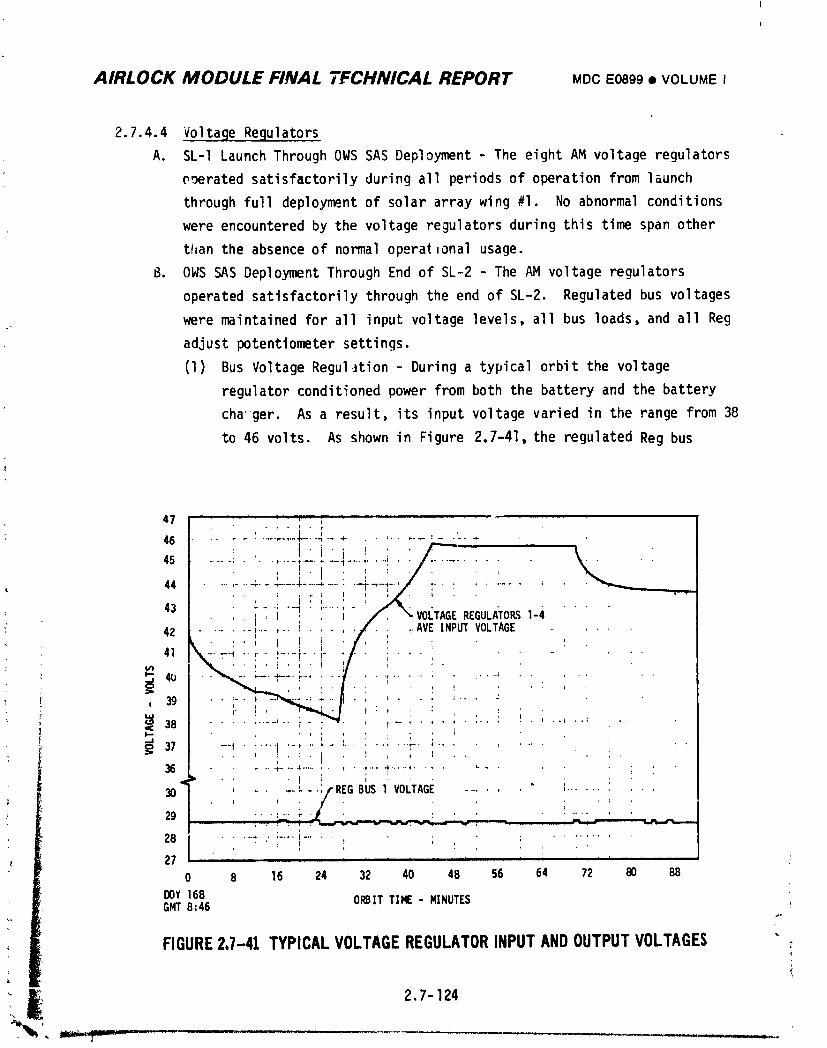
AIRLOCK MODULE FINAL 7FCHNICAL REPORT MDCE0899• VOLUMEI
2.7.4.4 VoltageRegulators
A. SL-ILaunchThroughOWS SAS Deployment- The eightAM voltageregulators
o_rated satisfactorilyduringall periodsof operationfrom launch
throughfull deploymentof solararraywing #1. No abnormalconditions
were encounteredby the voltageregulatorsduringthis time spanother
thanthe absenceof normaloperationalusage.
B. OWS SAS DeploymentThroughEnd of SL-2 - The AM voltageregulators
operatedsatisfactorilythroughthe end of SL-2. Regulatedbus voltages
weremaintainedfor all inputvoltagelevels,all bus loads,and all Reg
adjustpotentiometersettings.
(1) Bus VoltageReguIJtion- Duringa typicalorbit the voltage
regulatorconditionedpower fromboth the batteryand the battery
cha'-ger.As a result,its inputvoltagevariedin the range from 38
to 46 volts. As shownin Figure2.7-41,the regulatedReg bus
47 ..... ,..... ; -.... I .
46 ....... ..L.-.-_-- +- ........ :- .'....
! . li + + I__>/.' /- +
45 ............ ; .... +T........ . "+• I .............
.... ,- .. +4-- . _++.._ ..... ,-,W...... ' _--+.+-. + +..... ,....
44 r , , ., ,,, , + ,,,,,....... -t - v..... + - _. VO _.. - • - •43 .... t : , t TAGEREGULATORS1-4
? 42 ....... i......i ..... u/ ; _AVE INPUT VOLTAGE . •+ . : • , + I + . f, , ' .
"+ ,it \----+.,-+-+ .....+- +- ./ _ .. :
h.. 41.} ........ +'r"++'_....... l' '' " "'-+ -', , .... + I ' i
38 ........ _" .+ _" ' I ............ + ..t ....cc t....+ ',. , '. ;
37 -'+ ...... t .......... ' ..... r-" ; ........ + ''• ' ' ,; ' " " I I _ + I . . +, ,
36 .... t-.-'+ ....... ' 1-" "+:............ ;q • ' t _ ' .... i
I/REG BUS 1 V " ' ._
30 ...... "+ OLTAGE ....... ' .......
29 ._ , " '- " i: ' . : " "- - ; ++ ; , + ; i ..... _ + i
, , _ .... , .. ,28 ...... ".... _....i ,. i +
i
27 , ........ " ' ''
0 8 16 24 32 40 48 56 64 72 80 B8
DOY 168 ORBIT TIME - MINUTESGMT8:46
FIGURE2.7-41 TYPICALVOLTAGEREGULATORINPUTANDOUTPUTVOLTAGES
_ 2,7- 124+
1974018208-520
AIRLOCK MODULE FINAL TECHNICAL REPORT MDCE089g• VOLUMEI
voltage was not affected by the relatively large variance in input
voltage, The small fluctuations in Reg bus voltage seen are attrib-
utable to bus load variations and/or telemetry data conversion
accuracy limitations.
(2) V-I Output Characteristic - With four voltage regulators operating
on one Reg bus, the bus voltage was expected to decrease from open
circuit voltage (OCV) by O.Ol volt per ampere of load. Figure
2.7-42 shows the relationship of telemetry data points to predicted
V-I curves. The curves are based on a O.Ol volt per ampere droop
and Reg bus 20CV settings of 29.22 and 29.45 volts. These values
closely approximate the desired settings for DOY 164 and DOY 170,
respectively. Considering the accuracy limitations on the telemetry
data, the data points compare favorably with the predicted curves
and the comparison is typical for both Reg buses. The Reg bus
potentiometerswere adjusted several times during SL-I/SL-2 for
the purpose of adjusting the AM load level or the AM/ATM load
sharing. No adjustments were required because of voltage regulation
drift or instability. The potentiometer adjustments were made over
nearly the entire adjustment range from almost fully CCW to a 29.5
OCV setting. Computer programs which simulated the normal AH/ATM
distribution system were used to calculate the amount of adjustment
: to be made. Each adjustment resulted in Reg bus voltages and AM/ATM
load sharing which compared favorably with those predicted by the
computer programs. Based on the foregoing considerations, it was
concluded that the eight voltage regulators properly regulated their
V-I output characteristic over a wide operating range.
( (3) Efficiency - For the operating conditions encountered through the
end of SLo2, the voltage regulator efficiency was expected to be
better than 93%. There is no evidence that the voltage regulators
did not operate at this high efficiency,
Voltage regulator temperatures in the range from 40°F to 60°F were
recorded by telemetry throughout SL-2. Temperatures in this range
, indicated normal operation with no over-heating or efficiency
" problems.
2,7-125
1974018208-521
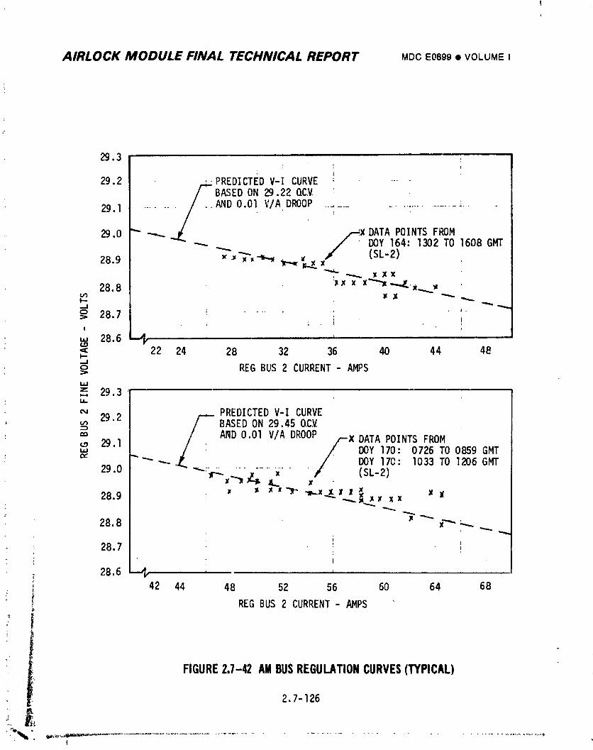
AIRLOCK MODULE FINAL TECHNICAL REPORT MOCE0899• VOLUMEI
29.3 ......
i
29.2 /PREDICTED V-I CURVE - ,__ BASED ON 29.22 QCV
29.1 - - _D 0.01 V/A. DROOP ........................ "..
29.0 /_X DATAPOINTSFROMDOY 164:1302 TO 1608 GMT
/ (SL-2)28.9 _ _'_'_-z-_i_ _E. x
28.8 _,x x x_ ....../..x.__I--
o ,._,'_°.'t : .......!
W
"=: 22 24 28 32 36 40 44 48I"--Jo REG BUS 2 CURRENT - AMPS
l.=J
z 29.3
m BASED ON 29.45 OC.V.: =0 ANDO.OlV/ADRO0
29 I X DATAPOINTSFROM"' " _Y 170: 0726 TO 0859 GMT"" "'*" _- DOY 170: 1033 TO 1206 GMT
29.0 ": ........... =" (SL-2)
28.9 x _ x =_ ,m,,.x_x_J ,_._x xx X W
28.8 _ _ x"" ;-..-..
t• 28.7
28.6 --,1,. , ..........42 44 48 52 56 60 64 68
REG BUS 2 CURRENT- AMPS
FIGURE2.7-42 AMBUSREGULATIONCURVES(TYPICAL)
2.7-126
t
1974018208-522
AIRLOCK MODULE FINAL TECHNICAL REPORT MOCE0899• VOLUMEI
" (4) PowerModuleOperation- The AM VoltaqeRegulatorcontainedfive
powermoduleswhich were redundantto meet the high reliability
requirements.Eachmoduleoperatedsuccessivelyas the output
currentdemandwas increasedby a 13-ampereincrement. DuringDOY
170,the Reg Bus loadwas greatenough,approximately15 amperes
per PCG,that two powermodulesin each regulatorwere requiredto
operate. The fact thatthe discharqecurrentsfor batteries
associatedwith the same Reg Bus remainednearlyequal and thatno
adjustmentof the FineAdjustpotentiometerswas requiredthroughout
SL-2 indicatesthat thesetwo powermodulesin each voltagerequlator
operatedsatisfactorily.
C. SL-2 to SL-3StoragePeriod- The AM voltageregulatorsoperatedsatis-
factorilythroughthe SL-2 to SL-3storageperiod. Regulatedbus voltages
were maintainedfor all inputvoltagelevelsand all bus loads. Regulator
telemetrytemperaturesindicatedno temperatureor efficiencyproblems.
Batterydischargecurrentsindicatedcontinuedproperloadsharing_etween
regulators.
D. SL-3MannedPhase - The eiqhtAM voltaqeregulatorsoperatedsatisfac-
torilythrouahoutthe SL-3mission. Analysisof flighttelemetrydata
i,ldicatednormaloperationby all eight regulatorswith no indicationof
failureor operationalanomalies. The requiredreq bus voltageswere
maintainedfor all inputvoltagelevels,all bus loads,and all Reg
Adjustpotentiometersettinqs. Observationof all eiqhtAM regulator
: temperaturesthroughoutthe SL-3missionindicatedno overheatingor
efficiencyDroblems. The curvesof Fiqures2.7-41and 2.7-42are
; also reDresentativeof the observedSL-3 volta.qereaulatorperformance.
_ Duringmost of SL-3,the AM loadwas suchas to exerciseonly the first
i moduleof each voltaqereaulator. However,therewere severalinstances,
I suchas {X)Y261 in which the loadwas sufficientto exceed13 amperes
per requlatorand which requiredthe operationof the secondmodule
in each regulator. Observationof the batterydischargecurrentindicated
oroperooerationof the firsttwo modulesat thesetimes. An apparent
short on the ATM TV Bus 2 Jn DOY 216 at 0320:21GMT resultedin a loadof
areaterthan200 ampereson Req Bus 2. This meant that fourand possiblyfiveof the modulesin each voltaqerequlatoroperatedfor a periodof
" __ approximatelythreeseconds.2.7-127
1974018208-523
AIRLOCK MODULE FINAL TECHNICAL REPORT MDCE0899• VOLUMEI
E. SL-3 to SL-4 Storage Period - The AM voltage regulators operated normally
through the SL-3 to SL-4 storage period. The bus voltages were adjusted
approximately two volts below their normal settings per the modified SL-3
AM EPS shutdown procedure. These regulated bus voltages were maintained
for all input voltage levels and all bus loads. The regulator temperature
telemetry parameters indicated no temperature or efficiency problems.
Battery discharge currents indicated continued proper load sharing
between regulators.
F. SL-4 Manned Phase - The eight AM voltage regulators operated satisfac-
torily throughout the SL-4 mission. Analysis of flight telemetry data
indicated normal operation by all eight regulators with no indication of
failure or operational anomalies. The required Reg bus voltages were
maintained for all input veltage levels, all bus loads, and all Reg
adjust potentiometer settings. Observation of all eight AM regulator
temperatures throughout the SL-4 mission indicated no overheating or
efficiency problems. The curves of Figures 2.7-41 and 2.7-42 are also
representativeof the observed SL-4 voltage regulator performance.
The Shunt regulator, discussed in paraqraph 2.7.2.3(E), was incorporated
into the Airlock design as protection aqainst a particular voltage
regulator failure mode. The AM voltage regulatorswere failure free
throughout the Skylab mission and operation of the Shunt Regulator was
never required.
2.7.4.5 PCG Controls and Monitors
The PCG controls were located on STS Panel 205 and the on-board monitors were
located on STS Panel 206.
A. SL-I Launch Through OWS SAS Deployment - Control usage during this periodf
: was by both DCS commands and crew switch actions. The low solar array
! power available to the PCG's was the reason for the control switching that
i was performed. The solar array output switches were cycled between theirinormal and alternate PCG's several times. This was done a_ a means of
increasing power to a single Pc_ so its battery could be charged, and as
a safety measure to preclude low power inputs to PCG equipments, The
b_ttery switches were used to turn the batteries off and on as required
to charge when possible and preclude discharging the rest of time. The
batteries were also turned on several times so the PCG's could act as
1974018208-524
AIRL(JCK MODULE FINAL TECHNICAL REPORT MDCE0899• VOLUMEI
backup for the AFM EPS. The charger switches were cycled in conjunction
: with the solar array output switches for analysis purposes and to protect
the battery chargers from low solar array power operation. The PCG
output switches were cycled off and on when the PCG's were acting as
backup for the ATM EPS. The discharge limit switches were pldced in
their inhibit positions on DOY 158 and returned to auto on DOY 159. This
was done as part of the OWS solar array wing deployment activities so the
PCG's could supply power, if necessary, even if the battery SOC's went
below 30%. All PCG telemetry signals and on-board displays provided
sufficient parameter information for operation and analysis throughout
this period.
B. OWS SAS Deployment through End of SL-2 - After the deployment of the
OWS solar array wing, _he PCG controls were used to return the PCG's to
their normal configuration. No subsequent control operations were
required during this mission phase. All monitors provided satisfactory
informationwith the exception of the SAS _4 current monitor. The
problem associated with the SAS a4 current monitor is discussed in
detail in section 2.7.4-7-A. A work-around method was developed which
allowed satisfactoryevaluation of all parameters despite this problem.
The SL-2 crew debriefing indicated the satisfactory design and operation
of the on-board PCG displays.
C. SL-2 to SL-3 Storage Period - No PCG control operations were required
during this period. All monitors performed satisfactnrily.
• D. SL-3 Manne_ Phase - All required PCG control switching during SL-3 was
accomplished successfully. All PCG telemetry and on-board monitors
provided satisfactory and sufficient parameter information for operation
and analysis throughout the SL-3 manned mission. The SAS #4 current
; monitor anomaly, described for SL-2, remained the same throughout SL-3.
Most of the PCG control switchinq was associated with the capacity dis-
charge testinq of PCG batteries 6 and 8 on DOY 238 and DOY 239
i respectively. The Discharge Limit command for PCG #3 was also used
_ several times during this period in conjunction with EREP passes. The
i Status Liaht switches and the Battery Charge selector switch (associated
with the _ S_C meter) were also used successfully by the crew for periodic
status checks on the AM EPS power system.
2.7-129
1974018208-525
AIRLOCK MODULE FINAL TECHNICAL REPORT MDC E0899 • VOLU_ ¢: I
The first usage o, any of the eight fine adjustment potentiometers
occurred during the SL-3 mission. Optimization became desirable during
SL-3 because EREP passes were scheduled at the rate of one to two per day
over an extended period toward the end of the SL-3 mission. This high
EREPactivity period alse occurred over a period of low Beta angle
conditions where both EPS systems, AM and ATM, had thei minimum power
capabilities.J,
Analysis of flight data showed that battery characteristics were very
similar for the eight batteries. Therefore, the pot adjustments were
made only to balance out the effects of array shadowing. The ATM
array shadowed one module each on SAE #5 and #8 and two modules on
SAG #6 (out of 15 modules which made up the SAG for each PCG). The
effects of the module shadowing was that PCG's #5, 6 and 8 received less
solar array pqwer and could not recover from a DODequal to the other
5 PCG's in the same amount of charge time. Based on the SI power capa-
bility definition, therefore, PCG#6 limited the power capability to chc
battery DODit could recover from and none of the other PCG's could be
operating at full capability. The amount of adjustment for the fine
adjustment pots was determined by using flight data and computer simula-
tion programs. Pot #7 was not adjusted because PCG#7 was sharing
equally with PCG's #I through #4 and had the equivalent solar array input.
Pots #5 and _8 were adjusted to cause their PCG's to supply 0.5 amperes
of battery dlscharge current, less than PCG#7 to compensate for )ne
shadowed module and pot a6 was adjusted so that PCG#6 would ,_pply
1.0 ampere of battery discharge current less than PCGa7 to compensate
for two shadowed modules. To maintain Lhis configuration as the two Reg
bus pots were adjusted for AM/ATM load sharing at subsequent Limes, it
was only necessary to adjust Reg bus pot /_2 so that PCG_7 discharge
current remained equal to PCG's al through a4.
: As a result of the adjustments described above, all batteries returned to
_; a fully charged state (100% SOC) at very close to the same time in a
: _ daylight perio'J. Therefore, no one PCG, despite differences in available
2.7-13o
Ig74018208-526
AIRLOCK MODULE FINAL TECHNICAL REPORT MDCE0899• VOLUME I
<_,,,..:...n_vw_.=_,limited,the SI Dower capability significantly different from
any other FCG. A more optimum power capability was achieved by use of
the fine adjustme_._.DotP-tiometers.
E. SL-3 to SL-4 Storage Period - No PCG control operations were required
during this period. All monitors performed satisfactorilywith the
exception of telemetry parameter M137, battery 25 voltage, which shifted
slightly higher on DOY 298 throush the end of thi_ period.
F. SL-4 Manh_d Phase - All required PCG control switching during SL-4 was
accomplished successfully. All PCG on-board monitors performed satis-
factorily throughout SL-4. The PCG telemetry monitors performed satis-
factorily with t_e exception of the SAS _l current, battery _l through #8
coarse :urrents, battery _l temperature, and EPS Control Bus _ and 2
current monitors. A T/M discrepancy caused erratic performance or,these
parameters fro_ DOY 349 ttrough the end of the mission. The SAS #4
current telemetry monitor anomaly, described for SL-2, remained the same
through the end of the mission. Fine adjustment potentiomoter #7 v ._
adjusted CCW slightly to equalize the battery #7 discharge current with
that of battery 25 and battery #8. End of n,is_ionbattery testing
required the operation of many relay circuits which had seen little prior
use. No problems were experienced as a result of this activity which
followed a lonq period of dormancy.
2.7.4.6 Power Distribution System
A. SL-I/SL-2 _issio_,Phase - All elements of the AM Power Distribution System
functioned properly durinq the SL-I/SL-2 mission phase. All required
switchinq operations were successfully accomplished. Power transfer and
load shar,nn between EPS systems was accomplished as required with no
limitations imposed bv the Power Distribution System. No problems result-
inQ in protective device operation were encountered durinq this period.
The f_ur major elements of the Power Distribution System are further
; discussed in the following paragraohs.
(1) Switcr_nq - The AM Power Distribution controls performed successfully
for the followin_ operations durinq SI.-I/SL-2.
o Activation of Sequential buses, and activation and deactivation
of Deploy buses in respons_ to OWS-IU commands. These were one-
!i time operations durinq the sequential portion of SL-I.
_i 2.7-131
1974018208-527
AIRLOCK MOOULE FINAL TECHNICAL REPORT MDC E0899 • VOLUME I
• Closing of Reg/Transfer bus tie_ in response to AM DES commards.
This oper_ion was performed during SL-I to parallel the AM dnd
ATM electrical power systems for the first time in flight.
• Ce_ctivation of secuential buses in response to manual control
_witching by crew. This was a one-time operation during SL-2only.
• Chanqina electrical sinqle point qround connection from AM to
CSM, and from CSMto AM in response to crew manual swltching of
the Elec Gnd control. The change from AM SPG to CSMVGP was
accomplished after CSMdocking and umbilical connection and during
SL-2 activation. The change back to AM SPG was accomplished
during SL-2 deactivation Drior to CSMundocking.
• Activation and deacLivation of EREP buses in response to manual
control switches located in the MDA. These switching oDerations
were performed throughout SL-2 in conjunction with all EREP
periods of operation.
(2) Protection - The Airlock Power Distribution System utilized parallel
circuit breakers on the Dower transfer feeder wires from Airlock to
CSM; between Airlock and ATM, and from Airlock to C)WS. There were
also two circuit breakers connecting the Req buses together. There
was only one unscheduled oDeninQ of any of these circuit breakers
du_inq SL-I/SL-2. Feeder circuit breaker 2 for C)WSbus 1 was opened
by an inadvertent crew action but was reclosed without any problem.
Scheduled operations of Transfer/CSM feeder circuit breakers and
Ren Bus tie circuit breakers were successfully accomDlished. These
operations were in conjunction with the orocedure for paralleling
and unparalleling the CSMpower system and the AM/ATMcombined
cluster Dower system,
Other protective devices utilized included: circuit breakers for
: transfer current monitors and for Dower distribution controls; fuses
for voltmeter circuits and Re_ Bus adjustment circuits; and
fusistors (fuse-resistors)ir telemetry sinnal lines for Airlock Bus
parameters. There were no unscheduled operations of any of these
circuit protective devices durinQ this mission phase. Scheduled
1974018208-528
AIRLOCK MODULE FINAL TECHNICAL REPORT MDC E0899 • VOLUME I
nn_r_t_An_,,r,,_,,v.._Of._he,..r_rruif_._ .. breakers for fhe,power distrihution
controls during activation and deactivation periods were successful
_,nall cases.
(3) _uwer Transfer - Prior to Solar Array Wing #l deployment, the
Air]ock Power Conditioning Groups were unable to supply power to the
AM Reg Buses because of the absence of solar array power. The
Airlock power distribution system was used successfully during this
period to receive and distribute ATM electrical power for all cluster
loads. The Airlock EPS Control Buses were kept powered by closing
selected PCG outout controls to allow ATM power to each of them by
way of the AM Req Buses. Power transfer during this period was as
high as 2700 watts from the ATM Buses to the AM Reg Buses. This
Dower tr,_,_sfercapability contributed to the successful continuation
of the SL-I/SL-2 mission until Solar Array Winq _l could be deployed.
After Solar Array l_inqal deployment, the AM and the ATM power systems
we-e successfully operated in parallel and controlled throughout the
SL-I/SL-2 mission to share the total cluster load. Actual power
transfer values durinq this period were as high as: 2150 watts from
the AM transfer Buses to the CSM Buses: 450 watts from the AM
Transfer buses to the ATM Buses: and I050 watts from the ATM Buses
to the AM Transfer Buses.
(4) Load Sharing - Load sharing between the AM and ATM electrical power
systems was controlled by the Re9 Adjust Bus l and Bus 2 potentio-
meters. These potentiometerswere adjusted a number of times
throuQhout the SL-2 mission and in all cases functioned as
expected to achieve the desired AM and ATM FPS load levels.
Prior to launch, both Reg Adjust potentiometerswere set for an
actual open circuit voltaae (GCV) of 29.3V on the Req buses. This
settinn was the calculated setting for the desired AP/ATM load
sharinq when the two systems would be Daralleled by DCS commands
durinq the SL-I mis._ionphase. In-flight adjustments were also
• referenced to QCV settinqs by takinq the sum of the Req bus voltage,
_: _nd the PCG total current times the Req bus voltaqe droop (O.OlK
_ 2.7-133
1974018208-529
AIRLOCK MODULE FINAL TECHNICAL REPORT MDCE0899• VOLUME I
volts per amp) as being the approximate OCV value. There were no
known inadvertentoperations of the Reg bus potentiometers during
SL-2.
B. SL-2 to SL-3 Storage Period - Power Distribution System operations were
minin_aldurinq this missiot_phase. No power distribution switchin9 was
accomplished and no protective devices operated during this period. Power
transfer was successfully accomplished from the AM EPS to the ATM EPS
during th;s period and the maximum transferred power value was 500 watts.
C. SL-3 Manned Phase - All elements of the AM Power Distribution System
continued to function pro;erlv durinn this mission phase. All required
switchinq ooerations were successfully accomplished. Power transfer and
load sharinq between EPS svstems were accomplished as required with no
limitations beinq imposed by the Power Distribution System. No problems
resultina in AM EPS protective device operation were encountered.
(1) Power Transfer - Power transfer values during this mission phase
were as hiqh as 2250 watts from the AM transfer buses to the CSM
buses; 350 watts from the AM transfer buses to the ATM buses; and
1550 watts from the ATM buses to the AM transfer buses. These
values do not include the contingency condition which occurred on
DOY 216 (SL-3 mission day _). _n this dav, a short apparently
occurred on the ATM load bus 2. The power provided to this short
by the combined AM/ATM power systems was sufficient to clear the
apnarent short in annroximatelv three seconds. Analysis of the
conditions durinn such a limited time span was difficult and did not
result in hiqhly accurate values. The analysis, however, did
indicate that approximately9,NnO watts was transferred from the
AM Rea buses throuqh the _M transfer buses to the ATM buses.
(2) Load Sharinq - The Ren Adjust Bus l and Bus 2 potentiometers were
adjusted a number of times throuqhout the SL-3 mission and in all
,, cases thev functioned as exnected to achieve the AM and ATM EPS load
levels.
r
'_ 2.7-134
_r .........
1974018208-530
AIRLOCK MODULE FINAL TECHNICAL REPORT MDCE0899• VOLUMEI
During the SL-3 mission one inadvertent adjustment of a Reg Adjust
potentiometeroccurred when on DOY 242 an astronaut's pant cuff
apparently caught on the Bus 2 potentiometer knob and resulted in a
CCW rotation which increased Reg Bus l current to 61.3 amperes and
decreased Reg Bus 2 current to I_.7 amperes. The system imbalance
was quickly corrected by adjusting the Bus 2 potentiometer CW for
equ,l PCG total currents.
D. SL-3 to SL-4 Storage Period - Power Distribution System operations were
minimal during this mission phase. No power distribution switching was
accomplishedand no protective devices operated during this period. The
Reg/Transfer Tie relays remained open throughout this period so no power
was transferred between the AM and ATM electrical power system.
E. SL-4 Manned Phase - All elen_nts of the AM Power Distribution System
continued to function properly :luringSL-4. All required switching
operations were successfully accomplished. Power transfer and load
sharing between EPS systems were accomplished as required with no
limitations being imposed by the Power Distribution System. No problems
resulting in AM EPS protective device operation were encountered. The
Reg Adjust Bus l and Bus 2 potentiometers were adjusted a number of times
throughout the SL-4 mission, primarily in conjunction with EREP and
; Kohoutek passes. In all cases they functioned as expected to achieve the
desired AM and ATM EPS load levels.
2.7.4.7 Anomalies - SAS #4 Current
One anomaly associated with the AM EPS occurred durinq the SL-I/SI.-2mission.
The SAS #4 current monitors, on-board and telemetry, indicated a SAS #4 current
consistently lower than the other SAS readings. This condition was discovered
shortly after the AM EPS became operational with the full deployment of all SAS
Winq #1 sections on DOY 159. SAS #4 current readings at this time indicated
approximately 3 amps below the readings for SAS's #I, #2 and #3. Other parameter
readings in PCG #4, however, indicated that PCG #4 was receivirg the same amount
of SAS power as the other PCG's. The initial battery charqe current readings in
particular indicated normal operation of PCG #4. Analysis of input and output
Dower values in PCG #4 also indicated that the PCG was receiving a SAS input
comparable to the other PCG's. At this time it was decided that only a
F
2.7-135
1974018208-531
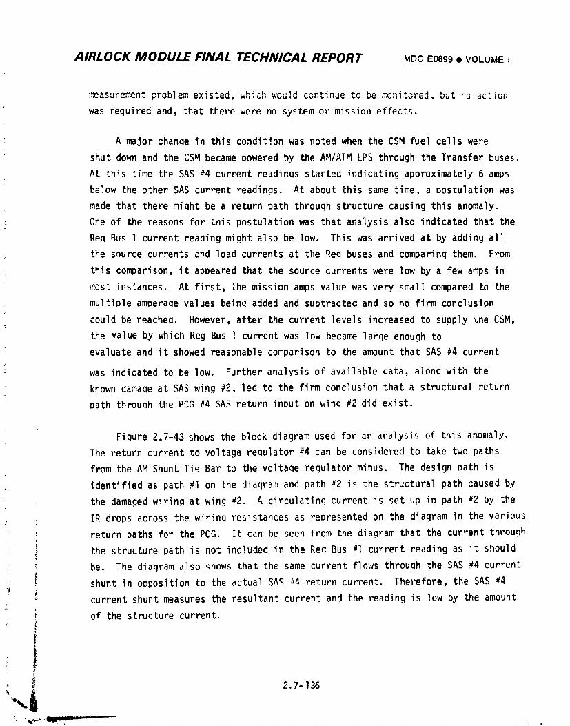
AIRLOCK MODULE FINAL TECHNICAL REPORT MDC E0899 • VOLUMEI
measurement problem existed, which would continue to be monitored, but no action
was required and, that there were no system or mission effects.
A major chanqe in this condition was noted when the CSM fuel cells were
shut down and the CSM became powered by the AM/ATM EPS through the Transfer buses.
At this time the SAS #4 current readings started indicating approximately 6 amps
below the other SAS current readings. At about this same time, a DOstulation was
made that there miqht be a return path through structure causing this anomaly.
One of the reasons for Lnis postulation was that analysis also indicated that the
Req Bus l current reaaing might also be low. This was arrived at by adding all
the source currents and load currents at the Reg buses and comparing them. From
this comparison, it appeared that the source currents were low by a few amps in
most instances. At first, _he mission amps value was very small compared to the
multiple amperaqe values beine added and subtracted and so no firm conclusion
could be reached. However, after the current levels increased to supply Lne CSM,
the value by which Reg Bus l current was low became large enough to
evaluate and it showed reasonable comparison to the amount that SAS #4 current
was indicated to be low. Further analysis of available data, alonq with the
known damage at SAS wing #2, led to the firm conclusion that a structural return
path throuah the PCG #4 SAS return inDut on winQ #2 did exist.
Figure 2.7-43 shows the block diagram used for an analysis of this anomaly.
The return current to voltage regulator a4 can be considered to take two paths
from the AM Shunt Tie Bar to the voltaqe requlator minus, lhe design path is
identified as path #1 on the diagram and path #2 is the structural path caused by
the damaged wiring at wing _2. A circulating current is set up in path _2 by the
IR drops across the wirinq resistances as reDresented on the diagram in the various
return oaths for the PCG. It can be seen from the diagram that the current through
the structure path is not included in the Reg Bus #l current reading as it should
be. The diagram also shows that the same current flows throuqh the SAS #4 current
shunt in opposition to the actual SAS _4 return current. Therefore, the SAS 44-!
current shunt measures the resultant current and the reading is low by the amount
of the structure current.
2.7-136
_ j
1974018208-532
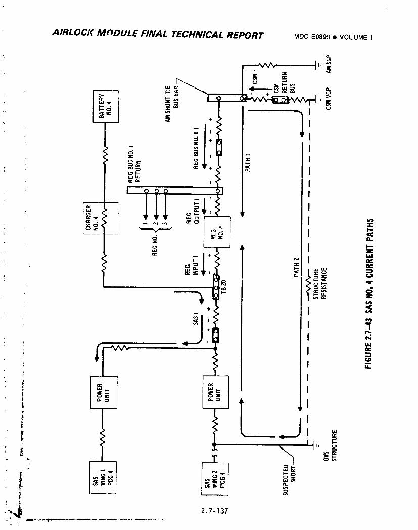
AIRLOCK MODULE FINAL TECHNICAL REPORT MDCE0899• VOLUMEI
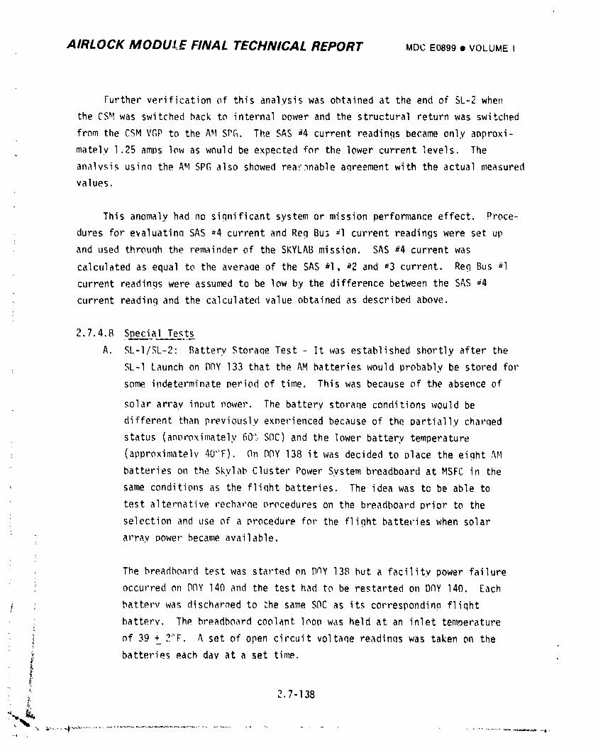
AIRLOCK MODU,t_E FINAL TECHNICAL REPORT MDCE0899• VOLUMEI
Further verification of this analysis was obtained at the end of SL-2 when
the CSH was switched hack to internal Dower and the structural return was switched
from the CSM VGP to the AH SPG. The SAS 44 current readings became only approxi-
mately 1.25 amDs low as would be expected for the lower current levels. The
analysis usinq the AM SPG also showed reaF_nable aqreement with the actual measured
values.
This anomaly had no significant system or mission performance effect. Proce-
dures for e_aluatinQ SAS =4 current and Reg Bu3 _l current readings were set up
and used throuqh the remainder of the SKYLAB mission. SAS _4 current was
calculated as equal to the averaQe of the SAS al, 42 and _3 current. Reg Bus 41
current readings were assumed to be low by the difference between the SAS a4
current reading and the calculated value obtained as described above.
2.7.4.8 SDeci__al Te_____.t_
A. SL-I/,_L-2: Battery Storaqe Test - It was established shortly after the
: SL-I Launch on DNY 133 that the AM batteries would probably be stored for
sonm.indeterminateperiod of time. This was because of the absence of
solar array input power. The battery storaqe conditions would be
different than previously exDerienced because of the partially charqed
status (anDroximately60% SNC) and the lower battery temperature
(approximately40"F). On DNY 138 it was decided to place the eight AM
batteries on the Skylab Cluster Power System breadboard at MSFC in the
, same conditions as the fliqht batteries. The idea was to be able to
test alternative recharne _rocedures on the breadboard prior to the
selection and use of a procedure for the flight batteries when solar
array Dower became available.
: The breadboard test was started on DNY 138 hut a facility power failure
occurred on DNY 140 and the test had to be restarted on DNY 140. Each
i battery was discharned to _he same SOC as its correspondino fliqht
battery. The breadboard coolant loop was held at an inlet tenmerature
of 39 + 2"F. A set of open circuit voltaqe readings was taken on the
batteries each day at a set time,
• _. 2,7-138
1974018208-534
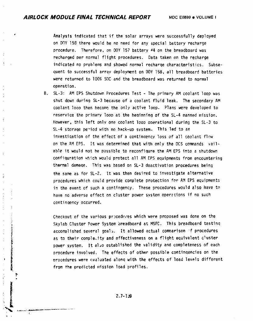
AIRLOCK MODULE FINAL TECHNICAL REPORT MDCE0899® VOLUMEI
" Analysis indicated that if the solar arrays were successfully deployed
on DOY 158 there would be no need for any special battery recharge
procedure. Therefore, on DOY 157 battery a4 on the breadboard was
recharged per normal flight procedures. Data taken on the recharge
indicated no problems and showed normal recharge characteristics. Subse-
quent to successful array deployment on DOY 158, all breadboard batteries
were returned to I00% SOC and the breadboard was returned to normal
operation.
B. SL-3: AM EPS Shutdown Procedures Test - The primary AM coolant loop was
shut down during SL-3 because of a coolant fluid leak. The secondary AM
coolant looo then became,the only active loop. Plans were developed to
reservice the primary loop at the beginning of the SL-4 manned mission.
However, this left only one coolant loop operational during the SL-3 to
SL-4 storaqe pe"iod with no back-up system. This led to an
investiqationof the effect of a continQency loss of all coolant flow
on the AH EPS. It was determined that with only the DCS commands vail-
, able it would not be possible to reconfiqure the AM EPS into a shutdown
configuration _,_hichwould protect all AM EPS equipments from encountering
thermal damaqe. This was based on SL-3 deactivation procedures being
the same as for SL-2. It was then desired to investigate alternative
procedures which could provide complete protection for AM EPS equipments
in the event of such a contingency. These procedures would also have to
have no adverse effect on cluster power system operations if no such
continqency occurred.
t
• Checkout of the various prJcedt!reswhich were proposed was done on the
Skylab Cluster Power System breadboard at MSFC. This breadboard testinq
accomplished several goal_. It allowed actual comparison f procedures
i as to their comple_.ityand effectiveness on a flight equivalent c_usterpower system. It al_o established the validity and completeness of each
i procedure involved. The effects of other possible continqencies on the
) procedures were _valuated along with the effects of load levels differentfrom the predicted nflssionload profiles.
2.7-I_
1974018208-535
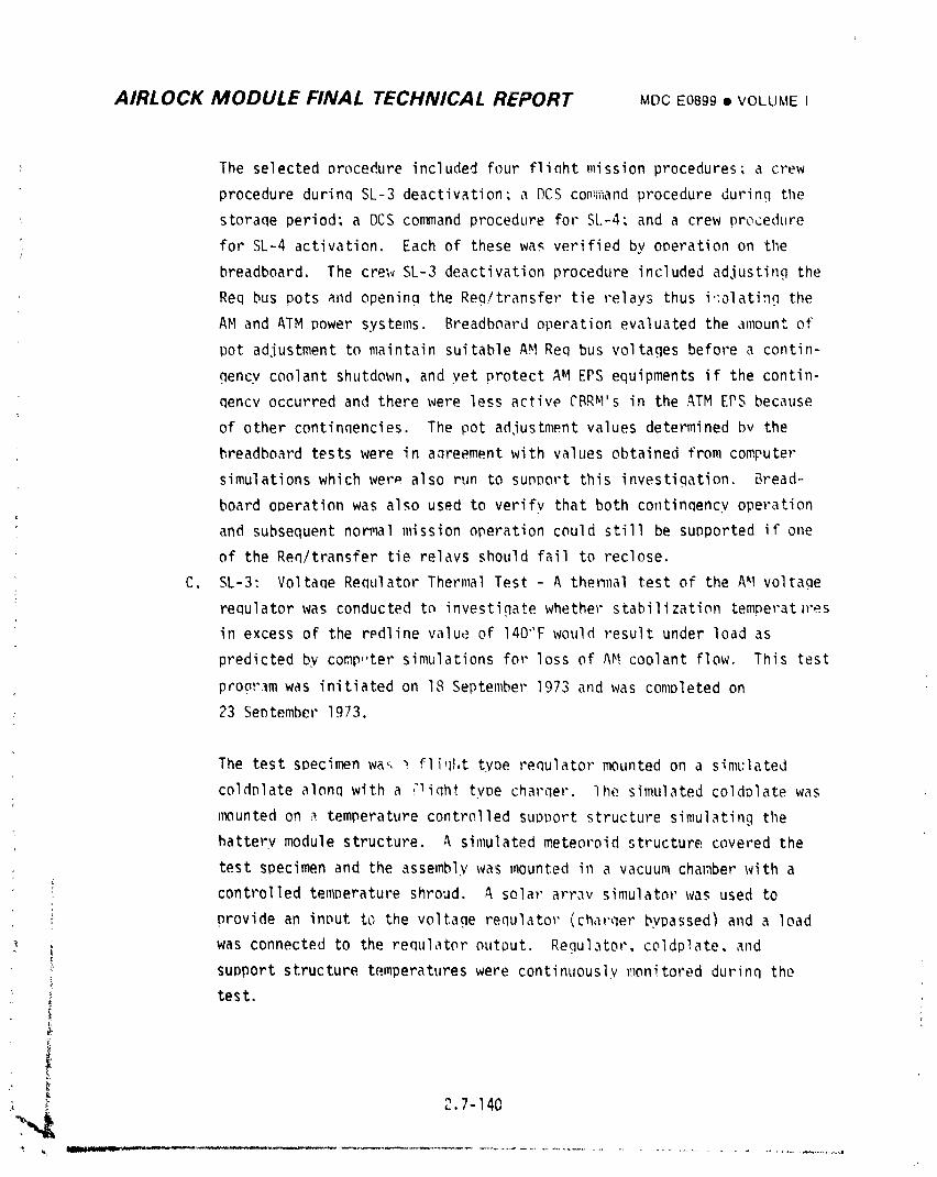
AIRLOCK MODULE FINAL TECHNICAL REPORT MDCE0899• VOLUMEI
The selected procedure included four fliaht mission procedures: a crew
procedure durinq SL-3 deactivation: a F)CSco_:mandprocedure durinq the
storaqe period: a DCS corm_andprocedure for SL-4: and a crew procedure
for SL-4 activation. Each of these was verified by operation on the
breadboard. The crew SL-3 deactivation procedure included adjusting the
Req bus pots and openina the Reg/transfer tie relays thus i';_latingthe
AM and ATM Dower systems. Breadboard operation evaluated the amount of
pot ad,iustment to maintain suitable AM Req bus voltages before a contin-
qency coolant shutdown, and yet protect AM EPS equipments if the contin-
qencv occurred and there were less active CBR_I's in the ATM EPS because
of other continqencies. The pot ad.iustment values determined bv the
breadboard tests were in aQreement with values obtained from computer
simulations which wer_ also run to sui_Dort this investiqation. Bread-
board ooeration was also used to verifv that both continqency operation
and subsequent nor_l mission operation could still be supported if one
of the Req/transfer tie relays should fail to reclose.
C. SL-3: Voltane Requlator Thermal Test - A then_lal test of the AM voltage
reQulator was conducted to investigate whether stabilization temperatures
in excess of the r_dline value of 140'_F would result under load as
predicted by comp,,ter simulations for loss of AM coolant flow. This test
proar_m was initiated on I,_ September 1973 and was completed on
23 Sentember 1973.
The test specimen wa_ _ fli,H,ttype requlator mounted on a sitar:fated
coldDlate alonq with a ,'liqhttyDe charqer. 7he simulated coldDlate was
mounted on a temperature controlled suot)ortstructure simulating the
battery module structure. A simulated meteoroid structure covered the
test specimen and the assembly was mounted in a vacuum chamber with a
controlled temperature shroud. A solar array simulator was used to
provide an input to the voltage renulator (charqer bypassed) and a load
_ was connected to the requlator output. Requl._.tor,coldplate and_ - •
_ suDPort structure temperatureswere continuously monitored durinq the
test.
\
, 2.7-140-',IW
1974018208-536
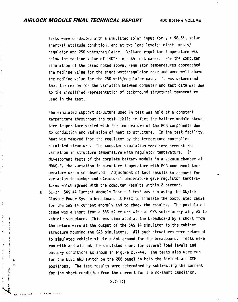
AIRLOCK MODULE FINAL TECHNICAL REPORT MDCE0699• VOLUMEI
Tests were conducted with a simulated solar input for 6 = 58.5°, solar
inertial attitude condition, and at two load levels; eight watts/
regulator and 250 watts/regulator. Voltage regulator temperature was
below the redline value of 140°F in both test cases. For the computer
simulation of the cases noted above, regulator temperatures approached
the redline value for the eight watt/regulator case and were well above
the redline value for the 250 watt/regulator case. It was determined
that the reason for the variation between computer and test data was due
to the simplified representationof background structural temperature
used in the test.
The simulated support structure used in test was held at a constant
temperature throuqhout the test, _hile in fact the battery module struc-
ture temperature varied with *he temperature of the PCG components due
to conduction and radiation of heat to structure. In the test facility,
heat was removed from the regulator by the temperature controlled
simulated structure. The computer simulation took into account the
variation in structure temperaturewith regulator temperature. In
dcvelopment tests of the complete battery module in a vacuum chamber at
L MDAC-E, the variation in structure temperature with PCG component tem-
perature was also observed. Adjustment of test results to account for
variation ir,background structural temperature gave regulator tempera-
tures which agreed with the computer results within 2 percent.
D. SL-3: SAS #4 Current Anomaly Test - A test was run using the Skylab
Cluster Power System breadboard at MSFC to simulate the postulated cause
for the SAS #4 current anomaly and to check the results. The postulated
cause was a short from a SAS #4 return wire at OWS solar array wing #2 to
vehicle structure. This was simulated at the breadboard by a short from
the return wire at the output of the SAS #4 simulator to the cabinet
structure housing the SAS simulators. All such structures were returned
to simulated vehicle single point ground for the breadboard. Tests were
_ run with and without the simulated short for several load levels and
i battery conditions as shown in Figure 2.7-44. The tests also were run
_ for the ELEC GND switch on the 206 panel in both the Airlock and CSM
" positions. The test results were determined by subtracting the current
• _ for the short condition from the current for the no-short condition.
;_ 2.7-141
1974018208-537
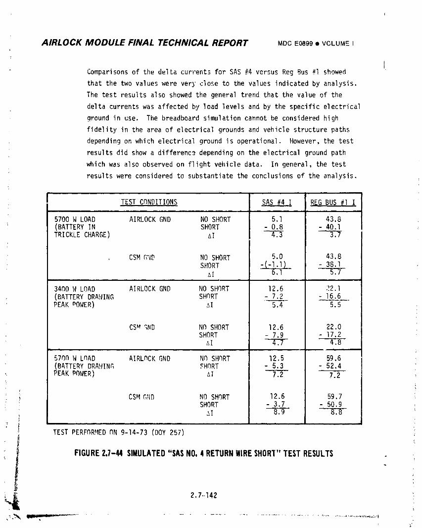
AIRLOCK MODULE FINAL TECHNICAL REPORT MDCE0899• VOLUMEI
Comparisons of the delta currents for SAS #4 versus Reg Bus #I showed
that the two values were very close to the values indicated by analysis.
The test results also showed the general trend that the value of the
delta currents was affected by load levels and by the specific electrical
ground in use. The breadboard simulation cannot be considered high
fidelity in the area of electrical grounds and vehicle structure paths
depending on which electrical ground is operational, However, the test
results did show a differenc_ _ depending on the electrical ground path
which was also observed on flight vehicle data. In general, the test
results were considered to substantiate the conclusions of the analysis.
,,. i
I TEST CnNDITIONS SAS #4 1 REG BUS _] Iiii i ii i i i i i
5700 W LOAD AIRLOCK GND NO SHORT 5.1 43.8(BATTERY IN SHORT - 0.8 - 40.ITRICKLE CHARGE) AI _.3
, CSM GND NO SHORT 5.0 43.8SHORT -(-l.l)_ - 38,I
AI 6.1 5.7
34n0 14LOAD AIRLOCK GND NO SHORT 12.6 22.1(BATTERYDRAWING SHNRT - 7.2 - 16.6PEAKDOWER) _I 5,4 5.5
CS_ ;;ND NO SHORT 12.6 22.0SHORT - 7.9 17.2AI _.7 T._
L
57F)OW LOAD AIRL(_CKGND NO SHORT 12.5 59.6(BATTERY DRAWING SH_RT - 5.3 52.4PEAKPF)WER) AI 7.2 7,2 _'
• _ CSMGr_D NO SHORT 12.6 59.7, SHORT - 3.7 - 50.9
! _I 8.9 8.'8"
_" i ........ in
TEST PERFnRHED (IN9-14-73 (DOY 257)
_ FIGURE2.7-44SIMULATED"SASNO,4RETURNWIRESHORI"TESTRESULTS
1974018208-538
AIRLOCK MODULE FINAL TECHNICAL REPORT MOCE0899• VOLUMEI
2.7.5 Conclusions and Recommendations
The AM Electrical Power System flight performance was completely successful in
satisfying all Skylab requirements. The system design concepts were exercised early
in the mission due to an unfortunate launch anomaly, The complet_ loss of one
solar array wing and minimal deployment of the other left the entire AM EPS with
practically no source of external energy for several weeks. During this time, the
built-in control flexibility was utilized to maintain 3 of 8 batteries fully
charged and the remaining batteries approximately 50% charge for possible
contingency use, or ready for normal operation when the remaining wing could be
fully deployed. Later deployment of the wing with resumption of normal EP_
operations (after appropriate management of bus settings, etc.) confirmed in
flight the features that had been designed and tested in the ground test programs.
AM EPS Flight Performance Milestones:
• Supplied approximately one-half cluster load despite loss of one-half of
the anticipated solar input energy.
e Successfully supported extension of SL-3 and SL-4 missions (with attendant
increase in number of EREP passes) with no deleterious effects.
e Succes_fully supported addition of Kohoutek comet observations.
e Successfully supported higher battery DOD's resulting from additional
nonsolar inertial attitude maneuvers to minimize TAC usage following SMG
failure.
e Flight mission rules for battery DOD's were relaxe_ as a result of
better than expected flight performance.
e Post SL-4 battery capacity tests revealed cycle life degradation lower
than predicted. Battery measured capacity ranged from 31,2 to 38.7 amper -
! hours as compared to a rated capacity of 33 ampere-hours.L
The success of the EPS is attributed to the systematic design concepts,
development and demonstration test philosophy, and the operational f|(;xibility.
_ These factors enabled the ground and/or crew to appropriately configure the
I; existing equipment to support the ever changing cluster flight conditions,
b
b'
_ 2.7-143
1974018208-539
AIRLOCK MODULE FINAL TECHNICAL REPORT MDCE0899• VOLUMEI
Systematic Design:
o Multiple PCGconcept provided system redundancy and growth capability to
support increased load requirements as the design matured.
e Modularization of chargers and regulator_: p'ovided internal redundancy ot
components and improved efficiency.
o State-of-the-art advancements in high power co_Jtrol were incorporated.ir
e High overall efficiency was achieved by usage of solar' array "p, ;k power r
tracking", and buck regulation throughout.
e All automatic controls were provided with override capability with the
exception of charge termination for battery overtemperature. The battery
overtemperature trip point was set _ a point where continued charging
would not result _n additional stored energy due to the low charge
efficiency. This control did not, however, preclude battery discharQe.
o Capability for alternate or bypass operational modes was provided for
contingency operation with a minimum loss in system power.
e Individual "fine tuning" of PCGregulators optimized power output by
compensatinq for variations in solar array input power and conditioning
compcnent performance.
m Redundant distribution busses precluded major impact of hypo_r,etical bus
short circuits.
e Output voltaqe adjustment capability provided for load snaring control
between AM, ATM, and CSM.
e Computer sl,nulation of AM EPS enabled prediction of operation within total
cluster power syst_ i under varlous operational configurations and permitted
real-time mission planning on a reasonable ti_1_ scale.
Systematic Testing:
! e Early development tests integrated and optimized key hardware featu_'es.
• Thorough Qualification and Acceptance testing of all hardware established ._
piece part capabilities.
m Operational test of one PCGincluding a solar array (SCST), validdted major
,, system interfaces.
: e Detailed Electrical/Enviropmental test of one batter', mqdule (_ PCG's) and
a complete dist. ibution system including interface simulation confirmed
'_ C that the various designed operational modes performed correctly and
efficiently Jnder various cluster operational conditions.
, ,, 2.7-144,_,_
"L', '_ "P"_""_ "*"'"" _ ii i f
1974018208-540
AIRLOCK MODULE FINAL TECHNICAL REPORT MDCE0899• VOLUMEI
• Battery cycle tests using predicted mission duty profile demonstrated
co_por,ent '""=
e Flight procedures and crew training were developed during system testing
basr.d_,,actual hardware expe ience.
EPS System flexibilityenabled:
• Hanagement of EPS during unexpected loss of array deployment.
• Formulationof contingency procedure for safe shutdown and reactivation
of EPS in event of loss of coolant (ystem fluid prior to SL-4 reservicing.
• Achievement of many of the flight milestones previously stated.
Upn_ co_@letionof SL-4, the EPS was configured into a "do_Inant"mode with the
batteries and all switchable busses off. The nonswitchable EPS control bus is
powered during periods of sufficient solar array illuminatien. All 8 PCG's were
operating properly at ground monitoring termination, and could have continued to
supply baseline performance indefinitely.
Recommendationsfor improving the _M EPS for a similar space program are
limited to minor improvements in the basic program such as:
• Additional parametric studies of the batteries to more fully understand the
interrelationshipsof temperature, DOD, second plateau, discharge rates,
etc.
• Additional studies of the battery/chargercharge scheme for possible
efficiency improvement.
Addition of a I00 percent reset capability for the ampere-hour meter.
This feature would permit resynchronizPtionof the battery SOC and
indicated SOC when ground telemetry indicated that the battery was fully
charged.
Y
F
" : 2.7-145/146
1974018208-541
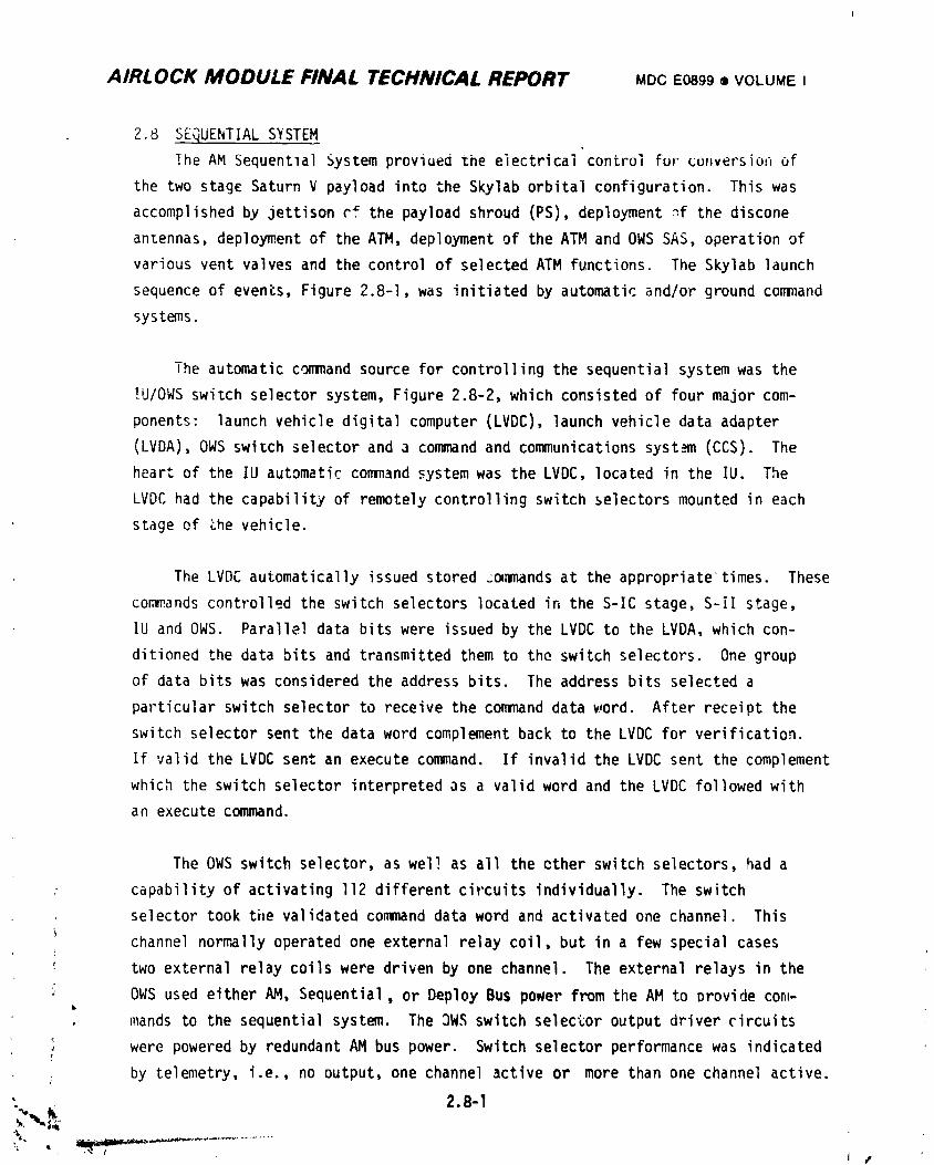
AIRLOCK MODULE FINAL TECHNICAL REPORT MDCE0899• VOLUMEI
2.8 SEQUENTIAL SYSTEM
The AM Sequentlal System provioed the electrical control fur conversion of
the two stage Saturn V payload into the Skylab orbital configuration. This was
accomplished by jettison cf the payload shroud (PS), deployment _f the discone
antennas, deployment of the ATM, deployment of the ATM and OWS SAS, operation of
various vent valves and the control of selected ATM functions. The Skylab launch
sequence of events, Figure 2.8-I, was initiated by automatic and/or ground command
systems.
The automatic command source for controlling the sequential system was the
IU/OWS switch selector system, Figure 2.8-2, which consisted of four major com-
ponents: launch vehicle digital computer (LVDC), launch vehicle data adapter
(LVDA), OWS switch selector and a command and communications system (CCS). The
heart of the IU automatic command system was the LVDC, located in the IU. The
LVDC had the capability of remotely controlling switch selectors mounted in each
stage ef the vehicle•
The LVDC automatically issued stored _e,mands at the appropriate times. These
con_ands controlled the switch selectors located in the S-IC stage, S-il stage,
IU and OWS. Parallel data bits were issued by the LVDC to the LVDA, which con-
ditioned the data bits and transmitted them to the switch selectors. One group
of data bits was considered the address bits. The address bits selected a
particular switch selector to receive the command data _rord. After receipt the
switch selector sent the data word complement back to the LVDC for verification.
If valid the LVDC sent an execute command. If invalid the LVDC sent the complement
which the switch selector interpretedas a valid word and the LVDC followed with
an execute command.
The OWS switch selector, as well as all the ether switch selectors, had a
capability of activating If2 different circuits individually. The switch
selector took the validated command data word and activated one channel. This
channel normally operated one external relay coil, but in a few special cases
_- two external relay coils were driven by one channel. The external relays in the
i OWS used either AM, Sequential, or Deploy Bus power from the AM to Provide con_-
mands to the sequential system. The OWS switch selector output driver circuits
' were powered by redundant AM bus power. Switch selector performance was indicated
by telemetry, i.e., no output, one channel active or more than one channel active.
; _ 2.8-1
/
1974018208-542
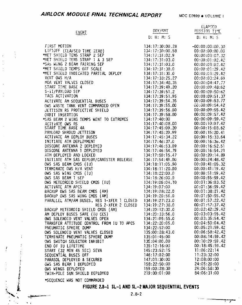
AIRLOCK MODULE FINAL TECHNICAL RZPORT MDCE0_99• VOLUMEI
ELAPSED
EVENT DC)Y/r_MT i'll SSIOT_TI'IED: II: M: S D: H: M: S
FIRST MOTION 134:17:30:00.28 -00:00:00:00.30LIFIOFF (ELAFSED TIME ZERO) 134:17:30:00.58 00:00"00:00.00
*MET SHIELD TENSSTRAP 2 SEP 134:17:31:02.9 00:00:01"02.32*MET SHIELD TENS STR,API & 3 SEP 134:17:31:03.0 00"00"01"02 42*SA_ WiNG 2 BEAM FAIRING SEP 134:17:31:03.0 00:00:01"02 42*MET SHIELD TEMPSOFF SCALE 134:17:31:30.0 00:00:01:29 42*MET SHIELD INDICATED PARTIAL DEPLOY 134:17:31:30.0 00:00:01:29 42VENTOWSH/A 134:17:33:25.27 00:00:03:24 69MDAVENTV,_LVESCLOSED 134:17:34:48.35 00:00:04:47 77START TIME BASE 4 134:17:39:49.20 00:00:09"48 62S-il/PAYLOAD SEP 134:17:39:51.2 00:00:09:50 62TACS ACTIVATION 134:1 7:39 : 51.95 O0:00:09: 51.37ACTIVATE AM SEQUENTIALBUSES 134:17:39:54.35 00:00:09:53.77OWSWASTETANK VENT COMMANDEDOPEN 134:17:39:55,00 00.00:09:54.42JETTISON RS PROTECTIVESHIELD 134:17:39:56.00 00:00:09:55.42ORBIT INSERTION 134:17:39:58.00 00:00:09:57.42
_AS BEAM2 WING TEMPSWENTTO EXTREMES 134:17:40:00 00:00:09:59.42ACTIVATE OWSRS 134:17:40:08.00 00:00:10:07.42START TIME BASE 4A 134:17:45:09.20 00:00:15:08.62PAYLOADSHROUDJETTISON 134:17:45:20.99 00:00"15:20.41ACTIVATE AM DEPLOYBUSES 134:17:45:34.22 00:00"15:33.64INITIATE ATM DEPLOYMENT 134:1 7:46:37.0 00:00:16:36.42DISCONEANTENNA2 DEPLOYED 134:17:46:53.09 00:00:16:52.51DISCONEANTENNA1 DEPLOYED 134:17:46:54.79 00:00:16:54.21ATM DEPLOYEDAND LOCKED 134:17:50:15.47 00:00:20:14.89INITIATE ATMSAS DEPLOY/CANISTERRELEASE 134:17:54:49.00 00:00:24:48.42OWSSAS BEAMCMDS(IU) 134:18:11:05.90 00:00:41:05.32TERMINATEOWSH/A VENT 134:18:11:20.00 00"00:41:19.42OWSSAS WING CMDS(IU) 134:18:22:00.0 00"00:51:59.42OWSSAS BEAM1 SEP 134:18:26:00.0 00:00:55:59.42OWSMETEOROIDSHIELD CMDS(IU) 134:19:06:04.10 00:01:36:03.52ACTIVATE ATMAPCS 134:19:07:00 00:01:36:59.42BACKUPOWSSAS BEAMCMDS(AM) 134:19:08:22.0 00:01:38:21.42BACKUPOWSSAS WING CMDS(AM) 134:19:20:56.0 00:01:50:55.42PARALLELATM/AMBUSES, REGI-XFER 1 CLOSED 134:19:27:23.0 00:01:57:22.42
REG2-XFER 2 CLOSED 134:19:27:38.0 00:01:57:37.42BACKUPMETEOROIDSHIELD CMDS(AM) 134:20:12:30.0 00:02:42:29.42AM DEPLOYBUSESSAFE (IU CCS) 134:20:33:56.0 00:03:03:55.42OWSSOLENOIDVENT VALVESOPEN 134:21:05:55.0 00:03:35:54.42TRANSFERATTITUDE CONTROLFROMIU TO APCS 134:22:20:05.0 00:04:50:04.42PNEUMATICSPHEREDUMP 134:22:52:00 00:05:21:59.42OWSSOLENOIDVENT VALVESCLOSED 135:00:28:43.0 00:06:58:42.42TERMINATEPNEUMATICSPHEREDUMP 135:01:45:00 00:08:14:59.42OWSSWITCHSELECTORINHIBIT 135:04:00.00 00:I0:29:59.42ENDOF IU LIFETIME 135:12:16:00 00:18:45:59.42
• START (32 MIN 45 SEC) SEVA 145:23:52:15 11:06:22:14
: SEQUENTIALBUSESOFF 146:17:02:00 II :23:32:00_, PARASOLDEPLOYED& SECURED 147:01:30:00 12:08:00:00
OWSSAS BEAM 1 DEPLOYED 158:22:50:00 24:05:20:00OWSWINGSDEPLOYED 159:00:28:30 24:06:58:30
LF TWIN-POLE SUNSHIELD DEPLOYED 219:00:01:00 84:06:31:00
#,. *SEQUENCEWASNOT COMMANDEDi;
:,, _ FIGURE2.8-1 SL-t ANDSL-2 MAJORSEQUENTIALEVENTS=J¢' =
_, , _,p_._,...... 2.8-2-_ ,D A
1974018208-543
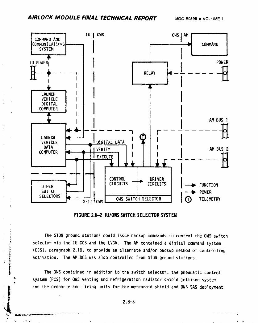
AIRLO_K MODULE FINAL TECHNICAL REPORT MDCE0899• VOLUMEI
1 iuI I, ,co..uN_AT;,Nsl-----,I
SYS,EM..,_ 1 7 COMMANDPOWER
_'-_IIU POWERI II RELAY _ IIW
LAUNCH I I• VEHICLEDIGITAL
COMPUTER I I
1 [ "-"
VEHICLE DIGITALDATA I I
DATA V-ERIFY I I I AM B
+ ;; ....l
i
SELECTORS OWS SWITCH SELECTOR TELEMETRY' S-II OWS;
FIGURE2,8-2 IU/OWSSWITCHSELECTORSYSTEM
r
I The STDN ground stations could issue backup commands t_ control the OWS switcht-
,- selector via the IU CCS and the LVDA. The AM contained a digital command system
(DCS) paragraph 2.10, to provide an alternate and/or backup method of controlling
! I activation. The AM DCS was also controlled from STDN ground stations.
i The OWS contained in addition to the switch selector, the pneumatic control
• system (PCS) for OWS venting and refrigeration radiator shield jettison systemP
iiI and the ordnance and firing units for the meteoroid shield and OWS SAS deployment2.8-3
i
1974018208-544
AIRLOCK MODULE FINAL TECHNICAL REPORT MDC E0899 • VOLUMEI
systems. The OWS PCS consisted of a sphere containing high pressure gaseous
nitrogen and actuation control modules. The electrically operated modules con-
trolled the flow of nitrogen to open and close habitation area vents, to open
waste tank vent and to jettison the refrigeration radiator shield. The ATH con-
tained the ordnance and firing units for ATM SAS deployment system. The AM
contained the power and control equipment for the AM Sequential System.
Verification of the design requirementswas successfully cmnpleted by the
test program. During the mission, the problems encountered with the OWS meteoroid
shield and OWS SAS deployment required the Skylab crews to erect sunshades and
complete deplo_nent of the OWS SAS wing I. All other sequences functioned as
planned.
The sequential system consists of several separate systems related to each
other only in that they each occur in the properly timed sequence as determined
by the co,m_andsfrom the IU/OWS switch selector system or the AM DCS. For
discussion purposes the sequential system will be divided into subsystems as follows:
l. Payload Shroud Jettison
2. ATM Deployment
3. Discone Antenna Deplojnnent
4. Power Control
5. Radiator Shield Jettison/RefrigerationSystem Activation
6. OWS Venting
7. OWS Meteoroid Shield Deployment
8. OWS SAS Deployment
9. ATM SAS Deployment
lO. ATM Activation
II. MDAVenting
Topics which will be covered under each subsystem heading are:
.- A. Design requirements
B. System description
C. Testing
D. Mission Results
E. Conclusions and Recolmmndations
,' _ 2.8-4
1974018208-545
AIRLOCK MODULE FINAL TECHNICAL REPORT MDCE0899• VOLUMEI
2.8.1 Payload Shroud Jettison Subsystem
The electrical sequential system required to jettison the shroud interfaced
with the OWS switch selector, the AM Command Relay Driver Unit (CRDU), the AM
power system and the payload shroud mechanical/ordnancesystem. Automatic and
JSC flight controller manual operating capabilities were included in the design.
One deviation in contractual requirements was requested and granted for the EBW
firing unit trigger circuit resistance. All other requirementswere met. The
hardware utilized in the design was selected from flight qualified equipment.
Detail Payload Shroud information is supplied in MDC Report G4679A.
2.8.1.I Payload Shroud Jettison Subsystem Design Requirements
The PS jettison circuit design was initiated when the early mechanical/
ordnance tradeoff studies were completed. The selected PS configuration was
a radially segmented design to be jettisoned in orbit. The integrity of the PS
monocoque structure was maintained during ground operations and ascent by pi .ned
upper and lower structural rinqs. Discrete latch actuator pins (16 required)
protruded through th_ links that held the structural rings together, Figure 2.8-3.
Each ring joint had two discrete latch actuators to obtain redundancy in releasing
: the _ings. Initially one EBW firing unit was allotted for each latch actuator,
which was to be controlled and powered by the IU via FAS wiring to the PS.
Subsequent redesign of the ordnance system resulted in the connection of the four
latch actuators in each segment to a common closed tubing manifold system, Figure
2.8-4. Linear explosive contained in the tubing terminated at the detonators. A
firing unit at each detonator provided the redundant means of detonating the
explosive and reduced the total number of latch actuator firing units to eight.
The gas generated by the burning linear explosive caused the latch actuator pins
i to retract After the discrete latch actuator pins were retracted, the fourL
shroud segments remained intact by the restraining rivets along the thrusting
joints.i
. The linear explosive contained in the thrusting joint bellows, Figure 2.8-5,
expanded after being ignited, shearing the rivets, and propelling the segments, away. Each end of the linear explosive terminated in a detonator, Figure 2.8-4.
2.8-5
1974018208-546
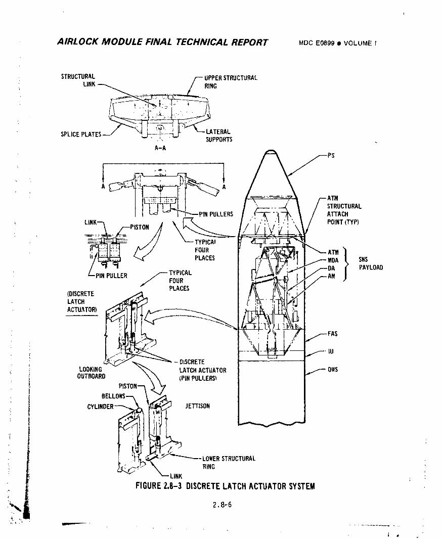
AIRLOCK MODULE FINAL TECHNICAL REPORT MOOE0899• VOLUMEI
: i r ,,e"_
":!I: i. _ ,':. " STRUCTURAL|/ -- I q"---PIN PULLERS ATTACH
TYPICA_
FOUR ATM }
PAYLOAD/ PINPULLER _TYPICAL
FOURPLACES
(DISCRETELATCHACTUATOR)
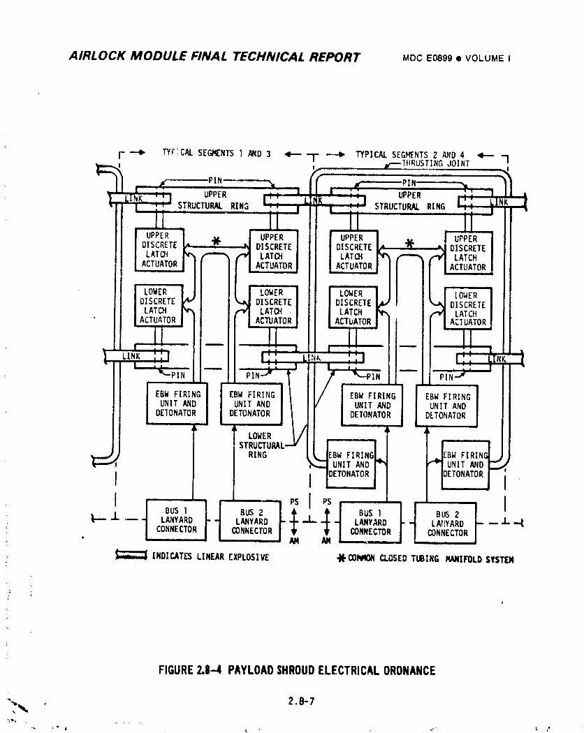
AIRLOCK MODULE FINAL TECHNICAL REPORT MDCE0899I VOLUMEI
F _ TYrTCALSEGMENTS l _D 3 _ -F" _ TYPICALSEG_NTS 2 AND 4 _ I,e,_THRUSTINGJOINT
PIN PIN'
UPPER UPPER
STRUCTURAL RIN3 STRUCTURAL RING
UPPER UPPER UPPERDISCRETE "J(' UPPERDISCRETE DISCRETE DISCRETELATO! LATCH LAT(}I LATCHACTUATOR ACTUATOR ACTUATOR ACTUATOR
LOWER LOWER LOWER LOWERDISCRETE DISCRETE DISCRETE DISCRETELATCH LATCH , LATCH LATCHACTUATOR ACTUATOR ACTbATOR ACTUATOR
LINK NK
! PiN-J'"
EBW FIRING EBW FIRIN(I EBW FIRING ' EBW FIRING
UNIT AND UNIT AND] UNIT AND UNIT ANDDETONATOR DETONATOR DETONATOR l DETONATORk
LOWER L/
STRUCTURAL--RING EBW FI EBW FIRI
UNIT AND UNIT AND
I I DETONATOR I
BUS I BUS 2 BUS I BUS 2 I'_ LANYARD ""1 LANYARD|- • LANYARD LAIIYARD -- 'J"
• CONNECTOR CONNECTORCONNECTOR,, _ AM AM
INDICATESLINEAREXPLOSIVE ,}(,COIqqONCLOSEDTUBING MANIFOLDSYSTEM
FIGURE2.8--4 PAYLOADSHROUDELECTRICALORDNANCE
_w ' 2.8-7
1974018208-548
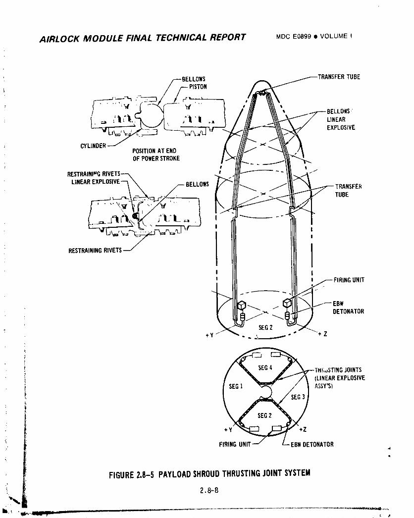
AIRLOCK MODULE FINAL TECHNICAL REPORT MDCE0899• VOLUMEI
//_//_.._BELLOWS TUBE
PISTON
t "LLOWS"
i" _ ='11 _ , ,='11"11 .. LINEAR---_r_ EXPLOSIVE
.~
CYLINDERPOSITIONATENDOFPOWERSTROKE
# t
RESTRAINpUGRIVETS_ I -. .j
LINEAREXPLOSIVEq\ _ BELLOWS SFER
/ I
RESTRAININGRIVETS
II
UNIT
s
[BW
I_'" _{ DETONATOR
SEG2+y ,," -..3...._ " +Z
i
r
* THt;JSTINGJOINTS
/ .... _//_ (LINEAREXPLOSIVE
__ ASSY'S)
+Y _,,______..__"" +Z/ /
FIRINGUNIT.--/ L--EBWDETONATOR4
4
FIGURE2.8-5 PAYLOADSHROUDTHRUSTINGJOINTSYSTEM
2.8-8
,,,illli,,,'!lii_,, I rr ! _ i. _ : _ . "*,_.,_
1974018208-549
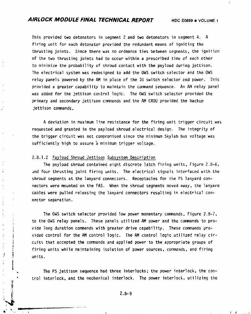
AIRLOCK MODULE FINAL TECHNICAL REPORT MDCE0899• VOLUMEI
This provided two detonators in segment 2 and two detonators in segment 4. A
firing unit for each detonator provided the redundant means of igniting the
thrusting joints. Since there was no ordnance ties between segments, the ignition
of the two thrusting joints had to occur within a prescribed time of each other
to minimize the probability of shroud contact with the payload during jettison.
The electrical system was redesigned to add the OWS switch selector and the OWS
relay panels powered by the AM in place of the IU switch selector and power. This
provided a greater capability to maintain the command sequence. An AM relay panel
was added for the jettison control logic. The OWS switch selector provided the
primary and secondary jettison commands and the AM CRDU provided the backup
jettison commands.
A deviation in maximum line resistance for the firing unit trigger circuit was
requested and granted in the payload shroud electrical design. The integrity of
the trigger circuit was not compromised since the minimum Skylab bus voltage was
sufficiently high to assure _ minimum trigger voltage.
2.8.1.2 Payload Shroud Jettison Subsystem Description
The payload shroud contained eight discrete latch firing units, Figure 2.8-6,
: and four thrusting joint firing units. The electrical signals interfaced with the
shroud segments at the lanyard connectors. Receptacles for the PS lanyard con-
nectors were mounted on the FAS. When the shroud segments meved away, the lanyaro
cables were pulled releasing the lanyard connectors resulting in electrical con-
nector separation.
• The OWS switch selector provided low power momentary commands, Figure 2.8-7,
to the OWS relay panels. These panels utilized AM power and the commands to pro-
vide long duration commands with greater drive capability. These commands pro-
: vided control for the AM control logic. The AM control logic utilized relay cir-
, cuits that accepted the conm_nds and applied power to the appropriate groups of
firing units while maintaining isolation of power sources, commands, and firing
•: _- units.
,, The PS jettison sequence had three interlocks; the power interlock, the con-
" trol interlock, and the mechanical interlock. The power interlock, utilizing the
_°",4";_ 2.8-9
1974018208-550
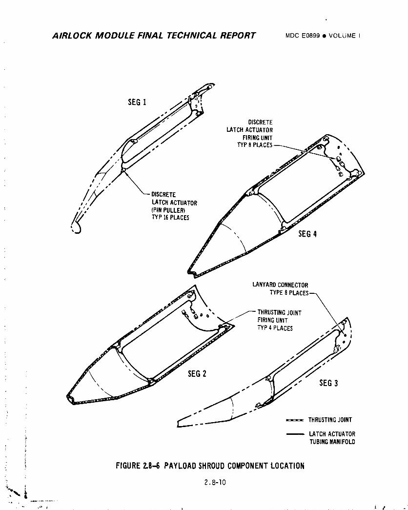
AIRLOCK MODULE FINAL TECHNICAL REPORT MDCE0899• VOLUMEI
DISCRETELATCHACTUATOR
FIRINGUNIT
TYP8 PU • ,,
O
I /' O 0
/,/_ DISCRETEo LATCHACTUATORI 4/
• (PINPULLER)
,/,,,_ TYP]6 PLACES ", SEG4
LANYARDCONNECTORTYPE8 PLACES---_
\,dV / _ _ _ ", _THRUSTING JOINT
.a_/ "_._jlP'_z ' TYP4 PLA_,ES ,,._ ',
-- LATCHACTUATOR', TUBINGMANIFOLD
,¢
" '- FIGURE2.8"6 PAYLOADSHROUDCOMPONENTLOCATION
' 2.8-10
]9740]8208-55]
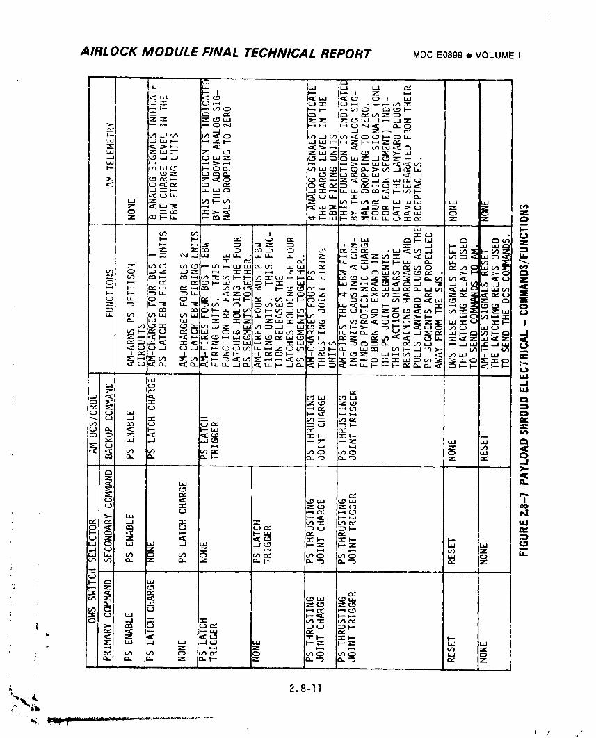
AIRLOCK MODULE FINAL TECHNICAL REPORT MDCE0899• VOLUME I
AIRLOCK MODULE FINAL TECHNICAL REPORT MDC E0899 • VOLUMEI
PS jettison enable circuit, prevented premature operation of the jettison sequence.
The enable commands energized the enable relays which armed the jettison circuits.
The control interlock which implemented individually commanded series relay cir-
cuits prevented the sequence from continuing if a malfunction in the switch
selector or OWSrelays had occurred. Due to the redundancy of these relay
circuits, at least two malfunctions would have been required to stop the sequence.
AM CRDUcommands were available to bypass the malfunctions. The mechanical inter-
lock required the discrete latch actuators to release the upper and lower struc-
tural rings so the thrusting joints could separate the shroud segments when the
joint separation con_ands were initiated.
The bus 1 latch control logic, Figure 2.8-8, used Sequential Bus 1 power,
paragraph 2.8.4, and primary commands from the OWSswitch selector and relays to
charge and trigger one latch firing unit in each segment via the lanyard con--
nectors, Figure 2.8-4. The other latch firing units were similarly charged and
triggered by the bus 2 latch control logic utilizing Sequential Bus 2 power and
the secondary commands. The AM CRDU, which utilizes separate sets of relays,
was available as a backup method of cycling the discrete latch actuators. The
bus 1 and bus 2 joint control logic used Sequential Buses 1 and 2 power, respec-
tively, and primary commands from the OWSswitch selector and relays to charg_
and trigger all the thrusting joint firing units, Figures 2.8-4 and 2.8-8. Upon
completion of this sequence the shroud should have been jettisoned unless a
malfunction had occurred. If a malfunction had occurred, the secondary commands
would have cycled all the thrusting joint firing units. Also the AM CRDUprovided
a backup method of cycling all the joint firing units utilizing separate sets of
relays.
2.8.1.3 Payload Shroud Jettison Subsystem Testing
A. Development Testinc t
(I) Vendor - The GFE EBWfiring units had additional vibration tests
._ .performed to qualify them for use in zero gravity by verifying that
no debris was present in the firing unit gap tube. The gap tube
was the high voltage switching device and a piece of debris passing
through the electrodes in zero gravity could have caused self-
triggering of the firing unit.
L 2.8-12
1974018208-553
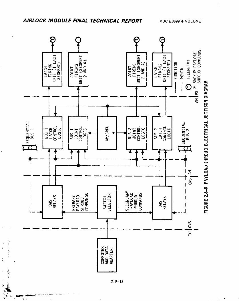
AIRLOCK MODULE FINAL TECHNICAL REPORT MDCE0899• VOLUMEI
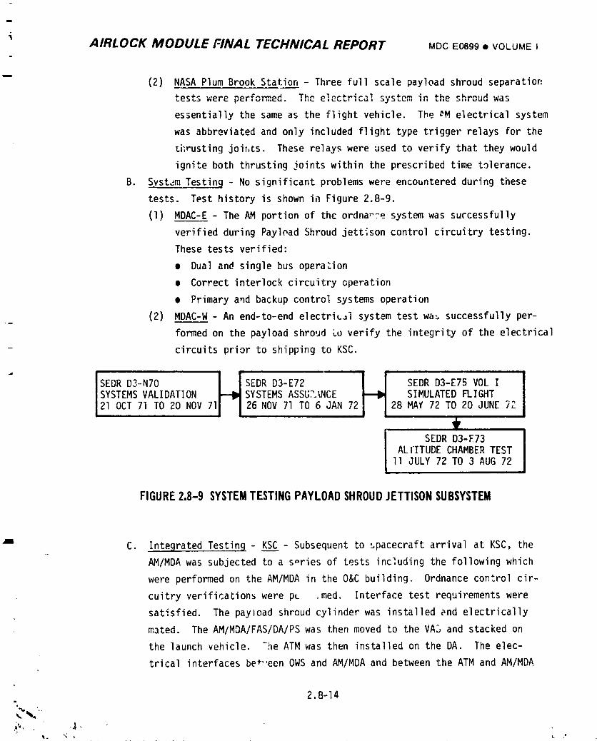
iAIRLOCK MODULE FINAL TECHNICAL REPORT MDC E0899 • VOLUME I
(2) NASAPlum Brook Station - Three full scale payload shroud separation
tests were v=-,_,,,,=_ ,h_ el ^_ <_• :_r,_,, system in the shroud was
essentially the same as the flight vehicle. The mMelectrical system
was abbreviated and only included flight type trigger relays for the
_i;rusting joir, ts. These relays were used to verify that they would
ignite both thrusting joints within the prescribed time tolerance.
B. Svstam Testin 9 - No significant problems were encountered during these
tests. Test history is shown in Figure 2.8-9.
(I) MDAC-E- The AM portion of the ordnance system was successfully
verified during Payload Shroud jettison control circuitry testing.
These tests verified:
• Dual and single bus opera_ion
• Correct interlock circuitry operation
• Primary and backup control systems operation
(2) MDAC-W- An end-to-end electriL_i system test wa_ successfully per-
formed on the payload shroud Lo verify the integrity of the electrical
circuits prior to shipping to KSC.
LJSEDRD3-N70 i _ISEDR D3-E72 SEDRD3-E75 VOL I
SYSTEMSVALIDATION SYSTEMSASSUL_NCE SIMULATEDFLIGHT21 OCT 71 TO 20 NOV71 26 NOV71 TO 6 JAN 72 28 MAY72 TO 20 JUNE 72
SEDRD3-E73ALTITUDE CHAMBERTEST
II JULY 72 TO 3 AUG72
FIGURE2,8-9 SYSTEMTESTINGPAYLOADSHROUDJETTISONSUBSYSTEM
" C. Inteorated Testin 9 - KSC - Subsequent to spacecraft arrival at KSC, the
AM/MDAwas subjected to a s_ries of tests including the following which
were performed on the AM/MDAin the O&C building. Ordnance control cir-
cuitry verificaLions were pc .med. Interface test requirements were
satisfied. The payload shroud cylinder was installed end electrically
mated. The AM/MDA/FAS/DA/PS was then moved to the VA3 and stacked on
the launch vehicle. "he ATMwas then installed on the DA. The elec-
trical interfaces bet,,een OWSand AM/MDAand between the ATM and AM/MDA:
2.8-14
i 9740i 8208-555
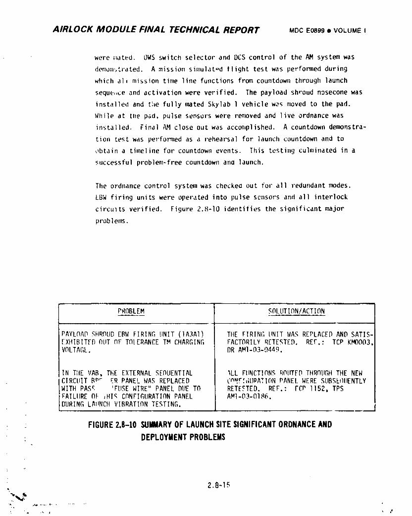
AIRLOCK MODULE FINAL TECHNICAL REPORT MDCE0899• VOLUMEI
were _ated. OWSswitctl selector and DCS control of the AM system was
denon.,trated. A mission simulated flight test was performed during
which ali mission time line functions from countdown through launch
seque,,ce and activation were verified. The payload shroud nosecone was
installed and the fully ,_ted Skylab 1 vehicle was moved to the pad.
While at tl_e pad, pulse sensors were removed and live ordnance was
installed. Final _1 close out was accomplished. A countdown demonstra-
tion test was performed as a rehearsal for launch countdown and to
obtain a timeline for countdown events. This testing culminated in a
successful prob]em-free countdown ana ]aunch.
The ordnance control system was checkea out for al1 redundant modes.
LBWfiring units were operated into pulse sensors and all interlock
circuits verified. Figure 2.8-10 identifies tlle significant major
problems.
PROBLEM SDI.UTION/ACTIDN
PAYLC)AD._HRDUDEBW FIRING UNIT (1A3A1) TIIEFIRING UNIT WAS REPLACED AND SATIS-EXHIBITFD C}tlTC)FT(IIERANCETM CHARGING FACTDRILY RETE,_TED. REF.: TCP KMO003,VOLTAGL. DR AM1-03-0449.
IN TIIEVAB, THE EXTERNAL SEf_IJENTIAL %LL FtlNCT!CINSROIITEDTHRCIUGIITHE NEWCIRCUIT Bp'- ER PANEL WAS REPLACED cnF'!F;,;UPATIC_NPANEL WERE SUBSE_IIIENTLYWITH PASc 'FUSEWIRE" PANEL DUE T(_ RETESTED. REF.: FCP I152, TPSFAILURE Ol ,HI_ CC}NFIGURATIONPANEL AM1-03-0186.DURING LA_NCH VIBRATION TESTING.
FIGURE2.8-10 SUMMARYOFLAUNCHSITESIGNIFICANTORDNANCEAND
: DEPLOYMENTPROBLEMS
2.8-15
2.
1974018208-556
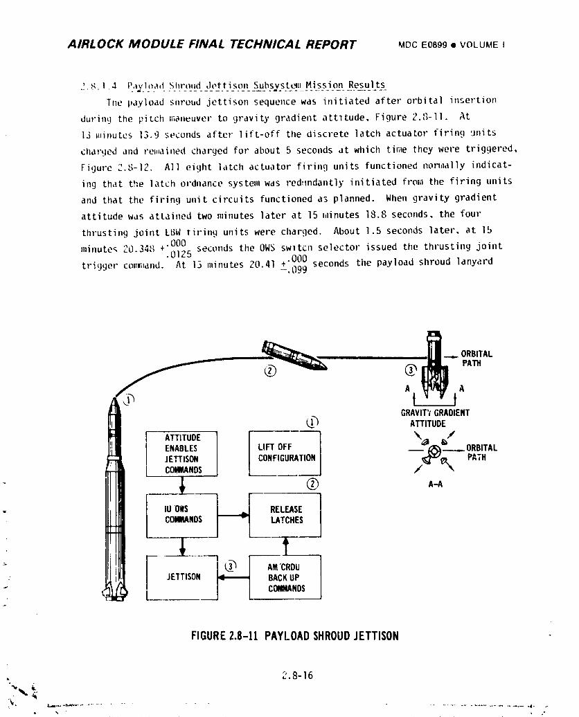
AIRLOCK MODULE FINAL TECHNICAL REPORT MDCE0899• VOLUMEI
.!,._.14 P..*x)_'_____t_.S_hr_,,_d:L,,tLi_._9_,t_s2.bsvst_jL_M_i__Sip,D__Re)uIt_s_The payload shroud jettison sequence was initiated after orbital insertion
durinq_the pitch E_ianeuverto gravity gradient attltude, Figure.2.o-11°. At
13 _ffnutes13.9 seconds after lift-off the discrete latch actuator firing units
clla;'Liedand re_,ainedcharged for about 5 seconds at which ti_aethey were triggered,
Figure _ '"_.o-]2. A]I eight ]atch actuator firing units functioned non,lally indicat-
ing that the latch ordnance system was red:mdantly initiated from the firing units
and that the firing unit circuits functioned as planned. When gravity gradient
attitude was attained two minutes later at 15 hlinutes18.8 seconds, the four
thrusting joint LI3Wtiring units were charged. About 1.5 seconds later, at 15
minute_ 20.34_3+.000 seconds the OWS swltcn selector issued the thrusting joint.0125
triqqer cot_w_and. At 13 minutes 20 41 +.000 seconds the payload shroud lanyard- " -.099
_ __...__ __...ORBITAL
Aj iA
I!iI ENABLESI IUFTOFF _ _____ORmTAL
c=°'o,/Illll $ I I ---° '-'IhII lUows _ RELEASE
COMMANDS]_ LATCHES
lllll _1_ _ --EIIJI!1 1_I ,,.c_ou_ i_ JETTISON_ BACKUP,;_L_ J i c_'_
FIGURE2.8-11 PAYLOADSHROUDJETTISON
2.8-16
-,
i_ • _ ................................................ , .-
• % .,' _ ow
] 974018208-557
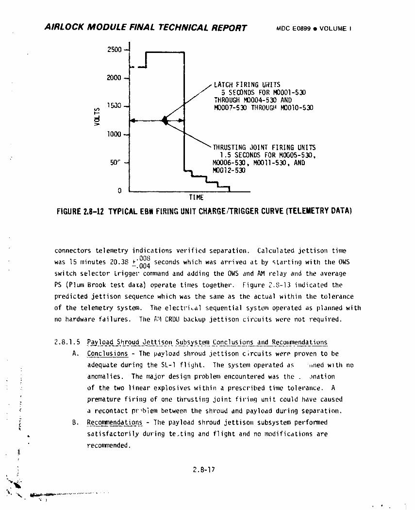
AIRLOCK MODULE FINAL TECHNICAL REPORT MDCE0899• VOLUMEI
2500 -
2000 -
LATCH FIRING Ui_ITS5 SECONDS FOR M0001-530
THROUGH M0004-530 ANDu_ 1500- / M0007-530 THROUGH M0010-530
1000--
"_IttRUSTING_ JOINT FIRING UNITS1.5 SECONDS FOR M0005-530,
50_- M0006-530, M0011-530, AND
o....TIME
FIGURE2.8-12TYPICALEBW FIRINGUNITCHARGE/TRIGGERCURVE (TELEMETRYDATA)
connectors telemetry indications verified separation. Calculated jettison time
was 15 minutes 20.38 �€�„which was arrived at by _Larting with tileOWS-.004switch selector Lrigger command and adding the OWS and _ relay and the average
PS (Plum Brook test data) operate times together. Figure 2.'J-13indicated the
predicted jettison sequence which was the same as the actual within tl_etolerance
of the telemetry system. The electri,.alsequential system operated as plamled with
no hardware failures. The A;.ICRDU backup jettison circuits were not required.
2.8.1.5 Paa_loadSI1roudJettisgn Su__bs_stej!1_Cgnclusions and Recol_,11endations
A. Conclusions - The payload shroud jettison c;rcuits were proven to be
adequate during the SL-I flight. The system operated as ',,nedwlth no
; anomalies. The n_jor design problem encountered was the _ anation
: of the two linear explosives within a prescribed time tolerance. A
•: premature firing of one thrusting joint firing unit could have caused
a recontact problem between the shroud and payload during separation.L
i B. Reconmlendations- The payload shroud jettison subsystem performed, satisfactorily during te.ting and flight and no modifications are
reconm_ended.
2.B-17
% .",2 I
t 'P 'l
1974018208-558
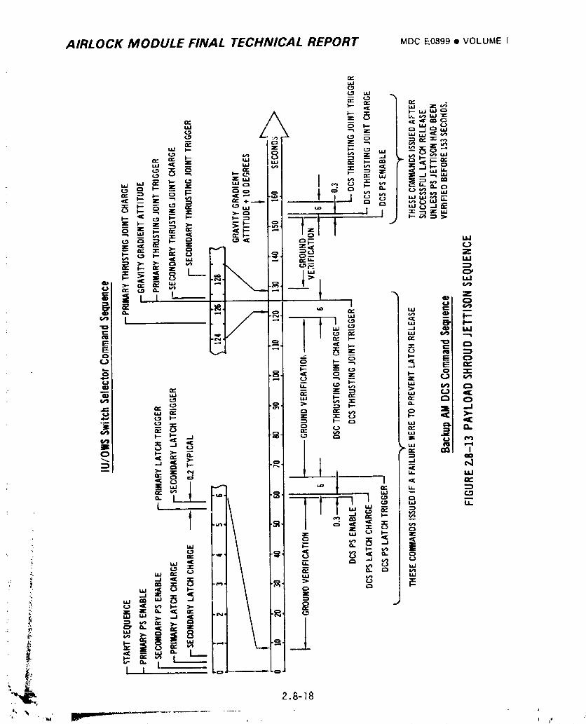
AIRLOCK MODULE FINAL TECHNICAL REPORT MDCE0899• VOLUMEI
i_ .o.,_=
.=., '.' "- ,o,# _, = _= _E ==,.,., ,,, ,., _,_
"_E_=,,_:_ o...= �˜�¸=_=___= _- _,_.., ,
,, . ;IoN
_ N
=" I F..
II--"
= = _, o 5 _
_°"/ " ° _'_ °:: =,_5 ,-, \ =R ,_.= ,.,
i _!__, I _
,_; I I .==...... o
_ii_, _._-_II, "W - ......
"' " •_ m_ j_llnnlli_ l i 't
1974018208-559
AIRLOCK MODULE FINAL TECHNICAL REPORT MDCE0899• VOLUMEI
2.8.2 ATM Deployment _Subszste_n,
The ATI4required deployment fror,_a launch position to a mission position to
clear the _)rir_arydocki_le,port and orient tileATH so its systems could function as
designed. The L)eploymentAssembly (DA) structure contained the mechanisms required
for deploy_,lent.Refer to Section 2.2 for detaiIs of the DA. Electrical
sequential subsystem deployment equipment included the OWS switch selector, the AM
CRDU, the /_Hpower system, the release mechanisms, and motor reel assemblies.
Automatic and JSC flight controller nBnual operating capabilities were included
in the design. Flight qualified equipment was utilized in the design.
2.8.2.1 ATM Deployment Subsystem Design Requirements
The ATM deployment circuit design was initiatedwhen the early mechanical
tradeoff studies were con_pleted. Initially, the DA design consisted of spring
loaded trunnion joints which 'dereto rotate the upper DA around to the deployed
position. Redundant motors were to control reels which payed out cable to allow
rotation. Scissor linkages and pin pullers which were not ordnance actuated
were to be used to release the Icunch latches to al1.owrotation. Discrete signals
were to be provided by the IU to the DA for initiation of the ATM deployment
: sequence. The primary signals were to be provided by IU programmed commands andi
the backup signals were to be provided by the IU via CCS col_mlands.All DA elec-
trical power requirementswere to be provided by the (U. Subsequent redesign
cha.i_gedthe payout reel to a deployment reel which pulled the ATM around during
de;,ioyment.The negator springs at the trunnion jeints were reversed to retard
rotation of the ATM DA. The reversing of tilesystem made more positive the
cycling of the latch mechanism allowing for higher spring forces in the latch
(see Section 2.2). The release mechanisn (launch latch) chanqed to an ordnance
initiated system using first the payload shroud discrete latch actuators and
• _ finally using smaller pin pullers. The ordnance system was initiated by redundant
GFE EBW firing units. The electrical system was also redesigned. The OWS switch
i selector and the OWS relay panels powered by the AM were utilized to provide a
,_ greater con=handdriving capability and to maintain the conm_andsequence. AM
relay panels were added for the ATM deployment control logic. The IU switch
selector and power were deleted. The OWS switch selector provided the primaryt
• deployment commands. The AM CRDU provided a backup set of commands.
:..._ 2.8-19
,. 4 ........
1974018208-560
AIRLOCK MODULE FINAL TECHNICAL REPORT MDC E0899 • VOLUME I
2.8.2.2 ATM Deplo3ment Subsystem Description
The ATM deployment assembly (DA) contained two release mechanism EBW firing
: units, and two motor reel assemblies. The OWS switch selector provided low power
momentary commands, Figure 2.8-14, to the OWS relay panels. These panels utilized
AM power and the momentary conBands to provide long duration commands with greater
drive capability. The AM control logic utilized relay circuits that accepted
the conm_andsand applied power to the appropriate firing unit or motor reel assembly
while maintaining isolation of power sources, commands, firing units and the motor
reel ass_l_blies.
One of the relay circuit functions was to provide ATM deployment inhibit
control. The ATM deployment inhibit circuits prevented electrical initiation of
the ATM deployment sequence before PS jettison. The inhibit circuit was initialized
by the PS jettison enable function. This action energized, via the PS lanyard con-
nectors, the ATM deploy inhibit relays. These relays were designed to inhibit
tileATM enable and motor on commands from initiating the ATM deployment sequence
until the PS was successfully jettisoned. When the PS was jettisoned the lanyard
connectors disconnected the circuit to the inhibit relays. The inhibit relays
deenergized and allowed the deployment commands to proceed. The deployment sequence
consisted of several interlocks; the power interlock, the control interlock, and
the mechanical interlock. The power interlock, utilizing the ATM DA enable cir-
cuit, prevented premature operation of the deployment sequence. The enable com-
mands energized the enable relays which armed the deployment circuits. The
control interlock which ii:_plementedindividually con=handedseries relay circuits
prevented the sequence frc.,.lcontinuing if a malfunction in the switch selector
or OWS relays had occurred. Due to the redundancy of these relay circuits, at
least two malfunctions would have been required to stop the sequence. AM CRDU
commands were available to bypass the malfunctions. The mechanical interlock
required the release n_echanismto free the upper DA so the deployment motor reel
assemblies could deploy the ATH.
J
The primary deployment relay logic Figure 2.8-15 used Sequential Bus 1! ' ,
power, Paragraph 2.8.4 and primary conm_andsfrom the OWS switch selector and
i relays to charge and trigger one release mechanism firing unit. The redundant [firing unit was charged and triggered in a using Sequential 2
simi'larfashion Bus
power, the secondary deployment relay logic and the primary commands from the OWS
\,__ 2.8-20
1974018208-561
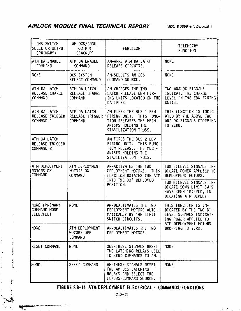
AIRLOCK MODULE FINAL TECHNICAL REPORT MDCE08996 VOLu, E!
J i . =... .,. ., . , . ,
OWSSWITCH AM DCS/CRDU'KFI I:rT0P AUTPlIT AIITPlIT I:IINrTTON TELEMETRY.......................... FUNCIION
( PRI MARY) (BACKUP)i
ATM DA ENABLE ATMDA ENABLE AM-ARMSATM DA LATCH NONECOMMAND COMMAND RELEASECl RCUITS.
NONE DCSSYSTEM AM-SELECTSAM DCS NONESELECTCOMMAND COMMANDSOURCE.
ATM DA LATCH ATM DA LATCH AM-CHARGESTHE TWO TWOANALOGSIGNALSRELEASECHARCE RELEASECHARGE LATCHRF,LEASE EBWFIR- INDICATE THE CHARGE
COMMAND COMMAND ING UNITS LOCATEDON THE LEVEL IN THE EBWFIRINGDA TRUSS. UNITS.
ATM DA LATCH ATM DA LATCH AM-FIRES THE BUS I EBW TillS FUNCTIONIS INDIC-RELEASETRIGGER RELEASETRIGGER FIRING UNIT. THIS FUNC- ATED BY THE ABOVETWOCOMMAND1 COMMAND TION RELEASESTHE MECH- ANALOGSIGNALS DROPPING
ANISMS HOLDINGTHE TO ZERO.STABILIZATION TRUSS.
ATM DA LATCH AM-FIRES THE BUS 2 EBWRELEASETRIGGER FIRING UNIT. THIS FUNC-COMMAND2 TION RELEASESTHE MECH-
ANISMS HOLDINGTHESTABILIZATION TRUSS.
ATM DEPLOYMENT ATM DEPLOYMENT AM-ACTIVATESTHE TWO TWOBILEVEL SIGNALS IN-MOTORSON MOTORSON DEPLOYMENTMOTORS. THIS DICATE POWERAPPLIED TOCOMMAND COMMAND FUNCTIONROTATESTIIE ATM DEPLOYMENTMOTORS.
INTO THE 90° DEPLOYEDPOSITION. TWOBILEVEL SIGNALS IN-
DICATE DOWNLIMIT SW'SHAVE BEEN TRIPPED, IN-DICATING ATM DEPLOY.
NONE(PRIMARY NONE AM-DEACTIVATESTHE TWO THIS FUNCTIONIS IN-COMMANDMODE DEPLOYMENTMOTORSAUTO- DICATED BY THE TWOBI-SELECTED) MATICALLYBY THE LIMIT LEVEL SIGNALS INDICAT-
SWITCHCIRCUITS. ING POWERAPPLIED TOATM DEPLOYMENTMOTORS
NONE ATM DEPLOYMENT AM-DEACTIVATESTile TWO DROPPINGTO ZERO.MOTORSOFF DEPLOYMENTMOTORS.COMMAND
,,, _,, ,w,
_, RESETCOMMAND NONE OWS-THESESIGNALS RESET NONE_; THE LATCHING RELAYSUSED_ TO SENDCOMMANDSTO AM.
NONE RESETCOMMAND AM-THESESIGNALS RESET NONE_" THE AM DCS LATCHING
" RELAYSAND SELECTTHEI U/OWS,COMMANDSOURCE.
FIGURE2,8-t4 ATMDEPLOYMENTELECTRICAL- COMMANDS/FUNCTIONS_ 2.8-21
1974018208-562
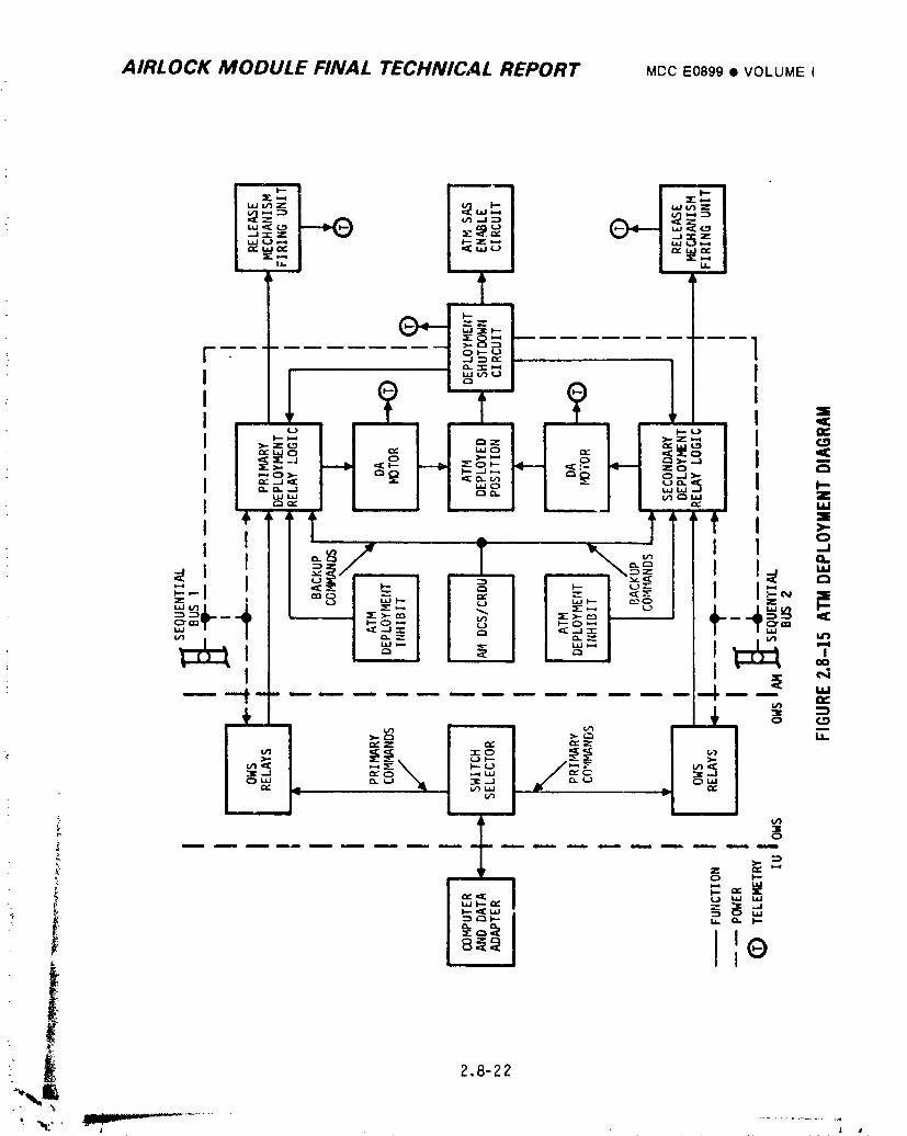
AIRLOCK MODULE FINAL TECHNICAL REPORT MDCE0899• VOLUMEI
2.8-22
L a
1974018208-563
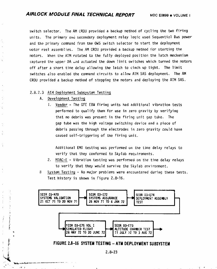
AIRLOCK MODULE FINAL TECHNICAL REPORT MDCE0899• VOLUMEI
switch selector. The AM CRDU provided a backup method of cycling the two firing
units. The primary and secondary deployment relay logic used Sequential Bus power
and the primary command from the OWS switch selector to start the deployment
w,lotorreel assemblies. The AM CRDU provided a backup method 1:orstarting the
motors. When the AIM rotated to the fully deployed position the latch mechanism
captured the upper DA _nd actuated the down limit switches which turned the motors
off after a short time delay allowing the latch to cinch up tight. The limit
switches also enabled the command circuits to allow ATM SAS deployment. The AM
CRDU provided a backup method of stopping the motors and deploying tileATM SAS.
2.8.2.3 AT,_Deployment Subsystem Testing
A. Development Testin9
I. Vendor - The GFE EBW firing units had additional vibration tests
perfo_mledto qualify them for use in zero gravity by verifying
that no debris was present in the firing unit gap tube. The
gap tube was the high voltage switching device and a piece of
debris passing through the electrodes in zero gravity could have
caused self-triggering of the firing unit.
Additional EMI testing was performed on the time delay relays to
verify that they conformed to Skylab requirements.
2. HDAC-E - Vibration testing was performed on the time delay relays
to verify that they would survive the Skylab environment.
B System Testing - No major problems were encountered during these tests.
Test history is shown in Figure 2.8-16.
'S'O'O N'O'IS O"O O"121 OCT71 TO20 NOV71 26 NOV71 ,0 6 JAN72 I I TEST
" i
L'_ SEDRD3-E73
" _,_ I_IIISIMULATEDFLIGHT ALTITUDECHAMBERTEST'_ I28 MAY72 TO20 JUNE72 11 JULY;,2 TO3 AUG72L
t, i iiii
_-_ FIGURE2.8-16 SYSTEMTESTING- ATMDEPLOYMENTSUBSYSTEM
:_' 2.8-23
1974018208-564
AIRLOCK MODULE FINAL TECHNICAL REPORT MDCE0899• VOLUME I
MDAC-E - The ordnance and deployment system was successfully verified
during DA deployment control circuitry testing. These tests verified:
• Dual and single bus operation
• Correct interlock circuitry operation
• Limit switch operation _
• Time delay ti'idng
• Primary and backup control systems operation
In an actual ATM deployment test, dual and single motor/reel mode
operation was verified. No major problems were encountered during
these tests.
C. Integrated Testing - KS___CC-Subsequent to spacecraft arrival at KSC the
AH/MDAwas subjected to a series of tests including the following which
were performed on the AM/MDAin the O&Cbuilding. Ordnance control
circuitry verifications were performed. Interface test requirements
were satisfied. Tile AM/MDAwas hardmated to the FAS and DA and all
electrical interfaces in this configurationwere flight mated. A I
powered DA deployment was performed. The AM/MDA/FAS/DA/PSwas then
moved to the VAB and stacked on the launch vehicle. TileATM was then
installed on the DA. The electrical interfaces between OWSand AM/MDA ,
and between tileATM and AM/MDA were mated. A con_prehensiveAM/OWS/ATM °
electrical interface test verified all systems operational function'
OWSswitch selector and DCS control of the AM system was demonstrated.
A mission simulated flight test was performed during which the ATM :
deployment sequence was verified. While at the pad, pulse senso',s
were removed and live ordnance was installed. Final AM close out was
accomplished. A countdown demonstration test was performed as a
rehearsal for launch countdown and to obtain a timeline for countdown
events. This testing culminated in a successful problem free countdown
; and launch. The ordnance and deployment control system was checked
out for all redundant modes. DA motors were operated, EBWfiring
units operated into pulse sensors and all interlock circuits verified.
i:I I
2.8-24 ,- i ............' __.1 r ............ L.._ '-_" _ .................... , ........ :>
]9740]8208-565
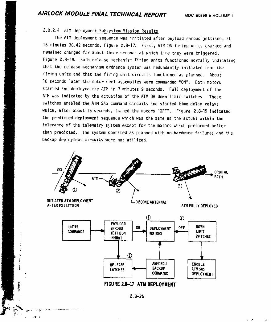
AIRLOCK MODULE FINAL TECHNICAL REPORT MDCE0899• VOLUMEI
2.8.2.4 ATM Deployment Subsystem Mission Results
The ATM deployment sequence was initiated after payload shroud jettison, at
16 minutes 36.42 seconds, Figure 2.8-17. First, ATM DA firing units charged and
remained charged far about three seconds at which time they were triggered,
Figure 2.8-I& Both release mechanism firing units functioned normally indicating
that the release mecilanismordnance system was redundantly initiated from the
firing units and that the firing unit circuits functioned as planned. About
lO seconds later the motor reel assemblies were commanded "ON" Both motors
started and deployed the ATM in 3 minutes 9 seconds. Full deployment cf the
ATM was indicated by the actuation of the ATM DA down limit switches. These
switches enabled the ATM SAS command circuits and started time delay relays
which, after about 15 seconds, tu,'nedthe motors "OFF". Figure 2.8-19 indicated
the predicted deployment sequence which was the same as the actual within the
tolerance of the telemetry system except for the motors which performed better
than predicted. The system operated as planned with no hardware failures and t_a
backup deployment circuits were not utilized.
SWS _._._ ORBITAL
AT_ PATH
(!)
INITIATEDATMDEPLOYMENT DISCONEANTENNASAFTERPSJETTISON ATMFULLYDEPLOYED
® ®
PAYLOAD ,_ J
IU/OWS SHROUD _ DEPLOYMENT DOWN 1; CNOS ----"JETT,SO. MOTORS L,M,T, INHIBIT SWITCHES
q p (T_
BACKUP
LATCHES I ]._.MMA NDS ATMSAS• DEPLOYMENT
_! FIGURE2.8-17 A'I"MDEPLOYMENT
2.8-25
t,
]9740]8208-566
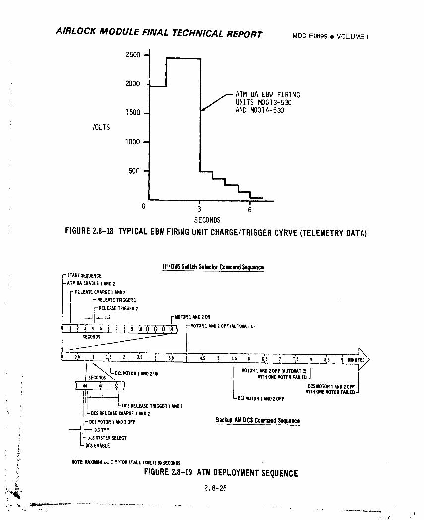
AIRLOCK MODULE FINAL TECHNICAL REPORT MDCE0899• VOLUMEI
2000
f ATMDA EBWFIRINGUNITSMOGI3-530ANDMDOI4-5301500
;OLTS
I000-
50P -' 11 '1 '
0 3 6
SECONDS
FIGURE2,8-18TYPICALEBWFIRINGUNITCHARGE/TRIGGERCYRVE(TELEMETRYDATA)
IU/OWSSwitchSelectorCommandSequence." STARTSEQUENCE-AT' DAENABLE,AND2
F _P.LEASECHARGE] AND2r RELEASETRIGGER1
Ir.LE._.,OOE.,----]J-- oJ r MOTORl ANOz°N0," i i "i i i i ! i i _ i'] (2 (3 1F_ -MOTORIANO20FF(AUTOIILATICI
SECONDS
... r,,,- i ' t T" i .... 1 v i
..o,.,.,o,,._,,c)]o=_,0,,,.D,_N I ..NONEMOT°,,.LEO I!
LY''<' ,'7 _ I I o=MOToNI,NO20FFi= • | WITHONEMOTORFAILED'-)/
LDCS_OTONi AND2OFF
' DC$RELEASETmGGER1AND2,
- OC$RELEASECHARGE| AND2T
-DCSmOTORI ANOZOFF BackupAMDCSCommandSequence"-"" _ 0.3TYP
-U,,SSYSTBSELECT
.DC$ENABLE
;'_ NOTE:lliAXil_Jtl_,T.,',,',"TONSTALLTitleIS30SECOND&
_ FIGURE2.8-19 ATMDEPLOYMENTSEQUENCE<_, 2.8-26
1974018208-567
AIRLOCK MODULE FIIL'AL TECHNICAL REPORT MDCSC,_9£,'_VOLUMEI
2.8.2.5 A_TM__D#plox_mentSubsystem Conclusions and Recommendations
A. Conclusions - The ATM deployment circuits re proven to be adequate
during the SL-I flight, The system operatea as planned with no anomalies.
An additional telemetry monitor which indicated the position of the ATM
during deployment would have aided the JSC flight controllers in
identifying the status of ATM position during deployment,
B. Recommendations - The ATM deplo)ment subsystem performed satisfactorily
: during f:ests and the mission. Added telemetry parameters providing ATM
deployment position data would be an aid.
i., 2.8-27
:NrZ 4¢ . ._ j[ ,
1974018208-568
AIRLOCK MODULE FINAL TECHNICAL REPORT MDC E0899 • VOLUME Z
2.8.3 Discone Antenna Depioyment Subsxstem
The electrical sequential system was required to release the discone antennas
from the launch secured position, allowing the mechanical system to deploy the
antennas. JSC flight controller manual operating mode was selected as the primary
and backup method of commanding antenna deployment.
2.8.3.1 Discone Antenna Deployment Subsystem Design Requirements
The discone antenna circuit design originally utilized an ordnance actuated
guillotine to releas_ the antenna booms. Eventually the ordnance system was
eliminatedand :lotwire actuators were added. Two AM CRDU commands were added to
allow the JSC flight controllers to deploy the antennas. The original flight plan
called for the ATM to be launched separately from the 3WS and by using LM, the
LM/ATM would be docked with the SWS. The crew would thee,deploy the antennas.
After tileSW3 went through its final evolution to a dry works_,op,the ATM was
launchedwith the SWS and the antn,_,,_were to be deployed by JSC flight con-
trollers. The electrical rcuit _eqt through J minimum of redesign retaining
the crew deployment ca.Y -i_y. ine design used hot wire actuators which
utilized the principle of ,,eatlag_ wire until i_ fused to allow a snring
loaded plunger (pin) to retract. The pin rptraction permitted the scissor
mechanism to open freeing the cables and allowing the spring loaded retainers
to release the strap assemblies. Once the straps were released the spring
loaded rotary joints rotated deploying the antenhas.
2.8.3.2 D__':ror_ ,..n,aDeployment Subsystem Pescriptio.
The d_sco .._ennadeploy,ent circuit. Figure 2.8-?0, consisted of the around
command mode and the crew contrailmode. The antenna deploy switch, _,,hennlaced
in tne command position, would allow each AM CRDU con_and to pass through the
switch and energize a relay. The relay would apply power to two hot wire
actuators _or a sufficient length of t_me to fuse the wire resultin_ in the
release of the actuator pins and the Jeployment of the antennas. An alternate
or crew COF,trOl method of deploying the antennas was available by having thek
cr_w place the antenna switch in the deploy position. This energized both
relays and actuated all the hot wire actuators releasing the antennas.
• 2.8-28t_
_'.
1974018208-569
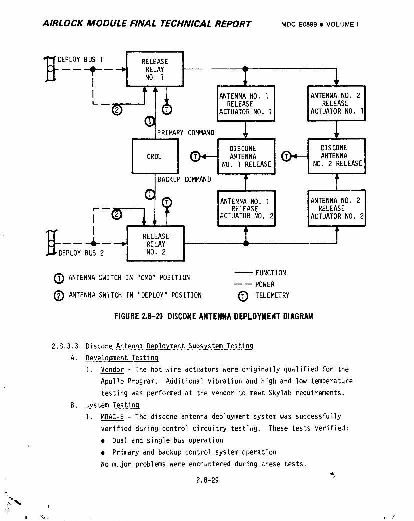
AIRLOCK MODULE FINAL TECHNICAL REPORT '_ocE0899• VOLUMEI
)EPLOY BUS 1 RELEASE4p---- RELAY
I NO. 1 .... r
ANTENNA NO. l ANTENNA NO. 2.. RELEASE RELEASE
2(_) ACTUATOR NO. l ACTUATOR NO.I i
@PRIMARY _ .
CR ANTENNA INO. l RELEASEI NO. 2 RELEASE
r- -- RELEASE RELEASE
I ACTUATOR NO. 2 ACTUATOR NO.
' _ RELEASE
_- -- RELAYDEPLOY BUS 2 NO. 2
FUNCTIONANTENNA SWITCH IN "CMD" POSITION -- POWER
Q ANTENNA SWITCH IN "DEPLOY" POSITION 0 TELEMETRY
FIGURE2.8-20 DISCONEANTENNADEPLOYMENTDIAGRAM
2.8.3.3 Discone Antenna Deplpyment Subsystem Testin9
A. Development Testing
I. Vendor - The not wire actuators were originaaly qualified for the
Apollo Program. Additional vibration and high and low temperature
testing was performed at the vendor to meut Skylab requirements.
B. _ystem Testing
I. MDAC-E - The discone antenna deployment system was successfully
verified during control circuitry testi.g. These tests verified:
• Dual and single bus operation
• Primary and backup control system operation
No m:jor problems were enceantered during Lhese tests.
4,2.8-29
a
1974018208-570
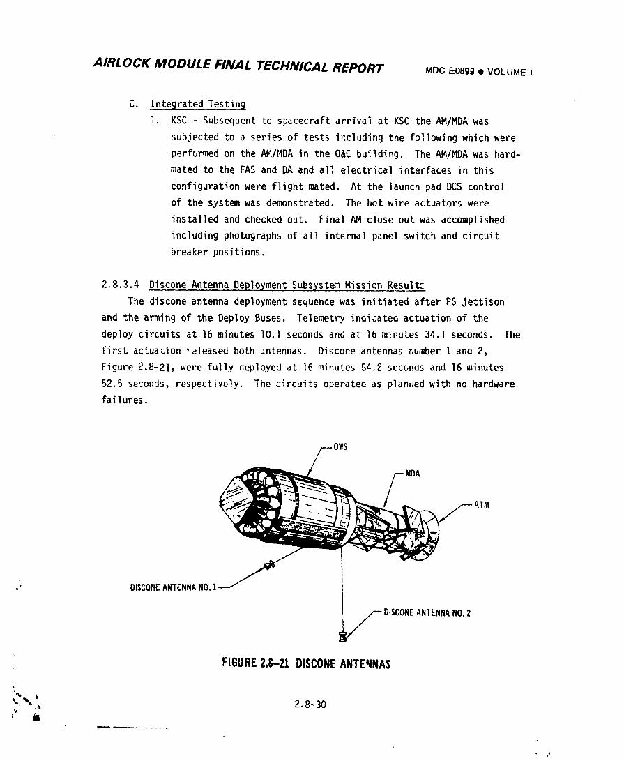
AIRLOCK MODULE FINAL TECHNICAL REPORT MDCE0899• VOLUME I
C. Integrated Testing
l. KSC - Subsequent to spacecraft arrival at KSC the AM/MDA was
subjected to a series of tests including the following which were
performed on the AM/MDA in the O&C building. The AM/MDA was hard-
mated to the FAS and DA and all electrical interfaces in this
configuration were flight mated. At the launch pa_ DCS control
of the system was demonstrated. The hot wire actuators were
installed and checked out. Final AM close out was accomplished
including photographs of all internal panel switch and circuit
breaker positions.
2.8.3.4 Discone Antenna Deployment Subsystem Mission Result_
The discone antenna deployment sequence was initiated after PS jettison
and the arming of the Deploy Buses. Telemetry indicated actuation of the
deploy circuits at 16 minutes lO.l seconds and at 16 minutes 34.l seconds. The
first actuation _leased both antennas. Discone antennas number l and 2,
Figure 2.8-2l, were fully deployed at ]6 minutes 54.2 seconds and 16 minutes
52.5 seconds, respectively. The circuits operated as plan,ed with no hardware
failures.
FOWS MDA
." DI$COHEANTENNANO,!
DISCONEANTENNANO.2
FIGURE2.G-21 DISCONEANTENNAS
4
_ 2,8-30
1974018208-571

AIRLOCK MODULE FINAL TECHNICAL REPORT MDC E0899 • VOLUME I
2.8.3.5 Discone Antenna Deplo_fment Subsystem Conclusions and Recommendations
A. Conclusions - The discone antenna deployment circuits were proven to
be adequate during the SL-1 flight. The system operated as planned with
no anL,lnal_es.
B. Recommendations - No recommendeddesign changes should be implemented.
¢.
z.8-31
iii J ....
1974018208-572
AI.-?LOCK .'VIODULE FINAL TECHNICAL REPORT MOCE0899• VOLUMEI
2.8.4 Power Control Subsystem
Electrical power was controlled to prevent premature initiation of an
activation sequence, especially during ascent vibration. The power buses
associated with the sequential system were armed when required, and then safed
after functions were completed. The primary method of arming the buses was
automatic, with the JSC flight controllers providing backup arming capability.
The-power control system was successfully tested at MDAC-E and at KSC.
During flight the power control system armed the buses as planned. Due
to problems encountered with the deployment of the OWS SAS and meteoroid shield,
the Deploy Buses were disarmed early by the flight controllers and the Sequential
Buses were disarmed by the SL-2 crew during the activation perioc which was about
IO days late due to the launch delay of SL-2. The power control system func-
tioned with no f_ilures.
2.8.4.1 Power Control Subsystem Desiqn Requirements
In the initial design, Squib Buses were created to control the Am cryogenic
system squib.. This system was to supply the cryogenics for the CSM fuel cells.
When discone antenna deployment circuits were added to the buses, the name was
changed from Squib to Deploy. Mec,lanical/ordnancetradeoff studies resulted
in mounting of the SAS on the OWS using an EBW ordnance system for deplqyment.
This deployment system was added to the Deploy Buses and the cryogenic system
was deleted. Subsequently the meteoroid shield deployment circuits and selected
ATM activation sequences were added to the Deploy Buses. These buses were to be
amled late in the first orbital revolution. The PS jettison and ATM deploy_,ent
circuits wcre planned te be a_tivated shortly after orbital insertion. The
Sequentia, Buses were created for this purpose. Later the OWS refrigeration
radiator shield jettison and selected ATM activation circuits were added to the
Sequential Buses. Subsequent changes in the flight plan resulted ir deployment
of the discone antennas just Pfter PS jettison ;'esultingin Deploy Bus arising
early in the first orbital revolution. At this time the two buses could have
been combined or the antenna circuits could have been moved to the Sequential
Buses. Since the circuits were already built and installed and a change would
have delayed the checkeut of the AM, the two buses remained intact.
" 2.8-32
1974018208-573
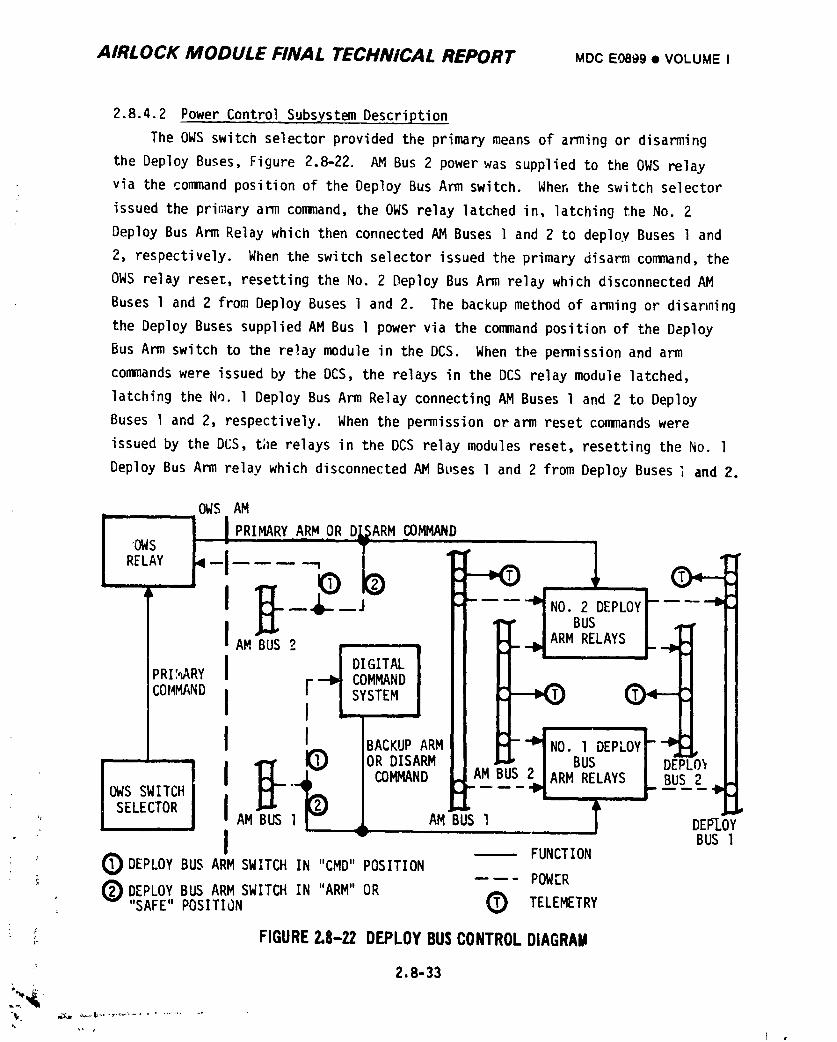
AIRLOCK MODULE FINAL TECHNICAL REPORT MDC E0899 • VOLUMEI
2.8.4.2 Power ControlSubsystemDescription
The OWS switchselectorprovidedthe primarymeans of armingor disarming
the DeployBuses,Figure 2.8-22. AM Bus 2 powerwas suppliedto the OWS relay
via the commandpositionof the DeployBus Arm switch. When the switchselector
issuedthe primaryarm command,the OWS relaylatchedin, latchingthe No. 2
DeployBus Arm Relaywhich then connectedAM Buses l and 2 to deployBuses l and
2, respectively.When the switchselectorissuedthe primarydisarmcommand,the
OWS relayreset,resettingthe No. 2 DeployBus Arm relaywhich disconnectedAM
Buses l and 2 from DeployBuses 1 and 2. The backupmethodof armingor disarming
the DeployBusessuppliedAM Bus l power via the commandpositionof the Deploy
Bus Arm switchto the relaymodulein the DCS. When the permissionand arm
commandswere issuedby the DCS, the relaysin the DCS relaymodule latched,
latchingthe No. 1 DeployBus Arm RelayconnectingAM Busesl and 2 to Deploy
Buses l and 2, respectively.When the permissionorarm resetcommandswere
issuedby the DCS, the relaysin the DCS relaymodulesreset,resettingthe No. l
DeployBus Arm relaywhich disconnectedAM Buses l and 2 from DeployBusesi and 2.
OWS AM
I i I PRIMARYARM'OR D_ARMcOMMANDRELAYOWST--IiiAM_"--2 _- J_ "'t - -'_'_A _ R EPLOYI,NORB_!DELAYS
I l DIGITAL)RI',_ARYF _ COMMAND
COMM/ND ,[ _ "ISYSTEMIBACKUPARM iU__ iI::IO_)Y___L.II
' " fORDISARM B
v BUS lI -- FUNCTION
O DEPLOYBUS ARM SWITCHIN "CMD"POSITIONPOWER
0 DEPLOYBUS ARM SWITCHIN "ARM"OR
m
', "SAFE"POSITION O TELEMETRY
:_ FIGURE2.8-22 DEPLOYBUSCONTROLDIAGRAil
" 2.8-33
,, (i ,
1974018208-574
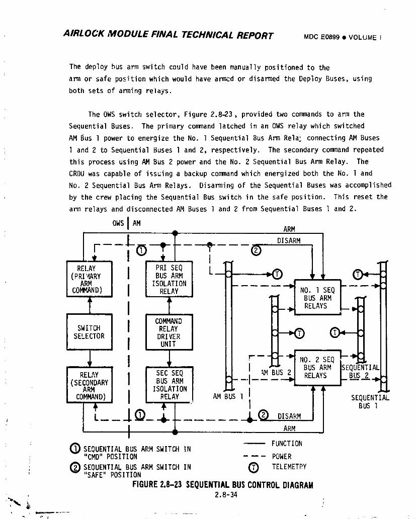
AIRLOCK MODULE FINAL TECHNICAL REPORT MDCE0899• VOLUMEI
The deploybus arm switchcouldhave beenmanuallypositionedto the
arm or safe positionwhichwould havearmcdor disarmedthe DeployBuses,using
both setsof aming relays.
The OWS switchselector,Figure2.8-23,providedtwo commandsto arm the
SequentialBuses. The primarycommandlatchedin an OWS relaywhich switched
AM Bus I powerto energizethe No. l SequentialBus Arm Rela-connectingAM Buses
1 and 2 to SequentialBuses I and 2, respectively.The secondarycommandrepeated
thisprocessusingAM Bus 2 powerand the No. 2 SequentialBus Arm Relay. The
CRDU was capableof issuinga backupcommandwhich energizedboth the No. l and
No. 2 SequentialBus Arm Relays. DisarmingoF the SequentialBuseswas accomplished
by the crew placingthe Sequ:.ntialBus switchin the safe position. This reset the
arm relaysand disconnectedAM Buses l and 2 from SequentialBuses l and 2.
OWS I AM ARM
l-----IJ--___-- _ (_)DISARM I I
l RELAY II P'RISEQ L_ =C)(PRI:_ARY BUS ARM H
ARMISOLATION I_ ..... "-_ NO. 1 SEQ I ----_"
COMMAND) _ II BUSARM L_F I
T II ' J RELAYS ICOMMAND II
SWITCH D_i_TEYR
SELECTOR
J, Ii F--FI- I,o.s,
[ [], ' 'M'_B'_S2 ] BUSARM 'SEQUENTIAL
RELAY f SEC SEQ _.[ ,,.,_u _ RELAYS I,us.:(SECONDARY , l BUS ARM
ARM [ISOLATION [ _, ,_
JSEQUENTIAL.COMMAND) l L RELAY AM BUS[
t L___.I ! L (_-DISARMI ARM
BUS[
IFUNCTION
O SEQUENTIALBUS ARM SWITCHIN"CMD"POSITION POWER
(_)SEQUENTIALBUS ARM SWITCHIN C) TELEMETPY' "SAFE"POSITION
FIGURE2.8-23SEQUENTIAL BUS CONTROL DIAGRAM2.8-34
>._,
1974018208-575
AIRLOCK MODULE FINAL TECHNICAL REPORT MCCE0899• VOLUMEI
2.8.4.3 Power Control Subsystem Testinq
Testing of this subsystem was accomplished during system and integrated
testing of the uther subsystems of the Sequential System.
2.8.4.4 Power Control Subsystem Mission Results
At 9 minutes, 53.77 seconds Ooth Sequential Buses were armed as a result of OWS
switch selector action. 3ince the relays were in parallel, redundant operation could
not be verified. At 11 days, 23 hours, 32 minutes, the Sequential Buses were
turned off by the crew. The Sequential Bus arming circuits operated as planned
with no hardware failures. Normally the buses were to be turned off on day two
by the crew, but since the ',eteoroidshield problem delayed the launch of SL-2
until I0 days later, the Sequential buses were left on for an extended period of
time. Sequential bus loads were designed so that no degradation of any component
would occur if the buses remained on. No degradation was detected.
The Deploy Buses were armed at 15 minutes, 33.64 seconds by the primary OWS
switch selector command. The buses were planned to be disarmed at 3 hours,
11 minutes, 28.59 seconds. They were actually disarmed at 3 hours, 3 minutes,
55.42 seconds to prevent the switch selector con_ands from activating the ATM
Thermal System. The circuit operated as plarinedwith no hardware failures. A
backup arming circuit was available but was not used.
2.8.4.5 Power Control Subsystem Conclusions and Recommendations
A. Conclusions - The power control circuits were proven tc be adequate
during the SL-I fliqht. The system operated with no anomalies.
B. Recommendations- No chanqes are recommended for this subsystem.
rm
2.8-35t
i •
1974018208-576
AIRLOCK MODULE FINAL TECHNICAL REPORT MDCE0399• VOLUME I
2.8.5 Radiator Shield Jettison/RefrigerationSubsystem Activation
The purpose of the OWS Refrigeration System (RS) was to provide freezers
for food and urine, and chillers for food, urine and water. The RS was a low
temperature thermal control system using a refrigerant fluid in a closed loop
circuit which dissipated heat through an externally mounted radiator. The first
of two sequential events required to activate the system was to expose the
externally mounted radiator which had been covered to prevent damage from Stage
• II retro rocket plumes during separation. The second event was to enable the RS,
2.8.5.1 OWS Radiator Shield Jettison/RefrigeratiorlSubs_sL_m Activation Design
Requirements
The original design which remained basically unchanged - except for the
addition of AM CRDU iso|atio;_relays - required an enable and disable control for
both the primary and secondary RS. The initial primary activation control was
provided by the T"'_WS switch selector system, while the AM CRDU provided initial
activation backup ._ntroland primary control after the useful life of the switch
selector system had expired. The addition of the RS radiator protective shield
required a jettison system which used a command from the IU/OWS switch selector
system and Sequential Bus power to control the PCS actuation control modules.
Cycling of these mndules was to allow gaseous nitrogen to release a pip pin
type mechanism which would cause a preloaded sb ing to release and jettison the
shield. AM CRDU provided a ['ackupjettison command,
2.8.5.2 OWS Radiator Shield Jettison/RefrigerationSubsystem Activation
Desc;'iption
The OWS relays converted the momentary IU/OWS switch selector command into
a long duration signal which cycled the actuation control modules, Figure 2.8-24.
Actuation of these modules permitted gaseous nitrogen to jettison the radiator
shield, Figure 2.8-25. The AM CRDU provided a backup jettison command.
The in;tial activaLion of the RS was provided by the IU/OWS switch selector
system, Figure 2.8-26, The AM CRDU provided backup activation control and primary
enable/disable control of the RS after the useful life of the switch selector had
expired.
2.8-36
J4
|, ,#
1974018208-577
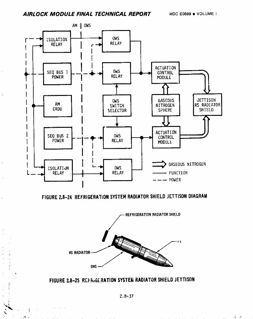
AIRLOCK MODULE FINAL TECHNICAL REPORT MDCE0899• VOLUMEI
AM I OWS
4' FI'f ACTUATION
OWS CONTROL- -- RELAY MODULE
_ I o,,,s o_oos I,_,,_so,,,AM IRS RADIATOR
CRDU I SWITCH NITROGEN I SHIELDs_,._TO_s_,._R_
I
ISEQ BUS 2 __ OWS CONTROLPOWER RELAY MODULE
L RELAY I RELAY _ FUNCTIONI
i ---- POWER
FIGURE2,8-24 REFRIGERATIONSYSTEHRADIATORSHIELDJETTISONDIAGRAM
REFRIGERATIONRADIATORSHIELD
RSRADI
OWS
,_; FIGURE2.8-25REFIi,GLRATIONSYSTEI_RADIATORSHIELDJETTISON
2.8-37
•Iv_"'
1974018208-578
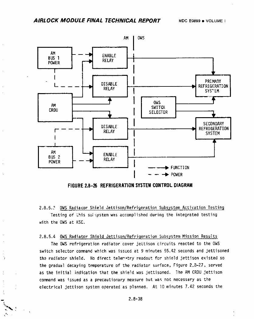
AIRLOCK MODULE FINAL "IECHNICAL REPORT MDCE0899• VOLUMEI
AM I OWSm
AM __ ENABLE IIBUS I RELAY I |POWER
, II i PRIMARYL DISABLE _ REFRIGERATION
RELAY I SYS"EM
l IIII uI
SWITCH
CRDU I SELECTOR
___ DISABLE I _ SECONDARY
REFRIGERATIONr RELAY I SYSTEMI
Ii !
BUS 2 RELAY
POWER - II_FUNCTION
I • POWER
FIGURE2.8-26 REFRIGERATIONSYSTEMCONTROLDIAGRAM
2.8.5.? OWSRadiator Shield Jettison/RefriBeratl_i_'on Subsystem Activation Testinq
Testing of this sui,_ystem was accomplished during the integrated testing
with the OWSat KSC.
2.8.5.4 OWSRadiator Shield Jettison/Refrigeration Subsystem Mission Results
The OWSrefrigeration radiator cover jettison circuits reacted to Lhe OWS
switch selector commandwhich was issued at 9 minutes 55.42 seconds and jettisoned
': th-= radiator shield. No direct telem:try readout for shield jettison existed so
the gradual decaying temperature of the radiator surface, Figure 2.8-27, served
• as the initialindicationthat the shieldwas jettisoned.The AM CRDUjettison
: commandwas issuedas a precautionarymeasurebut was not necessaryas the
electricaljettisonsystemoperatedas planneo. At lO minutes7.42 secondsthe
=: 2.8-38
I
i9740i8208-579
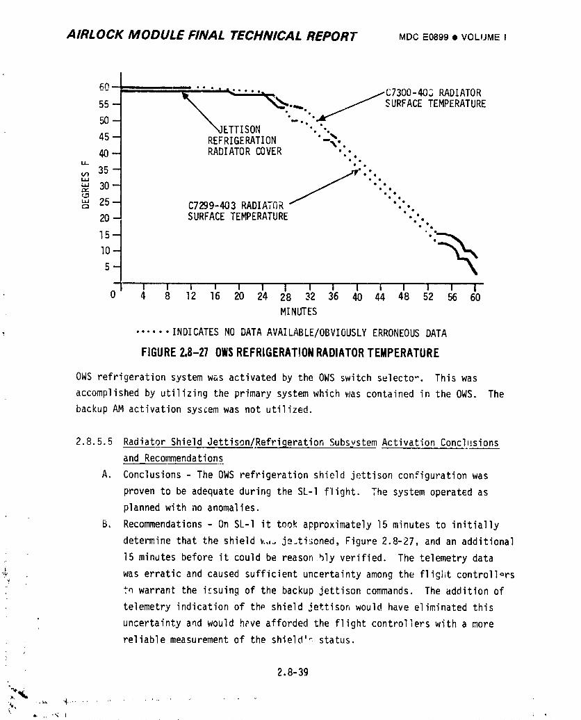
AIRLOCK MODULE FINAL TECHNICAL REPORT MDCE0899• VOLIJMEI
60....... I _ ..... C7300-403 RADIATOR
55-50- _ ETTISON _...,_._ _JS URFACETEMPERATURE..
45 --- REFRIGERATION "-_°,_40 -J RADIATOR COVER
m
_.,.,,,, as3o-' //"_": :: ".-.¢.,_ ° iIa,J 25-- • •Q C7299-403 RADIATiIR
".':20- SURFACE TEMPERATURE °.
15 - '.'_
10-
5-
i ,
I I I I I I I I I I I I I i I0 4 8 12 16 20 24 28 32 36 40 44 48 52 56 60
MINUTES
, ...... INDICATES NO DATA AVAILABLE/OBVIOUSLYERRONEOUS DATA
FIGURE2,8-27OWSREFRIGERATIONRADIATORTEMPERATURE
OWS refrigeration system w_s activated by the OWS switch selecto_. This was
accomplished by utilizing the primary system which was contained in the OWS. The
backup AM activation system was not utilized.
2.8.5.5 Radiator Shield Jettison/RefrigerationSubsystem Activation Concl,_sions
and Recommendations
A. Conclusions - The OWS refrigeration shield jettison configuration was
proven to be adequate during the SL-I flight. The system operated as
planned with no anomalies.
B, Recommendations- On SL-I it took approximately 15 minutes to initially
determine that the shield _,,_ je.tisoned, Figure 2.8-27, and an additional
15 minutes before it could be reason bly verified. The telemetry data
,_ was erratic and caused sufficient uncertainty among the flight controllorsv
tn warrant the i_suing of the backup jettison commands. The addition of
telemetry indication of th_ shield jettison would have eliminated this
uncertainty and would hPve afforded the flight controllers with a more
reliable measurement of the shield's status.
2.8-39
1974018208-580
AIRLOCK MODULE FINAL TECHNICAL REPORT MDCE0899• VOLUMEI
2.8.6 OWS Ventin9 Subsystem
The OWS was pressurized to aid in maintaining structural integrity during
the initial powered flight phase. As the ascent loads diminished the
pressurization loads were reduced by venting the Ow_ habitation area and the waste
tank. The depressurized habitation area allowed a controlled habitable atmosphere
to be added. The continuously vented waste tank allowe_ various waste products to
out,ass without pressurizing the tank. After the PCS usefullness had expired, the
pneumatic (GN2) sphere was depressurized. Automatic control of the vents was
provided except for the solenoid vent valves which had JSC flight controller
manual control capability only.
2.8.6.1 OWS Ventin9 Subsystem Design Requirements
The OWS habitation area and waste tank were pressurized to about 23 psia prior
to lift off to aid in maintaining structural integrity through launch and ascent.
The PCS actuated the vents used luring initial activation. The actuation control
modules in the PCS were controlled by the electrical system. One set of modules
when powered, opened the parallel habitation area vent valves. When power was
removed the vent valves closed. The waste tank in a similar fashion utilized the
PCS to open the waste tank vents. The vents once opened remained opened. The
final sequence in the PCS was to vent the GN2 pneumatic sphere. The electrical
system operated a pneumatic dump valve which depres_urized the sphere. The
solenoid vent valves, arranged in a series-parallelcombination and controlled by
the AM-CRDU, provided G backup habitation area _anting system during initial
activation and they provided the primary venting system after initial activation.
2.8.6.2 OWS Venting_Su_bsystemDescrip_tio__n
A. OWS Habitation Area Ve._ts- The IU/OWS switch selector system utilized
AM Bus power to control the PCS actuation cohtrol modules, Figure 2.8-28.
The open commands cycled the actuation control modules to allow the
pneumatic pressure to open the vent valves. Issuing the closed commands
"_ effected the removal of pneumatic pressure and the rlosure of the
valves. Parallel vent valves were used so both valves had to cycle to
stop venting. The crew had the capability of capplng thc vent if the
valves faileQ to close.
B. OWS Waste Tank Vents - The IU/OWS switch selector system utilized AM
Bus power to control the PCS actual:ioncontrol modules, Figure 2.8-29.
2.8 ',0
i(_ ' \,
J ,
1974018208-581
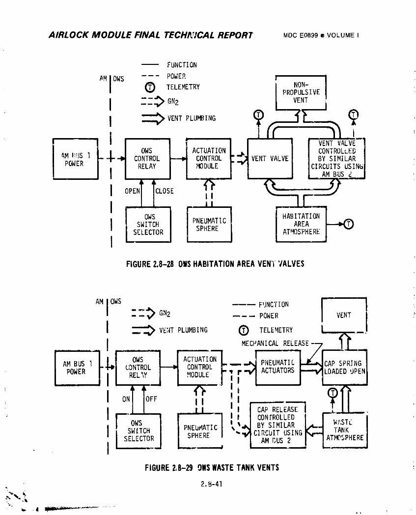
AIRLOCK MODULE FINAL TECH_VCAL REPORT MDCE0899• VOLUMEI
FUNCTION
I ---- POWER ! 1
#M OWSTELEMETRY NON-
PROPULSI VE
I : : _ GN2 VENT
il '
] I'll I _ t VENT VALVE
OWS ACTUATION CONTROLLEDAM_US 1 CONTROL CONTROL VENT VALVE BY SIMILARPOWER RELAY ,MODULE CIRCUITS USINLi
AM BUS ,)
I c,o II
I . ilOWS HABITATION
I SWITCH PNEUMATIC AREASELECTOR SPHERE ATMOSPHERE
IFIGURE2.8-28OWSHABITATIONAREAVEN_"VALVES
" -'_ GN2 POWER VENT II _ VENTPLUMBING 0 TELEMETRY / ___
MECHANICA!''R"'LEAISEj_
_. REL.",YJ I ,%DULEJ, ,ll:/r-I/1 ACTUATORSI!-_1_ LOADED['JPENII
ON OFF _ i I CAP RELEASE
I I -- I ! CONTROLLED r-_l._,..
F !W I _._ BY SIMILAR __.j w',o.L_,-" r TANK
I SWITCH I J AM r,US 2 " L TMOSPHERE. Ii SELECTO.RJ SPHERE I "ll CIR.blT USING {_ ]_
FIGURE2,8-299WSWASTETANKVENTS
2.B-41
1974018208-582
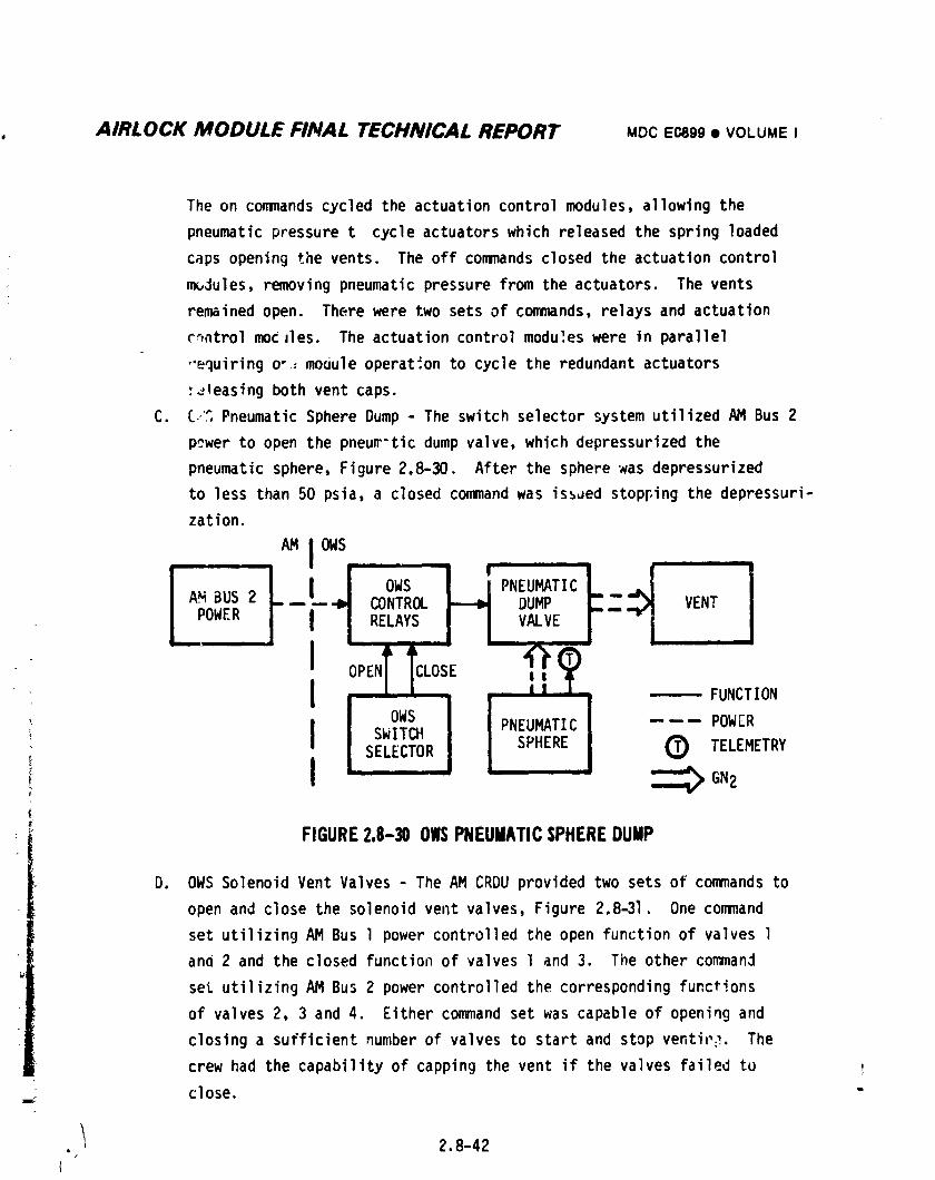
, AIRLOCK MODULE FINAL TECHNICAL REPORT MDCECJ)99• VOLUMEI
The on commandscycled the actuation control modules, allowing the
pneumatic pressure t cycle actuators which released the spring loaded
caps opening the vents. The off commandsclosed the actuation control
n_Jules, removing pneumatic pressure from the actuators. The vents
remained open. There were two sets of commands,relays and actuation
c_atrol moCJles. The actuation control moduleswere in parallel
.'equiring o-= mouule operation to cycle the redundant actuators
)Jleasing both vent caps.
C. 6,.'SPneumatic Sphere Dump- The switch selector system utilized AMBus 2
power to open the pneur-tic dumpvalve, which depressurized the
pneumatic sphere, Figure 2.8-30. After the sphere was depressurized
to less than 50 psia, a closed commandwas is_ded stopping the depressuri-
zation.
AMlOWS
OWS PNEUMATICAM BUS 2 -- _ CONTROL DUMP _.
POWER RELAYS, VALVEi
OPEN CLOS
I , , -------FUNCTIONB
I OWS I PNEUMATIC ------ POWER
SWITCH I
i SELECTOR SPHEREI o TELEMETRY
! _ GN2(
FIGURE2.8-30 OWSPNEUMATICSPHEREDUMP
D. OWSSolenoid Vent Valves - The AMCRDUprovided two sets of commandsto
open and close the solenoid vent valves, Figure 2,841. One command
set utilizingAM Bus 1 powercontrolledthe open functionof valvesl
and 2 and the closedfunctionof valvesl and 3. The other command
set utilizingAM Bus 2 powercontrolledthe correspondingfunctions
of valves2, 3 and 4. Eithercommandset was capableof openingand
closinga sufficientnumberof valvesto startand stopventit,_.The
crew had the capabilityof cappingthe vent if the valvesfailedto
__ close.
. I 2.8-42/
i9740i8208-583
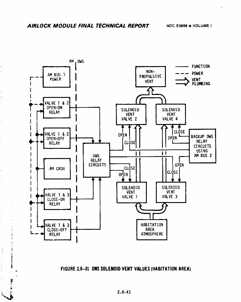
AIRLOCK MODULE FINAL TECHNICAL REPORT MDCE0899,_ VOLUMEI
t
AM OWS
i iil _, FUNCTION
NON- POWERAM BUS l PROPULSIVE
P -- POWER VENT! VENT PLUMBING
, iiI
jI, ' .... li SOLENOID SOLENOID
I RELAY I VENT VENTVALVE2 VALVE4
I 4VALVE I & 0 N N_SE BACKUPOWS
j OPEN-OFF,,,I ___J ElI o_k- &RELAY _ CL RELAYClRCUITSUSING
I I
i l OWS ] IsO:_NF'_AM BUS 2
CIRCUITS iI AM CRDU CLOSE
l _EN_ CLi I '
• l I ii _ _ so_o_o! ! so_o_o, VALVE I m VALVE3
_i-i-"_! ! II 'RELAY' II
, L,,I',,ALVE, &31 'I HABITATION
: : /CLOSE-OFF AREA• ATMOSPHERE
I FIGURE2.8-31 OIlSSOLENOIDVENTVALUES(HABITATIONAREA)Ik
_.,,_ 2.8.,3
1974018208-584
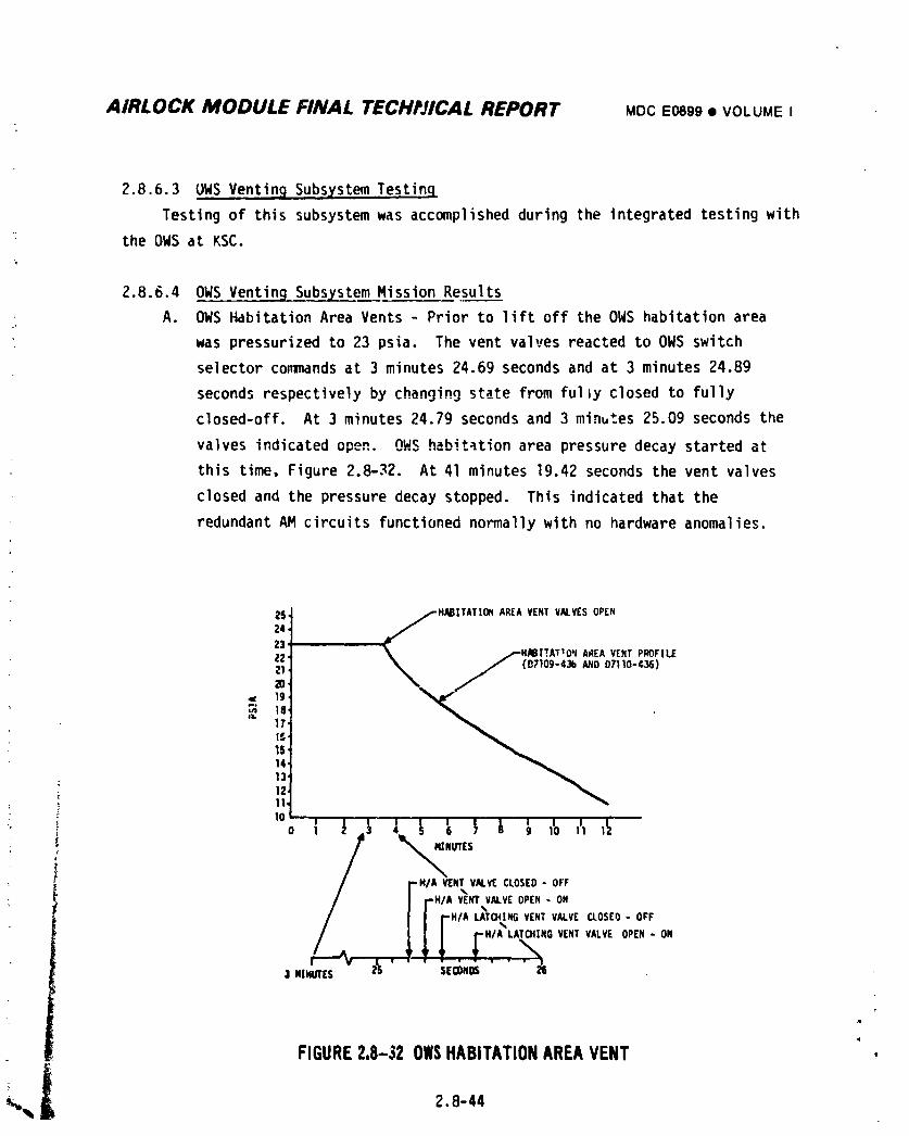
AIRLOCK MODULE FINAL TECHI'JICAL REPORT MDCE0899• VOLUMEI
2.8.6.3 UNS Venting Subsxstem Testinq
Testing of this subsystem was accomplished during the integrated testing with
the OWSat KSC.
2.8.6.4 OgS Venting Subsystem Mission Results
A. OWSHabitation Area Vents - Prior to lift off the OWShabitation area
was pressurized to 23 psia. The vent valves reacted to OWSswitch
selector commandsat 3 minutes 24.69 seconds and at 3 minutes 24.89
seconds respectively by changin9 state from fully closed to fully
closed-off. At 3 minutes 24.79 seconds and 3 minutes 25.09 seconds the
valves indicated opeR. OHS habitation area pressure decay started at
this time, Figure 2.8-32. At 41 minutes 19.42 seconds the vent valves
closed and the pressure decay stopped. This indicated that the
redundant AH circuits functioned normally with no hardware anomalies.
2S _HM|TATIOfl AREAVENTVALVESOPEN24Z3
21ZO,
:3 _s17'I_,15'14,13'12,11.
10 '' " i , I ill Itl _ .], I [ 5 } _ g 10
NUTES-HIA VENTVALVECLOSED- OFF
rWA vrmVALVrOPEN- ON/ r "/AUT_N_VE.TVALVEa0sEo- off
r";' °"'°'='_-' ' s=m'(-N--" " Z63 NINUTES
_r
FIGURE2.8-32 OWSHABITATIONAREAVENT
2.8-44
1974018208-585
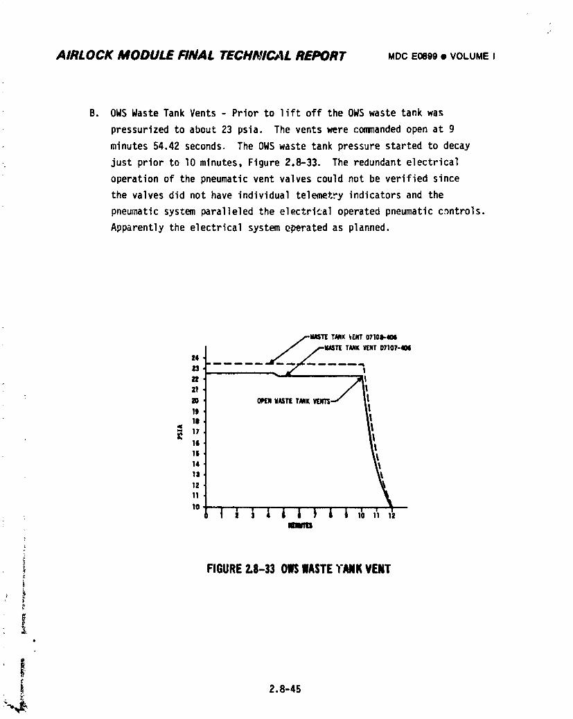
AIRLOCK MODULE FINAL TECHI_#C,4LREPORT MDCE0899• VOLUMEI
B. OWS WasteTank Vents- Priorto liftoff the OWS waste tank was
pressurizedto about23 psia. The ventswere commandedopen at g
minutes54.42seconds. The OWS waste tank pressurestartedto decay
just priorto lO minutes,Figure2.8-33. The redundantelectrical
operationof the pneumaticvent valvescouldnot be verifiedsince
the valvesdid not have individualtelemetryindicatorsand the
pneumaticsystemparalleledthe electricaloperatedpneumaticc)ntrols.
Apparentlythe electricalsystemoperatedas planned.
MASTTTANK_r(NT07108-404%IAST[TANKV[NTD7107-40it4
...... -77/---....
° _/,21
: 20 OPLrNWAS'lIETANK19lm
16 1
,,
1411
1111
)
)
SFIGURE2.8-33 OIlSIIASTETANKVENT
¢
• I.
!I 2.8-45
1974018208-586
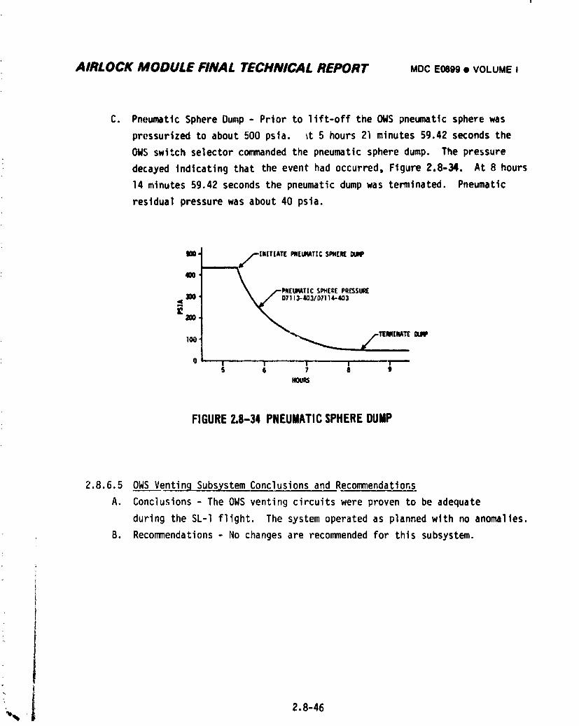
AIRLOCK MODULE FINAL TECHNICAL REPORT MDCE0899• VOLUMEI
C. PneumaticSphereDump - Prior to lift-offthe OWS pneumaticspherewas
pressurizedto about500 psla. _t5 hours21 minutes59.42secondsthe
OWS switchselectorcommandedthe pneumaticspheredump. The pressure
decayedindicatingthat the event had occurred,Figure2.8-34. At 8 hours
14 minutes59.42 secondsthe pneumaticdump was temlnat_. Pneumatic
residual pressure was about 40 psta.
mO, /--INIT|ATE PNEUIMTICSPHEREDU_K*
40O
\ _PNEUR_TIC SPHEREPRE3SuR(
300 _/ D7113-403/07114-403
x,.0 I I I i i
S 6 7 8 tHOURS
FIGURE2.8-34 PNEUMATICSPHEREDUMP
2.8.6.50WS VentinqSubsystemConclusionsand Recommendations
A. Conclusions- The OWS ventingcircuitswere provento be adequate
duringthe SL-Iflight. The systemoperatedas plannedwith no anomalies.
B. Recommendations- No changesare recommendedfor this subsystem.)
_,_ . 2.8-46
1974018208-587
AIRLOCK MODULE FINAL TECHNICAL REPORT .DC EO0_• VOLUUE0
2.8.7 OWS MeteoroidShieldDeploy_nt Sub_
Fhe purposeof deployingthe OWS_teorold shieldwas to reducethe
probabilityof micrometeoroldpenetrationof the OWS habitationarea. The shield
alsowas to providethermalprotectionfor the habitationarea. The AM electrical
sequentialsystemwas requiredto providea backupdeploymentcontrolsystemand
to provldepower for the primaryand backupdeploymentsystems. Automaticand
JSC fligntcontrollermanualoperatingcapabilitieswere includedin the design.
The AM hardwareutilizedin the designwas selectedfrom flightqualified
equipment.
2.8.7.1 OWS MeteoroidShieldDeploymentSubsystemDesignRequirements
The OWS meteoroidshielddeploymentcircuitdesignwas initiatedwhen the
earlymechanical/ordnancetrade()ffstudieswere completed. The IU/OWSswitch
selectorsystemwas chosento cyclean EBW firingunit/EBWdetonator/confined
detonatingfuse (CDF)which igniteda mild detonatingfuse (MDF)in an expandable
tube. This expandedtube shearedthe strapsand allowedthe preloadedtorsion
bars to rotateand deploythe shield. The AM CRDU had the capabilityof cycling
a separateEBW Firingunit,MDF and expandabletube to providea backupmethod
of shearingthe strapsand deployingthe shield.
2.8.7.20WS MeteoriodShieldDeploymentSubsystemDescription
The OWS meteoroidshielddeploymentcircuitutilizedSequentialBus 2 power
and the IU/OWSswitchselectorsystemto chargeand triggerthe primaryEBW firing
unit,Figure2.8-35. This actionresultedin the deploymentof the shield. A
backupmethodof deployingthe meteoroidshieldwas providedby using Sequential
Bus 1 powerand the AM CRDUcommandsystemto cycle the backupEBW firingunit.
2.8.7.30WS MeteoroidShieldDeploymentSubsystemTesting
Electricaltestingof thissubsystemwas accomplishedduringthe integrated
f testingwith the OWS at KSC.
o
2.8.7.40WS MeteoroidShield DeploymentSubsystem Mission Results
Approximately63 secondsafter llftoff, telemetryreadoutsindicatedthat
. the meteoroidshieldstructurefailedand the shleldwas tornaway from the OWS.
The primaryand backupdeploymentcommandswere issuedat 1 hour,36 minutes!
2.8-47
1974018208-588
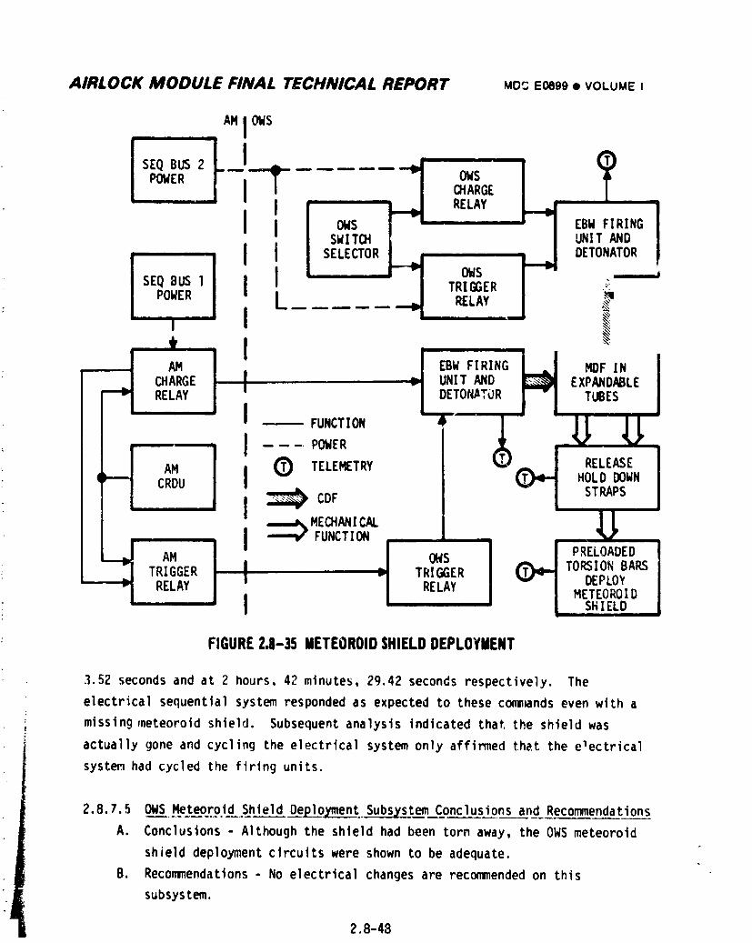
AIRLOCK MODULE FINAL TECHNICAL REPORT MO: EOegg• VOLUMEI
AM JOWS
SEQ BUS 2POWER OWS
CHARGE
0....!
8_I = I ows ,SEQ TRIGGER -"POWER I I
|
' I H iAM 1 EBW FIRING MDF IN
CHARGE UNIT AND EXPANDABLE
RELAY DETONATOR TUBESI
-- _u.c,,o,, • (_ _ _
FUNCTION
_ AMITRIGGER _ OIVSTRIGGER _ PRELOADED
I _ TORSIONBARS
RELAY I RELAY DEPLOYMETEOROIDI SHIELD
FIGURE2.8-35 METEOROIDSHIELDDEPLOYMENT
3.52secondsand at 2 hours,42 minutes,29.42secondsrespectively.The
electricalsequentialsystemrespondedas expectedto thesecommandsevenwith a
missingmeteoroidshield. Subsequentanalysisindicatedthatthe shieldwas
actuallygone and cyclingthe electrlcalsystemonly affirmedthat the electrical
systemhad cycledthe firingunits.
2.8.7.50WS MeteoroidShieldDep_Lo___q.nt_stemConclusionsand Recommendations
A. Concluslons- Althoughthe shleldhad been torn away, the OWS meteoroid
shielddeploymentcircuitswere shownto be adequate.
B. Recommendations- No electricalchangesare recommendedon this
subsystem.
2.8-48
1974018208-589
AIRLOCK MODULE FINAL TECHNICAL REPORT MDCEOeg9• VOLUMEI
2.8.80WS SASDeplojcmentSubsystem
The OWSsolar array system (SAS) was folded and stored on _ppostte st_es of
the OWS exteriorduringascent. The SAS consistedof two wing assemblieswhich
unfoldedupon receivingautomaticor JSC flightcontrollerbackupcommands. The
OWS SAS was the power sourcefor the AM electricalpower system(EPS),Section
2.7. The AM hardwareutilizedin thedesignwas selectedfrom flightqualified
equipment.
2.8.8.1 OWSSASDeployment SubsystemDesign Requirements
The Initialmechanical/ordnancetradeoff studiesresultedin OWS mounting
of the SAS usingan EBW ordnancesystemfor initiatingdeployment.The firstof
two sequentialeventsrequiredfor OWS SAS deploymentwas the releaseof the beam
fairingswhich protectedth_ solararraysduringascentand separation.The
electricalsequentialsystemcycledan EBW firingunitwhich detonatedan EBW
detonator,and causeda confineddetonatingfuse (CDF)to burn resultinqin the
ignitingof a milddetonatingfuse (MDF). As it burned,the MDF causedthe tube
in which itwas containedto expandand shear the beamfairingholddown straps.
Preloadedspringsin the hingejointscausddthe beamfalrlngsto rotateto the
deployedposition(go degreesfrom the X axis). The secondevent - releasingthe
foldedsolarwings - usedan ordnancesystemsimilarto the one described
aboveexceptthat tensionstrapswereemployedin placeof the holddown straps.
Preloadedspringsin the hingejointscausedthe wingsto deploy. The IU/OWS
switchselectorsystemwas designatedas the primarycommandsystemwith the AM
CRDU providingthe backupcommands.
2.8.8.20WS SAS Oeplo)mentSubsxstemDescription
The OWS beamfairingdeploymentcircuitsutilizedDeployBus 2 powerand the
IU/OWSswitchselectorsystemto chargeand triggerthe primaryEBW firingunit,
Figure2.8-36. Thiscombinedactionresultedin the deploymentof the OWS beam
fairings. A backupmethodof deployment,usingDeployBus 1 powerand the AM CRDU
i commandsystemto cycle the backupEBW firingunit,was alsoavailable. The
' ) . OWS wing deploymentcircuitcycledthe primarywing EBW firingulit ordnance,
Figure2.8-37,in a fashionsimilarto the beam fairingdeploymentcircuit. In
, thiscase, however,the beamfairingtriggerrelayactedas an i,lterlockto
preventthe wings from beingreleasedpriorto the beam fairingdeployment.
1974018208-590
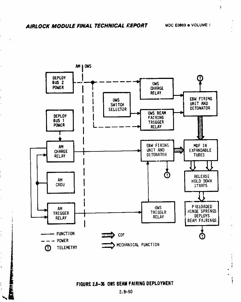
AIRLOCK MODULE FINAL TECHNICAL REPORT MDCE0699• VOLUMEI
_ AMI OWS
I IBUS2 --" OWS IPOWER aiARGE I
RELAY____ EBWuNITFIRINGAND
DEPLOY FAIRING I "BUS1 TRIGGER IPOWER RELAY |
u " I* I
__ AM EBW FIRING MDF IN
CHARGE l UNIT AND EXPANDABLERELAY I DETONATOR TUBES
I
- I _s_AM
( CRDU I HOLD DOWN3TRAPS
I
' TRIGGER I TRIGGER I HINGESPRINGS
i RELAY I RELAY _ DEPLOYSI /BEA'_IFAIRINGS
------FUNCTION CDF
---- POWER
(_ TELEMETRY _ MECHANICALFUNCTION
FIGURE2,8-36 OW_;BEAMFAIRINGDEPLOYMENT
2.8-50
1974018208-591
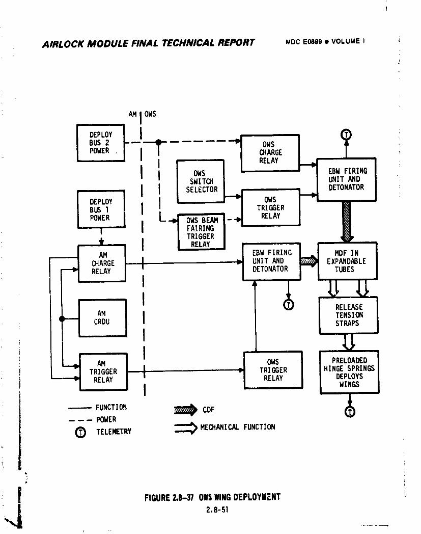
AIRLOCK MODULE FINAL TECHNICAL REPORT MOCEO89g• VOLUMEI
AMJOWS
I..o.t,BUS 2 ...... OWSCHARGE
POWER J i RELAY
J J OWS EBW FIRINGSWITCH UNIT AND
I I SELECTOR DETONATOR ,
DEPLOY I J OWS
BUSI J TRIGGER
POWER L-,l OWS BEAN i- RELAYI J FAIRING J
I TRIGGER Je J RELAY •
AM EBW FIRING MDF IN
CHARGE , | UNIT AND EXPANDABLERELAY I DETONATOR TUBES
I
AMCRDU I TENSIONSTRAPS
- I
i' I IAM OWS PRELOADED
TRIGGER I _ TRIGGER HINGESPRINGS• I RELAY RELAY DEPLOYS
j WINGS
----- FUNCTION _ CDF---- POWER
O TELEMETRY _ MECHANICALFUNCTION
Ii
_J FIGURE2.8-37 OWSWINGDEPLOYMENT
2.8-51
1974018208-592
AIRLOCK MODULE FINAL TECHNICAL REPORT MDCEosgg• VOLUMEI
The AMCPDUbypassed the beamfairing Interlock and provided backupwing deployment
commands.
2.8.8.30WS SASDeploymentSubsystemTesting
Electrical testing of this subsystemwas accomplishedduring the integrated
testingwiththe OWS at KSC.
2.8.8.40WS SASDeployment SubsystemMission ResultsDuring the ascent phase of the flight the OWSmeteoroid shield was torn off.
This causedthe OWS beam fairingnumber2 holddown strapsto breakand thusfree
the beam fairingwhich was forcedto deployduringretro rocketfiringduring
stage II separation.The beam fairingevidentlyrotatedto the deployedposition
with a forcethatwas sufficientto shear the hingejoint and tear the beam
fairingoff. When the meteoroidshieldtore off,a pieceof the shieldstructure
embeddedintobeam fairingnumber1 preventingit fromdeploying. The primary
OWS SAS beam fairingand OWS wingdeploymentcommandswere issuedat 41 minutes,
5.32 secondsand at 51 minutes59.._2secondsrespectively.At 55 minutes59.42
secondstelemetryindicationsshowedthatthe holddownsreleased. Due to thet
restrictionof the meteoroidshieldstructure,fullbeam fairingdeploymentwas
not obtained. The AM CRDU backupOWS SAS beam fairingand OWS wing deployment
commandswere issuedat l hour38 minutes21.42 secondsand at I hcr 50 minutes
55.42 secondsrespectively.The backupsystemreleasedthe wings but was still
unsuccessful;ndeployingthe beamfairing. The cyclingof the primaryand
back,,psystemsdid provethat the electricalsequentialsystemfunctionedas
plannedwith no hardwarefailures. The SL-2crew performeda standup extra-
vehiclaractivity(SEVA)from the CSM to deploybeamfairingnumber1. This
attemptwas also unsuccessful.Twentyfourdays after SL-I liftoff,the SL-2 crew .
performedan EVA and successfullydeployedthe beam fairing. Subsequentlybeam
i fairingNo. 1 wingswere fullydeployeo°i!
i ..8.8.5 OWS SAS DeploymentSubsystemConclusionsand RecommendationsA. Conclusions- The OWS SAS electricaldeploymentcircuitsfunctionedas
I plannedduringthe SL-I flightwith no anomalies.
I B. Recommenaations- No changeto tileelectricaldesignis recommended. • :
• t
28-s2
1974018208-593
AIRLOCK MODULE FINAL TECHNICAL REPORT MDCEO89e_ VOLUMEI
2.8.9 ATM SAS Deployment/CanisterReleaseSubsystem
The ATM solararray system(SAS)and the ATM canisterwere restrainedto
protectthemfrom the structuralloadinggeneratedduringthe poweredflight
phaseand the deploymentof the ATM. After the ATM deploymentwas complete,the
ATM SAS was deployed,providingthe powersourcefor the ATM electricalpower
system. The SAS deploymentcircuitsalso releasedthe canister. Automaticand
JSC flightcontrollermanualoperatingcapabilitieswere includedin the
requirement.
2.8.9.1 ATM SAS Deployment/CanisterReleaseSubsystemDesignRequirements
The ATM SAS deploymentinitiallyusedthe IIJ/OWSswitchselectorsystem
to providea decinchingfunctionto releasethe wings and a motor control
functionto deploythe wings. The declnchingfunctionutilizedEBW firing
unitsand detonatorsto igniteCDF's. The CDF's igniteJpressurecartridges-
actuatingthe thrusterassemblies- resultingin the rotationof torquetubes
allowingballend rods to slip out of key holeslots in the torquetubes. This
actionfreed thewings. The deploymentmotorswere cycledon and the wings
whichwere foldedin scissorsstyle,were pushedout as the motorsreeledin
cablesclosingthe scissorsmechanisms. When the wings reachedtheirfully
deployedposition,the latchessecuredthe wingsand the limitswitchesturned
the motorsoff. The AM CRDU was availableas a backupcommandsystem. An
inhibitcircuitwas added to the automaticsystemto preventSAS deployment
beforethe ATM was fullydeployed. Isolationrelayswere added to the AM CRDU
circuits. A launchpad monitorwas added to indicateinadvertentarmingof
the ATM EBW circuits. An AM CRDU commandinhibitcircuitwas added to prevent
ignitingthe ATM ordnanceon the launchpad. The ATM canisterreleasefunction
was paralleledoff the ATM SAS decinchingrelaycircuits.
! 2.8.9.2 ATM SAS De_loyment/Cani.sterReleaseSubsystemDescription
i The ATM deploymentlimitswitches,section2.8.2.2,sensedfulldeploymentof the ATM and latchedin the SAS enablerelays. These relaysappliedDeploy
I Bus powerto the OWS relaysin the IU/OWSswitchselectorcommandsystem,
_ Figure2.8-38. The switchselectorcommands,Figure2.8-39l,chargedand
triggeredthe SAS decinchingand canisterreleaseEBW firingunits. This
• " actionfreed the wings and releasedthe canister. Subsequentcommandsenergized
2.8-53
1974018208-594
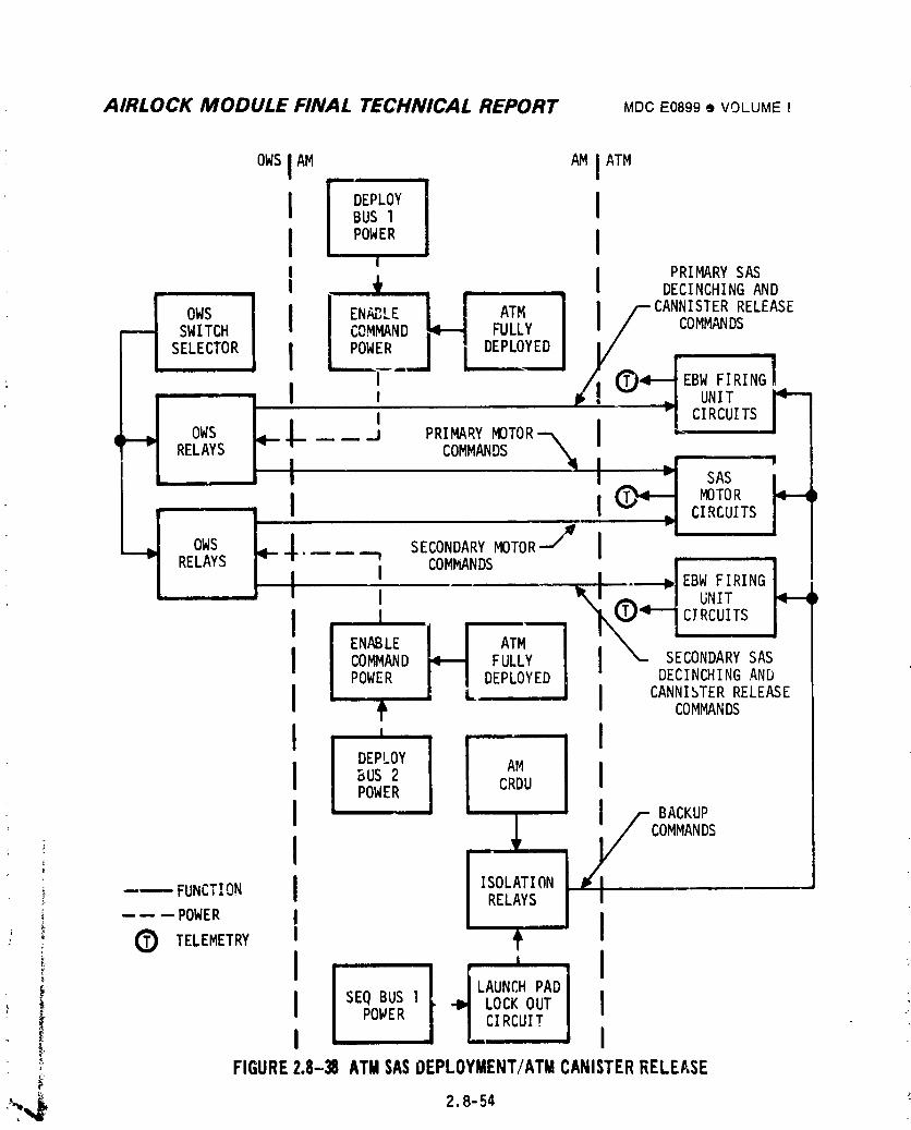
AIRLOCK MODULE FINAL TECHNICAL REPORT MDCE0899• VOLUMEI
OWSIAM AM IATM
I DEPLOY IBUS 1
II PRIMARYSAS
, I _{ ..... DECINCHINGAND
40WS I ENABLE I I ATM f CANNISTERRELEASEsWITCH COMMAND"_ DEPLOYEDFULLY COMMANDS
s i J i '...... / _,_z_'_°1RELAYS COMMANDS
I I ._rMOTOR
I I . CIRCUITS
OWS SECONDARYMOTORJ I
RELAYS I ' _4 "F
I COMMANDSm_ EBW FIRING
i UNIT
II ! CIRCUITS
ENABLE I I ATMCOMMAND _ FULLY SECONDARYSAS
DECI I ANDPOWER _ LDEPLOYED NCH NG
I ,_ I CANNISTERcoMMANDsRELEASE
I ' IDEPLOY AMI _0s_ IPOWER CRDU
I L/,,-_u_COMMANDS
;_ RELAYS-- -- -- POWER I
L i Lc (_) TELEMETRY
/ LAUNCHPAD)i I SEQBUS1 -I_ LOCKOUT I_o_, LC,_CU,:' I I!, FIGURE2.8-38 ATMSASOEPLOYMENT/ATMCANISTERRELEASE
1974018208-595
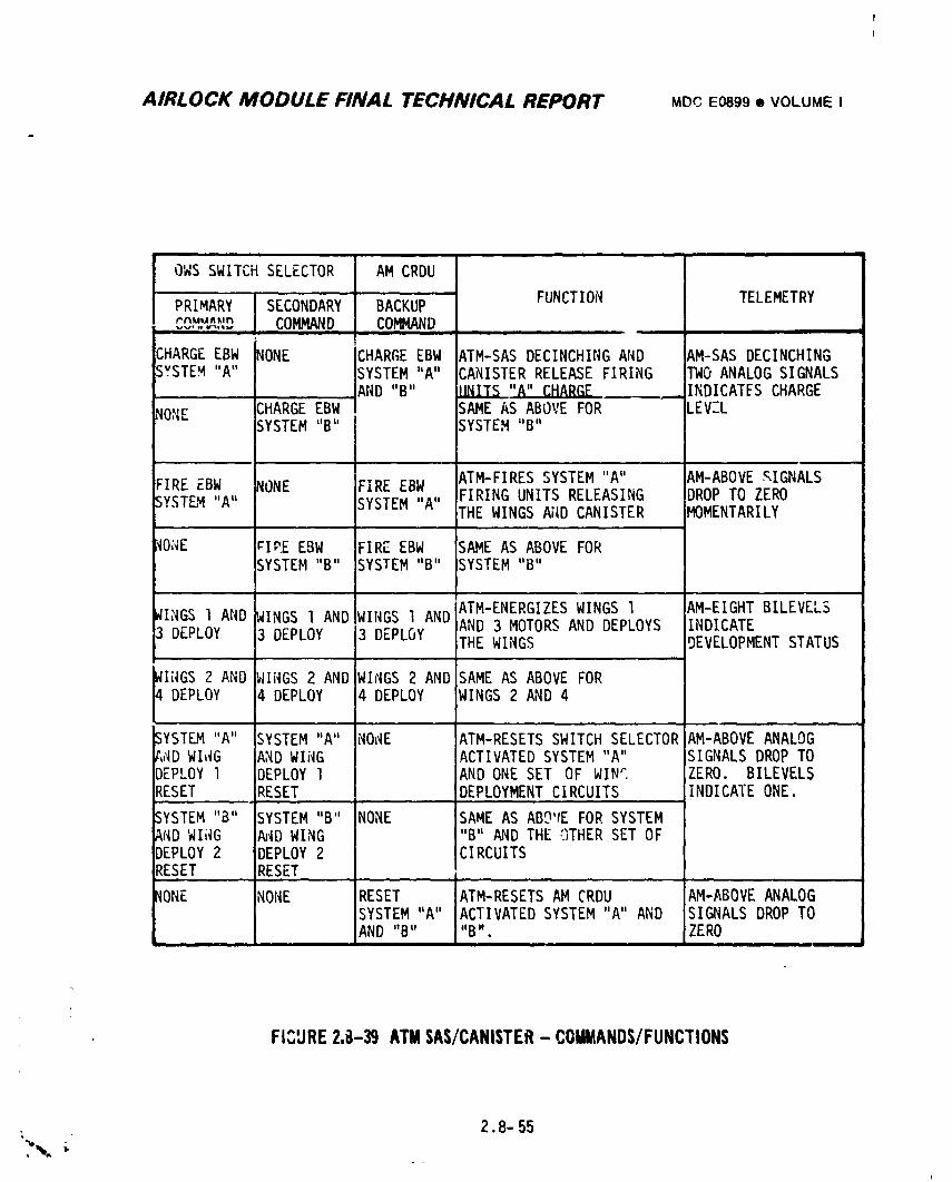
AIRLOCK MODULE FINAL TECHNICAL REPORT MDCE0899• VOLUMEI
OWS SWITCHSELECTOR AM CRDU
PRIMARY SECONDARY BACKUP FUNCTION TELEMETRYrnuun_,n... COMMAND COI_MAND
ml
CHARGEEBW _ONE CHARGEEBW ATM-SASDECINCHINGAND AM-SASDECINCHINGSYSTEM"A" SYSTEM"A" iCANISTERRELEASEFIRING TWO ANALOGSIGNALS.... _ND "B" UNITS "_" CHARGE .INDICATFSCHARGE
NO_|E _HARGEEBW SAME AS ABOVE FOR LEVELSYSTEM"B" SYSTEM"B"
FIREEBW WONE FIREEBW ATM-FIRESSYSTEM"A" AM-ABOVE_IGNALSSYSTEM"A" SYSTEM"A" FIRINGUNITSRELEASING DROPTO ZERO
THE WINGS AIIDCANISTER MOMENTARILY
_O;,_E rlP.EEBW FIREEBW SAMEAS ABOVE FORSYSTEM"B" SYSTEM"B" SYSTEM"B"
ATM-ENERGIZESWINGS l AM-EIGHTBILEVELS_I_GSl AND ,_INGSl AND WINGS l AND AND 3 MOTORSAND DEPLOYS INDICATE3 DEPLOY 3 DEPLOY 3 DEPLOY THE WINGS DEVELOPMENTSTATUS
_Ii_GS2 AND IWINGS2 AND WIs_IGS2 AND SAME AS ABOVE FOR4 DEPLOY 4 DEPLOY 4 DEPLOY WINGS 2 AND 4
SYSTEM"A" SYSTEM"A" NOI,_E ATM-RESETSSWITCHSELECTORAM-ABOVEANALOGt,,'_DWII_G AND WIi'_G ACTIVATEDSYSTEM"A" SIGNALSDROPTO" ID,-P.OYl DEPLOYl AND ONE SET OF WIN'. ZERO. BILEVELSRESET RESET DEPLOYMENTCIRCUITS INDICATEONE.
SYSTEM"B" SYSTEM"B" NONE SAME AS ABO'tEFOR SYSTEMAND WIi_G AND WING "B" AND THE ,'.)THERSET OFDEPLOY2 DEPLOY2 CIRCUITSRESET RESET
_IONE NONE RESET ATM-RESETSAM CRDU AM-ABOVEANALOGSYSTEM"A°' ACTIVATEDSYSTEM"A" AND SIGNALSDROPTOAND "B" "B". ZERO
FICURE2,z}-39ATMSAS/CANISTER- COMMANDS/FUNCTIONS
2.8-55
I
1974018208-596
AIRLOCK MODULE FINAL TECHNICAL REPORT MDCE0899• VOLUMEI
the motor circuits which deployed the SAS wings, lhe AM CRDU bypassed the ATM
deployment limit switches and provided backup commands for decinching, release
and deployment functions.L
2.8.9.3 ATM SAS Deployment/CanisterRelease Subsystem Testing
Electrical testing of this subsystem was accomplished during the
integrated testing with the ATM at KSC.
2.8.9.4 ATM SAS Deployment/CanisterRelease Subsystem Mission Results
At 24 minutes, 48.42 seconds the command sequence was initiated resulting
ir,the decinching of the SAS, release of the canister and deployment of the
wings. The system operated as planned with no hardware failures. The AM CRDU
backup command system was not utilized.
2.8.9.5 ATM SAS Deployment/CanisterRelease Subsystem Conclusions &
Recommendations
A. Conclusions - The ATM SAS deployment and canister release circuits were
proven to be adequate during the SL-| flight. The system,operated as
planned with no failures.
B. Recommendations - No electrical changes are recommended on this
subsystem.
_% 2.8-56I
1974018208-597
AIRLOCK MODULE FINAL TECHNICAL REPORT MDCE0899• VOLUMEI
. 2.8.10 ATM ActivationSubsJfstem
ATM activationcircuitswere to initiallyactivatevariousATM systems,
and after activation,providecontrolof selectedATM functions. The sequential
systemwas requiredto operatein conjunctionwith the IU/OWSswitchselector
system,the AM CRDU and the AM power system. Automaticand JSC flightcontroller
manualoperatingcapabilitieswere includedin the requirement.The hardware
utilizedin the designwas selectedfromflightqualifiedequipment.
2.8.10.1 ATM ActivationSubsystemDesignRequirements
Initiallythe IllswitchselectorutilizingIU powerwas to providethe ATM
activationcommandswith the AM providinginterconnectingcircuitsbetweenthe
IU and ATM. At completionof the early electrical/commandsystemtradeoff
studies,thisdesignwas alteredto utilizeAM powerwith the IU/OWSswitch
selectorsystemfor ATM activation.The AM CRDU was selectedas a backup
commandsourceand the isolationrelayswere added to providea greatercommand
arivingcapabilityfor the CRDU commands.
2.8.10.2 ATM ActivationSubsystemDescriptign
Figure 2.8-40 Identifies the functions supplied by the sequential system
forATM activationand control. The IU/OWSswitchselectorsystem,Figure
2.82, was utilized except the AMprovided an interconnecting circuit between
the OWS and ATM so thatcommandswere transfereddirectlyto the ATM. This
system provided the primary and secondary activation commands. The AMCRDU
providedbackupactivationand controlcommandsfor the ATM, Figure2.8-41.
L
. 2.8.10.3 ATM ActivationSubsystemTesting
F1ectricaltestingof thissubsystemwas accomplishedduringthe integrated5v
; testingwith the ATM at KSC.
! 2.8,10.4 ATM ActivationSubsystemMissionResultsJ
The command/sequentialsystem performedas expectedprovidingselectedATM
controlfunctions.
Y
2.8-s7
1974018208-598
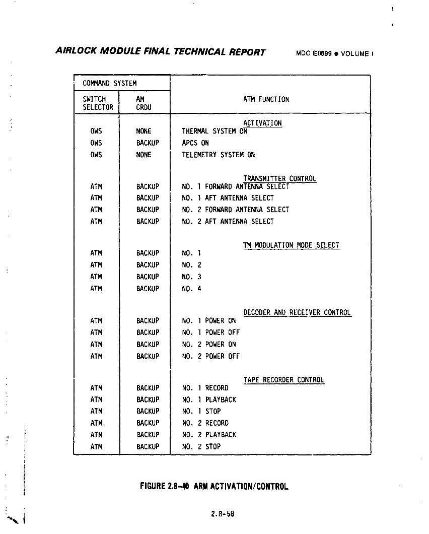
AIRLOCK MODULE FINAL TECHNICAL REPORT MDCE0899,VOLUMEI
I COMI_NDSYSTEM
SWITCH AM ATM FUNCTIONSELECTOR CRDU
" ACTIVATIONOWS NONE THERMALSYSTEMON
OWS BACKUP APCS ON
OWS NONE TELEMETRYSYSTEMON
TRANSMITTERCONTROLATM BACKUP NO. l FORWARDANTENNASELECt
ATM BACKUP NO. I AFT ANTENNASELECT
ATM BACKUP NO. 2 FORWARDANTENNASELECT
ATM BACKUP NO. 2 AFT ANTENNASELECT
TM MODULATIONMODE SELECTATM BACKUP NO. l
ATM BACKUP NO. 2i
ATM BACKUP NO. 3
ATM BACKUP NO. 4
DECODERAND RECEIVERCONTROLATM BACKUP NO. l POWERON
ATM BACKUP NO. l POWEROFF
ATM BACKUP NO. 2 POWERON
ATM BACKUP NO. 2 POWEROFF
TAPE RECORDERCONTROLATM BACKUP NO. I RECORD
ATM BACKUP NO. I PLAYBACK
ATM BACKUP NO. I STOP
ATM BACKUP NO. 2 RECORD
ATM BACKUP NO. 2 PLAYBACK
' ATM BACKUP NO, 2 STOP
FIGURE2.8-40ARMACTIVATION/CONTROL
2.8-8
1974018208-599
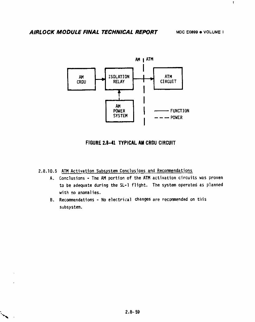
AIRLOCK MODULE FINAL TECHNICAL REPORT MDCE0899• VOLUMEI
IATM
AM ISOLATION ATM
CRDU RELAY CIRCUIT
[' liPOWER -- FUNCTION
SYSTEM -----POWER
FIGURE2.8-41 TYPICAL AMCRDUCIRCUIT
2.8.10.5 ATM ActivationSubsystemConclusionsand Recommendations
A. Conclusions- The AM portionof the ATM activationcircuitswas proven
to be adequateduringthe SL-I flight. The systemoperatedas planned
with no anomalies.
B. Recommendations- No electricalchangesare recommendedon this
subsystem.
_. 2.8- 59
1974018208-600
AltfLOCK MODULE FINAL TECHNICAL REPORT MDCE0899• VOLUMEI
2.8.11 MDA Ventin9 Subsystem
MDA venting was required in order to dump the AM/MDA atmosphere in flight
so a controlled oxygen/nitrogengas mixture could be added before crew arrival.
The electrical sequential system provided MDA vent valve control using the OWS
switch selector zommand and AM power systems. JSC flight controllers had a
partial backup capability by utilizing the IU CCS to re-issue switch selector
commands.
2.8.11.1 MDA Venting Subsystem Design Requirements
Initially the venting of the MDA was to be accomplished by launchinq
with the vent valves closed and then opening the valves after lift-off.
The valves were in parallel to assure venting. When the pressure decayed to
an acceptable level the valves were to be closed. The OWS switch selector
provided primary commands to control the valves with AM CRDU providing backup
commands. Later the operational procedure was changed to open the valves
prior to lift-off via AM CRDU with the switch selector commanding the valves
closed after the pressure decayed to an acceptable level. This operational mode
required both valves to close to preclude a hard vacuum in the AM/MDA.
Subsequent redesign put tF_ valves in series with the valves being opened and
verified before lift-off. This configuration required only one of the redundant
switch selector commands to cycle one valve in flight to terminate venting. The
AM CRDU commands were deleted.
2.8.11.2 MDA Ventinq Subsystem Descriptlon
The commands, Figure 2.8-42, for controlling the AM relays originated frot_
tl,(OWS switch selector. The switch selector issued these momentary commands to
latch in OWS relays. These relays provided continuous commands to energize AM
relays, using AM power, to cycle the MDA vent valves, Figure 2.8-43. The OWS
and AM relay circuits were configured so that two commands were required to
initiate the cycling of the valves. The MDA vent valves remained closed during
launch pad operations to reduce the probability of contaminating the AM/MDA
atmosphere. Just before lift-off the valves were commanded open to a11ow
venting during ascent. An electrical solenoid in the valve released a mechanical
brake a11owing the motor to run and cycle the valve. When the cycle was
completed limit switches removed power from the solenoid applying the brake
_%. ; 2.8-60
i
1974018208-601
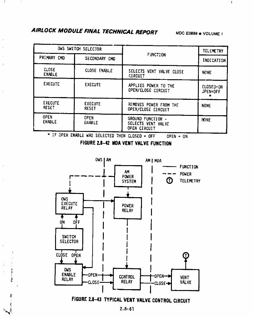
AIRLOCK MODULE FINAL TECHNICAL REPORT MDCE089S• VOLUMEO
OWS SWITCHSELECTOR TELEMETRY...... FUNCTIONPRIMARYCMD SECONDARYCMD INDICATION
-- l Jli
CLOSE CLOSEENABLE SELECTSVENT VALVECLOSE NONEENABLE CIRCUIT
I I
EXECUTE EXECUTE APPLIESPOWERTO THE CLOSED=ONOPEN/CLOSECIRCUIT JPEN=OFF
I •
EXECUTE EXECUTE REMOVESPOWERFROMTHE NONERESET RESET OPEN/CLOSECIRCUIT
I Iiii • I
OPEN OPEN GROUNDFUNCTION- NONEENABLE ENABLE SELECTSVENT VALVE
OPEN CIRCUITIi . , III
* IFOPEN ENABLEWAS SELECTEDTHEN CLOSED= OFF OPEN= ON
FIGURE2.8-42MDAVENTVALVEFUNCTION
OWSlAM AM IMDA FUNCTION
LI AM I ----- POWERF .... "I POWERI I I SYSTEM I 0 TELEMETRY
1i '.... POWER J
RELAY I
ON OFF I JI
I,,ows
_- ENABLE OPEN_ CONTROL VENT
RELAY S RELAY VALVE
• I m. I
FIGURE2.8--43TYPICALVENTVALVECONTROLCIRCUIT
_ 2.8-61
1974018208-602
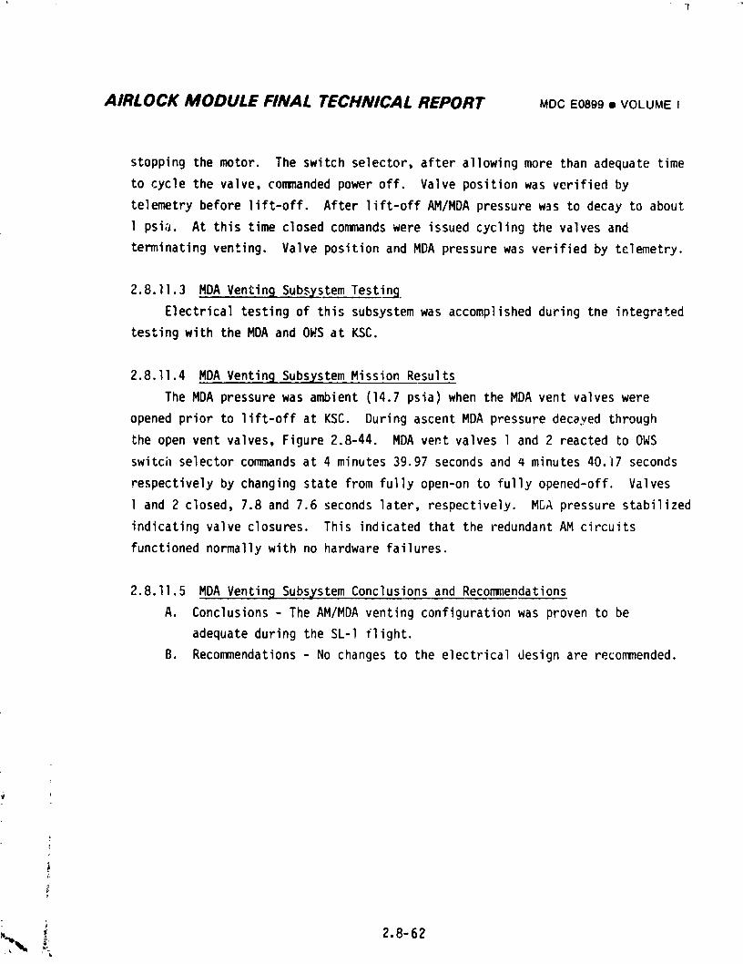
AIRLOCK MODULE FINAL TECHNICAL REPORT MDCE0899• VOLUMEt
stopping the motor. The switch selector, after allowing more than adequate time
to cycle the valve, commanded power off. Valve position was verified by
telemetry before lift-off. After lift-off AM/MDA pressure was to decay to about
I psia. At this time closed commands were issued cycling the valves and
terminating venting. Valve position and MDA pressure was verified by telemetry.
2.8.11.3 MDA Venting SubsysteETesting
Electrical testing of this subsystem was accomplished during the integrated
testing with the MDA and OWS at KSC.
2.8.11.4 MDA Venting Subsystem Mission Results
The MDA pressure was ambient (14.7 psia) when the MDA vent valves were
opened prior to lift-off at KSC. During ascent MDA pressure decayed through
the open vent valves, Figure 2.8-44. MDA vent valves 1 and 2 reacted to OWS
switch selector commands at 4 minutes 39.97 seconds and 4 minutes 40.17 seconds
respectively by changing state from fully open-on to fully opened-off. Valves
1 and 2 closed, 7.8 and 7.6 seconds later, respectively. MSA pressure stabilized
indicatingvalve closures. This indicated that the redundant AM circuits
functioned normally with no hardware failures.
2.8.11.5 MDA Ventin9 Subsystem Conclusions and Recommendations
A. Conclusions - The AM/MDA venting configuration was proven to be
adequate during the SL-I flight.
B. Recommendations - No changes to the electrical design are recommended.
2.8-62
1974018208-603
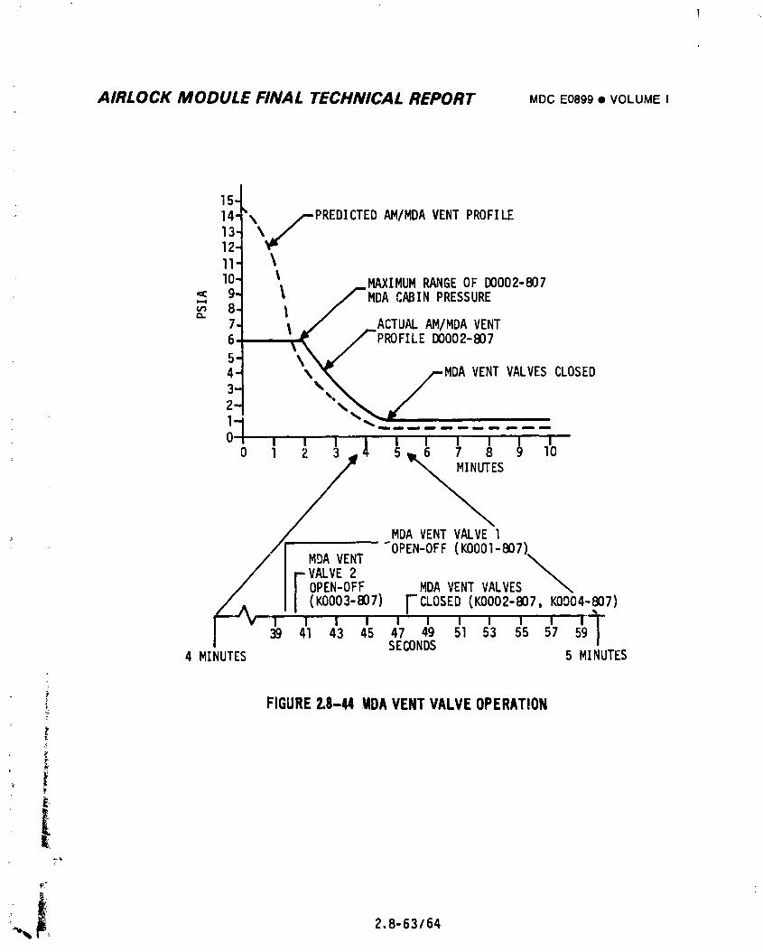
AIRLOCK MODULE FINAL TECHNICAL REPORT MDCE0899• VOLUMEI
15-
,: 14-'\ _PREDICTED AM/MDAVENT PROFILE13- \,,/12-11- \
I
lO- l MAXIMUMRANGEOF D0002-807
_ _" l fMDA CABINPRESSURE-7,, • _ ACTUALAM/MDAVENT
I,_" / PROFILEI)0002-807
45"- \\ MDA VENT VALVESCLOSED3-2-
l..,m ,m_ i Immm ,m _im m i Imm ,ImIb emlm Imm,
' I I I I I "0 I I _ _p6 7 8 9 lO
oiMDA VENTVALVEl
/ MDA VENT
vA,vE F
OPEN-OFF MDAVENTVALVES
(I(0003-807) CLOSED(K0002-_7, KOOO4-p7)m m i W m m m m i" m m41 43 45 47 49 51 53 55 57 59 l
4 MINUTES SECONDS 5 MINUTES
FIGURE2.8-44 MDAVENTVALVEOPERATION
t
_: °
-°_,,_ ,, 2.8-63/64
1974018208-604
!
AIRLOCK MODULE FINAL TECHNICAL REPORT MDCEO89g• VOLUMEI
2.9 INSTRUMENTATIONSYSTEM
The initial Saturn Workshop InstrumentationSystem utilized Gemini Program
hardware. It was expanded to Its present form during the change from the wet to
dry workshop concept. This expansion resulted in equipment modifications,
additional hardware, relocation of components and accommodation of MDA, OWS, and
selected ATM measurements by this system. Subsequent design changes during the
proQram only added selected sensors. The final system consisted of:
i Sensors/Signal Conditioners
e Regulated Power Converters
o PCM Multiplexers/Programmer/InterfaceBox
e T_pe Recorder/Reproducers
This equipment was used to sense, condition, multiplex and encode vehicle systems,
exDeriment and biomedical data for downlink to the Spaceflight Tracking and Data
Network (STDN). Telemetry data was backed up by selected crew displays and by PCM
hardline capability for prelaunch checkout. Real time data was supplemented from
on-board recordings played back for downlink in delayed time. A totaI of I07F
tele_letrychannels, 566 in the AN, lO in the ATM, 416 in the OWS, and 84 in the
MDA, were monitored by this system. Figure 2.9-I depicts the system in block
diagram form.
2.9.1 Design Requirements
The prime requirementsof the InstrumentationSystem were to acquire, multiplex
and enco(;¢_ata from the AM, OWS, and MDA and to provide the data as follows:
• Via telemeLry for real time coverage.
• Via tape recordings _er continuous coverage.
• Via panel displays for crewmen.
• Via h3rdline for prelaunch operation.
Some of these requirementswere established during the course of the design
proqram; all were implemented prior to test and delivery of the AM. Detailed
requirements, specific to equipment design ard performance are defined where
applicable in the system description section. No equipment requirements imposed
_ upon the equipment vendors are discussed except where necessary to describe the
equipment or its function. Specific requirements governing system design, operation,. use, and documer.'_tionincluded the following:
• Make maximum use of existing flight qualifled l_ardware.
• Make r,_aximumuse of co_on equipment between vehicles.
2.9-I
1974018208-605
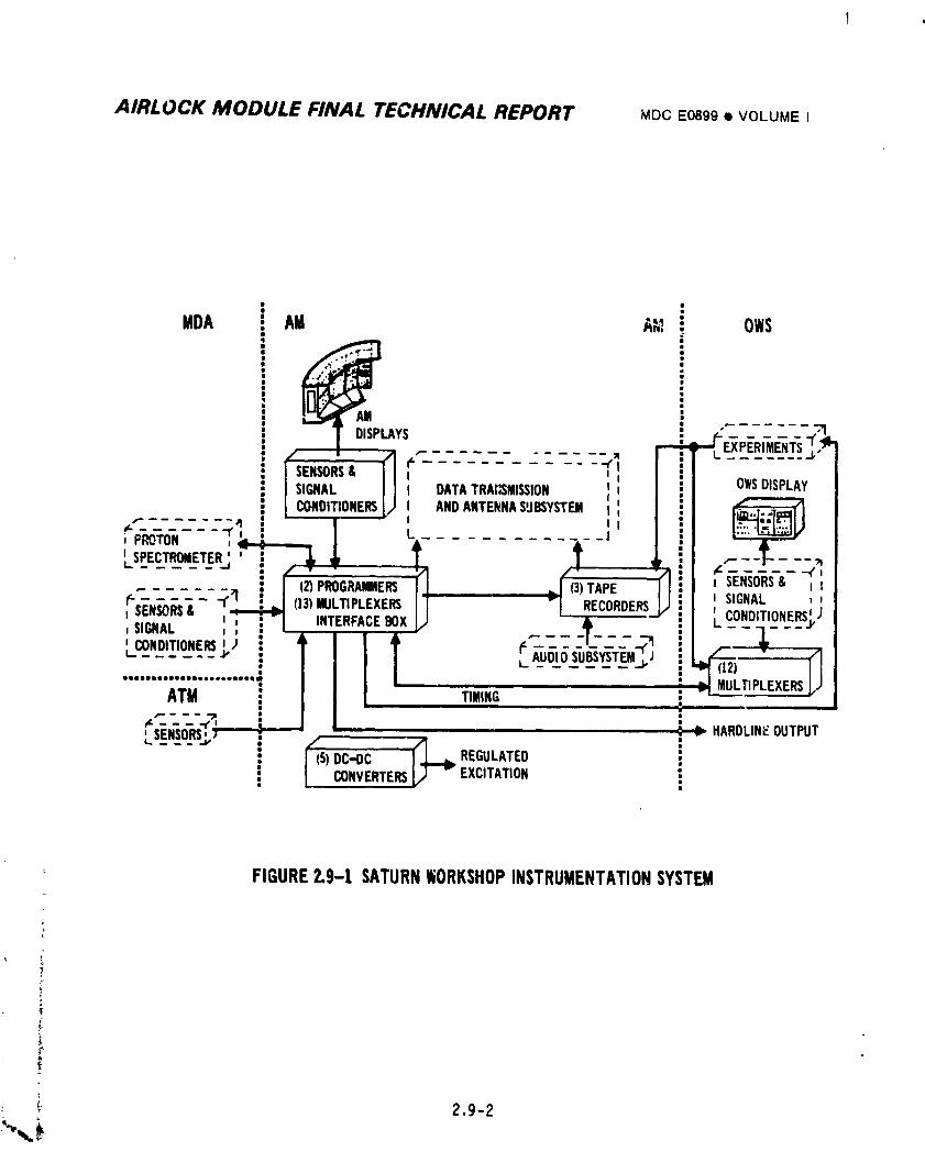
AIRLOCK MODULE FINAL TECHNICAL REPORT MDCE0899• VOLUMEI
iMDA AM A_,; OWS
SENSORS= I I '_ "I"_; [ OWSDISPLAYSIGNAL I I I DATATRAIISMISSION Ill [
CONDITIONERS_) I ANDANTEI_'NASUBSYSTEM,:, 'I :: [__
L_Ec_r_E;E_;'i __ _ _ --t----_..... : . . • I ,_"- I
....... .. : _ (2)PROGRAWERS _ (3)TAPE , SENSORS& _ I
eS_'N;'n_- -(q LU (13)BULTIPLEXERS v| RECORDERS/ i t SIGNAL ,,t _,_-._.,-._ t_ INTERFACEBOX . ; CONDITIONERS!J
'"--" ', :'- • • - -t---_ : --¥--"_u_i_s-u_v_-T_Mj
.......................: / s I /ATM [ / I [ TIMING : _" MULTIPLEXERSi Jl i
,:c_:-_ i / [ i " HARDLIN_OUTPUTLSe.so_Rs_,,;! 5)DC..OC REGULATED
! CONVERTERS EXCITATION i
FIGURE2.9-1 SATURNWORKSHOPINSTRUMENTATIONSYSTEM
T
T"
i 2.9-2
1974018208-606
I
t
i AIRLOCK MODULE FINAL TECHNICAL REPORT MDCE0899• VOLUMEI
e Provide for in-flight replacement capability of selected hardware.
e Provide redundancy to meet mission requirements except signal _onditioners,
transducers,and multiplexers.e Design system for compatibility with the STDN.
e Provide timing to OWS experiments from PCM Interface Box.
e Provide scientific experiments support.
e Monitor all parameters during manned missions and selected measurements
during storage.
e Provide isolated outputs on transducers which supply signals to _ore
than one system.
e Use Pulse Code Modu;ation tel.-metry.
e Provide ground control over equipment selection and functions with
crew control backup.
e Provide crew control over experiment and voice recording.
e Provide ground control over data downlink.
e Provide timing to EREP.
e Design system to a goal that equipment be neither source of nor susceptible
to EMI.
2.9.2 System Description
The InstrumentationSystem was assembled by utilizing existing Gemini Program
designs where applicable and/or by modifying these and other designs to accommodate
AM requirements. New designs were used only where available hardware did not
satisfy needs.
The initial system consi_,tedof 238 channels of PCM telemetry with single tape
recorder capability. Program evolution and mission redefinitions resulted in a
_ _ series of studies to determine the best methods to accommodate the data from other
i Skylab vehicles; downlink and redundancy alternatives were also considered. It was
,_ concluded tLat an expansion of the PCM Multiplexer/Encoder equipment in the AM down-
linked via VHF transmitterswould be the most efficient method to satisfy the newi.
_ requirements. An interface box was added to the PCM equipment which allowed use
I of an increased quantity of low sample rate channels via added multiplexers. A
•
total of 37 multiplexers could be accommodated. The interface box also provided
• for three additional separate portions of the real time data output to be available
for recording; these allowed excess housekeeping and experiment data to be
available via delayed time. Two additional tape recorder/reproducersand an
i_ 2.g-3
1974018208-607
AIRLOCK MODULE FINAL TECHNICAL REPORT MDCE0899• VOLUMEI
additional DC-DC converter required for their txcitationwere added. Redundancy
for selected equipment was provided. The evolutlon of the vehicle system desig,s
dictated some new sensors, ranqe changes on existinq sensors, an increase in the
nominal sensor types and some additional signal conditioning be provided to satisfyJ
the added functionalmonitorinQ renuirements. This baseline system provided an
increase in telemetry channel capacity to 428 channels with 342 used; multiplexers
were located in the AM and OWS.
During the charge from a wet to dry workshop concept, the major alteration to
this baseline was an increase in the quantity of multiplexers. The measurement
capability in the AM was now 629 channels; 535 channels were allocated.
Subsequent changes to the InstrumentationSystem included reallocation of
multiplexers among the Skylab modules to optimize mission data acquisition and
operations. Nominal measurement changes resulting from vehicle and experiment
system evolution were also experienced during this program period. The final
flight system provided 1297 telemetry channels of which i076 were used; remote
multiplexers were only located in the AM and OWS. Data signals from the MDA and
selected measurements from other modu]e_ were wired across the appropriate vehicle
interface and accommodated by the multiplexing _nd encoding hardware in the AM.
System control was primarily ground command with crew backup. The Airlock
Module InstrulaentationSystem provided a portion of either sensing, multiplexing
and encoding,or recording functions for the following total parameters from tileAM,
MDA, OWS, and ATr_:
363 Temperatures
I06 Pressures
15 Flows
536 Events
284 Voltages/Currents
ll7 Miscellaneous
The end result was a system with maximum data monitoring flexib;ITty which still
maintained efficient operational ease for crew members as well as qround controllers.
The subsequent paragraphs describe the individual components containFd in this
system.
:,.
1974018208-608
AIRLOCK MODULE FIN, .L TECHNICAL REPORT MDCE0899• VOLUMEI
2.9.2.! Sensors and Siqnal Conditioners
The devices used to provide life support, physical environment and systems
housekeeping data in the AM _re described below. The temperature, pressure and CO2
partial pressure sensors were basic Gemini Program designs. New AM designs
included the gas flowmeter, rapid pressure loss and fire detectors. The rc_aining
units, acoustic noise, dew point temperature, 02 partial pressure and quartz
crystal microbalance contamination sensors were essentially existing designs
modified for AM needs. The signal conditioners fit into all three categories, the
new designs being mainly those used in the Caution and Warning System. The
description of the rapid pressure loss detector and ultraviolet fire detector are
presented in Section 2.11. These devices _ere primarily used to supply emergency
inDuts to the Caution and Warning System. Similar data from these was also
monitored via the telemetry system.
A. Temperature Sensors - Twenty-two different configuration resistive-elemen_
temperature sensors were provided in the AM to sense various temperatures,
and to convert these temperatures into proportional electrical outp, s for
telemetry and fo_ crew displays. Sensor outputs to the C&WSystem were
signal conditioned prior to use. The sensors consisted of surface-mounted
and probe sensing elements with integral bridges. The sensing elements
were made from fully annealed pure platinum wire encased in ceramic
insulation in a strain-free manner to provide maximum stability.
Surface-mounted sensors were used to measure the skin temperatures of
components and spacecraft structures. Air probe temperature sensors were
positioned upstream and downstream of the mole sieve heat exchanger to
provide cabin temperature data and for evaluation of the heat exchanger
performance. An additional air probe sensor was located in the aft
compartment of the AM. This sensor indication was a function of the OWS
return air temperature and the OWScooling module performance. Sensor
outputs t_ telemetry ranged from 0 to 20 millivolts DC while 0 to 0.4 volts
DC were provided to panel displays.
B. Dew Point Temperature - The dew point sensor utilized tne cold mirror
techniqGe in which a reflective surface was cooled to the temperature at
which condensation began to form on the mirror surface. This t_mperature
was the dew point. The presencr of moisture on the mirror surface was
detected by the change in intensity of a light beam reflected off the
2.9-5k
1974018208-609
AIRLOCK MODULE FINAL TECHNICAL REPORT MDCE0899• VOLUME I
mirror onto a photocell. The dew point sensor provided a 0 to 5 VDC output
for telemetry corresponding to a dew point temperature of 20 to 80°F and a
0 to 0.4 VDC output for a crew display. Two dew point sensors were used
in AM, one at the inlet of each mole sieve.
C. Pressure Transduzers/Switches- Ten different absolute and differential
pressure transducerswere provided to sense 02 , N2, water and coolantpressures and to convert these pressures into proportional electrical
outputs for telemetry and crew displays. Six different pre3sure switches
were used for telemetry,display, control and C&W. The mechanical portion
of eight of the transducerswas a bellows or a capsule which varied the
wiper position of a potentiometer proportionallywith input pressure
variation. Two potentiometerswere used in the dual output units to insure
that the indicator circuit did not create a loadlng error on the PCM output.
The pressure switches used a mechanical switch in lieu of the potentiomete_"
as the output. Redundant units were provlded for critical functions.
The transducersconverted the pressure into proportional Electrical outputs
ranging from 0 to 5 VDC for telemetry and 0 to 0.4 VDC for crew displays.
Low pressures were sensed by the other two transducer types by a unit
consistingof a diaphragm mounted to a slug ira transformer. Small
deflectionsof a diaphragm changed the reluctance in the transformer coils,
which were cGnnected as legs of an AC Bridge. The output from this bridge
was suitably conditioned to provide a O to 5 VDC output for telemetry and
a 0 to 0.4 VDC signal for crew displays.
D. Carbon Dioxide Partial Pressure Detector - The PPCO2 transducer ionizedfiltered gas to obtain an output signal which was proportional to the
partial pressure of CO2 present at the point of measurement. The trans-
Jucer consisted of two in-flight replaceable filters, two ion chambers and
a bridge circuit. An inlet gas stream was divided into two substreams.
One substream was filtered for CO2 and H20 removal; the other was filtered
for H20 removal only. The output gas substreams were ionized by the
chambers containing approximately 400 microcuries of Americium 241 each.
The resulting ion currents from each substream were compared in a bridg_
'_ circuit to obtain the measurement.
' 2.9-6
i"$i
1974018208-610
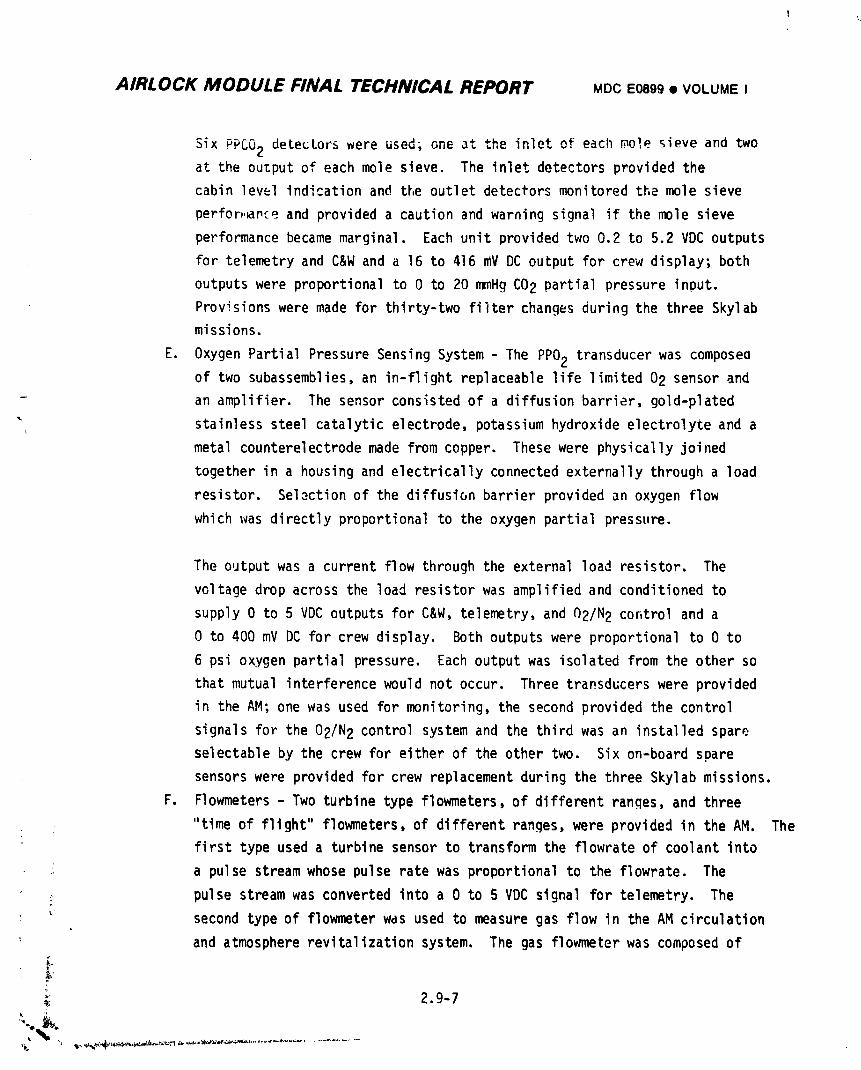
AIRLOCK MODULE FINAL TECHNICAL REPORT MDCE0899• VOLUMEI
Six PPCO2 detectorswere used;one at the inletof eachmole sieveand twoat the ouzputof eachmole sieve. The inletdetectorsprovidedthe
cabinlewl indicationand the outletdetecforsmonitoredthe mole sieve
perfor,.srceand provideda cautionand warningsignalif the mole sieve
performancebecamemarginal. Each unit providedtwo 0.2 to 5.2 VDC outputs
for telemetryand C&W and a 16 to 416 mv DC outputfor crew display;both
outputswere proportionalto 0 to 20 mmHg CO2 partialpressureinput.
Provisionswere made for thirty-twofilterchangesduringthe three Skylabmissions.
E. OxygenPartialPressureSensingSystem- The PPO2 transducerwas composeaof two subassemblies,an in-flightreplaceablelifelimited02 sensorand
- an amplifier. The sensorconsistedof a diffusionbarrier,gold-plated
" stainlesssteelcatalyticelectrode,potassiumhydroxideelectrolyteand a
metal counterelectrodemade fromcopper. Thesewere physicallyjoined
togetherin a housingand electricallyconnectedexternallythrougha load
resistor. Selectionof the diffusionbarrierprovidedan oxygenflow
whichwas directlyproportionalto the oxygenpartialpressure.
The outputwas a currentflow throughthe externalload resistor. The
voltagedropacrossthe load resistorwas amplifiedand conditionedto
supply0 to 5 VDC outputsfor C&W,telemetry,and 02/N2 controland a
0 to 400 mV DC for crewdisplay. Bothoutputswere proportionalto 0 to
6 psi oxygenpartialpressure. Eachoutputwas isolatedfromthe other so
thatmutualinterferencewould not occur. Threetransducerswere provided
in the AM; one was used for monitoring,the secondprovidedthe control
signalsfor the 02/N2 controlsystemand the thirdwas an installedspare
selectableby the crew for eitherof the other two. Six on-boardspare
sensorswere providedfor crew replacementduringthe three Skylabmissions.
F. Flowmeters- Two turbinetype flowmeters,of differentranges,and three
"timeof flight"flowmeters,of differentranges,were providedin the AM. The
firsttype useda turbinesensorto transformthe flowrateof coolantinto
: a pulse streamwhose pulseratewas proportionalto the flowrate. The
pulsestreamwas convertedintoa 0 to 5 VDC signalfor telemetry. The
_ secondtypeof flowmeterwas used to measuregas flow in the AM circulation
and atmosphererevitalizationsystem. The gas flowmeterwas composedof
i2.9-7
1974018208-611
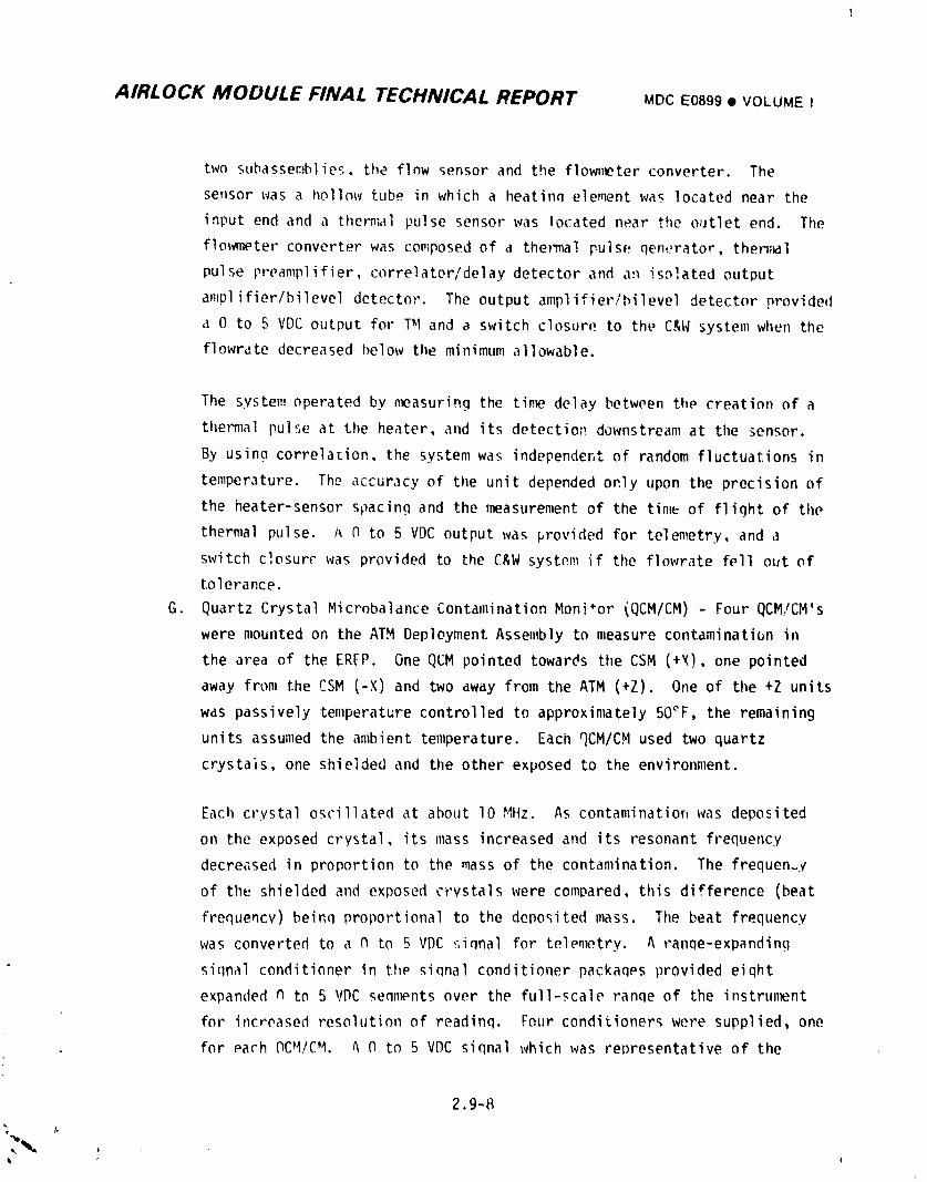
AIRLOCK MODULE FINAL TECHNICAL REPORT MD¢E0899• VOLUMEI
two subassemblies, the flow sensor and the flow,w_terconverter. The
serlsorwas a hollow tube in which a heatinn element was located near the
input end and a thern_alpulse sensor was located near _.heoutlet end. The
flowmeter converter was composed of a thermal puls(;qen,;rator,thersTBl
pulse preamplifier, correlator/delaydetector and a:1isolated output
amplifier/bileveldetector. The output amplifier/bileveldetector provided
a 0 to 5 VDC output for T_Iand a switch closure to the C&W system when the
flowrate decreased below the minimum allowable.
The system operated by _w_asuringthe ti,_ delay between the creation of a
ti_e1_,.lalpulse at the heater, and its detectior_downstream at the sensor.
By usinn correlation, the system was independentof random fluctuations in
temperature. The accuracy of the unit depended only upon the precision of
the heater-sensor spacing and the measurement of the time of flight of the
thermal pulse. I_N to 5 VDC output was provided for telemetry, and a
switch closurr was provided to the C&W system if the flowrate fell out of
tolerance.
G. Quartz Crystal Microbalance Contamination Moni*or (QCM/CM) - Four QCM/CM's
were mounted on the ATM Deployment Assembly to measure contamination in
the area of the ERFP. One QCM pointed towards the CSM (+X), one pointed
away from the CSM (-X) and two away from the ATM (+Z). One of the +Z units
was passively temperature controlled to approximately 50°F, the remaining
units assumed the ambient temperature. Each QCM/CM used two quartz
crystais, one shie]ded and the other exposed to the environment.
Each crystal oscillated at about lO MHz. As contamination was deposited
on the exposed crystal, its mass increased and its resonant frequency
decreased in proportion to the mass of the contamination. The frequency
of th_ shielded and exposed crystals were compared, this difference (beat
frequency) beinq proportional to the deposited mass. The beat frequency
was converted to a 0 to 5 VDC :;iqnalfor tele,_try. A ranqe-expanding
siqnal conditioner in the siqnal conditioner packaqes provided eiqht
expanded tlto 5 VDC sennpnts over the full-scale ranqe of the instrull_nt
for it_creasedresolution of readinq. Four conditioners were supplied, one
for each OC_I/CM. _ 0 to 5 VDC siqnal which was renresentative of the
2.9-8
i
1974018208-612
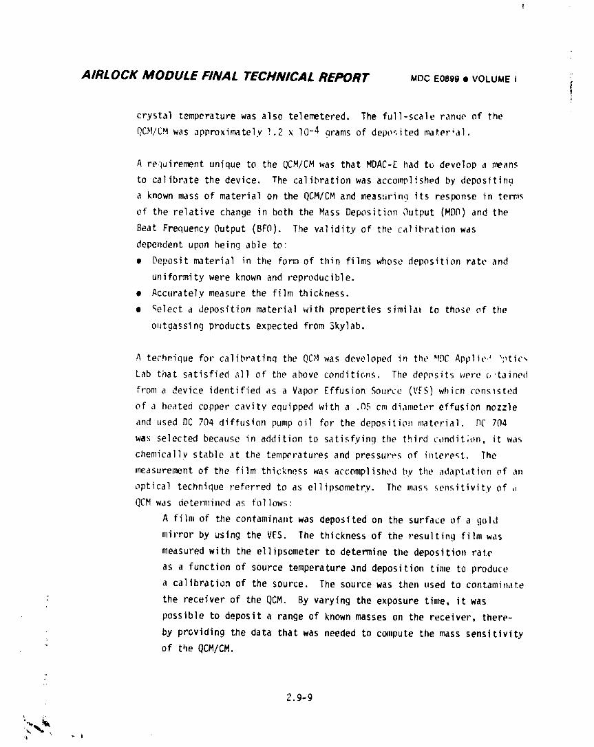
AIRLOCK MODULE FINAL TECHNICAL REPORT MDCE0899• VOLUME I "
t
crystal temperature was also telemetered. The full-scale ranue of the
[!C_I/CMwas approxifnately1.2 x I0-4 grams of depo_.itedmater_a|.
A re,_uirementunique to the QCM/CM was that MDAC-E had to develop a ,cans
to calibrate the device. The calibration was accomplished by depositin9
a known mass of material on the QCM/CM and n'masuringits response in te_s
of the relative change in both the Mass Deposition Output (MD(1)and the
Beat Frequency Output (BFO). The validity of the calibration was
dependent upon heing able to:
• Deposit material in the for_:}of thin films whose deposition rate and
uniformity were known and reproducible.
• Accurately measure the film thickness.
• _elect a deposition material with properties similal to those of the
o=_tgassingproducts expected from 3kylab.
A technique for calibratinq the QC_Iwas developed in the _!DCApplie,J ';'tic_
Lab tilatsatisfied all of the above conditic,r_s. The deposits tvere(,,taine(I
from a _ieviceidentified as a Vapor Effusion Source (VES) which ('ons_sted
of a heated copper cavity equipped with a .05 cm diameter effusion nozzle
and used DC 704 diffusion pump oil for the deposition _w_terial. I)C704
was selected because in addition to satisfying the third condit;o,, it was
chemically stable at the temperatures and pressures of interest. The
m_asurement of the film thickness was accomplished by the adapt,itionof an
optical technique referred to as ellipsometry. The mass _en_itivity of ,,
QCM was determined a_ follows:
A film of the contaminant was deposited on the surface of a gold
mirror by using the VES. The thickness of the resulting film was
measured with the ellipsometer to determine the deposition rate
as a function of source temperature and deposition time to produce
a calibration of the source. The source was then used to contamin,_te
the receiver of the QCM. By varying the exposure time, it was
possible to deposit a range of known masses on the receiver, there-
by providing the data that was needed to compute the mass sensitivity
_' of the QCM/CM.
2.9-9
•,_
"i • _ |
1974018208-613
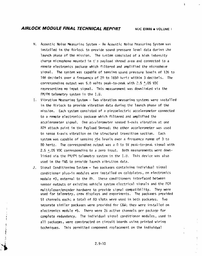
AIRLOCK MODULE FINAL TECHNICAL REPORT MDCE0899I VOLUMEI
H. Acoustic Noise Measuring System - An Acoustic Noise P1easurinqSystem was
insta|led in the Airlock to provide sound pressure level data durinq lhe
laurlchphase of the mission. The svstem consisted of a high intensity
charge microphone mountei in t'_ payload shroud area a,d connected to a
remote electronics packaqe which filtered and amplified the micropho,le
siqnal. The system was capable of sensinq sound pressure levels of 126 to
146 declbels over a frequency of 20 to 1650 hertz within 3 decibels. Ti_e
correspondinq output was 5.0 volts peak-to-peak with 2.5 +.05 VDC
representinq no input signal. This ,w_asurenw_ntwas down]inked via the
FM/FM telemetry system in the I.U.
I. Vibration Measuring System - Two vibration measuring systems were _nstalled
in the Airlock to provide vibration data during tilelaunch phase of the
mission. Each system consisted of a piezoelectric accelerometer connected
to a remote electronics package which filtered and amplified the
accelerometer signal. One ac_ulerometer sensed X-axis vibration at one
ATM attach point in the Payload Shroud; the oti_eraccelerometerwas used
to sense X-axis vibration on the structural transition section. Eaci}
system was capable of sensinq +5q levels over a frequency ranqe of 3 to
80 hertz. The corresponding output was a 0 to 5V peak-to-peak siqnal with
2.5 +.05 VDC correspondinq to a zero input. Both measurements were down-
linked via the FH/PI telemetry system in the I.U. Tilisdevice was also
used in the nWS to provide launch vibr_,tiondata.
J. Siqnal Conditioninq System - Two packaqes containinq individual signal
conditione_ plug-in modules were installed on coldplates, on electronics
n_dule a3, external to the A_. These conditioners interfaced between
sensor outputs or existing vehicle system electrical siqnals and the PCH
mu]tiplexer/encoderhardware to provide signal compatibility. They wereused for telemetry, crew displays and experiments. The packages provided
51 channels each; a total of 83 slots were used in boti_packages. T_,o
separate similar packaqes were provided for C&W; they were instal]ed on
electronics module a5. There were 26 active channels per package for
complete redundancy. The individual siqnal conditioner modules, used in
all packages, were constructed on circuit boards usinq printed wirinq
i tcchniques. This permitted component replacement on the individual
_, 2.9-10
1974018208-614
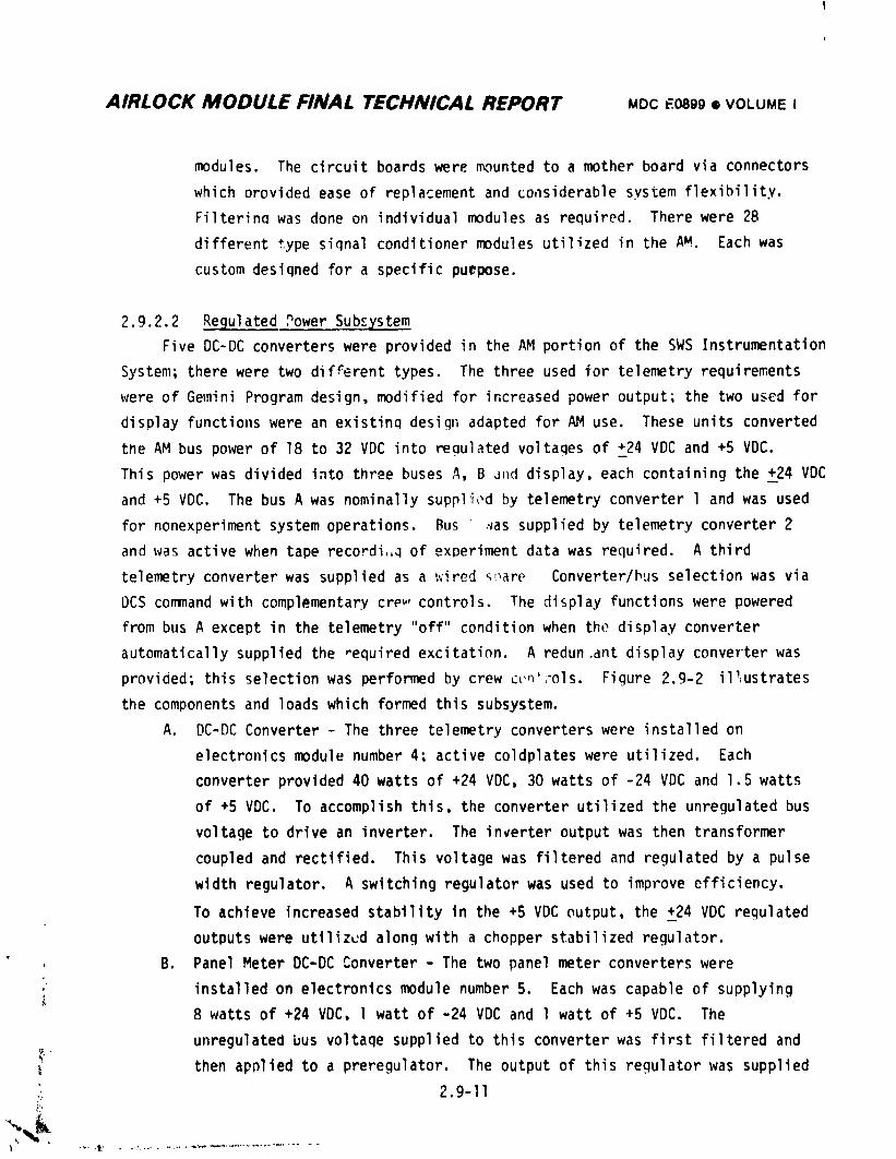
AIRLOCK MODULE FINAL TECHNICAL REPORT MOC E0899• VOLUME I
modules. The circuit boards were _,_untedto a mother board via connectors
which provided ease of replacement and co,lsiderablesystem flexibility.
Filterin_ was done on individual modules as required. There were 28
different type siqnal conditioner modules utilized in the AM. Each was
custom desiqned for a specific puepose.
2.9.2.2 Regulated Power Subcystem
Five DC-DC converters were provided in the AM portion of the SWS Instrumentation
System; there were two different types. The three used for telemetry requirements
were of Gemini Program design, modified for increased power output; the two used for
display functions were an existinq design adapted for AM use. These units converted
the AM bus power of 18 to 32 VDC into regulated voltaqes of +__24VDC and +5 VDC.
This power was divided into three buses A, B _nd display, each containing the +_24VDC
and +5 VDC. The bus A was nominally supplit_dby telemetry converter l and was used
for nonexperiment system operations. Bus ,vassupplied by telemetry converter 2
and was active when tape recordi,,Qof exDeriment data was required. A third
telemetry converter was supplied as a ;.,'ired_are Converter/bus selection was via
L)CScommand with complementary crew,controls. The display functions were powered
from bus A except in the telemetry "off" condition when the display converter
automaticallysupplied the _equired excitation. A redun.ant display converter was
provided; this selection was performed by crew c_'_'ols. Figure 2.9-2 il_,ustrates
the components and loads which formed this subsystem.
A. DC-DC Converter - The three telemetry converters were installed on
electronics module number 4; active coldplates were utilized. Each
converter provided 40 watts of +24 VDC, 30 watts of -24 VDC and 1.5 watts
of +5 VDC. To accomplish this, the converter utilized the unregulated bus
voltage to drive an inverter. The inverter output was then transformer
coupled and rectified. This voltage was filtered and regulated by a pulse
width regulator. A switching regulator was used to improve efficiency.
To achieve increased stability in the +5 VDC output, the +_24VDC regulated
outputs were utilized along with a chopper stabilized regulator.
B. Panel Meter DC-DC Converter - The two panel meter converters were
installed on electronics module number 5. Each was capable of supplying
8 watts of +24 VDC, l watt of -24 VDC and l watt of +5 VDC. The
unregulated bus voltaqe supplied to this converter was first filtered and_-
then apnlied to a preregulator. The output of this regulator was supplied
.; 2.9-11
1974018208-615
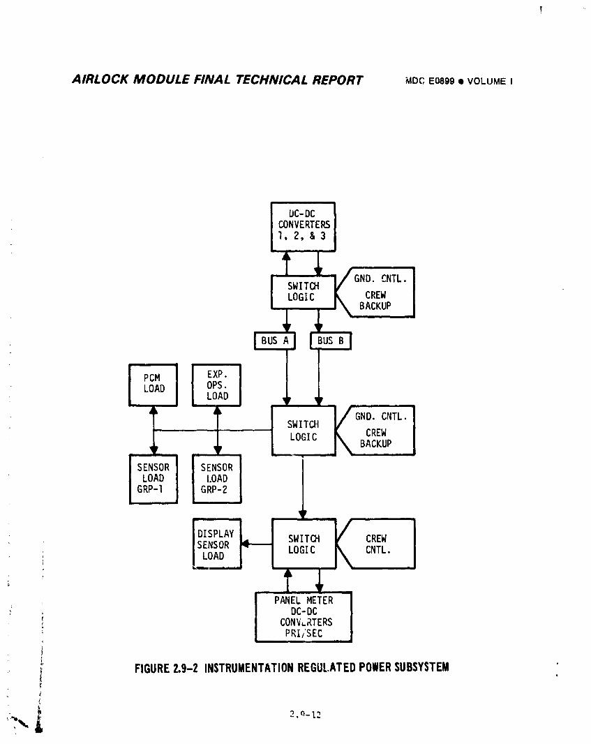
AIRLOCK MODULE FINAL TECHNICAL REPORT ape E0899• VOLUMEI
IJC-DCCONVERTERS1,2,&3
GND CNTL.SWITCHLOGIC ;REW
BACKUP
BUS A
PCM I EXP.LOAD OPS.
LOADi
SWITCH _ CREW
LOGIC _ BACKUP
LOAD LOADGRP-I GRP-2
|
DISPLAY SWITCH K CREW
SENSOR II----- LOGIC CNTL.' LOADi
PANELMETER; . DC-DC
i CONV.RTERS; PRI/SEC
I.FIGURE2.9-2 INSTRUMENTATIONREGULATEDPOWERSUBSYSTEM
t
_- _ 2.(_-12
1974018208-616
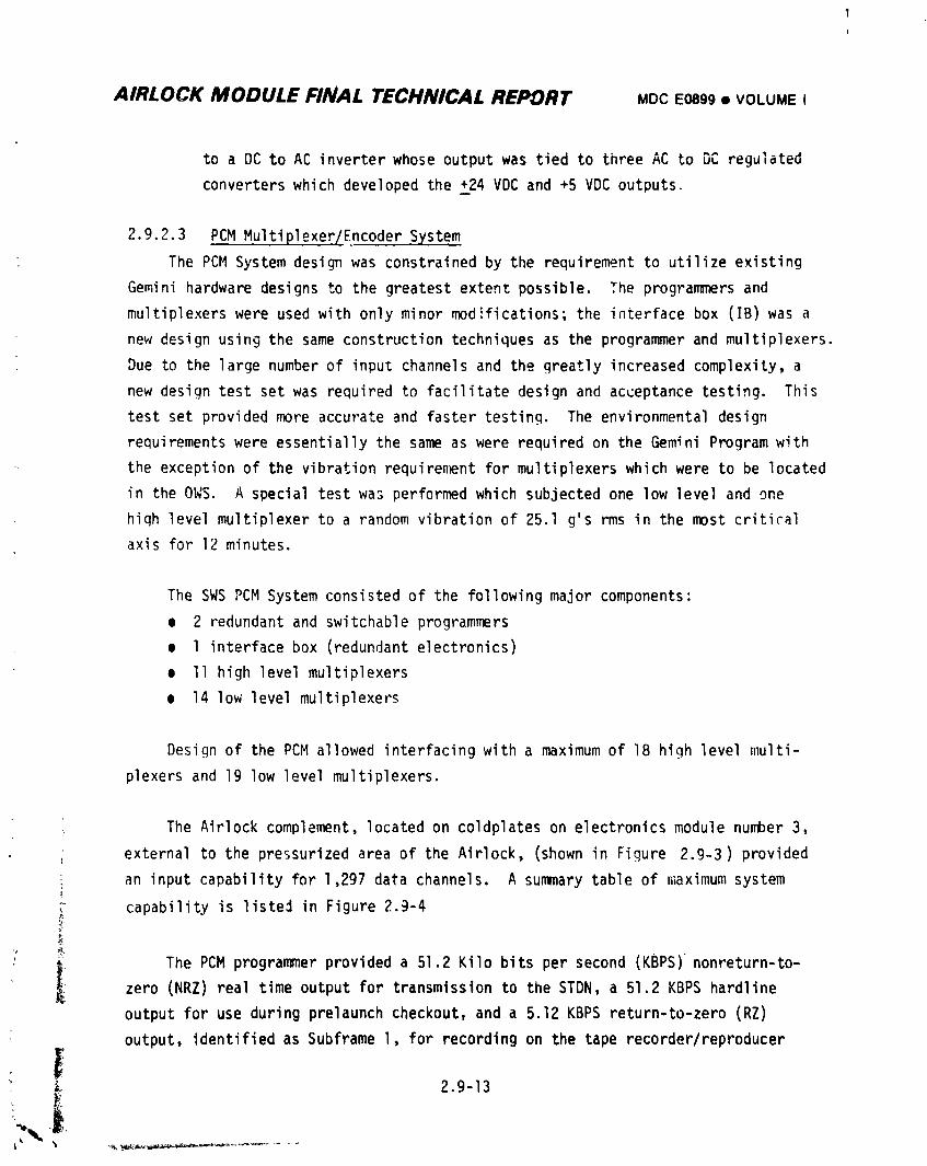
AIRLOCK MODULE FINAL TECHNICAL REPORT MOCE0899• VOLUMEI
to a DC to AC inverter whose output was tied to three AC to DC regulated
converters which developed the +24 VDC and +5 VDC outputs.
2.9.2.3 PCM MultiplexeT/EncoderSystem
The PCM System design was constrained by the requirement to utilize existing
Gemini hardware designs to the greatest extent possible. The programmers and
multiplexers were used with only minor modifications; the interface box (IB) was a
new design using the same construction techniques as the programmer and multiplexers.
Due to the large number of input channels and the greatly increased complexity, a
new design test set was required to facilitate design and acceptance testing. This
test set provided more accurate and faster testing. The environmental design
requirementswere essentially the same as were required on the Gemini Program with
the exception of the vibration requirement for multiplexers which were to be located
in the OWS. A special test was performed which subjected one low level and one
hiqh level multiplexer to a random vibration of 25.1 g's rms in the most critical
axis for 12 minutes.
The SWS PCM System consisted of the following major components:
o 2 redundant and switchable programmers
• l interface box (redundant electronics)
• II high level multiplexers
e 14 low level multiplexers
Design of the PCM allowed interfacing with a maximum of 18 high level multi-
plexers and 19 low level multiplexers.
The Airlock complement, located on coldplates on electronics module number 3,
external to the pressurized area of the Airlock, (shown in Figure 2.9-3) provided
i an input capability for 1,297 data channels. A summary table of maximum system
i capability is liste_ in Figure 2.9-4
_ The PCM programmer provided a 51.2 Kilo bits per second (KBPS)nonreturn-to-
zero (NRZ) real time output for transmission to the STDN, a 51.2 KBPS hardline
output for use during prelaunch checkout, and a 5.12 KBPS return-to-zero (RZ)
output, identified as Subframe l, for recording on the tape recorder/reproducer
_. 2.9-13
1974018208-617
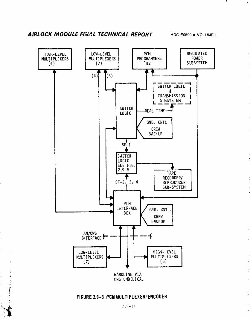
AIRLOCK MODULE FIIVAL TECHNICAL REPORT MDC E0899 • VOLUME I
ii ii i
HIGH-LEVEL LOW-LEVEL PCM I REGULATED _
i
MULTIPLEXERS MUI.TIPLEXERS PROGRAMMERS I POWER(6) (7) l&2 SUBSYSTEM
I il
(4)
F__o_c-]I TRANSMISSION 1L SUBSYSTEM
SWITCH -_REAL TIMC---_LOGIC
__ _ GND. CNTL.
CREWBACKUP
ISF-I
SWITCH I
LOGICSEE FIG.
2.9-5
TAPE I
RECORDER/SF-2, 3, 4 REPRODUCER
I
L SUB-SYSTEM-'b
•"Ib PCM
. ,,T_,AC_F_o'C_TL_I• "- BOX \ CREW |
BACKUP J, _L
AM,O_S__I_2INTERFACE3--"-- F .... '_
I
--MULTIPLEXERS ill-.,--'J " MULTIPLEXERS
(7) / (5)
HARDLI!_EVIAOWS UMBILICAL
FIGURE 2.9-3 PCM P,IULTIPLEXER/ENCODER
1974018208-618
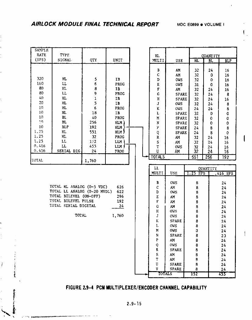
AIRLOCK MODULE FINAL TECHNICAL REPORT MDCE0899• VOLUMEI
1
S_fl_ LE
RATE TYPE HL ,,_UANTITY(SPS) SIGNAl, QTY UNIT MULTI USE HL BL BLP
B AM 32 24 16C AM 32 0 16
320 HI. 5 IB D OWS 32 0 16
160 LL 6 PROG E OWS 31 0 16
80 HL 8 IB F AM 32 24 16
80 LL 9 PROG G SPARE 32 24 8
40 HL i IB H SPARE 32 24 16
20 HI, 5 IB J OWS 32 24 8I0 HL 6 PROG K OWS 24 24 8
10 HL 18 IB L l SPARE 32 0 0
i0 BL 40 PROG M SPARE 32 0 0
]_ BL 256 HLM) N SPARE 32 0 0
I0 BLP 192 HLM --I P SPARE 24 8 81.25 HL 551 HLM Q SPARE 24 8 0
1.25 HL 32 PROG R AM 32 24 16 l
1.25 LL 152 LLM} ___ S AM 32 24 16
!
O.416 LL 455 LLM -- T OWS 32 24 16
0.416 SERIAL DIG 24 PROG U AM 32 24 16
-,'-TOTALS 551 256 192TOTAL 1,760
LL 9UANTITYMULTI USE 1.25 SPS .416 SPS
B OWS 8 24
TOTAL HL ANALOG (0-5 VDC) 626 C AM 8 24
TOTAL LL ANALOG (0-20 MVDC) 622 D OWS 8 24TOTAL BILEVEL (ON-OFF) 296 E AM 8 24
TOTAL BILEVEL PULSE 192 F AM 8 24
TOTAL SERIAL DIGITAL 24 G AM 8 24
H OWS 8 24TOTAL i,760 J OWS 8 24
K SPARE 8 24
I, OWS 8 24
M OWS 8 24
N SPARE 8 23 !
V AM 8 24Q ows 8 24R SPARE 8 24
t
• l S AM 8 24
' L_ T AM 8 24
• :_ U SPARE 8 24
; _ V SPARE 8 24
- YO_ALS 152 455
FIGURE2.9-4 PCMMULTIPLEXEK/ENCODERCHANNELCAPABILITY_: 2.9-15
1974018208-619
AIRLOCK MODULE FINAL TECHNICAL REPORT MDCE0899• VOLUMEI
system. The Interface Box (IB) provided three additional 5.12 KBPS RZ signals
to the tape recorder/reproducersystem which were identified as Subframes (SF's)
2 through 4.
A. Programmer o The programmer provided the functions of data multiplexing,
analog-to-digital (A-D) conversion, digital-data multiplexing, and the
required timing functions for the IB. The programmer contained some input
gates but primarily consisted of the circuitry necessary to provide
51.2 KBPS nonreturn-to-zero (NRZ) change PCM pulse trains to the transmitter
and to provide 5.12 KBPS return-to-zero (RZ) pulse train signal and clock
pulses for Subframe l to the tape recorder/reproducersubsystems.
B. Interface Box - The interface box (IB) accepted timing signals from the
programmer and provided signals to the remotely located multiplexers. It
also provided timing signals necessa_, for the generation and multiplexing
of the data in Subframes 2, 3 and 4. The programmer provided the 51.2 KBPS
signal to the interface box where Subframes 2, 3 and 4 were separated and
prepared for transfer to the tape recorder/reproducersubsystem. Three
internal power supplies were located in the interface box. One was used
by the internal circuitry in the IB and the other two provided power to
the multiplexers, lhe interface box was composed of a redundant set of
electronics each capable of full systems operation independent of theother.
C. High Level Multiplexer - The hiqh level multiplexer functioned as a high
level analog commutator and an ON-OFF digital data multiplexer. The purpose
of this unit was to sample 32 high level data channels (0 to 5 VDC), 24
bilevel signals (0 or 28 VDC), and 16 bilevel pulse signals (0 to 28 VDC),
All high level multiplexer analog data outputs were switched tl_rough the
interface box to the programmer. Each multiplexer was individually wired
to the IB where third tier switching was performed before the data was
sent to the programmers, Individual third tier switching was used to
prevent a short in one multiplexer line from shorting all other multiplexers
and to keep line capacitance at a minimum,
2.9-16
ti
] 974018208-620
AIRLOCK MODULE FINAL TECHNICAL REPORT MDCE0899• VOLUMEI
The high level multiplexer used a slaved timing chain driven by signals
from the IB to support the required sampling functions.
D. Low Level Multiplexer - The low level multiplexer was a differential-input
analog commutator whose purpose was to sequentidlly samp,e 32 low level
"(0 to 20 MVDC) signals. The multiplexer contained a slaved timing chain
and digital logic to support the required sampling functions. Operating
power and timing slave signals were received from the IB.
All low level multiplexers, except E, F and G, were individually switched
through third tier switches located in the IB. Multiplexers E, F and G
were gated by, and switched through, the selected programmer.
2.9.2.4 Tape Recorder/ReproducerSubsystem
Three tape recorders capable of simultaneous operation were employed to
provide continuous data coverage durinq periods when the Skylab vehicle was out of
STDN contact. This recorder was a Gemini Program design modified for voice ' cord
and multiple playback caDability. They were installed on coldplates in the forward
compartment of the AM. Each recorder received from the PCM programmer or interface
box, a 5.12 KBPS RZ data stream comprising one of the four recordable PCM subframes.
This data was recorded on track A, while crew voice was recorded on track B; record
speed was l 7/8 IPS. Maximum record tingewas 3 hours per recorder. In addition
to the subframe data, the recorders could also accommodate experiment M509 or
TOl3 data at a bit rate of 5.76 KBPS. The recorder played back the PCM data in a
NRZ - space format into one transmitter; the voice was played back simultaneously
into another transmitter. The playback occurred at _ speed of 22 times the
record speed; data and voice was played back in an order reverse to what they
were recorded. Playback of 3 hours of data was accomplished in 8 minutes, 24
seconds. Upon removal of the playback command, tne recorder switched from the
playback mode to the record mode. In the event of faulty data reception, the
tape recorders could be rewound at the playback speed for another dump by appli-
cation of a fast-forward nonrecord command. During this rewind no modulation
was present at the transmitter. Figure 2.9-5 provides a flow diagram of the
recording process.
' 2.9-17
] 9740] 8208-62 ]
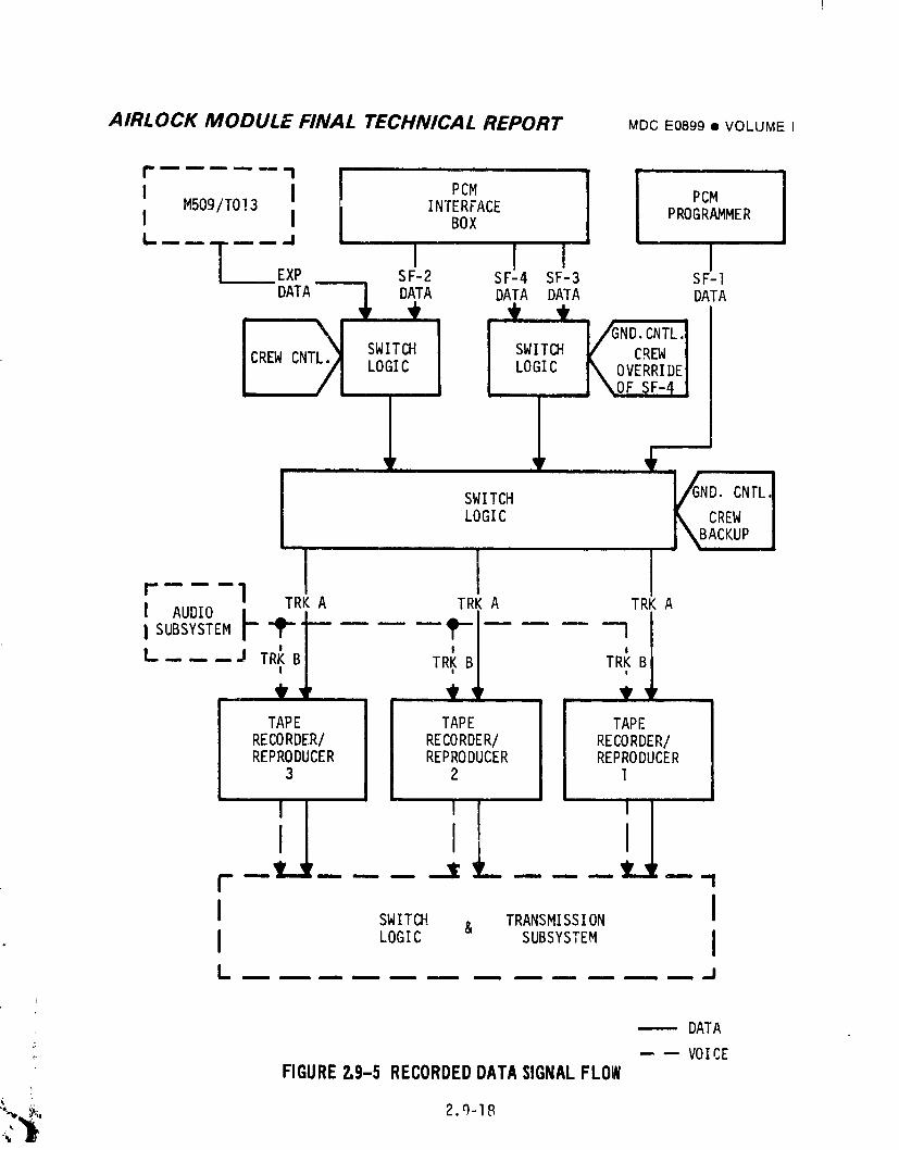
AIRLOCK MODULE FINAL TECHNICAL REPORT MDCE0899• VOLUMEI
...... ....PC.1 I'c'I M509/TO!3 I INTERFACE PROGRAMMERI I l BOX
"--"l"--" I I I II _xP s,-_ _F-,s_-_ SF-_
DATA I DATA DATA DATA DATA, + i' _t___t_
1CREW CNT SWITCH SWITCH _" CREW I
LOGIC LOGIC _ OVERRIDEI_ \OF SF-4 1
l SWITCH VND. CNTLLOGIC _ CREW
j\BACKUP
r--- -I TRK A TRK A TRK A
I AUDIO F ,.__i I(_BI
I SUBSYSTEM _ -- l
L-,..,..._.J TR_I TRK TR_B
TAPE TAPE TAPE !
RECORDER/ RECORDER/ RECORDER/REPRODUCER REPRODUCER REPRODUCER
3 2 lii =
I S.ITm& TRANSMISSION II LOG,C SUBSYSTEM IL ............ J
------ DATA
,. -- -- VOICEFIGUREZ.9-5RECORDEDDATASIGNALFLOW
"%,__ 2.q-18
C_
1974018208-622
AIRLOCK MODULE FINAL TECHNICAL REPORT MDCE0899• VOLUMEI
Recorder manaqement was primarily a ground control function; the crew however,
were provideG wltn duplicate controls. The crew exercised LJntrol over voice
and experiment "ecerd functiens. Telemetered recorder f, mctions i,lcluded tape
n_)tion and playu_c_ mode detect. The crew was supplied ith tape motion and tape
stopped lights at all recorder control stations.
Four recorders were launched on SL-I as in-flight replacements. These units
were installed in the AM lock compartment for launch and were transferred to the
OWSfor stowage after activation. Two adJitional recorders were resupplied during
the second manned mission.
2.9.2.5 Latch Relay Menitor
The latch relay monitor circuit identified a particular position of the AM
latch relays via a telemetry parameter. This rircuit was vital to the mission si,ce
SL-I was launched unmanned and these circuits were accessable only throuqh DCS
durinq countdown.
During testing at MDAC-E and at KSC this latch rel_y monitor circuit served a
dual purpose: to gain confidence in test procedures and to aid in locating an
imprcperly positioned latch relay. Over 500 latch relays were positioned in the
ECS, EPS, Lighting, Sequential, Instrumentation, Communication, _nd C&WSystems so
that the latch monitor circuit could be used to establish the integrlty of all the
latch rel_ys. Once t_is was established those _ew systems which _;_tained relays
requiring a different lift-off position were cycled to the proper position and, by
other telemetry indications, these circuits were established as operational with
_:he associated latch rel]ys being properly configured.
2._'.2.6 Configuration Documentation
The Instrumentation hardware, measurement characteristics and calibration data
was documented primarily by three reports:
MDACReport F639 - Instrumentation System Description
All IP&CL - Instrumentation Proqram & Components List
MDACReport E0502 - Telemetry anJ Recording Technical Manual
Report F639 consisted of five separate volumes and was mainly used for in-house
desiqn, test and m ssion support activities. Report E0502 provided PCMMultiplpxer/
Encoder and tape recorder details. Both of these reports were submifted as
2,9-19i
1974018208-623
AIRLOCK MODULE FINAL TECHNICAL REPORT MDCE0899• VOLUMEI
information items to MSFC. The IP&CL measurements list and a set of computer
punched cards conta <_-- _:l_hm_flnn data were submitted to MSFCfor approval
rl_ose do=uments were kept current via periodic updates during the design and test
phase of the program. Measurement and calibration changes were handled on an
individual basis d,_d included in the appropriate ECP or CCPthat defined the change;
these were supplied to MSFC. The contents of each report was as follows:
A. F639 Volume 1 - This report presented descriptions of each component of
the Instrumentat=on System. Design information, theory of operation and
_hysic_l characteristics were documented. The controls and _splays were
also discussed. In addition, a word description of each telemetry and
display measurement defin'ng the function monitored was given.
B. F639 Volume II - The second volume of this report was measurement oriented
It consisted of a series of tabulations geared to _becific user require-
ments; these lists were generated by a computer/magnetic tape file,
storaqe and retrieval system. The different lists and their contents were
as follows:
(I) SummaryTable - This was a list by parameter sequence rumber
presenting the basic m_asurement characteristics.
(2) Setup Table - This tabulation by parameter sequence number listed
characteristics as well as sensor and signal conditioner information
on each measurement.
(3) Equipment List - This listed Instrumentation System hardware by part
number, parameter _equence number, serial number and location of the
part in the vehicle.
(4) Format Assignment and Decommutation Setup - This was a tabulation by
parameter sequence number and provided multiplexer/encoder channel
identification correlated to equipment connector pin assignments
associated with _hat channel. It also contained the decommutation
code u_ed to retrieve the measurement from the data bit stream
utilizinq the St. Louis PCMground station.
(5) Siqnal Conditioner Assignments - A tabulation by signal conditioner
channel of aart used with associated serial number and parameter
sequence number. Location within the four signal conditioner
packages were also provided.
F"
i
2.9-20
• _,-%,
1974018208-624
AIRLOCK MODULE FINAL TECHNICAL REPORT MDCEOB99• VOLUMEi
(6) Parts List - This was composed of two different tabulations. One
listed light hardware _y part number with numerical quantity oT eacil
kind used on the vehicle. The second list provided similar informa-
tion for spare and test hardware.
(7) Parameter Type Su_nary - This was a one-paqe tab_iation providing
quantity of parameters by sample rate and type. It included a list
of spare multip_exer/encoderchannels available.
(t) Telemetry Format Logic _iagram - This provided a definition of the
multiplexer/encoderchannel sampling sequence in terms of a matrix
which showed channel number versus parameter seque_ce number.
{9) Format Allocation - This list provided both the telemetry equipment
: vendor channel code and the IP&CL channel code versus the IP&CL
parameter identificationnumber.
C. F639 Volume Ill - An end-to-end schematic of each telemetry and display
pa;'ameterwas presented in this re_ort. Electrical schematics of each
signal conditioner, requlated power distribution, controls and othe,
_ircuitry associated with these parameters were also provided.
D. F639 Volume IV - This volume presented calibration data for each telemetry
and display measurement oriqinating in the A_I,MDA and PS. Extensive
utilization of computer technology was employed in collecting, controlling
and processinq this data. The calibration information fcr each sensor
and/or signal conditioner was prGcessed through a least squares curve
fitting routine to establish th_ best first, second or third order curve.
The data was presented in combinations of the following four basic formats:
(1) Calibration Plot - The inpuL/output data points were presented in an
X-Y plot with a line representing the best fi.'st,second or third
order curve fit meeting the specified accuracy requirements.
(2) PCM Counts Tabulation - Calculated engineering unit values were
tabulated versus each PCM count. Zero counts represented an under-
scale, one count w_s zero, 254 counts represented full-scale and
255 )unts indicated an overscale.
(3) Percent Tabulation - This was a tabulation in 5 percent increments
, from 0 to lO0 percent versus the equivalent in engineering units.
(4) Real Data Tabulation - This contained the raw data taken durinq the
calibration test.
2.q-21
,4 "
2
i 9740i 8208-625
AIRLOCK MODULE FINAL TECHNICAL REPORT MDCE0899_ VOLUMEI
Discrete event calibration data was presented in tabular form only. This
list contained the identificationof the binary ones and zeros of each bit
of the bilevel channels. Voltage levels for step functions on analog
channels and the meaning of on/off indications of crew display lights were
also identified. The values presented were actual calibrated trigger
points when level sensing devices were used in the circuit. A complete
calibration data package for the AM, MDA and PS was also supplied in a
different format to MSFC. This was derived from the same calibration file
as the F639 Vtlume IV data. The format used was a key punched computer
card utilized by MSFC to generate a master calibration tape for all Skylab
data users. Update cards were supplied with each change to insure the
tape reflected the vehicle cenfiguration.
E. MDC Report F639, Volume V containes the calibration data for the second
(U-2) AM/MDA and PS.
F. IP&CL - This document was used to define and control telemet:-yand display
parameters and the associated hardware. Additions and deletions required
MSFC approval. All measurements oriqinatinq in the AM were presented; the
ATM measurements multiplexed and encoded by the S_S InstrumentationSystem
were also included. This listing was derived from the ._amecomputer/
magnetic tape system used to qenerate the F639 Volume II lists. The
tabulations contained all flight and launch instrumentationmeasurement
numbers, names, transmission w._de,range, telen,etrvchannel identification,
accuracy, sample rate, transducer, signal conditioner and sensor locations
where applicable. Measurements which required in-fliqht recording,
on-board display and prelaunch display were identified. This document was
updated as required and submitted to MSFC for approval prior to
implementation.
G. E0502 - The Telametering & Recording Technical Manual provided a
discussion of che PCM multiplexer/encoderand tape recorder functions.
Details were p_esented on the physical description of this hardware
; together with th _ building hlock modules utilized in their construction.
Block diagrams were also provided, these were broken down on a functional
!. basis consisting of 30 separate sections for the PCM hardware and
lO sections for the tape recorder/reproducer. The system timinq and logic
diagrams, building block module schenBtics, a PCM format explanation, and
_i 2.9-22
1974018208-626
AIRLOCK MODULE FINAL TECHNICAL REPORT MOCE0899• VOLUMEI
an englneerlnq drawing 11st for this equipment was dlsu in_luded. Sensors,
si,]nalcorditioners, DC-DC converters, downlink transmittersand telemetry
paras,e-or_ werc v:otdiscussed in this report.
2.').2.7 Results Focu1_entdtion
The SWS Instrun_entationSystem was utilized to provide ,,perationsand
evaluation informationdurinq vehicle testinq and fron:the actual fliqht. This
data was proceRsed and reduced into time history tabulations and plots. Strip
charts and other data presentation fe:-matswere also used. This section presents a
discussion of tr;etreatment of test and mission data at MbAC-[ in St. Louis.
A. Vendor Test Data - Component Qualification and acceptance test data was
presented in vendor reports. The format included plots as well as tabular
dat_. All qualification test results were reviewed and approved with NASA
concurrence. Actual tests were witnessed by Governn._ntInspection and in
most cases by MDAC Quality Assurance. Ac.'eptancetest records were used
as the input to the calibration data file described in ti_eprevious
section or as baseline data tu provide test criteria fo,'subsequent
testinq at HDAC. This was tileonly processing of vendor tesL data
performed at HDAC.
B. HDAC Test Data - Pre-lnstallationTest data w,_sprocessed into calibration
inform,_tionfor use in data reduction. All data froE:lvehicle systems
testinc was recorded on maqnetic tap,,;processinq of this data into plots
and tabulationswas on a selected basis. Durinq tilevarious systems tests,
pertinent data values were noted on data sheets contained iw_the test
procedure. Real time strip charts a_idvisual display._were also available
at the test qround station durinq all testinq. Processing of K£C systems
test data was similar to that perforn_d at _,nAr
r Mission Data - There were two main sources of vehicle telemetry data
i during the Skylab missions. The _kylab Test Unit (STU/STDN) station
_ provided processed data acquired during all St. Louis p._sses. MSFC
_ supplied raw and processed data fo; all vehicle orbits.
i (1) STU/STDN - This facility included tracking cap,ibi|itywilichprovided asource of real time telemetry data; when data dumps were performed
within range, tileon-board recorded data was also obtained. All
telemetry data that was received was recorded on magnetic tape.
:ii_ 2.9-23
1974018208-627
AIRLOCK MODULE FINAL TECHNICAL REPORT MDCE0899• VOLUME I
This data was routed to a ccmputer where the first sample of Pach AM
measurement in the 2.4 second data frame was placed in aisc storage.
Following the pass, this stored data was available for conversion
into engineering units and to be presented in tabular form on a
system oriented basis. Processing was on a keep-up basis. There
were 75 tabulations, each containing a maximum of nineteen measure-
ments. Measurement number, name ranqe, engineerinq units, GMTand
the actual data points were provided on each page. A capability
existed to flag Cata values which fell outside of predefir.ed
tolerances. The tolerance values were printed on the tabulations.
A summary sheet listing all flags was provided for each pass. Special
tabulations and printout of all available data points were provided
upon request. Block diagrams of selected ECS/TCS subsystems were
constructed for each pass. These presented single data values at the
sensor locations on the block diagram; they were used as quick look
system status information. The data processed by MSF was also used
to construct system oriented graphs for the complete mission. One
data value per day per measurement was plotted. These graphs were
displayed in the Skylab Communications Center in St. Louis and updated
on a daily basis with current data. Strip chart recordings of 32
analog and I00 discrete measurements were made on selected vehicle
passes over St. Louis. Tile capability was available for real time
monitori1_q of critical measurements. Additional strip charts could
be generated post pass from the magnetic tape. MSF operational
details are presented in Section 7 of this report.
(2) IISFC - Additional mission data was obtained via approved Data Request
Forms (DRF). These sheets defined raw and processed data required by
MDAC-Efor mission support and evaluation. One hundred thirty-sever,
DRF's were prepared and submitted to MS_C for approval. Many
different forms of data were requested. Compressed user tapes were
provided by MSFCfor all available mission time periods. These
magnetic tapes were in data redundancy removed (DRR) form and con-
tained all AM and selected I.IDA, OWSand ATM measurements. Each user
tape contained four dictionary records followed by data records.
The dictionary records contained tape identification, MSFC ID numbers,
?.9-24
i.
1974018208-628
AIRLOCK MODULE FINAL TECHNICAL REPORT MDCE0899• VOLUMEI
correspondingmeasurement numbers and engineering unit definitions.
The data records contained data source, GMT, and MSFC ID for each
data value. A software program was written to reduce this data into
time history plots and tabulations. Processing of Lhe tapes wasi
limited to problem time periods where detailed systems information
was required. The processing software consisted of two prngrams
written for the IBM 370-145 and the IBM 360-55 computer systems. The
first program processed the tape and provided data tabulations and a
magnetic tape. The second program converted the magnetic tape into
data plots. The tabulation program operated in three phases:
initialization,processing, and presentation. The initialization
phase consisted of processing the control cards, base file and
portions of the user tape dictionary records. The control cards
contained the processing directions specifying the time intervals,
measurement tabulations and program options to be exercised. The
base file was a magnetic tape in Extended Binary Coded Decimai nter-
change Code (EBCDIC) containing card images of information defiv_ing
tabulation and plot formats. Tabulations were defined by tab set
number, column number, measurement number, HSFC ID number, engineering
units, band-edit value and measurement subframe. Fifty-two tab sets
were defined for analog measurements, one for time and five for
discrete events. Plot informationwas defined for each measurement
on a tab set. Information filed was tab number, plot number, grid
number, measurement number, name, range, symbol and right or left
scale notation. Grids were defined by minimum, maximum and number of
divisions. Changes to this base file were accomplished via new card
image inputs. All processing was done in one pass through the user
tape. Band editing of the data was performed on a selected basis.
This feature compared the absolute difference of each data value and
the previous value output with a band-edit delta read from the base
file. A difference of less than or equa_ Lo the delta was not
tabulated. A value greater than the delta was tabulated and used for
comparison to succeeding data values until the delta was again
exceeded. Time was incremented on the tabulations equal to the
sample rate of the measurements being tabulated. In the case where
2.9-25
q
1974018208-G29
AIRLOCK MODULE FINAL TECHNICAL REPORT MDC E0899 • VOLUIqEI
the number of the i_asure_ent samples ,,..'asgreater than the tabulation
rate, the last sample in the time increment was used. There were
eleven columns of data values together with time and measurement
identifiers. The first data line on each page presented the last
printed value from the previous page. A notation was made of each
change of real or delayed time and the end of each data segment was
identified. The plotting program translated the data from the
: magnetic tape created during the tabulation program into appropriate
languaqe for the plotter. The data was point plotted with data gaps
identified. There were four separate qrids per page; the number of
measurements per grid varied from one to four with a maximum of
eleven measurements per page. All data on one page was limited to
the measurements on one tab set. A maximum of four plots could be
defined for one tab set. The X-axis of each qrid was fixed a, 24
divisions, time periods of 2, 4, 6, or 8 hours including start time
could be used. Each Y-axis was defined by a minimum, maximum and
number of divisions: 2, 3, 4, 5, 6, 8, lO, or 12 divisions were
available. Both left and right scales were used. Figure 2.9-6
presents a flow diagram depicting tileprocessing steps. Several
analog tapes from various STDN sites were also processed for detailed
systems data. This reduction activity was performed in tileMSF and
is described in Section 7 of this report.
2.9.3 TestinQ
The InstrumentationSystem was sub.iectedto a comprehensive test program to
verify system performance and insure vehicle compatibility. Individual components
were tested by both the equipment vendor and MDAC prior to installation in the
vehicle. Subsequent testing was conducted on installed hardware at the subsystem
and system level at MDAC and KSC. All test requirel_.ntswere successfully completed
prior to Skylab launch. The backup Airlock .Moduledesiqnated U-2, was also
subjected to subsystem a,;dsystem level testinq in St. LoL,is. These tests were
the same as those performed on U-l; all tests up to altitude chamber were included.
Following this activity, the U-2 article was installed in an altitude chamber at
MDAC for u_e in mission simulations and support.
1974018208-630
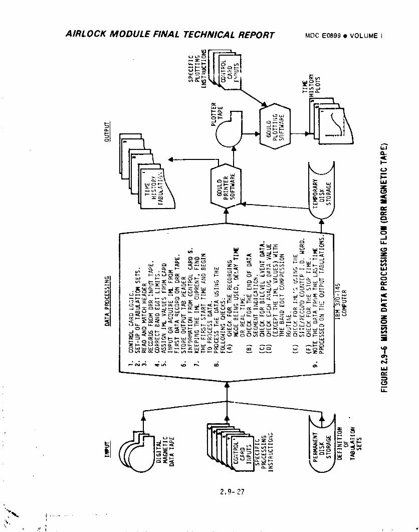
2..0- 27
_,
974018208-63
AIRLOCK MODULE FINAL TECHNICAL REPORT MDC E0899 • VOLUMEI
;_.:I.3.1C'_1_onentand HUAL-L bvstem ]ests
Each different hardware item was either subjected to a qualificatien test or
qualified by similarity to a previously tested like item. During these tests the
component was exposed to various environnw_ntalconditions while the performance
characteristicswere monitored. The environments included vibration, shock,
acceleration, acoustic noise, hiqh and low temperature, pressure, oxygen,
at,re)sphere,humidity, fungus, salt spray, life and RFI. Some of the individual
environn_ntal tests were run with the test article in a nonoperating mode, llowever,
performance checks were run prior to and after the exposure period. Problems
encountered during qual testing that necessitated equipment desi.qnchanges resulted
in retest at that particular environment and repeat of selected previously run
tests that were considered pertinent to the design change verification. All
individual components were acceptance tested by the equipment vendor to verify
specification con_liance prior to hardware delivery; test records were delivered
with each part. At MDAC, each delivered item was subjected to a pre-installation
acceptance (PIA) test; calibration data was taken during these tests. Uninstalled
equipnw_ntwas re-PIA'd on a periodic basis. Individual component testing resulted
in detection and removing suspect parts prior to system assembly, these included
tape recorders, PCM telemetry equipment, power converters, and some sensors.
The InstrumentationSystem w._sutilized as a source ot Veii:Cle systems pert,_rm-
ante data during final tests at HDAC; GS[ displays w_.,,'ealso available to,".,limited
number of measurenents. This dictated checkout of the InstrumentationSystem m'im"
to start of formal vehicle testinq. [lectronic_ r:w_dule3 containing the PC_
multiplexer/encoderhardware, electronics module .icontaininq DC-DC converters and
the tape recorder module were i,_terconne;'tedand operated tin]ether. Simulated
inputs were provided to the PCH h,,rdwarear,ieach channel was individually
monitored to verify proper operation. After installationof these nl_dulesin the
vehicle, there were _ix major svstenls tests. These w,,re performed at botl_ ambient
and at altitude; _o,_,included prime and l_ackupcrew i,articipation. The _IP_was
mated to the A_!JtlYinq the Final tests. The P.1and I.\Swere als,_included in these
: te_ts; a simulator wa_ u,_ed in place of th," workshop. Durinq this te_tinq all
system parameters were evaluated ver_u_ _,rformance specifi,,'ations t, ,nq a valiJated
GSF test complex, with I,,IASAparti_ ]pation. A sunuuar._ot this te_tin,_ is silown in
I-i_lure ;_'.q- 7.
•v _ ,..9 - 28
1974018208-632
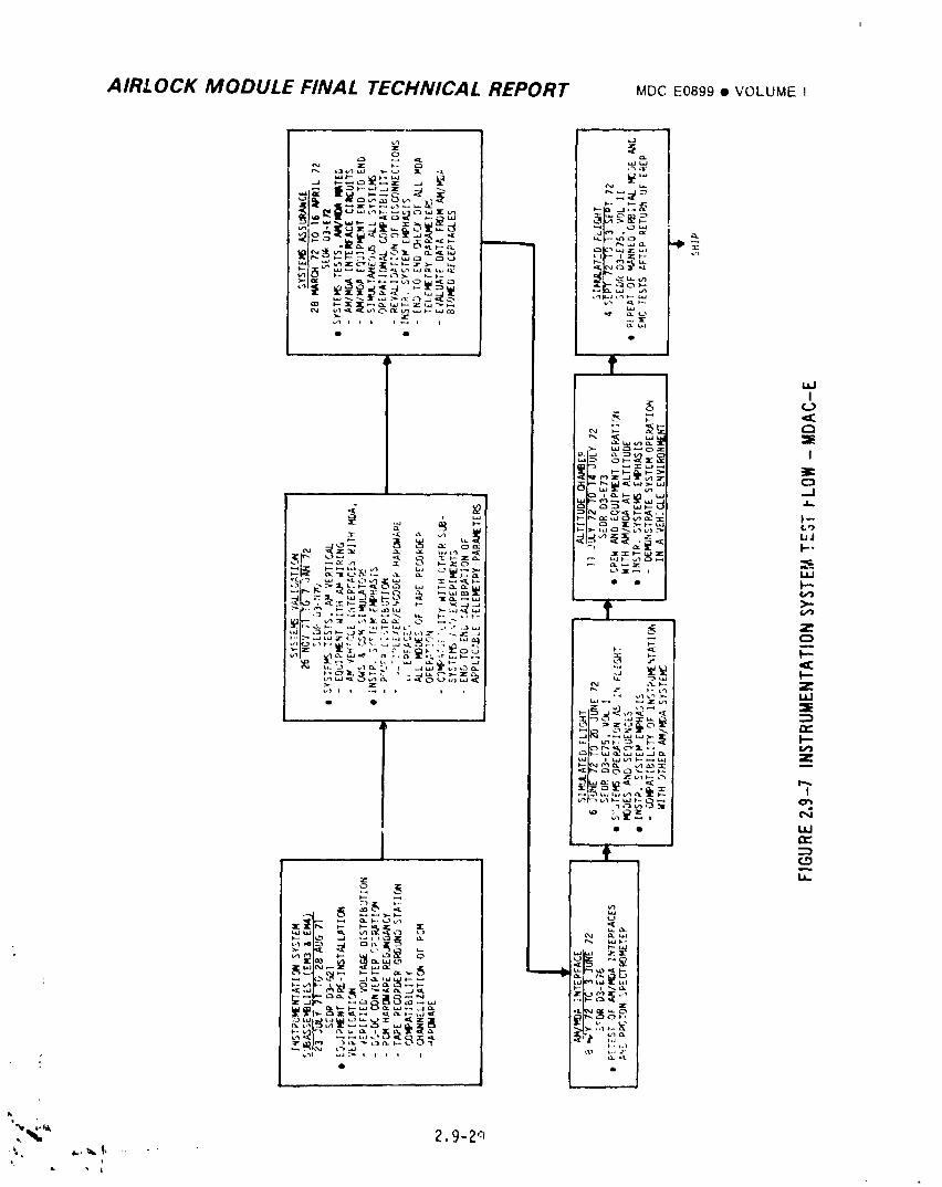
AIRLOCK MODULE FINAL TECHNICAL REPORT MDCE0899• VOLUMEI
","'_' +.9-Z+-+
1974018208-633
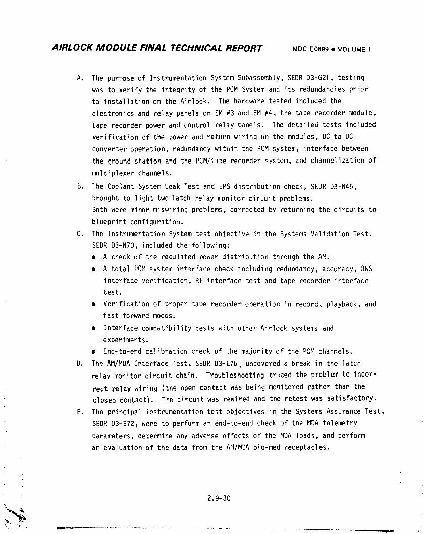
AIRLOCK MODULE FINAL TECHNICAL REPORT MDCE0899• VOLUMEI
A. The purpose of Instrumentation System Subassembly, SEDRD3-G21, testing
was to verify the integrity of the PCM System and its redundancies prior
to installation on the Airlock. The hardware tested included the
electronics and relay panels on EM a3 and EM #4, the tape recorder module,
tape recorder power and control relay panels. The detailed tests included
verification of the power and return wiring on the modules, DC to DC
converter operation, redundancy within the PCMsystem, interface between
the ground stdtion and the PCM/£,_perecorder system, and channelization of
multiplexer channels.
B. lhe Coolant System Leak Test and EPS distribution check, SEDRD3-N46,
brought to light two latch _elay monitor circuit problems.
Both were minor miswiring problems, corrected by returning the circuits to
blueprint configuration.
C. The Instrumentation System test objective in the Systems Validation Test,
SEDRD3-N70, included the following:
e A check of the requlated power distribution through the AM.
e A total PCMsystem interface check including redundancy, accuracy, OWS
interface verification, RF interface test and tape recorder interface
test.
e Verification of proper tape recorder operation in record, playback, and
fast forward modes.
e Interface compatibility tests with other Airlock systems and
experiments.
e End-to-end calibration check of the majority of the PCMchannels.
D. The AM/MDA Interface Test, SEDRD3-E76, uncovered a break in the latcn
relay monitor circuit chain. Troubleshooting tr_.ced the problem to incor-
rect relay wirinq (the open contact was being monitored rather than the
closed contact). The circuit was rewired and the retest was satisfactory.
E. The principal i,_strumentationtest objectives in the Systems Assurance Test,
SEDR D3-E72, were to perform an end-to-end check of the HDA telemetry
parameters, determine any adverse effects of the MDA loads, and perform
an evaluation of the data from the AM/MDA bio-med receptacles.
2.9-30
] 974018208-6:34
AIRLOCK MODULE FINAL TECHNICAL REPORT MDCE0899• VOLUMEI
F. During Lhe AM/MDA Interface Test, SEDR D3-E76, several parameters were
retcsted, a reworked interface box, which cnntained blocking diodes in
the course time shift register circuitry, was verified, and a retest of
th_ n_.-.fiedProton Spectrometer was performed. In the time interval
between SF__R'sD3-E76 and D3-E75 several minor tests were performed by
MPS. A final test of the Experiment MSO9/Tape Recorder Interface was
performed by MPS's 146 and 151.
G. During Simulated Flight Test, SEDR D3.-E75,Vol. I, the primary instrumen-
tation objective was to demonstrate that no mutual incompatibilityexisted
between the InstrumentationSystem and the other AN/MDA systems. A
special test was conducted to demonstrate that the PCM split phase
converter was capable of driving the long facility lines at KSC. This
test, performed "inSt. Louis, was successful and the split phase converter
was shipped to KSC.
H. The instrumentationobjectives in the Altitude Chamber Test, SEDR D3-E73,
were to demonstrate that equipment mounted on the exterior of the Airlock
would operate properly in a vacuum and to verify those instrumentation
components in the ECS that could only be checked at reduced pressure.
I. The instrumentationobjectives in the abbreviated Simulated Flight Test,
SEDR D3-E75, Vol. II, was to verify compatibility with the EREP.
Foilmvinq this last St. Louis test and prior"to shipment to KSC, several
MPS's were performed on the Airlock. The PPCO2 end plates were reworked
to replace the cartridge springs which were subject to permanent set. This
rework and cartridge inspection was performed per MPS 214. A pressure trans-
ducar and pressure switch that failed during SEDR D3-E75 were replaced and
retested by MPS 223.
2.9.3.2 Problems and Solutions
The significant discrepancies resulting from the MDAC-E test phase and their
resolution are presented below. A slgnificant discrepancy is considered one which
requires component or vehicle modification for resolution.
A. Tape Recorder/GroundStation Sync - During systems validation testing, the
telemetry ground station was unable to maintain sync on the delayed time
data from subframe 4 and experiment M509. Investigationrevealed that the
data siqnal was severely attenuated by high cable capacitance between the
: tape recorder and data transmitter. The data had a high successive zero
2.9-31
i,
1974018208-635
AIRLOCK MODULE FINAL TECHNICAL REPORT MDCE0899• VOLUMEI
bit content due to some unused high sample rate channels in the PCMhard-
ware. The tape recorder output circuitry was modified to be compatiblu
with the actual 3500 picofarad wiring capacitance in the vehicle.
Reference voltages were also added to the unused data channels. Retest\
was successfully performed.
B. Elapsed Time Errors - Randomerrors were observed on the least significant
bit (LS8) of elapsed time data byte contained in subframes 2, 3, and 4
during systems assurance testing. It was determined that the digital data
insert pulse from the PCM programmer to the interface box generated an
extra pulse on the bilevel signal outputs. This discrepancy was resolvedby adding blocking diodes to the 24 bilevel gates in the interface box. )
Retest with the modified unit resulted in acceptable time data. "
C. Inconsistent Gas Flowmeter Data - Erratic flowmeter data was observed on
the qas flowmeter outputs during systems assurance testing. Investigation
revealed that a combination of gas turbulence and excessive sensitivity
to that turbulence was causing the erratic data. The performance of one
of the flowmeters was improved by relocatlnq the sensor to an area of
lower turhu!ence and makinq a sliqht adjustment in the C&Wtrip point to
avoid false low flow warninqs. The testinq also identified an incomp-=.i-
bilitv in the wirinq shield groundina confiquration which was causinq a
reduction in the sensitivity of the flowmeters. The shields for all gas
flowmeter systems were reterminated. A retest of the modified configb,'a-
ticn resulted in acceptable data.
D. Proton SpectrometerDigital Output Errors - During systems assurance test-
ing, it was determined that an impeaancemismatch between the proton
spectrometer and the F:]Minterface box caused attenuation of the timing
signal to the spectrometer. The spectrometer was returned to the vendor
for modification. Verification of this fix occurred during AM/MOA
interface retest; again digital errors were noted. The AM side oi:the
interface was changed to expedite solution of this problem, The isolation
capacitor between the PCM interface box and the proton spectromc,ter was
replaced by an isolation resistor and resulted in acceptable operation.
• E. Inconsistent PPCO2 Detector Readings - Erratic PPCO2 d_ta was first noted
during the unmanned altitude chamber runs. All filter cartridges were
replaced prior to the manned testing phase. During the manned phase, the
crew chanqed out cartridges in an effort to correct the inconsistent
2.9-32
i
1974018208-636
AIRLOCK MODULE FINAL TECHNICAL REPORT MDCE0899_ VOLUMEI
rPading, An analysis of these cartridges indicated flow blockage due to
caking of calclum _ulfate from excessive mositu_e content. The source of
this moisture was traced to excessively high gas flow r'_te through the
cartridge. The inlet connection to the PPC02 detector ;'._s removed from
the mole sieve heat exchanger outlet and connected to the inlet of the
heat exchanger. The flow rate was reduced and the detector active car-
tridges were recharged with silica go" 'lithium hydroxide monohydrate in
lieu of sodium hydroxide and calcium sulphate to elimir,ate moisture clogging.
F. Tape Recorder Erratic Operation - Three related problems were observed on
three different tape recorders during the delta simulated flight testing.
These resulted in a design modification to ti_e tape recorder. The first
was observed via the absence of a record light when S/N 22 recorder was
manually commandedon. The cause was determined to be teo little radial
play in the tape reels resulting in the magnetic tape _wisting and coining
off an idler pulley. Some metal-t._-metal rubbing of the reels also occurred
which caused loops in the tape. During this same test period the _ _>e
.notion telemetry signal frem a different recorder was erratic. In_,Jection
of the tape recorder revealed several turns of tape around the capstan
drive which permitted the motion signal to be on until the tape slack was
taken up. The third problem wa_ noted when the motion monitor continued
to indicate tape mution after the recorder was off. Operation of this
recorder in the laboratory indicated that when end of tape w_s reached,
the reels slowly oscillated causing the motion monitor to remain on n_st
of the time. This reel cycling was related to the problems noted with
the other recorders. These conditions were corrected by reshimmin_ the
reel mechanism, modifying the end of tape switch to remove power frc)m the
recorder at end of tape, and subjecting the recorders to a confidence test.
During this testing, a tape recorder drive mechanism rea_ed operatlon.
Investigation re,'ealed dry bearings. A record search indicated one of the
recorders on the U-I vehicle, which was now at KSC, was suspected to have
dry bearings. This unit was returned for inspection and repair. All three
flight units, and the four flight spares were changed-out prior to launch.
"_, 2.9.3.3 Launch Site Testin_ _
At _',_e launch complex, the AM/MDA, FAS, ATM, and PS were mated to the OWSand
:, subsequently to the launch vehicle. Integrated systems testing wa_ performed at
each step; the AM/MDAwas also tested with the CS'I. There were 18 major test_ in
; , Lhis series that culminated in launch of the Skylab. Figure 2.9-8 presents a summary
z.9-3a
1974018208-837
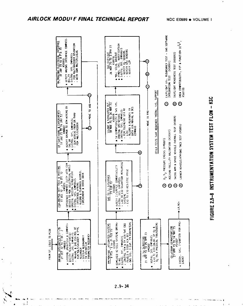
AIRLOCK MODUi F FINAL TECHNICAL REPORT MDCE0899• VOLUMEI
, 2.9- 34
1974018208-638
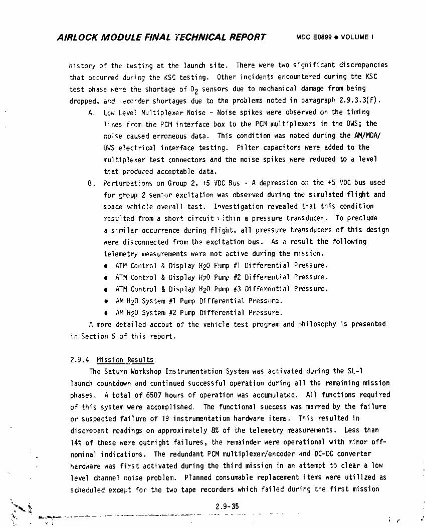
AIRLOCK MODULE FINAL TECHNICAL REPORT MDC E0899 • VOLUMEI
history of the testing at the launch site. There were two significant discrepancies
that occurred dur_r.gthe KSC testing. Other incidents encountered during the KSC
test phase _-le,-ethe shortage of 02 sensors due to mechanical damage from being
dropped, and ,eco_der shortages due to the problems noted in paragraph 2.9.3.3(F).
A. Low Leve_ Multiplexer Noise - Noise spikes were observed on the timing
lines from the PCM interface box to the PCH multiplexers in the OWS; the
noise caused erroneous data. This condition was noted during the AM/MDA/
OWS electrical interface testing. Filter capacitorswere added to the
multiplexer test connectors and the noise spikes were reduced to a level
that produced acceptable data.
B. Perturbationson Group 2, +5 VDC Bus - A depression on the +5 VDC bus used
for group 2 sen._orexcitation was observed during the simulated flight and
space vehicle overall test. Investigation revealed that this condition
resulted from a short circuit _ithin a pressure transducer. To preclude
a slmilar occurrence during flight, all pressure transducers of this design
were disconnected from the excitation bus. As a result the following
telemetry measurementswere not active during the missior_.
• ATM Control & Display H20 FiJmp#I Differential Pressure.
• ATM Control & Display H20 Pump #2 Differential Pressure.
o ATM Control & Display H20 Pump #3 Differential Pressure.
• AM H20 System #1 Pump DifferentialPressure.
• AM H20 System #2 Pump Differential Pressure.
A more detailed accout of the vehicle test program and philosophy is presented
in Section 5 of this report.
2.9.4 Mission Results
The Saturn Workshop InstrumentationSystem was activated during the SL-I
launch countdown and continued successful operation during all the remaining mission
phases. A total of 6507 hours of operation was accumulated. All functions required
of this system were accomplished The functional success was marred by the failure
or suspected failure of 19 instrumentationhardware items. This resulted in
discrepant readings on approximately 8% of the telemetry measurements. Less than
14% of these were outright failures, the remainder were operational with ,T.inoroff-
nominal indications. The redundant PCM multiplexer/encoderand DC-DC converter
hardware was first activated during the third mission in an attempt to clear a low
level channel noise problem. Planned consumable replacement items were utilized as
scheduled except for the two tape recorders which faiIGd during the first mission
"_°_._. 2.9- 35
L,. r ,'; J
1974018208-639
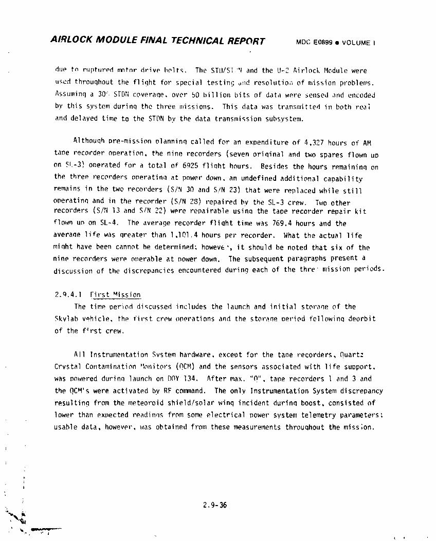
AIRLOCK MODULE FINAL TECHNICAL REPORT MDCE0899• VOLUME I
dl,Ptn r_ptIJrPdnlntnrdrivP bPlts. The STII/Si'N and the U-2 Airlock Module were
t,_edthrouqhout the flight for special testint;_nd resolutio_ of mission problems.
Assuminq a 30",STDN coveraqe, over 50 billion bits of data were sensed ,_ndencoded
by this system durinq the three missions. This data was transmitted in both real
and delayed time to the STDN by the data transmission subsystem.
Althouqh Dre-mission Dlanninq called for an expenditure of 4,327 hours of AM
ta_e recorder operation, the nine recorders (seven oriQinal and two spares flown UD
on Sl.-3)operated for a total of 6925 flinht hours. Besides the hours remaininq on
the three recorders oneratinn at power down, an undefined additional capability
remains in the two recorders (S/N 30 and S/N 23) that were replaced while still
oneratinq and in the recorder (S/N 28) repaired by the SL-3 crew. Two other
recorders (S/N 13 and S/N _) were repairable usinQ the tape recorder repair kit
flown un on SL-4. The average recorder fliQht time was 769.4 hours and the
averane life was qreater than l,lOl.4 hours per recorder. What the actual life
minht have been cannot he determined; howew', it should he noted that six of the
nine recorders were operable at power down. The subsequent paragraphs present a
discussion of the discrepancies encountered during each of the thre mission periods.
2.q.4.1 First _ission
The time period discussed includes the launch and initial storaqe of the
Skvlab vehicle, the first crew operations and the storane period followinq deorbit
of the f_rst crew.
All InstrumentationSystem hardware, except for the tape recorders, Quartz
Crystal Contamination _Ionitors(QCM) and the sensors associated with life support,
was p_wered durinn launch on D(_Y134. After max. "CI",tape recorders l and 3 and
the QCM's were activated by RF cormnand. The only Instrumentation System discrepancy
resulting from the meteoroid shield/solarwing incident durinn boost, consisted of
lower than expected readinqs from some electrical Dower system telemetry parameters,
usable data, however, was obtained from these measurements throuQhout the miss;on.
2.9-36
ilb,
1974018208-640
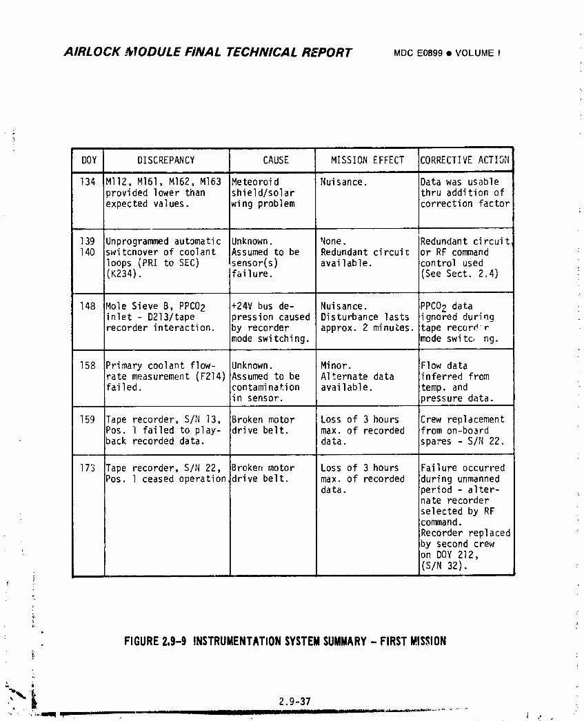
AIRLOCK _VODULE FINAL TECHNICAL REPORT MDCE0899• VOLUMEI
DOY DISCREPANCY CAUSE MISSION EFFECT CORRECTIVEACTIONi i
134 MII2, MI61, M162, M163 Meteoroid Nuisance. Data was usableprovided lower than shield/solar thru addition ofexpected values, wing problem correction factor
139 Unprogrammed automatic Unknown. None. Redundant circuit140 switcnover of coolant Assumed to be Redundant circuit or RF command
loops (PRI to SEC) sensor(s) available, control used(K234). failure. (See Sect. 2.4) :
148 Mole Sieve B, PPC02 +24V bus de- Nuisance. PPCO2 datainlet - D213/tape pression caused Disturbance lasts ignored duringrecorder interaction, by recorder approx. 2 minutes, tape recorder
mode switching, mode switc,,ng.
158 Primary coolant flow- Unknown. Minor. Flow datarate measurement (F214)Assumed to be Alternate data inferred fromfailed, contamination available, temp. and
in sensor. )ressure data.
159 Tape recorder, S/N 13, Broken motor Loss of 3 hours Crew replacementPos. ] failed to play- drive belt. max. of recorded from on-boardback recorded data. data. spares - S/N 22.
173 Tape recorder, S/N 22, Broken motor Loss of 3 hours Failure occurredPos. l ceased operation drive belt. max. of recorded during unmanned
data. _eriod - alter-nate recorder
selected by RFcommand.
Recorder replacedby second crewon DOY 212,(S/N 32).
t
i,
FIGURE2,9-9 INSTRUMENTATIONSYSTEMSUMMARY- FIRSTMISSION
o
\
1974018208-841
AIRLOCK MODULE FINAL TECHNICAL REPORT Mr>cE0899• VOLUMEI
There were four instrumentationhardware items that failed during thc #irst
mission. Two tape recorders ceased operation due to broken drive belts; both units
were replaced from on-board spares resulting in minimal los_ of data. A flowmeter
in the primary coolant loop failed on DOY 158. Contamination was suspected to be
the cause. The cause of the coolant loop switchovers that occurred early in the
first mission was attributed to failure of one or more of the sensors used in the
automatic switchover circuit,
During this time period, there were more than 935 tape recorder dumps to the
STDN. The premission estimate of tape recorder usaqe was exceeded by more than
4_0 hours. This was due to the lO-day delay in launch of the first crew.
Figure 2.9-9 presents a summary history of InstrumentationSystem discrepancies
el_counteredduring the first mission.
2.9.4.2 Second Mission
This time period started with the launch of the second crew on DOY 209 and
continued through the storage period following deorbit of this crew.
The system performance during this time period was similar to the first mission,
all functional requirementswere accomplish._d. There were two hardware items that
experienced partial failure. The fine ovc_ut from the +X QCM became erratic and
went below scale. The associated sign]l conditioner is believed to have caused
this discrepancy. The ot:,e;"failure concerned the intermittent operation of low
level m_:ItiplexerB in the OWS. No cause was found fo_ this problem. The multi-
plexer experienced intermittentoperation during the remainder of all missions.
Other discrepancies included minor off-nominal performance for several other
parameters. These are discussed in Figure 2.q-lO in chronological order of
occurrence.
There were approximately 1400 cape recorder dumps to the STDN during this
mission. One tape recorder was replaced due to excessive bit errors after it had
exceeded its specification life.
2.9-38
1974018208-642
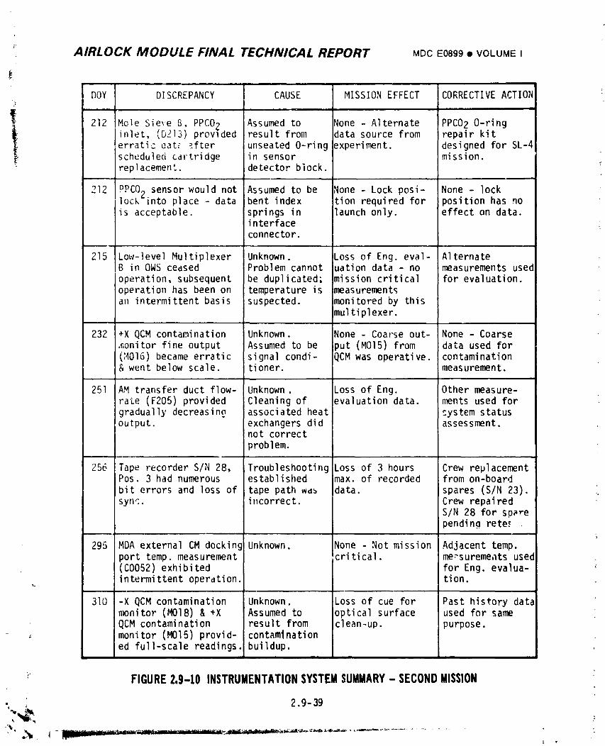
_ AIRLOCK MODULE FINAL TECHNICAL REPORT MDCE0899® VOLUMEI
DOY DISCREPANCY CAUSE MISSION EFFECT CORRECTIVEACTION;_
J i im i
212 Mole Sieve B, PPCO2 Assumed to _one - Alternate PPC02 O-ring
inlet, (DZ]3) provlded result from data source from repair kiterratic oat_ _fter unseated O-ring _:xperiment. designed for SL-4scheduled cartridge in sensor mission.replacement, detector block.
212 PPCO; sensor would not Assumed to be _lone - Lock posi- None - locklock_into place - data bent index tion required for position has nois acceptable, springs in launch only. effect on data.
i nterfaceconnector.
, , , • , ,
215 Low-level Multiplexer Unknown. Loss of Eng. eval- AlternateB in OWSceased Problem cannot uation data - no measurements usedoperation, subsequent be duplicated; mission critical for evaluation.operation has been on temperature is ;measurementsan intermittent basis suspected, imonitored by this
Jmultiplexer.
232 +X QCMcontamination Unknown. None - Coarse out- None - Coarsemonitor fine output Assumed to be iput (MOI5) from data used for(_4016) became erratic signal condi- QCMwas operative, contamination& went below scale, tioner, measurement.
251 AM transfer duct flow- Unknown. Loss of Eng. Other measure-rate (F205) provided Cleaning of evaluation data. ments used forgradually decreasing associated heat system statusoutput, exchangers did assessment.
not correctproblem.
256 Tape recorder S/N 28, Troubleshooting .oss of 3 hours Crew replacementPos. 3 had numerous established max. of recorded from on-boardbit errors and loss of tape path Wd_ data. spares (S/N 23).sync, incorrect. Crew repai red
S/N 28 for sparependina rete,_
295 MDAexternal CM docking Unknown. None - Not mission Adjacent temp.port temp. measurement critical, me:surements used(C0052) exhibited for Eng. evalua-i ntermi trent operati on. ti on.
310 -X QCMcontamination Unknown. Loss of cue for Past history datanmnitor (MOIS) & +X Assumed to optical surface used for sameQCMcontamination result from clean-up, purpose.
_ monitor (MOI5) provid- contaminationed full-scale readings, buildup•
FIGURE2.9-10 INSTRUMENTATIONSYSTEMSUMMARY- SECONDMISSION
,, . 2.9-39
] .
i974018208-643
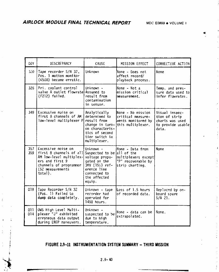
AIRLOCK MODULE FINAL TECHNICAL REPORT MDCE0899• VOLUMEI
| '"'
DOY DISCRFPANCY CAUSE MISSION EFFECT CORRECTIVE ACT!ONi
320 Tape recorder S/N 32, Unknown None - Does not NonePos. l motion monitor affect record/(K508) became erratic, playback process.
326 Pri. coolant control Unknown - None - Not a Temp. and pres-valve A outlet flowratelAssumed to mission critical sure data used to(F212) failed, result from measurement, infer flowrates.
contaminationin sensor.
349 Excessive noise on Analytically None - No mission VisLialinsDec-first 8 channels of AM determined to critical measure- tion of striplow-level multiplexer P result from ,_nts monitored by charts was used ,-
change in turn- this multiplexer, to provide usableon characteris- data.tics of secondtier switch inmultiplexer.
357 Excessive noise on Unknown - None - Data from None359 first 8 cilannelsof all Suspected to be all of the
AM low-level multiplex- voltage propa- multiplexers excepters and first 9 gated on the "P" recoverable bychannels of prograni1_er3MV (15",_)ref- strip charting.(52 measurements erence linetotal), connected to
the affected
equip.
019 Tape Recorder S/N 32 Unknown - tape Loss of 1.5 hours Replaced by on-(Pos. l) Failed to recorder had of recorded data. board spare
dump data completely, operated for S/N 21.1450 hours.
011 OWS High Level Multi- Unknown - None - data can be None.014 plexer "J" exhibited suspected to be
erroneous data output due to high extrapolated.during EREP maneuvers, temperature.
I
FIGURE2.9-11 INSTRUMENTATIONSYSTEMSUMMARY- THIRDMISSION
1974018208-644
k_
AIRLOCK MODULE FINAL TECHNICAL REPORT upc EOS._.o• VOLU_,E,
2.Q.4.3 Third Mission
lho time _eriod to be discussed started with the ;aunch of the _Inal crm,,and
ended with their dem'b_t L_,I{'OY3-;. Discrei_anciesdurin,_thi:.;;e"i.-.Jare
• ._,idressedin Finure 2.9-II.4
There was one major discret_ancvassociated with this svste,-durinq tt,etinal
,,i_,;ian._-iCtv-twolow level telemetry channels exhibited e\cessiv,,noise on
.,a.,a,;dcontinued thls way throuqh the completion or"the missien. The meas,_"e-
ments were contained in all the .I._Imp level multiplexers and :n the _,roqra,'r_er.
The redundant protlral,lner, other hat f of the interface be: and an alternate PC-PC
c �`�xwere activated for the fir._t time in an attemt_t to ."ear this problem.
I Investiqation of this problem reveal,,d that tile nk_st probable cause of the problem
was a voltaqe propaqated on the 3 mtllivolt (15".._ reCerence line connected to all
the affected multiplexers and the nronranlners, causinq a failure in each of the
affected boxes. Usable data was obtained throuO visual inspection of strip chart_cordinQs of the affected nw_asurements.
The one tai_e r_,corder failure durinq tt_e SL-4 Hission occurred on ',_0_ 19.
when S'N 32 failed in th,, playback mode, after acctimulatinq 1450 hours. S ._ .'3
; t,lp_ recorder was roplac_,d on i_OY 21 by S'N 14. At the time of renlacem,,nt, it
: was still oueratinn satisfactorily but had accumulated 1"',,_,1hour¢..
Other discrepancies included failure of a primary coolant loop flo_,_eter and
SoP_e "li IlOt" off--llOIlli hal readi llqs fl'Ol" telemetry 11_aStll'el_lOI1 tS.
; 2.,I.5 Conclusions and Ruco,l_endation._
t The Instrumentation Sv,;tem de.,,iqn and the ade,luaCy of the develop,_:nt and t,,_ti r,ro,lram_ associated with this system were reviewed in view of its performance din'in4
the Skvlab mission. The followin.qconclusions and reconm_endatiensresulted from
this review.
,2.c_.5.1 Conclusions
: The lnstrmm, ntation System was ot_erational durinq all tq_ases of the Sks'l,lb
" mi s._ion and stlcces_¢u11 v acqui red, mul t i pl e\ed and encoded sel ec ted vehi cl e ,_vs .,'eros,
e\neriment and biomedical data. Pata handl_n(1 included telemetry down,_nk, crew
¢ dist_l ws and PCH hardlino for t_rolaunch utilization
; ,'. _-41=
% - _'* i
1974018208-645
AIRLOCK MODULE FINAL TECHNICAL REPORT MOCE0899• VOLUMEI
During the mission, the syste,,sampled and encoded over 1200 input parameters
and transmitted in real time approximately 4 x IOII bits of data. An additional
IOII bits of data, excluding voice comments,were recorded on the AM tape recorders
and transmitted during delayed time data dumps. Over 3650 delayed time data dumps
were successfully initiated. Followi1:gthe resolution of early mission STDN
station(s) PCM bit synchronization problems, ground recovery of all data was
consistently good.
Although some discrepancies occurred during tF.emission with certain sensors,
low level multiplexers and tape recorders, the system concept and design proved
extremely feasible for _meting the unique mission requirements and for handling
the large quantity of data involved.
2.9.5.2 Recommendations
The following items were identified during system testing and/or mission
support activities and are recommended to further improve the capabilities of the
Instrumentation System:
A. Reduce quantity of transmitted data by utilizing data compression
techniques, or by providing priority selection capability of data to
be recorded/transmitted.
B. Minimize dependence on life limited items, such as tape records for
data recovery, to the maximum extent possible during system design.
C. Improve techniques to more accurately measure gas Flow. Install gas
flow measuring device at a location where gas Flow turbulence is
minimal.
D. Utilize a differential pressure device to measure liquid flow in lieu of
the presently used inline turbine type device. This change would reduce4"
handling and contamination problems encountered with the present sensor.
E. Include the capability to control the temperature of the quartz crystal
contaminationmonitor to improve comparative measurement.
F. Improve the design of the water system differential pressure transducer.
The Skylab sensor incorporated a fluorosilicone/dacrondiaphragm which
did not provide an adequate barrier between the water and the electricalL
protion of the sensor. A diaphragm consisting of Ethylene Propylene
_ using Terpolymer compound #726 as the elastomer is believed to be7,
compatiblewith water and stronger than the existing diaphragm.
2.9-42i
1974018208-646
- AIRLOCK MODULE FINAL TECHNICAL REPORT MDCE0899• VOLUMEI
L
_ G. Improvetechniquesto measurePPCO2. The SkylabCO2 detectorwas of
1962 vintage. Smallerand more accurateCO2 monitorsare now available,
such ._san electrochemicalsensor. These new sensorsare easierto
install,are more accuratebecauseof insensitivityto the atmosphere
and have lesslongter_,_drift,and requirerelativelylittlemaintenance.
H. Providediscretemeasurementsvia telemetryto allowsystemconfiguration
and controlstatusinformationto be availablefor missionsupport
- activities.
2.9-431 44
4 ,
1974018208-647
Related Documents