NASA TECHNICAL MEMORAWRUM - - CASE FILE.% py AUXILIARY LOOP FOR REMOVAL OF DECAY HEAT FROM A SPACE POWER REACTOR by G~eorge B. Ttrrnqr ad Edward J. Petri&

Welcome message from author
This document is posted to help you gain knowledge. Please leave a comment to let me know what you think about it! Share it to your friends and learn new things together.
Transcript

N A S A T E C H N I C A L
M E M O R A W R U M - -
CASE FILE.% py
AUXILIARY LOOP FOR REMOVAL OF DECAY HEAT FROM A SPACE POWER REACTOR
by G~eorge B. Ttrrnqr a d Edward J. Petri&

National Aeronautics and Space Administration
Technical Memorandum National Aeronautics and Space Administration Washington, D. C. 20546
removing decay heat from a proposed 2.17-megawatt space power reactor. Based on a selected set of operating conditions and assumptions, minimum areas were deter- mined for the auxiliary loop heat exchanger and radiator. The minimum auxiliary
the maximum temperature of the auxiliary radiator was about 1 7 6 0 ~ R (978 K). The flow rates and temperatures of sodium in the auxiliary loop were determined a s a function of time after reactor shutdown for reactor operating times (before shutdown) of 1 year and 1 day. A significant conclusion from the preliminary study is that the size (and/or mass) of the auxiliary loop is relatively small.
Unclassified - unlimited Space power reactor
Unclassified Unclassified
*For s a I e by the Clearinghouse for Federal Scientific and Technical Information Springfield, Virginia 22151

AUXILIARY LOOP FOR REMOVAL OF DECAY HEAT FROM
A SPACE POWER REACTOR
by George E. Turney and Edward J. Petrik
Lewis Research Center
SUMMARY
An auxiliary loop using sodium as a coolant was investigated as a means for remov-
ing decay heat from a proposed 2.17-megawatt space power reactor. This loop consists of an auxiliary radiator, an auxiliary heat exchanger, a liquid sodium pump, and the necessary flow control valves and piping.
Based on a selected set of operating conditions and assumptions, minimum areas were determined for the auxiliary loop heat exchanger and radiator. The minimum auxiliary heat exchanger surface area required to transfer the decay heat from the re-
2 2 actor loop to the auxiliary loop was 0.64 ft (0.0594 m ). The minimum auxiliary radi- 2 2 ator surface area required to reject the decay heat was 37.7 ft (3.50 m ). Based on
these areas , the maximum temperature of the auxiliary radiator was 1760' R (978 K). The configurations and minimum areas for the auxiliary loop heat exchanger and
radiator were used to determine sodium flow rates and temperatures throughout the auxiliary loop a s a function of time after reactor shutdown. The sodium flow rates and temperatures were determined for preshutdown reactor operating times of 1 year and 1 day.
It was concluded from this preliminary study that the size (and/or mass) of the auxiliary loop is relatively small,
INTRODUCTION
In the coming years, the electric power requirements for our nation's projected space programs will continue to increase. To meet these projected requirements, the Lewis Research Center has been participating in a technology program aimed a t a rela- tively high-powered nuclear Brayton space powerplant.
The heat source being considered for the Brayton cycle space powerplant is a com-
pact, fast-spectrum nuclear reactor. The design thermal output of the reactor i s 2 .17 megawatts, and the design operating lifetime for the reactor and powerplant has been se t
a t 50 000 hours.
An a r e a of concern in the overall design of this powerplant is the removal of decay
heat from the nuclear reactor following a system shutdown Although shutdowns a r e un-
desirable, particularly in a space power system, they must be considered in the system
design. And provisions must be made for removing the reactor decay heat following a
shutdown.
In this report, an auxiliary radiator loop with sodium coolant is investigated a s a
means for removing reactor decay heat. The objectives of this preliminary investigation
a r e (1) to determine the size of an auxiliary radiator which will reject the decay heat and
operate a t an acceptable temperature level during the shutdown period, (2) to determine
the size of an auxiliary heat exchanger which will transfer the decay heat from the re -
actor primary loop to the auxiliary radiator loop, and (3) to evaluate the sodium flow
ra tes and temperatures in the auxiliary radiator loop a s a function of time after shutdown.
An important consideration related to shutdown is the ability to r e s t a r t the system
and return it to the design operating level in a minimum amount of t ime. Based on this
consideration, a mode of operation was chosen in which the reactor coolant temperatures
were maintained a t their respective design values during the period of shutdown.
DESCRIPTION OF POWERPLANT
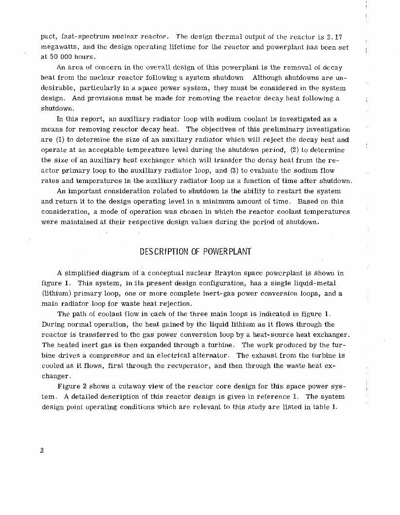
A simplified diagram of a conceptual nuclear Brayton space powerplant is shown in
figure 1. This system, in its present design configuration, has a single liquid-metal
(lithium) primary loop, one o r more complete inert-gas power conversion loops, and a main radiator loop for waste heat rejection.
The path of coolant flow in each of the three main loops is indicated in figure 1. During normal operation, the heat gained by the liquid lithium a s it flows through the
reactor is transferred to the gas power conversion loop by a heat- source heat exchanger.
The heated inert gas is then expanded through a turbine. The work produced by the tur-
bine drives a compressor and an electrical alternator. The exhaust from the turbine is cooled as i t flows, first through the recuperator, and then through the waste heat ex-
changer.
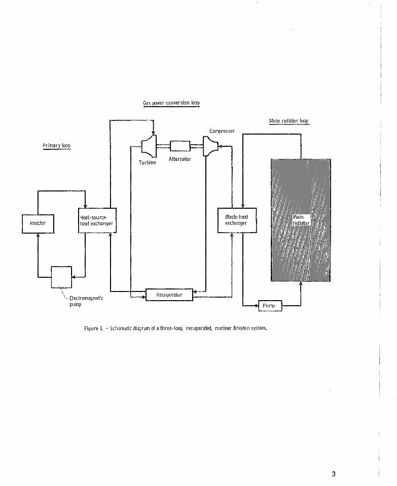
Figure 2 shows a cutaway view of the reactor core design for this space power sys-
tem. A detailed description of this reactor design is given in reference 1. The system
design point operating conditions which a re relevant to this study a r e listed in table I.
Gas power conversion loop
Primary loop
Figure 1. - Schematic diagram of a three-loop, recuperated, nuclear Brayton system.
23 in. x--
CD-10412-22
F igure 2. - Nuclear Brayton space power reactor.
TABLE I. - DESIGN POINT OPERATING CONDITIONS
Lithium temperature a t reactor inlet, OR (K)

AUXILIARY LOOP
General Considerations
Following a shutdown of the nuclear reactor , decay heat continues to be generated in
the reac tor core a t a r a t e which depends pr imari ly on (4) the reac tor ' s initial operating
power level, and (2) the period of t ime during which the reactor was in operation before
the shutdown. In a space power reactor , the decay heat must ultimately be rejected to
space by some type of waste-beat radiator.
It may be both impractical and undesirable to use the main radiator loop of the sys-
tem (fig. I) as a primary scheme for rejection of decay heat. It is conceivable that a
shutdown may be caused by a failure in the main radiator loop. In such case, it may be
impossible to use the main radiator. Furthermore, it may be desirable in the system
design to have a method for rejection of decay heat which is independent of the main sys-
tem operation.
Auxiliary Loop Descr ip t ion
One scheme for rejecting the decay heat is to use a liquid-metal auxiliary radiator
loop. Figure 3 shows a sodium-cooled auxiliary loop which is connected to the reac tor
pr imary loop by an auxiliary heat exchanger. The auxiliary loop consists of a high-
temperature auxiliary radiator, an auxiliary heat exchanger, a liquid- sodium pump, and
the necessary flow control valves and piping. Sodium was selected a s the coolant in the
auxiliary loop because it has a reasonably low melting point and also a relatively low
vapor pressure for the temperatures which we will be considering.
During normal system operation, nearly a.11 the heat generated in the reac tor is
t ransfer red to the gas power conversion loop. But when a shutdown occurs, the decay
heat generated in the reactor must be t ransfer red to the auxiliary loop. To accomplish
this, the flow of lithium in the pr imary loop must be bypassed around the heat-source
heat exchanger; and the sodium flow ra te in the auxiliary loop must be increased to
t ransfer the decay heat. Hence, the auxiliary loop undergoes a transient s tar tup imme-
diately foil-owing the reactor shutdown.
Operat ing Assumpt ions
To investigate the operation of this loop, some assumptions were made regarding
the initial conditions in the loop and the mode of operation of this loop during the reactor

Auxi l iary loop (sodium coolant)
-------
(Lithium coolant)
Figure 3. - Pr imary loop with auxi l iary radiator loop for decay heat rejection. (See appendix for number designaiions.
shutdown transient. Fo r the preliminary investigation presented herein, we assume that
the shutdown is not the resu l t of a ser ious failure and that, as a consequence, the sys-
tem is capable of being res ta r ted and returned to its design operating condition.
As a point of interest , the restar t ing of this fast-spectrum reactor is, in some r e - spects, l ess complicated than that of a thermal-spectrum reac tor . This is because the
xenon-135 and samarium-149 concentrations, which build up after shutdowns, do not a c t
as strong absorbers (i. e . , their absorption c ros s sections a r e small) for high-energy
neutrons. And the problem of overriding the poisoning effects of these isotopes is far less ser ious in this reac tor .
The major assumptions used in this preliminary analysis and related t o the operat-
ing conditions a r e l isted below:
(1) The lithium temperature a t the reactor inlet is maintained constant a t 2100' R (1169 K) during the shutdown. (This is the design point operating temperature (table I). )
(2) The lithium temperature a t the reactor outlet is held constant a t 2200' R ($222 K)
during shutdown. (This is also the design point operating temperature (table I). )
(3) The initial temperature of sodium in the auxiliary loop a t shutdown is 100' R
(55. 6 K) above the melting temperature of sodium, or 770' R (428 K).
(4) In order to keep the auxiliary loop temperatures reasonably uniform after shut-
down, we assume the mixed-mean temperature difference across the auxiliary heat ex-
changer to be constant a t 100' R (55.6 K); that is, (TNa, - TNa, ) = 100' R (55.6 K).
(All symbols a r e defined in appendix A. )
(5) A maximum allowable sodium temperature of 1760' R (978 K) a t the auxiliary
radiator inlet is assumed. Assumptions (1) and (2) a r e consistent with a requirement that the system be capable
of being restarted in a minimum time. Maintaining the primary loop temperatures at their respective design values will minimize the time required to return the system to
its design operating level.
The selection of an auxiliary loop temperature of 770' R (428 K) (assumption (3)) was
based on several considerations. F i rs t , this initial (or standby) temperature level of
770' R (428 K) gives a reasonable margin of safety against freezing of sodium in the
auxiliary loop. At the same time, this temperature is low enough during standby oper-
ation that the heat rejected by the auxiliary radiator (which is a parasitic thermal load)
is small relative to the reactor design thermal power.
Assumptions (4) and (5) limit the operating temperature and the differential tempera-
tu re in the auxiliary loop. These values should not be considered a s absolute limits.
They were selected somewhat arbi trar i ly for this preliminary investigation in order to
place some constraint on the operating conditions in the auxiliary loop during the decay
heat removal period.
Auxiliary Loop Flow Models
In order to make a preliminary investigation of this loop, simplified flow models
were developed to represent the auxiliary radiator and auxiliary heat exchanger. The
auxiliary loop material (including the auxiliary heat exchanger, auxiliary radiator, and
piping) is assumed to be tantalum. All tantalum physical properties used were taken
from reference 2 . A description of the flow models is given below.
Auxiliary heat exchanger. - The auxiliary heat exchanger is a counterflow type,
consisting of two concentric cylindrical ducts. Figure 4 is a sketch of the auxiliary heat
exchanger. Lithium is assumed to flow through the inner passage, and sodium flows

L i t h f low Section A-A
Figure 4. - Aux i l i a ry heat exchanger flow model.
TABLE 11. - AUXILIARY HEAT EXCHANGER CROSS-
SECTIONAL CONFIGURATION
Inside diameter of sodium annular flow passage, in. (cm) Outside diameter of sodium annular flow passage, in. (c
cou~ltercurrent ly in the annular passage. Based on preliminary estimates of the a r e a
requirements of this heat exchanger, a cross-sectional configuration was selected. The cross-sectional configuration is described in table II.
Auxiliary radiator . - The auxiliary radiator is made up of a number of coplanar
parallel tubes with central connecting fins. F o r this study, the effectiveness of the fins
was assumed to be 100 percent. A sketch of the auxiliary radiator configuration is shown in figure 5.
Prel iminary estimates were made to determine the a r e a requirements and a reason-
able planform configuration for the auxiliary radiator. From these estimates, a c ross-
sectional configuration was selected. It i s based on the assumption that beat is rejected

TABLE 111. - AUXILIARY RADIATOR CROSS-SECTIONAL CONFIGURATION
-
Outside diameter of tubes, in. (cm) Inside diameter of tubes, in. (em)
t o space f rom both s ides of the auxiliary radiator. A description of the auxiliary radi-
a to r cross-sectional configuration is given in table 111.
The central fin width (1.055 in. o r 2 .68 cm) was chosen for convenience. With this
fin width, the surface a r e a of a l l tubes is equivalent to the product of total radiator su r -
face a r e a (which includes tubes and connecting fins) and the configuration factor f rom the
auxiliary radiator to space.
ANALY S IS
Heat-Transfer Corre lat ions
The correlations used to compute the ra te or" heat flow in the auxiliary loop a r e de-

scribed below. The heat-transfer coefficient on the lithium side of the auxiliary heat ex-
changer was computed from the correlation (ref. 3)
The lithium properties used in this study were obtained from reference 4.
The sodium heat-transfer coefficient of the annular flow passage was determined
from the equation (ref. 5).
The physical properties of sodium were taken from reference 6.
The overall heat- transf e r coefficient for the auxiliary heat exchanger, based on the
surface a r e a of the sodium side, is given by
In the auxiliary radiator, an infinite heat-transfer coefficient was assumed on the
liquid-sodium side of the flow passages. This assumption is discussed later in this
section.
Analytical Equations
Primary loop. - The lithium flow ra te required to maintain a constant temperature
difference of 100' R (55.6 K) across the core a t any time t after shutdown is given by
where TLi, = 2200' R (1222 K) and TLi, = 2100' R (1167 K). In equation (4), Q is
the decay heat generation rate, which varies with time after shutdown.
Auxiliarv loop. - The total flow rate of sodium needed to maintain a constant mixed-

mean temperature difference of 100' R (55.6 K) in the auxiliary loop at any time t after
shutdown is given by
From operating assumption number (4) in the section AUXILIARY LOOP,
( T ~ a , 8 - T ~ a , 5 ) is constant and equal to loo0 R (55.6 K) throughout the shutdown period.
The decay heat generation rate and the overall lithium-to-sodium temperature differ-
ence ac ross the auxiliary heat exchanger change with time following a shutdown. Conse-
quently, the flow ra te of sodium in the auxiliary heat exchanger wNa, must also change
with time. The sodium flow ra te needed to transfer the decay heat from primary loop to
auxiliary loop at any time t after shutdown was determined from the equation
The sodium flow ra te which bypasses the auxiliary heat exchanger is the difference be-
tween the total sodium flow rate and the sodium flow rate which goes through the auxil-
ia ry heat exchanger; that is,
The effectiveness of the counterflow auxiliary heat exchanger (E in eq. (6)) is also
time variant, and is defined by the following expression (ref. 7):
The sodium temperature a t the outlet of the auxiliary heat exchanger was determined
from the equation
For calculational purposes, the flow passages in the auxiliary radiator were con-
sidered to be made up of a number of equal length segments arranged in ser ies . (The actual cross-sectional configuration of this radiator is described in table III. ) A sketch

Outlet
In le t I Inside surface
Figure 6. - Analytical model used to represent auxi l iary radiator.
of the analytical model for the auxiliary radiator is shown in figure 6. As indicated in
the figure, each tube in the auxiliary radiator was assumed to be made up of "nu seg-
ments. A segment length of 1 . 8 inches (4.57 cm) was used in the analysis. The reason
for using a segment length of 1 . 8 inches or 4.57 cm is given later in this section.
The following assumptions were used in the auxiliary radiator calculations:
(1) The temperature drop through the auxiliary radiator tube wall is negligible.
(2) Heat conduction along the length of the auxiliary radiator is negligible.
(3) Only the thermal capacitance of the auxiliary radiator (which includes tubes and
fins) is considered.
(4) Sink temperature is constant and equal to 400' R (222 K).
(5) Radiator surface emissivity E is equal to 0.80.
With steady flow in the auxiliary radiator, a n energy balance on a typical segment
(e. g. , segment j ) is
Rate of change of Rate of heat trans- Rate of change in Rate of heat re- sodium internal fer from sodium sensible heat of jection by radi-
- - - - energy across to radiator wall radiator seg- + ator segment j
segment j in segment j ment j to sink
Or, in equation form, -
- W ~ a , / ~ ~ p ~ a d T ~ a , j = hR A+ (? Na, j - T ~ , j)
In equation (11) the subscripts i and o on AA refer to the inside and outside surfaces
of the radiator tubes (see fig. 6). With liquid-sodium flow, the wall-to-bulk temperature difference in the auxiliary
radiator tubes is relatively small. (For a radiator temperature of 1 '200~ R (944 K), the
wall-to-bulk. AT with turbulent flow is less than 10' R (5.56 K). ) Therefore, we can
neglect the liquid-metal film resistance and assume that T R, - - TNa, without introduc-
ing a significant e r ro r . And equation (I 1 ), in finite-difference form, becomes
where
- - T ~ a , j, in + T ~ a , j , out
T ~ a , j - 2
The sodium flow ra te in the bypass around the auxiliary radiator is given by
The mass of each radiator segment (i. e. , the value of AM in eq. (11)) was deter-
mined from the cross-sectional configuration listed in table 111 along with the assumed
length of the segments. As stated earl ier in this section, only the mass of the auxiliary
radiator (which includes tubes and fins) was considered in the study; and the thermal
capacitance of the auxiliary heat exchanger, inlet plenums, valves, and piping were
ignored.
The time interval AT used in equation (12) is equal to the auxiliary loop transport
delay (or delay time). The transport delay is defined a s the time required for the sodium
coolant to traverse the auxiliary loop. Expressed a s an equation,
Total volume of auxiliary loop A, = - Sodium volumetric flow rate

AT = (Volume of auxiliary radiator) + (Volume of auxiliary loop flow lines) (16)
W ~ a , 5
3 A volume of 0. 260 cubic feet (0.02835 m ) was assumed for the auxiliary loop flow
lines. This volume is equivalent to that of a I. 5-inch- (3. 81-cm-) inside-diameter pipe
with a length of about 2% feet (5. I m) .
The volume of the auxiliary radiator is equal to the product of the auxiliary radiator
flow a r e a and length. The flow a r e a is obtained from table 111, and the procedure used to
de'termine the length of the auxiliary radiator is described later in this section.
Analytical Procedure
A digital computer code was written to analyze the decay heat removal from the pri-
mary loop of the nuclear space powerplant. For purposes of analysis, the removal of
decay heat from the primary loop can be considered to take place in two sequential steps.
F i rs t , for some period of time immediately following a shutdown, most of the decay
power goes to increasing the sensible heat of the sodium-cooled auxiliary loop. During
this period, the sodium flow ra tes through and around the auxiliary heat exchanger
(fig. 3) a r e regulated such that the mixed-mean sodium temperature r i se ac ross the
auxiliary heat exchanger is 100' R (55.6 K). (This is consistent with operating assump-
tion (4) in the section AUXILIARY LOOP. ) Throughout this auxiliary loop heat-up period,
the total flow of sodium passes through the auxiliary radiator. And the auxiliary loop
temperature is raised from its initial value of 770' R (428 K) to some selected final oper-
ating temperature. (In the section AUXILIARY LOOP, a maximum allowable sodium tern-
perature of 1 7 6 0 ~ R (978 K) a t the auxiliary radiator inlet was assumed. )
The second part of the decay heat removal period begins when the sodium tempera-
ture a t the auxiliary radiator inlet reaches its final operating temperature. Then, the
mixed-mean sodium temperatures in the auxiliary loop (TNa, and TNa, in fig. 3)
a r e held a t their respective levels by regulating the flow ra tes of sodium through and
around the auxiliary heat exchanger and auxiliary radiator. A sketch of the typical his-
tory of the sodium temperature a t the auxiliary heat exchanger inlet following a shutdown
is shown in figure 7.
In the following paragraphs, we describe the procedure used in the decay heat r e -
moval analysis. Decay heat generation ra tes for the space power reactor were calculated
for several full-power operating time periods. The method of calculating the decay heat
Increasing t ime after shutdown
Figure 7. -Typical h is to ry of sodium temperature at auxi l iary heat exchanger i n l e t as funct ion of t ime after shutdown.
r a t e s is described in reference 8. From these calculated values, an upper and lower
limit for decay heat generation rate was determined. The upper limit corresponds to a
reactor full-power operating period of 1 year; the lower limit corresponds to a full-
power operating period of 1 day.
An iterative technique was used to determine the minimum areas required by the auxiliary heat exchanger and auxiliary radiator. The upper limit of decay heat genera-
tion was used a s the basis for these calculations. The calculations were made by picking
t r i a l values of a r e a (or length) for the auxiliary loop heat exchanger and radiator.
With these trial values, flow ra tes and temperatures were calculated in the auxiliary
loop a s a function of time after shutdown.
The temperatures and flow ra tes obtained were then used a s guidelines to update the
a r e a s (or lengths) of the auxiliary heat exchanger and auxiliary radiator. The calcula-
tions were then repeated with the updated areas . This calculational procedure (in which
successive computations were made with updated values of a rea or length) was continued
until the final a reas (or lengths) obtained were minimum values consistent with the estab-
lished temperature limitations for the auxiliary loop.
The flow rate in the auxiliary heat exchanger wNa, was calculated a s a function of
t ime after shutdown from equations (6) and (8). An iterative technique was used to solve
these equations for each t r ia l value of auxiliary heat exchanger area .
The sodium temperature a t the auxiliary radiator outlet TNa, was determined by
numerically integrating equation (11) from auxiliary radiator inlet (segment I ) to outlet
(segment n) . As stated earl ier in this section, the total sodium flow rate passes through

the auxiliary radiator dtrrmg the au~i l ia~ry- loop heatup period. But when the sodium tem- perature a t the auxiliary radiator i n k t reaches 1'560~ IEZ (958 K), the decay heat genera-
tion r a t e must be balanced by the net ra te of heat lost by the sodium in the a u i l i a r y radi-
a tor . This cr i ter ion was used to determine the minimum a r e a (or length) of the a u i l i a r y
radiator .
After the sodium temperature a t the auxiliary radiator inlet reaches 1 '360~ R (978 K),
a part of the total sodium flow must be bypassed around the auxiliary radiator in order to
maintain the proper heat rejection ra tes . The flow ra t e s through and around the auxil-
i a ry radiator were calculated from equations (12) and (14). An iterative procedure was
used to determine these flow ra t e s a s a function of t ime.
The numerical open-loop integration of equation (12) is subject to a cumulative e r r o r .
The significance of the e r r o r depends pr imari ly on (I) the s ize and/or number of seg-
ments used to represent the auxiliary radiator , and (2) the number of numerical integra-
tions car r ied out.
The magnitude of this cumulative e r r o r was investigated by using radiator segments
with lengths ranging from 0.72 to 7'. 2 inches (1. 83 to 18 .3 cm). F rom this investigation,
it was determined that a segment length of 1 . 8 inches (4.5'7 cm) gives a reasonably aecu-
r a t e representation of the auxiliary loop variables, provided the shutdown t imes used in
the analysis a r e relatively shor t (i. e . , on the order of 3 h r ( I0 800 sec ) or less ) .
All calculations required in this quasi-steady-state analysis were performed on a high-speed digital computer. In table IV, we have summarized the values used for the
input variables i n this analysis. These input values have been stated and discussed in
previous sections of this report .
TABLE IV. - SUMMARY OF VALUES USED IN ANALYSIS
Radiator surface emissivity, E
Sink temperature, Ts, OR (K) Lithium temperature a t reactor inlet, TLi, OR (K) Lithium temperature a t reactor outlet, TLi, 2, OR (K) Initial temperature of auxiliary loop prior to
shutdown, OR (K)
Sodium mixed-mean temperature difference,
TNa, 8 - T ~ a , 57 OR (K) NIaxin~um allowable sodium temperature a t
auxiliary radiator inlet, TNa, 8, OR (K)
RESULTS A N D DISCUSSION
Decay heat generation ra tes in the nuclear space power reactor were calculated a s a frtnciiorr of time following reactor shatdom. Figure 8 shows the ratio of reactor decay
power to steady-state design power against time after reactor shutdown. The parameter
in figure 8 is the reactor full-power operating time before shutdown.
Time after shutdown, sec
F igure 8. - Ratio of reactor decay power t o steady-state paver against t ime after shutdov~n wi th reactor f u l l power operating t ime as a parameter.
The lithium flow ra tes required to maintain a constant lithium temperature difference
of 100' R (55.6 K) across the reactor core a r e shown against time after shutdown in fig-
u r e 9. These flow ra tes were calculated from equation (4), and a r e based on the reactor
design operating power of 2.17 megawatts-thermal.
As explained in the section ANALYSIS, the upper limit of decay heat generation
(which corresponds to 1 year of reactor full-power operation before shutdown) was used
t o determine the a rea requirements of the auxiliary heat exchanger and auxiliary radi-
a tor . From the procedure described in the section ANALYSIS, the following a r e a and/or
length requirements were determined:
F o r the auxiliary heat exchanger,
Length, LHX, ft (m) . . . . . . . . . . . ... . . . . . . . . . . . . . . . . 1. 81 (0.562) 2 2 Heat-transfer surface area, As, ,, f t (m ). . . . . . . . . . . . . . . . . . 0.64 (0.0594)
(The cross-sectional configuration of the auxiliary heat exchanger is described in table 11. j
10
" a,
" a, V)
Reactor full-power L
B E .2 10-1
.- +-
5 3
3
10-2 102 103 104 106
Time after shutdown, sec
Figure 9. - L i th ium flow rate against t ime after shutdown w i th reactor f u l l power operating t ime as a parameter. L i th ium temperature r i s e across core constant at 100" R (55.5 K).
For the auxiliary radiator,
Planform length, Lhd, f t (m) . . . . . . . . . . . . . . . . . . . . . . . . . . 6 . 0 (1.83) 2 2 Effective radiation a r e a (both sides), f t (m ) . . . . . . . . . . . . . . . . . 37.7 (3.50)
Planform width (tubes and fins), f t (m). . . . . . . . . . . . . . . . . . . . . 3.14 (0.958)
(The cross-sectional configuration of the auxiliary radiator is described in table 111. )
From the cross-sectional configuration and the value of Lmd, the total mass of the
auxiliary radiator (which includes tubes and fins only) was calculated to be approximately
22 5 pounds (1 02 kg).
The auxiliary radiator mass and the heat-transfer surface a reas just listed were
used to determine flow rates and temperatures in the auxiliary loop a s a function of time
after shutdown. Two se t s of data were calculated. One se t was based on a reactor full-
power operating time of 1 year; the other se t was for a full-power operating time of
1 day. In the following paragraphs, we present data for each of these reactor operating
times.
Reactor Operating Time of 1 Year
Calculated sodium flow rates and temperatures in the auxiliary loop a r e shown a s a function of time after reactor shutdown in figures 10 to 14. These data (figs. I0 to 14)

,? Flow rate through / auxiliary heat exchanger, wNa,7
,/
Time after shutdown, sec
Figure 10. - Total sodium flow rate i n auxiliary loop and s d i u m flow rate in auxiliary heat exchanger against t ime after shutdown. Reactor operating time, 1 year; reactor power, 2.17 megawatts-thermal.
a r e based on a reactor operating time of 1 year before shutdown.
The total flow ra te of sodium in the auxiliary loop and the flow ra te which passes through the auxiliary heat exchanger a r e shown against time in figure 10. The difference
between the two flow ra tes is equal to the auxiliary heat exchanger bypass flow rate; that
'Na, 6 = ' ~ a , 8 - W ~ a , 7 a t any time t after shutdown.
At approximately 106 seconds after shutdown, the difference between the curves in figure 10 approaches zero. And the bypass flow rate at this time is essentially zero.
The fact that the curves in figure 10 a r e tangent at some time after shutdown signifies
that the area (or length) assigned to the auxiliary heat exchanger is indeed a minimum for the configuration assumed and described in table 11.

Total Na flow passes r Total flow rate w t h r o u g h aux i l i a ry radiator
2
I I aux i l i a ry radiator, iNa,4 J /
0 L 0 1000 2000 3000 4000 5000 6000 7000 8000 9000
Time after shutdown, sec
Figure 11. -Total sodium flow rate in aux i l i a ry loop and sodium flow rate in aux i l i a ry radiator against t ime after shutdown. Reactor operating tirne, 1 year; reactor power, 2. 17 megawatts-thermal.
The total sodium flow ra te in the auxiliary loop and the flow ra te in the auxiliary ra- diator a r e shown as a function of t ime after shutdown in figure 11. As indicated i n fig-
u re 11, for the t ime span from 0 to 166 seconds a f te r shutdown, the total sodium flow
passes through the auxiliary radiator. But for t imes greater than 166 seconds, a f r ac -
tion of the total flow bypasses the auxiliary radiator. The bypass flow ra te wNa, is the difference between the total flow ra te WNa, 8 and the flow ra te through the auxiliary
radiator GNa, 4. Figure 1 l (b) shows that after 2-1 hours (9000 sec) , only about 20 per- 2
cent of the total sodium flow goes through the auxiliary radiator.
The mixed-mean temperatures of sodium at the auxiliary radiator inlet and auxiliary

A u x i l i a r y radiator in le t
1800
1600
M
L
= constant = 100" R (55.5 K ) 7G 1200 L
E a, a
+- 1000
400 L
600 1 I 0 20 40 60 80 100 120 140 160 180 200
Time after shutdown, sec
Figure 12. - Mixed-mean temperature of sodium at aux i l i a ry radiator in le t and auxi l iary heat exchanger i n l e t against t ime after shutdown. Reactor operating time, 1 year; reactor power, 2.17 megawatts-thermal.
heat exchanger inlet a r e shown against time after shutdown in figure 12. The difference
in temperature between these curves at any time t (i. e . , TNa, 8 - TNa, 5) is constant and
equal to loo0 R (55.6 K) throughout the shutdown period. The slopes of the curves in fig-
u re 12 decrease with time and asymptotically approach a final value of zero. About
166 seconds a r e required before the mixed-mean temperatures (TNa, 8 and TNa, 5)
reach their final values. For times greater than 166 seconds, the temperatures TNa, 8
and T ~ a , 5 a r e essentially constant and equal to 1760' R (978 K) and 1660' R (922 K),
respectively.
The shapes of the curves in figure 12 a r e influenced primarily by the effectiveness of
the auxiliary radiator and the decay heat input to the auxiliary loop. The auxiliary radi-
ator effectiveness increases with temperature and/or time after shutdown, whereas the
decay heat generation ra te (fig. 8) decreases with time.
Figure 13 shows the sodium temperature a t the auxiliary heat exchanger outlet
against time after reactor shutdown. Shortly after a shutdown occurs, the sodium tem-
perature a t the auxiliary heat exchanger outlet is approximately 1300' R (722 K). It in-
creases from this value a t a significant rate during the first 400 seconds after shutdown;
and thereafter it slowly approaches the maximum lithium temperature TLi, in the pri-
mary loop.
During normal system operations (i. e. , prior to a shutdown), a small flow rate of
sodium is required in the auxiliary heat exchanger in order to keep the sodium mixed-
mean temperatures at the assumed standby level of 760' R (372 K). Even with the low

I 1000 2000 3000 4000 5000 6000 7000 8000 9000 Time afler shutdown, sec
Figure 13. - Sodium temperature at auxiliary heat exchanger outlet against time afler shutdown. Reactor operating time, 1 year; reactor power, 2.17 megawatts-thermal.
sodium flow rate which occurs during normal system operation, the liquid-sodium heat-
transfer coefficient is relatively large. And a s a result, the sodium temperature at the auxiliary heat exchanger outlet during normal system operation is near the maximum
lithium temperature TLi, of 2200' R (1222 K). Hence, immediately after a shutdown, a sudden change must occur in the auxiliary heat exchanger outlet temperature.
This momentary transient was not considered; and for this reason the temperature
curve in figure 13 does not extend to the time zero point.
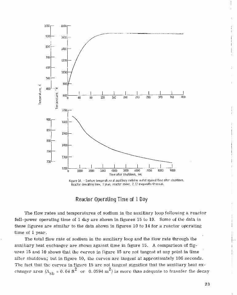
Figure 14 shows the sodium temperature at the auxiliary radiator outlet a s a func-
tion of time after shutdown. The temperature TNa, reaches a maximum of 1660' R (922 K) at about 166 seconds after shutdown. (As shown in figure 11, this time also
corresponds to the initiation of bypass flow around the auxiliary radiator. ) After about
166 seconds, the temperature TNa, decreases with time. The reason for the gradual
decrease in TNa, is that the sodium flow ra te which goes through the auxiliary radi- ator gets smaller with time. As a result, the dwell time of the sodium in the auxiliary
radiator gets larger with time after shutdown.
1200 1 0 1000 2000 3000 4000 5000 6000 7000 8000 9000
Time af ler shutdown, sec
Figure 14. - Sodium temperature at auxi l iary radiator outlet against t ime after shutdown. Reactor operating time, 1 year; reactor power, 2.17 megawatts-thermal.
Reactor Operating Time of 1 Bay
The flow ra tes and temperatures of sodium in the auxiliary loop following a reactor
full-power operating time of 1 day a r e shown in figures 15 to 19. Some of the data in
these figures a r e similar to the data shown in figures P O to 14 for a reactor operating
time of 1 year.
The total flow ra te of sodium in the auxiliary loop and the flow rate through the
auxiliary heat exchanger a r e shown against time in figure 15. A comparison of fig-
u res 15 and 10 shows that the curves in figure 15 a r e not tangent a t any point in time
after shutdown; but in figure PO, the curves a r e tangent a t approximately 106 seconds.
The fact that the curves in figure 15 a r e not tangent signifies that the auxiliary heat ex- 2 2 changer area (Asb = 0 .64 f or 0.0594 m ) i s more than adequate to transfer the decay

12
10
8
6 ,-Flow rate t h r o u a h ,/' aux i l i a ry heat exchanger, \ v ~ ~ , ~
4
2
0 40 80 120 160 200 240 280 320 360 400
1.2
.8
.4 ,-Flow rate t h r o u g h ,'' aux i l i a ry heat exchanger, w
0 1000 2000 3000 4000 5000 6000 7000 8000 9000 Time after shutdown, sec
Figure 15. -To ta l sodium flow rate i n aux i l i a ry loop and sodium flow rate i n aux i l i a ry heat exchanger against t ime after shutdown. Reactor operating t ime, 1 day; reactor power, 2.17 megawatts-thermal.
heat to the auxiliary loop for a reactor preshutdown operating time of 1 day. Conse-
quently, a large fraction of the total sodium flow r a t e bypasses the auxiliary heat ex-
changer throughout the shutdown. (The auxiliary heat exchanger bypass flow ra t e is the
difference between the curves in fig. 15. )
Figure 16 shows the total sodium flow r a t e in the auxiliary loop and the sodium flow
ra te in the auxiliary radiator against t ime after shutdown. A comparison of figures 16 and I 1 shows that the bypass flow around the auxiliary radiator begins at approxi-
mately the same time (about 166 s e c after shutdown) for both reactor preshutdown oper-
ating t imes. This indicates that the rat ios of heat rejection ra te to decay heat input rate
for the two preshutdown operating t imes a r e equal a t about the same time af ter shutdown.
Figure 17 shows the mixed-mean sodium temperatures at the auxiliary radiator

Flow rate t h rough aux i l ia ry radiator, i ~ ~ ~ , ~ 7,
Total Na flow passes t h rough aux i l ia ry radiator9!
1.6
1.2
. 8
.4
0 1000 2000 3000 4000 5000 6000 7000 8000 9000 Tinie after shutdcwn, sec
Fiyure 16. -Tota l sodium flow rate i n aux i l ia ry loop and scd iun~ f1oi.i rate i n aclxiliary radiator against t ime after shutdown. Reactor operating time, 1 day; reactor poiver, 2. 17 megawatts-thermal,
1000 1800
1600 'Auxi l iary heat exchanger
inlet teii~pel-ature, TNa,5 1400
AT = constant = IN' R (55.5 K)
2 1000
500
800 400
600 0 20 40 60 80 100 120 140 160 180 200
Time after shutdown, sec
Figure 17. - Mixed-mean temperatc~re of sodiunl d l aux i l ia ry radiator inlet and aux i l ia rv heat exchanger in le t against t ime after shutdoivn. Reactor operatincl time, 1 day; reactor power, 2. 17 megawatts-thermal.

inlet and auxiliary heat exchanger inlet against time after shutdown. The ternperahrres
in figure 17 increase with time and reach their final values a t approximately 166 seconds
after shutdown. Mter 166 seconds, the temperatures TNa, 8 and TNa7 a r e essen-
tially constant and equal to 1 7 1 0 ~ and 1 6 1 0 ~ R (950 and 894 I(), respectively. These final
temperatures a r e approximately 50' R (27.8 K) lower than those shown in figure 12.
The sodium temperature a t the auxiliary heat exchanger outlet is shown against time
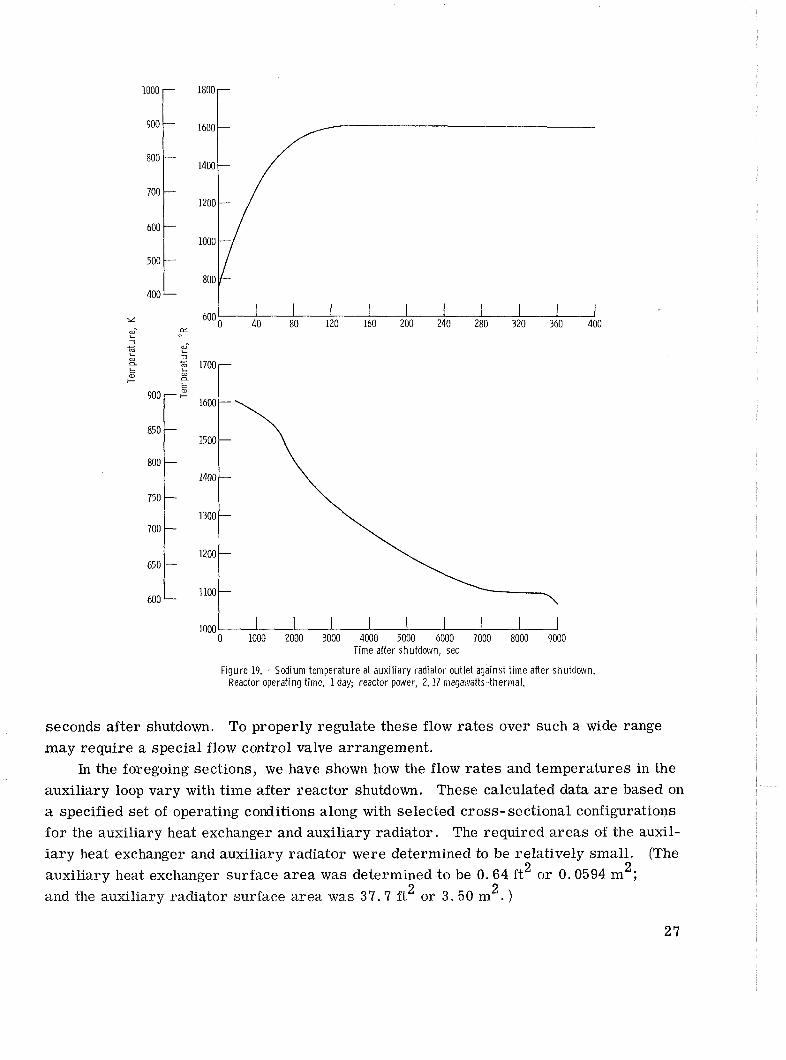
after shutdown in figure 18. This temperature curve is similar to that shown in figure 13. Figure 19 shows the sodium temperature a t the auxiliary radiator outlet against time
after shutdown. The temperature TNa, reaches a maximum of 1610' R (894 K) a t about 166 seconds after shutdown. (Figure 16 shows that this time also corresponds to
the initiation of bypass flow around the auxiliary radiator. ) After 166 seconds, the tem-
perature TNa, decreases gradually with time.
From a control standpoint, the range of sodium flow ra tes required during the shut-
down period is important. The calculated data show that some of the sodium flow ra tes
in the auxiliary loop change by two orders a t magnitude (or more) during the first 9000
950 17001 0 1000 2000 3000 4000 5000 6000 7000 8000 9000
Time after shutdown, sec
Figure 18. - Sodium temperature at aux i l i a ry heat exchanger outlet against t ime after shutdown. Reactor operating time, 1 day; reactor power, 2.17 megawatts-thermal.
1000 0 1000 2000 3000 4000 5000 6000 7000 8000 9000
Time after shutdown, sec
Figure 19. - Sodium temperature at auxi l iary radiator outlet against t ime after shutdown. Reactor operating time, 1 day; reactor power, 2.17 megawatts-thermal.
seconds after shutdown. To properly regulate these flow rates over such a wide range may require a special flow control valve arrangement.
In the foregoing sections, we have shown how the flow rates and temperatures in the auxiliary loop vary with time after reactor shutdown. These calculated data a r e based on a specified set of operating conditions along with selected cross-sectional configurations for the auxiliary heat exchanger and auxiliary radiator. The required areas of the auxil- iary heat exchanger and auxiliary radiator were determined to be relatively small. (The
2 2 auxiliary heat exchanger surface area was determined to be 0.64 f t or 0.0594 m ; 2 2 and the auxiliary radiator surface area was 37.7 f t or 3.50 m . )
The reason that the auifiary radiator is so smal l is due, i n par t , to the thermal
capacitance of the a v x ~ l i a r y loop. Immediately following a shutdown, the decay heat gen-
eration rates (fig. 8) a r e relatively large. h d the thermal capacita~lce of the a.uxiliary loop is used during tine ear ly part of the shutdown period (I. e . , for about the first 60 s e e
or so) to absorb most of the decay heat.
An auxiliary radiator loop with sodium coolant was investigated as a possible means
for removing decay heat f rom a proposed 2.15-megawatt-thermal space power reactor .
The' auxiliary loop considered for this study is made up of an auxiliary heat exchanger, a n
auxiliary radiator, a liquid-sodium pump, and the necessary flow control valves and pip-
ing, The sodium-cooled auxiliary loop is connected to the reactor pr imary loop by the
auxiliary heat exchanger.
Based on a selected s e t of operating conditions and assumptions, minimum a r e a s
were determined for both the auxiliary heat exchanger and the auxiliary radiator.
The minimum auxiliary heat exchanger surface a r e a required to t ransfer the decay
heat froan the reactor pr imary loop to the auxiliary loop was determined to be 0 .64 2 square foot (0.0594 m ). The auxiliary heat exchanger model used in this study is a
simple counterflow type, consisting of two concentric cylindrical ducts.
The minimum surface a r e a required by the auxiliary radiator was determined to be 2 37. '5 sq.uare feet (3.50 m ). Based on this surface a rea , the maximum radiator temper-
a ture was about 1 7 6 0 ~ R (998 K). The auxiliary radiator model consisted of 24 coplanar
parallel tubes with central connecting fins of 100 percent effectiveness. The planform
dimensions of the auxiliary radiator (assuming heat is rejected to space f rom both s ides
of the radiator) a r e : planform length, 6. 0 feet (1.83 m); planform width, 3 . 14 feet
(0.958 m) .
The configurations and minimum a r e a s for the auxiliary heat exchanger and auxiliary
radiator were used to determine sodium flow r a t e s and temperatures throughout the
auxiliary loop as a function of t ime after reactor shutdown. The sodium flow r a t e s and
temperatures were determined for preshutdown reactor operating t imes of 1 year and
9 day.
The calculated data show that some of the sodium flow r a t e s in the auxiliary loop
change by two o rde r s of magnitude (or more ) during the f i r s t 9000 seconds af ter shut-
down.
A significant conclusion obtained f rom this preliminary study is that the s ize (and/or
mass) of the auxiliary loop is relatively small .
Lewis Research Center,
National Aeronautics and Space Administration, Cleveland, Ohio, May 26, 1970,
120-27.

APPENDIX - SYMBOLS
surface a rea of segment in ana- thermal coxlductivity of auxiliary heat exchanger material (tanta- lum), ~ t u / ( s e c ) (ft) (OR);
kW/ (m) (Po
lytical model of auxiliary radi- ator, ft2; m 2
surface a rea for heat transfer in length of auxiliary heat exchanger,
ft; m auxiliary heat exchanger based on inside surface of sodium an- nular flow passage, ft2; m 2
length of auxiliary radiator, ft; m
specific heat of radiator material (tantalum), ~ tu / ( l bm) VR); kW-sec/(kg) (K)
mass of radiator segment in ana- lytical model of auxiliary radi- ator, lbm; kg
specific heat, Btu/ (lbm) (OR);
k ~ - s e c / (kg) (K) Nusselt number
Peclet number inside diameter of lithium flow
duct in auxiliary heat exchanger (see fig. 4), f t ; m
Prandtl number
reactor decay heat generation
rate, Btu/sec; kW inside diameter of sodium annu- lar flow passage in auxiliary heat exchanger (see fig. 4), f t ; m
Reynolds number
temperature, OR; K
average coolant temperature in radiator segment, OR; K outside diameter of sodium annu-
lar flow passage in auxiliary heat exchanger (see fig. 4), ft; m
average material temperature of radiator segment, OR; K
effectiveness of counterflow auxil- t time after reactor shutdown, sec
iary heat exchanger (eq. (8)) Ub overall heat-transfer coefficient
convective heat-transfer coeffi- for auxiliary heat exchanger
cient in auxiliary heat ex- (eq. (311, ~ t u / ( s e c ) ( f t ~ ) ? ~ ) ;
changer, Btu/(sec) (ft2) YR); kw/(m2) (K)
kw/(m2) (K) w flow rate, lbm/sec; kg/sec
convective heat-transfer coeffi- E radiator surface emissivity cient in auxiliary radiator,
P 3
2 o density, ibm/ft ; kg/m3 Btu/(sec) (ft ) ( R); kw/(m2) (K)

a Stefan- Boltzmann constant, 2 0 4 13. 476x10-l2 ~ t u / ( s e c ) ( f t ) ( R );
5.71x10-" k ~ / ( m ' ) ( ~ ~ )
AT auxiliary loop transport delay
(eta. (15)), set
Subscripts :
i inside surface of auxiliary radi-
ator tubes (fig. 6)
in inlet of segment in analytical
model of auxiliary radiator
(fig. 6)
j segment number in analytical model of auxiliary radiator
Li lithium
Na sodium
o outside surface of auxiliary radi-
ator tubes (fig. 6)
out outlet of segrvrent in analytical
model of auxiliary radiator
(fig. 6)
reactor outlet (fig. 3)
reactor inlet (fig. 3)
auxiliary radiator bypass (fig. 3)
auxiliary radiator outlet (fig. 3)
auxiliary heat exchanger inlet
(fig. 3)
auxiliary heat exchanger bypass
(fig. 3)
auxiliary heat exchanger outlet
(fig. 3)
auxiliary radiator inlet (fig. 3)

REFERENCES
I . Davison, B a r r y W. : Preliminary - h a l y s i s of Accidents in a Lithium-Cooled Space Nuclear Powerplant. NASA TM X- 1937? 1970.
2. Lyman, Taylor, ed. : Propert ies and Selection of Metals. Vol. 1 of M e h l s gland-
book. Eighth ed. , American Society for Metals, 1961, p. 1223.
3 . Kreith, Frank: Principles of Heat Transfer . Second ed. , International Textbook
Go., 1965.
4. Davison, Har ry W. : Compilation of ThermopIilysical Propert ies of Liquid Lithium.
NASA TN D-4650, 1968.
5. Baker, R. A. ; and Sesonske, A. : Heat Transfer i n Sodium- Potassium Alloy. Trans.
Am. Nuel. Soc., vol. 3, no. 2, Dec. 1960, pp. 468-469.
6. Jackson, Carey B . , ed. : Liquid Metals Handbook. Sodium-MaK Supplement. AEC
Rep. TID-5277 and Bureau of Ships, July 1, 1955.
7. Kays, W. M. ; and London, A. E. : Compact Heat Exchangers. Second ed . ,
McGraw-Hill Book Co. , Inc. , 1964.
8. Peoples, John A. : Malfunction Analysis of Space Power Fast-Spectrum Reactor.
NASA TM X-2057, 1970

. . . . . . - . . . . - . - - +,-:+- . . - - - , . . - ! ,;,-,--. .;>?.=.,#
', . ,-. ;L - .:,I . - . - , -
.: >:-'-, 1. p s i - . . . - . - - -17 . :;a--=:8.'-=
$id d s w e advi8ies ~ o f $be U d e d St&s siwB be caditded J J B ~ J S t~ ~ a s f r i b ~ t t e . .'. ta E&# expmsim of bt~nzm b a d - srdge of f i b m a n 8 ~ k the d s ~ o s $ b r e & s p m . TA& Are!~))%srtrafiw ska& @raprid+? far $he ~i8te1t pmtimB1e mLb @p~$rdkrse d i z $ d @ a : h i ~ ej t f fo r t~~d io~z ~ul~cmwkg its a~ti+~i.tieb a d the res~dts iher~df."
NASA St3ENTPErIC APdD TECEUYfCAL PUBLICGZTONS
"PEtXINIW REEZOAn: Scimtik a d rim t ~ h i a l hforrsatisa c m i d a d k ~ ~ t , ~ L I M M 19 st f a e i p bqpg conrpke, znd a luting unnibz~tim m misting W f&dt N&A dkr ihdm in &&h.
TECHlVZCAL. WOIZANDFJMS: IIrfmmarim receiving limited digribaim because bf pmliminary data, security chsifica- rion, w ncha r-9.
C Q ~ A ~ R EEWRTS: kimc3ntiflc a d recbnimoll i d m m t b generated u d m a NASA cantm m gmt a d cmsideted an impamnr cmtmihtticm to exbting knmledge.
TEWOL(X.Y wnmATI.oN WrU$UmNS: I n f c m n a ~ 4a tech~~hgy zrwd by NASA r h t m y be aaf pasrkdar inrerese in cammrckl and 0th nm-a~rcropae apphati~ag. PuMisatks MLI& Tech Bdefd, Technology Utilktim Reports 4 N-S, & T e ~ h n d ~ g S T ~ Q ~ S .
Related Documents